UTS SERIES - MEDs Interconnect
216
UTS SERIES Waterproof Plastic Connectors IP68 and IP69K AUTHORISED REPRESENTATIVE: MEDs Interconnect Pte Ltd 5012 Ang Mo Kio 5, #03-09 Techplace II (East Wing), Singapore 569876 Email: sales[email protected] Tel: +65 6235 6355
-
Upload
khangminh22 -
Category
Documents
-
view
0 -
download
0
Transcript of UTS SERIES - MEDs Interconnect

UT
S S
ER
IES
Waterproof Plastic ConnectorsIP68 and IP69K
AUTHORISED REPRESENTATIVE: MEDs Interconnect Pte Ltd5012 Ang Mo Kio 5, #03-09 Techplace II (East Wing), Singapore 569876 Email: [email protected] Tel: +65 6235 6355


3
Typical Applications .......................................... 06Features & Benefits .......................................... 07 Range Overview ............................................... 08Layouts ............................................................. 10General Technical Characteristics ..................... 12
OverviewDescription ....................................................... 162 Contact Plating Selector Guide ........................ 163 Contact Selector Guide .................................... 164 Packaging ......................................................... 164 Crimp Contacts ................................................ 165 #16 Coaxial Contacts ....................................... 167PCB Contacts ................................................... 168 Fiber Optic Contacts ........................................ 170
Contacts
#16 Coaxial Contacts/Cabling Notices ............ 200 Glossary of Terms ............................................. 207 Discrimination/Keying Methods ....................... 208Part Number Index ........................................... 209
Appendices
Connector
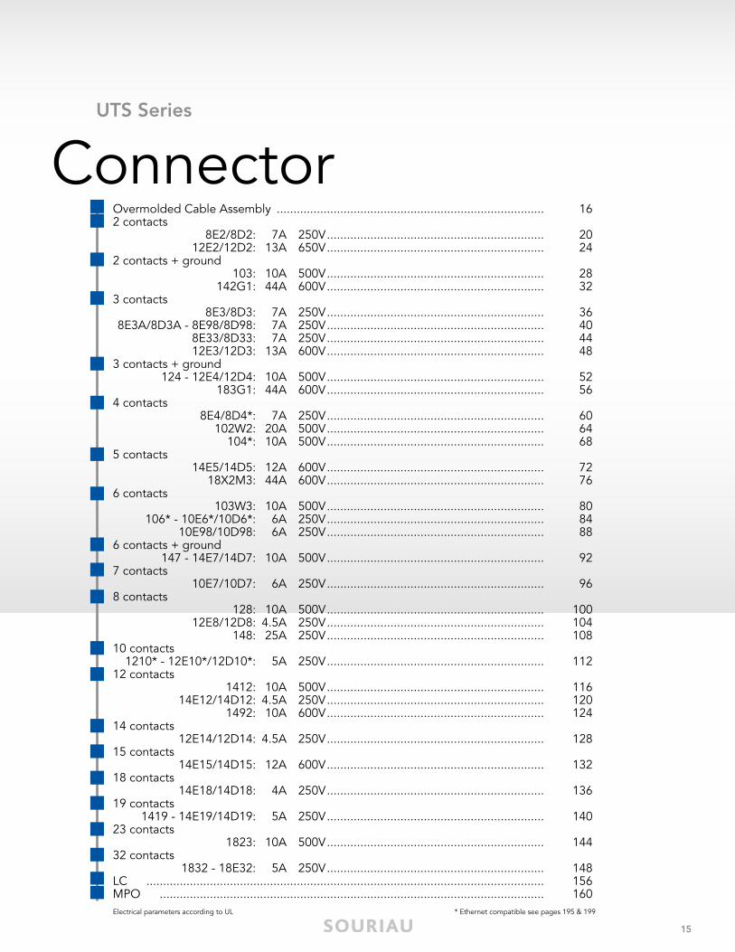
Overmolded Cable Assembly .......................... 162 contacts ......................................................... 202 + ground contacts ......................................... 283 contacts ......................................................... 36 3 + ground contacts ......................................... 524 contacts ......................................................... 60 5 contacts ......................................................... 72 6 contacts ......................................................... 80 6 + ground contacts ......................................... 927 contacts ......................................................... 96 8 contacts ......................................................... 100 10 contacts ....................................................... 11212 contacts ....................................................... 116 14 contacts ....................................................... 128 15 contacts ....................................................... 132 18 contacts ....................................................... 136 19 contacts ....................................................... 14023 contacts ....................................................... 144 32 contacts ....................................................... 148LC (Fiber Optic) ................................................ 152 MPO (Fiber Optic) ............................................ 156
Tooling .............................................................. 174Stripping & Crimping Instructions .................... 176Handle & Interchangeable Heads .................... 178Insertion & Extraction Tools .............................. 179Overmolded Cable Assembly Dimensions ....... 179Assembly Instructions ....................................... 180 Mated Connector Lengths ............................... 184 Mating Procedure ............................................. 185Rated Current & Working Voltage .................... 186UV Resistance ................................................... 187UL94 + UL1977 ................................................. 188IEC 61984 & IP Codes Explained ..................... 191IEC 61140 Explained ........................................ 193What is NEMA Rating ? .................................... 194Ethernet for the Layman ................................... 195
Technical Information
UTS Series |
Contents
Ap
pen
dic
esTe
chni
cal I
nfo
rmat
ion
Co
ntac
tsC
onn
ecto
rO
verv
iew

UT
S S
ER
IES
© 2015 SOURIAU - SOURIAU is a registered trademark

5
OverviewUTS Series
Typical Applications ................................................................................................ 06
Features & Benefits ................................................................................................ 07
Range Overview .................................................................................................... 08
Layouts ................................................................................................................... 10
General Technical Characteristics ........................................................................... 12

6
Typical Applications
UTS Series | Overview
Typical Applications
Stage - Light
Off-Road - Mining - Railway Energy - Power
© V
ibe
Imag
es /
Fot
olia
© S
erg
ey M
ilovi
dov
/ F
otol
ia
Instrumentation - Measurement
Building Automation & Control
© V
olod
ymyr
Kyr
ylyu
k /
Foto
lia
© k
rung
chin
gp
ixs
/ Fo
tolia
© c
acho
udes
ign
/ F
otol
ia
Telecom - Data infrastructure
© O
livie
r Tu
ffé /
Fot
olia

7
Features & Benefits
UTS Series | Overview
WATERPROOF
UVRESISTANT
UL/IECCOMPLIANT
qUICk MATINg
COSTSAVINgS
IP68/69k Dynamic Mated & UnmatedIdeal for outdoor and indoor dynamic applications requiring continuous underwater immersion, routine pressure washingand dust protection.
1/3 Bayonet CouplingWith only 1/3 twist of the bayonet coupling system, connectors are mated with audible "click" and tactile feel to confirm proper mating. This mating feature eliminates connection uncertainty and reducestime and labor during installation.
Mixed Power & Signal LayoutsPower supply and signal transmission can be combined ina unique interconnect solution to reduce system complexity and minimize component and installation costs.
qualified & CertifiedIn accordance with:- UL 1977 - Certificate ECBT2, File number: E169916 - CSA C22.2 n°182.3 - Certificate ECBT8, File number: E169916.
No Degradation Over TimeNo mechanical deterioration or important color variation after5 years of exposure in natural environment (equivalent exposureto sun and moisture as per ISO4892) and F1 rated per UL 746C.
Ove
rvie
w

8
UTS Series | Overview
UTS Backshells
Corrosion-proofPlastic housing
UTS Sealed Unmated
Sealed Unmated: IP68/69K dynamicMIL-C-26482 compatibleUV resistantUL/IEC compliant
Range
Sealed mated:IP68/69K dynamicUV resistantUL/IEC compliant
Corrosion-proofPlastic housing
UTS Standard
Contacts Loaded
Plug
Handsolder
Contacts Loaded
Screw Termination
Cable Sealing
Double Sealing(Wires + Cable)
Cable Sealed
grommet
UTS Series
Single WireSealed
Overmolded Cable Assembly
Single WireSealed
Contacts Supplied Separately
PCB Contacts
Choice of Crimp Contacts • Machined• Stamped and Formed• Coaxial
Fiber Optic
Flexible conduitadaptors
Contact us for more information

9
UTS Series | Overview
UTS Backshells
Overview
Metal hold down clips - to lock the connector easily on the PCB and to release stress on solder joints - suitable for soldering in a metallic hole
Pre-assembled PCB contacts - machined or stamped versions available - different solder tails lengths possible - different plating options
Low profile housing to limit space between panel and PCB
Stand-offs to allow cleaning after soldering
UTS PCB Contacts
UTS Standard Receptacle
UTS SealedUnmated Receptacle
Contacts Loaded
Handsolder
PCB
Cable Sealing
Double Sealing(Wires + Cable)
grommet
Contacts Loaded
Screw Termination
PCB
Single WireSealed
Square Flange
ThreadedReceptacle
In-line
Jam Nut
Jam Nut
Square Flange
Contacts Supplied Separately
PCB Contacts
Choice of Crimp Contacts • Machined• Stamped and Formed• Coaxial
Fiber Optic
Contacts Supplied Separately
PCB Contacts
Choice of Crimp Contacts • Machined• Stamped and Formed• Coaxial
Fiber Optic
Flexible conduitadaptors
Contact us for more information
Ove
rvie
w

10
Shell Size Contact #16 (Ø 1.6mm) Contact #20 (Ø 1.0mm) Contact #8 (Ø 3.6mm) Hybrid & others
8
10
12
1
2 4
3
5
1
2 4
3
5
1
2 4
3
5
1
2 4
3
5
1
2 4
3
5
1
2 4
3
5
1: M12, M16 and M20 threaded receptacle available 2: NPT available 3: Discrete wire grommet option 4: Screw termination contacts * Ethernet compatible: see pages 195 & 196
1
2 4
3
5
1
2 4
3
5
1
2 4
3
51
2 4
3
5
1
2 4
3
5
UTS Series | Overview
Layouts (Electrical parameter according to UL1977)
1
2 4
3
5
8E2/8D2(1)
7A 250V2 contacts
8E3A/8D3A(1)
7A 250V3 contacts
8E33/8D33(1)
7A 250V3 contacts
8E4*/8D4*(1)
7A 250V4 contacts
10310A 500V2+ground
12E2/12D213A 650V2 contacts
104*(3)
10A 500V4 contacts
12E3/12D313A 600V3 contacts
124(4)
12E4/12D410A 500V3+ground
10E98/10D986A 250V
6 contacts
106*10E6*(1)/10D6*
6A 250V6 contacts
10E7(1)/10D76A 250V
7 contacts
102W220A 500V4 contacts2xØ2.4 (#12)2xØ1.0 (#20)
103W310A 500V6 contacts3xØ1.6 (#16)3xØ1.0 (#20)
8E3/8D3(1)
7A 250V3 contacts
12E14/12D144.5A 250V14 contacts
8E98/8D98(1)
7A 250V3 contacts
Page 20
Page 100 Page 104
Page 40
Page 44 Page 60
Page 28
Page 24
Page 68
Page 48
Page 52
Page 112
Page 88
Page 84
Page 96
Page 64 Page 80
Page 36
Page 128
Page 40
1210*12E10*/12D10*
5A 250V10 contacts
128(1) (3)
10A 500V8 contacts
12E8/12D8 4.5A 250V8 contacts

11
Shell Size Contact #16 (Ø 1.6mm) Contact #20 (Ø 1.0mm) Contact #8 (Ø 3.6mm) Hybrid & others
14
18
1
2 4
3
5
1
2 4
3
5
1
2 4
3
5
1
2 4
3
5
1
2 4
3
5
XXXXXX blue highlighted items: UTS Sealed in Unmated Condition
1
2 4
3
5
1
2 4
3
5
1
2 4
3
5
1
2 4
3
5
1
2 4
3
5
1
2 4
3
5
1
2 4
3
5
UTS Series | Overview
1
2 4
3
5
14E5/14D512A 600V5 contacts
1412(3)
10A 500V12 contacts
1492(3)
10A 600V12 contacts
182310A 500V
23 contacts
183G1(2)
44A 600V3+ground
18X2M3(2)
44A 600V5 contacts
3xØ1.6 (#16) + 2xØ3.6 (#8)
MPO
LC
142G1(2)
44A 600V2+ground
Page 72
Page 116 Page 124
Page 144 Page 148 Page 56Page 76
Page 160
Page 156
Page 136
Page 140
Page 92
Page 32
14E12/14D124.5A 250V12 contacts
4xØ1.6 (#16)+8xØ1.0 (#20)
14825A 250V8 contacts
4xØ1.6 (#16)+4xØ2.4 (#12)
Page 120
Page 132
Page 108
183218E325A 250V
32 contacts
141914E19/14D19
5A 250V19 contacts
14E15/14D1512A 600V
15 contacts1xØ1.6 (#16)+14xØ1.0 (#20)
14E18/14D184A 250V
18 contacts
147(3) (4)
14E7/14D710A 500V6+ground
Contacts #16:from AWG 30 to 140.05 to 2.5 mm²
Contacts #20:from AWG 26 to 180.13 to 0.93 mm²
Contacts #8:from AWG 16 to 81.5 to 10 mm²
Contacts #12:from AWG 22 to 120.13 to 4 mm²
Ove
rvie
w

12
UTS Series | Overview
Materials
•Bodyconnector+Backshell: Thermoplastic
•Insert: - UTS Standard, UTS Single Wire Sealed, UTS Screw Termination Contacts: Thermoplastic - UTS Sealed Unmated Handsolder & UTS Sealed Unmated with PC Tails Contacts: Elastomer
•Nut:Metal
•Contacts:See page 161
•Halogenfree
•RoHScompliant&conformstotheChinese standardSJ/T1166-2006 (ChineseRoHSequivalent)
Environmental
•Operatingtemperature: from -40°C to +105°C 40/100/21 per NFF 61-030
•Flammabilityrating: - UL94 V-0 (all UTS except the Sealed Unmated version) see page 188 - UL94 HB (UTS Sealed Unmated version only) see page 188 - I2F3 according to NFF 16101 & NFF 16102
•Saltspray: ≥500 hours per EIA-026A
•UVresistant: No mechanical degradation or important color variation after 5 years of exposure in natural environment (equivalent exposure to sun and moisture as per ISO 4892) and F1 rated per UL 746C
•Sealing: - UTS Standard: IP68/IP69K dynamic (mated) - UTS Sealed Unmated version: IP68/IP69K dynamic (unmated) - UTS Single Wire Sealed: IP67/69K (up to IP68 with double sealing backshell) - UTS Screw Termination Contacts: IP68/IP69K dynamic (mated) Note: IP68=10 m underwater during 1 week
•Fluidresistance: - Gas and Oil - Mineral Oil - Acid Bath - Basic Bath
Electrical
•Inaccordancewith: - UL 1977: Certificate ECBT2 File number: E169916 - CSA C22.2 n°182.3: Certificate ECBT8 File number: E169916
•Also see pages 10 & 11
Optical•Please consult us for more information about UTSLC and UTSMPO
Mechanical
•Durability: 250 matings & unmatings per MIL-C-26482
•Vibrationresistance(allUTSversions exceptUTSScrewTerminationcontacts): Sinusoidal vibrations per IEC 60512-4 - from 10 to 2000 Hz
•Thermalshock: 5 cycles 30 min. from -40°C to 105°C per MIL-STD-1344 method 1003
GeneralTechnicalCharacteristics

13
UTS Series | Overview
Notes
Ove
rvie
w

UT
S S
ER
IES
© 2015 SOURIAU - SOURIAU is a registered trademark
15
Overmolded Cable Assembly ................................................................................ 162 contacts 8E2/8D2: 7A 250V ................................................................. 20 12E2/12D2: 13A 650V ................................................................. 242 contacts + ground 103: 10A 500V ................................................................. 28 142G1: 44A 600V ................................................................. 323 contacts 8E3/8D3: 7A 250V ................................................................. 36 8E3A/8D3A - 8E98/8D98: 7A 250V ................................................................. 40 8E33/8D33: 7A 250V ................................................................. 44 12E3/12D3: 13A 600V ................................................................. 483 contacts + ground 124 - 12E4/12D4: 10A 500V ................................................................. 52 183G1: 44A 600V ................................................................. 564 contacts 8E4/8D4*: 7A 250V ................................................................. 60 102W2: 20A 500V ................................................................. 64 104*: 10A 500V ................................................................. 685 contacts 14E5/14D5: 12A 600V ................................................................. 72 18X2M3: 44A 600V ................................................................. 766 contacts 103W3: 10A 500V ................................................................. 80 106* - 10E6*/10D6*: 6A 250V ................................................................. 84 10E98/10D98: 6A 250V ................................................................. 886 contacts + ground 147 - 14E7/14D7: 10A 500V ................................................................. 927 contacts 10E7/10D7: 6A 250V ................................................................. 968 contacts 128: 10A 500V ................................................................. 100 12E8/12D8: 4.5A 250V ................................................................. 104 148: 25A 250V ................................................................. 10810 contacts 1210* - 12E10*/12D10*: 5A 250V ................................................................. 112 12 contacts 1412: 10A 500V ................................................................. 116 14E12/14D12: 4.5A 250V ................................................................. 120 1492: 10A 600V ................................................................. 12414 contacts 12E14/12D14: 4.5A 250V ................................................................. 12815 contacts 14E15/14D15: 12A 600V ................................................................. 13218 contacts 14E18/14D18: 4A 250V ................................................................. 13619 contacts 1419 - 14E19/14D19: 5A 250V ................................................................. 140 23 contacts 1823: 10A 500V ................................................................. 14432 contacts 1832 - 18E32: 5A 250V ................................................................. 148LC ....................................................................................................................... 156MPO ................................................................................................................... 160Electrical parameters according to UL * Ethernet compatible see pages 195 & 199
ConnectorUTS Series

UTS Series | Connector
16
OUTDOOR
INDOOR
UV
res
ista
nce
Ambient temperature+80°C-40°C
PVCStatic or dynamic installation
PURStatic or dynamic installation
Wet
Cle
aner
,ch
lorin
eIm
mer
sed
Che
mic
al a
gg
ress
ion (black outer jacket)
Please consult us
TPEStatic installation SILICON
Static installation
FEPStatic installation
PTFEStatic installation
How to choose the outer jacket material
Overmolded Cable AssemblySOURIAU has provided connectors for various applications for more than 90 years and has been used in the most extreme environments. Conscious about the difficulty in finding a quick and reliable harness manufacturer, we began our own in-house cable assembly production. It allows customers to reduce the number of suppliers and to take advantage of the “best in class” quality of the SOURIAU group. Overmolding is a process that further enhances the sealing properties and helps to minimize stress on the cable termination to the connector. In addition, the wires are encapsulated inside the molding which creates a barrier preventing liquid/moisture from entering the equipment through the connector or cable jacket if breached.

UTS Series | Connector
17
Overmolding Description
Connector with cable gland backshell
CompoundThermoplastic orelastomer insert
Overmolding adapterO-ring
PVC or PURovermolding
...water ingress unhampered, leading to damage.
If cable jacket is breached...
Overmolded connector
...prevents water ingress via capillary action.
If cable jacket is breached...
gOOD
BEST
Co
nnec
tor

UTS Series | Connector
18
UTS Waterproof Plastic Overmold
DescriptionCable• PVC Jacket (Black)• 16 AWG conductors• Multi-conductor 4, 8 or 12• 300V• Unshielded• Flammability rating UL 1685 (UL1581 Sec.1160)
Applications• Industrial Controls• Electronics• Controlled Environment Equipment• LED Lighting
PLATINg SALT SPRAY TEMPERATURE* WATERPROOF* MECHANICAL
No plating 500 H -30°C up to +50°C IP68/IP69K dynamic (mated) 250 matings/unmatings
Overmolding Specifications
* With appropriate cable and overmolding
Overmolding on Curly Cable Overmolding with Double Ends
Example of Customized Cable Assemblies
Harness for PCB Connection
To define your customized cable assembly needs, please contact our Technical Service Team for support.

UTS Series | Connector
19
Cable Information
Rangeoftemperature: -30°C +50°C
Ratedvoltage: U0/U: 300/500V
Wiresection: Layouts with #16 contact: wire section 1.5 mm² / 16AWG
Harmonizedreference: H05 VV - F XX
Standardization of American Cable
Nomenclature key Definitions of Cable TypesS: Service Grade (also means extra hard service when not followed by J, V, or P)J: Hard ServiceV: Vacuum cleaner cord (also light duty cable)P: Parallel cord (also known as zip cord) – Always light dutyE: Thermoplastic Elastomer (UL/NEC designation ONLY)O: Oil Resistant outer jacketOO: Oil Resistant outer jacket and insulationT: Thermoplastic W: Outdoor-includes sunlight resistant jacket and wet location rated conductors (formerly "W-A")H: Heater cableVW-1: Flame retardant (vertical grade)FT2: Flame retardant (horizontal grade)
SVT: Thermoplastic insulated vacuum cleaner cord, with or without 3rd conductor for grounding purposes; 300V (PVC)SJT: Junior hard service, thermoplastic insulated conductors and jacket. 300V (PVC)SJTW: Same as SJT except outdoor rated. (PVC)SJTO: Same as SJT but oil resistant outer jacket. (PVC)SJTOW: Same as SJTO except outdoor rated. (PVC)ST: Hard service cord with all thermoplastic construction, 600V (PVC)STW: Same as ST except outdoor rated. (PVC)STO: Same as ST but with oil resistant outer jacket. (PVC)STOW: Same as STO except outdoor rated. (PVC)
Co
nnec
tor

UTS Series | Connector
20
OR OR
WITH
Layout
OR
Connector Part Numbers
Possibilities of discrimination/keying methods see page 208
8E2/8D2 (Shell size 8, 2x#20)
Sealed unmated
Contact type Connector type BackshellPart number
Male insert Female insert
Handsolderelectrical contacts
loadedsee page 23
Square flangereceptacle Without (Fig. 1) UTS08E2P UTS08E2S
PlugWithout (Fig. 7) UTS68E2P UTS68E2S
Cable gland (Fig. 8) UTS6JC8E2P UTS6JC8E2SJam nut
receptacle Without (Fig. 4) UTS78E2P UTS78E2S
M12 threaded receptacle Without (Fig. 3) UTS78E2PM12 UTS78E2SM12
PCBcontacts loaded
see page 23
Square flangereceptacle
Without (Fig. 2) UTS08D2P UTS08D2S
Jam nut receptaclewith stand off and
with hold down clipsWithout (Fig. 6) UTS78D2P32 UTS78D2S32
Jam nut receptacle with stand off and
without hold down clipsWithout (Fig. 5) UTS78D2P UTS78D2S
M12 threaded receptacle Without (Fig. 3) UTS78D2PM12 UTS78D2SM12

UTS Series | Connector
21
Note: all dimensions are in inches
Square Flange Receptacle - UTS0 M12 Threaded Receptacle - UTS7
Front view Front view
0.460" 0.342"0.814" 0.866"
Ø0.
472"
Ø0.
472"
0.60
2"
0.090" 0.196"Ø0.125"M12x1.5
0.275" mini
0.295" 0.303"
Fig. 2 Fig. 3
Fig. 1
Plug - UTS6
0.996"
2.126"Fig. 8
Fig. 7
Ø0.
885"
Mated Connector Lengths
2.405"
2.622"
UTS7
UTS0
Jam Nut Receptacle - UTS7
Front view
0.952"
0.95
2"
0.708"
Ø0.
472"
0.137"
0.133"
Fig. 5 Fig. 6Fig. 4
0.708" 0.165"
Ø0.
472"
0.137"
0.133"
0.708"
Ø0.
472"
0.137"
0.133" 0.145" mini
Dimensions
8E2/8D2 (Shell size 8, 2x#20)
Drilling Pattern
0.059"
Ø0.531"
Ø0.866"
Ø0.696"
15°
15°
Ø0.157"
Ø0.122"
0.059"
Panel Cut Out
0.60
2"
0.602"
Ø0.129"
Square Flange Receptacle - UTS0 Jam Nut Receptacle - UTS7
0.54
1"
0.574"
Front mountingØ0.492"
Rear mountingØ0.570"
Hole size:0.035"
2 contacts7A/250V
per UL 1977
2

UTS Series | Connector
22
Accessories
Jam Nut or M12 Threaded Receptacle Sealing Caps Plug Protective CapSquare Flange Sealing Cap
Metal terminal IP40IP68/69K IP68/69K IP68/69K
Part number
UTS8DCGE
Part number
UTS68C
Metal terminal
Part number
UTS8DCG
Part number
UTS8DCGR
Part numbers
Receptacle cap
Plug cap
85005585A 85005594
Plastic Protective Cap
Part numbers
UTFD11B
gasket Color Coding Rings
G for Green
Y for Yellow
Part numbers
Receptacles Plugs
UTS78CCRR UTS68CCRR
UTS78CCRY UTS68CCRY
UTS78CCRG UTS68CCRGR for Red
8E2/8D2 (Shell size 8, 2x#20)
IP68/69K

UTS Series | Connector
23
Electrical Characteristics
UL7A 250V UL94 HB
CSA7A 250V UL94 HB
IEC7A 32V 1.5kV 3
UTS 8E2/8D2 Derating Curves
Testconditions
Contactused:Machined contactsWiresused:0.518mm²
0 20 40 60 80 100 1200
6
10
18
Current (A)
Ambient Operating Temperature (°C)
12
14
16
2
4
8
Current use Limited use Not recommended use
Contacts
#20 Contact type Plating Cable acceptance (AWg) Wire stripping length
Han
dso
lder
Loaded in the connector Min 0.4µ gold over 0.8µ Ni 22 to 18 0.196"
PC
B
Machined, loaded in the connector (1) Min 0.4µ gold over 0.8µ Ni - -
8E2/8D2 (Shell size 8, 2x#20)
(1): For dimensions see page 169
2 contacts7A/250V
per UL 1977
2

UTS Series | Connector
24
OR
WITH
OR
Layout
Connector Part Numbers
12E2/12D2 (Shell size 12, 2x#16)
Contact type Connector type BackshellPart number
Male insert Female insert
Handsolderelectrical contacts
loadedsee page 27
Square flangereceptacle Without (Fig. 1) UTS012E2P UTS012E2S
PlugWithout (Fig. 6) UTS612E2P UTS612E2S
Cable gland (Fig. 7) UTS6JC12E2P UTS6JC12E2SJam nut
receptacle Without (Fig. 3) UTS712E2P UTS712E2S
PCBcontacts loaded
see page 27
Square flangereceptacle Without (Fig. 2) UTS012D2P UTS012D2S
Jam nut receptaclewith stand off and
with hold down clipsWithout (Fig. 5) UTS712D2P32 UTS712D2S32
Jam nut receptaclewith stand off and
without hold down clipsWithout (Fig. 4) UTS712D2P UTS712D2S
Sealed unmated

UTS Series | Connector
25
Square Flange Receptacle - UTS0
Front view
0.444" 0.444" 1.039"
Ø0.
748"
Ø0.
748"
0.81
8"
0.090" 0.090"
Ø0.125"
0.295" 0.295"0.318" mini
Fig. 2Fig. 1
Plug - UTS6 Mated Connector Lengths0.996"
2.626"Fig. 7
Fig. 6
Ø1.
185"
3.055"
3.216"
UTS7
UTS0
Jam Nut Receptacle - UTS7
Front view
1.070"
1.25
5"
0.708"0.708" 0.708"
Ø0.
748"
Ø0.
748"
Ø0.
748"
0.137" 0.137" 0.137"
0.118" 0.118" 0.185" mini
0.118"0.165"
Fig. 4 Fig. 5Fig. 3
12E2/12D2 (Shell size 12, 2x#16)
Dimensions
Panel Cut Out
0.81
8"
0.818"
Ø0.129"
Jam Nut Receptacle - UTS7
0.82
6"
0.875"
Square Flange Receptacle - UTS0
Front mountingØ0.720"
Rear mountingØ0.877"
Drilling Pattern
0.090"
Ø0.866"
Ø1.200"
Ø1.031"
30°
68°
0.393"
Ø0.122"
0.090"
0.05
5"
22° Hole size:0.051"
Note: all dimensions are in inches
2 contacts13A/650V
per UL 1977
2

UTS Series | Connector
26
Color Coding Rings
G for Green
Y for Yellow
Part numbers
Receptacle cap
Plug cap
85005587A 85005596
Plastic Protective Cap
Part numbers
UTFD13B
gasket
Part numbers
Receptacles Plugs
UTS712CCRR UTS612CCRR
UTS712CCRY UTS612CCRY
UTS712CCRG UTS612CCRGR for Red
Accessories
12E2/12D2 (Shell size 12, 2x#16)
Jam Nut Sealing Caps
IP68/69K
Plug Sealing Cap
Part number
UTS612DCG
IP68/69K IP68/69K
Square Flange Sealing Cap
Metal terminalIP68/69K
Part number
UTS12DCGE
Metal terminal
Part number
UTS12DCG
Part number
UTS12DCGR
IP68/69K

UTS Series | Connector
27
0 20 40 60 80 100 120
Current (A)
Ambient Operating Temperature (°C)
Electrical Characteristics
UL13A 650V UL94 HB
CSA13A 600V UL94 HB
IEC16A 150V 2.5kV 3
UTS 12E2/12D2 Derating Curves
Testconditions
Contactused:Machined contactsWiresused:1.31mm²
Current use Limited use Not recommended use
Contacts
12E2/12D2 (Shell size 12, 2x#16)
468
12141618
02
10
202224262830
#16 Contact type Plating Cable acceptance (AWg) Wire stripping length
Han
dso
lder
Loaded in the connector Min 0.4µ gold over 0.8µ Ni 18 to 14 0.196"
PC
B
Machined, loaded in the connector (1) Min 0.4µ gold over 0.8µ Ni - -
(1): For dimensions see page 169
2 contacts13A/650V
per UL 1977
2

UTS Series | Connector
28
OR OR
WITH
Layout
Contact type Connector type BackshellPart number
Male insert Female insert
Crimpcontacts supplied
separatelysee page 31
Free hangingreceptacle Cable gland (Fig. 1) UTS1JC103P UTS1JC103S
PlugWithout (Fig. 2) UTS6103P UTS6103S
Cable gland (Fig. 3) UTS6JC103P UTS6JC103S
Jam nut receptacle Without (Fig. 4) UTS7103P UTS7103S
PCBcontacts supplied
separatelysee page 31
Jam nut receptacle Without (Fig. 4) UTS7103P UTS7103S
Connector Part Numbers
103 (Shell size 10, 2 + ground, 3x#16)

UTS Series | Connector
29
Free Hanging - UTS1
2.755"
Ø0.
594"
Fig. 1
Mated Connector Length - UTS7
3.043"
Jam Nut Receptacle - UTS7
Fig. 4
0.720" 1.070"0.484"
0.885"
Ø0.
594"
0.137"
Plug - UTS6
Female
Male
Fig. 2 Fig. 3
1.299" 2.488"
0.996"
Ø1.
031"
Ø1.
031"
103 (Shell size 10, 2 + ground, 3x#16)
Dimensions
Drilling PatternPanel Cut OutJam Nut Receptacle - UTS7
0.65
1"
0.686"
0.102" 0.102"
0.05
9"0.
118"
Hole size:0.051"
Note: all dimensions are in inches
2 + ground10A/500V
per UL 1977
2 +

UTS Series | Connector
30
Part numbers
Receptacle cap
Plug cap
85005586A 85005595
Plastic Protective Cap
Color Coding Rings
Part numbers
Receptacles Plugs
UTS710CCRR UTS610CCRR
UTS710CCRY UTS610CCRY
UTS710CCRG UTS610CCRG
G for Green
Y for Yellow
R for Red
Accessories and Tooling
103 (Shell size 10, 2 + ground, 3x#16)
Tool kitHandle (without Head)
Part number
ToolkiT
Part number
ShAnDlES
Plug Sealing Cap
Part number
UTS610DCG
Part number
RX2025GE1
Extraction Tool #16
Contacts Contact sizePart number
of head
RM/RC 28M1k(1)
Standard contacts
#16Ø 1.6 mm
S16RCM20*RM/RC 24M9k(1) S16RCM20*RM/RC 20M13k(1) S16RCM20*RM/RC 20M12k(1) S16RCM20*RM/RC 16M23k(1) S16RCM16*RM/RC 14M30k(1) S16RCM14*SM/SC 24Ml1Tk6(1) S16SCM20*SM/SC 20Ml1Tk6(1) S16SCM20*SM/SC 16Ml1Tk6(1) S16SCMl1*SM/SC 14Ml1Tk6(1) S16SCMl1*SM/SC 16Ml11Tk6(1) S16SCMl11*
RMDXk10D28k
Coaxial contacts
M10S1Jwith die set
& stop bushingsee page
202 to 205
RCDXk1D28kRM/RC DX60xxD28kRM/RC DXk10D28 +
york090RM/RC DX60xxD28
Crimp Tooling (without Shandles)
(1): Example of plating, for other plating options see page 164* Heads to be used with handle PN: SHANDLES
Jam Nut Sealing Caps
IP68/69K
IP68/69K
IP68/69K Metal terminal
Part number
UTS10DCG
Part number
UTS10DCGR
See page 212 for more information
Part number / Polyamide 6.6
SMSPkE0
Dummy Contact #16
+ =Handle Head Complete set

UTS Series | Connector
31
UL10A 500V UL94 V-0
CSA7A 500V UL94 V-0
IEC16A 300V 4kV 3
Temperature elevation: 50°C
Electrical Characteristics UTS 103 Derating Curves
Testconditions
Contactused:Machined contactsWiresused:1.31mm²
Current use Limited use Not recommended use
0 20 40 60 80 1000
3
5
8
10
13
15
18
20
23
25
28
30
Current (A)
Ambient Operating Temperature (°C)120
Contacts
103 (Shell size 10, 2 + ground, 3x#16)
(1): Example of plating, for other plating see page 164(2): For loose piece contact packaging, place "L" in part number. Example: SM20Ml1Tk6(3): For dimensions see page 172
Note: all dimensions are in inches
#16 Contact typeWire size Part number Max
wire ØMax
insulator ØAWg mm² Male Female
Cri
mp
Machined
30-28 0.50-0.08 RM28M1k(1) RC28M1k(1) 0.021" 0.039"
26-24 0.13-0.20 RM24M9k(1) RC24M9k(1) 0.031" 0.062"
22-20 0.32-0.52 RM20M13k(1) RC20M13k(1) 0.045" 0.070"
22-20 0.32-0.52 RM20M12k(1) RC20M12k(1) 0.045" 0.086"
20-16 0.52-1.31 RM16M23k(1) RC16M23k(1) 0.070" 0.125"
16-14 1.31-2.08 RM14M30k(1) RC14M30k(1) 0.090" 0.125"
Stamped & Formed reeled contacts
See note (2) for loose piece
26-24 0.13-0.20 SM24M1Tk6(1)(2) SC24M1Tk6(1)(2) - 0.035"-0.062"
22-20 0.32-0.52 SM20M1Tk6(1)(2) SC20M1Tk6(1)(2) - 0.047"-0.082"
18-16 0.80-1.31 SM16M1Tk6(1)(2) SC16M1Tk6(1)(2) - 0.125"
18-16 0.80-1.31 SM16M11Tk6(1)(2) SC16M11Tk6(1)(2) - 0.118"
14 2.08 SM14M1Tk6(1)(2) SC14M1Tk6(1)(2) - 0.125"
PC
B
Machined (3) - - RM20M12E83k(1) RC20M12E84k(1) - -
Co
axia
l
Cable Multipiece
see pages 167,200 to 206
RMDXk10D28 RCDXk1D28 - -
Cable Monocrimp RMDX60xxD28 RCDX60xxD28 - -
Twisted pair MultipieceRMDXk10D28 +
york090RCDXk1D28 +york090
- -
Twisted pair Monocrimp RMDX60xxD28 RCDX60xxD28 - -
Fib
er
op
tic POF contacts
(Plastic Optical Fiber)see page
170 RMPoF1000 RCPoF1000B - -
2 + ground10A/500V
per UL 1977
2 +

UTS Series | Connector
32
OR
WITH
OR OR OR
Contact type Connector type BackshellPart number
Male insert Female insert
Crimpcontacts supplied
separatelysee page 35
Square flange receptacle Without (Fig. 1) UTS0142G1P -Free hanging
receptacle Cable gland (Fig. 6) UTS1JC142G1P UTS1JC142G1S
PlugWithout (Fig. 3) UTS6142G1P UTS6142G1S
Cable gland (Fig. 4) UTS6JC142G1P UTS6JC142G1SJam nut
receptacle Without (Fig. 2) UTS7142G1P UTS7142G1S
NPT 1/2" threadedreceptacle Without (Fig. 5) - UTS7142G1SnPT
PCBcontacts supplied
separatelysee page 35
Square flange receptacle Without (Fig. 1) UTS0142G1P -Jam nut
receptacle Without (Fig. 2) UTS7142G1P UTS7142G1S
NPT 1/2" threadedreceptacle Without (Fig. 5) - UTS7142G1SnPT
NPT 1/2" threadedreceptacle with nut Without (Fig. 5) - UTS7142G1SnPTnUT
Layout
Connector Part Numbers
142g1 (Shell size 14, 2 + ground, 3x#8)

UTS Series | Connector
33
Plug - UTS6
Male
Fig. 3
1.378"
1.263"
Ø1.
381"
Free Hanging - UTS13.090"
Ø0.
877"
Fig. 6
NPT Threaded Receptacle - UTS7
Fig. 5
1.000"
1.00
0"
1.389"Ø
0.87
7"
0.909" NPT - 1/2˝
Square Flange Receptacle - UTS0 Jam Nut Receptacle - UTS7
Fig. 2
0.708" 1.381"0.062"
1.196"
Ø0.
877"
0.137"
0.444"
Ø0.
877"
0.090"
0.862"
Fig. 10.
913"
1.133"
Front viewFig. 1
Drilling Pattern
0.141" 0.141"
0.08
2"0.
165"
Panel Cut Out
Jam Nut Receptacle - UTS7
0.94
8"
1.003"
NPT
0.740
"
NPT 1/
2"
142g1 (Shell size 14, 2 + ground, 3x#8)
Dimensions
Ø0.125"
Hole size:0.129"
Note: all dimensions are in inches
Fig. 4
2.755"
Female
Mated Connector Lengths
2.952"
3.228"UTS7
UTS0
2 + ground44A/600V
per UL 1977
2 +

UTS Series | Connector
34
Hand Tool
Part number
M317
Positioner + Locator Setting #8
Part number
VGE10078A
Extraction Tool #8
Part number
51060210936
Plug Sealing Cap
Part number
UTS614DCG
Part numbers
Receptacle cap
Plug cap
85005588A 85005597
Plastic Protective Cap
Part numbers
UTFD14B
gasket
Color Coding Rings
Part numbers
Receptacles Plugs
UTS714CCRR UTS614CCRR
UTS714CCRY UTS614CCRY
UTS714CCRG UTS614CCRG
G for Green
Y for Yellow
R for Red
142g1 (Shell size 14, 2 + ground, 3x#8)
Accessories and Tooling
Jam Nut or NPT Threaded Receptacle Sealing Caps
IP68/69K IP68/69K
IP68/69K
Metal terminal
Part number
UTS14DCG
Part number
UTS14DCGR
IP68/69K

UTS Series | Connector
35
UL44A 600V UL94 V-0
CSA30A 600V UL94 V-0
IEC40A 300V 4kV 3
Electrical Characteristics UTS 142g1 Derating Curves
Current use Limited use Not recommended use
Testconditions
Contactused:Machined contactsWiresused:6mm²
0 20 40 60 80 100 1200
10
15
20
25
30
35
40
45
50
Current (A)
Ambient Operating Temperature (°C)
5
Contacts
142g1 (Shell size 14, 2 + ground, 3x#8)
#8 Contact typeWire size Part number Max
wire ØMax
insulator ØAWg mm² Male Female
Cri
mp
Machined
16 1.31 82913601A 82913600A 0.067"
0.255"
14 2.08 82913603A 82913602A 0.087"
12 3.31 82913605A 82913604A 0.111"
10 5.26 82913607A 82913606A 0.137"
8 8.37 82913609A 82913608A 0.171"
PC
B
Machined (1) - 82911685nPC 82911684nPC - -
(1): For dimensions see page 168 Note: all dimensions are in inches
2 + ground44A/600V
per UL 1977
2 +

UTS Series | Connector
36
OR
WITH
OR OR
Layout
Connector Part Numbers
Possibilities of discrimination/keying methods see page 208
8E3/8D3 (Shell size 8, 3x#20)
Contact type Connector type BackshellPart number
Male insert Female insert
Handsolderelectrical contacts
loadedsee page 39
Square flangereceptacle Without (Fig. 1) UTS08E3P UTS08E3S
PlugWithout (Fig. 7) UTS68E3P UTS68E3S
Cable gland (Fig. 8) UTS6JC8E3P UTS6JC8E3SJam nut
receptacle Without (Fig. 4) UTS78E3P UTS78E3S
M12 threaded receptacle Without (Fig. 3) UTS78E3PM12 UTS78E3SM12
PCBcontacts loaded
see page 39
Square flangereceptacle Without (Fig. 2) UTS08D3P UTS08D3S
Jam nut receptaclewith stand off and
with hold down clipsWithout (Fig. 6) UTS78D3P32 UTS78D3S32
Jam nut receptaclewith stand off and
without hold down clipsWithout (Fig. 5) UTS78D3P UTS78D3S
M12 threaded receptacle Without (Fig. 3) UTS78D3PM12 UTS78D3SM12
Sealed unmated

UTS Series | Connector
37
Plug - UTS6
0.996"
2.126"Fig. 8
Fig. 7
Ø0.
885"
Mated Connector Lengths
2.405"
2.622"
UTS7
UTS0
Jam Nut Receptacle - UTS7
Front view
0.952"
0.95
2"
0.708"
Ø0.
472"
0.137"
0.133"
Fig. 5 Fig. 6Fig. 4
0.708" 0.165"
Ø0.
472"
0.137"
0.133"
0.708"
Ø0.
472"
0.137"
0.133" 0.145" mini
8E3/8D3 (Shell size 8, 3x#20)
Dimensions
Drilling Pattern
0.062"
Ø0.531"
Ø0.866"
Ø0.696"
15°
15°
Ø0.157"
Ø0.122"
0.062"
0.07
4"
0.03
5"
Panel Cut Out
0.60
2"
0.602"
Ø0.129"
Jam Nut Receptacle - UTS7
0.54
1"
0.574"
Square Flange Receptacle - UTS0
Front mountingØ0.492"
Rear mountingØ0.570"
Hole size:0.035"
Square Flange Receptacle - UTS0 M12 Threaded Receptacle - UTS7
Front view Front view
0.460" 0.342"0.814" 0.866"
Ø0.
472"
Ø0.
472"
0.60
2"
0.090" 0.196"Ø0.125"M12x1.5
0.275" mini
0.295" 0.303"
Fig. 2 Fig. 3
Fig. 1
Note: all dimensions are in inches
3 contacts7A/250V
per UL 1977
3

UTS Series | Connector
38
Part numbers
Receptacle cap
Plug cap
85005585A 85005594
Plastic Protective Cap
Part numbers
UTFD11B
gasket Color Coding Rings
G for Green
Y for Yellow
Part numbers
Receptacles Plugs
UTS78CCRR UTS68CCRR
UTS78CCRY UTS68CCRY
UTS78CCRG UTS68CCRGR for Red
Accessories
8E3/8D3 (Shell size 8, 3x#20)
Plug Protective CapSquare Flange Sealing Cap
Metal terminal IP40IP68/69K IP68/69K IP68/69K
Part number
UTS8DCGE
Part number
UTS68C
Metal terminal
Part number
UTS8DCG
Part number
UTS8DCGR
Jam Nut or M12 Threaded Receptacle Sealing Caps
IP68/69K

UTS Series | Connector
39
UTS 8E3/8D3 Derating Curves
Testconditions
Contactused:Machined contactsWiresused:0.518mm²
Current (A)
Ambient Operating Temperature (°C)0 20 40 60 80 100 120
0
6
10
8
18
12
14
16
2
4
Electrical Characteristics
UL7A 250V UL94 HB
CSA7A 250V UL94 HB
IEC7A 32V 1.5kV 3
Current use Limited use Not recommended use
Contacts
8E3/8D3 (Shell size 8, 3x#20)
#20 Contact type Plating Cable acceptance (AWg) Wire stripping length
Han
dso
lder
Loaded in the connector Min 0.4µ gold over 0.8µ Ni 22 to 18 0.196"
PC
B
Machined, loaded in the connector (1) Min 0.4µ gold over 0.8µ Ni - -
(1): For dimensions see page 169
3 contacts7A/250V
per UL 1977
3

UTS Series | Connector
40
OR
WITH
OR OR
Contact type Connector type BackshellPart number
Male insert Female insert
Handsolderelectrical contacts
loadedsee page 43
Square flangereceptacle Without (Fig. 1)
UTS08E3AP UTS08E3ASUTS08E98P UTS08E98S
Plug
Without (Fig. 7)UTS68E3AP UTS68E3ASUTS68E98P UTS68E98S
Cable gland (Fig. 8)UTS6JC8E3AP UTS6JC8E3ASUTS6JC8E98P UTS6JC8E98S
Jam nutreceptacle Without (Fig. 4)
UTS78E3AP UTS78E3ASUTS78E98P UTS78E98S
M12 threaded receptacle Without (Fig. 3)UTS78E3APM12 UTS78E3ASM12
UTS78E98PM12 UTS78E98SM12
PCBcontacts loaded
see page 43
Square flangereceptacle Without (Fig. 2)
UTS08D3AP UTS08D3ASUTS08D98P UTS08D98S
Jam nut receptaclewith stand off and
with hold down clipsWithout (Fig. 6)
UTS78D3AP32 UTS78D3AS32
UTS78D98P32 UTS78D98S32
Jam nut receptaclewith stand off and
without hold down clipsWithout (Fig. 5)
UTS78D3AP UTS78D3AS
UTS78D98P UTS78D98S
M12 threaded receptacle Without (Fig. 3)UTS78D3APM12 UTS78D3ASM12
UTS78D98PM12 UTS78D98SM12
Layout
Connector Part Numbers
Sealed unmatedPossibilities of discrimination/keying methods see page 208
8E3A/8D3A - 8E98/8D98 (Shell size 8, 3x#20)

UTS Series | Connector
41
Jam Nut Receptacle - UTS7
Front view
0.952"
0.95
2"
0.708"
Ø0.
472"
0.137"
0.118"
Fig. 5 Fig. 6Fig. 4
0.708" 0.165"
Ø0.
472"
0.137"
0.118"
0.708"
Ø0.
472"
0.137"
0.118"
Plug - UTS6 Mated Connector Lengths
0.996"
2.126"
Fig. 8
Fig. 7
Ø0.
885"
2.622"
UTS7
UTS0
2.405"
8E3A/8D3A - 8E98/8D98 (Shell size 8, 3x#20)
Dimensions
Drilling PatternPanel Cut Out
0.60
2"
0.602"
Ø0.129"
Jam Nut Receptacle - UTS7
0.54
1"
0.574"
0.062"
Ø0.866"
15°
15°
Ø0.157"
Ø0.122"
0.062"
0.07
4"
0.03
5"
Front mountingØ0.492"
Rear mountingØ0.570"
Hole size:0.035"
Square Flange Receptacle - UTS0
Ø0.531"
Ø0.696"
0.145" mini
Square Flange Receptacle - UTS0 M12 Threaded Receptacle - UTS7
Front view Front view
0.460" 0.342"0.814" 0.866"
Ø0.
472"
Ø0.
472"
0.60
2"
0.090" 0.196"Ø0.125"M12x1.5
0.275" mini
0.295" 0.303"
Fig. 2 Fig. 3
Fig. 1
Note: all dimensions are in inches
3 contacts7A/250V
per UL 1977
3

UTS Series | Connector
42
Part numbers
Receptacle cap
Plug cap
85005585A 85005594
Plastic Protective Cap
Part numbers
UTFD11B
gasket Color Coding Rings
G for Green
Y for Yellow
Part numbers
Receptacles Plugs
UTS78CCRR UTS68CCRR
UTS78CCRY UTS68CCRY
UTS78CCRG UTS68CCRGR for Red
Accessories
8E3A/8D3A - 8E98/8D98 (Shell size 8, 3x#20)
Plug Protective CapSquare Flange Sealing Cap
Metal terminal IP40IP68/69K IP68/69K IP68/69K
Part number
UTS8DCGE
Part number
UTS68C
Metal terminal
Part number
UTS8DCG
Part number
UTS8DCGR
Jam Nut or M12 Threaded Receptacle Sealing Caps
IP68/69K

UTS Series | Connector
43
UTS 8E3A/8D3A - 8E98/8D98 Derating CurvesElectrical Characteristics
UL7A 250V UL94 HB
CSA7A 250V UL94 HB
IEC7A 50V 1.5kV 3
Current use Limited use Not recommended use
Testconditions
Contactused:Machined contactsWiresused:0.518mm²
Contacts
Current (A)
Ambient Operating Temperature (°C)
8E3A/8D3A - 8E98/8D98 (Shell size 8, 3x#20)
0 20 40 60 80 100 1200
6
10
8
18
12
14
16
2
4
#20 Contact type Plating Cable acceptance (AWg) Wire stripping length
Han
dso
lder
Loaded in the connector Min 0.4µ gold over 0.8µ Ni 22 to 18 0.196"
PC
B
Machined, loaded in the connector (1) Min 0.4µ gold over 0.8µ Ni - -
(1): For dimensions see page 169
3 contacts7A/250V
per UL 1977
3

UTS Series | Connector
44
OR
WITH
OR OR
Contact type Connector type BackshellPart number
Male insert Female insert
Handsolderelectrical contacts
loadedsee page 47
Square flangereceptacle Without (Fig. 1) UTS08E33P UTS08E33S
PlugWithout (Fig. 7) UTS68E33P UTS68E33S
Cable gland (Fig. 8) UTS6JC8E33P UTS6JC8E33SJam nut
receptacle Without (Fig. 4) UTS78E33P UTS78E33S
M12 threaded receptacle Without (Fig. 3) UTS78E33PM12 UTS78E33SM12
PCBcontacts loaded
see page 47
Square flangereceptacle Without (Fig. 2) UTS08D33P UTS08D33S
Jam nut receptaclewith stand off and
with hold down clipsWithout (Fig. 6) UTS78D33P32 UTS78D33S32
Jam nut receptaclewith stand off and
without hold down clipsWithout (Fig. 5) UTS78D33P UTS78D33S
M12 threaded receptacle Without (Fig. 3) UTS78D33PM12 UTS78D33SM12
Layout
Sealed unmated
Connector Part Numbers
Possibilities of discrimination/keying methods see page 208
8E33/8D33 (Shell size 8, 3x#20)

UTS Series | Connector
45
Jam Nut Receptacle - UTS7
Front view
0.952"
0.95
2"
0.708"
Ø0.
472"
0.137"
0.133"
Fig. 5 Fig. 6Fig. 4
0.708" 0.165"
Ø0.
472"
0.137"
0.133"
0.708"
Ø0.
472"
0.137"
0.133"
Plug - UTS6
0.996"
2.126"
Fig. 8
Fig. 7
Ø0.
885"
Mated Connector Lengths2.405"
2.622"
UTS7
UTS0
8E33/8D33 (Shell size 8, 3x#20)
Dimensions
Drilling PatternPanel Cut Out
0.60
2"
0.602"
Ø0.129"
Jam Nut Receptacle - UTS7
0.54
1"
0.574"
0.062"
Ø0.531"
Ø0.866"
Ø0.696"
15°
15°
Ø0.157"
Ø0.122"
0.062"
0.03
5"
0.07
4"
Front mountingØ0.492"
Rear mountingØ0.570"
Hole size:0.035"
Square Flange Receptacle - UTS0
0.145" mini
Square Flange Receptacle - UTS0 M12 Threaded Receptacle - UTS7
Front view Front view
0.460" 0.342"0.814" 0.866"
Ø0.
472"
Ø0.
472"
0.60
2"
0.090" 0.196"Ø0.125"M12x1.5
0.275" mini
0.295" 0.303"
Fig. 2 Fig. 3
Fig. 1
Note: all dimensions are in inches
3 contacts7A/250V
per UL 1977
3

UTS Series | Connector
46
Part numbers
Receptacle cap
Plug cap
85005585A 85005594
Plastic Protective Cap
Part numbers
UTFD11B
gasket Color Coding Rings
G for Green
Y for Yellow
Part numbers
Receptacles Plugs
UTS78CCRR UTS68CCRR
UTS78CCRY UTS68CCRY
UTS78CCRG UTS68CCRGR for Red
8E33/8D33 (Shell size 8, 3x#20)
Accessories
Plug Protective CapSquare Flange Sealing Cap
Metal terminal IP40IP68/69K IP68/69K IP68/69K
Part number
UTS8DCGE
Part number
UTS68C
Metal terminal
Part number
UTS8DCG
Part number
UTS8DCGR
Jam Nut or M12 Threaded Receptacle Sealing Caps
IP68/69K

UTS Series | Connector
47
UTS 8E33/8D33 Derating CurvesElectrical Characteristics
UL7A 250V UL94 HB
CSA7A 250V UL94 HB
IEC7A 50V 1.5kV 3
Current use Limited use Not recommended use
Testconditions
Contactused:Machined contactsWiresused:0.518mm²
Current (A)
Ambient Operating Temperature (°C)
8E33/8D33 (Shell size 8, 3x#20)
Contacts
0 20 40 60 80 100 1200
6
10
8
18
12
14
16
2
4
#20 Contact type Plating Cable acceptance (AWg) Wire stripping length
Han
dso
lder
Loaded in the connector Min 0.4µ gold over 0.8µ Ni 22 to 18 0.196"
PC
B
Machined, loaded in the connector (1) Min 0.4µ gold over 0.8µ Ni - -
(1): For dimensions see page 169
3 contacts7A/250V
per UL 1977
3

UTS Series | Connector
48
OR
WITH
OR
Contact type Connector type BackshellPart number
Male insert Female insert
Handsolder electrical contacts
loadedsee page 51
Square flangereceptacle Without (Fig. 6) UTS012E3P UTS012E3S
PlugWithout (Fig. 1) UTS612E3P UTS612E3S
Cable gland (Fig. 2) UTS6JC12E3P UTS6JC12E3SJam nut
receptacle Without (Fig. 3) UTS712E3P UTS712E3S
PCBcontacts loaded
see page 51
Square flangereceptacle Without (Fig. 7) UTS012D3P UTS012D3S
Jam nut receptaclewith stand off and
with hold down clipsWithout (Fig. 5) UTS712D3P32 UTS712D3S32
Jam nut receptaclewith stand off and
without hold down clipsWithout (Fig. 4) UTS712D3P UTS712D3S
Layout
Sealed unmated
Connector Part Numbers
Possibilities of discrimination/keying methods see page 208
12E3/12D3 (Shell size 12, 3x#16)

UTS Series | Connector
49
Jam Nut Receptacle - UTS7
Front view
1.070"
1.25
5"
0.708"0.708" 0.708"
Ø0.
748"
Ø0.
748"
Ø0.
748"
0.137" 0.137" 0.137"
0.118" 0.118" 0.185" mini
0.118"0.165"
Fig. 4 Fig. 5Fig. 3
Plug - UTS6
Fig. 1 Fig. 2
2.626"
Ø1.
185"
0.996"
Square Flange Receptacle - UTS0 Mated Connector Lengths
Fig. 6
Fig. 70.444"
Ø0.
748"
0.090"
0.295"
0.81
8"
1.039"
Ø0.125"Front view
3.055"
3.216"
UTS7
UTS0
12E3/12D3 (Shell size 12, 3x#16)
Dimensions
Drilling PatternPanel Cut Out
0.81
8"
0.818"
Ø0.129"
Jam Nut Receptacle - UTS7
0.82
6"
0.875"
0.090"
Ø0.866"
Ø1.200"
Ø1.031"
30°
68°
0.393"
Ø0.122"
0.090"
0.11
0"0.
055"
22°
Front mountingØ0.720"
Rear mountingØ0.877"
Hole size:0.051"
Square Flange Receptacle - UTS0
0.318"mini
Note: all dimensions are in inches
3 contacts13A/600V
per UL 1977
3

UTS Series | Connector
50
Metal terminal
Color Coding Rings
Part numbers
Receptacles Plugs
UTS712CCRR UTS612CCRR
UTS712CCRY UTS612CCRY
UTS712CCRG UTS612CCRG
G for Green
Y for Yellow
R for Red
Square Flange Sealing CapPlug Sealing Cap
Part number
UTS612DCG
Part number
UTS12DCGE
Part numbers
Receptacle cap
Plug cap
85005587A 85005596
Plastic Protective Cap
Part numbers
UTFD13B
gasket
12E3/12D3 (Shell size 12, 3x#16)
Accessories
Jam Nut Sealing Caps
IP68/69K IP68/69K IP68/69K IP68/69K Metal terminal
Part number
UTS12DCG
Part number
UTS12DCGR
IP68/69K

UTS Series | Connector
51
Electrical Characteristics
UL13A 600V UL94 HB
CSA13A 600V UL94 HB
IEC16A 150V 2.5kV 3
UTS 12E3/12D3 Derating Curves
Testconditions
Contactused:Machined contactsWiresused:1.31mm²
Current use Limited use Not recommended use
0 20 40 60 80 100 12002468
1012141618
30
Current (A)
Ambient Operating Temperature (°C)
2022242628
12E3/12D3 (Shell size 12, 3x#16)
Contacts
#16 Contact type Plating Cable acceptance (AWg) Wire stripping length
Han
dso
lder
Loaded in the connector Min 0.4µ gold over 0.8µ Ni 18 to 14 0.196"
PC
B
Machined, loaded in the connector (1) Min 0.4µ gold over 0.8µ Ni - -
(1): For dimensions see page 169
3 contacts13A/600V
per UL 1977
3

UTS Series | Connector
52
OR
WITH
Contact type Connector type BackshellPart number
Male insert Female insert
Crimpcontacts supplied
separately see page 55
Square flange receptacle Without (Fig. 1) UTS0124P -Jam nut receptacle Without (Fig. 4) UTS7124P UTS7124S
Free hanging receptacle Cable gland (Fig. 12) UTS1JC124P UTS1JC124S
PlugWithout (Fig. 10) UTS6124P UTS6124S
Cable gland (Fig. 11) UTS6JC124P UTS6JC124S
Screwcontacts loaded
Jam nut receptacle Without (Fig. 6 & 7) UTS7124PSCR UTS7124SSCR
PlugWithout (Fig. 10) UTS6124PSCR UTS6124SSCR
Cable gland (Fig. 11) UTS6JC124PSCR UTS6JC124SSCRFree hanging receptacle Cable gland (Fig. 12) UTS1JC124PSCR -
PCB contacts suppliedseparately see page 55
Square flange receptacle Without (Fig. 3) UTS0124P -Jam nut receptacle Without (Fig. 5) UTS7124P UTS7124S
Handsolderelectrical contacts
loaded see page 55
Square flange receptacle Without (Fig. 2) UTS012E4P UTS012E4SJam nut receptacle Without (Fig. 9) UTS712E4P UTS712E4S
Plug Without (Fig. 10) UTS612E4P UTS612E4SPlug Cable gland (Fig. 11) UTS6JC12E4P UTS6JC12E4S
PCBcontacts loaded
see page 55
Square flange receptacle Without (Fig. 3) UTS012D4P UTS012D4SJam nut receptaclewith stand off and
without hold down clipsWithout (Fig. 9) UTS712D4P UTS712D4S
Jam nut receptaclewith stand off and
with hold down clipsWithout (Fig. 8) UTS712D4P32 UTS712D4S32
Layout
124 - 12E4/12D4 (Shell size 12, 3 + ground, 4x#16)
Connector Part Numbers
Sealed unmated

UTS Series | Connector
53
Free Hanging - UTS1 / Plug - UTS6 Mated Connector Lengths
0.996"
2.913"
2.626"
Fig. 12
Fig. 10 Fig. 11
Ø1.
185"
3.055"
3.216"
UTS7
UTS0
Jam Nut Receptacle - UTS7
Male
Female
Fig. 5 Fig. 7
Fig. 6Fig. 40.708" 0.708"
Ø0.
748"
Ø0.
748"
0.137" 0.137"
0.094" 0.094"
Hold down clip
Front viewFig. 9
Fig. 8
1.25
5"
1.070"0.708"Ø
0.74
8"
0.137"
0.165"
0.118"
Square Flange Receptacle - UTS0
0.444"
Ø0.
748"
0.81
8"
1.039"
0.090"
0.295"
0.318"
mini
Ø0.125"Front viewFig. 3
0.444"
Ø0.
748"
0.090"
0.295"
Fig. 1
0.444"Ø
0.74
8"
0.090"
Fig. 2
0.295"
124 - 12E4/12D4 (Shell size 12, 3 + ground, 4x#16)
Dimensions
Panel Cut Out
0.81
8"
0.818"
Front mountingØ0.720"
Rear mountingØ0.877"
Jam Nut Receptacle - UTS7
0.82
6"
0.875"
Drilling Pattern
0.122"
Ø0.866"
Ø1.200"
Ø1.031"
30°
68°
0.393"
Ø0.122"
0.122"
0.12
2"0.
122"
22° Hole size:0.051"
Square Flange Receptacle - UTS0
Note: all dimensions are in inches
Ø0.129"
3 + ground10A/500V
per UL 1977
3 +

UTS Series | Connector
54
G for Green
Y for Yellow
R for Red
Plug Sealing Cap Square Flange Sealing Cap
Part number
UTS612DCG
Part number
UTS12DCGE
Part numbers
Receptacle cap
Plug cap
85005587A 85005596
Plastic Protective Cap
Part numbers
UTFD13B
gasket
Color Coding Rings
Part numbers
Receptacles Plugs
UTS712CCRR UTS612CCRR
UTS712CCRY UTS612CCRY
UTS712CCRG UTS612CCRG
Metal terminal
Accessories and Tooling
124 - 12E4/12D4 (Shell size 12, 3 + ground, 4x#16)
Tool kitHandle (without Head)
Part number
ToolkiT
Part number
ShAnDlES
+ =Handle Head Complete set
Contacts Contact sizePart number
of head
RM/RC 28M1k(1)
Standard contacts
#16Ø 1.6 mm
S16RCM20*RM/RC 24M9k(1) S16RCM20*RM/RC 20M13k(1) S16RCM20*RM/RC 20M12k(1) S16RCM20*RM/RC 16M23k(1) S16RCM16*RM/RC 14M30k(1) S16RCM14*SM/SC 24Ml1Tk6(1) S16SCM20*SM/SC 20Ml1Tk6(1) S16SCM20*SM/SC 16Ml1Tk6(1) S16SCMl1*SM/SC 14Ml1Tk6(1) S16SCMl1*SM/SC 16Ml11Tk6(1) S16SCMl11*
RMDXk10D28k
Coaxial contacts
M10S1Jwith die set
& stop bushingsee page
202 to 205
RCDXk1D28kRM/RC DX60xxD28kRM/RC DXk10D28 +
york090RM/RC DX60xxD28
Crimp Tooling (without Shandles)
(1): Example of plating, for other plating options see p. 168* Heads to be used with handle PN: SHANDLES
Coaxial contacts available see pages 167, 200 to 206
IP68/69K IP68/69K
Jam Nut Sealing Caps
IP68/69K IP68/69K Metal terminal
Part number
UTS12DCG
Part number
UTS12DCGR
Extraction tool #16 (RX2025GE1) see page 179. Dummy contact (SMSPkE0) see page 208.
IP68/69K

UTS Series | Connector
55
IEC16A 300V 4kV 3
Temperature elevation: 50°C
UTS 124UL
10A 500V UL94 V-0
CSA7A 500V UL94 V-0
UTS 12E4/12D4UL
10A 500V UL94 HB
CSA7A 500V UL94 HB
0 20 40 60 80 100 1200
10
30
Current (A)
Ambient Operating Temperature (°C)
20
18
15
13
28
25
23
8
5
3
Electrical Characteristics UTS 124 - 12E4/12D4 Derating Curves
Testconditions
Contactused:Machined contactsWiresused:1.31mm²
Current use Limited use Not recommended use
Contacts for 124
Contacts for 12E4/12D4
124 - 12E4/12D4 (Shell size 12, 3 + ground, 4x#16)
#16 Contact typeWire size Part number Max
wire ØMax
insulator ØAWg mm² Male Female
Cri
mp
Machined
30-28 0.50-0.08 RM28M1k(1) RC28M1k(1) 0.021" 0.039"
26-24 0.13-0.20 RM24M9k(1) RC24M9k(1) 0.031" 0.062"
22-20 0.32-0.52 RM20M13k(1) RC20M13k(1) 0.045" 0.070"
22-20 0.32-0.52 RM20M12k(1) RC20M12k(1) 0.045" 0.086"
20-16 0.52-1.31 RM16M23k(1) RC16M23k(1) 0.070" 0.125"
16-14 1.31-2.08 RM14M30k(1) RC14M30k(1) 0.090" 0.125"
Stamped & Formed reeled contacts
See note (2) for loose piece
26-24 0.13-0.20 SM24M1Tk6(1)(2) SC24M1Tk6(1)(2) - 0.035"-0.062"
22-20 0.32-0.52 SM20M1Tk6(1)(2) SC20M1Tk6(1)(2) - 0.047"-0.082"
18-16 0.80-1.31 SM16M1Tk6(1)(2) SC16M1Tk6(1)(2) - 0.125"
18-16 0.80-1.31 SM16M11Tk6(1)(2) SC16M11Tk6(1)(2) - 0.118"
14 2.08 SM14M1Tk6(1)(2) SC14M1Tk6(1)(2) - 0.125"
PC
B
Machined (3) - - RM20M12E83k(1) RC20M12E84k(1) - -
Co
axia
l
Cable Multipiece
see pages 167,200 to 206
RMDXk10D28 RCDXk1D28 - -
Cable Monocrimp RMDX60xxD28 RCDX60xxD28 - -
Twisted pair MultipieceRMDXk10D28 +
york090RCDXk1D28 +york090
- -
Twisted pair Monocrimp RMDX60xxD28 RCDX60xxD28 - -
Fib
er
op
tic POF contacts
(Plastic Optical Fiber)see page
170 RMPoF1000 RCPoF1000B - -
Han
d-
sold
er
Loaded in the connector 14-18 2.08-0.80 - -
#16 Contact type Plating Cable acceptance (AWg) Wire stripping length
Han
d-
sold
er
Loaded in the connector Min 0.4µ gold over 0.8µ Ni 18 to 14 0.196"
PC
B
Machined, loaded in the connector (1) Min 0.4µ gold over 0.8µ Ni - -
(1): For dimensions see page 169
(1): Example of plating, for other plating see page 168 (2): For loose piece contact packaging, place "L" in part number. Example: SM20Ml1Tk6 (3): For dimensions see page 168 Note: all dimensions are in inches
3 + ground10A/500V
per UL 1977
3 +

UTS Series | Connector
56
WITH
Contact type Connector type BackshellPart number
Male insert Female insert
Crimpcontacts supplied
separatelysee page 59
NPT 3/4" threadedreceptacle Without (Fig. 1) - UTS7183G1SnPT
Plug Without (Fig. 2) UTS6183G1P -
Plug Cable gland (Fig. 3) UTS6JC183G1P -
PCB contacts suppliedseparately see page 59
NPT 3/4" threadedreceptacle Without (Fig. 1) - UTS7183G1SnPT
Plug Without (Fig. 2) UTS6183G1P -
Layout
Connector Part Numbers
183g1 (Shell size 18, 3 + ground, 4x#8)

UTS Series | Connector
57
NPT Threaded Receptacle - UTS7
0.681" 1.252"0.570"
NPT - 3/4˝
Ø1.
126"
Ø0.
771"
Fig. 1
Plug - UTS6
Fig. 2 Fig. 3
1.476" 3.200"
Ø1.
653"
Mated Connector Length - UTS6JC3.563"
Drilling PatternPanel cut0.200" 0.200"
0.20
0"0.
200"
NPT
0.921
"
3/4 N
PT
Dimensions
183G1 (Shell size 18, 3 + ground, 4x#8)
Note: all dimensions are in inches
Hole size:0.129"
3 + ground44A/600V
per UL 1977
3 +

UTS Series | Connector
58
G for Green
Y for Yellow
R for Red
Hand Tool
Part number
M317
Positioner + Locator Setting #8
Part number
VGE10078A
Extraction Tool #8
Part number
51060210936
Part numbers
Receptacle cap
Plug cap
85005590A 85005599
Plastic Protective Cap
Part numbers
UTFD16B
gasket
Color Coding Rings
Part numbers
Receptacles Plugs
UTS718CCRR UTS618CCRR
UTS718CCRY UTS618CCRY
UTS718CCRG UTS618CCRG
Plug Sealing Cap
Part number
UTS618DCG
Accessories and Tooling
183g1 (Shell size 18, 3 + ground, 4x#8)
IP68/69K
Jam Nut or NPT Threaded Receptacle Sealing Caps
IP68/69K IP68/69K Metal terminal
Part number
UTS18DCG
Part number
UTS18DCGR
IP68/69K

UTS Series | Connector
59
Contacts
#8 Contact typeWire size Part number Max
wire ØMax
insulator ØAWG mm² Male Female
Cri
mp
Machined
16 1.31 82913601A 82913600A 0.067"
0.255"
14 2.08 82913603A 82913602A 0.087"
12 3.31 82913605A 82913604A 0.111"
10 5.26 82913607A 82913606A 0.137"
8 8.37 82913609A 82913608A 0.171"
PC
B
Machined (1) - - 82911685NPC 82911684NPC - -
(1): For dimensions see page 168
UL44A 600V UL94 V-0
CSA26A 600V UL94 V-0
IEC32A 300V 4kV 3
Electrical Characteristics UTS 183G1 Derating Curves
Current use Limited use Not recommended use
Testconditions
Contact used:Machined contactsWires used:6mm²
1200 20 40 60 80 1000
5
10
15
20
25
30
35
40
45
50
Current (A)
Ambient Operating Temperature (°C)
183G1 (Shell size 18, 3 + ground, 4x#8)
Note: all dimensions are in inches
3 + ground44A/600V
per UL 1977
3 +

UTS Series | Connector
60
OR OR
WITH
OR
Contact type Connector type BackshellPart number
Male insert Female insert
Handsolderelectrical contacts
loadedsee page 63
Square flangereceptacle Without (Fig. 1) UTS08E4P UTS08E4S
PlugWithout (Fig. 7) UTS68E4P UTS68E4S
Cable gland (Fig. 8) UTS6JC8E4P UTS6JC8E4SJam nut
receptacle Without (Fig. 4) UTS78E4P UTS78E4S
M12 threaded receptacle Without (Fig. 3) UTS78E4PM12 UTS78E4SM12
PCBcontacts loaded
see page 63
Square flangereceptacle Without (Fig. 2) UTS08D4P UTS08D4S
Jam nut receptaclewith stand off and
with hold down clipsWithout (Fig. 6) UTS78D4P32 UTS78D4S32
Jam nut receptaclewith stand off and
without hold down clipsWithout (Fig. 5) UTS78D4P UTS78D4S
Layout
Sealed unmatedPossibilities of discrimination/keying methods see page 208
8E4/8D4 (Shell size 8, 4x#20)
Connector Part Numbers

UTS Series | Connector
61
Jam Nut Receptacle - UTS7
Front view
0.952"
0.95
2"
0.708"
Ø0.
472"
0.137"
0.133"
Fig. 5 Fig. 6Fig. 4
0.708" 0.165"
Ø0.
472"
0.137"
0.133"
0.708"
Ø0.
472"
0.137"
0.133" 0.145" mini
Plug - UTS6 Mated Connector Lengths
0.996"
2.126"
Fig. 8
Fig. 7
Ø0.
885"
2.405"
2.622"
UTS7
UTS0
Dimensions
8E4/8D4 (Shell size 8, 4x#20)
Drilling PatternPanel Cut Out
0.60
2"
0.602"
Ø0.129"
Jam Nut Receptacle - UTS7
0.54
1"
0.574"
0.055"
Ø0.531"
Ø0.866"
Ø0.696"
15°
15°
Ø0.157"
Ø0.122"
0.055"
0.05
5"
0.05
5"
Front mountingØ0.492"
Rear mountingØ0.570"
Hole size:0.035"
Square Flange Receptacle - UTS0
Square Flange Receptacle - UTS0 M12 Threaded Receptacle - UTS7
Front view Front view
0.460" 0.342"0.814" 0.866"
Ø0.
472"
Ø0.
472"
0.60
2"
0.090" 0.196"Ø0.125"M12x1.5
0.275" mini
0.295" 0.303"
Fig. 2 Fig. 3
Fig. 1
Note: all dimensions are in inches
4 contacts7A/250V
per UL 1977
4

UTS Series | Connector
62
Part numbers
Receptacle cap
Plug cap
85005585A 85005594
Plastic Protective Cap
Part numbers
UTFD11B
gasket Color Coding Rings
G for Green
Y for Yellow
Part numbers
Receptacles Plugs
UTS78CCRR UTS68CCRR
UTS78CCRY UTS68CCRY
UTS78CCRG UTS68CCRGR for Red
8E4/8D4 (Shell size 8, 4x#20)
Accessories
Jam Nut or M12 Threaded Receptacle Sealing Caps Plug Protective CapSquare Flange Sealing Cap
Metal terminal IP40IP68/69K IP68/69K IP68/69K
Part number
UTS8DCGE
Part number
UTS68C
Metal terminal
Part number
UTS8DCG
Part number
UTS8DCGR
IP68/69K

UTS Series | Connector
63
UTS 8E4/8D4 Derating CurvesElectrical Characteristics
UL7A 250V UL94 HB
CSA7A 250V UL94 HB
IEC7A 32V 1.5kV 3
Current use Limited use Not recommended use
Testconditions
Contactused:Machined contactsWiresused:0.518mm²
0 20 40 60 80 100 1200
4
2
6
8
10
12
14
16
18
Current (A)
Ambient Operating Temperature (°C)
8E4/8D4 (Shell size 8, 4x#20)
Contacts
#20 Contact type Plating Cable acceptance (AWg) Wire stripping length
Han
dso
lder
Loaded in the connector Min 0.4µ gold over 0.8µ Ni 22 to 18 0.196"
PC
B
Machined, loaded in the connector (1) Min 0.4µ gold over 0.8µ Ni - -
(1): For dimensions see page 169
4 contacts7A/250V
per UL 1977
4

UTS Series | Connector
64
WITH
Contact type Connector type BackshellPart number
Male insert Female insert
Crimpcontacts supplied
separatelysee page 67
Free hangingreceptacle Cable gland (Fig. 1) UTS1JC102W2P UTS1JC102W2S
Plug Without (Fig. 2) UTS6102W2P UTS6102W2S
Plug Cable gland (Fig. 3) UTS6JC102W2P UTS6JC102W2SJam nut
receptacle Without (Fig. 4) UTS7102W2P UTS7102W2S
Layout
102W2 (Shell size 10, 2x#20, 2x#12)
Connector Part Numbers

UTS Series | Connector
65
Free Hanging - UTS12.755"
Ø0.
594"
Fig. 1
Plug - UTS6
FemaleMaleFig. 2 Fig. 2 Fig. 3
1.299" 2.488"
Ø1.
031"
Ø1.
031"
0.996"
Drilling PatternPanel Cut Out
Jam Nut Receptacle - UTS7
0.65
1"
0.686"0.118" 0.118" 0.
118"
0.11
8"
Jam Nut Receptacle - UTS7 Mated Connector Length - UTS7
Fig. 4
0.720" 1.070"
0.885"
Ø0.
594"
0.137"
0.094"
3.043"
Dimensions
102W2 (Shell size 10, 2x#20, 2x#12)
Note: all dimensions are in inches
4 contacts20A/500V
per UL 1977
4

UTS Series | Connector
66
Crimp Tooling #20
Part number
ToolkiT
(1): Example of plating, for other plating options see page 164(2): loose contact* Heads to be used with handle PN: SHANDLES
Part number
ShAnDlES
Contacts Contact sizePart number
of head
RM/RC 24W3K(1)
Standard contacts
#20Ø 1.0 mm
S20RCM*RM/RC 20W3K(1) S20RCM*RM/RC 18W3K(1) S20RCM*SM/SC 24WL3(1)(2) S20SCM20*SM/SC 20WL3(1)(2) S20SCM20*
G for Green
Y for Yellow
R for Red
Plug Sealing Cap
Part number
UTS610DCG
Part numbers
Receptacle cap
Plug cap
85005586A 85005595
Plastic Protective Cap
Part numbers
UTFD12B
gasket
Color Coding Rings
Part numbers
Receptacles Plugs
UTS710CCRR UTS610CCRR
UTS710CCRY UTS610CCRY
UTS710CCRG UTS610CCRG
Accessories and Tooling
102W2 (Shell size 10, 2x#20, 2x#12)
Jam Nut Sealing Caps
IP68/69K IP68/69K
IP68/69K
Metal terminal
Part number
UTS10DCG
Part number
UTS10DCGR
Part number
RX20D44
Extraction Tool #20
Crimp Tooling #12 Extraction Tool #12
Part numberpositioner + locator setting
VGE10078A
Part number hand tool
M317 Part numberextraction tool
51060210924
IP68/69K + =Handle Head Complete set

UTS Series | Connector
67
UL20A 500V UL94 V-0
CSA18A 500V UL94 V-0
IEC25A 150V 2.5kV 3
Temperature elevation: 50°C
Electrical Characteristics UTS 102W2 Derating Curves
Testconditions
Contactused:Machined contactsWiresused:0.518mm²
Current use Limited use Not recommended use
1200 20 40 60 80 1000
5
10
15
20
25
30
35
40
45
50
Current (A)
Ambient Operating Temperature (°C)
Contacts
102W2 (Shell size 10, 2x#20, 2x#12)
#20 Contact typeWire size Part number Max
wire ØMax
insulator ØAWg mm² Male Female
Cri
mp
Machined
26-24 0.13-0.20 RM24W3k RC24W3k 0.031" 0.062"
22-20 0.32-0.52 RM20W3k RC20W3k 0.045" 0.062"
20-18 0.52-0.80 RM18W3k RC18W3k 0.051" 0.082"
Stamped & Formed reeled contacts
See note (2) for loose piece
26-24 0.13-0.20 SM24W3Tk6(1)(2) SC24W3Tk6(1)(2) - 0.035"-0.062"
26-24 0.13-0.20 SM24W3S26(1)(2) SC24W3S25(1)(2) - 0.035"-0.062"
22-20 0.32-0.52 SM20W3Tk6(1)(2) SC20W3Tk6(1)(2) - 0.047"-0.082"
22-20 0.32-0.52 SM20W3S26(1)(2) SC20W3S25(1)(2) - 0.047"-0.082"
#12
Cri
mp
Machined
22 0.32 82911457nA 82911456A 0.034"
0.192"
20 0.52 82911459nA 82911458A 0.044"
18 0.80 82911461nA 82911460A 0.055"
16 1.31 82911463nA 82911462A 0.067"
14 2.08 82911465nA 82911464A 0.087"
12 3.31 82911467nA 82911466A 0.111"(1): Example of plating, for other plating see page 164(2): For loose piece contact packaging, place "L" in part number. Example: SM20Wl3Tk6
Note: all dimensions are in inches
4 contacts20A/500V
per UL 1977
4

UTS Series | Connector
68
OR OR OR
WITH
OR
Contact type Connector type BackshellPart number
Male insert Female insert
Crimpcontacts supplied
separatelysee page 71
Square flangereceptacle Without (Fig. 1) UTS0104P UTS0104S
Free hangingreceptacle
Cable gland and grommet*(Fig. 2) UTS1GJC104P -
Free hangingreceptacle Nut and grommet* (Fig. 3) UTS1Gn104P -
Free hangingreceptacle Cable gland (Fig. 2) UTS1JC104P UTS1JC104S
Plug Without (Fig. 4) UTS6104P UTS6104S
Plug Cable gland and grommet*(Fig. 5) - UTS6GJC104S
Plug Nut and grommet* (Fig. 6) - UTS6Gn104S
Plug Cable gland (Fig. 5) UTS6JC104P UTS6JC104SJam nut
receptacle Without (Fig. 7) UTS7104P UTS7104S
Jam nutreceptacle
Cable gland and grommet*(Fig. 9) UTS7GJC104P -
Jam nutreceptacle Nut and grommet* (Fig. 8) UTS7Gn104P -
PCB contacts suppliedseparately see page 71
Jam nutreceptacle Without (Fig. 7) UTS7104P UTS7104S
Layout
Possibilities of discrimination/keying methods see page 208* Grommet for discrete wire sealing
104 (Shell size 10, 4x#16)
Connector Part Numbers
Overmolded Cable Assembly Part NumbersOvermolding type Description Wire size Partnumber(length:3ft)*
Overmolded harnesses, straight ending
D/E assembly 1 male plug & 1 female plug 16 AWG UTS6V1004PS03FT00
S/E assembly 1 female plug 16 AWG UTS6V1004S03FT00
S/E assembly 1 male plug 16 AWG UTS6V1004P03FT00* Other lengths available: 3, 6, 12 feet only: e.g. UTS6V1004PS06FT00 for a 6 feet version

UTS Series | Connector
69
Square Flange Receptacle - UTS0 Free Hanging - UTS10.444"
2.755"
1.610"
Ø0.
594"
Ø0.
594"
0.72
8"
0.944"
0.090"
0.413"
Ø0.125"Front viewFig. 1 Fig. 3
Fig. 2
Plug - UTS6
Female
Male
Fig. 4 Fig. 5 Fig. 6
1.299" 1.279"2.488"
0.996"
Ø1.
031"
Jam Nut Receptacle - UTS7 Mated Connector Lengths
Fig. 7 Fig. 9
Fig. 80.720"
0.720"1.614"
2.783"
Ø27
.2
Ø0.
594"
0.137" 0.137"
0.094"2.791"
3.043"
UTS7
UTS0
Dimensions
104 (Shell size 10, 4x#16)
Drilling PatternPanel Cut Out
0.72
8"
0.728"
Ø0.129"
Jam Nut Receptacle - UTS7
0.65
1"
0.686"
0.11
8"
0.118"
0.11
8"
0.118"
Front mountingØ0.598"
Rear mountingØ0.704"
Hole size:0.051"
Square Flange Receptacle - UTS0
Note: Overmolded cable assembly dimensions available page 179. Note: all dimensions are in inches
4 contacts10A/500V
per UL 1977
4

UTS Series | Connector
70
G for Green
Y for Yellow
R for Red
Plug Sealing Cap Square Flange Sealing Cap
Part number
UTS610DCG
Part number
UTS10DCGE
Part numbers
Receptacle cap
Plug cap
85005586A 85005595
Plastic Protective Cap
Part numbers
UTFD12B
gasket
Color Coding Rings
Part numbers
Receptacles Plugs
UTS710CCRR UTS610CCRR
UTS710CCRY UTS610CCRY
UTS710CCRG UTS610CCRG
Metal terminal
Accessories and Tooling
104 (Shell size 10, 4x#16)
Tool kitHandle (without Head)
Part number
ToolkiT
Part number
ShAnDlES
Contacts Contact sizePart number
of head
RM/RC 28M1k(1)
Standard contacts
#16Ø 1.6 mm
S16RCM20*RM/RC 24M9k(1) S16RCM20*RM/RC 20M13k(1) S16RCM20*RM/RC 20M12k(1) S16RCM20*RM/RC 16M23k(1) S16RCM16*RM/RC 14M30k(1) S16RCM14*SM/SC 24Ml1Tk6(1) S16SCM20*SM/SC 20Ml1Tk6(1) S16SCM20*SM/SC 16Ml1Tk6(1) S16SCMl1*SM/SC 14Ml1Tk6(1) S16SCMl1*SM/SC 16Ml11Tk6(1) S16SCMl11*
RMDXk10D28k
Coaxial contacts
M10S1Jwith die set
& stop bushingsee page
202 to 205
RCDXk1D28kRM/RC DX60xxD28kRM/RC DXk10D28 +
york090RM/RC DX60xxD28
Crimp Tooling (without Shandles)
IP68/69K IP68/69K
Jam Nut Sealing Caps
IP68/69K IP68/69K Metal terminal
Part number
UTS10DCG
Part number
UTS10DCGR
IP68/69K
(1): Example of plating, for other plating options see p. 168* Heads to be used with handle PN: SHANDLES
Extraction tool #16 (RX2025GE1) see page 179. Dummy contact (SMSPkE0) see page 208.
+ =Handle Head Complete set

UTS Series | Connector
71
UL10A 500V UL94 V-0
CSA7A 500V UL94 V-0
IEC13A 150V 2.5kV 3
Electrical Characteristics UTS 104 Derating Curves
Testconditions
Contactused:Machined contactsWiresused:1.31mm²
Current use Limited use Not recommended use
0 20 40 60 80 1000
3
5
8
10
13
15
18
20
23
25
28
30Current (A)
Ambient Operating Temperature (°C)120
104 (Shell size 10, 4x#16)
Contacts
#16 Contact typeWire size Part number Max
wire ØMax
insulator ØAWg mm² Male Female
Cri
mp
Machined
30-28 0.50-0.08 RM28M1k(1) RC28M1k(1) 0.021" 0.039"
26-24 0.13-0.20 RM24M9k(1) RC24M9k(1) 0.031" 0.062"
22-20 0.32-0.52 RM20M13k(1) RC20M13k(1) 0.045" 0.070"
22-20 0.32-0.52 RM20M12k(1) RC20M12k(1) 0.045" 0.086"
20-16 0.52-1.50 RM16M23k(1) RC16M23k(1) 0.070" 0.125"
16-14 1.31-2.08 RM14M30k(1) RC14M30k(1) 0.090" 0.125"
Stamped & Formed reeled contacts
See note (2) for loose piece
26-24 0.13-0.20 SM24M1Tk6(1)(2) SC24M1Tk6(1)(2) - 0.035"-0.062"
22-20 0.32-0.52 SM20M1Tk6(1)(2) SC20M1Tk6(1)(2) - 0.047"-0.082"
18-16 0.80-1.31 SM16M1Tk6(1)(2) SC16M1Tk6(1)(2) - 0.125"
18-16 0.80-1.31 SM16M11Tk6(1)(2) SC16M11Tk6(1)(2) - 0.118"
14 2.08 SM14M1Tk6(1)(2) SC14M1Tk6(1)(2) - 0.125"
PC
B
Machined (3) - - RM20M12E83k(1) RC20M12E84k(1) - -
Co
axia
l
Cable Multipiece
see pages 167,200 to 206
RMDXk10D28 RCDXk1D28 - -
Cable Monocrimp RMDX60xxD28 RCDX60xxD28 - -
Twisted pair MultipieceRMDXk10D28 +
york090RCDXk1D28 +york090
- -
Twisted pair Monocrimp RMDX60xxD28 RCDX60xxD28 - -
Fib
er
op
tic POF contacts
(Plastic Optical Fiber)see page
170 RMPoF1000 RCPoF1000B - -
(1): Example of plating, for other plating see page 164(2): For loose piece contact packaging, place "L" in part number. Example: SM20Ml1Tk6(3): For dimensions see page 168
Note: all dimensions are in inches
4
4 contacts10A/500V
per UL 1977

UTS Series | Connector
72
OR
WITH
OR
Contact type Connector type BackshellPart number
Male insert Female insert
Handsolderelectrical contacts
loadedsee page 75
Square flangereceptacle Without (Fig. 6) UTS014E5P UTS014E5S
PlugWithout (Fig. 1) UTS614E5P UTS614E5S
Cable gland (Fig. 2) UTS6JC14E5P UTS6JC14E5SJam nut
receptacle Without (Fig. 3) UTS714E5P UTS714E5S
PCBcontacts loaded
see page 75
Square flangereceptacle Without (Fig. 6) UTS014D5P UTS014D5S
Jam nut receptaclewith hold down clips Without (Fig. 5) UTS714D5P32 UTS714D5S32
Jam nut receptaclewith stand off and
without hold down clipsWithout (Fig. 4) UTS714D5P UTS714D5S
Layout
Sealed unmatedPossibilities of discrimination/keying methods see page 208
14E5/14D5 (Shell size 14, 5x#16)
Connector Part Numbers

UTS Series | Connector
73
Jam Nut Receptacle - UTS7
Front view
1.196"
1.38
1"
0.708"
Ø0.
877"
0.137"
0.118"
Fig. 4 Fig. 5Fig. 3
0.708"Ø
0.87
7"
0.137"
0.165"0.118"
Plug - UTS6
Fig. 1 Fig. 2
2.755"
Ø1.
381"
0.996"
Mated Connector Lengths
2.952"
3.228"
Square Flange Receptacle - UTS0
Fig. 6
0.444"
Ø0.
877"
0.090"
0.295"
0.91
3"
1.133"
Ø0.125"
Front view
UTS7
UTS0
Dimensions
14E5/14D5 (Shell size 14, 5x#16)
Drilling PatternPanel Cut Out
0.91
3"
0.913"
Ø0.129"
Jam Nut Receptacle - UTS7
0.95
0"
1.005"
0.157"
Ø0.866"
Ø1.200"
Ø1.031"
30°
68°
0.393"
Ø0.122"
0.090"
0.14
5"0.
023"
0.09
8"
22°
Front mountingØ0.846"
Rear mountingØ0.988"
Hole sizes:0.051"
Square Flange Receptacle - UTS0
0.708"
Ø0.
877"
0.137"
0.118" 0.188" mini
0.318" mini
Note: all dimensions are in inches
5 contacts12A/600V
per UL 1977
5

UTS Series | Connector
74
Square Flange Sealing CapPlug Sealing Cap
Part number
UTS614DCG
Part number
UTS14DCGE
Part numbers
Receptacle cap
Plug cap
85005588A 85005597
Plastic Protective Cap
Part numbers
UTFD14B
gasket Color Coding Rings
Part numbers
Receptacles Plugs
UTS714CCRR UTS614CCRR
UTS714CCRY UTS614CCRY
UTS714CCRG UTS614CCRG
G for Green
Y for Yellow
R for Red
14E5/14D5 (Shell size 14, 5x#16)
Accessories and Tooling
Jam Nut Sealing Caps
IP68/69K IP68/69K IP68/69K IP68/69K IP68/69K Metal terminal Metal terminal
Part number
UTS14DCG
Part number
UTS14DCGR
IP68/69K

UTS Series | Connector
75
UTS 14E5/14D5 Derating CurvesElectrical Characteristics
UL12A 600V UL94 HB
CSA12A 600V UL94 HB
IEC16A 150V 2.5kV 3
Current use Limited use Not recommended use
Testconditions
Contactused:Machined contactsWiresused:1.31mm²
0 20 40 60 80 100 1200
5
10
15
20
25
30
Current (A)
Ambient Operating Temperature (°C)
14E5/14D5 (Shell size 14, 5x#16)
Contacts
#16 Contact type Plating Cable acceptance (AWg) Wire stripping length
Han
dso
lder
Loaded in the connector Min 0.4µ gold over 0.8µ Ni 18 to 14 0.196"
PC
B
Machined, loaded in the connector (1) Min 0.4µ gold over 0.8µ Ni - -
(1): For dimensions see page 169
5 contacts12A/600V
per UL 1977
5

UTS Series | Connector
76
OR OR
WITH
Layout
Contact type Connector type BackshellPart number
Male insert Female insert
Crimpcontacts supplied
separatelysee page 79
NPT 3/4" threadedreceptacle Without (Fig. 1) UTS718X2M3PnPT UTS718X2M3SnPT
Plug Without (Fig. 2) UTS618X2M3P UTS618X2M3S
Plug Cable gland (Fig. 3) UTS6JC18X2M3P UTS6JC18X2M3SPCB contacts suppliedseparately see page 79
NPT 3/4" threadedreceptacle Without (Fig. 1) UTS718X2M3PnPT UTS718X2M3SnPT
18X2M3 (Shell size 18, 3x#16, 2x#8)
Connector Part Numbers

UTS Series | Connector
77
NPT Threaded Receptacle - UTS7
0.677" 1.252"
1.25
2"
0.566"
NPT - 3/4˝
Ø1.
122"
Ø0.
767"
Fig. 1
Plug - UTS6
Fig. 2 Fig. 3
1.460" 3.200"
Ø1.
563"
Ø0.
846"
Mated Connector Length - UTS6JC3.563"
Drilling PatternPanel cut0.232"
0.25
5"
NPT
0.921
"
NPT -
3/4˝
Dimensions
18X2M3 (Shell size 18, 3x#16, 2x#8)
Note: all dimensions are in inches
#16Hole sizes:
0.051"
#8Hole sizes:
0.129"
5 contacts44A/600V
per UL 1977
5

UTS Series | Connector
78
G for Green
Y for Yellow
R for Red
Part numbers
Receptacle cap
Plug cap
85005590A 85005599
Plastic Protective Cap Extraction Tool
Color Coding Rings
Part numbers
Receptacles Plugs
UTS718CCRR UTS618CCRR
UTS718CCRY UTS618CCRY
UTS718CCRG UTS618CCRG
Plug Sealing Cap
Part number
UTS618DCG
Crimp Tooling #16
Part number
ShAnDlES
Part number
ToolkiT
18X2M3 (Shell size 18, 3x#16, 2x#8)
Accessories and Tooling
Jam Nut or NPT Threaded Receptacle Sealing Caps
IP68/69K IP68/69K
IP68/69K
Metal terminal
Part number
UTS18DCG
Part number
UTS18DCGR
Crimp Tooling #8
Part numberpositioner + locator setting
VGE10078A
Part number hand tool
M317
See page 208 for more information
Part number / Polyamide 6.6
SMSPkE0
Dummy Contact #16
Contacts Contact sizePart number
of head
RM/RC 28M1k(1)
Standard contacts
#16Ø 1.6 mm
S16RCM20*RM/RC 24M9k(1) S16RCM20*RM/RC 20M13k(1) S16RCM20*RM/RC 20M12k(1) S16RCM20*RM/RC 16M23k(1) S16RCM16*RM/RC 14M30k(1) S16RCM14*SM/SC 24Ml1Tk6(1) S16SCM20*SM/SC 20Ml1Tk6(1) S16SCM20*SM/SC 16Ml1Tk6(1) S16SCMl1*SM/SC 14Ml1Tk6(1) S16SCMl1*SM/SC 16Ml11Tk6(1) S16SCMl11*
RMDXk10D28k
Coaxial contacts
M10S1Jwith die set
& stop bushingsee page
202 to 205
RCDXk1D28kRM/RC DX60xxD28kRM/RC DXk10D28 +
york090RM/RC DX60xxD28
(1): Example of plating, for other plating options see p. 168* Heads to be used with handle PN: SHANDLES
Part numbers
# 16 # 8
RX2025GE1 51060210936
51060210936
RX2025GE1
RX2025GE1

UTS Series | Connector
79
UL44A 600V UL94 V-0
CSA34A 600V UL94 V-0
IEC32A 300V 4kV 3
Electrical Characteristics UTS 18X2M3 Derating Curves
Current use Limited use Not recommended use
Testconditions
Contactused:Machined contactsWiresused:8.37mm²
1200 20 40 60 80 1000
5
10
15
20
25
30
35
40
45
50
Current (A)
Ambient Operating Temperature (°C)
#16 Contact typeWire size Part number Max
wire ØMax
insulator ØAWg mm² Male Female
Cri
mp
Machined
30-28 0.50-0.08 RM28M1k RC28M1k 0.021" 0.039"
26-24 0.13-0.20 RM24M9k RC24M9k 0.031" 0.062"
22-20 0.32-0.52 RM20M13k RC20M13k 0.045" 0.070"
22-20 0.32-0.52 RM20M12k RC20M12k 0.045" 0.086"
20-16 0.52-1.31 RM16M23k RC16M23k 0.070" 0.125"
16-14 1.31-2.08 RM14M30k RC14M30k 0.090" 0.125"
Stamped & Formed reeled contacts
See note (2) for loose piece
26-24 0.13-0.20 SM24M1Tk6(1)(2) SC24M1Tk6(1)(2) - 0.035"-0.062"
22-20 0.32-0.52 SM20M1Tk6(1)(2) SC20M1Tk6(1)(2) - 0.047"-0.082"
18-16 0.80-1.31 SM16M1Tk6(1)(2) SC16M1Tk6(1)(2) - 0.125"
18-16 0.80-1.31 SM16M11Tk6(1)(2) SC16M11Tk6(1)(2) - 0.118"
14 2.08 SM14M1Tk6(1)(2) SC14M1Tk6(1)(2) - 0.125"
PC
B
Machined (3) - - RM20M12E83k(1) RC20M12E84k(1) - -
Co
axia
l
Cable Multipiece
see pages 167,200 to 206
RMDXk10D28 RCDXk1D28 - -
Cable Monocrimp RMDX60xxD28 RCDX60xxD28 - -
Twisted pair MultipieceRMDXk10D28 +
york090RCDXk1D28 +york090
- -
Twisted pair Monocrimp RMDX60xxD28 RCDX60xxD28 - -
Fib
er
op
tic POF contacts
(Plastic Optical Fiber)see page
170 RMPoF1000 RCPoF1000B - -
#8
Cri
mp
Machined
16 1.31 82913601A 82913600A 0.067"
0.255"
14 2.08 82913603A 82913602A 0.087"
12 3.31 82913605A 82913604A 0.111"
10 5.26 82913607A 82913606A 0.137"
8 8.37 82913609A 82913608A 0.171"
PC
B
Machined (3) - - 82911685nPC(1) 82911684nPC(1) - -
18X2M3 (Shell size 18, 3x#16, 2x#8)
Contacts
(1): Example of plating, for other plating see page 168 (2): For loose piece contact packaging, place "L" in part number. Example: SM20Ml1Tk6 (3): For dimensions see page 168 Note: all dimensions are in inches
5 contacts44A/600V
per UL 1977
5

UTS Series | Connector
80
Contact type Connector type BackshellPart number
Male insert Female insert
Crimpcontacts supplied
separatelysee page 83
Free hangingreceptacle Cable gland (Fig. 1) UTS1JC103W3P UTS1JC103W3S
Plug Without (Fig. 2) UTS6103W3P UTS6103W3S
Plug Cable gland (Fig. 3) UTS6JC103W3P UTS6JC103W3SJam nut
receptacle Without (Fig. 4) UTS7103W3P UTS7103W3S
PCBcontacts supplied
separatelysee page 83
Jam nut receptaclewith stand off and
without hold down clipsWithout (Fig. 4) UTS7103W3P UTS7103W3S
OR
WITH
OR
Layout
103W3 (Shell size 10, 3x#20, 3x#16)
Connector Part Numbers

UTS Series | Connector
81
Plug - UTS6
FemaleMaleFig. 2 Fig. 2 Fig. 3
1.299" 2.488"
Ø1.
031"
Ø1.
031"
0.996"
Jam Nut Receptacle - UTS7 Mated Connector Length - UTS7
Fig. 4
0.720" 1.070"
0.885"
Ø0.
594"
0.137"
0.094"
3.043"
Free Hanging - UTS12.755"
Ø0.
594"
Fig. 1
Dimensions
103W3 (Shell size 10, 3x#20, 3x#16)
Drilling PatternPanel Cut Out
0.118" 0.098"
0.09
8"
0.02
7"0.
031"
Jam Nut Receptacle - UTS7
0.65
1"
0.686"
Hole sizes:#20:0.035"#16:0.051"
Note: all dimensions are in inches
6 contacts10A/500V
per UL 1977
6

UTS Series | Connector
82
G for Green
Y for Yellow
R for Red
Plug Sealing Cap Square Flange Sealing Cap
Part number
UTS610DCG
Part number
UTS10DCGE
Part numbers
Receptacle cap
Plug cap
85005586A 85005595
Plastic Protective Cap
Part numbers
UTFD12B
gasket
Color Coding Rings
Part numbers
Receptacles Plugs
UTS710CCRR UTS610CCRR
UTS710CCRY UTS610CCRY
UTS710CCRG UTS610CCRG
Tool kitHandle
Part number
ToolkiT
Part number
ShAnDlES
(1): Example of plating, for other plating see page 164*: Heads to be used with handle PN: SHANDLES
Contacts Contact sizePart number
of head
RM/RC 28M1K
Standard contacts
#16Ø 1.6 mm
S16RCM20*RM/RC 24M9K S16RCM20*RM/RC 20M13K S16RCM20*RM/RC 20M12K S16RCM20*RM/RC 16M23K S16RCM16*RM/RC 14M30K S16RCM14*
SM/SC 24ML1TK6(1) S16SCM20*SM/SC 20ML1TK6(1) S16SCM20*SM/SC 16ML1TK6(1) S16SCMl1*SM/SC 14ML1TK6(1) S16SCMl1*SM/SC 16ML11TK6(1) S16SCMl11*
RMDXK10D28
Coaxial contacts
M10S1Jwith die set
& stop bushingsee page
202 to 205
RCDXK1D28RMDX60xxD28RCDX60xxD28
RM/RC DXK10D28 + york090
RM/RC 24W3K(1)
Standard contacts
#20Ø 1.0 mm
S20RCM*RM/RC 20W3K(1) S20RCM*RM/RC 18W3K(1) S20RCM*SM/SC 24WL3S S20SCM20*SM/SC 20WL3S S20SCM20*
Crimp Tooling
103W3 (Shell size 10, 3x#20, 3x#16)
Accessories and Tooling
Jam Nut Sealing Caps
IP68/69K
IP68/69K
IP68/69K
IP68/69K
Metal terminal
Metal terminal
Part number
UTS10DCG
Part number
UTS10DCGR
IP68/69K
Extraction tool #16 (RX2025GE1) see page 179. Dummy contact (SMSPkE0) see page 208.

UTS Series | Connector
83
UL10A 500V UL94 V-0
CSA7A 500V UL94 V-0
IEC5A 32V 1.5kV 3
Temperature elevation: 50°C
UTS 103W3 Derating CurvesElectrical Characteristics
Testconditions
Contactused:Machined contactsWiresused:1.31mm² 0.518mm²
Current use Limited use Not recommended use
0 20 40 60 80 1000
3
5
8
10
13
15
18
20
23
25
28
30
Current (A)
Ambient Operating Temperature (°C)120
#16 Contact typeWire size Part number Max
wire ØMax
insulator ØAWg mm² Male Female
Cri
mp
Machined
30-28 0.50-0.08 RM28M1k RC28M1k 0.021" 0.039"26-24 0.13-0.20 RM24M9k RC24M9k 0.031" 0.062"22-20 0.32-0.52 RM20M13k RC20M13k 0.045" 0.070"22-20 0.32-0.52 RM20M12k RC20M12k 0.045" 0.086"20-16 0.52-1.50 RM16M23k RC16M23k 0.070" 0.125"16-14 1.31-2.08 RM14M30k RC14M30k 0.090" 0.125"
Stamped & Formed reeled contactsSee note (2) for loose piece
26-24 0.13-0.20 SM24M1Tk6(1)(2) SC24M1Tk6(1)(2) - 0.035"-0.062"22-20 0.32-0.52 SM20M1Tk6(1)(2) SC20M1Tk6(1)(2) - 0.047"-0.082"18-16 0.80-1.31 SM16M1Tk6(1)(2) SC16M1Tk6(1)(2) - 0.125"18-16 0.80-1.31 SM16M11Tk6(1)(2) SC16M11Tk6(1)(2) - 0.118"
14 2.08 SM14M1Tk6(1)(2) SC14M1Tk6(1)(2) - 0.125"
PC
B
Machined (3) - - RM20M12E83k(1) RC20M12E84k(1) - -
Co
axia
l
Cable Multipiece
see pages 167,200 to 206
RMDXk10D28 RCDXk1D28 - -Cable Monocrimp RMDX60xxD28 RCDX60xxD28 - -
Twisted pair Multipiece RMDXk10D28 +york090
RCDXk1D28 +york090 - -
Twisted pair Monocrimp RMDX60xxD28 RCDX60xxD28 - -
Fib
er
op
tic POF contacts
(Plastic Optical Fiber)see page
170RMPoF1000 RCPoF1000B - -
#20
Cri
mp
Machined
26-24 0.13-0.20 RM24W3k(1) RC24W3k(1) 0.031" 0.062"
22-20 0.32-0.52 RM20W3k(1) RC20W3k(1) 0.045" 0.062"
20-18 0.50-0.93 RM18W3k(1) RC18W3k(1) 0.051" 0.082"
Stamped & Formed reeled contactsSee note (2) for loose piece
26-24 0.13-0.20 SM24W3Tk6(2) SC24W3Tk6(2) - 0.035"-0.062"
26-24 0.13-0.20 SM24W3S26(2) SC24W3S25(2) - 0.035"-0.062"
22-20 0.32-0.52 SM20W3Tk6(2) SC20W3Tk65(2) - 0.047"-0.082"
22-20 0.32-0.52 SM20W3S26(2) SC20W3S25(2) - 0.047"-0.082"
PC
B
Machined (3) - - RMW5016k RCW5016k - -
103W3 (Shell size 10, 3x#20, 3x#16)
Contacts
(1): Example of plating, for other plating see page 168 (2): For loose piece contact packaging, place "L" in part number. Example: SM20Ml1Tk6 (3): For dimensions see page 168 Note: all dimensions are in inches
6
6 contacts10A/500V
per UL 1977

UTS Series | Connector
84
OR OROR
WITH
OR
Layout
Contact type Connector type BackshellPart number
Male insert Female insert
Crimp contactssupplied separately
see page 87
Free hanging receptacle Cable gland (Fig. 1) UTS1JC106P UTS1JC106SPlug Without (Fig. 2) UTS6106P UTS6106SPlug Cable gland (Fig. 3) UTS6JC106P UTS6JC106S
Jam nut receptacle Without (Fig. 4) UTS7106P UTS7106SPCB contacts suppliedseparately see page 87 Jam nut receptacle Without (Fig. 4) UTS7106P UTS7106S
Handsolderelectrical contacts
loaded see page 87
Square flange receptacle Without (Fig. 10) UTS010E6P UTS010E6S
PlugWithout (Fig. 2) UTS610E6P UTS610E6S
Cable gland (Fig. 3) UTS6JC10E6P UTS6JC10E6SJam nut receptacle Without (Fig. 5) UTS710E6P UTS710E6S
Handsolderelectrical contacts
loaded see page 87
M16 threadedreceptacle Without (Fig. 8) UTS710E6PM16 UTS710E6SM16
PCBcontacts loaded
see page 87
Square flange receptacle Without (Fig. 9) UTS010D6P UTS010D6SJam nut receptaclewith stand off and
with hold down clipsWithout (Fig. 7) UTS710D6P32 UTS710D6S32
Jam nut receptaclewith stand off and
without hold down clipsWithout (Fig. 6) UTS710D6P UTS710D6S
Sealed unmatedPossibilities of discrimination/keying methods see page 208
106 - 10E6/10D6 (Shell size 10, 6x#20)
Connector Part Numbers

UTS Series | Connector
85
Free Hanging - UTS1
2.755"
Ø0.
594"
Fig. 1
Plug - UTS6
Female
Male
Fig. 2 Fig. 3
1.299" 2.488"
Ø1.
031"
0.996"
Square Flange Receptacle - UTS0
Fig. 10
Fig. 90.444"
Ø0.
594"
0.090"
0.72
8"
0.944"
Ø0.125"Front view
Mated Connector Lengths
2.791"
3.043"
UTS7
UTS0
0.295"
Jam Nut Receptacle - UTS7
Front view
0.885"
1.07
0"
Fig. 7
0.720"0.720"
Ø0.
594"
0.137" 0.137"
0.165"
0.118"
Fig. 5
Fig. 4 Fig. 60.094"
M16 Threaded Receptacle - UTS7 0.846"
Ø0.
594"
0.944"
M16x0.059"0.547"
0.196"
Fig. 8Front view
Dimensions
106 - 10E6/10D6 (Shell size 10, 6x#20)
Drilling PatternPanel Cut Out
0.72
8"
0.728"
Ø0.129"
0.110"
Ø0.531"
Ø0.866"
Ø0.696"
15°
15°
Ø0.157"
Ø0.122"
0.12
9"0.
062"
Front mountingØ0.598"
Rear mountingØ0.704"
Jam nut receptacle UTS7
0.65
1"
0.686
"
M16
M16
x0.05
9"
0.771"
Chf.45°x0.104"
Hole size:0.035"
Square Flange Receptacle - UTS0
0.185"
mini
0.318" mini
Note: all dimensions are in inches
6 contacts6A/250V
per UL 1977
6

UTS Series | Connector
86
G for Green
Y for Yellow
R for Red
Contacts Contact sizePart number
of head
RM/RC 24W3k(1)
Standard contacts
#20Ø 1.0 mm
S20RCM*RM/RC 20W3k(1) S20RCM*RM/RC 18W3k(1) S20RCM*SM/SC 24Wl3S S20SCM20*SM/SC 20Wl3S S20SCM20*
Plug Sealing Cap Square Flange Sealing Cap
Part number
UTS610DCG
Part number
UTS10DCGE
Part numbers
Receptacle cap
Plug cap
85005586A 85005595
Plastic Protective Cap
Part numbers
UTFD12B
gasket
Color Coding Rings
Part numbers
Receptacles Plugs
UTS710CCRR UTS610CCRR
UTS710CCRY UTS610CCRY
UTS710CCRG UTS610CCRG
Tool kit
Part number
ToolkiT
Part number
ShAnDlES
(1): Example of plating, for other plating see page 164*: Heads to be used with handle PN: SHANDLES
Accessories and Tooling
106 - 10E6/10D6 (Shell size 10, 6x#20)
Handle (without Head)
Crimp Tooling (without Shandles)
Extraction Tool #20
Part number
RX20D44
IP68/69K
IP68/69K
IP68/69K
IP68/69K
Metal terminal
Metal terminal
Part number
UTS10DCG
Part number
UTS10DCGR
Jam Nut or M16 Threaded Receptacle Sealing Caps
IP68/69K
+ =Handle Head Complete set

UTS Series | Connector
87
Electrical Characteristics UTS 106 - 10E6/10D6 Derating Curves
Testconditions
Contact used:Machined contactsWires used:0.518mm²
Current use Limited use Not recommended use
0 20 40 60 80 100 1200
4
21
3
5
7
9
6
8
1011
13
15
12
14
Current (A)
Ambient Operating Temperature (°C)
IEC7A 32V 1.5kV 3
UTS 106UL
5A 250V UL94 V-0
CSA4A 250V UL94 V-0
UTS 10E6/10D6UL
6A 250V UL94 HB
CSA6A 250V UL94 HB
Contacts for 106
Contacts for 10E6/10D6
106 - 10E6/10D6 (Shell size 10, 6x#20)
#20 Contact typeWire size Part number Max
wire ØMax
insulator ØAWG mm² Male Female
Cri
mp
Machined
26-24 0.13-0.20 RM24W3K(1) RC24W3K(1) 0.031" 0.062"
22-20 0.32-0.52 RM20W3K(1) RC20W3K(1) 0.045" 0.062"
20-18 0.52-0.80 RM18W3K(1) RC18W3K(1) 0.051" 0.082"
Stamped & Formed reeled contacts
See note (2) for loose piece
26-24 0.13-0.20 SM24W3TK6(2) SC24W3TK6(2) - 0.035"-0.062"
26-24 0.13-0.20 SM24W3S26(2) SC24W3S25(2) - 0.035"-0.062"
22-20 0.32-0.52 SM20W3TK6(2) SC20W3TK6(2) - 0.047"-0.082"
22-20 0.32-0.52 SM20W3S26(2) SC20W3S25(2) - 0.047"-0.082"
PC
B
Machined (3) - - RMW5016K RCW5016K - -
(1): Example of plating, for other plating see page 164(2): For loose piece contact packaging, place "L" in part number. Example: SM20WL3TK6(3): For dimensions see page 168
Note: all dimensions are in inches
#20 Contact type Plating Cable acceptance (AWG) Wire stripping length
Han
dso
lder
Loaded in the connector Min 0.4µ gold over 0.8µ Ni 22 to 18 0.196"
PC
B
Machined, loaded in the connector (1) Min 0.4µ gold over 0.8µ Ni - -
(1): For dimensions see page 169
6
6 contacts6A/250V
per UL 1977

UTS Series | Connector
88
OR
WITH
OR
Contact type Connector type BackshellPart number
Male insert Female insert
Handsolderelectrical contacts
loadedsee page 91
Square flangereceptacle Without (Fig. 6) UTS010E98P UTS010E98S
PlugWithout (Fig. 1) UTS610E98P UTS610E98S
Cable gland (Fig. 2) UTS6JC10E98P UTS6JC10E98SJam nut
receptacle Without (Fig. 3) UTS710E98P UTS710E98S
PCBcontacts loaded
see page 91
Square flangereceptacle Without (Fig. 7) UTS010D98P UTS010D98S
Jam nut receptaclewith stand off and
with hold down clipsWithout (Fig. 4) UTS710D98P32 UTS710D98S32
Jam nut receptaclewith stand off and
without hold down clipsWithout (Fig. 5) UTS710D98P UTS710D98S
Layout
Sealed unmatedPossibilities of discrimination/keying methods see page 208
10E98/10D9810E98/10D98 (Shell size 10, 6x#20)
Connector Part Numbers

UTS Series | Connector
89
Plug - UTS6
Fig. 1 Fig. 2
2.755"
Ø1.
031"
0.996"
Jam Nut Receptacle - UTS7
Front view
0.881"
1.07
0"
0.720"
0.137"
0.118"
Fig. 4 Fig. 5Fig. 3
0.720"0.165"Ø
0.59
4"
0.137"
0.118"
0.720"
Ø0.
594"
0.137"
0.118"
Ø0.
594"
Square Flange Receptacle - UTS0 Mated Connector Lengths
Fig. 6
Fig. 70.444"
Ø0.
594"
0.090"
0.295" 0.318"
mini
0.72
8"
0.944"
Ø0.125"Front view
2.791"
3.043"
UTS7
UTS0
Dimensions
10E98/10D9810E98/10D98 (Shell size 10, 6x#20)
Drilling Pattern
0.129" 0.062"
Ø0.531"
Ø0.866"
Ø0.696"
0.11
0"0.
129"
Panel Cut Out
0.72
8"
0.728"
Ø0.129"
Jam Nut Receptacle - UTS7
0.65
1"
0.686"
Front mountingØ0.598"
Rear mountingØ0.704" 30°
68°Ø0.122"
22°
0.393"
Hole size:0.035"
Square Flange Receptacle - UTS0
0.185" mini
Note: all dimensions are in inches
6 contacts6A/250V
per UL 1977
6

UTS Series | Connector
90
Square Flange Sealing CapPlug Protective Cap
Part number
UTS610DCG
Part number
UTS10DCGE
Part numbers
Receptacle cap
Plug cap
85005586A 85005595
Plastic Protective Cap
Part numbers
UTFD12B
gasket Color Coding Rings
Part numbers
Receptacles Plugs
UTS710CCRR UTS610CCRR
UTS710CCRY UTS610CCRY
UTS710CCRG UTS610CCRG
G for Green
Y for Yellow
R for Red
Accessories and Tooling
10E98/10D98 (Shell size 10, 6x#20)
Jam Nut Sealing Caps
IP68/69K IP68/69K IP68/69K IP68/69K Metal terminal Metal terminal
Part number
UTS10DCG
Part number
UTS10DCGR
IP68/69K

UTS Series | Connector
91
UTS 10E98/10D98 Derating CurvesElectrical Characteristics
UL6A 250V UL94 HB
CSA6A 250V UL94 HB
IEC7A 50V 1.5kV 3
Current use Limited use Not recommended use
Testconditions
Contactused:Machined contactsWiresused:0.518mm²
Current (A)
Ambient Operating Temperature (°C)
Contacts
10E98/10D98 (Shell size 10, 6x#20)
#20 Contact type Plating Cable acceptance (AWg) Wire stripping length
Han
dso
lder
Loaded in the connector Min 0.4µ gold over 0.8µ Ni 22 to 18 0.196"
PC
B
Machined, loaded in the connector (1) Min 0.4µ gold over 0.8µ Ni - -
(1): For dimensions see page 169
0 20 40 60 80 100 1200
4
21
3
5
7
9
6
8
1011
13
15
12
14
6
6 contacts6A/250V
per UL 1977

UTS Series | Connector
92
OR OR
WITH
OR OR OR
Contact type Connector type BackshellPart number
Male insert Female insert
Crimpcontacts supplied
separatelysee page 95
Square flange receptacle Without (Fig. 1) UTS0147P UTS0147SFree hanging receptacle Cable gland and grommet* (Fig. 4) UTS1GJC147P -Free hanging receptacle Nut and grommet* (Fig. 5) UTS1Gn147P -Free hanging receptacle Cable gland (Fig. 4) UTS1JC147P UTS1JC147S
Plug Without (Fig. 6) UTS6147P UTS6147SPlug Cable gland and grommet* (Fig. 7) - UTS6GJC147SPlug Nut and grommet* (Fig. 8) - UTS6Gn147SPlug Cable gland (Fig. 7) UTS6JC147P UTS6JC147S
Jam nut receptacle Without (Fig. 9) UTS7147P UTS7147SJam nut receptacle Cable gland and grommet* (Fig. 11) UTS7GJC147P -Jam nut receptacle Nut and grommet* (Fig. 10) UTS7Gn147P -
PCBcontacts supplied
separately see page 95
Jam nut receptacle with stand off and hold down clips Without (Fig. 12) UTS7147PSEk9 -
Screwcontacts loaded
Jam nut receptacle Without (Fig. 9) UTS7147PSCR UTS7147SSCRFree hanging receptacle Cable gland (Fig. 4) UTS1JC147PSCR -
Plug Cable gland (Fig. 6) UTS6JC147PSCR UTS6JC147SSCR
Handsolderelectrical contacts loaded
see page 95
Square flange receptacle Without (Fig. 3) UTS014E7P UTS014E7SPlug Cable gland (Fig. 7) UTS6JC14E7P UTS6JC14E7S
Jam nut receptacle Without (Fig. 9) UTS714E7P UTS714E7S
PCBcontacts loaded
see page 95
Square flange receptacle Without (Fig. 2) UTS014D7P UTS014D7SJam nut receptacle with stand
off and hold down clips Without (Fig. 12) UTS714D7P32 UTS714D7S32
Jam nut receptacle with stand off and without hold down clips Without (Fig. 12) UTS714D7P UTS714D7S
Layout
Sealed unmated* Grommet for discrete wire sealing
147 - 14E7/14D7 (Shell size 14, 6 + ground, 7x#16)
Connector Part Numbers

UTS Series | Connector
93
Jam Nut Receptacle - UTS7
Fig. 12 Fig. 11
Fig. 10Fig. 90.708"
0.708"1.929"
2.783"
Ø31
.8
Ø0.
877"
0.137"0.137"
0.062"
0.165"
0.118"
Mated Connector Lengths
2.952"
3.228"
UTS7
UTS0
Free Hanging - UTS1
Square Flange Receptacle - UTS0
3.090"
1.692"
Ø0.
877"
Fig. 5
Fig. 4
0.444" 1.145"
Ø0.
877"
0.090" 0.866"
Fig. 3
Fig. 2
Dimensions
147 - 14E7/14D7 (Shell size 14, 6 + ground, 7x#16)
Drilling Pattern
0.251" 0.125"
Ø0.531"
Ø0.866"
Ø0.696"
Ø0.122"
0.20
4"
Panel Cut Out
0.91
3"
0.913"
Ø0.129"
Jam Nut Receptacle - UTS7
0.95
0"
1.005"
Front mountingØ0.846"
Rear mountingØ0.988"
0.393"
Hole size:0.051"
Square Flange Receptacle - UTS0
Note: all dimensions are in inches
Plug - UTS6Fig. 7
Fig. 8
Female
Male
Fig. 6
1.299"
0.996"
Ø1.
381"
2.755"
1.259"
0.91
3"
1.133"
Ø0.125"Front view
0.444"
Ø0.
877"
0.090" 0.413"
0.862"
Fig. 1
Female
Male
6 + ground10A/500V
per UL 1977
6 +

UTS Series | Connector
94
G for Green
Y for Yellow
R for Red
Plug Sealing Cap Square Flange Sealing Cap
Part number
UTS614DCG
Part number
UTS14DCGE
Part numbers
Receptacle cap
Plug cap
85005588A 85005597
Plastic Protective Cap
Part numbers
UTFD14B
gasket
Color Coding Rings
Part numbers
Receptacles Plugs
UTS714CCRR UTS614CCRR
UTS714CCRY UTS614CCRY
UTS714CCRG UTS614CCRG
Accessories and ToolingAccessories and Tooling
147 - 14E7/14D7 (Shell size 14, 6 + ground, 7x#16)
Tool kitHandle (without Head)
Part number
ToolkiT
Part number
ShAnDlES
Contacts Contact sizePart number
of head
RM/RC 28M1k(1)
Standard contacts
#16Ø 1.6 mm
S16RCM20*RM/RC 24M9k(1) S16RCM20*RM/RC 20M13k(1) S16RCM20*RM/RC 20M12k(1) S16RCM20*RM/RC 16M23k(1) S16RCM16*RM/RC 14M30k(1) S16RCM14*SM/SC 24Ml1Tk6(1) S16SCM20*SM/SC 20Ml1Tk6(1) S16SCM20*SM/SC 16Ml1Tk6(1) S16SCMl1*SM/SC 14Ml1Tk6(1) S16SCMl1*SM/SC 16Ml11Tk6(1) S16SCMl11*
RMDXk10D28k
Coaxial contacts
M10S1Jwith die set
& stop bushingsee page
202 to 205
RCDXk1D28kRM/RC DX60xxD28kRM/RC DXk10D28 +
york090RM/RC DX60xxD28
Crimp Tooling (without Shandles)
(1): Example of plating, for other plating options see page 164* Heads to be used with handle PN: SHANDLES
Jam Nut Sealing Caps
IP68/69K
IP68/69K
IP68/69K
IP68/69K
Metal terminal
Metal terminal
Part number
UTS14DCG
Part number
UTS14DCGR
IP68/69K
Extraction tool #16 (RX2025GE1) see page 179. Dummy contact (SMSPkE0) see page 208.
+ =Handle Head Complete set
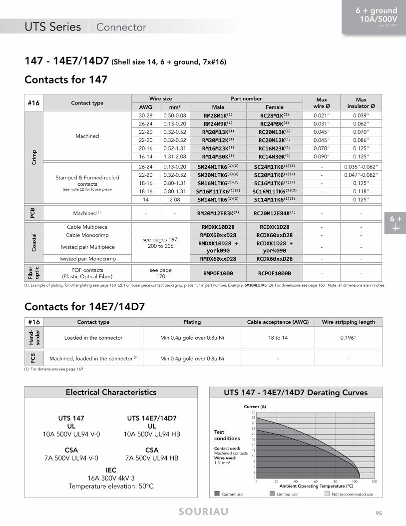
UTS Series | Connector
95
UTS 147 - 14E7/14D7 Derating Curves
Testconditions
Contactused:Machined contactsWiresused:1.31mm²
Current use Limited use Not recommended use
0 20 40 60 80 100 1200
5
3
8
10
20
18
15
13
23
25
28
30
Current (A)
Ambient Operating Temperature (°C)
147 - 14E7/14D7 (Shell size 14, 6 + ground, 7x#16)
IEC16A 300V 4kV 3
Temperature elevation: 50°C
UTS 147UL
10A 500V UL94 V-0
CSA7A 500V UL94 V-0
UTS 14E7/14D7UL
10A 500V UL94 HB
CSA7A 500V UL94 HB
Electrical Characteristics
Contacts for 147
Contacts for 14E7/14D7
#16 Contact typeWire size Part number Max
wire ØMax
insulator ØAWg mm² Male Female
Cri
mp
Machined
30-28 0.50-0.08 RM28M1k(1) RC28M1k(1) 0.021" 0.039"
26-24 0.13-0.20 RM24M9k(1) RC24M9k(1) 0.031" 0.062"
22-20 0.32-0.52 RM20M13k(1) RC20M13k(1) 0.045" 0.070"
22-20 0.32-0.52 RM20M12k(1) RC20M12k(1) 0.045" 0.086"
20-16 0.52-1.31 RM16M23k(1) RC16M23k(1) 0.070" 0.125"
16-14 1.31-2.08 RM14M30k(1) RC14M30k(1) 0.090" 0.125"
Stamped & Formed reeled contacts
See note (2) for loose piece
26-24 0.13-0.20 SM24M1Tk6(1)(2) SC24M1Tk6(1)(2) - 0.035"-0.062"
22-20 0.32-0.52 SM20M1Tk6(1)(2) SC20M1Tk6(1)(2) - 0.047"-0.082"
18-16 0.80-1.31 SM16M1Tk6(1)(2) SC16M1Tk6(1)(2) - 0.125"
18-16 0.80-1.31 SM16M11Tk6(1)(2) SC16M11Tk6(1)(2) - 0.118"
14 2.08 SM14M1Tk6(1)(2) SC14M1Tk6(1)(2) - 0.125"
PC
B
Machined (3) - - RM20M12E83k(1) RC20M12E84k(1) - -
Co
axia
l
Cable Multipiece
see pages 167,200 to 206
RMDXk10D28 RCDXk1D28 - -
Cable Monocrimp RMDX60xxD28 RCDX60xxD28 - -
Twisted pair MultipieceRMDXk10D28 +
york090RCDXk1D28 +york090
- -
Twisted pair Monocrimp RMDX60xxD28 RCDX60xxD28 - -
Fib
er
op
tic POF contacts
(Plastic Optical Fiber)see page
170 RMPoF1000 RCPoF1000B - -
#16 Contact type Plating Cable acceptance (AWg) Wire stripping length
Han
d-
sold
er
Loaded in the connector Min 0.4µ gold over 0.8µ Ni 18 to 14 0.196"
PC
B
Machined, loaded in the connector (1) Min 0.4µ gold over 0.8µ Ni - -
(1): For dimensions see page 169
(1): Example of plating, for other plating see page 168 (2): For loose piece contact packaging, place "L" in part number. Example: SM20Ml1Tk6 (3): For dimensions see page 168 Note: all dimensions are in inches
6 +
6 + ground10A/500V
per UL 1977

UTS Series | Connector
96
OR
WITH
OR OR
Layout
Sealed unmated
Contact type Connector type BackshellPart number
Male insert Female insert
Handsolderelectrical contacts
loadedsee page 99
Square flangereceptacle Without (Fig. 1) UTS010E7P UTS010E7S
PlugWithout (Fig. 2) UTS610E7P UTS610E7S
Cable gland (Fig. 3) UTS6JC10E7P UTS6JC10E7SJam nut
receptacle Without (Fig. 4) UTS710E7P UTS710E7S
M16 threadedreceptacle Without (Fig. 7) UTS710E7PM16 UTS710E7SM16
PCBcontacts loaded
see page 99
Square flangereceptacle Without (Fig. 1) UTS010D7P UTS010D7S
Jam nut receptacle with stand off and hold down
clipsWithout (Fig. 5) UTS710D7P32 UTS710D7S32
Jam nut receptacle with stand off and without hold
down clipsWithout (Fig. 6) UTS710D7P UTS710D7S
Possibilities of discrimination/keying methods see page 208
10E7/10D7 (Shell size 10, 7x#20)
Connector Part Numbers

UTS Series | Connector
97
Plug - UTS6
Fig. 2 Fig. 3
2.755"
Ø1.
031"
0.996"
Square Flange Receptacle - UTS0
Fig. 1
Ø0.
594"
0.090"
0.295"
0.318" mini
0.444"
0.72
8"
0.944"
Ø0.125"Front view
Jam Nut Receptacle - UTS7
0.720" 0.720" 0.720"
0.137" 0.137"0.165"
0.137"
0.118" 0.185"
mini0.118"
Fig. 4 Fig. 5 Fig. 6
Ø0.
594"
Ø0.
594"
Ø0.
594"
Front view
0.881"
1.07
0"Mated Connector Lengths
2.791"
3.043"
UTS7
UTS0
M16 Threaded Receptacle - UTS7
Fig. 7
0.846"
0.547"
0.944"
M16x0.059"
Ø0.
594"
0.196"
Dimensions
10E7/10D7 (Shell size 10, 7x#20)
Drilling Pattern
0.110"
Ø0.531"
Ø0.866"
Ø0.696"
15°
15°
Ø0.157"
Ø0.122"
0.12
9"
0.06
2"
Panel Cut Out
0.72
8"
0.728"
Ø0.129"
Front mountingØ0.598"
Rear mountingØ0.704"
Jam nut receptacle UTS7
0.65
1"
0.686
"
M16
M16
x0.05
9"
0.771"
Chf.45°x0.104"
Hole size:0.035"
Square Flange Receptacle - UTS0
Note: all dimensions are in inches
7 contacts6A/250V
per UL 1977
7

UTS Series | Connector
98
Square Flange Sealing CapPlug Sealing Cap
Part number
UTS610DCG
Part number
UTS10DCGE
Part numbers
Receptacle cap
Plug cap
85005586A 85005595
Plastic Protective Cap
Part numbers
UTFD12B
gasket Color Coding Rings
Part numbers
Receptacles Plugs
UTS710CCRR UTS610CCRR
UTS710CCRY UTS610CCRY
UTS710CCRG UTS610CCRG
G for Green
Y for Yellow
R for Red
10E7/10D7 (Shell size 10, 7x#20)
Accessories and Tooling
IP68/69K IP68/69K IP68/69K IP68/69K Metal terminal Metal terminal
Part number
UTS10DCG
Part number
UTS10DCGR
Jam Nut or M16 Threaded Receptacle Sealing Caps
IP68/69K

UTS Series | Connector
99
UTS 10E7/10D7 Derating Curves
UL6A 250V UL94 HB
CSA6A 250V UL94 HB
IEC7A 50V 1.5kV 3
Electrical Characteristics
Current use Limited use Not recommended use
Testconditions
Contactused:Machined contactsWiresused:0.518mm²
0 20 40 60 80 100 1200
67
1011
Current (A)
Ambient Operating Temperature (°C)
12131415
23
1
45
89
10E7/10D7 (Shell size 10, 7x#20)
ContactsContacts
#20 Contact type Plating Cable acceptance (AWg) Wire stripping length
Han
dso
lder
Loaded in the connector Min 0.4µ gold over 0.8µ Ni 22 to 18 0.196"
PC
B
Machined, loaded in the connector (1) Min 0.4µ gold over 0.8µ Ni - -
(1): For dimensions see page 169
7
7 contacts6A/250V
per UL 1977

UTS Series | Connector
100
OR OROR OR
WITH
OR OR
Contact type Connector type BackshellPart number
Male insert Female insert
Crimpcontacts supplied
separatelysee page 103
Square flangereceptacle Without (Fig. 1) UTS0128P UTS0128S
Free hangingreceptacle
Cable gland and grommet*(Fig. 2) UTS1GJC128P -
Free hangingreceptacle Nut and grommet* (Fig. 3) UTS1GN128P -
M20 threadedreceptacle
Gasket and nut (Fig. 8) UTS7128PM20NUT UTS7128SM20NUTGasket (Fig. 9) UTS7128PM20 UTS7128SM20
Free hangingreceptacle Cable gland (Fig. 2) UTS1JC128P UTS1JC128S
Plug Without (Fig. 10) UTS6128P UTS6128S
Plug Cable gland and grommet*(Fig. 11) - UTS6GJC128S
Plug Nut and grommet* (Fig. 12) - UTS6GN128S
Plug Cable gland (Fig. 11) UTS6JC128P UTS6JC128SJam nut
receptacle Without (Fig. 4) UTS7128P UTS7128S
Jam nutreceptacle
Cable gland and grommet*(Fig. 7) UTS7GJC128P -
Jam nutreceptacle Nut and grommet* (Fig. 6) UTS7GN128P -
PCBcontacts loaded see page 103
Jam nut receptacle with stand off and hold down clips Without (Fig. 5) UTS7128PSEK9 -
Layout
Possibilities of discrimination/keying methods see page 208 * Grommet for discrete wire sealing
128 (Shell size 12, 8x#16)
Connector Part Numbers
Overmolded Cable Assembly Part NumbersOvermolding type Description Wire size Part number (length: 3 ft)*
Overmolded harnesses, straight ending
D/E assembly 1 male plug & 1 female plug 16 AWG UTS6V1208PS03FT00
S/E assembly 1 female plug 16 AWG UTS6V1208S03FT00
S/E assembly 1 male plug 16 AWG UTS6V1208P03FT00* Other lengths available: 3, 6, 12 feet only: e.g. UTS6V128PS06FT00 for a 6 feet version
contacts loadedsee page

UTS Series | Connector
101
Free Hanging - UTS1Square Flange Receptacle - UTS00.444"
Ø0.
751"
0.81
8"
1.039"
0.090" 0.413"
0.712"
Ø0.125"Front viewFig. 1
2.933"
1.610"
Ø0.
751"
Fig. 3
Fig. 2
Jam Nut & M20 Threaded Receptacle - UTS7
Fig. 4Fig. 6 Fig. 8
Fig. 5
Fig.7Fig. 9
Mated Connector Lengths
3.055"
3.216"
UTS7
UTS0
Plug - UTS6
0.708"0.708"
1.933"
1.259"
0.240"
0.767"
Panel gasket
2.933"
Ø1.
255"
Ø0.
751"
Ø0.
751"
1.00
0"
1.063"
0.137"0.137"
0.062"
0.165"
0.118"
Dimensions
128 (Shell size 12, 8x#16)
Drilling Pattern
0.173" 0.133"
0.078"
0.17
7"0.
157"
0.11
0"0.
035"
Panel Cut Out
0.81
8"
0.818"
Ø0.129"
Jam Nut Receptacle - UTS7
0.82
6"
0.875"
Front mountingØ0.720"
Rear mountingØ0.877"
Hole size:0.051"
Square Flange Receptacle - UTS0
Female
Male
Fig. 10 Fig. 12
Fig. 111.299"
0.996" 1.299"
Ø1.
185"
2.586"
M20X0.059"
Note: Overmolded cable assembly dimensions available page 179. Note: all dimensions are in inches
8 contacts10A/500V
per UL 1977
8

UTS Series | Connector
102
G for Green
Y for Yellow
R for Red
Plug Sealing Cap Square Flange Sealing Cap
Part number
UTS612DCG
Part number
UTS12DCGE
Part numbers
Receptacle cap
Plug cap
85005587A 85005596
Plastic Protective Cap
Part numbers
UTFD13B
gasket
Color Coding Rings
Part numbers
Receptacles Plugs
UTS712CCRR UTS612CCRR
UTS712CCRY UTS612CCRY
UTS712CCRG UTS612CCRG
128 (Shell size 12, 8x#16)
Accessories and Tooling
Tool kitHandle (without Head)
Part number
ToolkiT
Part number
ShAnDlES
Contacts Contact sizePart number
of head
RM/RC 28M1k(1)
Standard contacts
#16Ø 1.6 mm
S16RCM20*RM/RC 24M9k(1) S16RCM20*RM/RC 20M13k(1) S16RCM20*RM/RC 20M12k(1) S16RCM20*RM/RC 16M23k(1) S16RCM16*RM/RC 14M30k(1) S16RCM14*SM/SC 24Ml1Tk6(1) S16SCM20*SM/SC 20Ml1Tk6(1) S16SCM20*SM/SC 16Ml1Tk6(1) S16SCMl1*SM/SC 14Ml1Tk6(1) S16SCMl1*SM/SC 16Ml11Tk6(1) S16SCMl11*
RMDXk10D28k
Coaxial contacts
M10S1Jwith die set
& stop bushingsee page
202 to 205
RCDXk1D28kRM/RC DX60xxD28kRM/RC DXk10D28 +
york090RM/RC DX60xxD28
Crimp Tooling (without Shandles)
(1): Example of plating, for other plating options see page 164* Heads to be used with handle PN: SHANDLES
Jam Nut or M20 Threaded Receptacle Sealing Caps
IP68/69K
IP68/69K
IP68/69K
IP68/69K
Metal terminal
Metal terminal
Part number
UTS12DCG
Part number
UTS12DCGR
IP68/69K
Extraction tool #16 (RX2025GE1) see page 179. Dummy contact (SMSPkE0) see page 208.
+ =Handle Head Complete set

UTS Series | Connector
103
UL10A 500V UL94 V-0
CSA7A 500V UL94 V-0
IEC10A 80V 1.5kV 3
Electrical Characteristics UTS 128 Derating Curves
Testconditions
Contactused:Machined contactsWiresused:1.31mm²
Current use Limited use Not recommended use
0 20 40 60 80 1000
3
5
8
10
13
15
18
20
23
25
28
30Current (A)
Ambient Operating Temperature (°C)120
128 (Shell size 12, 8x#16)
Contacts
#16 Contact typeWire size Part number Max
wire ØMax
insulator ØAWg mm² Male Female
Cri
mp
Machined
30-28 0.50-0.08 RM28M1k(1) RC28M1k(1) 0.021" 0.039"
26-24 0.13-0.20 RM24M9k(1) RC24M9k(1) 0.031" 0.062"
22-20 0.32-0.52 RM20M13k(1) RC20M13k(1) 0.045" 0.070"
22-20 0.32-0.52 RM20M12k(1) RC20M12k(1) 0.045" 0.086"
20-16 0.52-1.31 RM16M23k(1) RC16M23k(1) 0.070" 0.125"
16-14 1.31-2.08 RM14M30k(1) RC14M30k(1) 0.090" 0.125"
Stamped & Formed reeled contacts
See note (2) for loose piece
26-24 0.13-0.20 SM24M1Tk6(1)(2) SC24M1Tk6(1)(2) - 0.035"-0.062"
22-20 0.32-0.52 SM20M1Tk6(1)(2) SC20M1Tk6(1)(2) - 0.047"-0.082"
18-16 0.80-1.31 SM16M1Tk6(1)(2) SC16M1Tk6(1)(2) - 0.125"
18-16 0.80-1.31 SM16M11Tk6(1)(2) SC16M11Tk6(1)(2) - 0.118"
14 2.08 SM14M1Tk6(1)(2) SC14M1Tk6(1)(2) - 0.125"
PC
B
Machined (3) - - RM20M12E83k(1) RC20M12E84k(1) - -
Co
axia
l
Cable Multipiece
see pages 167,200 to 206
RMDXk10D28 RCDXk1D28 - -
Cable Monocrimp RMDX60xxD28 RCDX60xxD28 - -
Twisted pair MultipieceRMDXk10D28 +
york090RCDXk1D28 +york090
- -
Twisted pair Monocrimp RMDX60xxD28 RCDX60xxD28 - -
Fib
er
op
tic POF contacts
(Plastic Optical Fiber)see page
170 RMPoF1000 RCPoF1000B - -
(1): Example of plating, for other plating see page 164(2): For loose piece contact packaging, place "L" in part number. Example: SM20Ml1Tk6(3): For dimensions see page 172
Note: all dimensions are in inches
8
8 contacts10A/500V
per UL 1977

UTS Series | Connector
104
OR
WITH
OR
Contact type Connector type BackshellPart number
Male insert Female insert
Handsolderelectrical contacts
loadedsee page 107
Square flangereceptacle Without (Fig. 6) UTS012E8P UTS012E8S
PlugWithout (Fig. 1) UTS612E8P UTS612E8S
Cable gland (Fig. 2) UTS6JC12E8P UTS6JC12E8SJam nut
receptacle Without (Fig. 3) UTS712E8P UTS712E8S
PCBcontacts loadedsee page 107
Square flangereceptacle Without (Fig. 7) UTS012D8P UTS012D8S
Jam nut receptaclewith stand off and
with hold down clipsWithout (Fig. 4) UTS712D8P32 UTS712D8S32
Jam nut receptaclewith stand off and
without hold down clipsWithout (Fig. 5) UTS712D8P UTS712D8S
Layout
Sealed unmatedPossibilities of discrimination/keying methods see page 208
12E8/12D8 (Shell size 12, 8x#20)
Connector Part Numbers

UTS Series | Connector
105
Jam Nut Receptacle - UTS7
Front view
1.070"
1.25
5"
0.708"
Ø0.
748"
0.137"
0.118"
Fig. 4 Fig. 5Fig. 3
0.708"0.165"
Ø0.
748"
0.137"
0.118" 0.185" mini
0.708"
Ø0.
748"
0.137"
0.122"
Plug - UTS6
Fig. 1 Fig. 2
2.626"
Ø1.
185"
0.996"
Square Flange Receptacle - UTS0 Mated Connector Lengths
Fig. 6
Fig. 70.444"
Ø0.
748"
0.090"
0.295" 0.318" mini
0.81
8"
1.039"
Ø0.125"Front view
3.055"
3.216"
UTS7
UTS0
Dimensions
12E8/12D8 (Shell size 12, 8x#20)
Drilling PatternPanel Cut Out
0.81
8"
0.818"
Ø0.129"
Jam Nut Receptacle - UTS7
0.82
6"
0.875"
Front mountingØ0.720"
Rear mountingØ0.877"
0.169"
Ø0.866"
Ø1.200"
Ø1.031"
30°
68°
0.393"
Ø0.122"
0.118"
0.062"
0.11
8"0.
169"
0.04
3"0.
153"
22° Hole sizes:0.035"
Square Flange Receptacle - UTS0
Note: all dimensions are in inches
8 contacts4.5A/250V
per UL 1977
8

UTS Series | Connector
106
Square Flange Sealing CapPlug Sealing Cap
Part number
UTS612DCG
Part number
UTS12DCGE
Part numbers
Receptacle cap
Plug cap
85005587A 85005596
Plastic Protective Cap
Part numbers
UTFD13B
gasket Color Coding Rings
Part numbers
Receptacles Plugs
UTS712CCRR UTS612CCRR
UTS712CCRY UTS612CCRY
UTS712CCRG UTS612CCRG
G for Green
Y for Yellow
R for Red
Accessories and Tooling
12E8/12D8 (Shell size 12, 8x#20)
Jam Nut Sealing Caps
IP68/69K IP68/69K IP68/69K IP68/69K Metal terminal Metal terminal
Part number
UTS12DCG
Part number
UTS12DCGR
IP68/69K

UTS Series | Connector
107
UTS 12E8/12D8 Derating CurvesElectrical Characteristics
UL4.5A 250V UL94 HB
CSA4.5A 250V UL94 HB
IEC6A 32V 1.5kV 3
Current use Limited use Not recommended use
Testconditions
Contactused:Machined contactsWiresused:0.518mm²
0 20 40 60 80 100 120
Current (A)
Ambient Operating Temperature (°C)
Contacts
12E8/12D8 (Shell size 12, 8x#20)
0
67
101112131415
23
1
45
89
#20 Contact type Plating Cable acceptance (AWg) Wire stripping length
Han
dso
lder
Loaded in the connector Min 0.4µ gold over 0.8µ Ni 22 to 18 0.196"
PC
B
Machined, loaded in the connector (1) Min 0.4µ gold over 0.8µ Ni - -
(1): For dimensions see page 169
8 contacts4.5A/250V
per UL 1977
8

UTS Series | Connector
108
OR
WITH
OR
Layout
Contact type Connector type BackshellPart number
Male insert Female insert
Crimpcontacts supplied
separatelysee page 111
Free hangingreceptacle Cable gland (Fig. 1) UTS1JC148P UTS1JC148S
Plug Without (Fig. 2) UTS6148P UTS6148S
Plug Cable gland (Fig. 3) UTS6JC148P UTS6JC148SJam nut
receptacle Without (Fig. 4) UTS7148P UTS7148S
148 (Shell size 14, 4x#16, 4x#12)
Connector Part Numbers

UTS Series | Connector
109
Free Hanging - UTS13.090"
Ø1.
381"
Fig. 1
Plug - UTS6
FemaleMaleFig. 2 Fig. 2 Fig. 3
1.299" 2.815"
Ø1.
381"
Ø1.
381"
0.996"
Jam Nut Receptacle - UTS7 Mated Connector Length - UTS7
3.228"
Fig. 4
0.708" 1.381"
1.196"
Ø0.
877"
0.137"
0.484 "
Dimensions
148 (Shell size 14, 4x#16, 4x#12)
Panel Cut Out
Jam Nut Receptacle - UTS7
0.95
0"
1.005"
Drilling Pattern
0.122" 0.007"0.031"0.173"
0.102"0.200"
0.102"
0.216"
0.01
1"
0.13
7"0.
220"
0.17
7"
0.01
5"0.17
7"
Note: all dimensions are in inches
8 contacts25A/250V
per UL 1977
8

UTS Series | Connector
110
Plastic Protective Cap
Part numbers
UTFD14B
gasket
Part numbers
Receptacle cap
Plug cap
85005588A 85005597
Color Coding Rings
G for Green
Y for Yellow
Part numbers
Receptacles Plugs
UTS714CCRR UTS614CCRR
UTS714CCRY UTS614CCRY
UTS714CCRG UTS614CCRGR for Red
Crimp Tooling #16
(1): Example of plating, for other plating see page 164*: Heads to be used with handle PN: SHANDLES
Contacts Contact sizePart number
of head
RM/RC 28M1k
Standard contacts
#16Ø 1.6 mm
S16RCM20*RM/RC 24M9k S16RCM20*RM/RC 20M13k S16RCM20*RM/RC 20M12k S16RCM20*RM/RC 16M23k S16RCM16*RM/RC 14M30k S16RCM14*
SM/SC 24Ml1Tk6(1) S16SCM20*SM/SC 20Ml1Tk6(1) S16SCM20*SM/SC 16Ml1Tk6(1) S16SCMl1*SM/SC 14Ml1Tk6(1) S16SCMl1*SM/SC 16Ml11Tk6(1) S16SCMl11*
Part number
ShAnDlES (without head)
Part number
ToolkiT
Crimp Tooling #12
Part numberpositioner + locator setting
VGE10078A
Part number hand tool
M317
148 (Shell size 14, 4x#16, 4x#12)
Accessories and Tooling
HEAD (without Shandles)
Plug Sealing Cap Square Flange Sealing Cap
Part number
UTS614DCG
Part number
UTS14DCGE
IP68/69K IP68/69K Metal terminal
Jam Nut Sealing Caps
IP68/69K IP68/69K Metal terminal
Part number
UTS14DCG
Part number
UTS14DCGR
Part numberExtraction tool #16
RX2025GE1
Part numberExtraction tool #12
M317
Extraction Tool
IP68/69K
Coaxial contacts available see pages 167, 200 to 206
Dummy contact (SMSPkE0) see page 208.
+ =Handle Head Complete set

UTS Series | Connector
111
UL25A 250V UL94 V-0
CSA17A 230V UL94 V-0
IEC17A 230V 1.5kV 3
Electrical Characteristics UTS 148 Derating Curves
Testconditions
Contactused:Machined contactsWiresused:1.31mm²
Current use Limited use Not recommended use
0 25 45 65 85 1050
5
10
15
20
25
30
Current (A)
Ambient Operating Temperature (°C)125
35
40
45
148 (Shell size 14, 4x#16, 4x#12)
Contacts
#16 Contact typeWire size Part number Max
wire ØMax
insulator ØAWg mm² Male Female
Cri
mp
Machined
30-28 0.50-0.08 RM28M1k(1) RC28M1k(1) 0.021" 0.039"
26-24 0.13-0.20 RM24M9k(1) RC24M9k(1) 0.031" 0.062"
22-20 0.32-0.52 RM20M13k(1) RC20M13k(1) 0.045" 0.070"
22-20 0.32-0.52 RM20M12k(1) RC20M12k(1) 0.045" 0.086"
20-16 0.52-1.31 RM16M23k(1) RC16M23k(1) 0.070" 0.125"
16-14 1.31-2.08 RM14M30k(1) RC14M30k(1) 0.090" 0.125"
Stamped & Formed reeled contacts
See note (2) for loose piece
26-24 0.13-0.20 SM24M1Tk6(1)(2) SC24M1Tk6(1)(2) - 0.035"-0.062"
22-20 0.32-0.52 SM20M1Tk6(1)(2) SC20M1Tk6(1)(2) - 0.047"-0.082"
18-16 0.80-1.31 SM16M1Tk6(1)(2) SC16M1Tk6(1)(2) - 0.125"
18-16 0.80-1.31 SM16M11Tk6(1)(2) SC16M11Tk6(1)(2) - 0.118"
14 2.08 SM14M1Tk6(1)(2) SC14M1Tk6(1)(2) - 0.125"
Co
axia
l
Cable Multipiece
see pages 167,200 to 206
RMDXk10D28 RCDXk1D28 - -
Cable Monocrimp RMDX60xxD28 RCDX60xxD28 - -
Twisted pair MultipieceRMDXk10D28 +
york090RCDXk1D28 +york090
- -
Twisted pair Monocrimp RMDX60xxD28 RCDX60xxD28 - -
Fib
er
op
tic POF contacts
(Plastic Optical Fiber)see page
170 RMPoF1000 RCPoF1000B - -
#12
Cri
mp
Machined
22 0.32 82911457nA(1) 82911456A(1) 0.034"
0.192"
20 0.52 82911459nA(1) 82911458A(1) 0.044"
18 0.80 82911461nA(1) 82911460A(1) 0.055"
16 1.31 82911463nA(1) 82911462A(1) 0.067"
14 2.08 82911465nA(1) 82911464A(1) 0.087"
12 3.31 82911467nA(1) 82911466A(1) 0.111"(1): Example of plating, for other plating see page 168 (2): For loose piece contact packaging, place "L" in part number. Example: SM20Ml1Tk6 Note: all dimensions are in inches
8 contacts25A/250V
per UL 1977
8

UTS Series | Connector
112
OROR OR
WITH
Contact type Connector type BackshellPart number
Male insert Female insert
Crimpcontacts supplied
separatelysee page 115
Free hangingreceptacle Cable gland (Fig. 1) UTS1JC1210P UTS1JC1210S
Plug Without (Fig. 2) UTS61210P UTS61210SPlug Cable gland (Fig. 3) UTS6JC1210P UTS6JC1210S
Jam nutreceptacle Without (Fig. 4) UTS71210P UTS71210S
Handsolderelectrical contacts
loadedsee page 115
Square flange receptacle Without (Fig. 8) UTS012E10P UTS012E10S
PlugWithout (Fig. 2) UTS612E10P UTS612E10S
Cable gland (Fig. 3) UTS6JC12E10P UTS6JC12E10SJam nut receptacle Without (Fig. 5) UTS712E10P UTS712E10S
PCBcontacts loadedsee page 115
Square flange receptacle Without (Fig. 8) UTS012D10P UTS012D10SJam nut receptaclewith stand off and
with hold down clipsWithout (Fig. 6) UTS712D10P32 UTS712D10S32
Jam nut receptaclewith stand off and
without hold down clipsWithout (Fig. 7) UTS712D10P UTS712D10S
Layout
Sealed unmatedPossibilities of discrimination/keying methods see page 208
1210 - 12E10/12D10 (Shell size 12, 10x#20)
Connector Part Numbers

UTS Series | Connector
113
2.913"
Ø0.
751"
Fig. 1
Free Hanging - UTS1 Plug - UTS6
Female
Male
Fig. 2
1.299"
Ø1.
185"
0.996"
Fig. 3
2.626"
Jam Nut Receptacle - UTS7
Front view
1.070"
1.25
5"
0.708"0.484"
Ø0.
751"
0.137" 0.118"Fig. 6 Fig. 7Fig. 5
Fig. 4
0.708"0.165"Ø
0.75
1"
0.137"
0.118" 0.185" mini
0.708"
Ø0.
751"
0.137"
0.122"
Mated Connector LengthsSquare Flange Receptacle - UTS0
Fig. 8
0.444"
Ø0.
751"
0.090"
0.295" 0.318"
mini
0.81
8"
1.039"
Ø0.125"Front view
3.055"
3.216"
UTS7
UTS0
Dimensions
1210 - 12E10/12D10 (Shell size 12, 10x#20)
Drilling PatternPanel Cut Out
0.81
8"
0.818"
Ø0.129"
Jam Nut Receptacle - UTS7
0.82
6"
0.875"
0.129"0.062"
Ø0.866"
Ø1.200"
Ø1.031"
22°
30°
68°
0.393"
Ø0.122"
0.192"
0.11
8"
Front mountingØ0.720"
Rear mountingØ0.877"
Hole size:0.035"
Square Flange Receptacle - UTS0
Note: all dimensions are in inches
10 contacts5A/250V
per UL 1977
10

UTS Series | Connector
114
G for Green
Y for Yellow
R for Red
Plug Sealing Cap Square Flange Sealing Cap
Part number
UTS612DCG
Part number
UTS12DCGE
Part numbers
Receptacle cap
Plug cap
85005587A 85005596
Plastic Protective Cap
Part numbers
UTFD13B
gasket
Color Coding Rings
Part numbers
Receptacles Plugs
UTS712CCRR UTS612CCRR
UTS712CCRY UTS612CCRY
UTS712CCRG UTS612CCRG
Tool kit
Part number
ToolkiT
Part number
ShAnDlES
Contacts Contact sizePart number
of head
RM/RC 24W3k(1)
Standard contacts
#20Ø 1.0 mm
S20RCM*RM/RC 20W3k(1) S20RCM*RM/RC 18W3k(1) S20RCM*SM/SC 24Wl3S S20SCM20*SM/SC 20Wl3S S20SCM20*
(1): Example of plating, for other plating see page 164*: Heads to be used with handle PN: SHANDLES
Accessories and Tooling
1210 - 12E10/12D10 (Shell size 12, 10x#20)
Handle (without Head)
Crimp Tooling (without Shandles)
Jam Nut Sealing Caps
IP68/69K
IP68/69K
IP68/69K
IP68/69K
Metal terminal
Metal terminal
Part number
UTS12DCG
Part number
UTS12DCGR
Extraction Tool #20
Part number
RX20D44
IP68/69K
+ =Handle Head Complete set

UTS Series | Connector
115
UTS 1210 - 12E10/12D10 Derating Curves
Testconditions
Contactused:Machined contactsWiresused:0.518mm²
Current use Limited use Not recommended use
0 20 40 60 80 1000
2
1
4
3
6
5
8
7
10
9
12
13
11
Current (A)
Ambient Operating Temperature (°C)120
IEC6A 50V 1.5kV 3
Electrical Characteristics
UTS 1210UL
5A 250V UL94 V-0
CSA4A 250V UL94 V-0
UTS 12E10/12D10UL
4.5A 250V UL94 HB
CSA4.5A 250V UL94 HB
1210 - 12E10/12D10 (Shell size 12, 10x#20)
Contacts for 1210
Contacts for 12E10/12D10
#20 Contact typeWire size Part number Max
wire ØMax
insulator ØAWg mm² Male Female
Cri
mp
Machined
26-24 0.13-0.20 RM24W3k(1) RC24W3k(1) 0.031" 0.062"
22-20 0.32-0.52 RM20W3k(1) RC20W3k(1) 0.045" 0.062"
20-18 0.50-0.80 RM18W3k(1) RC18W3k(1) 0.051" 0.082"
Stamped & Formed reeled contacts
See note (2) for loose piece
26-24 0.13-0.20 SM24W3Tk6(2) SC24W3Tk6(2) - 0.035"-0.062"
26-24 0.13-0.20 SM24W3S26(2) SC24W3S25(2) - 0.035"-0.062"
22-20 0.32-0.52 SM20W3Tk6(2) SC20W3Tk6(2) - 0.047"-0.082"
22-20 0.32-0.52 SM20W3S26(2) SC20W3S25(2) - 0.047"-0.082"(1): Example of plating, for other plating see page 164(2): For loose piece contact packaging, place "L" in part number. Example: SM20Wl3Tk6
#20 Contact type Plating Cable acceptance (AWg) Wire stripping length
Han
dso
lder
Loaded in the connector Min 0.4µ gold over 0.8µ Ni 22 to 18 0.196"
PC
B
Machined, loaded in the connector (1) Min 0.4µ gold over 0.8µ Ni - -
(1): For dimensions see page 169 Note: all dimensions are in inches
10 contacts5A/250V
per UL 1977
10

UTS Series | Connector
116
OR OR OR OR
WITH
OR OR
Contact type Connector type BackshellPart number
Male insert Female insert
Crimpcontacts supplied
separatelysee page 119
Square flangereceptacle Without (Fig. 1) UTS01412P UTS01412S
Free hangingreceptacle
Cable gland and grommet*(Fig. 2) UTS1GJC1412P -
Free hangingreceptacle Nut and grommet* (Fig. 3) UTS1Gn1412P -
Free hangingreceptacle Cable gland (Fig. 2) UTS1JC1412P UTS1JC1412S
Plug Without (Fig. 4) UTS61412P UTS61412S
Plug Cable gland and grommet*(Fig. 5) - UTS6GJC1412S
Plug Nut and grommet* (Fig. 6) - UTS6Gn1412S
Plug Cable gland (Fig. 5) UTS6JC1412P UTS6JC1412S
Jam nut receptacle Without (Fig. 7) UTS71412P UTS71412S
Jam nut receptacle Cable gland and grommet*(Fig. 9) UTS7GJC1412P -
Jam nut receptacle Nut and grommet* (Fig. 8) UTS7Gn1412P -PCB
contacts suppliedseparately
see page 119
Square flangereceptacle Without (Fig. 1) UTS01412P UTS01412S
Jam nut receptacle Without (Fig. 7) UTS71412P UTS71412S
Layout
Possibilities of discrimination/keying methods see page 208
1412 (Shell size 14, 12x#16)
Connector Part Numbers
Overmolded Cable Assembly Part NumbersOvermolding type Description Wire size Partnumber(length:3ft)*
Overmolded harnesses, straight ending
D/E assembly 1 male plug & 1 female plug 16 AWG UTS6V1412PS03FT00
S/E assembly 1 female plug 16 AWG UTS6V1412S03FT00
S/E assembly 1 male plug 16 AWG UTS6V1412P03FT00* Other lengths available: 3, 6, 12 feet only: e.g. UTS6V1412PS06FT00 for a 6 feet version
* Grommet for discrete wire sealing

UTS Series | Connector
117
Plug - UTS6
Female
Male
Fig. 4 Fig. 5 Fig. 6
1.299" 1.259"2.755"
0.996"
Ø1.
381"
Jam Nut Receptacle - UTS7 Mated Connector Lengths
Fig. 7 Fig. 9
Fig. 80.708"
0.708"1.929"
2.783"
Ø0.
877"
Ø0.
877"
0.137" 0.137"
0.062"2.952"
3.228"UTS7
UTS0
Square Flange Receptacle - UTS0 Free Hanging - UTS1
3.090"
1.692"
Ø0.
877"
Fig. 3
Fig. 20.444"
Ø0.
877"
0.91
3"
1.133"
0.090" 0.413"
0.862"
Ø0.125"Front viewFig. 1
Female
Male
Dimensions
1412 (Shell size 14, 12x#16)
Drilling PatternPanel Cut Out
0.91
3"
0.913"
Ø0.129"
0.086" 0.027"0.149" 0.228"
0.200"
0.078" 0.055"
0.03
9"
0.08
6"
0.17
7"
0.23
2"
0.03
9"
0.01
1" 0.11
4"0.21
6"
Front mountingØ0.846"
Rear mountingØ0.988"
Jam Nut Receptacle - UTS7
0.95
0"
1.005"
Hole size:0.051"
Square Flange Receptacle - UTS0
Note: Overmolded cable assembly dimensions available page 179. Note: all dimensions are in inches
12 contacts10A/500V
per UL 1977
12

UTS Series | Connector
118
Accessories and Tooling
G for Green
Y for Yellow
R for Red
Plug Sealing Cap Square Flange Sealing Cap
Part number
UTS614DCG
Part number
UTS14DCGE
Part numbers
Receptacle cap
Plug cap
85005588A 85005597
Plastic Protective Cap
Part numbers
UTFD14B
gasket
Color Coding Rings
Part numbers
Receptacles Plugs
UTS714CCRR UTS614CCRR
UTS714CCRY UTS614CCRY
UTS714CCRG UTS614CCRG
1412 (Shell size 14, 12x#16)
Tool kitHandle (without Head)
Part number
ToolkiT
Part number
ShAnDlES
Contacts Contact sizePart number
of head
RM/RC 28M1k(1)
Standard contacts
#16Ø 1.6 mm
S16RCM20*RM/RC 24M9k(1) S16RCM20*RM/RC 20M13k(1) S16RCM20*RM/RC 20M12k(1) S16RCM20*RM/RC 16M23k(1) S16RCM16*RM/RC 14M30k(1) S16RCM14*SM/SC 24Ml1Tk6(1) S16SCM20*SM/SC 20Ml1Tk6(1) S16SCM20*SM/SC 16Ml1Tk6(1) S16SCMl1*SM/SC 14Ml1Tk6(1) S16SCMl1*SM/SC 16Ml11Tk6(1) S16SCMl11*
RMDXk10D28k
Coaxial contacts
M10S1Jwith die set
& stop bushingsee page
202 to 205
RCDXk1D28kRM/RC DX60xxD28kRM/RC DXk10D28 +
york090RM/RC DX60xxD28
Crimp Tooling (without Shandles)
(1): Example of plating, for other plating options see page 164* Heads to be used with handle PN: SHANDLES
Jam Nut Sealing Caps
IP68/69K
IP68/69K
IP68/69K
IP68/69K
Metal terminal
Metal terminal
Part number
UTS14DCG
Part number
UTS14DCGR
IP68/69K
Extraction tool #16 (RX2025GE1) see page 179. Dummy contact (SMSPkE0) see page 208.
+ =Handle Head Complete set

UTS Series | Connector
119
UL10A 500V UL94 V-0
CSA7A 500V UL94 V-0
IEC10A 63V 1.5kV 3
Electrical Characteristics UTS 1412 Derating Curves
Testconditions
Contactused:Machined contactsWiresused:1.31mm²
Current use Limited use Not recommended use
Current (A)
Ambient Operating Temperature (°C)0 20 40 60 80 100
0
3
5
8
10
13
15
18
20
23
25
28
30
120
Contacts
1412 (Shell size 14, 12x#16)
#16 Contact typeWire size Part number Max
wire ØMax
insulator ØAWg mm² Male Female
Cri
mp
Machined
30-28 0.50-0.08 RM28M1k(1) RC28M1k(1) 0.021" 0.039"
26-24 0.13-0.20 RM24M9k(1) RC24M9k(1) 0.031" 0.062"
22-20 0.32-0.52 RM20M13k(1) RC20M13k(1) 0.045" 0.070"
22-20 0.32-0.52 RM20M12k(1) RC20M12k(1) 0.045" 0.086"
20-16 0.52-1.31 RM16M23k(1) RC16M23k(1) 0.070" 0.125"
16-14 1.31-2.08 RM14M30k(1) RC14M30k(1) 0.090" 0.125"
Stamped & Formed reeled contacts
See note (2) for loose piece
26-24 0.13-0.20 SM24M1Tk6(1)(2) SC24M1Tk6(1)(2) - 0.035"-0.062"
22-20 0.32-0.52 SM20M1Tk6(1)(2) SC20M1Tk6(1)(2) - 0.047"-0.082"
18-16 0.80-1.31 SM16M1Tk6(1)(2) SC16M1Tk6(1)(2) - 0.125"
18-16 0.80-1.31 SM16M11Tk6(1)(2) SC16M11Tk6(1)(2) - 0.118"
14 2.08 SM14M1Tk6(1)(2) SC14M1Tk6(1)(2) - 0.125"
PC
B
Machined (3) - - RM20M12E83k(1) RC20M12E84k(1) - -
Co
axia
l
Cable Multipiece
see pages 167,200 to 206
RMDXk10D28 RCDXk1D28 - -
Cable Monocrimp RMDX60xxD28 RCDX60xxD28 - -
Twisted pair MultipieceRMDXk10D28 +
york090RCDXk1D28 +york090
- -
Twisted pair Monocrimp RMDX60xxD28 RCDX60xxD28 - -
Fib
er
op
tic POF contacts
(Plastic Optical Fiber)see page
170 RMPoF1000 RCPoF1000B - -
(1): Example of plating, for other plating see page 164(2): For loose piece contact packaging, place "L" in part number. Example: SM20Wl3Tk6(3): For dimensions see page 172
Note: all dimensions are in inches
12 contacts10A/500V
per UL 1977
1212

UTS Series | Connector
120
OR OR
WITH
OR
Contact type Connector type BackshellPart number
Male insert Female insert
Handsolderelectrical contacts
loadedsee page 123
Square flangereceptacle Without (Fig. 6) UTS014E12P UTS014E12S
PlugWithout (Fig. 1) UTS614E12P UTS614E12S
Cable gland (Fig. 2) UTS6JC14E12P UTS6JC14E12SJam nut
receptacle Without (Fig. 3) UTS714E12P UTS714E12S
PCBcontacts loadedsee page 123
Square flangereceptacle Without (Fig. 6) UTS014D12P UTS014D12S
Jam nut receptaclewith stand off and
with hold down clipsWithout (Fig. 4) UTS714D12P32 UTS714D12S32
Jam nut receptaclewith stand off and
without hold down clipsWithout (Fig. 5) UTS714D12P UTS714D12S
Layout
Sealed unmatedPossibilities of discrimination/keying methods see page 208
14E12/14D12 (Shell size 14, 8x#20, 4x#16)
Connector Part Numbers

UTS Series | Connector
121
14E12/14D12 (Shell size 14, 8x#20, 4x#16)
Jam Nut Receptacle - UTS7
Front view
1.196"
1.38
1"
0.708"
Ø0.
877"
0.137"
0.118"
Fig. 4 Fig. 5Fig. 3
0.708"0.165"
Ø0.
877"
0.137"
0.118" 0.188" mini0.708"
Ø0.
877"
0.137"
0.118"
Plug - UTS6
Fig. 1 Fig. 2
2.755"
Ø1.
381"
0.996"
Square Flange Receptacle - UTS0 Mated Connector Lengths
0.444"
Ø0.
877"
0.090"
0.295" 0.318"
mini
0.91
3"
1.133"
Ø0.125"
Fig. 6 Front view
2.952"
3.228"UTS7
UTS0
Dimensions
Panel Cut Out
0.91
3"
0.913"
Ø0.129"
Jam Nut Receptacle - UTS7
0.95
0"
1.005"
Front mountingØ0.846"
Rear mountingØ0.988"
Drilling Pattern
0.177"0.161"
Ø0.866"Ø1.031"
Ø1.200"
30°
68°
0.393"
Ø0.122"
0.062"
0.17
7"
0.09
0"
0.26
3"
22° Hole sizes:#20:0.035"#16:0.051"
Square Flange Receptacle - UTS0
Note: all dimensions are in inches
12 contacts4.5A/250V
per UL 1977
12

UTS Series | Connector
122
Square Flange Sealing CapPlug Sealing Cap
Part number
UTS614DCG
Part number
UTS14DCGE
Part numbers
Receptacle cap
Plug cap
85005588A 85005597
Plastic Protective Cap
Part numbers
UTFD14B
gasket Color Coding Rings
Part numbers
Receptacles Plugs
UTS714CCRR UTS614CCRR
UTS714CCRY UTS614CCRY
UTS714CCRG UTS614CCRG
G for Green
Y for Yellow
R for Red
Accessories and Tooling
14E12/14D12 (Shell size 14, 8x#20, 4x#16)
Jam Nut Sealing Caps
IP68/69K IP68/69K IP68/69K IP68/69K Metal terminal Metal terminal
Part number
UTS14DCG
Part number
UTS14DCGR
IP68/69K

UTS Series | Connector
123
UTS 14E12/14D12 Derating Curves
UL4.5A 250V UL94 HB
CSA4.5A 250V UL94 HB
IEC4A 50V 1.5kV 3
Electrical Characteristics
Current use Limited use Not recommended use
Testconditions
Contactused:Machined contactsWiresused:0.518mm²
0 20 40 60 80 100 1200
4
2
6
8
10
12
14
Current (A)
Ambient Operating Temperature (°C)
#16 Contact type Plating Cable acceptance (AWg) Wire stripping length
Han
dso
lder
Loaded in the connector Min 0.4µ gold over 0.8µ Ni 18 to 14 0.196"
PC
B
Machined, loaded in the connector (1) Min 0.4µ gold over 0.8µ Ni - -
#20 Contact type Plating Cable acceptance (AWg) Wire stripping length
Han
dso
lder
Loaded in the connector Min 0.4µ gold over 0.8µ Ni 22 to 18 0.149"
PC
B
Machined, loaded in the connector (1) Min 0.4µ gold over 0.8µ Ni - -
Contacts
14E12/14D12 (Shell size 14, 8x#20, 4x#16)
(1): For dimensions see page 169
12 contacts4.5A/250V
per UL 1977
12

UTS Series | Connector
124
WITH
OR OR
Contact type Connector type BackshellPart number
Male insert Female insert
Crimpcontacts supplied
separatelysee page 127
Free hangingreceptacle Cable gland (Fig. 1) UTS1JC1492P UTS1JC1492S
Plug Without (Fig. 2) UTS61492P UTS61492S
Plug Cable gland (Fig. 3) UTS6JC1492P UTS6JC1492S
Jam nut receptacle Without (Fig. 4) UTS71492P UTS71492SPCB
contacts suppliedseparately
see page 127
Jam nut receptacle Without (Fig. 4) UTS71492P UTS71492S
Layout
Possibilities of discrimination/keying methods see page 208
1492 (Shell size 14, 12x#16)
Connector Part Numbers

UTS Series | Connector
125
Plug - UTS6
Female
Male
Fig. 2 Fig. 3
1.299" 2.755"
0.996"
Ø1.
381"
Jam Nut Receptacle - UTS7 Mated Connector Lengths0.708"
Ø1.
381"
0.137"
0.062"
3.228"
UTS7
Dimensions
1492 (Shell size 14, 12x#16)
Drilling PatternPanel Cut Out
0.102" 0.208"
0.224"0.141" 0.074"
0.09
0"
0.09
4"
0.20
0"
0.05
5"
0.03
1"
0.18
1"0.23
2"Jam Nut Receptacle - UTS7
0.95
0"
1.005"
Hole size:0.051"
Free Hanging - UTS1
3.090"
Ø0.
877"
Fig. 1
Note: all dimensions are in inches
Fig. 4
12 contacts10A/600V
per UL 1977
12

UTS Series | Connector
126
Accessories and Tooling
1492 (Shell size 14, 12x#16)
G for Green
Y for Yellow
R for Red
Plug Sealing Cap Square Flange Sealing Cap
Part number
UTS614DCG
Part number
UTS14DCGE
Part numbers
Receptacle cap
Plug cap
85005588A 85005597
Plastic Protective Cap
Part numbers
UTFD14B
gasket
Color Coding Rings
Part numbers
Receptacles Plugs
UTS714CCRR UTS614CCRR
UTS714CCRY UTS614CCRY
UTS714CCRG UTS614CCRG
Tool kitHandle (without Head)
Part number
ToolkiT
Part number
ShAnDlES
Contacts Contact sizePart number
of head
RM/RC 28M1k(1)
Standard contacts
#16Ø 1.6 mm
S16RCM20*RM/RC 24M9k(1) S16RCM20*RM/RC 20M13k(1) S16RCM20*RM/RC 20M12k(1) S16RCM20*RM/RC 16M23k(1) S16RCM16*RM/RC 14M30k(1) S16RCM14*SM/SC 24Ml1Tk6(1) S16SCM20*SM/SC 20Ml1Tk6(1) S16SCM20*SM/SC 16Ml1Tk6(1) S16SCMl1*SM/SC 14Ml1Tk6(1) S16SCMl1*SM/SC 16Ml11Tk6(1) S16SCMl11*
RMDXk10D28k
Coaxial contacts
M10S1Jwith die set
& stop bushingsee page
202 to 205
RCDXk1D28kRM/RC DX60xxD28kRM/RC DXk10D28 +
york090RM/RC DX60xxD28
Crimp Tooling (without Shandles)
(1): Example of plating, for other plating options see page 164* Heads to be used with handle PN: SHANDLES
Jam Nut Sealing Caps
IP68/69K
IP68/69K
IP68/69K
IP68/69K
Metal terminal
Metal terminal
Part number
UTS14DCG
Part number
UTS14DCGR
IP68/69K
Extraction tool #16 (RX2025GE1) see page 179. Dummy contact (SMSPkE0) see page 208.
+ =Handle Head Complete set

UTS Series | Connector
127
UL10A 600V UL94 V-0
CSA7A 500V UL94 V-0
IEC10A 63V 1.5kV 3
Electrical Characteristics UTS 1492 Derating Curves
Testconditions
Contactused:Machined contactsWiresused:1.31mm²
Current use Limited use Not recommended use
Current (A)
Ambient Operating Temperature (°C)
1492 (Shell size 14, 12x#16)
0 20 40 60 80 1000
3
5
8
10
13
15
18
20
23
25
28
30
120
Contacts
#16 Contact typeWire size Part number Max
wire ØMax
insulator ØAWg mm² Male Female
Cri
mp
Machined
30-28 0.50-0.08 RM28M1k(1) RC28M1k(1) 0.021" 0.039"
26-24 0.13-0.20 RM24M9k(1) RC24M9k(1) 0.031" 0.062"
22-20 0.32-0.52 RM20M13k(1) RC20M13k(1) 0.045" 0.070"
22-20 0.32-0.52 RM20M12k(1) RC20M12k(1) 0.045" 0.086"
20-16 0.52-1.31 RM16M23k(1) RC16M23k(1) 0.070" 0.125"
16-14 1.31-2.08 RM14M30k(1) RC14M30k(1) 0.090" 0.125"
Stamped & Formed reeled contacts
See note (2) for loose piece
26-24 0.13-0.20 SM24M1Tk6(1)(2) SC24M1Tk6(1)(2) - 0.035"-0.062"
22-20 0.32-0.52 SM20M1Tk6(1)(2) SC20M1Tk6(1)(2) - 0.047"-0.082"
18-16 0.80-1.31 SM16M1Tk6(1)(2) SC16M1Tk6(1)(2) - 0.125"
18-16 0.80-1.31 SM16M11Tk6(1)(2) SC16M11Tk6(1)(2) - 0.118"
14 2.08 SM14M1Tk6(1)(2) SC14M1Tk6(1)(2) - 0.125"
PC
B
Machined (3) - - RM20M12E83k(1) RC20M12E84k(1) - -
Co
axia
l
Cable Multipiece
see pages 167,200 to 206
RMDXk10D28 RCDXk1D28 - -
Cable Monocrimp RMDX60xxD28 RCDX60xxD28 - -
Twisted pair MultipieceRMDXk10D28 +
york090RCDXk1D28 +york090
- -
Twisted pair Monocrimp RMDX60xxD28 RCDX60xxD28 - -
Fib
er
op
tic POF contacts
(Plastic Optical Fiber)see page
170 RMPoF1000 RCPoF1000B - -
(1): Example of plating, for other plating see page 164(2): For loose piece contact packaging, place "L" in part number. Example: SM20Wl3Tk6(3): For dimensions see page 172
Note: all dimensions are in inches
12 contacts10A/600V
per UL 1977
12

UTS Series | Connector
128
OR
WITH
OR
Contact type Connector type BackshellPart number
Male insert Female insert
Handsolderelectrical contacts
loadedsee page 131
Square flangereceptacle Without (Fig. 6) UTS012E14P UTS012E14S
PlugWithout (Fig. 1) UTS612E14P UTS612E14S
Cable gland (Fig. 2) UTS6JC12E14P UTS6JC12E14SJam nut
receptacle Without (Fig. 3) UTS712E14P UTS712E14S
PCBcontacts loadedsee page 131
Square flangereceptacle Without (Fig. 7) UTS012D14P UTS012D14S
Jam nut receptaclewith stand off and
with hold down clipsWithout (Fig. 4) UTS712D14P32 UTS712D14S32
Jam nut receptaclewith stand off and
without hold down clipsWithout (Fig. 5) UTS712D14P UTS712D14S
Layout
Sealed unmatedPossibilities of discrimination/keying methods see page 208
12E14/12D14 (Shell size 12, 14x#20)
Connector Part Numbers

UTS Series | Connector
129
Jam Nut Receptacle - UTS7
Front view
1.070"
1.25
5"
0.708"
Ø0.
748"
0.137"
0.118"
Fig. 4 Fig. 5Fig. 3
0.708"0.165"
Ø0.
748"
0.137"
0.118" 0.149" mini
0.708"
Ø0.
748"
0.137"
0.122"
Plug - UTS6
Fig. 1 Fig. 2
2.626"
Ø1.
185"
0.996"
Square Flange Receptacle - UTS0 Mated Connector Lengths
Fig. 6
Fig. 70.444"
Ø0.
748"
0.090"
0.295"0.318"
mini
0.81
8"
1.039"
Ø0.125"Front view
3.055"
3.216"
UTS7
UTS0
12E14/12D14 (Shell size 12, 14x#20)
Dimensions
Drilling PatternPanel Cut Out
0.81
8"
0.818"
Ø0.129"
Jam Nut Receptacle - UTS7
0.82
6"
0.875"
0.173"
Ø0.866"
Ø1.200"
Ø1.031"
30°
68°
0.393"
Ø0.122"
0.106"
0.078"
0.18
5"0.
149"
0.07
0"0.
055"
22°
Front mountingØ0.720"
Rear mountingØ0.877"
Hole size:0.035"
Square Flange Receptacle - UTS0
Note: all dimensions are in inches
14 contacts4.5A/250V
per UL 1977
14

UTS Series | Connector
130
Square Flange Sealing CapPlug Sealing Cap
Part number
UTS612DCG
Part number
UTS12DCGE
Part numbers
Receptacle cap
Plug cap
85005587A 85005596
Plastic Protective Cap
Part numbers
UTFD13B
gasket Color Coding Rings
Part numbers
Receptacles Plugs
UTS712CCRR UTS612CCRR
UTS712CCRY UTS612CCRY
UTS712CCRG UTS612CCRG
G for Green
Y for Yellow
R for Red
12E14/12D14 (Shell size 12, 14x#20)
Accessories and Tooling
Jam Nut Sealing Caps
IP68/69K IP68/69K IP68/69K IP68/69K Metal terminal Metal terminal
Part number
UTS12DCG
Part number
UTS12DCGR
IP68/69K

UTS Series | Connector
131
UTS 12E14/12D14 Derating Curves
UL4.5A 250V UL94 HB
CSA4.5A 250V UL94 HB
IEC5A 32V 1.5kV 3
Electrical Characteristics
Current use Limited use Not recommended use
Testconditions
Contactused:Machined contactsWiresused:0.518mm²
0 20 40 60 80 100 1200
1
3
5
7
8
4
2
6
9
11
10
Current (A)
Ambient Operating Temperature (°C)
12E14/12D14 (Shell size 12, 14x#20)
Contacts
#20 Contact type Plating Cable acceptance (AWg) Wire stripping length
Han
dso
lder
Loaded in the connector Min 0.4µ gold over 0.8µ Ni 22 to 18 0.196"
PC
B
Machined, loaded in the connector (1) Min 0.4µ gold over 0.8µ Ni - -
(1): For dimensions see page 169
14 contacts4.5A/250V
per UL 1977
14

UTS Series | Connector
132
OR
WITH
OR
Contact type Connector type BackshellPart number
Male insert Female insert
Handsolderelectrical contacts
loadedsee page 135
Square flangereceptacle Without (Fig. 6) UTS014E15P UTS014E15S
PlugWithout (Fig. 1) UTS614E15P UTS614E15S
Cable gland (Fig. 2) UTS6JC14E15P UTS6JC14E15SJam nut
receptacle Without (Fig. 3) UTS714E15P UTS714E15S
PCBcontacts loadedsee page 135
Square flangereceptacle Without (Fig. 7) UTS014D15P UTS014D15S
Jam nut receptaclewith stand off and
with hold down clipsWithout (Fig. 4) UTS714D15P32 UTS714D15S32
Jam nut receptaclewith stand off and
without hold down clipsWithout (Fig. 5) UTS714D15P UTS714D15S
Layout
Sealed unmatedPossibilities of discrimination/keying methods see page 208
14E15/14D15 (Shell size 14, 14x#20, 1x#16)
Connector Part Numbers

UTS Series | Connector
133
Jam Nut Receptacle - UTS7
Front view
1.196"
1.38
1"
0.708"
Ø0.
877"
0.137"
0.118"
Fig. 4 Fig. 5Fig. 3
0.708"0.165"
Ø0.
877"
0.137"
0.118" 0.188" mini0.708"
Ø0.
877"
0.137"
0.118"
Plug - UTS6
Fig. 1 Fig. 2
2.755"
Ø1.
381"
0.996"
Square Flange Receptacle - UTS0 Mated Connector Lengths
Fig. 6
Fig. 70.444"
Ø0.
877"
0.090"
0.295" 0.318"
mini
0.91
3"
1.133"
Ø0.125"Front view
2.952"
3.228"
UTS7
UTS0
14E15/14D15 (Shell size 14, 14x#20, 1x#16)
Dimensions
Drilling PatternPanel Cut Out
0.91
3"
0.913"
Ø0.129"
Jam Nut Receptacle - UTS7
0.95
0"
1.005"
30°
68°
22°
0.125"0.216"
0.098" 0.106"
0.240"
0.200"
0.20
8"0.
244"
0.11
0"
0.01
1" 0.22
4"
0.07
4"0.
039"
0.13
7"
Front mountingØ0.846"
Rear mountingØ0.988"
Hole sizes:#20: 0.035"#16: 0.051"
Square Flange Receptacle - UTS0
Note: all dimensions are in inches
15 contacts12A/600V
per UL 1977
15

UTS Series | Connector
134
Square Flange Sealing CapPlug Sealing Cap
Part number
UTS614DCG
Part number
UTS14DCGE
Part numbers
Receptacle cap
Plug cap
85005588A 85005597
Plastic Protective Cap
Part numbers
UTFD14B
gasket Color Coding Rings
Part numbers
Receptacles Plugs
UTS714CCRR UTS614CCRR
UTS714CCRY UTS614CCRY
UTS714CCRG UTS614CCRG
G for Green
Y for Yellow
R for Red
Accessories and Tooling
14E15/14D15 (Shell size 14, 14x#20, 1x#16)
Jam Nut Sealing Caps
IP68/69K IP68/69K IP68/69K IP68/69K Metal terminal Metal terminal
Part number
UTS14DCG
Part number
UTS14DCGR
IP68/69K

UTS Series | Connector
135
UTS 14E15/14D15 Derating Curves
UL12A 600V UL94 HB
CSA12A 600V UL94 HB
IEC4A 50V 1.5kV 3
Electrical Characteristics
Current use Limited use Not recommended use
Testconditions
Contactused:Machined contactsWiresused:1.31mm²
0 20 40 60 80 100 120
Current (A)
Ambient Operating Temperature (°C)
0
5
3
8
10
20
18
15
13
23
25
28
30
Contacts
14E15/14D15 (Shell size 14, 14x#20, 1x#16)
#16 Contact type Plating Cable acceptance (AWg) Wire stripping length
Han
dso
lder
Loaded in the connector Min 0.4µ gold over 0.8µ Ni 18 to 14 0.196"
PC
B
Machined, loaded in the connector (1) Min 0.4µ gold over 0.8µ Ni - -
#20 Contact type Plating Cable acceptance (AWg) Wire stripping length
Han
dso
lder
Loaded in the connector Min 0.4µ gold over 0.8µ Ni 22 to 18 0.149"
PC
B
Machined, loaded in the connector (1) Min 0.4µ gold over 0.8µ Ni - -
(1): For dimensions see page 169
15 contacts12A/600V
per UL 1977
15

UTS Series | Connector
136
OR
WITH
OR
Contact type Connector type BackshellPart number
Male insert Female insert
Handsolderelectrical contacts
loadedsee page 139
Square flangereceptacle Without (Fig. 6) UTS014E18P UTS014E18S
PlugWithout (Fig. 1) UTS614E18P UTS614E18S
Cable gland (Fig. 2) UTS6JC14E18P UTS6JC14E18SJam nut
receptacle Without (Fig. 3) UTS714E18P UTS714E18S
PCBcontacts loadedsee page 139
Square flangereceptacle Without (Fig. 7) UTS014D18P UTS014D18S
Jam nut receptaclewith stand off and
with hold down clipsWithout (Fig. 4) UTS714D18P32 UTS714D18S32
Jam nut receptaclewith stand off and
without hold down clipsWithout (Fig. 5) UTS714D18P UTS714D18S
Layout
Sealed unmatedPossibilities of discrimination/keying methods see page 208
14E18/14D18 (Shell size 14, 18x#20)
Connector Part Numbers

UTS Series | Connector
137
Jam Nut Receptacle - UTS7
Front view
1.196"
1.38
1"
0.708"
Ø0.
877"
0.137"
0.118"
Fig. 4 Fig. 5Fig. 3
0.708"0.165"Ø
0.87
7"
0.137"
0.118" 0.188" mini
0.708"
Ø0.
877"
0.137"
0.118"
Plug - UTS6
Fig. 1 Fig. 2
2.755"
Ø1.
381"
0.996"
Square Flange Receptacle - UTS0 Mated Connector Lengths
Fig. 6
Fig. 70.444"
Ø0.
877"
0.090"
0.295" 0.318" mini
0.91
3"
1.133"
Ø0.125"Front view
2.952"
3.228"
UTS7
UTS0
14E18/14D18 (Shell size 14, 18x#20)
Dimensions
Drilling PatternPanel Cut Out
0.91
3"
0.913"
Ø0.129"
0.062"0.129"
0.259"
Ø0.866"Ø1.031"Ø1.200"
22°
30°
68°
0.393"
Ø0.122"
0.192"
0.11
0"0.
224"
0.25
1"
Front mountingØ0.846"
Rear mountingØ0.988"
Jam Nut Receptacle - UTS7
0.95
0"
1.005"
Hole size:0.035"
Square Flange Receptacle - UTS0
Note: all dimensions are in inches
18 contacts4A/250V
per UL 1977
18

UTS Series | Connector
138
Square Flange Sealing CapPlug Sealing Cap
Part number
UTS614DCG
Part number
UTS14DCGE
Part numbers
Receptacle cap
Plug cap
85005588A 85005597
Plastic Protective Cap
Part numbers
UTFD14B
gasket Color Coding Rings
Part numbers
Receptacles Plugs
UTS714CCRR UTS614CCRR
UTS714CCRY UTS614CCRY
UTS714CCRG UTS614CCRG
G for Green
Y for Yellow
R for Red
Accessories and Tooling
14E18/14D18 (Shell size 14, 18x#20)
Jam Nut Sealing Caps
IP68/69K IP68/69K IP68/69K IP68/69K Metal terminal Metal terminal
Part number
UTS14DCG
Part number
UTS14DCGR
IP68/69K

UTS Series | Connector
139
UTS 14E18/14D18 Derating Curves
UL4A 250V UL94 HB
CSA4A 250V UL94 HB
IEC5A 50V 1.5kV 3
Electrical Characteristics
Current use Limited use Not recommended use
Testconditions
Contactused:Machined contactsWiresused:0.518mm²
0 20 40 60 80 100 120
Current (A)
Ambient Operating Temperature (°C)
0
6
4
2
8
5
3
1
7
10
9
14E18/14D18 (Shell size 14, 18x#20)
Contacts
#20 Contact type Plating Cable acceptance (AWg) Wire stripping length
Han
dso
lder
Loaded in the connector Min 0.4µ gold over 0.8µ Ni 22 to 18 0.196"
PC
B
Machined, loaded in the connector (1) Min 0.4µ gold over 0.8µ Ni - -
(1): For dimensions see page 169
18 contacts4A/250V
per UL 1977
18

UTS Series | Connector
140
OR OR
WITH
OR
Contact type Connector type BackshellPart number
Male insert Female insert
Crimpcontacts supplied
separatelysee page 143
Free hanging receptacle Cable gland (Fig. 1) UTS1JC1419P UTS1JC1419SPlug Without (Fig. 2) UTS61419P UTS61419SPlug Cable gland (Fig. 3) UTS6JC1419P UTS6JC1419S
Jam nut receptacle Without (Fig. 4) UTS71419P UTS71419SPCB
contacts suppliedseparately
see page 143
Jam nut receptacle Without (Fig. 4) UTS71419P UTS71419S
Handsolderelectrical contacts
loadedsee page 143
Square flange receptacle Without (Fig. 8) UTS014E19P UTS014E19S
PlugWithout (Fig. 2) UTS614E19P UTS614E19S
Cable gland (Fig. 3) UTS6JC14E19P UTS6JC14E19S
Jam nut receptacle Without (Fig. 5) UTS714E19P UTS714E19S
PCBcontacts loadedsee page 143
Square flange receptacle Without (Fig. 9) UTS014D19P UTS014D19SJam nut receptaclewith stand off and
with hold down clipsWithout (Fig. 6) UTS714D19P32 UTS714D19S32
Jam nut receptaclewith stand off and
without hold down clipsWithout (Fig. 7) UTS714D19P UTS714D19S
Layout
Sealed unmatedPossibilities of discrimination/keying methods see page 208
1419 - 14E19/14D19 (Shell size 14, 19x#20)
Connector Part Numbers

UTS Series | Connector
141
Free Hanging - UTS13.090"
Ø0.
877"
Fig. 1
Plug - UTS6
Female
Male
Fig. 2
1.299"
Ø1.
381"
0.996"Fig. 3
2.755"
Square Flange Receptacle - UTS0 Mated Connector Lengths
Fig. 8
Fig. 90.444"
Ø0.
877"
0.090"
0.295" 0.318" mini
0.91
3"
1.133"
Ø0.125"Front view
2.952"
3.228"
UTS7
UTS0
Jam Nut Receptacle - UTS7
Front view
1.196"
1.38
1"
0.708"0.484"
0.137" 0.118"
Fig. 6 Fig. 7Fig. 5
Fig. 4
0.708"0.165"Ø
0.87
7"
0.137"
0.118" 0.188" mini0.708"
Ø0.
877"
Ø0.
877"
0.137"
0.118"
1419 - 14E19/14D19 (Shell size 14, 19x#20)
Dimensions
Drilling PatternPanel Cut Out
0.91
3"
0.913"
Ø0.129"
0.062"0.192"
Ø0.866"Ø1.031"Ø1.200"
30°
68°
0.393"
Ø0.122"
0.129"0.259"
0.11
0"0.
224"
22°
Front mountingØ0.846"
Rear mountingØ0.988"
Jam Nut Receptacle - UTS7
0.95
0"
1.005"
Hole size:0.035"
Square Flange Receptacle - UTS0
Note: all dimensions are in inches
19 contacts5A/250V
per UL 1977
19

UTS Series | Connector
142
G for Green
Y for Yellow
R for Red
Plug Sealing Cap Square Flange Sealing Cap
Part number
UTS614DCG
Part number
UTS14DCGE
Part numbers
Receptacle cap
Plug cap
85005588A 85005597
Plastic Protective Cap
Part numbers
UTFD14B
gasket
Color Coding Rings
Part numbers
Receptacles Plugs
UTS714CCRR UTS614CCRR
UTS714CCRY UTS614CCRY
UTS714CCRG UTS614CCRG
Tool kit
Part number
ToolkiT
Part number
ShAnDlES
Contacts Contact sizePart number
of head
RM/RC 24W3k(1)
Standard contacts
#20Ø 1.0 mm
S20RCM*RM/RC 20W3k(1) S20RCM*RM/RC 18W3k(1) S20RCM*SM/SC 24Wl3S S20SCM20*SM/SC 20Wl3S S20SCM20*
(1): Example of plating, for other plating see page 164*: Heads to be used with handle PN: SHANDLES
Accessories and ToolingAccessories
1419 - 14E19/14D19 (Shell size 14, 19x#20)
Handle (without Head)
Crimp Tooling (without Shandles)
Jam Nut Sealing Caps
IP68/69K
IP68/69K
IP68/69K
IP68/69K
Metal terminal
Metal terminal
Part number
UTS14DCG
Part number
UTS14DCGR
Extraction Tool #20
Part number
RX20D44
IP68/69K
+ =Handle Head Complete set

UTS Series | Connector
143
UTS 1419 - 14E19/14D19 Derating Curves
Testconditions
Contactused:Machined contactsWiresused:0.518mm²
Current use Limited use Not recommended use
0 20 40 60 80 1000
1
3
2
5
4
8
7
6
9
10
Current (A)
Ambient Operating Temperature (°C)120
IEC5A 32V 1.5kV 3
Electrical Characteristics
UTS 1419UL
5A 250V UL94 V-0
CSA4A 250V UL94 V-0
UTS 14E19/14D19UL
4A 250V UL94 HB
CSA4A 250V UL94 HB
1419 - 14E19/14D19 (Shell size 14, 19x#20)
Contacts for 1419
Contacts for 14E19/14D19
(1): Example of plating, for other plating see page 164(2): For loose piece contact packaging, place "L" in part number. Example: SM20Wl3Tk6(3): For dimensions see page 172
#20 Contact type Plating Cable acceptance (AWg) Wire stripping length
Han
dso
lder
Loaded in the connector Min 0.4µ gold over 0.8µ Ni 22 to 18 0.196"
PC
B
Machined, loaded in the connector (1) Min 0.4µ gold over 0.8µ Ni - -
(1): For dimensions see page 169
#20 Contact typeWire size Part number Max
wire ØMax
insulator ØAWg mm² Male Female
Cri
mp
Machined
26-24 0.13-0.20 RM24W3k(1) RC24W3k(1) 0.031" 0.062"
22-20 0.32-0.52 RM20W3k(1) RC20W3k(1) 0.045" 0.062"
20-18 0.50-0.80 RM18W3k(1) RC18W3k(1) 0.051" 0.082"
Stamped & Formed reeled contacts
See note (2) for loose piece
26-24 0.13-0.20 SM24W3Tk6(2) SC24W3Tk6(2) - 0.035"-0.062"
26-24 0.13-0.20 SM24W3S26(2) SC24W3S25(2) - 0.035"-0.062"
22-20 0.32-0.52 SM20W3Tk6(2) SC20W3Tk6(2) - 0.047"-0.082"
22-20 0.32-0.52 SM20W3S26(2) SC20W3S25(2) - 0.047"-0.082"
PC
B
Machined (3) - - RMW5016k RCW5016k - -
19 contacts5A/250V
per UL 1977
19

UTS Series | Connector
144
OR OR OR
WITH
Contact type Connector type BackshellPart number
Male insert Female insert
Crimpcontacts supplied
separatelysee page 147
Square flangereceptacle Without (Fig. 1) UTS01823P UTS01823S
Free hangingreceptacle Cable gland (Fig. 2) UTS1JC1823P UTS1JC1823S
Plug Without (Fig. 3) UTS61823P UTS61823S
Plug Cable gland (Fig. 4) UTS6JC1823P UTS6JC1823SJam nut
receptacle Without (Fig. 5) UTS71823P UTS71823S
PCBcontacts supplied
separatelysee page 147
Square flangereceptacle Without (Fig. 1) UTS01823P UTS01823S
Jam nutreceptacle Without (Fig. 5) UTS71823P UTS71823S
Layout
Possibilities of discrimination/keying methods see page 208
Connector Part Numbers
1823 (Shell size 18, 23x#16)

UTS Series | Connector
145
Plug - UTS6
Female
Male
Fig. 3 Fig. 4
1.299" 3.200"
0.996"
Ø1.
653"
Ø1.
653"
Square Flange Receptacle - UTS0 Free Hanging - UTS1
3.503"
Ø1.
126"
Fig. 2
0.444"
Ø1.
126"
1.06
6"
1.318"
0.098" 0.405"
0.744"
Ø0.125"
Front viewFig. 1
Female
Male
Jam Nut Receptacle - UTS7 Mated Connector Lengths
Front view
1.452"
1.63
3"
Fig. 5
0.708" 0.484"
Ø1.
126"
0.137"
3.311"
3.574"UTS7
UTS0
1823 (Shell size 18, 23x#16)
Dimensions
Panel Cut Out
1.06
6"
1.066"
Ø0.129"
Jam Nut Receptacle - UTS7
1.19
5"
1.253"
Drilling Pattern
0.137"
0.196"0.326"
0.145"
0.263"
0.13
3"
0.18
8"
0.07
4"
0.30
3"0.
338"
0.21
2"
Front mountingØ1.098"
Rear mountingØ1.255"
Hole size:0.051"
Square Flange Receptacle - UTS0
Note: all dimensions are in inches
23 contacts10A/500V
per UL 1977
23

UTS Series | Connector
146
Plug Sealing Cap Square Flange Sealing Cap
Part number
UTS618DCG
Part number
UTS18DCGE
Part numbers
Receptacle cap
Plug cap
85005590A 85005599
Plastic Protective Cap
Part numbers
UTFD16B
gasket
G for Green
Y for Yellow
R for Red
Color Coding Rings
Part numbers
Receptacles Plugs
UTS718CCRR UTS618CCRR
UTS718CCRY UTS618CCRY
UTS718CCRG UTS618CCRG
1823 (Shell size 18, 23x#16)
Accessories and Tooling
Tool kitHandle (without Head)
Part number
ToolkiT
Part number
ShAnDlES
Contacts Contact sizePart number
of head
RM/RC 28M1k(1)
Standard contacts
#16Ø 1.6 mm
S16RCM20*RM/RC 24M9k(1) S16RCM20*RM/RC 20M13k(1) S16RCM20*RM/RC 20M12k(1) S16RCM20*RM/RC 16M23k(1) S16RCM16*RM/RC 14M30k(1) S16RCM14*SM/SC 24Ml1Tk6(1) S16SCM20*SM/SC 20Ml1Tk6(1) S16SCM20*SM/SC 16Ml1Tk6(1) S16SCMl1*SM/SC 14Ml1Tk6(1) S16SCMl1*SM/SC 16Ml11Tk6(1) S16SCMl11*
RMDXk10D28k
Coaxial contacts
M10S1Jwith die set
& stop bushingsee page
202 to 205
RCDXk1D28kRM/RC DX60xxD28kRM/RC DXk10D28 +
york090RM/RC DX60xxD28
Crimp Tooling (without Shandles)
(1): Example of plating, for other plating options see page 164* Heads to be used with handle PN: SHANDLES
Jam Nut Sealing Caps
IP68/69K
IP68/69K
IP68/69K
IP68/69K
Metal terminal
Metal terminal
Part number
UTS18DCG
Part number
UTS18DCGR
IP68/69K
Extraction tool #16 (RX2025GE1) see page 179. Dummy contact (SMSPkE0) see page 208.
+ =Handle Head Complete set

UTS Series | Connector
147
UL10A 500V UL94 V-0
CSA7A 500V UL94 V-0
IEC9A 63V 1.5kV 3
Electrical Characteristics UTS 1823 Derating Curves
Testconditions
Contactused:Machined contactsWiresused:1.31mm²
Current use Limited use Not recommended use
0 20 40 60 80 1000
3
5
8
10
13
15
18
20
23
25
28
30Current (A)
Ambient Operating Temperature (°C)120
1823 (Shell size 18, 23x#16)
Contacts
#16 Contact typeWire size Part number Max
wire ØMax
insulator ØAWg mm² Male Female
Cri
mp
Machined
30-28 0.50-0.08 RM28M1k(1) RC28M1k(1) 0.021" 0.039"
26-24 0.13-0.20 RM24M9k(1) RC24M9k(1) 0.031" 0.062"
22-20 0.32-0.52 RM20M13k(1) RC20M13k(1) 0.045" 0.070"
22-20 0.32-0.52 RM20M12k(1) RC20M12k(1) 0.045" 0.086"
20-16 0.52-1.31 RM16M23k(1) RC16M23k(1) 0.070" 0.125"
16-14 1.31-2.08 RM14M30k(1) RC14M30k(1) 0.090" 0.125"
Stamped & Formed reeled contacts
See note (2) for loose piece
26-24 0.13-0.20 SM24M1Tk6(1)(2) SC24M1Tk6(1)(2) - 0.035"-0.062"
22-20 0.32-0.52 SM20M1Tk6(1)(2) SC20M1Tk6(1)(2) - 0.047"-0.082"
18-16 0.80-1.31 SM16M1Tk6(1)(2) SC16M1Tk6(1)(2) - 0.125"
18-16 0.80-1.31 SM16M11Tk6(1)(2) SC16M11Tk6(1)(2) - 0.118"
14 2.08 SM14M1Tk6(1)(2) SC14M1Tk6(1)(2) - 0.125"
PC
B
Machined (3) - - RM20M12E83k(1) RC20M12E84k(1) - -
Co
axia
l
Cable Multipiece
see pages 167,200 to 206
RMDXk10D28 RCDXk1D28 - -
Cable Monocrimp RMDX60xxD28 RCDX60xxD28 - -
Twisted pair MultipieceRMDXk10D28 +
york090RCDXk1D28 +york090
- -
Twisted pair Monocrimp RMDX60xxD28 RCDX60xxD28 - -
Fib
er
op
tic POF contacts
(Plastic Optical Fiber)see page
170 RMPoF1000 RCPoF1000B - -
(1): Example of plating, for other plating see page 164(2): For loose piece contact packaging, place "L" in part number. Example: SM20Wl3Tk6(3): For dimensions see page 172
Note: all dimensions are in inches
23 contacts10A/500V
per UL 1977
23

UTS Series | Connector
148
OR
WITH
OR OR
Contact type Connector type BackshellPart number
Male insert Female insert
CrimpContact supplied
separatelysee page 151
Free hangingreceptacle Cable gland (Fig. 2) UTS1JC1832P UTS1JC1832S
Plug Without (Fig. 3) UTS61832P UTS61832S
Plug Cable gland (Fig. 4) UTS6JC1832P UTS6JC1832SJam nut
receptacle Without (Fig. 5) UTS71832P UTS71832S
PCBcontacts supplied
separatelysee page 151
Jam nutreceptacle Without (Fig. 5) UTS71832P UTS71832S
Handsolderelectrical contacts
loadedsee page 151
Square flangereceptacle Without (Fig. 1) UTS018E32P -
Layout
Sealed unmatedPossibilities of discrimination/keying methods see page 208
Connector Part Numbers
1832 - 18E32 (Shell size 18, 32x#20)

UTS Series | Connector
149
Plug - UTS6
Female
Male
Fig. 3 Fig. 4
1.299" 3.200"
0.996"
Ø1.
653"
Ø1.
653"
Square Flange Receptacle - UTS0 Free Hanging - UTS1
3.503"
Ø1.
126"
Fig. 2
Jam Nut Receptacle - UTS7
Front view
1.452"
1.63
3"
0.708" 0.484"
Ø1.
126"
0.137"
Fig. 5
1832 - 18E32 (Shell size 18, 32x#20)
Dimensions
Drilling Pattern
0.062"0.173"
0.224"0.318"
0.094"
0.122"0.208"
0.129"0.240"
0.381"
0.188"
0.283"0.342"
0.03
1"
0.09
4"0.14
9"
0.22
0"
0.35
8"
0.19
2"
0.22
8" 0.09
4"0.
216"
0.30
3"
0.35
0"
0.15
7"
0.26
3"
0.33
4"
Hole size:0.035"
Note: all dimensions are in inches
0.444"
Ø1.
126"
1.06
6"
1.318"
0.098" 0.405"
0.744"
Ø0.125"Front viewFig. 1
Female
Male
Mated Connector Lengths3.311"
3.574"UTS7
UTS0
Panel Cut Out
1.06
6"
1.066"
Ø0.129"
Jam Nut Receptacle - UTS7
1.19
5"
1.253"
Front mountingØ1.098"
Rear mountingØ1.255"
Square Flange Receptacle - UTS0
32 contacts5A/250V
per UL 1977
32

UTS Series | Connector
150
Plug Sealing Cap Square Flange Sealing Cap
Part number
UTS618DCG
Part number
UTS18DCGE
Part numbers
Receptacle cap
Plug cap
85005590A 85005599
Plastic Protective Cap
Part numbers
UTFD16B
gasket
Tool kitHandle (without Head)
Part number
ToolkiT
Part number
ShAnDlES
Crimp Tooling (without Shandles)
Contacts Contact sizePart number
of head
RM/RC 24W3k(1)
Standard contacts
#20Ø 1.0 mm
S20RCM*RM/RC 20W3k(1) S20RCM*RM/RC 18W3k(1) S20RCM*SM/SC 24Wl3S S20SCM20*SM/SC 20Wl3S S20SCM20*
(1): Example of plating, for other plating see page 164*: Heads to be used with handle PN: SHANDLES
G for Green
Y for Yellow
R for Red
Color Coding Rings
Part numbers
Receptacles Plugs
UTS718CCRR UTS618CCRR
UTS718CCRY UTS618CCRY
UTS718CCRG UTS618CCRG
1832 - 18E32 (Shell size 18, 32x#20)
Accessories and Tooling
Jam Nut Sealing Caps
IP68/69K
IP68/69K
IP68/69K
IP68/69K
Metal terminal
Metal terminal
Part number
UTS18DCG
Part number
UTS18DCGR
Extraction Tool #20
Part number
RX20D44
IP68/69K
+ =Handle Head Complete set

UTS Series | Connector
151
UL5A 250V UL94 V-0
CSA4A 250V UL94 V-0
IEC4A 32V 1.5kV 3
Electrical Characteristics UTS 1832 - 18E32 Derating Curves
Testconditions
Contactused:Machined contactsWiresused:0.518mm²
Current use Limited use Not recommended use
0 20 40 60 80 1000
2
4
6
8
7
5
3
1
9
10
Current (A)
Ambient Operating Temperature (°C)120
1832 - 18E32 (Shell size 18, 32x#20)
Contacts
#20 Contact typeWire size Part number Max
wire ØMax
insulator ØWire strip-ping lengthAWg mm² Male Female
Cri
mp
Machined
26-24 0.13-0.20 RM24W3k(1) RC24W3k(1) 0.031" 0.062" 0.188"
22-20 0.32-0.52 RM20W3k(1) RC20W3k(1) 0.045" 0.062" 0.188"
20-18 0.50-0.80 RM18W3k(1) RC18W3k(1) 0.051" 0.082" 0.188"
Stamped & Formed reeled contacts
See note (2) for loose piece
26-24 0.13-0.20 SM24W3Tk6(2) SC24W3Tk6(2) - 0.035"-0.062" 0.157"
26-24 0.13-0.20 SM24W3S6(2) SC24W3S25(2) - 0.035"-0.062" 0.157"
22-20 0.32-0.52 SM20W3Tk6(2) SC20W3Tk6(2) - 0.047"-0.082" 0.157"
22-20 0.32-0.52 SM20W3S6(2) SC20W3S25(2) - 0.047"-0.082" 0.157"
PC
B
Machined (3) - - RMW5016k RCW5016k - - -
(1): Example of plating, for other plating see page 164(2): For loose piece contact packaging, place "L" in part number. Example: SM20Wl3Tk6(3): For dimensions see page 172
Note: all dimensions are in inches
#20 Contact type Plating Cable acceptance (AWg) Wire stripping length
Han
dso
lder
Loaded in the connector Min 0.4µ gold over 0.8µ Ni 22 to 18 0.196"
32 contacts5A/250V
per UL 1977
32

UTS Series | Connector
152
OR
WITH
OR
LC (Fiber Optic)
Connector Part Numbers
Connector type BackshellPart number
Male insert Female insert
Free hanging receptacle Cable gland (Fig. 1) UTS1JC18lCn -Plug Cable gland (Fig. 2) - UTS6JC18lCn
Jam nut receptacle Without (Fig. 3) UTS718lCn -LC contacts not includedFor IP rating and general details please consult us

UTS Series | Connector
153
LC (Fiber Optic)
Dimensions
Panel Cut Out
Free Hanging Receptacle -UTS1JC18LCN
Ø 0.236" max
Ø 0.236" max
Ø 0.118" min
Ø 0.118" min
4.803" max
Plug - UTS6JC18LCN
4.409" max
Jam Nut Receptacle - UTS718LCN
0.728" max
0.688" max
0.196" max
Ø 1
.791
" m
ax
Jam Nut Receptacle - UTS7
1.19
5"
1.253"
Mated Connector Length - UTS7 4.566"
1.653" maxi
1.653" maxi
Fig. 2
Fig. 3
Fig. 1
LC

UTS Series | Connector
154
LC (Fiber Optic)
Accessories
Sealing Caps
Part number
UTS618DCG2
Part number
UTS18DCG2
For UTS1JC18LCN & UTS718LCNFor UTS6JC18LCN

UTS Series | Connector
155
LC

UTS Series | Connector
156
OR
WITH
OR
MPO (Fiber Optic)
Connector Part Numbers
Connector type BackshellPart number
Male insert Female insert
Free hanging receptacle Cable gland (Fig. 1) UTS1JC18MPn -Plug Cable gland (Fig. 2) - UTS6JC18MPn
Jam nut receptacle Without (Fig. 3) UTS718MPn -LC contacts not includedFor IP rating and general details please consult us

UTS Series | Connector
157
MPO (Fiber Optic)
Dimensions
Panel Cut Out
Jam Nut Receptacle - UTS718MPN
0.728" max
0.688" max
0.196" max
Ø 1
.791
" m
ax
Mated Connector Length - UTS7 4.566"
Jam Nut Receptacle - UTS7
1.19
5"
1.253"
Free Hanging Receptacle -UTS1JC18MPN
Ø 0.236" max
Ø 0.236" max
Ø 0.118" min
Ø 0.118" min
4.803" max
Plug - UTS6JC18MPN
4.409" max 1.653" maxi
1.653" maxi
Fig. 2
Fig. 3
Fig. 1
MPO

UTS Series | Connector
158
MPO (Fiber Optic)
Accessories
Sealing Caps
Part number
UTS618DCG2
Part number
UTS18DCG2
For UTS1JC18MPN & UTS718MPNFor UTS6JC18MPN

UTS Series | Connector
159
MPO

UT
S S
ER
IES
© 2015 SOURIAU - SOURIAU is a registratred trademark

161
Description ............................................................................................................... 162
Contact Plating Selector Guide ................................................................................ 163
Contact Selector Guide ............................................................................................ 164
Packaging ................................................................................................................. 164
Crimp Contacts ........................................................................................................ 165
#16 Coaxial Contacts ............................................................................................... 167
PCB Contacts ........................................................................................................... 168
Fiber Optic Contacts ................................................................................................ 170
ContactsUTS Series

162
Contacts
Description
• Stamped & Formed • Coaxial • Fiber Optic• Machined
The UTS series is delivered with (solder, PCB versions and screw termination) or without contact (crimp version) and offers the unique feature to use the same contact style in any layout with the same active part size (i.e. #20, #16, #12, etc.). This provides our customers with an easy solution to buy only one type of contact to equip all their connectors even if housings/shell sizes are different.
This provides the benefit of standardization and subsequent reduced inventory costs. In addition, it eliminates the need for added tooling and simplifies the assembly process. SOURIAU contacts are designed for simple snap-in installation and further eliminate the need for insertion tooling.
In addition to the below “crimp” style contact options, the UTS series can also be equipped with PCB contacts.
Crimp contacts are available in different versions:
UTS Series | Contacts

163
Contact Plating Selector Guide
Once the contact size has been selected, the next step is to decide on which type to use. SOuriau offers two main types of electrical contacts:
•Machined
•Stamped&Formed
Machinedcontactsaregenerallychosenasabettersolutionforpowerapplicationsorwhenlowerquantitiesareneeded.
Stamped & Formed contacts offer the ability to be crimped automatically which makes them more suitable for high volume productionapplications.
Thenextdecisiontomakeis:WhatplatingshouldIchoose?
Thegraphbelowcanhelpguideyoutoplatingrecommendationsbasedonapplication,matingcyclesandcurrent/voltageneeds.
Note:Toavoidgalvaniccouples,frettingcorrosionandattheendinterruptionofelectricalsignaldonotmixdifferentplatings(i.e.tinplatedpincontactswithgoldplatedsocketcontacts).
If customer mixes different contact platings, Souriau can’t guarantee electrical performances.
250
100
0.4μm of gold min
Gold flash
Silver
Tin
1amp5mV
Contact size
#20 #12
#16 #8
VibrationNumber of
cycles
Current/Voltage
uTS Series | Contacts
Co
ntac
ts

164
UTS Series | Contacts
Due to the wide variety of applications, contact packaging is offered for small series (bulk package) and high volume production (reeled contacts):
Size contacts #20 (Ø0.039") & #16 (Ø0.062")
Packaging
Contact Selector Guide
Electrical characteristics: contact resistance
#20Ø0.039"
Machined < 6mΩ
Stamped & Formed < 6mΩ
#16Ø0.062"
Machined < 3mΩ
Stamped & Formed < 6mΩ
#12Ø0.094"
Machined < 5mΩ
#8Ø0.141"
Machined < 5mΩ
Available platings (contacts supplied separately)
A 2μm Nickel + 2μm Ag
J Gold flash over Nickel 2μm mini
K 0.4 μm Gold over 2 μm Nickel mini
S31Active part: Gold flash over Nickel
Crimp area: 1.3μm Tin mini over NickelOther: 1.3μm Tin mini
S18Active part: 0.75μm Gold mini over Nickel
Crimp area: 1.3μm Tin mini over NickelOther: 1.3μm Tin mini
S25S26
Active part: 0.75μm Au over NickelCrimp area: flash Au over Nickel
TK6 0.5μm - 2.5μm Sn pre-plated
D70 Superseded by S31
S6 Superseded by S18
Other platings on request (contacts supplied separately)
T Tin 3μm (-0/+2) over 1.3μm Nickel mini
D28* 0.75μm mini Gold over 2μm Nickel mini
NPC 2 μm Ni
Electrical characteristics: contact resistance
#20Ø0.039"
Machined < 4mΩ
#16Ø0.062"
Machined < 3mΩAvailable plating (contact preloaded)
Min 0.4μm gold over 0.8μm Nickel
Contact preloaded
Contacts supplied separately
• 100 pieces bulk package(Machined contacts)
Size contacts #12 (Ø0.094") & #8 (Ø0.141")
Note: 1,000 pieces bulk package available by adding 1000 at the end of the part number: e.g. RC16M23K10002,000 pieces reeled package available by adding K at the beginning of the part number: e.g. KRC16M23K
• 50 pieces bulk package(Machined contacts)
• 25 pieces loose package(Stamped & Formed
contacts)
• 1,000 piecesbulk package
(Machined contacts)
• 2,000 pieces reeled (Machined contacts)
size #16 only
• 3,000 pieces reeled(Stamped & Formed
contacts)
* For Coax contacts only

165
UTS Series | Contacts
Crimp Contacts
(1) contact reeled (2) loose contactExample: RM24W3K - Size #20, Machined, AWG24 wire.
Standard Version
Contact size
TypeWire size Part number
Maxwire Ø
Maxinsulator Ø
Availableplating
see page 164AWG mm² Male Female
#20Ø1.0mmØ0.039"
Machined 26-24 0.13-0.20 RM24W3K RC24W3K - 0.062" max K
Stamped & Formed 26-24 0.13-0.20
SM24W3-(1) SC24W3-(1) -0.035"-0.062"
TK6S25 (female) S26 (male)SM24WL3-(2) SC24WL3-(2) -
Machined 22-20 0.32-0.52 RM20W3K RC20W3K - 0.062" max K
Stamped & Formed 22-20 0.33-0.52
SM20W3-(1) SC20W3-(1) -0.046"-0.081"
TK6S25 (female) S26 (male)SM20WL3-(2) SC20WL3-(2) -
Machined 20-18 0.52-0.80 RM18W3K RC18W3K 0.082" max K
#16Ø1.6mmØ0.062"
Machined 30-28 0.05-0.08 RM28M1- RC28M1- 0.021" 0.043" K, J
Machined 26-24 0.13-0.20 RM24M9- RC24M9- 0.031" 0.062" K, J
Stamped & Formed 26-24 0.13-0.20 SM24M1-(1)
SM24ML1-(2)SC24M1-(1)
SC24ML1-(2) 0.035"-0.050" No insulationgrip S31, S18, TK6
Machined 22-20 0.32-0.52RM20M13- RC20M13-
0.046"0.070"
K, JRM20M12- RC20M12- 0.086"
Stamped & Formed 22-20 0.35-0.52 SM20M1-(1)
SM20ML1-(2)SC20M1-(1)
SC20ML1-(2) 0.046"-0.081" No insulationgrip S31, S18, TK6
Machined 20-16 0.52-1.31 RM16M23- RC16M23- 0.070" 0.125" K, J
Stamped & Formed 18-16 0.80-1.31 SM16M1-(1)
SM16ML1-(2)SC16M1-(1)
SC16ML1-(2) 0.118" No insulationgrip S31, S18, TK6
Stamped & Formed 18-16 0.80-1.31 SM16M11-(1)
SM16ML11-(2)SC16M11-(1)
SC16ML11-(2) 0.078"-0.118" Insulationgrip S31, S18, TK6
Machined 16-14 1.31-20.8 RM14M30- RC14M30- 0.089" 0.125" K, J
Stamped & Formed 14 2.08 SM14M1-(1)
SM14ML1-(2)SC14M1-(1)
SC14ML1-(2) 0.125" No insulationgrip S31, S18, TK6
#12Ø2.4mmØ0.094"
Machined
22 0.32 82911457N- 82911456-
- 0.192" A, K
20 0.52 82911459N- 82911458-18 0.80 82911461N- 82911460-16 1.31 82911463N- 82911462-14 2.08 82911465N- 82911464-12 3.31 82911467N- 82911466-
#8Ø3.0mmØ0.141"
Machined
16 1.31 82913601A 82913600A
- 0.255" A
14 2.08 82913603A 82913602A12 3.31 82913605A 82913604A10 5.26 82913607A 82913606A8 8.37 82913609A 82913608A
Note: all dimensions are in inches, other wise noted
Co
ntac
ts

166
Crimp Contacts (Continued)
Contact 1
Contact 2
Standard male contact
Standard female contact
Longer male contact
Standard male contact
Standard female contact FMLB
Shorter female contact LMFB
First Mate Last Break contacts should be chosen only if the cavity is not marked with the ground symbol. For cavities marked with the ground symbol, standard contacts will fulfill the same role as a first mate, last break contact used in a standard cavity.
ground symbol
How to make FMLB / LMFB connection
First Mate Last Break Contacts
Contact size
TypeWire size Part number Max
wire Ø(mm)
Maxinsulator Ø
(mm)
Color band Availableplating
see p. 164AWg mm² Male Female Front Rear
#16Ø0.062"
Longer male contact
(+0.039")
Machined
30-28 0.05-0.08 RM28M1GE1k
-
0.021" 0.043" - Red
K
26-24 0.13-0.20 RM24M9GE1k 0.031" 0.062" Red Red
22-20 0.32-0.52RM20M13GE1k
0.046"0.070" Black Red
RM20M12GE1k 0.086" Blue Red
20-16 0.52-1.31 RM16M23GE1k 0.070" 0.125" - Red
16-14 1.31-2.08 RM14M30GE1k 2.28 - - Red
#16Ø0.062"
Shorter female contact
(-0.027")
Machined
30-28 0.05-0.08
-
RC28M1GE7k 0.021" 0.043" - Blue
K
26-24 0.13-0.20 RC24M9GE7k 0.031" 0.062" Red Blue
22-20 0.32-0.52RC20M13GE7k
0.046"0.070" Black Blue
RC20M12GE7k 0.086" Blue Blue
20-16 0.52-1.31 RC16M23GE7k 0.070" 0.125" - Blue
16-14 1.31-2.08 RC14M30GE7k 0.089" - - Blue
Note: all dimensions are in inches
UTS Series | Contacts

167
#16 Coaxial Contacts
SOURIAU provides 2 types of coaxial contacts suitable for 50 or 75Ω, coaxial cable or twisted pair cable.
Monocrimp coaxial contact
• The monocrimp one-piece coaxial contacts offer high reliability plus the econo-mic advantage of a 95% reduction in installation time over conventional assembly methods.
• This economy is achieved by simultaneously crimping both the inner conductor and outer braid or drain wire.
Multipiece crimp coaxial contact
• The inner conductor and outer braid is crimped individually.
• The thermoplastic insulating bushing in the outer body is designed to accept and permanently retain the inner contact.
• An outer ferrule is used to connect the braid to the outer contact and provide cable support to ensure against bending and vibration.
Suitable for coaxial cable or twisted cable
• For jacket diameter from 0.070" to 0.120" Inner conductor up to 0.096" diameter
• For jacket diameter from 0.025" to 0.057" Inner conductor from AWG30 to AWG24
Coaxial Contact Range
Contacts for coaxial cable summary
Contact typeContact range
Contact part number with cable combination
Cabling noticeMale contact Female contact
Multipiece RMDXk10D28 RCDXk1D28See page 200
See pages 204 & 205
Monocrimp RMDX60xxD28 RCDX60xxD28 See page 206
Contacts for twisted pairs cable summary
Contact typeContact range Contact part number with
cable combinationCabling notice
Male contact Female contact
Multipiece RMDXk10D28+ YoRk090
RCDXk1D28+ YoRk090 See page 201
See page 202
Monocrimp RMDX60xxD28 RCDX60xxD28 See page 203
UTS Series | Contacts
Co
ntac
ts

168
UTS Series | Contacts
PCB Contacts
PCB Contacts Supplied Separately - UTS Standard Series
PCB soldering
The UTS Series can be used in a wave soldering process, but not reflow soldering process.All high temperature processes are prohibited.
Contact sizePart number Plating
see page 164Male Female
#20Ø0.039"
RMW50A7kRMW5016k
RCW50A7kRCW5016k K
#16Ø0.062"
RM20M12E8kRM20M12E83kRM20M12E84k
RC20M12E8kRC20M12E83kRC20M12E84kRC20M12E85kRC20M12E86kRC20M12E87k
K
#8Ø0.141" 82911685nPC 82911684nPC 2 μm Ni
Nominal length g (inches)
Dimension of dipsolder contacts out of connector(contacts to be ordered separately).
G
* Plating indication see page 164
Note: all dimensions are in inches
Connector sizePin contact Socket contact
RM20M12E8k*
RM20M12E83k*
RM20M12E84k*
RC20M12E8k*
RC20M12E83k*
RC20M12E84k*
RC20M12E87k*
10 0.165" 0.370" 0.507" 0.165" 0.370" 0.507" 0.255"
12 0.141" 0.346" 0.484" 0.165" 0.370" 0.507" 0.255"
14 0.129" 0.334" 0.472" 0.102" 0.307" 0.444" 0.192"
18 0.165" 0.366" 0.507" 0.165" 0.370" 0.507" 0.255"
UTS0 with PCB contacts #16
Connector sizePin contact Socket contact
RM20M12E83k*
RM20M12E84k*
RMW50A7k*
RMW5016k*
RC20M12E84k*
RCW50A7k*
RCW5016k*
10 0.287" 0.425" 0.330" 0.366" 0.141" 0.330" 0.366"
12 0.287" 0.425" 0.330" 0.366" 0.153" 0.330" 0.366"
14 0.287" 0.425" 0.330" 0.366" 0.141" - -
18 0.318" 0.456" 0.330" 0.366" 0.141" - -
UTS7 with PCB contacts #20 and #16
Connector typePin contact Socket contact
RM20M12E83k* 82911685NPC* RC20M12E87k* 82911684NPC*
UTS7142g1P - 0.251" - -
UTS7142g1S - - - 0.322"
UTS7142g1SNPT - 0.228" - 0.212"
UTS718X2M3 0.192" 0.177" 0.114" 0.204"
UTS7183g1SNPT - - - 0.164"
UTS7 with PCB contacts #16 and #8

169
UTS Series | Contacts
PCB Contacts Loaded - UTS Sealed Unmated Series
PCB soldering
The UTS Series can be used in a wave soldering process, but not reflow soldering process.All high temperature processes are prohibited.
Nominal length g (inches)
Dimension of dipsolder contacts out of connector(contacts to be ordered separately).
GG
Note: all dimensions are in inches
Connector size
ConnectorPart Number
Pin contact Socket contact
g mini g maxi g mini g maxi
8
8D2 - 8D38D4 0.283" 0.362" 0.275" 0.354"
8D3A/8D988D33 0.318" 0.409" 0.318" 0.397"
1010D6 - 10D98
10D7 0.318" 0.401" 0.318" 0.405"
12
12D2 - 12D312D8 - 12D10 0.318" 0.401" 0.318" 0.405"
12D4 0.322" 0.393" 0.318" 0.405"
12D14 0.283" 0.354" 0.279" 0.362"
1414D5 - 14D12 - 14D15
14D18 - 14D19 0.318" 0.401" 0.318" 0.405"
14D7 0.322" 0.393" 0.318" 0.405"
Connector size
ConnectorPart Number
Pin contact Socket contact
g mini g maxi g mini g maxi
8
8D2 - 8D38D4 0.149" 0.240" 0.145" 0.232"
8D3A/8D988D33 0.185" 0.287" 0.185" 0.275"
1010D6 - 10D98
10D7 0.185" 0.287" 0.185" 0.275"
12
12D2 - 12D3 12D8 - 12D10 0.185" 0.287" 0.185" 0.275"
12D4 0.192" 0.279" 0.185" 0.275"
12D14 0.149" 0.232" 0.149" 0.232"
1414D5 - 14D12 - 14D15
14D18 - 14D19 0.188" 0.287" 0.192" 0.275"
14D7 0.192" 0.279" 0.192" 0.275"
UTS0
UTS7
UTS0 UTS7
Co
ntac
ts

170
UTS Series | Contacts
Fiber Optic Contacts
Performance• Fiber type: .................................................................................................. POF• Wave length: ............................................................................................... 650 nm• Optical insertion loss (typ.): ........................................................................ 2 dB max.• Jacketed external diameter: ....................................................................... 0.086"• Temperature range: .................................................................................... -25°C to +70°C• Cable retention: .......................................................................................... 49N• Mating cycles without cleaning: ................................................................. 50• Max. mating cycles: .................................................................................... 500
Construction• Contact body: Copper alloy
Connector accommodationAny TRIM TRIO® size 16 contact can be used in any contact position in any connector in the TRIM TRIO® size 16 interconnection system: UTP, UTS, UTG, UTO, UTL.
Description
Technical Characteristics
Size 16 fiber optic contacts for UTS and other TRIM TRIO® connectorsSize 16 fiber optic contacts are designed for the integration of optical links in UTS and other TRIM TRIO® cable connectors.
TheFiberopticcontactsaredesignedtoaccommodate:
• Plastic Optical Fiber (POF) 0.039" core and 0.086" jacket
Typicalfeaturesandbenefitsare:
• Socket contact is spring loaded to avoid any air gap between the two optical faces.
• Low insertion loss is provided by high precision pieces.
• Single jumpers, multiway harness and active device housings can be supplied regarding customer requirement.

171
UTS Series | Contacts
POF Contact (Plastic Optical Fiber)
Ordering Information
Part numbers Descriptions
80WD0005 Stripping tool
80WD0025 Automatic stripping tool for Ø 0.019",0.023", 00.027" & 0.149"
80WM0006 Ruler
80WP0005 Polishing plate
80WP0013 Non slip base (to hold the polishing plate)
80WP0014 Polishing disk (grain size 9µm)
80WP0018 Polishing tool
80WP0019 Polishing disk (grain size 30µm)
80WS0002 Crimping plier
STANDARD TOOLINg kIT - P/N 80MS0004The standard tooling kit is made of the part numbers below that can be ordered separately as well.
Part numbers Descriptions
80WG0010 Needle
80WG0015 Capsule
80WG0016 Syringe
80Wn0005 Dry air spray
80Wn0006 Optical paper
80Wn0012 Dropper bottle
80Wn0008 Wiping solvent
SPECIFIC TOOLINg LIST - Can only be ordered separately
POF Contacts (Plastic Optical Fiber)Male contact ........................................ RMPOF1000
Female contact .................................. RCPOF1000B
Co
ntac
ts

UT
S S
ER
IES
© 2015 SOURIAU - SOURIAU is a registratred trademark

173
Tooling .................................................................................................................... 174
Stripping & Crimping Instructions .......................................................................... 176
Handle & Interchangeable Heads .......................................................................... 178
Insertion & Extraction Tools .................................................................................... 179
Overmolded Harnesses Dimensions ...................................................................... 179
Assembly Instructions ............................................................................................. 180
Mated Connector Lengths ..................................................................................... 184
Mating Procedure ................................................................................................... 185
Rated Current & Working Voltage .......................................................................... 186
UV Resistance ......................................................................................................... 187
UL94 + UL1977 ....................................................................................................... 188
IEC 61984 & IP Codes Explained ........................................................................... 191
IEC 61140 Explained .............................................................................................. 193
What is NEMA Rating ? .......................................................................................... 194
Ethernet for the Layman ......................................................................................... 195
Technical InformationUTS Series

174
UTS Series | Technical Information
Mecal sales network:
Mini Applicator Stripper Presses
http://www.mecalbystarn.com/
Automatic Crimping Tools
SOURIAU has been working in partnership with Mecal for many years. With sales offices located in all major industrial regions of the world, the combined strengths of both organizations has resulted in a truly global solution to all your production tooling needs.
Mecal is a leader in manufacturing tooling for crimping terminals over a stripped wire.Established in 1976, Mecal has become one of the world's leading companies dedicated to the design and manufacture of semi automatic production tools for strip fed, open barrel crimp terminals, serving the Automotive, Telecom and Datacom industries.
The extreme environment interconnect specialist “from deep sea to deep space”.SOURIAU designs, manufactures and markets high performance interconnect solutions for severe environments dedicated to the aerospace, defense, light and heavy industry markets.

175
UTS Series | Technical Information
Tooling
Contact size Part numberTool with separate locator
Extraction toolsHand tool Positioner + locator setting
#12Ø0.094"
82911457n* / 82911456*
M317 VGE10077A
1-2
51060210924
82911459n* / 82911458* 282911461n* / 82911460* 282911463n* / 82911462* 382911465n* / 82911464* 382911467n* / 82911466* 4
#8Ø0.141"
82913601A / 82913600A
M317 VGE10078A
3
5106021093682913603A / 82913602A 382913605A / 82913604A 482913607A / 82913606A 582913609A / 82913608A 6/7
Specific contacts (First mate Last break contacts)
Contact size Part number*Hand tools
(SHANDLES) headTool with separate locator
Extraction toolsHand tool Positioner + locator setting
#16Ø0.062"
Longer RM contact
RM28M1GE1k
S16RCM20 - - -
RX2025GE1
RM24M9GE1kRM20M13GE1kRM16M23GE1kRM20M12GE1k S16RCM16 Mh860 Mh86186 6/8
RM14M30GE1k S16RCM14 - - -
#16Ø0.062"
Shorter RC contact
RC28M1GE7k
S16RCM20 Mh860 Mh86164G
4/6RC24M9GE7k 5/6RC20M13GE7kRC20M12GE7k 5/7
RC16M23GE7k S16RCM16 6/8RC14M30GE7k S16RCM14 M317 Uh25 3
Coaxial contactsSee coax contacts details on page 167 and cabling notice pages 202 to 206.
Crimp Tool Table
Standard contacts
(1) loose contact * endurance of SHANDLES & Head tools = 50,000 cycles
Contact size Part number Head* Handles* Extraction tools
#20Ø0.039"
RM/RC 24W3kS20RCM
ShAnDlES
RX20D44
RM/RC 20W3kRM/RC 18W3kSM 24Wl3S*(1)
SC 24Wl3S*(1) S20SCM20SM/SC 20Wl3S*(1)
#16Ø0.062"
RM/RC 28M1*
S16RCM20
RX2025GE1
RM/RC 24M9*RM/RC 20M13*RM/RC 20M12*RM/RC 16M23* S16RCM16RM/RC 14M30* S16RCM14SM/SC 24Ml1*(1)
S16SCM20SM/SC 20Ml1*(1)
SM/SC 16Ml1*(1)
S16SCMl1SM/SC 14Ml1*(1)
SM/SC 16Ml11*(1) S16SCMl11
* see page 164 for plating options and other contact details
* see page 165 for plating options and other contact details
Tech
nica
l Inf
orm
atio
n

176
Stripping & Crimping Instructions
Wire Stripping Crimp Version
Part number Stripping length L(inches)Male Female
Machined contact #20 (Ø0.039")
RM24W3- / RM20W3-RM18W3-
RC24W3- / RC20W3-RC18W3- 0.188"
#16 (Ø0.062")
RM28M1- / RM24M9-RM20M13- / RM20M12-
RC28M1- / RC24M9-RC20M13- / RC20M12- 0.188"
RM16M23- /RM14M30- RC16M23- /RC14M30- 0.279"
#8 (Ø0.141")
82913601- / 82913603-82913605- / 82913607-
82913609-
82913600- / 82913602-82913604- / 82913606-
82913608-0.255" to 0.295"
Stamped & Formed #16 (Ø0.062")
SM24M1- / SM24Ml1-SM20M1- / SM20Ml1-
SC24M1- / SC24Ml1-SC20M1- / SC20Ml1- 0.157"
SM16M11- / SM16Ml11- SC16M11- / SC16Ml11- 0.183"
#20 (Ø0.039")
SM24W3- / SM24Wl3-SM20W3- / SM20Wl3-
SC24W3- / SC24Wl3-SC20W3- / SC20Wl3- 0.157"
#16 (Ø0.062")
SM16M1- / SM16Ml1- SC16M1- / SC16Ml1- 0.250"
SM14M1- / SM14Ml1- SC14M1- / SC14Ml1- 0.250"
Power Contacts Machined #12 (Ø0.094")
82911457- / 82911459-82911461- / 82911463-82911465- / 82911467-
82911456- / 82911458-82911460- / 82911462-82911464- / 82911466-
0.275" to 0.314"
#8 (Ø0.141")
82913601- / 82913603-82913605- / 82913607-
82913609-
82913600- / 82913602-82913604- / 82913606-
82913608-0.255" to 0.295"
Note: See page 165 for plating options and other contact details
Stripping length L
Solder contact delivered with connector #16 (Ø0.062") & #20 (Ø0.039")
0.196"
Screw contact delivered with connector #16 (Ø0.062")
0.228"
Wire Stripping Solder and Screw Versions
Note: all dimensions are in inches
UTS Series | Technical Information
L
L
Without insulation support
L
L
L
With insulation support
L
L

177
Activecontact
partContact type
Dielocationon heads
Wiresectionrange
Section(inches²)
Tensilestraight
test (mini)
Height(inches)
H (±0.002")
Width(inches)
W (±0.002")
Tooling head p/n
Machinedcontacts size
#20Ø0.039"
RM24W3kRC24W3k 26/24
AWG 26 0.004" min 15 N0.037" 0.050"
S20RCM
AWG 24 0.009" max 32 N
RM20W3kRC20W3k 22/20
AWG 22 0.012" min 40 N0.049" 0.070"
AWG 20 0.019" max 60 N
RM18W3kRC18W3k 20/18
AWG 20 0.019" max 60 N0.053" 0.073"
AWG 18 0.032" max 90 N
S & Fcontacts size
#20Ø0.039"
SM24Wl3Tk6*SC24Wl3Tk6* 26/24
AWG 26 0.004" min 15 N0.031" 0.058"
S20SCM20AWG 24 0.009" max 32 N
SM20Wl3Tk6*SC20Wl3Tk6* 22/20
AWG 22 0.012" min 40 N0.039" 0.060"
AWG 20 0.019" max 60 N
Machinedcontacts size
#16Ø0.062"
RM28M1k*RC28M1k* 30/28
AWG 30 0.001" min 11 N0.044" 0.055"
S16RCM20
AWG 28 0.08 max 11 N
RM24M9k*RC24M9k* 26/24
AWG 26 0.004" min 15 N0.045" 0.055"
AWG 24 0.009" max 32 N
RM20M13k*RC20M13k*
22/20
AWG 22 0.012" min 40 N
0.049" 0.069"AWG 20 0.019" max 60 N
RM20M12k*RC20M12k*
AWG 22 0.012" min 40 NAWG 20 0.019" max 60 N
RM16M23k*RC16M23k*
20 AWG 20 0.019" max 60 N 0.065" 0.085"S16RCM16 18 AWG 18 0.032" max 90 N 0.070" 0.089"
16 AWG 16 0.059" max 150 N 0.077" 0.095"
RM14M30k*RC14M30k*
16 AWG 16 0.059" min 150 N 0.082" 0.105"S16RCM14
14 AWG 14 0.098" min 230 N 0.090" 0.109"
S & Fcontacts size
#16Ø0.062"
SM24Ml1Tk6*SC24Ml1Tk6* 26/24
AWG 26 0.004" min 15 N0.033" 0.059"
S16SCM20AWG 24 0.009" max 32 N
SM20Ml1Tk6*SC20Ml1Tk6* 22/20
AWG 22 0.012" min 40 N0.040" 0.060"
AWG 20 0.019" max 60 N
SM16Ml11Tk6*SC16Ml11Tk6*
18 AWG 18 0.032" min 90 N 0.051" 0.082"S16SCMl11
16 AWG 16 0.059" max 150 N 0.053" 0.082"
SM16Ml1Tk6*SC16Ml1Tk6*
18 AWG 18 0.032" min 90 N 0.058" 0.079"
S16SCMl116 AWG 16 0.059" max 150 N 0.066" 0.080"
SM14Ml1Tk6*SC14Ml1Tk6* 14 AWG 14 0.098" max 230 N 0.070" 0.1001"
* example of plating options, for other plating see page 164
W W
H H
Machinedcontact
Stamped & Formedcontact
Crimping
UTS Series | Technical Information
One of the key factors which affects the performance of a connector is the way contacts are terminated. Crimped connections are nowadays seen as the best solution to ensure quality throughout the lifetime of the product. Here are some reasons why we recommend this method of termination for UTS connectors:
Advantages(ExtractfromtheIEC60352-2):- Efficient processing of connections at each production level- Processing by fully-automatic or semi- automatic crimping machines, or with hand operated tools- No cold-soldered joints- No degradation of the spring characteristic of female contacts by the soldering temperature
- No health risk from heavy metal and flux steam- Preservation of conductor flexibility behind the crimped connection- No burnt, discolored and overheated wire insulation- Good connections with reproducible electrical and mechanical performances- Easy production control.
To ensure that the crimp tooling is performing according to original specifications, it is important to carry out regular checks. A common way to check the performance of tooling is with a simple pull test, ideally using a dedicated electric pull tester. Minimum recommended pull forces are indicated in the tables below:
Tech
nica
l Inf
orm
atio
n

178
gOOD WRONg WRONg
UTS Series | Technical Information
Handle & Interchangeable Heads
User guide
8) To control crimp quality, slighty pull cable with two fingers to control retention.
3) Close the two pins simultaneously to maintain the head.
7) To crimp contact assembly-cable, tighten sharply the clip to the end of the mechanism (maxi 175N).
2) Choose the adapter head (sold separately), keep vertical and slide it into the handle until the mechanical end.
6) Position the contact in the bottom of the tool by checking its orientation.
1) Fully close then release the tool, keep it open. Open the 2 pins.
5) Place conductors, with no deteriorations, in the bucket contact. All strands to be located in the crimp bucket.
4) Strip the cable properly check the recommended size in the catalog on page 180.

179
UTS Series | Technical Information
Insertion & Extraction Tools
Contact extraction instructionPlace the tool into the cavity from front face of the connector, push on the handle, then remove the contact.
RX2025GE1Contact size Insertion tool
#20Ø0.039" RTM205
#16Ø0.062" RTM205
Contact size Extraction tools
#20Ø0.039" RX20D44
#16Ø0.062" RX2025GE1
#12Ø0.094" 51060210924
#8Ø0.141" 51060210936
RX20D44
51060210924
51060210936
RTM205
Note: all dimensions are in inches
Overmolded Cable Assembly Dimensions
L
L
L1
UTS0
UTS7
Shellsize
UTS0 UTS7
L max L1 max L max L1 max
10 3.44" 3.2" 3.67" 3.2"
12 3.55" 3.3" 3.79" 3.3"
14 3.85" 3.6" 4.08" 3.6"
Tech
nica
l Inf
orm
atio
n

180
UTS Series | Technical Information
• Strip wires, crimp or solder contacts (see pages 176 & 177)• Insert contacts into connector cavities (insert manually or use tool RTM205 crimp contacts)• Place receptacle in the panel cut-out• Secure receptacle with screws (not supplied) Tighten screws: M2.5 (recommended torque: see table below)• For complete sealing of the system use optional gasket and sealed screw solution (not sold by SOURIAU).
UTS0 Assembly (Mounting Suggestion)
Assembly Instructions
Rearmounting:CrimpversionFrontmounting:Crimpversion
gasket (optional)gasket (optional) Optional coding ring
Optional coding ring
Panelthickness:0.098" max
Panel
Receptacle flange
Receptacle flange
0.118" max3mm max
gasket (optional)Optional coding ring
Optional coding ring
Rearmounting:SolderversionFrontmounting:Solderversion
gasket (optional)
Shell size
8 10 12 14 18
Screw tightening torque (Nm)
0.30/0.40 0.30/0.40 0.30/0.40 0.30/0.40 0.35/0.45
1 1
2 2
3 3

181
UTS Series | Technical Information
UTS7 Assembly (Mounting Suggestion)
UTS6 or UTS7 with gN Backshell Assembly
Nut
grommet+ Compression ring
Optional coding ring
Shell sizeJam nut torque
(Nm) maxi
Exteriorjam nut
dim. (inches)
Ø Wire
Standard version
Discrete wire
sealing
8 1.5 0.748"
0.125"max.
From0.066"
to0.118"
10 3 0.874"
12 4 1.063"
14 5 1.185"
18 5 1.437"
Shell sizeJam nut torque
(Nm) maxiThreading
P mini(mm)
8 2.5 M12 x 1.5 0.303"
10 3.75 M16 x 1.5 0.303"
12 3.75 M20 x 1.5 0.409"
14 4.18 1/2" 0.326"
18 4.76 3/4" 0.456"
• Strip wires and crimp contacts (see pages 176 & 177)• Insert contacts into connector cavities (insert manually or use tool RTM205 crimp contacts )• Seat o-ring, place receptacle in the panel cut-out• Tighten jam nut
O-ring
Jam nut
Receptacle
Panelthickness:3.2mm max
Panelthickness
P
Optional coding ring
Crimp or solder version
Threaded version
• Strip wires and crimp contacts (see pages 176 & 177)• Insert first contact into the grommet (first contact in cavity A, no tool is required). Then insert the contact in the connector cavity A (insert manually or use tool RTM205)• Insert the other contacts• Tighten the nut to rear of either UTS6 or UTS7 (recommended torque values to be applied according to the table below).
Shell size layoutNut tightening
torque (Nm)Ø Wire
10 4 1From
0.066"to
0.118"
12 8 1.5
14 7 1.5
14 12 1.5UTS7
UTS6
Threaded receptacle
Tech
nica
l Inf
orm
atio
n

182
•
•
UTS Series | Technical Information
UTS6JCAssembly:SolderVersion
UTS1JCorUTS6JCAssembly:CrimpVersion
Assembly Instructions (Continued)
• Slide accessories onto the cable
• Mate the plug with a corresponding counter part• Strip external cable jacket• Strip wires and crimp contacts (see pages 176 & 177)• Insert contacts into connector cavities (insert manually or use tool RTM205)• Tighten adapter with plug UTS6 or receptacle UTS1, choose right seal (waste the other seal)• Tighten the nut to rear of either UTS1 or UTS6 (recommended torque values to be applied according table to the right)• Caution: only one of both delivered gasket should be used !
Shell size
Recommended jacket strip
length (inches)
Adapter tightening
torque (Nm)
Nuttightening
torque (Nm)
Ø Cable range Standard seal
(inches)
Ø Cable range Reducing seal
(inches)
Ø Wire
(inches)Male Female
10 0.826" 1.141" 1.5 1 0.098"/0.0314" 0.059"/0.196" From0.066"
to0.118"
12 0.984" 1.299" 2 2.5 0.196"/0.472" 0.118"/0.354"14 1.141" 1.417" 3 2.5 0.275"/0.551" 0.196"/0.472"18 1.456" 1.771" 4 3.5 0.354"/0.708" 0.275"/0.629"
Coding ring(optional)
Nut
Adapter + mounted gasket
Make sure the seal is positioned as shown.
• Slide accessories onto the cable
• Mate the plug with a corresponding receptacle• Strip external cable jacket• Strip wires and crimp contacts (see pages 176 & 177)• Insert contacts into connector cavities (insert manually or use tool RTM205)• Tighten adapter with plug, choose right seal (waste the other seal)• Tighten the nut to rear of either UTS6 (recommended torque values to be applied according table to the right)• Caution: only one of both delivered gasket should be used !
Make sure the seal is positioned as shown.
Coding ring(optional)
Nut
Adapter + mounted gasket
Shell size
Recommended jacket strip
length (inches)
Adapter tightening
torque (Nm)
Nuttightening
torque (Nm)
Ø Cable range Standard seal
(inches)
Ø Cable range Reducing seal
(inches)
Ø Wire(inches)
Male8 0.669" 1 0.75 0.098"/0.255" 1.5/0.196" From
0.066"to
0.118"
10 0.826" 1.5 1 0.098"/0.314" 1.5/0.196"12 0.984" 2 2.5 0.196"/0.472" 0.118"/0.354"14 1.141" 3 2.5 0.275"/0.551" 0.196"/0.472"
Cable ranges
Reducing Standard
Cable ranges
Reducing Standard
Cablerange
Cablerange
Note: all dimensions are in inches
UTS6
UTS1

183
•
UTS Series | Technical Information
UTS6JC Screw Termination Assembly
Shell size
Recommended jacket strip length (inches)
Adaptertightening torque
(Nm)
Nuttightening torque
(Nm)
Ø Cable range Standard seal
(inches)
Ø Cable range Reducing seal
(inches)
Ø Wire(inches)
Male Female
12 0.897" max 0.594" max 2 2.5 0.196"/0.472" 0.118"/0.354" From 0.066"to 0.118"14 1.051" max 0.74" max 3 2.5 0.275"/0.551" 0.196"/0.472"
• Mate the plug with a corresponding receptacle equiped with its contacts• Choose and place right seal depending on cable diameter (see table below)
Receptacle
Plug
Nut
Note: all dimensions are in inches
• Strip the wires (strip length 0.228")
0.228"
1
• Place the conductors in the contact barrel. Make sure all conductor strands are inside the barrel• Tight the contact screws, advised torque 20 Ncm
Torque:20NcmHead dimension 0.157"x 0.078"
4
• Slide accessories on the cable• Strip external jacket (see table below).
2
• Check the mechanical cable retention, by gently pulling the cable with 2 fingers• Tighten adapter with the plug (recommended torque: see table)
5
3
• Tighten backshell nut with adapter (recommended torque: see table below) (cables should not turn into the backshell during this operation).
6
Tech
nica
l Inf
orm
atio
n

184
UTS Series | Technical Information
UTS1gJC or UTS6gJC Assembly
Mated Connector Lengths
Assembly Instructions (Continued)
• Slide accessories onto the cable (make sure to keep compression ring on the grommet)• Strip external cable jacket• Strip wires and crimp contacts (see pages 176 & 177)• Insert first contact into the grommet (first contact in cavity A, no tool is required). Then insert the contact in the connector cavity A (insert manually or use tool RTM205)• Place the grommet and compression ring on the insulator• Insert the other contacts• Tighten adapter with plug UTS6 or receptacle UTS1, choose right seal (waste the other seal) • Tighten the nut to rear of either UTS1 or UTS6 (recommended torque values to be applied according to the table right).
Nut
Adapter + mounted gasket
grommet +Compression ring
Shell size
Recommended jacket strip
length (inches)
Adapter tightening
torque (Nm)
Nuttightening
torque (Nm)
Ø Cable range Standard seal
(inches)
Ø Cable range Reducing seal
(inches)
Ø Wire(inches)
Male Female10 0.826" 1.141" 1.5 2 0.098"/8.0 0.059"/0.196" From
0.066"to
0.118"
12 0.984" 1.299" 2 2.5 0.196"/0.472" 0.118"/0.354"
14 1.141" 1.417" 3 2.5 0.275"/0.551" 0.196"/0.472"
Coding ring(optional)
Cable ranges
Reducing Standard
Cablerange
UTS6
UTS1
Shell sizeUTS0
+ UTS6JC or UTS6gJCUTS0
+ UTS6gNUTS7
+ UTS6JC or UTS6gJCUTS7
+ UTS6gN
A max B max C max D max
8 2.405" - 3.622" -
10 2.881" 1.559" 3.043" 1.720"
12 3.055" 1.551" 3.216" 1.712"
14 3.287" 1.574" 3.448" 1.736"
18 3.665" - 3.826" -
AB
CD
Note: all dimensions are in inches
UTS0 + UTS6 UTS7 + UTS6
UTS6JC or UTS6gJC UTS6JC or UTS6gJC
UTS6gNUTS6gN
UTS0 UTS7

185
7
UTS Series | Technical Information
UTS Coupling Procedure
Mating Procedure
The pictures below provide step by step instructions on how to mate a plug and receptacle connector in order to avoid damaging any of the contacts.
• If the cable is free, a mechanical stress can appear on the plug and receptacle, at the end you can have a break of the plug or receptacle if there is a high vibration level.
Example of installation
• Identify the primary key of each connector. • Align the primary keys of the connectors.
• Incorrect positioning: • Offer the plug to the receptacle.
• Turn coupling ring until you hear a 'click'
1
4
2
5
3
6Te
chni
cal I
nfo
rmat
ion

186
UTS Series | Technical Information
Rated Current & Working Voltage
The current carrying capacity of a connector is limited by the thermal properties of materials used in its construction. The amount of current that can be handled depends on the size of cable used, the ambient temperature and the heat that is generated inside the connector. Part 3 of the IEC 60512 standard determines through a derating curve, the maximum current permissible, which varies from one layout to another (Fig.1 & Fig.2). Wire size plays an important role in dissipating heat and avoid overheating (Fig.1 & Fig.3).
Please note that the curve should be adjusted when dealing with potential hot spots, which can occur as a result of unequal loading of current across a number of contacts. As a general rule, it is best to avoid placing power handling contacts in the middle of the connector; try to locate them towards the edge where heat can be dissipated more effectively. Eventually you should find a level which represents the permissible ope-rating range:
The rated current is defined as uninterrupted continuous current that a connector can take when all contacts are energized simultaneously without exceeding the maximum limit of temperature. The earth contact is never loaded.
0 20 40 60 80 100 1200
3
5
8
10
13
15
18
20
23
25
28
30
Cur
rent
(A)
Ambient Operating Temperature (°C)
Fig.1:UTS12-4–1.5mm²wires
0 20 40 60 80 100 1200
3
5
8
10
13
15
18
20
23
25
28
30
Cur
rent
(A
)
Ambient Operating Temperature (°C)
Fig.2:UTS12-8–1.5mm²wires
Current use
Limited use
Not recommended use
0 20 40 60 80 100 1200
358
10
1315
1820
23252830
Cur
rent
(A)
Ambient Operating Temperature (°C)
Fig.3:UTS12-4–2.5mm²wires
3335
Current Carrying Capacity

187
UTS Series | Technical Information
Solar radiation affects all materials, but plastics can be susceptible to extreme degradation over time. The choice of materials for the UTS series was therefore a critical consideration.
All over the world we are not exposed to the same amount of energy given by the sun. The chart shown here clearly illustrates this.
So we performed test according to the ISO 4892-2 and simulated 5 years exposure to outdoor environments (temperature, humidity, etc.).
After this period there was no significant colour variation, no crazing, no cracking and no major variation of mechanical properties.
In addition, we asked UL to perform UV test per the UL746C. Our material has been rated F1 which is the highest level in this standard.
Exposure in Natural Environment
UV Resistance
Yearly mean of daily irradiation in UV (280-400 nm)on horizontal plane (J/cm²) (1990-2004)
90°
60°
30°
0°
- 30°
- 90°
- 60°
90°60°30°0°- 30°- 90° - 60° 180°150°120°- 180° - 150° - 120°
J/cm²
0 10 20 30 50 60 70 80 90
100
110
120
130
150
160
170
180
19040 140
Tech
nica
l Inf
orm
atio
n

188
UTS Series | Technical Information
Therearetwomainstandardsforindustrialconnectors:UL94&UL1977
UL94This standard is dedicated to plastics flammability. It characterises how the material burns in various orientation and thicknesses.
The UTS series has been rated at V-0 for UTS sealed mated & HB for UTS sealed unmated.
Procedure: A specimen is supported in a vertical or horizontal position and a flame is applied to the bottom of the specimen. The flame is applied for ten seconds and then removed until flaming stops, at which time the flame is reapplied for another ten seconds and then removed. Two sets of five specimens are tested.
V-0Verticalburning:• Specimens must not burn with flaming combustion for more than 10 seconds after each test flame application• Total flaming combustion time must not exceed 50 seconds for each set of 5 specimens• Specimens must not burn with flaming or glowing combustion up to the specimen holding clamp• Specimens must not drip flaming particles that ignite the cotton• No specimen can have glowing combustion remain for longer than 30 seconds after removal of the test flame.
Underwriter Laboratories
HBHorizontalburning:• A material classified HB shall not have a burning rate exceeding 40 mm per minute over a 75 mm span for specimens having a thickness of 3.0 to 13 mm• A material classified HB shall not have a burning rate exceeding 75 mm per minute over a 75 mm span for specimens having a thickness less than 3.0 mm• A material classified HB shall cease to burn before the 100 mm reference mark.
45°
45°
Material
100±1mm
25±1mm
10±1mmWire gauze
Wire gauze
UL94 + UL1977
~~
125±1mm
300±1mm
45°
Cotton
Mat
eria
l
13±0.5mm
13±0.5mm

189
UTS Series | Technical Information
Underwriter Laboratories
UL1977There are several standards which deal with plug and receptacle. Each of them is only for a small area of applications. It could be telecommunication, etc. The UL 1977 covers single and multipole connectors intended for factory assembly.
Requirements apply to devices taking into account intensity and voltage. The categories are as follows:
Type 0 Type 1A
Tybe 1B
Type 2
Type 3
Type 4
0
0
31 A
1000 A
600 V30 V
(42 V peak)
According to above table, the level of performance that has to be reached could be different. Most of them are explained in the following page.
Assembly:Connector has to be keyed to prevent any mismating that can damage the machine or hurt the user. In the same way, plugs and sockets have to be equipped to protect persons against contact with live parts.Finally the identified grounding contact shall be located so that the corresponding electrical continuity has to be completed before any other contact.
Insulatingmaterials:Material uses for electrical insulation, as a minimum, have to comply with the characteristics shown below:
• Minimum ratings for polymeric materials
Type Flame ratingRelative thermal index (RTI)
Electrical/mechanical w/o impact */**
0 - 50/50
1A HB 50/50
1B HB 50/50
2 HB 50/50
3 HB 50/50
4 HB 50/50
* The RTI of the material shall not be lower than the temperature measured during the Temperature Test.** For a thickness less than that for which a value has been established, the RTI of the minimum thickness with an established value shall be used.
Tech
nica
l Inf
orm
atio
n

190
UTS Series | Technical Information
Underwriter Laboratories
UL1977Spacing:For a 250V max connector, distance through air or over material shall be 1.2mm whereas from 250V to 600V connector the spacing is 3.2mm minimum. These distances have to be taken between uninsulated live parts as shown in the matrix below:
An alternative way to determine voltage rating is with the Dielectric-Withstand test. If during one minute there is no arc-over or breakdown the rated voltage is given as shown below:
a) 500 volts for a type 1B device b) 1000 volts plus twice rated voltage for types 1A, 2, 3 and 4 devices.
• Applicability of spacing requirements
TypeUninsulated live part - uninsulated
live part of opposite polarityUninsulated live part - uninsulated
grounded metal partUninsulated live part - exposed dead
metal part
0 No No No
1A Yes Yes Yes
1B Yes Yes No
2 Yes Yes Yes
3 Yes Yes Yes
4 Yes Yes Yes
Marking:A device shall be legibly marked with the manufacturer's trade name, trade mark, or other descriptive marking by which the organization responsible for the product may be identified. (Exception: If the device is too small, or where the legibility would be difficult to attain, the manufacturer’s name, trademark, or other descriptive marking may appear on the smallest unit container or carton)
The following shall be marked on the device or on the smallest unit container or carton or on a stuffer sheet in the smallest unit container or carton:
a) The catalog number or an equivalent designation b) The electrical rating in both volts and amperes, if assigned c) Whether ac or dc, if restricted d) Flammability class, if identified
Example - Marking for the arrangement 10-3: 10A 500V UL94 V-0
UL94 + UL1977 (Continued)

191
UTS Series | Technical Information
The norm is dedicated to connectors with rated voltage above 50V and up to 1000V and rated currents up to 125A per contact.Depending on your application connectors should be compliant with another standard. This has to be double checked with the customer.
There are a lot of constructional requirements and performances specified in that standard. Most of them are illustrated in greater details hereafter.
Provisionsforearthing:The UTS connector is intended to be used on Class I or Class III (see IEC 61140) systems. Even if the purpose of our connector is not to interrupt current, there is a need to add a protective earth contact. This one shall be a “First mate, last break” style. Critically, among all of the normal assumptions we make in designing a connector, this contact has to be considered as a live part and must be protected attached to the ground wire.
IPCode:IP is a coding system defined by the IEC 60529 to indicate the degrees of protection provided by an enclosure. The aim of this is to give information regarding the accessibility of live parts against ingress of water and other foreign bodies.
1st digit Degree of protection 2nd digit Degree of protection0 No protection against accidental contact.
No protection against solid foreign bodies.0 No protection against water.
1 Protection against contact with any large area by hand and against large solid foreign bodies with a diameter bigger than 50 mm.
1 Drip-proof. Protection against vertical water drips.
2 Protection against contact with the fingers. Protection against solid foreign bodies with a diameter bigger than 12 mm.
2 Drip-proof. Protection against water drips up to a 15° angle.
3 Protection against tools, wires or similar objects with a diameter bigger than 2.5 mm. Protection against small solid bodies with a diameter bigger than 2.5 mm.
3 Spray-proof. Protection against diagonal water drips up to a 60° angle.
4 Same as 3 however diameter is bigger than 1 mm. 4 Splash-proof. Protection against splashed water from all directions.
5 Full protection against contact. Protection against interior injurious dust deposits.
5 Hose-proof. Protection against water (out of a nozzle) from all directions.
6 Total protection against contact. Protection against penetration of dust.
6 Protection against temporary flooding.
7 Protection against temporary immersions.8 Protection against water pressure.
Pressure to be specified by supplier.
9k High pressure hose-proof. Protection against high pressure water (out of a nozzle) from all directions.
IP 6 8
First digit(foreign bodies
protection)
Second digit(water
protection)
Code letters(internationalProtection)
UTS offers high sealing performance IP68 / 69K… Even in dynamic situations.
In addition to the IEC 60529 we conjointly use the DIN 40050 part 9 which are dedicated to road vehicles. The main differences are:•Firstdigit:5 replaced by 5K, 6 by 6K. In the DIN the tested equipment is not depressurized as it is in the IEC.•Seconddigit: 5K and 6K has been added and are equivalent respectively to 5 and 6 but with higher pressure. 9K which represents the High pressure cleaning.
IEC 61984 ed.2.0 “Copyright © 2008 IEC Geneva, Switzerland.www.iec.ch"IEC 60664-1 ed.2.0 “Copyright © 2007 IEC Geneva, Switzerland.www.iec.ch”
IEC 61984
IEC 61984 & IP Codes Explained
Tech
nica
l Inf
orm
atio
n

192
UTS Series | Technical Information
OvervoltageUTS connectors are qualified to be used on systems rated at Overvoltage category III
Per the IEC 60664-1 (formely VDE 0110) each category is linked to the end application and where the device will be implemented: •CategoryIV(primary overcurrent protection equipment): Origin of the installation •CategoryIII(any fixed installation with a permanent connection) Fixed installation and equipment and for cases where the reliability and the availability is subject to special requirements •CategoryII (domestic appliances): Energy consuming equipment to be supplied from the fixed installation •CategoryI (protected electronic circuit): For connection to circuit in which measures are taken to limit transient overvoltage.
Pollution degreePer the IEC 60664-1 (formerly VDE 0110) the environment affects the performance of the insulation. Particles can build a bridge between two metal parts. As a rule dust mixed with water can be conductive and more generally speaking metal dust is conductive. Finally, the standard defines 4 levels of pollution:
• Degree 1 (Air conditioned dry room): No pollution or only dry, non conductive pollution occurs. The pollution has no influence.
• Degree 2 (Personal computer in a residential area): Only non conductive pollution occurs except that occasionally a temporary conductivity caused by condensation is to be expected.
• Degree 3 (Machine tools): Conductive pollution occurs or dry non-conductive pollution occurs which becomes conductive due to condensation which is to be expected.
• Degree 4 (Equipments on roof, locomotives): Continuous conductivity occurs due to conductive dust, rain or other wet conditions.
Finally, the harsher the environment is, the longer clearance and creepage distances should be. Nonetheless, according the IEC 61984, enclosure rated at IP54 or higher can be dimensioned for a lower pollution degree. This applies to mated connectors disengaged for test and maintenance.
MarkingThe marking should give enough details to the user to know what the main characteristics are and without going deep in technical documentation. Below examples identify the suitability of the connector:
•Example1: Marking of a connector with rated current 16A, rated voltage 400V, rated impulse voltage 6kV and pollution degree 3, 2 and 1 for use in any system, preferably unearthed or delta-earthed systems:
16A 400V 6kV 3
•Example2: Marking of a connector with rated current 16A, rated insulation voltages line-to-earth 250V, line-to-line 400V, rated impulse voltage 4kV and pollution degree 3, 2 and 1 for use in earthed systems:
16A 250V 400V 4kV 316A 250V 400V 4kV 3
16A 400V 6kV 3
IEC 61984
IEC 61984 & IP Codes Explained (Continued)

193
UTS Series | Technical Information
On a daily basis, we are using many electrical appliances, some are grounded, and some are not. The levels of grounding protection are clearly defined by the International Electrotechnical Commission standard IEC 61140, a standard that has an influence on our connectors and how they should be used; our customers therefore need to pay particular attention to the three categories defined within this standard to ensure compatibility with their system. Everything explained hereafter is valid for connectors not intended to interrupt current.
ClassI:
Devices which belong to this category have their chassis grounded via the ground wire (green/yellow in Europe, green in the US, Canada and Japan). A fault in the appliance might cause a live conductor to energize the casing. In this case, the current flows to the ground conductor and the circuit interrupter will cut off the power supply. In case of the UTS series, it means the envelope (coupling ring, backshell and housing) may become live, therefore, care needs to be taken to attach the connector to the ground. This is usually done via the ground conductor using a splice between the ground contact and the housing.
ClassII:
Products in this category have reinforced insulation, meaning that the casing does not need to be connected to ground. In this case, the possibility of electric shock has been removed. Most of the time, reinforced insulation means double insulation, i.e. the second layer will take over the first one in case the first one fails. The UTS series is not designed to comply with this standard, so we cannot recommend it for this product category.
Note: UL 1310 also defines a class II device, but in that case this is just to set the upper limit of use, like a wall charger for our cell phone.
ClassIII:
In this category, electrical appliances are fed by a low voltage source (<48VAC or < 120VDC). In normal conditions live conductors can be accessible without any risk for the end user. No particular attention needs to be taken in regards to UTS series when it comes to a class III device.
Conclusion:
UTS series can be used in class I and class III environments, but each category affects the product performance. Throughout the catalog, current and voltage ratings have been given for class I devices keeping in mind the ground conductor needs to be attached according to recommended wiring instructions.
Note: Special applications like recreational vehicles are not under the scope of the IEC 61140.
IEC 61140
IEC 61140 Explained
Tech
nica
l Inf
orm
atio
n

194
Enclosurerating
IP20 IP22 IP55 IP64 IP65 IP66 IP67 IP68
Type 1 •Type 3 •Type 3R •Type 3S •Type 4 •
Type 4X •Type 6 •Type 6P •Type 12 •Type 13 •
• indicates compliance
6 IP67 Enclosures constructed for either indoor or outdoor use to provide a degree of protection to personnel against incidental contact with the enclosed equipment, falling dirt, hose-directed water, the entry of water during occasional temporary submersion at a limited depth and damage from external ice formation.
6P IP68 Enclosures constructed for either indoor or outdoor use to provide a degree of protection to personnel against incidental contact with the enclosed equipment, falling dirt, hose-directed water, the entry of water during prolonged submersion at a limited depth and damage from external ice formation.
Type 6 rating can be either Type 6 or Type 6P - please see below:
• NEMA ratings vs IP ratings
Whereas IP ratings only consider protection against ingress of foreign bodies (first digit) and ingress of water (second digit), NEMA ratings consider these but also verify protection from external ice, corrosive materials, oil immersion, etc.
The correlation between NEMA & IP being limited only to dust and water, we can state that a NEMA type is equivalent to an IP rating but it is not possible to say the contrary.
Below a list of some NEMA standards:
What is NEMA Rating ?
UTS Series | Technical Information

195
In order to explain basic Ethernet theory, we can use a functional comparison to a busy city with highways, buildings and cars. To illustrate this, the table below provides correlation between the different components/pieces/links that encompass Ethernet network connectivity, and the larger scale infrastructure of a metropolitan city.
Ethernet BasicsEthernet is a widely used communications protocol that is used to transmit data packets (datagrams) between network devices. Imagine a highway in a large metropolitan area six lanes wide at rush hour. The vehicles on the highway need rules to follow so that they get to their destination without crashing into each other. In an Ethernet network link, there could be 100 million bits of information transmitted in one second. In the Ethernet standard, there exist rules to govern packet structure, transmission requirements, error correction, communication with end equipment, etc.
Examining the differences between 100Mhz, 100 Base TX, Cat5e/Cat6.What does it all mean?When discussing connectors and Ethernet, there are a few key details to be aware of:• 100Mhz is a measurement of Frequency for the signal - Comparable to the Speed Limit of a highway• 100BaseTX (or Fast Ethernet) is an Ethernet link standard and identifies available link bandwidth. The bandwidth is measured in units of MBits/S (megabits per second) - Comparable to the number of cars that pass a point in one second• Cat5e/Cat6 are an EIA/TIA standard for performance and physical characteristics for cables and connectors - Comparable to performance specifications of the car and highway. In connectors and cables, Fast Ethernet uses 2 pairs. One for transmit and one for receive. This way data traffic can flow in both directions simultaneously.
•City: The network itself•Buildings: End equipment, PC, server, etc.•Roads: Ethernet cabling•Cars: Data packets, datagrams, bits, bytes, etc.•Tolls: Firewalls•Bridges: Connectors •Trafficlaws: Protocol/communication specifications
Ethernet for the Layman
UTS Series | Technical Information
Tech
nica
l Inf
orm
atio
n

196
UTS Series | Technical Information
Souriauoffering:Standard solutions.
What about using coax contacts ?Ethernet twisted pairs carry a symmetrical (balanced) signal. Once terminated into a coax contact, the inner core will be protected by a shield - but not the outer contact. Because of EMI issues, the signal will no longer be balanced. Conclusion - it does not work and is not recommended.
ConclusionTo carry 100Mb/s data signal, 100BaseTX or Fast Ethernet recommends the use of Cat5e connectors as well as Cat5e cable with the support of a 100MHz signal. Nevertheless, a 100Mb/s signal can be transmitted in certain conditions (short distance, only one connector, lower frequency but a different code) thru many other connection materials - not necessarily Cat5e rated.
What about using quadrax contacts ?The Quadrax contact is used in railway applications because of the use of quad cable. In this specific market, the standard Ethernet twisted pairs wires cannot be offered, they are too thin and often solid (not stranded).
In the rest of industry, UTP (Unshielded Twisted Pairs) cables are widely used. The Quadrax contact is not designed to terminate them. And thus, are not advised for industrial applications.
Ethernet for the Layman (Continued)
UTS Hi seal size 8, 4 contacts
1 (Pair 1) Ã A2 (Pair 1) Ã C3 (Pair 2) Ã B4 (Pair 2) Ã D
8E4/8D44 Ø 0.039" (#20)
UTS size 12, 10 contacts
1 (Pair 1) Ã C2 (Pair 1) Ã B 3 (Pair 2) Ã G4 (Pair 2) Ã H
1210/12E10/12D1010 Ø 0.039" (#20)
UTS size 10, 6 contacts
1 (Pair 1) Ã A2 (Pair 1) Ã B 3 (Pair 2) Ã E4 (Pair 2) Ã D
106/10E6/10D66 Ø 0.039" (#20)
Shielding continuity done in cavity C&F.Note:ShieldingcanbereplacedbyDC power.

197
UTS Series | Technical Information
Tech
nica
l Inf
orm
atio
n

UT
S S
ER
IES
© 2015 SOURIAU - SOURIAU is a registratred trademark

199
#16 Coaxial Contacts/Cabling Notices .................................................................. 200
Glossary of Terms ................................................................................................ 207
Discrimination/Keying Methods ............................................................................. 208
Part Number Index ................................................................................................ 209
AppendicesUTS Series

200
UTS Series | Appendices
#16 Coaxial Contacts
Cabletype
Impe-dance
Contact type
Ø over jacket
Ø overdielectric
Inner cond size
Ø outer braid Male contact kit for coaxial cable
Female contact kit for coaxial cable
inch mm inch mmExt. Ø
mminch mm
Rg161/U 75
Multipiece
0.09" 2.29 0.057" 1.45 - - -
RMDXk10D28 RCDXk1D28
Rg179A/U 75 0.105" 2.67 0.063" 1.6 0.3 0.084" 2.13 max
Rg179B/U 75 0.105" 2.67 0.063" 1.6 0.3 0.084" 2.13 max
Rg187/U 75 0.11" 2.79 max 0.06" 1.52 0.3 - -
Rg188/U 50 0.11" 2.79 max 0.06" 1.52 0.51 0.078" 1.98 max
Rg174/U 50 0.11" 2.92 0.06" 1.52 0.48 0.088" 2.24 max
AMPHENOL 21-598 50 0.105" 2.67 0.06" 1.52 0.48 - -
Rg196/U 50 0.08" 2.03 max 0.034" 0.086 0.3 - --
Rg178A/U 50 0.075" 1.91 0.034" 0.86 0.3 0.054" 1.37 max
Rg/188A/U 50
Monocrimp
0.110" 2.79 0.06" 1.52 0.51 0.078" 1.98 max RMDX6036D28 RCDX6036D28kX21TVT (europe)
Rg178 B/U50 0.075" 1.91 0.034" 0.86 0.3 0.054" 1.37 max RMDX6034D28 RCDX6034D28
Rg178 / BU 50 0.075" 1.91 0.034" 0.86 0.3 0.054" 1.37 max RMDX6050D28 RCDX6016D28Rg174/U 50 0.115" 2.92 0.06" 1.52 0.48 0.088" 2.24 max RMDX6032D28 RCDX6032D28
Rg188A/U 50 0.11" 2.79 0.06" 1.52 0.51 0.078" 1.98 max RMDX6036D28 RCDX6036D28Rg316/U 50 0.107" 2.72 0.06" 1.52 0.51 0.078" 2.05 max RMDX6036D28 RCDX6036D28
raychem 5024A3111 50 0.12" 3.05 0.083" 2.11 0.64 0.097" 2.46 RMDX6052D28 RCDX6052D28raychem 5026e1614 50 0.083" 2.11 0.05" 1.27 0.48 0.067" 1.7 RMDX6036D28 RCDX6036D28
surprenant pn 8134 - Multipiece 0.1" 2.54 0.058" 1.47 0.3 - - RMDXk10D28 RCDXk1D28
PRD PN 247AS-C1123-001
-
Monocrimp
0.103" 2.62 0.06" 1.52 0.51 0.078" 1.98 RMDX6018D28 RCDX6018D28
PRD PN 247AS-C1251 - 0.092" 2.34 0.05" 1.27 0.64 0.067" 1.7 RMDX6018D28 RCDX6018D28JUDD C15013010902 - 0.087" 2.13 0.05" 1.27 0.48 0.066" 1.67 RMDX6036D28 RCDX6036D28
CDC PIN22939200 - 0.09" 2.29 0.048" 1.22 0.3 0.064" 1.63 RMDX6046D28 RCDX6016D28CDC PIN22939200 - 0.09" 2.29 0.048" 1.22 0.3 0.064" 1.63 RMDX6050D28 RCDX6016D28CDC PIN245670000 - 0.104" 2.64 0.067" 1.7 0.3 0.083" 2.11 RMDX6050D28 RCDX6016D28
ampex - 0.114" 2.9 0.075" 1.91 0.38 0.09" 1.29 RMDX6032D28 RCDX6032D28TI PN 920580 - 0.7" 1.78 0.038" 0.96 0.48 0.054v 1.37 RMDX6024D28 RCDX6024D28
Honeywell PN 58000062 - 0.12" 3.05 0.077" 1.96 0.41 solid 0.096" 2.44 RMDX6026D28 RCDX6026D28
- - 0.104" 2.64 0.067" 1.7 0.3 - 2.11 RMDX6050D28 -- - 0.09" 2.29 0.048" 1.22 0.3 - 1.63 RMDX6050D28 -- - 0.114" 2.9 0.075" 1.91 0.38 - 1.29 RMDX6032D28 RCDX6032D28- - 0.07" 1.78 0.038" 0.96 0.48 - 1.37 RMDX6024D28 RCDX6024D28- - 0.12" 3.05 0.077" 1.96 0.41 - 2.44 RMDX6026D28 RCDX6026D28
Coaxial Cable - Contact Monocrimp and Multipiece

201
UTS Series | Appendices
Cabletype
Contact type
Inner AWg cond
Ø over jacket
(single wire)Inner cond size
Ø outerbraid Male
contact kit for coaxial cable
Femalecontact kit for coaxial cable
inch mmStranded definition
Ext. Ø mm
inch mm
2#24 stranded MIL-W-16878 type B
Multipiece
24 0.049" 1.24 max 7/.008 - - - RMDXk10D28 RCDXk1D28
2 #24 solid MIL-W-76 type LW 24 0.047" 1.12 max 1/.0201 - - - RMDXk10D28 RCDXk1D28
2 #26 stranded MIL-W-76 type LWor MIL-W-16878 type B&E
26 0.043" 1.09 max 7/.0063 0.16 - - RMDXk10D28 RCDXk1D28
2 #28 solid MIL-W-81822/3 28 0.028" 0.71 max - - - - RMDXk10D28 RCDXk1D28
Twisted pair 1/.201 solid MIL-W-76 type LW or MIL-W-16878
26 0.044" 1.12 max 1/.0201 0.511 - - RMDXk10D28 RCDXk1D28
Twisted pair solid MIL-W-81822/3 28 0.028" 0.71 max 1/.0126 0.32 - - RMDXk10D28 RCDXk1D28
#28 7/.0036 per Hitachi specec-711 (13-2820)
Monocrimp
- 0.046" 1.17 7/.0036 - - - RMDX6031D28 + YoRX090
RCDX6031D28 + YoRX090
20218201 - 0.028" 0.71 - - - - RMDX6031D28 + YoRX090
RCDX6031D28 + YoRX090
#30 solid - 0.025" 0.64 - - - - RMDX6015D28 + YoRX090
RCDX6015D28 + YoRX090
#26 7/.0063 26 0.028" 0.71 7/.063 0.16 - - RMDX6031D28 + YoRX090
RCDX6031D28 + YoRX090
#26 19/.004 26 0.049" 1.24 19/.004 - - - RMDX6019D28 + YoRX090
RCDX6019D28 + YoRX090
#24 7/.008 24 0.049" 1.24 7/.008 - - - RMDX6019D28 + YoRX090
RCDX6019D28 + YoRX090
#24 19/.005 24 0.057" 1.45 19/.005 - - - RMDX6019D28 + YoRX090
RCDX6019D28 + YoRX090
- 26 - 1.25 - - - 19x0.1 RMDX6019D28 + YoRX090
RCDX6019D28 + YoRX090
- 24 - 1.25 - - - 7x0.2 RMDX6019D28 + YoRX090
RCDX6019D28 + YoRX090
- 24 - 1.45 - - - 19x0.13 RMDX6019D28 + YoRX090
RCDX6019D28 + YoRX090
- 26 - 0.7 - - - 7x0.16 RMDX6031D28 + YoRX090
RCDX6031D28 + YoRX090
Twisted Cable - Contact Monocrimp and Multipiece
Ap
pen
dic
es

202
UTS Series | Appendices
Twisted Pair Cable Multipiece Contact Cabling
#16 Coaxial Contacts (Continued)
Cable reference
Contact type
Male contactFemale contact
Crimp tool
Die set
Stop bushing
Cable strip length
Inner conduc-tor crimp
Braid crimp
A B C g dim t dim g dim t dim2#24 stranded mil w 16878 type B
Multipiece RMDXk10D28 RCDXk1D28 M10S1J - - See assembly notice
2 #24 solid mil-w-76 type LW
2 #26 stranded mil w 76 type LW or
mil w16878 type B & E
2 #28 solid mil-w-81822/3
twisted pair 1/.201 solid mil w 76 type LW or mil
w 16878
twisted pair solid mil w 81822/3
Male contact
Outer male contact
RMDX60-2Inner socketRFD26L-1
Outer hyringYOC074
Inner supporting sleeveRMDXB-055-3
Twisted pair adapterYORK-090 Conductor "Y"
Conductor "Z"
Strip lengths of cable
7.95±0.41
15.54±0.41
7.95±0.41
Outer hyringInner supporting sleeve
Twisted pair adapterLocking louver typical
Grounding louver typical
Step 1: Step 2: Step 3:
7.54
0.25±0.05
5.94±0.41
7.54±0.41
15.54±0.41
7.95±0.41When using solid wire flatten conductor "X" and "Z" using N24FL-1 die as shown
Female contact
Step 1: Step 2: Step 3:
Outer hyringSupporting sleeve
Twisted pair adapter
Conductor "W"
Conductor "X"
Strip lengths of cable
6.35±0.41
13.49±0.41
7.95±0.41
Outer female contactRCDX60-2
Inner pinRMD26L-1
Outer hyringYOC074
Inner supporting sleeveRCDXB-055-1
Twisted pair adapterYORK-090
Note : all dimensions are in mm

203
UTS Series | Appendices
Twisted Pair Cable Monocrimp Contact Cabling
Cable referenceContact
typeMale
contactFemale contact
Crimp tool
Die set
Stop bushing
Cable strip length
Inner conductor crimp
Braid crimp
A B C g dim t dim g dim t dim#28 7/.0036 per Hitachi spec
ec-711 (13-2820)
Monocrimp
RMDX6031D28+ YORX090
RCDX6031D28+ YORX090 M10S1J
S80 Sl105 4.7 6.1 4.32 1.30 to 1.12 1.4 to 1.22 2.97 to
2.84 3.07 to 2.9
20218204 S80 Sl105 3.94 6.1 3.16 1.30 to 1.17 1.4 to 1.22 2.97 to
2.843.07 to 2.79
#30 solid S83 Sl105 4.7 6.1 4.06 1.22 to 1.12
1.35 to 1.22
2.97 to 2.84
3.12 to 2.95
#26 7/.0063 S80 Sl105 4.7 6.1 4.06 1.30 to 1.17 1.4 to 1.22 2.97 to
2.84 3.07 to 2.9
#26 19/.004M10SG8 ASSY'Y Tool DiE SETSToP BUShinG M10S1J Tool
4.7 6.1 4.06 1.22 to 1.17
1.35 to 1.22
2.84 to 2.79
3.12 to 2.97
#24 7/.008 4.7 6.1 4.06 1.22 to 1.17
1.35 to 1.22
2.84 to 2.79
3.12 to 2.97
#24 19/.005 4.7 6.1 4.06 1.22 to 1.17
1.35 to 1.22
2.84 to 2.79
3.12 to 2.97
AWg26 (19x0.1)M10SG8
crimping kit 4.7 6 4AWg24 (7x0.2)
AWg24 (19x0.13)
AWg26 (7x0.16) S80 Sl105
g
g
Braid crimp (G) to be measured with die set fully closed
Inner conductor crimp (G) to be measured with die set fully closed
RCDX60Female coax contact
RMDX60Male coax contact
See cable strip lengths
Cable strip length
A
B C
16 min.
• Select appropriate monocrimp coax twisted pair contact and cable combination.• Select appropriate crimp tooling (hand tool, S-die set, stop bushing).• Strip the twisted pair cable to the designated wire strip lengths.• Insert the stripped cable into the contact. One cable is to be inserted into the inside diameter of hyring, and pushed forward into the inner contact. The second cable is to be inserted between the outside diameter of hyring and the inside diameter of the outer contact body.• Crimp the contact.
Note : all dimensions are in mm
Ap
pen
dic
es

204
UTS Series | Appendices
Multipiece Male Contact with Coax Cable
Multipiece kit details
RMDXk10D28 includes
RMDX602D28 Outer contact
RFD26l1D28 Inner contact
YoC074 Outer hyring
RMDXB0553 Inner supporting sleeve
Cable strip length
A
B
C
Dielectric diameter
Contact assembly with dielectric diameter over 1.4mm - without inner supporting sleeve
Outer male contactRMDX60-2 Inner socket
RFD26L-1
Outer hyringYOC074
Strip lengths of cable
15.88±0.41
4.37±0.41
7.95±0.41
Step 1:- Assemble outer hyring onto cable- Assemble inner socket to inner conductor and crimp
Step 2:- Insert the assembly into the outer male contact until the inner socket snaps into place- The cable braid (shield) should now cover the barrel of the outer male contact as shown
Step 3:- Slide outer hyring forward against spring and crimp in place as shown
Locking louver typical
Grounding louver typical
Contact assembly with dielectric diameter under 1.4mm - with inner supporting sleeve
Outer male contactRMDX60-2 Inner socket
RFD26L-1
Outer hyringYOC074 Strip lengths
of cable
17.53±0.41
7.54±0.41
9.12±0.41Inner supporting sleeveRMDXB-055-3
Step 1:- Assemble outer hyring onto cable- Assemble supporting sleeve over dielectric and under braid- Assemble inner socket to inner conductor, push back against sleeve and crimp
Supporting sleeve Outer hyring
Step 2:- Insert the assembly into the outer male contact until the inner socket snaps into place- The cable braid (shield) should now cover the barrel of the outer male contact as shown
Step 3:- Slide outer hyring forward against spring and crimp in place as shown
Locking louver typical
Grounding louver typical
#16 Coaxial Contacts (Continued)
Cablereference
ContactHyring
complementarycompoments
Outer contact crimp tool Inner contact crimp tool
Cable strip lengthCrimp tool M10S1J Crimp tool M10S1J
Die set Stop bushing Die set Stop bushingA B C
RG161U
Male:
RMDXk10D28
YoC074
S221 Sl471
S23D2
Sl46D2
4.37 7.95 15.88
RG179 4.37 7.95 15.88
RG187U 4.37 7.95 15.88
RG188/US26D2
4.37 7.95 15.88
RG174/U 4.37 7.95 15.88
RG178A/U YoC074 + RMDXB0553 S23D2
7.54 9.12 17.53
RG196U 7.54 9.12 17.53
AMPHENOL 21-598
YoC074- 4.37 7.95 15.88
surprenant pn 8134 - 4.37 7.95 15.88
Note : all dimensions are in mm

205
UTS Series | Appendices
Multipiece Female Contact with Coax Cable
Contact assembly with dielectric diameter over 1.4mm - without inner supporting sleeveOuter female contactRCDX60-2
Inner pinRMD26L-1
Outer hyringYOC074Strip lengths
of cable
11.13±0.41
4.37±0.41
Step 1:- Assemble outer hyring onto cable- Assemble inner pin to inner conductor and crimp
Step 2:- Insert the assembly into the outer female contact until the inner pin snaps into place- The cable braid (shield) should now cover the barrel of the outer female contact as shown
Step 3:- Slide outer hyring forward against spring and crimp in place as shown
Contact assembly with dielectric diameter under 1.4mm - with inner supporting sleeveOuter female contactRCDX60-2028
Inner pinRMD26L-1
Outer hyringYOC074
Strip lengths of cable
11.13±0.41
6.35±0.41
Supporting sleeveRCDXB-055-1
Supporting sleeveOuter hyring
Step 1:- Assemble outer hyring onto cable- Assemble supporting sleeve over dielectric and under braid- Assemble inner pin to inner conductor, push back against sleeve and crimp
Step 2:- Insert the assembly into the outer female contact until the inner pin snaps into place- The cable braid (shield) should now cover the barrel of the outer female contact as shown
Step 3:- Slide outer hyring forward against spring and crimp in place as shown
RCDXk1D28includes
RCDX602D28 Outer contact
RMD26l1D28 Inner contact
YoC074 Outer hyring
RCDXB0553 Inner supporting sleeve
Multipiece kit details Cable strip length
A
B
C
Dielectric diameter
Cablereference
ContactHyring
complementarycompoments
Outer contact crimp tool Inner contact crimp tool
Cable strip lengthCrimp tool M10S1J Crimp tool M10S1J
Die set Stop bushing Die set Stop bushingA B C
RG161U
Female:
RCDXk1D28
YoC074
S221 Sl471
S23D2
Sl46D2
4.37
-
11.13
RG179 4.37 11.13
RG187U 4.37 11.13
RG188/US26D2
4.37 11.13
RG174/U 4.37 11.13
RG178A/U YoC074 + RMDXB0553 S23D2
6.35 11.13
RG196U 6.35 11.13
AMPHENOL 21-598
YoC074- 4.37 11.13
surprenant pn 8134 - 4.37 11.13
Note : all dimensions are in mm
Ap
pen
dic
es

206
UTS Series | Appendices
Coax Cable with Monocrimp Contact Cabling
RCDX60Female coax contact
RMDX60Male coax contact
See cable strip lengths
Cable strip length
A
B
C
• Select appropriate cable and contact combination.• Select appropriate crimp tooling (hand tool, S-die set, stop bushing).• Strip coax cable to the designated wire strip lengths.• Insert the stripped coax into the rear of the contact.• Crimp the contact.
#16 Coaxial Contacts (Continued)
Cablereference
Malecontact
Female contact
Crimp tool
Dieset
Stop bushing
Cable strip lengthInner conductor
crimpBraid crimp
A B C g dim t dim g dim t dimCDC PIN22939200 RMDX6046D28 RCDX6016D28
M10S1J
S80 Sl105 4.19 5.97 8.51 1.30/1.17 1.40/1.22 2.77/2.64 3.02/2.84
CDC PIN22939200 RMDX6046D28 RCDX6016D28 S87 Sl105 5.08 6.35 8.89 1.30/1.17 1.40/1.22 2.77/2.64 3.02/2.84
CDC PIN245670000 RMDX6050D28 RCDX6016D28 S80 Sl105 5.08 6.35 8.89 1.30/1.17 1.40/1.22 2.97/2.84 3.12/2.95
kX21TVT (europe)Rg178 B/U
RMDX6034D28 RCDX6034D28 S82 Sl105 5.08 6.35 8.89 1.30/1.17 1.32/1.17 2.84/2.74 3.07/2.9
Rg178 / BU RMDX6050D28 RCDX6016D28 S87 Sl105 5.08 6.35 8.89 1.30/1.17 1.40/1.22 2.77/2.64 3.02/2.84
ampex RMDX6032D28 RCDX6032D28 S80 Sl105 5.08 6.35 11.68 1.30/1.17 1.40/1.22 2.97/2.84 3.12/2.95
TI PN 920580 RMDX6024D28 RCDX6024D28 S82 Sl105 5.08 6.35 8.89 1.35/1.19 1.42/1.27 2.87/2.74 3.07/2.9
Rg174/U RMDX6032D28 RCDX6032D28 S80 Sl105 5.08 6.35 11.68 1.30/1.17 1.40/1.22 2.97/2.84 3.12/2.95
Honeywell PN 58000062 RMDX6026D28 RCDX6026D28 S82 Sl105 5.08 6.35 8.89 1.35/1.19 1.42/1.27 2.87/2.74 3.07/2.9
Rg188A/U RMDX6036D28 RCDX6036D28 S80 Sl105 5.08 6.35 11.68 1.30/1.17 1.40/1.22 2.97/2.84 3.12/2.95
Rg316/U RMDX6036D28 RCDX6036D28 S80 Sl105 5.08 6.35 11.68 1.30/1.17 1.40/1.22 2.97/2.84 3.12/2.95
PRD PN247AS-C1123-001
RMDX6018D28 RCDX6018D28 M10SG8 ASSY'YTool DiE SETSToP BUShinGM10S1J Tool
5.08 6.35 8.89 1.22/1.17 1.35/1.22 2.92/2.79 3.12/2.97
PRD PN 247AS-C1251 RMDX6018D28 RCDX6018D28 5.08 6.35 8.89 1.22/1.17 1.35/1.22 2.92/2.79 3.12/2.97
raychem 5024A3111 RMDX6052D28 RCDX6052D28 S88 Sl105 5.08 6.35 11.68 1.37/1.27 1.45/1.32 2.92/2.79
raychem 5026e1614 RMDX6036D28 RCDX6036D28 M10SG8 ASSY'YTool DiE SETSToP BUShinGM10S1J Tool
5.08 6.35 8.89 1.22/1.17 1.35/1.22 2.92/2.79 3.12/2.97
JUDD C15013010902 RMDX6036D28 RCDX6036D28 5.08 6.35 8.89 1.22/1.17 1.35/1.22 2.92/2.79 3.12/2.97
inner cond. #30,braid diam 2.64 RMDX6050D28 - S80 Sl105 5.1 6.35 8.9 - - - -
inner cond. #30,braid diam 2.29 RMDX6050D28 - S87 Sl105 4.2 6.35 8.5 - - - -
inner cond. #28,braid diam 2.9 RMDX6032D28 RCDX6032D28 S80 Sl105 5.1 6.35 11.7 - - - -
inner cond. #26,braid diam 1.78 RMDX6024D28 RCDX6024D28 S82 Sl105 5.1 6.35 8.9 - - - -
inner cond. #26,braid diam 3.05 RMDX6026D28 RCDX6026D28 S82 Sl105 5.1 6.35 8.9 - - - -
Note : all dimensions are in mm

207
UTS Series | Appendices
•ClearancePer the IEC 60664-1 it is the shortestdistance between two conductive partseven over the air.
•CreepagedistancePer the IEC 60664-1 it represents theshortest distance along the surfaceof the insulating material between twoconductive parts.
•WorkingvoltagePer the IEC 60664-1 it is the highest r.m.s. value of A.C. or D.C. voltage across any particular insulation which can occur when the equipment is supplied at rated voltage.
•RatedimpulsevoltageImpulse withstands voltage value assigned by the manufacturer to the equipment or to a part of it characterizing the specified withstand capability of its insulation against transient overvoltage.
•WorkingcurrentIt is the maximum continuous and not interrupted current able to be carried by all contacts without exceeding the maximum temperature of the insulating material.
•TransientvoltageExtract from the IEC 60664-1: Short duration overvoltage of a few millisecond or less, oscillatory or non-oscillatory, usually highly damped.
•CTI(ComparativeTrackingIndex)The CTI value is commonly used to characterise the electrical breakdown properties of an insulating material. It allows users to know the tendency to create creepage paths. This value represents the maximum voltage after 50 drops of ammonium chloride solution without any breakdown.
•RTI(RelativetemperatureIndex):Extract from ULs website:Maximum service temperature for a material, where a class of critical property will not be unacceptably compromised through chemical thermal degradation, over the reasonable life of an electrical product, relative to a reference material having a confirmed, acceptable corresponding performance defined RTI.
- RTI Elec: Electrical RTI, associated with critical electrical insulating properties.
- RTI Mech Imp: Mechanical Impact RTI, associated with critical impact resistance, resilience and flexibility properties.
- RTI Mech Str: Mechanical Strength (Mechanical without Impact) RTI, associated with critical mechanical strength where impact resistance, resilience and flexibility are not essential.
Air gapCreepage distance
glossary of Terms
Ap
pen
dic
es

208
UTS Series | Appendices
In applications where similar connectors are used next to each other, mismatching can cause disturbances, system failure or even danger to operating personnel.
To eliminate mismatching, some Trim Trio® connectors are offered with discrimination keys to avoid interconnection system errors. In addition, the connector insert can also be rotated inside the shell to create custom keying options.
Discrimination/keying Methods
SMSPkE0 (only for UTS layouts using #16 contacts)
When one of these dummy contacts is used, the UTS connector will only mate with a connector which has a vacant cavity at the corresponding position.
The material used is polyamide 6.6.
SMSPKE0
Shell size
LayoutDiscrimination keys degrees
W X Y Z
8
8E2/8D2 58° 122° - -
8E3/8D38E3A/ 8D3A 8E98/8D98
60° 210° - -
8E4/8D4 45° - - -
8E33/8D33 90° - - -
10
103 - - - -
104 45° - - -
102W2/103W3 - - - -
106 10E6/10D6
90° - - -
10E7/10D7 90° - -
10E98/10D98
90° 180° 240° 270°
12
12E2/12D2 - - - -
12E3/12D3 - - 180° -
12412E4/12D4
- - - -
128 26° - - -
12E8/12D8 90° 112° 203° 292°
121012E10/12D10
60° 155° 270° 295°
12E14/12D14 45° - - -
14
14E5/14D5 40° 92° 184° 273°
142g1 - - - -
14714E7/14D7
- - - -
148 - - - -
1412 60° - - -
1492 49° 71° 145° -
14E12/14D12 43° 90° - -
14E15/14D15 17° 110° 155° 234°
14E18/14D18 15° 90° 180° 270°
1419 30° 165° 315° -
14E19/14D19 30° 165° 315° -
18
183g1 - - - -
18X2M3 - - - -
1823 - 158° - 270°
183218E32
85° 138° 222° 265°
Connectors with rotated inserts can be ordered by adding the suffix W, X, Y or Z to the standard part number.
e.g. UTS6JC104S (N key) UTS6JC104SW (W key)
Consult us for overmolded harnesses.
N (Normal)
Note: Insert rotated in body (viewed from front face of male insert)
Other keys

209
UTS Series | Appendices
Part Number Index
ConnectorsUTS0104P .................................... P. 68UTS0104S .................................... P. 68UTS010D6P ................................. P. 84UTS010D6S ................................. P. 84UTS710D6P ................................. P. 84UTS710D6P32 ............................. P. 84UTS710D6S ................................. P. 84UTS710D6S32 ............................. P. 84UTS010D98P ............................... P. 88UTS010D98S ............................... P. 88UTS010E6P .................................. P. 84UTS010E6S .................................. P. 84UTS010D7P ................................. P. 96UTS010D7S ................................. P. 96UTS010E7P .................................. P. 96UTS010E7S .................................. P. 96UTS010E98P ................................ P. 88UTS010E98S ................................ P. 88UTS0124P .................................... P. 52UTS0128P .................................... P. 100UTS0128S .................................... P. 100UTS012D10P ............................... P. 112UTS012D10S ............................... P. 112UTS012D14P ............................... P. 128UTS012D14S ............................... P. 128UTS012D2P ................................. P. 24UTS012D2S ................................. P. 24UTS012D3P ................................. P. 48UTS012D3S ................................. P. 48UTS012D4P ................................. P. 52UTS012D4S ................................. P. 52UTS012D8P ................................. P. 104UTS012D8S ................................. P. 104UTS012E10P ................................ P. 112UTS012E10S ................................ P. 112UTS012E14P ................................ P. 128UTS012E14S ................................ P. 128UTS012E2P .................................. P. 24UTS012E2S .................................. P. 24UTS012E3P .................................. P. 48UTS012E3S .................................. P. 48UTS012E4P .................................. P. 52UTS012E4S .................................. P. 52UTS012E8P .................................. P. 104UTS012E8S .................................. P. 104UTS01412P .................................. P. 116UTS01412S .................................. P. 116UTS0142G1P ............................... P. 32UTS0147P .................................... P. 92UTS0147S .................................... P. 92UTS014D7P ................................. P. 92UTS014D7S ................................. P. 92UTS014D12P ............................... P. 120
UTS014D12S ............................... P. 120UTS014D15P ............................... P. 132UTS014D15S ............................... P. 132UTS014D18P ............................... P. 136UTS014D18S ............................... P. 136UTS014D19P ............................... P. 140UTS014D19S ............................... P. 140UTS014D5P ................................. P. 72UTS014D5S ................................. P. 72UTS014E12P ................................ P. 120UTS014E12S ................................ P. 120UTS014E15P ................................ P. 132UTS014E15S ................................ P. 132UTS014E18P ................................ P. 136UTS014E18S ................................ P. 136UTS014E19P ................................ P. 140UTS014E19S ................................ P. 140UTS014E5P .................................. P. 72UTS014E5S .................................. P. 72UTS014E7P .................................. P. 92UTS014E7S .................................. P. 92UTS01823P .................................. P. 144UTS01823S .................................. P. 144UTS018E32P ................................ P. 148UTS08D2P ................................... P. 20UTS08D2S ................................... P. 20UTS08D33P ................................. P. 44UTS08D33S ................................. P. 44UTS08D3AP ................................. P. 40UTS08D3AS ................................. P. 40UTS08D3P ................................... P. 36UTS08D3S ................................... P. 36UTS08D4P ................................... P. 60UTS08D4S ................................... P. 60UTS08D98P ................................. P. 40UTS08D98S ................................. P. 40UTS08E2P .................................... P. 20UTS08E2S .................................... P. 20UTS08E33P .................................. P. 44UTS08E33S .................................. P. 44UTS08E3AP ................................. P. 40UTS08E3AS ................................. P. 40UTS08E3P .................................... P. 36UTS08E3S .................................... P. 36UTS08E4P .................................... P. 60UTS08E4S .................................... P. 60UTS08E98P .................................. P. 40UTS08E98S .................................. P. 40UTS1GJC104P ............................. P. 68UTS1GJC128P ............................. P. 100UTS1GJC1412P ........................... P. 116UTS1GJC147P ............................. P. 92UTS1GN104P .............................. P. 68UTS1GN128P .............................. P. 100
UTS1GN1412P ............................ P. 116UTS1GN147P .............................. P. 92UTS1JC102W2P .......................... P. 64UTS1JC102W2S .......................... P. 64UTS1JC103P ................................ P. 28UTS1JC103S ................................ P. 28UTS1JC103W3P .......................... P. 80UTS1JC103W3S .......................... P. 80UTS1JC104P ................................ P. 68UTS1JC104S ................................ P. 68UTS1JC106P ................................ P. 84UTS1JC106S ................................ P. 84UTS1JC1210P .............................. P. 112UTS1JC1210S .............................. P. 112UTS1JC124P ................................ P. 52UTS1JC124PSCR ......................... P. 52UTS1JC124S ................................ P. 52UTS1JC128P ................................ P. 100UTS1JC128S ................................ P. 100UTS1JC1412P .............................. P. 116UTS1JC1412S .............................. P. 116UTS1JC1419P .............................. P. 140UTS1JC1419S .............................. P. 140UTS1JC142G1P ........................... P. 32UTS1JC142G1S ........................... P. 32UTS1JC147P ................................ P. 92UTS1JC1492P .............................. P. 124UTS1JC1492S .............................. P. 124UTS1JC147PSCR ......................... P. 92UTS1JC147S ................................ P. 92UTS1JC148P ................................ P. 108UTS1JC148S ................................ P. 108UTS1JC1823P .............................. P. 144UTS1JC1823S .............................. P. 144UTS1JC1832P .............................. P. 148UTS1JC1832S .............................. P. 148UTS1JC18LCN ............................. P. 152UTS1JC18MPN ............................ P. 156UTS6102W2P ............................... P. 64UTS6102W2S ............................... P. 64UTS6103P .................................... P. 28UTS6103S .................................... P. 28UTS6103W3P ............................... P. 80UTS6103W3S ............................... P. 80UTS6104P .................................... P. 68UTS6104S .................................... P. 68UTS6106P .................................... P. 84UTS6106S .................................... P. 84UTS610E6P .................................. P. 84UTS610E6S .................................. P. 84UTS610E7P .................................. P. 96UTS610E7S .................................. P. 96UTS610E98P ................................ P. 88UTS610E98S ................................ P. 88
Ap
pen
dic
es

210
UTS Series | Appendices
UTS61210P .................................. P. 112UTS61210S .................................. P. 112UTS6124P .................................... P. 52UTS6124PSCR ............................. P. 52UTS6124SSCR ............................. P. 52UTS6128P .................................... P. 100UTS6128S .................................... P. 100UTS612E10P ................................ P. 112UTS612E10S ................................ P. 112UTS612E14P ................................ P. 128UTS612E14S ................................ P. 128UTS612E2P .................................. P. 24UTS612E2S .................................. P. 24UTS612E3P .................................. P. 48UTS612E3S .................................. P. 48UTS612E4P .................................. P. 52UTS612E4S .................................. P. 52UTS612E8P .................................. P. 104UTS612E8S .................................. P. 104UTS61412P .................................. P. 116UTS61412S .................................. P. 116UTS61419P .................................. P. 140UTS61419S .................................. P. 140UTS6142G1P ............................... P. 32UTS6142G1S ............................... P. 32UTS6147P .................................... P. 92UTS6147S .................................... P. 92UTS6148P .................................... P. 108UTS6148S .................................... P. 108UTS61492P .................................. P. 124UTS61492S .................................. P. 124UTS614E12P ................................ P. 120UTS614E12S ................................ P. 120UTS614E15P ................................ P. 132UTS614E15S ................................ P. 132UTS614E18P ................................ P. 136UTS614E18S ................................ P. 136UTS614E19P ................................ P. 140UTS614E19S ................................ P. 140UTS614E5P .................................. P. 72UTS614E5S .................................. P. 72UTS61823P .................................. P. 144UTS61823S .................................. P. 144UTS61832P .................................. P. 148UTS61832S .................................. P. 148UTS6183G1P ............................... P. 56UTS618X2M3P ............................ P. 76UTS618X2M3S ............................. P. 76UTS68E2P .................................... P. 20UTS68E2S .................................... P. 20UTS68E33P .................................. P. 44UTS68E33S .................................. P. 44UTS68E3AP ................................. P. 40UTS68E3AS ................................. P. 40
UTS68E3P .................................... P. 36UTS68E3S .................................... P. 36UTS68E4P .................................... P. 60UTS68E4S .................................... P. 60UTS68E98P .................................. P. 40UTS68E98S .................................. P. 40UTS6GJC104S ............................. P. 68UTS6GJC128S ............................. P. 100UTS6GJC1412S ........................... P. 116UTS6GJC147S ............................. P. 92UTS6GN104S .............................. P. 68UTS6GN128S .............................. P. 100UTS6GN1412S ............................ P. 116UTS6GN147S .............................. P. 92UTS6JC102W2P .......................... P. 64UTS6JC102W2S .......................... P. 64UTS6JC103P ................................ P. 28UTS6JC103S ................................ P. 28UTS6JC103W3P .......................... P. 80UTS6JC103W3S .......................... P. 80UTS6JC104P ................................ P. 68UTS6JC104S ................................ P. 68UTS6JC106P ................................ P. 84UTS6JC106S ................................ P. 84UTS6JC10E6P .............................. P. 84UTS6JC10E6S .............................. P. 84UTS6JC10E7P .............................. P. 96UTS6JC10E7S .............................. P. 96UTS6JC10E98P ............................ P. 88UTS6JC10E98S ............................ P. 88UTS6JC1210P .............................. P. 112UTS6JC1210S .............................. P. 112UTS6JC124P ................................ P. 52UTS6JC124PSCR ......................... P. 52UTS6JC124S ................................ P. 52UTS6JC124SSCR ......................... P. 52UTS6JC128P ................................ P. 100UTS6JC128S ................................ P. 100UTS6JC12E10P ............................ P. 112UTS6JC12E10S ............................ P. 112UTS6JC12E14P ............................ P. 128UTS6JC12E14S ............................ P. 128UTS6JC12E2P .............................. P. 24UTS6JC12E2S .............................. P. 24UTS6JC12E3P .............................. P. 48UTS6JC12E3S .............................. P. 48UTS6JC12E4P .............................. P. 52UTS6JC12E4S .............................. P. 52UTS6JC12E8P .............................. P. 104UTS6JC12E8S .............................. P. 104UTS6JC1412P .............................. P. 116UTS6JC1412S .............................. P. 116UTS6JC1419P .............................. P. 140UTS6JC1419S .............................. P. 140
UTS6JC142G1P ........................... P. 32UTS6JC142G1S ........................... P. 32UTS6JC147P ................................ P. 92UTS6JC147PSCR ......................... P. 92UTS6JC147S ................................ P. 92UTS6JC147SSCR ......................... P. 92UTS6JC1492P .............................. P. 124UTS6JC1492S .............................. P. 124UTS6JC148P ................................ P. 108UTS6JC148S ................................ P. 108UTS6JC14E12P ............................ P. 120UTS6JC14E12S ............................ P. 120UTS6JC14E15P ............................ P. 132UTS6JC14E15S ............................ P. 132UTS6JC14E18P ............................ P. 136UTS6JC14E18S ............................ P. 136UTS6JC14E19P ............................ P. 140UTS6JC14E19S ............................ P. 140UTS6JC14E5P .............................. P. 72UTS6JC14E5S .............................. P. 72UTS6JC14E7P .............................. P. 92UTS6JC14E7S .............................. P. 92UTS6JC1823P .............................. P. 144UTS6JC1823S .............................. P. 144UTS6JC1832P .............................. P. 148UTS6JC1832S .............................. P. 148UTS6JC183G1P ........................... P. 56UTS6JC18LCN ............................. P. 152UTS6JC18MPN ............................ P. 156UTS6JC18X2M3P ........................ P. 76UTS6JC18X2M3S ........................ P. 76UTS6JC8E2P ................................ P. 20UTS6JC8E2S ................................ P. 20UTS6JC8E33P .............................. P. 44UTS6JC8E33S .............................. P. 44UTS6JC8E3AP ............................. P. 40UTS6JC8E3AS ............................. P. 40UTS6JC8E3P ................................ P. 36UTS6JC8E3S ................................ P. 36UTS6JC8E4P ................................ P. 60UTS6JC8E4S ................................ P. 60UTS6JC8E98P .............................. P. 40UTS6JC8E98S .............................. P. 40UTS7102W2P ............................... P. 64UTS7102W2S ............................... P. 64UTS7103P .................................... P. 28UTS7103S .................................... P. 28UTS7103W3P ............................... P. 80UTS7103W3S ............................... P. 80UTS7104P .................................... P. 68UTS7104S .................................... P. 68UTS7106P .................................... P. 84UTS7106S .................................... P. 84UTS710D98P ............................... P. 88
Part Number Index (Continued)

211
UTS Series | Appendices
UTS710D98P32 ........................... P. 88UTS710D98S ............................... P. 88UTS710D98S32 ........................... P. 88UTS710E6P .................................. P. 84UTS710E6S .................................. P. 84UTS710E6PM16 ........................... P. 84UTS710E6SM16 ........................... P. 84UTS710D7P ................................. P. 96UTS710D7P32 ............................. P. 96UTS710D7S ................................. P. 96UTS710D7S32 ............................. P. 96UTS710E7P .................................. P. 96UTS710E7S .................................. P. 96UTS710E7PM16 ........................... P. 96UTS710E7SM16 ........................... P. 96UTS710E98P ................................ P. 88UTS710E98S ................................ P. 88UTS71210P .................................. P. 112UTS71210S .................................. P. 112UTS7124P .................................... P. 52UTS7124PSCR ............................. P. 52UTS7124S .................................... P. 52UTS7124SSCR ............................. P. 52UTS7128P .................................... P. 100UTS7128PM20 ............................. P. 100UTS7128PM20NUT ..................... P. 100UTS7128PSEK9 ............................ P. 100UTS7128S .................................... P. 100UTS7128SM20 ............................. P. 100UTS7128SM20NUT ..................... P. 100UTS712D10P ............................... P. 112UTS712D10P32 ........................... P. 112UTS712D10S ............................... P. 112UTS712D10S32 ........................... P. 112UTS712D14P ............................... P. 128UTS712D14P32 ........................... P. 128UTS712D14S ............................... P. 128UTS712D14S32 ........................... P. 128UTS712D2P ................................. P. 24UTS712D2P32 ............................. P. 24UTS712D2S ................................. P. 24UTS712D2S32 ............................. P. 24UTS712D3P ................................. P. 48UTS712D3P32 ............................. P. 48UTS712D3S ................................. P. 48UTS712D3S32 ............................. P. 48UTS712D4P ................................. P. 52UTS712D4P32 ............................. P. 52UTS712D4S ................................. P. 52UTS712D4S32 ............................. P. 52UTS712D8P ................................. P. 104UTS712D8P32 ............................. P. 104UTS712D8S ................................. P. 104UTS712D8S32 ............................. P. 104
UTS712E10P ................................ P. 112UTS712E10S ................................ P. 112UTS712E14P ................................ P. 128UTS712E14S ................................ P. 128UTS712E2P .................................. P. 24UTS712E2S .................................. P. 24UTS712E3P .................................. P. 48UTS712E3S .................................. P. 48UTS712E4P .................................. P. 52UTS712E4S .................................. P. 52UTS712E8P .................................. P. 104UTS712E8S .................................. P. 104UTS71412P .................................. P. 116UTS71412S .................................. P. 116UTS71419P .................................. P. 140UTS71419S .................................. P. 140UTS7142G1P ............................... P. 32UTS7142G1S ............................... P. 32UTS7142G1SNPT ........................ P. 32UTS7147P .................................... P. 92UTS7147PSCR ............................. P. 92UTS7147PSEK9 ............................ P. 92UTS7147S .................................... P. 92UTS71492P .................................. P. 124UTS71492S .................................. P. 124UTS7147SSCR ............................. P. 92UTS714D7P ................................. P. 92UTS714D7P32 ............................. P. 92UTS714D7S ................................. P. 92UTS714D7S32 ............................. P. 92UTS714D12P ............................... P. 120UTS714D12P32 ........................... P. 120UTS714D12S ............................... P. 120UTS714D12S32 ........................... P. 120UTS714D15P ............................... P. 132UTS714D15P32 ........................... P. 132UTS714D15S ............................... P. 132UTS714D15S32 ........................... P. 132UTS714D18P ............................... P. 136UTS714D18P32 ........................... P. 136UTS714D18S ............................... P. 136UTS714D18S32 ........................... P. 136UTS714D19P ............................... P. 140UTS714D19P32 ........................... P. 140UTS714D19S ............................... P. 140UTS714D19S32 ........................... P. 140UTS714D5P ................................. P. 72UTS714D5P32 ............................. P. 72UTS714D5S ................................. P. 72UTS714D5S32 ............................. P. 72UTS714E12P ................................ P. 120UTS714E12S ................................ P. 120UTS714E15P ................................ P. 132UTS714E15S ................................ P. 125
UTS714E18P ................................ P. 136UTS714E18S ................................ P. 136UTS714E19P ................................ P. 140UTS714E19S ................................ P. 140UTS714E5P .................................. P. 72UTS714E5S .................................. P. 72UTS714E7P .................................. P. 92UTS714E7S .................................. P. 92UTS71823P .................................. P. 144UTS71823S .................................. P. 144UTS71832P .................................. P. 148UTS71832S .................................. P. 148UTS7183G1SNPT ........................ P. 56UTS718LCN ................................. P. 152UTS718MPN ................................ P. 156UTS718X2M3PNPT ...................... P. 76UTS718X2M3SNPT ...................... P. 76UTS78D2P ................................... P. 20UTS78D2P32 ............................... P. 20UTS78D2S ................................... P. 20UTS78D2S32 ............................... P. 20UTS78D33P ................................. P. 44UTS78D33P32 ............................. P. 44UTS78D33S ................................. P. 44UTS78D33S32 ............................. P. 44UTS78D3AP ................................. P. 40UTS78D3AP32 ............................. P. 40UTS78D3AS ................................. P. 40UTS78D3AS32 ............................. P. 40UTS78D3P ................................... P. 36UTS78D3P32 ............................... P. 36UTS78D3S ................................... P. 36UTS78D3S32 ............................... P. 36UTS78D4P ................................... P. 60UTS78D4P32 ............................... P. 60UTS78D4S ................................... P. 60UTS78D4S32 ............................... P. 60UTS78D98P ................................. P. 40UTS78D98P32 ............................. P. 40UTS78D98S ................................. P. 40UTS78D98S32 ............................. P. 40UTS78E2P .................................... P. 20UTS78E2S .................................... P. 20UTS78E33P .................................. P. 44UTS78E33S .................................. P. 44UTS78E3AP ................................. P. 40UTS78E3AS ................................. P. 40UTS78E3P .................................... P. 36UTS78E3S .................................... P. 36UTS78E4P .................................... P. 60UTS78E4S .................................... P. 60UTS78E98P .................................. P. 40UTS78E98S .................................. P. 40UTS7GJC104P ............................. P. 68
Ap
pen
dic
es

212
UTS Series | Appendices
UTS7GJC128P ............................. P. 100UTS7GJC1412P ........................... P. 116UTS7GJC147P ............................. P. 92UTS7GN104P .............................. P. 68UTS7GN128P .............................. P. 100UTS7GN1412P ............................ P. 116UTS7GN147P .............................. P. 92
Overmolded Cable AssembliesUTS6V0V104P03FT00 ................. P. 68UTS6V0V104PS03FT00 ............... P. 68UTS6V0V104SS03FT00 ................ P. 68UTS6V0V104SST100 .................... P. 68UTS6V0V128P03FT00 ................. P. 100UTS6V0V128PS03FT00 ............... P. 100UTS6V0V128SS03FT00 ................ P. 100UTS6V0V128SST100 .................... P. 100UTS6V0V1412P03FT00 ............... P. 116UTS6V0V1412PS03FT00 ............. P. 116UTS6V0V1412SS03FT00 .............. P. 116UTS6V0V1412SST100 .................. P. 116
Accessories85005585A .................................. P. 2285005586A .................................. P. 3085005587A .................................. P. 2685005588A .................................. P. 3485005590A .................................. P. 5885005594..................................... P. 2285005595..................................... P. 3085005596..................................... P. 2685005597..................................... P. 3485005599..................................... P. 58UTS18DCG2 ................................ P. 154UTS610CCRG .............................. P. 30UTS610CCRR ............................... P. 30UTS610CCRY ............................... P. 30UTS612CCRG .............................. P. 26UTS612CCRR ............................... P. 26UTS612CCRY ............................... P. 26UTS614CCRG .............................. P. 34UTS614CCRR ............................... P. 34UTS614CCRY ............................... P. 34UTS618CCRG .............................. P. 58UTS618CCRR ............................... P. 58UTS618CCRY ............................... P. 58UTFD11B ..................................... P. 22UTFD12B ..................................... P. 30UTFD13B ..................................... P. 26UTFD14B ..................................... P. 34UTFD16B ..................................... P. 58UTS10DCG .................................. P. 30UTS10DCGE ................................ P. 70UTS10DCGR ................................ P. 30
UTS12DCG .................................. P. 26UTS12DCGE ................................ P. 26UTS12DCGR ................................ P. 26UTS14DCG .................................. P. 34UTS14DCGE ................................ P. 74UTS14DCGR ................................ P. 34UTS18DCG .................................. P. 58UTS18DCGE ................................ P. 146UTS18DCGR ................................ P. 58UTS610DCG ................................ P. 30UTS612DCG ................................ P. 26UTS614DCG ................................ P. 34UTS618DCG ................................ P. 58UTS618DCG2 .............................. P. 154UTS68C ....................................... P. 22UTS68CCRG ................................ P. 22UTS68CCRR ................................. P. 22UTS68CCRY ................................. P. 22UTS710CCRG .............................. P. 30UTS710CCRR ............................... P. 30UTS710CCRY ............................... P. 30UTS712CCRG .............................. P. 26UTS712CCRR ............................... P. 26UTS712CCRY ............................... P. 26UTS714CCRG .............................. P. 34UTS714CCRR ............................... P. 34UTS714CCRY ............................... P. 34UTS718CCRG .............................. P. 58UTS718CCRR ............................... P. 58UTS718CCRY ............................... P. 58UTS78CCRG ................................ P. 22UTS78CCRR ................................. P. 22UTS78CCRY ................................. P. 22UTS8DCGE .................................. P. 22UTS8DCGR .................................. P. 22
Contacts82911456A .................................. P. 16582911456K .................................. P. 16582911457NA ............................... P. 16582911457NK ............................... P. 16582911458A .................................. P. 16582911458K .................................. P. 16582911459NA ............................... P. 16582911459NK ............................... P. 16582911460A .................................. P. 16582911460K .................................. P. 16582911461NA ............................... P. 16582911461NK ............................... P. 16582911462A .................................. P. 16582911462K .................................. P. 16582911463NA ............................... P. 16582911463NK ............................... P. 16582911464A .................................. P. 165
82911464K .................................. P. 16582911465NA ............................... P. 16582911465NK ............................... P. 16582911466A .................................. P. 16582911466K .................................. P. 16582911467NA ............................... P. 16582911467NK ............................... P. 16582911684NPC ............................. P. 16882911685NPC ............................. P. 16882913600A .................................. P. 16582913601A .................................. P. 16582913602A .................................. P. 16582913603A .................................. P. 16582913604A .................................. P. 16582913605A .................................. P. 16582913606A .................................. P. 16582913607A .................................. P. 16582913608A .................................. P. 16582913609A .................................. P. 165RC14M30GE7K ........................... P. 166RC14M30J ................................... P. 165RC14M30K .................................. P. 165RC16M23GE7K ........................... P. 166RC16M23J ................................... P. 165RC16M23K .................................. P. 165RC18W3K .................................... P. 165RC20M12E83K ............................ P. 168RC20M12E84K ............................ P. 168RC20M12E85K ............................ P. 168RC20M12E86K ............................ P. 168RC20M12E87K ............................ P. 168RC20M12E8K .............................. P. 168RC20M12GE7K ........................... P. 166RC20M12K .................................. P. 165RC20M13GE7K ........................... P. 166RC20M13K .................................. P. 165RC20W3K .................................... P. 165RC24M9GE7K ............................. P. 166RC24M9K .................................... P. 165RC24W3K .................................... P. 165RC28M1GE7K ............................. P. 166RC28M1K .................................... P. 165RCDX6015D28 ............................ P. 201RCDX6016D28 ............................ P. 200RCDX6018D28 ............................ P. 200RCDX6019D28 ............................ P. 201RCDX6024D28 ............................ P. 200RCDX6026D28 ............................ P. 200RCDX602D28 .............................. P. 205RCDX6031D28 ............................ P. 201RCDX6032D28 ............................ P. 200RCDX6034D28 ............................ P. 200RCDX6036D28 ............................ P. 200RCDX6052D28 ............................ P. 200
Part Number Index (Continued)

213
UTS Series | Appendices
RCDXB0553 ................................. P. 205RCDXK1D28 ................................ P. 200RCPOF1000B ............................... P. 171RCW5016K .................................. P. 168RCW50A7K .................................. P. 168RFD26L1D28 ............................... P. 204RM14M30GE1K ........................... P. 166RM14M30K .................................. P. 165RM16M23GE1K ........................... P. 166RM16M23K .................................. P. 165RM18W3K .................................... P. 165RM20M12E83K ............................ P. 168RM20M12E84K ............................ P. 168RM20M12E8K .............................. P. 168RM20M12GE1K ........................... P. 166RM20M12K .................................. P. 165RM20M13GE1K ........................... P. 166RM20M13K .................................. P. 165RM20W3K .................................... P. 165RM24M9GE1K ............................. P. 166RM24M9K .................................... P. 165RM24W3K .................................... P. 165RM28M1GE1K ............................. P. 166RM28M1J .................................... P. 165RM28M1K .................................... P. 165RMD26L1D28 .............................. P. 205RMDX6015D28 ............................ P. 201RMDX6018D28 ............................ P. 200RMDX6019D28 ............................ P. 201RMDX6024D28 ............................ P. 200RMDX6026D28 ............................ P. 200RMDX602D28 .............................. P. 204RMDX6031D28 ............................ P. 201RMDX6032D28 ............................ P. 200RMDX6034D28 ............................ P. 200RMDX6036D28 ............................ P. 200RMDX6050D28 ............................ P. 200RMDX6052D28 ............................ P. 200RMDXB0553 ................................ P. 204RMDXK10D28 ............................. P. 200RMPOF1000 ................................ P. 171RMW5016K .................................. P. 168RMW50A7K ................................. P. 168SC14M1S18 ................................. P. 165SC14M1S31 ................................. P. 165SC14M1TK6 ................................ P. 165SC14ML1S18 ............................... P. 165SC14ML1S31 ............................... P. 165SC14ML1TK6 ............................... P. 165SC16M11S18 ............................... P. 165SC16M11S31 ............................... P. 165SC16M11TK6 .............................. P. 165SC16M1S18 ................................. P. 165SC16M1S31 ................................. P. 165
SC16M1TK6 ................................ P. 165SC16ML11S18 ............................. P. 165SC16ML11S31 ............................. P. 165SC16ML11TK6 ............................. P. 165SC16ML1S18 ............................... P. 165SC16ML1S31 ............................... P. 165SC16ML1TK6 ............................... P. 165SC20M1S18 ................................. P. 165SC20M1S31 ................................. P. 165SC20M1TK6 ................................ P. 165SC20ML1S18 ............................... P. 165SC20ML1S31 ............................... P. 165SC20ML1TK6 ............................... P. 165SC20W3S25 ................................. P. 165SC20W3TK6 ................................ P. 165SC20WL3S25 ............................... P. 165SC20WL3TK6 .............................. P. 165SC24M1S18 ................................. P. 165SC24M1S31 ................................. P. 165SC24M1TK6 ................................ P. 165SC24ML1S18 ............................... P. 165SC24ML1S31 ............................... P. 165SC24ML1TK6 ............................... P. 165SC24W3S25 ................................. P. 165SC24W3TK6 ................................ P. 165SC24WL3S25 ............................... P. 165SC24WL3TK6 .............................. P. 165SM14M1S18 ................................ P. 165SM14M1S31 ................................ P. 165SM14M1TK6 ................................ P. 165SM14ML1S18 .............................. P. 165SM14ML1S31 .............................. P. 165SM14ML1TK6 .............................. P. 165SM16M11S18 .............................. P. 165SM16M11S31 .............................. P. 165SM16M11TK6 .............................. P. 165SM16M1S18 ................................ P. 165SM16M1S31 ................................ P. 165SM16M1TK6 ................................ P. 165SM16ML11S18 ............................ P. 165SM16ML11S31 ............................ P. 165SM16ML11TK6 ............................ P. 165SM16ML1S18 .............................. P. 165SM16ML1S31 .............................. P. 165SM16ML1TK6 .............................. P. 165SM20M1S18 ................................ P. 165SM20M1S31 ................................ P. 165SM20M1TK6 ................................ P. 165SM20ML1S18 .............................. P. 165SM20ML1S31 .............................. P. 165SM20ML1TK6 .............................. P. 165SM20W3S26 ................................ P. 165SM20W3TK6 ................................ P. 165SM20WL3S26 .............................. P. 165
SM20WL3TK6 .............................. P. 165SM24M1S18 ................................ P. 165SM24M1S31 ................................ P. 165SM24M1TK6 ................................ P. 165SM24ML1S18 .............................. P. 165SM24ML1S31 .............................. P. 165SM24ML1TK6 .............................. P. 165SM24W3S26 ................................ P. 165SM24W3TK6 ................................ P. 165SM24WL3S26 .............................. P. 165SM24WL3TK6 .............................. P. 165
Tooling51060210924............................... P. 17951060210936............................... P. 179M10S1J ........................................ P. 202M10SG8....................................... P. 203M317 ........................................... P. 179MH860 ......................................... P. 179MH86164G .................................. P. 179MH86186 ..................................... P. 179RXTM205 ..................................... P. 179RX2025GE1 ................................. P. 179RX20D44 ..................................... P. 179S16RCM14 ................................... P. 175S16RCM16 ................................... P. 175S16RCM20 ................................... P. 175S16SCM20 ................................... P. 175S16SCML1 ................................... P. 175S16SCML11 ................................. P. 175S20RCM ....................................... P. 175S20SCM20 ................................... P. 175S221............................................. P. 204S23D2 .......................................... P. 204S26D2 .......................................... P. 204S80............................................... P. 203S82............................................... P. 206S83............................................... P. 203S87............................................... P. 206S88............................................... P. 206SHANDLES .................................. P. 175SL105 ........................................... P. 203SL46D2 ........................................ P. 204SL471 ........................................... P. 204UH25 ........................................... P. 175VGE10077A ................................. P. 175VGE10078A ................................. P. 175
Ap
pen
dic
es

214
Notes
UTS Series | Appendices


Your local contact
WC
AU
TSU
USE
N02
© C
opyr
ight
SO
URI
AU
201
5 -
SOU
RIA
U is
a re
gis
tere
d t
rad
emar
k A
ll in
form
atio
n in
thi
s d
ocum
ent
pre
sent
s on
ly g
ener
al p
artic
ular
s an
d s
hall
not
form
par
t of
any
con
trac
t. A
ll rig
hts
rese
rved
to
SOU
RIA
U fo
r ch
ang
es w
ithou
t p
rior
notifi
cat
ion
or p
ublic
ann
ounc
emen
t. A
ny d
uplic
atio
n is
pro
hib
ited
, unl
ess
app
rove
d in
writ
ing
.
Our contribution to environmental protection:This catalog is printed on PEFC certifi ed paperAdvancement of sustainablewood cultivation. www.pefc.org
Reliable People, Reliable Solutions


![Filsafat Ilmu [UTS & UAS 2014]](https://static.fdokumen.com/doc/165x107/63330dd01a52294ec2035886/filsafat-ilmu-uts-uas-2014.jpg)