A Distributed Deadlock Detection and Resolution Algorithm ...
151
A Distributed Deadlock Detection and Resolution Algorithm Using Agents by Mani Samani B.Sc., University of Isfahan, 2011 THESIS SUBMITTED IN PARTIAL FULFILLMENT OF THE REQUIREMENTS FOR THE DEGREE OF MASTER OF SCIENCE IN COMPUTER SCIENCE UNIVERSITY OF NORTHERN BRITISH COLUMBIA December 2017 © Mani Samani, 2017
-
Upload
khangminh22 -
Category
Documents
-
view
0 -
download
0
Transcript of A Distributed Deadlock Detection and Resolution Algorithm ...

A Distributed Deadlock Detection and Resolution Algorithm Using Agents
by
Mani Samani
B.Sc., University of Isfahan, 2011
THESIS SUBMITTED IN PARTIAL FULFILLMENT OFTHE REQUIREMENTS FOR THE DEGREE OF
MASTER OF SCIENCEIN
COMPUTER SCIENCE
UNIVERSITY OF NORTHERN BRITISH COLUMBIA
December 2017
© Mani Samani, 2017
Abstract
Deadlock is an intrinsic bottleneck in Distributed Real-Time Database Systems
(DRTDBS). Deadlock detection and resolution algorithms are important because in
DRTDBS, deadlocked transactions are prone to missing deadlines. We propose an
Agent Deadlock Detection and Resolution algorithm (ADCombine), a novel frame-
work for distributed deadlock handling using stationary agents, to address the
high overhead suffered by current agent-based algorithms. We test a combined
deadlock detection and resolution algorithm that enables the Multi Agent System
to adjust its execution based on the changing system load, and that selects its vic-
tim transactions more judiciously. We demonstrate the advantages of ADCombine
over existing algorithms that use agents or traditional edge-chasing through simu-
lation experiments that measure overhead and performance under a widely vary-
ing of experimental conditions.
ii
TABLE OF CONTENTS
Abstract ii
Table of Contents iii
List of Figures vi
List of Tables vii
List of Algorithms viii
Acronyms x
Acknowledgements xii
Dedication xiii
1 Introduction 11.1 Deadlock Handling . . . . . . . . . . . . . . . . . . . . . . . . . . . . . 31.2 Deadlock Scheduling . . . . . . . . . . . . . . . . . . . . . . . . . . . . 51.3 Multi Agent Systems . . . . . . . . . . . . . . . . . . . . . . . . . . . . 6
1.3.1 Teamwork in Agents with Helpful Behaviour . . . . . . . . . 61.4 Problem Statement . . . . . . . . . . . . . . . . . . . . . . . . . . . . . 81.5 Thesis Organization . . . . . . . . . . . . . . . . . . . . . . . . . . . . 9
2 Background and Related Work 102.1 Distributed Database Systems . . . . . . . . . . . . . . . . . . . . . . 10
2.1.1 Data Distribution . . . . . . . . . . . . . . . . . . . . . . . . . . 112.1.2 Transactions . . . . . . . . . . . . . . . . . . . . . . . . . . . . . 122.1.3 Priority Scheduling . . . . . . . . . . . . . . . . . . . . . . . . . 142.1.4 Concurrency Control Protocols . . . . . . . . . . . . . . . . . . 142.1.5 Locking Protocols . . . . . . . . . . . . . . . . . . . . . . . . . . 152.1.6 Commit Protocols . . . . . . . . . . . . . . . . . . . . . . . . . . 172.1.7 Deadlocks . . . . . . . . . . . . . . . . . . . . . . . . . . . . . . 18
2.1.7.1 Preemption . . . . . . . . . . . . . . . . . . . . . . . . 202.1.7.2 Deadlocks Persistence Time . . . . . . . . . . . . . . 22
iii
2.1.7.3 Deadlocks Detection Interval . . . . . . . . . . . . . 222.2 Intelligent Agents . . . . . . . . . . . . . . . . . . . . . . . . . . . . . . 23
2.2.1 Teamwork . . . . . . . . . . . . . . . . . . . . . . . . . . . . . . 242.2.2 Helpful Behaviour . . . . . . . . . . . . . . . . . . . . . . . . . 262.2.3 Agent protocols . . . . . . . . . . . . . . . . . . . . . . . . . . . 272.2.4 Action Help . . . . . . . . . . . . . . . . . . . . . . . . . . . . . 282.2.5 Agent Memory . . . . . . . . . . . . . . . . . . . . . . . . . . . 30
2.3 Deadlock Detection and Resolution Algorithms . . . . . . . . . . . . 302.3.1 Types of Deadlock Detection . . . . . . . . . . . . . . . . . . . 30
2.3.1.1 Path-Pushing . . . . . . . . . . . . . . . . . . . . . . . 312.3.1.2 Edge-Chasing . . . . . . . . . . . . . . . . . . . . . . . 322.3.1.3 Diffusing Computation and Global State Detection 33
2.3.2 Multi Agent Deadlock Detection . . . . . . . . . . . . . . . . . 342.3.3 Deadlock Resolution . . . . . . . . . . . . . . . . . . . . . . . . 36
3 Proposed Deadlock Handling Model 383.1 The Motivation and Research Objectives . . . . . . . . . . . . . . . . 383.2 Deadlock Detection and Resolution Model . . . . . . . . . . . . . . . 40
3.2.1 Agent Deadlock Detection Algorithm . . . . . . . . . . . . . . 403.2.2 Agent Deadlock Detection Model . . . . . . . . . . . . . . . . 423.2.3 Agent Deadlock Resolution Algorithm . . . . . . . . . . . . . 473.2.4 Agent Deadlock Resolution Model . . . . . . . . . . . . . . . . 503.2.5 ADCombine Algorithm . . . . . . . . . . . . . . . . . . . . . . . . 55
4 System Model and Simulator Architecture 584.1 The Simulated System . . . . . . . . . . . . . . . . . . . . . . . . . . . 59
4.1.1 Transaction Manager . . . . . . . . . . . . . . . . . . . . . . . . 604.1.2 Data Manager . . . . . . . . . . . . . . . . . . . . . . . . . . . . 614.1.3 Lock Manager . . . . . . . . . . . . . . . . . . . . . . . . . . . . 62
4.2 Deadlock Handling in The Simulated System . . . . . . . . . . . . . 634.3 The Simulated System in This Study . . . . . . . . . . . . . . . . . . 64
4.3.1 Network Architecture . . . . . . . . . . . . . . . . . . . . . . . 654.3.2 Node Architecture and Configuration . . . . . . . . . . . . . . 67
4.4 The Simulator . . . . . . . . . . . . . . . . . . . . . . . . . . . . . . . . 704.4.1 Distributed Real-Time Database System Model . . . . . . . . 704.4.2 Additional Modules . . . . . . . . . . . . . . . . . . . . . . . . 72
4.4.2.1 Simulator Events . . . . . . . . . . . . . . . . . . . . . 744.4.2.2 Transaction Generator . . . . . . . . . . . . . . . . . . 75
4.4.3 Simplifications . . . . . . . . . . . . . . . . . . . . . . . . . . . . 764.4.4 Simulation Set-up . . . . . . . . . . . . . . . . . . . . . . . . . . 774.4.5 Architecture Considerations . . . . . . . . . . . . . . . . . . . . 77
iv
5 Experimental Results and Evaluation 855.1 Performance Comparisons . . . . . . . . . . . . . . . . . . . . . . . . 85
5.1.1 Impact of Number of Pages . . . . . . . . . . . . . . . . . . . . 875.1.2 Impact of Transaction Arrival Interval . . . . . . . . . . . . . . 885.1.3 Impact of Page Update Percentage . . . . . . . . . . . . . . . . 905.1.4 Impact of Maximum Active Transactions . . . . . . . . . . . . 915.1.5 Impact of Detection Interval . . . . . . . . . . . . . . . . . . . . 945.1.6 Summary . . . . . . . . . . . . . . . . . . . . . . . . . . . . . . . 95
5.2 The System Performance Impact of ADCombine . . . . . . . . . . . . 955.2.1 Impact of Number of Pages . . . . . . . . . . . . . . . . . . . . 965.2.2 Impact of Transaction Arrival Interval . . . . . . . . . . . . . . 975.2.3 Impact of Page Update Percentage . . . . . . . . . . . . . . . . 995.2.4 Impact of Maximum Active Transactions . . . . . . . . . . . . 995.2.5 Impact of Detection Interval . . . . . . . . . . . . . . . . . . . . 1005.2.6 Summary . . . . . . . . . . . . . . . . . . . . . . . . . . . . . . . 102
6 Conclusions and Future Work 1036.1 Future Work . . . . . . . . . . . . . . . . . . . . . . . . . . . . . . . . . 105
Bibliography 107
Appendices 120
A Probabilistic Simulation Model 121A.1 Average Expected IO Time of a Distributed Transaction at a Site . . 121
A.1.1 Local Transactions . . . . . . . . . . . . . . . . . . . . . . . . . . 122A.1.2 Remote Transactions . . . . . . . . . . . . . . . . . . . . . . . . 123
A.2 Average Expected CPU Time of a Distributed Transaction at a Site . 123A.2.1 Local Transactions . . . . . . . . . . . . . . . . . . . . . . . . . . 125A.2.2 Remote Transactions . . . . . . . . . . . . . . . . . . . . . . . . 127
A.3 Agent Deadlock Handling Model . . . . . . . . . . . . . . . . . . . . 128A.3.1 Agent Memory and Adaptation . . . . . . . . . . . . . . . . . 131
A.4 Simulation UML Diagrams . . . . . . . . . . . . . . . . . . . . . . . . 132
B Deadlock Handling Cost 135B.1 Mathematical Formulation . . . . . . . . . . . . . . . . . . . . . . . . 135
v
LIST OF FIGURES
1.1 Deadline Types . . . . . . . . . . . . . . . . . . . . . . . . . . . . . . . 3
2.1 Partitioned, fully replicated, and partially replicated data distribu-tion . . . . . . . . . . . . . . . . . . . . . . . . . . . . . . . . . . . . . . 12
2.2 Two-Phase Locking Protocol . . . . . . . . . . . . . . . . . . . . . . . 162.3 Two-Phase Commit Protocol . . . . . . . . . . . . . . . . . . . . . . . 192.4 a) Transaction T1 is holding data item D1 and requests data item
D2 which is held by T2 while T2 is waiting for T3 to release dataitem D3 and T3 will not release D3 until it acquires D1 and thus thesystem is in a deadlock; b) The structure of a WFG . . . . . . . . . . 20
2.5 False Deadlock Detection in Obermarck’s Algorithm . . . . . . . . . 322.6 Chandy Mirsa Haas Algorithm . . . . . . . . . . . . . . . . . . . . . . 34
3.1 The Framework of ADDetect . . . . . . . . . . . . . . . . . . . . . . . 413.2 The Interaction Between SAg and GAg . . . . . . . . . . . . . . . . . 423.3 The ADDetect execution flow representation. The agents partici-
pating in the algorithm execute detection flow. . . . . . . . . . . . . 483.4 The Framework of ADRes . . . . . . . . . . . . . . . . . . . . . . . . . 493.5 ADRes Decision Making Phase . . . . . . . . . . . . . . . . . . . . . . 553.6 The ADRes execution flow representation. The agents participating
in the algorithm execute resolution flow. . . . . . . . . . . . . . . . . 56
4.1 Internal and External Modules of a Database System . . . . . . . . . 604.2 Transaction Manager Sequence . . . . . . . . . . . . . . . . . . . . . . 624.3 Transaction Life-Cycle . . . . . . . . . . . . . . . . . . . . . . . . . . . 634.4 Network Architecture . . . . . . . . . . . . . . . . . . . . . . . . . . . 654.5 Communication Pattern for A Hypercube . . . . . . . . . . . . . . . 664.6 The Interaction Between Internal and External Modules . . . . . . . 754.7 Simulation UML Class Diagram . . . . . . . . . . . . . . . . . . . . . 794.8 A detected deadlock with the corresponding information. Each
square represents a transaction in the cyclic wait. In this example,the transaction #473 is selected as the victim . . . . . . . . . . . . . . 81
4.9 MySQL™ Workbench Environment . . . . . . . . . . . . . . . . . . . . 83
5.1 PCOT versus Number of Pages . . . . . . . . . . . . . . . . . . . . . . 875.2 Overhead versus Number of Pages . . . . . . . . . . . . . . . . . . . 88
vi
5.3 PCOT versus Arrival Interval . . . . . . . . . . . . . . . . . . . . . . . 895.4 Overhead versus Arrival Interval . . . . . . . . . . . . . . . . . . . . 905.5 PCOT versus Update Percent . . . . . . . . . . . . . . . . . . . . . . . 915.6 Overhead versus Update Percent . . . . . . . . . . . . . . . . . . . . 925.7 PCOT versus Maximum Active Transactions . . . . . . . . . . . . . 925.8 Overhead versus Maximum Active Transactions . . . . . . . . . . . 935.9 Overhead versus Detection Interval . . . . . . . . . . . . . . . . . . . 945.10 PCOT versus Number of Pages . . . . . . . . . . . . . . . . . . . . . . 965.11 Overhead versus Number of Pages . . . . . . . . . . . . . . . . . . . 975.12 PCOT versus Arrival Interval . . . . . . . . . . . . . . . . . . . . . . . 985.13 Overhead versus Arrival Interval . . . . . . . . . . . . . . . . . . . . 985.14 PCOT versus Update Percent . . . . . . . . . . . . . . . . . . . . . . . 995.15 Overhead versus Update Percent . . . . . . . . . . . . . . . . . . . . 1005.16 PCOT versus Maximum Active Transactions . . . . . . . . . . . . . 1015.17 Overhead versus Maximum Active Transactions . . . . . . . . . . . 1015.18 Overhead versus Detection Interval . . . . . . . . . . . . . . . . . . . 102
A.1 A worst case example for Tarjan’s algorithm [145] . . . . . . . . . . 129A.2 Simulation Package Diagram . . . . . . . . . . . . . . . . . . . . . . . 133A.3 Simulation Deadlock Handling UML Class Diagram . . . . . . . . . 134
vii

LIST OF TABLES
3.1 Message Complexity Comparison of Algorithms . . . . . . . . . . . 57
4.1 Simulation Configuration Parameters and Values . . . . . . . . . . . 734.2 Simulation Transaction Parameters and Values . . . . . . . . . . . . 74
5.1 Simulation Baseline Parameter Settings for Deadlock Detection Al-gorithm . . . . . . . . . . . . . . . . . . . . . . . . . . . . . . . . . . . . 86
A.1 IO Consumption Variables . . . . . . . . . . . . . . . . . . . . . . . . 122A.2 CPU Consumption Variables . . . . . . . . . . . . . . . . . . . . . . . 123
viii
LIST OF ALGORITHMS
1 Deadlock Detection Algorithm . . . . . . . . . . . . . . . . . . . . . . . 452 Agent Deadlock Resolution Algorithm for TAgTi . . . . . . . . . . . . 513 Decision Making for TAgTi . . . . . . . . . . . . . . . . . . . . . . . . . 53
ix

ACRONYMS
2PC Two-Phase Commit. vi, 17, 18, 71, 123, 126, 127
2PL Two-Phase Locking. vi, 15, 16
ACID Atomicity, Consistency, Isolation, and Durability. 2, 7, 13
ADCombine Agent Deadlock Combined Detection and Resolution Algorithm. 9,54, 57, 95, 96, 97, 99, 100, 101, 103, 104, 105, 130
ADDetect Agent Deadlock Detection Algorithm. vi, 8, 40, 41, 43, 47, 49, 57, 85, 87,88, 89, 90, 91, 94, 95, 104, 105
ADRes Agent Deadlock Resolution Algorithm. vi, 8, 47, 49, 50, 54, 64, 95, 100, 104
BDI Belief-Desire-Intention. 24, 29
BIAMAP Bidirectionally Initiated Action MAP. 27, 28
CCP Concurrency Control Protocol. 14, 60, 61, 67, 69
CNP Contract Net Protocol. 27, 29
D2PL Dynamic Two-Phase Locking. 16, 69, 72
DAI Distributed Artificial Intelligence. 29
DCOP Distributed Constraint Optimization Problem. 25
DDBS Distributed Database System. 1, 10, 11, 17, 18, 30, 38, 41, 43, 50, 58, 61, 70,77, 82, 103
DEC-POMDP Decentralized Partially Observable Markov Decision Processes. 25
DM Data Manager. 59, 60, 61, 72
DRTDBS Distributed Real-Time Database System. 1, 7, 8, 10, 18, 30, 33, 34, 36, 38,39, 45, 57, 58, 61, 69, 70, 71, 74, 83, 103, 105, 132
FDR First Deadlock Resolution. 64, 95, 96, 97, 100, 101
FIFO First-In-First-Out. 69, 131
GAg Global Agent. vi, 41, 43, 44, 46, 76
x
HIAMAP Helper-Initiated Action MAP. 29
LAN Local Area Network. 64
LM Lock Manager. 15, 59, 61
MA Mobile Agent. 35
MAEDD Mobile Agent Enabled Deadlock Detection. 8, 35, 38, 57, 85, 87, 88, 89,90, 91, 94, 104
MAP Mutual Assistance Protocol. 27, 28
MAP Multi-Agent Platform. 40, 41
MAS Multi Agent System. 5, 6, 7, 8, 10, 23, 24, 25, 27, 29, 38, 39, 43, 76, 103, 104,131
PCOT Percentage Completed On Time. vi, vii, 82, 85, 87, 89, 90, 91, 94, 96, 97, 99,100
PDR Priority Deadlock Resolution. 64, 86, 95, 96, 97, 100, 101
POMDP Partially Observable Markov Decision Processes. 25
RIAMAP Requester-Initiated Action MAP. 29
RTDBS Real-Time Database System. 1, 2, 7, 13, 14, 16, 20, 41, 64, 71, 103
S2PL Static Two-Phase Locking. 16
SA Static Agent. 35
SAg Site Agent. vi, 40, 41, 43, 44, 76
TAg Transaction Agent. 47, 49, 50
TG Transaction Generator. 59, 60, 75
TM Transaction Manager. vi, 41, 59, 60, 61, 71, 75
WAN Wide Area Network. 33, 34, 64
WFG Wait-For-Graph. vi, 18, 20, 30, 31, 33, 36, 40, 41, 43, 47, 57, 77, 80, 82
xi
Acknowledgements
I would like to sincerely express my gratitude to my supervisor, Dr. David Casper-
son, for his invaluable support throughout all stages of this thesis. Such a study
would not happen today without his experience, advice, encouragement, and pa-
tience.
xii

This Thesis is dedicated to my wife
Nahid Taheri
for her endless love, support, and encouragement.
xiii
Chapter 1
Introduction
Database systems are universally used in various applications across almost all
industries. In general, these systems provide a safe and efficient method to store
and retrieve information. In addition, Real-Time Database Systems are defined as
systems where time is a crucial constraint to consider [161]. Database systems can
be categorized as centralized or distributed. While a centralized database system
stores data at a single node, the Distributed Database System consists of multiple
nodes which could be geographically distributed and function independently as
data is shared among them through a communication network [48]. Distributed
Database Systems provide many advantages over single-node database systems,
including higher system availability and throughput, as well as incremental ex-
pandability [158]. Distributed Real-Time Database Systems (DRTDBS) are adopted
in many real-time applications that require guaranteed response times and stable
operation in the case of catastrophic failures, such as banking, robotics, network
management and air traffic control systems [4, 164]. The growing trend in keeping
1
large amounts of data as well as the need for instant access to databases has led to
extensive research on DRTDBSs.
Access to a database system is possible through the atomic unit of data pro-
cessing known as the transaction, which carries out the basic operations of request-
ing or modifying data through the read and write requests; multiple transactions
may execute these operations concurrently [124]; however, database transactions
must guarantee Atomicity, Consistency, Isolation, and Durability (ACID) [56]. By
definition, atomicity protects the completeness of a transaction (that is, prevent
from partial execution). Consistency ensures that at the end of any transaction the
system is in a valid state, whether it is completed or not. The isolation property
guarantees that all transactions are running exclusively independent from one an-
other. Finally, the result of a transaction remains permanent as the consequence of
durability [13].
In a Real-Time Database System (RTDBS), “completion of a process or a set
of processes has a value to the system which can be expressed as a function of
time” [69]. Each transaction has an associated time constraint in the form of a
completion deadline. The performance of RTDBS is then evaluated based on the
number of transactions that are able to complete their tasks before their deadline
expires. The expired transactions are aborted and discarded from the system be-
fore the completion of an execution [57].
Typically, transactions have a positive value at arrival time; this value de-
creases after the deadline expires at a rate depending on the deadline type and the
time elapsed. In general, deadlines are categorized as hard, firm, and soft [103].
The value of the transactions with a hard deadline is considered as negative in
2
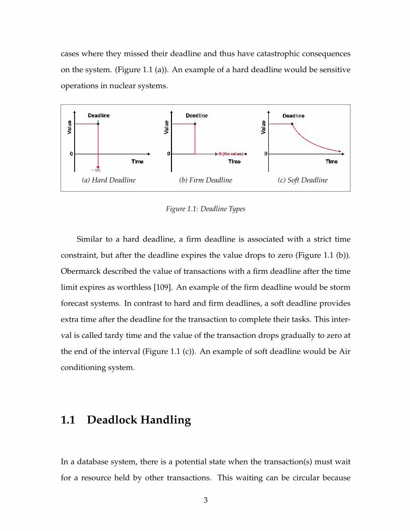
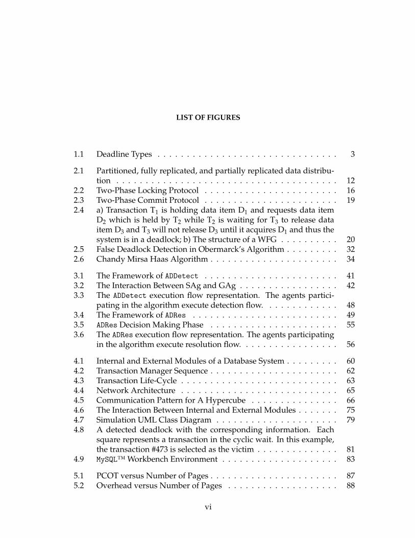
cases where they missed their deadline and thus have catastrophic consequences
on the system. (Figure 1.1 (a)). An example of a hard deadline would be sensitive
operations in nuclear systems.
(a) Hard Deadline (b) Firm Deadline (c) Soft Deadline
Figure 1.1: Deadline Types
Similar to a hard deadline, a firm deadline is associated with a strict time
constraint, but after the deadline expires the value drops to zero (Figure 1.1 (b)).
Obermarck described the value of transactions with a firm deadline after the time
limit expires as worthless [109]. An example of the firm deadline would be storm
forecast systems. In contrast to hard and firm deadlines, a soft deadline provides
extra time after the deadline for the transaction to complete their tasks. This inter-
val is called tardy time and the value of the transaction drops gradually to zero at
the end of the interval (Figure 1.1 (c)). An example of soft deadline would be Air
conditioning system.
1.1 Deadlock Handling
In a database system, there is a potential state when the transaction(s) must wait
for a resource held by other transactions. This waiting can be circular because
3
a transaction may be waiting for a resource locked by another transaction which
in turn is waiting for the first transaction. This cyclic wait condition is known as
deadlock [32]. No progress can be made until the cycle is broken. Various deadlock
handling approaches are discussed in the this section.
There are different approaches to deadlock handling in a database system.
These approaches include (a) prevention, (b) avoidance, (c) detection and reso-
lution of a deadlock. Deadlock prevention protocols guarantee a deadlock-free
condition [158] by structuring a database system to prevent at least one of the con-
ditions necessary for a deadlock to occur [30] (i.e., “mutual exclusion, hold and
wait, no preemption and circular wait” [139]). These algorithms postpone a trans-
action execution in case of the existence of one of these conditions; the prevented
transaction must restart at a later time. Even though implementing a deadlock
prevention algorithm is relatively straightforward, the cost of transaction restart is
significantly high.
Deadlock avoidance, on the other hand, reduces the system overhead and
hence is preferred over the prevention protocols [158]. Deadlock avoidance pro-
tocols attempt to predict deadlocks at the time a resource is requested by a trans-
action and react to the request accordingly to avoid deadlock [30]. Each request is
analyzed dynamically in order to achieve efficient transaction execution. Deadlock
avoidance algorithms require information about the potential use of each resource
associated with each transaction. Unavailability of sufficient information at analy-
sis time will lead the system to inefficient transaction execution.
Contrary to deadlock prevention and avoidance algorithms, deadlock detec-
tion algorithms do not preclude the possibility of a deadlock, but attempts to min-
4
imize its adverse execution impact [24]. The presence of deadlocks is detected by
a periodic iteration of a deadlock detection algorithm. When detected, a resolu-
tion algorithm selects a transaction to abort, releasing its held resources in order to
break the deadlock cycle [24, 30, 154].
It is widely accepted that both deadlock prevention and deadlock avoidance
algorithms are conservative and less capable of handling real deadlock problems,
because they make unrealistic assumptions about the knowledge of the resource al-
location requirements of participating transactions. However, deadlock detection
and resolution algorithms are broadly used as an optimistic and feasible solution
to the deadlock problem [24, 31, 75, 154]. Implementation of deadlock detection
and resolution is possible through a centralized decision-making mechanism or
through use of a team of distributed cooperative processes.
1.2 Deadlock Scheduling
The overall performance of deadlock handling protocol in a real-time environment
not only depends on the transaction execution cost, but also on how frequently
the deadlock handling protocol is executed [75]. In particular, deadlock detection
and resolution scheduling is an important factor that can significantly affect the
efficiency of deadlock handling [24].
Furthermore, the absence of distributed deadlock detection scheduling, par-
ticularly how frequently it should be conducted in a distributed environment, has
an insufficient impact on the performance of deadlock handling [24, 149, 154].
5
In this research, we explored the use of Multi Agent Systems (MAS) to detect
and resolve deadlocks.
1.3 Multi Agent Systems
Michael Wooldridge defines an agent as a computer system that is located in some
environment (for example in software application or the physical world) and is
able to act autonomously in order to fulfill its designated objectives [155]. Al-
though there is no universal definition of an agent, this is the definition we adopted
in this thesis. A MAS consists of an environment with several agents interacting
with each other while proactively pursuing their objectives. Shoham and Leyton-
Brown describe a MAS as a system with a combination of multiple entities, with
different objectives or having different data or a combination of both [125].
1.3.1 Teamwork in Agents with Helpful Behaviour
Many tasks in our daily life can only be achieved through human teamwork (that
is, the process of working collaboratively with a group of individuals to achieve a
specific goal). According to the academic investigation of management practices,
mutual support in human teamwork is one of the vital success factors [84]. Pre-
dominantly, each of the team partners performs a different piece of the joint task
and may mutually perform a cooperative act towards accomplishing the shared
goal. For about three decades, consideration of teamwork has become a major
field of study in systems using artificial intelligence. The collaborative behaviour
6

of an agent with a team refers to helpful cooperative action in order to benefit its
team. In particular, intelligent agents are able to perform supportive attitudes in a
teamwork activity with other agents or humans in pursuance of achieving a joint
goal. Fundamental studies of teamwork in MASs have been presented in several
studies [27, 35, 54, 88, 116, 143, 155].
The teamwork approach in MAS provides certain advantages for problem
solving in distributed environments [133]. In general, multi agent coordination
and cooperation as a team offers improvement in a system’s robustness and in-
creases flexibility and adaptability [42]. Cooperation and coordination techniques
in MAS have different approaches, including centralized, where a single agent as-
signs tasks to other agents such as in the study by [142], and shared, such as in
the study by [131] where tasks are distributed among the agents using negotiation
strategies.
In human encounters, having a mutual interaction is intuitively understood,
however, this concept needs clarification in agent communication. Once specifica-
tions of agents interaction are precisely defined, then it can be improved, formu-
lated, and incorporated into Multi Agent System software development libraries
and platforms. Several studies have been carried out on different agents interac-
tion protocols, such as auctions, negotiation, and bargaining [41, 66, 131].
7
1.4 Problem Statement
RTDBSs add a temporal constraint to the notion of ACID. The increased demand
for DRTDBSs requires improved system throughput. Deadlocks are one of the key
phenomena which affect performance negatively, particularly when they go unde-
tected, and thus unresolved. Deadlock detection techniques such as the one pro-
posed by Chandy and Misra [21], impose undesirable system overhead. Also, the
agent-based deadlock handling algorithms such as [165] are not practical because
of including unrealistic assumptions about the network or the significant overhead
associated with them.
The problem addressed in this thesis is the potential system performance im-
provements in DRTDBS by developing a detailed adaptive MAS deadlock detec-
tion and resolution algorithm. For this purpose, we study the effectiveness of
exploiting a team of agents in the context of DRTDBS, in particular agents with
helpful behaviour. Agents have advantage of being on the same site as the peer
site, and interacting with the peer locally and autonomously. This allows us to de-
velop algorithms that observe the most up-to-date system information for dead-
lock detection and resolution and reduce unnecessary communications. We com-
pared our algorithm with existing deadlock detection and resolution algorithms
through simulation experiments. Particularly, we investigated the impact of our
algorithm on system throughput in a DRTDBS and compared the results with other
algorithms including Mobile Agent Enabled Deadlock Detection (MAEDD) [17] and
Chandy [22]. Note that we chose other algorithms so as to compare our algorithm
with another agent-based algorithm, and with a well-known algorithm.
8
1.5 Thesis Organization
In this thesis, we investigate incorporating a team of agents with helpful behaviour
as an aid for deadlock detection and resolution in a distributed environment. We
first start with an experiment of using intelligent agents to investigate the transac-
tions’ condition at the time of deadlock using an Agent Deadlock Detection Algo-
rithm (ADDetect) and then we select the victim transaction judiciously. An Agent
Deadlock Resolution Algorithm (ADRes), allows agents in the deadlock to deliber-
ately initiate help negotiation by offering to abort its transaction to teammates in
order to maximize team benefit voluntarily, and therefore decrease transactions’
re-execution costs. Finally, we improve the balance between interaction and bi-
lateral decision-making to leverage the advantage of incorporating agents into a
real-time database deadlock situation.
The thesis is organized as follows: Chapter 2 reviews relevant literature in this
field of study; Chapter 3 elucidates the Agent Deadlock Combined Detection and
Resolution Algorithm (ADCombine); Chapter 4 covers the simulator architecture;
Chapter 5 lays out the evaluation; and Chapter 6 discusses the conclusions and
future work.
9
Chapter 2
Background and Related Work
This chapter reviews some background studies and related research in Distributed
Real-Time Database Systems, deadlock handling, transaction processing, and var-
ious execution protocols. Also, we outline some fundamental concepts of Multi
Agent Systems (MAS), agent teamwork, helpful behaviour in a team of agents,
agent interaction protocols, and bidirectional deliberation on direct help in agent
teamwork, with the focus relevant to this thesis.
2.1 Distributed Database Systems
Ozsu and Valduriez [112] defined a distributed database as a collection of multiple
databases with logical similarities that are spread over a network. A Distributed
Database System (DDBS) is a software system that contains a plurality of sites each
storing data in at least one database locally and permitting the management of a
10

distributed database [112, 141]. The following sections provide essential defini-
tions and reference to related works on DDBSs.
2.1.1 Data Distribution
In a Distributed Database System (DDBS), data distribution is possible between
sites using replication or partition approaches. In the partitioned approach, there
is no intersection between databases at different nodes, and thus unique data items
are distributed across distinct nodes. Although the cost of maintaining consistency
is reasonably low in partitioned distribution, it is insecure given that system col-
lapse can occur due to failure at a single site. On the other hand, the existence
of multiple copies of the same data at different nodes in replicated distribution
would guarantee continued progress if one or more sites fail. However, updating
all copies of data is necessary to ensure consistency [37]. The locality and replica-
tion of data can severely affect performance and integrity of the entire system [12].
Replicated structure can be further classified as fully or partially replicated accord-
ing to the number of copies of data items in the system. In partial replication, a data
item is stored on one or more nodes, whereas, in a fully replicated environment, a
copy of each data item is stored at all sites. The variance in the number of repli-
cas for each data item is based on its criticality and access frequency [153]. This is
illustrated in Figure 2.1.
11
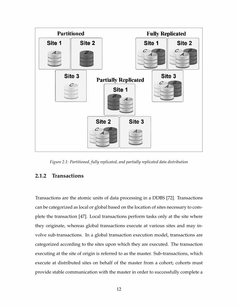
Figure 2.1: Partitioned, fully replicated, and partially replicated data distribution
2.1.2 Transactions
Transactions are the atomic units of data processing in a DDBS [72]. Transactions
can be categorized as local or global based on the location of sites necessary to com-
plete the transaction [47]. Local transactions perform tasks only at the site where
they originate, whereas global transactions execute at various sites and may in-
volve sub-transactions. In a global transaction execution model, transactions are
categorized according to the sites upon which they are executed. The transaction
executing at the site of origin is referred to as the master. Sub-transactions, which
execute at distributed sites on behalf of the master from a cohort; cohorts must
provide stable communication with the master in order to successfully complete a
12

global transaction [3]. Therefore, successful completion of a transaction in a dis-
tributed environment requires extra effort due to the existence of sub-transactions.
The lifetime of each transaction can be divided into two phases: the work
phase and the commit phase [40]. In its work phase, a transaction reads or ma-
nipulates data. The master process dispatches a cohort of sub-processes, one for
each site involved. After the sub-processes have completed their work phase, then
respond to the master referring to confirmation of the completed task. When all
the cohorts acknowledge their “WORKDONE” approval to the master, the work phase
of transaction is considered completed. The transaction is then ready to start its
second phase. In the commit phase, either a commit protocol records the changes
permanently, or an abort protocol executes to discard any adjustment made in the
work phase [139].
Execution of multiple transactions on the same data concurrently requires a
method that guarantees the serial execution of transactions [12]. Serialization al-
lows the transactions of a RTDBS to be executed simultaneously while maintaining
the global order of execution [40]. Serializations of transactions require locking and
commit protocols in the work and commit phases, respectively. These protocols are
further discussed in Sections 2.1.5 and 2.1.6.
In a RTDBS, each transaction must meet the time constraints assigned to it,
as well as the more general constraints of Atomicity, Consistency, Isolation, and
Durability (ACID) [40, 138]. Song et al. evaluate a RTDBS according to the number
of transactions completed before the deadlines [136]. Also, the consequence of
missing deadlines and the average lateness or tardiness of late transactions are
presented in [136].
13
2.1.3 Priority Scheduling
Transactions are allocated a priority to specify their degree of importance and or-
der of execution. In the case of data conflict, the priority assignment protocol de-
termines which transactions will be executed first and which transactions will be
blocked or restarted. Priority inversion can occur when a higher priority transac-
tion is being blocked by a lower priority transaction [122]. In a real-time database
system, priority inversion can cause the undesirable situation of a high priority
transaction missing its deadline while waiting for the resource(s) being held by a
lower priority transaction.
Liu and Layland classified priority assignment protocols into static, dynamic,
and hybrid [92]. In static priority scheduling protocols, a transaction’s priority is
assigned before the transaction starts its execution in the system. Once assigned,
theses priorities do not change [34]. On the other hand, dynamic scheduling pro-
tocols assign priorities at run time after considering factors such as deadline, slack
time, and execution time. Finally, a priority assignment protocol is said to be hy-
brid if static priority is used for some transactions and dynamic priority for the
others.
2.1.4 Concurrency Control Protocols
Concurrency control is an important method to maintain the consistency of a data-
base management system. A Concurrency Control Protocol (CCP) guarantees that
transactions can simultaneously access shared data without interfering with one
14
another [10]. CCPs ensure the serialization in RTDBS and maintain the atomicity
of transactions by controlling the behaviour of the locking and the commit proto-
cols [124]. Thus, the main purpose of employing a CCP is to maximize the concur-
rency and maintain the consistency of the databases [121]. Some of the best-known
proposed CCPs are greedy locking, greedy locking all copies, and adaptive specu-
lative locking [53, 117, 139].
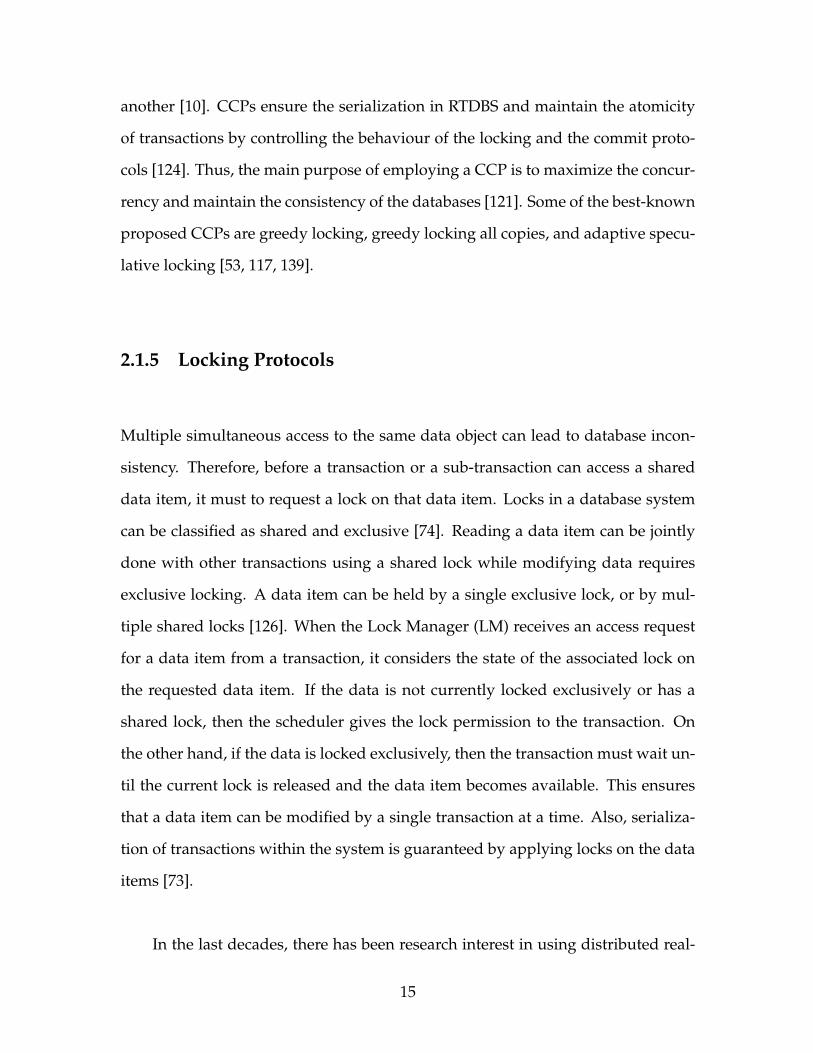
2.1.5 Locking Protocols
Multiple simultaneous access to the same data object can lead to database incon-
sistency. Therefore, before a transaction or a sub-transaction can access a shared
data item, it must to request a lock on that data item. Locks in a database system
can be classified as shared and exclusive [74]. Reading a data item can be jointly
done with other transactions using a shared lock while modifying data requires
exclusive locking. A data item can be held by a single exclusive lock, or by mul-
tiple shared locks [126]. When the Lock Manager (LM) receives an access request
for a data item from a transaction, it considers the state of the associated lock on
the requested data item. If the data is not currently locked exclusively or has a
shared lock, then the scheduler gives the lock permission to the transaction. On
the other hand, if the data is locked exclusively, then the transaction must wait un-
til the current lock is released and the data item becomes available. This ensures
that a data item can be modified by a single transaction at a time. Also, serializa-
tion of transactions within the system is guaranteed by applying locks on the data
items [73].
In the last decades, there has been research interest in using distributed real-
15
time locking protocols in order to enhance system performance by improving con-
current execution of transactions [11, 79, 123, 140]. One of the best-known lock-
ing protocols, proposed by Abbott and Garcia-Molina in [1], is Two-Phase Lock-
ing (2PL) in which execution of a transaction includes two phases of growing and
shrinking. The growing phase includes acquiring needed locks to a transaction
while during the shrinking phase, the transaction releases its locks; hence, trans-
action operations execute once all the locks are acquired. The 2PL protocol guar-
antees data consistency in a database system [12]. The process of a 2PL protocol is
illustrated in Figure 2.2.
Figure 2.2: Two-Phase Locking Protocol
The 2PL protocol can be divided into Static Two-Phase Locking (S2PL) and Dy-
namic Two-Phase Locking (D2PL) [80]. D2PL acquires the needed locks for a trans-
action on demand and releases its aquired locks when the transaction is terminated
or committed [146]. In S2PL, the required locks of a transaction are acquired prior
to the transaction execution. The locks needed for the transaction during its ex-
ecution are assumed to be known beforehand in the S2PL protocol [147]. In the
last two decades, there has been much research comparing D2PL with S2PL in both
16

Real-Time and non-Real-Time Database Systems [85, 124].
2.1.6 Commit Protocols
A commit protocol guarantees that the work done by local and global transactions
is successfully completed and any modification of data in the database will be per-
manent. In addition, commit protocols secure the atomic feature of transactions.
In order to ensure atomicity of a transaction, commit protocols prevent locks on
data items from being released until after the modifications are permanent [130].
Moreover, in order to protect atomicity in a distributed environment, all the op-
erations performed by a global transaction, such as master and cohorts, need to
commit individually before the parent transaction can commit. This could possi-
bly result in extensive message passing and logging between master and cohorts,
thereby increasing the overall execution time.
In a DDBS, numerous commit protocols have been proposed [40, 58, 59, 102,
130]. One of the commit protocols that is most commonly used in practice is the
Two-Phase Commit (2PC), proposed by Gupta et al. [55]. The 2PC protocol have
two main states of the prepare phase and the commit phase. At first, the preparation
phase starts when all cohorts send a “WORKDONE” message to the master; in other
words, when the cohorts successfully execute their assigned tasks and respond to
the master in a transaction completion report. Soon after collecting that informa-
tion, the master initiates committing by sending a “PREPARE-TO-COMMIT” message
back to all of the cohorts. Afterward, each cohort prepares a log regarding com-
mitting or aborting the execution and replies to the master by voting to commit
or to abort. Meanwhile, prepared-to-commit cohorts await further notice from the
17
master. The commit phase starts when a master has collected all of the feedback
from cohorts and unilaterally makes a global decision to either commit or abort the
global transaction. In the case of a unanimous commit decision, the master creates
a commit log and broadcasts the commit message to all cohorts. Each cohort then
reacts based on the received command by logging commit and abort operations
for the global commit and global abort respectively. Finally, both the cohort and
master reach the final state of ABORT or COMMIT, and the transaction is consid-
ered complete, and the lock on the modified data can be released [55]. A diagram
of a Two-Phase Commit protocol is presented in Figure 2.3.
2.1.7 Deadlocks
The deadlock problem occurs in many different contexts [65]. A universal example
is the traffic deadlock when four cars arrive at a four-way intersection at the same
time, each wishing to proceed ahead. Deadlock is a common problem within mul-
titasking concurrent programming systems [30]. Furthermore, the deadlock prob-
lem becomes more sophisticated where the underlying system is geographically
distributed and the transactions have time constraints, in particular, DRTDBS [61].
The problem of deadlock handling has received much attention in DDBS literature
[17, 21, 30–32, 75, 77, 109, 129, 133, 154, 158, 159, 165].
A deadlock in DRTDBS occurs when a set of transactions are not able to com-
plete their tasks because each transaction is waiting for the resource held by other
transactions from this set [77]. A deadlocks drive DRTDBS into an undesirable sit-
uation that affects the system negatively [30]. The consequences of deadlocks on
the system include decreasing the system throughput, collapsing the utilization of
18
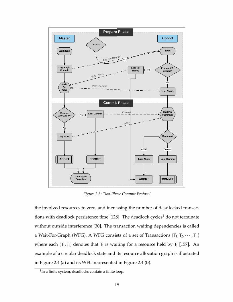
Figure 2.3: Two-Phase Commit Protocol
the involved resources to zero, and increasing the number of deadlocked transac-
tions with deadlock persistence time [128]. The deadlock cycles1 do not terminate
without outside interference [30]. The transaction waiting dependencies is called
a Wait-For-Graph (WFG). A WFG consists of a set of Transactions {T1, T2, · · · , Tn}
where each (Ti, Tj) denotes that Ti is waiting for a resource held by Tj [157]. An
example of a circular deadlock state and its resource allocation graph is illustrated
in Figure 2.4 (a) and its WFG represented in Figure 2.4 (b).
1In a finite system, deadlocks contain a finite loop.
19
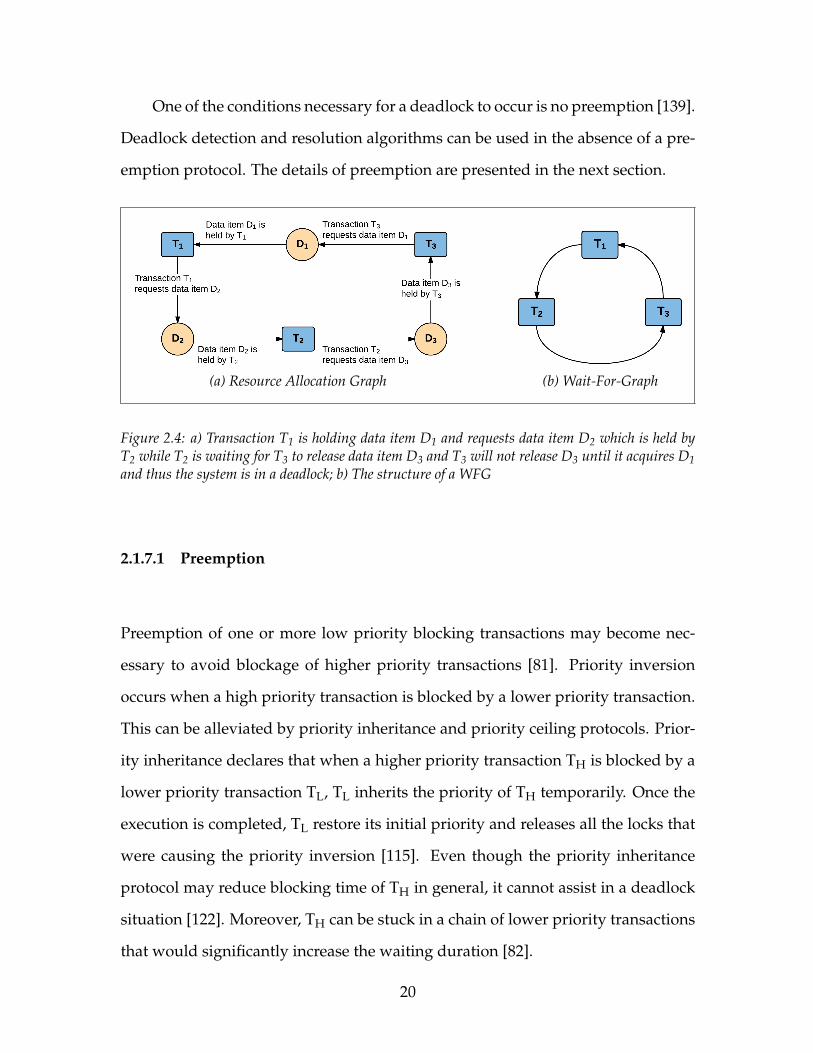
One of the conditions necessary for a deadlock to occur is no preemption [139].
Deadlock detection and resolution algorithms can be used in the absence of a pre-
emption protocol. The details of preemption are presented in the next section.
(a) Resource Allocation Graph (b) Wait-For-Graph
Figure 2.4: a) Transaction T1 is holding data item D1 and requests data item D2 which is held byT2 while T2 is waiting for T3 to release data item D3 and T3 will not release D3 until it acquires D1and thus the system is in a deadlock; b) The structure of a WFG
2.1.7.1 Preemption
Preemption of one or more low priority blocking transactions may become nec-
essary to avoid blockage of higher priority transactions [81]. Priority inversion
occurs when a high priority transaction is blocked by a lower priority transaction.
This can be alleviated by priority inheritance and priority ceiling protocols. Prior-
ity inheritance declares that when a higher priority transaction TH is blocked by a
lower priority transaction TL, TL inherits the priority of TH temporarily. Once the
execution is completed, TL restore its initial priority and releases all the locks that
were causing the priority inversion [115]. Even though the priority inheritance
protocol may reduce blocking time of TH in general, it cannot assist in a deadlock
situation [122]. Moreover, TH can be stuck in a chain of lower priority transactions
that would significantly increase the waiting duration [82].
20
A priority ceiling protocol is an extension of the priority inheritance proto-
col. In this protocol, the highest priority of the transactions trying to access the
same data item is assigned to the transaction causing the priority inversion. There-
fore, preempting the blocking transaction requires a priority, superior to other
preempted transactions. Despite the fact that a priority ceiling can reduce block-
ing time and prevent a deadlock from occurrence [122], it may cause unnecessary
blockage of a lower priority transaction by a higher priority transaction while read-
ing [160]. Additionally, in a RTDBS which is using the priority ceiling protocol,
serialization of real-time transactions cannot be guaranteed [82].
Huang et al. proposed the concept of conditional priority inheritance based
on transaction execution time estimation [62]. In the case of priority inversion,
newly arrived high priority transaction evaluates waiting time required for the
lower priority transaction to be completed. If the higher priority transaction can
afford to wait without missing its deadline, then the lower priority transaction
inherits the priority of higher priority transaction. Otherwise, the lower priority
transaction is preempted. Conditional priority inheritance manages transaction
abortion in such a way that the system not only benefits from reducing wasted
resources, but also avoids extended blocking time for high priority transactions
[151]. Despite the advantage of conditional preemption in a one-to-one conflict
situation (that is, there are no multiple transactions involved in the conflict), the
protocol may fail in a chained block. Also, the higher priority transaction should
have an accurate time estimate to perform properly, which may not always be
available [151].
21
2.1.7.2 Deadlocks Persistence Time
The persistence time of a deadlock denotes the temporal interval between the time
at which deadlock detection and resolution algorithm detects and resolves the
deadlock and the time at which the deadlock is initially formed. It grows linearly
until the deadlock is resolved using one of the deadlock resolution algorithms [24].
Park et al. discussed that upon initiation of a deadlock, other transactions request-
ing resources currently held by the deadlocked transactions immediately fall into
the deadlock state [113]. Therefore, a formed deadlock acts as a transaction trap
that may increases the deadlock size. Particularly, increasing the deadlock persis-
tence time results in a growing number of blocked transactions which leads to a
higher deadlock resolution cost [129]. Note that the deadlock detection process
time is significantly more than a resolution process time. Hence, the deadlock per-
sistence time can be stopped as soon as the deadlock detection algorithm executes.
2.1.7.3 Deadlocks Detection Interval
The deadlock detection interval represents the time between each search for dead-
lock. When the detection interval is small, the deadlock detection algorithm exe-
cutes more frequently result in reducing deadlock persistence time. On the other
hand, Ling et al. showed that an optimal deadlock detection interval can minimize
the deadlock persistence time and increase the system throughput [24, 91].
22
2.2 Intelligent Agents
To consider an agent (see also 1.3) to be intelligent, the agent is expected to hold
three capabilities, the ability to be: reactive, proactive, and social [156]. Reactive
behaviour is defined as the ability to perceive the environment and respond ac-
cordingly to changes in a timely manner. Proactive behaviour is characterized by
the ability to use creativity in executing goal-directed actions. Finally, social be-
haviour is explained as the potential of having interactions with other agents and
possibly people.
Russell and Norvig have proposed a classification model for different types
of environments based on where an agent might be located [118]. For example,
an environment might be static or dynamic. A static environment can be consid-
ered unaffected unless by the agent’s action. However, a dynamic environment is
beyond the agent’s control because other processes are operating on that as well.
Likewise, an environment might be deterministic in which any action performed
by an agent has a single guaranteed effect, and there is no uncertainty about the
state of environment derived from that action; or it can be non-deterministic. In a
Multi Agent System (MAS), the environment that an agent is situated in has some
initial state as perceived by an agent. The agent then performs an action in order
to achieve its objective; meanwhile, the environment may transform to another
state because of an agent’s action. Note that changing the state of an environment
could cause the agent to fail in achieving its goal, potentially requiring it to execute
another response [155].
The practical reasoning architecture proposed from philosophical work by Brat-
man [14] is known as one of the most reliable agent designs of the last two decades.
23

In general, practical reasoning agents are equipped with a mental state similar to
humans’ minds, which is then used in their decision-making process. In contrast
to the practical reasoning that is directed toward actions, theoretical reasoning is
directed towards beliefs. Theoretical reasoning agents consider logical theorems
as models of decision-making while practical reasoning agents employ deliberation
and means-ends reasoning for their decision-making process. Deliberation indicates
what state of affairs to achieve, whereas means-ends reasoning identifies how to
achieve these states of affairs. The output of means-ends reasoning is the plan and
the output of deliberation is the intention in which the agent has some level of
commitment [155].
The most popular framework for designing practical reasoning agents is known
as Belief-Desire-Intention (BDI). The performance of a MAS with a BDI framework
relies on the specified mental attitudes [15]. In this context, agents build their infor-
mative state (beliefs) perceived about the environment which may not necessarily
be accurate. Also, agents apply these beliefs to establish their motivational state
(desires) that indicates the states of the environment that the agent would like to
accomplish. Finally, selecting particular tasks from desires leads to the deliber-
ative state of a rational agent (intention) to which the agent is committed [155].
Overall, the BDI structure has been implemented and used in many real world
systems [49, 50, 93, 99].
2.2.1 Teamwork
Teamwork involves each artificial intelligent agent’s commitment to a joint action
in order to accomplish a shared goal [27]. Over the past two decades, there have
24
been many scientific studies on the semantics of agent teamwork. The fundamen-
tal investigation presented by Cohen et al. [26] defines the concept of joint inten-
tion, joint action, and joint commitment [88]. They investigate the necessity of
multiple joint actions involving agents when individual agents are sharing certain
specific mental properties. Also, they study joint commitment and joint intention
specifications when a team of agents acts as an aggregate agent [88].
In a highly dynamic environment, where the state of the environment is fre-
quently changing, finding an optimal decisive goal-directed teamwork policy is
complicated since there is tension between individual intentions and acting as one
aggregate agent [27]. Kaelbling et al. work on Partially Observable Markov Deci-
sion Processes (POMDP) which allow an agent to make decisions when faced with
uncertainty, especially in a highly dynamic environment [70]. Also, in a probability
distribution over all possible states that is given to individual agents, both actions
and perceptions with uncertainty are considered in this model. The implementa-
tion of POMDP is applied to real world domains, including robot navigation sys-
tems [110] and multi agent teamwork research studies [105, 106, 148]. Furthermore,
decentralized POMDP (DEC-POMDP) provides frameworks to model POMDP in
MAS [9].
Providing the ability to perform optimization in a distributed environment
verifies a powerful framework for multi agent teamwork, called a Distributed Con-
straint Optimization Problem (DCOP), as investigated by Mailler and Lesser [95].
In the proposed framework, agents are cooperative in teamwork actions and share
a common reward function. According to the research done by Taylor et al., execution-
time reasoning is considered a critical component of MAS and thus DCOP is ap-
plied to address deadline problems, task allocations, and coordinating teams of
25
agents [148].
2.2.2 Helpful Behaviour
Agents are situated in an environment where unpredictable states and unexpected
results may occur beyond the agent developer’s expectations. Furthermore, imple-
mentation of an agent with a lot of capabilities could be an expensive task. Hence,
agent developers prefer to construct effective agents in terms of ability in their ob-
jective domain, so as to reuse them in similar tasks. Although an agent may be
designed for a certain application, it could possibly need assistance from its team-
mates that can provide a positive impact on team performance [114]. Generally,
agents with helpful behaviour are equipped with the capability of assisting other
team members by performing some action or providing relevant information. In
the last two decades, helpful behaviour in agent teamwork has been received much
attention [18, 67, 71, 96, 100, 114]
Even though enough encouragements exist for an agent to help its teammates
achieve a committed shared goal, still some level of deliberations need to be con-
sidered. Therefore, Kamar et al. discuss the existence of some cost in agent’s inter-
action, which may influence the team’s expenses [71]. There are various source of
costs, such as communication coste, spent resources whilst helping, and missing
opportunities to execute other actions. According to work presented by Kamar et
al., help in agent teamwork includes either executing other’s actions or providing
some relevant information for a teammate [71]. Moreover, they use a unilateral
decision-making system which means that help deliberation is made by only one
member of the team. However, because agents use their beliefs as the only source
26
of help in decision making, accuracy is not guaranteed.
In a MAS, helpful behaviour can be enforced by a centralized mechanism over
a group of agents, or it can be specified as direct help. During agents’ teamwork,
direct assistance can be initiated by an agent as needed and bilaterally decided
by the agents involved in the help act [54]. Research in specifying direct help as
one of the components in a decentralized MAS has been investigated in [35]. Fur-
thermore, Nalbandyan introduced the Mutual Assistance Protocol (MAP), which
implements a direct help mechanism in a team of agents with different skills, sit-
uated in a dynamically changing environment [107]. The proposed algorithm is
based on a bilaterally distributed agreement in which both requester and helper
agents agree to execute a helpful action. Notably, the research argued that bilateral
decision-making has a behavioural advantage over the unilateral approach when
the communication cost is low or mutual knowledge between agents is high.
Malek Akhlagh extended this work and proposed an interaction protocol for
bilateral direct help, called the Bidirectionally Initiated Action MAP (BIAMAP) [96].
The research is based on a mutually distributed agreement in a distributed envi-
ronment where both the requester and helper engage in a shared decision. Addi-
tionally, this research illustrates some improvement over the unilateral approach
when the communication cost is comparably low.
2.2.3 Agent protocols
In general, agent protocols can be categorized into two groups, hi-level protocols
(interaction protocol) and low-level protocols (communication protocol). Interaction
27
protocols model individual agents’ social behaviour, that is, coordination, nego-
tiation, and collaboration, by implementing an anthology of rules. However, the
Contract Net Protocol (CNP) introduced by Reid Smith [131] is one of the most suc-
cessful and widely used agent interaction protocols in a distributed environment.
On the other hand, agent interaction protocols rely on communication protocols
that control the manner of sending and receiving information between agents. Ac-
cordingly, communication protocols provide speech act classification and the logic
for the agents to understand each other while interacting [155]. Overall, two fa-
mous agent communication protocols, FIPA-ACL and KQML/KIF, have been pro-
posed by the Foundation of Intelligent Physical Agents [43] and Mayfield et al. [98]
respectively.
The agent’s social behaviour might vary in terms of properties. Hence, the
theory of designing a universal interaction protocol among agent teams is not re-
alistic, according to Dunn-Davies et al. [36]. Basically, they argue that each domain
requires constructing specific interaction protocols for individual agents.
2.2.4 Action Help
Bidirectionally Initiated Action MAP (BIAMAP) was implemented for reciprocal
help behaviour in agent teamwork [96]. The proposed method is an extension of
the Mutual Assistance Protocol (MAP) [107] in which agents are equipped with
the capability of assisting their teammates directly when the mutually distributed
agreement is possible through a bidding sequence. A bidding sequence is defined
as a situation when an agent receives the task announcement, then evaluates it
according to some factors. If the agent realizes that it is suitable for the task, it
28
submits a bid [107]. Overall, BIAMAP provides the significant feature of providing
and receiving help while sending or requesting for help.
In another approach, different interaction models toward help actions are
used, such as Requester-Initiated Action MAP (RIAMAP) and Helper-Initiated
Action MAP (HIAMAP) [97, 107]. In the first model, agents are able to proac-
tively receive broadcasted help requests from teammates, whereas in the second
model they are capable of proactively offering help to teammates. It has been
demonstrated that performance of RIAMAP and HIAMAP are complementary in
a MAS [108].
Applying cooperation and coordination in geographically Distributed Artifi-
cial Intelligence (DAI) systems with limited resources was investigated by Findler
and Elder [42]. In this research, resource conflict is managed by implementing a
technique called “hierarchical iterative conflict resolution” [42]. In the proposed
technique, agents are situated in a highly dynamic environment where agents’
tasks are prioritized based on CNP negotiation between groups of agents in or-
der to achieve a common goal. When tasks are constrained by time, agents with a
higher priority can borrow or take resources from lower priority agents and solve
their task earlier. The author argues that employing helpful agents with cooper-
ation and coordination behaviour can be useful in other distributed applications
where limited resources have to be allocated to different processes on the basis of
the urgency and importance of the tasks at hand.
29
2.2.5 Agent Memory
Lerman et al. proposed agent memory as a general mechanism for adaptation of ar-
tificial agents [87]. By employing memory into BDI architecture, agents can modify
their behaviour based on past environmental events. Each individual agent uses
memory, which is constructed based on its perception of the environment, to esti-
mate the global state of the system and adjust its actions accordingly.
2.3 Deadlock Detection and Resolution Algorithms
Generally, deadlock detection and deadlock resolutions in DDBSs are discussed
separately; however, the latter is as important as the former. In this section, we
provide a summary of existing distributed deadlock detection and deadlock reso-
lution algorithms.
2.3.1 Types of Deadlock Detection
Distributed deadlock detection algorithms can generally be divided into four ma-
jor categories: Path-Pushing (WFG-based)(see Figure 2.4), Edge-Chasing (Probe-based),
Diffusing Computation, and Global State Detection [75]. The first category includes
the most common algorithms adopted in DRTDBS. A deadlock detection algo-
rithm must satisfy two main criteria: First, no false deadlock detection and second,
all the deadlocks must be detected in a finite time [6].
30
2.3.1.1 Path-Pushing
Path-pushing algorithms support an explicit table of waiting a dependencies in
the form of a directed interdependency graph, that is, a WFG. Each site creates its
local waiting processes list periodically in order to create a local WFG. Thereafter,
every site sends its local WFG to other sites in the system. The integrated topology
of the waiting process in the distributed system is shared between all sites once
all the local WFGs are collected from each site. Then, each site updates its local
WFG by inserting the received wait dependency to develop a global WFG. This
detection process is finalized by detecting any existing deadlock in the generated
global WFG. One of the best-known algorithms in this category was proposed by
Obermarck [109].
In the Obermarck [109] algorithm, each site constructs its local WFG and re-
ceives the WFG from other sites using a distinguished special virtual node called
External. The External node (Ex) represents the portion of a global WFG that is
unknown to the site. The local WFG is then updated accordingly and the pres-
ence of any deadlock is checked. The found deadlocks are resolved by breaking
cycles that do not contain an External node. For the deadlock cycles which contain
the External node in the form of Ex → T1 → T2 → · · · → Tn → Ex which possi-
bly constitute a global deadlock, the current WFG is sent in the form of a “string”
message to the site that Tn resides in if and only if the ID of T1 is greater than the
ID of Tn. In this way, the number of sending messages is reduced [78]. Note that
Ex represents a possible wait condition, which need not exist [76]. The algorithm
suffers from false deadlock detection as the constructed asynchronous WFG does
not represent a snapshot of the global WFG at any instant [6]. An example of the
false deadlock detection process using the Obermarck algorithm is given in Fig-
31
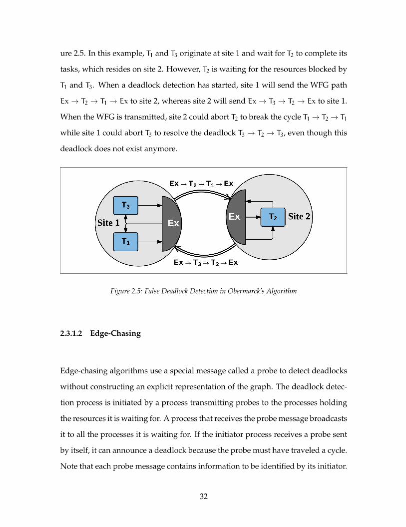
ure 2.5. In this example, T1 and T3 originate at site 1 and wait for T2 to complete its
tasks, which resides on site 2. However, T2 is waiting for the resources blocked by
T1 and T3. When a deadlock detection has started, site 1 will send the WFG path
Ex → T2 → T1 → Ex to site 2, whereas site 2 will send Ex → T3 → T2 → Ex to site 1.
When the WFG is transmitted, site 2 could abort T2 to break the cycle T1 → T2 → T1
while site 1 could abort T3 to resolve the deadlock T3 → T2 → T3, even though this
deadlock does not exist anymore.
Figure 2.5: False Deadlock Detection in Obermarck’s Algorithm
2.3.1.2 Edge-Chasing
Edge-chasing algorithms use a special message called a probe to detect deadlocks
without constructing an explicit representation of the graph. The deadlock detec-
tion process is initiated by a process transmitting probes to the processes holding
the resources it is waiting for. A process that receives the probe message broadcasts
it to all the processes it is waiting for. If the initiator process receives a probe sent
by itself, it can announce a deadlock because the probe must have traveled a cycle.
Note that each probe message contains information to be identified by its initiator.
32

Probe-based algorithms were originally proposed by Chandy and Misra [21].
In the algorithm proposed by Chandy et al. [22], a probe message is initiated
by one transaction sent to another for deadlock detection. The probe message is a
3-word message length in the format of (i, j, k) where i is the initiator transaction,
j is a transaction that i is locally waiting for, whilst k is the transaction that holds
a resource that j is waiting for which resides in a different site than i and j. An
example of a deadlock detection process using the Chandy et al. algorithm is pre-
sented in Figure 2.6. Suppose a deadlock detection is initiated by T1 in Site 1. On
this site, T1 is waiting for the data held by T2, which is waiting for the blocked data
by T3 and T3 is waiting for T4 to release its blocked data. Meanwhile, T4 is waiting
for the data held by T5 in Site 2. The global probe message (T1, T4, T5) will be sent to
T5. Then, T5 broadcasts the probe until it is received by the initiator (i.e., (T1, T14, T1)
resulting in detecting of a deadlock).
2.3.1.3 Diffusing Computation and Global State Detection
Diffusing computations is proposed by Dijkstra and Scholten in [33] and global
state detection is proposed by Chandy and Lamport in [19] is used to detect and
terminate deadlocks in a distributed system. These deadlock detection algorithms
have found use in distributed simulation [20]. In this thesis, we only use algo-
rithms of type path-pushing and edge-chasing.
33
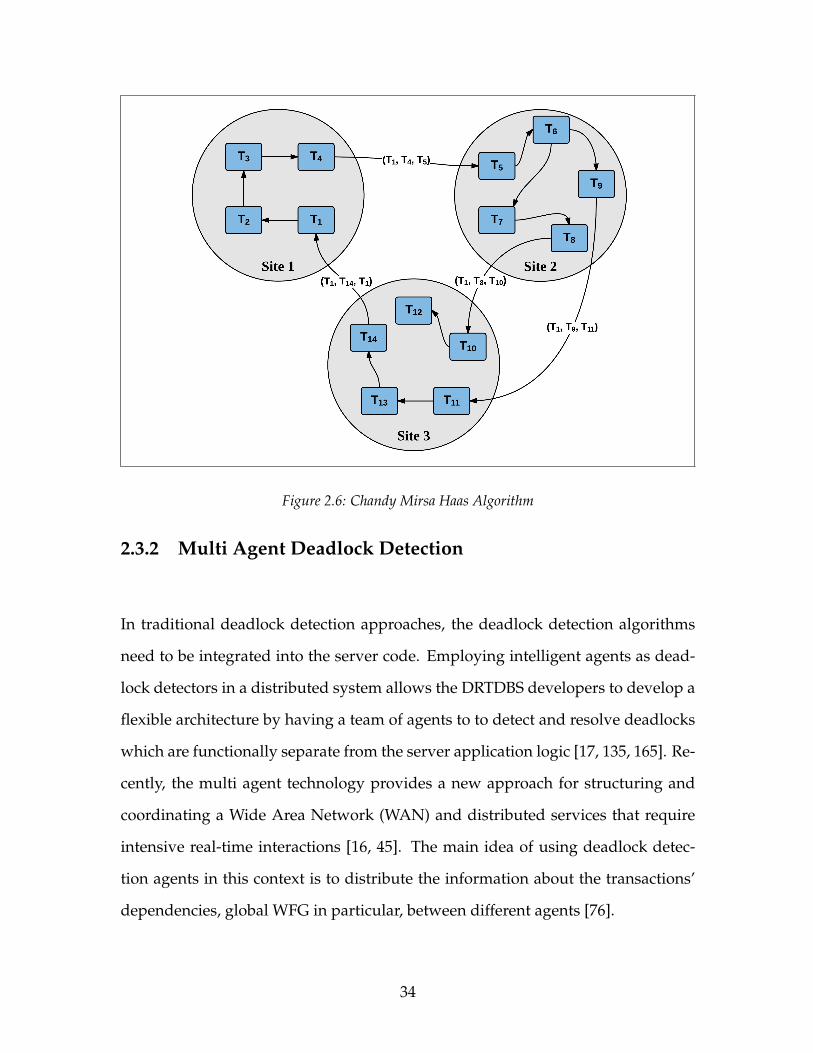
Figure 2.6: Chandy Mirsa Haas Algorithm
2.3.2 Multi Agent Deadlock Detection
In traditional deadlock detection approaches, the deadlock detection algorithms
need to be integrated into the server code. Employing intelligent agents as dead-
lock detectors in a distributed system allows the DRTDBS developers to develop a
flexible architecture by having a team of agents to to detect and resolve deadlocks
which are functionally separate from the server application logic [17, 135, 165]. Re-
cently, the multi agent technology provides a new approach for structuring and
coordinating a Wide Area Network (WAN) and distributed services that require
intensive real-time interactions [16, 45]. The main idea of using deadlock detec-
tion agents in this context is to distribute the information about the transactions’
dependencies, global WFG in particular, between different agents [76].
34

There are two different approaches to the cooperation in handling deadlocks,
whether to detect or resolve cycles: An agent can migrate through the system to
collect needed data. Alternatively, an agent can reside on a permanent site to pro-
vide support remotely as the need arises. The former approach is known as a
mobile agent, and the latter is a stationary agent. The practical impact of the two dif-
ferent approaches on database system throughput has been investigated through
simulation studies [17, 42, 165]. While mobile agents are suitable for distributed
environments that require intensive real-time interactions [16], stationary agents
often perform better in cooperating and coordinating in a distributed Wide Area
Network and highly dynamic environment with limited resources [38]. The ad-
vantage of stationary agents has given rise to the research question about the pos-
sibility of improving the throughput of DRTDBS by using stationary agents with
helpful behaviour.
Cao et al. proposed a new algorithm called Mobile Agent Enabled Deadlock
Detection (MAEDD) [17]. In this algorithm, Static Agents (SA) reside on each site.
SAs initialize and dispatch Mobile Agent (MAs). Each MA is in the type of mobile
agents, and SAs are in the type stationary agents. The SA is responsible for man-
aging a resource location table which records where the available resources are. In
each deadlock detection interval, each SA dispatch a MA which encapsulates the
deadlock detection strategy, together with the necessary data, and then dispatches
it to the network. MAs are capable of navigating through the network to exchange
information and perform tasks at the sites they visit. Once a deadlock cycle is de-
tected by one of the MAs, it will select a victim process according to the embedded
deadlock resolution algorithm.
Zhou et al. [165] proposed the M-Guard algorithm for deadlock detection in
35
distributed systems under the MAEDD framework. M-Guard is an agent roaming
in the system in order to collect resource requests or propagate information for
detecting deadlock cycles as well as propagating the resource information among
the sites. Employing M-Guard as an agent with a dual role reduces the overall
communication overhead and deadlock cycle persisting time when the scale of
the whole system is not too big. However, M-Guard is insecure given that the
algorithm collapse can occur due to failure of the agent.
2.3.3 Deadlock Resolution
In a DRTDBS, a deadlock resolution algorithm must be triggered soon enough to
permit the deadlocked transactions to complete within their deadline after being
restarted [159]. Nonetheless, resolving a deadlock by indiscriminately aborting
deadlocked transactions is significantly inefficient because dropping transactions
with a higher priority have a negative impact on the system [24]. Aborting all the
deadlocked transactions is extremely costly because computations have to start
over again. Also, a transitive blocked transaction might not belong to any deadlock
cycle in the WFG [24, 75, 149].
Distributed deadlock resolution algorithms must know all the transactions
and resources needed by the transactions to resolve a deadlock efficiently [24]. The
minimum abort set problem in a deadlock resolution algorithm is to determine a
set of victim transactions whose abortion resolves the deadlock to minimizes the
overall abortion cost [149]. The cost involves a transaction’s partial rollback, lock
de-escalation, or the transaction’s complete termination [120]. Although the over-
all cost of deadlock handling is closely associated with aggregated deadlock detec-
36
tion and resolution cost, deadlock resolution can be more expensive than deadlock
detection regarding message complexity, particularly when the deadlock size in-
creases. Park et al. [113] pointed out that “the reduction of deadlock resolution cost
can be achieved at the expense of deadlock detection cost.”
In general, deadlock resolution in a database system involves the following
steps: victim transaction selection, victim transaction abortion, and deletion of
all the deadlock detection information concerning the victim transaction at all
sites [89, 134, 137]. After the victim transaction is selected, a deadlock resolution
algorithm must terminate the transaction and release all the resources held by it.
Execution of the first two steps, i.e., selection and abortion of the victim transaction,
can be computationally expensive for the optimal resolution of the deadlock. Par-
ticularly, in an environment where a transaction can concurrently wait for multiple
resources and the allocation of a released resource to another transaction can cause
a deadlock. The last step, i.e., deletion of all the deadlock detection information, is
even more critical, since deleting the information related to the victim transaction
can be delayed which may cause several other transactions to wait, leadings to a
false deadlock [30]. An example of a traditional deadlock resolution algorithm is
Priority Deadlock Resolution [25], which selects the transaction with the lowest
priority as the victim.
37

Chapter 3
Proposed Deadlock Handling Model
In the previous chapter, we saw that deadlock detection and resolution are im-
portant modules of practical Distributed Real-Time Database System (DRTDBS).
This chapter motivates using agent-based deadlock detection and resolution, and
presents new algorithms to do so. Section 3.1 describes the research motivation.
Section 3.2 formalizes the deadlock detection and resolution model by explicitly
presenting the details of each algorithm. Section 3.2 then presents a combined al-
gorithm.
3.1 The Motivation and Research Objectives
Our motivation for employing of agents in a Distributed Database System (DDBS)
emanates from agents’ potential benefits in practical applications. In this study, we
are interested in investigating the actual impact of agents’ teamwork upon system
38

throughput. Our research objectives involve developing a comprehensive mecha-
nism for the deadlock detection and resolution process in transactions processing
in order to increase system throughput. The Mobile Agent Enabled Deadlock De-
tection (MAEDD) [17] approach provides a Multi Agent System (MAS) mechanism by
enabling agents in a database system to detect deadlock cycles, and then resolve
the deadlocks (as discussed in Section 2.3.2). Distributed planning on a shared goal
is the underlying principle of MAEDD. From an individual perspective, the members
of an agent team follow their beliefs to jointly deliberate on performing an action.
Each action results from either a multi distributed agreement or a unilateral deci-
sion that is in the interests of the team and thus the whole system.
In this research, we propose a new model that uses a team of stationary agents
with helpful behaviour to implement distributed deadlock detection and resolu-
tion. The specifications of this new algorithm are intended to leverage the advan-
tages of agents’ cooperation and coordination in handling deadlock cycles.
Several publications on the MAS approach to distributed deadlock detection
and resolution demonstrate that the analysis of the impact of stationary agents
on system performance is appropriate for our comparative studies of new and
existing algorithms. The impact of the new algorithm on DRTDBS completion
rates and throughput is explored through simulation experiments in Chapter 5.
39

3.2 Deadlock Detection and Resolution Model
In traditional deadlock detection approaches in distributed systems using either
path-pushing or edge-chasing, the algorithm must be integrated into the server
code. We consider instead a group of stationary agents resides on server sites in a
distributed system. This allows us to develop a flexible architecture by having sta-
tionary agents observe the status of the system and coordinate with other agents,
which are functionally separated from the application logic. Using the MAS is not
restricted to a particular database system, and can potentially be applied to dif-
ferent practical system applications [17]. In the following sections, we outline the
basics of the distributed deadlock detection and deadlock resolution algorithms
using a team of artificial agents and formulate the questions to be explored in the
rest of this thesis.
3.2.1 Agent Deadlock Detection Algorithm
In this section, we first describe the implementation details of different agents in
our deadlock detection algorithm, ADDetect. Then we present the deadlock detec-
tion model and agents interaction. Finally, we introduce an improvement to the
algorithm.
Site Agents (SAgs) are capable of observing the state of a site and performing
tasks. SAgs reside on the Multi-Agent Platform (MAP) of each site. The SAg is
responsible for holding transaction wait dependencies (that is, the local Wait-For-
Graph (WFG)) for a site. When a local deadlock is detected, the SAg reacts by
40
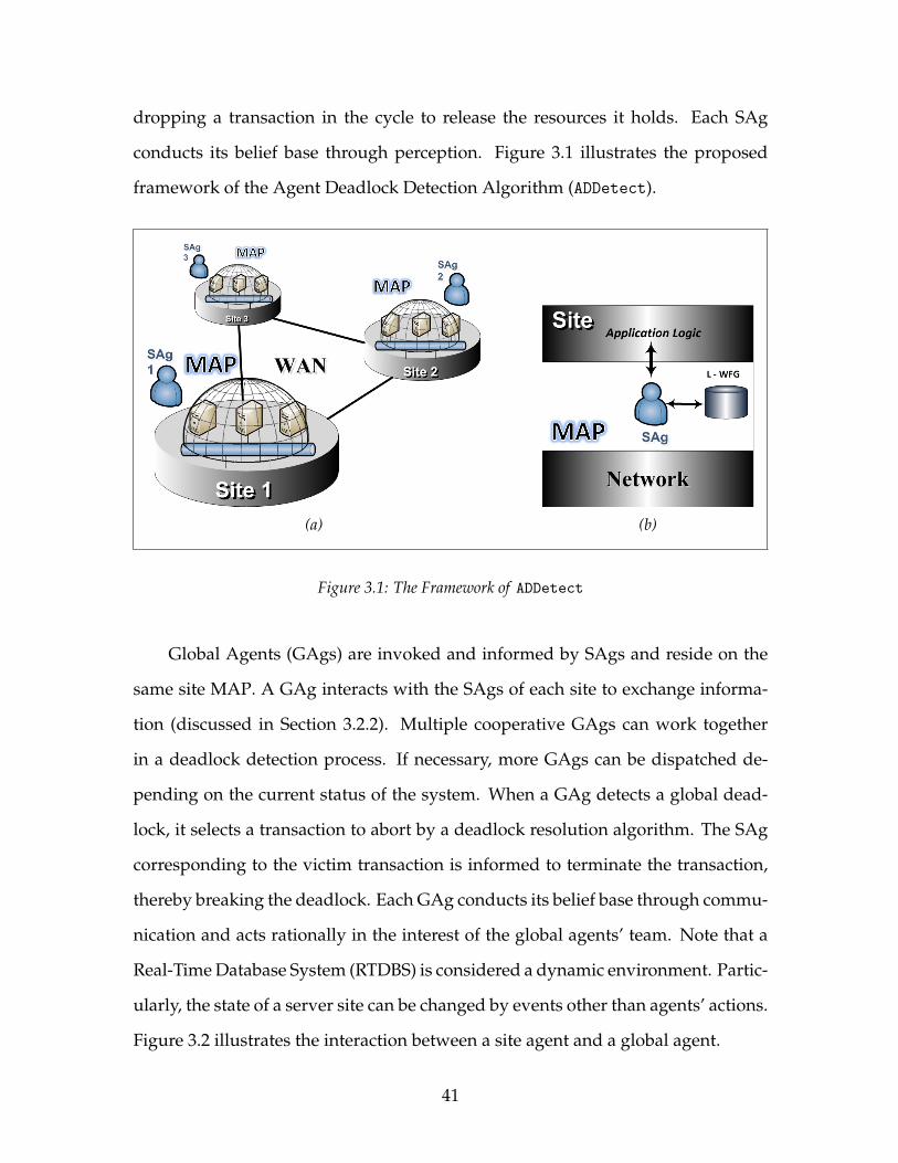
dropping a transaction in the cycle to release the resources it holds. Each SAg
conducts its belief base through perception. Figure 3.1 illustrates the proposed
framework of the Agent Deadlock Detection Algorithm (ADDetect).
(a) (b)
Figure 3.1: The Framework of ADDetect
Global Agents (GAgs) are invoked and informed by SAgs and reside on the
same site MAP. A GAg interacts with the SAgs of each site to exchange informa-
tion (discussed in Section 3.2.2). Multiple cooperative GAgs can work together
in a deadlock detection process. If necessary, more GAgs can be dispatched de-
pending on the current status of the system. When a GAg detects a global dead-
lock, it selects a transaction to abort by a deadlock resolution algorithm. The SAg
corresponding to the victim transaction is informed to terminate the transaction,
thereby breaking the deadlock. Each GAg conducts its belief base through commu-
nication and acts rationally in the interest of the global agents’ team. Note that a
Real-Time Database System (RTDBS) is considered a dynamic environment. Partic-
ularly, the state of a server site can be changed by events other than agents’ actions.
Figure 3.2 illustrates the interaction between a site agent and a global agent.
41
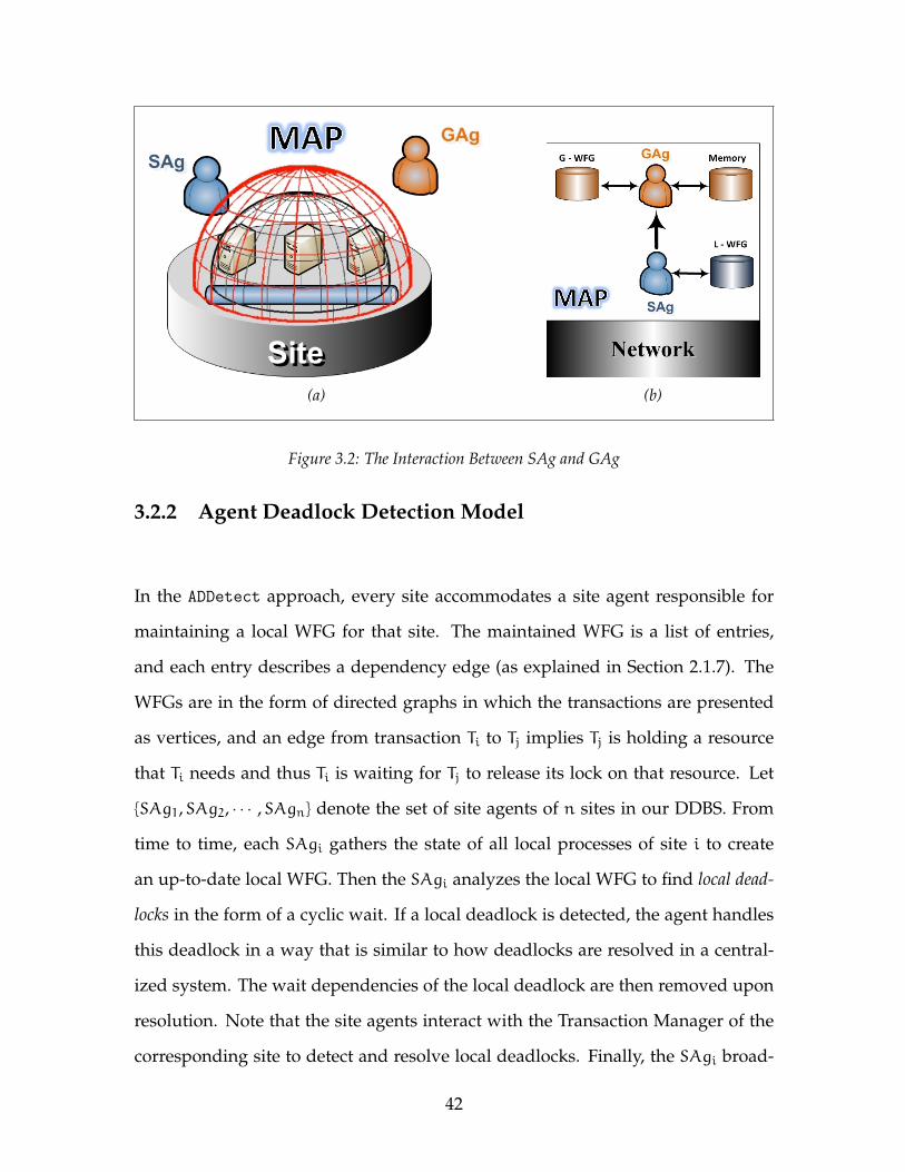
(a) (b)
Figure 3.2: The Interaction Between SAg and GAg
3.2.2 Agent Deadlock Detection Model
In the ADDetect approach, every site accommodates a site agent responsible for
maintaining a local WFG for that site. The maintained WFG is a list of entries,
and each entry describes a dependency edge (as explained in Section 2.1.7). The
WFGs are in the form of directed graphs in which the transactions are presented
as vertices, and an edge from transaction Ti to Tj implies Tj is holding a resource
that Ti needs and thus Ti is waiting for Tj to release its lock on that resource. Let
{SAg1,SAg2, · · · ,SAgn} denote the set of site agents of n sites in our DDBS. From
time to time, each SAgi gathers the state of all local processes of site i to create
an up-to-date local WFG. Then the SAgi analyzes the local WFG to find local dead-
locks in the form of a cyclic wait. If a local deadlock is detected, the agent handles
this deadlock in a way that is similar to how deadlocks are resolved in a central-
ized system. The wait dependencies of the local deadlock are then removed upon
resolution. Note that the site agents interact with the Transaction Manager of the
corresponding site to detect and resolve local deadlocks. Finally, the SAgi broad-
42
cast the local-deadlock-free WFG to any existing GAg.
In this study, we demonstrate the benefit of restructuring the WFG that GAg
receives as input in a way that improves the overall system performance. This
approach was also adopted in psychology and behavioural economics [68, 86], and
recently in Multi Agent Systems [7, 119]. The idea is that the global agents believe
that the WFG is local-deadlock-free and thus requires a substantially smaller CPU
consumption. This technique guarantees that local deadlocks do not cause the
global deadlocks. Furthermore, a site that does not contain any WFG with remote
dependencies can be excluded from the deadlock detection process. This way,
global deadlocks can be detected more efficiently.
Let {GAg1,GAg2, · · · ,GAgm} denote the set of m active Global Agents in our
DDBS such that 2 6 m 6 n, where n is the number of sites. Note that the number of
active GAgs at each detection interval can be managed by the current active GAgs
in a joint agreement decision-making process. The mechanism for Global Agents
in ADDetect comprises three phases as follows.
1. Detecting the deadlocks
Upon receiving the local WFGs, each GAg initiates the deadlock detection
process by simply merging the incoming local WFGs. Let the list of incoming
local WFGs be {WFGSAg1 ,WFGSAg2 , · · · ,WFGSAgp}, where p is the number of
sites providing their local WFGs. Note that a SAg can abstain from providing
its local WFG if the local WFG does not have any remote dependency by
notifying GAgs through a simple message. A GAg then constructs the global
WFG, G WFG.
In the next step, the GAg generates the node list of the global WFG (that is,
43
the list of unique transactions involved in G WFG) as follows:
T = {Ti | Ti is a vertext of G WFG}
where the Tis are partitioned among the Global Agents. Each GAg indepen-
dently searches the whole G WFG to find cycles. Details of the global dead-
lock detection algorithm are presented in Algorithm 1.
A GAg uses Tarjan’s depth-first search algorithm [144], which is the classical
algorithm for finding cycles in a directed graph. When a GAg is tracing the
G WFG, it takes the ID of the Ti as the head edge. The head edge must have
a lower ID than a tail edge. For instance, if Ti is waiting for Tj, and GAgp,
(2 6 p 6 m 6 n), is responsible for tracking Tj in G WFG, GAgp will continue
tracing if the ID of Tj is greater that the ID of Ti. The only exception is when
the ID of Tj is equal to the ID of Ti, and thus the GAgp knows that a deadlock
cycle has been detected. Otherwise, the GAgp will continue searching for
any existing deadlock cycle until there is no unvisited edge related to Tj. In
the proposed algorithm, each deadlock cycle is detected by only one agent.
Therefore, the probability of detecting phantom deadlocks1 is reduced. The
mathematical proof is provided in Appendix A.3.
2. Resolving the deadlocks
In this state, when the agent detects a cycle, it tries to resolve it by a deadlock
resolution algorithm. When a transaction to drop is selected, the GAg passes
that transaction ID to its corresponding SAg, which will drop the transaction.
The resources held by the dropped transaction are then released.
The list of sites that are involved in that global deadlock is then created by
the GAg that found the cycle. Finally, the GAg passes the resolved deadlock
1Phantom deadlock is a cycle detected as a deadlock which does not actually exists [109].
44
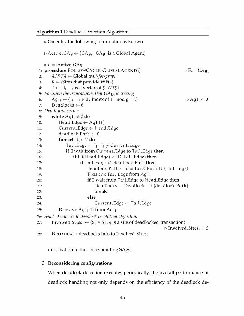
Algorithm 1 Deadlock Detection Algorithm
. On entry the following information is known
. Active GAg← {GAgi | GAgi is a Global Agent}
. g = |Active GAg|
1: procedure FOLLOWCYCLE GLOBALAGENT(i) . For GAgi2: G WFG← Global wait-for-graph3: S← {Sites that provide WFG}
4: T ← {Ti | Ti is a vertex of G WFG}
5: Partition the transactions that GAgi is tracing6: AgTi ← {Ti | Ti ∈ T, index of Ti mod g = i} . AgTi ⊂ T
7: Deadlocks← ∅8: Depth-first search9: while AgTi 6= ∅ do
10: Head Edge← AgTi(1)
11: Current Edge← Head Edge
12: deadlock Path← ∅13: foreach Ti ∈ T do14: Tail Edge← Ti | Ti 6= Current Edge15: if ∃ wait from Current Edge to Tail Edge then16: if ID(Head Edge) < ID(Tail Edge) then17: if Tail Edge 6∈ deadlock Path then18: deadlock Path← deadlock Path ∪ {Tail Edge}
19: Remove Tail Edge from AgTi20: if ∃ wait from Tail Edge to Head Edge then21: Deadlocks← Deadlocks ∪ {deadlock Path}
22: break23: else24: Current Edge← Tail Edge
25: Remove AgTi(1) from AgTi
26: Send Deadlocks to deadlock resolution algorithm27: Involved Sitesi ← {Si ∈ S | Si is a site of deadlocked transaction}
. Involved Sitesi ⊆ S28: Broadcast deadlocks info to Involved Sitesi
information to the corresponding SAgs.
3. Reconsidering configurations
When deadlock detection executes periodically, the overall performance of
deadlock handling not only depends on the efficiency of the deadlock de-
45
tection algorithm, but also on how frequently the algorithm is executed
[24, 77, 94, 113]. When transactions have a time constraint, deadlocked trans-
actions are prone to missing their deadline unless the deadlock detection pro-
cess is invoked soon enough [158]. Particularly, in a DRTDBS, the choice of
deadlock detection interval presents a trade-off between deadlock detection
overhead and deadlock resolution cost [75, 77, 113, 129]. Chen et al. proved
that there exists an asymptotic optimal deadlock detection frequency that
yields the minimum long-run average cost [24]. Further details are provided
in Appendix B.1.
When transactions are distributed, various server sites can be involved in a
deadlock cycle. Increasing the number of sites involved can influence the
deadlock’s persistence time and therefore raise the number of trapped trans-
actions. In this study, we experiment with the effect of elevating the number
of participating agents in the overall system performance when the number
of deadlocks increases. Elder [38] discussed the potential benefits of provid-
ing more agents when resources are limited. Increasing the number of agents
involved can raise the number of resolved tasks within a given time period.
A collection of tasks can thereby be resolved faster with multiple agents than
with individual agents. However, additional agents impose extra overhead
to a deadlock detection process because the message passing between site
agents and global agents increases [165].
In this study, we consider adjusting detection configuration after each detec-
tion process. To support this improvement, each GAg maintains an extra set
of resolved deadlock information in the form of memory. Memory is embed-
ded into each global agent’s structure to keep track of the number of dead-
locks in the previous detection intervals. This feature of agents gives infor-
mation in advance about the past to estimate the global state of the system in
46
the future from individual observations. GAgs use the captured information
to adjust their further actions accordingly. These actions include adjusting
the detection interval and setting the number of active global agents. For
example, the global agents can individually decide to reduce the interval be-
tween detection processes and employ more global agents based on whether
the number of deadlocks is increasing or decreasing.
However, the autonomous decision of each agent must be communicated to
other agents. We forgot to model the effect of communication overhead in
this scenario. We believe that it does not measurably affect our evaluation.
Change is only going to happen when there are reasonable numbers of dead-
locks, in which case the WFG communication is likely much larger than the
occasional agent number change message. The details of agents’ memory
consumption are presented in Appendix A.3.1
Figure 3.3 illustrate the execution flow representations of ADDetect.
3.2.3 Agent Deadlock Resolution Algorithm
In this section, first we explain the implementation details of the agents in the
deadlock resolution algorithm. Then we present the deadlock resolution model
and agents interaction. Finally, we formulate how bilateral distributed agreement
works in distributed decision making.
Transaction Agents (TAg) are capable of resolving deadlocked cycles by coop-
eration and coordination with other artificial agents. Deadlock detector agents ini-
47
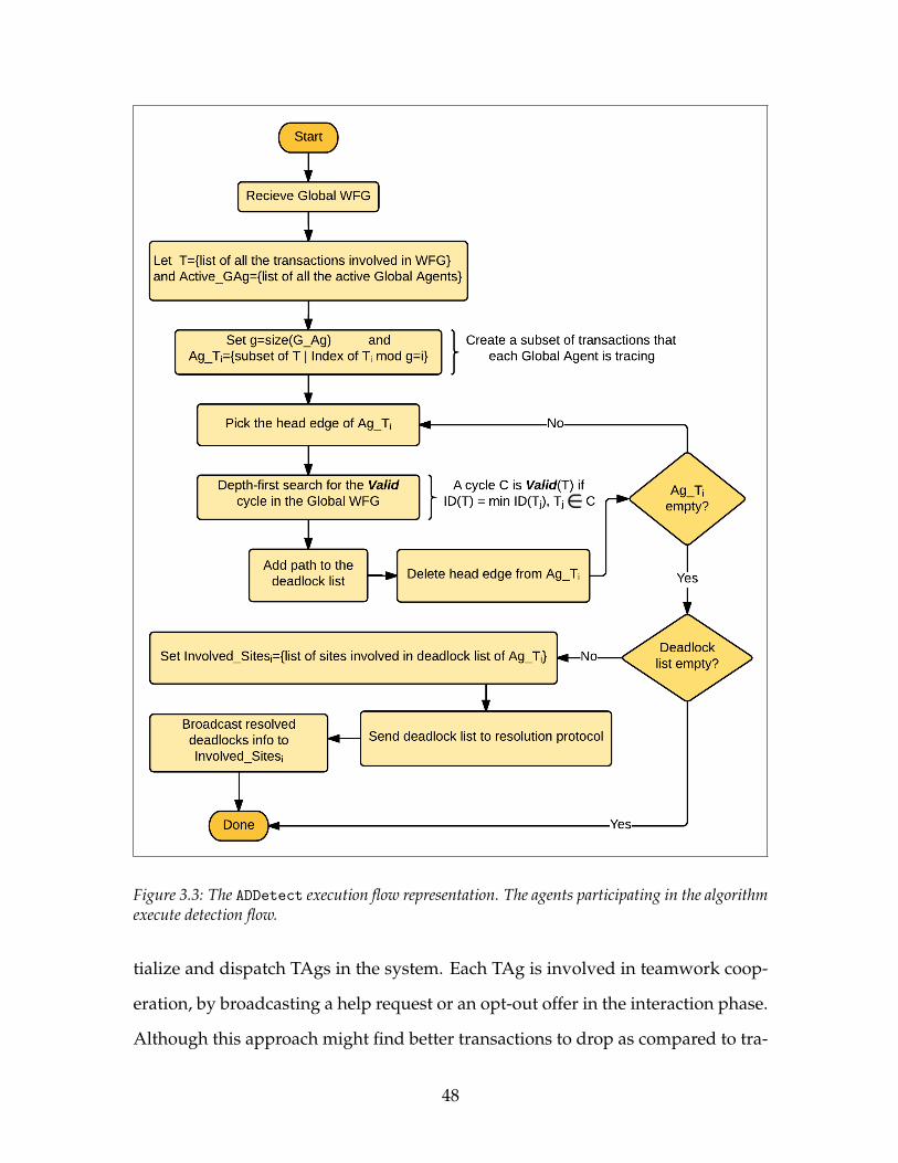
Figure 3.3: The ADDetect execution flow representation. The agents participating in the algorithmexecute detection flow.
tialize and dispatch TAgs in the system. Each TAg is involved in teamwork coop-
eration, by broadcasting a help request or an opt-out offer in the interaction phase.
Although this approach might find better transactions to drop as compared to tra-
48
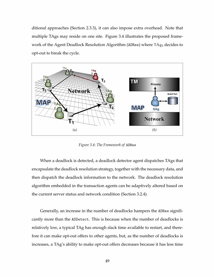
ditional approaches (Section 2.3.3), it can also impose extra overhead. Note that
multiple TAgs may reside on one site. Figure 3.4 illustrates the proposed frame-
work of the Agent Deadlock Resolution Algorithm (ADRes) where TAg3 decides to
opt-out to break the cycle.
(a) (b)
Figure 3.4: The Framework of ADRes
When a deadlock is detected, a deadlock detector agent dispatches TAgs that
encapsulate the deadlock resolution strategy, together with the necessary data, and
then dispatch the deadlock information to the network. The deadlock resolution
algorithm embedded in the transaction agents can be adaptively altered based on
the current server status and network condition (Section 3.2.4).
Generally, an increase in the number of deadlocks hampers the ADRes signifi-
cantly more than the ADDetect. This is because when the number of deadlocks is
relatively low, a typical TAg has enough slack time available to restart, and there-
fore it can make opt-out offers to other agents, but, as the number of deadlocks is
increases, a TAg’s ability to make opt-out offers decreases because it has less time
49
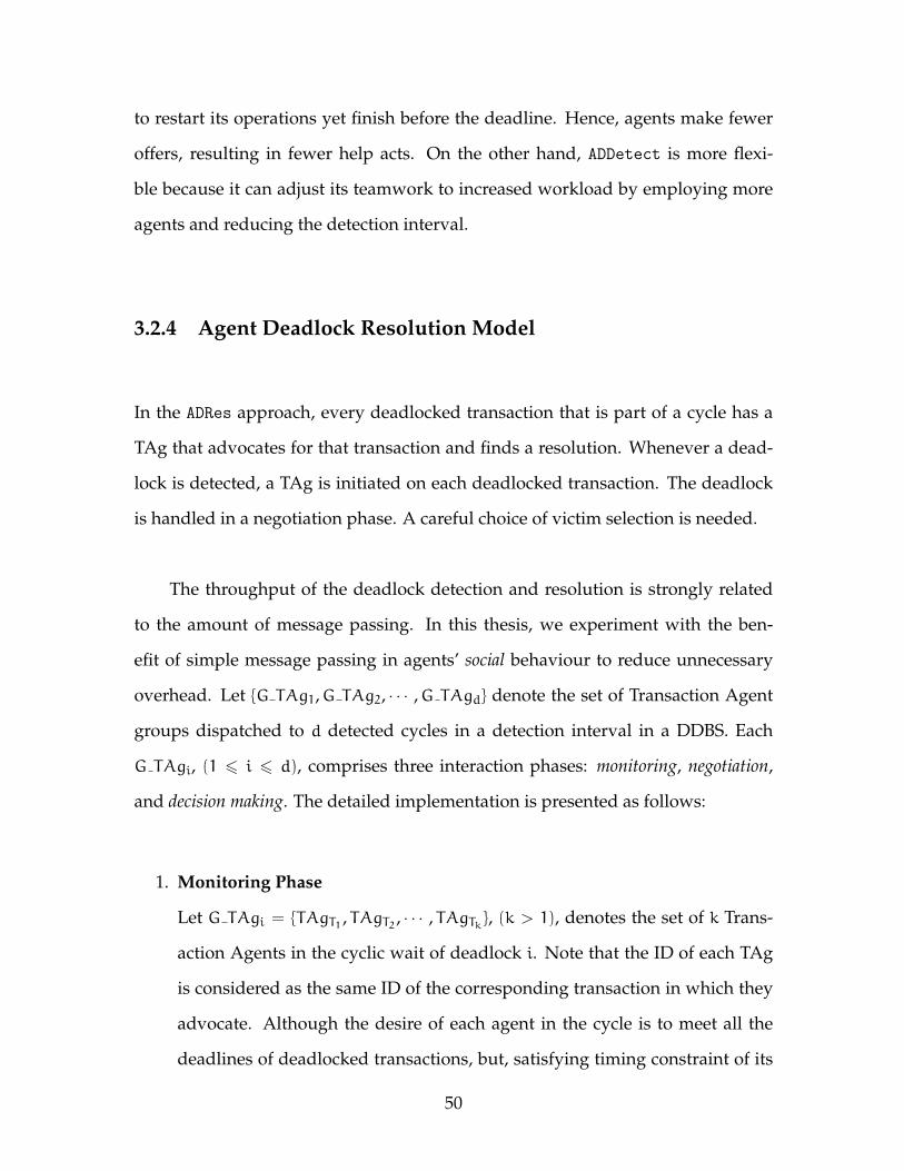
to restart its operations yet finish before the deadline. Hence, agents make fewer
offers, resulting in fewer help acts. On the other hand, ADDetect is more flexi-
ble because it can adjust its teamwork to increased workload by employing more
agents and reducing the detection interval.
3.2.4 Agent Deadlock Resolution Model
In the ADRes approach, every deadlocked transaction that is part of a cycle has a
TAg that advocates for that transaction and finds a resolution. Whenever a dead-
lock is detected, a TAg is initiated on each deadlocked transaction. The deadlock
is handled in a negotiation phase. A careful choice of victim selection is needed.
The throughput of the deadlock detection and resolution is strongly related
to the amount of message passing. In this thesis, we experiment with the ben-
efit of simple message passing in agents’ social behaviour to reduce unnecessary
overhead. Let {G TAg1,G TAg2, · · · ,G TAgd} denote the set of Transaction Agent
groups dispatched to d detected cycles in a detection interval in a DDBS. Each
G TAgi, (1 6 i 6 d), comprises three interaction phases: monitoring, negotiation,
and decision making. The detailed implementation is presented as follows:
1. Monitoring Phase
Let G TAgi = {TAgT1 , TAgT2 , · · · , TAgTk}, (k > 1), denotes the set of k Trans-
action Agents in the cyclic wait of deadlock i. Note that the ID of each TAg
is considered as the same ID of the corresponding transaction in which they
advocate. Although the desire of each agent in the cycle is to meet all the
deadlines of deadlocked transactions, but, satisfying timing constraint of its
50
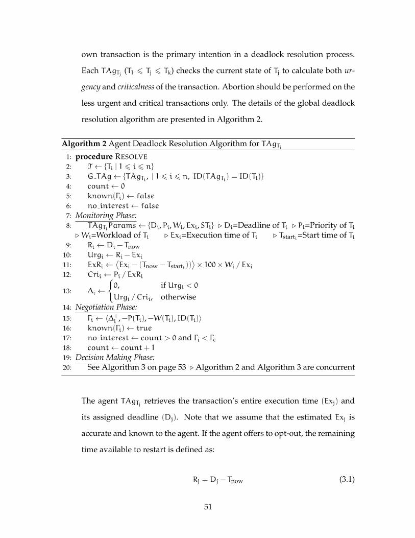
own transaction is the primary intention in a deadlock resolution process.
Each TAgTj (T1 6 Tj 6 Tk) checks the current state of Tj to calculate both ur-
gency and criticalness of the transaction. Abortion should be performed on the
less urgent and critical transactions only. The details of the global deadlock
resolution algorithm are presented in Algorithm 2.
Algorithm 2 Agent Deadlock Resolution Algorithm for TAgTi1: procedure RESOLVE2: T ← {Ti | 1 6 i 6 n}3: G TAg← {TAgTi , | 1 6 i 6 n, ID(TAgTi) = ID(Ti)}
4: count← 0
5: known(Γi)← false
6: no interest← false
7: Monitoring Phase:8: TAgTiParams← {Di,Pi,Wi,Exi,STi} . Di=Deadline of Ti . Pi=Priority of Ti
.Wi=Workload of Ti . Exi=Execution time of Ti . Tstarti=Start time of Ti9: Ri ← Di − Tnow
10: Urgi ← Ri − Exi11: ExRi ←
⟨Exi − (Tnow − Tstarti))
⟩× 100×Wi / Exi
12: Crii ← Pi / ExRi
13: ∆i ←
{0, if Urgi < 0Urgi / Crii, otherwise
14: Negotiation Phase:15: Γi ← 〈∆+
i ,−P(Ti),−W(Ti), ID(Ti)〉16: known(Γi)← true
17: no interest← count > 0 and Γi < Γc18: count← count+ 1
19: Decision Making Phase:20: See Algorithm 3 on page 53 . Algorithm 2 and Algorithm 3 are concurrent
The agent TAgTj retrieves the transaction’s entire execution time (Exj) and
its assigned deadline (Dj). Note that we assume that the estimated Exj is
accurate and known to the agent. If the agent offers to opt-out, the remaining
time available to restart is defined as:
Rj = Dj − Tnow (3.1)
51
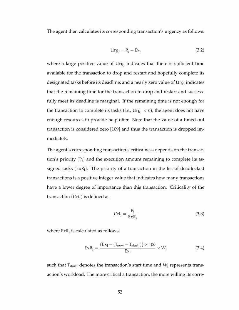
The agent then calculates its corresponding transaction’s urgency as follows:
Urgj = Rj − Exj (3.2)
where a large positive value of Urgj indicates that there is sufficient time
available for the transaction to drop and restart and hopefully complete its
designated tasks before its deadline; and a nearly zero value ofUrgj indicates
that the remaining time for the transaction to drop and restart and success-
fully meet its deadline is marginal. If the remaining time is not enough for
the transaction to complete its tasks (i.e., Urgj < 0), the agent does not have
enough resources to provide help offer. Note that the value of a timed-out
transaction is considered zero [109] and thus the transaction is dropped im-
mediately.
The agent’s corresponding transaction’s criticalness depends on the transac-
tion’s priority (Pj) and the execution amount remaining to complete its as-
signed tasks (ExRj). The priority of a transaction in the list of deadlocked
transactions is a positive integer value that indicates how many transactions
have a lower degree of importance than this transaction. Criticality of the
transaction (Crij) is defined as:
Crij =Pj
ExRj(3.3)
where ExRj is calculated as follows:
ExRj =
(Exj − (Tnow − Tstartj)
)× 100
Exj×Wj (3.4)
such that Tstartj denotes the transaction’s start time and Wj represents trans-
action’s workload. The more critical a transaction, the more willing its corre-
52
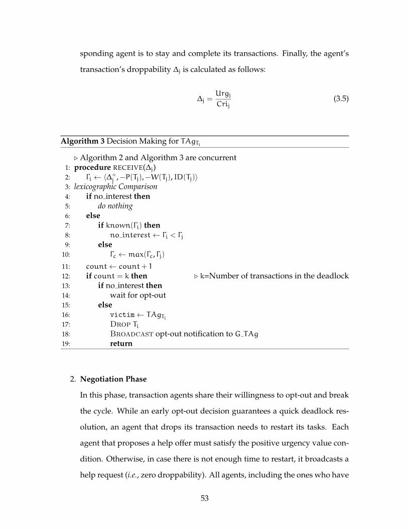
sponding agent is to stay and complete its transactions. Finally, the agent’s
transaction’s droppability ∆j is calculated as follows:
∆j =Urgj
Crij(3.5)
Algorithm 3 Decision Making for TAgTi
. Algorithm 2 and Algorithm 3 are concurrent1: procedure RECEIVE(∆j)2: Γi ← 〈∆+
j ,−P(Tj),−W(Tj), ID(Tj)〉3: lexicographic Comparison4: if no interest then5: do nothing6: else7: if known(Γi) then8: no interest← Γi < Γj9: else
10: Γc ← max(Γc, Γj)11: count← count+ 1
12: if count = k then . k=Number of transactions in the deadlock13: if no interest then14: wait for opt-out15: else16: victim← TAgTi17: Drop Ti18: Broadcast opt-out notification to G TAg
19: return
2. Negotiation Phase
In this phase, transaction agents share their willingness to opt-out and break
the cycle. While an early opt-out decision guarantees a quick deadlock res-
olution, an agent that drops its transaction needs to restart its tasks. Each
agent that proposes a help offer must satisfy the positive urgency value con-
dition. Otherwise, in case there is not enough time to restart, it broadcasts a
help request (i.e., zero droppability). All agents, including the ones who have
53
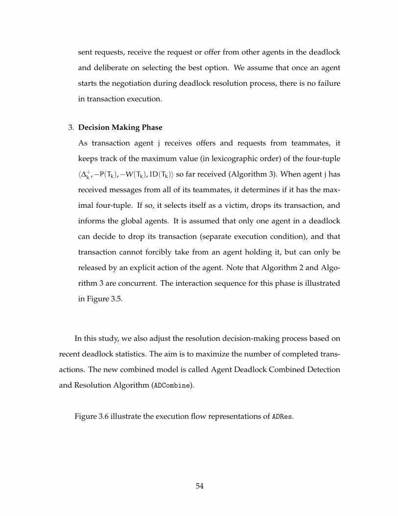
sent requests, receive the request or offer from other agents in the deadlock
and deliberate on selecting the best option. We assume that once an agent
starts the negotiation during deadlock resolution process, there is no failure
in transaction execution.
3. Decision Making Phase
As transaction agent j receives offers and requests from teammates, it
keeps track of the maximum value (in lexicographic order) of the four-tuple
〈∆+k ,−P(Tk),−W(Tk), ID(Tk)〉 so far received (Algorithm 3). When agent j has
received messages from all of its teammates, it determines if it has the max-
imal four-tuple. If so, it selects itself as a victim, drops its transaction, and
informs the global agents. It is assumed that only one agent in a deadlock
can decide to drop its transaction (separate execution condition), and that
transaction cannot forcibly take from an agent holding it, but can only be
released by an explicit action of the agent. Note that Algorithm 2 and Algo-
rithm 3 are concurrent. The interaction sequence for this phase is illustrated
in Figure 3.5.
In this study, we also adjust the resolution decision-making process based on
recent deadlock statistics. The aim is to maximize the number of completed trans-
actions. The new combined model is called Agent Deadlock Combined Detection
and Resolution Algorithm (ADCombine).
Figure 3.6 illustrate the execution flow representations of ADRes.
54
Figure 3.5: ADRes Decision Making Phase
3.2.5 ADCombine Algorithm
The new combined algorithm is expected to leverage the advantages of helpful
agents in both detection and resolution processes. For that purpose, we need an
analysis of their behaviour over the parameter space. In this development, we
analyze the overhead incurred by the ADCombine.
In designing the combined algorithm, we seek to reduce the deadlock han-
dling overhead, particularly in message passing. One might envision different
possible combination improvements of the detector and resolver agents. One pos-
sible combined algorithm is to allow an agent to detect and resolve cycles at the
same time, possibly in a combined mechanism; however, such a design increases
55
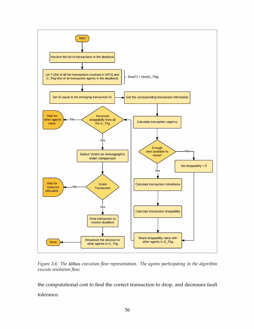
Figure 3.6: The ADRes execution flow representation. The agents participating in the algorithmexecute resolution flow.
the computational cost to find the correct transaction to drop, and decreases fault
tolerance.
56

Table 3.1: Message Complexity Comparison of Algorithms
Algorithm Delay* Number ofMessages Message Size
Chandy et.al [21] O(n) k× (n−1)2 O(1)
Obermarck [109] O(n) n× (n−1)2 O(n)
MAEDD [17] O(n2) n× (m+ 1) O(n)
ADDetect O(n) n× (m+1)2 O(k)
n = the number of sitesk = the number of waiting transactionsm = the number of agents involved in the deadlock detection* = Delay is the worst-case time complexity [120]
A design in which the interaction phase is simplified allows agents to reduce
overhead. When the overhead is low, the transaction wait time decreases. An al-
ternative design, in which the message complexity is simplified, is to let the agents
first determine the transactions involved in a deadlock cycle, and then deliberate
on resolving. This approach avoids unnecessary message passing; we adopt it as
the basis for our combined algorithm.
The ADCombine utilizes a pair structure to communicate the WFG between
agents, which represents the ID of each edge in the WFG, particularly in dead-
lock detection. Table 3.1 compares the complexity of different deadlock detection
algorithms for distributed deadlocks in the DRTDBS [78]. As shown in this table,
the complexity of the ADDetectis close to or better than the existing algorithms in
the worst case scenario. Details are provided in Appendix A.3.
The experiment setup, results, and interpretations are provided in Chapter 5.
57
Chapter 4
System Model and Simulator
Architecture
This chapter presents the methodology deployed in this research. The first sec-
tion describes the design and architecture of the distributed real-time transaction
processing simulator, which is considered as the research tool to analyze deadlock
handling algorithms in a Distributed Real-Time Database System (DRTDBS). The
second section provides the performance analysis as well as the considerations re-
quired in the design of the agent based algorithms to handle distributed deadlocks
in a real-time environment.
58
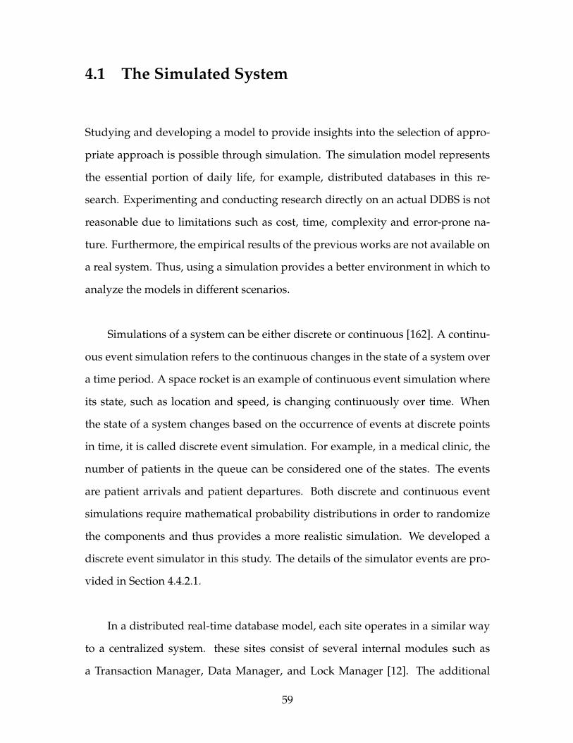
4.1 The Simulated System
Studying and developing a model to provide insights into the selection of appro-
priate approach is possible through simulation. The simulation model represents
the essential portion of daily life, for example, distributed databases in this re-
search. Experimenting and conducting research directly on an actual DDBS is not
reasonable due to limitations such as cost, time, complexity and error-prone na-
ture. Furthermore, the empirical results of the previous works are not available on
a real system. Thus, using a simulation provides a better environment in which to
analyze the models in different scenarios.
Simulations of a system can be either discrete or continuous [162]. A continu-
ous event simulation refers to the continuous changes in the state of a system over
a time period. A space rocket is an example of continuous event simulation where
its state, such as location and speed, is changing continuously over time. When
the state of a system changes based on the occurrence of events at discrete points
in time, it is called discrete event simulation. For example, in a medical clinic, the
number of patients in the queue can be considered one of the states. The events
are patient arrivals and patient departures. Both discrete and continuous event
simulations require mathematical probability distributions in order to randomize
the components and thus provides a more realistic simulation. We developed a
discrete event simulator in this study. The details of the simulator events are pro-
vided in Section 4.4.2.1.
In a distributed real-time database model, each site operates in a similar way
to a centralized system. these sites consist of several internal modules such as
a Transaction Manager, Data Manager, and Lock Manager [12]. The additional
59

module, Transaction Generator, presented in Section 4.4.2.2. In the following sec-
tions, the details of each internal module are discussed. Figure 4.1 represents the
high-level view of these modules.
Figure 4.1: Internal and External Modules of a Database System
4.1.1 Transaction Manager
In a transaction processing environment, the Transaction Manager (TM) is the
core component [5]. The Transaction Manager is a component that manages the
concurrent execution of transactions by employing a Concurrency Control Proto-
col (CCP). The serialization of transaction execution is ensured by the TM. When
the TM accepts a transaction operation from the Transaction Generator, it performs
one of the following based on the order of each transaction execution:
Executes the operation by passing it to the Data Manager (DM) and receives the
results consequently. The results are then committed to the Data Manager by
60

the Transaction Manager.
Delays the operation by holding the transaction in a queue within the Transaction
Manager, and it will be processed with either execution or rejection at a later
time.
The TM in a DDBS is responsible for database consistency. Furthermore, in a
real-time environment it must also consider the time constraint on transactions as
well [23]. The TM sequence diagram of our simulator is illustrated in Figure 4.2.
4.1.2 Data Manager
The DM at each site receives transactions’ operations from the TM once the or-
der of execution is determined. Typically, in a database system, the pages of data
are permanently stored in stable storage [83]. When a transaction requests access
a page, the DM to locates the page in stable storage to make it available for that
transaction. Transactions’ operations are then processed by using one of the read,
write, commit, or abort actions in the DM. When a transaction is performing a read
and write operation, the TM submits disk jobs to DM to perform the operation
against the database. However, when a transaction commits or aborts, an update
or rollback action is performed respectively by the DM using CCP to guarantee the
consistency of the database (Section 2.1.4).
61

Figure 4.2: Transaction Manager Sequence
4.1.3 Lock Manager
In a DRTDBS, every transaction entering the system has some associated proper-
ties such as arrival time, deadline, priority, and so on [8]. A Lock Manager is a com-
ponent responsible for ensuring isolation between concurrent transactions. The
Lock Manager maintains at most one exclusive lock or a finite number of shared
locks on each page at any given time. Whenever a lock request for a page is re-
62
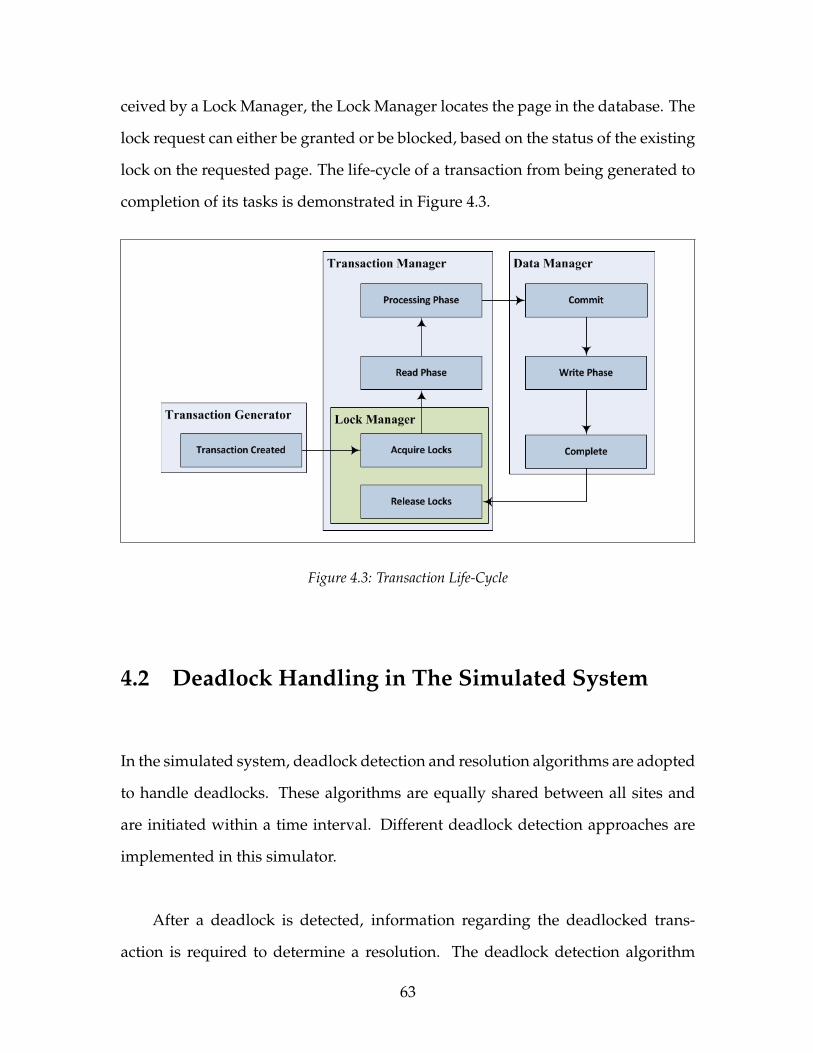
ceived by a Lock Manager, the Lock Manager locates the page in the database. The
lock request can either be granted or be blocked, based on the status of the existing
lock on the requested page. The life-cycle of a transaction from being generated to
completion of its tasks is demonstrated in Figure 4.3.
Figure 4.3: Transaction Life-Cycle
4.2 Deadlock Handling in The Simulated System
In the simulated system, deadlock detection and resolution algorithms are adopted
to handle deadlocks. These algorithms are equally shared between all sites and
are initiated within a time interval. Different deadlock detection approaches are
implemented in this simulator.
After a deadlock is detected, information regarding the deadlocked trans-
action is required to determine a resolution. The deadlock detection algorithm
63

generates a list of transactions that are involved in the deadlock and passes it to
the deadlock resolution algorithm. The deadlock resolution algorithm then deter-
mines which transaction to abort to resolve the deadlock. The deadlock resolution
algorithms implemented in this simulator are as follows:
First Deadlock Resolution: The transaction that appears at the top of the dead-
lock list is selected as the victim transaction to abort. This algorithm is also
known as random selection.
Priority Deadlock Resolution: The transaction with the lowest priority in the dead-
lock list is selected as the victim transaction to abort.
Agent Deadlock Resolution Algorithm: The transaction with the lowest droppa-
bility in the deadlock list is selected as the victim transaction to abort (ex-
plained in Section 3.2.3).
4.3 The Simulated System in This Study
In a distributed database model, databases are scattered across physical locations
called sites. Each distributed database is modeled as a collection of pages that
are uniformly distributed across all the sites. Each page is replicated once, and
that each server has a contiguous range of pages, and that the page numbers used
by transactions are uniformly randomly generated. Sites are connected through
a network. The details of the network architecture and node configurations are
provided in the following.
64
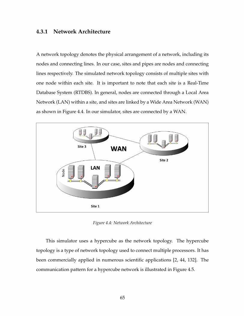
4.3.1 Network Architecture
A network topology denotes the physical arrangement of a network, including its
nodes and connecting lines. In our case, sites and pipes are nodes and connecting
lines respectively. The simulated network topology consists of multiple sites with
one node within each site. It is important to note that each site is a Real-Time
Database System (RTDBS). In general, nodes are connected through a Local Area
Network (LAN) within a site, and sites are linked by a Wide Area Network (WAN)
as shown in Figure 4.4. In our simulator, sites are connected by a WAN.
Figure 4.4: Network Architecture
This simulator uses a hypercube as the network topology. The hypercube
topology is a type of network topology used to connect multiple processors. It has
been commercially applied in numerous scientific applications [2, 44, 132]. The
communication pattern for a hypercube network is illustrated in Figure 4.5.
65
Figure 4.5: Communication Pattern for A Hypercube
Each of these network connections is a pipe that denotes a bi-directional con-
nection between one site and another. A router at each site is responsible for all the
network connections between itself and other sites. Additionally, each network
node stores its own routing table that consists of all the possible destination nodes.
A message might need to travel through multiple intermediate sites to reach its
final destination.
Each message may be a complex data structure. In the course of a simulation
run, messages are scheduled to occur, or they may be exchanged or even canceled.
A message holds two attributes: A source node which is the site from which a
message initiates, and the site to which a message should arrive at known as the
destination. Every network connection contains the following parameters:
• Bandwidth is the maximum number of message units that can be carried from
one point to another in each tick. The number of events carried by a message
is message unit.
• Latency is the amount of time taken by a message to travel from its source to
66

the desired destination server through a network connection.
4.3.2 Node Architecture and Configuration
A node within the simulator is characterized by many components such as proces-
sor, disk, and local transaction generator. These components are described in the
following paragraphs.
The processor organizes and controls all processes in a node. A node is equipped
with one processor, and a processor can deal with at most one data item at a time.
The processors are characterized by one parameter, Processing time, which is the
amount of time taken by a processor to process one page.
The disk is responsible for organizing and managing all the pages in a node.
Disks are non-volatile storage devices in which a specified set of pages is stored. A
disk is capable of performing only a one-page read and write operation at a time.
Pages can be replicated in multiple nodes. However, pages that are replicated
across multiple nodes require extra configuration on CCP. The disks have two pa-
rameters: Access time which is the amount of time taken by a disk to read from or
write to a page, and the number of pages that are stored on each disk known as
page range.
The final component of the node is the local transaction generator which is
responsible for creating transactions to be submitted at that node. The properties of
transactions are defined in the transaction generator’s attributes which are defined
as follows:
67
• Size is the total number of transactions to be created during a simulation run.
• Arrival Interval defines the mean inter-arrival time between the two transac-
tions arriving at a node.
• Slack Time represents the extra time allocated to a transaction to complete its
operations and still meets its deadline.
• Work Size is the maximum number of accessible pages for a transaction dur-
ing its execution.
• Update Percent defines the probability of a page being written to or updated
by a transaction as a function of the total number of pages access.
Node architecture is partly described by the components listed above. How-
ever, the basis of transaction processing in a node requires additional characteris-
tics. The system employs the use of a transaction timeout attribute. In the latter case,
the system employs a timer that is activated upon initiation of each transaction and
when the timer expires the transaction is aborted. Maximum active transactions is
another node attribute which is the highest number of transactions that are al-
lowed to run concurrently on a node. In the case of exceeding that limit, the newly
arriving transactions are held in the transaction wait queue.
When a transaction is waiting in a queue, a priority protocol determines which
transaction within a priority queue should be processed next. In this simulator,
a priority protocol controls the behaviour of all of the priority queues within a
node, including the transaction queue. Prioritizing protocols implemented in the
simulator are:
Earliest Deadline First: The priority of a transaction is determined according to
the deadline. The transaction with the earliest deadline is considered as the
68
highest priority transaction in order to meet its deadline.
First Come First Serve: The priority of a transaction is assigned based on the or-
der of its arrival and is served in a First-In-First-Out (FIFO) queue.
Least Slack Time First: The priority of a transaction is allocated based on the trans-
action’s total amount of time provided as a slack time to complete. The short-
est slack time gets the highest priority.
Random Priority: The priority of a transaction is allocated randomly.
CCPs are used to guarantee the isolation property of transactions for both
committed and aborted transactions [12]. Each transaction’s request for a lock on
a page is handled through these protocols. A shared lock on a page is granted
to transactions requesting reading access, and an exclusive lock is given to trans-
actions requesting write operation on a page. Furthermore, locking algorithms
based on data access patterns of operations can be classified into static or dynamic
locking [101]. In static locking algorithms, a transaction requests locks on all the
pages that will be required during the transaction’s lifetime, before the initiation
of its execution. Locks will be released when the transaction is completed or ter-
minated. One of the most well-known static locking algorithms is greedy locking
[163] which supports the locks on replicated pages across nodes as well. However,
in dynamic locking algorithms, a transaction will request for access to data items
as the need arises [8]. In general, dynamic locking algorithms proved to perform
better than static locking algorithms [8, 63, 150]. In this research, we use Dynamic
Two-Phase Locking (D2PL) [60] as our Concurrency Control Protocol. In this proto-
col, a transaction requires a page to be locked before it starts processing that page.
69

4.4 The Simulator
This section describes the adopted DRTDBS model followed by the design and
architecture of the distributed real-time transaction processing simulator.
4.4.1 Distributed Real-Time Database System Model
In this research, we used the simulation model for DRTDBS, proposed by Ulu-
soy and Belford [153]. The model can be used in evaluating various components
of transaction scheduling algorithms, including deadlock detection and resolution
algorithms. The model supports modeling the relevant performance behaviour of
each component. Therefore, the users can study the system under diverse real-
time database environments to get insights about different approaches. Two per-
formance metrics used in the evaluations are the percentage of transactions com-
pleted on time, success ratio, and the average of incurred overhead [153].
The adopted model simulates the characteristics of a Distributed Database
System (DDBS) in which transactions are associated with timing constraints. Let
{S1,S2, · · · ,Sn} denote the set of n sites in our DDBS. We experiment with eight
sites, and it is assumed that the database at each site has the same size. The
replicated data distribution structure denotes that the site Sk contains data item
D, which can have 0 to n − 1 remote copies at the other sites (explained in Sec-
tion 2.1.1). Let N(D) indicate the number of replicas of D, including the original.
We assume a double replication of each page in the simulated system.
70

Each distributed database is modeled as a collection of pages that are uni-
formly distributed across all the sites. The transactions’ consistency in the dis-
tributed system is guaranteed using the “read-one, write-all” approach. If a local
copy of the data exists on the originating site, the read operation can be performed;
otherwise, any remote copy of the data is accessed with uniform probability. How-
ever, writing on a data requires all the copies of the data to perform a “write-all”
operation.
The performance models of RTDBS are not sufficiently developed to evaluate
real-time capabilities of the system [152]. The database community has developed
several benchmarks, TPC-B [28] and TPC-C [29],to evaluate the performance of tra-
ditional transaction processing databases. However, the benchmarks for real-time
systems such as [90] are focused too much on disk performance. Additionally, the
existing benchmarks do not consider adequate properties of database transaction
management. Therefore, developing performance model and benchmarks to eval-
uate real-time functions are needed for DRTDBS.
The number of transactions that arrive in a time interval have an Exponential
distribution [135]. Each transaction has an associated firm time constraint in the
form of a deadline. Each transaction is executed to complete its assigned tasks,
even if it misses its deadline. The deadline (an instant in time) is computed using
the following formula:
Tdeadline = Tarrival + Tprocess + Tslack (4.1)
The processing time (Tslack) is the total time that the transaction requires for its ex-
ecution. The slack factor is a constant that provides control over the slackness of
71
the transaction deadlines. In this model, each transaction supports the single mas-
ter, multiple cohorts structure. The cohorts are dynamically created as needed. At
each site, there can be at most one operating cohort of a transaction. For each exe-
cuted transaction, the TM is responsible for identifying which server stores copies
of data used by transaction. The data item is referenced by the transaction using
the global data dictionary available at each site. Then the cohort(s) of the trans-
action at the relevant sites are activated to perform the operation on one or more
data items. However, the master transaction does not perform any database oper-
ations before the coordination of cohort transactions. The atomic commitment of
each transaction is provided by the Two-Phase Commit (2PC) protocol (explained
in Section 2.1.6) [55].
The DM is responsible for providing IO and CPU services for reading and
writing data and processing data respectively. Each server is assumed to have
one CPU and one disk. A summary of the simulation configuration and workload
parameters is listed in Table 4.1. Also, Table 4.2 determines the default values of
the system transactions parameters used in the simulation experiment. All sites
of the system are assumed to be running under identical simulation configuration.
We used a fixed value for IO and CPU services. The detailed calculation of IO and
CPU consumption formulated in Appendix A.1 and Appendix A.2.
4.4.2 Additional Modules
The discrete event simulator was developed to experiment with deadlock handling
in a distributed real-time transaction-based database system. It provides various
parameters for the user to configure the system for different scenarios. Various
72
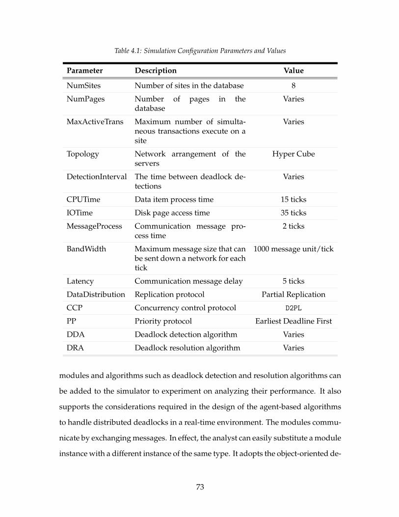
Table 4.1: Simulation Configuration Parameters and Values
Parameter Description Value
NumSites Number of sites in the database 8
NumPages Number of pages in thedatabase
Varies
MaxActiveTrans Maximum number of simulta-neous transactions execute on asite
Varies
Topology Network arrangement of theservers
Hyper Cube
DetectionInterval The time between deadlock de-tections
Varies
CPUTime Data item process time 15 ticks
IOTime Disk page access time 35 ticks
MessageProcess Communication message pro-cess time
2 ticks
BandWidth Maximum message size that canbe sent down a network for eachtick
1000 message unit/tick
Latency Communication message delay 5 ticks
DataDistribution Replication protocol Partial Replication
CCP Concurrency control protocol D2PL
PP Priority protocol Earliest Deadline First
DDA Deadlock detection algorithm Varies
DRA Deadlock resolution algorithm Varies
modules and algorithms such as deadlock detection and resolution algorithms can
be added to the simulator to experiment on analyzing their performance. It also
supports the considerations required in the design of the agent-based algorithms
to handle distributed deadlocks in a real-time environment. The modules commu-
nicate by exchanging messages. In effect, the analyst can easily substitute a module
instance with a different instance of the same type. It adopts the object-oriented de-
73
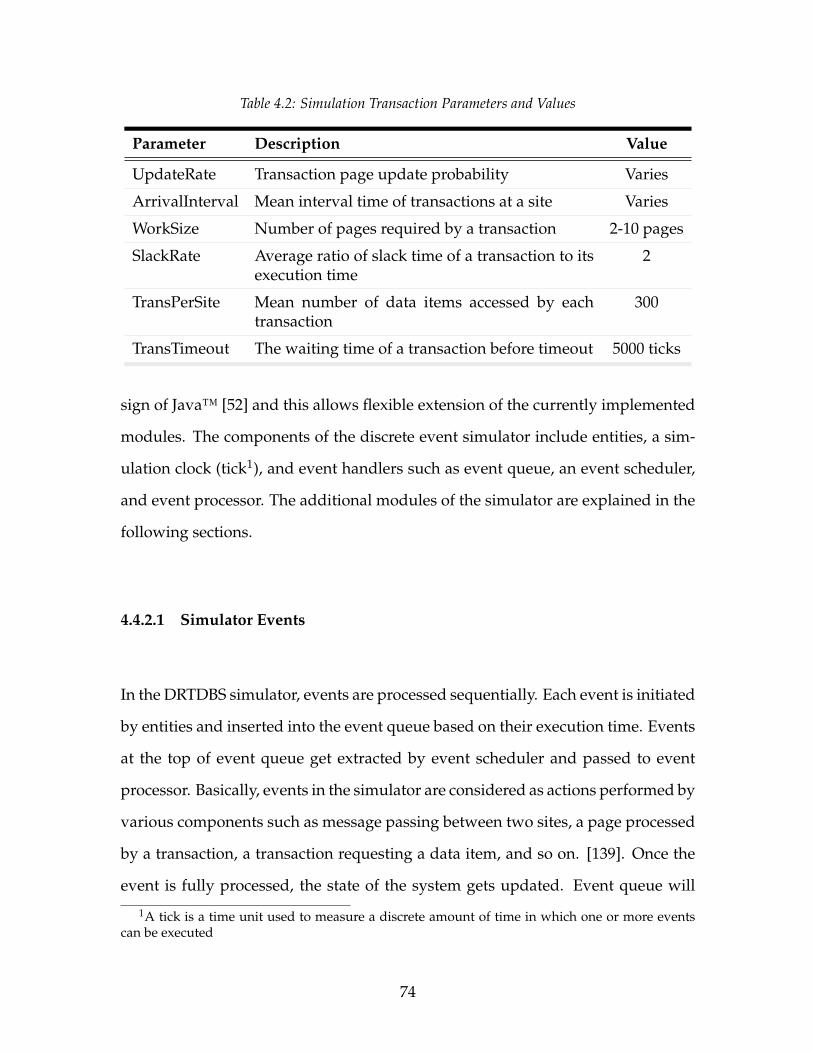
Table 4.2: Simulation Transaction Parameters and Values
Parameter Description Value
UpdateRate Transaction page update probability Varies
ArrivalInterval Mean interval time of transactions at a site Varies
WorkSize Number of pages required by a transaction 2-10 pages
SlackRate Average ratio of slack time of a transaction to itsexecution time
2
TransPerSite Mean number of data items accessed by eachtransaction
300
TransTimeout The waiting time of a transaction before timeout 5000 ticks
sign of Java™ [52] and this allows flexible extension of the currently implemented
modules. The components of the discrete event simulator include entities, a sim-
ulation clock (tick1), and event handlers such as event queue, an event scheduler,
and event processor. The additional modules of the simulator are explained in the
following sections.
4.4.2.1 Simulator Events
In the DRTDBS simulator, events are processed sequentially. Each event is initiated
by entities and inserted into the event queue based on their execution time. Events
at the top of event queue get extracted by event scheduler and passed to event
processor. Basically, events in the simulator are considered as actions performed by
various components such as message passing between two sites, a page processed
by a transaction, a transaction requesting a data item, and so on. [139]. Once the
event is fully processed, the state of the system gets updated. Event queue will
1A tick is a time unit used to measure a discrete amount of time in which one or more eventscan be executed
74
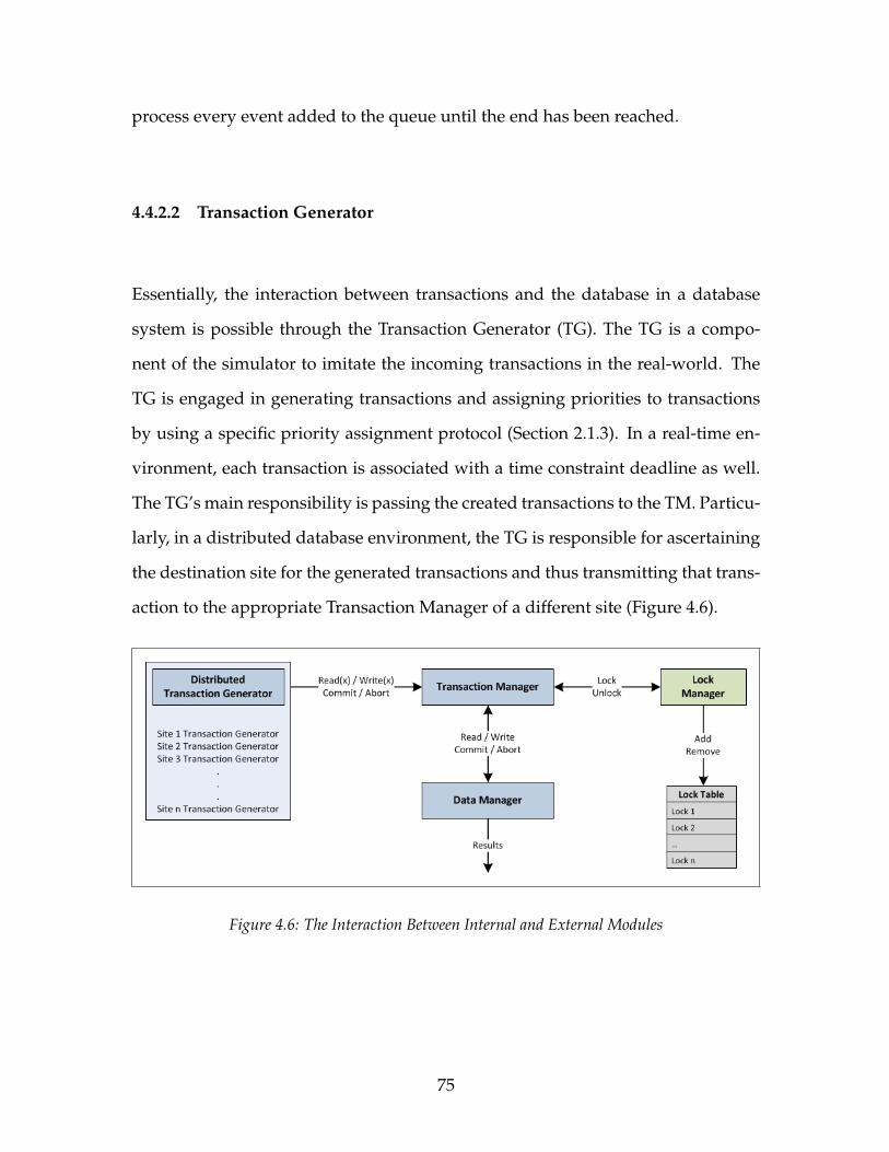
process every event added to the queue until the end has been reached.
4.4.2.2 Transaction Generator
Essentially, the interaction between transactions and the database in a database
system is possible through the Transaction Generator (TG). The TG is a compo-
nent of the simulator to imitate the incoming transactions in the real-world. The
TG is engaged in generating transactions and assigning priorities to transactions
by using a specific priority assignment protocol (Section 2.1.3). In a real-time en-
vironment, each transaction is associated with a time constraint deadline as well.
The TG’s main responsibility is passing the created transactions to the TM. Particu-
larly, in a distributed database environment, the TG is responsible for ascertaining
the destination site for the generated transactions and thus transmitting that trans-
action to the appropriate Transaction Manager of a different site (Figure 4.6).
Figure 4.6: The Interaction Between Internal and External Modules
75
4.4.3 Simplifications
This section describes the changes made to the simulated system to simplify the
simulator:
• To model agent interaction protocols without explicit synchronization de-
tails, it is assumed that both Site Agent (SAg) and Global Agent (GAg) per-
form actions synchronously in each detection interval.
• From the way Multi Agent System (MAS) modeled, we presumed that agents
communicate only at the start of each detection interval, in a sequence of
asynchronous phases.
• During the agent’s negotiations, we assume that there is no failure in the
transaction execution.
• The transactions global information is assumed to be known to each agent.
• The network connection is assumed to be reliable having the following char-
acteristics:
– No message is lost in the system.
– Each message is delivered within a finite amount of time.
– The network does not get partitioned2.
2A network partition of a system refers to the failure of a network connection that causes anetwork to be split into multiple sub-systems.
76

4.4.4 Simulation Set-up
The adopted simulator implements appropriate abstractions which allows one to
reuse existing functionality for the development of new algorithms and operate
with already implemented ones. Moreover, there is the possibility for a user to
alter the basic implementation of transactions with a different perception of serial-
izability such as nested transactions or advanced transaction models [39, 46, 51].
The probabilistic consumed-time model is implemented in the simulator in
order to imitate a more realistic model of time consumption for CPU and IO when
processing a transaction in the DDBS. Expected CPU and IO utilizations are mod-
eled as system parameters, allowing users to study resource utilization under vary-
ing scenarios. The details are formulated in Appendix A.
4.4.5 Architecture Considerations
In designing and developing the simulator architecture, we have also considered
the possibility of modeling complex protocols. We used Java™ [52] as our base im-
plementation language due to its object-oriented design and for its flexible cross-
platform environment. All the developed protocols within the simulator adopt
a common fundamental framework. This framework provides the groundwork
for implementing modular algorithms such as the deadlock detection algorithms,
deadlock detection algorithms, and priority assignment protocols. Each deadlock
detection algorithm and deadlock resolution algorithm are pluggable components
of a server. Exploiting hierarchical class structure provides several categories of
77
deadlock detection and resolution algorithm. These categories include a deadlock
detection algorithm baseline; deadlock detection algorithms which inherit from
the baseline algorithms and use Wait-For-Graph (WFG) for deadlock detection;
and agent-based deadlock detection algorithms which inherit from WFG proto-
cols. Simulation categories in deadlock resolution algorithms consist of dead-
lock resolution algorithm baseline and agent-based deadlock resolution algorithms
which inherit from deadlock resolution algorithm baseline. The simulator consists
of over ten thousand lines of code and eleven libraries for different components
and protocols. The simulation UML diagram is presented in Figure 4.7. More de-
tailed diagrams are presented in Appendix A.4.
One of the key components in our design consideration was an efficient event
handling model capable of conducting millions of events in a simulation run. A
discrete event model is adopted due to the behaviour of transaction processing
system [111]. A priority queue is used to manage the events in the simulation.
The events are added to the queue with their simulation time used as the priority.
Note that each event is added to the queue with its simulation time. The execution
of the simulation proceeds by repeatedly pulling from the top of the queue and
executing the event thereon. A new event is created using the following method:
78
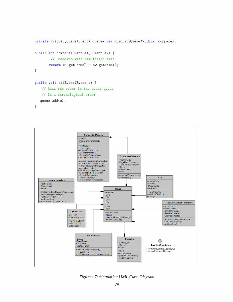
private PriorityQueue<Event> queue= new PriorityQueue<>(this::compare);
public int compare(Event e1, Event e2) {
// Compares with simulation time
return e1.getTime() - e2.getTime();
}
public void addEvent(Event e) {
// Adds the event in the event queue
// In a chronological order
queue.add(e);
}
Figure 4.7: Simulation UML Class Diagram
79
The newly created event object holds the name of the runnable job within the
object and is stored in the global event queue. The event is processed through the
event queue with the following methods:
Runnable job = e.getJob(); // Get the name of the runnable job in the
object
job.run(); // Invoke the execution
The statistics class is developed to analyze the performance of the algorithm
and keep track of the key events. The statistics accumulate the information regard-
ing the transactions executed time and whether the deadline is met. Moreover,
it collects the deadlock handling data, including the number of cycles found and
resolved by the deadlock detection and deadlock resolution algorithm. The gath-
ered information is represented by graphs that are displayed in real-time within
the running simulation (Figure 4.8). The ability to track the generated WFGs while
the simulation is executing is also available.
The method for collecting a completed transaction information is:
Statistics stats = new Statistics();
private void complete(Transaction t) {
LockManager lm = server.getLM();
t.getReadPageNums().forEach(pageNum -> lm.releaseLocks(t.getID(), pageNum,
t.getDeadline()));
t.getWritePageNums().forEach(pageNum -> lm.releaseLocks(t.getID(),
pageNum, t.getDeadline()));
int time = getTime();
boolean completedOnTime = t.getDeadline() >= time;
80

Figure 4.8: A detected deadlock with the corresponding information. Each square represents atransaction in the cyclic wait. In this example, the transaction #473 is selected as the victim
// Set the transaction status as completed
t.setCompleted(true);
// Log the completed time
t.setCompletedTime(time);
if (!(t instanceof CohortTransaction)) {
// If completed its tasks before its assigned deadline
// Then add it to transactions completed on-time list
if (completedOnTime)
stats.addCompletedOnTime(t.getID());
// Else add it to transactions completed late list
else
stats.addCompletedLate(t.getID());
}
// Add to the list of completed transactions and remove from active
transactions list
completedTransactions.add(t);
activeTransactions.remove(t);
81

// Integrity Check
lm.getWaitingLocks().values().forEach(locksLists -> {
locksLists.forEach(lock -> {
if (lock.getTransID() == t.getID())
throw new Exception(serverID + ": Transaction " +
t.getID() + " just completed but it has waiting
locks still! (Page " + lock.getPageNum() + ")");
});
});
lm.getHeldLocks().values().forEach(locksLists -> {
locksLists.forEach(lock -> {
if (lock.getTransID() == t.getID())
throw new Exception(serverID + ": Transaction " +
t.getID() + " just completed but it has held
locks still! (Page " + lock.getPageNum() + ")");
});
});
}
The primary performance metric of the experiments is the ratio of completed
transactions before their deadline expires to the total number of input transactions
known as Percentage Completed On Time (PCOT). The study analyzes the perfor-
mance of the deadlock detection and resolution algorithms under different work-
loads by changing the arrival interval of the transaction, the number of pages avail-
able for each site, the update ratio of the transactions, and so on. Furthermore,
transactions in a DDBS have to acquire the needed data from different nodes that
geographically span in a distributed area in order to complete the required pro-
cess. Thus, the communication overhead can have a significant effect on the system
throughput [24]. To test a more realistic situation, network communication over-
head was considered the second performance metric. Note that the overhead has
different interpretations in a different context. However, a combination of message
82
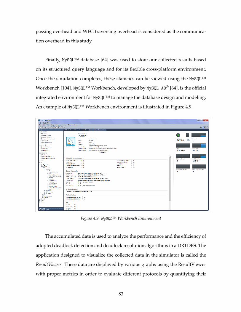
passing overhead and WFG traversing overhead is considered as the communica-
tion overhead in this study.
Finally, MySQL™ database [64] was used to store our collected results based
on its structured query language and for its flexible cross-platform environment.
Once the simulation completes, these statistics can be viewed using the MySQL™
Workbench [104]. MySQL™ Workbench, developed by MySQL AB® [64], is the official
integrated environment for MySQL™ to manage the database design and modeling.
An example of MySQL™ Workbench environment is illustrated in Figure 4.9.
Figure 4.9: MySQL™ Workbench Environment
The accumulated data is used to analyze the performance and the efficiency of
adopted deadlock detection and deadlock resolution algorithms in a DRTDBS. The
application designed to visualize the collected data in the simulator is called the
ResultViewer. These data are displayed by various graphs using the ResultViewer
with proper metrics in order to evaluate different protocols by quantifying their
83

collective effects in a meaningful manner.
84
Chapter 5
Experimental Results and Evaluation
This chapter presents the performance results for using agent teams that employ
our new deadlock detection and resolution algorithms, in comparison with two
previously existing algorithms. We provide simulation results for three distributed
deadlock detection and resolution algorithms, using the model proposed by Ulu-
soy et al. [153]. The results reveal some of the most influential performance and
efficiency trade-offs to be taken into account when a distributed deadlock detec-
tion and resolution algorithm has to fulfill a given set of performance design goals.
5.1 Performance Comparisons
The following simulation experiments, the performance compare of: (a) Agent
Deadlock Detection Algorithm (ADDetect), (b) Mobile Agent Enabled Deadlock
Detection (MAEDD), (c) and Chandy et al. algorithms. The metric used is the per-
85

Table 5.1: Simulation Baseline Parameter Settings for Deadlock Detection Algorithm
Parameter Value
NumSites 8
NumPages 80
MaxActiveTrans 30
DetectionInterval 100 ticks
BandWidth 1000 message unit/tick
Latency 5 ticks
UpdateRate 100 %
ArrivateInterval 600 ticks
Topology Hyper Cube
PP Earliest Deadline First
Work-Size 2-10 pages
TransPerSite 300
DRP Priority Deadlock Resolution
centage of transactions completing on time (PCOT). The deadlock handling cost
(communication overhead) is used as the secondary metric. In the experiments,
the baseline parameters are selected as shown in Tables 5.1, and a selected pa-
rameter is varied to compare performance of the three algorithms over a range
of circumstances. The input range for each parameter is selected in a way that it
shows noticeable results.
The accumulated results are also considered with the previous simulated ex-
periments in the literature [17, 127, 165] to evaluate the simulator. Note that the
parameter values used in the following simulation experiments are approximately
equal to the parameter set in the existing simulated experiments.
86

5.1.1 Impact of Number of Pages
The number of pages depicts the number of data items available in the system.
Hosting more pages accessible for each transaction leads to less contention for a
particular page, which in turn fewer deadlocks occur. The range of the number of
pages varied from 40 to 280 pages (that is, 5 to 35 pages per site).
Figure 5.1: PCOT versus Number of Pages
Figure 5.1, shows the comparative PCOT for varying the number of pages
available in the system. Note that the transaction update rate is 100% that results in
high data contention. The relatively high value of transactions writes operation fa-
vor the stationary agent approach, ADDetect, when the number of pages is low. Al-
though, in a high number of pages ADDetect grows gradually but falls marginally
below MAEDD. One can note that each agent-based algorithm (ADDetect or MAEDD)
generally outperforms the Chandy algorithm, but note that Chandy achieves a
higher PCOT than MAEDD when there are a few pages available. However, Chandy
87
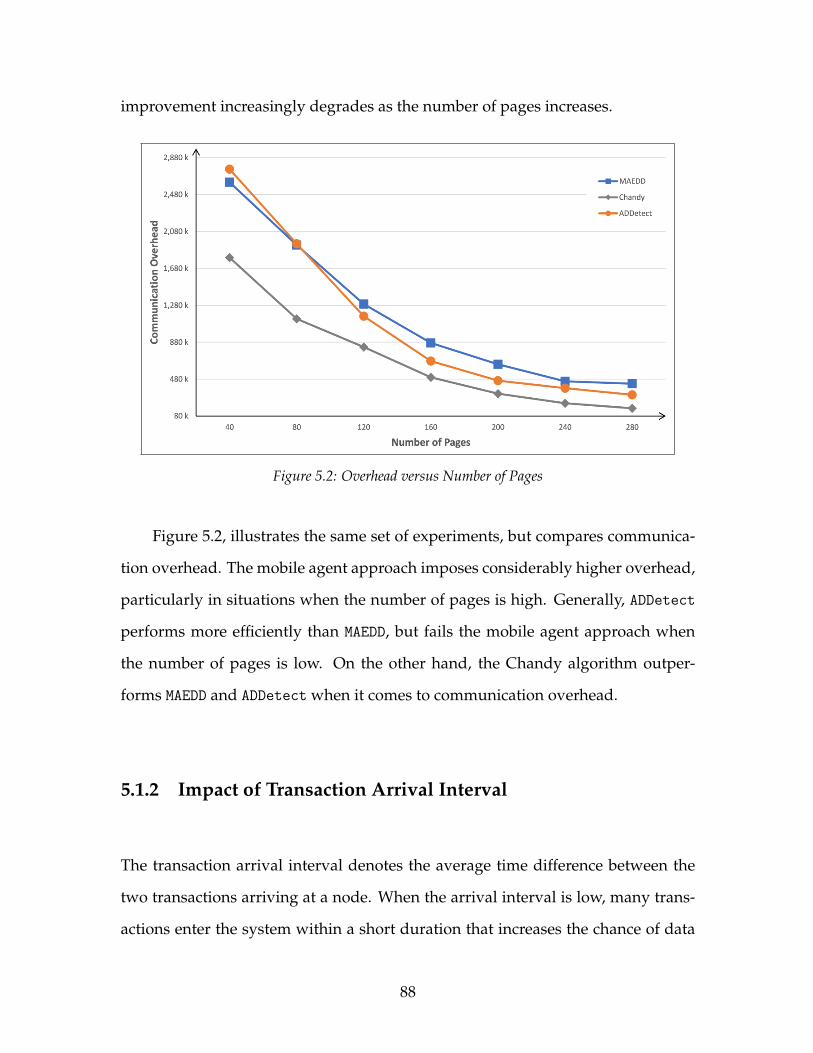
improvement increasingly degrades as the number of pages increases.
Figure 5.2: Overhead versus Number of Pages
Figure 5.2, illustrates the same set of experiments, but compares communica-
tion overhead. The mobile agent approach imposes considerably higher overhead,
particularly in situations when the number of pages is high. Generally, ADDetect
performs more efficiently than MAEDD, but fails the mobile agent approach when
the number of pages is low. On the other hand, the Chandy algorithm outper-
forms MAEDD and ADDetect when it comes to communication overhead.
5.1.2 Impact of Transaction Arrival Interval
The transaction arrival interval denotes the average time difference between the
two transactions arriving at a node. When the arrival interval is low, many trans-
actions enter the system within a short duration that increases the chance of data
88
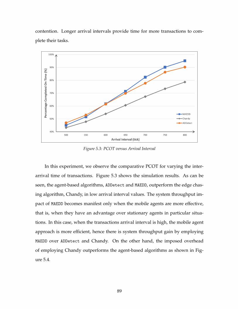
contention. Longer arrival intervals provide time for more transactions to com-
plete their tasks.
Figure 5.3: PCOT versus Arrival Interval
In this experiment, we observe the comparative PCOT for varying the inter-
arrival time of transactions. Figure 5.3 shows the simulation results. As can be
seen, the agent-based algorithms, ADDetect and MAEDD, outperform the edge chas-
ing algorithm, Chandy, in low arrival interval values. The system throughput im-
pact of MAEDD becomes manifest only when the mobile agents are more effective,
that is, when they have an advantage over stationary agents in particular situa-
tions. In this case, when the transactions arrival interval is high, the mobile agent
approach is more efficient, hence there is system throughput gain by employing
MAEDD over ADDetect and Chandy. On the other hand, the imposed overhead
of employing Chandy outperforms the agent-based algorithms as shown in Fig-
ure 5.4.
89
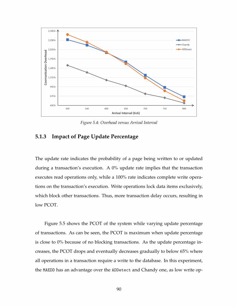
Figure 5.4: Overhead versus Arrival Interval
5.1.3 Impact of Page Update Percentage
The update rate indicates the probability of a page being written to or updated
during a transaction’s execution. A 0% update rate implies that the transaction
executes read operations only, while a 100% rate indicates complete write opera-
tions on the transaction’s execution. Write operations lock data items exclusively,
which block other transactions. Thus, more transaction delay occurs, resulting in
low PCOT.
Figure 5.5 shows the PCOT of the system while varying update percentage
of transactions. As can be seen, the PCOT is maximum when update percentage
is close to 0% because of no blocking transactions. As the update percentage in-
creases, the PCOT drops and eventually decreases gradually to below 65% where
all operations in a transaction require a write to the database. In this experiment,
the MAEDD has an advantage over the ADDetect and Chandy one, as low write op-
90
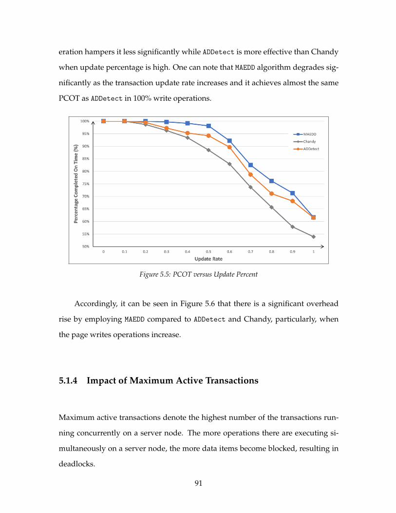
eration hampers it less significantly while ADDetect is more effective than Chandy
when update percentage is high. One can note that MAEDD algorithm degrades sig-
nificantly as the transaction update rate increases and it achieves almost the same
PCOT as ADDetect in 100% write operations.
Figure 5.5: PCOT versus Update Percent
Accordingly, it can be seen in Figure 5.6 that there is a significant overhead
rise by employing MAEDD compared to ADDetect and Chandy, particularly, when
the page writes operations increase.
5.1.4 Impact of Maximum Active Transactions
Maximum active transactions denote the highest number of the transactions run-
ning concurrently on a server node. The more operations there are executing si-
multaneously on a server node, the more data items become blocked, resulting in
deadlocks.
91
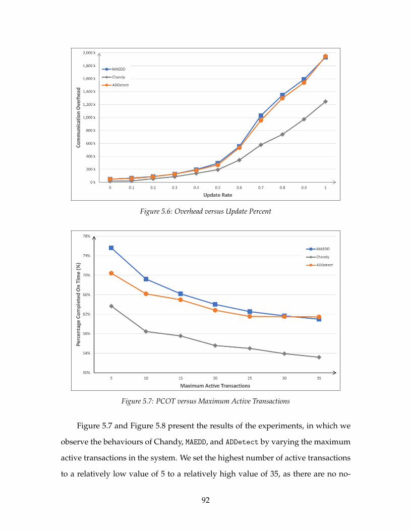
Figure 5.6: Overhead versus Update Percent
Figure 5.7: PCOT versus Maximum Active Transactions
Figure 5.7 and Figure 5.8 present the results of the experiments, in which we
observe the behaviours of Chandy, MAEDD, and ADDetect by varying the maximum
active transactions in the system. We set the highest number of active transactions
to a relatively low value of 5 to a relatively high value of 35, as there are no no-
92
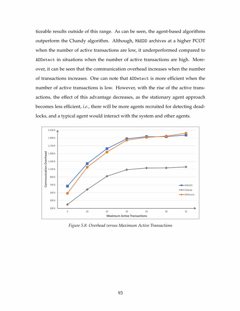
ticeable results outside of this range. As can be seen, the agent-based algorithms
outperform the Chandy algorithm. Although, MAEDD archives at a higher PCOT
when the number of active transactions are low, it underperformed compared to
ADDetect in situations when the number of active transactions are high. More-
over, it can be seen that the communication overhead increases when the number
of transactions increases. One can note that ADDetect is more efficient when the
number of active transactions is low. However, with the rise of the active trans-
actions, the effect of this advantage decreases, as the stationary agent approach
becomes less efficient, i.e., there will be more agents recruited for detecting dead-
locks, and a typical agent would interact with the system and other agents.
Figure 5.8: Overhead versus Maximum Active Transactions
93

5.1.5 Impact of Detection Interval
The deadlock detection interval represents the time between each search for dead-
lock. When the detection interval is small, the deadlock detection algorithm ex-
ecutes more frequently result in identifying deadlocks faster. Although detecting
deadlocks faster diminishes the deadlock persistence time, it comes at the cost of
extra overhead.
Figure 5.9: Overhead versus Detection Interval
In the last experiment, we observed the comparative performance of Chandy,
MAEDD, and ADDetect while varying the initial deadlock detection interval value.
The simulation results are presented in Figure 5.9. As can be seen, the edge chas-
ing algorithm (Chandy) imposes considerably less overhead than agent-based al-
gorithms (MAEDD and ADDetect). However, the overhead of employing ADDetect
decreases more in situations when the time interval between detection processes
is high and fewer agents can be involved in a detection process, as discussed in
Section 3.2.2. For example, it can be observed that ADDetect and Chandy dictate
94
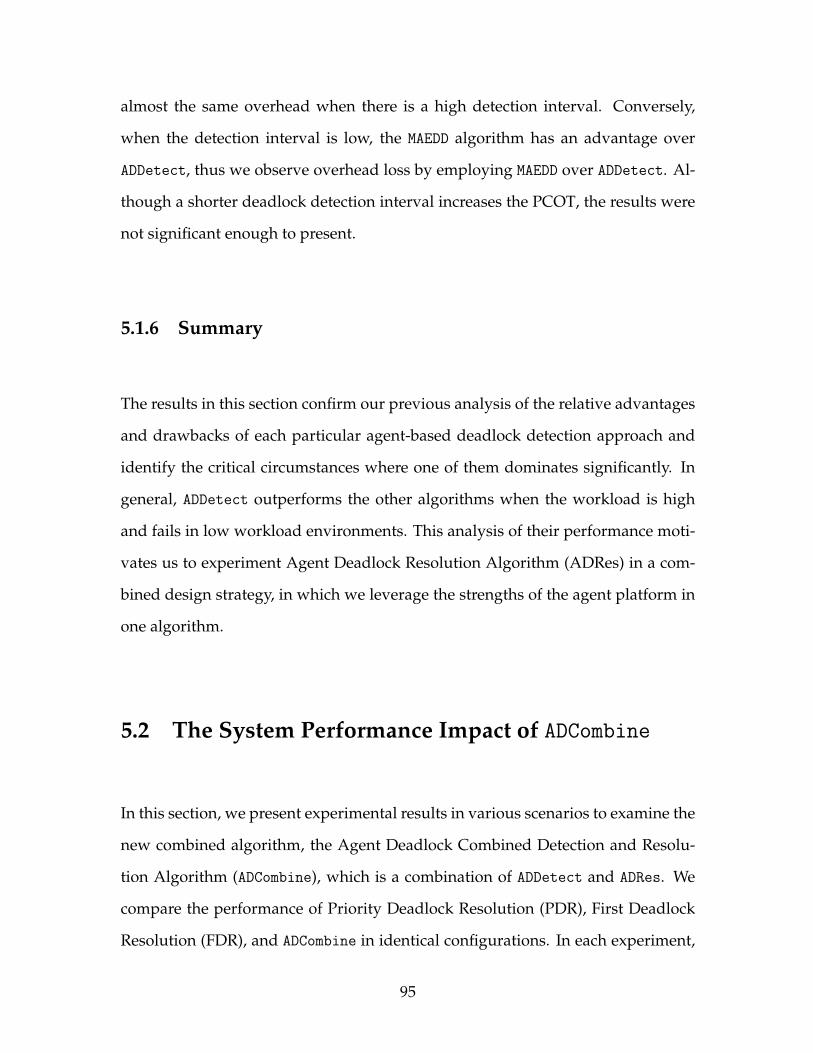
almost the same overhead when there is a high detection interval. Conversely,
when the detection interval is low, the MAEDD algorithm has an advantage over
ADDetect, thus we observe overhead loss by employing MAEDD over ADDetect. Al-
though a shorter deadlock detection interval increases the PCOT, the results were
not significant enough to present.
5.1.6 Summary
The results in this section confirm our previous analysis of the relative advantages
and drawbacks of each particular agent-based deadlock detection approach and
identify the critical circumstances where one of them dominates significantly. In
general, ADDetect outperforms the other algorithms when the workload is high
and fails in low workload environments. This analysis of their performance moti-
vates us to experiment Agent Deadlock Resolution Algorithm (ADRes) in a com-
bined design strategy, in which we leverage the strengths of the agent platform in
one algorithm.
5.2 The System Performance Impact of ADCombine
In this section, we present experimental results in various scenarios to examine the
new combined algorithm, the Agent Deadlock Combined Detection and Resolu-
tion Algorithm (ADCombine), which is a combination of ADDetect and ADRes. We
compare the performance of Priority Deadlock Resolution (PDR), First Deadlock
Resolution (FDR), and ADCombine in identical configurations. In each experiment,
95
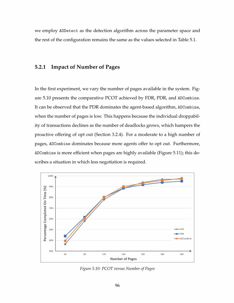
we employ ADDetect as the detection algorithm across the parameter space and
the rest of the configuration remains the same as the values selected in Table 5.1.
5.2.1 Impact of Number of Pages
In the first experiment, we vary the number of pages available in the system. Fig-
ure 5.10 presents the comparative PCOT achieved by FDR, PDR, and ADCombine.
It can be observed that the PDR dominates the agent-based algorithm, ADCombine,
when the number of pages is low. This happens because the individual droppabil-
ity of transactions declines as the number of deadlocks grows, which hampers the
proactive offering of opt out (Section 3.2.4). For a moderate to a high number of
pages, ADCombine dominates because more agents offer to opt out. Furthermore,
ADCombine is more efficient when pages are highly available (Figure 5.11); this de-
scribes a situation in which less negotiation is required.
Figure 5.10: PCOT versus Number of Pages
96

Figure 5.11: Overhead versus Number of Pages
5.2.2 Impact of Transaction Arrival Interval
Figure 5.12 presents the results of the second experiment in which we vary the
transaction arrival interval. The comparative PCOT show that the agent-based
algorithm, ADCombine, dominates when transaction inter-arrival time is high. This
is because the agent-based approach is more effective with more time available for
negotiation. On the other hand, the PDR algorithm is more efficient at moderate to
low transaction arrival times as shown in Figure 5.13. One can note that the FDR
algorithm imposes marginally more overhead compared to ADCombine and PDR, as
the higher priority transactions drop and restart which leads to more deadlocks.
97
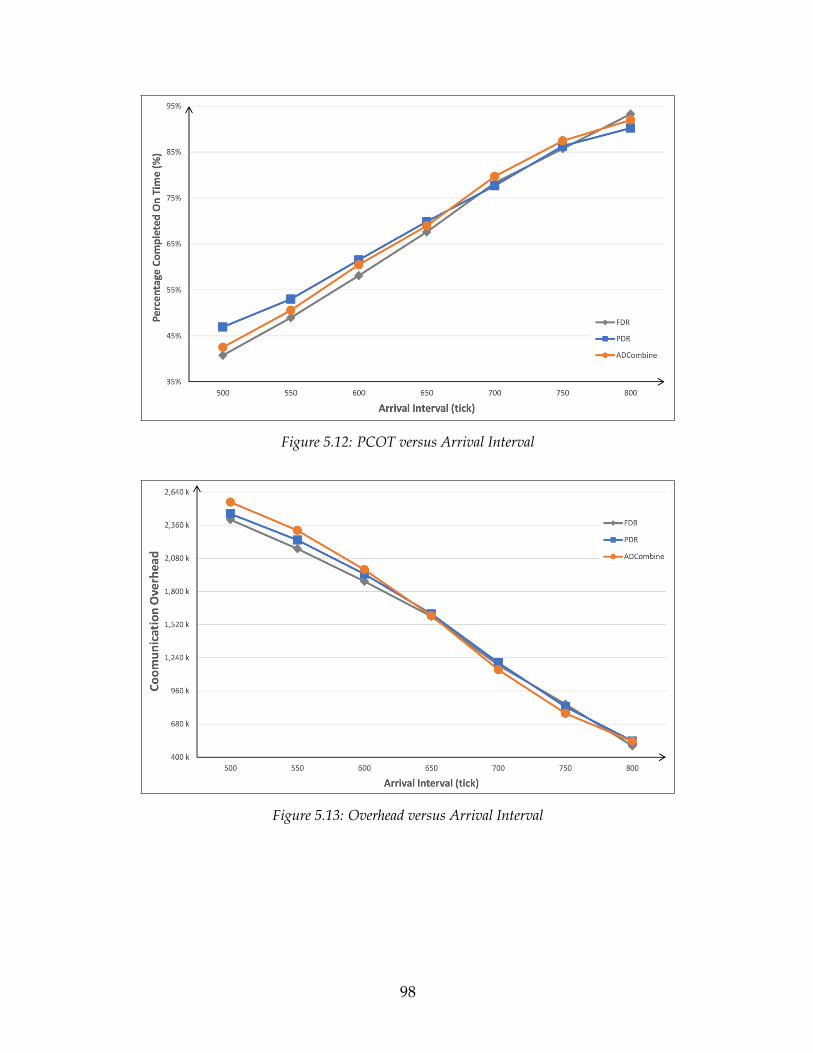
Figure 5.12: PCOT versus Arrival Interval
Figure 5.13: Overhead versus Arrival Interval
98

5.2.3 Impact of Page Update Percentage
In the third experiment, we varied the transaction update percentage. Figure 5.14
presents the results. In the lower update percentage, PCOT is maximum as writing
operations are less than reading operation, results in more transactions complete
their tasks before the deadline expires. As can be seen, the ADCombine dominates
when the update percentage is low and achieves almost the same PCOT as PDR
in 100% write operations. On the other hand, the efficiency of the FDR algorithm
dominates, particularly when the update percentage is high (Figure 5.15).
Figure 5.14: PCOT versus Update Percent
5.2.4 Impact of Maximum Active Transactions
Figure 5.16, presents the results of the experiment in which we varied the max-
imum active transactions on the system. The comparative system throughput
99
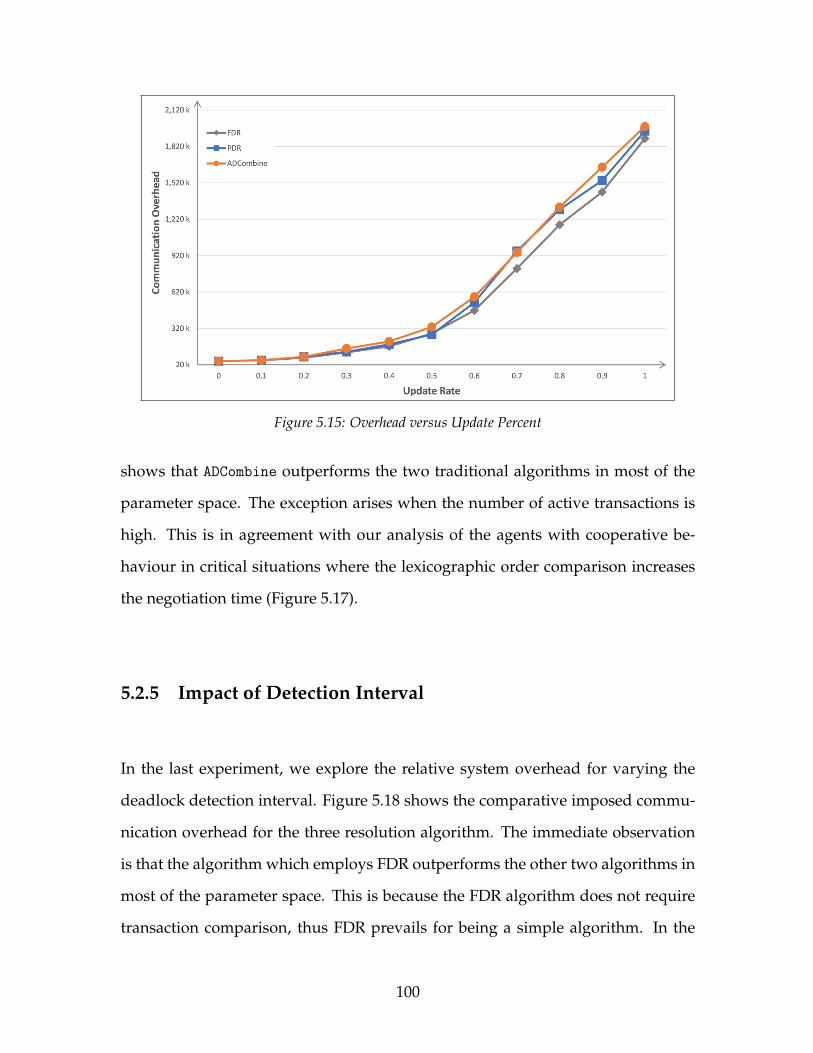
Figure 5.15: Overhead versus Update Percent
shows that ADCombine outperforms the two traditional algorithms in most of the
parameter space. The exception arises when the number of active transactions is
high. This is in agreement with our analysis of the agents with cooperative be-
haviour in critical situations where the lexicographic order comparison increases
the negotiation time (Figure 5.17).
5.2.5 Impact of Detection Interval
In the last experiment, we explore the relative system overhead for varying the
deadlock detection interval. Figure 5.18 shows the comparative imposed commu-
nication overhead for the three resolution algorithm. The immediate observation
is that the algorithm which employs FDR outperforms the other two algorithms in
most of the parameter space. This is because the FDR algorithm does not require
transaction comparison, thus FDR prevails for being a simple algorithm. In the
100
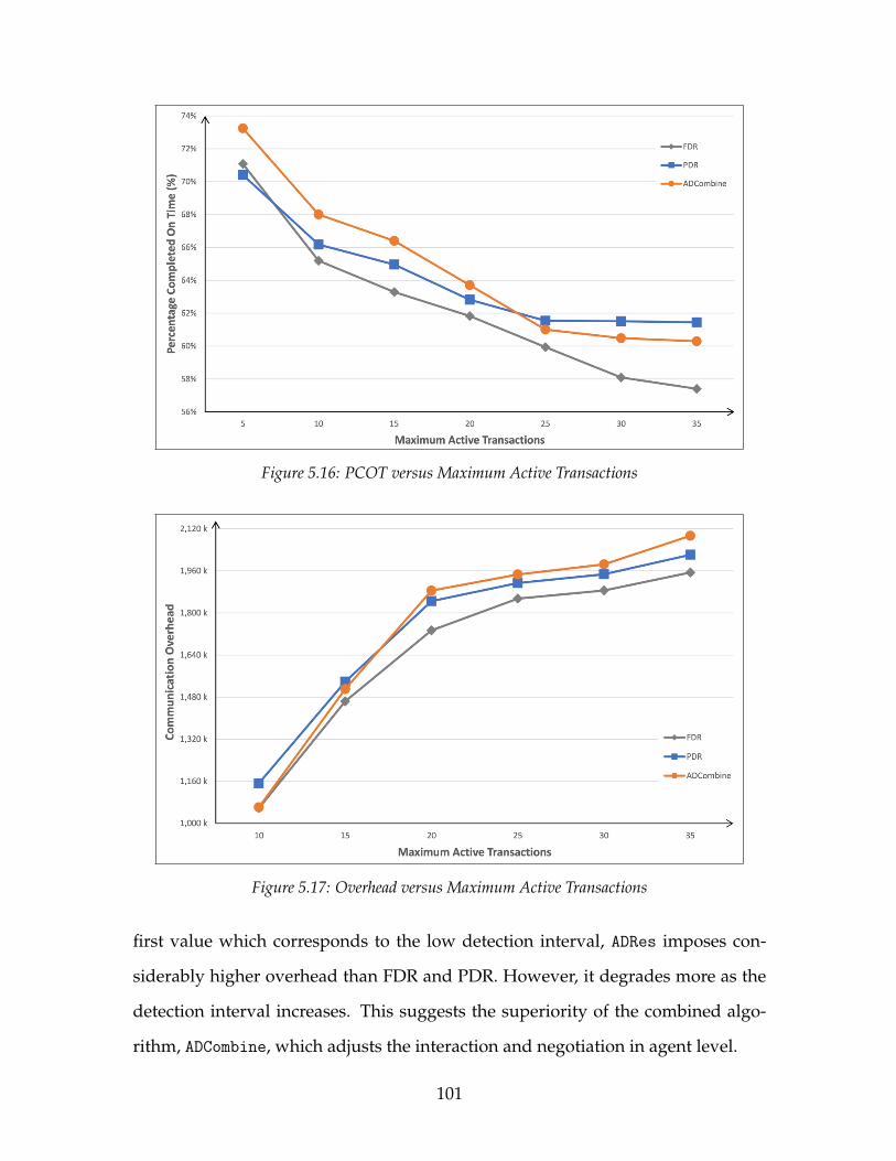
Figure 5.16: PCOT versus Maximum Active Transactions
Figure 5.17: Overhead versus Maximum Active Transactions
first value which corresponds to the low detection interval, ADRes imposes con-
siderably higher overhead than FDR and PDR. However, it degrades more as the
detection interval increases. This suggests the superiority of the combined algo-
rithm, ADCombine, which adjusts the interaction and negotiation in agent level.
101
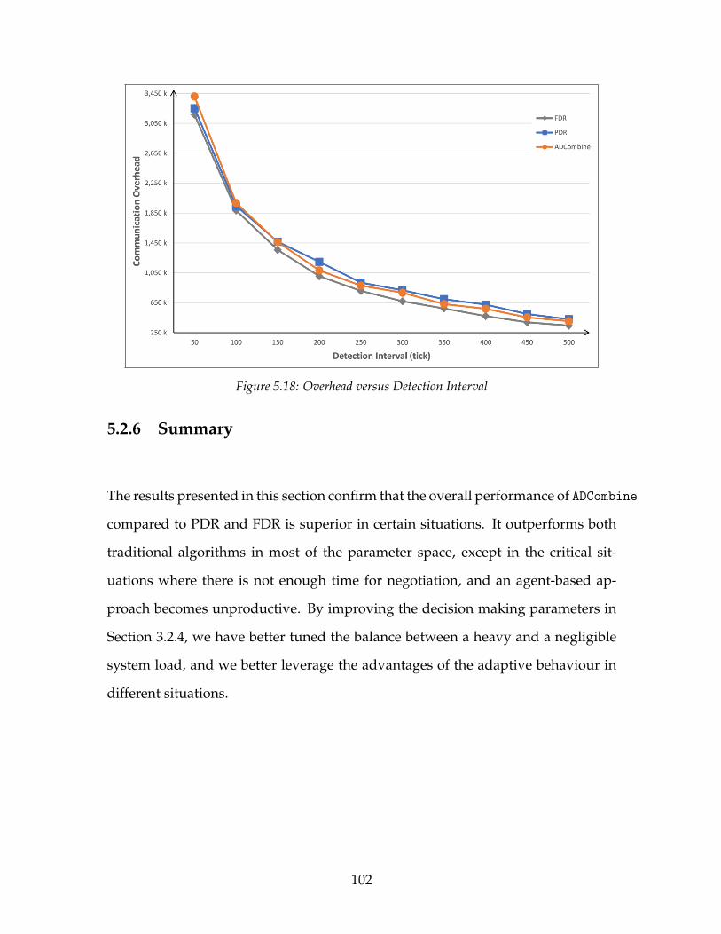
Figure 5.18: Overhead versus Detection Interval
5.2.6 Summary
The results presented in this section confirm that the overall performance of ADCombine
compared to PDR and FDR is superior in certain situations. It outperforms both
traditional algorithms in most of the parameter space, except in the critical sit-
uations where there is not enough time for negotiation, and an agent-based ap-
proach becomes unproductive. By improving the decision making parameters in
Section 3.2.4, we have better tuned the balance between a heavy and a negligible
system load, and we better leverage the advantages of the adaptive behaviour in
different situations.
102
Chapter 6
Conclusions and Future Work
Real-Time Database System (RTDBS)s are universally adopted in various practi-
cal applications. The increased demand for distributed RTDBS (DRTDBS) in the
industry expects an improved system throughput. Deadlock problems can oc-
cur in any DRTDBS and has a major impact on the system performance. This
thesis presents a new distributed real-time deadlock handling algorithm using
agents, called Agent Deadlock Combined Detection and Resolution Algorithm
(ADCombine), for incorporating helpful behaviour into DRTDBSs. Initial research
has comprised a study of literature in several areas of DRTDBS and Multi Agent
Systems (MAS), especially deadlock detection and resolution algorithms, helpful
behaviour in agent protocols, and deadlock handling using agents. The study led
to an observation that, despite the growing use of artificial agents in handling
deadlocks for DRTDBS, there is a shortage of algorithms designed for station-
ary agents, and particularly for incorporating helpful behaviour into stationary
agents. Another observation was that some of the existing approaches to deadlock
103

handling using MAS are either impractical for large DDBSs or over-simplified in
their assumptions, which in many realistic environments may be inaccurate. These
observations motivated the design of a new algorithm for stationary agents, with
particular attention to the cooperation of individual agents involved in the dead-
lock handling.
Considering the existing algorithms on employing mobile agents in handling
deadlocks, Mobile Agent Enabled Deadlock Detection (MAEDD), we inherit its prin-
cipal and design features such as the local execution autonomy. Inspired by previ-
ous research on mobile agents, we have analyzed two different approaches to han-
dle deadlocks, including their localization features and decision-making patterns.
In the first approach, agents are located in stationary sites and provide services
remotely as the need arises; in the second, agents can recruit more agents to de-
cide about which transaction to drop and break the cycle in a bilateral distributed
agreement. The novel features of ADCombine allow an agent to adjust its execution
based on the most up-to-date status of the system. The impact of ADCombine on the
system’s throughput is investigated through an extensive set of simulation experi-
ments using a diverse range of workload and system parameters. The experiment
results suggest superiority of ADCombine compared to MAEDD in certain scenarios.
In our simulation model, we first designed a new detection algorithm using
a team of stationary agents with helpful behaviour, called ADDetect, to compare
with the existing variation of deadlock detection algorithm using MAS. Then, by
analysis of the relative strengths and weaknesses of the stationary agents and re-
alizing the possibility that a single algorithm can incorporate an agent-based solu-
tion strategy, we have designed the new combined algorithm, ADCombine. The new
algorithm is a composition of ADDetect and ADRes, and leverages the advantages
104
of agents’ cooperation and coordination in handling deadlock cycles.
The simulation results demonstrate the system throughput gains for the algo-
rithm that employs stationary agents and mobile agents in high and low data con-
tention respectively. This indicates that higher system loads caused a larger level
of congestion, which resulted in the mobile agent thrashing. The ADDetect perfor-
mance is superior in most of the parameter space, except in situations when remote
detection and resolution becomes unproductive. This motivated us to introduce
an additional strategy into ADDetect to employ additional agents to resolve dead-
locks more judiciously in a low data contention situation. In the current version of
ADCombine, the performance was improved in situations where ADDetect failed to
mobile agent approach.
In this thesis, an agent deliberating about performing deadlock detection re-
lies on its local beliefs, acquired through perception which is assumed to be accu-
rate. Similarly, agents’ shared belief is acquired through communication with the
rest of the agents. The communication network is assumed to be reliable, and all
messages are delivered within a finite amount of time. Also, each agent relies on
the transaction execution stability in a detection and resolution process.
6.1 Future Work
We have investigated our agent-based deadlock handling algorithm in the con-
text of a transaction processing, supported in the Distributed Real-Time Database
System (DRTDBS). In this study, we have simplified our modeling of the agent
105
teams, the network, and the transaction execution, to investigate the behaviour of
the stationary agent in a relatively stable form, without the impact of extraneous
factors that may vary significantly across real-world applications. When applying
our algorithms to practical systems, one may need to analyze the engineering re-
quirements such as scalability of changing the size of the system, the possibility
of execution fault, communication or execution delay, potential to inject time to
the deadlines for completing more transactions, and so forth. Also, the effect of
communication overhead in adjusting global detection configuration must consid-
ered. Furthermore, implementing agents with organized panic behaviour when
the overhead is exponentially increasing can be investigated. Nevertheless, while
this thesis did not explore these considerations in particular; this topic leads to
interesting research and development questions that merit further study.
106

Bibliography
[1] Robert K Abbott and Hector Garcia-Molina, Scheduling real-time transactions:A performance evaluation, ACM Transactions on Database Systems (TODS) 17(1992), no. 3, 513–560.
[2] Micah Adler, Eran Halperin, Richard M Karp, and Vijay V Vazirani, Astochastic process on the hypercube with applications to peer-to-peer networks, Pro-ceedings of the thirty-fifth annual ACM symposium on Theory of comput-ing, ACM, 2003, pp. 575–584.
[3] Rakesh Agrawal, Michael J Carey, and Miron Livny, Concurrency controlperformance modeling: alternatives and implications, ACM Transactions onDatabase Systems (TODS) 12 (1987), no. 4, 609–654.
[4] Mumtaz Ahmad, Query interactions in database systems, Ph.D. thesis, Univer-sity of Waterloo, 2013.
[5] Subbu Allamaraju, Nuts and bolts of transaction processing, white paper, http://www.subrahmanyam.com/articles/transactions/NutsAndBoltsOfTP.
html, 1999.
[6] BM Monjurul Alom, Frans Alexander Henskens, and Michael Richard Han-naford, Deadlock detection views of distributed database, Information Technol-ogy: New Generations, 2009. ITNG’09. Sixth International Conference on,IEEE, 2009, pp. 730–737.
[7] Amos Azaria, Zinovi Rabinovich, Claudia V Goldman, and Sarit Kraus,Strategic information disclosure to people with multiple alternatives, ACM Trans-actions on Intelligent Systems and Technology (TIST) 5 (2015), no. 4, 64.
[8] Jonas Y. Bambi, Priority-based speculative locking protocols for distributedreal-time database systems, Master’s thesis, University Of Northern BritishColumbia, Prince George, 2008.
[9] Daniel S Bernstein, Robert Givan, Neil Immerman, and Shlomo Zilberstein,The complexity of decentralized control of markov decision processes, Mathematicsof operations research 27 (2002), no. 4, 819–840.
107

[10] Philip A Bernstein and Nathan Goodman, Concurrency control in distributeddatabase systems, ACM Computing Surveys (CSUR) 13 (1981), no. 2, 185–221.
[11] , An algorithm for concurrency control and recovery in replicated dis-tributed databases, ACM Transactions on Database Systems (TODS) 9 (1984),no. 4, 596–615.
[12] Philip A Bernstein, Vassos Hadzilacos, and Nathan Goodman, Concurrencycontrol and recovery in database systems, Addison- Wesley, 1987.
[13] Philip A Bernstein and Eric Newcomer, Principles of transaction processing,Morgan Kaufmann, 2009.
[14] Michael E Bratman, Intention, plans, and practical reason, Philosophical Re-view 100 (1991), no. 2, 277–284.
[15] Michael E Bratman, David J Israel, and Martha E Pollack, Plans and resource-bounded practical reasoning, Computational intelligence 4 (1988), no. 3, 349–355.
[16] Jiannong Cao, GH Chan, Tharam S Dillon, et al., Checkpointing and rollback ofwide-area distributed applications using mobile agents, Parallel and DistributedProcessing Symposium., Proceedings 15th International, IEEE, 2001, pp. 1–6.
[17] Jiannong Cao, Jingyang Zhou, Weiwei Zhu, Daoxu Chen, and Jian Lu, A mo-bile agent enabled approach for distributed deadlock detection, International Con-ference on Grid and Cooperative Computing, Springer, 2004, pp. 535–542.
[18] Sen Cao, Richard A Volz, Thomas R Ioerger, and Michael S Miller, On proac-tive helping behaviors in teamwork., IC-AI, vol. 5, 2005, pp. 974–980.
[19] K Mani Chandy and Leslie Lamport, Distributed snapshots: Determining globalstates of distributed systems, ACM Transactions on Computer Systems (TOCS)3 (1985), no. 1, 63–75.
[20] K Mani Chandy and Jayadev Misra, Asynchronous distributed simulation viaa sequence of parallel computations, Communications of the ACM 24 (1981),no. 4, 198–206.
[21] , A distributed algorithm for detecting resource deadlocks in distributed sys-tems, Proceedings of the first ACM SIGACT-SIGOPS symposium on Princi-ples of distributed computing, ACM, 1982, pp. 157–164.
[22] K Mani Chandy, Jayadev Misra, and Laura M Haas, Distributed deadlock de-tection, ACM Transactions on Computer Systems (TOCS) 1 (1983), no. 2, 144–156.
[23] Hong-Ren Chen and Yeh-Hao Chin-Fu, An adaptive scheduler for distributedreal-time database systems, Information Sciences 153 (2003), 55–83.
108
[24] Shigang Chen and Yibei Ling, Stochastic analysis of distributed deadlock schedul-ing, Proceedings of the twenty-fourth annual ACM symposium on Principlesof distributed computing, ACM, 2005, pp. 265–273.
[25] Alok N. Choudhary, Walter H. Kohler, John A. Stankovic, and Don Towsley,A modified priority based probe algorithm for distributed deadlock detection andresolution, IEEE Transactions on Software Engineering 15 (1989), no. 1, 10–17.
[26] Philip R Cohen and Hector J Levesque, Intention is choice with commitment,Artificial intelligence 42 (1990), no. 2-3, 213–261.
[27] , Teamwork, Nous 25 (1991), no. 4, 487–512.
[28] Transaction Processing Performance Council, tpc benchmark b, Standard Spec-ification, Waterside Associates, Fremont, CA (1990).
[29] , Tpc benchmarks, 2005.
[30] Saad M Darwish, Adel A El-Zoghabi, and Marwan H Hassan, Soft computingfor database deadlock resolution, International Journal of Modeling and Opti-mization 5 (2015), no. 1, 15.
[31] JR Gonzalez De Mendıvil, Federico Farina, JR Garitagotia, Carlos F Alas-truey, and Jose M. Bernabeu-Auban, A distributed deadlock resolution algorithmfor the AND model, IEEE transactions on parallel and distributed systems 10(1999), no. 5, 433–447.
[32] Gupta Dhiraj and VK Gupta, Approaches for deadlock detection and deadlockprevention for distributed systems, Research Journal of Recent Sciences ISSN2277 (2012), 2502.
[33] Edsger W Dijkstra and Carel S. Scholten, Termination detection for diffusingcomputations, Information Processing Letters 11 (1980), no. 1, 1–4.
[34] Wanfu Ding and Ruifeng Guo, Design and evaluation of sectional real-timescheduling algorithms based on system load, Young Computer Scientists, 2008.ICYCS 2008. The 9th International Conference for, IEEE, 2008, pp. 14–18.
[35] Barbara Dunin-Keplicz and Rineke Verbrugge, Teamwork in multi-agent sys-tems: A formal approach, vol. 21, John Wiley & Sons, 2011.
[36] Hywel R Dunn-Davies, RJ Cunningham, and Shamimabi Paurobally, Propo-sitional statecharts for agent interaction protocols, Electronic Notes in TheoreticalComputer Science 134 (2005), 55–75.
[37] Amr El Abbadi and Sam Toueg, Availability in partitioned replicated databases,Proceedings of the fifth ACM SIGACT-SIGMOD symposium on Principlesof database systems, ACM, 1985, pp. 240–251.
109
[38] Gregory D Elder, Multi-agent coordination and cooperation in a distributed dy-namic environment with limited resources: simulated air wars, Tech. report, DTICDocument, 1993.
[39] Ahmed K Elmagarmid, Database transaction models for advanced applications,Morgan Kaufmann Publishers Inc., 1992.
[40] Kapali P. Eswaran, Jim N Gray, Raymond A. Lorie, and Irving L. Traiger, Thenotions of consistency and predicate locks in a database system, Communicationsof the ACM 19 (1976), no. 11, 624–633.
[41] Amos Fiat, Yishay Mansour, and Uri Nadav, Efficient contention resolution pro-tocols for selfish agents, SODA, vol. 7, 2007, pp. 179–188.
[42] Nicholas V Findler and Gregory D Elder, Multiagent coordination and coopera-tion in a distributed dynamic environment with limited resources, Artificial Intel-ligence in Engineering 9 (1995), no. 3, 229–238.
[43] ACL FIPA, Foundation of intelligent physical agents, 2008.
[44] Geoffrey C Fox and Steve W Otto, Algorithms for concurrent processors, PhysicsToday 37 (1984), 50–59.
[45] Stefan Fuenfrocken, Integrating java-based mobile agents into web servers un-der security concerns, System Sciences, 1998., Proceedings of the Thirty-FirstHawaii International Conference on, vol. 7, IEEE, 1998, pp. 34–43.
[46] Barbara Gallina, Nicolas Guelfi, and Alexander Romanovsky, Coordinatedatomic actions for dependable distributed systems: the current state in concepts,semantics and verification means, The 18th IEEE International Symposium onSoftware Reliability (ISSRE’07), IEEE, 2007, pp. 29–38.
[47] Hector Garcia-Molina, Using semantic knowledge for transaction processing in adistributed database, ACM Transactions on Database Systems (TODS) 8 (1983),no. 2, 186–213.
[48] Hector Garcia-Molina and Bruce Lindsay, Research directions for distributeddatabases, ACM SIGMOD Record 19 (1990), no. 4, 98–103.
[49] Michael P Georgeff and Amy L Lansky, Reactive reasoning and planning.,AAAI, vol. 87, 1987, pp. 677–682.
[50] Michael Peter Georgeff and Anand S Rao, A profile of the Australian artificialintelligence institute, IEEE Expert: Intelligent Systems and Their Applications11 (1996), no. 6, 89–92.
[51] Christos K Georgiadis and Elias Pimenidis, Proposing an evaluation frame-work for B2B web services-based transactions, Proceedings of the E-Activity andLeading Technologies conference, IASK, Porto, Portugal, 2007, pp. 164–171.
110
[52] James Gosling, Bill Joy, Guy L Steele, Gilad Bracha, and Alex Buckley, Thejava® language specification java se 8 edition, vol. 8, Pearson Education, 3 2015.
[53] Paul WPJ Grefen and Peter MG Apers, Dynamic action scheduling in a par-allel database system, International Conference on Parallel Architectures andLanguages Europe, Springer, 1992, pp. 807–824.
[54] Barbara J Grosz and Sarit Kraus, Collaborative plans for complex group action,Artificial Intelligence 86 (1996), no. 2, 269–357.
[55] Ramesh Gupta, Jayant Haritsa, and Krithi Ramamritham, Revisiting commitprocessing in distributed database systems, ACM SIGMOD Record 26 (1997),no. 2, 486–497.
[56] Theo Haerder and Andreas Reuter, Principles of transaction-oriented databaserecovery, ACM Computing Surveys (CSUR) 15 (1983), no. 4, 287–317.
[57] Jayant R Haritsa, Michael J Carey, and Miron Livny, Data access scheduling infirm real-time database systems, Real-Time Systems 4 (1992), no. 3, 203–241.
[58] Jayant R Haritsa and Krithi Ramamritham, Adding pep to real-time distributedcommit processing, Real-Time Systems Symposium, 2000. Proceedings. The21st IEEE, IEEE, 2000, pp. 37–46.
[59] Jayant R Haritsa, Krithi Ramamritham, and Ramesh Gupta, Real-time commitprocessing, Real-Time Database Systems, Springer, 2002, pp. 227–243.
[60] Carl S Hartzman, The delay due to dynamic two-phase locking, IEEE transactionson software engineering 15 (1989), no. 1, 72–82.
[61] Mark F Hornick and Stanley B Zdonik, A shared, segmented memory system foran object-oriented database, ACM Transactions on Information Systems (TOIS)5 (1987), no. 1, 70–95.
[62] Jiandong Huang, John A Stankovic, Krithi Ramamritham, and Don Towsley,On using priority inheritance in real-time databases, Real-Time Systems Sympo-sium, 1991. Proceedings., Twelfth, IEEE, 1991, pp. 210–221.
[63] Sheung-Lun Hung and Kam-Yiu Lam, Performance comparison of static vs. dy-namic two phase locking protocols, Journal of Database Management (JDM) 3(1992), no. 2, 12–23.
[64] Dedi Iskandar Inan and Ratna Juita, Analysis and design complex and large database using MySQL™ workbench, International Journal of Computer Science &Information Technology 3 (2011), no. 5, 173.
[65] Sreekaanth S Isloor and T Anthony Marsland, The deadlock problem: Anoverview., IEEE Computer 13 (1980), no. 9, 58–78.
111

[66] Takayuki Ito, Hiromitsu Hattori, and Mark Klein, Multi-issue negotiation pro-tocol for agents: Exploring nonlinear utility spaces, IJCAI, vol. 7, 2007, pp. 1347–1352.
[67] Hideshi Itoh, Incentives to help in multi-agent situations, Econometrica: Journalof the Econometric Society (1991), 611–636.
[68] Sheena Iyengar, The art of choosing, Twelve, 2010.
[69] E Douglas Jensen, C Douglas Locke, and Hideyuki Tokuda, A time-drivenscheduling model for real-time operating systems, RTSS, vol. 85, 1985, pp. 112–122.
[70] Leslie Pack Kaelbling, Michael L Littman, and Anthony R Cassandra, Plan-ning and acting in partially observable stochastic domains, Artificial intelligence101 (1998), no. 1, 99–134.
[71] Ece Kamar, Ya’akov Gal, and Barbara J Grosz, Incorporating helpful behaviorinto collaborative planning, Proceedings of The 8th International Conferenceon Autonomous Agents and Multiagent Systems-Volume 2, InternationalFoundation for Autonomous Agents and Multiagent Systems, 2009, pp. 875–882.
[72] Ben Kao and Hector Garcia-Molina, An overview of real-time database systems,Real Time Computing, Springer, 1994, pp. 261–282.
[73] Zvi M Kedem and Abraham Silberschatz, Controlling concurrency using lock-ing protocols, Foundations of Computer Science, 1979., 20th Annual Sympo-sium on, IEEE, 1979, pp. 274–285.
[74] , Locking protocols: from exclusive to shared locks, Journal of the ACM(JACM) 30 (1983), no. 4, 787–804.
[75] Edgar Knapp, Deadlock detection in distributed databases, ACM ComputingSurveys (CSUR) 19 (1987), no. 4, 303–328.
[76] Natalija Krivokapic, Control mechanisms in distributed object bases, vol. 54, IOSPress, 1999.
[77] Natalija Krivokapic, Alfons Kemper, and Ehud Gudes, Deadlock detection indistributed database systems: a new algorithm and a comparative performance anal-ysis, The International Journal on Very Large Data Bases 8 (1999), no. 2, 79–100.
[78] Shivendra P Kumar, Hari T Krishna, and RK Kapoor, Distributed deadlockdetection technique with the finite automata, Journal of Information Technology& Software Engineering 5 (2015), no. 2, 1.
112
[79] Twi-Wei Kuo, Yuan-Ting Kao, and LihChyun Shu, A two-version approach forreal-time concurrency control and recovery, High-Assurance Systems Engineer-ing Symposium, 1998. Proceedings. Third IEEE International, IEEE, 1998,pp. 279–286.
[80] Kam-yiu Lam, Concurrency control in distributed real-time database systems,Ph.D. thesis, City Polytechnic of Hong Kong, 1994.
[81] Kwok-Wa Lam and Sheung-Lun Hung, A pre-emptive transaction schedulingprotocol for controlling priority inversion, Real-Time Computing Systems andApplications, 1996. Proceedings., Third International Workshop on, IEEE,1996, pp. 144–151.
[82] Kwok-wa Lam, Sang Hyuk Son, and Sheung-Lun Hung, A priority ceilingprotocol with dynamic adjustment of serialization order, Data Engineering, 1997.Proceedings. 13th International Conference on, IEEE, 1997, pp. 552–561.
[83] Butler W Lampson and Howard E Sturgis, Reflections on an operating systemdesign, Communications of the ACM 19 (1976), no. 5, 251–265.
[84] Jeffrey A Le Pine, Mary A Hanson, Walter C Borman, and Stephan J Mo-towidlo, Contextual performance and teamwork: Implications for staffing, Re-search in personnel and human resources management 19 (2000), 53.
[85] Victor CS Lee, Kam-Yiu Lam, and Ben Kao, Priority scheduling of transactionsin distributed real-time databases, Real-Time Systems 16 (1999), no. 1, 31–62.
[86] Thomas C Leonard, Richard H. Thaler, Cass R. Sunstein, nudge: Improving de-cisions about health, wealth, and happiness, Constitutional Political Economy 19(2008), no. 4, 356–360.
[87] Kristina Lerman and Aram Galstyan, Agent memory and adaptation in multi-agent systems, Proceedings of the second international joint conference onAutonomous agents and multiagent systems, ACM, 2003, pp. 797–803.
[88] Hector J Levesque, Philip R Cohen, and Jose HT Nunes, On acting together,AAAI, vol. 90, 1990, pp. 94–99.
[89] Tong Li, Carla Schlatter Ellis, Alvin R Lebeck, and Daniel J Sorin, Pulse: Adynamic deadlock detection mechanism using speculative execution., USENIX An-nual Technical Conference, General Track, vol. 44, 2005.
[90] Jan Lindstrom and Tiina Niklander, Benchmark for real-time database systemsfor telecommunications, Databases in Telecommunications II (2001), 88–101.
[91] Yibei Ling, Shigang Chen, and Cho-Yu Jason Chiang, On optimal deadlockdetection scheduling, IEEE Transactions on Computers 55 (2006), no. 9, 1178–1187.
113

[92] Chung Laung Liu and James W Layland, Scheduling algorithms for multi-programming in a hard-real-time environment, Journal of the ACM (JACM) 20(1973), no. 1, 46–61.
[93] Magnus Ljungberg and Andrew Lucas, The oasis air traffic management system,Proc. 2nd Pacific Rim Conference on AI (1992), 1–12.
[94] Philip P Macri, Deadlock detection and resolution in a codasyl based data manage-ment system, Proceedings of the 1976 ACM SIGMOD international conferenceon Management of data, ACM, 1976, pp. 45–49.
[95] Roger Mailler and Victor Lesser, Solving distributed constraint optimizationproblems using cooperative mediation, Proceedings of the Third InternationalJoint Conference on Autonomous Agents and Multiagent Systems-Volume1, IEEE Computer Society, 2004, pp. 438–445.
[96] Mojtaba Malek Akhlagh, An interaction protocol for bidirectional deliberation ondirect help in agent teamwork, Master’s thesis, University Of Northern BritishColumbia, Prince George, 2015.
[97] Mojtaba Malek Akhlagh and Jernej Polajnar, Distributed deliberation on di-rect help in agent teamwork, European Conference on Multi-Agent Systems,Springer, 2014, pp. 128–143.
[98] James Mayfield, Yannis Labrou, and Tim Finin, Evaluation of kqml as an agentcommunication language, International Workshop on Agent Theories, Archi-tectures, and Languages, Springer, 1995, pp. 347–360.
[99] David McIlroy and Clinton Heinze, Air combat tactics implementation in thesmart whole air mission model (swarmm), Proceedings of the First InternationalSimTecT Conference, 1996.
[100] Maria Miceli, Amedeo Cesta, and Paola Rizzo, Autonomous help in distributedwork environments, Seventh European Conference on Cognitive Ergonomics,Bonn, Germany, 1994.
[101] Abha Mittal and Sivarama P Dandamudi, Dynamic versus static locking inreal-time parallel database systems, Parallel and Distributed Processing Sym-posium, 2004. Proceedings. 18th International, IEEE, 2004, p. 32.
[102] C Mohan, Bruce Lindsay, and Ron Obermarck, Transaction management inthe r* distributed database management system, ACM Transactions on DatabaseSystems (TODS) 11 (1986), no. 4, 378–396.
[103] Aloysius K Mok, Fundamental design problems of distributed systems for thehard-real-time environment, Tech. report, Massachusetts Institute of Technol-ogy, Cambridge, MA, USA, 1983.
114
[104] AB MySQL®, MySQL™: the world’s most popular open source database, http://www.mysql.com/, 2005.
[105] Ranjit Nair, Milind Tambe, Makoto Yokoo, David Pynadath, and StacyMarsella, Taming decentralized pomdps: Towards efficient policy computation formultiagent settings, IJCAI, 2003, pp. 705–711.
[106] Ranjit Nair, Pradeep Varakantham, Milind Tambe, and Makoto Yokoo, Net-worked distributed pomdps: A synthesis of distributed constraint optimization andpomdps, AAAI, vol. 5, 2005, pp. 133–139.
[107] Narek Nalbandyan, A mutual assistance protocol for agent teamwork, Master’sthesis, University Of Northern British Columbia, Prince George, 2012.
[108] Narek Nalbandyan, Jernej Polajnar, Denish Mumbaiwala, Desanka Polajnar,and Omid Alemi, Requester vs. helper-initiated protocols for mutual assistance inagent teamwork, 2013 IEEE International Conference on Systems, Man, andCybernetics, IEEE, 2013, pp. 2741–2746.
[109] Ron Obermarck, Distributed deadlock detection algorithm, ACM Transactionson Database Systems (TODS) 7 (1982), no. 2, 187–208.
[110] Shayegan Omidshafiei, Ali-akbar Agha-mohammadi, Christopher Amato,and Jonathan P How, Decentralized control of partially observable Markov deci-sion processes using belief space macro-actions, 2015 IEEE International Confer-ence on Robotics and Automation (ICRA), IEEE, 2015, pp. 5962–5969.
[111] Onur Ozgun and Yaman Barlas, Discrete vs. continuous simulation: When doesit matter?, Proceedings of the 27th international conference of the system dy-namics society, vol. 6, 2009, pp. 1–22.
[112] M Tamer Ozsu and Patrick Valduriez, Principles of distributed database systems,Springer Science & Business Media, 2011.
[113] Young Chul Park, Peter Scheuermann, and Sang Ho Lee, A periodic deadlockdetection and resolution algorithm with a new graph model for sequential trans-action processing, Data Engineering, 1992. Proceedings. Eighth InternationalConference on, IEEE, 1992, pp. 202–209.
[114] Jernej Polajnar, Behrooz Dalvandi, and Desanka Polajnar, Does empathy be-tween artificial agents improve agent teamwork?, Cognitive Informatics & Cog-nitive Computing (ICCI* CC), 2011 10th IEEE International Conference on,IEEE, 2011, pp. 96–102.
[115] Ragunathan Rajkumar, Synchronization in real-time systems: a priority inheri-tance approach, vol. 151, Springer Science & Business Media, 2012.
[116] Anand S Rao, Michael P Georgeff, et al., Bdi agents: From theory to practice.,ICMAS, vol. 95, 1995, pp. 312–319.
115

[117] P Krishna Reddy and Masaru Kitsuregawa, Speculative locking protocols to im-prove performance for distributed database systems, IEEE Transactions on Knowl-edge and Data Engineering 16 (2004), no. 2, 154–169.
[118] Stuart Jonathan Russell, Peter Norvig, John F Canny, Jitendra M Malik, andDouglas D Edwards, Artificial intelligence: a modern approach, vol. 2, Prenticehall Upper Saddle River, 2003.
[119] David Sarne, Avshalom Elmalech, Barbara J Grosz, and Moti Geva, Less ismore: restructuring decisions to improve agent search, The 10th InternationalConference on Autonomous Agents and Multiagent Systems-Volume 1, In-ternational Foundation for Autonomous Agents and Multiagent Systems,2011, pp. 431–438.
[120] Srinivasan Selvaraj and Rajaram Ramasamy, An efficient detection and reso-lution of generalized deadlocks in distributed systems, International Journal ofComputer Applications 1 (2010), no. 19, 1–7.
[121] Lui Sha, Ragunathan Rajkumar, and John P Lehoczky, Concurrency control fordistributed real-time databases, ACM SIGMOD Record 17 (1988), no. 1, 82–98.
[122] , Priority inheritance protocols: An approach to real-time synchronization,IEEE Transactions on computers 39 (1990), no. 9, 1175–1185.
[123] Lui Sha, Ragunathan Rajkumar, Sang Hyuk Son, and C-H Chang, A real-timelocking protocol, IEEE Transactions on computers 40 (1991), no. 7, 793–800.
[124] Udai Shanker, Manoj Misra, and Anil K Sarje, Distributed real time databasesystems: background and literature review, Distributed and parallel databases23 (2008), no. 2, 127–149.
[125] Yoav Shoham and Kevin Leyton-Brown, Multiagent systems: Algorithmic,game-theoretic, and logical foundations, Cambridge University Press, 2008.
[126] Abraham Silberschatz and ZM Kedam, A family of locking protocols for databasesystems that are modeled by directed graphs, IEEE Transactions on Software En-gineering (1982), no. 6, 558–562.
[127] Jayanta Singh and SC Mehrotra, Performance analysis of a real time distributeddatabase system through simulation, 15th IASTED International Conf. on Ap-plied Simulation & Modelling, Greece, vol. 1, 2006, pp. 45–50.
[128] Sonia Singh and SS Tyagi, A review of distributed deadlock detection techniquesbased on diffusion computation approach, International Journal of ComputerApplications 48 (2012), no. 9, 28–32.
[129] Mukesh Singhal, Deadlock detection in distributed systems, Computer 22 (1989),no. 11, 37–48.
116
[130] Dale Skeen, Nonblocking commit protocols, Proceedings of the 1981 ACM SIG-MOD international conference on Management of data, ACM, 1981, pp. 133–142.
[131] R Smith, The contract net protocol: High-level communication and control in adistributed problem solver, IEEE Trans. on Computers, C 29 (1980), 1104–1113.
[132] Robert D Snelick, Performance evaluation of hypercube applications: Using aglobal clock and time dilation, NIST Interagency/Internal Report (NISTIR)-4630 (1991).
[133] Nadav Sofy and David Sarne, Effective deadlock resolution with self-interestedpartially-rational agents, Annals of Mathematics and Artificial Intelligence 72(2014), no. 3-4, 225–266.
[134] Alireza Soleimany and Zahra Giahi, An efficient distributed deadlock detectionand prevention algorithm by daemons, International Journal of Computer Sci-ence and Network Security (IJCSNS) 12 (2012), no. 4, 150.
[135] Yumnam Somananda, Y Jayanta Singh, Ashok Gaikwad, and SC Mehrotra,Management of missed transactions in a distributed system through simulation,Computer Science and Information Technology (ICCSIT), 2010 3rd IEEE In-ternational Conference on, vol. 5, IEEE, 2010, pp. 472–476.
[136] Xiaohui Song and Jane WS Liu, How well can data temporal consistency be main-tained?, Computer-Aided Control System Design, 1992.(CACSD), 1992 IEEESymposium on, IEEE, 1992, pp. 275–284.
[137] Selvaraj Srinivasan and Ramasamy Rajaram, Message-optimal algorithm for de-tection and resolution of generalized deadlocks in distributed systems, Informatica:An International Journal of Computing and Informatics 35 (2011), no. 4, 489–498.
[138] John A Stankovic and Wei Zhao, On real-time transactions, ACM SIGMODRecord 17 (1988), no. 1, 4–18.
[139] Paul R Stokes, Design and simulation of an adaptive concurrency control protocolfor distributed real-time database systems, Master’s thesis, University Of North-ern British Columbia, Prince George, 2007.
[140] Alexander D Stoyenko, Constructing predictable real time systems, vol. 146,Springer Science & Business Media, 2012.
[141] Herbert P Sutter, Independent distributed database system, September 3 2002,US Patent 6,446,092.
[142] Katia P Sycara, Argumentation: Planning other agents’ plans., IJCAI, vol. 89,1989, pp. 20–25.
117

[143] Katia P Sycara and Michael Lewis, Integrating intelligent agents into humanteams, Team Cognition (2004), 203–231.
[144] Robert E Tarjan, Depth-first search and linear graph algorithms, SIAM journalon computing 1 (1972), no. 2, 146–160.
[145] Robert E Tarjan and Jan Van Leeuwen, Worst-case analysis of set union algo-rithms, Journal of the ACM (JACM) 31 (1984), no. 2, 245–281.
[146] YC Tay and Rajan Suri, Choice and performance in locking for databases, Proceed-ings of the 10th International Conference on Very Large Data Bases, MorganKaufmann Publishers Inc., 1984, pp. 119–128.
[147] Yong Chiang Tay, Rajan Suri, and Nathan Goodman, A mean value perfor-mance model for locking in databases: the no-waiting case, Journal of the ACM(JACM) 32 (1985), no. 3, 618–651.
[148] Matthew E Taylor, Manish Jain, Christopher Kiekintveld, Jun-young Kwak,Rong Yang, Zhengyu Yin, and Milind Tambe, Two decades of multiagent team-work research: past, present, and future, Collaborative Agents-Research and De-velopment, Springer, 2011, pp. 137–151.
[149] Igor Terekhov and Tracy Camp, Time efficient deadlock resolution algorithms,Information Processing Letters 69 (1999), no. 3, 149–154.
[150] Alexander Thomasian and In Kyung Ryu, Performance analysis of two-phaselocking, IEEE Transactions on Software Engineering 17 (1991), no. 5, 386–402.
[151] Waqar ul Haque, Transaction processing in real-time database systems, Ph.D. the-sis, Iowa State University, 1993, in Digital Repository.
[152] Ozgur Ulusoy, Research issues in real-time database systems: survey paper, Infor-mation Sciences 87 (1995), no. 1-3, 123–151.
[153] Ozgur Ulusoy and Geneva G Belford, A simulation model for distributed real-time database systems, Simulation Symposium, 1992. Proceedings., 25th An-nual, IEEE, 1992, pp. 232–240.
[154] J Wang, S Huang, and N Chen, A distributed algorithm for detecting generalizeddeadlocks, Tech. report, National Tsing-Hua University, 1990.
[155] Michael Wooldridge, An introduction to multiagent systems, John Wiley &Sons, 2009.
[156] Michael Wooldridge and Nicholas R Jennings, Formalizing the cooperativeproblem solving process, Synthese Library (1997), 143–162.
[157] Jie Wu, Distributed system design, CRC press, 1998.
118
[158] Chin-Fu Yeung and Sheung-Lun Hung, A new deadlock detection algorithmsfor distributed real-time database systems, Reliable Distributed Systems, 1995.Proceedings., 14th Symposium on, IEEE, 1995, pp. 146–153.
[159] , Deadlock resolution for distributed real-time database systems, Microelec-tronics Reliability 36 (1996), no. 6, 807–820.
[160] Philip S Yu, Kun-Lung Wu, Kwei-Jay Lin, and Sang H Son, On real-timedatabases: Concurrency control and scheduling, Proceedings of the IEEE 82(1994), no. 1, 140–157.
[161] Liu Yunsheng, Real time database systems, Comput Sci 21 (1994), no. 3, 42–46.
[162] Bernard P Zeigler, Herbert Praehofer, and Tag Gon Kim, Theory of modelingand simulation: integrating discrete event and continuous complex dynamic sys-tems, second ed., Academic press, Orlando, FL, USA, 2000.
[163] Aidong Zhang and Bharat Bhargava, Principles and realization strategies ofintegrating autonomous software systems: extension of multidatabase transactionmanagement techniques, CSD-TR (1994), 1–19.
[164] Alexander Zharkov, Performance evaluation of transaction handling policies onreal-time dbms prototype., SYRCoDIS, 2007.
[165] Jingyang Zhou, Xiaolin Chen, Han Dai, Jiannong Cao, and Daoxu Chen, M-guard: a new distributed deadlock detection algorithm based on mobile agent tech-nology, International Symposium on Parallel and Distributed Processing andApplications, Springer, 2004, pp. 75–84.
119

Appendices
120
Appendix A
Probabilistic Simulation Model
A.1 Average Expected IO Time of a Distributed Trans-
action at a Site
The following section provides the details of IO time from the adopted model by
Ulusoy et al. in [153]. The variables used in the equations are presented in Ta-
ble A.1.
121
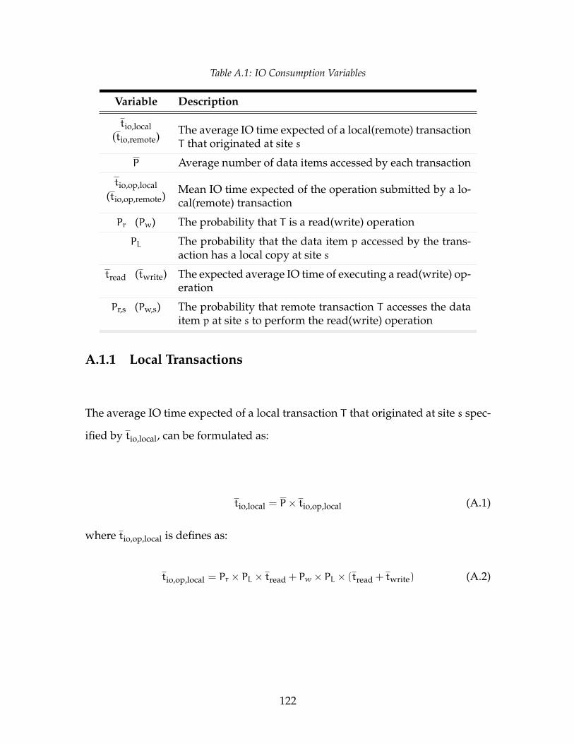
Table A.1: IO Consumption Variables
Variable Description
tio,local(tio,remote) The average IO time expected of a local(remote) transaction
T that originated at site s
P Average number of data items accessed by each transaction
tio,op,local(tio,op,remote)
Mean IO time expected of the operation submitted by a lo-cal(remote) transaction
Pr (Pw) The probability that T is a read(write) operation
PL The probability that the data item p accessed by the trans-action has a local copy at site s
tread (twrite) The expected average IO time of executing a read(write) op-eration
Pr,s (Pw,s) The probability that remote transaction T accesses the dataitem p at site s to perform the read(write) operation
A.1.1 Local Transactions
The average IO time expected of a local transaction T that originated at site s spec-
ified by tio,local, can be formulated as:
tio,local = P× tio,op,local (A.1)
where tio,op,local is defines as:
tio,op,local = Pr × PL × tread + Pw × PL × (tread + twrite) (A.2)
122
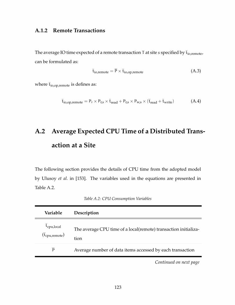
A.1.2 Remote Transactions
The average IO time expected of a remote transaction T at site s specified by tio,remote,
can be formulated as:
tio,remote = P× tio,op,remote (A.3)
where tio,op,remote is defines as:
tio,op,remote = Pr × Pr,s × tread + Pr,s × Pw,s × (tread + twrite) (A.4)
A.2 Average Expected CPU Time of a Distributed Trans-
action at a Site
The following section provides the details of CPU time from the adopted model
by Ulusoy et al. in [153]. The variables used in the equations are presented in
Table A.2.
Table A.2: CPU Consumption Variables
Variable Description
tcpu,local
(tcpu,remote)The average CPU time of a local(remote) transaction initializa-
tion
P Average number of data items accessed by each transaction
Continued on next page
123
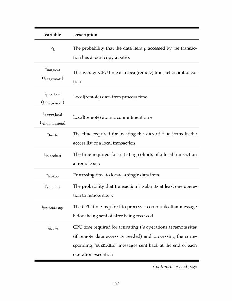
Variable Description
PL The probability that the data item p accessed by the transac-
tion has a local copy at site s
tinit,local
(tinit,remote)The average CPU time of a local(remote) transaction initializa-
tion
tproc,local
(tproc,remote)Local(remote) data item process time
tcomm,local
(tcomm,remote)Local(remote) atomic commitment time
tlocate The time required for locating the sites of data items in the
access list of a local transaction
tinit,cohort The time required for initiating cohorts of a local transaction
at remote sits
tlookup Processing time to locate a single data item
Psubmit,k The probability that transaction T submits at least one opera-
tion to remote site k
tproc,message The CPU time required to process a communication message
before being sent of after being received
tactive CPU time required for activating T ’s operations at remote sites
(if remote data access is needed) and processing the corre-
sponding “WORKDONE” messages sent back at the end of each
operation execution
Continued on next page
124
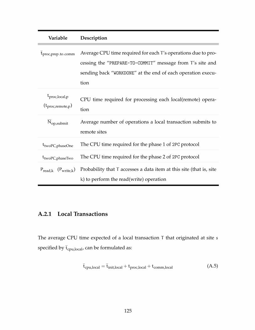
Variable Description
tproc,prep to comm Average CPU time required for each T ’s operations due to pro-
cessing the “PREPARE-TO-COMMIT” message from T ’s site and
sending back “WORKDONE” at the end of each operation execu-
tion
tproc,local,p
(tproc,remote,p)CPU time required for processing each local(remote) opera-
tion
Nop,submit Average number of operations a local transaction submits to
remote sites
ttwoPC,phaseOne The CPU time required for the phase 1 of 2PC protocol
ttwoPC,phaseTwo The CPU time required for the phase 2 of 2PC protocol
Pread,k (Pwrite,k) Probability that T accesses a data item at this site (that is, site
k) to perform the read(write) operation
A.2.1 Local Transactions
The average CPU time expected of a local transaction T that originated at site s
specified by tcpu,local, can be formulated as:
tcpu,local = tinit,local + tproc,local + tcomm,local (A.5)
125
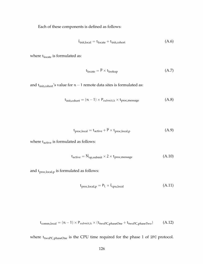
Each of these components is defined as follows:
tinit,local = tlocate + tinit,cohort (A.6)
where tlocate is formulated as:
tlocate = P× tlookup (A.7)
and tinit,cohort’s value for n− 1 remote data sites is formulated as:
tinit,cohort = (n− 1)× Psubmit,k × tproc,message (A.8)
tproc,local = tactive + P× tproc,local,p (A.9)
where tactive is formulated as follows:
tactive = Nop,submit × 2× tproc,message (A.10)
and tproc,local,p is formulated as follows:
tproc,local,p = PL × tcpu,local (A.11)
tcomm,local = (n− 1)× Psubmit,k × (ttwoPC,phaseOne + ttwoPC,phaseTwo) (A.12)
where ttwoPC,phaseOne is the CPU time required for the phase 1 of 2PC protocol.
126
Recall that the prepare phase of 2PC protocol is sending a message to each of the
cohort sites and processing the messages sent back from those sites (Section 2.1.6).
It is formulated as follows:
ttwoPC,phaseOne = 2× tproc,message (A.13)
and ttwoPC,phaseTwo is the CPU time required for the phase 2 of 2PC protocol. Re-
member that the commit phase of 2PC protocol is sending the final decision message
to cohort sites (Section 2.1.6). It is formulated as follows:
ttwoPC,phaseTwo = tproc,message (A.14)
A.2.2 Remote Transactions
The average CPU time expected of a remote transaction T at site s specified by
CPUr, can be formulated as:
tcpu,remote = tinit,remote + tproc,remote + tcomm,remote (A.15)
Each of these components is defined as follows:
tinit,remote = Psubmit,k × tproc,message (A.16)
127
tproc,remote = P× (tproc,prep to comm + tproc,remote,p) (A.17)
where tproc,prep to comm is formulated as follows:
tproc,prep to comm = (Pr × Pread,k + Pw × Pwrite,k)× (2× tproc,message) (A.18)
and tproc,remote,p is formulated as follows:
tproc,remote,p = (Pr × Pread,k + Pw × Pwrite,k)× tcpu,remote (A.19)
tcomm,remote = Psubmit,k × (ttwoPC,phaseOne + ttwoPC,phaseTwo) (A.20)
where ttwoPC,phaseOne and ttwoPC,phaseTwo are formulated as follows:
ttwoPC,phaseOne = 2× tproc,message (A.21)
ttwoPC,phaseTwo = tproc,message (A.22)
A.3 Agent Deadlock Handling Model
Theorem 1. An agent will trace a directed graph if the ID of each edge in the cycle is
greater than the ID of head edge. Head edge is the initial edge in a tracing process. Hence,
128
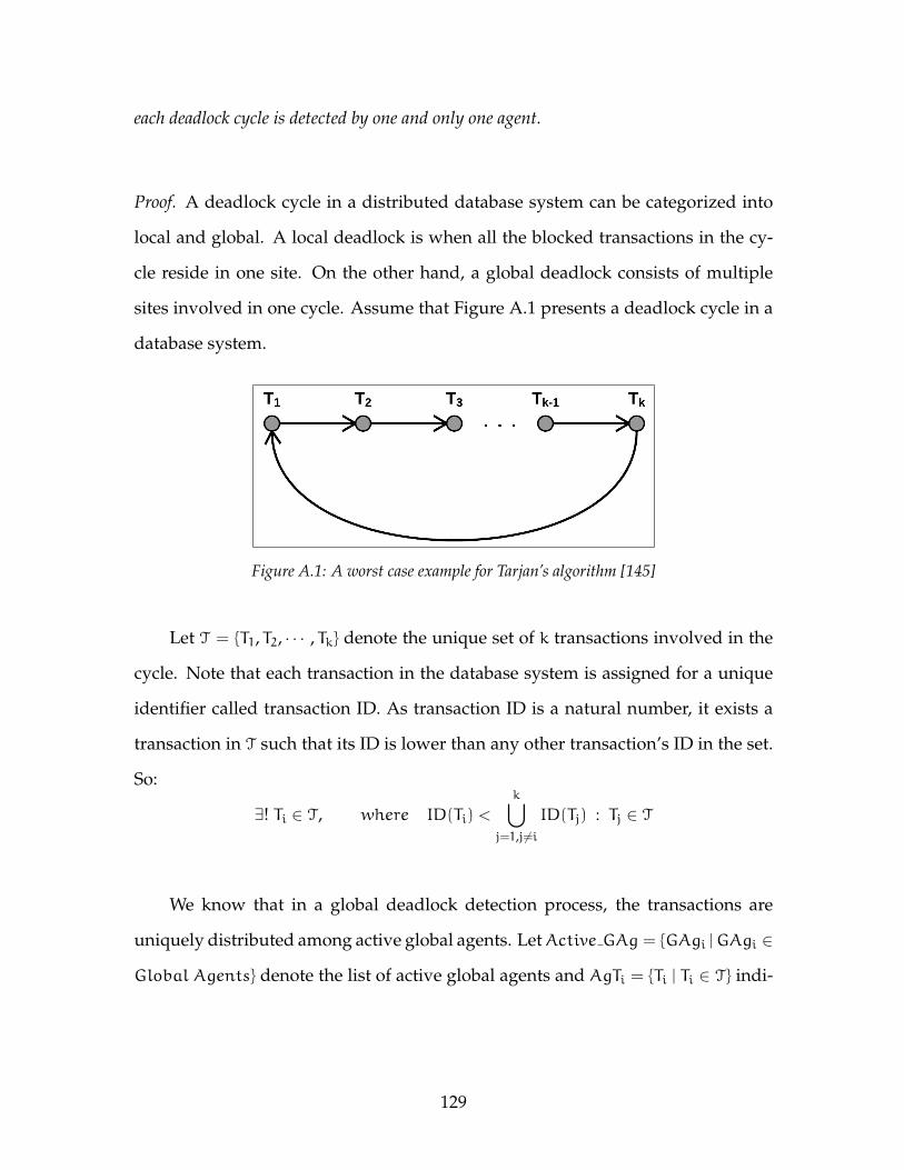
each deadlock cycle is detected by one and only one agent.
Proof. A deadlock cycle in a distributed database system can be categorized into
local and global. A local deadlock is when all the blocked transactions in the cy-
cle reside in one site. On the other hand, a global deadlock consists of multiple
sites involved in one cycle. Assume that Figure A.1 presents a deadlock cycle in a
database system.
Figure A.1: A worst case example for Tarjan’s algorithm [145]
Let T = {T1, T2, · · · , Tk} denote the unique set of k transactions involved in the
cycle. Note that each transaction in the database system is assigned for a unique
identifier called transaction ID. As transaction ID is a natural number, it exists a
transaction in T such that its ID is lower than any other transaction’s ID in the set.
So:
∃! Ti ∈ T, where ID(Ti) <
k⋃j=1,j6=i
ID(Tj) : Tj ∈ T
We know that in a global deadlock detection process, the transactions are
uniquely distributed among active global agents. LetActive GAg = {GAgi |GAgi ∈
Global Agents} denote the list of active global agents and AgTi = {Ti | Ti ∈ T} indi-
129
cate the list of transactions that GAgi is responsible for. Thus:
∃! GAgi ∈ Active GAg, where Ti ∈ AgTi
Since Ti has the lowest ID in the cycle, then GAgi is the only global agent that
can find the cycle.
In a local deadlock situation, the cycle is handled by one agent only. Because
there is only one transaction in a deadlock that holds the lowest ID in compare to
other transactions in the cycle, the deadlock can be found only once.
Theorem 2. In a deadlock detection process, if k is the number of agents involved to detect
deadlocks in a graph with n nodes, the total computation cost in the worst case scenario
would be:
number of messages = T(e)×n× k+ 12
where T(e) indicates messages transmission time unit.
Proof. In ADCombine, each agent will trace [nk ] transactions in each detection process
in the worst case scenario. So, the cost of tracing for the first agent would be n
where n denotes the edges of the directed wait-for-graph. The second agent will
trace part of the biggest deadlock excluding the part that first agent is responsible.
So, the cost of tracing for the second agent would be n− [nk ]. The same idea applies
to the next agents. Thus, k’s agent will trace part of the biggest deadlock excluding
the parts that k−1 agents are responsible (i.e., n−(k−1)[nk ]). Therefore, the number
130
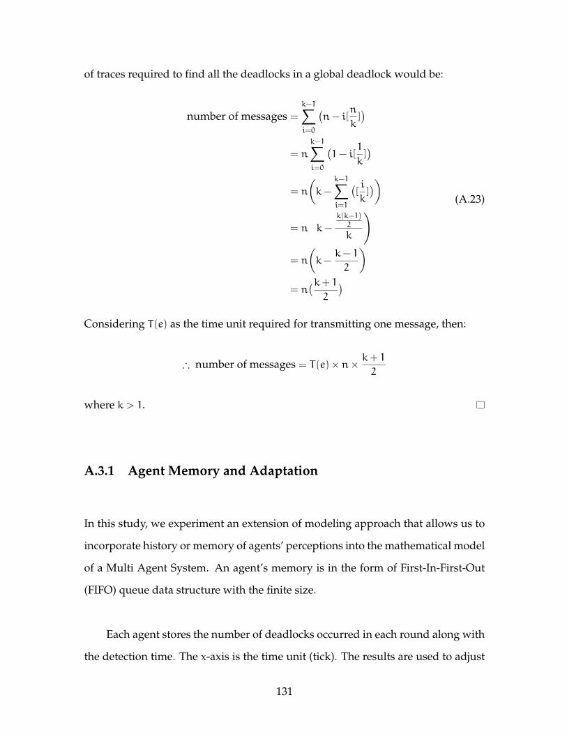
of traces required to find all the deadlocks in a global deadlock would be:
number of messages =
k−1∑i=0
(n− i[
n
k])
= n
k−1∑i=0
(1− i[
1
k])
= n
(k−
k−1∑i=1
([i
k]))
= n
(k−
k(k−1)2
k
)
= n
(k−
k− 1
2
)= n
(k+ 12
)
(A.23)
Considering T(e) as the time unit required for transmitting one message, then:
∴ number of messages = T(e)×n× k+ 12
where k > 1.
A.3.1 Agent Memory and Adaptation
In this study, we experiment an extension of modeling approach that allows us to
incorporate history or memory of agents’ perceptions into the mathematical model
of a Multi Agent System. An agent’s memory is in the form of First-In-First-Out
(FIFO) queue data structure with the finite size.
Each agent stores the number of deadlocks occurred in each round along with
the detection time. The x-axis is the time unit (tick). The results are used to adjust
131
the agents’ behaviour to the system’s current configuration. In this case, we see
that as the simulation runs, the deadlock detection/resolution condition evolve to
a steady state in which the number of deadlocks at each interval does not change,
even though individual agents continue to process. In general, the adaptive agents
appear to be more efficient than the non-adaptive agents [87].
We quantify the system’s efficiency more precisely by deadlock ratio trend.
The deadlock ratio trend is the system alignment an agent will predict for the de-
cisions in the future. The trend is used to adjust the detection interval, number
of active agents, and influence the deadlock resolver agents. The deadlock ratio
function defines as follows:
δ =
n∑i=1
tidi −ntd
t2i − t2
(A.24)
where δ is the deadlock ratio, t is the detection time, n is the memory depth, and
d is the number of deadlocks detected. tan δ is used to identify the trend of the
system. The value of this metric is expected to be high when there are many dead-
locks, and conversely, it is low, when there is a significant number of unnecessary
agents.
A.4 Simulation UML Diagrams
A sample package specification of DRTDBS simulator is presented in Figure A.2.
The simulator deadlock handling architecture diagram illustrated in Figure A.3.
132
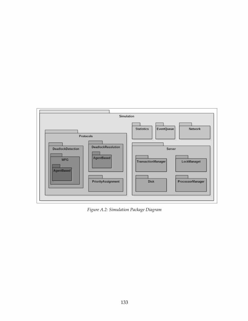
Figure A.2: Simulation Package Diagram
133
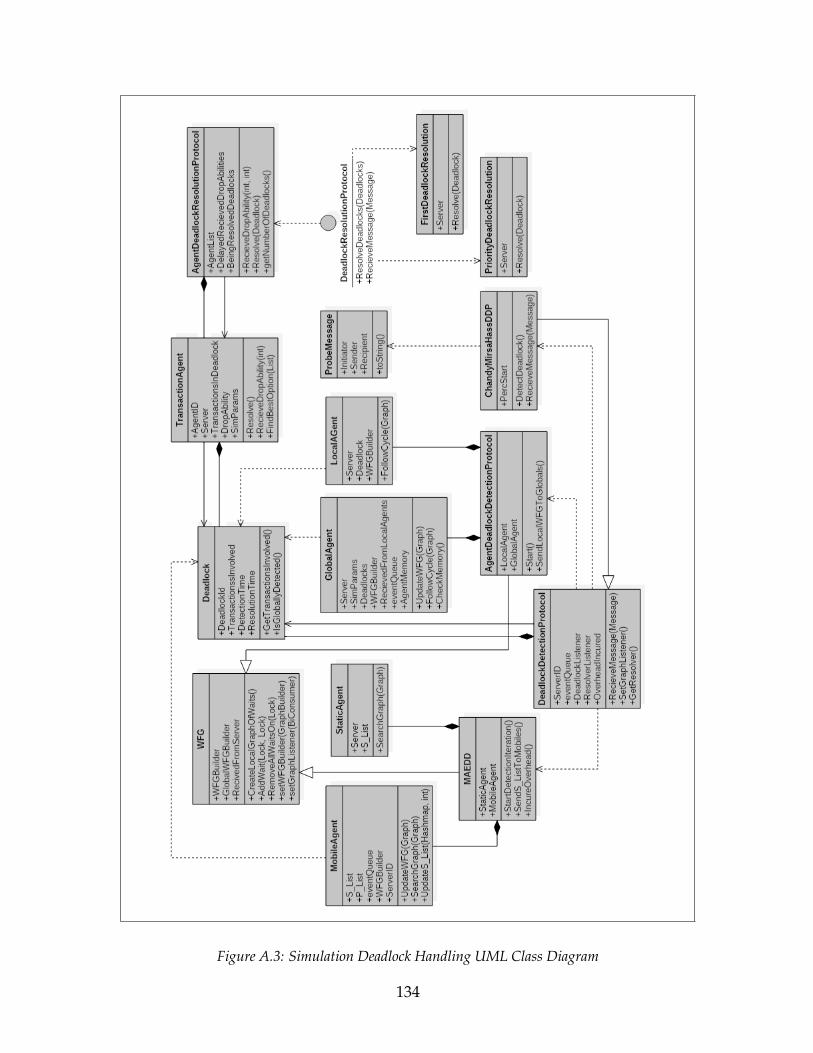
Figure A.3: Simulation Deadlock Handling UML Class Diagram
134
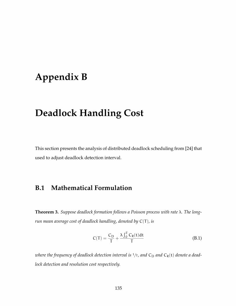
Appendix B
Deadlock Handling Cost
This section presents the analysis of distributed deadlock scheduling from [24] that
used to adjust deadlock detection interval.
B.1 Mathematical Formulation
Theorem 3. Suppose deadlock formation follows a Poisson process with rate λ. The long-
run mean average cost of deadlock handling, denoted by C(T), is
C(T) =CDT
+λ∫T0 CR(t)dt
T(B.1)
where the frequency of deadlock detection interval is 1/T , and CD and CR(t) denote a dead-
lock detection and resolution cost respectively.
135
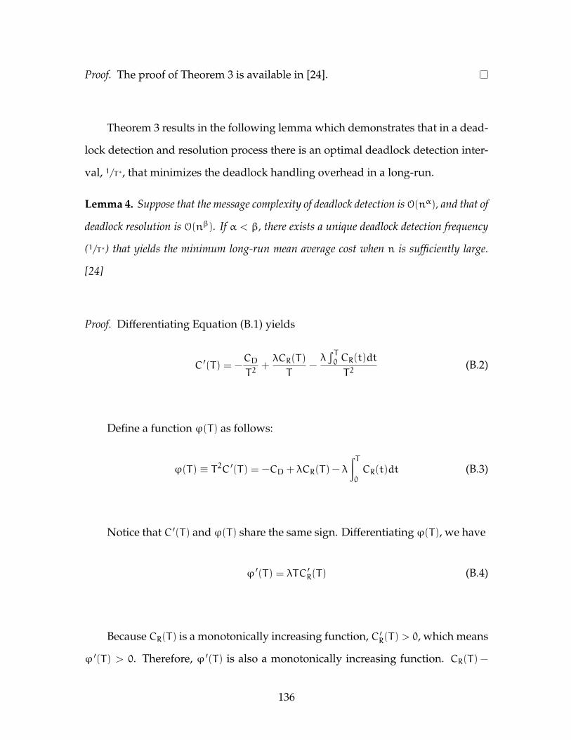
Proof. The proof of Theorem 3 is available in [24].
Theorem 3 results in the following lemma which demonstrates that in a dead-
lock detection and resolution process there is an optimal deadlock detection inter-
val, 1/T∗, that minimizes the deadlock handling overhead in a long-run.
Lemma 4. Suppose that the message complexity of deadlock detection is O(nα), and that of
deadlock resolution is O(nβ). If α < β, there exists a unique deadlock detection frequency
(1/T∗) that yields the minimum long-run mean average cost when n is sufficiently large.
[24]
Proof. Differentiating Equation (B.1) yields
C ′(T) = −CDT2
+λCR(T)
T−λ∫T0 CR(t)dt
T2(B.2)
Define a function ϕ(T) as follows:
ϕ(T) ≡ T2C ′(T) = −CD + λCR(T) − λ
∫T0CR(t)dt (B.3)
Notice that C ′(T) and ϕ(T) share the same sign. Differentiating ϕ(T), we have
ϕ ′(T) = λTC ′R(T) (B.4)
Because CR(T) is a monotonically increasing function, C ′R(T) > 0, which means
ϕ ′(T) > 0. Therefore, ϕ ′(T) is also a monotonically increasing function. CR(T) −
136
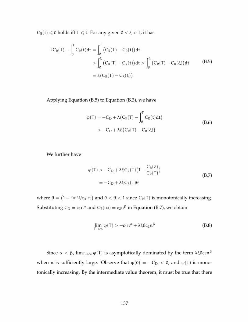
CR(t) 6 0 holds iff T 6 t. For any given 0 < ξ < T , it has
TCR(T) −
∫T0CR(t)dt =
∫T0
(CR(T) −CR(t)
)dt
>
∫ξ0
(CR(T) −CR(t)
)dt >
∫ξ0
(CR(T) −CR(ξ)
)dt
= ξ(CR(T) −CR(ξ)
)(B.5)
Applying Equation (B.5) to Equation (B.3), we have
ϕ(T) = −CD + λ(CR(T) −
∫T0CR(t)dt
)> −CD + λξ
(CR(T) −CR(ξ)
) (B.6)
We further have
ϕ(T) > −CD + λξCR(T)(1−
CR(ξ)
CR(T)
)= −CD + λξCR(T)θ
(B.7)
where θ =(1− CR(ξ)/CR(T)
)and 0 < θ < 1 since CR(T) is monotonically increasing.
Substituting CD = c1nα and CR(∞) = c2n
β in Equation (B.7), we obtain
limT→∞ϕ(T) > −c1n
α + λξθc2nβ (B.8)
Since α < β, limT→∞ϕ(T) is asymptotically dominated by the term λξθc2nβ
when n is sufficiently large. Observe that ϕ(0) = −CD < 0, and ϕ(T) is mono-
tonically increasing. By the intermediate value theorem, it must be true that there
137
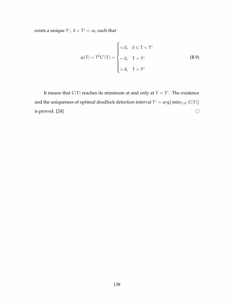
exists a unique T∗, 0 < T∗ <∞, such that
ϕ(T) = T2C ′(T) =
< 0, 0 6 T < T∗
= 0, T = T∗
> 0, T > T∗
(B.9)
It means that C(T) reaches its minimum at and only at T = T∗. The existence
and the uniqueness of optimal deadlock detection interval T∗ = arg(
minT>0 C(T))
is proved. [24]
138