Explosive Atmosphere Sensors
117
Explosive Atmosphere Sensors
-
Upload
khangminh22 -
Category
Documents
-
view
6 -
download
0
Transcript of Explosive Atmosphere Sensors

Explosive Atmosphere Sensors
US
180.0
00
.2/10.17
12
1
SENSORS FOR POTENTIALLY EXPLOSIVE ATMOSPHERES
Sensors for Potentially Explosive Locations:
HDA 4700 ATEX, CSA, IECEx Flameproof enclosure
EDS 4400 ATEX, CSA, IECEx Flameproof enclosure, programmable
ETS 4500 ATEX, CSA, IECEx Flameproof enclosure
HDA 4700 ATEX Intrinsically safe
HDA 4400 ATEX Intrinsically safe
HDA 4300 ATEX Intrinsically safe
HDA 4100 ATEX Intrinsically safe
EDS 4400 ATEX Intrinsically safe, programmable
EDS 4300 ATEX Intrinsically safe, programmable
EDS 4100 ATEX Intrinsically safe, programmable
HDA 4700 CSA Intrinsically Safe
HDA 4400 CSA Intrinsically Safe
HDA 4300 CSA Intrinsically Safe
HDA 4100 CSA Intrinsically Safe
HDA 4700 IECEx Intrinsically safe
HDA 4400 IECEx Intrinsically safe
HDA 4300 IECEx Intrinsically safe
HDA 4100 IECEx Intrinsically safe
HDA 4700 Flush membrane ATEX Intrinsically safe
HDA 4400 Flush membrane ATEX Intrinsically safe
HDA 4300 Flush membrane ATEX Intrinsically safe
HDA 4700 Flush membrane IECEx Intrinsically safe
HDA 4400 Flush membrane IECEx Intrinsically safe
HDA 4300 Flush membrane IECEx Intrinsically safe
HDA 4700 Flush membrane ATEX, CSA, IECEx flameproof enclosure HFS 2100 ATEX Intrinsically safe
HFS 2500 ATEX Intrinsically safe
HFT 3100 ATEX CSA IECEx flameproof enclosure HFT 3100 ATEX IECEx Intrinsically Safe
Further sensors for potentially explosive locations can be found in the section "OEM Products for Large Volume Production" .
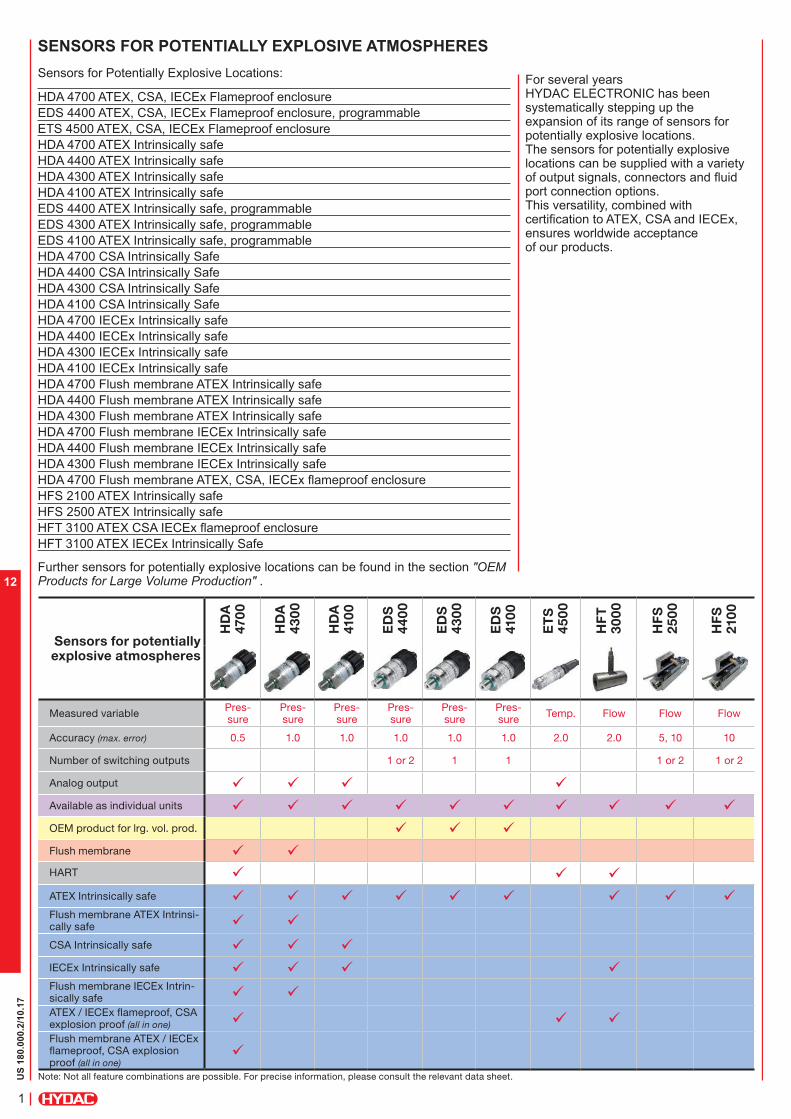
For several years HYDAC ELECTRONIC has been systematically stepping up the expansion of its range of sensors for potentially explosive locations.The sensors for potentially explosive locations can be supplied with a variety of output signals, connectors and fluid port connection options. This versatility, combined with certification to ATEX, CSA and IECEx, ensures worldwide acceptance of our products.
Sensors for potentially explosive atmospheres
HD
A
470
0
HD
A
43
00
HD
A
410
0
ED
S
44
00
ED
S
43
00
ED
S
410
0
ET
S
45
00
HF
T
30
00
HF
S
25
00
HF
S
210
0
Measured variable Pres-sure
Pres-sure
Pres-sure
Pres-sure
Pres-sure
Pres-sure
Temp. Flow Flow Flow
Accuracy (max. error) 0.5 1.0 1.0 1.0 1.0 1.0 2.0 2.0 5, 10 10
Number of switching outputs 1 or 2 1 1 1 or 2 1 or 2
Analog output ü ü ü üAvailable as individual units ü ü ü ü ü ü ü ü ü üOEM product for lrg. vol. prod. ü ü üFlush membrane ü üHART ü ü üATEX Intrinsically safe ü ü ü ü ü ü ü ü üFlush membrane ATEX Intrinsi-cally safe ü üCSA Intrinsically safe ü ü üIECEx Intrinsically safe ü ü ü üFlush membrane IECEx Intrin-sically safe ü üATEX / IECEx flameproof, CSA explosion proof (all in one) ü ü üFlush membrane ATEX / IECEx flameproof, CSA explosion proof (all in one)
ü
Note: Not all feature combinations are possible. For precise information, please consult the relevant data sheet.
US
18.3
85.1
/10.17
2
12
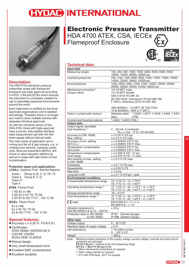
Electronic Pressure Transmitter
HDA 4700 ATEX, CSA, IECEx Flameproof Enclosure
Description:The HDA 4700 electronic pressure transmitter series with flameproof enclosure has triple approval according to ATEX, CSA and IECEx which ensures the instrument is universally suitable for use in potentially explosive environments around the world.
Each instrument is certified by the three approvals organizations and is labelled accordingly. Therefore there is no longer any need to stock multiple devices with separate individual approvals.
As with the industrial version of the HDA 4700, those with triple approval have a proven, fully-welded stainless steel measurement cell with thin film strain gauge without internal seals.
The main areas of application are in mining and the oil & gas industry, e.g. in underground vehicles, hydraulic power units, blow-out preventers (BOPs), drill drives or valve actuation stations as well as in areas with high levels of dust contamination.
Protection types and applications: CCSAUS Explosion Proof - Seal Not Required
Class I Group A, B, C, D, T6, T5 Class II Group E, F, G Class III Type 4
ATEX Flame Proof
I M2 Ex d I Mb II 2G Ex d IIC T6, T5 Gb II 2D Ex tb IIIC T110 .. 130 °C Db
IECEx Flame Proof
Ex d I Mb Ex d IIC T6, T5 Gb Ex tb IIIC T110 .. 130 °C Db
Special features: Accuracy ≤ ± 0.25 % FS B.F.S.L
Certificates:ATEX KEMA 10ATEX0100 XCSA MC 224264IECEx KEM 10.0053X
Robust design
Very small temperature error
Excellent EMC characteristics
Excellent durability
Technical data:Input data
Measuring ranges 100, 300, 500, 1000, 1500, 3000, 5000, 6000, 9000, 10000, 15000, 20000, 30000 psi
Overload pressures 290, 1160, 1160, 2900, 2900, 7250, 11600, 11600, 14500, 14500, 23200, 38400, 43500 psi
Burst pressures 1450, 2900, 2900, 7250, 7250, 14500, 29000, 29000, 29000, 29000, 43500, 43500, 58000 psi
Mechanical connection1) 1/4-18 NPT, male (torque value) 1/4-18 NPT, female
SAE 6 9/16-18 UNF 2A
SF 250 CS20, Autoclave(7/16-20-UNF 2B) F 250 C, Autoclave (9/16-18 UNF 2B)
30lb-ft(40Nm) - 1/4 NPT, SF 250 CX20 15 lb-ft(20Nm) - SAE 6, F 250 C
Parts in contact with medium Stainless steel: 1.4542; 1.4571; 1.4435; 1.4404; 1.4301Seal: FPM
Conduit and housing material 1.4404; 1.4435 (316L)Output data
Output signal, permitted load resistance 2) 4 .. 20 mA, 2 conductor
RLmax.= (UB - 8 V) / 20 mA [kW]
Accuracy to DIN 16086, ≤ ± 0.25 % FS typ.Max. setting ≤ ± 0.5 % FS max.Accuracy at min. setting ≤ ± 0.0045% FS/°F typ.(B.F.S.L.) ≤ ± 0.0085% FS/°F max.
Temperature compensation ≤ ± 0.0045% FS/°F typ.Zero point ≤ ± 0.0085% FS/°F max.
Temperature compensation ≤ ± 0.008 % FS / °C typ.Over range ≤ ± 0.015 % FS / °C max.
Non-linearity at max. setting ≤ ± 0.3 % FS max.to DIN 16086
Hysteresis ≤ ± 0.1 % FS max.
Repeatability ≤ ± 0.05 % FS
Rise time ≤ 1.5 ms
Long-term drift ≤ ± 0.1 % FS typ. / year
Environmental conditions
Compensated temperature range T5, T130 °C: -13..+176°F T6, T110 °C: -13..+140°F
Operating temperature range 3) T5, T130 °C: -40..+176°F / -4..+176°F T6, T110 °C: -40..+140°F / -4..+140°F
Storage temperature range -40..+212°FFluid temperature range 3) T5, T130 °C: -40..+176°F / -4..+176°F
T6, T110 °C: -40..+140°F / -4..+140°F mark EN 61000-6-1 / 2 / 3 / 4
EN 60079-0 / 1 / 31
Vibration resistance to ≤ 20 gDIN EN 60068-2-6 at 10 .. 500 Hz
Protection class to IEC 60529 IP 65 (Vented Gauge) to ISO 20653 IP 69K (Sealed Gauge)
Other data
Voltage supply 8 .. 30 V DC
Residual ripple of supply voltage ≤ 5 %
Life expectancy > 10 million cycles0 .. 100 % FS
Weight ~ 300 g
Note: Reverse polarity protection of the supply voltage, excess voltage, override and short circuit protection are provided. FS (Full Scale) = relative to the full measuring range B.F.S.L.= Best Fit Straight Line 1) Other mechanical connections on request2) Other output signals on request3) -4°F with FPM seal, -40°F on request
US
18.3
85.1
/10.17
2
12
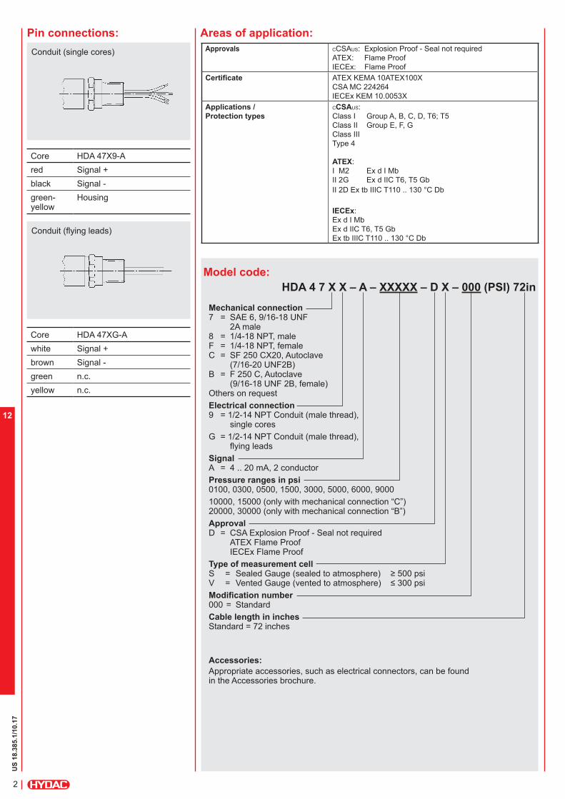
Pin connections:
Model code:
HDA 4 7 X X – A – XXXXX – D X – 000 (PSI) 72in
Mechanical connection 7 = SAE 6, 9/16-18 UNF
2A male8 = 1/4-18 NPT, male F = 1/4-18 NPT, female C = SF 250 CX20, Autoclave
(7/16-20 UNF2B) B = F 250 C, Autoclave
(9/16-18 UNF 2B, female) Others on request
Electrical connection 9 = 1/2-14 NPT Conduit (male thread),
single cores
G = 1/2-14 NPT Conduit (male thread), flying leads
Signal A = 4 .. 20 mA, 2 conductor
Pressure ranges in psi 0100, 0300, 0500, 1500, 3000, 5000, 6000, 9000
10000, 15000 (only with mechanical connection “C”) 20000, 30000 (only with mechanical connection “B”)
Approval D = CSA Explosion Proof - Seal not required
ATEX Flame Proof IECEx Flame Proof
Type of measurement cell S = Sealed Gauge (sealed to atmosphere) ≥ 500 psi V = Vented Gauge (vented to atmosphere) ≤ 300 psiModification number 000 = Standard
Cable length in inches Standard = 72 inches
Accessories:
Appropriate accessories, such as electrical connectors, can be found in the Accessories brochure.
Areas of application:
Approvals CCSAUS: Explosion Proof - Seal not required
ATEX: Flame ProofIECEx: Flame Proof
Certificate ATEX KEMA 10ATEX100X
CSA MC 224264
IECEx KEM 10.0053X
Applications /
Protection types
CCSAUS: Class I Group A, B, C, D, T6; T5Class II Group E, F, G
Class III
Type 4
ATEX:I M2 Ex d I Mb
II 2G Ex d IIC T6, T5 Gb
II 2D Ex tb IIIC T110 .. 130 °C Db
IECEx: Ex d I Mb
Ex d IIC T6, T5 Gb
Ex tb IIIC T110 .. 130 °C Db
Conduit (single cores)
Core HDA 47X9-A
red Signal +black Signal -
green-yellow
Housing
Conduit (flying leads)
Core HDA 47XG-A
white Signal +brown Signal -
green n.c.
yellow n.c.
US
18.3
85.1
/10.17
4
12
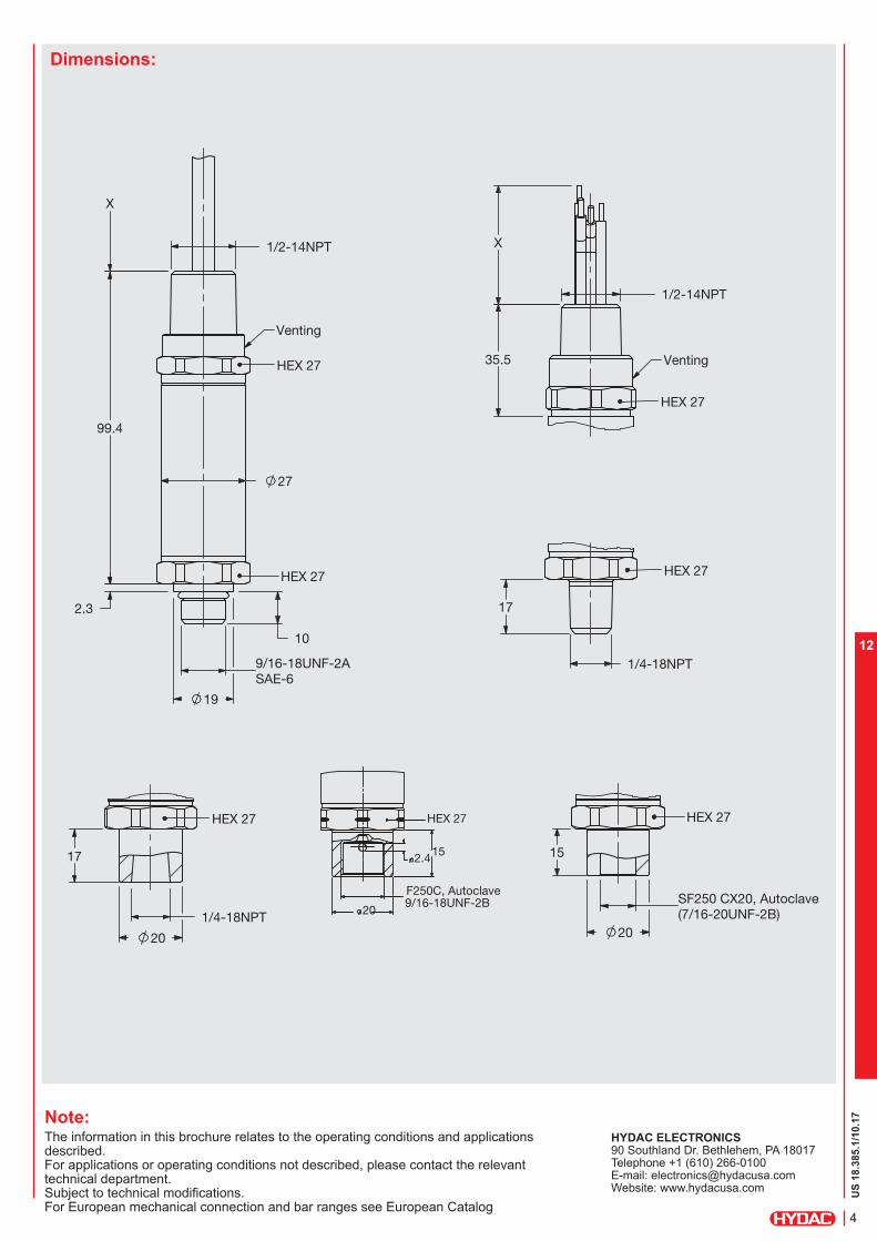
Dimensions:
Note:The information in this brochure relates to the operating conditions and applications described.For applications or operating conditions not described, please contact the relevant technical department.Subject to technical modifications.For European mechanical connection and bar ranges see European Catalog
HYDAC ELECTRONICS 90 Southland Dr. Bethlehem, PA 18017 Telephone +1 (610) 266-0100 E-mail: [email protected]: www.hydacusa.com
HEX 27
1/4-18NPT
17
HEX 27
HEX 27
Venting
SAE-69/16-18UNF-2A
27
2.3
X
10
99.4
19
1/2-14NPT
Venting
HEX 27
35.5
X
1/2-14NPT
HEX 27
17
1/4-18NPT
20
HEX 27
SF250 CX20, Autoclave(7/16-20UNF-2B)
20
15 2.4
HEX 27
15
F250C, Autoclave9/16-18UNF-2B
20

US
18.3
85.1
/10.17
5
12

US
18.3
86.1
/10.17
6
12
Electronic Pressure Switch
EDS 4400 Programmable ATEX, CSA, IECEx Flameproof Enclosure
Description:The programmable electronic pressure switch EDS 4400 with flameproof enclosure has triple approval according to ATEX, CSA and IECEx which ensures the instrument is universally suitable for use in potentially explosive environments around the world. Each instrument is certified by the three approval organizations and is labelled accordingly. Therefore there is no longer any need to stock multiple devices with separate individual approvals.
As with the industrial version of the EDS 4400, those with triple approval have a proven, fully-welded stainless steel measurement cell with thin film strain gauge without internal seals.
The instrument is programmed conveniently and simply using the HPG 3000 HYDAC programming unit.
The main areas of application are in mining and the oil & gas industry, e.g. in underground vehicles, hydraulic power units, blow-out preventers (BOPs), drill drives or valve actuation stations as well as in areas with high dust loads.
Protection types and applications: CCSAUS Explosion Proof - Seal Not Required
Class I Group A, B, C, D, T6, T5 Class II Group E, F, G Class III Type 4
ATEX Flame Proof
I M2 Ex d I Mb II 2G Ex d IIC T6, T5 Gb II 2D Ex tb IIIC T110 .. 130 °C Db
IECEx Flame Proof
Ex d I Mb Ex d IIC T6, T5 Gb Ex tb IIIC T110 .. 130 °C Db
Special features: Accuracy ≤ ± 0.5% FS B.F.S.L.
Certificates:ATEX KEMA 10ATEX100 XCSA MC 224264IECEx KEM 10.0053X
Robust design
Very small temperature error
Excellent EMC characteristics
Excellent durability
Technical data:Input data
Measuring ranges 100, 300, 500, 1000, 1500, 3000, 5000, 6000, 9000, 10000, 15000, 20000, 30000 psi
Overload pressures 290, 1160, 1160, 2900, 2900, 7250, 11600, 11600, 14500, 14500, 23200, 38400, 43500 psi
Burst pressure 1450, 2900, 2900, 7250, 7250, 14500, 29000, 29000, 29000, 29000, 43500, 43500, 58000 psi
Mechanical connection1) 1/4-18 NPT, male (torque value) 1/4-18 NPT, female
SAE 6 9/16-18 UNF 2A
SF 250 CX20, Autoclave(7/16-20-UNF 2B)
SAE 6: 15lb-ft(20Nm)SF 250 CX20, 1/4 NPT: 30lb-ft(40Nm)
Parts in contact with medium Stainless steel: 1.4542; 1.4571; 1.4435; 1.4404; 1.4301
Seal: FPMConduit and housing material 1.4404; 1.4435 (316L)Output data
Accuracy to DIN 16086, ≤ ± 0.5 % FS typ.Max. setting ≤ ± 1.0 % FS max.
Repeatability ≤ ± 0.1 % FS max.Temperature drift ≤ ± 0.017% FS/°F max. zero point
≤ ± 0.017% FS/°F max. rangeSwitch output 2) 1 or 2 PNP transistor switch outputs
Output load max. 1.2 A on version with 1 switch output max. 1 A each on version with 2 switch outputs
Switch points / hysteresis / N/C or user-programmable with HYDAC N/O function Programming Unit HPG 3000
Rising switch point and 8 .. 2000 ms; User-programmable with falling switch point delay HYDAC Programming Unit HPG 3000
Long-term drift ≤ ± 0.3 % FS typ. / year
Environmental conditions
Compensated temperature range T5, T130 °C: -13..+176°F T6, T110 °C: -13..+140°F
Operating temperature range3) T5, T130 °C: -40..+176°F / -4..+176°F T6, T110 °C: -40..+140°F / -4..+140°F
Storage temperature range -40..+212°FFluid temperature range3) T5, T130 °C: -40..+176°F / -4..+176°F
T6, T110 °C: -40..+140°F / -4..+140°F mark EN 61000-6-1 / 2 / 3 / 4
EN 60079-0 / 1 / 31
Vibration resistance to ≤ 20 gDIN EN 60068-2-6 at 10 .. 500 Hz
Protection class to IEC 60529 IP 65 (Vented Gauge) to ISO 20653 IP 69K (Sealed Gauge)
Other data
Voltage supply 12 .. 30 V DC
Current consumption ~ 25 mA (plus switching current)
Residual ripple of supply voltage ≤ 5 %Life expectancy > 10 million cycles
0 .. 100 % FS
Weight ~ 300 g
Note: Reverse polarity protection of the supply voltage, excess voltage, override and short circuit protection are provided. FS (Full Scale) = relative to complete measuring range 1) Other mechanical connection options available on request2) NPN switching outputs upon request3) -4 °F with FPM seal, -40 °F on request

US
18.3
86.1
/10.17
7
12
Pin connections:
Model code:
EDS 4 4 X X –XXXX – X P – D X – 000 (PSI) 72in
Mechanical connection 7 = SAE 6, 9/16-18 UNF
2A male
8 = 1/4-18 NPT, male
F = 1/4-18 NPT, female
C = SF 250 CX20, Autoclave (7/16-20 UNF2B) B = F 250 C, Autoclave
(9/16-18 UNF 2B, female)
Others on request
Electrical connection 9 = 1/2-14 NPT Conduit
(male thread), single cores
G = 1/2-14 NPT Conduit (male thread), flying leads
Pressure ranges in psi 0100, 0300, 0500, 1500, 3000, 5000, 6000, 9000
10000, 15000 (only with mechanical connection “C”)
20000, 30000 (only with mechanical connection “B”)
Number of switch outputs 1 = 1 switch output 2 = 2 switch outputs
Output type P = Programmable
Approval D = CSA Explosion Proof - Seal not required
ATEX Flame Proof IECEx Flame Proof
Type of measurement cell S = Sealed Gauge (sealed to atmosphere) ≥ 500 psi V = Vented Gauge (vented to atmosphere) ≤ 300 psiModification number 000 = Standard
Cable length in inches Standard = 72 inches
Accessories:
Appropriate accessories, such as electrical connectors, can be found in the Accessories brochure.
Areas of application:
Conduit (single cores)
Core EDS 44x9-*-1P EDS 44x9-*-2P
red +UB +UB
white Switch output 1 Switch output 1
brown --------- Switch output 2
black 0 V 0 V
green SDA1) SDA1)
Conduit (flying leads)
Setting ranges for the switch outputs: - Switch point or upper switch value
5% .. 100% of the measurement range
- Hysteresis or lower switch value1% .. 96% of the measurement range
Core EDS 44xG-*-1P EDS 44xG-*-2P
white Switch output 1 Switch output 1
brown n.c. Switch output 2
green SDA1) SDA1)
yellow 0 V 0 V
grey +UB +UB
1) Programming line
Programming Unit:(must be ordered separately)
HPG 3000 – 000 Portable Programming Unit Part. No. 909 422
HPG 3000 Power Supply with connector: Part #02091103
electr. conn.
female 5 pole
The pressure switch can be connected to the HPG 3000 very simply by using the UVM 3000 Connection Adapter (see Accessories Brochure).
CAUTION! The HPG 3000 Programming Unit may only be used outside the potentially explosive area.
Approvals CCSAUS: Explosion Proof - Seal not required
ATEX: Flame ProofIECEx: Flame Proof
Certificate ATEX KEMA 10ATEX100X
CSA MC 224264
IECEx KEM 10.0053X
Applications /
Protection types
CCSAUS: Class I Group A, B, C, D, T6; T5Class II Group E, F, G
Class III
Type 4
ATEX:I M2 Ex d I Mb
II 2G Ex d IIC T6, T5 Gb
II 2D Ex tb IIIC T110 .. 130 °C Db
IECEx: Ex d I Mb
Ex d IIC T6, T5 Gb
Ex tb IIIC T110 .. 130 °C Db

US
18.3
86.1
/10.17
8
12
Dimensions:
Note:The information in this brochure relates to the operating conditions and applications described.For applications or operating conditions not described, please contact the relevant technical department. Subject to technical modifications.For European mechanical connection and bar ranges see European Catalog
HYDAC ELECTRONICS 90 Southland Dr. Bethlehem, PA 18017 Telephone +1 (610) 266-0100 E-mail: [email protected]: www.hydacusa.com
HEX 27
HEX 27
Venting
27
9/16-18UNF-2ASAE-6
2.3
10
99.4
X
19
1/2-14NPT
Venting
HEX 27
X
35.5
1/2-14NPT
HEX 27
1/4-18NPT
17
1/4-18NPT
20
17
HEX 27
SF 250 CX20, Autoclave(7/16-20UNF-2B)
20
15
2.4
HEX 27
15
F250C, Autoclave9/16-18UNF-2B
20

US
18.3
86.1
/10.17
9
12

US
18.3
87.1
/10.17
10
12
Electronic Temperature Transmitter ETS 4500 ATEX, CSA, IECEx Flameproof Enclosure
Description:The electronic temperature transmitter series ETS 4500 with flameproof enclosure has triple approval according to ATEX, CSA and IECEx which ensures that the device is universally suitable for use in potentially explosive environments around the world. Each device is certified by the three approval organizations and is labelled accordingly. Therefore it is no longer necessary to stock multiple devices with separate individual approvals. Based on a silicon semiconductor device and corresponding evaluation electronics, the temperature sensor is designed to measure temperatures in the range -13 to +212 °F. Its main applications are in mining and the oil and gas industry, e.g. in underground vehicles, hydraulic power units, blow-out preventers (BOPs), drill drives or valve actuation stations as well as in areas with high dust loads.
Protection types and applications: CCSAUS Explosion Proof - Seal Not Required
Class I Group A, B, C, D, T6, T5 Class II Group E, F, G Class III Type 4
ATEX Flame Proof
I M2 Ex d I Mb II 2G Ex d IIC T6, T5 Gb II 2D Ex tb IIIC T110 .. 130 °C Db
IECEx Flame Proof
Ex d I Mb Ex d IIC T6, T5 Gb Ex tb IIIC T110 .. 130 °C Db
Special features: Accuracy ≤ ± 1.5 % FS B.F.S.L.
Certificates:ATEX KEMA 10ATEX100 X
CSA MC 224264
IECEx KEM 10.0053X
Robust design
Pressure resistant to 8700 psi(depending on model)
Excellent EMC characteristics
Excellent durability
Technical data:Input data
Measuring principle Silicon semiconductor device
Measuring range -13 to 212°F(-25..+100°F)
Probe length 0.42(10.7), 3.94(100), 9.84(250), 13.8(350) inch(mm)
Pressure resistance 8700 psi (probe length 0.42)
1812 psi (probe length 3.94)
1812 psi (probe length 9.84)
1812 psi (probe length 13.8)
Mechanical connection 1/4-18 NPT male (30 ft-lb (40 Nm))
SAE 6 9/16-UNF 2A (15 ft-lb (20 Nm))
Parts in contact with medium Stainless steel: 1.4571; 1.4301 (316Ti; 304) Seal: FPM
Conduit and housing material 1.4404; 1.4435 (316L)Output data
Output signal1) 4 .. 20 mA, 2 conductor RLmax = (UB - 8 V) / 20 mA [kW]
Accuracy ≤ ± 1.5 % FS typ.≤ ± 3.0 % FS max.
Rise time to DIN EN 60751 t50
: ~ 10 s t90
: ~ 15 s
Environmental conditions
Operating temperature range 2) T5, T130 °C: -40..+176°F / -4..+176° T6, T110 °C: -40..+140°F / -4..+140°F
Storage temperature range -40..212°F
Fluid temperature range 2) T5, T130 °C: -40..+176°F/ -4..+176°F T6, T110 °C: -40..+140°F/ -4..+140°F
mark EN 61000-6-1 / 2 / 3 / 4 EN 60079-0 / 1 / 31
Vibration resistance to ≤ 20 gDIN EN 60068-2-6 at 10 .. 500 Hz
Protection class to ISO 20653 IP 69K Other data
Voltage supply 8 .. 30 V DC
Residual ripple of supply voltage ≤ 5 %
Life expectancy > 10 million cycles0 .. 100 % FS
Weight ~ 280 g (probe length 0.42 in) ~ 315 g (probe length 3.94 in) ~ 350 g (probe length 9.84 in) ~ 385 g (probe length 13.8 in)
Note: Reverse polarity protection of the supply voltage, excess voltage and override short circuit protection are provided. FS (Full Scale) = relative to the complete measuring range 1) Other output signals on request2) -4 °F with FPM seal, -40 °F on request
US
18.3
87.1
/10.17
11
12
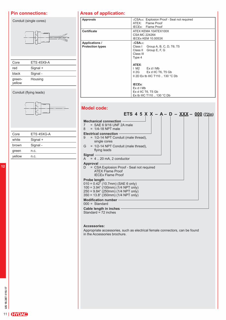
Pin connections:
Model code:
ETS 4 5 X X – A – D – XXX – 000 (72in)
Mechanical connection 7 = SAE 6 9/16 UNF 2A male 8 = 1/4-18 NPT male
Electrical connection 9 = 1/2-14 NPT Conduit (male thread),
single cores
G = 1/2-14 NPT Conduit (male thread), flying leads
Signal A = 4 .. 20 mA, 2 conductor
Approval D = CSA Explosion Proof - Seal not required
ATEX Flame Proof IECEx Flame Proof
Probe length 010 = 0.42“ (10.7mm) (SAE 6 only) 100 = 3.94“ (100mm) (1/4 NPT only) 250 = 9.84“ (250mm) (1/4 NPT only) 350 = 13.8“ (350mm) (1/4 NPT only)
Modification number 000 = Standard
Cable length in inches Standard = 72 inches
Accessories:
Appropriate accessories, such as electrical female connectors, can be found in the Accessories brochure.
Areas of application:
Conduit (single cores)
Core ETS 45X9-A
red Signal +
black Signal -
green-yellow
Housing
Conduit (flying leads)
Core ETS 45XG-A
white Signal +
brown Signal -
green n.c.
yellow n.c.
Approvals CCSAUS: Explosion Proof - Seal not required
ATEX: Flame ProofIECEx: Flame Proof
Certificate ATEX KEMA 10ATEX100X
CSA MC 224264
IECEx KEM 10.0053X
Applications /
Protection types
CCSAUS: Class I Group A, B, C, D, T6; T5Class II Group E, F, G
Class III
Type 4
ATEX:I M2 Ex d I Mb
II 2G Ex d IIC T6, T5 Gb
II 2D Ex tb IIIC T110 .. 130 °C Db
IECEx: Ex d I Mb
Ex d IIC T6, T5 Gb
Ex tb IIIC T110 .. 130 °C Db

US
18.3
87.1
/10.17
12
12
Dimensions:
Note:The information in this brochure relates to the operating conditions and applications described.For applications and operating conditions not described, please contact the relevant technical department.Subject to technical modifications.For European mechanical connection see European Catalog
HYDAC ELECTRONICS 90 Southland Dr. Bethlehem, PA 18017 Telephone +1 (610) 266-0100 E-mail: [email protected]: www.hydacusa.com
9.4
8
Z
1/4-18NPT
19
HEX 27
HEX 27
2
SAE-6
20
9/16-18UNF-2A
12
99.4
27
35.5
18.9
1/2-14NPT
X
HEX 27
35.5
1/2-14NPT
X

US
18.3
87.1
/10.17
13
12

US
18.3
35.2
/10.17
14
12
Relevant data for Ex applications Ex ia, ic Ex nA, ta, tb, tcSupply voltage Ui = 12 .. 28 V 12 .. 28 VMax. input current Ii = 100 mAMax. input power Pi = 1 W max. power consuption
≤ 1 WConnection capacitance of the sensor Ci = ≤ 22 nFInductance of the sensor Li = 0 mHInsulation voltage 3) 50 V AC, with integrated overvoltage protection EN
61000-6-2Other dataResidual ripple of supply voltage ≤ 5 %Life expectancy > 10 million cycles
0 .. 100 % FSWeight ~ 150 gNote: Reverse polarity protection of the supply voltage, excess voltage,
override and short circuit protection are provided. FS (Full Scale) = relative to the full measuring range, B.F.S.L.= Best Fit Straight Line 1) 15000 psi only with mechanical connection SF 250 CX20, Autoclave2) -4°F with FPM seal, -40°F on request3) 500 V AC on request
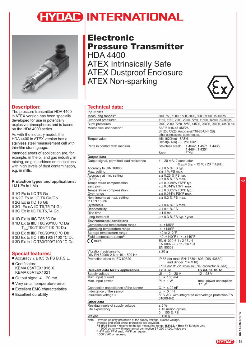
Electronic
Pressure Transmitter
HDA 4700 ATEX Intrinsically Safe ATEX Dustproof Enclosure ATEX Non-sparking
Description:The pressure transmitter HDA 4700 in ATEX version has been specially developed for use in potentially explosive atmospheres and is based on the HDA 4000 series.
As with the industry model, the HDA 4700 in ATEX version has a stainless steel measurement cell with thin-film strain gauge.Intended areas of application are, for example, in the oil and gas industry, in mining, on gas turbines or in locations with high levels of dust contamination, e.g. in mills.
Protection types and applications: I M1 Ex ia I Ma
II 1G Ex ia IIC T6 Ga II 1/2G Ex ia IIC T6 Ga/Gb II 2G Ex ia IIC T6 Gb II 3G Ex nA llC T6,T5,T4 Gc II 3G Ex ic llC T6,T5,T4 Gc
II 1D Ex ia lIIC T85°C Da II 1D Ex ta lllC T80/90/100°C Da T
500T90/T100/T110°C Da
II 2D Ex tb lllC T80/90/100°C Db II 3D Ex tc lllC T80/T90/T100°C Dc II 3D Ex ic lllC T80/T90/T100°C Dc
Special features: Accuracy ≤ ± 0.25 % FS B.F.S.L. Certificates:
KEMA 05ATEX1016 XKEMA 05ATEX1021 Output signal 4 .. 20 mA
Very small temperature error
Excellent EMC characteristics
Excellent durability
Technical data:Input data
Measuring ranges1) 150, 500, 750, 1000, 1500, 3000, 5000, 6000, 9000, 15000 psi
Overload pressures 290, 1160, 1740, 2900, 2900, 7250, 11600, 11600, 14500, 23200 psi
Burst pressures 1450, 2900, 4350, 7250, 7250, 14500, 29000, 29000, 29000, 43500 psi
Mechanical connection1) SAE 6 9/16-18 UNF 2A SF 250 CS20, Autoclave(7/16-20-UNF 2B)
Torque value 15lb-ft(20Nm) - SAE 6 30lb-ft(40Nm) SF 250 CX20
Parts in contact with medium Stainless steel: 1.4542; 1.4571; 1.4435; 1.4404; 1.4301
Seal: FPMOutput data
Output signal permitted load resistance 4 .. 20 mA, 2 conductor RLmax = (UB - 12 V) / 20 mA [kW]
Accuracy to DIN 16086, ≤ ± 0.25 % FS typ. Max. setting ≤ ± 0.5 % FS max.Accuracy at min. setting ≤ ± 0.15 % FS typ.(B.F.S.L.) ≤ ± 0.3 % FS max.Temperature compensation 0.0045% FS/°F typ. Zero point 0.0085% FS/°F max.Temperature compensation 0.0045% FS/°F typ. Over range 0.0085% FS/°F max.Non-linearity at max. setting ≤ ± 0.3 % FS max.to DIN 16086
Hysteresis ≤ ± 0.1 % FS max.Repeatability ≤ ± 0.05 % FSRise time ≤ 1.5 ms
Long-term drift ≤ ± 0.1 % FS typ. / yearEnvironmental conditions
Compensated temperature range -4..+185°FOperating temperature range2) -40..+140°F/ -4..+140°FStorage temperature range -40 to 212°FFluid temperature range2) -20..+140°F
40..+140°F / -4..+140°F mark EN 61000-6-1 / 2 / 3 / 4
EN 60079-0 / 11 / 26 / 31 EN 50303
Vibration resistance to ≤ 20 gDIN EN 60068-2-6 at 10 .. 500 Hz
Protection class to IEC 60529 IP 65 (for male EN175301-803 (DIN 43650) and Binder 714 M18)
IP 67 (for M12x1 male when an IP 67 connector is used)

US
18.3
35.2
/10.17
15
12
Pin connections:
Binder series 714 M18 Model code:
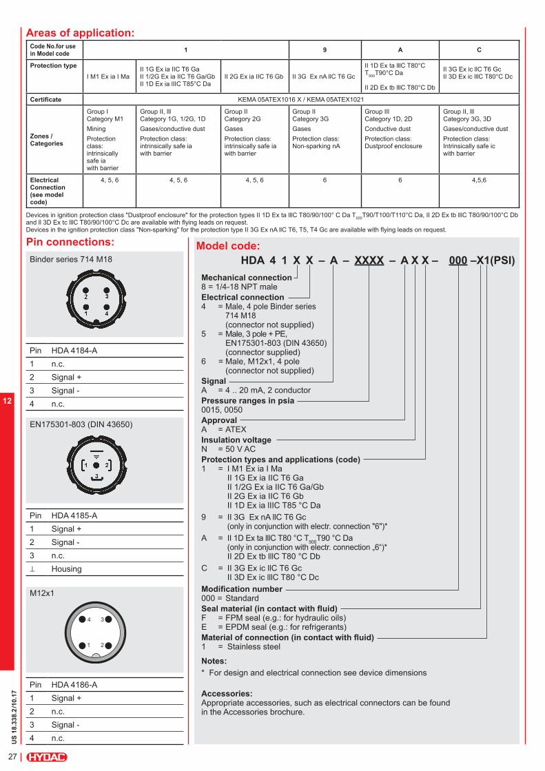
HDA 4 7 X X – A – XXXX – A X X – 000 (PSI)
Mechanical connection 7 = SAE 6, 9/16-18 UNF 2A male C = SF 250 CX20, Autoclave
(only for “15000 psi” press. range)
Electrical connection 4 = Male, 4 pole Binder series 714 M18
(connector not supplied) 5 = Male, 3 pole + PE, EN175301-803
(DIN 43650) (connector supplied)
6 = Male, M12x1, 4 pole (connector not supplied)
Signal A = 4 .. 20 mA, 2 conductor
Pressure ranges in psi 0150, 0500, 0750, 1000, 1500, 3000, 5000, 6000, 9000 15000 psi (only in conjunction with mechanical connection type “C”)
Approval A = ATEX Insulation voltage N = 50 V AC
Protection types and applications (code) 1 = I M1 Ex ia I Ma
II 1G Ex ia IIC T6 Ga II 1/2G Ex ia IIC T6 Ga/Gb II 2G Ex ia IIC T6 Gb II 1D Ex ia lIIC T85 °C Da
9 = II 3G Ex nA llC T6 Gc (only in conjunction with electr. connection “6“)*
A = II 1D Ex ta lllC T80 °C T500
T90 °C Da (only in conjunction with electr. connection "6")*
II 2D Ex tb lllC T80 °C DbC = II 3G Ex ic llC T6 Gc
II 3D Ex ic lllC T80 °C Dc
Modification number 000 = Standard
Notes:
* For design and electrical connection see device dimensions
Accessories:
Appropriate accessories, such as electrical connectors, can be found in the Accessories brochure.
Pin HDA 47X4-A1 n.c.
2 Signal +
3 Signal -
4 n.c.
Pin HDA 47X5-A1 Signal +
2 Signal -
3 n.c.
^ Housing
Pin HDA 47X6-A1 Signal +
2 n.c.
3 Signal -
4 n.c.
EN175301-803 (DIN 43650)
M12x1
Areas of application:Code No.for use in Model code
1 9 A C
Protection type
I M1 Ex ia I MaII 1G Ex ia IIC T6 GaII 1/2G Ex ia IIC T6 Ga/GbII 1D Ex ia lIIC T85°C Da
II 2G Ex ia IIC T6 Gb II 3G Ex nA llC T6 Gc
II 1D Ex ta lllC T80°C T
500T90°C Da
II 2D Ex tb lllC T80°C Db
II 3G Ex ic llC T6 Gc II 3D Ex ic lllC T80°C Dc
Certificate KEMA 05ATEX1016 X / KEMA 05ATEX1021
Zones / Categories
Group I Category M1
Mining
Protection class: intrinsically safe ia with barrier
Group II, lll Category 1G, 1/2G, 1D
Gases/conductive dust
Protection class: intrinsically safe ia with barrier
Group II Category 2G
Gases
Protection class: intrinsically safe ia with barrier
Group II Category 3G
Gases
Protection class:Non-sparking nA
Group IIl Category 1D, 2D
Conductive dust
Protection class:Dustproof enclosure
Group II, lll Category 3G, 3D
Gases/conductive dust
Protection class:Intrinsically safe icwith barrier
ElectricalConnection (see model code)
4, 5, 6 4, 5, 6 4, 5, 6 6 6 4,5,6
Devices in ignition protection class "Dustproof enclosure" for the protection types II 1D Ex ta lllC T80/90/100° C Da T500
T90/T100/T110°C Da, II 2D Ex tb lllC T80/90/100°C Db and ll 3D Ex tc lllC T80/90/100°C Dc are available with flying leads on request. Devices in the ignition protection class "Non-sparking" for the protection type II 3G Ex nA llC T6, T5, T4 Gc are available with flying leads on request.

US
18.3
35.2
/10.17
16
12
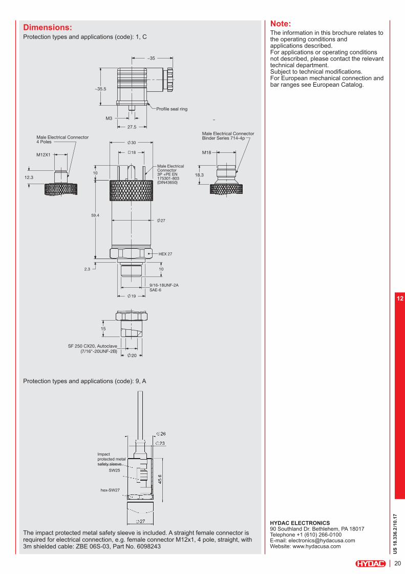
Dimensions:Protection types and applications (code): 1, C
Note:The information in this brochure relates to the operating conditions and applications described.For applications or operating conditions not described, please contact the relevant technical department. Subject to technical modifications.For European mechanical connection and bar ranges see European Catalog
HYDAC ELECTRONIC GMBH 90 Southland Dr. Bethlehem, PA 18017 Telephone +1 (610) 266-0100 E-mail: [email protected]: www.hydacusa.com
Impact
protected metal
safety sleeve
SW25
Protection ratings and areas of application (code): 9, A
The impact protected metal safety sleeve is included. A straight female connector is required for electrical connection; e.g. female connector M12x1, 4 pole, straight, with 3m shielded cable: ZBE 06S-03, Part No. 6098243
hex. SW27
Profile seal ring
~35
~35.5
27.5
M3
Male Electrical ConnectorBinder Series 714-4p
Male Electrical Connector
20
15
SF 250 CX20, Autoclave(7/16"-20UNF-2B)
Profile seal ring
Male Electrical ConnectorBinder Series 714-4p
M18
18.3
Male Electrical Connector4 Poles
12.3
M12X1
SAE-6
10 2.3
59.4
10
30
18
19
9/16-18UNF-2A
27
HEX 27
Male ElectricalConnector 3P +PE EN 175301-803 (DIN43650)

US
18.3
35.2
/10.17
17
12
US
18.3
36.2
/10.17
18
12
Electronic
Pressure Transmitter
HDA 4400 ATEX Intrinsically Safe ATEX Dustproof Enclosure ATEX Non-sparking
Description:The pressure transmitter HDA 4400 in ATEX version has been specially developed for use in potentially explosive atmospheres and is based on the HDA 4000 series.
As with the industry model, the HDA 4400 in ATEX version has a stainless steel measurement cell with thin-film strain gauge.Intended areas of application are, for example, in the oil and gas industry, in mining, on gas turbines or in locations with high levels of dust contamination, e.g. in mills.
Protection types and applications: I M1 Ex ia I Ma
II 1G Ex ia IIC T6 Ga II 1/2G Ex ia IIC T6 Ga/Gb II 2G Ex ia IIC T6 Gb II 3G Ex nA llC T6,T5,T4 Gc II 3G Ex ic llC T6,T5,T4 Gc
II 1D Ex ia lIIC T85 °C Da II 1D Ex ta lllC T80/90/100 °C Da T
500T90/T100/T110 °C Da
II 2D Ex tb lllC T80/90/100 °C Db II 3D Ex tc lllC T80/T90/T100 °C Dc II 3D Ex ic lllC T80/T90/T100 °C Dc
Special features: Accuracy ≤ ± 0.5 % FS B.F.S.L.
Certificates:KEMA 05ATEX1016 XKEMA 05ATEX1021
Output signal 4 .. 20 mA
Very small temperature error
Excellent EMC characteristics
Excellent durability
Technical data:Input data
Measuring ranges1) 500, 750, 1000, 1500, 3000, 6000, 9000, 15000 psi
Overload pressures 1160, 1160, 2900, 2900, 7250, 11600, 14500, 23200 psi
Burst pressures 2900, 2900, 7250, 7250, 14500, 29000, 29000, 43500 psi
Mechanical connection1) SAE 6 9/16-18 UNF2A SF 250 CS20, Autoclave(7/16-20-UNF 2B) other connections upon request
Torque value 15lb-ft(20Nm) - SAE 6 30lb-ft(40Nm) - SF 250 CX20
Parts in contact with medium Stainless steel: 1.4542; 1.4571; 1.4435; 1.4404; 1.4301
Seal: FPMOutput data
Output signal, permitted load resistance 4 .. 20 mA, 2 conductor RLmax.= (UB - 12 V) / 20 mA [kΩ]
Accuracy to DIN 16086, ≤ ± 0.5 % FS typ. Max. setting ≤ ± 1 % FS max.Accuracy at min. setting ≤ ± 0.25 % FS typ.(B.F.S.L.) ≤ ± 0.5 % FS max.
Temperature compensation ≤ ± 0.0085% FS/°F typ.Zero point ≤ ± 0.014% FS/°F max.
Temperature compensation ≤ ± 0.0085% FS/°F typ.Over range ≤ ± 0.014% FS/°F max.
Non-linearity at max. setting ≤ ± 0.3 % FS max.to DIN 16086
Hysteresis ≤ ± 0.4 % FS max.
Repeatability ≤ ± 0.1 % FS
Rise time ≤ 1.5 ms
Long-term drift ≤ ± 0.3 % FS typ. / year
Environmental conditions
Compensated temperature range -4..+185°F
Operating temperature range -4..+140°F
Storage temperature range -40 to 212°F
Fluid temperature range2) -40..+140°F / -4..+140°F
mark EN 61000-6-1 / 2 / 3 / 4 EN 60079-0 / 11 / 26 / 31 EN 50303
Vibration resistance to ≤ 20 gDIN EN 60068-2-6 at 10 .. 500 Hz
Protection class to IEC 60529 IP 65 (for male EN175301-803 (DIN 43650) and Binder 714 M18)
IP 67 (for M12x1 when an IP 67 connector is used)
Relevant data for Ex applications Ex ia, ic Ex nA, ta, tb, tcSupply voltage Ui = 12 .. 28 V 12 .. 28 VMax. input current Ii = 100 mAMax. input power Pi = 1 W max. power consuption
≤ 1 WConnection capacitance of the sensor Ci = ≤ 22 nFInductance of the sensor Li = 0 mHInsulation voltage 3) 50 V AC, with integrated overvoltage protection EN
61000-6-2Other dataResidual ripple of supply voltage ≤ 5 %Life expectancy > 10 million cycles
0 .. 100 % FSWeight ~ 150 gNote: Reverse polarity protection of the supply voltage, excess voltage,
override and short circuit protection are provided. FS (Full Scale) = relative to the full measuring range, B.F.S.L.= Best Fit Straight Line 1) 15000 psi only with mechanical connection SF 250 CX20, Autoclave2) -4°F with FPM seal, -40°F on request3) 500 V AC on request

US
18.3
36.2
/10.17
19
12
Model code:
HDA 4 4 X X – A – XXXX – A N X – 000 (PSI)
Mechanical connection 7 = SAE 6 9/16-18 UNF2A C = SF 250 CX20, Autoclave
(only for “15000 psi” press. range)
Electrical connection 4 = Male 4 pole Binder series 714 M18
(connector not supplied) 5 = Male 3 pole + PE, EN175301-803
(DIN 43650) (connector supplied)
6 = Male M12x1, 4 pole (connector not supplied)
Signal A = 4 .. 20 mA, 2 conductor
Pressure ranges in psi 0500, 0750, 1000, 1500, 3000, 5000, 6000, 9000 15000 psi (only in conjunction with mechanical connection type “C”)
Approval A = ATEX
Insulation voltage N = 50 V AC
Protection type and applications (code) 1 = I M1 Ex ia I Ma
II 1G Ex ia IIC T6 Ga II 1/2G Ex ia IIC T6 Ga/Gb II 2G Ex ia IIC T6 Gb II 1D Ex ia lIIC T85 °C Da
9 = II 3G Ex nA llC T6 Gc (only in conjunction with electr. conn. “6“)*
A = II 1D Ex ta lllC T80 °C T500
T90 °C Da (only in conjunction with electr. conn. "6")* II 2D Ex tb lllC T80 °C Db
C = II 3G Ex ic llC T6 Gc ll 3D Ex ic lllC T80 °C Dc
Modification number 000 = Standard
Notes:
* For design and electrical connection see device dimensions
Accessories:
Appropriate accessories, such as electrical connectors, can be found in the Accessories brochure.
Binder series 714 M18
Pin HDA 44X4-A
1 n.c.
2 Signal +
3 Signal -
4 n.c.
Pin HDA 44X5-A
1 Signal +
2 Signal -
3 n.c.
^ Housing
Pin HDA 44X6-A
1 Signal +
2 n.c.
3 Signal -
4 n.c.
EN175301-803 (DIN 43650)
M12x1
Areas of application:Code No. for use in Model code
1 9 A C
Protection type
I M1 Ex ia I MaII 1G Ex ia IIC T6 GaII 1/2G Ex ia IIC T6 Ga/GbII 1D Ex ia lIIC T85°C Da
II 2G Ex ia IIC T6 Gb II 3G Ex nA llC T6 Gc
II 1D Ex ta lllC T80°C T
500T90°C Da
II 2D Ex tb lllC T80°C Db
II 3G Ex ic llC T6 Gc II 3D Ex ic lllC T80°C Dc
Certificate KEMA 05ATEX1016 X / KEMA 05ATEX1021
Zones / Categories
Group I Category M1
Mining
Protection class: intrinsically safe ia with barrier
Group II, lll Category 1G, 1/2G, 1D
Gases/conductive dust
Protection class: intrinsically safe ia with barrier
Group II Category 2G
Gases
Protection class: intrinsically safe ia with barrier
Group II Category 3G
Gases
Protection class:Non-sparking nA
Group IIl Category 1D, 2D
Conductive dust
Protection class:Dustproof enclosure
Group II, lll Category 3G, 3D
Gases/conductive dust
Protection class:Intrinsically safe icwith barrier
ElectricalConnection (see model code)
4, 5, 6 4, 5, 6 4, 5, 6 6 6 4,5,6
Devices in ignition protection class "Dustproof enclosure" for the protection types II 1D Ex ta lllC T80/90/100° C Da T500
T90/T100/T110°C Da, II 2D Ex tb lllC T80/90/100°C Db and ll 3D Ex tc lllC T80/90/100°C Dc are available with flying leads on request. Devices in the ignition protection class "Non-sparking" for the protection type II 3G Ex nA llC T6, T5, T4 Gc are available with flying leads on request.
Pin connections:
US
18.3
36.2
/10.17
20
12
Note:The information in this brochure relates to the operating conditions and applications described.For applications or operating conditions not described, please contact the relevant technical department. Subject to technical modifications.For European mechanical connection and bar ranges see European Catalog.
HYDAC ELECTRONICS 90 Southland Dr. Bethlehem, PA 18017 Telephone +1 (610) 266-0100 E-mail: [email protected]: www.hydacusa.com
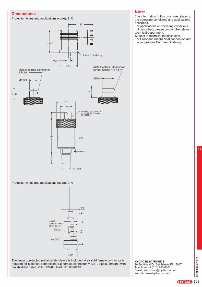
Dimensions:Protection types and applications (code): 1, C
Impact
protected metal
safety sleeve
SW25
hex-SW27
Protection types and applications (code): 9, A
The impact protected metal safety sleeve is included. A straight female connector is required for electrical connection, e.g. female connector M12x1, 4 pole, straight, with 3m shielded cable: ZBE 06S-03, Part No. 6098243
Profile seal ring
~35
~35.5
27.5
M3
Male Electrical ConnectorBinder Series 714-4p
Male Electrical Connector
20
15
SF 250 CX20, Autoclave(7/16"-20UNF-2B)
Profile seal ring
Male Electrical ConnectorBinder Series 714-4p
M18
18.3
Male Electrical Connector4 Poles
12.3
M12X1
SAE-6
10 2.3
59.4
10
30
18
19
9/16-18UNF-2A
27
HEX 27
Male ElectricalConnector 3P +PE EN 175301-803 (DIN43650)

US
18.3
36.2
/10.17
21
12

US
18.3
37.2
/10.17
223
12
Electronic
Pressure Transmitter
HDA 4300 ATEX Intrinsically Safe ATEX Dustproof Enclosure ATEX Non-sparking
Description:The pressure transmitter HDA 4300 in ATEX version has been specially developed for use in potentially explosive atmospheres and is based on the HDA 4000 series.
As with the industry model, the ATEX version HDA 4300 has a ceramic measurement cell with thick-film strain gauge.
Intended areas of application are, for example, in the oil and gas industry, in mining, on gas turbines or in locations with high levels of dust contamination, e.g. in mills.
Protection types and applications: I M1 Ex ia I Ma
II 1G Ex ia IIC T6 Ga II 1/2G Ex ia IIC T6 Ga/Gb II 2G Ex ia IIC T6 Gb II 3G Ex nA llC T6,T5,T4 Gc II 3G Ex ic llC T6,T5,T4 Gc
II 1D Ex ia lIIC T85 °C Da II 1D Ex ta lllC T80/90/100 °C Da T
500T90/T100/T110 °C Da
II 2D Ex tb lllC T80/90/100 °C Db II 3D Ex tc lllC T80/T90/T100 °C Dc II 3D Ex ic lllC T80/T90/T100 °C Dc
Special features: Accuracy ≤ ± 0.5 % FS B.F.S.L.
Certificates:KEMA 05ATEX1016 XKEMA 05ATEX1021
Output signal 4 .. 20 mA
Very small temperature error
Excellent EMC characteristics
Excellent durability
Technical data:Input data
Measuring ranges -14.5 to 135.5, 15, 30, 50, 100, 150, 250, 500 psi
Overload pressures 450, 45, 100, 150, 290, 450, 725, 1500 psi
Burst pressures 650, 70, 150, 250, 400, 650, 1000, 2500 psi
Mechanical connection 1/4-18 NPT male
Torque value 30 ft-lb (40 Nm)
Parts in contact with medium Sensor: Ceramic Mech. connection: 1.4301 Seal: FPM / EPDM
Output data
Output signal, permitted 4 .. 20 mA, 2 conductor load resistance RLmax.= (UB - 12 V) / 20 mA [kW]
Accuracy to DIN 16086, ≤ ± 0.5 % FS typ.Max. setting ≤ ± 1 % FS max.Accuracy at min. setting ≤ ± 0.25 % FS typ.(B.F.S.L.) ≤ ± 0.5 % FS max.
Temperature compensation ≤ ± 0.012% FS/°F typ.
Zero point ≤ ± 0.017% FS/°F max.
Temperature compensation ≤ ± 0.012% FS/°F typ.Over range ≤ ± 0.017% FS/°F max.
Non-linearity at max. setting ≤ ± 0.5 % FS max.to DIN 16086
Hysteresis ≤ ± 0.4 % FS max.
Repeatability ≤ ± 0.1 % FS
Rise time ≤ 1.5 ms
Long-term drift ≤ ± 0.3 % FS typ. / year
Environmental conditions
Compensated temperature range -4..+185°F
Operating temperature range -4..+140°F
Storage temperature range -40 to 212°F
Fluid temperature range 1) -40..+140°F / -4..+140°F
mark EN 61000-6-1 / 2 / 3 / 4 EN 60079-0 / 11 / 26 / 31 EN 50303
Vibration resistance to ≤ 20 gDIN EN 60068-2-6 at 10 .. 500 Hz
Protection class to IEC 60529 IP 65 (for male EN175301-803 (DIN 43650) and Binder 714 M18)
IP 67 (for M12x1, when an IP 67 connector is used)Relevant data for Ex applications Ex ia, ic Ex nA, ta, tb, tcSupply voltage Ui = 12 .. 28 V 12 .. 28 VMax. input current Ii = 100 mAMax. input power Pi = 1 W max. power consuption
≤ 1 WConnection capacitance of the sensor Ci = ≤ 22 nFInductance of the sensor Li = 0 mHInsulation voltage 2) 50 V AC, with integrated overvoltage protection EN
61000-6-2Other dataResidual ripple of supply voltage ≤ 5 %Life expectancy > 10 million cycles
0 .. 100 % FSWeight ~ 180 gNote: Reverse polarity protection of the supply voltage, excess voltage,
override and short circuit protection are provided. FS (Full Scale) = relative to the full measuring range, B.F.S.L.= Best Fit Straight Line
1) -4°F with FPM or EPDM seal, -40°F on request2) 500 V AC on request

US
18.3
37.2
/10.17
224
12
Model code:
HDA 4 3 X X – A – XXXX – A X X – 000 –X1(PSI)
Mechanical connection 8 = 1/4-18 NPT male
Electrical connection 4 = Male, 4 pole Binder series
714 M18 (connector not supplied) 5 = Male, 3 pole + PE,
EN175301-803 (DIN 43650) (connector supplied)
6 = Male, M12x1, 4 pole (connector not supplied)
Signal A = 4 .. 20 mA, 2 conductor
Pressure ranges in psi
0135 (-14.5 to 135.5 psi), 0015, 0030, 0050, 0100, 0150, 0250, 0500
Approval A = ATEX
Insulation voltage N = 50 V AC
Protection types and applications (code) 1 = I M1 Ex ia I Ma
II 1G Ex ia IIC T6 Ga II 1/2G Ex ia IIC T6 Ga/Gb II 2G Ex ia IIC T6 Gb II 1D Ex ia lIIC T85°C Da
9 = II 3G Ex nA llC T6 Gc (only in conjunction with electr. conn. “6“)*
A = II 1D Ex ta lllC T80°C T500
T90°C Da (only in conjunction with electr. conn. “6“)*
II 2D Ex tb lllC T80°C Db
C = II 3G Ex ic llC T6 Gc II 3D Ex ic lllC T80°C Dc
Modification number 000 = Standard
Seal material (in contact with fluid) F = FPM seal (e.g.: for hydraulic oils) E = EPDM seal (e.g.: for refrigerants)Material of connection (in contact with fluid) 1 = Stainless steel
Notes:
* For design and electrical connection see device dimensions
Accessories: Appropriate accessories, such as electrical connectors can be found in the Accessories brochure.
Pin connections:
Binder series 714 M18
Pin HDA 4384-A
1 n.c.
2 Signal +
3 Signal -
4 n.c.
Pin HDA 4385-A
1 Signal +
2 Signal -
3 n.c.
^ Housing
Pin HDA 4386-A
1 Signal +
2 n.c.
3 Signal -
4 n.c.
EN175301-803 (DIN 43650)
M12x1
Areas of application:Code No.for use in Model code
1 9 A C
Protection type
I M1 Ex ia I MaII 1G Ex ia IIC T6 GaII 1/2G Ex ia IIC T6 Ga/GbII 1D Ex ia lIIC T85°C Da
II 2G Ex ia IIC T6 Gb II 3G Ex nA llC T6 Gc
II 1D Ex ta lllC T80°C T
500T90°C Da
II 2D Ex tb lllC T80°C Db
II 3G Ex ic llC T6 Gc II 3D Ex ic lllC T80°C Dc
Certificate KEMA 05ATEX1016 X / KEMA 05ATEX1021
Zones / Categories
Group I Category M1
Mining
Protection class: intrinsically safe ia with barrier
Group II, lll Category 1G, 1/2G, 1D
Gases/conductive dust
Protection class: intrinsically safe ia with barrier
Group II Category 2G
Gases
Protection class: intrinsically safe ia with barrier
Group II Category 3G
Gases
Protection class:Non-sparking nA
Group IIl Category 1D, 2D
Conductive dust
Protection class:Dustproof enclosure
Group II, lll Category 3G, 3D
Gases/conductive dust
Protection class:Intrinsically safe icwith barrier
ElectricalConnection (see model code)
4, 5, 6 4, 5, 6 4, 5, 6 6 6 4,5,6
Devices in ignition protection class "Dustproof enclosure" for the protection types II 1D Ex ta lllC T80/90/100 °C Da T500
T90/T100/T110 °C Da, II 2D Ex tb lllC T80/90/100 °C Db and ll 3D Ex tc lllC T80/90/100 °C Dc are available with flying leads on request. Devices in the ignition protection class "Non-sparking" for the protection type II 3G Ex nA llC T6, T5, T4 Gc are available with flying leads on request.

US
18.3
37.2
/10.17
225
12
Note:The information in this brochure relates to the operating conditions and applications described.For applications or operating conditions not described, please contact the relevant technical department.Subject to technical modifications.For European mechanical connection and bar ranges see European Catalog.
HYDAC ELECTRONICS 90 Southland Dr. Bethlehem, PA 18017 Telephone +1 (610) 266-0100 E-mail: [email protected]: www.hydacusa.com
Dimensions:Protection types and applications (code): 1, C
Impact
protected metal
safety sleeve
SW25
Protection types and applications (code): 9, A
The impact protected metal safety sleeve is included. A straight female connector is required for electrical connection; e.g. female connector M12x1, 4 pole, straight, with 3m shielded cable: ZBE 06S-03, Part No. 6098243
hex. SW27
Profile seal ring
~35
~35.5
27.5
M3
Male Electrical Connector
Male Electrical Connector4 Poles
12.3
M12X1
Male Electrical ConnectorBinder Series 714-4p
M18
18.3
HEX 27
59.4 27
10
17
18
30
Male ElectricalConnector 3P +PE EN 175301-803 (DIN43650)

US
18.3
37.2
/10.17
226
12

US
18.3
38.2
/10.17
26
12
Electronic Absolute
Pressure Transmitter
HDA 4100 ATEX Intrinsically Safe ATEX Dustproof housing ATEX Non-sparking
Description:The pressure transmitter HDA 4100 in ATEX version has been specially developed for use in potentially explosive atmospheres for absolute measurement in the low pressure range and is based on the HDA 4000 series.
As with the industry model, the ATEX version HDA 4100 has a ceramic measurement cell with thick-film strain gauge.
Intended areas of application are, for example, in the oil and gas industry, in mining, on gas turbines or in locations with high levels of dust contamination, e.g. in mills.
Protection types and applications: I M1 Ex ia I Ma
II 1G Ex ia IIC T6 Ga II 1/2G Ex ia IIC T6 Ga/Gb II 2G Ex ia IIC T6 Gb II 3G Ex nA llC T6,T5,T4 Gc II 3G Ex ic llC T6,T5,T4 Gc
II 1D Ex ia lIIC T85 °C Da II 1D Ex ta lllC T80/90/100 °C Da T
500T90/T100/T110 °C Da
II 2D Ex tb lllC T80/90/100 °C Db II 3D Ex tc lllC T80/T90/T100 °C Dc II 3D Ex ic lllC T80/T90/T100 °C Dc
Special features: Accuracy ≤ ± 0.5 % FS B.F.S.L.
Certificates:KEMA 05ATEX1016 XKEMA 05ATEX1021
Output signal 4 .. 20 mA
Very small temperature error
Excellent EMC characteristics
Excellent durability
Technical data:Input data
Measuring ranges 15, 50 psia
Overload pressures 45, 150 psia
Burst pressures 70, 250 psia
Mechanical connection 1/4-18 NPT male
Torque value 30 ft-lb (40 Nm)
Parts in contact with medium Sensor: Ceramic Mech. connection: 1.4301 Seal: FPM / EPDM
Output data
Output signal, permitted load resistance 4 .. 20 mA, 2 conductor RLmax = (UB - 12 V) / 20 mA [kW]
Accuracy to DIN 16086, ≤ ± 0.5 % FS typ.Max. setting ≤ ± 1 % FS max.
Accuracy at min. setting ≤ ± 0.25 % FS typ.(B.F.S.L.) ≤ ± 0.5 % FS max.
Temperature compensation ≤ ± 0.012% FS/°F typ.Zero point ≤ ± 0.017% FS/°F max.
Temperature compensation ≤ ± 0.012% FS/°F typ.Over range ≤ ± 0.017% FS/°F max.
Non-linearity at max. setting ≤ ± 0.5 % FS max.to DIN 16086
Hysteresis ≤ ± 0.4 % FS max.
Repeatability ≤ ± 0.1 % FS
Rise time ≤ 1.5 ms
Long-term drift ≤ ± 0.3 % FS typ. / year
Environmental conditions
Compensated temperature range -4..+185°F
Operating temperature range -4..+140°F
Storage temperature range -40 to 212°F
Fluid temperature range1) -40..+140°F / -4..+140°F
mark EN 61000-6-1 / 2 / 3 / 4 EN 60079-0 / 11 / 26 / 31 EN 50303
Vibration resistance to ≤ 20 gDIN EN 60068-2-6 at 10 .. 500 Hz
Protection class to IEC 60529 IP 65 (for male EN175301-803 (DIN 43650) and Binder 714 M18)
IP 67 (for M12x1, when an IP 67 connector is used)Relevant data for Ex applications Ex ia, ic Ex nA, ta, tb, tcSupply voltage Ui = 12 .. 28 V 12 .. 28 VMax. input current Ii = 100 mAMax. input power Pi = 1 W max. power consuption ≤ 1 WConnection capacitance of the sensor Ci = ≤ 22 nFInductance of the sensor Li = 0 mHInsulation voltage 2) 50 V AC, with integrated overvoltage protection EN
61000-6-2Other dataResidual ripple of supply voltage ≤ 5 %Life expectancy > 10 million cycles
0 .. 100 % FSWeight ~ 180 gNote: Reverse polarity protection of the supply voltage, excess voltage,
override and short circuit protection are provided. FS (Full Scale) = relative to the full measuring range, B.F.S.L.= Best Fit Straight Line 1) -4 °F with FPM or EPDM seal, -40 °F on request 2) 500 V AC on request
US
18.3
38.2
/10.17
27
12
Model code:
HDA 4 1 X X – A – XXXX – A X X – 000 –X1(PSI)
Mechanical connection 8 = 1/4-18 NPT male
Electrical connection 4 = Male, 4 pole Binder series
714 M18 (connector not supplied)
5 = Male, 3 pole + PE, EN175301-803 (DIN 43650)
(connector supplied) 6 = Male, M12x1, 4 pole
(connector not supplied)
Signal A = 4 .. 20 mA, 2 conductor
Pressure ranges in psia 0015, 0050
Approval A = ATEX
Insulation voltage N = 50 V AC
Protection types and applications (code) 1 = I M1 Ex ia I Ma
II 1G Ex ia IIC T6 Ga II 1/2G Ex ia IIC T6 Ga/Gb II 2G Ex ia IIC T6 Gb II 1D Ex ia lIIC T85 °C Da
9 = II 3G Ex nA llC T6 Gc (only in conjunction with electr. connection "6")*
A = II 1D Ex ta lllC T80 °C T500
T90 °C Da (only in conjunction with electr. connection „6“)*
II 2D Ex tb lllC T80 °C Db
C = II 3G Ex ic llC T6 Gc II 3D Ex ic lllC T80 °C Dc
Modification number 000 = Standard
Seal material (in contact with fluid) F = FPM seal (e.g.: for hydraulic oils) E = EPDM seal (e.g.: for refrigerants)Material of connection (in contact with fluid) 1 = Stainless steel
Notes:
* For design and electrical connection see device dimensions
Accessories: Appropriate accessories, such as electrical connectors can be found in the Accessories brochure.
Pin connections:
Binder series 714 M18
Pin HDA 4184-A
1 n.c.
2 Signal +
3 Signal -
4 n.c.
Pin HDA 4185-A
1 Signal +
2 Signal -
3 n.c.
^ Housing
Pin HDA 4186-A
1 Signal +
2 n.c.
3 Signal -
4 n.c.
EN175301-803 (DIN 43650)
M12x1
Areas of application:Code No.for use in Model code
1 9 A C
Protection type
I M1 Ex ia I MaII 1G Ex ia IIC T6 GaII 1/2G Ex ia IIC T6 Ga/GbII 1D Ex ia lIIC T85°C Da
II 2G Ex ia IIC T6 Gb II 3G Ex nA llC T6 Gc
II 1D Ex ta lllC T80°C T
500T90°C Da
II 2D Ex tb lllC T80°C Db
II 3G Ex ic llC T6 Gc II 3D Ex ic lllC T80°C Dc
Certificate KEMA 05ATEX1016 X / KEMA 05ATEX1021
Zones / Categories
Group I Category M1
Mining
Protection class: intrinsically safe ia with barrier
Group II, lll Category 1G, 1/2G, 1D
Gases/conductive dust
Protection class: intrinsically safe ia with barrier
Group II Category 2G
Gases
Protection class: intrinsically safe ia with barrier
Group II Category 3G
Gases
Protection class:Non-sparking nA
Group IIl Category 1D, 2D
Conductive dust
Protection class:Dustproof enclosure
Group II, lll Category 3G, 3D
Gases/conductive dust
Protection class:Intrinsically safe icwith barrier
ElectricalConnection (see model code)
4, 5, 6 4, 5, 6 4, 5, 6 6 6 4,5,6
Devices in ignition protection class "Dustproof enclosure" for the protection types II 1D Ex ta lllC T80/90/100° C Da T500
T90/T100/T110°C Da, II 2D Ex tb lllC T80/90/100°C Db and ll 3D Ex tc lllC T80/90/100°C Dc are available with flying leads on request. Devices in the ignition protection class "Non-sparking" for the protection type II 3G Ex nA llC T6, T5, T4 Gc are available with flying leads on request.
US
18.3
38.2
/10.17
28
12
Note:The information in this brochure relates to the operating conditions and applications described.For applications or operating conditions not described, please contact the relevant technical department.Subject to technical modifications.For European mechanical connection and bar ranges see European Catalog.
HYDAC ELECTRONICS 90 Southland Dr. Bethlehem, PA 18017 Telephone +1 (610) 266-0100 E-mail: [email protected]: www.hydacusa.com
Dimensions:Protection types and applications (code): 1, C
Impact
protected metal
safety sleeve
SW25
Protection types and applications (code): 9, A
The impact protected metal safety sleeve is included. A straight female connector is required for electrical connection; e.g. female connector M12x1, 4 pole, straight, with 3m shielded cable: ZBE 06S-03, Part. No. 6098243
hex. SW27
Profile seal ring
~35
~35.5
27.5
M3
Male Electrical ConnectoBinder Series 714-4p
Male Electrical Connector4 Poles
12.3
M12X1
Male Electrical ConnectorBinder Series 714-4p
M18
18.3
2.3
59.4
10
HEX 27
Male Electrical Connector3P +PE EN 175301-803(DIN43650)
59.4 27
10
17
18
30
1/4-18NPT

US
18.3
38.2
/10.17
29
12
US
18.3
39.2
/10.17
30
12
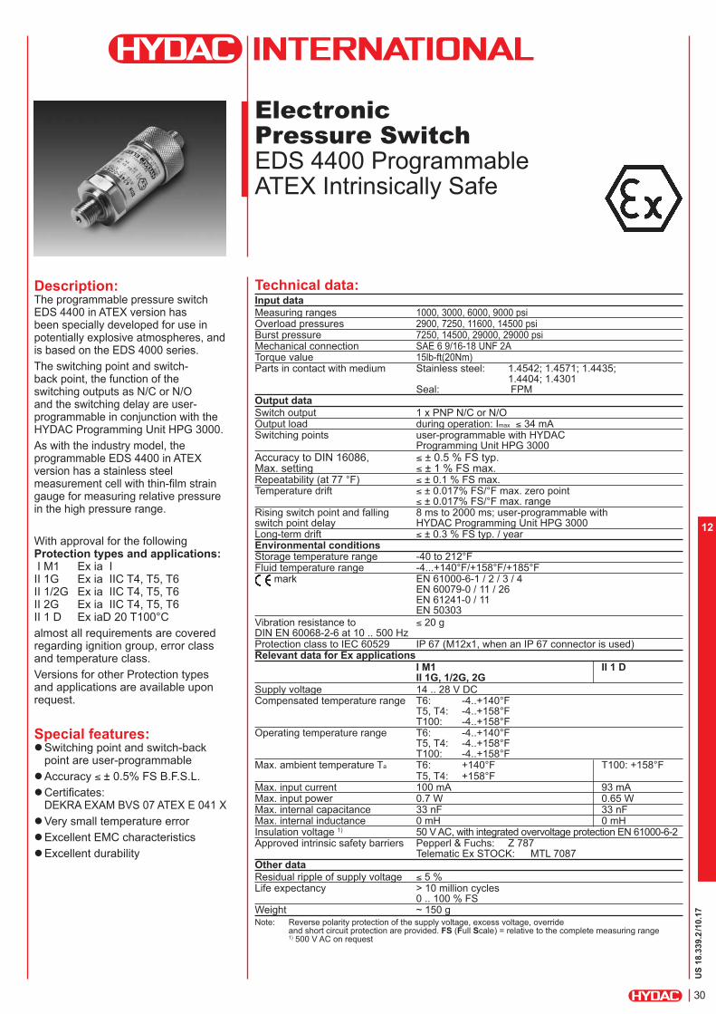
Electronic
Pressure Switch
EDS 4400 Programmable ATEX Intrinsically Safe
Description:The programmable pressure switch EDS 4400 in ATEX version has been specially developed for use in potentially explosive atmospheres, and is based on the EDS 4000 series.
The switching point and switch-back point, the function of the switching outputs as N/C or N/O and the switching delay are user-programmable in conjunction with the HYDAC Programming Unit HPG 3000.
As with the industry model, the programmable EDS 4400 in ATEX version has a stainless steel measurement cell with thin-film strain gauge for measuring relative pressure in the high pressure range.
With approval for the following Protection types and applications: I M1 Ex ia I II 1G Ex ia IIC T4, T5, T6 II 1/2G Ex ia IIC T4, T5, T6 II 2G Ex ia IIC T4, T5, T6 II 1 D Ex iaD 20 T100°C
almost all requirements are covered regarding ignition group, error class and temperature class.
Versions for other Protection types and applications are available upon request.
Special features: Switching point and switch-back
point are user-programmable
Accuracy ≤ ± 0.5% FS B.F.S.L.
Certificates:DEKRA EXAM BVS 07 ATEX E 041 X
Very small temperature error
Excellent EMC characteristics
Excellent durability
Technical data:Input data
Measuring ranges 1000, 3000, 6000, 9000 psiOverload pressures 2900, 7250, 11600, 14500 psiBurst pressure 7250, 14500, 29000, 29000 psiMechanical connection SAE 6 9/16-18 UNF 2ATorque value 15lb-ft(20Nm)Parts in contact with medium Stainless steel: 1.4542; 1.4571; 1.4435;
1.4404; 1.4301 Seal: FPM
Output data
Switch output 1 x PNP N/C or N/OOutput load during operation: Imax ≤ 34 mASwitching points user-programmable with HYDAC
Programming Unit HPG 3000
Accuracy to DIN 16086, ≤ ± 0.5 % FS typ.Max. setting ≤ ± 1 % FS max.Repeatability (at 77 °F) ≤ ± 0.1 % FS max.Temperature drift ≤ ± 0.017% FS/°F max. zero point
≤ ± 0.017% FS/°F max. rangeRising switch point and falling 8 ms to 2000 ms; user-programmable with switch point delay HYDAC Programming Unit HPG 3000Long-term drift ≤ ± 0.3 % FS typ. / yearEnvironmental conditions Storage temperature range -40 to 212°FFluid temperature range -4...+140°F/+158°F/+185°F
mark EN 61000-6-1 / 2 / 3 / 4 EN 60079-0 / 11 / 26 EN 61241-0 / 11 EN 50303
Vibration resistance to ≤ 20 gDIN EN 60068-2-6 at 10 .. 500 Hz Protection class to IEC 60529 IP 67 (M12x1, when an IP 67 connector is used)Relevant data for Ex applications
I M1 II 1 D II 1G, 1/2G, 2G
Supply voltage 14 .. 28 V DCCompensated temperature range T6: -4..+140°F
T5, T4: -4..+158°FT100: -4..+158°F
Operating temperature range T6: -4..+140°FT5, T4: -4..+158°FT100: -4..+158°F
Max. ambient temperature Ta T6: +140°F T100: +158°FT5, T4: +158°F
Max. input current 100 mA 93 mAMax. input power 0.7 W 0.65 WMax. internal capacitance 33 nF 33 nFMax. internal inductance 0 mH 0 mHInsulation voltage 1) 50 V AC, with integrated overvoltage protection EN 61000-6-2Approved intrinsic safety barriers Pepperl & Fuchs: Z 787
Telematic Ex STOCK: MTL 7087Other data
Residual ripple of supply voltage ≤ 5 %Life expectancy > 10 million cycles
0 .. 100 % FSWeight ~ 150 gNote: Reverse polarity protection of the supply voltage, excess voltage, override
and short circuit protection are provided. FS (Full Scale) = relative to the complete measuring range 1) 500 V AC on request

US
18.3
39.2
/10.17
31
12
Setting options:In conjunction with the HYDAC Programming Unit HPG 3000, all the settings are combined in an easy-to-follow menu.
Model code:
EDS 4 4 7 8 – XXXX – X – A X X – 000 (PSI)
Mechanical connection 7 = SAE 6 9/16-18 UNF2A
Electrical connection 8 = Male M12x1, 5 pole
(connector not supplied)
Pressure ranges in psi 1000, 3000, 6000, 9000
Switching output P = Programmable
Approval A = ATEX
Insulation voltage N = 50 V AC
Protection types and applications (code) 1 = I M1 Ex ia I 2 = II 1G Ex ia IIC T4, T5, T6 3 = II 2G Ex ia IIC T4, T5, T6 / II 1/2G Ex ia IIC T4, T5, T6 8 = II 1D Ex iaD 20 T100 °C
Modification number 000 = Standard
Accessories:
Appropriate accessories, such as electrical connectors, can be found in the Accessories brochure.
Pin Process connection
HPG connection
1 +UB
+UB
2 0 V Comport 1 *
3 0 V 0 V
4 Out 1 n.c.
5 0 V Comport 2 *
* Comport = programming connection
M12x1, 5 pole
1 2
34
5
Areas of application:
Code No.
for use in
Model
code
1 2 3 8
Protection
Type
I M1 Ex ia I II 1G Ex ia IIC
T4, T5, T6
II 2G Ex ia IIC
II 1/2G Ex ia IIC
T4, T5, T6
II 1D Ex iaD 20
T100 °C
CertificateDEKRA EXAM
BVS 07 ATEX
E 041 X
DEKRA EXAM
BVS 07 ATEX
E 041 X
DEKRA EXAM
BVS 07 ATEX
E 041 X
DEKRA EXAM
BVS 07 ATEX
E 041 X
Zones /
Categories
Group I
Category M1
Mining
Protection
class: intrinsically
safe ia with
barrier
Group II
Category 1G
Gases
Protection class: intrinsically safe ia
with barrier
For use in Zone 0
T4, T5: Ta = 70 °C
T6: Ta = 60 °C
Group II
Category 2G, 1/2G
Gases
Protection class: intrinsically safe ia
with barrier
For use in Zone 1, 2
For mounting to
Zone 0T4, T5: T
a = 70 °C
T6: Ta = 60 °C
Group II
Category iD
Dusts
Protection class: intrinsically safe ia
with barrier
For use in Zone 20, 21, 22
For mounting to
Zone 20T100: T
a = 70 °C
Electrical
Connection
8 8 8 8
Instruments for other Protection types and applications are available on request. Please contact our technical sales department for more information.
Pin connections:
Setting ranges for the switch outputs:
Measuring range in psi
Increment in psi
0 .. 1000 2
0 .. 3000 5
0 .. 6000 10
0 .. 9000 20
The switch point (upper switch value) on all instruments is between 5 % and 100 % of the measuring range and the switch-back point (lower switch value) is between 1 % and 96 % of the measuring range.
Minimum value in ms
Maximum value in ms
Switch-on delay Ton1/Ton2
8 2040
Switch-off delay ToF1/ToF2
8 2040
The increment for all instruments is 8 ms.

US
18.3
39.2
/10.17
32
12
Note:The information in this brochure relates to the operating conditions and applications described.For applications or operating conditions not described, please contact the relevant technical department.Subject to technical modifications.For European mechanical connection and bar ranges see European Catalog.
HYDAC ELECTRONICS 90 Southland Dr. Bethlehem, PA 18017 Telephone +1 (610) 266-0100 E-mail: [email protected]: www.hydacusa.com
Dimensions:
Safety instructions: These units must only be programmed outside the potentially explosive location.
When operating in potentially explosive locations, the programming cables may only be connected to the 0 V outside of the potentially explosive area.
The switching output draws the switching energy from the power supply to thepressure switch. No additional energy is introduced into the electrical circuitthrough the switching output.
The dual Zener barriers specified and approved in the technical data must beused to connect the pressure switch.These have a reverse polarity diode to decouple the signal.The signal path may only be passively loaded.
Ensure that measured fluids in contact with the pressure switch are compatible with the materials used.
electr. conn.
female 5 pole
Programming Unit:(must be ordered separately)
HPG 3000 – 000 Portable Programming Unit Part. No. 909 422
HPG 3000 Power Supply with connector: Part no. 02091103
Caution:The HPG 3000 Programming Unit may only be used outside the potentially explosive area.
HEX 27
Male Electrical Connector5 Poles
12.3
SAE-6
10
9/16-18UNF-2A
30
19
27 59.4
M12X1

US
18.3
39.2
/10.17
33
12

US
18.3
40.2
/10.17
34
12
Electronic
Pressure Switch
EDS 4300 Programmable ATEX Intrinsically Safe
Description:The programmable pressure switch EDS 4300 in ATEX version was specially developed for use in potentially explosive atmospheres and is based on the EDS 4000 series.
The switching point and switch-back point, the function of the switching outputs as N/C or N/O and the switching delay are user-programmable in conjunction with the HYDAC Programming Unit HPG 3000.
As with the industry model, the programmable EDS 4300 in ATEX version has a ceramic measurement cell with thick-film strain gauge for measuring relative pressure in the low pressure range.
With approval for the following Protection types and applications: I M1 Ex ia I II 1G Ex ia IIC T4, T5, T6 II 1/2G Ex ia IIC T4, T5, T6 II 2G Ex ia IIC T4, T5, T6 II 1 D Ex iaD 20 T100 °C
almost all requirements are covered regarding ignition group, error class and temperature class.
Versions for other Protection types and applications are available on request.
Special features: Switching point and switch-back
point user-programmable
Accuracy ≤ ± 0.5% FS B.F.S.L.
Certificates:DEKRA EXAM BVS 07 ATEX E 041 X
Very small temperature error
Excellent EMC characteristics
Excellent durability
Technical data:Input data
Measuring ranges 15, 50, 100, 150, 250, 500 psiOverload pressures 45, 150, 290, 450, 725, 1500 psiBurst pressures 70, 250, 400, 650, 1000, 2500 psiMechanical connection 1/4-18 NPTTorque value 15lb-ft (20 Nm)Parts in contact with medium Sensor: Ceramic
Mech. connection: 1.4301 Seal: FPM / EPDM
Output data
Switch output 1 x PNP N/C or N/OOutput load during operation: Imax ≤ 34 mASwitching points user-programmable with HYDAC Programming Unit HPG 3000Accuracy to DIN 16086, ≤ ± 0.5 % FS typ.Max. setting ≤ ± 1 % FS max.Repeatability (at 77 °F) ≤ ± 0.1 % FS max.Temperature drift ≤ ± 0.017% /°F max. zero point
≤ ± 0.017% /°F max. rangeRising switch point and falling 8 ms to 2000 ms; user-programmable with switch point delay HYDAC Programming Unit HPG 3000Long-term drift ≤ ± 0.3 % FS typ. / yearEnvironmental conditions Storage temperature range -40 to 212°FFluid temperature range -4...+140°F/+158°F/+185°F
mark EN 61000-6-1 / 2 / 3 / 4 EN 60079-0 / 11 / 26 EN 61241-0 / 11 EN 50303
Vibration resistance to ≤ 20 gDIN EN 60068-2-6 at 10 .. 500 Hz Protection class to IEC 60529 IP 67
(M12x1, when an IP 67 connector is used)Relevant data for Ex applications
I M1 II 1 D II 1G, 1/2G, 2G
Supply voltage 14 .. 28 V DCCompensated temperature range T6: -4..+140°F
T5, T4: -4..+158°FT100: -4..+158°F
Operating temperature range T6: -4..+140°FT5, T4: -4..+158°FT100: -4..+158°F
Max. ambient temperature Ta T6: +140°F T100: +158°FT5, T4: +158°F
Max. input current 100 mA 93 mAMax. input power 0.7 W 0.65 WMax. internal capacitance 33 nF 33 nFMax. internal inductance 0 mH 0 mHInsulation voltage 1) 50 V AC, with integrated overvoltage
protection EN 61000-6-2Approved intrinsic safety barriers Pepperl & Fuchs: Z 787
Telematic Ex STOCK: MTL 7087Other data
Residual ripple of supply voltage ≤ 5 %Life expectancy > 10 million cycles
0 .. 100 % FSWeight ~ 150 gNote: Reverse polarity protection of the supply voltage, excess voltage, override
and short circuit protection are provided. FS (Full Scale) = relative to the full measuring range 1) 500 V AC on request

US
18.3
40.2
/10.17
35
12
Setting options:In conjunction with the HYDAC Programming Unit HPG 3000, all the settings are combined in an easy-to-follow menu.
Model code:
EDS 4 3 8 8 – XXXX – X – AX X – 000 – X1(PSI)
Mechanical connection 8 = 1/4-18 NPT, male
Other connections upon request
Electrical connection 8 = Male M12x1, 5 pole
(connector not supplied)
Pressure ranges in psi 0015, 0050, 0100, 0250, 0500
Switching output P = Programmable
Approval A = ATEX
Insulation voltage N = 50 V AC
Protection types and applications (code) 1 = I M1 Ex ia I 2 = II 1G Ex ia IIC T4, T5, T6 3 = II 2G Ex ia IIC T4, T5, T6 / II 1/2G Ex ia IIC T4, T5, T6 8 = II 1D Ex iaD 20 T100 °C
Modification number 000 = Standard
Seal material (in contact with fluid) F = FPM seal (e.g.: for hydraulic oils) E = EPDM seal (e.g.: for refrigerants)Material of connection (in contact with fluid) 1 = Stainless steel
Accessories:
Appropriate accessories, such as electrical connectors, can be found in the Accessories brochure.
Pin Process connection
HPG connection
1 +UB
+UB
2 0 V Comport 1 *
3 0 V 0 V
4 Out 1 n.c.
5 0 V Comport 2 *
* Comport = programming connection
M12x1, 5 pole
1 2
34
5
Areas of application:
Code No.
for use in
Model
code
1 2 3 8
Protection
Type
I M1 Ex ia I II 1G Ex ia IIC
T4, T5, T6
II 2G Ex ia IIC
II 1/2G Ex ia IIC
T4, T5, T6
II 1D Ex iaD 20
T100 °C
CertificateDEKRA EXAM
BVS 07 ATEX
E 041 X
DEKRA EXAM
BVS 07 ATEX
E 041 X
DEKRA EXAM
BVS 07 ATEX
E 041 X
DEKRA EXAM
BVS 07 ATEX
E 041 X
Zones /
Categories
Group I
Category M1
Mining
Protection
class: intrinsically
safe ia with
barrier
Group II
Category 1G
Gases
Protection class: intrinsically safe ia
with barrier
For use in Zone 0
T4, T5: Ta = 70 °C
T6: Ta = 60 °C
Group II
Category 2G, 1/2G
Gases
Protection class: intrinsically safe ia
with barrier
For use in Zone 1, 2
For mounting to
Zone 0T4, T5: T
a = 70 °C
T6: Ta = 60 °C
Group II
Category iD
Dusts
Protection class: intrinsically safe ia
with barrier
For use in Zone 20, 21, 22
For mounting to
Zone 20T100: T
a = 70 °C
Electrical
Connection
8 8 8 8
Instruments for other Protection types and applications are available on request. Please contact our technical sales department for more information.
Pin connections:
Setting ranges for the switch outputs:
Measuring range in psi
Increment in psi
0 .. 15 0.05
0 .. 50 0.05
0 .. 100 0.2
0 .. 250 0.5
0 .. 500 1
The switch point (upper switch value) on all instruments is between 5 % and 100 % of the measuring range and the switch-back point (lower switch value) is between 1 % and 96 % of the measuring range.
Minimum value in ms
Maximum value in ms
Switch-on delay Ton1/Ton2
8 2040
Switch-off delay ToF1/ToF2
8 2040
The increment for all instruments is 8 ms.

US
18.3
40.2
/10.17
36
12
Safety instructions: These units must only be programmed outside the potentially explosive location.
When operating in potentially explosive locations, the programming cables mayonly be connected to the 0 V outside of the potentially explosive area.
The switching output draws the switching energy from the power supply to the pressure switch. No additional energy is introduced into the electrical circuit through the switching output.
Dual Zener barriers specified and approved in the technical data must be used toconnect the pressure switch.These have a reverse polarity diode to decouple the signal.The signal path may only be passively loaded.
Ensure that measured fluids in contact with the pressure switch are compatiblewith the materials used.
Note:The information in this brochure relates to the operating conditions and applications described.For applications or operating conditions not described, please contact the relevant technical department.Subject to technical modifications. For European mechanical connection and bar ranges see European Catalog
HYDAC ELECTRONICS 90 Southland Dr. Bethlehem, PA 18017 Telephone +1 (610) 266-0100 E-mail: [email protected]: www.hydacusa.com
Dimensions:
Programming Unit:(must be ordered separately)
HPG 3000 – 000 Portable Programming Unit Part No. 909 422
HPG 3000 Power Supply with connector: Part No. 02091103
Caution:The HPG 3000 Programming Unit may only be used outside the potentially explosive area.
electr. conn.
female 5 pole
HEX 27
Male Electrical Connector5 Poles
1/4-18NPT
17
59.4 27
12.3
30
M12X1
2.3

US
18.3
40.2
/10.17
37
12
US
18.3
41.2
/10.17
38
12
Electronic Absolute
Pressure Switch
EDS 4100 Programmable ATEX Intrinsically Safe
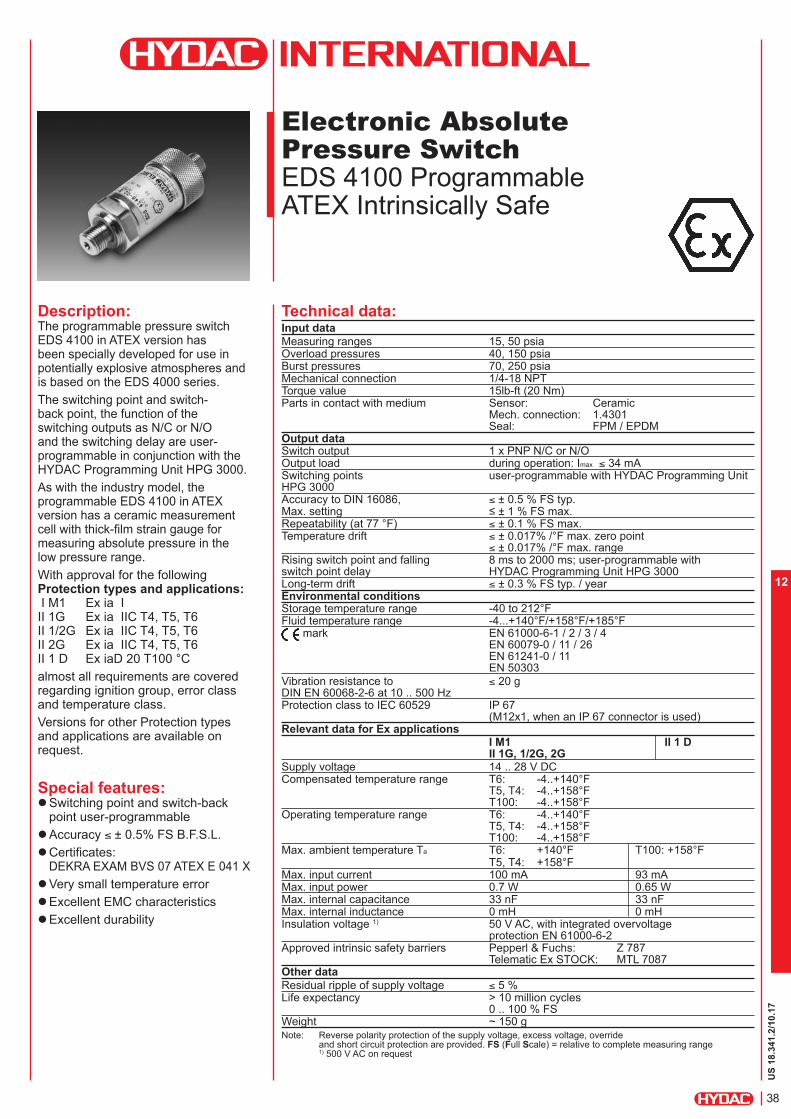
Description:The programmable pressure switch EDS 4100 in ATEX version has been specially developed for use in potentially explosive atmospheres and is based on the EDS 4000 series.
The switching point and switch-back point, the function of the switching outputs as N/C or N/O and the switching delay are user-programmable in conjunction with the HYDAC Programming Unit HPG 3000.
As with the industry model, the programmable EDS 4100 in ATEX version has a ceramic measurement cell with thick-film strain gauge for measuring absolute pressure in the low pressure range.
With approval for the following Protection types and applications: I M1 Ex ia I II 1G Ex ia IIC T4, T5, T6 II 1/2G Ex ia IIC T4, T5, T6 II 2G Ex ia IIC T4, T5, T6 II 1 D Ex iaD 20 T100 °C
almost all requirements are covered regarding ignition group, error class and temperature class.
Versions for other Protection types and applications are available on request.
Special features: Switching point and switch-back
point user-programmable
Accuracy ≤ ± 0.5% FS B.F.S.L.
Certificates:DEKRA EXAM BVS 07 ATEX E 041 X
Very small temperature error
Excellent EMC characteristics
Excellent durability
Technical data:Input data
Measuring ranges 15, 50 psiaOverload pressures 40, 150 psiaBurst pressures 70, 250 psiaMechanical connection 1/4-18 NPTTorque value 15lb-ft (20 Nm)Parts in contact with medium Sensor: Ceramic
Mech. connection: 1.4301 Seal: FPM / EPDM
Output data Switch output 1 x PNP N/C or N/OOutput load during operation: Imax ≤ 34 mASwitching points user-programmable with HYDAC Programming Unit HPG 3000Accuracy to DIN 16086, ≤ ± 0.5 % FS typ.Max. setting ≤ ± 1 % FS max.Repeatability (at 77 °F) ≤ ± 0.1 % FS max.Temperature drift ≤ ± 0.017% /°F max. zero point
≤ ± 0.017% /°F max. rangeRising switch point and falling 8 ms to 2000 ms; user-programmable with switch point delay HYDAC Programming Unit HPG 3000Long-term drift ≤ ± 0.3 % FS typ. / yearEnvironmental conditions Storage temperature range -40 to 212°FFluid temperature range -4...+140°F/+158°F/+185°F
mark EN 61000-6-1 / 2 / 3 / 4 EN 60079-0 / 11 / 26 EN 61241-0 / 11 EN 50303
Vibration resistance to ≤ 20 gDIN EN 60068-2-6 at 10 .. 500 Hz Protection class to IEC 60529 IP 67
(M12x1, when an IP 67 connector is used)Relevant data for Ex applications
I M1 II 1 D II 1G, 1/2G, 2G
Supply voltage 14 .. 28 V DCCompensated temperature range T6: -4..+140°F
T5, T4: -4..+158°FT100: -4..+158°F
Operating temperature range T6: -4..+140°FT5, T4: -4..+158°FT100: -4..+158°F
Max. ambient temperature Ta T6: +140°F T100: +158°FT5, T4: +158°F
Max. input current 100 mA 93 mAMax. input power 0.7 W 0.65 WMax. internal capacitance 33 nF 33 nFMax. internal inductance 0 mH 0 mHInsulation voltage 1) 50 V AC, with integrated overvoltage
protection EN 61000-6-2Approved intrinsic safety barriers Pepperl & Fuchs: Z 787
Telematic Ex STOCK: MTL 7087Other data
Residual ripple of supply voltage ≤ 5 %Life expectancy > 10 million cycles
0 .. 100 % FSWeight ~ 150 gNote: Reverse polarity protection of the supply voltage, excess voltage, override
and short circuit protection are provided. FS (Full Scale) = relative to complete measuring range 1) 500 V AC on request
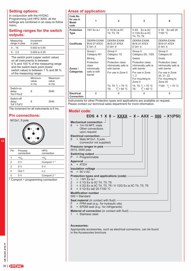
US
18.3
41.2
/10.17
39
12
Setting options:In conjunction with the HYDAC Programming Unit HPG 3000, all the settings are combined in an easy-to-follow menu.
Model code:
EDS 4 1 X 8 – XXXX – X – AXX – 000 – X1(PSI)
Mechanical connection 8 = 1/4-18 NPT, male
Other connections upon request
Electrical connection 8 = Male M12x1, 5 pole
(connector not supplied)
Pressure ranges in psia 0015, 0050 psia
Switching output P = Programmable
Approval A = ATEX
Insulation voltage N = 50 V AC
Protection types and applications (code) 1 = I M1 Ex ia I 2 = II 1G Ex ia IIC T4, T5, T6 3 = II 2G Ex ia IIC T4, T5, T6 / II 1/2G Ex ia IIC T4, T5, T6 8 = II 1D Ex iaD 20 T100 °C
Modification number 000 = Standard
Seal material (in contact with fluid) F = FPM seal (e.g.: for hydraulic oils) E = EPDM seal (e.g.: for refrigerants)Material of connection (in contact with fluid) 1 = Stainless steel
Accessories:
Appropriate accessories, such as electrical connectors, can be found in the Accessories brochure.
Pin Process connection
HPG connection
1 +UB
+UB
2 0 V Comport 1 *
3 0 V 0 V
4 Out 1 n.c.
5 0 V Comport 2 *
* Comport = programming connection
M12x1, 5 pole
1 2
34
5
Areas of application:
Code No.
for use in
Model
code
1 2 3 8
Protection
Type
I M1 Ex ia I II 1G Ex ia IIC
T4, T5, T6
II 2G Ex ia IIC
II 1/2G Ex ia IIC
T4, T5, T6
II 1D Ex iaD 20
T100 °C
CertificateDEKRA EXAM
BVS 07 ATEX
E 041 X
DEKRA EXAM
BVS 07 ATEX
E 041 X
DEKRA EXAM
BVS 07 ATEX
E 041 X
DEKRA EXAM
BVS 07 ATEX
E 041 X
Zones /
Categories
Group I
Category M1
Mining
Protection
class: intrinsically
safe ia with
barrier
Group II
Category 1G
Gases
Protection class: intrinsically safe ia
with barrier
For use in Zone 0
T4, T5: Ta = 70 °C
T6: Ta = 60 °C
Group II
Category 2G, 1/2G
Gases
Protection class: intrinsically safe ia
with barrier
For use in Zone 1, 2
For mounting to
Zone 0T4, T5: T
a = 70 °C
T6: Ta = 60 °C
Group II
Category iD
Dusts
Protection class: intrinsically safe ia
with barrier
For use in Zone 20, 21, 22
For mounting to
Zone 20T100: T
a = 70 °C
Electrical
Connection
8 8 8 8
Instruments for other Protection types and applications are available on request. Please contact our technical sales department for more information.
Pin connections:
Setting ranges for the switch outputs:
Measuring range in psia
Increment in psia
0 .. 15 0.002 to 0.05
0 .. 2.5 0.005 to 0.05
The switch point (upper switch value) on all instruments is between 5 % and 100 % of the measuring range and the switch-back point (lower switch value) is between 1 % and 96 % of the measuring range.
Minimum value in ms
Maximum value in ms
Switch-on delay Ton1/Ton2
8 2040
Switch-off delay ToF1/ToF2
8 2040
The increment for all instruments is 8 ms.

US
18.3
41.2
/10.17
40
12
Note:The information in this brochure relates to the operating conditions and applications described.For applications or operating conditions not described, please contact the relevant technical department.Subject to technical modifications.For European mechanical connection and bar ranges see European Catalog
Safety instructions: These units must only be programmed outside the potentially explosive location.
When operating in potentially explosive locations, the programming cables may only be connected to the 0 V outside of the potentially explosive area.
The switching output draws the switching energy from the power supply to the pressure switch. No additional energy is introduced into the electrical circuit through the switching output.
Dual Zener barriers specified and approved in the technical data must be used to connect the pressure switch. These have a reverse polarity diode to decouple the signal. The signal path may only be passively loaded.
Ensure that measured fluids in contact with the pressure switch are compatible with the materials used.
Dimensions:
Programming Unit:(must be ordered separately)
HPG 3000 – 000 Portable Programming Unit Part. No. 909 422
HPG 3000 Power Supply with connector: Part No. 02091103
Caution:The HPG 3000 Programming Unit may only be used outside the potentially explosive area.
electr. conn.
female 5 poleHYDAC ELECTRONICS 90 Southland Dr. Bethlehem, PA 18017 Telephone +1 (610) 266-0100 E-mail: [email protected]: www.hydacusa.com
HEX 27
Male Electrical Connector5 Poles
1/4-18NPT
17
59.4 27
12.3
30
M12X1
2.3

US
18.3
41.2
/10.17
41
12

US
18.3
42.2
/10.17
42
12
Electronic Pressure Transmitter
HDA 4700 CSA Intrinsically safe CSA Non Incendive
Description:The pressure transmitter HDA 4700 in CSA version has been specially developed for the North American market for use in potentially explosive atmospheres and is based on the HDA 4000 series.
As with the industry model, the HDA 4700 in CSA version has a stainless steel measurement cell with thin-film strain gauge.
Intended areas of application are, for example, the oil and gas industry, on gas turbines or in locations with high levels of dust, e.g. in mills.
Protection types and applications:
Intrinsically safe: - Class I Div. 1 Group A, B, C, D T6 [C, US]- Class I Zone 0 AEx ia IIC T6 [US] - Ex ia IIC T6 [C]
- Class I, II, IIIDiv. 1Group A, B, C, D, E, F, G T6 [C, US]
Non incendive: - Class I Div. 2 Group A, B, C, D T4A [C, US]- Class I Zone 2 AEx nL IIC T4 [US] - Class I Zone 2 Ex nL IIC T4 [C]
- Class I, II, IIIDiv. 2Group A, B, C, D, F, G T4A [C, US]
- Class I Zone 2 AEx nA II T4 [US] - Class I Zone 2 Ex nA II T4 [C]
Special features: Accuracy ≤ ± 0.25 % FS B.F.S.L.
Certificate: CSA 1760344 Output signal 4 .. 20 mA Very small temperature error
Excellent EMC characteristics
Excellent durability
Technical data:Input data Measuring ranges1)2) 150, 500, 750, 1000, 1500, 3000, 5000, 6000, 9000, 15000 psiOverload pressures 290, 1160, 1740, 2900, 2900, 7250, 11600, 11600, 14500,
23200 psiBurst pressures 1450, 2900, 4350, 7250, 7250, 14500, 29000, 29000, 29000,
43500 psiMechanical connection2) SAE 6 9/16-18 UNF 2A
SF 250 CS20, Autoclave (7/16-20-UNF 2B)Torque value 15lb-ft(20Nm) - SAE 6
30lb-ft(40Nm) SF 250 CX20Parts in contact with medium Stainless steel: 1.4542; 1.4571; 1.4435;
1.4404; 1.4301 Seal: FPM
Output data Output signal, 4 .. 20 mA, 2 conductor permitted load resistance RLmax = (UB - 12 V) / 20 mA [kW]Accuracy to DIN 16086 ≤ ± 0.25 % FS typ.Max. setting ≤ ± 0.5 % FS max.Accuracy at min. setting ≤ ± 0.15 % FS typ.(B.F.S.L.) ≤ ± 0.25 % FS max.Temperature compensation ≤ ± 0.0045% FS/°F typ.Zero point ≤ ± 0.0085% FS/°F max.Temperature compensation ≤ ± 0.0045% FS/°F typ.Over range ≤ ± 0.0085% FS/°F max.Non-linearity at max. setting ≤ ± 0.3 % FS max.to DIN 16086 Hysteresis ≤ ± 0.1 % FS max.Repeatability ≤ ± 0.05 % FSRise time ≤ 1.5 msLong-term drift ≤ ± 0.1 % FS typ. / yearEnvironmental conditions Compensated temperature range Intrinsically safe: -4..+140°F
Non incendive: 4..+185°FOperating temperature range3) Intrinsically safe: -40..+140°F/ -4..+140°F
Non incendive: -40..+185°F/ -4..+185°FStorage temperature range -40 to 212°FFluid temperature range3) Intrinsically safe: -40..+140°F / -4..+140°F
Non incendive: -40..+185°F / -4..+185°F mark Certificate No.: CSA 1760344
Vibration resistance to ≤ 20 gDIN EN 60068-2-6 at 10 .. 500 Hz Protection class to IEC 60529 / NEMA Min. IP 65 (depending on the electr. connection) Min. NEMA 4Relevant data for Ex applicationsSupply voltage 12 .. 28 V DCMax. input current 100 mAMax. input power up to 28 V: 1 WConnection capacitance of the sensor ≤ 22 nFInductance of the sensor 0 mHInsulation voltage 4) 50 V AC, with integrated overvoltage
protection EN 61000-6-2Other data Residual ripple of supply voltage ≤ 5 %Life expectancy > 10 million cycles
0 .. 100 % FS
Weight ~ 150 gNote: Reverse polarity protection of the supply voltage, excess voltage, override and
short circuit protection are provided. FS (Full Scale) = relative to complete measuring range
B.F.S.L.= Best Fit Straight Line 1) Bar pressure ranges on European datasheet2) 15000 psi only with mechanical connection SF 250 CX20, Autoclave3) -4°F with FPM seal, -40°F on request4) 500 V AC on request

US
18.3
42.2
/10.17
43
12
Pin connections:
Conduit (single cores)
Model code:
HDA 4 7 X X – A – XXXX – C X X – 000 (PSI) (48 inch)
Mechanical connection 7 = SAE 6, 9/16-18 UNF
2A male 8 = 1/4-18 NPTC = SF 250 CX20, Autoclave
(only for “15000 psi” press. range)
Electrical connection 5 = Male, 3 pole + PE,
EN175301-803 (DIN 43650) (connector supplied)
9 = Conduit connection thread (1/2-14 NPT, male)
A = Male, EN175301-803 (DIN 43650), 3 pole + PE
(1/2’’ conduit female thread)Signal A = 4 .. 20 mA, 2 conductorPressure ranges in psi 0150, 0500, 0750, 1000, 1500, 3000, 5000, 6000, 900015000 psi (only in conjunction with mechanical connection type “C”)
Approval C = CSAInsulation voltage N = 50 V ACProtection types and applications (code) A = Group 1 B = Group 2 and 3 C = Group 4Modification number 000 = StandardCable length in inches (only for electr. connection type 9) Standard = 48 inches
Accessories: Appropriate accessories, such as electrical connectors can be found in the Accessories brochure.
Core HDA 47X9-A
green Signal +white Signal -green-yellow
Housing
Pin HDA 47X5-A HDA 47XA-A
1 Signal + Signal +2 Signal - Signal -3 n.c. n.c.
^ Housing Housing
EN175301-803 (DIN 43650)
Areas of application:
Group 1 2 3 4
Protection
Type
Intrinsically safe
Gases and dusts
Intrinsically safe
Gases
Non incendive(with field cabling)Gases
Non incendive
Gases and dusts
Certificate CSA 1760344
Zones /
Categories
Intrinsically safe
- Class I, II, III
- Division 1
- Group
A, B, C, D, E, F, G
T6
Intrinsically safe
Ex ia IIC T6
- Class I
- Zone 0
- AEx ia IIC T6
- Class I
- Division I
- Group
A, B, C, D
T6
Non incendive
- Class I
- Division 2
- Group
A, B, C, D
T4A
- Class I
- Zone 2
- AEx nL IIC T4
- Class I
- Zone 2
- Ex nL IIC T4
Non incendive
- Class I, II, III
- Division 2
- Group
A, B, C, D, F, G
T4A
- Class I
- Zone 2
- Ex nA II T4
- Class I
- Zone 2
- AEx nA II T4 IP 6x
Electrical
Connection
9, A 5, 9, A 5, 9, A 9
Code for
Model Code
A B C
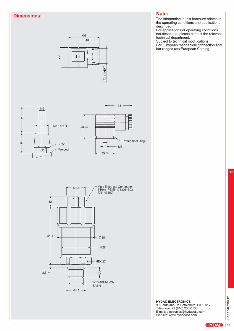
US
18.3
42.2
/10.17
44
12
Dimensions: Note:The information in this brochure relates to the operating conditions and applications described.For applications or operating conditions not described, please contact the relevant technical department.Subject to technical modifications.For European mechanical connection and bar ranges see European Catalog.
HYDAC ELECTRONICS 90 Southland Dr. Bethlehem, PA 18017 Telephone +1 (610) 266-0100 E-mail: [email protected]: www.hydacusa.com
HEX 27
Male Electrical Connector3 Pole+PE EN175301-B03 (DIN 43650)
54.4 35
SAE-6
10
27
9/16-18UNF-2A
19
2.3
12
18
54.4
SW19
Welded
30
X
1/2-14NPT
Profile Seal Ring
M3
~35.5
~35
27.5

US
18.3
42.2
/10.17
45
12
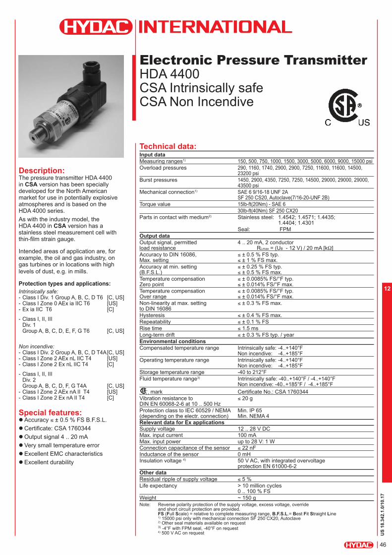
US
18.3
42.1
.0/10.17
46
12
Electronic Pressure Transmitter
HDA 4400 CSA Intrinsically safe CSA Non Incendive
Description:The pressure transmitter HDA 4400 in CSA version has been specially developed for the North American market for use in potentially explosive atmospheres and is based on the HDA 4000 series.
As with the industry model, the HDA 4400 in CSA version has a stainless steel measurement cell with thin-film strain gauge.
Intended areas of application are, for example, the oil and gas industry, on gas turbines or in locations with high levels of dust, e.g. in mills.
Protection types and applications:
Intrinsically safe: - Class I Div. 1 Group A, B, C, D T6 [C, US]- Class I Zone 0 AEx ia IIC T6 [US] - Ex ia IIC T6 [C]
- Class I, II, IIIDiv. 1Group A, B, C, D, E, F, G T6 [C, US]
Non incendive: - Class I Div. 2 Group A, B, C, D T4A [C, US]- Class I Zone 2 AEx nL IIC T4 [US] - Class I Zone 2 Ex nL IIC T4 [C]
- Class I, II, IIIDiv. 2Group A, B, C, D, F, G T4A [C, US]
- Class I Zone 2 AEx nA II T4 [US] - Class I Zone 2 Ex nA II T4 [C]
Special features: Accuracy ≤ ± 0.5 % FS B.F.S.L.
Certificate: CSA 1760344 Output signal 4 .. 20 mA Very small temperature error
Excellent EMC characteristics
Excellent durability
Technical data:Input data
Measuring ranges1) 150, 500, 750, 1000, 1500, 3000, 5000, 6000, 9000, 15000 psiOverload pressures 290, 1160, 1740, 2900, 2900, 7250, 11600, 11600, 14500,
23200 psiBurst pressures 1450, 2900, 4350, 7250, 7250, 14500, 29000, 29000, 29000,
43500 psiMechanical connection1) SAE 6 9/16-18 UNF 2A
SF 250 CS20, Autoclave(7/16-20-UNF 2B)Torque value 15lb-ft(20Nm) - SAE 6
30lb-ft(40Nm) SF 250 CX20Parts in contact with medium2) Stainless steel: 1.4542; 1.4571; 1.4435;
1.4404; 1.4301Seal: FPM
Output data
Output signal, permitted 4 .. 20 mA, 2 conductor load resistance RLmax = (UB - 12 V) / 20 mA [kW]
Accuracy to DIN 16086, ≤ ± 0.5 % FS typ.Max. setting ≤ ± 1 % FS max.
Accuracy at min. setting ≤ ± 0.25 % FS typ.(B.F.S.L.) ≤ ± 0.5 % FS max.
Temperature compensation ≤ ± 0.0085% FS/°F typ.Zero point ≤ ± 0.014% FS/°F max.Temperature compensation ≤ ± 0.0085% FS/°F typ.Over range ≤ ± 0.014% FS/°F max.Non-linearity at max. setting ≤ ± 0.3 % FS max.to DIN 16086 Hysteresis ≤ ± 0.4 % FS max.
Repeatability ≤ ± 0.1 % FS
Rise time ≤ 1.5 ms
Long-term drift ≤ ± 0.3 % FS typ. / yearEnvironmental conditions
Compensated temperature range Intrinsically safe: -4..+140°F Non incendive: -4..+185°F
Operating temperature range Intrinsically safe: -4..+140°F Non incendive: -4..+185°F
Storage temperature range -40 to 212°FFluid temperature range3) Intrinsically safe: -40..+140°F / -4..+140°F
Non incendive: -40..+185°F / -4..+185°F mark Certificate No.: CSA 1760344
Vibration resistance to ≤ 20 gDIN EN 60068-2-6 at 10 .. 500 Hz Protection class to IEC 60529 / NEMA Min. IP 65 (depending on the electr. connection) Min. NEMA 4Relevant data for Ex applications
Supply voltage 12 .. 28 V DCMax. input current 100 mA
Max. input power up to 28 V: 1 WConnection capacitance of the sensor ≤ 22 nF
Inductance of the sensor 0 mH
Insulation voltage 4) 50 V AC, with integrated overvoltage protection EN 61000-6-2
Other data
Residual ripple of supply voltage ≤ 5 %
Life expectancy > 10 million cycles0 .. 100 % FS
Weight ~ 150 gNote: Reverse polarity protection of the supply voltage, excess voltage, override
and short circuit protection are provided. FS (Full Scale) = relative to complete measuring range, B.F.S.L.= Best Fit Straight Line 1) 15000 psi only with mechanical connection SF 250 CX20, Autoclave2) Other seal materials available on request 3) -4°F with FPM seal, -40°F on request4) 500 V AC on request

US
18.3
42.1
.0/10.17
47
12
Pin connections:
Conduit (single cores)
Model code:
HDA 4 4 X X – A – XXXX – C X X – 000 (PSI) (48in)
Mechanical connection 7 = SAE 6, 9/16-18 UNF 2A male C = SF 250 CX20, Autoclave
(only for “15000 psi” press. range)
Electrical connection 5 = Male, 3 pole + PE,
EN175301-803 (DIN 43650) (connector supplied)
9 = Conduit connection thread (1/2-14 NPT, male)
A = Male, EN175301-803 (DIN 43650), 3 pole + PE (1/2’’ conduit female thread)
Signal A = 4 .. 20 mA, 2 conductorPressure ranges in psi 0500, 0750, 1000, 1500, 3000, 5000, 6000, 900015000 psi (only in conjunction with mechanical connection type “C”) Approval C = CSAInsulation voltage N = 50 V ACProtection types and applications (code) A = Group 1 B = Group 2 and 3 C = Group 4Modification number 000 = StandardCable length in inches (only for electr. connection code 9) Standard = 48 inches
Accessories: Appropriate accessories, such as electrical connectors can be found in the Accessories brochure.
Core HDA 44X9-Agreen Signal +white Signal -green-yellow
Housing
Pin HDA 44X5-A HDA 44XA-A1 Signal + Signal +2 Signal - Signal -3 n.c. n.c.
^ Housing Housing
EN175301-803 (DIN 43650)
Areas of application:
Group 1 2 3 4
Protection
Type
Intrinsically safe
Gases and dusts
Intrinsically safe
Gases
Non incendive
(with field cabling)Gases
Non incendive
Gases and dusts
Certificate CSA 1760344
Zones /
Categories
Intrinsically safe
- Class I, II, III
- Division 1
- Group
A, B, C, D, E, F, G
T6
Intrinsically safe
Ex ia IIC T6
- Class I
- Zone 0
- AEx ia IIC T6
- Class I
- Division I
- Group
A, B, C, D
T6
Non incendive
- Class I
- Division 2
- Group
A, B, C, D
T4A
- Class I
- Zone 2
- AEx nL IIC T4
- Class I
- Zone 2
- Ex nL IIC T4
Non incendive
- Class I, II, III
- Division 2
- Group
A, B, C, D, F, G
T4A
- Class I
- Zone 2
- Ex nA II T4
- Class I
- Zone 2
- AEx nA II T4 IP 6x
Electrical
Connection
9, A 5, 9, A 5, 9, A 9
Code for
Model Code
A B C

US
18.3
42.1
.0/10.17
48
12
Dimensions: Note:The information in this brochure relates to the operating conditions and applications described.For applications or operating conditions not described, please contact the relevant technical department.Subject to technical modifications.For European mechanical connection and bar ranges see European Catalog
HYDAC ELECTRONICS 90 Southland Dr. Bethlehem, PA 18017 Telephone +1 (610) 266-0100 E-mail: [email protected]: www.hydacusa.com
Profile Seal Ring
M3
~35.5
~35
SW19
Welded
30
X
1/2-14NPT
HEX 27
Male Electrical Connector3 Pole+PE EN175301-B03 (DIN 43650)
54.4 35
SAE-6
10
27
9/16-18UNF-2A
19
2.3
12
18
54.4
HEX 27
(7/16-20UNF-2B)SF250 CX20, Autoclave
20
15
electrical connector with 1/2 NPT connection

US
18.3
42.1
.0/10.17
49
12

US
18.3
43.2
/10.17
50
12
Electronic
Pressure Transmitter
HDA 4300 CSA Intrinsically safe CSA Non Incendive
Description:The pressure transmitter HDA 4300 in CSA version has been specially developed for the North American market for use in potentially explosive atmospheres and is based on the HDA 4000 series.
As with the industry model, the HDA 4300 in CSA version has a ceramic measurement cell with thick-film strain gauge for measuring relative pressure in the low pressure range.
Intended areas of application are, for example, the oil and gas industry, on gas turbines or in locations with high levels of dust, e.g. in mills.
Protection types and applications: Intrinsically safe: - Class I Div. 1 Group A, B, C, D T6 [C, US]- Class I Zone 0 AEx ia IIC T6 [US] - Ex ia IIC T6 [C]
- Class I, II, IIIDiv. 1Group A, B, C, D, E, F, G T6 [C, US]
Non incendive: - Class I Div. 2 Group A, B, C, D T4A [C, US]- Class I Zone 2 AEx nL IIC T4 [US] - Class I Zone 2 Ex nL IIC T4 [C]
- Class I, II, IIIDiv. 2Group A, B, C, D, F, G T4A [C, US]
- Class I Zone 2 AEx nA II T4 [US] - Class I Zone 2 Ex nA II T4 [C]
Special features: Accuracy ≤ ± 0.5 % FS B.F.S.L.
Certificate: CSA 1760344 Output signal 4 .. 20 mA
Very small temperature error
Excellent EMC characteristics
Excellent durability
Technical data:Input data
Measuring ranges1) 15, 30, 50, 100, 150, 250, 500 psi
Overload pressures 45, 100, 150, 290, 450, 725, 1500 psiBurst pressures 70, 150, 250, 400, 650, 1000, 2500 psiMechanical connection 1/4-18 NPT male
Torque value 30 ft-lb (40 Nm)
Parts in contact with medium Sensor: Ceramic Al203 Mech. conn.: 1.4301 Seal: FPM / EPDM
Output data
Output signal, permitted load resistance 4 .. 20 mA, 2 conductor RLmax = (UB - 12 V) / 20 mA [kW]
Accuracy to DIN 16086, ≤ ± 0.5 % FS typ.Max. setting ≤ ± 1.0 % FS max.Accuracy at min. setting ≤ ± 0.25 % FS typ.(B.F.S.L.) ≤ ± 0.5 % FS max.
Temperature compensation ≤ ± 0.012% FS/°F typ.Zero point ≤ ± 0.017% FS/°F max.Temperature compensation ≤ ± 0.012% FS/°F typ.Over range ≤ ± 0.017% FS/°F max.Non-linearity at max. setting ≤ ± 0.5 % FS max.to DIN 16086
Hysteresis ≤ ± 0.4 % FS max.
Repeatability ≤ ± 0.1 % FS
Rise time ≤ 1.5 ms
Long-term drift ≤ ± 0.3 % FS typ. / year
Environmental conditions
Compensated temperature range Intrinsically safe: -4..+140°F Non incendive: -4..+185°F
Operating temperature range Intrinsically safe: -4..+140°F Non incendive: -4..+185°F
Storage temperature range -40 to 212°F
Fluid temperature range2) Intrinsically safe: -40..+140°F / -4..+140°F Non incendive: -40..+185°F / -4..+185°F
mark Certificate No.: CSA 1760344Vibration resistance to ≤ 20 gDIN EN 60068-2-6 at 10 .. 500 Hz
Protection class to IEC 60529 / NEMA Min. IP 65 (depending on the electr. connection) Min. NEMA 4Relevant data for Ex applicationsSupply voltage 12 .. 28 V DCMax. input current 100 mAMax. input power up to 28 V: 1 WConnection capacitance of the sensor ≤ 22 nFInductance of the sensor 0 mHInsulation voltage 3) 50 V AC, with integrated overvoltage
protection EN 61000-6-2Other data
Residual ripple of supply voltage ≤ 5 %
Life expectancy > 10 million cycles0 .. 100 % FS
Weight ~ 180 g
Note: Reverse polarity protection of the supply voltage, excess voltage, override and short circuit protection are provided. FS (Full Scale) = relative to complete measuring range B.F.S.L.= Best Fit Straight Line 1) For bar ranges see European catalog2) -4°F with FPM or EPDM seal, -40°F on request3) 500 V AC on request

US
18.3
43.2
/10.17
51
12
Pin connections:
Conduit (single cores)
Model code:
HDA 4 3 8 X – A – XXXX – C X X – XXX – X 1(PSI) (48in)
Mechanical connection 8 = 1/4“-18 NPT male Electrical connection 5 = Male, 3 pole+ PE,
EN175301-803 (DIN 43650) (connector supplied)
9 = Conduit connection thread (1/2-14 NPT, male)
A = Male, EN175301-803 (DIN 43650), 3 pole + PE (1/2’’ conduit female thread)
Signal A = 4 .. 20 mA, 2 conductor
Pressure ranges in psi 0015, 0030, 0050, 0100, 0250, 0500
Approval C = CSA
Insulation voltage N = 50 V AC
Protection types and applications (code) A = Group 1 B = Group 2 and 3 C = Group 4
Modification number 000 = Standard
Seal material (in contact with fluid) F = FPM seal (e.g.: for hydraulic oils) E = EPDM seal (e.g.: for refrigerants)Material of connection (in contact with fluid) 1 = Stainless steel
Cable length in inches (only for electr. connection type 9) Standard = 48 inches
Accessories: Appropriate accessories, such as electrical connectors can be found in the Accessories brochure.
EN175301-803 (DIN 43650)
Areas of application:
Group 1 2 3 4
Protection
Type
Intrinsically safe
Gases and dusts
Intrinsically safe
Gases
Non incendive
(with field cabling)Gases
Non incendive
Gases and dusts
Certificate CSA 1760344
Zones /
Categories
Intrinsically safe
- Class I, II, III
- Division 1
- Group
A, B, C, D, E, F, G
T6
Intrinsically safe
Ex ia IIC T6
- Class I
- Zone 0
- AEx ia IIC T6
- Class I
- Division I
- Group
A, B, C, D
T6
Non incendive
- Class I
- Division 2
- Group
A, B, C, D
T4A
- Class I
- Zone 2
- AEx nL IIC T4
- Class I
- Zone 2
- Ex nL IIC T4
Non incendive
- Class I, II, III
- Division 2
- Group
A, B, C, D, F, G
T4A
- Class I
- Zone 2
- Ex nA II T4
- Class I
- Zone 2
- AEx nA II T4 IP 6x
Electrical
Connection
9, A 5, 9, A 5, 9, A 9
Code for
Model Code
A B C
Core HDA 43X9-A
green Signal +white Signal -
green-yellow
Housing
Pin HDA 43X5-A HDA 43XA-A
1 Signal + Signal +2 Signal - Signal -
3 n.c. n.c.
^ Housing Housing

US
18.3
43.2
/10.17
52
12
Dimensions: Note:The information in this brochure relates to the operating conditions and applications described.For applications or operating conditions not described, please contact the relevant technical department.Subject to technical modifications.For European mechanical connection and bar ranges see European Catalog
HYDAC ELECTRONICS 90 Southland Dr. Bethlehem, PA 18017 Telephone +1 (610) 266-0100 E-mail: [email protected]: www.hydacusa.com
SW19
Welded
30
X
1/2-14NPT
Profile Seal Ring
M3
~35.5
~35
27.5
3 Pole+PE EN175301-B03
HEX 27
Male Electrical Connector3 Pole+PE EN175301-B03 (DIN 43650)
27
35 54.4
17
18
12
1/4-18-NPT

US
18.3
43.2
/10.17
53
12
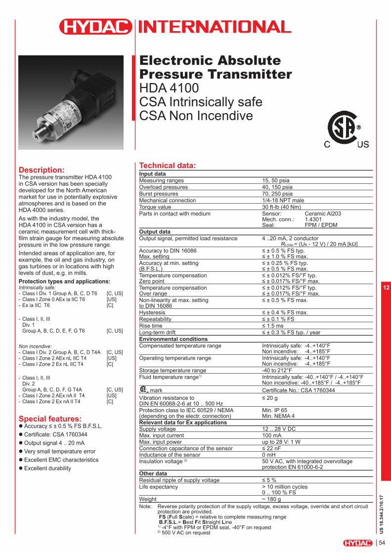
US
18.3
44.2
/10.17
54
12
Electronic Absolute
Pressure Transmitter
HDA 4100 CSA Intrinsically safe CSA Non Incendive
Description:The pressure transmitter HDA 4100 in CSA version has been specially developed for the North American market for use in potentially explosive atmospheres and is based on the HDA 4000 series.
As with the industry model, the HDA 4100 in CSA version has a ceramic measurement cell with thick-film strain gauge for measuring absolute pressure in the low pressure range.Intended areas of application are, for example, the oil and gas industry, on gas turbines or in locations with high levels of dust, e.g. in mills.Protection types and applications: Intrinsically safe: - Class I Div. 1 Group A, B, C, D T6 [C, US]- Class I Zone 0 AEx ia IIC T6 [US] - Ex ia IIC T6 [C]
- Class I, II, IIIDiv. 1Group A, B, C, D, E, F, G T6 [C, US]
Non incendive: - Class I Div. 2 Group A, B, C, D T4A [C, US]- Class I Zone 2 AEx nL IIC T4 [US] - Class I Zone 2 Ex nL IIC T4 [C]
- Class I, II, IIIDiv. 2Group A, B, C, D, F, G T4A [C, US]
- Class I Zone 2 AEx nA II T4 [US] - Class I Zone 2 Ex nA II T4 [C]
Special features: Accuracy ≤ ± 0.5 % FS B.F.S.L. Certificate: CSA 1760344 Output signal 4 .. 20 mA Very small temperature error
Excellent EMC characteristics
Excellent durability
Technical data:Input data
Measuring ranges 15, 50 psiaOverload pressures 40, 150 psia
Burst pressures 70, 250 psiaMechanical connection 1/4-18 NPT male
Torque value 30 ft-lb (40 Nm)Parts in contact with medium Sensor: Ceramic Al203
Mech. conn.: 1.4301 Seal: FPM / EPDM
Output data
Output signal, permitted load resistance 4 ..20 mA, 2 conductor RLmax.= (UB - 12 V) / 20 mA [kW]
Accuracy to DIN 16086 ≤ ± 0.5 % FS typ. Max. setting ≤ ± 1.0 % FS max.Accuracy at min. setting ≤ ± 0.25 % FS typ. (B.F.S.L.) ≤ ± 0.5 % FS max.Temperature compensation ≤ ± 0.012% FS/°F typ. Zero point ≤ ± 0.017% FS/°F max.Temperature compensation ≤ ± 0.012% FS/°F typ. Over range ≤ ± 0.017% FS/°F max.Non-linearity at max. setting ≤ ± 0.5 % FS max. to DIN 16086
Hysteresis ≤ ± 0.4 % FS max.Repeatability ≤ ± 0.1 % FSRise time ≤ 1.5 msLong-term drift ≤ ± 0.3 % FS typ. / yearEnvironmental conditions
Compensated temperature range Intrinsically safe: -4..+140°F Non incendive: -4..+185°F
Operating temperature range Intrinsically safe: -4..+140°F Non incendive: -4..+185°F
Storage temperature range -40 to 212°FFluid temperature range1) Intrinsically safe: -40..+140°F / -4..+140°F
Non incendive: -40..+185°F / -4..+185°F mark Certificate No.: CSA 1760344Vibration resistance to ≤ 20 g DIN EN 60068-2-6 at 10 .. 500 Hz
Protection class to IEC 60529 / NEMA Min. IP 65 (depending on the electr. connection) Min. NEMA 4Relevant data for Ex applicationsSupply voltage 12 .. 28 V DCMax. input current 100 mAMax. input power up to 28 V: 1 WConnection capacitance of the sensor ≤ 22 nFInductance of the sensor 0 mHInsulation voltage 2) 50 V AC, with integrated overvoltage
protection EN 61000-6-2Other data
Residual ripple of supply voltage ≤ 5 %Life expectancy > 10 million cycles
0 .. 100 % FSWeight ~ 180 gNote: Reverse polarity protection of the supply voltage, excess voltage, override and short circuit
protection are provided. FS (Full Scale) = relative to complete measuring range B.F.S.L.= Best Fit Straight Line 1) -4°F with FPM or EPDM seal, -40°F on request2) 500 V AC on request

US
18.3
44.2
/10.17
55
12
Pin connections:
Conduit (single cores)
EN175301-803 (DIN 43650)
Areas of application:
Group 1 2 3 4
Protection
Type
Intrinsically safe
Gases and dusts
Intrinsically safe
Gases
Non incendive (with field cabling)Gases
Non incendive
Gases and dusts
Certificate CSA 1760344
Zones /
Categories
Intrinsically safe
- Class I, II, III
- Division 1
- Group
A, B, C, D, E, F, G
T6
Intrinsically safe
Ex ia IIC T6
- Class I
- Zone 0
- AEx ia IIC T6
- Class I
- Division I
- Group
A, B, C, D
T6
Non incendive
- Class I
- Division 2
- Group
A, B, C, D
T4A
- Class I
- Zone 2
- AEx nL IIC T4
- Class I
- Zone 2
- Ex nL IIC T4
Non incendive
- Class I, II, III
- Division 2
- Group
A, B, C, D, F, G
T4A
- Class I
- Zone 2
- Ex nA II T4
- Class I
- Zone 2
- AEx nA II T4 IP 6x
Electrical
Connection
9, A 5, 9, A 5, 9, A 9
Code for
Model Code
A B C
Model code:
HDA 4 1 X X – A – XXXX – C X X – 000 – X 1 (PSI) (48in)
Mechanical connection 8 = 1/4-18 NPT male Electrical connection 5 = Male, 3 pole+ PE,
EN175301-803 (DIN 43650) (connector supplied)
9 = Conduit connection thread (1/2-14 NPT, male)
A = Male EN175301-803 (DIN 43650), 3 pole + PE (1/2’’ conduit female thread)
Signal A = 4 .. 20 mA, 2 conductor
Pressure ranges in psi 0015, 0050
Approval C = CSA
Insulation voltage N = 50 V AC
Protection types and applications (code) A = Group 1 B = Group 2 and 3 C = Group 4
Modification number 000 = Standard
Seal material (in contact with fluid) F = FPM seal (e.g.: for hydraulic oils) E = EPDM seal (e.g.: for refrigerants)Material of connection (in contact with fluid) 1 = Stainless steel
Cable length in inches (only for electr. connection type 9) Standard = 48 inches
Accessories: Appropriate accessories, such as electrical connectors can be found in the Accessories brochure.
Core HDA 41X9-A
green Signal +white Signal -green-yellow
Housing
Pin HDA 41X5-A HDA 41XA-A
1 Signal + Signal +2 Signal - Signal -3 n.c. n.c.
^ Housing Housing

US
18.3
44.2
/10.17
56
12
Dimensions: Note:The information in this brochure relates to the operating conditions and applications described.For applications or operating conditions not described, please contact the relevant technical department.Subject to technical modifications.For European mechanical connection and bar ranges see European Catalog
HYDAC ELECTRONICS 90 Southland Dr. Bethlehem, PA 18017 Telephone +1 (610) 266-0100 E-mail: [email protected]: www.hydacusa.com
SW19
Welded
30
X
1/2-14NPT
Profile Seal Ring
M3
~35.5
~35
27.5
Male Electrical Connector3 Pole+PE EN175301-B03
HEX 27
Male Electrical Connector3 Pole+PE EN175301-B03 (DIN 43650)
27
35 54.4
17
18
12
1/4-18-NPT

US
18.3
44.2
/10.17
57
12

US
18.3
92.1
/10.17
58
12
Electronic Pressure Transmitter HDA 4700 IECEx Intrinsically Safe IECEx Dustproof Enclosure IECEx Non-sparking
Description:The pressure transmitter HDA 4700 IECEx Intrinsically Safe version has been especially developed for use in potentially explosive atmospheres and is based on the HDA 4000 series.
As with the industrial version of the HDA 4700, devices with IECEx Intrinsically Safe approval have a field-proven, all-welded stainless steel measurement cell with thin film strain gauge without internal seal.
Intended areas of application are, for example, in the oil and gas industry, in mining, on gas turbines or in locations with high dust loads, e.g. in mills.
Protection types and applications:
Ex ia l Ma
Ex ia llC T6 Ga Ex ia llC T6 Ga/Gb Ex ia llC T6 Gb Ex nA llC T6,T5,T4 Gc Ex ic llC T6,T5,T4 Gc
Ex ta lllC T80/90/100 °C Da T
500 90/100/110 °C Da
Ex tb lllC T80/90/100 °C Db Ex tc lllC T80/90/100 °C Dc Ex ic lllC T80/90/100 °C Dc Ex ia lllC T85 °C Da
Special features: Accuracy ≤ ± 0.25 % FS B.F.S.L.
Certificate:IECEx TSA 09.0041X /IECEx KEM 08.0014X
Output signal 4 .. 20 mA
Robust design
Very small temperature error
Excellent EMC characteristics
Excellent long-term properties
Technical data:Input data
Measuring ranges1) 150, 500, 750, 1000, 1500, 3000, 5000, 6000, 9000, 15000 psi
Overload pressures 290, 1160, 1740, 2900, 2900, 7250, 11600, 11600, 14500, 23200 psi
Burst pressure 1450, 2900, 4350, 7250, 7250, 14500, 29000, 29000, 29000, 43500 psi
Mechanical connection1) SAE 6 9/16-18 UNF 2A SF 250 CS20, Autoclave(7/16-20-UNF 2B)
Torque value 15lb-ft(20Nm) - SAE 6
30lb-ft(40Nm) SF 250 CX20
Parts in contact with medium Stainl. steel: 1.4542; 1.4571; 1.4435; 1.4404; 1.4301
Seal: FPMOutput data
Output signal, permitted load resistance 4 .. 20 mA, 2 conductor RLmax = (UB - 12 V) / 20 mA [kW]
Accuracy to DIN 16086, ≤ ± 0.25 % FS typ.Max. setting ≤ ± 0.5 % FS max.
Accuracy at min. setting ≤ ± 0.15 % FS typ.(B.F.S.L.) ≤ ± 0.3 % FS max.
Temperature compensation ≤ ± 0.0045% FS/°F typ.Zero point ≤ ± 0.0085% FS/°F max.
Temperature compensation ≤ ± 0.0045% FS/°F typ.Over range ≤ ± 0.0085% FS/°F max.
Non-linearity at max. setting ≤ ± 0.3 % FS max.to DIN 16086
Hysteresis ≤ ± 0.1 % FS max.
Repeatability ≤ ± 0.05 % FS
Rise time ≤ 1.5 ms
Long-term drift ≤ ± 0.1 % FS typ. / year
Environmental conditions
Compensated temperature range -4..+185°F
Operating temperature range2) -40..+140°F/ -4..+140°F
Storage temperature range -40..+212°F
Fluid temperature range2) -40..+140°F/ -4..+140°F
mark EN 61000-6-1 / 2 / 3 / 4; EN 60079-0 / 11 / 26 / 36
Vibration resistance to ≤ 20 gDIN EN 60068-2-6 at 10 .. 500 Hz
Protection class to IEC 60529 IP 65 (for male EN175301-803 (DIN 43650) and Binder 714 M18)
IP 67 (for M12x1 male, when an IP 67 female connector is used)
Relevant data for Ex applications Ex ia, ic Ex nA, ta, tb, tcSupply voltage Ui = 12 .. 28 V 12 .. 28 VMax. input current Ii = 100 mAMax. input power Pi = 1 W max. power consuption
≤ 1 WConnection capacitance of the sensor Ci = ≤ 22 nFInductance of the sensor Li = 0 mHInsulation voltage 3) 50 V AC, with integrated overvoltage protection
EN 61000-6-2Other dataResidual ripple of supply voltage ≤ 5 %Life expectancy > 10 million cycles
0 .. 100 % FSWeight ~ 150 gNote: Reverse polarity protection of the supply voltage, excess voltage,
override and short circuit protection are provided. FS (Full Scale) = relative to the full measuring range, B.F.S.L.= Best Fit Straight Line 1) 15000 psi only with mechanical connection SF 250 CX20, Autoclave2) -4°F with FPM seal, -40°F on request3) 500 V AC on request

US
18.3
92.1
/10.17
59
12
Areas of application:
Protection types
and
applications
Ex ia I MaEx ia IIC T6 Ga
Ex ia IIC T6 Ga/GbEx ia IIC T6 Gb Ex nA llC T6 Gc
Ex ta lllC T80 °C
T500
T90 °C Da
Ex tb lllC T80 °C Db
Ex ic llC T6 Gc
Ex ic lllC T80 °C DcEx ia lIIC T85 °C Da
Zones /
Categories
Equipment protec-
tion level
Ma
Mining
Protection class: intrinsically safe ia
with barrier
Equipment
protection level
Ga, Ga/Gb
Gases
Protection class: intrinsically safe ia
with barrier
Equipment
protection level
Gb
Gases
Protection class: intrinsically safe ia
with barrier
Equipment
protection level
Gc
Gases
Protection class: non-sparking nA
Equipment
protection level
Da, Db
Conductive dust
Protection class: Dustproof
enclosure
Equipment
protection level
Gc, Dc
Gases/conductive dust
Protection class:Intrinsically safe ic
with barrier
Equipment
protection level
Da
Conductive dust
Protection class: intrinsically safe ia
with barrier
Electrical connection 4, 5, 6 4, 5, 6 4, 5, 6 6 6 4, 5, 6 4, 5, 6
Code for
use in
Model code
IECEx IECEx
Australia
1 ü ü ü ü ü
9 ü ü
A ü ü
C ü ü
D ü ü ü ü ü
Certificate numbers: IECEx TSA 09.0041X, IECEx KEM 08.0014X
Devices in the ignition protection class "Dustproof enclosure" for the protection types Ex ta lllC T80/90/100 °C Da T500T90/T100/T110°C Da, Ex tb lllC T80/90/100 °C Db and Ex tc lllC T80/90/100 °C Dc are available with flying leads on request. Devices in the ignition protection class "non-sparking" for protection type Ex nA llC T6, T5, T4 Gc are available with flying leads on request.
Model code:
HDA 4 7 X X – A – XXXX – I X X – 000 (PSI)
Mechanical connection 7 = SAE 6, 9/16-18 UNF 2A male
C = SF 250 CX20, Autoclave (only for "15000 psi" press. range)
Electrical connection 4 = Male 4 pole Binder series 714 M18 (connector not supplied) 5 = Male 3 pole + PE, EN175301-803 (DIN 43650) (connector supplied) 6 = Male M12x1, 4 pole (connector not supplied)
Signal A = 4 .. 20 mA, 2 conductor
Pressure ranges in psi 0500, 0750, 1000, 1500, 3000, 5000, 6000, 9000 15000 psi (only in conjunction with mechanical connection type "C")
Approval I = IECEx
Insulation voltage N = 50 V AC
Protection types and applications (code) 1 = Ex ia l Ma
Ex ia llC T6 Ga Ex ia llC T6 Ga/Gb Ex ia llC T6 Gb
9 = Ex nA llC T6 Gc (only in conjunction with electr. connection "6")*
A = Ex ta lllC T80 °C T500
T90 °C Da (only in conjunction with electr. connection "6")* Ex tb lllC T80 °C Db
C = Ex ic llC T6 Gc Ex ic lllC T80 °C Dc
D = Ex ia l Ma Ex ia llC T6 Ga Ex ia llC T6 Ga/Gb Ex ia llC T6 Gb Ex ia lllC T85 °C Da
Modification number 000 = Standard
Notes:
* For design and electrical connection see Dimensions
Accessories:
Appropriate accessories, such as electrical female connectors, can be found in the Accessories brochure.

US
18.3
92.1
/10.17
60
12
Pin connections:
Binder series 714 M18
Pin HDA 47x4-A
1 n.c.
2 Signal +
3 Signal -
4 n.c.
Pin HDA 47x5-A
1 Signal +
2 Signal -
3 n.c.
^ Housing
Pin HDA 47x6-A
1 Signal +
2 n.c.
3 Signal -
4 n.c.
EN175301-803 (DIN 43650)
M12x1
Dimensions:Protection types and applications: (code): 1, C, D
Protection types and applications: (code): 9, A
Impact
protected metal
safety sleeve
SW25
hex-SW27
The impact protected metal safety sleeve is included. A straight female connector is required for electrical connection, e.g. female connector M12x1, 4 pole, straight, with 3m shielded cable: ZBE 06S-03, Part No. 6098243
Profile seal ring
~35
~35.5
27.5
M3
Male Electrical ConnectorBinder Series 714-4p
Male Electrical ConnectorBinder Series 714-4p
M18
18.3
20
15
SF 250 CX20, Autoclave(7/16"-20UNF-2B)
Male Electrical Connector4 Poles
12.3
M12X1
HEX 27
59.4 27
10
17
18
30
1/4-18NPT
Male ElectricalConnector 3P +PE EN 175301-803 (DIN43650)
US
18.3
92.1
/10.17
61
12
Note:The information in this brochure relates to the operating conditions and applications described.For applications and operating conditions not described, please contact the relevant technical department.Subject to technical modifications.For European mechanical connection and bar ranges see European Catalog
HYDAC ELECTRONICS 90 Southland Dr. Bethlehem, PA 18017 Telephone +1 (610) 266-0100 E-mail: [email protected]: www.hydacusa.com
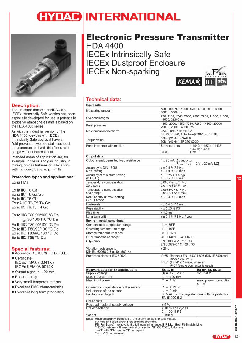
US
18.3
92.1
.0/10.17
62
12
Technical data:Input data
Measuring ranges1) 150, 500, 750, 1000, 1500, 3000, 5000, 6000, 9000, 15000 psi
Overload ranges290, 1160, 1740, 2900, 2900, 7250, 11600, 11600, 14500, 23200 psi
Burst pressure1450, 2900, 4350, 7250, 7250, 14500, 29000, 29000, 29000, 43500 psi
Mechanical connection1) SAE 6 9/16-18 UNF 2A SF 250 CS20, Autoclave(7/16-20-UNF 2B)
Torque value15lb-ft(20Nm) - SAE 6 30lb-ft(40Nm) SF 250 CX20
Parts in contact with medium Stainless steel: 1.4542; 1.4571; 1.4435; 1.4404; 1.4301
Seal: FPM
Output data
Output signal, permitted load resistance 4 .. 20 mA, 2 conductor RLmax = (UB – 12 V) / 20 mA [kΩ]
Accuracy to DIN 16086, Max. setting
≤ ± 0.5 % FS typ. ≤ ± 1.0 % FS max.
Accuracy at minimum setting (B.F.S.L.)
≤ ± 0.25 % FS typ. ≤ ± 0.5 % FS max.
Temperature compensation Zero point
0.0085% FS/°F typ. 0.014% FS/°F max.
Temperature compensation Over range
0.0085% FS/°F typ. 0.014% FS/°F max.
Non-linearity at max. setting to DIN 16086
≤ ± 0.3 % FS max.
Hysteresis ≤ ± 0.4 % FS max.Repeatability ≤ ± 0.25 % FSRise time ≤ 1.5 msLong term drift ≤ ± 0.3 % FS typ. / yearEnvironmental conditions
Compensated temperature range -4..+185°FOperating temperature range -4..+140°FStorage temperature range -40..+212°FFluid temperature range2) -40..+140°F / -4..+140°F
- mark EN 61000-6-1 / 2 / 3 / 4 EN 60079-0 / 11 / 26 / 36
Vibration resistance to DIN EN 60068-2-6 at 10 ..500 Hz
≤ 20 g
Protection class to IEC 60529 IP 65 (for male EN 175301-803 (DIN 43650) and Binder 714 M18)
IP 67 (for M12x1 male, when an IP 67 female connector is used)
Electronic Pressure Transmitter
HDA 4400 IECEx Intrinsically Safe IECEx Dustproof Enclosure IECEx Non-sparking
Description:The pressure transmitter HDA 4400 IECEx Intrinsically Safe version has been especially developed for use in potentially explosive atmospheres and is based on the HDA 4000 series.
As with the industrial version of the HDA 4400, devices with IECEx Intrinsically Safe approval have a field-proven, all-welded stainless steel measurement cell with thin film strain gauge without internal seal.
Intended areas of application are, for example, in the oil and gas industry, in mining, on gas turbines or in locations with high dust loads, e.g. in mills.
Protection types and applications:
Ex ia l Ma
Ex ia llC T6 Ga Ex ia llC T6 Ga/Gb Ex ia llC T6 Gb Ex nA llC T6,T5,T4 Gc Ex ic llC T6,T5,T4 Gc
Ex ta lllC T80/90/100 °C Da T
500 90/100/110 °C Da
Ex tb lllC T80/90/100 °C Db Ex tc lllC T80/90/100 °C Dc Ex ic lllC T80/90/100 °C Dc Ex ia lllC T85 °C Da
Special features: Accuracy: ≤ ± 0.5 % FS B.F.S.L. Certificate:
IECEx TSA 09.0041X /IECEx KEM 08.0014X
Output signal 4 .. 20 mA
Robust design
Very small temperature error
Excellent EMC characteristics
Excellent long-term properties
Relevant data for Ex applications Ex ia, ic Ex nA, ta, tb, tcSupply voltage Ui = 12 .. 28 V 12 .. 28 VMax. input current Ii = 100 mAMax. input power Pi = 1 W max. power consuption
≤ 1 WConnection capacitance of the sensor Ci = ≤ 22 nFInductance of the sensor Li = 0 mHInsulation voltage 3) 50 V AC, with integrated overvoltage protection
EN 61000-6-2Other dataResidual ripple of supply voltage ≤ 5 %Life expectancy > 10 million cycles
0 .. 100 % FSWeight ~ 150 gNote: Reverse polarity protection of the supply voltage, excess voltage,
override and short circuit protection are provided. FS (Full Scale) = relative to the full measuring range, B.F.S.L.= Best Fit Straight Line 1) 15000 psi only with mechanical connection SF 250 CX20, Autoclave2) -4°F with FPM seal, -40°F on request3) 500 V AC on request
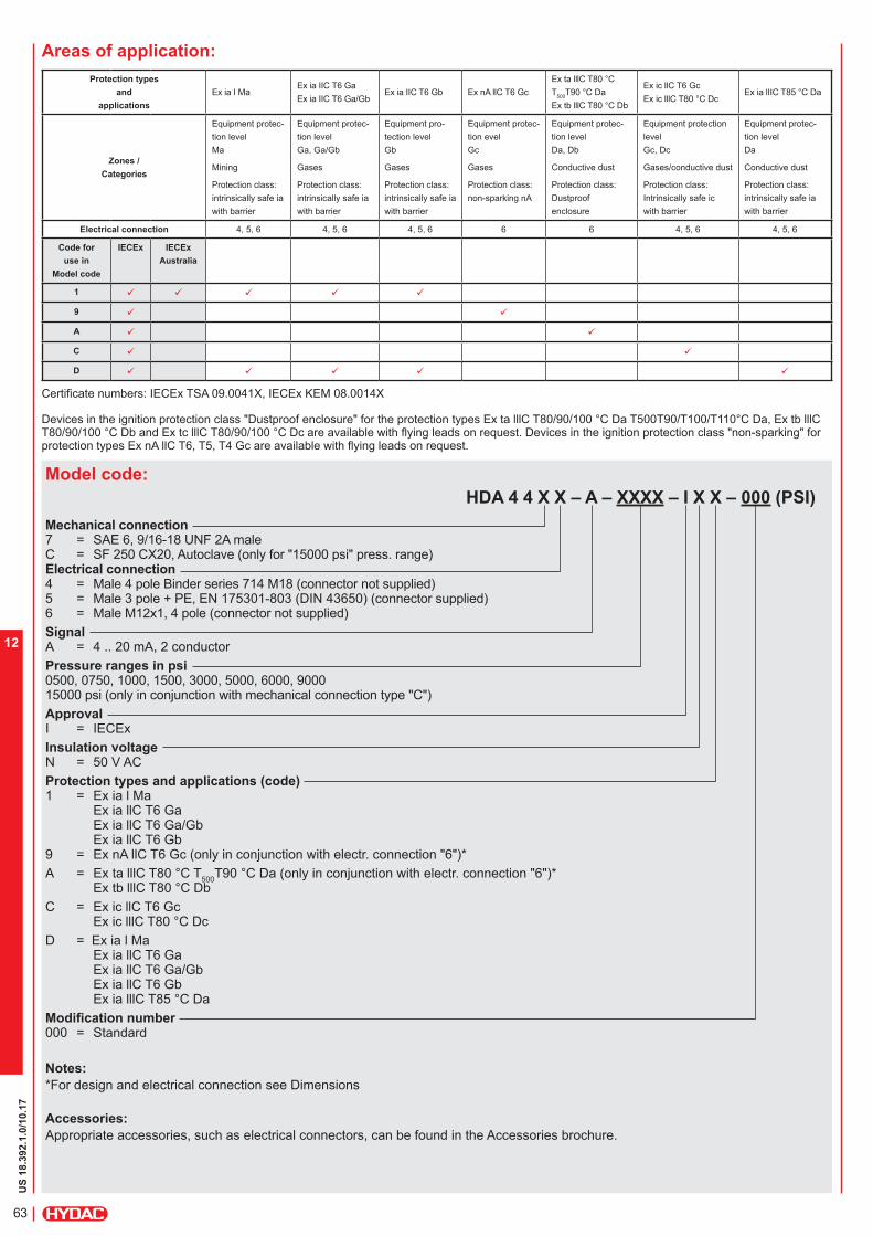
US
18.3
92.1
.0/10.17
63
12
Areas of application:
Protection types
and
applications
Ex ia I MaEx ia IIC T6 Ga
Ex ia IIC T6 Ga/GbEx ia IIC T6 Gb Ex nA llC T6 Gc
Ex ta lllC T80 °C T
500T90 °C Da
Ex tb lllC T80 °C Db
Ex ic llC T6 Gc
Ex ic lllC T80 °C DcEx ia lIIC T85 °C Da
Zones /
Categories
Equipment protec-
tion level
Ma
Mining
Protection class:
intrinsically safe ia
with barrier
Equipment protec-
tion level
Ga, Ga/Gb
Gases
Protection class:
intrinsically safe ia
with barrier
Equipment pro-
tection level
Gb
Gases
Protection class:
intrinsically safe ia
with barrier
Equipment protec-
tion evel
Gc
Gases
Protection class:
non-sparking nA
Equipment protec-
tion level
Da, Db
Conductive dust
Protection class:
Dustproof
enclosure
Equipment protection
level
Gc, Dc
Gases/conductive dust
Protection class:
Intrinsically safe ic
with barrier
Equipment protec-
tion level
Da
Conductive dust
Protection class:
intrinsically safe ia
with barrier
Electrical connection 4, 5, 6 4, 5, 6 4, 5, 6 6 6 4, 5, 6 4, 5, 6
Code for
use in
Model code
IECEx IECEx
Australia
1 ü ü ü ü ü
9 ü ü
A ü ü
C ü ü
D ü ü ü ü ü
Certificate numbers: IECEx TSA 09.0041X, IECEx KEM 08.0014X
Devices in the ignition protection class "Dustproof enclosure" for the protection types Ex ta lllC T80/90/100 °C Da T500T90/T100/T110°C Da, Ex tb lllC T80/90/100 °C Db and Ex tc lllC T80/90/100 °C Dc are available with flying leads on request. Devices in the ignition protection class "non-sparking" for protection types Ex nA llC T6, T5, T4 Gc are available with flying leads on request.
Model code:
HDA 4 4 X X – A – XXXX – I X X – 000 (PSI)
Mechanical connection 7 = SAE 6, 9/16-18 UNF 2A maleC = SF 250 CX20, Autoclave (only for "15000 psi" press. range)Electrical connection 4 = Male 4 pole Binder series 714 M18 (connector not supplied)5 = Male 3 pole + PE, EN 175301-803 (DIN 43650) (connector supplied)6 = Male M12x1, 4 pole (connector not supplied)
Signal A = 4 .. 20 mA, 2 conductor
Pressure ranges in psi 0500, 0750, 1000, 1500, 3000, 5000, 6000, 9000 15000 psi (only in conjunction with mechanical connection type "C")
Approval I = IECEx
Insulation voltage N = 50 V AC
Protection types and applications (code) 1 = Ex ia l Ma
Ex ia llC T6 Ga Ex ia llC T6 Ga/Gb Ex ia llC T6 Gb
9 = Ex nA llC T6 Gc (only in conjunction with electr. connection "6")*
A = Ex ta lllC T80 °C T500
T90 °C Da (only in conjunction with electr. connection "6")* Ex tb lllC T80 °C Db
C = Ex ic llC T6 Gc Ex ic lllC T80 °C Dc
D = Ex ia l Ma Ex ia llC T6 Ga Ex ia llC T6 Ga/Gb Ex ia llC T6 Gb Ex ia lllC T85 °C Da
Modification number 000 = Standard
Notes:
*For design and electrical connection see Dimensions
Accessories:
Appropriate accessories, such as electrical connectors, can be found in the Accessories brochure.

US
18.3
92.1
.0/10.17
64
12
Pin connections:
Pin HDA 44x4-A
1 n.c.
2 Signal +
3 Signal -
4 n.c.
Pin HDA 44x5-A
1 Signal +
2 Signal -
3 n.c.
Housing
Pin HDA 44x6-A
1 Signal +
2 n.c.
3 Signal -
4 n.c.
Binder series 714 M18
M12x1, 4 pole
EN 175301-803 (DIN 43650)
Dimensions:Protection types and applications: (code): 1, C, D
Protection types and applications: (code): 9, A
Impact
protected metal
safety sleeve
SW25
hex-SW27
The impact protected metal safety sleeve is included. A straight female connector is required for electrical connection, e.g. female connector M12x1, 4 pole, straight, with 3m shielded cable: ZBE 06S-03, Part No. 6098243
Profile seal ring
~35
~35.5
27.5
M3
Male Electrical ConnectorBinder Series 714-4p
Male Electrical Connector
20
15
SF 250 CX20, Autoclave(7/16"-20UNF-2B)
Profile seal ring
Male Electrical ConnectorBinder Series 714-4p
M18
18.3
Male Electrical Connector4 Poles
12.3
M12X1
SAE-6
10 2.3
59.4
10
30
18
19
9/16-18UNF-2A
27
HEX 27
Male ElectricalConnector 3P +PE EN 175301-803 (DIN43650)

US
18.3
92.1
.0/10.17
65
12
Note:The information in this brochure relates to the operating conditions and applications described.For applications and operating conditions not described, please contact the relevant technical department.Subject to technical modifications.For European mechanical connection and bar ranges see European Catalog
HYDAC ELECTRONICS 90 Southland Dr. Bethlehem, PA 18017 Telephone +1 (610) 266-0100 E-mail: [email protected]: www.hydacusa.com

US
18.3
92.3
.0/10.17
66
12
Electronic
Pressure Transmitter
HDA 4300 IECEx Intrinsically Safe IECEx Dustproof Enclosure IECEx Non-sparking
Description:The pressure transmitter HDA 4300 in IECEx Intrinsically Safe version has been specially developed for use in potentially explosive atmospheres and is based on the HDA 4000 series.
As with the industrial version, the HDA 4300 with IECEx Intrinsically Safe approval has the field-proven ceramic measuring cell with thick-film strain gauge.
Intended areas of application are, for example, in the oil and gas industry, in mining, on gas turbines or in locations with high levels of dust contamination, e.g. in mills.
Protection types and applications:
Ex ia l Ma
Ex ia llC T6 Ga Ex ia llC T6 Ga/Gb Ex ia llC T6 Gb Ex nA llC T6,T5,T4 Gc Ex ic llC T6,T5,T4 Gc
Ex ta lllC T80/90/100°C Da T
500 90/100/110°C Da
Ex tb lllC T80/90/100°C Db Ex tc lllC T80/90/100°C Dc Ex ic lllC T80/90/100°C Dc Ex ia lllC T85°C Da
Special features: Accuracy: ≤ ± 0.5 % FS B.F.S.L. Certificate:
IECEx TSA 09.0041X /IECEx KEM 08.0014X
Output signal 4 .. 20 mA
Very small temperature error
Excellent EMC characteristics
Excellent durability
Technical data:Input data
Measuring ranges 15, 30, 50, 100, 150, 250, 500 psi
Overload pressures 45, 100, 150, 290, 450, 725, 1500 psi
Burst pressures 70, 150, 250, 400, 650, 1000, 2500 psi
Mechanical connection 1/4-18 NPT male
Torque value 30 ft-lb (40 Nm)
Parts in contact with medium Sensor: CeramicMech. connection: 1.4301 Seal: FPM / EPDM
Output data
Output signal, permitted load resistance 4 .. 20 mA, 2-conductor RLmax = (UB – 12 V) / 20 mA [kΩ]
Accuracy to DIN 16086, max. setting
≤ ± 0.5 % FS typ. ≤ ± 1.0 % FS max.
Accuracy at minimum setting (B.F.S.L.)
≤ ± 0.25 % FS typ. ≤ ± 0.5 % FS max.
Temperature compensation Zero point
≤ ± 0.012% FS/°F typ. ≤ ± 0.017% FS/°F max.
Temperature compensation Over range
≤ ± 0.012% FS/°F typ. ≤ ± 0.017% FS/°F max.
Non-linearity at max. setting to DIN 16086
≤ ± 0.5 % FS max.
Hysteresis ≤ ± 0.4 % FS max.Repeatability ≤ ± 0.1 % FSRise time ≤ 1.5 msLong term drift ≤ ± 0.3 % FS typ. / yearEnvironmental conditions
Compensated temperature range -4..+185°FOperating temperature range -4..+140°FStorage temperature range -40..+212°FFluid temperature range1) -40..+140°F / -4..+140°F
- markEN 61000-6-1 / 2 / 3 / 4 EN 60079-0 / 11 / 26 / 36
Vibration resistance to DIN EN 60068-2-6 at 10 ..500 Hz
≤ 20 g
Protection class to IEC 60529 IP 65 (for male EN 175301-803 (DIN 43650) and Binder 714 M18)
IP 67 (for M12x1 male, when an IP 67 female connector is used)
Relevant data for Ex applications Ex ia, ic Ex nA, ta, tb, tcSupply voltage Ui = 12 .. 28 V 12 .. 28 VMax. input current Ii = 100 mAMax. input power Pi = 1 W max. power consuption
≤ 1 WConnection capacitance of the sensor Ci = ≤ 22 nFInductance of the sensor Li = 0 mHInsulation voltage 2) 50 V AC, with integrated overvoltage protection
EN 61000-6-2Other dataResidual ripple of supply voltage ≤ 5 %Life expectancy > 10 million cycles
0 .. 100 % FSWeight ~ 180 g
Note: Reverse polarity protection of the supply voltage, excess voltage, override and short circuit protection are provided. FS (Full Scale) = relative to the full measuring range, B.F.S.L.= Best Fit Straight Line 1) -4 °F with FPM or EPDM seal, -40 °F on request2) 500 V AC on request

US
18.3
92.3
.0/10.17
67
12
Model code:
HDA 4 3 8 X – A – XXXX – I X X – 000 – X 1 (PSI)
Mechanical connection 8 = 1/4-18 NPT male
Electrical connection 4 = Male, 4 pole Binder series 714 M18 (connector not supplied)5 = Male, 3 pole + PE, EN 175301-803 (DIN 43650) (connector supplied)6 = Male, M12x1, 4 pole (connector not supplied)
Signal A = 4 .. 20 mA, 2 conductor
Pressure ranges in psi 0015, 0030, 0050, 0100, 0150, 0250, 0500
Approval I = IECEx
Insulation voltage N = 50 V AC
Protection types and applications (code) 1 = Ex ia l Ma
Ex ia llC T6 Ga Ex ia llC T6 Ga/Gb Ex ia llC T6 Gb
9 = Ex nA llC T6 Gc (only in conjunction with electr. connection “6“)*
A = Ex ta lllC T80°C T500
T90°C Da (only in conjunction with electr. connection 6")* Ex tb lllC T80°C Db
C = Ex ic llC T6 Gc Ex ic lllC T80°C Dc
D = Ex ia l Ma Ex ia llC T6 Ga Ex ia llC T6 Ga/Gb Ex ia llC T6 Gb Ex ia lllC T85°C Da
Modification number 000 = Standard
Seal material (in contact with fluid) F = FPM seal (e.g.: for hydraulic oils) E = EPDM seal (e.g.: for refrigerants)
Material of connection (in contact with fluid) 1 = Stainless steel
Notes:
* For design and electrical connection see device dimensions
Accessories:Appropriate accessories, such as electrical connectors, can be found in the Accessories brochure.
Areas of application:
Protection types
and
applications
Ex ia I MaEx ia IIC T6 Ga
Ex ia IIC T6 Ga/GbEx ia IIC T6 Gb Ex nA llC T6 Gc
Ex ta lllC T80°C
T500
T90°C Da
Ex tb lllC T80°C Db
Ex ic llC T6 Gc
Ex ic lllC T80°C DcEx ia lIIC T85° C Da
Zones /
Categories
Equipment level
standard
Ma
Mining
Protection class:
intrinsically
safe ia
with barrier
Equipment level
standard
Ga, Ga/Gb
Gases
Protection class:
intrinsically safe ia
with barrier
Equipment level
standard
Gb
Gases
Protection class:
intrinsically safe ia
with barrier
Equipment level
standard
Gc
Gases
Protection class:
non-sparking nA
Equipment level
standard
Da, Db
Conductive dust
Protection class:
Dustproof
enclosure
Equipment level
standard
Gc, Dc
Gases/conductive dust
Protection class:
Intrinsically safe ic
with barrier
Equipment level
standard
Da
Conductive dust
Protection class:
intrinsically safe ia
with barrier
Electrical connection 4, 5, 6 4, 5, 6 4, 5, 6 6 6 4, 5, 6 4, 5, 6
Code (see
model code)
IECEx IECEx
Australia
1 ü ü ü ü ü
9 ü ü
A ü ü
C ü ü
D ü ü ü ü ü
Certificate numbers: IECEx TSA 09.0041X, IECEx KEM 08.0014X
Devices in the ignition protection class "Dustproof enclosure" for the protection types Ex ta lllC T80/90/100° C Da T500T90/T100/T110°C Da, Ex tb lllC T80/90/100°C Db and Ex tc lllC T80/90/100°C Dc are available with flying leads on request. Devices in the ignition protection class "non-sparking" for protection type Ex nA llC T6, T5, T4 Gc are available with flying leads on request.
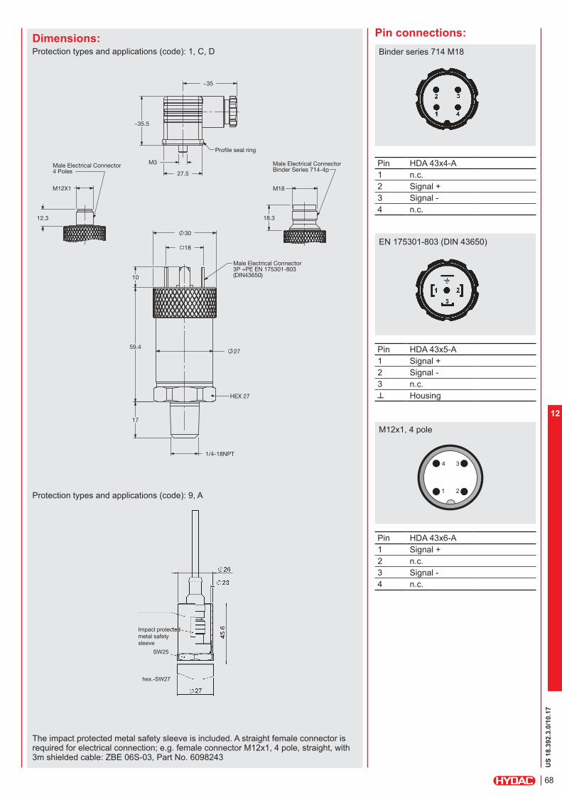
US
18.3
92.3
.0/10.17
68
12
Pin connections:
Pin HDA 43x4-A
1 n.c.
2 Signal +
3 Signal -
4 n.c.
Pin HDA 43x5-A
1 Signal +
2 Signal -
3 n.c.
Housing
Pin HDA 43x6-A
1 Signal +
2 n.c.
3 Signal -
4 n.c.
Binder series 714 M18
M12x1, 4 pole
EN 175301-803 (DIN 43650)
Dimensions:Protection types and applications (code): 1, C, D
The impact protected metal safety sleeve is included. A straight female connector is required for electrical connection; e.g. female connector M12x1, 4 pole, straight, with 3m shielded cable: ZBE 06S-03, Part No. 6098243
Protection types and applications (code): 9, A
Impact protected
metal safety
sleeve
SW25
hex.-SW27
Male Electrical Connector4 Poles
12.3
M12X1
Male Electrical ConnectorBinder Series 714-4p
M18
18.3
Profile seal ring
~35
~35.5
27.5
M3
Male Electrical ConnectoBinder Series 714-4p
2.3
59.4
10
HEX 27
Male Electrical Connector3P +PE EN 175301-803(DIN43650)
59.4 27
10
17
18
30
1/4-18NPT

US
18.3
92.3
.0/10.17
69
12
Note:The information in this brochure relates to the operating conditions and applications described.For applications or operating conditions not described, please contact the relevant technical department.Subject to technical modifications.For European mechanical connection and bar ranges see European Catalog
HYDAC ELECTRONICS 90 Southland Dr. Bethlehem, PA 18017 Telephone +1 (610) 266-0100 E-mail: [email protected]: www.hydacusa.com
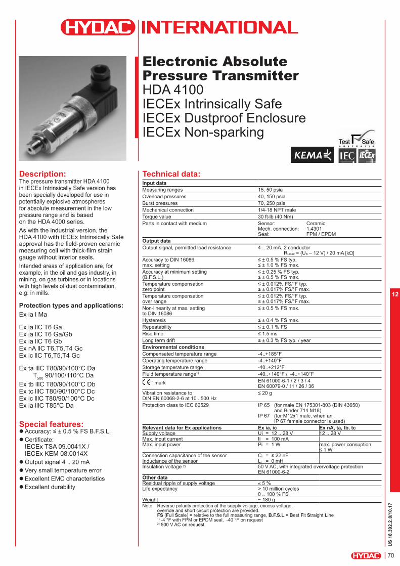
US
18.3
92.2
.0/10.17
70
12
Electronic Absolute
Pressure Transmitter
HDA 4100 IECEx Intrinsically Safe IECEx Dustproof Enclosure IECEx Non-sparking
Description:The pressure transmitter HDA 4100 in IECEx Intrinsically Safe version has been specially developed for use in potentially explosive atmospheres for absolute measurement in the low pressure range and is based on the HDA 4000 series.
As with the industrial version, the HDA 4100 with IECEx Intrinsically Safe approval has the field-proven ceramic measuring cell with thick-film strain gauge without interior seals.
Intended areas of application are, for example, in the oil and gas industry, in mining, on gas turbines or in locations with high levels of dust contamination, e.g. in mills.
Protection types and applications:
Ex ia l Ma
Ex ia llC T6 Ga Ex ia llC T6 Ga/Gb Ex ia llC T6 Gb Ex nA llC T6,T5,T4 Gc Ex ic llC T6,T5,T4 Gc
Ex ta lllC T80/90/100°C Da T
500 90/100/110°C Da
Ex tb lllC T80/90/100°C Db Ex tc lllC T80/90/100°C Dc Ex ic lllC T80/90/100°C Dc Ex ia lllC T85°C Da
Special features: Accuracy: ≤ ± 0.5 % FS B.F.S.L. Certificate:
IECEx TSA 09.0041X /IECEx KEM 08.0014X
Output signal 4 .. 20 mA
Very small temperature error
Excellent EMC characteristics
Excellent durability
Technical data:Input data
Measuring ranges 15, 50 psia
Overload pressures 40, 150 psia
Burst pressures 70, 250 psia
Mechanical connection 1/4-18 NPT male
Torque value 30 ft-lb (40 Nm)
Parts in contact with medium Sensor: Ceramic Mech. connection: 1.4301 Seal: FPM / EPDM
Output data
Output signal, permitted load resistance 4 .. 20 mA, 2 conductor RLmax = (UB – 12 V) / 20 mA [kΩ]
Accuracy to DIN 16086, max. setting
≤ ± 0.5 % FS typ. ≤ ± 1.0 % FS max.
Accuracy at minimum setting (B.F.S.L.)
≤ ± 0.25 % FS typ. ≤ ± 0.5 % FS max.
Temperature compensation zero point
≤ ± 0.012% FS/°F typ. ≤ ± 0.017% FS/°F max.
Temperature compensation over range
≤ ± 0.012% FS/°F typ. ≤ ± 0.017% FS/°F max.
Non-linearity at max. setting to DIN 16086
≤ ± 0.5 % FS max.
Hysteresis ≤ ± 0.4 % FS max.Repeatability ≤ ± 0.1 % FSRise time ≤ 1.5 msLong term drift ≤ ± 0.3 % FS typ. / yearEnvironmental conditions
Compensated temperature range -4..+185°FOperating temperature range -4..+140°FStorage temperature range -40..+212°FFluid temperature range1) -40..+140°F / -4..+140°F
- mark EN 61000-6-1 / 2 / 3 / 4 EN 60079-0 / 11 / 26 / 36
Vibration resistance to DIN EN 60068-2-6 at 10 ..500 Hz
≤ 20 g
Protection class to IEC 60529 IP 65 (for male EN 175301-803 (DIN 43650) and Binder 714 M18)
IP 67 (for M12x1 male, when an IP 67 female connector is used)
Relevant data for Ex applications Ex ia, ic Ex nA, ta, tb, tcSupply voltage Ui = 12 .. 28 V 12 .. 28 VMax. input current Ii = 100 mAMax. input power Pi = 1 W max. power consuption
≤ 1 WConnection capacitance of the sensor Ci = ≤ 22 nFInductance of the sensor Li = 0 mHInsulation voltage 2) 50 V AC, with integrated overvoltage protection
EN 61000-6-2Other dataResidual ripple of supply voltage ≤ 5 %Life expectancy > 10 million cycles
0 .. 100 % FSWeight ~ 180 g
Note: Reverse polarity protection of the supply voltage, excess voltage, override and short circuit protection are provided. FS (Full Scale) = relative to the full measuring range, B.F.S.L.= Best Fit Straight Line 1) -4 °F with FPM or EPDM seal, -40 °F on request 2) 500 V AC on request
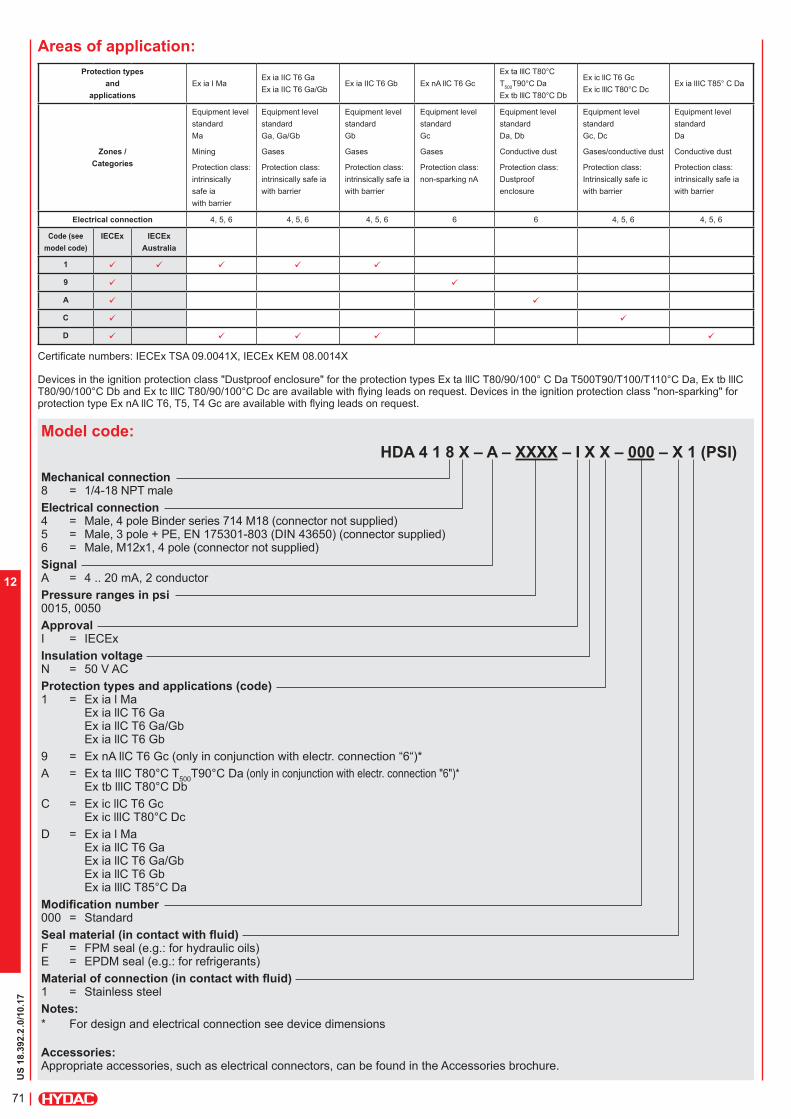
US
18.3
92.2
.0/10.17
71
12
Model code:
HDA 4 1 8 X – A – XXXX – I X X – 000 – X 1 (PSI)
Mechanical connection 8 = 1/4-18 NPT male
Electrical connection 4 = Male, 4 pole Binder series 714 M18 (connector not supplied)5 = Male, 3 pole + PE, EN 175301-803 (DIN 43650) (connector supplied)6 = Male, M12x1, 4 pole (connector not supplied)
Signal A = 4 .. 20 mA, 2 conductor
Pressure ranges in psi 0015, 0050
Approval I = IECEx
Insulation voltage N = 50 V AC
Protection types and applications (code) 1 = Ex ia l Ma
Ex ia llC T6 Ga Ex ia llC T6 Ga/Gb Ex ia llC T6 Gb
9 = Ex nA llC T6 Gc (only in conjunction with electr. connection “6“)*
A = Ex ta lllC T80°C T500
T90°C Da (only in conjunction with electr. connection "6")* Ex tb lllC T80°C Db
C = Ex ic llC T6 Gc Ex ic lllC T80°C Dc
D = Ex ia l Ma Ex ia llC T6 Ga Ex ia llC T6 Ga/Gb Ex ia llC T6 Gb Ex ia lllC T85°C Da
Modification number 000 = Standard
Seal material (in contact with fluid) F = FPM seal (e.g.: for hydraulic oils) E = EPDM seal (e.g.: for refrigerants)
Material of connection (in contact with fluid) 1 = Stainless steel
Notes:
* For design and electrical connection see device dimensions
Accessories:Appropriate accessories, such as electrical connectors, can be found in the Accessories brochure.
Areas of application:
Protection types
and
applications
Ex ia I MaEx ia IIC T6 Ga
Ex ia IIC T6 Ga/GbEx ia IIC T6 Gb Ex nA llC T6 Gc
Ex ta lllC T80°C
T500
T90°C Da
Ex tb lllC T80°C Db
Ex ic llC T6 Gc
Ex ic lllC T80°C DcEx ia lIIC T85° C Da
Zones /
Categories
Equipment level
standard
Ma
Mining
Protection class:
intrinsically
safe ia
with barrier
Equipment level
standard
Ga, Ga/Gb
Gases
Protection class:
intrinsically safe ia
with barrier
Equipment level
standard
Gb
Gases
Protection class:
intrinsically safe ia
with barrier
Equipment level
standard
Gc
Gases
Protection class:
non-sparking nA
Equipment level
standard
Da, Db
Conductive dust
Protection class:
Dustproof
enclosure
Equipment level
standard
Gc, Dc
Gases/conductive dust
Protection class:
Intrinsically safe ic
with barrier
Equipment level
standard
Da
Conductive dust
Protection class:
intrinsically safe ia
with barrier
Electrical connection 4, 5, 6 4, 5, 6 4, 5, 6 6 6 4, 5, 6 4, 5, 6
Code (see
model code)
IECEx IECEx
Australia
1 ü ü ü ü ü
9 ü ü
A ü ü
C ü ü
D ü ü ü ü ü
Certificate numbers: IECEx TSA 09.0041X, IECEx KEM 08.0014X
Devices in the ignition protection class "Dustproof enclosure" for the protection types Ex ta lllC T80/90/100° C Da T500T90/T100/T110°C Da, Ex tb lllC T80/90/100°C Db and Ex tc lllC T80/90/100°C Dc are available with flying leads on request. Devices in the ignition protection class "non-sparking" for protection type Ex nA llC T6, T5, T4 Gc are available with flying leads on request.

US
18.3
92.2
.0/10.17
72
12
Pin connections:
Pin HDA 41x4-A
1 n.c.
2 Signal +
3 Signal -
4 n.c.
Pin HDA 41x5-A
1 Signal +
2 Signal -
3 n.c.
Housing
Pin HDA 41x6-A
1 Signal +
2 n.c.
3 Signal -
4 n.c.
Binder series 714 M18
M12x1, 4 pole
EN 175301-803 (DIN 43650)
Dimensions:Protection types and applications: (code): 1, C, D
Protection types and applications (code): 9, A
Impact protected
metal safety
sleeve
SW25
hex.-SW27
The impact protected metal safety sleeve is included. A straight female connector is required for electrical connection; e.g. female connector M12x1, 4 pole, straight, with 3m shielded cable: ZBE 06S-03, Part No. 6098243
Male Electrical Connector4 Poles
12.3
M12X1
Male Electrical ConnectorBinder Series 714-4p
M18
18.3
Profile seal ring
~35
~35.5
27.5
M3
Male Electrical ConnectoBinder Series 714-4p
2.3
59.4
10
HEX 27
Male Electrical Connector3P +PE EN 175301-803(DIN43650)
59.4 27
10
17
18
30
1/4-18NPT

US
18.3
92.2
.0/10.17
73
12
Note:The information in this brochure relates to the operating conditions and applications described.For applications or operating conditions not described, please contact the relevant technical department.Subject to technical modifications.For European mechanical connection and bar ranges see European Catalog
HYDAC ELECTRONICS 90 Southland Dr. Bethlehem, PA 18017 Telephone +1 (610) 266-0100 E-mail: [email protected]: www.hydacusa.com

US
18.3
74.1
.0/10.17
74
12
Electronic
Pressure Transmitter HDA 4700 with Flush Membrane ATEX Intrinsically Safe ATEX Dustproof Enclosure ATEX Non-sparking
Description:The pressure transmitter HDA 4700 in ATEX version with flush membrane has been specially developed for use in potentially explosive atmospheres.
Like the standard model, the HDA 4700 with flush membrane has a stainless steel measurement cell with a thin film strain gauge.
The pressure connection is achieved with an all-welded stainless steel front membrane filled internally with a pressure transfer fluid. The process pressure is transmitted hydrostatically to the measurement cell via the pressure transfer fluid.This device is used for applications in which a standard pressure connection could become blocked, clogged or frozen by the particular medium used. Further applications include processes where the medium changes regularly and any residues could cause mixing or contamination of the media, or in highly viscous media. Intended areas of application are, for example, the oil and gas industry, in mines or in locations with high levels of dust, e.g. in mills.
Protection types and applications: I M1 Ex ia I Ma
II 1G Ex ia IIC T6 Ga II 1/2G Ex ia IIC T6 Ga/Gb II 2G Ex ia IIC T6 Gb II 3G Ex nA llC T6,T5,T4 Gc II 3G Ex ic llC T6,T5,T4 Gc
II 1D Ex ia lIIC T85 °C Da II 1D Ex ta lllC T80/90/100 °C Da T
500T90/T100/T110 °C Da
II 2D Ex tb lllC T80/90/100 °C Db II 3D Ex tc lllC T80/T90/T100 °C Dc II 3D Ex ic lllC T80/T90/T100 °C Dc
Special features: Pressure connection has a flush
membrane
Accuracy ≤ 0.25 % FS B.F.S.L. Certificates:
KEMA 05ATEX1016 XKEMA 05ATEX1021
Robust design
Very small temperature error
Excellent EMC characteristics
Excellent long-term properties
Technical data:Input data
Measuring ranges 500, 750, 1000, 1500, 3000, 6000, 9000 psi
Overload ranges 1160, 1740, 2900, 2900, 7250, 11600, 14500 psi
Burst pressure 1) 2900, 4350, 7250, 7250, 14500, 29000, 29000 psi
Mechanical connection G1/2 A DIN 3852 G1/2 with additional front O-ring seal
Pressure transfer fluid Silicon-free oil
Torque value 33 ft-lb (45 Nm)
Parts in contact with medium 2) Stainless steel: 1.4435; 1.4301Seal: FPM O-ring: FPM
Output data
Output signal, permitted load resistance 4 .. 20 mA, 2 conductor RLmax = (UB – 12 V) / 20 mA [kΩ]
Accuracy to DIN 16086, max. setting
≤ ± 0.25 % FS typ. ≤ ± 0.5 % FS max.
Accuracy at minimum setting (B.F.S.L.)
≤ ± 0.15 % FS typ. ≤ ± 0.25 % FS max.
Temperature compensation Zero point
≤ ± 0.0045% FS/°F typ. ≤ ± 0.0085% FS/°F max.
Temperature compensation Over range
≤ ± 0.0045% FS/°F typ. ≤ ± 0.0085% FS/°F max.
Non-linearity at max. setting to DIN 16086
≤ ± 0.3 % FS max.
Hysteresis ≤ ± 0.1 % FS max.Repeatability ≤ ± 0.05 % FSRise time ≤ 1.5 msLong term drift ≤ ± 0.1 % FS typ. / yearEnvironmental conditions
Compensated temperature range -4..+185°F
Operating temperature range3) -40..+140°F/ -4..+140°F
Storage temperature range -40..+212°F
Fluid temperature range3) -20..+140°F-40..+140°F / -4..+140°F
mark EN 61000-6-1 / 2 / 3 / 4 EN 60079-0 / 11 / 26 / 31 EN 50303
Vibration resistance to DIN EN 60068-2-6 at 10 .. 500 Hz
≤ 20 g
Protection class to IEC 60529 IP 65 (for male EN 175301-803(DIN 43650)) IP 67 (for M12x1 male, when an
IP 67 female connector is used)
Relevant data for Ex applications Ex ia, ic Ex nA, ta, tb, tcSupply voltage Ui = 12 .. 28 V 12 .. 28 VMax. input current Ii = 100 mAMax. input power Pi = 1 W max. power consuption
≤ 1 WConnection capacitance of the sensor Ci = ≤ 22 nFInductance of the sensor Li = 0 mHInsulation voltage 4) 50 V AC, with integrated overvoltage protection
EN 61000-6-2Other dataResidual ripple of supply voltage ≤ 5 %Life expectancy > 10 million cycles
0 .. 100 % FSWeight ~ 180 g
Note: Reverse polarity protection of the supply voltage, excess voltage, override and short circuit protection are provided. FS (Full Scale) = relative to complete measuring range B.F.S.L. = Best Fit Straight Line1) G1/2 with additional front O-ring seal max. 21750 psi 2) Other seal materials on request3) -4 °F with FPM seal, -40 °F on request4) 500 V AC on request

US
18.3
74.1
.0/10.17
75
12
Model code:
HDA 4 7 X X – A – XXXX – XXX – A X X – 000 (PSI)
Mechanical process connection Z = Flush membrane
Electrical connection 5 = Male 3 pole + PE,
EN 175301-803 (DIN 43650) (female connector supplied)
6 = Male M12x1, 4 pole (female connector not supplied)
Signal A = 4 .. 20 mA, 2 conductor
Pressure ranges in psi 0500, 0750, 1000, 1500, 3000, 5000, 6000, 9000
Mechanical connection G01 = G1/2 A, DIN 3852 G02 = G1/2 with additional front O-ring seal
Approval A = ATEX
Insulation voltage N = 50 V AC
Protection types and applications (code) 1 = I M1 Ex ia I Ma
II 1G Ex ia IIC T6 Ga II 1/2G Ex ia IIC T6 Ga/Gb II 2G Ex ia IIC T6 Gb II 1D Ex ia lIIC T85 °C Da
9 = II 3G Ex nA llC T6 Gc (only in conjunction with electr. connection “6“)*
A = II 1D Ex ta lllC T80 °C T500
T90 °C Da (only in conjunction with electr. connection “6“)* II 2D Ex tb lllC T80 °C Db
C = II 3G Ex ic llC T6 Gc II 3D Ex ic lllC T80 °C Dc
Modification number 000 = Standard
Notes:
* For design and electrical connection see Dimensions
Accessories:Appropriate accessories, such as electrical female connectors, can be found in the Accessories brochure.
Pin connections:
Pin HDA 47Z5-A
1 Signal +
2 Signal -
3 n.c.
^ Housing
Pin HDA 47Z6-A
1 Signal +
2 n.c.
3 Signal -
4 n.c.
EN175301-803 (DIN 43650)
M12x1, 4 pole
Areas of application:Code used inModel code
1 9 A C
Protection type
I M1 Ex ia I MaII 1G Ex ia IIC T6 GaII 1/2G Ex ia IIC T6 Ga/GbII 1D Ex ia lIIC T85°C Da
II 2G Ex ia IIC T6 Gb II 3G Ex nA llC T6 Gc
II 1D Ex ta lllC T80°C T
500T90°C Da
II 2D Ex tb lllC T80°C Db
II 3G Ex ic llC T6 Gc II 3D Ex ic lllC T80°C Dc
Certificate KEMA 05ATEX1016 X / KEMA 05ATEX1021
Zones / Categories
Group I Category M1
Mining
Protection class: intrinsically safe ia with barrier
Group II, lll Category 1G, 1/2G, 1D
Gases/conductive dust
Protection class: intrinsically safe ia with barrier
Group II Category 2G
Gases
Protection class: intrinsically safe ia with barrier
Group II Category 3G
Gases
Protection class:Non-sparking nA
Group IIl Category 1D, 2D
Conductive dust
Protection class:Dustproof enclosure
Group II, lll Category 3G, 3D
Gases/conductive dust
Protection class:Intrinsically safe icwith barrier
ElectricalConnection (see model code)
4, 5, 6 4, 5, 6 4, 5, 6 6 6 4,5,6
Devices in ignition protection class "Dustproof enclosure" for the protection types II 1D Ex ta lllC T80/90/100° C Da T500
T90/T100/T110°C Da, II 2D Ex tb lllC T80/90/100°C Db and ll 3D Ex tc lllC T80/90/100°C Dc are available with flying leads on request. Devices in the ignition protection class "Non-sparking" for the protection type II 3G Ex nA llC T6, T5, T4 Gc are available with flying leads on request.

US
18.3
74.1
.0/10.17
76
12
Note:The information in this brochure relates to the operating conditions and applications described.For applications and operating conditions not described, please contact the relevant technical department.Subject to technical modifications.For bar ranges see European Catalog
HYDAC ELECTRONICS 90 Southland Dr. Bethlehem, PA 18017 Telephone +1 (610) 266-0100 E-mail: [email protected]: www.hydacusa.com
Profile seal ring
~ 35
M3
27.5
35.
5
12.3
male electr. conn. 4p
M12x1
59.4
3
13.8
12
male electr. conn. 3p +PE EN 175301-803 (DIN 43650)
Elastomer profile seal ring DIN3869
hex-SW27
G1/2 A
Ø 29.5
Ø 26 h14
Ø 35
Ø 27
18
20.5
10
3
Ø 29.5
Ø 18.1
G1/2 A
Ø 26 h14
seal ring DIN3869 18.5 x 23.9 x 1.5
O-ring 15 x 2
hex-SW27
Dimensions:Protection types and applications (code): 1, C
Protection types and applications (code): 9, A
Impact protected metal safety sleeve
SW25
hex-SW27
The impact protected metal safety sleeve is included. A straight female connector is required for electrical connection, e.g. female connector M12x1, 4 pole, straight, with 3m shielded cable: ZBE 06S-03, Part. No. 6098243

US
18.3
74.1
.0/10.17
77
12

US
18.3
75.1
.0/10.17
78
12
Electronic
Pressure Transmitter HDA 4400 with Flush Membrane ATEX Intrinsically Safe ATEX Dustproof Enclosure ATEX Non-sparking
Description:The pressure transmitter HDA 4400 in ATEX version has been specially developed for use in potentially explosive atmospheres and is based on the HDA 4000 series.
As with the industrial version, the HDA 4400 in ATEX version has a stainless steel measurement cell with thin-film strain gauge.The pressure connection is achieved with an all-welded stainless steel front membrane filled internally with a pressure transfer fluid. The process pressure is transmitted hydrostatically to the measurement cell via the pressure transfer fluid.This device is used for applications in which a standard pressure connection could become blocked, clogged or frozen by the particular medium used. Further applications include processes where the medium changes regularly and any residues could cause mixing or contamination of the media. Intended areas of application are, for example, the oil and gas industry, in mines, or in locations with high levels of dust, e.g. in mills.
Protection types and applications: I M1 Ex ia I Ma
II 1G Ex ia IIC T6 Ga II 1/2G Ex ia IIC T6 Ga/Gb II 2G Ex ia IIC T6 Gb II 3G Ex nA llC T6,T5,T4 Gc II 3G Ex ic llC T6,T5,T4 Gc
II 1D Ex ia lIIC T85 °C Da II 1D Ex ta lllC T80/90/100 °C Da T
500T90/T100/T110 °C Da
II 2D Ex tb lllC T80/90/100 °C Db II 3D Ex tc lllC T80/T90/T100 °C Dc II 3D Ex ic lllC T80/T90/T100 °C Dc
Special features: Pressure connection has a flush
membrane
Accuracy ≤ 0.5 % FS B.F.S.L. Certificates:
KEMA 05ATEX1016 XKEMA 05ATEX1021
Robust design
Very small temperature error
Excellent EMC characteristics
Excellent long-term properties
Technical data:Input data
Measuring ranges 500, 750, 1000, 1500, 3000, 6000, 9000 psi
Overload ranges 1160, 1740, 2900, 2900, 7250, 11600, 14500 psi
Burst pressure 1) 2900, 4350, 7250, 7250, 14500, 29000, 29000 psi
Mechanical connection G1/2A DIN 3852 G1/2 with add. front O-ring seal G1/4 with add. front O-ring seal
Pressure transfer fluid Silicon-free oil
Torque value 33 ft-lb (45 Nm) for G1/2, G1/2A 15 ft-lb (20 Nm) for G1/4
Parts in contact with medium 2) Stainless steel: 1.4435; 1.4301Seal: FPM O-ring: FPM
Output data
Output signal, permitted load resistance 4 .. 20 mA, 2 conductor RLmax = (UB – 12 V) / 20 mA [kΩ]
Accuracy to DIN 16086, max. setting
≤ ± 0.5 % FS typ. ≤ ± 1.0 % FS max.
Accuracy at minimum setting (B.F.S.L.)
≤ ± 0.25 % FS typ. ≤ ± 0.5 % FS max.
Temperature compensation Zero point
≤ ± 0.0085% FS/°F typ. ≤ ± 0.014% FS/°F max.
Temperature compensation Over range
≤ ± 0.0085% FS/°F typ. ≤ ± 0.014% FS/°F max.
Non-linearity at max. setting to DIN 16086 ≤ ± 0.3 % FS max.Hysteresis ≤ ± 0.4 % FS max.Repeatability ≤ ± 0.1 % FSRise time ≤ 1.5 msLong term drift ≤ ± 0.3 % FS typ. / yearEnvironmental conditions
Compensated temperature range -4..+185°F
Operating temperature range -4..+140°F
Storage temperature range -40..+212°F
Fluid temperature range3) -40..+140°F / -4..+140°F
mark EN 61000-6-1 / 2 / 3 / 4 EN 60079-0 / 11 / 26 / 31 EN 50303
Vibration resistance to DIN EN 60068-2-6 at 10 ..500 Hz
≤ 20 g
Protection class to IEC 60529 IP 65 (for male EN 175301-803(DIN 43650)) IP 67 (for M12x1 male, when an
IP 67 female connector is used)
Relevant data for Ex applications Ex ia, ic Ex nA, ta, tb, tcSupply voltage Ui = 12 .. 28 V 12 .. 28 VMax. input current Ii = 100 mAMax. input power Pi = 1 W max. power consuption
≤ 1 WConnection capacitance of the sensor Ci = ≤ 22 nFInductance of the sensor Li = 0 mHInsulation voltage 4) 50 V AC, with integrated overvoltage protection
EN 61000-6-2Other dataResidual ripple of supply voltage ≤ 5 %Life expectancy > 10 million cycles
0 .. 100 % FSWeight ~ 180 g
Note: Reverse polarity protection of the supply voltage, excess voltage, override and short circuit protection are provided. FS (Full Scale) = relative to complete measuring range B.F.S.L. = Best Fit Straight Line1) G1/2 with additional front O-ring seal max. 21750 psi 2) Other seal materials on request3) -4 °F with FPM seal, -40 °F on request4) 500 V AC on request

US
18.3
75.1
.0/10.17
79
12
Model code:
HDA 4 4 Z X – A – XXXX – XXX – A X X – 000 (PSI)
Mechanical process connection Z = Flush membrane
Electrical connection 5 = Male 3 pole + PE,
EN 175301-803 (DIN 43650) (female connector supplied)
6 = Male M12x1, 4 pole (female connector not supplied)
Signal A = 4 .. 20 mA, 2 conductor
Pressure ranges in psi 0500, 0750, 1000, 1500, 3000, 5000, 6000, 9000
Mechanical connection G01 = G1/2 A, DIN 3852 G02 = G1/2 with additional front O-ring seal G04 = G1/4 with additional front O-ring seal
Approval A = ATEX
Insulation voltage N = 50 V AC
Protection types and applications (code) 1 = I M1 Ex ia I Ma
II 1G Ex ia IIC T6 Ga II 1/2G Ex ia IIC T6 Ga/Gb II 2G Ex ia IIC T6 Gb II 1D Ex ia lIIC T85 °C Da
9 = II 3G Ex nA llC T6 Gc (only in conjunction with electr. connection “6“)*
A = II 1D Ex ta lllC T80 °C T500
T90 °C Da (only in conjunction with electr. connection “6“)*
II 2D Ex tb lllC T80 °C Db
C = II 3G Ex ic llC T6 Gc II 3D Ex ic lllC T80 °C Dc
Modification number 000 = Standard
Notes:
* For design and electrical connection see Dimensions
Accessories:Appropriate accessories, such as electrical female connectors, can be found in the Accessories brochure.
Pin HDA 44Z5-A
1 Signal +
2 Signal -
3 n.c.
Housing
Pin HDA 44Z6-A
1 Signal +
2 n.c.
3 Signal -
4 n.c.
EN 175301-803 (DIN 43650)
M12x1, 4 pole
Code used inModel code
1 9 A C
Protection type
I M1 Ex ia I MaII 1G Ex ia IIC T6 GaII 1/2G Ex ia IIC T6 Ga/GbII 1D Ex ia lIIC T85°C Da
II 2G Ex ia IIC T6 Gb II 3G Ex nA llC T6 Gc
II 1D Ex ta lllC T80°C T
500T90°C Da
II 2D Ex tb lllC T80°C Db
II 3G Ex ic llC T6 Gc II 3D Ex ic lllC T80°C Dc
Certificate KEMA 05ATEX1016 X / KEMA 05ATEX1021
Zones / Categories
Group I Category M1
Mining
Protection class: intrinsically safe ia with barrier
Group II, lll Category 1G, 1/2G, 1D
Gases/conductive dust
Protection class: intrinsically safe ia with barrier
Group II Category 2G
Gases
Protection class: intrinsically safe ia with barrier
Group II Category 3G
Gases
Protection class:Non-sparking nA
Group IIl Category 1D, 2D
Conductive dust
Protection class:Dustproof enclosure
Group II, lll Category 3G, 3D
Gases/conductive dust
Protection class:Intrinsically safe icwith barrier
ElectricalConnection (see model code)
4, 5, 6 4, 5, 6 4, 5, 6 6 6 4,5,6
Devices in ignition protection class "Dustproof enclosure" for the protection types II 1D Ex ta lllC T80/90/100° C Da T500
T90/T100/T110°C Da, II 2D Ex tb lllC T80/90/100°C Db and ll 3D Ex tc lllC T80/90/100°C Dc are available with flying leads on request. Devices in the ignition protection class "Non-sparking" for the protection type II 3G Ex nA llC T6, T5, T4 Gc are available with flying leads on request.
Areas of application:
Pin connections:

US
18.3
75.1
.0/10.17
80
12
Note:The information in this brochure relates to the operating conditions and applications described.For applications and operating conditions not described, please contact the relevant technical department.Subject to technical modifications.For bar ranges see European Catalog
HYDAC ELECTRONICS 90 Southland Dr. Bethlehem, PA 18017 Telephone +1 (610) 266-0100 E-mail: [email protected]: www.hydacusa.com
59.4
3
13.8
12 1
2.3
Profile seal ring
male electr. conn. 3p +PE EN 175301-803 (DIN 43650)
male electr. conn. 4p
Elastomer profile seal ring DIN3869
hex-SW27
G1/2 A
Ø 29.5
Ø 29 h14
19.5
20.5
8 10
2 3
Ø 29.5 Ø 29.5
Ø 18.9
Ø 18.1Ø 10.9
G1/4 A G1/2 A
Ø 26 h14
seal ring DIN3869 11.6 x 16.5 x 1.5
seal ring DIN3869 18.5 x 23.9 x 1.5
O-ring 7.65 x 1.78O-ring 15 x 2
Ø 35
Ø 27
hex-SW27 hex-SW27
~ 35
M3
18 M12x1
27.5
35.
5
Dimensions:Protection types and applications (code): 1, C
Protection types and applications (code): 9, A
Impact protected metal safety sleeve
SW25
hex-SW27
The impact protected metal safety sleeve is included. A straight female connector is required for electrical connection. e.g. female connector M12x1, 4 pole, straight, with 3m shielded cable: ZBE 06S-03, Part. No. 6098243

US
18.3
75.1
.0/10.17
81
12

US
18.3
76.3
.0/10.17
82
12
Electronic
Pressure Transmitter HDA 4300 with Flush Membrane ATEX Intrinsically Safe ATEX Dustproof Enclosure ATEX Non-sparking
Description:The pressure transmitter HDA 4300 in ATEX version has been specially developed for use in potentially explosive atmospheres and is based on the HDA 4000 series.
As with the industrial version, the HDA 4300 in ATEX version has the field-proven ceramic measurement cell with thick-film strain gauge.The pressure connection is achieved with an all-welded stainless steel front membrane filled internally with a pressure transfer fluid. The process pressure is transmitted hydrostatically to the measurement cell via the pressure transfer fluid.This device is used for applications in which a standard pressure connection could become blocked, clogged or frozen by the particular medium used. Further applications include processes where the medium changes regularly and any residues could cause mixing or contamination of the media. Intended areas of application are, for example, the oil and gas industry, in mines, or in locations with high levels of dust, e.g. in mills.
Protection types and applications: I M1 Ex ia I Ma
II 1G Ex ia IIC T6 Ga II 1/2G Ex ia IIC T6 Ga/Gb II 2G Ex ia IIC T6 Gb II 3G Ex nA llC T6,T5,T4 Gc II 3G Ex ic llC T6,T5,T4 Gc
II 1D Ex ia lIIC T85°C Da II 1D Ex ta lllC T80/90/100°C Da T
500T90/T100/T110°C Da
II 2D Ex tb lllC T80/90/100°C Db II 3D Ex tc lllC T80/T90/T100°C Dc II 3D Ex ic lllC T80/T90/T100°C Dc
Special features: Pressure connection has a flush
membrane
Accuracy: ≤ ± 0.5 % FS B.F.S.L. Certificates:
KEMA 05ATEX1016 XKEMA 05ATEX1021
Robust design
Very small temperature error
Excellent EMC characteristics
Excellent durability
Technical data:Input data
Measuring ranges 15, 30, 50, 100, 150, 250, 500 psi
Overload range 45, 100, 150, 290, 450, 725, 1500 psi
Burst pressure 70, 150, 250, 400, 650, 1000, 2500 psi
Mechanical connection G1/2A DIN 3852 G1/2 with additional front O-ring seal G1/4 with additional front O-ring seal
Pressure transfer fluid Silicon-free oil
Torque value 33 ft-lb (45 Nm) for G1/2, G1/2A 15 ft-lb (20 Nm) for G1/4
Parts in contact with medium 1) Stainless steel: 1.4435; 1.4301Seal: FPMO-ring: FPM
Output data
Output signal, permitted load resistance 4 .. 20 mA, 2 conductor RLmax = (UB – 12 V) / 20 mA [kΩ]
Accuracy to DIN 16086, max. setting
≤ ± 0.5 % FS typ. ≤ ± 1.0 % FS max.
Accuracy at minimum setting (B.F.S.L.)
≤ ± 0.25 % FS typ. ≤ ± 0.5 % FS max.
Temperature compensation Zero point
≤ ± 0.012% FS/°F typ. ≤ ± 0.017% FS/°F max.
Temperature compensation Over range
≤ ± 0.012% FS/°F typ. ≤ ± 0.017% FS/°F max.
Non-linearity at max. setting to DIN 16086
≤ ± 0.5 % FS max.
Hysteresis ≤ ± 0.4 % FS max.Repeatability ≤ ± 0.1 % FSRise time ≤ 1.5 msLong term drift ≤ ± 0.3 % FS typ. / yearEnvironmental conditions
Compensated temperature range -4..+185°F
Operating temperature range --4..+140°F
Storage temperature range -40 to 212°F
Fluid temperature range2) -40..+140°F / -4..+140°F
- mark EN 61000-6-1 / 2 / 3 / 4 EN 60079-0 / 11 / 26 / 31 EN 50303
Vibration resistance to DIN EN 60068-2-6 at 10 ..500 Hz
≤ 20 g
Protection class to IEC 60529 IP 65 (for male EN 175301-803(DIN 43650)) IP 67 (for M12x1 male, when an
IP 67 female connector is used)
Relevant data for Ex applications Ex ia, ic Ex nA, ta, tb, tcSupply voltage Ui = 12 .. 28 V 12 .. 28 VMax. input current Ii = 100 mAMax. input power Pi = 1 W max. power consuption
≤ 1 WConnection capacitance of the sensor Ci = ≤ 22 nFInductance of the sensor Li = 0 mHInsulation voltage 3) 50 V AC, with integrated overvoltage protection
EN 61000-6-2Other dataResidual ripple of supply voltage ≤ 5 %Life expectancy > 10 million cycles
0 .. 100 % FSWeight ~ 180 g
Note: Reverse polarity protection of the supply voltage, excess voltage, override and short circuit protection are provided. FS (Full Scale) = relative to complete measuring range B.F.S.L. = Best Fit Straight Line1) Other seal materials on request2) -4 °F with FPM seal, -40 °F on request3) 500 V AC on request
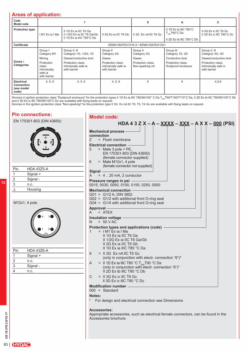
US
18.3
76.3
.0/10.17
83
12
Model code:
HDA 4 3 Z X – A – XXXX – XXX – A X X – 000 (PSI)
Mechanical process connection Z = Flush membrane
Electrical connection 5 = Male 3 pole + PE,
EN 175301-803 (DIN 43650) (female connector supplied)
6 = Male M12x1, 4 pole (female connector not supplied)
Signal A = 4 .. 20 mA, 2 conductor
Pressure ranges in psi 0015, 0030, 0050, 0100, 0150, 0250, 0500
Mechanical connection G01 = G1/2 A, DIN 3852 G02 = G1/2 with additional front O-ring seal G04 = G1/4 with additional front O-ring seal
Approval A = ATEX
Insulation voltage N = 50 V AC
Protection types and applications (code) 1 = I M1 Ex ia I Ma
II 1G Ex ia IIC T6 Ga II 1/2G Ex ia IIC T6 Ga/Gb II 2G Ex ia IIC T6 Gb II 1D Ex ia lIIC T85 °C Da
9 = II 3G Ex nA llC T6 Gc (only in conjunction with electr. connection “6“)*
A = II 1D Ex ta lllC T80 °C T500
T90 °C Da (only in conjunction with electr. connection “6“)* II 2D Ex tb lllC T80 °C Db
C = II 3G Ex ic llC T6 Gc ll 3D Ex ic lllC T80 °C Dc
Modification number 000 = Standard
Notes:
* For design and electrical connection see Dimensions
Accessories:Appropriate accessories, such as electrical female connectors, can be found in the Accessories brochure.
Pin HDA 43Z5-A
1 Signal +
2 Signal -
3 n.c.
Housing
Pin HDA 43Z6-A
1 Signal +
2 n.c.
3 Signal -
4 n.c.
EN 175301-803 (DIN 43650)
M12x1, 4 pole
CodeModel code
1 9 A C
Protection type
I M1 Ex ia I MaII 1G Ex ia IIC T6 GaII 1/2G Ex ia IIC T6 Ga/GbII 1D Ex ia lIIC T85°C Da
II 2G Ex ia IIC T6 Gb II 3G Ex nA llC T6 Gc
II 1D Ex ta lllC T80°C T
500T90°C Da
II 2D Ex tb lllC T80°C Db
II 3G Ex ic llC T6 Gc II 3D Ex ic lllC T80°C Dc
Certificate KEMA 05ATEX1016 X / KEMA 05ATEX1021
Zones / Categories
Group I Category M1
Mining
Protection class: intrinsically safe ia with barrier
Group II, lll Category 1G, 1/2G, 1D
Gases/conductive dust
Protection class: intrinsically safe ia with barrier
Group II Category 2G
Gases
Protection class: intrinsically safe ia with barrier
Group II Category 3G
Gases
Protection class:Non-sparking nA
Group IIl Category 1D, 2D
Conductive dust
Protection class:Dustproof enclosure
Group II, lll Category 3G, 3D
Gases/conductive dust
Protection class:Intrinsically safe icwith barrier
ElectricalConnection (see model code)
4, 5, 6 4, 5, 6 4, 5, 6 6 6 4,5,6
Devices in ignition protection class "Dustproof enclosure" for the protection types II 1D Ex ta lllC T80/90/100° C Da T500
T90/T100/T110°C Da, II 2D Ex tb lllC T80/90/100°C Db and ll 3D Ex tc lllC T80/90/100°C Dc are available with flying leads on request. Devices in the ignition protection class "Non-sparking" for the protection type II 3G Ex nA llC T6, T5, T4 Gc are available with flying leads on request.
Areas of application:
Pin connections:

US
18.3
76.3
.0/10.17
84
12
Dimensions:Protection types and applications (code): 1, C
Note:The information in this brochure relates to the operating conditions and applications described.For applications and operating conditions not described, please contact the relevant technical department.Subject to technical modifications.For bar ranges see European Catalog
HYDAC ELECTRONICS 90 Southland Dr. Bethlehem, PA 18017 Telephone +1 (610) 266-0100 E-mail: [email protected]: www.hydacusa.com
61.4
3
13.8
12
12.3
Profile seal ring
male electr. conn.
3p +PE EN 175301-803 (DIN 43650) male electr. conn. 4p
Elastomer profile
seal ring DIN3869
hex-SW27
G1/2 A
Ø 29.5
Ø 26 h14
20.5
19.5
8
10
23
Ø 29.5Ø 29.5
Ø 18.9
Ø 18.1Ø 10.9
G1/4 AG1/2 A
Ø 26 h14
seal ring DIN3869
11.6 x 16.5 x 1.5seal ring DIN3869
18.5 x 23.9 x 1.5
O-ring 7.65 x 1.78O-ring 15 x 2
Ø 35
Ø 27
hex-SW27 hex-SW27
~ 35
M3
18 M12x1
27.5
35.
5
Impact
protected metal
safety sleeve
SW25
hex-SW27
Protection types and applications (code): 9, A
The impact protected metal safety sleeve is included. A straight female connector is required for electrical connection. e.g. female connector M12x1, 4 pole, straight, with 3m shielded cable: ZBE 06S-03, Part. No. 6098243

US
18.3
76.3
.0/10.17
85
12

US
18.3
74.3
.0/10.17
86
12
Electronic
Pressure Transmitter HDA 4700 with Flush Membrane IECEx Intrinsically Safe IECEx Dustproof Enclosure IECEx Non-sparking
Description:The pressure transmitter HDA 4700 in IECEx Intrinsically Safe version has been especially developed for use in potentially explosive atmospheres and is based on the HDA 4000 series.
As with the industrial version of the HDA 4700, devices with IECEx Intrinsically Safe approval have a field-proven, all-welded stainless steel measurement cell with thin-film strain gauge without internal seal.
The pressure connection is achieved with an all-welded stainless steel front membrane filled internally with a pressure transfer fluid. The process pressure is transmitted hydrostatically to the measurement cell via the pressure transfer fluid.This device is used for applications in which a standard pressure connection could become blocked, clogged or frozen by the particular medium used. Further applications include processes where the medium changes regularly and any residues could cause mixing or contamination of the media, or in highly viscous media. Intended areas of application are, for example, the oil and gas industry, in mines or in locations with high levels of dust, e.g. in mills.
Protection types and applications:
Ex ia l Ma
Ex ia llC T6 GaEx ia llC T6 Ga/GbEx ia llC T6 GbEx nA llC T6,T5,T4 GcEx ic llC T6,T5,T4 Gc
Ex ta lllC T80/90/100°C Da T
500 90/100/110°C Da
Ex tb lllC T80/90/100°C DbEx tc lllC T80/90/100°C DcEx ic lllC T80/90/100°C Dc Ex ia lllC T85°C Da
Special features: Pressure connection has a flush
membrane
Accuracy ≤ 0.25 % FS B.F.S.L. Certificate:
IECEx KEM 08.0014X
Robust design
Very small temperature error
Excellent EMC characteristics
Excellent long-term properties
Technical data:Input data
Measuring ranges 500, 750, 1000, 1500, 3000, 6000, 9000 psi
Overload ranges 1160, 1740, 2900, 2900, 7250, 11600, 14500 psi
Burst pressure1) 2900, 4350, 7250, 7250, 14500, 29000, 29000 psi
Mechanical connection G1/2 A DIN 3852
G1/2 with additional front O-ring seal
Pressure transfer fluid Silicon-free oil
Torque value 33 ft-lb (45 Nm)
Parts in contact with medium 2) Stainless steel: 1.4435; 1.4301Seal: FPM
O-ring: FPMOutput data
Output signal, permitted load resistance 4 .. 20 mA, 2 conductor
RLmax = (UB – 12 V) / 20 mA [kΩ]Accuracy to DIN 16086,
max. setting
≤ ± 0.25 % FS typ. ≤ ± 0.5 % FS max.
Accuracy at minimum setting
(B.F.S.L.)≤ ± 0.15 % FS typ. ≤ ± 0.25 % FS max.
Temperature compensation
zero point
≤ ± 0.0045% FS/°F typ. ≤ ± 0.0085% FS/°F max.
Temperature compensation
over range
≤ ± 0.0045% FS/°F typ. ≤ ± 0.0085% FS/°F max.
Non-linearity at max. setting
to DIN 16086
≤ ± 0.3 % FS max.
Hysteresis ≤ ± 0.1 % FS max.Repeatability ≤ ± 0.05 % FSRise time ≤ 1.5 msLong term drift ≤ ± 0.1 % FS typ. / yearEnvironmental conditions
Compensated temperature range -20..+85 °C to -4..+185°F
Operating temperature range 3) -40..+60°C / -20..+60°C to -40..+140°F/ -4..+140°F
Storage temperature range -40..+100°C to -40 to 212°F
Fluid temperature range 3) -40..+60°C / -20..+60°C to -40..+140°F / -4..+140°F
mark EN 61000-6-1 / 2 / 3 / 4
EN 60079-0 / 11 / 26 / 36
Vibration resistance to
DIN EN 60068-2-6 at 10 ..500 Hz
≤ 20 g
Protection class to IEC 60529 IP 65 (for male EN 175301-803 (DIN 43650))
IP 67 (for M12x1 male, when an
IP 67 female connector is used)
Relevant data for Ex applications Ex ia, ic Ex nA, ta, tb, tcSupply voltage Ui = 12 .. 28 V 12 .. 28 VMax. input current Ii = 100 mAMax. input power Pi = 1 W max. power consuption
≤ 1 WConnection capacitance of the sensor Ci = ≤ 22 nFInductance of the sensor Li = 0 mHInsulation voltage 4) 50 V AC, with integrated overvoltage protection
EN 61000-6-2Other dataResidual ripple of supply voltage ≤ 5 %Life expectancy > 10 million cycles
0 .. 100 % FSWeight ~ 180 g
Note: Reverse polarity protection of the supply voltage, excess voltage, override and short circuit protection are provided. FS (Full Scale) = relative to complete measuring range B.F.S.L. = Best Fit Straight Line1) G1/2 with additional front O-ring seal max. 21750 psi 2) Other seal materials on request3) -4 °F with FPM seal, -40 °F on request4) 500 V AC on request
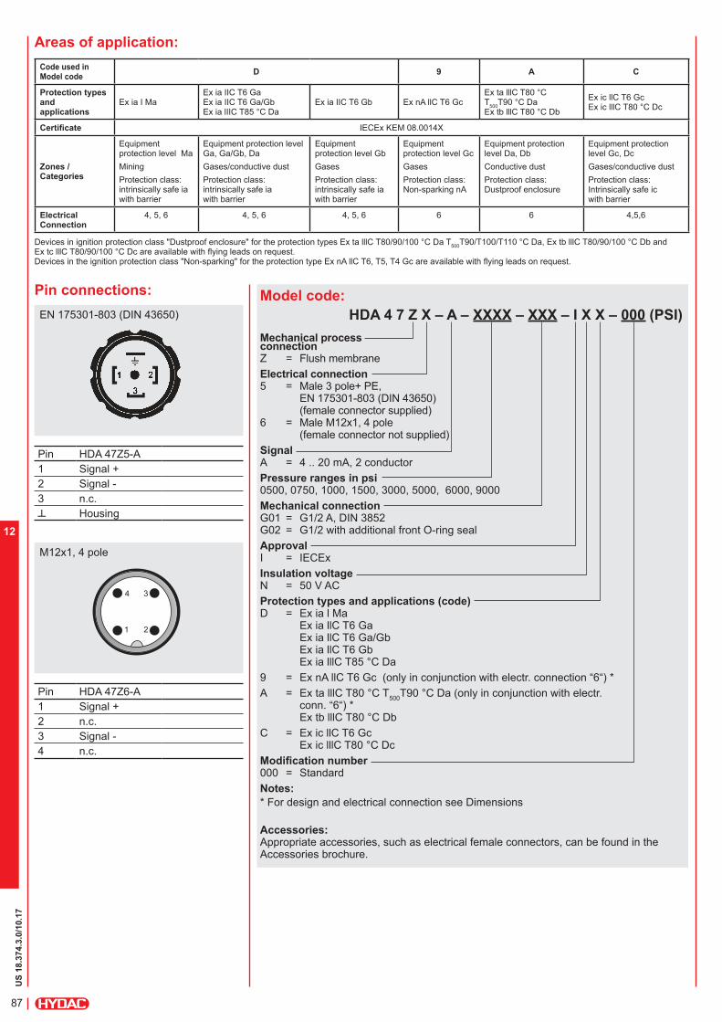
US
18.3
74.3
.0/10.17
87
12
Model code:
HDA 4 7 Z X – A – XXXX – XXX – I X X – 000 (PSI)
Mechanical process connection Z = Flush membrane
Electrical connection 5 = Male 3 pole+ PE,
EN 175301-803 (DIN 43650) (female connector supplied)
6 = Male M12x1, 4 pole (female connector not supplied)
Signal A = 4 .. 20 mA, 2 conductor
Pressure ranges in psi 0500, 0750, 1000, 1500, 3000, 5000, 6000, 9000
Mechanical connection G01 = G1/2 A, DIN 3852 G02 = G1/2 with additional front O-ring seal
Approval I = IECEx
Insulation voltage N = 50 V AC
Protection types and applications (code) D = Ex ia l Ma
Ex ia llC T6 Ga Ex ia llC T6 Ga/Gb Ex ia llC T6 Gb Ex ia lllC T85 °C Da
9 = Ex nA llC T6 Gc (only in conjunction with electr. connection “6“) *
A = Ex ta lllC T80 °C T500
T90 °C Da (only in conjunction with electr. conn. “6“) * Ex tb lllC T80 °C Db
C = Ex ic llC T6 Gc Ex ic lllC T80 °C Dc
Modification number 000 = Standard
Notes:
* For design and electrical connection see Dimensions
Accessories:Appropriate accessories, such as electrical female connectors, can be found in the Accessories brochure.
Pin connections:
Pin HDA 47Z5-A
1 Signal +
2 Signal -
3 n.c.
Housing
Pin HDA 47Z6-A
1 Signal +
2 n.c.
3 Signal -
4 n.c.
EN 175301-803 (DIN 43650)
M12x1, 4 pole
Areas of application:
Code used inModel code
D 9 A C
Protection types and applications
Ex ia I MaEx ia IIC T6 GaEx ia IIC T6 Ga/GbEx ia lIIC T85 °C Da
Ex ia IIC T6 Gb Ex nA llC T6 Gc Ex ta lllC T80 °C T
500T90 °C Da
Ex tb lllC T80 °C Db
Ex ic llC T6 Gc Ex ic lllC T80 °C Dc
Certificate IECEx KEM 08.0014X
Zones / Categories
Equipment protection level Ma
Mining
Protection class: intrinsically safe ia with barrier
Equipment protection level Ga, Ga/Gb, Da
Gases/conductive dust
Protection class: intrinsically safe ia with barrier
Equipment protection level Gb
Gases
Protection class: intrinsically safe ia with barrier
Equipment protection level Gc
Gases
Protection class:Non-sparking nA
Equipment protection level Da, Db
Conductive dust
Protection class:Dustproof enclosure
Equipment protection level Gc, Dc
Gases/conductive dust
Protection class:Intrinsically safe icwith barrier
ElectricalConnection
4, 5, 6 4, 5, 6 4, 5, 6 6 6 4,5,6
Devices in ignition protection class "Dustproof enclosure" for the protection types Ex ta lllC T80/90/100 °C Da T500
T90/T100/T110 °C Da, Ex tb lllC T80/90/100 °C Db and Ex tc lllC T80/90/100 °C Dc are available with flying leads on request. Devices in the ignition protection class "Non-sparking" for the protection type Ex nA llC T6, T5, T4 Gc are available with flying leads on request.

US
18.3
74.3
.0/10.17
88
12
Note:The information in this brochure relates to the operating conditions and applications described.For applications and operating conditions not described, please contact the relevant technical department.Subject to technical modifications.For bar ranges see European Catalog
HYDAC ELECTRONICS 90 Southland Dr. Bethlehem, PA 18017 Telephone +1 (610) 266-0100 E-mail: [email protected]: www.hydacusa.com
20.5
10
3
Ø 29.5
Ø 18.1
G1/2 A
Ø 26 h14
seal ring DIN3869 18.5 x 23.9 x 1.5
O-ring 15 x 2
hex-SW27
59.4
3
13.8
12
12.3
male electr. conn. 3p +PE EN 175301-803 (DIN 43650)
male electr. conn. 4p
Elastomer profile seal ring DIN3869
hex-SW27
G1/2 A
Ø 29.5
Ø 26 h14
Ø 35
Ø 27
18 M12x1
Profile seal ring
35
M3
27.5
35.
5
Dimensions:Protection types and applications (code): D, C
Protection types and applications (code): 9, A
Impact protected metal safety sleeve
SW25
hex-SW27
The impact protected metal safety sleeve is included. A straight female connector is required for electrical connection. e.g. female connector M12x1, 4 pole, straight, with 3m shielded cable: ZBE 06S-03, Part. No. 6098243

US
18.3
74.3
.0/10.17
89
12

US
18.3
92.4
.0/10.17
90
12
Electronic
Pressure Transmitter HDA 4400 with Flush Membrane IECEx Intrinsically Safe IECEx Dustproof Enclosure IECEx Non-sparking
Description:The pressure transmitter HDA 4400 in IECEx Intrinsically Safe version has been especially developed for use in potentially explosive atmospheres and is based on the HDA 4000 series.
As with the industrial version of the HDA 4400, devices with IECEx Intrinsically Safe approval have a field-proven, all-welded stainless steel measurement cell with thin film strain gauge without internal seal.
The pressure connection is achieved with an all-welded stainless steel front membrane filled internally with a pressure transfer fluid. The process pressure is transmitted hydrostatically to the measurement cell via the pressure transfer fluid.This device is used for applications in which a standard pressure connection could become blocked, clogged or frozen by the particular medium used. Further applications include processes where the medium changes regularly and any residues could cause mixing or contamination of the media, or in highly viscous media. Intended areas of application are, for example, the oil and gas industry, in mines or in locations with high levls of dust, e.g. in mills.
Protection types and applications:
Ex ia l Ma
Ex ia llC T6 GaEx ia llC T6 Ga/GbEx ia llC T6 GbEx nA llC T6,T5,T4 GcEx ic llC T6,T5,T4 Gc
Ex ta lllC T80/90/100 °C Da T
500 90/100/110 °C Da
Ex tb lllC T80/90/100 °C DbEx tc lllC T80/90/100 °C DcEx ic lllC T80/90/100 °C Dc Ex ia lllC T85 °C Da
Special features: Pressure connection has a flush
membrane
Accuracy: ≤ ± 0.5 % BFSL typ. Certificate:
IECEx KEM 08.0014X
Robust design
Very small temperature error
Excellent EMC characteristics
Excellent durability
Technical data:Input data
Measuring ranges 500, 750, 1000, 1500, 3000, 6000, 9000 psi
Overload pressures 1160, 1740, 2900, 2900, 7250, 11600, 14500 psi
Burst pressure 1) 2900, 4350, 7250, 7250, 14500, 29000, 29000 psi
Mechanical connection G1/2 A DIN 3852 G1/2 with additional front O-ring seal G1/4 with additional front O-ring seal
Pressure transfer fluid Silicon-free oil
Torque value 33 ft-lb (45 Nm) for G1/2, G1/2A 15 ft-lb (20 Nm) for G1/4
Parts in contact with medium 2) Stainless steel: 1.4435; 1.4301Seal: FPM O-ring: FPM
Output data
Output signal, permitted load resistance 4 .. 20 mA, 2 conductor RLmax = (UB – 12 V) / 20 mA [kΩ]
Accuracy to DIN 16086, max. setting
≤ ± 0.5 % FS typ. ≤ ± 1 % FS max.
Accuracy at minimum setting (B.F.S.L.)
≤ ± 0.25 % FS typ. ≤ ± 0.5 % FS max.
Temperature compensation Zero point
≤ ± 0.0085% FS/°F typ. ≤ ± 0.014% FS/°F max.
Temperature compensation Over range
≤ ± 0.0085% FS/°F typ. ≤ ± 0.014% FS/°F max.
Non-linearity at max. setting to DIN 16086
≤ ± 0.3 % FS max.
Hysteresis ≤ ± 0.4 % FS max.Repeatability ≤ ± 0.1 % FSRise time ≤ 1.5 msLong term drift ≤ ± 0.3 % FS typ. / yearEnvironmental conditions
Compensated temperature range -4..+185°F
Operating temperature range -4..+140°F
Storage temperature range -40..+212°F
Fluid temperature range 3) -40..+140°F / -4..+140°F
- mark EN 61000-6-1 / 2 / 3 / 4 EN 60079-0 / 11 / 26 / 36
Vibration resistance to DIN EN 60068-2-6 at 10 ..500 Hz
≤ 20 g
Protection class to IEC 60529 IP 65 (for male EN 175301-803(DIN 43650)) IP 67 (for M12x1 male, when an
IP 67 female connector is used)
Relevant data for Ex applications Ex ia, ic Ex nA, ta, tb, tcSupply voltage Ui = 12 .. 28 V 12 .. 28 VMax. input current Ii = 100 mAMax. input power Pi = 1 W max. power consuption
≤ 1 WConnection capacitance of the sensor Ci = ≤ 22 nFInductance of the sensor Li = 0 mHInsulation voltage 4) 50 V AC, with integrated overvoltage protection
EN 61000-6-2Other dataResidual ripple of supply voltage ≤ 5 %Life expectancy > 10 million cycles
0 .. 100 % FSWeight ~ 180 g
Note: Reverse polarity protection of the supply voltage, excess voltage, override and short circuit protection are provided. FS (Full Scale) = relative to complete measuring range B.F.S.L. = Best Fit Straight Line1) G1/2 with additional front O-ring seal max. 21750 psi 2) Other seal materials on request3) -4 °F with FPM seal, -40 °F on request4) 500 V AC on request

US
18.3
92.4
.0/10.17
91
12
Model code:
HDA 4 4 Z X – A – XXXX – XXX – I X X – 000 (PSI)
Mechanical process connection Z = Flush membrane
Electrical connection 5 = Male 3 pole+ PE,
EN 175301-803 (DIN 43650) (female connector supplied)
6 = Male M12x1, 4 pole (female connector not supplied)
Signal A = 4 .. 20 mA, 2 conductor
Pressure ranges in psi 0500, 0750, 1000, 1500, 3000, 5000, 6000, 9000
Mechanical connection G01 = G1/2 A, DIN 3852 G02 = G1/2 with additional front O-ring seal G04 = G1/4 with additional front O-ring seal
Approval I = IECEx
Insulation voltage N = 50 V AC
Protection types and applications (code) D = Ex ia l Ma
Ex ia llC T6 Ga Ex ia llC T6 Ga/Gb Ex ia llC T6 Gb Ex ia lllC T85 °C Da
9 = Ex nA llC T6 Gc (only in conjunction with electr. connection "6")*
A = Ex ta lllC T80 °C T500
T90 °C Da (only in conjunction with electr. connection "6")* Ex tb lllC T80 °C Db
C = Ex ic llC T6 Gc Ex ic lllC T80 °C Dc
Modification number 000 = Standard
Notes:
* For design and electrical connection see Dimensions
Accessories:Appropriate accessories, such as electrical female connectors, can be found in the Accessories brochure.
Pin connections:
Pin HDA 44Z5-A
1 Signal +
2 Signal -
3 n.c.
Housing
Pin HDA 44Z6-A
1 Signal +
2 n.c.
3 Signal -
4 n.c.
EN 175301-803 (DIN 43650)
M12x1, 4 pole
Areas of application:
Code No. for use inModel code
D 9 A C
Protection types and applications
Ex ia I MaEx ia IIC T6 GaEx ia IIC T6 Ga/GbEx ia lIIC T85°C Da
Ex ia IIC T6 Gb Ex nA llC T6 Gc Ex ta lllC T80°C T
500T90°C Da
Ex tb lllC T80°C Db
Ex ic llC T6 Gc Ex ic lllC T80°C Dc
Certificate IECEx KEM 08.0014X
Zones / Categories
Equipment protection level Ma
Mining
Protection class: intrinsically safe ia with barrier
Equipment protection level Ga, Ga/Gb, Da
Gases/conductive dust
Protection class: intrinsically safe ia with barrier
Equipment protection level Gb
Gases
Protection class: intrinsically safe ia with barrier
Equipment protection level Gc
Gases
Protection class:Non-sparking nA
Equipment protection level Da, Db
Conductive dust
Protection class:Dustproof enclosure
Equipment protection level Gc, Dc
Gases/conductive dust
Protection class:Intrinsically safe icwith barrier
Electrical connection
4, 5, 6 4, 5, 6 4, 5, 6 6 6 4,5,6
Devices in ignition protection class "Dustproof enclosure" for the protection types Ex ta lllC T80/90/100 °C Da T500
T90/T100/T110 °C Da, Ex tb lllC T80/90/100 °C Db and Ex tc lllC T80/90/100 °C Dc are available with flying leads on request. Devices in the ignition protection class "Non-sparking" for the protection type Ex nA llC T6, T5, T4 Gc are available with flying leads on request.
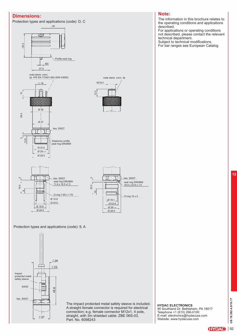
US
18.3
92.4
.0/10.17
92
12
Note:The information in this brochure relates to the operating conditions and applications described.For applications or operating conditions not described, please contact the relevant technical department.Subject to technical modifications. For bar ranges see European Catalog
HYDAC ELECTRONICS 90 Southland Dr. Bethlehem, PA 18017 Telephone +1 (610) 266-0100 E-mail: [email protected]: www.hydacusa.com
59.4
3
13.8
12
12.3
Profile seal ring
male electr. conn. 3p +PE EN 175301-803 (DIN 43650) male electr. conn. 4p
Elastomer profile seal ring DIN3869
hex. SW27
G1/2 A
Ø 29.5
Ø 29 h14
19.5
20.5
8
10
2 3
Ø 29.5 Ø 29.5
Ø 18.9
Ø 18.1Ø 10.9
G1/4 A G1/2 A
Ø 26 h14
seal ring DIN3869 11.6 x 16.5 x1.5
seal ring DIN3869 18.5 x 23.9 x 1.5
O-ring 7.65 x 1.78O-ring 15 x 2
Ø 35
Ø 27
hex. SW27 hex. SW27
35
M3
18 M12x1
27.5
35.
5
Dimensions:Protection types and applications (code): D, C
Protection types and applications (code): 9, A
Impact protected metal safety sleeve
SW25
hex. SW27
The impact protected metal safety sleeve is included. A straight female connector is required for electrical connection; e.g. female connector M12x1, 4 pole, straight, with 3m shielded cable: ZBE 06S-03, Part. No. 6098243

US
18.3
92.4
.0/10.17
93
12

US
18.3
76.2
.0/10.17
94
12
Electronic
Pressure Transmitter
HDA 4300 with Flush Membrane IECEx Intrinsically Safe IECEx Dustproof Enclosure IECEx Non-sparking
Description:The pressure transmitter HDA 4300 in IECEx Intrinsically Safe version has been especially developed for use in potentially explosive atmospheres and is based on the HDA 4000 series.
As with the industrial version HDA 4300, the devices with IECEx Intrinsically Safe approval have the field-proven ceramic measuring cell with thick-film strain gauge.
The pressure connection is achieved with an all-welded stainless steel front membrane filled internally with a pressure transfer fluid. The process pressure is transmitted hydrostatically to the measurement cell via the pressure transfer fluid.This device is used for applications in which a standard pressure connection could become blocked, clogged or frozen by the particular medium used. Further applications include processes where the medium changes regularly and any residues could cause mixing or contamination of the media. Intended areas of application are, for example, the oil and gas industry, in mines, or in locations with high levels of dust, e.g. in mills.
Protection types and applications:
Ex ia l Ma
Ex ia llC T6 GaEx ia llC T6 Ga/GbEx ia llC T6 GbEx nA llC T6,T5,T4 GcEx ic llC T6,T5,T4 Gc
Ex ta lllC T80/90/100 °C Da T
500 90/100/110 °C Da
Ex tb lllC T80/90/100 °C DbEx tc lllC T80/90/100 °C DcEx ic lllC T80/90/100 °C Dc Ex ia lllC T85 °C Da
Special features: Pressure connection has a flush
membrane
Accuracy: ≤ ± 0.5 % FS B.F.S.L. Certificate:
IECEx KEM 08.0014X
Robust design
Very small temperature error
Excellent EMC characteristics
Excellent long-term properties
Technical data:Input data
Measuring ranges 15, 30, 50, 100, 150, 250, 500 psi
Overload pressures 45, 100, 150, 290, 450, 725, 1500 psi
Burst pressure 70, 150, 250, 400, 650, 1000, 2500 psi
Mechanical connection G1/2 A DIN 3852 G1/2 with additional front O-ring seal G1/4 with additional front O-ring seal
Pressure transfer fluid Silicon-free oil
Torque value 33 ft-lb (45 Nm) for G1/2, G1/2A 15 ft-lb (20 Nm) for G1/4
Parts in contact with medium 1) Stainless steel: 1.4435; 1.4301Seal: FPMO-ring: FPM
Output data
Output signal, permitted load resistance 4 .. 20 mA, 2 conductor RLmax = (UB – 12 V) / 20 mA [kΩ]
Accuracy to DIN 16086, max. setting
≤ ± 0.5 % FS typ. ≤ ± 1.0 % FS max.
Accuracy at minimum setting (B.F.S.L.)
≤ ± 0.25 % FS typ. ≤ ± 0.5 % FS max.
Temperature compensation zero point
≤ ± 0.012% FS/°F typ. ≤ ± 0.017% FS/°F max.
Temperature compensation over range
≤ ± 0.012% FS/°F typ. ≤ ± 0.017% FS/°F max.
Non-linearity at max. setting to DIN 16086
≤ ± 0.5 % FS max.
Hysteresis ≤ ± 0.4 % FS max.Repeatability ≤ ± 0.1 % FSRise time ≤ 1.5 msLong term drift ≤ ± 0.3 % FS typ. / yearEnvironmental conditions
Compensated temperature range -4..+185°F
Operating temperature range -4..+140°F
Storage temperature range -40..+212°F
Fluid temperature range 2) -40..+140°F / -4..+140°F
mark EN 61000-6-1 / 2 / 3 / 4 EN 60079-0 / 11 / 26 / 36
Vibration resistance acc. to DIN EN 60068-2-6 at 10 .. 500 Hz
≤ 20 g
Protection class to IEC 60529 IP 65 (for male EN 175301-803 (DIN 43650)) IP 67 (for M12x1 male, when an
IP 67 female connector is used)
Relevant data for Ex applications Ex ia, ic Ex nA, ta, tb, tcSupply voltage Ui = 12 .. 28 V 12 .. 28 VMax. input current Ii = 100 mAMax. input power Pi = 1 W max. power consuption
≤ 1 WConnection capacitance of the sensor Ci = ≤ 22 nFInductance of the sensor Li = 0 mHInsulation voltage 3) 50 V AC, with integrated overvoltage protection
EN 61000-6-2Other dataResidual ripple of supply voltage ≤ 5 %Life expectancy > 10 million cycles
0 .. 100 % FSWeight ~ 180 g
Note: Reverse polarity protection of the supply voltage, excess voltage, override and short circuit protection are provided. FS (Full Scale) = relative to complete measuring range B.F.S.L. = Best Fit Straight Line1) Other seal materials on request2) -4 °F with FPM seal, -40 °F on request3) 500 V AC on request

US
18.3
76.2
.0/10.17
95
12
Model code:
HDA 4 3 Z X – A – XXXX – XXX – I X X – 000 (PSI)
Mechanical process connection Z = Flush membrane
Electrical connection 5 = Male 3 pole + PE,
EN 175301-803 (DIN 43650) (female connector supplied)
6 = Male M12x1, 4 pole (female connector not supplied)
Signal A = 4 .. 20 mA, 2 conductor
Pressure ranges in psi 0015, 0030, 0050, 0100, 0150, 0250, 0500
Mechanical connection G01 = G1/2 A, DIN 3852 G02 = G1/2 with additional front O-ring seal G04 = G1/4 with additional front O-ring seal
Approval I = IECEx
Insulation voltage N = 50 V AC
Protection types and applications (code) D = Ex ia l Ma
Ex ia llC T6 Ga Ex ia llC T6 Ga/Gb Ex ia llC T6 Gb Ex ia lllC T85 °C Da
9 = Ex nA llC T6 Gc (only in conjunction with electr. connection “6“)*
A = Ex ta lllC T80 °C T500
T90 °C Da (only in conjunction with electr. connection “6“)* Ex tb lllC T80 °C Db
C = Ex ic llC T6 Gc Ex ic lllC T80 °C Dc
Modification number 000 = Standard
Notes:
* For design and electrical connection see device dimensions
Accessories:Appropriate accessories, such as electrical female connectors, can be found in the Accessories brochure.
Pin connections:
Pin HDA 43Z5-A
1 Signal +
2 Signal -
3 n.c.
Housing
Pin HDA 43Z6-A
1 Signal +
2 n.c.
3 Signal -
4 n.c.
EN 175301-803 (DIN 43650)
M12x1, 4 pole
Areas of application:
Code for use inModel code
D 9 A C
Protection types and applications
Ex ia I MaEx ia IIC T6 GaEx ia IIC T6 Ga/GbEx ia lIIC T85°C Da
Ex ia IIC T6 Gb Ex nA llC T6 Gc Ex ta lllC T80°C T
500T90°C Da
Ex tb lllC T80°C Db
Ex ic llC T6 Gc Ex ic lllC T80°C Dc
Certificate IECEx KEM 08.0014X
Zones / Categories
Equipment protec-tion level Ma
Mining
Protection class: intrinsically safe ia with barrier
Equipment protection level Ga, Ga/Gb, Da
Gases/conductive dust
Protection class: intrinsically safe ia with barrier
Equipment protection level Gb
Gases
Protection class: intrinsically safe ia with barrier
Equipment protection level Gc
Gases
Protection class:Non-sparking nA
Equipment protection level Da, Db
Conductive dust
Protection class:Dustproof enclosure
Equipment protection level Gc, Dc
Gases/conductive dust
Protection class:Intrinsically safe icwith barrier
ElectricalConnection
4, 5, 6 4, 5, 6 4, 5, 6 6 6 4,5,6
Devices in the ignition protection class "Dustproof enclosure" for the protection types Ex ta lllC T80/90/100° C Da T500
T90/T100/T110°C Da, Ex tb lllC T80/90/100°C Db and Ex tc lllC T80/90/100°C Dc are available with flying leads on request. Devices in the ignition protection class "non-sparking" for protection type Ex nA llC T6, T5, T4 Gc are available with flying leads on request.

US
18.3
76.2
.0/10.17
96
12
Note:The information in this brochure relates to the operating conditions and applications described.For applications and operating conditions not described, please contact the relevant technical department.Subject to technical modifications. For bar ranges see European Catalog
HYDAC ELECTRONICS 90 Southland Dr. Bethlehem, PA 18017 Telephone +1 (610) 266-0100 E-mail: [email protected]: www.hydacusa.com
59.4
3
13.8
12
12.3
Profile seal ring
male electr. conn. 3p +PE EN 175301-803 (DIN 43650)
male electr. conn. 4p
Elastomer profile seal ring DIN3869
hex-SW27
G1/2 A
Ø 29.5
Ø 29 h14
19.5
20.5
8
10
2 3
Ø 29.5 Ø 29.5
Ø 18.9
Ø 18.1Ø 10.9
G1/4 A G1/2 A
Ø 26 h14
seal ring DIN3869 11.6 x 16.5 x 1.5
seal ring DIN3869 18.5 x 23.9 x 1.5
O-ring 7.65 x 1.78O-ring 15 x 2
Ø 35
Ø 27
hex-SW27
hex-SW27
35
M3
18 M12x1
27.5
35.
5
Dimensions:Protection types and applications (code): D, C
Protection types and applications (code): 9, A
Impact protected metal safety sleeve
SW25
hex-SW27
The Impact protected metal safety sleeve is included. A straight female connector is required for electrical connection. e.g. female connector M12x1, 4 pole, straight, with 3m shielded cable: ZBE 06S-03, Part No. 6098243

US
18.3
76.2
.0/10.17
97
12

US
18.3
74.2
.0/10.17
98
12
Electronic
Pressure Transmitter
HDA 4700 with Flush Membrane ATEX, IECEx, CSA Flameproof Enclosure
Description:The electronic pressure transmitter HDA 4700 with flush membrane is certified in the ignition protection class Flameproof Enclosure to ATEX, IECIx and CSA. The devices have triple approval, ensuring that they are universally suitable for use in potentially explosive environments around the world. Therefore it is no longer necessary to stock multiple devices with separate individual approvals. The pressure connection is achieved with an all-welded stainless steel front membrane filled internally with a pressure transfer fluid. The process pressure is transmitted hydrostatically to the measurement cell via the pressure transfer fluid.This device is used for applications in which a standard pressure connection could become blocked, clogged or frozen by the particular medium used. Further applications include processes where the medium changes regularly and any residues could cause mixing or contamination of the media, or in highly viscous media.Its main applications are in mining and the oil and gas industry, e.g. in underground vehicles, hydraulic power units (HPU), blow-out preventers (BOPs), drill drives or in lubrication systems.Protection types and applications:
CCSAUS Explosion Proof – Seal Not RequiredClass I Group A, B, C, D, T6, T5Class II Group E, F, GClass IIIType 4
ATEX Flame ProofI M2 Ex d I Mb
II 2G Ex d IIC T6, T5 GbII 2D Ex tb IIIC T110 .. 130 °C Db
IECEx Flame ProofEx d I MbEx d IIC T6, T5 GbEx tb IIIC T110 .. 130 °C Db
Special features: Accuracy ≤ 0.25 % FS B.F.S.L. Certificates:
ATEX KEMA 10ATEX0100 XCSA MC 224264IECEx KEM 10.0053X Robust design Very small temperature error
Excellent EMC characteristics
Excellent durability
Technical data:Input data
Measuring ranges 500, 750, 1000, 1500, 3000, 6000, 9000 psiOverload ranges 1160, 1740, 2900, 2900, 7250, 11600, 14500 psiBurst pressure 2900, 4350, 7250, 7250, 14500, 29000, 29000 psiMechanical connection1) G1/2 A DIN 3852
G1/2 with add. front O-ring sealPressure transfer fluid Silicon-free oil
Torque value 33 ft-lb (45 Nm)Parts in contact with medium Stainless steel: 1.4435; 1.4301
Seal: FPM O-ring: FPM
Conduit, housing material 1.4404; 1.4435 (316L)Output data
Output signal, permitted load resistance2) 4 .. 20 mA, 2 conductor RLmax = (UB – 8 V) / 20 mA [kΩ]
Accuracy to DIN 16086, max. setting
≤ ± 0.25 % FS typ. ≤ ± 0.5 % FS max.
Accuracy at minimum setting (B.F.S.L.)
≤ ± 0.15 % FS typ. ≤ ± 0.25 % FS max.
Temperature compensation Zero point
≤ ± 0.0045% FS/°F typ. ≤ ± 0.0085% FS/°F max.
Temperature compensation Over range
≤ ± 0.0045% FS/°F typ. ≤ ± 0.0085% FS/°F max.
Non-linearity at max. setting to DIN 16086
≤ ± 0.3 % FS max.
Hysteresis ≤ ± 0.1 % FS max.Repeatability ≤ ± 0.05 % FSRise time ≤ 1.5 msLong term drift ≤ ± 0.1 % FS typ. / yearEnvironmental conditions
Compensated temperature range T5: -13..+176°F T6: -13..+140°F
Operating temperature range 3) T5: -40..+176°F T6: -40..+140°F-40..+212°F
Fluid temperature range 3) T5: -40..+176°F T6: -40..+140°F
mark EN 61000-6-1 / 2 / 3 / 4 EN 60079-0 / 1 / 31
Vibration resistance to DIN EN 60068-2-6 at 10 ..500 Hz
≤ 20 g
Protection class to IEC 60529 to ISO 20653
IP 65 (Vented Gauge) IP 69K (Sealed Gauge)
Other data
Supply voltage 8 .. 30 V DCResidual ripple of supply voltage ≤ 5 %Life expectancy > 10 million load cycles, 0 .. 100 % FSWeight ~ 300 g
Note.: Reverse polarity protection of the supply voltage, excess voltage, override and short circuit protection are provided. FS (Full Scale) = relative to complete measuring range B.F.S.L. = Best Fit Straight Line
1) Other mechanical connections on request2) Other output signals on request3) -4 °F with FPM seal , -40 °F on request
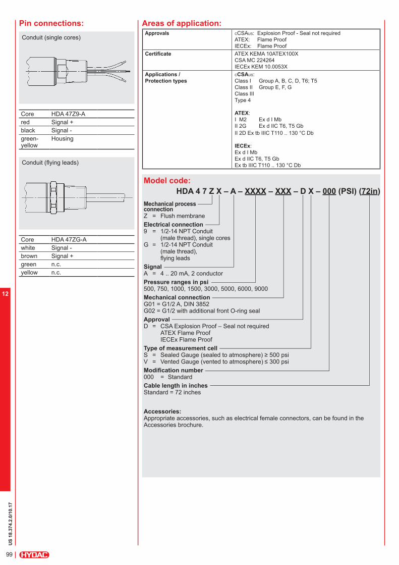
US
18.3
74.2
.0/10.17
99
12
Model code:
HDA 4 7 Z X – A – XXXX – XXX – D X – 000 (PSI) (72in)
Mechanical process connection Z = Flush membrane
Electrical connection 9 = 1/2-14 NPT Conduit
(male thread), single coresG = 1/2-14 NPT Conduit
(male thread), flying leads
Signal A = 4 .. 20 mA, 2 conductorPressure ranges in psi 500, 750, 1000, 1500, 3000, 5000, 6000, 9000Mechanical connection G01 = G1/2 A, DIN 3852 G02 = G1/2 with additional front O-ring sealApproval D = CSA Explosion Proof – Seal not required
ATEX Flame Proof IECEx Flame Proof
Type of measurement cell S = Sealed Gauge (sealed to atmosphere) ≥ 500 psi V = Vented Gauge (vented to atmosphere) ≤ 300 psiModification number 000 = StandardCable length in inches Standard = 72 inches
Accessories:Appropriate accessories, such as electrical female connectors, can be found in the Accessories brochure.
Pin connections:
Core HDA 47Z9-A
red Signal +black Signal -
green-yellow
Housing
Core HDA 47ZG-A
white Signal -
brown Signal +green n.c.yellow n.c.
Conduit (flying leads)
Areas of application:
Conduit (single cores)Approvals CCSAUS: Explosion Proof - Seal not required
ATEX: Flame ProofIECEx: Flame Proof
Certificate ATEX KEMA 10ATEX100X
CSA MC 224264IECEx KEM 10.0053X
Applications /
Protection types
CCSAUS: Class I Group A, B, C, D, T6; T5Class II Group E, F, G
Class III
Type 4
ATEX:I M2 Ex d I MbII 2G Ex d IIC T6, T5 GbII 2D Ex tb IIIC T110 .. 130 °C Db
IECEx: Ex d I MbEx d IIC T6, T5 GbEx tb IIIC T110 .. 130 °C Db
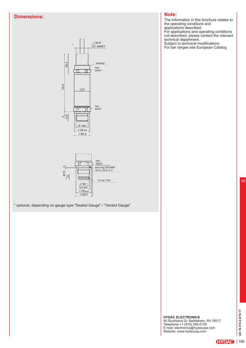
US
18.3
74.2
.0/10.17
100
12
Dimensions: Note:The information in this brochure relates to the operating conditions and applications described.For applications and operating conditions not described, please contact the relevant technical department.Subject to technical modifications. For bar ranges see European Catalog
HYDAC ELECTRONICS 90 Southland Dr. Bethlehem, PA 18017 Telephone +1 (610) 266-0100 E-mail: [email protected]: www.hydacusa.com
hex-SW27
Venting*
hex-SW27
seal ring DIN3869 18.5 x 23.9 x1.5
hex-SW27
O-ring 15x2
* optional, depending on gauge type "Sealed Gauge" / "Vented Gauge"

US
18.3
74.2
.0/10.17
101
12

US
18.3
93.1
/10.17
102
12
Electro-Mechanical
Flow Switch
HFS 2100 ATEX Encapsulationfor Oils / Viscous Fluids
Description:The HYDAC HFS 2100 flow switch in ATEX version has been specially developed for use in potentially explosive atmospheres. Like the standard version it is based on the variable area float principle, and can be mounted in any position.
The test medium moves a spring-loaded float in the direction of flow, depending on the flow rate. A fully encapsulated reed contact is fitted to the outside of the instrument and is therefore separate from the flow circuit. When the magnet inside the float reaches the preset position, the reed contact switches.
Intended areas of application are, for example, the oil and gas industry, on gas turbines or in locations with high levels of dust contamination, e.g. in mills.
Protection types and applications:
II 2G Ex mb II T6 / T5
II 2D Ex tD A21 IP67 T80 °C / T100 °C
Medium: Oils / viscous fluids
Special features: Accuracy ≤ ± 10 % FS Viscosity compensation from
30 .. 600 cSt
Any mounting position
High level of functional reliability
High level of switching accuracy Stepless switch point setting
by user
High pressure resistance
Threaded connection
Certificate:PTB 03 ATEX 2159 X
PTB 03 ATEX N056-3
Technical data:
Input data
Switching ranges [l/min] Size 1 Size 2
0.5 .. 1.6 0.5 .. 1.5
0.8 .. 3.0 1 .. 4
2.0 .. 7.0 2 .. 8
3 .. 10
5 .. 15
8 .. 24
10 .. 30
15 .. 45
20 .. 60
30 .. 90
35 .. 110
Operating pressure
Brass version Stainless steel version
300 bar 350 bar
250 bar 300 bar
Pressure drop 0.02 .. 0.2 bar 0.02 .. 0.4 bar
Mechanical connection See dimensions
Parts in contact with mediumBrass version St. steel 1.4571; FPM 1); brass nickel-pl.; brass; hard
ferrite
Stainless steel version Stainless steel 1.4571; FPM 1); hard ferrite
Output data
Switching outputs 1 or 2 Reed contacts
Change-over or normally open type 2)
Accuracy 3) ≤ ± 10 % FS Repeatability 2 % FS max. Switching capacity
Change-over contact max. 250 V / 1 A / 30 W Back-up fuse 1 A (outside the hazardous area)
N/O contact max. 250 V / 2 A / 60 W Back-up fuse 2 A (outside the hazardous area)
Environmental conditions
Operating temperature range T6 / T80 °C: T5 / T100 °C:
-20 .. +75 °C-20 .. +90 °C
Fluid temperature range T6 / T80 °C: T5 / T100 °C:
-20 .. +75 °C-20 .. +90 °C
Max. surface temperature T6 / T80 °C: T5 / T100 °C:
+75 °C+90 °C
Viscosity range 30 .. 600 cSt
- mark Directive 2006 / 95 / EC Directive 2004 / 108 / EC Directive 94 / 9 / EC EN 60079-0:2006 / EN 60079-18:2004 EN 61241-0:2006 / EN 61241-1:2004
Protection class to IEC 60529 IP 67
Other data
Housing material Brass (nickel-plated) or stainless steel 1.4571
Electrical connection Flying leads (2 m cable length)
Note.: FS (Full Scale) = relative to the complete measuring range 1) Other seal materials available on request2) The contact opens / switches when the flow falls below the pre-set switching point.3) 3% possible with calibration to a certain viscosity

US
18.3
93.1
/10.17
103
12
HFS 2 1 X 1 – XX – XXXX–XXXX – 7 – X – X – A00
Measuring principle 2 = Variable area float
Test medium 1 = Oils / viscous fluids
Mechanical connection 4) 6) 1 = 1/4 " 2 = 3/8 " 3 = 1/2 " 4 = 3/4 " 5 = 1 "
Electrical connection 1 = Flying leads
(2m in length)
Switching contacts 5) 1S = 1 N/O contact 2S = 2 N/O contacts 1W = 1 Change-over contact 2W = 2 Change-over contacts
Switching ranges in l/min 6) Oil 10 % -Size 1- 00.5-01.6; 00.8-03.0; 02.0-07.0
Oil 10 % - Size 2- 00.5-01.5; 0001-0004; 0002-0008; 0003-0010; 0005-0015; 0008-0024; 0010-0030; 0015-0045; 0020-0060; 0030-0090; 0035-0110
Accuracy 7 = ≤ 10.0 % FS
Housing material B = Brass (nickel-plated) S = Stainless steel
Mechanical indicator 0 = Without indicator 1 = With indicator
Modification number A00 = ATEX version for potentially explosive areas
4) Mechanical connection options depend on housing type(see Dimensions).
5) When the model with 2 switching contacts is selected, the second contact is mountedon the side of the instrument, at 90° to the first contact.
6) Other models available on request.
Accessories: Appropriate accessories, such as electrical connectors can be found in the Accessories brochure.
Model code:Pin assignment:Flying leads
Core HFS 21X1-XS HFS 21X1-XW1
N/O contact
Centre
2 N/C contact
3 N/O contact
Notes on installation: The medium must not contain solid
particles! We recommend usingcontamination strainers.
External magnetic fields can affectthe switching contact. Ensure sufficientdistance from magnetic fields(e.g. from electric motors)!
Safety instructions: The circuits must not incorporate any
effective inductance or capacitance.
The maximum ratings stipulated inthe technical data must never beexceeded, not even for a short time. To protect the switching contact, a
fuse for the circuit must be providedoutside the hazardous area, unlessthe switching unit is connected to anintrinsically safe circuit.
Unless the device is connected to anintrinsic safe circuit, special safetyprecautions have to be implemented.
The device may be used in hazardousareas designated as category 2.
The device must not be used in areaswhere there is a possibility that anelectrostatic charge can be caused inthe plastic housing.
The device must not be used inmachinery, systems or medicalapparatus where, in the event ofa malfunction, persons, animalsor equipment could be harmed ordamaged.

US
18.3
93.1
/10.17
104
12
Dimensions without indicator:
OIL -Size 1- without indicator
OIL -Size 2- without indicator
Type
[l/min]
Installation dimensions
[mm]
Weight (approx.) [g]
DN SW G L
0.5 .. 1.6 8 10 15
24 24 27
1/4“ 3/8“ 1/2“ *)
98 119 90
450 500 400
0.8 .. 3.015 27 1/2“ 90 400
2.0 .. 7.0
*) Standard
Type
[l/min]
Installation dimensions
[mm]
Weight (approx.) [g]
DN SW G L T
0.5 .. 1.5 8 15 20 25
34 34 34 40
1/4" 1/2" 3/4" 1" *)
152 152 152 130
10 14 15 17
1500 1425 1340 1160
1 .. 4
2 .. 8
15 20 25
34 34 40
1/2" 3/4" 1" *)
152 152 130
14 15 17
1425 1340 1160
3 .. 10
5 .. 15
8 .. 24
10 .. 3020 25
34 40
3/4" 1" *)
152 130
15 17
1340 1160
15 .. 45
20 .. 60
30 .. 9025 40 1" 130 17 1160
35 .. 110
*) Standard
15
15
G
G 31.2
ca.: 39.2
SW
ca.: 50.2
L
40
40
G
TT
G
ca
.: 6
3.1
L
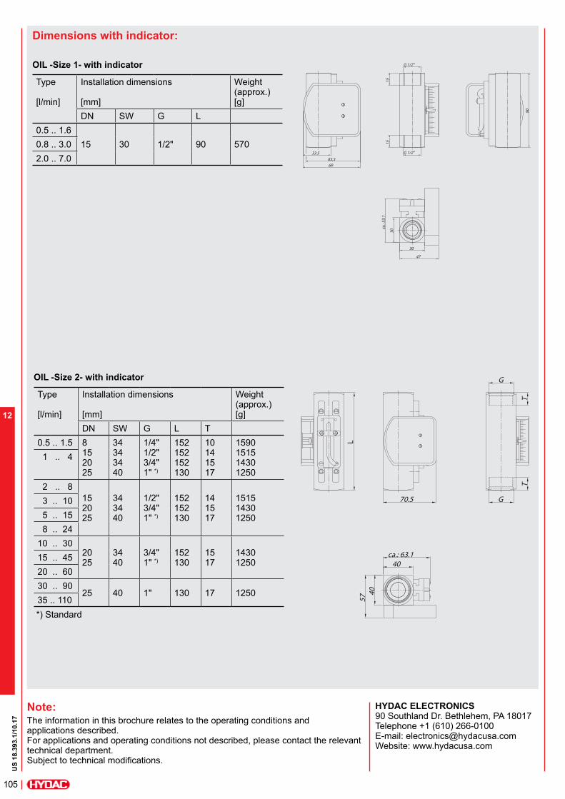
US
18.3
93.1
/10.17
105
12
Note:The information in this brochure relates to the operating conditions and applications described. For applications and operating conditions not described, please contact the relevant technical department. Subject to technical modifications.
HYDAC ELECTRONICS 90 Southland Dr. Bethlehem, PA 18017 Telephone +1 (610) 266-0100 E-mail: [email protected]: www.hydacusa.com
Dimensions with indicator:
OIL -Size 1- with indicator
OIL -Size 2- with indicator
Type
[l/min]
Installation dimensions
[mm]
Weight (approx.) [g]
DN SW G L
0.5 .. 1.6
15 30 1/2" 90 5700.8 .. 3.0
2.0 .. 7.0
Type
[l/min]
Installation dimensions
[mm]
Weight (approx.) [g]
DN SW G L T
0.5 .. 1.5 8 15 20 25
34 34 34 40
1/4" 1/2" 3/4" 1" *)
152 152 152 130
10 14 15 17
1590 1515 1430 1250
1 .. 4
2 .. 8
15 20 25
34 34 40
1/2" 3/4" 1" *)
152 152 130
14 15 17
1515 1430 1250
3 .. 10
5 .. 15
8 .. 24
10 .. 3020 25
34 40
3/4" 1" *)
152 130
15 17
1430 1250
15 .. 45
20 .. 60
30 .. 9025 40 1" 130 17 1250
35 .. 110
*) Standard
90
30
G 1/2"33.5
65.5
69
15
G 1/2"
15
47
30c
a.: 5
3.1
70.5 G
G
TT
40
40
57
ca.: 63.1
L
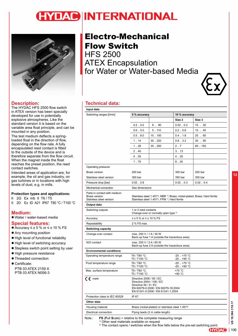
US
18.3
94.1
/10.17
106
12
Electro-Mechanical
Flow Switch
HFS 2500 ATEX Encapsulation for Water or Water-based Media
Description:The HYDAC HFS 2500 flow switch in ATEX version has been specially developed for use in potentially explosive atmospheres. Like the standard version it is based on the variable area float principle, and can be mounted in any position.
The test medium deflects a spring-loaded float in the direction of flow, depending on the flow rate. A fully encapsulated reed contact is fitted to the outside of the device and is therefore separate from the flow circuit. When the magnet inside the float reaches the preset position, the reed contact switches. Intended areas of application are, for example, the oil and gas industry, on gas turbines or in locations with high levels of dust, e.g. in mills.
Protection types and applications:
II 2G Ex mb II T6 / T5
II 2D Ex tD A21 IP67 T80 °C / T100 °C
Medium: Water / water-based media
Special features: Accuracy ≤ ± 5 % or ≤ ± 10 % FS Any mounting position High level of functional reliability High level of switching accuracy Stepless switch point setting by user High pressure resistance Threaded connection
Certificate:PTB 03 ATEX 2159 XPTB 03 ATEX N056-3
Input data
Switching ranges [l/min] 5 % accuracy 10 % accuracy
Size 2 Size 3
0.2 .. 4.0 8 .. 90 0.02 .. 0.2 10 .. 30
0.6 .. 5.0 5 .. 110 0.2 .. 0.6 15 .. 45
0.5 .. 8.0 10 .. 150 0.4 .. 1.8 20 .. 60
1 .. 14 35 .. 220 0.8 .. 3.2 30 .. 90
1 .. 28 35 .. 250 2 .. 7 60 .. 150
2 .. 40 3 .. 13
4 .. 55 4 .. 20
1 .. 70 8 .. 30
Operating pressure
Brass version 200 bar 300 bar 250 bar
Stainless steel version 300 bar 350 bar 300 bar
Pressure drop [bar] 0.02 .. 0.8 0.02 .. 0.3 0.02 .. 0.4
Mechanical connection See dimensions
Parts in contact with medium Brass version Stainless steel version
Stainless steel 1.4571; NBR 1); Brass; nickel-plated; Brass; Hard ferrite Stainless steel 1.4571; FPM 1); Hard ferrite
Output data
Switching outputs 1 or 2 reed contacts Change-over or normally open type 2)
Accuracy ≤ ± 5 % or ≤ ± 10 % FS
Repeatability 2 % FS max.
Switching capacity
Change-over contact max. 250 V / 1 A / 30 W Back-up fuse 1 A (outside the hazardous area)
N/O contact max. 250 V / 2 A / 60 W Back-up fuse 2 A (outside the hazardous area)
Environmental conditions
Operating temperature range T6 / T80 °C: T5 / T100 °C:
-20 .. +75 °C-20 .. +90 °C
Fluid temperature range T6 / T80 °C: T5 / T100 °C:
-20 .. +75 °C-20 .. +90 °C
Max. surface temperature T6 / T80 °C: T5 / T100 °C:
+75 °C+90 °C
mark Directive 2006 / 95 / EC Directive 2004 / 108 / EC Directive 94 / 9 / EC EN 60079-0:2006 / EN 60079-18:2004 EN 61241-0:2006 / EN 61241-1:2004
Protection class to IEC 60529 IP 67
Other data
Housing material Brass (nickel-plated) or stainless steel 1.4571
Electrical connection Flying leads (2 m cable length)
Note.: FS (Full Scale) = relative to the complete measuring range 1) Other seal materials available on request2) The contact opens / switches when the flow falls below the pre-set switching point.
Technical data:

US
18.3
94.1
/10.17
107
12
Pin connections:
Flying leads
Model code:
HFS 2 5 X 1 – XX – XXXX–XXXX – X – X – X – A00Measuring principle 2 = Variable area floatTest medium 5 = Water or
water-basedMechanical connection 3)5) 1 = 1/4 " 2 = 3/8 " 3 = 1/2 " 4 = 3/4 " 5 = 1 " 6 = 1 1/4 " 7 = 1 1/2 "
Electrical connection 1 = Flying leads (2m in length)Switching contacts 4) 1S = 1 N/O contact 2S = 2 N/O contacts 1W = 1 Change-over contact 2W = 2 Change-over contactsSwitching ranges in l/min 5) Water 5 % 00.2-04.0; 00.6-05.0; 00.5-08.0; 01.0-0014; 01.0-0028; 02.0-0040; 04.0-0055; 01.0-0070; 08.0-0090; 0005-0110; 0010-0150; 0035-0220; 0035-0250;
==================================== Water 10 % -Size 2-
0.02-00.2; 00.2-00.6; 00.4-01.8; 00.8-03.2; 02.0-07.0; 03.0-0013; 04.0-0020; 08.0-0030
Water 10 % - Size 3 -
0010-0030; 0015-0045; 0020-0060; 0030-0090; 0060-0150
Accuracy 6 = ≤ 5.0 % FS 7 = ≤ 10.0 % FSHousing material B = Brass, nickel-plated S = Stainless steel
Mechanical indicator 0 = Without indicator 1 = With indicator
Modification number A00 = ATEX version for potentially explosive areas
3) Mechanical connection options depend on housing type(see Dimensions)
4) When the model with 2 switching contacts is selected, the second switching contact is mounted on the side of the instrument, at 90° to the first contact.
5) Other models available on request.
Accessories:
Appropriate accessories, such as electrical connectors, can be found in the Accessories brochure.
Pin HFS 25X1-XS HFS 25X1-XW
1N/O contact
Centre
2 N/C contact
3 N/O contact
Notes on installation: The medium must not contain solid
particles! We recommend usingcontamination strainers.
External magnetic fields can affect theswitching contact.Ensure sufficient distance frommagnetic fields (e.g. from electricmotors)!
Safety instructions: The circuits must not incorporate any
effective inductance or capacities.
The maximum ratings stipulated in thetechnical data must never be exceeded,even for a short time.
To protect the switching contact, afuse for the circuit must be providedoutside the hazardous area, unlessthe switching unit is connected to anintrinsically safe circuit.
Unless the device is connected to anintrinsic safe circuit, special safetyprecautions have to be implemented.
The device may be used in hazardousareas designated as category 2.
The device must not be used in areaswhere an electrical charge in the plastichousing is likely.
The device must not be used inmachinery, systems or medicalapparatus where, in the event ofa malfunction, persons, animalsor equipment could be harmed ordamaged.

US
18.3
94.1
/10.17
108
12
Dimensions without indicator:
Type
[l/min]
Installation dimensions
[mm]
Weight (approx.) [g]
SW D B G DN T L
Water 5 % accuracy
0.2 .. 4.0
27 30 531/4"3/8"1/2"
81015
14 131 850
0.6 .. 5.0
0.5 .. 8.0
1 .. 14
1 .. 28
2 .. 40 27 32
30 35
531/2" 3/4"
15 20
14 16
146 174
900 4 .. 55
1 .. 7034 40
40 40
63 63
3/4" 1"
20 25
18 19
152 156
1400 1100
8 .. 90
5 .. 110
10 .. 150 50 50 73 1 1/4" 32 21 200 2750
35 .. 220 50 50 73 1 1/4" 32 21 200 3000
35 .. 250 60 60 78 1 1/2" 40 24 200 3800
Water 10 % Accuracy - Size 2-
0.02 .. 0.2
27 31 67 1/2 ’’ 15 15 90 400
0.2 .. 0.6
0.4 .. 1.8
0.8 .. 3.2
2.0 .. 7.0
3.0 .. 13.0
4.0 .. 20.0
8.0 .. 30.0
Water 10 % Accuracy - Size 3-
10 .. 30
34 47 933/4 „ 1" *)
20 25
21 17
152 130
1200 1050
15 .. 45
20 .. 60
30 .. 90
60 .. 150 41 47 93 1" 25 17 130 1050
*) Standard
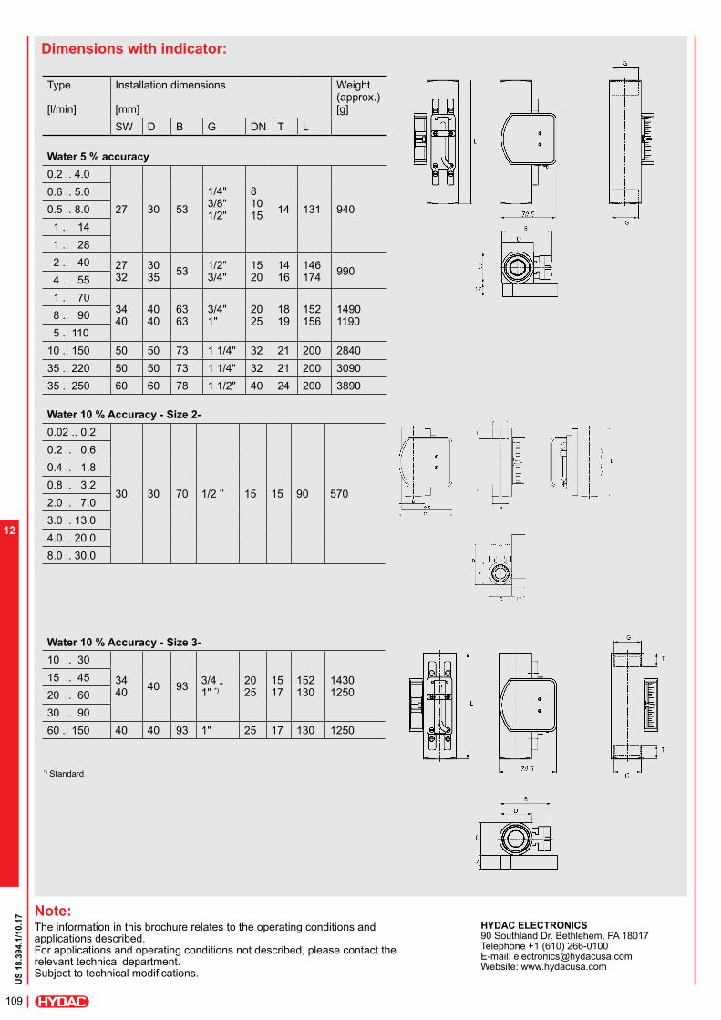
US
18.3
94.1
/10.17
109
12
Note:The information in this brochure relates to the operating conditions and applications described.For applications and operating conditions not described, please contact the relevant technical department. Subject to technical modifications.
HYDAC ELECTRONICS 90 Southland Dr. Bethlehem, PA 18017 Telephone +1 (610) 266-0100 E-mail: [email protected]: www.hydacusa.com
Dimensions with indicator:
Type
[l/min]
Installation dimensions
[mm]
Weight (approx.) [g]
SW D B G DN T L
Water 5 % accuracy
0.2 .. 4.0
27 30 53
1/4"3/8"1/2"
81015
14 131 940
0.6 .. 5.0
0.5 .. 8.0
1 .. 14
1 .. 28
2 .. 40 27 32
30 35
531/2" 3/4"
15 20
14 16
146 174
990 4 .. 55
1 .. 7034 40
40 40
63 63
3/4" 1"
20 25
18 19
152 156
1490 1190
8 .. 90
5 .. 110
10 .. 150 50 50 73 1 1/4" 32 21 200 2840
35 .. 220 50 50 73 1 1/4" 32 21 200 3090
35 .. 250 60 60 78 1 1/2" 40 24 200 3890
Water 10 % Accuracy - Size 2-
0.02 .. 0.2
30 30 70 1/2 ’’ 15 15 90 570
0.2 .. 0.6
0.4 .. 1.8
0.8 .. 3.2
2.0 .. 7.0
3.0 .. 13.0
4.0 .. 20.0
8.0 .. 30.0
Water 10 % Accuracy - Size 3-
10 .. 30
34 40
40 933/4 „ 1" *)
20 25
15 17
152 130
1430 1250
15 .. 45
20 .. 60
30 .. 90
60 .. 150 40 40 93 1" 25 17 130 1250
*) Standard

US
18.3
94.1
/10.17
110
12

Status 2015-04-14
Description: HFT 3100 with HART interface is a compact flow rate transmitter with flameproof enclosure specially developed for applications in hydraulic systems and other fluid power systems. The triple approval in accordance with ATEX, IECEx and CSA enables universal, world-wide utilisation of the devices in potentially explosive atmospheres. HFT 3100 operates in accordance with the turbine principle, which means that the rpm of an impeller wheel rotating in the flow of the media is recorded and converted into a 4 .. 20 mA analogue signal. In addition with the analogue output of the measured value, digital communication is possible by means of the HART protocol.
Two additional SAE 6 threaded bore holes in the turbine housing provide the flow rate transmitter with additional connection options, e.g. for temperature and pressure sensors.
Protection types and applications
CCSAUS Explosion Proof - seal not required Class I Group A, B, C, D, T6, T5 Class II Group E, F, G Class III Type 4
ATEX Flame Proof I M2 Ex d I Mb II 2G Ex d IIC T6, T5 Gb II 2D Ex tb IIIC T110 .. 120 °C Db
IECEx Flame Proof Ex d I Mb Ex d IIC T6, T5 Gb Ex tb IIIC T110 .. 120 °C Db
Flow Rate Transmitter HFT 3100 ATEX, IECEx, CSA
Flameproof enclosure
with HART Interface
Technical data: Input data
Measuring ranges and operating pressure
HFT 31XX- F21-0020 0.32 .. 5.28 gpm 6090 psi
HFT 31XX- F21-0060 1.59 .. 15.85 gpm 6090psi
HFT 31XX- F21-0300 3.96 .. 79.25 gpm 6090 psi
HFT 31XX- F21-0600 10.57 .. 158.5 gpm 6090psi Additional connection options 1) 2 x SAE 6 female threads for pressure or
temperature sensors
Parts in contact with fluid Stainless steel: 316L, 329, tungsten carbide
Output data
Output signal, permitted load resistance
4...20 mA, 2 conduits, with HART Protocol RLmax=(UB - 12 V) / 20 mA [kΩ] for HART communikation min. 250 Ω
HART Communication according to HART 7 specification
HART Common Practice Commands i.e.
Altering of measuring range limits (see table)
Accuracy ≤ 2 % of the actual value
Ambient conditions
Compensated temperature range -40.. +158°F
Operating/ Ambient temperature range 2) T6, T110 Ta = -40 .. 140 °F
T5 Ta = -40 .. 158 °F
Storage temperature range -40 .. +212 °F
Fluid temperature range 2) T6, T110 Ta = -40 .. 140 °F
T5 Ta = -40 .. 158 °F
- mark EN 61000-6-1, EN 61000-6-2
EN 61000-6-3, EN 61000-6-4
Vibration resistance to DIN EN 60068-2-6 at 10 .. 500 Hz
10g
Protection class to IEC 60529 ISO 20653
IP 69 IP 6K9K
Other data
Measuring medium hydraulic fluids, water-based media
Viscosity range 1 .. 100 cSt
Calibration viscosity 30 cSt
Supply voltage 12 .. 30 VDC
Residual ripple of supply voltage 46 bis 125 Hz: < 0.2 Vpp > 125 Hz < 1.2 mVRMS
Current consumption ≤ 25mA
Weight:
HFT 318X- F21-0020, SAE 8 approx. 2.5 kg
HFT 319X- F21-0060, SAE 14 approx. 4.0 kg
HFT 31AX- F21-0300, SAE 20 approx. 5.5 kg
HFT 31BX- F21-0600, SAE 24 approx. 7.0 kg
Note: Reverse polarity protection of the supply voltage, excess voltage, override and short circuit protection are provided. 1) not for measuring range: 0.32 .. 5.28 gpm
2) T120°C at Ta = -40 .. +158°F with electrical connection single leads available
111
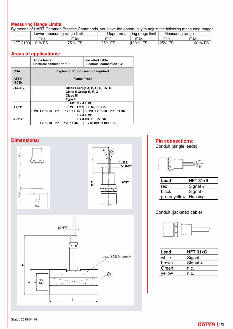
Status 2015-04-14
Measuring Range Limits: By means of HART Common Practice Commands, you have the opportunity to adjust the following measuring ranges:
Areas of applications:
Single leads Electrical connection "9"
Jacketed cable Electrical connection "G"
CSA
ATEX IECEx
Explosion Proof - seal not required
Flame Proof
CCSAUS Class I Group A, B, C, D, T6, T5 Class II Group E, F, G Class III Type 4
ATEX
I M2 Ex d I Mb II 2G Ex d IIC T6, T5 Gb
II 2D Ex tb IIIC T110 ...120 °C Db II 2D Ex tb IIIC T110°C Db
IECEx
Ex d I Mb
Ex d IIC T6, T5 Gb
Ex tb IIIC T110...120°C Db Ex tb IIIC T110°C Db
Dimensions: Pin connections: Conduit (single leads)
Conduit (jacketed cable)
Lower measuring range limit Upper measuring range limit Measuring range min max min max min max
HFT 3100 0 % FS 75 % FS 25% FS 100 % FS 25% FS 100 % FS
Lead HFT 31x9
red Signal +
black Signal -
green-yellow Housing
Lead HFT 31xG
white Signal -
brown Signal +
Green n.c.
yellow n.c.
thread SAE 6, female
112

Status 2015-04-14
Without threaded holes for temperature and pressure sensors:
With threaded holes for temperature and pressure sensors:
Model code: HFT 31 X X – F21 – XXXX – S- X - D - 000 (72”)
Mechanical Process Connection 8 = 3/4 -16 UNF 2B (SAE8 female) only for mr: 1.2 .. 20 l/min
9 = 1 3/16 -12 UN 2B (SAE14 female) only for mr: 6 .. 60 l/min H = 1 5/8 -12 UN 2B (SAE 20 female) only for mr: 15 .. 300 l/min
B = 1 7/8 -12 UN 2B (SAE24 female) only for mr: 40 .. 600 l/min
Electrical connection 9 = 1/2-14 NPT Conduit (male thread), single leads G = 1/2-14 NPT Conduit (male thread), jacketed cable
Signal F21 = 4 .. 20 mA ( with HART Interface)
Measuring ranges 0020 = 0.32 .. 5.28 gpm 0060 = 1.59 .. 15.85 gpm 0300 = 3.96 .. 79.25 gpm 0600 = 10.57 .. 158.5 gpm
Housing material S = Stainless steel
Housing design 1 = without threaded bore (measuring ranges 0020) 3 = with two additional female threads 9/16-18 UNF 2B (SAE 6),
(measuring ranges (0060, 0300, 0600)
Approval D = CSA Explosion Proof (seal not required)
ATEX Flame Proof
IECEx Flame Proof
Modification number 000 = standard
Cable length in inch Standard = 72 inch
Model Measurement
range L H D / SW G Tightening torque DN
HFT 31XX-F21-0020 0.32 .. 5.28 gpm 117 mm 158 mm 60 / 56 mm SAE 8 (3/4 -16 UNF 2B)
60 Nm 7 mm
Model Measurement
range L H D / SW G
Tightening torque
DN Thread
HFT 31XX- F21-0060 1.59 .. 15.85 gpm 144 mm 160 mm 63 / 60 mm SAE 14 (1 3/16 -12 UN 2B)
140 Nm 11 mm SAE 6
HFT 31XX- F21-0300 3.96 .. 79.25 gpm 155 mm 173 mm 75.5 / 72 mm SAE 20 (1 5/8 -12 UN 2B)
290 Nm 22 mm SAE 6
HFT 31XX- F21-0600 10.57 ..158.5 gpm 181mm 178 mm 81 / 76 mm SAE 24 (1 7/8 -12 UN
2B) 325 Nm 30 mm
SAE 6
Note: The information in this brochure relates to the operating conditions and applications described. For applications or operating conditions not described, please contact the relevant technical department. For applications or operating conditions not described please contact the relevant technical department.
113
HYDAC ELECTRONICS 90 Southland Dr. Bethlehem, PA 18017 Telephone +1 (610) 266-0100 E-mail: [email protected]: www.hydacusa.com
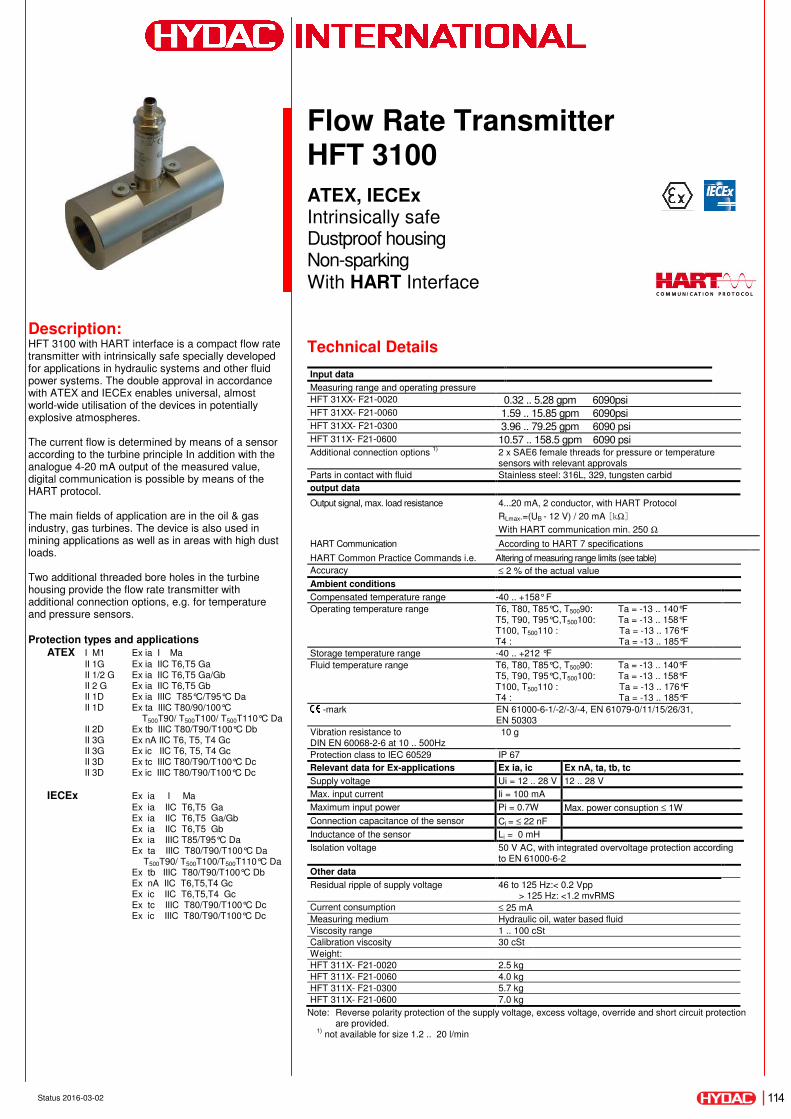
Status 2016-03-02
Description: HFT 3100 with HART interface is a compact flow rate transmitter with intrinsically safe specially developed for applications in hydraulic systems and other fluid power systems. The double approval in accordance with ATEX and IECEx enables universal, almost world-wide utilisation of the devices in potentially explosive atmospheres.
The current flow is determined by means of a sensor according to the turbine principle In addition with the analogue 4-20 mA output of the measured value, digital communication is possible by means of the HART protocol.
The main fields of application are in the oil & gas industry, gas turbines. The device is also used in mining applications as well as in areas with high dust loads.
Two additional threaded bore holes in the turbine housing provide the flow rate transmitter with additional connection options, e.g. for temperature and pressure sensors.
Protection types and applications ATEX I M1 Ex ia I Ma
II 1G Ex ia IIC T6,T5 Ga II 1/2 G Ex ia IIC T6,T5 Ga/Gb II 2 G Ex ia IIC T6,T5 Gb II 1D Ex ia IIIC T85°C/T95°C Da II 1D Ex ta IIIC T80/90/100°C
T500T90/ T500T100/ T500T110°C Da II 2D Ex tb IIIC T80/T90/T100°C Db II 3G Ex nA IIC T6, T5, T4 Gc II 3G Ex ic IIC T6, T5, T4 Gc II 3D Ex tc IIIC T80/T90/T100°C Dc II 3D Ex ic IIIC T80/T90/T100°C Dc
IECEx Ex ia I Ma
Ex ia IIC T6,T5 Ga Ex ia IIC T6,T5 Ga/Gb Ex ia IIC T6,T5 Gb Ex ia IIIC T85/T95°C Da Ex ta IIIC T80/T90/T100°C Da T500T90/ T500T100/T500T110°C Da Ex tb IIIC T80/T90/T100°C Db Ex nA IIC T6,T5,T4 Gc Ex ic IIC T6,T5,T4 Gc Ex tc IIIC T80/T90/T100°C Dc Ex ic IIIC T80/T90/T100°C Dc
Flow Rate Transmitter HFT 3100
ATEX, IECEx Intrinsically safe Dustproof housing Non-sparking With HART Interface
Technical Details
Input data
Measuring range and operating pressure
HFT 31XX- F21-0020 0.32 .. 5.28 gpm 6090psi HFT 31XX- F21-0060 1.59 .. 15.85 gpm 6090psi HFT 31XX- F21-0300 3.96 .. 79.25 gpm 6090 psi HFT 311X- F21-0600 10.57 .. 158.5 gpm 6090 psi Additional connection options
1)2 x SAE6 female threads for pressure or temperature sensors with relevant approvals
Parts in contact with fluid Stainless steel: 316L, 329, tungsten carbid
output data
Output signal, max. load resistance 4...20 mA, 2 conductor, with HART Protocol
RLmax.=(UB - 12 V) / 20 mA [kΩ]
With HART communication min. 250 Ω
HART Communication According to HART 7 specifications
HART Common Practice Commands i.e. Altering of measuring range limits (see table)
Accuracy ≤ 2 % of the actual value
Ambient conditions
Compensated temperature range -40 .. +158° F
Operating temperature range T6, T80, T85°C, T50090: Ta = -13 .. 140°F T5, T90, T95°C,T500100: Ta = -13 .. 158°F T100, T500110 : Ta = -13 .. 176°F T4 : Ta = -13 .. 185°F
Storage temperature range -40 .. +212 °F
Fluid temperature range T6, T80, T85°C, T50090: Ta = -13 .. 140°F T5, T90, T95°C,T500100: Ta = -13 .. 158°F T100, T500110 : Ta = -13 .. 176°F T4 : Ta = -13 .. 185°F
-mark EN 61000-6-1/-2/-3/-4, EN 61079-0/11/15/26/31, EN 50303
Vibration resistance to DIN EN 60068-2-6 at 10 .. 500Hz
10 g
Protection class to IEC 60529 IP 67
Relevant data for Ex-applications Ex ia, ic Ex nA, ta, tb, tc
Supply voltage Ui = 12 .. 28 V 12 .. 28 V
Max. input current Ii = 100 mA
Maximum input power Pi = 0.7W Max. power consuption ≤ 1W
Connection capacitance of the sensor Ci = ≤ 22 nF
Inductance of the sensor Li = 0 mH
Isolation voltage 50 V AC, with integrated overvoltage protection according to EN 61000-6-2
Other data
Residual ripple of supply voltage 46 to 125 Hz:< 0.2 Vpp > 125 Hz: <1.2 mvRMS
Current consumption ≤ 25 mA
Measuring medium Hydraulic oil, water based fluid
Viscosity range 1 .. 100 cSt
Calibration viscosity 30 cSt
Weight:
HFT 311X- F21-0020 2.5 kg
HFT 311X- F21-0060 4.0 kg
HFT 311X- F21-0300 5.7 kg
HFT 311X- F21-0600 7.0 kg
Note: Reverse polarity protection of the supply voltage, excess voltage, override and short circuit protection are provided.
1) not available for size 1.2 .. 20 l/min
114
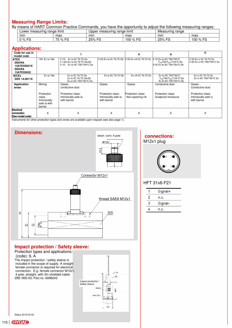
Status 2016-03-02
Measuring Range Limits: By means of HART Common Practice Commands, you have the opportunity to adjust the following measuring ranges:
Lower measuring range limit Upper measuring range limit Measuring range min max min max min max 0 % FS 75 % FS 25% FS 100 % FS 25% FS 100 % FS
Applications: Code for use in model code
1 9 A C
ATEX DEKRA 13ATEX0031X DEKRA 13ATEX0032
I M1 Ex ia I Ma II 1G Ex ia IIC T6,T5 Ga II 1/2G Ex ia IIC T6,T5 Ga/Gb II 1D Ex ia lIIC T85/T95°C Da
II 2G Ex ia IIC T6,T5 Gb II 3G Ex nA llC T6,T5 Gc II 1D Ex ta lllC T80/T90°C T500T90/T500T100°C Da
II 2D Ex tb lllC T80/T90°C Db
II 3G Ex ic llC T6,T5 Gc ll 3D Ex ic lllC T80/T90°C Dc
IECEx DEK 14.0011X
Ex ia I Ma Ex ia IIC T6,T5 Ga Ex ia IIC T6,T5 Ga/Gb Ex ia lIIC T85/T95°C Da
Ex ia IIC T6,T5 Gb Ex nA llC T6,T5 Gc Ex ta lllC T80/T90°C T500T90/T500T100°C Da Ex tb lllC T80/T90°C Db
Ex ic llC T6,T5 Gc Ex ic lllC T80/T90°C Dc
Application areas
Mining
Protection class: Intrinsically safe ia with barrier
Gases conductive dust
Protection class: Intrinsically safe ia with barrier
Gases
Protection class: Intrinsically safe ia with barrier
Gases
Protection class: Non-sparking nA
Conductive dust
Protection class: Dustproof enclosure
Gases Conductive dust
Protection class: Intrinsically safe ic with barrier
Electrical connection (See model code)
6 6 6 6 6 6
Instruments for other protection types and zones are available upon request (see also page 1).
Dimensions:
Impact protection / Safety sleeve: Protection types and applications: (code): 9, A The impact protection / safety sleeve is included in the scope of supply. A straight female connector is required for electrical connection. E.g. female connector M12x1, 4 pole, straight, with 3m shielded cable: ZBE 06S-03, Part.no. 6098243
connections: M12x1 plug
HFT 31x6-F21
thread SAE6 M12x1
electr. conn. 4 pole
Impact protection / Safety sleeve
115

Status 2016-03-02
Without threaded holes for temperature and pressure sensors:
With threaded holes for temperature and pressure sensors:
Model code: HFT 31 X X – F21 – XXXX – S- X-XXX-XXX
Mechanical Process Connection 8 = 3/4 -16 UNF 2B (SAE8 female) only for mr: 1.2 .. 20 l/min
9 = 1 3/16 -12 UN 2B (SAE14 female) only for mr: 6 .. 60 l/min H = 1 5/8 -12 UN 2B (SAE 20 female) only for mr: 15 .. 300 l/min
B = 1 7/8 -12 UN 2B (SAE24 female) only for mr: 40 .. 600 l/min
Electrical connection 6 = M12x1, 4 pole, male
Signal F21 = 4 .. 20 mA ( with HART Interface)
Measuring ranges 0020 = 1.2 .. 20 l/min (0.32 .. 5.28 gpm) 0060 = 6.0 .. 60 l/min (1.59 .. 15.85 gpm) 0300 = 15.0 .. 300 l/min (3.96 .. 79.25 gpm) 0600 = 40.0 .. 600 l/min (10.57 .. 158.5 gpm)
Housing material S = Stainless steel
Housing design 1 = without threaded bore (measuring ranges 0020) 3 = with two additional female threads 9/16-18 UNF 2B (SAE 6),
(measuring ranges (0060, 0300, 0600)
Approval E = ATEX and IECEx see Applications/ Protection Types (Overview) Isolation voltage N = 50 V AC Protection types and applications: (code)
ATEX IECEx
1 = I M1 Ex ia I Ma II 1G Ex ia IIC T6,T5 Ga II 1/2 G Ex ia IIC T6,T5 Ga/Gb II 2 G Ex ia IIC T6,T5 Gb II 1D Ex ia IIIC T85°C/T95°C Da
Ex ia I Ma Ex ia IIC T6,T5 Ga Ex ia IIC T6,T5 Ga/Gb Ex ia IIC T6,T5 Gb Ex ia IIIC T85°C/T95°C Da
9 = II 3G Ex nA IIC T6, T5 Gc Ex nA IIC T6, T5 Gc only in conjunction with electr. connection "6"
A = II 1D Ex ta IIIC T80/T90°C T500T90/ T500T100 Da
II 2D Ex tb IIIC T80/T90°C Db
Ex ta IIIC T80/T90°C Da T500T90/ T500100°C Da
Ex tb IIIC T80/T90°C Db only in conjunction with electr. connection "6"
C = II 3G Ex ic IIC T6, T5 Gc II 3D Ex ic IIIC T80/T90°C Dc
Ex ic IIC T6, T5 Gc Ex ic IIIC T80/T90°C Dc
Modification number 000 = standard
Model Measurement
range L H D / SW G Tightening torque DN
HFT 31XX-F21-0020 0.32 .. 5.28 gpm 117 mm 158 mm 60 / 56 mm SAE 8 (3/4 -16 UNF 2B)
60 Nm 7 mm
Model Measurement
range L H D / SW G
Tightening torque
DN Thread
HFT 31XX- F21-0060 1.59 .. 15.85 gpm 144 mm 160 mm 63 / 60 mm SAE 14 (1 3/16 -12 UN 2B)
140 Nm 11 mm SAE 6
HFT 31XX- F21-0300 3.96 .. 79.25 gpm 155 mm 173 mm 75.5 / 72 mm SAE 20 (1 5/8 -12 UN 2B)
290 Nm 22 mm SAE 6
HFT 31XX- F21-0600 10.57 ..158.5 gpm 181mm 178 mm 81 / 76 mm SAE 24 (1 7/8 -12 UN
2B) 325 Nm 30 mm
SAE 6
Note: The information in this brochure relates to the operating conditions and applications described. For applications or operating conditions not described please contact the relevant technical department. Subject to technical modifications. 116
HYDAC ELECTRONICS 90 Southland Dr. Bethlehem, PA 18017 Telephone +1 (610) 266-0100 E-mail: [email protected]: www.hydacusa.com