IoT Flow Sensors/IoT Pressure Sensors - Omron Europe
43
IoT Flow Sensors/IoT Pressure Sensors E8FC/E8PC Series Additional "temperature monitoring" feature that allows you to detect cooling and hydraulic pressure abnormalities quickly Flow Sensor E8FC Pressure Sensor E8PC MPa °C °C ℓ/min
-
Upload
khangminh22 -
Category
Documents
-
view
1 -
download
0
Transcript of IoT Flow Sensors/IoT Pressure Sensors - Omron Europe
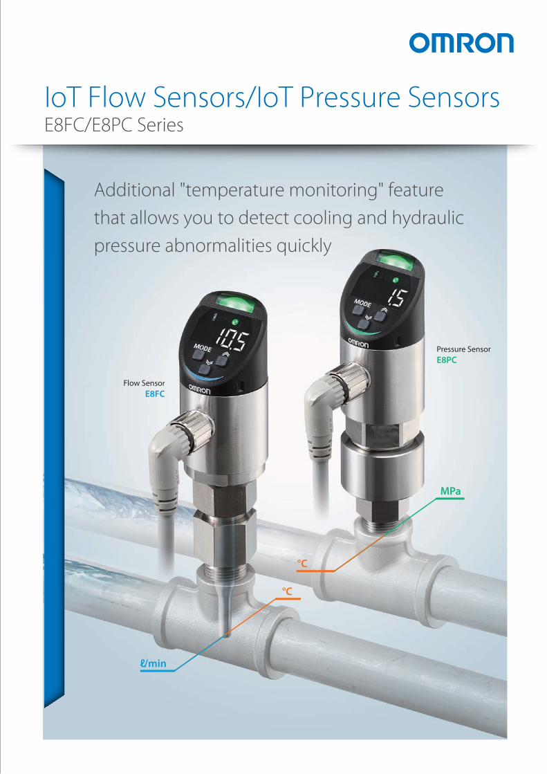
IoT Flow Sensors/IoT Pressure SensorsE8FC/E8PC Series
Additional "temperature monitoring" feature that allows you to detect cooling and hydraulic pressure abnormalities quickly
Flow SensorE8FC
Pressure SensorE8PC
MPa
°C
°C
ℓ/min

2 IoT Flow Sensor/IoT Pressure Sensor
"Temperature" can also be monitored in the same position,allowing quicker detection of signs of abnormalities than conventional methods
Flow rate
IoT Flow Sensor
E8FC
IoT Pressure Sensor
E8PCFor detecting signs of
cooling abnormalities
For detecting signs ofhydraulic pressure
abnormalities
Pressure
Time
Temperature Threshold value for temperature rise detection
Threshold value for insufficient flow rate detection
Time
Flow rateFlow rate is normal but...
Detect abnormalities in temperature changesTemp. rise
Time
Threshold value for temperature rise detection
Threshold value for insufficient pressure detection
Time
Reducedpressure
The temperature changes �rst.
Temperature
PressurePressure Sign 2
Sign 1
Signs of cooling abnormalities detectedwith "temperature"
Signs of hydraulic pressure drops detectedwith "temperature"
Even if the cooling water flow rate satisfies the conditions, if the water temperature is too high and it is not sufficiently cooled, manufacturing defects will occur. It is crucial to be able to monitor flow rate and temperature in the same position at the same time.
Signs of hydraulic pressure drops are shown by rises in temperature. It is crucial to be able to monitor pressure and temperature in the same position at the same time.
Temp.
Temp.

3
"Temperature" can also be monitored in the same position,allowing quicker detection of signs of abnormalities than conventional methods
You can replace pressure gauges and flow
rate meters at the position where they are
currently installed without cutting the piping.
A wide variety of size conversion adapters
are available, enabling easy replacement of
existing sensors.
To ensure accurate monitoring of equipment states,
the sensor performs self-diagnosis of its own status.
It sends notification to a host device when signs
of a connection error or a malfunction appears,
so you can address problems before failures occur.
Even if the sensor is installed in dark locations
or at the back of equipment at manufacturing
sites, a high luminosity LED enables you to
easily read the status. You can immediately
tell which sensor is showing signs of
abnormalities by the colors of the indicators.
You can also know when the sensor requires maintenance ahead of time
You can see the precise location of the abnormality with a glance
Diagnostic itemsduring operations
IO-Link communications status
Internal system status of sensors
Output load short circuit status
Also works in high temperatures and high pressures!
Metal pipe : Supports 10 to 25 AResin pipe : Supports 13 to 34 mm dia.
Water, pure
waterAntifreeze
You can install the sensor without cutting the piping
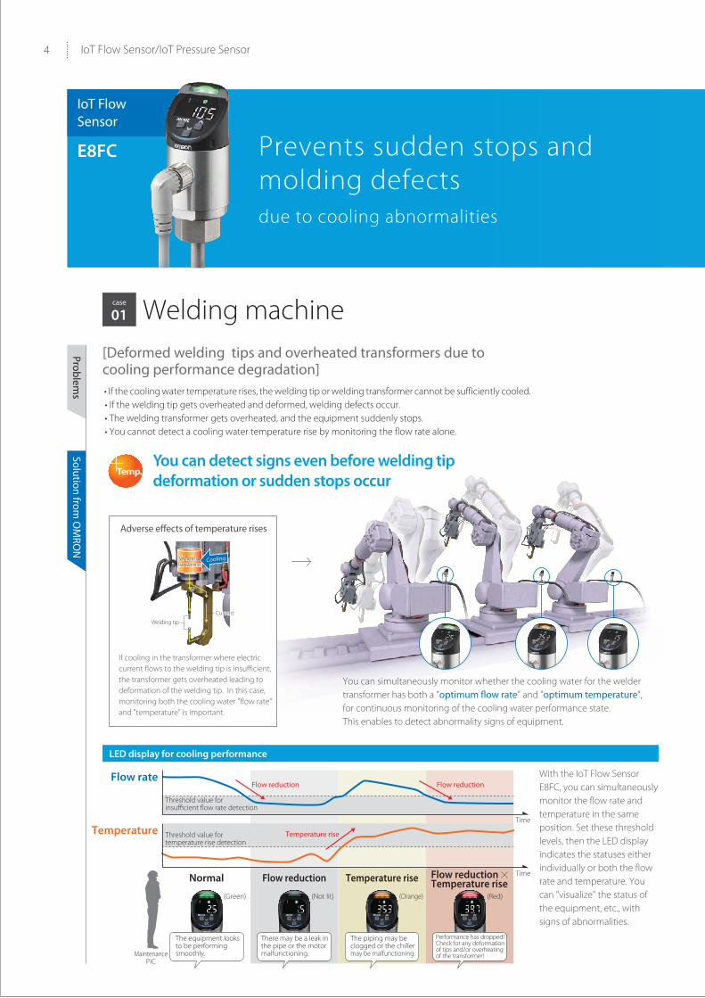
LED display for cooling performance
4 IoT Flow Sensor/IoT Pressure Sensor
[Deformed welding tips and overheated transformers due to cooling performance degradation] • If the cooling water temperature rises, the welding tip or welding transformer cannot be sufficiently cooled. • If the welding tip gets overheated and deformed, welding defects occur. • The welding transformer gets overheated, and the equipment suddenly stops. • You cannot detect a cooling water temperature rise by monitoring the flow rate alone.
Welding tip
Welding transformerWelding
transformerCoolingCooling
CurrentCurrent
Threshold value for insufficient flow rate detection
Time
Flow reduction Flow reduction
Temperature riseThreshold value for temperature rise detection
Flow rate
Temperature
Normal Flow reduction Temperature rise Flow reductionTemperature rise
Time
MaintenancePiC
(Green) (Not lit) (Orange) (Red)
The equipment looks to be performing smoothly.
There may be a leak in the pipe or the motor malfunctioning.
The piping may be clogged or the chiller may be malfunctioning.
Performance has dropped!Check for any deformation of tips and/or overheating of the transformer!
case
01 Welding machine
Problems
Solution from O
MRO
N
You can detect signs even before welding tip deformation or sudden stops occur
With the IoT Flow Sensor E8FC, you can simultaneously monitor the flow rate and temperature in the same position. Set these threshold levels, then the LED display indicates the statuses either individually or both the flow rate and temperature. You can "visualize" the status of the equipment, etc., with signs of abnormalities.
You can simultaneously monitor whether the cooling water for the welder transformer has both a "optimum flow rate" and "optimum temperature", for continuous monitoring of the cooling water performance state. This enables to detect abnormality signs of equipment.
If cooling in the transformer where electric current flows to the welding tip is insufficient, the transformer gets overheated leading to deformation of the welding tip. In this case, monitoring both the cooling water "flow rate" and "temperature" is important.
Adverse effects of temperature rises
Prevents sudden stops and molding defectsdue to cooling abnormalities
IoT Flow Sensor
E8FC
Temp.

5
[Molding defects due to cooling performance degradation]• Even if the amount of cooling water is adequate, a rise in water temperature leads to a drop in cooling performance. • If the cooling performance declines, the processed part on the mold cannot be adequately cooled, resulting in deformation, voids, or other molding defects.
• You cannot detect a cooling water temperature rise by monitoring the flow rate alone.
Cool
Hot Hot
Oilcooler
Cooling water flow
Processedpart
(mold)
Processedpart
(mold)
Cool
case
02 Molding machine
Problems
Solution from O
MRO
N
You can detect signs of cooling performance degradation even before occurrence of molding defects.
Monitor the "flow rate" and "temperature changes" in the same position, and quantify the optimum ranges for flow rate and temperature. You can detect signs of cooling performance degradation without relying on the experience or skills of maintenance personnel.In addition, by mounting sensors on multiple pipes, you can quickly tell from the sensor LEDs what abnormality has occurred, in which pipe.
Temp.
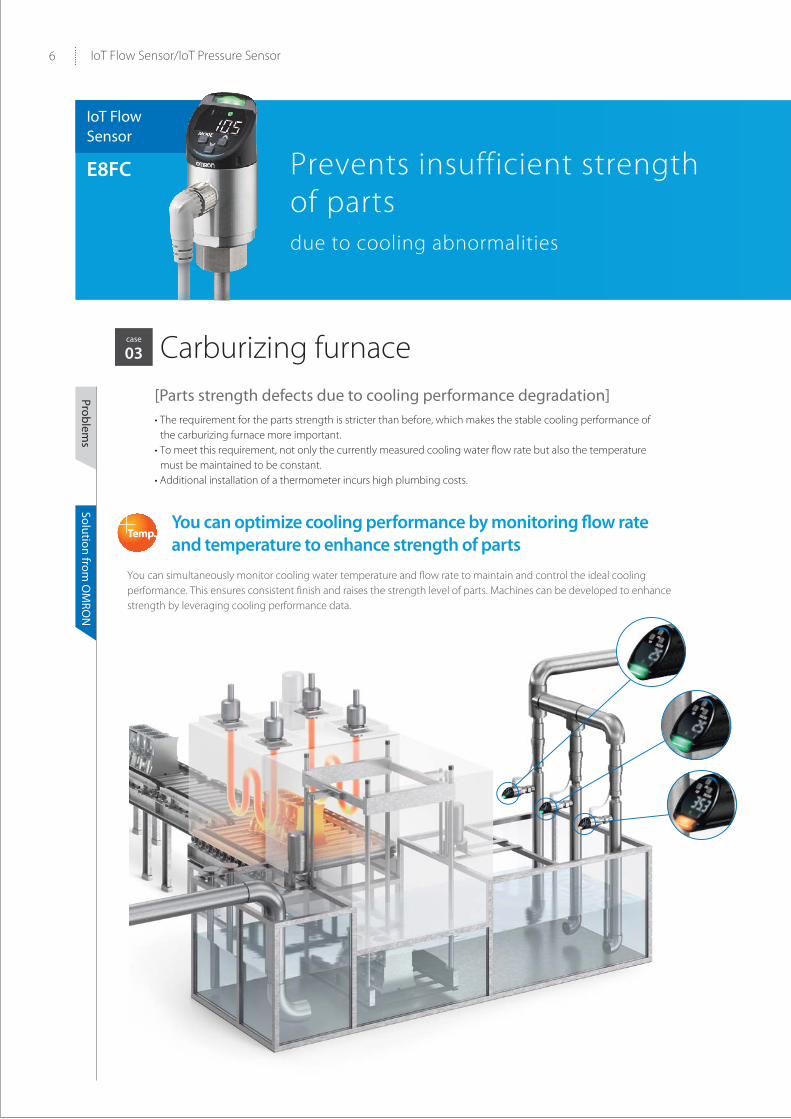
6 IoT Flow Sensor/IoT Pressure Sensor
Temp.
You can simultaneously monitor cooling water temperature and flow rate to maintain and control the ideal cooling performance. This ensures consistent finish and raises the strength level of parts. Machines can be developed to enhance strength by leveraging cooling performance data.
case
03 Carburizing furnace
Problems
Solution from O
MRO
N
Prevents insufficient strength of parts due to cooling abnormalities
IoT Flow Sensor
E8FC
[Parts strength defects due to cooling performance degradation]• The requirement for the parts strength is stricter than before, which makes the stable cooling performance of
the carburizing furnace more important.• To meet this requirement, not only the currently measured cooling water flow rate but also the temperature
must be maintained to be constant.• Additional installation of a thermometer incurs high plumbing costs.
You can optimize cooling performance by monitoring flow rate and temperature to enhance strength of parts
7
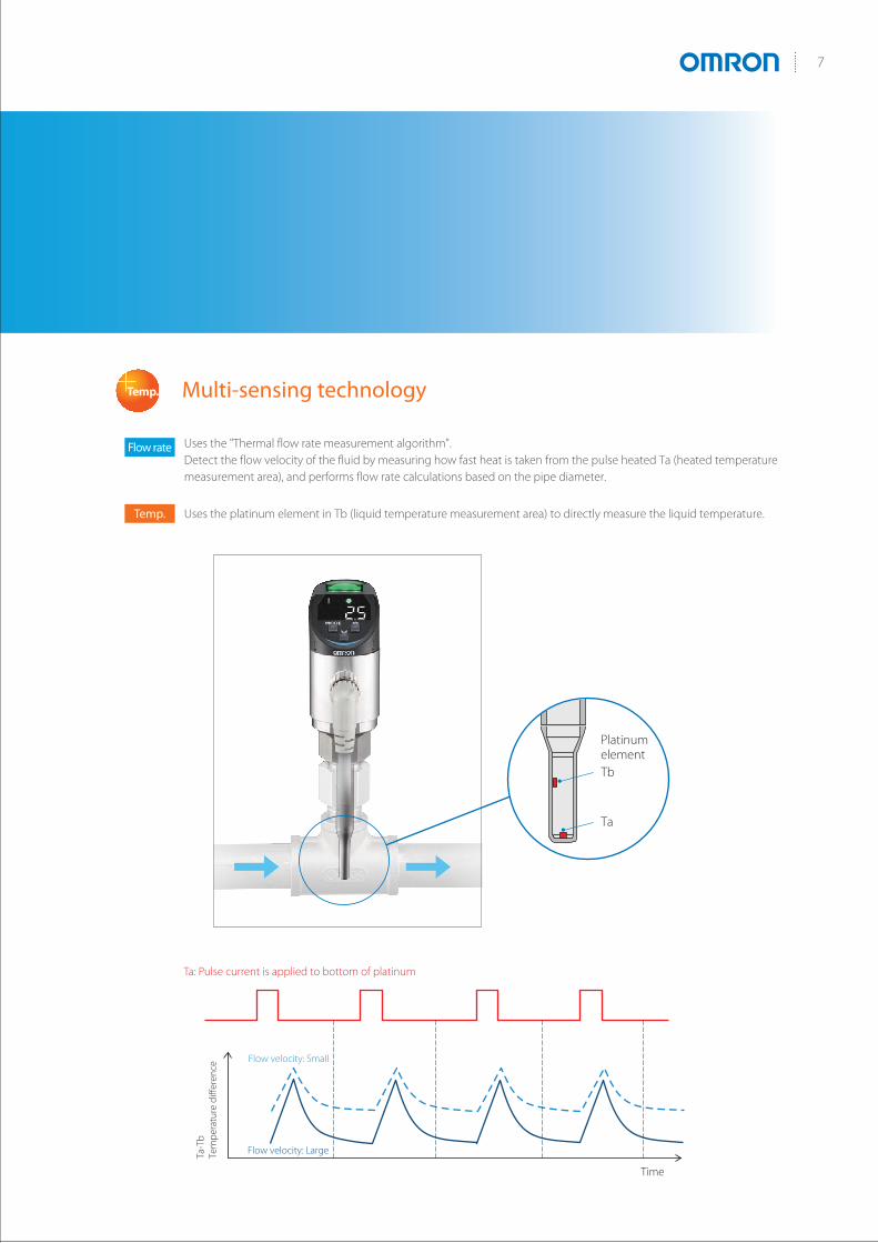
Multi-sensing technologyTemp.
Uses the "Thermal flow rate measurement algorithm".Detect the flow velocity of the fluid by measuring how fast heat is taken from the pulse heated Ta (heated temperature measurement area), and performs flow rate calculations based on the pipe diameter.
Uses the platinum element in Tb (liquid temperature measurement area) to directly measure the liquid temperature.
Time
Ta-T
bTe
mpe
ratu
re d
iffer
ence
Platinum element
Ta
Tb
Flow velocity: Small
Ta: Pulse current is applied to bottom of platinum
Flow velocity: Large
Flow rate
Temp.
Long period of operation
Rise in hydraulic oil temperature
Reduction in hydraulic oil viscosity
Hydraulic pressurereduction
Manufacturing defects
8 IoT Flow Sensor/IoT Pressure Sensor
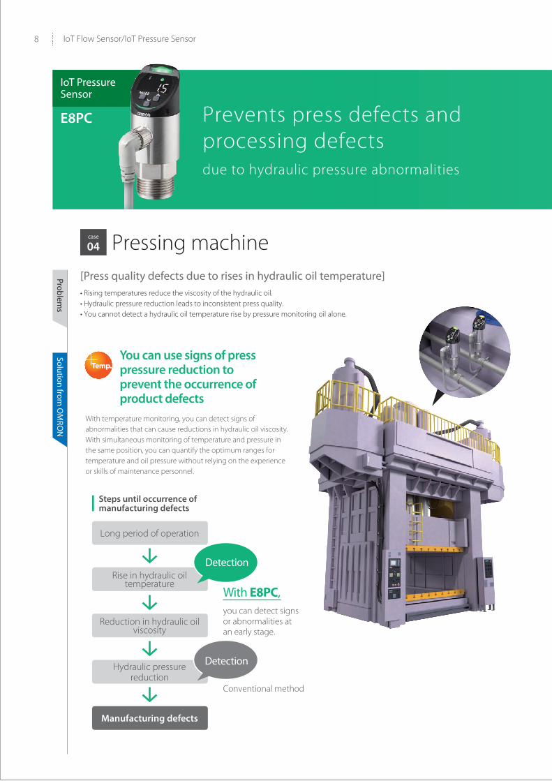
case
04 Pressing machine[Press quality defects due to rises in hydraulic oil temperature]• Rising temperatures reduce the viscosity of the hydraulic oil. • Hydraulic pressure reduction leads to inconsistent press quality. • You cannot detect a hydraulic oil temperature rise by pressure monitoring oil alone.
You can use signs of press pressure reduction to prevent the occurrence of product defects
With E8PC,you can detect signs or abnormalities at an early stage.
Conventional method
Steps until occurrence of manufacturing defects
With temperature monitoring, you can detect signs of abnormalities that can cause reductions in hydraulic oil viscosity. With simultaneous monitoring of temperature and pressure in the same position, you can quantify the optimum ranges for temperature and oil pressure without relying on the experience or skills of maintenance personnel.
Detection
IoT Pressure Sensor
E8PC Prevents press defects and processing defectsdue to hydraulic pressure abnormalities
Detection
Temp.
Problems
Solution from O
MRO
N

Tool changer
Pallet changer
Chuck
Loader/Unloader
9
case
05 Machining center[Tool gripping force declines due to hydraulic oil leak] • Hydraulic oil temperature rises with repeated tool changes. • Pipe packing deteriorates, resulting in hydraulic oil leak. • Oil pressure reduction causes reduction in processing quality. • The hydraulic pressure system is divided into multiple sections, so finding degraded packing locations takes time.
You can use a rise in hydraulic oil temperature to detect signs of hydraulic oil leak
You can monitor hydraulic oil temperature changes to understand how much of a rise in temperature will have an effect on packing degradation. By mounting sensors on multiple pipes, you can quickly tell from the sensor LED displays what abnormality has occurred, in which pipe.
Leak due to packing deterioration
Temp.
Problems
Solution from O
MRO
N
Long period of operation
Change in sealant temperature
Reduction in sealant viscosity
Excessive dispensing
Manufacturing defects
10 IoT Flow Sensor/IoT Pressure Sensor
Temp.
Problems
Solution from O
MRO
N
case
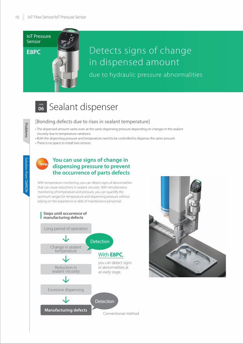
06 Sealant dispenser
IoT Pressure Sensor
E8PC Detects signs of change in dispensed amount due to hydraulic pressure abnormalities
[Bonding defects due to rises in sealant temperature]• The dispensed amount varies even at the same dispensing pressure depending on changes in the sealant viscosity due to temperature variations.
• Both the dispensing pressure and temperature need to be controlled to dispense the same amount.• There is no space to install two sensors.
You can use signs of change in dispensing pressure to prevent the occurrence of parts defects
With temperature monitoring, you can detect signs of abnormalities that can cause reductions in sealant viscosity. With simultaneous monitoring of temperature and pressure, you can quantify the optimum ranges for temperature and dispensing pressure without relying on the experience or skills of maintenance personnel.
With E8PC,you can detect signs or abnormalities at an early stage.
Conventional method
Steps until occurrence of manufacturing defects
Detection
Detection

11
Multi-sensing technologyTemp.
Uses a piezoelectric element. Since the sensing surface is made of a high-hard ceramics, it withstands high pressure. Pressure values are detected from changes in resistance of the strain gauge.
Uses a platinum temperature measuring element mounted to the back of the piezoelectric element to measure temperature.
Temperature measuring element
Piezoelectric element
Pressure
Temp.
12 IoT Flow Sensor/IoT Pressure Sensor
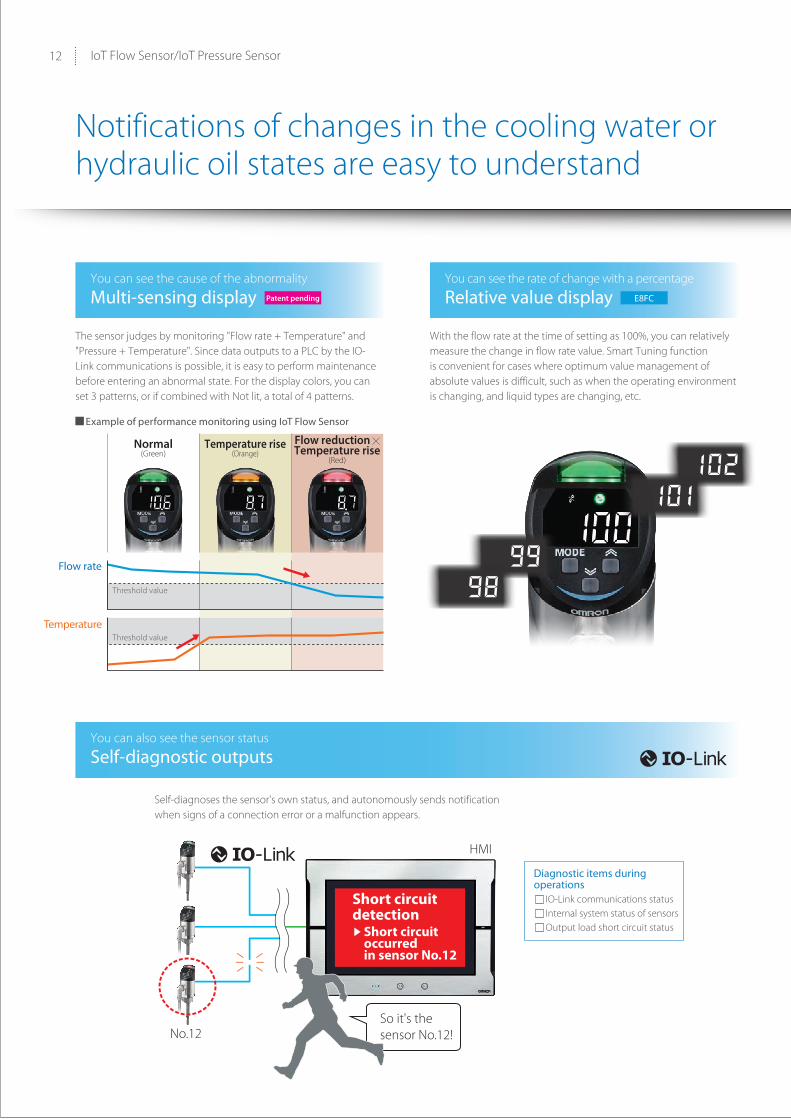
You can also see the sensor status
Self-diagnostic outputs
HMI
So it's the sensor No.12!No.12
Short circuit detection
Short circuit occurred in sensor No.12
You can see the cause of the abnormality
Multi-sensing displayYou can see the rate of change with a percentage
Relative value display
Normal(Green)
Threshold value
Threshold value
Flow rate
Temperature
Example of performance monitoring using IoT Flow Sensor
Temperature rise(Orange)
Flow reduction Temperature rise
(Red)
Notifications of changes in the cooling water or hydraulic oil states are easy to understand
Patent pending E8FC
The sensor judges by monitoring "Flow rate + Temperature" and "Pressure + Temperature". Since data outputs to a PLC by the IO-Link communications is possible, it is easy to perform maintenance before entering an abnormal state. For the display colors, you can set 3 patterns, or if combined with Not lit, a total of 4 patterns.
Self-diagnoses the sensor's own status, and autonomously sends notification when signs of a connection error or a malfunction appears.
With the flow rate at the time of setting as 100%, you can relatively measure the change in flow rate value. Smart Tuning function is convenient for cases where optimum value management of absolute values is difficult, such as when the operating environment is changing, and liquid types are changing, etc.
Diagnostic items duringoperations IO-Link communications status Internal system status of sensors Output load short circuit status
13
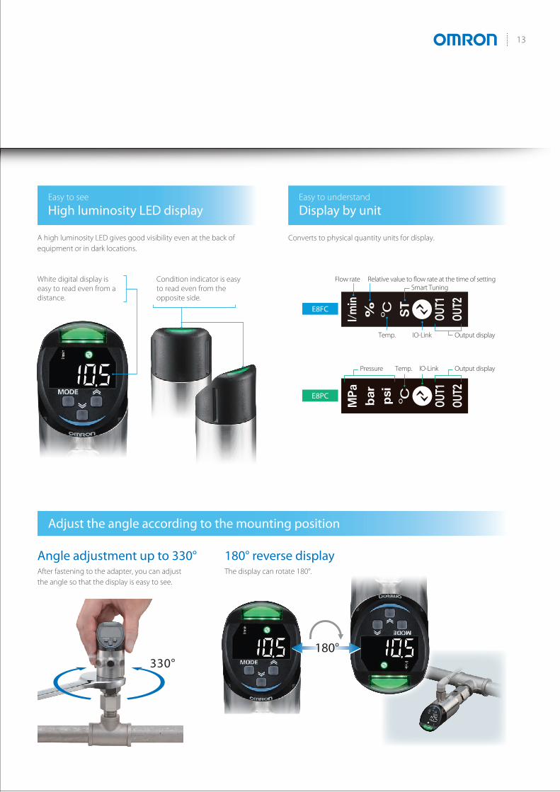
Adjust the angle according to the mounting position
Angle adjustment up to 330° 180° reverse display
Easy to see
High luminosity LED displayEasy to understand
Display by unit
Flow rate Relative value to flow rate at the time of settingSmart Tuning
Temp. IO-Link Output display
Temp.Pressure IO-Link Output display
E8FC
E8PC
Flow rate Relative value to flow rate at the time of settingSmart Tuning
Temp. IO-Link Output display
Temp.Pressure IO-Link Output display
E8FC
E8PC
180°330°
After fastening to the adapter, you can adjust the angle so that the display is easy to see.
The display can rotate 180°.
A high luminosity LED gives good visibility even at the back of equipment or in dark locations.
White digital display is easy to read even from a distance.
Condition indicator is easy to read even from the opposite side.
Converts to physical quantity units for display.

14 IoT Flow Sensor/IoT Pressure Sensor
Direct setting
Expanded cable and adapter lineups(sold separately)*
Highly durable liquid contact part
Easy-to-clean structure
Compact and space-saving
Straight
L-shapedAdapters for Flow Sensors
Adapters for Pressure Sensors
90.9mm
34mm dia.
69.4mm
15mm
55mm
Detecting unit: SUS304L
Pressure port: SUS304
O-ring: FKM
O-ring: FKM
Diaphragm pressure port: Al2O3 (alumina)
E8PC
E8FC
Batch setting from host devices
Controller
Pressure Sensor
IO-Link Master
Sysmac Studio
IndividualID
Setting
Flow Sensor
Response time
Timer setting
Flow rate/Pressure Temperature display switching
Threshold settings (hysteresis width)
Zero-cut setting
Setting initialization, etc.
Easy to use in various location
You can even mount in narrow spaces with multiple pipes arrayed.
Structure is easily removable from the piping for periodic inspections, etc., and easily cleaned.
* Use our dedicated adapters. In addition, if there is a possibility of pulsations or vibrations to a Pressure Sensor, we recommend the attachment of a throttle (sold separately).
Button on the body for quick setting. After setting, you can use the key lock function to prevent operation in error.
During maintenance, the settings must be the same conditions as when the product was initially mounted. If you use the IO-Link function, you can perform batch setting from a host device. You can manage by quantifying the adjustment that is performed by skilled personnel to avoid affecting the manufacturing quality.

15
IoT Flow Sensors
E8FCDetect Signs of Abnormalities in Cooling Water by Simultaneous Measurement of “Flow Rate + Temperature”• Multi-sensing of “Flow rate + temperature” for preventing a
sudden stops or manufacturing defects.• Various lineup of replacement adapters to enable easy
replacement of your current pressure gauges and flow meters.• Analog current output function in addition to the IO-Link
communications function that can perform self-diagnosis of abnormalities in the sensor itself.
Ordering InformationSensors [Refer to Dimensions on page 27.]
Note: Please contact your OMRON sales representative regarding the IO-Link setup file (IODD file).* The applicable fluid is a liquid that does not erode the wetted part materials (for example, water or a fluid whose conductivity is equivalent to that
of water).
Appearance Applicable fluid * Control output Communication
method IO-Link baud rate Model
Liquid
PNP IO-LinkAnalog
COM2 (38.4 kbps) E8FC-25D
COM3 (230.4 kbps) E8FC-25T
NPN Analog --- E8FC-25
For the most recent information on models that have been certified for safety standards, refer to your OMRON website.Refer to Safety Precautions on page 24.

E8FC
16
Adapters [Refer to Dimensions on page 27.]It must be selected from the adapters below.
* It is recommended that the piping fitting diameters be theme on both the piping side and the sensor mounting side.Because the sensor is designed so that the measurement area is in the center of the piping, correct measurement may not be possible with different diameter fittings.Refer to Piping Method on page 26 for the recommended pipe joint.
Cables (Sensor I/O Connectors) A Cable is not provided with the Sensor. It must be ordered separately.
Note: Refer to Sensor I/O Connectors/Sensor Controllers on OMRON website for details.* Straight type/L-shape type combinations are also available.
O-ring (for replacement) [Refer to Dimensions on page 28.]
AppearanceApplicable diameter *
Thread type Materials ModelNominal diameter A
Nominal diameter B
10 A 3/8”R (taper thread)
SUS304
E8FC-YA-R10A
NPT (taper thread) E8FC-YA-N10A
15 A 1/2”R (taper thread) E8FC-YA-R15A
NPT (taper thread) E8FC-YA-N15A
20 A 3/4”R (taper thread) E8FC-YA-R20A
NPT (taper thread) E8FC-YA-N20A
25 A 1”
R (taper thread) E8FC-YA-R25A
NPT (taper thread) E8FC-YA-N25A
Type Appearance Cable Model
Socket on one cable end
2 m XS5F-D421-D80-F
5 m XS5F-D421-G80-F
2 m XS5F-D422-D80-F
5 m XS5F-D422-G80-F
Socket and plug on cable ends *
2 m XS5W-D421-D81-F
5 m XS5W-D421-G81-F
2 m XS5W-D422-D81-F
5 m XS5W-D422-G81-F
Appearance Type Model
For E8FC-25@ E8FC-YL-1
Applicable diameter (Sensor installation side)
Measurement area
Applicable diameter (Piping side)
Straight
L-shaped
Straight/straight
L-shaped/L-shaped

E8FC
17
Ratings and SpecificationsSensors
ModelPNP (COM2) E8FC-25DPNP (COM3) E8FC-25T
NPN E8FC-25
Applicablediameter
Nominal diameter B 3/8" 1/2" 3/4" 1"
Nominal diameter A 10 A 15 A 20 A 25 A
Applicable fluid The fluid must not corrode the material of the wetted part (for example, water or a fluid whose conductivity is equivalent to that of water).
Permissible pressure *1 10 MPa
Flow ratemonitoring *2
Rated flow rate range0.6 to 14 l/min 1 to 30 l/min 1.5 to 60 l/min 2 to 100 l/min
Inner diameter setting (10 A, 15 A, 20 A, 25 A)
Display range 0 to 16 l/min 0 to 33 l/min 0 to 66 l/min 0 to 110 l/min
Zero cutting flow rate *3 0.6 l/min 1 l/min 1.5 l/min 2 l/min
Display resolution (l/min) 0.1/1 (Selectable)
Flow rate monitoring response time Control output: 1.0, 2.5, 5, 10, 30, 60 s
Flow rate monitoring precision *4 ± (7.0% of measured value + 2.0% F.S.) or less
Flow rate repeatability / F.S. (prescribed for each response time)
1 s: ±3.5%, 2.5 s: ±2.5%, 5 s: ±1.6%, 10 s: ±1%, 30 s: ±0.8%, 60 s: ±0.6%
Ambient temperature characteristics *5 ±1.0% F.S./10°C
Hysteresis Variable
Temperature monitoring *6
Temperature monitoring rated range *7 0 to 85°C
Temperature monitoring precision ±2.5°C
Temperature repeatability ±0.5°C
Control output judgment(selectable)
Standard mode Judge if the measured value is the threshold value or more (or less).
Window mode Judge if the measured value is within the upper and lower limits.
Display method
Numerical value indication: 4-digit 7-segment white LED with inverting functionStatus indicators: The content of indication is selectable from green, orange, red,
and OFF.Output indicator: OUT1 operation (orange), OUT2 operation (orange)Unit indicator: l/min (White), % (White), °C (White), ST (White)Communication indicator: Lighting when communications are in progress (green)
Delay setting 1 to 9999 ms (Select a function from invalid, ON delay, OFF delay, and one-shot.)
Connection method M12, 4-pole connector type
Output ch1(selectable)
Control output
Flow rate control output (N.O./N.C.)E8FC-25D/-25T: PNPE8FC-25: NPN30 VDC or less, Class 2, 100 mA max., residual voltage 1 V or less
Pulse output 1/ 10/ 100/1000 l
Output ch2(selectable)
Control output
Flow rate control output (N.O./N.C.) / temperature control output (N.O./N.C.)E8FC-25D/-25T: PNPE8FC-25: NPN30 VDC or less, Class 2, 100 mA max. residual voltage 1 V or less
Analog current output *8Flow rate analog output /temperature analog outputCurrent output 4 to 20 mA (maximum load resistance 350Ω or less) (Display value ± 2% of F.S.)
Pulse output 1/ 10/ 100/1000 l
External input Smart tuning, One-point tuning,short-circuit current 1.5 mA or less, input time 20 ms or more
E8FC
18
*1.Even instantaneous pressure fluctuation such as water hammer must be within the permissible pressure.*2. Flow monitoring performance is defined by the values measured under the following conditions using OMRON's factory adjustment equipment.
• OMRON's factory adjustment equipment: Pipe diameter 20A, straight pipe length 900 mm or more, recommended pipe joint (KITZ's PTZ-20A), dedicated adapter (E8FC-YA-R20A)
• The long side of the chassis holding unit is installed toward the upstream side of the piping. Refer to Piping method on page 26.• Measured normal temperature water (approx. 23°C) under normal temperature environment (approx. 23°C)
Since each performance depends on the water level of the piping, there is a possibility that the measured value may deviate depending on the condition that the inside of the piping including the pipe joint is not filled with water, fluid pulsation, and clogging of the piping.
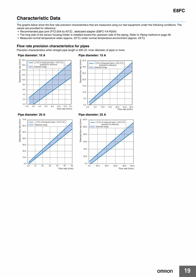
*3.Cutting to zero is the function outputting the flow rate less than the minimum rated flow rate as zero.*4. The accuracy of flow rate monitoring when the pipe diameter is 20A. For piping sizes 10A, 15A and 25A, refer to Characteristic Data on page 19
in the catalog before use.*5. The ambient temperature characteristics are defined by the values measured under the following conditions.
• Pipe diameter 20A, Straight pipe length: 900 mm or more, recommended pipe joint (KITZ's PTZ-20A), dedicated adapter (E8FC-YA-R20A)• The long side of the chassis holding unit is installed toward the upstream side of the piping. Refer to Piping method on page 26.• Water at room temperature (approx. 23°C) was measured at a flow rate of 30 l/min.
*6. The performance of temperature monitoring is specified by the values measured under the following conditions.• Pipe diameter 20 A, recommended pipe joint (KITZ's PTZ-20A), dedicated adapter (E8FC-YA-R20A)• The long side of the chassis holding unit is installed toward the upstream side of the piping. Refer to Piping method on page 26.• In a normal temperature environment (approx. 23°C)
*7. If the pipe temperature exceeds 70°C, do not contact any cables with the pipe.*8.Do not connect CH 2 (pin 2) with the IO-Link master unit in analog current output mode. Otherwise, the unit might fail.
IO-Link
IO-Link specification Ver 1.1
Baud rate E8FC-25D: COM2 (38.4kbps)E8FC-25T: COM3 (230.4Kbps)
Data length PD Size: 6 byteOD Size: 1 byte (M-sequence type: TYPE_2_V)
Minimum cycle time E8FC-25D (COM2): 3.2 msE8FC-25T(COM3): 2.0 ms
Power supply
Power supply voltage 15 to 30 VDC (including 10% ripple (p-p)), Class 2
Power consumption2,880 mW or less (When power supply voltage is 30 V, current consumption must be 96 mA or less. When power supply voltage is 15 V, current consumption must be 192 mA or less.)
Protection circuit Power supply reverse connection protection, output short-circuit protection, and output reverse connection protection
Environment resistance
Ambient temperature range -20 to 80°C in operation and storage, respectively (no condensation)
Applicable fluid temperature 0 to 85°C (no icing on the pipe surface)
Ambient humidity range 35 to 85%RH in operation and storage, respectively (no condensation)
Withstand voltage 500 VAC 50/60 Hz 1min
Vibration resistance (destruction) 10 to 2000 Hz, double amplitude 1.5 mm, 2 hours in X/Y/Z direction each
Shock resistance (destruction) 500 m/s2, three times in X/Y/Z direction each
Protective structure IP67
Pollution degree 3
Altitude 2,000 m or less
Installation place Indoor
MaterialsWetted part Detecting unit: SUS304L, O-ring: FKM
Other than wetted part Head: PPSU, display unit: PES, button: PBT, chassis: SUS304L, nut: SUS304
Weight Approx. 190 g
Accessories
• Ferrite core x 1 (TDK's Model ZCAT1 730-0730A)• User's manual (Japanese, English, and Chinese), one each• Compliance sheet• Index list
ModelPNP (COM2) E8FC-25DPNP (COM3) E8FC-25T
NPN E8FC-25
E8FC
19
Characteristic DataThe graphs below show the flow rate precision characteristics that are measured using our test equipment under the following conditions. The values are provided for reference.• Recommended pipe joint (PTZ-20A by KITZ) , dedicated adapter (E8FC-YA-R20A)• The long side of the sensor housing holder is installed toward the upstream side of the piping. Refer to Piping method on page 26.• Measured normal temperature water (approx. 23°C) under normal temperature environment (approx. 23°C)
Flow rate precision characteristics for pipesPrecision characteristics when straight pipe length is 40D (D: inner diameter of pipe) or more
Pipe diameter: 10 A Pipe diameter: 15 A
Pipe diameter: 20 A Pipe diameter: 25 A
0.0
2.0
4.0
6.0
8.0
10.0
12.0
14.0
16.0
18.0
0.0 2.0 4.0 6.0 8.0 10.0 12.0 14.0
± (7.0% of measured value + 15% F.S.)(example for reference)
Detected range
Flow rate (l/min)
Det
ecte
d flo
w r
ate
(l/m
in)
0.0
5.0
10.0
15.0
20.0
25.0
30.0
35.0
0.0 5.0 10.0 15.0 20.0 25.0 30.0
± (7.0% of measured value + 4.0% F.S.)(example for reference)
Detected range
Flow rate (l/min)
Det
ecte
d flo
w r
ate
(l/m
in)
0.00.0
10.0
20.0
30.0
40.0
50.0
60.0
70.0
10 20 30 40 50 60
± (7.0% of measured value + 2.0% F.S.)
Detected range
Flow rate (l/min)
Det
ecte
d flo
w r
ate
(l/m
in)
0.00.0
20.0
40.0
60.0
80.0
100.0
120.0
20.0 40.0 60.0 80.0 100.0
± (7.0% of measured value + 8.0% F.S.)(example for reference)
Detected range
Flow rate (l/min)
Det
ecte
d flo
w r
ate
(l/m
in)
E8FC
20
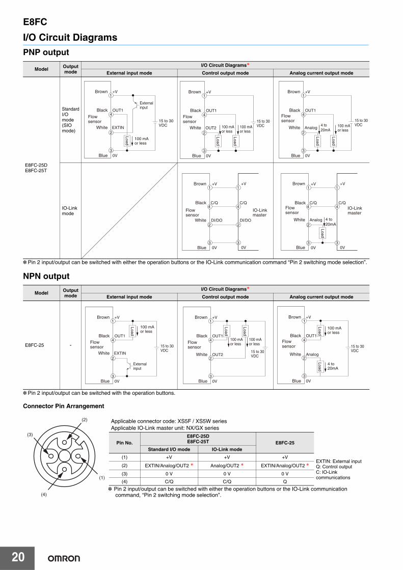
I/O Circuit DiagramsPNP output
* Pin 2 input/output can be switched with either the operation buttons or the IO-Link communication command “Pin 2 switching mode selection”.
NPN output
* Pin 2 input/output can be switched with the operation buttons.
Connector Pin Arrangement
Model Output mode
I/O Circuit Diagrams*External input mode Control output mode Analog current output mode
E8FC-25DE8FC-25T
Standard I/O mode(SIO mode)
IO-Linkmode
Model Output mode
I/O Circuit Diagrams*External input mode Control output mode Analog current output mode
E8FC-25 -
1
4
2
3
OUT1
EXTIN
0V
+V
Load
Flowsensor
100 mAor less
External input
15 to 30 VDC
Brown
Black
White
Blue
Flowsensor
100 mAor less
100 mAor less
15 to 30 VDC
1
4
2
3
OUT1
OUT2
0V
+V
Load
Load
Brown
Black
White
Blue
Flowsensor
100 mAor less
15 to 30 VDC
1
4
2
3
OUT1
Analog
0V
+V
Load
Load
4 to20mA
Brown
Black
White
Blue
Flowsensor
IO-Link master
1
4
2
3
1
4
3
C/Q
DI/DO2
DI/DO
C/Q
0V
+V
0V
+VBrown
Black
White
Blue
Flowsensor
IO-Link master
Analog 4 to20mA
1
4
2
3
1
4
3
C/Q C/Q
0V
+V
0V
+V
Load
Brown
Black
White
Blue
Flowsensor
100 mAor less
External input
15 to 30 VDC
1
4
2
3
OUT1
EXTIN
0V
+V
Load
Brown
Black
White
Blue
Flowsensor
100 mAor less
100 mAor less
15 to 30 VDC
1
4
2
3
OUT1
OUT2
0V
+V
Load
Load
Brown
Black
White
Blue
Flowsensor
100 mAor less
15 to 30 VDC
1
4
2
3
OUT1
Analog
0V
+V
LoadLoad
4 to20mA
Brown
Black
White
Blue
(2)
(1)
(3)
(4)* Pin 2 input/output can be switched with either the operation buttons or the IO-Link communication
command, “Pin 2 switching mode selection”.
Applicable connector code: XS5F / XS5W seriesApplicable IO-Link master unit: NX/GX series
Pin No.E8FC-25DE8FC-25T E8FC-25
Standard I/O mode IO-Link mode
(1) +V +V +VEXTIN: External inputQ: Control outputC: IO-Link communications
(2) EXTIN/Analog/OUT2 * Analog/OUT2 * EXTIN/Analog/OUT2 *(3) 0 V 0 V 0 V
(4) C/Q C/Q Q

E8FC
21
Timing ChartsThe PNP output is described below by using the flow rate control output of OUT1 as an example.The activity is the same even when temperature control output is selected in OUT2.
PNP output
*1.The N.O./N.C. setting can be changed by the operation buttons or IO-Link communications.*2.The timer function can be set individually for OUT1 and OUT2 by the operation buttons or IO-Link communications.
(Selection of ON delay, OFF delay, or one-shot function, and selection of a timer time from 1 to 9999 ms)The delay timing of each function is same as the NPN output. Refer to the next page.
*3.Factory default
Model Output modeN.O./N.C. setting *1
Timing charts *2
Standard mode Window mode
E8FC-25DE8FC-25T
Standard I/O mode (SIO mode)
N.O. *3
N.C.
IO-Link mode
N.O. *3
N.C.
ON
OFF
ON
OFF
Time
Flow rate
OUT1 operation indicator (orange)
OUT1 control output
HysteresisThreshold level
Hysteresis
Hysteresis
ON
OFF
ON
OFF
Threshold level.H
Threshold level.L
Time
Flow rate
OUT1 operation indicator (orange)
OUT1 control output
ON
OFF
ON
OFF
Time
Flow rate
OUT1 operation indicator (orange)
OUT1 control output
HysteresisThreshold level
ON
OFF
ON
OFF
Hysteresis
Hysteresis
Time
Flow rate
OUT1 operation indicator (orange)
OUT1 control output
Threshold level.H
Threshold level.L
1
0
Time
OUT1 operation indicator (orange)
Communication indicator (Green)
ON
OFF
Lighting
Threshold level
Flow rate
OUT1 control output (Byte1_bit0)
Hysteresis
Hysteresis
Hysteresis
1
0
ON
OFF
Threshold level.H
Threshold level.L
Lighting
Time
OUT1 operation indicator (orange)
Communication indicator (Green)
Flow rate
OUT1 control output (Byte1_bit0)
Lighting
Threshold level
1
0
Time
OUT1 operation indicator (orange)
Communication indicator (Green)
ON
OFF
Flow rate
OUT1 control output (Byte1_bit0)
Hysteresis
1
0
OUT1 operation indicator (orange)
Communication indicator (Green)
OUT1 control output (Byte1_bit0)
Flow rate
Time
Hysteresis
Hysteresis
ON
OFF
Threshold level.H
Threshold level.L
Lighting
E8FC
22
NPN output
*1. The N.O/N.C setting can be changed by the operation buttons.*2. The timer function can be set individually for OUT1 and OUT2 by the operation buttons.
(Selection of ON delay, OFF delay, or one-shot function, and selection of a timer time from 1 to 9999 ms)
*3. Factory default
Model N.O./N.C. setting *1Timing charts *2
Standard mode Window mode
E8FC-25
N.O. *3
N.C.
ON delay One-shot
OFF delay
Time
OUT1 control output
OUT1 operation indicator (orange)
Hysteresis
ON
OFF
ON
OFF
Flow rate
Threshold level
ON
OFF
Time
Hysteresis
Hysteresis
ON
OFFOUT1 operation indicator (orange)
Flow rate
OUT1 control output
Threshold level.H
Threshold level.L
Hysteresis
ON
OFF
ON
OFF
Time
Flow rate
OUT1 operation indicator (orange)
OUT1 control output
Threshold level
OUT1 operation indicator (orange)
OUT1 control output
Hysteresis
Hysteresis
ON
OFF
Time
ON
OFF
Flow rate
Threshold level.H
Threshold level.L
ONT
N.O.
N.C.
OFF
1
0
ON
OFF
1
0
T
T
Detection level
ONT
N.O.
N.C.
OFF
1
0
ON
OFF
1
0
T
T
Detection level
ONT
N.O.
N.C.
OFF
1
0
ON
OFF
1
0
T
T
Detection level

E8FC
23
Nomenclature
[Status indicators: green/orange/red]Lit up according to the measured value andsetting of Flow rate and temperature.
[Unit indicator: white]Displays the current unit setting.
[ST indicator: white]Lit up when smart tuning is executed.
[Communication indicator: green]Lit up when IO-Link communicationsare in progress.
[Output indicator: orange]Lit up when output is ON.
[Measured value: white digital]Displays the measured value.
Switch setting[UP/DOWN] buttonChanges the threshold value andsetting parameters.
Mode switching[MODE] buttonCalls a menu, selects (determine) amenu, and switches the unit.

E8FC
24
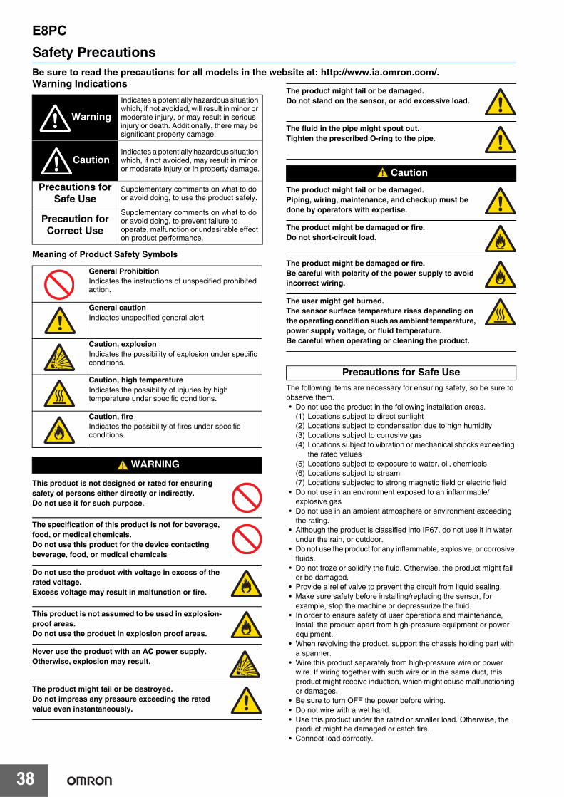
Safety PrecautionsBe sure to read the precautions for all models in the website at: http://www.ia.omron.com/.Warning Indications
Meaning of Product Safety Symbols
This product is not designed or rated for ensuring safety of persons either directly or indirectly. Do not use it for such purpose.
The specification of this product is not for beverage, food, or medical chemicals. Do not use this product for the device contacting beverage, food, or medical chemicals.
Do not use the product with voltage in excess of the rated voltage.Excess voltage may result in malfunction or fire.
This product is not assumed to be used in explosion-proof areas.Do not use the product in explosion proof areas.
Never use the product with an AC power supply. Otherwise, explosion may result.
The product might fail or be destroyed. Do not impress any pressure exceeding the rated value even instantaneously.
The product might fail or be damaged. Do not stand on the sensor, or add excessive load.
The fluid in the pipe might spout out. Tighten the prescribed O-ring to the pipe.
The product might fail or be damaged. Piping, wiring, maintenance, and checkup must be done by operators with expertise.
The product might be damaged or fire. Do not short-circuit load.
The product might be damaged or fire. Be careful with polarity of the power supply to avoid incorrect wiring.
The user might get burned. The sensor surface temperature rises depending on the operating condition such as ambient temperature, power supply voltage, or fluid temperature. Be careful when operating or cleaning the product.
The following items are necessary for ensuring safety, so be sure to observe them.• Do not use the product in the following installation areas.
(1) Locations subject to direct sunlight(2) Locations subject to condensation due to high humidity(3) Locations subject to corrosive gas(4) Locations subject to vibration or mechanical shocks exceeding
the rated values(5) Locations subject to exposure to water, oil, chemicals(6) Locations subject to stream(7) Locations subjected to strong magnetic field or electric field
• Do not use in an environment exposed to an inflammable/explosive gas
• Do not use in an ambient atmosphere or environment exceeding the rating.
• Although the product is classified into IP67, do not use it in water, under the rain, or outdoor.
• Do not use the product for any inflammable, explosive, or corrosive fluids.
• Do not froze or solidify the fluid. Otherwise, the product might fail or be damaged.
• Provide a relief valve to prevent the circuit from liquid sealing.• The surface temperature of the sensing part may increase. Use
caution while operating and cleaning the product.• Make sure safety before installing/replacing the sensor, for
example, stop the machine or depressurize the fluid.• In order to ensure safety of user operations and maintenance,
install the product apart from high-pressure equipment or power equipment.
• When revolving the product, support the chassis holding part with a spanner.
• Wire this product separately from high-pressure wire or power wire. If wiring together with such wire or in the same duct, this product might receive induction, which might cause malfunctioning
Warning
Indicates a potentially hazardous situation which, if not avoided, will result in minor or moderate injury, or may result in serious injury or death. Additionally, there may be significant property damage.
CautionIndicates a potentially hazardous situation which, if not avoided, may result in minor or moderate injury or in property damage.
Precautions for Safe Use
Supplementary comments on what to do or avoid doing, to use the product safely.
Precaution for Correct Use
Supplementary comments on what to do or avoid doing, to prevent failure to operate, malfunction or undesirable effect on product performance.
General ProhibitionIndicates the instructions of unspecified prohibited action.
General cautionIndicates unspecified general alert.
Caution, explosionIndicates the possibility of explosion under specific conditions.
Caution, high temperature Indicates the possibility of injuries by high temperature under specific conditions.
Caution, fireIndicates the possibility of fires under specific conditions.
WARNING
Caution
Precautions for Safe Use
E8FC
25
or damages.• Be sure to turn OFF the power before wiring.• Do not wire with a wet hand.• Use this product under the rated or smaller load. Otherwise, the
product might be damaged or catch fire.• Connect load correctly.• If the load and sensor use separate power supplies, turn ON the
sensor's power first.• Process unwired terminals so that they do not contact other wire or
equipment.• Do not use the product with the main unit damaged.• Be careful with the sharp screw parts.• Do not pull connected cables hard.• Do not use organic solvents such as thinner or alcohol for cleaning
because they deteriorate the degree of protection and indication performance.
• Do not try to disassemble, repair, or alter the main unit.• If disposing this product, handle it as industrial waste.• This product is certified by the UL standard based on the
assumption that Class 2 circuits are used. Operate this product using Class 2 power supply in the United States or Canada.
• Use cables of Omron model XS5F-D4 series or model XS5W-D4 series.
• The mark shown on the sensor nameplate means direct current.
• Electromagnetic environment: Industrial electromagnetic environment (EN 61326-1 Table2)
• Do not use this product as a measuring apparatus for commercial transactions.
• Do not use this product for any fluids containing impurities.• If the fluid is non-conductive and the pipe is made of resin, ground
the chassis.• Use the product in the condition that the fluid temperature is higher
than the ambient temperature. For preventing condensation, use the product as dehumidifying by air conditioning and 30 cm or more apart from cold pipes.
• Do not add excessive impart such as falling or collision.• Do not touch the detecting unit with bare hands.• Apply grease to the thread parts to prevent them from getting hard
to remove due to seizure.• Fasten by the prescribed torque.• When using a cable of which diameter is different from that of the
recommended cable, prepare a ferrite core suitable for the cable diameter separately.
• If using the product in IO-Link mode, keep the wiring length between the master unit and sensor 20 m or less.
• Just after the power is turned ON, it might take long for the measured value to get stable according to the operating environment.
• Do not connect CH 2 (pin 2) with the IO-Link master unit in analog current output mode. The unit might fail depending on the specification of the IO-Link master.
• Do not push the button with something sharp such as a screwdriver because doing so might damage the button.
• If using the product in an environment subject to sharp temperature variation, evaluate the product in the environment in advance.
• When implementing maintenance, use a soft brush or waste cloth so as not to damage the detecting unit or O-ring.
• When replacing the O-ring, prevent dust/dirt from being mixed into the O-ring.
• Use the product in an environment at altitudes less than 2,000 m.• Use the product in an environment of pollution degree 3.
Precaution for Correct Use

E8FC
26
Piping method• Use the adapter according to the connection pipe diameter of the
piping.• When assembling pipes, use the KITZ's PTZ piping joint (*1).• Use a pipe joint whose applicable diameter of the piping side is
equal to that of the sensor installation side.Because the sensor is designed so that the measurement area is in the center of the piping, correct measurement may not be possible with different diameter fittings.
• Feed the fluid so that the inside of the pipe is filled up with water. Otherwise, measured values might be misaligned or fluctuate.
• When piping, ensure a straight pipe length (*2) on both upstream and downstream sides. (The measured value may deviate.)
• Mount the product so that the measurement area does not contact the piping wall. (Fig. A)
• Do not mount the product on the downward piping whose lower part is open. (Fig. B)
• In the case of horizontal piping, it is recommended to install the sensor from the side. (Fig. C)
• In the case of vertical piping, it is recommended to install the sensor such that the flow is from the bottom to the top. (Fig. D)
• The chassis holding unit can be revolved along the boundary between itself and body unit.When revolving the body unit, support the chassis holding unit with a wrench.
• For both horizontal and vertical piping, install the product with turning the long side of the chassis holding unit to the upstream side of the piping.
• Mount the attached ferrite core at a position located within 10 mm from the edge of the cable bushing when you use this product as CE acceptable goods.
<Dedicated adapter>E8FC-YA-R10A E8FC-YA-N10AE8FC-YA-R15A E8FC-YA-N15AE8FC-YA-R20A E8FC-YA-N20AE8FC-YA-R25A E8FC-YA-N25A
*1<Recommended Pipe joint>
KITZ's PTZ-10A PTZ-15A PTZ-20A PTZ-25A
[OK]
[NG]
Body unit
Chassis holding unit
Chassis holding unit Bottom view
Watercurrent
Applicable diameter (Sensor installation side)
Measurement area
Applicable diameter(Piping side)
*2. Straight pipe length: 900 mm (*3) or more*3. 40D (D: Pipe inner diameter) or more
*2. Straight pipe length: 200 mm or more (recommended)
Platinum temperature sensing element
Short side(Downstream side)
Long side(Upstream side)
Water current
Long side of chassis holding unit
Recommended tightening torque 25±5 N•m
Holding unit
Adapter
Pipe joint
(Fig. B)
(Fig. C)
(Fig. D)
Short side of chassis holding unit
(Fig. A)

E8FC
27
DimensionsSensors
Adapters
(Unit: mm)Tolerance class IT16 applies to dimensions in this data sheet unless otherwise specified.
M12×1
26
5 dia.8 dia. (27.50)
55
34 dia. 44.50
69.4
15
IoT Flow SensorE8FC-25@
Thread R/NPT*
M18×1.5
12.5
18.5 (41)
10
22 0-0.1
8
10.5
E8FC-YA-R10AE8FC-YA-N10A
* The specification for each model is shown in the table below.
Model E8FC-YA-R10A E8FC-YA-N10A
Applicable diameter 10 A
Threaded R3/8 NPT3/8
M18×1.5
Thread*
15.5
13.3 (38.8)
108
13.5
22E8FC-YA-R15AE8FC-YA-N15A
* The specification for each model is shown in the table below.
Model E8FC-YA-R15A E8FC-YA-N15A
Applicable diameter 15 A
Threaded R1/2 NPT1/2
Thread*
M18×1.5
17
8(35)
10
15
22
8
E8FC-YA-R20AE8FC-YA-N20A
* The specification for each model is shown in the table below.
Model E8FC-YA-R20A E8FC-YA-N20A
Applicable diameter 20 A
Threaded R3/4 NPT3/4
M18×1.5
Thread R/NPT*
17
8 10
6
19
(35)
22E8FC-YA-R25AE8FC-YA-N25A
* The specification for each model is shown in the table below.
Model E8FC-YA-R25A E8FC-YA-N25A
Applicable diameter 25 A
Threaded R1 NPT1

E8FC
28
CablesSensor I/O Connectors (M12, Socket on one cable end) Sensor I/O Connectors (M12, Socket and plug on cable ends)
Cross-sectional view A-A
AA
1.5
8.5 dia.
11.5 dia.O-ringE8FC-YL-1
StraightXS5F-D421-D80-FXS5F-D421-G80-F
40.7L (cable length)
5030 5M12×1
14.9 dia.
Straight/straightXS5W-D421-D81-FXS5W-D421-G81-F
40.7L (cable length)
44.7
M12×1
14.9 dia. 14.9 dia.
L-shapedXS5F-D422-D80-FXS5F-D422-G80-F
25.3
28.3
L (cable length)
5030 5
M12×1
14.9 dia.
1234
Terminal No. Cable conductor cladding color
BlueBlack
BrownWhite
2
14
3
L-shaped/L-shapedXS5W-D422-D81-FXS5W-D422-G81-F
L (cable length)
32.328.3
M12×114.9 dia.
14.9 dia.
1234
1234
Terminal No.
BlueBlack
BrownWhite
Cable conductor cladding color
1
2
3
42
14
3
Female (socket)Contact side
Male (plug)Contact side

29
IoT Pressure Sensors
E8PCDetect Signs of Abnormalities in Cooling Water and Hydraulic Oil by Simultaneous Measurement of “Pressure + Temperature”• Multi-sensing of “Pressure + temperature” for preventing a
sudden stops or manufacturing defects.• Various lineup of replacement adapters to enable easy
replacement of your current pressure gauges and flow meters.• Analog current output function in addition to the IO-Link
communications function that can perform self-diagnosis of abnormalities in the sensor itself.
Ordering InformationSensors [Refer to Dimensions on page 40.]
Note: Please contact your OMRON sales representative regarding the IO-Link setup file (IODD file).* The applicable fluid is a liquid that do not erode the liquid contact part materials (such as water, glycol solution, and oil).
For the most recent information on models that have been certified for safety standards, refer to your OMRON website.
Refer to Safety Precautions on page 38.
Appearance Applicable fluid * Rated pressure range Control output Communication
method IO-Link baud rate Model
Liquid and gas -0.1 to 1 MPaPNP IO-Link
AnalogCOM2 (38.4 kbps) E8PC-010D-E
COM3 (230.4 kbps) E8PC-010T-E
NPN Analog --- E8PC-010-E
Liquid
0 to 10 MPaPNP IO-Link
AnalogCOM2 (38.4 kbps) E8PC-100D-E
COM3 (230.4 kbps) E8PC-100T-E
NPN Analog --- E8PC-100-E
0 to 40 MPaPNP IO-Link
AnalogCOM2 (38.4 kbps) E8PC-400D-E
COM3 (230.4 kbps) E8PC-400T-E
NPN Analog --- E8PC-400-E

E8PC
30
Adapters [Refer to Dimensions on page 40.]It must be selected from the adapters below.
* The nominal diameter of the thread is the size of the part shown below on the adapter.
Appearance TypeNominal diameter of thread *
Thread type Materials ModelNominal diameter A
Nominal diameter B
R1/8 male 6 A 1/8" R (taper thread) SUS304 E8PC-YA-A18
R1/4 male 8 A 1/4" R (taper thread) SUS304 E8PC-YA-A14
R3/8 male 10 A 3/8" R (taper thread) SUS304 E8PC-YA-A38
G1/4 female 8 A 1/4" G (parallel thread) SUS304 E8PC-YA-B14N
NPT1/8 male 6 A 1/8" NPT (taper thread) SUS304 E8PC-YA-C18
NPT1/2 male 8 A 1/4" NPT (taper thread) SUS304 E8PC-YA-C14
Piping side

E8PC
31
Cables (Sensor I/O Connectors)A Cable is not provided with the Sensor. It must be ordered separately.
Note: Refer to Sensor I/O Connector/Sensor Controller on your OMRON website for details.* Straight type/L-shape type combinations are also available.
Throttle [Refer to Dimensions on page 41.]If the excessive pulsation or surge voltage is expected, use a throttle. Install it inside the adapter and use.
O-ring (for replacement) [Refer to Dimensions on page 41.]
* Provided with the sensor.
Type Appearance Cable Model
Socket on one cable end
2 m XS5F-D421-D80-F
5 m XS5F-D421-G80-F
2 m XS5F-D422-D80-F
5 m XS5F-D422-G80-F
Socket and plug on cable ends *
2 m XS5W-D421-D81-F
5 m XS5W-D421-G81-F
2 m XS5W-D422-D81-F
5 m XS5W-D422-G81-F
Appearance Type Material Model Installation method
For a male adapter SUS304 E8PC-YS
For a female adapter SUS304 E8PC-YS-N
Appearance Type Model
For E8PC-010@ E8PC-YL-1 *
For E8PC-100@/-400@ E8PC-YL-2 *
Female for adapter G1/4 E8PC-YL-3
Straight
L-shaped
Straight/straight
L-shaped/L-shaped
Throttle
Pressure sensor
Adapter
E8PC
32
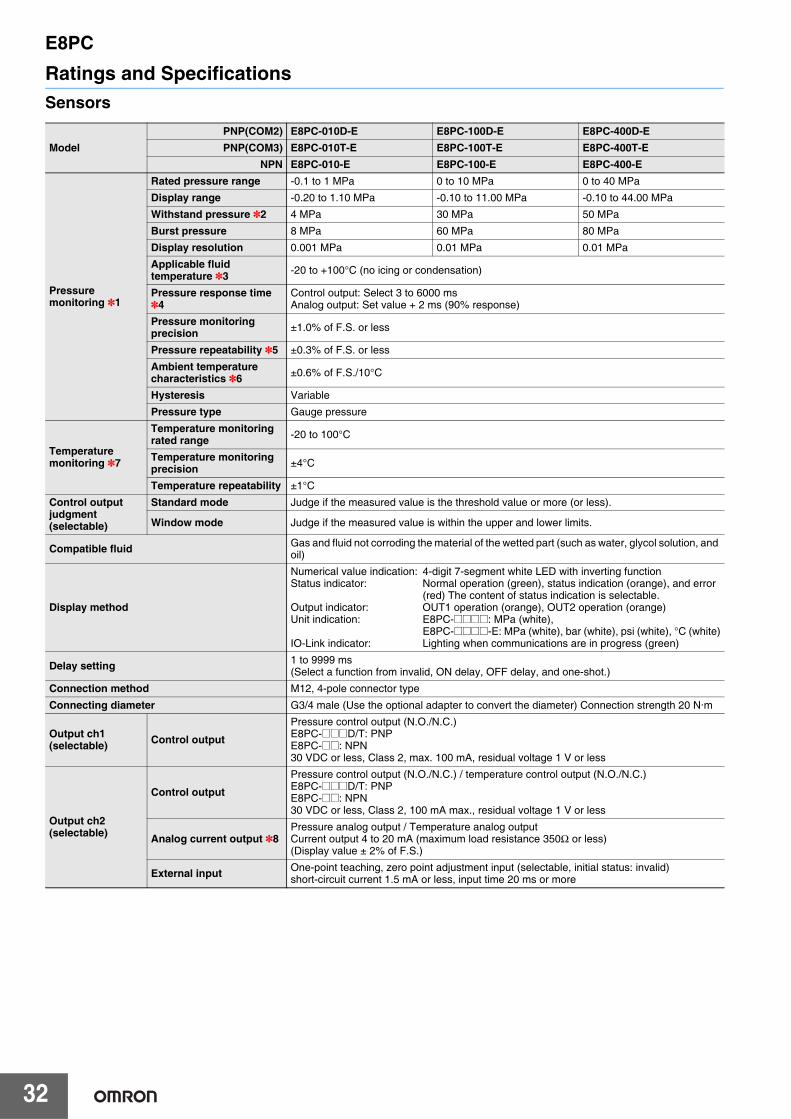
Ratings and SpecificationsSensors
ModelPNP(COM2) E8PC-010D-E E8PC-100D-E E8PC-400D-EPNP(COM3) E8PC-010T-E E8PC-100T-E E8PC-400T-E
NPN E8PC-010-E E8PC-100-E E8PC-400-E
Pressuremonitoring *1
Rated pressure range -0.1 to 1 MPa 0 to 10 MPa 0 to 40 MPa
Display range -0.20 to 1.10 MPa -0.10 to 11.00 MPa -0.10 to 44.00 MPa
Withstand pressure *2 4 MPa 30 MPa 50 MPa
Burst pressure 8 MPa 60 MPa 80 MPa
Display resolution 0.001 MPa 0.01 MPa 0.01 MPa
Applicable fluid temperature *3 -20 to +100°C (no icing or condensation)
Pressure response time *4
Control output: Select 3 to 6000 ms Analog output: Set value + 2 ms (90% response)
Pressure monitoring precision ±1.0% of F.S. or less
Pressure repeatability *5 ±0.3% of F.S. or less
Ambient temperature characteristics *6 ±0.6% of F.S./10°C
Hysteresis Variable
Pressure type Gauge pressure
Temperature monitoring *7
Temperature monitoring rated range -20 to 100°C
Temperature monitoring precision ±4°C
Temperature repeatability ±1°C
Control output judgment (selectable)
Standard mode Judge if the measured value is the threshold value or more (or less).
Window mode Judge if the measured value is within the upper and lower limits.
Compatible fluid Gas and fluid not corroding the material of the wetted part (such as water, glycol solution, and oil)
Display method
Numerical value indication: 4-digit 7-segment white LED with inverting function Status indicator: Normal operation (green), status indication (orange), and error
(red) The content of status indication is selectable.Output indicator: OUT1 operation (orange), OUT2 operation (orange)Unit indication: E8PC-@@@@: MPa (white),
E8PC-@@@@-E: MPa (white), bar (white), psi (white), °C (white)IO-Link indicator: Lighting when communications are in progress (green)
Delay setting 1 to 9999 ms(Select a function from invalid, ON delay, OFF delay, and one-shot.)
Connection method M12, 4-pole connector type
Connecting diameter G3/4 male (Use the optional adapter to convert the diameter) Connection strength 20 N·m
Output ch1(selectable) Control output
Pressure control output (N.O./N.C.)E8PC-@@@D/T: PNPE8PC-@@: NPN30 VDC or less, Class 2, max. 100 mA, residual voltage 1 V or less
Output ch2(selectable)
Control output
Pressure control output (N.O./N.C.) / temperature control output (N.O./N.C.)E8PC-@@@D/T: PNPE8PC-@@: NPN30 VDC or less, Class 2, 100 mA max., residual voltage 1 V or less
Analog current output *8Pressure analog output / Temperature analog outputCurrent output 4 to 20 mA (maximum load resistance 350Ω or less)(Display value ± 2% of F.S.)
External input One-point teaching, zero point adjustment input (selectable, initial status: invalid)short-circuit current 1.5 mA or less, input time 20 ms or more

E8PC
33
*1.The pressure precision is defined based on the values measured in the ordinary temperature environment (approx. 23°C) using water at the ordinary temperature (approx. 23°C).
*2.Even instantaneous pressure fluctuation such as water hammer must be within the withstand pressure. If instantaneous pressure fluctuation is expected, use the throttle included in the package.
*3. If the pipe temperature exceeds 70°C, do not contact any cables with the pipe.*4.The maximum actual response time has error of 1 ms when the set response time is 3 to 10 ms, 5 ms when it is 11 to 100 ms, and +5% when
it is 101 ms or more.*5.The pressure repeatability is the error of the detection point when pressure is applied repeatedly in the ordinary temperature environment
(approx. 23°C) using water at the ordinary temperature (approx. 23°C) in the rated pressure range.*6.The ambient temperature characteristics are prescribed based on the value measured using oil as applying a pressure value of 50% of the
maximum rated pressure.*7.The temperature monitoring precision is prescribed based on the value measured using water.
Temperature measurements are affected by both of the temperatures, the medium and the piping.Temperature measuring elements are installed on the back surface of the piezoelectric element (inside the product) and used to measure the temperature. It might take long for the measured value to get stable according to the heat transmission speed.
*8.Do not connect CH 2 (pin 2) with the IO-Link master unit in analog current output mode. Otherwise, the unit might fail.
IO-Link
IO-Link specification Ver 1.1
Baud rate E8PC-@@@D: COM2 (38.4kbps)E8PC-@@@T: COM3 (230.4Kbps)
Data length PD Size: 6 byteOD Size: 1 byte (M-sequence type: TYPE_2_V)
Minimum cycle time E8PC-@@@D (COM2): 3.2 msE8PC-@@@T (COM3): 2.0 ms
Power supply
Power supply voltage 10 to 30 VDC (including 10% ripple (p-p)), Class 2
Power consumption1,200 mW or less (When power supply voltage is 30 V, current consumption must be 40 mA or less.When power supply voltage is 10 V, current consumption must be 120 mA or less.)
Protection circuit Power supply reverse connection protection, output short-circuit protection, and output reverse connection protection
Environment resistance
Ambient temperature range -20 to 80°C in operation and storage, respectively (no condensation)
Ambient humidity range -35 to 85%RH in operation and storage, respectively (no condensation)
Vibration resistance (destruction) 1000 VAC, 50/60 Hz, 1 min. between current-carrying parts and case
Shock resistance (destruction) 10 to 2000 Hz, double amplitude 1.5 mm, 2 hours in X/Y/Z direction each
Impact (endurance) 500 m/s2, three times in X/Y/Z direction each
Protective structure IP67
Pollution degree 3
Altitude 2,000 m or less
Installation place Indoor
MaterialWetted part Pressure port: SUS304L, diaphragm pressure port: Al2O3 (alumina), O-ring: FKM
Other than wetted part Head: PPSU, display unit: PES, button: PBT, chassis: SUS304L
Weight Approx.190 g
Accessories
• Throttle (Model E8PC-YS and E8PC-YS-N), one each• O-ring x 1 (Model E8PC-010: Model E8PC-YL-1, Model E8PC-100/400: Model E8PC-YL-2)• Ferrite core x 1 (TDK's Model ZCAT1730-0730A)• User's manual (Japanese, English, and Chinese), one each• Compliance sheet• Index list
ModelPNP(COM2) E8PC-010D-E E8PC-100D-E E8PC-400D-EPNP(COM3) E8PC-010T-E E8PC-100T-E E8PC-400T-E
NPN E8PC-010-E E8PC-100-E E8PC-400-E
E8PC
34
I/O Circuit DiagramsPNP output
* Pin 2 input/output can be switched with either the operation buttons or the IO-Link communication command, “Pin 2 switching mode selection.”
NPN output
* Pin 2 input/output can be switched with the operation buttons.
Connector Pin Arrangement
Model Output mode
I/O Circuit Diagrams *External input mode Control output mode Analog current output mode
E8PC-@@@D-EE8PC-@@@T-E
Standard I/O mode (SIO mode)
IO-Linkmode
Model Output mode
I/O Circuit Diagrams *External input mode Control output mode Analog current output mode
E8PC-@@@-E ---
1
4
2
3
OUT1
EXTIN
0V
+V
Load
100 mAor less
External input
10 to 30 VDC
Pressuresensor
Brown
Black
White
Blue
100 mAor less
100 mAor less
10 to 30 VDC
Pressuresensor
1
4
2
3
OUT1
OUT2
0V
+V
Load
Load
Brown
Black
White
Blue
100 mAor less
10 to 30 VDC
Pressuresensor
1
4
2
3
OUT1
Analog
0V
+V
Load
Load
4 to20mA
Brown
Black
White
Blue
IO-Link master
1
4
2
3
1
4
3
C/Q
DI/DO2
DI/DO
C/Q
0V
+V
0V
+V
Pressuresensor
Brown
Black
White
Blue
IO-Link master
Pressuresensor
Analog 4 to20mA
1
4
2
3
1
4
3
C/Q C/Q
0V
+V
0V
+V
Load
Brown
Black
White
Blue
100 mAor less
External input
10 to 30 VDC
Pressuresensor
1
4
2
3
OUT1
EXTIN
0V
+V
Load
Brown
Black
White
Blue
100 mAor less
100 mAor less
10 to 30 VDC
Pressuresensor
1
4
2
3
OUT1
OUT2
0V
+V
Load
Load
Brown
Black
White
Blue
100 mAor less
10 to 30 VDC
Pressuresensor
1
4
2
3
OUT1
Analog
0V
+V
LoadLoad
4 to20mA
Brown
Black
White
Blue
(2)
(1)
(3)
(4)
Applicable OMRON connector cables: XS5F/XS5W SeriesApplicable IO-Link master unit: NX/GX series
* Pin 2 input/output can be switched with either the operation buttons or the IO-Link communication command, “Pin 2 switching mode selection.”
Pin No.E8PC-@@@D-EE8PC-@@@T-E E8PC-@@@-E
Standard I/O mode IO-Link mode
(1) +V +V +VEXTIN: External inputQ: Control outputC: IO-Link communications
(2) EXTIN/Analog/OUT2 * Analog/OUT2 * EXTIN/Analog/OUT2 *(3) 0 V 0 V 0 V
(4) C/Q C/Q Q

E8PC
35
Timing ChartsThe timing chart is described below by using the pressure control output of OUT1 as an example.The activity is the same even when temperature control output is set in OUT2.
PNP output
*1.The N.O./N.C. setting can be changed by the operation buttons or IO-Link communications.*2.The timer function can be set individually for OUT1 and OUT2 by the operation buttons or IO-Link communications.
(Selection of ON delay, OFF delay, or one-shot function, and selection of a timer time from 1 to 9999 ms)The delay timing of each function is same as the NPN output. Refer to the next page.
*3.Factory default
Model Output mode N.O./N.C. setting *1
Timing charts *2Standard mode Window mode
E8PC-@@@D-EE8PC-@@@T-E
Standard I/O mode (SIO mode)
N.O. *3
N.C.
IO-Link mode
N.O. *3
N.C.
ON
OFF
ON
OFF
Hysteresis
Time
Pressure
OUT1 operation indicator (orange)
OUT1 control output
Threshold level
Hysteresis
Hysteresis
ON
OFF
ON
OFF
Threshold level.H
Threshold level.L
Time
Pressure
OUT1 operation indicator (orange)
OUT1 control output
ON
OFF
ON
OFF
Time
Pressure
OUT1 operation indicator (orange)
OUT1 control output
HysteresisThreshold level
ON
OFF
ON
OFF
Hysteresis
Hysteresis
Time
Pressure
OUT1 operation indicator (orange)
OUT1 control output
Threshold level.H
Threshold level.L
1
0
Time
OUT1 operation indicator (orange)
Communication indicator (Green)
ON
OFF
Lighting
Threshold level
Pressure
OUT1 control output (Byte1_bit0)
Hysteresis
Hysteresis
Hysteresis
1
0
ON
OFF
Threshold level.H
Threshold level.L
Lighting
Time
OUT1 operation indicator (orange)
Communication indicator (Green)
Pressure
OUT1 control output (Byte1_bit0)
Lighting
Threshold level
1
0
Time
OUT1 operation indicator (orange)
Communication indicator (Green)
ON
OFF
Pressure
OUT1 control output (Byte1_bit0)
Hysteresis
1
0
OUT1 operation indicator (orange)
Communication indicator (Green)
OUT1 control output (Byte1_bit0)
Pressure
Time
Hysteresis
Hysteresis
ON
OFF
Threshold level.H
Threshold level.L
Lighting

E8PC
36
NPN output
*1. The N.O./N.C. setting can be changed by the operation buttons.*2. The timer function can be set individually for OUT1 and OUT2 by the operation buttons.
(Selection of ON delay, OFF delay, or one-shot function, and selection of a timer time from 1 to 9999 ms)
*3. Factory default
Model N.O./N.C. setting *1
Timing charts *2Standard mode Window mode
E8PC-@@@-E
N.O. *3
N.C.
ON delay One-shot
OFF delay
Time
OUT1 control output
OUT1 operation indicator (orange)
Hysteresis
ON
OFF
ON
OFF
Pressure
Threshold level
ON
OFF
Time
Hysteresis
Hysteresis
ON
OFFOUT1 operation indicator (orange)
Pressure
OUT1 control output
Threshold level.H
Threshold level.L
Hysteresis
ON
OFF
ON
OFF
Time
Pressure
OUT1 operation indicator (orange)
OUT1 control output
Threshold level
OUT1 operation indicator (orange)
OUT1 control output
Hysteresis
Hysteresis
ON
OFF
Time
ON
OFF
Pressure
Threshold level.H
Threshold level.L
ONT
N.O.
N.C.
OFF
1
0
ON
OFF
1
0
T
T
Detection level
ONT
N.O.
N.C.
OFF
1
0
ON
OFF
1
0
T
T
Detection level
ONT
N.O.
N.C.
OFF
1
0
ON
OFF
1
0
T
T
Detection level

E8PC
37
Nomenclature
bar
psi
[Status indicators: green/orange/red]Lit up according to the measured value andsetting of pressure and temperature.
[Unit indicator: white]Displays the current unit setting.
Mode switching[MODE] buttonCalls a menu, selects (determine) amenu, and switches the unit.
[Communication indicator: green]Lit up when IO-Link communicationsare in progress.
[Output indicator: orange]Lit up when output is ON.
[Measured value: white digital]Displays the measured value.
Switch setting[UP/DOWN] buttonChanges the threshold value andsetting parameters.
E8PC
38
Safety PrecautionsBe sure to read the precautions for all models in the website at: http://www.ia.omron.com/.Warning Indications
Meaning of Product Safety Symbols
This product is not designed or rated for ensuring safety of persons either directly or indirectly. Do not use it for such purpose.
The specification of this product is not for beverage, food, or medical chemicals.Do not use this product for the device contacting beverage, food, or medical chemicals
Do not use the product with voltage in excess of the rated voltage.Excess voltage may result in malfunction or fire.
This product is not assumed to be used in explosion-proof areas.Do not use the product in explosion proof areas.
Never use the product with an AC power supply. Otherwise, explosion may result.
The product might fail or be destroyed. Do not impress any pressure exceeding the rated value even instantaneously.
The product might fail or be damaged.Do not stand on the sensor, or add excessive load.
The fluid in the pipe might spout out.Tighten the prescribed O-ring to the pipe.
The product might fail or be damaged. Piping, wiring, maintenance, and checkup must be done by operators with expertise.
The product might be damaged or fire. Do not short-circuit load.
The product might be damaged or fire. Be careful with polarity of the power supply to avoid incorrect wiring.
The user might get burned. The sensor surface temperature rises depending on the operating condition such as ambient temperature, power supply voltage, or fluid temperature. Be careful when operating or cleaning the product.
The following items are necessary for ensuring safety, so be sure to observe them.• Do not use the product in the following installation areas.
(1) Locations subject to direct sunlight(2) Locations subject to condensation due to high humidity(3) Locations subject to corrosive gas(4) Locations subject to vibration or mechanical shocks exceeding
the rated values(5) Locations subject to exposure to water, oil, chemicals(6) Locations subject to stream(7) Locations subjected to strong magnetic field or electric field
• Do not use in an environment exposed to an inflammable/explosive gas
• Do not use in an ambient atmosphere or environment exceeding the rating.
• Although the product is classified into IP67, do not use it in water, under the rain, or outdoor.
• Do not use the product for any inflammable, explosive, or corrosive fluids.
• Do not froze or solidify the fluid. Otherwise, the product might fail or be damaged.
• Provide a relief valve to prevent the circuit from liquid sealing.• Make sure safety before installing/replacing the sensor, for
example, stop the machine or depressurize the fluid.• In order to ensure safety of user operations and maintenance,
install the product apart from high-pressure equipment or power equipment.
• When revolving the product, support the chassis holding part with a spanner.
• Wire this product separately from high-pressure wire or power wire. If wiring together with such wire or in the same duct, this product might receive induction, which might cause malfunctioning or damages.
• Be sure to turn OFF the power before wiring.• Do not wire with a wet hand.• Use this product under the rated or smaller load. Otherwise, the
product might be damaged or catch fire.• Connect load correctly.
Warning
Indicates a potentially hazardous situation which, if not avoided, will result in minor or moderate injury, or may result in serious injury or death. Additionally, there may be significant property damage.
CautionIndicates a potentially hazardous situation which, if not avoided, may result in minor or moderate injury or in property damage.
Precautions for Safe Use
Supplementary comments on what to do or avoid doing, to use the product safely.
Precaution for Correct Use
Supplementary comments on what to do or avoid doing, to prevent failure to operate, malfunction or undesirable effect on product performance.
General ProhibitionIndicates the instructions of unspecified prohibited action.
General cautionIndicates unspecified general alert.
Caution, explosionIndicates the possibility of explosion under specific conditions.
Caution, high temperatureIndicates the possibility of injuries by high temperature under specific conditions.
Caution, fireIndicates the possibility of fires under specific conditions.
WARNING
Caution
Precautions for Safe Use
E8PC
39
• If the load and sensor use separate power supplies, turn ON the sensor's power first.
• Process unwired terminals so that they do not contact other wire or equipment.
• Do not use the product with the main unit damaged.• Be careful with the sharp screw parts.• Do not pull connected cables hard.• Do not use organic solvents such as thinner or alcohol for cleaning
because they deteriorate the degree of protection and indication performance.
• Do not try to disassemble, repair, or alter the main unit.• If disposing this product, handle it as industrial waste.• This product is certified by the UL standard based on the
assumption that Class 2 circuits are used. Operate this product using Class 2 power supply in the United States or Canada.
• Use cables of Omron model XS5F-D4 series or model XS5W-D4 series.
• The mark shown on the sensor nameplate means direct current.
• Electromagnetic environment: Industrial electromagnetic environment (EN 61326-1 Table2)
• Do not use this product as a measuring apparatus for commercial transactions.
• Do not use this product for any fluids containing impurities.• If the fluid is non-conductive and the pipe is made of resin, ground
the chassis.• Use the product in the condition that the fluid temperature is higher
than the ambient temperature. For preventing condensation, use the product as dehumidifying by air conditioning and 30 cm or more apart from cold pipes.
• Do not add excessive impart such as falling or collision.• Do not touch the detecting unit with bare hands.• Apply grease to the thread parts to prevent them from getting hard
to remove due to seizure.• Fasten by the prescribed torque.• When using a cable of which diameter is different from that of the
recommended cable, prepare a ferrite core suitable for the cable diameter separately.
• If using the product in IO-Link mode, keep the wiring length between the master unit and sensor 20 m or less.
• Just after the power is turned ON, it might take long for the measured value to get stable according to the operating environment.
• Do not connect CH 2 (pin 2) with the IO-Link master unit in analog current output mode. The unit might fail depending on the specification of the IO-Link master.
• Do not push the button with something sharp such as a screwdriver because doing so might damage the button.
• If using the product in an environment subject to sharp temperature variation, evaluate the product in the environment in advance.
• When implementing maintenance, use a soft brush or waste cloth so as not to damage the detecting unit or O-ring.
• When replacing the O-ring, prevent dust/dirt from being mixed into the O-ring.
• Use the product in an environment at altitudes less than 2,000 m.• Use the product in an environment of pollution degree 3.
Piping Method• Use adapters according to the connecting diameter of the pipe.• To use the adapter, use the prescribed O-ring.• If it is expected that the product receives excessive pulsation or
surge pressure, use the throttle.• When revolving the product, support the chassis holding part with
a spanner.• Mount the attached ferrite core at a position located within 10 mm
from the edge of the cable bushing when you use this product as CE acceptable goods.
* When using the E8PC-YA-B14N dedicated adapter, use the E8PC-YL-3 O-ring on the female side of the adapter.
Precaution for Correct Use
Recommended tightening torque20±5 N•m
O Ring
Adapter
Pipe joint
Holding unit
<Dedicated adapter>E8PC-YA-A18E8PC-YA-A14E8PC-YA-A38E8PC-YA-B14N *E8PC-YA-C18E8PC-YA-C14
Conversion Adapter Conversion Adapter Conversion Adapter
O RingE8PC-YL-1
O RingE8PC-YL-2
Throttle E8PC-YSE8PC-YS-N
The product can be screwed down in the adapter center.

E8PC
40
DimensionsSensors
Adapter
(Unit: mm)
(27.50)
34 dia.
2.60
15.40
M12×1
27.50
90.9
*
44.50
47.50
* There is no vent in E8PC-100/400-E.
Sensing part11 dia. Depth 2.9 (E8PC-010-E)7 dia. Depth 2.9 (E8PC-100/400-E)
30 dia.
27 (double walled)
G3/4 effective length 10
IoT Pressure SensorE8PC-@@@-E
C
(D)
B
A
G
F dia.
0-0.10
E dia.
C1
C0.5
E8PC-YA-A@@E8PC-YA-C@@
Model E8PC-YA-A18 E8PC-YA-A14 E8PC-YA-A38 E8PC-YA-C18 E8PC-YA-C14
Thread G3/4×R1/8 G3/4×R1/4 G3/4×R3/8 G3/4×NPT1/8 G3/4×NPT1/4
A 43.3 47.1 47.6 43.3 47.1
B 21.1
C 13
D 9.2 13 13.5 9.2 13
E 34
F 3.7 4.8 5 3.7 4.8
G 17 17 19 17 17
E8PC-YA-B14N
35.4
14
(21.4)
27 -0.10
34 dia.
C1
C0.5 X
X M6×0.75
Cross section X-X
G3/4 effective depth: 10 mm
G1/4 effective depth: 12.3 mm

E8PC
41
Throttle
O-ring
CableRefer to page 28 of E8FC.
E8PC-YS
M6×0.75
0.5 dia.
4.2
1.2
1.2
E8PC-YS-N
(9.09)
1.2±0.10
3
1.6
10 dia.
M6×0.75
C1
Cross-sectional viewA-A
AA
22.5 dia.
19.5 dia.
1.5
E8PC-YL-1
8 dia.12.8 dia.
15 dia.
1.9
2.4
AA
Cross-sectional viewA-A
E8PC-YL-2
14 dia.
17.6 dia.
AA
1.8Cross-sectional view
A-A
E8PC-YL-3
Terms and Conditions AgreementRead and understand this catalog.
Please read and understand this catalog before purchasing the products. Please consult your OMRON representative if you have any questions or comments.
Warranties.(a) Exclusive Warranty. Omron’s exclusive warranty is that the Products will be free from defects in materials and workmanship
for a period of twelve months from the date of sale by Omron (or such other period expressed in writing by Omron). Omron disclaims all other warranties, express or implied.
(b) Limitations. OMRON MAKES NO WARRANTY OR REPRESENTATION, EXPRESS OR IMPLIED, ABOUT NON-INFRINGEMENT, MERCHANTABILITY OR FITNESS FOR A PARTICULAR PURPOSE OF THE PRODUCTS. BUYER ACKNOWLEDGES THAT IT ALONE HAS DETERMINED THAT THE PRODUCTS WILL SUITABLY MEET THE REQUIREMENTS OF THEIR INTENDED USE.
Omron further disclaims all warranties and responsibility of any type for claims or expenses based on infringement by the Products or otherwise of any intellectual property right. (c) Buyer Remedy. Omron’s sole obligation hereunder shall be, at Omron’s election, to (i) replace (in the form originally shipped with Buyer responsible for labor charges for removal or replacement thereof) the non-complying Product, (ii) repair the non-complying Product, or (iii) repay or credit Buyer an amount equal to the purchase price of the non-complying Product; provided that in no event shall Omron be responsible for warranty, repair, indemnity or any other claims or expenses regarding the Products unless Omron’s analysis confirms that the Products were properly handled, stored, installed and maintained and not subject to contamination, abuse, misuse or inappropriate modification. Return of any Products by Buyer must be approved in writing by Omron before shipment. Omron Companies shall not be liable for the suitability or unsuitability or the results from the use of Products in combination with any electrical or electronic components, circuits, system assemblies or any other materials or substances or environments. Any advice, recommendations or information given orally or in writing, are not to be construed as an amendment or addition to the above warranty.
See http://www.omron.com/global/ or contact your Omron representative for published information.
Limitation on Liability; Etc.OMRON COMPANIES SHALL NOT BE LIABLE FOR SPECIAL, INDIRECT, INCIDENTAL, OR CONSEQUENTIAL DAMAGES, LOSS OF PROFITS OR PRODUCTION OR COMMERCIAL LOSS IN ANY WAY CONNECTED WITH THE PRODUCTS, WHETHER SUCH CLAIM IS BASED IN CONTRACT, WARRANTY, NEGLIGENCE OR STRICT LIABILITY.
Further, in no event shall liability of Omron Companies exceed the individual price of the Product on which liability is asserted.
Suitability of Use.Omron Companies shall not be responsible for conformity with any standards, codes or regulations which apply to the combination of the Product in the Buyer’s application or use of the Product. At Buyer’s request, Omron will provide applicable third party certification documents identifying ratings and limitations of use which apply to the Product. This information by itself is not sufficient for a complete determination of the suitability of the Product in combination with the end product, machine, system, or other application or use. Buyer shall be solely responsible for determining appropriateness of the particular Product with respect to Buyer’s application, product or system. Buyer shall take application responsibility in all cases.
NEVER USE THE PRODUCT FOR AN APPLICATION INVOLVING SERIOUS RISK TO LIFE OR PROPERTY OR IN LARGE QUANTITIES WITHOUT ENSURING THAT THE SYSTEM AS A WHOLE HAS BEEN DESIGNED TO ADDRESS THE RISKS, AND THAT THE OMRON PRODUCT(S) IS PROPERLY RATED AND INSTALLED FOR THE INTENDED USE WITHIN THE OVERALL EQUIPMENT OR SYSTEM.
Programmable Products.Omron Companies shall not be responsible for the user’s programming of a programmable Product, or any consequence thereof.
Performance Data.Data presented in Omron Company websites, catalogs and other materials is provided as a guide for the user in determining suitability and does not constitute a warranty. It may represent the result of Omron’s test conditions, and the user must correlate it to actual application requirements. Actual performance is subject to the Omron’s Warranty and Limitations of Liability.
Change in Specifications.Product specifications and accessories may be changed at any time based on improvements and other reasons. It is our practice to change part numbers when published ratings or features are changed, or when significant construction changes are made. However, some specifications of the Product may be changed without any notice. When in doubt, special part numbers may be assigned to fix or establish key specifications for your application. Please consult with your Omron’s representative at any time to confirm actual specifications of purchased Product.
Errors and Omissions.Information presented by Omron Companies has been checked and is believed to be accurate; however, no responsibility is assumed for clerical, typographical or proofreading errors or omissions.

Authorized Distributor:
In the interest of product improvement, specifications are subject to change without notice.
Cat. No. E472-E1-02 0920 (0618)
© OMRON Corporation 2018-2020 All Rights Reserved.
OMRON Corporation Industrial Automation Company
OMRON ELECTRONICS LLC2895 Greenspoint Parkway, Suite 200 Hoffman Estates, IL 60169 U.S.A.Tel: (1) 847-843-7900/Fax: (1) 847-843-7787
Regional HeadquartersOMRON EUROPE B.V.Wegalaan 67-69, 2132 JD HoofddorpThe NetherlandsTel: (31)2356-81-300/Fax: (31)2356-81-388
Contact: www.ia.omron.comKyoto, JAPAN
OMRON ASIA PACIFIC PTE. LTD.No. 438A Alexandra Road # 05-05/08 (Lobby 2), Alexandra Technopark, Singapore 119967Tel: (65) 6835-3011/Fax: (65) 6835-2711
OMRON (CHINA) CO., LTD.Room 2211, Bank of China Tower, 200 Yin Cheng Zhong Road, PuDong New Area, Shanghai, 200120, ChinaTel: (86) 21-5037-2222/Fax: (86) 21-5037-2200
· EtherCAT® is a registered trademark and patented technology, licensed by Beckhoff Automation GmbH, Germany.· Sysmac is a trademark or registered trademark of OMRON Corporation in Japan and other countries for OMRON factory automation products.· Other company names and product names in this document are the trademarks or registered trademarks of their respective companies.
CSM_3_1