X044-E1-3.pdf - Omron eData
144
2 CONTENTS Selection Guide 2 ..................................... System Configuration 11 .............................. G71, G72C, G720 12 ......................................... G730 14 ................................................... G700 16 ................................................... G71P 18 ................................................... Technical Data I/O Block Base G70A 21 ................................................... Remote Interface G71 28 .................................................... Remote Terminal G72C 33 ................................................... G72C-V 40 ................................................. Remote I/O Terminal G720 46 ................................................... Remote I/O Interface G700-E 54 .................................................. I/O Block G700-S 60 .................................................. G700-T 65 .................................................. I/O Terminal G700-U 69 ................................................. Master Unit (Master/Expansion Unit) G730-M/N 81 ............................................... Transistor Remote Terminal G730-V 90 ................................................. Relay-mounted Remote Terminal G730-R 100 ................................................ Remote Terminal G730-ROC04-A 111 .......................................... Remote Interface G71P 140 ..................................................
-
Upload
khangminh22 -
Category
Documents
-
view
0 -
download
0
Transcript of X044-E1-3.pdf - Omron eData
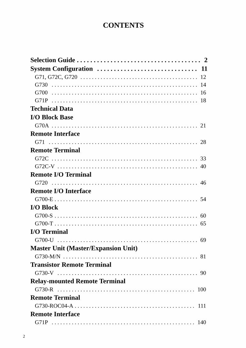
2
CONTENTS
Selection Guide 2. . . . . . . . . . . . . . . . . . . . . . . . . . . . . . . . . . . . .System Configuration 11. . . . . . . . . . . . . . . . . . . . . . . . . . . . . .
G71, G72C, G720 12. . . . . . . . . . . . . . . . . . . . . . . . . . . . . . . . . . . . . . . . .G730 14. . . . . . . . . . . . . . . . . . . . . . . . . . . . . . . . . . . . . . . . . . . . . . . . . . .G700 16. . . . . . . . . . . . . . . . . . . . . . . . . . . . . . . . . . . . . . . . . . . . . . . . . . .G71P 18. . . . . . . . . . . . . . . . . . . . . . . . . . . . . . . . . . . . . . . . . . . . . . . . . . .
Technical DataI/O Block Base
G70A 21. . . . . . . . . . . . . . . . . . . . . . . . . . . . . . . . . . . . . . . . . . . . . . . . . . .Remote Interface
G71 28. . . . . . . . . . . . . . . . . . . . . . . . . . . . . . . . . . . . . . . . . . . . . . . . . . . .Remote Terminal
G72C 33. . . . . . . . . . . . . . . . . . . . . . . . . . . . . . . . . . . . . . . . . . . . . . . . . . .G72C-V 40. . . . . . . . . . . . . . . . . . . . . . . . . . . . . . . . . . . . . . . . . . . . . . . . .
Remote I/O TerminalG720 46. . . . . . . . . . . . . . . . . . . . . . . . . . . . . . . . . . . . . . . . . . . . . . . . . . .
Remote I/O InterfaceG700-E 54. . . . . . . . . . . . . . . . . . . . . . . . . . . . . . . . . . . . . . . . . . . . . . . . . .
I/O BlockG700-S 60. . . . . . . . . . . . . . . . . . . . . . . . . . . . . . . . . . . . . . . . . . . . . . . . . .G700-T 65. . . . . . . . . . . . . . . . . . . . . . . . . . . . . . . . . . . . . . . . . . . . . . . . . .
I/O TerminalG700-U 69. . . . . . . . . . . . . . . . . . . . . . . . . . . . . . . . . . . . . . . . . . . . . . . . .
Master Unit (Master/Expansion Unit)G730-M/N 81. . . . . . . . . . . . . . . . . . . . . . . . . . . . . . . . . . . . . . . . . . . . . . .
Transistor Remote TerminalG730-V 90. . . . . . . . . . . . . . . . . . . . . . . . . . . . . . . . . . . . . . . . . . . . . . . . .
Relay-mounted Remote TerminalG730-R 100. . . . . . . . . . . . . . . . . . . . . . . . . . . . . . . . . . . . . . . . . . . . . . . .
Remote TerminalG730-ROC04-A 111. . . . . . . . . . . . . . . . . . . . . . . . . . . . . . . . . . . . . . . . . .
Remote InterfaceG71P 140. . . . . . . . . . . . . . . . . . . . . . . . . . . . . . . . . . . . . . . . . . . . . . . . . .

3
Classification According to Terminal CharacteristicsClassification I/O Block Base PROFIBUS SYSMAC BUS
Model G70A G71P G71 G72C
G72C G72C-V
Appearance
234 x 75 x 64(W x D x H)
60 x 85 x 63.5(W x D x H)
60 x 85 x 63.5(W x D x H)
182 x 85 x 45(W x D x H)
202 x 45 x 63(W x D x H)
Features I/O Blockconforming to VDEstandards.
I/O Bus Unitconforming toDIN19245.
I/O Unit for G70A. I/O Unit combined with I/O Block.
Communication speed --- 9.6/19.2/500 kbps 187.5 kbps
Relay G2R --- --- --- ---
Output capacity 10 A 30 mA 30 mA 0.3 A
I/O points 16 16 16 16
Applicable PC Unit --- C200H-PH C200H-RM201/3G2A5-RM201
Approved standards VDE --- UL/CSA UL/CSA
Other Relays are soldseparately.
I/O blocks are sold separately. ---
Page 22 141 29 34 41
Classification SYSMAC BUS SYSMAC BUS/2
Model G720 G700
G700-U G700-E G700-T G700-S
Appearance
208 x 91 x 60(W x D x H)
60 x 85 x 63.5(W x D x H)
60 x 85 x 63.5(W x D x H)
182 x 85 x 45(W x D x H)
202 x 45 x 63(W x D x H)
Features I/O Unit combinedwith I/O Blockincorporating IP67input connector.
I/O Bus Unitconforming toDIN19245.
I/O Unit forG70A-ZOC.
I/O Unit combined with I/O Block.
Communication speed 187.5 kbps 1.5 Mbps
Relay --- --- --- --- G7T
Output capacity --- 0.3 A 50 mA 0.3 A 2 A
I/O points 16 16 32 4
Applicable PC Unit C200H-RM201/3G2A5-RM201
CV500-RM221 G700-E
Approved standards --- ---
Other --- --- I/O blocks are soldseparately.
---
Page 47 70 55 66 61
Note: The SYSMAC BUS and SYSMAC BUS/2 systems allow connection of a maximum of 32 I/O Units.

4
Classification SYSMAC BUS
Model G730
G730-M G730-V16 G730-V8 G730-V4 G730-R4
Appearance
20 x 111 x 90(W x D x H)
115 x 50 x 67(W x D x H)
80 x 75 x 70(W x D x H)
Features General-purpose transmission system connecting to a variety of controllers.G730-M: MasterG730-V16/-V8/-R4: I/O Unit combined with I/O Block
Communication speed 187.5 kbps
Relay --- --- G2R
Output capacity 20 mA 0.3 A 5 A
I/O points 32 16 8 4 4
Applicable PC Unit Receiving NPNoutput.
G730-M/N
Approved standards ---
Other I/O blocks are soldseparately.
Applicable Remote Masters for SYSMAC BUS: C200H-RM201 and3G2A5-RM201
Page 82 91 101
Note: The SYSMAC BUS system allows connection of a maximum of 32 I/O Units.
PC and I/O Terminal ConnectionName Model C20H/40H/60H/
(Other maker’s PC)CQM1 C200H/C1000H CV500/CV1000
I/O Block G70A Using I/O connector(see note 1)
Connector connection Connector connection Connector connection(see note 2)
G70A + G71P Connection impossible Connection impossible Two wires (see note 6) Connection impossible
I/O Unit
p p p
G70A + G71 Connection impossible Connection impossible Two wires (see note 3) Two wires
I/O Unit(I/O Bl k)
G72C Connection impossible Connection impossible Two wires Two wires/(I/O Block) G720 Connection impossible Connection impossible Two wires Two wires
G730 Using I/O connector(see note 4)
Connection impossible Two wires; using I/Oconnector (see note 4)
Two wires; using I/Oconnector (see note 4)
G700 Connection impossible Connection impossible Connection impossible Two wires (see note 5)
Note: 1. Connection of G70A and Loose Wires: page 22
2. Connection of G70A and Connector: page 223. SYSMAC BUS: page 134. G730 Bus: page 155. SYSMAC BUS/2: page 176. PROFIBUS: page 19

5
Connection of G70A and PC CardsCQM1’s I/O Cards
I/O Unit G70A-ZIM16-5 G70A-ZOC16-3 G70A-ZOC16-4
CQM1-ID213 (32) G79-IjC-j --- ---
CQM1-OD213 (32) --- G79-OjC-j ---
CQM1-ID212 (16) G79-YjC/G79-AjC --- ---
CQM1-OD212 (16) --- G79-YjC/G79-AjC ---
CQM1-OD214 (16 PNP) --- --- G79-YjC/G79-AjC
Note: Data in parentheses represents the number of total points, the number of connectors, or the number of I/O points per connector. PNP orNPN description is required between the parentheses attached to Output Card model numbers.
C200H’s I/O CardsI/O Unit G70A-ZIM16-5 G70A-ZOC16-3 G70A-ZOC16-4
C200H-ID215 (32) G79-jC --- ---
C200H-MD215 (16/16) G79-jC G79-jC ---
C200H-OD215 (32) --- G79-jC ---
C200H-ID216 (32) G79-IjC-j --- ---
C200H-ID217 (64) G79-IjC-j --- ---
C200H-OD218 (32) --- G79-OjC-j ---
C200H-OD219 (64) --- G79-OjC-j ---
C200H-ID212 (16) G79-YjC/G79-AjC --- ---
C200H-OD212 (16) --- G79-YjC/G79-AjC ---
C200H-OD214 (8 PNP) --- --- G79-YjC/G79-AjC
C200H-OD217 (12 PNP) --- --- G79-YjC/G79-AjC
C1000H’s I/O CardsI/O Unit G70A-ZIM16-5 G70A-ZOC16-3 G70A-ZOC16-4
3G2A5-ID218 (32) G79-YjC/G79-AjC --- ---
3G2A5-MD211CN (16/16) G79-jC G79-jC ---
3G2A5-OD215 (16) --- G79-YjC/G79-AjC ---
3G2A5-ID218CN (32) G79-jC --- ---
3G2A5-OD218 (32) --- G79-YjC/G79-AjC ---
3G2A5-ID212 (64) G79-YjC/G79-AjC --- ---
3G2A5-OD212 (32 PNP) --- --- G79-YjC/G79-AjC
C500-OD219 (16) G79-IjC-j --- ---
3G2A5-OD213 (64) --- G79-OjC-j ---
Note: The G79 is an I/O cable.
SYSMAC C-series (SYSMAC BUS)PC I/O Unit I/O Block Page
C200H-RM201 or3G2A RM201 (SYSMAC BUS)
G71-IC G70A-ZIM 22, 293G2A5-RM201 (SYSMAC BUS) G71-OD G70A-ZOC
G72-IN 34, 41
G72-OUT
G720-VID16C 47
G730-IN 82, 91, 101, 112
G730-OUT
6
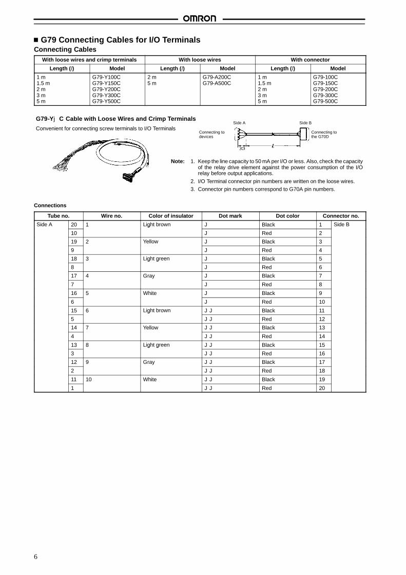
G79 Connecting Cables for I/O TerminalsConnecting Cables
With loose wires and crimp terminals With loose wires With connector
Length (l) Model Length (l) Model Length (l) Model
1 m1.5 m2 m3 m5 m
G79-Y100CG79-Y150CG79-Y200CG79-Y300CG79-Y500C
2 m5 m
G79-A200CG79-A500C
1 m1.5 m2 m3 m5 m
G79-100CG79-150CG79-200CG79-300CG79-500C
G79-YjC Cable with Loose Wires and Crimp Terminals
Convenient for connecting screw terminals to I/O Terminals
Note: 1. Keep the line capacity to 50 mA per I/O or less. Also, check the capacityof the relay drive element against the power consumption of the I/Orelay before output applications.
2. I/O Terminal connector pin numbers are written on the loose wires.3. Connector pin numbers correspond to G70A pin numbers.
Connecting todevices
Connecting tothe G70D
Side A Side B
Connections
Tube no. Wire no. Color of insulator Dot mark Dot color Connector no.
Side A 20 1 Light brown J Black 1 Side B
10
g
J Red 2
19 2 Yellow J Black 3
9 J Red 4
18 3 Light green J Black 5
8
g g
J Red 6
17 4 Gray J Black 7
7 J Red 8
16 5 White J Black 9
6 J Red 10
15 6 Light brown JJ Black 11
5
g
JJ Red 12
14 7 Yellow JJ Black 13
4 JJ Red 14
13 8 Light green JJ Black 15
3
g g
JJ Red 16
12 9 Gray JJ Black 17
2 JJ Red 18
11 10 White JJ Black 19
1 JJ Red 20

7
G79-AjC Cable with Loose Wires
Device connection end provides loose wires.
Note: 1. Loose wires are AWG24 (wire diameter: 0.6 mm).2. Connector pin numbers correspond to G70A pin numbers.
Connecting toperipheral devices
Connecting tothe G70D
Side A Side B
Connections
Tube no. Wire no. Color of insulator Dot mark Dot color Connector no.
Side A 1 Light brown J Black 20 Side Bg
J Red 19
2 Yellow J Black 18
J Red 17
3 Light green J Black 16g g
J Red 15
4 Gray J Black 14
J Red 13
5 White J Black 12
J Red 11
6 Light brown JJ Black 10g
JJ Red 9
7 Yellow JJ Black 8
JJ Red 7
8 Light green JJ Black 6g g
JJ Red 5
9 Gray JJ Black 4
JJ Red 3
10 White JJ Black 2
JJ Red 1
G79-jC Cable with Connector (1:1)
Convenient for 1:1 connection of various devices to I/O Terminals.
Side ASide B
Connections
Note: Connector pin numbers correspond to G70A pin numbers.
12
11
10
9
8
7
6
5
4
3
2
120 19
18
16
14
12
10
8
6
4
2
17
15
13
11
9
7
5
3
1
12
11
10
9
8
7
6
5
4
3
2
1
PC connector pin No.A B
I/O Relay Terminalconnector pin No.
Triangle mark
G79 Cable withconnector (1:1)

8
G79-OjC-j/-IjC-j Cable with Connectors (1:2)Both Input and Output Cables available (Input: connect to PC I/O Units, tape color: red; Output: connect to PC I/O Units, tape color: yellow)
Length For input For output
A B Model Model
1 m1.5 m2 m3 m5 m
0.75 m1.25 m1.75 m2.75 m4.75 m
G79-I100C-75G79-I150C-125G79-I200C-175G79-I300C-275G79-I500C-475
G79-O100C-75G79-O150C-125G79-O200C-175G79-O300C-275G79-O500C-475
Straight-line distance(no curves)
Side A Side B2
Side B1
SYSMAC CV-series (SYSMAC BUS/2)PC Unit I/O Terminal I/O Block Page
CV500-RM221 (SYSMACBUS/2)
G700-IN 55, 61, 66, 70(BUS/2) G700-OUT
C200H-RM201 or3G2A RM201 (SYSMAC BUS)
G71-IC16-3 G70A-ZIM 22, 293G2A5-RM201 (SYSMAC BUS) G71-OD16 G70A-ZOC
G72-IN 34, 41
G72-OUT
G720-VID16C 47
G730-IN 82, 91, 101, 112
G730-OUT
Note: If I/O Terminals and/or I/O Blocks other than G700 Models are connected, the system functions will conform to those of the SYSMACBUS system.
G71P PROFIBUSPC Unit I/O Terminal I/O Block Page
C200H-PFB21 G71P-IC G70A-ZIM 22, 29
G71P-OD G70A-ZOC

9
System ConfigurationWith G79 Connecting Cable
Saves wiring effort and panel-mounting space.
Prevents wiring mistakes.
Reduces the number of wiring steps.
Photoelectricsensor
Proximitysensor Limit switch
Input Devices
Output Devices
Motor Solenoid Valve
C200H-ID215C200H-OD215C200H-MD2153G2A5-ID218CN3G2A5-OD415CN3G2A5-MD211CN
G70A-ZOC16-3
G79 ConnectingCable (1:1)
G79-I, G79-OConnectingCable (1:2)
G70A-ZOC16-3
G70A-ZOC16-3
G79-Y Cable withcrimp-style
terminalsG79-Y Cable withcrimp-style terminalsor G79-A Cable withloose wires
PC (Programmable Controller)
3G2A5-ID2193G2A5-OD213
G70A-ZIM16-5
G70A-ZIM16-5
10
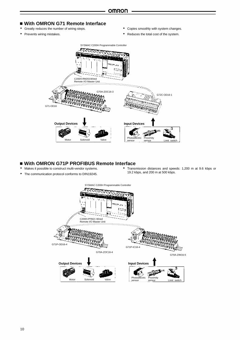
With OMRON G71 Remote Interface Greatly reduces the number of wiring steps.
Prevents wiring mistakes.
Copies smoothly with system changes.
Reduces the total cost of the system.
C200H-RM201WiredRemote I/O Master Unit
SYSMAC C200H Programmable Controller
G70A-ZOC16-3G72C-OD16-1
Photoelectricsensor
Proximitysensor Limit switch
Input DevicesOutput Devices
Motor Solenoid Valve
G71-OD16
With OMRON G71P PROFIBUS Remote Interface Makes it possible to construct multi-vendor systems.
The communication protocol conforms to DIN19245.
Transmission distances and speeds: 1,200 m at 9.6 kbps or19.2 kbps, and 200 m at 500 kbps.
C200H-PFB21 WiredRemote I/O Master Unit
SYSMAC C200H Programmable Controller
Photoelectricsensor
Proximitysensor Limit switch
Input DevicesOutput Devices
Motor Solenoid Valve
G71P-OD16-4
G70A-ZOC16-4
G71P-IC16-4
G70A-ZIM16-5

11
Mounted with Relay and SSR (G70A)G2RApplicable Models
Models Coil ratings Contact form Accessory Applicable I/O Model
G2R-1-SN 24 VDC SPDT-NO/NC Operation indicator G70A-ZOC16-3G70A-ZOC16-4
G2R-1A3-SN 12/24 VDC110/230 VAC
SPST-NO G70A-ZIM16-5
G2R-13-SN
/110/230 VAC SPDT-NO/NC
G2R-1A3-SND 12/24 VDC SPST-NO Operation indicator +di dG2R-13-SND SPDT-NO/NC
pdiode
Contact Ratings
Item G2R-1-SN
Load Resistive load (cosf = 1) Inductive load (cosf = 0.4; L/R = 7 ms)
Rated load 10 A at 250 VAC; 10 A at 30 VDC 7.5 A at 250 VAC;5 A at 30 VDC
Rated carry current 10 A
Max. operating voltage 400 VAC, 125 VDC
Max. operating current 10 A
Min. permissible load 100 mA at 5 VDC
Max. switching capacity 2,500 VA, 300 W 1,875 VA, 150 W
G3RApplicable Models
Models Coil ratings Contact form Accessory Applicable I/O Model
G3R-OA202SZN 5 to 24 VDC SPST-NO (zero cross) forAC
Operation indicator G70A-ZOC16-3G70A-ZOC16-4
G3R-OA202SLN SPST-NO for AC
G3R-ODX02SN SPST-NO for DC
G3R-OD201SN 100 to 240 VAC,VDC 12 2 VDC
SPST-NO for DC
G3R-IAZR1SN
,5 VDC, 12 to 24 VDC G70A-ZIM16-5
G3R-IDZR1SN
G3R-IDZR1SN-1 SPST-NO (high speed) forDC
Ratings
Model Applicable load voltage Output current Inrush current
G3R-OA202SZN 75 to 264 VAC 0.05 to 2 A 30 A (60 Hz, 1 cycle)
G3R-OA202SLN
G3R-ODX02SN 4 to 60 VDC 0.01 to 2 A 8 A (10 ms)
G3R-OD201SN 40 to 200 VDC 0.01 to 1.5 A 8 A (10 ms)
G3R-IAZR1SN 4 to 32 VDC 0.1 to 100 mA ---
G3R-IDZR1SN
G3R-IDZR1SN-1
12
System ConfigurationSYSMAC BUS
G71 , G72C, G720 12. . . . . . . . . . . . . . . . . . . . . . . . . . . . . . . . . . . . . . . . . . . . . . . . .
Original BUS
G730 14. . . . . . . . . . . . . . . . . . . . . . . . . . . . . . . . . . . . . . . . . . . . . . . . . . . . . . . . . . . .
SYSMAC BUS/2
G700 16. . . . . . . . . . . . . . . . . . . . . . . . . . . . . . . . . . . . . . . . . . . . . . . . . . . . . . . . . . . .
PROFIBUS
G71P 18. . . . . . . . . . . . . . . . . . . . . . . . . . . . . . . . . . . . . . . . . . . . . . . . . . . . . . . . . . . .

13
I/O Terminal (SYSMAC BUS)
C200H-RM201WiredRemote I/O Master Unit
SYSMAC C200H Programmable Controller
Two-conductorcable
G71-OD16
G70A-ZOC16-3
Photoelectricsensor
Proximitysensor Limit switch
Input Devices
Output Devices
Motor Solenoid Valve
Photoelectricsensor
Proximitysensor Limit switch
Input Devices
Remote Terminals and I/O Blocks can be connected in series with 2-conductor cables (VCTF0.75 recommended) to construct a Local I/O Network with a maximum total transmissiondistance of 200 m and a transmission time of 2 ms multiplied by the number of G71 and G72CRemote Terminals in the Network. Up to 32 nodes can be designed into the Network. Witheach node consisting of a G72C Remote Terminal or a pair of G71 Remote Interface and I/OBlock. All Remote Terminals and I/O Blocks must be provided with a power supply. Althoughthe Network below use a C200H Programmable Controller (PC), a C500 PC can also be used.
Connection possible to up to32 terminals total.
G72C-OD16(-1)G72C-VOD16
Output Devices
Input Devices
Output Devices
Input Devices
Solenoid, etc.
Photoelectricsensor, etc.
PCB display panel
PCB control panel
G71-OD16
G71-IC16
G72C-ID16(-1)G72C-VID16
G72C-OD16
G720
14
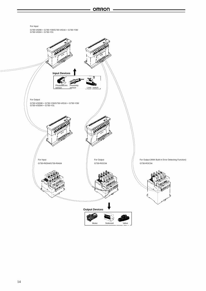
For Input
G730-VID08 + G730-Y30/G730-VID16 + G730-Y30/G730-VID04 + G730-Y31
For Output
G730-VOD08 + G730-Y30/G730-VID16 + G730-Y30/G730-VOD04 + G730-Y31
For Input
G730-RID04/G730-RIA04
For Output
G730-ROC04
For Output (With Built-in Error Detecting Function)
G730-ROC04
Photoelectricsensor
Proximitysensor Limit switch
Input Devices
Output Devices
Motor Solenoid Valve

15
G730 Remote Terminals Connect to General-purpose Transmission Systems andSaves Wiring Effort
G730 Remote Terminals collectively transmit signals that are input from sensors and switches, and signals that are output to PCs, motors, andvalves over a single two-conductor cable. It is possible to use G730 Remote Terminals as Remote I/O Units in SYSMAC BUS systems. G730Remote Terminals connect to a variety of controllers via a G730-M Master Unit, thus making it possible to construct general-purpose transmis-sion systems that save wiring effort and reduce mounting space.
Directly Connecting to OMRON’s PCs andWired SYSMAC BUS Systems
A G730-V or G730-R Remote Terminal directly connects to OM-RON C-series PCs over a single two-conductor cable. It is possibleto use G730 Remote Terminal and wired SYSMAC BUS Units suchas G72C and G71 Units together in the same system. G730-V-se-ries and G730-R-series Models are available with 16, 8, or 4 pointsand are ideal for small-scale applications or system expansion pur-poses.
C200HS/C200HCVM1/CVRemote I/O Master Unit
G71
G72C
G730-V/-R
Constructing General-purpose Systems withEase
A general-purpose transmission system can be constructed withease by connecting the G730-M Master to a variety of controllersand personal computers. The Master alone allows 32-point signaltransmission. A maximum of three G730-N Expansion Units can beconnected to the Master. If three G730-N Expansion Units are con-nected to the Master, it will be possible to control a maximum of 128points.
Constructing Safe SystemsG730-ROC04-A-series models are the world’s first remote termi-nals with an error detecting function and indicator. With this function,the indicator will be lit if there is incorrect relay contact or contactweld. Furthermore, the error detecting signal will be fed back to theMaster or PC.
G730-M
G730-ROC04-A
Control signal
Error detecting signal
Constructing Low-cost SystemsA series of G730 Remote Terminals with 16, 8, or 4 I/O points isavailable. These input and output models can be freely combined,which makes it possible to adjust the number of I/O points accordingto the application and to construct low-cost systems. G730 RemoteTerminals are ideal for small-scale lines and applications that do notrequire any I/O point.
Constructing Space-saving SystemsThe G730-VjD16 is approximately one-third the size of the con-ventional G72C(-V) and does not require much mounting space,thus making it possible to reduce the size of the panel. By using anadaptor, the G730-VjD16 can be DIN-track mounted.
16
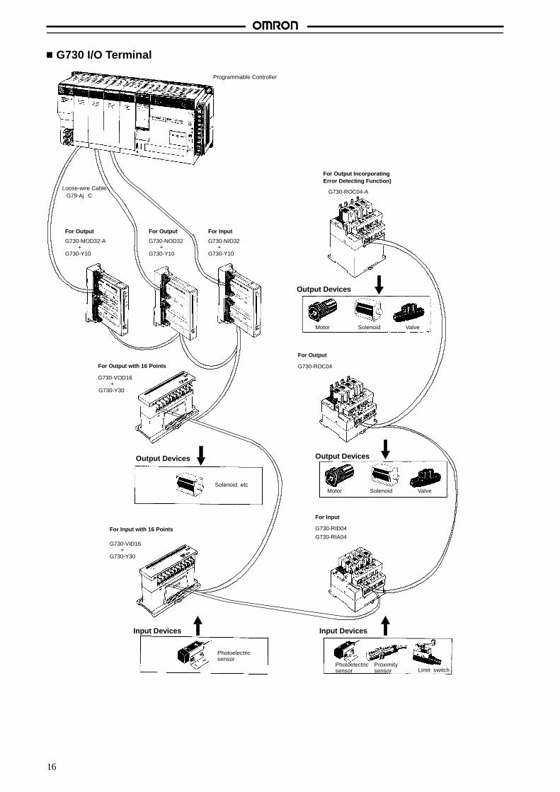
G730 I/O Terminal
Solenoid. etc
Output Devices
Photoelectricsensor
Proximitysensor Limit switch
Input Devices
Motor Solenoid Valve
Output Devices
Photoelectricsensor
Motor Solenoid Valve
Output Devices
Loose-wire Cable
For Output with 16 Points
For Output IncorporatingError Detecting Function)
For Output For Output For Input
Input Devices
G730-VOD16
G730-Y30+
G730-VID16
G730-Y30+
For Input with 16 Points
G730-MOD32-A
G730-Y10+
G79-AjC
G730-NOD32
G730-Y10+
G730-NID32
G730-Y10+
For Output
G730-ROC04
For Input
G730-RID04
G730-RIA04
G730-ROC04-A
Programmable Controller
17
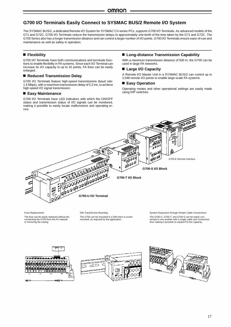
G700 I/O Terminals Easily Connect to SYSMAC BUS/2 Remote I/O System
The SYSMAC BUS/2, a dedicated Remote I/O System for SYSMAC CV-series PCs, supports G700 I/O Terminals. As advanced models of theG71 and G72C, G700 I/O Terminals reduce the transmission delays to approximately one-tenth of the time taken by the G71 and G72C. TheG700 Series also has a longer transmission distance and can control a larger number of I/O points. G700 I/O Terminals ensure ease-of-use andmaintenance as well as safety in operation.
FlexibilityG700 I/O Terminals have both communications and terminals func-tions to enable flexibility in FA systems. Since each I/O Terminal canincrease its I/O capacity to up to 32 points, FA lines can be easilyenlarged.
Reduced Transmission DelayG700 I/O Terminals feature high-speed transmissions (baud rate:1.5 Mbps), with a maximum transmission delay of 5.2 ms, to achievehigh-speed I/O signal transmission.
Easy MaintenanceG700 I/O Terminals have LED indicators with which the ON/OFFstatus and transmission status of I/O signals can be monitored,making it possible to easily locate malfunctions and operating er-rors.
Long-distance Transmission CapabilityWith a maximum transmission distance of 500 m, the G700 can beused in large FA networks.
Large I/O CapacityA Remote I/O Master Unit in a SYSMAC BUS/2 can control up to2,048 remote I/O points to enable large-scale FA systems.
Easy OperationOperating modes and other operational settings are easily madeusing DIP switches.
G700-U I/O Terminal
G700-T I/O Block
G700-S I/O Block
G700-E Remote Interface
Fuse Replacement
The fuse can be easily replaced without dis-connecting the G700 from the FA networkor removing the casing.
DIN Track/Screw Mounting
The G700 can be mounted to a DIN track or screw-mounted, as required by the application.
System Expansion through Simple Cable Connections
The G700-U, G700-T, and G700-S can be easily con-nected to one another with a single cable and connectors,thus making it possible to expand FA line capacity.
18
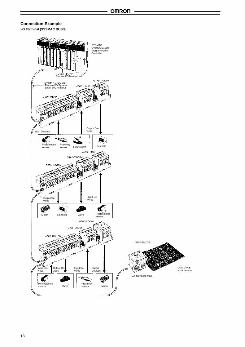
Connection ExampleI/O Terminal (SYSMAC BUS/2)
Input DevicesOutput De-vices
SolenoidLimit switchProximitysensor
Photoelectricsensor
Photoelectricsensor
Motor Solenoid Valve
Photoelectricsensor Valve
Proximitysensor Motor
SYSMACCV500/CV1000ProgrammableController
Remote I/O Master Unit
Remote I/O System(total: 500 m max.)
Output De-vices
Input De-vices
OutputDevices
Input De-vices
Output De-vices
G700-EMD32
G700-SOC04
32 Interfaces max.
User’s PCBinput devices
Input De-vices
19
G71PFeaturesThe G71P-jj16-4 Remote Interface connects aG70A-jjj16-j I/O Block or User’s designing board to a PROFI-BUS network.The G71P-jj16-4 acts as a PROFIBUS Slave which supports thecomplete PROFIBUS protocol and contains a PROFIBUS applica-tion program that covers the following operations:
Automatic data exchange with a PROFIBUS Master similar tothat in the SYSMAC BUS.
10 kinds of services.
10 Masters can be accessed at the same time.
The G71P-jj16-4 Remote Interface has 16 I/O points of distrib-uted control.
PROFIBUSGeneral InformationPROFIBUS is an international field bus standard which was origi-nally specified by a group of equipment manufacturers and spon-sored by the German Federal Ministry for Research and Technolo-gy.PROFIBUS realizes a 3-layer stack (Layer 1, 2 and 7) correspond-ing to the ISO/OSI model of open communication.
The PROFIBUS protocol is defined in the German Standard“DIN19245”. DIN19245-part 1 defines Layer 1 (physical layer) andLayer 2 (data link layer), and DIN19245-part 2 defines Layer 7 (ap-plication layer).Layer 7 of the PROFIBUS protocol, FMS (Field Message Service)offers a subset of MAP Layer 7 services called MMS (ManufacturingMessage Service).
System ConfigurationIn a PROFIBUS system, three different parameters must be definedbefore operation. These parameters are:
Bus parameters
Communication Reference List (CRL, or KBL in German)
Object Dictionary (OD, or OV in German)
G71P-jj16-4 PROFIBUS System provides 2 different ways ofsetting some of these parameters. These are:
Default Configuration
Configuration through communications
ServicesThe G71P-jj16-4 supports the complete PROFIBUS protocol. The following services are supported:
Service Description
Initiate With this service a connection between two communication partners is established.
Abort With this service an existing connection between two communication partners is aborted. An abort request orabort response is generated automatically without involving the application program.
Status This service is used to read the statuses of the Unit and application program.
Identify This service allows a communication partner to read basic information about a virtual field device via the bus.The identification consists of:
Vendor name
Model name
Revision
The listed strings and numbers in the identification list above are transmitted.
Get-OD This service accesses the Object Dictionary (OD). Addressing via the object name is not provided, but the ob-ject name is accessed in a subsequent Get-OD response. The short and long forms of the Get-OD service aresupported.
Read This service is used to read objects. Access must be made via the index. A cyclic Read is not possible since thiswould slow down the average reaction time of the whole system.
Write This service is used to write objects. Access must be made via the index. A cyclic Write is not possible since thiswould slow down the average reaction time of the whole system.
Physical Read With this service a direct read access to the physical memory of the processor is possible.
Physical Write With this service a direct write access to the physical memory of the processor is possible.
Information Report With this service a remote unit can transmit simple-variable objects, arrays, and records to a server.

20
PROFIBUS System ConfigurationThe following diagram shows the configuration of a PROFIBUS System.
Master 1 Master 2
G71P-ID16-4
G71P-OD16-4
G71P-IC16-4
Slave 1 Slave 2
Other maker’s Other maker’s
Othermaker’s
Othermaker’s
Repeater
Personalcomputer
PFB21 CPUC200H
Connections At least one Remote I/O Master Unit is required to connect G71P-jj16-4 Units to a PROFIBUS System. G71P-jj16-4Units must be bus-connected to a Master Unit.

21
Technical Data
I/O Block Base
G70A 21. . . . . . . . . . . . . . . . . . . . . . . . . . . . . . . . . . . . . . . . . . . . . . . . . . . . . . . . . . . .
Remote Interface
G71 28. . . . . . . . . . . . . . . . . . . . . . . . . . . . . . . . . . . . . . . . . . . . . . . . . . . . . . . . . . . . .
Remote Terminal33
G72C 33. . . . . . . . . . . . . . . . . . . . . . . . . . . . . . . . . . . . . . . . . . . . . . . . . . . . . . . . . . . .G72C-V 40. . . . . . . . . . . . . . . . . . . . . . . . . . . . . . . . . . . . . . . . . . . . . . . . . . . . . . . . . .
Remote I/O Terminal
G720 46. . . . . . . . . . . . . . . . . . . . . . . . . . . . . . . . . . . . . . . . . . . . . . . . . . . . . . . . . . . .
Remote I/O Interface
G700-E 54. . . . . . . . . . . . . . . . . . . . . . . . . . . . . . . . . . . . . . . . . . . . . . . . . . . . . . . . . .
I/O Block
G700-S 60. . . . . . . . . . . . . . . . . . . . . . . . . . . . . . . . . . . . . . . . . . . . . . . . . . . . . . . . . .G700-T 65. . . . . . . . . . . . . . . . . . . . . . . . . . . . . . . . . . . . . . . . . . . . . . . . . . . . . . . . . .
I/O Terminal
G700-U 69. . . . . . . . . . . . . . . . . . . . . . . . . . . . . . . . . . . . . . . . . . . . . . . . . . . . . . . . . .
Master Unit (Master/Expansion Unit)
G730-M/N 81. . . . . . . . . . . . . . . . . . . . . . . . . . . . . . . . . . . . . . . . . . . . . . . . . . . . . . . .
Transistor Remote Terminal
G730-V 90. . . . . . . . . . . . . . . . . . . . . . . . . . . . . . . . . . . . . . . . . . . . . . . . . . . . . . . . . .
Relay-mounted Remote Terminal
G730-R 100. . . . . . . . . . . . . . . . . . . . . . . . . . . . . . . . . . . . . . . . . . . . . . . . . . . . . . . . .
Remote Terminal
G730-ROC04-A 111. . . . . . . . . . . . . . . . . . . . . . . . . . . . . . . . . . . . . . . . . . . . . . . . . .
Remote Interface
G71P 140. . . . . . . . . . . . . . . . . . . . . . . . . . . . . . . . . . . . . . . . . . . . . . . . . . . . . . . . . . .
22
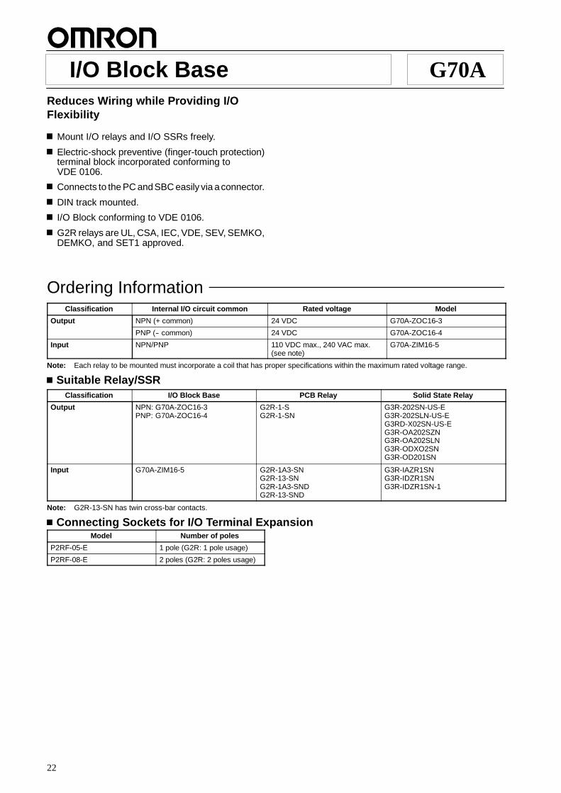
I/O Block Base G70AReduces Wiring while Providing I/OFlexibility
Mount I/O relays and I/O SSRs freely.
Electric-shock preventive (finger-touch protection)terminal block incorporated conforming toVDE 0106.
Connects to the PC andSBC easily via aconnector.
DIN track mounted.
I/O Block conforming to VDE 0106.
G2R relays are UL, CSA, IEC, VDE, SEV, SEMKO,DEMKO, and SET1 approved.
Ordering InformationClassification Internal I/O circuit common Rated voltage Model
Output NPN (+ common) 24 VDC G70A-ZOC16-3
PNP (-- common) 24 VDC G70A-ZOC16-4
Input NPN/PNP 110 VDC max., 240 VAC max.(see note)
G70A-ZIM16-5
Note: Each relay to be mounted must incorporate a coil that has proper specifications within the maximum rated voltage range.
Suitable Relay/SSRClassification I/O Block Base PCB Relay Solid State Relay
Output NPN: G70A-ZOC16-3PNP: G70A-ZOC16-4
G2R-1-SG2R-1-SN
G3R-202SN-US-EG3R-202SLN-US-EG3RD-X02SN-US-EG3R-OA202SZNG3R-OA202SLNG3R-ODXO2SNG3R-OD201SN
Input G70A-ZIM16-5 G2R-1A3-SNG2R-13-SNG2R-1A3-SNDG2R-13-SND
G3R-IAZR1SNG3R-IDZR1SNG3R-IDZR1SN-1
Note: G2R-13-SN has twin cross-bar contacts.
Connecting Sockets for I/O Terminal ExpansionModel Number of poles
P2RF-05-E 1 pole (G2R: 1 pole usage)
P2RF-08-E 2 poles (G2R: 2 poles usage)
G70A G70A
23
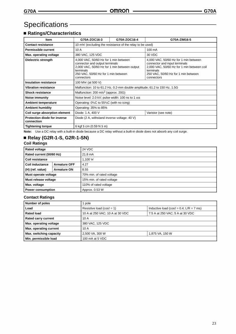
SpecificationsRatings/Characteristics
Item G70A-ZOC16-3 G70A-ZOC16-4 G70A-ZIM16-5
Contact resistance 10 mW (excluding the resistance of the relay to be used)
Permissible current 10 A 100 mA
Max. operating voltage 380 VAC, 125 VDC 30 VDC
Dielectric strength 4,000 VAC, 50/60 Hz for 1 min betweenconnector and output terminals2,000 VAC, 50/60 Hz for 1 min between outputterminals250 VAC, 50/60 Hz for 1 min betweenconnectors
4,000 VAC, 50/60 Hz for 1 min betweenconnector and input terminals2,000 VAC, 50/60 Hz for 1 min between coilterminals250 VAC, 50/60 Hz for 1 min betweenconnectors
Insulation resistance 100 MW (at 500 V)
Vibration resistance Malfunction: 10 to 61.2 Hz, 0.2-mm double amplitude; 61.2 to 150 Hz, 1.5G
Shock resistance Malfunction: 200 m/s2 (approx. 20G)
Noise immunity Noise level: 2.0 kV; pulse width: 100 ns to 1 ms
Ambient temperature Operating: 0%C to 55%C (with no icing)
Ambient humidity Operating: 35% to 85%
Coil surge absorption element Diode: 1 A, 400 V Varistor (see note)
Protection diode for inverseconnection
Diode (2 A, withstand inverse voltage: 40 V)
Tightening torque 6 kgf $ cm (0.59 N $ m)
Note: Use a DC relay with a built-in diode because a DC relay without a built-in diode does not absorb any coil surge.
Relay (G2R-1-S, G2R-1-SN)Coil RatingsRated voltage 24 VDC
Rated current (50/60 Hz) 21.8 mA
Coil resistance 1,100 W
Coil inductance Armature OFF 4.27
(H) (ref. value) Armature ON 8.55
Must operate voltage 70% min. of rated voltage
Must release voltage 15% min. of rated voltage
Max. voltage 110% of rated voltage
Power consumption Approx. 0.53 W
Contact RatingsNumber of poles 1 pole
Load Resistive load (cosf = 1) Inductive load (cosf = 0.4; L/R = 7 ms)
Rated load 10 A at 250 VAC; 10 A at 30 VDC 7.5 A at 250 VAC; 5 A at 30 VDC
Rated carry current 10 A
Max. operating voltage 380 VAC, 125 VDC
Max. operating current 10 A
Max. switching capacity 2,500 VA, 300 W 1,875 VA, 150 W
Min. permissible load 100 mA at 5 VDC
G70A G70A
24
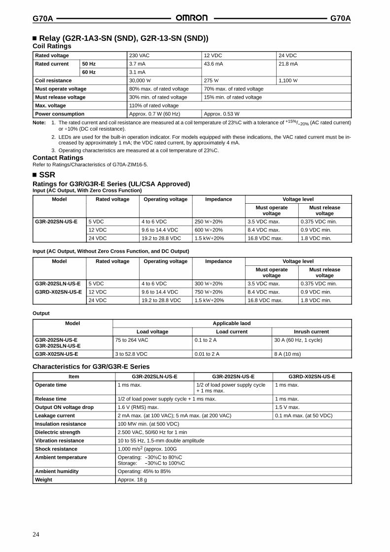
Relay (G2R-1A3-SN (SND), G2R-13-SN (SND))Coil RatingsRated voltage 230 VAC 12 VDC 24 VDC
Rated current 50 Hz 3.7 mA 43.6 mA 21.8 mA
60 Hz 3.1 mA
Coil resistance 30,000 W 275 W 1,100 W
Must operate voltage 80% max. of rated voltage 70% max. of rated voltage
Must release voltage 30% min. of rated voltage 15% min. of rated voltage
Max. voltage 110% of rated voltage
Power consumption Approx. 0.7 W (60 Hz) Approx. 0.53 W
Note: 1. The rated current and coil resistance are measured at a coil temperature of 23%C with a tolerance of +15%/--20% (AC rated current)or +10% (DC coil resistance).
2. LEDs are used for the built-in operation indicator. For models equipped with these indications, the VAC rated current must be in-creased by approximately 1 mA; the VDC rated current, by approximately 4 mA.
3. Operating characteristics are measured at a coil temperature of 23%C.Contact RatingsRefer to Ratings/Characteristics of G70A-ZIM16-5.
SSRRatings for G3R/G3R-E Series (UL/CSA Approved)Input (AC Output, With Zero Cross Function)
Model Rated voltage Operating voltage Impedance Voltage level
Must operatevoltage
Must releasevoltage
G3R-202SN-US-E 5 VDC 4 to 6 VDC 250 W+20% 3.5 VDC max. 0.375 VDC min.
12 VDC 9.6 to 14.4 VDC 600 W+20% 8.4 VDC max. 0.9 VDC min.
24 VDC 19.2 to 28.8 VDC 1.5 kW+20% 16.8 VDC max. 1.8 VDC min.
Input (AC Output, Without Zero Cross Function, and DC Output)
Model Rated voltage Operating voltage Impedance Voltage level
Must operatevoltage
Must releasevoltage
G3R-202SLN-US-E 5 VDC 4 to 6 VDC 300 W+20% 3.5 VDC max. 0.375 VDC min.
G3RD-X02SN-US-E 12 VDC 9.6 to 14.4 VDC 750 W+20% 8.4 VDC max. 0.9 VDC min.
24 VDC 19.2 to 28.8 VDC 1.5 kW+20% 16.8 VDC max. 1.8 VDC min.
Output
Model Applicable laod
Load voltage Load current Inrush current
G3R-202SN-US-EG3R-202SLN-US-E
75 to 264 VAC 0.1 to 2 A 30 A (60 Hz, 1 cycle)
G3R-X02SN-US-E 3 to 52.8 VDC 0.01 to 2 A 8 A (10 ms)
Characteristics for G3R/G3R-E SeriesItem G3R-202SLN-US-E G3R-202SN-US-E G3RD-X02SN-US-E
Operate time 1 ms max. 1/2 of load power supply cycle+ 1 ms max.
1 ms max.
Release time 1/2 of load power supply cycle + 1 ms max. 1 ms max.
Output ON voltage drop 1.6 V (RMS) max. 1.5 V max.
Leakage current 2 mA max. (at 100 VAC); 5 mA max. (at 200 VAC) 0.1 mA max. (at 50 VDC)
Insulation resistance 100 MW min. (at 500 VDC)
Dielectric strength 2.500 VAC, 50/60 Hz for 1 min
Vibration resistance 10 to 55 Hz, 1.5-mm double amplitude
Shock resistance 1,000 m/s2 (approx. 100G
Ambient temperature Operating: --30%C to 80%CStorage: --30%C to 100%C
Ambient humidity Operating: 45% to 85%
Weight Approx. 18 g
G70A G70A
25
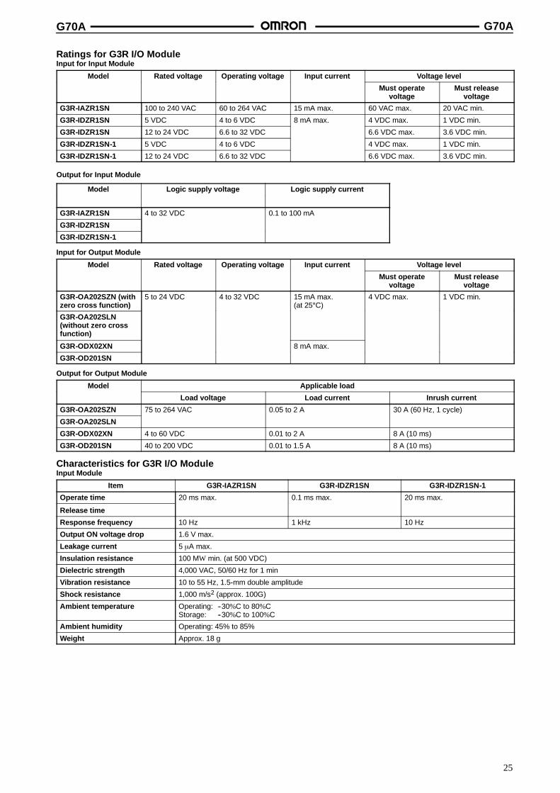
Ratings for G3R I/O ModuleInput for Input Module
Model Rated voltage Operating voltage Input current Voltage level
Must operatevoltage
Must releasevoltage
G3R-IAZR1SN 100 to 240 VAC 60 to 264 VAC 15 mA max. 60 VAC max. 20 VAC min.
G3R-IDZR1SN 5 VDC 4 to 6 VDC 8 mA max. 4 VDC max. 1 VDC min.
G3R-IDZR1SN 12 to 24 VDC 6.6 to 32 VDC 6.6 VDC max. 3.6 VDC min.
G3R-IDZR1SN-1 5 VDC 4 to 6 VDC 4 VDC max. 1 VDC min.
G3R-IDZR1SN-1 12 to 24 VDC 6.6 to 32 VDC 6.6 VDC max. 3.6 VDC min.
Output for Input Module
Model Logic supply voltage Logic supply current
G3R-IAZR1SN 4 to 32 VDC 0.1 to 100 mA
G3R-IDZR1SN
G3R-IDZR1SN-1
Input for Output Module
Model Rated voltage Operating voltage Input current Voltage level
Must operatevoltage
Must releasevoltage
G3R-OA202SZN (withzero cross function)
5 to 24 VDC 4 to 32 VDC 15 mA max.(at 25C)
4 VDC max. 1 VDC min.
G3R-OA202SLN(without zero crossfunction)
G3R-ODX02XN 8 mA max.
G3R-OD201SN
Output for Output Module
Model Applicable load
Load voltage Load current Inrush current
G3R-OA202SZN 75 to 264 VAC 0.05 to 2 A 30 A (60 Hz, 1 cycle)
G3R-OA202SLN
G3R-ODX02XN 4 to 60 VDC 0.01 to 2 A 8 A (10 ms)
G3R-OD201SN 40 to 200 VDC 0.01 to 1.5 A 8 A (10 ms)
Characteristics for G3R I/O ModuleInput Module
Item G3R-IAZR1SN G3R-IDZR1SN G3R-IDZR1SN-1
Operate time 20 ms max. 0.1 ms max. 20 ms max.
Release time
Response frequency 10 Hz 1 kHz 10 Hz
Output ON voltage drop 1.6 V max.
Leakage current 5 ←A max.
Insulation resistance 100 MW min. (at 500 VDC)
Dielectric strength 4,000 VAC, 50/60 Hz for 1 min
Vibration resistance 10 to 55 Hz, 1.5-mm double amplitude
Shock resistance 1,000 m/s2 (approx. 100G)
Ambient temperature Operating: --30%C to 80%CStorage: --30%C to 100%C
Ambient humidity Operating: 45% to 85%
Weight Approx. 18 g

G70A G70A
26
Output Module
Item G3R-OA202SZN G3R-OA202SLN G3R-ODX02SN G3R-OD201SN
Operate time 1/2 of load power supply cycle + 1 ms max. 1 ms max.
Release time 2 ms max.
Response frequency 20 Hz 100 Hz
Output ON voltage drop 1.6 V max. 2.5 V max.
Leakage current 1.5 mA max. 1 mA max.
Insulation resistance 100 MW min. (at 500 VDC)
Dielectric strength 4,000 VAC, 50/60 Hz for 1 min
Vibration resistance 10 to 55 Hz, 1.5-mm double amplitude
Shock resistance 1,000 m/s2 (approx. 100G)
Ambient temperature Operating: --30%C to 80%CStorage: --30%C to 100%C
Ambient humidity Operating: 45% to 85%
Weight Approx. 18 g
DimensionsNote: All units are in millimeters unless otherwise indicated.
G70A-ZOC16 (Output)
G70A-ZIM16 (Input)
234
75
10.2
9.2 19.6M3.5
48.7
35.5--8.2
20.7
34.254
234
75 35.5--8.2
20.7
34.248.7
9.2 19.6
28.6
M3.5
64

G70A G70A
27
P2RF-05-E
Mounting Holes(for Surface Mounting)
Terminal Arrangement(Top View)
3.2-dia.hole
M3 or3.5-dia.hole
M3.5 screw
85.5 max.
3.5-dia.hole
16.0 max.
59 max.
48 max.
39.5
35.5
11.5
Note: Pin numbers in parentheses apply to DIN standard.61 max.
(11)
(12)(14)
(A1)(A2)
1
2
3
4
5
39.5+0.1
P2RF-08-E Terminal Arrangement(Top View)
85.5max.
2 1.5 M3 screw
3.5 dia. hole
16.0 max.
5
63.0max.
48.0 max.
2
3
39.5
35.5
11.561.0max.
Mounting Holes(for Surface Mounting)
3.2-dia.hole
M3 or3.5-dia.hole
39.5+0.1
8
1
6 3
7 2
5 4
(A1)
(A2)
(21)(22)(24)
(11)(12)(14)
InstallationTerminal Arrangement/Internal Connection
G70A-ZOC16-3 (NPN)
Connector TerminalArrangement(Top View)

G70A G70A
28
G70A-ZOC16-4 (PNP)
Connector TerminalArrangement(Top View)
G70A-ZIM16-5 (NPN/PNP)
Connector TerminalArrangement(Top View)
COM. 1A2 2A2 3A2 4A2 5A2 6A2 7A2 8A2 9A2 10A2 11A2 12A2 13A2 14A2 15A2 16A2
9A1 10A1 11A1 12A1 13A1 14A1 15A1 16A15A1 6A1 7A1 8A11A1 2A1 3A1 4A1
ALL DIMENSIONS SHOWN ARE IN MILLIMETERS.To convert millimeters into inches, multiply by 0.03937. To convert grams into ounces, multiply by 0.03527.
Cat. No. J87-E1-2A
29
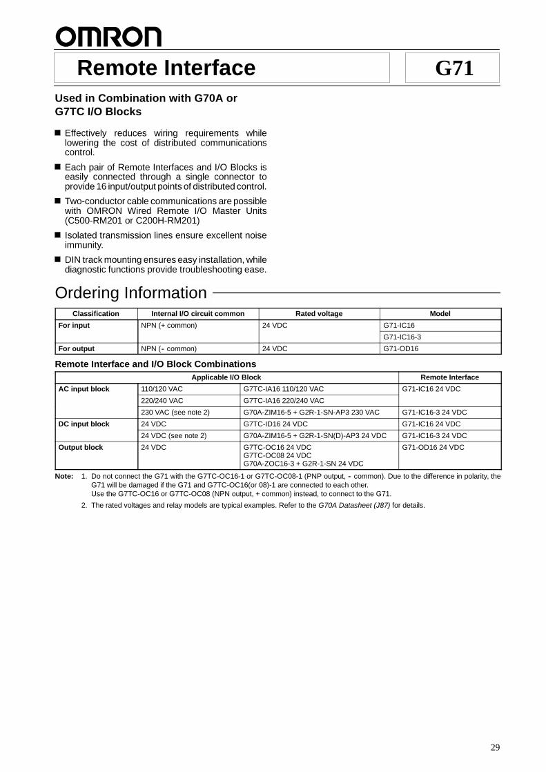
Remote Interface G71Used in Combination with G70A orG7TC I/O Blocks
Effectively reduces wiring requirements whilelowering the cost of distributed communicationscontrol.
Each pair of Remote Interfaces and I/O Blocks iseasily connected through a single connector toprovide 16 input/output points of distributed control.
Two-conductor cable communications are possiblewith OMRON Wired Remote I/O Master Units(C500-RM201 or C200H-RM201)
Isolated transmission lines ensure excellent noiseimmunity.
DIN track mounting ensures easy installation, whilediagnostic functions provide troubleshooting ease.
Ordering InformationClassification Internal I/O circuit common Rated voltage Model
For input NPN (+ common) 24 VDC G71-IC16
G71-IC16-3
For output NPN (-- common) 24 VDC G71-OD16
Remote Interface and I/O Block CombinationsApplicable I/O Block Remote Interface
AC input block 110/120 VAC G7TC-IA16 110/120 VAC G71-IC16 24 VDC
220/240 VAC G7TC-IA16 220/240 VAC
230 VAC (see note 2) G70A-ZIM16-5 + G2R-1-SN-AP3 230 VAC G71-IC16-3 24 VDC
DC input block 24 VDC G7TC-ID16 24 VDC G71-IC16 24 VDC
24 VDC (see note 2) G70A-ZIM16-5 + G2R-1-SN(D)-AP3 24 VDC G71-IC16-3 24 VDC
Output block 24 VDC G7TC-OC16 24 VDCG7TC-OC08 24 VDCG70A-ZOC16-3 + G2R-1-SN 24 VDC
G71-OD16 24 VDC
Note: 1. Do not connect the G71 with the G7TC-OC16-1 or G7TC-OC08-1 (PNP output, -- common). Due to the difference in polarity, theG71 will be damaged if the G71 and G7TC-OC16(or 08)-1 are connected to each other.Use the G7TC-OC16 or G7TC-OC08 (NPN output, + common) instead, to connect to the G71.
2. The rated voltages and relay models are typical examples. Refer to the G70A Datasheet (J87) for details.
G71 G71
30
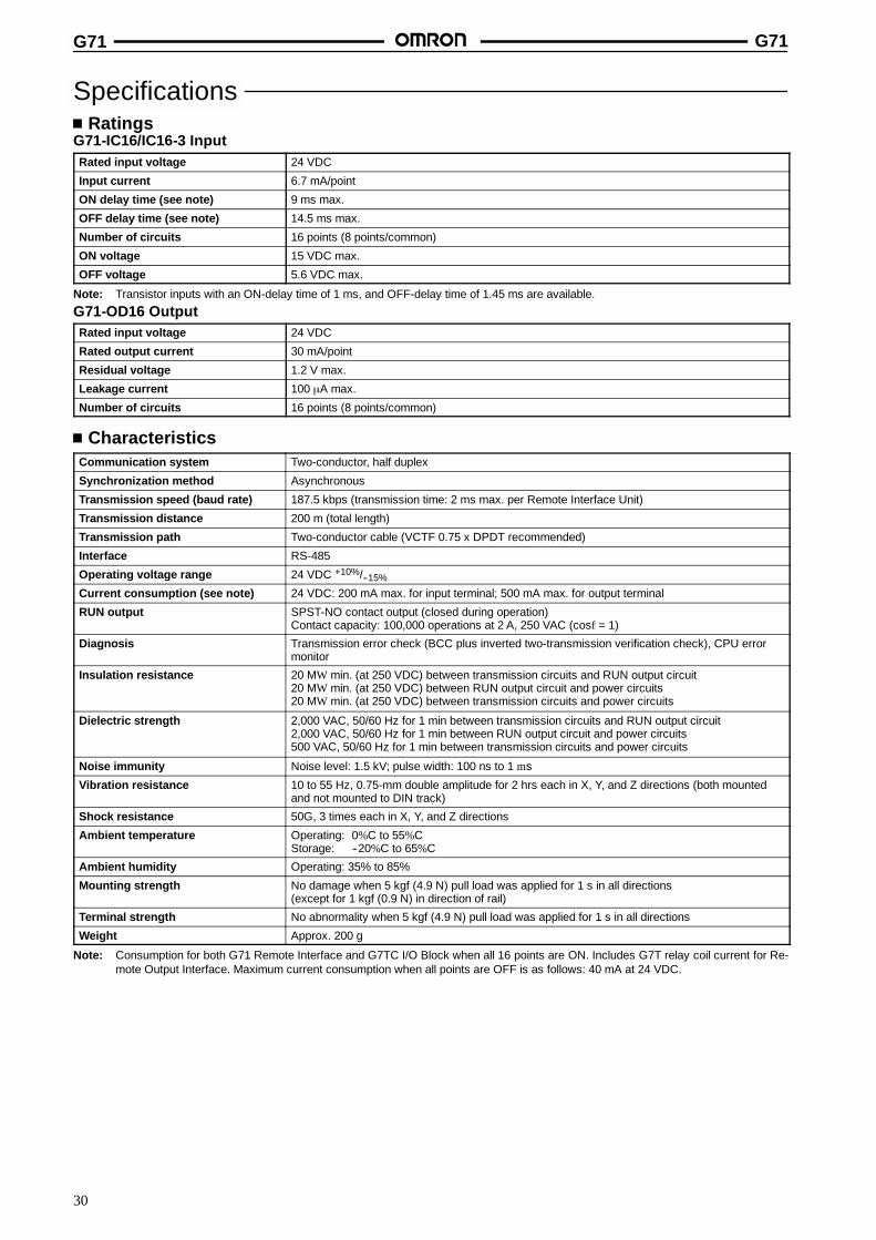
SpecificationsRatings
G71-IC16/IC16-3 InputRated input voltage 24 VDC
Input current 6.7 mA/point
ON delay time (see note) 9 ms max.
OFF delay time (see note) 14.5 ms max.
Number of circuits 16 points (8 points/common)
ON voltage 15 VDC max.
OFF voltage 5.6 VDC max.
Note: Transistor inputs with an ON-delay time of 1 ms, and OFF-delay time of 1.45 ms are available.
G71-OD16 OutputRated input voltage 24 VDC
Rated output current 30 mA/point
Residual voltage 1.2 V max.
Leakage current 100 ←A max.
Number of circuits 16 points (8 points/common)
CharacteristicsCommunication system Two-conductor, half duplex
Synchronization method Asynchronous
Transmission speed (baud rate) 187.5 kbps (transmission time: 2 ms max. per Remote Interface Unit)
Transmission distance 200 m (total length)
Transmission path Two-conductor cable (VCTF 0.75 x DPDT recommended)
Interface RS-485
Operating voltage range 24 VDC +10%/--15%
Current consumption (see note) 24 VDC: 200 mA max. for input terminal; 500 mA max. for output terminal
RUN output SPST-NO contact output (closed during operation)Contact capacity: 100,000 operations at 2 A, 250 VAC (cosf = 1)
Diagnosis Transmission error check (BCC plus inverted two-transmission verification check), CPU errormonitor
Insulation resistance 20 MW min. (at 250 VDC) between transmission circuits and RUN output circuit20 MW min. (at 250 VDC) between RUN output circuit and power circuits20 MW min. (at 250 VDC) between transmission circuits and power circuits
Dielectric strength 2,000 VAC, 50/60 Hz for 1 min between transmission circuits and RUN output circuit2,000 VAC, 50/60 Hz for 1 min between RUN output circuit and power circuits500 VAC, 50/60 Hz for 1 min between transmission circuits and power circuits
Noise immunity Noise level: 1.5 kV; pulse width: 100 ns to 1 ms
Vibration resistance 10 to 55 Hz, 0.75-mm double amplitude for 2 hrs each in X, Y, and Z directions (both mountedand not mounted to DIN track)
Shock resistance 50G, 3 times each in X, Y, and Z directions
Ambient temperature Operating: 0%C to 55%CStorage: --20%C to 65%C
Ambient humidity Operating: 35% to 85%
Mounting strength No damage when 5 kgf (4.9 N) pull load was applied for 1 s in all directions(except for 1 kgf (0.9 N) in direction of rail)
Terminal strength No abnormality when 5 kgf (4.9 N) pull load was applied for 1 s in all directions
Weight Approx. 200 g
Note: Consumption for both G71 Remote Interface and G7TC I/O Block when all 16 points are ON. Includes G7T relay coil current for Re-mote Output Interface. Maximum current consumption when all points are OFF is as follows: 40 mA at 24 VDC.
G71 G71
31
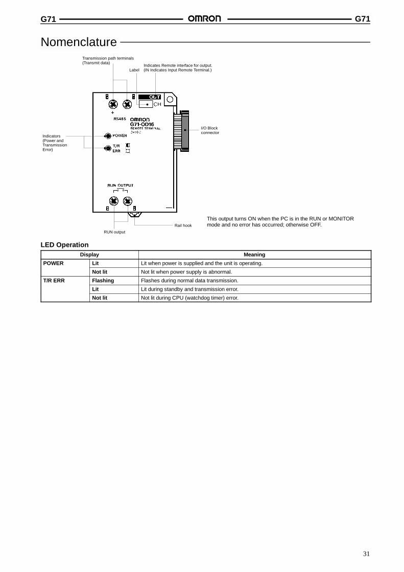
NomenclatureTransmission path terminals(Transmit data)
LabelIndicates Remote interface for output.(IN Indicates Input Remote Terminal.)
I/O Blockconnector
Indicators(Power andTransmissionError)
RUN output
Rail hook
This output turns ON when the PC is in the RUN or MONITORmode and no error has occurred; otherwise OFF.
LED OperationDisplay Meaning
POWER Lit Lit when power is supplied and the unit is operating.
Not lit Not lit when power supply is abnormal.
T/R ERR Flashing Flashes during normal data transmission.
Lit Lit during standby and transmission error.
Not lit Not lit during CPU (watchdog timer) error.
G71 G71
32
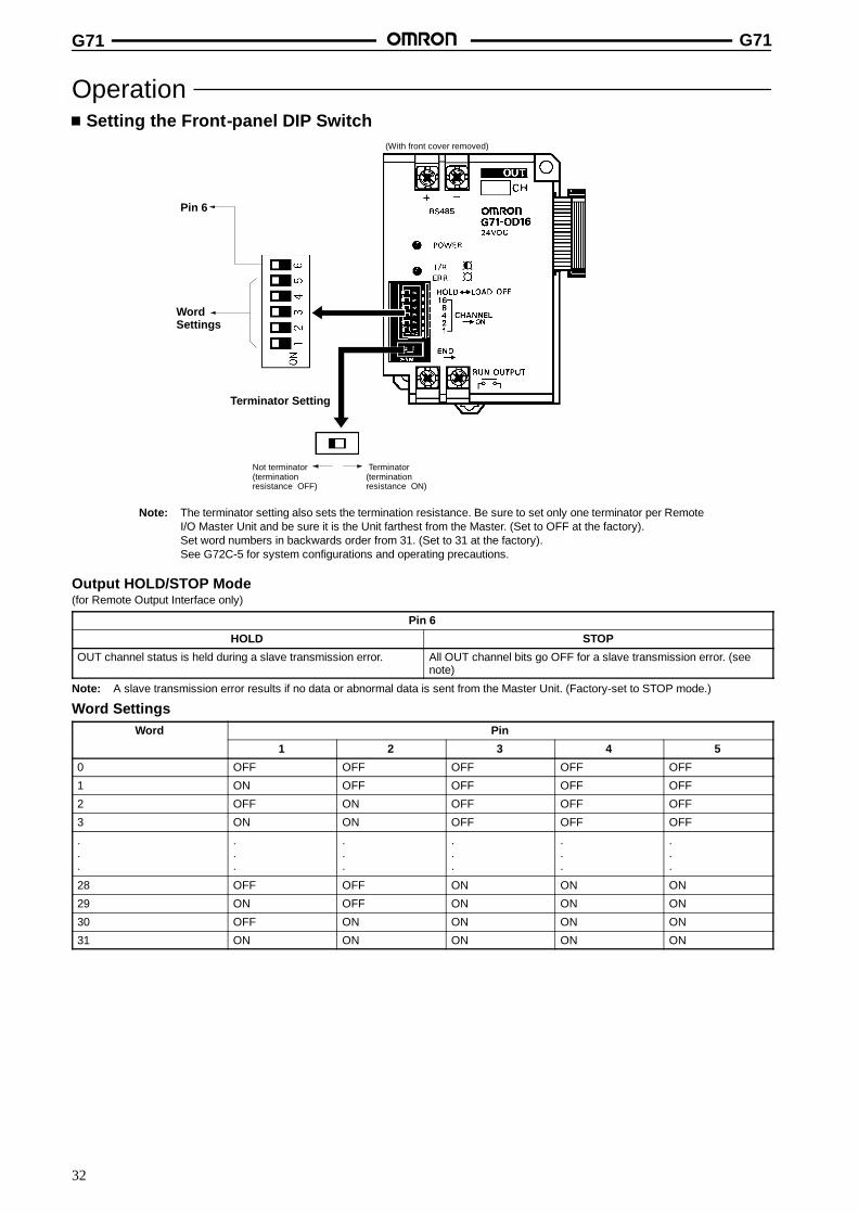
OperationSetting the Front-panel DIP Switch
Note: The terminator setting also sets the termination resistance. Be sure to set only one terminator per RemoteI/O Master Unit and be sure it is the Unit farthest from the Master. (Set to OFF at the factory).Set word numbers in backwards order from 31. (Set to 31 at the factory).See G72C-5 for system configurations and operating precautions.
(With front cover removed)
Terminator Setting
Not terminator(terminationresistance OFF)
Terminator(terminationresistance ON)
Pin 6
WordSettings
Output HOLD/STOP Mode(for Remote Output Interface only)
Pin 6
HOLD STOP
OUT channel status is held during a slave transmission error. All OUT channel bits go OFF for a slave transmission error. (seenote)
Note: A slave transmission error results if no data or abnormal data is sent from the Master Unit. (Factory-set to STOP mode.)
Word SettingsWord Pin
1 2 3 4 5
0 OFF OFF OFF OFF OFF
1 ON OFF OFF OFF OFF
2 OFF ON OFF OFF OFF
3 ON ON OFF OFF OFF
.
.
.
.
.
.
.
.
.
.
.
.
.
.
.
.
.
.
28 OFF OFF ON ON ON
29 ON OFF ON ON ON
30 OFF ON ON ON ON
31 ON ON ON ON ON
G71 G71
33
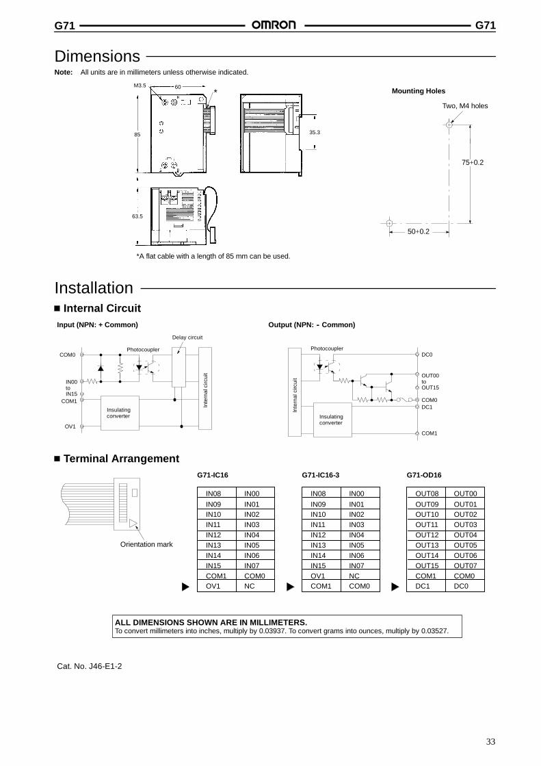
DimensionsNote: All units are in millimeters unless otherwise indicated.
Two, M4 holes
75+0.2
50+0.2
Mounting Holes
*A flat cable with a length of 85 mm can be used.
M3.5 60
85
63.5
35.3
*
InstallationInternal Circuit
Input (NPN: + Common) Output (NPN: -- Common)
COM0
IN00toIN15
COM1
OV1
Photocoupler
Delay circuit
Inte
rnal
circ
uit
Insulatingconverter
Inte
rnal
circ
uit
Insulatingconverter
PhotocouplerDC0
OUT00toOUT15
COM0DC1
COM1
Terminal Arrangement
Orientation mark
IN08IN09IN10IN11IN12IN13IN14IN15COM1OV1
IN00IN01IN02IN03IN04IN05IN06IN07COM0NC
G71-IC16
IN08IN09IN10IN11IN12IN13IN14IN15OV1COM1
IN00IN01IN02IN03IN04IN05IN06IN07NCCOM0
G71-IC16-3
OUT08OUT09OUT10OUT11OUT12OUT13OUT14OUT15COM1DC1
OUT00OUT01OUT02OUT03OUT04OUT05OUT06OUT07COM0DC0
G71-OD16
ALL DIMENSIONS SHOWN ARE IN MILLIMETERS.To convert millimeters into inches, multiply by 0.03937. To convert grams into ounces, multiply by 0.03527.
Cat. No. J46-E1-2
34
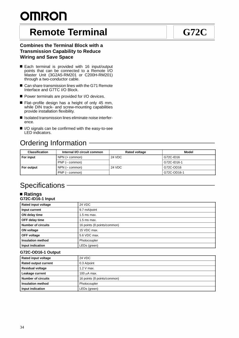
Remote Terminal G72CCombines the Terminal Block with aTransmission Capability to ReduceWiring and Save Space
Each terminal is provided with 16 input/outputpoints that can be connected to a Remote I/OMaster Unit (3G2A5-RM201 or C200H-RM201)through a two-conductor cable.
Can share transmission lines with the G71 RemoteInterface and G7TC I/O Block.
Power terminals are provided for I/O devices.
Flat--profile design has a height of only 45 mm,while DIN track- and screw-mounting capabilitiesprovide installation flexibility.
Isolated transmission lines eliminate noise interfer-ence.
I/O signals can be confirmed with the easy-to-seeLED indicators.
Ordering InformationClassification Internal I/O circuit common Rated voltage Model
For input NPN (+ common) 24 VDC G72C-ID16
PNP (-- common) G72C-ID16-1
For output NPN (-- common) 24 VDC G72C-OD16
PNP (-- common) G72C-OD16-1
SpecificationsRatings
G72C-ID16-1 InputRated input voltage 24 VDC
Input current 9.7 mA/point
ON delay time 1.5 ms max.
OFF delay time 1.5 ms max.
Number of circuits 16 points (8 points/common)
ON voltage 15 VDC max.
OFF voltage 5.6 VDC max.
Insulation method Photocoupler
Input indication LEDs (green)
G72C-OD16-1 OutputRated input voltage 24 VDC
Rated output current 0.3 A/point
Residual voltage 1.2 V max.
Leakage current 100 ←A max.
Number of circuits 16 points (8 points/common)
Insulation method Photocoupler
Input indication LEDs (green)
G72C G72C
35
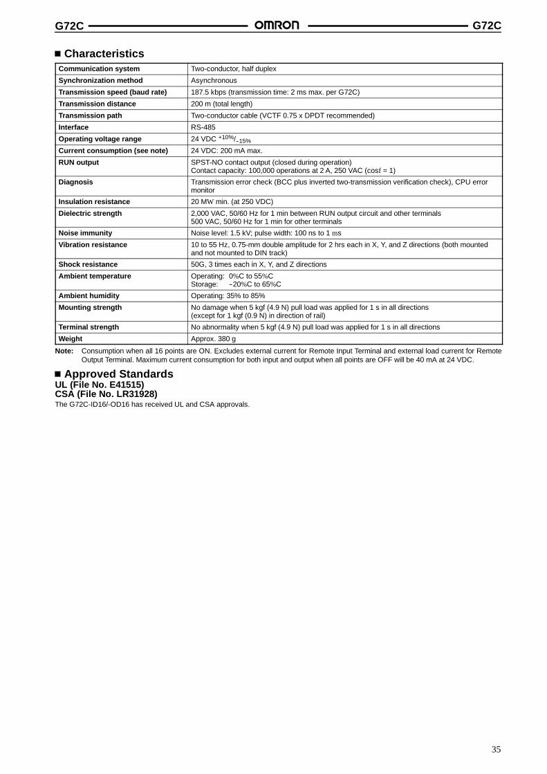
CharacteristicsCommunication system Two-conductor, half duplex
Synchronization method Asynchronous
Transmission speed (baud rate) 187.5 kbps (transmission time: 2 ms max. per G72C)
Transmission distance 200 m (total length)
Transmission path Two-conductor cable (VCTF 0.75 x DPDT recommended)
Interface RS-485
Operating voltage range 24 VDC +10%/--15%
Current consumption (see note) 24 VDC: 200 mA max.
RUN output SPST-NO contact output (closed during operation)Contact capacity: 100,000 operations at 2 A, 250 VAC (cosf = 1)
Diagnosis Transmission error check (BCC plus inverted two-transmission verification check), CPU errormonitor
Insulation resistance 20 MW min. (at 250 VDC)
Dielectric strength 2,000 VAC, 50/60 Hz for 1 min between RUN output circuit and other terminals500 VAC, 50/60 Hz for 1 min for other terminals
Noise immunity Noise level: 1.5 kV; pulse width: 100 ns to 1 ms
Vibration resistance 10 to 55 Hz, 0.75-mm double amplitude for 2 hrs each in X, Y, and Z directions (both mountedand not mounted to DIN track)
Shock resistance 50G, 3 times each in X, Y, and Z directions
Ambient temperature Operating: 0%C to 55%CStorage: --20%C to 65%C
Ambient humidity Operating: 35% to 85%
Mounting strength No damage when 5 kgf (4.9 N) pull load was applied for 1 s in all directions(except for 1 kgf (0.9 N) in direction of rail)
Terminal strength No abnormality when 5 kgf (4.9 N) pull load was applied for 1 s in all directions
Weight Approx. 380 g
Note: Consumption when all 16 points are ON. Excludes external current for Remote Input Terminal and external load current for RemoteOutput Terminal. Maximum current consumption for both input and output when all points are OFF will be 40 mA at 24 VDC.
Approved StandardsUL (File No. E41515)CSA (File No. LR31928)The G72C-ID16/-OD16 has received UL and CSA approvals.

G72C G72C
36
Nomenclature
Indicates Remote Terminal for input.(Out indicates Remote Terminal for output.)
TransmissionPath Terminals
PowerTerminals
I/O LEDs
I/O Terminals
Rail Hook
RUN Output
LEDs
Label
Power &TransmissionError
Indicates negative side terminal
LED OperationDisplay Meaning
POWER Lit Lit when power is supplied and the unit is operating.
Not lit Not lit when power supply is abnormal.
T/R ERR Flashing Flashes during normal data transmission.
Lit Lit during standby and transmission error.
Not lit Not lit during CPU (watchdog timer) error.
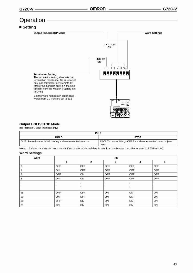
OperationSetting
Word Settings
Output HOLD/STOP Mode
OFF ONNot terminator(termination resistanceOFF)
Terminator(termination resistanceON)
Terminator Setting
The terminator setting also sets the terminationresistance. Be sure to set only one terminatorper Remote I/O Master Unit and be sure it isthe Unit farthest from the Master (Factory setto OFF.)
Set word numbers in order backwards from 31.(Factory set to 31.)

G72C G72C
37
Output HOLD/STOP Mode(for Remote Output Interface only)
Pin 6
HOLD STOP
OUT channel status is held during a slave transmission error. All OUT channel bits go OFF for a slave transmission error. (seenote)
Note: A slave transmission error results if no data or abnormal data is sent from the Master Unit. (Factory-set to STOP mode.)
Word SettingsWord Pin
1 2 3 4 5
0 OFF OFF OFF OFF OFF
1 ON OFF OFF OFF OFF
2 OFF ON OFF OFF OFF
3 ON ON OFF OFF OFF
.
.
.
.
.
.
.
.
.
.
.
.
.
.
.
.
.
.
28 OFF OFF ON ON ON
29 ON OFF ON ON ON
30 OFF ON ON ON ON
31 ON ON ON ON ON
System ConfigurationCPU Rack
Wired Master Unit (3G2A5-RM201 or C200H-RM201)Two-conductor cable
Two-conductorcable
G71 RemoteInterface
G7TC I/O Block G72C Remote Terminal
DimensionsNote: All units are in millimeters unless otherwise indicated.
182 max.
85 max.
Two, 5 dia. holes (for M4 screws)
35 max.
45 max.
35.3�0.2

G72C G72C
38
InstallationInternal Circuits
G72C-ID16 for Input G72C-OD16 for Output
G72C-ID16-1 for Input G72C-OD16-1 for Output
Tran
smis
sion
path
+0
--1
+2
--3
Pow
ersu
pply
Fuse
DC/DCconverter
Inte
rnal
circ
uit
Relay contacts
Photocoupler
Photocoupler
A
B
B0 (+)
A0
B1 (--)
B2 (+)
A1
B3 (--)
RUNoutput
Tran
smis
sion
path
+0
--1
+2
--3
Pow
ersu
pply Fuse
DC/DCconverter
Inte
rnal
circ
uit
Photocoupler
Photocoupler
Relay contacts
4.3 kτ
4.3 kτ
A
B
B0 (+)
A0
B1 (--)
B2 (+)
A1
B3 (--)
RUNoutput
Tran
smis
sion
path
+0
--1
+2
--3
Pow
ersu
pply
DC/DCconverter
Inte
rnal
circ
uit
PHC
PHC
A
BB0 (+)A0
B1 (--)
B2 (+)
A1
B3 (--)
Tran
smis
sion
path
+0
--1
+2
--3
Pow
ersu
pply
DC/DCconverter
Inte
rnal
circ
uit
A
B
B0 (+)
A0
B1 (--)
PHC
PHCB2 (+)
A1
B3 (--)
Terminal Arrangement
A A0 A1 A2 A3 A4 A5 A6 A7 A8 A9 A10 A11 A12 A13 A14 A15
B B0 B1 B2 B3 B4 B5 B6 B7 B8 B9 B10 B11 B12 B13 B14 B15
0 1 2 3
+ --
Transmission path Power supply
+ --
Black marks
Note: Positive power terminal no. 2 at the upper-right part is internallyconnected to the B0, B2, B4, B6, B8, B10, B12, and B14 I/O ter-minals at the lower part, and negative power terminal no. 3 at theupper-right part is internally connected to the B1, B3, B5, B7, B9,B11, B13, and B15 I/O terminals at the lower part and have blackmarks.
G72C G72C
39
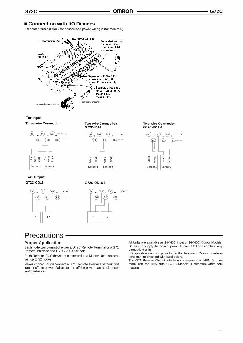
Connection with I/O Devices(Repeater terminal block for sensor/load power wiring is not required.)
For InputThree-wire Connection Two-wire Connection
G72C-ID16Two-wire ConnectionG72C-ID16-1
For OutputG72C-OD16 G72C-OD16-1
Bla
ck
B0
A0
B1
A1
B2
A2--+ +
Sensor 1
Whi
teR
ed
Bla
ck
Sensor 2
Whi
teR
ed
IN
B0
A0 A1
B1
A2
B2
+ -- +
Whi
te
Bla
ck
Sensor 1
Whi
te
Bla
ck
Sensor 2
IN
A2A1
B2B1
A0
B0
+ -- +
L1 L2
OUT
B0
A0 A1
B1
A2
B2
+ -- +
Bla
ck
Whi
te
Sensor 1
B;a
cl
Whi
teSensor 2
IN
A2A1
B2B1
A0
B0
+ -- +
L1 L2
OUT
Photoelectric sensorProximity sensor
PrecautionsProper ApplicationEach node can consist of either a G72C Remote Terminal or a G71Remote Interface and G7TC I/O Block pair.Each Remote I/O Subsystem connected to a Master Unit can con-tain up to 32 nodes.Never connect or disconnect a G71 Remote Interface without firstturning off the power. Failure to turn off the power can result in op-erational errors.
All Units are available as 24-VDC Input or 24-VDC Output Models.Be sure to supply the correct power to each Unit and combine onlycompatible units.I/O specifications are provided in the following. Proper combina-tions can be checked with label colors.The G71 Remote Output Interface corresponds to NPN (-- com-mon). Use the NPN-output G7TC Models (+ common) when con-necting.

G72C G72C
40
Always confirm that all G71 and G72C Units have been turned onbefore turning providing power to the Master.
G71 Remote Interface G7TC I/O Block G72C Remote Terminal
Model Label color Model Label display(color)
Model Label color
Input G71-IC16 Red G7TC-IA16/ID16 US16 (red) G72C-ID16 Red
Output G71-OD16 Yellow G7TC-OC16/OC08 OS16/OS08 (yellow) G72C-OD16 Yellow
Note: Do not connect a G71 Remote Interface to a G7TC-OC16-1 I/O Block, which is a PNP Model (-- common) and therefore incompatible.
Connections
Correct Example
Always wire in order from the Master,connecting positive to positive and neg-ative to negative, without branching.
Incorrect Example 1
The wiring below is incorrectbecause positive has beenconnected to negative.
Incorrect Example 2
The wiring below is incorrect becausea branch has been created.
Remote I/OMaster3G2A5-RM201C200H-RM201
G71 RemoteInterfaceG72C RemoteTerminal
G71 RemoteInterfaceG72C RemoteTerminal
G71 RemoteInterfaceG72C RemoteTerminal
Remote I/OMaster3G2A5-RM201C200H-RM201
Remote I/OMaster3G2A5-RM201C200H-RM201
G71 RemoteInterfaceG72C RemoteTerminal
G71 RemoteInterfaceG72C RemoteTerminal
ALL DIMENSIONS SHOWN ARE IN MILLIMETERS.To convert millimeters into inches, multiply by 0.03937. To convert grams into ounces, multiply by 0.03527.
Cat. No. J47-E1-1B

41
Remote Terminal G72C-VSlim-profile Remote Terminal Combinesthe Terminal Block with a TransmissionCapability
Slim-profile design has a depth of only 45 mmagainst a width of 202 mm and a height of 63 mm.
Each Terminal Unit is provided with 16 input/outputpoints that can be connected to a Remote I/OMaster Unit (3G2A5-RM201 or C200H-RM201)through a two-wire cable.
Power terminals are provided for I/O devices.
Can share transmission lines with the G71 RemoteInterface and G7TC or G72C I/O Block.
Isolated transmission lines eliminate noise interfer-ence.
DIN track- and screw-mounting capabilities provideinstallation flexibility.
Ordering InformationClassification Internal I/O circuit common I/O points Rated voltage Model
For input NPN (+ common) 16 points 24 VDC G72C-VID16
For output NPN (-- common) 24 VDC G72C-VOD16
Note: UL and CSA approvals are pending.
SpecificationsRatings
G72C-VID16 InputInput current 9.7 mA/point
ON delay time 1.5 ms max.
OFF delay time 1.5 ms max.
Number of circuits 16 points (8 points/common)
ON voltage 15 VDC max.
OFF voltage 5.6 VDC max.
Insulation method Photocoupler
Input indication LEDs (green)
G72C-VOD16 OutputRated output current 0.3 A/point, 2.4 A/unit
Residual voltage 1.2 V max.
Leakage current 100 ←A max.
Number of circuits 16 points (8 points/common)
Insulation method Photocoupler
Input indication LEDs (green)

G72C-V G72C-V
42
CharacteristicsCommunication system Two-conductor, half duplex
Synchronization method Asynchronous
Transmission speed (baud rate) 187.5 kbps (transmission time: 2 ms max. per G72C-V)
Transmission distance 200 m (total length)
Transmission path Two-conductor cable (VCTF 0.75 x DPDT recommended)
Interface RS-485
Operating voltage range 24 VDC +10%/--15%
Current consumption (see note) 24 VDC: 200 mA max.
RUN output SPST-NO contact output (closed during operation)Contact capacity: 100,000 operations at 2 A, 250 VAC (cosf = 1)
Diagnosis Transmission error check (BCC plus inverted two-transmission verification check), CPU errormonitor
Insulation resistance 20 MW min. (at 250 VDC)
Dielectric strength 2,000 VAC, 50/60 Hz for 1 min between RUN output circuit and other terminals500 VAC, 50/60 Hz for 1 min for other terminals
Noise immunity Noise level: 1.5 kV; pulse width: 100 ns to 1 ms
Vibration resistance 10 to 55 Hz, 0.75-mm double amplitude for 2 hrs each in X, Y, and Z directions (both mountedand not mounted to DIN track)
Shock resistance 500 m/s2 (approx. 50G)
Ambient temperature Operating: 0%C to 55%C
Ambient humidity Operating: 35% to 85%
Mounting strength No damage when 5 kgf (4.9 N) pull load was applied for 1 s in all directions(except for 1 kgf (0.9 N) in direction of rail)
Terminal strength No abnormality when 5 kgf (4.9 N) pull load was applied for 1 s in all directions
Weight Approx. 380 g
Note: Consumption when all 16 points are ON. Excludes external sensor current for Remote Input Terminal and external load current forRemote Output Terminal. Maximum current consumption for both input and output when all points are OFF will be 40 mA at 24 VDC.
NomenclatureSurface SwitchCover
I/O LEDs
RUN Output
Label
Indicates Remote Terminal forinput.(Out indicates Remote Terminalfor output.)
LEDs
I/O TerminalsPower Supply Terminals
TransmissionTerminals
Power &TransmissionError
LED OperationDisplay Meaning
POWER Lit Lit when power is supplied and the unit is operating.
Not lit Not lit when power supply is abnormal.
T/R ERR Flashing Flashes during normal data transmission.
Lit Lit during standby and transmission error.
Not lit Not lit during CPU (watchdog timer) error.
G72C-V G72C-V
43
OperationSetting
Terminator SettingThe terminator setting also sets thetermination resistance. Be sure to setonly one terminator per Remote I/OMaster Unit and be sure it is the Unitfarthest from the Master. (Factory setto OFF.)
Set the word numbers in order back-wards from 31 (Factory set to 31.)
Output HOLD/STOP Mode Word Settings
Output HOLD/STOP Mode(for Remote Output Interface only)
Pin 6
HOLD STOP
OUT channel status is held during a slave transmission error. All OUT channel bits go OFF for a slave transmission error. (seenote)
Note: A slave transmission error results if no data or abnormal data is sent from the Master Unit. (Factory-set to STOP mode.)
Word SettingsWord Pin
1 2 3 4 5
0 OFF OFF OFF OFF OFF
1 ON OFF OFF OFF OFF
2 OFF ON OFF OFF OFF
3 ON ON OFF OFF OFF
.
.
.
.
.
.
.
.
.
.
.
.
.
.
.
.
.
.
28 OFF OFF ON ON ON
29 ON OFF ON ON ON
30 OFF ON ON ON ON
31 ON ON ON ON ON
G72C-V G72C-V
44
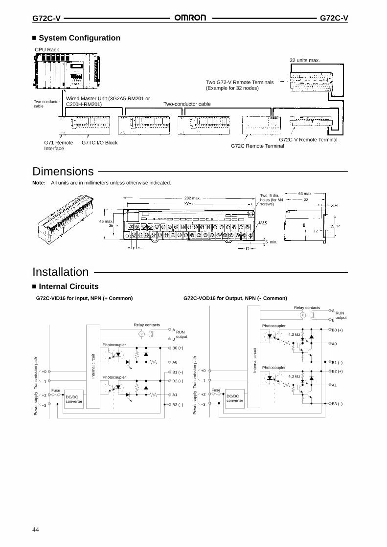
System ConfigurationCPU Rack
Wired Master Unit (3G2A5-RM201 orC200H-RM201) Two-conductor cableTwo-conductor
cable
G71 RemoteInterface
G7TC I/O BlockG72C Remote Terminal
G72C-V Remote Terminal
Two G72-V Remote Terminals(Example for 32 nodes)
32 units max.
DimensionsNote: All units are in millimeters unless otherwise indicated.
202 max.
45 max.
Two, 5 dia.holes (for M4screws)
5 min.
63 max.
InstallationInternal Circuits
G72C-VID16 for Input, NPN (+ Common) G72C-VOD16 for Output, NPN (-- Common)
Tran
smis
sion
path
+0
--1
+2
--3
Pow
ersu
pply
Fuse
DC/DCconverter
Inte
rnal
circ
uit
Relay contacts
Photocoupler
Photocoupler
A
B
B0 (+)
A0
B1 (--)
B2 (+)
A1
B3 (--)
RUNoutput
Tran
smis
sion
path
+0
--1
+2
--3
Pow
ersu
pply Fuse
DC/DCconverter
Inte
rnal
circ
uit
Photocoupler
Photocoupler
Relay contacts
4.3 kτ
4.3 kτ
A
B
B0 (+)
A0
B1 (--)
B2 (+)
A1
B3 (--)
RUNoutput
G72C-V G72C-V
45
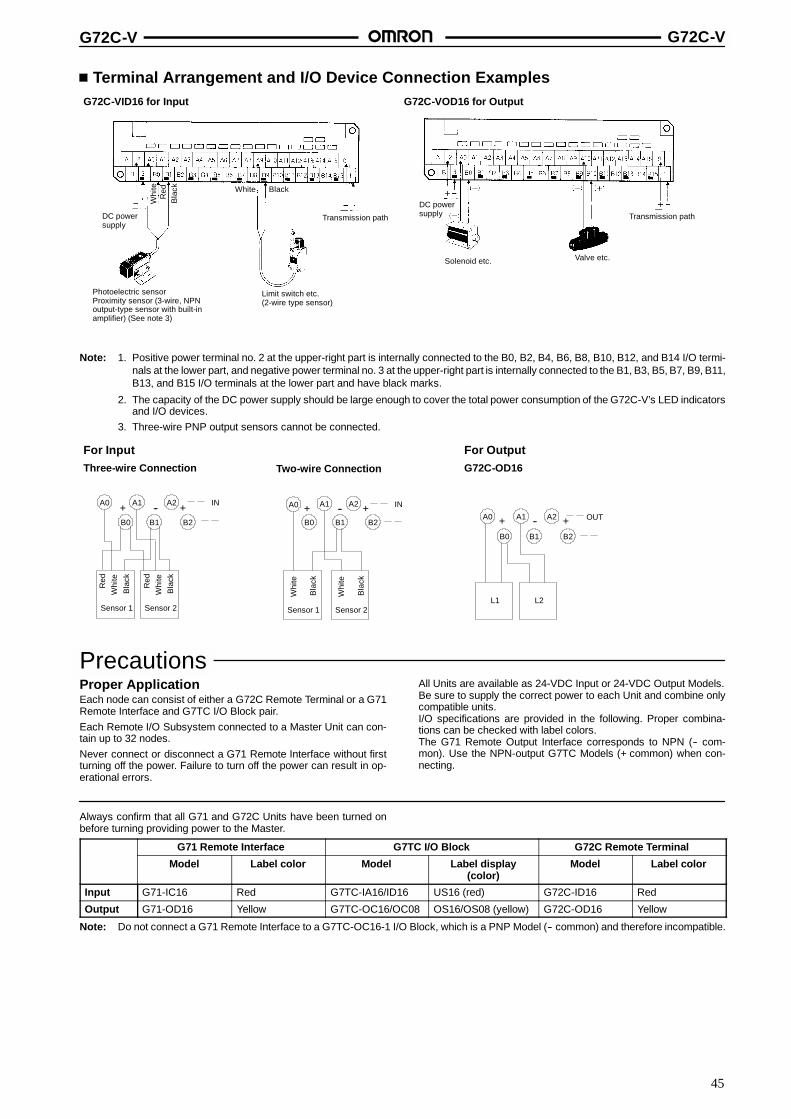
Terminal Arrangement and I/O Device Connection ExamplesG72C-VID16 for Input G72C-VOD16 for Output
DC powersupply
Whi
teR
edB
lack White Black
Transmission path
Limit switch etc.(2-wire type sensor)
Photoelectric sensorProximity sensor (3-wire, NPNoutput-type sensor with built-inamplifier) (See note 3)
DC powersupply Transmission path
Valve etc.Solenoid etc.
Note: 1. Positive power terminal no. 2 at the upper-right part is internally connected to the B0, B2, B4, B6, B8, B10, B12, and B14 I/O termi-nals at the lower part, and negative power terminal no. 3 at the upper-right part is internally connected to the B1, B3, B5, B7, B9, B11,B13, and B15 I/O terminals at the lower part and have black marks.
2. The capacity of the DC power supply should be large enough to cover the total power consumption of the G72C-V’s LED indicatorsand I/O devices.
3. Three-wire PNP output sensors cannot be connected.
For InputThree-wire Connection Two-wire Connection
For OutputG72C-OD16
Bla
ck
B0
A0
B1
A1
B2
A2--+ +
Sensor 1
Whi
teR
ed
Bla
ck
Sensor 2
Whi
teR
ed
IN
B0
A0 A1
B1
A2
B2
+ -- +
Whi
te
Bla
ck
Sensor 1
Whi
te
Bla
ck
Sensor 2
IN
A2A1
B2B1
A0
B0
+ -- +
L1 L2
OUT
PrecautionsProper ApplicationEach node can consist of either a G72C Remote Terminal or a G71Remote Interface and G7TC I/O Block pair.Each Remote I/O Subsystem connected to a Master Unit can con-tain up to 32 nodes.Never connect or disconnect a G71 Remote Interface without firstturning off the power. Failure to turn off the power can result in op-erational errors.
All Units are available as 24-VDC Input or 24-VDC Output Models.Be sure to supply the correct power to each Unit and combine onlycompatible units.I/O specifications are provided in the following. Proper combina-tions can be checked with label colors.The G71 Remote Output Interface corresponds to NPN (-- com-mon). Use the NPN-output G7TC Models (+ common) when con-necting.
Always confirm that all G71 and G72C Units have been turned onbefore turning providing power to the Master.
G71 Remote Interface G7TC I/O Block G72C Remote Terminal
Model Label color Model Label display(color)
Model Label color
Input G71-IC16 Red G7TC-IA16/ID16 US16 (red) G72C-ID16 Red
Output G71-OD16 Yellow G7TC-OC16/OC08 OS16/OS08 (yellow) G72C-OD16 Yellow
Note: Do not connect a G71 Remote Interface to a G7TC-OC16-1 I/O Block, which is a PNP Model (-- common) and therefore incompatible.
G72C-V G72C-V
46
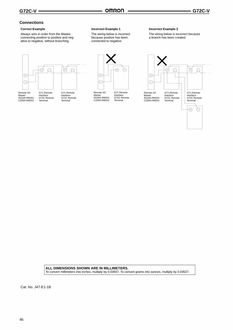
Connections
Correct Example
Always wire in order from the Master,connecting positive to positive and neg-ative to negative, without branching.
Incorrect Example 1
The wiring below is incorrectbecause positive has beenconnected to negative.
Incorrect Example 2
The wiring below is incorrect becausea branch has been created.
Remote I/OMaster3G2A5-RM201C200H-RM201
G71 RemoteInterfaceG72C RemoteTerminal
G71 RemoteInterfaceG72C RemoteTerminal
G71 RemoteInterfaceG72C RemoteTerminal
Remote I/OMaster3G2A5-RM201C200H-RM201
Remote I/OMaster3G2A5-RM201C200H-RM201
G71 RemoteInterfaceG72C RemoteTerminal
G71 RemoteInterfaceG72C RemoteTerminal
ALL DIMENSIONS SHOWN ARE IN MILLIMETERS.To convert millimeters into inches, multiply by 0.03937. To convert grams into ounces, multiply by 0.03527.
Cat. No. J47-E1-1B
47
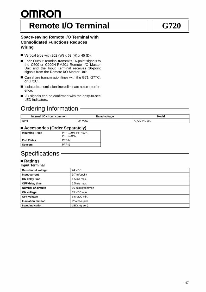
Remote I/O Terminal G720Space-saving Remote I/O Terminal withConsolidated Functions ReducesWiring
Vertical type with 202 (W) x 63 (H) x 45 (D).
Each Output Terminal transmits 16-point signals tothe C500-or C200H-RM201 Remote I/O MasterUnit and the Input Terminal receives 16-pointsignals from the Remote I/O Master Unit.
Can share transmission lines with the G71, G7TC,or G72C.
Isolated transmission lines eliminate noise interfer-ence.
I/O signals can be confirmed with the easy-to-seeLED indicators.
Ordering InformationInternal I/O circuit common Rated voltage Model
NPN 24 VDC G720-VID16C
Accessories (Order Separately)Mounting Track PFP-100N, PFP-50N,
PFP-100N2
End Plates PFP-M
Spacers PFP-S
SpecificationsRatings
Input TerminalRated input voltage 24 VDC
Input current 9.7 mA/point
ON delay time 1.5 ms max.
OFF delay time 1.5 ms max.
Number of circuits 16 points/common
ON voltage 15 VDC max.
OFF voltage 5.6 VDC min.
Insulation method Photocoupler
Input indication LEDs (green)

G720 G720
48
CharacteristicsCommunication method Two-conductor, half duplex
Synchronization method Asynchronous
Transmission distance 200 m (total length)
Transmission speed (baud rate) 187.5 kbps (transmission time: 2 ms max. per G720)
Interface RS-485
Operating voltage range 24 VDC +10%/--15%
Current consumption 24 VDC: 200 mA max. (see Note)
Diagnosis Transmission error check (BCC plus inverted 2-transmission verification check) and CPU errormonitor
Insulation resistance 20 MW min. (at 250 VDC)
Dielectric strength 2,000 VAC, 50/60 Hz for 1 min between transmission circuits and DIN rail
Noise immunity Noise level: 1.5 kV; pulse width: 100 ns to 1 ms (transmission path line winding noise only)
Vibration resistance 10 to 55 Hz, 0.75-mm double amplitude for 2 hrs each in X, Y, and Z directions (both mountedand not mounted to DIN rail)
Shock resistance 300 m/s2 (approx. 30G)
Ambient temperature Operating: 0%C to 55%CStorage: --20%C to 65%C
Ambient humidity Operating: 35% to 85%
Mounting strength No damage when 5 kgf (49N) pull load was applied for 1 s in all directions (except for 1 kgf(9.8 N) in direction of rail)
Enclosure rating Drip-proof construction
Weight Approx. 680 g
Note: The current consumption shows the current that is consumed when all 16 points are ON excluding the current consumed by the exter-nal sensor. When all points are OFF, the current consumption will be 40 mA max. at 24 VDC.
G720 G720
49
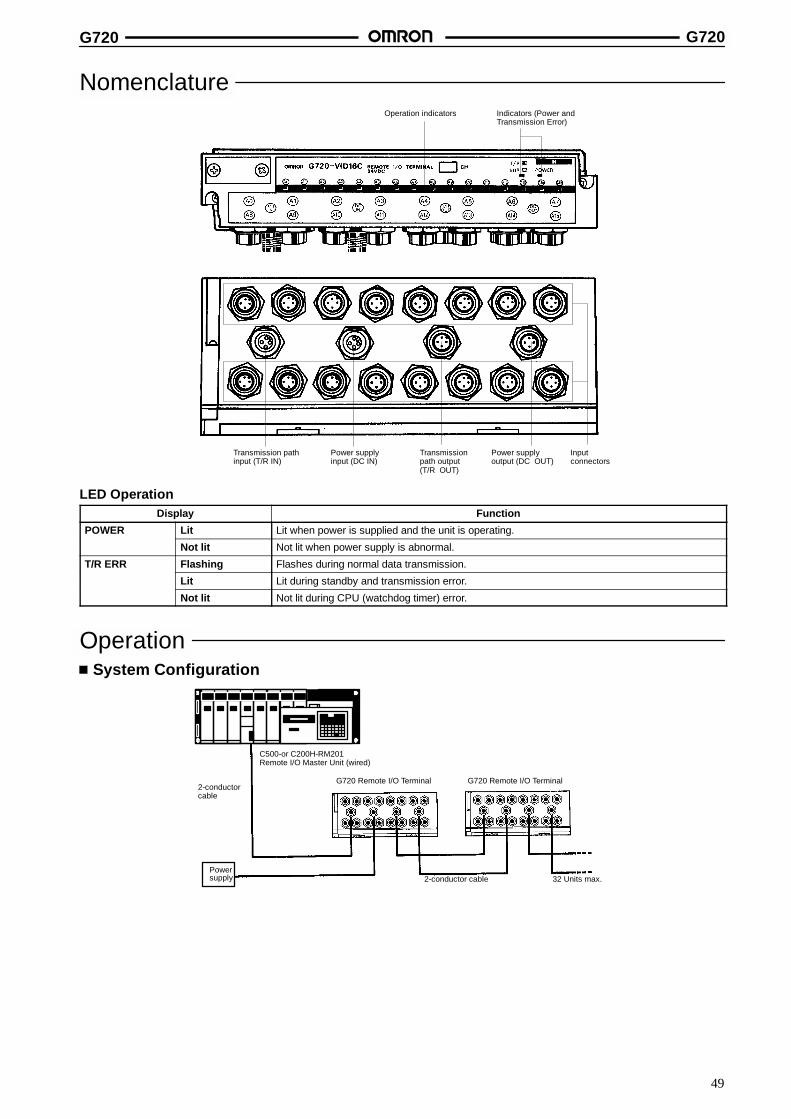
NomenclatureOperation indicators Indicators (Power and
Transmission Error)
Transmission pathinput (T/R IN)
Power supplyinput (DC IN)
Power supplyoutput (DC OUT)
Inputconnectors
Transmissionpath output(T/R OUT)
LED OperationDisplay Function
POWER Lit Lit when power is supplied and the unit is operating.
Not lit Not lit when power supply is abnormal.
T/R ERR Flashing Flashes during normal data transmission.
Lit Lit during standby and transmission error.
Not lit Not lit during CPU (watchdog timer) error.
OperationSystem Configuration
2-conductorcable
C500-or C200H-RM201Remote I/O Master Unit (wired)
G720 Remote I/O TerminalG720 Remote I/O Terminal
Powersupply 2-conductor cable 32 Units max.
G720 G720
50
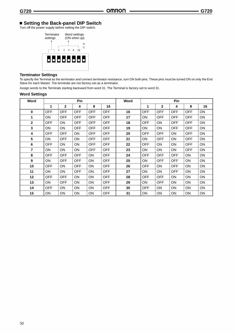
Setting the Back-panel DIP SwitchTurn off the power supply before setting the DIP switch.
1 2 4 8 16
NC
Terminatorsettings
Word settings(ON when up)
Terminator SettingsTo specify the Terminal as the terminator and connect terminator resistance, turn ON both pins. These pins must be turned ON on only the EndSlave for each Master. The terminals are not factory-set as a terminator.
Assign words to the Terminals starting backward from word 31. The Terminal is factory-set to word 31.
Word Settings
Word Pin Word Pin
1 2 4 8 16 1 2 4 8 16
0 OFF OFF OFF OFF OFF 16 OFF OFF OFF OFF ON
1 ON OFF OFF OFF OFF 17 ON OFF OFF OFF ON
2 OFF ON OFF OFF OFF 18 OFF ON OFF OFF ON
3 ON ON OFF OFF OFF 19 ON ON OFF OFF ON
4 OFF OFF ON OFF OFF 20 OFF OFF ON OFF ON
5 ON OFF ON OFF OFF 21 ON OFF ON OFF ON
6 OFF ON ON OFF OFF 22 OFF ON ON OFF ON
7 ON ON ON OFF OFF 23 ON ON ON OFF ON
8 OFF OFF OFF ON OFF 24 OFF OFF OFF ON ON
9 ON OFF OFF ON OFF 25 ON OFF OFF ON ON
10 OFF ON OFF ON OFF 26 OFF ON OFF ON ON
11 ON ON OFF ON OFF 27 ON ON OFF ON ON
12 OFF OFF ON ON OFF 28 OFF OFF ON ON ON
13 ON OFF ON ON OFF 29 ON OFF ON ON ON
14 OFF ON ON ON OFF 30 OFF ON ON ON ON
15 ON ON ON ON OFF 31 ON ON ON ON ON
G720 G720
51
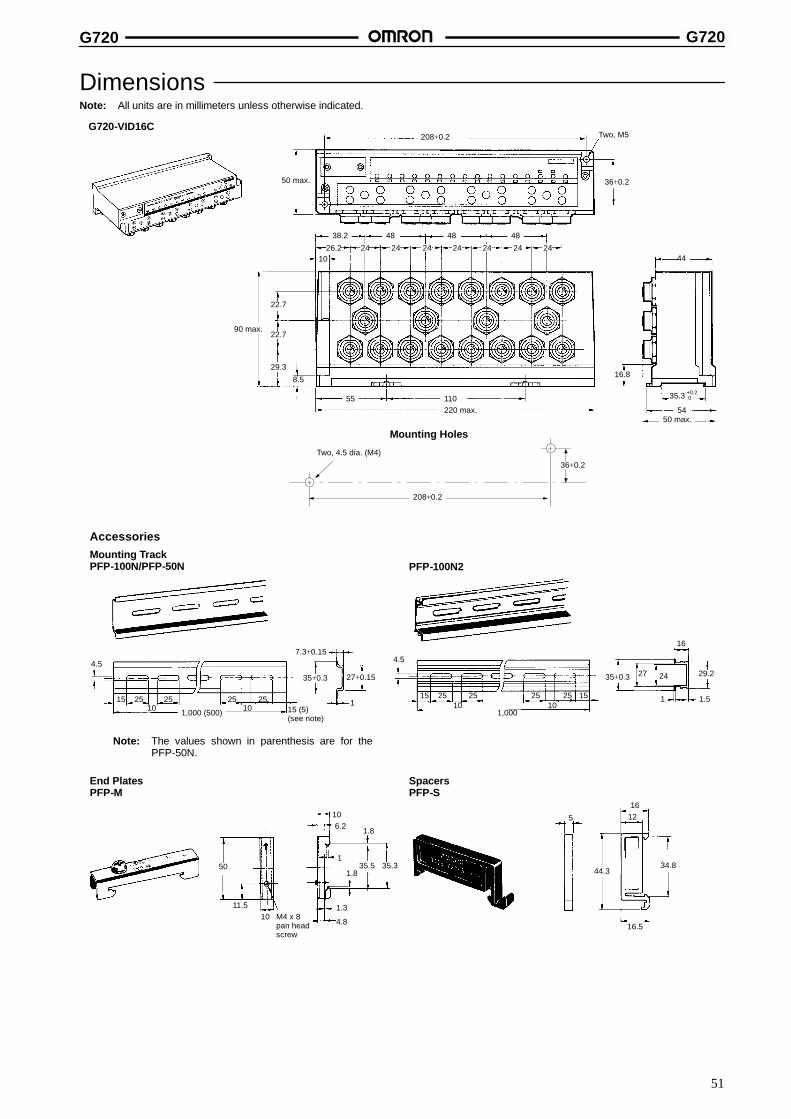
DimensionsNote: All units are in millimeters unless otherwise indicated.
Mounting Holes
G720-VID16C
26.2 24 24 24 24 24 24 2410
90 max.
50 max. 36+0.2
220 max.
208+0.2
55 110
16.8
50 max.54
48 48 4838.2
44
22.7
29.3
8.5
Two, M5
22.7
35.3 +0.20
36+0.2
208+0.2
Two, 4.5 dia. (M4)
AccessoriesMounting TrackPFP-100N/PFP-50N
4.5
15 25 25 25 2510 101,000 (500)
7.3+0.15
35+0.3 27+0.15
1
4.5
15 25 25 25 25 1510 10
1,000
35+0.3 27 24
16
29.2
1 1.5
50
11.5M4 x 8pan headscrew
106.2 1.8
135.5 35.3
1.8
1.3
4.8
5
1612
44.334.8
16.510
PFP-100N2
15 (5)(see note)
Note: The values shown in parenthesis are for thePFP-50N.
End PlatesPFP-M
SpacersPFP-S

G720 G720
52
InstallationInternal Circuit Configuration
1
23
4
12
34
12
34
12
34
1
23
4
1
23
4
Transmissionpath input
Power supplyinput
Transmissionpath output
Fuse
DC/DCconverter
Internalcircuits
Photocoupler
Photocoupler
A0
A1
Powersupplyoutput
+
--
+
--
External Circuit ConfigurationThree-wire Connection Two-wire Connection
Sensor 1Sensor 1
1
3
4
1
3
4
Red(Brown)
White(Black)
Black(Blue)
White(Brown)
Black(Blue)
Terminal Arrangement/I/O Device Connection ExamplesA power supply relay terminal block is not required for sensors/loads.
Input Terminal
Photoelectric sensor orproximity sensor (sensorwith built-in amplifier and3-wire, NPN output)
Limit switch or other 2-wiresensor

G720 G720
53
PrecautionsConnection Example
Incorrect Example 1
Do not reverse polarity.
Incorrect Example 2
Do not branch connections.
+
--
+ --
+
--
+ -- + --
+ --
Remote I/OInterface(G71) orRemoteI/O Terminal(G72C/G720)
Remote I/OInterface (G71)or RemoteI/O Terminal(G72C/G720)
Remote I/O Interface(G71) or RemoteI/O Terminal(G72C/G720)
Remote I/OMaster Unit(C500-RM201 orC200H-RM201)
Remote I/OMaster Unit(C500-RM201 orC200H-RM201)
Correct Example
Connect the Slaves in seriesstarting from the Master.
+
--
+ -- + --
Remote I/OMaster Unit(C500-RM201 orC200H-RM201)
Remote I/OInterface(G71) orRemoteI/O Terminal(G72C/G720)
Remote I/OInterface(G71) orRemoteI/O Terminal(G72C/G720)
32 max.
Recommended Connecting Methods of OMRON’s Sensor and Connector with CableWhen connecting a sensor I/O connector to OMRON’s sensor, refer to the following table and select the colors of the cable conductor covers forthe purposes of unification and easy maintenance.
Connector terminal Recommended color Sensor output stage
number Two-wire Three-wire Four-wire
1 Red Not used Power supply (+V) Power supply (+V)
2 Orange (see note) Not used Not used Output (2)
3 Black Power supply (0 V) Power supply (0 V) Power supply ( 0 V)
4 White Output (1) Output (1) Output (1)
Recommended CablesAny cable available on the market with an external diameter of 3 to6 mm with a conductor size of 0.18 to 0.75 mm2 (crimp-type) or0.5 mm2 (solder-type) can be used as a cable for an Assembly-typeConnector. If water-tight and oil resistive capabilities are required,use the following cable.Maker: Shinagawa DensenModel: S-FLEX [V1] SKCVV
Connector WiringWhen configuring a system using a Sensor I/O Connector, for safetyreasons, always attach a male connector to the sensor cable and afemale connector to the sensor end of the power source cable whenwiring from a Sensor I/O Connector to the control panel. Similarly,the power supply end of the connector cable should be male, andthe power outlet connector should be female.
Sensor
Male Female
Wiring
Male
Panel(power source)
Female
Tightening the Cap1. Use of pliers or other tools may damage the cap. Tighten the
cap firmly by hand. (4 to 5 kgf $ cm) (0.39 to 0.49 N $ m)2. If the cap is not on tight enough, it may not be possible to use
the IP67 protective housing. Also, it may become loose fromvibration.
Inserting and Removing the ConnectorBe sure to turn off the power before inserting or removing any con-nector.Before mating any connector, insert the mateable part fully, andtighten the anchors so as not to damage the threads.When tightening the anchors, do not use a tool, but tighten firmly (4to 5 kgf $ cm (0.39 to 0.49 N $ m)) by hand so that the threads cannotbe seen.When removing a connector, do not loosen the cap, but loosen theanchor.Loosen the anchor in the direction of the groove.
GrooveScrew counterclockwiseto tighten
Mountingfixture
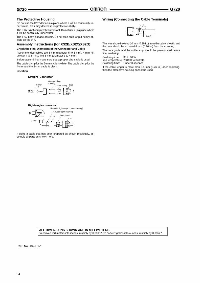
G720 G720
54
The Protective HousingDo not use the IP67 device in a place where it will be continually un-der stress. This may decrease its protective ability.The IP67 is not completely waterproof. Do not use it in a place whereit will be continually underwater.The IP67 body is made of resin. Do not step on it, or put heavy ob-jects on top of it.
Assembly Instructions (for XS2B/XS2C/XS2G)Check the Final Diameters of the Connector and CableRecommended cables are 6-mm (diameter 5 to 6 mm), 4-mm (di-ameter 4 to 5 mm), and 3-mm (diameter 3 to 4 mm).Before assembling, make sure that a proper size cable is used.The cable clamp for the 6-mm cable is white. The cable clamp for the4-mm and the 3-mm cable is black.
Insertion
Straight Connector
Right-angle connector
Cover Cap
Cover
Cable clampCap
Waterproofingbushing
Cable clamp
Ring (for right-angle connector only)
Water-tight bushing
If using a cable that has been prepared as shown previously, as-semble all parts as shown here.
Wiring (Connecting the Cable Terminals)
6+0.5
46
The wire should extend 10 mm (0.39 in.) from the cable sheath, andthe core should be exposed 4 mm (0.16 in.) from the covering.The core guide and the solder cup should be pre-soldered beforefinal soldering.Soldering iron: 30 to 60 WIron temperature: 280%C to 340%CSoldering time: Under 3 secondsIf the cable length is more than 6.5 mm (0.26 in.) after soldering,then the protective housing cannot be used.
ALL DIMENSIONS SHOWN ARE IN MILLIMETERS.To convert millimeters into inches, multiply by 0.03937. To convert grams into ounces, multiply by 0.03527.
Cat. No. J89-E1-1
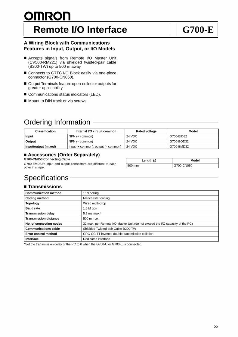
55
Remote I/O Interface G700-EA Wiring Block with CommunicationsFeatures in Input, Output, or I/O Models
Accepts signals from Remote I/O Master Unit(CV500-RM221) via shielded twisted-pair cable(B200-TW) up to 500 m away.
Connects to G7TC I/O Block easily via one-piececonnector (G700-CN050).
Output Terminals feature open-collector outputs forgreater applicability.
Communications status indicators (LED).
Mount to DIN track or via screws.
Ordering InformationClassification Internal I/O circuit common Rated voltage Model
Input NPN (+ common) 24 VDC G700-EID32
Output NPN (-- common) 24 VDC G700-EOD32
Input/output (mixed) Input (+ common); output (-- common) 24 VDC G700-EMD32
Accessories (Order Separately)G700-CN050 Connecting CableG700-EMD32’s input and output connectors are different to eachother in shape.
Length (l) Model
500 mm G700-CN050
SpecificationsTransmissions
Communication method 1: N polling
Coding method Manchester coding
Topology Wired multi-drop
Baud rate 1.5 M bps
Transmission delay 5.2 ms max.*
Transmission distance 500 m max.
No. of connecting nodes 32 max. per Remote I/O Master Unit (do not exceed the I/O capacity of the PC)
Communications cable Shielded Twisted-pair Cable B200-TW
Error control method CRC-CCITT inverted double transmission collation
Interface Dedicated interface
*Set the transmission delay of the PC to 0 when the G700-U or G700-E is connected.
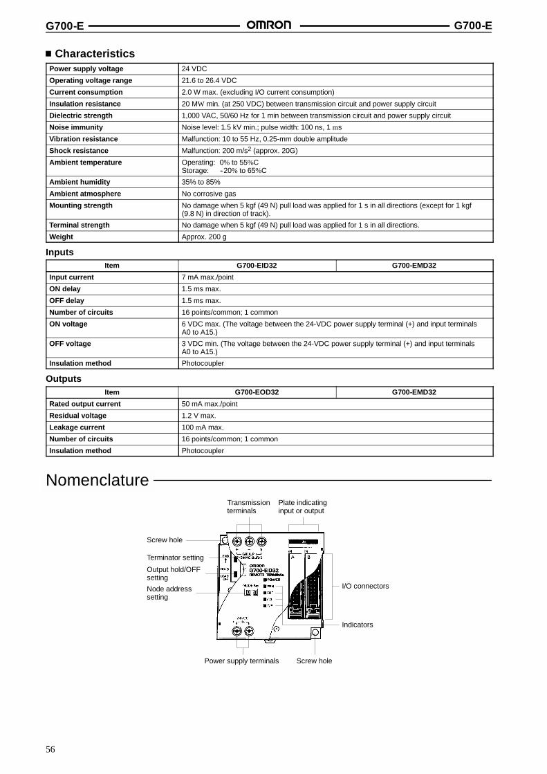
G700-E G700-E
56
CharacteristicsPower supply voltage 24 VDC
Operating voltage range 21.6 to 26.4 VDC
Current consumption 2.0 W max. (excluding I/O current consumption)
Insulation resistance 20 MW min. (at 250 VDC) between transmission circuit and power supply circuit
Dielectric strength 1,000 VAC, 50/60 Hz for 1 min between transmission circuit and power supply circuit
Noise immunity Noise level: 1.5 kV min.; pulse width: 100 ns, 1 ms
Vibration resistance Malfunction: 10 to 55 Hz, 0.25-mm double amplitude
Shock resistance Malfunction: 200 m/s2 (approx. 20G)
Ambient temperature Operating: 0% to 55%CStorage: --20% to 65%C
Ambient humidity 35% to 85%
Ambient atmosphere No corrosive gas
Mounting strength No damage when 5 kgf (49 N) pull load was applied for 1 s in all directions (except for 1 kgf(9.8 N) in direction of track).
Terminal strength No damage when 5 kgf (49 N) pull load was applied for 1 s in all directions.
Weight Approx. 200 g
InputsItem G700-EID32 G700-EMD32
Input current 7 mA max./point
ON delay 1.5 ms max.
OFF delay 1.5 ms max.
Number of circuits 16 points/common; 1 common
ON voltage 6 VDC max. (The voltage between the 24-VDC power supply terminal (+) and input terminalsA0 to A15.)
OFF voltage 3 VDC min. (The voltage between the 24-VDC power supply terminal (+) and input terminalsA0 to A15.)
Insulation method Photocoupler
OutputsItem G700-EOD32 G700-EMD32
Rated output current 50 mA max./point
Residual voltage 1.2 V max.
Leakage current 100 mA max.
Number of circuits 16 points/common; 1 common
Insulation method Photocoupler
Nomenclature
Screw hole
Terminator setting
Output hold/OFFsetting
Node addresssetting
Transmissionterminals
Plate indicatinginput or output
Power supply terminals
I/O connectors
Indicators
Screw hole
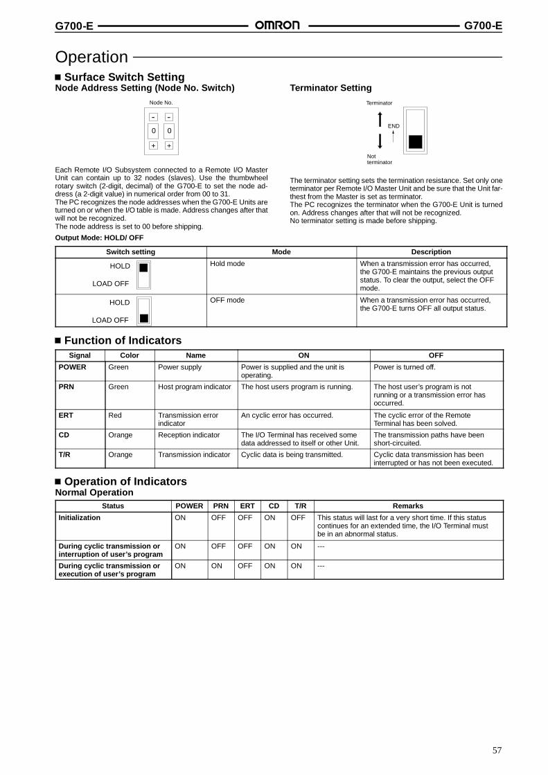
G700-E G700-E
57
OperationSurface Switch Setting
Node Address Setting (Node No. Switch)
--
+
0
--
+
0
Node No.
Each Remote I/O Subsystem connected to a Remote I/O MasterUnit can contain up to 32 nodes (slaves). Use the thumbwheelrotary switch (2-digit, decimal) of the G700-E to set the node ad-dress (a 2-digit value) in numerical order from 00 to 31.The PC recognizes the node addresses when the G700-E Units areturned on or when the I/O table is made. Address changes after thatwill not be recognized.The node address is set to 00 before shipping.
Terminator SettingTerminator
Notterminator
END
The terminator setting sets the termination resistance. Set only oneterminator per Remote I/O Master Unit and be sure that the Unit far-thest from the Master is set as terminator.The PC recognizes the terminator when the G700-E Unit is turnedon. Address changes after that will not be recognized.No terminator setting is made before shipping.
Output Mode: HOLD/ OFF
Switch setting Mode Description
HOLD
LOAD OFF
Hold mode When a transmission error has occurred,the G700-E maintains the previous outputstatus. To clear the output, select the OFFmode.
HOLD
LOAD OFF
OFF mode When a transmission error has occurred,the G700-E turns OFF all output status.
Function of IndicatorsSignal Color Name ON OFF
POWER Green Power supply Power is supplied and the unit isoperating.
Power is turned off.
PRN Green Host program indicator The host users program is running. The host user’s program is notrunning or a transmission error hasoccurred.
ERT Red Transmission errorindicator
An cyclic error has occurred. The cyclic error of the RemoteTerminal has been solved.
CD Orange Reception indicator The I/O Terminal has received somedata addressed to itself or other Unit.
The transmission paths have beenshort-circuited.
T/R Orange Transmission indicator Cyclic data is being transmitted. Cyclic data transmission has beeninterrupted or has not been executed.
Operation of IndicatorsNormal Operation
Status POWER PRN ERT CD T/R Remarks
Initialization ON OFF OFF ON OFF This status will last for a very short time. If this statuscontinues for an extended time, the I/O Terminal mustbe in an abnormal status.
During cyclic transmission orinterruption of user’s program
ON OFF OFF ON ON ---
During cyclic transmission orexecution of user’s program
ON ON OFF ON ON ---
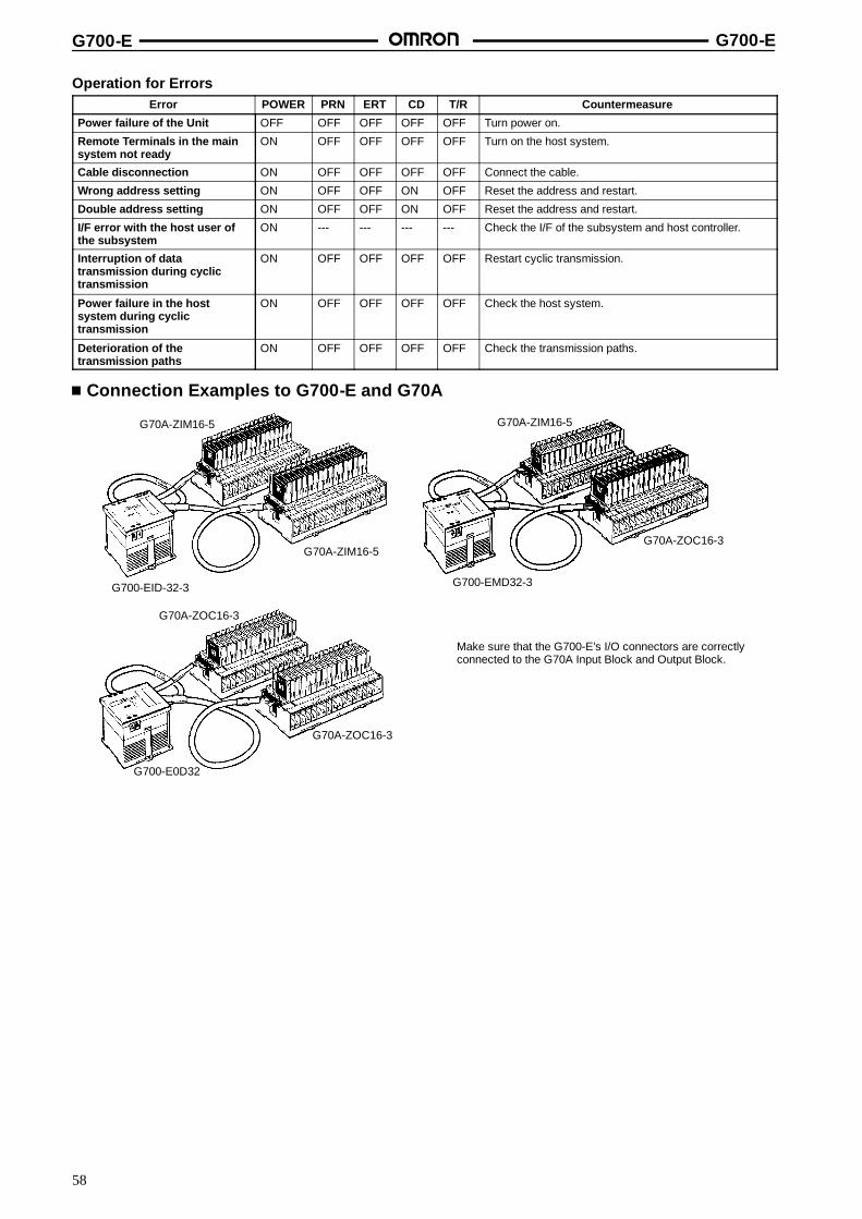
G700-E G700-E
58
Operation for ErrorsError POWER PRN ERT CD T/R Countermeasure
Power failure of the Unit OFF OFF OFF OFF OFF Turn power on.
Remote Terminals in the mainsystem not ready
ON OFF OFF OFF OFF Turn on the host system.
Cable disconnection ON OFF OFF OFF OFF Connect the cable.
Wrong address setting ON OFF OFF ON OFF Reset the address and restart.
Double address setting ON OFF OFF ON OFF Reset the address and restart.
I/F error with the host user ofthe subsystem
ON --- --- --- --- Check the I/F of the subsystem and host controller.
Interruption of datatransmission during cyclictransmission
ON OFF OFF OFF OFF Restart cyclic transmission.
Power failure in the hostsystem during cyclictransmission
ON OFF OFF OFF OFF Check the host system.
Deterioration of thetransmission paths
ON OFF OFF OFF OFF Check the transmission paths.
Connection Examples to G700-E and G70A
Make sure that the G700-E’s I/O connectors are correctlyconnected to the G70A Input Block and Output Block.
G70A-ZIM16-5
G70A-ZIM16-5
G700-EID-32-3
G70A-ZIM16-5
G700-EMD32-3
G70A-ZOC16-3
G70A-ZOC16-3
G700-E0D32
G70A-ZOC16-3

G700-E G700-E
59
DimensionsNote: All units are in millimeters unless otherwise indicated.
Mounting Holes75 max. 65 max.
75 max. 67+0.2
M4 or 4.5 dia. hole
67+0.2
G700-CN050 Connecting Cable
1 11
2 12
3 13
4 14
5 15
6 16
7 17
8 18
9 19
10 20
1 11
2 12
3 13
4 14
5 15
6 16
7 17
8 18
9 19
10 20
Terminal Arrangement
l
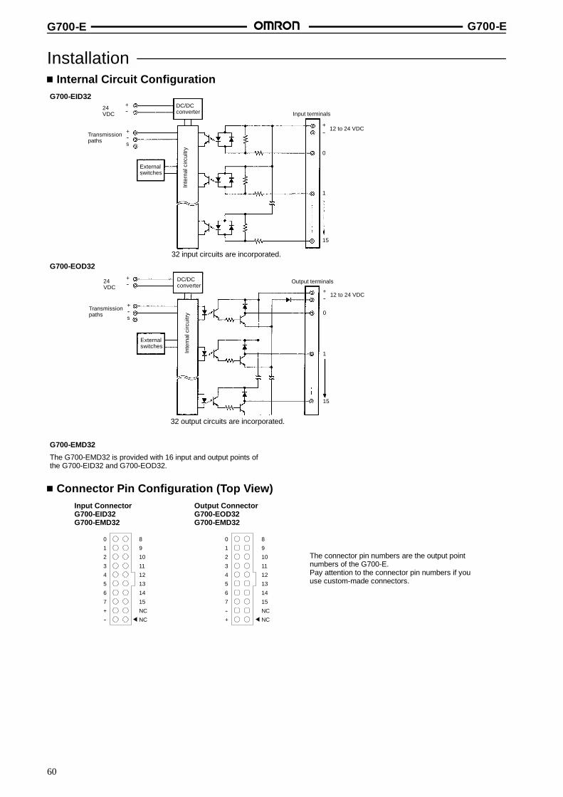
G700-E G700-E
60
InstallationInternal Circuit Configuration
G700-EID32
G700-EMD32
The G700-EMD32 is provided with 16 input and output points ofthe G700-EID32 and G700-EOD32.
Inte
rnal
circ
uitry
Inte
rnal
circ
uitry
Transmissionpaths
+--s
DC/DCconverter
12 to 24 VDC
Externalswitches
32 input circuits are incorporated.
Input terminals
Output terminals
32 output circuits are incorporated.
+--24
VDC
Transmissionpaths
+--s
DC/DCconverter
12 to 24 VDC
Externalswitches
+--24
VDC
0
1
15
15
1
0
+--
+--
G700-EOD32
Connector Pin Configuration (Top View)Input ConnectorG700-EID32G700-EMD32
Output ConnectorG700-EOD32G700-EMD32
The connector pin numbers are the output pointnumbers of the G700-E.Pay attention to the connector pin numbers if youuse custom-made connectors.
0 8
1 9
2 10
3 11
4 12
5 13
6 14
7 15
+ NC
-- NC
0 8
1 9
2 10
3 11
4 12
5 13
6 14
7 15
-- NC
+ NC
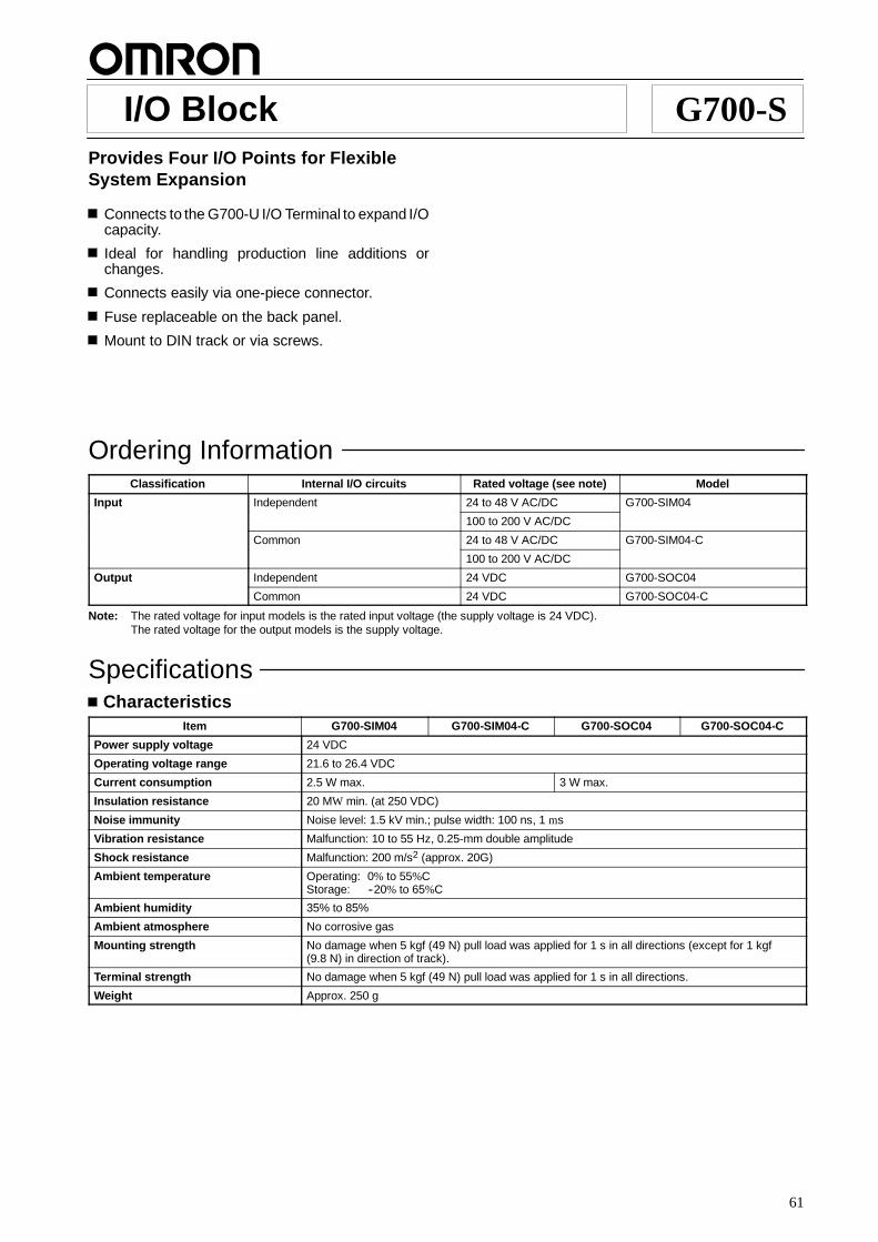
61
I/O Block G700-SProvides Four I/O Points for FlexibleSystem Expansion
Connects to the G700-U I/O Terminal to expand I/Ocapacity.
Ideal for handling production line additions orchanges.
Connects easily via one-piece connector.
Fuse replaceable on the back panel.
Mount to DIN track or via screws.
Ordering InformationClassification Internal I/O circuits Rated voltage (see note) Model
Input Independent 24 to 48 V AC/DC G700-SIM04
100 to 200 V AC/DC
Common 24 to 48 V AC/DC G700-SIM04-C
100 to 200 V AC/DC
Output Independent 24 VDC G700-SOC04
Common 24 VDC G700-SOC04-C
Note: The rated voltage for input models is the rated input voltage (the supply voltage is 24 VDC).The rated voltage for the output models is the supply voltage.
SpecificationsCharacteristics
Item G700-SIM04 G700-SIM04-C G700-SOC04 G700-SOC04-C
Power supply voltage 24 VDC
Operating voltage range 21.6 to 26.4 VDC
Current consumption 2.5 W max. 3 W max.
Insulation resistance 20 MW min. (at 250 VDC)
Noise immunity Noise level: 1.5 kV min.; pulse width: 100 ns, 1 ms
Vibration resistance Malfunction: 10 to 55 Hz, 0.25-mm double amplitude
Shock resistance Malfunction: 200 m/s2 (approx. 20G)
Ambient temperature Operating: 0% to 55%CStorage: --20% to 65%C
Ambient humidity 35% to 85%
Ambient atmosphere No corrosive gas
Mounting strength No damage when 5 kgf (49 N) pull load was applied for 1 s in all directions (except for 1 kgf(9.8 N) in direction of track).
Terminal strength No damage when 5 kgf (49 N) pull load was applied for 1 s in all directions.
Weight Approx. 250 g

G700-S G700-S
62
InputsItem G700-SIM04 G700-SIM04-C
Rated input voltage 24 to 48 VAC/VDC 100 to 200 VAC/VDC
Mounting relay G7T-1122S 24 VDC
Operating input current range 24 V: --10%; 48 V: +10% 100 V: --10%; 200 V: +10%
ON delay 1.5 ms max.
OFF delay 1.5 ms max.
Number of circuits 4 points/independent; commons
Insulation method Photocoupler + relay
Input indicators LED (orange)
OutputsItem G700-SOC04 G700-SOC04--C
Mounting relay G7T-1112S 24 VDC
Max. contact voltage value 250 VAC/125 VDC
Max. contact current value 2 A/point 6 A (for 4 points, common)
Number of circuits 4 points
Output indicators LED (orange)
NomenclatureExpansion cable Input indicators
Mechanical relaymonitor windows
Expansion connector
Power supplyterminals
I/O terminals

G700-S G700-S
63
DimensionsNote: All units are in millimeters unless otherwise indicated.
Mounting Holes
12 74
65
3
7
7
7Cable length: 60
86 max.
75 max.
61+0.2
M4 or 4.5 dia. hole
72+0.2
35.3+0.20
InstallationInternal Circuit Configuration
Input CircuitsG700-SIM04 (4 Points;/Independent Commons)
Exp
ansi
on
Inte
rnal
circ
uitry
R: 56 kW for 24 to 48 VDC/VAC power supplyR: 330 kW for 100 to 200 VAC/VDC power supply
Power supply (positive)+-- 24 VDC
R
R
R
R
R
R
R
R
A0
B0
A1
B1
A2
B2
A3
B3
conn
ecto
rE
xpan
sion
conn
ecto
r

G700-S G700-S
64
Output CircuitsG700-SOC04 (4 Points;/Independent Commons)
G700-SIM04-C (4 Points/Common)
G700-SOC04-C (4 Points/Common)
Exp
ansi
on
Inte
rnal
circ
uitry
R: 56 kW for 24 to 48 VDC/VAC power supplyR: 330 kW for 100 to 200 VAC/VDC power supply
Power supply for loadR
R
R
R
R
R
R
R
Power supply (positive)+-- 24 VDC
B0B1A0
A1
B2
A2
A3
B3
conn
ecto
rE
xpan
sion
conn
ecto
rE
xpan
sion
Inte
rnal
circ
uitry
Power supply (positive)+-- 24 VDC
A0
B0
A1
B1
A2
B2
A3
B3
conn
ecto
rE
xpan
sion
conn
ecto
rE
xpan
sion
Inte
rnal
circ
uitry
Power supply (positive)+-- 24 VDC
B0B1A0
A1
B2
A2
A3
B3
Power supply for load
conn
ecto
rE
xpan
sion
conn
ecto
r
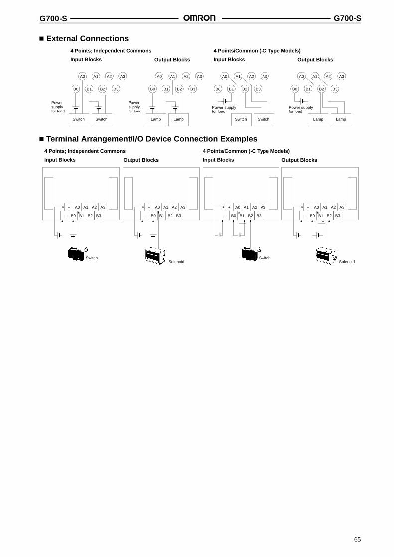
G700-S G700-S
65
External Connections4 Points; Independent Commons
Input Blocks Output Blocks
4 Points/Common (-C Type Models)
Input Blocks Output Blocks
A0
B0 B1
A1
B2
A2
B3
A3
Powersupplyfor load
Switch Switch
A0
B0 B1
A1
B2
A2
B3
A3
Powersupplyfor load
Lamp Lamp
A0
B0 B1
A1
B2
A2
B3
A3
Power supplyfor load
Switch Switch
A0
B0 B1
A1
B2
A2
B3
A3
Power supplyfor load
Lamp Lamp
Terminal Arrangement/I/O Device Connection Examples
Output Blocks
4 Points; Independent Commons
Input Blocks Output Blocks
4 Points/Common (-C Type Models)
Input Blocks
+ A0 A1 A2 A3
-- B0 B1 B2 B3
Switch
+ A0 A1 A2 A3
-- B0 B1 B2 B3
Solenoid
+ A0 A1 A2 A3
-- B0 B1 B2 B3
Switch
+ A0 A1 A2 A3
-- B0 B1 B2 B3
Solenoid
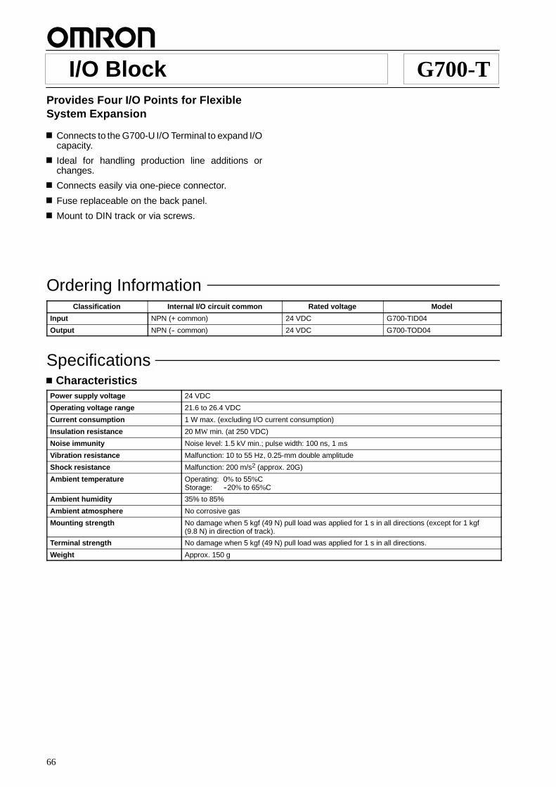
66
I/O Block G700-TProvides Four I/O Points for FlexibleSystem Expansion
Connects to the G700-U I/O Terminal to expand I/Ocapacity.
Ideal for handling production line additions orchanges.
Connects easily via one-piece connector.
Fuse replaceable on the back panel.
Mount to DIN track or via screws.
Ordering InformationClassification Internal I/O circuit common Rated voltage Model
Input NPN (+ common) 24 VDC G700-TID04
Output NPN (-- common) 24 VDC G700-TOD04
SpecificationsCharacteristics
Power supply voltage 24 VDC
Operating voltage range 21.6 to 26.4 VDC
Current consumption 1 W max. (excluding I/O current consumption)
Insulation resistance 20 MW min. (at 250 VDC)
Noise immunity Noise level: 1.5 kV min.; pulse width: 100 ns, 1 ms
Vibration resistance Malfunction: 10 to 55 Hz, 0.25-mm double amplitude
Shock resistance Malfunction: 200 m/s2 (approx. 20G)
Ambient temperature Operating: 0% to 55%CStorage: --20% to 65%C
Ambient humidity 35% to 85%
Ambient atmosphere No corrosive gas
Mounting strength No damage when 5 kgf (49 N) pull load was applied for 1 s in all directions (except for 1 kgf(9.8 N) in direction of track).
Terminal strength No damage when 5 kgf (49 N) pull load was applied for 1 s in all directions.
Weight Approx. 150 g
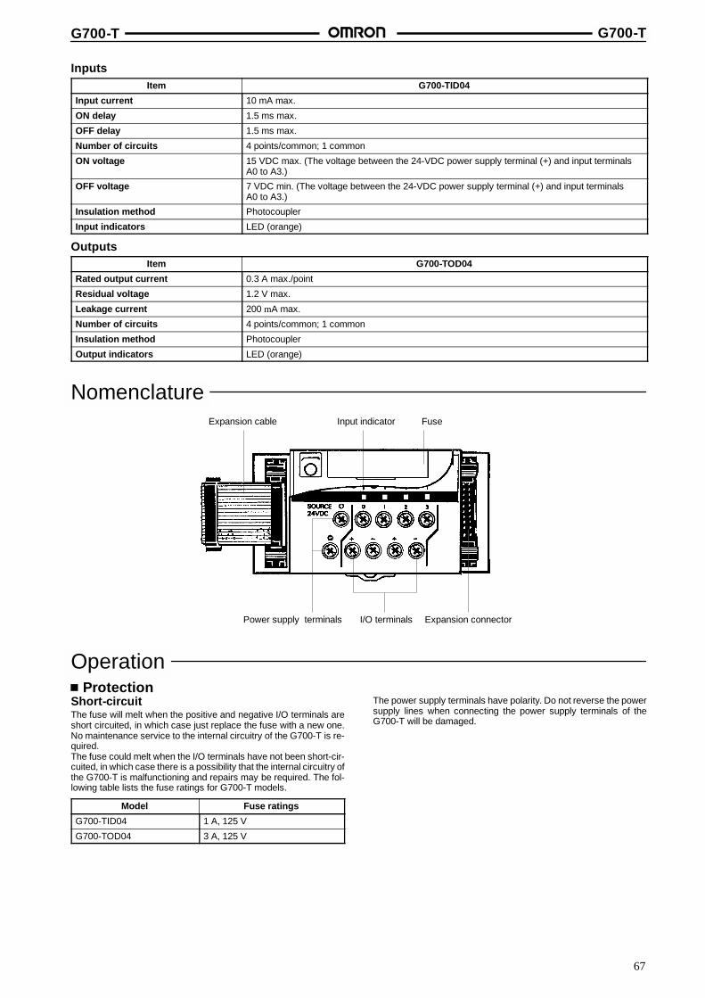
G700-T G700-T
67
InputsItem G700-TID04
Input current 10 mA max.
ON delay 1.5 ms max.
OFF delay 1.5 ms max.
Number of circuits 4 points/common; 1 common
ON voltage 15 VDC max. (The voltage between the 24-VDC power supply terminal (+) and input terminalsA0 to A3.)
OFF voltage 7 VDC min. (The voltage between the 24-VDC power supply terminal (+) and input terminalsA0 to A3.)
Insulation method Photocoupler
Input indicators LED (orange)
OutputsItem G700-TOD04
Rated output current 0.3 A max./point
Residual voltage 1.2 V max.
Leakage current 200 mA max.
Number of circuits 4 points/common; 1 common
Insulation method Photocoupler
Output indicators LED (orange)
NomenclatureExpansion cable Input indicator
Power supply terminals I/O terminals Expansion connector
Fuse
OperationProtection
Short-circuitThe fuse will melt when the positive and negative I/O terminals areshort circuited, in which case just replace the fuse with a new one.No maintenance service to the internal circuitry of the G700-T is re-quired.The fuse could melt when the I/O terminals have not been short-cir-cuited, in which case there is a possibility that the internal circuitry ofthe G700-T is malfunctioning and repairs may be required. The fol-lowing table lists the fuse ratings for G700-T models.
Model Fuse ratings
G700-TID04 1 A, 125 V
G700-TOD04 3 A, 125 V
The power supply terminals have polarity. Do not reverse the powersupply lines when connecting the power supply terminals of theG700-T will be damaged.
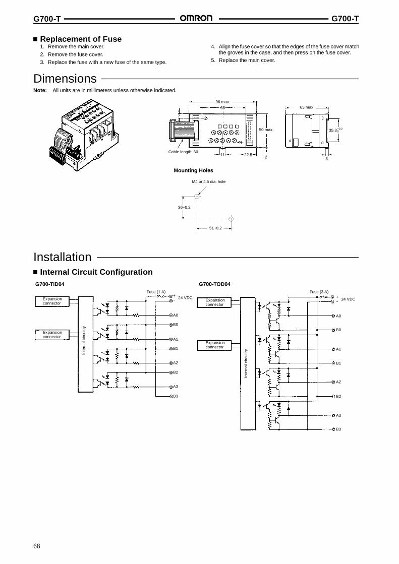
G700-T G700-T
68
Replacement of Fuse1. Remove the main cover.2. Remove the fuse cover.3. Replace the fuse with a new fuse of the same type.
4. Align the fuse cover so that the edges of the fuse cover matchthe groves in the case, and then press on the fuse cover.
5. Replace the main cover.
DimensionsNote: All units are in millimeters unless otherwise indicated.
Mounting Holes
68
7
11 22.5 2 3
96 max.65 max.
Cable length: 60
50 max.
51+0.2
36+0.2
M4 or 4.5 dia. hole
35.3+0.20
InstallationInternal Circuit Configuration
G700-TID04 G700-TOD04
Inte
rnal
circ
uitry
Expansionconnector
Fuse (1 A)+-- 24 VDC
A0
B0
A1
B1
A2
B2
A3
B3
Expansionconnector
Inte
rnal
circ
uitry
Fuse (3 A)+-- 24 VDC
A0
B0
A1
B1
A2
B2
A3
B3
Expansionconnector
Expansionconnector

G700-T G700-T
69
External ConnectionsNo relay terminal boards for the sensor loads are required.
Input Blocks
Three-wire System (NPN) Two-wire System
Output Blocks
A0
B0 B1
A1
B2
Red White Black(brown) (black) (blue)
Sensor 1
A0
B0 B1
A1
B2
White Black(brown) (blue)
Sensor 1
White Black(brown) (blue)
Sensor 2
A0
B0 B1
A1
B2
-- +L1
-- +L2
Red White Black(brown) (black) (blue)
Sensor 2
Terminal Arrangement/I/O Device Connection ExamplesInput Blocks Output Blocks
+ A0 A1 A2 A3
-- B0 B1 B2 B3
Black(blue)White
(black)
White(brown)
Red(brown)
24 VDC
Photoelectric sensorProximity sensor(or other sensor withbuilt-in amplifier and3-wired outputs)
Limit switch(or sensor with 2-wiredoutputs)
+ A0 A1 A2 A3
-- B0 B1 B2 B3
24 VDC
(--)(+) (--)(+)
Solenoid Valve
Black(blue)
Note: The colors in the parentheses apply to present models in accordance with a recent revision ofthe Japanese Industrial Standards.

70
I/O Terminal G700-UCombines the Features of aCommunications Terminal with a WiringBlock; I/O Quantity and Blend Flexibility
Reduced mounting space requirements.
Accepts signals from Remote I/O Master Unit(CV500-RM221) via shielded twisted-pair cable(B200-TW) up to 500 m away.
Expandable in increments of four I/O points byadding the G700-T or G700-S I/O Blocks.
Expandable to up to 32 I/O points.
Inputs and outputs can be mixed.
ON/OFF indicator (LED) for each I/O point andcommunications status indicators (LED).
Fuse replaceable on the back panel.
Mount to DIN track or via screws.
Provides power terminals for I/O devices.
Ordering InformationClassification Internal I/O circuit common Rated voltage Model
Input NPN (+ common) 24 VDC G700-UID16
Output NPN (-- common) 24 VDC G700-UOD16
Input/output (mixed) Input (+ common); output (-- common) 24 VDC G700-UMD16
SpecificationsTransmission
Communication method 1: N polling
Coding method Manchester coding
Topology Wired multi-drop
Baud rate 1.5 M bps
Transmission delay 5.2 ms max.*
Transmission distance 500 m max.
No. of connecting nodes 32 max. per Remote I/O Master Unit (do not exceed the I/O capacity of the PC)
Communications cable Shielded Twisted-pair Shielded Cable B200-TW
Error control method CRC-CCITT inverted double transmission collation
Interface Dedicated interface
*Set the transmission delay of the PC to 0 when the G700-U or G700-E is connected.
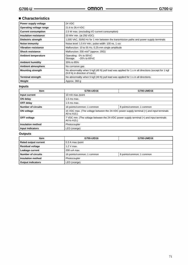
G700-U G700-U
71
CharacteristicsPower supply voltage 24 VDC
Operating voltage range 21.6 to 26.4 VDC
Current consumption 2.5 W max. (excluding I/O current consumption)
Insulation resistance 20 MW min. (at 250 VDC)
Dielectric strength 1,000 VAC, 50/60 Hz for 1 min between the transmission paths and power supply terminals
Noise immunity Noise level: 1.5 kV min.; pulse width: 100 ns, 1 ms
Vibration resistance Malfunction: 10 to 55 Hz, 0.25-mm single amplitude
Shock resistance Malfunction: 200 m/s2 (approx. 20G)
Ambient temperature Operating: 0% to 55%CStorage: --20% to 65%C
Ambient humidity 35% to 85%
Ambient atmosphere No corrosive gas
Mounting strength No abnormality when 5 kgf (49 N) pull load was applied for 1 s in all directions (except for 1 kgf(9.8 N) in direction of track).
Terminal strength No abnormality when 5 kgf (49 N) pull load was applied for 1 s in all directions.
Weight Approx. 360 g
InputsItem G700-UID16 G700-UMD16
Input current 10 mA max./point
ON delay 1.5 ms max.
OFF delay 1.5 ms max.
Number of circuits 16 points/common; 1 common 8 points/common; 1 common
ON voltage 15 VDC max. (The voltage between the 24-VDC power supply terminal (+) and input terminalsA0 to A15.)
OFF voltage 7 VDC min. (The voltage between the 24-VDC power supply terminal (+) and input terminalsA0 to A15.)
Insulation method Photocoupler
Input indicators LED (orange)
OutputsItem G700-UID16 G700-UMD16
Rated output current 0.3 A max./point
Residual voltage 1.2 V max.
Leakage current 200 mA max.
Number of circuits 16 points/common; 1 common 8 points/common; 1 common
Insulation method Photocoupler
Output indicators LED (orange)
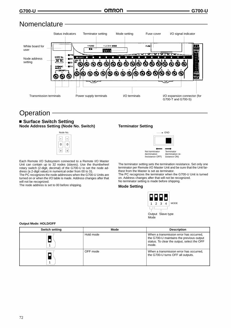
G700-U G700-U
72
Nomenclature
White board foruser
Status indicators Terminator setting Mode setting Fuse cover
Node addresssetting
Transmission terminals I/O terminals I/O expansion connector (forG700-T and G700-S)
I/O signal indicator
Power supply terminals
OperationSurface Switch Setting
Node Address Setting (Node No. Switch)
--
+
--
+
00
Node No.
Each Remote I/O Subsystem connected to a Remote I/O MasterUnit can contain up to 32 nodes (slaves). Use the thumbwheelrotary switch (2-digit, decimal) of the G700-U to set the node ad-dress (a 2-digit value) in numerical order from 00 to 31.The PC recognizes the node addresses when the G700-U Units areturned on or when the I/O table is made. Address changes after thatwill not be recognized.The node address is set to 00 before shipping.
Terminator SettingEND
Not terminator(terminationresistance OFF)
Terminator(termination re-sistance ON)
The terminator setting sets the termination resistance. Set only oneterminator per Remote I/O Master Unit and be sure that the Unit far-thest from the Master is set as terminator.The PC recognizes the terminator when the G700-U Unit is turnedon. Address changes after that will not be recognized.No terminator setting is made before shipping.
Mode Setting
1 3 42 MODE
OutputMode
Slave type
Output Mode: HOLD/OFF
Switch setting Mode Description
1
Hold mode When a transmission error has occurred,the G700-U maintains the previous outputstatus. To clear the output, select the OFFmode.
1
OFF mode When a transmission error has occurred,the G700-U turns OFF all outputs.

G700-U G700-U
73
Slave TypeThe slave type must be set to 2M, 2I, 2Q or 4M so that the PC can allocate the proper number of I/O bits.
Switch setting Slave type Connecting model Description
3 42
2M: G700-UID16G700-UOD16G700-UMD16
G700-TID04G700-TOD04G700-SIM04(-C)G700-SOC04(-C)
Up to 16 input and 16 outputpoints are available.
3 42
2I: G700-UID16 G700-TID04G700-SIM04(-C)
Up to 32 input points areavailable.
32 4
2Q: G700-UOD16 G700-TOD04G700-SOC04(-C)
Up to 32 output points areavailable.
3 42
4M: G700-UID16G700-UOD16G700-UMD16
G700-TID04G700-TOD04G700-SIM04(-C)G700-SOC04(-C)
Up to 32 input and 32 outputpoints are available.
Note: 1. 2M mode is set before shipping.
2. The G700-U does not operate if the slave type switch is set to any setting not shown above.3. The G700-U’s expansion signal is a dynamic time-division signal. Connections other than those shown above will damage the
G700-U. Use the expansion cables that are sold together with the I/O Blocks.If the number of I/O points you expanded is beyond the permissiblerange, the PC will support only the I/O points within the permissiblerange and the I/O points exceeding the permissible range will be ig-nored.
Possible expansion areaBeyond the possibleexpansion area
PC and No. of Connecting G700-U Units
PC G700-U
2M 2I 2Q 4M
SYSMAC CV500 32 units 32 units 32 units 16 units
SYSMAC CV1000 64units*
64units*
64units*
32 units
*With two Remote I/O Master Units
Function of IndicatorsSignal Color Name ON OFF
POWER Green Power supply Power is supplied and the unit isoperating.
Power is turned off.
PRN Green Host program indicator The host users program is running. The host user’s program is notrunning or a transmission error hasoccurred.
ERT Red Transmission errorindicator
An cyclic error has occurred. The cyclic error of the RemoteTerminal has been solved.
CD Orange Reception indicator The I/O Terminal has received somedata addressed to itself or other Unit.
The transmission paths have beenshort-circuited.
T/R Orange Transmission indicator Cyclic data is being transmitted. Cyclic data transmission has beeninterrupted or has not been executed.
Operation of IndicatorsNormal Operation
Status POWER PRN ERT CD T/R Remarks
Initialization ON OFF OFF ON OFF This status will last for a very short time. If this statuscontinues an extended time, the I/O Terminal must bein an abnormal status.
During cyclic transmission orinterruption of user’s program
ON OFF OFF ON ON ---
During cyclic transmission orexecution of user’s program
ON ON OFF ON ON ---
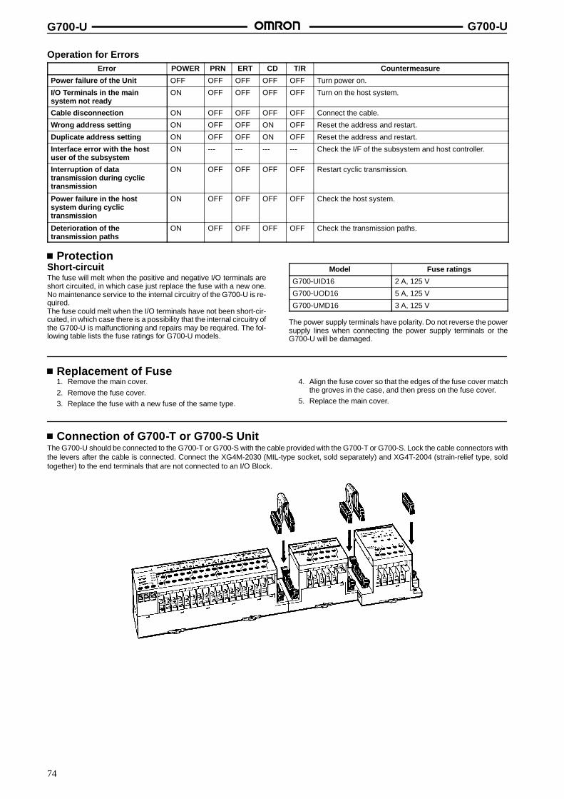
G700-U G700-U
74
Operation for ErrorsError POWER PRN ERT CD T/R Countermeasure
Power failure of the Unit OFF OFF OFF OFF OFF Turn power on.
I/O Terminals in the mainsystem not ready
ON OFF OFF OFF OFF Turn on the host system.
Cable disconnection ON OFF OFF OFF OFF Connect the cable.
Wrong address setting ON OFF OFF ON OFF Reset the address and restart.
Duplicate address setting ON OFF OFF ON OFF Reset the address and restart.
Interface error with the hostuser of the subsystem
ON --- --- --- --- Check the I/F of the subsystem and host controller.
Interruption of datatransmission during cyclictransmission
ON OFF OFF OFF OFF Restart cyclic transmission.
Power failure in the hostsystem during cyclictransmission
ON OFF OFF OFF OFF Check the host system.
Deterioration of thetransmission paths
ON OFF OFF OFF OFF Check the transmission paths.
ProtectionShort-circuitThe fuse will melt when the positive and negative I/O terminals areshort circuited, in which case just replace the fuse with a new one.No maintenance service to the internal circuitry of the G700-U is re-quired.The fuse could melt when the I/O terminals have not been short-cir-cuited, in which case there is a possibility that the internal circuitry ofthe G700-U is malfunctioning and repairs may be required. The fol-lowing table lists the fuse ratings for G700-U models.
Model Fuse ratings
G700-UID16 2 A, 125 V
G700-UOD16 5 A, 125 V
G700-UMD16 3 A, 125 V
The power supply terminals have polarity. Do not reverse the powersupply lines when connecting the power supply terminals or theG700-U will be damaged.
Replacement of Fuse1. Remove the main cover.2. Remove the fuse cover.3. Replace the fuse with a new fuse of the same type.
4. Align the fuse cover so that the edges of the fuse cover matchthe groves in the case, and then press on the fuse cover.
5. Replace the main cover.
Connection of G700-T or G700-S UnitThe G700-U should be connected to the G700-T or G700-S with the cable provided with the G700-T or G700-S. Lock the cable connectors withthe levers after the cable is connected. Connect the XG4M-2030 (MIL-type socket, sold separately) and XG4T-2004 (strain-relief type, soldtogether) to the end terminals that are not connected to an I/O Block.
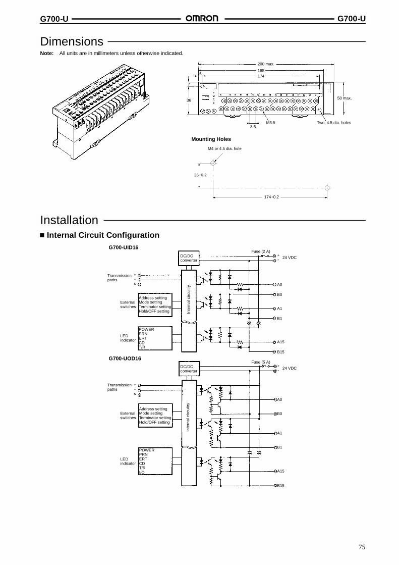
G700-U G700-U
75
DimensionsNote: All units are in millimeters unless otherwise indicated.
Mounting Holes
185174
8.5
5
7
36
200 max.
M3.5 Two, 4.5 dia. holes
50 max.
174+0.2
36+0.2
M4 or 4.5 dia. hole
InstallationInternal Circuit Configuration
G700-UID16
G700-UOD16
Inte
rnal
circ
uitry
Transmissionpaths
+--s
Externalswitches
LEDindicator
POWERPRNERTCDT/R
Address settingMode settingTerminator settingHold/OFF setting
DC/DCconverter
+-- 24 VDC
A0
B0
A1
B1
A15
B15
Fuse (2 A)
Inte
rnal
circ
uitry
Transmissionpaths
+--s
Externalswitches
Address settingMode settingTerminator settingHold/OFF setting
DC/DCconverter
Fuse (5 A)+-- 24 VDC
A0
B0
A1
B1
A15
B15
LEDindicator
POWERPRNERTCDT/RI/O

G700-U G700-U
76
G700-UMD16
Inte
rnal
circ
uitry
LEDindicator
POWERPRNERTCDT/R
Transmissionpaths
+--s
Externalswitches
Address settingMode settingTerminator settingHold/OFF setting
DC/DCconverter
Fuse (3 A)+-- 24 VDC
A0
B0
A7
B7
A8
B8
A15
B15
External ConnectionsNo relay terminal boards for the sensor loads are required.
Input Blocks
Three-wire System (NPN) Two-wire System
Output Blocks
A0
B0 B1
A1
B2
Red White Black(brown) (black) (blue)
Sensor 1
A0
B0 B1
A1
B2
White Black(brown) (blue)
Sensor 1
White Black(brown) (blue)
Sensor 2
A0
B0 B1
A1
B2
-- +L1
-- +L2
Red White Black(brown) (black) (blue)
Sensor 2
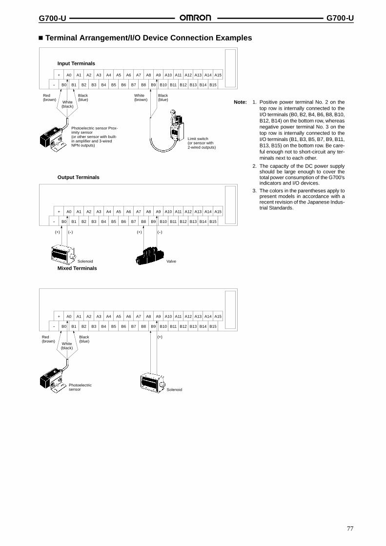
G700-U G700-U
77
Terminal Arrangement/I/O Device Connection Examples
Input Terminals
Output Terminals
Mixed Terminals
Note: 1. Positive power terminal No. 2 on thetop row is internally connected to theI/O terminals (B0, B2, B4, B6, B8, B10,B12, B14) on the bottom row, whereasnegative power terminal No. 3 on thetop row is internally connected to theI/O terminals (B1, B3, B5, B7, B9, B11,B13, B15) on the bottom row. Be care-ful enough not to short-circuit any ter-minals next to each other.
2. The capacity of the DC power supplyshould be large enough to cover thetotal power consumption of the G700’sindicators and I/O devices.
3. The colors in the parentheses apply topresent models in accordance with arecent revision of the Japanese Indus-trial Standards.
+ A0 A1 A2 A3 A4 A5 A6 A7 A8 A9 A10 A11 A12 A13 A14 A15
-- B0 B1 B2 B3 B4 B5 B6 B7 B8 B9 B10 B11 B12 B13 B14 B15
Black(blue)
White(black)
Red(brown)
Black(blue)
White(brown)
Photoelectric sensor Prox-imity sensor(or other sensor with built-in amplifier and 3-wiredNPN outputs)
Limit switch(or sensor with2-wired outputs)
+ A0 A1 A2 A3 A4 A5 A6 A7 A8 A9 A10 A11 A12 A13 A14 A15
-- B0 B1 B2 B3 B4 B5 B6 B7 B8 B9 B10 B11 B12 B13 B14 B15
(--)(+)(--)(+)
Solenoid Valve
+ A0 A1 A2 A3 A4 A5 A6 A7 A8 A9 A10 A11 A12 A13 A14 A15
-- B0 B1 B2 B3 B4 B5 B6 B7 B8 B9 B10 B11 B12 B13 B14 B15
Photoelectricsensor
(+)
Solenoid
Black(blue)
White(black)
Red(brown)
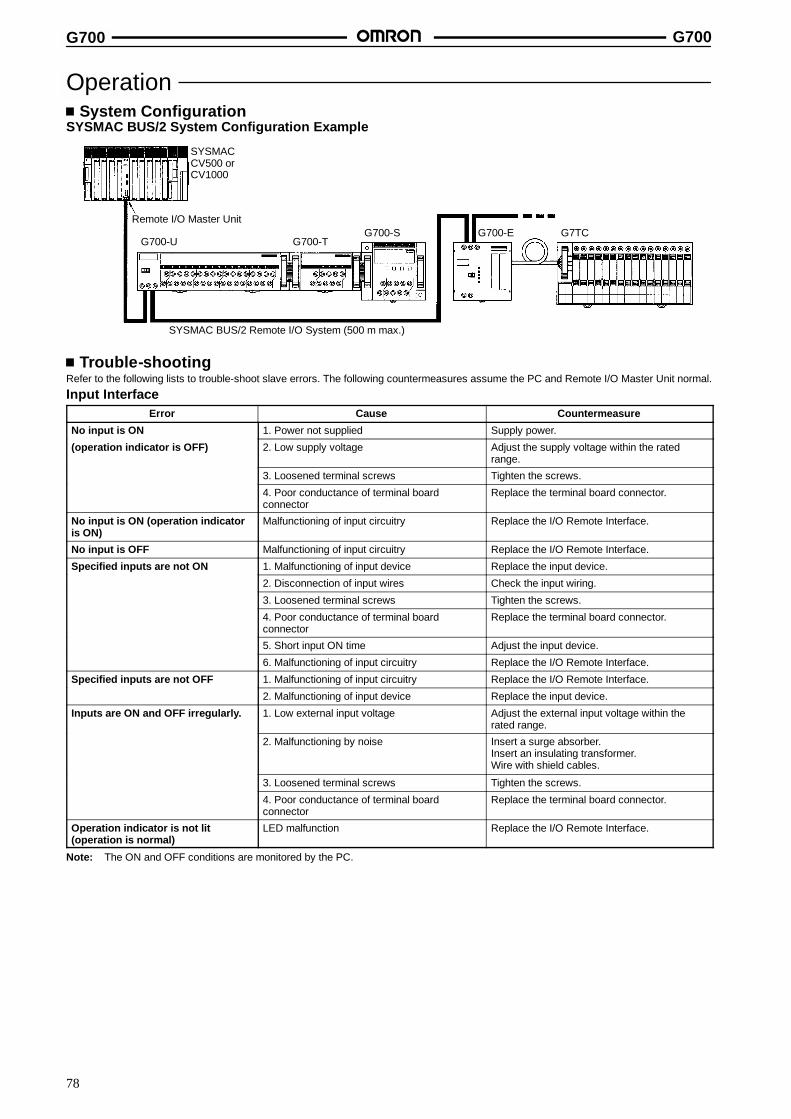
G700 G700
78
OperationSystem Configuration
SYSMAC BUS/2 System Configuration Example
Remote I/O Master Unit
SYSMAC BUS/2 Remote I/O System (500 m max.)
SYSMACCV500 orCV1000
G700-UG700-S
G700-TG700-E G7TC
Trouble-shootingRefer to the following lists to trouble-shoot slave errors. The following countermeasures assume the PC and Remote I/O Master Unit normal.
Input InterfaceError Cause Countermeasure
No input is ON 1. Power not supplied Supply power.
(operation indicator is OFF) 2. Low supply voltage Adjust the supply voltage within the ratedrange.
3. Loosened terminal screws Tighten the screws.
4. Poor conductance of terminal boardconnector
Replace the terminal board connector.
No input is ON (operation indicatoris ON)
Malfunctioning of input circuitry Replace the I/O Remote Interface.
No input is OFF Malfunctioning of input circuitry Replace the I/O Remote Interface.
Specified inputs are not ON 1. Malfunctioning of input device Replace the input device.
2. Disconnection of input wires Check the input wiring.
3. Loosened terminal screws Tighten the screws.
4. Poor conductance of terminal boardconnector
Replace the terminal board connector.
5. Short input ON time Adjust the input device.
6. Malfunctioning of input circuitry Replace the I/O Remote Interface.
Specified inputs are not OFF 1. Malfunctioning of input circuitry Replace the I/O Remote Interface.
2. Malfunctioning of input device Replace the input device.
Inputs are ON and OFF irregularly. 1. Low external input voltage Adjust the external input voltage within therated range.
2. Malfunctioning by noise Insert a surge absorber.Insert an insulating transformer.Wire with shield cables.
3. Loosened terminal screws Tighten the screws.
4. Poor conductance of terminal boardconnector
Replace the terminal board connector.
Operation indicator is not lit(operation is normal)
LED malfunction Replace the I/O Remote Interface.
Note: The ON and OFF conditions are monitored by the PC.

G700 G700
79
Output InterfaceError Cause Countermeasure
No output is ON 1. Load power not supplied Supply power.
2. Low load supply voltage Adjust the supply voltage within the ratedrange.
3. Loosened terminal screws Tighten the screws.
4. Fuse burnout Replace the fuse.
5. Malfunctioning of output circuitry Replace the I/O Remote Interface.
No output is ON Malfunctioning of output circuitry Replace the I/O Remote Interface.
Specified outputs are not ON 1. Short output ON time Correct the program.
(operation indicator is OFF) 2. Malfunctioning of output circuitry Replace the I/O Remote Interface.
Specified outputs are not ON 1. Malfunctioning of output device Replace the output device.
(operation indicator is ON) 2. Disconnection of output wires Check the output wiring.
3. Loosened terminal screws Tighten the screws.
4. Malfunctioning of output relay Replace the relay.
5. Malfunctioning of output circuitry Replace the I/O Remote Interface.
Specified inputs are not OFF 1. Malfunctioning of output relay Replace the I/O Remote Interface.
(operation indicator is OFF) 2. Improper reset due to a current leakage orresidual voltage.
Add an external load or dummy load.
Specified inputs are not OFF(operation indicator is OFF)
Malfunctioning of output circuitry Replace the I/O Remote Interface.
Inputs are ON and OFF irregularly. 1. Low load supply voltage Adjust the load supply voltage within the ratedrange.
2. Malfunctioning by noise Insert a surge absorber.Insert an insulating transformer.Wire with shield cables.
3. Loosened terminal screws Tighten the screws.
Operation indicator is not lit(operation is normal)
LED malfunction Replace the I/O Remote Interface.
DimensionsNote: All units are in millimeters unless otherwise indicated.
Mounting TrackPFP-100N, PFP-50N PFP-100N2
It is recommended to use a panel 1.6- to 2.0-mm thick.L: Length
1 m PFP-100N50 cm PFP-50N1 m PFP-100N2
4.5
15 25 25 25 25 *10 10
L
7.3+0.15
35+0.3 27+0.15
1
4.5
15 25 25 25 25 1510 10
L
35+0.3 27 24
16
29.2
1 1.5

G700 G700
80
End PlatesPFP-M
SpacersPFP-S
50
11.510M4 x 8 panhead screw
106.2
1.8
135.5 35.3
1.8
1.3
4.8
5
1612
44.334.8
16.5
PrecautionsConnection of Transmission Cable (G700-U, G700-E)
Correct Example Incorrect Example 1
The positive and negative terminals are reversed.
Incorrect Example 2
A single Remote I/O Master Unit is directly connected to twoslaves.
Incorrect Example 3
The ground (shield) terminals are not connected.
+
--
S S-- S--++
Slave (G700-U)
Remote I/O Master Unit
Slave (G700-U)
OK
+
--
S S-- S--++
Slave (G700-U)
Remote I/O Master Unit
Slave (G700-U)
No
SS-- S--++
Slave (G700-U) Slave (G700-U)
No
+
--
Remote I/O Master Unit
+
--
S S-- S--++
Slave (G700-U)
Remote I/O Master Unit
Slave (G700-U)
NoIncorrect Example 4
The transmission paths are branched at a slave.
+
--
S S-- S--++
Slave (G700-U)
Remote I/O Master Unit
Slave (G700-U)
No
S--+Slave (G700-U)
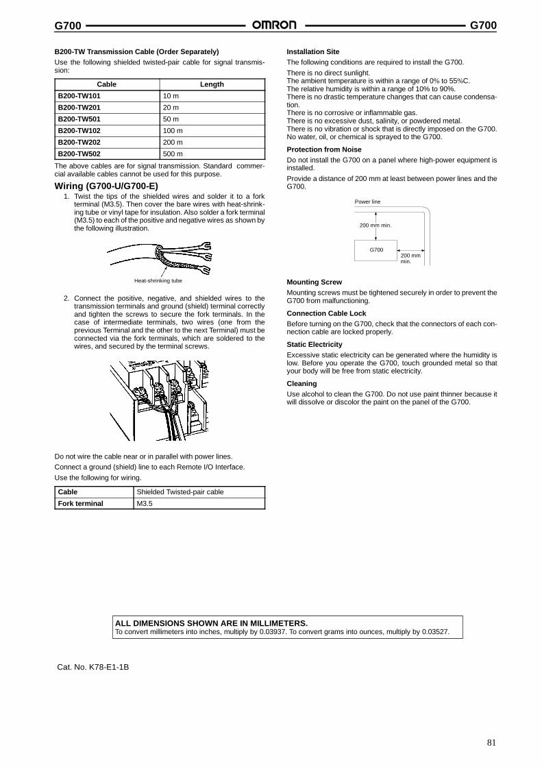
G700 G700
81
B200-TW Transmission Cable (Order Separately)Use the following shielded twisted-pair cable for signal transmis-sion:
Cable Length
B200-TW101 10 m
B200-TW201 20 m
B200-TW501 50 m
B200-TW102 100 m
B200-TW202 200 m
B200-TW502 500 m
The above cables are for signal transmission. Standard commer-cial available cables cannot be used for this purpose.
Wiring (G700-U/G700-E)1. Twist the tips of the shielded wires and solder it to a fork
terminal (M3.5). Then cover the bare wires with heat-shrink-ing tube or vinyl tape for insulation. Also solder a fork terminal(M3.5) to each of the positive and negative wires as shown bythe following illustration.
Heat-shrinking tube
2. Connect the positive, negative, and shielded wires to thetransmission terminals and ground (shield) terminal correctlyand tighten the screws to secure the fork terminals. In thecase of intermediate terminals, two wires (one from theprevious Terminal and the other to the next Terminal) must beconnected via the fork terminals, which are soldered to thewires, and secured by the terminal screws.
Do not wire the cable near or in parallel with power lines.Connect a ground (shield) line to each Remote I/O Interface.Use the following for wiring.
Cable Shielded Twisted-pair cable
Fork terminal M3.5
Installation SiteThe following conditions are required to install the G700.There is no direct sunlight.The ambient temperature is within a range of 0% to 55%C.The relative humidity is within a range of 10% to 90%.There is no drastic temperature changes that can cause condensa-tion.There is no corrosive or inflammable gas.There is no excessive dust, salinity, or powdered metal.There is no vibration or shock that is directly imposed on the G700.No water, oil, or chemical is sprayed to the G700.
Protection from NoiseDo not install the G700 on a panel where high-power equipment isinstalled.Provide a distance of 200 mm at least between power lines and theG700.
Power line
G700200 mmmin.
200 mm min.
Mounting ScrewMounting screws must be tightened securely in order to prevent theG700 from malfunctioning.
Connection Cable LockBefore turning on the G700, check that the connectors of each con-nection cable are locked properly.
Static ElectricityExcessive static electricity can be generated where the humidity islow. Before you operate the G700, touch grounded metal so thatyour body will be free from static electricity.
CleaningUse alcohol to clean the G700. Do not use paint thinner because itwill dissolve or discolor the paint on the panel of the G700.
ALL DIMENSIONS SHOWN ARE IN MILLIMETERS.To convert millimeters into inches, multiply by 0.03937. To convert grams into ounces, multiply by 0.03527.
Cat. No. K78-E1-1B
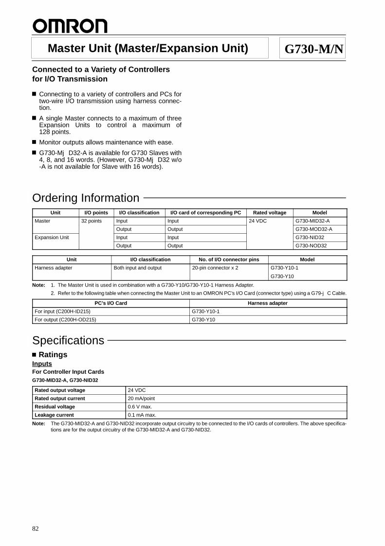
82
Master Unit (Master/Expansion Unit) G730-M/NConnected to a Variety of Controllersfor I/O Transmission
Connecting to a variety of controllers and PCs fortwo-wire I/O transmission using harness connec-tion.
A single Master connects to a maximum of threeExpansion Units to control a maximum of128 points.
Monitor outputs allows maintenance with ease.
G730-MjD32-A is available for G730 Slaves with4, 8, and 16 words. (However, G730-MjD32 w/o-A is not available for Slave with 16 words).
Ordering InformationUnit I/O points I/O classification I/O card of corresponding PC Rated voltage Model
Master 32 points Input Input 24 VDC G730-MID32-A
Output Output G730-MOD32-A
Expansion Unit Input Input G730-NID32
Output Output G730-NOD32
Unit I/O classification No. of I/O connector pins Model
Harness adapter Both input and output 20-pin connector x 2 G730-Y10-1
G730-Y10
Note: 1. The Master Unit is used in combination with a G730-Y10/G730-Y10-1 Harness Adapter.
2. Refer to the following table when connecting the Master Unit to an OMRON PC’s I/O Card (connector type) using a G79-jC Cable.
PC’s I/O Card Harness adapter
For input (C200H-ID215) G730-Y10-1
For output (C200H-OD215) G730-Y10
SpecificationsRatings
InputsFor Controller Input CardsG730-MID32-A, G730-NID32
Rated output voltage 24 VDC
Rated output current 20 mA/point
Residual voltage 0.6 V max.
Leakage current 0.1 mA max.
Note: The G730-MID32-A and G730-NID32 incorporate output circuitry to be connected to the I/O cards of controllers. The above specifica-tions are for the output circuitry of the G730-MID32-A and G730-NID32.

G730-M/N G730-M/N
83
OutputsFor Controller Output CardsG730-MOD32-A, G730-NOD32
Input current 10 mA max./point
On delay (see note) 1 ms max.
OFF delay (see note) 1.5 ms max.
On voltage 10 VDC max.
OFF voltage 1 mA min.
Note: The G730-MOD32-A and G730-NOD32 may malfunction if they are connected to relays or switches with long chattering times. Con-tact your OMRON representative if the delay time of your model needs to be changed.
Error Detecting Circuit Output SpecificationG730-MID32-A, G730-MOD32-A
Rated output voltage 24 VDC
Rated output current 20 mA
Residual voltage 1.2 V max.
CharacteristicsCommunication method Two-conductor, half duplex
Synchronization method Asynchronous
Transmission distance 200 m (total length)
Transmission speed 187.5 kbps
Transmission path Two-conductor cable (VCTF 0.75 x 2 C is recommended)
Interface RS-485
Maximum I/O cable length betweenthe Master Unit and a controller
5 m
No. of connecting I/O points 32 points per Unit (128 points max. with three Expansion Units)
Operating voltage range 24 VDC +10%/--15%
Current consumption (see note) Input: 60 mA max. at 24 VDCOutput: 100 mA max. at 24 VDC
Insulation resistance 20 Mτ min. (at 250 VDC)
Dielectric strength 500 VAC for 1 min between the power supply terminals and transmission terminals
Noise immunity Power supply normal: 600 V for 10 min with a pulse width of 100 ns to 1 ←sPower supply common: 1.5 kV for 10 min with a pulse width of 100 ns to 1 ←sCoiling around transmission path: 1.5 kV for 10 min with a pulse width of 100 ns to 1 ←sCoiling around Unit: 600 V for 10 min with a pulse width of 100 ns to 1 ←s
Vibration resistance 10 to 55 Hz, 0.75-mm double amplitude for 2 hrs each in X, Y, and Z directions
Shock resistance Destruction: 300 m/s2 (approx. 30G)Malfunction: 200 m/s2 (approx. 20G)
Ambient temperature Operating: 0 to 55 CStorage: --20 to 65 C
Ambient humidity Operating: 35% to 85%
Mounting strength No damage when 5 kgf (49N) pull load was applied for 10 s in all directions (except for 1 kgf(9.8 N) in direction of rail)
Terminal strength Tightening strength: 10 kgf S cm (0.98 N S m) for 10 sPulling strength: 5 kgf (50 N) for 10 s
Weight G730-MjD, -NjD: approx. 95 gHarness adapter: approx. 45 g
Note: The above current consumption is a value with all the 32 points turned ON.

G730-M/N G730-M/N
84
Nomenclature
ALARM Terminal
NC Terminal Power SupplyTerminals
TransmissionTerminals
Harness Adapter(for mounting the G730-Y10)
PWR Indicator
Terminator Detecting Indicator
T/R Indicator
ALM Indicator
HOLD/HOLD OFF Selector
NODE Indicator
G730-MID32G730-MOD32
ALARM TerminalNPN open collector output is ON when the G730-ROC04-A has error output.PWR IndicatorLit when power is supplied.Terminator Detecting Indicator
Display Function
Not lit Turns OFF when the terminator of the system is found.
Lit Lit while the Master Unit is looking for the terminator.
Flashing Flashes when the Master Unit finds more than one terminator in the system.
T/R Indicator
Display Function
Flashing Flashes during normal transmission.
Lit Lit while the Master Unit is waiting for transmission or when a transmission error results.
Not lit Turns OFF when the CPU is running abnormally.
ALM IndicatorLit if the G730-ROC04-A Slave Output Unit has an output error.
NODE Indicator
Display Function
Lit Lit when the Slave Units are set to word 28 to 30.
Flashing Flashes if the I/O configuration of the Slave Units and that of the Master Unit in the system donot coincide, 4-point Slave Units exist at word 24 to 27, or there is I/O duplication.
Note: 1. The Slave Units used are G730-VID08(-1), G730-VOD08(-1), G730-VID16, G730-VOD16, G730-RIA(D)04, G730-ROC04, orG730-ROC04-A models.
2. The Master Unit used is a G730-MID32-A, G730-NID32, G730-MOD32-A, or G730-NOD32 model.3. The 4-point Slave Units used are G730-VID04, G730-VOD04, G730-RIA(D)04, G730-ROC04, or G730-ROC04-A models.
HOLD/HOLD OFF Selector
Setting Function
HOLD If there is a transmission error during signal transmission, the signal being transmitted is put onhold.
HOLD OFF If there is a transmission error during signal transmission, the signal being transmitted isturned OFF.
Note: The HOLD/HOLD OFF selector is factory-set to HOLD OFF. Be sure to turn off the Master Unit before setting the HOLD/HOLD OFFselector.
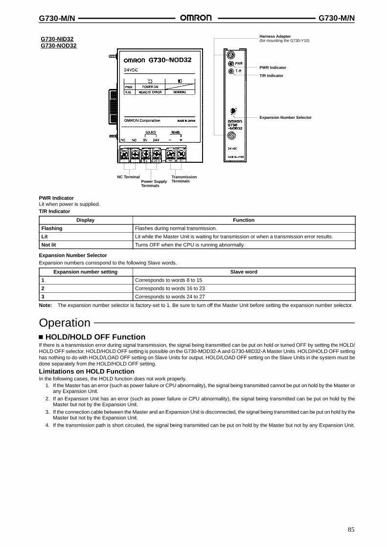
G730-M/N G730-M/N
85
G730-NID32G730-NOD32
NC TerminalPower SupplyTerminals
TransmissionTerminals
Expansion Number Selector
Harness Adapter(for mounting the G730-Y10)
PWR Indicator
T/R Indicator
PWR IndicatorLit when power is supplied.T/R Indicator
Display Function
Flashing Flashes during normal transmission.
Lit Lit while the Master Unit is waiting for transmission or when a transmission error results.
Not lit Turns OFF when the CPU is running abnormally.
Expansion Number SelectorExpansion numbers correspond to the following Slave words.
Expansion number setting Slave word
1 Corresponds to words 8 to 15
2 Corresponds to words 16 to 23
3 Corresponds to words 24 to 27
Note: The expansion number selector is factory-set to 1. Be sure to turn off the Master Unit before setting the expansion number selector.
OperationHOLD/HOLD OFF Function
If there is a transmission error during signal transmission, the signal being transmitted can be put on hold or turned OFF by setting the HOLD/HOLD OFF selector. HOLD/HOLD OFF setting is possible on the G730-MOD32-A and G730-MID32-A Master Units. HOLD/HOLD OFF settinghas nothing to do with HOLD/LOAD OFF setting on Slave Units for output. HOLD/LOAD OFF setting on the Slave Units in the system must bedone separately from the HOLD/HOLD OFF setting.
Limitations on HOLD FunctionIn the following cases, the HOLD function does not work properly.
1. If the Master has an error (such as power failure or CPU abnormality), the signal being transmitted cannot be put on hold by the Master orany Expansion Unit.
2. If an Expansion Unit has an error (such as power failure or CPU abnormality), the signal being transmitted can be put on hold by theMaster but not by the Expansion Unit.
3. If the connection cable between the Master and an Expansion Unit is disconnected, the signal being transmitted can be put on hold by theMaster but not by the Expansion Unit.
4. If the transmission path is short circuited, the signal being transmitted can be put on hold by the Master but not by any Expansion Unit.
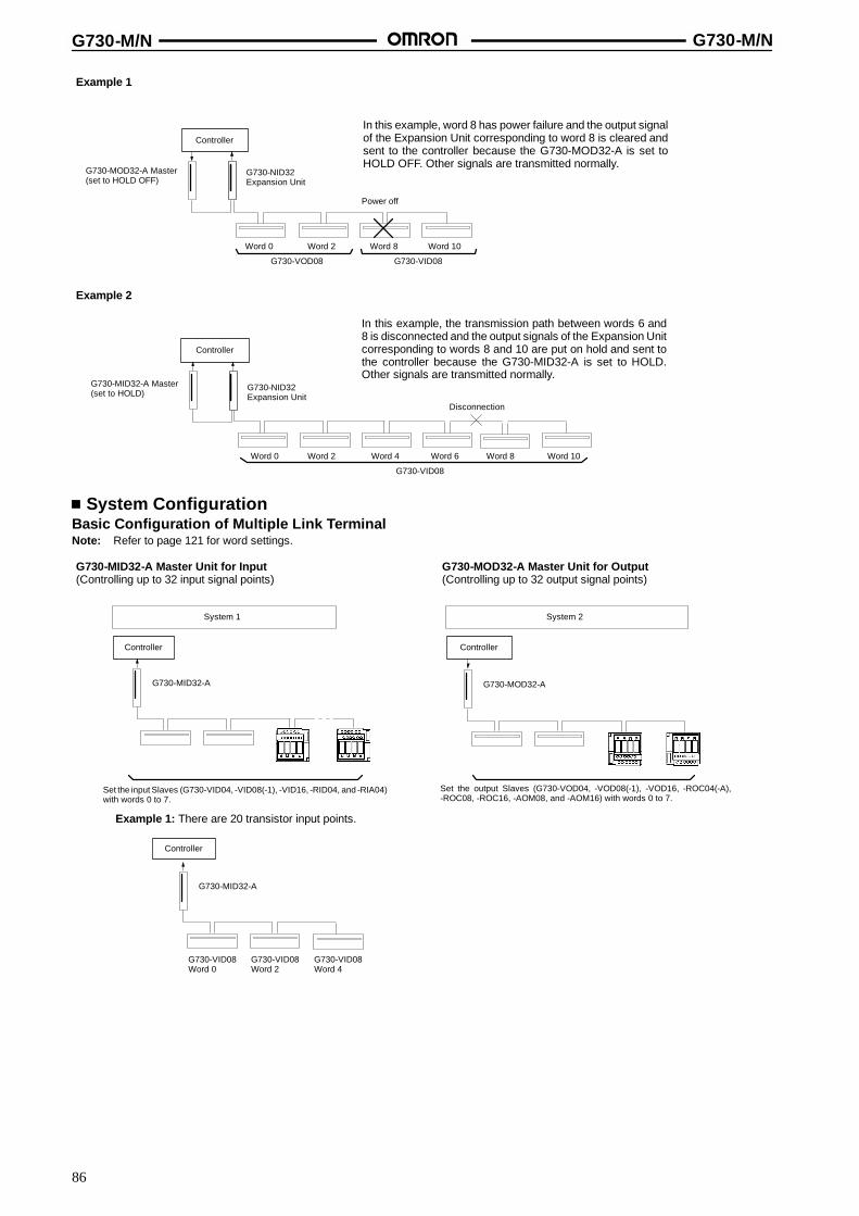
G730-M/N G730-M/N
86
Example 1
Example 2
In this example, word 8 has power failure and the output signalof the Expansion Unit corresponding to word 8 is cleared andsent to the controller because the G730-MOD32-A is set toHOLD OFF. Other signals are transmitted normally.
In this example, the transmission path between words 6 and8 is disconnected and the output signals of the Expansion Unitcorresponding to words 8 and 10 are put on hold and sent tothe controller because the G730-MID32-A is set to HOLD.Other signals are transmitted normally.
Word 0 Word 2 Word 8 Word 10
G730-VOD08 G730-VID08
Word 0 Word 2 Word 4 Word 6
G730-VID08
Word 8 Word 10
Controller
Controller
G730-MOD32-A Master(set to HOLD OFF)
G730-NID32Expansion Unit
Power off
G730-NID32Expansion Unit
G730-MID32-A Master(set to HOLD)
Disconnection
System ConfigurationBasic Configuration of Multiple Link TerminalNote: Refer to page 121 for word settings.
G730-MID32-A Master Unit for Input(Controlling up to 32 input signal points)
G730-MOD32-A Master Unit for Output(Controlling up to 32 output signal points)
Example 1: There are 20 transistor input points.
G730-MID32-A
G730-MID32-A
G730-MOD32-A
System 1
Controller
Set the input Slaves (G730-VID04, -VID08(-1), -VID16, -RID04, and -RIA04)with words 0 to 7.
Controller
G730-VID08Word 0
G730-VID08Word 2
G730-VID08Word 4
System 2
Controller
Set the output Slaves (G730-VOD04, -VOD08(-1), -VOD16, -ROC04(-A),-ROC08, -ROC16, -AOM08, and -AOM16) with words 0 to 7.
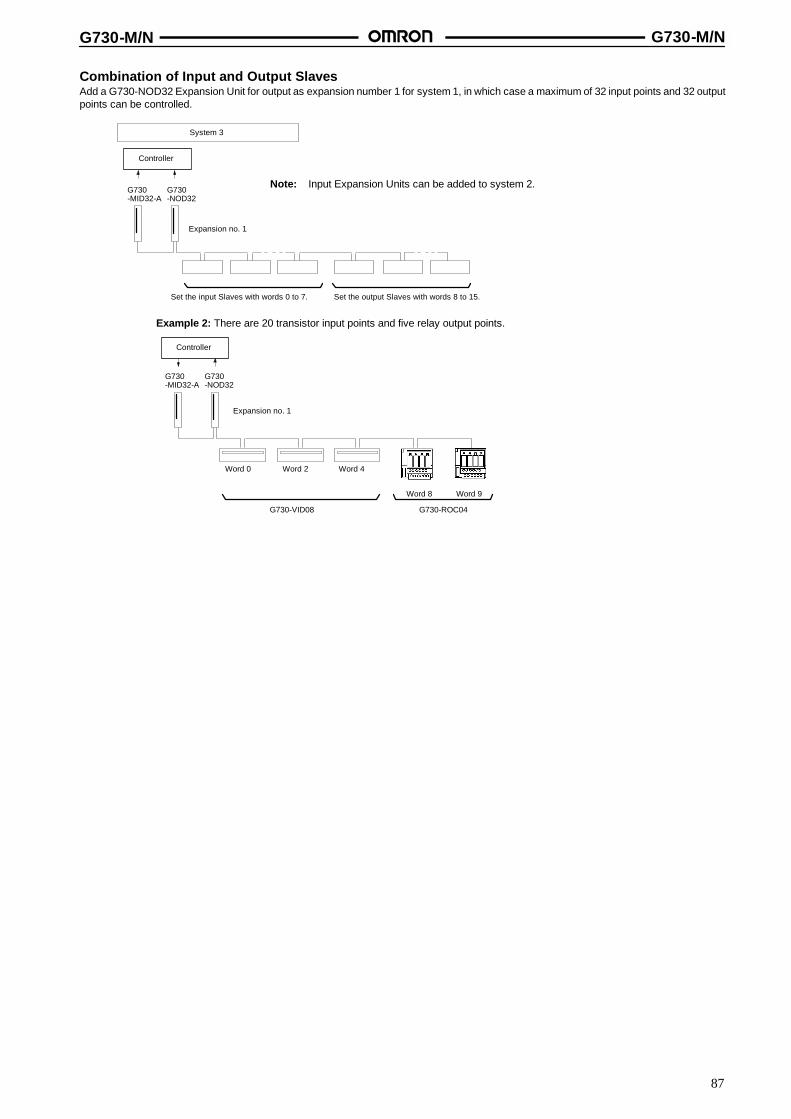
G730-M/N G730-M/N
87
Combination of Input and Output SlavesAdd a G730-NOD32 Expansion Unit for output as expansion number 1 for system 1, in which case a maximum of 32 input points and 32 outputpoints can be controlled.
Example 2: There are 20 transistor input points and five relay output points.
Word 0 Word 2 Word 4
Word 8
G730-VID08
G730-NOD32
Word 9
G730-ROC04
G730-MID32-A
G730-NOD32
G730-MID32-A
System 3
Controller
Set the input Slaves with words 0 to 7. Set the output Slaves with words 8 to 15.
Expansion no. 1
Controller
Note: Input Expansion Units can be added to system 2.
Expansion no. 1

G730-M/N G730-M/N
88
For Increment of the Number of Control PointsAdd a G730-NID32 Expansion Unit for input as expansion number 2 for system 3, in which case a maximum of 64 input points and 32 outputpoints can be controlled.
Example 3: There are 40 transistor input points and 10 relay output points.
G730-MID32-A
G730-NID32
Controller
System 4
Note: By increasing the number of Expansion Units to expansionnumber 3, up to 128 points can be controlled.
Set the input Slaves withwords 0 to 7.
Set the output Slaves withwords 8 to 15.
Set the input Slaves withwords 16 to 23.
G730-NOD32
No.1 No.2
G730-NOD32
Word 0 Word 2 Word 4 Word 6
G730-VID08
Word 16
Word 8
G730-ROC04
Word 9 Word 10
No.1 No.2
G730-MID32-A
G730-NID32
Controller
Reducing Transmission DelayIt is possible to reduce the transmission delay in a system by rearranging the configuration of the system.
System 6 incorporating two Masters has less transmission delay than system 5 incorporating a single Master and anExpansion Unit. Refer to page 127 “Transmission Delay” for details on the calculation formula for transmission delay.There is less delay time if one G730-VjD16 Slave is used instead of two G730-VjD08 Slaves.
Controller Controller
System 5
Expansion no.1
Master(for input)
Expansion Unit(for output)
Input Slaves Output Slaves Input Slaves Output Slaves
Reduces transmission delay.
System 6
Master(for input)
Master(for output)
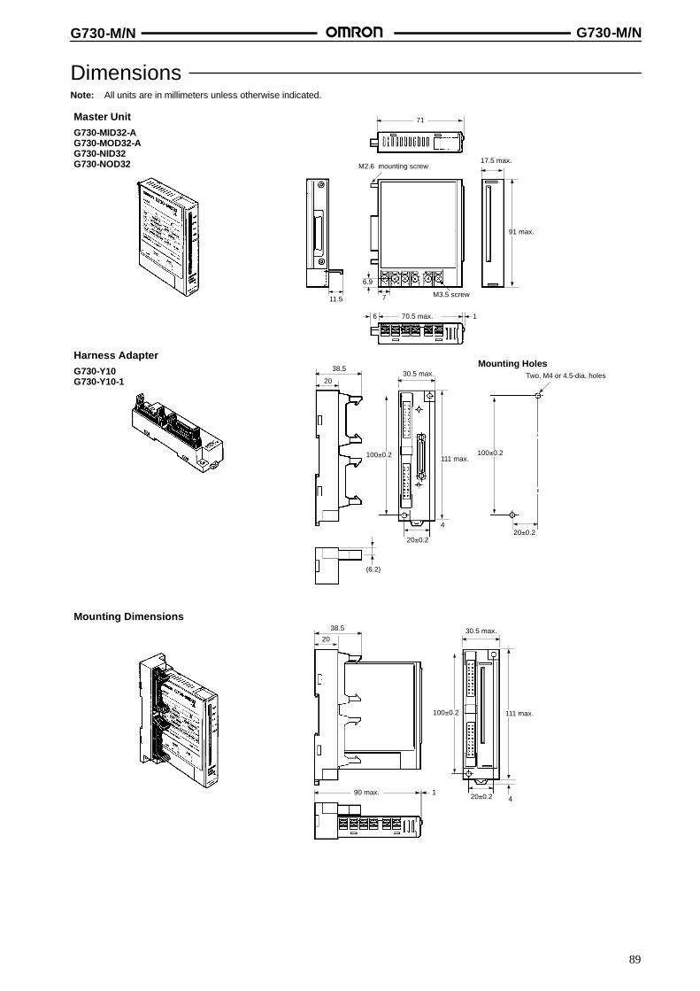
G730-M/N G730-M/N
89
DimensionsNote: All units are in millimeters unless otherwise indicated.
Master UnitG730-MID32-AG730-MOD32-AG730-NID32G730-NOD32 M2.6 mounting screw
17.5 max.
91 max.
6.9
11.5 7 M3.5 screw
70.5 max.6 1
71
Harness AdapterG730-Y10G730-Y10-1
Mounting HolesTwo, M4 or 4.5-dia. holes
100�0.2100�0.2
20�0.2
(6.2)
20�0.2
30.5 max.
111 max.
4
38.5
20
Mounting Dimensions38.5
20
90 max. 1 20�0.2 4
100�0.2 111 max.
30.5 max.

G730-M/N G730-M/N
90
InstallationInternal Circuit Configuration
InputG730-MID32-A, G730-NID32
OutputG730-MOD32-A, G730-NOD32
DC-DCconverter(non-insula-tion type)
RS-485transmissionpaths
+
--
ALMError output(see note)
24 V
0 V
24-VDCpower supply
Pulse transformer
Internalcircuit
24 V
GND
To harnessadapter
Note: Only the G730-MID32-A Master incorporates an error output function.
Note: Only the G730-MOD32-A Master incorporates an error output function.
24 V
GND
To harnessadapter
DC-DCconverter(non-insula-tion type)
RS-485transmissionpaths
+
--
ALMError output(see note)
24 V
0 V
24-VDCpower supply
Pulse transformer
Internalcircuit
5 V
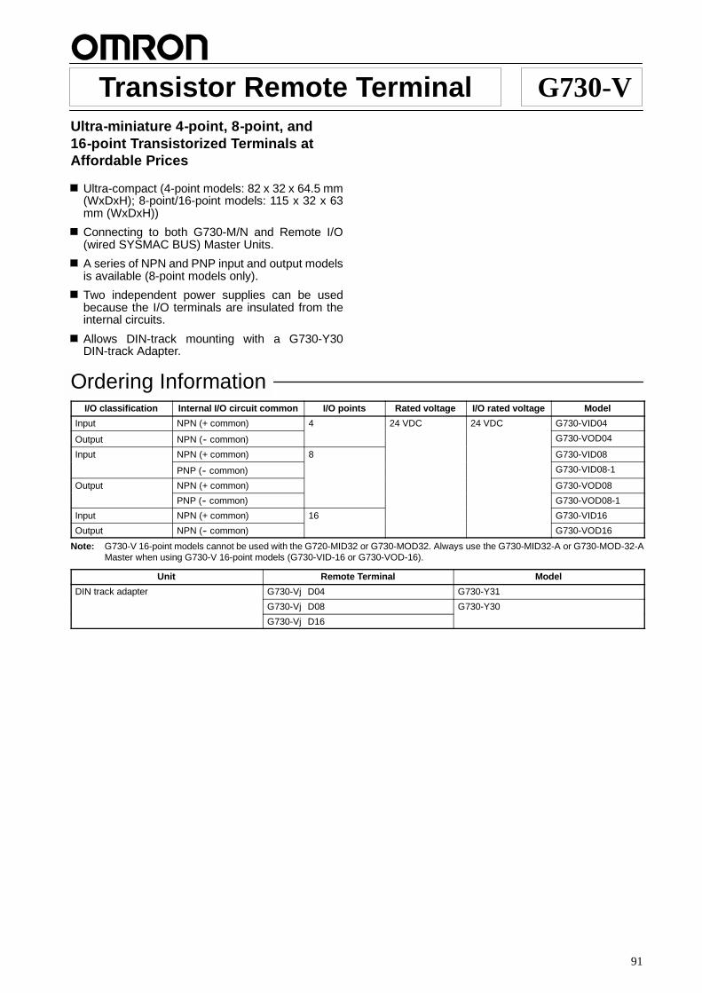
91
Transistor Remote Terminal G730-VUltra-miniature 4-point, 8-point, and16-point Transistorized Terminals atAffordable Prices
Ultra-compact (4-point models: 82 x 32 x 64.5 mm(WxDxH); 8-point/16-point models: 115 x 32 x 63mm (WxDxH))
Connecting to both G730-M/N and Remote I/O(wired SYSMAC BUS) Master Units.
A series of NPN and PNP input and output modelsis available (8-point models only).
Two independent power supplies can be usedbecause the I/O terminals are insulated from theinternal circuits.
Allows DIN-track mounting with a G730-Y30DIN-track Adapter.
Ordering InformationI/O classification Internal I/O circuit common I/O points Rated voltage I/O rated voltage Model
Input NPN (+ common) 4 24 VDC 24 VDC G730-VID04
Output NPN (-- common) G730-VOD04
Input NPN (+ common) 8 G730-VID08
PNP (-- common) G730-VID08-1
Output NPN (+ common) G730-VOD08
PNP (-- common) G730-VOD08-1
Input NPN (+ common) 16 G730-VID16
Output NPN (-- common) G730-VOD16
Note: G730-V 16-point models cannot be used with the G720-MID32 or G730-MOD32. Always use the G730-MID32-A or G730-MOD-32-AMaster when using G730-V 16-point models (G730-VID-16 or G730-VOD-16).
Unit Remote Terminal Model
DIN track adapter G730-VjD04 G730-Y31
G730-VjD08 G730-Y30
G730-VjD16
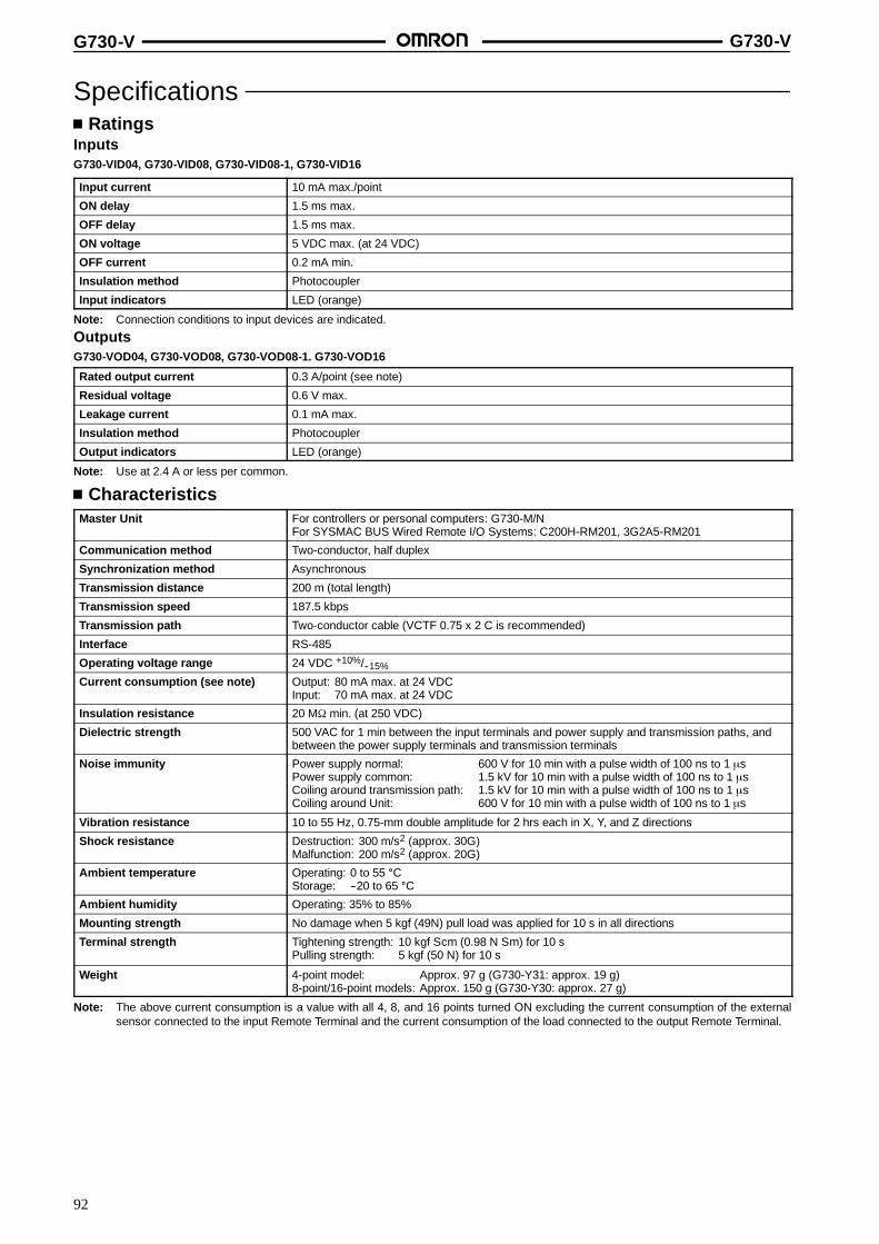
G730-V G730-V
92
SpecificationsRatings
InputsG730-VID04, G730-VID08, G730-VID08-1, G730-VID16
Input current 10 mA max./point
ON delay 1.5 ms max.
OFF delay 1.5 ms max.
ON voltage 5 VDC max. (at 24 VDC)
OFF current 0.2 mA min.
Insulation method Photocoupler
Input indicators LED (orange)
Note: Connection conditions to input devices are indicated.
OutputsG730-VOD04, G730-VOD08, G730-VOD08-1. G730-VOD16
Rated output current 0.3 A/point (see note)
Residual voltage 0.6 V max.
Leakage current 0.1 mA max.
Insulation method Photocoupler
Output indicators LED (orange)
Note: Use at 2.4 A or less per common.
CharacteristicsMaster Unit For controllers or personal computers: G730-M/N
For SYSMAC BUS Wired Remote I/O Systems: C200H-RM201, 3G2A5-RM201
Communication method Two-conductor, half duplex
Synchronization method Asynchronous
Transmission distance 200 m (total length)
Transmission speed 187.5 kbps
Transmission path Two-conductor cable (VCTF 0.75 x 2 C is recommended)
Interface RS-485
Operating voltage range 24 VDC +10%/--15%
Current consumption (see note) Output: 80 mA max. at 24 VDCInput: 70 mA max. at 24 VDC
Insulation resistance 20 Mτ min. (at 250 VDC)
Dielectric strength 500 VAC for 1 min between the input terminals and power supply and transmission paths, andbetween the power supply terminals and transmission terminals
Noise immunity Power supply normal: 600 V for 10 min with a pulse width of 100 ns to 1 ←sPower supply common: 1.5 kV for 10 min with a pulse width of 100 ns to 1 ←sCoiling around transmission path: 1.5 kV for 10 min with a pulse width of 100 ns to 1 ←sCoiling around Unit: 600 V for 10 min with a pulse width of 100 ns to 1 ←s
Vibration resistance 10 to 55 Hz, 0.75-mm double amplitude for 2 hrs each in X, Y, and Z directions
Shock resistance Destruction: 300 m/s2 (approx. 30G)Malfunction: 200 m/s2 (approx. 20G)
Ambient temperature Operating: 0 to 55 CStorage: --20 to 65 C
Ambient humidity Operating: 35% to 85%
Mounting strength No damage when 5 kgf (49N) pull load was applied for 10 s in all directions
Terminal strength Tightening strength: 10 kgf S cm (0.98 N S m) for 10 sPulling strength: 5 kgf (50 N) for 10 s
Weight 4-point model: Approx. 97 g (G730-Y31: approx. 19 g)8-point/16-point models: Approx. 150 g (G730-Y30: approx. 27 g)
Note: The above current consumption is a value with all 4, 8, and 16 points turned ON excluding the current consumption of the externalsensor connected to the input Remote Terminal and the current consumption of the load connected to the output Remote Terminal.
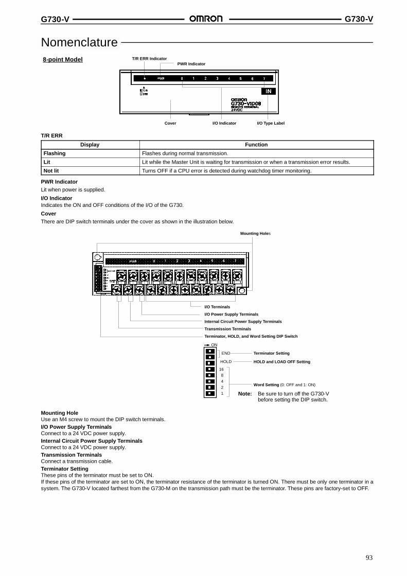
G730-V G730-V
93
NomenclatureT/R ERR Indicator
PWR Indicator
I/O Type LabelI/O IndicatorCover
8-point Model
T/R ERR
Display Function
Flashing Flashes during normal transmission.
Lit Lit while the Master Unit is waiting for transmission or when a transmission error results.
Not lit Turns OFF if a CPU error is detected during watchdog timer monitoring.
PWR IndicatorLit when power is supplied.
I/O IndicatorIndicates the ON and OFF conditions of the I/O of the G730.
CoverThere are DIP switch terminals under the cover as shown in the illustration below.
Mounting Holes
I/O Terminals
I/O Power Supply Terminals
Internal Circuit Power Supply Terminals
Transmission Terminals
Terminator, HOLD, and Word Setting DIP Switch
END
HOLD
Terminator Setting
HOLD and LOAD OFF Setting
Word Setting (0: OFF and 1: ON)
168421
ON
Note: Be sure to turn off the G730-Vbefore setting the DIP switch.
Mounting HoleUse an M4 screw to mount the DIP switch terminals.I/O Power Supply TerminalsConnect to a 24 VDC power supply.Internal Circuit Power Supply TerminalsConnect to a 24 VDC power supply.Transmission TerminalsConnect a transmission cable.Terminator SettingThese pins of the terminator must be set to ON.If these pins of the terminator are set to ON, the terminator resistance of the terminator is turned ON. There must be only one terminator in asystem. The G730-V located farthest from the G730-M on the transmission path must be the terminator. These pins are factory-set to OFF.
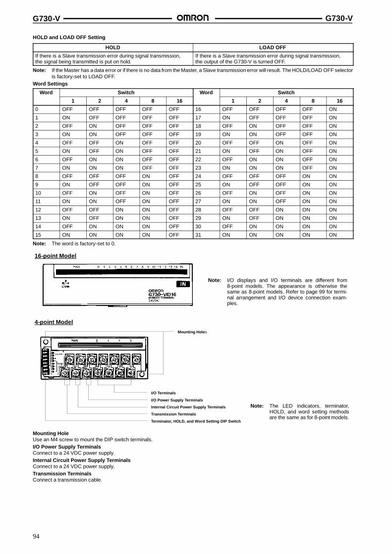
G730-V G730-V
94
HOLD and LOAD OFF Setting
HOLD LOAD OFF
If there is a Slave transmission error during signal transmission,the signal being transmitted is put on hold.
If there is a Slave transmission error during signal transmission,the output of the G730-V is turned OFF.
Note: If the Master has a data error or if there is no data from the Master, a Slave transmission error will result. The HOLD/LOAD OFF selectoris factory-set to LOAD OFF.
Word Settings
Word Switch Word Switch
1 2 4 8 16 1 2 4 8 16
0 OFF OFF OFF OFF OFF 16 OFF OFF OFF OFF ON
1 ON OFF OFF OFF OFF 17 ON OFF OFF OFF ON
2 OFF ON OFF OFF OFF 18 OFF ON OFF OFF ON
3 ON ON OFF OFF OFF 19 ON ON OFF OFF ON
4 OFF OFF ON OFF OFF 20 OFF OFF ON OFF ON
5 ON OFF ON OFF OFF 21 ON OFF ON OFF ON
6 OFF ON ON OFF OFF 22 OFF ON ON OFF ON
7 ON ON ON OFF OFF 23 ON ON ON OFF ON
8 OFF OFF OFF ON OFF 24 OFF OFF OFF ON ON
9 ON OFF OFF ON OFF 25 ON OFF OFF ON ON
10 OFF ON OFF ON OFF 26 OFF ON OFF ON ON
11 ON ON OFF ON OFF 27 ON ON OFF ON ON
12 OFF OFF ON ON OFF 28 OFF OFF ON ON ON
13 ON OFF ON ON OFF 29 ON OFF ON ON ON
14 OFF ON ON ON OFF 30 OFF ON ON ON ON
15 ON ON ON ON OFF 31 ON ON ON ON ON
Note: The word is factory-set to 0.
Note: I/O displays and I/O terminals are different from8-point models. The appearance is otherwise thesame as 8-point models. Refer to page 99 for termi-nal arrangement and I/O device connection exam-ples.
16-point Model
Note: The LED indicators, terminator,HOLD, and word setting methodsare the same as for 8-point models.
Mounting Holes
I/O Terminals
I/O Power Supply Terminals
Internal Circuit Power Supply Terminals
Transmission Terminals
Terminator, HOLD, and Word Setting DIP Switch
4-point Model
Mounting HoleUse an M4 screw to mount the DIP switch terminals.I/O Power Supply TerminalsConnect to a 24 VDC power supply.Internal Circuit Power Supply TerminalsConnect to a 24 VDC power supply.Transmission TerminalsConnect a transmission cable.
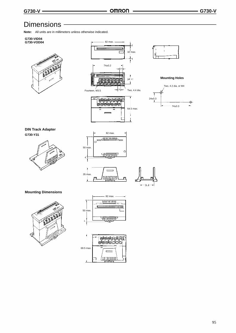
G730-V G730-V
95
DimensionsNote: All units are in millimeters unless otherwise indicated.
G730-VID04G730-VOD04
Mounting Holes
DIN Track AdapterG730-Y31
Mounting Dimensions
82 max.
32 max.
64.5 max.
Two, 4.2 dia. or M4
50 max.
35 max.
82 max.
50 max.
82 max.
69.5 max.
74�0.2
Fourteen, M3.5 Two, 4.4 dia.
24�0.3
74�0.3
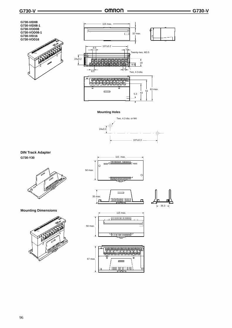
G730-V G730-V
96
G730-VID08G730-VID08-1G730-VOD08G730-VOD08-1G730-VID16G730-VOD16
Mounting Holes
115 max.
8.5
8.5
32 max.
Twenty-two, M3.5
Two, 4.3-dia.
198.5
63 max.53
435.3
7
24�0.2
7107�0.2
Two, 4.2-dia. or M4
107�0.3
24�0.3
DIN Track AdapterG730-Y30
Mounting Dimensions
115 max.
50 max.
35 max.
35.3
115 max.
50 max.
67 max.
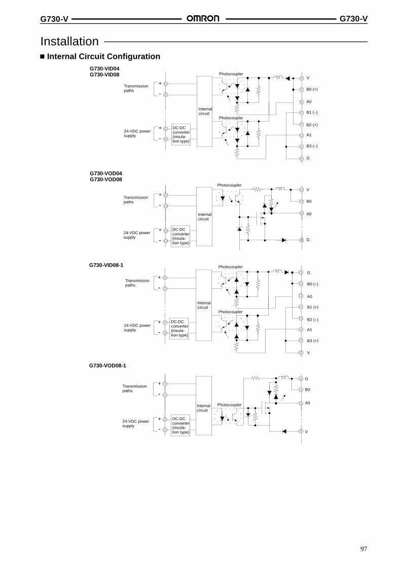
G730-V G730-V
97
InstallationInternal Circuit Configuration
G730-VID04G730-VID08
+
--
+
--
Transmissionpaths
24-VDC powersupply
DC-DCconverter(insula-tion type)
Internalcircuit
PhotocouplerV
B0 (+)
A0
B1 (--)
B2 (+)
A1
B3 (--)
G
Photocoupler
G730-VOD04G730-VOD08
DC-DCconverter(insula-tion type)
+
--
+
--24-VDC powersupply
Internalcircuit
PhotocouplerV
B0Transmissionpaths
G
A0
G730-VOD08-1
+
--
+
--
24-VDC powersupply
Transmissionpaths
DC-DCconverter(insula-tion type)
Internalcircuit
Photocoupler
G
B0
A0
V
G730-VID08-1
+
--
+
--
DC-DCconverter(insula-tion type)
Transmissionpaths
24-VDC powersupply
Internalcircuit
PhotocouplerG
B0 (--)
A0
B1 (+)
B2 (--)
A1
B3 (+)
V
Photocoupler

G730-V G730-V
98
G730-VOD16
G730-VID16
+
--
+
--
DC-DCconverter(insula-tion type)
Transmissionpaths
24-VDC powersupply
Internalcircuit
PhotocouplerV
0
1
2
3
4
5
G
Photocoupler
DC-DCconverter(insula-tion type)
+
--
+
--
24-VDC powersupply
Internalcircuit
PhotocouplerV
B0Transmissionpaths
G
A0
External ConnectionsNo relay terminal boards for the sensor loads are required.
Three-wire SystemG730-VID04/G730-VID08 with NPN OutputG730-VID08-1 with PNP Output
Two-wire SystemG730-VID04/G730-VID08 G730-VID08-1
Bla
ck(b
lue)
B0
A0
B1
A1
B2
A2
B0
A0 A1
B1
A2
B2
+ ----+ + A0
B0 B1
A1
B2
A2+ + -- +
Sensor 1
Whi
te(b
lack
)
Red
(bro
wn)
Bla
ck(b
lue)
Sensor 2
Whi
te(b
lack
)R
ed(b
row
n)
Whi
te(b
row
n)
Bla
ck(b
lue)
Sensor 1
Whi
te(b
row
n)
Bla
ck(b
lue)
Sensor 2
Whi
te(b
row
n)
Bla
ck(b
lue)
Sensor 1
Whi
te(b
row
n)
Bla
ck(b
lue)
Sensor 2
Input BlocksG730-VID16 with NPN Output Two-wire System
G730-VID16
Bro
wn
(red
)B
lack
(whi
te)
Blu
e(b
lack
)
Sensor 1
Bro
wn
(red
)B
lack
(whi
te)
Blu
e(b
lack
)
Sensor 2
Bro
wn
(whi
te)
Blu
e(b
lack
)
Sensor 1
Bro
wn
(whi
te)
Blu
e(b
lack
)
Sensor 2

G730-V G730-V
99
Output BlocksG730-VOD04/G730-VOD08 G730-VOD08-1
A2A1
B2B1
A0
B0
A0
B0 B1
A1
B2
A2+ + + -- -- --
L1 L2L1 L2
G730-VOD16
Terminal Arrangement/I/O Device Connection ExamplesNote: 1. The connections examples shown are for NPN models.
2. Wire colors have been changed as a result of changes in JIS standards for photoelectric and proximity sensors. Colors in paren-theses are the old colors.
Input TerminalsG730-VID04 G730-VID08
G730-VID16
Transmissionpaths
Internalcircuitpowersupply
I/Opowersupply
Photoelectric sensorProximity sensor(Three-wire sensor witha built-in amplifier)
Limit switch(Two-wire sensor)
Bro
wn
(red
)
Blu
e(b
lack
)B
lack
(whi
te)
Bla
ck(w
hite
)
Blu
e(b
lack
)
Transmissionpaths
Internalcircuitpowersupply
I/O powersupply
Photoelectric sensorProximity sensor(Three-wire sensor witha built-in amplifier)
Limit switch(Two-wire sensor)
Bro
wn
(red
)
Blu
e(b
lack
)B
lack
(whi
te)
Bla
ck(w
hite
)
Blu
e(b
lack
)
Transmissionpaths
Internalcircuitpowersupply
I/O powersupply
Photoelectric sensorProximity sensor(Three-wire sensor witha built-in amplifier)
Limit switch(Two-wire sensor)
Bro
wn
(red
)
Blu
e(b
lack
)B
lack
(whi
te)
Bla
ck(w
hite
)
Blu
e(b
lack
)

G730-V G730-V
100
Output TerminalsG730-VOD04 G730-VOD08
G730-VOD16
Solenoid, valve
Transmissionpaths
Internalcircuitpowersupply
I/Opowersupply
Transmissionpaths
Internalcircuitpowersupply
I/Opowersupply
ValveSolenoid
ValveSolenoid
Transmissionpaths
Internalcircuitpowersupply
I/Opowersupply
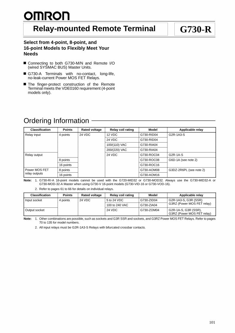
101
Relay-mounted Remote Terminal G730-RSelect from 4-point, 8-point, and16-point Models to Flexibly Meet YourNeeds
Connecting to both G730-M/N and Remote I/O(wired SYSMAC BUS) Master Units.
G730-A Terminals with no-contact, long-life,no-leak-current Power MOS FET Relays.
The finger-protect construction of the RemoteTerminal meets the VDE0160 requirement (4-pointmodels only).
Ordering InformationClassification Points Rated voltage Relay coil rating Model Applicable relay
Relay input 4 points 24 VDC 12 VDC G730-RID04 G2R-1A3-S
24 VDC G730-RID04
100/(110) VAC G730-RIA04
200/(220) VAC G730-RIA04
Relay output 24 VDC G730-ROC04 G2R-1A-S
8 points G730-ROC08 G6D-1A (see note 2)
16 points G730-ROC16
Power MOS FETl
8 points G730-AOM08 G3DZ-2R6PL (see note 2)relay outputs 16 points G730-AOM16
Note: 1. G730-R/-A 16-point models cannot be used with the G720-MID32 or G730-MOD32. Always use the G730-MID32-A orG730-MOD-32-A Master when using G730-V 16-point models (G730-VID-16 or G730-VOD-16).
2. Refer to pages 61 to 66 for details on individual relays.
Classification Points Rated voltage Relay coil rating Model Applicable relay
Input socket 4 points 24 VDC 5 to 24 VDC G730-ZID04 G2R-1A3-S, G3R (SSR)G3RZ (P MOS FET l )100 to 240 VAC G730-ZIA04
, ( )G3RZ (Power MOS FET relay)
Output socket 24 VDC G730-ZOM04 G2R-1A-S, G3R (SSR),G3RZ (Power MOS FET relay)
Note: 1. Other combinations are possible, such as sockets and G3R SSR and sockets, and G3RZ Power MOS FET Relays. Refer to pages70 to 135 for model numbers.
2. All input relays must be G2R-1A3-S Relays with bifurcated crossbar contacts.
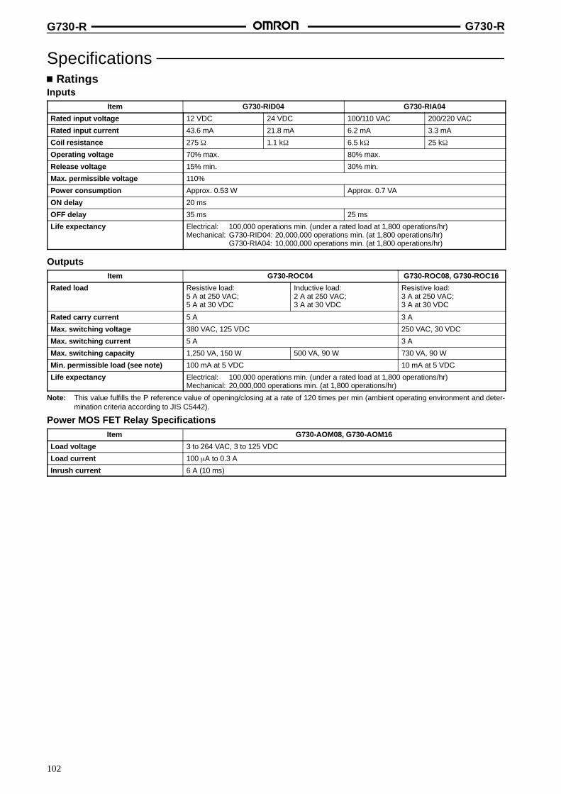
G730-R G730-R
102
SpecificationsRatings
InputsItem G730-RID04 G730-RIA04
Rated input voltage 12 VDC 24 VDC 100/110 VAC 200/220 VAC
Rated input current 43.6 mA 21.8 mA 6.2 mA 3.3 mA
Coil resistance 275 τ 1.1 kτ 6.5 kτ 25 kτ
Operating voltage 70% max. 80% max.
Release voltage 15% min. 30% min.
Max. permissible voltage 110%
Power consumption Approx. 0.53 W Approx. 0.7 VA
ON delay 20 ms
OFF delay 35 ms 25 ms
Life expectancy Electrical: 100,000 operations min. (under a rated load at 1,800 operations/hr)Mechanical: G730-RID04: 20,000,000 operations min. (at 1,800 operations/hr)
G730-RIA04: 10,000,000 operations min. (at 1,800 operations/hr)
OutputsItem G730-ROC04 G730-ROC08, G730-ROC16
Rated load Resistive load:5 A at 250 VAC;5 A at 30 VDC
Inductive load:2 A at 250 VAC;3 A at 30 VDC
Resistive load:3 A at 250 VAC;3 A at 30 VDC
Rated carry current 5 A 3 A
Max. switching voltage 380 VAC, 125 VDC 250 VAC, 30 VDC
Max. switching current 5 A 3 A
Max. switching capacity 1,250 VA, 150 W 500 VA, 90 W 730 VA, 90 W
Min. permissible load (see note) 100 mA at 5 VDC 10 mA at 5 VDC
Life expectancy Electrical: 100,000 operations min. (under a rated load at 1,800 operations/hr)Mechanical: 20,000,000 operations min. (at 1,800 operations/hr)
Note: This value fulfills the P reference value of opening/closing at a rate of 120 times per min (ambient operating environment and deter-mination criteria according to JIS C5442).
Power MOS FET Relay SpecificationsItem G730-AOM08, G730-AOM16
Load voltage 3 to 264 VAC, 3 to 125 VDC
Load current 100 ←A to 0.3 A
Inrush current 6 A (10 ms)

G730-R G730-R
103
CharacteristicsItem G730-RID04, G730-ROD04 G730-ROC08 G730-ROC16 G730-AOM08 G730-AOM16
Master Unit For controllers or personal computers: G730-M/NFor SYSMAC BUS Wired Remote I/O Systems: C200H-RM201, 3G2A5-RM201
Communication method Two-conductor, half duplex
Synchronization method Asynchronous
Transmission distance 200 m (total length)
Transmission speed 187.5 kbps
Transmission path Two-conductor cable (VCTF 0.75 x 2 C is recommended)
Interface RS-485
Operating voltage range 24 VDC +10%/--15%
Current consumption (seenote)
Input: 70 mA max. at 24 VDCOutput: 220 mA max. at 24 VDC
Input: 70 mA max. at 24 VDCOutput: 220 mA max. at 24 VDC
Insulation resistance 20 Mτ min. (at 250 VDC)
Dielectric strength G730-RIA04/-ROC04:2,700 VAC for 1 min between thewhole I/O terminals and power supplyand transmission terminals,500 VAC for 1 min between the wholepower supply terminals andtransmission terminalsG730-RID04:500 VAC for 1 min between the wholeI/O terminals and power supply andtransmission terminals; between thewhole power supply terminals andtransmission terminals
2,000 VAC for 1 min between the whole output terminals andpower supply and transmission terminals500 VAC for 1 min between the whole power supply terminalsand transmission terminals
Noise immunity Power supply normal: 600 V for 10 min with a pulse width of 100 ns to 1 ←sPower supply common: 1.5 kV for 10 min with a pulse width of 100 ns to 1 ←sCoiling around transmission path: 1.5 kV for 10 min with a pulse width of 100 ns to 1 ←sCoiling around Unit: 600 V for 10 min with a pulse width of 100 ns to 1 ←s
Vibration resistance 10 to 55 Hz, 0.75-mm double amplitude for 2 hrs each in X, Y, and Z directions
Shock resistance Destruction: 300 m/s2 (approx. 30G)Malfunction: 100 m/s2 (approx. 10G)
Ambient temperature Operating: 0 to 55 CStorage: --20 to 65 C
Ambient humidity Operating: 35% to 85%
Mounting strength No damage when 5 kgf (49N) pull load was applied for 1 s in all directions
Terminal strength Tightening strength: 10 kgf S cm (0.98 N S m)Pulling strength: 5 kgf (50 N) for 1 min
Weight G730-RID: approx. 223 gG730-RIA: approx. 225 g;G730-ROC: approx. 224 g (with all therelays mounted.)
Approx. 140 g(with all therelaysmounted.)
Approx. 230 g(with all therelaysmounted.)
Approx. 140 g(with all therelaysmounted.)
Approx. 230 g(with all therelaysmounted.)
Note: The above current consumption is a value with all the points turned ON including the current consumption of the G2R/G6D coils for theRemote Output Terminal.

G730-R G730-R
104
Engineering DataOutput
G2R-1A-S Relay (24 VDC)For G730-ROC04 and G730-ROC04-A
Life Expectancy Max. Switching Capacity
Sw
itchi
ngcu
rren
t(A
)Switching voltage (V)Switching current (A)
Life
expe
ctan
cy(x
10op
erat
ions
)3
250 VAC resistive load30 VDC resistive load
250 VAC inductive load(cos ∞ = 0.4)
30 VDC inductive load(L/R = 7 ms)
DC resistive load
DC inductive load(L/R = 7 ms)
AC inductiveload (cos ∞ = 0.4)
AC resistive load
5,000
1,000
500
100
50
G6D-1A Relay (24 VDC)For G730-ROC08 and G730-ROC16
Life Expectancy Max. Switching Capacity
Sw
itchi
ngcu
rren
t(A
)
Switching voltage (V)Switching current (A)
Life
expe
ctan
cy(x
10op
erat
ions
)3 250 VAC/30 VDC resistive load
250 VAC/30 VDC inductive load(cos∞ = 0.4, L/R = 7 ms)
AC resistive load
DC inductive load
30
50
100
300
500
1000
3000
5000
DC resistive load
DCinductiveloadcos∞ = 0.4
G3DZ-2RGPL RelayFor G730-AOM08 and G730-AOM16
Load Current vs. Ambient TemperatureCharacteristics
Inrush Current ResistivityNon-repetitive (Keep the inrush current to half the rated value if it
occurs repetitively.)
Inru
shcu
rren
t(A
.Pea
k)
Energizing time (ms)Ambient temperature (C)
Load
curr
ent
(A)

G730-R G730-R
105
Nomenclature
DIP Switch Setting Guide Label
I/O Type Label
Mounting HoleUse an M4 screw to mount the G730.
HOLD and LOAD OFF Setting(select output hold or clear)(These pins are used on only RemoteOutput Terminals. These pins on Re-mote Input Terminals are not used.)
Terminator, HOLD, and Word Setting
T/R ERR Indicator
PWR Indicator
I/O Indicator
Relay Removal Lever
I/O Relay
Mounting Holes
I/O Terminals
Internal Circuit Power Supply Terminals
Transmission Terminals
Switch Cover
Note: Be sure to turn off the G730before setting the DIP switch.
HOLD168421
END
Word Setting(0: OFF and 1: ON)
Terminator Setting ON
G730-RIA04, G730-RID04, G730-ROC04

G730-R G730-R
106
Mounting HoleUse an M4 screw to mount the G730.
HOLD and LOAD OFF Setting(select output hold or clear)(These pins are used on only RemoteOutput Terminals. These pins on Re-mote Input Terminals are not used.)
Terminator, HOLD, and Word Setting
T/R ERR Indicator
PWR IndicatorOutput Relay
Mounting Holes
Internal Circuit Power Supply TerminalsTransmission Terminals
Switch Cover
Note: Be sure to turn off the G730before setting the DIP switch.
HOLD168
421
END
Word Setting(0: OFF and 1: ON)
Terminator Setting ON
G730-ROC16, G730-AOM16
I/O Terminals
DIP Switch Setting Label
Mounting HolesUse an M4 screw to mount the G730.Terminator SettingThese pins on the terminator must be set to ON.If these pins on the terminator are set to ON, the terminator resistance of the terminator is turned ON. There must be only one terminator in asystem. The G730-V located farthest from the G730-M on the transmission path must be the terminator. These pins are factory-set to OFF.
HOLD and LOAD OFF Setting
HOLD LOAD OFF
If there is a Slave transmission error during signal transmission,the signal being transmitted is put on hold.
If there is a Slave transmission error during signal transmission,the output of the G730-V is turned OFF.
Note: If the Master has a data error or if there is no data from the Master, a Slave transmission error will result. The HOLD/LOAD OFF selectoris factory-set to LOAD OFF.
T/R ERR Indicator
Display Function
Flashing Flashes during normal transmission.
Lit Lit while the Master Unit is waiting for transmission or when a transmission error results.
Not lit Turns OFF if a CPU error is detected during watchdog timer monitoring.
PWR Indicator
Display Function
Lit Lit when the G730-R is in operation.
Not lit Turns off when there is a power failure.
I/O IndicatorIndicates the ON and OFF conditions of the I/O of the G730.
Internal Circuit Power Supply TerminalsConnect to a 24-VDC power supply.
Transmission TerminalsConnect a transmission cable.
Switch CoverThere is a DIP switch under the cover, which is used for word, terminator, and HOLD settings.

G730-R G730-R
107
Word Settings
Word Switch Word Switch
1 2 4 8 16 1 2 4 8 16
0 OFF OFF OFF OFF OFF 16 OFF OFF OFF OFF ON
1 ON OFF OFF OFF OFF 17 ON OFF OFF OFF ON
2 OFF ON OFF OFF OFF 18 OFF ON OFF OFF ON
3 ON ON OFF OFF OFF 19 ON ON OFF OFF ON
4 OFF OFF ON OFF OFF 20 OFF OFF ON OFF ON
5 ON OFF ON OFF OFF 21 ON OFF ON OFF ON
6 OFF ON ON OFF OFF 22 OFF ON ON OFF ON
7 ON ON ON OFF OFF 23 ON ON ON OFF ON
8 OFF OFF OFF ON OFF 24 OFF OFF OFF ON ON
9 ON OFF OFF ON OFF 25 ON OFF OFF ON ON
10 OFF ON OFF ON OFF 26 OFF ON OFF ON ON
11 ON ON OFF ON OFF 27 ON ON OFF ON ON
12 OFF OFF ON ON OFF 28 OFF OFF ON ON ON
13 ON OFF ON ON OFF 29 ON OFF ON ON ON
14 OFF ON ON ON OFF 30 OFF ON ON ON ON
15 ON ON ON ON OFF 31 ON ON ON ON ON
Note: The word is factory-set to 0.
G730-ROC08, G730-AOM08
The LED indicators, terminator, HOLD, and wordsetting methods are the same as for 8-point models.
DimensionsNote: All units are in millimeters unless otherwise indicated.
G730-RID(A)04
Mounting Holes23.611.8
1.510
78.5
4.3 26.843.1
70 max.
75 max.
66�0.2
72�0.2
66�0.3
72�0.3
Two, 4.2-dia. or M4
80 max.
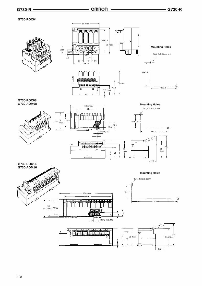
G730-R G730-R
108
G730-ROC04
23.611.8
1.5
107
8.5
4.3 26.843.1
75 max.
70 max.
66�0.2
72�0.2
7180 max.
Mounting Holes
66�0.3
72�0.3
Two, 4.2-dia. or M4
G730-ROC08G730-AOM08
101 max.
51max.
51max.
51max.
Two, 4.2 dia. or M4
Two, 4.2 dia. or M4
156 max.
51 max. 51 max.
51max.
Mounting Holes
G730-ROC16G730-AOM16
Mounting Holes
Sixteen, M3
40�0.2
Thirty-two, M3

G730-R G730-R
109
InstallationInternal Circuit Configuration
Output CircuitG730-ROC04
Input CircuitsG730-RID04
Internalcircuit
24 V
0 V
24 V
0 V
24 V
0 V
24-VDC powersupply
DC-DCconverter(insulationtype)
Internalcircuit
G2R or SSR
A0 to A3
B0 to B3
24-VDC powersupply
24-VDC powersupply
DC-DCconverter(insulationtype)
DC-DCconverter(insulationtype)
Internalcircuit
G2R or SSR
G2R or SSR
A0 to A3
B0 to B3
A0 to A3
B0 to B3
G730-RIA04
G730-ROC08, G730-ROC16, G730-AOM08, G730-AOM16
Transmissionpaths
24-VDCpower supply
DC-DCconverter(insulationtype)
Inte
rnal
circ
uit
Relay driver circuit
Relay driver circuit
Relay driver circuit
Relay driver circuit
A0 (A4, A8, A12)
B0 (B2, B4, B6)
B1 (B3, B5, B7)
A1 (A3, A9, A13)
A2 (A5, A10, A14)
A3 (A7, A11, A15)

G730-R G730-R
110
External ConnectionsInput BlocksG730-RIA04, G730-RID04
Output BlocksG730-ROC04
A0 A1 A2 A3
B0 B1 B2 B3
A0 A2 A3
B0 B1 B2 B3
AC/DC loadpower supply
SwitchSwitch
AC/DC loadpower supply
LampSolenoid
A1
Output BlocksG730-ROC08, G730-ROC16, G730-AOM08, G730-AOM16
A0
A1
A2
A3
B0
B1
Lam
p
Lam
p
Lam
p
Lam
p Load powersupply
Terminal Arrangement/I/O Device Connection ExamplesInput TerminalsG730-RIA04, G730-RID04
Output TerminalsG730-ROC04
RS485--
+ A0 A1 A2 A3
-- B0 B1 B2 B3
SwitchSolenoid
RS485+
RS485--
+ A0 A1 A2 A3
-- B0 B1 B2 B3
RS485+
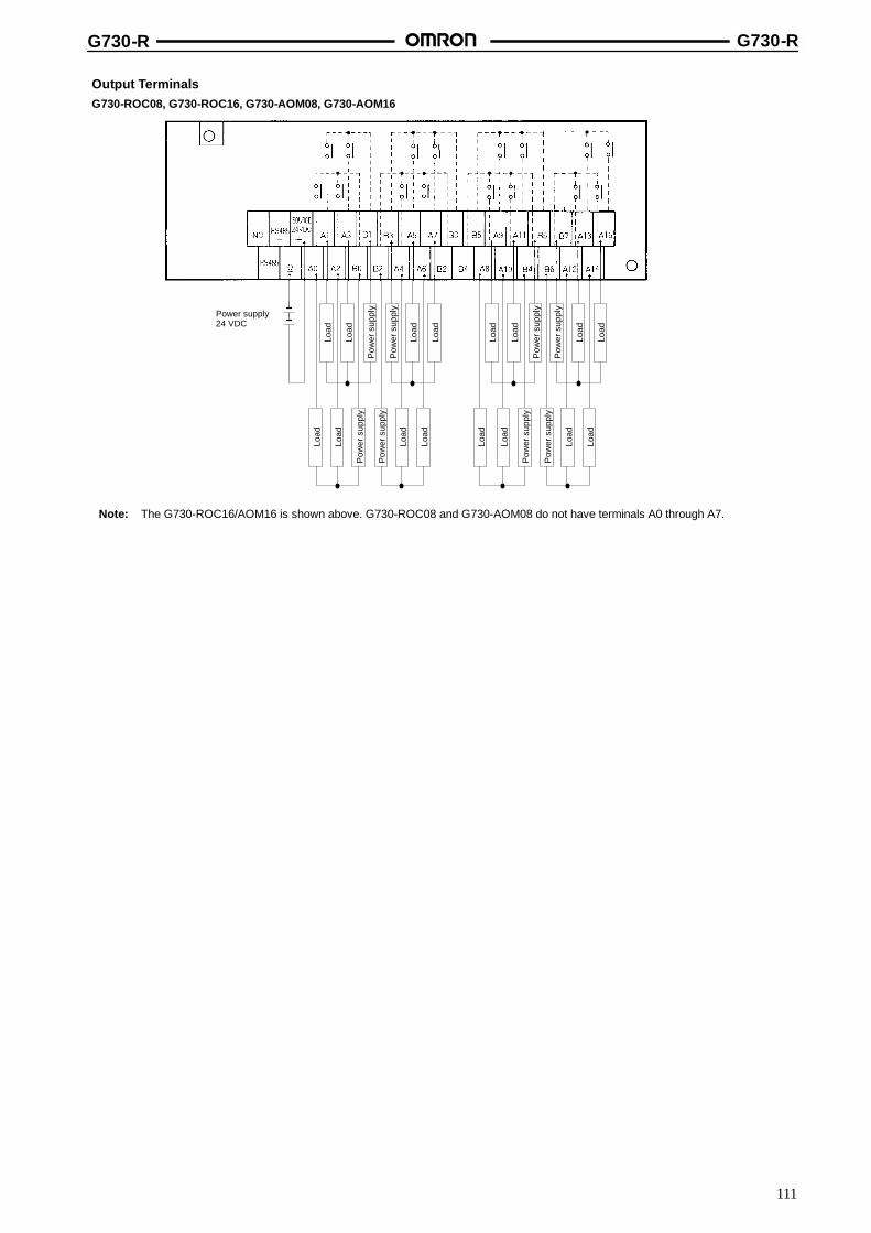
G730-R G730-R
111
Output TerminalsG730-ROC08, G730-ROC16, G730-AOM08, G730-AOM16
Power supply24 VDC
Pow
ersu
pply
Load
Load
Load
Pow
ersu
pply
Load
Load
Load
Pow
ersu
pply
Load
Pow
ersu
pply
Load
Pow
ersu
pply
Load
Load
Load
Pow
ersu
pply
Load
Load
Load
Pow
ersu
pply
Load
Pow
ersu
pply
Load
Note: The G730-ROC16/AOM16 is shown above. G730-ROC08 and G730-AOM08 do not have terminals A0 through A7.
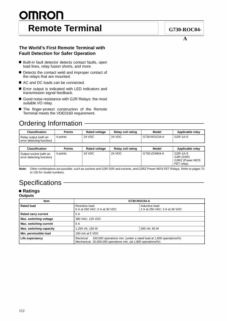
112
Remote Terminal G730-ROC04-
A
The World’s First Remote Terminal withFault Detection for Safer Operation
Built-in fault detector detects contact faults, openload lines, relay fusion shorts, and more.
Detects the contact weld and improper contact ofthe relays that are mounted.
AC and DC loads can be connected.
Error output is indicated with LED indicators andtransmission signal feedback.
Good noise resistance with G2R Relays: the mostsuitable I/O relay.
The finger-protect construction of the RemoteTerminal meets the VDE0160 requirement.
Ordering InformationClassification Points Rated voltage Relay coil rating Model Applicable relay
Relay output (with anerror detecting function)
4 points 24 VDC 24 VDC G730-ROC04-A G2R-1A-S
Classification Points Rated voltage Relay coil rating Model Applicable relay
Output socket (with anerror detecting function)
4 points 24 VDC 24 VDC G730-ZOM04-A G2R-1A-SG3R (SSR)G3RZ (Power MOSFET relay)
Note: Other combinations are possible, such as sockets and G3R SSR and sockets, and G3RZ Power MOS FET Relays. Refer to pages 70to 135 for model numbers.
SpecificationsRatings
OutputsItem G730-ROC04-A
Rated load Resistive load:5 A at 250 VAC; 5 A at 30 VDC
Inductive load:2 A at 250 VAC; 3 A at 30 VDC
Rated carry current 5 A
Max. switching voltage 380 VAC; 125 VDC
Max. switching current 5 A
Max. switching capacity 1,250 VA; 150 W 500 VA; 90 W
Min. permissible load 100 mA at 5 VDC
Life expectancy Electrical: 100,000 operations min. (under a rated load at 1,800 operations/hr)Mechanical: 20,000,000 operations min. (at 1,800 operations/hr)

G730-ROC04-A G730-ROC04-A
113
Error Detecting PerformanceDetecting mode 1. Contact weld detection
2. Improper contact detection (including load disconnection and fuse blowout)
Detecting load current 0.5 to 5 A (AC/DC)
Open detection selector Improper contact detecting function is canceled when the selector is set to OFF.
Error output 1. Output indicator LED for each terminal flashes2. Transmission signal feedback (However, no distinction is made between contact weld andimproper contact.)
Error detection delay Approx. 300 ms
CharacteristicsMaster Unit For controllers or personal computers: G730-M/N
For SYSMAC BUS Wired Remote I/O Systems: C200H-RM201, 3G2A5-RM201
Communication method Two-conductor, half duplex
Synchronization method Asynchronous
Transmission distance 200 m (total length)
Transmission speed 187.5 kbps
Transmission path Two-conductor cable (VCTF 0.75 x 2 C is recommended)
Interface RS-485
Operating voltage range 24 VDC +10%/--15%
Current consumption (see note) 260 mA max. at 24 VDC
Insulation resistance 20 Mτ min. (at 250 VDC)
Dielectric strength 2,700 VAC for 1 min between the I/O terminals and power supply and transmission terminals500 VAC for 1 min between the power supply terminals and transmission terminals
Noise immunity Power supply normal: 600 V for 10 min with a pulse width of 100 ns to 1 ←sPower supply common: 1.5 kV for 10 min with a pulse width of 100 ns to 1 ←sCoiling around transmission path: 1.5 kV for 10 min with a pulse width of 100 ns to 1 ←sCoiling around Unit: 600 V for 10 min with a pulse width of 100 ns to 1 ←s
Vibration resistance 10 to 55 Hz, 0.75-mm double amplitude for 2 hrs each in X, Y, and Z directions
Shock resistance Destruction: 300 m/s2 (approx. 30G)Malfunction: 100 m/s2 (approx. 10G)
Ambient temperature Operating: 0 to 55 CStorage: --20 to 65 C
Ambient humidity Operating: 35% to 85%
Mounting strength No damage when 5 kgf (49N) pull load was applied for 10 s in all directions
Terminal strength Tightening strength: 10 kgf S cm (0.98 N S m) for 10 sPulling strength: 5 kgf (50 N) for 10 s
Weight Approx. 330 g (with all the relays mounted)
Note: The above current consumption is a value with all the points turned ON including the current consumption of the G2R coils for theRemote Output Terminal.

G730-ROC04-A G730-ROC04-A
114
Nomenclature
DIP Switch Setting Guide Label
Mounting Hole
Terminator, HOLD, and Word Setting
T/R ERR Indicator
PWR Indicator
Relay Removal Lever
Mounting Hole
Internal Circuit Power Supply Terminals
Transmission Terminals
Switch Cover
Note: Be sure to turn off the G730before setting the DIP switch.
HOLD168421
END
Open Detection Selector
Output Type Label
HOLD and LOAD OFF Setting(select output hold or clear)
Terminator Setting
Word Setting(0: OFF and 1: ON)
Output Indicators
Output Relay
Output Terminals
ON
ON OFF
Open Detection Selector
ON OFF
Open detection and short detection are possible. Only short detection is possible.
Note: This selector is factory-set to ON.Mounting HoleUse an M4 screw to mount the G730.Terminator SettingThese pins of the terminator must be set to ON.If these pins of the terminator are set to ON, the terminator resistance of the terminator is turned ON. There must be only one terminator in asystem. The G730-V located farthest from the G730-M on the transmission path must be the terminator. These pins are factory-set to OFF.
HOLD and LOAD OFF Setting
HOLD LOAD OFF
If there is a Slave transmission error during signal transmission,the signal being transmitted is put on hold.
If there is a Slave transmission error during signal transmission,the output of the G730-V is turned OFF.
Note: If the Master has a data error or if there is no data from the Master, a Slave transmission error will result. The HOLD/LOAD OFF selectoris factory-set to LOAD OFF.
T/R ERR Indicator
Display Function
Flashing Flashes during normal transmission.
Lit Lit while the Master Unit is waiting for transmission or when a transmission error results.
Not lit Turns OFF if a CPU error is detected during watchdog timer monitoring.
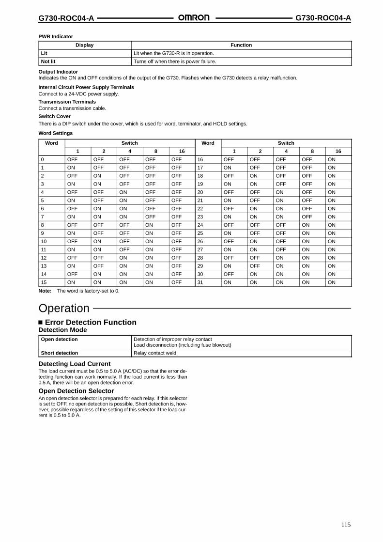
G730-ROC04-A G730-ROC04-A
115
PWR Indicator
Display Function
Lit Lit when the G730-R is in operation.
Not lit Turns off when there is power failure.
Output IndicatorIndicates the ON and OFF conditions of the output of the G730. Flashes when the G730 detects a relay malfunction.
Internal Circuit Power Supply TerminalsConnect to a 24-VDC power supply.
Transmission TerminalsConnect a transmission cable.
Switch CoverThere is a DIP switch under the cover, which is used for word, terminator, and HOLD settings.
Word Settings
Word Switch Word Switch
1 2 4 8 16 1 2 4 8 16
0 OFF OFF OFF OFF OFF 16 OFF OFF OFF OFF ON
1 ON OFF OFF OFF OFF 17 ON OFF OFF OFF ON
2 OFF ON OFF OFF OFF 18 OFF ON OFF OFF ON
3 ON ON OFF OFF OFF 19 ON ON OFF OFF ON
4 OFF OFF ON OFF OFF 20 OFF OFF ON OFF ON
5 ON OFF ON OFF OFF 21 ON OFF ON OFF ON
6 OFF ON ON OFF OFF 22 OFF ON ON OFF ON
7 ON ON ON OFF OFF 23 ON ON ON OFF ON
8 OFF OFF OFF ON OFF 24 OFF OFF OFF ON ON
9 ON OFF OFF ON OFF 25 ON OFF OFF ON ON
10 OFF ON OFF ON OFF 26 OFF ON OFF ON ON
11 ON ON OFF ON OFF 27 ON ON OFF ON ON
12 OFF OFF ON ON OFF 28 OFF OFF ON ON ON
13 ON OFF ON ON OFF 29 ON OFF ON ON ON
14 OFF ON ON ON OFF 30 OFF ON ON ON ON
15 ON ON ON ON OFF 31 ON ON ON ON ON
Note: The word is factory-set to 0.
OperationError Detection Function
Detection ModeOpen detection Detection of improper relay contact
Load disconnection (including fuse blowout)
Short detection Relay contact weld
Detecting Load CurrentThe load current must be 0.5 to 5.0 A (AC/DC) so that the error de-tecting function can work normally. If the load current is less than0.5 A, there will be an open detection error.
Open Detection SelectorAn open detection selector is prepared for each relay. If this selectoris set to OFF, no open detection is possible. Short detection is, how-ever, possible regardless of the setting of this selector if the load cur-rent is 0.5 to 5.0 A.
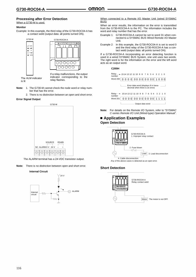
G730-ROC04-A G730-ROC04-A
116
Processing after Error DetectionWhen a G730-M is used.
MonitorExample: In this example, the third relay of the G730-ROC04-A has
a contact weld (output data: all points turned ON).
G730-M G730-ROC04-A
The ALM indicatoris lit
If a relay malfunctions, the outputindicator corresponding to therelay flashes.
Note: 1. The G730-M cannot check the node word or relay num-ber that has the error.
2. There is no distinction between an open and short error.
Error Signal Output
ALARM
SOURCE RS485
NC 0 V 24 V +--
G730-M
The ALARM terminal has a 24-VDC transistor output.
Note: There is no distinction between open and short error.
Internal Circuit
24 V
ALARMInternalcircuit
When connected to a Remote I/O Master Unit (wired SYSMACBUS)When an error results, the information on the error is transmittedfrom the G730-ROC04-A to the PC. The information includes theword and relay number that has the error.Example 1: G730-ROC04-A cannot be set to word 31 when con-
nected to a SYSMAC BUS Wired Remote I/O MasterUnit.
Example 2: In this example, the G730-ROC04-A is set to word 0and the third relay of the G730-ROC04-A has a con-tact weld (output data: all points turned ON).
If a G730-ROC04-A incorporating an error detecting function isused in a wired SYSMAC BUS System, one unit uses two words.The right word is for the information on the error and the left wordacts as an output word.
0 0 0 0 0 0 0 0 0 0 0 0 1 0 0 0
0 0 0 0 0 0 0 0 0 0 0 0 1 1 1 1
15 14 13 12 11 10 9 8 7 6 5 4 3 2 1 0
15 14 13 12 11 10 9 8 7 6 5 4 3 2 1 0
RelaynumberWord 200
Word 201
Relaynumber
Error data word (displays 8 in hexa-decimal when there is an error)
Output data word
C200H
Note: For details on the Remote I/O System, refer to “SYSMACC-series Remote I/O Unit (Wired-type) Operation Manual”.
Application ExamplesOpen Detection
G730-ROC04-A1. Improper relay contact
2. Fuse blown
Load 3. Load disconnection
4. Cable disconnectionAny of the above cases is detected as an open error.
Short Detection
G730-ROC04-ARelay contact weld
Motor The motor is not OFF.

G730-ROC04-A G730-ROC04-A
117
Open Detection Selector
0.2-A lamp,heater, orfuse
Load Load 5-A lamp,heater, orfuse
G730-ROC04-ARelay contact weld
It is possible to detect the disconnection of a 5-A load.Set the open detection selector to ON.
ON OFF
The G730-ROC04-A detects the disconnection of the load with acurrent consumption of 0.5 to 5.0 A. If the current consumption ofthe load is 0.2 A, for example, the G730-ROC04-A will have an opendetection error. In such a case set the open detection selector toOFF.Even if the open detection selector is set to OFF, theG730-ROC04-A has the short detecting function for a 0.5- to 5-Aload.
ON OFF
DimensionsNote: All units are in millimeters unless otherwise indicated.
Mounting Holes
G730-ROC04-A
23.611.8
1.510 8.5
7
4.3
56.973.2
66�0.2
72�0.2
75 max.
100 max.
80 max.
Two, 4.2 dia. or M4
72�0.3
66�0.3
InstallationInternal Circuit Configuration
24 V
0 V
24-VDC powersupply
DC-DCconverter(insulationtype)
Internalcircuit
G2R or SSR
A0 to A3
B0 to B3
Errordetectioncircuit
Sensor
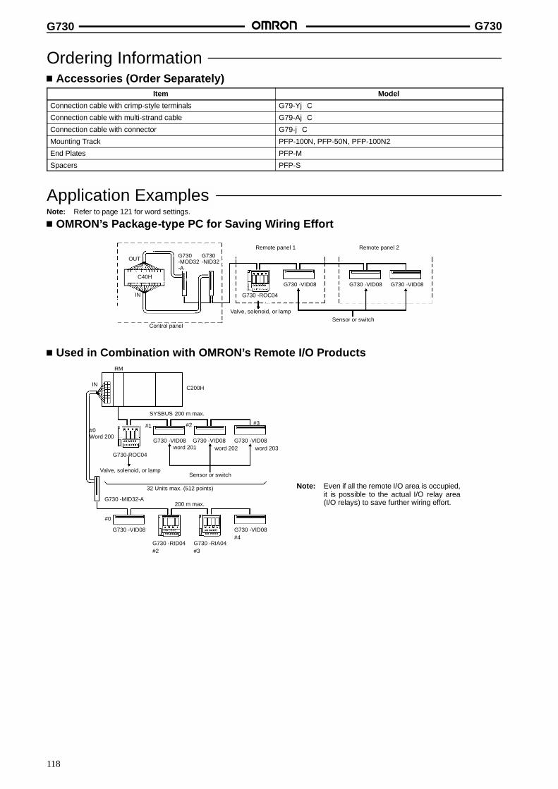
G730 G730
118
Ordering InformationAccessories (Order Separately)
Item Model
Connection cable with crimp-style terminals G79-YjC
Connection cable with multi-strand cable G79-AjC
Connection cable with connector G79-jC
Mounting Track PFP-100N, PFP-50N, PFP-100N2
End Plates PFP-M
Spacers PFP-S
Application ExamplesNote: Refer to page 121 for word settings.
OMRON’s Package-type PC for Saving Wiring Effort
OUT
C40H
IN
G730-MOD32-A
G730-NID32
G730 -ROC04
G730 -VID08 G730 -VID08 G730 -VID08
Remote panel 1
Control panel
Valve, solenoid, or lampSensor or switch
Remote panel 2
Used in Combination with OMRON’s Remote I/O Products
IN
RM
C200H
200 m max.
Valve, solenoid, or lampSensor or switch
G730 -MID32-A
G730 -VID08
G730 -VID08 G730 -VID08 G730 -VID08
32 Units max. (512 points)
G730 -RIA04
G730 -VID08
G730-ROC04
SYSBUS
G730 -RID04
Note: Even if all the remote I/O area is occupied,it is possible to the actual I/O relay area(I/O relays) to save further wiring effort.200 m max.
#0Word 200
#1
word 201 word 202 word 203
#2 #3
#0
#2 #3
#4
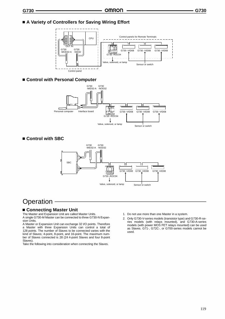
G730 G730
119
A Variety of Controllers for Saving Wiring Effort
G730 -VID08 G730 -VID08 G730 -VID08
Control panels for Remote Terminals
Sensor or switch
G730 -ROC04
CPU
G730-MOD32-A
G730-NID32
Control panel
OUT IN
Valve, solenoid, or lamp
Control with Personal Computer
Sensor or switch
G730 -VID08 G730 -VID08 G730 -VID08
G730-NOD32
Personal computer Interface board
G730 -ROC04
Valve, solenoid, or lamp
G730-MID32-A
Control with SBC
G730 -ROC04
G730 -VID08 G730 -VID08 G730 -VID08
Valve, solenoid, or lamp
SBC
Sensor or switch
G730-NOD32
G730-MID32-A
OperationConnecting Master Unit
The Master and Expansion Unit are called Master Units.A single G730-M Master can be connected to three G730-N Expan-sion Units.A Master or Expansion Unit can exchange 32 I/O points. Thereforea Master with three Expansion Units can control a total of128 points. The number of Slaves to be connected varies with thekind of Slaves; 4-point, 8-point, and 16-point. The maximum num-ber of Slaves connected is 28 (24 4-point Slaves and four 8-pointSlaves).Take the following into consideration when connecting the Slaves.
1. Do not use more than one Master in a system.2. Only G730-V-series models (transistor type) and G730-R-se-
ries models (with relays mounted), and G730-A-seriesmodels (with power MOS FET relays mounted) can be usedas Slaves. G71-, G72C-, or G700-series models cannot beused.
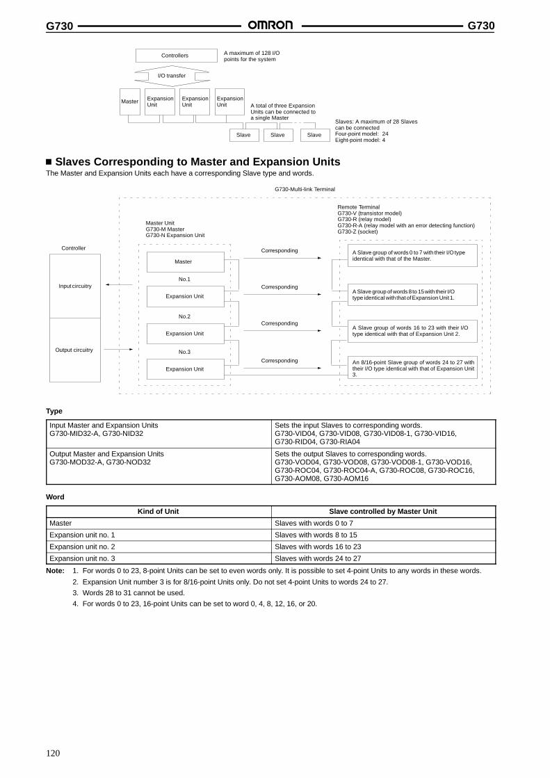
G730 G730
120
Controllers A maximum of 128 I/Opoints for the system
I/O transfer
Master ExpansionUnit
ExpansionUnit
ExpansionUnit
Slave Slave Slave
A total of three ExpansionUnits can be connected toa single Master
Slaves: A maximum of 28 Slavescan be connectedFour-point model: 24Eight-point model: 4
Slaves Corresponding to Master and Expansion UnitsThe Master and Expansion Units each have a corresponding Slave type and words.
Input circuitry
Output circuitry
Master
Expansion Unit
Expansion Unit
Expansion Unit
Corresponding
Corresponding
Corresponding
Corresponding
Remote TerminalG730-V (transistor model)G730-R (relay model)G730-R-A (relay model with an error detecting function)G730-Z (socket)
A Slave group of words 0 to 7 with their I/O typeidentical with that of the Master.
A Slave group of words 8 to 15with their I/Otype identical with that ofExpansion Unit1.
A Slave group of words 16 to 23 with their I/Otype identical with that of Expansion Unit 2.
An 8/16-point Slave group of words 24 to 27 withtheir I/O type identical with that of Expansion Unit3.
G730-Multi-link Terminal
Master UnitG730-M MasterG730-N Expansion Unit
No.1
No.2
No.3
Controller
Type
Input Master and Expansion UnitsG730-MID32-A, G730-NID32
Sets the input Slaves to corresponding words.G730-VID04, G730-VID08, G730-VID08-1, G730-VID16,G730-RID04, G730-RIA04
Output Master and Expansion UnitsG730-MOD32-A, G730-NOD32
Sets the output Slaves to corresponding words.G730-VOD04, G730-VOD08, G730-VOD08-1, G730-VOD16,G730-ROC04, G730-ROC04-A, G730-ROC08, G730-ROC16,G730-AOM08, G730-AOM16
Word
Kind of Unit Slave controlled by Master Unit
Master Slaves with words 0 to 7
Expansion unit no. 1 Slaves with words 8 to 15
Expansion unit no. 2 Slaves with words 16 to 23
Expansion unit no. 3 Slaves with words 24 to 27
Note: 1. For words 0 to 23, 8-point Units can be set to even words only. It is possible to set 4-point Units to any words in these words.
2. Expansion Unit number 3 is for 8/16-point Units only. Do not set 4-point Units to words 24 to 27.3. Words 28 to 31 cannot be used.4. For words 0 to 23, 16-point Units can be set to word 0, 4, 8, 12, 16, or 20.
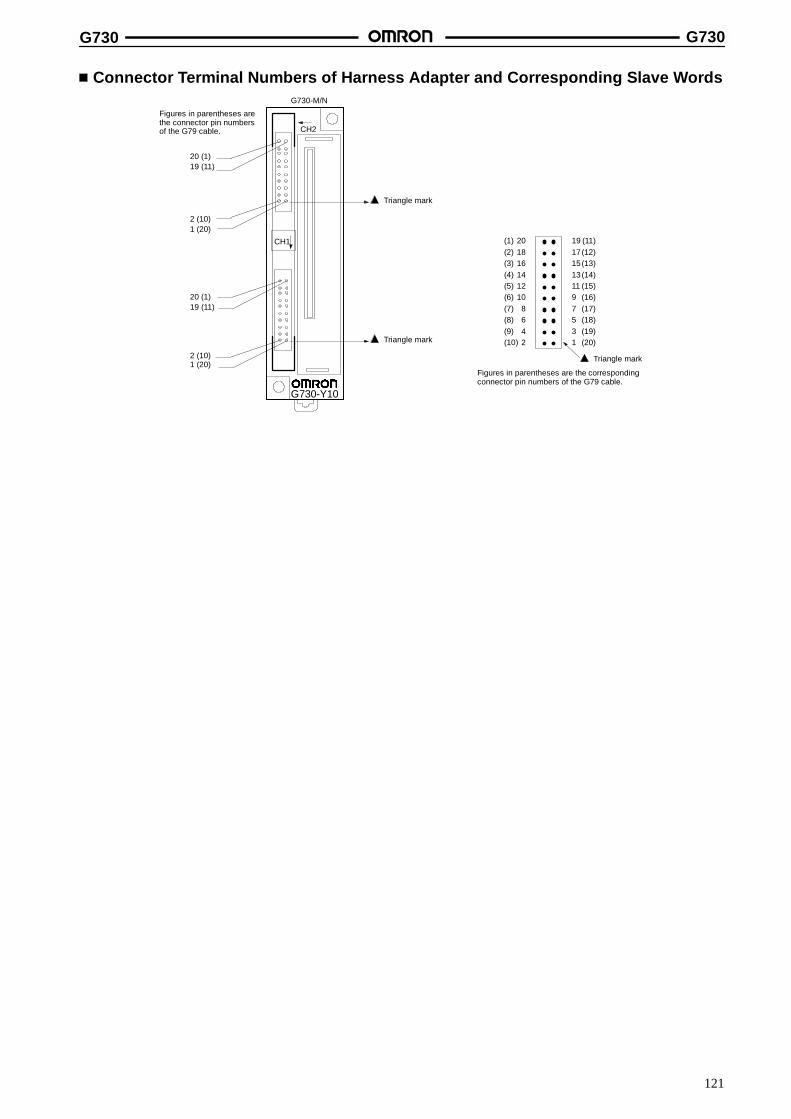
G730 G730
121
Connector Terminal Numbers of Harness Adapter and Corresponding Slave Words
(1) 20 19 (11)(2) 18 17(12)(3) 16 15(13)(4) 14 13(14)(5) 12 11 (15)(6) 10 9 (16)(7) 8 7 (17)(8) 6 5 (18)(9) 4 3 (19)(10) 2 1 (20)
Triangle mark
Figures in parentheses are the correspondingconnector pin numbers of the G79 cable.
20 (1)19 (11)
2 (10)1 (20)
CH2
20 (1)19 (11)
2 (10)1 (20)
G730-M/N
Figures in parentheses arethe connector pin numbersof the G79 cable.
Triangle mark
Triangle mark
G730-Y10
CH1

G730 G730
122
G730-MID32-A, G730-MOD32-ACorresponds to the Slaves (G730-V, G730-R, and G730-A Slaves) set to words 0 to 7.
Connector terminal no.( )
I/O signal 4-point Unit 8-point Unit 16-point Unit(see note)
/ gname Word no. Terminal
no.Word no. Terminal
no.Word no. Terminal
no.
CH1 20181614
(1)(2)(3)(4)
I/O00I/O01I/O02I/O03
0 0123
0 01234
0 0123412
1086
(5)(6)(7)(8)
I/O04I/O05I/O06I/O07
1 0123
4567
4567
42
(9)(10)
GND (+24 V)+24 V (GND)
---
19171513
(11)(12)(13)(14)
I/O08I/O09I/O10I/O11
2 0123
2 01234
0 8910111211
975
(15)(16)(17)(18)
I/O12I/O13I/O14I/O15
3 0123
4567
12131415
31
(19)(20)
GND (+24 V)+24 V (GND)
---
CH2 20181614
(1)(2)(3)(4)
I/O00I/O01I/O02I/O03
4 0123
4 01234
4 0123412
1086
(5)(6)(7)(8)
I/O04I/O05I/O06I/O07
5 0123
4567
4567
42
(9)(10)
GND (+24 V)+24 V (GND)
---
19171513
(11)(12)(13)(14)
I/O08I/O09I/O10I/O11
6 0123
6 01234
4 8910111211
975
(15)(16)(17)(18)
I/O12I/O13I/O14I/O15
7 0123
4567
12131415
31
(19)(20)
GND (+24 V)+24 V (GND)
---
Note: 1. Figures in parentheses are corresponding connector pin numbers when OMRON’s G79 Cable is used.
2. The data in the parentheses in the I/O signal name column are for G730-Y10-1 signals.
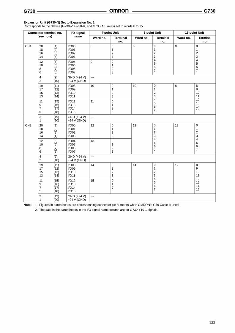
G730 G730
123
Expansion Unit (G730-N) Set to Expansion No. 1Corresponds to the Slaves (G730-V, G730-R, and G730-A Slaves) set to words 8 to 15.
Connector terminal no.( )
I/O signal 4-point Unit 8-point Unit 16-point Unit(see note)
/ gname Word no. Terminal
no.Word no. Terminal
no.Word no. Terminal
no.
CH1 20181614
(1)(2)(3)(4)
I/O00I/O01I/O02I/O03
8 0123
8 01234
8 0123412
1086
(5)(6)(7)(8)
I/O04I/O05I/O06I/O07
9 0123
4567
4567
42
(9)(10)
GND (+24 V)+24 V (GND)
---
19171513
(11)(12)(13)(14)
I/O08I/O09I/O10I/O11
10 0123
10 01234
8 8910111211
975
(15)(16)(17)(18)
I/O12I/O13I/O14I/O15
11 0123
4567
12131415
31
(19)(20)
GND (+24 V)+24 V (GND)
---
CH2 20181614
(1)(2)(3)(4)
I/O00I/O01I/O02I/O03
12 0123
12 01234
12 0123412
1086
(5)(6)(7)(8)
I/O04I/O05I/O06I/O07
13 0123
4567
4567
42
(9)(10)
GND (+24 V)+24 V (GND)
---
19171513
(11)(12)(13)(14)
I/O08I/O09I/O10I/O11
14 0123
14 01234
12 8910111211
975
(15)(16)(17)(18)
I/O12I/O13I/O14I/O15
15 0123
4567
12131415
31
(19)(20)
GND (+24 V)+24 V (GND)
---
Note: 1. Figures in parentheses are corresponding connector pin numbers when OMRON’s G79 Cable is used.
2. The data in the parentheses in the I/O signal name column are for G730-Y10-1 signals.

G730 G730
124
Expansion Unit (G730-N) Set to Expansion No. 2Corresponds to the Slaves (G730-V, G730-R, and G730-A Slaves) set to words 16 to 23.
Connector terminal no.( )
I/O signal 4-point Unit 8-point Unit 16-point Unit(see note)
/ gname Word no. Terminal
no.Word no. Terminal
no.Word no. Terminal
no.
CH1 20181614
(1)(2)(3)(4)
I/O00I/O01I/O02I/O03
16 0123
16 01234
16 0123412
1086
(5)(6)(7)(8)
I/O04I/O05I/O06I/O07
17 0123
4567
4567
42
(9)(10)
GND (+24 V)+24 V (GND)
---
19171513
(11)(12)(13)(14)
I/O08I/O09I/O10I/O11
18 0123
18 01234
16 8910111211
975
(15)(16)(17)(18)
I/O12I/O13I/O14I/O15
19 0123
4567
12131415
31
(19)(20)
GND (+24 V)+24 V (GND)
---
CH2 20181614
(1)(2)(3)(4)
I/O00I/O01I/O02I/O03
20 0123
20 01234
20 0123412
1086
(5)(6)(7)(8)
I/O04I/O05I/O06I/O07
21 0123
4567
4567
42
(9)(10)
GND (+24 V)+24 V (GND)
---
19171513
(11)(12)(13)(14)
I/O08I/O09I/O10I/O11
22 0123
22 01234
20 8910111211
975
(15)(16)(17)(18)
I/O12I/O13I/O14I/O15
23 0123
4567
12131415
31
(19)(20)
GND (+24 V)+24 V (GND)
---
Note: 1. Figures in parentheses are corresponding connector pin numbers when OMRON’s G79 Cable is used.
2. The data in the parentheses in the I/O signal name column are for G730-Y10-1 signals.

G730 G730
125
Expansion Unit (G730-N) Set to Expansion No. 3Corresponds to the Slaves (G730-V, and G730-R/-A (8/16-point) Slaves) set to words 24 to 27.
Connector terminal no.( 1)
I/O signal name 8-point Unit 16-point Unit(see note 1)
/ g
Word no. Terminal no. Word no. Terminal no.
CH1 20181614
(1)(2)(3)(4)
I/O00I/O01I/O02I/O03
24 01234
24 0123412
1086
(5)(6)(7)(8)
I/O04I/O05I/O06I/O07
4567
4567
42
(9)(10)
GND (+24 V)+24 V (GND)
--- ---
19171513
(11)(12)(13)(14)
I/O08I/O09I/O10I/O11
25 01234
24 8910111211
975
(15)(16)(17)(18)
I/O12I/O13I/O14I/O15
4567
12131415
31
(19)(20)
GND (+24 V)+24 V (GND)
--- ---
CH2 20181614
(1)(2)(3)(4)
I/O00I/O01I/O02I/O03
26 01234
26 0123412
1086
(5)(6)(7)(8)
I/O04I/O05I/O06I/O07
4567
4567
42
(9)(10)
GND (+24 V)+24 V (GND)
--- ---
19171513
(11)(12)(13)(14)
I/O08I/O09I/O10I/O11
27 01234
26 8910111211
975
(15)(16)(17)(18)
I/O12I/O13I/O14I/O15
4567
12131415
31
(19)(20)
GND (+24 V)+24 V (GND)
--- ---
Note: 1. Figures in parentheses are corresponding connector pin numbers when OMRON’s G79 Cable is used.
2. Expansion Unit number 3 are for 8/16-point Units only. Therefore words 24 to 27 can be used by 8/16-point Units only.3. I/O signal names in parentheses are for the G730-Y10-1.
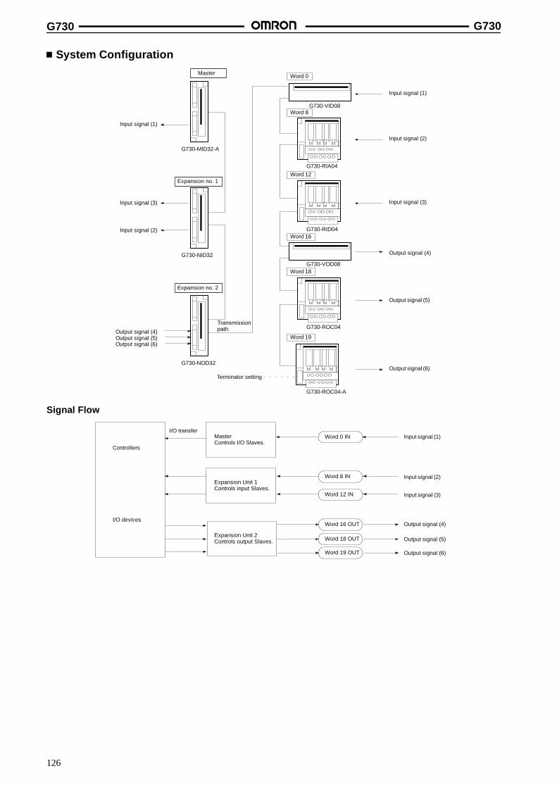
G730 G730
126
System Configuration
G730-MID32-A
G730-NID32
G730-NOD32
Word 0
Word 8
Word 12
Word 16
Word 18
Word 19
G730-VID08
G730-RIA04
G730-RID04
G730-VOD08
G730-ROC04
G730-ROC04-A
Master
Input signal (1)
Input signal (3)
Input signal (2)
Expansion no. 1
Expansion no. 2
Output signal (4)Output signal (5)Output signal (6)
Transmissionpath
Input signal (1)
Input signal (2)
Input signal (3)
Output signal (4)
Output signal (5)
Output signal (6)
Terminator setting
Signal Flow
Controllers
I/O devices
I/O transferMasterControls I/O Slaves.
Expansion Unit 1Controls input Slaves.
Expansion Unit 2Controls output Slaves.
Input signal (1)
Input signal (2)
Input signal (3)
Output signal (4)
Output signal (5)
Output signal (6)
Word 0 IN
Word 8 IN
Word 12 IN
Word 16 OUT
Word 18 OUT
Word 19 OUT
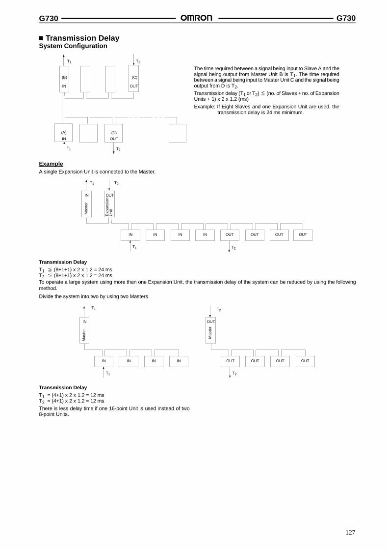
G730 G730
127
Transmission DelaySystem Configuration
IN
T1
OUT
T2
T1 T2
(B)
(A) (D)
(C)
IN OUT
The time required between a signal being input to Slave A and thesignal being output from Master Unit B is T1. The time requiredbetween a signal being input to Master Unit C and the signal beingoutput from D is T2.Transmission delay (T1 or T2) ≦ (no. of Slaves + no. of ExpansionUnits + 1) x 2 x 1.2 (ms)Example: If Eight Slaves and one Expansion Unit are used, the
transmission delay is 24 ms minimum.
ExampleA single Expansion Unit is connected to the Master.
IN IN IN OUT
IN
T1
T1
IN OUT OUT OUT
T2
OUT
T2
Mas
ter
Exp
ansi
onU
nit
Transmission DelayT1 ≦ (8+1+1) x 2 x 1.2 = 24 msT2 ≦ (8+1+1) x 2 x 1.2 = 24 msTo operate a large system using more than one Expansion Unit, the transmission delay of the system can be reduced by using the followingmethod.
Divide the system into two by using two Masters.
IN IN IN IN
IN
T1
T1
OUT OUT OUT OUT
OUT
T2
T2
Mas
ter
Mas
ter
Transmission DelayT1 = (4+1) x 2 x 1.2 = 12 msT2 = (4+1) x 2 x 1.2 = 12 msThere is less delay time if one 16-point Unit is used instead of two8-point Units.
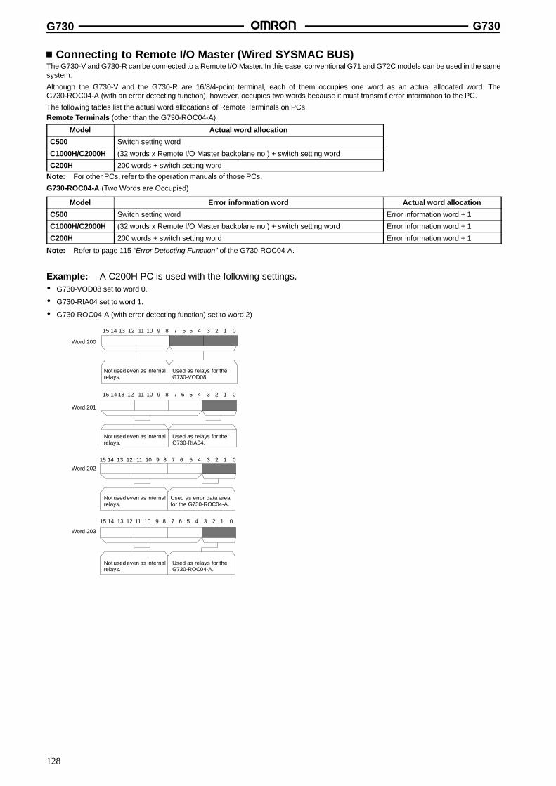
G730 G730
128
Connecting to Remote I/O Master (Wired SYSMAC BUS)The G730-V and G730-R can be connected to a Remote I/O Master. In this case, conventional G71 and G72C models can be used in the samesystem.
Although the G730-V and the G730-R are 16/8/4-point terminal, each of them occupies one word as an actual allocated word. TheG730-ROC04-A (with an error detecting function), however, occupies two words because it must transmit error information to the PC.
The following tables list the actual word allocations of Remote Terminals on PCs.Remote Terminals (other than the G730-ROC04-A)
Model Actual word allocation
C500 Switch setting word
C1000H/C2000H (32 words x Remote I/O Master backplane no.) + switch setting word
C200H 200 words + switch setting wordNote: For other PCs, refer to the operation manuals of those PCs.
G730-ROC04-A (Two Words are Occupied)
Model Error information word Actual word allocation
C500 Switch setting word Error information word + 1
C1000H/C2000H (32 words x Remote I/O Master backplane no.) + switch setting word Error information word + 1
C200H 200 words + switch setting word Error information word + 1
Note: Refer to page 115 “Error Detecting Function” of the G730-ROC04-A.
Example: A C200H PC is used with the following settings. G730-VOD08 set to word 0.
G730-RIA04 set to word 1.
G730-ROC04-A (with error detecting function) set to word 2)
15 14 13 12 11 10 9 8 7 6 5 4 3 2 1 0
15 14 13 12 11 10 9 8 7 6 5 4 3 2 1 0
15 14 13 12 11 10 9 8 7 6 5 4 3 2 1 0
15 14 13 12 11 10 9 8 7 6 5 4 3 2 1 0
Word 200
Word 201
Word 202
Word 203
Not used even as internalrelays.
Used as relays for theG730-VOD08.
Not used even as internalrelays.
Used as relays for theG730-RIA04.
Not used even as internalrelays.
Used as error data areafor the G730-ROC04-A.
Not used even as internalrelays.
Used as relays for theG730-ROC04-A.
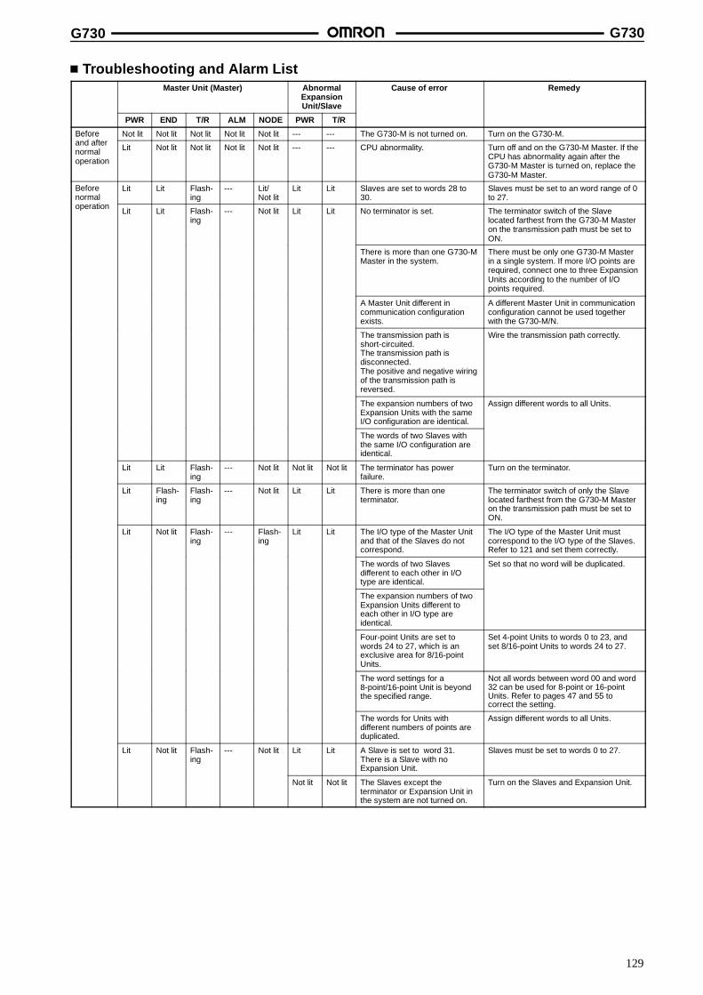
G730 G730
129
Troubleshooting and Alarm ListMaster Unit (Master) Abnormal
ExpansionUnit/Slave
Cause of error Remedy
PWR END T/R ALM NODE PWR T/R
Befored ft
Not lit Not lit Not lit Not lit Not lit --- --- The G730-M is not turned on. Turn on the G730-M.Beforeand afternormaloperation
Lit Not lit Not lit Not lit Not lit --- --- CPU abnormality. Turn off and on the G730-M Master. If theCPU has abnormality again after theG730-M Master is turned on, replace theG730-M Master.
Beforenormal
ti
Lit Lit Flash-ing
--- Lit/Not lit
Lit Lit Slaves are set to words 28 to30.
Slaves must be set to an word range of 0to 27.normal
operation Lit Lit Flash-ing
--- Not lit Lit Lit No terminator is set. The terminator switch of the Slavelocated farthest from the G730-M Masteron the transmission path must be set toON.
There is more than one G730-MMaster in the system.
There must be only one G730-M Masterin a single system. If more I/O points arerequired, connect one to three ExpansionUnits according to the number of I/Opoints required.
A Master Unit different incommunication configurationexists.
A different Master Unit in communicationconfiguration cannot be used togetherwith the G730-M/N.
The transmission path isshort-circuited.The transmission path isdisconnected.The positive and negative wiringof the transmission path isreversed.
Wire the transmission path correctly.
The expansion numbers of twoExpansion Units with the sameI/O configuration are identical.
Assign different words to all Units.
The words of two Slaves withthe same I/O configuration areidentical.
Lit Lit Flash-ing
--- Not lit Not lit Not lit The terminator has powerfailure.
Turn on the terminator.
Lit Flash-ing
Flash-ing
--- Not lit Lit Lit There is more than oneterminator.
The terminator switch of only the Slavelocated farthest from the G730-M Masteron the transmission path must be set toON.
Lit Not lit Flash-ing
--- Flash-ing
Lit Lit The I/O type of the Master Unitand that of the Slaves do notcorrespond.
The I/O type of the Master Unit mustcorrespond to the I/O type of the Slaves.Refer to 121 and set them correctly.
The words of two Slavesdifferent to each other in I/Otype are identical.
Set so that no word will be duplicated.
The expansion numbers of twoExpansion Units different toeach other in I/O type areidentical.
Four-point Units are set towords 24 to 27, which is anexclusive area for 8/16-pointUnits.
Set 4-point Units to words 0 to 23, andset 8/16-point Units to words 24 to 27.
The word settings for a8-point/16-point Unit is beyondthe specified range.
Not all words between word 00 and word32 can be used for 8-point or 16-pointUnits. Refer to pages 47 and 55 tocorrect the setting.
The words for Units withdifferent numbers of points areduplicated.
Assign different words to all Units.
Lit Not lit Flash-ing
--- Not lit Lit Lit A Slave is set to word 31.There is a Slave with noExpansion Unit.
Slaves must be set to words 0 to 27.
Not lit Not lit The Slaves except theterminator or Expansion Unit inthe system are not turned on.
Turn on the Slaves and Expansion Unit.

G730 G730
130
RemedyCause of errorAbnormalExpansionUnit/Slave
Master Unit (Master)
T/RPWRNODEALMT/RENDPWR
Afternormaloperation
Lit Not lit Lit --- --- Lit Lit The transmission path isshort-circuited.The transmission path isdisconnected.
Wire the transmission path correctly.
Not lit Not lit The Expansion Unit is turnedoff.
Turn on the Expansion Unit.
The Slave has power failure. Turn on the Slave.
Lit Not lit Flash-ing
Lit Not lit Lit Flash-ing
Relay contact weld, improperrelay contact, or loaddisconnection has caused theSlave to indicate an errordetecting function.
Replace the relay or connect the load.
Lit Not lit Lit --- --- Lit Not lit The CPU on the Expansion Unitfor the Slave has abnormality.
Turn off the Slave and Expansion Unitand turn them on again and check if theyoperate normally. If they do not operatenormally, replace them.
Note: 1. Doted lines mean that the indication of the LEDs have nothing to do with the errors.
2. Refer to “SYSMAC C-series Remote I/O Unit (wired-type) Operation Manual” for details on troubleshooting when the system isconnected to a Remote I/O Master.
DimensionsNote: All units are in millimeters unless otherwise indicated.
Harness Adapter Cable (Sold Separately)Note: Contact your OMRON representative for cables other than the following ones.
G79 Connecting CableG79-YjC with Crimp-style Terminals
The G79-YjC Cable is convenient for con-necting the screw terminals of a controller andthe G730-M/N Master Unit.
Note: 1. The wire capacity must be 50 mA max. per I/O.2. Each wire has a pin number as shown in the following table
Connections.
G79-AjC with Multi-strand Cable
The G79-AjC has a multi-strand cable on thecontroller side.
Note: 1. The diameter of each wire is 0.6 mm (AWG24)2. Each wire has a pin number as shown in the following table
Connections.
L: Length
1,000 mm G79-Y100C1,500 mm G79-Y150C2,000 mm G79-Y200C3,000 mm G79-Y300C5,000 mm G79-Y500C
L: Length
2,000 mm G79-A200C5,000 mm G79-A500C
300
300
Connecting to peripheraldevices
Connecting to the G730.
Connecting to peripheraldevices
Connecting to the G730.
l
l
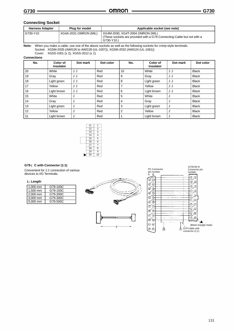
G730 G730
131
Connecting SocketHarness Adapter Plug for model Applicable socket (see note)
G730-Y10 XG4A-2031 OMRON (MIL) XG4M-2030, XG4T-2004 OMRON (MIL)(These sockets are provided with a G79 Connecting Cable but not with aG730-Y10.)
Note: When you make a cable, use one of the above sockets as well as the following sockets for crimp-style terminals.Socket: XG5M-2035 (AWG26 to AWG28 (UL-1007)), XG5M-2032 (AWG24 (UL-1061))Cover: XG5S-1001 (x 2), XG5S-2012 (x 1)
Connections
No. Color ofinsulator
Dot mark Dot color No. Color ofinsulator
Dot mark Dot color
20 White JJ Red 10 White JJ Black
19 Gray JJ Red 9 Gray JJ Black
18 Light green JJ Red 8 Light green JJ Black
17 Yellow JJ Red 7 Yellow JJ Black
16 Light brown JJ Red 6 Light brown JJ Black
15 White J Red 5 White J Black
14 Gray J Red 4 Gray J Black
13 Light green J Red 3 Light green J Black
12 Yellow J Red 2 Yellow J Black
11 Light brown J Red 1 Light brown J Black
11121314151617181920
123456789
10
G79-jC with Connector (1:1)
Convenient for 1:1 connection of variousdevices to I/O Terminals.
L: Length
1,000 mm G79-100C1,500 mm G79-150C2,000 mm G79-200C3,000 mm G79-300C5,000 mm G79-500C
PC Connectorpin numberA B
G79 Cable withconnector (1:1)
(Black triangle mark)
G730-M/-NConnector pinnumber
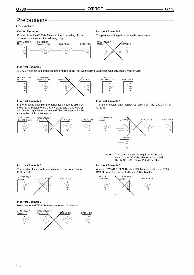
G730 G730
132
PrecautionsConnection
Correct ExampleConnect from the G730-M Master to the succeeding Units insequence as shown in the following diagram.
Incorrect Example 1The positive and negative terminals are reversed.
Incorrect Example 3In the following example, the transmission path is split fromthe G730-M Master to the G730-NOD32 and G730-VOD08,which is wrong. Connect from the G730-M Master to the thesucceeding Units in sequence.
Incorrect Example 4The transmission path cannot be split from the G730-V/R orG730-N.
Note: The same caution is required when con-necting the G730-M Master to a wiredSYSMAC BUS Remote I/O Master Unit.
Incorrect Example 5The Master Unit cannot be connected to the conventionalG71 or G72C.
Incorrect Example 6A wired SYSMAC BUS Remote I/O Master such as a C200H-RM201 cannot be connected to a G730-M Master.
Incorrect Example 7More than one G730-M Master cannot exist in a system.
+
--
+
--
+
--
+
--
+
--
+
--
+
--
+
--
+
--
+
--
G730-MOD32-AMaster
G730-NID32Expansion Unit G730-ROC04 G730-VID08
G730-MOD32-AMaster G730-VOD08
G730-NOD32Expansion Unit
G730-MOD32-AMaster G730-ROC04G730-VOD08
+
--
+
--
+
--
+
--
+
--
+
--
+
--
+
--
+
--
+
--
+
--
+
--
+
--
+
--
+
--
G730-MID32-AMaster G730-VID08
G730-VID08
G730-RID08 G730-RIA04
G730-MID32-AMaster G72C-VID16 G730-VID08
RemoteI/O Master
G730-MOD32-AMaster G730-VOD08
G730-MID32-AMaster
G730-MOD32-AMaster G730-VOD08 G730-VID08
Incorrect Example 2A G730-N cannot be connected in the middle of the line. Connect the Expansion Unit only after a Master Unit.
+
--
+
--
+
--
+
--
G730-MOD32-AMaster
G730-NOD32Expansion Unit G730-VOD08 G730-ROC0
4+
--
+
--
G730-NID32Expansion Unit G730-VID08

G730 G730
133
WiringDo not wire the cable near or in parallel with power lines.Pay attention to the polarities of the terminals.Be sure to wire the transmission path and power lines correctly.Design the whole system with the correct voltage specification forI/O exchange.Disconnect the Master Unit from the harness adapter before wiringthe Master Unit.
Screwdriver
Screwdriver
Installation SiteThe following conditions are required to install the G730.There is no direct sunlight.The ambient temperature is within a range of 0 to 55 C.The relative humidity is within a range of 10% to 90%.There is no drastic temperature changes that can cause condensa-tion.There is no corrosive or inflammable gas.There is no excessive dust, salinity, or powdered metal.No vibration or shock is directly imposed on the G730.No water, oil, or chemical is sprayed on the G730.
Protection from NoiseDo not install the G730 on a panel where high-power equipment isinstalled.Provide a distance of 200 mm at least between power lines and theG730.
Power line
200 mm min.
G730200 mmmin.
Mounting ScrewsMounting screws must be tightened securely to prevent the G730from malfunctioning.
Connection Cable LockBefore turning on the G730, check that the connectors of each con-nection cable are locked properly.
Static ElectricityExcessive static electricity can be generated where the humidity islow. Before you operate the G730, touch grounded metal so thatyour body will be free from static electricity.
CleaningUse alcohol to clean the G730. Do not use paint thinner; it will dis-solve or discolor the paint on the panel of the G730.
Dismounting Finger Protect CoverUse a screwdriver to unlock parts (1), (2), and (3).
(3)
(1)
(2)
Mounting AdapterHarness Adapter
Note: Tighten the screws securely.
G730-M/N
G730-Y10
DIN Track Adapter
Note: Mount the G730-V to the G730-Y30 so thatthe G730-V and G739-Y30 mate securelywith each other.
G730-V
G730-Y30
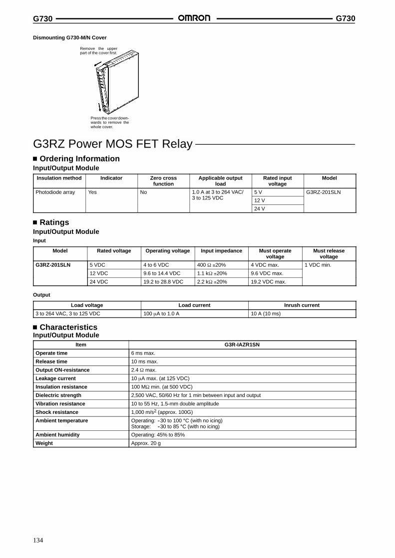
G730 G730
134
Dismounting G730-M/N Cover
Remove the upperpart of the cover first.
Press the coverdown-wards to remove thewhole cover.
G3RZ Power MOS FET RelayOrdering Information
Input/Output ModuleInsulation method Indicator Zero cross
functionApplicable output
loadRated input
voltageModel
Photodiode array Yes No 1.0 A at 3 to 264 VAC/3 12 VDC
5 V G3RZ-201SLN/3 to 125 VDC 12 V
24 V
RatingsInput/Output ModuleInput
Model Rated voltage Operating voltage Input impedance Must operatevoltage
Must releasevoltage
G3RZ-201SLN 5 VDC 4 to 6 VDC 400 τ �20% 4 VDC max. 1 VDC min.
12 VDC 9.6 to 14.4 VDC 1.1 kτ �20% 9.6 VDC max.
24 VDC 19.2 to 28.8 VDC 2.2 kτ �20% 19.2 VDC max.
Output
Load voltage Load current Inrush current
3 to 264 VAC, 3 to 125 VDC 100 ←A to 1.0 A 10 A (10 ms)
CharacteristicsInput/Output Module
Item G3R-IAZR1SN
Operate time 6 ms max.
Release time 10 ms max.
Output ON-resistance 2.4 τ max.
Leakage current 10 ←A max. (at 125 VDC)
Insulation resistance 100 Mτ min. (at 500 VDC)
Dielectric strength 2,500 VAC, 50/60 Hz for 1 min between input and output
Vibration resistance 10 to 55 Hz, 1.5-mm double amplitude
Shock resistance 1,000 m/s2 (approx. 100G)
Ambient temperature Operating: --30 to 100 C (with no icing)Storage: --30 to 85 C (with no icing)
Ambient humidity Operating: 45% to 85%
Weight Approx. 20 g
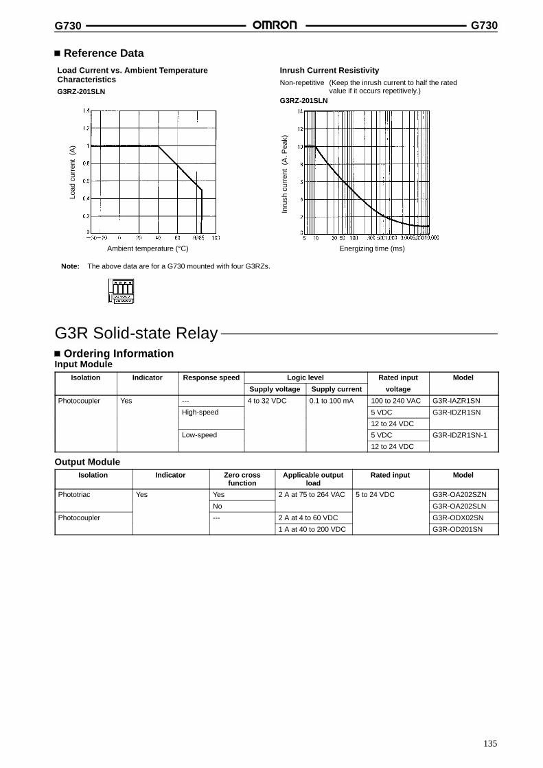
G730 G730
135
Reference DataLoad Current vs. Ambient TemperatureCharacteristicsG3RZ-201SLN
Inrush Current ResistivityNon-repetitive (Keep the inrush current to half the rated
value if it occurs repetitively.)G3RZ-201SLN
Load
curr
ent
(A)
Inru
shcu
rren
t(A
.Pea
k)
Ambient temperature (C) Energizing time (ms)
Note: The above data are for a G730 mounted with four G3RZs.
G3R Solid-state RelayOrdering Information
Input ModuleIsolation Indicator Response speed Logic level Rated input Model
Supply voltage Supply current voltage
Photocoupler Yes --- 4 to 32 VDC 0.1 to 100 mA 100 to 240 VAC G3R-IAZR1SN
High-speed 5 VDC G3R-IDZR1SNg p
12 to 24 VDC
Low-speed 5 VDC G3R-IDZR1SN-1p
12 to 24 VDC
Output ModuleIsolation Indicator Zero cross
functionApplicable output
loadRated input Model
Phototriac Yes Yes 2 A at 75 to 264 VAC 5 to 24 VDC G3R-OA202SZN
No G3R-OA202SLN
Photocoupler --- 2 A at 4 to 60 VDC G3R-ODX02SN
1 A at 40 to 200 VDC G3R-OD201SN
G730 G730
136
RatingsInput ModuleInput
Model Rated voltage Operating voltage Input current Must operatevoltage
Must releasevoltage
G3R-IAZR1SN 100 to 240 VAC 60 to 264 VAC 15 mA max. 60 VAC max. 20 VAC min.
G3R-IDZR1SN 5 VDC 4 to 6 VDC 8 mA max. 4 VDC max. 1 VDC min.
12 to 24 VDC 6.6 to 32 VDC 6.6 VDC max. 3.6 VDC min.
G3R-IDZR1SN-1 5 VDC 4 to 6 VDC 4 VDC max. 1 VDC min.
12 to 24 VDC 6.6 to 32 VDC 6.6 VDC max. 3.6 VDC min.
Output
Model Logic level supply voltage Logic level supply current
G3R-IAZR1SN 4 to 32 VDC 0.1 to 100 mA
G3R-IDZR1SN
G3R-IDZR1SN-1
Output ModuleInput
Model Rated voltage Operating voltage Input current Must operatevoltage
Must releasevoltage
G3R-OA202SZN 5 to 24 VDC 4 to 32 VDC 15 mA max.( 2 C)
4 VDC max. 1 VDC min.
G3R-OA202SLN(at 25C)
G3R-ODX02SN 8 mA max.
G3R-OD201SN
Output
Model Load voltage Load current (see note) Inrush current
G3R-OA202SZN 75 to 264 VAC 0.05 to 2 A 30 A (60 Hz, 1 cycle)
G3R-OA202SLN
G3R-ODX02SN 4 to 60 VDC 0.01 to 2 A 8 A (10 ms)
G3R-OD201SN 40 to 200 VDC 0.01 to 1.5 A 8 A (10 ms)
Note: The minimum current value is measured at 10C min..
CharacteristicsInput Module
Item G3R-IAZR1SN G3R-IDZR1SN G3R-IDZR1SN-1
Operate time 20 ms max. 0.1 ms max. 15 ms max.
Release time 20 ms max. 0.1 ms max. 15 ms max.
Response frequency 10 Hz 1 kHz 10 Hz
Output ON voltage drop 1.6 V max.
Leakage current 5 ←A max.
Insulation resistance 100 Mτ min. between input and output
Dielectric strength 4,000 VAC for 1 min between input and output
Vibration resistance 10 to 55 Hz, 1.5-mm double amplitude
Shock resistance 1,000 m/s2 (approx. 100G)
Ambient temperature Operating: --30 to 80 C (with no icing)Storage: --30 to 100 C (with no icing)
Ambient humidity Operating: 45% to 85%
Weight Approx. 18 g

G730 G730
137
Output ModuleItem G3R-OA202SZN G3R-OA202SLN G3R-ODX02SN G3R-OA201SN
Operate time 1/2 of load power source cycle + 1 ms max. 1 ms max.
Release time 1/2 of load power source cycle + 1 ms max. 2 ms max.
Response frequency 20 Hz 100 kHz
Output ON voltage drop 1.6 V max. 2.5 V max.
Leakage current 1.5 mA max. 1 mA max.
Insulation resistance 100 Mτ min. between input and output
Dielectric strength 4,000 VAC for 1 min between input and output
Vibration resistance 10 to 55 Hz, 1.5-mm double amplitude
Shock resistance 1,000 m/s2 (approx. 100G)
Ambient temperature Operating: --30 to 80 C (with no icing)Storage: --30 to 100 C (with no icing)
Ambient humidity Operating: 45% to 85%
Weight Approx. 18 g
Engineering DataLoad Current vs. Ambient TemperatureCharacteristicsG730-ZOM04 + G3R-OA202SjN G730-ZOM04 + G3R-OD201SN
(40 to 200 VDC)G730-ZOM04 + G3R-ODX02SN(4 to 60 VDC)
Ambient temperature (C)
Load
curr
ent
(A)
Ambient temperature (C)
Load
curr
ent
(A)
Ambient temperature (C)
Load
curr
ent
(A)
Inrush Current ResistivityNon-repetitive (Keep the inrush current to half the rated value if it occurs repetitively.)
G3R-OA202SjN
Inru
shcu
rren
t(A
.Pea
k)
Energizing time (ms)
Inru
shcu
rren
t(A
.Pea
k)
Energizing time (ms)
Inru
shcu
rren
t(A
.Pea
k)
Energizing time (ms)
Four points mounted Four points mounted
Four points mounted
Note: The above data are for a G730 mounted with four G3Rs.
G3R-ODX02SN G3R-OD201SN
G730 G730
138
G6D Power RelayOrdering Information
Contact form Rated coil voltage Model
SPST-NO 5 VDC G6D-1A
12 VDC
24 VDC
Coil RatingsOutput ModuleRated voltage 5 VDC 12 VDC 24 VDC
Rated current 40 mA 16.7 mA 8.3 mA
Coil resistance 125 τ 720 τ 2,880 τ
Must operate voltage (see note 1) 70% max. of rated voltage
Must release voltage 10% min. of rated voltage
Max. voltage 130% of rated voltage
Power consumption Approx. 200 mW
Note: 1. The must operate voltage is 75% or less of the rated voltage if the relay is mounted upside down.
2. Rated current and coil resistance were measured at a coil temperature of 23_C with a tolerance of 10%.3. Operating characteristics were measured at a coil temperature of 23_C.4. The maximum allowable voltage is the maximum value of the allowable voltage range for the relay coil operating power supply.
There is no continuous allowance.
CharacteristicsOutput ModuleContact resistance (see note 2) 100 mτ max.
Operate time 10 ms max.
Release time 5 ms max.
Insulation resistance 1,000 Mτ min. (at 500 VDC)
Dielectric strength 3,000 VAC, 50/60 Hz for 1 min between coil and contacts750 VAC, 50/60 Hz for 1 min between contacts of same polarity
Surge withstand voltage 6,000 V, 1.2 x 50 ←s between coil and contacts
Vibration resistance Destruction: 10 to 55 Hz, 1.5-mm double amplitudeMalfunction: 10 to 55 Hz, 1.5-mm double amplitude
Shock resistance Destruction: 1,000 m/s2
Malfunction: 100 m/s2
Life expectancy Mechanical: 20,000,000 operations min. (at 18,000 operations/hr)Electrical: 100,000 operations min. (5 A at 250 VAC, resistive load)
100,000 operations min. (5 A at 30 VDC, resistive load)300,000 operations min. (2 A at 250 VAC, resistive load)300,000 operations min. (2 A at 30 VDC, resistive load)(at 1,800 operations/hr)
Ambient temperature Operating: --25C to 70C
Ambient humidity Operating: 45% to 85%
Weight Approx. 3 g
Note: 1. The above values are initial values.
2. Measurement condition: 1 A at 5 VDC
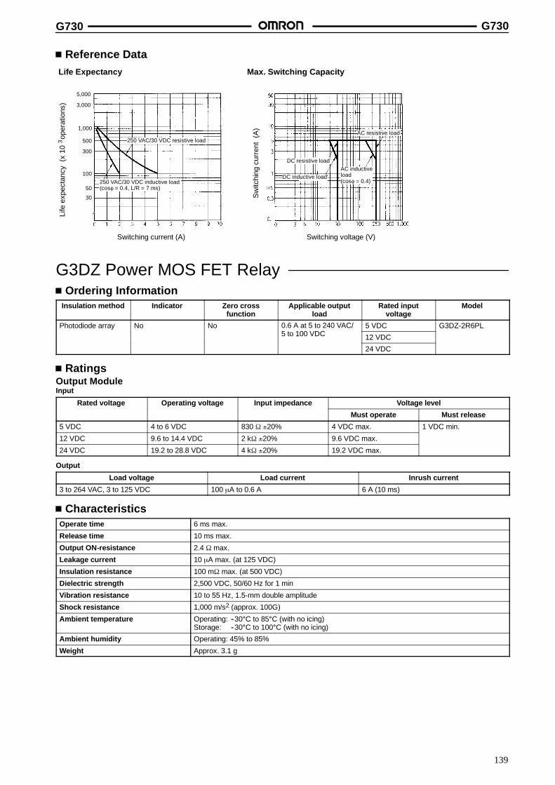
G730 G730
139
Reference DataLife Expectancy Max. Switching Capacity
Switching current (A) Switching voltage (V)
Life
expe
ctan
cy(x
10op
erat
ions
)3
Sw
itchi
ngcu
rren
t(A
)
5,000
3,000
1,000
500
300
100
50
30
250 VAC/30 VDC resistive load
250 VAC/30 VDC inductive load(cos∞ = 0.4, L/R = 7 ms)
DC resistive load
DC inductive load
AC resistive load
AC inductiveload(cos∞ = 0.4)
G3DZ Power MOS FET RelayOrdering Information
Insulation method Indicator Zero crossfunction
Applicable outputload
Rated inputvoltage
Model
Photodiode array No No 0.6 A at 5 to 240 VAC/100 VDC
5 VDC G3DZ-2R6PL/5 to 100 VDC 12 VDC
24 VDC
RatingsOutput ModuleInput
Rated voltage Operating voltage Input impedance Voltage level
Must operate Must release
5 VDC 4 to 6 VDC 830 τ �20% 4 VDC max. 1 VDC min.
12 VDC 9.6 to 14.4 VDC 2 kτ �20% 9.6 VDC max.
24 VDC 19.2 to 28.8 VDC 4 kτ �20% 19.2 VDC max.
Output
Load voltage Load current Inrush current
3 to 264 VAC, 3 to 125 VDC 100 ←A to 0.6 A 6 A (10 ms)
CharacteristicsOperate time 6 ms max.
Release time 10 ms max.
Output ON-resistance 2.4 τ max.
Leakage current 10 ←A max. (at 125 VDC)
Insulation resistance 100 mτ max. (at 500 VDC)
Dielectric strength 2,500 VDC, 50/60 Hz for 1 min
Vibration resistance 10 to 55 Hz, 1.5-mm double amplitude
Shock resistance 1,000 m/s2 (approx. 100G)
Ambient temperature Operating: --30C to 85C (with no icing)Storage: --30C to 100C (with no icing)
Ambient humidity Operating: 45% to 85%
Weight Approx. 3.1 g

G730 G730
140
Reference DataLoad Current vs. Ambient TemperatureCharacteristicsG3DZ-2R6PL
Inrush Current Resistivity
Non-repetitive (Keep the inrush current to half the rated valueif it occurs repetitively.)
G3DZ-2R6PL
Ambient temperature (C) Energizing time (ms)
Load
curr
ent
(A)
Inru
shcu
rren
t(A
.Pea
k)Note: The above data are for a G730 mounted with 8 or 16 G3DZs.
DIN Track Mounting AccessoriesMounting TrackPFP-100NPFP-50N
4.5
15 25 25 25 2510 10
1,000 (500)*
7.3+0.15
35+0.3 27+0.15
1
4.5
15 25 25 25 25 1510 10
1,000
35+0.3 27 24
16
29.2
1 1.5
PFP-100N2
End PlatesPFP-M
50
11.5M4 x 8 panhead screw
106.2
1.8
135.5 35.3
1.8
1.3
4.8
5
1612
44.334.8
16.5
SpacersPFP-S
M4 springwasher
15 (5)*
*PFP-50N
Note: Order the above parts in units of 10.
ALL DIMENSIONS SHOWN ARE IN MILLIMETERS.To convert millimeters into inches, multiply by 0.03937. To convert grams into ounces, multiply by 0.03527.
Cat. No. J94-E1-2A

141
Remote Interface G71PConnects to Standard DIN Bus
Can be combined with a G70A I/O Block to provide16 input/output points of distributed control througha two-conductor cable.
Conforms to DIN-19245.
One G71P can be connected to a maximum of 10Master Units.
Data transmission speed (baud rate) is change-able.
Easily connects to I/O devices via connector.
Either DIN-rail or screw mounting possible.
Built-in diagnostic functions provide easy trouble-shooting.
Terminator function incorporated.
Ordering InformationI/O classification I/O points Internal I/O circuit common Rated voltage Model
Contact input 16 points PNP (-- common) 24 VDC G71P-IC16-4
Transistor input G71P-ID16-4
Transistor output PNP (+ common) G71P-OD16-4
Do not connect the G7TC I/O Block to the G71P. Use the G70A (PNP output, 16 I/O points, mounting G2R relays) instead, to connect to theG71P.
Remote Interface and I/O Block CombinationsPROFIBUS Models
Application I/O block Remote Interface
AC input block 230 VAC G70A-ZIM16-5 G71P-IC16-4 24 VDC
DC input block 24 VDC G70A-ZIM16-5
Output block 24 VDC G70A-ZOC16-4 G71P-OD16-4 24 VDC
SpecificationsRatings
G71P-ID16-4/IC16-4 InputItem G71P-ID16-4 G71P-IC16-4
Rated input voltage 24 VDC
Input current 6.7 mA/points
ON delay time 1.5 ms max. 9 ms max.
OFF delay time 1.5 ms max. 14.5 ms max.
Number of circuits 16 points (8 points/common)
ON voltage 15 VDC max.
OFF voltage 5.6 VDC min.
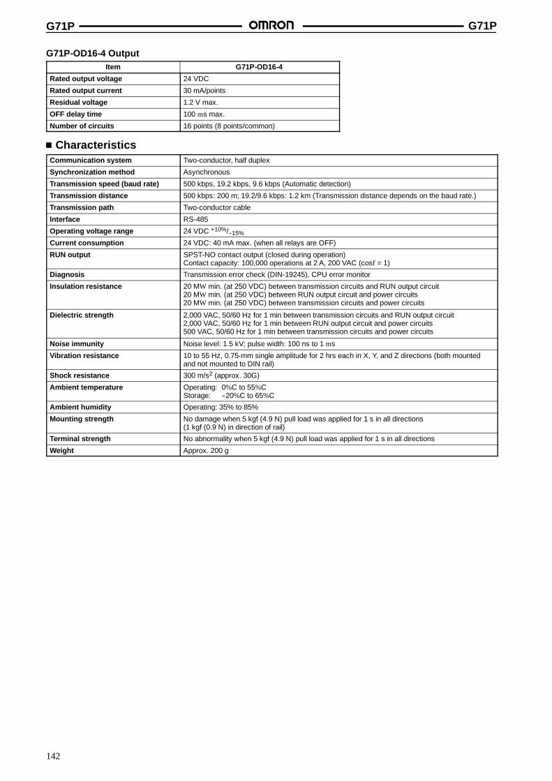
G71P G71P
142
G71P-OD16-4 OutputItem G71P-OD16-4
Rated output voltage 24 VDC
Rated output current 30 mA/points
Residual voltage 1.2 V max.
OFF delay time 100 ms max.
Number of circuits 16 points (8 points/common)
CharacteristicsCommunication system Two-conductor, half duplex
Synchronization method Asynchronous
Transmission speed (baud rate) 500 kbps, 19.2 kbps, 9.6 kbps (Automatic detection)
Transmission distance 500 kbps: 200 m; 19.2/9.6 kbps: 1.2 km (Transmission distance depends on the baud rate.)
Transmission path Two-conductor cable
Interface RS-485
Operating voltage range 24 VDC +10%/--15%
Current consumption 24 VDC: 40 mA max. (when all relays are OFF)
RUN output SPST-NO contact output (closed during operation)Contact capacity: 100,000 operations at 2 A, 200 VAC (cosf = 1)
Diagnosis Transmission error check (DIN-19245), CPU error monitor
Insulation resistance 20 MW min. (at 250 VDC) between transmission circuits and RUN output circuit20 MW min. (at 250 VDC) between RUN output circuit and power circuits20 MW min. (at 250 VDC) between transmission circuits and power circuits
Dielectric strength 2,000 VAC, 50/60 Hz for 1 min between transmission circuits and RUN output circuit2,000 VAC, 50/60 Hz for 1 min between RUN output circuit and power circuits500 VAC, 50/60 Hz for 1 min between transmission circuits and power circuits
Noise immunity Noise level: 1.5 kV; pulse width: 100 ns to 1 ms
Vibration resistance 10 to 55 Hz, 0.75-mm single amplitude for 2 hrs each in X, Y, and Z directions (both mountedand not mounted to DIN rail)
Shock resistance 300 m/s2 (approx. 30G)
Ambient temperature Operating: 0%C to 55%CStorage: --20%C to 65%C
Ambient humidity Operating: 35% to 85%
Mounting strength No damage when 5 kgf (4.9 N) pull load was applied for 1 s in all directions(1 kgf (0.9 N) in direction of rail)
Terminal strength No abnormality when 5 kgf (4.9 N) pull load was applied for 1 s in all directions
Weight Approx. 200 g
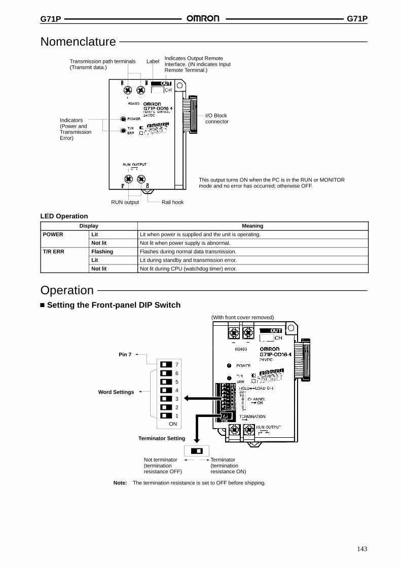
G71P G71P
143
NomenclatureTransmission path terminals(Transmit data.)
Label Indicates Output RemoteInterface. (IN indicates InputRemote Terminal.)
I/O BlockconnectorIndicators
(Power andTransmissionError)
RUN output Rail hook
This output turns ON when the PC is in the RUN or MONITORmode and no error has occurred; otherwise OFF.
LED OperationDisplay Meaning
POWER Lit Lit when power is supplied and the unit is operating.
Not lit Not lit when power supply is abnormal.
T/R ERR Flashing Flashes during normal data transmission.
Lit Lit during standby and transmission error.
Not lit Not lit during CPU (watchdog timer) error.
OperationSetting the Front-panel DIP Switch
ON
1
3
4
5
6
2
Terminator Setting
Not terminator(terminationresistance OFF)
Terminator(terminationresistance ON)
(With front cover removed)
Pin 7
Word Settings
7
Note: The termination resistance is set to OFF before shipping.
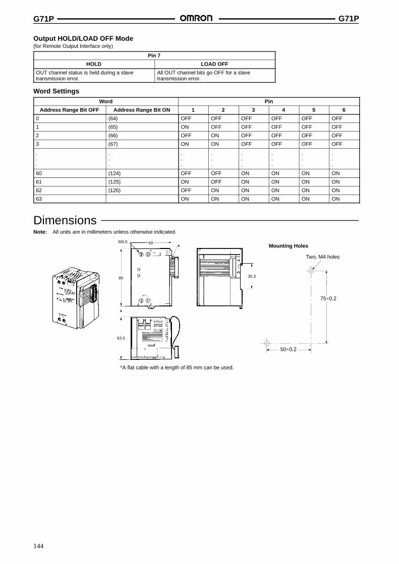
G71P G71P
144
Output HOLD/LOAD OFF Mode(for Remote Output Interface only)
Pin 7
HOLD LOAD OFF
OUT channel status is held during a slavetransmission error.
All OUT channel bits go OFF for a slavetransmission error.
Word SettingsWord Pin
Address Range Bit OFF Address Range Bit ON 1 2 3 4 5 6
0 (64) OFF OFF OFF OFF OFF OFF
1 (65) ON OFF OFF OFF OFF OFF
2 (66) OFF ON OFF OFF OFF OFF
3 (67) ON ON OFF OFF OFF OFF
.
.
.
.
.
.
.
.
.
.
.
.
.
.
.
.
.
.
.
.
.
.
.
.
60 (124) OFF OFF ON ON ON ON
61 (125) ON OFF ON ON ON ON
62 (126) OFF ON ON ON ON ON
63 ON ON ON ON ON ON
DimensionsNote: All units are in millimeters unless otherwise indicated.
Two, M4 holes
75+0.2
50+0.2
Mounting Holes
*A flat cable with a length of 85 mm can be used.
M3.5 60
85
63.5
35.3
*
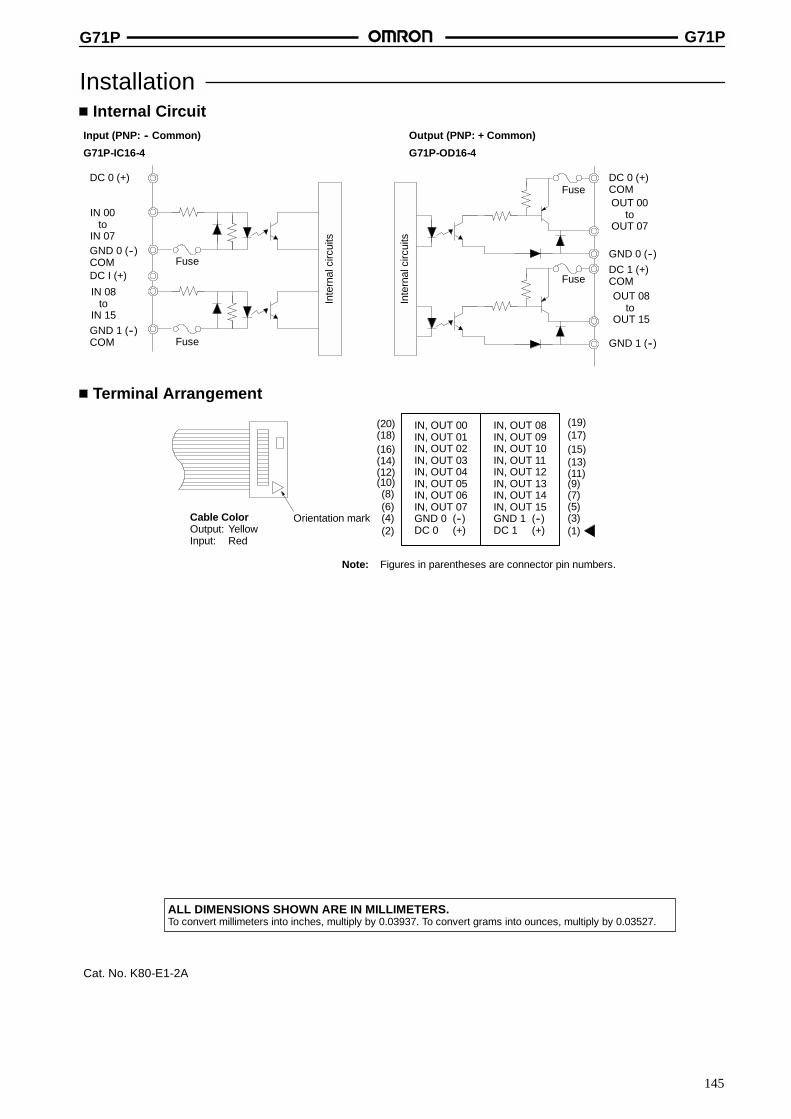
G71P G71P
145
InstallationInternal Circuit
Input (PNP: -- Common)
G71P-IC16-4
Output (PNP: + Common)
G71P-OD16-4
OUT 08to
OUT 15
GND 1 (--)
GND 0 (--)
Fuse
IN 00to
IN 07GND 0 (--)COMDC I (+)
IN 08to
IN 15GND 1 (--)COM
DC 0 (+)
Fuse
FuseIn
tern
alci
rcui
ts
Inte
rnal
circ
uits
OUT 00to
OUT 07
DC 1 (+)COM
DC 0 (+)COMFuse
Terminal Arrangement
Cable ColorOutput: YellowInput: Red
Orientation mark
IN, OUT 00IN, OUT 01IN, OUT 02IN, OUT 03IN, OUT 04IN, OUT 05IN, OUT 06IN, OUT 07GND 0 (--)DC 0 (+)
IN, OUT 08IN, OUT 09IN, OUT 10IN, OUT 11IN, OUT 12IN, OUT 13IN, OUT 14IN, OUT 15GND 1 (--)DC 1 (+)(2)
(4)(6)(8)
(10)(12)(14)
(20)
(1)(3)(5)(7)(9)(11)(13)(15)(17)(19)
(16)(18)
Note: Figures in parentheses are connector pin numbers.
ALL DIMENSIONS SHOWN ARE IN MILLIMETERS.To convert millimeters into inches, multiply by 0.03937. To convert grams into ounces, multiply by 0.03527.
Cat. No. K80-E1-2A