Electric Actuators - LEY Series - SMC CORPORATION
141
Rod Type LEY Series Guide Rod Type LEYG Series Drivers Long stroke: Max. 500 mm (LEY32, 40) Lateral end load: 5 times more *1 Compatible with sliding bearings and ball bushing bearings Compatible with moment loads and stoppers (sliding bearings) • Either positioning or pushing control can be selected. It is possible to hold the actuator with the rod pushing a workpiece, etc. • High-output motor (100/200/400 W) •Improved high-speed transfer ability • High acceleration/deceleration compatible (5000 mm/s 2 ) • Pulse input/CC-Link/SSCNET# types • With internal absolute encoder (For the LECSB/C/S-T) Rod Type LEY Series Guide Rod Type LEYG Series Mounting variations •Direct mounting: 3 directions, Bracket mounting: 3 types • Either positioning or pushing control can be selected. It is possible to hold the actuator with the rod pushing a workpiece, etc. *1 Compared with the rod type, size 25, and 100 mm stroke Size: 16, 25, 32, 40 Size: 16, 25, 32, 40 Size: 25, 32, 63 Size: 25, 32 Controllers/ Drivers p. 299 p. 367 p. 373, 378 p. 305, 312 p. 684 p. 764 p. 608 Rod type/ In-line motor type Guide rod type Rod type Auto switch mountable Guide rod type/ In-line motor type Guide rod type Guide rod type/ In-line motor type Rod type Rod type/ In-line motor type * Size: 25, 32 * The X5 is not UL compliant. Step Motor (Servo/24 VDC) Servo Motor (24 VDC) sStep data input type JXC51/61/LECA6 Series (64 positioning points) sProgramless type LECP1 Series (14 positioning points) sEtherCAT ® /EtherNet/IP™/PROFINET/ DeviceNet™/IO-Link/CC-Link direct input type JXCE1/91/P1/D1/L1/M1 Series sPulse input type LECPA Series AC Servo Motor Dust-tight/Water-jet-proof (IP65 Equivalent): -X5 Dust-tight/Water-jet-proof (IP65 Equivalent): -X5 Step Motor (Servo/24 VDC) Servo Motor (24 VDC) AC Servo Motor sFor incremental encoders ¡Pulse input type/ Positioning type LECSA Series sFor absolute encoders ¡Pulse input type LECSB-T Series ¡CC-Link direct input type LECSC-T Series ¡SSCNET3 type LECSS Series ¡SSCNET3/H type LECSS-T Series ¡Network card type LECSN-T Series ¡MECHATROLINK type LECY Series * The X5 is not UL compliant. The LECSB-S, LECSC-S, and LECSS-S electric actuator drivers are to be discontinued. Please select one of the substitute drivers ending with a “-T” instead: the LECSB-T, LECSC-T, and LECSS-T. Electric Actuators Rod Type / Guide Rod Type LEY Series RoHS ® Click here for details. Click here for details. 290 LEFS LEFB LEL LEJS LEJB LEM LEY LEYG LES LESH LEPY LEPS LER LEH LEY-X5 11-LEFS 11-LEJS 25A- Motorless LECY LECS LECS-T JXC LEC LAT3 F
-
Upload
khangminh22 -
Category
Documents
-
view
3 -
download
0
Transcript of Electric Actuators - LEY Series - SMC CORPORATION

Rod Type LEY Series Guide Rod Type LEYG Series
Drivers
Long stroke:Max. 500 mm (LEY32, 40)
Lateral end load: 5 times more∗1
Compatible with sliding bearings and ball bushing bearingsCompatible with moment loads and stoppers (sliding bearings)•Either positioning or pushing control can be selected.
It is possible to hold the actuator with the rod pushing a workpiece, etc.
•High-output motor (100/200/400 W)• Improved high-speed transfer ability•High acceleration/decelerationcompatible (5000 mm/s2)
•Pulse input/CC-Link/SSCNET# types•With internal absolute encoder (For the LECSB/C/S-T)
Rod Type LEY Series
Guide Rod Type LEYG Series
Mounting variations•Direct mounting: 3 directions, Bracket mounting: 3 types•Either positioning or pushing control can be selected.
It is possible to hold the actuator with the rod pushing a workpiece, etc.
∗1 Compared with the rod type, size 25, and 100 mm stroke
Size: 16, 25, 32, 40
Size: 16, 25, 32, 40
Size: 25, 32, 63 Size: 25, 32
Controllers/Drivers
�p. 299
�p. 367
�p. 373, 378�p. 305, 312
�p. 684�p. 764
�p. 608
Rod type/In-line motor type
Guide rod type
Rod typeAuto switch mountable
Guide rod type/In-line motor type
Guiderod type
Guide rod type/In-line motor type
Rod type
Rod type/In-line motor type
∗ Size: 25, 32∗ The X5 is not UL compliant.
Step Motor (Servo/24 VDC) Servo Motor (24 VDC)
sStep data input typeJXC51/61/LECA6 Series (64 positioning points)
sProgramless typeLECP1 Series (14 positioning points)
sEtherCAT®/EtherNet/IP™/PROFINET/DeviceNet™/IO-Link/CC-Link direct input typeJXCE1/91/P1/D1/L1/M1 Series
sPulse input typeLECPA Series
AC Servo Motor
Dust-tight/Water-jet-proof (IP65 Equivalent): -X5
Dust-tight/Water-jet-proof (IP65 Equivalent): -X5
Step Motor (Servo/24 VDC)
Servo Motor (24 VDC) AC Servo Motor
sFor incremental encoders
¡Pulse input type/Positioning typeLECSA Series
sFor absolute encoders¡Pulse input type
LECSB-T Series
¡CC-Link direct input typeLECSC-T Series
¡SSCNET3 typeLECSS Series
¡SSCNET3/H typeLECSS-T Series
¡Network card typeLECSN-T Series
¡MECHATROLINK typeLECY � Series
∗ The X5 is not UL compliant.
The LECSB-S, LECSC-S, and LECSS-S electric actuator drivers are to be discontinued. Please select one of the substitute drivers ending with a “-T” instead: the LECSB-T, LECSC-T, and LECSS-T.
Electric Actuators
Rod Type / Guide Rod Type
LEY Series RoHS
®
Click here for details. Click here for details.
290
LE
FS
LE
FB
LE
LL
EJS
LE
JBL
EM
LE
YL
EY
GL
ES
LE
SH
LE
PY
LE
PS
LE
RL
EH
LEY-
X511
-LEF
S11
-LEJ
S25
A-
Moto
rless
LEC
Y�LE
CS
�LE
CS�-
TJX
C�
LE
C�
LA
T3
F

Equipped with scrapersas standard
Prevents foreign matterfrom entering the device
Singleknuckle joint
Simplejoint
Double knuckle joint
For manual piston rod operationAdjustment operation is possiblewhen the power is OFF.
�Standard cable�Robotic cable (Flexible cable)
Select from 2 types of actuator cables.
Rod Type LEY Series/Size: 16, 25, 32, 40
�Step motor (Servo/24 VDC)Ideal for the low-speed transfer of heavy loads and pushing operations
�Servo motor (24 VDC)Stable at high speedsSilent operation
Prevents workpiecesfrom dropping (Holding)
Right sideparallel type
Left sideparallel type
In-linemotor type
Selectable motor mounting position
Scraper
Rod end brackets
Motor top mounting type
Red Green Red
Optimum operating range
Operating range OFFON
2-color indicator solid state auto switchAppropriate setting of themounting position can beperformed without mistakes.
Motor cover available(Option)
Non-magnetizinglock mechanism (Option)
Speed
Wor
k lo
ad
Step motor
Servo motorSelect from 2 types of motors.
Step Motor (Servo/24 VDC) Servo Motor (24 VDC)
Auto switch
p. 361, 362 For checking the limit and the intermediate signalApplicable to the D-M9�, D-M9�E, and D-M9�W (2-color indicator)∗ The auto switches should be ordered separately. Refer to pages 363 to 365 for details.
A green light
lights up at theoptimum operatingrange.
Manual override screw∗ The cover has an opening.
Mounting groove for auto switches
Control of intermediate positioning and pushing is possible.High precision with ball screws(Positioning repeatability: ±0.02 mm)
Rod Type LEY Series/Guide Rod Type LEYG Series
291

Rod Type LEY Series/Size: 25, 32, 63
Speed
Wor
k lo
ad Step motor
AC servo motor
Servo motor
�High-output motor (100/200/400 W)�Improved high-speed transfer ability�High acceleration/deceleration compatible (5000 mm/s2)�Pulse input/CC-Link direct input/SSCNET 3 types�With internal absolute encoder
∗ An incremental encoder can also be selected.
�Positioning repeatability: ±0.01 mm (High-precision type)
AC Servo Motor
Large bore size 63Selectable motor mounting position (4 directions)
Horizontal
Vertical
In-lineTop mounting Right side parallel Left side parallel
¡Max. work load [kg]
¡Max. force [N]
¡High-output motor: 400 w
¡Max. speed: 1000 mm/s ∗ 500 mm stroke
¡Dust-tight/Water-jet-proof specification (IP65 equivalent)∗ Option
Top/Parallel In-line
200 80
115 72
Top/Parallel 3343
In-line 1910
Rod Type LEY Series/Guide Rod Type LEYG Series
Rod type
Rod type/In-line motor type
292
LE
FS
LE
FB
LE
LL
EJS
LE
JBL
EM
LE
YL
EY
GL
ES
LE
SH
LE
PY
LE
PS
LE
RL
EH
LEY-
X511
-LEF
S11
-LEJ
S25
A-
Moto
rless
LEC
Y�LE
CS
�LE
CS�-
TJX
C�
LE
C�
LA
T3

When the cylinder is retracted (initial value), the non-rotating accuracy without a load and without deflection of the guide rods will be below the values shown in the table above.
Bore size [mm]
Sliding bearings
Ball bushing bearings
±0.06°
±0.05°
16 25
±0.05°
±0.04°
32 40
Compact, integrated guide rodsLateral load resistance andhigh non-rotating accuracy
Direct Mounting
Head end Rod end
Body bottom
Bracket Mounting
Head flange Double clevis
∗ Body bottom tapped
Application Examples
For lifters
For delivery Forrotation
For pushingoperations
For press fitting
For stoppers
Improved rigidityLateral end load: 5 times more∗1
∗1 Compared with the rod type, size 25, and 100 mm stroke
Non-rotating accuracy improved by using two guide rods
Guide Rod Type LEYG Series/Size: 16, 25, 32, 40
�Sliding bearingsSuitable for lateral load applications such as when using a stopper where impact is applied
�Ball bushing bearingsSmooth operation suitable forpushers and lifters
Compatible with sliding bearings and ball bushing bearings
Motor top mounting type
In-line motor type
Step Motor (Servo/24 VDC) Servo Motor (24 VDC)
Guide Rod Type LEYG Series/Size: 25, 32
Foot Rod flange
Mounting Variations
AC Servo Motor
Guide rod typeGuide rod type/
In-line motor type
When using auto switches for the guide rod type LEYG series, refer to page 414.
Rod Type LEY Series/Guide Rod Type LEYG Series
293

�Enclosure: IP65 equivalent (Refer to page 607.)
�Max. stroke: 500 mm∗1
∗1 For size 32
Lube-retainer (Excludes the LEY63)
Retains grease oil film
Scraper
Prevents dust and water droplets from entering between the cable and motor cover
Top mountingtype
In-line motor type
Top mounting type
In-line motor type
LEY-X5 (Refer to page 608.)
LEY-X5 (Refer to page 305.)
AC Servo Motor (100/200 W)
Step Motor (Servo/24 VDC)
Servo Motor (24 VDC)
Seal connector
Protects the motor
Aluminum cover
Reduces internal pressure fluctuations in order to prevent dust and water droplets from entering the device∗ Be sure to attach tubing and place
the end of the tubing so it is not exposed to dust or water.
∗ For size 63, order a fitting separately.
Vent hole
Mounting groove for auto switches
25, 32
Size LEY63���-�P(Refer to page 305./Option)
AC Servo Motor (400 W)
63
Size
In-line
Top mounting
Right side parallel
Left side parallel
Tubing∗ Order the tubing
separately.
Water-resistant type For checking the limit and the intermediate signal∗ Order the water-resistant 2-color
indicator solid state auto switch separately. (Refer to page 630.)
Dust-tight/Water-jet-proof (IP65 Equivalent)
Rod Type LEY Series/Guide Rod Type LEYG Series
294
LE
FS
LE
FB
LE
LL
EJS
LE
JBL
EM
LE
YL
EY
GL
ES
LE
SH
LE
PY
LE
PS
LE
RL
EH
LEY-
X511
-LEF
S11
-LEJ
S25
A-
Moto
rless
LEC
Y�LE
CS
�LE
CS�-
TJX
C�
LE
C�
LA
T3

Electric Actuator/Rod Type LEY Series
INDEX
Rod Type LEY Series
Model Selection ········································································································································· p. 299How to Order ·············································································································································· p. 319Specifications ············································································································································· p. 323Construction ··············································································································································· p. 325Dimensions ················································································································································· p. 327Accessory Mounting Brackets ············································································································· p. 361
Step Motor (Servo/24 VDC)
Step Motor (Servo/24 VDC)
Servo Motor (24 VDC)
LECYm Series
Rod Type LEY Series
Model Selection ········································································································································· p. 312How to Order ·············································································································································· p. 351Specifications ············································································································································· p. 353Construction ··············································································································································· p. 355Dimensions ················································································································································· p. 356
Model Selection ········································································································································· p. 305How to Order ·············································································································································· p. 333Specifications ············································································································································· p. 335Construction ··············································································································································· p. 337Dimensions ················································································································································· p. 338
Rod Type LEY Series
LECSm Series
AC Servo Motor
AC Servo Motor
25, 32Size
Model Selection ········································································································································· p. 305How to Order ·············································································································································· p. 343Specifications ············································································································································· p. 344Construction ··············································································································································· p. 345Dimensions ················································································································································· p. 346
Rod Type LEY Series * Option63Size
Electric Actuator/Guide Rod Type LEYG Series
Guide Rod Type LEYG Series
Model Selection ········································································································································· p. 367How to Order ·············································································································································· p. 383Specifications ············································································································································· p. 387Construction ··············································································································································· p. 389Dimensions ················································································································································· p. 391Support Block ············································································································································· p. 395
Model Selection ········································································································································· p. 373How to Order ·············································································································································· p. 397Specifications ············································································································································· p. 399Construction ··············································································································································· p. 400Dimensions ················································································································································· p. 401Support Block ············································································································································· p. 403
Guide Rod Type LEYG Series
LECSm Series
LECYm Series
Guide Rod Type LEYG Series
Model Selection ········································································································································· p. 378How to Order ·············································································································································· p. 405Specifications ············································································································································· p. 407Construction ··············································································································································· p. 408Dimensions ················································································································································· p. 409Support Block ············································································································································· p. 411
Dust-tight/Water-jet-proof (IP65 Equivalent)
Servo Motor (24 VDC)
Auto Switch ··············································································································································································· p. 363
295

Step Motor (Servo/24 VDC)/ Servo Motor (24 VDC) Controller/DriverStep Data Input Type/JXC51/61 ………………………… p. 706-1Step Data Input Type/LECA6 Series …………………… p. 707Gateway Unit/LEC-G Series ………………………………… p. 715Programless Controller/LECP1 Series ………………… p. 719Pulse Input Type/LECPA Series …………………………… p. 731EtherCAT®/EtherNet/IP™/PROFINET/DeviceNet™/IO-Link
Direct Input Type/JXCE1/91/P1/D1/L1 Series …… p. 741
4-Axis Step Motor (Servo/24 VDC) ControllerParallel I/O Type/JXC73/83 Series ……………………… p. 749EtherNet/IP™ Type/JXC93 Series ……………………… p. 749
Rod Type LEY-X5 (Made to Order)Model Selection ………………………………………………………………………………………………… p. 608How to Order …………………………………………………………………………………………………… p. 611Specifications …………………………………………………………………………………………………… p. 614Construction ……………………………………………………………………………………………………… p. 616Dimensions ……………………………………………………………………………………………………… p. 617
Model Selection ………………………………………………………………………………………………… p. 305How to Order …………………………………………………………………………………………………… p. 619Specifications …………………………………………………………………………………………………… p. 621Construction ……………………………………………………………………………………………………… p. 622Dimensions ……………………………………………………………………………………………………… p. 623
LECSm Series
Rod Type LEY-X5 (Made to Order)
Model Selection ………………………………………………………………………………………………… p. 312How to Order …………………………………………………………………………………………………… p. 625Specifications …………………………………………………………………………………………………… p. 627Dimensions ……………………………………………………………………………………………………… p. 628
LECYm Series
Rod Type LEY-X5 (Made to Order)
Secondary Battery CompatibleRod Type 25A-LEY
EnvironmentStep Motor (Servo/24 VDC)
Step Motor (Servo/24 VDC)
AC Servo Motor
AC Servo Motor
Dust-tight/Water-jet-proof (IP65 Equivalent)
Dust-tight/Water-jet-proof (IP65 Equivalent)
Dust-tight/Water-jet-proof (IP65 Equivalent)
Servo Motor (24 VDC)
Servo Motor (24 VDC)
Model Selection …………………………………………………………………………………… p. 299, 305, 312How to Order ……………………………………………………………………………………… p. 673, 677, 679
Specific Product Precautions …………………………………………………………………………………………………………………………………………… p. 412
Auto Switch ………………………………………………………………………………………………………………………………………………………………… p. 630
3-Axis Step Motor Controller
AC Servo Motor Driver
EtherNet/IP™ Type/JXC92 Series ……………………… p. 747
LECSA Series ……………………………………………………… p. 777LECSB-T/LECSC-T/LECSS-T Series …………………… p. 777LECSN-T Series ……………………………………………… 20-E763LECYM/LECYU Series ………………………………………… p. 801
Actuator Cable ……………………………………………… p. 758Communication Cable for Controller Setting/LEC-W2A-m …… p. 760Teaching Box/LEC-T1 …………………………………… p. 761
296
LE
FS
LE
FB
LE
LL
EJS
LE
JBL
EM
LE
YL
EY
GL
ES
LE
SH
LE
PY
LE
PS
LE
RL
EH
LEY-
X511
-LEF
S11
-LEJ
S25
A-
Moto
rless
LEC
Y�LE
CS
�LE
CS�-
TJX
C�
LE
C�
LA
T3
D

297

AC Servo Motor Driver
Step Motor/Servo Motor Controller/Driver p. 684
p. 764
p. 319
p. 611
p. 673
p. 619
p. 343
Environment
25A-LEY
25A-LEY
Motor top/parallel type
In-line motor type
LEY-X5 (Made to order) LEY25/32-X5 (Made to order)
Motor top mounting type
In-line motor typeIn-line motor type
Motor top mounting type
Motor top/parallel type
Motor top/parallel type
In-line motor type
In-line motor type
Motor top/parallel type
In-line motor type
p. 333, 351
p. 677, 679
LEY63mmm-mP (Option)
Dust-tight/Water-jet-proof (IP65 Equivalent) Dust-tight/Water-jet-proof (IP65 Equivalent)
Secondary Battery Compatible
Secondary Battery Compatible
Step Motor (Servo/24 VDC) Servo Motor (24 VDC)
Step Motor (Servo/24 VDC) Servo Motor (24 VDC)
AC Servo Motor
AC Servo Motor
298
LEY Series
Rod TypeElectric Actuators
LE
FS
LE
FB
LE
LL
EJS
LE
JBL
EM
LE
YL
EY
GL
ES
LE
SH
LE
PY
LE
PS
LE
RL
EH
LEY-
X511
-LEF
S11
-LEJ
S25
A-
Moto
rless
LEC
Y�LE
CS
�LE
CS�-
TJX
C�
LE
C�
LA
T3

T1
a1 a2
L
Spe
ed: V
[mm
/s]
Time [s]
T2 T3 T4
W
Wor
k lo
ad [k
g]
Speed [mm/s]
10
8
6
4
2
00 300200 400100 500 600
Lead 5: LEY16B
Lead 10: LEY16A
Lead 2.5: LEY16C
Step 1 Check the work load–speed. <Speed–Vertical work load graph>
Step 2 Check the cycle time.
Workpiece mass: 4 [kg] Speed: 100 [mm/s]
Acceleration/Deceleration: 3000 [mm/s2]
Stroke: 200 [mm]
Workpiece mounting condition: Vertical upwarddownward transfer
Operatingconditions
Selection Procedure
Positioning Control Selection Procedure
Selection Example
Step 1Check the work load–speed.(Vertical transfer) Step 2 Check the cycle time.
Calculate the cycle time using the following calculation method.
Cycle time:T can be found from the following equation.
Select a model based on the workpiece mass and speed while referencing the speed–vertical work load graph.
Selection example) The LEY16B can be temporarily selected as a possible candidate based on the graph shown on the right side.
T = T1 + T2 + T3 + T4 [s]
T1 = V/a1 [s]
T4 = 0.2 [s]
T3 = V/a2 [s]
T2 = [s]L − 0.5 · V · (T1 + T3)
V
T4: Settling time varies depending on the conditions such as motor types, load and in position of the step data. Therefore, calculate the settling time while referencing the following value.
T2: Constant speed time can be found from the following equation.
T1: Acceleration time and T3: Deceleration time can be found by the following equation.
L : Stroke [mm] ⋅⋅⋅ (Operating condition)V : Speed [mm/s] ⋅⋅⋅ (Operating condition)a1: Acceleration [mm/s2] ⋅⋅⋅ (Operating condition)a2: Deceleration [mm/s2] ⋅⋅⋅ (Operating condition)
T1: Acceleration time [s] ⋅⋅⋅ Time until reaching the set speedT2: Constant speed time [s] ⋅⋅⋅ Time while the actuator is
operating at a constant speedT3: Deceleration time [s] ⋅⋅⋅ Time from the beginning of the
constant speed operation to stopT4: Settling time [s] ⋅⋅⋅ Time until positioning is completed
Calculation example)T1 to T4 can be calculated as follows.
T1 = V/a1 = 100/3000 = 0.033 [s], T3 = V/a2 = 100/3000 = 0.033 [s]
T4 = 0.2 [s]
The cycle time can be found as follows.T = T1 + T2 + T3 + T4 = 0.033 + 1.967 + 0.033 + 0.2 = 2.233 [s]
T2 = = = 1.97 [s]L − 0.5 · V · (T1 + T3)
V
200 − 0.5 · 100 · (0.033 + 0.033)
100
<Speed–Vertical work load graph>(LEY16/Step motor)
Based on the above calculation result, the LEY16B-200 should be selected.
* It is necessary to mount a guide outside the actuator when used for horizontal transfer. When selecting the target model, refer to the horizontal work load in the specifications on pages 323 and 324 and the precautions.
Step Motor (Servo/24 VDC) Servo Motor (24 VDC)
Electric Actuator/Rod Type Secondary Battery Compatible
LEY/25A-LEY Series
Model SelectionLEY Seriessp. 319 25A-LEY Seriessp. 673
299

B
Pushing control
AP
ositi
on
Time
Jig
Load
: F [N
]
Stroke [mm]0 100 200 300 400 500 600
100
10
1
LEY32�
LEY25�
LEY16
Duty ratio = A/B x 100 [%]
*1 Set values for the controller
<Graph of allowable lateral load on the rod end>
Step 1 Check the duty ratio.<Conversion table of pushing force–duty ratio>
Step 2 Check the pushing force. <Force conversion graph>
Mounting condition: Horizontal (pushing) Duty ratio: 20 [%]
Jig weight: 0.2 [kg] Speed: 100 [mm/s]
Pushing force: 60 [N] Stroke: 200 [mm]
Operatingconditions
Pushing Control Selection Procedure
Selection Example
Step 1 Check the duty ratio. Check the lateral load on the rod end.
Step 2 Check the pushing force.
Select a model based on the pushing force set value and force while referencing the force conversion graph.
Selection example)Based on the graph shown on the right side,Pushing force set value: 70 [%]Pushing force: 60 [N]The LEY16B can be temporarily selected as a possible candidate.
Step 3 Check the lateral load on the rod end.<Graph of allowable lateral load on the rod end>Confirm the allowable lateral load on the rod end of the actuator:LEY16, which has been selected temporarily while referencing the graph of allowable lateral load on the rod end.
Selection example)Based on the graph shown on the right side,Jig weight: 0.2 [kg] ≈ 2 [N]Product stroke: 200 [mm]The lateral load on the rod end is in the allowable range.
Select the [Pushing force] from the duty ratio while referencing the conversion table of pushing force–duty ratio.
Selection example)Based on the table below, Duty ratio: 20 [%]The pushing force set value will be 70 [%].
Step 3
* The duty ratio is a ratio of the operation time in one cycle.
* [Pushing force set value] is one of the step data input to the controller.* [Continuous pushing time] is the time that the actuator can continuously keep pushing.
<Force conversion graph>(LEY16/Step motor)
<Conversion table of pushing force–duty ratio>(LEY16/Step motor)
Based on the above calculation result, the LEY16B-200 should be selected.
For
ce [N
]
Pushing force set value [%] ∗1
160
140
120
100
80
60
40
20
00 60%40% 80%20% 100%
Max. 85%
Lead 2.5: LEY16C
Lead 5: LEY16B
Lead 10: LEY16A
Pushing forceset value [%]
Duty ratio[%]
Continuouspushing time [min]
40 or less 100 —
50 70 12
70 20 1.3
85 15 0.8
Selection Procedure
300
Model Selection LEY/25A-LEY SeriesStep Motor (Servo/24 VDC) Servo Motor (24 VDC) Secondary Battery Compatible
LE
FS
LE
FB
LE
LL
EJS
LE
JBL
EM
LE
YL
EY
GL
ES
LE
SH
LE
PY
LE
PS
LE
RL
EH
LEY-
X511
-LEF
S11
-LEJ
S25
A-
Moto
rless
LEC
Y�LE
CS
�LE
CS�-
TJX
C�
LE
C�
LA
T3

Hor
izon
tal w
ork
load
[kg]
Speed [mm/s]
0
5
106
1517202325
30
35
40
0 300200 400100 500 600
Lead 2.5: LEY16C
Lead 5: LEY16B
Lead 10: LEY16A
Hor
izon
tal w
ork
load
[kg]
Speed [mm/s]
0
10
20
30
40
505560
70
80
0 300200 400100 500 600
Lead 3: LEY25C
Lead 6: LEY25B
Lead 12: LEY25A
Hor
izon
tal w
ork
load
[kg]
Speed [mm/s]
0
10
20
30
404550
60
70
80
90
0 300200 400100 500 600
Lead 4: LEY32C
Lead 8: LEY32B
Lead 16: LEY32A
Hor
izon
tal w
ork
load
[kg]
Speed [mm/s]
0
20
40
50
60
80
70
90
100
0 300 400 500200100 600
Lead 4: LEY40C
Lead 8: LEY40B
Lead 16: LEY40A
0
2
4
5
8
10
Ver
tical
wor
k lo
ad [k
g]
Speed [mm/s]
0 300200 400100 500 600
Lead 2.5: LEY16C
Lead 5: LEY16B
Lead 10: LEY16A
0
10
16
8
20
30
35V
ertic
al w
ork
load
[kg]
Speed [mm/s]
0 300200 400100 500 600
Lead 3: LEY25C
Lead 6: LEY25B
Lead 12: LEY25A
0
10
20
11
22
30
4043
50
Ver
tical
wor
k lo
ad [k
g]
Speed [mm/s]
0 300200 400100 500 600
Lead 4: LEY32C
Lead 8: LEY32B
Lead 16: LEY32A
0
20
27
13
40
53
60
Ver
tical
wor
k lo
ad [k
g]
Speed [mm/s]
0 300200100 600400 500
Lead 4: LEY40C
Lead 8: LEY40B
Lead 16: LEY40A
Horizontal Vertical
LEY16m
LEY25m
LEY32m LEY32m
LEY40m LEY40m
LEY25m
LEY16m
Speed–Work Load Graph (Guide)For Step Motor (Servo/24 VDC) JXCm1, LECP1
for acceleration/deceleration: 2000 mm/s2
for acceleration/deceleration: 2000 mm/s2
for acceleration/deceleration: 2000 mm/s2
for acceleration/deceleration: 2000 mm/s2
Refer to page 302 for the LECPA, JXCm23
and page 303 for the LECA6.
301
LEY/25A-LEY SeriesStep Motor (Servo/24 VDC) Servo Motor (24 VDC) Secondary Battery Compatible
A

Hor
izon
tal w
ork
load
[kg]
Speed [mm/s]
0
54
1011
6
151720
25
30
35
40
0 300200 400100 500 600
Lead 2.5: LEY16C
Lead 5: LEY16B
Lead 10: LEY16A
Hor
izon
tal w
ork
load
[kg]
Speed [mm/s]
0
10
201812
30
40
50
60
70
80
0 300200 400100 500 600
Lead 3: LEY25C
Lead 6: LEY25B
Lead 12: LEY25A
Hor
izon
tal w
ork
load
[kg]
Speed [mm/s]
0
10
20
30
40
50
60
70
80
90
0 300200 400100 500 600
Lead 4: LEY32C
Lead 8: LEY32B
Lead 16: LEY32A
Hor
izon
tal w
ork
load
[kg]
Speed [mm/s]
0
20
30
40
60
80
100
0 300 400 500200100 600
Lead 4: LEY40CLead 8: LEY40B
Lead 16: LEY40A
Ver
tical
wor
k lo
ad [k
g]
Speed [mm/s]
0
5
8
4
2
10
0 300200 400100 500 600
Lead 2.5: LEY16C
Lead 5: LEY16B
Lead 10: LEY16A
Ver
tical
wor
k lo
ad [k
g]
Speed [mm/s]
0
108
16
20
30
35
0 300200 400100 500 600
Lead 3: LEY25C
Lead 6: LEY25B
Lead 12: LEY25A
Ver
tical
wor
k lo
ad [k
g]
Speed [mm/s]
0
10
20
30
4043
22
11
50
0 300200 400100 500 600
Lead 4: LEY32C
Lead 8: LEY32B
Lead 16: LEY32A
Ver
tical
wor
k lo
ad [k
g]
Speed [mm/s]
0
20
40
53
27
13
60
0 300 400 500200100 600
Lead 4: LEY40C
Lead 8: LEY40B
Lead 16: LEY40A
Horizontal Vertical
LEY16m
LEY25m
LEY32m LEY32m
LEY40m LEY40m
LEY25m
LEY16m
Speed–Work Load Graph (Guide)For Step Motor (Servo/24 VDC) LECPA, JXCm2
3
for acceleration/deceleration: 2000 mm/s2
for acceleration/deceleration: 2000 mm/s2
for acceleration/deceleration: 2000 mm/s2
Refer to page 301 for the JXCm1, LECP1 and page 303 for the LECA6.
302
Model Selection LEY/25A-LEY SeriesStep Motor (Servo/24 VDC) Servo Motor (24 VDC) Secondary Battery Compatible
LE
FS
LE
FB
LE
LL
EJS
LE
JBL
EM
LE
YL
EY
GL
ES
LE
SH
LE
PY
LE
PS
LE
RL
EH
LEY-
X511
-LEF
S11
-LEJ
S25
A-
Moto
rless
LEC
Y�LE
CS
�LE
CS�-
TJX
C�
LE
C�
LA
T3
A
Hor
izon
tal w
ork
load
[kg]
Speed [mm/s]
0
3
6
9
12
15
0 300200 400100 500 600
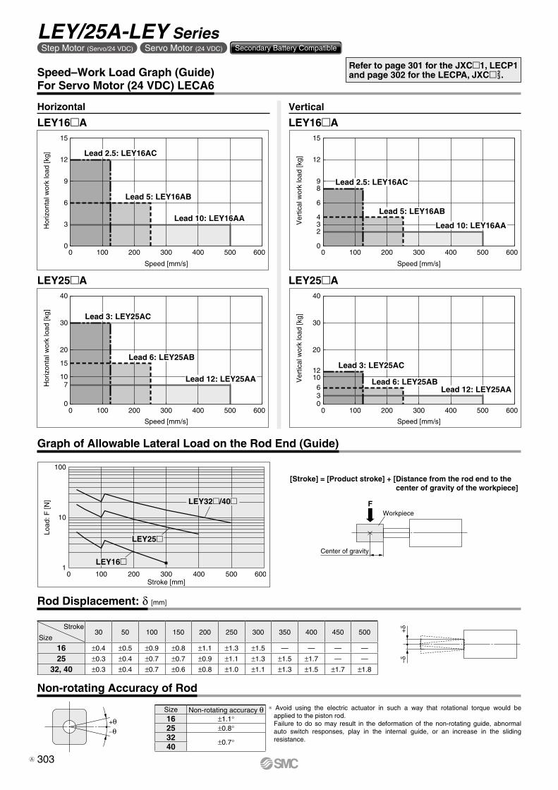
Lead 2.5: LEY16AC
Lead 5: LEY16AB
Lead 10: LEY16AA
Hor
izon
tal w
ork
load
[kg]
Speed [mm/s]
0
10
30
40
0 300200 400100 500 600
20
15
7
Lead 3: LEY25AC
Lead 6: LEY25AB
Lead 12: LEY25AA
Ver
tical
wor
k lo
ad [k
g]
Speed [mm/s]
0
3
6
98
4
2
12
15
0 300200 400100 500 600
Lead 2.5: LEY16AC
Lead 5: LEY16AB
Lead 10: LEY16AA
Ver
tical
wor
k lo
ad [k
g]
Speed [mm/s]
0
10
20
30
40
0 300200 400100 500 600
6
12
3
Lead 3: LEY25AC
Lead 6: LEY25ABLead 12: LEY25AA
Load
: F [N
]
Stroke [mm]
100
10
10 300200 400100 500 600
LEY32�/40�
LEY16�
LEY25�
F
Center of gravity
Workpiece
+δ
–δ
Graph of Allowable Lateral Load on the Rod End (Guide)
[Stroke] = [Product stroke] + [Distance from the rod end to thecenter of gravity of the workpiece]
Horizontal Vertical
LEY16mA
LEY25mA LEY25mA
LEY16mA
Speed–Work Load Graph (Guide)For Servo Motor (24 VDC) LECA6
Rod Displacement: d [mm]
Stroke
Size30 50 100 150 200 250 300 350 400 450 500
16 ±0.4 ±0.5 ±0.9 ±0.8 ±1.1 ±1.3 ±1.5 — — — —
25 ±0.3 ±0.4 ±0.7 ±0.7 ±0.9 ±1.1 ±1.3 ±1.5 ±1.7 — —
32, 40 ±0.3 ±0.4 ±0.7 ±0.6 ±0.8 ±1.0 ±1.1 ±1.3 ±1.5 ±1.7 ±1.8
Refer to page 301 for the JXCm1, LECP1 and page 302 for the LECPA, JXCm2
3.
Non-rotating Accuracy of Rod
* Avoid using the electric actuator in such a way that rotational torque would be applied to the piston rod.Failure to do so may result in the deformation of the non-rotating guide, abnormal auto switch responses, play in the internal guide, or an increase in the sliding resistance.
+θ−θ
Size Non-rotating accuracy q16 ±1.1°25 ±0.8°32 ±0.7°40
303
LEY/25A-LEY SeriesStep Motor (Servo/24 VDC) Servo Motor (24 VDC) Secondary Battery Compatible
A

10 20 30 40 50 60 70 80 900
100
200
300
400
500
Max. 65%
For
ce [N
]
Pushing force set value [%]∗1
Min. 35%
Lead 3: LEY25C
Lead 6: LEY25BLead 12: LEY25A
10 20 30 40 50 60 70 80 900
100200300400500600700
1100
800900
1000
Max. 65%
Pushing force set value [%]∗1
For
ce [N
]
Min. 35%
Lead 4: LEY40CLead 8: LEY40B
Lead 16: LEY40A
020
40
60
80
100
120
140
160
10 20 30 40 50 60 70 80 90Pushing force set value [%]∗1 Max. 85%
For
ce [N
]
Min. 35%
Lead 2.5: LEY16CLead 5: LEY16B
Lead 10: LEY16A
10 20 30 40 50 60 70 80 90Max. 85%
0100
200
300
400
500
600
700
800
Pushing force set value [%]∗1
For
ce [N
]
Min. 35%
Lead 4: LEY32CLead 8: LEY32B
Lead 16: LEY32A
For
ce [N
]
0
20
40
60
80
100
120
Pushing force set value [%]∗1 Max. 95%50 60 70 80 90 100
Min.60%
Lead 10: LEY16AA
Lead 2.5: LEY16AC
Lead 5: LEY16AB
Lead 3: LEY25AC
Lead 6: LEY25AB
Pushing force set value [%]∗1 Max. 95%50 60 70 80 90 100
For
ce [N
]
0
20
40
60
80
100
120
140
Min. 70%
Lead 12: LEY25AA
*1 Set values for the controller
Force Conversion Graph (Guide)
Step Motor (Servo/24 VDC)
LEY16
LEY25
LEY32
LEY40
Servo Motor (24 VDC)
LEY16A
LEY25A
For vertical loads (upward), set the pushing force to the max. value shown below and operate at the work load or less.
Model LEY16 LEY25 LEY32 LEY40 LEY16A LEY25ALead A B C A B C A B C A B C A B C A B C
Work load [kg] 1 1.5 3 2.5 5 10 4.5 9 18 7 14 28 1 1.5 3 1.2 2.5 5Pushing force 85% 65% 85% 65% 95% 95%
Ambient temperature Pushing force set value [%] Duty ratio [%] Continuous pushing time [min]40°C or less 95 or less 100 —
Ambient temperature Pushing force set value [%] Duty ratio [%] Continuous pushing time [min]40°C or less 95 or less 100 —
Ambient temperature Pushing force set value [%] Duty ratio [%] Continuous pushing time [min]25°C or less 85 or less 100 —
40°C 65 or less 100 —85 50 15
Ambient temperature Pushing force set value [%] Duty ratio [%] Continuous pushing time [min]25°C or less 85 or less 100 —
40°C
40 or less 100 —50 70 1270 20 1.385 15 0.8
Ambient temperature Pushing force set value [%] Duty ratio [%] Continuous pushing time [min]40°C or less 65 or less 100 —
Ambient temperature Pushing force set value [%] Duty ratio [%] Continuous pushing time [min]40°C or less 65 or less 100 —
<Set Values for Vertical Upward Transfer Pushing Operations>
<Limit Values for Pushing Force and Trigger Level in Relation to Pushing Speed>Without Load
Model LeadPushing speed
[mm/s]Pushing force
(Setting input value)Model Lead
Pushing speed[mm/s]
Pushing force(Setting input value)
LEY16 A/B/C 21 to 50 60 to 85% LEY16A A/B/C 21 to 50 80 to 95%LEY25 A/B/C 21 to 35 50 to 65% LEY25A A/B/C 21 to 35 80 to 95%
LEY32A 24 to 30
60 to 85%B/C 21 to 30
LEY40A 24 to 30
50 to 65%B/C 21 to 30
There is a limit to the pushing force in relation to the pushing speed. If the product is operated outside of the range (low pushing force), the completion signal [INP] may be output before the pushing operation has been completed (during the moving operation).If operating with the pushing speed below the min. speed, please check for operating problems before using the product.
304
Model Selection LEY/25A-LEY SeriesStep Motor (Servo/24 VDC) Servo Motor (24 VDC) Secondary Battery Compatible
LE
FS
LE
FB
LE
LL
EJS
LE
JBL
EM
LE
YL
EY
GL
ES
LE
SH
LE
PY
LE
PS
LE
RL
EH
LEY-
X511
-LEF
S11
-LEJ
S25
A-
Moto
rless
LEC
Y�LE
CS
�LE
CS�-
TJX
C�
LE
C�
LA
T3

Speed [mm/s]
Wor
k lo
ad [k
g]
0
5
10
15
20
25
30
35
40
0 200 400 600 800 1000 1200
Lead 3: LEY25C
Lead 12: LEY25A
Lead 6: LEY25B
T1
a1 a2
L
Spe
ed: V
[mm
/s]
Time [s]
T2 T3 T4
W
Step 1 Check the work load–speed. <Speed–Vertical work load graph>
Step 2 Check the cycle time.
Workpiece mass: 16 [kg] Speed: 300 [mm/s]
Acceleration/Deceleration: 5000 [mm/s2]
Stroke: 300 [mm]
Workpiece mounting condition: Vertical upward downward transfer
Operatingconditions
Selection Procedure
Positioning Control Selection Procedure
Selection Example
Step 1Check the work load–speed.(Vertical transfer) Step 2 Check the cycle time.
Calculate the cycle time using the following calculation method.
Cycle time:T can be found from the following equation.
Select a model based on the workpiece mass and speed while referencing the speed–vertical work load graph.
Selection example) The LEY25B can be temporarily selected as a possible candidate based on the graph shown on the right side.
T = T1 + T2 + T3 + T4 [s]
T1 = V/a1 [s]
T4 = 0.05 [s]
T3 = V/a2 [s]
T2 = [s]L − 0.5 · V · (T1 + T3)
V
T4: Settling time varies depending on the motor type and load. The value below is recommended.
T2: Constant speed time can be found from the following equation.
T1: Acceleration time and T3: Deceleration time can be found by the following equation.
L : Stroke [mm] ⋅⋅⋅ (Operating condition)V : Speed [mm/s] ⋅⋅⋅ (Operating condition)a1: Acceleration [mm/s2] ⋅⋅⋅ (Operating condition)a2: Deceleration [mm/s2] ⋅⋅⋅ (Operating condition)
T1: Acceleration time [s] ⋅⋅⋅ Time until reaching the set speedT2: Constant speed time [s] ⋅⋅⋅ Time while the actuator is
operating at a constant speedT3: Deceleration time [s] ⋅⋅⋅ Time from the beginning of the
constant speed operation to stopT4: Settling time [s] ⋅⋅⋅ Time until positioning is completedCalculation example)
T1 to T4 can be calculated as follows.
T1 = V/a1 = 300/5000 = 0.06 [s], T3 = V/a2 = 300/5000 = 0.06 [s]
T4 = 0.05 [s]
The cycle time can be found as follows.T = T1 + T2 + T3 + T4 = 0.06 + 0.94 + 0.06 + 0.05 = 1.11 [s]
T2 = = = 0.94 [s] L − 0.5 · V · (T1 + T3)
V
300 − 0.5 · 300 · (0.06 + 0.06)
300
<Speed–Vertical work load graph>(LEY25)
∗ It is necessary to mount a guide outside the actuator when used for horizontal transfer. When selecting the target model, refer to the horizontal work load in the specifications on pages 335, 336, 344, and 621 and the precautions.
Based on the above calculation result, the LEY25S2B-300 should be selected.
The regeneration option may be necessary. Refer to pages 307 and 308 for the “Required Conditions for Regeneration Option.”
AC Servo Motor LECS Series
Electric Actuator/Rod TypeLEY/LEY-X5/25A-LEY Series Dust-tight/Water-jet-proof (IP65 Equivalent) Secondary Battery Compatible
Model Selection 25, 32, 63Size
LEY Seriessp. 333, 343 LECY Seriessp. 351
LEY-X5 Seriessp. 619 25A-LEY Seriessp. 677
305

For
ce [N
]
Torque limit/Command value [%]
500
400
300
200
100
02010 4030
Lead 12: LEY25A
Lead 3: LEY25C
Lead 6: LEY25B
Jig
Load
: F [N
]
Stroke [mm]0 100 200 300 400 500 600
100
10
1
LEY32
LEY25
B
Pushing control
AP
ositi
on
Time
<Graph of allowable lateral load on the rod end>
Step 2 Check the force. <Force conversion graph>
Mounting condition: Horizontal (pushing) Duty ratio: 60 [%]
Jig weight: 0.5 [kg] Speed: 100 [mm/s]
Force: 255 [N] Stroke: 300 [mm]
Operatingconditions
Force Control Selection Procedure
Selection Example
Check the lateral load on the rod end.
Step 2 Check the force.
Select a model based on the torque limit/command value and pushing force while referencing the force conversion graph.
Selection example)Based on the graph shown on the right side,Torque limit/Command value: 30 [%]Force: 255 [N]The LEY25B can be temporarily selected as a possible candidate.
Step 3 Check the lateral load on the rod end. <Graph of allowable lateral load on the rod end>Confirm the allowable lateral load on the rod end of the actuator: LEY25B, which has been selected temporarily while referencing the graph of allowable lateral load on the rod end.
Selection example)Based on the graph shown on the right side,Jig weight: 0.5 [kg] ≈ 5 [N]Product stroke: 300 [mm]The lateral load on the rod end is in the allowable range.
Step 3
<Force conversion graph>(LEY25)
Based on the above calculation result, the LEY25S2B-300 should be selected.
Selection Procedure
Step 1 Check the duty ratio.
* The duty ratio is a ratio of the operation time in one cycle.
Step 1 Check the duty ratio.<Conversion table of force–duty ratio>Select the [Force] from the duty ratio while referencing the conversion table of force–duty ratio.
Selection example)Based on the table below, Duty ratio: 60 [%]Torque limit/Command value will be 30 [%].
* [Torque limit/Command value [%]] is the set value for the driver.* [Continuous pushing time] is the time that the actuator can continuously keep pushing.
<Conversion table of force–duty ratio>(LEY25/AC Servo motor)
Torque limit/Command value [%]
Duty ratio[%]
Continuouspushing time [min]
25 or less 100 —
30 60 1.5
Duty ratio = A/B x 100 [%]
306
Model Selection LEY/LEY-X5/25A-LEY SeriesAC Servo Motor 25, 32, 63Size Dust-tight/Water-jet-proof (IP65 Equivalent) Secondary Battery Compatible
LE
FS
LE
FB
LE
LL
EJS
LE
JBL
EM
LE
YL
EY
GL
ES
LE
SH
LE
PY
LE
PS
LE
RL
EH
LEY-
X511
-LEF
S11
-LEJ
S25
A-
Moto
rless
LEC
Y�LE
CS
�LE
CS�-
TJX
C�
LE
C�
LA
T3

0
10
20
30
40
16
8
0 200 400 600 800 1000 1200Speed [mm/s]
Wor
k lo
ad [k
g]
Lead 3: LEY25�C
Lead 6: LEY25�B
Lead 12: LEY25�A
Area where the regeneration option is required
37
19
9
0 200 400 600 800 1000 140012000
10
20
30
40
50
Speed [mm/s]
Wor
k lo
ad [k
g]
Lead 5: LEY32�C
Lead 10: LEY32�B
Lead 20: LEY32�A
Area where the regeneration option is required
0 200 400 600 800 1000 12000
10
20
30
40
50
60
Speed [mm/s]
Wor
k lo
ad [k
g]
12
24
46
Lead 4: LEY32D�C
Lead 8: LEY32D�B
Lead 16: LEY32D�A
Area where the regeneration option is required
Speed [mm/s]
Wor
k lo
ad [k
g]
0
20
40
60
80
120
100
0 200 400 600 800 1000 1200 1400
Lead 5: LEY63�C
Lead 2.86: LEY63�L (Top/Parallel type only)
Lead 20: LEY63�A
Area where the regeneration option is required
Lead 10: LEY63�B
Speed–Vertical Work Load Graph/Required Conditions for “Regeneration Option”
Required conditions for “Regeneration option”* Regeneration option is required when using the product above the regenera-
tion line in the graph. (It must be ordered separately.)
“Regeneration Option” Models
LEY25S2 6/T6 (Motor mounting position: Top/Parallel, In-line)
LEY32S3 7/T7 (Motor mounting position: Top/Parallel) LEY32DS3
7/T7 (Motor mounting position: In-line)
LEY63S4 8/T8 (Motor mounting position: Top/Parallel, In-line)
Size Model
LEY25 LEC-MR-RB-032
LEY32 LEC-MR-RB-032
LEY63 LEC-MR-RB-12
307
LEY/LEY-X5/25A-LEY SeriesAC Servo Motor 25, 32, 63Size Dust-tight/Water-jet-proof (IP65 Equivalent) Secondary Battery Compatible

0 200 400 600 800 1000 140012000
20
40
50
60
70
Speed [mm/s]
Wor
k lo
ad [k
g]
Lead 3: LEY25�C
Lead 12: LEY25�A
Lead 6: LEY25�B
Area where the regeneration option is required
0 200 400 600 800 1000 140012000
20
30
40
60
80
Speed [mm/s]
Wor
k lo
ad [k
g]
Area where the regeneration option is required
Lead 5: LEY32�C
Lead 20: LEY32�A
Lead 10: LEY32�B
0 200 400 600 800 1000 140012000
20
30
40
60
80
Speed [mm/s]
Wor
k lo
ad [k
g]
Lead 4: LEY32D�C
Area where the regeneration option is required
Lead 16: LEY32D�A
Lead 8: LEY32D�B
Speed [mm/s]
Wor
k lo
ad [k
g]
0
50
100
150
200
250
0 200 400 600 800 12001000
Lead 5: LEY63�C
Lead 2.86: LEY63�L (Top/Parallel type only)
Lead 20: LEY63�A
Lead 10: LEY63�B
Speed–Horizontal Work Load Graph/Required Conditions for “Regeneration Option”
Required conditions for “Regeneration option”* Regeneration option is required when using the product above the regenera-
tion line in the graph. (It must be ordered separately.)
“Regeneration Option” Models
LEY25S2 6/T6 (Motor mounting position: Top/Parallel, In-line)
LEY32S3 7/T7 (Motor mounting position: Top/Parallel)
LEY63lS4 8/T8 (Motor mounting position: Top/Parallel, In-line)
LEY32DS3 7/T7 (Motor mounting position: In-line)
Allowable Stroke Speed [mm/s]
ModelAC servo
motorLead Stroke [mm]
Symbol [mm] 30 50 100 150 200 250 300 350 400 450 500 600 700 800
LEY25S2 6/T6
Motor mounting position:Top/Parallel, In-line
100 W/40
A 12 900 600 — — —B 6 450 300 — — —C 3 225 150 — — —
(Motor rotation speed) (4500 rpm) (3000 rpm) — — —
LEY32S3 7/T7
Motor mounting position:Top/Parallel
200 W/60
A 20 1200 800 —B 10 600 400 —C 5 300 200 —
(Motor rotation speed) (3600 rpm) (2400 rpm) —
LEY32DS3 7/T7
Motor mounting position:In-line
200 W/60
A 16 1000 640 —B 8 500 320 —C 4 250 160 —
(Motor rotation speed) (3750 rpm) (2400 rpm) —
LEY63S4 8/T8
Motor mounting position:Top/Parallel, In-line
400 W/60
A 20 1000 800 600 500B 10 500 400 300 250C 5 250 200 150 125
(Motor rotation speed) (3000 rpm) (2400 rpm) (1800 rpm) (1500 rpm)L*1 2.86 70
(Motor rotation speed) (1470 rpm)
Size Model
LEY25 LEC-MR-RB-032
LEY32 LEC-MR-RB-032
LEY63 —
*1 Top/Parallel type only
308
Model Selection LEY/LEY-X5/25A-LEY SeriesAC Servo Motor 25, 32, 63Size Dust-tight/Water-jet-proof (IP65 Equivalent) Secondary Battery Compatible
LE
FS
LE
FB
LE
LL
EJS
LE
JBL
EM
LE
YL
EY
GL
ES
LE
SH
LE
PY
LE
PS
LE
RL
EH
LEY-
X511
-LEF
S11
-LEJ
S25
A-
Moto
rless
LEC
Y�LE
CS
�LE
CS�-
TJX
C�
LE
C�
LA
T3
For
ce [N
]
Torque limit/Command value [%]
500
400
300
200
100
02010 4030
Lead 3: LEY25�C
Lead 6: LEY25�B
Lead 12: LEY25�A
For
ce [N
]
Torque limit/Command value [%]
600
500
400
300
200
100
02010 4030
Lead 5: LEY32�C
Lead 10: LEY32�B
Lead 20: LEY32�A
For
ce [N
]
Torque limit/Command value [%]
800
700
600
500
400
300
200
1000
2010 4030
Lead 4: LEY32D�C
Lead 8: LEY32D�B
Lead 16: LEY32D�A
0
500
1000
1500
2000
2500
3000
3500
10 20 30 40 50 60Torque limit/Command value [%]
For
ce [N
]
Lead 5: LEY63�C
Lead 2.86: LEY63�L(Top/Parallel type only)
Lead 10: LEY63�B
Lead 20: LEY63�A
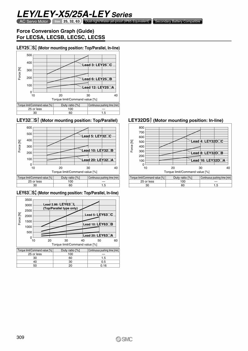
Force Conversion Graph (Guide)For LECSA, LECSB, LECSC, LECSS
LEY25S2 6 (Motor mounting position: Top/Parallel, In-line)
LEY32DS3 7 (Motor mounting position: In-line)LEY32S3
7 (Motor mounting position: Top/Parallel)
LEY63S4 8 (Motor mounting position: Top/Parallel, In-line)
Torque limit/Command value [%] Duty ratio [%] Continuous pushing time [min]25 or less 100 —
30 60 1.540 30 0.550 20 0.16
Torque limit/Command value [%] Duty ratio [%] Continuous pushing time [min]25 or less 100 —
30 60 1.5
Torque limit/Command value [%] Duty ratio [%] Continuous pushing time [min]25 or less 100 —
30 60 1.5
Torque limit/Command value [%] Duty ratio [%] Continuous pushing time [min]25 or less 100 —
30 60 1.5
309
LEY/LEY-X5/25A-LEY SeriesAC Servo Motor 25, 32, 63Size Dust-tight/Water-jet-proof (IP65 Equivalent) Secondary Battery Compatible

Force Conversion Graph (Guide)For LECSS-T
LEY25T6 (Motor mounting position: Top/Parallel, In-line)
LEY32DT7 (Motor mounting position: In-line)LEY32T7 (Motor mounting position: Top/Parallel)
LEY63T8 (Motor mounting position: Top/Parallel, In-line)
Torque limit/Command value [%] Duty ratio [%] Continuous pushing time [min]20 or less 100 —
24 60 1.5
Torque limit/Command value [%] Duty ratio [%] Continuous pushing time [min]20 or less 100 —
24 60 1.5
Torque limit/Command value [%] Duty ratio [%] Continuous pushing time [min]20 or less 100 —
24 60 1.5
Torque limit/Command value [%] Duty ratio [%] Continuous pushing time [min]20 or less 100 —
24 60 1.532 30 0.540 20 0.16
For
ce [N
]
Torque limit/Command value [%]
500
400
300
200
100
020 25241510 12 30
Lead 3: LEY25�C
Lead 6: LEY25�B
Lead 12: LEY25�A
For
ce [N
]
Torque limit/Command value [%]
600
500
400
300
200
100
02010 1512 302524
Lead 5: LEY32�C
Lead 10: LEY32�B
Lead 20: LEY32�A
10 12 20 30 40 50Torque limit/Command value [%]
For
ce [N
]
3500
3000
2500
2000
1500
1000
500
0
Lead 5: LEY63�C
Lead 2.86: LEY63�L(Top/Parallel only)
Lead 10: LEY63�B
Lead 20: LEY63�A
For
ce [N
]
Torque limit/Command value [%]
800700600500400300200100
020 252410 1512 30
Lead 4: LEY32D�C
Lead 8: LEY32D�B
Lead 16: LEY32D�A
310
Model Selection LEY/LEY-X5/25A-LEY SeriesAC Servo Motor 25, 32, 63Size Dust-tight/Water-jet-proof (IP65 Equivalent) Secondary Battery Compatible
LE
FS
LE
FB
LE
LL
EJS
LE
JBL
EM
LE
YL
EY
GL
ES
LE
SH
LE
PY
LE
PS
LE
RL
EH
LEY-
X511
-LEF
S11
-LEJ
S25
A-
Moto
rless
LEC
Y�LE
CS
�LE
CS�-
TJX
C�
LE
C�
LA
T3

F
Center of gravity
Workpiece
Load
: F [N
]
Stroke [mm]
100
1
10
0 100 200 300 400 500 600 700 800 900 1000
LEY63LEY32
LEY25
+δ
–δ
Graph of Allowable Lateral Load on the Rod End (Guide)
[Stroke] = [Product stroke] + [Distance from the rod end to the center of gravity of the workpiece]
Rod Displacement (Reference Value): d [mm]
Stroke
Size30 50 100 150 200 250 300 350 400 450 500 600 700 800
25 ±0.3 ±0.4 ±0.7 ±0.7 ±0.9 ±1.1 ±1.3 ±1.5 ±1.7 — — — — —
32 ±0.3 ±0.4 ±0.7 ±0.6 ±0.8 ±1.0 ±1.1 ±1.3 ±1.5 ±1.7 ±1.8 — — —
63 — ±0.5 ±0.7 ±0.9 ±1.2 ±1.1 ±1.3 ±1.5 ±1.7 ±1.9 ±2.1 ±1.7 ±2.0 ±2.2
Non-rotating Accuracy of Rod
* Avoid using the electric actuator in such a way that rotational torque would be applied to the piston rod.Failure to do so may result in the deformation of the non-rotating guide, abnormal auto switch responses, play in the internal guide, or an increase in the sliding resistance.
+θ−θ
Size Non-rotating accuracy q25 ±0.8°32 ±0.7°63 ±0.6°
* The values without a load are shown.
311
LEY/LEY-X5/25A-LEY SeriesAC Servo Motor 25, 32, 63Size Dust-tight/Water-jet-proof (IP65 Equivalent) Secondary Battery Compatible
A

W
T1
a1 a2
L
Spe
ed: V
[mm
/s]
Time [s]
T2 T3 T4
0
5
10
15
20
25
30
35
40
0 200 400 600 800 1000 1200Speed [mm/s]
Wor
k lo
ad [k
g]
Lead 6: LEY25B
Lead 3: LEY25C
Lead 12: LEY25AStep 1 Check the work load–speed. <Speed–Vertical work load graph>
Step 2 Check the cycle time.
Workpiece mass: 16 [kg] Speed: 300 [mm/s]
Acceleration/Deceleration: 5000 [mm/s2]
Stroke: 300 [mm]
Workpiece mounting condition: Vertical upward downward transfer
Operatingconditions
Positioning Control Selection Procedure
Selection Example
Step 1Check the work load–speed.(Vertical transfer) Step 2 Check the cycle time.
Calculate the cycle time using the following calculation method.
Cycle time:T can be found from the following equation.
Select a model based on the workpiece mass and speed while referencing the speed–vertical work load graph.
Selection example) The LEY25B can be temporarily selected as a possible candidate based on the graph shown on the right side.
T = T1 + T2 + T3 + T4 [s]
T4 = 0.05 [s]
T4: Settling time varies depending on the motor type and load. The value below is recom-mended.
T2 = [s]L − 0.5 · V · (T1 + T3)
V
T2: Constant speed time can be found from the following equation.
T1 = V/a1 [s] T3 = V/a2 [s]
T1: Acceleration time and T3: Deceleration time can be found by the following equation.
L : Stroke [mm] ⋅⋅⋅ (Operating condition)V : Speed [mm/s] ⋅⋅⋅ (Operating condition)a1: Acceleration [mm/s2] ⋅⋅⋅ (Operating condition)a2: Deceleration [mm/s2] ⋅⋅⋅ (Operating condition)
T1: Acceleration time [s] ⋅⋅⋅ Time until reaching the set speedT2: Constant speed time [s] ⋅⋅⋅ Time while the actuator is
operating at a constant speedT3: Deceleration time [s] ⋅⋅⋅ Time from the beginning of the
constant speed operation to stopT4: Settling time [s] ⋅⋅⋅ Time until positioning is completedCalculation example)
T1 to T4 can be calculated as follows.
T1 = V/a1 = 300/5000 = 0.06 [s], T3 = V/a2 = 300/5000 = 0.06 [s]
T4 = 0.05 [s]
The cycle time can be found as follows.T = T1 + T2 + T3 + T4 = 0.06 + 0.94 + 0.06 + 0.05 = 1.11 [s]
T2 = = = 0.94 [s] L − 0.5 · V · (T1 + T3)
V
300 − 0.5 · 300 · (0.06 + 0.06)
300
<Speed–Vertical work load graph>(LEY25)
∗ It is necessary to mount a guide outside the actuator when used for horizontal transfer. When selecting the target model, refer to the horizontal work load in the specifications on pages 353 and 354 and the precautions.
Based on the above calculation result, the LEY25V6B-300 should be selected.
The regenerative resistor may be necessary. Refer to pages 314 and 315 for the “Conditions for Regenerative Resistor (Guide).”
Selection Procedure
AC Servo Motor LECY Series
Electric Actuator/Rod TypeLEY/LEY-X5/25A-LEY Series Dust-tight/Water-jet-proof (IP65 Equivalent) Secondary Battery Compatible
Model Selection 25, 32, 63Size
LEY Seriessp. 351 LECS Seriessp. 333, 343
LEY-X5 Seriessp. 625 25A-LEY Seriessp. 679
312
LE
FS
LE
FB
LE
LL
EJS
LE
JBL
EM
LE
YL
EY
GL
ES
LE
SH
LE
PY
LE
PS
LE
RL
EH
LEY-
X511
-LEF
S11
-LEJ
S25
A-
Moto
rless
LEC
Y�LE
CS
�LE
CS�-
TJX
C�
LE
C�
LA
T3

Jig
Load
: F [N
]
Stroke [mm]0 100 200 300 400 500 600
100
10
1
LEY32
LEY25
For
ce [N
]
Torque limit/Command value [%]
500
400
300
200
100
06030 12090
Lead 3: LEY25C
Lead 12: LEY25A
Lead 6: LEY25B
<Graph of allowable lateral load on the rod end>
Step 2 Check the pushing force. <Force conversion graph>
Mounting condition: Horizontal (pushing) Duty ratio: 60 [%]
Jig weight: 0.5 [kg] Pushing speed: 35 [mm/s]
Force: 255 [N] Stroke: 300 [mm]
Operatingconditions
Pushing Control Selection Procedure
Selection Example
Check the lateral load on the rod end.
Step 2 Check the force.
Select a model based on the torque limit/command value and pushing force while referencing the force conversion graph.
Selection example)Based on the graph shown on the right side,Torque limit/Command value: 90 [%]Pushing force: 255 [N]The LEY25B can be temporarily selected as a possible candidate.
Step 3 Check the lateral load on the rod end. <Graph of allowable lateral load on the rod end>Confirm the allowable lateral load on the rod end of the actuator: LEY25B, which has been selected temporarily while referencing the graph of allowable lateral load on the rod end.
Selection example)Based on the graph shown on the right side,Jig weight: 0.5 [kg] ≈ 5 [N]Product stroke: 300 [mm]The lateral load on the rod end is in the allowable range.
Step 3
<Force conversion graph>(LEY25)
Based on the above calculation result, the LEY25V6B-300 should be selected.
Selection Procedure
Step 1 Check the duty ratio.
* The duty ratio is a ratio of the operation time in one cycle.
Step 1 Check the duty ratio.<Conversion table of pushing force–duty ratio>Select the [Pushing force] from the duty ratio while referencing the conversion table of pushing force–duty ratio.
Selection example)Based on the table below, Duty ratio: 60 [%]Torque limit/command value will be 90 [%].
* [Pushing force set value] is one of the data input to the driver.* [Continuous pushing time] is the time that the actuator can continuously keep pushing.
<Conversion table of pushing force–duty ratio>(LEY25/AC Servo motor)
Pushing forceset value [%]
Duty ratio[%]
Continuouspushing time [min]
75 or less 100 —
90 60 1.5
313
LEY/LEY-X5/25A-LEY SeriesAC Servo Motor 25, 32, 63Size Dust-tight/Water-jet-proof (IP65 Equivalent) Secondary Battery Compatible

0
10
20
30
40
0 200 400 600 800 1000 1200
“Regenerative resistor” area
Lead 3: LEY25�C
Lead 6: LEY25�B
Lead 12: LEY25�A
Speed [mm/s]
Wor
k lo
ad [k
g]
0
10
20
30
40
50
0 200 400 600 800 1000 1200 1400
“Regenerative resistor” area
Lead 5: LEY32�C
Lead 10: LEY32�B
Lead 20: LEY32�A
Speed [mm/s]
Wor
k lo
ad [k
g]
0
10
20
30
40
50
60
0 200 400 600 800 1000 1200
“Regenerative resistor” area
Lead 4: LEY32D�C
Lead 8: LEY32D�B
Lead 16: LEY32D�A
Speed [mm/s]
Wor
k lo
ad [k
g]
0
20
40
60
0 200 400 600 800 1000 1200
Lead 3: LEY25�C
Lead 6: LEY25�B
Lead 12: LEY25�A
Speed [mm/s]
Wor
k lo
ad [k
g]
0
20
40
60
80
0 200 400 600 800 1000 1200 1400
Lead 5: LEY32�C
Lead 10: LEY32�B
Lead 20: LEY32�A
Speed [mm/s]
Wor
k lo
ad [k
g]
0
20
40
60
80
0 200 400 600 800 1000 1200
Lead 4: LEY32D�C
Lead 8: LEY32D�B
Lead 16: LEY32D�A
Speed [mm/s]
Wor
k lo
ad [k
g]
Speed–Work Load Graph/Conditions for “Regenerative Resistor” (Guide)
LEY25lV6 (Motor mounting position: Top/Parallel, In-line)
LEY32lV7 (Motor mounting position: Top/Parallel)
LEY32DV7 (Motor mounting position: In-line)
Vertical
Vertical
Vertical Horizontal
Horizontal
Horizontal
“Regenerative resistor” area
ModelApplicable model
Motor Servopack (SMC driver)
LEY25l SGMJV-01A3A SGDV-R90A11l (LECYM2-V5)SGDV-R90A21l (LECYU2-V5)
LEY32l SGMJV-02A3A SGDV-1R6A11l (LECYM2-V7)SGDV-1R6A21l (LECYU2-V7)
Applicable Motors/Drivers* When using the actuator in the “Regenerative resistor” area, download the “AC
servo drive capacity selection program/SigmaJunmaSize+” from the SMC website. Then, calculate the necessary regenerative resistor capacity to prepare an appropriate external regenerative resistor.
* Regenerative resistor should be provided by the customer.
314
Model Selection LEY/LEY-X5/25A-LEY SeriesAC Servo Motor 25, 32, 63Size Dust-tight/Water-jet-proof (IP65 Equivalent) Secondary Battery Compatible
LE
FS
LE
FB
LE
LL
EJS
LE
JBL
EM
LE
YL
EY
GL
ES
LE
SH
LE
PY
LE
PS
LE
RL
EH
LEY-
X511
-LEF
S11
-LEJ
S25
A-
Moto
rless
LEC
Y�LE
CS
�LE
CS�-
TJX
C�
LE
C�
LA
T3

“Regenerative resistor” area
Lead 2.86: LEY63�L (Top/Parallel type only)
Lead 5: LEY63�C
Lead 10: LEY63�B
Lead 20: LEY63�A
0
20
40
60
80
100
120
0 200 400 600 800 1000 1200 1400Speed [mm/s]
Wor
k lo
ad [k
g]
Lead 2.86: LEY63�L (Top/Parallel type only)
Lead 5: LEY63�C
Lead 10: LEY63�B
Lead 20: LEY63�A
0
50
100
150
200
250
0 200 400 600 800 1000 1200 1400Speed [mm/s]
Wor
k lo
ad [k
g]
[mm/s]
ModelAC servo
motorLead Stroke [mm]
Symbol [mm] Up to 30 Up to 50 Up to 100 Up to 150 Up to 200 Up to 250 Up to 300 Up to 350 Up to 400 Up to 450 Up to 500 Up to 600 Up to 700 Up to 800
LEY25lV6Motor mounting
position:Top/Parallel, In-line
100 W/l40
A 12 900 600 — — — — —
B 6 450 300 — — — — —
C 3 225 150 — — — — —(Motor rotation speed) (4500 rpm) (3000 rpm) — — — — —
LEY32lV7Motor mounting
position:Top/Parallel
200 W/l60
A 20 1200 800 — — —
B 10 600 400 — — —
C 5 300 200 — — —(Motor rotation speed) (3600 rpm) (2400 rpm) — — —
LEY32DV7Motor mounting
position:In-line
200 W/l60
A 16 1000 640 — — —
B 8 500 320 — — —
C 4 250 160 — — —(Motor rotation speed) (3750 rpm) (2400 rpm) — — —
LEY63lV8Motor mounting
position:Top/Parallel, In-line
400 W/l60
A 20 — 1000 800 600 500
B 10 — 500 400 300 250
C 5 — 250 200 150 125(Motor rotation speed) — (3000 rpm) (2400 rpm) (1800 rpm) (1500 rpm)
L 2.86 — 70(Motor rotation speed) — (1470 rpm)
Speed–Work Load Graph/Conditions for “Regenerative Resistor” (Guide)
LEY63lV8 (Motor mounting position: Top/Parallel, In-line)Vertical Horizontal
“Regenerative resistor” area
Product no.Applicable model
Motor Servopack (SMC driver)
LEY63l SGMJV-04A3A SGDV-2R8A11l (LECYM2-V8)SGDV-2R8A21l (LECYU2-V8)
Applicable Motors/Drivers
Allowable Stroke Speed
* When using the actuator in the “Regenerative resistor” area, download the “AC servo drive capacity selection program/SigmaJunmaSize+” from the SMC website. Then, calculate the necessary regenerative resistor capacity to prepare an appropriate external regenerative resistor.
* Regenerative resistor should be provided by the customer.
315
LEY/LEY-X5/25A-LEY SeriesAC Servo Motor 25, 32, 63Size Dust-tight/Water-jet-proof (IP65 Equivalent) Secondary Battery Compatible

500
400
300
200
100
06030 12090
Lead 3: LEY25�C
Lead 6: LEY25�B
Lead 12: LEY25�A
For
ce [N
]
Torque limit/Command value [%]
600
500
400
300
200
100
06030 12090
Lead 5: LEY32�C
Lead 10: LEY32�B
Lead 20: LEY32�A
For
ce [N
]
Torque limit/Command value [%]
800
700
600
500
400
300
200
1000
6030 12090
Lead 4: LEY32D�C
Lead 8: LEY32D�B
Lead 16: LEY32D�A
For
ce [N
]
Torque limit/Command value [%]
30 60 90 120 150 180
Lead 5: LEY63�C
Lead 10: LEY63�B
Lead 20: LEY63�A
For
ce [N
]
Torque limit/Command value [%]
0
500
1000
1500
2000
2500
3000
3500Lead 2.86: LEY63�L(Top/Parallel type only)
Force Conversion Graph (Guide)
LEY25lV6 (Motor mounting position: Top/Parallel, In-line)
LEY32lV7 (Motor mounting position: Top/Parallel) LEY32DV7 (Motor mounting position: In-line)
LEY63lV8 (Motor mounting position: Top/Parallel, In-line)
Torque limit/Command value [%] Duty ratio [%] Continuous pushing time [min]75 or less 100 —
90 60 1.5120 30 0.5150 20 0.16
Torque limit/Command value [%] Duty ratio [%] Continuous pushing time [min]75 or less 100 —
90 60 1.5
Torque limit/Command value [%] Duty ratio [%] Continuous pushing time [min]75 or less 100 —
90 60 1.5
Torque limit/Command value [%] Duty ratio [%] Continuous pushing time [min]75 or less 100 —
90 60 1.5
316
Model Selection LEY/LEY-X5/25A-LEY SeriesAC Servo Motor 25, 32, 63Size Dust-tight/Water-jet-proof (IP65 Equivalent) Secondary Battery Compatible
LE
FS
LE
FB
LE
LL
EJS
LE
JBL
EM
LE
YL
EY
GL
ES
LE
SH
LE
PY
LE
PS
LE
RL
EH
LEY-
X511
-LEF
S11
-LEJ
S25
A-
Moto
rless
LEC
Y�LE
CS
�LE
CS�-
TJX
C�
LE
C�
LA
T3

F
Center of gravity
Workpiece
+δ
–δ
100
10
1
LEY63LEY32
LEY25Load
: F [N
]
Stroke [mm]0 100 200 300 400 500 600 700 800 900 1000
Graph of Allowable Lateral Load on the Rod End (Guide)
[Stroke] = [Product stroke] + [Distance from the rod end to the center of gravity of the workpiece]
Rod Displacement (Reference Value): d [mm]
Stroke
Size30 50 100 150 200 250 300 350 400 450 500 600 700 800
25 ±0.3 ±0.4 ±0.7 ±0.7 ±0.9 ±1.1 ±1.3 ±1.5 ±1.7 — — — — —
32 ±0.3 ±0.4 ±0.7 ±0.6 ±0.8 ±1.0 ±1.1 ±1.3 ±1.5 ±1.7 ±1.8 — — —
63 — ±0.5 ±0.7 ±0.9 ±1.2 ±1.1 ±1.3 ±1.5 ±1.7 ±1.9 ±2.1 ±1.7 ±2.0 ±2.2
Non-rotating Accuracy of Rod
* Avoid using the electric actuator in such a way that rotational torque would be applied to the piston rod.Failure to do so may result in the deformation of the non-rotating guide, abnormal auto switch responses, play in the internal guide, or an increase in the sliding resistance.
+θ−θ
Size Non-rotating accuracy q25 ±0.8°32 ±0.7°63 ±0.6°
* The values without a load are shown.
317
LEY/LEY-X5/25A-LEY SeriesAC Servo Motor 25, 32, 63Size Dust-tight/Water-jet-proof (IP65 Equivalent) Secondary Battery Compatible
A

318
LE
FS
LE
FB
LE
LL
EJS
LE
JBL
EM
LE
YL
EY
GL
ES
LE
SH
LE
PY
LE
PS
LE
RL
EH
LEY-
X511
-LEF
S11
-LEJ
S25
A-
Moto
rless
LEC
Y�LE
CS
�LE
CS�-
TJX
C�
LE
C�
LA
T3

How to Order
e Motor type
Symbol TypeApplicable size Compatible
controllers/driversLEY16 LEY25 LEY32/40
Nil Step motor(Servo/24 VDC)
V V V
JXCE1JXC91JXCP1JXCD1JXCL1JXCM1JXC51JXC61
LECP1LECPA
A Servo motor(24 VDC)
V V — LECA6
o Actuator cable type/length∗9
Standard cable [m] Robotic cable [m]Nil None R1 1.5 RA 10∗8
S1 1.5∗11 R3 3 RB 15∗8
S3 3∗11 R5 5 RC 20∗8
S5 5∗11 R8 8∗8
q w e r t y u i o
q Size16253240
r Lead [mm]Symbol LEY16 LEY25 LEY32/40
A 10 12 16
B 5 6 8
C 2.5 3 4
u Rod end threadNil Rod end female thread
MRod end male thread
(1 rod end nut is included.)
w Motor mounting positionNil Top mounting
R Right side parallel
L Left side parallel
D In-line
i Mounting∗3
Symbol TypeMotor mounting position
Top/Parallel In-line
NilEnds tapped/Body bottom tapped∗4 V V
L Foot V —
F Rod flange∗4 V∗6 V
G Head flange∗4 V∗7 —
D Double clevis∗5 V —
Motor mounting position: Top/Parallel Motor mounting position: In-line
LEY 16 B 30 S1
y Motor option∗2
Nil Without option
C With motor cover
B With lock
W With lock/motor cover
Motor
∗ For details, refer to the applicable stroke table below.
t Stroke [mm]30 30
to to
500 500
V: StandardStroke
[mm]Model30 50 100 150 200 250 300 350 400 450 500 Manufacturable
stroke range
LEY16 V V V V V V V — — — — 10 to 300
LEY25 V V V V V V V V V — — 15 to 400
LEY32/40 V V V V V V V V V V V 20 to 500
Applicable Stroke Table∗1
For auto switches, refer to pages 363 to 365.
!0 !1 !2
AN 1LECm Series
CD17TJXCm Series
For details on controllers, refer to page 320.
Click here for details.Click here for details.
Step Motor (Servo/24 VDC) Servo Motor (24 VDC)
Electric ActuatorRod TypeLEY Series LEY16, 25, 32, 40
Dust-tight/Water-jet-proofsp. 611 Secondary Battery Compatiblesp. 673
319C

LECm Series (For details, refer to page 321.)
JXCm Series (For details, refer to page 321.)
!0 Controller/Driver type∗10
Nil Without controller/driver6N LECA6
(Step data input type)NPN
6P PNP1N LECP1∗11
(Programless type)NPN
1P PNPAN LECPA∗11 ∗12
(Pulse input type)NPN
AP PNP
!0
!1 I/O cable length∗13
Nil Without cable(Without communication plug connector)
1 1.5 m3 3 m∗14
5 5 m∗14
!2 Controller/Driver mountingNil Screw mountingD DIN rail∗15
!0 ControllerNil Without controller
Cm1mm With controller
Caution[CE-compliant products]q EMC compliance was tested by combining the electric actuator LEY
series and the controller LEC/JXC series.The EMC depends on the configuration of the customer’s control panel and the relationship with other electrical equipment and wiring. Therefore, compliance with the EMC directive cannot be certified for SMC components incorporated into the customer’s equipment under actual operating conditions. As a result, it is necessary for the customer to verify compliance with the EMC directive for the machinery and equipment as a whole.
w For the servo motor (24 VDC) specification, EMC compliance was tested by installing a noise filter set (LEC-NFA). Refer to page 713 for the noise filter set. Refer to the LECA series Operation Manual for installation.
[UL-compliant products (For the LEC series)]When compliance with UL is required, the electric actuator and controller/driver should be used with a UL1310 Class 2 power supply.
∗1 Please consult with SMC for non-standard strokes as they are produced as special orders.∗2 When “With lock” or “With lock/motor cover” is selected for the top
mounting and right/left side parallel types, the motor body will stick out from the end of the body for size 16/40 with strokes of 30 mm or less. Check for interference with workpieces before selecting a model.
∗3 The mounting bracket is shipped together with the product but does not come assembled.∗4 For the horizontal cantilever mounting of the rod flange, head flange, or
ends tapped types, use the actuator within the following stroke range.·LEY25: 200 mm or less ·LEY32/40: 100 mm or less
∗5 For the mounting of the double clevis type, use the actuator within the following stroke range.·LEY16: 100 mm or less ·LEY25: 200 mm or less ·LEY32/40: 200 mm or less
∗6 The rod flange type is not available for the LEY16/40 with a 30 mm stroke and motor option “With lock,” “With lock/motor cover.”
∗7 The head flange type is not available for the LEY32/40.∗8 Produced upon receipt of order (Robotic cable only)∗9 The standard cable should only be used on fixed parts.
For use on moving parts, select the robotic cable.Refer to pages 758 and 759 if only the actuator cable is required.
∗10 For details on controllers/drivers and compatible motors, refer to the compatible controllers/drivers on the next page.
∗11 Only available for the motor type “Step motor”∗12 When pulse signals are open collector, order the current limiting
resistor (LEC-PA-R-m) on page 736 separately.∗13 When “Without controller/driver” is selected for controller/driver types,
I/O cable cannot be selected. Refer to page 713 (For LECA6), page 724 (For LECP1), or page 736 (For LECPA) if I/O cable is required.
∗14 When “Pulse input type” is selected for controller/driver types, pulse input usable only with differential. Only 1.5 m cables usable with open collector
∗15 The DIN rail is not included. It must be ordered separately.∗16 Select “Nil” for anything other than DeviceNet™, CC-Link, or parallel
input. Select “Nil,” “S,” or “T” for DeviceNet™ or CC-Link. Select “Nil,” “1,” “3,” or “5” for parallel input.
AN 1!1 !2
The actuator and controller/driver are sold as a package.Confirm that the combination of the controller/driver and actuator is correct.
<Check the following before use.>q �Check the actuator label for the model number. This
number should match that of the controller/driver.w Check that the Parallel I/O configuration matches
(NPN or PNP).
∗ Refer to the Operation Manual for using the products. Please download it via our website: https://www.smcworld.com
For single axis
1D T7CInterface
(Communication protocol/Input/Output)E EtherCAT® L IO-Link9 EtherNet/IP™ M CC-Link Ver 1.10P PROFINET 5 Parallel input (NPN)D DeviceNet™ 6 Parallel input (PNP)
Mounting7 Screw mounting8∗15 DIN rail
Communication plug connector I/O cable∗16
Symbol Type Applicable interfaceNil Without accessory —S Straight type communication plug connector DeviceNet™
CC-Link Ver 1.10T T-branch type communication plug connector1 I/O cable (1.5 m)
Parallel input (NPN)Parallel input (PNP)3 I/O cable (3 m)
5 I/O cable (5 m)
q w
320
Electric ActuatorRod Type LEY Series
Motorless TypeStep Motor (Servo/24 VDC) Servo Motor (24 VDC)
LE
FS
LE
FB
LE
LL
EJS
LE
JBL
EM
LE
YL
EY
GL
ES
LE
SH
LE
PY
LE
PS
LE
RL
EH
LEY-
X511
-LEF
S11
-LEJ
S25
A-
Moto
rless
LEC
Y�LE
CS
�LE
CS�-
TJX
C�
LE
C�
LA
T3
B

Compatible Controllers/Drivers
Type
Step datainput type
Step datainput type
Programless type Pulse input type
SeriesJXC51JXC61
LECA6 LECP1 LECPA
Features Parallel I/OValue (Step data) input
Standard controller
Capable of setting up operation (step data) without using a PC or teaching box
Operation by pulse signals
Compatible motorStep motor
(Servo/24 VDC)Servo motor
(24 VDC)Step motor
(Servo/24 VDC)
Max. number of step data 64 points 14 points —Power supply voltage 24 VDC
Reference page 706-1 707 719 731
Type
EtherCAT®
direct input type
EtherNet/IP™direct input type
PROFINETdirect input type
DeviceNet™direct input type
IO-Linkdirect input type
CC-Linkdirect input type
Series JXCE1 JXC91 JXCP1 JXCD1 JXCL1 JXCM1
FeaturesEtherCAT®
direct inputEtherNet/IP™
direct inputPROFINETdirect input
DeviceNet™direct input
IO-Linkdirect input
CC-Linkdirect input
Compatible motorStep motor
(Servo/24 VDC)
Max. number of step data 64 points
Power supply voltage 24 VDC
Reference page 741
321
LEY SeriesStep Motor (Servo/24 VDC) Servo Motor (24 VDC)
B

322
LE
FS
LE
FB
LE
LL
EJS
LE
JBL
EM
LE
YL
EY
GL
ES
LE
SH
LE
PY
LE
PS
LE
RL
EH
LEY-
X511
-LEF
S11
-LEJ
S25
A-
Moto
rless
LEC
Y�LE
CS
�LE
CS�-
TJX
C�
LE
C�
LA
T3
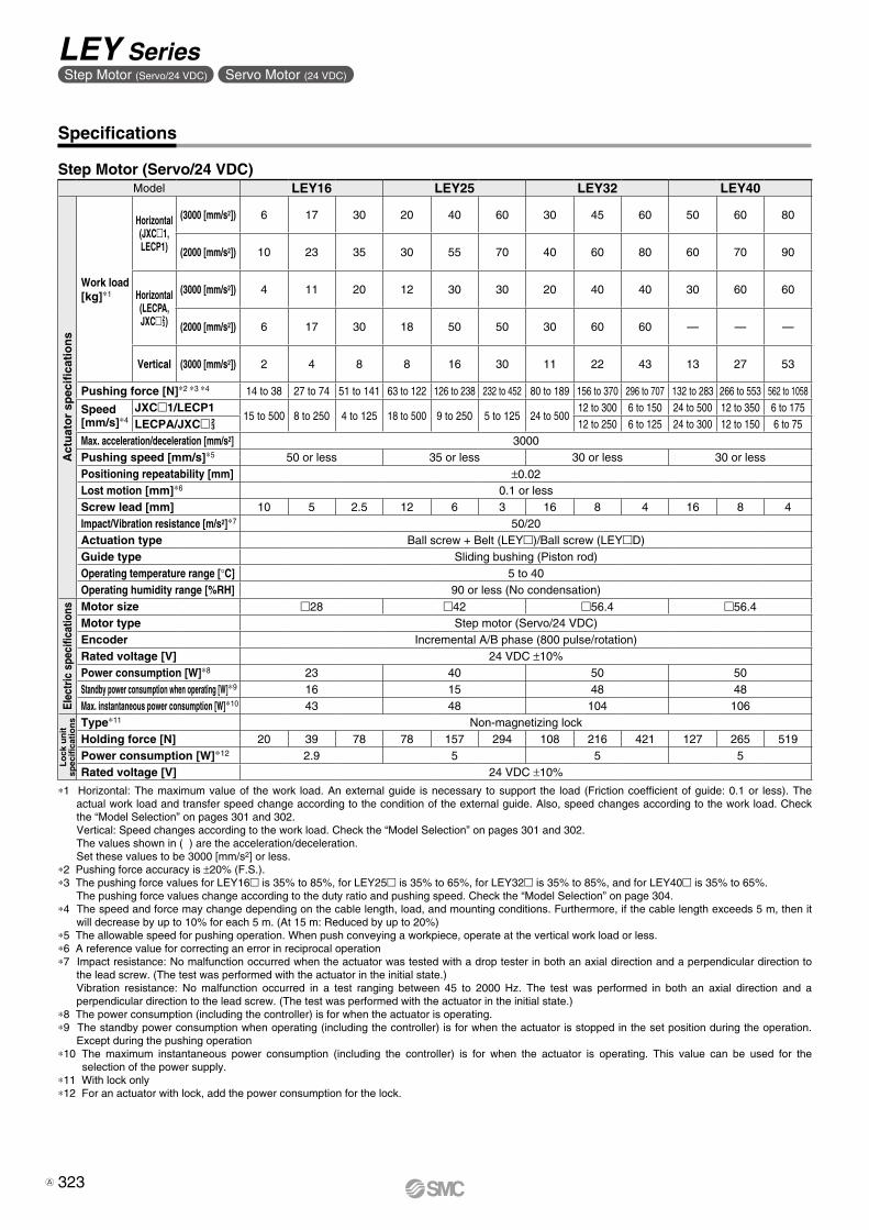
*1 Horizontal: The maximum value of the work load. An external guide is necessary to support the load (Friction coefficient of guide: 0.1 or less). The actual work load and transfer speed change according to the condition of the external guide. Also, speed changes according to the work load. Check the “Model Selection” on pages 301 and 302.Vertical: Speed changes according to the work load. Check the “Model Selection” on pages 301 and 302.The values shown in ( ) are the acceleration/deceleration.Set these values to be 3000 [mm/s2] or less.
*2 Pushing force accuracy is ±20% (F.S.).*3 The pushing force values for LEY16 is 35% to 85%, for LEY25 is 35% to 65%, for LEY32 is 35% to 85%, and for LEY40 is 35% to 65%.
The pushing force values change according to the duty ratio and pushing speed. Check the “Model Selection” on page 304.*4 The speed and force may change depending on the cable length, load, and mounting conditions. Furthermore, if the cable length exceeds 5 m, then it
will decrease by up to 10% for each 5 m. (At 15 m: Reduced by up to 20%)*5 The allowable speed for pushing operation. When push conveying a workpiece, operate at the vertical work load or less.*6 A reference value for correcting an error in reciprocal operation*7 Impact resistance: No malfunction occurred when the actuator was tested with a drop tester in both an axial direction and a perpendicular direction to
the lead screw. (The test was performed with the actuator in the initial state.)Vibration resistance: No malfunction occurred in a test ranging between 45 to 2000 Hz. The test was performed in both an axial direction and a perpendicular direction to the lead screw. (The test was performed with the actuator in the initial state.)
*8 The power consumption (including the controller) is for when the actuator is operating.*9 The standby power consumption when operating (including the controller) is for when the actuator is stopped in the set position during the operation.
Except during the pushing operation*10 The maximum instantaneous power consumption (including the controller) is for when the actuator is operating. This value can be used for the
selection of the power supply.*11 With lock only*12 For an actuator with lock, add the power consumption for the lock.
Specifications
Step Motor (Servo/24 VDC)Model LEY16 LEY25 LEY32 LEY40
Act
uat
or
spec
ifica
tio
ns
Work load[kg]*1
Horizontal(JXC1,LECP1)
(3000 [mm/s2]) 6 17 30 20 40 60 30 45 60 50 60 80
(2000 [mm/s2]) 10 23 35 30 55 70 40 60 80 60 70 90
Horizontal(LECPA,JXC2
3)
(3000 [mm/s2]) 4 11 20 12 30 30 20 40 40 30 60 60
(2000 [mm/s2]) 6 17 30 18 50 50 30 60 60 — — —
Vertical (3000 [mm/s2]) 2 4 8 8 16 30 11 22 43 13 27 53
Pushing force [N]*2 *3 *4 14 to 38 27 to 74 51 to 141 63 to 122 126 to 238 232 to 452 80 to 189 156 to 370 296 to 707 132 to 283 266 to 553 562 to 1058
Speed[mm/s]*4
JXC1/LECP115 to 500 8 to 250 4 to 125 18 to 500 9 to 250 5 to 125 24 to 500
12 to 300 6 to 150 24 to 500 12 to 350 6 to 175LECPA/JXC2
3 12 to 250 6 to 125 24 to 300 12 to 150 6 to 75Max. acceleration/deceleration [mm/s2] 3000Pushing speed [mm/s]*5 50 or less 35 or less 30 or less 30 or lessPositioning repeatability [mm] ±0.02Lost motion [mm]*6 0.1 or lessScrew lead [mm] 10 5 2.5 12 6 3 16 8 4 16 8 4Impact/Vibration resistance [m/s2]*7 50/20Actuation type Ball screw + Belt (LEY)/Ball screw (LEYD)Guide type Sliding bushing (Piston rod)Operating temperature range [°C] 5 to 40Operating humidity range [%RH] 90 or less (No condensation)
Elec
tric
spe
cific
atio
ns Motor size 28 42 56.4 56.4Motor type Step motor (Servo/24 VDC)Encoder Incremental A/B phase (800 pulse/rotation)Rated voltage [V] 24 VDC ±10%Power consumption [W]*8 23 40 50 50Standby power consumption when operating [W]*9 16 15 48 48Max. instantaneous power consumption [W]*10 43 48 104 106
Lo
ck u
nit
spec
ifica
tio
ns Type*11 Non-magnetizing lock
Holding force [N] 20 39 78 78 157 294 108 216 421 127 265 519Power consumption [W]*12 2.9 5 5 5Rated voltage [V] 24 VDC ±10%
323
LEY SeriesStep Motor (Servo/24 VDC) Servo Motor (24 VDC)
A
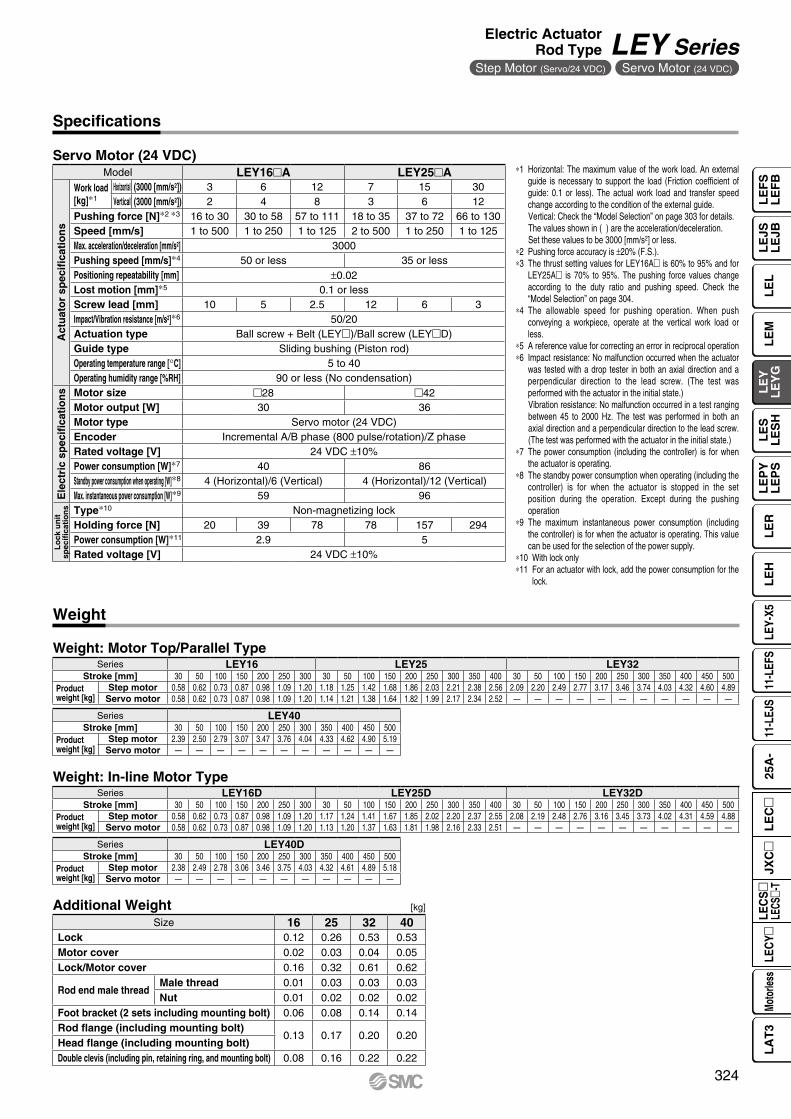
*1 Horizontal: The maximum value of the work load. An external guide is necessary to support the load (Friction coefficient of guide: 0.1 or less). The actual work load and transfer speed change according to the condition of the external guide.Vertical: Check the “Model Selection” on page 303 for details. The values shown in ( ) are the acceleration/deceleration.Set these values to be 3000 [mm/s2] or less.
*2 Pushing force accuracy is ±20% (F.S.).*3 The thrust setting values for LEY16A is 60% to 95% and for
LEY25A is 70% to 95%. The pushing force values change according to the duty ratio and pushing speed. Check the “Model Selection” on page 304.
*4 The allowable speed for pushing operation. When push conveying a workpiece, operate at the vertical work load or less.
*5 A reference value for correcting an error in reciprocal operation*6 Impact resistance: No malfunction occurred when the actuator
was tested with a drop tester in both an axial direction and a perpendicular direction to the lead screw. (The test was performed with the actuator in the initial state.)Vibration resistance: No malfunction occurred in a test ranging between 45 to 2000 Hz. The test was performed in both an axial direction and a perpendicular direction to the lead screw. (The test was performed with the actuator in the initial state.)
*7 The power consumption (including the controller) is for when the actuator is operating.
*8 The standby power consumption when operating (including the controller) is for when the actuator is stopped in the set position during the operation. Except during the pushing operation
*9 The maximum instantaneous power consumption (including the controller) is for when the actuator is operating. This value can be used for the selection of the power supply.
*10 With lock only*11 For an actuator with lock, add the power consumption for the
lock.
Specifications
Servo Motor (24 VDC)
Weight
Weight: Motor Top/Parallel Type
Additional Weight [kg]
Weight: In-line Motor TypeSeries LEY16D LEY25D LEY32D
Stroke [mm] 30 50 100 150 200 250 300 30 50 100 150 200 250 300 350 400 30 50 100 150 200 250 300 350 400 450 500Productweight [kg]
Step motor 0.58 0.62 0.73 0.87 0.98 1.09 1.20 1.17 1.24 1.41 1.67 1.85 2.02 2.20 2.37 2.55 2.08 2.19 2.48 2.76 3.16 3.45 3.73 4.02 4.31 4.59 4.88Servo motor 0.58 0.62 0.73 0.87 0.98 1.09 1.20 1.13 1.20 1.37 1.63 1.81 1.98 2.16 2.33 2.51 — — — — — — — — — — —
Series LEY40DStroke [mm] 30 50 100 150 200 250 300 350 400 450 500
Productweight [kg]
Step motor 2.38 2.49 2.78 3.06 3.46 3.75 4.03 4.32 4.61 4.89 5.18Servo motor — — — — — — — — — — —
Series LEY40Stroke [mm] 30 50 100 150 200 250 300 350 400 450 500
Productweight [kg]
Step motor 2.39 2.50 2.79 3.07 3.47 3.76 4.04 4.33 4.62 4.90 5.19Servo motor — — — — — — — — — — —
Series LEY16 LEY25 LEY32Stroke [mm] 30 50 100 150 200 250 300 30 50 100 150 200 250 300 350 400 30 50 100 150 200 250 300 350 400 450 500
Productweight [kg]
Step motor 0.58 0.62 0.73 0.87 0.98 1.09 1.20 1.18 1.25 1.42 1.68 1.86 2.03 2.21 2.38 2.56 2.09 2.20 2.49 2.77 3.17 3.46 3.74 4.03 4.32 4.60 4.89Servo motor 0.58 0.62 0.73 0.87 0.98 1.09 1.20 1.14 1.21 1.38 1.64 1.82 1.99 2.17 2.34 2.52 — — — — — — — — — — —
Size 16 25 32 40Lock 0.12 0.26 0.53 0.53Motor cover 0.02 0.03 0.04 0.05Lock/Motor cover 0.16 0.32 0.61 0.62
Rod end male threadMale thread 0.01 0.03 0.03 0.03Nut 0.01 0.02 0.02 0.02
Foot bracket (2 sets including mounting bolt) 0.06 0.08 0.14 0.14Rod flange (including mounting bolt)
0.13 0.17 0.20 0.20Head flange (including mounting bolt)Double clevis (including pin, retaining ring, and mounting bolt) 0.08 0.16 0.22 0.22
Model LEY16A LEY25A
Act
uat
or
spec
ifica
tio
ns
Work load[kg]*1
Horizontal (3000 [mm/s2]) 3 6 12 7 15 30Vertical (3000 [mm/s2]) 2 4 8 3 6 12
Pushing force [N]*2 *3 16 to 30 30 to 58 57 to 111 18 to 35 37 to 72 66 to 130Speed [mm/s] 1 to 500 1 to 250 1 to 125 2 to 500 1 to 250 1 to 125Max. acceleration/deceleration [mm/s2] 3000Pushing speed [mm/s]*4 50 or less 35 or lessPositioning repeatability [mm] ±0.02Lost motion [mm]*5 0.1 or lessScrew lead [mm] 10 5 2.5 12 6 3Impact/Vibration resistance [m/s2]*6 50/20Actuation type Ball screw + Belt (LEY)/Ball screw (LEYD)Guide type Sliding bushing (Piston rod)Operating temperature range [°C] 5 to 40Operating humidity range [%RH] 90 or less (No condensation)
Ele
ctri
c sp
ecifi
cati
on
s Motor size 28 42Motor output [W] 30 36Motor type Servo motor (24 VDC)Encoder Incremental A/B phase (800 pulse/rotation)/Z phaseRated voltage [V] 24 VDC ±10%Power consumption [W]*7 40 86Standby power consumption when operating [W]*8 4 (Horizontal)/6 (Vertical) 4 (Horizontal)/12 (Vertical)Max. instantaneous power consumption [W]*9 59 96
Lo
ck u
nit
spec
ifica
tio
ns Type*10 Non-magnetizing lock
Holding force [N] 20 39 78 78 157 294Power consumption [W]*11 2.9 5Rated voltage [V] 24 VDC ±10%
324
Electric ActuatorRod Type LEY Series
Motorless TypeStep Motor (Servo/24 VDC) Servo Motor (24 VDC)
LE
FS
LE
FB
LE
LL
EJS
LE
JBL
EM
LE
YL
EY
GL
ES
LE
SH
LE
PY
LE
PS
LE
RL
EH
LEY-
X511
-LEF
S11
-LEJ
S25
A-
Moto
rless
LEC
Y�LE
CS
�LE
CS�-
TJX
C�
LE
C�
LA
T3

#3 #2
@3
!1
!6!7
@1@2
@4 @5
!9
@0
!8
@0
!9
!8
!4
!0
uu !2 !3ie!5 rtwqy
o
@5@4@3 #0
Construction
Motor top/parallel typeWith lock/motor cover
When rod end male thread selected
Motor top mounting type: LEY16253240
325
LEY SeriesStep Motor (Servo/24 VDC) Servo Motor (24 VDC)
A

@5 @4 @3#0#1
@5 @4 @3
@8@9!0
@6 @7
In-line motor type: LEY D
In-line motor type: With lock/motor cover
16253240
Construction
Component PartsNo. Description Material Note25 Grommet Synthetic resin Only “With motor cover”26 Motor block Aluminum alloy Anodized27 Motor adapter Aluminum alloy Anodized/LEY16, 25 only28 Hub Aluminum alloy29 Spider NBR30 Motor cover with lock Aluminum alloy Only “With lock/motor cover”31 Cover support Aluminum alloy Only “With lock/motor cover”32 Socket (Male thread) Free cutting carbon steel Nickel plating33 Nut Alloy steel Zinc chromating
No. Description Material Note1 Body Aluminum alloy Anodized2 Ball screw shaft Alloy steel3 Ball screw nut Synthetic resin/Alloy steel4 Piston Aluminum alloy5 Piston rod Stainless steel Hard chrome plating6 Rod cover Aluminum alloy7 Bearing holder Aluminum alloy8 Rotation stopper Synthetic resin9 Socket Free cutting carbon steel Nickel plating10 Connected shaft Free cutting carbon steel Nickel plating11 Bushing Bearing alloy12 Bearing —13 Return box Aluminum die-cast Coating14 Return plate Aluminum die-cast Coating15 Magnet —16 Wear ring holder Stainless steel Stroke 101 mm or more17 Wear ring Synthetic resin Stroke 101 mm or more18 Screw shaft pulley Aluminum alloy19 Motor pulley Aluminum alloy20 Belt —21 Seal NBR22 Retaining ring Steel for spring Phosphate coating23 Motor —24 Motor cover Synthetic resin Only “With motor cover”
Replacement Parts (Motor top/parallel only)/BeltNo. Size Order no.
2016 LE-D-2-1
25 LE-D-2-2
32, 40 LE-D-2-3
Replacement Parts/Grease PackApplied portion Order no.
Piston rodGR-S-010 (10 g)GR-S-020 (20 g)
* Apply grease on the piston rod periodically. Grease should be applied at 1 million cycles or 200 km, whichever comes first.
326
Electric ActuatorRod Type LEY Series
Motorless TypeStep Motor (Servo/24 VDC) Servo Motor (24 VDC)
LE
FS
LE
FB
LE
LL
EJS
LE
JBL
EM
LE
YL
EY
GL
ES
LE
SH
LE
PY
LE
PS
LE
RL
EH
LEY-
X511
-LEF
S11
-LEJ
S25
A-
Moto
rless
LEC
Y�LE
CS
�LE
CS�-
TJX
C�
LE
C�
LA
T3
A

A + Stroke
B + StrokeL
Y
XW
EH
EV
J
M
M
�V
�K∗4
H thread depth C
4 x O1 thread depth R
S
UT
M
M
4 x O1 thread depth R
Motor cable (2 x ø5)
65
Cab
le le
ngth
≈ 3
00
øD
2[2]
Origin∗2
[Stroke end]
Stroke end[Origin]∗3
Rod operating range∗1
Stroke
Section XX
6 x MO thread depth MRøXA H9 depth XA
XA H9
XB
XA
MH
MD
MA ML + Stroke
MC(MB)
20
20 24
24
Step motor Servo motor
Connector
Dimensions: Motor Top/Parallel
[mm]
*1 This is the range within which the rod can move when it returns to origin. Make sure workpieces mounted on the rod do not interfere with the workpieces and facilities around the rod.
*2 Position after returning to origin*3 [ ] for when the direction of return to origin has changed*4 The direction of rod end width across flats (K) differs depending on the products.
SizeStroke
range [mm] A B C D EH EV H J K L M O1 R S T U VStep motor Servo motor
YW X W X
1610 to 100 101 90.5
10 16 34 34.3 M5 x 0.8 18 14 10.5 25.5 M4 x 0.7 7 35 67.5 0.5 28 61.8 80.3 62.5 81 22.5101 to 300 121 110.5
2515 to 100 130.5 116
13 20 44 45.5 M8 x 1.25 24 17 14.5 34 M5 x 0.8 8 46 92 1 42 63.4 85.4 59.6 81.6 26.5101 to 400 155.5 141
3220 to 100 148.5 130
13 25 51 56.5 M8 x 1.25 31 22 18.5 40 M6 x 1.0 10 60 118 1 56.4 68.4 95.4 — — 34101 to 500 178.5 160
4020 to 100 148.5 130
13 25 51 56.5 M8 x 1.25 31 22 18.5 40 M6 x 1.0 10 60 118 1 56.4 90.4 117.4 — — 34101 to 500 178.5 160
[mm]Body Bottom Tapped
SizeStroke
range [mm] MA MB MC MD MH ML MO MR XA XB
1610 to 39
15 35.517 23.5
2340
M4 x 0.7 5.5 3 440 to 100 32 31101 to 300 62 46 60
25
15 to 39
20 46
24 32
29
50
M5 x 0.8 6.5 4 540 to 100
42 41101 to 124
75125 to 200 59 49.5201 to 400 76 58
3240
20 to 39
25 55
22 36
30
50
M6 x 1 8.5 5 640 to 100
36 43101 to 124
80125 to 200 53 51.5201 to 500 70 60
Section XX details
327
LEY SeriesStep Motor (Servo/24 VDC) Servo Motor (24 VDC)

US
1
T2 T2
US
1
X2
T2
Motor cable(2 x ø5)
65
Cab
le le
ngth
≈ 2
50
2020
15
20
20
15
24
24
Cab
le le
ngth
≈ 4
00
65
Cab
le le
ngth
≈ 2
50
X2
Lock cable (ø3.5)
T2
Motor cable(2 x ø5)
WX
Motor cable(2 x ø5)
Lock cable(ø3.5)
65
Cab
le le
ngth
≈ 4
00
Dimensions: Motor Top/Parallel
Motor left side parallel type: LEY L16253240
Motor right side parallel type: LEY R16253240 [mm]
* When the motor is mounted on the left or right side in parallel, the groove for auto switch on the side to which the motor is mounted is hidden.
Size S1 T2 U
16 35.5 67 0.5
25 47 91 1
32, 40 61 117 1
Step motor
Lock cable
Motor cable
Servo motor
Connector
With motor cover: LEY -C
With lock/motor cover: LEY -W
With lock: LEY -B16253240
16253240
16253240
ABC
ABC
ABC
[mm]
Motor cover material: Synthetic resin
[mm]
SizeStep motor Servo motor
W X W X16 103.3 121.8 104.0 122.5
25 103.9 125.9 100.1 122.1
32 111.4 138.4 — —
40 133.4 160.4 — —
Size T2 X2
16 7.5 83
25 7.5 88.5
32 7.5 98.5
40 7.5 120.5
[mm]
Size T2 X2
16 7.5 124.5
25 7.5 129
32 7.5 141.5
40 7.5 163.5
328
Electric ActuatorRod Type LEY Series
Motorless TypeStep Motor (Servo/24 VDC) Servo Motor (24 VDC)
LE
FS
LE
FB
LE
LL
EJS
LE
JBL
EM
LE
YL
EY
GL
ES
LE
SH
LE
PY
LE
PS
LE
RL
EH
LEY-
X511
-LEF
S11
-LEJ
S25
A-
Moto
rless
LEC
Y�LE
CS
�LE
CS�-
TJX
C�
LE
C�
LA
T3
A

XA H9
XB
XA
Section XX
øXA H9 depth XA
MD
MC
ML + StrokeMA
6 x MOthread depth MR
MH
UJ
EVT M
�K∗4
M
EH
B + StrokeL W
65
Cab
le le
ngth
≈ 3
00
�V
Y 2
S
A + Stroke
øD
H thread depth C
4 x O1
thread depth R
Motor cable (2 x ø5)
2[2]Origin∗2
[Stroke end]
Stroke end[Origin]∗3
Rod operating range∗1
Stroke20
20 24
24
Step motor Servo motor
Connector
Dimensions: In-line Motor
[mm]
*1 This is the range within which the rod can move when it returns to origin. Make sure workpieces mounted on the rod do not interfere with the workpieces and facilities around the rod.
*2 Position after returning to origin*3 [ ] for when the direction of return to origin has changed*4 The direction of rod end width across flats (K) differs depending on the products.
SizeStroke
range [mm]
Stepmotor
Servomotor B C D EH EV H J K L M O1 R S T U V
Stepmotor
Servomotor Y
A W
1610 to 100 166.3 167 92
10 16 34 34.3 M5 x 0.8 18 14 10.5 25.5 M4 x 0.7 7 35 35.5 0.5 28 61.8 62.5 24101 to 300 186.3 187 112
2515 to 100 195.4 191.6 115.5
13 20 44 45.5 M8 x 1.25 24 17 14.5 34 M5 x 0.8 8 45 46.5 1.5 42 63.4 59.6 26101 to 400 220.4 216.6 140.5
3220 to 100 216.9 — 128
13 25 51 56.5 M8 x 1.25 31 22 18.5 40 M6 x 1 10 60 61 1 56.4 68.4 — 32101 to 500 246.9 — 158
4020 to 100 238.9 — 128
13 25 51 56.5 M8 x 1.25 31 22 18.5 40 M6 x 1 10 60 61 1 56.4 90.4 — 32101 to 500 268.9 — 158
[mm]Body Bottom Tapped
SizeStroke
range [mm] MA MC MD MH ML MO MR XA XB
1610 to 39
1517 23.5
2340
M4 x 0.7 5.5 3 440 to 100 32 31101 to 300 62 46 60
25
15 to 39
20
24 32
29
50
M5 x 0.8 6.5 4 540 to 100
42 41101 to 124
75125 to 200 59 49.5201 to 400 76 58
3240
20 to 39
25
22 36
30
50
M6 x 1 8.5 5 640 to 100
36 43101 to 124
80125 to 200 53 51.5201 to 500 70 60
Section XX details
329
LEY SeriesStep Motor (Servo/24 VDC) Servo Motor (24 VDC)

LC
VX2
T2
A + Stroke
2020
15
20
20
15
24
24
Motor cable(2 x ø5)
Lock cable (ø3.5)
65
Cab
le le
ngth
≈ 4
00
2 VBA + Stroke
CV
LX2
T2
A + Stroke
Cab
le le
ngth
≈ 4
00
Cab
le le
ngth
≈ 2
50
Motor cable(2 x ø5)Lock cable
(ø3.5)
Dimensions: In-line Motor
With motor cover: LEY D -C16253240
ABC
[mm]
Size Stroke range A T2 X2 L CV
16100st or less 169
7.5 66.5 35 43101st or more, 200st or less 189
25100st or less 198.5
7.5 68.5 46 54.5101st or more, 400st or less 223.5
32100st or less 220
7.5 73.5 60 68.5101st or more, 500st or less 250
40100st or less 242
7.5 95.5 60 68.5101st or more, 500st or less 272
Step motor
Lockcable
Motorcable
Servo motorConnector
With lock: LEY D -B16253240
ABC
[mm]
Size Stroke rangeStep motor Servo motor Step motor Servo motor
A VB
16100st or less 207.8 208.5
103.3 104101st or more, 200st or less 227.8 228.5
25100st or less 235.9 232.1
103.9 100.1101st or more, 400st or less 260.9 257.1
32100st or less 259.9 —
111.4 —101st or more, 500st or less 289.9 —
40100st or less 281.9 —
133.4 —101st or more, 500st or less 311.9 —
With lock/motor cover: LEY Dl -lW16253240
ABC
[mm]
Size Stroke range A T2 X2 L CV
16100st or less 210.5
7.5 108 35 43101st or more, 300st or less 230.5
25100st or less 239
7.5 109 46 54.4101st or more, 400st or less 264
32100st or less 263
7.5 116.5 60 68.5101st or more, 500st or less 293
40100st or less 285
7.5 138.5 60 68.5101st or more, 500st or less 315
330
Electric ActuatorRod Type LEY Series
Motorless TypeStep Motor (Servo/24 VDC) Servo Motor (24 VDC)
LE
FS
LE
FB
LE
LL
EJS
LE
JBL
EM
LE
YL
EY
GL
ES
LE
SH
LE
PY
LE
PS
LE
RL
EH
LEY-
X511
-LEF
S11
-LEJ
S25
A-
Moto
rless
LEC
Y�LE
CS
�LE
CS�-
TJX
C�
LE
C�
LA
T3
A

Y Y
LS + Stroke
A + Stroke
LTLL
LT
LG
X X
LH
LY
LX
LZ
Special cap bolt
4 x øLD
X Y
LS + Stroke LS1
C1
L2
H1
MM
L1
Width across flats B1
øD
Dimensions
Material: Carbon steel (Chromating)∗ The A measurement is when the unit is in the original position. At this position, 2 mm at the end.∗ When the motor mounting is the right or left side parallel type, the head side foot bracket should be mounted outward.
∗ Refer to page 361 for details on the rod end nut and mounting bracket.∗ Refer to the “Handling” precautions on pages 412 to 415 when mounting end brackets such
as knuckle joint or workpieces.∗ The L1 measurement is when the unit is in the original
position. At this position, 2 mm at the end.
End male thread: LEY -M16253240
ABC
[mm]
Size B1 C1 D H1 L1 L2 MM
16 13 12 16 5 24.5 14 M8 x 1.25
25 22 20.5 20 8 38 23.5 M14 x 1.5
32, 40 22 20.5 25 8 42.0 23.5 M14 x 1.5
Outward mounting
ABC
Foot: LEY -L16253240
Included parts Foot bracket Body mounting bolt
[mm]Foot
SizeStroke range
[mm] A LS LS1 LL LD LG LH LT LX LY LZ X Y
1610 to 100 106.1 76.7
16.1 5.4 6.6 2.8 24 2.3 48 40.3 62 9.2 5.8101 to 300 126.1 96.7
2515 to 100 136.6 98.8
19.8 8.4 6.6 3.5 30 2.6 57 51.5 71 11.2 5.8101 to 400 161.6 123.8
3240
20 to 100 155.7 11419.2 11.3 6.6 4 36 3.2 76 61.5 90 11.2 7
101 to 500 185.7 144
331
LEY SeriesStep Motor (Servo/24 VDC) Servo Motor (24 VDC)
A
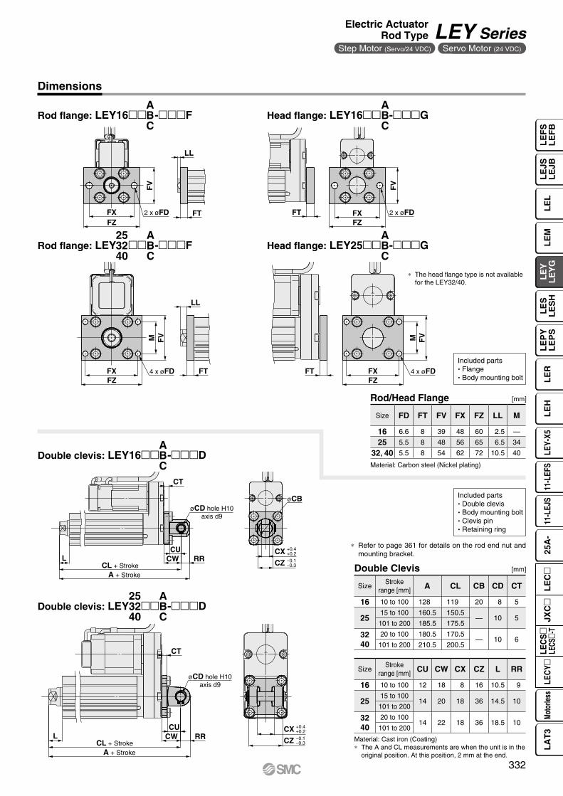
FZFX
FVM
FT
LL
4 x øFDFZFX
M FV
FT 4 x øFD
CURRCWL
CL + StrokeA + Stroke
CT
øCD hole H10axis d9
+0.4+0.2CX−0.1−0.3CZ
FXFZ
FV
FT
LL
2 x øFDFZFX
FV
FT 2 x øFD
A + StrokeCL + Stroke
CUCW RRL
CT
+0.4+0.2CX−0.1−0.3CZ
øCBøCD hole H10
axis d9
Rod flange: LEY16 -F Head flange: LEY16 -G
Rod flange: LEY -F
Double clevis: LEY16 -D
Double clevis: LEY -D253240
253240
ABC
ABC
ABC
ABC
ABC
ABC
Head flange: LEY25 -G
Material: Cast iron (Coating)∗ The A and CL measurements are when the unit is in the
original position. At this position, 2 mm at the end.
Included parts Double clevis Body mounting bolt Clevis pin Retaining ring
Included parts Flange Body mounting bolt
[mm]Double Clevis
[mm]
Material: Carbon steel (Nickel plating)
Rod/Head Flange
∗ Refer to page 361 for details on the rod end nut and mounting bracket.
∗ The head flange type is not available for the LEY32/40.
Size FD FT FV FX FZ LL M
16 6.6 8 39 48 60 2.5 —
25 5.5 8 48 56 65 6.5 34
32, 40 5.5 8 54 62 72 10.5 40
SizeStroke
range [mm] A CL CB CD CT
16 10 to 100 128 119 20 8 5
2515 to 100 160.5 150.5
— 10 5101 to 200 185.5 175.5
3240
20 to 100 180.5 170.5— 10 6
101 to 200 210.5 200.5
SizeStroke
range [mm] CU CW CX CZ L RR
16 10 to 100 12 18 8 16 10.5 9
2515 to 100
14 20 18 36 14.5 10101 to 200
3240
20 to 10014 22 18 36 18.5 10
101 to 200
Dimensions
332
Electric ActuatorRod Type LEY Series
Motorless TypeStep Motor (Servo/24 VDC) Servo Motor (24 VDC)
LE
FS
LE
FB
LE
LL
EJS
LE
JBL
EM
LE
YL
EY
GL
ES
LE
SH
LE
PY
LE
PS
LE
RL
EH
LEY-
X511
-LEF
S11
-LEJ
S25
A-
Moto
rless
LEC
Y�LE
CS
�LE
CS�-
TJX
C�
LE
C�
LA
T3

Motor
How to Order
25 100B 2 A1
Applicable Stroke Table
Sw e r t y u i o !0 !1 !2 !3
* Please consult with SMC for non-standard strokes as they are produced as special orders.
w Size
* For details, refer to the applicable stroke table below.
y Stroke [mm]
*1 When “With lock” is selected for the top mounting and right/left side parallel types, the motor body will stick out from the end of the body for size 25 with strokes of 30 mm or less. Check for interference with workpieces before selecting a model.
u Motor option
i Rod end thread
e Motor mounting position
*1 The mounting bracket is shipped together with the product but does not come assembled.
*2 For the horizontal cantilever mounting of the rod flange, head flange, or ends tapped types, use the actuator within the following stroke range. LEY25: 200 mm or less LEY32: 100 mm or less
*3 For the mounting of the double clevis type, use the actuator within the following stroke range. LEY25: 200 mm or less LEY32: 200 mm or less
*4 The rod flange type is not available for the LEY25 with a 30 mm stroke and motor option “With lock.”
*5 The head flange type is not available for the LEY32.
S2
*1 The values shown in ( ) are the leads for the size 32 top mounting, right/left side parallel types. (Equivalent leads which include the pulley ratio [1.25:1])
t Lead [mm]
o Mounting*1
For auto switches, refer to pages 363 to 365.
: Standard
q Accuracy
LEY Hq
Nil Basic type
H High-precision type
Symbol TypeMotor mounting positionTop/Parallel In-line
Nil Ends tapped/Body bottom tapped
*2
L Foot —
F Rod flange*2 *4
G Head flange*2 *5 —
D Double clevis*3 —
Symbol LEY25 LEY32*1
A 12 16 (20)
B 6 8 (10)
C 3 4 (5)
Nil Top mounting
R Right side parallel
L Left side parallel
D In-line
Nil Rod end female thread
M Rod end male thread(1 rod end nut is included.)
Nil Without option
B With lock*1
30 30
to to
500 500
2532
Stroke[mm]Model
30 50 100 150 200 250 300 350 400 450 500 Manufacturablestroke range
LEY25 — — 15 to 400
LEY32 20 to 500
AC Servo Motor LECS Series
Electric ActuatorRod TypeLEY Series LEY25, 32 25, 32Size
LECY Seriessp. 351 Dust-tight/Water-jet-proofsp. 619
r Motor type
*1 For motor type S2 and S6, the compatible driver part number suffixes are S1 and S5 respectively.
*2 For motor type T6, the compatible driver part number is LECS2-T5.
*3 For details on the driver, refer to page 764.
Symbol TypeOutput
[W]Actuator
sizeCompatible
drivers*3UL-
compliant
S2*1 AC servo motor(Incremental encoder)
100 25 LECSA-S1
S3 200 32 LECSA-S3
S6*1
AC servo motor(Absolute encoder)
100 25LECSB-S5LECSC-S5LECSS-S5
—
S7 200 32LECSB-S7LECSC-S7LECSS-S7
—
T6*2
AC servo motor(Absolute encoder)
100 25
LECSB2-T5LECSC2-T5LECSN2-T5-
—
LECSS2-T5
T7 200 32
LECSB2-T7LECSC2-T7LECSN2-T7-
—
LECSS2-T7
Secondary Battery Compatiblesp. 677 Motorless Typesp. 907
RoHS
Click here for details.Click here for details.
The LECSB-S, LECSC-S, and LECSS-S electric actuator drivers are to be discontinued. The LECSB-T, LECSC-T, and LECSS-T drivers are available as substitutes. In the product number, select T6 instead of S6, or T7 instead of S7 for the r Motor type, and select B2 instead of B1, C2 instead of C1, or S2 instead of S1 for the !2 Driver type.
333C

Motor mounting position: Top/Parallel Motor mounting position: In-line
*1 The motor and encoder cables are included. (The lock cable is also included when the motor with lock option is selected.)
*2 Standard cable entry direction is Top/Parallel: (A) Axis side In-line: (B) Counter axis side(Refer to page 796 for details.)
!0 Cable type*1 *2 !1 Cable length*1 [m]
*1 The length of the motor, encoder, and lock cables are the same.
!3 I/O cable length [m]*1
*1 When “Without driver” is selected for driver type, only “Nil: Without cable” can be selected. Refer to page 797 if I/O cable is required. (Options are shown on page 797.)
Nil Without cable
H Without cable (Connector only)
1 1.5
Nil Without cable
2 2
5 5
A 10
Nil Without cable
S Standard cable
R Robotic cable (Flexible cable)
Compatible Drivers
!2 Driver type*1
*1 When a driver type is selected, a cable is included. Select the cable type and cable length.Example)S2S2: Standard cable (2 m) + Driver (LECSS2) S2: Standard cable (2 m) Nil: Without cable and driver
Driver type
Pulse input type/Positioning type
Pulse input type
CC-Link directinput type
SSCNET # type Pulse input type CC-Link directinput type
type
Network card type
Series LECSA LECSB LECSC LECSS LECSB-T LECSC-T LECSS-T LECSN-T
Number of point tables*1 Up to 7 — Up to 255 (2 stations occupied) — Up to 255 Up to 255 (2 stations occupied) — Up to 255
Pulse input — — — — —
Applicable network — — CC-Link SSCNET 3 — CC-Link SSCNET3/HPROFINETEtherCAT®
EtherNet/IP™
Control encoder Incremental17-bit encoder
Absolute18-bit encoder
Absolute18-bit encoder
Absolute18-bit encoder
Absolute 22-bit encoder
Absolute 18-bit encoder
Absolute22-bit encoder
Absolute22-bit encoder
Communication function USB communication USB communication, RS422 communication USB communication USB communication, RS422 communication USB communication USB communication
Power supply voltage [V]
100 to 120 VAC (50/60 Hz)200 to 230 VAC (50/60 Hz)
200 to 240 VAC
(50/60 Hz)
200 to 230 VAC
(50/60 Hz)
200 to 240 VAC
(50/60 Hz)
200 to 240 VAC (50/60 Hz)
Reference page 777
*1 The LECSN-T only supports PROFINET and EtherCAT®.
Compatibledrivers
Power supply voltage [V]
Nil Without driver —
A1 LECSA1-Sm 100 to 120
A2 LECSA2-Sm 200 to 230
B1 LECSB1-Sm 100 to 120
B2LECSB2-Sm 200 to 230LECSB2-Tm 200 to 240
C1 LECSC1-Sm 100 to 120
C2LECSC2-Sm
200 to 230LECSC2-Tm
S1 LECSS1-Sm 100 to 120
S2LECSS2-Sm 200 to 230LECSS2-Tm 200 to 240
N2 LECSN2-Tm 200 to 240
92 LECSN2-Tm-9 200 to 240
E2 LECSN2-Tm-E 200 to 240
P2 LECSN2-Tm-P 200 to 240
334
Electric ActuatorRod Type LEY Series
AC Servo Motor 25, 32Size
LE
FS
LE
FB
LE
LL
EJS
LE
JBL
EM
LE
YL
EY
GL
ES
LE
SH
LE
PY
LE
PS
LE
RL
EH
LEY-
X511
-LEF
S11
-LEJ
S25
A-
Moto
rless
LEC
Y�LE
CS
�LE
CS�-
TJX
C�
LE
C�
LA
T3
B

Specifications: LECSA/LECSB/LECSC/LECSS
*1 This is the maximum value of the horizontal work load. An external guide is necessary to support the load. The actual work load changes according to the condition of the external guide. Confirm the load using the actual device.
*2 The force setting range (set values for the driver) for the force control with the torque control mode. Set it while referencing the “Force Conversion Graph” on page 309. When the control equivalent to the pushing operation of the LECP series controller is performed, select the LECSS driver and combine it with a Simple Motion module (manufactured by Mitsubishi Electric Corporation) which has a pushing operation function.
*3 The allowable speed changes according to the stroke. Set the number of rotations according to speed.
*4 The allowable collision speed for collision with the workpiece with the torque control mode
*5 A reference value for correcting an error in reciprocal operation
*6 Impact resistance: No malfunction occurred when the actuator was tested with a drop tester in both an axial direction and a perpendicular direction to the lead screw. (The test was performed with the actuator in the initial state.)Vibration resistance: No malfunction occurred in a test ranging between 45 to 2000 Hz. The test was performed in both an axial direction and a perpendicular direction to the lead screw. (The test was performed with the actuator in the initial state.)
*7 The power consumption (including the driver) is for when the actuator is operating.*8 The standby power consumption when operating (including the driver) is for when the
actuator is stopped in the set position during the operation.*9 The maximum instantaneous power consumption (including the driver) is for when the
actuator is operating.*10 Only when motor option “With lock” is selected*11 For an actuator with lock, add the power consumption for the lock.
[kg]Additional Weight
Weight[kg]Product Weight
Series LEY25S2 6 (Motor mounting position: Top/Parallel) LEY32S3
7 (Motor mounting position: Top/Parallel)Stroke [mm] 30 50 100 150 200 250 300 350 400 30 50 100 150 200 250 300 350 400 450 500
Mot
orty
pe Incremental encoder 1.31 1.38 1.55 1.81 1.99 2.16 2.34 2.51 2.69 2.42 2.53 2.82 3.29 3.57 3.85 4.14 4.42 4.70 4.98 5.26Absolute encoder 1.37 1.44 1.61 1.87 2.05 2.22 2.40 2.57 2.75 2.36 2.47 2.76 3.23 3.51 3.79 4.08 4.36 4.64 4.92 5.20
Series LEY25DS2 6 (Motor mounting position: In-line) LEY32DS3
7 (Motor mounting position: In-line)Stroke [mm] 30 50 100 150 200 250 300 350 400 30 50 100 150 200 250 300 350 400 450 500
Mot
orty
pe Incremental encoder 1.34 1.41 1.58 1.84 2.02 2.19 2.37 2.54 2.72 2.44 2.55 2.84 3.31 3.59 3.87 4.16 4.44 4.72 5.00 5.28Absolute encoder 1.40 1.47 1.64 1.90 2.08 2.25 2.43 2.60 2.78 2.38 2.49 2.78 3.25 3.53 3.81 4.10 4.38 4.66 4.94 5.22
Size 25 32
LockIncremental encoder 0.20 0.40Absolute encoder [S6/S7] 0.30 0.66
Rod end male threadMale thread 0.03 0.03Nut 0.02 0.02
Foot bracket (2 sets including mounting bolt) 0.08 0.14Rod flange (including mounting bolt)
0.17 0.20Head flange (including mounting bolt)Double clevis (including pin, retaining ring, and mounting bolt) 0.16 0.22
Model LEY25S26 (Top/Parallel)/LEY25DS2
6 (In-line) LEY32S37 (Top/Parallel) LEY32DS3
7 (In-line)
Act
uat
or
spec
ifica
tio
ns
Work load [kg]Horizontal*1 18 50 50 30 60 60 30 60 60Vertical 8 16 30 9 19 37 12 24 46
Force [N]*2 (Set value: 15 to 30%) 65 to 131 127 to 255 242 to 485 79 to 157 154 to 308 294 to 588 98 to 197 192 to 385 368 to 736Max.*3
speed[mm/s]
Strokerange
Up to 300 900 450 2251200 600 300 1000 500 250
305 to 400 600 300 150405 to 500 — — — 800 400 200 640 320 160
Pushing speed [mm/s]*4 35 or less 30 or less 30 or lessMax. acceleration/deceleration [mm/s2] 5000 5000Positioning repeatability [mm]
Basic type ±0.02High-precision type ±0.01
Lost motion [mm]*5 Basic type 0.1 or lessHigh-precision type 0.05 or less
Lead [mm] (including pulley ratio) 12 6 3 20 10 5 16 8 4Impact/Vibration resistance [m/s2]*6 50/20 50/20Actuation type Ball screw + Belt (LEY)/Ball screw (LEYD) Ball screw + Belt [1.25:1] Ball screwGuide type Sliding bushing (Piston rod) Sliding bushing (Piston rod)Operating temperature range [°C] 5 to 40 5 to 40Operating humidity range [%RH] 90 or less (No condensation) 90 or less (No condensation)Regeneration option May be required depending on speed and work load (Refer to pages 307 and 308.)
Ele
ctri
c sp
ecifi
catio
ns Motor output/Size 100 W/40 200 W/60Motor type AC servo motor (100/200 VAC) AC servo motor (100/200 VAC)
Encoder Motor type S2, S3: Incremental 17-bit encoder (Resolution: 131072 p/rev)Motor type S6, S7: Absolute 18-bit encoder (Resolution: 262144 p/rev)
Powerconsumption [W]*7
Horizontal 45 65 65Vertical 145 175 175
Standby power consumptionwhen operating [W]*8
Horizontal 2 2 2Vertical 8 8 8
Max. instantaneous power consumption [W]*9 445 724 724
Lock
uni
tsp
ecifi
catio
ns Type*10 Non-magnetizing lockHolding force [N] 131 255 485 157 308 588 197 385 736Power consumption [W] at 20°C*11 6.3 7.9 7.9Rated voltage [V] 24 VDC 0
−10%
* Refer to the next page for the LECSS-T.
335
LEY SeriesAC Servo Motor 25, 32Size

Size 25 32Lock Absolute encoder [T6/T7] 0.3 0.4
Rod end male threadMale thread 0.03 0.03Nut 0.02 0.02
Foot bracket (2 sets including mounting bolt) 0.08 0.14Rod flange (including mounting bolt)
0.17 0.20Head flange (including mounting bolt)Double clevis (including pin, retaining ring, and mounting bolt) 0.16 0.22
Model LEY25T6 (Top/Parallel)/LEY25DT6 (In-line) LEY32T7 (Top/Parallel) LEY32DT7 (In-line)
Act
uat
or
spec
ifica
tio
ns
Work load [kg]Horizontal∗1 18 50 50 30 60 60 30 60 60Vertical 8 16 30 9 19 37 12 24 46
Force [N]∗2 (Set value: 12 to 24%) 65 to 131 127 to 255 242 to 485 79 to 157 154 to 308 294 to 588 98 to 197 192 to 385 368 to 736Max.∗3
speed[mm/s]
Strokerange
Up to 300 900 450 2251200 600 300 1000 500 250
305 to 400 600 300 150405 to 500 — — — 800 400 200 640 320 160
Pushing speed [mm/s]∗4 35 or less 30 or less 30 or lessMax. acceleration/deceleration [mm/s2] 5000 5000Positioning repeatability [mm]
Basic type ±0.02 ±0.02High-precision type ±0.01 ±0.01
Lost motion∗5 [mm]
Basic type 0.1 or lessHigh-precision type 0.05 or less
Lead [mm] (including pulley ratio) 12 6 3 20 10 5 16 8 4Impact/Vibration resistance [m/s2]∗6 50/20 50/20Actuation type Ball screw + Belt (LEY)/Ball screw (LEYD) Ball screw + Belt [1.25:1] Ball screwGuide type Sliding bushing (Piston rod) Sliding bushing (Piston rod)Operating temperature range [°C] 5 to 40 5 to 40Operating humidity range [%RH] 90 or less (No condensation) 90 or less (No condensation)Regeneration option May be required depending on speed and work load (Refer to pages 307 and 308.)
Elec
tric
spe
cific
atio
ns
Motor output/Size 100 W/40 200 W/60Motor type AC servo motor (200 VAC) AC servo motor (200 VAC)
Encoder∗12 Motor type T6, T7: Absolute 22-bit encoder (Resolution: 4194304 p/rev) (For LECSB-T, LECSS-T)Motor type T6, T7: Absolute 18-bit encoder (Resolution: 262144 p/rev) (For LECSC-T)
Powerconsumption [W]∗7
Horizontal 45 65 65Vertical 145 175 175
Standby power consumptionwhen operating [W]∗8
Horizontal 2 2 2Vertical 8 8 8
Max. instantaneous power consumption [W]∗9 445 724 724
Lock
uni
tsp
ecifi
catio
ns Type∗10 Non-magnetizing lockHolding force [N] 131 255 485 157 308 588 197 385 736Power consumption [W] at 20°C∗11 6.3 7.9 7.9Rated voltage [V] 24 VDC 0
−10%
Specifications: LECS-T
[kg]
[kg]Additional Weight
WeightProduct Weight
Series LEY25T6 (Motor mounting position: Top/Parallel) LEY32T7 (Motor mounting position: Top/Parallel)Stroke [mm] 30 50 100 150 200 250 300 350 400 30 50 100 150 200 250 300 350 400 450 500
Moto
r ty
pe Absolute encoder 1.4 1.5 1.6 1.9 2.0 2.2 2.4 2.6 2.7 2.3 2.4 2.7 3.2 3.5 3.8 4.1 4.3 4.6 4.9 5.2
Series LEY25DT6 (Motor mounting position: In-line) LEY32DT7 (Motor mounting position: In-line)Stroke [mm] 30 50 100 150 200 250 300 350 400 30 50 100 150 200 250 300 350 400 450 500
Moto
r ty
pe Absolute encoder 1.4 1.5 1.6 1.9 2.1 2.2 2.4 2.6 2.8 2.4 2.5 2.8 3.2 3.5 3.8 4.1 4.4 4.6 4.9 5.2
∗1 This is the maximum value of the horizontal work load. An external guide is necessary to support the load. The actual work load changes according to the condition of the external guide. Confirm the load using the actual device.
∗2 The force setting range (set values for the driver) for the force control with the torque control mode. Set it while referencing the “Force Conversion Graph (Guide)” on page 310. When the control equivalent to the pushing operation of the JXC51/61 series controller is performed, select the LECSS-T or LECSB2-T driver.The point table no. input method is used for the LECSB2-T. When selecting the LECSS2-T, combine it with a Simple Motion module (manufactured by Mitsubishi Electric Corporation) which has a pushing operation function.
∗3 The allowable speed changes according to the stroke.∗4 The allowable collision speed for collision with the workpiece with the
torque control mode∗5 A reference value for correcting an error in reciprocal operation
∗6 Impact resistance: No malfunction occurred when the actuator was tested with a drop tester in both an axial direction and a perpendicular direction to the lead screw. (The test was performed with the actuator in the initial state.)Vibration resistance: No malfunction occurred in a test ranging between 45 to 2000 Hz. The test was performed in both an axial direction and a perpendicular direction to the lead screw. (The test was performed with the actuator in the initial state.)
∗7 The power consumption (including the driver) is for when the actuator is operating.
∗8 The standby power consumption when operating (including the driver) is for when the actuator is stopped in the set position during the operation.
∗9 The maximum instantaneous power consumption (including the driver) is for when the actuator is operating.
∗10 Only when motor option “With lock” is selected∗11 For an actuator with lock, add the power consumption for the lock.∗12 The resolution will change depending on the driver type.
336
Electric ActuatorRod Type LEY Series
AC Servo Motor 25, 32Size
LE
FS
LE
FB
LE
LL
EJS
LE
JBL
EM
LE
YL
EY
GL
ES
LE
SH
LE
PY
LE
PS
LE
RL
EH
LEY-
X511
-LEF
S11
-LEJ
S25
A-
Moto
rless
LEC
Y�LE
CS
�LE
CS�-
TJX
C�
LE
C�
LA
T3
A
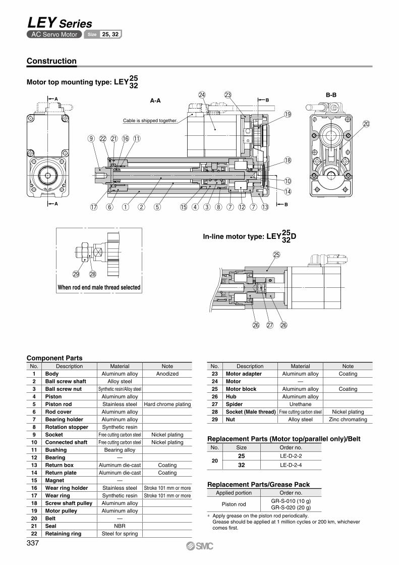
@6 @7 @6
@5
@9 @8
B
B!7 y q w t !5 r e i u u!2 !3
!4
!0
!8
!9
@3@4
!1!6@1@2o
@0Cable is shipped together.
A-AA
A
B-B
Construction
Component Parts
Motor top mounting type: LEY2532
When rod end male thread selected
In-line motor type: LEY D2532
No. Description Material Note23 Motor adapter Aluminum alloy Coating24 Motor —25 Motor block Aluminum alloy Coating26 Hub Aluminum alloy27 Spider Urethane28 Socket (Male thread) Free cutting carbon steel Nickel plating29 Nut Alloy steel Zinc chromating
No. Description Material Note1 Body Aluminum alloy Anodized2 Ball screw shaft Alloy steel3 Ball screw nut Synthetic resin/Alloy steel4 Piston Aluminum alloy5 Piston rod Stainless steel Hard chrome plating6 Rod cover Aluminum alloy7 Bearing holder Aluminum alloy8 Rotation stopper Synthetic resin9 Socket Free cutting carbon steel Nickel plating10 Connected shaft Free cutting carbon steel Nickel plating11 Bushing Bearing alloy12 Bearing —13 Return box Aluminum die-cast Coating14 Return plate Aluminum die-cast Coating15 Magnet —16 Wear ring holder Stainless steel Stroke 101 mm or more17 Wear ring Synthetic resin Stroke 101 mm or more18 Screw shaft pulley Aluminum alloy19 Motor pulley Aluminum alloy20 Belt —21 Seal NBR22 Retaining ring Steel for spring
Replacement Parts (Motor top/parallel only)/BeltNo. Size Order no.
2025 LE-D-2-2
32 LE-D-2-4
Replacement Parts/Grease PackApplied portion Order no.
Piston rodGR-S-010 (10 g)GR-S-020 (20 g)
* Apply grease on the piston rod periodically. Grease should be applied at 1 million cycles or 200 km, whichever comes first.
337
LEY SeriesAC Servo Motor 25, 32Size

MD Section XX
6 x MO thread depth MRøXA H9 depth XA
XA H9
XB
XA MAMC
ML + Stroke (MB)
MH
Rod operating range∗1
(Stroke + 4 mm)
Encoder Z-phase detecting position
M
2 ±1
�V
EV
J
�K∗2
EH
M
W
MY UM
TZ
S
X
L
Hthread depth C
B + Stroke
A + Stroke
4 x O1
thread depth R
øD
4 x O1
thread depth R
Dimensions: Motor Top/Parallel
[mm]
*1 This is the range within which the rod can move. Make sure workpieces mounted on the rod do not interfere with the workpieces and facilities around the rod.
*2 The direction of rod end width across flats (K) differs depending on the products.
SizeStroke range
[mm]
Incremental encoder Absolute encoder [S6/S7] Absolute encoder [T6/T7]
Without lock With lock Without lock With lock Without lock With lock
W X Z W X Z W X Z W X Z W X Z W X Z
2515 to 100
87 120 14.1 123.9 156.9 15.8 82.4 115.4 14.1 123.5 156.5 15.8 82.4 115.4 14.1 123 156 15.8105 to 400
3220 to 100
88.2 128.2 17.1 116.8 156.8 17.1 76.6 116.6 17.1 116.1 156.1 17.1 76.6 116.6 17.1 113.4 153.4 17.1105 to 500
SizeStroke range
[mm] A B C D EH EV H J K L M O1 R S T U Y V
2515 to 100 130.5 116
13 20 44 45.5 M8 x 1.25 24 17 14.5 34 M5 x 0.8 8 46 92 1 26.5 40105 to 400 155.5 141
3220 to 100 148.5 130
13 25 51 56.5 M8 x 1.25 31 22 18.5 40 M6 x 1.0 10 60 118 1 34 60105 to 500 178.5 160
[mm]Body Bottom Tapped
SizeStroke range
[mm] MA MB MC MD MH ML MO MR XA XB
25
15 to 39
20 46
24 32
29
50
M5 x 0.8 6.5 4 5
40 to 10042 41
101 to 124
75125 to 200 59 49.5
201 to 400 76 58
32
20 to 39
25 55
22 36
30
50
M6 x 1 8.5 5 6
40 to 10036 43
101 to 124
80125 to 200 53 51.5
201 to 500 70 60
Section XX details
338
Electric ActuatorRod Type LEY Series
AC Servo Motor 25, 32Size
LE
FS
LE
FB
LE
LL
EJS
LE
JBL
EM
LE
YL
EY
GL
ES
LE
SH
LE
PY
LE
PS
LE
RL
EH
LEY-
X511
-LEF
S11
-LEJ
S25
A-
Moto
rless
LEC
Y�LE
CS
�LE
CS�-
TJX
C�
LE
C�
LA
T3
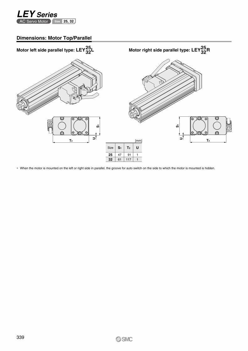
US
1
T2 T2
US
1
Dimensions: Motor Top/Parallel
Motor left side parallel type: LEY L2532 Motor right side parallel type: LEY R25
32
[mm]
* When the motor is mounted on the left or right side in parallel, the groove for auto switch on the side to which the motor is mounted is hidden.
Size S1 T2 U
25 47 91 1
32 61 117 1
339
LEY SeriesAC Servo Motor 25, 32Size

L
øD
B + Stroke
A + Stroke
W
Encoder Z-phase detecting position
Rod operating range∗1
(Stroke + 4 mm)
J
T EV
S
EH
M�K∗2
M
4 x O1
thread depth R
Hthread depth C
Z
�V
U
2 ±1
XA H9
XB
XA
Section XX
øXA H9 depth XA 6 x MOthread depth MR
MH
MA
MDMC
ML + Stroke
Dimensions: In-line Motor
[mm]
*1 This is the range within which the rod can move. Make sure workpieces mounted on the rod do not interfere with the workpieces and facilities around the rod.
*2 The direction of rod end width across flats (K) differs depending on the products.
SizeStroke range
[mm]
Incremental encoder Absolute encoder [S6/S7] Absolute encoder [T6/T7]Without lock With lock Without lock With lock Without lock With lock
A W Z A W Z A W Z A W Z A VB VC A VB VC
2515 to 100 238
87 14.6274.9
123.9 16.3233.4
82.4 14.6274.5
123.5 16.3233.4
82.4 14.6274
123 16.3105 to 400 263 299.9 258.4 299.5 258.4 299
3220 to 100 262.7
88.2 17.1291.3
116.8 17.1251.1
76.6 17.1290.6
116.1 17.1251.1
76.6 17.1287.9
113.4 17.1105 to 500 292.7 321.3 281.1 320.6 281.1 317.9
SizeStroke range
[mm] C D EH EV H J K L M O1 R S T U B V
2515 to 100
13 20 44 45.5 M8 x 1.25 24 17 14.5 34 M5 x 0.8 8 45 46.5 1.5136.5
40105 to 400 161.5
3220 to 100
13 25 51 56.5 M8 x 1.25 31 22 18.5 40 M6 x 1.0 10 60 61 1156
60105 to 500 186
[mm]Body Bottom Tapped
SizeStroke range
[mm] MA MC MD MH ML MO MR XA XB
25
15 to 39
20
24 32
29
50
M5 x 0.8 6.5 4 5
40 to 10042 41
101 to 124
75125 to 200 59 49.5
201 to 400 76 58
32
20 to 39
25
22 36
30
50
M6 x 1 8.5 5 6
40 to 10036 43
101 to 124
80125 to 200 53 51.5
201 to 500 70 60
Section XX details
340
Electric ActuatorRod Type LEY Series
AC Servo Motor 25, 32Size
LE
FS
LE
FB
LE
LL
EJS
LE
JBL
EM
LE
YL
EY
GL
ES
LE
SH
LE
PY
LE
PS
LE
RL
EH
LEY-
X511
-LEF
S11
-LEJ
S25
A-
Moto
rless
LEC
Y�LE
CS
�LE
CS�-
TJX
C�
LE
C�
LA
T3

Y Y
LS + Stroke
A + Stroke
LT
LL
LT
LG
X X
Special cap bolt
X Y
LS + Stroke LS1
LH L
Y
LX
LZ
4 x øLD
C1
L2
H1
MM
L1
Width across flats B1
øD
Outward mounting
Dimensions
ABC
Included parts Foot bracket Body mounting bolt
Foot: LEY -L2532
[mm]Foot
Material: Carbon steel (Chromating)∗ The A measurement is when the unit is in the Z-phase first detecting position. At this position, 2 mm
at the end.∗ When the motor mounting is the right or left side parallel type, the head side foot bracket should be
mounted outward.
SizeStroke range
[mm] A LS LS1 LL LD LG LH LT LX LY LZ X Y
2515 to 100 136.6 98.8
19.8 8.4 6.6 3.5 30 2.6 57 51.5 71 11.2 5.8101 to 400 161.6 123.8
3220 to 100 155.7 114
19.2 11.3 6.6 4 36 3.2 76 61.5 90 11.2 7101 to 500 185.7 144
End male thread: LEY -M2532
ABC
∗ Refer to page 361 for details on the rod end nut and mounting bracket.
∗ Refer to the precautions on page 414 when mounting end brackets such as knuckle joint or workpieces.
[mm]
∗ The L1 measurement is when the unit is in the original position. At this position, 2 mm at the end.
Size B1 C1 D H1 L1 L2 MM
25 22 20.5 20 8 38 23.5 M14 x 1.5
32 22 20.5 25 8 42.0 23.5 M14 x 1.5
341
LEY SeriesAC Servo Motor 25, 32Size
A

FZFX
M FV
FT 4 x øFDFZFX
FVM
FT
LL
4 x øFD
CURRCWL
CL + StrokeA + Stroke
CT
øCD hole H10axis d9
+0.4+0.2CX−0.1−0.3CZ
[mm]Double Clevis
Double clevis: LEY -D2532
ABC Included parts
Double clevis Body mounting bolt Clevis pin Retaining ring
Included parts Flange Body mounting bolt
[mm]
Material: Carbon steel (Nickel plating)
Rod/Head Flange
∗ Refer to page 361 for details on the rod end nut and mounting bracket.
Rod flange: LEY -F2532
ABC
ABC
Head flange: LEY25 -G
∗ The head flange type is not available for the LEY32.
Dimensions
Material: Cast iron (Coating)∗ The A and CL measurements are when the unit is in
the Z-phase first detecting position. At this position, 2 mm at the end.
SizeStroke range
[mm] CU CW CX CZ L RR
2515 to 100
14 20 18 36 14.5 10101 to 200
3220 to 100
14 22 18 36 18.5 10101 to 200
Size FD FT FV FX FZ LL M
25 5.5 8 48 56 65 6.5 34
32 5.5 8 54 62 72 10.5 40
SizeStroke range
[mm] A CL CD CT
2515 to 100 160.5 150.5
10 5101 to 200 185.5 175.5
3220 to 100 180.5 170.5
10 6101 to 200 210.5 200.5
342
Electric ActuatorRod Type LEY Series
AC Servo Motor 25, 32Size
LE
FS
LE
FB
LE
LL
EJS
LE
JBL
EM
LE
YL
EY
GL
ES
LE
SH
LE
PY
LE
PS
LE
RL
EH
LEY-
X511
-LEF
S11
-LEJ
S25
A-
Moto
rless
LEC
Y�LE
CS
�LE
CS�-
TJX
C�
LE
C�
LA
T3

w y !0i oe r tq u !1 !2 !3 !4
Applicable Stroke Table
* Please consult with SMC for non-standard strokes as they are produced as special orders.
Stroke[mm]
Model50 100 150 200 250 300 350 400 450 500 600 700 800 Manufacturable
stroke range
LEY63 50 to 800
S 2BH S4 200LEY 63 A2
AC Servo Motor LECS Series
Electric ActuatorRod Type Dust-tight/Water-jet-proof (IP65 Equivalent)
LEY Series LEY63 63Size
LECY Seriessp. 351 Motorless Typesp. 907
How to Order
* Option
Refer to page 305 for model selection.
* When a driver type is selected, a cable is included. Select the cable type and cable length.
Example) S2S2: Standard cable (2 m) + Driver (LECSS2) S2: Standard cable (2 m) Nil: Without cable and driver
!2 Cable length*2 [m]
*2 The length of the encoder, motor, and lock cables are the same.
Nil Without cable2 25 5A 10
!1 Cable type*1
*1 The motor and encoder cables are included. (The lock cable is also included when the motor with lock option is selected.)
* Standard cable entry direction is • Top/Parallel: (A) Axis side • In-line: (B) Counter axis side (Refer to page 796 for details.)
Nil Without cableS Standard cableR Robotic cable (Flexible cable)
*1 The mounting bracket is shipped together with the product but does not come assembled.
*2 For the horizontal cantilever mounting of the rod flange or ends tapped types, use the actuator within the following stroke range.
• LEY63: 400 mm or less*3 For the mounting of the double clevis type, use the ac-
tuator within the following stroke range.• LEY63: 300 mm or less
!0 Mounting*1
Symbol TypeMotor mounting positionTop/Parallel In-line
Nil Ends tapped/Body bottom tapped
*2
L Foot —F Rod flange*2 D Double clevis*3 —
y Stroke [mm]50 50to to
800 800
t Lead [mm]
*1 Screw lead 5 mm, Pulley ratio [4:7] equivalent lead
*2 Only available for top mounting and right/left side parallel types
Symbol LEY63A 20B 10C 5L 2.86*1 *2
o Rod end threadNil Rod end female thread
M Rod end male thread(1 rod end nut is included.)
u Dust-tight/Water-jet-proof
* When using the dust-tight/water-jet-proof (IP65 equivalent), correctly mount the fitting and tubing to the vent hole tap, and then place the end of the tubing in an area not exposed to dust or water.
* The fitting and tubing should be provided sepa-rately by the customer. Select [Applicable tubing O.D.: ø4 or more, Connection thread: Rc1/8].
* Cannot be used in an environment where oil such as cutting oil splashes or it is constantly exposed to water. Take appropriate protective measures. For details on enclosure, refer to the “Enclosure” on page 415.
Nil IP5x equivalent (Dust-protected)
P IP65 equivalent (Dust-tight/Water-jet-proof)/With vent hole tap
i Motor optionNil Without optionB With lock
q AccuracyNil Basic typeH High-precision type
w Size63
e Motor mounting positionNil Top mountingR Right side parallelL Left side parallelD In-line
!4 I/O cable length [m]*1
Nil Without cableH Without cable (Connector only)1 1.5
*1 When “Without driver” is selected for driver type, only “Nil: Without cable” can be selected. Refer to page 797 if I/O cable is required. (Options are shown on page 797.)
* For details, refer to the applicable stroke table below.
r Motor type
Symbol TypeOutput[W]
Actuatorsize
Compatibledrivers
UL-compliant
S4AC servo motor
(Incremental encoder)
400 63 LECSA2-S4 V
S8AC servo motor
(Absolute encoder)
400 63LECSB2-S8LECSC2-S8LECSS2-S8
—
T8AC servo motor
(Absolute encoder)
400 63
LECSB2-T8LECSC2-T8LECSN2-T8-
—
LECSS2-T8 V
!3 Driver type*
Compatible drivers Power supply voltageNil Without driver —A2 LECSA2-S4 200 to 230
B2LECSB2-S8 200 to 230LECSB2-T8 200 to 240
C2LECSC2-S8
200 to 230LECSC2-T8
S2LECSS2-S8 200 to 230LECSS2-T8 200 to 240
N2 LECSN2-T8 200 to 240E2 LECSN2-T8-E 200 to 24092 LECSN2-T8-9 200 to 240P2 LECSN2-T8-P 200 to 240
The LECSB-S, LECSC-S, and LECSS-S electric actuator drivers a re to be d i scon t i nued . The LECSB-T, LECSC-T, and LECSS-T drivers are available as substitutes. In the product number, select T8 instead of S8 for the ❹ Motor type.
Click here for details.Click here for details.
343C

Weight
Product Weight Additional Weight [kg] [kg]
Specifications
Size 63
Lock
Incremental encoder 0.4Absolute encoder(Motor type S8) 0.6
Absolute encoder(Motor type T8) 0.4
Rod end male thread
Male thread 0.12Nut 0.04
Foot bracket (2 sets including mounting bolt) 0.26Rod flange (including mounting bolt) 0.51Double clevis (including pin, retaining ring, and mounting bolt) 0.58
Series LEY63S48 (Motor mounting position: Top/Parallel)
Stroke [mm] 50 100 150 200 250 300 350 400 450 500 600 700 800
Mo
tor
typ
e Incrementalencoder 4.9 5.4 6.0 6.6 7.8 8.3 8.9 9.4 10.0 10.5 12.2 13.4 14.5
Absolute encoder(Motor type S8) 5.0 5.5 6.1 6.7 7.9 8.4 9.0 9.5 10.1 10.6 12.3 13.5 14.6
Absolute encoder(Motor type T8) 4.9 5.4 6.0 6.6 7.8 8.3 8.9 9.4 10.0 10.5 12.2 13.4 14.5
Series LEY63DS48 (Motor mounting position: In-line)
Stroke [mm] 50 100 150 200 250 300 350 400 450 500 600 700 800
Mo
tor
typ
e Incrementalencoder 5.1 5.6 6.2 6.7 7.9 8.4 9.0 9.6 10.2 10.7 12.4 13.5 14.7
Absolute encoder(Motor type S8) 5.2 5.7 6.3 6.8 8.0 8.5 9.1 9.7 10.3 10.8 12.5 13.6 14.8
Absolute encoder(Motor type T8) 5.1 5.6 6.2 6.7 7.9 8.4 9.0 9.6 10.2 10.7 12.4 13.5 14.7
∗1 This is the maximum value of the horizontal work load. An external guide is necessary to support the load. The actual work load changes according to the condition of the external guide. Confirm the load using the actual device.
∗2 Set values for the driver∗3 The force setting range (set values for the driver) for the force control with the torque control mode. The force and duty ratio change according to the set value. Set it while referencing the “Force
Conversion Graph” on page 309. When the control equivalent to the pushing operation of the JXC51/61 series controller is performed, select the LECSS, LECSS-T or LECSB2-T driver.The point table no. input method is used for the LECSB2-T. When selecting the LECSS or LECSS2-T, combine it with a Simple Motion module (manufactured by Mitsubishi Electric Cor-poration) which has a pushing operation function.
∗4 For the motor type T8, the set value is from 12 to 40%.∗5 The allowable speed changes according to the stroke. Set the number of rotations according to speed.∗6 The allowable collision speed for collision with the workpiece with the torque control mode∗7 A reference value for correcting an error in reciprocal operation∗8 Impact resistance: No malfunction occurred when the actuator was tested with a drop tester in both an axial direction and a perpendicular direction to
the lead screw. (The test was performed with the actuator in the initial state.)Vibration resistance: No malfunction occurred in a test ranging between 45 to 2000 Hz. The test was performed in both an axial direction and a perpen-
dicular direction to the lead screw. (The test was performed with the actuator in the initial state.)∗9 The power consumption (including the driver) is for when the actuator is operating.∗10 The standby power consumption when operating (including the driver) is for when the actuator is stopped in the set position during the operation.∗11 The maximum instantaneous power consumption (including the driver) is for when the actuator is operating.∗12 Only when motor option “With lock” is selected∗13 For an actuator with lock, add the power consumption for the lock.∗14 When mounting vertically and using the product facing upwards in an environment where water is present, take necessary measures to prevent water
from splashing on the rod cover, because water will accumulate on the rod seal due to the structure of the product.∗15 For motor type T8, the resolution will change depending on the driver type.
Model LEY63S48 /T8 (Top/Parallel) LEY63DS4
8 /T8 (In-line)
Act
uat
or
spec
ifica
tio
ns
Work load [kg]Horizontal∗1 40 70 80 200 40 70 80Vertical∗14 19 38 72 115 19 38 72
Force [N]/Set value∗2: 15 to 50%∗3, 4 156 to 521 304 to 1012 573 to 1910 1003 to 3343 156 to 521 304 to 1012 573 to 1910
∗5Max. speed[mm/s]
Strokerange
Up to 500 1000 500 250
70
1000 500 250505 to 600 800 400 200 800 400 200605 to 700 600 300 150 600 300 150705 to 800 500 250 125 500 250 125
Pushing speed [mm/s]∗6 30 or lessMax. acceleration/deceleration [mm/s2] 5000 3000 5000Positioning repeatability [mm]
Basic type ±0.02High-precision type ±0.01
Lost motion [mm]∗7 Basic type 0.1 or lessHigh-precision type 0.05 or less
Screw lead [mm] (including pulley ratio) 20 10 5 5 (2.86) 20 10 5Impact/Vibration resistance [m/s2]∗8 50/20Actuation type Ball screw + Belt Ball screw + Belt [Pulley ratio 4:7] Ball screwGuide type Sliding bushing (Piston rod)Operating temperature range [°C] 5 to 40Operating humidity range [%RH] 90 or less (No condensation)Regeneration option May be required depending on speed and work load (Refer to pages 307 and 308.)
Ele
ctri
c sp
ecifi
cati
on
s
Motor output/Size 400 W/60Motor type AC servo motor (200 VAC)
Encoder∗15
Motor type S4: Incremental 17-bit encoder (Resolution: 131072 p/rev)Motor type S8: Absolute 18-bit encoder (Resolution: 262144 p/rev)
Motor type T8: Absolute 22-bit encoder (Resolution: 4194304 p/rev) (For LECSB2-T8, LECSS2-T8)Motor type T8: Absolute 18-bit encoder (Resolution: 262144 p/rev) (For LECSC2-T8)
Power consumption [W]∗9 Horizontal 210Vertical 230
Standby power consumptionwhen operating [W]∗10
Horizontal 2Vertical 18
Max. instantaneous power consumption [W]∗11 1275
Lo
ck u
nit
sp
ecifi
cati
on
s Type∗12 Non-magnetizing lockHolding force [N] 313 607 1146 2006 313 607 1146Power consumption [W] at 20°C∗13 7.9Rated voltage [V] 24 VDC 0
−10%
344
Electric ActuatorRod Type LEY Series
Motorless TypeAC Servo Motor 63Size Dust-tight/Water-jet-proof (IP65 Equivalent)
* Option
LE
FS
LE
FB
LE
LL
EJS
LE
JBL
EM
LE
YL
EY
GL
ES
LE
SH
LE
PY
LE
PS
LE
RL
EH
LEY-
X511
-LEF
S11
-LEJ
S25
A-
Moto
rless
LEC
Y�LE
CS
�LE
CS�-
TJX
C�
LE
C�
LA
T3
A

Cable is shipped together.
y
o
q reiu @0!6 !5 !4 !1 !2
!7
wt
!3
!0 @8!9
!8
@3@4
@1@2
@9 @9#0
@7@8
@4
@5@6
When rod end male thread selected
Component PartsNo. Description Material Note
1 Body Aluminum alloy Anodized
2 Ball screw shaft Alloy steel
3 Ball screw nut Synthetic resin/Alloy steel
4 Piston Aluminum alloy
5 Piston rod Stainless steel Hard chrome plating
6 Rod cover Aluminum alloy
7 Bearing holder Aluminum alloy
8 Rotation stopper Synthetic resin
9 Socket Free cutting carbon steel Nickel plating
10 Bushing Bearing alloy
11 Bearing —
12 Return box Aluminum alloy Coating
13 Return plate Aluminum alloy Coating
14 Magnet —
15 Wear ring holder Stainless steel
No. Description Material Note
16 Wear ring Synthetic resin
17 Screw shaft pulley Aluminum alloy
18 Motor pulley Aluminum alloy
19 Belt —
20 Lock nut Alloy steel Black dyed
21 Seal NBR
22 Retaining ring Steel for spring
23 Motor adapter Aluminum alloy Coating
24 Motor —
25 Socket (Male thread) Free cutting carbon steel Nickel plating
26 Nut Alloy steel Trivalent chromating
27 Motor block Aluminum alloy Coating
28 Spacer A Stainless steel
29 Hub Aluminum alloy
30 Spider Urethane
Replacement Parts (Motor top/parallel only)/BeltNo. Size Lead Order no.
19 63A/B/C LE-D-2-5
L LE-D-2-6
Construction
Motor top mounting type: LEY63
In-line motor type: LEY63D
Replacement Parts/Grease PackApplied portion Order no.
Piston rodGR-S-010 (10 g)GR-S-020 (20 g)
* Apply grease on the piston rod periodically. Grease should be applied at 1 million cycles or 200 km, whichever comes first.
345
LEY SeriesAC Servo Motor 63Size Dust-tight/Water-jet-proof (IP65 Equivalent)
* Option

ZZ
Section XX details
XAXBXA H9
ML + Stroke
Section XXMCMA
øXA H9 depth XA6 x MOthread depth MR
MH
MD
ZT
UM
SM
4 x O1
thread depth RA + Stroke
B + Stroke
YL
XW
Encoder Z-phase detecting position
4 ±1
Rod operating range∗1
(Stroke + 8 mm)
øD
EV
�V
J
EHM
4 x O1
thread depth R
M
H x 2thread depth C
�K∗2
Rc1/8Vent hole tap∗1
18
IP65 equivalent (Dust-tight/Water-jet-proof): LEY63-P(View ZZ)
*1 When using the dust-tight/water-jet-proof (IP65 equivalent), correctly mount the fitting and tubing to the vent hole tap, and then place the end of the tubing in an area not exposed to dust or water. The fitting and tubing should be provided separately by the customer.Select [Applicable tubing O.D.: ø4 or more, Connection thread: Rc1/8].
[mm]
SizeStroke range
[mm] A B C D EH EV H J K L M O1 R S Y T U V
63 Up to 200 192.6 155.2
21 40 76 82 M16 x 2 44 36 37.4 60 M8 x 1.25 16 80 32.2 146 4 60205 to 500 227.6 190.2
505 to 800 262.6 225.2
SizeStroke range
[mm]
Incremental encoder Absolute encoder [S8] Absolute encoder [T8]
Without lock With lock Without lock With lock Without lock With lock
W X Z W X Z W X Z W X Z W X Z W X Z
63 Up to 200
110.2 150.215.6
(16.6)*1 138.8 178.815.6
(16.6)*1 98.5 138.515.6
(16.6)*1 138 17815.6
(16.6)*1 98.3 138.315.6
(16.6)*1 135.1 175.115.6
(16.6)*1205 to 500
505 to 800
*1 The values in ( ) are the dimensions when L is selected for screw lead.
Dimensions: Motor Top/Parallel
*1 This is the range within which the rod can move.Make sure workpieces mounted on the rod do not interfere with the workpieces and facilities around the rod.
*2 The direction of rod end width across flats (K) differs depending on the products.
[mm]
SizeStroke range
[mm] MA MC MD MH ML MO MR XA XB
63
50 to 74
38
24 50
4465
M8 x 1.25 10 6 775 to 124 45 60.5125 to 200 58 67201 to 500
86 81100
501 to 800 135
Body Bottom Tapped
346
Electric ActuatorRod Type LEY Series
Motorless TypeAC Servo Motor 63Size Dust-tight/Water-jet-proof (IP65 Equivalent)
* Option
LE
FS
LE
FB
LE
LL
EJS
LE
JBL
EM
LE
YL
EY
GL
ES
LE
SH
LE
PY
LE
PS
LE
RL
EH
LEY-
X511
-LEF
S11
-LEJ
S25
A-
Moto
rless
LEC
Y�LE
CS
�LE
CS�-
TJX
C�
LE
C�
LA
T3

T2
S1
U
S1
T2 U
Dimensions: Motor Top/Parallel
* When the motor is mounted on the left or right side in parallel, the groove for auto switch on the side to which the motor is mounted is hidden.
[mm]
Size S1 T2 U63 84 142 4
Motor left side parallel type: LEY63L Motor right side parallel type: LEY63R
347
LEY SeriesAC Servo Motor 63Size Dust-tight/Water-jet-proof (IP65 Equivalent)
* Option

10.5
50
Rc1/8Vent hole tap∗1
U�VWB + Stroke
A + Stroke
Rod operating range∗1
(Stroke + 8 mm)
4 ±1
L
M
�K∗2
MEHS
JE
VTZ
H thread effective depth C
4 x O1 thread effective depth R
Encoder Z-phase detecting position
øD
ZZ
MH
6 x MO threadeffective depth MRøXA H9 depth XA
XAXBXA H9
MAMC
ML + Stroke
MDSection XX
Section XX details
Dimensions: In-line Motor
LEY63D
IP65 equivalent (Dust-tight/Water-jet-proof): LEY63D-P
*1 This is the range within which the rod can move. Make sure workpieces mounted on the rod do not interfere with the workpieces and facilities around the rod.
*2 The direction of rod end width across flats (K) differs depending on the products.
[mm]
*1 When using the dust-tight/water-jet-proof (IP65 equivalent), correctly mount the fitting and tubing to the vent hole tap, and then place the end of the tubing in an area not exposed to dust or water. The fitting and tubing should be provided separately by the customer.Select [Applicable tubing O.D.: ø4 or more, Connection thread: Rc1/8].
(View ZZ)
[mm]
SizeStroke range
[mm] MA MC MD MH ML MO MR XA XB
63
50 to 74
38
24 50
4465
M8 x 1.25 10 6 775 to 124 45 60.5125 to 200 58 67201 to 500
86 81100
501 to 800 135
Body Bottom Tapped
SizeStroke range
[mm] C D EH EV H J K L M O1 R S T U B V
63 Up to 200
21 40 76 82 M16 x 2 44 36 37.4 60 M8 x 1.25 16 78 83 5
190.7
60205 to 500 225.7
505 to 800 260.7
SizeStroke range
[mm]
Incremental encoder [S4] Absolute encoder [S8] Absolute encoder [T8]
Without lock With lock Without lock With lock Without lock With lock
A W Z A W Z A W Z A W Z A W Z A W Z
63Up to 200 338.3
110.2 8.1
366.9
138.8 8.1
326.6
98.5 8.1
366.1
138 8.1
326.4
98.3 8.1
363.2
135.1 8.1205 to 500 373.3 401.9 361.6 401.1 361.4 398.2
505 to 800 408.3 436.9 396.6 436.1 396.4 433.2
348
Electric ActuatorRod Type LEY Series
Motorless TypeAC Servo Motor 63Size Dust-tight/Water-jet-proof (IP65 Equivalent)
* Option
LE
FS
LE
FB
LE
LL
EJS
LE
JBL
EM
LE
YL
EY
GL
ES
LE
SH
LE
PY
LE
PS
LE
RL
EH
LEY-
X511
-LEF
S11
-LEJ
S25
A-
Moto
rless
LEC
Y�LE
CS
�LE
CS�-
TJX
C�
LE
C�
LA
T3
A
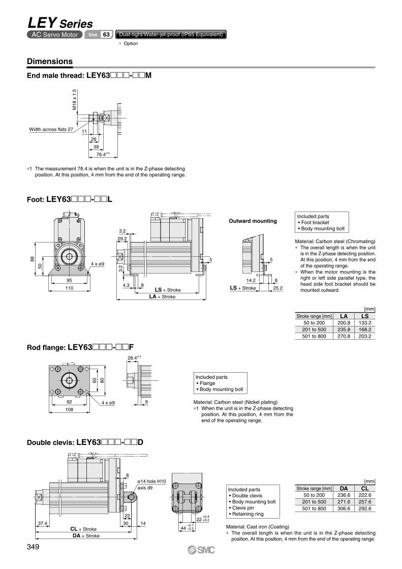
M18
x 1
.5
76.4∗1
39
26
Width across flats 27 11
Outward mounting
110
95
88
50
4 x ø9
LA + StrokeLS + Stroke
84.3
3.2
29.2
3.2
5 5
25.2
814.2
LS + Stroke
28.4∗1
9
108
92
60 80
4 x ø9
DA + StrokeCL + Stroke
1430
22
ø14 hole H10axis d9
8
37.4 −0.144 −0.3
+0.422 +0.2
End male thread: LEY63-M
*1 The measurement 76.4 is when the unit is in the Z-phase detecting position. At this position, 4 mm from the end of the operating range.
Included parts• Flange• Body mounting bolt
Included parts• Foot bracket• Body mounting bolt
Included parts• Double clevis• Body mounting bolt• Clevis pin• Retaining ring
Material: Carbon steel (Chromating)* The overall length is when the unit
is in the Z-phase detecting position. At this position, 4 mm from the end of the operating range.
* When the motor mounting is the right or left side parallel type, the head side foot bracket should be mounted outward.
Rod flange: LEY63-F
Foot: LEY63-L
Double clevis: LEY63-D
Dimensions
Material: Carbon steel (Nickel plating)*1 When the unit is in the Z-phase detecting
position. At this position, 4 mm from the end of the operating range.
Material: Cast iron (Coating)* The overall length is when the unit is in the Z-phase detecting
position. At this position, 4 mm from the end of the operating range.
[mm]Stroke range [mm] LA LS
50 to 200 200.8 133.2201 to 500 235.8 168.2501 to 800 270.8 203.2
[mm]Stroke range [mm] DA CL
50 to 200 236.6 222.6201 to 500 271.6 257.6501 to 800 306.6 292.6
349
LEY SeriesAC Servo Motor 63Size Dust-tight/Water-jet-proof (IP65 Equivalent)
* Option

350
LE
FS
LE
FB
LE
LL
EJS
LE
JBL
EM
LE
YL
EY
GL
ES
LE
SH
LE
PY
LE
PS
LE
RL
EH
LEY-
X511
-LEF
S11
-LEJ
S25
A-
Moto
rless
LEC
Y�LE
CS
�LE
CS�-
TJX
C�
LE
C�
LA
T3
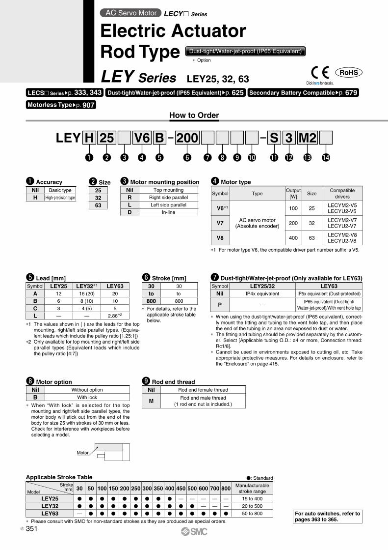
Motor
How to Order
Applicable Stroke Table
* Please consult with SMC for non-standard strokes as they are produced as special orders.
* When “With lock” is selected for the top mounting and right/left side parallel types, the motor body will stick out from the end of the body for size 25 with strokes of 30 mm or less.Check for interference with workpieces before selecting a model.
i Motor option o Rod end thread
e Motor mounting position
For auto switches, refer to pages 363 to 365.
r Motor type
V: Standard
Symbol TypeOutput
[W]Size
Compatibledrivers
V6*1
AC servo motor(Absolute encoder)
100 25 LECYM2-V5LECYU2-V5
V7 200 32 LECYM2-V7LECYU2-V7
V8 400 63 LECYM2-V8LECYU2-V8
*1 The values shown in ( ) are the leads for the top mounting, right/left side parallel types. (Equiva-lent leads which include the pulley ratio [1.25:1])
*2 Only available for top mounting and right/left side parallel types (Equivalent leads which include the pulley ratio [4:7])
t Lead [mm]Symbol LEY25 LEY32*1 LEY63
A 12 16 (20) 20
B 6 8 (10) 10
C 3 4 (5) 5
L — — 2.86*2
Nil Top mounting
R Right side parallel
L Left side parallel
D In-line
Nil Rod end female thread
MRod end male thread
(1 rod end nut is included.)
* When using the dust-tight/water-jet-proof (IP65 equivalent), correct-ly mount the fitting and tubing to the vent hole tap, and then place the end of the tubing in an area not exposed to dust or water.
* The fitting and tubing should be provided separately by the custom-er. Select [Applicable tubing O.D.: ø4 or more, Connection thread: Rc1/8].
* Cannot be used in environments exposed to cutting oil, etc. Take appropriate protective measures. For details on enclosure, refer to the “Enclosure” on page 415.
u Dust-tight/Water-jet-proof (Only available for LEY63)Symbol LEY25/32 LEY63
Nil IP4x equivalent IP5x equivalent (Dust-protected)
P —IP65 equivalent (Dust-tight/
Water-jet-proof)/With vent hole tap
Nil Without option
B With lock
* For details, refer to the applicable stroke table below.
y Stroke [mm]30 30
to to
800 800
Stroke[mm]Model
30 50 100 150 200 250 300 350 400 450 500 600 700 800 Manufacturablestroke range
LEY25 V V V V V V V V V — — — — — 15 to 400
LEY32 V V V V V V V V V V V — — — 20 to 500
LEY63 — V V V V V V V V V V V V V 50 to 800
w Size253263
LEY 25 200BH 3 M2Sw e r tq y u i o !0 !1 !2 !3 !4
V6
q AccuracyNil Basic type
H High-precision type
AC Servo Motor LECY Series
Electric ActuatorRod Type Dust-tight/Water-jet-proof (IP65 Equivalent)
LEY Series LEY25, 32, 63LECS Seriessp. 333, 343 Dust-tight/Water-jet-proof (IP65 Equivalent)sp. 625 Secondary Battery Compatiblesp. 679
* Option
*1 For motor type V6, the compatible driver part number suffix is V5.
Motorless Typesp. 907
Click here for details.
351A
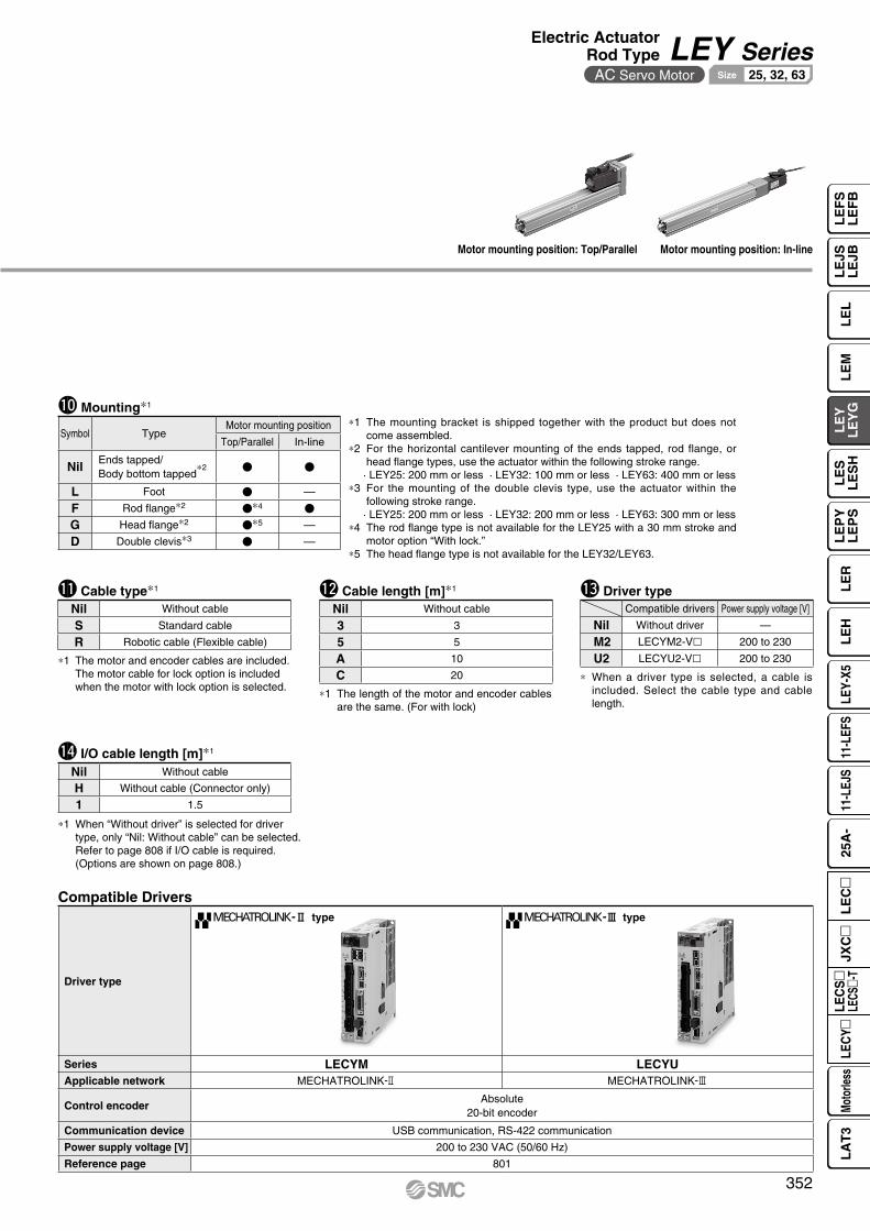
Motor mounting position: Top/Parallel Motor mounting position: In-line
!1 Cable type∗1 !2 Cable length [m]∗1 !3 Driver type
∗ When a driver type is selected, a cable is included. Select the cable type and cable length.
Compatible drivers Power supply voltage [V]
Nil Without driver —
M2 LECYM2-Vl 200 to 230
U2 LECYU2-Vl 200 to 230
Nil Without cable
3 3
5 5
A 10
C 20
Nil Without cable
S Standard cable
R Robotic cable (Flexible cable)
Compatible Drivers
Driver type
-@ type -# type
Series LECYM LECYUApplicable network MECHATROLINK-2 MECHATROLINK-3
Control encoderAbsolute
20-bit encoder
Communication device USB communication, RS-422 communication
Power supply voltage [V] 200 to 230 VAC (50/60 Hz)
Reference page 801
∗1 The mounting bracket is shipped together with the product but does not come assembled.
∗2 For the horizontal cantilever mounting of the ends tapped, rod flange, or head flange types, use the actuator within the following stroke range.
· LEY25: 200 mm or less · LEY32: 100 mm or less · LEY63: 400 mm or less∗3 For the mounting of the double clevis type, use the actuator within the
following stroke range.· LEY25: 200 mm or less · LEY32: 200 mm or less · LEY63: 300 mm or less
∗4 The rod flange type is not available for the LEY25 with a 30 mm stroke and motor option “With lock.”
∗5 The head flange type is not available for the LEY32/LEY63.
Symbol TypeMotor mounting position
Top/Parallel In-line
NilEnds tapped/
∗2Body bottom tapped
V V
L Foot V —F Rod flange∗2 V∗4 V
G Head flange∗2 V∗5 —D Double clevis∗3 V —
!0 Mounting∗1
!4 I/O cable length [m]∗1
Nil Without cable
H Without cable (Connector only)
1 1.5
∗1 When “Without driver” is selected for driver type, only “Nil: Without cable” can be selected. Refer to page 808 if I/O cable is required. (Options are shown on page 808.)
∗1 The length of the motor and encoder cables are the same. (For with lock)
∗1 The motor and encoder cables are included. The motor cable for lock option is included when the motor with lock option is selected.
352
Electric ActuatorRod Type LEY SeriesAC Servo Motor 25, 32, 63Size
LE
FS
LE
FB
LE
LL
EJS
LE
JBL
EM
LE
YL
EY
GL
ES
LE
SH
LE
PY
LE
PS
LE
RL
EH
LEY-
X511
-LEF
S11
-LEJ
S25
A-
Moto
rless
LEC
Y�LE
CS
�LE
CS�-
TJX
C�
LE
C�
LA
T3

Model LEY25V6 (Top/Parallel)/LEY25DV6 (In-line) LEY32V7 (Top/Parallel) LEY32DV7 (In-line)
Act
uat
or
spec
ifica
tio
ns
Work load [kg]Horizontal*1 18 50 50 30 60 60 30 60 60Vertical 8 16 30 9 19 37 12 24 46
Force [N]*2
(Set value: 45 to 90%) 65 to 131 127 to 255 242 to 485 79 to 157 154 to 308 294 to 588 98 to 197 192 to 385 368 to 736
Max.*3
speed[mm/s]
Strokerange
Up to 300 900 450 2251200 600 300 1000 500 250
305 to 400 600 300 150405 to 500 — — — 800 400 200 640 320 160
Pushing speed [mm/s]*4 35 or less 30 or less 30 or lessMax. acceleration/deceleration [mm/s2] 5000 5000Positioning repeatability [mm]
Basic type ±0.02 ±0.02High-precision type ±0.01 ±0.01
Lost motion*5
[mm] Basic type 0.1 or less 0.1 or lessHigh-precision type 0.05 or less 0.05 or less
Lead [mm] (including pulley ratio) 12 6 3 20 10 5 16 8 4Impact/Vibration resistance [m/s2]*6 50/20 50/20Actuation type Ball screw + Belt (LEY)/Ball screw (LEYD) Ball screw + Belt [1.25:1] Ball screwGuide type Sliding bushing (Piston rod) Sliding bushing (Piston rod)Operating temperature range [°C] 5 to 40 5 to 40Operating humidity range [%RH] 90 or less (No condensation) 90 or less (No condensation)Conditions for*7
“Regenerative resistor” [kg]Horizontal Not required Not requiredVertical 6 or more 4 or more
Ele
ctri
c sp
ecifi
catio
ns Motor output/Size 100 W/40 200 W/60Motor type AC servo motor (200 VAC) AC servo motor (200 VAC)Encoder Absolute 20-bit encoder (Resolution: 1048576 p/rev)Powerconsumption [W]*8
Horizontal 45 65 65Vertical 145 175 175
Standby power consumptionwhen operating [W]*9
Horizontal 2 2 2Vertical 8 8 8
Max. instantaneous power consumption [W]*10 445 724 724
Lock
uni
tsp
ecifi
catio
ns Type*11 Non-magnetizing lockHolding force [N] 131 255 485 157 308 588 197 385 736Power consumption [W] at 20°C*12 5.5 6 6Rated voltage [V] 24 VDC +10%
0
Size 25 32Lock 0.30 0.60
Rod end male threadMale thread 0.03 0.03Nut 0.02 0.02
Foot bracket (2 sets including mounting bolt) 0.08 0.14Rod flange (including mounting bolt)
0.17 0.20Head flange (including mounting bolt)Double clevis (including pin, retaining ring, and mounting bolt) 0.16 0.22
Series LEY25V6 (Motor mounting position: Top/Parallel) LEY32V7 (Motor mounting position: Top/Parallel)Stroke [mm] 30 50 100 150 200 250 300 350 400 30 50 100 150 200 250 300 350 400 450 500Weight [kg] 1.2 1.3 1.6 1.7 1.9 2.1 2.2 2.4 2.6 2.3 2.4 2.7 3.2 3.5 3.8 4.0 4.3 4.6 4.9 5.2
Series LEY25DV6 (Motor mounting position: In-line) LEY32DV7 (Motor mounting position: In-line)Stroke [mm] 30 50 100 150 200 250 300 350 400 30 50 100 150 200 250 300 350 400 450 500Weight [kg] 1.2 1.3 1.5 1.7 1.9 2.1 2.3 2.4 2.6 2.3 2.4 2.7 3.2 3.5 3.8 4.1 4.3 4.6 4.9 5.2
[kg]
[kg]Additional Weight
Specifications
WeightProduct Weight
*1 This is the maximum value of the horizontal work load. An external guide is necessary to support the load. The actual work load changes according to the condition of the external guide. Confirm the load using the actual device.
*2 The force setting range (set values for the driver) for the force control with the torque control mode. Set it while referencing the “Force Conversion Graph (Guide)” on page 316.
*3 The allowable speed changes according to the stroke.*4 The allowable collision speed for collision with the workpiece with the torque control mode*5 A reference value for correcting an error in reciprocal operation*6 Impact resistance: No malfunction occurred when the actuator was tested with a
drop tester in both an axial direction and a perpendicular direction to the lead screw. (The test was performed with the actuator in the initial state.)Vibration resistance: No malfunction occurred in a test ranging between 45 to 2000 Hz. The test was performed in both an axial direction and a perpendicular direction to the lead screw. (The test was performed with the actuator in the initial state.)
*7 The work load conditions which require the “Regenerative resistor” when operating at the maximum speed (Duty ratio: 100%). Order the regenerative resistor separately. For details, refer to the “Conditions for Regenerative Resistor (Guide)” on pages 314 and 315.
*8 The power consumption (including the driver) is for when the actuator is operating.
*9 The standby power consumption when operating (including the driver) is for when the actuator is stopped in the set position during the operation.
*10 The maximum instantaneous power consumption (including the driver) is for when the actuator is operating.
*11 Only when motor option “With lock” is selected*12 For an actuator with lock, add the power consumption for the lock.
353
LEY SeriesAC Servo Motor 25, 32, 63Size

354
Series LEY63V8 (Motor mounting position: Top/Parallel)Stroke [mm] 50 100 150 200 250 300 350 400 450 500 600 700 800Weight [kg] 4.8 5.3 6.0 6.5 7.7 8.2 8.8 9.3 9.9 10.4 12.1 13.3 14.4
Series LEY63DV8 (Motor mounting position: In-line)Stroke [mm] 50 100 150 200 250 300 350 400 450 500 600 700 800Weight [kg] 5.0 5.5 6.1 6.6 7.8 8.3 9.0 9.5 10.1 10.6 12.3 13.4 14.6
Additional Weight [kg] [kg]
*1 This is the maximum value of the horizontal work load. An external guide is necessary to support the load. The actual work load changes according to the condition of the external guide. Confirm the load using the actual device.
*2 Set values for the driver*3 The force setting range (set values for the driver) for the force control with the torque control mode. The force and duty ratio change according to the set
value. Set it while referencing the “Force Conversion Graph (Guide)” on page 316.*4 The allowable speed changes according to the stroke.*5 The allowable collision speed for collision with the workpiece with the torque control mode*6 A reference value for correcting an error in reciprocal operation*7 Impact resistance: No malfunction occurred when the actuator was tested with a drop tester in both an axial direction and a perpendicular direction to
the lead screw. (The test was performed with the actuator in the initial state.)Vibration resistance: No malfunction occurred in a test ranging between 45 to 2000 Hz. The test was performed in both an axial direction and a
perpendicular direction to the lead screw. (The test was performed with the actuator in the initial state.)*8 The work load conditions which require the “Regenerative resistor” when operating at the maximum speed (Duty ratio: 100%)*9 The power consumption (including the driver) is for when the actuator is operating.*10 The standby power consumption when operating (including the driver) is for when the actuator is stopped in the set position during the operation.*11 The maximum instantaneous power consumption (including the driver) is for when the actuator is operating.*12 Only when motor option “With lock” is selected*13 For an actuator with lock, add the power consumption for the lock.
Model LEY63V8 (Top/Parallel) LEY63DV8 (In-line)
Act
uat
or
spec
ifica
tio
ns
Work load [kg]Horizontal*1 40 70 80 200 40 70 80
Vertical 19 38 72 115 19 38 72Force [N]/Set value*2 : 45 to 150%*3 156 to 521 304 to 1012 573 to 1910 1003 to 3343 156 to 521 304 to 1012 573 to 1910
*4Max. speed[mm/s]
Strokerange
Up to 500 1000 500 250
70
1000 500 250505 to 600 800 400 200 800 400 200605 to 700 600 300 150 600 300 150705 to 800 500 250 125 500 250 125
Pushing speed [mm/s]*5 30 or lessMax. acceleration/deceleration [mm/s2] 5000 3000 5000Positioning repeatability [mm]
Basic type ±0.02High-precision type ±0.01
Lost motion [mm]*6 Basic type 0.1 or lessHigh-precision type 0.05 or less
Screw lead [mm] (including pulley ratio) 20 10 5 5 (2.86) 20 10 5Impact/Vibration resistance [m/s2]*7 50/20Actuation type Ball screw Ball screw + Belt [Pulley ratio 4:7] Ball screwGuide type Sliding bushing (Piston rod)Operating temperature range [°C] 5 to 40Operating humidity range [%RH] 90 or less (No condensation)Conditions for*8
“Regenerative resistor” [kg]Horizontal Not required
Vertical 2.5 or more
Ele
ctri
c sp
ecifi
catio
ns Motor output/Size 400 W/60Motor type AC servo motor (200 VAC)Encoder Absolute 20-bit encoder (Resolution: 1048576 p/rev)
Power consumption [W]*9 Horizontal 210Vertical 230
Standby power consumptionwhen operating [W]*10
Horizontal 2Vertical 18
Max. instantaneous power consumption [W]*11 1275
Lock un
it specifi
cations Type*12 Non-magnetizing lock
Holding force [N] 313 607 1146 2006 313 607 1146Power consumption [W] at 20°C*13 6Rated voltage [V] 24 VDC +10%
0
Size 63Lock 0.6
Rod end male thread
Male thread 0.12Nut 0.04
Foot bracket (2 sets including mounting bolt) 0.26Rod flange (including mounting bolt) 0.51Double clevis (including pin, retaining ring, and mounting bolt) 0.58
Specifications
Weight
Product Weight
Electric ActuatorRod Type LEY SeriesAC Servo Motor 25, 32, 63Size
LE
FS
LE
FB
LE
LL
EJS
LE
JBL
EM
LE
YL
EY
GL
ES
LE
SH
LE
PY
LE
PS
LE
RL
EH
LEY-
X511
-LEF
S11
-LEJ
S25
A-
Moto
rless
LEC
Y�LE
CS
�LE
CS�-
TJX
C�
LE
C�
LA
T3

!2
u u!0 @5 @6 @7 @6 @4
A
A
B-B
@0
A-A
Cable is shipped together.B
B!7 !6 y q w t !5 r e i u !2 !3
!4
!0
!8
!9
@3@4
!1@1@2o
u
@9 @8
No. Description Material Note
19 Motor pulley Aluminum alloy
20 Belt —
21 Seal NBR
22 Retaining ring Steel for spring Phosphate coating
23 Motor adapter Aluminum alloy Coating
24 Motor —
25 Motor block Aluminum alloy Coating
26 Hub Aluminum alloy
27 Spider Urethane
28 Socket (Male thread) Free cutting carbon steel Nickel plating
29 Nut Alloy steel Zinc chromating
No. Description Material Note
1 Body Aluminum alloy Anodized
2 Ball screw shaft Alloy steel
3 Ball screw nut Synthetic resin/Alloy steel
4 Piston Aluminum alloy
5 Piston rod Stainless steel Hard chrome plating
6 Rod cover Aluminum alloy
7 Bearing holder Aluminum alloy
8 Rotation stopper Synthetic resin
9 Socket Free cutting carbon steel Nickel plating
10 Connected shaft Free cutting carbon steel Nickel plating
11 Bushing Bearing alloy
12 Bearing —
13 Return box Aluminum die-cast Coating
14 Return plate Aluminum die-cast Coating
15 Magnet —
16 Wear ring holder Stainless steel Stroke 101 mm or more
17 Wear ring Synthetic resin Stroke 101 mm or more
18 Screw shaft pulley Aluminum alloy
No. Size Order no.
2025 LE-D-2-2
32 LE-D-2-4
No. Size Lead Order no.
20 63A/B/C LE-D-2-5
L LE-D-2-6
Replacement Parts (Motor top/parallel only)/Belt
Component Parts
Motor top mounting type: LEY253263
When rod end male thread selected
In-line motor type: LEY D253263
Construction
355
LEY SeriesAC Servo Motor 25, 32, 63Size

�V
EV
J
�K∗2
EHM
4 x O1
thread depth R
M
Hthread depth C
Rod operating range∗1
(Stroke + G mm)
Encoder Z-phase detecting position
F ±1
øD
YL B + Stroke
A + Stroke
W
X
UM
TZ
M
S4 x O1
thread depth R
ZZ
MH
(MB)ML + StrokeMAMC
MD
øXA H9 depth XA 6 x MO thread depth MR
Section XX
Rc 1/8Vent hole tap∗1
18
XA H9
XB
XA
Dimensions: Motor Top/Parallel
*1 This is the range within which the rod can move. Make sure workpieces mounted on the rod do not interfere with the workpieces and facilities around the rod.
*2 The direction of rod end width across flats (mK) differs depending on the products.
[mm]
*1 L lead
SizeStroke range
[mm]Without lock With lock
F GW X Z W X Z
2515 to 100
82.5 115.5 11 127.5 160.5 11 2 4105 to 400
3220 to 100
80 120 14 120 160 14 2 4105 to 500
6350 to 200
98.5 138.512.5
(13.5)*1 138.5 178.512.5
(13.5)*1 4 8205 to 500505 to 800
IP65 equivalent (Dust-tight/Water-jet-proof): LEY63mmm-mP(View ZZ)
*1 When using the dust-tight/water-jet-proof (IP65 equivalent), correctly mount the fitting and tubing to the vent hole tap, and then place the end of the tubing in an area not exposed to dust or water. The fitting and tubing should be provided separately by the customer.Select [Applicable tubing O.D.: ø4 or more, Connection thread: Rc1/8].
Body Bottom Tapped [mm]
SizeStroke range
[mm] MA MB MC MD MH ML MO MR XA XB
25
15 to 35
20 46
24 32
29
50
M5 x 0.8 6.5 4 540 to 100
42 41105 to 120
75125 to 200 59 49.5205 to 400 76 58
32
20 to 35
25 55
22 36
30
50
M6 x 1 8.5 5 640 to 100
36 43105 to 120
80125 to 200 53 51.5205 to 500 70 60
63
50 to 70
38 52.2
24 50
44 65
M8 x 1.25 10 6 775 to 120 45 60.5
125 to 200 58 67205 to 500
86 81100
505 to 800 135
Section XX details
SizeStroke range
[mm] A B C D EH EV H J K L M O1 R S T U Y V
2515 to 100 130.5 116
13 20 44 45.5 M8 x 1.25 24 17 14.5 34 M5 x 0.8 8 46 92 1 26.5 40105 to 400 155.5 141
3220 to 100 148.5 130
13 25 51 56.5 M8 x 1.25 31 22 18.5 40 M6 x 1.0 10 60 118 1 34 60105 to 500 178.5 160
63Up to 200 192.6 155.2
21 40 76 82 M16 x 2 44 36 37.4 60 M8 x 1.25 16 80 146 4 32.2 60205 to 500 227.6 190.2505 to 800 262.6 225.2
356
Electric ActuatorRod Type LEY SeriesAC Servo Motor 25, 32, 63Size
LE
FS
LE
FB
LE
LL
EJS
LE
JBL
EM
LE
YL
EY
GL
ES
LE
SH
LE
PY
LE
PS
LE
RL
EH
LEY-
X511
-LEF
S11
-LEJ
S25
A-
Moto
rless
LEC
Y�LE
CS
�LE
CS�-
TJX
C�
LE
C�
LA
T3

US
1
T2 US
1
T2
Dimensions: Motor Top/Parallel
* When the motor is mounted on the left or right side in parallel, the groove for auto switch on the side to which the motor is mounted is hidden.
[mm]Size S1 T2 U25 47 91 132 61 117 163 84 142 4
Motor left side parallel type: LEY L253263
Motor right side parallel type: LEY R253263
357
LEY SeriesAC Servo Motor 25, 32, 63Size

10.5
50
Rc1/8Vent hole tap∗1
ZZ
J
T EV
Z
4 x O1
thread depthR
Hthread depth C
M
SEHM
�K∗2
øD
Encoder Z-phase detecting position
Rod operating range∗1
(Stroke + G mm)
F ±1
L B + Stroke
A + Stroke
W �V
U
ML + StrokeMAMC
MDSection XX
MH
øXA H9 depth XA 6 x MOthread depth MR
XA H9
XB
XA
Dimensions: In-line Motor
*1 This is the range within which the rod can move. Make sure workpieces mounted on the rod do not interfere with the workpieces and facilities around the rod.
*2 The direction of rod end width across flats (mK) differs depending on the products.
IP65 equivalent (Dust-tight/Water-jet-proof): LEY63Dmm-mP
* LEY63 only *1 When using the dust-tight/water-jet-proof (IP65 equivalent), correctly mount the fitting and tubing to the vent hole tap, and then place the end of the tubing in an area not exposed to dust or water. The fitting and tubing should be provided separately by the customer.Select [Applicable tubing O.D.: ø4 or more, Connection thread: Rc1/8].
(View ZZ)
[mm]
SizeStroke range
[mm] C D EH EV H J K L M O1 R S T U B V
2515 to 100
13 20 44 45.5 M8 x 1.25 24 17 14.5 34 M5 x 0.8 8 45 46.5 1.5136.5
40105 to 400 161.5
3220 to 100
13 25 51 56.5 M8 x 1.25 31 22 18.5 40 M6 x 1.0 10 60 61 1156
60105 to 500 186
6350 to 200
21 40 76 82 M16 x 2 44 36 37.4 60 M8 x 1.25 16 78 83 5190.7
60205 to 500 225.7505 to 800 260.7
SizeStroke range
[mm]Without lock With lock
F GA W Z A W Z
2515 to 100 233.5
82.5 11.5278.5
127.5 11.5 2 4105 to 400 258.5 303.5
3220 to 100 254.5
80 14294.5
120 14 2 4105 to 500 284.5 324.5
6350 to 200 326.6
98.5 5366.6
138.5 5 4 8205 to 500 361.6 401.6505 to 800 396.6 436.6
Section XX details
Body Bottom Tapped [mm]
SizeStroke range
[mm] MA MC MD MH ML MO MR XA XB
25
15 to 35
20
24 32
29
50
M5 x 0.8 6.5 4 540 to 100
42 41105 to 120
75125 to 200 59 49.5205 to 400 76 58
32
20 to 35
25
22 36
30
50
M6 x 1 8.5 5 640 to 100
36 43105 to 120
80125 to 200 53 51.5205 to 500 70 60
63
50 to 70
38
24 50
44 65
M8 x 1.25 10 6 775 to 120 45 60.5125 to 200 58 67205 to 500
86 81100
505 to 800 135
358
Electric ActuatorRod Type LEY SeriesAC Servo Motor 25, 32, 63Size
LE
FS
LE
FB
LE
LL
EJS
LE
JBL
EM
LE
YL
EY
GL
ES
LE
SH
LE
PY
LE
PS
LE
RL
EH
LEY-
X511
-LEF
S11
-LEJ
S25
A-
Moto
rless
LEC
Y�LE
CS
�LE
CS�-
TJX
C�
LE
C�
LA
T3

X Y
LS + Stroke LS1
LG
Y Y
LS + Stroke
A + Stroke
X X
Special cap bolt
LT
LL
LT
LH L
Y
LX
LZ
4 x øLD
C1
L2
H1
L1
MM
øD
Width acrossflats B1
Outward mounting
Dimensions
ABCL Included parts
·Foot bracket·Body mounting bolt
Foot: LEY ll -lllL253263
[mm]Foot
Material: Carbon steel (Chromating)* The A measurement is when the unit is in the Z-phase first detecting position. At this position, 2 mm at the end
(size 25, 32) and 4 mm at the end (size 63).* When the motor mounting is the right or left side parallel type, the head side foot bracket should be mounted
outward.
SizeStroke
range [mm] A LS LS1 LL LD LG LH LT LX LY LZ X Y
2515 to 100 136.6 98.8
19.8 8.4 6.6 3.5 30 2.6 57 51.5 71 11.2 5.8105 to 400 161.6 123.8
3220 to 100 155.7 114
19.2 11.3 6.6 4 36 3.2 76 61.5 90 11.2 7105 to 500 185.7 144
6350 to 200 200.8 133.2
25.2 29.2 8.6 5 50 3.2 95 88 110 14.2 8205 to 500 235.8 168.2505 to 800 270.8 203.2
End male thread: LEY ll -llM2532 63
ABCL
* Refer to page 361 for details on the rod end nut and mounting bracket.
* Refer to the precautions on page 414 when mounting end brackets such as knuckle joint or workpieces.
[mm]
*1 The L1 measurement is when the unit is in the Z-phase first detecting position. At this position, 2 mm at the end (size 25, 32) and 4 mm at the end (size 63).
Size B1 C1 D H1 L1*1 L2 MM25 22 20.5 20 8 38 23.5 M14 x 1.532 22 20.5 25 8 42.0 23.5 M14 x 1.563 27 26 40 11 76.4 39 M18 x 1.5
359
LEY SeriesAC Servo Motor 25, 32, 63Size
A

FZFX 4 x øFD
FVM
LL
FT FTFZFX 4 x øFD
M FV
CTøCD hole H10
axis d9
CURRCWL
CL + StrokeA + Stroke
+0.4+0.2CX−0.1−0.3CZ
[mm]Double Clevis
Double clevis: LEY ll -lllD
Material: Cast iron (Coating)* The A and CL measurements are when the unit is in the Z-phase first detecting position.
At this position, 2 mm at the end (size 25, 32) and 4 mm at the end (size 63).
Included parts·Double clevis·Body mounting bolt·Clevis pin·Retaining ring
[mm]
Material: Carbon steel (Nickel plating)
Rod/Head Flange
* Refer to page 361 for details on the rod end nut and mounting bracket.
Rod flange: LEY ll -lllF Head flange: LEY ll -lllG
* The head flange type is not available for the LEY32/LEY63.
Dimensions
Size FD FT FV FX FZ LL M
25 5.5 8 48 56 65 6.5 3432 5.5 8 54 62 72 10.5 4063 9 9 80 92 108 28.4 60
SizeStroke range
[mm] A CL CD CT CU CW CX CZ L RR
2515 to 100 160.5 150.5
10 5 14 20 18 36 14.5 10105 to 200 185.5 175.5
3220 to 100 180.5 170.5
10 6 14 22 18 36 18.5 10105 to 200 210.5 200.5
6350 to 200 236.6 222.6 14 8
22 30 22 44 37.4 14205 to 500 271.6 257.6 — —505 to 800 306.6 292.6 — —
253263
253263
253263
ABCL
ABCL
ABCL
* The LL measurement is when the unit is in the Z-phase first detecting position. At this position, 2 mm at the end (size 25, 32) and 4 mm at the end (size 63).
Included parts·Flange·Body mounting bolt
360
Electric ActuatorRod Type LEY SeriesAC Servo Motor 25, 32, 63Size
LE
FS
LE
FB
LE
LL
EJS
LE
JBL
EM
LE
YL
EY
GL
ES
LE
SH
LE
PY
LE
PS
LE
RL
EH
LEY-
X511
-LEF
S11
-LEJ
S25
A-
Moto
rless
LEC
Y�LE
CS
�LE
CS�-
TJX
C�
LE
C�
LA
T3

ø ø
ø ø
L2
L1
øND hole H10axis d9
øND hole H10axis d9
Mounting bracket
Order qty.
Applicable sizeContents
16 25 32, 40 63
Foot 2*1 LEY-L016 LEY-L025 LEY-L032 LEY-L063Foot bracket x 2Mounting bolt x 4
Flange 1 LEY-F016 LEY-F025 LEY-F032 LEY-F063Flange x 1Mounting bolt x 4
Double clevis
1 LEY-D016 LEY-D025 LEY-D032 LEY-D063
Clevis x 1Mounting bolt x 4Clevis pin x 1Type C retaining ring for axis x 2
Accessory Brackets/Support Brackets
I-G02 I-G04 Y-G02 Y-G04
Knuckle Pin
Mounting Bracket Part Nos.
Rod End Nut
Single Knuckle Joint Double Knuckle Joint* If a knuckle joint is used, select the body option [end male thread].
*1 When ordering foot brackets, order 2 pieces per actuator.
* Knuckle pin and retaining ring are included.[mm] [mm]
[mm]Material: Carbon steel
[mm]Material: Carbon steel
Material: Carbon steel Material: Cast ironMaterial: Carbon steel Material: Cast iron
LEY Series
Accessory Mounting Brackets
Part no.Applicable
size d H B C
NT-02 16 M8 x 1.25 5 13 15.0
NT-04 25, 32, 40 M14 x 1.5 8 22 25.4
NT-05 63 M18 x 1.5 11 27 31.2
Part no.Applicable
size A A1 E1 L1 MM R1
Y-G02 16 34 8.5 16 25 M8 x 1.25 10.3
Y-G04 25, 32, 40 42 16 ø22 30 M14 x 1.5 12
Y-G05 63 56 20 ø28 40 M18 x 1.5 16
Partno.
Applicablesize A A1 E1 L1 MM R1 U1 NDH10 NX
I-G02 16 34 8.5 16 25 M8 x 1.25 10.3 11.5 8 +0.058 0 8 −0.2
−0.4
I-G04 25, 32, 40 42 14 ø22 30 M14 x 1.5 12 14 10 +0.058 0 18 −0.3
−0.5
I-G05 63 56 18 ø28 40 M18 x 1.5 16 20 14 +0.070 0 22 −0.3
−0.5
Part no.Applicable
size U1 NDH10 NX NZ L Applicablepin part no.
Y-G02 16 11.5 8 +0.058 0 8 +0.4
+0.2 16 21 IY-G02Y-G04 25, 32, 40 14 10 +0.058
0 18 +0.5+0.3 36 41.6 IY-G04
Y-G05 63 20 14 +0.070 0 22 +0.5
+0.3 44 50.6 IY-G05
Part no.Applicable
size Dd9 L1 L2 d m t Retainingring
IY-G02 16 8 −0.040−0.076 21 16.2 7.6 1.5 0.9 Type C retaining ring 8
IY-G04 25, 32, 40 10 −0.040−0.076 41.6 36.2 9.6 1.55 1.15 Type C retaining ring 10
IY-G05 63 14 −0.050−0.093 50.6 44.2 13.4 2.05 1.15 Type C retaining ring 14
* Common with double clevis pin
361

Joint
Type A mounting bracket
Joint
Type B mounting bracket
T1U
VT2
FB
Joint
M W
E
2 x øD
HWith locking adhesive
C
L
ød
1
UT
UA
ød
2
K
T1
T2V
B
Joint
RS
M W
J
E2 x øO counterbore2 x øD through
Joint
Simple Joint Brackets ∗ The joint is not included in type A and type B mounting brackets. Therefore, it must be ordered separately.
Floating Joints (Refer to the Web Catalog for details.)
Type A Mounting Bracket
Material: Chromium molybdenum steel[mm]
Type B Mounting Bracket
Material: Stainless steel[mm]
Material: Stainless steel[mm]
Joint and Mounting Bracket (Type A/B)/Part No.
LEY U025
Allowable Eccentricity [mm]
Joint and Mounting Bracket (Type A/B)/Part No.
Applicable size
<How to Order>• The joint is not included in type A and
type B mounting brackets. Therefore, it must be ordered separately.
Example) Order no.• Joint.......................................LEY-U025• Type A mounting bracket ......YA-03
For Male Thread/JA
For Male Thread/JS (Stainless steel)Stainless steel 304
(Appearance)
Dust coverFluororubber/Silicone rubber
For Male Thread/JC (Light weight type)With the aluminum case
For Female Thread/JB
BasicFoot
Flange
Joint
YA 03
Mounting bracket Applicable size
Mountingbracket
03 25, 32, 40YA Type A mounting bracket
YB Type B mounting bracket
Applicable size Thread size
16 M8 x 1.25
25, 32, 40 M14 x 1.5
63 M18 x 1.5
Applicable size Thread size
16 M5 x 0.8
25, 32, 40 M8 x 1.25
63 M16 x 2
Applicable sizeJoint
part no.Applicable mounting bracket part no.
Type A mounting bracket Type B mounting bracket
25, 32, 40 LEY-U025 YA-03 YB-03
Applicable size 25 32 40Eccentricity tolerance ±1
Backlash 0.5
025 25, 32, 40
Part no.Applicable
size UA C d1 d2 H K L UT Weight[g]
LEY-U025 25, 32, 40 17 11 16 8 M8 x 1.25 14 7 6 22
Part no.Applicable
size T1 T2 V W RS Weight[g]
YB-03 25, 32, 40 6.5 10 18 50 9 80
Part no.Applicable
size B D E J M øO
YB-03 25, 32, 40 12 7 25 9 34 11.5 depth 7.5
Part no.Applicable
size V W Weight[g]
YA-03 25, 32, 40 18 56 55
Part no.Applicable
size B D E F M T1 T2 U
YA-03 25, 32, 40 18 6.8 16 6 42 6.5 10 6
362
Accessory Mounting Brackets LEY Series
LE
FS
LE
FB
LE
LL
EJS
LE
JBL
EM
LE
YL
EY
GL
ES
LE
SH
LE
PY
LE
PS
LE
RL
EH
LEY-
X511
-LEF
S11
-LEJ
S25
A-
Moto
rless
LEC
Y�LE
CS
�LE
CS�-
TJX
C�
LE
C�
LA
T3

PrecautionsCaution
Fix the auto switch with the existing screw installed on the auto switch body. The auto switch may be damaged if a screw other than the one supplied is used.
Weight [g]
Grommet
* Refer to page 996 for solid state auto switch common specifications.* Refer to page 996 for lead wire lengths.
DimensionsD-M9m D-M9mV
P 2-wire load current is reduced (2.5 to 40 mA).
P Using flexible cable as standard spec.
[mm]
Oilproof Heavy-duty Lead Wire Specifications
RoHS
Solid State Auto SwitchDirect Mounting TypeD-M9N(V)/D-M9P(V)/D-M9B(V)
Auto Switch SpecificationsPLC: Programmable Logic Controller
Refer to the SMC website for details on products that are compliant with international standards.
Most sensitive position
ø2.
6
2.6
3.95
2.8
6
22.8
Mounting screw M2.5 x 4 L
Slotted set screw (flat point)
Indicator light
19.5
15.9
7.5
9.5
4
2.6
0.3
ø2.6
Indicator light
Slotted set screw2
Most sensitive position6
2.8 4.6
500
(100
0) (
3000
) (5
000)
Mounting screw M2.5 x 4 L
D-M9l, D-M9lV (With indicator light)Auto switch model D-M9N D-M9NV D-M9P D-M9PV D-M9B D-M9BVElectrical entry direction In-line Perpendicular In-line Perpendicular In-line Perpendicular
Wiring type 3-wire 2-wire
Output type NPN PNP —
Applicable load IC circuit, Relay, PLC 24 VDC relay, PLC
Power supply voltage 5, 12, 24 VDC (4.5 to 28 V) —
Current consumption 10 mA or less —
Load voltage 28 VDC or less — 24 VDC (10 to 28 VDC)
Load current 40 mA or less 2.5 to 40 mA
Internal voltage drop 0.8 V or less at 10 mA (2 V or less at 40 mA) 4 V or less
Leakage current 100 mA or less at 24 VDC 0.8 mA or less
Indicator light Red LED illuminates when turned ON.
Standard CE marking, RoHS
Auto switch model D-M9N(V) D-M9P(V) D-M9B(V)Sheath Outside diameter [mm] 2.6
InsulatorNumber of cores 3 cores (Brown/Blue/Black) 2 cores (Brown/Blue)
Outside diameter [mm] 0.88
ConductorEffective area [mm2] 0.15
Strand diameter [mm] 0.05
Minimum bending radius [mm] (Reference values) 17
Auto switch model D-M9N(V) D-M9P(V) D-M9B(V)
Lead wire length
0.5 m (Nil) 8 7
1 m (M) 14 13
3 m (L) 41 38
5 m (Z) 68 63
363
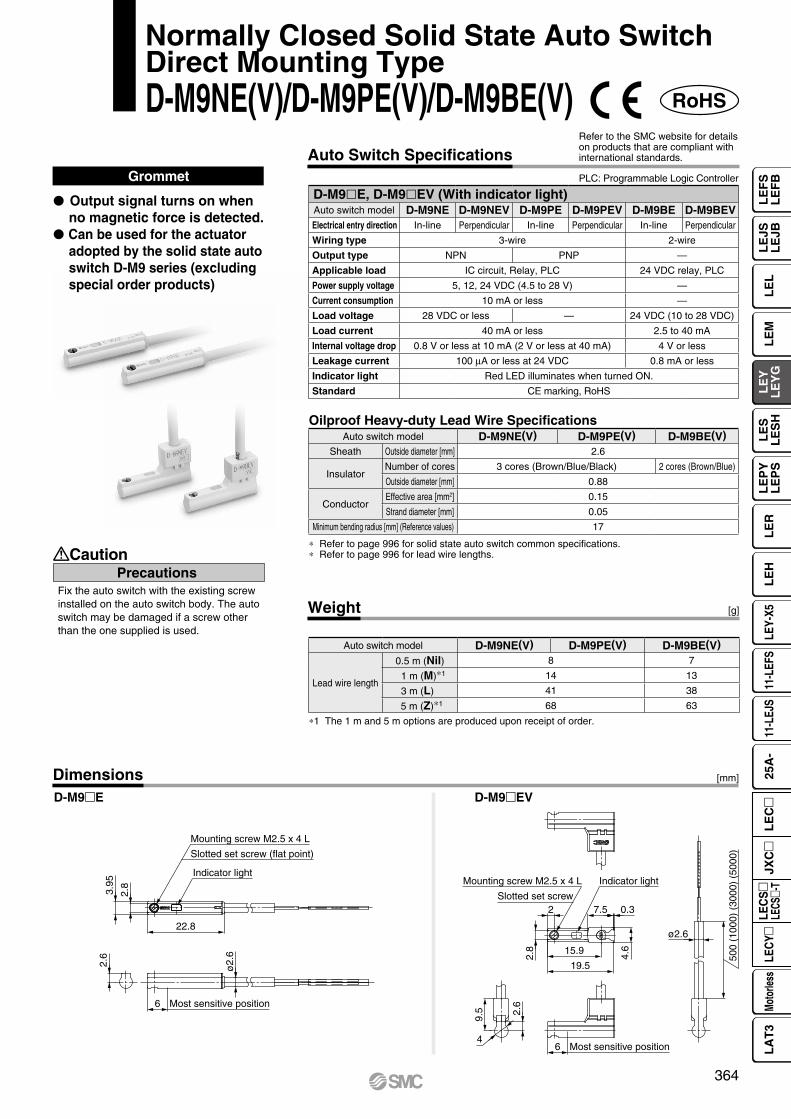
PrecautionsCaution
Fix the auto switch with the existing screw installed on the auto switch body. The auto switch may be damaged if a screw other than the one supplied is used.
Weight [g]
* Refer to page 996 for solid state auto switch common specifications.* Refer to page 996 for lead wire lengths.
DimensionsD-M9mE D-M9mEV
[mm]
Oilproof Heavy-duty Lead Wire Specifications
RoHS
Normally Closed Solid State Auto SwitchDirect Mounting TypeD-M9NE(V)/D-M9PE(V)/D-M9BE(V)
Auto Switch SpecificationsPLC: Programmable Logic Controller
Refer to the SMC website for details on products that are compliant with international standards.
*1 The 1 m and 5 m options are produced upon receipt of order.
Grommet
P Output signal turns on when no magnetic force is detected.
P Can be used for the actuator adopted by the solid state auto switch D-M9 series (excluding special order products)
Most sensitive position
ø2.
6
2.6
3.95
2.8
6
22.8
Mounting screw M2.5 x 4 L
Slotted set screw (flat point)
Indicator light
19.5
15.9
7.5
9.5
4
2.6
0.3
ø2.6
Indicator light
Slotted set screw2
Most sensitive position6
2.8
4.6
500
(100
0) (
3000
) (5
000)
Mounting screw M2.5 x 4 L
D-M9lE, D-M9lEV (With indicator light)Auto switch model D-M9NE D-M9NEV D-M9PE D-M9PEV D-M9BE D-M9BEVElectrical entry direction In-line Perpendicular In-line Perpendicular In-line Perpendicular
Wiring type 3-wire 2-wire
Output type NPN PNP —
Applicable load IC circuit, Relay, PLC 24 VDC relay, PLC
Power supply voltage 5, 12, 24 VDC (4.5 to 28 V) —
Current consumption 10 mA or less —
Load voltage 28 VDC or less — 24 VDC (10 to 28 VDC)
Load current 40 mA or less 2.5 to 40 mA
Internal voltage drop 0.8 V or less at 10 mA (2 V or less at 40 mA) 4 V or less
Leakage current 100 mA or less at 24 VDC 0.8 mA or less
Indicator light Red LED illuminates when turned ON.
Standard CE marking, RoHS
Auto switch model D-M9NE(V) D-M9PE(V) D-M9BE(V)Sheath Outside diameter [mm] 2.6
InsulatorNumber of cores 3 cores (Brown/Blue/Black) 2 cores (Brown/Blue)
Outside diameter [mm] 0.88
ConductorEffective area [mm2] 0.15
Strand diameter [mm] 0.05
Minimum bending radius [mm] (Reference values) 17
Auto switch model D-M9NE(V) D-M9PE(V) D-M9BE(V)
Lead wire length
0.5 m (Nil) 8 7
1 m (M)*1 14 13
3 m (L) 41 38
5 m (Z)*1 68 63
364
LE
FS
LE
FB
LE
LL
EJS
LE
JBL
EM
LE
YL
EY
GL
ES
LE
SH
LE
PY
LE
PS
LE
RL
EH
LEY-
X511
-LEF
S11
-LEJ
S25
A-
Moto
rless
LEC
Y�LE
CS
�LE
CS�-
TJX
C�
LE
C�
LA
T3
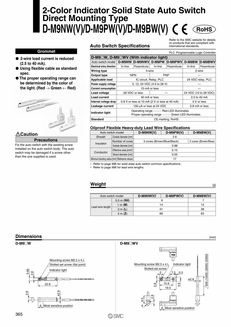
Weight [g]
Dimensions
Grommet
* Refer to page 996 for solid state auto switch common specifications.* Refer to page 996 for lead wire lengths.
P 2-wire load current is reduced (2.5 to 40 mA).
P Using flexible cable as standard spec.
P The proper operating range can be determined by the color of the light. (Red → Green ← Red)
D-M9mW D-M9mWV
RoHS
Oilproof Flexible Heavy-duty Lead Wire Specifications
2-Color Indicator Solid State Auto SwitchDirect Mounting TypeD-M9NW(V)/D-M9PW(V)/D-M9BW(V)
PrecautionsCaution
Fix the auto switch with the existing screw installed on the auto switch body. The auto switch may be damaged if a screw other than the one supplied is used.
Auto Switch SpecificationsRefer to the SMC website for details on products that are compliant with international standards.
PLC: Programmable Logic Controller
6 Most sensitive position
2.6
ø2.
6
22.8
Indicator light
3.95
2.8
Slotted set screw (flat point)
Mounting screw M2.5 x 4 L
500
(100
0) (
3000
) (5
000)
Indicator light
ø2.6
4.6
0.37.5
Mounting screw M2.5 x 4 L
Slotted set screw
2.8
9.5 2.
6
4Most sensitive position6
19.5
15.9
2
D-M9lW, D-M9lWV (With indicator light)Auto switch model D-M9NW D-M9NWV D-M9PW D-M9PWV D-M9BW D-M9BWVElectrical entry direction In-line Perpendicular In-line Perpendicular In-line Perpendicular
Wiring type 3-wire 2-wire
Output type NPN PNP —
Applicable load IC circuit, Relay, PLC 24 VDC relay, PLC
Power supply voltage 5, 12, 24 VDC (4.5 to 28 V) —
Current consumption 10 mA or less —
Load voltage 28 VDC or less — 24 VDC (10 to 28 VDC)
Load current 40 mA or less 2.5 to 40 mA
Internal voltage drop 0.8 V or less at 10 mA (2 V or less at 40 mA) 4 V or less
Leakage current 100 mA or less at 24 VDC 0.8 mA or less
Indicator lightOperating range .......... Red LED illuminates.Proper operating range .......... Green LED illuminates.
Standard CE marking, RoHS
Auto switch model D-M9NW(V) D-M9PW(V) D-M9BW(V)Sheath Outside diameter [mm] 2.6
InsulatorNumber of cores 3 cores (Brown/Blue/Black) 2 cores (Brown/Blue)
Outside diameter [mm] 0.88
ConductorEffective area [mm2] 0.15
Strand diameter [mm] 0.05
Minimum bending radius [mm] (Reference values) 17
Auto switch model D-M9NW(V) D-M9PW(V) D-M9BW(V)
Lead wire length
0.5 m (Nil) 8 7
1 m (M) 14 13
3 m (L) 41 38
5 m (Z) 68 63
[mm]
365

Motor top mounting type Motor top mounting type
In-line motor type In-line motor type
Guide Rod TypeElectric Actuators
LEYG Series
AC Servo Motor Driver p. 764
Step Motor/Servo Motor Controller/Driver p. 684
p. 383 p. 397, 405
Step Motor (Servo/24 VDC) Servo Motor (24 VDC) AC Servo Motor
366
LE
FS
LE
FB
LE
LL
EJS
LE
JBL
EM
LE
YL
EY
GL
ES
LE
SH
LE
PY
LE
PS
LE
RL
EH
LEY-
X511
-LEF
S11
-LEJ
S25
A-
Moto
rless
LEC
Y�LE
CS
�LE
CS�-
TJX
C�
LE
C�
LA
T3

L L
m mL
m
L
m
Eccentric distance L [mm]
Load
mas
s m
[kg]
0.1
1
100
10
10 100 1000
LEYG32M�/40M
LEYG25M�
LEYG16M�
Eccentric distance L [mm]
Load
mas
s m
[kg]
0.1
1
100
10
10 100 1000
LEYG32M�/40M
LEYG25M�LEYG16M�
LEYG16L�
Eccentric distance L [mm]
Load
mas
s m
[kg]
0.1
1
100
10
10 100 1000
LEYG32L�/40L
LEYG25L�
Eccentric distance L [mm]
Load
mas
s m
[kg]
0.1
1
100
10
10 100 1000
LEYG32L�/40L
LEYG25L�
LEYG16L�
Moment Load Graph
Selection conditions
*1 For the sliding bearing type, the speed is restricted with a horizontal/moment load.
Vertical Mounting, Sliding Bearingq 70 mm stroke or less w Over 75 mm stroke
Vertical Mounting, Ball Bushing Bearinge 35 mm stroke or less r Over 40 mm stroke
* The limit of vertical load mass varies depending on “lead” and “speed.” Check the “Speed–Work Load Graph” on pages 369 to 371.
* The limit of vertical load mass varies depending on “lead” and “speed.” Check the “Speed–Work Load Graph” on pages 369 to 371.
Mounting position
Vertical Horizontal
Max. speed [mm/s] “Speed–Work Load Graph” 200 or less Over 200
BearingSliding bearing Graphs q, w Graphs t, y*1 —
Ball bushing bearing Graphs e, r Graphs u, i Graphs o, !0
Step Motor (Servo/24 VDC) Servo Motor (24 VDC)
Electric Actuator/Guide Rod TypeLEYG Series
Model SelectionLEYG Seriessp. 383
367

Stroke [mm]
Load
mas
s m
[kg]
0.1
1
10
10 100 100070 75
LEYG32M�/40M�
LEYG16M�
LEYG25M�
LEYG32M�/40M�
LEYG16M�
LEYG25M�
Stroke [mm]
Load
mas
s m
[kg]
0.1
1
10
10 100 100070 75
LEYG16M�
LEYG25M�
LEYG32M�/40M�
LEYG16M�
LEYG25M�
LEYG32M�/40M�
Stroke [mm]
Load
mas
s m
[kg]
0.1
1
10
10 100 100035 40
LEYG16L�LEYG25L�
LEYG32L�/40L�
LEYG16L�
LEYG25L�
LEYG32L�/40L�
120 125
Stroke [mm]
Load
mas
s m
[kg]
0.1
1
10
10 100 100035 40
LEYG16L�LEYG25L�
LEYG32L�/40L�
LEYG16L�
LEYG25L�
LEYG32L�/40L�
120 125
Stroke [mm]
Load
mas
s m
[kg]
0.1
1
10
10 100 100035 40
LEYG16L�LEYG25L�
LEYG32L�/40L�
LEYG16L�LEYG25L�LEYG32L�/40L�
120 125
Stroke [mm]
Load
mas
s m
[kg]
0.1
1
10
10 100 100035 40
LEYG16L�
LEYG25L�LEYG32L�/40L�
LEYG16L�
LEYG25L�
LEYG32L�/40L�
120 125
L ≈
50 m
m
m
υm
Transfer speed υ [m/min]
Wor
k lo
ad m
[kg]
504020 30105
100504030
20
10543
2
1
LEYG32M/40M
LEYG25MLEYG16M
LEYGM (Sliding bearing)Caution
Operating Range when Used as a Stopper
Horizontal Mounting, Sliding Bearingt L = 50 mm
Horizontal Mounting, Ball Bushing Bearingu L = 50 mm Max. speed = 200 mm/s or less
Handling Precautions* When used as a stopper, select a model
with a stroke of 30 mm or less.* LEYGL (ball bushing bearing) cannot be
used as a stopper.* Workpiece collision in series with guide rod
cannot be permitted (Fig. a).* The body should not be mounted on the
end. It must be mounted on the top or bottom (Fig. b).
* Set the speed to less than or equal to the values shown below.
* For the specifications below, operate the system at the “load mass” shown in the graph x 80%. LEYG25MAA/Servo motor (24 VDC), Lead 12
y L = 100 mm
i L = 100 mm Max. speed = 200 mm/s or less
o L = 50 mm Max. speed = Over 200 mm/s !0 L = 100 mm Max. speed = Over 200 mm/s
Moment Load Graph
Fig. a
Fig. b
Motor type LEYGMA LEYGMB LEYGMCStep motor (Servo/24 VDC) 200 mm/s 125 mm/s 75 mm/s
Servo motor (24 VDC) 200 mm/s 200 mm/s 125 mm/s
368
Model Selection LEYG SeriesStep Motor (Servo/24 VDC) Servo Motor (24 VDC)
LE
FS
LE
FB
LE
LL
EJS
LE
JBL
EM
LE
YL
EY
GL
ES
LE
SH
LE
PY
LE
PS
LE
RL
EH
LEY-
X511
-LEF
S11
-LEJ
S25
A-
Moto
rless
LEC
Y�LE
CS
�LE
CS�-
TJX
C�
LE
C�
LA
T3

Hor
izon
tal w
ork
load
[kg]
Speed [mm/s]
0
5
106
1517202325
30
35
40
0 300200 400100 500 600
Lead 2.5: LEYG16M L C
Lead 5: LEYG16M L B
Lead 10: LEYG16M L A
Hor
izon
tal w
ork
load
[kg]
Speed [mm/s]
0
10
20
30
40
505560
70
80
0 300200 400100 500 600
Lead 3: LEYG25M L C
Lead 6: LEYG25M L B
Lead 12: LEYG25M L A
Hor
izon
tal w
ork
load
[kg]
Speed [mm/s]
0
10
20
30
404550
60
70
80
90
0 300200 400100 500 600
Lead 4: LEYG32M L C
Lead 8: LEYG32M L B
Lead 16: LEYG32M L A
Hor
izon
tal w
ork
load
[kg]
Speed [mm/s]
0
20
40
50
60
80
70
90
100
0 300 400 500200100 600
Lead 4: LEYG40M L C
Lead 8: LEYG40M L B
Lead 16: LEYG40M L A
Ver
tical
wor
k lo
ad [k
g]
Speed [mm/s]
0
5
7.5
3.5
1.5
10
0 300200 400100 500 600
Lead 2.5: LEYG16M L C
Lead 5: LEYG16M L B
Lead 10: LEYG16M L A
Ver
tical
wor
k lo
ad [k
g]
Speed [mm/s]
0
107
15
20
2930
0 300200 400100 500 600
Lead 3: LEYG25M L C
Lead 6: LEYG25M L B
Lead 12: LEYG25M L A
Ver
tical
wor
k lo
ad [k
g]
Speed [mm/s]
0
109
20
30
4041
50
0 300200 400100 500 600
Lead 4: LEYG32M L C
Lead 8: LEYG32M L B
Lead 16: LEYG32M L A
Ver
tical
wor
k lo
ad [k
g]
Speed [mm/s]
0
20
11
40
51
25
60
0 300 400 500200100 600
Lead 4: LEYG40M L C
Lead 8: LEYG40M L B
Lead 16: LEYG40M L A
Horizontal Vertical
LEYG16M L m
LEYG25M L m
LEYG32M L m LEYG32M
L m
LEYG40M L m LEYG40M
L m
LEYG25M L m
LEYG16M L m
Speed–Work Load Graph (Guide)For Step Motor (Servo/24 VDC) JXCm1, LECP1
Refer to page 370 for the LECPA, JXCm2
3 and page 371 for the LECA6.
for acceleration/deceleration: 2000 mm/s2
for acceleration/deceleration: 2000 mm/s2
for acceleration/deceleration: 2000 mm/s2
for acceleration/deceleration: 2000 mm/s2
* These graphs show the work load when the external guide is used together. When using the LEYG alone, refer to pages 367 and 368.
369
LEYG SeriesStep Motor (Servo/24 VDC) Servo Motor (24 VDC)
A

Hor
izon
tal w
ork
load
[kg]
Speed [mm/s]
0
54
1011
6
151720
25
30
35
40
0 300200 400100 500 600
Lead 2.5: LEYG16M L C
Lead 5: LEYG16M L B
Lead 10: LEYG16M L A
Hor
izon
tal w
ork
load
[kg]
Speed [mm/s]
0
30
40
50
60
70
80
0 300200 400100 500 600
10
201812
Lead 3: LEYG25M L C
Lead 6: LEYG25M L B
Lead 12: LEYG25M L A
Hor
izon
tal w
ork
load
[kg]
Speed [mm/s]
0
10
20
30
40
50
60
70
80
90
0 300200 400100 500 600
Lead 4: LEYG32M L C
Lead 8: LEYG32M L B
Lead 16: LEYG32M L A
Hor
izon
tal w
ork
load
[kg]
Speed [mm/s]
0
20
30
40
60
80
100
0 300 400 500200100 600
Lead 4: LEYG40M L C
Lead 8: LEYG40M L B
Lead 16: LEYG40M L A
Ver
tical
wor
k lo
ad [k
g]
Speed [mm/s]
0
5
7.5
3.5
1.5
10
0 300200 400100 500 600
Lead 2.5: LEYG16M L C
Lead 5: LEYG16M L B
Lead 10: LEYG16M L A
Ver
tical
wor
k lo
ad [k
g]
Speed [mm/s]
0
10
15
7
20
2930
0 300200 400100 500 600
Lead 3: LEYG25M L C
Lead 6: LEYG25M L B
Lead 12: LEYG25M L A
Ver
tical
wor
k lo
ad [k
g]
Speed [mm/s]
0
109
20
30
4041
50
0 300200 400100 500 600
Lead 4: LEYG32M L C
Lead 8: LEYG32M L B
Lead 16: LEYG32M L A
Ver
tical
wor
k lo
ad [k
g]
Speed [mm/s]
0
20
40
51
25
11
60
0 300 400 500200100 600
Lead 4: LEYG40M L C
Lead 8: LEYG40M L B
Lead 16: LEYG40M L A
Horizontal Vertical
Speed–Work Load Graph (Guide)For Step Motor (Servo/24 VDC) LECPA, JXCm2
3
Refer to page 369 for the JXCm1, LECP1 and page 371 for the LECA6.
LEYG16M L m
LEYG25M L m
LEYG32M L m LEYG32M
L m
LEYG40M L m LEYG40M
L m
LEYG25M L m
LEYG16M L m for acceleration/deceleration: 2000 mm/s2
for acceleration/deceleration: 2000 mm/s2
for acceleration/deceleration: 2000 mm/s2
* These graphs show the work load when the external guide is used together. When using the LEYG alone, refer to pages 367 and 368.
370
Model Selection LEYG SeriesStep Motor (Servo/24 VDC) Servo Motor (24 VDC)
LE
FS
LE
FB
LE
LL
EJS
LE
JBL
EM
LE
YL
EY
GL
ES
LE
SH
LE
PY
LE
PS
LE
RL
EH
LEY-
X511
-LEF
S11
-LEJ
S25
A-
Moto
rless
LEC
Y�LE
CS
�LE
CS�-
TJX
C�
LE
C�
LA
T3
A

Hor
izon
tal w
ork
load
[kg]
Speed [mm/s]
0
3
6
9
12
15
0 300200 400100 500 600
Lead 2.5: LEYG16M L AC
Lead 5: LEYG16M L AB
Lead 10: LEYG16M L AA
Hor
izon
tal w
ork
load
[kg]
Speed [mm/s]
0
107
15
20
30
40
0 300200 400100 500 600
Lead 3: LEYG25M L AC
Lead 6: LEYG25M L AB
Lead 12: LEYG25M L AA
Ver
tical
wor
k lo
ad [k
g]
Speed [mm/s]
0
3
6
7.5
3.5
1.5
9
10
0 300200 400100 500 600
Lead 2.5: LEYG16M L AC
Lead 5: LEYG16M L AB
Lead 10: LEYG16M L AA
Ver
tical
wor
k lo
ad [k
g]
Speed [mm/s]
0
1011
5
2
15
0 300200 400100 500 600
Lead 3: LEYG25M L AC
Lead 6: LEYG25M L AB
Lead 12: LEYG25M L AA
Horizontal Vertical
Speed–Work Load Graph (Guide)For Servo Motor (24 VDC) LECA6
LEYG16M L mA
LEYG25M L mA LEYG25M
L mA
LEYG16M L mA
Refer to page 369 for the JXCm1, LECP1 and page 370 for the LECPA, JXCm2
3.
371
LEYG SeriesStep Motor (Servo/24 VDC) Servo Motor (24 VDC)
A

10 20 30 40 50 60 70 80 900
100
200
300
400
500
Max. 65%
Lead 3: LEYG25 CML
Lead 6: LEYG25 BML
Lead 12: LEYG25 AML
Pus
hing
forc
e [N
]
Pushing force set value [%]∗1
Min. 35%
020
40
60
80
100
120
140
160
10 20 30 40 50 60 70 80 90Max. 85%
Pus
hing
forc
e [N
]
Pushing force set value [%]∗1
Min. 35%
Lead 2.5: LEYG16 CML
Lead 5: LEYG16 BML
Lead 10: LEYG16 AML
10 20 30 40 50 60 70 80 900
100
200
300
400
500
600
700
800
Lead 4: LEYG32 CML
Lead 8: LEYG32 BML
Lead 16: LEYG32 AML
Pushing force set value [%]∗1
Pus
hing
forc
e [N
]
Max. 85%
Min. 35%
10 20 30 40 50 60 70 80 900
100200300400500600700
1100
800900
1000
Max. 65%
Lead 4: LEYG40 CML
Lead 8: LEYG40 BML
Lead 16: LEYG40 AML
Pushing force set value [%]∗1
Pus
hing
forc
e [N
]
Min. 35%
Pus
hing
forc
e [N
]
0
20
40
60
80
100
120Lead 2.5: LEYG16 ACM
L
Lead 5: LEYG16 ABML
Lead 10: LEYG16 AAML
Max. 95%50 60 70 80 90 100
Pushing force set value [%]∗1
Min. 60%
Lead 3: LEYG25 ACML
Lead 6: LEYG25 ABML
Pus
hing
forc
e [N
]
50 60 70 80 90 1000
20
40
60
80
100
120
140
Pushing force set value [%]∗1 Max. 95%
Min. 70%
Lead 12: LEYG25 AAM
L
Force Conversion Graph (Guide)
Step Motor (Servo/24 VDC)
LEYG16 ML
LEYG25 ML
Servo Motor (24 VDC)
LEYG16 AML
LEYG25 AML
LEYG32 ML
LEYG40 ML
*1 Set values for the controller
Ambient temperature Pushing force set value [%] Duty ratio [%] Continuous pushing time [min]40°C or less 95 or less 100 —
Ambient temperature Pushing force set value [%] Duty ratio [%] Continuous pushing time [min]40°C or less 95 or less 100 —
Ambient temperature Pushing force set value [%] Duty ratio [%] Continuous pushing time [min]25°C or less 85 or less 100 —
40°C 65 or less 100 —85 50 15
Ambient temperature Pushing force set value [%] Duty ratio [%] Continuous pushing time [min]25°C or less 85 or less 100 —
40°C
40 or less 100 —50 70 1270 20 1.385 15 0.8
Ambient temperature Pushing force set value [%] Duty ratio [%] Continuous pushing time [min]40°C or less 65 or less 100 —
Ambient temperature Pushing force set value [%] Duty ratio [%] Continuous pushing time [min]40°C or less 65 or less 100 —
<Set Values for Vertical Upward Transfer Pushing Operations>For vertical loads (upward), set the pushing force to the max. value shown below and operate at the work load or less.
Model LEYG16ML LEYG25M
L LEYG32ML LEYG40M
L LEYG16ML A LEYG25M
L ALead A B C A B C A B C A B C A B C A B C
Work load [kg] 0.5 1 2.5 1.5 4 9 2.5 7 16 5 12 26 0.5 1 2.5 0.5 1.5 4Pushing force 85% 65% 85% 65% 95% 95%
<Limit Values for Pushing Force and Trigger Level in Relation to Pushing Speed>Without Load
Model Lead Pushing speed[mm/s]
Pushing force(Setting input value) Model Lead Pushing speed
[mm/s]Pushing force
(Setting input value)
LEYG16M L A/B/C 21 to 50 60 to 85% LEYG16M
L A A/B/C 21 to 50 80 to 95%
LEYG25M L A/B/C 21 to 35 50 to 65% LEYG25M
L A A/B/C 21 to 35 80 to 95%
LEYG32M L
A 24 to 3060 to 85%
B/C 21 to 30
LEYG40M L
A 24 to 3050 to 65%
B/C 21 to 30
There is a limit to the pushing force in relation to the pushing speed. If the product is operated outside of the range (low pushing force), the completion signal [INP] may be output before the pushing operation has been completed (during the moving operation).If operating with the pushing speed below the min. speed, please check for operating problems before using the product.
372
Model Selection LEYG SeriesStep Motor (Servo/24 VDC) Servo Motor (24 VDC)
LE
FS
LE
FB
LE
LL
EJS
LE
JBL
EM
LE
YL
EY
GL
ES
LE
SH
LE
PY
LE
PS
LE
RL
EH
LEY-
X511
-LEF
S11
-LEJ
S25
A-
Moto
rless
LEC
Y�LE
CS
�LE
CS�-
TJX
C�
LE
C�
LA
T3

L L
m mL
m
L
m
Eccentric distance L [mm]
Load
mas
s m
[kg]
1
100
10
10 100
LEYG32M�
LEYG25M�
1000
Eccentric distance L [mm]
Load
mas
s m
[kg]
0.1
1
100
10
10 100
LEYG32M�
LEYG25M�
1000
Eccentric distance L [mm]
Load
mas
s m
[kg]
0.1
1
100
10
10 100
LEYG32L�
LEYG25L�
1000
Eccentric distance L [mm]
Load
mas
s m
[kg]
0.1
1
100
10
10 100
LEYG32L�
LEYG25L�
1000
Moment Load Graph
Selection conditions
Vertical Mounting, Sliding Bearingq 70 mm stroke or less w Over 75 mm stroke
r Over 40 mm stroke
Vertical Mounting, Ball Bushing Bearinge 35 mm stroke or less
∗ The limit of vertical load mass varies depending on “lead” and “speed.” Check the “Speed–Vertical Work Load Graph” on page 375.
∗ The limit of vertical load mass varies depending on “lead” and “speed.” Check the “Speed–Vertical Work Load Graph” on page 375.
∗1 For the sliding bearing type, the speed is restricted with a horizontal/moment load.
Mounting position
Vertical Horizontal
Max. speed [mm/s] “Speed–Vertical Work Load Graph” 200 or less Over 200
BearingSliding bearing Graphs q, w Graphs t, y∗1 Graphs u, i
Ball bushing bearing Graphs e, r Graphs o, !0 Graphs !1, !2
AC Servo Motor LECS Series
Electric Actuator/Guide Rod TypeLEYG Series
Model SelectionLEYG Seriessp. 397 LECY Seriessp. 405
373

LEYG32M� LEYG32M�
LEYG25M� LEYG25M�
Load
mas
s m
[kg]
0.1
1
10
Stroke [mm]100 10007010 75
LEYG32M�
LEYG25M�
LEYG32M�
LEYG25M�
Load
mas
s m
[kg]
0.1
1
10
Stroke [mm]100 10007010 75
LEYG32M�
LEYG25M�LEYG32M�
LEYG25M�
Load
mas
s m
[kg]
0.1
1
10
Stroke [mm]100 10007010 75
LEYG32M�
LEYG25M�LEYG32M�
LEYG25M�Lo
ad m
ass
m [k
g]
0.1
1
10
Stroke [mm]100 10007010 75
LEYG32L� LEYG32L�
LEYG25L� LEYG25L�
Load
mas
s m
[kg]
0.1
1
10
Stroke [mm]100 1000403510
120 125
LEYG32L� LEYG32L�
LEYG25L� LEYG25L�
Load
mas
s m
[kg]
0.1
1
10
Stroke [mm]100 1000403510
120 125
LEYG32L� LEYG32L�
LEYG25L� LEYG25L�
Load
mas
s m
[kg]
0.1
1
10
Stroke [mm]100 1000403510
120 125
LEYG32L� LEYG32L�
LEYG25L� LEYG25L�
Load
mas
s m
[kg]
0.1
1
10
Stroke [mm]100 1000403510
120 125
L ≈
50 m
m
m
υm
Transfer speed υ [m/min]
Wor
k lo
ad m
[kg]
504020 30105
100504030
20
10543
2
1
LEYG32M
LEYG25M
LEYGM (Sliding bearing)
Caution
Operating Range when Used as a Stopper
Horizontal Mounting, Sliding Bearingt L = 50 mm Max. speed = 200 mm/s or less
u L = 50 mm Max. speed = Over 200 mm/s i L = 100 mm Max. speed = Over 200 mm/s
Handling Precautions* When used as a stopper, select a model
with a stroke of 30 mm or less.* LEYGL (ball bushing bearing) cannot
be used as a stopper.* Workpiece collision in series with guide
rod cannot be permitted (Fig. a).* The body should not be mounted on the
end. It must be mounted on the top or bottom (Fig. b).
y L = 100 mm Max. speed = 200 mm/s or less
Horizontal Mounting, Ball Bushing Bearingo L = 50 mm Max. speed = 200 mm/s or less
!1 L = 50 mm Max. speed = Over 200 mm/s !2 L = 100 mm Max. speed = Over 200 mm/s
!0 L = 100 mm Max. speed = 200 mm/s or less
Moment Load Graph
Fig. a
Fig. b
374
Model Selection LEYG SeriesAC Servo Motor
LE
FS
LE
FB
LE
LL
EJS
LE
JBL
EM
LE
YL
EY
GL
ES
LE
SH
LE
PY
LE
PS
LE
RL
EH
LEY-
X511
-LEF
S11
-LEJ
S25
A-
Moto
rless
LEC
Y�LE
CS
�LE
CS�-
TJX
C�
LE
C�
LA
T3

0 200 400 600 800 1000 14001200Speed [mm/s]
Wor
k lo
ad [k
g]
0
10
40
30
20
Lead 3: LEYG25�C
Lead 6: LEYG25�B
Lead 12: LEYG25�A
Area where the regeneration option is required
Lead 5: LEYG32�C
Lead 10: LEYG32�B
Lead 20: LEYG32�A
0 200 400 600 800 1000 14001200Speed [mm/s]
Wor
k lo
ad [k
g]
0
10
50
30
40
20
Area where the regeneration option is required
0 200 400 600 800 1000 14001200Speed [mm/s]
Wor
k lo
ad [k
g]
0
10
60
50
30
40
20
Lead 4: LEYG32D�C
Lead 8: LEYG32D�B
Lead 16: LEYG32D�A
Area where the regeneration option is required
0 200 400 600 800 1000 14001200Speed [mm/s]
Wor
k lo
ad [k
g]
0
20
10
70
50
60
40
30
Lead 3: LEYG25�C
Lead 6: LEYG25�B
Lead 12: LEYG25�A
Area where the regeneration option is required
Lead 10: LEYG32�B
Lead 5: LEYG32�C
Lead 20: LEYG32�A
0 200 400 600 800 1000 14001200Speed [mm/s]
Wor
k lo
ad [k
g]
0
20
10
80
70
50
60
40
30
Area where the regeneration option is required
Lead 4: LEYG32D�C
Lead 8: LEYG32D�B
Lead 16: LEYG32D�A
0 200 400 600 800 1000 14001200Speed [mm/s]
Wor
k lo
ad [k
g]
0
20
10
80
70
50
60
40
30
Area where the regeneration option is required
Speed–Vertical Work Load Graph/Required Conditions for “Regeneration Option”
Required conditions for “Regeneration option”LEYG25S2 6/T6 (Motor mounting position: Top mounting/In-line)
LEYG32S3 7/T7 (Motor mounting position: Top mounting) LEYG32DS3
7/T7 (Motor mounting position: In-line)
Speed–Horizontal Work Load Graph/Required Conditions for “Regeneration Option”
* Regeneration option is required when using the product above the regenera-tion line in the graph. (It must be ordered separately.)
Required conditions for “Regeneration option”LEYG25S2 6/T6 (Motor mounting position: Top mounting/In-line)
LEYG32S3 7/T7 (Motor mounting position: Top mounting) LEYG32DS3
7/T7 (Motor mounting position: In-line)
* Regeneration option is required when using the product above the regenera-tion line in the graph. (It must be ordered separately.)
“Regeneration Option” Models
“Regeneration Option” Models
Size Model
LEYG25 LEC-MR-RB-032
LEYG32 LEC-MR-RB-032
Size Model
LEYG25 LEC-MR-RB-032
LEYG32 LEC-MR-RB-032
* These graphs show the work load when the external guide is used together. When using the LEYG alone, refer to pages 373 and 374.
* These graphs show the work load when the external guide is used together. When using the LEYG alone, refer to pages 373 and 374.
375
LEYG SeriesAC Servo Motor
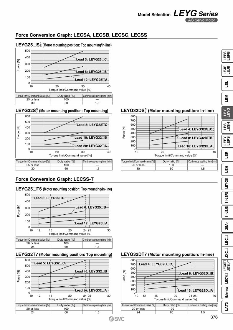
For
ce [N
]
Torque limit/Command value [%]
500
400
300
200
100
02010 4030
Lead 3: LEYG25�C
Lead 6: LEYG25�B
Lead 12: LEYG25�A
For
ce [N
]
Torque limit/Command value [%]
600
500
400
300
200
100
02010 4030
Lead 5: LEYG32�C
Lead 10: LEYG32�B
Lead 20: LEYG32�A
For
ce [N
]
Torque limit/Command value [%]
800700600500400300200100
02010 4030
Lead 4: LEYG32D�C
Lead 8: LEYG32D�B
Lead 16: LEYG32D�A
Force Conversion Graph: LECSA, LECSB, LECSC, LECSS
LEYG25S2 6 (Motor mounting position: Top mounting/In-line)
LEYG32DS3 7 (Motor mounting position: In-line)LEYG32S3
7 (Motor mounting position: Top mounting)
Torque limit/Command value [%] Duty ratio [%] Continuous pushing time [min]25 or less 100 —
30 60 1.5
Torque limit/Command value [%] Duty ratio [%] Continuous pushing time [min]25 or less 100 —
30 60 1.5
Torque limit/Command value [%] Duty ratio [%] Continuous pushing time [min]25 or less 100 —
30 60 1.5
Force Conversion Graph: LECSS-T
LEYG25T6 (Motor mounting position: Top mounting/In-line)
LEYG32DT7 (Motor mounting position: In-line)LEYG32T7 (Motor mounting position: Top mounting)
Torque limit/Command value [%] Duty ratio [%] Continuous pushing time [min]20 or less 100 —
24 60 1.5
Torque limit/Command value [%] Duty ratio [%] Continuous pushing time [min]20 or less 100 —
24 60 1.5
Torque limit/Command value [%] Duty ratio [%] Continuous pushing time [min]20 or less 100 —
24 60 1.5
For
ce [N
]
Torque limit/Command value [%]
500
400
300
200
100
020 25241510 12 30
Lead 3: LEYG25�C
Lead 6: LEYG25�B
Lead 12: LEYG25�A
For
ce [N
]
Torque limit/Command value [%]
600
500
400
300
200
100
02010 1512 302524
Lead 5: LEYG32�C
Lead 10: LEYG32�B
Lead 20: LEYG32�A
For
ce [N
]
Torque limit/Command value [%]
800700600500400300200100
020 252410 1512 30
Lead 4: LEYG32D�C
Lead 8: LEYG32D�B
Lead 16: LEYG32D�A
376
Model Selection LEYG SeriesAC Servo Motor
LE
FS
LE
FB
LE
LL
EJS
LE
JBL
EM
LE
YL
EY
GL
ES
LE
SH
LE
PY
LE
PS
LE
RL
EH
LEY-
X511
-LEF
S11
-LEJ
S25
A-
Moto
rless
LEC
Y�LE
CS
�LE
CS�-
TJX
C�
LE
C�
LA
T3

+θ−θ
−δ
+δ
Allowable Rotational Torque of Plate
Non-rotating Accuracy of Plate
Torque: T [N⋅m]
T [N⋅m]
SizeNon-rotating accuracy θ
LEYGM LEYGL16
0.06°0.05°
250.04°32
0.05°40
ModelStroke [mm]
30 50 100 200 300
LEYG16M 0.70 0.57 1.05 0.56 —
LEYG16L 0.82 1.48 0.97 0.57 —
LEYG25M 1.56 1.29 3.50 2.18 1.36
LEYG25L 1.52 3.57 2.47 2.05 1.44
LEYG32M 2.55 2.09 5.39 3.26 1.88
LEYG32L 2.80 5.76 4.05 3.23 2.32
LEYG40M 2.55 2.09 5.39 3.26 1.88
LEYG40L 2.80 5.76 4.05 3.23 2.32
Plate Displacement (Reference Value): δ
[mm]
ModelStroke [mm]
30 50 100 200 300
LEYG16M ±0.20 ±0.25 ±0.24 ±0.27 —
LEYG16L ±0.13 ±0.12 ±0.17 ±0.19 —
LEYG25M ±0.26 ±0.31 ±0.25 ±0.38 ±0.36
LEYG25L ±0.13 ±0.13 ±0.17 ±0.20 ±0.23
LEYG32M ±0.23 ±0.29 ±0.23 ±0.36 ±0.34
LEYG32L ±0.11 ±0.11 ±0.15 ±0.19 ±0.22
LEYG40M ±0.23 ±0.29 ±0.23 ±0.36 ±0.34
LEYG40L ±0.11 ±0.11 ±0.15 ±0.19 ±0.22
* The values without a load are shown.
377
LEYG SeriesStep Motor (Servo/24 VDC) Servo Motor (24 VDC) AC Servo Motor
A

Mounting position
Vertical Horizontal
Max. speed [mm/s] “Speed–Work Load Graph” 200 or less Over 200
BearingSliding bearing Graphs q, w Graphs t, y*1 Graphs u, i
Ball bushing bearing Graphs e, r Graphs o, !0 Graphs !1, !2
L L
m mL
m
L
m
Eccentric distance L [mm]
Load
mas
s m
[kg]
1
100
10
10 100
LEYG32M�
LEYG25M�
1000
Eccentric distance L [mm]
Load
mas
s m
[kg]
0.1
1
100
10
10 100
LEYG32M�
LEYG25M�
1000
Eccentric distance L [mm]
Load
mas
s m
[kg]
0.1
1
100
10
10 100
LEYG32L�
LEYG25L�
1000
Eccentric distance L [mm]
Load
mas
s m
[kg]
0.1
1
100
10
10 100
LEYG32L�
LEYG25L�
1000
Selection conditions
q 70 mm stroke or less w Over 75 mm stroke
r Over 40 mm strokee 35 mm stroke or less
* The limit of vertical load mass varies depending on “lead” and “speed.” Check the “Speed–Work Load Graph” on page 380.
* The limit of vertical load mass varies depending on “lead” and “speed.” Check the “Speed–Work Load Graph” on page 380.
*1 For the sliding bearing type, the speed is restricted with a horizontal/moment load.
Moment Load Graph
Vertical Mounting, Sliding Bearing
Vertical Mounting, Ball Bushing Bearing
AC Servo Motor LECY Series
Electric Actuator/Guide Rod TypeLEYG Series
Model SelectionLEYG Seriessp. 405 LECS Seriessp. 397
378
LE
FS
LE
FB
LE
LL
EJS
LE
JBL
EM
LE
YL
EY
GL
ES
LE
SH
LE
PY
LE
PS
LE
RL
EH
LEY-
X511
-LEF
S11
-LEJ
S25
A-
Moto
rless
LEC
Y�LE
CS
�LE
CS�-
TJX
C�
LE
C�
LA
T3

LEYG32M� LEYG32M�
LEYG25M� LEYG25M�
Load
mas
s m
[kg]
0.1
1
10
Stroke [mm]100 10007010 75
LEYG32M�
LEYG25M�
LEYG32M�
LEYG25M�
Load
mas
s m
[kg]
0.1
1
10
Stroke [mm]100 10007010 75
LEYG32M�
LEYG25M�LEYG32M�
LEYG25M�
Load
mas
s m
[kg]
0.1
1
10
Stroke [mm]100 10007010 75
LEYG32M�
LEYG25M�LEYG32M�
LEYG25M�Lo
ad m
ass
m [k
g]
0.1
1
10
Stroke [mm]100 10007010 75
LEYG32L� LEYG32L�
LEYG25L� LEYG25L�
Load
mas
s m
[kg]
0.1
1
10
Stroke [mm]100 1000403510
120 125
LEYG32L� LEYG32L�
LEYG25L� LEYG25L�
Load
mas
s m
[kg]
0.1
1
10
Stroke [mm]100 1000403510
120 125
LEYG32L� LEYG32L�
LEYG25L� LEYG25L�
Load
mas
s m
[kg]
0.1
1
10
Stroke [mm]100 1000403510
120 125
LEYG32L� LEYG32L�
LEYG25L� LEYG25L�
Load
mas
s m
[kg]
0.1
1
10
Stroke [mm]100 1000403510
120 125
m
Transfer speed υ [m/min]
Wor
k lo
ad m
[kg]
504020 30105
100504030
20
10543
2
1
LEYG32M
LEYG25ML ≈
50 m
m
m
υCaution
t L = 50 mm Max. speed = 200 mm/s or less
u L = 50 mm Max. speed = Over 200 mm/s i L = 100 mm Max. speed = Over 200 mm/s
Handling Precautions* When used as a stopper, select a model
with a stroke of 30 mm or less.* LEYGL (ball bushing bearing) cannot
be used as a stopper.* Workpiece collision in series with guide
rod cannot be permitted (Fig. a).* The body should not be mounted on the
end. It must be mounted on the top or bottom (Fig. b).
y L = 100 mm Max. speed = 200 mm/s or less
o L = 50 mm Max. speed = 200 mm/s or less
!1 L = 50 mm Max. speed = Over 200 mm/s !2 L = 100 mm Max. speed = Over 200 mm/s
!0 L = 100 mm Max. speed = 200 mm/s or less
Fig. a
Fig. b
Moment Load Graph
Operating Range when Used as a Stopper
Horizontal Mounting, Sliding Bearing
LEYGM (Sliding bearing)
Horizontal Mounting, Ball Bushing Bearing
379
LEYG SeriesAC Servo Motor

12000
10
20
30
40
0 200 400 600 800 1000
“Regenerative resistor” area
Lead 3: LEYG25�C
Lead 6: LEYG25�B
Lead 12: LEYG25�A
Speed [mm/s]
Wor
k lo
ad [k
g]
14000
10
20
30
40
50
0 200 400 600 800 1000 1200
“Regenerative resistor” area
Lead 5: LEYG32�C
Lead 10: LEYG32�B
Lead 20: LEYG32�A
Speed [mm/s]
Wor
k lo
ad [k
g]
12000
10
20
30
40
50
60
0 200 400 600 800 1000
“Regenerative resistor” area
Lead 4: LEYG32�D�C
Lead 8: LEYG32�D�B
Lead 16: LEYG32�D�A
Speed [mm/s]
Wor
k lo
ad [k
g]
12000
20
40
60
0 200 400 600 800 1000
Lead 3: LEYG25�C
Lead 6: LEYG25�B
Lead 12: LEYG25�A
Speed [mm/s]
Wor
k lo
ad [k
g]
14000
20
40
60
80
0 200 400 600 800 1000 1200
Lead 5: LEYG32�C
Lead 10: LEYG32�B
Lead 20: LEYG32�A
Speed [mm/s]
Wor
k lo
ad [k
g]
12000
20
40
60
80
0 200 400 600 800 1000
Lead 4: LEYG32�D�C
Lead 8: LEYG32�D�B
Lead 16: LEYG32�D�A
Speed [mm/s]
Wor
k lo
ad [k
g]
Speed–Work Load Graph/Conditions for “Regenerative Resistor” (Guide)
LEYG25lV6 (Motor mounting position: Top mounting/In-line)
LEYG32V7 (Motor mounting position: Top mounting)
LEYG32DV7 (Motor mounting position: In-line)
Vertical
Vertical
Vertical Horizontal
Horizontal
Horizontal
“Regenerative resistor” area Applicable Motors/Drivers
ModelApplicable model
Motor Servopack (SMC driver)
LEYG25l SGMJV-01A3A SGDV-R90A11l (LECYM2-V5)SGDV-R90A21l (LECYU2-V5)
LEYG32l SGMJV-02A3A SGDV-1R6A11l (LECYM2-V7)SGDV-1R6A21l (LECYU2-V7)
* When using the actuator in the “Regenerative resistor” area, download the “AC servo drive capacity selection program/SigmaJunmaSize+” from the SMC website. Then, calculate the necessary regenerative resistor capacity to prepare an appropriate external regenerative resistor.
* Regenerative resistor should be provided by the customer.
* These graphs show the work load when the external guide is used together. When using the LEYG alone, refer to pages 378 and 379.
380
Model Selection LEYG SeriesAC Servo Motor
LE
FS
LE
FB
LE
LL
EJS
LE
JBL
EM
LE
YL
EY
GL
ES
LE
SH
LE
PY
LE
PS
LE
RL
EH
LEY-
X511
-LEF
S11
-LEJ
S25
A-
Moto
rless
LEC
Y�LE
CS
�LE
CS�-
TJX
C�
LE
C�
LA
T3

For
ce [N
]
Torque limit/Command value [%]
500
400
300
200
100
06030 12090
Lead 3: LEYG25�C
Lead 6: LEYG25�B
Lead 12: LEYG25�A
For
ce [N
]
Torque limit/Command value [%]
600
500
400
300
200
100
06030 12090
Lead 5: LEYG32�C
Lead 10: LEYG32�B
Lead 20: LEYG32�A
For
ce [N
]
Torque limit/Command value [%]
800
700
600
500
400
300
200
100
06030 12090
Lead 4: LEYG32D�C
Lead 8: LEYG32D�B
Lead 16: LEYG32D�A
Torque limit/Command value [%] Duty ratio [%] Continuous pushing time [min]75 or less 100 —
90 60 1.5
Torque limit/Command value [%] Duty ratio [%] Continuous pushing time [min]75 or less 100 —
90 60 1.5
Torque limit/Command value [%] Duty ratio [%] Continuous pushing time [min]75 or less 100 —
90 60 1.5
LEYG25V6 (Motor mounting position: Top mounting/In-line)
LEYG32DV7 (Motor mounting position: In-line)LEYG32V7 (Motor mounting position: Top mounting)
Force Conversion Graph
381
LEYG SeriesAC Servo Motor
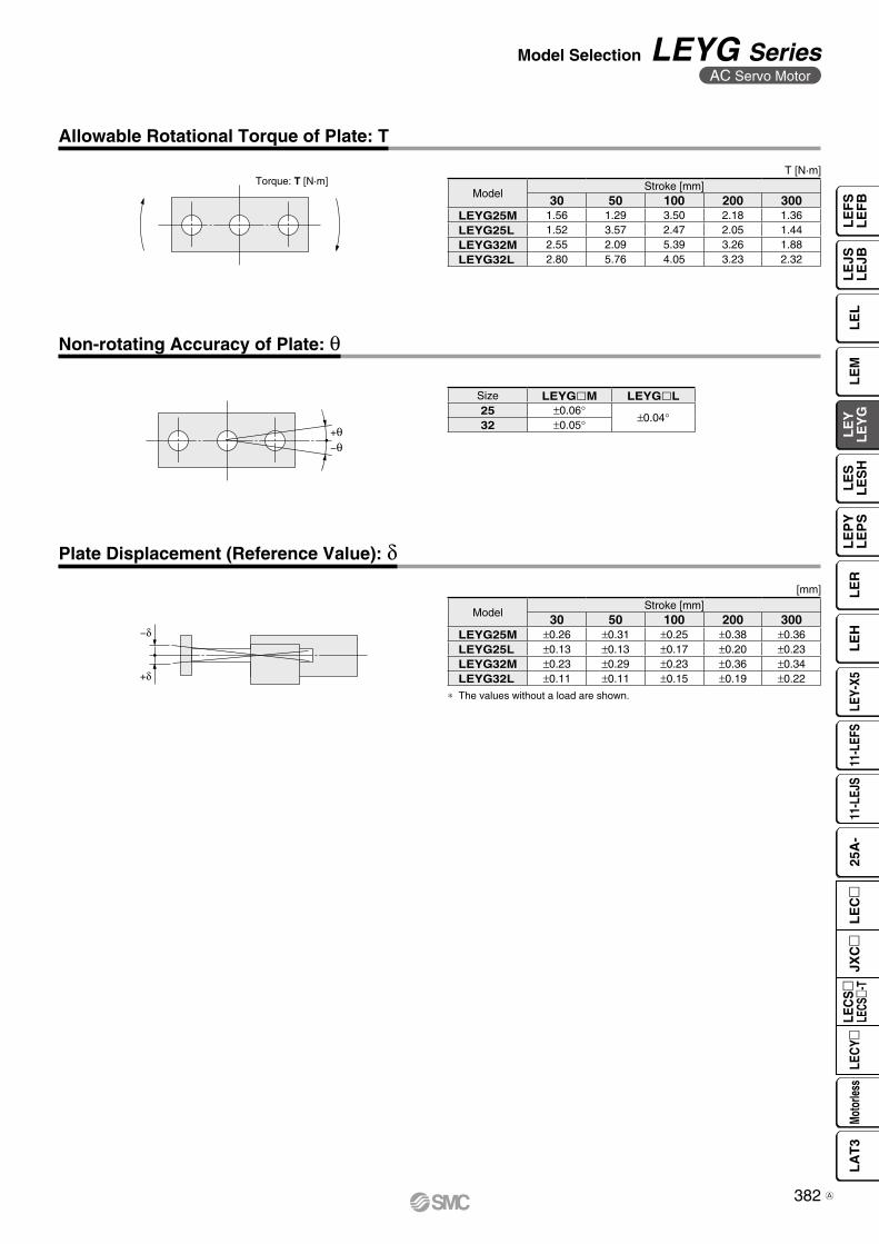
Torque: T [N·m]
+θ−θ
−δ
+δ
Allowable Rotational Torque of Plate: T
Non-rotating Accuracy of Plate: θ
Plate Displacement (Reference Value): δ
T [N·m]
[mm]
ModelStroke [mm]
30 50 100 200 300LEYG25M 1.56 1.29 3.50 2.18 1.36LEYG25L 1.52 3.57 2.47 2.05 1.44LEYG32M 2.55 2.09 5.39 3.26 1.88LEYG32L 2.80 5.76 4.05 3.23 2.32
Size LEYGlM LEYGlL25 ±0.06°
±0.04°32 ±0.05°
ModelStroke [mm]
30 50 100 200 300LEYG25M ±0.26 ±0.31 ±0.25 ±0.38 ±0.36LEYG25L ±0.13 ±0.13 ±0.17 ±0.20 ±0.23LEYG32M ±0.23 ±0.29 ±0.23 ±0.36 ±0.34LEYG32L ±0.11 ±0.11 ±0.15 ±0.19 ±0.22
* The values without a load are shown.
382
Model Selection LEYG SeriesAC Servo Motor
LE
FS
LE
FB
LE
LL
EJS
LE
JBL
EM
LE
YL
EY
GL
ES
LE
SH
LE
PY
LE
PS
LE
RL
EH
LEY-
X511
-LEF
S11
-LEJ
S25
A-
Moto
rless
LEC
Y�LE
CS
�LE
CS�-
TJX
C�
LE
C�
LA
T3
A

How to Order
r Motor type
Symbol TypeApplicable size Compatible controllers/
driversLEYG16 LEYG25 LEYG32/40
Nil Step motor(Servo/24 VDC)
V V V
JXCE1JXC91JXCP1JXCD1JXCL1
JXCM1JXC51JXC61
LECP1LECPA
A Servo motor(24 VDC)
V V — LECA6
o Actuator cable type/length∗7
Standard cable [m] Robotic cable [m]Nil None R1 1.5 RA 10∗6
S1 1.5∗9 R3 3 RB 15∗6
S3 3∗9 R5 5 RC 20∗6
S5 5∗9 R8 8∗6
For auto switches, refer to pages 363 to 365.
q w e r t y u i o
e Motor mounting positionNil Top mounting
D In-line
t Lead [mm]Symbol LEYG16 LEYG25 LEYG32/40
A 10 12 16
B 5 6 8
C 2.5 3 4
i Guide option∗5
Nil Without option
F With grease retaining function
u Motor option∗4
Nil Without option
C With motor cover
B With lock
W With lock/motor cover
q Size16253240
w Bearing type∗1
M Sliding bearing
L Ball bushing bearing
Use of auto switches for the guide rod type LEYG series· Auto switches must be inserted from the front side with the rod (plate) sticking out.· Auto switches cannot be fixed with the parts hidden behind the guide attachment (the side of the rod that sticks out).· Please consult with SMC when using auto switches on the side of the rod that sticks out, as it is produced as a special order.
Motor mounting position: Top mounting
Motor mounting position: In-line
LEYG 16 M B 50 S1
y Stroke∗2 ∗3 [mm]30 30to to
300 300
∗ For details, refer to the applicable stroke table below.
V: Standard
Stroke[mm]
Model30 50 100 150 200 250 300
Manufacturable stroke range
[mm]
LEYG16 V V V V V — — 10 to 200
LEYG25 V V V V V V V 15 to 300
LEYG32/40 V V V V V V V 20 to 300
Applicable Stroke Table∗2
!0 !1 !2
AN 1LECm Series
CD17TJXCm Series
For details on controllers, refer to page 384.
Click here for details.Click here for details.
Step Motor (Servo/24 VDC) Servo Motor (24 VDC)
Electric ActuatorGuide Rod Type LEYG Series LEYG16, 25, 32, 40
383C

LECm Series (For details, refer to page 385.)
JXCm Series (For details, refer to page 385.)
!0 Controller/Driver type∗8
Nil Without controller/driver6N LECA6
(Step data input type)NPN
6P PNP1N LECP1∗9
(Programless type)NPN
1P PNPAN LECPA∗9 ∗10
(Pulse input type)NPN
AP PNP
!0
!1 I/O cable length∗11
Nil Without cable(Without communication plug connector)
1 1.5 m3 3 m∗12
5 5 m∗12
!2 Controller/Driver mountingNil Screw mountingD DIN rail∗13
!0 ControllerNil Without controller
Cm1mm With controller
Caution[CE-compliant products]q EMC compliance was tested by combining the electric actuator LEY
series and the controller LEC/JXC series.The EMC depends on the configuration of the customer’s control panel and the relationship with other electrical equipment and wiring. Therefore, compliance with the EMC directive cannot be certified for SMC components incorporated into the customer’s equipment under actual operating conditions. As a result, it is necessary for the customer to verify compliance with the EMC directive for the machinery and equipment as a whole.
w For the servo motor (24 VDC) specification, EMC compliance was tested by installing a noise filter set (LEC-NFA). Refer to page 713 for the noise filter set. Refer to the LECA series Operation Manual for installation.
[UL-compliant products (For the LEC series)]When compliance with UL is required, the electric actuator and controller/driver should be used with a UL1310 Class 2 power supply.
∗1 When [M: Sliding bearing] is selected, the maximum speed of lead [A] is 400 mm/s (at no-load, horizontal mounting). The speed is also restricted with a horizontal/moment load. Refer to the “Model Selection” on page 367.
∗2 Please consult with SMC for non-standard strokes as they are produced as special orders.
∗3 There is a limit for mounting the size 32/40 top mounting types and strokes of 50 mm or less. Refer to the dimensions.
∗4 When “With lock” or “With lock/motor cover” is selected for the top mounting type, the motor body will stick out from the end of the body for size 16/40 with strokes of 30 mm or less. Check for interference with workpieces before selecting a model.
∗5 Only available for size 25, 32, and 40 sliding bearings (Refer to the “Construction” on page 390.)
∗6 Produced upon receipt of order (Robotic cable only)∗7 The standard cable should only be used on fixed parts.
For use on moving parts, select the robotic cable. Refer to pages 758 and 759 if only the actuator cable is required.
∗8 For details on controllers/drivers and compatible motors, refer to the compatible controllers/drivers on the next page.
∗9 Only available for the motor type “Step motor”∗10 When pulse signals are open collector, order the current limiting
resistor (LEC-PA-R-m) on page 736 separately.∗11 When “Without controller/driver” is selected for controller/driver types,
I/O cable cannot be selected. Refer to page 713 (For LECA6), page 724 (For LECP1), or page 736 (For LECPA) if I/O cable is required.
∗12 When “Pulse input type” is selected for controller/driver types, pulse input usable only with differential. Only 1.5 m cables usable with open collector
∗13 The DIN rail is not included. It must be ordered separately.∗14 Select “Nil” for anything other than DeviceNet™, CC-Link, or parallel
input. Select “Nil,” “S,” or “T” for DeviceNet™ or CC-Link. Select “Nil,” “1,” “3,” or “5” for parallel input.
AN 1!1 !2
The actuator and controller/driver are sold as a package.Confirm that the combination of the controller/driver and actuator is correct.
<Check the following before use.>q �Check the actuator label for the model number. This
number should match that of the controller/driver.w Check that the Parallel I/O configuration matches
(NPN or PNP).
∗ Refer to the Operation Manual for using the products. Please download it via our website: https://www.smcworld.com
For single axis
1D T7CInterface
(Communication protocol/Input/Output)E EtherCAT® L IO-Link9 EtherNet/IP™ M CC-Link Ver 1.10P PROFINET 5 Parallel input (NPN)D DeviceNet™ 6 Parallel input (PNP)
Mounting7 Screw mounting8∗13 DIN rail
Communication plug connector I/O cable∗14
Symbol Type Applicable interfaceNil Without accessory —S Straight type communication plug connector DeviceNet™
CC-Link Ver 1.10T T-branch type communication plug connector1 I/O cable (1.5 m)
Parallel input (NPN)Parallel input (PNP)3 I/O cable (3 m)
5 I/O cable (5 m)
q w
384
Electric ActuatorGuide Rod Type LEYG Series
Step Motor (Servo/24 VDC) Servo Motor (24 VDC)
LE
FS
LE
FB
LE
LL
EJS
LE
JBL
EM
LE
YL
EY
GL
ES
LE
SH
LE
PY
LE
PS
LE
RL
EH
LEY-
X511
-LEF
S11
-LEJ
S25
A-
Moto
rless
LEC
Y�LE
CS
�LE
CS�-
TJX
C�
LE
C�
LA
T3
B

Compatible Controllers/Drivers
Type
Step datainput type
Step datainput type
Programless type Pulse input type
SeriesJXC51JXC61
LECA6 LECP1 LECPA
Features Parallel I/OValue (Step data) input
Standard controller
Capable of setting up operation (step data) without using a PC or teaching box
Operation by pulse signals
Compatible motorStep motor
(Servo/24 VDC)Servo motor
(24 VDC)Step motor
(Servo/24 VDC)
Max. number of step data 64 points 14 points —
Power supply voltage 24 VDC
Reference page 706-1 707 719 731
Type
EtherCAT®
direct input type
EtherNet/IP™direct input type
PROFINETdirect input type
DeviceNet™direct input type
IO-Linkdirect input type
CC-Linkdirect input type
Series JXCE1 JXC91 JXCP1 JXCD1 JXCL1 JXCM1
FeaturesEtherCAT®
direct inputEtherNet/IP™
direct inputPROFINETdirect input
DeviceNet™direct input
IO-Linkdirect input
CC-Linkdirect input
Compatible motorStep motor
(Servo/24 VDC)
Max. number of step data 64 points
Power supply voltage 24 VDC
Reference page 741
385
LEYG SeriesStep Motor (Servo/24 VDC) Servo Motor (24 VDC)
B
386
LE
FS
LE
FB
LE
LL
EJS
LE
JBL
EM
LE
YL
EY
GL
ES
LE
SH
LE
PY
LE
PS
LE
RL
EH
LEY-
X511
-LEF
S11
-LEJ
S25
A-
Moto
rless
LEC
Y�LE
CS
�LE
CS�-
TJX
C�
LE
C�
LA
T3

Specifications
*1 Horizontal: An external guide is necessary to support the load (Friction coefficient of guide: 0.1 or less). The actual work load and transfer speed change according to the condition of the external guide. Also, speed changes according to the work load. Check the “Model Selection” on pages 369 and 370.Vertical: Speed changes according to the work load. Check the “Model Selection” on pages 369 and 370.Set the acceleration/deceleration values to be 3000 [mm/s2] or less.
*2 Pushing force accuracy is ±20% (F.S.).*3 The pushing force values for LEYG16 is 35% to 85%, for LEYG25 is 35% to 65%, for LEYG32 is 35% to 85%, and for LEYG40 is 35% to
65%. The pushing force values change according to the duty ratio and pushing speed. Check the “Model Selection” on page 372.*4 The speed and force may change depending on the cable length, load and mounting conditions. Furthermore, if the cable length exceeds 5 m, then it
will decrease by up to 10% for each 5 m. (At 15 m: Reduced by up to 20%) When [M: Sliding bearing] is selected, the maximum speed of lead [A] is 400 mm/s (at no-load, horizontal mounting). The speed is also restricted with a horizontal/moment load. Refer to the “Model Selection” on page 367.
*5 The allowable speed for the pushing operation*6 A reference value for correcting an error in reciprocal operation*7 Impact resistance: No malfunction occurred when it was tested with a drop tester in both an axial direction and a perpendicular direction to the lead
screw. (The test was performed with the actuator in the initial state.) Vibration resistance: No malfunction occurred in a test ranging between 45 to 2000 Hz. The test was performed in both an axial direction and a perpendicular direction to the lead screw. (The test was performed with the actuator in the initial state.)
*8 The power consumption (including the controller) is for when the actuator is operating.*9 The standby power consumption when operating (including the controller) is for when the actuator is stopped in the set position during the operation.
Except during the pushing operation*10 The maximum instantaneous power consumption (including the controller) is for when the actuator is operating. This value can be used for the
selection of the power supply.*11 With lock only*12 For an actuator with lock, add the power consumption for the lock.
Step Motor (Servo/24 VDC)Model LEYG16 M
L LEYG25 ML LEYG32 M
L LEYG40 ML
Act
uat
or
spec
ifica
tio
ns
Work load[kg ]*1
Horizontal(JXC1,LECP1)
Acceleration/Decelerationat 3000 [mm/s2]
6 17 30 20 40 60 30 45 60 50 60 80
Acceleration/Decelerationat 2000 [mm/s2]
10 23 35 30 55 70 40 60 80 60 70 90
Horizontal(LECPA,JXC2
3)
Acceleration/Decelerationat 3000 [mm/s2]
4 11 20 12 30 30 20 40 40 30 60 60
Acceleration/Decelerationat 2000 [mm/s2]
6 17 30 18 50 50 30 60 60 — — —
VerticalAcceleration/Deceleration
at 3000 [mm/s2]1.5 3.5 7.5 7 15 29 9 20 41 11 25 51
Pushing force [N]*2 *3 *4 14 to 38 27 to 74 51 to 141 63 to 122 126 to 238 232 to 452 80 to 189 156 to 370 296 to 707 132 to 283 266 to 553 562 to 1058
Speed [mm/s]*4
JXC1/LECP115 to 500 8 to 250 4 to 125 18 to 500 9 to 250 5 to 125 24 to 500
12 to 300 6 to 150 24 to 500 12 to 350 6 to 175LECPA/JXC2
3 12 to 250 6 to 125 24 to 300 12 to 150 6 to 75Max. acceleration/deceleration [mm/s2] 3000Pushing speed [mm/s]*5 50 or less 35 or less 30 or less 30 or lessPositioning repeatability [mm] ±0.02Lost motion [mm]*6 0.1 or lessScrew lead [mm] 10 5 2.5 12 6 3 16 8 4 16 8 4Impact/Vibration resistance [m/s2]*7 50/20Actuation type Ball screw + Belt (LEYG), Ball screw (LEYGD)Guide type Sliding bearing (LEYGM), Ball bushing bearing (LEYGL)Operating temp. range [°C] 5 to 40Operating humidity range [%RH] 90 or less (No condensation)
Elec
tric
spe
cific
atio
ns Motor size 28 42 56.4 56.4Motor type Step motor (Servo/24 VDC)Encoder Incremental A/B phase (800 pulse/rotation)Rated voltage [V] 24 VDC ±10%Power consumption [W]*8 23 40 50 50Standby power consumption when operating [W]*9 16 15 48 48Max. instantaneous power consumption [W]*10 43 48 104 106
Lo
ck u
nit
spec
ifica
tio
ns Type*11 Non-magnetizing lock
Holding force [N] 20 39 78 78 157 294 108 216 421 127 265 519Power consumption [W]*12 2.9 5 5 5Rated voltage [V] 24 VDC ±10%
387
LEYG SeriesStep Motor (Servo/24 VDC) Servo Motor (24 VDC)
A

Specifications
Weight
Additional Weight
Servo Motor (24 VDC)
Weight: In-line Motor Type
[kg]
*1 Horizontal: An external guide is necessary to support the load (Friction coefficient of guide: 0.1 or less). The actual work load and transfer speed change according to the condition of the external guide.Vertical: Check the “Model Selection” on page 371 for details.Set the acceleration/deceleration values to be 3000 [mm/s2] or less.
*2 Pushing force accuracy is ±20% (F.S.).*3 The thrust setting values for LEYG16A is 60% to
95% and for LEYG25A is 70% to 95%. The pushing force values change according to the duty ratio and pushing speed. Check the “Model Selection” on page 372.
*4 The allowable speed for the pushing operation*5 A reference value for correcting an error in reciprocal
operation*6 Impact resistance: No malfunction occurred when it
was tested with a drop tester in both an axial direction and a perpendicular direction to the lead screw. (The test was performed with the actuator in the initial state.)Vibration resistance: No malfunction occurred in a test ranging between 45 to 2000 Hz. The test was performed in both an axial direction and a perpendicular direction to the lead screw. (The test was performed with the actuator in the initial state.)
*7 The power consumption (including the controller) is for when the actuator is operating.
*8 The standby power consumption when operating (including the controller) is for when the actuator is stopped in the set position during the operation. Except during the pushing operation
*9 The maximum instantaneous power consumption (including the controller) is for when the actuator is operating. This value can be used for the selection of the power supply.
*10 With lock only*11 For an actuator with lock, add the power
consumption for the lock.
Weight: Motor Top Mounting Type
Model LEYG40M LEYG40LStroke [mm] 30 50 100 150 200 250 300 30 50 100 150 200 250 300Productweight [kg]
Step motor 3.20 3.46 4.01 4.57 5.24 5.73 6.17 3.20 3.47 3.86 4.41 4.95 5.46 5.85Servo motor — — — — — — — — — — — — — —
Model LEYG40M LEYG40LStroke [mm] 30 50 100 150 200 250 300 30 50 100 150 200 250 300Productweight [kg]
Step motor 3.21 3.47 4.02 4.58 5.25 5.74 6.18 3.21 3.48 3.87 4.42 4.96 5.47 5.86Servo motor — — — — — — — — — — — — — —
Model LEYG16L LEYG25L LEYG32LStroke [mm] 30 50 100 150 200 30 50 100 150 200 250 300 30 50 100 150 200 250 300Productweight [kg]
Step motor 0.84 0.97 1.14 1.43 1.58 1.68 1.89 2.13 2.56 2.82 3.14 3.38 2.91 3.18 3.57 4.12 4.66 5.17 5.56Servo motor 0.84 0.97 1.14 1.43 1.58 1.64 1.85 2.09 2.52 2.78 3.10 3.34 — — — — — — —
Model LEYG16M LEYG25M LEYG32MStroke [mm] 30 50 100 150 200 30 50 100 150 200 250 300 30 50 100 150 200 250 300Productweight [kg]
Step motor 0.83 0.97 1.20 1.49 1.66 1.67 1.86 2.18 2.60 2.94 3.28 3.54 2.91 3.17 3.72 4.28 4.95 5.44 5.88Servo motor 0.83 0.97 1.20 1.49 1.66 1.63 1.82 2.14 2.56 2.90 3.24 3.50 — — — — — — —
Model LEYG16L LEYG25L LEYG32LStroke [mm] 30 50 100 150 200 30 50 100 150 200 250 300 30 50 100 150 200 250 300Productweight [kg]
Step motor 0.84 0.97 1.14 1.43 1.58 1.67 1.88 2.12 2.55 2.81 3.13 3.37 2.90 3.17 3.56 4.11 4.65 5.16 5.55Servo motor 0.84 0.97 1.14 1.43 1.58 1.63 1.84 2.08 2.51 2.77 3.09 3.33 — — — — — — —
Model LEYG16 ML A LEYG25 M
L A
Act
uat
or
spec
ifica
tio
ns
Work load[kg]*1
HorizontalAcceleration/Deceleration
at 3000 [mm/s2]3 6 12 7 15 30
VerticalAcceleration/Deceleration
at 3000 [mm/s2]1.5 3.5 7.5 2 5 11
Pushing force [N]*2 *3 16 to 30 30 to 58 57 to 111 18 to 35 37 to 72 66 to 130Speed [mm/s] 1 to 500 1 to 250 1 to 125 2 to 500 1 to 250 1 to 125Max. acceleration/deceleration [mm/s2] 3000Pushing speed [mm/s]*4 50 or less 35 or lessPositioning repeatability [mm] ±0.02Lost motion [mm]*5 0.1 or lessScrew lead [mm] 10 5 2.5 12 6 3Impact/Vibration resistance [m/s2]*6 50/20Actuation type Ball screw + Belt (LEYG), Ball screw (LEYGD)Guide type Sliding bearing (LEYGM), Ball bushing bearing (LEYGL)Operating temp. range [°C] 5 to 40Operating humidity range [%RH] 90 or less (No condensation)
Ele
ctri
c sp
ecifi
cati
on
s Motor size 28 42Motor output [W] 30 36Motor type Servo motor (24 VDC)Encoder Incremental A/B (800 pulse/rotation)/Z phaseRated voltage [V] 24 VDC ±10%Power consumption [W]*7 40 86Standby power consumption when operating [W]*8 4 (Horizontal)/6 (Vertical) 4 (Horizontal)/12 (Vertical)Max. instantaneous power consumption [W]*9 59 96
Lo
ck u
nit
spec
ifica
tio
ns Type*10 Non-magnetizing lock
Holding force [N] 20 39 78 78 157 294Power consumption [W]*11 2.9 5Rated voltage [V] 24 VDC ±10%
Size 16 25 32 40Lock 0.12 0.26 0.53 0.53Motor cover 0.02 0.03 0.04 0.05Lock/Motor cover 0.16 0.32 0.61 0.62
Model LEYG16M LEYG25M LEYG32MStroke [mm] 30 50 100 150 200 30 50 100 150 200 250 300 30 50 100 150 200 250 300Productweight [kg]
Step motor 0.83 0.97 1.20 1.49 1.66 1.66 1.85 2.17 2.59 2.93 3.27 3.53 2.90 3.16 3.71 4.27 4.94 5.43 5.87Servo motor 0.83 0.97 1.20 1.49 1.66 1.62 1.81 2.13 2.55 2.89 3.23 3.49 — — — — — — —
388
Electric ActuatorGuide Rod Type LEYG Series
Step Motor (Servo/24 VDC) Servo Motor (24 VDC)
LE
FS
LE
FB
LE
LL
EJS
LE
JBL
EM
LE
YL
EY
GL
ES
LE
SH
LE
PY
LE
PS
LE
RL
EH
LEY-
X511
-LEF
S11
-LEJ
S25
A-
Moto
rless
LEC
Y�LE
CS
�LE
CS�-
TJX
C�
LE
C�
LA
T3

@5 $1@4@3
@5 @4 @3
#9$0!0
#7 #8
@5$1$2 @4 @3
!9
@0
@3 @4 @5
!8
!4
!0
@2 @1 !1
!3u!2uie!5!6!7 rtwqy
o
Construction
Motor top mounting type
Motor top mounting typeWith lock/motor cover
In-line motor typeWith lock/motor cover
In-line motor type
389
LEYG SeriesStep Motor (Servo/24 VDC) Servo Motor (24 VDC)
A

@8@9 #0 #2 @6 @7
#4 #5
#6
#3 #2
Construction
LEYGM
LEYGL
Component Parts
When grease retaining function selected
LEYG16L: Over 30st, 100st or less
LEYG L: Over 100st
LEYG16L: 30st or lessLEYG L: 100st or less
LEYG M: 50st or less16253240
LEYG M: Over 50st16253240
LEYG M -F: 50st or less253240
ABC
LEYG M -F: Over 50st253240
ABC
253240
16253240
* Felt material is inserted to retain grease at the sliding part of the sliding bearing. This lengthens the life of the sliding part, but does not guarantee it permanently.
Replacement Parts/BeltNo. Size Order no.
2016 LE-D-2-125 LE-D-2-2
32, 40 LE-D-2-3
No. Description Material Note28 Plate Aluminum alloy Anodized29 Plate mounting cap screw Carbon steel Nickel plating30 Guide cap screw Carbon steel Nickel plating31 Sliding bearing Bearing alloy32 Lube-retainer Felt33 Holder Resin34 Retaining ring Steel for spring Phosphate coating35 Ball bushing —36 Spacer Aluminum alloy Chromating37 Motor block Aluminum alloy Anodized38 Motor adapter Aluminum alloy Anodized/LEY16, 25 only39 Hub Aluminum alloy40 Spider NBR41 Motor cover with lock Aluminum alloy Only “With lock/motor cover”42 Cover support Aluminum alloy Only “With lock/motor cover”
No. Description Material Note1 Body Aluminum alloy Anodized2 Ball screw shaft Alloy steel3 Ball screw nut Synthetic resin/Alloy steel4 Piston Aluminum alloy5 Piston rod Stainless steel Hard chrome plating6 Rod cover Aluminum alloy7 Bearing holder Aluminum alloy8 Rotation stopper Synthetic resin9 Socket Free cutting carbon steel Nickel plating10 Connected shaft Free cutting carbon steel Nickel plating11 Bushing Bearing alloy12 Bearing —13 Return box Aluminum die-cast Coating14 Return plate Aluminum die-cast Coating15 Magnet —16 Wear ring holder Stainless steel Stroke 101 mm or more17 Wear ring Synthetic resin Stroke 101 mm or more18 Screw shaft pulley Aluminum alloy19 Motor pulley Aluminum alloy20 Belt —21 Seal NBR22 Retaining ring Steel for spring Phosphate coated23 Motor —24 Motor cover Synthetic resin Only “With motor cover”25 Grommet Synthetic resin Only “With motor cover”26 Guide attachment Aluminum alloy Anodized27 Guide rod Carbon steel
Replacement Parts/Grease PackApplied portion Order no.
Piston rodGuide rod
GR-S-010 (10 g)GR-S-020 (20 g)
* Apply grease on the piston rod period-ically.Grease should be applied at 1 million cycles or 200 km, whichever comes first.
390
Electric ActuatorGuide Rod Type LEYG Series
Step Motor (Servo/24 VDC) Servo Motor (24 VDC)
LE
FS
LE
FB
LE
LL
EJS
LE
JBL
EM
LE
YL
EY
GL
ES
LE
SH
LE
PY
LE
PS
LE
RL
EH
LEY-
X511
-LEF
S11
-LEJ
S25
A-
Moto
rless
LEC
Y�LE
CS
�LE
CS�-
TJX
C�
LE
C�
LA
T3

CFB
0.5
0.5 CFB
VBVA
65
YB + Stroke
A + Stroke
FA
�204 x øG through
Z WA
X P
øD
AøD
B
L + Stroke
(0.5)
øXA H9 depth XA 4 x OA thread depth OB
2 x NAthread depth NC
Section XX
X
ZWB
WAWC + Stroke
K
(0.5)
XA H9
XB
XA
4 x OA through
øXA H9 depth XA
Section XX
EHT
SQ
JU
EV
�V
X
4 x NAthread depth NB
M
M
EB
H
EA
GA
Stroke
Rod operating range∗1
Origin∗2
[Stroke end]
Stroke end[Origin]∗3
[2] 2
(FC)Y
∗4
Section XX
Section Y details
Dimensions: Motor Top Mounting
LEYGM, LEYGL Common
LEYGM (Sliding bearing)LEYGL (Ball bushing bearing)
*1 This is the range within which the rod can move when it returns to origin. Make sure workpieces mounted on the rod do not interfere with the workpieces and facilities around the rod.
*2 Position after returning to origin*3 [ ] for when the direction of return to
origin has changed*4 Through holes cannot be used for size
32/40 with strokes of 50 mm or less.
[mm]
[mm]
[mm]
Size Stroke range OA OB P Q S T U V Step motor Servo motor WA WB WC X XA XB Y ZVA VB VA VB
1630 to 35
M5 x 0.8 10 65 15 25 79 6.8 28 80.3 61.8 81 62.525 19 55 44 3 4 22.5 6.540 to 100 40 26.5
105 to 200 70 41.5 75
25
30 to 35
M6 x 1.0 12 80 18 30 95 6.8 42 85.4 63.4 81.6 59.6
35 26 70
54 4 5 26.5 8.540 to 100 50 33.5105 to 120
95125 to 200 70 43.5205 to 300 85 51
32
30 to 35
M6 x 1.0 12 95 28 40 117 7.3 56.4 95.4 68.4 — —
40 28.5 75
64 5 6 34 8.540 to 100 50 33.5105 to 120
105125 to 200 70 43.5205 to 300 85 51
40
30 to 35
M6 x 1.0 12 95 28 40 117 7.3 56.4 117.4 90.4 — —
40 28.5 75
64 5 6 34 8.540 to 100 50 33.5105 to 120
105125 to 200 70 43.5205 to 300 85 51
Size Stroke range L DB
16 30 to 90 75 8
95 to 200 105
2530 to 110 91
10115 to 190 115195 to 300 133
3240
30 to 110 97.513115 to 190 116.5
195 to 300 134
Size Stroke range L DB
1630 to 60 51.5
1065 to 90 74.595 to 200 105
2530 to 55 67.5
1260 to 185 100.5190 to 300 138
3240
30 to 50 741655 to 180 107
185 to 300 144
Size Stroke range A B C DA EA EB EH EV FA FB FC G GA H J K M NA NB NC
1630 to 35 109 90.5 37
16 35 69 83 41.1 8 10.5 8.5 4.3 31.8 74.3 24.8 23 25.5 M4 x 0.7 7 5.540 to 100 52105 to 200 129 110.5 82
25
30 to 35 141.5 116 50
20 46 85 103 52.3 11 14.5 12.5 5.4 40.3 98.8 30.8 29 34 M5 x 0.8 8 6.540 to 100 67.5105 to 120
166.5 141125 to 200 84.5205 to 300 102
3240
30 to 35 160.5 130 55
25 60 101 123 63.8 12 18.5 16.5 5.4 50.3 125.3 38.3 30 40 M6 x 1.0 10 8.540 to 100 68105 to 120
190.5 160125 to 200 85205 to 300 102
391
LEYG SeriesStep Motor (Servo/24 VDC) Servo Motor (24 VDC)
A
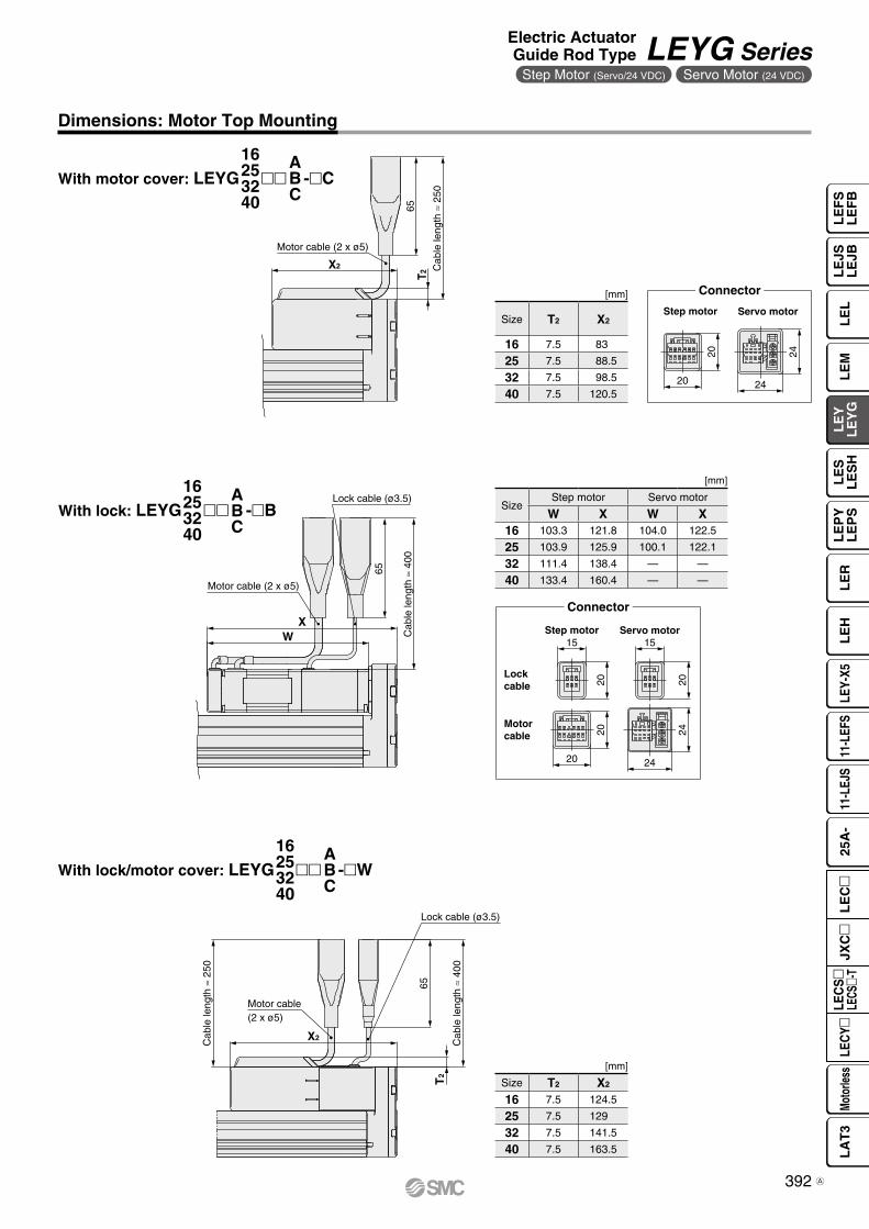
20
20 24
24
X2
T2
Motor cable (2 x ø5)
65
Cab
le le
ngth
≈ 2
50
2020
15
20
20
15
24
24
WX
Motor cable (2 x ø5)
Lock cable (ø3.5)
65
Cab
le le
ngth
≈ 4
00
Cab
le le
ngth
≈ 4
00
65
Cab
le le
ngth
≈ 2
50
X2
Lock cable (ø3.5)
T2
Motor cable(2 x ø5)
Step motor
Lock cable
Motor cable
Servo motor
Connector
Step motor Servo motor
Connector
With motor cover: LEYG mm -mC16253240
ABC
With lock: LEYG mm -mB16253240
ABC
Dimensions: Motor Top Mounting
[mm]
SizeStep motor Servo motor
W X W X16 103.3 121.8 104.0 122.5
25 103.9 125.9 100.1 122.1
32 111.4 138.4 — —
40 133.4 160.4 — —
[mm]
Size T2 X2
16 7.5 83
25 7.5 88.5
32 7.5 98.5
40 7.5 120.5
With lock/motor cover: LEYG mm -mW16253240
ABC
[mm]
Size T2 X2
16 7.5 124.5
25 7.5 129
32 7.5 141.5
40 7.5 163.5
392
Electric ActuatorGuide Rod Type LEYG Series
Step Motor (Servo/24 VDC) Servo Motor (24 VDC)
LE
FS
LE
FB
LE
LL
EJS
LE
JBL
EM
LE
YL
EY
GL
ES
LE
SH
LE
PY
LE
PS
LE
RL
EH
LEY-
X511
-LEF
S11
-LEJ
S25
A-
Moto
rless
LEC
Y�LE
CS
�LE
CS�-
TJX
C�
LE
C�
LA
T3
A

CFB
0.5
XA H9
XB
XA
EBEA
GA H
�V
SQ
EV
JU X
TEH øXA H9 depth XA
4 x OA through
Section XX
KX
WB(0.5)
WAZWC + Stroke
øXA H9 depth XA 4 x OA thread depth OB
2 x NA thread depth NC
Section XX
øD
BX
øD
A
P
WA(0.5)
ZL + Stroke
4 x øGthrough
Stroke end[Origin]∗3
Origin∗2
[Stroke end]
65
A + Stroke
VB
2YD
B + Stroke
2 (FC)
FBFA
0.5 C
Stroke[2]
Cab
le le
ngth
≈ 3
00
Rod operating range∗1
Y
Section XX
*1 This is the range within which the rod can move when it returns to origin. Make sure workpieces mounted on the rod do not interfere with the workpieces and facilities around the rod.
*2 Position after returning to origin*3 [ ] for when the direction of return to
origin has changed
Section Y details
LEYGM, LEYGL Common
LEYGM (Sliding bearing)LEYGL (Ball bushing bearing) [mm]
[mm]
[mm]
Dimensions: In-line Motor
Size Stroke range OA OB P Q S T U V Step motor Servo motor WA WB WC X XA XB YD ZVB
1630 to 35
M5 x 0.8 10 65 15 25 79 6.8 28 61.8 62.525 19 55 44 3 4 24 6.540 to 100 40 26.5
105 to 200 70 41.5 75
25
30 to 35
M6 x 1.0 12 80 18 30 95 6.8 42 63.4 59.6
35 26 70
54 4 5 26 8.540 to 100 50 33.5105 to 120
95125 to 200 70 43.5205 to 300 85 51
32
30 to 35
M6 x 1.0 12 95 28 40 117 7.3 56.4 68.4 —
40 28.5 75
64 5 6 32 8.540 to 100 50 33.5105 to 120
105125 to 200 70 43.5205 to 300 85 51
40
30 to 35
M6 x 1.0 12 95 28 40 117 7.3 56.4 90.4 —
40 28.5 75
64 5 6 32 8.540 to 100 50 33.5105 to 120
105125 to 200 70 43.5205 to 300 85 51
Size Stroke range L DB
16 30 to 90 75 8
95 to 200 105
2530 to 110 91
10115 to 190 115195 to 300 133
3240
30 to 110 97.513115 to 190 116.5
195 to 300 134
Size Stroke range L DB
1630 to 60 51.5
1065 to 90 74.595 to 200 105
2530 to 55 67.5
1260 to 185 100.5190 to 300 138
3240
30 to 50 741655 to 180 107
185 to 300 144
Size Stroke range Step motor Servo motor B C DA EA EB EH EV FA FB FC G GA H J K NA NCA
1630 to 35 174.3 175 92 37
16 35 69 83 41.1 8 10.5 8.5 4.3 31.8 42.3 24.8 23 M4 x 0.7 5.540 to 100 52105 to 200 194.3 195 112 82
25
30 to 35 206.4 202.6 115.5 50
20 45 85 103 52.3 11 14.5 12.5 5.4 40.3 53.3 30.8 29 M5 x 0.8 6.540 to 100 67.5105 to 120
231.4 227.6 140.5125 to 200 84.5205 to 300 102
32
30 to 35 228.9 — 128 55
25 60 101 123 63.8 12 18.5 16.5 5.4 50.3 68.3 38.3 30 M6 x 1.0 8.540 to 100 68105 to 120
258.9 — 158125 to 200 85205 to 300 102
40
30 to 35 250.9 — 128 55
25 60 101 123 63.8 12 18.5 16.5 5.4 50.3 68.3 38.3 30 M6 x 1.0 8.540 to 100 68105 to 120
280.9 — 158125 to 200 85205 to 300 102
393
LEYG SeriesStep Motor (Servo/24 VDC) Servo Motor (24 VDC)
A

CV
LX2
T2
A + Stroke
Cab
le le
ngth
≈ 4
00
Cab
le le
ngth
≈ 2
50
Motor cable(2 x ø5)Lock cable
(ø3.5)
H
L
L
CV
X2
T2
A + Stroke
H
L
2020
15
20
20
15
24
24
Motor cable (2 x ø5)
Lock cable (ø3.5)
65
Cab
le le
ngth
≈ 4
00
2 VBA + Stroke
20
20 24
24
Dimensions: In-line Motor
With lock/motor cover: LEYG Dm -mW16253240
ABC
Step motor
Lock cable
Motor cable
Servo motor
Connector
With motor cover: LEYG mDm -mC16253240
ABC
With lock: LEYG mDm -mB16253240
ABC
[mm]
Size Stroke range A T2 X2 L H CV
16Up to 100 177
7.5 66.5 35 49.8 43105 to 200 197
25Up to 100 209.5
7.5 68.5 46 61.3 54.5105 to 300 234.5
32Up to 100 232
7.5 73.5 60 75.8 68.5105 to 300 262
40Up to 100 254
7.5 95.5 60 75.8 68.5105 to 300 284
[mm]
Size Stroke rangeStep motor Servo motor Step motor Servo motor
A VB
16Up to 100 215.8 216.5
103.3 104105 to 200 235.8 236.5
25Up to 100 246.9 243.1
103.9 100.1105 to 300 271.9 268.1
32Up to 100 271.9 —
111.4 —105 to 300 301.9 —
40Up to 100 293.9 —
133.4 —105 to 300 323.9 —
[mm]
Size Stroke range A T2 X2 L H CV
16Up to 100 218.5
7.5 108 35 49.8 43105 to 200 238.5
25Up to 100 250
7.5 109 46 61.3 54.4105 to 300 275
32Up to 100 275
7.5 116.5 60 75.8 68.5105 to 300 305
40Up to 100 297
7.5 138.5 60 75.8 68.5105 to 300 327
Step motor Servo motor
Connector
394
Electric ActuatorGuide Rod Type LEYG Series
Step Motor (Servo/24 VDC) Servo Motor (24 VDC)
LE
FS
LE
FB
LE
LL
EJS
LE
JBL
EM
LE
YL
EY
GL
ES
LE
SH
LE
PY
LE
PS
LE
RL
EH
LEY-
X511
-LEF
S11
-LEJ
S25
A-
Moto
rless
LEC
Y�LE
CS
�LE
CS�-
TJX
C�
LE
C�
LA
T3
B
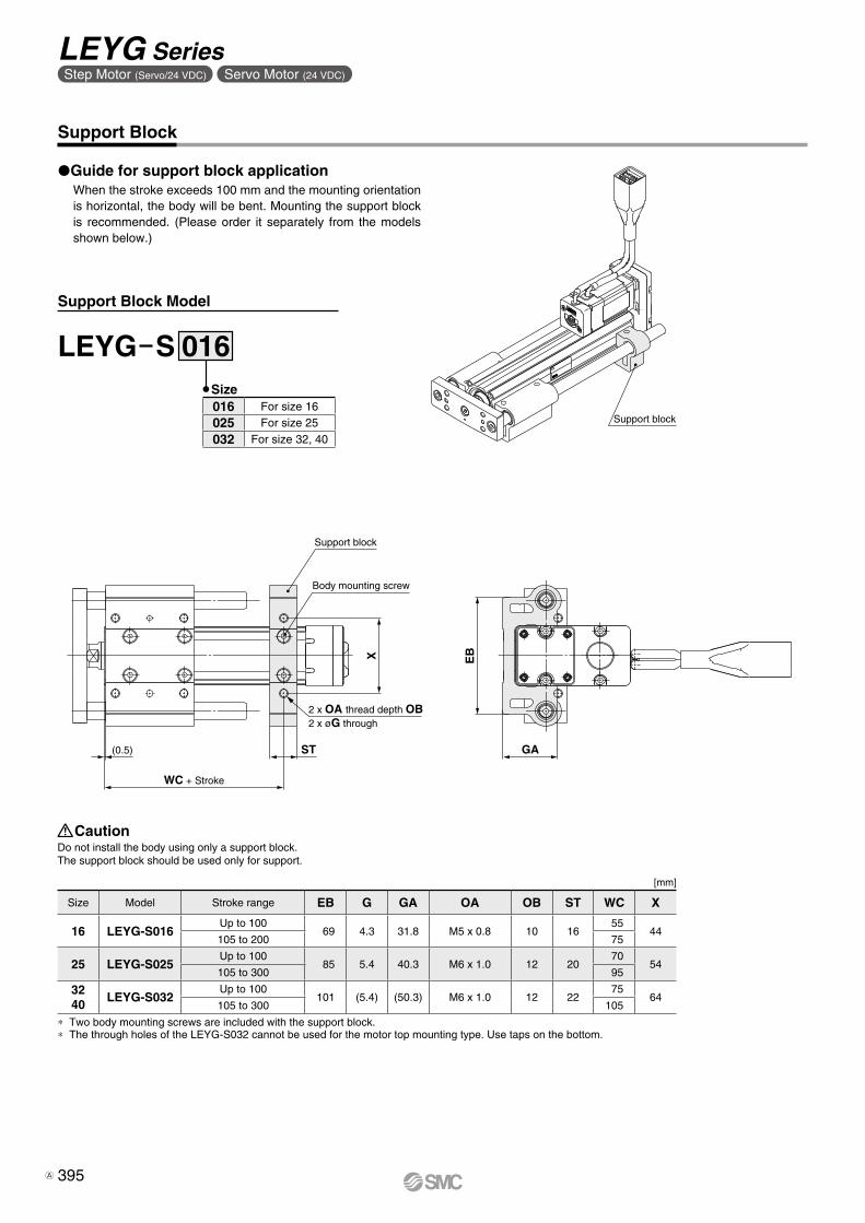
WC + Stroke
Support block
ST(0.5)
X
Body mounting screw
2 x OA thread depth OB2 x øG through
EB
GA
Support block
Support Block
Guide for support block applicationWhen the stroke exceeds 100 mm and the mounting orientation is horizontal, the body will be bent. Mounting the support block is recommended. (Please order it separately from the models shown below.)
∗ Two body mounting screws are included with the support block.∗ The through holes of the LEYG-S032 cannot be used for the motor top mounting type. Use taps on the bottom.
Do not install the body using only a support block.The support block should be used only for support.
Caution
LEYG S 016Size
[mm]
Size Model Stroke range EB G GA OA OB ST WC X
16 LEYG-S016Up to 100
69 4.3 31.8 M5 x 0.8 10 16 55
44105 to 200 75
25 LEYG-S025Up to 100
85 5.4 40.3 M6 x 1.0 12 20 70
54105 to 300 95
3240
LEYG-S032Up to 100
101 (5.4) (50.3) M6 x 1.0 12 22 75
64105 to 300 105
016 For size 16
025 For size 25
032 For size 32, 40
Support Block Model
395
LEYG SeriesStep Motor (Servo/24 VDC) Servo Motor (24 VDC)
A

396
LE
FS
LE
FB
LE
LL
EJS
LE
JBL
EM
LE
YL
EY
GL
ES
LE
SH
LE
PY
LE
PS
LE
RL
EH
LEY-
X511
-LEF
S11
-LEJ
S25
A-
Moto
rless
LEC
Y�LE
CS
�LE
CS�-
TJX
C�
LE
C�
LA
T3

How to Order
Applicable Stroke Table
* Please consult with SMC for non-standard strokes as they are produced as special orders.
For auto switches, refer to pages 363 to 365.
: Standard
25 100B 2 A1Sw
LEY Gre t y u i o !0 !1 !2 !3
S2Mq
H
q AccuracyNil Basic type
H High-precision type
!1 Cable length*1 [m]
*1 The length of the motor, encoder, and lock cables are the same.
Nil Without cable
2 2
5 5
A 10
o Guide option
* Only available for size 25 and 32 sliding bearings (Refer to the “Construction” on page 400.)
Nil Without option
F With grease retaining function
*1 The motor and encoder cables are included. (The lock cable is also included when the motor with lock option is selected.)
*2 Standard cable entry direction is Top mounting: (A) Axis side In-line: (B) Counter axis side (Refer to page 796 for details.)
!0 Cable type*1 *2
Nil Without cable
S Standard cable
R Robotic cable (Flexible cable)
*1 The values shown in ( ) are the leads for the size 32 top mounting type. (Equivalent leads which include the pulley ratio [1.25:1])
y Lead [mm]Symbol LEYG25 LEYG32*1
A 12 16 (20)
B 6 8 (10)
C 3 4 (5)
e Bearing typeM Sliding bearing
L Ball bushing bearing
r Motor mounting positionNil Top mounting
D In-line
i Motor optionNil Without option
B With lock
* For details, refer to the applicable stroke table below.* There is a limit for mounting the size 32 top
mounting type and strokes of 50 mm or less. Refer to the dimensions.
u Stroke [mm]30 30
to to
300 300
Stroke[mm]Model
30 50 100 150 200 250 300 Manufacturablestroke range
LEYG25 15 to 300
LEYG32 20 to 300
w Size2532
AC Servo Motor LECS Series
Electric ActuatorGuide Rod TypeLEYG Series LEYG25, 32
LECY Seriessp. 405 Motorless Typesp. 921
t Motor type*1
*1 For motor type S2 and S6, the compatible driver part number suffixes are S1 and S5 respectively.*2 For motor type T6, the compatible driver part number is LECS2-T5.*3 For details on the driver, refer to page 764.
Symbol Type Output [W] Actuator size Compatible drivers*3 UL-compliant
S2*1 AC servo motor(Incremental encoder)
100 25 LECSA-S1
S3 200 32 LECSA-S3
S6*1
AC servo motor(Absolute encoder)
100 25LECSB-S5LECSC-S5LECSS-S5
—
S7 200 32LECSB-S7LECSC-S7LECSS-S7
—
T6*2
AC servo motor(Absolute encoder)
100 25
LECSB2-T5LECSC2-T5LECSN2-T5-
—
LECSS2-T5
T7 200 32
LECSB2-T7LECSC2-T7LECSN2-T7-
—
LECSS2-T7
Click here for details.Click here for details.
The LECSB-S, LECSC-S, and LECSS-S electric actuator dr ivers are to be discontinued. The LECSB-T, LECSC-T, and LECSS-T drivers are available as substitutes. In the product number, select T6 instead of S6, or T7 instead of S7 for the t Motor type, and select B2 instead of B1, C2 instead of C1, or S2 instead of S1 for the !2 Driver type.
397C

Use of auto switches for the guide rod type LEYG series⋅ Auto switches must be inserted from the front side with the rod (plate) sticking out.⋅ Auto switches cannot be fixed with the parts hidden behind the guide attachment (the side
of the rod that sticks out).⋅ Please consult with SMC when using auto switches on the side of the rod that sticks out, as it is
produced as a special order.
!3 I/O cable length [m]*1
*1 When “Without driver” is selected for driver type, only “Nil: Without cable” can be selected. Refer to page 797 if I/O cable is required. (Options are shown on page 797.)
Nil Without cable
H Without cable (Connector only)
1 1.5
Motor mounting position: Top mounting Motor mounting position: In-line
Compatible Drivers
!2 Driver type*1
*1 When a driver type is selected, a cable is included. Select the cable type and cable length.Example)S2S2: Standard cable (2 m) + Driver (LECSS2) S2: Standard cable (2 m) Nil: Without cable and driver
Compatible drivers Power supply voltage [V]Nil Without driver —
A1 LECSA1-Sm 100 to 120
A2 LECSA2-Sm 200 to 230
B1 LECSB1-Sm 100 to 120
B2LECSB2-Sm 200 to 230LECSB2-Tm 200 to 240
C1 LECSC1-Sm 100 to 120
C2LECSC2-Sm
200 to 230LECSC2-Tm
S1 LECSS1-Sm 100 to 120
S2LECSS2-Sm 200 to 230LECSS2-Tm 200 to 240
N2 LECSN2-Tm 200 to 240
92 LECSN2-Tm-9 200 to 240
E2 LECSN2-Tm-E 200 to 240
P2 LECSN2-Tm-P 200 to 240
Driver type
Pulse input type/Positioning type
Pulse input type
CC-Link directinput type
SSCNET # type Pulse input type CC-Link directinput type
type
Network card type
Series LECSA LECSB LECSC LECSS LECSB-T LECSC-T LECSS-T LECSN-T
Number of point tables*1 Up to 7 — Up to 255 (2 stations occupied) — Up to 255 Up to 255 (2 stations occupied) — Up to 255
Pulse input — — — — —
Applicable network — — CC-Link SSCNET 3 — CC-Link SSCNET 3/HPROFINETEtherCAT®
EtherNet/IP™
Control encoder Incremental17-bit encoder
Absolute18-bit encoder
Absolute18-bit encoder
Absolute18-bit encoder
Absolute 22-bit encoder
Absolute 18-bit encoder
Absolute22-bit encoder
Absolute22-bit encoder
Communication function USB communication USB communication, RS422 communication USB communication USB communication, RS422 communication USB communication USB communication
Power supply voltage [V]
100 to 120 VAC (50/60 Hz)200 to 230 VAC (50/60 Hz)
200 to 240 VAC
(50/60 Hz)
200 to 230 VAC
(50/60 Hz)
200 to 240 VAC
(50/60 Hz)
200 to 240VAC
(50/60 Hz)
Reference page 777
*1 The LECSN-T only supports PROFINET and EtherCAT®.
398
Electric ActuatorGuide Rod Type LEYG Series
AC Servo Motor
LE
FS
LE
FB
LE
LL
EJS
LE
JBL
EM
LE
YL
EY
GL
ES
LE
SH
LE
PY
LE
PS
LE
RL
EH
LEY-
X511
-LEF
S11
-LEJ
S25
A-
Moto
rless
LEC
Y�LE
CS
�LE
CS�-
TJX
C�
LE
C�
LA
T3
B

Specifications
WeightWeight: Motor Top Mounting Type [kg]
Series LEYG25MS2 6/T6 LEYG32MS3
7/T7Stroke [mm] 30 50 100 150 200 250 300 30 50 100 150 200 250 300
Mo
tor
typ
e Incremental encoder 1.80 1.99 2.31 2.73 3.07 3.41 3.67 3.24 3.50 4.05 4.80 5.35 5.83 6.28Absolute encoder [S6
7] 1.86 2.05 2.37 2.79 3.13 3.47 3.73 3.18 3.44 3.99 4.74 5.29 5.77 6.22Absolute encoder [T6
7] 1.8 2.0 2.4 2.8 3.1 3.5 3.7 3.2 3.4 4.0 4.7 5.3 5.7 6.2
Series LEYG25LS2 6/T6 LEYG32LS3
7/T7Stroke [mm] 30 50 100 150 200 250 300 30 50 100 150 200 250 300
Mo
tor
typ
e Incremental encoder 1.81 2.02 2.26 2.69 2.95 3.27 3.51 3.24 3.51 3.9 4.64 5.06 5.56 5.96Absolute encoder [S6
7] 1.87 2.08 2.32 2.75 3.01 3.33 3.57 3.18 3.45 3.84 4.58 5.00 5.50 5.90Absolute encoder [T6
7] 1.9 2.1 2.3 2.7 3.0 3.3 3.6 3.2 3.4 3.8 4.6 5.0 5.5 5.9
Weight: In-line Motor Type [kg]
Series LEYG25MDS2 6/T6 LEYG32MDS3
7/T7Stroke [mm] 30 50 100 150 200 250 300 30 50 100 150 200 250 300
Mo
tor
typ
e Incremental encoder 1.83 2.02 2.34 2.76 3.10 3.44 3.70 3.26 3.52 4.07 4.82 5.37 5.85 6.30Absolute encoder [S6
7] 1.89 2.08 2.40 2.82 3.16 3.50 3.76 3.20 3.46 4.01 4.76 5.31 5.79 6.24Absolute encoder [T6
7] 1.9 2.1 2.4 2.8 3.1 3.5 3.7 3.2 3.4 4.0 4.7 5.3 5.8 6.2
Series LEYG25LDS2 6/T6 LEYG32LDS3
7/T7Stroke [mm] 30 50 100 150 200 250 300 30 50 100 150 200 250 300
Mo
tor
typ
e Incremental encoder 1.84 2.05 2.29 2.72 2.98 3.30 3.54 3.26 3.53 3.92 4.66 5.08 5.58 5.98Absolute encoder [S6
7] 1.90 2.11 2.35 2.78 3.04 3.36 3.60 3.20 3.47 3.86 4.60 5.02 5.52 5.92Absolute encoder [T6
7] 1.9 2.1 2.3 2.8 3.0 3.3 3.6 3.2 3.4 3.8 4.6 5.0 5.5 5.9
Additional Weight [kg]
Size 25 32
LockIncremental encoder 0.20 0.40
Absolute encoder [S6 7] 0.30 0.66
Absolute encoder [T6 7] 0.3 0.7
Specifications
∗1 This is the maximum value of the horizontal work load. An external guide is necessary to support the load. The actual work load changes according to the condition of the external guide. Confirm the load using the actual device.
∗2 The force setting range (set values for the driver) for the force control with the torque control mode. Set it while referencing the “Force Conversion Graph” on page 376. When the control equivalent to the pushing operation of the JXC51/61 series controller is performed, select the LECSS, LECSS-T or LECSB2-T driver.The point table no. input method is used for the LECSB2-T. When selecting the LECSS or LECSS2-T, combine it with a Simple Motion module (manufactured by Mitsubishi Electric Corporation) which has a pushing operation function.
∗3 The allowable collision speed for collision with the workpiece with the torque control mode∗4 A reference value for correcting an error in reciprocal operation∗5 Impact resistance: No malfunction occurred when the actuator was tested with a drop
tester in both an axial direction and a perpendicular direction to the lead screw. (The test
was performed with the actuator in the initial state.)Vibration resistance: No malfunction occurred in a test ranging between 45 to 2000 Hz. The test was performed in both an axial direction and a perpendicular direction to the lead screw. (The test was performed with the actuator in the initial state.)
∗6 The power consumption (including the driver) is for when the actuator is operating.∗7 The standby power consumption when operating (including the driver) is for when the
actuator is stopped in the set position during operation.∗8 The maximum instantaneous power consumption (including the driver) is for when the
actuator is operating.∗9 Only when motor option “With lock” is selected∗10 For an actuator with lock, add the power consumption for the lock.∗11 For motor types T6 and T7, the set value is 12 to 24%.∗12 For motor types T6 and T7, the resolution will change depending on the driver type.
Model LEYG25S26/T6 (Top mounting)
LEYG25DS26/T6 (In-line) LEYG32S3
7/T7 (Top mounting) LEYG32DS37/T7 (In-line)
Act
uat
or
spec
ifica
tio
ns
Work load [kg] Horizontal∗1 18 50 50 30 60 60 30 60 60Vertical 7 15 29 7 17 35 10 22 44
Force [N]∗2 (Set value: 15 to 30%)∗11 65 to 131 127 to 255 242 to 485 79 to 157 154 to 308 294 to 588 98 to 197 192 to 385 368 to 736Max. speed [mm/s] 900 450 225 1200 600 300 1000 500 250Pushing speed [mm/s2]∗3 35 or less 30 or less 30 or lessMax. acceleration/deceleration [mm/s2] 5000 5000Positioning repeatability [mm]
Basic type ±0.02High-precision type ±0.01
Lost motion∗4
[mm]Basic type 0.1 or lessHigh-precision type 0.05 or less
Lead [mm] (including pulley ratio) 12 6 3 20 10 5 16 8 4Impact/Vibration resistance [m/s2]∗5 50/20 50/20Actuation type Ball screw + Belt [1:1]/Ball screw Ball screw + Belt [1.25:1] Ball screwGuide type Sliding bearing (LEYGM), Ball bushing bearing (LEYGL)Operating temperature range [°C] 5 to 40 5 to 40Operating humidity range [%RH] 90 or less (No condensation) 90 or less (No condensation)Regeneration option May be required depending on speed and work load (Refer to page 375.)
Ele
ctri
c sp
ecifi
catio
ns
Motor output/Size 100 W/40 200 W/60Motor type AC servo motor (100/200 VAC) AC servo motor (100/200 VAC)
Encoder∗12
Motor type S2, S3: Incremental 17-bit encoder (Resolution: 131072 p/rev)Motor type S6, S7: Absolute 18-bit encoder (Resolution: 262144 p/rev)
Motor type T6, T7: Absolute 22-bit encoder (Resolution: 4194304 p/rev) (For LECSB-T, LECSS-T)Motor type T6, T7: Absolute 18-bit encoder (Resolution: 262144 p/rev) (For LECSC-T)
Powerconsumption [W]∗6
Horizontal 45 65 65Vertical 145 175 175
Standby power consumptionwhen operating [W]∗7
Horizontal 2 2 2Vertical 8 8 8
Max. instantaneous power consumption [W]∗8 445 724 724
Lock
uni
tsp
ecifi
catio
ns Type∗9 Non-magnetizing lock Non-magnetizing lockHolding force [N] 131 255 485 157 308 588 197 385 736Power consumption at 20°C [W]∗10 6.3 7.9 7.9Rated voltage [V] 24 VDC 0
−10%
399
LEYG SeriesAC Servo Motor
A

#6 #7
#9
#4 #3 #1 #2#5 #6
$0
#8
@7
@5
@6
@2!6y qwt r ei!2
@0
!9
@3 !3 !4@4
u!5
!7 !1o @1
!8
!0
#1 #0 @8 @9#4 #3
#6 #7
Construction
Component Parts
Motor mounting position: Top mounting type
LEYGMLEYG25/32M: 50st or less
LEYG25/32M: Over 50st
LEYG25/32L: 100st or less
LEYG25/32L: Over 100st
LEYG25/32M: 50st or less
When grease retaining function selected
LEYG25/32M: Over 50st
LEYGL
Motor mounting position: In-line type
Support BlockSize Order no.25 LEYG-S02532 LEYG-S032
∗ Two body mounting screws are included with the support block.
No. Description Material Note27 Spider Urethane28 Guide attachment Aluminum alloy Anodized29 Guide rod Carbon steel30 Plate Aluminum alloy Anodized31 Plate mounting cap screw Carbon steel Nickel plating32 Guide cap screw Carbon steel Nickel plating33 Sliding bearing Bearing alloy34 Felt Felt35 Holder Synthetic resin36 Retaining ring Steel for spring Phosphate coating37 Ball bushing —38 Spacer Aluminum alloy Chromating
Replacement Parts/BeltSize Order no.25 LE-D-2-232 LE-D-2-4
No. Description Material Note1 Body Aluminum alloy Anodized2 Ball screw shaft Alloy steel3 Ball screw nut Synthetic resin/Alloy steel4 Piston Aluminum alloy5 Piston rod Stainless steel Hard chrome plating6 Rod cover Aluminum alloy7 Bearing holder Aluminum alloy8 Rotation stopper Synthetic resin9 Socket Free cutting carbon steel Nickel plating10 Connected shaft Free cutting carbon steel Nickel plating11 Bushing Bearing alloy12 Bearing —13 Return box Aluminum die-cast Coating14 Return plate Aluminum die-cast Coating15 Magnet —16 Wear ring holder Stainless steel Stroke 101 mm or more17 Wear ring Synthetic resin Stroke 101 mm or more18 Screw shaft pulley Aluminum alloy19 Motor pulley Aluminum alloy20 Belt —21 Seal NBR22 Retaining ring Steel for spring Phosphate coating23 Motor adapter Aluminum alloy Coating24 Motor —25 Motor block Aluminum alloy Coating26 Hub Aluminum alloy
Replacement Parts/Grease PackApplied portion Order no.
Piston rodGuide rod
GR-S-010 (10 g)GR-S-020 (20 g)
∗ Apply grease on the piston rod periodically. Grease should be applied at 1 million cycles or 200 km, whichever comes first.
400
Electric ActuatorGuide Rod Type LEYG Series
AC Servo Motor
LE
FS
LE
FB
LE
LL
EJS
LE
JBL
EM
LE
YL
EY
GL
ES
LE
SH
LE
PY
LE
PS
LE
RL
EH
LEY-
X511
-LEF
S11
-LEJ
S25
A-
Moto
rless
LEC
Y�LE
CS
�LE
CS�-
TJX
C�
LE
C�
LA
T3

CFB
0.5
øD
AøD
B
4 x øG through
X P
0.5
Z WAL + Stroke
Rod operating range∗1
(Stroke + 4 mm)
0.5
FA FB
VAVB
C Y
B + Stroke
A + Stroke
Encoder Z-phasedetecting position∗2
(FC)
EHTX
S
Section XX
4 x M OA through
øXA H9 depth XA
Q
UJEV
�V
MEAEB
GA
4 x NAthread depth NB
MH
VC
øXA H9 depth XA 4 x OA thread depth OB
2 x NAthread depth NC
X
(0.5)
WC + Stroke
K
Section XX
ZWB
WA
2 ±1
Y
∗3
XA H9 XA
XB
Section XX
Section Y details
Dimensions: Motor Top Mounting
[mm]LEYGL (Ball bushing bearing)
[mm]LEYGM, LEYGL Common
[mm]LEYGM (Sliding bearing)
*1 This is the range within which the rod can move. Make sure workpieces mounted on the rod do not interfere with the workpieces and facilities around the rod.
*2 The Z-phase first detecting position from the stroke end of the motor side
*3 Through holes cannot be used for size 32 with strokes of 50 mm or less.
Size Stroke range [mm] L DB
2530 to 55 67.5
1260 to 185 100.5190 to 300 138
3230 to 50 74
1655 to 180 107185 to 300 144
SizeStroke range
[mm] OA OB P Q S T U V WA WB WC X XA XB Y Z
25
30 to 35
M6 x 1.0 12 80 18 30 95 6.8 40
35 26 70
54 4 5 26.5 8.540 to 100
50 33.5105 to 120
95125 to 200 70 43.5205 to 300 85 51
32
30 to 35
M6 x 1.0 12 95 28 40 117 7.3 60
40 28.5 75
64 5 6 34 8.540 to 100
50 33.5105 to 120
105125 to 200 70 43.5205 to 300 85 51
SizeIncremental encoder [S2/S3] Absolute encoder [S6/S7] Absolute encoder [T6/T7]
Without lock With lock Without lock With lock Without lock With lockVA VB VC VA VB VC VA VB VC VA VB VC VA VB VC VA VB VC
25 120 87 14.1 156.9 123.9 15.8 115.4 82.4 14.1 156.5 123.5 15.8 115.4 82.4 14.1 156 123 15.832 128.2 88.2 17.1 156.8 116.8 17.1 116.6 76.6 17.1 156.1 116.1 17.1 116.6 76.6 17.1 153.4 113.4 17.1
SizeStroke range
[mm] A B C DA EA EB EH EV FA FB FC G GA H J K M NA NB NC
25
30 to 35141.5 116
50
20 46 85 103 52.3 11 14.5 12.5 5.4 40.3 98.8 30.8 29 34 M5 x 0.8 8 6.540 to 100
67.5105 to 120
166.5 141125 to 200 84.5205 to 300 102
32
30 to 35160.5 130
55
25 60 101 123 63.8 12 18.5 16.5 5.4 50.3 125.3 38.3 30 40 M6 x 1.0 10 8.540 to 100
68105 to 120
190.5 160125 to 200 85205 to 300 102
Size Stroke range [mm] L DB
2530 to 110 91
10115 to 190 115195 to 300 133
3230 to 110 97.5
13115 to 190 116.5195 to 300 134
401
LEYG SeriesAC Servo Motor
A
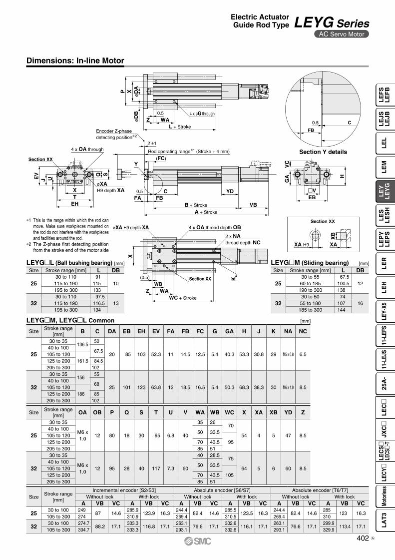
0.5
FB
C
4 x OA through
UJEV
GA
VC
X
0.5
FA FBC YD
B + Stroke VBA + Stroke
�VEB
Rod operating range∗1 (Stroke + 4 mm)
2 ±1
Encoder Z-phasedetecting position∗2
(FC)
(0.5)
Z WAWC + Stroke
Section XX
øXA H9 depth XA 4 x OA thread depth OB
2 x NAthread depth NC
EHTX
øXAH9 depth XA
Section XX
SQ
WB
H
Y
K
4 x øG throughZ WA
L + Stroke
0.5
øD
AøD
BXP
XA H9 XA
XB
Section XX
Section Y details
Dimensions: In-line Motor
[mm]LEYGL (Ball bushing bearing)
[mm]LEYGM, LEYGL Common
[mm]LEYGM (Sliding bearing)
*1 This is the range within which the rod can move. Make sure workpieces mounted on the rod do not interfere with the workpieces and facilities around the rod.
*2 The Z-phase first detecting position from the stroke end of the motor side
Size Stroke range [mm] L DB
2530 to 55 67.5
1260 to 185 100.5190 to 300 138
3230 to 50 74
1655 to 180 107185 to 300 144
SizeStroke range
[mm] OA OB P Q S T U V WA WB WC X XA XB YD Z
25
30 to 35
M6 x1.0
12 80 18 30 95 6.8 40
35 26 70
54 4 5 47 8.540 to 100
50 33.5105 to 120
95125 to 200 70 43.5205 to 300 85 51
32
30 to 35
M6 x1.0
12 95 28 40 117 7.3 60
40 28.5 75
64 5 6 60 8.540 to 100
50 33.5105 to 120
105125 to 200 70 43.5205 to 300 85 51
SizeStroke range
[mm]
Incremental encoder [S2/S3] Absolute encoder [S6/S7] Absolute encoder [T6/T7]Without lock With lock Without lock With lock Without lock With lock
A VB VC A VB VC A VB VC A VB VC A VB VC A VB VC
2530 to 100 249
87 14.6285.9
123.9 16.3244.4
82.4 14.6285.5
123.5 16.3244.4
82.4 14.6285
123 16.3105 to 300 274 310.9 269.4 310.5 269.4 310
3230 to 100 274.7
88.2 17.1303.3
116.8 17.1263.1
76.6 17.1302.6
116.1 17.1263.1
76.6 17.1299.9
113.4 17.1105 to 300 304.7 333.3 293.1 332.6 293.1 329.9
SizeStroke range
[mm] B C DA EB EH EV FA FB FC G GA H J K NA NC
25
30 to 35136.5
50
20 85 103 52.3 11 14.5 12.5 5.4 40.3 53.3 30.8 29 M5 x 0.8 6.540 to 100
67.5105 to 120
161.5125 to 200 84.5205 to 300 102
32
30 to 35156
55
25 101 123 63.8 12 18.5 16.5 5.4 50.3 68.3 38.3 30 M6 x 1.0 8.540 to 100
68105 to 120
186125 to 200 85205 to 300 102
Size Stroke range [mm] L DB
2530 to 110 91
10115 to 190 115195 to 300 133
3230 to 110 97.5
13115 to 190 116.5195 to 300 134
402
Electric ActuatorGuide Rod Type LEYG Series
AC Servo Motor
LE
FS
LE
FB
LE
LL
EJS
LE
JBL
EM
LE
YL
EY
GL
ES
LE
SH
LE
PY
LE
PS
LE
RL
EH
LEY-
X511
-LEF
S11
-LEJ
S25
A-
Moto
rless
LEC
Y�LE
CS
�LE
CS�-
TJX
C�
LE
C�
LA
T3
A

Support block
Support block
Body mounting screw
2 x OA thread depth OB2 x øG through
X
WC + Stroke
ST(0.5)
EB
GA
Support Block
Guide for support block applicationWhen the stroke exceeds 100 mm and the mounting orientation is horizontal, the body will be bent. Mounting the support block is recommended. (Please order it separately from the models shown below.)
∗ Two body mounting screws are included with the support block.∗ The through holes of the LEYG-S032 cannot be used for the motor top mounting type. Use taps on the bottom.
Do not install the body using only a support block.The support block should be used only for support.
Caution
LEYG S 025Size
[mm]
025 For size 25
032 For size 32
Size Model Stroke range EB G GA OA OB ST WC X
25 LEYG-S025Up to 100
85 5.4 40.3 M6 x 1.0 12 20 70
54105 to 300 95
32 LEYG-S032Up to 100
101 (5.4) (50.3) M6 x 1.0 12 22 75
64105 to 300 105
Support Block Model
403
LEYG SeriesAC Servo Motor
A

404
LE
FS
LE
FB
LE
LL
EJS
LE
JBL
EM
LE
YL
EY
GL
ES
LE
SH
LE
PY
LE
PS
LE
RL
EH
LEY-
X511
-LEF
S11
-LEJ
S25
A-
Moto
rless
LEC
Y�LE
CS
�LE
CS�-
TJX
C�
LE
C�
LA
T3

Motor
How to Order
Applicable Stroke Table
* Please consult with SMC for non-standard strokes as they are produced as special orders.
w Size
* For details, refer to the applicable stroke table below.
* There is a limit for mounting the size 32 top mounting type and strokes of 50 mm or less. Refer to the dimensions.
u Stroke [mm] i Motor option
r Motor mounting position
*1 The values shown in ( ) are the leads for the top mounting type. (Equivalent leads which include the pulley ratio [1.25:1])
y Lead [mm]
!0 Cable type*1o Guide option
* Only available for the sliding bearing
!1 Cable length [m]*1
For auto switches, refer to pages 363 to 365.
t Motor type
V: Standard
Symbol TypeOutput
[W]Actuator
sizeCompatible
drivers
V6*1
AC servo motor(Absolute encoder)
100 25LECYM2-V5LECYU2-V5
V7 200 32LECYM2-V7LECYU2-V7
Nil Without cable
3 3
5 5
A 10
C 20
Nil Without option
F With grease retaining function
Nil Without cable
S Standard cable
R Robotic cable (Flexible cable)
Symbol LEYG25 LEYG32*1
A 12 16 (20)
B 6 8 (10)
C 3 4 (5)
e Bearing typeM Sliding bearing
L Ball bushing bearing
Nil Top mounting
D In-line
Nil Without option
B With lock
30 30
to to
300 300
Stroke[mm]Model
30 50 100 150 200 250 300 Manufacturablestroke range
LEYG25 V V V V V V V 15 to 300
LEYG32 V V V V V V V 20 to 300
2532
* When “With lock” is selected for the top mount-ing type, the motor body will stick out from the end of the body for size 25 with strokes of 30 mm or less. Check for interference with work-pieces before selecting a model.
LEY G 25 200B 3 M2Sw req t y u i o !0 !1 !2 !3
V6MH
q AccuracyNil Basic type
H High-precision type
AC Servo Motor LECY Series
Electric ActuatorGuide Rod TypeLEYG Series LEYG25, 32
*1 For motor type V6, the compatible driver part number suffix is V5.
*1 The motor and encoder cables are included. The motor cable for lock option is included when the motor with lock option is selected. *1 The length of the motor and encoder cables
are the same. (For with lock)
LECS Seriessp. 397 Motorless Typesp. 921Click here for details.
405A

Motor mounting position: Top mounting Motor mounting position: In-line
Use of auto switches for the guide rod type LEYG series· Auto switches must be inserted from the front side with the rod (plate) sticking out.· Auto switches cannot be fixed with the parts hidden behind the guide attachment (the side of the rod that sticks out).· Please consult with SMC when using auto switches on the side of the rod that sticks out, as it is produced as a special order.
!2 Driver type
* When a driver type is selected, a cable is included. Select the cable type and cable length.
Compatible drivers Power supply voltage [V]
Nil Without driver —
M2 LECYM2-Vl 200 to 230
U2 LECYU2-Vl 200 to 230
Compatible Drivers
Driver type
-@ type -# type
Series LECYM LECYUApplicable network MECHATROLINK-2 MECHATROLINK-3
Control encoderAbsolute
20-bit encoder
Communication device USB communication, RS-422 communication
Power supply voltage [V] 200 to 230 VAC (50/60 Hz)
Reference page 801
!3 I/O cable length [m]*1
Nil Without cable
H Without cable (Connector only)
1 1.5
*1 When “Without driver” is selected for driver type, only “Nil: Without cable” can be selected. Refer to page 808 if I/O cable is required. (Options are shown on page 808.)
406
Electric ActuatorGuide Rod Type LEYG Series
AC Servo Motor
LE
FS
LE
FB
LE
LL
EJS
LE
JBL
EM
LE
YL
EY
GL
ES
LE
SH
LE
PY
LE
PS
LE
RL
EH
LEY-
X511
-LEF
S11
-LEJ
S25
A-
Moto
rless
LEC
Y�LE
CS
�LE
CS�-
TJX
C�
LE
C�
LA
T3

Model LEYG25MLV6 (Top mounting)
LEYG25MLDV6 (In-line) LEYG32M
L V7 (Top mounting) LEYG32MLDV7 (In-line)
Act
uat
or
spec
ifica
tio
ns
Work load [kg]Horizontal*1 18 50 50 30 60 60 30 60 60Vertical 7 15 29 7 17 35 10 22 44
Force [N]*2 (Set value: 45 to 90%) 65 to 131 127 to 255 242 to 485 79 to 157 154 to 308 294 to 588 98 to 197 192 to 385 368 to 736
Max. speed [mm/s] 900 450 225 1200 600 300 1000 500 250Pushing speed [mm/s]*3 35 or less 30 or less 30 or lessMax. acceleration/deceleration [mm/s2] 5000 5000Positioning repeatability [mm]
Basic type ±0.02 ±0.02High-precision type ±0.01 ±0.01
Lost motion [mm]Basic type 0.1 or less 0.1 or lessHigh-precision type 0.05 or less 0.05 or less
Lead [mm] (including pulley ratio) 12 6 3 20 10 5 16 8 4Impact/Vibration resistance [m/s2]*4 50/20 50/20Actuation type Ball screw + Belt [1:1]/Ball screw Ball screw + Belt [1:1.25] Ball screwGuide type Sliding bearing (LEYGM), Ball bushing bearing (LEYGL)Operating temperature range [°C] 5 to 40 5 to 40Operating humidity range [%RH] 90 or less (No condensation) 90 or less (No condensation)Conditions for*5
“Regenerative resistor” [kg]Horizontal Not required Not requiredVertical 5 or more 2 or more
Ele
ctri
c sp
ecifi
catio
ns Motor output/Size 100 W/40 200 W/60Motor type AC servo motor (200 VAC) AC servo motor (200 VAC)Encoder Absolute 20-bit encoder (Resolution: 1048576 p/rev)Powerconsumption [W]*6
Horizontal 45 65 65Vertical 145 175 175
Standby power consumptionwhen operating [W]*7
Horizontal 2 2 2Vertical 8 8 8
Max. instantaneous power consumption [W]*8 445 724 724
Lock
uni
tsp
ecifi
catio
ns Type*9 Non-magnetizing lock Non-magnetizing lockHolding force [N] 131 255 485 157 308 588 197 385 736Power consumption at 20°C [W]*10 5.5 6 6Rated voltage [V] 24 VDC +10%
0
Size 25 32Lock 0.3 0.6
Product Weight: Motor Top Mounting Type
[kg]Additional Weight
*1 This is the maximum value of the horizontal work load. An external guide is necessary to support the load. The actual work load changes according to the condition of the external guide. Confirm the load using the actual device.
*2 The force setting range (set values for the driver) for the force control with the torque control mode Set it while referencing the “Force Conversion Graph” on page 381.
*3 The allowable collision speed for collision with the workpiece with the torque control mode
*4 Impact resistance: No malfunction occurred when the actuator was tested with a drop tester in both an axial direction and a perpendicular direction to the lead screw. (The test was performed with the actuator in the initial state.)Vibration resistance: No malfunction occurred in a test ranging between 45 to 2000 Hz. The test was performed in both an axial direction and a perpendicular direction to the lead screw. (The test was performed with the actuator in the initial state.)
*5 The work load conditions which require the “Regenerative resistor” when operating at the maximum speed (Duty ratio: 100%)Order the regenerative resistor separately. For details, refer to the “Conditions for Regenerative Resistor (Guide)” on page 380.
*6 The power consumption (including the driver) is for when the actuator is operating.
*7 The standby power consumption when operating (including the driver) is for when the actuator is stopped in the set position during operation.
*8 The maximum instantaneous power consumption (including the driver) is for when the actuator is operating.
*9 Only when motor option “With lock” is selected*10 For an actuator with lock, add the power consumption for the lock.
Specifications
Weight
[kg]
Series LEYG25MV6 LEYG32MV7Stroke [mm] 30 50 100 150 200 250 300 30 50 100 150 200 250 300Weight [kg] 1.7 1.9 2.2 2.6 3.0 3.3 3.6 3.1 3.4 4.0 4.7 5.3 5.7 6.2
Series LEYG25LV6 LEYG32LV7Stroke [mm] 30 50 100 150 200 250 300 30 50 100 150 200 250 300Weight [kg] 1.7 1.9 2.2 2.6 2.9 3.2 3.4 3.1 3.4 3.8 4.5 5.0 5.5 5.9
Series LEYG25LDV6 LEYG32LDV7Stroke [mm] 30 50 100 150 200 250 300 30 50 100 150 200 250 300Weight [kg] 1.7 2.0 2.2 2.6 2.9 3.2 3.4 3.2 3.4 3.8 4.6 5.0 5.5 5.9
Series LEYG25MDV6 LEYG32MDV7Stroke [mm] 30 50 100 150 200 250 300 30 50 100 150 200 250 300Weight [kg] 1.7 1.9 2.2 2.6 3.0 3.3 3.6 3.2 3.4 4.0 4.7 5.3 5.8 6.2
Product Weight: In-line Motor Type
[kg]
407
LEYG SeriesAC Servo Motor

Size Order no.25 LEYG-S02532 LEYG-S032
No. Description Material Note19 Motor pulley Aluminum alloy20 Belt —21 Seal NBR22 Retaining ring Steel for spring Phosphate coating23 Motor adapter Aluminum alloy Coating24 Motor —25 Motor block Aluminum alloy Coating26 Hub Aluminum alloy27 Spider Urethane28 Guide attachment Aluminum alloy Anodized29 Guide rod Carbon steel30 Plate Aluminum alloy Anodized31 Plate mounting cap screw Carbon steel Nickel plating32 Guide cap screw Carbon steel Nickel plating33 Sliding bearing Bearing alloy34 Retaining ring Steel for spring Phosphate coating35 Ball bushing —
Size Order no.25 LE-D-2-232 LE-D-2-4
No. Description Material Note1 Body Aluminum alloy Anodized2 Ball screw shaft Alloy steel3 Ball screw nut —4 Piston Aluminum alloy5 Piston rod Stainless steel Hard chrome plating6 Rod cover Aluminum alloy7 Bearing holder Aluminum alloy8 Rotation stopper Synthetic resin9 Socket Free cutting carbon steel Nickel plating10 Connected shaft Free cutting carbon steel Nickel plating11 Bushing Bearing alloy12 Bearing —13 Return box Aluminum die-cast Coating14 Return plate Aluminum die-cast Coating15 Magnet —16 Wear ring holder Stainless steel Stroke 101 mm or more17 Wear ring Synthetic resin Stroke 101 mm or more18 Screw shaft pulley Aluminum alloy
!7!6y qwt rei u !2 !3
!4
!0
!8
@0!9
@3@4
!5
!1o @1@2
u@5 @6
@7
#1 #0 @8 @9#2 #3 #4 #5
LEYGM LEYGL
Replacement Parts/BeltSupport Block
Component Parts
∗ Two body mounting screws are included with the support block.
Construction
Motor mounting position: Top mounting type
Motor mounting position: In-line type
408
Electric ActuatorGuide Rod Type LEYG Series
AC Servo Motor
LE
FS
LE
FB
LE
LL
EJS
LE
JBL
EM
LE
YL
EY
GL
ES
LE
SH
LE
PY
LE
PS
LE
RL
EH
LEY-
X511
-LEF
S11
-LEJ
S25
A-
Moto
rless
LEC
Y�LE
CS
�LE
CS�-
TJX
C�
LE
C�
LA
T3

øD
AøD
BX
0.5
Z WAL + Stroke
P
VAVB
Rod operating range(Stroke + 4 mm)
∗1
Encoder Z-phasedetecting position∗2
(FC)
2 ±1
4 x M OA through
øXA H9 depth XA
SQ
EHTX
Section XX
UJEV
�V
0.5
FA FBC Y
B + Stroke
A + Stroke
øXA H9 depth XA 4 x OA thread depth OB
X
2 x NAthread depth NC
K
(0.5)
WC + Stroke
Section XX
ZWB
WA
MH
VC
4 x NAthread depth NB
GA
MEAEB
4 x øG through∗3
Section Y
XA H9 XA
XB
C0.5
FB
Section XX
Dimensions: Motor Top Mounting
[mm]LEYGlL (Ball bushing bearing)
[mm]LEYGlM, LEYGlL Common
[mm]LEYGlM (Sliding bearing)
*1 This is the range within which the rod can move. Make sure workpieces mounted on the rod do not interfere with the work-pieces and facilities around the rod.
*2 The Z-phase first detecting position from the stroke end of the motor side
*3 Through holes cannot be used for size 32 with strokes of 50 mm or less.
Size Stroke range (mm) L DB
2530 to 55 67.5
1260 to 185 100.5190 to 300 138
3230 to 50 74
1655 to 180 107185 to 300 144
SizeStroke range
[mm] OA OB P Q S T U V WA WB WC X XA XB Y Z
25
30 to 35
M6 x 1.0 12 80 18 30 95 6.8 40
35 2670
54 4 5 26.5 8.540 to 100
50 33.5105 to 120
95125 to 200 70 43.5205 to 300 85 51
32
30 to 35
M6 x 1.0 12 95 28 40 117 7.3 60
40 28.575
64 5 6 34 8.540 to 100
50 33.5105 to 120
105125 to 200 70 43.5205 to 300 85 51
SizeWithout lock With lock
VA VB VC VA VB VC25 115.5 82.5 11 160.5 127.5 1132 120 80 14 160 120 14
SizeStroke range
[mm] A B C DA EA EB EH EV FA FB FC G GA H J K M NA NB NC
25
30 to 35141.5 116
50
20 46 85 103 52.3 11 14.5 12.5 5.4 40.3 98.8 30.8 29 34 M5 x 0.8 8 6.540 to 100
67.5105 to 120
166.5 141125 to 200 84.5205 to 300 102
32
30 to 35160.5 130
55
25 60 101 123 63.8 12 18.5 16.5 5.4 50.3 125.3 38.3 30 40 M6 x 1.0 10 8.540 to 100
68105 to 120
190.5 160125 to 200 85205 to 300 102
Size Stroke range [mm] L DB
2530 to 110 91
10115 to 190 115195 to 300 133
3230 to 110 97.5
13115 to 190 116.5195 to 300 134
Section Y details
409
LEYG SeriesAC Servo Motor
A

øD
AXP
Z WAL + Stroke
0.5
UJEVH
Section XX
4 x OA through
øXAH9 depth XA
SQ
EHTX
Rod operating range∗1 (Stroke + 4 mm)
2 ±1
Encoder Z-phasedetecting position∗2
(FC)
0.5
FA FBC YD
B + Stroke VBA + Stroke
X
øXA H9 depth XA 4 x OA thread depth OB
K
2 x NAthread depth NC
(0.5)
Z WA
WC + Stroke
WB
�V(EB)
GA
VC
øD
B 4 x øG through
Section XX
Section Y
XA H9 XA
XB
C0.5
FB
Section XX
Dimensions: In-line Motor
[mm]LEYGlL (Ball bushing bearing)
[mm]LEYGlM, LEYGlL Common
[mm]LEYGlM (Sliding bearing)
*1 This is the range within which the rod can move. Make sure workpieces mount-ed on the rod do not interfere with the workpieces and facilities around the rod.
*2 The Z-phase first detecting position from the stroke end of the motor side
Size Stroke range [mm] L DB
2530 to 55 67.5
1260 to 185 100.5190 to 300 138
3230 to 50 74
1655 to 180 107185 to 300 144
SizeStroke range
[mm] OA OB P Q S T U V WA WB WC X XA XB YD Z
25
30 to 35
M6 x1.0
12 80 18 30 95 6.8 40
35 2670
54 4 5 47 8.540 to 100
50 33.5105 to 120
95125 to 200 70 43.5205 to 300 85 51
32
30 to 35
M6 x1.0
12 95 28 40 117 7.3 60
40 28.575
64 5 6 60 8.540 to 100
50 33.5105 to 120
105125 to 200 70 43.5205 to 300 85 51
SizeStroke range
[mm]Without lock With lock
A VB VC A VB VC
2530 to 100 255.5
82.5 11.5300.5
127.5 11.5105 to 300 280.5 325.5
3230 to 100 266.5
80 14306.5
120 14105 to 300 296.5 336.5
SizeStroke range
[mm] B C DA EB EH EV FA FB FC G GA H J K NA NC
25
30 to 35136.5
50
20 85 103 52.3 11 14.5 12.5 5.4 40.3 53.3 30.8 29 M5 x 0.8 6.540 to 100
67.5105 to 120
161.5125 to 200 84.5205 to 300 102
32
30 to 35156
55
25 101 123 63.8 12 18.5 16.5 5.4 50.3 68.3 38.3 30 M6 x 1.0 8.540 to 100
68105 to 120
186125 to 200 85205 to 300 102
Size Stroke range [mm] L DB
2530 to 110 91
10115 to 190 115195 to 300 133
3230 to 110 97.5
13115 to 190 116.5195 to 300 134
Section Y details
410
Electric ActuatorGuide Rod Type LEYG Series
AC Servo Motor
LE
FS
LE
FB
LE
LL
EJS
LE
JBL
EM
LE
YL
EY
GL
ES
LE
SH
LE
PY
LE
PS
LE
RL
EH
LEY-
X511
-LEF
S11
-LEJ
S25
A-
Moto
rless
LEC
Y�LE
CS
�LE
CS�-
TJX
C�
LE
C�
LA
T3
A

Support block
WC + Stroke
ST(0.5)
2 x OA thread depth OB2 x øG through
Support block
Body mounting screw
X EB
GA
Support Block
lGuide for support block applicationWhen the stroke exceeds 100 mm and the mounting orienta-tion is horizontal, the body will be bent. Mounting the support block is recommended. (Please order it separately from the models shown below.)
* Two body mounting screws are included with the support block.* The through holes of the LEYG-S032 cannot be used for the motor top mounting type. Use taps on the bottom.
Do not install the body using only a support block.The support block should be used only for support.
Caution
LEYG S 025Size
[mm]
025 For size 25
032 For size 32
Size Model Stroke range EB G GA OA OB ST WC X
25 LEYG-S02530 to 100
85 5.4 40.3 M6 x 1.0 12 2070
54105 to 300 95
32 LEYG-S03230 to 100
101 5.4 50.3 M6 x 1.0 12 2275
64105 to 300 105
Support Block Model
411
LEYG SeriesAC Servo Motor
A

Design / Selection
Warning1. Do not apply a load in excess of the specification limits.
Select a suitable actuator by work load and allowable lateral load on the rod end. If a load in excess of the specification limits is applied to the piston rod, the generation of play in the piston rod sliding parts, reduced accuracy, etc., may occur and adversely affect the operation and service life of the product.
2. Do not use the product in applications where excessive external force or impact force is applied to it.Failure to do so may result in a malfunction.
3. When used as a stopper, select the LEYG series “Sliding bearing” for strokes of 30 mm or less.
4. When used as a stopper, fix the main body with a guide attachment (“Top mounting” or “Bottom mounting”).If the end of the actuator is used to fix the main body (end mounting), the excessive load acts on the actuator, which may adversely affect the operation and service life of the product.
Handling
Caution1. INP output signal
1) Positioning operationWhen the product comes within the set range of the step data [In position], the INP output signal will turn ON.Initial value: Set to [0.50] or higher.
2) Pushing operationWhen the effective force exceeds the step data [Trigger LV], the INP output signal will turn ON.Use the product within the specified range of the [Pushing force] and [Trigger LV].
a) To ensure that the actuator pushes the workpieces with the set [Pushing force], it is recommended that the [Trigger LV] be set to the same value as the [Pushing force].
b) When the [Pushing force] and the [Trigger LV] are set below the specified range, the INP output signal will turn ON from the pushing start position.
Handling
Caution
2. To conduct a pushing operation, be sure to set the product to [Pushing operation].Also, refrain from bumping the workpiece during a positioning operation or when in the range of the positioning operation. Failure to do so may result in a malfunction.
3. Use the product within the specified pushing speed range for the pushing operation.Failure to do so may result in damage or malfunction.
4. The moving force should be the initial value (LEY16 /25/32/40: 100%, LEY16A: 150%, and LEY25A: 200%).If the moving force is set below the initial value, it may cause the generation of an alarm.
5. The actual speed of this actuator is affected by the load.Check the model selection section of the catalog.
6. Do not apply a load, impact, or resistance in addition to the transferred load during return to origin.Additional force will cause the displacement of the origin position since it is based on the detected motor torque.
7. For pushing operations, set the product to a position at least 2 mm away from a workpiece. (This position is referred to as the pushing start position.)The following alarms may be generated and operation may become unstable if setting is not done correctly.a. “Posn failed”
The product cannot reach the pushing start position due to variations in the target positions.
b. “Pushing ALM”The product is pushed back from the pushing start position after starting to push.
LEY/LEYG SeriesSpecific Product Precautions 1Be sure to read this before handling the products. Refer to page 984 for safety instructions, pages 985 to 990 for electric actuator precautions, and pages 991 to 1000 for auto switch precautions.
Model LEY16A LEY25ALead A B C A B C
Work load [kg] 1 1.5 3 1.2 2.5 5Pushing force 95% 95%
Model LEY16 LEY25 LEY32 LEY40Lead A B C A B C A B C A B C
Work load [kg] 1 1.5 3 2.5 5 10 4.5 9 18 7 14 28Pushing force 85% 65% 85% 65%
Model LEYG16ML LEYG25M
L LEYG32ML LEYG40M
L Lead A B C A B C A B C A B C
Work load [kg] 0.5 1 2.5 1.5 4 9 2.5 7 16 5 12 26Pushing force 85% 65% 85% 65%
Model LEYG16ML A LEYG25M
L ALead A B C A B C
Work load [kg] 0.5 1 2.5 0.5 1.5 4Pushing force 95% 95%
<Set Values for Vertical Upward Transfer Pushing Operations>For vertical loads (upward), set the pushing force to the max. value shown below and operate at the work load or less.
<Limit Values for Pushing Force and Trigger Level in Relation to Pushing Speed>Without Load
Model Lead Pushing speed[mm/s]
Pushing force(Setting input value) Model Lead Pushing speed
[mm/s]Pushing force
(Setting input value)
LEY16 A/B/C 21 to 50 60 to 85% LEY16A A/B/C 21 to 50 80 to 95%LEY25 A/B/C 21 to 35 50 to 65% LEY25A A/B/C 21 to 35 80 to 95%
LEY32A 24 to 30
60 to 85%B/C 21 to 30
LEY40A 24 to 30
50 to 65%B/C 21 to 30
There is a limit to the pushing force in relation to the pushing speed. If the product is op-erated outside of the range (low pushing force), the completion signal [INP] may be out-put before the pushing operation has been completed (during the moving operation).If operating with the pushing speed below the min. speed, please check for operating problems before using the product.
412
LE
FS
LE
FB
LE
LL
EJS
LE
JBL
EM
LE
YL
EY
GL
ES
LE
SH
LE
PY
LE
PS
LE
RL
EH
LEY-
X511
-LEF
S11
-LEJ
S25
A-
Moto
rless
LEC
Y�LE
CS
�LE
CS�-
TJX
C�
LE
C�
LA
T3

Wrench
Socket
40
13. When rotational torque is applied to the end of the plate, use it within the allowable range. [LEYG series]Failure to do so may result in the deformation of the guide rod and bushing, play in the guide, or an increase in the sliding resistance.
14. For pushing operations, use the product within the duty ratio range below.The duty ratio is a ratio of the operation time in one cycle.
15. When mounting the product, secure a space of 40 mm or more to allow for bends in the cable.
16. When mounting a bolt, workpiece, or jig, hold the flats of the piston rod end with a wrench so that the piston rod does not rotate. The bolt should be tightened within the specified torque range.Failure to do so may result in abnormal auto switch responses, play in the internal guide, or an increase in the sliding resistance.
• Step motor (Servo/24 VDC)
Handling
Caution
When screwing a bracket or nut into the piston rod end, hold the flats of the end of the “socket” with a wrench (the piston rod should be fully retracted). Do not apply tightening torque to the non-rotating mechanism.
LEY16
• Servo motor (24 VDC)
LEY16A
LEY25A
LEY32
LEY25/40
LEY/LEYG SeriesSpecific Product Precautions 2
8. Do not scratch or dent the sliding parts of the piston rod by bumping them or placing objects on them.The piston rod and guide rod are manufactured to precise toler-ances, so even a slight deformation may result in a malfunction.
9. When an external guide is used, connect it in such a way that no impact or load is applied to it.Use a freely moving connector (such as a floating joint).
10. Do not operate by fixing the piston rod and moving the actuator body.Excessive load will be applied to the piston rod, resulting in damage to the actuator and a reduced service life of the product.
11. When an actuator is operated with one end fixed and the other free (ends tapped or flange), a bending moment may act on the actuator due to vibration generated at the stroke end, which can damage the actuator. In such cases, install a mounting bracket to suppress the vibration of the actuator body or reduce the speed so that the actuator does not vibrate at the stroke end.Also, use a mounting bracket when moving the actuator body or when a long stroke actuator is mounted horizontally and fixed at one end.
12. Avoid using the electric actuator in such a way that rotational torque would be applied to the piston rod.Failure to do so may result in the deformation of the non-rotating guide, abnormal auto switch responses, play in the internal guide, or an increase in the sliding resistance.Refer to the table below for the approximate values of the allowable range of rotational torque.
Pushingforce [%]
Ambient temperature: 25°C or less Ambient temperature: 40°CDuty ratio
[%]Continuous pushing
time [min]Duty ratio
[%]Continuous pushing
time [min]65 or less 100 — 100 —
Pushingforce [%]
Ambient temperature: 25°C or less Ambient temperature: 40°CDuty ratio
[%]Continuous pushing
time [min]Duty ratio
[%]Continuous pushing
time [min]65 or less
100 —100 —
85 50 15
Pushingforce [%]
Ambient temperature: 25°C or less Ambient temperature: 40°CDuty ratio
[%]Continuous pushing
time [min]Duty ratio
[%]Continuous pushing
time [min]95 or less 100 — 100 —
Pushingforce [%]
Ambient temperature: 25°C or less Ambient temperature: 40°CDuty ratio
[%]Continuous pushing
time [min]Duty ratio
[%]Continuous pushing
time [min]95 or less 100 — 100 —
Pushingforce [%]
Ambient temperature: 25°C or less Ambient temperature: 40°CDuty ratio
[%]Continuous pushing
time [min]Duty ratio
[%]Continuous pushing
time [min]40 or less
100 —
100 —50 70 1270 20 1.385 15 0.8
Allowable rotationaltorque [N⋅m] or less
LEY16 LEY25 LEY32/40 LEY630.8 1.1 1.4 2.8
Be sure to read this before handling the products. Refer to page 984 for safety instructions, pages 985 to 990 for electric actuator precautions, and pages 991 to 1000 for auto switch precautions.
* Failure to do so may result in cable breakage.
413
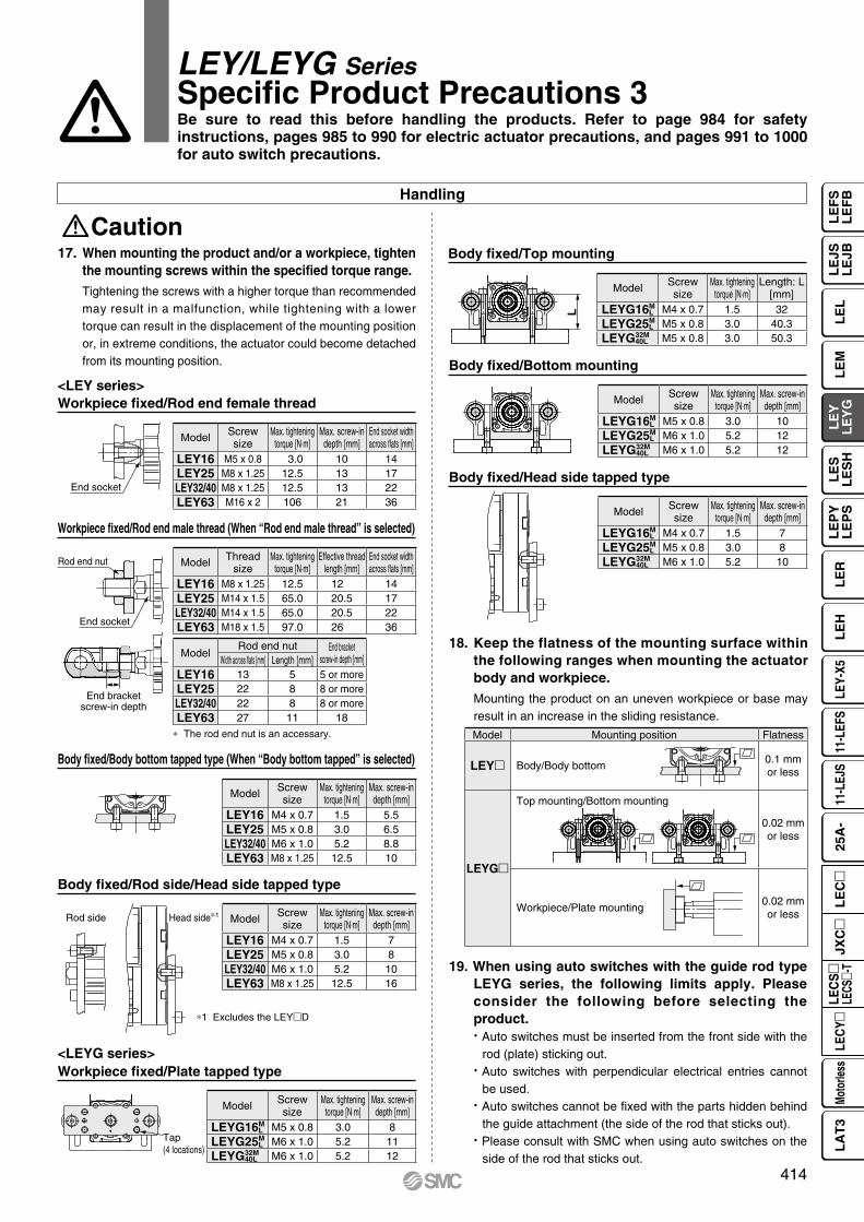
End socket
End socket
End bracketscrew-in depth
Rod end nut
Tap(4 locations)
Rod side Head side∗1
L
Handling
Body fixed/Body bottom tapped type (When “Body bottom tapped” is selected)
Body fixed/Rod side/Head side tapped type
Workpiece fixed/Plate tapped type
Body fixed/Bottom mounting
Body fixed/Head side tapped type
Caution
Workpiece fixed/Rod end male thread (When “Rod end male thread” is selected)
∗ The rod end nut is an accessary.
∗1 Excludes the LEYD
Workpiece fixed/Rod end female thread<LEY series>
<LEYG series>
17. When mounting the product and/or a workpiece, tighten the mounting screws within the specified torque range.Tightening the screws with a higher torque than recommended may result in a malfunction, while tightening with a lower torque can result in the displacement of the mounting position or, in extreme conditions, the actuator could become detached from its mounting position.
LEY/LEYG SeriesSpecific Product Precautions 3
18. Keep the flatness of the mounting surface within the following ranges when mounting the actuator body and workpiece.Mounting the product on an uneven workpiece or base may result in an increase in the sliding resistance.
19. When using auto switches with the guide rod type LEYG series, the following limits apply. Please consider the following before selecting the product. Auto switches must be inserted from the front side with the
rod (plate) sticking out. Auto switches with perpendicular electrical entries cannot
be used. Auto switches cannot be fixed with the parts hidden behind
the guide attachment (the side of the rod that sticks out). Please consult with SMC when using auto switches on the
side of the rod that sticks out.
Body fixed/Top mounting
Model Screwsize
Max. tighteningtorque [N⋅m]
Max. screw-indepth [mm]
End socket widthacross flats [mm]
LEY16 M5 x 0.8 3.0 10 14LEY25 M8 x 1.25 12.5 13 17LEY32/40 M8 x 1.25 12.5 13 22LEY63 M16 x 2 106 21 36
ModelRod end nut End bracket
screw-in depth [mm]Width across flats [mm] Length [mm]LEY16 13 5 5 or moreLEY25 22 8 8 or moreLEY32/40 22 8 8 or moreLEY63 27 11 18
Model Threadsize
Max. tighteningtorque [N⋅m]
Effective threadlength [mm]
End socket widthacross flats [mm]
LEY16 M8 x 1.25 12.5 12 14LEY25 M14 x 1.5 65.0 20.5 17LEY32/40 M14 x 1.5 65.0 20.5 22LEY63 M18 x 1.5 97.0 26 36
Model Screwsize
Max. tighteningtorque [N⋅m]
Max. screw-indepth [mm]
LEY16 M4 x 0.7 1.5 7LEY25 M5 x 0.8 3.0 8LEY32/40 M6 x 1.0 5.2 10LEY63 M8 x 1.25 12.5 16
Model Screwsize
Max. tighteningtorque [N⋅m]
Max. screw-indepth [mm]
LEY16 M4 x 0.7 1.5 5.5LEY25 M5 x 0.8 3.0 6.5LEY32/40 M6 x 1.0 5.2 8.8LEY63 M8 x 1.25 12.5 10
Model Screwsize
Max. tighteningtorque [N⋅m]
Length: L[mm]
LEYG16ML M4 x 0.7 1.5 32
LEYG25ML M5 x 0.8 3.0 40.3
LEYG32M40L M5 x 0.8 3.0 50.3
Model Screwsize
Max. tighteningtorque [N⋅m]
Max. screw-indepth [mm]
LEYG16ML M5 x 0.8 3.0 8
LEYG25ML M6 x 1.0 5.2 11
LEYG32M40L M6 x 1.0 5.2 12
Model Screwsize
Max. tighteningtorque [N⋅m]
Max. screw-indepth [mm]
LEYG16ML M5 x 0.8 3.0 10
LEYG25ML M6 x 1.0 5.2 12
LEYG32M40L M6 x 1.0 5.2 12
Model Screwsize
Max. tighteningtorque [N⋅m]
Max. screw-indepth [mm]
LEYG16ML M4 x 0.7 1.5 7
LEYG25ML M5 x 0.8 3.0 8
LEYG32M40L M6 x 1.0 5.2 10
Model Mounting position Flatness
LEY Body/Body bottom0.1 mmor less
LEYG
Top mounting/Bottom mounting
0.02 mmor less
Workpiece/Plate mounting0.02 mmor less
Be sure to read this before handling the products. Refer to page 984 for safety instructions, pages 985 to 990 for electric actuator precautions, and pages 991 to 1000 for auto switch precautions.
414
LE
FS
LE
FB
LE
LL
EJS
LE
JBL
EM
LE
YL
EY
GL
ES
LE
SH
LE
PY
LE
PS
LE
RL
EH
LEY-
X511
-LEF
S11
-LEJ
S25
A-
Moto
rless
LEC
Y�LE
CS
�LE
CS�-
TJX
C�
LE
C�
LA
T3

LEY/LEYG SeriesSpecific Product Precautions 4
Maintenance
Enclosure
Warning1. Ensure that the power supply is stopped and the
workpiece is removed before starting maintenance work or replacing the product.
• Maintenance frequencyPerform maintenance according to the table below.
• Items for visual appearance check1. Loose set screws, Abnormal amount of dirt, etc.2. Check for visible damage, Check of cable joint3. Vibration, Noise
∗1 Select whichever comes first.
• First Digit:Degree of protection against solid foreign objects
• Second Digit:Degree of protection against water
• Items for belt checkStop operation immediately and replace the belt when any of the following occur. In addition, ensure your operating environment and conditions satisfy the requirements specified for the product.a. Tooth shape canvas is worn out
Canvas fiber becomes fuzzy, Rubber is coming off and the fiber has become whitish, Lines of fibers have become unclear
b. Peeling off or wearing of the side of the beltBelt corner has become rounded and frayed threads stick out
c. Belt is partially cutBelt is partially cut, Foreign matter caught in the teeth of other parts is causing damage
d. A vertical line on belt teeth is visibleDamage which is made when the belt runs on the flange
e. Rubber back of the belt is softened and stickyf. Cracks on the back of the belt are visible
Example) IP65: Dust-tight, Water-jet-proof type“Water-jet-proof” means that no water enters the equipment that could hinder it from operating normally when water is applied for 3 minutes in the prescribed manner. Take appropriate protective measures as the device is not usable in environments where droplets of water are splashed constantly.
IPFirst digit Second digit
0 Not protected —
1 Protected against vertically falling waterdroplets
Dripprooftype 1
2 Protected against vertically falling water droplets when enclosure is tilted up to 15°
Dripprooftype 2
3 Protected against rainfall when enclosure istilted up to 60°
Rainprooftype
4 Protected against splashing waterSplashprooftype
5 Protected against water jetsWater-jet-proof type
6 Protected against powerful water jetsPowerful water-jet-proof type
7 Protected against the effects of temporary immersion in water
Immersibletype
8 Protected against the effects of continuous immersion in water
Submersibletype
0 Not protected1 Protected against solid foreign objects of 50 mmø and larger2 Protected against solid foreign objects of 12 mmø and larger3 Protected against solid foreign objects of 2.5 mmø and larger4 Protected against solid foreign objects of 1.0 mmø and larger5 Dust protected6 Dust-tight
Frequency Appearance check Belt checkInspection before daily operation —
Inspection every 6 months/250 km/5 million cycles∗1
Be sure to read this before handling the products. Refer to page 984 for safety instructions, pages 985 to 990 for electric actuator precautions, and pages 991 to 1000 for auto switch precautions.
Handling
Caution20. When using the product with the IP65 or equivalent
specifications, be sure to mount the tubing to the vent hole, and then place the end of the tubing in an area where it is not exposed to dust or water. When the actuator is used without mounting the fitting and tubing to the vent hole, water or dust may enter the inside of the actuator, resulting in a malfunction.
21. When fluctuations in the load are caused during operation, malfunction, noise, or alarm generation may occur. (In the case of the AC servo motor)The gain tuning may not be suitable for fluctuating loads.Adjust the gain properly by following the instructions in the driver manual.
415

Motorless Type
AC Servo Motor Motorless Type
¡ Max. force: 12000 N, Work load: 1200 kg, Max. stroke: 1000 mm
¡Can be mounted in accordance with ISO 15552¡Modify the force/speed specifications
(Change specifications by changing or removing the reducer)
¡Motorless type¡An auto switch can be mounted
Reducer
Manufacturers of compatible motors: 7 companies
Can be used with your current motor and driver!
¡Mitsubishi Electric Corporation ¡YASKAWA Electric Corporation
¡SANYO DENKI CO., LTD. ¡NIDEC SANKYO CORPORATION
¡KEYENCE CORPORATION ¡FUJI ELECTRIC CO., LTD.
¡Delta Electronics, Inc.
Electric Actuator
Rod Type
LEY100 Series

Short
Lig
ht
Stroke
Lo
ad
Long
Hea
vy
Up to 1000 mm
Up to 800 mm
Up to 500 mm
Electric Actuator LEY100 Series
Work load
Max. force Applicable stroke
AC Servo Motor Rod Type Series Variations
LEY100DT9L (Lead 2) 12000 N (3.5 times)Compared with the existing model LEY63mL (Max. 3343 N)
LEY100D 100 to 1000 mm (1.2 times)Compared with the existing model LEY63m (Stroke 100 to 800 mm)
Max. work load (Horizontal)LEY100DT9L (Lead 2) 1200 kg (6 times)
Max. work load (Vertical)LEY100DT9L (Lead 2) 200 kg (1.7 times)
Compared with the existing model LEY63mL(Max. horizontal work load 200 kg)
Compared with the existing model LEY63mL(Max. vertical work load 115 kg)
LEY100
LEY63
LEY25/32
1200 kg/200 kg
200 kg/115 kg
60 kg/46 kg
Work load(Horizontal/Vertical)
Speed [mm/s]
Wor
k lo
ad [k
g]
Wor
k lo
ad [k
g]
Speed [mm/s]
1

Electric Actuator LEY100 Series
The ISO cylinder (C96 ø80) and flange mounting bracket are now standardized.
The max. force and max. speed settings can be changed by changing the reducer.
An auto switch can be mounted from the front of the groove.
2600 N 12000 N500 mm/s 100 mm/s
Standardized mounting pitch
Same standardized rod end as the ISO cylinder
Rod clevis Ball joint Floating joint
“Without reducer,” “Reduction ratio 1/3,” and “Reduction ratio 1/5” can be selected.
Motor flange assembly(without reducer)
Motor
Motor
Motor flange assembly(with reducer)
Switch spacer (BMY3-016)
Auto switch mounting screw (Accessory)
Flat head watchmaker’s screwdriver
Auto switch (D-M9m)
Can be mounted in accordance with ISO 15552
Modify the force/speed specifications
An auto switch can be mounted
Max. force Max. forceMax. speed Max. speed
Specifications can be changed.
2

Electric Actuator LEY100 Series
Motor flange assembly (Option)“Standard-compatible motor”
Manufacturer Series Type NN
Mitsubishi Electric CorporationMELSERVO-J4 HG-KR V
MELSERVO-J5 HK-KT V
YASKAWA Electric CorporationΣ-V SGMJV V
Σ-7 SGM7J V
SANYO DENKI CO., LTD. SANMOTION R R2 V
NIDEC SANKYO CORPORATION S-FLAG MX V
KEYENCE CORPORATION SV SV-M/SV-B V
FUJI ELECTRIC CO., LTD. ALPHA5/7 GYS/GYB/GYG V
Delta Electronics, Inc. ASDA-A2 ECMA V
Servo-driven press machine Replenishment unit (spring extended piston control)
Motorless
Motor flange assembly (Option)“Compatible with motors from Mitsubishi, Yaskawa, etc.”
(Motor: Provided by the customer)
Application examples
Motorless Type
3

Speed [mm/s]
Wor
k lo
ad [k
g]
0
50
100
150
250
200
0 100 200 300 400 500 600
Lead 10: LEY100�B
Area where the regeneration option is required
Lead 3.3: LEY100�DLead 2: LEY100�L
AB
C
C
Speed [mm/s]
Wor
k lo
ad [k
g]
0
200
400
600
800
1200
1000
1400
0 100 200 300 400 600500
Lead 3.3: LEY100�D
Area where the regeneration option is required
Lead 10: LEY100�B
Lead 2: LEY100�L
A
AC Servo Motor Motorless Type
LEY100 Series
Model Selection
Speed–Vertical Work Load Graph/Required Conditions for the Regeneration Option
Required conditions for the regeneration option* The regeneration option is required when using the product above the
regeneration line in the graph. (It must be ordered separately.)
Regeneration Option ModelsSize Model Note
LEY100mLEC-MR-RB-032 A area
LEC-MR-RB-12B areaC area
Speed–Horizontal Work Load Graph/Required Conditions for the Regeneration Option
Required conditions for the regeneration option* The regeneration option is required when using the product above the
regeneration line in the graph. (It must be ordered separately.)
Regeneration Option ModelsSize Model Note
LEY100m LEC-MR-RB-032 A area
Force Conversion Graph (Guide) For the LECSS-T
Load–Acceleration/Deceleration Chart
Force–Stroke Table
Torque limit/Command value [%] Duty ratio [%] Continuous pushing time [min]
25 or less 100 —
30 90 6.00 or less
40 50 1.23 or less
50 30 0.57 or less
55 20 0.25 or less
10 15 20 25 30 35 555040 45 60Torque limit/Command value [%]
For
ce [N
]
14000
12000
10000
8000
6000
4000
2000
0
Lead 3.3: LEY100D�D
Lead 2: LEY100D�L
Lead 10: LEY100D�B
* Motorless specification is lead 10 only
Max. acceleration/deceleration (Horizontal) [mm/s2]
Lead Work load [kg]Symbol [mm] 100 200 300 400 500 600 700 800 900 1000 1100 1200
B 10 3000 2000*1 —D 3.3 2370 2250 2120 2000 1870 1750 1620 1500 1370 1250 1120 1000L 2 1900 1800 1700 1600 1500 1420 1350 1280 1210 1140 1070 1000
*1 The max. work load can be set to any weight up to 240 kilograms.
Max. acceleration/deceleration (Vertical) [mm/s2]
Lead Work load [kg]Symbol [mm] 20 40 60 80 100 120 140 160 180 200
B 10 2500 2000 1500 1000 —D 3.3 2370 2200 2020 1850 1680 1510 1340 1170 1000*2 —L 2 1880 1770 1660 1550 1450 1360 1270 1180 1090 1000
*2 The max. work load can be set to any weight up to 185 kilograms.
Stroke [mm]0 100 200 300 400 500 600 700 800 900 1000
Force [N] 12000 12000 12000 12000 12000 12000 11000 8900 6900 5600 4600
4

AC Servo Motor LECS Series
Electric Actuator/Rod TypeLEY100 Series 100Size
w y !0i oe r tq u !1 !2
How to Order
!0 Cable length [m]*6
Nil Without cable2 25 5A 10
*6 The length of the encoder, motor, and lock cables are the same.
o Cable type*5
Nil Without cableS Standard cableR Robotic cable (Flexible)
*5 A motor cable and encoder cable are included with the product. (A lock cable is also included if motor option “B: With lock” is selected.)
i Mounting*3 *4
Symbol TypeMotor mounting position
In-lineNil Ends tapped V
L Foot V
F Flange V
*3 The mounting bracket is shipped together with the product but does not come assembled.
*4 Do not mount using the “flange” or “ends tapped” options for the horizontal type with one end secured.
t Stroke [mm]100 100to to
1000 1000
* For details, refer to the applicable stroke table below.
r Lead [mm]Symbol LEY100B 10D 3.33*1
L 2*2
*1 Screw lead 10 mm, reducer ratio [1:3]*2 Screw lead 10 mm, reducer ratio [1:5]
u Rod end threadNil Rod end female thread
M Rod end male thread(1 rod end nut is included.)
y Motor optionNil Without optionB With lock
q Size100
w Motor mounting positionD In-line
Applicable Stroke Table
SizeStroke [mm]
100 200 300 400 500 600 700 800 900 1000 Manufacturable stroke range
100 V V V V V V V V V V 100 to 1000
* Please contact SMC for non-standard strokes as they are produced as special orders.
e Motor type
Symbol TypeOutput
[W]Actuator size Compatible drivers
T9AC servo motor
(Absolute encoder)
750 100
LECSB2-T9LECSC2-T9LECSS2-T9
LECSN2-T9(-)
LEY 100 D T9 B 200 S 2 B2DriverLECS Series
!2 I/O cable length [m]*7
Nil Without cableH Without cable (Connector only)1 1.5
*7 When “Nil: Without driver” is selected for the driver type, only “Nil: Without cable” can be selected.Refer to the Web Catalog if an I/O cable is required.
!1 Driver typeCompatible drivers Power supply voltage [V]
Nil Without driver
B2 LECSB2-T9/Pulse input(Absolute encoder)
200 to 240
C2 LECSC2-T9/CC-Link(Absolute encoder)
200 to 230
S2 LECSS2-T9/SSCNET/H(Absolute encoder)
200 to 230
92 LECSN2-T9-9/EtherNet/IP(Absolute encoder)
200 to 240
E2 LECSN2-T9-E/EtherCAT(Absolute encoder)
200 to 240
P2 LECSN2-T9-P/PROFINET(Absolute encoder)
200 to 240
N2 LECSN2-T9/Without network card(Absolute encoder)
200 to 240
5

6
Electric Actuator/Rod Type LEY100 SeriesAC Servo Motor 100Size
Specifications
Model LEY100DmL LEY100DmD LEY100DmB
Act
uat
or
spec
ifica
tio
ns
Stroke [mm] 100, 200, 300, 400, 500, 600, 700, 800, 900, 1000
Work load [kg]Horizontal*1 1200 1200 240
Vertical 200 185 80Rated force [N]/Set value*2: 25%*3 5500 3300 1100Max. force [N]/Set value*2: 55%*3 12000 7200 2600
Max. speed [mm/s]*4
Up to 500 100 167 500600 74 123 370700 57 95 285800 45 75 225900 36 60 180
1000 30 50 150Pushing speed [mm/s]*5 20 or lessMax. acceleration/deceleration [mm/s2] 2000 3000Positioning repeatability [mm] 0.02Lost motion [mm]*6 0.10Screw lead [mm] 10Reduction ratio 1/5 1/3 —Lead [mm] 2 3.3 10Impact/Vibration resistance [m/s2]*7 50/20Actuation type Ball screwGuide type Sliding bushing (Piston rod)Operating temperature range [°C] 5 to 40Operating humidity range [%RH] 90 or less (No condensation)
Elec
tric
spe
cific
atio
ns Motor output [W]/Size [mm] 750/m80Motor type AC servo motor (200 VAC)
Power consumption [W]*8 Horizontal 250Vertical 450
Standby power consumption when operating [W]*9
Horizontal 20Vertical 30
Max. instantaneous power consumption [W]*10 1100
Lock u
nit spe
cificat
ions Type*11 Non-magnetizing lock
Holding force [N] 4860 2925 1080Power consumption [W] at 20°C*12 10Rated voltage [V] 24 VDC 0−10%
*1 This is the max. value of the horizontal work load. An external guide is necessary to support the load. The actual work load changes according to the condition of the external guide. Confirm the load using the actual device.
*2 Set values for the driver*3 The force setting range (set values for the driver) for the force control
with the torque control mode. The force and duty ratio change according to the set value. Set it while referencing the “Force Conversion Graph” on page 4.When the control equivalent to the pushing operation of the LECP6 series controller is performed, select the LECSS2-T or LECSB2-T driver.The point table no. input method is used for the LECSB2-T.When selecting the LECSS2-T, combine it with a Simple Motion module (manufactured by Mitsubishi Electric Corporation) which has a pushing operation function.
*4 The allowable speed changes according to the stroke. Set the number of rotations according to speed.
*5 The allowable collision speed for collision with the workpiece with the torque control mode
*6 A reference value for correcting errors in reciprocal operation*7 Impact resistance: No malfunction occurred when the actuator was
tested with a drop tester in both an axial direction and a perpendicular direction to the lead screw. (The test was performed with the actuator in the initial state.)Vibration resistance: No malfunction occurred in a test ranging between 45 to 2000 Hz. The test was performed in both an axial direction and a perpendicular direction to the lead screw. (The test was performed with the actuator in the initial state.)
*8 The power consumption (including the driver) is for when the actuator is operating.
*9 The standby power consumption when operating (including the driver) is for when the actuator is stopped in the set position during the operation.
*10 The max. instantaneous power consumption (including the driver) is for when the actuator is operating.
*11 Only when motor option “With lock” is selected*12 For an actuator with lock, add the power consumption for the lock.

@3
o !0 !3 !8!4 w q i e !9 !5 @4
@7
@0 y r t !2 u @1!1 !6 @2 !7 @5 @6
When the rod end female thread is selected
Component PartsNo. Description Material Note
1 Body Aluminum alloy Anodized
2 Screw shaft Alloy steel
3 Ball screw nut Alloy steel
4 Piston Aluminum alloy
5 Piston rod Alloy steel Hard chrome plating
6 Rod cover Aluminum alloy Anodized
7 Bearing holder Aluminum alloy
8 Rotation stopper Synthetic resin
9 Socket (Male thread) Alloy steel Nickel plating
10 Bushing Bearing alloy
11 Bearing —
12 Magnet —
13 Wear ring holder Aluminum alloy
14 Wear ring Synthetic resin
No. Description Material Note
15 Anti-loosening nut Alloy steel
16 Motor block Aluminum alloy Anodized
17 Motor flange Aluminum alloy Anodized
18 Bumper Urethane
19 O-ring NBR
20 Scraper NBR
21 Sintered element Stainless steel
22 Motor adapter Aluminum alloy Anodized
23 Nut Alloy steel Zinc chromating
24 Coupling —
25 Reducer —
26 Motor —
27 Socket (Female thread) Alloy steel Nickel plating
Construction
In-line motor type: LEY100
Replacement Parts/Grease PackApplied portion Order no.
Piston rodGR-S-010 (10 g)
GR-S-020 (20 g)
* Apply grease to the piston rod periodically.Grease should be applied when 1 million cycles or 200 km have been reached, whichever comes first.
7
LEY100 SeriesAC Servo Motor 100Size
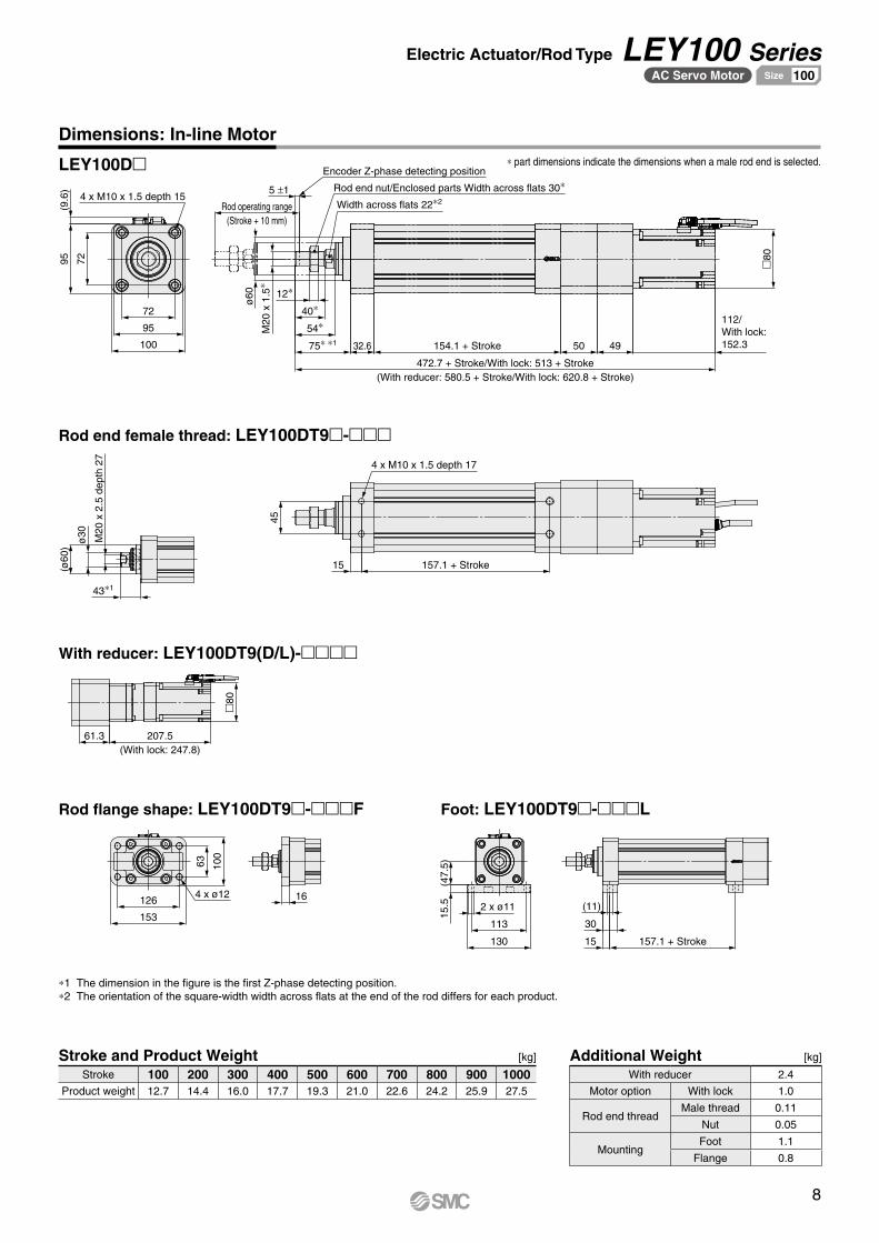
7295
472.7 + Stroke/With lock: 513 + Stroke(With reducer: 580.5 + Stroke/With lock: 620.8 + Stroke)
154.1 + Stroke32.675∗ ∗1
54∗40∗
4950
�80
(ø60
)
61.3 207.5(With lock: 247.8)
157.1 + Stroke
45
153
126
100
63
130
113
(47.
5)
157.1 + Stroke
(9.6
)
4 x M10 x 1.5 depth 15
Encoder Z-phase detecting position
Rod operating range(Stroke + 10 mm)
ø60
M20
x 1
.5∗
12∗
Width across flats 22∗2
112/With lock: 152.3
M20
x 2
.5 d
epth
27
ø30
43∗1
15
4 x M10 x 1.5 depth 17
4 x ø12 16
15.5 2 x ø11
15
30
(11)
5 ±1
�80
Rod end nut/Enclosed parts Width across flats 30∗
100
95
72
Dimensions: In-line Motor
Rod end female thread: LEY100DT9m-mmm
LEY100Dm
With reducer: LEY100DT9(D/L)-mmmm
Rod flange shape: LEY100DT9m-mmmF Foot: LEY100DT9m-mmmL
*1 The dimension in the figure is the first Z-phase detecting position.*2 The orientation of the square-width width across flats at the end of the rod differs for each product.
Stroke and Product Weight [kg]
Stroke 100 200 300 400 500 600 700 800 900 1000Product weight 12.7 14.4 16.0 17.7 19.3 21.0 22.6 24.2 25.9 27.5
Additional Weight [kg]
With reducer 2.4
Motor option With lock 1.0
Rod end threadMale thread 0.11
Nut 0.05
MountingFoot 1.1
Flange 0.8
* part dimensions indicate the dimensions when a male rod end is selected.
8
Electric Actuator/Rod Type LEY100 SeriesAC Servo Motor 100Size

How to Order
Motorless Type
Electric Actuator/Rod TypeLEY100 Series 100Size
w ye r tq u
u Mounting*2 *3
Symbol TypeMotor mounting position
In-line
Nil Ends tapped V
L Foot V
F Flange V
*2 The mounting bracket is shipped together with the product but does not come assembled.
*3 Do not mount using the “flange” or “ends tapped” options for the horizontal type with one end secured.
t Stroke [mm]100 100
to to
1000 1000
* For details, refer to the applicable stroke table below.
r Lead [mm]Symbol LEY100B 10
y Rod end threadNil Rod end female thread
M Rod end male thread(1 rod end nut is included.)
q Size100
w Motor mounting positionD In-line
Applicable Stroke Table
SizeStroke [mm]
100 200 300 400 500 600 700 800 900 1000 Manufacturable stroke range
100 V V V V V V V V V V 100 to 1000
* Please contact SMC for non-standard strokes as they are produced as special orders.
e Motor type*1
Symbol Type Note
NN ø80 - M5 thread hole —
*1 A motor adapter and motor flange are not included.
Motorless Type LEY 100 D NN B 200
Compatible MotorsManufacturer Series Type NN
Mitsubishi Electric Corporation
MELSERVO-J4 HG-KR V
MELSERVO-J5 HK-KT V
YASKAWA Electric Corporation
Σ-V SGMJV V
Σ-7 SGM7J V
SANYO DENKI CO., LTD. SANMOTION R R2 V
NIDEC SANKYO CORPORATION S-FLAG MX V
KEYENCE CORPORATION SV SV-M/SV-B V
FUJI ELECTRIC CO., LTD. ALPHA5/ALPHA7 GYS/GYB/GYG V
Delta Electronics, Inc. ASDA-A2 ECMA V
9

Specifications
Model LEY100DNNB
Act
uat
or
spec
ifica
tio
ns
Stroke [mm] 100, 200, 300, 400, 500, 600, 700, 800, 900, 1000
Work load [kg]Horizontal*1 240/1200 [When equipped with reducer (reduction ratio 1/5)]
Vertical 80/200 [When equipped with reducer (reduction ratio 1/5)]
Rated force [N]/Set value: Rated torque 87%*2 1100/5500 [When equipped with reducer (reduction ratio 1/5)]
Max. force [N]/Set value: Max. torque 192%*2 2600/12000 [When equipped with reducer (reduction ratio 1/5)]
Max. speed [mm/s]*3
Up to 500 500
600 370
700 285
800 225
900 180
1000 150
Pushing speed [mm/s]*4 20 or less
Max. acceleration/deceleration [mm/s2] 3000/2000 [When equipped with reducer (reduction ratio 1/5)]
Positioning repeatability [mm] ±0.02
Lost motion [mm]*5 0.1 or less
Screw lead [mm] 10
Impact/Vibration resistance [m/s2]*6 50/20
Actuation type Ball screw
Guide type Sliding bushing (Piston rod)
Operating temperature range [°C] 5 to 40
Operating humidity range [%RH] 90 or less (No condensation)
Other
specifi
cation
s*7 Actuation unit weight [kg] (* [ST]: Stroke) 2.80 + (7.50 x 10⁻³) x [ST]
Other inertia [kg·cm] 0.047
Friction coefficient 0.05
Mechanical efficiency 0.9
Refer
ence
mot
or sp
ec.
Motor shape m80
Motor type AC servo motor
Rated output capacity [W] 750
Rated torque [N·m] 2.4
Rated rotation [rpm] 3000
*1 This is the max. value of the horizontal work load. An external guide is necessary to support the load (Friction coefficient of guide: 0.1 or less).The actual work load changes according to the condition of the external guide. Confirm the load using the actual device.
*2 The force setting range for the force control (Speed control mode, Torque control mode)The force changes according to the set value. Set it with reference to the “Force Conversion Graph (Guide)” on page 4.
*3 The allowable speed changes according to the stroke.*4 The allowable collision speed for collision with the workpiece*5 A reference value for correcting errors in reciprocal operation*6 Impact resistance: No malfunction occurred when the actuator was tested with a drop tester in both an axial direction and a perpendicular direction to
the lead screw. (The test was performed with the actuator in the initial state.)Vibration resistance: No malfunction occurred in a test ranging between 45 to 2000 Hz. The test was performed in both an axial direction and a perpendicular direction to the lead screw. (The test was performed with the actuator in the initial state.)
*7 Each value is only to be used as a guide to select a motor of the appropriate capacity.
* The values in this specifications table are the allowable values of the actuator body with the standard motor mounted.* Do not use the actuator so that it exceeds these values.
10
Electric Actuator/Rod Type LEY100 SeriesMotorless Type 100Size

95
72
7295
Rod operating range(Stroke + 10 mm)
Rod end nut/Enclosed parts Width across flats 30∗
Width across flats 22
M20
x 1
.5∗
ø60
12∗
299.6 + Stroke
154.1 + Stroke32.670∗54∗
40∗
10 +0.2 0
42.9
(32.9) ø19
h7
0
−0.
021
ø80
h7 0
−0
.030
7295
95
72
38
M20
x 2
.5 d
epth
27
ø30
(ø60
) 45
15 157.1 + Stroke
4 x M10 x 1.5 depth 17
153
126 4 x ø12
100
63
16
130
113
2 x ø11
15.5
(47.
5)
15
30
(11)
157.1 + Stroke
4 x M10 x 1.5 depth 15 4 x M10 x 1.5 depth 16
Dimensions: In-line Motor
LEY100
Rod end female thread: LEY100DNNB-mmm
Rod flange shape: LEY100DNNB-mmmF
Foot: LEY100DNNB-mmmL
* part dimensions indicate the dimensions when a male rod end is selected.
11
LEY100 Seriesモータレス仕様 63サイズMotorless Type 100Size

LEY100 Series
Option
Motor Flange Assembly
Mounting Bracket
q
q
Motor flange LEY MF NZD100
q Motor flange type
Symbol Motor type (Note)A B C C D
Motor adapter
Motor flange
Coupling(O.D. ø40)
Coupling(O.D. ø55)
Reducer
NZ Mounting type Z Mitsubishi and others V V — — —
NZC Mounting type Z + Coupling included
O.D. ø40 V V V — —
NG Mounting type G For reducers V V — — —
NGC Mounting type G + Coupling included
O.D. ø55 V V — V —
NGC3 Mounting type G +With reducer*1
Reduction ratio 1/3
V V — V V
NGC5 Mounting type G +With reducer*1
Reduction ratio 1/5
V V — V V
N Without motor flange
Motor adapter only
V — — — —
*1 A coupling (O.D. ø55) is also included.
q Mounting bracketSymbol Mounting bracket
L Foot
F Flange
LEY L 100
L: Foot F: Flange
Compatible Motors
Manufacturer Series TypeNZC/
NGC3/NGC5
Mitsubishi Electric Corporation
MELSERVO-J4 HG-KR V
MELSERVO-J5 HK-KT V
YASKAWA Electric Corporation
Σ-V SGMJV V
Σ-7 SGM7J V
SANYO DENKI CO., LTD.
SANMOTION R DXF V
SANMOTION R R2 V
NIDEC SANKYO CORPORATION
S-FLAG MX V
KEYENCE CORPORATION SV SV-M/SV-B V
FUJI ELECTRIC CO., LTD. ALPHA5/ALPHA7 GYS/GYB/GYG V
Delta Electronics,Inc.
ASDA-A2 ECMA V
CCoupling DReducer (Reduction ratio 1:3/1:5)
C
C
AMotor adapter
A
A
C-C
BMotor flange (Mounting type G)BMotor flange (Mounting type Z)
B
B
B-BA-A95
42
89100
4 x M5 thread depth 12
50
12
ø76
G6
+0.0
29
+0.0
10
100
95
4 x M6 thread depth 14
ø70
+0.
06
+0.
03
59
5
100
95 71.3
5
ø70
+0.
06
+0.
03
Mounting type Z: ø40Mounting type G: ø55
Mounting type Z: 66Mounting type G: 78.3
4 x M6 thread depth 20
ø70
h7 0
−0
.030
ø19
h6
0
−0.
013
30
145.5
95.5
254 x M6 thread depth 13
ø70 G7 +0.040 +0.010 depth 6
ø19 G7 +0.028 +0.007 depth 50
ø90
ø90
ø90
12

Motor flange assembly
ReducerMotor flangeCouplingMotor adapter
Type Z
Type G
O.D. ø40
O.D. ø55
Products from other companies and self-produced products can be used instead.
Handling
Caution
LEY100 SeriesSpecific Product PrecautionsBe sure to read this before handling the products.
Continuous use at max. force is prohibited.When using the product at max. force, be sure to use the product within 15 s and with a duty ratio of 20% or less. (With motor)
Motor Flange Assembly
For the motorless type, be sure to check the specifications of the motor and driver to be used in combination before use.The force should be within the rated force when using continuously.
Max. force drive15 s
Non-drive60 s
Example of driving conditions with a duty ratio of 20%
Symbol Motor adapterMotor flange
(Type)Coupling
(ø40)Coupling
(ø55)Reducer
(Reduction ratio)
NZ V V (Z) — — —
NZC V V (Z) V — —
NG V V (G) — — —
NGC V V (G) — V —
NGC3 V V (G) — V V (1/3)
NGC5 V V (G) — V V (1/5)
N V — — — —
13

Safety Instructions Be sure to read the “Handling Precautions for SMC Products” (M-E03-3) and “Operation Manual” before use.
Electric ActuatorRod Type
AC Servo Motor Motorless Type