Energy saving ejector - SMC
48
Reduced-wiring Vacuum Ejector Vacuum Pump System Energy saving ejector Compact / Lightweight More efficient ejector 30 % reduction 50 % increase Suction flow Air consumption 28 % reduction 59 % reduction Volume 88 cm 3 Weight 81g Q1 + Q2 = Suction flow Two-stage ejector Air consumption Vacuum Unit First ejector Second ejector High-noise reduction silencer D-sub connector/Flat ribbon cable/Individual wiring Low noise: 46 dB ∗1 (A) Suction flow rate: Improved by up to approx. 20 % ∗2 ∗1 Nozzle size: Ø 0.7 ∗2 Nozzle size: Ø 1.5 (Based on SMC’s measuring conditions) High-noise reduction silencer added ∗Based on SMC’s measuring conditions New New ∗ ∗ Bas Based on SMC C’s mea m sur uring in g condi ndi ndi ndi ndi d ditio tio o tio tio tio tio tions ns ns ns ns ns 90 % reduction Digital pressure switch for vacuum with energy saving function cuts supply air when the pressure reached the desired vacuum. (Compared to other SMC single stage ejectors) ∗ Current product ZK2 CAT.EUS100-102C-UK New New RoHS Series ZK2
-
Upload
khangminh22 -
Category
Documents
-
view
1 -
download
0
Transcript of Energy saving ejector - SMC

Reduced-wiring
Vacuum Ejector Vacuum Pump System
Energy saving ejector
Compact / Lightweight
More efficient ejector
30 % reduction
jjj
50 % increaseSuction flow
Air consumption
ggg g
28 % reduction
59 % reduction
Volume 88 cm3
Weight 81 g
Q1 + Q2 = Suction flow
Two-stage ejector
Air consumption
Vacuum Unit
First ejector Second ejector
High-noise reduction silencer
D-sub connector/Flat ribbon cable/Individual wiring
Low noise: 46 dB∗1(A)Suction flow rate: Improved by up to approx. 20 %∗2
∗1 Nozzle size: Ø 0.7∗2 Nozzle size: Ø 1.5(Based on SMC’s measuring conditions)
High-noise reduction silencer added
∗Based on SMC’s measuring conditions
NewNew
∗∗BasBased on SMCC’s meam sururinging condindindindindidditiotiootiotiotiotiotionsnsnsnsnsns
90 % reduction
Digital pressure switch for vacuum with energy saving function cuts supply air when the pressure reached the desired vacuum.
(Compared to other SMC single stage ejectors)
∗
Current product
ZK2
CAT.EUS100-102C-UK
NewNewRoHS
Series ZK2

Energy saving ejectorwith energy saving functionh ener
90 %Digital pressure switch with energy saving function reduces air consumption by 90 %∗.
Nozzlesize
Ø 1.5Through-hole silencer
Built-in silencer
Exhaust type
8067
Maximum suction flow rate [l/min (ANR)]40 80
60
200315
500800
12502000
31505000
800012500
20000
50
40
30
20
10
0
Noi
se le
vel [
dB (
A)]
Frequency [Hz]
Through-hole silencer
ZK2A07 (Built-in silencer)ZK2G07 (Through-hole silencer)
Power consumption cost per year reduced by
565 €/year
Energysaving
efficiency
Lownoise
Suctionflow rate
Workpiece
Current product
Vacuum Air is supplied and exhaustedcontinuously during theadsorption of the workpiece.
Workpiece
Energy saving ejector
Airsupply
Airsupply
VacuumAir is supplied and exhaustedintermittently when thevacuum decreases.
Exhaust
Exhaust Exhaust
Cost conditions⋅ Electric power charge: 0.12 €/kWh, Operating hours: 10 hours/day, Operating days: 250 days/year, When 10 units are used⋅ Power consumption of the compressor is the theoretical value from the air consumption of each product at 0.35 MPa.
Power consumption cost per year
Energising timeper year
Exhaust timeCompressor’s consumption
per unit time
42.75 €/year
607.5 €/year
1875 h/year
18750 h/year
0.19 kWh
0.27 kWh
ZK2/With energy saving function
Current product
With energysaving function
The exhaust is discharged directly to atmosphere, cutting off the unpleasant frequency while exhibiting the maximum possible vacuum performance.
Digital pressure switchfor vacuum with energysaving function
The energy saving function shortens the exhaust time, which reduces the annual power consumption cost.
Improved low noise and suction flow by adoption of a through-hole silencerImproved low noise and suction flow by adoption of a through-hole silencer
Approx.20 %
46 dB∗(A)46 dB∗(A)∗Nozzle size: Ø 0.7
Improved by up to approx. 20 %Improved by up to approx. 20 %
0.6 s6 s
Supply valve signalONOFFONOFF
Energy savingcontrol
Current product
Vacuum pressure
Energy savingON/OFF operation
Achievablevacuum pressure
Atmosphericpressure
Vac
uum
por
t pre
ssur
e
Currentejector
Ejector with energysaving switch
∗Based on SMC’s measuring conditions
Vacuum Unit Series ZK2
While the suction signal is ON, the ON/OFF operation of the supply valve is also performed automatically within the set value.
Reduces high frequency range from 2000 to 20000 Hz.
1

Vacuum Unit Series ZK2
� Linked supply and release valves operation
� Power saving pilot valve
� Supply valve: Self-holding
Single unitbracketmounting
� OptionsManifoldDIN railmounting
Single unitDIN railmounting
Variations
reduced!!Installation timeWiringPipingPAll in One
ng pilot valve
qw
e
w
qw
q
∗Cannot be selected with the energy saving function.
The self-holding type supply valve will be turned off by turning on the release valve. It is not necessary to send a signal to stop the vacuum, which simplifies the wiring and programming. (Conventional double solenoid and latching type require a signal to stop the vacuum.)
Supply and release valve are low power consumption type.
Even if there is a power cut, the vacuum is maintained as long as there is supply air. qThe vacuum is maintained during power failure as long as air is supplied.
This can prevent the workpiece from being dropped.wThe unit turns on by instantaneous energising (minimum 20 ms.). Continuous energising is not necessary.
This can reduce the power consumption.
Master sensor(source of copy)
1 unit
2 units
10 units
↓ Slave side ↓
� Set value copy function:Reduction in setting work/Prevention ofmistakes in setting
Set valuecan be copied
up to 10units.
Silencer cover
Filter case
Bracket
Mounting bracketStopper
� Filter element and the sound absorbing material can be installed/removed without using screws.
� Transparent filter case allows visual check of the contamination.
� If there is dirt inside the case, it is possible to remove the case and clean it.
(0.35 W)
Vacuum break flowadjusting needle
One-touch fitting
Air supply
Vacuum
Easier maintenance Digital pressure switch for vacuum∗
Pressure sensor/switch
With digital pressure switch for vacuum with
energy saving function
Digital pressure switchfor vacuum
Pressure sensor
Sound absorbing material
Suction filter Silencer exhaust
Dual 2 port valve (Release valve/Supply valve)
CopyCopy
Filter element
Mo
un
tin
g
2

Vacuum Ejector Vacuum Pump System
Vacuum Unit Series ZK2VVVVaaccuuuumm UUnniit Seerriieses ZZKK222ss
Vacuum Unit Variations
Individual portexhaust
Individual wiringFlat ribbon cableD-sub connector
Common air pressuresupply (PV) port
High-noise reduction silencer exhaust
D-sub connector
Individual air pressuresupply (PV) port (Option)
Complex exhaust Note)
Individualwiring
Note) The complex exhaust is a combined exhaust method of the common exhaust from the end plate and the direct exhaust from each station.
Complex exhaust Note)
Individual port exhaustHigh-noise reduction silencer exhaust
Pilot pressure supply(PS) port
Ø 4, Ø 5/16" One-touch fittings
Vacuum (V) portØ 6, Ø 8 One-touch fittings
Ø 1/4", Ø 5/16" One-touch fittings
Vacuum pressure supply (PV) portØ 6, Ø 1/4" One-touch fittings
Supply valve
N.C
N.C
None
Release valve
N.C
None
N.C
None
Supply valve/Release valve: Rated voltage12, 24 V DC
Vacuum switch
Combination of supply valve and release valve
Pressure switch for vacuumPressure switch for vacuumwith energy saving functionWithout vacuum switch
Screwdriveroperation type(Option)
Round locknut type(Option)
Air pressure supply (PV) port
Nozzle sizeØ 0.7, Ø 1.0, Ø 1.2, Ø 1.5
Vacuum (V) portØ 6, Ø 8 One-touch fittings
Ø 1/4", Ø 5/16" One-touch fittings
Vacuum break flow adjusting needle
Ø 6, Ø 1/4" One-touch fittings
Common pilot pressure supply (PS) port
Common vacuum pressuresupply (PV) port
Flat ribboncable connector
Man
ifo
ld V
aria
tio
ns
Manifold stations
1 to 10 stations
Wiring type Exhaust type Air pressure supply (PV) portØ 8, Ø 5/16"
Vacuum pressure (PV) portØ 8, Ø 5/16"
With individual releasepressure supply (PD) port∗
PD port (M3)
∗Option
Self-holdingrelease valve linked
Sin
gle
Un
it V
aria
tio
ns
3

How to Order
How to Order Single Unit ................................................................................5, 7How to Order Manifold ........................................................................................ 9
Specifi cations/Flow Rate Characteristics
Specifi cations, Weight .......................................................................................12Exhaust Characteristics, Flow Rate Characteristics ....................................13Vacuum Pump System Flow Rate Characteristics, Vacuum Release Flow Rate Characteristics, How to Read Flow Rate Characteristics Graph ............................................15Pressure Sensor/Digital Pressure Switch for Vacuum Specifi cations .......16Digital Pressure Switch for Vacuum Specifi cations, Description, Internal Circuit and Wiring Example................................................................17
Port Layout
Standard Products .............................................................................................18Option -D .............................................................................................................20Option -L..............................................................................................................23
Construction
Construction ........................................................................................................25Replacement Parts/How to Order ...................................................................26
Exploded View of Manifold ..........................................................................27
Dimensions ...........................................................................................................29
Electrical Wiring Specifi cations, Optional Specifi cations/Functions/Applications ............................................36Cable Assembly .................................................................................................37
Specifi c Product Precautions ....................................................................38
INDEX
Series ZK2 Vacuum Unit
4
Co
nst
ruct
ion
Po
rt L
ayo
ut
Explo
ded V
iew of
Man
ifold
Dim
ensi
on
sSp
ecific
Prod
uct P
recau
tions
Ho
w t
o O
rder
Spec
ifica
tions
/Fl
ow R
ate
Char
acte
ristic
s

RoHS
q System/Body TypeSymbol System Body type Exhaust type
A
Ejectorsystem
Single unit
Silencerexhaust
B Portexhaust
G
High-noise reduction silencer exhaust
C
For manifold
Note 2)Complexexhaust
FIndividual
portexhaust
H
High-noise reduction silencer exhaust
Note 1) Port size of exhaust port: mm: Ø 8inch: Ø 5/16"
Note 2) The complex exhaust is a combined exhaust method of the common exhaust from the end plate and the direct exhaust from each station.
Vacuum Unit
Series ZK2Ejector System
w Nominal Nozzle Size
Note 3) Standard supply pressure for nozzle size 07 to 12 is 0.35 MPa,
15 is 0.4 MPa
Note 7) Rated voltagefor the supply and release valve
r Rated Voltage Note 7)
Note 4) Only non-locking type is available for the manual override for “K, J, R”.Note 5) Self-holding type maintains vacuum by instantaneous energisation (20 ms or more).
Stopping the vacuum turns on the release valve. (signal to stop vacuum not needed)Note 6) When the digital pressure switch for vacuum with energy saving function is selected,
select “K” for t Pressure Sensor/Digital Pressure Switch for Vacuum Specifi cations.
e Combination of Supply Valve and Release Valve Note 4)
t Pressure Sensor/Digital Pressure Switch for Vacuum Specifi cations
Note 8) Fixed unit: kPaNote 9) When “K, Q, R, S” is selected, select “K” for e Combination of Supply
Valve and Release Valve. Select “W” or “L3” for y.
Refer to page 9 for How toOrder Manifold.
Symbol System Nominal size
07
Ejector system Note 3)
Ø 0.7
10 Ø 1.0
12 Ø 1.2
15 Ø 1.5
Symbol Voltage
5 24 V DC
6 12 V DC
0 When e is “N”
Symbol Supply valve Release valve
Note 6)
K N.C. N.C.
J N.C. None
RNote 5)
Self-holding releasevalve linked
N.C.
N None None
Symbol Type Pressure range [kPa] Specifi cations
P Pressuresensor
0 to -101 Analogue output 1 to 5 V
T -100 to 100 Analogue output 1 to 5 V
A
Digitalpressure
switchfor
vacuum
0 to -101
NPN2 outputs
Unit selection function
B SI unit only Note 8)
C PNP2 outputs
Unit selection function
D SI unit only Note 8)
E
-100 to 100
NPN2 outputs
Unit selection function
F SI unit only Note 8)
H PNP2 outputs
Unit selection function
J SI unit only Note 8)
K Digital pressureswitch for vacuumwith energy saving
function Note 10)
-100 to 100
NPN1 output
Unit selection function
Q SI unit only Note 8)
R PNP1 output
Unit selection function
S SI unit only Note 8)
N Without pressure sensor/digital pressure switch for vacuum
How to Order Single Unit
With Valve
Without Valve
12
12wq e r t y u i
ZK2 08A K 5 A L
ZK2 08A N 0 N NRemains blankwhen no option is selected.
Pressure sensor
Digital pressure switchfor vacuum with energysaving function
Digital pressure switch for vacuum
Supply valveRelease valve
5

Note 25) When “J” is selected for e Combination of Supply Valve and Release Valve, “J or K” cannot be selected for i Optional Specifi cations.For options not in the table, please contact SMC.∗Refer to page 42 when mounting a single unit onto the DIN rail.
¡PV: Air pressure supply port/Port for vacuum source (Vacuum pump) ¡PS: Pilot pressure supply port¡PD: Individual release pressure supply port ¡V: Vacuum port ¡EXH: Exhaust port¡PE: Pilot pressure exhaust port For details ⇒ Page 24
y Supply Valve/Release Valve/Digital Pressure Switch for Vacuum Connector Specifi cations
Note 16) Supply port (PV) size of single unit:Ø 6 (mm), Ø 1/4" (inch)
u Vacuum (V) Port Note 16)
Note 10) Solenoid valve with light/surge voltage suppressorNote 11) Standard lead wire length for solenoid valve is 300 mm.Note 12) For lead wire lengths other than standard, select “L1 or
L3”, and order the connector assembly with desired length. (Refer to page 26.)
Note 13) Standard lead wire length for pressure sensor is 3 m. Stan-dard lead wire length with connector for pressure switch for vacuum and the lead wire length for switch with energy saving function is 2 m.
Note 14) Select “C, L, L1, Y” when the pressure sensor (P, T) is selected for t Pressure Sensor/Digital Pressure Switch for Vacuum Specifi cations.Since only grommet type is available for the pressure sensor, sensor without lead wire cannot be selected.
Note 15) Select when no pressure switch for vacuum, pressure sensor, or pressure switch for vacuum with connector without lead wire is used.
Single Unit and Options Note 25)
i Optional Specifi cations Note 17)
Note 17) When more than one option is selected, list the option symbols in an alphabetical order.Example) -BJRefer to page 36 for Function/Application.
Note 18) Only M3 is available for PD port size. Use One-touch fi tting (KQ2S23-M3G) or barb fi t-ting for piping. (O.D.: within Ø 8)
Note 19) Select body for manifold. Select “L” for mani-fold type. When the common supply and indi-vidual supply are mixed, please contact SMC.
Note 20) When “-D” is selected for manifold option, select “-P” option for the single unit model number.
Note 21) To prevent backfl ow of the manifold common ex-haust, not for holding vacuum. This option does not completely stop the backfl ow of the exhaust air. Select port exhaust type depending on purpose.
Note 22) When “J” is selected for e Combination of Supply Valve and Release Valve and “W” (with exhaust interference prevention valve) is selected for i Optional Specifi cations, install a release valve or vacuum breaker.
Note 23) When “K, Q, R, S” is selected for t Pressure Sensor/Digital Pressure Switch for Vacuum Specifi cations, models with exhaust interference prevention valve is provided. So, it is not neces-sary to select “W”.
Note 24) For high-noise reduction silencer exhaust, “W” (With exhaust interference prevention valve) cannot be selected.
Symbol�eFor supply valve/release valve Note 10) �tLead wire with connector
for pressure switch/sensor Note 13)Connector type Lead wire with connector
CCommon wiring
(Plug-in)(For manifold)
�
� Note 14)
C1 � Note 15)
L
L-type plugconnector
� Note 11) � Note 14)
L1 � Note 12) � Note 14)
L2 � Note 11) � Note 15)
L3 � Note 12) � Note 15)
W With lead wire for switch withenergy saving function
Y Non-valve (without supply/release valve) When “N” is selected for e
� Note 14)
Y1 �
NWhen “N” is selected for both e (Combination of Supply Valve and Release Valve)and t (Pressure Sensor/Digital Pressure Switch for Vacuum Specifi cations)(without supply/release valve, without switch, pressure sensor)
�qSystem/
Body type
�wNominal
nozzle size
�eCombination of supplyvalve and release valve
�rRatedvoltage
�tPressure sensor/digital pressureswitch for vacuum specifi cations
�ySupply valve/release valve/digital pressureswitch for vacuum connector specifi cations
�uVacuum (V)
port
�iOptional
specifi cations
A/B/G
07·
10·
12·
15
K
5·
6
P/T L/L1
06·
08·
07·
09
B/D/J/K/WA/B/C/D/E/F/H/J L/L1/L2/L3N L2/L3
K/Q/R/S L3/W B/D/J/K
RP/T L/L1
B/D/J/K/WA/B/C/D/E/F/H/J L/L1/L2/L3N L2/L3
JP/T L/L1
B/WA/B/C/D/E/F/H/J L/L1/L2/L3N L2/L3
N 0P/T Y
B/WA/B/C/D/E/F/H/J Y/Y1N N
C/F/H
K
5·
6
P/T C/L/L1J/K/L/P/WA/B/C/D/E/F/H/J C/C1/L/L1/L2/L3
N C1/L2/L3K/Q/R/S L3/W J/K/L/P
RP/T C/L/L1
J/K/L/P/WA/B/C/D/E/F/H/J C/C1/L/L1/L2/L3N C1/L2/L3
JP/T C/L/L1
L/WA/B/C/D/E/F/H/J C/C1/L/L1/L2/L3N C1/L2/L3
N 0P/T Y
L/WA/B/C/D/E/F/H/J Y/Y1N N
Symbol Type Symbol Type
— Without optionL Manifold individual
supply specifi cation Note 19)
B With one bracket for mounting a single unit(Mounting screw is attached.)
P Manifold common releasepressure supply specifi cation Note 20)
D With individual release pressure supply(PD) port Note 18)
W With exhaust interferenceprevention valve Note 21, 23, 24, 25)
J Vacuum break fl ow adjusting needleRound lock nut type
K Vacuum break fl ow adjusting needle Screwdriver operation type
Symbol Type Port size
06Metricsize
Ø 6One-touch fi tting
08 Ø 8One-touch fi tting
07Inchsize
Ø 1/4"One-touch fi tting
09 Ø 5/16"One-touch fi tting
V
6
Vacuum Unit Series ZK2Ejector System
Co
nst
ruct
ion
Po
rt L
ayo
ut
Explo
ded V
iew of
Man
ifold
Dim
ensi
on
sSp
ecific
Prod
uct P
recau
tions
Ho
w t
o O
rder
Spec
ifica
tions
/Fl
ow R
ate
Char
acte
ristic
s

How to Order Single Unit
ZK2Vacuum Pump System 08P K 5 A L00q w e r t y u
Note 2) Only non-locking type is available for the manual override for “K, J, R”.Note 3) When “J” is selected for vacuum pump system, install a release valve or
vacuum breaker.Note 4) Self-holding type maintains vacuum by instantaneous energisation (20
ms or more). Stopping the vacuum turns on the release valve. (signal to stop vacuum not needed)
w Combination of Supply Valve and Release Valve Note 2)
Note 5) Rated voltage for the supply and release valve
q System/Body Type
r Pressure Sensor/Digital Pressure Switch for Vacuum Specifi cations
Remains blankwhen no option is selected.
Vacuum Unit
Series ZK2
Note 1) PS port size of pump system: mm: Ø 4inch: Ø 5/32"
e Rated Voltage Note 5)
Note 6) Fixed unit: kPa
Vacuum Pump SystemRefer to page 9 for How toOrder Manifold.
Symbol System Body type Exhaust type
P
Vacuumpump
system
Single unit —
Note 1)
Q For manifold —
Symbol Voltage
5 24 V DC
6 12 V DC
Symbol Supply valve Release valve
K N.C. N.C.
J N.C.Note 3)
None
RNote 4)
Self-holding releasevalve linked N.C.
Symbol Type Pressure range [kPa] Specifi cations
P Pressuresensor
0 to -101 Analogue output 1 to 5 V
T -100 to 100 Analogue output 1 to 5 V
A
Digitalpressure
switchfor
vacuum
0 to -101
NPN2 outputs
Unit selection function
B SI unit only Note 6)
C PNP2 outputs
Unit selection function
D SI unit only Note 6)
E
-100 to 100
NPN2 outputs
Unit selection function
F SI unit only Note 6)
H PNP2 outputs
Unit selection function
J SI unit only Note 6)
N Without pressure sensor/Digital pressure switch for vacuum
RoHS
Supply valveRelease valve
Pressure sensor
Digital pressure switch for vacuum
7

¡PV: Air pressure supply port/Port for vacuum source (Vacuum pump) ¡PS: Pilot pressure supply port¡PD: Individual release pressure supply port ¡V: Vacuum port ¡EXH: Exhaust port¡PE: Pilot pressure exhaust port For details ⇒ Page 24
Single Unit and Options Note 18)
t Supply Valve/Release Valve/Digital Pressure Switch for Vacuum Connector Specifi cations
Note 7) Solenoid valve with light/surge voltage suppressorNote 8) Standard lead wire length for solenoid valve is 300 mm.Note 9) For lead wire lengths other than standard, select “L1 or L3”, and
order the connector assembly with desired length. (Refer to page 26.)
Note 10) Standard lead wire length for pressure sensor is 3 m. Standard lead wire length with connector for switch for vacuum and the lead wire length for switch with energy saving function is 2 m.
Note 11) Select “C, L, L1” when the pressure sensor (P, T) is selected for r Pressure Sensor/Digital Pressure Switch for Vacuum Specifi -cations. Since only grommet type is available for the pressure sensor, sensor without lead wire cannot be selected.
Note 12) Select when no pressure switch for vacuum, pressure sensor, or pressure switch for vacuum with connector without lead wire is used.
Note 13) Supply port (PV) size of single unit:Ø 6 (mm), Ø 1/4" (inch)
y Vacuum (V) Port Note 13)
u Optional Specifi cations Note 14, 17)
Note 14) When more than one option is selected, list the option symbols in an alphabetical order. Example) -BJ
Note 15) Only M3 is available for PD port size. Use One-touch fi tting (KQ2S23-M3G) or barb fi tting for piping. (O.D.: within Ø 8)
Note 16) When “-D” is selected for manifold option, select “-P” option for the single unit model number.
Note 17) Refer to page 36 for Function/Application.
Note 18) When “J” is selected for w Combination of Supply Valve and Release Valve, “J or K” cannot be selected for u Optional Specifi cations.For options not in the table, please contact SMC.∗Refer to page 42 when mounting a single unit onto the DIN rail.
Symbol�wFor supply valve/release valve Note 7) �rLead wire with connector
for pressure switch/sensor Note 10)Connector type Lead wire with connector
CCommon wiring
(Plug-in)(For manifold)
�
� Note 11)
C1 � Note 12)
L
L-type plugconnector
� Note 8) � Note 11)
L1 � Note 9) � Note 11)
L2 � Note 8) � Note 12)
L3 � Note 9) � Note 12)
Symbol Type Port size
06Metricsize
Ø 6One-touch fi tting
08 Ø 8One-touch fi tting
07Inchsize
Ø 1/4"One-touch fi tting
09 Ø 5/16"One-touch fi tting
Symbol Type Symbol Type
— Without optionJ Vacuum break fl ow adjusting needle
Round lock nut typeB With one bracket for mounting a single unit
(Mounting screw is attached.)K Vacuum break fl ow adjusting needle
Screwdriver operation typeC Pump system PE port female
thread specifi cationP Manifold common release
pressure supply specifi cation Note 16)
D With individual release pressure supply(PD) port Note 15)
�qSystem/
Body type
Vacuum pump system
part number
�wCombination of supply valve
and release valve
�eRated voltage
�rPressure sensor/digital pressure switch
for vacuum specifi cations
�tSupply valve/release valve/digital pressure switch
for vacuum connector specifi cations
�yVacuum (V) port
�uOptional specifi cations
P
00
K/R
5·
6
P/T L/L1
06·
08·
07·
09
B/C/D/J/KA/B/C/D/E/F/H/J L/L1/L2/L3N L2/L3
JP/T L/L1
B/CA/B/C/D/E/F/H/J L/L1/L2/L3N L2/L3
Q
K/RP/T C/L/L1
C/J/K/PA/B/C/D/E/F/H/J C/C1/L/L1/L2/L3N C1/L2/L3
JP/T C/L/L1
CA/B/C/D/E/F/H/J C/C1/L/L1/L2/L3N C1/L2/L3
V
8
Vacuum Unit Series ZK2Vacuum Pump System
Co
nst
ruct
ion
Po
rt L
ayo
ut
Explo
ded V
iew of
Man
ifold
Dim
ensi
on
sSp
ecific
Prod
uct P
recau
tions
Ho
w t
o O
rder
Spec
ifica
tions
/Fl
ow R
ate
Char
acte
ristic
s
AZZK2 04q w t y
1e r
L
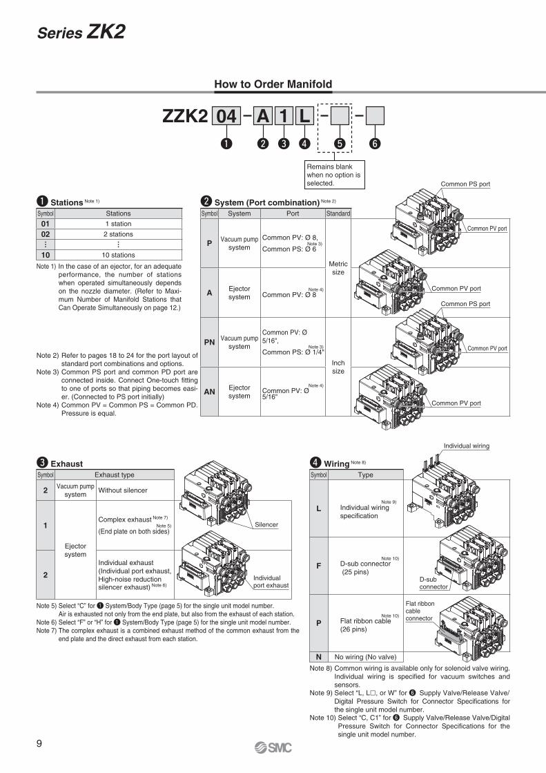
q Stations Note 1) w System (Port combination) Note 2)
Note 2) Refer to pages 18 to 24 for the port layout of standard port combinations and options.
Note 3) Common PS port and common PD port are connected inside. Connect One-touch fi tting to one of ports so that piping becomes easi-er. (Connected to PS port initially)
Note 4) Common PV = Common PS = Common PD. Pressure is equal.
e Exhaust
Note 5) Select “C” for q System/Body Type (page 5) for the single unit model number.Air is exhausted not only from the end plate, but also from the exhaust of each station.
Note 6) Select “F” or “H” for q System/Body Type (page 5) for the single unit model number.Note 7) The complex exhaust is a combined exhaust method of the common exhaust from the
end plate and the direct exhaust from each station.
r Wiring Note 8)
Note 8) Common wiring is available only for solenoid valve wiring. Individual wiring is specifi ed for vacuum switches and sensors.
Note 9) Select “L, L�, or W” for y Supply Valve/Release Valve/Digital Pressure Switch for Connector Specifi cations for the single unit model number.
Note 10) Select “C, C1” for y Supply Valve/Release Valve/Digital Pressure Switch for Connector Specifi cations for the single unit model number.
How to Order Manifold
Note 1) In the case of an ejector, for an adequate performance, the number of stations when operated simultaneously depends on the nozzle diameter. (Refer to Maxi-mum Number of Manifold Stations that Can Operate Simultaneously on page 12.)
Remains blank when no option is selected.
Symbol Stations
01 1 station
02 2 stations
… …
10 10 stations
Symbol System Port Standard
P Vacuum pumpsystem
Common PV: Ø 8,Note 3)
Common PS: Ø 6
Metricsize
A Ejectorsystem
Note 4)Common PV: Ø 8
PN Vacuum pumpsystem
Common PV: Ø 5/16",
Note 3)Common PS: Ø 1/4"
Inchsize
AN Ejectorsystem
Note 4)Common PV: Ø 5/16"
Common PV port
Common PV port
Common PS port
Common PV port
Common PV port
Common PS port
Symbol Exhaust type
2 Vacuum pumpsystem
Without silencer
1
Ejectorsystem
Complex exhaust Note 7)
Note 5)(End plate on both sides)
2
Individual exhaust(Individual port exhaust, High-noise reduction silencer exhaust) Note 6)
Silencer
Individualport exhaust
Symbol Type
LNote 9)
Individual wiringspecifi cation
FNote 10)
D-sub connector (25 pins)
PNote 10)
Flat ribbon cable(26 pins)
N No wiring (No valve)
Individual wiring
D-subconnector
Flat ribboncableconnector
9
Series ZK2

Note 15) Kit consists of end plates for both ends and tension bolts.
t Option Note 11)
Note 11) When more than one option is selected, list the option symbols in an alphabetical order.Example) -BD
Note 12) DIN rail should be ordered separately. (Refer to page 27.)Note 13) When “-D” is selected for the manifold model number, select “-P” for i
Optional Specifi cations for the single unit model number. Refer to pages 18 to 24 for port layout.
Note 14) When “-L (individual supply)” is selected for i Optional Specifi cations for the single unit model number, specify “-L” for manifold, too.
y Manifold Assembly (Delivery condition)
• When the manifold is viewed from V port, the fi rst station starts from the left (D side).
• After the manifold part number, specify the installed single unit from the fi rst station.
• Complex exhaust and individual port exhaust cannot be mixed in the ejector system manifold.
• DIN rail should be ordered separately. (Page 27)
How to Order Valve Manifold Assembly
ZZK204-A1P-B· · · · · · · · · ·1 set (Manifold part number)∗ ZK2C10R5NC1-08 · · · · · ·3 sets (Common wiring specifi cation)∗ ZK2C10R5NL2-08 · · · · · ·1 set (Individual wiring specifi cation)
∗ The asterisk denotes the symbol for assembly.∗ Prefi x to the single unit part number.
Example
ZZK202-A1L-A ··············1 set (Manifold part number)ZK2C10K5BL3-08·········1 set (Single unit part number)ZK2C10K5PL1-08·········1 set (Single unit part number)
Do not add “∗”
Manifold parts when not assembled
Manifold Type and Options
Symbol Type
— Without option
B
Note 12)
With DIN railmountingbracket
D
Note 13)
With commonrelease pressuresupply (PD) port
L
Note 14)
Manifold individualsupply specifi cation
Symbol Type
— Individual units assembled delivered as a manifold
A Delivered as individual parts (not assembled) Note 15)
�q �w �e �r�t
�yB D L
ZZK201
…
10
P·
PN2
L·
F·
P� �
—·A
A·
AN
1·
2
L·
F·
P·
N
� � �
ZZK204-A1P-B
ZK2C10R5NC1-08ZK2C10R5NL2-08
12
3Stations
D side
U side
Tension bolt
End plate
Ejector: Single unitManifold parts
DIN rail mounting bracket
Common PD port
Individual PV port
10
Vacuum Unit Series ZK2
Co
nst
ruct
ion
Po
rt L
ayo
ut
Explo
ded V
iew of
Man
ifold
Dim
ensi
on
sSp
ecific
Prod
uct P
recau
tions
Ho
w t
o O
rder
Spec
ifica
tions
/Fl
ow R
ate
Char
acte
ristic
s

11

Note 1) The characteristics are satisfi ed when tested for 2 hours in each of the X, Y and Z directions at 10 to 500 Hz without energisation. (Initial value)
Note 2) The characteristics are satisfi ed when tested one time in each of the X, Y and Z directions without energisa-tion. (Initial value)
Specifi cations
Weight
General Specifi cations
Note 3) Refer to y Valve assembly on page 26 for the valve model number.Note 4) ZK2-VA�R: After instantaneous energisation of the supply valve (20 ms or
more), ON state is maintained without energisation. Supply valve turns off simultaneously when the release valve turns on.
ZK2-VA�K: Supply valve turns off when it is not energised. Select this type when energy saving switch is used.
Valve Common Specifi cations
Note 5) Values are based on standard of SMC measurements. They depend on atmospheric pressure (weather, altitude, etc.) and measurement method.Note 6) The value in ( ) is for without valve. For nozzle size 07 to 12, the value is common to the ejectors with valve and without valve.
Note 7) As long as the number of stations operated simultaneously is the value on the table or less, then the manifold is available up to 10 stations.
Ejector Specifi cations
Maximum Number of Manifold Stations that Can Operate Simultaneously Note 7)
Single Unit
Pressure Sensor/Pressure Switch for Vacuum
Manifold Base
(Single unit weight x Number of stations) + (Pressure sensor/Pressure switch for vacuum weight x Number of stations) + Manifold base
Example) 5-station manifold with pressure sensors
85 g x 5 pcs. + 5 g × 5 pcs. + 141 g = 591 g
� Calculation of Weight for the Manifold Type
Operating temperature range –5 to 50 °C (with no condensation)
Fluid Air
Note 1)Vibrationresistance
30 m/s2 Without pressure sensor/switch for vacuumWith pressure sensor
20 m/s2 With switch for vacuum
Note 2)Impactresistance
150 m/s2 Without pressure sensor/switch for vacuumWith pressure sensor
100 m/s2 With switch for vacuum
Valve model Note 3) ZK2-VA�R ZK2-VA�K ZK2-VA�JType of actuation Note 4)
Self-holding supply valveRelease valve N.C. (Linked)
Supply valve N.C.Release valve N.C.
Supply valve N.C.Without release valve
Valve confi guration Pilot operated dual 2 port Pilot operated 2 port
Operating pressure range 0.3 to 0.6 MPa
Valve construction Poppet seal
Manual override Push type
Rated voltage 24 V DC, 12 V DC
Power consumption 0.35 W
Lead wire(ZK2-LV∗∗-A)
Cross section: 0.2 mm2 (AWG24)
Insulator O.D.: 1.4 mm
Item Model ZK2�07 ZK2�10 ZK2�12 ZK2�15Nozzle diameter [mm] 0.7 1.0 1.2 1.5
Note 5)Max. suction fl ow
Port exhaust [l/min (ANR)] 34 56 74 89
Silencer exhaust/Complex exhaust [l/min (ANR)] 29 44 61 67
High-noise reduction silencer exhaust [l/min (ANR)] 32 48 70 80
Air consumption Note 5) [l/min (ANR)] 24 40 58 90
Maximum vacuum pressure Note 5) [kPa] -91
Supply pressure range [MPa] 0.3 to 0.6
Standard supply pressure Note 6) [MPa] 0.35 0.4 (0.37)
Item Model (Nozzle size) ZK2�07 ZK2�10 ZK2�12 ZK2�15
Air pressure supply (PV) portØ 8, Ø 5/16"
Complex exhaustSupply from one side 8 5 4 3
Supply from both sides 10 7 5 5
Individual port exhaust, High-noise reduction silencer exhaust
Supply from one side 8 6 6 3
Supply from both sides 10 9 9 6
Single unit model Weight [g]
ZK2P00K�� (Vacuum pump system, Single unit, Without pressure sensor/switch for vacuum) 83
ZK2A��K�� (Ejector system, Single unit, Without pressure sensor/switch for vacuum) 81
ZK2A��N0NN (Ejector system, Single unit, Without valve) 54
ZK2 (One station for manifold, Without pressure sensor/switch for vacuum) 85
Pressure sensor/Pressure switch for vacuum model Weight [g]
ZK2-PS�-A (Except cable portion) 5
ZK2-ZS�-A (Except lead wire assembly with connector)14
ZK2-ZSV�-A (Except special lead wire assembly with connector)
1 station 2 stations 3 stations 4 stations 5 stations 6 stations 7 stations 8 stations 9 stations 10 stations
Weight [g] 129 132 135 138 141 144 147 149 152 155
12
Vacuum Unit Series ZK2
Co
nst
ruct
ion
Po
rt L
ayo
ut
Explo
ded V
iew of
Man
ifold
Dim
ensi
on
sSp
ecific
Prod
uct P
recau
tions
Ho
w t
o O
rder
Spec
ifica
tions
/Fl
ow R
ate
Char
acte
ristic
s

-100
-80
-60
-40
-20
00 10 20 30 40
Suction flow [l/min (ANR)]
Vac
uum
pre
ssur
e [k
Pa]
-100
-80
-60
-40
-20
00 10 20 30 40 50 60
Suction flow [l/min (ANR)]
Vac
uum
pre
ssur
e [k
Pa]
-100
-90
-80
-70
-60
-50
-40
-30
-20
-10
00 0.1 0.2 0.3 0.4 0.5 0.6
Supply pressure [MPa]
Vac
uum
pre
ssur
e [k
Pa]
0
5
10
15
20
25
30
35
40
45
50
Suc
tion
flow
[l/m
in (
AN
R)]
Air
cons
umpt
ion
[l/m
in (
AN
R)]
Suc
tion
flow
[l/m
in (
AN
R)]
Air
cons
umpt
ion
[l/m
in (
AN
R)]
Vacuum pressureVacuum pressure
Air consumption
-100
-90
-80
-70
-60
-50
-40
-30
-20
-10
00 0.1 0.2 0.3 0.4 0.5 0.6
Supply pressure [MPa]
Vac
uum
pre
ssur
e [k
Pa]
0
10
20
30
40
50
60
70
80
90
100
Vacuum pressure
Air consumption
Suction flow (Individual port exhaust)
Individual port exhaustSilencer exhaust/Complex exhaust
Individual port exhaustSilencer exhaust/Complex exhaust
Suction flow(Silencer exhaust/Complex exhaust)
Suction flow(Silencer exhaust/Complex exhaust)
Suction flow(Silencer exhaust/Complex exhaust)
Suction flow(High-noise reduction
silencer exhaust)
Suction flow(High-noise reduction
silencer exhaust)
Vacuum pressure
Suction flow(Individual port exhaust)
Flow Rate CharacteristicsExhaust Characteristics
Exhaust Characteristics Flow Rate Characteristics
-100
-80
-60
-40
-20
00 10 20 30 40
Suction flow [l/min (ANR)]
Vac
uum
pre
ssur
e [k
Pa]
-100
-80
-60
-40
-20
00 10 20 30 40 50 60
Suction flow [l/min (ANR)]
Vac
uum
pre
ssur
e [k
Pa]
High-noise reduction silencer exhaust
High-noise reduction silencer exhaust
Flow Rate Characteristics
Flow Rate Characteristics
ZK2�07
ZK2�10
Ejector Exhaust Characteristics/Flow Rate Characteristics ∗The fl ow rate characteristics correspond to the standard supply pressure.
13
Series ZK2

-100
-80
-60
-40
-20
00 20 40 60 80
Suction flow [l/min (ANR)]
Vac
uum
pre
ssur
e [k
Pa]
-100
-80
-60
-40
-20
00 20 40 60 80 100
Suction flow [l/min (ANR)]
Vac
uum
pre
ssur
e [k
Pa]
High-noise reduction silencer exhaust
High-noise reduction silencer exhaust
Suc
tion
flow
[l/m
in (
AN
R)]
Air
cons
umpt
ion
[l/m
in (
AN
R)]
Suc
tion
flow
[l/m
in (
AN
R)]
Air
cons
umpt
ion
[l/m
in (
AN
R)]
-100
-90
-80
-70
-60
-50
-40
-30
-20
-10
00 0.1 0.2 0.3 0.4 0.5 0.6
Supply pressure [MPa]
Vac
uum
pre
ssur
e [k
Pa]
0
10
20
30
40
50
60
70
80
90
100
Vacuum pressure
Air consumption
Suction flow(Individual port exhaust)
-100
-90
-80
-70
-60
-50
-40
-30
-20
-10
00 0.1 0.2 0.3 0.4 0.5 0.6
Supply pressure [MPa]
Vac
uum
pre
ssur
e [k
Pa]
0
15
30
45
60
75
90
105
120
135
150
Vacuum pressure
Air consumption
Suction flow(High-noise reduction
silencer exhaust)
Suction flow(High-noise reduction
silencer exhaust)
Exhaust Characteristics
Exhaust Characteristics
Flow Rate Characteristics
Flow Rate Characteristics
Suction flow(Individual port exhaust)
Suction flow(Silencer exhaust/Complex exhaust)
Suction flow(Silencer exhaust/Complex exhaust)
Suction flow(Silencer exhaust/Complex exhaust)
Suction flow(Silencer exhaust/Complex exhaust)
-100
-80
-60
-40
-20
00 20 40 60 80
Suction flow [l/min (ANR)]
Vac
uum
pre
ssur
e [k
Pa]
-100
-80
-60
-40
-20
00 20 40 60 80 100
Suction flow [l/min (ANR)]
Vac
uum
pre
ssur
e [k
Pa]
Individual port exhaustSilencer exhaust/Complex exhaust
Individual port exhaustSilencer exhaust/Complex exhaust
Flow Rate Characteristics
Flow Rate Characteristics
ZK2�12
ZK2�15 Note 8) The following graphs show the characteristics of the ejector with valve. (Please contact SMC for models without valve.)
Ejector Exhaust Characteristics/Flow Rate Characteristics ∗The fl ow rate characteristics correspond to the standard supply pressure.
14
Vacuum Unit Series ZK2
Co
nst
ruct
ion
Po
rt L
ayo
ut
Explo
ded V
iew of
Man
ifold
Dim
ensi
on
sSp
ecific
Prod
uct P
recau
tions
Ho
w t
o O
rder
Spec
ifica
tions
/Fl
ow R
ate
Char
acte
ristic
s

Vac
uum
pre
ssur
e
Suction flow
0 Q1 Qmax
Pmax
P1
-100-90-80-70-60-50-40-30-20
00
-10
5 10 15 20 25 30Suction flow [l/min (ANR)]
Vac
uum
pre
ssur
e [k
Pa]
0
10
20
30
40
0 1 2 3 4 5 6 7 8 9 10Needle opening [Number of rotations]
Rel
ease
flow
[l/m
in (
AN
R)]
Sup
ply
pres
sure
[MP
a]
0.5
0.40.350.3
0.2
0
10
20
30
40
50
60
0 1 2 3 4 5 6 7 8 9 10
Needle opening [Number of rotations]
Rel
ease
flow
[l/m
in (
AN
R)]
Sup
ply
pres
sure
[MP
a]0.5
0.40.350.3
0.2
The actual suction flow at the point of suction varies depending on the piping conditions to the vacuum port. (The above graph shows the value when V port is Ø 8.)
The actual suction flow at the point of suction varies depending on the piping conditions to the vacuum port.
The actual suction flow at the point of suction varies depending on the piping conditions to the vacuum port. (The above graph shows the value of the ZK2B07.)
ZK2���(Ejector System)
ZK2���(Pump System)
Vacuum Pump System Flow Rate Characteristics/ZK2P00
The graph shows the suction fl ow rate characteristics of the vacuum pump system at different vacuum pressures.
The graph shows the fl ow rate characteristics at different supply pressures when the vacuum break fl ow adjusting needle is open from the fully closed state.
Vacuum Release Flow Rate Characteristics
How to Read Flow Rate Characteristics Graph
Flow rate characteristics are expressed in ejector vacuum pressure and suction fl ow. If suction fl ow changes, the vacuum pressure will also be changed. Normally this relationship is expressed in ejector standard operating pressure use. In graph, Pmax is maximum vacuum pressure and Qmax is maximum suction fl ow. The values are specifi ed according to catalogue use. Changes in vacuumpressure are expressed in the below order.
1. When ejector suction port is covered and made airtight, suction fl ow becomes zero and vacuum pressure is at maximum value (Pmax).
2. When suction port is opened gradually, air can fl ow through, (air leakage), suction fl ow increases, but vacuum pressure decreases. (condition P1 and Q1)
3. When suction port is opened further and fully opened, suction fl ow moves to maximum value (Qmax), but vacuum pressure is near zero (atmospheric pressure).
As described above, the vacuum pressure changes when the suction fl ow changes. In other words, when there is no leakage from the vacuum (V) port, the vacuum pressure can reach its maximum, but as the amount of leakage increases, the vacuum pressure decreases. When the amount of leakage and the maximum suction fl ow become equal, the vacuum pressure becomes almost zero.In the case when ventilative or leaky work should be adsorbed, take note that vacuum pressure will not rise.
Vacuum Pump System Flow Rate Characteristics of Flow Path and Vacuum Release
(∗) When needle is fully open
Port size Flow rate characteristics of V → PV (Vacuum side) Flow rate characteristics of PS → V (Vacuum release side)(∗)
PV port V port C[dm3/(s·bar)] b Cv C[dm3/(s·bar)] b Cv
Ø 6 Ø 8 0.39 0.14 0.09 0.20 0.06 0.04
15
Series ZK2
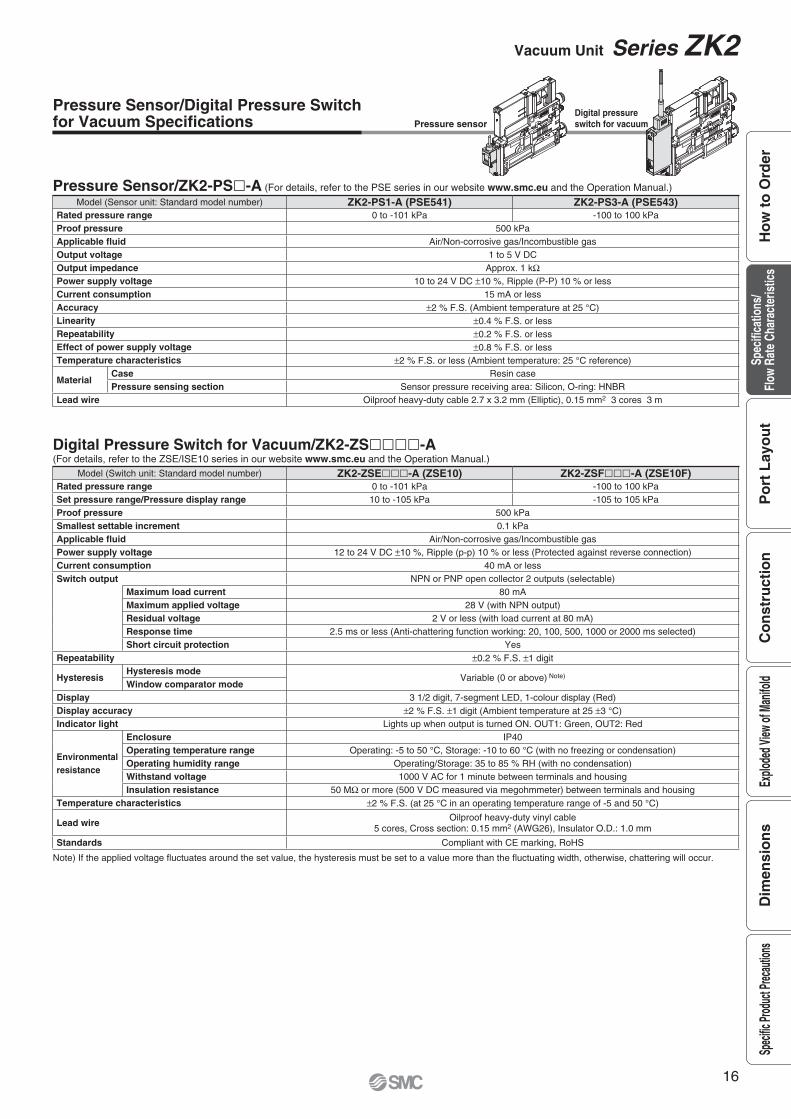
Pressure Sensor/Digital Pressure Switchfor Vacuum Specifi cations
Note) If the applied voltage fl uctuates around the set value, the hysteresis must be set to a value more than the fl uctuating width, otherwise, chattering will occur.
Pressure Sensor/ZK2-PS�-A (For details, refer to the PSE series in our website www.smc.eu and the Operation Manual.)
Digital Pressure Switch for Vacuum/ZK2-ZS����-A ( For details, refer to the ZSE/ISE10 series in our website www.smc.eu and the Operation Manual.)
Pressure sensorDigital pressure switch for vacuum
Model (Sensor unit: Standard model number) ZK2-PS1-A (PSE541) ZK2-PS3-A (PSE543)Rated pressure range 0 to -101 kPa -100 to 100 kPaProof pressure 500 kPaApplicable fl uid Air/Non-corrosive gas/Incombustible gasOutput voltage 1 to 5 V DCOutput impedance Approx. 1 kΩPower supply voltage 10 to 24 V DC ±10 %, Ripple (P-P) 10 % or lessCurrent consumption 15 mA or lessAccuracy ±2 % F.S. (Ambient temperature at 25 °C)Linearity ±0.4 % F.S. or lessRepeatability ±0.2 % F.S. or lessEffect of power supply voltage ±0.8 % F.S. or lessTemperature characteristics ±2 % F.S. or less (Ambient temperature: 25 °C reference)
MaterialCase Resin casePressure sensing section Sensor pressure receiving area: Silicon, O-ring: HNBR
Lead wire Oilproof heavy-duty cable 2.7 x 3.2 mm (Elliptic), 0.15 mm2 3 cores 3 m
Model (Switch unit: Standard model number) ZK2-ZSE���-A (ZSE10) ZK2-ZSF���-A (ZSE10F)Rated pressure range 0 to -101 kPa -100 to 100 kPaSet pressure range/Pressure display range 10 to -105 kPa -105 to 105 kPaProof pressure 500 kPaSmallest settable increment 0.1 kPaApplicable fl uid Air/Non-corrosive gas/Incombustible gasPower supply voltage 12 to 24 V DC ±10 %, Ripple (p-p) 10 % or less (Protected against reverse connection)Current consumption 40 mA or lessSwitch output NPN or PNP open collector 2 outputs (selectable)
Maximum load current 80 mAMaximum applied voltage 28 V (with NPN output)Residual voltage 2 V or less (with load current at 80 mA)Response time 2.5 ms or less (Anti-chattering function working: 20, 100, 500, 1000 or 2000 ms selected)Short circuit protection Yes
Repeatability ±0.2 % F.S. ±1 digit
HysteresisHysteresis mode
Variable (0 or above) Note)Window comparator mode
Display 3 1/2 digit, 7-segment LED, 1-colour display (Red)Display accuracy ±2 % F.S. ±1 digit (Ambient temperature at 25 ±3 °C)Indicator light Lights up when output is turned ON. OUT1: Green, OUT2: Red
Environmentalresistance
Enclosure IP40Operating temperature range Operating: -5 to 50 °C, Storage: -10 to 60 °C (with no freezing or condensation)Operating humidity range Operating/Storage: 35 to 85 % RH (with no condensation)Withstand voltage 1000 V AC for 1 minute between terminals and housingInsulation resistance 50 MΩ or more (500 V DC measured via megohmmeter) between terminals and housing
Temperature characteristics ±2 % F.S. (at 25 °C in an operating temperature range of -5 and 50 °C)
Lead wire Oilproof heavy-duty vinyl cable5 cores, Cross section: 0.15 mm2 (AWG26), Insulator O.D.: 1.0 mm
Standards Compliant with CE marking, RoHS
16
Vacuum Unit Series ZK2
Co
nst
ruct
ion
Po
rt L
ayo
ut
Explo
ded V
iew of
Man
ifold
Dim
ensi
on
sSp
ecific
Prod
uct P
recau
tions
Ho
w t
o O
rder
Spec
ifica
tions
/Fl
ow R
ate
Char
acte
ristic
s

button (UP)button (DOWN)
button (SET)
LED display
Output (OUT2) display (Red)
Output (OUT1) display (Green)
Connector terminal Lead wire with connector
Brown DC(+)
Black OUT 1
White OUT 2
FUNCBlue DC(−)
Mai
n ci
rcui
t Load
Load 12 V DCto
24 V DC
Brown DC(+)
Black OUT 1
White OUT 2
FUNCBlue DC(−)
Mai
n ci
rcui
t
Load
Load
12 V DCto
24 V DC
Max. 80 mAResidual voltage: 2 V or less
Max. 28 V, 80 mAResidual voltage: 2 V or less
(Analogue output)1 kΩ
Load
Mai
n ci
rcui
t
12 V DCto
24 V DC
Brown DC(+)
Black OUT +− +
−+−
Blue DC(−)
Voltage output type: 1 to 5 VOutput impedance: Approx. 1 kΩ
24 V DC
BlueGrey
White
BlackBrown
+−
−
FUNC−
Digital pressure switch(NPN Output)
OUT2
+OUT1
Connector cord assembly (ZK2-LWA20-A)
BCA
Pilot valvefor release
Pilot valvefor supply
Pilot valvefor release
Pilot valvefor supply
Mai
n ci
rcui
t
Load24 V DC
BlueGrey
White
BlackBrown
FUNC
Digital pressure switch(PNP Output)
OUT2OUT1
Connector cord assembly (ZK2-LWB20-A)
BCA
Mai
n ci
rcui
t
Load
−+
+
−
+
Output (OUT1) display (Green) Lights up when OUT1 is turned ON.Output (OUT2) display (Red) Lights up when OUT2 is turned ON.LED display Displays the current pressure, set mode and error code.
button (UP)Selects the mode or increases the ON/OFF set-value.Use for switching to the peak display mode.
button (DOWN)Selects the mode or decreases the ON/OFF set-value.Use for switching to the bottom display mode.
button (SET) Use for changing the mode or setting the set-value.
Description (Pressure Switch for Vacuum)
Internal Circuit and Wiring Example
�Pressure Switch for VacuumZK2-ZS�A��-ANPN (2 Outputs)
ZK2-ZS�B��-APNP (2 Outputs)
�Pressure Switch for Vacuum with Energy Saving FunctionZK2-ZSVA��-ANPN (Output)
ZK2-ZSVB��-APNP (Output)
�Pressure SensorZK2-PS�-A
∗The FUNC terminal is connected when using the copy function. (Refer to the Operation Manual.)
Digital Pressure Switch for Vacuum Ejector with Energy Saving Function
Note) If the applied voltage fl uctuates around the set value, the hysteresis must be set to a value more than the fl uctuating width, otherwise, chattering will occur.
Digital Pressure Switch for Vacuum Specifi cationsDigital pressure switchfor vacuum with energysaving function
Model Specifi cationsRated pressure range -100 to 100 kPaSet pressure range -105 to 105 kPaProof pressure 500 kPaSmallest settable increment 0.1 kPaApplicable fl uid Air/Non-corrosive gas/Incombustible gasPower supply voltage 12 to 24 V DC ±10 % Ripple (P-P) 10 % or less (Protected against reverse connection)Current consumption 40 mA or lessSwitch output NPN or PNP open collector OUT1: General purpose, OUT2: Valve control
Maximum load current 80 mAMaximum applied voltage 26.4 V DCResidual voltage 2 V or less (with load current at 80 mA)Response time 2.5 ms or less (Anti-chattering function working: 20, 100, 500, 1000 or 2000 ms selected)Short circuit protection Yes
Repeatability ±0.2 % F.S. ±1 digitHysteresis Hysteresis mode Variable (0 or above) Note)
Display 3 1/2 digit, 7-segment LED, 1-colour display (Red)Display accuracy ±2 % F.S. ±1 digit (Ambient temperature at 25 ±3 °C)Indicator light Lights up when output is turned ON. OUT1: Green, OUT2: Red
Environmentalresistance
Enclosure IP40Operating humidity range 5 to 50 °CWithstand voltage 1000 V AC for 1 minute between terminals and housingInsulation resistance 50 MΩ or more (500 V DC measured via megohmmeter) between terminals and housing
Temperature characteristics ±2 % F.S. (at 25 °C in an operating temperature range of 5 and 50 °C)Lead wire Cable: 5 cores Ø 3.5, 2 m Cross section: 0.15 mm2 (AWG26) Insulator O.D.: 1.0 mmStandards CE marking, RoHS
17
Series ZK2

PP
PE
V
PE
Supply valve: Self-holding type(R type)
Release valve: N.C. Supply valve: N.C. Release valve: N.C.(K type)
EXH EXHCommon PD
V
Common PDCommon PSCommon PV
Common PSCommon PV
P
Supply valve: Self-holding type(R type)
Release valve: N.C.
PV
PE
PS(= PD)
V
P
Silencer exhaustEXH
PV
V
Release valveSupply valve
Exhaust port Note)
EXH
Supply valve: Self-holding type(R type)
Release valve: N.C.
(= Common PD)(= Common PD)
V
Common PVCommon PV
Common PSCommon PS
(including PE)
EXHEXH
(including PE)
PVPE
PS(= PD)
V
PV(= PS = PD)
V
EXH Note)
Port Layout ∗System depends on vacuum source (vacuum pump/vacuum ejector).
Standard Products
Port combination: PV ≠ PS = PD
Port combination: Common PV ≠ Common PS = Common PD
Port combination: PV = PS = PD
Circuit example
Circuit example
Circuit example
Refer to page 24 for the purpose of port and the operating pressure range.
Note) Nozzle size: 12, 15
Portlayout No. 1Single unit: ZK2P00����-�
System Vacuum pumpBody type Single unitExhaust type Without silencer
Applicationandpurpose
Vacuum pressure —Exhaust —Release pressure Same pressure as PS
Portlayout No. 2Single unit: ZK2Q00����-�Manifold: ZZK2��-P2�
System Vacuum pumpBody type ManifoldExhaust type Without silencer
Applicationandpurpose
Vacuum pressure Common for each stationExhaust —Release pressure Same pressure as common PS
Portlayout No. 3Single unit: ZK2A������-�
System EjectorBody type Single unitExhaust type Silencer exhaust
Applicationandpurpose
Vacuum pressure —Exhaust Released in operating environmentRelease pressure Same pressure as PV
18
Vacuum Unit Series ZK2
Co
nst
ruct
ion
Po
rt L
ayo
ut
Explo
ded V
iew of
Man
ifold
Dim
ensi
on
sSp
ecific
Prod
uct P
recau
tions
Ho
w t
o O
rder
Spec
ifica
tions
/Fl
ow R
ate
Char
acte
ristic
s

PV(= PS = PD)
EXH(including PE)
V
P
Port exhaustEXH
PV
V
Supply valve: N.C.(J type)
Release valve: Without release valve
P
Supply valve: N.C. Release valve: N.C. (K type)
High-noise reduction silencer exhaust
EXH
PV
V
Individualexhaustport
Note)EXH
Individualexhaustport
Note)EXH
PP
EXH EXH
VSupply valve: Self-holding type Release valve: N.C.
Common PD
V
Common PDCommon PSCommon PV
Common PSCommon PV
(R type) Supply valve: N.C. Release valve: N.C.
(K type)
(= Common PS= Common PD)(= Common PS
= Common PD)
(including PE) (including PE)
Common PVCommon PV
Common EXH Common EXH
V
EXH(including PE)
V
PV(= PS = PD)
Portlayout No. 4
Portlayout No. 5
Portlayout No. 6
Standard Products
Port combination: Common PV = Common PS = Common D
Circuit example
Port combination: PV = PS = PD
Circuit example
Port combination: PV ( = PS = PD)
Circuit example
Note) For complex exhaust type, individual exhaust port is provided to each station.
Refer to page 24 for the purpose of port and the operating pressure range.
Single unit: ZK2B������-�
System EjectorBody type Single unitExhaust type Port exhaust
Applicationandpurpose
Vacuum pressure —Exhaust After piping, individual exhaust is necessary.Release pressure Same pressure as PV
System EjectorBody type Single unitExhaust type High-noise reduction silencer exhaust
Applicationandpurpose
Vacuum pressure —Exhaust Released in operating environmentRelease pressure Same pressure as PV
System EjectorBody type ManifoldExhaust type Complex exhaust Note)
Applicationandpurpose
Vacuum pressure Common for each stationExhaust Released in operating environmentRelease pressure Same pressure as common PV
Single unit: ZK2C������-�Manifold: ZZK2��-A1�
Single unit: ZK2G�����-�
Port Layout ∗System depends on vacuum source (vacuum pump/vacuum ejector).
Note) The complex exhaust is a combined exhaust method of the common exhaust from the end plate and the direct exhaust from each station.
19
Series ZK2

Portlayout No. 7
Portlayout No. 8
Portlayout No. 9
Option -DPort combination: PV ≠ PS ≠ PD
Circuit example
Refer to page 24 for the purpose of port and the operating pressure range.
Standard Products
Single unit: ZK2F�����-�Manifold: ZZK2��-A2�
System EjectorBody type ManifoldExhaust type High-noise reduction silencer exhaust
Applicationandpurpose
Vacuum pressure Common for each stationExhaust Released in operating environmentRelease pressure Same pressure as common PV
Single unit: ZK2H�����-�Manifold: ZZK2��-A2�
System Vacuum pumpBody type Single unitExhaust type Without silencer
Applicationandpurpose
Vacuum pressure —Exhaust —
Release pressurePD pressure has to be
supplied with PS pressure.
Single unit: ZK2P00����-�-D
Port combination: Common PV = Common PS = Common D
Circuit example
Port Layout ∗System depends on vacuum source (vacuum pump/vacuum ejector).
System EjectorBody type ManifoldExhaust type Individual port exhaust
Applicationandpurpose
Vacuum pressure Common for each stationExhaust After piping, individual exhaust is necessary.Release pressure Same pressure as common PV
(including PE)
(= Common PS= Common PD)(= Common PS
= Common PD)
Common PVCommon PV
V
Individual EXH
V
(including PE)
(= Common PS= Common PD)
(= Common PS= Common PD)
Common PV
Common PV
Individual EXH
PE PV
PD
PS
VP
Supply valve: N.C. Release valve: N.C.(K type)
PD
PV
PE
PS
V
Port exhaustHigh-noise reduction silencer exhaust
EXH
PP
EXH
EXH
VV
Common PDCommon PSCommon PV
Common PSCommon PV
7 8
Common PDEXH
Supply valve: Self-holding type(R type)
Release valve: N.C. Supply valve: N.C. Release valve: N.C.(K type)
20
Vacuum Unit Series ZK2
Co
nst
ruct
ion
Po
rt L
ayo
ut
Explo
ded V
iew of
Man
ifold
Dim
ensi
on
sSp
ecific
Prod
uct P
recau
tions
Ho
w t
o O
rder
Spec
ifica
tions
/Fl
ow R
ate
Char
acte
ristic
s

Option -D
Single unit: ZK2B������-�-D
Note) Nozzle size: 12, 15
Single unit: ZK2Q00����-�Manifold: ZZK2��-P2�-D
Single unit: ZK2A������-�-D
Refer to page 24 for the purpose of port and the operating pressure range.
Port combination: Common PV ≠ Common PS ≠ Common PD
Port combination: PV = PS ≠ PD
Port combination: PV = PS ≠ PD
Circuit example
Circuit example
Circuit example
Port Layout ∗System depends on vacuum source (vacuum pump/vacuum ejector).
Portlayout No. 10
Portlayout No. 11
Portlayout No. 12
System Vacuum pumpBody type ManifoldExhaust type Without silencer
Applicationandpurpose
Vacuum pressure Common for each stationExhaust —
Release pressureCommon PD pressure has to be supplied with common PS.
System EjectorBody type Single unitExhaust type Silencer exhaust
Applicationandpurpose
Vacuum pressure —Exhaust Released in operating environment
Release pressurePD pressure has to be
supplied with PV pressure.
System EjectorBody type Single unitExhaust type Port exhaust
Applicationandpurpose
Vacuum pressure —Exhaust After piping, individual exhaust is necessary.
Release pressurePD pressure has to be
supplied with PV pressure.
P
PD
Supply valve: N.C. Release valve: N.C.(K type)
Port exhaustEXH
PV
V
PV(= PS)
PD
EXH(including PE)
V
Common PD( Common PS)
Common PD( Common PS)
V
Common PS Common PSCommon PVCommon PV
PP
PE
V
PE
EXH EXHCommon PD
V
Common PDCommon PSCommon PV
Common PSCommon PV
Supply valve: Self-holding type(R type)
Release valve: N.C. Supply valve: N.C. Release valve: N.C.(K type)
(including PE)
EXHEXH
(including PE)
PD
V
PV(= PS)
EXH Note)
P
Supply valve: Self-holding type Release valve: N.C.(R type)
PD
EXH
PV
V
Exhaust port Note)
EXHSilencer exhaust
21
Series ZK2
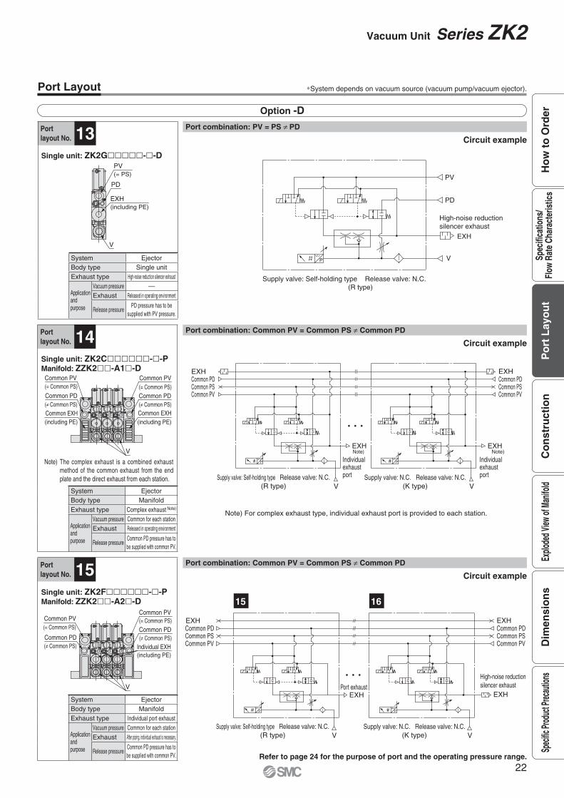
Portlayout No. 13
Portlayout No. 14
Portlayout No. 15
Option -D
Single unit: ZK2C������-�-PManifold: ZZK2��-A1�-D
System EjectorBody type ManifoldExhaust type Individual port exhaust
Applicationandpurpose
Vacuum pressure Common for each stationExhaust After piping, individual exhaust is necessary.
Release pressureCommon PD pressure has to be supplied with common PV.
System EjectorBody type ManifoldExhaust type Complex exhaust Note)
Applicationandpurpose
Vacuum pressure Common for each stationExhaust Released in operating environment
Release pressureCommon PD pressure has to be supplied with common PV.
Single unit: ZK2F������-�-PManifold: ZZK2��-A2�-D
Single unit: ZK2G�����-�-D
Port combination: PV = PS ≠ PD
Circuit example
Circuit example
Circuit example
Refer to page 24 for the purpose of port and the operating pressure range.
Port combination: Common PV = Common PS ≠ Common PD
Port combination: Common PV = Common PS ≠ Common PD
Port Layout ∗System depends on vacuum source (vacuum pump/vacuum ejector).
System EjectorBody type Single unitExhaust type High-noise reduction silencer exhaust
Applicationandpurpose
Vacuum pressure —Exhaust Released in operating environment
Release pressurePD pressure has to be
supplied with PV pressure.
Note) For complex exhaust type, individual exhaust port is provided to each station.
Note) The complex exhaust is a combined exhaust method of the common exhaust from the end plate and the direct exhaust from each station.
(= Common PS)(= Common PS)
( Common PS) ( Common PS)
(including PE)(including PE)
Common PV
Common PD
Common EXH
Common PV
Common PD
Common EXH
V
(including PE)
(= Common PS)(= Common PS)
( Common PS)( Common PS)
Common PV
Common PD
Common PV
Common PD
Individual EXH
V
PD
EXH(including PE)
V
PV(= PS)
P
(R type)Supply valve: Self-holding type Release valve: N.C.
PD
High-noise reduction silencer exhaust
EXH
PV
V
Individualexhaustport
Note)EXH
Individualexhaustport
Note)EXH
PP
EXH EXH
V
Common PD
V
Common PDCommon PSCommon PV
Common PSCommon PV
Supply valve: Self-holding type(R type)
Release valve: N.C. Supply valve: N.C. Release valve: N.C.(K type)
Port exhaust
High-noise reduction silencer exhaust
EXH
PP
EXH
EXH EXH
V
Common PD
V
Common PDCommon PSCommon PV
Common PSCommon PV
15 16
Supply valve: Self-holding type(R type)
Release valve: N.C. Supply valve: N.C. Release valve: N.C.(K type)
22
Vacuum Unit Series ZK2
Co
nst
ruct
ion
Po
rt L
ayo
ut
Explo
ded V
iew of
Man
ifold
Dim
ensi
on
sSp
ecific
Prod
uct P
recau
tions
Ho
w t
o O
rder
Spec
ifica
tions
/Fl
ow R
ate
Char
acte
ristic
s

Portlayout No. 16
Portlayout No. 17
Portlayout No. 18
Option -L
Option -D
Single unit: ZK2C������-�-LManifold: ZZK2��-A1�-L
System Ejector
Body type Manifold
Exhaust type Complex exhaust Note)
Applicationandpurpose
Vacuum pressure PV pressure can be changed per station.
Exhaust Released in operating environment
Release pressure Same pressure for common PS and common PD
Single unit: ZK2H�����-�-PManifold: ZZK2��-A2�-D
Single unit: ZK2F������-�-LManifold: ZZK2��-A2�-L
System EjectorBody type ManifoldExhaust type Individual port exhaust
Applicationandpurpose
Vacuum pressure PV pressure can be changed per station.
Exhaust After piping, individual exhaust is necessary.
Release pressure Same pressure for common PS and common PD
Port combination: Common PV = Common PS ≠ Common PD
Circuit example
Circuit example
Circuit example
Refer to page 24 for the purpose of port and the operating pressure range.
Port combination: Individual PV ≠ Common PS = Common PD
Port combination: Individual PV ≠ Common PS = Common PD
Port Layout ∗System depends on vacuum source (vacuum pump/vacuum ejector).
System EjectorBody type ManifoldExhaust type High-noise reduction silencer exhaust
Applicationandpurpose
Vacuum pressure Common for each stationExhaust Released in operating environment
Release pressure PD pressure has to be supplied with PV pressure.
Note) For complex exhaust type, individual exhaust port is provided to each station
Note) The complex exhaust is a combined exhaust method of the common exhaust from the end plate and the direct exhaust from each station.
PP
PVPV
VV
Individualexhaust port
Note)EXH
Individualexhaust port
Note)EXH
EXH EXHCommon PD Common PD
Common PSCommon PV
Common PSCommon PV
Supply valve: Self-holding type(R type)
Release valve: N.C. Supply valve: N.C. Release valve: N.C.(K type)
(= Common PD)(= Common PD)
(including PE)(including PE)
Common PS
Common EXH
Common PS
Individual PV
Common EXH
V
Individual EXH(including PE)
Common PD( Common PS)
Common PD( Common PS)
V
Common PV(= Common PS)
Common PV(= Common PS)
(= Common PD)(= Common PD)
(including PE)
Common PS Common PS
Individual PV
Individual EXH
V
Port exhaust
High-noise reduction silencer exhaust
EXH
PP
EXH
EXH EXH
V
Common PD
V
Common PDCommon PSCommon PV
Common PSCommon PV
15 16
Supply valve: Self-holding type(R type)
Release valve: N.C. Supply valve: N.C. Release valve: N.C.(K type)
Port exhaustHigh-noise reduction silencer exhaust
EXH
P P
PVPV
EXH
EXH EXH
V
Common PD
V
Common PDCommon PSCommon PV
Common PSCommon PV
18 19
Supply valve: Self-holding type(R type)
Release valve: N.C. Supply valve: N.C. Release valve: N.C.(K type)
23
Series ZK2
B
A
(PE) 3)
PV
PS/EXH(PE) 2)
V
Valve assembly
EXH(PE) 2)
Spacer
PD (Option)
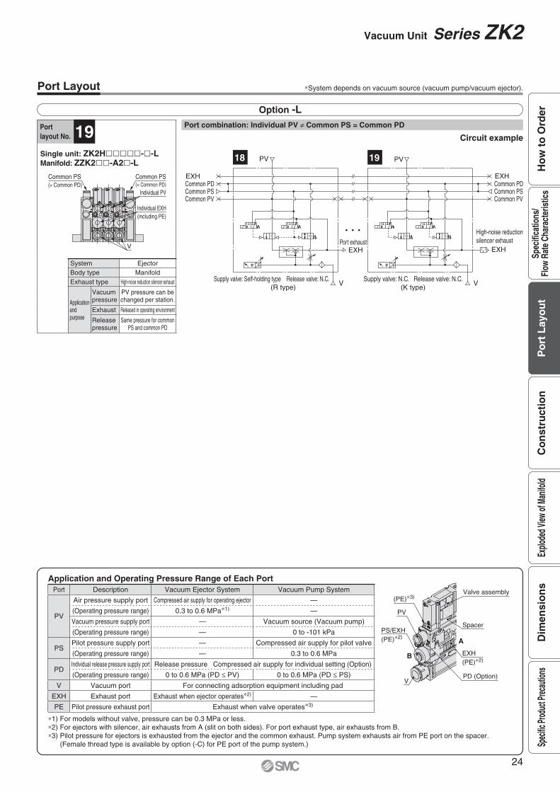
Option -L
Single unit: ZK2H�����-�-LManifold: ZZK2��-A2�-L
∗1) For models without valve, pressure can be 0.3 MPa or less.∗2) For ejectors with silencer, air exhausts from A (slit on both sides). For port exhaust type, air exhausts from B.∗3) Pilot pressure for ejectors is exhausted from the ejector and the common exhaust. Pump system exhausts air from PE port on the spacer.
(Female thread type is available by option (-C) for PE port of the pump system.)
Application and Operating Pressure Range of Each PortPort Description Vacuum Ejector System Vacuum Pump System
PV
Air pressure supply port Compressed air supply for operating ejector —
(Operating pressure range) 0.3 to 0.6 MPa∗1) —
Vacuum pressure supply port — Vacuum source (Vacuum pump)
(Operating pressure range) — 0 to -101 kPa
PSPilot pressure supply port — Compressed air supply for pilot valve
(Operating pressure range) — 0.3 to 0.6 MPa
PDIndividual release pressure supply port Release pressure Compressed air supply for individual setting (Option)
(Operating pressure range) 0 to 0.6 MPa (PD ≤ PV) 0 to 0.6 MPa (PD ≤ PS)
V Vacuum port For connecting adsorption equipment including pad
EXH Exhaust port Exhaust when ejector operates∗2) —
PE Pilot pressure exhaust port Exhaust when valve operates∗3)
Port Layout ∗System depends on vacuum source (vacuum pump/vacuum ejector).
Port combination: Individual PV ≠ Common PS = Common PD
Circuit examplePortlayout No. 19
System EjectorBody type ManifoldExhaust type High-noise reduction silencer exhaust
Applicationandpurpose
Vacuum pressure
PV pressure can be changed per station.
Exhaust Released in operating environment
Release pressure
Same pressure for common PS and common PD
Individual PV
Individual EXH(including PE)
Common PS(= Common PD)
Common PS(= Common PD)
VPort exhaust
High-noise reductionsilencer exhaust
EXH
P P
PVPV
EXH
EXH EXH
VSupply valve: Self-holding type Release valve: N.C.
(R type)Supply valve: N.C. Release valve: N.C.
(K type)
Common PD
V
Common PDCommon PSCommon PV
Common PSCommon PV
18 19
24
Vacuum Unit Series ZK2
Co
nst
ruct
ion
Po
rt L
ayo
ut
Explo
ded V
iew of
Man
ifold
Dim
ensi
on
sSp
ecific
Prod
uct P
recau
tions
Ho
w t
o O
rder
Spec
ifica
tions
/Fl
ow R
ate
Char
acte
ristic
s

With Pressure Switch for Vacuum
With High-noise Reduction Silencer
With Pressure Sensor
Component Parts
Replacement Parts
Construction
etoNlairetaMnoitpircseD.oN
1 Valve body assembly Resin HNBR, NBR and steel are also used.
2 Needle assembly Brass Electroless nickel plated brass, resin, steel and NBR are used.
3 Ejector body assembly Resin HNBR, NBR and steel are also used.
4 Ejector assembly .desu osla si RBNniseR
5 Filter case assembly Resin Case body: Polycarbonate (Refer to Specifi c Product Precautions on page 40.)
etoNnoitpircseD.oN
6 Valve assembly
7 Connector assembly Connector for solenoid valve 3 wire (For double), 2 wire (For single)
8 One-touch fi tting assembly Standard supply (PV) port: Ø 6, Ø 1/4"
9 Sound absorbing material 10 pcs. per set
10 Vacuum port adapter assembly With One-touch fi tting and fi lter element (Case material: Polycarbonate)
11 Filter element Nominal fi ltration rating: 30 µm, 10 pcs. per set
12 Check valve For replacement or addition for manifold exhaust interference prevention (10 pcs. per set)
13 Vacuum pressure switch assembly With 2 screws and 1 gasket
14 Lead wire with connector
15 Pressure sensor assembly With 2 screws and 1 gasket
16 High-noise reduction silencer case assembly With sound absorbing material (Part number: ZK2-SE3-6-A, 5 pcs. per set)
25
Series ZK2

Red
White
Black
Red
Black
For doubleFor single
Replacement Parts/How to Order
y Valve assembly
ZK2 VA AA K 5 L
q w e r
u Connector assembly
ZK2 LV AW
i One-touch fi tting assembly (Purchasing order is available in units of 10 pieces.)
KJH C204
q Applicable system
o Sound absorbing material (10 pcs. per set)
ZK2 SE1 A1Sound absorbing material holes diameter
!0 Vacuum port adapter assembly
ZK2 VA1S A8One-touch fi tting size
Applicable valve type
Port size
w Valve type
e Ratedvoltage r Lead wire entry direction
Lead wire length
Select the ZK2-VAAK�L�-A for a switch with energy saving function.This assembly does not include special cable assembly for a switch with energy saving function.
!1 Filter element (10 pcs. per set)
ZK2 FE1 A3Nominal fi ltration rating
ZS 39 5G
!3 Pressure switch for vacuum assembly
ZK2 ZS AE A M G
q w e r t
q Rated pressure range and function
w Output specifi cations
e Unit specifi cations
t Mounting Note)
Mounting Note)
r Lead wire with connector
Note 1) Fixed unit: kPa
!4 Lead wire with connector for pressure switch for vacuum(When individual lead wire is necessary, order with the port number below.)
ZK2 LW 20 AAOutput specifi cations
¡Lead wire with connector for pressure switch for vacuum
¡Lead wire with connector for switch with energy saving function
!5 Pressure sensor assembly
ZK2 PS ARated pressure range and specifi cations
1
The screw length mounted to the ejector is different.Note) When ordering an ejector without valve, select "—" for mounting.
The screw length mounted to the ejector is different.Note) When ordering an ejector without valve, select "—" for mounting.
A For ejector system P For vacuum pump system
K Supply valve N.C., Release valve N.C.R Supply valve, self-holding type (Linked to release valve)J Supply valve only (Single)
5 24 V DC6 12 V DC
C For plug-in (Manifold common wiring)L L-type plug connector with lead wire (Individual wiring)
LO L-type plug connector, without connector
W Valve type K/R(With supply valve and release valve)
S Valve type J(Supply valve only)
— 300 mm6 600 mm
10 1000 mm20 2000 mm30 3000 mm
04 Ø 4 One-touch fi tting (Straight) Metricsize06 Ø 6 One-touch fi tting (Straight)
03 Ø 5/32" One-touch fi tting (Straight) Inchsize07 Ø 1/4" One-touch fi tting (Straight)
6 Ø 6 One-touch fi tting Metricsize8 Ø 8 One-touch fi tting
7 Ø 1/4" One-touch fi tting Inchsize9 Ø 5/16" One-touch fi tting
3 30 μm
E 0 to -101 kPaPressure switch for vacuum Open collector 2 outputs
F -100 to 100 kPaV -100 to 100 kPa Pressure switch with energy saving function Open collector 1 output
A NPNB PNP
— Unit selection functionM SI unit only Note 1)
— None
GWithleadwire
When q is E or F···For pressure switch for vacuum,Lead wire with connector (Length 2 m)
When q is V··· For switch with energy saving function,Lead wire with connector (Length 2 m)
— Mounted to the single unitL Mounted to the manifold
A NPN open collectorB PNP open collector
1 0 to -101 kPa, Output: 1 to 5 V,Accuracy: ±2 % F.S. or less
3 -100 to 100 kPa, Output: 1 to 5 V,Accuracy: ±2 % F.S. or less
— Mounted to the single unitL Mounted to the manifold
1 300 μm
!2 Check valve Note) (10 pcs. per set)
ZK2 CV ANote) When mounting a check valve additionally, the workpiece may
not be removed unless vacuum release pressure is applied.
ZK2 SC3 A4Exhaust port size4 Ø 4 For nozzle size 07, 106 Ø 6 For nozzle size 12, 15
!6 High-noise reduction silencer case assembly
26
Vacuum Unit Series ZK2
Co
nst
ruct
ion
Po
rt L
ayo
ut
Explo
ded V
iew of
Man
ifold
Dim
ensi
on
sSp
ecific
Prod
uct P
recau
tions
Ho
w t
o O
rder
Spec
ifica
tions
/Fl
ow R
ate
Char
acte
ristic
s
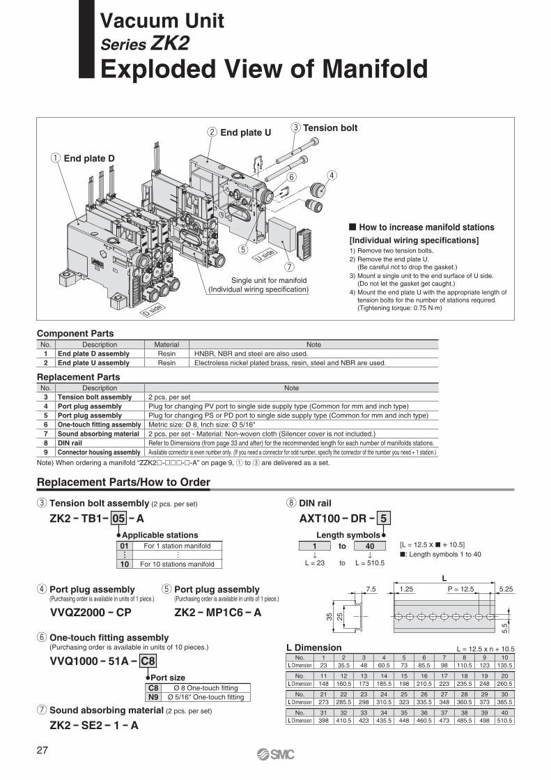
5.5
1.25 P = 12.5 5.257.5
2535
L
End plate D
End plate U Tension bolt
Single unit for manifold (Individual wiring specification)
D side
U side
Replacement Parts/How to Order
e Tension bolt assembly (2 pcs. per set)
ZK2 TB1 A05Applicable stations
u Sound absorbing material (2 pcs. per set)
ZK2 SE2 A1
y One-touch fi tting assembly (Purchasing order is available in units of 10 pieces.)
VVQ1000 51A C8Port size
r Port plug assembly (Purchasing order is available in units of 1 piece.)
VVQZ2000 CP
t Port plug assembly (Purchasing order is available in units of 1 piece.)
ZK2 MP1C6 A
� How to increase manifold stations[Individual wiring specifi cations]1) Remove two tension bolts.2) Remove the end plate U.
(Be careful not to drop the gasket.)3) Mount a single unit to the end surface of U side.
(Do not let the gasket get caught.)4) Mount the end plate U with the appropriate length of
tension bolts for the number of stations required.(Tightening torque: 0.75 N·m)
i DIN rail
AXT100 DR 5
[L = 12.5 x � + 10.5]�: Length symbols 1 to 40
Length symbols
L Dimension L = 12.5 x n + 10.5
Component Parts
Replacement Parts
Note) When ordering a manifold “ZZK2�-���-�-A” on page 9, q to e are delivered as a set.
No. Description Material Note1 End plate D assembly Resin HNBR, NBR and steel are also used.2 End plate U assembly Resin Electroless nickel plated brass, resin, steel and NBR are used.
No. Description Note3 Tension bolt assembly 2 pcs. per set4 Port plug assembly Plug for changing PV port to single side supply type (Common for mm and inch type)5 Port plug assembly Plug for changing PS or PD port to single side supply type (Common for mm and inch type)6 One-touch fi tting assembly Metric size: Ø 8, Inch size: Ø 5/16"7 Sound absorbing material 2 pcs. per set - Material: Non-woven cloth (Silencer cover is not included.)8 DIN rail Refer to Dimensions (from page 33 and after) for the recommended length for each number of manifolds stations.9 Connector housing assembly Available connector is even number only. (If you need a connector for odd number, specify the connector of the number you need + 1 station.)
01 For 1 station manifold
···
···
10 For 10 stations manifold
C8 Ø 8 One-touch fi ttingN9 Ø 5/16" One-touch fi tting
No. 1 2 3 4 5 6 7 8 9 10L Dimension 23 35.5 48 60.5 73 85.5 98 110.5 123 135.5
No. 11 12 13 14 15 16 17 18 19 20L Dimension 148 160.5 173 185.5 198 210.5 223 235.5 248 260.5
No. 21 22 23 24 25 26 27 28 29 30L Dimension 273 285.5 298 310.5 323 335.5 348 360.5 373 385.5
No. 31 32 33 34 35 36 37 38 39 40L Dimension 398 410.5 423 435.5 448 460.5 473 485.5 498 510.5
Vacuum UnitSeries ZK2Exploded View of Manifold
1 to 40↓ ↓
L = 23 to L = 510.5
27

5
43
21
How to remove thejunction box B
Clip in.
The side withsquare holefaces the body.
Square hole
Connector recess
Clip
Protrusion ofjunction box B
Assembled unit
Pump spacer(Part no.: ZK2-SS1-A)
When ordering ejector for pump system, spacer is included.
U side
D side
Valve assembly
Junction box B
Vacuum pressure switch assembly
Connector
Junction box A
Tension bolt
End plate U
Fig. 3-A
Fig. 3Fig. 2
Gasket
Fig. 1
End plate D assembly
Mark tube(Station number indication) Fig. 4
Clip
Clip
D side
U side
Ø d
Ø D
L
A
o Connector housing assembly
ZK2 CH A2 04
Connector type
Applicable stations
[To increase the number of stations from even number to odd number, or increase two stations or more]
� Plug (For One-touch fi tting) (Purchasing order is available in units of 10 pieces.)
Mounted onto ports which are not used (PV, PS, PD, etc.)
KQ2P 06
Model and dimensions
02 For 2 stations manifold04 For 4 stations manifold06 For 6 stations manifold08 For 8 stations manifold10 For 10 stations manifold
1 D sub-connector (25 pins)2 Flat ribbon cable (26 pins)
SymbolApplicable size
Ø dA L Ø D
Weight[g]
Note
06 Ø 6 18 35 8 1 White08 Ø 8 20.5 39 10 2 White07 Ø 1/4" 18 35 8.5 1 Orange09 Ø 5/16" 20.5 39 10 2 Orange
� How to increase manifold stations[To increase the number of stations from odd number (1, 3, 5, 7, 9) in common wiring type to even number (2, 4, 6, 8, 10)](Common wiring of odd number station has a vacant connector for one station. Easy to add a station.)
1) Remove the tension bolt.2) Remove the end plate U.3) Remove the valve assembly of a single unit for extra station(s) for manifold.4) Remove the switch assembly if it is present. (Be careful not
to drop the gasket. Refer to )5) Remove the junction box B (top) using a precision
screwdriver. (Refer to )6) Mount the extra connector to the junction box B. (Refer to
) (Engage the recess of the connector and the protrusion of the junction box B. (Refer to )
7) Mount a single unit for extra station(s) for manifold to the end sur-face of U side. (Do not let the gasket or lead wire get caught.)
8) Mount the end plate U with the appropriate length of tension bolts for the number of stations required. (Tightening torque: 0.75 N·m.)
9) Mount the junction box B to the junction box A.10) Assemble the valve assembly. (Tightening torque: 0.15 N·m)
Fig.1
Fig.2
Fig.3Fig.3-A
1) Remove the valve assembly for all stations. (Single unit for extra station is also removed.)
2) Remove the switch assembly if it is present. (Be careful not to drop the gasket. Refer to )
3) Remove the junction box B (top) for all stations using a precision screwdriver. (Refer to ) (Remove the junction box B from D side.)
4) Remove all connectors mounted to the junction box B. (Be careful not to break the connector clip.)
5) Remove the tension bolt.6) Remove the end plate D assembly.7) Remove the connector housing assembly from the end plate
D assembly. (Refer to )8) Mount the connector housing assembly for extra station(s) to
the end plate D assembly. (Refer to ) (Insert two clips of the housing mounting surface to the square holes of the end plate, and slide the connector housing assembly.)
9) Remove the end plate U. (Be careful not to drop the gasket.)10) Mount a single unit for extra station(s) for manifold to the
end surface of U side. Do not let the gasket get caught.11) Mount the end plate U and D with the appropriate length of tension bolts
for the number of stations required. (Tightening torque: 0.75 N·m.)12) Mount the connector for all stations to the junction box B.
(Refer to ) (Engage the recess of the connector and the protrusion of the junction box B. (Refer to )
13) Mount the junction box A to the junction box B.Push the wires down the side and mount the junction box A to the junction box B following a decreasing mark tube numbers from U side. (Do not let the lead wire get caught.)
14) Assemble the valve assembly. (Tightening torque: 0.15 N·m)
∗ When adding a pump system, the pump spacer for extra station is required separately.
Fig.1
Fig.2
Fig.4
Fig.4
Fig.3Fig.3-A
28
Exploded View of Manifold Series ZK2
Co
nst
ruct
ion
Po
rt L
ayo
ut
Explo
ded V
iew of
Man
ifold
Dim
ensi
on
sSp
ecific
Prod
uct P
recau
tions
Ho
w t
o O
rder
Spec
ifica
tions
/Fl
ow R
ate
Char
acte
ristic
s

E∗2, ∗3
(300
: Lea
d w
ire le
ngth
)
∗4 15
Manual override (Supply valve) 33.5 6
Manual override (Release valve)
B75.6
79.8
E∗1, ∗3
Fully open 10
Suction filter
Locking position
A78.8
38.516.5
19.4
27.57579
2 x Ø 4.5 Mounting hole
Exhaust (EXH) portMetric size: 08 (Ø 8)Inch size: 09 (Ø 5/16")
26.4
10.4
Air pressure supply (PV) port
Vacuum break flowadjusting needle
Hex
agon
wid
th a
cros
s fla
ts C
Vacuum (V) port
3.5
8.4
37.445
.9
15
(300
: Lea
d w
ire le
ngth
)
Manual override (Supply valve) 33.5 6
Manual override (Release valve)
2 x Ø 4.5 Mounting hole
75.6
79.8 B
Fully open 10
8.6
Suction filter78.8
38.5
A16.5
19.4
27.5
8084
Locking position
Pilot pressure supply (PS) portMetric size: Ø 4Inch size: Ø 5/32"
Vacuum pressuresupply (PV) port
Hexa
gon
widt
hac
ross
flat
s C
Vacuum (V) port
3.5
8.4
2.6Pilot pressure exhaust port
Vacuum break flowadjusting needle
37.445
.954.8
∗1
∗5
34.1High-noise reduction silencercase assembly∗6
E Exhaust portFor nozzle size 07, 10: Ø 4For nozzle size 12, 15: Ø 6
For high-noise reduction silencer exhaust
For port exhaust
ZK2 �NL2-��Ejector system, Single unit, With supply valve/release valve, Without pressure sensor/switch
AB
KR
ZK2P00 �NL2-�Vacuum pump system, Single unit, With supply valve/release valve, Without pressure sensor/switch
KR
∗1 For silencer exhaust type, air is exhausted from the slit on both sides. (Do not cover both sides. Release at least one side.)
∗2 For port exhaust type, air is exhausted from the One-touch fi tting.
∗3 Pilot pressure exhaust is common with ejector exhaust.∗5 Nozzle size 12 and 15 have exhaust port.∗6 Refer to page 41 for the part number and maintenance of
the high-noise reduction silencer case assembly.
∗4 Refer to page 32 for dimensions with a mounting bracket.
∗1 Refer to page 32 for dimensions with a mounting bracket.
Dimensions: Single Unit
PV port type BMetric size 06 Ø 6 9.7Inch size 07 Ø 1/4" 12.3
V port type A CMetric size
06 Ø 6 8.25 408 Ø 8 11.4 6
Inch size
07 Ø 1/4" 10.8 4.7609 Ø 5/16" 11.4 6
PV port type BMetric size 06 Ø 6 9.7Inch size 07 Ø 1/4" 12.3
V port type A CMetric size
06 Ø 6 8.25 408 Ø 8 11.4 6
Inch size
07 Ø 1/4" 10.8 4.7609 Ø 5/16" 11.4 6
29
Series ZK2

E∗2, ∗3
E∗2
(300
: Lea
d w
ire le
ngth
)
15
Locking position
Suction filter
A78.8
38.516.5
19.4
27.57579
2 x Ø 4.5 Mounting holeE∗1,∗3
B75.6
79.8
Manual override (Supply valve)
Exhaust (EXH) portMetric size: 08 (Ø 8)Inch size: 09 (Ø 5/16")
26.4
10.4Air pressure supply (PV) port
Vacuum (V) port
Hex
agon
wid
th a
cros
s fla
ts C
8.445
.9
26.4
Exhaust (EXH) portMetric size: 08 (Ø 8)Inch size: 09 (Ø 5/16")
10.4
Locking position
∗4
15∗3
27.5
19.4
56.9
16.5 38.5
78.8 A
Suction filter
2 x Ø 4.5 Mounting hole
72.8 B E∗1
Hex
agon
wid
th a
cros
s fla
ts C
8.445
.9(58.
2)
Air pressure supply (PV) port
Vacuum (V) port
∗5
∗4
39.5
34.1High-noise reduction silencer case assembly∗6
E Exhaust portFor nozzle size 07, 10: Ø 4For nozzle size 12, 15: Ø 6
For high-noise reduction silencer exhaust
For port exhaust
High-noise reduction silencer case assembly∗5
34.1
E Exhaust portFor nozzle size 07, 10: Ø 4For nozzle size 12, 15: Ø 6
For high-noise reduction silencer exhaust
For port exhaust
ZK2 �J�NL2-�Ejector system, Single unit, With supply valve, Without pressure sensor/switch
AB
ZK2 �N0NN-�Ejector system, Single unit, Without valve, Without pressure sensor/switch
AB
∗1 For silencer exhaust type, air is ex-hausted from the slit on both sides. (Do not cover both sides. Release at least one side.)
∗2 For port exhaust type, air is exhaust-ed from the One-touch fi tting.
∗4 Nozzle size 12 and 15 have exhaust port.∗5 Refer to page 41 for the part number
and maintenance of the high-noise reduction silencer case assembly.
∗3 Refer to page 32 for dimensions with a mounting bracket.
∗4 Refer to page 32 for dimensions with a mounting bracket.
Dimensions: Single Unit
PV port type BMetric size 06 Ø 6 9.7Inch size 07 Ø 1/4" 12.3
V port type A CMetric size
06 Ø 6 8.25 408 Ø 8 11.4 6
Inch size
07 Ø 1/4" 10.8 4.7609 Ø 5/16" 11.4 6
PV port type BMetric size 06 Ø 6 9.7Inch size 07 Ø 1/4" 12.3
V port type A CMetric size
06 Ø 6 8.25 408 Ø 8 11.4 6
Inch size
07 Ø 1/4" 10.8 4.7609 Ø 5/16" 11.4 6
∗1 For silencer exhaust type, air is ex-hausted from the slit on both sides. (Do not cover both sides. Release at least one side.)
∗2 For port exhaust type, air is exhaust-ed from the One-touch fi tting.
∗3 Pilot pressure exhaust is common with ejector exhaust.
∗5 Nozzle size 12 and 15 have exhaust port.∗6 Refer to page 41 for the part number
and maintenance of the high-noise re-duction silencer case assembly.
30
Vacuum Unit Series ZK2
Co
nst
ruct
ion
Po
rt L
ayo
ut
Explo
ded V
iew of
Man
ifold
Dim
ensi
on
sSp
ecific
Prod
uct P
recau
tions
Ho
w t
o O
rder
Spec
ifica
tions
/Fl
ow R
ate
Char
acte
ristic
s

(300
: Lea
d w
ire le
ngth
)
15
Manual override (Supply valve) 33.5 6
Manual override (Release valve)
E∗1, ∗3
Fully open 10
Suction filter
A94.2
38.516.5
19.4
27.5
38.7
75
9.9
75.6
79.8 B
2 x Ø 4.5 Mounting hole
Exhaust (EXH) portMetric size: 08 (Ø 8)Inch size: 09 (Ø 5/16")
26.4
10.4
Air pressure supply(PV) port
Vacuum (V) port3.5
8.4
37.445
.9
79
Suction filter
∗4
Connector terminal
LED display
33.5 6
26.4
10.4
Hex
agon
wid
th a
cros
s fla
ts C
3.5
8.437
.445.9
79.8
75.6
2 x Ø 4.5 Mounting hole
B
15∗3
1.1 104 A16.5 38.5
79 75
57.6 27
.519
.4
Fully open 10
89
�button (DOWN)
�button (UP)
S button (SET)
OUT1 display (Green)
OUT2 display (Red)
(30)
Manual override (Supply valve)
Manual override (Release valve)
E∗1, ∗4
(200
0: L
ead
wire
leng
th)
Vacuum (V) port
(300
: Lea
d w
ire le
ngth
)
Exhaust (EXH) portMetric size: 08 (Ø 8)Inch size: 09 (Ø 5/16")
Air pressure supply(PV) port
Vacuum break flowadjusting needle
34.1High-noise reductionsilencer case assembly∗6
High-noise reductionsilencer case assembly∗6
E Exhaust portFor nozzle size 07, 10: Ø 4For nozzle size 12, 15: Ø 6
For high-noise reduction silencer exhaust
34.1
E Exhaust portFor nozzle size 07, 10: Ø 4For nozzle size 12, 15: Ø 6
For high-noise reduction silencer exhaust
∗5
∗5
Hexa
gon w
idth a
cross
flats
C
E∗2, ∗3
For port exhaust
E∗2, ∗4
For port exhaust
(300
0: L
ead
wire
leng
th)
Vacuum break flowadjusting needle
ZK2 L-��Ejector system, Single unit, With supply valve/release valve, With pressure sensor
AB �K
RPT
ZK2 � ��L-�
Ejector system, Single unit, With supply valve/release valve, With pressure switch
KR
AB
∗1 For silencer exhaust type, air is exhausted from the slit on both sides.(Do not cover both sides. Release at least one side.)
∗2 For port exhaust type, air is exhausted from the One-touch fi tting.∗3 Pilot pressure exhaust is common with ejector exhaust.∗4 Refer to page 32 for dimensions with a mounting bracket.∗5 Nozzle size 12 and 15 have exhaust port.∗6 Refer to page 41 for the part number and maintenance of the high-noise reduction silencer case assembly.
∗1 For silencer exhaust type, air is exhausted from the slit on both sides. (Do not cover both sides. Release at least one side.)∗2 For port exhaust type, air is exhausted from the One-touch fi tting.∗3 Pilot pressure exhaust is common with ejector exhaust.∗4 Refer to page 32 for dimensions with a mounting bracket.∗5 Nozzle size 12 and 15 have exhaust port.∗6 Refer to page 41 for the part number and maintenance of the high-noise reduction silencer case assembly.
A to J
Dimensions: Single Unit
V port type A CMetric size
06 Ø 6 8.25 408 Ø 8 11.4 6
Inch size
07 Ø 1/4" 10.8 4.7609 Ø 5/16" 11.4 6
PV port type BMetric size 06 Ø 6 9.7Inch size 07 Ø 1/4" 12.3
PV port type BMetric size 06 Ø 6 9.7Inch size 07 Ø 1/4" 12.3
V port type A CMetric size
06 Ø 6 8.25 408 Ø 8 11.4 6
Inch size
07 Ø 1/4" 10.8 4.7609 Ø 5/16" 11.4 6
31
Series ZK2

Co
nst
ruct
ion
Po
rt L
ayo
ut
Explo
ded V
iew of
Man
ifold
Dim
ensi
on
sSp
ecific
Prod
uct P
recau
tions
Ho
w t
o O
rder
Spec
ifica
tions
/Fl
ow R
ate
Char
acte
ristic
s
M4 Nut
M4 x 20
∗
14.5
55.826.515
46.4
18.
9
2 x Ø 4.6
33.5
With bracket
∗ Mounting bracket for single unit (Option), [Nuts and bolts are included.] Part number: ZK2-BK1-A
Dimensions: Single Unit
32
Vacuum Unit Series ZK2

A
C
D
L4
L1L2L3
B
PS and PD portdimensions ∗1,∗4
U sideD side Number of stations n2 31
75 (Ejector system)80 (Vacuum pump system)3.8
10 1.3
(75.
6)
Ful
ly o
pen
10
(54.
8)DIN rail mounting bracketOption symbol (-B)∗5
2 x Common pilot pressure supply (PS) port ∗1
12.8
10.5
88.870
5.5
5
1.5
6
(5.3)
(L6)
(L5)
DIN rail clamping screw (When Option -B is selected)∗5
4 x M4 Mounting hole
Manual override (Release valve)
Manual override (Supply valve)
32(5
.5)
(35)
(App
rox.
300
: Lea
d w
ire le
ngth
)
79 (
Eje
ctor
sys
tem
)84
(V
acuu
m p
ump
syst
em)
Vacuum break flowadjusting needle
n x Vacuum (V) port(Built-in suction filter)
10.5
8.4
62
5337
.4
26.4
33
3.5
(n−1) x 1515
n x Individual exhaust (EXH) port ∗3
2 x Common exhaust (EXH) port ∗2
2 x Common supply (PD) port ∗4
Inch size: 2 x Ø 5/16"
Metric size: 2 x Ø 8
Common supply (PV) port
1
38
Individual exhaust port ∗6
∗1 Common pilot pressure supply port is available for vacuum pump system or option L (Manifold individual supply specifi cation). (mm: Ø 6 inch: Ø 1/4")∗2 Pump system with individual exhaust port type does not have exhaust port.∗3 When individual exhaust port type is selected (Body type: F)∗4 Only when common PD port type option (Symbol: -D) is selected (mm: Ø 6 inch: Ø 1/4")∗5 To fi x the manifold to DIN rail, select an option for the manifold model number.∗6 For complex exhaust type, air is also exhausted from the individual exhaust port of each station in addition to the common exhaust. (Ejector system)
Ejector system, Vacuum pump system, Individual wiring manifold, With supply valve/release valve, Without pressure sensor/switch
[mm]
Dimensions: Manifold Individual Wiring
Port type A Hexagon widthacross fl ats B C D
Metricsize
06 8.3 4 9.7 8.708 11.4 6 — —
Inchsize
07 10.8 4.76 12.3 11.309 11.4 6 — —
Number ofstations 1 2 3 4 5 6 7 8 9 10
L1 30 45 60 75 90 105 120 135 150 165L2 45 60 75 90 105 120 135 150 165 180L3 56.8 71.8 86.8 101.8 116.8 131.8 146.8 161.8 176.8 191.8L4 67.5 82.5 97.5 112.5 127.5 142.5 157.5 172.5 187.5 202.5L5 62.5 75 87.5 112.5 125 137.5 150 162.5 187.5 200L6 73 85.5 98 123 135.5 148 160.5 173 198 210.5
ZZK2 -PA L
33
Series ZK2

D
C
A
L1L2L3
L4
B
PS and PD portdimensions ∗1,∗4
DIN rail mounting bracketOption symbol (-B)∗5
3.8
10
38.7 (Approx. 3000: Lead wire length)
(99)
(54.
8)
Ful
ly o
pen
10Manual override (Release valve)
Manual override (Supply valve)
(5.5
)
(35)
6
32
1.52 x Common pilot pressure supply (PS) port ∗1
5
5.5
DIN rail clamping screw(When Option -B is selected)∗5
4 x M4 Mounting hole
15.4
12.8
10.5
88.870
(L6)
(L5)
(5.3)
U sideD side Number of stations n2 31
2 x Common supply (PD) port ∗4
Inch size: 2 x Ø 5/16"
Metric size: 2 x Ø 8
Common supply (PV) port
1
n x Individual exhaust (EXH) port ∗3
2 x Common exhaust (EXH) port ∗2
(n−1) x 15
3.5
33
3638
15
10.5
8.4
Vacuum break flowadjusting needle
75 (E
ject
or s
yste
m)
80 (
Vac
uum
pum
p sy
stem
)
62
53
37.4
26.4
n x Vacuum (V) port(Built-in suction filter)
Individual exhaust port ∗6
∗1 Common pilot pressure supply port is available for vacuum pump system or option L (Manifold individual supply specifi cation). (mm: Ø 6 inch: Ø 1/4")∗2 Pump system with individual exhaust port type does not have exhaust port.∗3 When individual exhaust port type is selected (Body type: F)∗4 Only when common PD port type option (Symbol: -D) is selected (mm: Ø 6 inch: Ø 1/4")∗5 To fi x the manifold to DIN rail, select an option for the manifold model number.∗6 For complex exhaust type, air is also exhausted from the individual exhaust port of each station in addition to the common exhaust. (Ejector system)
Ejector system, Vacuum pump system, Common wiring manifold, With supply valve/release valve, With pressure sensor
[mm]
Dimensions: Manifold D-sub Connector
Port type A Hexagon widthacross fl ats B C D
Metricsize
06 8.3 4 9.7 8.708 11.4 6 — —
Inchsize
07 10.8 4.76 12.3 11.309 11.4 6 — —
Number ofstations 1 2 3 4 5 6 7 8 9 10
L1 30 45 60 75 90 105 120 135 150 165L2 45 60 75 90 105 120 135 150 165 180L3 56.8 71.8 86.8 101.8 116.8 131.8 146.8 161.8 176.8 191.8L4 73.5 88.5 103.5 118.5 133.5 148.5 163.5 178.5 193.5 208.5L5 75 100 112.5 125 137.5 150 175 187.5 200 212.5L6 85.5 110.5 123 135.5 148 160.5 185.5 198 210.5 223
ZZK2 -PA F
34
Vacuum Unit Series ZK2
Co
nst
ruct
ion
Po
rt L
ayo
ut
Explo
ded V
iew of
Man
ifold
Dim
ensi
on
sSp
ecific
Prod
uct P
recau
tions
Ho
w t
o O
rder
Spec
ifica
tions
/Fl
ow R
ate
Char
acte
ristic
s

2 x Common pilot pressure supply (PS) port ∗1
DIN rail clamping screw(When Option -B is selected)∗5
4 x M4 Mounting hole
2 x Common exhaust(EXH) port ∗2
2 x Common supply (PD) port ∗4
Inch size: 2 x Ø 5/16"
Metric size: 2 x Ø 8
Common supply (PV) port
n x Vacuum (V) port(Built-in suction filter)
Vacuum break flowadjusting needle
75 (E
ject
or s
yste
m)
80 (
Vac
uum
pum
p sy
stem
)
Manual override (Release valve)
Manual override (Supply valve)
n x Individual exhaust port ∗7
PS and PD portdimensions ∗1, ∗4
1.5L1L2L3
L455.5
6
(5.5
)
(35)
32
26.3
88.870
12.8
10.5
(L6)
(L5)
(5.3)
8.4
B
62
53
37.4
26.4
1
3638
∗3
(n−1) x 15
3.5
15 33
10.5
D
C
A
DIN rail mounting bracketOption symbol (-B)∗5
3.8
10
57.6 Approx. 2000: Lead wire length
(30)
∗6
Ful
ly o
pen
10
(54.
8)
(99)
U sideD side Number of stations n2 31
Triangle mark
ZZK2 -PA P
∗1 Common pilot pressure supply port is available for vacuum pump system or option L (Manifold individual supply specifi cation). (mm: Ø 6 inch: Ø 1/4")∗2 Pump system with individual exhaust port type does not have exhaust port.∗3 When individual exhaust port type is selected (Body type: F)∗4 Only when common PD port type option (Symbol: -D) is selected (mm: Ø 6 inch: Ø 1/4")∗5 To fi x the manifold to DIN rail, select an option for the manifold model number.∗6 Applicable connector: Connector for fl at ribbon cable (26P)(MIL-C-83503 compliant)∗7 For complex exhaust type, air is also exhausted from the individual exhaust port of each station in addition to the common exhaust. (Ejector system)
Ejector system, Common wiring manifold, With supply valve/release valve, With pressure switch
[mm]
Dimensions: Manifold Flat Ribbon Cable
Port type A Hexagon widthacross fl ats B C D
Metricsize
06 8.3 4 9.7 8.708 11.4 6 — —
Inchsize
07 10.8 4.76 12.3 11.309 11.4 6 — —
Number ofstations 1 2 3 4 5 6 7 8 9 10
L1 30 45 60 75 90 105 120 135 150 165L2 45 60 75 90 105 120 135 150 165 180L3 56.8 71.8 86.8 101.8 116.8 131.8 146.8 161.8 176.8 191.8L4 73.5 88.5 103.5 118.5 133.5 148.5 163.5 178.5 193.5 208.5L5 75 100 112.5 125 137.5 150 175 187.5 200 212.5L6 85.5 110.5 123 135.5 148 160.5 185.5 198 210.5 223
35
Series ZK2

Symbol Type Function/Application
B With one bracket for mounting a single unit(Mounting screw is attached.)
• Use when a single unit is mounted to the fl oor in an upright position is requested. (When ordering only bracket, refer to page 32.)
C Pump system PE port female thread specifi cation
• Use for pilot pressure exhaust piping (Standard pump system is released to the atmosphere.)
D With individual release pressure supply (PD) port
• Use when supply pressure for vacuum release which pressure is different from the ejector supply pressure is requested.
JVacuum break fl ow adjusting needleRound lock nut type
• Thicker than standard hexagon type. More suitable for hand tightening.
• Round lock nut improves operability when manifold, pump system, or exhaust port type is used.
K Vacuum break fl ow adjusting needleScrewdriver operation type
• Slotted type improves fi ne adjustment performance when manifold, pump system, or exhaust port type is used.
L Manifold individualsupply specifi cation
• Adjust the supply pressure individually for manifold in order to adjust the vacuum pressure reached by each ejector.
P Manifold common releasepressure supply specifi cation
• When selecting “D” (with common release pressure supply (PD) port) for manifold option, supplying a pressure which is different from for common PV to common PD is requested.
W With exhaust interferenceprevention valve
• When ejectors are operated individually, ex-hausted air may fl ow backward from the V port of ejectors that are turned off. Exhaust interfer-ence prevention valve prevents backfl ow.
Electrical Wiring Specifi cations
Optional Specifi cations/Functions/Applications
D-sub Connector Flat Ribbon Cable Connector
(∗) The valve installed onto the product is non-polar type.Can be used as negative common.
(∗) The valve installed onto the product is non-polar type.Can be used as negative common.
A D-sub connector (25P) conforming to MIL standards is used.
A fl at ribbon cable connector (26P) conforming to MIL standards is used.
Polarity
(–)(–)(–)(–)(–)(–)(–)(–)(–)(–)(–)(–)(–)(–)(–)(–)(–)(–)(–)(–)
(+)(+)
Release valveSupply valveRelease valveSupply valveRelease valveSupply valveRelease valveSupply valveRelease valveSupply valveRelease valveSupply valveRelease valveSupply valveRelease valveSupply valveRelease valveSupply valve
Triangle mark indicator position
Connector terminal no.Terminalnumber
10 stations
9 stations
8 stations
7 stations
6 stations
5 stations
4 stations
3 stations
2 stations
1 station(+)(+)(+)(+)(+)(+)(+)(+)(+)(+)(+)(+)(+)(+)(+)(+)(+)(+)(+)(+)
(–)(–)
6
4
26
24
22
20
18
16
14
12
10
8
2
25
23
21
19
17
15
13
11
9
7
5
3
1
COM. 26
COM. 25
242322212019181716151413121110987654321
Release valveSupply valve
( ) Negative common specification
Positive common specification
Polarity
(–)(–)(–)(–)(–)(–)(–)(–)(–)(–)(–)(–)(–)(–)(–)(–)(–)(–)(–)(–)
(+)
Release valveSupply valveRelease valveSupply valveRelease valveSupply valveRelease valveSupply valveRelease valveSupply valveRelease valveSupply valveRelease valveSupply valveRelease valveSupply valveRelease valveSupply valve
Terminalnumber
10 stations
9 stations
8 stations
7 stations
6 stations
5 stations
4 stations
3 stations
2 stations
1 station(+)(+)(+)(+)(+)(+)(+)(+)(+)(+)(+)(+)(+)(+)(+)(+)(+)(+)(+)(+)
(–)
24
25
14
15
16
17
18
19
20
21
22
23
1
2
3
4
5
6
7
8
9
10
11
12
13
COM. 13
251224112310229218207196185174163152141
Release valveSupply valve
Connector terminal no.
Positive common specification( ) Negative common specification
Bracket
Vacuum break flow adjusting needle
Vacuum break flow adjusting needle
PE port
PD port
Exhaust interference prevention valve
Individual supply port
36
Vacuum Unit Series ZK2
Co
nst
ruct
ion
Po
rt L
ayo
ut
Explo
ded V
iew of
Man
ifold
Dim
ensi
on
sSp
ecific
Prod
uct P
recau
tions
Ho
w t
o O
rder
Spec
ifica
tions
/Fl
ow R
ate
Char
acte
ristic
s

Cable0.3 mm2 x 25 pinsO.D. Ø 1.4
Seal (Length)
ConnectorDB-25SF-NJapan AviationElectronics Industry, Ltd.
Socket side
Terminal no.
Ø 10
47.04
55
1644
8(2
.4)
L
1···············13
14···············25
Molded cover
2 x M2.6 x 0.45
015
6
(15.6)
LTerminal no.
Red
28AWG
37.5
(26
P)
262
251
D-sub Connector
D-sub connectorcable assembly
Wire Color byTerminal Number
D-sub Connector Cable Assembly (Option)
∗For other commercial connectors, use a 25-pin type with female connector conforming to MIL-C-24308.
∗Cannot be used for movable wiring.
Note) The minimum bending inner radius of D-sub connector cable is 20 mm.
Electrical Characteristics Connector manufacturers’example
• Fujitsu Limited• Japan Aviation Electronics
Industry, Ltd.• J.S.T. Mfg. Co., Ltd.• Hirose Electric Co., Ltd.
Flat Ribbon Cable Connector
Flat Ribbon Cable Connector Assembly (Option)
∗For other commercial connectors, use a 26-pin type with strain relief conforming to MIL-C-83503.
∗Cannot be used for movable wiring.
Connector manufacturers’ example
• Hirose Electric Co., Ltd.• Sumitomo 3M Limited • Fujitsu Limited
• Japan Aviation Electronics Industry, Ltd.• J.S.T. Mfg. Co., Ltd.• Oki Electric Cable Co., Ltd.
Cable Assembly
Terminalnumber
Lead wirecolour
Dotmarking
1 Black None2 Brown None3 Red None4 Orange None5 Yellow None6 Pink None7 Blue None8 Purple White9 Grey Black10 White Black11 White Red 12 Yellow Red 13 Orange Red 14 Yellow Black15 Pink Black16 Blue White17 Purple None18 Grey None19 Orange Black20 Red White21 Brown White22 Pink Red 23 Grey Red 24 Black White25 White None
Cablelength (L) Assembly part number Note
1.5 m AXT100-DS25-015 Cable0.3 mm2 x 25 cores
3 m AXT100-DS25-0305 m AXT100-DS25-050
Item PropertyConductor resistance
Ω/km, 20 °C65 or less
Voltage limitV, 1 min, AC 1000
Insulation resistance
MΩ/km, 20 °C5 or more
Cablelength (L)
Assembly part number26P
1.5 m AXT100-FC26-13 m AXT100-FC26-25 m AXT100-FC26-3
AXT100-DS25-015030050
AXT100-FC26-123
37
Series ZK2

Release valvemanual overrideGreen
Supply valve manual overrideOrange
Ø 3.2
Release valveSOL.b
Supply valveSOL.a
LED light position
Release valveSOL.b
Supply valveSOL.a
LED light position
Valve assembly
UUU
Plug lead type
Plug-in type
LED (Red)
LED (Green)
Supply valve
Release valve
Coil
Coil
LED (Red)
Supply valve Coil
Lead wire: RedC [COM](+, −)
A [SOL.a](−, +)Lead wire: Black
Lead wire: WhiteB [SOL.b](−, +)
Lead wire: RedC [COM](+, −)
Lead wire: BlackA [SOL.a](−, +)
Double solenoid (With release valve)Single solenoid (Without release valve)
Supply Valve / Release Valve Supply Valve / Release Valve
Warning Warning1. Manual override operation
• Manual override is non-locking push type. Push the manual override with a screwdriver of a diameter smaller than indicated in the diagram until it reaches the end.
• Confirm that the product operates safely before the manual override is operated.
Note) When operation of the linked type supply and release valves is selected, the supply valve can hold the position and will not switch off even if the supply valve manual override operation is fi nished unless the release valve manual override is pressed.
2. Self-holding function of supply valveFor valve assemblies where the supply and release valves are linked the supply valve is a self-holding type. Instanta-neous energisation (20 ms or more) of the supply valve allows the supply valve to hold. Continuous energisation is not necessary. Energise the release valve to turn the supply valve off.Note 1) Main valve in the valve assembly is made of elastic seal.
Self-holding is performed by friction resistance of the seal. Do not apply impact resistance in the direction of the main valve shaft during the installation to moving parts. When the self-holding valve is applied with impact, energise it continuously, or use K type. (Refer to Combination of Supply Valve and Release Valve on pages 5 and 7.) (Vibration and impact should be 50 m/s2 or less.)
Note 2) Self-holding type valve cannot use a digital switch for vacuum with energy saving function.
3. Default settingWhen the valve assembly is delivered, the supply valve is on the OFF position, but it may be on the ON position due to the vibration or impact during transportation or device installation. Turn to the OFF position manually or by ener-gising before use.
4. Wiring specifi cations and light/surge voltage suppressorWiring should be connected as shown below. Connect with the power supply respectively. (Solenoid valve is non-polar type.)
Light/surge voltage suppressor circuit is equipped for both single and double solenoid. Red LED turns on when supply valve (SOL.a) is energised. Green LED turns on when release valve (SOL.b) is energised.
5. Continuous dutyIf a supply valve/release valve is energised continuously for a long time, the rise in temperature due to heat-up of the coil may cause a decline in solenoid valve perfor-mance, reduce service life, or have adverse effects on peripheral equipment. When the energising time per day is longer than non-energising time, use self-holding linked type valve using instantaneous energising.
Be sure to read this before handling. Refer to the back cover for Safety Instructions. For Vacuum Equipment Precautions, refer to “Handling Precautions for SMC Products” and the Operation Manual on the SMC website, http://www.smc.eu
Series ZK2Specifi c Product Precautions 1
38
Co
nst
ruct
ion
Po
rt L
ayo
ut
Explo
ded V
iew of
Man
ifold
Dim
ensi
on
sSp
ecific
Prod
uct P
recau
tions
Ho
w t
o O
rder
Spec
ifica
tions
/Fl
ow R
ate
Char
acte
ristic
s

Lever
Lever clip
Mating part
Connector
Cover
For doubleFor single
Red
Black
Red
White
Black
A B
Filter element
Vacuum port adapter
Mating mark
Lower face
Wid
th a
cros
s fla
ts
Gap Bending
Plug Connector
Suction Filter
Caution1. Installation/Removal of connector
• To install the connector, hold the cover and insert the connector straight pushing the connector lever with your fi nger. Ensure that the connector lever clip is properly inserted onto mating part.
• To remove the connector, hold the cover and pull out the connector straight pushing the connector lever clip.
2. Part number of connector assembly and lead wire lengthThe standard lead wire length for the connector assembly is 300 mm. For other lengths, refer to the table below.
ZK2-LVS�-A Connector assembly for single(For with supply valve, no release valve)
ZK2-LVW�-A Connector assembly for double (For with both supply valve and release valve)
Note) Do not pull the lead wire with a force of 25 N or more, as this may damage the connector or cover.
Note) When ordering, put the connector assembly part number to the prod-uct part number without connector.
1. Replacement procedure for fi lter element• To pull out the vacuum port adapter, rotate the adapter
by about 90 degrees in direction A and pull in direction B. The adapter can be removed with the suction fi lter from the fi lter case.
• Remove the suction fi lter from the vacuum port adapter and replace it with a new suction fi lter.
• When installing the fi lter, insert the fi lter to the end so that there is no gap or bending between the fi lter and the vacuum port adapter. The gap or bending will cause the element to deform inside the case.
• Put the fi lter back into the fi lter case following this proce-dure in reverse.
• To mount the vacuum port adapter into the fi lter case, turn the adapter so that the mating mark of the adapter and the case are aligned. (Rotation stops there.)
• If it is diffi cult to remove the vacuum port adapter, you can remove the adapter with a hexagon wrench using the hexagonal hole in V port. The table shows the port size and the width across fl ats.
Caution CautionThe surge voltage created when the power supply is cut off could apply to the de-energised load equipment through the output circuit. In cases where the energised load equipment has a larger capacity (power consumption) and is connected to the same power supply as the product, the surge voltage could malfunction and/or damage the internal circuit element of the product and the internal device of the output equipment. To avoid this situation, place a diode which can suppress the surge voltage between the COM lines of the load equipment and output equipment.
Be sure to read this before handling. Refer to the back cover for Safety Instructions. For Vacuum Equipment Precautions, refer to “Handling Precautions for SMC Products” and the Operation Manual on the SMC website, http://www.smc.eu
— 300 mm6 600 mm10 1000 mm20 2000 mm30 3000 mm
V port size Width across fl atsØ 6 4
Ø 8, Ø 5/16" 6Ø 1/4" 4.76
Surge Voltage Intrusion
Series ZK2Specifi c Product Precautions 2
39

Release lever
GrooveBody
Filter case
Body gasket B Check valve
Body
D
Hook A C Hook B
Exhaust slit(On both sides)
Release leverClip hole
Notch
A
Ejector Exhaust
Caution2. Filter case maintenance
• When the filter case is dirty, it can be removed and cleaned.To remove the fi lter case, insert a precision screwdriver into the groove of the release lever and push in direction (q), and slide the fi lter case in direction (w).
Note) Surface A of the fi lter case is the seal-ing surface when vacuum is generated. Handle with care so that the surface is not scratched or damaged.
Note) Filter case is made of polycarbonate. Avoid chemicals such as thinner, carbon tetrachloride, chloroform, acetic ester, aniline, cyclohexane, trichloroethylene, sulfuric acid, lactic acid, water base cutting fl uid (alkaline).
Note) Do not expose the fi lter case to direct sunlight for a long period of time.
• Put the fi lter case back into the ejector by the following procedure.
1) Make sure that body gasket (B) and the check valve are installed correctly onto the ejector. If they are out of the place, vacuum leakage may occur.
2) Push the fi lter case in direction (q). Be careful the fi lter case hook (A) and hook (B) do not touch the body of the ejector.
3) Slide the fi lter case in direction (w) while pushing the fi lter case gently in contact with the ejector. Make sure that the clip (C) is locked and there is no gap in part (D).
Note) If excess force is applied to the fi lter case, hook A and B may break. Handle with care.
• The exhaust resistance should be as small as possible to obtain the full ejector performance. There should be no shield around the exhaust slit for silencer exhaust type. When the product is installed, one of the ports should be open to atmosphere.
For port exhaust type, back pressure may increase depending on the piping size and length. Ensure that the back pressure does not exceed 0.005 MPa (5 kPa).In addition, the exhaust port should not be blocked or pressurised.
• If the sound absorbing material is clogged, it will cause a reduction in the ejector performance.Sometimes, if the operating environment contains a lot of particles or mist, the replacement of the fi lter element only is not enough to recover vacuum performance - as the sound absorbing material may be clogged. Replace the sound absorbing material. (Regular replacement of the filter element and sound absorbing material is recommended.)
Replacement Procedure for Sound Absorbing Material (for Silencer Exhaust)
1) Remove the filter case following the procedure of filter case maintenance.
2) Flip the ejector, push the release lever again with a fi nger or precision screwdriver until the release lever stops.
Suction Filter
Caution
Be sure to read this before handling. Refer to the back cover for Safety Instructions. For Vacuum Equipment Precautions, refer to “Handling Precautions for SMC Products” and the Operation Manual on the SMC website, http://www.smc.eu
Series ZK2Specifi c Product Precautions 3
40
Co
nst
ruct
ion
Po
rt L
ayo
ut
Explo
ded V
iew of
Man
ifold
Dim
ensi
on
sSp
ecific
Prod
uct P
recau
tions
Ho
w t
o O
rder
Spec
ifica
tions
/Fl
ow R
ate
Char
acte
ristic
s

Projection
Projection
Clip hole
Release lever
Diffuser I.D.
Sound absorbingmaterial Projection of diffuser
Clip
Port plug
For nozzle size 12, 15For nozzle size 07, 10
64
High-noise reduction silencer case assemblyPart number: ZK2-SC3- -A
Cap
Notch
Sound absorbing materialPart number: ZK2-SE3-6-A(5 pcs. per set)
Diffuser hole viewed from the port plug
3) To remove the clip that holds the port plug, insert a precision screwdriver from the release lever notch. Move the screwdriver in direction (q) to pull out the clip in direction (w).
4) Remove the port plug. Slide back the release lever.
5) Remove the sound absorbing material from the slit (hole) at the side of the body by using a precision screwdriver.
6) Insert the new sound absorbing material. Be careful not to scratch the material with the projection of the diffuser assembly.
(Procedure to put parts back together)7) Insert the port plug.
8) Push the release lever until it stops. Insert the clip into the groove using the lever hole. (Push completely to the end.)Note) Do not pull or bend the two projections at the end surface of the
diffuser. These are spacers to prevent the displacement of the diffuser and they may break if force is applied.
Ejector Exhaust
Caution
Be sure to read this before handling. Refer to the back cover for Safety Instructions. For Vacuum Equipment Precautions, refer to “Handling Precautions for SMC Products” and the Operation Manual on the SMC website, http://www.smc.eu
Series ZK2Specifi c Product Precautions 4
Replacement Procedure for High-noise Reduction Silencer Case Assembly
CautionRefer to the replacement procedure of the sound absorbing material (silencer exhaust) to replace the assembly.Note) When a high-noise reduction silencer case assembly is attached to body
type “A” (silencer exhaust), the silencing effect cannot be acquired.
When only replacing the sound absorbing material (for high-noise reduction silencer exhaust)1) Use the notch to remove the cap.2) Use a precision screwdriver to remove the sound absorbing material.3) Insert the new sound absorbing material, and return the cap.
Operating Supply Pressure
Caution• Use the product within the specifi ed supply pressure range.
Operation over the maximum operating pressure can cause damage to the product.The parts around the vacuum port of this product are designed to be used with vacuum pressure. With the vacuum pump system, since air is not released to the atmosphere from a silencer, the applied air for vacuum release increases the internal pressure of the vacuum port. Select the vacuum pad which shape allows smooth exhaust of release air to the atmosphere and avoid clogging.
41

M4 Nut
M4 x 20
Stopper bracket (1 pc.)Part number: TXE1-SMC
Pressure range of the noise
Peak vacuum pressure
Vac
uum
pre
ssur
e
Standard supply pressure0
Supply pressure
How to Mount a Single Unit
Caution1. Single unit can be mounted to DIN rail or wall
using the holes in the body (2 x Ø 4.5).• When mounting the ejector to DIN rail, unlock the fi lter
case assembly beforehand. (Refer to the maintenance procedure on page 40.)
• Hook the ejector onto the DIN rail from direction (q).• Mount the ejector onto the DIN rail by pushing it down in
direction (w).• Push the fi lter case assembly in direction (e) until it is
locked.
2. To mount a single unit onto the floor, use the optional bracket.
• To hold the ejector onto the DIN rail, hold it from both sides using the stopper brackets.
∗ Mounting bracket for single unit (Option), [Nuts and bolts are included.] Part number: ZK2-BK1-A
Be sure to read this before handling. Refer to the back cover for Safety Instructions. For Vacuum Equipment Precautions, refer to “Handling Precautions for SMC Products” and the Operation Manual on the SMC website, http://www.smc.eu
Series ZK2Specifi c Product Precautions 5
Exhaust Noise
Caution• When vacuum ejector generates vacuum, noise can be
heard from the exhaust port when the standard supply pressure is close to the pressure that generates peak vacuum pressure making vacuum pressure unstable. If the vacuum pressure range is adequate for adsorption, there should not be a problem. If the noise causes a problem or affects the setting of the pressure switch, change the supply pressure slightly to avoid the pressure range of the noise.
Port Size of Single Unit
Caution• Port size
— : Not applicable
∗1) Piping for PE port is available as an option. (Refer to page 8.)
∗2) A model with PD port is available as an option. (Refer to pages 6 and 8.)
PortSize
Ejector System Vacuum Pump SystemMetric Inch Metric Inch
PV Ø 6 Ø 1/4" Ø 6 Ø 1/4"V Ø 6, Ø 8 Ø 1/4", Ø 5/16" Ø 6, Ø 8 Ø 1/4", Ø 5/16"
EXH(Port exhaust) Ø 8 Ø 5/16" — —
PE EXH Common Port open to atmosphere ∗1)
PS — — Ø 4 Ø 5/32"PD ∗2) M3 — M3 —
42
Co
nst
ruct
ion
Po
rt L
ayo
ut
Explo
ded V
iew of
Man
ifold
Dim
ensi
on
sSp
ecific
Prod
uct P
recau
tions
Ho
w t
o O
rder
Spec
ifica
tions
/Fl
ow R
ate
Char
acte
ristic
s

50 or
long
er
Holes for tightening
Mounting bracket
End plate
Clip L
Notch A Notch B Sound absorbing material(ZK2-SE2-1-A)
Silencer cover
Manifold Ports
Caution• Manifold ports are common at the end plate. Port description
and application are the same as the single unit. (Refer to page 24 for application and operating pressure range of each port.)
• Refer to page 12 for the number of stations that can operate simultaneously for each ejector size.
• If one side is not used for air supply, plug the unused port or change to the dedicated port plug as shown below.
Vacuum Break Flow Adjusting Needle
Caution1. The fl ow rate characteristics show the represen-
tative values of the product itself. They may change depending on piping, circuit and pressure conditions,
etc. The fl ow rate characteristics and the number of needle rotations vary due to the range of the specifi cations of the product.
2. The needle has a retaining mechanism, so it will not turn further when it reaches the rotation stop position.
Turning the needle too far may cause damage.3. Do not tighten the handle with tools such as nippers. This can result in breakage due to idle turning.4. Do not over tighten the lock nut. It is possible to tighten the standard lock nut (hexagon) manually.
When tightening further with tools, tighten by approximately 15° to 30°. Over tightening may cause breakage.
5. When screwdriver operation type needle is selected as option (-K), make sure the lock nut is not loose to prevent the nut from coming off due to vibration.
• When PS = PD, the common PS/PD ports on the end plate are used, PS port is equipped with One-touch fi tting and PD port is plugged at the time of shipment from the factory. Since the PS and PD are connected inside the end plate, common supply location can be changed by exchanging the One-touch fi tting and the plug.
• When PS ≠ PD, PS and PD are not connected inside the end plate. (It is necessary to supply each port individually.)
∗ There are 4 types depending on the manifold port specifi cation.
Be sure to read this before handling. Refer to the back cover for Safety Instructions. For Vacuum Equipment Precautions, refer to “Handling Precautions for SMC Products” and the Operation Manual on the SMC website, http://www.smc.eu
Standard Plug part numberCommon PV port Ø 8 One-touch VVQZ2000-CPCommon PS port Ø 6 One-touch ZK2-MP1C6-ACommon PD port
Common EXHport
Common PS/PDports Application
ZZK2 -A 1 Yes PS = PD Ejector common exhaust+ PV = PS = PD specifi cation
ZZK2 -A 1 -D Yes PS ≠ PD Ejector common exhaust+ PV = PS ≠ PD specifi cation
ZZK2 -A 2ZZK2 -P2 None PS = PD
Ejector individual exhaust+ PV = PS = PD
Pump system+ PV ≠ PS = PD
ZZK2 -A 2 -DZZK2 -P2 -D None PS ≠ PD
Ejector individual exhaust+ PV = PS ≠ PDPump system
+ PV ≠ PS ≠ PD
Series ZK2Specifi c Product Precautions 6
How to Mount a Manifold
Caution• Manifolds can be mounted onto the fl oor using M4 holes on
the end plate.• It is possible to mount the manifold onto the DIN rail by
manifold option.· Hook the mounting bracket of the end plate to DIN rail from direction (q).· Mount the ejector onto the DIN rail by pushing it down in direction (w).· Use a 50 mm or longer Phillips screwdriver to tighten the mounting bracket (e). (Tightening torque: 0.9 ±0.1 N·m)
· Removal should be performed by following the mounting procedure in reverse.
Manifold Silencer
Caution• Ejector system manifold silencer common exhaust type has a
sound absorbing material in the end plate. If the sound absorb-ing material is clogged, ejector performance is deteriorated, leading to suction failure or response delay. Regular replace-ment of the sound absorbing material is recommended.
Replacement Procedure• Insert a precision screwdriver to notch (A) of the end plate
and remove a clip (L) (q).• Insert a precision screwdriver to notch (B) and remove the
silencer cover (w).• Pull out the sound absorbing material from the silencer cover (e).• Mounting of a new element should be performed by follow-
ing the removal procedure in reverse.
43

Environment
Warning1. The structure of pressure switches is not
intended to prevent explosion.Never use in an atmosphere of fl ammable gas or explosive gas.
Assembling / Removing Connectors
Caution• When assembling the connector to the switch housing, push the
connector straight onto the pins until the level locks into the housing slot.
• When removing the connector from the switch housing, push the section A (lever) down with your thumb to unlock it from the slot and then withdraw the connector straight off of the pins.
• Do not attempt to insert or pull out the connector from the switch while the power is on. Otherwise, it may cause switch output malfunction.
Caution1. The product is CE marked, but not immune to
lightning strikes.Take measures against lightning strikes in your system.
2. Do not use the switches in locations where static electricity would be problematic.Otherwise, it may result in the system failure and trouble.
Handling
Caution1. Incorrect wiring can cause the switch to be damaged
or malfunction. Connections should only be made when the power supply is turned off.
2. Do not attempt to insert or pull out the connector from the switch while the power is on.Otherwise, it may cause switch output malfunction.
3. Malfunctions stemming from noise may occur if the wire is installed in the same route as that of power or high-voltage cable.Wire the switch independently.
4. Be sure to ground the frame ground (FG) terminal when using a commercially available switching power supply.
�Handling of Pressure Switch for Vacuum Assembly
Be sure to read this before handling. Refer to the back cover for Safety Instructions. For Vacuum Equipment Precautions, refer to “Handling Precautions for SMC Products” and the Operation Manual on the SMC website, http://www.smc.eu
Section A (Lever)
Series ZK2Specifi c Product Precautions 7
Handling
Caution1. Do not drop, bump or apply excessive impact
(980 m/s2) when handling. Even if the sensor body is not damaged, the internal parts
may get damaged, leading to malfunction.
2. The tensile strength of the power cord is within 50 N, and pulling it with a greater force can cause failure.
Hold the body when handling the product.
3. Refer to the Operation Manual of the pressure sensor PSE540 series for how to connect the connectors for sensor.
1. The use of resin piping can cause static electricity to be generated, depending on the fl uid.
Therefore, when connecting this sensor, take appropriate measures against static electricity at the equipment side to which this product is mounted, and separate the grounding for the product from the grounding for any equipment which generates a strong electromagnetic noise or high frequency.
Otherwise, static electricity can break the sensor.
Environment
Caution
Handling
Caution1. Do not drop, bump or apply excessive impact
(100 m/s2) when handling. Even if the sensor body is not damaged, the internal parts
may get damaged, leading to malfunction.
2. The tensile strength of the power cord is within 35 N, and pulling it with a greater force can cause failure.
Hold the body when handling the product.
3. Do not allow repeated bending or stretching forces to be applied to lead wires.
Wiring arrangements in which repeated bending stress or stretching force is applied to the lead wires can cause broken wires.
If the lead wire can move, fi x it near the body of the product. The recommended bending radius of the lead wire is 6 times the outside diameter of the sheath, or 33 times the outside diameter of the insulation material, whichever is larger. Replace the damaged lead wire with a new one. For details, please consult with SMC.
�Handling of Pressure Sensor Assembly
�Handling of Pressure Switch for Vacuum Assembly
44
Co
nst
ruct
ion
Po
rt L
ayo
ut
Explo
ded V
iew of
Man
ifold
Dim
ensi
on
sSp
ecific
Prod
uct P
recau
tions
Ho
w t
o O
rder
Spec
ifica
tions
/Fl
ow R
ate
Char
acte
ristic
s

Mounting
Caution1. Tighten to the specifi ed tightening torque.
If the tightening torque is exceeded, the mounting screws and the pressure switch may break. Insuffi cient torque may cause displacement of the pressure switch and loosening of the mounting screws.Tightening torque: 0.08 to 0.10 N·m
2. Be sure to ground the frame ground (FG) terminal when using a commercially available switching power supply.
3. Do not drop, hit or apply shock to the product.Otherwise, the internal parts of the pressure switch may get damaged and cause malfunction.
4. Do not pull the lead wire with force, or lift the product by pulling the lead wire. (Tensile strength within 20 N)Hold the product body when handling to prevent damage, failure or malfunction. Otherwise, the pressure switch will be damaged, leading to failure and malfunction.
5. Eliminate any dust left in the piping by using a blast of air before connecting the piping to the product.Otherwise, failure or malfunction may occur.
6. Do not insert metal wires or other foreign matter into the pressure port.Otherwise, the pressure sensor may get damaged, leading to failure and malfunction.
7. If the fl uid contains foreign matter, install and connect a fi lter or mist separator to the inlet.Otherwise, failure, malfunction or inaccurate measurements from the pressure switch may occur.
Other Tube Brands
Caution1. When tubing of brands other than SMC’s are
used, verify that the tubing O.D. satisfies the following accuracy;1) Nylon tubing: Within ±0.1 mm2) Soft nylon tubing: Within ±0.1 mm3) Polyurethane tubing: Within +0.15 mm, within –0.2 mmDo not use tubing which does not meet these outside diameter tolerances.It may not be possible to connect them, or they may cause other trouble, such as air leakage or the tube pulling out after connection.
�Handling of Digital Pressure Switch with Energy Saving Function
Be sure to read this before handling. Refer to the back cover for Safety Instructions. For Vacuum Equipment Precautions, refer to “Handling Precautions for SMC Products” and the Operation Manual on the SMC website, http://www.smc.eu
Series ZK2Specifi c Product Precautions 8
45


Lithuania +370 5 2308118 www.smclt.lt [email protected] +31 (0)205318888 www.smcpneumatics.nl [email protected] +47 67129020 www.smc-norge.no [email protected] +48 222119600 www.smc.pl [email protected] +351 226166570 www.smc.eu [email protected] +40 213205111 www.smcromania.ro [email protected] +7 8127185445 www.smc-pneumatik.ru [email protected] +421 (0)413213212 www.smc.sk [email protected] +386 (0)73885412 www.smc.si [email protected] +34 902184100 www.smc.eu [email protected] +46 (0)86031200 www.smc.nu [email protected] +41 (0)523963131 www.smc.ch [email protected] +90 212 489 0 440 www.smcpnomatik.com.tr [email protected] UK +44 (0)845 121 5122 www.smcpneumatics.co.uk [email protected]
Specifications are subject to change without prior notice and any obligation on the part of the manufacturer.SMC CORPORATION Akihabara UDX 15F, 4-14-1, Sotokanda, Chiyoda-ku, Tokyo 101-0021, JAPAN Phone: 03-5207-8249 FAX: 03-5298-5362
1st printing TT printing TU 00 Printed in Spain
Austria +43 (0)2262622800 www.smc.at [email protected] +32 (0)33551464 www.smcpneumatics.be [email protected] +359 (0)2807670 www.smc.bg [email protected] Croatia +385 (0)13707288 www.smc.hr [email protected] Republic +420 541424611 www.smc.cz [email protected] Denmark +45 70252900 www.smcdk.com [email protected] Estonia +372 6510370 www.smcpneumatics.ee [email protected] +358 207513513 www.smc.fi [email protected] +33 (0)164761000 www.smc-france.fr [email protected] +49 (0)61034020 www.smc.de [email protected] +30 210 2717265 www.smchellas.gr [email protected] +36 23511390 www.smc.hu [email protected] +353 (0)14039000 www.smcpneumatics.ie [email protected] +39 0292711 www.smcitalia.it [email protected] +371 67817700 www.smclv.lv [email protected]
Safety Instructions Be sure to read “Handling Precautions for SMC Products” (M-E03-3) before using.
SMC Corporation (Europe)
1. The compatibility of the product is the responsibility of the person who designs the equipment or decides its specifications.
Since the product specified here is used under various operating conditions, its compatibility with specific equipment must be decided by the person who designs the equipment or decides its specifications based on necessary analysis and test results. The expected performance and safety assurance of the equipment will be the responsibility of the person who has determined its compatibility with the product. This person should also continuously review all specifications of the product referring to its latest catalogue information, with a view to giving due consideration to any possibility of equipment failure when configuring the equipment.
2. Only personnel with appropriate training should operate machinery and equipment.
The product specified here may become unsafe if handled incorrectly. The assembly, operation and maintenance of machines or equipment including our products must be performed by an operator who is appropriately trained and experienced.
3. . Do not service or attempt to remove product and machinery/equipment until safety is confirmed.1. The inspection and maintenance of machinery/equipment should only be performed
after measures to prevent falling or runaway of the driven objects have been confirmed.
2. When the product is to be removed, confirm that the safety measures as mentioned above are implemented and the power from any appropriate source is cut, and read and understand the specific product precautions of all relevant products carefully.
3. Before machinery/equipment is restarted, take measures to prevent unexpected operation and malfunction.
4. Contact SMC beforehand and take special consideration of safety measures if the product is to be used in any of the following conditions. 1. Conditions and environments outside of the given specifications, or use outdoors or in
a place exposed to direct sunlight.2. Installation on equipment in conjunction with atomic energy, railways, air navigation,
space, shipping, vehicles, military, medical treatment, combustion and recreation, or equipment in contact with food and beverages, emergency stop circuits, clutch and brake circuits in press applications, safety equipment or other applications unsuitable for the standard specifications described in the product catalogue.
3. An application which could have negative effects on people, property, or animals requiring special safety analysis.
4. Use in an interlock circuit, which requires the provision of double interlock for possible failure by using a mechanical protective function, and periodical checks to confirm proper operation.
Warning Limited warranty and Disclaimer/Compliance Requirements The product used is subject to the following “Limited warranty and Disclaimer” and “Compliance Requirements”.Read and accept them before using the product.
1. The product is provided for use in manufacturing industries.The product herein described is basically provided for peaceful use in manufacturing industries. If considering using the product in other industries, consult SMC beforehand and exchange specifications or a contract if necessary. If anything is unclear, contact your nearest sales branch.
CautionSMC products are not intended for use as instruments for legal metrology.Measurement instruments that SMC manufactures or sells have not been qualified by type approval tests relevant to the metrology (measurement) laws of each country.Therefore, SMC products cannot be used for business or certification ordained by the metrology (measurement) laws of each country.
Caution
Limited warranty and Disclaimer1. The warranty period of the product is 1 year in service or 1.5 years
after the product is delivered, wichever is first.∗2)
Also, the product may have specified durability, running distance or replacement parts. Please consult your nearest sales branch.
2. For any failure or damage reported within the warranty period which is clearly our responsibility, a replacement product or necessary parts will be provided. This limited warranty applies only to our product independently, and not to any other damage incurred due to the failure of the product.
3. Prior to using SMC products, please read and understand the warranty terms and disclaimers noted in the specified catalogue for the particular products.
∗2) Vacuum pads are excluded from this 1 year warranty.A vacuum pad is a consumable part, so it is warranted for a year after it is delivered. Also, even within the warranty period, the wear of a product due to the use of the vacuum pad or failure due to the deterioration of rubber material are not covered by the limited warranty.
Compliance Requirements1. The use of SMC products with production equipment for the manufacture of
weapons of mass destruction (WMD) or any other weapon is strictly prohibited.
2. The exports of SMC products or technology from one country to another are governed by the relevant security laws and regulations of the countries involved in the transaction. Prior to the shipment of a SMC product to another country, assure that all local rules governing that export are known and followed.
These safety instructions are intended to prevent hazardous situations and/or equipment damage. These instructions indicate the level of potential hazard with the labels of “Caution,” “Warning” or “Danger.” They are all important notes for safety and must be followed in addition to International Standards (ISO/IEC)∗1), and other safety regulations.
∗1) ISO 4414: Pneumatic fluid power – General rules relating to systems. ISO 4413: Hydraulic fluid power – General rules relating to systems. IEC 60204-1: Safety of machinery – Electrical equipment of machines. (Part 1: General requirements) ISO 10218-1: Manipulating industrial robots - Safety. etc.
Caution indicates a hazard with a low level of risk which, if not avoided, could result in minor or moderate injury.
Warning indicates a hazard with a medium level of risk which, if not avoided, could result in death or serious injury.
Caution:
Warning:
Danger : Danger indicates a hazard with a high level of risk which, if not avoided, will result in death or serious injury.
Safety Instructions