Common Supply Regulator - SMC Products/CAD Models
24
Doc. No. AR-OMY0028 PRODUCT NAME Common Supply Regulator MODEL / Series / Product Number AR20M(K)-(F,N)(0101,0201,0202)(B,E,E1,E2,E3,E4,G,H,M)(-1,N,Y,Z,ZA)-D AR30M(K)-(F,N)(0202,0302)(B,E,E1,E2,E3,E4,G,H,M)(-1,N,Y,Z,ZA)-D AR40M(K)-(F,N)(0302,0303,0402,0403)(B,E,E1,E2,E3,E4,G,H,M)(-1,N,Y,Z,ZA)-D
-
Upload
khangminh22 -
Category
Documents
-
view
0 -
download
0
Transcript of Common Supply Regulator - SMC Products/CAD Models

Doc. No. AR-OMY0028
PRODUCT NAME
Common Supply Regulator
MODEL / Series / Product Number
AR20M(K)-(F,N)(0101,0201,0202)(B,E,E1,E2,E3,E4,G,H,M)(-1,N,Y,Z,ZA)-D
AR30M(K)-(F,N)(0202,0302)(B,E,E1,E2,E3,E4,G,H,M)(-1,N,Y,Z,ZA)-D
AR40M(K)-(F,N)(0302,0303,0402,0403)(B,E,E1,E2,E3,E4,G,H,M)(-1,N,Y,Z,ZA)-D

Contents
Page
1. Safety Instructions 2~6
2. Application 7
3. Standard Specifications 7
4. How to Order 8
5. Options 9
6. Structural Drawing and Replacement Parts 10
7. Assembly of Optional Parts 11
8. Operation and Adjustment 12
9. Trouble Shooting 13~14
10. How to Replace the Components 15~19
10-1. Diaphragm Assembly Replacement 15
10-2. Valve Guide Assembly and Valve Assembly Replacement 16
10-3. Square Embedded Type Pressure Gauge Replacement 17
10-4. Plug Assembly Replacement 18
10-5. Plug Assembly Replacement 19
11. Disassembly Drawing 20~21
12. Dimensions 22
-1-

Common Supply Regulator Safety Instructions These safety instructions are intended to prevent hazardous situations and/or equipment damage. These instructions indicate the level of potential hazard with the labels of “Caution,” “Warning” or “Danger.” They are all important notes for safety and must be followed in addition to International Standards (ISO/IEC)*1) , and other safety regulations. *1) ISO 4414: Pneumatic fluid power -- General rules relating to systems. ISO 4413: Hydraulic fluid power -- General rules relating to systems. IEC 60204-1: Safety of machinery -- Electrical equipment of machines .(Part 1: General requirements) ISO 10218: Manipulating industrial robots -Safety. etc.
Caution Caution indicates a hazard with a low level of risk which, if not avoided, could result
in minor or moderate injury.
Warning Warning indicates a hazard with a medium level of risk which, if not avoided, could
result in death or serious injury.
Danger Danger indicates a hazard with a high level of risk which, if not avoided, will result in death or serious injury.
Warning 1. The compatibility of the product is the responsibility of the person who designs the equipment or
decides its specifications. Since the product specified here is used under various operating conditions, its compatibility with specific equipment must be decided by the person who designs the equipment or decides its specifications based on necessary analysis and test results. The expected performance and safety assurance of the equipment will be the responsibility of the person who has determined its compatibility with the product. This person should also continuously review all specifications of the product referring to its latest catalog information, with a view to giving due consideration to any possibility of equipment failure when configuring the equipment.
2. Only personnel with appropriate training should operate machinery and equipment. The product specified here may become unsafe if handled incorrectly. The assembly, operation and maintenance of machines or equipment including our products must be performed by an operator who is appropriately trained and experienced.
3. Do not service or attempt to remove product and machinery/equipment until safety is confirmed. 1.The inspection and maintenance of machinery/equipment should only be performed after measures to
prevent falling or runaway of the driven objects have been confirmed. 2.When the product is to be removed, confirm that the safety measures as mentioned above are implemented and the power from any appropriate source is cut, and read and understand the specific product precautions of all relevant products carefully. 3. Before machinery/equipment is restarted, take measures to prevent unexpected operation and malfunction.
4. Contact SMC beforehand and take special consideration of safety measures if the product is to be used in any of the following conditions. 1. Conditions and environments outside of the given specifications, or use outdoors or in a place exposed to direct sunlight. 2. Installation on equipment in conjunction with atomic energy, railways, air navigation, space, shipping,
vehicles, military, medical treatment, combustion and recreation, or equipment in contact with food and beverages, emergency stop circuits, clutch and brake circuits in press applications, safety equipment or other applications unsuitable for the standard specifications described in the product catalog.
3. An application which could have negative effects on people, property, or animals requiring special safety analysis.
4.Use in an interlock circuit, which requires the provision of double interlock for possible failure by using a mechanical protective function, and periodical checks to confirm proper operation.
-2-

Common Supply Regulator Safety Instructions
Caution The product is provided for use in manufacturing industries.
The product herein described is basically provided for peaceful use in manufacturing industries. If considering using the product in other industries, consult SMC beforehand and exchange specifications or a contract if necessary.
If anything is unclear, contact your nearest sales branch.
Limited warranty and Disclaimer/Compliance Requirements The product used is subject to the following “Limited warranty and Disclaimer” and “Compliance Requirements”. Read and accept them before using the product.
Limited warranty and Disclaimer
1.The warranty period of the product is 1 year in service or 1.5 years after the product is
delivered,whichever is first.2) Also, the product may have specified durability, running distance or replacement parts. Please consult your nearest sales branch.
2. For any failure or damage reported within the warranty period which is clearly our responsibility, a replacement product or necessary parts will be provided. This limited warranty applies only to our product independently, and not to any other damage
incurred due to the failure of the product. 3. Prior to using SMC products, please read and understand the warranty terms and disclaimers
noted in the specified catalog for the particular products.
2) Vacuum pads are excluded from this 1 year warranty. A vacuum pad is a consumable part, so it is warranted for a year after it is delivered.
Also, even within the warranty period, the wear of a product due to the use of the vacuum pad or failure due to the deterioration of rubber material are not covered by the limited
warranty.
Compliance Requirements
1. The use of SMC products with production equipment for the manufacture of weapons of mass destruction(WMD) or any other weapon is strictly prohibited.
2. The exports of SMC products or technology from one country to another are governed by the relevant security laws and regulation of the countries involved in the transaction. Prior to the shipment of a SMC product to another country, assure that all local rules governing that export are known and followed.
Caution SMC products are not intended for use as instruments for legal metrology.
Measurement instruments that SMC manufactures or sells have not been qualified by type approval tests relevant to the metrology (measurement) laws of each country.
Therefore, SMC products cannot be used for business or certification ordained by the metrology
(measurement) laws of each country.
! Caution
SMC products are not intended for use as instruments for legal metrology.
Measurement instruments that SMC manufactures or sells have not been qualified by type approval tests relevant to the metrology (measurement) laws of each country. Therefore, SMC products cannot be used for business or certification ordained by the metrology (measurement) laws of each country.
-3-

Precautions for Design
Warning
(1) Polyacetal resin parts are used for the exterior. Organic solvents including thinner, acetone, alcohol
and ethylene chloride; chemicals including sulphuric acid, nitric acid and hydrochloric acid; cutting
oil, synthetic oils, ester-based compressor oil, alkali, kerosene, gasoline, and thread lock solutions
are harmful. Do not use the product where these are present.
(2) Consult SMC if no leakage is allowed due to the environment, or if the operating fluid is not air.
(3) Shield from ultra violet light and heat radiation with protective cover.
(4) A safety device should be installed if output pressure is exceeding the set pressure, otherwise this
can cause breakage of outlet device and equipment or lead to malfunction.
Caution
(1) Allowed air consumption from the exhaust port is 0.1 L/min(ANR) or less.
(2) When multiple regulators are connected together, supply an adequate amount of air.
If air supply is inadequate, the flow rate characteristics (as if when a single product is used alone)
will not be obtained.
Selection
Warning
(1) Grease used on the internal sliding parts and seals may flow to the outlet side. If this is not
acceptable, please consult SMC.
(2) Residual pressure of product without backflow function is released unstably even though the inlet
pressure is released (pressure might be left in the product). Please select a regulator with backflow
function to release the residual pressure completely.
(3) Long absence of operation or operation with outlet circuit sealed or balancing circuit may cause
pressure fluctuation in outlet set pressure. Please consult SMC if this is not acceptable.
(4) Set range of outlet pressure shall be 85% or less of the inlet pressure. Operating at a setting
exceeding 85% causes the outlet pressure to be easily affected by fluctuations in flow rate and inlet
pressure, leading to instability.
(5) Since the safety margin is calculated to the maximum regulating pressure range shown in the
specification table, the pressure setting may be over the maximum value. However, use the
product within the specified range.
(6) If the product is used with circuit which requires high exhaust sensitivity or set precision, please
consult SMC.
Caution
(1) This product cannot be installed between the solenoid valve and actuator. For that application,
please use AR□K-D series.
Mounting
Warning
(1) Connect the product ensuring the direction of "1" and "2” for air direction and indicated arrow.
Incorrect connection leads to malfunction.
(2) Install with enough space around the filter regulator to perform regular maintenance and
operation. Refer to (P22) the dimensional drawings for necessary space.
(3) Do not drop or apply impact during transportation or installation. Damage of products or pressure
gauge can result in malfunction.
(4) Do not install in areas with high humidity or high temperature. It may lead to a malfunction of the
pressure gauge.
-4-

Adjustment
Warning
(1) Adjust the set pressure ensuring correct inlet and outlet pressures. Turning the knob excessively
can cause damage to the internal parts.
(2) Operate the knob by hand. Tools may break the knob.
Caution
(1) For the product with a pressure gauge, do not apply pressure exceeding the maximum scale of the
pressure gauge in order to protect the gauge.
(2) Adjust the pressure whilst the pressure is increasing. Pressure may become lower than the set
pressure if adjusted by decreasing the value. Rotate the knob clockwise to increase the set
pressure. Counterclockwise to decrease the pressure. Moreover, please lock the knob after setting
pressure.
(3) For the regulator with backflow function, upstream pressure needs to be higher than downstream
pressure by 0.05MPa or more.
(4) Outlet pressure may rise when the inlet pressure is discharged and resupplied after pressure
setting. In this case, allow flow of air through the product by consuming air at the outlet, which will
bring the pressure closer to the set pressure.
(5) Outlet pressure may change if the product is used for a long period of time. Please confirm the set
pressure regularly.
(6) When pressure difference between the inlet side and the outlet side is large, chattering may occur.
In that case, please reduce the pressure difference between the inlet and the outlet. Please consult
SMC if chattering continues.
Piping
Warning
(1) Before piping is connected, it should be thoroughly blown out with air (flushing) or washed to
remove chips, cutting oil and solid foreign material from inside the pipe. Contamination of piping
may cause damage or malfunction.
(2) When screwing piping or fittings into ports, ensure that chips from the pipe threads or sealing
material do not enter the product. When a sealant tape is used, leave 1.5 to 2 thread ridges
exposed at the end of the threads.
(3) Connect piping/fittings using the recommended torque while holding the female thread side tightly.
Insufficient tightening torque can cause loose piping or sealing failure. Excess tightening torque
may cause damage to threads. If the female side is not held while tightening, excessive force will be
applied to the bracket directly, causing breakage.
Recommended tightening torque (Unit: Nm)
Thread 1/8 1/4 3/8 1/2
Torque 7 to 9 12 to 14 22 to 24 28 to 30
(4) Do not apply torsion or bending moment other than the weight of the product itself. External piping
needs to be supported separately as it may cause damage. Non-flexible piping like steel tube is
susceptible to excessive moment load or vibration. Insert flexible tubes to prevent this.
-5-

Air Supply
Warning
(1) Use clean air. Do not use compressed air containing chemicals, organic solvent, synthetic oil or
corrosive gas as it may be cause of breakage of components or operation failure.
(2) Air containing too much moisture may cause malfunction. Install an air drier or aftercooler before
the air combination.
Maintenance
Warning
(1) Release the pressure in the product to the atmosphere when replacing parts or removing piping.
(2) Maintenance and checks should be done by following the procedure in this operation manual.
Incorrect handling of the product may cause breakage, operation failure of the equipment or
device.
Caution
(1) If an emergency countermeasure is taken during setting failure or exhaust leakage, the internal
sliding part of the valve and valve seat should be checked before performing the countermeasure.
-6-

2. Application This product aims at regulating pressure of air lines from common supply.
3. Standard Specifications
-7-
Model
IN OUT IN OUT IN OUT
1/8 1/8 - - - -
1/8
1/4
1/4
3/8
1/4
3/8
Pressure gauge port size Note 1)
Fluid
Ambient and fluid temperature Note 2)
Proof pressure
Max. operatin pressure
Without backflow
function
With backflow
function
Construction
Weight (kg)
Note 1) Pressure gauge connection threads are not available for product with a square enbedded type pressure gauge
or a digital pressure switch.
Note 2) -5 to 50°C for the products with the digital pressure switch.
Set pressure range
0.05 to 0.85 MPa
1.0 MPa
Port size
1/4 1/4 -
3/8- 1/4
1/2- -
1/4
3/8
-
AR40M-DAR20M-D AR30M-D
-
0.500.290.16
Relieving type
0.1 to 0.85 MPa
1.5 MPa
-5 to 60°C (with no freezing)
Air
1/8
--

4. How to Order
AR - - - D
-8-
❺
M BE0203K
❼❻Common
supply
30
❶ ❷ ❸ ❹
Note 1) Selectable when the port size of the IN side is 1/4. ●:Available for all port size.
Note 2)❻Option and ❼Semi-standard: Select one each for a to f. 〇:Available depending on options. Refer to the notes.
Note 3) Minimum set pressure is 0.1MPa for backflow function type.
Note 4)For NPT thread type only.
Note 5)Select with an option E1, E2, E3 or E4.
20 30 40
Nil ● ● ●
K ● ● ●
Nil ● ● ●
N ● ● ●
F ● ● ●
01 ● - -
02 ● ● -
03 - ● ●
04 - - ●
01 ● - -
02 ○Note 1) ● ●
03 - - ●
Nil Without mounting option ● ● ●
B With bracket ● ● ●
H With set nut (for panel mount) ● ● ●
Nil Without pressure gauge ● ● ●
E ● ● ●
G Round type pressure gauge (with limit indicator) ● ● ●
M Round type pressure gauge (with color zone) ● ● ●
E1 NPN output / Wiring bottom entry ● ● ●
E2 NPN output/ Wiring top entry ● ● ●
E3 PNP output / Wiring bottom entry ● ● ●
E4 PNP output/ Wiring top entry ● ● ●
Nil 0.05 to 0.85 MPa setting ● ● ●
1 0.02 to 0.2 MPa setting ● ● ●
Nil Relieving type ● ● ●
N Non-relieving type ● ● ●
Nil Downward ● ● ●
Y Upward ● ● ●
Nil Pressure unit: MPa Temp. unit: oC ● ● ●
Z Pressure unit: psi Temp. unit: oF ○Note 4) ○Note 4) ○Note 4)
ZA Digital pressure switch: With unit selection function ○Note 5) ○Note 5) ○Note 5)
Body size
➋ With backflow
function
➌ Thread type
Description
G
NPT
Rc
With backflow function
Symbol
➊
Pressure gauge
1/4
1/8
Without backflow function
d
3/8
1/4
1/8
1/2
3/8
c Set pressure Note 3)
Square embedded type pressure gauge
(with limit indicator)
➍ Port size (IN)
Mounting
b
Digital pressure
switch
❺ Port size (OUT)
❻
Option
a
❼
Sem
i-sta
ndard
e Knob
f Unit indication
Exhaust
mechanism
No
te2
)N
ote
2)

5. Options
-9-
(4)
(5)
(6)
(1)
(2)
(3)
Options
AR20M-D AR30M-D AR40M-D
(1) Bracket assembly Note 1) - AR23P-270AS AR33P-270AS AR43P-270AS
(2) Set nut - AR23P-260S AR33P-260S AR43P-260S
Rc G46-10-01
G46-10-N01
Z : Both in MPa and psi G46-P10-N01-X30
G G46-10-01
Rc G46-10-01-L
NPT G46-10-N01-L
G G46-10-01-L
-
NPT Z : Both in MPa and psi
(5) Pressure gauge cover assembly -
Output specification Bottom entry wiring Top entry wiring
NPN ISE35-N-25-MLA-X523 ISE35-R-25-MLA-X523
PNP ISE35-N-65-MLA-X523 ISE35-R-65-MLA-X523
NPN ISE35-N-25-LA-X523 ISE35-R-25-LA-X523
PNP ISE35-N-65-LA-X523 ISE35-R-65-LA-X523
NPN ISE35-N-25-PLA-X523 ISE35-R-25-PLA-X523
PNP ISE35-N-65-PLA-X523 ISE35-R-65-PLA-X523
Note 1)
Note 2)
Note 3)
Assembly of 2 types of bracket and 2 set screws.
G36-10-01-L
G46-4-01 (Rc type) / G46-4-N01 (NPT type) / G46-P4-N01-X30 (NPT, Z type).
Part number for 0.2 MPa: G36-4-01 (Rc type) / G36-4-N01 (NPT type) / G36-P4-N01-X30 (NPT, Z type).
This is an assembly of a bracket and set nut (2).
NPTZ
The numbers in the table and structural draw ings are consistent w ith the numbers in sections [10. How to Replace the Components] (P15-19) and [11. Disassembly Draw ing] (P20-21).
: Unit selection function
Initial setting: psi
With O-ring (1 pc.) and mounting screws (2 pcs.). Part number for 0.2 MPa: GC3-4AS-D (Rc, NPT type) / GC3-P4AS-D-X30 (NPT, Z type).
-
Pressure gauge Note 2)
(Round type, with color zone)G36-10-N01-L
G36-10-01-L
Part No.
-
-
GC3-10AS-D-
G36-P10-N01-X30
-
G36-10-01
-
G36-10-N01-
G36-10-01
No. Description
Piping
thread
type
Semi-standard specification
NPT
(3)
Pressure gauge Note 2)
(Round type)
-
-
-
(4)Square embedded type pressure gauge
Note 3)
(Including part (5)) GC3-P10AS-D-X30
-
-
-
136150A
(6)Digital pressure switch
(with accessories for mounting)
<Common for all sizes>
ZA : Unit selection function
Without pressure gauge/
With round type pressure gauge
With square embedded type pressure gauge/
With digital pressure switch

6.Structural Drawing and Replacement Parts
Without pressure gauge/
With round type pressure gauge
Construction/ Common replacement parts
-10-
(7)
(8)
(9)
(11)(10)
Replacement part
AR20M-D AR30M-D AR40M-D
AR24P-060AS AR34P-060AS AR44P-060AS
AR24KP-560AS AR34KP-560AS AR44KP-560AS
AR24P-150AS AR34P-150AS AR44P-150AS
AR24P-150AS-N AR34P-150AS-N AR44P-150AS-N
(9) Valve guide assembly - AR24P-050AS AR34P-050AS AR44P-050AS
Rc / G
NPT
Rc
NPT
G
The numbers in the table and structural drawings are consistent with the numbers in sections [10. How to Replace the Components] (P15-19)
and [11. Disassembly Drawing] (P20-21).
(11)Plug assembly
(Including part (10))
- AR24P-320AS-01
-
(10) Plug - AR24P-370AS-01
- AR24P-370AS-N01
AR24P-320AS-N01
- AR24P-320AS-F01
-
Semi-standard specificationPart No.
-:Without backflow
function
K:With backflow
function
-:Relief
N:Non-relief(8) Diaphragm assembly -
Component
No.Description
(7) Valve assembly -
Piping
thread
type

7. Assembly of Optional Parts
7-1. Bracket (Panel mount)
1) Bracket mounting
2) Secure with the set nut
3) Tightening
Note) When retightening
7-2. Pressure gauge (round type)
1) Pressure gauge mounting (round type)
Wrench size
Note1) Positioning of pressure gauge
Note2)
Note3) Torque control
-11-
Please use the value in the torque table described in
"Piping" on page 5 when controlling the tightening torque.
Mount the bracket to the regulator as shown in the
picture.
Assemble so that the rotation stopper of the regulator and
the bracket are engaged properly.
Ensure that the knurled faces of the bracket and the set
nut are facing each other.
Turn the set nut while the regulator is aligned correctly
with the bracket. The knurling of the bracket and set nut
stops loosening of the screw. Usually, these can be
tightened adequately by hand. (Extra tightening is
recommended for panel mounting).
Please use a hook wrench on the grooves of the set nut.
After hand tightening, follow the values in the table below
for retightening.
Before mounting the pressure gauge onto the pressure
gauge port of the regulator, confirm that sealing material
has been applied to the pressure gauge.
Please refer to "Piping" on page 5 when using sealing
tape.
Adjust the pressure gauge position by tightening it.
Adjustment in loosening direction may cause air leakage.
No plug is mounted onto the pressure gauge port of
product with a round type pressure gauge.
Set nut
Bracket
Model Tool sizeAmount of
retighteningReference torque
AR20M-D 34/38 2.0+/-0.2 N m
AR30M-D 52/55 3.5+/-0.3 N m
AR40M-D 52/55 4.0+/-0.4 N m
2 to 5 notch
Model Tool size
AR20M-D
AR30M-D
AR40M-D
14
(Knurled face)
(Knurled face)
Grooves for applying wrench
Rotation stopper
Regulator
Pressure gauge(round type)
Regulator
Pressure gauge port
Wrench flats

8. Operation and Adjustment
8-1. Pressure regulation
8-2. Indicator adjustment of the square embedded type pressure gauge
-12-
(1) Pull the knob in the arrow direction for unlocking, revealing an orange mark.
(2) Turning the knob clockwise increases the outlet pressure. When the knob of the relief type is rotated counterclockwise, pressure decreases.Note) Adjust the pressure in pressure increasing direction (rotate in the arrow direction). Otherwise, it may cause insufficient set pressure.
(3) After adjusting pressure, lock the knob by pushing it in the arrow direction.
Knob
Orange mark
Opening of transparent cover Indicator (green)
(1) Pull the opening of the transparent cover to unlock.
(2) Open the transparent cover as in the drawing and adjust the indicator to the upper and lower limit positions to be controlled.
(3) Close the transparent cover after adjusting the indicator.

9. Trouble Shooting
Refer to sections [10. How to Replace the Components] (P15-19) and [11. Disassembly Drawing] (P20-21).
Category Failure
1. Air pressure is not supplied to the
inlet.
Check the supply pressure. Ensure that
the supply side ball valve is opened. ―
2. The product is not correctly mounted
in the direction of flow.
Install the product correctly after
confirming the direction of flow. The side
with “1” for IN and “2” is for OUT. ―
3. Pressure regulating spring is
damaged.
Replace the pressure regulating spring.P15
4. Valve spring is damaged. Replace the valve spring.P16
5. Foreign matter is caught in the valve
seat or valve sliding O-ring. In case
of back flow function type, foreign
matter may get caught in the check
seal.
Remove the valve and eliminate foreign
materials.
When the condition is not improved,
replace the valve guide assembly and
valve assembly.
P16
6. Valve seat is damaged. Replace the valve assembly.P16
1. Foreign matter is caught in the valve
seat or valve sliding O-ring. In case
of back flow function type, foreign
matter may get caught in the check
valve seal.
Remove the valve and eliminate foreign
materials.
When the condition is not improved,
replace the valve guide assembly and
valve assembly.
P16
2. Valve seat is damaged. Replace the valve assembly.P16
3. Valve spring is damaged. Replace the valve spring.P16
4. The valve is fixed in an opened
position.
Clean the valve sliding surface of O-ring
and apply grease additionally. P16
1. The product is not correctly mounted
in the direction of flow.
Install the product correctly after
confirming the direction of flow. The side
with “1” for IN and “2” is for OUT. ―
2. Diaphragm assembly is damaged. Replace the diaphragm assembly.P15
3. Foreign matter is caught in seating
part of the relief valve.
Clean the seating part of the relief valve or
replace the diaphragm assembly. P15
4. Foreign matter got caught in the
valve seat or valve sliding O-ring. In
case of back flow function type,
foreign matter may get caught in the
check valve seal.
Remove the valve guide and clean the
valve seat and valve sliding O-ring (or
check valve seal). After cleaning then,
apply grease to the valve sliding O-ring (or
check valve seal) and valve guide sliding
part.
P16
5. Valve seat is damaged. Replace the valve assembly.P16
-13-
Page for
reference
Air leaks from
the bonnet
exhaust port.
Note ) Fluorine grease is recommended when applying additional grease.
Air
le
aka
ge
Pre
ssu
reProblem
CountermeasurePossible cause
The pressure
can not be
adjusted.
The set pressure
does not become
zero even when
the knob is
loosened.

Refer to sections [10. How to Replace the Components] (P15-19) and [11. Disassembly Drawing] (P20-21).
Category Failure
Air leaks from
the bonnet
exhaust port.
6. Back pressure exceeding the set
pressure is applied to the
downstream.
Revise the air circuit so that back
pressure does not exceed the set
pressure.―
1. Loosened bonnet screws. Fasten the bonnet.P15
2. Diaphragm assembly is damaged. Replace the diaphragm assembly.P15
1. Product without backflow function
is used.
Check the product number if backflow
function is equipped. P8
2. Foreign matter caught in the
check valve seal leads to
malfunction. Or, the check valve
seal is stuck.
Clean the check valve seal and add
grease. If the condition is not
improved, replace the valve guide
assembly and check valve assembly.
P16
ProblemPossible cause Countermeasure
Page for
reference
Air leakage
-14-
Air leaks from
between the
bonnet and the
body.
Backw
ard
flo
w
Air does not
flow
backwards.
Note ) Fluorine grease is recommended when applying additional grease.

10. How to Replace the Products
! Warning
Before replacement, make sure that no pressure remains in the epuipment.
Also, make sure to loosen the knob of the regulator so that the set pressure is zero.
After replacement, confirm that the product satisfies specific functions and no external leakage occurs before operating it.
10-1. Diaphragm Assembly Replacement
Applicable
model
Work
categoryTool Criteria
1) Loosen the knob completely before
disassembly. - -
2) Remove the 4 screws and remove the bonnet.Phillips
screwdriver-
3) Remove the pressure regulating screw
assembly, pressure regulating spring, and
diaphragm assembly in that order.- -
4) Assemble the diaphragm assembly, pressure
regulating spring, and then pressure regulating
screw assembly.-
Direction of diaphragm assembly
and pressure regulating screw
assembly
5) Assemble the bonnet to the body.
Mount the bonnet to the body with the protuded
side facing upwards an inline with ports. Tighten
four mounting screws temporarily, then
tightening them diagonally and evenly to fix the
bonnet.
Phillips
screwdriver
-15-
Step
AR20M
AR30M
AR40M
Disassembly
Assembly
Body
Diaphragm assembly (Cross section)
Tightening torque
AR20M
AR30M
AR40M 3.5 ±0.3N・m
2.35+/-0.3 N m
(Protruded part)
Mounting direction of the protuded part of the bonnet
Mount the bonnet and body so that the protuded part and ports are placed as in the drawing above.
OUTCommon
Common
Screws (4 pcs.)
Knob
Bonnet
Adjust screw assembly
Adjust spring
(8) Diaphragm assembly
(Seating part of relief valve)

10-2. Valve Guide Assembly and Valve Assembly Replacement
Applicable
model
Work
categoryTool Criteria
1) Remove the cap.
Insert a precision screwdriver (-) between the
body and cap to lift the cap.
Precision
screwdriver (-)-
2) Remove the cover.
Insert round pliers into the small holes of the
cover and rotate 45 degree to the left or right,
then lift the cover to remove.
Round pliers
Nominal: 125
-
3) Remove the valve guide assembly.
Remove it while lifting the circumferential part
with a precision screwdriver.
Precision
screwdriver (-)-
4) Remove the valve spring. - -
5) Remove the valve assembly. - -
Assembly 6) After replacing the removed components with
new components, place them into the regulator.
Assemble the components in reverse order to
the removal procedure.
-
(See below for the mounting
direction of the components.)
-16-
Step
AR20M
AR30M
AR40M
Disassembly
Cap
Cap
Cover
(9) Valve guide assembly
Valve spring
(7) Valve assemby
Regulator
Precision screwdriver (-) inlet
Valve sliding O-ring and
check valve seal
(Valve seat)
(7) Valve assembly (upside down)
Round pliers inlet (4 holes)

10-3. Square Embedded Type Pressure Gauge Replacement
Applicable
model
Work
categoryTool Criteria
1) Remove the pressure gauge cover.
Rotate the pressure gauge cover 15 degrees in
the arrow direction (counterclockwise) and pull it
out.
- -
2) Remove the pressure gauge.
Remove the 2 mounting screws and remove the
pressure gauge.
Phillips
screwdriver-
3) Confirm that the O-ring is mounted onto the
pressure gauge.
When the O-ring comes out or is left on the
regulator, mount the O-ring to the pressure
gauge correctly.
- Presence of the O-ring
4) Mount the pressure gauge.
Mount the pressure gauge to the regulator with
the mounting screws and tighten the screws
referring to the tightening torque to the specified
criteria.
Phillips
screwdriver
Tightening torque:
0.85+/-0.05 N m
5) Mount the pressure gauge cover.
Set the pressure gauge cover with its arrow on
the lower right corner. Mate the 2 fingers of the
pressure gauge cover with the 2 finger slits of
the pressure gauge, and rotate the pressure
gauge cover 15 degrees to the opposite
direction of the arrow (clockwise).
- -
*Note ) Applicable to the product with square embedded type pressure gauge (E).
Step
AR20M
AR30M
AR40M
Assembly
Disassembly
-17-
(5) Pressure gauge cover assembly
(5) Pressure gauge cover
Mounting screws
(2 pcs.)
Pressure gauge
O-ring
(4) Square embedded type pressure gauge

10-4. Plug Replacement
Applicable
model
Work
categoryTool Criteria
Disassembly 1) Remove the plug by turning anti-clockwise.Hexagon wrench
(Nominal size: 4)-
Assembly 2) Assemble the plug by turning clockwise to the
specified tightening torque.Hexagon wrench
(Nominal size: 4)
Tightening torque:
0.6+/-0.05 N m
Note ) Applicable to the product without pressure gauge.
-18-
Step
AR20M
AR30M
AR40M
(10) Plug

10-5. Plug Assembly Replacement
Applicable
model
Work
categoryTool Criteria
Disassembly 1) Remove the plug assembly.
Remove the 2 mounting screws and remove the
plug assembly.
Phillips
screwdriver-
2) Confirm that the O-ring is mounted onto the
plug assembly.
When the O-ring comes out or is left on the
regulator, mount the O-ring to the plug
assembly correctly.
- Presence of the O-ring
3) Assemble the plug assembly.
Assemble the plug assembly to the product with
the mounting screws and tighten the screws
referring to the tightening torque specified in the
right column.
Phillips
screwdriver
Tightening torque:
0.6+/-0.05 N m
Step
AR20M
AR30M
AR40M
Assembly
-19-
O-ring
Product
(12) Plug assembly
Plug assembly
Mounting screws(2 pcs.)
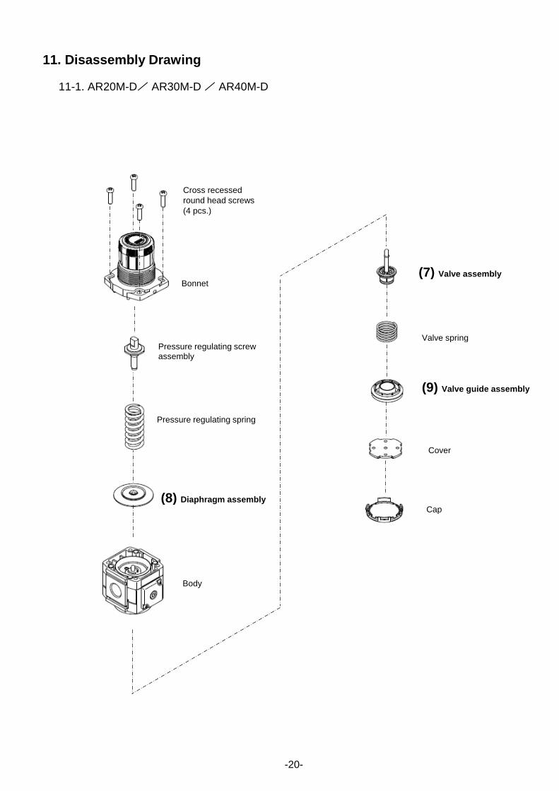
11. Disassembly Drawing
11-1. AR20M-D/ AR30M-D / AR40M-D
-20-
Cross recessed
round head screws
(4 pcs.)
Bonnet
(8) Diaphragm assembly
Body
(7) Valve assembly
Valve spring
(9) Valve guide assembly
Cover
Cap
Pressure regulating screw assembly
Pressure regulating spring

11-2. Disassembly Drawing of the Pressure Gauge Port
- When (4) square embedded type pressure gauge and (6) digital pressure switch is mounted, tighten with the torque of 0.85±0.05 N・m. When another part is mounted, tighten with the torque of 0.6±0.05 N・m.
-21-
Note) Refer to the operation manual included in the product with digital pressure switch.
Product
(6) Digital pressure switch
Mounting screws(2 pcs.)
(11) Plug assembly
(10) Plug
(3) Pressure gauge (round type)
Pressure gauge adapter assembly
O-ring
Square embedded type
pressure gauge
O-ring
(5) Pressure gauge cover
(4) Square embedded type pressure gauge
Mounting screws(2 pcs.)

12. Domensions
Dimensions
P1 P2 P3 A BNote 1) C D F J K L1 H J H J H J
AR20M-D 1/8・1/4 1/8 1/8・1/4 40 66.8 26.5 21 M28X1 26 2 9 φ37.5 62.5 φ37.5 63.5 φ37.5 63.5
AR30M-D 1/4・3/8 1/8 1/4 53 86.5 30.5 26.5 M38X1.5 31.5 3.5 14.5 φ37.5 68 φ37.5 69 φ37.5 69
AR40M-D 3/8・1/2 1/8 1/4・3/8 70 91.5 35.5 35.5 M42X1.5 40.5 0 14.5 φ42.5 78 φ42.5 78 φ42.5 78
H J H J M N Q R S T U V W Y Z
AR20M-D □28 27 □27.8 38 30 34 43.9 5.4 15.4 55 2.3 24.7 28.5 14 6
AR30M-D □28 33 □27.8 43 41 40 46 6.5 8 53 2.3 31.3 38.5 19 7
AR40M-D □28 42 □27.8 52 50 54 54 8.5 10.5 70 2.3 35.5 42.5 21 7
Note 1) The dimension of B is the length when the regulator knob is unlocked.
Note 2) Panel cutout dimensions in the table indicate the dimensions for panel mounting a single regulator.
Model
Optional specifications
Round type
pressure gauge
Round type
pressure gauge
(Semi-standard:Z)
Round type
pressure gauge
(with color zone)
Bracket mount Panel mountNote 2)
Optional specifications
Standard specifications
-22-
Model
Square
embedded type
pressure gauge
Digital
pressure
switch
Plate thickness
AR20M/30-MD: Max.3.5
AR40-D: Max.5
Round type pressure gaugeSquare embedded type
pressure gaugeDigital pressure switch
Center of
piping
Center of
piping
Center of
piping

Revision history
4-14-1, Sotokanda, Chiyoda-ku, Tokyo 101-0021 JAPAN Tel: + 81 3 5207 8249 Fax: +81 3 5298 5362 URL https://www.smcworld.com Note: Specifications are subject to change without prior notice and any obligation on the part of the manufacturer. © 2019 SMC Corporation All Rights Reserved