Guide Cylinder - SMC Products/CAD Models
32
Series MLGC Guide Cylinder Built-in Fine Lock Cylinder Compact Type CAT.ES20-192A A linear transfer cylinder unit with a built-in locking mechanism and a guide rod integrated in a compact design. Locking in both directions is possible. Locking in either side of cylinder stroke is possible, too. Maximum piston speed: 500 mm/s It can be used at 50 to 500 mm/s provided that it is within the allowable kinetic energy range. Air cushion is standard. Enables the impact to be absorbed at the stroke end when the cylinder is operated at high speeds. Cylinder position can be detected. Built-in magnet for auto switches is provided in all models. Locking method Stopping accuracy ∗ Features Spring locking Pneumatic locking Spring and pneumatic locking ±1.0 mm ±0.5 mm Works on the safety side. (Exhaust locking) High precision Holding power can be adjusted freely. High precision Holding power can be adjusted freely. Works on the safety side. High level of stopping accuracy, Three-types of locking mechanism High level of stopping accuracy, Three-types of locking mechanism ∗ Piston speed at 300 mm/s
-
Upload
khangminh22 -
Category
Documents
-
view
0 -
download
0
Transcript of Guide Cylinder - SMC Products/CAD Models

Series MLGC
Guide CylinderBuilt-in Fine Lock Cylinder Compact Type
CAT.ES20-192A
A linear transfer cylinder unit with a built-in locking mechanism and a guide rod integrated in a compact design.
� Locking in both directions is possible.Locking in either side of cylinder stroke is possible, too.
� Maximum piston speed: 500 mm/sIt can be used at 50 to 500 mm/s provided that it is within the allowable kinetic energy range.
� Air cushion is standard.Enables the impact to be absorbed at the stroke end whenthe cylinder is operated at high speeds.
� Cylinder position can be detected.Built-in magnet for auto switches is provided in all models.
Locking method
Stopping accuracy∗
Features
Spring locking Pneumatic locking Spring and pneumatic locking
±1.0 mm ±0.5 mm
� Works on the safety side. (Exhaust locking)
� High precision� Holding power can be adjusted freely.
� High precision� Holding power can be adjusted freely.� Works on the safety side.
High level of stopping accuracy,Three-types of locking mechanismHigh level of stopping accuracy, Three-types of locking mechanism
∗ Piston speed at 300 mm/s

Applicable Auto Switches / For detailed auto switch specifications, refer to page 10 through to 20.
∗ Lead wire length symbols: 0.5 m ·········· Nil (Example) M9NW 1 m ··········· M (Example) M9NWM 3 m ··········· L (Example) M9NWL 5 m ··········· Z (Example) M9NWZ None ··········· N (Example) H7CN
∗ Solid state switches marked with “ ” are produced upon receipt of order.∗ D-A9�V, M9�V, M9�WV, and D-F9BA cannot be mounted.
∗ Since there are other applicable auto switches than listed, refer to page 9 for details.∗ For details about auto switches with pre-wired connector, refer to “Best Pneumatics 2004” Vol. 9
catalog.∗ D-A9�, M9�, M9�W are shipped together (but not assembled).
(Only switch mounting bracket is assembled at the time of shipment.)
When using auto switches shown inside ( ), stroke end detection may not be possible depending on the one-touch fitting or speed controller model. Please contact SMC in this case.
Caution
Special function Electricalentry
Grommet
Grommet
Grommet
Connector
Connector
Grommet
100 V
100 V or less
100 V, 200 V
200 V or less
24 V or less
Wiring(Output)
3-wire(NPN equivalent)
2-wire
3-wire (NPN)
3-wire (PNP)
2-wire
3-wire (NPN)
3-wire (PNP)
2-wire
4-wire (NPN)
Load voltage
DC
24 V
24 V
5 V
12 V
5 V, 12 V
12 V
5 V, 12 V
12 V
5 V, 12 V
AC
Lead wire length (m)
0.5(Nil)
3(L)
1(M)
5(Z)
None(N)
Applicableload
Pre-wiredconnector
Relay,PLC
Relay,PLC
Auto switch model
Applicable tubing I.D.
ø20, ø25 ø40ø32
Diagnostic indication (2-color indication)
Diagnostic indication(2-color indication)
Water resistant (2-color indication)
With diagnostic output (2-color indication)
A96
A93A90
C73CC80C
M9NM9PM9BH7C
M9NWM9PWM9BWH7BAH7NF
B54B64
(B54)(B64)
(B59W) B59W
Type
Indic
ator
light
Yes
None
Yes
None
Yes
None
Yes
Yes
Ree
d s
wit
chS
olid
sta
te s
wit
ch
IC circuit
IC circuit
ICcircuit
ICcircuit
ICcircuit
L R E M9BWB 32MLGC 100
Number of auto switchesNil
Sn
2 pcs.
1 pc.
“n” pcs.
Auto switch
∗ For applicable auto switch models, refer to the below table.
NilWithout auto switch(Built-in magnet)
Rear plateWithout rear plate
With rear plate
Nil
R
Lock operationSpring locking (Exhaust locking)
Pneumatic locking (Pressure locking)
Spring and pneumatic locking
EPD
Cylinder stroke (mm)Refer to “Standard Stroke” on page 2.
Port thread typeM5 x 0.8
Rc
NPT
G
Nil
TNTF
∗ For bore size 20 and 25, M5 x 0.8 is only available.
Bore size20253240
20 mm
25 mm
32 mm
40 mm
MountingBF
Basic
Front mounting flange
Bearing typeML
Slide bearing
Ball bushing bearing
Guide cylinder(Built-in fine lock cylinder compact type)
Made to OrderFor details, refer to page 2.
1
Guide Cylinder: Built-in Fine Lock CylinderCompact Type
ø20, ø25, ø32, ø40Series MLGC
How to Order

Made to Order (For details, refer to page 21.)
OrderMade
Symbol
Machining tapped hole, drilled holeand pin hole additionally
Specifications
XC79
∗ Intermediate strokes and short strokes other than the above are produced upon receipt of order.
Model (Bearing type)Standard stroke
(mm)Long stroke (mm)
Bore size(mm)
MLGCM (Slide bearing)
MLGCL (Ball bushing bearing)
75, 100, 125, 150, 200
75, 100, 125, 150, 200, 250, 300
250, 300, 350, 400
350, 400, 450, 500
350, 400, 450, 500, 600
350, 400, 450, 500, 600, 700, 800
20253240
OUT INUnit: N
Note) Theoretical output (N) = Pressure (MPa) x Piston area (mm2)
Theoretical Output
314
264
491
412
804
691
1260
1060
0.2 62.8
52.8
98.2
82.4
161
138
252
212
0.3 94.2
79.2
147
124
241
207
378
318
0.4126
106
196
165
322
276
504
424
0.5157
132
246
206
402
346
630
530
0.6188
158
295
247
482
415
756
636
0.7220
185
344
288
563
484
882
742
0.8 251
211
393
330
643
553
1010
848
0.9 283
238
442
371
724
622
1130
954
1.0 314
264
491
412
804
691
1260
1060
Bore size(mm)
20
25
32
40
Rod size(mm)
Operatingdirection
8
10
12
16
OUT
IN
OUT
IN
OUT
IN
OUT
IN
Piston area(mm2)
Operating pressure (MPa)
Model / Specifications
Lock operationSpring locking
(Exhaust locking)Spring and
pneumatic lockingPneumatic locking(Pressure locking)
Fluid
Maximum operating pressure
Unlocking pressure
Lock starting pressure
Locking direction
Air
0.5 MPa
Both directions
0.3 MPa or more
0.25 MPa or less
0.1 MPa or more
0.05 MPa or less
Fine Lock Specifications
Standard Stroke
∗1 Constraints associated with the allowable kinetic energy are imposed on the speeds at which the piston can be locked. The maximum speed of 750 mm/s can be accommodated if the piston is to be locked in the stationary state for the purpose of drop prevention.
∗2 When the cylinder is retracted (initial value), with no load or without deflection of the guide rod, the non-rotating accuracy shall be the value in the table or less.
∗3 For bore size 20 and 25, M5 x 0.8 is only available.
Action
Fluid
Proof pressure
Maximum operating pressure
Minimum operating pressure
Ambient and fluid temperature
Piston speed∗1
Cushion
Base cylinder lubrication
Thread tolerance
Stroke length tolerance
Non-rotating accuracy ∗2
Lock operation
Model
Basic cylinder
Bore size (mm)
Cylinder port
Lock port
Slide bearing
Ball bushing bearing
Piping port size ∗3
(Rc, NPT, G)
MLGC��20 MLGC��25 MLGC��32 MLG��40
�Spring locking (Exhaust locking)�Pneumatic locking (Pressure locking)�Spring and pneumatic locking
Double acting
Air
1.5 MPa
1.0 MPa
0.2 MPa (Horizontal with no load)
–10 to 60ºC
50 to 500 mm/s
Air cushion
Non-lube
JIS Class 2+1.9+0.2 mm
20 25 32 40CDLG1BA Bore size Thread type Stroke Lock operation Auto switch
1/8
M5 x 0.8 1/8
±0.06º±0.04º
±0.05º±0.04º
±0.05º±0.04º
±0.04º±0.04º
Specifications
JIS Symbol
2
Series MLGCGuide CylinderBuilt-in Fine Lock Cylinder Compact Type

For detailed specifications about the fine lock cylinder CLG1 series, refer to “Best Pneumatics 2004” Vol. 9 catalog.
Recommended Pneumatic Circuit / Caution on Handling
Caution
(kg)
Bore size (mm)
Moving parts basic weight
Additional weight with rear plate
Additional weight per each 50 mm of stroke
20 25 32 40
Calculation: (Example)MLGCLB32-500-R-D• Moving parts basic weight········································································· 1.17• Additional weight with rear plate······························································· 0.47• Additional stroke weight··································································· 0.29/50 st• Stroke···································································································· 500 st1.17 + 0.47 + 0.29 x 500/50 = 4.54 kg
Moving Parts Weights
2.21
0.8
0.46
1.17
0.47
0.29
1.17
0.47
0.28
0.59
0.29
0.18
20 25 32 40Bore size (mm)
(kg)
LB type (Ball bushing bearing / Basic)
LF type (Ball bushing bearing / Front mounting flange)
MB type (Slide bearing / Basic)
MF type (Slide bearing / Front mounting flange)
Weights
2.8 4.45 4.54 8.12
3.52 5.42 5.52 9.61
2.74
3.45
0.29
0.21
0.01
4.35
5.31
0.47
0.32
0.01
4.44
5.42
0.47
0.34
0.02
7.84
9.33
0.8
0.54
0.03
Additional weight with rear plate
Additional weight per each 50 mm of stroke
Additional weight for long stroke
Calculation: (Example)MLGCLB32-500-R-D(Ball bushing bearing / Basic, ø32/500 st., with rear plate)• Basic weight··············································································· 4.54 (LB type)• Additional weight with rear plate································································ 0.47• Additional stroke weight··································································· 0.34/50 st• Stroke····································································································· 500 st• Additional weight for long stroke································································ 0.024.54 + 0.47 + 0.34 x 500/50 + 0.02 = 8.43 kg
Locking method
Spring locking (Exhaust locking)
Pneumatic locking (Pressure locking)Spring and pneumatic locking
Piston speed (mm/s)
50±0.4
±0.2
100±0.5
±0.3
300±1.0
±0.5
500±2.0
±1.5
Condition/ Load: 25% of thrust force at 0.5 MPa Solenoid valve: mounted to the lock port
(mm)
Stopping Accuracy (Not including tolerance of control system.)
1.The holding force is the lock’s ability to hold a static load that does not involve vibrations or shocks, after it is locked without a load. Therefore, to use the cylinder near the upper limit of the constant holding force, be aware of the following:• If the piston rod slips because the lock’s holding force has been exceeded,
the brake shoe could become damaged, resulting in a reduced holding force or shortened life.
• To use the lock for drop prevention purposes, the load to be attached to the cylinder must be within 35% of the cylinder’s holding force.
• Do not use the cylinder in the locked state to sustain a load that involves impact.
Holding Force of Pneumatic Locking (Max. static load)
Bore size (mm)
Holding force (N)
20196
25313
32443
40784
Note) Holding force at piston rod extended side decreases approximately 15%.
Holding Force of Spring Locking (Max. static load)
Bore size (mm)
Allowable kinetic energy (J)
200.26
250.42
320.67
401.19
Allowable Kinetic Energy when Locking
In terms of specific load conditions, the allowable kinetic energy indicated in the table above is equivalent to a 50% load ratio at 0.5 MPa, and a piston speed of 300 mm/sec. Therefore, if the operating conditions are below these values, calculations are unnecessary.1.Apply the following formula to obtain the kinetic energy of the load.
EK: Kinetic energy of load (J)m: Load weight (kg)
(Load weight + Moving parts weight)υ: Piston speed (m/s) (Average speed x 1.2)
2.The piston speed will exceed the average speed immediately before locking. To determine the piston speed for the purpose of obtaining the kinetic energy of load, use 1.2 times the average speed as a guide.
3.The relation between the speed and the load of the respective tube bores is indicated in the diagram below. Use the cylinder in the range below the line.
4. During locking, the lock mechanism must absorb the thrust of the cylinder, in addition to the kinetic energy of the load. Therefore, in order to insure the proper braking force, even within a given allowable kinetic energy level, there is an upper limit to the size of the load. Thus, a horizontally mounted cylinder must be operated below the solid line, and a vertically mounted cylinder must be operated below the dotted line.
EK = mυ212
Hol
ding
forc
e (N
)
Air pressure applied to pressurized locking port (MPa)
Load
wei
ght (
kg)
Piston speed (mm/s)
Bas
ic w
eig
ht
3
Series MLGC

Component Parts
123456789101112
13
14151617181920212223242526272829303132333435363738
DescriptionRod coverTube coverCoverIntermediate coverPiston rodPistonBrake pistonBrake armBrake shoeRollerPinSnap ring
Brake spring
BushingBushingManual lock release camCam guideLock nutFlat washerSnap ringHexagon socket head cap screwSpring washerHexagon socket head cap screwSpring washerHexagon socket head cap screwSpring washerWear ringWear ringHexagon socket head plugElementRod end nutPiston sealPiston gasketRod seal ARod seal BBrake piston sealIntermediate cover gasketCam gasket
MaterialAluminum alloyAluminum alloyCarbon steelAluminum alloyCarbon steelAluminum alloyCarbon steelCarbon steel
Special friction materialCarbon steelCarbon steel
Stainless steel
Spring steel wire
Oil-impregnated sintered alloyOil-impregnated sintered alloyChromium molybdenum steel
Carbon steelRolled steelRolled steel
Stainless steelChromium molybdenum steel
Steel wireChromium molybdenum steel
Steel wireChromium molybdenum steel
Steel wireResinResin
Carbon steelBronze
Rolled steelNBRNBRNBRNBRNBRNBRNBR
Dacrodized
Hard chrome plated
Nickel plated
ø20, ø25 are stainless steel.
For spring locking, spring/pneumatic locking
For spring locking
No. DescriptionClear hard anodized
Hard anodizedNitrided
Clear hard anodized
ChromatedNitridedNitrided
NitridedHeat treated
Nitrided, Nickel platedNitrided, painted
Nickel platedNickel plated
Nickel platedNickel platedNickel platedNickel platedNickel platedNickel plated
Nickel plated
Component Parts
3940414243444546474849505152535455565758
59
6061
62
63
6465666768697071727374
DescriptionCylinder tube gasketHad coverCylinder tubeCushion valve ACushion valve BSeal retainerCushion valve ACushion valve BValve retainerLock nutSnap ringCushion seal ACushion seal BCushion ring gasket ACushion ring gasket BValve seal AValve seal BValve retainer gasketMagnetGuide bodySmall flangeLarge flangeFront plateRear plateSlide bearingBall bushing bearing
Guide rod
End bracketWasherSpring washerFeltHolderC-type snap ring for holeGrease nippleHexagon socket head cap screwHexagon socket head cap screwHexagon socket head cap screwHexagon socket head cap screw
MaterialNBR
Aluminum alloyAluminum alloy
BrassBrass
Rolled steelChromium molybdenum steel
Rolled steelRolled steelRolled steel
Stainless steelUrethaneUrethane
NBRNBRNBRNBRNBR—
Aluminum alloy
Rolled steel
Rolled steelCast iron
Bearing alloy—
Carbon steelHigh carbon chrome bearing steel
Carbon steelRolled steelSteel wire
FeltStainless steel
Carbon tool steel—
Chromium molybdenum steelChromium molybdenum steelChromium molybdenum steelChromium molybdenum steel
Flat nickel plated
Hard chrome platedQuenched, Hard chrome plated
Nickel platedNickel platedNickel platedNickel plated
BasicFront mounting flange
For slide bearingFor ball bushing bearing
For cylinder mountingFor large/small flange mountingFor front plate mountingFor rear plate mounting
No. Description
White hard anodizedHard anodized
Zinc chromatedElectroless nickel platedElectroless nickel platedElectroless nickel platedElectroless nickel plated
Clear anodized
Flat nickel platedPlatinum silver
For slide bearingFor ball bushing bearing
Flat nickel platedNickel platedNickel plated
Nickel platedNickel plated
Note) ^11, &4 will not be required for without rear plate.
View B-B'
View A-A'
Slide bearingLong stroke
Ball bushing bearingFront mounting flange
@5 @6 ^7 ^8 ^9 @4 @3 t $2 y #3 #2 &4 ^1 %7 @7 $4 %1 %5
$7
$8
$6
%6
$3
%3
w
%8^2%9^3^0
&3
@2
@1
#1
^5
^4
^6
&1
&2
&0
#5 e #7 r #8 !7 @0 !6 !8 !9 #6 @8 u #7 @9 $1 $2 %0 #9 %2 $0 ^2#0
#9
q
%2
$9 $5 %4
!4 o i !1 !0 !5 #4 !3 #4 %0!2
A
A'
B
B'
4
Construction: With Rear Plate
Series MLGCGuide CylinderBuilt-in Fine Lock Cylinder Compact Type

Bore size (mm)
20253240
Y129
146
146
191
Without Rear PlateBore size (mm)
20253240
250 to 400
350 to 500
350 to 600
350 to 800
R14
14
14
15
Z190
207
210
236
Stroke range (mm)
Long Stroke
Note 1) Dimensions marked with “∗” are not required for without rear plate.Note 2) For bore size 20 and 25, M5 x 0.8 is only available.Rc, NPT, G port are available for bore size with 32 or greater.Note 3) Rc, NPT, G port are available.
Bore size (mm)
20253240
Bore size (mm)
20253240
Stroke range (mm)
75, 100, 125, 150, 200
75, 100, 125150, 200, 250
300
P Note 2)
M5 x 0.8
M5 x 0.8
1/8
1/8
GD54
62
62
67
GK3.5
4
4
4
GL 5.5
9
9
11
GQ4
7
7
8
GR4
7
7
7
HM8 x 1.25 depth 14
M10 x 1.5 depth 18
M10 x 1.5 depth 18
M12 x 1.75 depth 21
I35
40
40
45
J60
70
70
82.5
K 80
95
95
115
L105
125
125
150
M50
60
60
75
N25
32
32
38
OM6 x 1
M8 x 1.25
M8 x 1.25
M8 x 1.25
Q 94
104
104
115
R12
12
12
12
S26
31
38
47
A 94
104
104
142
AA12
16
16
19
AB13
16
16
19
AC16.5
19
19
22
AD 70
75
75
110
AE35
40
40
45
AFM6 x 1 depth 12
M8 x 1.25 depth 16
M8 x 1.25 depth 16
M10 x 1.5 depth 20
AP32
37
37
42
B135
160
160
194
BP Note 3)
1/8
1/8
1/8
1/8
BZ73.5
86.5
86.5
95
C26.5
31.5
31.5
37
D50
50
50
80
E118
140
140
170
F 6.8
8.6
8.6
10.5
G11 depth 8
14 depth 10
14 depth 10
17 depth 12
GC28
29
30
35
Standard Stroke
Bore size (mm)
20253240
T16
20
20
25
U112
132
132
162
V53
63
63
73
W50
60
60
70
WH23
25
28.5
33
Wθ30
30
25
20
X30
37
37
44
Y146
167
167
210
Z182
199
202
227
(mm)
LOC
K F
RE
E
N
I
J
BZ
KM
GK
L
2 x O through
AP∗
V∗
W∗
U∗
8 x AFAC AD
AE
Z + Stroke
Y + Stroke
AA GC GD
X A AB∗
R
C
Q
D
BE
GL
GR
GQ
øT
øS
4 x øF through Counterbore øGBack side 4 x H
BP (Rc, NPT, G) Lock port for pressure lock(Plug with breathing hole for spring locking)
Rear plateP (Rc, NPT, G) Head side cylinder port
View A-A'
A
A'
P (Rc, NPT, G) Rod side cylinder port
BP (Rc, NPT, G) Unlocking portUnlocked when pressurized
WH (Max.)
10º
Wθ
5
Series MLGC
Dimensions
Basic: With rear plateMLGC�B��-�-R-�

Bore size (mm)
20253240
Bore size (mm)
20253240
Stroke range (mm)
75, 100, 125, 150, 200
75, 100, 125150, 200, 250
300
P Note 2)
M5 x 0.8
M5 x 0.8
1/8
1/8
GL 5.5
9
9
11
GQ4
7
7
8
GR4
7
7
7
I35
40
40
45
J60
70
70
82.5
K 80
95
95
115
L105
125
125
150
M50
60
60
75
N25
32
32
38
OM6 x 1
M8 x 1.25
M8 x 1.25
M8 x 1.25
Q 94
104
104
115
R12
12
12
12
S26
31
38
47
T16
20
20
25
U112
132
132
162
V53
63
63
73
W50
60
60
70
A 94
104
104
142
AA12
16
16
19
AB13
16
16
19
AG134
160
160
190
AH150
176
176
210
AI 92
110
110
115
AJ108
125
125
135
AK 9
9
9
11
AL 9
9
9
12
AM75
88
88
96
AN140
165
165
200
AOM8
M8
M8
M10
AP32
37
37
42
B135
160
160
194
BZ73.5
86.5
86.5
95
GC28
29
30
35
GD54
62
62
67
GK3.5
4
4
4
BP Note 3)
1/8
1/8
1/8
1/8
Bore size (mm)
20253240
Y129
146
146
191
Without Rear Plate
Standard Stroke
Bore size (mm)
20253240
250 to 400
350 to 500
350 to 600
350 to 800
R14
14
14
15
Z190
207
210
236
Stroke range (mm)
Long Stroke
Bore size (mm)
20253240
WH23
25
28.5
33
X30
37
37
44
Y146
167
167
210
Z182
199
202
227
Wθ30
30
25
20
(mm)
Note 1) Dimensions marked with “∗” are not required for without rear plate.Note 2) For bore size 20 and 25, M5 x 0.8 is only available.Rc, NPT, G port are available for bore size 32 or greater.Note 3) Rc, NPT, G port are available.
A
A'
Mounting dimensions
Cutout window
LOC
K F
RE
E
N
I
J
AI
AJ
KMAH
AG L
2 x O through
AP∗
BZ
V∗
W∗ G
K
U∗
For 4 x AO
AN
AG
AM A
I
Z + Stroke
Y + Stroke
AA AL
GDGC
X A AB∗R
Q
B
GL
GR
GQ
øT
øS
BP (Rc, NPT, G) Lock port for pressure lock(Plug with breathing hole for spring locking)
Rear plate
P (Rc, NPT, G) Head side cylinder port
WH (Max.)
10º
Wθ
View A-A'
P (Rc, NPT, G) Rod side cylinder port
BP (Rc, NPT, G) Unlocking portUnlocked when pressurized
4 x øAK hole
6
Front mounting flange: With rear plateMLGC�F��-�-R-�
Dimensions
Series MLGCGuide CylinderBuilt-in Fine Lock Cylinder Compact Type

D-C7, C8 type,D-H7 type
D-B5, B6 type,D-G5, K5 type
D-B7, B8 type,D-G7, K7 type
D-A9 type,D-M9, M9�W type
(mm)Auto Switch Mounting Height
∗ ( ): Values for long strokes.Note) When setting an auto switch, confirm the operation and adjust its mounting position.
Auto Switch Proper Mounting Position (mm)
Applicablebore size
Autoswitchmodel
20
25
32
40
D-M9�D-M9�W
D-B7�D-B80D-B73CD-B80CD-G79D-K79D-K79C
D-C7�D-C80D-C73CD-C80C
D-H7�D-H7CD-H7�WD-H7BALD-H7NF
D-B5�D-B64 D-B59W
D-G5�D-K59D-G5NTLD-G5�WD-K59WD-G59FD-G5BAL
10.5
10.5
10.5
13.5
D-A9�
6.5
6.5
6.5
9.5
BA BA23
(31)
23(31)
25(33)
28(37)
27(35)
27(35)
29(37)
32(41)
8
8
8
11
BA24.5(32.5)
24.5(32.5)
26.5(34.5)
29.5(38.5)
7
7
7
10
BA23.5(31.5)
23.5(31.5)
25.5(33.5)
28.5(37.5)
6
6
6
9
BA22.5(30.5)
22.5(30.5)
24.5(32.5)
27.5(36.5)
1
1
1
4
BA17.5(25.5)
17.5(25.5)
19.5(27.5)
22.5(31.5)
4
4
4
7
BA20.5(28.5)
20.5(28.5)
22.5(30.5)
25.5(34.5)
2.5
2.5
2.5
5.5
BA19
(27)
19(27)
21(29)
24(33)
Hs
24
26.5
30
34.5
Hs
24.5
27
30.5
35
Hs
27
29.5
33
37.5
Hs
27.5
30
33.5
38
D-A9�D-M9�D-M9�W
Applicablebore size
20
25
32
40
Autoswitchmodel
D-C7/C8D-H7�D-H7�WD-H7NFD-H7BAL
D-C73CD-C80C
D-B7/B8D-B73CD-B80CD-G7/K7D-K79CD-H7CD-G5�D-K59
D-G5�WD-K59WD-G5NTLD-B5/B6D-B59WD-G5BALD-G59F
Auto switch
Auto switch
Auto switch
A B8.5
A 12
A 8.5
11.5
16
14.5
24.5
14.5
B
B
Hs
Hs
11
Hs
BA 8.5 11
Hs
16.5
Auto switch
Auto Switch Proper Mounting Position (Detection at stroke end) and Its Mounting Height
7
Series MLGC

D-A93D-M9�D-M9�W
Auto switch model
With two auto switches
Same side
Less than 50 stroke
Less than 55 stroke
The auto switches are offset (one auto switch is displaced more around the outside of the cylinder tube) so that the auto switches and lead wires do not interfere with each other.
Note) Caution when two D-A93, M9�, M9�W auto switches are used.
D-H7�D-H7�WD-H7BALD-H7NF
D-C7�D-C80
D-B59W
D-B5�D-B64D-G5�D-K59�
10 50
10 60
10 65
50 + 45 (n-2)
60 + 45 (n-2)
65 + 50 (n-2)
75 + 55 (n-2)
75 + 55 (n-2)
10 75
10 75
D-A9�D-M9�D-M9�W
Auto switch modelWith 1 pc.
With 2 pcs. With n pcs.
Number of auto switches mounted
10 Note)
Same side
45
Same side
45 + 45 (n-2)
n: Number of auto switches (mm)
D-C73C/C80CD-H7CD-B73C/B80CD-K79C
D-B7�D-B80D-G79D-K79
50 + 45 (n-2)10 45
8
Minimum Stroke for Auto Switch Mounting
Series MLGCGuide CylinderBuilt-in Fine Lock Cylinder Compact Type

Operating Range
∗ With pre-wired connector is available for solid state auto switches. For details, refer to “Best Pneumatics 2004” Vol. 9 catalog. ∗ Normally closed (NC = b contact), solid state switches (D-F9G, F9H type) are also available. For details, refer to “Best Pneumatics 2004” Vol. 9 catalog.∗ Wide range detection type, solid state auto switch (D-G5NBL type) is also available. For details, refer to “Best Pneumatics 2004” Vol. 9 catalog.
Other than the applicable auto switches listed in “How to Order”, the following auto switches can be mounted.For detailed specifications, refer to “Best Pneumatics 2004” Vol. 9 catalog, etc.
Type Model FeaturesElectrical entry(Direction)
D-C73, C76, B73, B73C, B76
D-C80, B80C
D-B53
D-H7A1, H7A2, H7B, G79, K79, K79C
D-H7NW, H7PW, H7BW
D-G5NTL
—
Without indicator light
—
—
Diagnostic indication (2-color indication)
With timer
Applicablebore size
ø20 to ø40Grommet (in-line)
Reed switch
Solid state switch
[Mounting screws set made of stainless steel]The following set of mounting screws made of stainless steel is also available. Use it in accordance with the operating environment. (Please order the switch mounting bracket separately, since it is not included.)
BBA3: For D-B5, B6, G5, K5 type BBA4: For D-C7, C8, H7 type
“D-H7BAL/G5BAL” switch is set on the cylinder with the stainless steel screws above when shipped. When only a switch is shipped independently, “BBA3” or “BBA4” screws are attached.
Auto switch modelBore size (mm)
D-C7�/C80D-C73C/C80CD-H7�/H7CD-H7�WD-H7BALD-H7NF
D-A9�D-M9�D-M9�W
D-B5�/B64D-B59WD-G5�/K59D-G5�W/K59WD-G5BALD-G59FD-G5NTLD-G5NBL
ø20 ø25
BMA2-020 BMA2-025
ø32
BMA2-032
BA-01 BA-02 BA-32
Note)qBMA2-020
wBJ3-1
Note)qBMA2-025
wBJ3-1
Note)qBMA2-032
wBJ3-1
ø40
BMA2-040
BA-04
Note)qBMA2-040
wBJ3-1
Note) Two types of brackets are used as a set.
Auto Switch Mounting Bracket Part No.
Auto switch modelBore size
20 7
3
5
(mm)
8
8
8
13
8
4
7
4
5
408
3.5
5.5
10
10
10
14
10
5
10
5
6
45
328
4
5
9
9
9
14
9
4.5
9
4.5
5.5
40
256
3
5.5
10
10
10
13
10
4
8.5
4
5
40 35
D-A9�D-M9�D-M9�W
D-G59FD-G5NBL
D-H7C
D-G5�/K59D-G5�W/K59WD-G5NTL/G5BAL
D-B7�/B80D-B73C/B80CD-C7�/C80D-C73C/C80CD-B5�/B64D-B59WD-G79/K79/K79CD-H7BALD-H7�/H7�W/H7NF
q BMA2-��� is a set containing a and b in the drawing.w BJ3-1 is a set containing c, d and e in the drawing.
Switch spacer(Stainless steel)
e
Switch holder(Resin)
d
Switch bracket(Stainless steel)
c Switch mountingscrew
b
Switch mounting banda
Auto switch
Set screw (not used)
BM1-01 BM1-02 BM1-32 BM1-04
D-B7�/B80D-B73C/B80CD-G79/K79D-K79C
∗ Since this is a guideline including hysteresis, not meant to be guaranteed.
(Assuming approximately ±30% dispersion.)There may be the case it will vary substantially depending
on an ambient environment.
9
Series MLGC

Series MLGCAuto Switch Specifications
Auto Switch Common Specifications
Lead Wire Length
Lead wire length indication
(Example)
0.5 m
3 mL1 mM
5 mZ
Nil
Lead wire length
LD-M9BW
(Example)
Flexible specification
61D-H7BAL-
Contact Protection Boxes: CD-P11, CD-P12<Applicable switch model>
Specifications
Internal Circuit
Dimensions
Connection
∗ Lead wire length Switch connection side 0.5 m Load connection side 0.5 m
D-A9/C73C/C80C typeThe auto switches below do not have a built-in contact protection circuit.Therefore, please use a contact protection box with the switch for any of the following cases:q Where the operation load is an inductive load.w Where the wiring length to load is greater than 5 m. e Where the load voltage is 100 VAC.The contact life may be shortened (due to permanent energizing conditions).
Part no.
Load voltage
Max. load current
CD-P11
CD-P11
100 VAC
25 mA
200 VAC
12.5 mA
CD-P12
24 VDC
50 mA
To connect a switch unit to a contact protection box, connect the lead wire from the side of the contact protection box marked SWITCH to the leadwire coming out of the switch unit. Keep the switch as close as possible to the contact protection box, with a lead wire length of no more than 1 meter.
CD-P12
Note 1) Applicable auto switch with 5 m lead wire “Z”Reed switch: D-B53, B54, C73(C), C80C typeSolid state switch: Manufactured upon receipt of order as standard.Note 2) To designate solid state switches with flexible specifications, add “-61”
after the lead wire length. Flexible cable is used for D-M9�, D-M9�W as standard. There is no need to place the suffix -61 to the end of part number.
Note 3) For 1 m (M), D-M9�W only.Note 4) Lead wire tolerance
Lead wire length Tolerance
±15 mm
±30 mm
±90 mm
±150 mm
0.5 m
1 m
3 m
5 m
Part No. of Lead Wires with Connectors (Applicable for Connector Type Only)
Model
D-LC05
D-LC30
D-LC50
Lead wire length
0.5 m
3 m
5 m
Note) D-C73C, C80C type: 1000 VAC/min. (Between lead wire and case)
Type
Leakage current
Operating time
Impact resistance
Insulation resistance
Withstand voltage
Ambient temperature
Enclosure
Standard
Reed switch
None
1.2 ms
300 m/s2
50 M or more at 500 VDC Mega (between lead wire and case)
–10 to 60ºC
IEC529 standard IP67, JIS C 0920 waterproof construction
Conforming to CE Standards
Solid state switch
3-wire: 100 A or less 2-wire: 0.8 mA or less
1 ms or less
1000 m/s2
1500 VAC for 1 minute (between lead wire and case) Note) 1000 VAC for 1 minute (between lead wire and case)
Surge absorberChoke
coil
OUT Brown
OUT Blue
OUT (+)Brown
OUT (–)Blue
Choke coil
Zener diode
10

Auto SwitchConnections and Examples
Basic Wiring
Solid state 3-wire, NPN 2-wireSolid state 3-wire, PNP(Solid state)
2-wire(Reed)
• Sink input specification3-wire, NPN
• 3-wire
• Source input specification3-wire, PNP
OR connection for NPN output
2-wire with 2-switch AND connection 2-wire with 2-switch OR connection
2-wire 2-wire
Switch
InputBlack
COM
Brown
Blue
Switch
Input
Blue COM
Brown
Switch
InputBlack
PLC internal circuitCOM
Brown
Blue
PLC internal circuit
PLC internal circuit
PLC internal circuit
Switch
InputBlue
COMBrown
Connect according to the applicable PLC input specifications, since the connection method will vary depending on the PLC input specifications.
(Power supplies for switch and load are separate.)
Example of AND (Serial) and OR (Parallel) Connection
Example of Connection to PLC (Programmable Logic Controller)
AND connection for NPN output(using relays)
AND connection for NPN output(performed with switches only)
The indicator lights will illuminate when both switches are turned ON.
Switch main circuit
Brown
Black
Blue
Load
Brown
Black
Blue
Load
Brown
Black
Blue
Load
Brown
Blue
Load
Brown
BlueLoad
Indicator light protectivecircuitetc.
Brown
Blue
Load
Brown
BlueLoad
Switch main circuit
Switch main circuit
Switch main circuit
Switch main circuit
Indicator light protectivecircuitetc.
Switch 1
Switch 2
Load
BrownBlackBlue
BrownBlackBlue
Switch 1
Brown
Switch 2
BlackBlue
Relay
Relay
BrownBlackBlue
Load
Relay contact
Switch 1
Brown
Switch 2
BlackBlue
Load
BrownBlackBlue
Power supply ResidualLoad voltage at ON = voltage – voltage x 2 pcs.
= 24 V - 4 V x 2 pcs. = 16 VExample: Power supply is 24 VDC. Internal voltage drop in switch is 4 V.
Load voltage at OFF = Leakage current x 2 pcs. x Load impedance = 1 mA x 2 pcs. x 3 k = 6 VExample: Load impedance is 3 k. Leakage current from switch is 1 mA.
Switch 1
Switch 2
Brown
Blue
Brown
Blue
LoadSwitch 1
Switch 2
Brown
Blue
Brown
Blue
Load
(Solid state) (Reed)When two switches are connected in series, a load may malfunction because the load voltage will decrease when in the ON state.The indicator lights will illuminate if both of the switches are in the ON state.
When two switches are connected in parallel, a malfunction may occur because the load voltage will increase when in the OFF state.
Because there is no current leakage, the load voltage will not increase when turned OFF. However, depend-ing on the number of switches in the ON state, the indicator lights may sometimes dim or not light because of the dispersion and reduction of the current flowing to the switches.
11

( ): dimensions for D-A93.
ø2.
722.8
4.5
4
22(24.5)
10
Indicator lightD-A90 type comes without indicator light.
Most sensitive position
M2.5 x 4 lSlotted set screw
Grommet PLC: Programmable Logic Controller
Note) q In a case where the operation load is an inductive load. w In a case where the wiring load is greater than 5 m. e In a case where the load voltage is 100 VAC.
Use the auto switch with a contact protection box in any of the above mentioned cases. (For details about the contact protection box, refer to page 10.)
Fix the switch with the existing screw installed on the switch body. The switch may be damaged if a screw other than the one supplied, is used.
Operating PrecautionsCaution
Auto switch part no.
Lead wire length(m)
D-A90
6
30
0.5
3
D-A93
6
30
D-A96
8
41
Unit: g
Unit: mm
Weight
Auto Switch Internal Circuit
D-A90
D-A93
D-A96
DimensionsD-A90/D-A93/D-A96
� Lead wires D-A90/D-A93 — Oilproof heavy-duty vinyl cable: ø2.7, 0.18 mm2 x 2 cores (Brown, Blue), 0.5 m D-A96 — Oilproof heavy-duty vinyl cable: ø2.7, 0.15 mm2 x 3 cores (Brown, Black, Blue), 0.5 mNote 1) Refer to page 10 for reed switch common specifications.Note 2) Refer to page 10 for lead wire lengths.
IC circuit, Relay, PLC
24 VAC/DC or less
50 mA
None
1 or less (including lead wire length of 3 m)
48 VAC/DC or less
40 mA
100 VAC/DC or less
20 mA
Relay, PLC
24 VDC
5 to 40 mA
None
D-A93 — 2.4 V or less (to 20 mA)/3 V or less (to 40 mA)
Red LED illuminates when ON.
Conforming to CE Standards
100 VAC
5 to 20 mA
IC circuit
4 to 8 VDC
20 mA
0.8 V or less
Auto switch part no.
Electrical entry direction
Applicable load
Load voltage
Maximum load current
Contact protection circuit
Internal resistance
D-A93/D-A96 (With indicator light)Auto switch part no.
Electrical entry direction
Applicable load
Load voltage
Indicator light
Standard
D-A90In-line
D-A96D-A93In-line
D-A90 (Without indicator light)
Auto Switch Specifications
Reed Switch: Direct Mounting StyleD-A90/D-A93/D-A96
Load current rangeand max. load current
Internal voltage drop
Contact protection circuit
Ree
d sw
itch
Ree
d sw
itch
Ree
d sw
itch
LED diode
LED diode
Contact protection box
CD-P11
CD-P12
OUT ()Brown
OUT ()Blue
OUT (+)Brown
OUT (–)Blue
Contact protection box
CD-P11
CD-P12
Blue
Resistor
Zener diode
Brown
LED diode
Resistor
Reverse current prevention diode
OUTBlack
DC (+)Brown
DC (–)Blue
Load
(+)
(–)
DC powersupply
12

SMC
14.3
6.5
ø4
33
13
15 129.
5
15.5
6.5
Indicator lightD-B64 type comes without indicator light.
Most sensitive positionø4.5
Auto Switch Internal Circuit
D-B64
D-B54
Dimensions
Grommet PLC: Programmable Logic Controller
D-B5 (With indicator light)
D-B6 (Without indicator light)Auto switch part no.
Applicable load
Load voltage
Maximum load current
Contact protection circuit
Internal resistance
Standard
Auto switch part no.
Applicable load
Load voltage
Load current range Note 3)
Contact protection circuit
Internal voltage drop
Indicator light Red LED illuminates when ON.
D-B54
Relay, PLC
24 VDC
5 to 50 mA
100 VAC
5 to 25 mA
200 VAC
5 to 12.5 mA
Built-in
2.4 V or less (to 20 mA)/3.5 V or less (to 50 mA)
D-B64
Relay, PLC
24 VAC/DC or less
Max. 50 mA
100 VAC
Max. 25 mA
200 VAC
Max. 12.5 mA
Built-in
25 or less
Conforming to CE Standards
Zener diode
Reedswitch
LEDdiode
Resistor
Choke coil
Surge absorber
OUT (–)Blue
Reed switch
Choke coil
Surge absorber
OUT ( )Blue
OUT (+)Brown
OUT ()Brown
Weight
Auto switch part no.
0.5
3
5
22
78
126
22
78
—
D-B54 D-B64
Unit: g
Unit: mm
Lead wire length(m)
Reed Switch: Band Mounting StyleD-B54/D-B64
Auto Switch Specifications
� Lead wires — Oilproof heavy-duty vinyl cable: ø4, 0.3 mm2 x 2 cores (Brown, Blue), 0.5 mNote 1) Refer to page 10 for reed switch common specifications.Note 2) Refer to page 10 for lead wire lengths.Note 3) Under 5 mA, the strength of the indicator light is poor. In some cases, visibility of the
indicator light will not be possible where the output signal is less than 2.5 mA. However, there is no problem in terms of contact output, when an output signal exceeds 1 mA or more.
13

Auto Switch Internal CircuitD-C73C
D-C80C
Weight
Dimensions
Auto switch part no.
0.5
3
5
14
53
83
14
53
83
D-C73C D-C80C
Unit: g
Unit: mm
Connector
Lead wire length(m)
D-C73C (With indicator light)Auto switch part no.
Applicable load
Load voltage
Load current range Note 4)
Contact protection circuit
Internal voltage drop
Indicator light
D-C73C
Relay, PLC
24 VDC
5 to 40 mA
None
2.4 V or less
Red LED illuminates when ON.
D-C80C (Without indicator light)Auto switch part no.
Applicable load
Load voltage
Maximum load current
Contact protection circuit
Internal resistance
Standard
D-C80CRelay, PLC
24 VAC/DC or less
50 mA
None
1 or less (including lead wire length of 3 m)
Conforming to CE Standards
Blue
Resistor
Zener diode
BrownOUT (+)Brown
OUT (–)Blue
Choke coil
Contact protection box
CD-P12
Zener diode
Contact protection box
CD-P11
CD-P12
OUT ()Brown
OUT ( )Blue
Note) q In a case where the operation load is an inductive load. w In a case where the wiring load is greater than 5 m.
Use the contact protection box in any of the above listed situations. The contact point life may decrease. (Refer to page 10 for contact protection box.)
1.Confirm that the connector is appropri-ately tightened. If tightened insuffi-ciently, the waterproof performance will deteriorate.
2. For how to handle a connector, refer to “Best Pneumatics 2004” Vol. 9 catalog.
Operating PrecautionsCaution
Reed Switch: Band Mounting StyleD-C73C/D-C80C
� Lead wires — Oilproof heavy-duty vinyl cable: ø3.4, 0.2 mm2 x 2 cores (Brown, Blue), 0.5 mNote 1) Refer to page 10 for reed switch common specifications.Note 2) Refer to page 10 for lead wire lengths.Note 3) Lead wire with connector may be shipped with switch.Note 4) Under 5 mA, the strength of the indicator light is poor. In some cases, visibility of the
indicator light will not be possible where the output signal is less than 2.5 mA. However, there is no problem in terms of contact output, when an output signal exceeds 1 mA or more.
PLC: Programmable Logic Controller
Auto Switch Specifications
Indicator lightD-C80C type comes without indicator light.
Most sensitive position
Lead wire with connector
Ree
d sw
itch
Ree
d sw
itch
LED diode
14

Auto Switch Internal Circuit
Unit: g
Grommet
Indicator light / Display method
Auto switch part no.
0.5
3
5
20
76
—
D-B59W
Lead wire length(m)
D-B59W (With indicator light)Auto switch part no.
Applicable load
Load voltage
Load current range Note 3)
Contact protection circuit
Internal voltage drop
Standard
Indicator light
D-B59W
Relay, PLC
24 VDC
5 to 40 mA
Built-in
4 V or less
Conforming to CE Standards
� Lead wires — Oilproof heavy-duty vinyl cable: ø4, 0.3 mm2 x 2 cores (Brown, Blue), 0.5 mNote 1) Refer to page 10 for reed switch common specifications.Note 2) Refer to page 10 for lead wire lengths.Note 3) Under 5 mA, the strength of the indicator light is poor. In some cases, visibility of the
indicator light will not be possible where the output signal is less than 2.5 mA. However, there is no problem in terms of contact output, when an output signal exceeds 1 mA or more.
Operating position .......... Red LED illuminates.Optimum operating position .......... Green LED illuminates.
Choke coil
Zener diode
Reed switch
LED
OUT (+)Brown
OUT (–)Blue
2-Color Indication Solid State Switch: Band Mounting StyleD-B59W
Weight
Unit: mmDimensions
PLC: Programmable Logic Controller
Auto Switch Specifications
Indicator light
Most sensitive position
� The optimum operating position can be determined by the color of the light.
(Red → Green → Red)
Switc
h m
ain
circ
uit
Operatingrange
Optimum operatingposition
DisplayRed Green Red
15
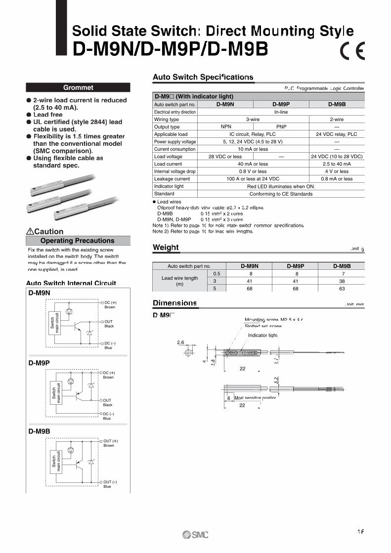
Solid State Switch: Direct Mounting StyleD-M9N/D-M9P/D-M9B
Auto Switch Internal CircuitD-M9N
D-M9B
D-M9P
Weight
Auto switch part no.
0.5
3
5
D-M9N 8
41
68
D-M9P 8
41
68
D-M9B 7
38
63
Unit: g
Lead wire length(m)
Grommet
Auto switch part no.
Electrical entry direction
Wiring type
Output type
Applicable load
Power supply voltage
Current consumption
Load voltage
Load current
Internal voltage drop
Leakage current
Indicator light
Standard
D-M9N D-M9B
2-wire
—
24 VDC relay, PLC
—
—
24 VDC (10 to 28 VDC)
2.5 to 40 mA
4 V or less
0.8 mA or less
D-M9P
Red LED illuminates when ON.
Conforming to CE Standards
3-wire
IC circuit, Relay, PLC
5, 12, 24 VDC (4.5 to 28 V)
10 mA or less
40 mA or less
0.8 V or less
100 A or less at 24 VDC
In-line
NPN PNP
28 VDC or less —
D-M9� (With indicator light)
� Lead wires Oilproof heavy-duty vinyl cable: ø2.7 x 3.2 ellipse D-M9B 0.15 mm2 x 2 cores D-M9N, D-M9P 0.15 mm2 x 3 coresNote 1) Refer to page 10 for solid state switch common specifications.Note 2) Refer to page 10 for lead wire lengths.
Dimensions
D-M9�Mounting screw M2.5 x 4 lSlotted set screw
Indicator light
2.7
22
22
2.6
4
2.8
3.2
6 Most sensitive position
Operating PrecautionsCaution
Unit: mm
PLC: Programmable Logic Controller
Auto Switch Specifications
� 2-wire load current is reduced (2.5 to 40 mA).
� Lead free� UL certified (style 2844) lead
cable is used.� Flexibility is 1.5 times greater
than the conventional model (SMC comparison).
� Using flexible cable as standard spec.
Fix the switch with the existing screw installed on the switch body. The switch may be damaged if a screw other than the one supplied, is used.
Sw
itch
mai
n ci
rcui
tS
witc
h m
ain
circ
uit
Sw
itch
mai
n ci
rcui
t
OUTBlack
DC (+)Brown
DC (–)Blue
OUTBlack
DC (+)Brown
DC (–)Blue
OUT (+)Brown
OUT (–)Blue
16

Auto Switch Internal CircuitAuto switch part no.
0.5
3
5
15
54
85
D-H7C
Unit: g
Solid State Switch: Band Mounting StyleD-H7C
Connector
Lead wire length(m)
D-H7C (With indicator light)Auto switch part no.
Wiring type
Output type
Applicable load
Power supply voltage
Current consumption
Load voltage
Load current
Internal voltage drop
Leakage current
Indicator light
Standard
D-H7C
2-wire
—
24 VDC Relay, PLC
—
—
24 VDC (10 to 28 VDC)
5 to 40 mA
4 V or less
0.8 mA or less at 24 VDC
Red LED illuminates when ON.
Conforming to CE Standards
� Lead wires — Oilproof heavy-duty vinyl cable: ø3.4, 0.2 mm2 x 2 cores (Brown, Blue), 0.5 mNote 1) Refer to page 10 for solid state switch common specifications.Note 2) Refer to page 10 for lead wire lengths and lead wire with connector.
1.Confirm that the connector is appropri-ately tightened. If tightened insuffi-ciently, the waterproof performance will deteriorate.
2. For how to handle a connector, refer to “Best Pneumatics 2004” Vol. 9 catalog.
Operating PrecautionsCaution
OUT (+)Brown
OUT (–)Blue
Weight
Unit: mmDimensions
PLC: Programmable Logic Controller
Auto Switch Specifications
Indicator light
Most sensitive position
Sw
itch
mai
n ci
rcui
t
17

Unit: mmDimensions
Auto switch part no.
Electrical entry direction
Wiring type
Output type
Applicable load
Power supply voltage
Current consumption
Load voltage
Load current
Internal voltage drop
Leakage current
Indicator light
Standard
D-M9NW D-M9BW
2-wire
—
24 VDC relay, PLC
—
—
24 VDC (10 to 28 VDC)
2.5 to 40 mA
4 V or less
0.8 mA or less
D-M9PW
Operating position .......... Red LED illuminates.Optimum operating position .......... Green LED illuminates.
3-wire
IC circuit, Relay, PLC
5, 12, 24 VDC (4.5 to 28 V)
10 mA or less
40 mA or less
0.8 V or less at 10 mA (2 V or less at 40 mA)
100 A or less at 24 VDC
Conforming to CE Standards
In-line
NPN PNP
28 VDC or less —
D-M9�W (With indicator light)
� Lead wires Oilproof heavy-duty vinyl cable: ø2.7 x 3.2 ellipse D-M9BW 0.15 mm2 x 2 cores D-M9NW, D-M9PW 0.15 mm2 x 3 coresNote 1) Refer to page 10 for solid state switch common specifications.Note 2) Refer to page 10 for lead wire lengths.
D-M9�W
2-Color Indication Solid State Switch: Direct Mounting StyleD-M9NW/D-M9PW/D-M9BW
Mounting screw M2.5 x 4 lSlotted set screw
Indicator light
2.7
22
22
2.6
4
2.8
3.2
6 Most sensitive position
Grommet
D-M9NW
D-M9BW
D-M9PW
OUTBlack
DC (+)Brown
DC (–)Blue
DC (+)Brown
OUTBlack
DC (–)Blue
OUT (+)Brown
OUT (–)Blue
Indicator light / Display method
Auto Switch Internal Circuit
ON
OFFOperatingrange
Weight Unit: g
Auto switch part no.
0.5
1
3
5
D-M9NW8
14
41
68
D-M9PW8
14
41
68
D-M9BW7
13
38
63
Lead wire length(m)
PLC: Programmable Logic Controller
Auto Switch Specifications
� 2-wire load current is reduced (2.5 to 40 mA).
� RoHS compliant� UL certified (style 2844) lead
cable is used.� The optimum operating
position can be determined by the color of the light. (Red → Green → Red)
Sw
itch
mai
n ci
rcui
tS
witc
h m
ain
circ
uit
Sw
itch
mai
n ci
rcui
t
Optimum operatingposition
DisplayRed Green Red
18
Auto Switch Internal Circuit
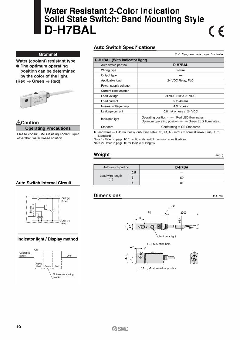
Grommet
ø3.
4
� Lead wires — Oilproof heavy-duty vinyl cable: ø3, ø4, 0.2 mm2 x 2 cores (Brown, Blue), 3 m (Standard)Note 1) Refer to page 10 for solid state switch common specifications.Note 2) Refer to page 10 for lead wire lengths.
D-H7BAL (With indicator light)Auto switch part no.
Wiring type
Output type
Applicable load
Power supply voltage
Current consumption
Load voltage
Load current
Internal voltage drop
Leakage current
Indicator light
Standard
D-H7BAL
2-wire
—
24 VDC Relay, PLC
—
—
24 VDC (10 to 28 VDC)
5 to 40 mA
4 V or less
0.8 mA or less at 24 VDC
Conforming to CE Standards
Operating position .......... Red LED illuminates.Optimum operating position .......... Green LED illuminates.
Operating PrecautionsCaution
Please consult SMC if using coolant liquid other than water based solution.
Indicator light / Display methodø3.5 Mounting hole
Auto switch part no.
0.5
3
5
Unit: g
Lead wire length(m)
D-H7BA—
50
81
Water Resistant 2-Color Indication Solid State Switch: Band Mounting StyleD-H7BAL
Weight
Unit: mmDimensions
PLC: Programmable Logic Controller
Auto Switch Specifications
Indicator light
Water (coolant) resistant type� The optimum operating
position can be determined by the color of the light.
(Red → Green → Red)
OUT (+)Brown
OUT (–)Blue
Sw
itch
mai
n ci
rcui
t
ON
OFFOperatingrange
Optimum operatingposition
DisplayRed Green Red
Most sensitive position
19
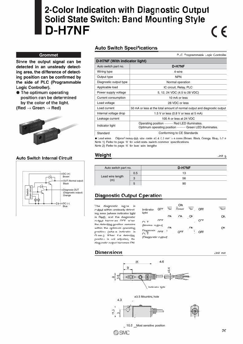
Auto Switch Internal Circuit
Diagnostic Output Operation
Dimensions
ø3.5 Mounting hole
Indicator light
Most sensitive position
ø3.
4
D-H7NF (With indicator light)Auto switch part no.
Wiring type
Output type
Diagnostic output type
Applicable load
Power supply voltage
Current consumption
Load voltage
Load current
Internal voltage drop
Leakage current
Indicator light
Standard
D-H7NF
4-wire
NPN
Normal operation
IC circuit, Relay, PLC
5, 12, 24 VDC (4.5 to 28 VDC)
10 mA or less
28 VDC or less
50 mA or less at the total amount of normal output and diagnostic output
1.5 V or less (0.8 V or less at 5 mA)
100 A or less at 24 VDC
Conforming to CE Standards
Operating position .......... Red LED illuminates.Optimum operating position .......... Green LED illuminates.
Since the output signal can be detected in an unsteady detect-ing area, the difference of detect-ing position can be confirmed by the side of PLC (Programmable Logic Controller).� The optimum operating
position can be determined by the color of the light.
(Red → Green → Red)
The diagnostic signal is output within unsteady detect-ing area (where indicator light is Red), and the diagnostic output becomes OFF when the detecting position remains within the optimum operating position (where indicator is Green). When the detecting position is not adjusted, the diagnostic output becomes ON.
OUT (Normal output)Black
DC (+)Brown
DC (–)Blue
Diagnosis OUT(Diagnostic output)Orange
Weight Unit: g
Unit: mm
Auto switch part no.
0.5
3
5
13
56
90
D-H7NF
Lead wire length(m)
2-Color Indication with Diagnostic Output Solid State Switch: Band Mounting StyleD-H7NF
Grommet
� Lead wires — Oilproof heavy-duty vinyl cable: ø3.4, 0.2 mm2 x 4 cores (Brown, Black, Orange, Blue), 0.5 mNote 1) Refer to page 10 for solid state switch common specifications.Note 2) Refer to page 10 for lead wire lengths.
PLC: Programmable Logic Controller
Auto Switch Specifications
Sw
itch
mai
n ci
rcui
t
Indicator light
Red Green Red Red
OUT(Normal output)
Diagnosis OUT(Diagnostic output)
20

This simple special is meant for machining additionally tapped hole, drilled hole, and pinned hole, as requested from customer, on parts designed largely for mounting a workpiece, etc. in the combined air cylinders.But, for each model, since they have the portions which are impossible to machine additionally, refer to the additional machining limitation.
Hole dia.
Tolerance
3 or less
+0.010
Over 3,6 or less+0.012
0+0.015
0
Over 6,10 or less
+0.0180
+0.0210
Over 10,18 or less
Over 18,20 or less
Common Complementary Explanation / Holes which can be additionally machined are the following 3 types.
D (Thread size)
A (Effective thread depth)
B = 3 x P(Incomplete thread section)
C = 0.3 x (D-P)
Note) P stands for thread pitch.
D
A (Effective depth)
C = 0.3D
DH7
A (Effective depth)
Precautions• We cannot take any responsibility as for the intensity of hole machined additionally and the effects of decreased intensity or the product itself.• It will not be plated again for the machined part additionally.• Be sure to fill in “through” for through-hole, and “effective depth” for blind hole.• When using by machining through-hole additionally, ensure that the tip of the bolt, etc. for mounting workpiece should not stick into the cylinder side. It may
result in an unexpected problem.• Use caution not to interfere the existing mounting hole on the standard products with the hole to be machined additionally. But it is possible to drill addition-
ally the larger size of hole at the same position as the existing hole.
Limitation for Machining Additionally / Since the slanted lines denote the restricted range for machining additionally, design the dimensions, referring to below.
Series MLGC
2-øDA
C B
Mounting sideConnecting port side
Front plate material: Iron
Dimensional Range Not Possible to Machine Additionally
Bore size
20253240
A19
24
24
30
B10
13
13
15
C28
36
36
42
D16
20
20
25
(mm)
1 Tapped Hole, Drilled Hole, Pinned Hole Machined Additionally XC79Symbol
Tapped hole
Designated nominal diameter and tapped hole of a pitch are machined additionally. (Maximum nominal thread diameter M20)Blind hole is deep into the bottom of prepared hole which sums up A to C in Fig. 1 in contrast to the effective depth of tapped hole. When there is a condition which does not allow through-hole, etc., leave sufficient thickness in the inner part of hole.
Drilled hole
Drilled hole of a designated internal diameter is machined. (Maximum hole diameter 20 mm)If you wish for blind hole, instruct us with effective depth. (Refer to Fig. 2.) Besides, dimensional accuracy for internal diameter will be ±0.2 mm.
Pinned hole
Pinned hole of a designated diameter (reamer hole) is machined. (Maximum hole diameter 20 mm)Internal dimension tolerates H7 tolerance to the designated hole diameter. (Refer to the table below.)
Series MLGC
These changes are dealt with Simple Specials System.Simple Specials
21

Back page 1
Series MLGC
Safety Instructions
1. The compatibility of the pneumatic equipment is the responsibility of the person who designs the pneumatic system or decides its specifications.Since the products specified here are used in various operating conditions, their compatibility for the specific pneumatic system must be based on specifications or post analysis and/or tests to meet the specific requirements. The expected performance and safety assurance are the responsibility of the person who has determined the compatibility of the system. This person should continuously review the suitability of all items specified, referring to the latest catalog information with a view to giving due consideration to any possibility of equipment failure when configuring a system.
2.Only trained personnel should operate pneumatically operated machinery and equipment.Compressed air can be dangerous if handled incorrectly. Assembly, handling or repair of pneumatic systems should be performed by trained and experienced operators. (Understanding JIS B 8370 General Rules for Pneumatic Equipment, and other safety rules are included.)
3. Do not service machinery/equipment or attempt to remove components until safety is confirmed.1. Inspection and maintenance of machinery/equipment should only be performed once measures to prevent falling or runaway of
the driven objects have been confirmed. 2. When equipment is removed, confirm that safety process as mentioned above. Turn off the supply pressure for this equipment
and exhaust all residual compressed air in the system, and release all the energy (liquid pressure, spring, condenser, gravity).3. Before machinery/equipment is restarted, take measures to prevent quick extension of a cylinder piston rod, etc.
4. Contact SMC if the product will be used in any of the following conditions:1. Conditions and environments beyond the given specifications, or if product is used outdoors.2. Installation on equipment in conjunction with atomic energy, railway, air navigation, vehicles, medical equipment, food and
beverages, recreation equipment, emergency stop circuits, clutch and brake circuits in press applications, or safety equipment.3. An application which has the possibility of having negative effects on people, property, requiring special safety analysis.4. If the products are used in an interlock circuit, prepare a double interlock style circuit with a mechanical protection function for
the prevention of a breakdown. And, examine the devices periodically if they function normally or not.
These safety instructions are intended to prevent a hazardous situation and/or equipment damage. These instructions indicate the level of potential hazard by labels of "Caution", "Warning" or "Danger". To ensure safety, be sure to observe ISO 4414 Note 1), JIS B 8370 Note 2) and other safety practices.
Danger In extreme conditions, there is a possible result of serious injury or loss of life.
Warning Operator error could result in serious injury or loss of life.
Caution Operator error could result in injury Note 3) or equipment damage. Note 4)
Labels Explanation of the labels
�Explanation of the Labels
�Selection/Handling/Applications
1. SMC, its officers and employees shall be exempted from liability for any loss or damage arising out of earthquakes or fire, action by a third person, accidents, customer error with or without intention, prod-uct misuse, and any other damages caused by abnormal operating conditions.
2. SMC, its officers and employees shall be exempted from liability for any direct or indirect loss or damage, including consequential loss or damage, loss of profits, or loss of chance, claims, demands, proceedings, costs, expenses, awards, judgments and any other liability whatsoever including legal costs and expenses, which may be suffered or incurred, whether in tort (including negligence), contract, breach of statutory duty, equity or otherwise.
3. SMC is exempted from liability for any damages caused by operations not contained in the catalogs and/or instruction manuals, and operations outside of the specification range.
4. SMC is exempted from liability for any loss or damage whatsoever caused by malfunctions of its prod-ucts when combined with other devices or software.
�Exemption from Liability
Note 1) ISO 4414: Pneumatic fluid power – General rules relating to systemsNote 2) JIS B 8370: General Rules for Pneumatic EquipmentNote 3) Injury indicates light wounds, burns and electrical shocks that do not require hospitalization or hospital visits for long-term medical treatment.Note 4) Equipment damage refers to extensive damage to the equipment and surrounding devices.

Design and Selection
Warning1. Confirm the specifications.
Read the specifications carefully and use this product appro-priately. The product may be damaged or malfunction if it is used outside the range of specifications of current load, voltage, temperature or impact. We do not guarantee any damage in any case the product is used outside of the specifi-cation range.
2. Pay attention to the length of time that a switch is on at an intermediate stroke position.When an auto switch is placed at an intermediate position of the stroke and a load is driven at the time the piston passes, the auto switch will operate. However if the speed is too great, the operating time will be shortened and the load may not operate properly. The maximum detectable piston speed is:
In cases of high piston speed, the use of an auto switch (D-G5NTL) with a built-in OFF delay timer ( 200 ms) makes it possible to extend the load operating time.Wide range detection type, D-G5NBL (operating range 35 to 45 mm) is also available.
3. Keep wiring as short as possible.<Reed switch>As the length of the wiring to a load gets longer, the rush current at switching ON becomes greater, and this may shorten the product’s life. (The switch will stay ON all the time.)Use a contact protection box when the wire length is 5 m or longer.
<Solid state switch>Although wire length should not affect switch function, use a wire 100 m or shorter.If the wiring is longer it will likely increase noise although the length is less than 100 m.When the wire length is long, we recommend attaching the ferrite core to the both ends of the cable to prevent excess noise.
4. Do not use a load that generates surge voltage. If a surge voltage is generated, the discharge occurs at the contact, possibly resulting in the shortening of product life.<Reed switch>If driving a load such as a relay that generates a surge voltage, use a contact protection box.
<Solid state switch>Although a zener diode for surge protection is connected at the output side of a solid state auto switch, damage may still occur if the surge is applied repeatedly. When a load, such as a relay or solenoid, which generates surge is directly driven, use a type of switch with a built-in surge absorbing element.
Caution1. Take precautions when multiple actuators are used
close together.When two or more actuators are lined up in close proximity to each other, magnetic field interference may cause the switches to malfunction. Maintain a minimum cylinder separa-tion of 40 mm.(When the allowable interval is specified for each cylinder series, use the indicated value.) The auto switches may malfunction due to the interference from the magnetic fields.
2. Take note of the internal voltage drop of the switch.<Reed switch>1) Switches with an indicator light (Except D-A96)
• If auto switches are connected in series as shown below, take note that there will be a large voltage drop because of internal resistance in the light emitting diodes. (Refer to internal voltage drop in the auto switch specifications.)[The voltage drop will be “n” times larger when “n” auto switches are connected.]Even though an auto switch operates normally, the load may not operate.
• In the same way, when operating under a specified voltage, although an auto switch may operate normally, the load may not operate. Therefore, the formula below should be satisfied after confirming the minimum operat-ing voltage of the load.
2) If the internal resistance of a light emitting diode causes a problem, select a switch without an indicator light (Model D-A90).
<Solid state switch>3) Generally, the internal voltage drop will be greater with a
2-wire solid state auto switch than with a reed switch. Take the same precautions as in 1).Also, note that a 12 VDC relay is not applicable.
Load
Back page 2
5. Cautions for use in an interlock circuitWhen an auto switch is used for an interlock signal requiring high reliability, devise a double interlock system to avoid trouble by providing a mechanical protection function, or by also using another switch (sensor) together with the auto switch. Also perform periodic maintenance and confirm proper operation.
6. Do not make any modifications to the product.Do not take the product apart. It may cause human injuries and accidents.
Series MLGC Auto SwitchesPrecautions 1Be sure to read this before handling.
V (mm/s) = Auto switch operating range (mm)
Load operating time (ms)x 1000
Supplyvoltage
– >Internal voltagedrop of switch
Minimum operatingvoltage of load

Mounting and AdjustmentDesign and Selection
Warning1. Instruction manual
Install the products and operate them only after reading the instruction manual carefully and understanding its contents. Also keep the manual where it can be referred to as neces-sary.
2. Do not drop or bump.Do not drop, bump or apply excessive impacts (300 m⁄s2 or more for reed switches and 1000 m⁄s2 or more for solid state switches) while handling. Although the body of the switch may not be damaged, the inside of the switch could be damaged and cause a malfunction.
3. Mount switches using the proper fastening torque.When a switch is tightened beyond the range of fastening torque, the mounting screws, mounting bracket or switch may be damaged. On the other hand, tightening below the range of fastening torque may allow the switch to slip out of position. (For mounting and moving auto switches, tightening torque, etc., refer to each series.)
4. Mount a switch at the center of the operating range.Adjust the mounting position of an auto switch so that the piston stops at the center of the operating range (the range in which a switch is ON). (The mounting position shown in a catalog indicates the optimum position at stroke end.) If mounted at the end of the operating range (around the borderline of ON and OFF), operation will be unstable or the service life will be shortened.
<D-M9�>When the D-M9� auto switch is used to replace old series auto switch, it may not activate depending on operating condi-tion because of its shorter operating range.Such as• Application where the stop position of actuator may
vary and exceed the operating range of the auto switch, for example, pushing, pressing, clamping operation, etc.
• Application where the auto switch is used for detecting an intermediate stop position of the actuator. (In this case the detecting time will be reduced.)
In these applications, set the auto switch to the center of the required detecting range.
Caution1. Do not carry an actuator by the auto switch lead
wires.Never carry a cylinder (actuator) by its lead wires. This may not only cause broken lead wires, but it may cause internal elements of the switch to be damaged by the stress.
2. Fix the switch with appropriate screw installed on the switch body. If using other screws, switch may be damaged.
Back page 3
Caution3. Pay attention to leakage current.
<Solid state switch>With a 2-wire solid state auto switch, current (leakage current) flows to the load to operate the internal circuit even when in the OFF state.
If the criteria given in the above formula are not met, it will not reset correctly (stays ON). Use a 3-wire switch if this specifica-tion will not be satisfied.Moreover, leakage current flow to the load will be “n” times larger when “n” auto switches are connected in parallel. Refer to “Best Pneumatics 2004” Vol. 9.
4. Ensure sufficient clearance for maintenance activi-ties.When designing an application, be sure to allow sufficient clearance for maintenance and inspections.
5. Minimum stroke for auto switch mountingThe minimum stroke value for mounting one or two auto switches is obtained when the switch can detect at the cylinder stroke ends.However, even if the switch is mounted at the proper position within the minimum stroke range, it may not be able to detect when the piston stops in the middle of the stroke due to a stopper, etc. It may also turn on in the middle of a stroke.
6. When multiple auto switches are required“n” indicates the number of switch which can be physically mounted. Detection intervals depends on the switch mounting structure and set position therefore some required interval and set positions may not be available.
7. Limitations of detectable positioningWhen using certain mounting brackets, the surface and position where an auto switch can be mounted maybe restricted due to physical interference. For example, when using some bracket types the switch cannot be surface mounted at an angle of 180 degrees.Please select the set position of the auto switch so that it does not interfere with the rear plate of the cylinder.
8. Use the cylinder and switch in proper combination.The auto switch is pre-adjusted to activate properly for an auto-switch-capable SMC cylinder.If the auto switch is mounted improperly, used for another brand of cylinder or used after the alternation of the machine installation, the switch may not activate properly.
Series MLGC Auto SwitchesPrecautions 2Be sure to read this before handling.
>Operating current ofload (OFF condition) Leakage current

Caution4. Avoid incorrect wiring.
<Reed switch>A 24 VDC switch with indicator light has polarity. The brown lead wire is (+) and the blue lead wire is (–).1) If connections are reversed, a switch will operate, however,
the light emitting diode will not light up.Also note that a current greater than that specified will damage a light emitting diode and it will no longer operate.Applicable models:D-A93, C73C, B54
2) When using D-B59W, the switch will constantly remain ON if the connections are reversed.
<Solid state switch>1) If connections are reversed on a 2-wire type switch, the
switch will not be damaged if protected by a protection circuit, but the switch will always stay in an ON state. However, it is still necessary to avoid reversed connec-tions, since the switch could be damaged by a load short circuit in this condition.
2) If connections are reversed (power supply line + and power supply line –) on a 3-wire type switch, the switch will be protected by a protection circuit. However, if the power supply line (+) is connected to the blue wire and the power supply line (–) is connected to the black wire, the switch will be damaged.
<D-M9�>D-M9� does not have built-in short circuit protection circuit. Be aware that if the power supply connection is reversed (e.g. (+) power supply wire and (–) power supply wire connection is reversed), the switch will be damaged.
5. When the cable sheath is stripped, confirm the stripping direction. The insulator may be split or damaged depending on the direction. (D-M9� only)
Model no.D-M9N-SWY
Model nameWire stripper
∗ Stripper for a round cable (ø2.0) can be used for a 2-wire type cable.
Recommended Tool
Back page 4
Wiring
Warning1. Confirm proper insulation of wiring.
Be certain that there is no faulty wiring insulation (contact with other circuits, ground fault, improper insulation between terminals, etc.). Damage may occur due to excess current flow into a switch.
2. Do not wire with power lines or high voltage lines.Wire separately from power lines or high voltage lines, avoid-ing parallel wiring or wiring in the same conduit with these lines. Control circuits, including auto switches, may malfunc-tion due to noise from these other lines.
Caution1. Avoid repeatedly bending or stretching lead wires.
Repeated bending or tensile force applied to the lead wire may cause the sheath to fall off or disconnection of the wire.If bending or tensile force are not avoidable, fix the lead wire close to the switch and allow a bend radius of R40 to 80 mm or larger. Please consult SMC for details. Stress and tensile force applied to the connection between the cable and switch increases the possibility of disconnection.Fix the cable in the middle so that it is not movable in the area where it connects with the switch.
2. Be sure to connect the load before power is applied.<2-wire type>If the power is turned ON when an auto switch is not connected to a load, the switch will be instantly damaged because of excess current.It is the same as when the 2-wire brown cord (+, output) is directly connected to the (+) power supply terminal.
3. Do not allow short circuit of loads.<Reed switch>If the power is turned ON with a load in a short circuited condition, the switch will be instantly damaged because of excess current flow into the switch.
<Solid state switch>Model D-M9� and all models of PNP output type switches do not have built-in short circuit prevention circuits. If loads are short circuited, the switches will be instantly damaged, as in the case of reed switches.Take special care to avoid reverse wiring with the power supply line (brown) and the output line (black) on 3-wire type switches.
Series MLGC Auto SwitchesPrecautions 3Be sure to read this before handling.

Maintenance
Warning1. Perform the following maintenance periodically in
order to prevent possible danger due to unex-pected auto switch malfunction.1) Securely tighten switch mounting screws.
If screws become loose or the mounting position is dislocated, retighten them after readjusting the mounting position.
2) Confirm that there is no damage to lead wires.To prevent faulty insulation, replace switches or repair lead wires, etc., if damage is discovered.
3) Confirm the lighting of the green light on the 2-color indica-tor type switch.Confirm that the green LED is turned on when stopped at the established position. If the red LED is turned on, the mounting position is not appropriate. Readjust the mount-ing position until the green LED lights up.
2. Maintenance procedures are outlined in the opera-tion manual.Not following proper procedures could cause the product to malfunction and could lead to damage to the equipment or machine.
3. Removal of equipment, and supply/exhaust of com-pressed airBefore any machinery or equipment is removed, first ensure that the appropriate measures are in place to prevent the fall or erratic movement of driven objects and equipment, then cut off the electric power and reduce the pressure in the system to zero. Only then should you proceed with the removal of any machinery and equipment.When machinery is restarted, proceed with caution after confirming that appropriate measures are in place to prevent actuators from sudden movement.
Caution1. Avoid accumulation of iron debris or close contact
with magnetic substances.When a large amount of ferrous debris such as machining chips or spatter is accumulated, or a magnetic substance (something attracted by a magnet) is brought into close proximity with an auto switch actuator, it may cause the auto switch to malfunction due to a loss of the magnetic force inside the actuator.
2. Please consult SMC concerning water resistance, elasticity of lead wires, usage at welding sites, etc.
3. Do not use in direct sunlight.4.Do not mount the product in locations where it is
exposed to radiant heat.
Back page 5
Operating Environment
Warning1. Never use in an atmosphere of explosive gases.
The construction of auto switches is not intended to prevent explosion. Never use in an atmosphere with an explosive gas since this may cause a serious explosion.
2. Do not use in an area where a magnetic field is generated.Auto switches will malfunction or magnets inside actuators will become demagnetized.
3. Do not use in an environment where the auto switch will be in water or continually exposed to water.Although switches, satisfy IEC standard IP67 construction (JIS C 0920: waterproof construction), do not use switches in applications where continually exposed to water splash or spray. Poor insulation or swelling of the potting resin inside switches may cause malfunction.
4. Do not use in an environment with oil or chemicals.Please consult SMC if auto switches will be used in an environment with coolant, cleaning solvent, various oils or chemicals. If auto switches are used under these conditions for even a short time, they may be adversely affected by improper insulation, malfunction due to swelling of the potting resin, or hardening of the lead wires.
5. Do not use in an environment with temperature cycles.Please consult SMC if switches are used where there are temperature cycles other than normal temperature changes, as they may be adversely affected internally.
6. Do not use in an environment where there is exces-sive impact shock.<Reed switch>When excessive impact (300 m/s2 or more) is applied to a reed switch during operation, the contact point will malfunction and generate or cut off a signal momentarily (1 ms or less). Please consult SMC regarding the need to use a solid state switch depending upon the environment.
7. Do not use in an area where surges are generated.<Solid state switch>When there are units (solenoid type lifter, high frequency induction furnace, motor, radio equipment etc.) which gener-ate large surges or electromagnetic waves in the area around actuators with solid state auto switches, this may cause deterioration or damage to the switches. Avoid sources of surge generation and crossed lines.
Series MLGC Auto SwitchesPrecautions 4Be sure to read this before handling.

Series MLGC Specific Product PrecautionsBe sure to read this before handling. For Safety Istructions, Actuators Precaution,refer to “Precautions for Handling Pneumatic Devices” (M-03-E3A).
Mounting and Adjustment
Caution on Handling the Fine Lock Cylinder
Warning
Caution
Caution
Protective cover installation example
Protective cover
Cover mounting bolt
Rear plate
Cover mounting bolt
Protective cover
Rear plate
Back page 6
1.Use caution that no scratch or dent will be given tothe slide part of the guide rod. Because the outer circumference of the guide rod is manufac-tured with precise tolerances, even a slight deformation,scratch, or gouge can lead to faulty operation or reduceddurability.
2.When fitting the guide body, use the guide bodywhich has high flatness of the fitting surface.If the guide rod has twisted, operation resistance will becomeabnormally higher and the bearing will wear at an early stage,thereby resulting in poor performance.
3.Allow an ample space around the cylinder.Ensure enough clearance around the cylinder to allow forunobstructed maintenance and inspection work.
4.Do not adjust the rod stroke by moving the rearplates. The resulting impact cannot be absorbed easily, the strokeposition cannot be maintained, and faulty operation mayensue.
5.LubricationTo prevent foreign particles from mixing with the grease, use agrease applicator that has a check valve. Use a high-qualitylithium soap-based no. 2 grease.
6. Mounting orientationFor ceiling mount (opening of the rear plate face downwards),the base cylinder head end and the rear plate may interferedue to the deflection of the guide rod.
1.Installing a protective cover (In the case of rear plate) During mounting, handling and operation, the rear plate makes reciprocating movements. Therefore, pay careful attention not to insert your hand, etc., between the cylinder and the rear plate.When you are going to fit this product to the outside of your equipment, take preventative measures such as installing a protective cover.
1. For details, make sure to refer to “Fine Lock Cylin-der (CLG1 series)” in “Best Pneumatics 2004” Vol. 9 catalog.


SMC'S GLOBAL MANUFACTURING, DISTRIBUTION AND SERVICE NETWORK
Akihabara UDX 15F, 4-14-1, Sotokanda, Chiyoda-ku, Tokyo 101-0021, JAPANPhone: 03-5207-8249 FAX: 03-5298-5362URL http://www.smcworld.com© 2006 SMC Corporation All Rights Reserved
Specifications are subject to change without prior notice and any obligation on the part of the manufacturer.
1st printing KZ printing KZ 120DN Printed in Japan.D-DN
This catalog is printed on recycled paper with concern for the global environment.
Safety Instructions Be sure to read “Precautions for Handling Pneumatic Devices” (M-03-E3A) before using.
NORWAYSMC Pneumatics Norway A/S
POLANDSMC Industrial Automation Polska Sp.z.o.o.
ROMANIA SMC Romania s.r.l.
RUSSIA SMC Pneumatik LLC.
SLOVAKIASMC Priemyselná automatizáciá, s.r.o.
SLOVENIASMC INDUSTRIJSKA AVTOMATIKA d.o.o.
SPAIN/PORTUGALSMC España, S.A.
SWEDENSMC Pneumatics Sweden AB
SWITZERLANDSMC Pneumatik AG.
UKSMC Pneumatics (U.K.) Ltd.
ASIACHINASMC (China) Co., Ltd.
HONG KONGSMC Pneumatics (Hong Kong) Ltd.
INDIASMC Pneumatics (India) Pvt. Ltd.
INDONESIAPT. SMC Pneumatics Indonesia
MALAYSIASMC Pneumatics (S.E.A.) Sdn. Bhd.
PHILIPPINESSHOKETSU-SMC Corporation
SINGAPORESMC Pneumatics (S.E.A.) Pte. Ltd.
SOUTH KOREASMC Pneumatics Korea Co., Ltd.
TAIWANSMC Pneumatics (Taiwan) Co., Ltd.
THAILANDSMC Thailand Ltd.
NORTH AMERICACANADASMC Pneumatics (Canada) Ltd.
MEXICOSMC Corporation (Mexico) S.A. de C.V.USASMC Corporation of America
SOUTH AMERICAARGENTINASMC Argentina S.A.
BOLIVIASMC Pneumatics Bolivia S.R.L.
BRAZILSMC Pneumaticos Do Brazil Ltda.
CHILESMC Pneumatics (Chile) S.A.
VENEZUELASMC Neumatica Venezuela S.A.
OCEANIAAUSTRALIASMC Pneumatics (Australia) Pty. Ltd.
NEW ZEALANDSMC Pneumatics (N.Z.) Ltd.
EUROPEAUSTRIASMC Pneumatik GmbH
BELGIUMSMC Pneumatics N.V./S.A.
BULGARIASMC Industrial Automation Bulgaria EOOD
CROATIASMC Industrijska automatika d.o.o.
CZECH REPUBLICSMC Industrial Automation CZ s.r.o.
DENMARKSMC Pneumatik A/S
ESTONIASMC Pneumatics Estonia OÜ
FINLANDSMC Pneumatics Finland OY
FRANCESMC Pneumatique SA
GERMANYSMC Pneumatik GmbH
GREECESMC Hellas EPE
HUNGARYSMC Hungary Ipari Automatizálási Kft.
IRELANDSMC Pneumatics (Ireland) Ltd.
ITALYSMC Italia S.p.A.
LATVIASMC Pnuematics Latvia SIA
LITHUANIASMC Pneumatics Lietuva, UAB
NETHERLANDSSMC Pneumatics BV.