Naturally aspirated gasoline engines and cylinder deactivation
Upload
khangminh22Category
view
1download
0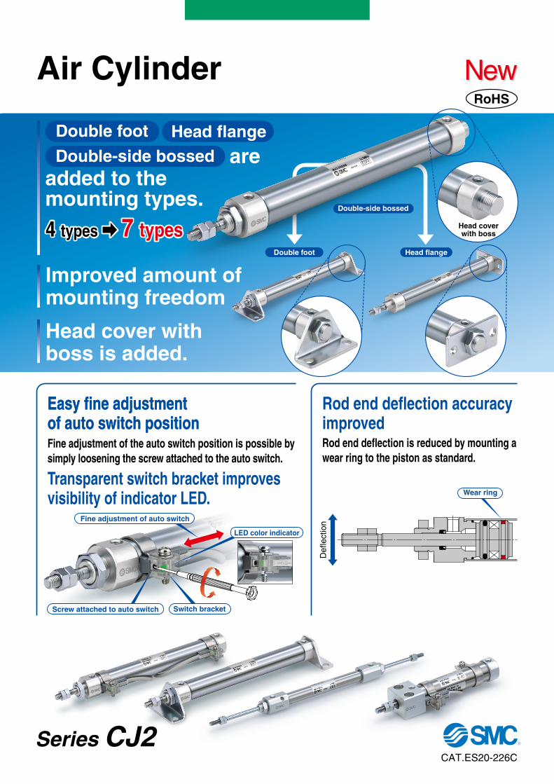
C
Series C
J2A
ir Cylin
der
Head coverwith boss
Double-side bossed
Head flangeDouble foot
Head flangeDouble foot
Double-side bossed are added to themounting types.
7 types4 types
Improved amount of mounting freedom
Head cover with boss is added.
CAT.ES20-226C
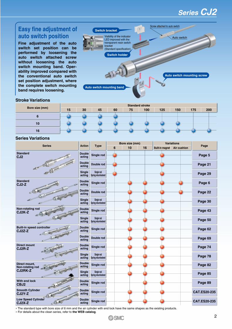
Fine adjustment of the auto switch position is possible by simply loosening the screw attached to the auto switch.
Easy fine adjustment of auto switch positionEasy fine adjustment of auto switch position
Transparent switch bracket improves visibility of indicator LED.
Screw attached to auto switch
LED color indicator
Switch bracket
Fine adjustment of auto switch
Rod end deflection is reduced by mounting a wear ring to the piston as standard.
Rod end deflection accuracy improved
Wear ring
Def
lect
ion
Air Cylinder NewNewRoHS
Series CJ2
1
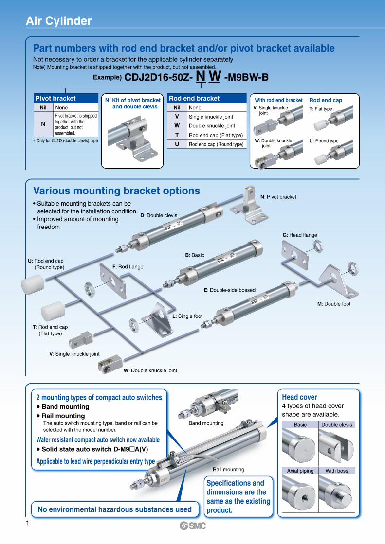
Part numbers with rod end bracket and/or pivot bracket available
Air Cylinder
Not necessary to order a bracket for the applicable cylinder separatelyNote) Mounting bracket is shipped together with the product, but not assembled.
T: Flat type
U: Round type
With rod end bracket Rod end capN: Kit of pivot bracket and double clevis
Example) CDJ2D16-50Z- N W -M9BW-B
Pivot bracketNil None
∗ Only for CJ2D (double clevis) type
N
Rod end bracketNil None
Single knuckle jointV
Double knuckle jointW
Rod end cap (Flat type)T
Rod end cap (Round type)U
V: Single knucklejoint
W: Double knucklejoint
Pivot bracket is shipped together with the product, but not assembled.
Various mounting bracket options• Suitable mounting brackets can be selected for the installation condition.• Improved amount of mounting freedom
N: Pivot bracket
D: Double clevis
B: Basic
E: Double-side bossed
G: Head flange
M: Double foot
F: Rod flange
L: Single foot
U: Rod end cap(Round type)
T: Rod end cap(Flat type)
V: Single knuckle joint
W: Double knuckle joint
2 mounting types of compact auto switches Band mounting Rail mounting
Water resistant compact auto switch now available Solid state auto switch D-M9A(V)
Applicable to lead wire perpendicular entry type
Head cover4 types of head cover shape are available.
The auto switch mounting type, band or rail can be selected with the model number.
Basic Double clevis
Axial piping With bossRail mounting
Band mounting
No environmental hazardous substances used
Specifications anddimensions are the same as the existing product.
Page 62
Page 43
Page 30
Page 6
Page 74
Page 82
CAT.ES20-235
CAT.ES20-235
Page 22
Page 29
Page 5
Page 21
Page 50
Page 69
Page 78
Page 85
Page 89
Built-in magnet Air cushion
VariationsSeries Action Type Page
45 60 75 100 125 150 175 20015 30Standard stroke
Bore size (mm)
6
10
16
106 16Bore size (mm)
Single rod
Single rod
Single rod
Single rod
Single rod
Single rod
Single rod
Single rod
StandardCJ2-Z
Non-rotating rodCJ2K-Z
Built-in speed controllerCJ2Z-Z
Direct mountCJ2R-Z
Direct mount,Non-rotating rodCJ2RK-Z
With end lockCBJ2
Low Speed CylinderCJ2X-Z
Smooth CylinderCJ2Y-Z
Stroke Variations
Series Variations
Auto switch mounting band
Switch holder
Auto switch mounting screw
Switch bracket
Auto switch
Screw attached to auto switch
Double rod
Double rod
Doubleacting
Doubleacting
Doubleacting
Doubleacting
Singleacting
Doubleacting
Doubleacting
Doubleacting
Doubleacting
Doubleacting
Singleacting
Doubleacting
Doubleacting
Doubleacting
Singleacting
Singleacting
Singleacting
Single rod
Double rod
Single rodSpring return/extend
Single rodSpring return/extend
Single rodSpring return/extend
Single rodSpring return/extend
Single rodSpring return/extend
StandardCJ2
∗ The standard type with bore size of 6 mm and the air cylinder with end lock have the same shapes as the existing products.∗ For details about the clean series, refer to the WEB catalog.
Easy fine adjustment of auto switch position
Series CJ2
Fine adjustment of the auto switch set position can be performed by loosening the auto switch attached screw without loosening the auto switch mounting band. Oper-ability improved compared with the conventional auto switch set position adjustment, where the complete switch mounting band requires loosening.
Visibility of the indicator LED improved with the transparent resin switch bracket (Standard specification)
2
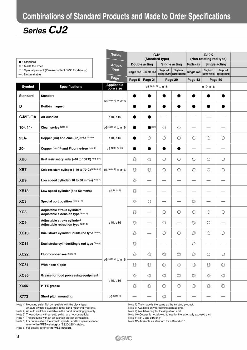
Note 7) The shape is the same as the existing product.Note 8) Available only for locking at head end.Note 9) Available only for locking at rod end.Note 10) Copper is not allowed to use for the externally exposed part.Note 11) ø10 and ø16 onlyNote 12) Available as standard for ø10 and ø16.
Note 1) Mounting style: Not compatible with the clevis type.An auto switch is available in the band mounting type only.
Note 2) An auto switch is available in the band mounting type only.Note 3) The products with an auto switch are not compatible. Note 4) The products with an air cushion are not compatible.Note 5) For details about the smooth cylinder and low speed cylinder,
refer to the WEB catalog or "ES20-235" catalog.Note 6) For details, refer to the WEB catalog.
Combinations of Standard Products and Made to Order Specifications
Series CJ2
CJ2(Standard type)
CJ2K(Non-rotating rod type)
Double acting Single acting Double acting Single acting
Single rod Double rodSingle rod
(spring return)Single rod
(spring extend)Single rod
Single rod(spring return)
Single rod(spring extend)
Page 5 Page 21 Page 29 Page 43 Page 50
Symbol Specifications Applicable bore size ø6 Note 7) to ø16 ø10, ø16
Standard Standard
ø6 Note 7) to ø16
V V V V V V V
D Built-in magnet V V V V V V V
CJ2-A Air cushion ø10, ø16 V V — — — — —
10-, 11- Clean series Note 1) ø6 Note 7) to ø16 V V Note 11) v v — — —
25A- Copper (Cu) and Zinc (Zn)-free Note 6) ø10, ø16 V v v v v v v
20- Copper Note 10) and Fluorine-free Note 2) ø6 Note 7) 12) V V V V — — —
XB6 Heat resistant cylinder (−10 to 150°C) Note 3) 4)
ø6 Note 7) to ø16
v v v v v
XB7 Cold resistant cylinder (−40 to 70°C) Note 3) 4) v v v v v
XB9 Low speed cylinder (10 to 50 mm/s) Note 4) — — — — — —
XB13 Low speed cylinder (5 to 50 mm/s) ø6 Note 7) — — — — — —
XC3 Special port position Note 2) 4)
ø10, ø16
v — — — —
XC8Adjustable stroke cylinder/Adjustable extension type Note 4) — v v v v v
XC9Adjustable stroke cylinder/Adjustable retraction type Note 4) — v — v —
XC10 Dual stroke cylinder/Double rod type Note 4) — v v v v
XC11 Dual stroke cylinder/Single rod type Note 4) — — — v — —
XC22 Fluororubber seal Note 4)
ø6 Note 7) to ø16
v v
XC51 With hose nipple
XC85 Grease for food processing equipment
ø10, ø16
X446 PTFE grease
X773 Short pitch mounting ø6 Note 7) — — — — — —
V : Standard : Made to Order v : Special product (Please contact SMC for details.)
— : Not available
Series
Action/Type
Page
3
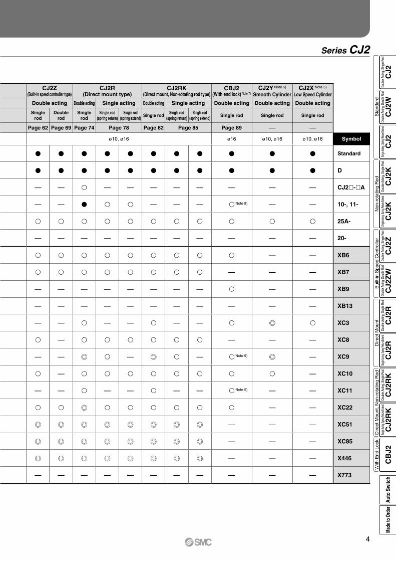
Series CJ2
CJ2Z(Built-in speed controller type)
CJ2R(Direct mount type)
CJ2RK(Direct mount, Non-rotating rod type)
CBJ2(With end lock) Note 7)
CJ2Y Note 5)
Smooth CylinderCJ2X Note 5)
Low Speed Cylinder
Double acting Double acting Single acting Double acting Single acting Double acting Double acting Double acting
Single rod
Double rod
Single rod
Single rod(spring return)
Single rod(spring extend)
Single rodSingle rod
(spring return)Single rod
(spring extend)Single rod Single rod Single rod
Page 62 Page 69 Page 74 Page 78 Page 82 Page 85 Page 89 — —
ø10, ø16 ø16 ø10, ø16 ø10, ø16 Symbol
V V V V V V V V V V V Standard
V V V V V V V V V V V D
— — v — — — — — — — — CJ2l-lA
— — V v v — — — v Note 8) — — 10-, 11-
v v v v v v v v v v v 25A-
— — — — — — — — — — — 20-
v v v v v v v v v — — XB6
v v v v v v v v — — — XB7
— — — — — — — — v — — XB9
— — — — — — — — — — — XB13
— — v — — v — — v v XC3
v — v v v v v v — — — XC8
— — v — v — v Note 9) — XC9
v — v v v v v v v v — XC10
— — v — — v — — v Note 9) — — XC11
v v v v v v v v — — XC22
— — — XC51
— — — XC85
— — — X446
— — — — — — — — — — — X773
4
CJ2
CJ2
WC
J2C
J2K
CJ2
KC
J2Z
CJ2
ZW
CJ2
RC
J2R
CJ2
RK
CJ2
RK
CB
J2
Sta
ndar
dN
on-r
otat
ing
Rod
Bui
lt-in
Spe
ed C
ontr
olle
rD
irect
Mou
ntD
irect
Mou
nt, N
on-r
otat
ing
Rod
With
End
Loc
kDo
uble
Actin
g, Do
uble
Rod
Single
Acting
, Sprin
g Retu
rn/Exte
ndDo
uble
Actin
g, Si
ngle
Rod
Single
Acting
, Sprin
g Retu
rn/Exte
ndDo
uble
Actin
g, Si
ngle
Rod
Doub
le Ac
ting,
Doub
le Ro
dDo
uble
Actin
g, Si
ngle
Rod
Single
Acting
, Sprin
g Retu
rn/Exte
ndDo
uble
Actin
g, Si
ngle
Rod
Single
Acting
, Sprin
g Retu
rn/Exte
ndDo
uble
Actin
g, Si
ngle
Rod
Auto
Sw
itch
Made
to O
rder
CJ2 R
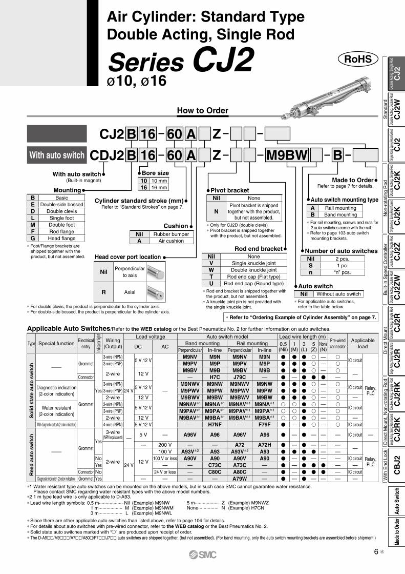
With auto switch M9BWCDJ2 RL 6 60
6 60
6 6 mm
Bore sizeB Basic
L Single foot
F Rod flange
Mounting
Cylinder standard stroke (mm)Refer to “Standard Strokes” on page 7.
With auto switch(Built-in magnet)
Nil 2 pcs.
S 1 pc.
n “n” pcs.
Number of auto switches
R Axial
Head cover port location
Example Band mounting CDJ2B6-60-B
Built-in Magnet Cylinder ModelSuffix the symbol “-B” (Band mounting style) to the end of part number for cylinder with auto switch.
* For rail mounting, screws and nuts for 2 auto switches come with the rail.
* Refer to page 103 for auto switch mounting brackets.
* ø6 is available only as in-line style.
L
C
Note) This symbol is indicated when the D-A9l or M9l type auto switch is specified.This mounting bracket does not apply to other auto switches (D-C7l and H7l, etc.) (Nil)
Auto switch mounting bracket Note)
Auto switch* For applicable auto switches, refer to the
table below.
If a built-in magnet cylinder without an auto switch is required, refer to the model of built-in magnet cylinder.
Made to OrderRefer to page 7 for details.
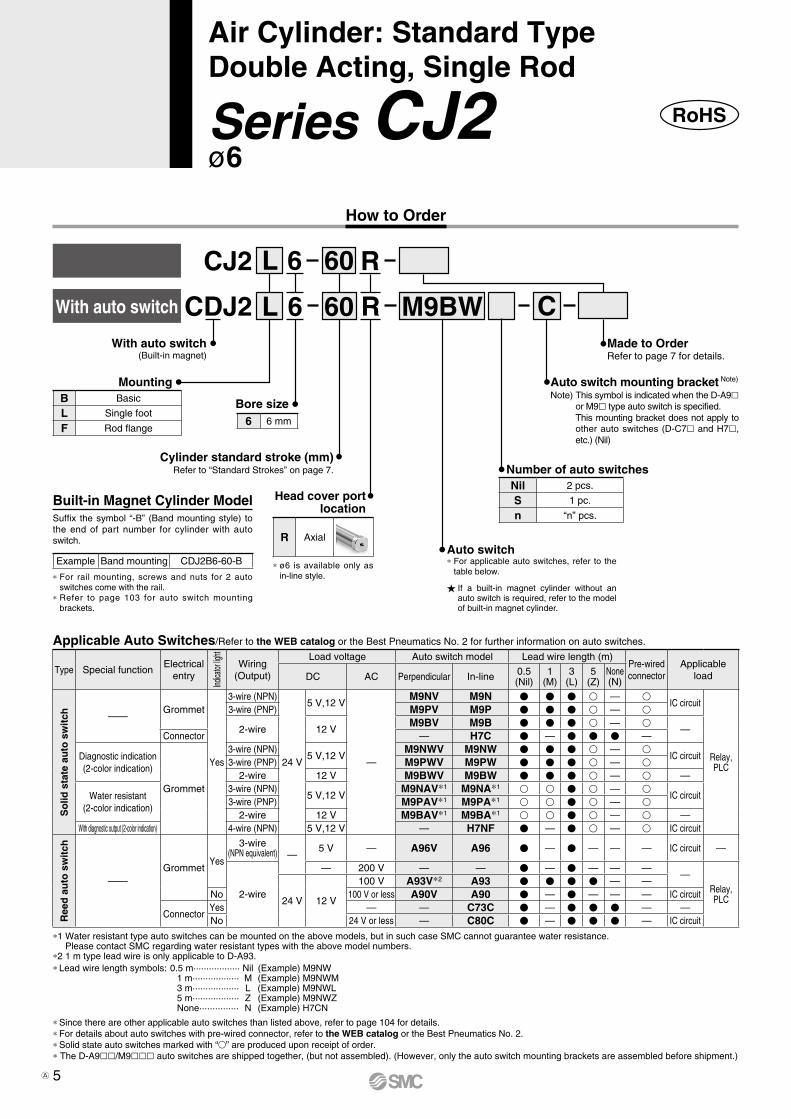
Type Special functionElectrical
entry
Indica
tor lig
ht
Wiring(Output)
Load voltage Auto switch model Lead wire length (m)Pre-wiredconnector
ApplicableloadDC AC Perpendicular In-line 0.5
(Nil)1
(M)3
(L)5
(Z)None(N)
So
lid s
tate
au
to s
wit
ch ——Grommet
Yes
3-wire (NPN)
24 V
5 V,12 V
—
M9NV M9N V V V v — vIC circuit
Relay,PLC
3-wire (PNP) M9PV M9P V V V v — v
2-wire 12 VM9BV M9B V V V v — v
—Connector — H7C V — V V V —
Diagnostic indication(2-color indication)
Grommet
3-wire (NPN)5 V,12 V
M9NWV M9NW V V V v — vIC circuit
3-wire (PNP) M9PWV M9PW V V V v — v2-wire 12 V M9BWV M9BW V V V v — v —
Water resistant(2-color indication)
3-wire (NPN)5 V,12 V
M9NAV*1 M9NA*1 v v V v — vIC circuit
3-wire (PNP) M9PAV*1 M9PA*1 v v V v — v2-wire 12 V M9BAV*1 M9BA*1 v v V v — v —
With diagnostic output (2-color indication) 4-wire (NPN) 5 V,12 V — H7NF V — V v — v IC circuit
Ree
d a
uto
sw
itch
——Grommet
Yes
3-wire(NPN equivalent) —
5 V — A96V A96 V — V — — — IC circuit —
2-wire
— 200 V — — V — V — — ——
Relay,PLC24 V 12 V
100 V A93V*2 A93 V V V V — —No 100 V or less A90V A90 V — V — — — IC circuit
ConnectorYes — — C73C V — V V V — —No 24 V or less — C80C V — V V V — IC circuit
Applicable Auto Switches/Refer to the WEB catalog or the Best Pneumatics No. 2 for further information on auto switches.
RoHSSeries CJ2ø6
Air Cylinder: Standard Type Double Acting, Single Rod
* Since there are other applicable auto switches than listed above, refer to page 104 for details.* For details about auto switches with pre-wired connector, refer to the WEB catalog or the Best Pneumatics No. 2.* Solid state auto switches marked with “v” are produced upon receipt of order.* The D-A9ll/M9lll auto switches are shipped together, (but not assembled). (However, only the auto switch mounting brackets are assembled before shipment.)
*1 Water resistant type auto switches can be mounted on the above models, but in such case SMC cannot guarantee water resistance. Please contact SMC regarding water resistant types with the above model numbers.
*2 1 m type lead wire is only applicable to D-A93.* Lead wire length symbols: 0.5 m·················· Nil (Example) M9NW 1 m·················· M (Example) M9NWM 3 m·················· L (Example) M9NWL 5 m·················· Z (Example) M9NWZ None··············· N (Example) H7CN
How to Order
5A
With auto switch(Built-in magnet)
RoHSSeries CJ2ø10, ø16
Air Cylinder: Standard Type Double Acting, Single Rod
Cylinder standard stroke (mm)Refer to “Standard Strokes” on page 7.
* Refer to “Ordering Example of Cylinder Assembly” on page 7.
Made to OrderRefer to page 7 for details.
A
A
* Only for CJ2D (double clevis)* Pivot bracket is shipped together
with the product, but not assembled.
Pivot bracket
* Foot/Flange brackets are shipped together with the product, but not assembled.
* Rod end bracket is shipped together with the product, but not assembled.
* A knuckle joint pin is not provided with the single knuckle joint.
Rod end bracket
* For applicable auto switches, refer to the table below.* For double clevis, the product is perpendicular to the cylinder axis.
* For double-side bossed, the product is perpendicular to the cylinder axis.
Head cover port location
Auto switch
Bore size
Mounting
M9BW BZ6016
Z6016
BWith auto switch CDJ2
BCJ2
B BasicE Double-side bossedD Double clevisL Single footM Double footF Rod flangeG Head flange
10 10 mm16 16 mm
Nil None
NPivot bracket is shipped
together with the product, but not assembled.
* For rail mounting, screws and nuts for 2 auto switches come with the rail.
* Refer to page 103 auto switch mounting brackets.
Auto switch mounting typeA Rail mountingB Band mounting
Number of auto switchesNil 2 pcs.S 1 pc.n “n” pcs.
Nil Without auto switch
Nil NoneV Single knuckle jointW Double knuckle jointT Rod end cap (Flat type)U Rod end cap (Round type)
NilPerpendicular
to axis
R Axial
CushionNil Rubber bumperA Air cushion
* Since there are other applicable auto switches than listed above, refer to page 104 for details.* For details about auto switches with pre-wired connector, refer to the WEB catalog or the Best Pneumatics No. 2.* Solid state auto switches marked with “v” are produced upon receipt of order.* The D-A9ll/M9lll/A7ll/A80l/F7ll/J7ll auto switches are shipped together, (but not assembled). (For band mounting, only the auto switch mounting brackets are assembled before shipment.)
*1 Water resistant type auto switches can be mounted on the above models, but in such case SMC cannot guarantee water resistance. Please contact SMC regarding water resistant types with the above model numbers.
*2 1 m type lead wire is only applicable to D-A93.* Lead wire length symbols: 0.5 m·················· Nil (Example) M9NW 1 m·················· M (Example) M9NWM 3 m·················· L (Example) M9NWL
5 m·················· Z (Example) M9NWZ None··············· N (Example) H7CN
Applicable Auto Switches/Refer to the WEB catalog or the Best Pneumatics No. 2 for further information on auto switches.
Type Special functionElectrical
entry
Indica
tor lig
ht
Wiring(Output)
Load voltage Auto switch model Lead wire length (m)Pre-wiredconnector
ApplicableloadDC AC
Band mounting Rail mounting 0.5(Nil)
1(M)
3(L)
5(Z)
None(N)Perpendicular In-line Perpendicular In-line
So
lid s
tate
au
to s
wit
ch ——Grommet
Yes
3-wire (NPN)
24 V
5 V,12 V
—
M9NV M9N M9NV M9N V V V v — vIC circuit
Relay,PLC
3-wire (PNP) M9PV M9P M9PV M9P V V V v — v
2-wire 12 VM9BV M9B M9BV M9B V V V v — v
—Connector — H7C J79C — V — V V V —
Diagnostic indication(2-color indication)
Grommet
3-wire (NPN)5 V,12 V
M9NWV M9NW M9NWV M9NW V V V v — vIC circuit
3-wire (PNP) M9PWV M9PW M9PWV M9PW V V V v — v2-wire 12 V M9BWV M9BW M9BWV M9BW V V V v — v —
Water resistant(2-color indication)
3-wire (NPN)5 V,12 V
M9NAV*1 M9NA*1 M9NAV*1 M9NA*1 v v V v — vIC circuit
3-wire (PNP) M9PAV*1 M9PA*1 M9PAV*1 M9PA*1 v v V v — v2-wire 12 V M9BAV*1 M9BA*1 M9BAV*1 M9BA*1 v v V v — v —
With diagnostic output (2-color indication) 4-wire (NPN) 5 V,12 V — H7NF — F79F V — V v — v IC circuit
Ree
d a
uto
sw
itch
——Grommet
Yes
3-wire(NPN equivalent) —
5 V — A96V A96 A96V A96 V — V — — — IC circuit —
2-wire
— 200 V — — A72 A72H V — V — — ——
Relay,PLC24 V
12 V
100 V A93V*2 A93 A93V*2 A93 V V V V — —No 100 V or less A90V A90 A90V A90 V — V — — — IC circuitYes — — C73C A73C — V — V V V — —
Connector No 24 V or less — C80C A80C — V — V V V — IC circuitDiagnostic indication (2-color indication) Grommet Yes — — — — A79W — V — V — — — —
How to Order
6
CJ2
CJ2
WC
J2C
J2K
CJ2
KC
J2Z
CJ2
ZW
CJ2
RC
J2R
CJ2
RK
CJ2
RK
CB
J2
Sta
ndar
dN
on-r
otat
ing
Rod
Bui
lt-in
Spe
ed C
ontr
olle
rD
irect
Mou
ntD
irect
Mou
nt, N
on-r
otat
ing
Rod
With
End
Loc
kDo
uble
Actin
g, Do
uble
Rod
Single
Acting
, Sprin
g Retu
rn/Exte
ndDo
uble
Actin
g, Si
ngle
Rod
Single
Acting
, Sprin
g Retu
rn/Exte
ndDo
uble
Actin
g, Si
ngle
Rod
Doub
le Ac
ting,
Doub
le Ro
dDo
uble
Actin
g, Si
ngle
Rod
Single
Acting
, Sprin
g Retu
rn/Exte
ndDo
uble
Actin
g, Si
ngle
Rod
Single
Acting
, Sprin
g Retu
rn/Exte
ndDo
uble
Actin
g, Si
ngle
Rod
Auto
Sw
itch
Made
to O
rder
A
Auto switchBand mounting
Double clevis
Pivot bracket
Double knuckle joint
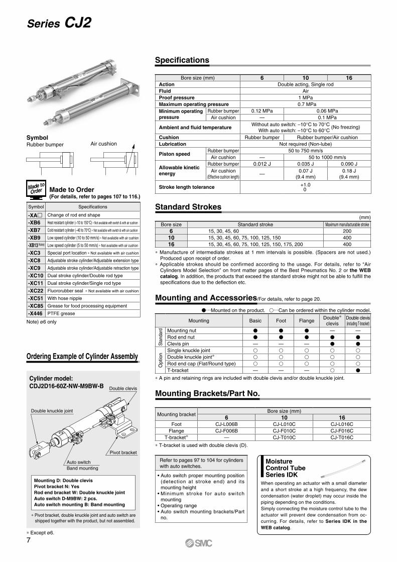
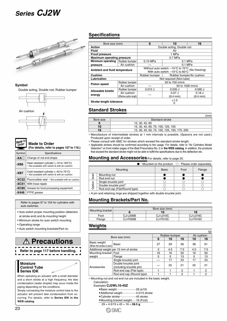
Bore size (mm) 6 10 16Action Double acting, Single rodFluid AirProof pressure 1 MPaMaximum operating pressure 10.7 MPaMinimum operating pressure
Rubber bumper 0.12 MPa 0.06 MPaAir cushion — 0.1 MPa
Ambient and fluid temperatureWithout auto switch: –10°C to 70°C (No freezing) With auto switch: –10°C to 60°C
Cushion Rubber bumper Rubber bumper/Air cushionLubrication Not required (Non-lube)
Piston speedRubber bumper 50 to 750 mm/s
Air cushion — 50 to 1000 mm/s
Allowable kinetic energy
Rubber bumper 0.012 J 0.035 J 0.090 JAir cushion
(Effective cushion length) —0.07 J
(9.4 mm)0.18 J
(9.4 mm)
Stroke length tolerance +1.00
Note) ø6 only
* Except ø6.
Standard Strokes
* Manufacture of intermediate strokes at 1 mm intervals is possible. (Spacers are not used.) Produced upon receipt of order.
* Applicable strokes should be confirmed according to the usage. For details, refer to “Air Cylinders Model Selection” on front matter pages of the Best Pneumatics No. 2 or the WEB catalog. In addition, the products that exceed the standard stroke might not be able to fulfill the specifications due to the deflection etc.
Bore size Standard stroke Maximum manufacturable stroke6 15, 30, 45, 60 200
10 15, 30, 45, 60, 75, 100, 125, 150 40016 15, 30, 45, 60, 75, 100, 125, 150, 175, 200 400
(mm)
Air cushion
Made to Order (For details, refer to pages 107 to 116.)
SymbolRubber bumper
Symbol Specifications
-XAl Change of rod end shape
-XB6 Heat resistant cylinder (−10 to 150°C) * Not available with switch & with air cushion
-XB7 Cold resistant cylinder (−40 to 70°C) * Not available with switch & with air cushion
-XB9 Low speed cylinder (10 to 50 mm/s) * Not available with air cushion
-XB13 Note) Low speed cylinder (5 to 50 mm/s) * Not available with air cushion
-XC3 Special port location * Not available with air cushion
-XC8 Adjustable stroke cylinder/Adjustable extension type
-XC9 Adjustable stroke cylinder/Adjustable retraction type
-XC10 Dual stroke cylinder/Double rod type
-XC11 Dual stroke cylinder/Single rod type
-XC22 Fluororubber seal * Not available with air cushion
-XC51 With hose nipple
-XC85 Grease for food processing equipment
-X446 PTFE grease
Refer to pages 97 to 104 for cylinders with auto switches.
• Auto switch proper mounting position (detection at stroke end) and its mounting height
• Minimum stroke for auto switch mounting
• Operating range• Auto switch mounting brackets/Part
no.
Specifications
* T-bracket is used with double clevis (D).
Mounting bracketBore size (mm)
6 10 16Foot CJ-L006B CJ-L010C CJ-L016C
Flange CJ-F006B CJ-F010C CJ-F016CT-bracket* — CJ-T010C CJ-T016C
Mounting Brackets/Part No.
Cylinder model: CDJ2D16-60Z-NW-M9BW-B
Mounting D: Double clevisPivot bracket N: YesRod end bracket W: Double knuckle jointAuto switch D-M9BW: 2 pcs.Auto switch mounting B: Band mounting
* Pivot bracket, double knuckle joint and auto switch are shipped together with the product, but not assembled.
Ordering Example of Cylinder Assembly
V…Mounted on the product. v…Can be ordered within the cylinder model.
* A pin and retaining rings are included with double clevis and/or double knuckle joint.
Mounting Basic Foot Flange Double*clevis
Double clevis(including T-bracket)
Stan
dard Mounting nut V V V — —
Rod end nut V V V V VClevis pin — — — V V
Opt
ion
Single knuckle joint v v v v vDouble knuckle joint* v v v v vRod end cap (Flat/Round type) v v v v vT-bracket — — — v V
Mounting and Accessories/For details, refer to page 20.
When operating an actuator with a small diameter and a short stroke at a high frequency, the dew condensation (water droplet) may occur inside the piping depending on the conditions.Simply connecting the moisture control tube to the actuator will prevent dew condensation from oc-curring. For details, refer to Series IDK in the WEB catalog.
MoistureControl TubeSeries IDK
7
Series CJ2

Action Double acting, Single rod
Bore size (mm) 6, 10, 16
Maximum operating pressure 0.7 MPa
Minimum operating
pressure
ø6 0.14 MPa
ø10, ø16 0.08 MPa
Cushion Rubber bumper/Air cushion
Standard stroke (mm) Same as standard type. (Refer to page 7.)
Auto switch Mountable (Band mounting type)
MountingBasic, Double-side bossed*, Single/Double foot*, Rod/Head flange*
Specifications
* The above figure is for ø16.
* ø10 and ø16 only
For the detailed specifications, refer to the “Pneumatic Clean Series” (WEB catalog). For details, refer to the WEB catalog or “ES20-235” catalog.
Construction
The dimensions are the same as the double acting, single rod type.
Low Speed CylinderZ
R6 ZXCJ2 Bore sizeMounting style
Smooth operation with a little sticking and slipping at low speed.Can start smoothly with a little ejection even after being rendered for hours.
Clean Series
10-CJ2
10-CJ2
Head coverport location
Head coverport location
Stroke
Stroke Stroke
Bore sizeMounting style
Mounting style
SpecificationsAction Double acting, Single rod
Bore size (mm) 10, 16
Fluid Air
Proof pressure 1.05 MPa
Maximum operating pressure 0.7 MPa
Minimum operating pressure 0.06 MPa
Ambient and fluid temperature
Without auto switch: –10 to 70°CWith auto switch: –10 to 60°C
(No freezing)
Cushion Rubber bumper (Standard equipment)
Lubrication Not required (Non-lube)
Stroke length tolerance +1.00
Piston speed 1 to 300 mm/s
Allowable kinetic energy
ø10 0.035 J
ø16 0.090 J
Refer to page 117 before handling.
Precautions
Clean Series
Air cylinder which is applicable for the system which discharges leakage from the rod section directly into the outside of clean room by relief port and making an actuator’s rod section having a double seal construction.
Low Speed Cylinder
(g)
* Mounting nut and rod end nut are included in the basic weight.
Note) Mounting nut is not included in the basic weight for the double clevis.
Calculation: Example) CJ2L10-45Z
OBasic weight ······················· 22 (ø10)OAdditional weight ················ 4/15 strokeOCylinder stroke ···················· 45 strokeOMounting bracket weight ····· 8 (Axial foot)
22 + 4/15 x 45 + 8 = 42 g
Bore size (mm)Rubber bumper Air cushion
6 10 16 10 16
Basic weight(When the stroke is zero)
Basic 15 22 46 39 66Axial piping 15 22 46 39 66Double clevis (including clevis pin) — 24 54 43 74Head-side bossed — 23 48 40 68
Additional weight per 15 mm of stroke 2 4 7 4 7
Mounting bracketweight
Single foot 8 8 25 8 25Double foot — 16 50 16 50Rod flange 5 5 13 5 13Head flange — 5 13 5 13
Accessories
Single knuckle joint — 17 23 17 23Double knuckle joint(including knuckle pin)
— 25 21 25 21
Rod end cap (Flat type) 1 1 2 1 2Rod end cap (Round type) 1 1 2 1 2T-bracket — 32 50 32 50
Weights
8
Air Cylinder: Standard TypeDouble Acting, Single Rod Series CJ2
CJ2
CJ2
WC
J2C
J2K
CJ2
KC
J2Z
CJ2
ZW
CJ2
RC
J2R
CJ2
RK
CJ2
RK
CB
J2
Sta
ndar
dN
on-r
otat
ing
Rod
Bui
lt-in
Spe
ed C
ontr
olle
rD
irect
Mou
ntD
irect
Mou
nt, N
on-r
otat
ing
Rod
With
End
Loc
kDo
uble
Actin
g, Do
uble
Rod
Single
Acting
, Sprin
g Retu
rn/Exte
ndDo
uble
Actin
g, Si
ngle
Rod
Single
Acting
, Sprin
g Retu
rn/Exte
ndDo
uble
Actin
g, Si
ngle
Rod
Doub
le Ac
ting,
Doub
le Ro
dDo
uble
Actin
g, Si
ngle
Rod
Single
Acting
, Sprin
g Retu
rn/Exte
ndDo
uble
Actin
g, Si
ngle
Rod
Single
Acting
, Sprin
g Retu
rn/Exte
ndDo
uble
Actin
g, Si
ngle
Rod
Auto
Sw
itch
Made
to O
rder
!8 !7 !1 !3o e wr tyi !9!2
we y t!0r i !6!5!3!2 !4!1o
!9
!8 !7
!8 !7 !1o e wr ui !9!2 !2
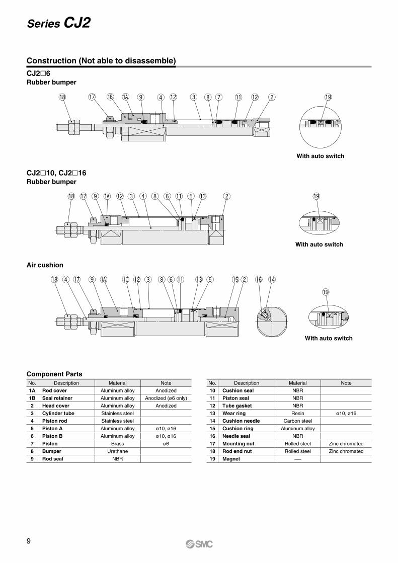
With auto switch
With auto switch
With auto switch
Air cushion
CJ2l6Rubber bumper
CJ2l10, CJ2l16Rubber bumper
Construction (Not able to disassemble)
Component PartsNo. Description Material Note
1A Rod cover Aluminum alloy Anodized
1B Seal retainer Aluminum alloy Anodized (ø6 only)
2 Head cover Aluminum alloy Anodized
3 Cylinder tube Stainless steel
4 Piston rod Stainless steel
5 Piston A Aluminum alloy ø10, ø16
6 Piston B Aluminum alloy ø10, ø16
7 Piston Brass ø6
8 Bumper Urethane
9 Rod seal NBR
No. Description Material Note
10 Cushion seal NBR
11 Piston seal NBR
12 Tube gasket NBR
13 Wear ring Resin ø10, ø16
14 Cushion needle Carbon steel
15 Cushion ring Aluminum alloy
16 Needle seal NBR
17 Mounting nut Rolled steel Zinc chromated
18 Rod end nut Rolled steel Zinc chromated
19 Magnet —
9
Series CJ2
øN
Dh
8
B 0–0.3
B
0–
0.3
øC
Piping port M5 x 0.8
MMNN
Y
AH
F
Z + Stroke
S + Stroke
NA
GA Piping port 2 x M5 x 0.8 GB
NB
øD
Rod end nut
Mounting nut
0 –0.3
0–0.3
0 –0.3
8 0–0.3B
B
øC
Rod end nut
MM
Mounting nut
NN
AH
Z + Stroke
S + Stroke
NATF
GA
øN
Dh
8
øD
Piping port M5 x 0.8 Piping port M5 x 0.8
NB
ø9
8
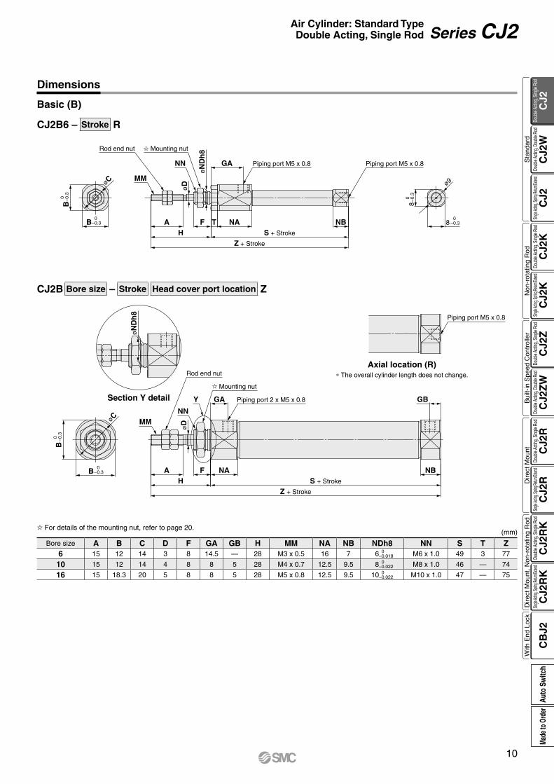
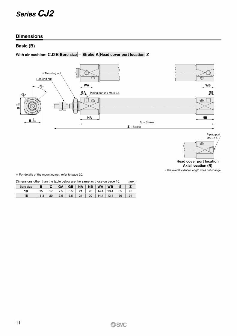
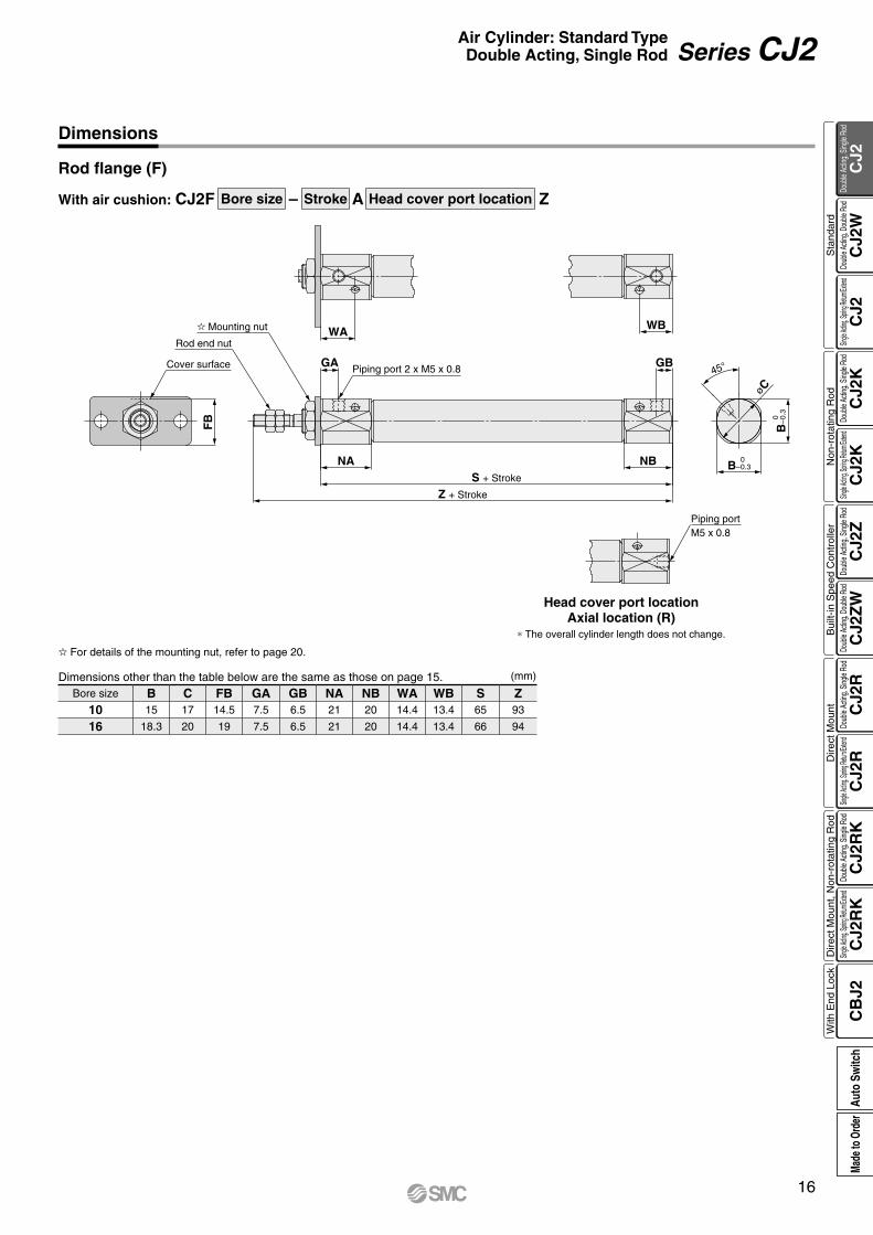
CJ2B Bore size – Stroke Head cover port location Z
CJ2B6 – Stroke R
(mm)
Bore size A B C D F GA GB H MM NA NB NDh8 NN S T Z6 15 12 14 3 8 14.5 — 28 M3 x 0.5 16 7 6 0
–0.018 M6 x 1.0 49 3 77
10 15 12 14 4 8 8 5 28 M4 x 0.7 12.5 9.5 8 0 –0.022 M8 x 1.0 46 — 74
16 15 18.3 20 5 8 8 5 28 M5 x 0.8 12.5 9.5 10 0 –0.022 M10 x 1.0 47 — 75
Dimensions
Basic (B)
* The overall cylinder length does not change.
Axial location (R)
For details of the mounting nut, refer to page 20.
Section Y detail
10
Air Cylinder: Standard TypeDouble Acting, Single Rod Series CJ2
CJ2
CJ2
WC
J2C
J2K
CJ2
KC
J2Z
CJ2
ZW
CJ2
RC
J2R
CJ2
RK
CJ2
RK
CB
J2
Sta
ndar
dN
on-r
otat
ing
Rod
Bui
lt-in
Spe
ed C
ontr
olle
rD
irect
Mou
ntD
irect
Mou
nt, N
on-r
otat
ing
Rod
With
End
Loc
kDo
uble
Actin
g, Do
uble
Rod
Single
Acting
, Sprin
g Retu
rn/Exte
ndDo
uble
Actin
g, Si
ngle
Rod
Single
Acting
, Sprin
g Retu
rn/Exte
ndDo
uble
Actin
g, Si
ngle
Rod
Doub
le Ac
ting,
Doub
le Ro
dDo
uble
Actin
g, Si
ngle
Rod
Single
Acting
, Sprin
g Retu
rn/Exte
ndDo
uble
Actin
g, Si
ngle
Rod
Single
Acting
, Sprin
g Retu
rn/Exte
ndDo
uble
Actin
g, Si
ngle
Rod
Auto
Sw
itch
Made
to O
rder
B
0–
0.3
B 0–0.3
øC
45° WA WB
GA Piping port 2 x M5 x 0.8
NA
Z + Stroke
S + Stroke
NB
GB
Piping portM5 x 0.8
Mounting nut
Rod end nut
With air cushion: CJ2B Bore size – Stroke A Head cover port location Z
Dimensions
Basic (B)
Head cover port locationAxial location (R)
* The overall cylinder length does not change.
For details of the mounting nut, refer to page 20.
(mm)Dimensions other than the table below are the same as those on page 10.
Bore size B C GA GB NA NB WA WB S Z10 15 17 7.5 6.5 21 20 14.4 13.4 65 93
16 18.3 20 7.5 6.5 21 20 14.4 13.4 66 94
11
Series CJ2
0 –0.3
0 –0.3
0–0.3
0–0.3 B
B8
8LXLZ
LY
LB
LH
2 x øLCMounting hole
Rod end nut
Mounting nut
MM
NNF GA Piping port M5 x 0.8
NATYXAH
LT
øD
Z + Stroke
S + Stroke
NB
Piping port M5 x 0.8
ø9 øC
Cover surface
View E
LZLX
LH L
B LY
Cover surface
Piping port M5 x 0.8
MMNN
F GA
øD
LT
AX Y NA
H S + Stroke
Z + Stroke
Piping port 2 x M5 x 0.8 GB
NB
0–0.3B
øC
0
–0.
3B
Mounting nut
Rod end nut
2 x øLCMounting hole
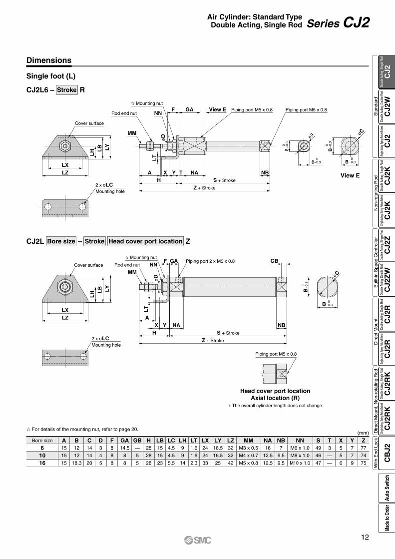
CJ2L Bore size – Stroke Head cover port location Z
CJ2L6 – Stroke R
(mm)
Bore size A B C D F GA GB H LB LC LH LT LX LY LZ MM NA NB NN S T X Y Z6 15 12 14 3 8 14.5 — 28 15 4.5 9 1.6 24 16.5 32 M3 x 0.5 16 7 M6 x 1.0 49 3 5 7 77
10 15 12 14 4 8 8 5 28 15 4.5 9 1.6 24 16.5 32 M4 x 0.7 12.5 9.5 M8 x 1.0 46 — 5 7 74
16 15 18.3 20 5 8 8 5 28 23 5.5 14 2.3 33 25 42 M5 x 0.8 12.5 9.5 M10 x 1.0 47 — 6 9 75
View E
Dimensions
Single foot (L)
For details of the mounting nut, refer to page 20.
Head cover port locationAxial location (R)
* The overall cylinder length does not change.
12
Air Cylinder: Standard TypeDouble Acting, Single Rod Series CJ2
CJ2
CJ2
WC
J2C
J2K
CJ2
KC
J2Z
CJ2
ZW
CJ2
RC
J2R
CJ2
RK
CJ2
RK
CB
J2
Sta
ndar
dN
on-r
otat
ing
Rod
Bui
lt-in
Spe
ed C
ontr
olle
rD
irect
Mou
ntD
irect
Mou
nt, N
on-r
otat
ing
Rod
With
End
Loc
kDo
uble
Actin
g, Do
uble
Rod
Single
Acting
, Sprin
g Retu
rn/Exte
ndDo
uble
Actin
g, Si
ngle
Rod
Single
Acting
, Sprin
g Retu
rn/Exte
ndDo
uble
Actin
g, Si
ngle
Rod
Doub
le Ac
ting,
Doub
le Ro
dDo
uble
Actin
g, Si
ngle
Rod
Single
Acting
, Sprin
g Retu
rn/Exte
ndDo
uble
Actin
g, Si
ngle
Rod
Single
Acting
, Sprin
g Retu
rn/Exte
ndDo
uble
Actin
g, Si
ngle
Rod
Auto
Sw
itch
Made
to O
rder
LB
GA
0
–0.
3B
øC
45°Cover surface
LB
WA WB
Piping port 2 x M5 x 0.8GA GB
NA
Z + Stroke
S + Stroke
NB
Piping port M5 x 0.8
0–0.3B
Rod end nut
Mounting nut
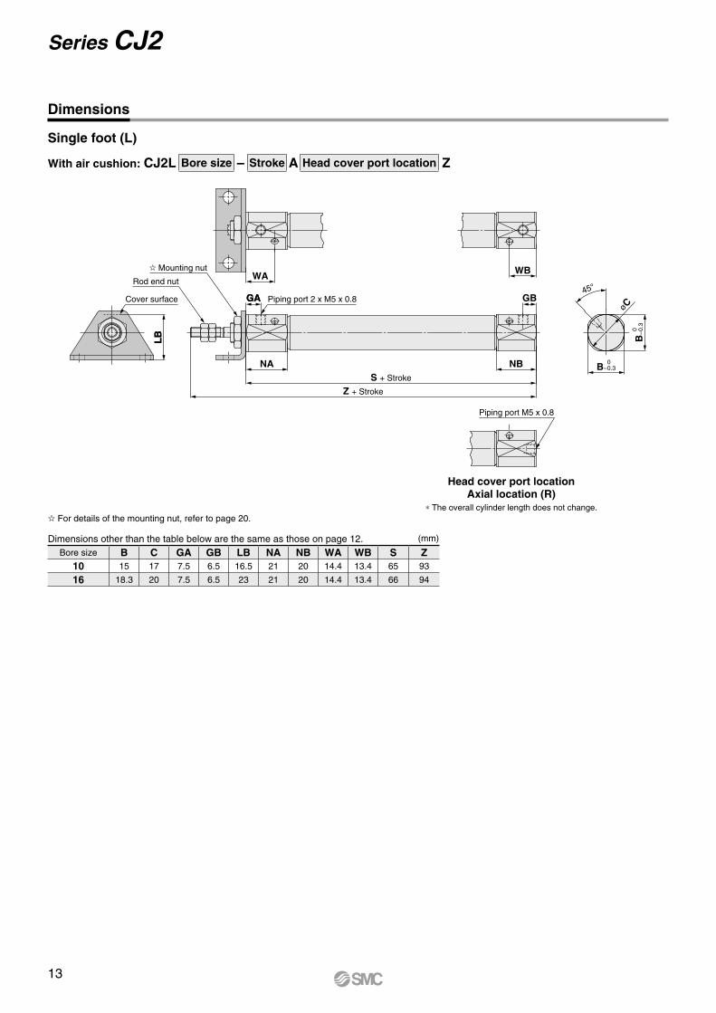
With air cushion: CJ2L Bore size – Stroke A Head cover port location Z
Single foot (L)
Dimensions
For details of the mounting nut, refer to page 20.
Head cover port locationAxial location (R)
* The overall cylinder length does not change.
Dimensions other than the table below are the same as those on page 12. (mm)
Bore size B C GA GB LB NA NB WA WB S Z10 15 17 7.5 6.5 16.5 21 20 14.4 13.4 65 93
16 18.3 20 7.5 6.5 23 21 20 14.4 13.4 66 94
13
Series CJ2

LB
LX
LZ
LH L
B LY
4 x øLCMounting hole
Cover surface
øD
LT
HF GA
A
X Y NA
S + Stroke
LS + Stroke
Z + Stroke
Piping port 2 x M5 x 0.8 GB F NN
LT
XYNB
Mounting nut
NNMM
Rod end nut
Mounting nut
øC45°Cover surface
LB
WA
Piping port 2 x M5 x 0.8GA
NA
Z + Stroke
S + Stroke
NB
WB
GB
0
–0.
3B
0–0.3BView E
Rod end nut
Mounting nut
Mounting nut
With air cushion: CJ2M Bore size – Stroke AZ
CJ2M Bore size – Stroke Z
With Air Cushion/Dimensions other than the table below are the same as the table above. (mm)
For details of the mounting nut, refer to page 20.(mm)
Bore size A D F GA GB H LB LC LH LS LT LX LY LZ MM NA NB NN S X Y Z10 15 4 8 8 5 28 15 4.5 9 60 1.6 24 16.5 32 M4 x 0.7 12.5 9.5 M8 x 1.0 46 5 7 86
16 15 5 8 8 5 28 23 5.5 14 65 2.3 33 25 42 M5 x 0.8 12.5 9.5 M10 x 1.0 47 6 9 90
Bore size B C GA GB LB NA NB WA WB S Z10 15 17 7.5 6.5 16.5 21 20 14.4 13.4 65 93
16 18.3 20 7.5 6.5 23 21 20 14.4 13.4 66 94
Double foot (M)
Dimensions
View E
14
Air Cylinder: Standard TypeDouble Acting, Single Rod Series CJ2
CJ2
CJ2
WC
J2C
J2K
CJ2
KC
J2Z
CJ2
ZW
CJ2
RC
J2R
CJ2
RK
CJ2
RK
CB
J2
Sta
ndar
dN
on-r
otat
ing
Rod
Bui
lt-in
Spe
ed C
ontr
olle
rD
irect
Mou
ntD
irect
Mou
nt, N
on-r
otat
ing
Rod
With
End
Loc
kDo
uble
Actin
g, Do
uble
Rod
Single
Acting
, Sprin
g Retu
rn/Exte
ndDo
uble
Actin
g, Si
ngle
Rod
Single
Acting
, Sprin
g Retu
rn/Exte
ndDo
uble
Actin
g, Si
ngle
Rod
Doub
le Ac
ting,
Doub
le Ro
dDo
uble
Actin
g, Si
ngle
Rod
Single
Acting
, Sprin
g Retu
rn/Exte
ndDo
uble
Actin
g, Si
ngle
Rod
Single
Acting
, Sprin
g Retu
rn/Exte
ndDo
uble
Actin
g, Si
ngle
Rod
Auto
Sw
itch
Made
to O
rder
B
0–
0.3
B 0–0.3
øD
Cover surface
FB FY
FXFZ 2 x øFC
Mounting hole
MM
NN GA
A
H
F
FT
NA
S + Stroke
Z + Stroke
Piping port 2 x M5 x 0.8 GB
NB
øC
Piping port M5 x 0.8
Mounting nut
Rod end nut
0 –0.3
0–0.3
0 –0.3
0–0.3
8
8 B
B
FXFZ
FB FY
2 x øFCMounting hole
Cover surface
Rod end nut
MM
Mounting nut
NN
øD
GA
FTA
HF T NA
Z + Stroke
S + Stroke
Piping port M5 x 0.8
View E
Piping port M5 x 0.8
NB
ø9 øC
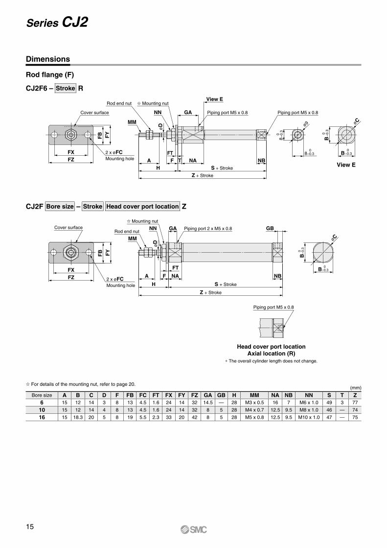
CJ2F6 – Stroke R
CJ2F Bore size – Stroke Head cover port location Z
(mm)
Bore size A B C D F FB FC FT FX FY FZ GA GB H MM NA NB NN S T Z6 15 12 14 3 8 13 4.5 1.6 24 14 32 14.5 — 28 M3 x 0.5 16 7 M6 x 1.0 49 3 77
10 15 12 14 4 8 13 4.5 1.6 24 14 32 8 5 28 M4 x 0.7 12.5 9.5 M8 x 1.0 46 — 74
16 15 18.3 20 5 8 19 5.5 2.3 33 20 42 8 5 28 M5 x 0.8 12.5 9.5 M10 x 1.0 47 — 75
View E
Dimensions
Rod flange (F)
Head cover port locationAxial location (R)
* The overall cylinder length does not change.
For details of the mounting nut, refer to page 20.
15
Series CJ2
øC
45°Cover surface
FB
WA
Piping port 2 x M5 x 0.8GA
NA
Z + Stroke
S + Stroke
WB
GB
NB
Piping portM5 x 0.8
B
0–
0.3
B 0–0.3
Rod end nut
Mounting nut
With air cushion: CJ2F Bore size – Stroke A Head cover port location Z
Rod flange (F)
Dimensions
Head cover port locationAxial location (R)
* The overall cylinder length does not change.
For details of the mounting nut, refer to page 20.
Dimensions other than the table below are the same as those on page 15. (mm)
Bore size B C FB GA GB NA NB WA WB S Z10 15 17 14.5 7.5 6.5 21 20 14.4 13.4 65 93
16 18.3 20 19 7.5 6.5 21 20 14.4 13.4 66 94
16
Air Cylinder: Standard TypeDouble Acting, Single Rod Series CJ2
CJ2
CJ2
WC
J2C
J2K
CJ2
KC
J2Z
CJ2
ZW
CJ2
RC
J2R
CJ2
RK
CJ2
RK
CB
J2
Sta
ndar
dN
on-r
otat
ing
Rod
Bui
lt-in
Spe
ed C
ontr
olle
rD
irect
Mou
ntD
irect
Mou
nt, N
on-r
otat
ing
Rod
With
End
Loc
kDo
uble
Actin
g, Do
uble
Rod
Single
Acting
, Sprin
g Retu
rn/Exte
ndDo
uble
Actin
g, Si
ngle
Rod
Single
Acting
, Sprin
g Retu
rn/Exte
ndDo
uble
Actin
g, Si
ngle
Rod
Doub
le Ac
ting,
Doub
le Ro
dDo
uble
Actin
g, Si
ngle
Rod
Single
Acting
, Sprin
g Retu
rn/Exte
ndDo
uble
Actin
g, Si
ngle
Rod
Single
Acting
, Sprin
g Retu
rn/Exte
ndDo
uble
Actin
g, Si
ngle
Rod
Auto
Sw
itch
Made
to O
rder
øC
øD
B
0–
0.3
B 0–0.3
MMNN
GA
A
H
F NA
S + Stroke
Z + Stroke
Piping port 2 x M5 x 0.8 GBNN
FTNB
F
FB FY
FX
FZ
Cover surface
2 x øFCMounting hole
Mounting nutRod end nut
WA WB
GBGA Piping port 2 x M5 x 0.8
NA
Z + Stroke
S + Stroke
NB
FB
Cover surface
Rod end nut
Mounting nut
øC
45°
B
0–
0.3
B 0–0.3
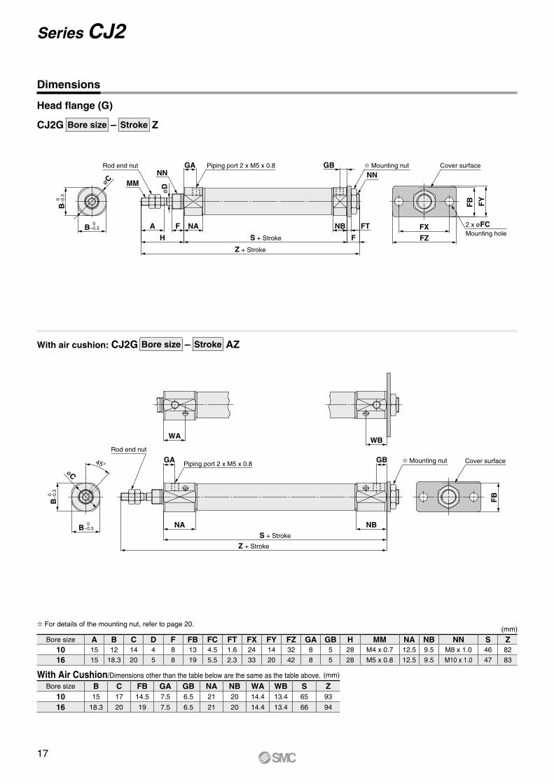
CJ2G Bore size – Stroke Z
With air cushion: CJ2G Bore size – Stroke AZ
Head flange (G)
Dimensions
For details of the mounting nut, refer to page 20.(mm)
With Air Cushion/Dimensions other than the table below are the same as the table above. (mm)
Bore size A B C D F FB FC FT FX FY FZ GA GB H MM NA NB NN S Z10 15 12 14 4 8 13 4.5 1.6 24 14 32 8 5 28 M4 x 0.7 12.5 9.5 M8 x 1.0 46 82
16 15 18.3 20 5 8 19 5.5 2.3 33 20 42 8 5 28 M5 x 0.8 12.5 9.5 M10 x 1.0 47 83
Bore size B C FB GA GB NA NB WA WB S Z10 15 17 14.5 7.5 6.5 21 20 14.4 13.4 65 93
16 18.3 20 19 7.5 6.5 21 20 14.4 13.4 66 94
17
Series CJ2

CZ
0
–0.
3
CZ 0–0.3
CX+0.2+0.1
øC
B
0–
0.3
B 0–0.3
øC
MM
A
H
NA
GAøD
ZZ + Stroke
Z + Stroke
S + Stroke
R
U
GBNBPiping port 2 x M5 x 0.8Rod end nut
WA
GAPiping port 2 x M5 x 0.8
NA
ZZ + Stroke
Z + Stroke
S + Stroke
WB
GBNBRod end nut
øC
45°
B
0–
0.3
B 0–0.3
øC
CZ
0
–0.
3
CZ 0–0.3
Clevis pin (øcdd9 )
øCDH9+0.030 0
–0.030–0.060
CJ2D Bore size – Stroke Z
With air cushion: CJ2D Bore size – Stroke AZ
Double clevis (D)
Dimensions
With Air Cushion/Dimensions other than the table below are the same as the table above. (mm)
(mm)* A clevis pin and retaining rings are included.
Bore size A B C CD (cd) CX CZ D GA GB H MM NA NB R S U Z ZZ10 15 12 14 3.3 3.2 12 4 8 18 28 M4 x 0.7 12.5 22.5 5 46 8 82 87
16 15 18.3 20 5 6.5 18.3 5 8 23 28 M5 x 0.8 12.5 27.5 8 47 10 85 93
Bore size B C CZ GA GB NA NB WA WB S Z ZZ10 15 17 15 7.5 19.5 21 33 14.4 26.4 65 101 106
16 18.3 20 18.3 7.5 24.5 21 38 14.4 31.4 66 104 112
18
Air Cylinder: Standard TypeDouble Acting, Single Rod Series CJ2
CJ2
CJ2
WC
J2C
J2K
CJ2
KC
J2Z
CJ2
ZW
CJ2
RC
J2R
CJ2
RK
CJ2
RK
CB
J2
Sta
ndar
dN
on-r
otat
ing
Rod
Bui
lt-in
Spe
ed C
ontr
olle
rD
irect
Mou
ntD
irect
Mou
nt, N
on-r
otat
ing
Rod
With
End
Loc
kDo
uble
Actin
g, Do
uble
Rod
Single
Acting
, Sprin
g Retu
rn/Exte
ndDo
uble
Actin
g, Si
ngle
Rod
Single
Acting
, Sprin
g Retu
rn/Exte
ndDo
uble
Actin
g, Si
ngle
Rod
Doub
le Ac
ting,
Doub
le Ro
dDo
uble
Actin
g, Si
ngle
Rod
Single
Acting
, Sprin
g Retu
rn/Exte
ndDo
uble
Actin
g, Si
ngle
Rod
Single
Acting
, Sprin
g Retu
rn/Exte
ndDo
uble
Actin
g, Si
ngle
Rod
Auto
Sw
itch
Made
to O
rder
B 0–0.3
øD
MM
NN
H
A F NA
S + Stroke
Z + Stroke
GA Piping port 2 x M5 x 0.8
NB
F
GB
NN
YY
øN
Dh
8
B
0–
0.3
Y
øN
Dh
8
Rod end nut
Mounting nut
B 0–0.3
B
0–
0.3
øC
45°
WA
Piping port 2 x M5 x 0.8GA
NA
Z + Stroke
S + Stroke
NBF
WB
GB
Mounting nut
Rod end nut
øC
CJ2E Bore size – Stroke Z
With air cushion: CJ2E Bore size – Stroke AZ
Double-side bossed (E)
Dimensions
Section Y detail
Section YY detail
With Air Cushion/Dimensions other than the table below are the same as the table above. (mm)
For details of the mounting nut, refer to page 20.(mm)
Bore size B C GA GB NA NB WA WB S Z10 15 17 7.5 6.5 21 20 14.4 13.4 65 101
16 18.3 20 7.5 6.5 21 20 14.4 13.4 66 102
Bore size A B C D F GA GB H MM NA NB NDh8 NN S Z10 15 12 14 4 8 8 5 28 M4 x 0.7 12.5 9.5 8 0
−0.022 M8 x 1.0 46 82
16 15 18.3 20 5 8 8 5 28 M5 x 0.8 12.5 9.5 10 0 −0.022 M10 x 1.0 47 83
19
Series CJ2
12
TDH10
TWTY
(U)(S + Stroke)
TU
+0.
2
0
TXTK
TN
TV
TH
7
TZ
TT
124 x øTC
12
NDH10
12
øND hole H10Axis d9
Material: Rolled steel
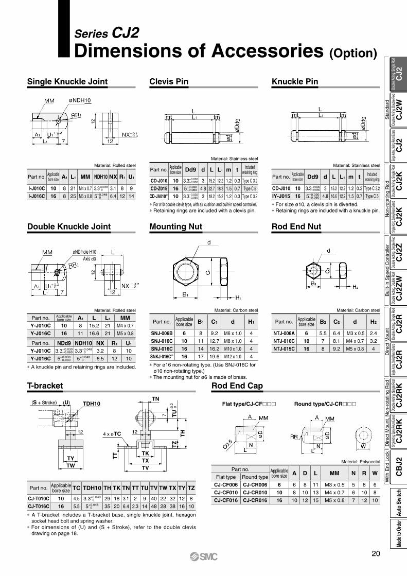
Series CJ2 Dimensions of Accessories (Option)
Part no. Applicablebore size A1 L1 MM NDH10 NX R1 U1
I-J010C 10 8 21 M4 x 0.7 3.3+0.048 0 3.1 8 9
I-J016C 16 8 25 M5 x 0.8 5+0.048 0 6.4 12 14
Single Knuckle Joint Clevis Pin Knuckle Pin
Material: Stainless steel
Material: Stainless steel
* For ø10 double clevis type, with air cushion and built-in speed controller.* Retaining rings are included with a clevis pin.
* For size ø10, a clevis pin is diverted.* Retaining rings are included with a knuckle pin.
Part no. Applicablebore size Dd9 d L L1 m t Included
retaining ring
CD-J010 10 3.3–0.030–0.060 3 15.2 12.2 1.2 0.3 Type C 3.2
IY-J015 16 5–0.030–0.060 4.8 16.6 12.2 1.5 0.7 Type C 5
Part no. Applicablebore size Dd9 d L L1 m t Included
retaining ring
CD-J010 10 3.3–0.030–0.060 3 15.2 12.2 1.2 0.3 Type C 3.2
CD-Z015 16 5–0.030–0.060 4.8 22.7 18.3 1.5 0.7 Type C 5
CD-JA010* 10 3.3–0.030–0.060 3 18.2 15.2 1.2 0.3 Type C 3.2
Double Knuckle Joint Mounting Nut Rod End Nut
T-bracket Rod End Cap
* A knuckle pin and retaining rings are included.
Material: Rolled steel
Part no. Applicablebore size A1 L L1 MM
Y-J010C 10 8 15.2 21 M4 x 0.7
Y-J016C 16 11 16.6 21 M5 x 0.8
Part no. NDd9 NDH10 NX R1 U1
Y-J010C 3.3–0.030–0.060 3.3+0.048
0 3.2 8 10
Y-J016C 5–0.030–0.060 5+0.048
0 6.5 12 10
Round type/CJ-CRFlat type/CJ-CF
Material: Polyacetal
* A T-bracket includes a T-bracket base, single knuckle joint, hexagon socket head bolt and spring washer.
* For dimensions of (U) and (S + Stroke), refer to the double clevis drawing on page 18.
Part no. Applicablebore size TC TDH10 TH TK TN TT TU TV TW TX TY TZ
CJ-T010C 10 4.5 3.3+0.048 0 29 18 3.1 2 9 40 22 32 12 8
CJ-T016C 16 5.5 5+0.048 0 35 20 6.4 2.3 14 48 28 38 16 10
Material: Carbon steel
Part no. Applicablebore size B1 C1 d H1
SNJ-006B 6 8 9.2 M6 x 1.0 4
SNJ-010C 10 11 12.7 M8 x 1.0 4
SNJ-016C 16 14 16.2 M10 x 1.0 4
SNKJ-016C* 16 17 19.6 M12 x 1.0 4
* For ø16 non-rotating type. (Use SNJ-016C for ø10 non-rotating type.)
* The mounting nut for ø6 is made of brass.
Material: Carbon steel
Part no. Applicablebore size B2 C2 d H2
NTJ-006A 6 5.5 6.4 M3 x 0.5 2.4
NTJ-010C 10 7 8.1 M4 x 0.7 3.2
NTJ-015C 16 8 9.2 M5 x 0.8 4
Part no. Applicablebore size A D L MM N R W
Flat type Round type
CJ-CF006 CJ-CR006 6 6 8 11 M3 x 0.5 5 8 6
CJ-CF010 CJ-CR010 10 8 10 13 M4 x 0.7 6 10 8
CJ-CF016 CJ-CR016 16 10 12 15 M5 x 0.8 7 12 10
20
CJ2
CJ2
WC
J2C
J2K
CJ2
KC
J2Z
CJ2
ZW
CJ2
RC
J2R
CJ2
RK
CJ2
RK
CB
J2
Sta
ndar
dN
on-r
otat
ing
Rod
Bui
lt-in
Spe
ed C
ontr
olle
rD
irect
Mou
ntD
irect
Mou
nt, N
on-r
otat
ing
Rod
With
End
Loc
kDo
uble
Actin
g, Do
uble
Rod
Single
Acting
, Sprin
g Retu
rn/Exte
ndDo
uble
Actin
g, Si
ngle
Rod
Single
Acting
, Sprin
g Retu
rn/Exte
ndDo
uble
Actin
g, Si
ngle
Rod
Doub
le Ac
ting,
Doub
le Ro
dDo
uble
Actin
g, Si
ngle
Rod
Single
Acting
, Sprin
g Retu
rn/Exte
ndDo
uble
Actin
g, Si
ngle
Rod
Single
Acting
, Sprin
g Retu
rn/Exte
ndDo
uble
Actin
g, Si
ngle
Rod
Auto
Sw
itch
Made
to O
rder
How to Order
Nil 2 pcs.S 1 pc.n “n” pcs.
Example Band mounting CDJ2WB6-45-B
B BasicL FootF Flange 6 6 mm
Type Special functionElectrical
entry
Indic
ator
light
Wiring(Output)
Load voltage Auto switch model Lead wire length (m)Pre-wiredconnector
ApplicableloadDC AC Perpendicular In-line 0.5
(Nil)1
(M)3
(L)5
(Z)None(N)
So
lid s
tate
au
to s
wit
ch ——Grommet
Yes
3-wire (NPN)
24 V
5 V,12 V
—
M9NV M9N V V V v — vIC circuit
Relay,PLC
3-wire (PNP) M9PV M9P V V V v — v
2-wire 12 VM9BV M9B V V V v — v
—Connector — H7C V — V V V —
Diagnostic indication(2-color indication)
Grommet
3-wire (NPN)5 V,12 V
M9NWV M9NW V V V v — vIC circuit
3-wire (PNP) M9PWV M9PW V V V v — v
2-wire 12 V M9BWV M9BW V V V v — v —
Water resistant(2-color indication)
3-wire (NPN)5 V,12 V
M9NAV*1 M9NA*1 v v V v — vIC circuit
3-wire (PNP) M9PAV*1 M9PA*1 v v V v — v
2-wire 12 V M9BAV*1 M9BA*1 v v V v — v —
Ree
d a
uto
sw
itch
——
GrommetYes
3-wire(NPN equivalent) —
5 V — A96V A96 V — V — — — IC circuit —
2-wire
— 200 V — — V — V — — ——
Relay,PLC24 V 12 V
100 V A93V*2 A93 V V V V — —
No 100 V or less A90V A90 V — V — — — IC circuit
ConnectorYes — — C73C V — V V V — —
No 24 V or less — C80C V — V V V — IC circuit
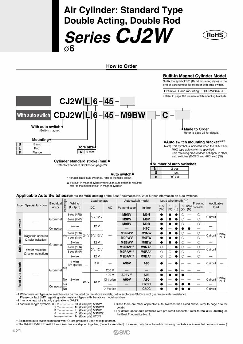
CDJ2WWith auto switch
CJ2W L
Bore size
Mounting
Cylinder standard stroke (mm)Refer to “Standard Strokes” on page 23.
With auto switch(Built-in magnet)
Built-in Magnet Cylinder ModelSuffix the symbol “-B” (Band mounting style) to the end of part number for cylinder with auto switch.
* Refer to page 103 for auto switch mounting brackets.
Applicable Auto Switches/Refer to the WEB catalog or the Best Pneumatics No. 2 for further information on auto switches.
L 6
6 45
45 M9BW
Auto switch* For applicable auto switches, refer to the table below.
If a built-in magnet cylinder without an auto switch is required, refer to the model of built-in magnet cylinder.
Number of auto switches
Made to OrderRefer to page 23 for details.
C
Note) This symbol is indicated when the D-A9l or M9l type auto switch is specified.This mounting bracket does not apply to other auto switches (D-C7l and H7l, etc.) (Nil)
Auto switch mounting bracket Note)
RoHSSeries CJ2Wø6
Air Cylinder: Standard TypeDouble Acting, Double Rod
* Solid state auto switches marked with “v” are produced upon receipt of order.* The D-A9ll/M9lll/A7ll auto switches are shipped together, (but not assembled). (However, only the auto switch mounting brackets are assembled before shipment.)
* Since there are other applicable auto switches than listed above, refer to page 104 for details.
* For details about auto switches with pre-wired connector, refer to the WEB catalog or the Best Pneumatics No. 2.
*1 Water resistant type auto switches can be mounted on the above models, but in such case SMC cannot guarantee water resistance. Please contact SMC regarding water resistant types with the above model numbers.
*2 1 m type lead wire is only applicable to D-A93.* Lead wire length symbols: 0.5 m·················· Nil (Example) M9NW 1 m·················· M (Example) M9NWM 3 m·················· L (Example) M9NWL 5 m·················· Z (Example) M9NWZ None··············· N (Example) H7CN
21A

How to Order
RoHS
Auto switch
Auto switch mounting type
M9BW BZ6016 A
A Z6016
LCDJ2W
BCJ2W
Cylinder standard stroke (mm)Refer to “Standard Strokes” on page 23.
Made to OrderRefer to page 23 for details.
Number of autoswitches
With auto switch
∗ Foot/Flange brackets are shipped together with the product, but not assembled.
MountingB BasicL FootF Flange
Bore size10 10 mm16 16 mm
A Rail mountingB Band mounting
∗ For rail mounting, screws and nuts for 2 auto switches come with the rail.
∗ Refer to page 103 for auto switch mounting brackets.
Nil 2 pcs.S 1 pc.n “n” pcs.
∗ For applicable auto switches, refer to the table below.
Nil Without auto switch
CushionNil Rubber bumperA Air cushion
Series CJ2Wø10, ø16
Air Cylinder: Standard TypeDouble Acting, Double Rod
∗ Since there are other applicable auto switches than listed above, refer to page 104 for details.∗ For details about auto switches with pre-wired connector, refer to the WEB catalog or the Best Pneumatics No. 2.∗ Solid state auto switches marked with “v” are produced upon receipt of order.∗ The D-A9ll/M9lll/A7ll/A80l/F7ll/J7ll auto switches are shipped together, (but not assembled). (For band mounting, only the auto switch mounting brackets are assembled before shipment.)
∗1 Water resistant type auto switches can be mounted on the above models, but in such case SMC cannot guarantee water resistance. Please contact SMC regarding water resistant types with the above model numbers.
∗2 1 m type lead wire is only applicable to D-A93.∗ Lead wire length symbols: 0.5 m·················· Nil (Example) M9NW 1 m·················· M (Example) M9NWM 3 m·················· L (Example) M9NWL 5 m·················· Z (Example) M9NWZ None··············· N (Example) H7CN
Applicable Auto Switches/Refer to the WEB catalog or the Best Pneumatics No. 2 for further information on auto switches.
Type Special functionElectrical
entry
Indica
tor lig
ht
Wiring(Output)
Load voltage Auto switch model Lead wire length (m)Pre-wiredconnector
ApplicableloadDC AC
Band mounting Rail mounting 0.5(Nil)
1(M)
3(L)
5(Z)
None(N)Perpendicular In-line Perpendicular In-line
So
lid s
tate
au
to s
wit
ch ——Grommet
Yes
3-wire (NPN)
24 V
5 V,12 V
—
M9NV M9N M9NV M9N V V V v — vIC circuit
Relay,PLC
3-wire (PNP) M9PV M9P M9PV M9P V V V v — v
2-wire 12 VM9BV M9B M9BV M9B V V V v — v
—Connector — H7C J79C — V — V V V —
Diagnostic indication(2-color indication)
Grommet
3-wire (NPN)5 V,12 V
M9NWV M9NW M9NWV M9NW V V V v — vIC circuit
3-wire (PNP) M9PWV M9PW M9PWV M9PW V V V v — v2-wire 12 V M9BWV M9BW M9BWV M9BW V V V v — v —
Water resistant(2-color indication)
3-wire (NPN)5 V,12 V
M9NAV∗1 M9NA∗1 M9NAV∗1 M9NA∗1 v v V v — vIC circuit
3-wire (PNP) M9PAV∗1 M9PA∗1 M9PAV∗1 M9PA∗1 v v V v — v2-wire 12 V M9BAV∗1 M9BA∗1 M9BAV∗1 M9BA∗1 v v V v — v —
With diagnostic output (2-color indication) 4-wire (NPN) 5 V,12 V — H7NF — F79F V — V v — v IC circuit
Ree
d a
uto
sw
itch
——Grommet
Yes
3-wire(NPN equivalent) —
5 V — A96V A96 A96V A96 V — V — — — IC circuit —
2-wire
— 200 V — — A72 A72H V — V — — ——
Relay,PLC24 V
12 V
100 V A93V∗2 A93 A93V∗2 A93 V V V V — —No 100 V or less A90V A90 A90V A90 V — V — — — IC circuitYes — — C73C A73C — V — V V V — —
Connector No 24 V or less — C80C A80C — V — V V V — IC circuitDiagnostic indication (2-color indication) Grommet Yes — — — — A79W — V — V — — — —
With auto switch(Built-in magnet)
22
CJ2
CJ2
WC
J2C
J2K
CJ2
KC
J2Z
CJ2
ZW
CJ2
RC
J2R
CJ2
RK
CJ2
RK
CB
J2
Sta
ndar
dN
on-r
otat
ing
Rod
Bui
lt-in
Spe
ed C
ontr
olle
rD
irect
Mou
ntD
irect
Mou
nt, N
on-r
otat
ing
Rod
With
End
Loc
kDo
uble
Actin
g, Do
uble
Rod
Single
Acting
, Sprin
g Retu
rn/Exte
ndDo
uble
Actin
g, Si
ngle
Rod
Single
Acting
, Sprin
g Retu
rn/Exte
ndDo
uble
Actin
g, Si
ngle
Rod
Doub
le Ac
ting,
Doub
le Ro
dDo
uble
Actin
g, Si
ngle
Rod
Single
Acting
, Sprin
g Retu
rn/Exte
ndDo
uble
Actin
g, Si
ngle
Rod
Single
Acting
, Sprin
g Retu
rn/Exte
ndDo
uble
Actin
g, Si
ngle
Rod
Auto
Sw
itch
Made
to O
rder
A
Made to Order(For details, refer to pages 107 to 116.)
Bore size (mm) 6 10 16Action Double acting, Double rodFluid AirProof pressure 1 MPaMaximum operating pressure 0.7 MPaMinimum operating pressure
Rubber bumper 0.15 MPa 0.1 MPaAir cushion — 0.1 MPa
Ambient and fluid temperatureWithout auto switch: –10°C to 70°C (No freezing) With auto switch: –10°C to 60°C
Cushion Rubber bumper Rubber bumper/Air cushionLubrication Not required (Non-lube)
Piston speedRubber bumper 50 to 750 mm/s
Air cushion — 50 to 1000 mm/s
Allowable kinetic energy
Rubber bumper 0.012 J 0.035 J 0.090 JAir cushion
(Effective cushion length)—
0.07 J(9.4 mm)
0.18 J(9.4 mm)
Stroke length tolerance +1.00
Standard Strokes
* Manufacture of intermediate strokes at 1 mm intervals is possible. (Spacers are not used.) Produced upon receipt of order.
* Please consult with SMC for strokes which exceed the standard stroke length.* Applicable strokes should be confirmed according to the usage. For details, refer to “Air Cylinders Model
Selection” on front matter pages of the Best Pneumatics No. 2 or the WEB catalog. In addition, the products that exceed the standard stroke might not be able to fulfill the specifications due to the deflection etc.
Bore size Standard stroke6 15, 30, 45, 60
10 15, 30, 45, 60, 75, 100, 125, 15016 15, 30, 45, 60, 75, 100, 125, 150, 175, 200
(mm)
Air cushion
SymbolDouble acting, Double rod, Rubber bumper
Symbol Specifications
-XAl Change of rod end shape
-XB6 Heat resistant cylinder (−10 to 150°C) * Not available with switch & with air cushion
-XB7 Cold resistant cylinder (−40 to 70°C) * Not available with switch & with air cushion
-XC22 Fluororubber seal * Not available with air cushion
-XC51 With hose nipple
-XC85 Grease for food processing equipment
-X446 PTFE grease
Refer to pages 97 to 104 for cylinders with auto switches.
• Auto switch proper mounting position (detection
at stroke end) and its mounting height
• Minimum stroke for auto switch mounting
• Operating range
• Auto switch mounting brackets/Part no.
Refer to page 117 before handling.
Precautions
Specifications
Mounting bracketBore size (mm)
6 10 16Foot CJ-L006B CJ-L010C CJ-L016C
Flange CJ-F006B CJ-F010C CJ-F016C
Mounting Brackets/Part No.
(g)
* Mounting nut and rod end nut are included in the basic weight.Calculation:Example) CJ2WL10-45Z
OBasic weight ······················· 29 (ø10)OAdditional weight ················ 4.5/15 strokeOCylinder stroke ···················· 45 strokeOMounting bracket weight ····· 16 (Foot)
29 + 4.5/15 x 45 + 16 = 58.5 g
Bore size (mm)Rubber bumper Air cushion
6 10 16 10 16Basic weight(When the stroke is zero)
Basic 27 29 56 36 61
Additional weight per 15 mm of stroke 3 4.5 7.5 4.5 7.5Mounting bracketweight
Foot 16 16 50 16 50Flange 5 5 13 5 13
Accessories
Single knuckle joint — 17 23 17 23Double knuckle joint(including knuckle pin)
— 25 21 25 21
Rod end cap (Flat type) 1 1 2 1 2Rod end cap (Round type) 1 1 2 1 2
Weights
V…Mounted on the product. v…Please order separately.
* A pin and retaining rings are shipped together with double knuckle joint.
Mounting Basic Foot Flange
Standa
rd Mounting nut V V VRod end nut V V V
Opt
ion Single knuckle joint v v v
Double knuckle joint* v v vRod end cap (Flat/Round type) v v v
Mounting and Accessories/For details, refer to page 20.
When operating an actuator with a small diameter and a short stroke at a high frequency, the dew condensation (water droplet) may occur inside the piping depending on the conditions.Simply connecting the moisture control tube to the actuator will prevent dew condensation from oc-curring. For details, refer to Series IDK in the WEB catalog.
MoistureControl TubeSeries IDK
23
Series CJ2W

Construction (Not able to disassemble)
For the detailed specifications, refer to the “Pneumatic Clean Series” (WEB catalog).
With autoswitch
Z-CJ2W
Clean Series
10 StrokeBore sizeMounting style
Air cylinder which is applicable for the system which discharges leakage from the rod section directly into the outside of clean room by relief port and making an actuator’s rod section having a double seal construction.
SpecificationsAction Double acting, Double rod
Bore size (mm) 10, 16
Maximum operating pressure 0.7 MPa
Minimum operating pressure 0.1 MPa
Cushion Rubber bumper
Standard stroke (mm) Same as standard type. (Refer to page 23.)
Auto switch Mountable (Band mounting type)
Mounting Basic, Foot, Flange
Clean Series
24
Air Cylinder: Standard TypeDouble Acting, Double Rod Series CJ2W
CJ2
CJ2
WC
J2C
J2K
CJ2
KC
J2Z
CJ2
ZW
CJ2
RC
J2R
CJ2
RK
CJ2
RK
CB
J2
Sta
ndar
dN
on-r
otat
ing
Rod
Bui
lt-in
Spe
ed C
ontr
olle
rD
irect
Mou
ntD
irect
Mou
nt, N
on-r
otat
ing
Rod
With
End
Loc
kDo
uble
Actin
g, Do
uble
Rod
Single
Acting
, Sprin
g Retu
rn/Exte
ndDo
uble
Actin
g, Si
ngle
Rod
Single
Acting
, Sprin
g Retu
rn/Exte
ndDo
uble
Actin
g, Si
ngle
Rod
Doub
le Ac
ting,
Doub
le Ro
dDo
uble
Actin
g, Si
ngle
Rod
Single
Acting
, Sprin
g Retu
rn/Exte
ndDo
uble
Actin
g, Si
ngle
Rod
Single
Acting
, Sprin
g Retu
rn/Exte
ndDo
uble
Actin
g, Si
ngle
Rod
Auto
Sw
itch
Made
to O
rder
w e u t !0 ri!6 !5 !1!7
we uo t!0 ri!6 !5 !1 !3 !4 !2!7
!6 !5 !0i we yu!1
!7
!B !A
Air cushion
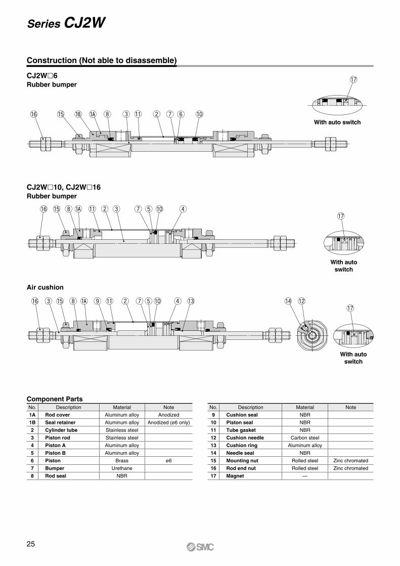
CJ2Wl10, CJ2Wl16Rubber bumper
With auto switch
With auto switch
With auto switch
CJ2Wl6Rubber bumper
Construction (Not able to disassemble)
Component PartsNo. Description Material Note
1A Rod cover Aluminum alloy Anodized
1B Seal retainer Aluminum alloy Anodized (ø6 only)
2 Cylinder tube Stainless steel
3 Piston rod Stainless steel
4 Piston A Aluminum alloy
5 Piston B Aluminum alloy
6 Piston Brass ø6
7 Bumper Urethane
8 Rod seal NBR
No. Description Material Note
9 Cushion seal NBR
10 Piston seal NBR
11 Tube gasket NBR
12 Cushion needle Carbon steel
13 Cushion ring Aluminum alloy
14 Needle seal NBR
15 Mounting nut Rolled steel Zinc chromated
16 Rod end nut Rolled steel Zinc chromated
17 Magnet —
25
Series CJ2W
øC
B
0
−0.
3
B 0 −0.3
MMNN
GA Piping port 2 x M5 x 0.8
Mounting nut
øN
Dh
8øD
NN
øD
MMGA
øN
Dh
8
Z + 2 x Stroke
S + StrokeHNAFA NA F
H + Stroke
A
Rod end nut
øC
45°
B
0
−0.
3
B 0 −0.3
WA
GA Piping port 2 x M5 x 0.8
WA
NA
Z + 2 x Stroke
S + Stroke
NA
Rod end nut
Mounting nut
GA
0 –0.3
0–0.3
B
B
øC
Rod end nut
MM
�Mounting nut
øN
Dh
8
GA
øD
NN
AH
F T NA
Z + 2 x Stroke
S + Stroke
NA T FH + Stroke
GA
øN
Dh
8
NN
A
MM
Piping port 2 x M5 x 0.8
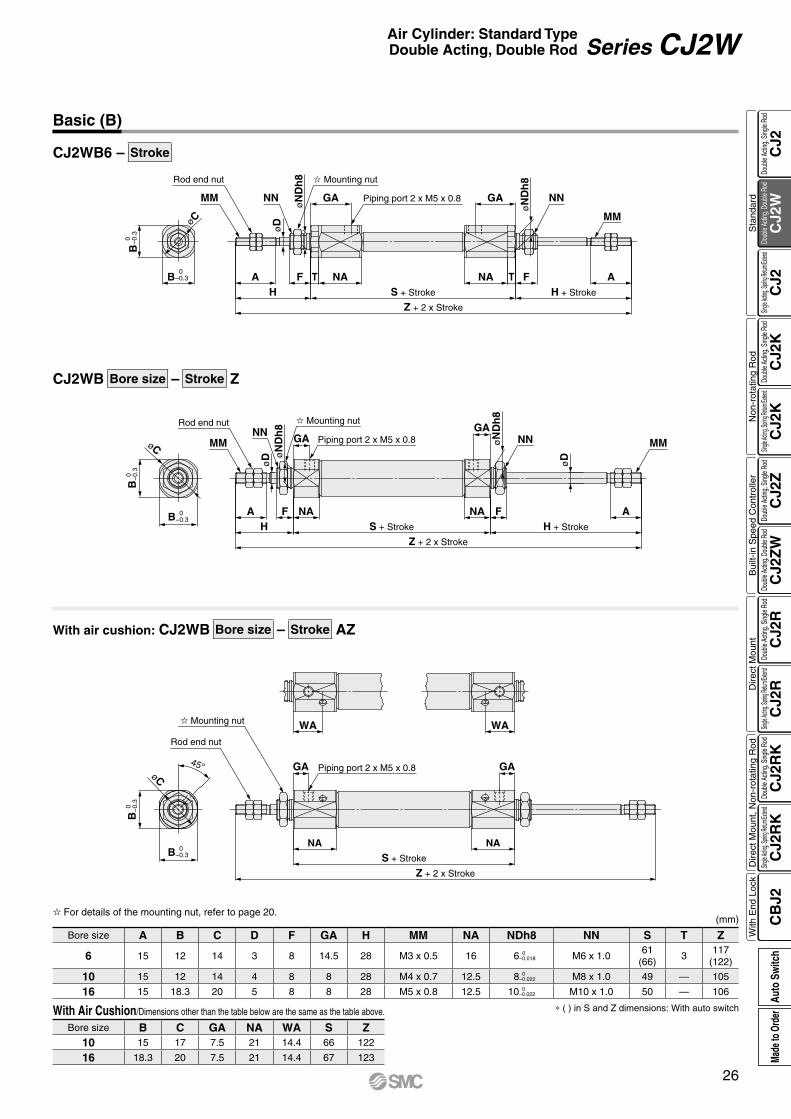
CJ2WB Bore size – Stroke Z
With air cushion: CJ2WB Bore size – Stroke AZ
CJ2WB6 – Stroke
(mm)
Bore size A B C D F GA H MM NA NDh8 NN S T Z
6 15 12 14 3 8 14.5 28 M3 x 0.5 16 6 0 –0.018 M6 x 1.0
61(66)
3117
(122)
10 15 12 14 4 8 8 28 M4 x 0.7 12.5 8 0 –0.022 M8 x 1.0 49 — 105
16 15 18.3 20 5 8 8 28 M5 x 0.8 12.5 10 0 –0.022 M10 x 1.0 50 — 106
∗ ( ) in S and Z dimensions: With auto switch
For details of the mounting nut, refer to page 20.
With Air Cushion/Dimensions other than the table below are the same as the table above.
Bore size B C GA NA WA S Z10 15 17 7.5 21 14.4 66 122
16 18.3 20 7.5 21 14.4 67 123
Basic (B)
26
Air Cylinder: Standard TypeDouble Acting, Double Rod Series CJ2W
CJ2
CJ2
WC
J2C
J2K
CJ2
KC
J2Z
CJ2
ZW
CJ2
RC
J2R
CJ2
RK
CJ2
RK
CB
J2
Sta
ndar
dN
on-r
otat
ing
Rod
Bui
lt-in
Spe
ed C
ontr
olle
rD
irect
Mou
ntD
irect
Mou
nt, N
on-r
otat
ing
Rod
With
End
Loc
kDo
uble
Actin
g, Do
uble
Rod
Single
Acting
, Sprin
g Retu
rn/Exte
ndDo
uble
Actin
g, Si
ngle
Rod
Single
Acting
, Sprin
g Retu
rn/Exte
ndDo
uble
Actin
g, Si
ngle
Rod
Doub
le Ac
ting,
Doub
le Ro
dDo
uble
Actin
g, Si
ngle
Rod
Single
Acting
, Sprin
g Retu
rn/Exte
ndDo
uble
Actin
g, Si
ngle
Rod
Single
Acting
, Sprin
g Retu
rn/Exte
ndDo
uble
Actin
g, Si
ngle
Rod
Auto
Sw
itch
Made
to O
rder
LB
øC
Cover surface
4 x øLCMounting hole
LZLX
LY
LB
LH
Piping port 2 x M5 x 0.8GANNMM
øD
A
LT
NAH
Z + 2 x Stroke
S + Stroke
X
FGA NN
H + Stroke
A
MM
NA Y XL
T
øD
B 0 −0.3
B
0
−0.
3
Y
View ERod end nut
F
Mounting nut
øC
45°Cover surface
WA
GA Piping port 2 x M5 x 0.8
NA NA
Z + 2 x Stroke
S + Stroke
WA
GA
B 0 −0.3
B
0
−0.
3
View E
Rod end nut
Mounting nut
0 –0.3
0–0.3
øC
B
B
MM
Rod end nut
Mounting nut
NN
A F GA
LT
HNATYX
øD Piping port 2 x M5 x 0.8
View E GA F NN
MM
A
H + Stroke
LT
XYTNA
Z + 2 x Stroke
S + Stroke
CJ2WL Bore size – Stroke Z
With air cushion: CJ2WL Bore size – Stroke AZ
CJ2WL6 – Stroke
(mm)
Bore size A B C D F GA H LB LC LH LT LX LY LZ MM NA NN S T X Y Z
6 15 12 14 3 8 14.5 28 15 4.5 9 1.6 24 16.5 32 M3 x 0.5 16 M6 x 1.061
(66)3 5 7
117(122)
10 15 12 14 4 8 8 28 15 4.5 9 1.6 24 16.5 32 M4 x 0.7 12.5 M8 x 1.0 49 — 5 7 105
16 15 18.3 20 5 8 8 28 23 5.5 14 2.3 33 25 42 M5 x 0.8 12.5 M10 x 1.0 50 — 6 9 106
* ( ) in S and Z dimensions: With auto switch
View E
Foot (L)
View E
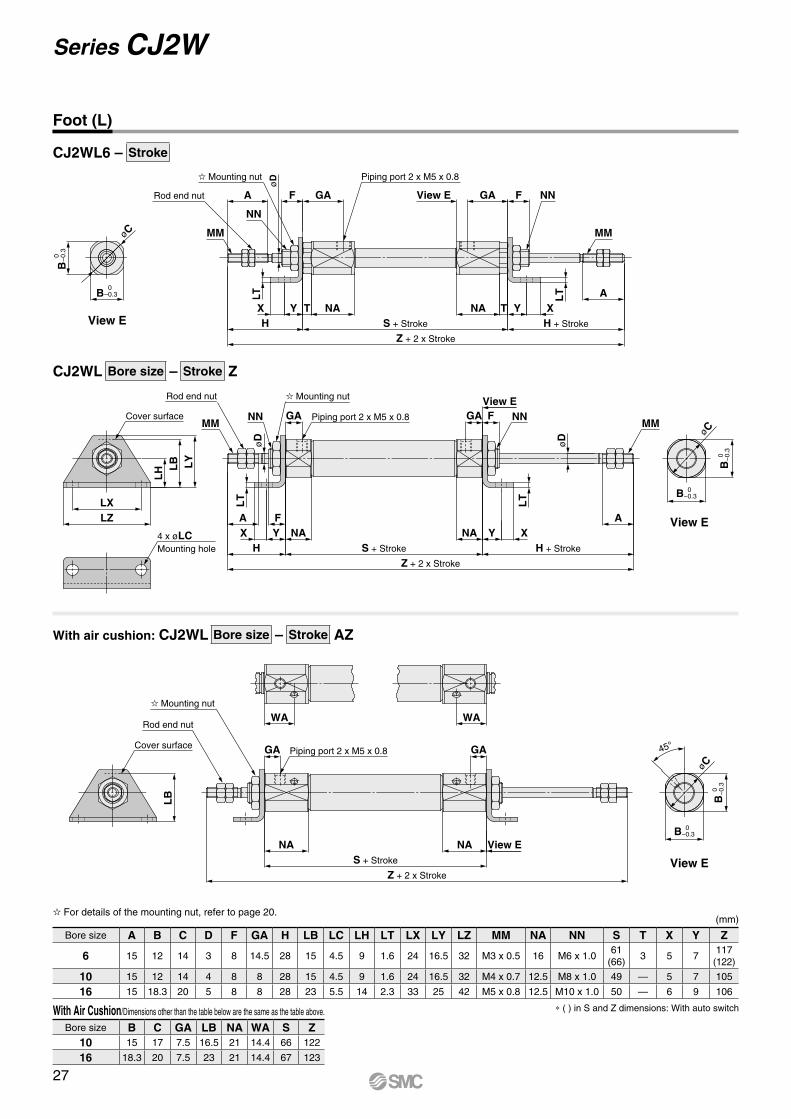
View E
For details of the mounting nut, refer to page 20.
With Air Cushion/Dimensions other than the table below are the same as the table above.
Bore size B C GA LB NA WA S Z10 15 17 7.5 16.5 21 14.4 66 122
16 18.3 20 7.5 23 21 14.4 67 123
27
Series CJ2W

F
FB
øCøC
45°
FZFX
Cover surface
FY
FB
2 x øFCMounting hole
MMNN GA Piping port 2 x M5 x 0.8
øD
NNGAMM
øD
Z + 2 x Stroke
S + StrokeHA F NA
FT
H + Stroke
NA F A B 0 −0.3
B
0
−0.
3
Cover surface
WA WA
GA Piping port 2 x M5 x 0.8
Z + 2 x Stroke
S + Stroke
NA NA B 0 −0.3
B
0
−0.
3
Mounting nutRod end nut
Rod end nut
Mounting nut
GA
0 –0.3
0–0.3
FZFX 2 x øFC
Mounting hole
FB FY
MM
Rod end nut
Mounting nut
NN
AH
øD
F T NA
GA View E
Piping port 2 x M5 x 0.8
GA
NAS + Stroke
Z + 2 x Stroke
H + Stroke
AFT
NN
MMøN
Dh
8
B
B
øC
Cover surface
FT
CJ2WF6 – Stroke
CJ2WF Bore size – Stroke Z
With air cushion: CJ2WF Bore size – Stroke AZ
(mm)
Bore size A B C D F FB FC FT FX FY FZ GA H MM NA NN S T Z
6 15 12 14 3 8 13 4.5 1.6 24 14 32 14.5 28 M3 x 0.5 16 M6 x 1.061
(66)3
117(122)
10 15 12 14 4 8 13 4.5 1.6 24 14 32 8 28 M4 x 0.7 12.5 M8 x 1.0 49 — 105
16 15 18.3 20 5 8 19 5.5 2.3 33 20 42 8 28 M5 x 0.8 12.5 M10 x 1.0 50 — 106
* ( ) in S and Z dimensions: With auto switch
View E
Flange (F)
For details of the mounting nut, refer to page 20.
With Air Cushion/Dimensions other than the table below are the same as the table above.
Bore size B C GA FB NA WA S Z10 15 17 7.5 14.5 21 14.4 66 122
16 18.3 20 7.5 19 21 14.4 67 123
28
Air Cylinder: Standard TypeDouble Acting, Double Rod Series CJ2W
CJ2
CJ2
WC
J2C
J2K
CJ2
KC
J2Z
CJ2
ZW
CJ2
RC
J2R
CJ2
RK
CJ2
RK
CB
J2
Sta
ndar
dN
on-r
otat
ing
Rod
Bui
lt-in
Spe
ed C
ontr
olle
rD
irect
Mou
ntD
irect
Mou
nt, N
on-r
otat
ing
Rod
With
End
Loc
kDo
uble
Actin
g, Do
uble
Rod
Single
Acting
, Sprin
g Retu
rn/Exte
ndDo
uble
Actin
g, Si
ngle
Rod
Single
Acting
, Sprin
g Retu
rn/Exte
ndDo
uble
Actin
g, Si
ngle
Rod
Doub
le Ac
ting,
Doub
le Ro
dDo
uble
Actin
g, Si
ngle
Rod
Single
Acting
, Sprin
g Retu
rn/Exte
ndDo
uble
Actin
g, Si
ngle
Rod
Single
Acting
, Sprin
g Retu
rn/Exte
ndDo
uble
Actin
g, Si
ngle
Rod
Auto
Sw
itch
Made
to O
rder

Nil 2 pcs.
S 1 pc.
n “n” pcs.
B Basic
L Single foot
F Rod flange
6 6 mm
Type Special functionElectrical
entry
Indica
tor lig
ht
Wiring(Output)
Load voltage Auto switch model Lead wire length (m)Pre-wiredconnector
Applicable loadDC AC Perpendicular In-line
0.5(Nil)
1(M)
3(L)
5(Z)
None(N)
So
lid s
tate
au
to s
wit
ch ——Grommet
Yes
3-wire (NPN)
24 V
5 V,12 V
—
M9NV M9N V V V v — vIC circuit
Relay,PLC
3-wire (PNP) M9PV M9P V V V v — v
2-wire 12 VM9BV M9B V V V v — v
—Connector — H7C V — V V V —
Diagnostic indication(2-color indication)
Grommet
3-wire (NPN)5 V,12 V
M9NWV M9NW V V V v — vIC circuit
3-wire (PNP) M9PWV M9PW V V V v — v2-wire 12 V M9BWV M9BW V V V v — v —
Water resistant(2-color indication)
3-wire (NPN)5 V,12 V
M9NAV*1 M9NA*1 v v V v — vIC circuit
3-wire (PNP) M9PAV*1 M9PA*1 v v V v — v2-wire 12 V M9BAV*1 M9BA*1 v v V v — v —
With diagnostic output (2-color indication) 4-wire (NPN) 5 V,12 V — H7NF V — V v — v IC circuit
Ree
d a
uto
sw
itch
——Grommet
Yes
3-wire(NPN equivalent) —
5 V — A96V A96 V — V — — — IC circuit —
2-wire
— 200 V — — V — V — — ——
Relay,PLC24 V 12 V
100 V A93V*2 A93 V V V V — —No 100 V or less A90V A90 V — V — — — IC circuit
ConnectorYes — — C73C V — V V V — —No 24 V or less — C80C V — V V V — IC circuit
R Axial
6
CDJ2 L 6 45With auto switch
CJ2
Bore size
Mounting
With auto switch(Built-in magnet)
Applicable Auto Switches/Refer to the WEB catalog or the Best Pneumatics No. 2 for further information on auto switches.
L 45
Cylinder standard stroke (mm)Refer to “Standard Strokes” on page 31.
S R
RS M9BW
Auto switch* For applicable auto switches,
refer to the table below.
If a built-in magnet cylinder without an auto switch is required, refer to the model of built-in magnet cylinder.
Head cover port locationNumber of auto switches
Made to OrderRefer to page 31 for details.
C
Note) This symbol is indicated when the D-A9l or M9l type auto switch is specified.This mounting bracket does not apply to other auto switches (D-C7l and H7l, etc.) (Nil)
Auto switch mounting bracket Note)
* ø6 is available only as in-line style.
RoHS
ActionS Single acting, Spring return
T Single acting, Spring extend
Series CJ2ø6
Air Cylinder: Standard TypeSingle Acting, Spring Return/Extend
* Solid state auto switches marked with “p” are produced upon receipt of order.* The D-A9ll/M9lll auto switches are shipped together, (but not assembled). (However, only auto switch mounting brackets are assembled before being shipped.)
*1 Water resistant type auto switches can be mounted on the above models, but in such case SMC cannot guarantee water resistance. Please contact SMC regarding water resistant types with the above model numbers.
*2 1 m type lead wire is only applicable to D-A93. * Since there are other applicable auto switches than listed, refer to page 104 for details. * For details about auto switches with pre-wired connector, refer to the WEB catalog or
the Best Pneumatics No. 2.
* Lead wire length symbols: 0.5 m·················· Nil (Example) M9NW 1 m·················· M (Example) M9NWM 3 m·················· L (Example) M9NWL 5 m·················· Z (Example) M9NWZ None··············· N (Example) H7CN
Example Band mounting CDJ2B6-45S-B
Built-in Magnet Cylinder ModelSuffix the symbol “-B” (Band mounting style) to the end of part number for cylinder with auto switch.
* Refer to page 103 for auto switch mounting brackets.
How to Order
29A
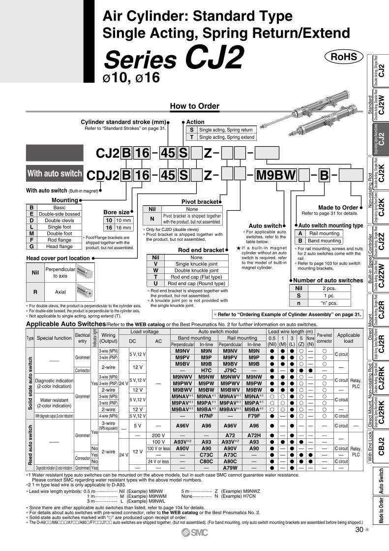
RoHS
Mounting
Z
Z
I f a bui l t - in magnet cylinder without an auto switch is required, refer to the model of built-in magnet cylinder.
* For applicable auto switches, refer to the table below.
Auto switch
M9BWS
S
Cylinder standard stroke (mm)Refer to “Standard Strokes” on page 31.
45B
With auto switch (Built-in magnet)
CJ2
4516BCDJ2
16
Bore size10 10 mm
16 16 mm
Head cover port location
B
* For rail mounting, screws and nuts for 2 auto switches come with the rail.
* Refer to page 103 for auto switch mounting brackets.
Auto switch mounting type
With auto switch
* Rod end bracket is shipped together with the product, but not assembled.
* A knuckle joint pin is not provided with the single knuckle joint.
Rod end bracketNil NoneV Single knuckle jointW Double knuckle jointT Rod end cap (Flat type)U Rod end cap (Round type)
* Refer to “Ordering Example of Cylinder Assembly” on page 31.
* Only for CJ2D (double clevis)* Pivot bracket is shipped together with
the product, but not assembled.
Pivot bracketNil None
N Pivot bracket is shipped together with the product, but not assembled.
* For double clevis, the product is perpendicular to the cylinder axis.* For double-side bossed, the product is perpendicular to the cylinder axis.* Not applicable to single acting, spring extend (T).
* Foot/Flange brackets are shipped together with the product, but not assembled.
Made to OrderRefer to page 31 for details.
Number of auto switches
ActionS Single acting, Spring return
T Single acting, Spring extend
B BasicE Double-side bossedD Double clevisL Single footM Double footF Rod flangeG Head flange
Nil 2 pcs.
S 1 pc.
n “n” pcs.
A Rail mounting
B Band mounting
Series CJ2ø10, ø16
Air Cylinder: Standard TypeSingle Acting, Spring Return/Extend
* Since there are other applicable auto switches than listed, refer to page 104 for details.* For details about auto switches with pre-wired connector, refer to the WEB catalog or the Best Pneumatics No. 2.* Solid state auto switches marked with “p” are produced upon receipt of order.* The D-A9ll/M9lll/A7ll/A80l/F7ll/J7ll auto switches are shipped together, (but not assembled). (For band mounting, only auto switch mounting brackets are assembled before being shipped.)
*1 Water resistant type auto switches can be mounted on the above models, but in such case SMC cannot guarantee water resistance. Please contact SMC regarding water resistant types with the above model numbers.
*2 1 m type lead wire is only applicable to D-A93.* Lead wire length symbols: 0.5 m·················· Nil (Example) M9NW 1 m·················· M (Example) M9NWM 3 m·················· L (Example) M9NWL
Type Special functionElectrical
entry
Indica
tor lig
ht
Wiring(Output)
Load voltage Auto switch model Lead wire length (m)Pre-wiredconnector
Applicable loadDC AC
Band mounting Rail mounting 0.5(Nil)
1(M)
3(L)
5(Z)
None(N)Perpendicular In-line Perpendicular In-line
So
lid s
tate
au
to s
wit
ch ——Grommet
Yes
3-wire (NPN)
24 V
5 V,12 V
—
M9NV M9N M9NV M9N V V V v — vIC circuit
Relay,PLC
3-wire (PNP) M9PV M9P M9PV M9P V V V v — v
2-wire 12 VM9BV M9B M9BV M9B V V V v — v
—Connector — H7C J79C — V — V V V —
Diagnostic indication(2-color indication)
Grommet
3-wire (NPN)5 V,12 V
M9NWV M9NW M9NWV M9NW V V V v — vIC circuit
3-wire (PNP) M9PWV M9PW M9PWV M9PW V V V v — v2-wire 12 V M9BWV M9BW M9BWV M9BW V V V v — v —
Water resistant(2-color indication)
3-wire (NPN)5 V,12 V
M9NAV*1 M9NA*1 M9NAV*1 M9NA*1 v v V v — vIC circuit
3-wire (PNP) M9PAV*1 M9PA*1 M9PAV*1 M9PA*1 v v V v — v2-wire 12 V M9BAV*1 M9BA*1 M9BAV*1 M9BA*1 v v V v — v —
With diagnostic output (2-color indication) 4-wire (NPN) 5 V,12 V — H7NF — F79F V — V v — v IC circuit
Ree
d a
uto
sw
itch
——Grommet
Yes
3-wire(NPN equivalent) —
5 V — A96V A96 A96V A96 V — V — — — IC circuit —
2-wire
— 200 V — — A72 A72H V — V — — ——
Relay,PLC24 V
12 V
100 V A93V*2 A93 A93V*2 A93 V V V V — —No 100 V or less A90V A90 A90V A90 V — V — — — IC circuit
ConnectorYes — — C73C A73C — V — V V V — —No 24 V or less — C80C A80C — V — V V V — IC circuit
Diagnostic indication (2-color indication) Grommet Yes — — — — A79W — V — V — — — —
Applicable Auto Switches/Refer to the WEB catalog or the Best Pneumatics No. 2 for further information on auto switches.
5 m·················· Z (Example) M9NWZ None··············· N (Example) H7CN
NilPerpendicular
to axis
R Axial
30
How to Order
CJ2
CJ2
WC
J2C
J2K
CJ2
KC
J2Z
CJ2
ZW
CJ2
RC
J2R
CJ2
RK
CJ2
RK
CB
J2
Sta
ndar
dN
on-r
otat
ing
Rod
Bui
lt-in
Spe
ed C
ontr
olle
rD
irect
Mou
ntD
irect
Mou
nt, N
on-r
otat
ing
Rod
With
End
Loc
kDo
uble
Actin
g, Do
uble
Rod
Single
Acting
, Sprin
g Retu
rn/Exte
ndDo
uble
Actin
g, Si
ngle
Rod
Single
Acting
, Sprin
g Retu
rn/Exte
ndDo
uble
Actin
g, Si
ngle
Rod
Doub
le Ac
ting,
Doub
le Ro
dDo
uble
Actin
g, Si
ngle
Rod
Single
Acting
, Sprin
g Retu
rn/Exte
ndDo
uble
Actin
g, Si
ngle
Rod
Single
Acting
, Sprin
g Retu
rn/Exte
ndDo
uble
Actin
g, Si
ngle
Rod
Auto
Sw
itch
Made
to O
rder
A
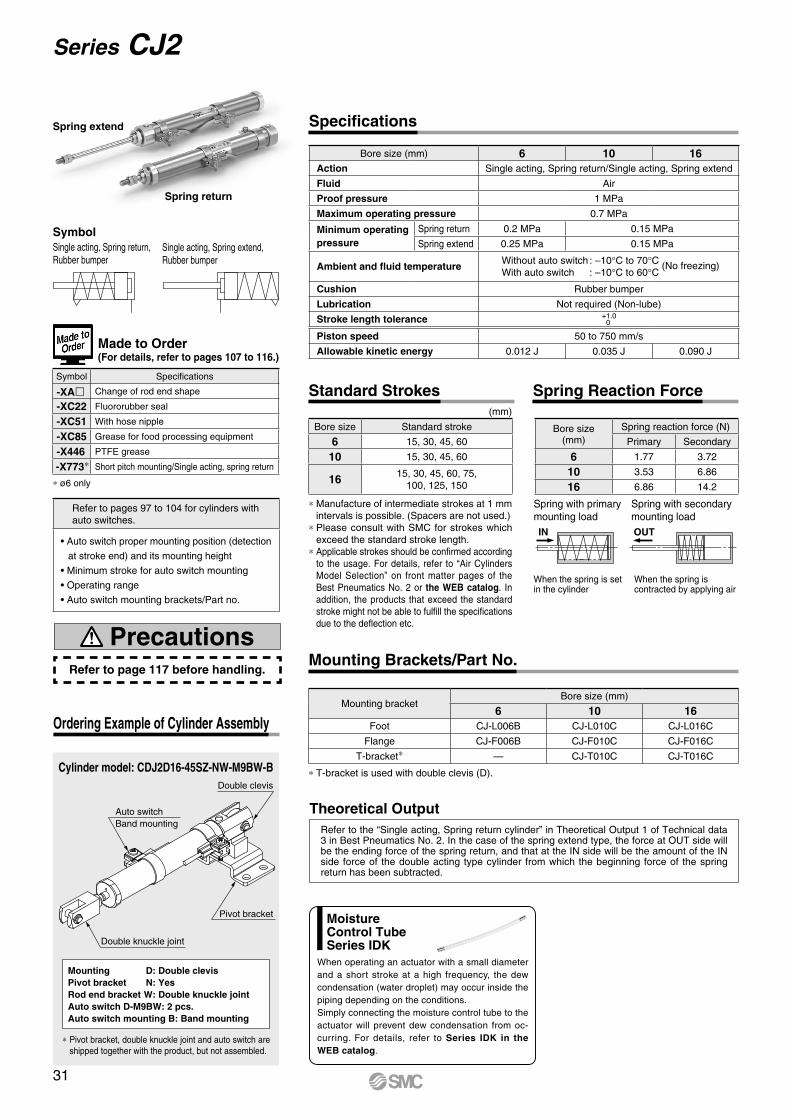
Auto switchBand mounting
Double clevis
Pivot bracket
Double knuckle joint
* ø6 only
Bore size (mm) 6 10 16Action Single acting, Spring return/Single acting, Spring extend
Fluid Air
Proof pressure 1 MPa
Maximum operating pressure 0.7 MPa
Minimum operating pressure
Spring return 0.2 MPa 0.15 MPa
Spring extend 0.25 MPa 0.15 MPa
Ambient and fluid temperatureWithout auto switch : –10°C to 70°C (No freezing)With auto switch : –10°C to 60°C
Cushion Rubber bumper
Lubrication Not required (Non-lube)
Stroke length tolerance +1.00
Piston speed 50 to 750 mm/s
Allowable kinetic energy 0.012 J 0.035 J 0.090 J
Single acting, Spring extend, Rubber bumper
SymbolSingle acting, Spring return, Rubber bumper
Cylinder model: CDJ2D16-45SZ-NW-M9BW-B
Mounting D: Double clevisPivot bracket N: YesRod end bracket W: Double knuckle jointAuto switch D-M9BW: 2 pcs.Auto switch mounting B: Band mounting
* Pivot bracket, double knuckle joint and auto switch are shipped together with the product, but not assembled.
Ordering Example of Cylinder Assembly
Spring return
Spring extend
Made to Order (For details, refer to pages 107 to 116.)
Symbol Specifications
-XAl Change of rod end shape
-XC22 Fluororubber seal
-XC51 With hose nipple
-XC85 Grease for food processing equipment
-X446 PTFE grease
-X773* Short pitch mounting/Single acting, spring return
Refer to pages 97 to 104 for cylinders with auto switches.
• Auto switch proper mounting position (detection
at stroke end) and its mounting height
• Minimum stroke for auto switch mounting
• Operating range
• Auto switch mounting brackets/Part no.
Refer to the “Single acting, Spring return cylinder” in Theoretical Output 1 of Technical data 3 in Best Pneumatics No. 2. In the case of the spring extend type, the force at OUT side will be the ending force of the spring return, and that at the IN side will be the amount of the IN side force of the double acting type cylinder from which the beginning force of the spring return has been subtracted.
Theoretical Output
Specifications
Refer to page 117 before handling.
Precautions
IN OUT
When the spring is contracted by applying air
When the spring is set in the cylinder
Spring with secondary mounting load
Spring with primary mounting load
* Manufacture of intermediate strokes at 1 mm intervals is possible. (Spacers are not used.)
* Please consult with SMC for strokes which exceed the standard stroke length.
* Applicable strokes should be confirmed according to the usage. For details, refer to “Air Cylinders Model Selection” on front matter pages of the Best Pneumatics No. 2 or the WEB catalog. In addition, the products that exceed the standard stroke might not be able to fulfill the specifications due to the deflection etc.
(mm)
Bore size Standard stroke
6 15, 30, 45, 60
10 15, 30, 45, 60
16 15, 30, 45, 60, 75, 100, 125, 150
Bore size(mm)
Spring reaction force (N)
Primary Secondary
6 1.77 3.72
10 3.53 6.86
16 6.86 14.2
Standard Strokes Spring Reaction Force
* T-bracket is used with double clevis (D).
Mounting bracketBore size (mm)
6 10 16Foot CJ-L006B CJ-L010C CJ-L016C
Flange CJ-F006B CJ-F010C CJ-F016C
T-bracket* — CJ-T010C CJ-T016C
Mounting Brackets/Part No.
When operating an actuator with a small diameter and a short stroke at a high frequency, the dew condensation (water droplet) may occur inside the piping depending on the conditions.Simply connecting the moisture control tube to the actuator will prevent dew condensation from oc-curring. For details, refer to Series IDK in the WEB catalog.
MoistureControl TubeSeries IDK
31
Series CJ2

Bore size (mm) 6 10 16
Mounting Basic BasicAxialpiping
Double clevis
(including clevis pin)
Head-side
bossedBasic
Axialpiping
Double clevis
(including clevis pin)
Head-side
bossed
Bas
ic w
eigh
t
15 stroke 11 28 28 29 28 62 62 69 64
30 stroke 16 35 35 35 35 77 77 84 79
45 stroke 18 44 44 45 45 95 95 102 97
60 stroke 23 54 54 55 54 113 113 119 115
75 stroke 134 134 141 136
100 stroke 167 167 174 169
125 stroke 204 204 212 206
150 stroke 227 227 234 229
Mou
ntin
gbr
acke
t wei
ght
Single foot 8 8 25
Double foot — 16 50
Rod flange 5 5 13
Head flange — 5 13
Acc
esso
ries
Single knuckle joint — 17 23
Double knuckle joint(including knuckle pin)
— 25 21
Rod end cap (Flat type)
1 1 2
Rod end cap (Round type)
1 1 2
T-bracket — 32 50
Bore size (mm) 6 10 16
Mounting Basic BasicAxialpiping
Double clevis
(including clevis pin)
Head-side
bossedBasic
Axialpiping
Double clevis
(including clevis pin)
Head-side
bossedB
asic
wei
ght
15 stroke 17 28 28 30 29 63 63 71 67
30 stroke 21 34 34 36 35 77 77 85 80
45 stroke 23 42 42 44 43 93 93 100 96
60 stroke 27 51 51 52 51 109 109 116 112
75 stroke 129 129 137 133
100 stroke 159 159 166 162
125 stroke 193 193 201 196
150 stroke 213 213 221 217
Mou
ntin
gbr
acke
t wei
ght
Single foot 8 8 25
Double foot — 16 50
Rod flange 5 5 13
Head flange — 5 13
Acc
esso
ries
Single knuckle joint — 17 23
Double knuckle joint(including knuckle pin)
— 25 21
Rod end cap (Flat type)
1 1 2
Rod end cap (Round type)
1 1 2
T-bracket — 32 50
∗ Mounting nut and rod end nut are included in the basic weight.Note) Mounting nut is not attached to the double clevis, so the mounting nut weight is already subtracted.
Calculation: Example) CJ2L10-45SZ
OBasic weight ······················· 44 (ø10-45 stroke)OMounting bracket weight ····· 8 (Single foot)
44 + 8 = 52 g
∗ Mounting nut and rod end nut are included in the basic weight.Note) Mounting nut is not attached to the double clevis, so the mounting nut weight is already subtracted.
Calculation: Example) CJ2L10-45TZ
OBasic weight ······················· 42 (ø10-45 stroke)OMounting bracket weight ····· 8 (Single foot)
42 + 8 = 50 g
(g)Spring Return Spring Extend(g)
Weights
V…Mounted on the product. v…Can be ordered within the cylinder model.
∗ A pin and retaining rings are shipped together with double clevis and double knuckle joint.
Mounting Basic Foot FlangeDouble∗
clevisDouble clevis(including T-bracket)
Sta
ndar
d Mounting nut V V V — —
Rod end nut V V V V V
Clevis pin — — — V V
Opt
ion
Single knuckle joint v v v v v
Double knuckle joint∗ v v v v v
Rod end cap (Flat/Round type) v v v v v
T-bracket — — — v V
Mounting and Accessories /For details, refer to page 20.
32
Air Cylinder: Standard TypeSingle Acting, Spring Return/Extend Series CJ2
CJ2
CJ2
WC
J2C
J2K
CJ2
KC
J2Z
CJ2
ZW
CJ2
RC
J2R
CJ2
RK
CJ2
RK
CB
J2
Sta
ndar
dN
on-r
otat
ing
Rod
Bui
lt-in
Spe
ed C
ontr
olle
rD
irect
Mou
ntD
irect
Mou
nt, N
on-r
otat
ing
Rod
With
End
Loc
kDo
uble
Actin
g, Do
uble
Rod
Single
Acting
, Sprin
g Retu
rn/Exte
ndDo
uble
Actin
g, Si
ngle
Rod
Single
Acting
, Sprin
g Retu
rn/Exte
ndDo
uble
Actin
g, Si
ngle
Rod
Doub
le Ac
ting,
Doub
le Ro
dDo
uble
Actin
g, Si
ngle
Rod
Single
Acting
, Sprin
g Retu
rn/Exte
ndDo
uble
Actin
g, Si
ngle
Rod
Single
Acting
, Sprin
g Retu
rn/Exte
ndDo
uble
Actin
g, Si
ngle
Rod
Auto
Sw
itch
Made
to O
rder
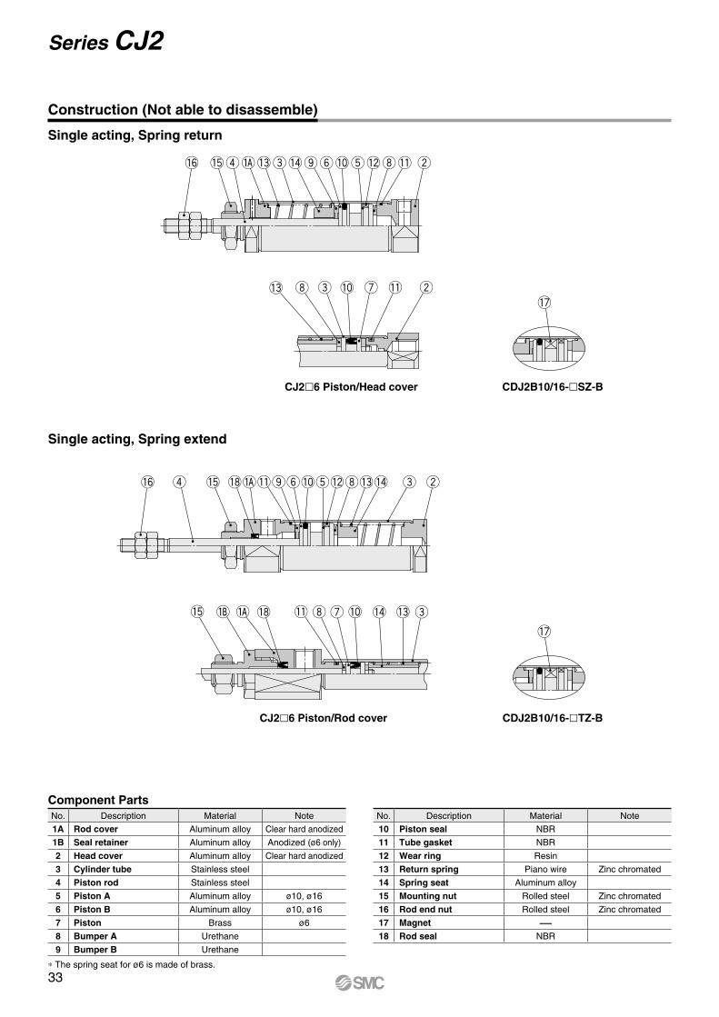
!6 !5r w!3e!4oy !2i!1
!6 !5r we!8 !0oy t!2i!3!4!1
!0t
!7
!7
w!3 e ui !1!0
!5 e!8 !0u !3!4!1 i
CDJ2B10/16-lTZ-B
CDJ2B10/16-lSZ-B
CJ2l6 Piston/Rod cover
CJ2l6 Piston/Head cover
* The spring seat for ø6 is made of brass.
Single acting, Spring extend
Single acting, Spring return
Construction (Not able to disassemble)
Component PartsNo. Description Material Note
1A Rod cover Aluminum alloy Clear hard anodized
1B Seal retainer Aluminum alloy Anodized (ø6 only)
2 Head cover Aluminum alloy Clear hard anodized
3 Cylinder tube Stainless steel
4 Piston rod Stainless steel
5 Piston A Aluminum alloy ø10, ø16
6 Piston B Aluminum alloy ø10, ø16
7 Piston Brass ø6
8 Bumper A Urethane
9 Bumper B Urethane
No. Description Material Note
10 Piston seal NBR
11 Tube gasket NBR
12 Wear ring Resin
13 Return spring Piano wire Zinc chromated
14 Spring seat Aluminum alloy
15 Mounting nut Rolled steel Zinc chromated
16 Rod end nut Rolled steel Zinc chromated
17 Magnet —18 Rod seal NBR
33
Series CJ2
øC
øC
B 0
−
0.3
B 0 −0.3
øN
Dh
8
MM
NN
Y
øD
Piping port M5 x 0.8
GBPiping port M5 x 0.8
NB
Z + Stroke
S + StrokeHA NAF
øN
Dh
8
B 0
−
0.3
B 0 −0.3
MMNN
Y
Z + Stroke
S + StrokeHA F NA
Piping port M5 x 0.8
FNB
NN
YYGB
øN
Dh
8
Mounting nut
Rod end nut
Mounting nut
Rod end nut
øD
CJ2B Bore size – Stroke S Head cover port location Z
CJ2B6 – Stroke SR
CJ2E Bore size – Stroke SZ
* ( ) in S and Z dimensions: With auto switch
Bore size
A B C D F GB H MM NA NB NDh8 NNS Z
5 to15 st
16 to30 st
31 to45 st
46 to60 st
61 to75 st
76 to100 st
101 to125 st
126 to150 st
5 to15 st
16 to30 st
31 to45 st
46 to60 st
61 to75 st
76 to100 st
101 to125 st
126 to150 st
6 15 8 9 3 8 — 28 M3 x 0.5 3 7 6 0–0.018 M6 x 1.0
34.5(39.5)
43.5(48.5)
47.5(52.5)
61.5(66.5)
— — — —62.5(67.5)
71.5(76.5)
75.5(80.5)
89.5(94.5)
— — — —
10 15 12 14 4 8 5 28 M4 x 0.7 4.8 9.5 8 0 –0.022 M8 x 1.0 45.5 53 65 77 — — — — 73.5 81 93 105 — — — —
16 15 18.3 20 5 8 5 28 M5 x 0.8 4.8 9.5 10 0 –0.022 M10 x 1.0 45.5 54 66 78 84 108 126 138 73.5 82 94 106 112 136 154 166
(mm)
Single Acting, Spring Return: Basic (B)
For details of the mounting nut, refer to page 20.
Head cover port locationAxial location (R)
* The overall cylinder length does not change.
Single Acting, Spring Return: Double-side Bossed (E)
Section Y detail
Section YY detail
For details of the mounting nut, refer to page 20.
Bore size
A B C D F GB H MM NA NB NDh8 NNS Z
5 to15 st
16 to30 st
31 to45 st
46 to60 st
61 to75 st
76 to100 st
101 to125 st
126 to150 st
5 to15 st
16 to30 st
31 to45 st
46 to60 st
61 to75 st
76 to100 st
101 to125 st
126 to150 st
10 15 12 14 4 8 5 28 M4 x 0.7 4.8 9.5 8 0 −0.022 M8 x 1.0 45.5 53 65 77 — — — — 73.5 81 93 105 — — — —
16 15 18.3 20 5 8 5 28 M5 x 0.8 4.8 9.5 10 0 −0.022 M10 x 1.0 45.5 54 66 78 84 108 126 138 73.5 82 94 106 112 136 154 166
(mm)
Section Y detail
34
Air Cylinder: Standard TypeSingle Acting, Spring Return/Extend Series CJ2
CJ2
CJ2
WC
J2C
J2K
CJ2
KC
J2Z
CJ2
ZW
CJ2
RC
J2R
CJ2
RK
CJ2
RK
CB
J2
Sta
ndar
dN
on-r
otat
ing
Rod
Bui
lt-in
Spe
ed C
ontr
olle
rD
irect
Mou
ntD
irect
Mou
nt, N
on-r
otat
ing
Rod
With
End
Loc
kDo
uble
Actin
g, Do
uble
Rod
Single
Acting
, Sprin
g Retu
rn/Exte
ndDo
uble
Actin
g, Si
ngle
Rod
Single
Acting
, Sprin
g Retu
rn/Exte
ndDo
uble
Actin
g, Si
ngle
Rod
Doub
le Ac
ting,
Doub
le Ro
dDo
uble
Actin
g, Si
ngle
Rod
Single
Acting
, Sprin
g Retu
rn/Exte
ndDo
uble
Actin
g, Si
ngle
Rod
Single
Acting
, Sprin
g Retu
rn/Exte
ndDo
uble
Actin
g, Si
ngle
Rod
Auto
Sw
itch
Made
to O
rder
øCøCClevis pin (øcdd9−0.030
−0.060)
øCDH9+0.030 0
B 0
−
0.3
B 0 −0.3
MM
øD
Piping port M5 x 0.8
GBNB
CZ
0
−0.
3
CZ 0 −0.3
CX+0.2 +0.1
ZZ + Stroke
Z + Stroke
S + StrokeHA NA
U
R
Rod end nut
øC
Cover surface
2 x øLCMounting hole
LY
LB
LH
LZLX
MM
NNA F
øD
LT
Z + Stroke
S + StrokeHYX
NA NB
GB Piping port M5 x 0.8
B0
−
0.3
B 0 −0.3
Piping port M5 x 0.8
Mounting nut
Rod end nut
CJ2D Bore size – Stroke SZ
CJ2L Bore size – Stroke S Head cover port location Z
CJ2L6 – Stroke SR
Bore size
A B C D F GB H LB LC LH LT LX LY LZ MM NA NB NNS
X YZ
5 to 15 st
16 to 30 st
31 to 45 st
46 to 60 st
61 to 75 st
76 to 100 st
101 to 125 st
126 to 150 st
5 to 15 st
16 to 30 st
31 to 45 st
46 to 60 st
61 to 75 st
76 to 100 st
101 to 125 st
126 to 150 st
6 15 8 9 3 8 — 28 13 4.5 9 1.6 24 16.5 32 M3 x 0.5 3 7 M6 x 1.034.5(39.5)
43.5(48.5)
47.5(52.5)
61.5(66.5)
— — — — 5 762.5(67.5)
71.5(76.5)
75.5(80.5)
89.5(94.5)
— — — —
10 15 12 14 4 8 5 28 15 4.5 9 1.6 24 16.5 32 M4 x 0.7 4.8 9.5 M8 x 1.0 45.5 53 65 77 — — — — 5 7 73.5 81 93 105 — — — —16 15 18.3 20 5 8 5 28 23 5.5 14 2.3 33 25 42 M5 x 0.8 4.8 9.5 M10 x 1.0 45.5 54 66 78 84 108 126 138 6 9 73.5 82 94 106 112 136 154 166
* ( ) in S and Z dimensions: With auto switch
(mm)
Single Acting, Spring Return: Double Clevis (D)
* A clevis pin and retaining rings are included.
Bore size A B C CD(cd)
CX CZ D GB H MM NA NB R US
5 to 15 st
16 to 30 st
31 to 45 st
46 to 60 st
61 to 75 st
76 to 100 st
101 to 125 st
126 to 150 st
10 15 12 14 3.3 3.2 12 4 18 20 M4 x 0.7 4.8 22.5 5 8 45.5 53 65 77 — — — —16 15 18.3 20 5 6.5 18.3 5 23 20 M5 x 0.8 4.8 27.5 8 10 45.5 54 66 78 84 108 126 138
Bore sizeZ ZZ
5 to 15 st
16 to 30 st
31 to 45 st
46 to 60 st
61 to 75 st
76 to 100 st
101 to 125 st
126 to 150 st
5 to 15 st
16 to 30 st
31 to 45 st
46 to 60 st
61 to 75 st
76 to 100 st
101 to 125 st
126 to 150 st
10 73.5 81 93 105 — — — — 78.5 86 98 110 — — — —16 75.5 84 96 108 114 138 156 168 83.5 92 104 116 122 146 164 176
(mm)
Single Acting, Spring Return: Single Foot (L)
Head cover port locationAxial location (R)
* The overall cylinder length does not change.
For details of the mounting nut, refer to page 20.
35
Series CJ2
Cover surface
LZLX
LY
LB
LH
4 x øLCMounting hole
H
MMA FNN
øD
LT
Z + Stroke
LS + Stroke
S + Stroke
YXNA
FGB Piping port M5 x 0.8
NBY X
LT
Rod end nut
Mounting nut
Mounting nut
øC
Cover surface
FZFX
2 x øFCMounting hole
FY
FB
MMNN
øD
Z + Stroke
S + StrokeHA F NA
FT
Piping port M5 x 0.8
GB
NB
B 0
−
0.3
B 0 −0.3
Piping port M5 x 0.8
Rod end nut
Mounting nut
CJ2M Bore size – Stroke SZ
CJ2F Bore size – Stroke S Head cover port location Z
CJ2F6 – Stroke SR
* ( ) in S and Z dimensions: With auto switch
Single Acting, Spring Return: Double Foot (M)
For details of the mounting nut, refer to page 20.
Boresize
A D F GB H LB LC LHLS
LT LX LY LZ MM NA NB NN5 to 15 st
16 to 30 st
31 to 45 st
46 to 60 st
61 to 75 st
76 to 100 st
101 to 125 st
126 to 150 st
10 15 4 8 5 28 15 4.5 9 59.5 67 79 91 — — — — 1.6 24 16.5 32 M4 x 0.7 4.8 9.5 M8 x 1.016 15 5 8 5 28 23 5.5 14 63.5 72 84 96 102 126 144 156 2.3 33 25 42 M5 x 0.8 4.8 9.5 M10 x 1.0
Boresize
SX Y
Z5 to 15 st
16 to 30 st
31 to 45 st
46 to 60 st
61 to 75 st
76 to 100 st
101 to 125 st
126 to 150 st
5 to 15 st
16 to 30 st
31 to 45 st
46 to 60 st
61 to 75 st
76 to 100 st
101 to 125 st
126 to 150 st
10 45.5 53 65 77 — — — — 5 7 85.5 93 105 117 — — — —16 45.5 54 66 78 84 108 126 138 6 9 88.5 97 109 121 127 151 169 181
(mm)
Single Acting, Spring Return: Rod Flange (F)
Head cover port locationAxial location (R)
* The overall cylinder length does not change. For details of the mounting nut, refer to page 20.
Boresize
A B C D F FBFC FT FXFYFZGB H MM NA NB NNS Z
5 to 15 st
16 to 30 st
31 to 45 st
46 to 60 st
61 to 75 st
76 to 100 st
101 to 125 st
126 to 150 st
5 to 15 st
16 to 30 st
31 to 45 st
46 to 60 st
61 to 75 st
76 to 100 st
101 to 125 st
126 to 150 st
6 15 8 9 3 8 11 4.5 1.6 24 14 32 — 28 M3 x 0.5 3 7 M6 x 1.034.5(39.5)
43.5(48.5)
47.5(52.5)
61.5(66.5)
— — — —62.5(67.5)
71.5(76.5)
75.5(80.5)
89.5(94.5)
— — — —
10 15 12 14 4 8 13 4.5 1.6 24 14 32 5 28 M4 x 0.7 4.8 9.5 M8 x 1.0 45.5 53 65 77 — — — — 73.5 81 93 105 — — — —16 15 18.3 20 5 8 19 5.5 2.3 33 20 42 5 28 M5 x 0.8 4.8 9.5 M10 x 1.0 45.5 54 66 78 84 108 126 138 73.5 82 94 106 112 136 154 166
(mm)
36
Air Cylinder: Standard TypeSingle Acting, Spring Return/Extend Series CJ2
CJ2
CJ2
WC
J2C
J2K
CJ2
KC
J2Z
CJ2
ZW
CJ2
RC
J2R
CJ2
RK
CJ2
RK
CB
J2
Sta
ndar
dN
on-r
otat
ing
Rod
Bui
lt-in
Spe
ed C
ontr
olle
rD
irect
Mou
ntD
irect
Mou
nt, N
on-r
otat
ing
Rod
With
End
Loc
kDo
uble
Actin
g, Do
uble
Rod
Single
Acting
, Sprin
g Retu
rn/Exte
ndDo
uble
Actin
g, Si
ngle
Rod
Single
Acting
, Sprin
g Retu
rn/Exte
ndDo
uble
Actin
g, Si
ngle
Rod
Doub
le Ac
ting,
Doub
le Ro
dDo
uble
Actin
g, Si
ngle
Rod
Single
Acting
, Sprin
g Retu
rn/Exte
ndDo
uble
Actin
g, Si
ngle
Rod
Single
Acting
, Sprin
g Retu
rn/Exte
ndDo
uble
Actin
g, Si
ngle
Rod
Auto
Sw
itch
Made
to O
rder
øC
B 0
−
0.3
B 0 −0.3
MM NN
øD
Z + Stroke
S + StrokeHA F NA
GB
FNB FT
Cover surface
2 x øFCMounting holeFZ
FX
FY
FB
Mounting nut
Rod end nut
Piping port M5 x 0.8
CJ2G Bore size – Stroke SZ
Single Acting, Spring Return: Head Flange (G)
Boresize
A B C D F FB FC FT FX FY FZ GB H MM NA NB NNS Z
5 to 15 st
16 to 30 st
31 to 45 st
46 to 60 st
61 to 75 st
76 to 100 st
101 to 125 st
126 to 150 st
5 to 15 st
16 to 30 st
31 to 45 st
46 to 60 st
61 to 75 st
76 to 100 st
101 to 125 st
126 to 150 st
10 15 12 14 4 8 13 4.5 1.6 24 14 32 5 28 M4 x 0.7 4.8 9.5 M8 x 1.0 45.5 53 65 77 — — — — 81.5 89 101 113 — — — —16 15 18.3 20 5 8 19 5.5 2.3 33 20 42 5 28 M5 x 0.8 4.8 9.5 M10 x 1.0 45.5 54 66 78 84 108 126 138 81.5 90 102 114 120 144 162 174
For details of the mounting nut, refer to page 20.(mm)
37
Series CJ2
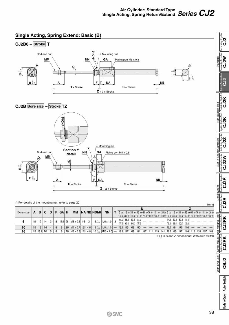
øC
øN
Dh
8
B 0
−
0.3
B 0 −0.3
MM
Y
øD
AH + Stroke
Z + 2 x Stroke
S + Stroke
NAF
Piping port M5 x 0.8GA
NB
Rod end nut
Mounting nut
NN
0 –0.3
0–0.3
0 –0.3
0–0.3
Rod end nut
MM
B
B
øC
AH + Stroke
Z + 2 x Stroke
S + Stroke
NATF
øD
NN GA Piping port M5 x 0.8
Mounting nut
øN
Dh
8
NB
ø9
8
8
CJ2B Bore size – Stroke TZ
CJ2B6 – Stroke T
Bore size A B C D F GA H MM NA NB NDh8 NN TS Z
5 to 15 st
16 to 30 st
31 to 45 st
46 to 60 st
61 to 75 st
76 to 100 st
101 to 125 st
126 to 150 st
5 to 15 st
16 to 30 st
31 to 45 st
46 to 60 st
61 to 75 st
76 to 100 st
101 to 125 st
126 to 150 st
6 15 12 14 3 8 14.5 28 M3 x 0.5 16 3 6 0 –0.018 M6 x 1.0 3
46.5(51.5)
55.5(60.5)
59.5(64.5)
73.5(78.5)
— — — —74.5(79.5)
83.5(88.5)
87.5(92.5)
101.5 (106.5)
— — — —
10 15 12 14 4 8 8 28 M4 x 0.7 12.5 4.8 8 0 –0.022 M8 x 1.0 — 48.5 56 68 80 — — — — 76.5 84 96 108 — — — —
16 15 18.3 20 5 8 8 28 M5 x 0.8 12.5 4.8 10 0 –0.022 M10 x 1.0 — 48.5 57 69 81 87 111 129 141 76.5 85 97 109 115 139 157 169
* ( ) in S and Z dimensions: With auto switch
Single Acting, Spring Extend: Basic (B)
Section Ydetail
For details of the mounting nut, refer to page 20.(mm)
38
Air Cylinder: Standard TypeSingle Acting, Spring Return/Extend Series CJ2
CJ2
CJ2
WC
J2C
J2K
CJ2
KC
J2Z
CJ2
ZW
CJ2
RC
J2R
CJ2
RK
CJ2
RK
CB
J2
Sta
ndar
dN
on-r
otat
ing
Rod
Bui
lt-in
Spe
ed C
ontr
olle
rD
irect
Mou
ntD
irect
Mou
nt, N
on-r
otat
ing
Rod
With
End
Loc
kDo
uble
Actin
g, Do
uble
Rod
Single
Acting
, Sprin
g Retu
rn/Exte
ndDo
uble
Actin
g, Si
ngle
Rod
Single
Acting
, Sprin
g Retu
rn/Exte
ndDo
uble
Actin
g, Si
ngle
Rod
Doub
le Ac
ting,
Doub
le Ro
dDo
uble
Actin
g, Si
ngle
Rod
Single
Acting
, Sprin
g Retu
rn/Exte
ndDo
uble
Actin
g, Si
ngle
Rod
Single
Acting
, Sprin
g Retu
rn/Exte
ndDo
uble
Actin
g, Si
ngle
Rod
Auto
Sw
itch
Made
to O
rder
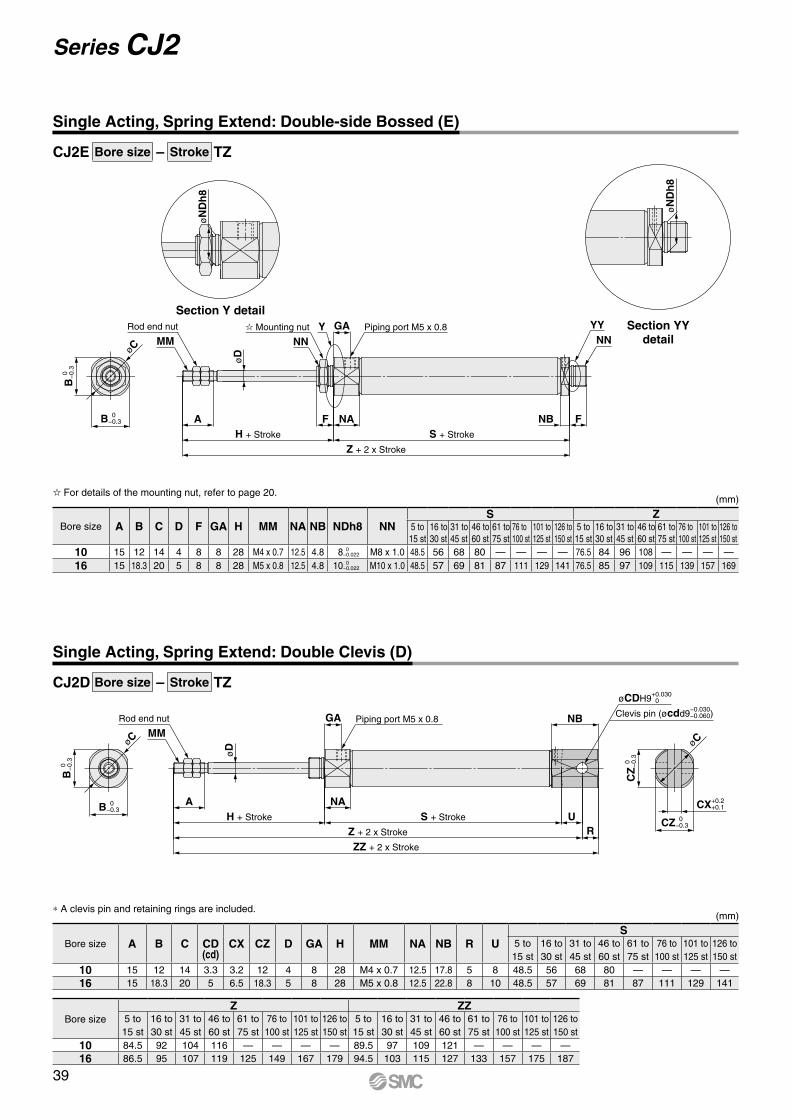
øC
øN
Dh
8
øN
Dh
8
B 0
−
0.3
B 0 −0.3
MM NNY
øD
Piping port M5 x 0.8GA
Z + 2 x Stroke
S + StrokeH + Stroke
A NAF FNB
NNYYRod end nut Mounting nut
øC
Clevis pin (øcdd9−0.030−0.060)
øCDH9+0.030 0
MM
øD
Piping port M5 x 0.8GA NB
UR
ZZ + 2 x Stroke
Z + 2 x Stroke
S + StrokeH + Stroke
A NA
CZ
0
−0.
3
CZ 0 −0.3
CX+0.2 +0.1
Rod end nut
øC
B 0
−
0.3
B 0 −0.3
CJ2E Bore size – Stroke TZ
CJ2D Bore size – Stroke TZ
Single Acting, Spring Extend: Double-side Bossed (E)
Bore size A B C D F GA H MM NA NB NDh8 NNS Z
5 to 15 st
16 to 30 st
31 to 45 st
46 to 60 st
61 to 75 st
76 to 100 st
101 to 125 st
126 to 150 st
5 to 15 st
16 to 30 st
31 to 45 st
46 to 60 st
61 to 75 st
76 to 100 st
101 to 125 st
126 to 150 st
10 15 12 14 4 8 8 28 M4 x 0.7 12.5 4.8 8 0 −0.022 M8 x 1.0 48.5 56 68 80 — — — — 76.5 84 96 108 — — — —
16 15 18.3 20 5 8 8 28 M5 x 0.8 12.5 4.8 10 0 −0.022 M10 x 1.0 48.5 57 69 81 87 111 129 141 76.5 85 97 109 115 139 157 169
For details of the mounting nut, refer to page 20.(mm)
Section Y detailSection YY
detail
Single Acting, Spring Extend: Double Clevis (D)
Bore size A B C CD(cd)
CX CZ D GA H MM NA NB R US
5 to 15 st
16 to 30 st
31 to 45 st
46 to 60 st
61 to 75 st
76 to 100 st
101 to 125 st
126 to 150 st
10 15 12 14 3.3 3.2 12 4 8 28 M4 x 0.7 12.5 17.8 5 8 48.5 56 68 80 — — — —16 15 18.3 20 5 6.5 18.3 5 8 28 M5 x 0.8 12.5 22.8 8 10 48.5 57 69 81 87 111 129 141
Bore sizeZ ZZ
5 to 15 st
16 to 30 st
31 to 45 st
46 to 60 st
61 to 75 st
76 to 100 st
101 to 125 st
126 to 150 st
5 to 15 st
16 to 30 st
31 to 45 st
46 to 60 st
61 to 75 st
76 to 100 st
101 to 125 st
126 to 150 st
10 84.5 92 104 116 — — — — 89.5 97 109 121 — — — —16 86.5 95 107 119 125 149 167 179 94.5 103 115 127 133 157 175 187
* A clevis pin and retaining rings are included.(mm)
39
Series CJ2
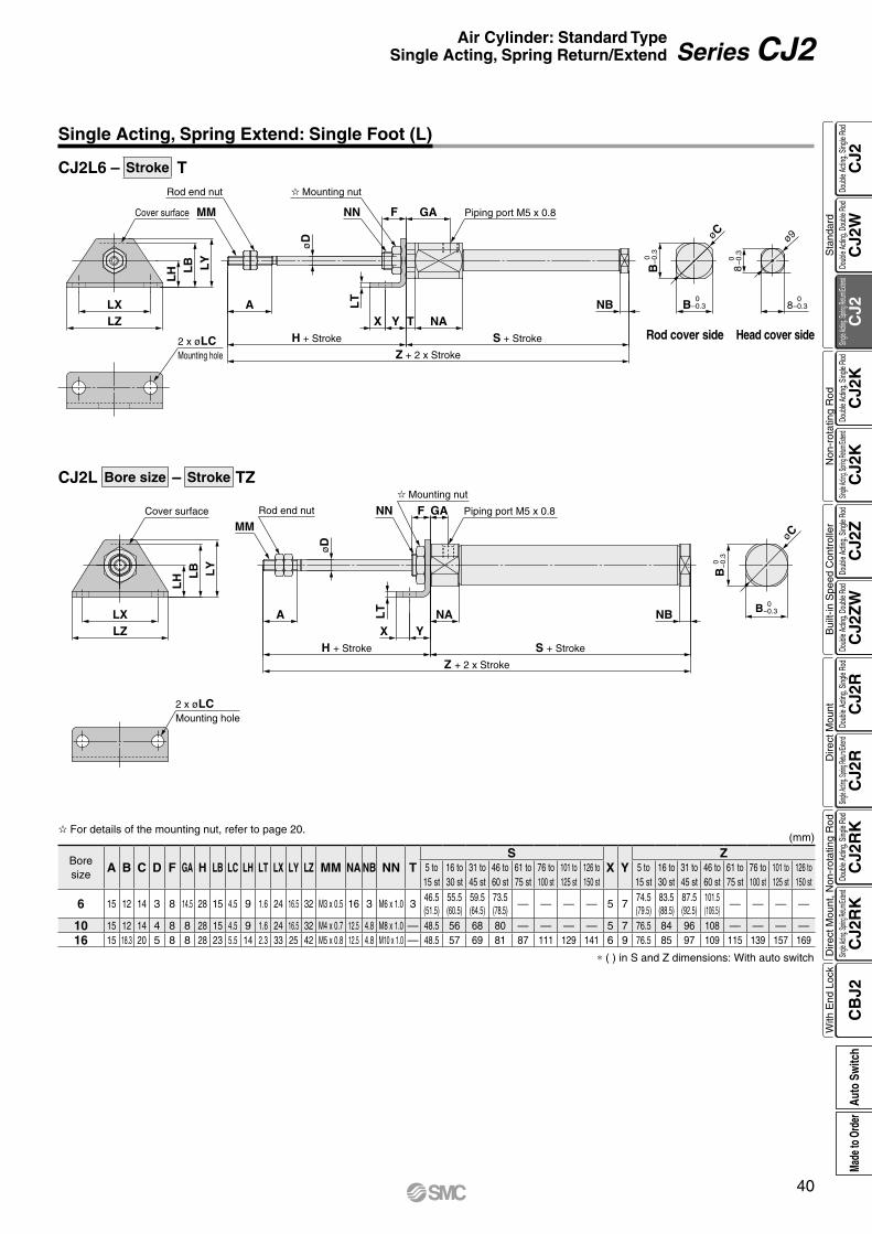
øC
Cover surface
LZLX
LY
LB
LH
2 x øLCMounting hole
MMPiping port M5 x 0.8F GA
øD
Z + 2 x Stroke
S + StrokeH + Stroke
A LT NA
YXNB
B 0
−
0.3
B 0 −0.3
Mounting nut
Rod end nut NN
0 –0.3
0 –0.3
0–0.3
0–0.3LX
LZ
2 x øLCMounting hole
LH L
B LY
Cover surface MM
Rod end nut Mounting nut
NN
øD
A
H + Stroke
Z + 2 x Stroke
X Y T NAS + Stroke
NB
GAF
LT
B
B
øC
8
ø9
8
Piping port M5 x 0.8
CJ2L Bore size – Stroke TZ
CJ2L6 – Stroke T
Boresize
A B C D F GA H LB LC LH LT LX LY LZ MM NA NB NN TS
X YZ
5 to 15 st
16 to 30 st
31 to 45 st
46 to 60 st
61 to 75 st
76 to 100 st
101 to 125 st
126 to 150 st
5 to 15 st
16 to 30 st
31 to 45 st
46 to 60 st
61 to 75 st
76 to 100 st
101 to 125 st
126 to 150 st
6 15 12 14 3 8 14.5 28 15 4.5 9 1.6 24 16.5 32 M3 x 0.5 16 3 M6 x 1.0 346.5(51.5)
55.5(60.5)
59.5(64.5)
73.5(78.5)
— — — — 5 774.5(79.5)
83.5(88.5)
87.5(92.5)
101.5 (106.5)
— — — —
10 15 12 14 4 8 8 28 15 4.5 9 1.6 24 16.5 32 M4 x 0.7 12.5 4.8 M8 x 1.0 — 48.5 56 68 80 — — — — 5 7 76.5 84 96 108 — — — —16 15 18.3 20 5 8 8 28 23 5.5 14 2.3 33 25 42 M5 x 0.8 12.5 4.8 M10 x 1.0 — 48.5 57 69 81 87 111 129 141 6 9 76.5 85 97 109 115 139 157 169
* ( ) in S and Z dimensions: With auto switch
Rod cover side Head cover side
(mm)
Single Acting, Spring Extend: Single Foot (L)
For details of the mounting nut, refer to page 20.
40
Air Cylinder: Standard TypeSingle Acting, Spring Return/Extend Series CJ2
CJ2
CJ2
WC
J2C
J2K
CJ2
KC
J2Z
CJ2
ZW
CJ2
RC
J2R
CJ2
RK
CJ2
RK
CB
J2
Sta
ndar
dN
on-r
otat
ing
Rod
Bui
lt-in
Spe
ed C
ontr
olle
rD
irect
Mou
ntD
irect
Mou
nt, N
on-r
otat
ing
Rod
With
End
Loc
kDo
uble
Actin
g, Do
uble
Rod
Single
Acting
, Sprin
g Retu
rn/Exte
ndDo
uble
Actin
g, Si
ngle
Rod
Single
Acting
, Sprin
g Retu
rn/Exte
ndDo
uble
Actin
g, Si
ngle
Rod
Doub
le Ac
ting,
Doub
le Ro
dDo
uble
Actin
g, Si
ngle
Rod
Single
Acting
, Sprin
g Retu
rn/Exte
ndDo
uble
Actin
g, Si
ngle
Rod
Single
Acting
, Sprin
g Retu
rn/Exte
ndDo
uble
Actin
g, Si
ngle
Rod
Auto
Sw
itch
Made
to O
rder
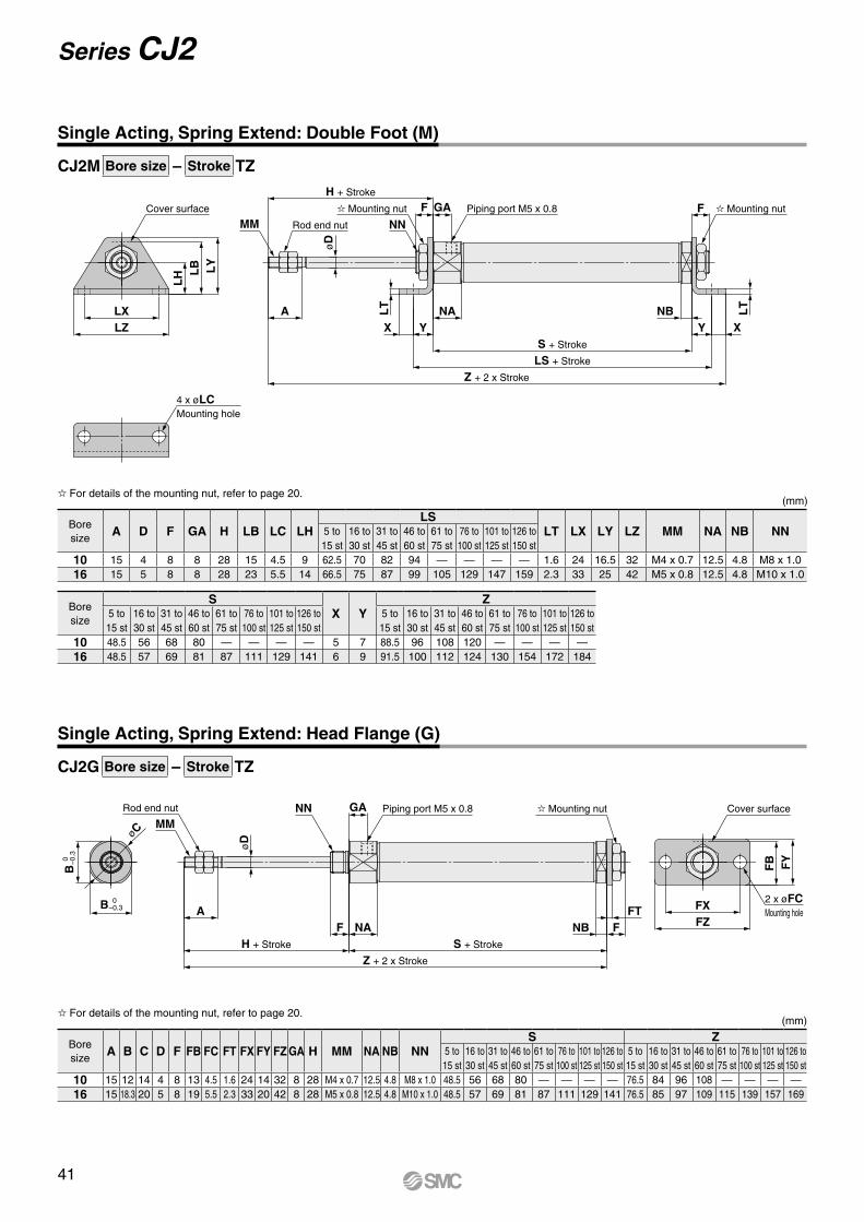
Cover surface
LZLX
LY
LB
LH
MM
H + Stroke
NNPiping port M5 x 0.8F GA
øD
A LT
Z + 2 x Stroke
LS + Stroke
S + Stroke
YXNA
F
LT
Y XNB
4 x øLCMounting hole
Rod end nut
Mounting nut Mounting nut
øC
B 0
−
0.3
B 0 −0.3
MMNN GA
øD
Piping port M5 x 0.8
Z + 2 x Stroke
H + Stroke S + Stroke
ANAF FNB
FTFZFX
Cover surface
2 x øFCMounting hole
Rod end nut Mounting nut
FY
FB
CJ2M Bore size – Stroke TZ
CJ2G Bore size – Stroke TZ
Boresize
A D F GA H LB LC LHLS
LT LX LY LZ MM NA NB NN5 to 15 st
16 to 30 st
31 to 45 st
46 to 60 st
61 to 75 st
76 to 100 st
101 to 125 st
126 to 150 st
10 15 4 8 8 28 15 4.5 9 62.5 70 82 94 — — — — 1.6 24 16.5 32 M4 x 0.7 12.5 4.8 M8 x 1.016 15 5 8 8 28 23 5.5 14 66.5 75 87 99 105 129 147 159 2.3 33 25 42 M5 x 0.8 12.5 4.8 M10 x 1.0
Boresize
SX Y
Z5 to 15 st
16 to 30 st
31 to 45 st
46 to 60 st
61 to 75 st
76 to 100 st
101 to 125 st
126 to 150 st
5 to 15 st
16 to 30 st
31 to 45 st
46 to 60 st
61 to 75 st
76 to 100 st
101 to 125 st
126 to 150 st
10 48.5 56 68 80 — — — — 5 7 88.5 96 108 120 — — — —16 48.5 57 69 81 87 111 129 141 6 9 91.5 100 112 124 130 154 172 184
For details of the mounting nut, refer to page 20.(mm)
Single Acting, Spring Extend: Double Foot (M)
Single Acting, Spring Extend: Head Flange (G)
Boresize
A B C D F FB FC FT FX FY FZ GA H MM NA NB NNS Z
5 to 15 st
16 to 30 st
31 to 45 st
46 to 60 st
61 to 75 st
76 to 100 st
101 to 125 st
126 to 150 st
5 to 15 st
16 to 30 st
31 to 45 st
46 to 60 st
61 to 75 st
76 to 100 st
101 to 125 st
126 to 150 st
10 15 12 14 4 8 13 4.5 1.6 24 14 32 8 28 M4 x 0.7 12.5 4.8 M8 x 1.0 48.5 56 68 80 — — — — 76.5 84 96 108 — — — —16 15 18.3 20 5 8 19 5.5 2.3 33 20 42 8 28 M5 x 0.8 12.5 4.8 M10 x 1.0 48.5 57 69 81 87 111 129 141 76.5 85 97 109 115 139 157 169
For details of the mounting nut, refer to page 20.(mm)
41
Series CJ2
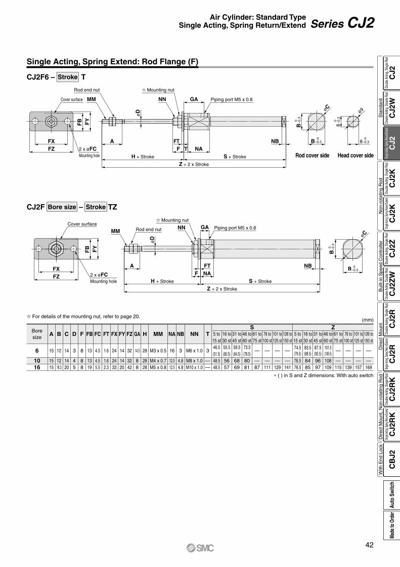
Cover surface
FZFX
FY
FB
2 x øFCMounting hole
MM
øD
NN GA Piping port M5 x 0.8
A
Z + 2 x Stroke
H + Stroke S + Stroke
NAFFT NB
Rod end nut
Mounting nut
øC
B 0
−
0.3
B 0 −0.3
0 –0.3
0 –0.3
0–0.3
0–0.3
ø9
8
8
øC
B
B
NB
S + Stroke
Z + 2 x Stroke
NA
Piping port M5 x 0.8GANN
� Mounting nut
F TFT
H + Stroke
AøD
Rod end nut
MMCover surface
FZFX
FY
FB
2 x øFCMounting hole
CJ2F Bore size – Stroke TZ
CJ2F6 – Stroke T
Boresize
A B C D F FB FC FT FX FY FZ GA H MM NA NB NN TS Z
5 to 15 st
16 to 30 st
31 to 45 st
46 to 60 st
61 to 75 st
76 to 100 st
101 to 125 st
126 to 150 st
5 to 15 st
16 to 30 st
31 to 45 st
46 to 60 st
61 to 75 st
76 to 100 st
101 to 125 st
126 to 150 st
6 15 12 14 3 8 13 4.5 1.6 24 14 32 14.5 28 M3 x 0.5 16 3 M6 x 1.0 346.5(51.5)
55.5(60.5)
59.5(64.5)
73.5(78.5)
— — — —74.5(79.5)
83.5(88.5)
87.5(92.5)
101.5(106.5)
— — — —
10 15 12 14 4 8 13 4.5 1.6 24 14 32 8 28 M4 x 0.7 12.5 4.8 M8 x 1.0 — 48.5 56 68 80 — — — — 76.5 84 96 108 — — — —16 15 18.3 20 5 8 19 5.5 2.3 33 20 42 8 28 M5 x 0.8 12.5 4.8 M10 x 1.0 — 48.5 57 69 81 87 111 129 141 76.5 85 97 109 115 139 157 169
Rod cover side Head cover side
* ( ) in S and Z dimensions: With auto switch
(mm)
Single Acting, Spring Extend: Rod Flange (F)
For details of the mounting nut, refer to page 20.
42
Air Cylinder: Standard TypeSingle Acting, Spring Return/Extend Series CJ2
CJ2
CJ2
WC
J2C
J2K
CJ2
KC
J2Z
CJ2
ZW
CJ2
RC
J2R
CJ2
RK
CJ2
RK
CB
J2
Sta
ndar
dN
on-r
otat
ing
Rod
Bui
lt-in
Spe
ed C
ontr
olle
rD
irect
Mou
ntD
irect
Mou
nt, N
on-r
otat
ing
Rod
With
End
Loc
kDo
uble
Actin
g, Do
uble
Rod
Single
Acting
, Sprin
g Retu
rn/Exte
ndDo
uble
Actin
g, Si
ngle
Rod
Single
Acting
, Sprin
g Retu
rn/Exte
ndDo
uble
Actin
g, Si
ngle
Rod
Doub
le Ac
ting,
Doub
le Ro
dDo
uble
Actin
g, Si
ngle
Rod
Single
Acting
, Sprin
g Retu
rn/Exte
ndDo
uble
Actin
g, Si
ngle
Rod
Single
Acting
, Sprin
g Retu
rn/Exte
ndDo
uble
Actin
g, Si
ngle
Rod
Auto
Sw
itch
Made
to O
rder

How to Order
RoHS
* Since there are other applicable auto switches than listed, refer to page 104 for details.* For details about auto switches with pre-wired connector, refer to the WEB catalog or the Best Pneumatics No. 2.* Solid state auto switches marked with “p” are produced upon receipt of order.* The D-A9ll/M9lll/A7ll/A80l/F7ll/J7ll auto switches are shipped together, (but not assembled). (For band mounting, only auto switch mounting brackets are assembled before being shipped.)
*1 Water resistant type auto switches can be mounted on the above models, but in such case SMC cannot guarantee water resistance. Please contact SMC regarding water resistant types with the above model numbers.
*2 1 m type lead wire is only applicable to D-A93.
Series CJ2Kø10, ø16
Air Cylinder: Non-rotating Rod TypeDouble Acting, Single Rod
* Lead wire length symbols: 0.5 m·················· Nil (Example) M9NW 1 m·················· M (Example) M9NWM 3 m·················· L (Example) M9NWL
Applicable Auto Switches/Refer to the WEB catalog or the Best Pneumatics No. 2 for further information on auto switches.
Type Special functionElectrical
entry
Indica
tor lig
ht
Wiring(Output)
Load voltage Auto switch model Lead wire length (m)Pre-wiredconnector
Applicable loadDC AC
Band mounting Rail mounting 0.5(Nil)
1(M)
3(L)
5(Z)
None(N)Perpendicular In-line Perpendicular In-line
So
lid s
tate
au
to s
wit
ch ——Grommet
Yes
3-wire (NPN)
24 V
5 V,12 V
—
M9NV M9N M9NV M9N V V V v — vIC circuit
Relay,PLC
3-wire (PNP) M9PV M9P M9PV M9P V V V v — v
2-wire 12 VM9BV M9B M9BV M9B V V V v — v
—Connector — H7C J79C — V — V V V —
Diagnostic indication(2-color indication)
Grommet
3-wire (NPN)5 V,12 V
M9NWV M9NW M9NWV M9NW V V V v — vIC circuit
3-wire (PNP) M9PWV M9PW M9PWV M9PW V V V v — v2-wire 12 V M9BWV M9BW M9BWV M9BW V V V v — v —
Water resistant (2-color indication)
3-wire (NPN)5 V,12 V
M9NAV*1 M9NA*1 M9NAV*1 M9NA*1 v v V v — vIC circuit
3-wire (PNP) M9PAV*1 M9PA*1 M9PAV*1 M9PA*1 v v V v — v2-wire 12 V M9BAV*1 M9BA*1 M9BAV*1 M9BA*1 v v V v — v —
With diagnostic output (2-color indication) 4-wire (NPN) 5 V,12 V — H7NF — F79F V — V v — v IC circuit
Ree
d a
uto
sw
itch
——Grommet
Yes
3-wire(NPN equivalent) —
5 V — A96V A96 A96V A96 V — V — — — IC circuit —
2-wire
— 200 V — — A72 A72H V — V — — ——
Relay,PLC24 V
12 V
100 V A93V*2 A93 A93V*2 A93 V V V V — —No 100 V or less A90V A90 A90V A90 V — V — — — IC circuit
ConnectorYes — — C73C A73C — V — V V V — —No 24 V or less — C80C A80C — V — V V V — IC circuit
Diagnostic indication (2-color indication) Grommet Yes — — — — A79W — V — V — — — —
Cylinder standard stroke (mm)Refer to “Standard Strokes” on page 44.
Bore size
M9BW6016
6016
B Z
Z
CDJ2K
BCJ2K
10 10 mm
16 16 mm
Mounting
With auto switch
Made to OrderRefer to page 44 for details.
Auto switch mounting type
Number of auto switches
B
I f a bui l t - in magnet cylinder without an auto switch is required, refer to the model of built-in magnet cylinder.
* For applicable auto switches, refer to the table below.
Auto switch
Pivot bracket
* Rod end bracket is shipped together with the product, but not assembled.
* A knuckle joint pin is not provided with the single knuckle joint.
Rod end bracket
* For double clevis, the product is perpendicular to the cylinder axis.* For double-side bossed, the product is perpendicular to the cylinder axis.
Head cover port location
With auto switch (Built-in magnet)
* Refer to “Ordering Example of Cylinder Assembly” on page 44.
* Foot/Flange brackets are shipped together with the product, but not assembled.
B BasicE Double-side bossedD Double clevisL Single footM Double footF Rod flangeG Head flange
Nil 2 pcs.S 1 pc.n “n” pcs.
* For rail mounting, screws and nuts for 2 auto switches come with the rail.
* Refer to page 103 for auto switch mounting brackets.
A Rail mountingB Band mounting
Nil NoneV Single knuckle jointW Double knuckle jointT Rod end cap (Flat type)U Rod end cap (Round type)
* Only for CJ2D (double clevis)* Pivot bracket is shipped together with
the product, but not assembled.
Nil None
N Pivot bracket is shipped together with the product, but not assembled.
5 m·················· Z (Example) M9NWZ None··············· N (Example) H7CN
Nil Perpendicular to axis
R Axial
43A
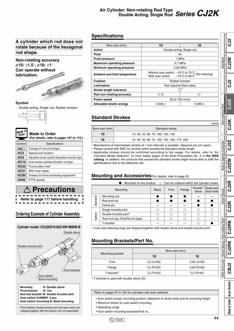
Auto switchBand mounting
Double clevis
Pivot bracket
Double knuckle joint
Cylinder model: CDJ2KD16-60Z-NW-M9BW-B
Mounting D: Double clevisPivot bracket N: YesRod end bracket W: Double knuckle jointAuto switch D-M9BW: 2 pcs.Auto switch mounting B: Band mounting
* Pivot bracket, double knuckle joint and auto switch are shipped together with the product, but not assembled.
Ordering Example of Cylinder Assembly
Double acting, Single rod, Rubber bumper
Symbol
Non-rotating accuracyø10: ±1.5°, ø16: ±1°Can operate without lubrication.
A cylinder which rod does not rotate because of the hexagonal rod shape.
Made to Order (For details, refer to pages 107 to 116.)
Symbol Specifications
-XAl Change of rod end shape
-XC3 Special port location
-XC9 Adjustable stroke cylinder/Adjustable retraction type
-XC10 Dual stroke cylinder/Double rod type
-XC22 Fluororubber seal
-XC51 With hose nipple
-XC85 Grease for food processing equipment
-X446 PTFE grease
Refer to pages 97 to 104 for cylinders with auto switches.
• Auto switch proper mounting position (detection at stroke end) and its mounting height
• Minimum stroke for auto switch mounting
• Operating range
• Auto switch mounting brackets/Part no.
Specifications
* Manufacture of intermediate strokes at 1 mm intervals is possible. (Spacers are not used.)* Please consult with SMC for strokes which exceed the standard stroke length.* Applicable strokes should be confirmed according to the usage. For details, refer to “Air
Cylinders Model Selection” on front matter pages of the Best Pneumatics No. 2 or the WEB catalog. In addition, the products that exceed the standard stroke might not be able to fulfill the specifications due to the deflection etc.
(mm)
Bore size (mm) Standard stroke
10 15, 30, 45, 60, 75, 100, 125, 150
16 15, 30, 45, 60, 75, 100, 125, 150, 175, 200
Standard Strokes
Refer to page 117 before handling.
Precautions
* T-bracket is used with double clevis (D).
Mounting bracketBore size (mm)
10 16
Foot CJ-L016C CJK-L016C
Flange CJ-F016C CJK-F016C
T-bracket* CJ-T010C CJ-T016C
Mounting Brackets/Part No.
V…Mounted on the product. v…Can be ordered within the cylinder model.
Mounting and Accessories /For details, refer to page 20.
Bore size (mm) 10 16Action Double acting, Single rod
Fluid Air
Proof pressure 1 MPa
Maximum operating pressure 0.7 MPa
Minimum operating pressure 0.06 MPa
Ambient and fluid temperatureWithout auto switch : –10°C to 70°C (No freezing)With auto switch : –10°C to 60°C
Cushion Rubber bumper
Lubrication Not required (Non-lube)
Stroke length tolerance +1.00
Rod non-rotating accuracy ±1.5° ±1°
Piston speed 50 to 750 mm/s
Allowable kinetic energy 0.035 J 0.090 J
* A pin and retaining rings are shipped together with double clevis and double knuckle joint.
Mounting Basic Foot Flange Double*clevis
Double clevis(including T-bracket)
Sta
ndar
d Mounting nut V V V — —
Rod end nut V V V V V
Clevis pin — — — V V
Opt
ion
Single knuckle joint v v v v v
Double knuckle joint* v v v v v
Rod end cap (Flat/Round type) v v v v v
T-bracket — — — v V
44
Air Cylinder: Non-rotating Rod TypeDouble Acting, Single Rod Series CJ2K
CJ2
CJ2
WC
J2C
J2K
CJ2
KC
J2Z
CJ2
ZW
CJ2
RC
J2R
CJ2
RK
CJ2
RK
CB
J2
Sta
ndar
dN
on-r
otat
ing
Rod
Bui
lt-in
Spe
ed C
ontr
olle
rD
irect
Mou
ntD
irect
Mou
nt, N
on-r
otat
ing
Rod
With
End
Loc
kDo
uble
Actin
g, Do
uble
Rod
Single
Acting
, Sprin
g Retu
rn/Exte
ndDo
uble
Actin
g, Si
ngle
Rod
Single
Acting
, Sprin
g Retu
rn/Exte
ndDo
uble
Actin
g, Si
ngle
Rod
Doub
le Ac
ting,
Doub
le Ro
dDo
uble
Actin
g, Si
ngle
Rod
Single
Acting
, Sprin
g Retu
rn/Exte
ndDo
uble
Actin
g, Si
ngle
Rod
Single
Acting
, Sprin
g Retu
rn/Exte
ndDo
uble
Actin
g, Si
ngle
Rod
Auto
Sw
itch
Made
to O
rder
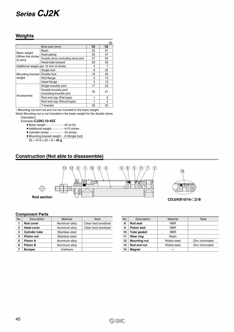
q we y tori u!4
!2 !1!3 !0
∗ Mounting nut and rod end nut are included in the basic weight.Note) Mounting nut is not included in the basic weight for the double clevis.
Calculation:Example) CJ2KL10-45Z
¡Basic weight ······················ 25 (ø10)¡Additional weight ··············· 4/15 stroke¡Cylinder stroke ·················· 45 stroke¡Mounting bracket weight ··· 8 (Single foot)
25 + 4/15 x 45 + 8 = 45 g
(g)Bore size (mm) 10 16
Basic weight(When the strokeis zero)
Basic 25 47Axial piping 25 47Double clevis (including clevis pin) 27 55Head-side bossed 29 50
Additional weight per 15 mm of stroke 4 7
Mounting bracketweight
Single foot 8 25Double foot 16 50Rod flange 5 13Head flange 5 13
Accessories
Single knuckle joint 17 23Double knuckle joint(including knuckle pin)
25 21
Rod end cap (Flat type) 1 2Rod end cap (Round type) 1 2T-bracket 32 50
Weights
Construction (Not able to disassemble)
CDJ2KB10/16-Z-BRod section
Component PartsNo. Description Material Note
1 Rod cover Aluminum alloy Clear hard anodized
2 Head cover Aluminum alloy Clear hard anodized
3 Cylinder tube Stainless steel
4 Piston rod Stainless steel
5 Piston A Aluminum alloy
6 Piston B Aluminum alloy
7 Bumper Urethane
No. Description Material Note
8 Rod seal NBR
9 Piston seal NBR
10 Tube gasket NBR
11 Wear ring Resin
12 Mounting nut Rolled steel Zinc chromated
13 Rod end nut Rolled steel Zinc chromated
14 Magnet —
45
Series CJ2K

KA
øCB
øCA
øN
Dh
8
BA
0
−
0.3
BA 0 −0.3
KA MM
NN
Y
GA Piping port 2 x M5 x 0.8
Z + Stroke
S + StrokeHA NAF NB
GB
BB
0
−
0.3
BB 0 −0.3
Piping port M5 x 0.8
Mounting nut
Rod end nut
øC
øN
Dh
8
øN
Dh
8
B
0
−0.
3
B 0 −0.3
KA
MM
NN
YGA Piping port 2 x M5 x 0.8
Z + Stroke
S + StrokeHA NAF NB
F
GBYY
NN Mounting nut
Rod end nut
CJ2KB Bore size – Stroke Head cover port location Z
CJ2KE Bore size – Stroke Z
Basic (B)
Head cover port locationAxial location (R)
* The overall cylinder length does not change.
Refer to page 20 for details of the mounting nut. (SNJ-016C for ø10, SNKJ-016C for ø16)
Bore size A BA BB CA CB F GA GB H KA MM NA NB NDh8 NN S Z10 15 15 12 17 14 8 8 5 28 4.2 M4 x 0.7 12.5 9.5 10 0
−0.022 M10 x 1.0 46 74
16 15 18.3 18.3 20 20 8 8 5 28 5.2 M5 x 0.8 12.5 9.5 12 0 −0.027 M12 x 1.0 47 75
(mm)
Double-side Bossed (E)
Rod section
Section Y detail
Rod section
Section Y detail Section YY detail
Refer to page 20 for details of the mounting nut. (SNJ-016C for ø10, SNKJ-016C for ø16)
Bore size A B C F GA GB H KA MM NA NB NDh8 NN S Z10 15 15 17 8 8 5 28 4.2 M4 x 0.7 12.5 9.5 10 0
−0.022 M10 x 1.0 46 82
16 15 18.3 20 8 8 5 28 5.2 M5 x 0.8 12.5 9.5 12 0 −0.027 M12 x 1.0 47 83
(mm)
46
Air Cylinder: Non-rotating Rod TypeDouble Acting, Single Rod Series CJ2K
CJ2
CJ2
WC
J2C
J2K
CJ2
KC
J2Z
CJ2
ZW
CJ2
RC
J2R
CJ2
RK
CJ2
RK
CB
J2
Sta
ndar
dN
on-r
otat
ing
Rod
Bui
lt-in
Spe
ed C
ontr
olle
rD
irect
Mou
ntD
irect
Mou
nt, N
on-r
otat
ing
Rod
With
End
Loc
kDo
uble
Actin
g, Do
uble
Rod
Single
Acting
, Sprin
g Retu
rn/Exte
ndDo
uble
Actin
g, Si
ngle
Rod
Single
Acting
, Sprin
g Retu
rn/Exte
ndDo
uble
Actin
g, Si
ngle
Rod
Doub
le Ac
ting,
Doub
le Ro
dDo
uble
Actin
g, Si
ngle
Rod
Single
Acting
, Sprin
g Retu
rn/Exte
ndDo
uble
Actin
g, Si
ngle
Rod
Single
Acting
, Sprin
g Retu
rn/Exte
ndDo
uble
Actin
g, Si
ngle
Rod
Auto
Sw
itch
Made
to O
rder
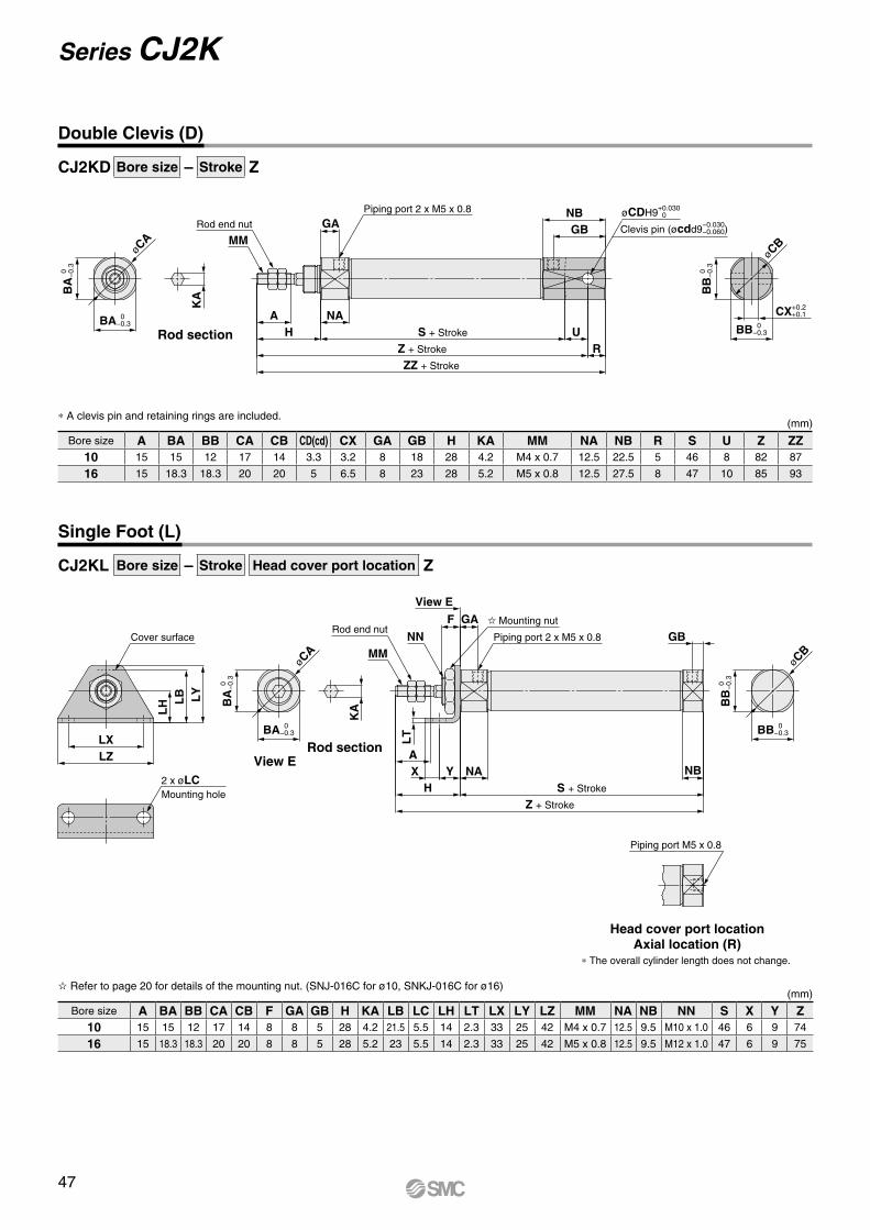
øCBøC
AClevis pin (øcdd9−0.030
−0.060)
øCDH9+0.0300
BA
0
−
0.3
BA 0 −0.3
KA
MMGA
Piping port 2 x M5 x 0.8
ZZ + Stroke
Z + Stroke
S + StrokeHA NA
UR
GBNB
BB
0
−
0.3
BB 0 −0.3
CX+0.2 +0.1
Rod end nut
øCB
øCA
Piping port M5 x 0.8
Cover surface
LZLX
LY
LB
LH
2 x øLCMounting hole
BA
0
−
0.3
BA 0 −0.3
KA
MMNN
View E
F GA
Piping port 2 x M5 x 0.8
Z + Stroke
S + StrokeHNAYX
ANB
GB
BB
0
−
0.3
BB 0 −0.3
LT
Rod end nut Mounting nut
CJ2KD Bore size – Stroke Z
CJ2KL Bore size – Stroke Head cover port location Z
Double Clevis (D)
Rod section
* A clevis pin and retaining rings are included.
Bore size A BA BB CA CB CD(cd) CX GA GB H KA MM NA NB R S U Z ZZ10 15 15 12 17 14 3.3 3.2 8 18 28 4.2 M4 x 0.7 12.5 22.5 5 46 8 82 87
16 15 18.3 18.3 20 20 5 6.5 8 23 28 5.2 M5 x 0.8 12.5 27.5 8 47 10 85 93
(mm)
Single Foot (L)
Head cover port locationAxial location (R)
Rod sectionView E
* The overall cylinder length does not change.
Refer to page 20 for details of the mounting nut. (SNJ-016C for ø10, SNKJ-016C for ø16)
Bore size A BA BB CA CB F GA GB H KA LB LC LH LT LX LY LZ MM NA NB NN S X Y Z10 15 15 12 17 14 8 8 5 28 4.2 21.5 5.5 14 2.3 33 25 42 M4 x 0.7 12.5 9.5 M10 x 1.0 46 6 9 74
16 15 18.3 18.3 20 20 8 8 5 28 5.2 23 5.5 14 2.3 33 25 42 M5 x 0.8 12.5 9.5 M12 x 1.0 47 6 9 75
(mm)
47
Series CJ2K
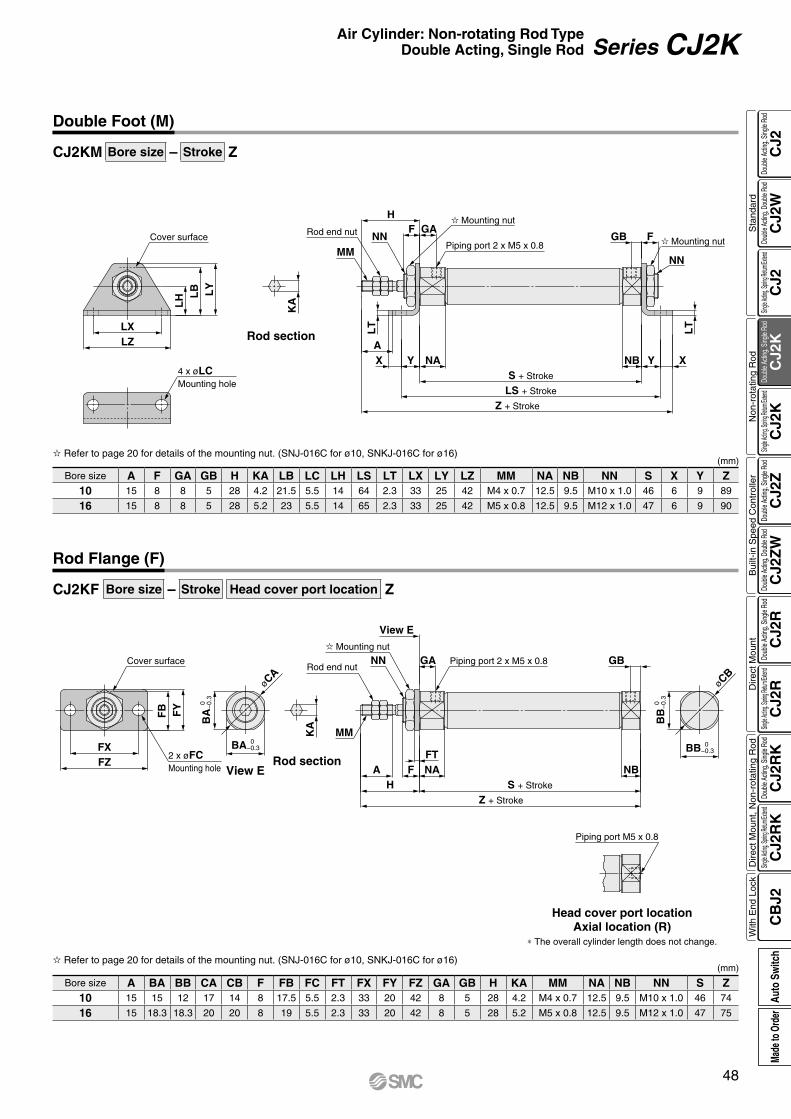
Piping port M5 x 0.8
Cover surface
LZLX
LY
LB
LH
4 x øLCMounting hole
KA
MMNN
HF GA
Piping port 2 x M5 x 0.8
A
LT
NAYX
Z + Stroke
LS + Stroke
S + Stroke
NB Y X
LT
NN
FGB
Mounting nut
Mounting nutRod end nut
øCA
øCB
Cover surface
FZFX
FY
FB
2 x øFCMounting hole
BA
0
−
0.3
BA 0 −0.3
KA
NN
MM
View E
GA Piping port 2 x M5 x 0.8
Z + Stroke
S + StrokeHA NAF
FTNB
GBB
B
0
−0.
3
BB 0 −0.3
Rod end nut
Mounting nut
CJ2KM Bore size – Stroke Z
CJ2KF Bore size – Stroke Head cover port location Z
Double Foot (M)
(mm)
Bore size A F GA GB H KA LB LC LH LS LT LX LY LZ MM NA NB NN S X Y Z10 15 8 8 5 28 4.2 21.5 5.5 14 64 2.3 33 25 42 M4 x 0.7 12.5 9.5 M10 x 1.0 46 6 9 89
16 15 8 8 5 28 5.2 23 5.5 14 65 2.3 33 25 42 M5 x 0.8 12.5 9.5 M12 x 1.0 47 6 9 90
Refer to page 20 for details of the mounting nut. (SNJ-016C for ø10, SNKJ-016C for ø16)
Rod section
View ERod section
Head cover port locationAxial location (R)
* The overall cylinder length does not change.
Rod Flange (F)
(mm) Refer to page 20 for details of the mounting nut. (SNJ-016C for ø10, SNKJ-016C for ø16)
Bore size A BA BB CA CB F FB FC FT FX FY FZ GA GB H KA MM NA NB NN S Z10 15 15 12 17 14 8 17.5 5.5 2.3 33 20 42 8 5 28 4.2 M4 x 0.7 12.5 9.5 M10 x 1.0 46 74
16 15 18.3 18.3 20 20 8 19 5.5 2.3 33 20 42 8 5 28 5.2 M5 x 0.8 12.5 9.5 M12 x 1.0 47 75
48
Air Cylinder: Non-rotating Rod TypeDouble Acting, Single Rod Series CJ2K
CJ2
CJ2
WC
J2C
J2K
CJ2
KC
J2Z
CJ2
ZW
CJ2
RC
J2R
CJ2
RK
CJ2
RK
CB
J2
Sta
ndar
dN
on-r
otat
ing
Rod
Bui
lt-in
Spe
ed C
ontr
olle
rD
irect
Mou
ntD
irect
Mou
nt, N
on-r
otat
ing
Rod
With
End
Loc
kDo
uble
Actin
g, Do
uble
Rod
Single
Acting
, Sprin
g Retu
rn/Exte
ndDo
uble
Actin
g, Si
ngle
Rod
Single
Acting
, Sprin
g Retu
rn/Exte
ndDo
uble
Actin
g, Si
ngle
Rod
Doub
le Ac
ting,
Doub
le Ro
dDo
uble
Actin
g, Si
ngle
Rod
Single
Acting
, Sprin
g Retu
rn/Exte
ndDo
uble
Actin
g, Si
ngle
Rod
Single
Acting
, Sprin
g Retu
rn/Exte
ndDo
uble
Actin
g, Si
ngle
Rod
Auto
Sw
itch
Made
to O
rder

øC
B
0
−0.
3
B 0 −0.3
KA
MM
NN GA Piping port 2 x M5 x 0.8
Z + Stroke
S + StrokeHA F NA
FNB FT
NN
GB Cover surface
FZFX
FY
FB
2 x øFCMounting hole
Mounting nutRod end nut
CJ2KG Bore size – Stroke Z
Head Flange (G)
Refer to page 20 for details of the mounting nut. (SNJ-016C for ø10, SNKJ-016C for ø16)(mm)
Bore size A B C F FB FC FT FX FY FZ GA GB H KA MM NA NB NN S Z10 15 15 17 8 17.5 5.5 2.3 33 20 42 8 5 28 4.2 M4 x 0.7 12.5 9.5 M10 x 1.0 46 82
16 15 18.3 20 8 19 5.5 2.3 33 20 42 8 5 28 5.2 M5 x 0.8 12.5 9.5 M12 x 1.0 47 83
Rod section
49
Series CJ2K

RoHSSeries CJ2Kø10, ø16
Air Cylinder: Non-rotating Rod TypeSingle Acting, Spring Return/Extend
With auto switch (Built-in magnet)
Cylinder standard stroke (mm)Refer to “Standard Strokes” on page 51.
With auto switch 4516
4516
SB Z
Z
CDJ2K
SBCJ2K
M9BW B
∗ For double clevis, the product is perpendicular to the cylinder axis.∗ For double-side bossed, the product is perpendicular to the cylinder axis.∗ Not applicable to single acting, spring extend (T).
Head cover port location
Made to OrderRefer to page 51 for details.
Number of auto switches
MountingBore size10 10 mm
16 16 mm
ActionS Single acting, Spring return
T Single acting, Spring extend
B BasicE Double-side bossedD Double clevisL Single footM Double footF Rod flangeG Head flange
Nil 2 pcs.S 1 pc.n “n” pcs.
Auto switch mounting type
∗ For rail mounting, screws and nuts for 2 auto switches come with the rail.
∗ Refer to page 103 for auto switch mounting brackets.
A Rail mounting
B Band mounting
∗ Foot/Flange brackets are shipped together with the product, but not assembled.
∗ Refer to “Ordering Example of Cylinder Assembly” on page 51.
I f a bui l t - in magnet cylinder without an auto switch is required, refer to the model of built-in magnet cylinder.
∗ For applicable auto switches, refer to the table below.
Auto switch
∗ Rod end bracket is shipped together with the product, but not assembled.
∗ A knuckle joint pin is not provided with the single knuckle joint.
Rod end bracketNil NoneV Single knuckle jointW Double knuckle jointT Rod end cap (Flat type)U Rod end cap (Round type)
Pivot bracket
∗ Only for CJ2D (double clevis)∗ Pivot bracket is shipped together with
the product, but not assembled.
Nil None
N Pivot bracket is shipped together with the product, but not assembled.
∗ Since there are other applicable auto switches than listed, refer to page 104 for details.∗ For details about auto switches with pre-wired connector, refer to the WEB catalog or the Best Pneumatics No. 2.∗ Solid state auto switches marked with “p” are produced upon receipt of order.∗ The D-A9ll/M9lll/A7ll/A80l/F7ll/J7ll auto switches are shipped together, (but not assembled). (For band mounting, only auto switch mounting brackets are assembled before being shipped.)
∗1 Water resistant type auto switches can be mounted on the above models, but in such case SMC cannot guarantee water resistance. Please contact SMC regarding water resistant types with the above model numbers.
∗2 1 m type lead wire is only applicable to D-A93.∗ Lead wire length symbols: 0.5 m·················· Nil (Example) M9NW 1 m·················· M (Example) M9NWM 3 m·················· L (Example) M9NWL
5 m·················· Z (Example) M9NWZ None··············· N (Example) H7CN
Applicable Auto Switches/Refer to the WEB catalog or the Best Pneumatics No. 2 for further information on auto switches.
Type Special functionElectrical
entry
Indica
tor lig
ht
Wiring(Output)
Load voltage Auto switch model Lead wire length (m)Pre-wiredconnector
Applicable loadDC AC
Band mounting Rail mounting 0.5(Nil)
1(M)
3(L)
5(Z)
None(N)Perpendicular In-line Perpendicular In-line
So
lid s
tate
au
to s
wit
ch ——Grommet
Yes
3-wire (NPN)
24 V
5 V,12 V
—
M9NV M9N M9NV M9N V V V v — vIC circuit
Relay,PLC
3-wire (PNP) M9PV M9P M9PV M9P V V V v — v
2-wire 12 VM9BV M9B M9BV M9B V V V v — v
—Connector — H7C J79C — V — V V V —
Diagnostic indication(2-color indication)
Grommet
3-wire (NPN)5 V,12 V
M9NWV M9NW M9NWV M9NW V V V v — vIC circuit
3-wire (PNP) M9PWV M9PW M9PWV M9PW V V V v — v2-wire 12 V M9BWV M9BW M9BWV M9BW V V V v — v —
Water resistant (2-color indication)
3-wire (NPN)5 V,12 V
M9NAV∗1 M9NA∗1 M9NAV∗1 M9NA∗1 v v V v — vIC circuit
3-wire (PNP) M9PAV∗1 M9PA∗1 M9PAV∗1 M9PA∗1 v v V v — v2-wire 12 V M9BAV∗1 M9BA∗1 M9BAV∗1 M9BA∗1 v v V v — v —
With diagnostic output (2-color indication) 4-wire (NPN) 5 V,12 V — H7NF — F79F V — V v — v IC circuit
Ree
d a
uto
sw
itch
——Grommet
Yes
3-wire(NPN equivalent) —
5 V — A96V A96 A96V A96 V — V — — — IC circuit —
2-wire
— 200 V — — A72 A72H V — V — — ——
Relay,PLC24 V
12 V
100 V A93V∗2 A93 A93V∗2 A93 V V V V — —No 100 V or less A90V A90 A90V A90 V — V — — — IC circuit
ConnectorYes — — C73C A73C — V — V V V — —No 24 V or less — C80C A80C — V — V V V — IC circuit
Diagnostic indication (2-color indication) Grommet Yes — — — — A79W — V — V — — — —
NilPerpendicular
to axis
R Axial
50
How to Order
CJ2
CJ2
WC
J2C
J2K
CJ2
KC
J2Z
CJ2
ZW
CJ2
RC
J2R
CJ2
RK
CJ2
RK
CB
J2
Sta
ndar
dN
on-r
otat
ing
Rod
Bui
lt-in
Spe
ed C
ontr
olle
rD
irect
Mou
ntD
irect
Mou
nt, N
on-r
otat
ing
Rod
With
End
Loc
kDo
uble
Actin
g, Do
uble
Rod
Single
Acting
, Sprin
g Retu
rn/Exte
ndDo
uble
Actin
g, Si
ngle
Rod
Single
Acting
, Sprin
g Retu
rn/Exte
ndDo
uble
Actin
g, Si
ngle
Rod
Doub
le Ac
ting,
Doub
le Ro
dDo
uble
Actin
g, Si
ngle
Rod
Single
Acting
, Sprin
g Retu
rn/Exte
ndDo
uble
Actin
g, Si
ngle
Rod
Single
Acting
, Sprin
g Retu
rn/Exte
ndDo
uble
Actin
g, Si
ngle
Rod
Auto
Sw
itch
Made
to O
rder
A
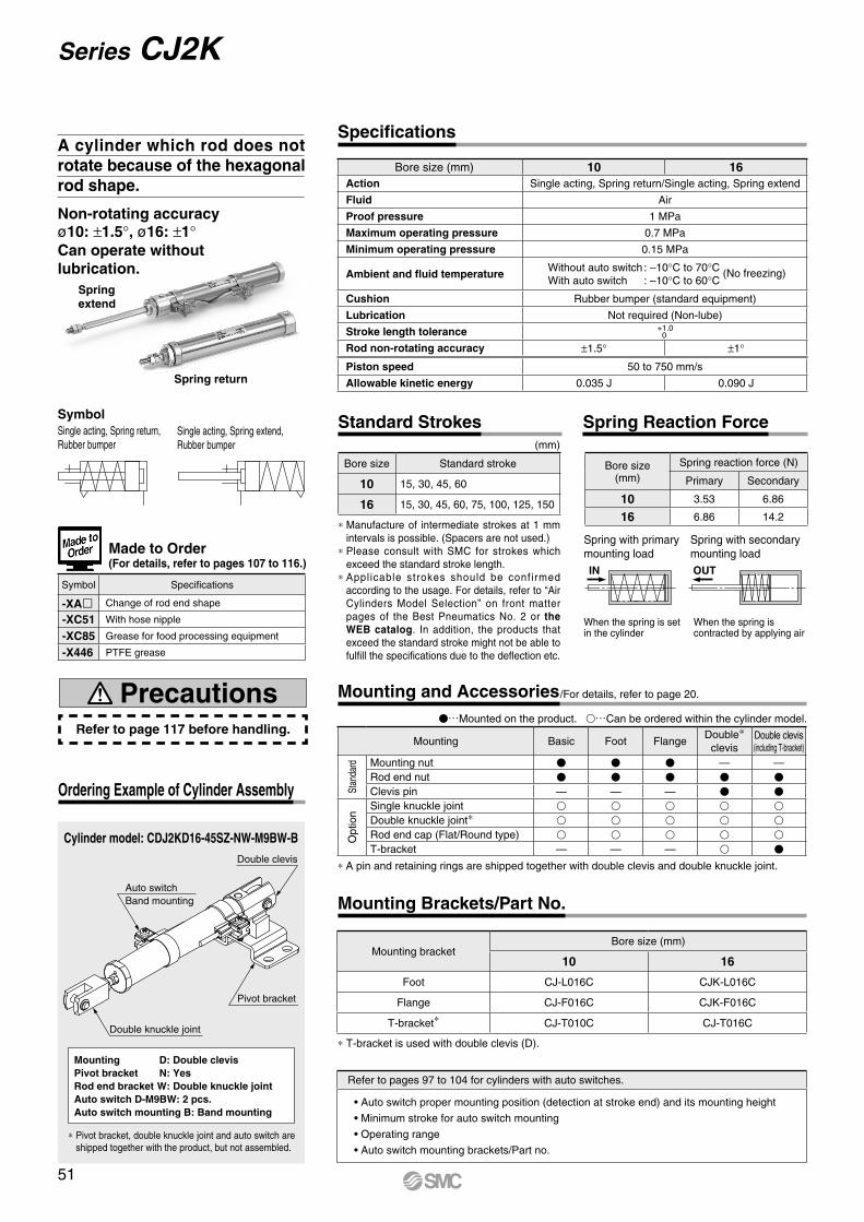
IN OUT
Auto switchBand mounting
Double clevis
Pivot bracket
Double knuckle joint
Made to Order(For details, refer to pages 107 to 116.)
Single acting, Spring extend, Rubber bumper
SymbolSingle acting, Spring return, Rubber bumper
Cylinder model: CDJ2KD16-45SZ-NW-M9BW-B
Mounting D: Double clevisPivot bracket N: YesRod end bracket W: Double knuckle jointAuto switch D-M9BW: 2 pcs.Auto switch mounting B: Band mounting
* Pivot bracket, double knuckle joint and auto switch are shipped together with the product, but not assembled.
Ordering Example of Cylinder Assembly
Spring return
Spring extend
Bore size (mm) 10 16Action Single acting, Spring return/Single acting, Spring extend
Fluid Air
Proof pressure 1 MPa
Maximum operating pressure 0.7 MPa
Minimum operating pressure 0.15 MPa
Ambient and fluid temperatureWithout auto switch : –10°C to 70°C (No freezing)With auto switch : –10°C to 60°C
Cushion Rubber bumper (standard equipment)
Lubrication Not required (Non-lube)
Stroke length tolerance +1.00
Rod non-rotating accuracy ±1.5° ±1°
Piston speed 50 to 750 mm/s
Allowable kinetic energy 0.035 J 0.090 J
Symbol Specifications
-XAl Change of rod end shape
-XC51 With hose nipple
-XC85 Grease for food processing equipment
-X446 PTFE grease
Refer to page 117 before handling.
Precautions
Non-rotating accuracyø10: ±1.5°, ø16: ±1°Can operate without lubrication.
A cylinder which rod does not rotate because of the hexagonal rod shape.
Specifications
When the spring is contracted by applying air
When the spring is set in the cylinder
Spring with secondary mounting load
Spring with primary mounting load
* Manufacture of intermediate strokes at 1 mm intervals is possible. (Spacers are not used.)
* Please consult with SMC for strokes which exceed the standard stroke length.
* Applicable strokes should be confirmed according to the usage. For details, refer to “Air Cylinders Model Selection” on front matter pages of the Best Pneumatics No. 2 or the WEB catalog. In addition, the products that exceed the standard stroke might not be able to fulfill the specifications due to the deflection etc.
(mm)
Bore size Standard stroke
10 15, 30, 45, 60
16 15, 30, 45, 60, 75, 100, 125, 150
Bore size(mm)
Spring reaction force (N)
Primary Secondary
10 3.53 6.86
16 6.86 14.2
Standard Strokes Spring Reaction Force
* T-bracket is used with double clevis (D).
Mounting bracketBore size (mm)
10 16
Foot CJ-L016C CJK-L016C
Flange CJ-F016C CJK-F016C
T-bracket* CJ-T010C CJ-T016C
Mounting Brackets/Part No.
V…Mounted on the product. v…Can be ordered within the cylinder model.
* A pin and retaining rings are shipped together with double clevis and double knuckle joint.
Mounting Basic Foot FlangeDouble*
clevisDouble clevis(including T-bracket)
Stan
dard Mounting nut V V V — —
Rod end nut V V V V VClevis pin — — — V V
Opt
ion
Single knuckle joint v v v v vDouble knuckle joint* v v v v vRod end cap (Flat/Round type) v v v v vT-bracket — — — v V
Mounting and Accessories/For details, refer to page 20.
Refer to pages 97 to 104 for cylinders with auto switches.
• Auto switch proper mounting position (detection at stroke end) and its mounting height
• Minimum stroke for auto switch mounting
• Operating range
• Auto switch mounting brackets/Part no.
51
Series CJ2K
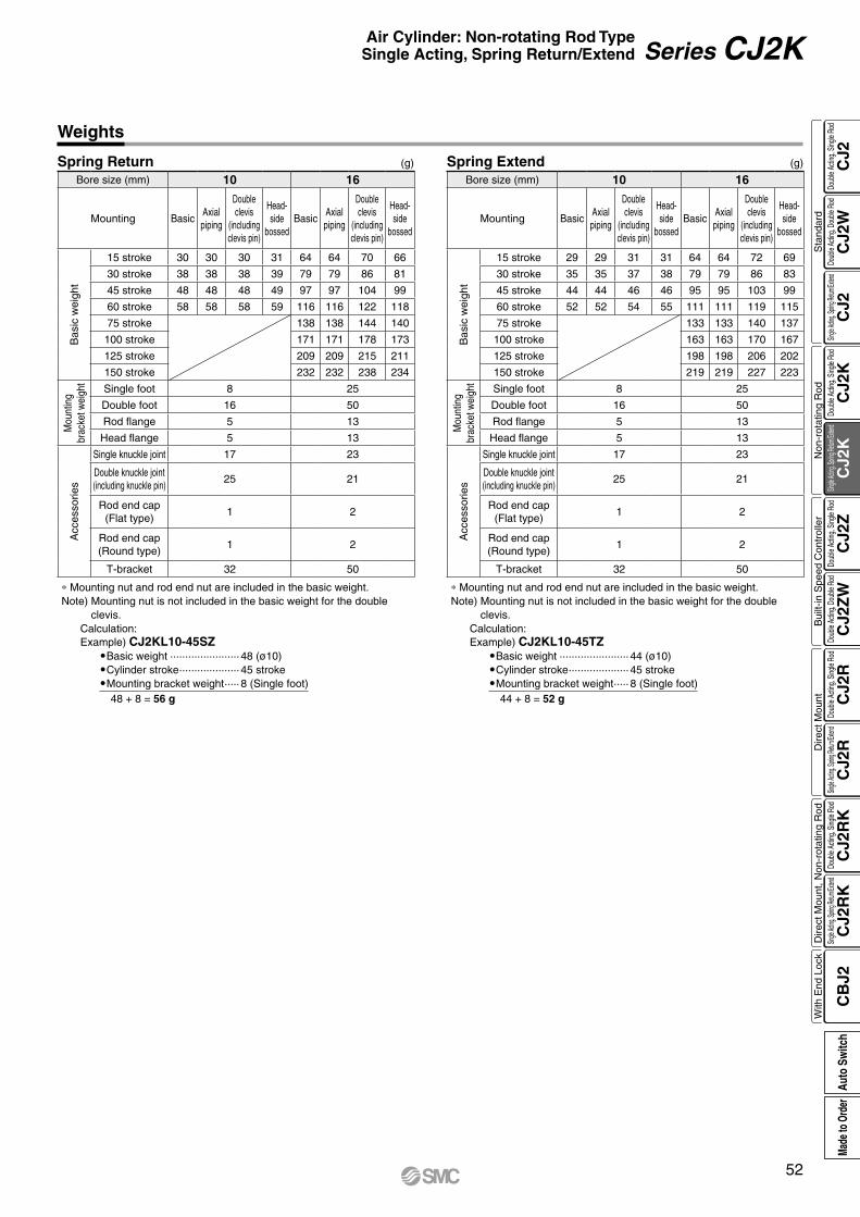
Weights
(g)Spring Return Spring ExtendBore size (mm) 10 16
Mounting BasicAxialpiping
Double clevis
(including clevis pin)
Head-side
bossedBasic
Axialpiping
Double clevis
(including clevis pin)
Head-side
bossed
Bas
ic w
eigh
t
15 stroke 30 30 30 31 64 64 70 66
30 stroke 38 38 38 39 79 79 86 81
45 stroke 48 48 48 49 97 97 104 99
60 stroke 58 58 58 59 116 116 122 118
75 stroke 138 138 144 140
100 stroke 171 171 178 173
125 stroke 209 209 215 211
150 stroke 232 232 238 234
Mou
ntin
gbr
acke
t wei
ght
Single foot 8 25
Double foot 16 50
Rod flange 5 13
Head flange 5 13
Acc
esso
ries
Single knuckle joint 17 23
Double knuckle joint(including knuckle pin)
25 21
Rod end cap (Flat type)
1 2
Rod end cap (Round type)
1 2
T-bracket 32 50
Bore size (mm) 10 16
Mounting BasicAxialpiping
Double clevis
(including clevis pin)
Head-side
bossedBasic
Axialpiping
Double clevis
(including clevis pin)
Head-side
bossed
Bas
ic w
eigh
t
15 stroke 29 29 31 31 64 64 72 69
30 stroke 35 35 37 38 79 79 86 83
45 stroke 44 44 46 46 95 95 103 99
60 stroke 52 52 54 55 111 111 119 115
75 stroke 133 133 140 137
100 stroke 163 163 170 167
125 stroke 198 198 206 202
150 stroke 219 219 227 223
Mou
ntin
gbr
acke
t wei
ght
Single foot 8 25
Double foot 16 50
Rod flange 5 13
Head flange 5 13
Acc
esso
ries
Single knuckle joint 17 23
Double knuckle joint(including knuckle pin)
25 21
Rod end cap (Flat type)
1 2
Rod end cap (Round type)
1 2
T-bracket 32 50
∗ Mounting nut and rod end nut are included in the basic weight.Note) Mounting nut is not included in the basic weight for the double
clevis.Calculation: Example) CJ2KL10-45SZ
OBasic weight ······················· 48 (ø10)OCylinder stroke ···················· 45 strokeOMounting bracket weight ····· 8 (Single foot)
48 + 8 = 56 g
(g)
∗ Mounting nut and rod end nut are included in the basic weight.Note) Mounting nut is not included in the basic weight for the double
clevis.Calculation: Example) CJ2KL10-45TZ
OBasic weight ······················· 44 (ø10)OCylinder stroke ···················· 45 strokeOMounting bracket weight ····· 8 (Single foot)
44 + 8 = 52 g
52
Air Cylinder: Non-rotating Rod TypeSingle Acting, Spring Return/Extend Series CJ2K
CJ2
CJ2
WC
J2C
J2K
CJ2
KC
J2Z
CJ2
ZW
CJ2
RC
J2R
CJ2
RK
CJ2
RK
CB
J2
Sta
ndar
dN
on-r
otat
ing
Rod
Bui
lt-in
Spe
ed C
ontr
olle
rD
irect
Mou
ntD
irect
Mou
nt, N
on-r
otat
ing
Rod
With
End
Loc
kDo
uble
Actin
g, Do
uble
Rod
Single
Acting
, Sprin
g Retu
rn/Exte
ndDo
uble
Actin
g, Si
ngle
Rod
Single
Acting
, Sprin
g Retu
rn/Exte
ndDo
uble
Actin
g, Si
ngle
Rod
Doub
le Ac
ting,
Doub
le Ro
dDo
uble
Actin
g, Si
ngle
Rod
Single
Acting
, Sprin
g Retu
rn/Exte
ndDo
uble
Actin
g, Si
ngle
Rod
Single
Acting
, Sprin
g Retu
rn/Exte
ndDo
uble
Actin
g, Si
ngle
Rod
Auto
Sw
itch
Made
to O
rder
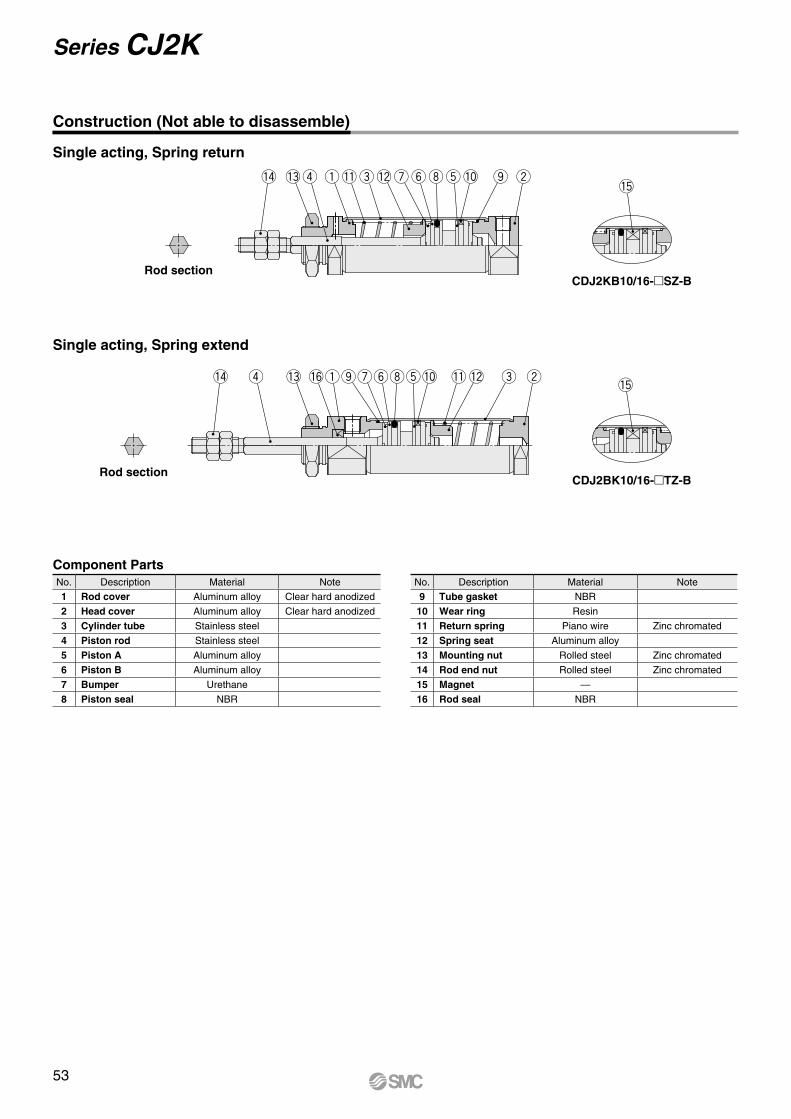
q we y t or iu!5
!4 !2!1!3 !0
q wey tor iu!5
!4 !2!6 !1!3 !0
Construction (Not able to disassemble)
Single acting, Spring return
Single acting, Spring extend
Rod section
Rod section
CDJ2KB10/16-SZ-B
CDJ2BK10/16-TZ-B
Component PartsNo. Description Material Note
1 Rod cover Aluminum alloy Clear hard anodized
2 Head cover Aluminum alloy Clear hard anodized
3 Cylinder tube Stainless steel
4 Piston rod Stainless steel
5 Piston A Aluminum alloy
6 Piston B Aluminum alloy
7 Bumper Urethane
8 Piston seal NBR
No. Description Material Note
9 Tube gasket NBR
10 Wear ring Resin
11 Return spring Piano wire Zinc chromated
12 Spring seat Aluminum alloy
13 Mounting nut Rolled steel Zinc chromated
14 Rod end nut Rolled steel Zinc chromated
15 Magnet —
16 Rod seal NBR
53
Series CJ2K
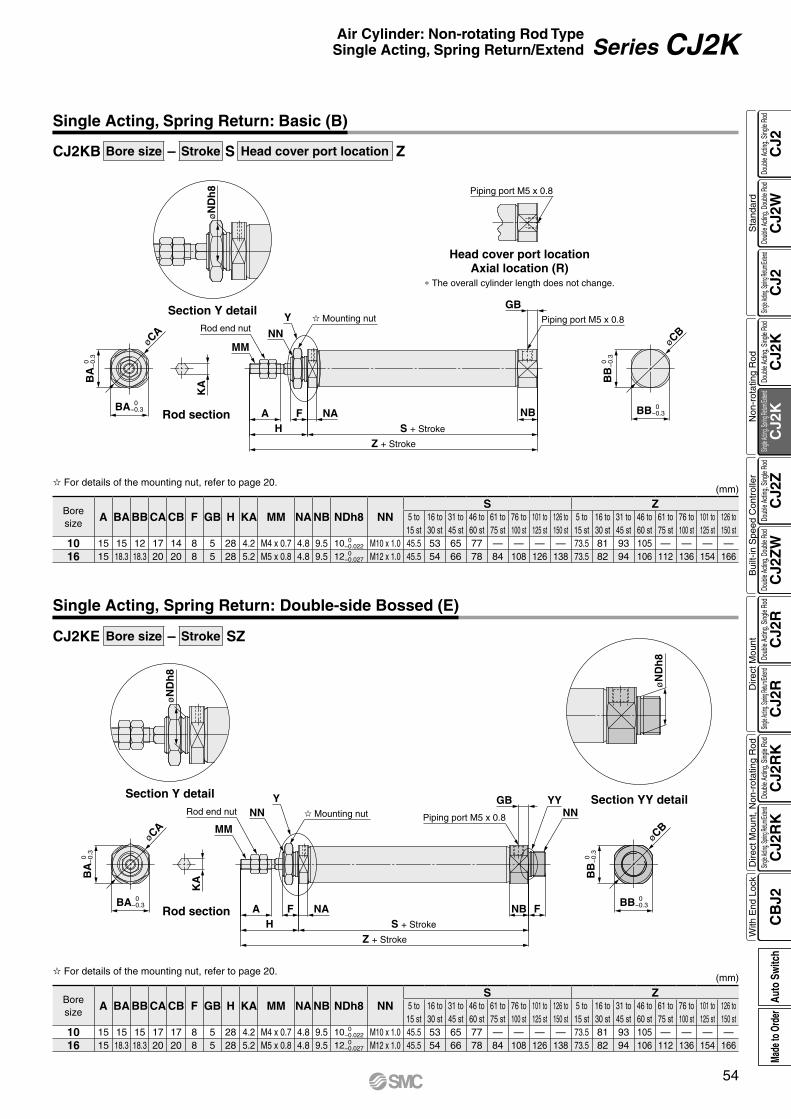
øCB
øCA
øN
Dh
8
BA
0
−
0.3
BA 0 −0.3
KA
MMNN
Y
Z + Stroke
S + StrokeHA F NA NB
Piping port M5 x 0.8 Mounting nutGB
BB
0
−
0.3
BB 0 −0.3
Piping port M5 x 0.8
Rod end nut
øCB
øCA
øN
Dh
8
øN
Dh
8
BA
0
−
0.3
BA 0 −0.3
KA
MM
NNY
Z + Stroke
S + StrokeHA F NA
Piping port M5 x 0.8
FNB
NNYYGB
BB
0
−
0.3
BB 0 −0.3
Mounting nutRod end nut
CJ2KB Bore size – Stroke S Head cover port location Z
CJ2KE Bore size – Stroke SZ
Single Acting, Spring Return: Basic (B)
Section Y detail
Head cover port locationAxial location (R)
* The overall cylinder length does not change.
Rod section
For details of the mounting nut, refer to page 20.
Boresize
A BA BB CA CB F GB H KA MM NA NB NDh8 NNS Z
5 to15 st
16 to30 st
31 to45 st
46 to60 st
61 to75 st
76 to100 st
101 to125 st
126 to150 st
5 to15 st
16 to30 st
31 to45 st
46 to60 st
61 to75 st
76 to100 st
101 to125 st
126 to150 st
10 15 15 12 17 14 8 5 28 4.2 M4 x 0.7 4.8 9.5 10 0 −0.022 M10 x 1.0 45.5 53 65 77 — — — — 73.5 81 93 105 — — — —
16 15 18.3 18.3 20 20 8 5 28 5.2 M5 x 0.8 4.8 9.5 12 0 −0.027 M12 x 1.0 45.5 54 66 78 84 108 126 138 73.5 82 94 106 112 136 154 166
(mm)
Single Acting, Spring Return: Double-side Bossed (E)
Section Y detail
Rod section
Section YY detail
For details of the mounting nut, refer to page 20.
Boresize
A BA BB CA CB F GB H KA MM NA NB NDh8 NNS Z
5 to15 st
16 to30 st
31 to45 st
46 to60 st
61 to75 st
76 to100 st
101 to125 st
126 to150 st
5 to15 st
16 to30 st
31 to45 st
46 to60 st
61 to75 st
76 to100 st
101 to125 st
126 to150 st
10 15 15 15 17 17 8 5 28 4.2 M4 x 0.7 4.8 9.5 10 0 −0.022 M10 x 1.0 45.5 53 65 77 — — — — 73.5 81 93 105 — — — —
16 15 18.3 18.3 20 20 8 5 28 5.2 M5 x 0.8 4.8 9.5 12 0 −0.027 M12 x 1.0 45.5 54 66 78 84 108 126 138 73.5 82 94 106 112 136 154 166
(mm)
54
Air Cylinder: Non-rotating Rod TypeSingle Acting, Spring Return/Extend Series CJ2K
CJ2
CJ2
WC
J2C
J2K
CJ2
KC
J2Z
CJ2
ZW
CJ2
RC
J2R
CJ2
RK
CJ2
RK
CB
J2
Sta
ndar
dN
on-r
otat
ing
Rod
Bui
lt-in
Spe
ed C
ontr
olle
rD
irect
Mou
ntD
irect
Mou
nt, N
on-r
otat
ing
Rod
With
End
Loc
kDo
uble
Actin
g, Do
uble
Rod
Single
Acting
, Sprin
g Retu
rn/Exte
ndDo
uble
Actin
g, Si
ngle
Rod
Single
Acting
, Sprin
g Retu
rn/Exte
ndDo
uble
Actin
g, Si
ngle
Rod
Doub
le Ac
ting,
Doub
le Ro
dDo
uble
Actin
g, Si
ngle
Rod
Single
Acting
, Sprin
g Retu
rn/Exte
ndDo
uble
Actin
g, Si
ngle
Rod
Single
Acting
, Sprin
g Retu
rn/Exte
ndDo
uble
Actin
g, Si
ngle
Rod
Auto
Sw
itch
Made
to O
rder
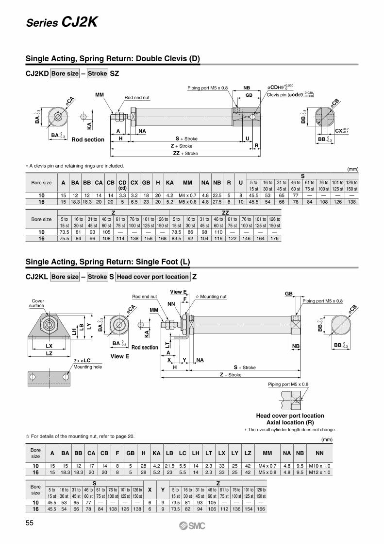
øCA
øCB
BA
0
−
0.3
BA 0 −0.3
KA
MM
ZZ + Stroke
Z + Stroke
S + StrokeHA NA
Piping port M5 x 0.8
UR
GB
NB
BB 0 −0.3
BB
0
−
0.3
Rod end nutClevis pin (øcdd9−0.030
−0.060)
øCDH9+0.030−0
CX+0.2 +0.1
øCB
Coversurface
LZLX
LY
LB
LH
2 x øLCMounting hole
KA
MMNN
FView E
Z + Stroke
S + StrokeHY NAX
A
LT NB
Piping port M5 x 0.8
GB
BB
0
−
0.3
BB 0 −0.3
Piping port M5 x 0.8
Mounting nutRod end nut
øCA
BA
0
−
0.3
BA 0 −0.3
CJ2KD Bore size – Stroke SZ
CJ2KL Bore size – Stroke S Head cover port location Z
Single Acting, Spring Return: Double Clevis (D)
* A clevis pin and retaining rings are included.
Bore size A BA BB CA CB CD(cd)
CX GB H KA MM NA NB R US
5 to15 st
16 to30 st
31 to45 st
46 to60 st
61 to75 st
76 to100 st
101 to125 st
126 to150 st
10 15 12 12 14 14 3.3 3.2 18 20 4.2 M4 x 0.7 4.8 22.5 5 8 45.5 53 65 77 — — — —16 15 18.3 18.3 20 20 5 6.5 23 20 5.2 M5 x 0.8 4.8 27.5 8 10 45.5 54 66 78 84 108 126 138
Bore sizeZ ZZ
5 to15 st
16 to30 st
31 to45 st
46 to60 st
61 to75 st
76 to100 st
101 to125 st
126 to150 st
5 to15 st
16 to30 st
31 to45 st
46 to60 st
61 to75 st
76 to100 st
101 to125 st
126 to150 st
10 73.5 81 93 105 — — — — 78.5 86 98 110 — — — —16 75.5 84 96 108 114 138 156 168 83.5 92 104 116 122 146 164 176
(mm)
Single Acting, Spring Return: Single Foot (L)
Boresize
SX Y
Z5 to15 st
16 to30 st
31 to45 st
46 to60 st
61 to75 st
76 to100 st
101 to125 st
126 to150 st
5 to15 st
16 to30 st
31 to45 st
46 to60 st
61 to75 st
76 to100 st
101 to125 st
126 to150 st
10 45.5 53 65 77 — — — — 6 9 73.5 81 93 105 — — — —16 45.5 54 66 78 84 108 126 138 6 9 73.5 82 94 106 112 136 154 166
Boresize
A BA BB CA CB F GB H KA LB LC LH LT LX LY LZ MM NA NB NN
10 15 15 12 17 14 8 5 28 4.2 21.5 5.5 14 2.3 33 25 42 M4 x 0.7 4.8 9.5 M10 x 1.016 15 18.3 18.3 20 20 8 5 28 5.2 23 5.5 14 2.3 33 25 42 M5 x 0.8 4.8 9.5 M12 x 1.0
For details of the mounting nut, refer to page 20.(mm)
Rod section
View E
Rod section
Head cover port locationAxial location (R)
* The overall cylinder length does not change.
55
Series CJ2K
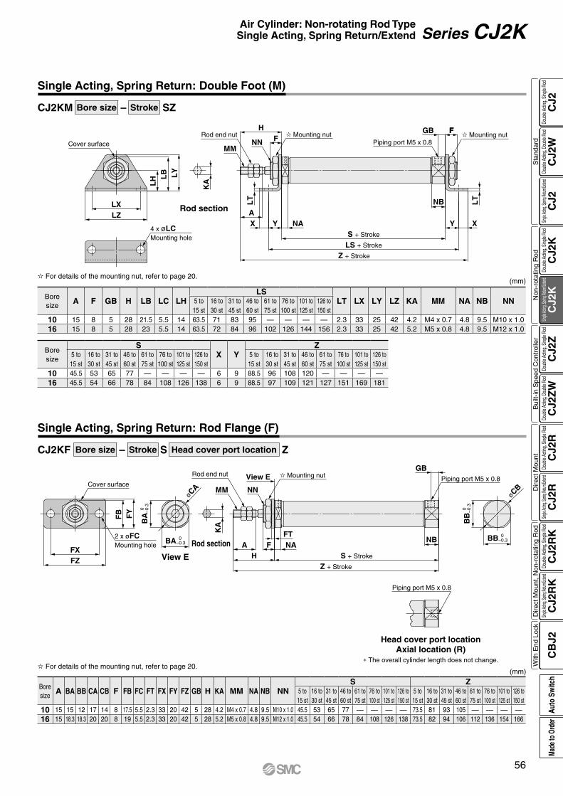
F
Cover surface
LZLX
LY
LB
LH
4 x øLCMounting hole
KA
MMNN
HF
LT
Z + Stroke
LS + Stroke
S + Stroke
AY NAX Y X
NB LT
FGB
Piping port M5 x 0.8 Mounting nut Mounting nutRod end nut
øCB
Cover surface
FZFX
FY
FB
2 x øFCMounting hole
KA
MM NN
View E
AH
Z + Stroke
S + Stroke
F NAFT
NB
Piping port M5 x 0.8
GB
BB 0 −0.3
BB
0
−
0.3
Piping port M5 x 0.8
Mounting nutRod end nut
øCA
BA
0
−
0.3
BA 0 −0.3
CJ2KM Bore size – Stroke SZ
CJ2KF Bore size – Stroke S Head cover port location Z
Single Acting, Spring Return: Double Foot (M)
Boresize
A F GB H LB LC LHLS
LT LX LY LZ KA MM NA NB NN5 to15 st
16 to30 st
31 to45 st
46 to60 st
61 to75 st
76 to100 st
101 to125 st
126 to150 st
10 15 8 5 28 21.5 5.5 14 63.5 71 83 95 — — — — 2.3 33 25 42 4.2 M4 x 0.7 4.8 9.5 M10 x 1.016 15 8 5 28 23 5.5 14 63.5 72 84 96 102 126 144 156 2.3 33 25 42 5.2 M5 x 0.8 4.8 9.5 M12 x 1.0
Boresize
SX Y
Z5 to15 st
16 to30 st
31 to45 st
46 to60 st
61 to75 st
76 to100 st
101 to125 st
126 to150 st
5 to15 st
16 to30 st
31 to45 st
46 to60 st
61 to75 st
76 to100 st
101 to125 st
126 to150 st
10 45.5 53 65 77 — — — — 6 9 88.5 96 108 120 — — — —16 45.5 54 66 78 84 108 126 138 6 9 88.5 97 109 121 127 151 169 181
For details of the mounting nut, refer to page 20.(mm)
Rod section
Single Acting, Spring Return: Rod Flange (F)
View E
Rod section
Head cover port locationAxial location (R)
* The overall cylinder length does not change.
Boresize
A BA BB CA CB F FB FC FT FX FY FZ GB H KA MM NA NB NNS Z
5 to15 st
16 to30 st
31 to45 st
46 to60 st
61 to75 st
76 to100 st
101 to125 st
126 to150 st
5 to15 st
16 to30 st
31 to45 st
46 to60 st
61 to75 st
76 to100 st
101 to125 st
126 to150 st
10 15 15 12 17 14 8 17.5 5.5 2.3 33 20 42 5 28 4.2 M4 x 0.7 4.8 9.5 M10 x 1.0 45.5 53 65 77 — — — — 73.5 81 93 105 — — — —16 15 18.3 18.3 20 20 8 19 5.5 2.3 33 20 42 5 28 5.2 M5 x 0.8 4.8 9.5 M12 x 1.0 45.5 54 66 78 84 108 126 138 73.5 82 94 106 112 136 154 166
For details of the mounting nut, refer to page 20.(mm)
56
Air Cylinder: Non-rotating Rod TypeSingle Acting, Spring Return/Extend Series CJ2K
CJ2
CJ2
WC
J2C
J2K
CJ2
KC
J2Z
CJ2
ZW
CJ2
RC
J2R
CJ2
RK
CJ2
RK
CB
J2
Sta
ndar
dN
on-r
otat
ing
Rod
Bui
lt-in
Spe
ed C
ontr
olle
rD
irect
Mou
ntD
irect
Mou
nt, N
on-r
otat
ing
Rod
With
End
Loc
kDo
uble
Actin
g, Do
uble
Rod
Single
Acting
, Sprin
g Retu
rn/Exte
ndDo
uble
Actin
g, Si
ngle
Rod
Single
Acting
, Sprin
g Retu
rn/Exte
ndDo
uble
Actin
g, Si
ngle
Rod
Doub
le Ac
ting,
Doub
le Ro
dDo
uble
Actin
g, Si
ngle
Rod
Single
Acting
, Sprin
g Retu
rn/Exte
ndDo
uble
Actin
g, Si
ngle
Rod
Single
Acting
, Sprin
g Retu
rn/Exte
ndDo
uble
Actin
g, Si
ngle
Rod
Auto
Sw
itch
Made
to O
rder
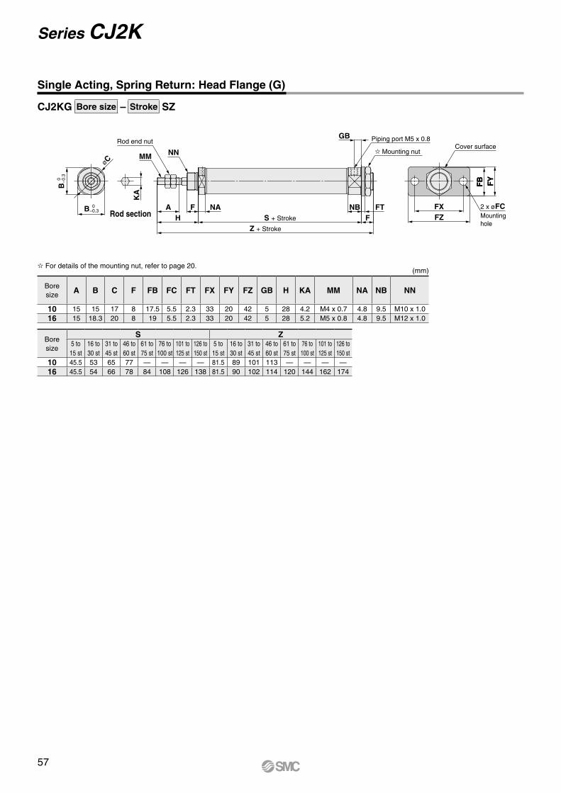
FY
FB
øC
B
0
−0.
3
B 0 −0.3
KA
MM NN
Z + Stroke
S + StrokeHA F NA
FNB FT
Piping port M5 x 0.8GBCover surface
FZFX 2 x øFC
Mounting hole
Rod end nut
Mounting nut
FY
FB
CJ2KG Bore size – Stroke SZ
Single Acting, Spring Return: Head Flange (G)
Boresize
S Z5 to15 st
16 to30 st
31 to45 st
46 to60 st
61 to75 st
76 to100 st
101 to125 st
126 to150 st
5 to15 st
16 to30 st
31 to45 st
46 to60 st
61 to75 st
76 to100 st
101 to125 st
126 to150 st
10 45.5 53 65 77 — — — — 81.5 89 101 113 — — — —16 45.5 54 66 78 84 108 126 138 81.5 90 102 114 120 144 162 174
Boresize
A B C F FB FC FT FX FY FZ GB H KA MM NA NB NN
10 15 15 17 8 17.5 5.5 2.3 33 20 42 5 28 4.2 M4 x 0.7 4.8 9.5 M10 x 1.016 15 18.3 20 8 19 5.5 2.3 33 20 42 5 28 5.2 M5 x 0.8 4.8 9.5 M12 x 1.0
For details of the mounting nut, refer to page 20.(mm)
Rod section
57
Series CJ2K
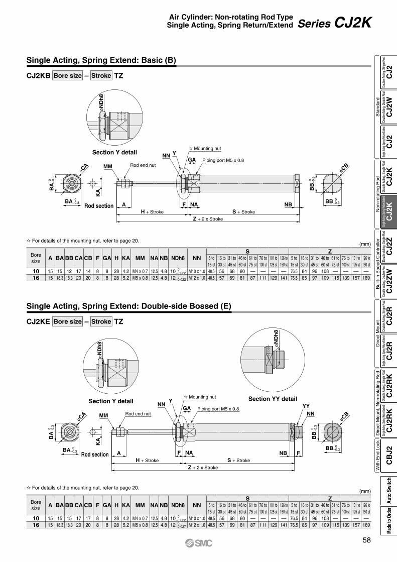
øCB
øCA
øN
Dh
8
BA
0
−
0.3
BA 0 −0.3
KA
MM
NN Y
Z + 2 x Stroke
S + StrokeH + Stroke
A NAF
Piping port M5 x 0.8GA
NB BB 0 −0.3
BB
0
−
0.3
Mounting nut
Rod end nut
øCB
øCA
øN
Dh8 ø
ND
h8
BA
0
−
0.3
BA 0 −0.3
KA
MM
NNY
Piping port M5 x 0.8GA
NAF
Z + 2 x Stroke
H + Stroke
AS + Stroke
FNB
NNYY
BB
0
−
0.3
BB 0 −0.3
Rod end nut
Mounting nut
CJ2KB Bore size – Stroke TZ
CJ2KE Bore size – Stroke TZ
Single Acting, Spring Extend: Basic (B)
Section Y detail
Rod section
Boresize
A BA BB CA CB F GA H KA MM NA NB NDh8 NNS Z
5 to15 st
16 to30 st
31 to45 st
46 to60 st
61 to75 st
76 to100 st
101 to125 st
126 to150 st
5 to15 st
16 to30 st
31 to45 st
46 to60 st
61 to75 st
76 to100 st
101 to125 st
126 to150 st
10 15 15 12 17 14 8 8 28 4.2 M4 x 0.7 12.5 4.8 10 0 −0.022 M10 x 1.0 48.5 56 68 80 — — — — 76.5 84 96 108 — — — —
16 15 18.3 18.3 20 20 8 8 28 5.2 M5 x 0.8 12.5 4.8 12 0 −0.022 M12 x 1.0 48.5 57 69 81 87 111 129 141 76.5 85 97 109 115 139 157 169
For details of the mounting nut, refer to page 20.(mm)
Single Acting, Spring Extend: Double-side Bossed (E)
Section Y detail Section YY detail
Rod section
Boresize
A BA BB CA CB F GA H KA MM NA NB NDh8 NNS Z
5 to15 st
16 to30 st
31 to45 st
46 to60 st
61 to75 st
76 to100 st
101 to125 st
126 to150 st
5 to15 st
16 to30 st
31 to45 st
46 to60 st
61 to75 st
76 to100 st
101 to125 st
126 to150 st
10 15 15 15 17 17 8 8 28 4.2 M4 x 0.7 12.5 4.8 10 0 −0.022 M10 x 1.0 48.5 56 68 80 — — — — 76.5 84 96 108 — — — —
16 15 18.3 18.3 20 20 8 8 28 5.2 M5 x 0.8 12.5 4.8 12 0 −0.027 M12 x 1.0 48.5 57 69 81 87 111 129 141 76.5 85 97 109 115 139 157 169
For details of the mounting nut, refer to page 20.(mm)
58
Air Cylinder: Non-rotating Rod TypeSingle Acting, Spring Return/Extend Series CJ2K
CJ2
CJ2
WC
J2C
J2K
CJ2
KC
J2Z
CJ2
ZW
CJ2
RC
J2R
CJ2
RK
CJ2
RK
CB
J2
Sta
ndar
dN
on-r
otat
ing
Rod
Bui
lt-in
Spe
ed C
ontr
olle
rD
irect
Mou
ntD
irect
Mou
nt, N
on-r
otat
ing
Rod
With
End
Loc
kDo
uble
Actin
g, Do
uble
Rod
Single
Acting
, Sprin
g Retu
rn/Exte
ndDo
uble
Actin
g, Si
ngle
Rod
Single
Acting
, Sprin
g Retu
rn/Exte
ndDo
uble
Actin
g, Si
ngle
Rod
Doub
le Ac
ting,
Doub
le Ro
dDo
uble
Actin
g, Si
ngle
Rod
Single
Acting
, Sprin
g Retu
rn/Exte
ndDo
uble
Actin
g, Si
ngle
Rod
Single
Acting
, Sprin
g Retu
rn/Exte
ndDo
uble
Actin
g, Si
ngle
Rod
Auto
Sw
itch
Made
to O
rder
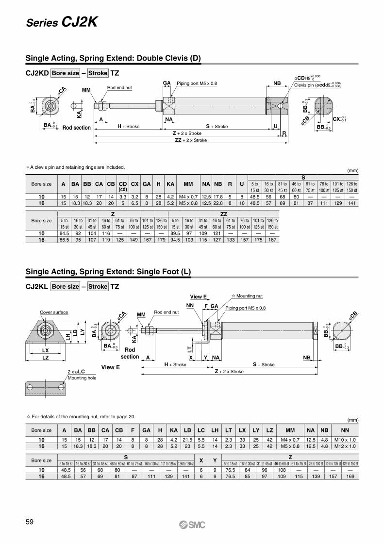
øCB
2 x øLCMounting hole
LZLX
LY
LB
LH
KA
MM
NN GAF
View E
LT
Z + 2 x Stroke
S + StrokeH + Stroke
A NAYX NB
BB
0
−0.
3
BB 0 −0.3
Cover surfacePiping port M5 x 0.8
Rod end nut
Mounting nut
øCA
BA 0 −0.3
BA
0
−0.
3
øCA
Clevis pin (øcdd9−0.030−0.060)
øCDH9+0.030 0
BA
0
−0.
3
BA 0 −0.3
KA
MMGA
ZZ + 2 x Stroke
Z + 2 x Stroke
H + Stroke
A NAS + Stroke U
R
NB
BB
0
−0.
3
BB 0 −0.3
CX+0.2 +0.1
øCB
Piping port M5 x 0.8Rod end nut
CJ2KD Bore size – Stroke TZ
CJ2KL Bore size – Stroke TZ
Single Acting, Spring Extend: Double Clevis (D)
Single Acting, Spring Extend: Single Foot (L)
Rod section
* A clevis pin and retaining rings are included.
Bore size A BA BB CA CB CD(cd)
CX GA H KA MM NA NB R US
5 to 15 st
16 to 30 st
31 to 45 st
46 to 60 st
61 to 75 st
76 to 100 st
101 to 125 st
126 to 150 st
10 15 15 12 17 14 3.3 3.2 8 28 4.2 M4 x 0.7 12.5 17.8 5 8 48.5 56 68 80 — — — —16 15 18.3 18.3 20 20 5 6.5 8 28 5.2 M5 x 0.8 12.5 22.8 8 10 48.5 57 69 81 87 111 129 141
Bore sizeZ ZZ
5 to 15 st
16 to 30 st
31 to 45 st
46 to 60 st
61 to 75 st
76 to 100 st
101 to 125 st
126 to 150 st
5 to 15 st
16 to 30 st
31 to 45 st
46 to 60 st
61 to 75 st
76 to 100 st
101 to 125 st
126 to 150 st
10 84.5 92 104 116 — — — — 89.5 97 109 121 — — — —16 86.5 95 107 119 125 149 167 179 94.5 103 115 127 133 157 175 187
(mm)
View E
Rod section
Bore size A BA BB CA CB F GA H KA LB LC LH LT LX LY LZ MM NA NB NN
10 15 15 12 17 14 8 8 28 4.2 21.5 5.5 14 2.3 33 25 42 M4 x 0.7 12.5 4.8 M10 x 1.016 15 18.3 18.3 20 20 8 8 28 5.2 23 5.5 14 2.3 33 25 42 M5 x 0.8 12.5 4.8 M12 x 1.0
Bore sizeS X Y Z
5 to 15 st 16 to 30 st 31 to 45 st 46 to 60 st 61 to 75 st 76 to 100 st 101 to 125 st 126 to 150 st 5 to 15 st 16 to 30 st 31 to 45 st 46 to 60 st 61 to 75 st 76 to 100 st 101 to 125 st 126 to 150 st10 48.5 56 68 80 — — — — 6 9 76.5 84 96 108 — — — —16 48.5 57 69 81 87 111 129 141 6 9 76.5 85 97 109 115 139 157 169
For details of the mounting nut, refer to page 20.(mm)
59
Series CJ2K
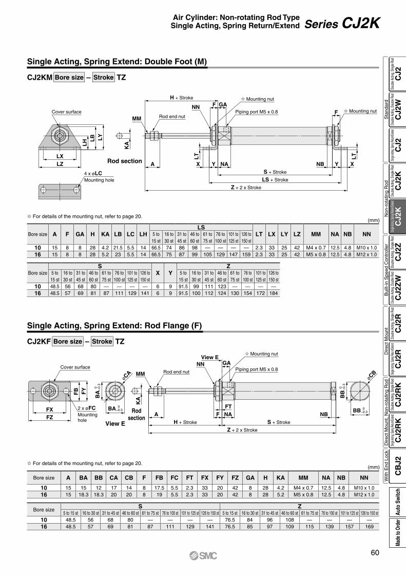
øCB
FZFX
Cover surface
FY
FB
2 x øFCMounting hole
KA
MM
NN GAView E
Piping port M5 x 0.8
A
Z + 2 x Stroke
H + Stroke S + Stroke
NAFFT
NB
BB
0
−0.
3
BB 0 −0.3
Rod end nut
Mounting nut
øCA
BA
0
−0.
3
BA 0 −0.3
Cover surface
LY
LB
LH
LZLX
4 x øLCMounting hole
KA
H + Stroke
NN
MM
GAFPiping port M5 x 0.8
LT
A
Z + 2 x Stroke
LS + Stroke
S + Stroke
NAYX
LT
Y XNB
FRod end nut
Mounting nut
Mounting nut
CJ2KM Bore size – Stroke TZ
CJ2KF Bore size – Stroke TZ
Single Acting, Spring Extend: Double Foot (M)
Rod section
(mm)
Bore size A F GA H KA LB LC LHLS
LT LX LY LZ MM NA NB NN5 to 15 st
16 to 30 st
31 to 45 st
46 to 60 st
61 to 75 st
76 to 100 st
101 to 125 st
126 to 150 st
10 15 8 8 28 4.2 21.5 5.5 14 66.5 74 86 98 — — — — 2.3 33 25 42 M4 x 0.7 12.5 4.8 M10 x 1.016 15 8 8 28 5.2 23 5.5 14 66.5 75 87 99 105 129 147 159 2.3 33 25 42 M5 x 0.8 12.5 4.8 M12 x 1.0
Bore sizeS
X YZ
5 to 15 st
16 to 30 st
31 to 45 st
46 to 60 st
61 to 75 st
76 to 100 st
101 to 125 st
126 to 150 st
5 to 15 st
16 to 30 st
31 to 45 st
46 to 60 st
61 to 75 st
76 to 100 st
101 to 125 st
126 to 150 st
10 48.5 56 68 80 — — — — 6 9 91.5 99 111 123 — — — —16 48.5 57 69 81 87 111 129 141 6 9 91.5 100 112 124 130 154 172 184
For details of the mounting nut, refer to page 20.
Single Acting, Spring Extend: Rod Flange (F)
View E
Rodsection
(mm)
Bore size A BA BB CA CB F FB FC FT FX FY FZ GA H KA MM NA NB NN
10 15 15 12 17 14 8 17.5 5.5 2.3 33 20 42 8 28 4.2 M4 x 0.7 12.5 4.8 M10 x 1.016 15 18.3 18.3 20 20 8 19 5.5 2.3 33 20 42 8 28 5.2 M5 x 0.8 12.5 4.8 M12 x 1.0
Bore sizeS Z
5 to 15 st 16 to 30 st 31 to 45 st 46 to 60 st 61 to 75 st 76 to 100 st 101 to 125 st 126 to 150 st 5 to 15 st 16 to 30 st 31 to 45 st 46 to 60 st 61 to 75 st 76 to 100 st 101 to 125 st 126 to 150 st10 48.5 56 68 80 — — — — 76.5 84 96 108 — — — —16 48.5 57 69 81 87 111 129 141 76.5 85 97 109 115 139 157 169
For details of the mounting nut, refer to page 20.
60
Air Cylinder: Non-rotating Rod TypeSingle Acting, Spring Return/Extend Series CJ2K
CJ2
CJ2
WC
J2C
J2K
CJ2
KC
J2Z
CJ2
ZW
CJ2
RC
J2R
CJ2
RK
CJ2
RK
CB
J2
Sta
ndar
dN
on-r
otat
ing
Rod
Bui
lt-in
Spe
ed C
ontr
olle
rD
irect
Mou
ntD
irect
Mou
nt, N
on-r
otat
ing
Rod
With
End
Loc
kDo
uble
Actin
g, Do
uble
Rod
Single
Acting
, Sprin
g Retu
rn/Exte
ndDo
uble
Actin
g, Si
ngle
Rod
Single
Acting
, Sprin
g Retu
rn/Exte
ndDo
uble
Actin
g, Si
ngle
Rod
Doub
le Ac
ting,
Doub
le Ro
dDo
uble
Actin
g, Si
ngle
Rod
Single
Acting
, Sprin
g Retu
rn/Exte
ndDo
uble
Actin
g, Si
ngle
Rod
Single
Acting
, Sprin
g Retu
rn/Exte
ndDo
uble
Actin
g, Si
ngle
Rod
Auto
Sw
itch
Made
to O
rder

øC
B 0
−
0.3
B 0 −0.3
KA
MMNN Piping port M5 x 0.8GA
Z + 2 x Stroke
H + Stroke
A NAS + Stroke
FF
NBFT
FZFX
Cover surface
FY
FB
2 x øFCMounting hole
Rod end nut
Mounting nut
CJ2KG Bore size – Stroke TZ
Single Acting, Spring Extend: Head Flange (G)
(mm)
Bore size A B C F FB FC FT FX FY FZ GA H KA MM NA NB NN
10 15 15 17 8 17.5 5.5 2.3 33 20 42 8 28 4.2 M4 x 0.7 12.5 4.8 M10 x 1.016 15 18.3 20 8 19 5.5 2.3 33 20 42 8 28 5.2 M5 x 0.8 12.5 4.8 M12 x 1.0
Bore sizeS Z
5 to 15 st 16 to 30 st 31 to 45 st 46 to 60 st 61 to 75 st 76 to 100 st 101 to 125 st 126 to 150 st 5 to 15 st 16 to 30 st 31 to 45 st 46 to 60 st 61 to 75 st 76 to 100 st 101 to 125 st 126 to 150 st10 48.5 56 68 80 — — — — 84.5 92 104 116 — — — —16 48.5 57 69 81 87 111 129 141 84.5 93 105 117 123 147 165 177
For details of the mounting nut, refer to page 20.
Rod section
61
Series CJ2K
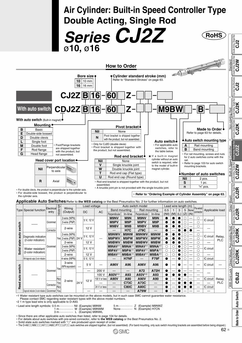
RoHSSeries CJ2Zø10, ø16
Air Cylinder: Built-in Speed Controller TypeDouble Acting, Single Rod
Applicable Auto Switches/Refer to the WEB catalog or the Best Pneumatics No. 2 for further information on auto switches.
Type Special function Electricalentry
Indica
tor lig
ht
Wiring(Output)
Load voltage Auto switch model Lead wire length (m)Pre-wiredconnector
Applicable loadDC AC
Band mounting Rail mounting 0.5(Nil)
1(M)
3(L)
5(Z)
None(N)Perpendicular In-line Perpendicular In-line
So
lid s
tate
au
to s
wit
ch ——Grommet
Yes
3-wire (NPN)
24 V
5 V, 12 V
—
M9NV M9N M9NV M9N V V V v — vIC circuit
Relay,PLC
3-wire (PNP) M9PV M9P M9PV M9P V V V v — v
2-wire 12 VM9BV M9B M9BV M9B V V V v — v
—Connector — H7C J79C — V — V V V —
Diagnostic indication(2-color indication)
Grommet
3-wire (NPN)5 V, 12 V
M9NWV M9NW M9NWV M9NW V V V v — vIC circuit
3-wire (PNP) M9PWV M9PW M9PWV M9PW V V V v — v2-wire 12 V M9BWV M9BW M9BWV M9BW V V V v — v —
Water resistant (2-color indication)
3-wire (NPN)5 V, 12 V
M9NAV*1 M9NA*1 M9NAV*1 M9NA*1 v v V v — vIC circuit
3-wire (PNP) M9PAV*1 M9PA*1 M9PAV*1 M9PA*1 v v V v — v2-wire 12 V M9BAV*1 M9BA*1 M9BAV*1 M9BA*1 v v V v — v —
With diagnostic output (2-color indication) 4-wire (NPN) 5 V, 12 V — H7NF — F79F V — V v — v IC circuit
Ree
d a
uto
sw
itch
——Grommet
Yes
3-wire(NPN equivalent) —
5 V — A96V A96 A96V A96 V — V — — — IC circuit —
2-wire
— 200 V — — A72 A72H V — V — — ——
Relay,PLC24 V
12 V
100 V A93V*2 A93 A93V*2 A93 V V V V — —No 100 V or less A90V A90 A90V A90 V — V — — — IC circuit
ConnectorYes — — C73C A73C — V — V V V — —No 24 V or less — C80C A80C — V — V V V — IC circuit
Diagnostic indication (2-color indication) Grommet Yes — — — — A79W — V — V — — — —
* Since there are other applicable auto switches than listed, refer to page 104 for details.* For details about auto switches with pre-wired connector, refer to the WEB catalog or the Best Pneumatics No. 2.* Solid state auto switches marked with “p” are produced upon receipt of order.* The D-A9ll/M9lll/A7ll/A80l/F7ll/J7ll auto switches are shipped together, (but not assembled). (For band mounting, only auto switch mounting brackets are assembled before being shipped.)
*1 Water resistant type auto switches can be mounted on the above models, but in such case SMC cannot guarantee water resistance. Please contact SMC regarding water resistant types with the above model numbers.
*2 1 m type lead wire is only applicable to D-A93.* Lead wire length symbols: 0.5 m·················· Nil (Example) M9NW 1 m·················· M (Example) M9NWM 3 m·················· L (Example) M9NWL
5 m·················· Z (Example) M9NWZ None··············· N (Example) H7CN
Cylinder standard stroke (mm)Refer to “Standard Strokes” on page 63.
Bore size
M9BW6016
6016
B Z
Z
CDJ2Z
BCJ2Z
10 10 mm
16 16 mm
Mounting
With auto switch
Made to OrderRefer to page 63 for details.
Auto switch mounting type
Number of auto switchesNil 2 pcs.S 1 pc.n “n” pcs.
B
* For double clevis, the product is perpendicular to the cylinder axis.* For double-side bossed, the product is perpendicular to
the cylinder axis.
Head cover port location
Nil Perpendicularto axis
R Axial
With auto switch (Built-in magnet)
B BasicE Double-side bossedD Double clevisL Single footM Double footF Rod flangeG Head flange * For rail mounting, screws and nuts
for 2 auto switches come with the rail.
* Refer to page 103 for auto switch mounting brackets.
A Rail mountingB Band mounting
* Refer to “Ordering Example of Cylinder Assembly” on page 63.
I f a bui l t - in magnet cylinder without an auto switch is required, refer to the model of built-in magnet cylinder.
* For applicable auto switches, refer to the table below.
Auto switch
* Rod end bracket is shipped together with the product, but not assembled.
* A knuckle joint pin is not provided with the single knuckle joint.
Rod end bracketNil NoneV Single knuckle jointW Double knuckle jointT Rod end cap (Flat type)U Rod end cap (Round type)
Pivot bracket
* Only for CJ2D (double clevis)* Pivot bracket is shipped together with
the product, but not assembled.
Nil None
N Pivot bracket is shipped together with the product, but not assembled.
* Foot/Flange brackets are shipped together with the product, but not assembled.
62
How to Order
CJ2
CJ2
WC
J2C
J2K
CJ2
KC
J2Z
CJ2
ZW
CJ2
RC
J2R
CJ2
RK
CJ2
RK
CB
J2
Sta
ndar
dN
on-r
otat
ing
Rod
Bui
lt-in
Spe
ed C
ontr
olle
rD
irect
Mou
ntD
irect
Mou
nt, N
on-r
otat
ing
Rod
With
End
Loc
kDo
uble
Actin
g, Do
uble
Rod
Single
Acting
, Sprin
g Retu
rn/Exte
ndDo
uble
Actin
g, Si
ngle
Rod
Single
Acting
, Sprin
g Retu
rn/Exte
ndDo
uble
Actin
g, Si
ngle
Rod
Doub
le Ac
ting,
Doub
le Ro
dDo
uble
Actin
g, Si
ngle
Rod
Single
Acting
, Sprin
g Retu
rn/Exte
ndDo
uble
Actin
g, Si
ngle
Rod
Single
Acting
, Sprin
g Retu
rn/Exte
ndDo
uble
Actin
g, Si
ngle
Rod
Auto
Sw
itch
Made
to O
rder
A
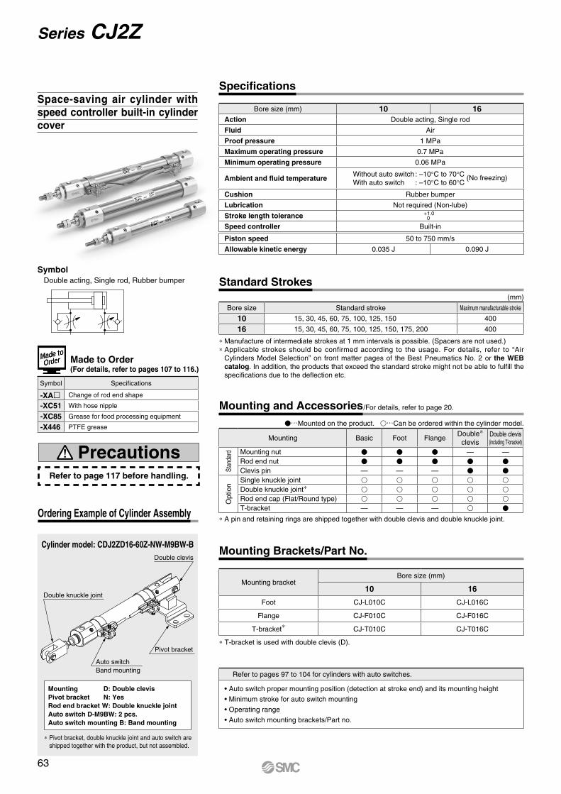
Auto switchBand mounting
Double clevis
Pivot bracket
Double knuckle joint
Symbol Double acting, Single rod, Rubber bumper
Cylinder model: CDJ2ZD16-60Z-NW-M9BW-B
Mounting D: Double clevisPivot bracket N: YesRod end bracket W: Double knuckle jointAuto switch D-M9BW: 2 pcs.Auto switch mounting B: Band mounting
* Pivot bracket, double knuckle joint and auto switch are shipped together with the product, but not assembled.
Ordering Example of Cylinder Assembly
Space-saving air cylinder with speed controller built-in cylinder cover
Made to Order(For details, refer to pages 107 to 116.)
Symbol Specifications
-XAl Change of rod end shape
-XC51 With hose nipple
-XC85 Grease for food processing equipment
-X446 PTFE grease
Refer to page 117 before handling.
Precautions
Bore size (mm) 10 16Action Double acting, Single rod
Fluid Air
Proof pressure 1 MPa
Maximum operating pressure 0.7 MPa
Minimum operating pressure 0.06 MPa
Ambient and fluid temperatureWithout auto switch : –10°C to 70°C (No freezing)With auto switch : –10°C to 60°C
Cushion Rubber bumper
Lubrication Not required (Non-lube)
Stroke length tolerance +1.00
Speed controller Built-in
Piston speed 50 to 750 mm/s
Allowable kinetic energy 0.035 J 0.090 J
Specifications
* Manufacture of intermediate strokes at 1 mm intervals is possible. (Spacers are not used.)* Applicable strokes should be confirmed according to the usage. For details, refer to “Air
Cylinders Model Selection” on front matter pages of the Best Pneumatics No. 2 or the WEB catalog. In addition, the products that exceed the standard stroke might not be able to fulfill the specifications due to the deflection etc.
Bore size Standard stroke Maximum manufacturable stroke
10 15, 30, 45, 60, 75, 100, 125, 150 400
16 15, 30, 45, 60, 75, 100, 125, 150, 175, 200 400
(mm)
Standard Strokes
V…Mounted on the product. v…Can be ordered within the cylinder model.
* A pin and retaining rings are shipped together with double clevis and double knuckle joint.
Mounting Basic Foot FlangeDouble*
clevisDouble clevis(including T-bracket)
Stan
dard Mounting nut V V V — —
Rod end nut V V V V VClevis pin — — — V V
Opt
ion
Single knuckle joint v v v v vDouble knuckle joint* v v v v vRod end cap (Flat/Round type) v v v v vT-bracket — — — v V
Mounting and Accessories/For details, refer to page 20.
* T-bracket is used with double clevis (D).
Mounting bracketBore size (mm)
10 16
Foot CJ-L010C CJ-L016C
Flange CJ-F010C CJ-F016C
T-bracket* CJ-T010C CJ-T016C
Mounting Brackets/Part No.
Refer to pages 97 to 104 for cylinders with auto switches.
• Auto switch proper mounting position (detection at stroke end) and its mounting height
• Minimum stroke for auto switch mounting
• Operating range
• Auto switch mounting brackets/Part no.
63
Series CJ2Z
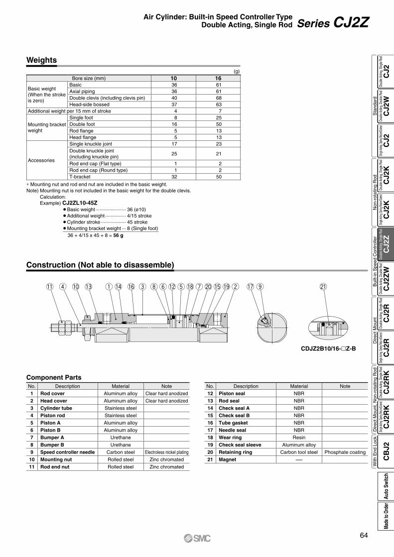
r q e iy u w ot!3 !4 !6 !2 !8 !5 !7 @1@0 !9!1 !0
Weights(g)
Bore size (mm) 10 16
Basic weight(When the strokeis zero)
Basic 36 61Axial piping 36 61Double clevis (including clevis pin) 40 68Head-side bossed 37 63
Additional weight per 15 mm of stroke 4 7
Mounting bracket weight
Single foot 8 25Double foot 16 50Rod flange 5 13Head flange 5 13
Accessories
Single knuckle joint 17 23Double knuckle joint(including knuckle pin)
25 21
Rod end cap (Flat type) 1 2Rod end cap (Round type) 1 2T-bracket 32 50
∗ Mounting nut and rod end nut are included in the basic weight.Note) Mounting nut is not included in the basic weight for the double clevis.
Calculation:Example) CJ2ZL10-45Z
¡Basic weight ······················ 36 (ø10)¡Additional weight ··············· 4/15 stroke¡Cylinder stroke ·················· 45 stroke¡Mounting bracket weight ··· 8 (Single foot) 36 + 4/15 x 45 + 8 = 56 g
Construction (Not able to disassemble)
CDJZ2B10/16-Z-B
Component PartsNo. Description Material Note
1 Rod cover Aluminum alloy Clear hard anodized
2 Head cover Aluminum alloy Clear hard anodized
3 Cylinder tube Stainless steel
4 Piston rod Stainless steel
5 Piston A Aluminum alloy
6 Piston B Aluminum alloy
7 Bumper A Urethane
8 Bumper B Urethane
9 Speed controller needle Carbon steel Electroless nickel plating
10 Mounting nut Rolled steel Zinc chromated
11 Rod end nut Rolled steel Zinc chromated
No. Description Material Note
12 Piston seal NBR
13 Rod seal NBR
14 Check seal A NBR
15 Check seal B NBR
16 Tube gasket NBR
17 Needle seal NBR
18 Wear ring Resin
19 Check seal sleeve Aluminum alloy
20 Retaining ring Carbon tool steel Phosphate coating
21 Magnet —
64
Air Cylinder: Built-in Speed Controller TypeDouble Acting, Single Rod Series CJ2Z
CJ2
CJ2
WC
J2C
J2K
CJ2
KC
J2Z
CJ2
ZW
CJ2
RC
J2R
CJ2
RK
CJ2
RK
CB
J2
Sta
ndar
dN
on-r
otat
ing
Rod
Bui
lt-in
Spe
ed C
ontr
olle
rD
irect
Mou
ntD
irect
Mou
nt, N
on-r
otat
ing
Rod
With
End
Loc
kDo
uble
Actin
g, Do
uble
Rod
Single
Acting
, Sprin
g Retu
rn/Exte
ndDo
uble
Actin
g, Si
ngle
Rod
Single
Acting
, Sprin
g Retu
rn/Exte
ndDo
uble
Actin
g, Si
ngle
Rod
Doub
le Ac
ting,
Doub
le Ro
dDo
uble
Actin
g, Si
ngle
Rod
Single
Acting
, Sprin
g Retu
rn/Exte
ndDo
uble
Actin
g, Si
ngle
Rod
Single
Acting
, Sprin
g Retu
rn/Exte
ndDo
uble
Actin
g, Si
ngle
Rod
Auto
Sw
itch
Made
to O
rder
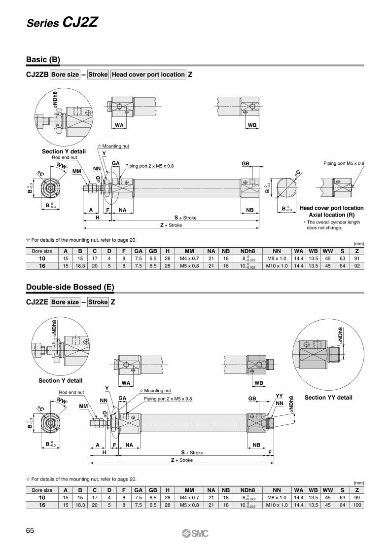
øC
WW°
øN
Dh
8
B 0
−
0.3
B 0 −0.3
MM
GA
WA WB
øD
A F NAH
Z + Stroke
S + Stroke
NBF
GBNNYY
øN
Dh
8
øN
Dh
8
Rod end nutPiping port 2 x M5 x 0.8
Mounting nutY
NN
øC
øC
WW°
B 0
−
0.3
B 0 −0.3
MM
GA
øD
Piping port 2 x M5 x 0.8
HA F NA
Z + Stroke
S + Stroke
NB
GB
B 0
−
0.3
B 0 −0.3
Piping port M5 x 0.8
WA WB
øN
Dh
8
NN
YRod end nut
Mounting nut
CJ2ZB Bore size – Stroke Head cover port location Z
CJ2ZE Bore size – Stroke Z
Basic (B)
Section Y detail
Head cover port locationAxial location (R)
* The overall cylinder length does not change.
(mm)
Bore size A B C D F GA GB H MM NA NB NDh8 NN WA WB WW S Z10 15 15 17 4 8 7.5 6.5 28 M4 x 0.7 21 18 8 0
−0.022 M8 x 1.0 14.4 13.5 45 63 91
16 15 18.3 20 5 8 7.5 6.5 28 M5 x 0.8 21 18 10 0 −0.022 M10 x 1.0 14.4 13.5 45 64 92
For details of the mounting nut, refer to page 20.
Double-side Bossed (E)
Section Y detail
Section YY detail
(mm)
Bore size A B C D F GA GB H MM NA NB NDh8 NN WA WB WW S Z10 15 15 17 4 8 7.5 6.5 28 M4 x 0.7 21 18 8 0
−0.022 M8 x 1.0 14.4 13.5 45 63 99
16 15 18.3 20 5 8 7.5 6.5 28 M5 x 0.8 21 18 10 0 −0.022 M10 x 1.0 14.4 13.5 45 64 100
For details of the mounting nut, refer to page 20.
65
Series CJ2Z
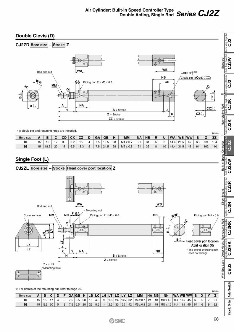
øCDH9+0.030 0
Clevis pin (øCdd9 )–0.030–0.060
MM
øD
GA
WA
Piping port 2 x M5 x 0.8
A NAH
ZZ + Stroke
Z + Stroke
S + Stroke
RU
GBNB
WBRod end nut
øC
WW°
B 0 −0.3
B 0
−
0.3
øC
CZ 0 −0.3
CX+0.2 +0.1
CZ
0
−0.
3
WW°
øC
WA
2 x øLCMounting hole
LZLX
LY
LB
LH
MM NN
NAYH
XA
LT
øD
F GA Piping port 2 x M5 x 0.8
Z + Stroke
S + Stroke
NB
GB
B 0
−
0.3
B 0 −0.3
Piping port M5 x 0.8
WB
Cover surface
Rod end nut
Mounting nut
CJ2ZD Bore size – Stroke Z
CJ2ZL Bore size – Stroke Head cover port location Z
Double Clevis (D)
(mm)* A clevis pin and retaining rings are included.
Bore size A B C CD CX CZ D GA GB H MM NA NB R U WA WB WW S Z ZZ10 15 15 17 3.3 3.2 15 4 7.5 19.5 28 M4 x 0.7 21 31 5 8 14.4 26.5 45 63 99 104
16 15 18.3 20 5 6.5 18.3 5 7.5 24.5 28 M5 x 0.8 21 36 8 10 14.4 31.5 45 64 102 110
Single Foot (L)
(mm)
Bore size A B C D F GA GB H LB LC LH LT LX LY LZ MM NA NB NN WA WB WW S X Y Z10 15 15 17 4 8 7.5 6.5 28 15 4.5 9 1.6 24 16.5 32 M4 x 0.7 21 18 M8 x 1.0 14.4 13.5 45 63 5 7 91
16 15 18.3 20 5 8 7.5 6.5 28 23 5.5 14 2.3 33 25 42 M5 x 0.8 21 18 M10 x 1.0 14.4 13.5 45 64 6 9 92
For details of the mounting nut, refer to page 20.
Head cover port locationAxial location (R)
* The overall cylinder length does not change.
66
Air Cylinder: Built-in Speed Controller TypeDouble Acting, Single Rod Series CJ2Z
CJ2
CJ2
WC
J2C
J2K
CJ2
KC
J2Z
CJ2
ZW
CJ2
RC
J2R
CJ2
RK
CJ2
RK
CB
J2
Sta
ndar
dN
on-r
otat
ing
Rod
Bui
lt-in
Spe
ed C
ontr
olle
rD
irect
Mou
ntD
irect
Mou
nt, N
on-r
otat
ing
Rod
With
End
Loc
kDo
uble
Actin
g, Do
uble
Rod
Single
Acting
, Sprin
g Retu
rn/Exte
ndDo
uble
Actin
g, Si
ngle
Rod
Single
Acting
, Sprin
g Retu
rn/Exte
ndDo
uble
Actin
g, Si
ngle
Rod
Doub
le Ac
ting,
Doub
le Ro
dDo
uble
Actin
g, Si
ngle
Rod
Single
Acting
, Sprin
g Retu
rn/Exte
ndDo
uble
Actin
g, Si
ngle
Rod
Single
Acting
, Sprin
g Retu
rn/Exte
ndDo
uble
Actin
g, Si
ngle
Rod
Auto
Sw
itch
Made
to O
rder
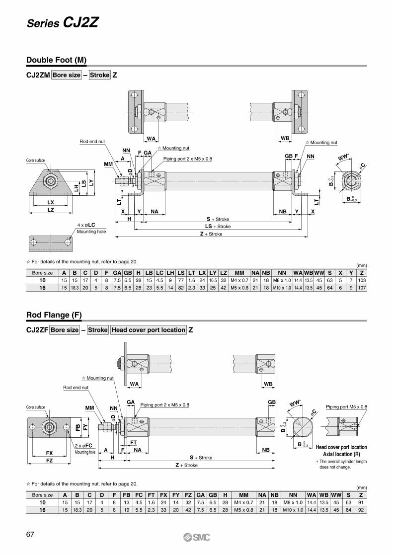
FY
FB
WW°
øC
Mounting hole4 x øLC
Cover surface
LZLX
LY
LB
LH
MMA
NN F GA
WA
øD
LT
NAY
Z + Stroke
LS + Stroke
S + StrokeHX NB Y
LT
X
FGB
B 0
−
0.3
B 0 −0.3
WBRod end nut
Mounting nut
Piping port 2 x M5 x 0.8
Mounting nut
NN
øCWW°
WA WB
Cover surface
FZFX
2 x øFCMounting hole
FY
FB
MM NNGA Piping port 2 x M5 x 0.8
øD
A
Z + Stroke
S + StrokeHNAF
FTNB
GB
B 0
−
0.3
B 0 −0.3
Piping port M5 x 0.8
Rod end nut
Mounting nut
CJ2ZM Bore size – Stroke Z
CJ2ZF Bore size – Stroke Head cover port location Z
Double Foot (M)
(mm)
Bore size A B C D F GA GB H LB LC LH LS LT LX LY LZ MM NA NB NN WA WB WW S X Y Z10 15 15 17 4 8 7.5 6.5 28 15 4.5 9 77 1.6 24 16.5 32 M4 x 0.7 21 18 M8 x 1.0 14.4 13.5 45 63 5 7 103
16 15 18.3 20 5 8 7.5 6.5 28 23 5.5 14 82 2.3 33 25 42 M5 x 0.8 21 18 M10 x 1.0 14.4 13.5 45 64 6 9 107
For details of the mounting nut, refer to page 20.
Rod Flange (F)
Head cover port locationAxial location (R)
* The overall cylinder length does not change.
(mm)
Bore size A B C D F FB FC FT FX FY FZ GA GB H MM NA NB NN WA WB WW S Z10 15 15 17 4 8 13 4.5 1.6 24 14 32 7.5 6.5 28 M4 x 0.7 21 18 M8 x 1.0 14.4 13.5 45 63 91
16 15 18.3 20 5 8 19 5.5 2.3 33 20 42 7.5 6.5 28 M5 x 0.8 21 18 M10 x 1.0 14.4 13.5 45 64 92
For details of the mounting nut, refer to page 20.
67
Series CJ2Z
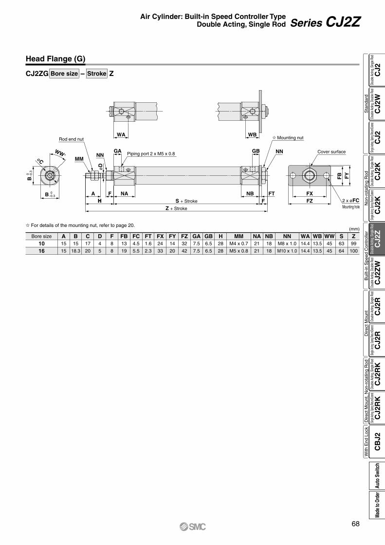
H
MMNN
GA
øD
Piping port 2 x M5 x 0.8
WA WB
GB NN
Z + Stroke
S + Stroke FHA NAF NB FT
FZFX
Cover surface
2 x øFCMounting hole
FY
FB
Rod end nut Mounting nut
WW°
øC
B 0
−
0.3
B 0 −0.3
CJ2ZG Bore size – Stroke Z
Head Flange (G)
(mm)
Bore size A B C D F FB FC FT FX FY FZ GA GB H MM NA NB NN WA WB WW S Z10 15 15 17 4 8 13 4.5 1.6 24 14 32 7.5 6.5 28 M4 x 0.7 21 18 M8 x 1.0 14.4 13.5 45 63 99
16 15 18.3 20 5 8 19 5.5 2.3 33 20 42 7.5 6.5 28 M5 x 0.8 21 18 M10 x 1.0 14.4 13.5 45 64 100
For details of the mounting nut, refer to page 20.
68
Air Cylinder: Built-in Speed Controller TypeDouble Acting, Single Rod Series CJ2Z
CJ2
CJ2
WC
J2C
J2K
CJ2
KC
J2Z
CJ2
ZW
CJ2
RC
J2R
CJ2
RK
CJ2
RK
CB
J2
Sta
ndar
dN
on-r
otat
ing
Rod
Bui
lt-in
Spe
ed C
ontr
olle
rD
irect
Mou
ntD
irect
Mou
nt, N
on-r
otat
ing
Rod
With
End
Loc
kDo
uble
Actin
g, Do
uble
Rod
Single
Acting
, Sprin
g Retu
rn/Exte
ndDo
uble
Actin
g, Si
ngle
Rod
Single
Acting
, Sprin
g Retu
rn/Exte
ndDo
uble
Actin
g, Si
ngle
Rod
Doub
le Ac
ting,
Doub
le Ro
dDo
uble
Actin
g, Si
ngle
Rod
Single
Acting
, Sprin
g Retu
rn/Exte
ndDo
uble
Actin
g, Si
ngle
Rod
Single
Acting
, Sprin
g Retu
rn/Exte
ndDo
uble
Actin
g, Si
ngle
Rod
Auto
Sw
itch
Made
to O
rder

How to Order
RoHS
Applicable Auto Switches/Refer to the WEB catalog or the Best Pneumatics No. 2 for further information on auto switches.
Series CJ2ZWø10, ø16
Air Cylinder: Built-in Speed Controller TypeDouble Acting, Double Rod
∗ Since there are other applicable auto switches than listed, refer to page 104 for details.∗ For details about auto switches with pre-wired connector, refer to the WEB catalog or the Best Pneumatics No. 2.∗ Solid state auto switches marked with “v” are produced upon receipt of order.∗ The D-A9ll/M9lll/A7ll/A80l/F7ll/J7ll auto switches are shipped together, (but not assembled). (For band mounting, only auto switch mounting brackets are assembled before being shipped.)
∗1 Water resistant type auto switches can be mounted on the above models, but in such case SMC cannot guarantee water resistance. Please contact SMC regarding water resistant types with the above model numbers.
∗2 1 m type lead wire is only applicable to D-A93.∗ Lead wire length symbols: 0.5 m·················· Nil (Example) M9NW 1 m·················· M (Example) M9NWM 3 m·················· L (Example) M9NWL 5 m·················· Z (Example) M9NWZ None··············· N (Example) H7CN
Type Special functionElectrical
entry
Indica
tor lig
ht
Wiring(Output)
Load voltage Auto switch model Lead wire length (m)Pre-wiredconnector
ApplicableloadDC AC
Band mounting Rail mounting 0.5(Nil)
1(M)
3(L)
5(Z)
None(N)Perpendicular In-line Perpendicular In-line
So
lid s
tate
au
to s
wit
ch ——Grommet
Yes
3-wire (NPN)
24 V
5 V,12 V
—
M9NV M9N M9NV M9N V V V v — vIC circuit
Relay,PLC
3-wire (PNP) M9PV M9P M9PV M9P V V V v — v
2-wire 12 VM9BV M9B M9BV M9B V V V v — v
—Connector — H7C J79C — V — V V V —
Diagnostic indication(2-color indication)
Grommet
3-wire (NPN)5 V,12 V
M9NWV M9NW M9NWV M9NW V V V v — vIC circuit
3-wire (PNP) M9PWV M9PW M9PWV M9PW V V V v — v2-wire 12 V M9BWV M9BW M9BWV M9BW V V V v — v —
Water resistant(2-color indication)
3-wire (NPN)5 V,12 V
M9NAV∗1 M9NA∗1 M9NAV∗1 M9NA∗1 v v V v — vIC circuit
3-wire (PNP) M9PAV∗1 M9PA∗1 M9PAV∗1 M9PA∗1 v v V v — v2-wire 12 V M9BAV∗1 M9BA∗1 M9BAV∗1 M9BA∗1 v v V v — v —
With diagnostic output (2-color indication) 4-wire (NPN) 5 V,12 V — H7NF — F79F V — V v — v IC circuit
Ree
d a
uto
sw
itch
——Grommet
Yes
3-wire(NPN equivalent) —
5 V — A96V A96 A96V A96 V — V — — — IC circuit —
2-wire
— 200 V — — A72 A72H V — V — — ——
Relay,PLC24 V
12 V
100 V A93V∗2 A93 A93V∗2 A93 V V V V — —No 100 V or less A90V A90 A90V A90 V — V — — — IC circuitYes — — C73C A73C — V — V V V — —
Connector No 24 V or less — C80C A80C — V — V V V — IC circuitDiagnostic indication (2-color indication) Grommet Yes — — — — A79W — V — V — — — —
Cylinder standard stroke (mm)Refer to “Standard Strokes” on page 70.
∗ For applicable auto switches, refer to the table below.
Auto switch
With auto switch (Built-in magnet)
M9BW BZ6016
Z6016
LWith auto switch CDJ2ZW
BCJ2ZW
B BasicL FootF Flange
10 10 mm16 16 mm
Nil 2 pcs.S 1 pc.n “n” pcs.
Nil Without auto switch
∗ For rail mounting, screws and nuts for 2 auto switches come with the rail.
∗ Refer to page 103 for auto switch mounting brackets.
Mounting
Bore size
Number of auto switches
Made to OrderRefer to page 70 for details.
∗ Foot/Flange brackets are shipped together with the product, but not assembled.
Auto switch mounting type
A Rail mountingB Band mounting
69A
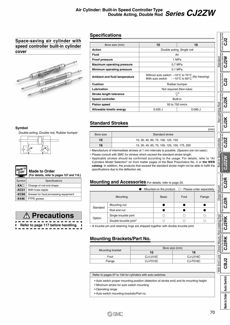
Space-saving air cylinder with speed controller built-in cylinder cover
Refer to page 117 before handling.
Precautions
Made to Order(For details, refer to pages 107 and 116.)
Symbol Specifications
-XAl Change of rod end shape
-XC51 With hose nipple
-XC85 Grease for food processing equipment
-X446 PTFE grease
Bore size (mm) 10 16Action Double acting, Single rod
Fluid Air
Proof pressure 1 MPa
Maximum operating pressure 0.7 MPa
Minimum operating pressure 0.1 MPa
Ambient and fluid temperatureWithout auto switch : –10°C to 70°C (No freezing)With auto switch : –10°C to 60°C
Cushion Rubber bumper
Lubrication Not required (Non-lube)
Stroke length tolerance +1.00
Speed controller Built-in
Piston speed 50 to 750 mm/s
Allowable kinetic energy 0.035 J 0.090 J
Specifications
* Manufacture of intermediate strokes at 1 mm intervals is possible. (Spacers are not used.)* Please consult with SMC for strokes which exceed the standard stroke length.* Applicable strokes should be confirmed according to the usage. For details, refer to “Air
Cylinders Model Selection” on front matter pages of the Best Pneumatics No. 2 or the WEB catalog. In addition, the products that exceed the standard stroke might not be able to fulfill the specifications due to the deflection etc.
(mm)
Bore size Standard stroke
10 15, 30, 45, 60, 75, 100, 125, 150
16 15, 30, 45, 60, 75, 100, 125, 150, 175, 200
Standard Strokes
Mounting bracketBore size (mm)
10 16Foot CJ-L010C CJ-L016C
Flange CJ-F010C CJ-F016C
Mounting Brackets/Part No.
Refer to pages 97 to 104 for cylinders with auto switches.
• Auto switch proper mounting position (detection at stroke end) and its mounting height
• Minimum stroke for auto switch mounting
• Operating range
• Auto switch mounting brackets/Part no.
SymbolDouble acting, Double rod, Rubber bumper
* A knuckle pin and retaining rings are shipped together with double knuckle joint.
Mounting Basic Foot Flange
StandardMounting nut V V V
Rod end nut V V V
OptionSingle knuckle joint v v v
Double knuckle joint* v v v
Mounting and Accessories /For details, refer to page 20.
V…Mounted on the product. v…Please order separately.
70
Air Cylinder: Built-in Speed Controller TypeDouble Acting, Double Rod Series CJ2ZW
CJ2
CJ2
WC
J2C
J2K
CJ2
KC
J2Z
CJ2
ZW
CJ2
RC
J2R
CJ2
RK
CJ2
RK
CB
J2
Sta
ndar
dN
on-r
otat
ing
Rod
Bui
lt-in
Spe
ed C
ontr
olle
rD
irect
Mou
ntD
irect
Mou
nt, N
on-r
otat
ing
Rod
With
End
Loc
kDo
uble
Actin
g, Do
uble
Rod
Single
Acting
, Sprin
g Retu
rn/Exte
ndDo
uble
Actin
g, Si
ngle
Rod
Single
Acting
, Sprin
g Retu
rn/Exte
ndDo
uble
Actin
g, Si
ngle
Rod
Doub
le Ac
ting,
Doub
le Ro
dDo
uble
Actin
g, Si
ngle
Rod
Single
Acting
, Sprin
g Retu
rn/Exte
ndDo
uble
Actin
g, Si
ngle
Rod
Single
Acting
, Sprin
g Retu
rn/Exte
ndDo
uble
Actin
g, Si
ngle
Rod
Auto
Sw
itch
Made
to O
rder
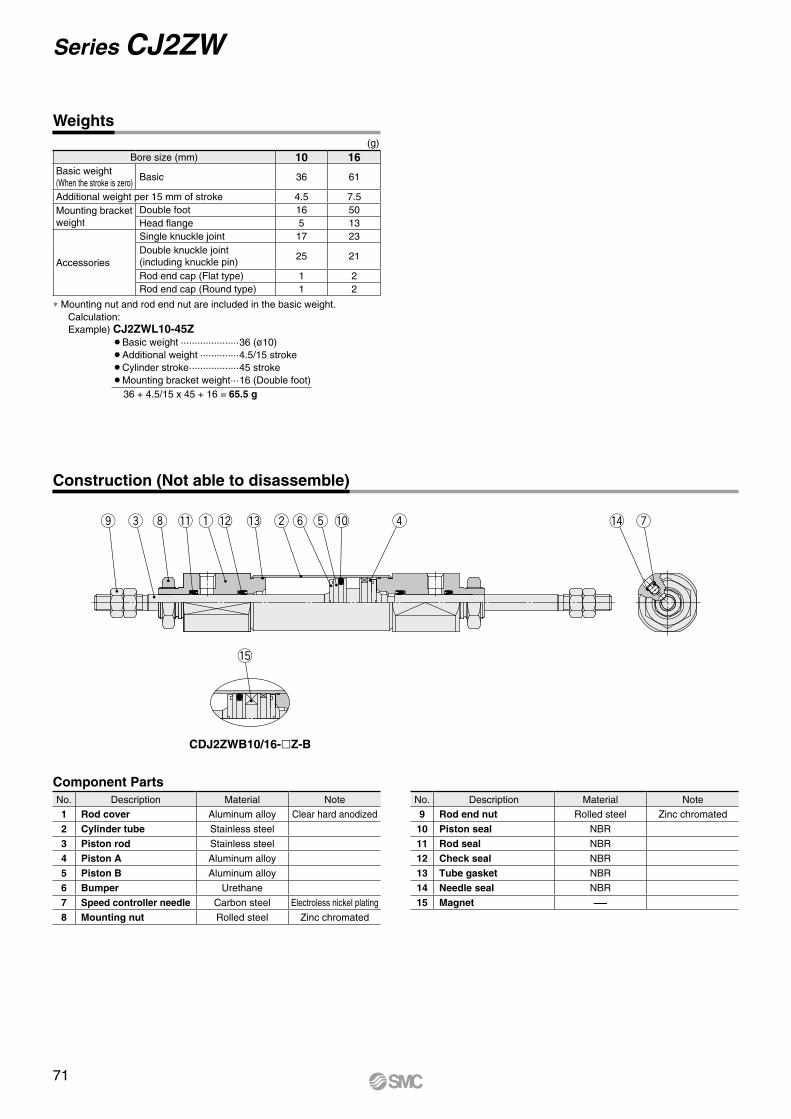
q we y to ri u
!5
!4!2!1 !3 !0
Weights(g)
Bore size (mm) 10 16Basic weight(When the stroke is zero)
Basic 36 61
Additional weight per 15 mm of stroke 4.5 7.5Mounting bracket weight
Double foot 16 50Head flange 5 13
Accessories
Single knuckle joint 17 23Double knuckle joint(including knuckle pin)
25 21
Rod end cap (Flat type) 1 2Rod end cap (Round type) 1 2
* Mounting nut and rod end nut are included in the basic weight.Calculation:Example) CJ2ZWL10-45Z
¡Basic weight ·····················36 (ø10)¡Additional weight ··············4.5/15 stroke¡Cylinder stroke ··················45 stroke¡Mounting bracket weight ···16 (Double foot) 36 + 4.5/15 x 45 + 16 = 65.5 g
Construction (Not able to disassemble)
CDJ2ZWB10/16-Z-B
Component PartsNo. Description Material Note
1 Rod cover Aluminum alloy Clear hard anodized
2 Cylinder tube Stainless steel
3 Piston rod Stainless steel
4 Piston A Aluminum alloy
5 Piston B Aluminum alloy
6 Bumper Urethane
7 Speed controller needle Carbon steel Electroless nickel plating
8 Mounting nut Rolled steel Zinc chromated
No. Description Material Note
9 Rod end nut Rolled steel Zinc chromated
10 Piston seal NBR
11 Rod seal NBR
12 Check seal NBR
13 Tube gasket NBR
14 Needle seal NBR
15 Magnet —
71
Series CJ2ZW
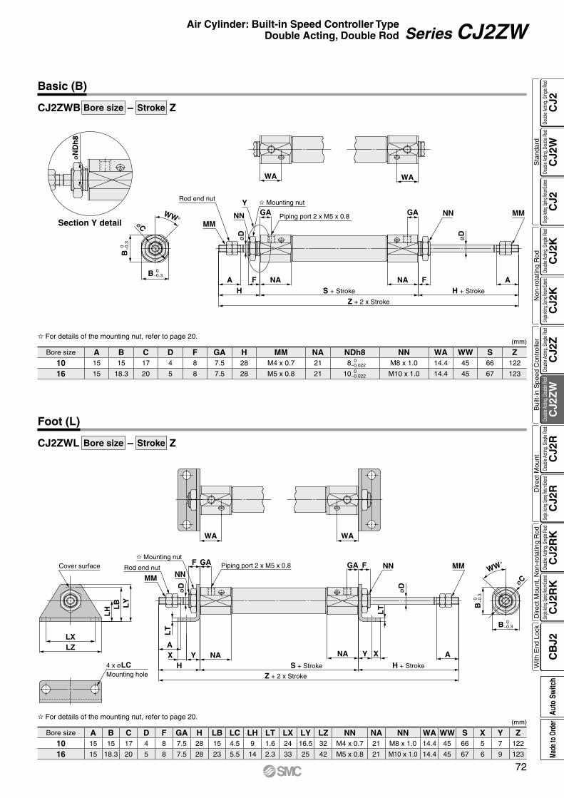
B 0 −0.3
øC
WW°
øN
Dh
8
WA WA
GA Piping port 2 x M5 x 0.8NN
Y
øD
MM
Z + 2 x Stroke
S + Stroke
NAH
A F NA F AH + Stroke
B 0
−
0.3
Rod end nut Mounting nut
GA
øD
NN MM
LZLX
LY
LB
LH
Cover surface
4 x øLCMounting hole
WA
WW°
øC
B 0
−
0.3
B 0 −0.3
F GA
MM
NAYH
XA
Z + 2 x Stroke
S + Stroke
LT
WA
H + Stroke
A
GAPiping port 2 x M5 x 0.8
NA XY
øD
NN
LT
Rod end nut
Mounting nutF
øD
NN MM
CJ2ZWB Bore size – Stroke Z
CJ2ZWL Bore size – Stroke Z
Basic (B)
(mm) For details of the mounting nut, refer to page 20.
Bore size A B C D F GA H MM NA NDh8 NN WA WW S Z10 15 15 17 4 8 7.5 28 M4 x 0.7 21 8 0
−0.022 M8 x 1.0 14.4 45 66 122
16 15 18.3 20 5 8 7.5 28 M5 x 0.8 21 10 0 −0.022 M10 x 1.0 14.4 45 67 123
Foot (L)
Section Y detail
(mm) For details of the mounting nut, refer to page 20.
Bore size A B C D F GA H LB LC LH LT LX LY LZ NN NA NN WA WW S X Y Z10 15 15 17 4 8 7.5 28 15 4.5 9 1.6 24 16.5 32 M4 x 0.7 21 M8 x 1.0 14.4 45 66 5 7 122
16 15 18.3 20 5 8 7.5 28 23 5.5 14 2.3 33 25 42 M5 x 0.8 21 M10 x 1.0 14.4 45 67 6 9 123
72
Air Cylinder: Built-in Speed Controller TypeDouble Acting, Double Rod Series CJ2ZW
CJ2
CJ2
WC
J2C
J2K
CJ2
KC
J2Z
CJ2
ZW
CJ2
RC
J2R
CJ2
RK
CJ2
RK
CB
J2
Sta
ndar
dN
on-r
otat
ing
Rod
Bui
lt-in
Spe
ed C
ontr
olle
rD
irect
Mou
ntD
irect
Mou
nt, N
on-r
otat
ing
Rod
With
End
Loc
kDo
uble
Actin
g, Do
uble
Rod
Single
Acting
, Sprin
g Retu
rn/Exte
ndDo
uble
Actin
g, Si
ngle
Rod
Single
Acting
, Sprin
g Retu
rn/Exte
ndDo
uble
Actin
g, Si
ngle
Rod
Doub
le Ac
ting,
Doub
le Ro
dDo
uble
Actin
g, Si
ngle
Rod
Single
Acting
, Sprin
g Retu
rn/Exte
ndDo
uble
Actin
g, Si
ngle
Rod
Single
Acting
, Sprin
g Retu
rn/Exte
ndDo
uble
Actin
g, Si
ngle
Rod
Auto
Sw
itch
Made
to O
rder
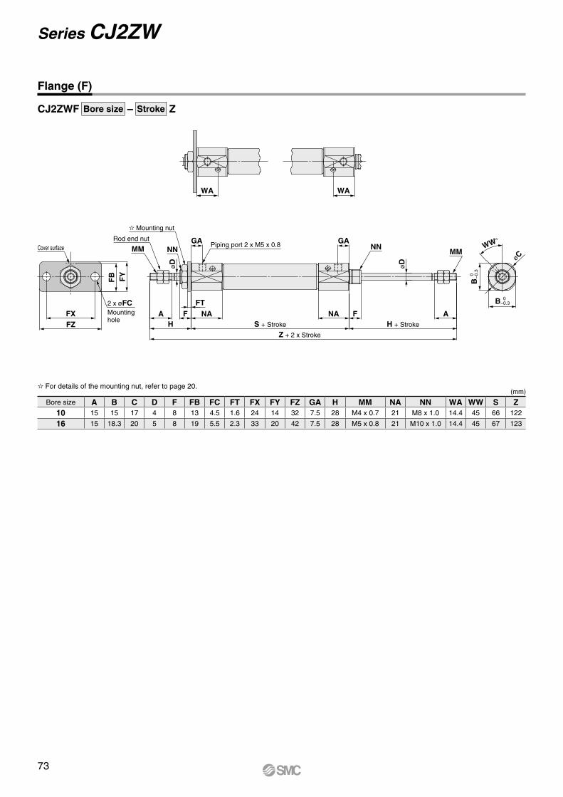
NNMM
øD
Cover surface
FZFX
2 x øFCMountinghole
FY
FB
MM NNGA Piping port 2 x M5 x 0.8
øD
WA
AH + Stroke
Z + 2 x Stroke
S + Stroke
NA FNAFT
HA F
WA
Rod end nut
Mounting nut
GA
øCWW°
B 0
−
0.3
B 0 −0.3
CJ2ZWF Bore size – Stroke Z
Flange (F)
(mm) For details of the mounting nut, refer to page 20.
Bore size A B C D F FB FC FT FX FY FZ GA H MM NA NN WA WW S Z10 15 15 17 4 8 13 4.5 1.6 24 14 32 7.5 28 M4 x 0.7 21 M8 x 1.0 14.4 45 66 122
16 15 18.3 20 5 8 19 5.5 2.3 33 20 42 7.5 28 M5 x 0.8 21 M10 x 1.0 14.4 45 67 123
73
Series CJ2ZW
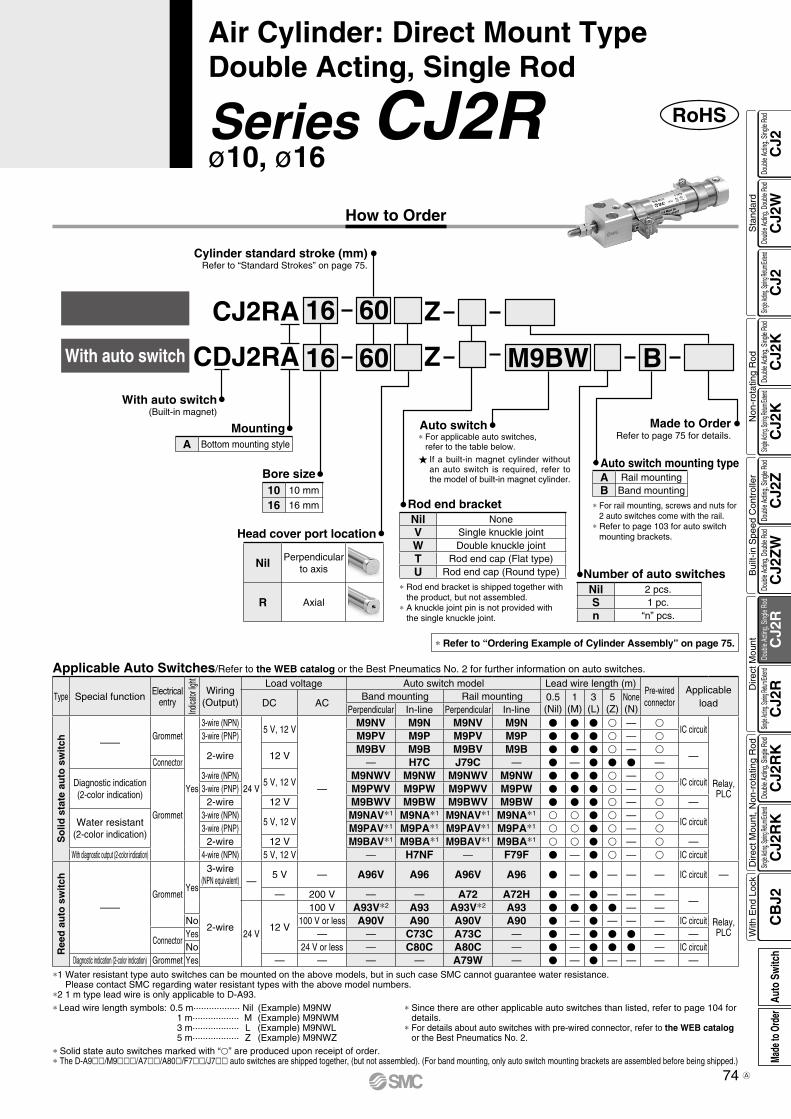
How to Order
RoHSSeries CJ2Rø10, ø16
Air Cylinder: Direct Mount TypeDouble Acting, Single Rod
* Solid state auto switches marked with “p” are produced upon receipt of order.* The D-A9ll/M9lll/A7ll/A80l/F7ll/J7ll auto switches are shipped together, (but not assembled). (For band mounting, only auto switch mounting brackets are assembled before being shipped.)
*1 Water resistant type auto switches can be mounted on the above models, but in such case SMC cannot guarantee water resistance. Please contact SMC regarding water resistant types with the above model numbers.
*2 1 m type lead wire is only applicable to D-A93. * Since there are other applicable auto switches than listed, refer to page 104 for
details. * For details about auto switches with pre-wired connector, refer to the WEB catalog
or the Best Pneumatics No. 2.
* Lead wire length symbols: 0.5 m·················· Nil (Example) M9NW 1 m·················· M (Example) M9NWM 3 m·················· L (Example) M9NWL 5 m·················· Z (Example) M9NWZ
Applicable Auto Switches/Refer to the WEB catalog or the Best Pneumatics No. 2 for further information on auto switches.
Type Special function Electricalentry
Indica
tor lig
ht
Wiring(Output)
Load voltage Auto switch model Lead wire length (m)Pre-wiredconnector
Applicable loadDC AC
Band mounting Rail mounting 0.5(Nil)
1(M)
3(L)
5(Z)
None(N)Perpendicular In-line Perpendicular In-line
So
lid s
tate
au
to s
wit
ch ——Grommet
Yes
3-wire (NPN)
24 V
5 V, 12 V
—
M9NV M9N M9NV M9N V V V v — vIC circuit
Relay,PLC
3-wire (PNP) M9PV M9P M9PV M9P V V V v — v
2-wire 12 VM9BV M9B M9BV M9B V V V v — v
—Connector — H7C J79C — V — V V V —
Diagnostic indication(2-color indication)
Grommet
3-wire (NPN)5 V, 12 V
M9NWV M9NW M9NWV M9NW V V V v — vIC circuit
3-wire (PNP) M9PWV M9PW M9PWV M9PW V V V v — v2-wire 12 V M9BWV M9BW M9BWV M9BW V V V v — v —
Water resistant (2-color indication)
3-wire (NPN)5 V, 12 V
M9NAV*1 M9NA*1 M9NAV*1 M9NA*1 v v V v — vIC circuit
3-wire (PNP) M9PAV*1 M9PA*1 M9PAV*1 M9PA*1 v v V v — v2-wire 12 V M9BAV*1 M9BA*1 M9BAV*1 M9BA*1 v v V v — v —
With diagnostic output (2-color indication) 4-wire (NPN) 5 V, 12 V — H7NF — F79F V — V v — v IC circuit
Ree
d a
uto
sw
itch
——Grommet
Yes
3-wire(NPN equivalent) —
5 V — A96V A96 A96V A96 V — V — — — IC circuit —
2-wire
— 200 V — — A72 A72H V — V — — ——
Relay,PLC24 V
12 V
100 V A93V*2 A93 A93V*2 A93 V V V V — —No 100 V or less A90V A90 A90V A90 V — V — — — IC circuit
ConnectorYes — — C73C A73C — V — V V V — —No 24 V or less — C80C A80C — V — V V V — IC circuit
Diagnostic indication (2-color indication) Grommet Yes — — — — A79W — V — V — — — —
M9BW60
60
16
16
With auto switch
CJ2RA Z
ZCDJ2RA B
Head cover port location
Nil Perpendicular to axis
R Axial
Rod end bracket
Auto switch mounting type
Auto switch
Cylinder standard stroke (mm)Refer to “Standard Strokes” on page 75.
With auto switch(Built-in magnet)
Nil 2 pcs.S 1 pc.n “n” pcs.
Number of auto switches
MountingA Bottom mounting style
Bore size10 10 mm
16 16 mm
Made to OrderRefer to page 75 for details.
A Rail mountingB Band mounting
* For rail mounting, screws and nuts for 2 auto switches come with the rail.
* Refer to page 103 for auto switch mounting brackets.
If a built-in magnet cylinder without an auto switch is required, refer to the model of built-in magnet cylinder.
* For applicable auto switches, refer to the table below.
* Refer to “Ordering Example of Cylinder Assembly” on page 75.
* Rod end bracket is shipped together with the product, but not assembled.
* A knuckle joint pin is not provided with the single knuckle joint.
Nil NoneV Single knuckle jointW Double knuckle jointT Rod end cap (Flat type)U Rod end cap (Round type)
74
CJ2
CJ2
WC
J2C
J2K
CJ2
KC
J2Z
CJ2
ZW
CJ2
RC
J2R
CJ2
RK
CJ2
RK
CB
J2
Sta
ndar
dN
on-r
otat
ing
Rod
Bui
lt-in
Spe
ed C
ontr
olle
rD
irect
Mou
ntD
irect
Mou
nt, N
on-r
otat
ing
Rod
With
End
Loc
kDo
uble
Actin
g, Do
uble
Rod
Single
Acting
, Sprin
g Retu
rn/Exte
ndDo
uble
Actin
g, Si
ngle
Rod
Single
Acting
, Sprin
g Retu
rn/Exte
ndDo
uble
Actin
g, Si
ngle
Rod
Doub
le Ac
ting,
Doub
le Ro
dDo
uble
Actin
g, Si
ngle
Rod
Single
Acting
, Sprin
g Retu
rn/Exte
ndDo
uble
Actin
g, Si
ngle
Rod
Single
Acting
, Sprin
g Retu
rn/Exte
ndDo
uble
Actin
g, Si
ngle
Rod
Auto
Sw
itch
Made
to O
rder
A

Auto switchBand mounting
Double knuckle joint
Cylinder model: CDJ2RA16-60Z-W-M9BW-B
Ordering Example of Cylinder Assembly
Mounting A: Bottom mounting styleRod end bracket W: Double knuckle jointAuto switch D-M9BW: 2 pcs.Auto switch mounting B: Band mounting
* Double knuckle joint and auto switch are shipped together with the product, but not assembled.
Specifications
Bore size (mm) 10 16Action Double acting, Single rod
Fluid Air
Proof pressure 1 MPa
Maximum operating pressure 0.7 MPa
Minimum operating pressure 0.06 MPa
Ambient and fluid temperatureWithout auto switch : –10°C to 70°C (No freezing)With auto switch : –10°C to 60°C
Cushion Rubber bumper
Lubrication Not required (Non-lube)
Stroke length tolerance +1.00
Piston speed 50 to 750 mm/s
Allowable kinetic energy 0.035 J 0.090 J
The CJ2R direct mount cylinder can be installed directly through the use of a square rod cover.
Symbol Specifications
-XAl Change of rod end shape
-XC9 Adjustable stroke cylinder/Adjustable retraction type
-XC22 Fluororubber seal
-XC51 With hose nipple
-XC85 Grease for food processing equipment
-X446 PTFE grease
Made to Order(For details, refer to pages 107 to 116.)
SymbolDouble acting, Single rod, Rubber bumper
Refer to page 117 before handling.
Precautions
* Manufacture of intermediate strokes at 1 mm intervals is possible. (Spacers are not used.)* Applicable strokes should be confirmed according to the usage. For details, refer to “Air
Cylinders Model Selection” on front matter pages of the Best Pneumatics No. 2 or the WEB catalog. In addition, the products that exceed the standard stroke might not be able to fulfill the specifications due to the deflection etc.
Bore size Standard stroke Maximum manufacturable stroke
10 15, 30, 45, 60, 75, 100, 125, 150 400
16 15, 30, 45, 60, 75, 100, 125, 150, 175, 200 400
Standard Strokes(mm)
* A knuckle pin and retaining rings are shipped together with double knuckle joint.** Can be ordered within the cylinder model.
Standard Rod end nut
Option** Single knuckle joint, Double knuckle joint*, Rod end cap (Flat/Round type)
Accessories/For details, refer to page 20.
Refer to pages 97 to 104 for cylinders with auto switches.
• Auto switch proper mounting position (detection at stroke end) and its mounting height
• Minimum stroke for auto switch mounting
• Operating range
• Auto switch mounting brackets/Part no.
Bore size (mm) 10 16Basic weight(When the stroke is zero)
Basic 36 61Axial piping 36 61
Additional weight per 15 mm of stroke 4 7
Accessories
Single knuckle joint 17 23Double knuckle joint(including knuckle pin) 25 21
Rod end cap (Flat type) 1 2Rod end cap (Round type) 1 2
Weights
* Mounting nut and rod end nut are included in the basic weight.Calculation:Example) CJ2RA10-45Z
OBasic weight ··········· 36 (ø10)OAdditional weight ···· 4/15 strokeOCylinder stroke ········ 45 stroke
36 + 4/15 x 45 = 48 g
(g)
75
Series CJ2R
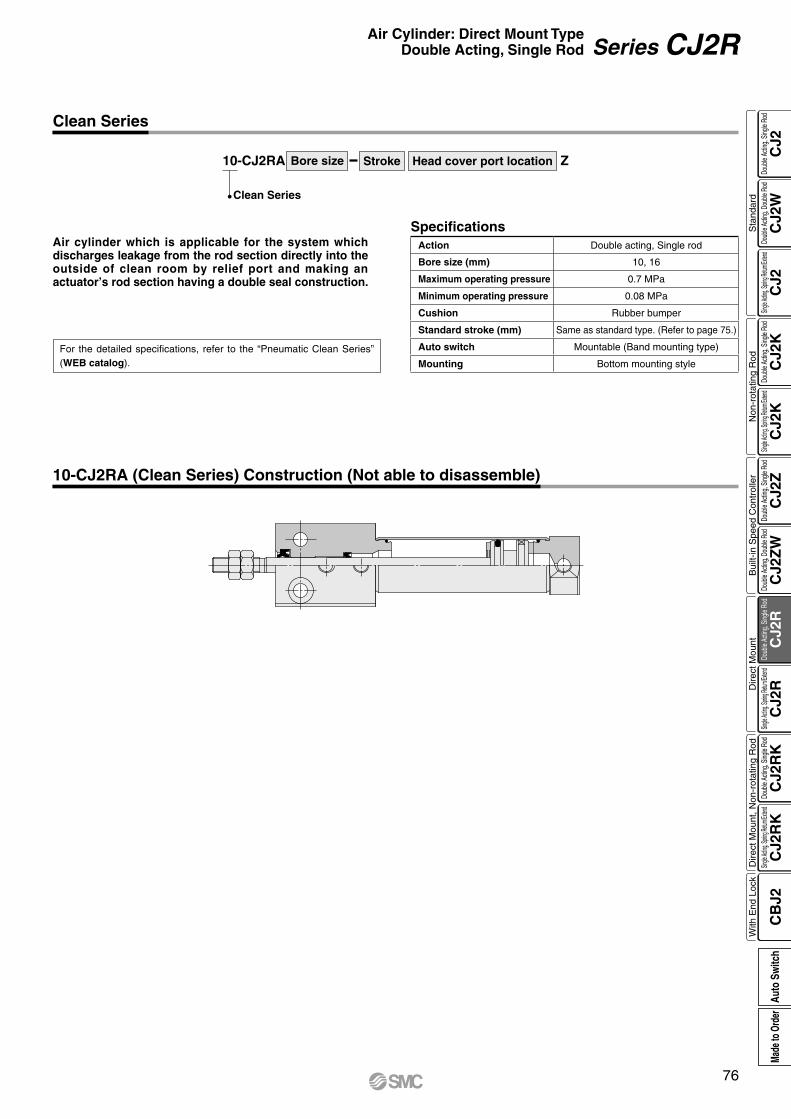
Bore size Stroke Head cover port location Z10-CJ2RA
Clean Series
For the detailed specifications, refer to the “Pneumatic Clean Series” (WEB catalog).
Air cylinder which is applicable for the system which discharges leakage from the rod section directly into the outside of clean room by relief port and making an actuator’s rod section having a double seal construction.
SpecificationsAction Double acting, Single rod
Bore size (mm) 10, 16
Maximum operating pressure 0.7 MPa
Minimum operating pressure 0.08 MPa
Cushion Rubber bumper
Standard stroke (mm) Same as standard type. (Refer to page 75.)
Auto switch Mountable (Band mounting type)
Mounting Bottom mounting style
Clean Series
10-CJ2RA (Clean Series) Construction (Not able to disassemble)
76
Air Cylinder: Direct Mount TypeDouble Acting, Single Rod Series CJ2R
CJ2
CJ2
WC
J2C
J2K
CJ2
KC
J2Z
CJ2
ZW
CJ2
RC
J2R
CJ2
RK
CJ2
RK
CB
J2
Sta
ndar
dN
on-r
otat
ing
Rod
Bui
lt-in
Spe
ed C
ontr
olle
rD
irect
Mou
ntD
irect
Mou
nt, N
on-r
otat
ing
Rod
With
End
Loc
kDo
uble
Actin
g, Do
uble
Rod
Single
Acting
, Sprin
g Retu
rn/Exte
ndDo
uble
Actin
g, Si
ngle
Rod
Single
Acting
, Sprin
g Retu
rn/Exte
ndDo
uble
Actin
g, Si
ngle
Rod
Doub
le Ac
ting,
Doub
le Ro
dDo
uble
Actin
g, Si
ngle
Rod
Single
Acting
, Sprin
g Retu
rn/Exte
ndDo
uble
Actin
g, Si
ngle
Rod
Single
Acting
, Sprin
g Retu
rn/Exte
ndDo
uble
Actin
g, Si
ngle
Rod
Auto
Sw
itch
Made
to O
rder
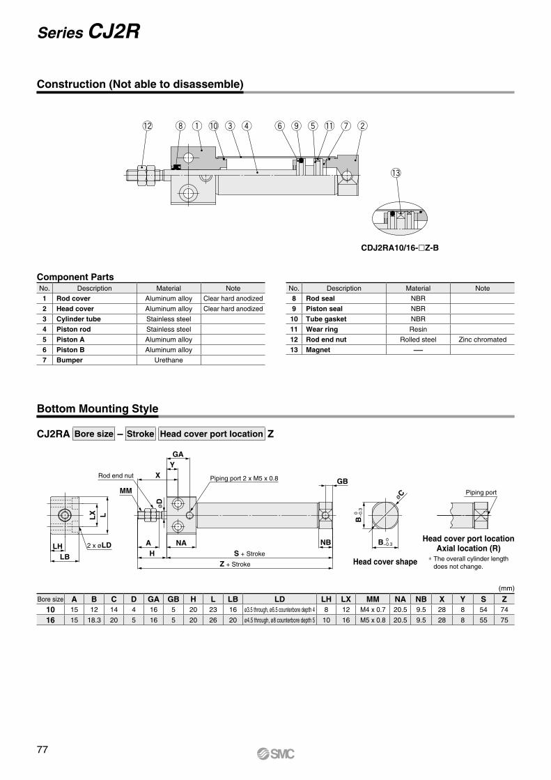
øC
øD
LLX
LBLH
MM
X
GAY
Z + Stroke
S + StrokeHNAA NB
GBRod end nut Piping port 2 x M5 x 0.8
B 0
−
0.3
B 0 −0.3
Piping port
2 x øLD
!2 i q e r y o t u w!0 !1
!3
CJ2RA Bore size – Stroke Head cover port location Z
Construction (Not able to disassemble)
Component PartsNo. Description Material Note
1 Rod cover Aluminum alloy Clear hard anodized
2 Head cover Aluminum alloy Clear hard anodized
3 Cylinder tube Stainless steel
4 Piston rod Stainless steel
5 Piston A Aluminum alloy
6 Piston B Aluminum alloy
7 Bumper Urethane
No. Description Material Note
8 Rod seal NBR
9 Piston seal NBR
10 Tube gasket NBR
11 Wear ring Resin
12 Rod end nut Rolled steel Zinc chromated
13 Magnet —
CDJ2RA10/16-Z-B
Bottom Mounting Style
Head cover shape
Head cover port locationAxial location (R)
* The overall cylinder length does not change.
Bore size A B C D GA GB H L LB LD LH LX MM NA NB X Y S Z10 15 12 14 4 16 5 20 23 16 ø3.5 through, ø6.5 counterbore depth 4 8 12 M4 x 0.7 20.5 9.5 28 8 54 74
16 15 18.3 20 5 16 5 20 26 20 ø4.5 through, ø8 counterbore depth 5 10 16 M5 x 0.8 20.5 9.5 28 8 55 75
(mm)
77
Series CJ2R
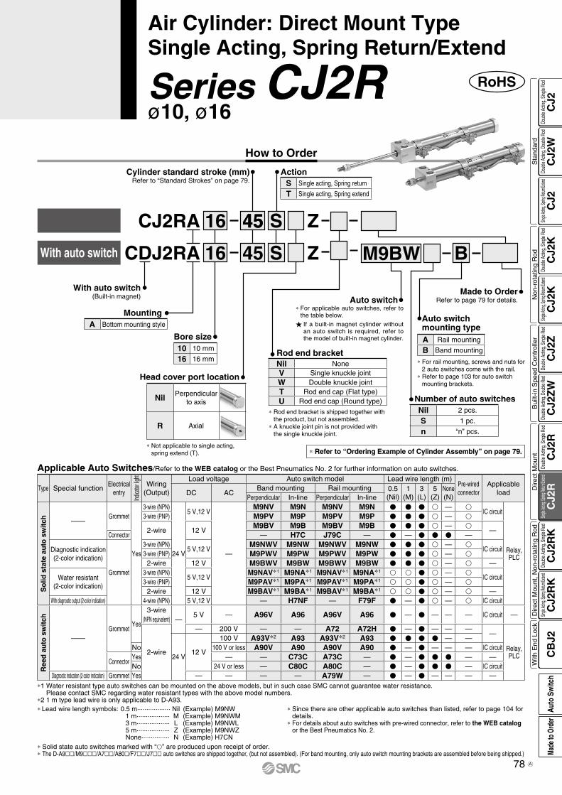
How to Order
Z
Z
S
S
16 45
4516
Cylinder standard stroke (mm)Refer to “Standard Strokes” on page 79.
With auto switch
CJ2RA
CDJ2RA
45
Bore size
Head cover port location
Nil Perpendicular to axis
R Axial
Rod end bracket
BM9BW
Auto switch
RoHSSeries CJ2Rø10, ø16
Air Cylinder: Direct Mount TypeSingle Acting, Spring Return/Extend
ActionS Single acting, Spring return
T Single acting, Spring extend
With auto switch(Built-in magnet)
MountingA Bottom mounting style
10 10 mm
16 16 mm
* Not applicable to single acting, spring extend (T).
Made to OrderRefer to page 79 for details.
Auto switch mounting typeA Rail mounting
B Band mounting
* For rail mounting, screws and nuts for 2 auto switches come with the rail.
* Refer to page 103 for auto switch mounting brackets.
Nil 2 pcs.
S 1 pc.
n “n” pcs.
Number of auto switches
* Solid state auto switches marked with “p” are produced upon receipt of order.* The D-A9ll/M9lll/A7ll/A80l/F7ll/J7ll auto switches are shipped together, (but not assembled). (For band mounting, only auto switch mounting brackets are assembled before being shipped.)
*1 Water resistant type auto switches can be mounted on the above models, but in such case SMC cannot guarantee water resistance. Please contact SMC regarding water resistant types with the above model numbers.
*2 1 m type lead wire is only applicable to D-A93. * Since there are other applicable auto switches than listed, refer to page 104 for
details. * For details about auto switches with pre-wired connector, refer to the WEB catalog
or the Best Pneumatics No. 2.
* Lead wire length symbols: 0.5 m·················· Nil (Example) M9NW 1 m·················· M (Example) M9NWM 3 m·················· L (Example) M9NWL 5 m·················· Z (Example) M9NWZ None··············· N (Example) H7CN
Type Special functionElectrical
entry
Indica
tor lig
ht
Wiring(Output)
Load voltage Auto switch model Lead wire length (m)Pre-wiredconnector
Applicable loadDC AC
Band mounting Rail mounting 0.5(Nil)
1(M)
3(L)
5(Z)
None(N)Perpendicular In-line Perpendicular In-line
So
lid s
tate
au
to s
wit
ch ——Grommet
Yes
3-wire (NPN)
24 V
5 V,12 V
—
M9NV M9N M9NV M9N V V V v — vIC circuit
Relay,PLC
3-wire (PNP) M9PV M9P M9PV M9P V V V v — v
2-wire 12 VM9BV M9B M9BV M9B V V V v — v
—Connector — H7C J79C — V — V V V —
Diagnostic indication(2-color indication)
Grommet
3-wire (NPN)5 V,12 V
M9NWV M9NW M9NWV M9NW V V V v — vIC circuit
3-wire (PNP) M9PWV M9PW M9PWV M9PW V V V v — v2-wire 12 V M9BWV M9BW M9BWV M9BW V V V v — v —
Water resistant (2-color indication)
3-wire (NPN)5 V,12 V
M9NAV*1 M9NA*1 M9NAV*1 M9NA*1 v v V v — vIC circuit
3-wire (PNP) M9PAV*1 M9PA*1 M9PAV*1 M9PA*1 v v V v — v2-wire 12 V M9BAV*1 M9BA*1 M9BAV*1 M9BA*1 v v V v — v —
With diagnostic output (2-color indication) 4-wire (NPN) 5 V,12 V — H7NF — F79F V — V v — v IC circuit
Ree
d a
uto
sw
itch
——Grommet
Yes
3-wire(NPN equivalent) —
5 V — A96V A96 A96V A96 V — V — — — IC circuit —
2-wire
— 200 V — — A72 A72H V — V — — ——
Relay,PLC24 V
12 V
100 V A93V*2 A93 A93V*2 A93 V V V V — —No 100 V or less A90V A90 A90V A90 V — V — — — IC circuit
ConnectorYes — — C73C A73C — V — V V V — —No 24 V or less — C80C A80C — V — V V V — IC circuit
Diagnostic indication (2-color indication) Grommet Yes — — — — A79W — V — V — — — —
Applicable Auto Switches/Refer to the WEB catalog or the Best Pneumatics No. 2 for further information on auto switches.
If a built-in magnet cylinder without an auto switch is required, refer to the model of built-in magnet cylinder.
* For applicable auto switches, refer to the table below.
* Refer to “Ordering Example of Cylinder Assembly” on page 79.
Nil NoneV Single knuckle jointW Double knuckle jointT Rod end cap (Flat type)U Rod end cap (Round type)
* Rod end bracket is shipped together with the product, but not assembled.
* A knuckle joint pin is not provided with the single knuckle joint.
78
CJ2
CJ2
WC
J2C
J2K
CJ2
KC
J2Z
CJ2
ZW
CJ2
RC
J2R
CJ2
RK
CJ2
RK
CB
J2
Sta
ndar
dN
on-r
otat
ing
Rod
Bui
lt-in
Spe
ed C
ontr
olle
rD
irect
Mou
ntD
irect
Mou
nt, N
on-r
otat
ing
Rod
With
End
Loc
kDo
uble
Actin
g, Do
uble
Rod
Single
Acting
, Sprin
g Retu
rn/Exte
ndDo
uble
Actin
g, Si
ngle
Rod
Single
Acting
, Sprin
g Retu
rn/Exte
ndDo
uble
Actin
g, Si
ngle
Rod
Doub
le Ac
ting,
Doub
le Ro
dDo
uble
Actin
g, Si
ngle
Rod
Single
Acting
, Sprin
g Retu
rn/Exte
ndDo
uble
Actin
g, Si
ngle
Rod
Single
Acting
, Sprin
g Retu
rn/Exte
ndDo
uble
Actin
g, Si
ngle
Rod
Auto
Sw
itch
Made
to O
rder
A
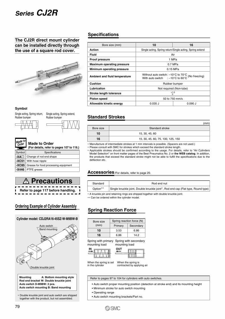
IN OUT
Auto switchBand mounting
Double knuckle joint
Single acting, Spring extend, Rubber bumper
Symbol
Single acting, Spring return, Rubber bumper
Cylinder model: CDJ2RA16-45SZ-W-M9BW-B
Ordering Example of Cylinder Assembly
Mounting A: Bottom mounting styleRod end bracket W: Double knuckle jointAuto switch D-M9BW: 2 pcs.Auto switch mounting B: Band mounting
* Double knuckle joint and auto switch are shipped together with the product, but not assembled.
Bore size (mm) 10 16Action Single acting, Spring return/Single acting, Spring extend
Fluid Air
Proof pressure 1 MPa
Maximum operating pressure 0.7 MPa
Minimum operating pressure 0.15 MPa
Ambient and fluid temperatureWithout auto switch : –10°C to 70°C (No freezing)With auto switch : –10°C to 60°C
Cushion Rubber bumper
Lubrication Not required (Non-lube)
Stroke length tolerance +1.00
Piston speed 50 to 750 mm/s
Allowable kinetic energy 0.035 J 0.090 J
Specifications
* Manufacture of intermediate strokes at 1 mm intervals is possible. (Spacers are not used.)* Please consult with SMC for strokes which exceed the standard stroke length.* Applicable strokes should be confirmed according to the usage. For details, refer to “Air Cylinders
Model Selection” on front matter pages of the Best Pneumatics No. 2 or the WEB catalog. In addition, the products that exceed the standard stroke might not be able to fulfill the specifications due to the deflection etc.
(mm)
Bore size Standard stroke
10 15, 30, 45, 60
16 15, 30, 45, 60, 75, 100, 125, 150
Standard Strokes
When the spring iscontracted by applying air
When the spring is setin the cylinder
Spring with secondarymounting load
Spring with primarymounting load
Bore size(mm)
Spring reaction force (N)
Primary Secondary
10 3.53 6.86
16 6.86 14.2
Spring Reaction Force
Refer to pages 97 to 104 for cylinders with auto switches.
• Auto switch proper mounting position (detection at stroke end) and its mounting height
• Minimum stroke for auto switch mounting
• Operating range
• Auto switch mounting brackets/Part no.
Refer to page 117 before handling.
Precautions
Symbol Specifications
-XAl Change of rod end shape
-XC51 With hose nipple
-XC85 Grease for food processing equipment
-X446 PTFE grease
Made to Order(For details, refer to pages 107 to 116.)
The CJ2R direct mount cylinder can be installed directly through the use of a square rod cover.
* A knuckle pin and retaining rings are shipped together with double knuckle joint.** Can be ordered within the cylinder model.
Standard Rod end nut
Option** Single knuckle joint, Double knuckle joint*, Rod end cap (Flat type, Round type)
Accessories /For details, refer to page 20.
79
Series CJ2R
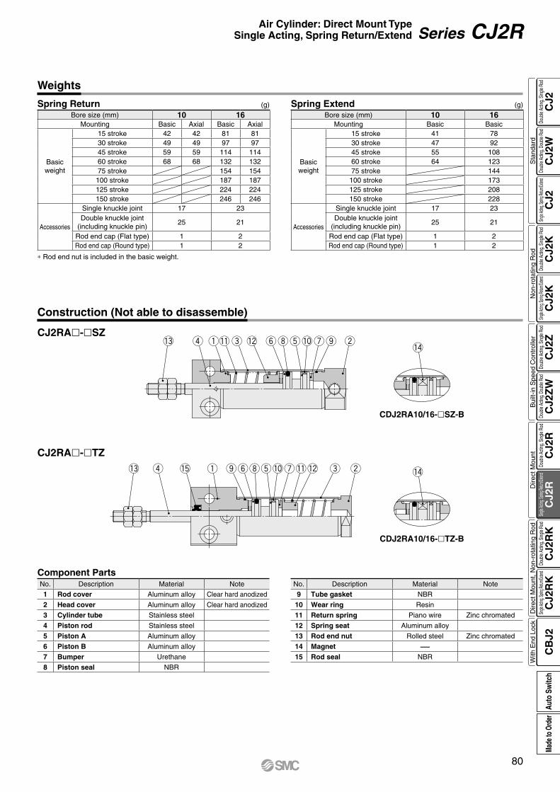
!3 r e !2 yit!0 wouq!1!4
!3 r e!2yit!0 wo uq!5 !1 !4
Weights
* Rod end nut is included in the basic weight.
(g)Spring Return Spring Extend(g)
Bore size (mm) 10 16Mounting Basic Axial Basic Axial
Basic weight
15 stroke 42 42 81 8130 stroke 49 49 97 9745 stroke 59 59 114 11460 stroke 68 68 132 13275 stroke 154 154
100 stroke 187 187125 stroke 224 224150 stroke 246 246
Accessories
Single knuckle joint 17 23Double knuckle joint
(including knuckle pin)25 21
Rod end cap (Flat type) 1 2Rod end cap (Round type) 1 2
Bore size (mm) 10 16Mounting Basic Basic
Basic weight
15 stroke 41 7830 stroke 47 9245 stroke 55 10860 stroke 64 12375 stroke 144
100 stroke 173125 stroke 208150 stroke 228
Accessories
Single knuckle joint 17 23Double knuckle joint
(including knuckle pin)25 21
Rod end cap (Flat type) 1 2Rod end cap (Round type) 1 2
Construction (Not able to disassemble)
CJ2RA-SZ
CJ2RA-TZ
CDJ2RA10/16-TZ-B
CDJ2RA10/16-SZ-B
Component PartsNo. Description Material Note
1 Rod cover Aluminum alloy Clear hard anodized
2 Head cover Aluminum alloy Clear hard anodized
3 Cylinder tube Stainless steel
4 Piston rod Stainless steel
5 Piston A Aluminum alloy
6 Piston B Aluminum alloy
7 Bumper Urethane
8 Piston seal NBR
No. Description Material Note
9 Tube gasket NBR
10 Wear ring Resin
11 Return spring Piano wire Zinc chromated
12 Spring seat Aluminum alloy
13 Rod end nut Rolled steel Zinc chromated
14 Magnet —15 Rod seal NBR
80
Air Cylinder: Direct Mount TypeSingle Acting, Spring Return/Extend Series CJ2R
CJ2
CJ2
WC
J2C
J2K
CJ2
KC
J2Z
CJ2
ZW
CJ2
RC
J2R
CJ2
RK
CJ2
RK
CB
J2
Sta
ndar
dN
on-r
otat
ing
Rod
Bui
lt-in
Spe
ed C
ontr
olle
rD
irect
Mou
ntD
irect
Mou
nt, N
on-r
otat
ing
Rod
With
End
Loc
kDo
uble
Actin
g, Do
uble
Rod
Single
Acting
, Sprin
g Retu
rn/Exte
ndDo
uble
Actin
g, Si
ngle
Rod
Single
Acting
, Sprin
g Retu
rn/Exte
ndDo
uble
Actin
g, Si
ngle
Rod
Doub
le Ac
ting,
Doub
le Ro
dDo
uble
Actin
g, Si
ngle
Rod
Single
Acting
, Sprin
g Retu
rn/Exte
ndDo
uble
Actin
g, Si
ngle
Rod
Single
Acting
, Sprin
g Retu
rn/Exte
ndDo
uble
Actin
g, Si
ngle
Rod
Auto
Sw
itch
Made
to O
rder
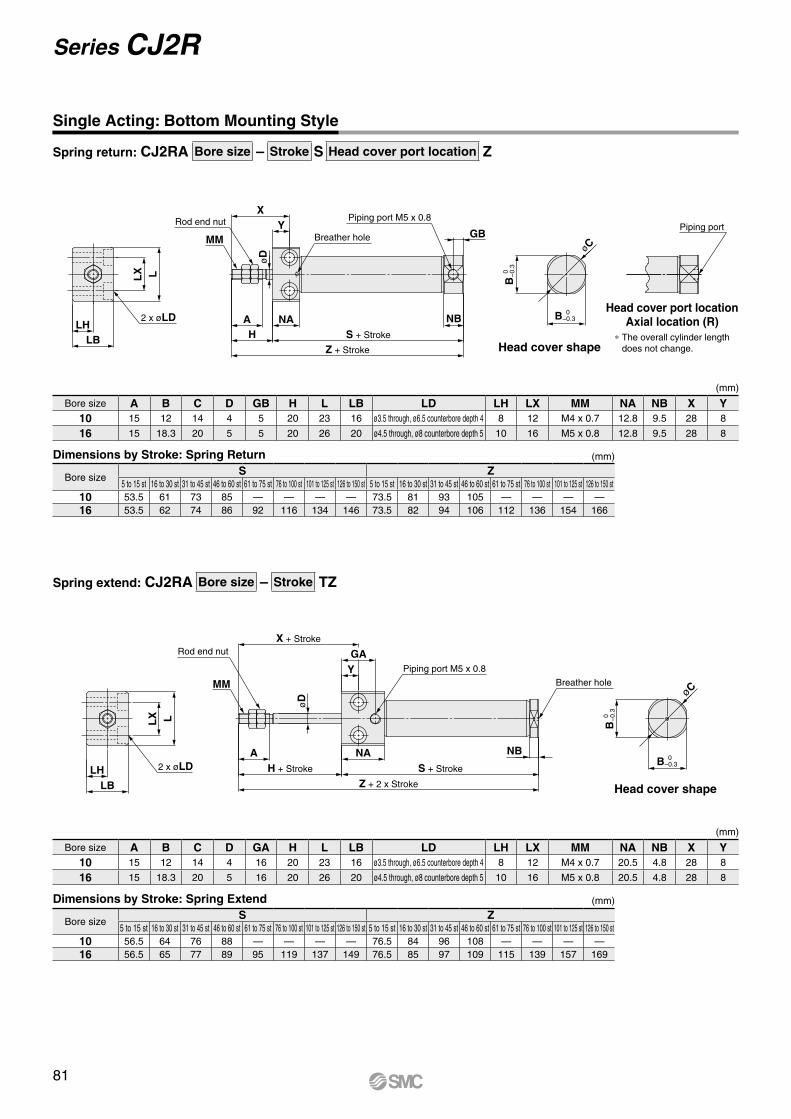
øCMM
B 0 −0.3
B 0
−
0.3
Z + Stroke
S + Stroke
NAH
A NB
X
GBY
LLX
LBLH
øD
2 x øLD
Rod end nut
Breather hole
Piping port M5 x 0.8Piping port
YMM
øC
B 0
−
0.3
B 0 −0.3
NB
LHLB
2 x øLDA
øD
Z + 2 x Stroke
S + Stroke
NA
Breather hole
X + Stroke
GARod end nut
Piping port M5 x 0.8
LLX
H + Stroke
Spring return: CJ2RA Bore size – Stroke S Head cover port location Z
Spring extend: CJ2RA Bore size – Stroke TZ
Single Acting: Bottom Mounting Style
(mm)Dimensions by Stroke: Spring Return
Bore size A B C D GB H L LB LD LH LX MM NA NB X Y10 15 12 14 4 5 20 23 16 ø3.5 through, ø6.5 counterbore depth 4 8 12 M4 x 0.7 12.8 9.5 28 8
16 15 18.3 20 5 5 20 26 20 ø4.5 through, ø8 counterbore depth 5 10 16 M5 x 0.8 12.8 9.5 28 8
Bore sizeS Z
5 to 15 st 16 to 30 st 31 to 45 st 46 to 60 st 61 to 75 st 76 to 100 st 101 to 125 st 126 to 150 st 5 to 15 st 16 to 30 st 31 to 45 st 46 to 60 st 61 to 75 st 76 to 100 st 101 to 125 st 126 to 150 st10 53.5 61 73 85 — — — — 73.5 81 93 105 — — — —16 53.5 62 74 86 92 116 134 146 73.5 82 94 106 112 136 154 166
(mm)
(mm)Dimensions by Stroke: Spring Extend
Bore size A B C D GA H L LB LD LH LX MM NA NB X Y10 15 12 14 4 16 20 23 16 ø3.5 through, ø6.5 counterbore depth 4 8 12 M4 x 0.7 20.5 4.8 28 8
16 15 18.3 20 5 16 20 26 20 ø4.5 through, ø8 counterbore depth 5 10 16 M5 x 0.8 20.5 4.8 28 8
Bore sizeS Z
5 to 15 st 16 to 30 st 31 to 45 st 46 to 60 st 61 to 75 st 76 to 100 st 101 to 125 st 126 to 150 st 5 to 15 st 16 to 30 st 31 to 45 st 46 to 60 st 61 to 75 st 76 to 100 st 101 to 125 st 126 to 150 st10 56.5 64 76 88 — — — — 76.5 84 96 108 — — — —16 56.5 65 77 89 95 119 137 149 76.5 85 97 109 115 139 157 169
(mm)
Head cover shape
Head cover shape
Head cover port locationAxial location (R)
∗ The overall cylinder length does not change.
81
Series CJ2R

How to Order
RoHSSeries CJ2RKø10, ø16
Air Cylinder: Direct Mount, Non-rotating Rod TypeDouble Acting, Single Rod
* Solid state auto switches marked with “p” are produced upon receipt of order.* The D-A9ll/M9lll/A7ll/A80l/F7ll/J7ll auto switches are shipped together, (but not assembled). (For band mounting, only auto switch mounting brackets are assembled before being shipped.)
*1 Water resistant type auto switches can be mounted on the above models, but in such case SMC cannot guarantee water resistance. Please contact SMC regarding water resistant types with the above model numbers.
*2 1 m type lead wire is only applicable to D-A93. * Since there are other applicable auto switches than listed, refer to page 104 for
details. * For details about auto switches with pre-wired connector, refer to the WEB catalog
or the Best Pneumatics No. 2.
* Lead wire length symbols: 0.5 m·················· Nil (Example) M9NW 1 m·················· M (Example) M9NWM 3 m·················· L (Example) M9NWL 5 m·················· Z (Example) M9NWZ None··············· N (Example) H7CN
Applicable Auto Switches/Refer to the WEB catalog or the Best Pneumatics No. 2 for further information on auto switches.
Type Special functionElectrical
entry
Indica
tor lig
ht
Wiring(Output)
Load voltage Auto switch model Lead wire length (m)Pre-wiredconnector
Applicable loadDC AC
Band mounting Rail mounting 0.5(Nil)
1(M)
3(L)
5(Z)
None(N)Perpendicular In-line Perpendicular In-line
So
lid s
tate
au
to s
wit
ch ——Grommet
Yes
3-wire (NPN)
24 V
5 V,12 V
—
M9NV M9N M9NV M9N V V V v — vIC circuit
Relay,PLC
3-wire (PNP) M9PV M9P M9PV M9P V V V v — v
2-wire 12 VM9BV M9B M9BV M9B V V V v — v
—Connector — H7C J79C — V — V V V —
Diagnostic indication(2-color indication)
Grommet
3-wire (NPN)5 V,12 V
M9NWV M9NW M9NWV M9NW V V V v — vIC circuit
3-wire (PNP) M9PWV M9PW M9PWV M9PW V V V v — v2-wire 12 V M9BWV M9BW M9BWV M9BW V V V v — v —
Water resistant(2-color indication)
3-wire (NPN)5 V,12 V
M9NAV*1 M9NA*1 M9NAV*1 M9NA*1 v v V v — vIC circuit
3-wire (PNP) M9PAV*1 M9PA*1 M9PAV*1 M9PA*1 v v V v — v2-wire 12 V M9BAV*1 M9BA*1 M9BAV*1 M9BA*1 v v V v — v —
With diagnostic output (2-color indication) 4-wire (NPN) 5 V,12 V — H7NF — F79F V — V v — v IC circuit
Ree
d a
uto
sw
itch
——Grommet
Yes
3-wire(NPN equivalent) —
5 V — A96V A96 A96V A96 V — V — — — IC circuit —
2-wire
— 200 V — — A72 A72H V — V — — ——
Relay,PLC24 V
12 V
100 V A93V*2 A93 A93V*2 A93 V V V V — —No 100 V or less A90V A90 A90V A90 V — V — — — IC circuit
ConnectorYes — — C73C A73C — V — V V V — —No 24 V or less — C80C A80C — V — V V V — IC circuit
Diagnostic indication (2-color indication) Grommet Yes — — — — A79W — V — V — — — —
M9BW60
60
16
16
With auto switch Z
ZCJ2RKA
CDJ2RKA
Head cover port location
Nil Perpendicular to axis
R Axial
B
Rod end bracket
Cylinder standard stroke (mm)Refer to “Standard Strokes” on page 83.
Nil 2 pcs.S 1 pc.n “n” pcs.
Number of auto switches
Auto switch mounting typeA Rail mountingB Band mounting
* For rail mounting, screws and nuts for 2 auto switches come with the rail.
* Refer to page 103 for auto switch mounting brackets.
MountingA Bottom mounting style
Bore size10 10 mm
16 16 mm
Made to OrderRefer to page 83 for details.
With auto switch(Built-in magnet)
* Refer to “Ordering Example of Cylinder Assembly” on page 83.
* Rod end bracket is shipped together with the product, but not assembled.
* A knuckle joint pin is not provided with the single knuckle joint.
Nil NoneV Single knuckle jointW Double knuckle jointT Rod end cap (Flat type)U Rod end cap (Round type)
Auto switch
If a built-in magnet cylinder without an auto switch is required, refer to the model of built-in magnet cylinder.
* For applicable auto switches, refer to the table below.
82
CJ2
CJ2
WC
J2C
J2K
CJ2
KC
J2Z
CJ2
ZW
CJ2
RC
J2R
CJ2
RK
CJ2
RK
CB
J2
Sta
ndar
dN
on-r
otat
ing
Rod
Bui
lt-in
Spe
ed C
ontr
olle
rD
irect
Mou
ntD
irect
Mou
nt, N
on-r
otat
ing
Rod
With
End
Loc
kDo
uble
Actin
g, Do
uble
Rod
Single
Acting
, Sprin
g Retu
rn/Exte
ndDo
uble
Actin
g, Si
ngle
Rod
Single
Acting
, Sprin
g Retu
rn/Exte
ndDo
uble
Actin
g, Si
ngle
Rod
Doub
le Ac
ting,
Doub
le Ro
dDo
uble
Actin
g, Si
ngle
Rod
Single
Acting
, Sprin
g Retu
rn/Exte
ndDo
uble
Actin
g, Si
ngle
Rod
Single
Acting
, Sprin
g Retu
rn/Exte
ndDo
uble
Actin
g, Si
ngle
Rod
Auto
Sw
itch
Made
to O
rder
A
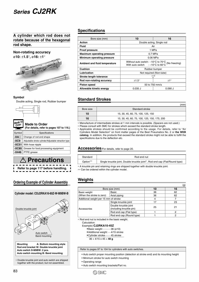
Auto switchBand mounting
Double knuckle joint
Cylinder model: CDJ2RKA16-60Z-W-M9BW-B
Ordering Example of Cylinder Assembly
Mounting A: Bottom mounting styleRod end bracket W: Double knuckle jointAuto switch D-M9BW: 2 pcs.Auto switch mounting B: Band mounting
* Double knuckle joint and auto switch are shipped together with the product, but not assembled.
SymbolDouble acting, Single rod, Rubber bumper
Symbol Specifications
-XAl Change of rod end shape
-XC9 Adjustable stroke cylinder/Adjustable retraction type
-XC51 With hose nipple
-XC85 Grease for food processing equipment
-X446 PTFE grease
Made to Order(For details, refer to pages 107 to 116.)
Refer to page 117 before handling.
Precautions
Bore size (mm) 10 16Action Double acting, Single rod
Fluid Air
Proof pressure 1 MPa
Maximum operating pressure 0.7 MPa
Minimum operating pressure 0.06 MPa
Ambient and fluid temperatureWithout auto switch : –10°C to 70°C (No freezing)With auto switch : –10°C to 60°C
Cushion Rubber bumper
Lubrication Not required (Non-lube)
Stroke length tolerance +1.00
Rod non-rotating accuracy ±1.5° ±1°
Piston speed 50 to 750 mm/s
Allowable kinetic energy 0.035 J 0.090 J
Specifications
* Manufacture of intermediate strokes at 1 mm intervals is possible. (Spacers are not used.)* Please consult with SMC for strokes which exceed the standard stroke length.* Applicable strokes should be confirmed according to the usage. For details, refer to “Air
Cylinders Model Selection” on front matter pages of the Best Pneumatics No. 2 or the WEB catalog. In addition, the products that exceed the standard stroke might not be able to fulfill the specifications due to the deflection etc.
(mm)
Bore size Standard stroke
10 15, 30, 45, 60, 75, 100, 125, 150
16 15, 30, 45, 60, 75, 100, 125, 150, 175, 200
Standard Strokes
* A knuckle pin and retaining rings are shipped together with double knuckle joint.** Can be ordered within the cylinder model.
Standard Rod end nut
Option** Single knuckle joint, Double knuckle joint*, Rod end cap (Flat/Round type)
Accessories/For details, refer to page 20.
Refer to pages 97 to 104 for cylinders with auto switches.
• Auto switch proper mounting position (detection at stroke end) and its mounting height
• Minimum stroke for auto switch mounting
• Operating range
• Auto switch mounting brackets/Part no.
(g)
* Rod end nut is included in the basic weight.Calculation:Example) CJ2RKA10-45Z
OBasic weight ··········· 36 (ø10)OAdditional weight ···· 4/15 strokeOCylinder stroke ········ 45 stroke
36 + 4/15 x 45 = 48 g
Bore size (mm) 10 16Basic weight(When the stroke is zero)
Basic 36 62Axial piping 36 62
Additional weight per 15 mm of stroke 4 7
Accessories
Single knuckle joint 17 23Double knuckle joint(including knuckle pin)
25 21
Rod end cap (Flat type) 1 2Rod end cap (Round type) 1 2
Weights
A cylinder which rod does not rotate because of the hexagonal rod shape.
Non-rotating accuracyø10: ±1.5°, ø16: ±1°
83
Series CJ2RK
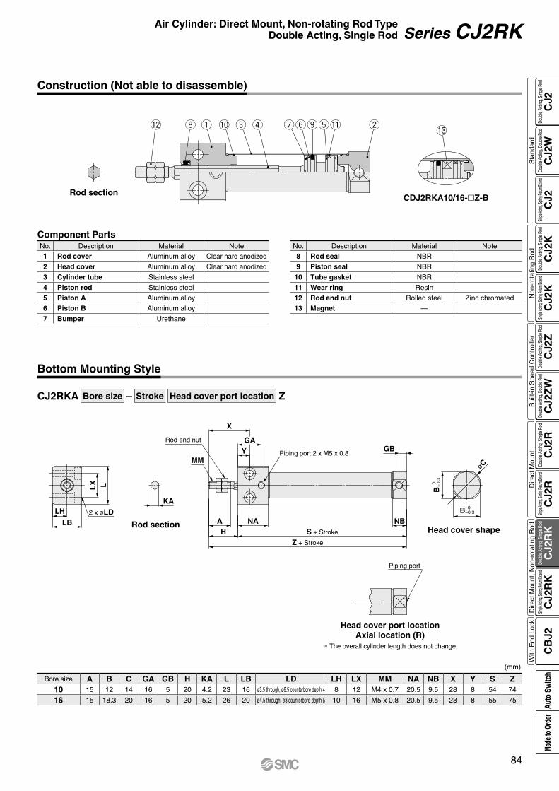
KA
øC
GB
LLX
LB
LH 2 x øLD
Z + Stroke
S + StrokeHNAA
X
YGA
MM
NB
Rod end nut
Piping port 2 x M5 x 0.8
Piping port
B 0
−
0.3
B 0 −0.3
q we y tori u!2 !1!3
!0
CJ2RKA Bore size – Stroke Head cover port location Z
Construction (Not able to disassemble)
Component PartsNo. Description Material Note
1 Rod cover Aluminum alloy Clear hard anodized
2 Head cover Aluminum alloy Clear hard anodized
3 Cylinder tube Stainless steel
4 Piston rod Stainless steel
5 Piston A Aluminum alloy
6 Piston B Aluminum alloy
7 Bumper Urethane
No. Description Material Note
8 Rod seal NBR
9 Piston seal NBR
10 Tube gasket NBR
11 Wear ring Resin
12 Rod end nut Rolled steel Zinc chromated
13 Magnet —
Rod sectionCDJ2RKA10/16-Z-B
Bottom Mounting Style
Head cover shape
Head cover port locationAxial location (R)
* The overall cylinder length does not change.
(mm)
Bore size A B C GA GB H KA L LB LD LH LX MM NA NB X Y S Z10 15 12 14 16 5 20 4.2 23 16 ø3.5 through, ø6.5 counterbore depth 4 8 12 M4 x 0.7 20.5 9.5 28 8 54 74
16 15 18.3 20 16 5 20 5.2 26 20 ø4.5 through, ø8 counterbore depth 5 10 16 M5 x 0.8 20.5 9.5 28 8 55 75
Rod section
84
Air Cylinder: Direct Mount, Non-rotating Rod TypeDouble Acting, Single Rod Series CJ2RK
CJ2
CJ2
WC
J2C
J2K
CJ2
KC
J2Z
CJ2
ZW
CJ2
RC
J2R
CJ2
RK
CJ2
RK
CB
J2
Sta
ndar
dN
on-r
otat
ing
Rod
Bui
lt-in
Spe
ed C
ontr
olle
rD
irect
Mou
ntD
irect
Mou
nt, N
on-r
otat
ing
Rod
With
End
Loc
kDo
uble
Actin
g, Do
uble
Rod
Single
Acting
, Sprin
g Retu
rn/Exte
ndDo
uble
Actin
g, Si
ngle
Rod
Single
Acting
, Sprin
g Retu
rn/Exte
ndDo
uble
Actin
g, Si
ngle
Rod
Doub
le Ac
ting,
Doub
le Ro
dDo
uble
Actin
g, Si
ngle
Rod
Single
Acting
, Sprin
g Retu
rn/Exte
ndDo
uble
Actin
g, Si
ngle
Rod
Single
Acting
, Sprin
g Retu
rn/Exte
ndDo
uble
Actin
g, Si
ngle
Rod
Auto
Sw
itch
Made
to O
rder
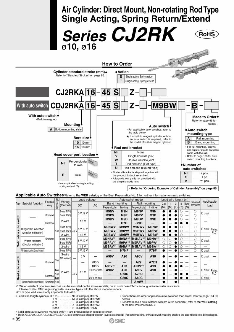
How to Order
With auto switch Z
Z
S4516
S4516
M9BW
CJ2RKA
CDJ2RKA
Nil Perpendicular to axis
R Axial
B
RoHSSeries CJ2RKø10, ø16
Air Cylinder: Direct Mount, Non-rotating Rod TypeSingle Acting, Spring Return/Extend
* Solid state auto switches marked with “p” are produced upon receipt of order.* The D-A9ll/M9lll/A7ll/A80l/F7ll/J7ll auto switches are shipped together, (but not assembled). (For band mounting, only auto switch mounting brackets are assembled before being shipped.)
*1 Water resistant type auto switches can be mounted on the above models, but in such case SMC cannot guarantee water resistance. Please contact SMC regarding water resistant types with the above model numbers.
*2 1 m type lead wire is only applicable to D-A93. * Since there are other applicable auto switches than listed, refer to page 104 for
details. * For details about auto switches with pre-wired connector, refer to the WEB catalog
or the Best Pneumatics No. 2.
* Lead wire length symbols: 0.5 m·················· Nil (Example) M9NW 1 m·················· M (Example) M9NWM 3 m·················· L (Example) M9NWL 5 m·················· Z (Example) M9NWZ None··············· N (Example) H7CN
Type Special function Electricalentry
Indica
tor lig
ht
Wiring(Output)
Load voltage Auto switch model Lead wire length (m)Pre-wiredconnector
Applicable loadDC AC
Band mounting Rail mounting 0.5(Nil)
1(M)
3(L)
5(Z)
None(N)Perpendicular In-line Perpendicular In-line
So
lid s
tate
au
to s
wit
ch ——Grommet
Yes
3-wire (NPN)
24 V
5 V,12 V
—
M9NV M9N M9NV M9N V V V v — vIC circuit
Relay,PLC
3-wire (PNP) M9PV M9P M9PV M9P V V V v — v
2-wire 12 VM9BV M9B M9BV M9B V V V v — v
—Connector — H7C J79C — V — V V V —
Diagnostic indication(2-color indication)
Grommet
3-wire (NPN)5 V,12 V
M9NWV M9NW M9NWV M9NW V V V v — vIC circuit
3-wire (PNP) M9PWV M9PW M9PWV M9PW V V V v — v2-wire 12 V M9BWV M9BW M9BWV M9BW V V V v — v —
Water resistant(2-color indication)
3-wire (NPN)5 V,12 V
M9NAV*1 M9NA*1 M9NAV*1 M9NA*1 v v V v — vIC circuit
3-wire (PNP) M9PAV*1 M9PA*1 M9PAV*1 M9PA*1 v v V v — v2-wire 12 V M9BAV*1 M9BA*1 M9BAV*1 M9BA*1 v v V v — v —
With diagnostic output (2-color indication) 4-wire (NPN) 5 V,12 V — H7NF — F79F V — V v — v IC circuit
Ree
d a
uto
sw
itch
——Grommet
Yes
3-wire(NPN equivalent) —
5 V — A96V A96 A96V A96 V — V — — — IC circuit —
2-wire
— 200 V — — A72 A72H V — V — — ——
Relay,PLC24 V
12 V
100 V A93V*2 A93 A93V*2 A93 V V V V — —No 100 V or less A90V A90 A90V A90 V — V — — — IC circuit
ConnectorYes — — C73C A73C — V — V V V — —No 24 V or less — C80C A80C — V — V V V — IC circuit
Diagnostic indication (2-color indication) Grommet Yes — — — — A79W — V — V — — — —
Applicable Auto Switches/Refer to the WEB catalog or the Best Pneumatics No. 2 for further information on auto switches.
Nil 2 pcs.S 1 pc.n “n” pcs.
Head cover port location
With auto switch(Built-in magnet)
10 10 mm
16 16 mm
Bore size
Cylinder standard stroke (mm)Refer to “Standard Strokes” on page 86.
Made to OrderRefer to page 86 for
details.
Auto switchmounting typeA Rail mountingB Band mounting
* For rail mounting, screws and nuts for 2 auto switches come with the rail.
* Refer to page 103 for auto switch mounting brackets.
* Not applicable to single acting, spring extend (T).
MountingA Bottom mounting style
ActionS Single acting, Spring return
T Single acting, Spring extend
* Refer to “Ordering Example of Cylinder Assembly” on page 86.
Rod end bracket
* Rod end bracket is shipped together with the product, but not assembled.
* A knuckle joint pin is not provided with the single knuckle joint.
Nil NoneV Single knuckle jointW Double knuckle jointT Rod end cap (Flat type)U Rod end cap (Round type)
Auto switch
If a built-in magnet cylinder without an auto switch is required, refer to the model of built-in magnet cylinder.
* For applicable auto switches, refer to the table below.
Number ofauto switches
85A
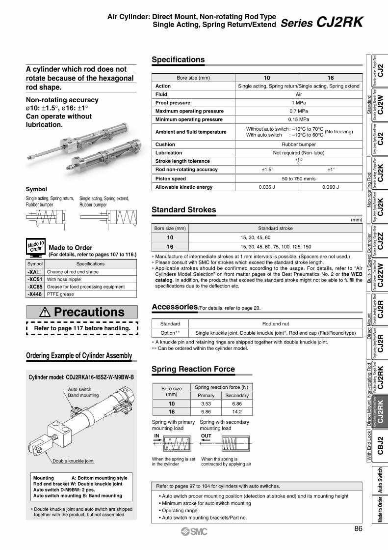
IN OUT
Auto switchBand mounting
Double knuckle joint
Cylinder model: CDJ2RKA16-45SZ-W-M9BW-B
Ordering Example of Cylinder Assembly
Mounting A: Bottom mounting styleRod end bracket W: Double knuckle jointAuto switch D-M9BW: 2 pcs.Auto switch mounting B: Band mounting
* Double knuckle joint and auto switch are shipped together with the product, but not assembled.
Specifications
Bore size (mm) 10 16Action Single acting, Spring return/Single acting, Spring extend
Fluid Air
Proof pressure 1 MPa
Maximum operating pressure 0.7 MPa
Minimum operating pressure 0.15 MPa
Ambient and fluid temperatureWithout auto switch : –10°C to 70°C (No freezing)With auto switch : –10°C to 60°C
Cushion Rubber bumper
Lubrication Not required (Non-lube)
Stroke length tolerance +1.00
Rod non-rotating accuracy ±1.5° ±1°
Piston speed 50 to 750 mm/s
Allowable kinetic energy 0.035 J 0.090 J
* Manufacture of intermediate strokes at 1 mm intervals is possible. (Spacers are not used.)* Please consult with SMC for strokes which exceed the standard stroke length.* Applicable strokes should be confirmed according to the usage. For details, refer to “Air
Cylinders Model Selection” on front matter pages of the Best Pneumatics No. 2 or the WEB catalog. In addition, the products that exceed the standard stroke might not be able to fulfill the specifications due to the deflection etc.
(mm)
Bore size (mm) Standard stroke
10 15, 30, 45, 60
16 15, 30, 45, 60, 75, 100, 125, 150
Standard Strokes
Refer to pages 97 to 104 for cylinders with auto switches.
• Auto switch proper mounting position (detection at stroke end) and its mounting height
• Minimum stroke for auto switch mounting
• Operating range
• Auto switch mounting brackets/Part no.
Refer to page 117 before handling.
Precautions
Symbol Specifications
-XAl Change of rod end shape
-XC51 With hose nipple
-XC85 Grease for food processing equipment
-X446 PTFE grease
Made to Order(For details, refer to pages 107 to 116.)
* A knuckle pin and retaining rings are shipped together with double knuckle joint.** Can be ordered within the cylinder model.
Standard Rod end nut
Option** Single knuckle joint, Double knuckle joint*, Rod end cap (Flat/Round type)
Accessories/For details, refer to page 20.
Non-rotating accuracyø10: ±1.5°, ø16: ±1°Can operate without lubrication.
A cylinder which rod does not rotate because of the hexagonal rod shape.
When the spring is contracted by applying air
When the spring is set in the cylinder
Spring with secondary mounting load
Spring with primary mounting load
Bore size(mm)
Spring reaction force (N)
Primary Secondary
10 3.53 6.86
16 6.86 14.2
Spring Reaction Force
Single acting, Spring extend, Rubber bumper
Symbol
Single acting, Spring return, Rubber bumper
86
Air Cylinder: Direct Mount, Non-rotating Rod TypeSingle Acting, Spring Return/Extend Series CJ2RK
CJ2
CJ2
WC
J2C
J2K
CJ2
KC
J2Z
CJ2
ZW
CJ2
RC
J2R
CJ2
RK
CJ2
RK
CB
J2
Sta
ndar
dN
on-r
otat
ing
Rod
Bui
lt-in
Spe
ed C
ontr
olle
rD
irect
Mou
ntD
irect
Mou
nt, N
on-r
otat
ing
Rod
With
End
Loc
kDo
uble
Actin
g, Do
uble
Rod
Single
Acting
, Sprin
g Retu
rn/Exte
ndDo
uble
Actin
g, Si
ngle
Rod
Single
Acting
, Sprin
g Retu
rn/Exte
ndDo
uble
Actin
g, Si
ngle
Rod
Doub
le Ac
ting,
Doub
le Ro
dDo
uble
Actin
g, Si
ngle
Rod
Single
Acting
, Sprin
g Retu
rn/Exte
ndDo
uble
Actin
g, Si
ngle
Rod
Single
Acting
, Sprin
g Retu
rn/Exte
ndDo
uble
Actin
g, Si
ngle
Rod
Auto
Sw
itch
Made
to O
rder

q we y t or iu!4
!2!1!3 !0
q wey tor iu!5 !4!2!1!3 !0
Weights
(g)(g)
* Rod end nut is included in the basic weight.
Bore size (mm) 10 16
Mounting Basic Axial Basic Axial
Basic weight
15 stroke 44 44 83 83
30 stroke 52 52 99 99
45 stroke 62 62 117 117
60 stroke 72 72 135 135
75 stroke 157 157
100 stroke 191 191
125 stroke 228 228
150 stroke 251 251
Accessories
Single knuckle joint 17 23
Double knuckle joint(including knuckle pin)
25 21
Rod end cap (Flat type) 1 2
Rod end cap (Round type) 1 2
Bore size (mm) 10 16
Mounting Basic Basic
Basic weight
15 stroke 42 79
30 stroke 48 93
45 stroke 57 110
60 stroke 66 126
75 stroke 147
100 stroke 177
125 stroke 213
150 stroke 234
Accessories
Single knuckle joint 17 23
Double knuckle joint(including knuckle pin)
25 21
Rod end cap (Flat type) 1 2
Rod end cap (Round type) 1 2
Spring Return Spring Extend
Construction (Not able to disassemble)
Single acting, Spring return
Rod section
Single acting, Spring extend
Rod section
CDJ2RKA10/16-SZ-B
CDJ2RKA10/16-TZ-B
Component PartsNo. Description Material Note
1 Rod cover Aluminum alloy Clear hard anodized
2 Head cover Aluminum alloy Clear hard anodized
3 Cylinder tube Stainless steel
4 Piston rod Stainless steel
5 Piston A Aluminum alloy
6 Piston B Aluminum alloy
7 Bumper Urethane
8 Piston seal NBR
No. Description Material Note
9 Tube gasket NBR
10 Wear ring Resin
11 Return spring Piano wire Zinc chromated
12 Spring seat Aluminum alloy
13 Rod end nut Rolled steel Zinc chromated
14 Magnet —
15 Rod seal NBR
87
Series CJ2RK
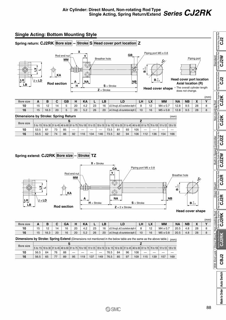
øC
LLX
LB
LH 2 x LD
KA
MMY
XRod end nut
Breather hole
Piping port M5 x 0.8GB
Z + Stroke
S + StrokeHA NA NB
B 0
−
0.3
B 0 −0.3
Piping port
øC
2 x LDLB
LH
LLX
KA
MMRod end nut
Z + 2 x Stroke
H + Stroke
A NAS + Stroke
Breather hole
Piping port M5 x 0.8
YGA
X + Stroke
NB
B 0
−
0.3
B 0 −0.3
Spring return: CJ2RK Bore size – Stroke S Head cover port location Z
Spring extend: CJ2RK Bore size – Stroke TZ
Single Acting: Bottom Mounting Style
Rod sectionHead cover shape
Head cover port locationAxial location (R)
∗ The overall cylinder length does not change.
Dimensions by Stroke: Spring Return (mm)
Bore sizeS Z
5 to 15 16 to 30 31 to 45 46 to 60 61 to 75 76 to 100 101 to 125 126 to 150 5 to 15 16 to 30 31 to 45 46 to 60 61 to 75 76 to 100 101 to 125 126 to 150
10 53.5 61 73 85 — — — — 73.5 81 93 105 — — — —
16 53.5 62 74 86 92 116 134 146 73.5 82 94 106 112 136 154 166
Bore size A B C GB H KA L LB LD LH LX MM NA NB X Y10 15 12 14 5 20 4.2 23 16 ø3.5 through, ø6.5 counterbore depth 4 8 12 M4 x 0.7 12.8 9.5 28 8
16 15 18.3 20 5 20 5.2 26 20 ø4.5 through, ø8 counterbore depth 5 10 16 M5 x 0.8 12.8 9.5 28 8
(mm)
Rod sectionHead cover shape
(mm)Dimensions by Stroke: Spring Extend (Dimensions not mentioned in the below table are the same as the above table.)
Bore size A B C GA H KA L LB LD LH LX MM NA NB X Y10 15 12 14 16 20 4.2 23 16 ø3.5 through, ø6.5 counterbore depth 4 8 12 M4 x 0.7 20.5 4.8 28 8
16 15 18.3 20 16 20 5.2 26 20 ø4.5 through, ø8 counterbore depth 5 10 16 M5 x 0.8 20.5 4.8 28 8
Bore sizeS Z
5 to 15 16 to 30 31 to 45 46 to 60 61 to 75 76 to 100 101 to 125 126 to 150 5 to 15 16 to 30 31 to 45 46 to 60 61 to 75 76 to 100 101 to 125 126 to 150
10 56.5 64 76 88 — — — — 76.5 84 96 108 — — — —
16 56.5 65 77 89 95 119 137 149 76.5 85 97 109 115 139 157 169
(mm)
88
Air Cylinder: Direct Mount, Non-rotating Rod TypeSingle Acting, Spring Return/Extend Series CJ2RK
CJ2
CJ2
WC
J2C
J2K
CJ2
KC
J2Z
CJ2
ZW
CJ2
RC
J2R
CJ2
RK
CJ2
RK
CB
J2
Sta
ndar
dN
on-r
otat
ing
Rod
Bui
lt-in
Spe
ed C
ontr
olle
rD
irect
Mou
ntD
irect
Mou
nt, N
on-r
otat
ing
Rod
With
End
Loc
kDo
uble
Actin
g, Do
uble
Rod
Single
Acting
, Sprin
g Retu
rn/Exte
ndDo
uble
Actin
g, Si
ngle
Rod
Single
Acting
, Sprin
g Retu
rn/Exte
ndDo
uble
Actin
g, Si
ngle
Rod
Doub
le Ac
ting,
Doub
le Ro
dDo
uble
Actin
g, Si
ngle
Rod
Single
Acting
, Sprin
g Retu
rn/Exte
ndDo
uble
Actin
g, Si
ngle
Rod
Single
Acting
, Sprin
g Retu
rn/Exte
ndDo
uble
Actin
g, Si
ngle
Rod
Auto
Sw
itch
Made
to O
rder
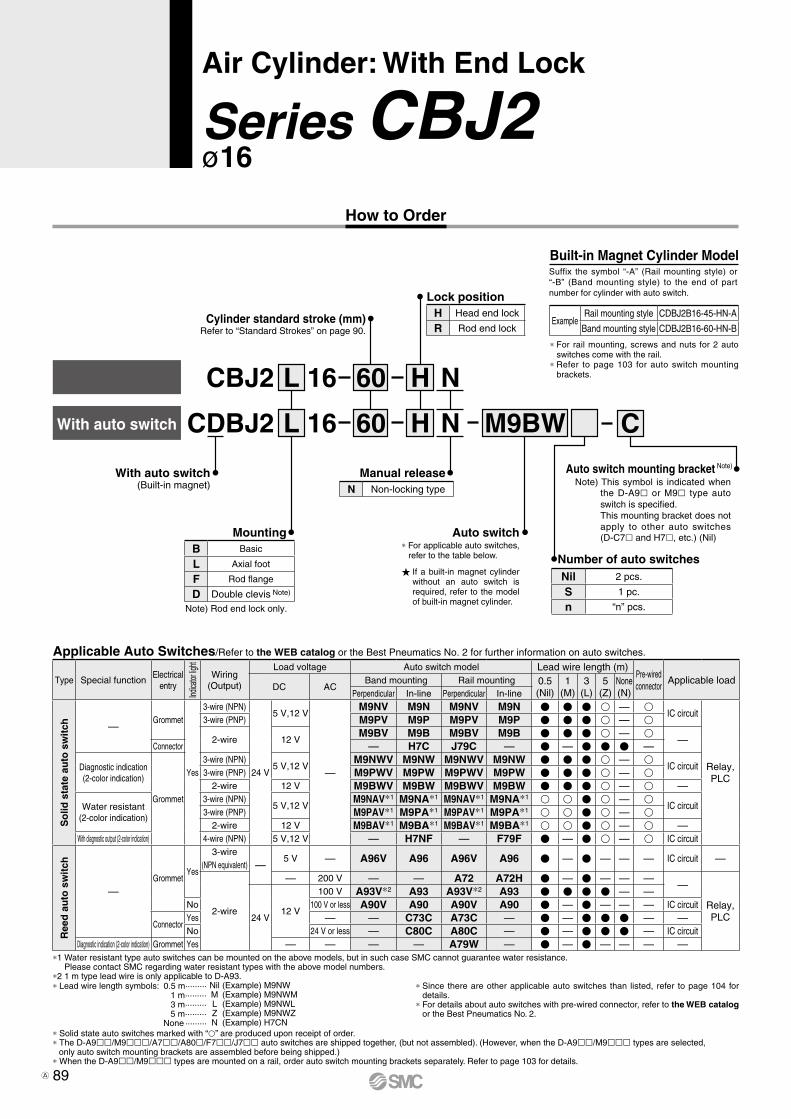
How to Order
CDBJ2
CBJ2
With auto switch
With auto switch(Built-in magnet)
Cylinder standard stroke (mm)Refer to “Standard Strokes” on page 90.
Auto switch
L
L
H
H
N
N
16
16
60
60
Number of auto switches
Mounting
Manual release
M9BW C
Lock position
Note) Rod end lock only.
* For rail mounting, screws and nuts for 2 auto switches come with the rail.
* Refer to page 103 for auto switch mounting brackets.
* For applicable auto switches, refer to the table below.
If a built-in magnet cylinder without an auto switch is required, refer to the model of built-in magnet cylinder.
Built-in Magnet Cylinder ModelSuffix the symbol “-A” (Rail mounting style) or “-B” (Band mounting style) to the end of part number for cylinder with auto switch.
Applicable Auto Switches/Refer to the WEB catalog or the Best Pneumatics No. 2 for further information on auto switches.
* Solid state auto switches marked with “p” are produced upon receipt of order.* The D-A9ll/M9lll/A7ll/A80l/F7ll/J7ll auto switches are shipped together, (but not assembled). (However, when the D-A9ll/M9lll types are selected,
only auto switch mounting brackets are assembled before being shipped.)* When the D-A9ll/M9lll types are mounted on a rail, order auto switch mounting brackets separately. Refer to page 103 for details.
*1 Water resistant type auto switches can be mounted on the above models, but in such case SMC cannot guarantee water resistance. Please contact SMC regarding water resistant types with the above model numbers.
*2 1 m type lead wire is only applicable to D-A93.(Example) M9NW(Example) M9NWM(Example) M9NWL(Example) M9NWZ(Example) H7CN
* Since there are other applicable auto switches than listed, refer to page 104 for details.
* For details about auto switches with pre-wired connector, refer to the WEB catalog or the Best Pneumatics No. 2.
* Lead wire length symbols: 0.5 m········· 1 m ········· 3 m ········· 5 m ········· None ·········
NilMLZN
Note) This symbol is indicated when the D-A9l or M9l type auto switch is specified.This mounting bracket does not apply to other auto switches (D-C7l and H7l, etc.) (Nil)
Auto switch mounting bracket Note)
Type Special functionElectrical
entry
Indica
tor lig
ht
Wiring(Output)
Load voltage Auto switch model Lead wire length (m)Pre-wiredconnector
Applicable loadDC AC
Band mounting Rail mounting 0.5(Nil)
1(M)
3(L)
5(Z)
None(N)Perpendicular In-line Perpendicular In-line
So
lid s
tate
au
to s
wit
ch —Grommet
Yes
3-wire (NPN)
24 V
5 V,12 V
—
M9NV M9N M9NV M9N V V V v — vIC circuit
Relay,PLC
3-wire (PNP) M9PV M9P M9PV M9P V V V v — v
2-wire 12 VM9BV M9B M9BV M9B V V V v — v
—Connector — H7C J79C — V — V V V —
Diagnostic indication(2-color indication)
Grommet
3-wire (NPN)5 V,12 V
M9NWV M9NW M9NWV M9NW V V V v — vIC circuit
3-wire (PNP) M9PWV M9PW M9PWV M9PW V V V v — v2-wire 12 V M9BWV M9BW M9BWV M9BW V V V v — v —
Water resistant (2-color indication)
3-wire (NPN)5 V,12 V
M9NAV*1 M9NA*1 M9NAV*1 M9NA*1 v v V v — vIC circuit
3-wire (PNP) M9PAV*1 M9PA*1 M9PAV*1 M9PA*1 v v V v — v2-wire 12 V M9BAV*1 M9BA*1 M9BAV*1 M9BA*1 v v V v — v —
With diagnostic output (2-color indication) 4-wire (NPN) 5 V,12 V — H7NF — F79F V — V v — v IC circuit
Ree
d a
uto
sw
itch
—Grommet
Yes
3-wire(NPN equivalent) —
5 V — A96V A96 A96V A96 V — V — — — IC circuit —
2-wire
— 200 V — — A72 A72H V — V — — ——
Relay,PLC24 V
12 V
100 V A93V*2 A93 A93V*2 A93 V V V V — —No 100 V or less A90V A90 A90V A90 V — V — — — IC circuit
ConnectorYes — — C73C A73C — V — V V V — —No 24 V or less — C80C A80C — V — V V V — IC circuit
Diagnostic indication (2-color indication) Grommet Yes — — — — A79W — V — V — — — —
Nil 2 pcs.
S 1 pc.
n “n” pcs.
ExampleRail mounting style CDBJ2B16-45-HN-A
Band mounting style CDBJ2B16-60-HN-B
N Non-locking type
B Basic
L Axial foot
F Rod flange
D Double clevis Note)
H Head end lock
R Rod end lock
Series CBJ2ø16
Air Cylinder: With End Lock
89A
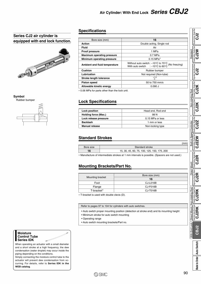
Series CJ2 air cylinder is equipped with end lock function.
Refer to pages 97 to 104 for cylinders with auto switches.
• Auto switch proper mounting position (detection at stroke end) and its mounting height
• Minimum stroke for auto switch mounting
• Operating range
• Auto switch mounting brackets/Part no.
SymbolRubber bumper
* 0.06 MPa for parts other than the lock unit.
Bore size (mm) 16Action Double acting, Single rod
Fluid Air
Proof pressure 1 MPa
Maximum operating pressure 0.7 MPa
Minimum operating pressure 0.15 MPa*
Ambient and fluid temperatureWithout auto switch : –10°C to 70°C (No freezing)With auto switch : –10°C to 60°C
Cushion Rubber bumper
Lubrication Not required (Non-lube)
Stroke length tolerance +1.00
Piston speed 50 to 750 mm/s
Allowable kinetic energy 0.090 J
Specifications
* Manufacture of intermediate strokes at 1 mm intervals is possible. (Spacers are not used.)
Bore size Standard stroke
16 15, 30, 45, 60, 75, 100, 125, 150, 175, 200
(mm)
Standard Strokes
Lock position Head end, Rod end
Holding force (Max.) 98 N
Lock release pressure 0.15 MPa or less
Backlash 1 mm or less
Manual release Non-locking type
Lock Specifications
* T-bracket is used with double clevis (D).
Mounting bracketBore size (mm)
16Foot CJ-L016B
Flange CJ-F016B
T-bracket* CJ-T016B
Mounting Brackets/Part No.
When operating an actuator with a small diameter and a short stroke at a high frequency, the dew condensation (water droplet) may occur inside the piping depending on the conditions.Simply connecting the moisture control tube to the actuator will prevent dew condensation from oc-curring. For details, refer to Series IDK in the WEB catalog.
MoistureControl TubeSeries IDK
90
Air Cylinder: With End Lock Series CBJ2
CJ2
CJ2
WC
J2C
J2K
CJ2
KC
J2Z
CJ2
ZW
CJ2
RC
J2R
CJ2
RK
CJ2
RK
CB
J2
Sta
ndar
dN
on-r
otat
ing
Rod
Bui
lt-in
Spe
ed C
ontr
olle
rD
irect
Mou
ntD
irect
Mou
nt, N
on-r
otat
ing
Rod
With
End
Loc
kDo
uble
Actin
g, Do
uble
Rod
Single
Acting
, Sprin
g Retu
rn/Exte
ndDo
uble
Actin
g, Si
ngle
Rod
Single
Acting
, Sprin
g Retu
rn/Exte
ndDo
uble
Actin
g, Si
ngle
Rod
Doub
le Ac
ting,
Doub
le Ro
dDo
uble
Actin
g, Si
ngle
Rod
Single
Acting
, Sprin
g Retu
rn/Exte
ndDo
uble
Actin
g, Si
ngle
Rod
Single
Acting
, Sprin
g Retu
rn/Exte
ndDo
uble
Actin
g, Si
ngle
Rod
Auto
Sw
itch
Made
to O
rder
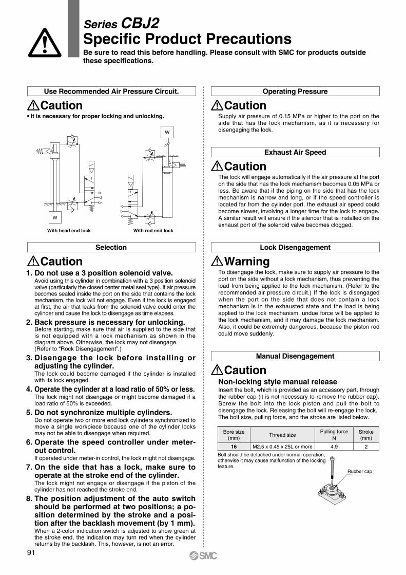
W
W
With head end lock With rod end lock
Series CBJ2Specific Product PrecautionsBe sure to read this before handling. Please consult with SMC for products outside these specifications.
Use Recommended Air Pressure Circuit.
Caution• It is necessary for proper locking and unlocking.
Operating Pressure
CautionSupply air pressure of 0.15 MPa or higher to the port on the side that has the lock mechanism, as it is necessary for disengaging the lock.
Exhaust Air Speed
CautionThe lock will engage automatically if the air pressure at the port on the side that has the lock mechanism becomes 0.05 MPa or less. Be aware that if the piping on the side that has the lock mechanism is narrow and long, or if the speed controller is located far from the cylinder port, the exhaust air speed could become slower, involving a longer time for the lock to engage. A similar result will ensure if the silencer that is installed on the exhaust port of the solenoid valve becomes clogged.
Lock Disengagement
WarningTo disengage the lock, make sure to supply air pressure to the port on the side without a lock mechanism, thus preventing the load from being applied to the lock mechanism. (Refer to the recommended air pressure circuit.) If the lock is disengaged when the port on the side that does not contain a lock mechanism is in the exhausted state and the load is being applied to the lock mechanism, undue force will be applied to the lock mechanism, and it may damage the lock mechanism. Also, it could be extremely dangerous, because the piston rod could move suddenly.
Selection
Caution1. Do not use a 3 position solenoid valve.
Avoid using this cylinder in combination with a 3 position solenoid valve (particularly the closed center metal seal type). If air pressure becomes sealed inside the port on the side that contains the lock mechanism, the lock will not engage. Even if the lock is engaged at first, the air that leaks from the solenoid valve could enter the cylinder and cause the lock to disengage as time elapses.
2. Back pressure is necessary for unlocking.Before starting, make sure that air is supplied to the side that is not equipped with a lock mechanism as shown in the diagram above. Otherwise, the lock may not disengage.(Refer to “Rock Disengagement”.)
3. Disengage the lock before installing or adjusting the cylinder.The lock could become damaged if the cylinder is installed with its lock engaged.
4. Operate the cylinder at a load ratio of 50% or less.The lock might not disengage or might become damaged if a load ratio of 50% is exceeded.
5. Do not synchronize multiple cylinders.Do not operate two or more end lock cylinders synchronized to move a single workpiece because one of the cylinder locks may not be able to disengage when required.
6. Operate the speed controller under meter-out control.If operated under meter-in control, the lock might not disengage.
7. On the side that has a lock, make sure to operate at the stroke end of the cylinder.The lock might not engage or disengage if the piston of the cylinder has not reached the stroke end.
8. The position adjustment of the auto switch should be performed at two positions; a po-sition determined by the stroke and a posi-tion after the backlash movement (by 1 mm).When a 2-color indication switch is adjusted to show green at the stroke end, the indication may turn red when the cylinder returns by the backlash. This, however, is not an error.
Rubber cap
Bolt should be detached under normal operation, otherwise it may cause malfunction of the locking feature.
Manual Disengagement
CautionNon-locking style manual releaseInsert the bolt, which is provided as an accessory part, through the rubber cap (it is not necessary to remove the rubber cap). Screw the bolt into the lock piston and pull the bolt to disengage the lock. Releasing the bolt will re-engage the lock.The bolt size, pulling force, and the stroke are listed below.
Bore size(mm)
Thread sizePulling force
NStroke(mm)
16 M2.5 x 0.45 x 25L or more 4.9 2
91
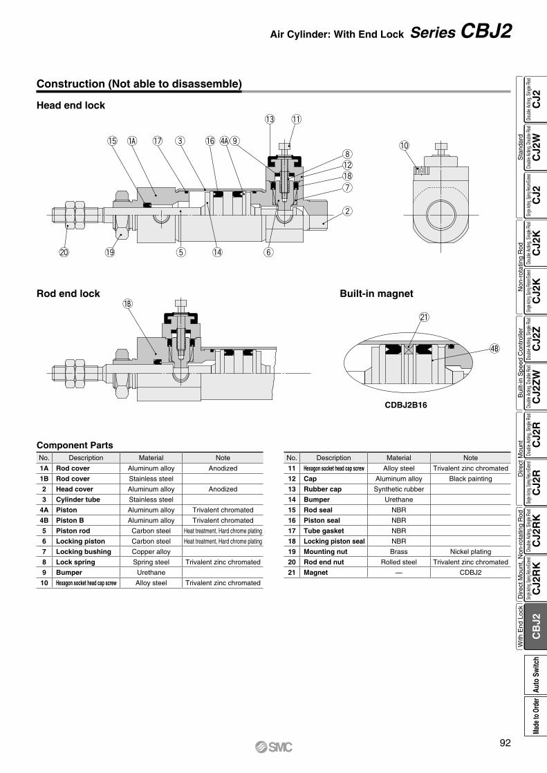
!0
@0 !9 t !4 y
u
w
!2!8
i
!1
o
!3
!6!7 e!5
@1
CDBJ2B16
Construction (Not able to disassemble)
Head end lock
Rod end lock Built-in magnet
Component PartsNo. Description Material Note
11 Hexagon socket head cap screw Alloy steel Trivalent zinc chromated
12 Cap Aluminum alloy Black painting
13 Rubber cap Synthetic rubber
14 Bumper Urethane
15 Rod seal NBR
16 Piston seal NBR
17 Tube gasket NBR
18 Locking piston seal NBR
19 Mounting nut Brass Nickel plating
20 Rod end nut Rolled steel Trivalent zinc chromated
21 Magnet — CDBJ2
No. Description Material Note
1A Rod cover Aluminum alloy Anodized
1B Rod cover Stainless steel
2 Head cover Aluminum alloy Anodized
3 Cylinder tube Stainless steel
4A Piston Aluminum alloy Trivalent chromated
4B Piston B Aluminum alloy Trivalent chromated
5 Piston rod Carbon steel Heat treatment, Hard chrome plating
6 Locking piston Carbon steel Heat treatment, Hard chrome plating
7 Locking bushing Copper alloy
8 Lock spring Spring steel Trivalent zinc chromated
9 Bumper Urethane
10 Hexagon socket head cap screw Alloy steel Trivalent zinc chromated
92
Air Cylinder: With End Lock Series CBJ2
CJ2
CJ2
WC
J2C
J2K
CJ2
KC
J2Z
CJ2
ZW
CJ2
RC
J2R
CJ2
RK
CJ2
RK
CB
J2
Sta
ndar
dN
on-r
otat
ing
Rod
Bui
lt-in
Spe
ed C
ontr
olle
rD
irect
Mou
ntD
irect
Mou
nt, N
on-r
otat
ing
Rod
With
End
Loc
kDo
uble
Actin
g, Do
uble
Rod
Single
Acting
, Sprin
g Retu
rn/Exte
ndDo
uble
Actin
g, Si
ngle
Rod
Single
Acting
, Sprin
g Retu
rn/Exte
ndDo
uble
Actin
g, Si
ngle
Rod
Doub
le Ac
ting,
Doub
le Ro
dDo
uble
Actin
g, Si
ngle
Rod
Single
Acting
, Sprin
g Retu
rn/Exte
ndDo
uble
Actin
g, Si
ngle
Rod
Single
Acting
, Sprin
g Retu
rn/Exte
ndDo
uble
Actin
g, Si
ngle
Rod
Auto
Sw
itch
Made
to O
rder
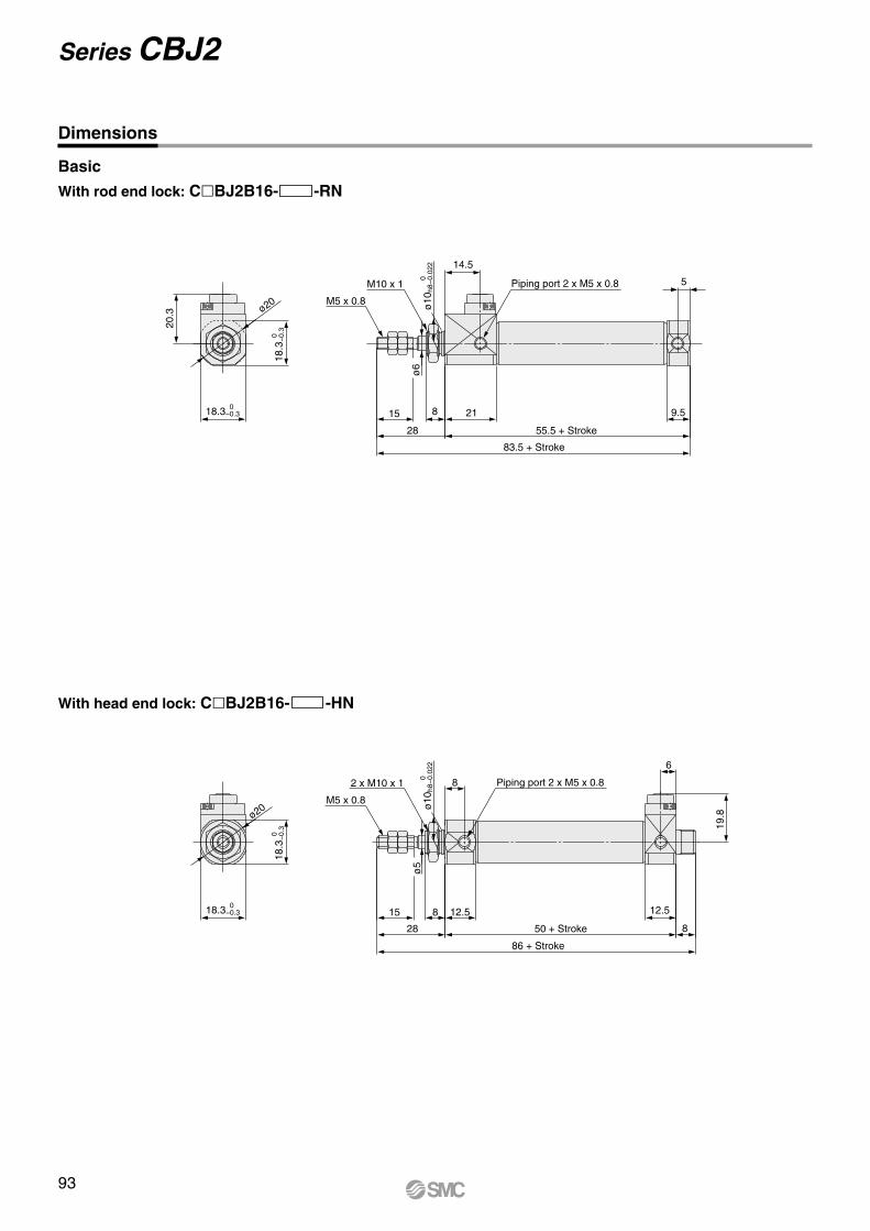
M5 x 0.8
M10 x 1 Piping port 2 x M5 x 0.8
ø20
83.5 + Stroke
28
15 8
55.5 + Stroke
9.5
5
14.5
21
20.3
ø6
18.3 0 −0.3
18.3
0
−0.
3
ø10
0
h8−
0.02
2
M5 x 0.8
2 x M10 x 1 Piping port 2 x M5 x 0.8
ø20
28
15 8 12.5
ø5
ø5
8
12.5
50 + Stroke 8
86 + Stroke
6
19.8
18.3 0 −0.3
18.3
0
−0.
3
ø10
0
h8−
0.02
2
Dimensions
Basic
With rod end lock: ClBJ2B16- -RN
With head end lock: ClBJ2B16- -HN
93
Series CBJ2

M5 x 0.8
M10 x 1Cover side (Head side)
2 x ø5.5Mounting hole
Piping port 2 x M5 x 0.8
28
15 8
2.3
33
42
19 20
ø20
83.5 + Stroke
55.5 + Stroke
9.5
5
14.5
21
20.3
ø6
18.3 0 −0.3
18.3
0
−0.
3
Piping port 2 x M5 x 0.8
M5 x 0.8
2 x M10 x 1Cover side (Rod side)
2 x ø5.5Mounting hole 12.5
8
12.5
50 + Stroke 8
86 + Stroke
6
19.8
28
15
ø5
8
2.3
33
42
19 20
ø20
18.3 0 −0.3
18.3
0
−0.
3
Dimensions
Flange
Cover outside diameter
Cover outside diameter
With rod end lock: ClBJ2F16- -RN
With head end lock: ClBJ2F16- -HN
94
Air Cylinder: With End Lock Series CBJ2
CJ2
CJ2
WC
J2C
J2K
CJ2
KC
J2Z
CJ2
ZW
CJ2
RC
J2R
CJ2
RK
CJ2
RK
CB
J2
Sta
ndar
dN
on-r
otat
ing
Rod
Bui
lt-in
Spe
ed C
ontr
olle
rD
irect
Mou
ntD
irect
Mou
nt, N
on-r
otat
ing
Rod
With
End
Loc
kDo
uble
Actin
g, Do
uble
Rod
Single
Acting
, Sprin
g Retu
rn/Exte
ndDo
uble
Actin
g, Si
ngle
Rod
Single
Acting
, Sprin
g Retu
rn/Exte
ndDo
uble
Actin
g, Si
ngle
Rod
Doub
le Ac
ting,
Doub
le Ro
dDo
uble
Actin
g, Si
ngle
Rod
Single
Acting
, Sprin
g Retu
rn/Exte
ndDo
uble
Actin
g, Si
ngle
Rod
Single
Acting
, Sprin
g Retu
rn/Exte
ndDo
uble
Actin
g, Si
ngle
Rod
Auto
Sw
itch
Made
to O
rder
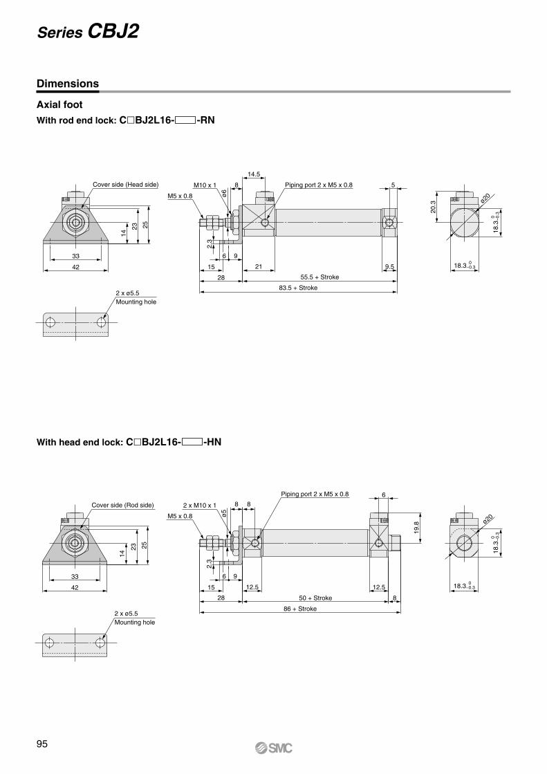
M5 x 0.8
Cover side (Head side)
2 x ø5.5Mounting hole
M10 x 1 Piping port 2 x M5 x 0.8
15
8
96
2.3
42
33
14
23 25
28
83.5 + Stroke
55.5 + Stroke
9.5
5
14.5
21
ø20
20.3
ø6
18.3
0
−0.
3
18.3 0 −0.3
M5 x 0.8
Cover side (Rod side) 2 x M10 x 1
Piping port 2 x M5 x 0.8
15
8
50 + Stroke
12.5
ø5
8
96
2.3
42
33
14
23 25
ø20
28 8
6
19.8
12.5
86 + Stroke2 x ø5.5Mounting hole
18.3
0
−0.
3
18.3 0 −0.3
Axial foot
Dimensions
With rod end lock: ClBJ2L16- -RN
With head end lock: ClBJ2L16- -HN
95
Series CBJ2
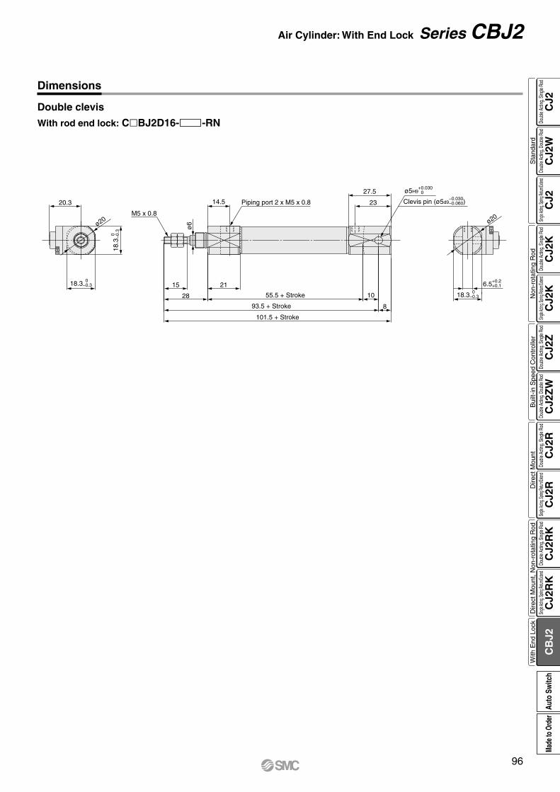
M5 x 0.8
Piping port 2 x M5 x 0.8
28
15
ø20
23
27.5
101.5 + Stroke
93.5 + Stroke 8
55.5 + Stroke 10
14.5
21
ø20
20.3
ø6
18.3 0 −0.3
18.3
0
−0.
3
18.3 0 −0.3
6.5+0.2 +0.1
Clevis pin (ø5d9−0.030−0.060)
ø5H9+0.030−0
Dimensions
Double clevis
With rod end lock: ClBJ2D16- -RN
96
Air Cylinder: With End Lock Series CBJ2
CJ2
CJ2
WC
J2C
J2K
CJ2
KC
J2Z
CJ2
ZW
CJ2
RC
J2R
CJ2
RK
CJ2
RK
CB
J2
Sta
ndar
dN
on-r
otat
ing
Rod
Bui
lt-in
Spe
ed C
ontr
olle
rD
irect
Mou
ntD
irect
Mou
nt, N
on-r
otat
ing
Rod
With
End
Loc
kDo
uble
Actin
g, Do
uble
Rod
Single
Acting
, Sprin
g Retu
rn/Exte
ndDo
uble
Actin
g, Si
ngle
Rod
Single
Acting
, Sprin
g Retu
rn/Exte
ndDo
uble
Actin
g, Si
ngle
Rod
Doub
le Ac
ting,
Doub
le Ro
dDo
uble
Actin
g, Si
ngle
Rod
Single
Acting
, Sprin
g Retu
rn/Exte
ndDo
uble
Actin
g, Si
ngle
Rod
Single
Acting
, Sprin
g Retu
rn/Exte
ndDo
uble
Actin
g, Si
ngle
Rod
Auto
Sw
itch
Made
to O
rder

≈Hs
16.5
A 22
(24)
B
≈Hs
16.5
A 24.5
(22)
B
≈Hs
16.5
A 20(22)
B
≈Hs16
.5
A 22 B
≈Hs
16.5
A B
≈Hs
16.5
A B
Auto switch
Auto switch
Auto switch
Auto switch
Auto switch
Auto switch
Series CJ2Auto Switch Mounting
Auto Switch Proper Mounting Position (Detection at stroke end) and Its Mounting Height
D-M9V D-M9MV D-M9AV
D-A9V
Solid state auto switch<Band mounting>
Reed auto switch<Band mounting>
D-M9D-M9WD-M9A
( ): Dimension of the D-M9AV.A and B are the dimensions from the end of the
head cover/rod cover to the end of the auto switch.
A and B are the dimensions from the end of the head cover/rod cover to the end of the auto switch.
( ): Dimension of the D-M9A.A and B are the dimensions from the end of the
head cover/rod cover to the end of the auto switch.
( ): Dimension of the D-A96.A and B are the dimensions from the end of the
head cover/rod cover to the end of the auto switch.
D-H7D-H7WD-H7BAD-H7NFD-H7C
D-C7/C80D-C73C/C80C
D-A9
97

12.5 12.5
≈Hs
23.5A B
Auto switch
≈Hs
12.5 12.5 26A B
Auto switch
(23.5)
14.514.5
≈Hs
21.5(23.5)
A B
Auto switch
Auto switch
Auto switchAuto switch
Auto switch
≈Hs
12.5 12.5 23.5(25.5)
A B
Auto switch
≈Hs
A B
≈Hs
A B
≈Hs
A B
BA
≈Hs
Auto Switch Proper Mounting Position (Detection at stroke end) and Its Mounting Height
( ): Dimension of the D-M9AV.
( ): Dimension of the D-M9A. ( ): Dimension of the D-A96.
<Rail mounting> <Rail mounting>
D-F7V/F7WVD-F7BAVD-J79C
D-M9D-M9W D-M9A
D-M9V D-M9WV D-M9AV
D-A9V
D-A9
D-F7/J79D-F7W/J79WD-F79F/F7BA
D-A7H/A80H
D-A7/A80D-A73C/A80CD-A79W
98
Auto Switch Mounting Series CJ2
CJ2
CJ2
WC
J2C
J2K
CJ2
KC
J2Z
CJ2
ZW
CJ2
RC
J2R
CJ2
RK
CJ2
RK
CB
J2
Sta
ndar
dN
on-r
otat
ing
Rod
Bui
lt-in
Spe
ed C
ontr
olle
rD
irect
Mou
ntD
irect
Mou
nt, N
on-r
otat
ing
Rod
With
End
Loc
kDo
uble
Actin
g, Do
uble
Rod
Single
Acting
, Sprin
g Retu
rn/Exte
ndDo
uble
Actin
g, Si
ngle
Rod
Single
Acting
, Sprin
g Retu
rn/Exte
ndDo
uble
Actin
g, Si
ngle
Rod
Doub
le Ac
ting,
Doub
le Ro
dDo
uble
Actin
g, Si
ngle
Rod
Single
Acting
, Sprin
g Retu
rn/Exte
ndDo
uble
Actin
g, Si
ngle
Rod
Single
Acting
, Sprin
g Retu
rn/Exte
ndDo
uble
Actin
g, Si
ngle
Rod
Auto
Sw
itch
Made
to O
rder
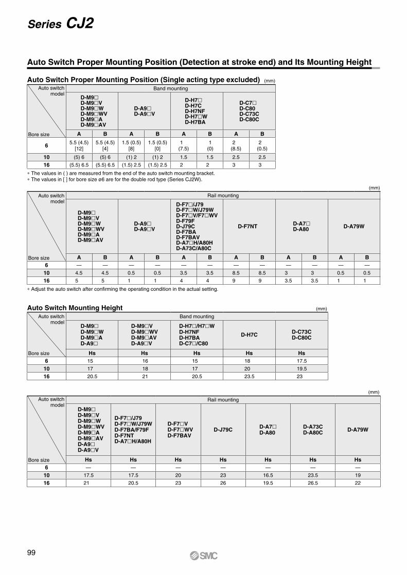
* The values in ( ) are measured from the end of the auto switch mounting bracket.* The values in [ ] for bore size ø6 are for the double rod type (Series CJ2W).
Auto Switch Proper Mounting Position (Detection at stroke end) and Its Mounting Height
(mm)
(mm)Auto Switch Mounting Height
(mm)
* Adjust the auto switch after confirming the operating condition in the actual setting.
(mm)Auto Switch Proper Mounting Position (Single acting type excluded)Auto switch
model
Bore size
Band mounting
D-M9lD-M9lVD-M9lWD-M9lWVD-M9lAD-M9lAV
D-A9lD-A9lV
D-H7lD-H7CD-H7NFD-H7lWD-H7BA
D-C7lD-C80D-C73CD-C80C
A B A B A B A B
6 5.5 (4.5)[12]
5.5 (4.5)[4]
1.5 (0.5)[8]
1.5 (0.5)[0]
1(7.5)
1(0)
2(8.5)
2(0.5)
10 (5) 6 (5) 6 (1) 2 (1) 2 1.5 1.5 2.5 2.5
16 (5.5) 6.5 (5.5) 6.5 (1.5) 2.5 (1.5) 2.5 2 2 3 3
Auto switchmodel
Bore size
Rail mounting
D-M9lD-M9lVD-M9lWD-M9lWVD-M9lAD-M9lAV
D-A9lD-A9lV
D-F7l/J79 D-F7lW/J79WD-F7lV/F7lWVD-F79FD-J79CD-F7BAD-F7BAVD-A7lH/A80HD-A73C/A80C
D-F7NT D-A7lD-A80 D-A79W
A B A B A B A B A B A B6 — — — — — — — — — — — —
10 4.5 4.5 0.5 0.5 3.5 3.5 8.5 8.5 3 3 0.5 0.5
16 5 5 1 1 4 4 9 9 3.5 3.5 1 1
Auto switchmodel
Bore size
Band mounting
D-M9lD-M9lWD-M9lAD-A9l
D-M9lVD-M9lWVD-M9lAVD-A9lV
D-H7l/H7lWD-H7NFD-H7BAD-C7l/C80
D-H7C D-C73CD-C80C
Hs Hs Hs Hs Hs6 15 16 15 18 17.5
10 17 18 17 20 19.5
16 20.5 21 20.5 23.5 23
Auto switchmodel
Bore size
Rail mounting
D-M9lD-M9lVD-M9lWD-M9lWVD-M9lAD-M9lAVD-A9lD-A9lV
D-F7l/J79D-F7lW/J79WD-F7BA/F79FD-F7NTD-A7lH/A80H
D-F7lVD-F7lWVD-F7BAV
D-J79C D-A7lD-A80
D-A73CD-A80C D-A79W
Hs Hs Hs Hs Hs Hs Hs6 — — — — — — —
10 17.5 17.5 20 23 16.5 23.5 19
16 21 20.5 23 26 19.5 26.5 22
99
Series CJ2
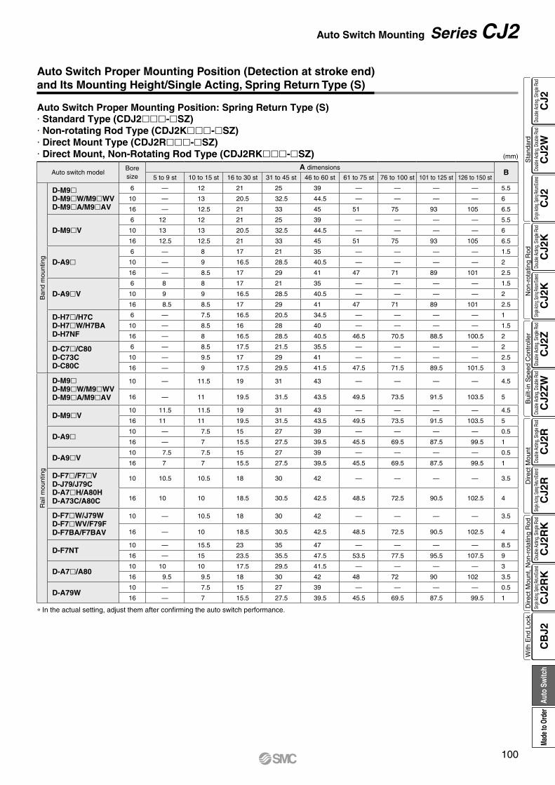
* In the actual setting, adjust them after confirming the auto switch performance.
(mm)
Auto switch modelBore size
A dimensionsB
5 to 9 st 10 to 15 st 16 to 30 st 31 to 45 st 46 to 60 st 61 to 75 st 76 to 100 st 101 to 125 st 126 to 150 st
Ban
d m
ount
ing
D-M9lD-M9lW/M9lWVD-M9lA/M9lAV
6 — 12 21 25 39 — — — — 5.5
10 — 13 20.5 32.5 44.5 — — — — 6
16 — 12.5 21 33 45 51 75 93 105 6.5
D-M9lV6 12 12 21 25 39 — — — — 5.5
10 13 13 20.5 32.5 44.5 — — — — 6
16 12.5 12.5 21 33 45 51 75 93 105 6.5
D-A9l6 — 8 17 21 35 — — — — 1.5
10 — 9 16.5 28.5 40.5 — — — — 2
16 — 8.5 17 29 41 47 71 89 101 2.5
D-A9lV6 8 8 17 21 35 — — — — 1.5
10 9 9 16.5 28.5 40.5 — — — — 2
16 8.5 8.5 17 29 41 47 71 89 101 2.5
D-H7l/H7CD-H7lW/H7BAD-H7NF
6 — 7.5 16.5 20.5 34.5 — — — — 1
10 — 8.5 16 28 40 — — — — 1.5
16 — 8 16.5 28.5 40.5 46.5 70.5 88.5 100.5 2
D-C7l/C80D-C73CD-C80C
6 — 8.5 17.5 21.5 35.5 — — — — 2
10 — 9.5 17 29 41 — — — — 2.5
16 — 9 17.5 29.5 41.5 47.5 71.5 89.5 101.5 3
Rai
l mou
ntin
g
D-M9lD-M9lW/M9lWVD-M9lA/M9lAV
10 — 11.5 19 31 43 — — — — 4.5
16 — 11 19.5 31.5 43.5 49.5 73.5 91.5 103.5 5
D-M9lV10 11.5 11.5 19 31 43 — — — — 4.5
16 11 11 19.5 31.5 43.5 49.5 73.5 91.5 103.5 5
D-A9l10 — 7.5 15 27 39 — — — — 0.5
16 — 7 15.5 27.5 39.5 45.5 69.5 87.5 99.5 1
D-A9lV10 7.5 7.5 15 27 39 — — — — 0.5
16 7 7 15.5 27.5 39.5 45.5 69.5 87.5 99.5 1
D-F7l/F7lVD-J79/J79CD-A7lH/A80HD-A73C/A80C
10 10.5 10.5 18 30 42 — — — — 3.5
16 10 10 18.5 30.5 42.5 48.5 72.5 90.5 102.5 4
D-F7lW/J79WD-F7lWV/F79FD-F7BA/F7BAV
10 — 10.5 18 30 42 — — — — 3.5
16 — 10 18.5 30.5 42.5 48.5 72.5 90.5 102.5 4
D-F7NT10 — 15.5 23 35 47 — — — — 8.5
16 — 15 23.5 35.5 47.5 53.5 77.5 95.5 107.5 9
D-A7l/A8010 10 10 17.5 29.5 41.5 — — — — 3
16 9.5 9.5 18 30 42 48 72 90 102 3.5
D-A79W10 — 7.5 15 27 39 — — — — 0.5
16 — 7 15.5 27.5 39.5 45.5 69.5 87.5 99.5 1
Auto Switch Proper Mounting Position: Spring Return Type (S)· Standard Type (CDJ2lll-lSZ)· Non-rotating Rod Type (CDJ2Klll-lSZ)· Direct Mount Type (CDJ2Rlll-lSZ)· Direct Mount, Non-Rotating Rod Type (CDJ2RKlll-lSZ)
Auto Switch Proper Mounting Position (Detection at stroke end) and Its Mounting Height/Single Acting, Spring Return Type (S)
100
Auto Switch Mounting Series CJ2
CJ2
CJ2
WC
J2C
J2K
CJ2
KC
J2Z
CJ2
ZW
CJ2
RC
J2R
CJ2
RK
CJ2
RK
CB
J2
Sta
ndar
dN
on-r
otat
ing
Rod
Bui
lt-in
Spe
ed C
ontr
olle
rD
irect
Mou
ntD
irect
Mou
nt, N
on-r
otat
ing
Rod
With
End
Loc
kDo
uble
Actin
g, Do
uble
Rod
Single
Acting
, Sprin
g Retu
rn/Exte
ndDo
uble
Actin
g, Si
ngle
Rod
Single
Acting
, Sprin
g Retu
rn/Exte
ndDo
uble
Actin
g, Si
ngle
Rod
Doub
le Ac
ting,
Doub
le Ro
dDo
uble
Actin
g, Si
ngle
Rod
Single
Acting
, Sprin
g Retu
rn/Exte
ndDo
uble
Actin
g, Si
ngle
Rod
Single
Acting
, Sprin
g Retu
rn/Exte
ndDo
uble
Actin
g, Si
ngle
Rod
Auto
Sw
itch
Made
to O
rder
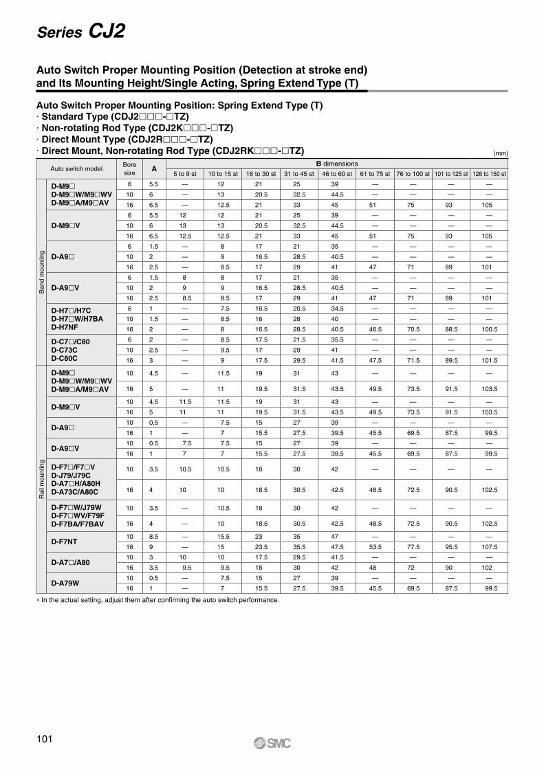
* In the actual setting, adjust them after confirming the auto switch performance.
(mm)
Auto switch modelBore size
AB dimensions
5 to 9 st 10 to 15 st 16 to 30 st 31 to 45 st 46 to 60 st 61 to 75 st 76 to 100 st 101 to 125 st 126 to 150 st
Ban
d m
ount
ing
D-M9lD-M9lW/M9lWVD-M9lA/M9lAV
6 5.5 — 12 21 25 39 — — — —
10 6 — 13 20.5 32.5 44.5 — — — —
16 6.5 — 12.5 21 33 45 51 75 93 105
D-M9lV6 5.5 12 12 21 25 39 — — — —
10 6 13 13 20.5 32.5 44.5 — — — —
16 6.5 12.5 12.5 21 33 45 51 75 93 105
D-A9l6 1.5 — 8 17 21 35 — — — —
10 2 — 9 16.5 28.5 40.5 — — — —
16 2.5 — 8.5 17 29 41 47 71 89 101
D-A9lV6 1.5 8 8 17 21 35 — — — —
10 2 9 9 16.5 28.5 40.5 — — — —
16 2.5 8.5 8.5 17 29 41 47 71 89 101
D-H7l/H7CD-H7lW/H7BAD-H7NF
6 1 — 7.5 16.5 20.5 34.5 — — — —
10 1.5 — 8.5 16 28 40 — — — —
16 2 — 8 16.5 28.5 40.5 46.5 70.5 88.5 100.5
D-C7l/C80D-C73CD-C80C
6 2 — 8.5 17.5 21.5 35.5 — — — —
10 2.5 — 9.5 17 29 41 — — — —
16 3 — 9 17.5 29.5 41.5 47.5 71.5 89.5 101.5
Rai
l mou
ntin
g
D-M9lD-M9lW/M9lWVD-M9lA/M9lAV
10 4.5 — 11.5 19 31 43 — — — —
16 5 — 11 19.5 31.5 43.5 49.5 73.5 91.5 103.5
D-M9lV10 4.5 11.5 11.5 19 31 43 — — — —
16 5 11 11 19.5 31.5 43.5 49.5 73.5 91.5 103.5
D-A9l10 0.5 — 7.5 15 27 39 — — — —
16 1 — 7 15.5 27.5 39.5 45.5 69.5 87.5 99.5
D-A9lV10 0.5 7.5 7.5 15 27 39 — — — —
16 1 7 7 15.5 27.5 39.5 45.5 69.5 87.5 99.5
D-F7l/F7lVD-J79/J79CD-A7lH/A80HD-A73C/A80C
10 3.5 10.5 10.5 18 30 42 — — — —
16 4 10 10 18.5 30.5 42.5 48.5 72.5 90.5 102.5
D-F7lW/J79WD-F7lWV/F79FD-F7BA/F7BAV
10 3.5 — 10.5 18 30 42 — — — —
16 4 — 10 18.5 30.5 42.5 48.5 72.5 90.5 102.5
D-F7NT10 8.5 — 15.5 23 35 47 — — — —
16 9 — 15 23.5 35.5 47.5 53.5 77.5 95.5 107.5
D-A7l/A8010 3 10 10 17.5 29.5 41.5 — — — —
16 3.5 9.5 9.5 18 30 42 48 72 90 102
D-A79W10 0.5 — 7.5 15 27 39 — — — —
16 1 — 7 15.5 27.5 39.5 45.5 69.5 87.5 99.5
Auto Switch Proper Mounting Position: Spring Extend Type (T)· Standard Type (CDJ2lll-lTZ)· Non-rotating Rod Type (CDJ2Klll-lTZ)· Direct Mount Type (CDJ2Rlll-lTZ)· Direct Mount, Non-rotating Rod Type (CDJ2RKlll-lTZ)
Auto Switch Proper Mounting Position (Detection at stroke end) and Its Mounting Height/Single Acting, Spring Extend Type (T)
101
Series CJ2

B
A
Auto switch model
With 2 auto switchesDifferent surfaces Note 1) Same surface Note 1)
The proper auto switch mounting position is 5.5 mm inward from the switch holder edge. The above A and B indicate values for band mounting in the table of page 99.
The auto switch is mounted by slightly displacing it in a direction (cylinder tube circumferential exterior) so that the auto switch and lead wire do not interfere with each other.
D-M9/M9W/M9A Less than 20 stroke Note 2) Less than 55 stroke Note 2)
D-A9 — Less than 50 stroke Note 2)
Note 3) When “n” is an odd number, an even number that is one larger than this odd number is used for the calculation.Note 4) When “n” is an odd number, an even number that is one larger than this odd number is used for the calculation.
However, the minimum even number is 4. So, 4 is used for the calculation when “n” is 1 to 3.Note 5) The dimension stated in ( ) shows the minimum mountable stroke when the auto switch does not project from
the end face of the cylinder body and the lead wire bending space is not hindered.Note 1) Auto switch mounting
Note 2) Minimum stroke for auto switch mounting in styles other than those mentioned in Note 1.
Auto switchD-M9(V)D-M9W(V)D-M9A(V)
(mm)
Auto switch mounting
Auto switch modelNumber of auto switches
With 1 pc.With 2 pcs. With n pcs. (n: Number of auto switches)
Different surfaces Same surface Different surfaces Same surface
Band mounting
D-M9lD-M9lWD-M9lAD-A9l
10 15 Note 1) 45 Note 1) 15 + 35(n – 2)2
(n = 2, 4, 6…) Note 3)
45 + 15 (n – 2)(n = 2, 3, 4, 5…)
D-M9lV 5 15 Note 1) 35 15 + 35(n – 2)2
(n = 2, 4, 6…) Note 3)
35 + 25 (n – 2)(n = 2, 3, 4, 5…)
D-M9lWVD-M9lAV 10 15 Note 1) 35 15 + 35(n – 2)
2(n = 2, 4, 6…) Note 3)
35 + 25 (n – 2)(n = 2, 3, 4, 5…)
D-A9lV 5 10 35 10 + 35(n – 2)2
(n = 2, 4, 6…) Note 3)
35 + 25 (n – 2)(n = 2, 3, 4, 5…)
D-H7l/H7lWD-H7BAD-H7NF
10 15 60 15 + 45(n – 2)2
(n = 2, 4, 6…) Note 3)
60 + 22.5 (n – 2)(n = 2, 3, 4, 5…)
D-C7lD-C80 10 15 50 15 + 40(n – 2)
2(n = 2, 4, 6…) Note 3)
50 + 20 (n – 2)(n = 2, 3, 4, 5…)
D-H7CD-C73CD-C80C
10 15 65 15 + 50(n – 2)2
(n = 2, 4, 6…) Note 3)
50 + 27.5 (n – 2)(n = 2, 3, 4, 5…)
Rail mounting
D-M9lV 5 — 5 — 10 + 10 (n – 2)(n = 4, 6…) Note 4)
D-A9lV 5 — 10 — 10 + 15 (n – 2)(n = 4, 6…) Note 4)
D-M9lD-A9l 10 (5) Note 5) — 10 — 15 + 15 (n – 2)
(n = 4, 6…) Note 4)
D-M9lWVD-M9lAV 10 — 15 — 15 + 15 (n – 2)
(n = 4, 6…) Note 4)
D-M9lW 15 (10) Note 5) — 15 — 20 + 15 (n – 2)(n = 4, 6…) Note 4)
D-M9lA 15 (10) Note 5) — 20 (15) Note 5) — 20 + 15 (n – 2)(n = 4, 6…) Note 4)
D-F7lD-J79 5 — 5 — 15 + 15 (n – 2)
(n = 4, 6…) Note 4)
D-F7lVD-J79C 5 — 5 — 10 + 10 (n – 2)
(n = 4, 6…) Note 4)
D-F7lW/J79WD-F7BA/F79F/F7NT 10 — 15 — 15 + 20 (n – 2)
(n = 4, 6…) Note 4)
D-F7lWVD-F7BAV 10 — 15 — 10 + 15 (n – 2)
(n = 4, 6…) Note 4)
D-A7l/A80D-A7lH/A80HD-A73C/A80C
5 — 10 — 15 + 10 (n – 2)(n = 4, 6…) Note 4)
D-A7lHD-A80H 5 — 10 — 15 + 15 (n – 2)
(n = 4, 6…) Note 4)
D-A79W 10 — 15 — 10 + 15 (n – 2)(n = 4, 6…) Note 4)
Minimum Stroke for Auto Switch Mounting
102
Auto Switch Mounting Series CJ2
CJ2
CJ2
WC
J2C
J2K
CJ2
KC
J2Z
CJ2
ZW
CJ2
RC
J2R
CJ2
RK
CJ2
RK
CB
J2
Sta
ndar
dN
on-r
otat
ing
Rod
Bui
lt-in
Spe
ed C
ontr
olle
rD
irect
Mou
ntD
irect
Mou
nt, N
on-r
otat
ing
Rod
With
End
Loc
kDo
uble
Actin
g, Do
uble
Rod
Single
Acting
, Sprin
g Retu
rn/Exte
ndDo
uble
Actin
g, Si
ngle
Rod
Single
Acting
, Sprin
g Retu
rn/Exte
ndDo
uble
Actin
g, Si
ngle
Rod
Doub
le Ac
ting,
Doub
le Ro
dDo
uble
Actin
g, Si
ngle
Rod
Single
Acting
, Sprin
g Retu
rn/Exte
ndDo
uble
Actin
g, Si
ngle
Rod
Single
Acting
, Sprin
g Retu
rn/Exte
ndDo
uble
Actin
g, Si
ngle
Rod
Auto
Sw
itch
Made
to O
rder
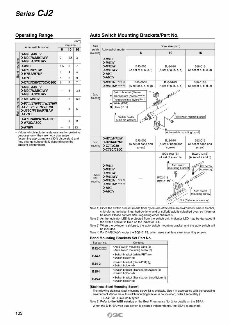
∗ Values which include hysteresis are for guideline purposes only, they are not a guarantee(assuming approximately ±30% dispersion) andmay change substantially depending on theambient environment.
(mm)
Auto switch
mountingAuto switch model
Bore size (mm)
6 10 16
Band mounting
D-M9lD-M9lVD-M9lWD-M9lWVD-A9lD-A9lV
BJ6-006(A set of a, b, d, f)
BJ6-010(A set of a, b, c, d)
BJ6-016(A set of a, b, c, d)
D-M9lA Note 2)
D-M9lAV Note 2)BJ6-006S
(A set of a, b, d, g)BJ6-010S
(A set of a, b, d, e)BJ6-016S
(A set of a, b, d, e)
Switch bracket (Resin)Transparent (Nylon) Note 1)
Transparent blue (Nylon) Note 1)
White (PBT)
c
f
Black (PBT)ge
Switch holder(Zinc die-casted)
d
Auto switch mounting banda
Auto switch mounting screwb
Band mounting
D-H7l/H7lWD-H7BA/H7NFD-C7l/C80D-C73C/C80C
BJ2-006(A set of band and
screw)
BJ2-010(A set of band and
screw)
BJ2-016(A set of band and
screw)
Note 4)
Rail mounting
D-M9lD-M9lVD-M9lWD-M9lWVD-M9lA Note 4)
D-M9lAV Note 4)
D-A9lD-A9lV
—
BQ2-012 (S)(A set of a and b)
BQ2-012 (S)(A set of a and b)
Set screw(Accessory)
Auto switchmounting screw
b
BQ2-012BQ2-012S
Auto switchmounting bracket
a
Nut (Cylinder accessory)
Auto switch modelBore size
6 10 16
Ban
d m
ount
ing
D-M9l/M9lVD-M9lW/M9lWVD-M9lA/M9lAV
2 2.5 3
D-A9l 4.5 6 7
D-H7l/H7lWD-H7BA/H7NF 3 4 4
D-H7C 5 8 9
D-C7l/C80/C73C/C80C 6 7 7
Rai
l mou
ntin
g
D-M9l/M9lVD-M9lW/M9lWVD-M9lA/M9lAV
— 3 3.5
D-A9l/A9lV — 6 6.5
D-F7l/J79/F7lW/J79WD-F7lV/F7lWV/F79FD-J79C/F7BA/F7BAVD-F7NT
— 5 5
D-A7l/A80/A7H/A80HD-A73C/A80C — 8 9
D-A79W — 11 13
Note 1) Since the switch bracket (made from nylon) are affected in an environment where alcohol, chloroform, methylamines, hydrochloric acid or sulfuric acid is splashed over, so it cannot be used. Please contact SMC regarding other chemicals.
Note 2) As the indicator LED is projected from the switch unit, indicator LED may be damaged if the switch bracket is fixed on the indicator LED.
Note 3) When the cylinder is shipped, the auto switch mounting bracket and the auto switch will be included.
Note 4) For D-M9A(V), order the BQ2-012S, which uses stainless steel mounting screws.
[Stainless Steel Mounting Screw]The following stainless steel mounting screw kit is available. Use it in accordance with the operating environment. (Since the auto switch mounting bracket is not included, order it separately.)
BBA4: For D-C7/C8/H7 typesNote 5) Refer to the WEB catalog or the Best Pneumatics No. 2 for details on the BBA4.
When the D-H7BA type auto switch is shipped independently, the BBA4 is attached.
Band Mounting Brackets Set Part No.Set part no. Contents
BJ2-lll • Auto switch mounting band (a)• Auto switch mounting screw (b)
BJ4-1 • Switch bracket (White/PBT) (e)• Switch holder (d)
BJ4-2 • Switch bracket (Black/PBT) (g)• Switch holder (d)
BJ5-1 • Switch bracket (Transparent/Nylon) (c)• Switch holder (d)
BJ5-2 • Switch bracket (Transparent blue/Nylon) (f)• Switch holder (d)
Operating Range Auto Switch Mounting Brackets/Part No.
103
Series CJ2
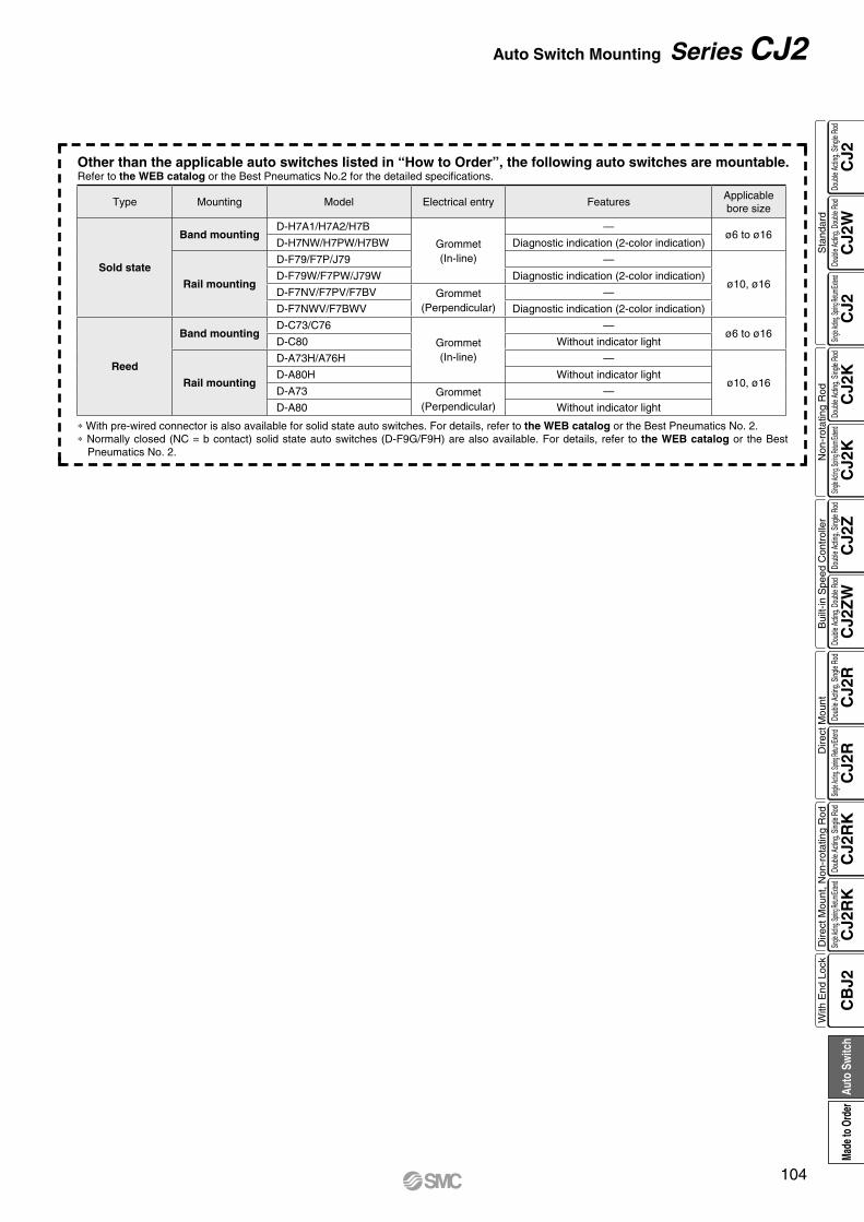
Other than the applicable auto switches listed in “How to Order”, the following auto switches are mountable.Refer to the WEB catalog or the Best Pneumatics No.2 for the detailed specifications.
∗ With pre-wired connector is also available for solid state auto switches. For details, refer to the WEB catalog or the Best Pneumatics No. 2.∗ Normally closed (NC = b contact) solid state auto switches (D-F9G/F9H) are also available. For details, refer to the WEB catalog or the Best
Pneumatics No. 2.
Type Mounting Model Electrical entry FeaturesApplicablebore size
Sold state
Band mountingD-H7A1/H7A2/H7B
Grommet(In-line)
—ø6 to ø16
D-H7NW/H7PW/H7BW Diagnostic indication (2-color indication)
Rail mounting
D-F79/F7P/J79 —
ø10, ø16D-F79W/F7PW/J79W Diagnostic indication (2-color indication)
D-F7NV/F7PV/F7BV Grommet(Perpendicular)
—
D-F7NWV/F7BWV Diagnostic indication (2-color indication)
Reed
Band mountingD-C73/C76
Grommet(In-line)
—ø6 to ø16
D-C80 Without indicator light
Rail mounting
D-A73H/A76H —
ø10, ø16D-A80H Without indicator light
D-A73 Grommet(Perpendicular)
—
D-A80 Without indicator light
104
Auto Switch Mounting Series CJ2
CJ2
CJ2
WC
J2C
J2K
CJ2
KC
J2Z
CJ2
ZW
CJ2
RC
J2R
CJ2
RK
CJ2
RK
CB
J2
Sta
ndar
dN
on-r
otat
ing
Rod
Bui
lt-in
Spe
ed C
ontr
olle
rD
irect
Mou
ntD
irect
Mou
nt, N
on-r
otat
ing
Rod
With
End
Loc
kDo
uble
Actin
g, Do
uble
Rod
Single
Acting
, Sprin
g Retu
rn/Exte
ndDo
uble
Actin
g, Si
ngle
Rod
Single
Acting
, Sprin
g Retu
rn/Exte
ndDo
uble
Actin
g, Si
ngle
Rod
Doub
le Ac
ting,
Doub
le Ro
dDo
uble
Actin
g, Si
ngle
Rod
Single
Acting
, Sprin
g Retu
rn/Exte
ndDo
uble
Actin
g, Si
ngle
Rod
Single
Acting
, Sprin
g Retu
rn/Exte
ndDo
uble
Actin
g, Si
ngle
Rod
Auto
Sw
itch
Made
to O
rder
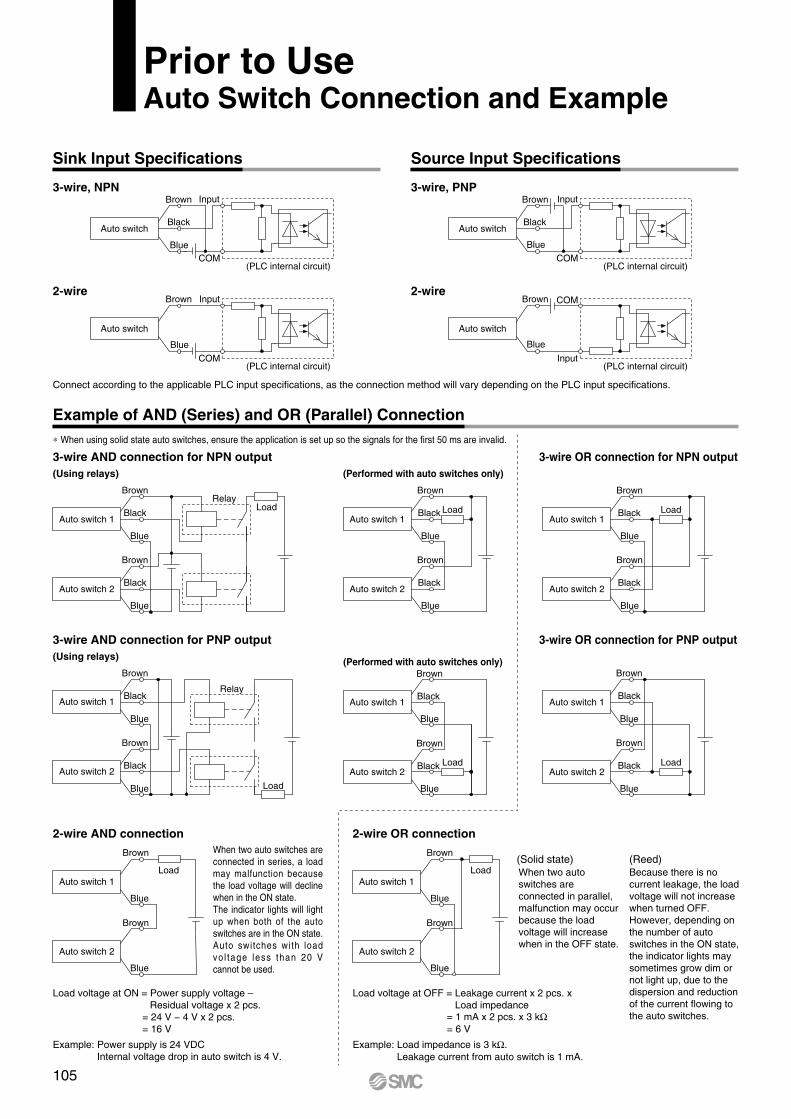
Relay
RelayLoad
Load
Load
Load Load
Load Load
Load
Blue
Black
Brown
Auto switch 2
Blue
Black
Brown
Auto switch 1
Blue
Black
Brown
Auto switch 2
Blue
Black
Brown
Auto switch 1
Blue
Black
Brown
Auto switch 2
Blue
Black
Brown
Auto switch 1
Blue
Black
Brown
Auto switch 2
Blue
Black
Brown
Auto switch 1
Blue
Brown
Auto switch 2
Blue
Brown
Auto switch 1
Blue
Black
Brown
Auto switch 2
Blue
Black
Brown
Auto switch 1
Blue
Brown
Auto switch 2
Blue
Brown
Auto switch 1
Blue
Black
Brown
Auto switch 2
Blue
Black
Brown
Auto switch 1
Input
COM
COMCOM
COM
InputInput
Input
Blue
Brown
Blue
Brown
Blue
Black
Brown
Blue
Black
Brown
Auto switch
Auto switch
Auto switch
Auto switch
* When using solid state auto switches, ensure the application is set up so the signals for the first 50 ms are invalid.
Connect according to the applicable PLC input specifications, as the connection method will vary depending on the PLC input specifications.
Because there is no current leakage, the load voltage will not increase when turned OFF. However, depending on the number of auto switches in the ON state, the indicator lights may sometimes grow dim or not light up, due to the dispersion and reduction of the current flowing to the auto switches.
When two auto switches are connected in parallel, malfunction may occur because the load voltage will increase when in the OFF state.Auto switches with load
vo l tage less than 20 V cannot be used.
When two auto switches are connected in series, a load may malfunction because the load voltage will decline when in the ON state.The indicator lights will light up when both of the auto switches are in the ON state.
(Reed)(Solid state)
Example: Load impedance is 3 kW.Leakage current from auto switch is 1 mA.
Load voltage at OFF = Leakage current x 2 pcs. x Load impedance
= 1 mA x 2 pcs. x 3 kW= 6 V
Example: Power supply is 24 VDCInternal voltage drop in auto switch is 4 V.
Load voltage at ON = Power supply voltage – Residual voltage x 2 pcs.
= 24 V − 4 V x 2 pcs.= 16 V
Prior to UseAuto Switch Connection and Example
3-wire, NPN
2-wire
3-wire, PNP
2-wire
(PLC internal circuit)
(PLC internal circuit)
(PLC internal circuit)
(PLC internal circuit)
3-wire AND connection for NPN output(Using relays) (Performed with auto switches only)
3-wire OR connection for NPN output
3-wire AND connection for PNP output(Using relays) (Performed with auto switches only)
3-wire OR connection for PNP output
2-wire AND connection 2-wire OR connection
Sink Input Specifications
Example of AND (Series) and OR (Parallel) Connection
Source Input Specifications
105
106
CJ2
CJ2
WC
J2C
J2K
CJ2
KC
J2Z
CJ2
ZW
CJ2
RC
J2R
CJ2
RK
CJ2
RK
CB
J2
Sta
ndar
dN
on-r
otat
ing
Rod
Bui
lt-in
Spe
ed C
ontr
olle
rD
irect
Mou
ntD
irect
Mou
nt, N
on-r
otat
ing
Rod
With
End
Loc
kDo
uble
Actin
g, Do
uble
Rod
Single
Acting
, Sprin
g Retu
rn/Exte
ndDo
uble
Actin
g, Si
ngle
Rod
Single
Acting
, Sprin
g Retu
rn/Exte
ndDo
uble
Actin
g, Si
ngle
Rod
Doub
le Ac
ting,
Doub
le Ro
dDo
uble
Actin
g, Si
ngle
Rod
Single
Acting
, Sprin
g Retu
rn/Exte
ndDo
uble
Actin
g, Si
ngle
Rod
Single
Acting
, Sprin
g Retu
rn/Exte
ndDo
uble
Actin
g, Si
ngle
Rod
Auto
Sw
itch
Made
to O
rder

Made to Order
Simple SpecialsThe following special specifications can be ordered as a simplified Made-to-Order.There is a specification sheet available on paper and CD-ROM. Please contact your SMC sales representatives if necessary.
Heat resistant cylinder (−10 to 150°C)
Cold resistant cylinder (−40 to 70°C)
Low speed cylinder (10 to 50 mm/s)
Low speed cylinder (5 to 50 mm/s) (ø6 only)
Special port position
Adjustable stroke cylinder/Adjustable extension type
Adjustable stroke cylinder/Adjustable retraction type
Dual stroke cylinder/Double rod type
Dual stroke cylinder/Single rod type
Fluororubber seal
With hose nipple
Grease for food processing equipment
PTFE grease
Short pitch mounting (ø6 only)
-XB6
-XB7
-XB9
-XB13
-XC3
-XC8
-XC9
-XC10
-XC11
-XC22
-XC51
-XC85
-X446
-X773
Specifications
Symbol
Symbol
Specifications
Change of rod end shape-XA0, 1, 10, 11
CJ2(Standard type)
Double acting Single actingSingle
rodDouble
rodSingle rod
(spring return)Single rod
(spring extend)
CJ2K(Non-rotating rod type)
Double acting Single actingSingle
rodSingle rod
(spring return)Single rod
(spring extend)
CJ2(Standard type)
Double acting Single actingSingle
rodDouble
rodSingle rod
(spring return)Single rod
(spring extend)
CJ2K(Non-rotating rod type)
Double acting Single actingSingle
rodSingle rod
(spring return)Single rod
(spring extend)
Series CJ2Simple Specials/Made to OrderPlease contact SMC for detailed specifications, delivery and prices.
107

-XB6
-XB7
-XB9
-XB13
-XC3
-XC8
-XC9
-XC10
-XC11
-XC22
-XC51
-XC85
-X446
-X773
Symbol
Symbol
-XA0, 1, 10, 11
Page 110
Page 110
Page 110
Page 111
Page 111
Page 111
Page 112
Page 112
Page 113
Page 114
Page 114
Page 115
Page 115
Page 116
Page 109
Page
Page
CJ2RK(Direct mount, Non-rotating rod type)
Double acting Single acting
Single rod Single rod(spring return)
Single rod(spring extend)
CJ2R(Direct mount type)
Double acting Single acting
Single rod Single rod(spring return)
Single rod(spring extend)
CJ2Z(Built-in speed controller type)
Double acting
Single rod Double rod
108
Simple Specials/Made to Order Series CJ2
CJ2
CJ2
WC
J2C
J2K
CJ2
KC
J2Z
CJ2
ZW
CJ2
RC
J2R
CJ2
RK
CJ2
RK
CB
J2
Sta
ndar
dN
on-r
otat
ing
Rod
Bui
lt-in
Spe
ed C
ontr
olle
rD
irect
Mou
ntD
irect
Mou
nt, N
on-r
otat
ing
Rod
With
End
Loc
kDo
uble
Actin
g, Do
uble
Rod
Single
Acting
, Sprin
g Retu
rn/Exte
ndDo
uble
Actin
g, Si
ngle
Rod
Single
Acting
, Sprin
g Retu
rn/Exte
ndDo
uble
Actin
g, Si
ngle
Rod
Doub
le Ac
ting,
Doub
le Ro
dDo
uble
Actin
g, Si
ngle
Rod
Single
Acting
, Sprin
g Retu
rn/Exte
ndDo
uble
Actin
g, Si
ngle
Rod
Single
Acting
, Sprin
g Retu
rn/Exte
ndDo
uble
Actin
g, Si
ngle
Rod
Auto
Sw
itch
Made
to O
rder
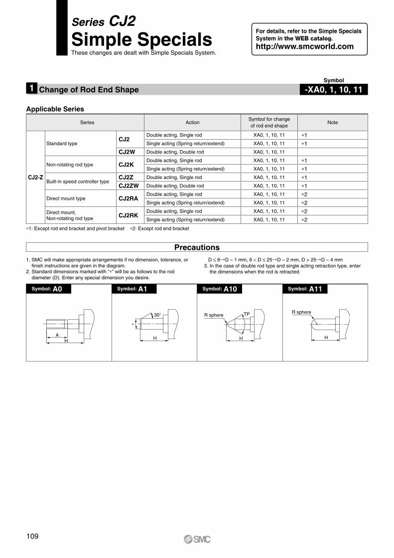
AH H
30°
∗
H
TPR sphere
H
R sphere
*1: Except rod end bracket and pivot bracket *2: Except rod end bracket
Symbol: A11Symbol: A10Symbol: A1Symbol: A0
Precautions D ≤ 6RD – 1 mm, 6 < D ≤ 25RD – 2 mm, D > 25RD – 4 mm3. In the case of double rod type and single acting retraction type, enter
the dimensions when the rod is retracted.
1. SMC will make appropriate arrangements if no dimension, tolerance, or finish instructions are given in the diagram.
2. Standard dimensions marked with “*” will be as follows to the rod diameter (D). Enter any special dimension you desire.
-XA0, 1, 10, 11Symbol
1 Change of Rod End Shape
Applicable Series
Series ActionSymbol for changeof rod end shape
Note
CJ2-Z
Standard typeCJ2
Double acting, Single rod XA0, 1, 10, 11 *1Single acting (Spring return/extend) XA0, 1, 10, 11 *1
CJ2W Double acting, Double rod XA0, 1, 10, 11
Non-rotating rod type CJ2KDouble acting, Single rod XA0, 1, 10, 11 *1Single acting (Spring return/extend) XA0, 1, 10, 11 *1
Built-in speed controller typeCJ2Z Double acting, Single rod XA0, 1, 10, 11 *1
CJ2ZW Double acting, Double rod XA0, 1, 10, 11 *1
Direct mount type CJ2RADouble acting, Single rod XA0, 1, 10, 11 *2Single acting (Spring return/extend) XA0, 1, 10, 11 *2
Direct mount, Non-rotating rod type CJ2RK
Double acting, Single rod XA0, 1, 10, 11 *2Single acting (Spring return/extend) XA0, 1, 10, 11 *2
Series CJ2Simple SpecialsThese changes are dealt with Simple Specials System.
For details, refer to the Simple Specials System in the WEB catalog.http://www.smcworld.com
109

Air cylinder which changed the seal material and grease, so that it could be used even at higher temperature up to 150 from –10°C.
Air cylinder which changed the seal material and grease, so that it could be used even at lower temperature down to – 40°C.
Even if driving at lower speeds 10 to 50 mm/s, there would be no stick-slip phenomenon and it can run smoothly.
Low speed cylinder
How to OrderStandard model no. XB9
1 Heat Resistant Cylinder (−10 to 150°C) -XB6Symbol
2 Cold Resistant Cylinder (−40 to 70°C) -XB7Symbol
3 Low Speed Cylinder (10 to 50 mm/s) -XB9Symbol
Heat resistant cylinder
How to OrderStandard model no. XB6
Note 1) Operate without lubrication from a pneumatic system lubricator.Note 2) Please contact SMC for details on the maintenance intervals for this
cylinder, which differ from those of the standard cylinder.Note 3) In principle, it is impossible to make built-in magnet type and the one
with auto switch. But, as for the one with auto switch, and the heat resistant cylinder with heat resistant auto switch, please contact SMC.
Note 4) Piston speed is ranged from 50 to 500 mm/s.
Applicable SeriesDescription Model Action Note
Standard type
CJ2Double acting,
Single rodExcept with air cushion
and auto switch
CJ2WDouble acting,
Double rodExcept with air cushion
and auto switch
Cold resistant cylinder
How to OrderStandard model no. XB7
Note 1) Operate without lubrication from a pneumatic system lubricator.Note 2) Use dry air which is suitable for heatless air dryer, etc. not to cause
the moisture to be frozen.Note 3) Please contact SMC for details on the maintenance intervals for this
cylinder, which differ from those of the standard cylinder.Note 4) Mounting auto switch is impossible.Note 5) Piston speed is ranged from 50 to 500 mm/s.
Applicable SeriesDescription Model Action Note
Standard type
CJ2Double acting,
Single rodExcept with air cushion and auto switch,
rod end bracket, pivot bracket
CJ2WDouble acting,
Double rodExcept with air cushion
and auto switch
Applicable SeriesDescription Model Action Note
Standard type CJ2Double acting,
Single rodExcept with air cushion
SpecificationsAmbient temperature range −10°C to 150°CSeals material Fluororubber
Grease Heat resistant grease
Specifications other than above and external dimensions Same as standard type
SpecificationsAmbient temperature range −40°C to 70°CSeals material Low nitrile rubber
Grease Cold resistant grease
Auto switch Not mountable
Dimensions Same as standard type
Additional specifications Same as standard type
Note) Operate without lubrication from a pneumatic system lubricator.
SpecificationsPiston speed 10 to 50 mm/s
Dimensions Same as standard type
Additional specifications Same as standard type
Be aware that smoking cigarettes etc. after your hands have come into contact with the grease used in this cylinder can create a gas that is hazardous to humans.
PrecautionsWarning
Be aware that smoking cigarettes etc. after your hands have come into contact with the grease used in this cylinder can create a gas that is hazardous to humans.
PrecautionsWarning
Be aware that smoking cigarettes etc. after your hands have come into contact with the grease used in this cylinder can create a gas that is hazardous to humans.
PrecautionsWarning
Series CJ2Made to OrderPlease contact SMC for detailed dimensions, specifications and lead times.
110
CJ2
CJ2
WC
J2C
J2K
CJ2
KC
J2Z
CJ2
ZW
CJ2
RC
J2R
CJ2
RK
CJ2
RK
CB
J2
Sta
ndar
dN
on-r
otat
ing
Rod
Bui
lt-in
Spe
ed C
ontr
olle
rD
irect
Mou
ntD
irect
Mou
nt, N
on-r
otat
ing
Rod
With
End
Loc
kDo
uble
Actin
g, Do
uble
Rod
Single
Acting
, Sprin
g Retu
rn/Exte
ndDo
uble
Actin
g, Si
ngle
Rod
Single
Acting
, Sprin
g Retu
rn/Exte
ndDo
uble
Actin
g, Si
ngle
Rod
Doub
le Ac
ting,
Doub
le Ro
dDo
uble
Actin
g, Si
ngle
Rod
Single
Acting
, Sprin
g Retu
rn/Exte
ndDo
uble
Actin
g, Si
ngle
Rod
Single
Acting
, Sprin
g Retu
rn/Exte
ndDo
uble
Actin
g, Si
ngle
Rod
Auto
Sw
itch
Made
to O
rder
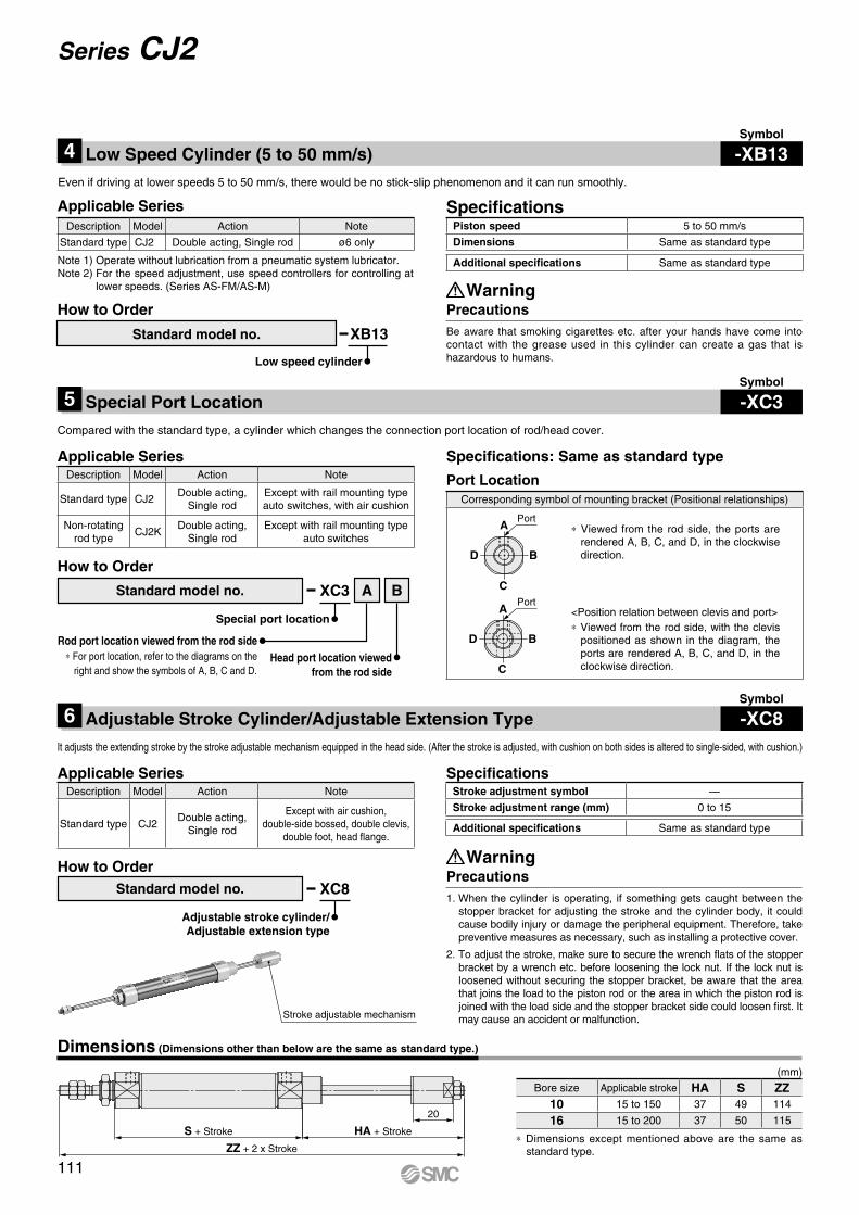
ZZ + 2 x Stroke
S + Stroke HA + Stroke
20
Even if driving at lower speeds 5 to 50 mm/s, there would be no stick-slip phenomenon and it can run smoothly.
4 Low Speed Cylinder (5 to 50 mm/s) -XB13Symbol
Description Model Action Note
Standard type CJ2 Double acting, Single rod ø6 only
Piston speed 5 to 50 mm/s
Dimensions Same as standard type
Additional specifications Same as standard type
Applicable Series Specifications
Note 1) Operate without lubrication from a pneumatic system lubricator.Note 2) For the speed adjustment, use speed controllers for controlling at
lower speeds. (Series AS-FM/AS-M)
Be aware that smoking cigarettes etc. after your hands have come into contact with the grease used in this cylinder can create a gas that is hazardous to humans.
PrecautionsWarning
XB13Standard model no.
How to Order
Low speed cylinder
Compared with the standard type, a cylinder which changes the connection port location of rod/head cover.
5 Special Port Location -XC3Symbol
Special port location
Rod port location viewed from the rod sideHead port location viewed
from the rod side* For port location, refer to the diagrams on the
right and show the symbols of A, B, C and D.
How to Order
Standard model no. XC3 A B
Corresponding symbol of mounting bracket (Positional relationships)
B
C
D
APort
D
C
B
APort
Applicable SeriesDescription Model Action Note
Standard type CJ2Double acting,
Single rodExcept with rail mounting typeauto switches, with air cushion
Non-rotating rod type
CJ2KDouble acting,
Single rodExcept with rail mounting type
auto switches
Specifications: Same as standard type
* Viewed from the rod side, the ports are rendered A, B, C, and D, in the clockwise direction.
<Position relation between clevis and port>* Viewed from the rod side, with the clevis
positioned as shown in the diagram, the ports are rendered A, B, C, and D, in the clockwise direction.
Port Location
Dimensions (Dimensions other than below are the same as standard type.)
* Dimensions except mentioned above are the same as standard type.
(mm)
Bore size Applicable stroke HA S ZZ10 15 to 150 37 49 114
16 15 to 200 37 50 115
It adjusts the extending stroke by the stroke adjustable mechanism equipped in the head side. (After the stroke is adjusted, with cushion on both sides is altered to single-sided, with cushion.)
6 Adjustable Stroke Cylinder/Adjustable Extension Type -XC8Symbol
Applicable SeriesDescription Model Action Note
Standard type CJ2Double acting,
Single rod
Except with air cushion, double-side bossed, double clevis,
double foot, head flange.
SpecificationsStroke adjustment symbol —
Stroke adjustment range (mm) 0 to 15
Additional specifications Same as standard type
Stroke adjustable mechanism
Standard model no.
Adjustable stroke cylinder/Adjustable extension type
How to OrderXC8
1. When the cylinder is operating, if something gets caught between the stopper bracket for adjusting the stroke and the cylinder body, it could cause bodily injury or damage the peripheral equipment. Therefore, take preventive measures as necessary, such as installing a protective cover.
2. To adjust the stroke, make sure to secure the wrench flats of the stopper bracket by a wrench etc. before loosening the lock nut. If the lock nut is loosened without securing the stopper bracket, be aware that the area that joins the load to the piston rod or the area in which the piston rod is joined with the load side and the stopper bracket side could loosen first. It may cause an accident or malfunction.
PrecautionsWarning
111
Series CJ2

ZZ + Stroke Max.30
BMAdjusting bolt
AD Stroke AB C
CDB A
NBZ + Stroke (A + B)
S + Stroke B S + Stroke A
D portB port C port A port
Stroke AStroke B AB D C
CBStroke B D A
Adjusting bolt
The retracting stroke of the cylinder can be adjusted by the adjusting bolt.
Two cylinders are constructed as one cylinder in a back-to-back configuration allowing the cylinder stroke to be controlled in three steps.
7 Adjustable Stroke Cylinder/Adjustable Retraction Type -XC9Symbol
8 Dual Stroke Cylinder/Double Rod Type -XC10Symbol
SpecificationsStroke adjustment symbol —Stroke adjustment range (mm) 0 to 15
Additional specifications Same as standard type
SpecificationsMaximum manufacturable stroke (mm) 300 (Maximum 150 on one side)
Additional specifications Same as standard type
Applicable SeriesDescription Model Action Note
Standard type CJ2Double acting,
Single rod
Except double-side bossed, double
clevis, double foot, head flange.
Non-rotating rod type CJ2KDouble acting,
Single rod
Except double-side bossed, double
clevis, double foot, head flange.
Direct mount type CJ2RDouble acting,
Single rod
Direct mount,Non-rotating rod type
CJ2RKDouble acting,
Single rod
Applicable SeriesDescription Model Action Note
Standardtype
CJ2Double acting,
Single rodExcept with air cushion, rod end
bracket and pivot bracket
Non-rotating rod type
CJ2KDouble acting,
Single rodExcept rod end bracket and
pivot bracket
Dual stroke cylinder/Double rod type
How to OrderMounting style Bore size Stroke A Stroke B XC10CJ2 Z
Dimensions (Dimensions other than below are the same as standard type.)
Adjustable stroke cylinder/Adjustable retraction type
How to OrderXC9
* Dimensions except mentioned above are the same as standard type.
(mm)
Bore size BM ZZ10 M5 x 0.8 74
16 M5 x 0.8 75
(mm)
Bore size NB S Z10 21 36.5 150
16 21 37.5 152
Dimensions (Dimensions other than below are the same as standard type.)
Function
When air pressure is supplied to ports and , both strokes A and B retract.
When air pressure is supplied to ports and , A out strokes.
When air pressure is supplied to ports and , B out strokes.
When air pressure is supplied to ports and , both strokes A and B out strokes.
1. When air is supplied to the cylinder, if the stroke adjusting bolt is loosened in excess of the allowable stroke adjustment amount, be aware that the stroke adjusting bolt could fly out or air could be discharged, which could injure personnel or damage the peripheral equipment.
2. Adjust the stroke when the cylinder is not pressurized.If it is adjusted in the pressurized state, the seal of the adjustment section could become deformed, leading to air leakage.
PrecautionsCaution
Standard model no.
112
Made to Order Series CJ2
CJ2
CJ2
WC
J2C
J2K
CJ2
KC
J2Z
CJ2
ZW
CJ2
RC
J2R
CJ2
RK
CJ2
RK
CB
J2
Sta
ndar
dN
on-r
otat
ing
Rod
Bui
lt-in
Spe
ed C
ontr
olle
rD
irect
Mou
ntD
irect
Mou
nt, N
on-r
otat
ing
Rod
With
End
Loc
kDo
uble
Actin
g, Do
uble
Rod
Single
Acting
, Sprin
g Retu
rn/Exte
ndDo
uble
Actin
g, Si
ngle
Rod
Single
Acting
, Sprin
g Retu
rn/Exte
ndDo
uble
Actin
g, Si
ngle
Rod
Doub
le Ac
ting,
Doub
le Ro
dDo
uble
Actin
g, Si
ngle
Rod
Single
Acting
, Sprin
g Retu
rn/Exte
ndDo
uble
Actin
g, Si
ngle
Rod
Single
Acting
, Sprin
g Retu
rn/Exte
ndDo
uble
Actin
g, Si
ngle
Rod
Auto
Sw
itch
Made
to O
rder

SA + Stroke ASB + Stroke B
Z + Stroke (A + B)
B port C port A port
Intermediate cover
ACB
Stroke B Stroke A
A
AC
AC
Stroke B Stroke A
CB
Stroke A
B
BStroke B – A
ACB
Stroke B Stroke A
ACB
Stroke B Stroke A
ACBStroke A
CB AStroke B
ACB
Stroke B Stroke A
ACB
W
Stroke A
W
Two cylinders can be integrated by connecting them in line, and the cylinder stroke can be controlled in two stages in both directions.
9 Dual Stroke Cylinder/Single Rod Type -XC11Symbol
Applicable SeriesDescription Model Action Note
Standard type CJ2Double acting,
Single rodExcept withair cushion
Dual stroke cylinder/Single rod type
How to OrderMounting style Bore size Stroke A Stroke B – A Pivot bracket Rod end bracket XC11CJ2 Z
Specifications: Same as standard type* Please contact SMC for each manufacturable stroke length.
(mm)
Bore size SA SB Z10 31.5 53 112.5
16 33 53 114
* Dimensions except mentioned above are the same as standard type.
Note 1) When mounting an auto switch at the extended piston rod A side, the following auto switches interfere with the intermediate cover. In this case, please mount on the stroke B side. Please be aware that the auto switch defects and temporarily turns ON/OFF when passing the intermediate position of the B stroke.Solid state auto switch: D-H7, D-H7C, D-H7W, D-H7NF,
D-H7BAReed auto switch: D-C7, D-C80, D-C73C, D-C80C, D-A80,
D-A9, D-A9V, D-A79W, D-A73Note 2) The maximum manufacturable stroke of this cylinder is 150 mm for
both A and B.
Dimensions (Dimensions other than below are the same as standard type.)
Functional description of dual stroke cylinder
Stroke A or Stroke B operation can be made individually.
Double output is possible.
4) Cylinder retractionWhen the air pressure is supplied from the
port, the rod re-tracts completely.
3) 2nd stage (Stroke B-A operation)Following the 1st stage, when the air pressure is supplied from the port, the rod operates the stroke B-A.
2) 1st stage (Stroke A operation)When the air pressure is supplied from the
port, the rod oper-ates the stroke A.
1) Initial state(0 stroke position)
2) Double outputWhen the air pressure is supplied to the and ports at the same time, the double output can be obtained in the stroke A range.
1) Initial state(0 stroke position)
Stroke B operation
2) OperationWhen the air pressure is supplied from the
port, the rod oper-ates the stroke B.
1) Initial state(0 stroke position)
Stroke A operation
2) OperationWhen the air pressure is supplied from the
port, the rod oper-ates the stroke A.
1) Initial state(0 stroke position)
1. Do not supply air until the cylinder is fixed.
2. If air is supplied without securing the cylinder, the cylinder could lurch, posing the risk of bodily injury or damage to the peripheral equipment.
PrecautionsCaution
113
Series CJ2
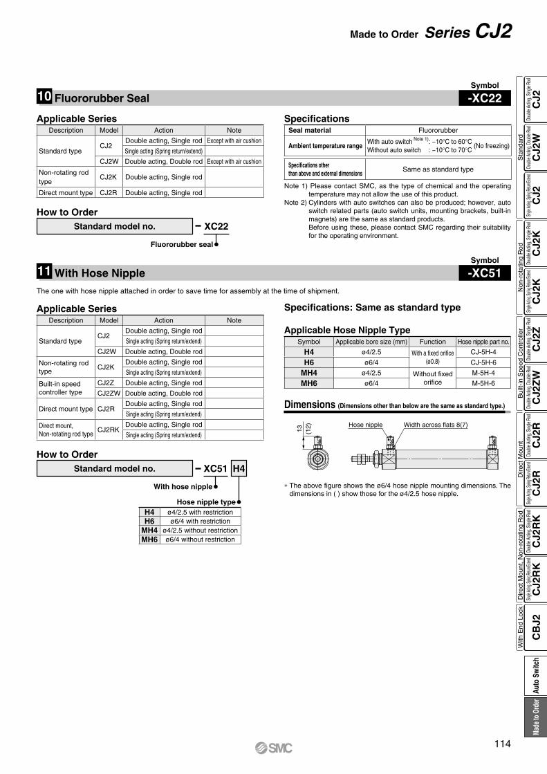
13 (12) Hose nipple Width across flats 8(7)
10 Fluororubber Seal -XC22Symbol
Fluororubber seal
How to OrderStandard model no. XC22
SpecificationsSeal material Fluororubber
Ambient temperature rangeWith auto switch Note 1): −10°C to 60°C
(No freezing)Without auto switch : −10°C to 70°C
Specifications otherthan above and external dimensions
Same as standard type
Note 1) Please contact SMC, as the type of chemical and the operating temperature may not allow the use of this product.
Note 2) Cylinders with auto switches can also be produced; however, auto switch related parts (auto switch units, mounting brackets, built-in magnets) are the same as standard products.Before using these, please contact SMC regarding their suitability for the operating environment.
Applicable SeriesDescription Model Action Note
Standard typeCJ2
Double acting, Single rod Except with air cushion
Single acting (Spring return/extend)
CJ2W Double acting, Double rod Except with air cushion
Non-rotating rod type
CJ2K Double acting, Single rod
Direct mount type CJ2R Double acting, Single rod
The one with hose nipple attached in order to save time for assembly at the time of shipment.
11 With Hose Nipple -XC51Symbol
Dimensions (Dimensions other than below are the same as standard type.)
Applicable SeriesDescription Model Action Note
Standard typeCJ2
Double acting, Single rod
Single acting (Spring return/extend)
CJ2W Double acting, Double rod
Non-rotating rod type
CJ2KDouble acting, Single rod
Single acting (Spring return/extend)
Built-in speed controller type
CJ2Z Double acting, Single rod
CJ2ZW Double acting, Double rod
Direct mount type CJ2RDouble acting, Single rod
Single acting (Spring return/extend)
Direct mount,Non-rotating rod type
CJ2RKDouble acting, Single rod
Single acting (Spring return/extend)
* The above figure shows the ø6/4 hose nipple mounting dimensions. The dimensions in ( ) show those for the ø4/2.5 hose nipple.
Specifications: Same as standard type
With hose nipple
How to OrderStandard model no. XC51 H4
Hose nipple typeH4 ø4/2.5 with restrictionH6 ø6/4 with restriction
MH4 ø4/2.5 without restrictionMH6 ø6/4 without restriction
Applicable Hose Nipple TypeSymbol Applicable bore size (mm) Function Hose nipple part no.
H4 ø4/2.5 With a fixed orifice(ø0.8)
CJ-5H-4
H6 ø6/4 CJ-5H-6
MH4 ø4/2.5 Without fixedorifice
M-5H-4
MH6 ø6/4 M-5H-6
114
Made to Order Series CJ2
CJ2
CJ2
WC
J2C
J2K
CJ2
KC
J2Z
CJ2
ZW
CJ2
RC
J2R
CJ2
RK
CJ2
RK
CB
J2
Sta
ndar
dN
on-r
otat
ing
Rod
Bui
lt-in
Spe
ed C
ontr
olle
rD
irect
Mou
ntD
irect
Mou
nt, N
on-r
otat
ing
Rod
With
End
Loc
kDo
uble
Actin
g, Do
uble
Rod
Single
Acting
, Sprin
g Retu
rn/Exte
ndDo
uble
Actin
g, Si
ngle
Rod
Single
Acting
, Sprin
g Retu
rn/Exte
ndDo
uble
Actin
g, Si
ngle
Rod
Doub
le Ac
ting,
Doub
le Ro
dDo
uble
Actin
g, Si
ngle
Rod
Single
Acting
, Sprin
g Retu
rn/Exte
ndDo
uble
Actin
g, Si
ngle
Rod
Single
Acting
, Sprin
g Retu
rn/Exte
ndDo
uble
Actin
g, Si
ngle
Rod
Auto
Sw
itch
Made
to O
rder
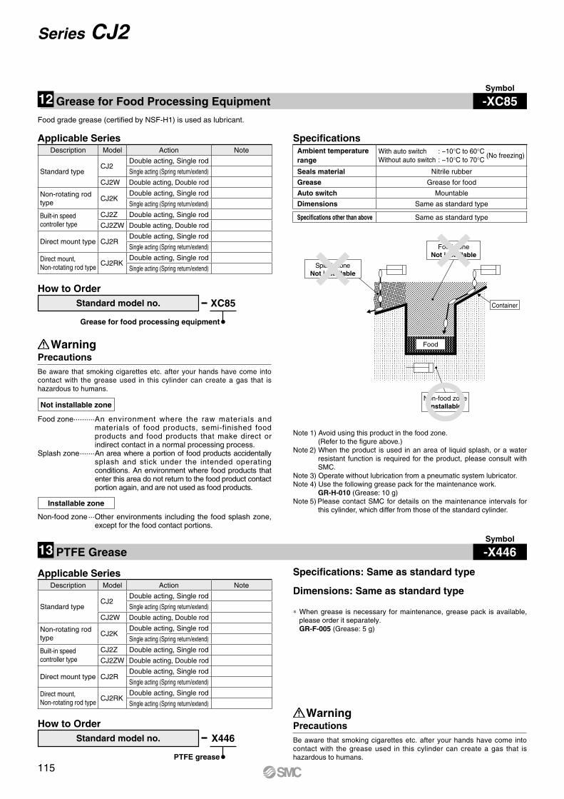
Splash zoneNot installable
Food zoneNot installable
Non-food zoneInstallable
Container
Food
Note 1) Avoid using this product in the food zone. (Refer to the figure above.)
Note 2) When the product is used in an area of liquid splash, or a water resistant function is required for the product, please consult with SMC.
Note 3) Operate without lubrication from a pneumatic system lubricator.Note 4) Use the following grease pack for the maintenance work.
GR-H-010 (Grease: 10 g)Note 5) Please contact SMC for details on the maintenance intervals for
this cylinder, which differ from those of the standard cylinder.
* When grease is necessary for maintenance, grease pack is available, please order it separately.GR-F-005 (Grease: 5 g)
Specifications: Same as standard type
Dimensions: Same as standard type
12 Grease for Food Processing Equipment -XC85Symbol
13 PTFE Grease -X446Symbol
Applicable SeriesDescription Model Action Note
Standard typeCJ2
Double acting, Single rod
Single acting (Spring return/extend)
CJ2W Double acting, Double rod
Non-rotating rod type
CJ2KDouble acting, Single rod
Single acting (Spring return/extend)
Built-in speed controller type
CJ2Z Double acting, Single rod
CJ2ZW Double acting, Double rod
Direct mount type CJ2RDouble acting, Single rod
Single acting (Spring return/extend)
Direct mount,Non-rotating rod type
CJ2RKDouble acting, Single rod
Single acting (Spring return/extend)
PTFE grease
How to OrderStandard model no. X446
Food grade grease (certified by NSF-H1) is used as lubricant.
Grease for food processing equipment
How to OrderStandard model no. XC85
SpecificationsAmbient temperature range
With auto switch : −10°C to 60°C (No freezing)
Without auto switch : −10°C to 70°C
Seals material Nitrile rubber
Grease Grease for food
Auto switch Mountable
Dimensions Same as standard type
Specifications other than above Same as standard type
Precautions
Precautions
Warning
Warning
Be aware that smoking cigarettes etc. after your hands have come into contact with the grease used in this cylinder can create a gas that is hazardous to humans.
Be aware that smoking cigarettes etc. after your hands have come into contact with the grease used in this cylinder can create a gas that is hazardous to humans.
Food zone ·········· An environment where the raw materials and materials of food products, semi-finished food products and food products that make direct or indirect contact in a normal processing process.
Splash zone ······· An area where a portion of food products accidentally splash and stick under the intended operating conditions. An environment where food products that enter this area do not return to the food product contact portion again, and are not used as food products.
Not installable zone
Non-food zone ··· Other environments including the food splash zone, except for the food contact portions.
Installable zone
115
Series CJ2

7.5 mm
ø7
ø3
Z + Stroke
S + Stroke 5
38
28
15
ø7
Air exhaust portM6 x 1.0M3 x 0.5
urethane tube (TU0425) or
Be sure to use a ø4 or ø2.5
a soft nylon tube (TS0425).
0
ø
6n8−
0.01
8
Dimensions
Applicationexample
Verification of push button actuation for mobile phones, etc.
Mounting pitch is shortened when cylinders are used in parallel.Changes rod cover and head cover dimensions to ø7.Shortens the full length with a head cover integrated with a barb fitting.
Note) Directly mounted with cylinder mounting screws
(mm)
Note1. When mounting a cylinder, make sure that the
air exhaust port on the rod cover is not blocked.2. When mounting a cylinder, apply thread locking
adhesive on the threaded part and hold the external diameter of the rod cover with a needle-nose pliers or regular pliers.
Symbol
-X773Short Pitch Mounting/Single Acting, Spring Return14
How to Order
Short pitch mounting/Single acting, spring return
StrokeCJ2B6 SU4 X773
Applicable SeriesDescription Model Action Note
Standard type CJ2 Single acting (Spring return)
SpecificationsBore size 6
Action Single acting, Spring return
Operating pressure range 0.2 to 0.7 MPa
Port size With ø4 barb fitting (For soft tube)
Connecting port location Head cover/Axial direction
Stroke 5 to 60
Auto switch None
Stroke 5 to 15 16 to 30 31 to 45 46 to 60
S 30.5 39.5 43.5 57.5
Z 63.5 72.5 76.5 90.5
116
Made to Order Series CJ2
CJ2
CJ2
WC
J2C
J2K
CJ2
KC
J2Z
CJ2
ZW
CJ2
RC
J2R
CJ2
RK
CJ2
RK
CB
J2
Sta
ndar
dN
on-r
otat
ing
Rod
Bui
lt-in
Spe
ed C
ontr
olle
rD
irect
Mou
ntD
irect
Mou
nt, N
on-r
otat
ing
Rod
With
End
Loc
kDo
uble
Actin
g, Do
uble
Rod
Single
Acting
, Sprin
g Retu
rn/Exte
ndDo
uble
Actin
g, Si
ngle
Rod
Single
Acting
, Sprin
g Retu
rn/Exte
ndDo
uble
Actin
g, Si
ngle
Rod
Doub
le Ac
ting,
Doub
le Ro
dDo
uble
Actin
g, Si
ngle
Rod
Single
Acting
, Sprin
g Retu
rn/Exte
ndDo
uble
Actin
g, Si
ngle
Rod
Single
Acting
, Sprin
g Retu
rn/Exte
ndDo
uble
Actin
g, Si
ngle
Rod
Auto
Sw
itch
Made
to O
rder
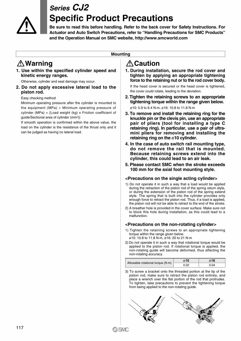
1. During installation, secure the rod cover and tighten by applying an appropriate tightening force to the retaining nut or to the rod cover body.If the head cover is secured or the head cover is tightened, the cover could rotate, leading to the deviation.
2. Tighten the retaining screws to an appropriate tightening torque within the range given below.ø10: 5.9 to 6.4 N·m, ø16: 10.8 to 11.8 N·m
3. To remove and install the retaining ring for the knuckle pin or the clevis pin, use an appropriate pair of pliers (tool for installing a type C retaining ring). In particular, use a pair of ultra-mini pliers for removing and installing the retaining ring on the ø10 cylinder.
4. In the case of auto switch rail mounting type, do not remove the rail that is mounted. Because retaining screws extend into the cylinder, this could lead to an air leak.
5. Please contact SMC when the stroke exceeds 100 mm for the axial foot mounting style.
<Precautions on the single acting cylinder>1) Do not operate it in such a way that a load would be applied
during the retraction of the piston rod of the spring return style, or during the extension of the piston rod of the spring extend style. The spring that is built into the cylinder provides only enough force to retract the piston rod. Thus, if a load is applied, the piston rod will not be able to retract to the end of the stroke.
2) A breather hole is provided in the cover surface. Make sure not to block this hole during installation, as this could lead to a malfunction.
<Precautions on the non-rotating cylinder>1) Tighten the retaining screws to an appropriate tightening
torque within the range given below.ø10: 10.8 to 11.8 N·m, ø16: 20 to 21 N·m
2) Do not operate it in such a way that rotational torque would be applied to the piston rod. If rotational torque is applied, the non-rotating guide will become deformed, thus affecting the non-rotating accuracy.
Allowable rotational torque (N·m)ø10 ø160.02 0.04
3) To screw a bracket onto the threaded portion at the tip of the piston rod, make sure to retract the piston rod entirely, and place a wrench over the flat portion of the rod that protrudes. To tighten, take precautions to prevent the tightening torque from being applied to the non-rotating guide.
Caution
Be sure to read this before handling. Refer to the back cover for Safety Instructions. For Actuator and Auto Switch Precautions, refer to “Handling Precautions for SMC Products” and the Operation Manual on SMC website, http://www.smcworld.com
Series CJ2Specific Product Precautions
1. Use within the specified cylinder speed and kinetic energy ranges.Otherwise, cylinder and seal damage may occur.
2. Do not apply excessive lateral load to the piston rod.Easy checking methodMinimum operating pressure after the cylinder is mounted to the equipment (MPa) = Minimum operating pressure of cylinder (MPa) + {Load weight (kg) x Friction coefficient of guide/Sectional area of cylinder (mm2)}
If smooth operation is confirmed within the above value, the load on the cylinder is the resistance of the thrust only and it can be judged as having no lateral load.
WarningMounting
117
¡The existing product (ø6) and the air cylinder with end lock(Series CBJ2) are added.
¡The models with rod end bracket and/or pivot bracket part numbers are added: CJ2-Z (Single acting), CJ2K-Z (Double acting, Single acting), CJ2Z-Z, CJ2R-Z (Double acting, Single acting), CJ2RK-Z (Double acting, Single acting)
¡Number of pages increased from 104 to 120. SX
Edition C
Revision history
¡Standard type (Double rod, Single acting), Non-rotating rod type,Direct mount type, Direct mount, Non-rotating rod type,Made to Order: Heat resistant cylinder (-XB6),Dual stroke cylinder (-XC10, 11) etc. are added.
¡Number of pages increased from 20 to 104. RW
Edition B
CautionSMC products are not intended for use as instruments for legal metrology.Measurement instruments that SMC manufactures or sells have not been qualified by type approval tests relevant to the metrology (measurement) laws of each country. Therefore, SMC products cannot be used for business or certification ordained by the metrology (measurement) laws of each country.
Compliance Requirements
∗1) ISO 4414: Pneumatic fluid power – General rules relating to systems. ISO 4413: Hydraulic fluid power – General rules relating to systems. IEC 60204-1: Safety of machinery – Electrical equipment of machines. (Part 1: General requirements) ISO 10218-1: Manipulating industrial robots – Safety. etc.
Caution indicates a hazard with a low level of risk which, if not avoided, could result in minor or moderate injury.Caution:Warning indicates a hazard with a medium level of risk which, if not avoided, could result in death or serious injury.Warning:
Danger : Danger indicates a hazard with a high level of risk which, if not avoided, will result in death or serious injury.
Warning Caution1. The compatibility of the product is the responsibility of the
person who designs the equipment or decides its specifications.Since the product specified here is used under various operating conditions, its compatibility with specific equipment must be decided by the person who designs the equipment or decides its specifications based on necessary analysis and test results. The expected performance and safety assurance of the equipment will be the responsibility of the person who has determined its compatibility with the product. This person should also continuously review all specifications of the product referring to its latest catalog information, with a view to giving due consideration to any possibility of equipment failure when configuring the equipment.
2. Only personnel with appropriate training should operate machinery and equipment.The product specified here may become unsafe if handled incorrectly. The assembly, operation and maintenance of machines or equipment including our products must be performed by an operator who is appropriately trained and experienced.
3. Do not service or attempt to remove product and machinery/equipment until safety is confirmed.1. The inspection and maintenance of machinery/equipment should only be
performed after measures to prevent falling or runaway of the driven objects have been confirmed.
2. When the product is to be removed, confirm that the safety measures as mentioned above are implemented and the power from any appropriate source is cut, and read and understand the specific product precautions of all relevant products carefully.
3. Before machinery/equipment is restarted, take measures to prevent unexpected operation and malfunction.
4. Contact SMC beforehand and take special consideration of safety measures if the product is to be used in any of the following conditions. 1. Conditions and environments outside of the given specifications, or use
outdoors or in a place exposed to direct sunlight.2. Installation on equipment in conjunction with atomic energy, railways, air
navigation, space, shipping, vehicles, military, medical treatment, combustion and recreation, or equipment in contact with food and beverages, emergency stop circuits, clutch and brake circuits in press applications, safety equipment or other applications unsuitable for the standard specifications described in the product catalog.
3. An application which could have negative effects on people, property, or animals requiring special safety analysis.
4. Use in an interlock circuit, which requires the provision of double interlock for possible failure by using a mechanical protective function, and periodical checks to confirm proper operation.
1. The product is provided for use in manufacturing industries.The product herein described is basically provided for peaceful use in manufacturing industries. If considering using the product in other industries, consult SMC beforehand and exchange specifications or a contract if necessary. If anything is unclear, contact your nearest sales branch.
Limited warranty and Disclaimer/Compliance RequirementsThe product used is subject to the following “Limited warranty and Disclaimer” and “Compliance Requirements”.Read and accept them before using the product.
Limited warranty and Disclaimer1. The warranty period of the product is 1 year in service or 1.5 years after
the product is delivered, whichever is first.∗2)
Also, the product may have specified durability, running distance or replacement parts. Please consult your nearest sales branch.
2. For any failure or damage reported within the warranty period which is clearly our responsibility, a replacement product or necessary parts will be provided. This limited warranty applies only to our product independently, and not to any other damage incurred due to the failure of the product.
3. Prior to using SMC products, please read and understand the warranty terms and disclaimers noted in the specified catalog for the particular products.
∗2) Vacuum pads are excluded from this 1 year warranty.A vacuum pad is a consumable part, so it is warranted for a year after it is delivered. Also, even within the warranty period, the wear of a product due to the use of the vacuum pad or failure due to the deterioration of rubber material are not covered by the limited warranty.
1. The use of SMC products with production equipment for the manufacture of weapons of mass destruction (WMD) or any other weapon is strictly prohibited.
2. The exports of SMC products or technology from one country to another are governed by the relevant security laws and regulations of the countries involved in the transaction. Prior to the shipment of a SMC product to another country, assure that all local rules governing that export are known and followed.
Safety Instructions Be sure to read “Handling Precautions for SMC Products” (M-E03-3) before using.
These safety instructions are intended to prevent hazardous situations and/or equipment damage. These instructions indicate the level of potential hazard with the labels of “Caution,” “Warning” or “Danger.” They are all important notes for safety and must be followed in addition to International Standards (ISO/IEC)∗1), and other safety regulations.
Safety Instructions
Copyright © 2022 FDOKUMEN