Lifting and pushing cylinder pneumatic system
30
Lifting and pushing cylinders pneumatic system: Seminar Lifting and pushing cylinder pneumatic system 1. Introduction in Pneumatics : Pneumatics has for some considerable time been used for carrying out the simplest mechanical tasks, but in more recent times has played a more important role in the development of pneumatic technology for automation. In the majority of applications compressed air is used for one or more of the following functions: • To determine the status of processors (sensors( • Information processing (processors( • Switching of actuators by means of final control elements • Carrying out work (actuators( To be able to control machinery and installations necessitates the construction of a generally complex logic interconnection of statuses and switching conditions. This occurs as a result of the interaction of sensors, processors, control elements and actuators in pneumatic or partly pneumatic systems. The technological progress made in material, design and production processes has further improved the quality and diversity of pneumatic components and thereb7 contributed to their widely spread use in automation. The pneumatic cylinder has a significant role as a linear drive unit, due 1
-
Upload
independent -
Category
Documents
-
view
1 -
download
0
Transcript of Lifting and pushing cylinder pneumatic system
Lifting and pushing cylinders pneumatic system:Seminar
Lifting and pushing cylinder pneumaticsystem
1. Introduction in Pneumatics :
Pneumatics has for some considerable time been
used for carrying out the simplest mechanical tasks, but in
more recent times has played a more important role in the
development of pneumatic technology for automation.
In the majority of applications compressed air is used for
one or more of the following functions:
• To determine the status of processors (sensors(
• Information processing (processors(
• Switching of actuators by means of final control
elements
• Carrying out work (actuators(
To be able to control machinery and installations
necessitates the construction of a generally complex logic
interconnection of statuses and switching conditions. This
occurs as a result of the interaction of sensors,
processors, control elements and actuators in pneumatic or
partly pneumatic systems.
The technological progress made in material, design and
production processes has further improved the quality and
diversity of pneumatic components and thereb7 contributed
to their widely spread use in automation.
The pneumatic cylinder has a significant role as a linear
drive unit, due
1
Lifting and pushing cylinders pneumatic system:Seminar
to its
• relatively low cost,
• ease of installation,
• simple and robust construction and
• ready availability in various sizes and stroke lengths.
The pneumatic cylinder has the following general
characteristics:
• Diameters 2.5 to 320 mm
• Stroke lengths 1 to 2000 mm
• Available forces 2 to 45000 N at 6 bar
• Piston speed 0.1 to 1.5 m/s
Pneumatic components can perform the following types of
motion:
Linear
Swivel
Rotary
Some industrial applications employing pneumatics are
listed below:
General methods of material handling:
Clamping
Shifting
Positioning
Orienting
Branching of material flow
General applications:
Packaging
Filling
2

Lifting and pushing cylinders pneumatic system:Seminar
Metering
Locking
Driving of axes
Door or chute control
Transfer of materials
Turning and inverting of parts
Sorting of parts
Stacking of components
Stamping and embossing of components
Pneumatics is used in carrying out matching and working
operations.
For example:
Drilling
Turning
Milling
Sawing
Finishing
Forming
Quality control
2. Lifting and pushing cylinder pneumatic system :
2.1. The mechanism and operation circuit :
3
Lifting and pushing cylinders pneumatic system:Seminar
This subject provides knowledge and information to
understand the mechanism of transfusion productions
pneumatically with a mechanical, scientific analysis and
description.
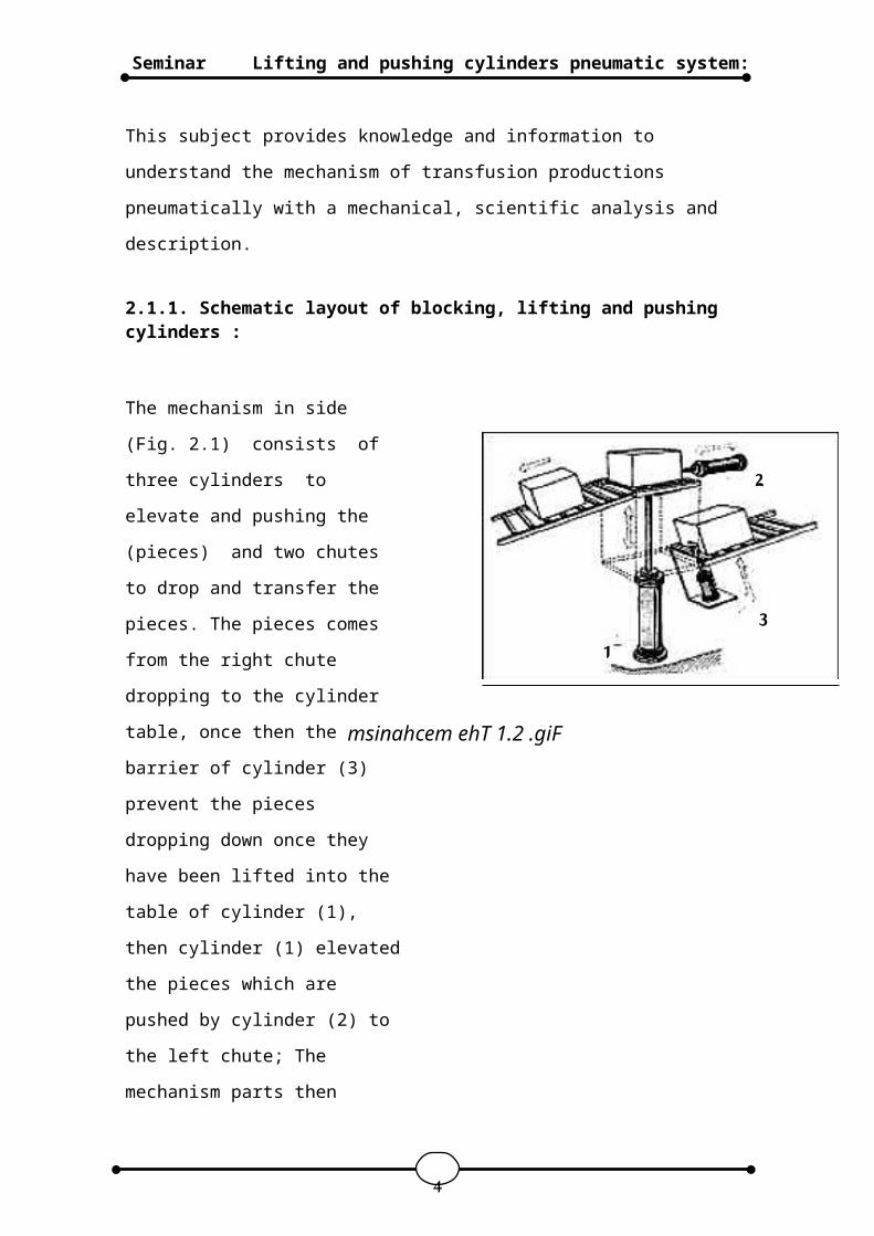
2.1.1. Schematic layout of blocking, lifting and pushing cylinders :
The mechanism in side
(Fig. 2.1) consists of
three cylinders to
elevate and pushing the
(pieces) and two chutes
to drop and transfer the
pieces. The pieces comes
from the right chute
dropping to the cylinder
table, once then the
barrier of cylinder (3)
prevent the pieces
dropping down once they
have been lifted into the
table of cylinder (1),
then cylinder (1) elevated
the pieces which are
pushed by cylinder (2) to
the left chute; The
mechanism parts then
4
1
2
3
msinahcem ehT 1.2 .giF
Lifting and pushing cylinders pneumatic system:Seminar
continues operating in a
cyclic order.
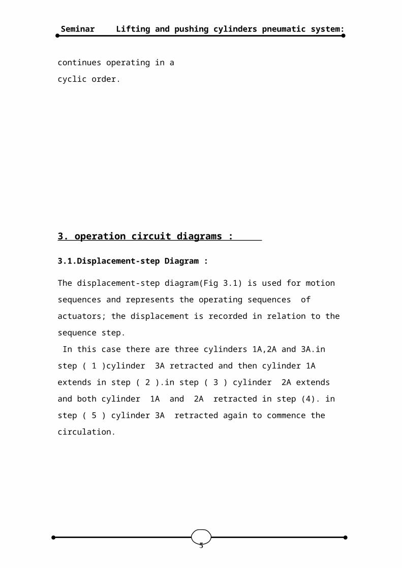
3. operation circuit diagrams :
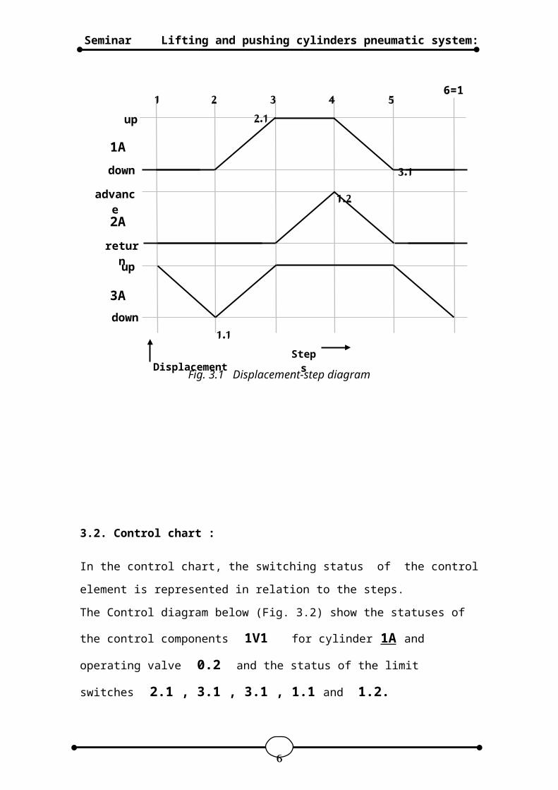
3.1.Displacement-step Diagram :
The displacement-step diagram(Fig 3.1) is used for motion
sequences and represents the operating sequences of
actuators; the displacement is recorded in relation to the
sequence step.
In this case there are three cylinders 1A,2A and 3A.in
step ( 1 )cylinder 3A retracted and then cylinder 1A
extends in step ( 2 ).in step ( 3 ) cylinder 2A extends
and both cylinder 1A and 2A retracted in step (4). in
step ( 5 ) cylinder 3A retracted again to commence the
circulation.
5
Lifting and pushing cylinders pneumatic system:Seminar
Fig. 3.1 Displacement-step diagram
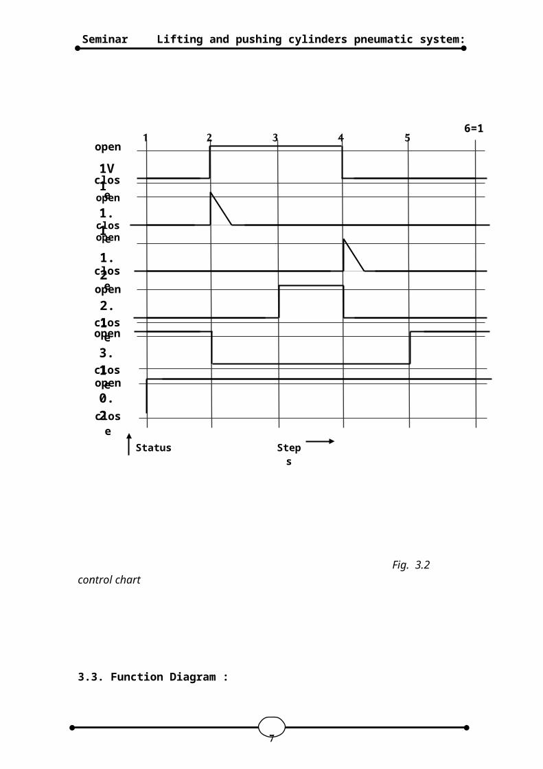
3.2. Control chart :
In the control chart, the switching status of the control
element is represented in relation to the steps.
The Control diagram below (Fig. 3.2) show the statuses of
the control components 1V1 for cylinder 1A and
operating valve 0.2 and the status of the limit
switches 2.1 , 3.1 , 3.1 , 1.1 and 1.2.
up1 2 3 4 5 6=1
1A
2A
3A
advance
up
down
return
down
StepsDisplacement
2.1
3.11.2
1.1
6
Lifting and pushing cylinders pneumatic system:Seminar
Fig. 3.2 control chart
3.3. Function Diagram :
7
1V1
1.1
1.2
2.1
3.1
0.2
1 2 3 4 5 6=1open
closeopen
open
close
close
open
closeopen
closeopen
close
Steps
Status
Lifting and pushing cylinders pneumatic system:Seminar
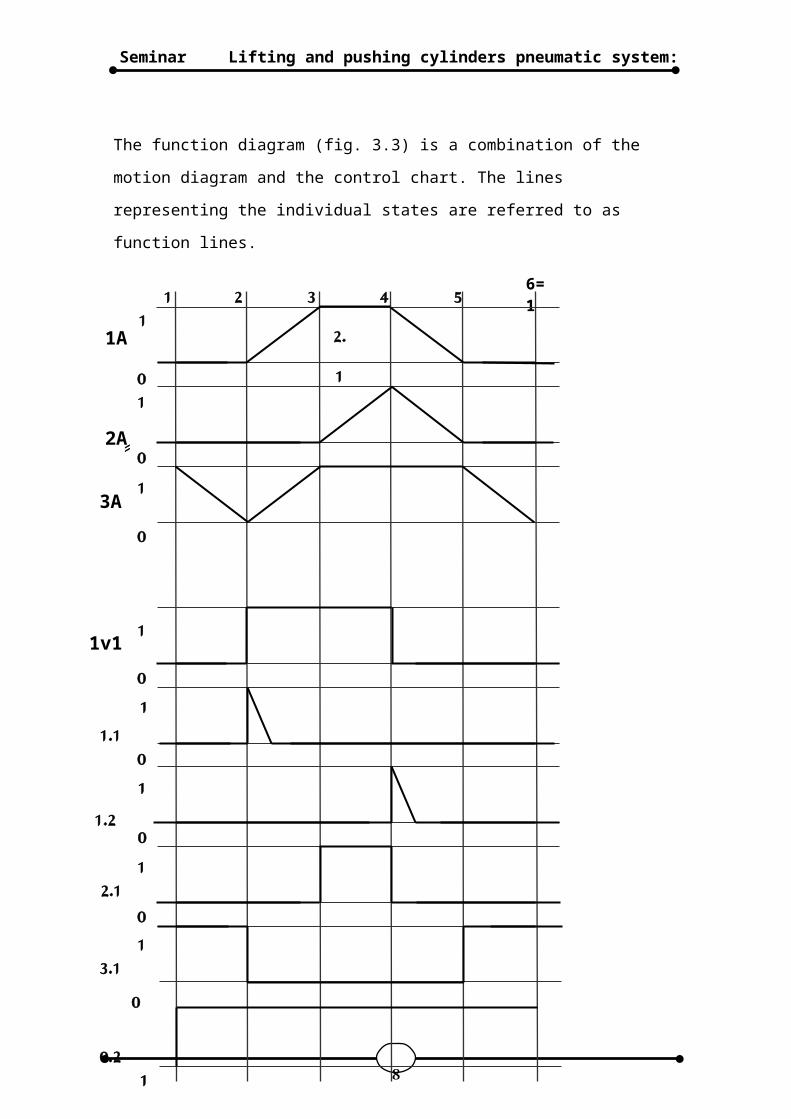
The function diagram (fig. 3.3) is a combination of the
motion diagram and the control chart. The lines
representing the individual states are referred to as
function lines.
8
1 2 3 4 5 6=11
010
1A
2Aِِ
2.1
10
101
010101
0
1
3A
1v1
1.1
1.2
2.1
3.1
0.2
Lifting and pushing cylinders pneumatic system:Seminar
Fig. 3.3
function diagram
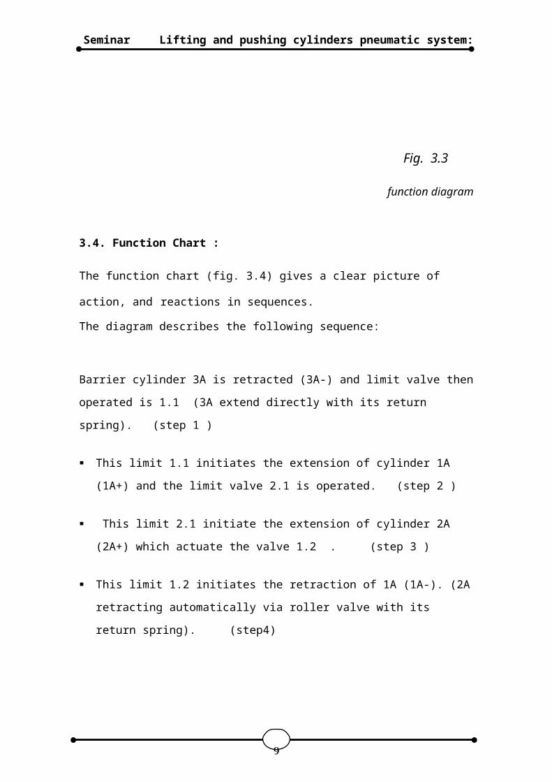
3.4. Function Chart :
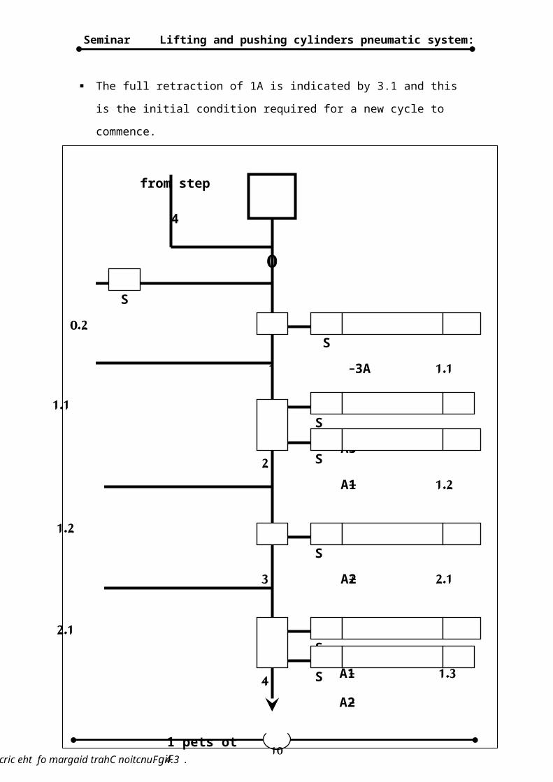
The function chart (fig. 3.4) gives a clear picture of
action, and reactions in sequences. The diagram describes the following sequence:
Barrier cylinder 3A is retracted (3A-) and limit valve then
operated is 1.1 (3A extend directly with its return
spring). (step 1 )
This limit 1.1 initiates the extension of cylinder 1A
(1A+) and the limit valve 2.1 is operated. (step 2 )
This limit 2.1 initiate the extension of cylinder 2A
(2A+) which actuate the valve 1.2 . (step 3 )
This limit 1.2 initiates the retraction of 1A (1A-). (2A
retracting automatically via roller valve with its
return spring). (step4)
9
Lifting and pushing cylinders pneumatic system:Seminar
The full retraction of 1A is indicated by 3.1 and this
is the initial condition required for a new cycle to
commence.
10
0
from step
4
S0.2
1S
3A- 1.11.1
2S
A3+S
A1+ 1.21.2
3S
A2+ 2.12.1
4S
A1- 1.3SA2-
1 pets otgiFtiucric eht fo margaid trahC noitcnuF 4.3 .
Lifting and pushing cylinders pneumatic system:Seminar
4. Pneumatic circuit diagram :
11
Lifting and pushing cylinders pneumatic system:Seminar
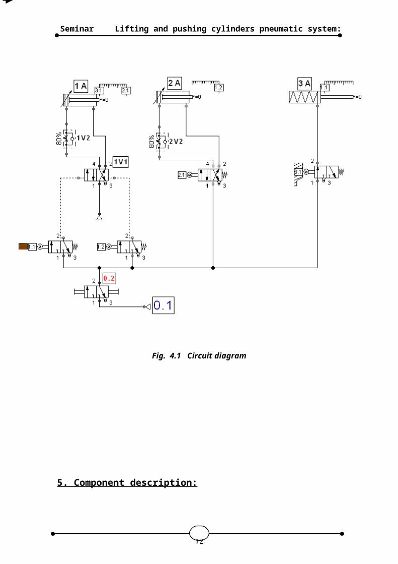
Fig. 4.1 Circuit diagram
5. Component description:
12
Lifting and pushing cylinders pneumatic system:Seminar
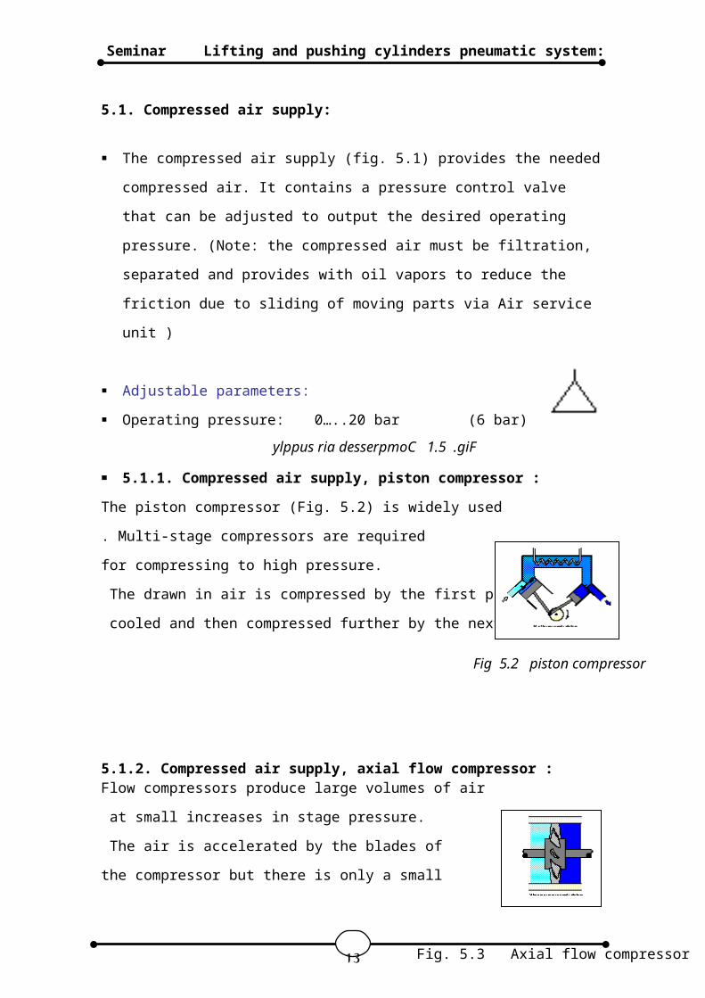
5.1. Compressed air supply:
The compressed air supply (fig. 5.1) provides the needed
compressed air. It contains a pressure control valve
that can be adjusted to output the desired operating
pressure. (Note: the compressed air must be filtration,
separated and provides with oil vapors to reduce the
friction due to sliding of moving parts via Air service
unit )
Adjustable parameters:
Operating pressure: 0…..20 bar (6 bar).
5.1.1. Compressed air supply, piston compressor :
The piston compressor (Fig. 5.2) is widely used
. Multi-stage compressors are required
for compressing to high pressure.
The drawn in air is compressed by the first piston,
cooled and then compressed further by the next stage.
5.1.2. Compressed air supply, axial flow compressor :Flow compressors produce large volumes of air
at small increases in stage pressure.
The air is accelerated by the blades of
the compressor but there is only a small
13
Fig 5.2 piston compressor
Fig. 5.3 Axial flow compressor
ylppus ria desserpmoC 1.5 .giF
Lifting and pushing cylinders pneumatic system:Seminar
increase in pressure (Fig. 5.3).
5.2. Valves in use :
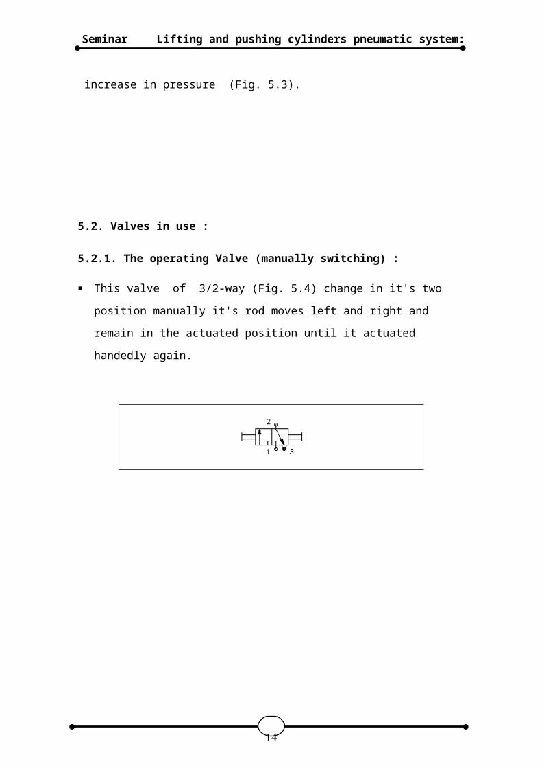
5.2.1. The operating Valve (manually switching) :
This valve of 3/2-way (Fig. 5.4) change in it's two
position manually it's rod moves left and right and
remain in the actuated position until it actuated
handedly again.
14
Lifting and pushing cylinders pneumatic system:Seminar
2
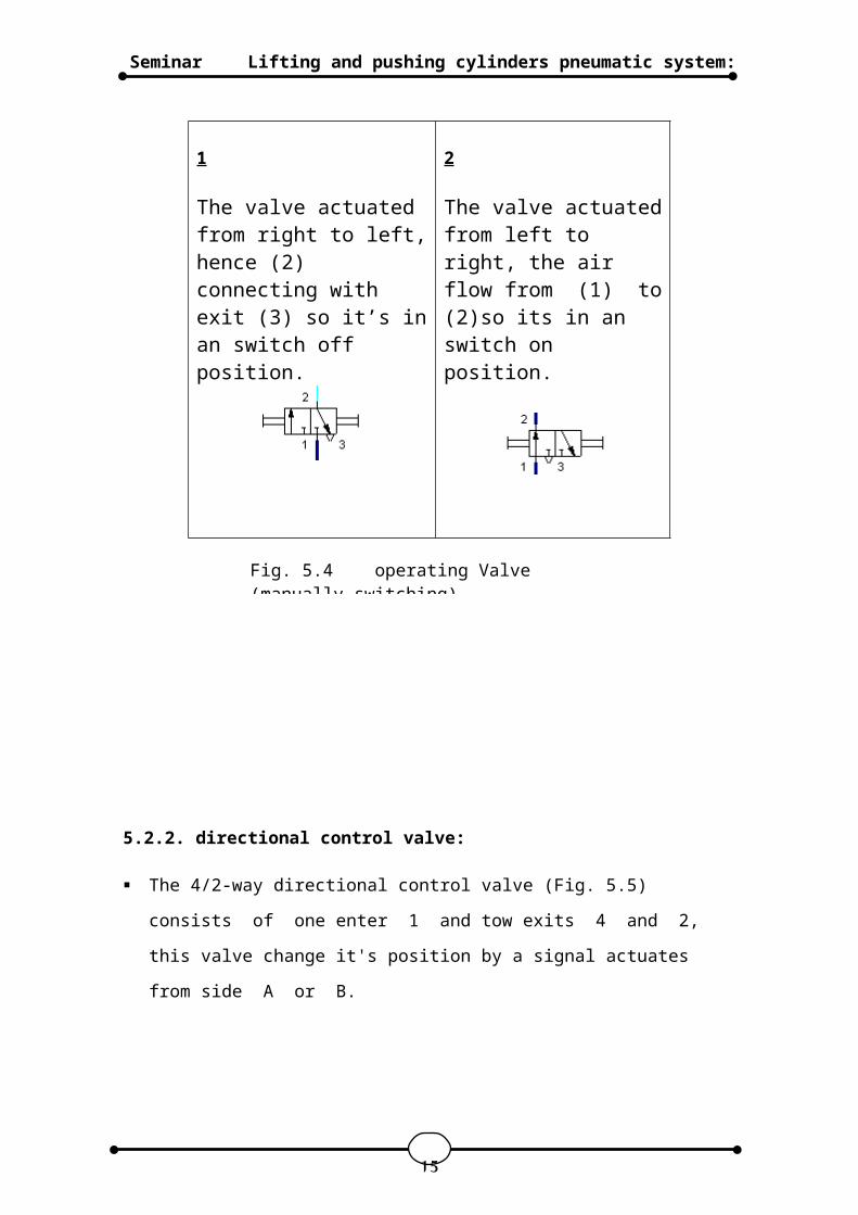
The valve actuatedfrom left to right, the air flow from (1) to(2)so its in an switch on position.
1
The valve actuated from right to left,hence (2) connecting with exit (3) so it’s inan switch off position.
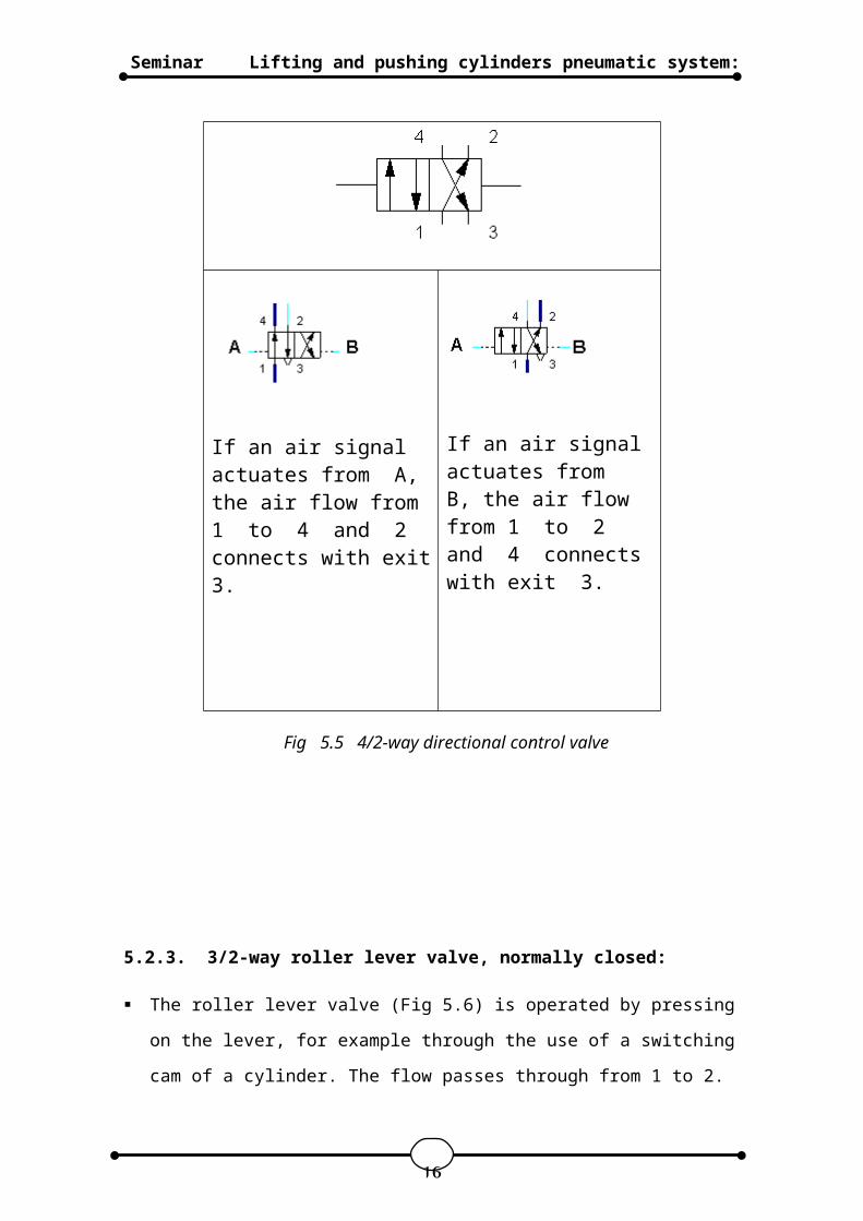
5.2.2. directional control valve:
The 4/2-way directional control valve (Fig. 5.5)
consists of one enter 1 and tow exits 4 and 2,
this valve change it's position by a signal actuates
from side A or B.
15
Fig. 5.4 operating Valve (manually switching)
Lifting and pushing cylinders pneumatic system:Seminar
If an air signalactuates from B, the air flow from 1 to 2 and 4 connectswith exit 3.
If an air signal actuates from A, the air flow from 1 to 4 and 2 connects with exit3.
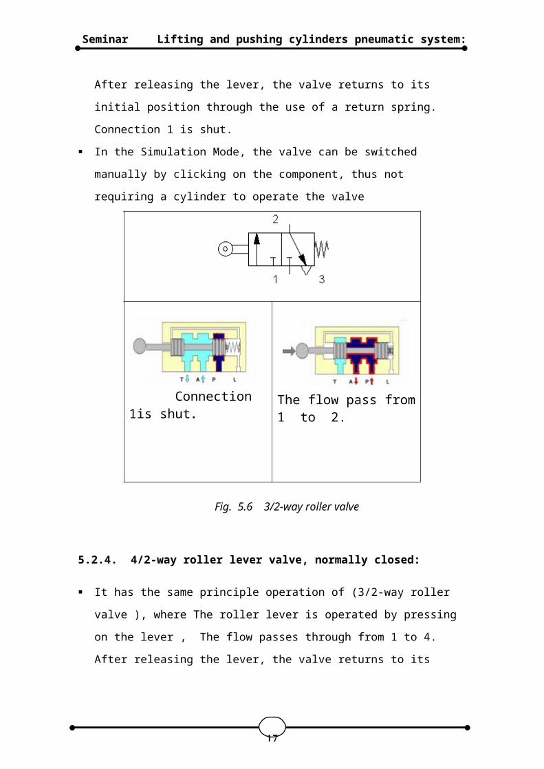
5.2.3. 3/2-way roller lever valve, normally closed:
The roller lever valve (Fig 5.6) is operated by pressing
on the lever, for example through the use of a switching
cam of a cylinder. The flow passes through from 1 to 2.
16
Fig 5.5 4/2-way directional control valve
Lifting and pushing cylinders pneumatic system:Seminar
After releasing the lever, the valve returns to its
initial position through the use of a return spring.
Connection 1 is shut.
In the Simulation Mode, the valve can be switched
manually by clicking on the component, thus not
requiring a cylinder to operate the valve
The flow pass from1 to 2.
Connection 1is shut.
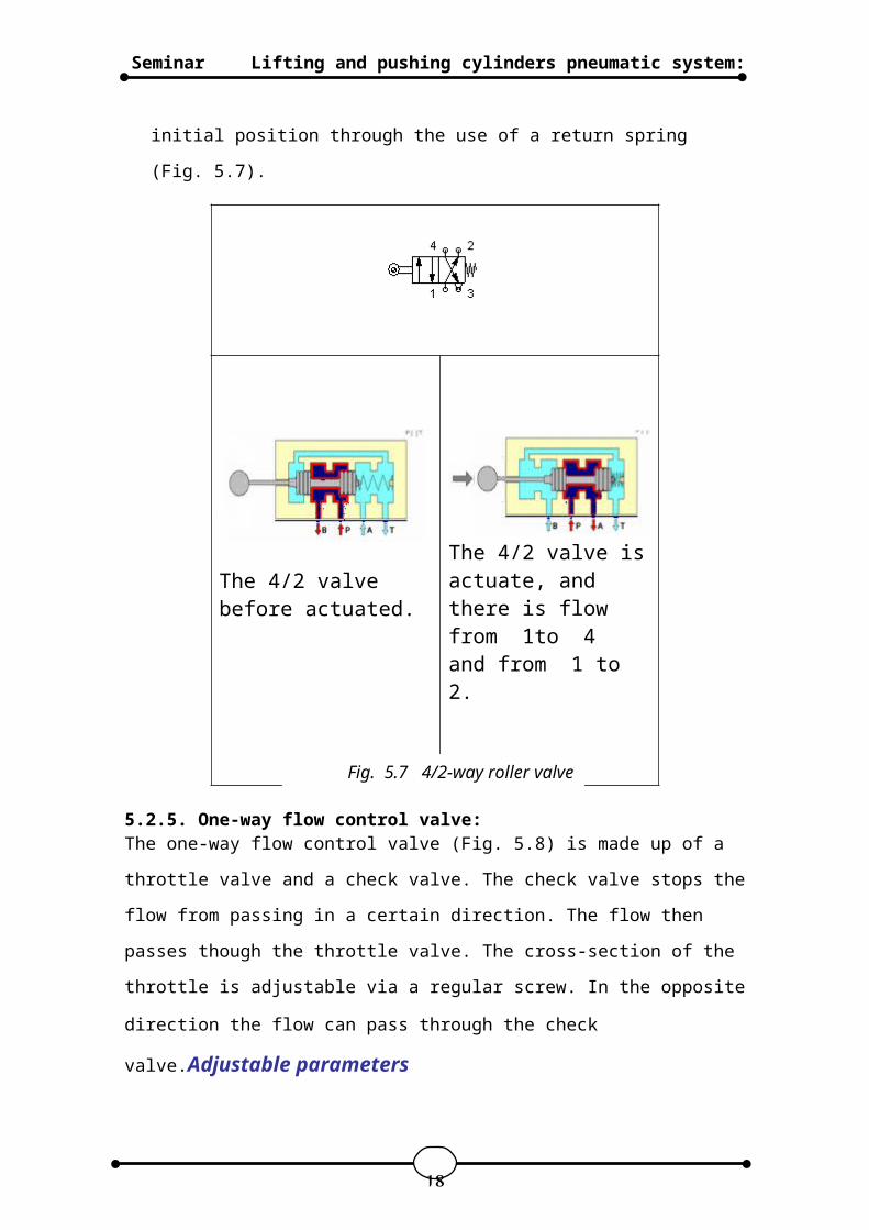
5.2.4. 4/2-way roller lever valve, normally closed:
It has the same principle operation of (3/2-way roller
valve ), where The roller lever is operated by pressing
on the lever , The flow passes through from 1 to 4.
After releasing the lever, the valve returns to its
17
Fig. 5.6 3/2-way roller valve
Lifting and pushing cylinders pneumatic system:Seminar
initial position through the use of a return spring
(Fig. 5.7).
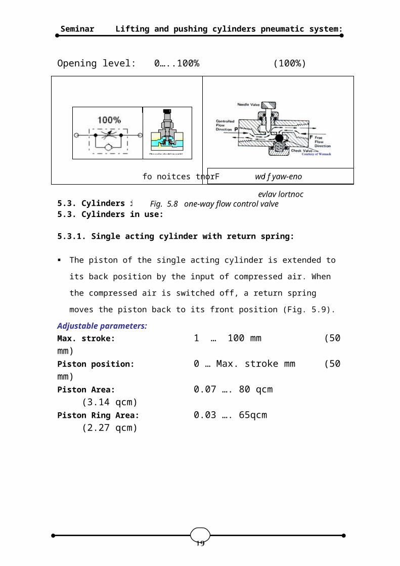
5.2.5. One-way flow control valve:The one-way flow control valve (Fig. 5.8) is made up of a
throttle valve and a check valve. The check valve stops the
flow from passing in a certain direction. The flow then
passes though the throttle valve. The cross-section of the
throttle is adjustable via a regular screw. In the opposite
direction the flow can pass through the check
valve.Adjustable parameters
The 4/2 valve isactuate, and there is flow from 1to 4 and from 1 to 2.
The 4/2 valve before actuated.
18
Fig. 5.7 4/2-way roller valve
Lifting and pushing cylinders pneumatic system:Seminar
Opening level: 0…..100% (100%)
5.3. Cylinders in use:5.3. Cylinders in use:
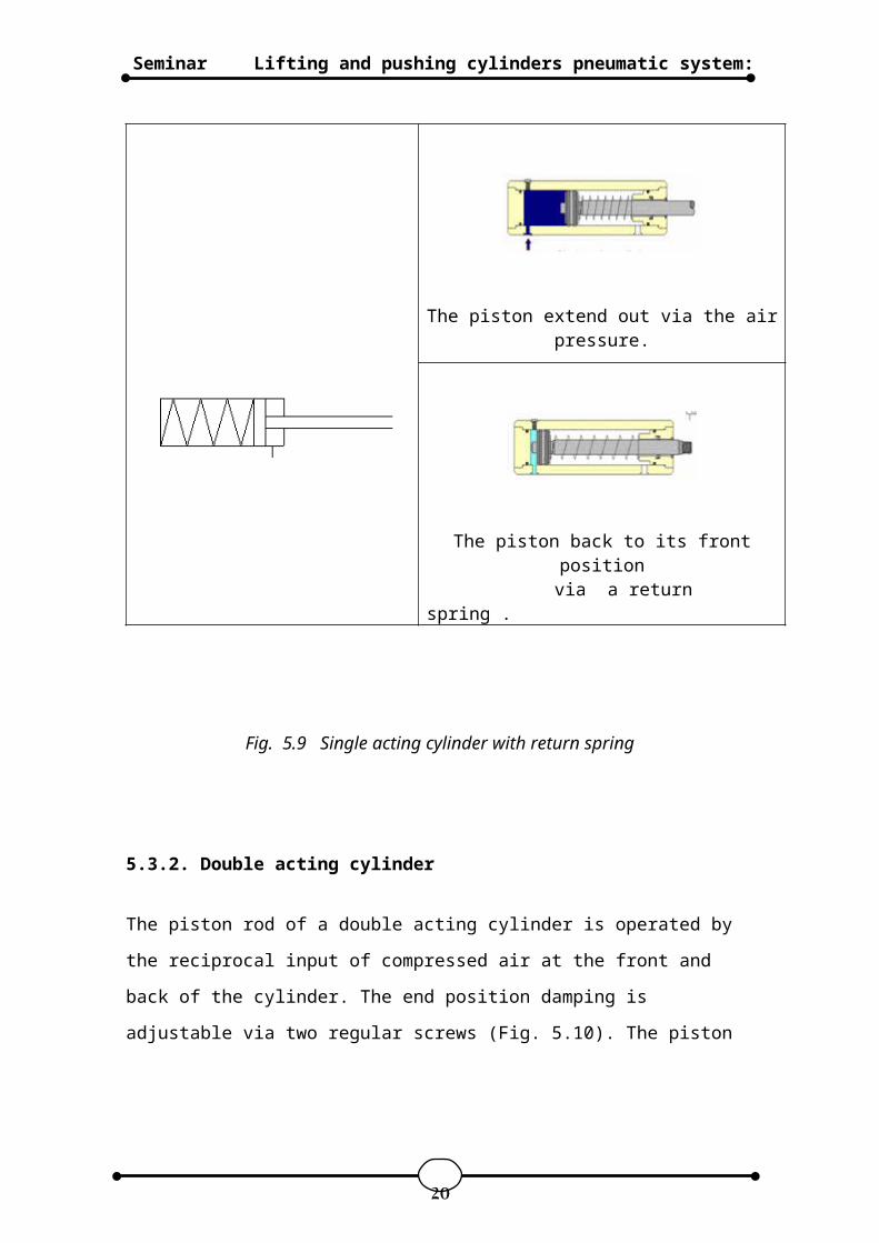
5.3.1. Single acting cylinder with return spring:
The piston of the single acting cylinder is extended to
its back position by the input of compressed air. When
the compressed air is switched off, a return spring
moves the piston back to its front position (Fig. 5.9).
Adjustable parameters:Max. stroke: 1 … 100 mm (50mm)Piston position: 0 … Max. stroke mm (50mm)Piston Area: 0.07 …. 80 qcm
(3.14 qcm)Piston Ring Area: 0.03 …. 65qcm
(2.27 qcm)
19
Fig. 5.8 one-way flow control valve fo noitces tnorF wol f yaw-eno
evlav lortnoc
Lifting and pushing cylinders pneumatic system:Seminar
The piston extend out via the airpressure.
The piston back to its frontposition
via a return spring .
Fig. 5.9 Single acting cylinder with return spring
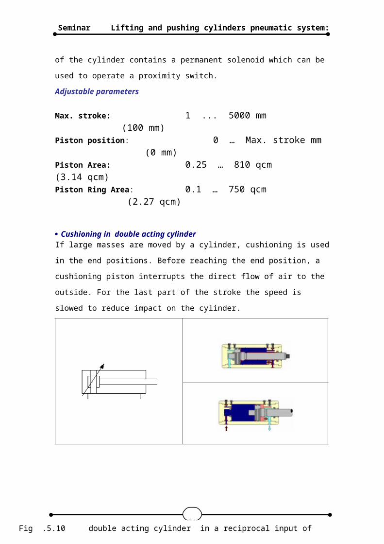
5.3.2. Double acting cylinder
The piston rod of a double acting cylinder is operated by
the reciprocal input of compressed air at the front and
back of the cylinder. The end position damping is
adjustable via two regular screws (Fig. 5.10). The piston
20
Lifting and pushing cylinders pneumatic system:Seminar
of the cylinder contains a permanent solenoid which can be
used to operate a proximity switch.
Adjustable parameters
Max. stroke: 1 ... 5000 mm (100 mm)
Piston position: 0 … Max. stroke mm (0 mm)
Piston Area: 0.25 … 810 qcm (3.14 qcm)Piston Ring Area: 0.1 … 750 qcm
(2.27 qcm)
Cushioning in double acting cylinderIf large masses are moved by a cylinder, cushioning is used
in the end positions. Before reaching the end position, a
cushioning piston interrupts the direct flow of air to the
outside. For the last part of the stroke the speed is
slowed to reduce impact on the cylinder.
21Fig .5.10 double acting cylinder in a reciprocal input of
compressed air
Lifting and pushing cylinders pneumatic system:Seminar
5.4. Distance ruleThe distance rule (Fig. 5.11) is a device for attaching
switches at the cylinder. The labels at the distance rule
define links to the actual proximity switches or limit
switches in the electrical circuit
6. Pneumatic system software:
FluidSIM-P is a teaching tool for simulating pneumatics
basics and runs using Microsoft Windows ©. It can be used
in combination with the Festo Didactic GmbH & Co. KG
training hardware, but also independently. FluidSIM was
developed as a joint venture between the University of
Paderborn, Festo Didactic GmbH & Co. KG, and Art Systems
Software GmbH, Paderborn.
A major feature of FluidSIM is its close connection with
CAD (Computer Aided Design) functionality and simulation.
FluidSIM allows DIN-compliant drawing of electro-pneumatic
circuit diagrams and can perform realistic simulations of
the drawing based on physical models of the components.
Simply stated, this eliminates the gap between the drawing
of a circuit diagram and the simulation of the related
pneumatic system.
The CAD functionality of FluidSIM has been specially
tailored for fluidics. For example, while drawing
, the program will check whether or not certain connections
between components are permissible.
22
Fig 5.11 distance
rule
Lifting and pushing cylinders pneumatic system:Seminar
Another feature of FluidSIM results from its well thought-
out didactic concept: FluidSIM supports learning,
educating, and visualizing pneumatic knowledge. Pneumatic
components are explained with textual descriptions,
figures, and animations that illustrate underlying working
principles; exercises and educational films mediate
knowledge about both important circuits and the usage of
pneumatic components.
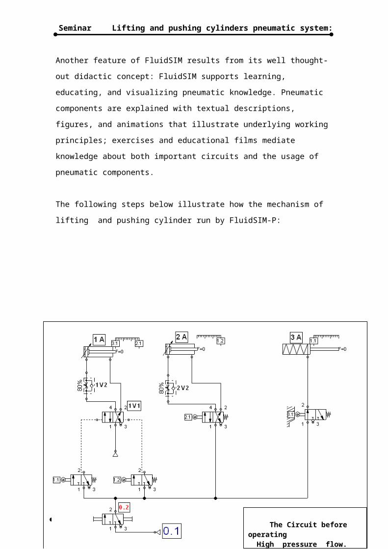
The following steps below illustrate how the mechanism of
lifting and pushing cylinder run by FluidSIM-P:
6.1. Pneumatic circuit diagram for the three actuator :
23 The Circuit before operating High pressure flow. Low pressure flow.
Lifting and pushing cylinders pneumatic system:Seminar
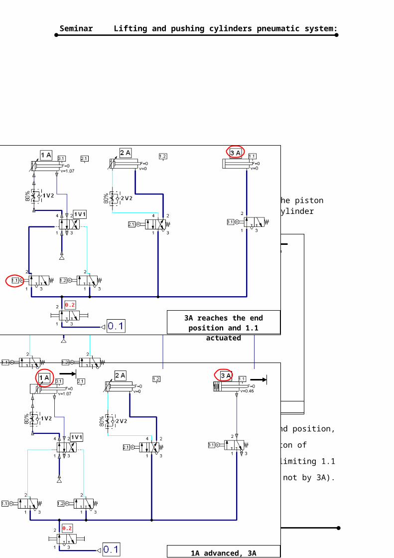
If the emergency valve switched handily, then the piston rod of the cylinder 3A retracted. (Note: This cylinder extends by its return spring).
When the cylinder 3A reaches its retracted end position,
the limit switch 1.1 is actuated and the piston of
cylinder 1A advances (note the actuating of limiting 1.1
actuated by the ensure of the piece dropping not by 3A).
24
The Circuit before operating High pressure flow. Low pressure flow.
3A retracts
3A reaches the end position and 1.1
actuated
1A advanced, 3A advanced
Lifting and pushing cylinders pneumatic system:Seminar
25
Lifting and pushing cylinders pneumatic system:Seminar
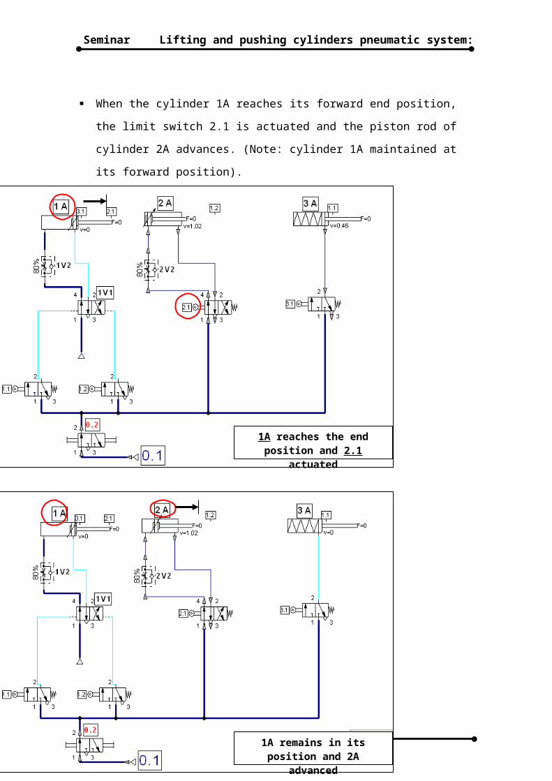
When the cylinder 1A reaches its forward end position,
the limit switch 2.1 is actuated and the piston rod of
cylinder 2A advances. (Note: cylinder 1A maintained at
its forward position).
26
1A reaches the end position and 2.1
actuated
1A remains in its position and 2A
advanced
Lifting and pushing cylinders pneumatic system:Seminar
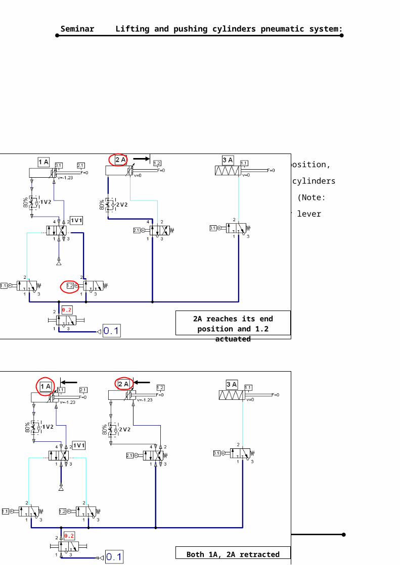
When the cylinder 2A reaches its forward end position,
the limit switch 1.2 is actuated and both two cylinders
1A and 2A retracted to their initial position. (Note:
cylinder 2A retracted automatically via roller lever
valve with its return spring).
27
2A reaches its end position and 1.2
actuated
Both 1A, 2A retracted
Lifting and pushing cylinders pneumatic system:Seminar
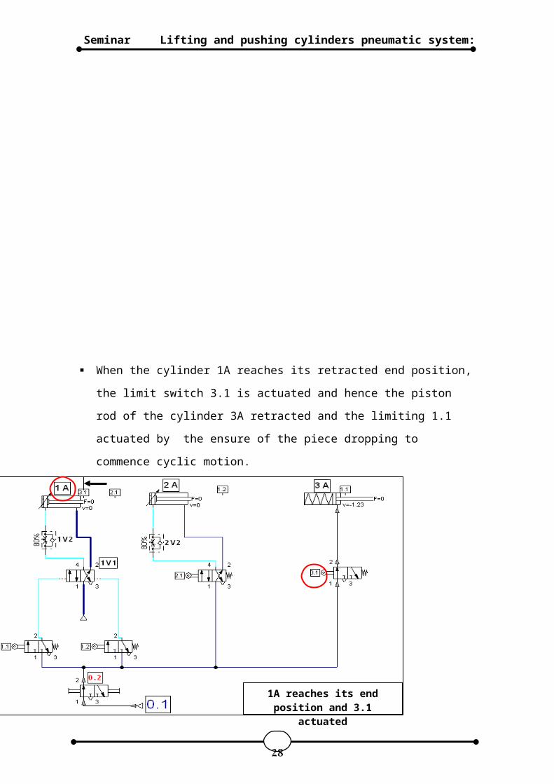
When the cylinder 1A reaches its retracted end position,
the limit switch 3.1 is actuated and hence the piston
rod of the cylinder 3A retracted and the limiting 1.1
actuated by the ensure of the piece dropping to
commence cyclic motion.
28
1A reaches its end position and 3.1
actuated
Lifting and pushing cylinders pneumatic system:Seminar
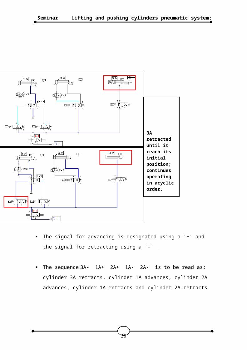
The signal for advancing is designated using a '+' and
the signal for retracting using a '-' .
The sequence 3A- 1A+ 2A+ 1A- 2A- is to be read as:
cylinder 3A retracts, cylinder 1A advances, cylinder 2A
advances, cylinder 1A retracts and cylinder 2A retracts.
29
3A retracted until it reach its initial position;continues operating in acyclic order.
Lifting and pushing cylinders pneumatic system:Seminar
30