Lifting Gear Hire - LGH Global
160
Lifting Gear Hire Lifting Equipment Rental Specialists Technical User Guide UK 2 ND EDITION
-
Upload
khangminh22 -
Category
Documents
-
view
1 -
download
0
Transcript of Lifting Gear Hire - LGH Global

Lifting Gear Hire Lifting Equipment Rental Specialists
Technical User Guide
UK 2ND EDITION

02
15 Hoisting
18 Hand Chain Hoists20 Beam Clamps22 Adjustable Beam Trolleys23 Beam Trolleys25 Combination Units27 Lever Hoists29 Electric Chain Hoists32 Air Chain Hoists35 Accessories & Controls36 Site Hoists37 Minifor Hoists38 Tirak Universal Hoist40 Aluminium Gantries42 Floor Cranes
71 Rigging
74 Grade 10 Chain Slings75 Wire Rope Slings76 Synthetic Slings78 Modulift Spreader Beams94 CMOD Spreader Frames96 Lattice Spreader Beams98 Crane Forks & Material Skips99 Access Cages & Gas Bottle
Carriers100 Block Grabs101 Stone Magnets102 Manhole Lifting Equipment103 Lifting Clutches104 Plate Clamps105 Lifting Magnets106 Alloy Bow Shackles 107 Heavy Duty Bow Shackles 108 Super Alloy Shackles 109 High Tensile Shackles110 Lifting Points 112 Lifting Rings114 Load Rings116 Digital Load Indicators117 Digital Load Shackles118 Eyebolt Tester120 Test Weights & Accessories
121 Material Handling
153 Technical Info
143 Safety
146 Safety Harnesses 147 Lanyards148 Fall Arrest Blocks149 Lifelines & Anchors150 Confined Space Equipment151 Man-Riding Davits151 Gas Detection & Breathing
Apparatus152 Porta Gantry Rapide
154 Technical Info158 Index
43 Pulling
53 Jacking
02 About LGH
03 About LGH04 Safety, Certainty & Great Service05 You Can Rely on LGH06 Industries We Serve07 Accreditation08 LGH UK Locations09 LGH UK Contact Details10 Around the World - LGH North
America11 Around the World - LGH Europe13 Rotrex Group Ltd14 Our Trusted Partners
Contents
44 Tirfor Machines, Ropes & Accessories
45 Hydraulic Tirfor 46 The Tirfor Principle 47 Wire Rope Blocks48 Cable Pulling Winch49 Cable Drum Jacks & Accessories50 Hydra-Slide52 Skates & Load Moving Systems
54 Jacks57 Hydraulic Cylinders66 Hydraulic Pumps67 Hydraulic Accessories69 Compression Load Cells 70 Compressive Load Cell Systems
122 Material Lifts 123 Material Lift Accessories 124 Material Lifts & Gas Hoist 125 Counterbalanced Material Lifts126 Glass Handling Cranes127 Glass Handling Attachments128 Roust-A-Bout & Panel Lifter129 Skoots & Stairclimbers130 Trucks & Trolleys132 Pallet Trucks134 Stone Handles, Extractors
& Clamps135 Manhole Cover Lifters 136 Forklift Accessories138 Bumpa Hoists139 Shifta Conveyors140 Building Hoists142 Skips
LGH - puts safety first
www.lgh.co.uk | 03704 247 247 03
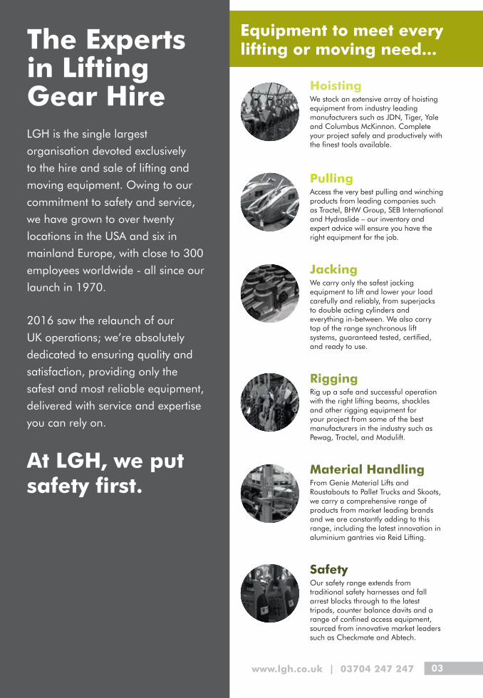
Hoisting We stock an extensive array of hoisting equipment from industry leading manufacturers such as JDN, Tiger, Yale and Columbus McKinnon. Complete your project safely and productively with the finest tools available.
Pulling Access the very best pulling and winching products from leading companies such as Tractel, BHW Group, SEB International and Hydraslide – our inventory and expert advice will ensure you have the right equipment for the job.
Jacking We carry only the safest jacking equipment to lift and lower your load carefully and reliably, from superjacks to double acting cylinders and everything in-between. We also carry top of the range synchronous lift systems, guaranteed tested, certified, and ready to use.
Rigging Rig up a safe and successful operation with the right lifting beams, shackles and other rigging equipment for your project from some of the best manufacturers in the industry such as Pewag, Tractel, and Modulift.
Material Handling From Genie Material Lifts and Roustabouts to Pallet Trucks and Skoots, we carry a comprehensive range of products from market leading brands and we are constantly adding to this range, including the latest innovation in aluminium gantries via Reid Lifting.
Safety Our safety range extends from traditional safety harnesses and fall arrest blocks through to the latest tripods, counter balance davits and a range of confined access equipment, sourced from innovative market leaders such as Checkmate and Abtech.
Equipment to meet every lifting or moving need...The Experts
in Lifting Gear HireLGH is the single largest
organisation devoted exclusively
to the hire and sale of lifting and
moving equipment. Owing to our
commitment to safety and service,
we have grown to over twenty
locations in the USA and six in
mainland Europe, with close to 300
employees worldwide - all since our
launch in 1970.
2016 saw the relaunch of our
UK operations; we’re absolutely
dedicated to ensuring quality and
satisfaction, providing only the
safest and most reliable equipment,
delivered with service and expertise
you can rely on.
At LGH, we put safety first.

04
Great Service- Committed to professionalism and keeping you happyWe invest the highest level of dedication, preparation, hard work and willingness in all facets of our operation to ensure optimal efficiency and provide our customers with the very best independent, specialist service.
We aim to exceed expectations every time - it’s all about communication:
• We’ll keep you up to date at every step of the process
• We’ll always respond in a concise and speedy manner
• We’ll share our expert knowledge to make your job easier
All enquiries and orders are managed through our customer contact centre. Call our friendly and expert team: 03704 247 247
Safety- Choose the safety specialists• We attribute much of our success to our devotion to the maintenance, preparation,
inspection, and testing of the vast array of quality lifting equipment we offer.
• We conduct quarterly internal audits to examine the operational and administrative practices at our customer contact centre and each of our remote warehouses.
• We also undertake frequent external audits as part of our external assurance programme with LEEA, HAE and others.
Certainty- You can rely on our products & services absolutely• In excellent working order
• Fit for purpose
• On time
• In full
We know how busy our customers are, and that construction and maintenance activities take place in busy, dynamic and fast paced environments. So when you use LGH, we’ll make sure you have one less thing to worry about.
Safety, Certainty, Great Service
Safety, Certainty & Great Service - the three pillars on which LGH is built
01
02
03

www.lgh.co.uk | 03704 247 247 05
Whether it’s for simple everyday tasks, or for special projects where expertise has to be matched with the right equipment.
We maintain an extensive inventory of equipment for each of our categories.
Just think of our inventory as your inventory.
The LGH UK team is comprised of seasoned lifting industry experts.
Our knowledge is continually maintained by comprehensive manufacturer-led training courses and practical workshops to ensure the latest statutory and legal requirements are always met or exceeded.
All of our equipment has been carefully selected for its durability and longevity from only the most trusted partners.
Tested, inspected and certified to the highest standards, we maintain it to be ready for immediate and above all, safe use.
You can rely on Lifting Gear Hire for:
The most comprehensive inventory
Industry leading knowledge
The best quality equipment

06
Industries We Serve
Whatever your industry, if you have lifting needs we have the best quality equipment and years of expertise to deliver exactly what you need. We will support you throughout your project for a safe and successful lift every time.

www.lgh.co.uk | 03704 247 247 07
Accreditations
At LGH our dedication to safety and ongoing training never waivers. We have worked hard to achieve industry recognised and required accreditations to ensure we can support all our customers to the highest standards possible.
These accreditations help to drive LGH to fulfill our vision and uphold our core value to ‘put safety first’.

08
Aberdeen
Manchester
London
The Experts in Lifting Gear Hire
LGH United Kingdom

www.lgh.co.uk | 03704 247 247 09
LGH LocationsLGH has grown to three locations since it relaunched in to the UK market in 2016; Aberdeen, Manchester and London. Our operation ensures optimal efficiency and provides our customers with the very best service. All three locations have a full suite of top quality core lifting equipment spanning across six categories; Hoisting, Pulling, Jacking, Rigging, Material Handling and Safety. All enquiries and orders are managed through our experienced team at our Customer Contact Centre in Manchester.
Aberdeen Warehouse:Unit 6 – 8, Kirkton Avenue, Pitmedden Road Industrial Estate,
Dyce, Aberdeen, AB21 0BF
Manchester Warehouse / National Rental Centre:120 Bolton Road, Atherton, Manchester, M46 9JZ
London Warehouse:Unit 9, Mudlands Trading Estate, Manor Way, Rainham, Essex, RM13 8RH
Customer Contact Centre:[email protected] | 03704 247 247

10 All our equipment is tested and certified to the highest standard
Lifting Gear Hire around the world - North America and Europe
LGH North America
LGH North America have over twenty warehouses nationwide. We are now the single largest organisation devoted exclusively to the rental and sale of lifting and moving equipment.
Safety, Certainty & Great service globally with Lifting Gear Hire

www.lgh.co.uk | 03704 247 247 11
LGH Europe
LGH Europe have over six warehouses across three mainland European countries; Germany, Holland and Belgium.

12 LGH - The authority in lifting

www.lgh.co.uk | 03704 247 247 13
Rotrex Group Ltd & LGH
Rotrex and LGHThe Rotrex brand has a long history with LGH. Over 30 years, LGH grew organically and by acquisition to become the largest and market leading lifting gear and winching plant hire company in the UK, with successful businesses operating in the USA, Netherlands and Germany.
In the early 1990’s, LGH (now LGH Group plc) acquired NIM Winches based in Alfreton, Derbyshire. This greatly strengthened the group’s winch capacity, capability and expertise and offered complementary equipment to the Lifting Gear Hire business.
In 2007, LGH Group plc was renamed as Rotrex Group Ltd in the UK, with Rotrex Winches and Rotrex OnSite as trading businesses. Rotrex Group Ltd is still owned by the founders of Lifting Gear Hire, as are the other LGH businesses which now have locations in USA, Canada, Netherlands, Belgium and Germany.The Rotrex and LGH businesses continue to work closely together to develop opportunities in various sectors including Construction, Marine, Rail, Tunnelling, Utilities, Telecoms and Offshore. By working together we are able to offer customers solutions for all of their winching and lifting equipment needs and ensure they get the best service and support.
Now Lifting Gear Hire has relaunched in the UK, this long history and unique relationship will continue to grow.
Rotrex Group LtdRotrex Winches has a 45 year history as the UK’s leading provider of winches and winch expertise and has 4 locations in the UK – Derby, London, Glasgow and Aberdeen. Rotrex Winches has recently expanded into mainland Europe and now has a base in the Netherlands.
Rotrex provides a wide range of winch hire, winch sales, winch service and winch support solutions, as well as offering maintenance, inspection and testing of customers own equipment.
14
Call our customer contact centre on: 03704 247 247
Our Trusted Partners- we only work with the best
Sales · Parts · Service
We work with innovative market leading manufacturers to bring you only the safest and most reliable equipment.If a supplier meets our high standards it’s a sure sign you’re going to be working with nothing but the very best.
DisclaimerAll equipment in this technical user guide is subject to availability and circumstances may lead to alternative equipment being offered.
The information in this technical user guide, relating to the equipment has been provided by the manufacturers. Whilst the technical user guide has been prepared in good faith, no representation, warranty, assurance or undertaking (express or implied) is or will be made, and no responsibility or liability is or will be accepted by or by its officers, employees or agents in relation to the accuracy or completeness of this technical user guide. All and any such responsibility and liability is expressly disclaimed. It is your responsibility to ensure that the equipment has the correct dimensions and weight to perform the tasks you require it for.
Lifting Gear Hire reserves the right, without prior notice, at any time and in any respect, to alter any of the information contained within this technical user guide. No information set out or referred to in this technical user guide shall form the basis of any contract. Any prospective hirer of Lifting Gear Hire equipment shall be required to enter into a legally binding agreement acknowledging that it has not relied on, or been induced to enter into such an agreement by, any representation, warranty, assurance or undertaking save as expressly set out in that agreement.
Delivering excellence in lifting throughout the UK
Sales · Parts · Service
www.lgh.co.uk | 03704 247 247 15
15Hoisting
18 Hand Chain Hoists
20 Beam Clamps
22 Adjustable Beam Trolleys
23 Beam Trolleys
25 Combination Units
27 Lever Hoists
29 Electric Chain Hoists
32 Air Chain Hoists
35 Accessories & Controls
36 Site Hoists
37 Minifor Hoists
38 Tirak Universal Hoist
40 Aluminium Gantries
42 Floor Cranes

16
HO
ISTI
NG
AVAILABLE FOR HIRE
AVAILABLE FOR HIR
E

17www.lgh.co.uk | 03704 247 247
HO
ISTI
NG
EXTREMESENGINEERED FOR
Explosion-proof pneumatic or hydraulic hoists and crane systems from J.D. Neuhaus are reliable in the extreme. Our equipment performs when used to build massive sea vessels or in any one of 70 additional industrial sectors across 90 countries world-wide. www.jdngroup.com
AVAILABLE FOR HIRE
AVAILABLE FOR H
IRE

18
HO
ISTI
NG
Hand Chain HoistsTCB14 Chain Hoist• Range from 0.5t to 30t• Rugged construction yet lightweight and portable• Patented quad cam mechanical brake• Certified 2% light load protection• Operating temperature of -40°C to +50°C• Proof tested to 1.5 times rated capacity• Standard lift height 3m, 6m, 9m, 12m HOL or can be chained to
meet your requirements• Tested and certified for “fleeting” and “cross-hauling” application
Product Code Model Capacity (t)
Effort (kg)
Dimensions (mm) Load Chain StdHOL (m)
Weight at Std HOL(kg)
Weight for Extra Metre
HOL (kg)
A B D E F1 F2 G Diameter(mm)
No. of Falls
H010100003 CB-0050 0.5 21 93 66 52 78 24 38 305 6.3 1 3 10.8 1.8
H010100103 CB-0100 1.0 25 93 66 63 87 28 45 340 6.3 1 3 11.8 1.8
H010100203 CB-0200 2.0 34 101 79 87 113 35 53 420 8.0 1 3 20.0 2.4
H010100303 CB-0300 3.0 38 109 84 98 157 36 56 550 10.0 1 3 30.6 3.2
H010100303 CB-030T 3.0 34 98 73 60 148 36 56 465 7.1 2 3 23.3 3.2
H010100503 CB-0500 5.0 37 101 79 122 209 49 70 575 8.0 3 3 37.8 5.2
H010101003 CB-1000 10.0 40 109 84 153 263 54 87 660 10.0 3 3 64.0 7.5
H010101503 CB-1500 15.0 41 109 84 225 378 59 81 840 10.0 5 3 128.5 11.8
H010102003 CB-2000 20.0 43 161 90 148 360 81 110 1050 10.0 6 3 178.7 14.2
H010103003 CB-3000 30.0 42 220 220 388 388 91 135 1200 10.0 10 3 306.9 23.8
LGH - puts safety first

19www.lgh.co.uk | 03704 247 247
HO
ISTI
NG
Hand Chain HoistsSS12 Corrosion Resistant Chain Hoist• Range from 0.5t to 30t• Fully corrosion protected body and components• Corrosion protected load and hand chain• Marine specific friction discs• Stainless steel fixings and fasteners• Certified 2% light load protection• Operating temperature of -40°C to +50°C• Standard lift height 3m, 6m, 9m, 12m HOL or can be chained to
meet your requirements
Product Code Model Capacity (t)
Effort (kg)
Dimensions (mm) Load Chain Std HOL (m)
Weight at Std HOL
(kg)
Weight for Extra Metre
HOL (kg)
A B D E F1 F2 G Diameter (mm)
No. of Falls
H010110003 SCB-0050 0.5 21 93 66 52 78 24 38 305 6.3 1 3 10.8 1.8
H010110103 SCB-0100 1.0 25 93 66 63 87 28 45 340 6.3 1 3 11.8 1.8
H010110153 SCB-0150 1.5 32 98 73 78 102 34 51 385 7.1 1 3 16.2 2.1
H010110203 SCB-0200 2.0 34 101 79 87 113 35 53 420 8.0 1 3 20.0 2.4
H010110303 SCB-0300 3.0 38 109 84 98 157 36 56 550 10.0 1 3 30.6 3.2
H010110503 SCB-0500 5.0 37 101 79 122 209 49 70 575 8.0 3 3 37.8 5.2
H010111003 SCB-1000 10.0 40 109 84 153 263 54 87 660 10.0 3 3 64.0 7.5
H010112003 SCB-2000 20.0 43 161 90 148 360 81 110 1050 10.0 6 3 178.7 14.2
H010113003 SCB-3000 30.0 42 220 220 388 388 91 135 1200 10.0 10 3 306.9 23.8

20
HO
ISTI
NG
Beam ClampsBCF Beam Clamps• Range from 1t to 20t
• Versatile rigging point for hoisting equipment
• Suitable for pulling and lifting at angles across the beam
• 90° side loading with no de-ration (100% WLL)
• 15° cross loading with no de-ration (100% WLL)
• Evenly distributed loads achieved through maximum jaw surface area
• Operating temperature -50°C to +50°C
• 4:1 factor of safety
Product Code Model Capacity (t)
Dimensions (mm) Weight (kg)
A B C D E F H J K L T
H030100101 BCF-0100 1.0 75-195 206-321 105 20 190 300-266 16 21 80 84 6 5.5
H030100201 BCF-0200 2.0 75-195 206-321 105 20 190 311-276 18 21 88 95 8 6.5
H030100304 BCF-0300 3.0 100-350 223-476 140 25 270 418-344 22 27 110 105 10 12.0
H030100303 BCF-030S 3.0 75-190 216-325 140 20 190 310-271 22 27 110 105 10 9.5
H030100506 BCF-0500 5.0 100-310 223-438 140 25 286 424-368 27 27 124 111 12 14.5
H030100503 BCF-050S 5.0 75-190 216-325 140 20 190 315-276 27 27 124 111 12 11.0
H030101004 BCF-1000 10.0 120-350 282-511 210 30 314 460-389 32 37 83 120 16 26.5
H030101504 BCF-1500 15.0 203-457 463-742 250 36 416 644-558 38 43.5 99 146 20 76.0
H030102004 BCF-2000 20.0 203-457 471-766 300 50 416 697-609 45 49 126 180 25 100.0
Larger sizes available on request
Capacities 1t, 2t, 3t, 5t
Capacities 10t, 15t, 20t
Safety, Certainty, Great Service

21www.lgh.co.uk | 03704 247 247
HO
ISTI
NG
BCA Adjustable Angle Clamps• Range of 1t and 3t
• Versatile rigging point for hoisting equipment
• V shaped clamping jaws ensure safe, secure grip
• Accommodates a wide range of steel angle sections
• Integrated adjusting screw spindle
• Operating temperature -50°C to +50°C
• 4:1 factor of safety
• Can be used up to a maximum of 15° from the vertical
Beam ClampsBCU Universal Beam Clamps• Range of 3t and 5t
• Versatile rigging point for hoisting equipment
• Highly flexible for lifting, pulling or as a semi-permanent anchor point
• For both vertical and side loading applications
• Full rated capacity at any lifting angle
• Operating temperature -50°C to +50°C
• 4:1 factor of safety
Product Code Model Capacity (t)
Dimensions (mm) Weight (kg)
A B C D E F G H J K L
H030110301 BCU-0300 3.0 387 60 70 63 32 235 100 25.4 28 20 125-204 15.5
H030110501 BCU-0500 5.0 524 70 74 72 32 270 120 25.4 38 24 125-305 27.0
H030111001 BCU-1000 10.0 524 70 75 82 32 278 120 25.4 38 25 125-305 31
Product Code Model Capacity (t)
Dimensions (mm) Weight (kg)
A B C D E G H J K
H030120101 BCA-0100 1.0 6 76.5 81 83 206 15 258 16 38-101 5.5
H030120301 BCA-0300 3.0 10 106.5 112 104 343 25.4 490 22 101-203 23.5
Warning: Do not use this equipment for lifting flat plate sections

22
HO
ISTI
NG
Adjustable Beam TrolleysAPT Adjustable Beam Trolleys - Push Travel• Range from 1t to 10t
• Screw spindle allows easy adjustment
• High clamping force
• The anti-drop plates ensure extra safety and prevent damage to wheels when contacting end rail stoppers
• Runs on sealed ball bearings - smoother rolling, less effort and maintenance
• 5:1 factor of safety allows for use with manual or powered hoists
AGT Adjustable Beam Trolleys - Geared Travel• Range of 6t and 10t
• Screw spindle allows easy adjustment
• High clamping force
• The anti-drop plates ensure extra safety and prevent damage to wheels when contacting end rail stoppers
• Runs on sealed ball bearings - smoother rolling, less effort and maintenance
• 5:1 factor of safety allows for use with manual or powered hoists
Product Code Model Capacity (t)
A Track Width Range
(mm)
Dimensions (mm) Min. Curve Ratio (m)
Weight (kg)
B C D E F
H040100101 APT-0100 1.0 75-210 391 83.5 16 110 81 1.0 9.6
H040100202 APT-0200 2.0 75-210 391 94.5 18 123 89 1.3 13.5
H040100302 APT-0300 3.0 75-210 403 105.5 22 141 112 1.5 23.0
H040100603 APT-0600 6.0 105-305 521 111 27 151.5 125 1.5 35.5
H040101003 APT-1000 10.0 160-305 606 119 32 170 83 2.7 118.0
Product Code Model Capacity (t)
A Track Width Range
(mm)
Dimensions (mm) Min. Curve Ratio (m)
Weight (kg)
B C D E F
H040200603 AGT-0600 6.0 105-305 521 111 27 151.5 125 1.5 40.1
H040201003 AGT-1000 10.0 160-305 606 119 32 170 83 2.7 221.0
All our equipment is tested and certified to the highest standard

23www.lgh.co.uk | 03704 247 247
HO
ISTI
NG
Beam TrolleysSingle Bar Trolleys - Push Travel• Plain Trolleys 0.5t to 10t
• Extended beam width available
• Anti-drop plates design ensures extra safety and prevents damage to wheels when contacting end rail stoppers
• Wheels use sealed ball bearings - smoother rolling, less effort and maintenance
• Operating temperature -30°C to +50°C
Single Bar Trolley (TPS)
Product Code Model Capacity (t)
Track Width Range 1
(mm)
Track Width Range 2
(mm)
Dimensions (mm) Min. Curve Ratio(m)
Plain Trolley
A B D E F B (mm) Weight (kg)
H040110051H040130051
TPS-0050TPT-0050
0.5 62-128 62-203 179 109 70 49 16 0.8 106 5.0
H040110101 H040130101
TPS-0100TPT-0100
1.0 62-128 62-203 195 111 79 50 16 1.0 113 7.3
H040110201 H040130201
TPS-0200TPT-0200
2.0 88-154 88-230 235 134 95 70 19 1.3 136 12.0
H040110301 H040130301
TPS-0300TPT-0300
3.0 88-154 88-230 263 145 111 79 16 1.5 146 19.0
H040110501 H040130501
TPS-0500TPT-0500
5.0 106-194 106-305 307 169 133 88 21 1.5 169 30.0
H040131001 TPT-1000 10.0 150-320 N/A 429 252 183 240 40 2.7 255 135.5
Plain Twin Bar Trolley (TPT)

24
HO
ISTI
NG
Beam TrolleysTwin Bar Trolleys - Geared Travel• Geared Trolleys 0.5t to 30t
• Extended beam width available
• Anti-drop plates design ensures extra safety and prevents damage to wheels when contacting end rail stoppers
• Wheels use sealed ball bearings - smoother rolling, less effort and maintenance
• Operating temperature -30°C to +50°C
Geared Twin Bar Trolley (TGT)
Product Code Model Capacity (t)
Track Width
Range 1 (mm)
Track Width
Range 2 (mm)
Dimensions (mm) Min. Curve Ratio (m)
Geared Trolley
A B C D E F B (mm)
Hand Chain Length
(m)
Weight (kg)
H040210051H040230051
TGS-0050 TGT-0050
0.5 62-128 62-203 195 106 98 20 0.8 165 2.5 8.9
H040210101H040230101
TGS-0100TGT-0100
1.0 62-128 62-203 213 113 106 20 1.0 170 2.5 11.1
H040210201H040230201
TGS-0200TGT-0200
2.0 88-154 88-230 236 136 132 25 1.3 182 2.5 16.3
H040210302H040230302
TGS-0300TGT-0300
3.0 88-154 88-230 277 146 150 25 1.5 187 2.5 23.3
H040210504H040230504
TGS-0500TGT-0500
5.0 106-194 106-305 323 169 174 30 1.5 210 2.5 34.3
H040231002 TGT-1000 10.0 150-320 N/A 429 252 183 240 40 2.7 335 2.5 150.0
H040232001 TGT-2000 20.0 150-320 N/A 930 255 182 270 42.5 6.0 335 2.5 356.0
H040232501 TGT-2500 25.0 150-320 N/A 930 255 182 277 42.5 6.0 335 2.5 363.0
H040233001 TGT-3000 30.0 150-320 N/A 990 267 182 288 42.5 6.0 348 2.5 368.0
Geared Single Bar Trolley (TGS)
LGH - The authority in lifting

25www.lgh.co.uk | 03704 247 247
HO
ISTI
NG
Combination UnitsSingle Bar Trolley Combination Unit• Range from 0.5t to 3t
• Ideal for locations where headroom is limited
• Geared and Plain Trolley versions available
• Single Bar Trolley options
• Extended beam width available
• Corrosion or Spark Resistant versions available
Product Code Model Capacity (t)
Dimensions (mm) Weight kg at Std HOL
D Extended
Width (mm)A B C H D
(Track Width)Plain
3m HOLGeared 3m HOL
Plain Geared
H040310051H040320051
CCBTPS-0050 CCBTGS-0050
0.5 195 106 165 106 310 62-128 16.2 20.2 62-203
H040310101H040320101
CCBTPS-0100 CCBTGS-0100
1.0 213 113 170 113 350 62-128 19.8 23.7 62-203
H040310201H040320201
CCBTPS-0200 CCBTGS-0200
2.0 236 136 182 136 450 88-154 33.2 37.7 88-230
H040310301H040320301
CCBTPS-0300 CCBTGS-0300
3.0 277 146 187 146 530 88-154 48.52 53.8 88-230
Geared Travel Trolley (TGS)Push Travel Trolley (TPS)

26
HO
ISTI
NG
Combination UnitsTwin Bar Trolley Combinations Units• Range from 0.5t to 10t
• Ideal for locations where headroom is limited
• Geared and Plain Trolley versions available
• Twin Bar Trolley options
• Extended beam width available
• Corrosion or Spark Resistant versions available
Product Code Model Capacity (t)
Dimensions (mm) Weight kg at Std HOL DExtended
Width (mm)
A B C H D (Track Width)
Plain 3m HOL
Geared 3m HOL
Plain Geared
H040330051H040340051
CCBTPT-0050 CCBTGT-0050
0.5 179 109 168 109 316 62-128 17.1 21.1 62-203
H040330101H040340101
CCBTPT-0100 CCBTGT-0100
1.0 195 111 178 111 342 62-128 20.4 24.4 62-203
H040330201H040340201
CCBTPT-0200 CCBTGT-0200
2.0 235 134 184 134 446 88-154 33.9 38.4 88-230
H040330301H040340301
CCBTPT-030T CCBTGT-030T
3.0 263 145 184 145 435 88-154 45.88 58.38 88-230
H040330501H040340501
CCBTPT-0500 CCBTGT-0500
5.0 307 169 206 169 545 106-194 69.0 74.6 106-305
H040331001H040341001
CCBTPT-1000 CCBTGT-1000
10.0 429 252 327 252 730 150-320 185.0 200.0 -
Geared Trolley Travel (TGT)Plain Trolley Travel (TPT)
Delivering excellence in lifting throughout the UK

27www.lgh.co.uk | 03704 247 247
HO
ISTI
NG
Lever HoistsPROLH Lever Hoists• Range from 0.8t to 20t
• Patented Quad Cam Pawl System
• Tiger’s unique dual brake mechanism
• One piece construction pinion gear
• Adaptable to use both inverted and horizontally
• 8 point multi start thread pinion shaft - increased efficiency in brake reaction times
• “EZ Check” hook feature
Product Code Model Capacity (t)
Effort (kg)
Dimensions (mm) Load Chain Std HOL (m)
Weight at Std HOL (kg)
Weight for Extra Metre HOL (kg)
A B C D E F1 F2 Diameter (mm)
No. of Falls
H060100815 PLH-0075 0.8 23 128 236 295 158 99 28 45 6.3 1 1.5 7.5 0.9
H060101515 PLH-0150 1.5 26 154 360 320 172 104 34 51 7.1 1 1.5 10.5 1.1
H060103015 PLH-0300 3.0 38 182 360 400 195 108 36 56 10.0 1 1.5 18.0 2.2
H060106015 PLH-0600 6.0 40 242 360 570 195 108 49 70 10.0 2 1.5 28.5 4.3
H060110015 PLH-1000 10.0 47 370 360 630 195 108 54 87 10.0 3 1.5 45.0 6.5
H060115015 PLH-1500 15.0 44 566 360 840 195 108 59 81 10.0 5 1.5 112.0 10.9
H060120015 PLH-2000 20.0 49 470 360 1050 250 160 81 110 10.0 6 1.5 156.0 13.0

28
HO
ISTI
NG
Lever HoistsSS11 Subsea Lever Hoist• Range from 0.8t to 20t
• Patented Quad Cam Pawl System
• Double switch brake mechanism
• One piece construction pinion gear
• Marine specific friction discs
• Fully corrosion protected body and components
• Adaptable to use both inverted and horizontally
• Brake chamber protection from outside contamination
Product Code Model Capacity (t)
Effort (kg)
Dimensions (mm) Load Chain Std HOL (m)
Weight at Std HOL (kg)
Weight for Extra Metre
HOL (kg)
A B C D E F1 F2 Diameter (mm)
No. of
Falls
H060160815 SS-0080 0.8 23 128 243 295 158 99 28 45 6.3 1 3 9.1 0.9
H060161515 SS-0150 1.5 26 154 370 320 172 104 34 51 7.1 1 3 12.6 1.1
H060163015 SS-0300 3.0 38 182 370 400 195 108 36 56 10.0 1 3 22.0 2.2
H060166015 SS-0600 6.0 40 242 370 570 195 108 49 70 10.0 2 3 34.5 4.3
H060170015 SS-1000 10.0 47 379 370 630 195 108 54 87 10.0 3 3 55.0 6.5
H060175015 SS-1500 15.0 44 566 370 840 195 108 59 81 10.0 5 3 128.0 10.9
H060180015 SS-2000 20.0 49 470 370 1050 250 160 81 110 10.0 6 3 174.0 13.0
LGH - puts safety first

29www.lgh.co.uk | 03704 247 247
HO
ISTI
NG
Electric Chain HoistsCM Lodestar Electric Chain HoistsThe Lodestar hoist is a tough and durable electric chain hoist, designed to keep working in the most arduous applications. This hoist is recognised and proven within the hire industry as the number one hoist, where high duty, combined with long heights of lift are required.
• Range from 0.25t to 3t
• Adjustable upper and lower limit switches
• 48V control, IP65 pendant as standard
• Thermal overload protection as standard
Product Code Model Operating Voltage Capacity (WLL) (kg)
No. of Falls of Load Chain
Lifting Speed(s) (m/min)
Weight at Std HOL
(kg)
Weight for Extra Metre HOL
(kg)
H010200021 G 230V or 110V 1ph 50Hz 250 1 8 29.0 0.8
H010200051 F 230V or 110V 1ph 50Hz 500 1 4 29.0 0.8
H010200051 J 230V or 110V 1ph 50Hz 500 1 8 51.0 1.4
H010200103 L 230V or 110V 1ph 50Hz 1,000 1 4 52.0 1.4
H010200103 LL 400V 3ph 50Hz 1,000 1 8 52.0 1.4
H010200103 LL2 400V 3ph 50Hz 1,000 1 8/2.5 53.0 1.4
H010200203 R 230V or 110V 1ph 50Hz 2,000 2 2 58.0 2.8
H010200203 RR 400V 3ph 50Hz 2,000 2 4 58.0 2.8
H010200203 RR2 400V 3ph 50Hz 2,000 2 4/1.3 59.0 2.8
H010200303 RT 230V or 110V 1ph 50Hz 3,000 3 1.33 64.0 4.2
Model A (mm)
B (mm)
C (mm)
D (mm)
F (mm)
H (mm)
J (mm)
L (mm)
M (mm)
P (mm)
AP (mm)
Lodestar 250/500 413 156 17 279 197 25 100 122 25 168 235
Lodestar 500/1000 471 194 22 241 271 30 138 184 28 198 271
Lodestar 2000 613 194 28 241 271 38 165 157 33 198 284
Lodestar 3000 750 194 28 241 271 38 165 157 33 198 319
30
HO
ISTI
NG
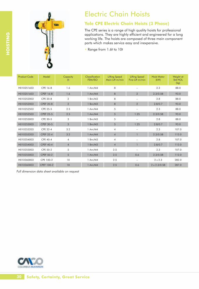
Electric Chain HoistsYale CPE Electric Chain Hoists (3 Phase) The CPE series is a range of high quality hoists for professional applications. They are highly efficient and engineered for a long working life. The hoists are composed of three main component parts which makes service easy and inexpensive.
• Range from 1.6t to 10t
Product Code Model Capacity (t)
ClassificationFEM/ISO
Lifting Speed Main Lift m/min
Lifting Speed Fine Lift m/min
Hoist Motor(kW)
Weight at Std HOL
(kg)
H010251603 CPE 16-8 1.6 1 Am/M4 8 – 2.3 88.0
H010251603 CPEF 16-8 1.6 1 Am/M4 8 2 2.3/0.58 93.0
H010252003 CPE 20-8 2 1 Bm/M3 8 – 2.8 88.0
H010252003 CPEF 20-8 2 1 Bm/M3 8 2 2.8/0.7 93.0
H010252503 CPE 25-5 2.5 1 Am/M4 5 – 2.3 88.0
H010252503 CPEF 25-5 2.5 1 Am/M4 5 1.25 2.3/0.58 93.0
H010253003 CPE 30-5 3 1 Bm/M3 5 – 2.8 88.0
H010253003 CPEF 30-5 3 1 Bm/M3 5 1.25 2.8/0.7 93.0
H010253203 CPE 32-4 3.2 1 Am/M4 4 – 2.3 107.0
H010253203 CPEF 32-4 3.2 1 Am/M4 4 1 2.3/0.58 112.0
H010254003 CPE 40-4 4 1 Bm/M3 4 – 2.8 107.0
H010254003 CPEF 40-4 4 1 Bm/M3 4 1 2.8/0.7 112.0
H010255003 CPE 50-2 5 1 Am/M4 2.5 – 2.3 107.0
H010255003 CPEF 50-2 5 1 Am/M4 2.5 0.6 2.3/0.58 112.0
H010260003 CPE 100-2 10 1 Am/M4 2.5 – 2 x 2.3 282.0
H010260003 CPEF 100-2 10 1 Am/M4 2.5 0.6 2 x 2.3/0.58 287.0
Full dimension data sheet available on request
Safety, Certainty, Great Service

31www.lgh.co.uk | 03704 247 247
HO
ISTI
NG
Electric Chain HoistsYale CPS Electric Chain HoistsThe CPS electric chain hoist lifts loads up to 0.25t - yet weighs from only 12kg. With an M4 high duty rating, the rugged CPS electric chain hoist keeps lifting and lifting - up to 240 motor starts per hour.
• Easy to install and maintain
• Ideal for jib and light crane systems
• Built to the highest standards
• Reliable
Product Code Model Capacity (WLL) (kg)
Supply Lifiting Speed (m/min)
ED Duty %
Weight (kg)
H010212503 CPS 110/1-4 125 110V 1ph 50Hz 4 mpm 40 12.0
H010212503 CPS 230/1-4 125 230V 1ph 50Hz 4 mpm 40 12.0
H010212503 CPS 400/1-4 125 400V 3ph 50Hz 4 mpm 40 12.0
H010212503 CPS 400/1-10 125 400V 3ph 50Hz 10 mpm 40 12.0
H010225003 CPS 110/2-2 250 110V 1ph 50Hz 2 mpm 40 14.0
H010225003 CPS 230/2-2 250 230V 1ph 50Hz 2 mpm 40 14.0
H010225003 CPS 400/2-2 250 400V 3ph 50Hz 2 mpm 40 14.0
H010225003 CPS 400/2-5 250 400V 3ph 50Hz 5 mpm 40 14.0
Rated Capacity(kg)
A (mm)
B (mm)
C (mm)
D (mm)
E (mm)
F (mm)
G (mm)
H (mm)
J (mm)
K (mm)
L (mm)
M (mm)
N (mm)
125 14 103 21 21 159 98 276 53 75 76 225 150 375
250 14 103 21 21 159 98 304 53 60 89 225 150 375
32
HO
ISTI
NG
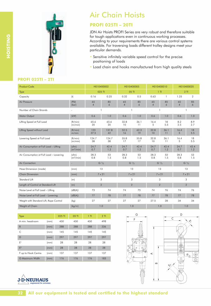
Air Chain HoistsPROFI 025TI – 20TIJDN Air Hoists PROFI Series are very robust and therefore suitable for tough applications even in continuous working processes. According to your requirements there are various control systems available. For traversing loads different trolley designs meet your particular demands.
• Sensitive infinitely variable speed control for the precise positioning of loads
• Load chain and hooks manufactured from high quality steels
Product Code H010400002 H010400005 H010400010 H010400020
Type 025 TI 05 TI 1 TI 2 TI
Capacity (t) 0.16 0.25 0.32 0.5 0.63 1 1.25 2
Air Pressure (PSI) (bar)
65 4
85 6
65 4
85 6
65 4
85 6
65 4
85 6
Number of Chain Strands - 1 1 1 1
Motor Output (kW) 0.6 1.0 0.6 1.0 0.6 1.0 0.6 1.0
Lifting Speed at Full Load (ft/min ) (m/min)
65.6 20
65.6 20
32.8 10
36.1 11
16.4 5
18 5.5
8.2 2.5
8.9 2.7
Lifting Speed without Load (ft/min ) m/min
123 37.5
137.8 42
52.5 16
62.3 19
32.8 10
36.1 11
16.4 5
18 5.5
Lowering Speed at Full Load (ft/min) (m/min)
124.7 38
124.7 38
55.8 17
55.8 17
32.8 10
36.1 11
16.4 5
18 5.5
Air Consumption at Full Load – Lifting (cfm ) (m3/min)
24.7 0.7
42.4 1.2
24.7 0.7
42.4 1.2
24.7 0.7
42.4 1.2
24.7 0.7
42.4 1.2
Air Consumption at Full Load – Lowering (cfm) (m3/min)
28.3 0.8
53 1.5
28.3 0.8
53 1.5
28.3 0.8
53 1.5
28.3 0.8
53 1.5
Air Connection - G 1/2 G 1/2 G 1/2 G 1/2
Hose Dimension (inside) (mm) 13 13 13 13
Chain Dimension (mm) 7 x 21 7 x 21 7 x 21 7 x 21
Standard Lift (m) 3 3 3 3
Length of Control at Standard Lift (m) 2 2 2 2
Noise Level at Full Load – Lifting (dB(A)) 73 74 74 75 74 76 74 76
Noise Level at Full Load – Lowering (dB(A)) 77 78 77 78 77 78 77 78
Weight with Standard Lift, Rope Control (kg) 27 27 27 27 27.5 28 34 34
Weight of Chain (kg/m) 1.0 1.0 1.0 1.0
Type 025 TI 05 TI 1 TI 2 TI
A min. headroom (mm) 450 450 450 498
B (mm) 288 288 288 336
C (mm) 145 145 145 145
D (mm) 297 297 297 297
E1 (mm) 28 28 28 28
E2 (mm) 28 28 28 28
F up to Hook Centre (mm) 137 137 137 137
G Maximum Width (mm) 176 176 176 183
G
F
DC
A
B
E1
E2
All our equipment is tested and certified to the highest standard
PROFI 025TI – 2TI
33www.lgh.co.uk | 03704 247 247
HO
ISTI
NG
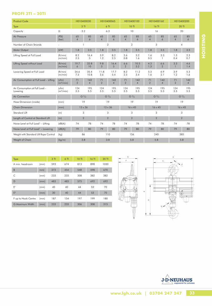
Product Code H010400030 H010400065 H010400100 H010400160 H010400200
Type 3 TI 6 TI 10 TI 16 TI 20 TI
Capacity (t) 3.2 6.3 10 16 20
Air Pressure (PSI) (bar)
65 4
85 6
65 4
85 6
65 4
85 6
65 4
85 6
654
856
Number of Chain Strands - 1 2 2 3 4
Motor Output (kW) 1.8 3.5 1.8 3.5 1.8 3.5 1.8 3.5 1.8 3.5
Lifting Speed at Full Load (ft/min ) (m/min)
8.2 2.5
16.4 5
3.9 1.2
8.2 2.5
2.6 0.8
5.2 1.6
1.6 0.5
3.3 1
1.30.4
2.30.7
Lifting Speed without Load (ft/min ) (m/min)
19.7 6
32.8 10
9.8 3
16.4 5
6.6 2
10.5 3.2
4.3 1.3
6.6 2
3.31
4.61.4
Lowering Speed at Full Load (ft/min ) (m/min)
24.6 7.5
35.4 10.8
11.8 3.6
17.7 5.4
8.2 2.5
11.2 3.4
5.3 1.6
6.9 2.1
3.91.2
5.31.6
Air Consumption at Full Load – Lifting (cfm ) (m3/min)
71 2
142 4
71 2
142 4
71 2
142 4
71 2
142 4
712
1424
Air Consumption at Full Load – Lowering
(cfm ) (m3/min)
124 3.5
195 5.5
124 3.5
195 5.5
124 3.5
195 5.5
124 3.5
195 5.5
1243.5
1955.5
Air Connection - G 3/4 G 3/4 G 3/4 G 3/4 G 3/4
Hose Dimension (inside) (mm) 19 19 19 19 19
Chain Dimension (mm) 13 x 36 13 x 36 16 x 45 16 x 45 16 x 45
Standard Lift ( m) 3 3 3 3 3
Length of Control at Standard Lift (m) 2 2 2 2 2
Noise Level at Full Load1 – Lifting (dB(A)) 74 78 74 78 74 78 74 78 74 78
Noise Level at Full Load1 – Lowering (dB(A)) 79 80 79 80 79 80 79 80 79 80
Weight with Standard Lift Rope Control (kg) 86 110 156 240 285
Weight of Chain (kg/m) 3.8 3.8 5.8 5.8 5.8
Type 3 TI 6 TI 10 TI 16 TI 20 TI
A min. headroom (mm) 593 674 813 898 1030
B mm) 373 454 548 598 670
C (mm) 233 233 308 382 382
D (mm) 483 483 575 692 692
E1 (mm) 40 40 44 53 70
E2 (mm) 30 40 44 53 70
F up to Hook Centre (mm) 187 154 197 199 180
G Maximum Width (mm) 233 233 306 308 315
G
F
D
C
A
B
E1
E2
PROFI 3TI – 20TI

34
HO
ISTI
NG
Product Code H010400250 H010400300 H010400370 H010400400 H010400500 H010400600 H010400750 H010401000
Type 25 TI 30 TI 37 TI 40 TI 50 TI 60 TI 75 TI 100 TI
Capacity (t) 25 30 37.5 40 50 60 75 100
Air Pressure (PSI) (bar)
85 6
Number of Chain Strands - 2 2 3 3 4 4 3 4
Lifting Speed at Full Load (m/min) 0.75 1.25 0.6 1 0.45 0.75 0.4 0.7 0.3 0.55 0.25 0.45 0.53 0.4
Lifting Speed without Load (m/min) 2.4 2.4 1.7 1.7 1.3 1.3 1.33 1
Lowering Speed at Full Load
(m/min) 1.4 2.8 1.4 2.8 1 2 1 2 0.9 1.6 0.9 1.6 1.25 0.95
Air Consumption at Full Load – Lifting
(m3/min) 6.5 7.6
Air Consumption at Full Load – Lowering
(m3/min) 2.9 6
Air Connection - G 11/2
Hose Dimension (inside) (mm) 35
Weight with Standard 3m Lift Rope Control
(kg) 550 550 850 850 940 940 1800 2000
Chain Dimension (mm) 23.5 x 66 32 x 90
Weight of Chain (kg/m) 12.2 21.3
Air Chain HoistsPROFI 25TI – 100TIJDN Air Hoists PROFI Series are very robust and therefore suitable for tough applications even in continuous working processes. According to your requirements there are various control systems available. For traversing loads different trolley designs meet your particular demands.
• Sensitive infinitely variable speed control for the precise positioning of loads
• Load chain and hooks manufactured from high quality steels
Type 25 TI 30 TI 37 TI 40 TI 50 TI 60 TI 75 TI 100 TI
A min. headroom (mm) 1260 1260 1470 1470 1485 1485 1930 1930
B (mm) 827 827 935 935 950 950 1250 1250
C (mm) 450 450 540 540 540 540 825 825
D (mm) 900 900 1080 1080 1080 1080 1535 1535
E1 (mm) 70 70 100 100 100 100 120 120
E2 (mm) 70 70 100 100 100 100 120 120
F up to Hook Centre (mm) 270 270 285 285 250 250 405 365
G Maximum Width (mm) 445 445 450 450 430 430 600 600
LGH - The authority in lifting

35www.lgh.co.uk | 03704 247 247
HO
ISTI
NG
Rope ControlUniversally applicable for any control length. This control enables sensitive starting and stopping. Lifting and lowering speeds are infinitely variable. The rope control is available for all PROFI hoists up to 25t carrying capacity. The PROFI 37 TI, 50 TI and 100 TI are fitted with a pull chain instead of a cord.
F-ControlAvailable for multi-function use. The F-control consists of unbreakable synthetic material resistant to ambient influences. The ergonomically designed housing enables good handling. Up to 18 different control functions can be integrated as for example key switch, double stage travelling speed or simultaneous control of several motors. As a special extra the F-control can also be delivered with infinitely variable control of hoisting and travelling speeds.
E-ControlLow Maintenance, corrosion-proof:
The very robust brass construction distinguishes the E-type pendant control value. Low weight and ergonomic design ensure ease of handling. Only available in single speed control version.
Air Line Filter LubricatorBuilt-in to a steel frame to improve protection, the filter lubricator is an essential component to ensure that the air hoist runs efficiently and without issue.
Accessories & ControlsCarrying capacities up to 20t• As manual trolleys (LN) for pushing or pulling the trolleys by hand• As reel chain trolleys (LH) for moving the trolleys by unwinding
the reel chain• As motorised trolleys (LM) powered by an air motor
Standard Features• Easy to install with anti-climb and anti-drop devices• Robust and with little maintenance• Able to negotiate curves
36
HO
ISTI
NG
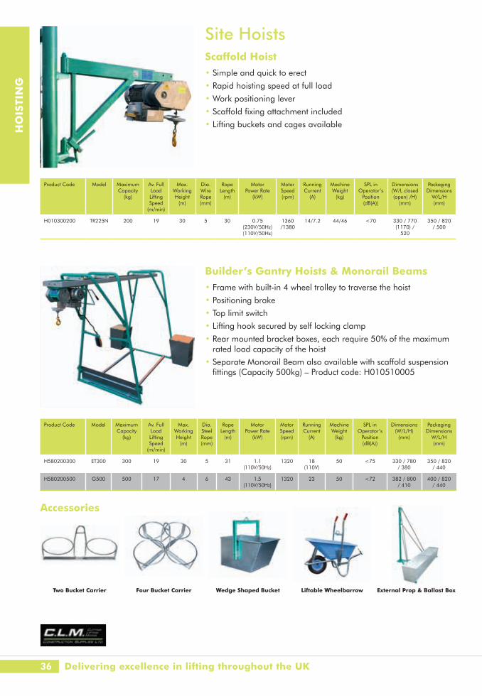
Site HoistsScaffold Hoist• Simple and quick to erect
• Rapid hoisting speed at full load
• Work positioning lever
• Scaffold fixing attachment included
• Lifting buckets and cages available
Builder’s Gantry Hoists & Monorail Beams• Frame with built-in 4 wheel trolley to traverse the hoist
• Positioning brake
• Top limit switch
• Lifting hook secured by self locking clamp
• Rear mounted bracket boxes, each require 50% of the maximum rated load capacity of the hoist
• Separate Monorail Beam also available with scaffold suspension fittings (Capacity 500kg) – Product code: H010510005
Accessories
Product Code Model Maximum Capacity
(kg)
Av. Full Load Lifting Speed
(m/min)
Max. Working Height
(m)
Dia. Wire Rope(mm)
Rope Length
(m)
Motor Power Rate
(kW)
Motor Speed(rpm)
Running Current
(A)
Machine Weight
(kg)
SPL in Operator’s
Position(dB(A))
Dimensions (W/L closed(open) /H)
(mm)
Packaging Dimensions
W/L/H(mm)
H010300200 TR225N 200 19 30 5 30 0.75(230V/50Hz)(110V/50Hz)
1360/1380
14/7.2 44/46 <70 330 / 770 (1170) /
520
350 / 820 / 500
Product Code Model Maximum Capacity
(kg)
Av. Full Load Lifting Speed
(m/min)
Max. Working Height
(m)
Dia. Steel Rope(mm)
Rope Length
(m)
Motor Power Rate
(kW)
Motor Speed(rpm)
Running Current
(A)
Machine Weight
(kg)
SPL in Operator’s
Position(dB(A))
Dimensions (W/L/H)
(mm)
Packaging Dimensions
W/L/H(mm)
H580200300 ET300 300 19 30 5 31 1.1(110V/50Hz)
1320 18(110V)
50 <75 330 / 780 / 380
350 / 820 / 440
H580200500 G500 500 17 4 6 43 1.5 (110V/50Hz)
1320 23 50 <72 382 / 800 / 410
400 / 820 / 440
Two Bucket Carrier Four Bucket Carrier Wedge Shaped Bucket Liftable Wheelbarrow External Prop & Ballast Box
Delivering excellence in lifting throughout the UK

37www.lgh.co.uk | 03704 247 247
HO
ISTI
NG
Minifor HoistsPortable Electric Hoists with unlimited lifting height
High Performance - Sturdy
• Excellent weight - power ratio
• Aluminium alloy housing
• Unlimited length of lifting wire rope
Safety
• Adjustable upper and lower stops
• Brake incorporated in motor
• Wire Rope 6.5mm available in increments of 20m to 100m
Minifor Sheaving KitBy using the Minifor Sheaving kit, you can increase the capacity of the unit by 100%. Remember to double your rope length when using this arrangement.
Ropes to suit Minifor TR30S / TR50
Product Code Model WLL Speed Dimensions (mm) Weight(kg)
Direct (kg)
Sheaved (kg)
Direct (m/min)
Sheaved (m/min)
A B C D E F G H I J K L M
H010600030 TR30S 300 600 13 6.5 430 20 212 642 224 181 90 20 20 347 492 302 15 31
H010600050 TR50 500 950 7 3.5 430 20 212 642 224 181 90 20 20 347 492 302 15 31
minifor®
TR 30S / TR 50Standard / Standard
réf. : T 2182 F/GBrév. n° :date : 01/03page : 1/1
fiche techniquetechnical data sheet
Modèle Vitesse Dimensions mm PoidsModel Speed Dimensions mm Weight
Direct /Direct
kg
Moufle/Sheaved
kg
Direct /Directm/min
Moufle/Sheaved
m/minA B C D E F G H I J K L M kg
TR30S 300 600 13 6,5 430 20 212 642 224 181 90 20 20 347 492 302 15 31
TR50 500 950 7 3,5 430 20 212 642 224 181 90 20 20 347 492 302 15 31
C.M.U.W.L.L.
A
C
B
D
J
K
L
M
E
GF
H I
Ø câbleØ wire rope Motorisation 1 phasePower supply 1 phaseCommande en tension directe / Direct controls
Motorisation 3 phasesPower supply 3 phasesCommande en basse tension 48V / Low voltage controls 48V
I.P. 55
6,5 mm
115 V - 230 V
400 V
All LGH units are fitted with wireless remote controls as standard
Product Code Model Maximum Capacity (kg)
H010610000 TR125 950
Product Code Length (m)
Weight (kg)
H01070020 20 5
H01070040 40 9
H01070060 60 12
H01070080 80 18
H01070100 100 22

38
HO
ISTI
NG
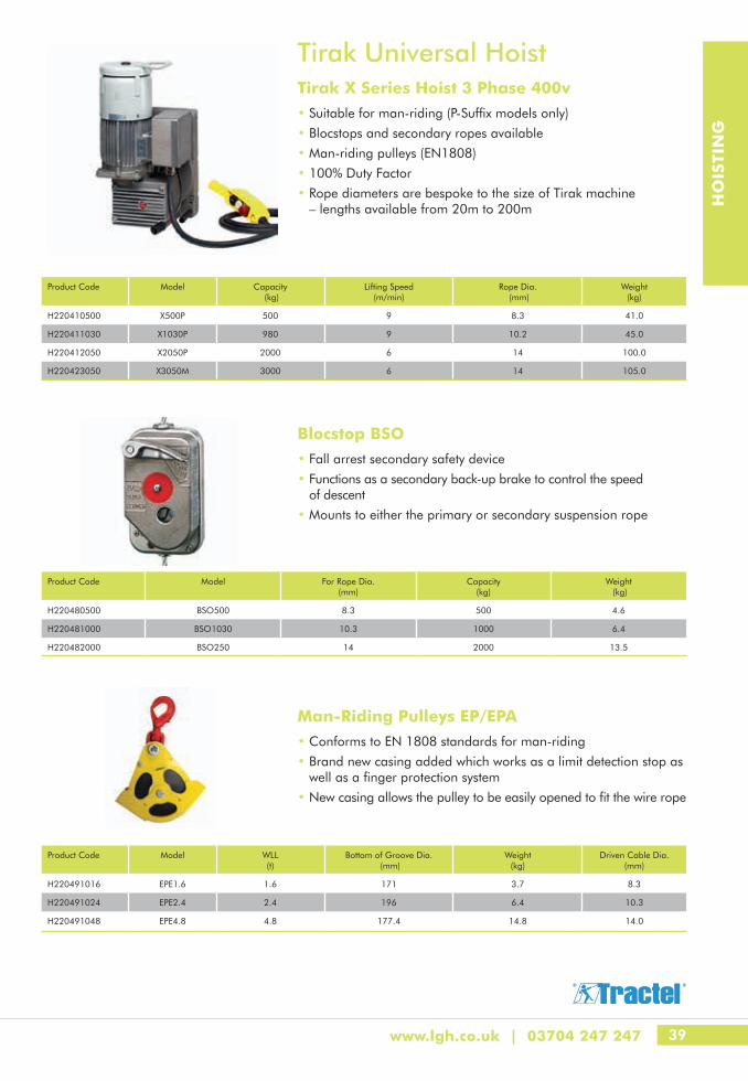
Tirak Universal Hoist• Range from 500kg to 3000kg• Traction hoist for unlimited length of rope• No reductions in working load limits or drive torque at increasing
heights of lift• 100% duty factor (80% in 110V)• Industry standard for elevator installations, building maintenance
units and wind turbines• Harsh environment protection• Fitment can be directly to the load or mounted within a frame• Suitable for man-riding operation
1x
To Anchor the Frame
Direct Lifting or Pulling
Orientation
Positioning
1x
2x
1x
1x
Lifting a Load
Lifting and Sheave Blocks
The TIRAK mobile winch automatically turns in the direction of pull. Unlike a conventional drum winch, the direction of line pull is always the same because of the fixed rope position design of the TIRAK. Moreover, with the TIRAK mobile winch, the capacity and speed remains constant at all times.
To anchor the frame: simply attach the TIRAK mobile winch to a suitable anchor point using a rope sling, chain or similar attachment.
If the pull is through an opening in the wall or ceiling capable of taking the load, simply site the winch by or above the hole.
If the hole is not big enough for the rope hook to pass through, position the TIRAK mobile winch and pass the wire rope through the hole and then into the TIRAK.
If the effective power is not enough increase the capacity using a set of multiple sheave blocks.
To lift: anchor the TIRAK mobile winch to a suitable point and pass the wire rope around one or more return pulleys.
LGH - puts safety first
39www.lgh.co.uk | 03704 247 247
HO
ISTI
NG
Tirak Universal HoistTirak X Series Hoist 3 Phase 400v• Suitable for man-riding (P-Suffix models only)
• Blocstops and secondary ropes available
• Man-riding pulleys (EN1808)
• 100% Duty Factor
• Rope diameters are bespoke to the size of Tirak machine – lengths available from 20m to 200m
Blocstop BSO• Fall arrest secondary safety device
• Functions as a secondary back-up brake to control the speed of descent
• Mounts to either the primary or secondary suspension rope
Man-Riding Pulleys EP/EPA• Conforms to EN 1808 standards for man-riding
• Brand new casing added which works as a limit detection stop as well as a finger protection system
• New casing allows the pulley to be easily opened to fit the wire rope
Product Code Model Capacity (kg)
Lifting Speed (m/min)
Rope Dia. (mm)
Weight (kg)
H220410500 X500P 500 9 8.3 41.0
H220411030 X1030P 980 9 10.2 45.0
H220412050 X2050P 2000 6 14 100.0
H220423050 X3050M 3000 6 14 105.0
Product Code Model WLL (t)
Bottom of Groove Dia. (mm)
Weight (kg)
Driven Cable Dia.(mm)
H220491016 EPE1.6 1.6 171 3.7 8.3
H220491024 EPE2.4 2.4 196 6.4 10.3
H220491048 EPE4.8 4.8 177.4 14.8 14.0
Product Code Model For Rope Dia. (mm)
Capacity (kg)
Weight (kg)
H220480500 BSO500 8.3 500 4.6
H220481000 BSO1030 10.3 1000 6.4
H220482000 BSO250 14 2000 13.5

40
HO
ISTI
NG
Aluminium GantriesPORTA-GANTRY - 0.5t to 5t• Lightweight, portable and safe, the innovative and unique
PORTA-GANTRY lifting system range is designed for easy transport, rapid assembly and safe use
• The world’s first WLL 5t capacity portable gantry. A range of Lift Height options and beam lengths are available
• Wind up jacking legs available for use on uneven ground
Dimensions use standard Master Link Trolley, other options available to increase resulting height of lift (HOL) and to assist with load movement. *Weight includes stabiliser legs
Fram
e si
ze
Dmax E Dmin F Hmax Hmin G
Max Height
to Lifting Eye
(mm)
Height Increment
(mm)
Min Height
to Lifting Eye
(mm)
Max Height
to Top of Beam(mm)
Max Height to Top
of Roller (mm)
Min Height to Top
of Roller (mm)
Width (mm)
A-Frame Weight
(kg)
Trolley Roller Size (mm)
Castor Dia. (mm)
WLL
(kg)
50010002000
S 2355 5 x 150 1605 2675 2757 2007 1212 38 82 150
M 2851 5 x 150 2101 3171 3253 2503 1429 40 82 150
I 3188 5 x 200 2188 3499 3581 2581 1726 46 82 200
T 4079 6 x 200 2879 4399 4481 3281 2011 51 82 200
TC4 4527 6 x 200 3327 4847 4930 3730 2234 80 82 200
TC3 5027 6 x 200 3827 5347 5430 4230 2557 82 82 200
TC2 5527 8 x 200 3927 5848 5930 4330 2733 87 82 200
TC1 5829 9 x 200 4029 6149 6231 4431 2733 95 82 200
WLL
(kg)
3000
S 2410 5 x 150 1660 2730 2812 2062 1212 55 82 200
M 2906 5 x 150 2156 3226 3308 2558 1429 60 82 200
I 3188 5 x 200 2188 3499 3581 2581 1726 70 82 200
T 4079 6 x 200 2879 4399 4481 3281 2011 82 82 200
TC4 4527 6 x 200 3327 4847 4930 3730 2234 80 82 200
TC3 5027 6 x 200 3827 5347 5430 4230 2557 82 82 200
TC2 5527 8 x 200 3927 5848 5930 4330 2733 87 82 200
WLL
(kg)
5000
I 3181 5 x 200 2181 3592 3717 2717 1736 97* 125 200
T 4049 6 x 200 2849 4487 4612 3412 2021 106* 125 200
TC4 4500 6 x 200 3300 4938 5062 3862 2234 85 125 200
TC3 5000 6 x 200 3800 5438 5562 4362 2557 90 125 200
S (small) & M (medium) versions also available as custom systems
WLL 5000kg dimensions systems are shown using the deeper ‘D’ section beam
Safety, Certainty, Great Service
Assembled PORTA-GANTRY dimensions (see diagram opposite)
41www.lgh.co.uk | 03704 247 247
HO
ISTI
NG
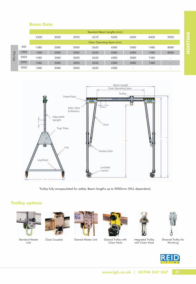
Adjustable Upright
‘Trap’ Plate
Leg
Leg Brace
Lockable Castors
Hockey Stick
Strut
Trolley
E
200mm
G
F H
Cheek Plate
Bolts, Nuts & Washers
Beam LengthClear Operating Span
D
Trolley options
Standard Beam Lengths (mm)
2500 3000 3920 4570 5500 6000 8400 9000
Clear Operating Span (mm)
WLL
(kg)
500 1580 2080 3000 3650 4580 5080 7480 8080
1000 1580 2080 3000 3650 4580 5080 7480 8080
2000 1580 2080 3000 3650 4580 5080 7480 -
3000 1580 2080 3000 3650 4580 5080 7480 -
5000 1580 2080 3000 3650 4580 - - -
Trolley fully encapsulated for safety. Beam lengths up to 9000mm (WLL dependent).
Standard Master Link
Close Coupled Geared Master Link Geared Trolley with Chain Hoist
Integrated Trolley with Chain Hoist
Sheaved Trolley for Winching
Beam Data

42
HO
ISTI
NG
Floor CranesHeavy Duty Folding Engine Cranes - 0.5t to 1tThese heavy duty hydraulic engine cranes are designed to solve all your workshop lifting applications. Configurations are available in 500kg and 1000kg versions and can have a parallel or V-shaped chassis.
• A hydraulic system that can rotate for use in confined spaces
• Parking brake fitted as standard to secure the crane firmly in position
• Cantilever arm rises to 2080mm and can be extended to suit applications
• Quickly and easily folded away by one person
Product Code Model Chassis Type Chassis W x L x H (mm)
Lifting Capacity Min-Max (kg)
Hook Height Min-Max (mm)
Distance Between Legs (mm)
Weight (kg)
H210105000 KLS8514 Parallel 990 x 1820 x 1680 250 - 500 770 - 2200 850 138.0
H210105001 KLS8515 "V" 990 x 1820 x 1680 250 - 500 770 - 2200 850 132.0
H210110000 KLS8516 Parallel 990 x 1820 x 1680 500 - 1000 770 - 2200 850 156.0
H210110001 KLS8517 "V" 990 x 1820 x 1680 500 - 1000 770 - 2200 850 150.0
Product Code Model Chassis Type Chassis L x W x H (mm)
Lifting Capacity Min-Max
(kg)
Hook Height Min-Max
(mm)
Jib Maximum Reach (mm)
Counterbalance Weight
(kg)
Weight (kg)
H210120010 CTC1000 Counterbalance 640 x 1470 x 1850 500 - 1000 420 - 2730 1310 900 265.0
H210120015 CTC1500 Counterbalance 640 x 2500 x 1850 1000 - 1500 420 - 2730 1310 900 280.0
H210120020 CTC2000 Counterbalance 640 x 2500 x 1850 1000 - 2000 420 - 2730 1310 900 300.0
Counterbalanced Floor Cranes - 1t, 1.5t & 2t• No forward leg restriction as with a standard unit
• Three position telescopic jib fitted to all models
• Swivel castors located on end enabling the unit to turn on the spot
• All models fitted with pressure relief valve to prevent overload
• 100% ballast must be applied to attain full rate capacity
• Varying capacity ratings dependent on jib extension and inclination
All our equipment is tested and certified to the highest standard
Mini Floor Crane• Max Capacity 900kg
• Max lifting height below the hook 3050mm
• Two long outriggers are back-wards mounted and are fitted with two counterweights boxes containing 14 counterweights each achieves max capacity and lifting height.
NB: See Page 126 for Load Chart
Product code Model Transport Position Working Position Loading Height Min.
(mm)
Boom Extention
each Position (mm)
Boom Length Max (mm)
Weight of chassis inc Boom (kg)Height
(mm)Length (mm)
Width (mm)
Height (mm)
Length (mm)
Width (mm)
H210130750 MFC750/K 1000 – 1920 1200 650 1920 1800 680 850 120 1200 160
43www.lgh.co.uk | 03704 247 247
HO
ISTI
NG
43Pulling
44 Tirfor Machines, Ropes & Accessories
45 Hydraulic Tirfor
46 The Tirfor Principle
47 Wire Rope Blocks
48 Cable Pulling Winch
49 Cable Drum Jacks & Accessories
50 Hydra-Slide
52 Skates & Load Moving Systems

44
PU
LLIN
G
Tirfor Machines, Ropes & AccessoriesTirfor TU Heavy Duty Series (manually operated)• For lifting, pulling and positioning heavy loads
• Unrivalled in terms of durability and sturdiness
• Extra shear pins in handle
• Rope sold separately
• T5 medium duty machines also available
Maxiflex Wire Ropes• Maxiflex ropes have been specifically designed to suit Tirfor products
• The rope is manufactured to extremely high tolerances which are necessary for the reliable operation of the product mechanism inside the machine, especially when lowering under load
• Using Maxiflex Ropes is part of the certification of the machine
Product Code Model WLL (kg)
Maxiflex Rope Dia. (mm)
Rope Breaking Strain (kg)
Machine Weight (kg)
(20m) Rope Weight (kg)
H220110008 TU8 800 8.3 5500 8.4 6.1
H220110016 TU16 1600 11.5 9200 20.0 13.1
H220110032 TU32 3200 16.3 18,400 27.0 23.0
Maxiflex Wire Rope
TU-8 / T508 Fitted with Hook8.3 Dia. (mm)
TU-16 / T516 Fitted with Hook11.5 Dia. (mm)
TU-32 / T532 Fitted with Shackle
16.3 Dia. (mm)
Length (m) Product Code Product Code Product Code
20 H220800820 H220811620 H220823220
40 H220800840 H220811640 H220823240
60 H220800860 H220811660 H220823260
80 H220800880 H220811680 H220823280
100 H220800900 H220811700 H220823300
Coni Clamp Ground Anchor Drum Reeler
Other lengths available on requestUp to 80m - 5 strand rope. Above 80m - 6 strand rope.
All Tirfor machines are supplied fully tested and certified in accordance with the statutory regulations. The TU16H and TU32H Tirfor machines must not be used for man-riding applications.
Accessories
LGH - The authority in lifting

45
PU
LLIN
G
www.lgh.co.uk | 03704 247 247
Model Capacity (kg)
Length(mm)
Height(mm)
Thickness(mm)
Rope Dia.(mm)
TU16H 1600 788 360 185 11.5
TU32H 3200 1070 430 204 16.5
Model Forward Operationm/min
Reverse Operationm/min
Hydraulic Power Pack
1 way 2 way 4 way 1 way 2 way 4 wayWeight
(kg)Dimension
(mm)
1 way 2 way 4 way WxLxH
TU16H 2 1.5 0.75 2.3 2 1 43.5 44.1 45.1 460x550x500
TU32H 0.7 0.35 0.17 1.6 0.8 0.4 43.5 44.1 45.1 460x550x500
Product Code 1600kg Systems
Description
H220310016 Tirfor TU16H fitted with a bracket WLL for lifting 1600kg
H220390001 VA2 self reciprocating hydraulic ram
H220380001 3m hydraulic hose 10mm ø, with female couplings
H220380002 3m hydraulic hose 10mm ø, with male couplings
H220210400 3 phase electric motor power pack
H220220000 Petrol driven power pack
Product Code 3200kg Systems
Description
H220310032 Tirfor TU32H fitted with a bracket WLL for lifting 3200kg
H220390000 VA3 self reciprocating hydraulic ram
H220380001 3m hydraulic hose 10mm ø, with female couplings
H220380002 3m hydraulic hose 10mm ø, with male couplings
H220210400 3 phase electric motor power pack
H220220000 Petrol driven power pack
Hydraulic TirforTirfor TU16H / TU32H (hydraulically operated)
• Electric or Petrol Power Pack for operating 1, 2, or 4 units

46
PU
LLIN
G
The Tirfor PrincipleA Tirfor has neither wheels nor gears• Two jaws alternately pull the wire rope and the load in the
required direction, just like pulling on a rope with both hands
• The jaws are self clamping, providing immediate and gradual safety
• The heavier the load, the tighter they clamp
• A release mechanism allows the wire rope to be inserted between the jaws
Mathematical method of calculating the effort required to move a given load
Where E Is the effort required to pull a load lying on the ground
W Is the weight of the load
μ Is the friction between load and ground which depends upon the area of contact of the load with the ground (presence of wheels, rollers, sand, mud concrete, etc...) is the angle of the slope
The value of U the coefficient of friction, must be known or estimated. Here are some general values of this coefficent.
Steel on steel 0.4-0.6 Iron on stone 0.3-0.7
Leather on metal 0.6 Continuously lubricated surfaces 0.15
Wood on stone 0.4 Load on wheels 0.02-0.05
PULL
LIFT
TENSION
Operates in every direction
Multifunction:• Work can be performed in any position;
horizontal, vertical or at an angle
• There is no limit to the length of wire rope
• The capacity can be increased
Increased Capacity:• Using the sheave block technique, the capacity of the Tirfor can be increased by a factor of 2, 3, 4 or more by
sheaving (see diagrams)
• The figures given must be multiplied by the nominal capacity of the device
• When calculating the working load limit, include a loss of around 4% per sheave, due to the friction of the sheaves
Safe and Reliable• Constant control of the load during lifting and lowering
with accuracy
• When stationary the load is automatically distributed between the two jaw units
• Overload safety device
Delivering excellence in lifting throughout the UK

47
PU
LLIN
G
www.lgh.co.uk | 03704 247 247
Wire Rope BlocksSnatch Block with Captive Shackle• Snatch blocks are supplied with bronze brushings and grease
fittings for ease of use and extended shelf life
• Manufactured with the highest tensile steel for improved performance
• Sheave sizes from 76mm Dia. (8-10mm rope) to 305mm (25-29mm rope)
• Available in sizes 2 – 20 tonnes
Product Code WLL (t)
Sheave Dia. (mm)
Wire Rope Size
(mm)
Dimensions (mm) Weight (kg)
A B E F G K L R
H320810302 2 76 8-10 35 30 64 11 75 150 228 217 3.8
H320810404 4 114 10-13 64 50 79 19 107 243 356 336 6.2
H320810608 8 152 16-19 87 76 104 32 152 320 484 452 13.2
H320810808 8 203 16-19 87 76 104 32 220 333 558 526 18.2
H320810612 12 152 19-22 78 80 134 44 167 359 540 496 24.8
H320810815 15 203 19-22 78 80 134 44 220 355 589 545 29.6
H320811015 15 254 19-22 78 80 134 44 280 423 714 670 42.7
H320811215 15 305 19-22 78 80 134 44 330 428 770 726 52.8
H320810820 20 203 25-29 109 93 150 55 216 433 671 616 41.6
H320811020 20 254 25-29 109 93 150 55 280 481 778 723 52.4
H320811220 20 305 25-29 109 93 150 55 330 485 883 778 62.8
48
PU
LLIN
G
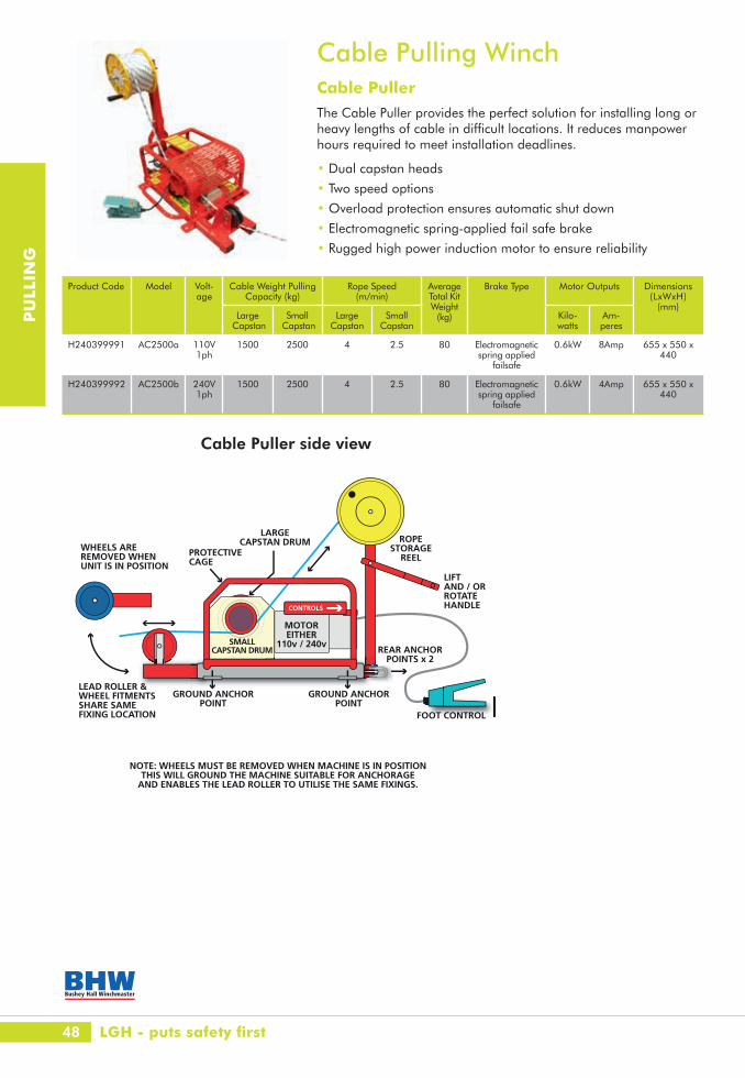
Cable Pulling WinchCable PullerThe Cable Puller provides the perfect solution for installing long or heavy lengths of cable in difficult locations. It reduces manpower hours required to meet installation deadlines.
• Dual capstan heads
• Two speed options
• Overload protection ensures automatic shut down
• Electromagnetic spring-applied fail safe brake
• Rugged high power induction motor to ensure reliability
Product Code Model Volt-age
Cable Weight Pulling Capacity (kg)
Rope Speed (m/min)
Average Total Kit Weight
(kg)
Brake Type Motor Outputs Dimensions (LxWxH)
(mm)Large
CapstanSmall
CapstanLarge
CapstanSmall
CapstanKilo-watts
Am-peres
H240399991 AC2500a 110V 1ph
1500 2500 4 2.5 80 Electromagnetic spring applied
failsafe
0.6kW 8Amp 655 x 550 x 440
H240399992 AC2500b 240V 1ph
1500 2500 4 2.5 80 Electromagnetic spring applied
failsafe
0.6kW 4Amp 655 x 550 x 440
NOTE: WHEELS MUST BE REMOVED WHEN MACHINE IS IN POSITIONTHIS WILL GROUND THE MACHINE SUITABLE FOR ANCHORAGE
AND ENABLES THE LEAD ROLLER TO UTILISE THE SAME FIXINGS.
WHEELS AREREMOVED WHENUNIT IS IN POSITION
LEAD ROLLER &WHEEL FITMENTSSHARE SAMEFIXING LOCATION
PROTECTIVECAGE
LARGECAPSTAN DRUM ROPE
STORAGEREEL
REAR ANCHORPOINTS x 2
GROUND ANCHORPOINT
GROUND ANCHORPOINT
MOTOREITHER
110v / 240v
CONTROLS
LIFT AND / ORROTATEHANDLE
FOOT CONTROL
SMALLCAPSTAN DRUM
Cable Puller side view
LGH - puts safety first

49
PU
LLIN
G
www.lgh.co.uk | 03704 247 247
Cable Drum Jacks & AccessoriesScrew Operation• Easy to handle and simple to operate
• Base plate designed to give stability even on soft ground
• Cable drum spindle bars available as an optional extra
AccessoriesCable Roller - Heavy Duty• Zinc plated heavy duty assembly suitable for cables up to 125mm dia.
• Steel frame fitted with large waisted steel roller running on sealed ball bearings
Triple Corner Cable Roller• Using two vertical and one horizontal steel rollers identical to
HSP125 for taking the heaviest cables round difficult corners
• Robust construction for use in the most arduous conditions
• Can be linked together with stake pins to form a continuous corner roller system
Hydraulic Operation • Versatile and easily adjustable within seconds to accommodate a
vast range of drums
• Excellent all round stability
• Fitted with wheels to be easily moved by one person
• Cable drum spindle bars available as an optional extra
Product Code Model Spindle Bar Capacity/Pair (t)
Min Drum Dia. (mm)
Max Drum Dia. (mm)
Base Area (mm)
Weight/Pair (kg)
Dia. (mm) Length (mm)
H310710003 SJ3 50 1200 3 1060 1600 300 x 300 37.0
H310710006 SJ6 50 1800 6 1360 1900 460 x 300 45.0
Product Code Model Height (mm) Width (mm) Length (mm) Load Cap. (kg) Weight (kg)
H310500150 HSP125 220 235 350 150 4.0
Product Code Model Height (mm) Width (mm) Length (mm) Load Cap. (kg) Weight (kg)
H310510075 CR4 295 230 330 75 8.0
Product Code Model Capacity/Pair (t) Min Drum Dia. (mm) Max Drum Dia. (mm) Base Area (mm) Weight/Pair (kg)
H310720003 HJ3 3 800 2500 830 x 700 106.0
H310720006 HJ6 6 880 3000 900 x 765 118.0
H310720010 HJ10 10 1080 3500 1060 x 985 180.0

50
PU
LLIN
G
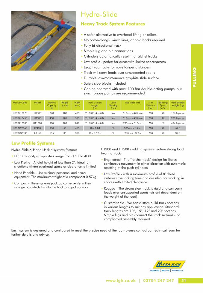
Hydra-SlideHydraulic Skidding Systems
• The Hydra-Slide heavy duty skidding systems provide superior load moving capability for moving, loading and unloading all types of heavy loads, such as transformers, generators, compressors, pressure vessels and machines safely
• Controlled by one operator working from a remotely positioned power unit, there is no need for personnel to be close to the load during operation
• No winch lines, no holdbacks and no heavy equipment required. All of our skid systems are fully bi-directional with track sections that are designed to be easily leap-frogged to move longer distances
SKIDDING RIGGING HYDRAULICS
HYDRAULIC SKIDDING SYSTEMSHydra-Slide HT300
Heavy Track System FeaturesŸ A safer alternative to overhead lifting or rollers
Ÿ No come-alongs, winch lines, or hold backs required
Ÿ Fully bi-directional track
Ÿ Simple lug and pin connections
Ÿ Cylinders automatically reset into ratchet tracks
Ÿ Low profile - perfect for areas with limited space/access
Ÿ Leap Frog tracks to move longer distances
Ÿ Track will carry loads over unsupported spans
Ÿ Durable low-maintenance graphite slide surface
Ÿ Safety stop blocks included
Ÿ can be operated with most 700 bar double-acting pumps, but
synchronous pumps are recommended
Always follow Operating Manual Instructions andsafe jacking practices.
All system components are stored in a steel toolbox for convenience and easy transportation.
Safety, Certainty, Great Service
51
PU
LLIN
G
www.lgh.co.uk | 03704 247 247
Hydra-SlideHeavy Track System Features
Low Profile SystemsHydra-Slide XLP and LP skid systems feature:
• High Capacity - Capacities range from 150t to 400t
• Low Profile - A total height of less than 2”. Ideal for situations where overhead space or clearance is limited
• Hand Portable - Use minimal personnel and heavy equipment. The maximum weight of a component is 57kg
• Compact - These systems pack up conveniently in their storage box which fits into the back of a pickup truck
HT300 and HT500 skidding systems feature strong load bearing track
• Engineered - The “ratchet track” design facilitates continuous movement in either direction with automatic resetting of the push cylinders
• Low Profile - with a maximum profile of 8” these systems save jacking time and are ideal for working in spaces with limited clearance
• Rugged - The strong steel track is rigid and can carry loads over unsupported spans (distant dependent on the weight of the load)
• Customisable - We can custom build track sections in various lengths to suit any application. Standard track lengths are 10”, 15”, 19” and 20” sections. Simple lugs and pins connect the track sections - no complicated assembly required
Each system is designed and configured to meet the precise need of the job - please contact our technical team for further details and advice.
Product Code Model Systems Capacity
(t)
Height (mm)
Width (mm)
Track Section Length
(m)
Load Bearing Track
Skid Shoe Size Max Pressure
(bar)
Skidding Speed (m/hr)
Track Section Weight (kg)
H339910270 HT300 270 180 485 2 x 3.05 4 x 5.84 Yes 610mm x 420 mm 700 28 186.0 per m
H339910450 HT500 450 205 535 2 x 3.05 4 x 5.84 Yes 610mm x 460 mm 700 17 283.0 per m
H339910900 HT1000 900 205 840 2 x 3.05 4 x 5.84 Yes 790mm x 610mm 700 9 454.0 per m
H339920360 LP400 360 50 485 10 x 1.83 No 305mm x 3.7 m 700 28 59.0
H339930135 XLP150 135 30 330 12 x 1.52m No 230mm x 3.7m 700 28 39.0
SKIDDING RIGGING HYDRAULICS
• A safer alternative to overhead lifting or rollers
• No come-alongs, winch lines, or hold backs required
• Fully bi-directional track
• Simple lug and pin connections
• Cylinders automatically reset into ratchet tracks
• Low profile - perfect for areas with limited space/access
• Leap Frog tracks to move longer distances
• Track will carry loads over unsupported spans
• Durable low-maintenance graphite slide surface
• Safety stop blocks included
• Can be operated with most 700 Bar double-acting pumps, but synchronous pumps are recommended
52
PU
LLIN
G
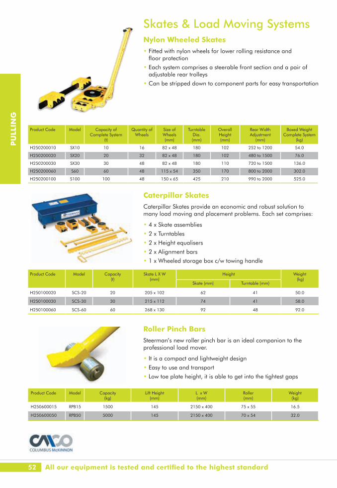
Roller Pinch BarsSteerman’s new roller pinch bar is an ideal companion to the professional load mover.
• It is a compact and lightweight design
• Easy to use and transport
• Low toe plate height, it is able to get into the tightest gaps
Caterpillar SkatesCaterpillar Skates provide an economic and robust solution to many load moving and placement problems. Each set comprises:
• 4 x Skate assemblies
• 2 x Turntables
• 2 x Height equalisers
• 2 x Alignment bars
• 1 x Wheeled storage box c/w towing handle
Product Code Model Capacity (t)
Skate L X W (mm)
Height Weight (kg)
Skate (mm) Turntable (mm)
H250100020 SCS-20 20 205 x 102 62 41 50.0
H250100030 SCS-30 30 215 x 112 74 41 58.0
H250100060 SCS-60 60 268 x 130 92 48 92.0
Product Code Model Capacity (kg)
Lift Height (mm)
L x W (mm)
Roller (mm)
Weight (kg)
H250600015 RPB15 1500 145 2150 x 400 75 x 55 16.5
H250600050 RPB50 5000 145 2150 x 400 70 x 54 32.0
Skates & Load Moving SystemsNylon Wheeled Skates• Fitted with nylon wheels for lower rolling resistance and
floor protection
• Each system comprises a steerable front section and a pair of adjustable rear trolleys
• Can be stripped down to component parts for easy transportation
Product Code Model Capacity of Complete System
(t)
Quantity of Wheels
Size of Wheels (mm)
Turntable Dia. (mm)
Overall Height (mm)
Rear Width Adjustment
(mm)
Boxed Weight Complete System
(kg)
H250200010 SX10 10 16 82 x 48 180 102 252 to 1200 54.0
H250200020 SX20 20 32 82 x 48 180 102 480 to 1500 76.0
H250200030 SX30 30 48 82 x 48 180 110 720 to 1500 136.0
H250200060 S60 60 48 115 x 54 350 170 800 to 2000 302.0
H250200100 S100 100 48 150 x 65 425 210 990 to 2000 525.0
All our equipment is tested and certified to the highest standard

53
PU
LLIN
G
www.lgh.co.uk | 03704 247 247
53Jacking
54 Jacks
57 Hydraulic Cylinders
66 Hydraulic Pumps
67 Hydraulic Accessories
69 Compression Load Cells
70 Compressive Load Cell Systems
54
JAC
KIN
G
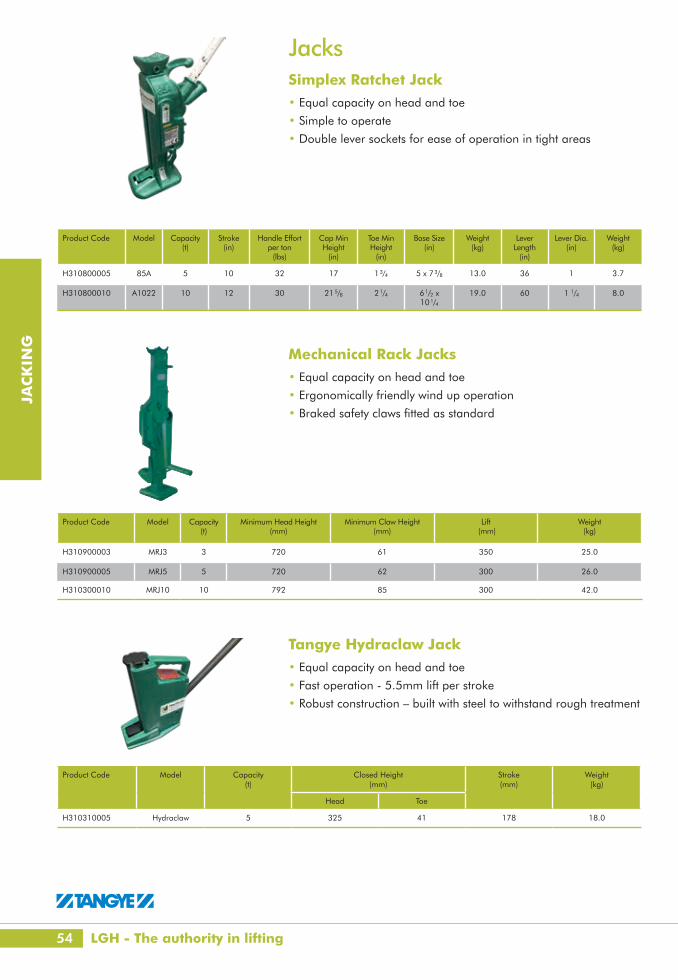
JacksSimplex Ratchet Jack• Equal capacity on head and toe
• Simple to operate
• Double lever sockets for ease of operation in tight areas
Mechanical Rack Jacks• Equal capacity on head and toe
• Ergonomically friendly wind up operation
• Braked safety claws fitted as standard
Tangye Hydraclaw Jack• Equal capacity on head and toe
• Fast operation - 5.5mm lift per stroke
• Robust construction – built with steel to withstand rough treatment
Product Code Model Capacity (t)
Closed Height(mm)
Stroke(mm)
Weight(kg)
Head Toe
H310310005 Hydraclaw 5 325 41 178 18.0
Product Code Model Capacity(t)
Stroke (in)
Handle Effortper ton
(lbs)
Cap Min Height
(in)
Toe Min Height
(in)
Base Size (in)
Weight (kg)
LeverLength
(in)
Lever Dia. (in)
Weight (kg)
H310800005 85A 5 10 32 17 13/4 5 x 73/8 13.0 36 1 3.7
H310800010 A1022 10 12 30 215/8 21/4 61/2 x 101/4
19.0 60 1 1/4 8.0
Product Code Model Capacity(t)
Minimum Head Height (mm)
Minimum Claw Height (mm)
Lift (mm)
Weight (kg)
H310900003 MRJ3 3 720 61 350 25.0
H310900005 MRJ5 5 720 62 300 26.0
H310300010 MRJ10 10 792 85 300 42.0
LGH - The authority in lifting

55
JAC
KIN
G
www.lgh.co.uk | 03704 247 247
Hollow Piston Jacks• Operates in any position
• Ideal for pulling applications
Compact Jacks• Spring assisted return piston
• Sealed hydraulic system
Product Code Model Capacity (t)
Closed Height (mm)
Stroke (mm)
Piston Dia. (mm)
Max Handle Height (mm)
Length (mm)
Width (mm)
Weight (kg)
H310361035 JCS10 10 76 35 38 266 240 70 4.5
H310362041 JCS20 20 102 41 51 281 257 102 5.5
H310363045 JCS30 30 112 45 60 285 281 125 8.0
Product Code Model Capacity (t)
Lift (mm)
Minimum Claw Height(mm)
Minimum Head Height(mm)
Effort Required at Full Load (daN)
Weight (kg)
H310311005 MH 50 5 205 25 368 38 25.0
H310310010 MH 100 10 230 30 420 40 35.0
H310311025 MH 250 25 215 58 505 40 109.0
Product Code Model Capacity (t)
Closed Height (mm)
Stroke (mm)
Piston Dia (mm)
Max Handle Height (mm)
Centre Hole (mm)
Length (mm)
Width (mm)
Weight (kg)
H310371341 JCH13 13 95 41 51 281 25 257 102 5.5
H310372145 JCH21 21 114 45 60 285 35 281 125 8.0
Multi-Purpose Superjacks• Lightweight construction
• Stroke limiting device
Product Code Model Capacity (t)
Closed Height (mm)
Stroke (mm)
Base Length (mm)
Base Width (mm)
Weight (kg)
H310321003 JAS103 10 131 75 162 75 4.3
H310321005 JAS105 10 181 125 162 75 5.7
Jacks360º Rotational Toe Jacks• Equal capacity on head and toe
• Can be used in any position
• Lifting by means of an integral hand pump
• Pressure control valve for a longer service life of the jack
• Low claw height
• Large base plate for a high level of stability
56
JAC
KIN
G
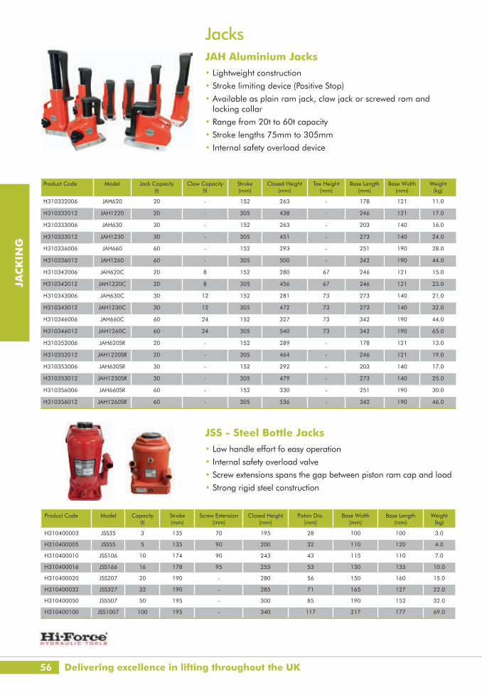
JacksJAH Aluminium Jacks• Lightweight construction
• Stroke limiting device (Positive Stop)
• Available as plain ram jack, claw jack or screwed ram and locking collar
• Range from 20t to 60t capacity
• Stroke lengths 75mm to 305mm
• Internal safety overload device
Product Code Model Jack Capacity (t)
Claw Capacity (t)
Stroke (mm)
Closed Height (mm)
Toe Height (mm)
Base Length (mm)
Base Width (mm)
Weight (kg)
H310332006 JAH620 20 - 152 263 - 178 121 11.0
H310332012 JAH1220 20 - 305 438 - 246 121 17.0
H310333006 JAH630 30 - 152 263 - 203 140 16.0
H310333012 JAH1230 30 - 305 451 - 273 140 24.0
H310336006 JAH660 60 - 152 293 - 251 190 28.0
H310336012 JAH1260 60 - 305 500 - 342 190 44.0
H310342006 JAH620C 20 8 152 280 67 246 121 15.0
H310342012 JAH1220C 20 8 305 456 67 246 121 23.0
H310343006 JAH630C 30 12 152 281 73 273 140 21.0
H310343012 JAH1230C 30 12 305 472 73 273 140 32.0
H310346006 JAH660C 60 24 152 327 73 342 190 44.0
H310346012 JAH1260C 60 24 305 540 73 342 190 65.0
H310352006 JAH620SR 20 - 152 289 - 178 121 13.0
H310352012 JAH1220SR 20 - 305 464 - 246 121 19.0
H310353006 JAH630SR 30 - 152 292 - 203 140 17.0
H310353012 JAH1230SR 30 - 305 479 - 273 140 25.0
H310356006 JAH660SR 60 - 152 330 - 251 190 30.0
H310356012 JAH1260SR 60 - 305 536 - 342 190 46.0
JSS - Steel Bottle Jacks• Low handle effort fo easy operation
• Internal safety overload valve
• Screw extensions spans the gap between piston ram cap and load
• Strong rigid steel construction
Product Code Model Capacity (t)
Stroke (mm)
Screw Extension (mm)
Closed Height (mm)
Piston Dia. (mm)
Base Width (mm)
Base Length (mm)
Weight (kg)
H310400003 JSS35 3 135 70 195 28 100 100 3.0
H310400005 JSS55 5 135 90 200 32 110 120 4.0
H310400010 JSS106 10 174 90 243 43 115 110 7.0
H310400016 JSS166 16 178 95 255 53 130 135 10.0
H310400020 JSS207 20 190 - 280 56 150 160 15.0
H310400032 JSS327 32 190 - 285 71 165 127 22.0
H310400050 JSS507 50 195 - 300 85 190 152 32.0
H310400100 JSS1007 100 195 - 340 117 217 177 69.0
Delivering excellence in lifting throughout the UK

57
JAC
KIN
G
www.lgh.co.uk | 03704 247 247
Product Code Model Capacity (t)
Stroke (mm)
Oil Cap (cm3)
Cyl Eff Area (cm2)
A(mm)
B(mm)
C(mm)
D(mm)
E(mm)
F(mm)
G1(mm)
G2(mm)
H(mm)
I(mm)
Weight (kg)
H330310040 HPS50 4.5 6 4 6.4 32 60 38 24 20 19 5.6 9.75 26 19 0.8
H330310041 HPS51 4.5 16 10 6.4 42 60 38 24 20 19 5.6 9.75 26 19 0.9
H330310100 HPS100 10 10 14 14.4 46 81 56 38 34 28 6.8 11.25 37 19 1.6
H330310200 HPS200 20 11 31 28.6 52 100 76 51 40 39 8.8 14.25 50 19 2.6
H330310300 HPS300 32 12 55 45.6 59 115 95 60 46 48 8.8 14.25 52 19 4.2
H330310500 HPS500 50 15 107 71.3 67 140 114 70 54 60 10.8 17.25 67 20 6.6
H330310730 HPS750 73 16 164 102.7 81 165 140 82 67 70 13 19 76 21 10.4
H330311090 HPS1000 109 16 245 153.4 91 215 180 114 75 90 12.8 19 130 29 23.2
H330311470 HPS1500 147 16 330 206.2 100 215 191 114 83 95 13 19 117 29 28.5
Product Code Model Capacity (t)
Stroke (mm)
Oil Cap (cm3)
Cyl Eff Area (cm2)
A(mm)
B(mm)
C(mm)
D(mm)
E(mm)
Weight (kg)
H330300100 HVL10 10 6 9 14.4 28 87 38 111 16.0 1.6
H330300200 HVL20 20 6 17 28.6 32 104 52 111 19.0 2.6
H330300320 HVL30 32 6 27 45.6 34 120 60 111 19.5 3.0
H330300500 HVL50 50 6 43 71.3 45 158 75 111 29.0 7.2
H330301040 HVL100 104 6 88 146.5 65 200 100 76 37.0 15.6
HPS - Single Acting Low Height Pad Cylinders• Single acting spring assisted return
• Range from 4.5t to 147t capacity
• Stroke lengths from 6mm to 16mm
• Working pressure 700 Bar
Hydraulic Cylinders HVL - Single Acting Very Low Height Pancake Cylinders• Single acting load return
• Range from 10t to 104t capacity
• Stroke length 6mm
• Working pressure 700 Bar

58
JAC
KIN
G
Product Code Model Capacity (t)
Stroke (mm)
Oil Cap (cm3)
Cyl Eff Area (cm2)
A(mm)
B(mm)
C(mm)
D(Eyebolt)
E(mm)
F(mm)
Weight (kg)
H330320100 HLS101 10 40 58 14.4 95 70 38 M8 40 19 2.4
H330320200 HLS201 20 44 126 28.6 102 90 51 M8 60 19 4.8
H330320320 HLS301 32 25 114 45.6 83 102 60 M8 80 19 5.0
H330320321 HLS302 32 60 274 45.6 119 102 60 M8 80 19 7.0
H330320500 HLS501 50 25 178 71.3 91 127 70 M8 80 20 8.4
H330320501 HLS502 50 60 428 71.3 126 127 70 M8 80 20 10.4
H330321090 HLS1001 109 25 384 153.4 108 178 114 M12 140 30 19.8
H330321091 HLS1002 109 60 921 153.4 143 178 114 M12 140 30 24.0
H330321470 HLS1501 147 25 516 206.2 130 216 114 M12 165 41 37.0
H330321471 HLS1502 147 60 1031 206.2 155 216 114 M12 165 41 42.0
Hydraulic CylindersHLS - Single Acting Low Height Cylinders
• Spring assisted return
• Range from 10t to 147t capacity
• Stroke lengths from 25mm to 60mm
• Working pressure 700 Bar
Product Code Model Capacity (t)
Stroke (mm)
Oil Cap (cm3)
Cyl Eff Area (cm2)
A(mm)
B(mm)
C(mm)
D E(mm)
F(Eyebolt)
G(mm)
H(mm)
Weight (kg)
H330330040 HSS51 4.5 25 16 6.4 107 38 24 1 1/2" - 16un 28 M6 25 19 1.0
H330330041 HSS52 4.5 50 32 6.4 132 38 24 1 1/2" - 16un 28 M6 25 19 1.2
H330330042 HSS53 4.5 75 48 6.4 157 38 24 1 1/2" - 16un 28 M6 25 19 1.4
Hydraulic CylindersHSS - Single Acting Multi-Purpose Cylinders
• Spring assisted return
• Collar threads withstand full load
• Piston rod thread on all models up to 30t
• Base mounting holes on all models (except HSS308)
• Optional piston rod saddles
• Range from 4.5t to 109t capacity
• Working pressure 700 Bar
LGH - puts safety first

59
JAC
KIN
G
www.lgh.co.uk | 03704 247 247
Product Code Model Capacity (t)
Stroke (mm)
Oil Cap (cm3)
Cyl Eff Area (cm2)
A(mm)
B(mm)
C(mm)
D E(mm)
F(Eyebolt)
G(mm)
H(mm)
Weight (kg)
H330330043 HSS54 4.5 100 64 6.4 182 38 24 1 1/2" - 16un 28 M6 25 19 1.5
H330330044 HSS55 4.5 125 80 6.4 207 38 24 1 1/2" - 16un 28 M6 25 19 1.8
H330330045 HSS57 4.5 176 113 6.4 258 38 24 1 1/2" - 16un 28 M6 25 19 2.0
H330330046 HSS59 4.5 227 146 6.4 308 38 24 1 1/2" - 16un 28 M6 25 19 2.4
H330330100 HSS101 10 25 36 14.4 100 57 35 2 1/4" - 14un 27 M8 40 19 1.8
H330330101 HSS102 10 56 81 14.4 131 57 35 2 1/4" - 14un 27 M8 40 19 2.4
H330330102 HSS104 10 100 144 14.4 175 57 35 2 1/4" - 14un 27 M8 40 19 3.0
H330330103 HSS106 10 150 217 14.4 225 57 35 2 1/4" - 14un 27 M8 40 19 4.2
H330330104 HSS108 10 206 297 14.4 281 57 35 2 1/4" - 14un 27 M8 40 19 5.0
H330330105 HSS1010 10 250 361 14.4 325 57 35 2 1/4" - 14un 27 M8 40 19 5.4
H330330106 HSS1012 10 305 440 14.4 379 57 35 2 1/4" - 14un 27 M8 40 16 6.2
H330330140 HSS152 14.5 50 101 20.3 154 70 41 2 3/4" - 16un 39 M10 48 19 3.4
H330330141 HSS154 14.5 100 203 20.3 204 70 41 2 3/4" - 16un 39 M10 48 19 5.0
H330330142 HSS156 14.5 150 304 20.3 254 70 41 2 3/4" - 16un 39 M10 48 19 6.6
H330330143 HSS1510 14.5 250 507 20.3 354 70 41 2 3/4" - 16un 39 M10 48 19 8.8
H330330250 HSS252 25 51 178 34.9 174 86 54 3 5/16" - 12un 49 M12 60 25 6.5
H330330251 HSS254 25 102 356 34.9 225 86 54 3 5/16" - 12un 49 M12 60 25 8.0
H330330252 HSS256 25 150 524 34.9 273 86 54 3 5/16" - 12un 49 M12 60 25 9.6
H330330253 HSS258 25 203 709 34.9 324 86 54 3 5/16" - 12un 49 M12 60 25 11.2
H330330254 HSS2510 25 250 874 34.9 374 86 54 3 5/16" - 12un 49 M12 60 25 12.6
H330330255 HSS2514 25 356 1242 34.9 480 86 54 3 5/16" - 12un 49 M12 60 25 16.8
H330330256 HSS2518 25 457 1597 34.9 611 86 54 3 5/16" - 12un 49 M12 60 25 21.4
H330330290 HSS308 29 205 860 41.9 374 102 57 3 5/16" - 12un 50 - - 50 18.6
H330330500 HSS502 50 51 364 71.3 150 127 79 5"-12un 55 M12 85 20 13.0
H330330501 HSS504 50 102 728 71.3 201 127 79 5"-12un 55 M12 85 20 16.8
H330330502 HSS506 50 152 1084 71.3 251 127 79 5"-12un 55 M12 85 20 20.0
H330330503 HSS508 50 203 1448 71.3 302 127 79 5"-12un 55 M12 85 20 23.2
H330330504 HSS5013 50 330 2354 71.3 429 127 79 5"-12un 55 M12 85 20 33.6
H330330730 HSS756 73 152 1561 102.7 272 146 95 5 3/4" - 12un 45 M12 115 31.5 31.0
H330331090 HSS1004 109 102 1565 153.4 223 185 114 6 7/8" - 12un 50 M12 146 32 41.6
H330331091 HSS1006 109 153 2347 153.4 274 185 114 6 7/8" - 12un 50 M12 146 32 49.8
H330331092 HSS10010 109 254 3896 153.4 375 185 114 6 7/8" - 12un 50 M12 146 32 65.5
Hydraulic CylindersHSS - Single Acting Multi-Purpose Cylinders Continued

60
JAC
KIN
G
Product Code Model Capacity (t)
Stroke (mm)
Oil Cap (cm3)
Cyl Eff Area (cm2)
A(mm)
B(mm)
C(mm)
D(mm)
E F(mm)
G(Eyebolt)
H(mm)
I(mm)
Weight (kg)
H330340110 HHS101 11 25 39 15.8 110 70 38 20 2 3/4" - 16un 30 M8 51 19 2.8
H330340111 HHS102 11 50 79 15.8 140 70 38 20 2 3/4" - 16un 30 M8 51 19 3.0
H330340112 HHS106 11 152 240 15.8 297 70 38 20 2 3/4" - 16un 30 M8 51 19 10.2
H330340230 HHS202 23 50 167 33.3 160 100 51 30 3 7/8" - 12un 40 M8 82.5 31 7.0
H330340231 HHS206 23 150 500 33.3 306 100 51 30 3 7/8" - 12un 40 M8 82.5 31 13.8
H330340330 HHS302 33 50 233 46.7 165 115 60 35 4 1/2" - 12un 40 M8 92 31 10.6
H330340331 HHS306 33 152 710 46.7 320 115 60 35 4 1/2" - 12un 40 M8 92 31 19.2
H330340610 HHS603 61 76 651 85.7 226 160 92 55 6 1/4" - 12un 59 M12 130 31 28.0
H330340611 HHS606 61 150 1285 85.7 315 160 92 55 6 1/4" - 12un 59 M12 130 31 40.6
H330341020 HHS1003 102 76 1088 143.1 276 213 127 81 8 3/8" - 12un 60 M16 178 45 64.0
H330341021 HHS1006 102 150 2147 143.1 350 213 127 81 8 3/8" - 12un 60 M16 178 45 75.0
Hydraulic CylindersHHS - Single Acting Hollow Piston Cylinders
• Spring assisted return
• Optional piston rod saddles
• Collar thread protector supplied as standard
• Range from 11t to 102t capacity
• Stroke lengths from 25mm to 152mm
• Working pressure 700 Bar
Safety, Certainty, Great Service

61
JAC
KIN
G
www.lgh.co.uk | 03704 247 247
Product Code Model Capacity Push (t)
Capacity Pull (t)
Stroke (mm)
Oil Cap (cm3)
Cyl Eff Area (cm2)
A(mm)
B(mm)
C(mm)
D(mm)
E F(mm)
G(Eye bolt)
H(mm)
I(mm)
J(mm)
Weight (kg)
H330340332 HHR302 33 24 51 238 46.7 180 115 60.3 35 4 1/2" - 12un 40 M8 92 28 119 12.2
H330340333 HHR306 33 24 150 701 46.7 279 115 60.3 35 4 1/2" - 12un 40 M8 92 28 218 17.6
H330340334 HHR3012 33 24 305 1424 46.7 434 115 60.3 35 4 1/2" - 12un 40 M8 92 28 373 25.7
H330340612 HHR603 61 38 76 652 85.7 239 160 92 55 6 1/4" - 12un 45 M12 130 31 166 30.6
H330340613 HHR606 61 38 152 1304 85.7 315 160 92 55 6 1/4" - 12un 45 M12 130 31 242 41.6
H330340614 HHR6010 61 38 254 2179 85.7 417 160 92 55 6 1/4" - 12un 45 M12 130 31 344 52.5
H330341022 HHR1003 102 43 76 1087 143.1 310 213 140 80 8 3/8" - 12un 40 M16 178 82 234 68.5
H330341023 HHR1006 102 43 152 2174 143.1 386 213 140 80 8 3/8" - 12un 40 M16 178 82 310 90.0
H330341520 HHR1508 152 71 203 4320 212.8 503 270 184 102 n/a n/a n/a n/a 98 389 170.0
H330342470 HHR2508 247 76 203 7039 346.5 505 350 254 150 n/a n/a n/a n/a 98 389 269.0
Hydraulic Cylinders HHR - Double Acting Hollow Piston Cylinders
The HHR double acting hollow piston cylinder range incorporates all of the design features of the HHS range with the added benefit of double acting design, which greatly enhances speed of operation and performance particularly in the longer length stroke options.

62
JAC
KIN
G
Hydraulic CylindersHDA - Double Acting High Tonnage Cylinders• Range from 25t to 1012t
• Stroke lengths from 152mm to 330mm
• Working pressure 700 Bar
• Lifting ring as standard on models 50t to 109t
• Eyebolts as standard on models from 152t to 1012t
• Base mounting holes
Product Number Model Capacity Push (t)
Capacity Pull (t)
Stroke (mm)
Oil Cap (l)
Cyl Eff Area (cm2)
A(mm)
B(mm)
C(mm)
D(mm)
E(mm)
F(Eyebolt)
H(mm)
I(mm)
Weight (kg)
H330350250 HDA256 25 10 152 0.53 34.9 287 92 50 3 5/16"-12un
53 M10 30 212 15.0
H330350500 HDA506 50 15 152 1.08 71.3 295 127 79 5"-12un 55 M12 20 216 28.4
H330350501 HDA5013 50 15 330 2.35 71.3 473 127 79 5"-12un 55 M12 20 394 42.6
H330351090 HDA1006 109 36 152 2.33 153.3 304 185 114 6 7/8"-12un 51 M12 30 226 64.5
H330351091 HDA10013 109 36 330 5.06 153.3 482 185 114 6 7/8"-12un 51 M12 30 404 89.0
H330351520 HDA1506 152 79 152 3.26 214.2 310 210 114 8"-12un 55 M16 35 231 90.0
H330351521 HDA15012 152 79 305 6.53 214.2 463 210 114 8"-12un 55 M16 35 384 120.5
H330352030 HDA2006 203 94 152 4.33 285.2 327 254 140 9 3/4"-12un 65 M20 43 238 129.8
H330352031 HDA20012 203 94 305 8.69 285.2 480 254 140 9 3/4"-12un 65 M20 43 391 167.4
H330353260 HDA3006 326 - 152 6.95 457.4 409 312 165 optional optional M20 50 262 193.0
H330353980 HDA4006 398 - 152 8.49 558.9 431 360 216 optional optional M24 55 277 286.0
H330355200 HDA5006 520 - 152 11.09 729.9 470 397 203 optional optional M24 65 300 372.0
H330358090 HDA8006 809 - 152 17.28 1134.1 535 500 300 optional optional optional 70 318 650.0
H330359990 HDA10006 1012 - 152 21.62 1419.3 590 540 320 optional optional optional 99 357 900.0
All our equipment is tested and certified to the highest standard

63
JAC
KIN
G
www.lgh.co.uk | 03704 247 247
Hydraulic CylindersHFL - Single Acting Low Height Failsafe Lock Ring Cylinders
The HFL low height single acting failsafe lock ring cylinder range combines all the versatility and efficiency of hydraulic power with the safety of mechanical load support, offering a sustainable lifting force in very confined work areas. Ideally suited for applications requiring load holding for extended periods, such as bridge support work.
• For easy rotation of the load holding locking ring we recommend the use of a tommy bar, available for hire or sale
Product Code Model Capacity(t)
Stroke (mm)
Oil Cap (l)
Cyl Eff Area (cm2)
Tommy Bar
A(mm)
B(mm)
C(mm)
D(mm)
E(mm)
Weight (kg)
H330360500 HFL502 50 51 0.36 71.3 TTB10 125 127 95 70 19 14.2
H330361090 HFL1002 109 50 0.77 153.4 TTB10 137 178 140 115 20 25.1
H330361520 HFL1502 152 45 1.07 214.3 TTB10 150 216 165 135 28 44.0
H330362600 HFL2502 260 45 1.65 366.1 TTB14 159 273 216 200 31 69.4
H330363980 HFL4002 398 45 2.51 559 TTB16 178 360 267 260 36 121.0
H330365200 HFL5002 520 45 3.29 729.9 TTB16 192 400 305 290 43 186.0

64
JAC
KIN
G
Hydraulic CylindersHFG - Single Acting Failsafe Lock Ring CylindersCombines all the versatility and efficiency of hydraulic power with the safety of mechanical load support. Ideally suited for applications requiring sustained load holding for extended periods, such as bridge support work. Features a single acting, load return piston, threaded throughout its stroke length to suit the threaded mechanical load holding lock ring.
Product Code Model Capacity (t)
Stroke (mm)
Oil Cap (l)
Cyl Eff Area (cm2)
Tommy Bar
A(mm)
B(mm)
C(mm)
D(mm)
E(mm)
Weight (kg)
H330360501 HFG502 50 51 0.36 71.3 TTB10 173 127 95 70 25.0 16.2
H330360502 HFG504 50 102 0.73 71.3 TTB10 224 127 95 70 25.0 20.6
H330360503 HFG506 50 150 1.07 71.3 TTB10 272 127 95 70 25.0 25.0
H330361090 HFG1002 109 51 0.76 153.4 TTB10 189 185 140 115 27.5 35.0
H330361091 HFG1004 109 100 1.53 153.4 TTB10 240 178 140 115 27.5 50.3
H330361092 HFG1006 109 150 2.30 153.4 TTB10 311 178 140 115 27.5 65.4
H330361520 HFG1502 152 51 1.07 214.3 TTB10 237 216 165 135 42.0 78.0
H330361521 HFG1504 152 100 2.14 214.3 TTB10 288 216 165 135 42.0 84.0
H330361522 HFG1506 152 150 3.21 214.3 TTB10 338 216 165 135 42.0 89.5
H330362030 HFG2002 203 50 1.42 285.1 TTB14 261 254 190 135 50.0 95.4
H330362031 HFG2006 203 152 4.33 285.1 TTB14 362 254 190 135 50.0 137.0
H330362560 HFG2506 256 152 5.50 366.5 TTB14 401 273 216 150 50.0 171.0
H330363260 HFG3006 326 150 6.87 457.7 TTB14 417 310 241 150 50.0 228.5
H330363980 HFG4006 398 151 8.44 559 TTB14 459 360 267 180 70.0 308.5
H330365200 HFG5006 520 152 11.10 729.9 TTB16 498 400 305 180 80.0 457.0
H330368090 HFG8006 809 152 17.47 1134.1 TTB16 565 480 380 340 80.0 735.0
H330369990 HFG10006 1012 152 21.61 1419.3 TTB20 620 540 425 380 90.0 1016.0
LGH - The authority in lifting

65
JAC
KIN
G
www.lgh.co.uk | 03704 247 247
Hydraulic CylindersHPC - Single Acting Pull Cylinders
The HPC pull cylinder range comprises of four models, with capacities ranging from 10t to 50t of pulling force. All models are 700 Bar maximum working pressure and feature a single acting, spring assisted return piston, with a 152mm stroke length.
Product Code Model Capacity (t)
Stroke (mm)
Oil Cap (cm3)
Cyl Eff Area (cm2)
A(mm)
B(mm)
C(mm)
D(mm)
E(mm)
F(mm)
G(mm)
H(mm)
Weight (kg)
H330400010 HPC106 10 152 228 15 600 752 114 67 32 33 - 80 12.0
H330410010 HPC106C 10 152 228 15 602 754 58 99 35 30 36 80 15.5
H330410030 HPC306 30 152 636 41.8 695 847 145 105 42 50 - 122 31.0
H330400050 HPC506 50 152 1078 71 819 971 149 130 52 69 - 153 54.0

66
JAC
KIN
G
Hydraulic PumpsHP - Manually Operated Pumps• Oil reservoir capacity up to 10 litres
• Externally adjustable pressure relief valve
• Factory set safety relief valve
• Changeover pressure for two speed models is 14 Bar
• Single or two speed operation
• Choice of control valves (2 way / 4 way)
• Working pressure 700 Bar
HEP Electric Powered Pumps• Totally enclosed, fan cooled, low noise electric motors
• Externally adjustable pressure relief valve
• Manual valve with load holding feature fitted as standard
Product Code Model Valve Type
Displacement Per Stroke
(cm3) 1st Stage
Displacement Per Stroke (cm3) 2nd
Stage
Usable Oil Cap
(l)
Handle Effort (kg)
A(mm)
B(mm)
C(mm)
D(mm)
E(mm)
F(mm)
Weight (kg)
H320100001 HP110 2 way 2.9 - 1.0 45 558 566 128 134 145 40 5.6
H320100100 HP227 2 way 12.9 2.3 2.3 38 544 597 168 135 145 53 10.5
H320100205 HP257 2 way 12.9 2.3 4.1 38 545 597 168 135 150 53 15.2
H320100910 HP245 2 way 113 4 10.0 40 420 180 124 15 1050 200 29.5
H320100920 HP245D 4 way 113 4 10.0 40 420 180 124 15 1050 200 31.0
Product Code Model Power Source Valve Type Usable Oil Cap(l)
Low Pressure Flow Rate @ 70
Bar (l/min)
High Pressure Flow Rate @ 700
Bar (l/min)
DimensionsLxWxD(mm)
Weight(kg)
H320233010 HEP207411 110v 4 Way 10.0 7.0 0.65 368x438x498 47.5
H320234825 HEP310321 110V 3 way 25.0 10.0 1.0 306x570x527 64.0
H320234840 HEP310341 110V 3 way 40.0 10.0 1.0 306x570x636 89.0
D
B C
A
E
F
L
K
G
H
JI
M
Further options of our powered hydraulic pumps are available
Delivering excellence in lifting throughout the UK
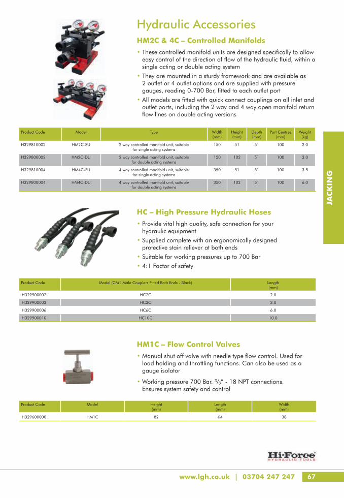
67
JAC
KIN
G
www.lgh.co.uk | 03704 247 247
HM1C – Flow Control Valves• Manual shut off valve with needle type flow control. Used for
load holding and throttling functions. Can also be used as a gauge isolator
• Working pressure 700 Bar. 3/8” - 18 NPT connections. Ensures system safety and control
Product Code Model Height (mm)
Length (mm)
Width (mm)
H329600000 HM1C 82 64 38
HC – High Pressure Hydraulic Hoses• Provide vital high quality, safe connection for your
hydraulic equipment
• Supplied complete with an ergonomically designed protective stain reliever at both ends
• Suitable for working pressures up to 700 Bar
• 4:1 Factor of safety
Product Code Model (CM1 Male Couplers Fitted Both Ends - Black) Length (mm)
H329900002 HC2C 2.0
H329900003 HC3C 3.0
H329900006 HC6C 6.0
H329900010 HC10C 10.0
Hydraulic AccessoriesHM2C & 4C – Controlled Manifolds• These controlled manifold units are designed specifically to allow
easy control of the direction of flow of the hydraulic fluid, within a single acting or double acting system
• They are mounted in a sturdy framework and are available as 2 outlet or 4 outlet options and are supplied with pressure gauges, reading 0-700 Bar, fitted to each outlet port
• All models are fitted with quick connect couplings on all inlet and outlet ports, including the 2 way and 4 way open manifold return flow lines on double acting versions
Product Code Model Type Width (mm)
Height (mm)
Depth (mm)
Port Centres (mm)
Weight (kg)
H329810002 HM2C-SU 2 way controlled manifold unit, suitable for single acting systems
150 51 51 100 2.0
H329800002 HM2C-DU 2 way controlled manifold unit, suitable for double acting systems
150 102 51 100 3.0
H329810004 HM4C-SU 4 way controlled manifold unit, suitable for single acting systems
350 51 51 100 3.5
H329800004 HM4C-DU 4 way controlled manifold unit, suitable for double acting systems
350 102 51 100 6.0
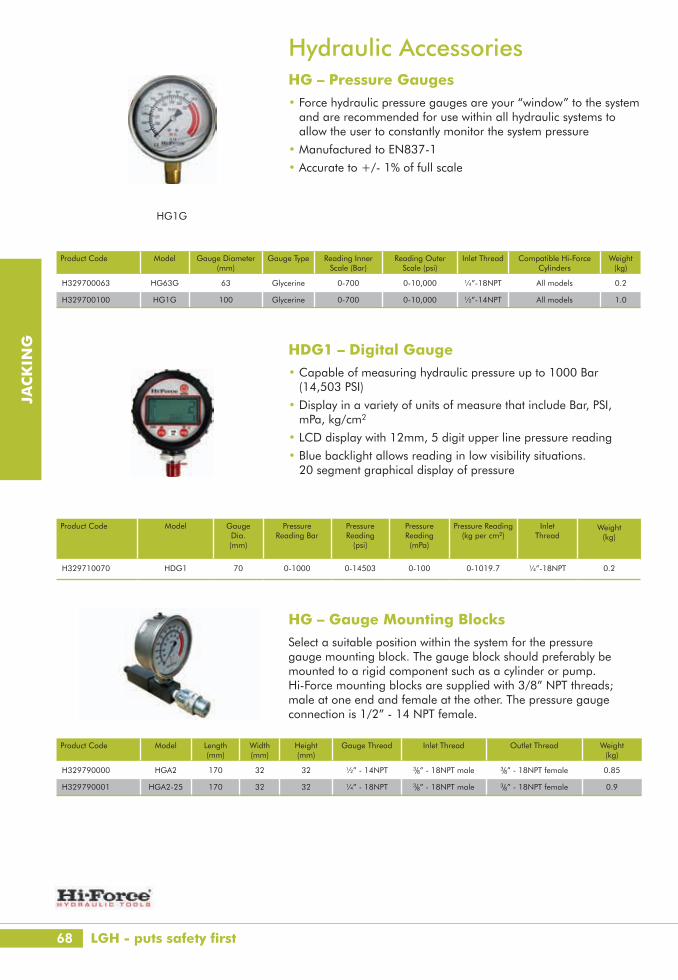
68
JAC
KIN
G
HG – Gauge Mounting BlocksSelect a suitable position within the system for the pressure gauge mounting block. The gauge block should preferably be mounted to a rigid component such as a cylinder or pump. Hi-Force mounting blocks are supplied with 3/8” NPT threads; male at one end and female at the other. The pressure gauge connection is 1/2” - 14 NPT female.
Product Code Model Length (mm)
Width (mm)
Height (mm)
Gauge Thread Inlet Thread Outlet Thread Weight (kg)
H329790000 HGA2 170 32 32 ½” - 14NPT 3/8” - 18NPT male 3/8” - 18NPT female 0.85
H329790001 HGA2-25 170 32 32 ¼” - 18NPT 3/8” - 18NPT male 3/8” - 18NPT female 0.9
Hydraulic Accessories HG – Pressure Gauges • Force hydraulic pressure gauges are your “window” to the system
and are recommended for use within all hydraulic systems to allow the user to constantly monitor the system pressure
• Manufactured to EN837-1
• Accurate to +/- 1% of full scale
HG1G
Product Code Model Gauge Diameter (mm)
Gauge Type Reading Inner Scale (Bar)
Reading Outer Scale (psi)
Inlet Thread Compatible Hi-Force Cylinders
Weight (kg)
H329700063 HG63G 63 Glycerine 0-700 0-10,000 ¼”-18NPT All models 0.2
H329700100 HG1G 100 Glycerine 0-700 0-10,000 ½”-14NPT All models 1.0
HDG1 – Digital Gauge• Capable of measuring hydraulic pressure up to 1000 Bar
(14,503 PSI)
• Display in a variety of units of measure that include Bar, PSI, mPa, kg/cm2
• LCD display with 12mm, 5 digit upper line pressure reading
• Blue backlight allows reading in low visibility situations. 20 segment graphical display of pressure
Product Code Model Gauge Dia. (mm)
Pressure Reading Bar
Pressure Reading
(psi)
Pressure Reading (mPa)
Pressure Reading (kg per cm2)
Inlet Thread
Weight (kg)
H329710070 HDG1 70 0-1000 0-14503 0-100 0-1019.7 ¼”-18NPT 0.2
LGH - puts safety first

69
JAC
KIN
G
www.lgh.co.uk | 03704 247 247
Compression Load CellsWireless Compression Load Cell • Proprietary 2.4GHz wireless• Industry leading wireless range of 700m (2300ft)
• Connects to SW-MWLC, WCOGS & SW-PTP software
• Error free data transmission
• Environmentally sealed to IP67/NEMA 6
• No cable assemblies required
• Unrivalled accuracy
• Battery life of 1200hrs
Product Code H340510005 H340510010 H340510025 H340510050 H340510100 H340510150 H340510300 H340510500
Capacity (t) 5.0 10.0 25.0 50.0 100.0 150.0 300.0 500.0
Resolution (te) 0.001 0.002 0.005 0.01 0.05 0.05 0.1 0.2
Dimension A (mm) 102 102 102 102 152 152 185 185
Dimension B (mm) 127 127 127 127 184 184 300 300
Dimension D (mm) 59 59 59 59 80 80 155 155
Dimension E (mm) 13 13 13 13 26 26 27.5 27.5
Dimension F (mm) M18 x 2.5 M18 x 2.5 M18 x 2.5 M20 x 2.5 M20 x 2.5 M20 x 2.5 M20 x 2.5 M20 x 2.5
Dimension G (mm) 152 152 152 152 432 432 432 432
Dimension H (mm) 158 158 158 158 208 208 241 241
Weight (kg) 6.2 6.2 6.2 6.2 15.5 15.5 65.0 65.0
Safety Factor 3:1
Battery Type Load cell 4 x AA Alkaline
Battery Life Load cell 1,200 hours continuous
Operating Temp -10°C to +50°C / 14°F to 122°F
Accuracy ±0.3% of applied load
Frequency 2.4GHz
System Range 700 metres - 2300 feet
Data Rate 3Hz (configurable to 200Hz)
Protection IP67 / NEMA 6

70
JAC
KIN
G
Product Code Model IP rating (SW-USBBSE) Operating Temp
Licence Frequency Range Load Cell
Inputs
PC Requirements
Operating System
H340500000 WCOGS IP54 NEMA 3 -10°C to +50°C (14°F
to 122°F)
Free 2.4 GHz 700m (2300 feet)
Up to 36 Intel i3 processor with 2GB RAM
Windows XP, Vista, Windows 7, 8 or 10 (must have English language regional settings selected)
Compressive Load Cell SystemsWireless Centre of Gravity • 100% wireless• Between 3-36 load cells of the same capacity can be used in the
system to measure and ascertain the centre of gravity (CoG)• ISO19901 compliant• 700m - 2300ft range• On screen, real time centre of gravity view• Three weighings per report with averages and statistical analysis• Plot load cell positioning using measurements or GPS co-ordinates• Extra fields for operator, client, wind speed and temperature
available for reporting.
Report Example
Home Screen
When large industrial items such as absorbers, generators, turbines, reactors, boilers, towers, locomotives, boats, military equipment or offshore industry parts such as oil rigs and production platforms have to be moved, heavy lift companies need large capacity load cells and easy to use software to quickly report weight and centre of gravity.
Each system is designed and configured to meet the precise need of the job - please contact our technical team for further details and advice.
Safety, Certainty, Great Service

71
JAC
KIN
G
www.lgh.co.uk | 03704 247 247
71Rigging
74 Grade 10 Chain Slings
75 Wire Rope Slings
76 Synthetic Slings
78 Modulift Spreader Beams
94 CMOD Spreader Frames
96 Lattice Spreader Beams
98 Crane Forks & Material Skips
99 Access Cages & Gas Bottle Carriers
100 Block Grabs
101 Stone Magnets
102 Manhole Lifting Equipment
103 Lifting Clutches
104 Plate Clamps
105 Lifting Magnets
106 Alloy Bow Shackles
107 Heavy Duty Bow Shackles
108 Super Alloy Shackles
109 High Tensile Shackles
110 Lifting Points
112 Lifting Rings
114 Load Rings
116 Digital Load Indicators
117 Digital Load Shackles
118 Eyebolt Tester
120 Test Weights & Accessories

72
RIG
GIN
G
Winner G10 Chain Slings
• Lifting capacities of up to 85 tonnes
• 25% increase in load capacity over traditional G8 chain slings resulting in lighter handling weight per kg lifted
• Comprehensive sling system with a large range of master link and terminal fitting options
• Manufactured in Europe by one of the worlds biggest and most trusted chain makers
Assembled in the UK for Lifting Gear Hire by
Experts in the design and manufacture of standard and
custom designed lifting equipment
● Modular Spreader Beams up to 400t in stock and available worldwide for distribution
● Modular Spreader Beams for 2–5000t and spans up to 100m /330ft
● Reduce your rigging weight and health and safety concerns by using the shackle-free Trunnion Spreader Beam system
● Experts in custom lifting solutions and projects requiring high QA standards
● All products fully tested and certi� ed with DNV Type approval as standard
Spreader & Lifting Frames
Lifting Beams
Trunnion Spreader Beams
Spreader Beams
07152_TRUN_and_generic_combo_ad_International_Cranes_210x297_2015_12.indd 3 07/01/2016 09:53
07152_TRUN_and_generic_combo_ad_International_Cranes_210x297_2015_12_FINAL (without contact).pdf 1 30/11/2017 14:48
AVAILABLE FOR HIRE
AVAILABLE FOR HIR
E

www.lgh.co.uk | 03704 247 247 73
RIG
GIN
G
Experts in the design and manufacture of standard and
custom designed lifting equipment
● Modular Spreader Beams up to 400t in stock and available worldwide for distribution
● Modular Spreader Beams for 2–5000t and spans up to 100m /330ft
● Reduce your rigging weight and health and safety concerns by using the shackle-free Trunnion Spreader Beam system
● Experts in custom lifting solutions and projects requiring high QA standards
● All products fully tested and certi� ed with DNV Type approval as standard
Spreader & Lifting Frames
Lifting Beams
Trunnion Spreader Beams
Spreader Beams
07152_TRUN_and_generic_combo_ad_International_Cranes_210x297_2015_12.indd 3 07/01/2016 09:53
07152_TRUN_and_generic_combo_ad_International_Cranes_210x297_2015_12_FINAL (without contact).pdf 1 30/11/2017 14:48
AVA
IL
ABLE FOR HIRE
AVAILABLE FOR HIRE

74
RIG
GIN
G
Grade 10 Chain SlingsPewag Winner Grade 10 Chain Slings• 25% greater capacity than Grade 8
• Load capacities up to 85t
• Multiple sling configurations available
• Locking type safety hooks and shorteners fitted as standard
• Other hooks available on request
• Multiple lengths available
Load Capacities
Safety Factor 4:1 1 Leg Chain Slings 2 Leg Chain Slings 3 + 4 Leg ChainSlings
Endless Chain Slings
Basket Chain Slings
Angle of Inclination (STV) - - up to 45° 45° - 60° up to 45° 45° - 60° up to 45° 45° - 60° - up to 45° 0° - 45°
Load Factor 1 0.8 1.4 1 1.2 0.8 2.1 1.5 1.6 1.4 2.1
Comments D (mm)
Load Cap. (t)
Our standard range of hire fleet slings are
available in 1m (single leg) 3m, 6m and
9m (multi-leg) lengths.
Other lengths available on
request
7 1.9 1.5 2.65 1.9 2.12 1.5 4.0 2.8 3.0 2.65 4.0
8 2.5 2.0 3.55 2.5 2.8 2.0 5.3 3.75 4.0 3.55 5.3
10 4.0 3.15 5.6 4.0 4.25 3.15 8.0 6.0 6.3 5.6 8.0
13 6.7 5.3 9.5 6.7 7.5 5.3 14.0 10.0 10.6 9.5 14.0
16 10.0 8.0 14.0 10.0 11.2 8.0 21.2 15.0 16.0 14.0 21.2
19 14.0 11.2 20.0 14.0 16.0 11.2 30.0 21.2 22.4 20.0 30.0
22 19.0 15.0 26.5 19.0 21.2 15.0 40.0 28.0 30.0 26.5 40.0
26 26.5 21.2 37.5 26.5 30.0 21.2 56.0 40.0 42.5 37.5 56.0
32 40.0 31.5 56.0 40.0 45.0 31.5 85.0 60.0 63.0 56.0 85.0
Demanding conditionsTemperature Load Factor Pewag
Winner 200Load Factor Pewag
Winner 400Asymmetric Load
DistributionEdge Load
(see Figure 1 below)Load Factor Shock Load Factor
-40°C – 200°C 1 1 The WLL has to be reduced by
at least 1 leg. In case of doubt only consider 1 leg as
load-bearing.
R = larger than 2 x d
1 Slight 1
Above 200°C – 300°C Not Permissible 0.9 R = larger than d 0.7 Medium 0.7
Above 300°C – 380°C Not Permissible 0.75 R = smaller than d 0.5 Strong Not Permissible
Single Leg Chain Slings
C Hook Sling Hook c/w Latch Locking Safety Hook Swivel Safety Locking Hook
Swivel Hook with Safety Catch
2 Leg Chain Slings 3 + 4 Leg Chain Slings Endless Chain Sling Basket Chain Slings
All our equipment is tested and certified to the highest standard

www.lgh.co.uk | 03704 247 247 75
RIG
GIN
G
Wire Rope SlingsWire ropes are widely used as a cost-effective alternative to chains, offering considerably higher capacities and additional properties such as resistance to salt water.
• Multiple configurations – 1, 2, 3, 4, 5 legs and endless
• Multiple terminations – Soft Eyes, Thimble Eyes, Sockets and Swaged Terminals
• Splice options – Talurit, Supersplice, Flemish eye
• Sling types – Single Laid, Cable Laid & Grommets
• Capacities - Grommets up to 6800t minimum breaking load (Double part)
Nominal Dia.
MBL MBF Single Leg (t)
WLL 2 Leg WLL 3/4 Leg Endless
0-45º 45-60º 0-45º 45-60º Chokehitch
8 4.56 44.7 0.8 1.1 0.8 1.7 1.2 1.3
9 5.76 56.5 1.0 1.4 1.0 2.1 1.5 1.6
10 7.12 69.8 1.2 1.7 1.2 2.5 1.8 1.9
13 12.0 118.0 2.0 2.8 2.0 4.2 3.0 3.2
16 18.3 179.0 3.0 4.2 3.0 6.3 4.5 4.8
18 23.0 226.0 4.0 5.6 4.0 8.4 6.0 6.4
20 28.5 279.0 5.0 7.0 5.0 10.5 7.5 8.0
22 34.5 338.0 6.0 8.4 6.0 12.6 9.0 9.6
24 41.0 402.0 7.0 9.8 7.0 14.7 10.5 11.2
26 48.1 472.0 8.0 11.2 8.0 16.8 12.0 12.8
28 55.8 547.0 10.0 14.0 10.0 21.0 15.0 16.0
32 72.9 715.0 13.0 18.2 13.0 27.3 19.5 20.8
36 92.2 904.0 16.0 22.4 16.0 33.6 24.0 25.6
38 103.0 1010.0 18.0 25.2 18.0 37.8 27.0 28.8
40 114.0 1120.0 20.0 28.0 20.0 42.0 30.0 32.0
44 138.0 1351.0 24.0 33.6 24.0 50.4 36.0 38.4
48 164.0 1608.0 29.0 40.6 29.0 60.9 43.5 46.4
52 192.0 1887.0 34.0 47.6 34.0 71.4 51.0 54.4
64 291.0 2855.0 52.0 72.8 52.0 109.2 78.0 83.2
76 411.0 4032.0 73.0 102.2 73.0 153.3 109.5 116.8
92 600.0 5886.0 108.0 151.2 108.0 226.8 162.0 172.8
103 800.0 7848.0 144.0 201.6 144.0 302.4 216.0 230.4
114 939.0 9212.0 169.0 236.6 169.0 354.9 253.5 270.4
128 1138.0 11164.0 204.0 285.6 204.0 428.4 306.0 326.4
Our range of Wire Rope Slings are wide and varied and sizes extend beyond the above table - Please call for details

76
RIG
GIN
G
Duplex & Quadplex WebslingsWebslings available up to 48t capacity
Roundslings & Endless WebslingsRoundslings available up to 200t capacity
Sling Type / Colour Code
Straight Pull M’ = 1
Choke Hitch M’ = 0.8
Basket Hitch
2 Leg SlingMax 90º M’ = 1.4
4 Leg SlingMax 90º M’ = 2
Roundsling (RS) Duplex (DX), Quadplex (QP) Quadplex Side by Side (QPS)
Webbing Width(mm)
Parallel M’ = 2
90ºM’ = 1.4
RS/DX 30 1.0 0.8 2.0 1.4 1.4 2.0
RS/DX 60 2.0 1.6 4.0 2.8 2.8 4.0
RS/DX 90 3.0 2.4 6.0 4.2 4.2 6.0
RS/DX 120 4.0 3.2 8.0 5.6 5.6 8.0
RS/DX 150 5.0 4.0 10.0 7.0 7.0 10.0
RS/DX 180 6.0 4.8 12.0 8.4 8.4 12.0
RS/DX 240 8.0 6.4 16.0 11.2 11.2 16.0
RS/DX 299 10.0 8.0 20.0 14.0 14.0 20.0
RS/DX 300 12.0 9.6 24.0 16.8 16.8 24.0
RS - 15.0 12.0 30.0 21.0 21.0 30.0
QP 240 16.0 12.8 32.0 22.4 22.4 32.0
RS/QP 299 20.0 16.0 40.0 28.0 28.0 40.0
QP 300 24.0 19.2 48.0 33.6 33.6 48.0
RS - 25.0 20.0 50.0 35.0 35.0 50.0
RS - 30.0 24.0 60.0 42.0 42.0 60.0
QPS 480 32.0 25.6 64.0 44.8 44.8 64.0
RS/QPS 598 40.0 32.0 80.0 56.0 56.0 80.0
QPS 600 48.0 38.4 96.0 67.2 67.2 96.0
RS - 50.0 40.0 100.0 70.0 70.0 100.0
RS - 60.0 48.0 120.0 84.0 84.0 120.0
RS - 80.0 64.0 160.0 112.0 112.0 160.0
RS - 100.0 80.0 200.0 140.0 140.0 200.0
RS - 120.0 96.0 240.0 168.0 168.0 240.0
RS - 150.0 120.0 300.0 210.0 210.0 300.0
RS - 200.0 160.0 400.0 280.0 280.0 400.0
Synthetic Slings
LGH - The authority in lifting

www.lgh.co.uk | 03704 247 247 77
RIG
GIN
G
Roundslings (BS EN 1492-2)
Standard and heavy duty roundslings are made from high tenacity polyester yarn encased in a colour coded tubular sleeve of durable woven polyester fabric.
• Standard SWL 1t to 12t - see colour code chart opposite
• Heavy duty SWL 15t to 200t
• Circ: up to 40m
• Factor of safety 7:1
• High strength to weight ratio
• Absorbs shock loads
• Light and flexible makes them easy to handle
Synthetic Slings Duplex & Quadplex Webslings (BS EN 1492-1)
• Material: Polyester
• Widths 25mm to 300mm
• Duplex SWL 1t to 12t - see colour code chart opposite
• Quadplex SWL 12t to 24t - see colour code chart opposite
• Eyes: Becket, flat, reversed or a range of compatible hardware
• Factor of safety 7:1
• High strength to weight ratio
• Absorbs shock loads
• Light and flexible makes them easy to handle
• Will not damage the surface of goods being lifted
Wear Sleeves
• Recommended when abrasion is a problem or sharp objects are being lifted
• Prolong the life of the sling
• Available in a variety of materials including polyurethane for particularly harsh or abrasive surfaces which can be coated either single sided or totally encapsulated

78
RIG
GIN
G
Modulift Spreader BeamsThe Modulift range of spreader beam assemblies offers a wide range of spans, configurations and capacities to suit your wide and varied lifting needs. Our sizes range from 24t to 1000t with spans available from 0.5m to over 30m.
Selecting your beam
• Determine the rigging plan and type of beam to be used
• Select span
• Select capacity
• Determine STV (sling to vertical) and consider any headroom restrictions
• Call us with all of this information and we will provide a detailed specification and quotation
Modulift CMOD RangeThe CMOD is a modular frame utilising corner units which are compatible with existing spreader beam struts and is modular in length and width. Every CMOD spreader frame consists of 4 x corner units, with intermediate struts that can be bolted into the assembly to achieve different spans.
Even the largest CMOD can be easily transported as the frame is broken down into modular parts, saving the cost of specialist transportation.
Modulift Heavy Range
Trunnion Spreader BeamAvailable on sizes MOD 250 and above, this beam provides a shackle free lifting solution that revolutionises the rigging industry by offering an efficient, lightweight and economic option.
It reduces the cost of rigging by up to 50%. Compared to similar applications, the rigging up phase can take up to half the duration therefore saving time and money.
• Reduce your rigging weight
• Reduce your health and safety concernsTrunnion End
Modulift Standard Range
MOD 70/70H
MOD 50
MOD 34
MOD 24
MOD 600
MOD 400
MOD 250
MOD 110SH
MOD 110/110H
Delivering excellence in lifting throughout the UK

www.lgh.co.uk | 03704 247 247 79
RIG
GIN
G
Modulift Spreader BeamsRigging Options• For extremely low headroom applications Modulift can design and fabricate a bespoke lifting frame to suit
your exact requirements
• Our technical team are available to provide recommendations on your lift plan. Send us details of your lift including weight, lifting points and position, height restrictions, load type, centre of gravity (COG) position, crane type and lifting environment
1. Simple Single Beam 2 Point Lift A single Spreader Beam is the simplest configuration and is suitable for 2 point lifts. The Spreader Beam absorbs the compression forces to protect the load being lifted.
2. Single Beam 4 Point Lift This configuration again uses a single beam where the load being lifted has four individual lifting points.
3. 1-Over-2 Rig We use this configuration when vertical slings are essential for 4 point lifts. By varying the sling lengths, we can also take into account an offset centre of gravity.
4. 1-Over-2 Inline Rig Ideal for those lifts where the span is long and potential bending of the load is a problem. Further cascading layers are available to increase the number of lifting points.
5. 1-Over-1 Where there are an uneven number of points to lift from, a 1 over 1 system can be used to lift the load whilst still providing a balanced rig.
6. Various Multi Spreader Beam Rigs With our expert help we can address most lifting issues using a combination of our products to fit the application and the circumstances.
7. CMOD Spreader Frame The CMOD spreader frame uses corner units to connect existing Modulift struts into a 4 point modular spreader frame. This uses less headroom than a 1 over 2 rig.
Your Guide to Some of the Configurations Available to You
1.
5.
2.
6.
3.
7.
4.

80
RIG
GIN
G
Span (m)
MOD 24
Sling to Vertical Angle (STV)
45º 30º 20º
SWL (t) Min. Top Sling Length (m) SWL (t) Min. Top Sling Length (m) SWL (t) Min. Top Sling Length (m)
1.0 24 0.6 24 0.9 24 1.3
1.5 24 0.9 24 1.4 24 2.1
2.0 24 1.3 24 1.9 24 2.8
2.5 24 1.7 24 2.4 24 3.5
3.0 24 2.0 24 2.9 24 4.3
3.5 24 2.4 24 3.4 24 5.0
4.0 23 2.7 24 3.9 24 5.7
4.5 19 3.1 24 4.4 24 6.5
5.0 16 3.4 24 4.9 24 7.2
5.5 13 3.8 23 5.4 24 7.9
6.0 11 4.1 19 5.9 24 8.7
6.5 9 4.5 16 6.4 24 9.4
7.0 8 4.8 14 6.9 22 10.1
7.5 6 5.2 12 7.4 19 10.8
8.0 6 5.5 11 7.9 16 11.6
Modulift Spreader BeamsMOD 24 Spreader Beams• Rated at 24t SWL at 5m span (30° STV)
• ‘Sling to Vertical’ angle, 45º or less
• End Units and Drop Links are rated at 12t WLL each
Please refer to the table below for load ratings at alternative sling to vertical (STV) angles and beam lengths.
MOD 24
Product Code Model Description Weight Item (kg)
H050220240 P1 End Unit 17
H050230240 P2 Drop Link 5
H050250248 P3 2.0m Strut 41
H050250246 P4 1.0m Strut 24
H050250243 P5 0.5m Strut 16
H550210170 P6 17t Safety Shackle 8
H550210120 P7 12t Safety Shackle 5
P8 M20 x 50, Grade 8.8 HT Bolts, Nuts & Washers
LGH - puts safety first

www.lgh.co.uk | 03704 247 247 81
RIG
GIN
G
Span (m)
MOD 50
Sling to Vertical Angle (STV)
45º 30º 20º
SWL (t) Min. Top Sling Length (m) SWL (t) Min. Top Sling Length (m) SWL (t) Min. Top Sling Length (m)
1.0 50 0.5 50 0.8 50 1.3
1.5 50 0.9 50 1.3 50 2.0
2.0 50 1.2 50 1.8 50 2.7
2.5 50 1.6 50 2.3 50 3.5
3.0 50 1.9 50 2.8 50 4.2
3.5 50 2.3 50 3.3 50 4.9
4.0 50 2.7 50 3.8 50 5.7
4.5 50 3.0 50 4.3 50 6.4
5.0 50 3.4 50 4.8 50 7.1
5.5 50 3.7 50 5.3 50 7.9
6.0 50 4.1 50 5.8 50 8.6
6.5 44 4.4 50 6.3 50 9.3
7.0 39 4.8 50 6.8 50 10.1
7.5 34 5.1 50 7.3 50 10.8
8.0 30 5.5 50 7.8 50 11.5
8.5 26 5.8 46 8.3 50 12.3
9.0 24 6.2 42 8.8 50 13.0
9.5 21 6.5 37 9.3 50 13.7
10.0 19 6.9 34 9.8 50 14.4
11.0 15 7.6 26 10.8 43 15.9
12.0 12 8.3 22 11.8 35 17.4
13.0 10 9.0 18 12.8 28 18.8
Modulift Spreader BeamsMOD 50 Spreader Beams• Rated at 50t SWL at 8m span (30° STV)
• ‘Sling to Vertical’ angle, 45º or less
• End Units and Drop Links are rated at 25t WLL each
Please refer to the table below for load ratings at alternative sling to vertical (STV) angles and beam lengths.
MOD 50
Product Code Model Description Weight Item (kg)
H050220500 P1 End Unit 38
H050230500 P2 Drop Link 11
H050250509 P3 4.0m Strut 140
H050250508 P4 2.0m Strut 82
H050250506 P5 1.0m Strut 53
H050250503 P6 0.5m Strut 38
H550210350 P7 35t Safety Shackle 20
H550210250 P8 25t Safety Shackle 14
P9 M20 x 65, Grade 8.8, HT Bolts, Nuts & Washers
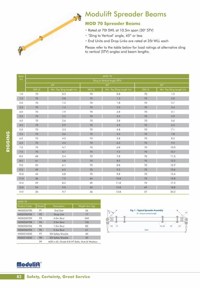
82
RIG
GIN
G
Modulift Spreader BeamsMOD 70 Spreader Beams• Rated at 70t SWL at 10.5m span (30° STV)
• ‘Sling to Vertical’ angle, 45º or less
• End Units and Drop Links are rated at 35t WLL each
Please refer to the table below for load ratings at alternative sling to vertical (STV) angles and beam lengths.
Span (m)
MOD 70
Sling to Vertical Angle (STV)
45º 30º 20º
SWL (t) Min. Top Sling Length (m) SWL (t) Min. Top Sling Length (m) SWL (t) Min. Top Sling Length (m)
1.0 70 0.5 70 0.8 70 1.2
1.5 70 0.8 70 1.3 70 2.0
2.0 70 1.2 70 1.8 70 2.7
2.5 70 1.5 70 2.3 70 3.4
3.0 70 1.9 70 2.8 70 4.1
3.5 70 2.2 70 3.3 70 4.9
4.0 70 2.6 70 3.8 70 5.6
4.5 70 2.9 70 4.3 70 6.3
5.0 70 3.3 70 4.8 70 7.1
5.5 70 3.6 70 5.3 70 7.8
6.0 70 4.0 70 5.8 70 8.5
6.5 70 4.4 70 6.3 70 9.3
7.0 70 4.7 70 6.8 70 10.0
7.5 70 5.1 70 7.3 70 10.7
8.0 68 5.4 70 7.8 70 11.5
8.5 61 5.8 70 8.3 70 12.2
9.0 55 6.1 70 8.8 70 12.9
9.5 49 6.5 70 9.3 70 13.6
10.0 44 6.8 70 9.8 70 14.4
11.0 36 7.5 64 10.8 70 15.8
12.0 29 8.2 49 11.8 70 17.3
13.0 24 9.0 43 12.8 69 18.8
14.0 20 9.7 36 13.8 57 20.2
MOD 70
Product Code Model Description Weight item (kg)
H050220700 P1 End Unit 56
H050230700 P2 Drop Link 17
H050250709 P3 4.0m Strut 240
H050250708 P4 2.0m Strut 136
H050250706 P5 1.0m Strut 85
H050250703 P6 0.5m Strut 61
H550210550 P7 55t Safety Shackle 40
H550210350 P8 35t Safety Shackle 20
P9 M20 x 65, Grade 8.8 HT Bolts, Nuts & Washers
User Instructions
Modulift UK Ltd tel: +44(0)1202 621511 email: [email protected] www.modulift.com
The Modulift Spreader is modular in length, and every spreader consists of 1 pair of End Units and erent spans.
● Personnel using this system should be suitably trained, competent and have a clear understanding of Safe Slinging procedures.
● The use of Modulift equipment must be in accordance with the procedures laid down in ‘Lifting Operations and Lifting Equipment Regulations 1998’ (LOLER).
● Never exceed stated SWL – Adhere to SWL in Table 2 for particular sling angle used. ● The top sling length is critical to the safe use of the spreader – Adhere to Table 2. ● Ensure Drop Links hang down, and smaller shackles are connected to bottom hole of Drop Link. ● anges – the spreader is designed for
axial compression, not bending.
WARNING!
MOD 70
MOD 70 has an assembled span ranging from 1 metre to 14 metres in 0.5 metre increments.
cation ● Rated at 70 tonnes SWL at 10.5 metres span
(30° STV). See Load Table for SWL at longer spans. ● ‘Sling to Vertical’ angle, β, 45 degrees or less. ● End Units & Drop Links are rated at 35 tonnes WLL each (70 tonnes combined capacity). ● Bolt tightening torque: 150Nm. Spanner size required: 30mm. ● Recommended additional equipment: Torque Wrench, Podger Spanner and Ring Spanner.
P1 P2P3–P6
Span
β P7
9P8P
β = Sling to vertical angle
Strut
Drop link
End unit sub-assy
Larger shackle
Smaller shackle
Drop link
Table 1 – Component List
Part Ref. Description Weight/item
P1 End Unit 56kg
P2 Drop Link 17kg
P3 4.0m Strut 240kg
P4 2.0m Strut 136kg
P5 1.0m Strut 85kg
P6 0.5m Strut 61kg
P7 55t Shackle 40kg
P8 35t Shackle 20kg
P9 M20 x 65, Grade 8.8 HT Bolts, Nuts & Washers
Fig. 1 – Typical Spreader Assembly
Safety, Certainty, Great Service

www.lgh.co.uk | 03704 247 247 83
RIG
GIN
G
Modulift Spreader BeamsMOD 70H Spreader Beams• Rated at 100t SWL at 8.5m span (30° STV)
• ‘Sling to Vertical’ angle, 45º or less
• End Units and Drop Links are rated at 50t WLL each
Please refer to the table below for load ratings at alternative sling to vertical (STV) angles and beam lengths.
Span (m)
MOD 70H
Sling to Vertical Angle (STV)
45º 30º 20º
SWL (t) Min. Top Sling Length (m) SWL (t) Min. Top Sling Length (m) SWL (t) Min. Top Sling Length (m)
1.0 100 0.4 100 0.7 100 1.1
1.5 100 0.7 100 1.2 100 1.9
2.0 100 1.1 100 1.7 100 2.6
2.5 100 1.4 100 2.2 100 3.3
3.0 100 1.8 100 2.7 100 4.1
3.5 100 2.2 100 3.2 100 4.8
4.0 100 2.5 100 3.7 100 5.5
4.5 100 2.9 100 4.2 100 6.3
5.0 100 3.2 100 4.7 100 7.0
5.5 100 3.6 100 5.2 100 7.7
6.0 100 3.9 100 5.7 100 8.5
6.5 96 4.3 100 6.2 100 9.2
7.0 86 4.6 100 6.7 100 9.9
7.5 77 5.0 100 7.2 100 10.6
8.0 68 5.3 100 7.7 100 11.4
8.5 61 5.7 100 8.2 100 12.1
9.0 55 6.0 96 8.7 100 12.8
9.5 49 6.4 86 9.2 100 13.6
10.0 44 6.8 78 9.7 100 14.3
11.0 36 7.5 64 10.7 100 15.8
12.0 29 8.2 49 11.7 83 17.2
13.0 24 8.9 43 12.7 69 18.7
14.0 20 9.6 36 13.7 57 20.1
MOD 70H
Product Code Model Description Weight item (kg)
H050221000 P1 End Unit 58
H050231000 P2 Drop Link 32
H050250709 P3 4.0m Strut 240
H050250708 P4 2.0m Strut 136
H050250706 P5 1.0m Strut 85
H050250703 P6 0.5m Strut 61
H550210850 P7 85t Safety Shackle 62
H550210550 P8 55t Safety Shackle 40
P9 M20 x 65, Grade 8.8 HT Bolts, Nuts & Washers
User Instructions
Modulift UK Ltd tel: +44(0)1202 621511 email: [email protected] www.modulift.com
The Modulift Spreader is modular in length, and every spreader consists of 1 pair of End Units and erent spans.
● Personnel using this system should be suitably trained, competent and have a clear understanding of Safe Slinging procedures.
● The use of Modulift equipment must be in accordance with the procedures laid down in ‘Lifting Operations and Lifting Equipment Regulations 1998’ (LOLER).
● Never exceed stated SWL – Adhere to SWL in Table 2 for particular sling angle used. ● The top sling length is critical to the safe use of the spreader – Adhere to Table 2. ● Ensure Drop Links hang down, and smaller shackles are connected to bottom hole of Drop Link. ● anges – the spreader is designed for
axial compression, not bending.
WARNING!
MOD 70H
MOD 70H has an assembled span ranging from 1 metre to 14 metres in 0.5 metre increments.
cation ● Rated at 100 tonnes SWL at 8.5 metres span
(30° STV). See Load Table for SWL at longer spans. ● ‘Sling to Vertical’ angle, β, 45 degrees or less. ● End Units & Drop Links are rated at 50 tonnes WLL each (100 tonnes combined capacity). ● Bolt tightening torque: 150Nm. Spanner size required: 30mm. ● Recommended additional equipment: Torque Wrench, Podger Spanner and Ring Spanner.
P1 P2P3–P6
Span
β P7
9P8P
β = Sling to vertical angle
Strut
Drop link
Larger shackle
Smaller shackle
Drop link
End unit sub-assy
Table 1 – Component List
Part Ref. Description Weight/item
P1 End Unit 58kg
P2 Drop Link 32kg
P3 4.0m Strut 240kg
P4 2.0m Strut 136kg
P5 1.0m Strut 85kg
P6 0.5m Strut 61kg
P7 85t Shackle 62kg
P8 55t Shackle 40kg
P9 M20 x 65, Grade 8.8 HT Bolts, Nuts & Washers
Fig. 1 – Typical Spreader Assembly

84
RIG
GIN
G
Span (m)
MOD 110
Sling to Vertical Angle (STV)
45º 30º 20º
SWL (t) Min. Top Sling Length (m) SWL (t) Min. Top Sling Length (m) SWL (t) Min. Top Sling Length (m)
2.0 110 1.1 110 1.7 110 2.6
2.5 110 1.4 110 2.2 110 3.3
3.0 110 1.8 110 2.7 110 4.1
3.5 110 2.2 110 3.2 110 4.8
4.0 110 2.5 110 3.7 110 5.5
4.5 110 2.9 110 4.2 110 6.3
5.0 110 3.2 110 4.7 110 7.0
5.5 110 3.6 110 5.2 110 7.7
6.0 110 3.9 110 5.7 110 8.5
6.5 110 4.3 110 6.2 110 9.2
7.0 110 4.6 110 6.7 110 9.9
7.5 110 5.0 110 7.2 110 10.6
8.0 110 5.3 110 7.7 110 11.4
8.5 110 5.7 110 8.2 110 12.1
9.0 110 6.0 110 8.7 110 12.8
9.5 110 6.4 110 9.2 110 13.6
10.0 110 6.8 110 9.7 110 14.3
11.0 107 7.5 110 10.7 110 15.8
12.0 91 8.2 110 11.7 110 17.2
13.0 78 8.9 110 12.7 110 18.7
14.0 67 9.6 110 13.7 110 20.1
15.0 57 10.3 100 14.7 110 21.6
16.0 48 11.0 85 15.7 110 23.1
17.0 41 11.7 73 16.7 110 24.5
18.0 35 12.4 60 17.7 101 26.0
MOD 110
Product Code Model Description Weight item (kg)
H050221100 P1 End Unit 178
H050231100 P2 Drop Link 45
H050251109 P3 4.0m Strut 367
H050251108 P4 2.0m Strut 212
H050251106 P5 1.0m Strut 134
H050251103 P6 0.5m Strut 96
H550210850 P7 85t Safety Shackle 62
H550210550 P8 55t Safety Shackle 40
P9 M20 x 65, Grade 8.8 HT Bolts, Nuts & Washers
Modulift Spreader BeamsMOD110 Spreader Beams• Rated at 110t SWL at 14m span (30° STV)
• ‘Sling to Vertical’ angle, 45º or less
• End Units and Drop Links are rated at 55t WLL each
Please refer to the table below for load ratings at alternative sling to vertical (STV) angles and beam lengths.
User Instructions
Modulift UK Ltd tel: +44(0)1202 621511 email: [email protected] www.modulift.com
The Modulift Spreader is modular in length, and every spreader consists of 1 pair of End Units and erent spans.
● Personnel using this system should be suitably trained, competent and have a clear understanding of Safe Slinging procedures.
● The use of Modulift equipment must be in accordance with the procedures laid down in ‘Lifting Operations and Lifting Equipment Regulations 1998’ (LOLER).
● Never exceed stated SWL – Adhere to SWL in Table 2 for particular sling angle used. ● The top sling length is critical to the safe use of the spreader – Adhere to Table 2. ● Ensure Drop Links hang down, and smaller shackles are connected to bottom hole of Drop Link. ● anges – the spreader is designed for
axial compression, not bending.
WARNING!
MOD 110
MOD 110 has an assembled span ranging from 2 metres to 18 metres in 0.5 metre increments.
cation ● Rated at 110 tonnes SWL at 14 metres span
(30° STV). See Load Table for SWL at longer spans. ● ‘Sling to Vertical’ angle, β, 45 degrees or less. ● End Units & Drop Links are rated at 55 tonnes WLL each (110 tonnes combined capacity). ● Bolt tightening torque: 150Nm. Spanner size required: 30mm. ● Recommended additional equipment: Torque Wrench, Podger Spanner and Ring Spanner.
P1 P2P3–P6
Span
β P7
9P8P
β = Sling to vertical angle
Strut
Larger shackle
Smaller shackle
Drop link
End unit sub-assy
Drop link
Table 1 – Component List
Part Ref. Description Weight/item
P1 End Unit 178kg
P2 Drop Link 45kg
P3 4.0m Strut 367kg
P4 2.0m Strut 212kg
P5 1.0m Strut 134kg
P6 0.5m Strut 96kg
P7 85t Shackle 62kg
P8 55t Shackle 40kg
P9 M20 x 65 Grade 8.8 HT Bolts, Nuts & Washers
Fig. 1 – Typical Spreader Assembly
All our equipment is tested and certified to the highest standard

www.lgh.co.uk | 03704 247 247 85
RIG
GIN
G
Span (m)
MOD 110H
Sling to Vertical Angle (STV)
45º 30º 20º
SWL (t) Min. Top Sling Length (m) SWL (t) Min. Top Sling Length (m) SWL (t) Min. Top Sling Length (m)
2.0 167 1.0 170 1.6 170 2.5
2.5 167 1.4 170 2.1 170 3.3
3.0 167 1.7 170 2.6 170 4.0
3.5 167 2.1 170 3.1 170 4.7
4.0 167 2.4 170 3.6 170 5.5
4.5 167 2.8 170 4.1 170 6.2
5.0 167 3.1 170 4.6 170 6.9
5.5 167 3.5 170 5.1 170 7.6
6.0 167 3.8 170 5.6 170 8.4
6.5 167 4.2 170 6.1 170 9.1
7.0 167 4.6 170 6.6 170 9.8
7.5 167 4.9 170 7.1 170 10.6
8.0 167 5.3 170 7.6 170 11.3
8.5 158 5.6 170 8.1 170 12.0
9.0 146 6.0 170 8.6 170 12.8
9.5 134 6.3 170 9.1 170 13.5
10.0 126 6.7 170 9.6 170 14.2
11.0 107 7.4 170 10.6 170 15.7
12.0 91 8.1 160 11.6 170 17.1
13.0 78 8.8 137 12.6 170 18.6
14.0 67 9.5 117 13.6 170 20.1
15.0 57 10.2 100 14.6 159 21.5
16.0 48 10.9 85 15.6 137 23.0
17.0 41 11.6 73 16.6 117 24.5
18.0 35 12.3 60 17.6 101 25.9
MOD 110H
Product Code Model Description Weight item (kg)
H050221670 P1 End Unit 178
H050231670 P2 Drop Link 55
H050251109 P3 4.0m Strut 367
H050251108 P4 2.0m Strut 212
H050251106 P5 1.0m Strut 134
H050251103 P6 0.5m Strut 96
H550211200 P7 120t Safety Shackle 110
H550210850 P8 85t Safety Shackle 62
P9 M20 x 65, Grade 8.8 HT Bolts, Nuts & Washers
Modulift Spreader BeamsMOD110H Spreader Beams• Rated at 170t SWL at 11.5m span (30° STV)
• ‘Sling to Vertical’ angle, 45º or less
• End Units and Drop Links are rated at 85t WLL each
Please refer to the table below for load ratings at alternative sling to vertical (STV) angles and beam lengths.
User Instructions
Modulift UK Ltd tel: +44(0)1202 621511 email: [email protected] www.modulift.com
The Modulift Spreader is modular in length, and every spreader consists of 1 pair of End Units and erent spans.
● Personnel using this system should be suitably trained, competent and have a clear understanding of Safe Slinging procedures.
● The use of Modulift equipment must be in accordance with the procedures laid down in ‘Lifting Operations and Lifting Equipment Regulations 1998’ (LOLER).
● Never exceed stated SWL – Adhere to SWL in Table 2 for particular sling angle used. ● The top sling length is critical to the safe use of the spreader – Adhere to Table 2. ● Ensure Drop Links hang down, and smaller shackles are connected to bottom hole of Drop Link. ● anges – the spreader is designed for
axial compression, not bending.
WARNING!
MOD 110H
MOD 110H has an assembled span ranging from 2 metres to 18 metres in 0.5 metre increments.
cation ● Rated at 170 tonnes SWL at 11.5 metres span
(30° STV). See Load Table for SWL at longer spans. ● ‘Sling to Vertical’ angle, β, 45 degrees or less. ● End Units & Drop Links are rated at 85 tonnes WLL each (170 tonnes combined capacity). ● Bolt tightening torque: 150Nm. Spanner size required: 30mm. ● Recommended additional equipment: Torque Wrench, Podger Spanner and Ring Spanner.
P1 P2P3–P6
Span
β P7
9P8P
β = Sling to vertical angle
Strut
Larger shackle
Smaller shackle
Drop link
End unit sub-assy
Drop link
Table 1 – Component List
Part Ref. Description Weight/item
P1 End Unit 178kg
P2 Drop Link 55kg
P3 4.0m Strut 367kg
P4 2.0m Strut 212kg
P5 1.0m Strut 134kg
P6 0.5m Strut 96kg
P7 120t Shackle 110kg
P8 85t Shackle 62kg
P9 M20 x 65 Grade 8.8 HT Bolts, Nuts & Washers
Fig. 1 – Typical Spreader Assembly

86
RIG
GIN
G
Span (m)
MOD 110SH
Sling to Vertical Angle (STV)
45º 30º 20º
SWL (t) Min. Top Sling Length (m) SWL (t) Min. Top Sling Length (m) SWL (t) Min. Top Sling Length (m)
2.0 210 1.0 240 1.6 240 2.5
2.5 210 1.4 240 2.1 240 3.2
3.0 210 1.7 240 2.6 240 4.0
3.5 210 2.1 240 3.1 240 4.7
4.0 210 2.4 240 3.6 240 5.4
4.5 210 2.8 240 4.1 240 6.2
5.0 210 3.1 240 4.6 240 6.9
5.5 210 3.5 240 5.1 240 7.6
6.0 210 3.8 240 5.6 240 8.4
6.5 210 4.2 240 6.1 240 9.1
7.0 210 4.5 240 6.6 240 9.8
7.5 210 4.9 240 7.1 240 10.6
8.0 210 5.2 240 7.6 240 11.3
8.5 195 5.6 240 8.1 240 12.0
9.0 181 6.0 240 8.6 240 12.7
9.5 167 6.3 240 9.1 240 13.5
10.0 155 6.7 240 9.6 240 14.2
11.0 132 7.4 225 10.6 240 15.7
12.0 112 8.1 195 11.6 240 17.1
13.0 96 8.8 167 12.6 240 18.6
14.0 81 9.5 142 13.6 225 20.1
15.0 69 10.2 121 14.6 191 21.5
16.0 56 10.9 97 15.6 153 23.0
17.0 37 11.6 65 16.6 103 24.4
MOD 110SH
Product Code Model Description Weight item (kg)
H050222100 P1 End Unit 192
H050232100 P2 Drop Link 90
H050252109 P3 4.0m Strut 442
H050252108 P4 2.0m Strut 249
H050252106 P5 1.0m Strut 153
H050252103 P6 0.5m Strut 105
H550211500 P7 150t Safety Shackle 160
H550211200 P8 120t Safety Shackle 110
P9 M20 x 65, Grade 8.8 HT Bolts, Nuts & Washers
Modulift Spreader BeamsMOD110SH Spreader Beams• Rated at 240t SWL at 10.5m span (30° STV)
• ‘Sling to Vertical’ angle, 45º or less
• End Units and Drop Links are rated at 120t WLL each
Please refer to the table below for load ratings at alternative sling to vertical (STV) angles and beam lengths.
User Instructions
Modulift UK Ltd tel: +44(0)1202 621511 email: [email protected] www.modulift.com
The Modulift Spreader is modular in length, and every spreader consists of 1 pair of End Units and erent spans.
● Personnel using this system should be suitably trained, competent and have a clear understanding of Safe Slinging procedures.
● The use of Modulift equipment must be in accordance with the procedures laid down in ‘Lifting Operations and Lifting Equipment Regulations 1998’ (LOLER).
● Never exceed stated SWL – Adhere to SWL in Table 2 for particular sling angle used. ● The top sling length is critical to the safe use of the spreader – Adhere to Table 2. ● Ensure Drop Links hang down, and smaller shackles are connected to bottom hole of Drop Link. ● anges – the spreader is designed for
axial compression, not bending.
WARNING!
MOD 110SH
MOD 110SH has an assembled span ranging from 2 metres to 17 metres in 0.5 metre increments.
cation ● Rated at 240 tonnes SWL at 10.5 metres span
(30° STV). See Load Table for SWL at longer spans. ● ‘Sling to Vertical’ angle, β, 45 degrees or less. ● End Units & Drop Links are rated at 120 tonnes WLL each (240 tonnes combined capacity). ● Bolt tightening torque: 150Nm. Spanner size required: 30mm. ● Recommended additional equipment: Torque Wrench, Podger Spanner and Ring Spanner.
P1 P2P3–P6
Span
β P7
9P8P
β = Sling to vertical angle
Strut
Larger shackle
Smaller shackle
Drop link
End unit sub-assy
Drop link
Part Ref. Description Weight/item
P1 End Unit 192kg
P2 Drop Link 90kg
P3 4.0m Strut 442kg
P4 2.0m Strut 249kg
P5 1.0m Strut 153kg
P6 0.5m Strut 105kg
P7 150t Shackle 160kg
P8 120t Shackle 110kg
P9 M20 x 65 Grade 8.8, HT Bolts, Nuts & Washers
Table 1 – Component List
Fig. 1 – Typical Spreader Assembly
LGH - The authority in lifting

www.lgh.co.uk | 03704 247 247 87
RIG
GIN
G
Span (m)
MOD 250/250
Sling to Vertical Angle (STV)
45º 30º 20º
SWL (t) Min. Top Sling Length (m) SWL (t) Min. Top Sling Length (m) SWL (t) Min. Top Sling Length (m)
2 250 0.9 250 1.5 250 2.4
3 250 1.6 250 2.5 250 3.9
4 250 2.3 250 3.5 250 5.4
5 250 3.1 250 4.5 250 6.8
6 250 3.8 250 5.5 250 8.3
7 250 4.5 250 6.5 250 9.7
8 250 5.2 250 7.5 250 11.2
9 250 5.9 250 8.5 250 12.7
10 250 6.6 250 9.5 250 14.1
11 234 7.3 250 10.5 250 15.6
12 204 8.0 250 11.5 250 17.1
13 178 8.7 250 12.5 250 18.5
14 158 9.4 250 13.5 250 20.0
15 138 10.1 235 14.5 250 21.4
16 120 10.8 211 15.5 250 22.9
17 105 11.5 185 16.5 250 24.4
18 91 12.2 160 17.5 250 25.8
19 80 13.0 141 18.5 226 27.3
20 69 13.7 122 19.5 196 28.8
21 59 14.4 106 20.5 171 30.2
MOD 250/250
Product Code Model Description Weight item (kg)
H050222500 P1 End Unit WLL 125t 365
H050232500 P2 Drop Link WLL 125t 90
H050252509 P3 6.0 Strut 860
H050252508 P4 3.0m Strut 495
H050252506 P5 2.0m Strut 375
H050252503 P6 1.0m Strut 255
H050250501 P7 0.5m Strut 192
H550222000 P8 200t Wide Body Shackle 205
H550221250 P9 125t Wide Body Shackle 92
P10 M24 x 80 Grade 8.8HT Bolts, Nuts & Washers
Modulift Spreader BeamsMOD250/250 Spreader Beams• Rated at 250t SWL at 14m span (30° STV)
• ‘Sling to Vertical’ angle, 45º or less
• End Units and Drop Links are rated at 125t WLL each
Please refer to the table below for load ratings at alternative sling to vertical (STV) angles and beam lengths.
User Instructions
Modulift UK Ltd tel: +44(0)1202 621511 email: [email protected] www.modulift.com
The Modulift Spreader is modular in length, and every spreader consists of 1 pair of End Units and erent spans.
● Personnel using this system should be suitably trained, competent and have a clear understanding of Safe Slinging procedures.
● The use of Modulift equipment must be in accordance with the procedures laid down in ‘Lifting Operations and Lifting Equipment Regulations 1998’ (LOLER).
● Never exceed stated SWL – Adhere to SWL in Table 2 for particular sling angle used. ● The top sling length is critical to the safe use of the spreader – Adhere to Table 2. ● Ensure Drop Links hang down, and smaller shackles are connected to bottom hole of Drop Link. ● anges – the spreader is designed for
axial compression, not bending.
WARNING!
MOD 250/250
MOD 250/250 has an assembled span ranging from 2 metres to 21 metres in 0.5m increments.
cation ● Rated at 250 tonnes SWL at 14 metres span
(30° STV). See Load Table for SWL at longer spans. ● ‘Sling to Vertical’ angle, β, 45 degrees or less. ● End Units & Drop Links are rated at 125 tonnes WLL each (250 tonnes combined capacity). ● Bolt tightening torque: 250Nm. Spanner size required: 36mm. ● Recommended additional equipment: Torque Wrench, Podger Spanner and Ring Spanner.
P1 P2P3–P7Span
β P8
01P9P
β = Sling to vertical angle
Strut
Larger shackle
Smaller shackle
Drop link
End unit sub-assy
Drop link
Part Ref. Description Weight/item
P1 End Unit WLL 125t 365kgP2 Drop Link WLL 125t 90kg
P3 6.0m Strut 860kg
P4 3.0m Strut 495kg
P5 2.0m Strut 375kg
P6 1.0m Strut 255kg
P7 0.5m Strut 192kg
P8 200t Wide Body Shackle 205kg
P9 125t Wide Body Shackle 92kg
P10 M24 x 80 Grade 8.8 HT Bolts, Nuts & Washers
Table 1 – Component List
Fig. 1 – Typical Spreader Assembly

88
RIG
GIN
G
Span (m)
MOD 400/400
Sling to Vertical Angle (STV)
45º 30º 20º
SWL (t) Min. Top Sling Length (m) SWL (t) Min. Top Sling Length (m) SWL (t) Min. Top Sling Length (m)
2 400 0.8 400 1.4 400 2.3
3 400 1.5 400 2.4 400 3.8
4 400 2.2 400 3.4 400 5.2
5 400 2.9 400 4.4 400 6.7
6 400 3.6 400 5.4 400 8.2
7 400 4.3 400 6.4 400 9.6
8 400 5.0 400 7.4 400 11.1
9 400 5.7 400 8.4 400 12.5
10 400 6.5 400 9.4 400 14.0
11 400 7.2 400 10.4 400 15.5
12 400 7.9 400 11.4 400 16.9
13 391 8.6 400 12.4 400 18.4
14 349 9.3 400 13.4 400 19.8
15 316 10.0 400 14.4 400 21.3
16 283 10.7 400 15.4 400 22.8
17 253 11.4 400 16.4 400 24.2
18 227 12.1 397 17.4 400 25.7
19 202 12.8 355 18.4 400 27.2
20 180 13.5 317 19.4 400 28.6
21 160 14.2 281 20.4 400 30.1
22 142 14.9 251 21.4 400 31.5
23 126 15.6 223 22.4 358 33.0
24 111 16.4 198 23.4 319 34.5
Modulift Spreader BeamsMOD 400/400 Spreader Beams• Rated at 400t SWL at 17m span (30° STV)
• ‘Sling to Vertical’ angle, 45º or less
• End Units and Drop Links are rated at 200t WLL each
Please refer to the table below for load ratings at alternative sling to vertical (STV) angles and beam lengths.
MOD 400/400
Product Code Model Description Weight item (kg)
H050224000 P1 End Unit WLL 200t 490
H050234000 P2 Drop Link WLL 200t 150
H050254009 P3 6.0m Strut 1365
H050254008 P4 3.0m Strut 785
H0505254006 P5 2.0m Strut 590
H050254003 P6 1.0m Strut 395
H050254001 P7 0.5m Strut 286
H550223000 P8 300t Wide Body Shackle 360
H550222000 P9 200t Wide Body Shackle 205
P10 M24 x 90 Grade 8.8 HT Bolts, Nuts & Washers
User Instructions
Modulift UK Ltd tel: +44(0)1202 621511 email: [email protected] www.modulift.com
The Modulift Spreader is modular in length, and every spreader consists of 1 pair of End Units and erent spans.
● Personnel using this system should be suitably trained, competent and have a clear understanding of Safe Slinging procedures.
● The use of Modulift equipment must be in accordance with the procedures laid down in ‘Lifting Operations and Lifting Equipment Regulations 1998’ (LOLER).
● Never exceed stated SWL – Adhere to SWL in Table 2 for particular sling angle used. ● The top sling length is critical to the safe use of the spreader – Adhere to Table 2. ● Ensure Drop Links hang down, and smaller shackles are connected to bottom hole of Drop Link. ● anges – the spreader is designed for
axial compression, not bending.
WARNING!
MOD 400/600
MOD 400/600 has an assembled span ranging from 2 metres to 24 metres in 0.5m increments.
cation ● Rated at 600 tonnes SWL at 14 metres span
(30° STV). See Load Table for SWL at longer spans. ● ‘Sling to Vertical’ angle, β, 45 degrees or less. ● End Units & Drop Links are rated at 300 tonnes WLL each (600 tonnes combined capacity). ● Bolt tightening torque: 250Nm. Spanner size required: 36mm. ● Recommended additional equipment: Torque Wrench, Podger Spanner and Ring Spanner.
P1 P2P3–P7Span
β P8
01P9P
β = Sling to vertical angle
Strut
Larger shackle
Smaller shackle
Drop link
End unit sub-assy
Drop link
Part Ref. Description Weight/item
P1 End Unit WLL 300t 610kgP2 Drop Link WLL 300t 150kg
P3 6.0m Strut 1365kg
P4 3.0m Strut 785kg
P5 2.0m Strut 590kg
P6 1.0m Strut 395kg
P7 0.5m Strut 286kg
P8 400t Wide Body Shackle 580kg
P9 300t Wide Body Shackle 360kg
P10 M24 x 90 Grade 8.8 HT Bolts, Nuts & Washers
Table 1 – Component List
Fig. 1 – Typical Spreader Assembly
Delivering excellence in lifting throughout the UK
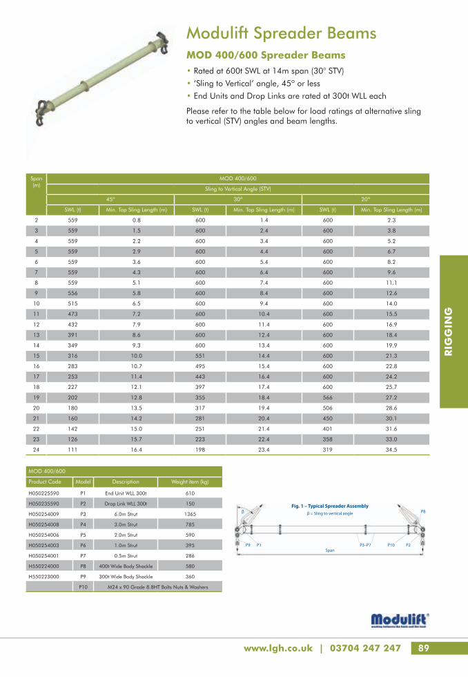
www.lgh.co.uk | 03704 247 247 89
RIG
GIN
G
Span (m)
MOD 400/600
Sling to Vertical Angle (STV)
45º 30º 20º
SWL (t) Min. Top Sling Length (m) SWL (t) Min. Top Sling Length (m) SWL (t) Min. Top Sling Length (m)
2 559 0.8 600 1.4 600 2.3
3 559 1.5 600 2.4 600 3.8
4 559 2.2 600 3.4 600 5.2
5 559 2.9 600 4.4 600 6.7
6 559 3.6 600 5.4 600 8.2
7 559 4.3 600 6.4 600 9.6
8 559 5.1 600 7.4 600 11.1
9 556 5.8 600 8.4 600 12.6
10 515 6.5 600 9.4 600 14.0
11 473 7.2 600 10.4 600 15.5
12 432 7.9 600 11.4 600 16.9
13 391 8.6 600 12.4 600 18.4
14 349 9.3 600 13.4 600 19.9
15 316 10.0 551 14.4 600 21.3
16 283 10.7 495 15.4 600 22.8
17 253 11.4 443 16.4 600 24.2
18 227 12.1 397 17.4 600 25.7
19 202 12.8 355 18.4 566 27.2
20 180 13.5 317 19.4 506 28.6
21 160 14.2 281 20.4 450 30.1
22 142 15.0 251 21.4 401 31.6
23 126 15.7 223 22.4 358 33.0
24 111 16.4 198 23.4 319 34.5
Modulift Spreader BeamsMOD 400/600 Spreader Beams• Rated at 600t SWL at 14m span (30° STV)
• ‘Sling to Vertical’ angle, 45º or less
• End Units and Drop Links are rated at 300t WLL each
Please refer to the table below for load ratings at alternative sling to vertical (STV) angles and beam lengths.
MOD 400/600
Product Code Model Description Weight item (kg)
H050225590 P1 End Unit WLL 300t 610
H050235590 P2 Drop Link WLL 300t 150
H050254009 P3 6.0m Strut 1365
H050254008 P4 3.0m Strut 785
H050254006 P5 2.0m Strut 590
H050254003 P6 1.0m Strut 395
H050254001 P7 0.5m Strut 286
H550224000 P8 400t Wide Body Shackle 580
H550223000 P9 300t Wide Body Shackle 360
P10 M24 x 90 Grade 8.8HT Bolts Nuts & Washers
User Instructions
Modulift UK Ltd tel: +44(0)1202 621511 email: [email protected] www.modulift.com
The Modulift Spreader is modular in length, and every spreader consists of 1 pair of End Units and erent spans.
● Personnel using this system should be suitably trained, competent and have a clear understanding of Safe Slinging procedures.
● The use of Modulift equipment must be in accordance with the procedures laid down in ‘Lifting Operations and Lifting Equipment Regulations 1998’ (LOLER).
● Never exceed stated SWL – Adhere to SWL in Table 2 for particular sling angle used. ● The top sling length is critical to the safe use of the spreader – Adhere to Table 2. ● Ensure Drop Links hang down, and smaller shackles are connected to bottom hole of Drop Link. ● anges – the spreader is designed for
axial compression, not bending.
WARNING!
MOD 400/600
MOD 400/600 has an assembled span ranging from 2 metres to 24 metres in 0.5m increments.
cation ● Rated at 600 tonnes SWL at 14 metres span
(30° STV). See Load Table for SWL at longer spans. ● ‘Sling to Vertical’ angle, β, 45 degrees or less. ● End Units & Drop Links are rated at 300 tonnes WLL each (600 tonnes combined capacity). ● Bolt tightening torque: 250Nm. Spanner size required: 36mm. ● Recommended additional equipment: Torque Wrench, Podger Spanner and Ring Spanner.
P1 P2P3–P7Span
β P8
01P9P
β = Sling to vertical angle
Strut
Larger shackle
Smaller shackle
Drop link
End unit sub-assy
Drop link
Part Ref. Description Weight/item
P1 End Unit WLL 300t 610kgP2 Drop Link WLL 300t 150kg
P3 6.0m Strut 1365kg
P4 3.0m Strut 785kg
P5 2.0m Strut 590kg
P6 1.0m Strut 395kg
P7 0.5m Strut 286kg
P8 400t Wide Body Shackle 580kg
P9 300t Wide Body Shackle 360kg
P10 M24 x 90 Grade 8.8 HT Bolts, Nuts & Washers
Table 1 – Component List
Fig. 1 – Typical Spreader Assembly

90
RIG
GIN
G
Modulift Spreader BeamsMOD 600XB/400 Spreader Beams• Rated at 400t SWL at 25m span (30° STV)
• ‘Sling to Vertical’ angle, 45º or less
• End Units and Drop Links are rated at 200t WLL each
Please refer to the table below for load ratings at alternative sling to vertical (STV) angles and beam lengths.
MOD 600XB/400
Product Code Model Description Weight item (kg)
H050222850 P1 End Unit WLL 200t 670
H050232850 P2 Drop Link WLL 200t 150
H050252859 P3 6.0m Strut 2665
H050252858 P4 5.0m Strut 2265
H050252857 P5 4.0m Strut 1865
H050252856 P6 3.0m Strut 1470
H050252855 P7 2.0m Strut 1070
H050252854 P8 1.0m Strut 675
H050252853 P9 0.5m Strut 475
H550223000 P10 300t Wide Body Shackle 360
H550222000 P11 200t Wide Body Shackle 205
P12 M24x90 Grade 10.9 HT Bolts, Nuts & Washers
Span (m)
MOD 600XB/400
Sling to Vertical Angle (STV)
45º 30º
SWL (t) Min. Top Sling Length (m) SWL (t) Min. Top Sling Length (m)
2 285 1.0 400 2
3 285 2.0 400 3
4 285 2.5 400 4
5 285 3.5 400 5
6 285 4.0 400 6
7 285 4.5 400 7
8 285 5.5 400 8
9 285 6.0 400 9
10 285 7.0 400 10
11 285 7.5 400 11
12 285 8.5 400 12
13 285 9.0 400 13
14 285 9.5 400 14
15 285 10.5 400 15
16 285 11.0 400 16
17 285 12.0 400 17
18 285 12.5 400 18
19 285 13.0 400 19
20 285 14.0 400 20
21 285 14.5 400 21
22 285 15.0 400 22
23 285 15.5 400 23
24 260 17.0 400 24
25 234 17.5 400 25
26 209 18.0 373 26
The Modulift Spreader is modular in length. Every spreader consists of 1 pair of End Units & DropLinks, with intermediate struts that can be bolted into the assembly to achieve different spans. The MOD 600XB/400 has an assembled span ranging from 2 metres to 26m in 0.5m increments.
USER INSTRUCTIONSMOD 600XB/400
DROPLINK
STRUT
MODULIFT UK LTD ·t.+44(0)1202 621511 e. [email protected] www.modulift.com
WARNING!
END UNITSUB-ASSY
Smaller shackle
Larger shackle
Drop Link
Personnel using this system should be suitably trained, competent and have a clear understanding of Safe Slinging procedures.The use of Modulift equipment must be in accordance with the procedures laid down in ‘Lifting Operations and Lifting Equipment Regulations 1998’ (LOLER).NEVER EXCEED STATED SWL - ADHERE TO SWL IN TABLE 2, FOR PARTICULAR SLING ANGLE USEDTHE TOP SLING LENGTH IS CRITICAL TO THE SAFE USE OF THE SPREADER - ADHERE TO TABLE 2.Ensure Drop Links hang down, and smaller shackles are connected to bottom hole of Drop Link.Do not under any circumstances hang load(s) from the tube or flanges - the spreader is designed for axial compression - not bending.
MOD 600XB/400 - Beam Specification.Rated at 400 tonnes SWL at 25 metres span (30° STV). See Load Table for SWL at longer spans.‘Sling to Vertical’ angle, β, 45 degrees or less.End Units & Drop Links are rated at 200 tonnes WLL each (400 tonnes combined capacity).Bolt tightening torque: 250Nm. Spanner size required: 36mm.Recommended additional equipment: Torque Wrench, Podger Spanner and Ring Spanner.
TABLE 1: COMPONENT LISTPART REF: DESCRIPTION WEIGHT / ITEMP1 END UNIT WLL 200t 670kgP2 DROP LINK WLL 200t 150kgP3 6.0m STRUT 2665kgP4 5.0m STRUT 2265kgP5 4.0m STRUT 1865kgP6 3.0m STRUT 1470kgP7 2.0m STRUT 1070kgP8 1.0m STRUT 675kgP9 0.5m STRUT 475kgP10 300t WIDE BODY SHACKLE 360kgP11 200t WIDE BODY SHACKLE 205kgP12 M24x90 Grade 10.9 HT BOLTS, NUTS &
WASHERS
b
Fig. 1: Typical Spreader Assembly.
P1P11 P12
P10
P2
P3 - P9
β =’Sling to Vertical’ angle
Span
LGH - puts safety first

www.lgh.co.uk | 03704 247 247 91
RIG
GIN
G
Modulift Spreader BeamsMOD 600XB/600 Spreader Beams• Rated at 600t SWL at 21m span (30° STV)
• ‘Sling to Vertical’ angle, 45º or less
• End Units and Drop Links are rated at 200t WLL each
Please refer to the table below for load ratings at alternative sling to vertical (STV) angles and beam lengths.
MOD 600XB/600
Product Code Model Description Weight item (kg)
H050224150 P1 End Unit WLL 300t 770
H050234150 P2 Drop Link WLL 300t 180
H050254159 P3 6.0m Strut 2665
H050254158 P4 5.0m Strut 2265
H050254157 P5 4.0m Strut 1865
H050254156 P6 3.0m Strut 1470
H050254155 P7 2.0m Strut 1070
H050254154 P8 1.0m Strut 675
H050254153 P9 0.5m Strut 475
H550224000 P10 400t Wide Body Shackle 580
H550223000 P11 300t Wide Body Shackle 360
P12 M24x90 Grade 10.9 HT Bolts, Nuts & Washers
Span (m)
MOD 600XB/600
Sling to Vertical Angle (STV)
45º 30º
SWL (t) Min. Top Sling Length (m) SWL (t) Min. Top Sling Length (m)
2 415 1.0 600 2
3 415 2.0 600 3
4 415 2.5 600 4
5 415 3.5 600 5
6 415 4.0 600 6
7 415 4.5 600 7
8 415 5.5 600 8
9 415 6.0 600 9
10 415 7.0 600 10
11 415 7.5 600 11
12 415 8.5 600 12
13 415 9.0 600 13
14 415 9.5 600 14
15 415 10.5 600 15
16 415 11.0 600 16
17 415 12.0 600 17
18 415 12.5 600 18
19 415 13.0 600 19
20 391 14.0 600 20
21 354 14.5 600 21
22 320 15.0 565 22
23 289 15.5 512 23
24 260 17.0 461 24
25 234 17.5 416 25
26 209 18.0 373 26
The Modulift Spreader is modular in length. Every spreader consists of 1 pair of End Units & DropLinks, with intermediate struts that can be bolted into the assembly to achieve different spans. The MOD 600XB/600 has an assembled span ranging from 2 metres to 26m in 0.5m increments.
USER INSTRUCTIONSMOD 600XB/600
DROPLINK
STRUT
MODULIFT UK LTD ·t.+44(0)1202 621511 e. [email protected] www.modulift.com
WARNING!
END UNITSUB-ASSY
Smaller shackle
Larger shackle
Drop Link
Personnel using this system should be suitably trained, competent and have a clear understanding of Safe Slinging procedures.The use of Modulift equipment must be in accordance with the procedures laid down in the ‘Lifting Operations and Lifting Equipment Regulations 1998’ (LOLER).NEVER EXCEED STATED SWL - ADHERE TO SWL IN TABLE 2, FOR PARTICULAR SLING ANGLE USEDTHE TOP SLING LENGTH IS CRITICAL TO THE SAFE USE OF THE SPREADER - ADHERE TO TABLE 2.Ensure Drop Links hang down, and smaller shackles are connected to bottom hole of Drop Link.Do not under any circumstances hang load(s) from the tube or flanges - the spreader is designed for axial compression - not bending.
MOD 600XB/600 - Beam Specification.Rated at 600 tonnes SWL at 21 metres span (30 STV). See Load Table for SWL at longer spans.‘Sling to Vertical’ angle, β, 45 degrees or less.End Units & Drop Links are rated at 300 tonnes WLL each (600 tonnes combined capacity).Bolt tightening torque: 250Nm. Spanner size required: 36mm.Recommended additional equipment: Torque Wrench, Podger Spanner and Ring Spanner.
TABLE 1: COMPONENT LISTPART REF: DESCRIPTION WEIGHT / ITEMP1 END UNIT WLL 300t 770kgP2 DROP LINK WLL 300t 180kgP3 6.0m STRUT 2665kgP4 5.0m STRUT 2265kgP5 4.0m STRUT 1865kgP6 3.0m STRUT 1470kgP7 2.0m STRUT 1070kgP8 1.0m STRUT 675kgP9 0.5m STRUT 475kgP10 400t WIDE BODY SHACKLE 580kgP11 300t WIDE BODY SHACKLE 360kgP12 M24x90 Grade 10.9 HT BOLTS, NUTS &
WASHERS
b
Fig. 1: Typical Spreader Assembly.
P1
P11P12
P10
P2
P3 - P9
β =’Sling to Vertical’ angle
Span

92
RIG
GIN
G
Modulift Spreader BeamsMOD 600XB/800 Spreader Beams• Rated at 800t SWL at 18m span (30° STV)
• ‘Sling to Vertical’ angle, 45º or less
• End Units and Drop Links are rated at 200t WLL each
Please refer to the table below for load ratings at alternative sling to vertical (STV) angles and beam lengths.
MOD 600XB/800
Product Code Model Description Weight item (kg)
H050225650 P1 End Unit WLL 400t 860
H050235650 P2 Drop Link WLL 400t 260
H050255659 P3 6.0m Strut 2665
H050255658 P4 5.0m Strut 2265
H050255657 P5 4.0m Strut 1865
H050255656 P6 3.0m Strut 1470
H050255655 P7 2.0m Strut 1070
H050255654 P8 1.0m Strut 675
H050255653 P9 0.5m Strut 475
H550225000 P10 500t Wide Body Shackle 780
H550224000 P11 400t Wide Body Shackle 580
P12 M24x90 Grade 10.9 HT Bolts, Nuts & Washers
Span (m)
MOD 600XB/800
Sling to Vertical Angle (STV)
45º 30º
SWL (t) Min. Top Sling Length (m) SWL (t) Min. Top Sling Length (m)
2 565 1.0 800 2
3 565 2.0 800 3
4 565 2.5 800 4
5 565 3.5 800 5
6 565 4.0 800 6
7 565 4.5 800 7
8 565 5.5 800 8
9 565 6.0 800 9
10 565 7.0 800 10
11 565 7.5 800 11
12 565 8.5 800 12
13 565 9.0 800 13
14 565 9.5 800 14
15 565 10.5 800 15
16 559 11.0 800 16
17 514 12.0 800 17
18 469 12.5 800 18
19 427 13.0 749 19
20 391 14.0 688 20
21 354 14.5 623 21
22 320 15.5 565 22
23 289 16.0 512 23
24 260 17.0 461 24
25 234 17.5 416 25
26 209 18.0 373 26
The Modulift Spreader is modular in length. Every spreader consists of 1 pair of End Units & DropLinks, with intermediate struts that can be bolted into the assembly to achieve different spans. The MOD 600XB/800 has an assembled span ranging from 2 metres to 26m in 0.5m increments.
USER INSTRUCTIONSMOD 600XB/800
DROPLINK
STRUT
MODULIFT UK LTD ·t.+44(0)1202 621511 e. [email protected] www.modulift.com
WARNING!
END UNITSUB-ASSY
Smaller shackle
Larger shackle
Drop Link
Personnel using this system should be suitably trained, competent and have a clear understanding of Safe Slinging procedures.The use of Modulift equipment must be in accordance with the procedures laid down in the ‘Lifting Operations and Lifting Equipment Regulations 1998’ (LOLER).NEVER EXCEED STATED SWL - ADHERE TO SWL IN TABLE 2, FOR PARTICULAR SLING ANGLE USEDTHE TOP SLING LENGTH IS CRITICAL TO THE SAFE USE OF THE SPREADER - ADHERE TO TABLE 2.Ensure Drop Links hang down, and smaller shackles are connected to bottom hole of Drop Link.Do not under any circumstances hang load(s) from the tube or flanges - the spreader is designed for axial compression - not bending.
MOD 600XB/800 - Beam Specification.Rated at 800 tonnes SWL at 18 metres span (30° STV). See Load Table for SWL at longer spans.‘Sling to Vertical’ angle, β, 45 degrees or less.End Units & Drop Links are rated at 400 tonnes WLL each (800 tonnes combined capacity).Bolt tightening torque: 250Nm. Spanner size required: 36mm.Recommended additional equipment: Torque Wrench, Podger Spanner and Ring Spanner.
TABLE 1: COMPONENT LISTPART REF: DESCRIPTION WEIGHT / ITEMP1 END UNIT WLL 400t 860kgP2 DROP LINK WLL 400t 260kgP3 6.0m STRUT 2665kgP4 5.0m STRUT 2265kgP5 4.0m STRUT 1865kgP6 3.0m STRUT 1470kgP7 2.0m STRUT 1070kgP8 1.0m STRUT 675kgP9 0.5m STRUT 475kgP10 500t WIDE BODY SHACKLE 780kgP11 400t WIDE BODY SHACKLE 580kgP12 M24x90 Grade 10.9 HT BOLTS, NUTS &
WASHERS
b
Fig. 1: Typical Spreader Assembly.
P1P11 P12
P10
P2
P3 - P9
β =’Sling to Vertical’ angle
Span
Safety, Certainty, Great Service

www.lgh.co.uk | 03704 247 247 93
RIG
GIN
G
Modulift Spreader BeamsMOD 600XB/1000 Spreader Beams• Rated at 1000t SWL at 15m span (30° STV)
• ‘Sling to Vertical’ angle, 45º or less
• End Units and Drop Links are rated at 200t WLL each
Please refer to the table below for load ratings at alternative sling to vertical (STV) angles and beam lengths.
MOD 600XB/1000
Product Code Model Description Weight item (kg)
H550225750 P1 End Unit WLL 500t 870
H550235750 P2 Drop Link WLL 500t 385
H550255759 P3 6.0m Strut 2665
H550255758 P4 5.0m Strut 2265
H550255757 P5 4.0m Strut 1865
H550255756 P6 3.0m Strut 1470
H550255755 P7 2.0m Strut 1070
H550255754 P8 1.0m Strut 675
H550255753 P9 0.5m Strut 475
H550226000 P10 600t Wide Body Shackle 980
H550225000 P11 500t Wide Body Shackle 780
P12 M24x90 Grade 10.9 HT Bolts, Nuts & Washers
Span (m)
MOD 600XB/1000
Sling to Vertical Angle (STV)
45º 30º
SWL (t) Min. Top Sling Length (m) SWL (t) Min. Top Sling Length (m)
2 575 1.0 1000 2
3 575 2.0 1000 3
4 575 2.5 1000 4
5 575 3.5 1000 5
6 575 4.0 1000 6
7 575 4.5 1000 7
8 575 5.5 1000 8
9 575 6.0 1000 9
10 575 7.0 1000 10
11 575 7.5 1000 11
12 575 8.5 1000 12
13 575 9.0 1000 13
14 575 9.5 1000 14
15 575 10.5 1000 15
16 559 11.0 977 16
17 514 12.0 899 17
18 469 12.5 821 18
19 427 13.0 749 19
20 391 14.0 688 20
21 354 14.5 623 21
22 320 15.5 565 22
23 289 16.0 512 23
24 260 17.0 461 24
25 234 17.5 416 25
26 209 18.0 373 26
The Modulift Spreader is modular in length. Every spreader consists of 1 pair of End Units & DropLinks, with intermediate struts that can be bolted into the assembly to achieve different spans. The MOD 600XB/1000 has an assembled span ranging from 2 metres to 26m in 0.5m increments.
USER INSTRUCTIONSMOD 600XB/1000
DROPLINK
STRUT
MODULIFT UK LTD ·t.+44(0)1202 621511 e. [email protected] www.modulift.com
WARNING!
END UNITSUB-ASSY
Smaller shackle
Larger shackle
Drop Link
Personnel using this system should be suitably trained, competent and have a clear understanding of Safe Slinging procedures.The use of Modulift equipment must be in accordance with the procedures laid down in the ‘Lifting Operations and Lifting Equipment Regulations 1998’ (LOLER).NEVER EXCEED STATED SWL - ADHERE TO SWL IN TABLE 2, FOR PARTICULAR SLING ANGLE USEDTHE TOP SLING LENGTH IS CRITICAL TO THE SAFE USE OF THE SPREADER - ADHERE TO TABLE 2.Ensure Drop Links hang down, and smaller shackles are connected to bottom hole of Drop Link.Do not under any circumstances hang load(s) from the tube or flanges - the spreader is designed for axial compression - not bending.
MOD 600XB/1000 - Beam Specification.Rated at 1000 tonnes SWL at 15 metres span (30° STV). See Load Table for SWL at longer spans.‘Sling to Vertical’ angle, β, 45 degrees or less.End Units & Drop Links are rated at 500 tonnes WLL each (1000 tonnes combined capacity).Bolt tightening torque: 250Nm. Spanner size required: 36mm.Recommended additional equipment: Torque Wrench, Podger Spanner and Ring Spanner.
TABLE 1: COMPONENT LISTPART REF: DESCRIPTION WEIGHT / ITEMP1 END UNIT WLL 500t 870kgP2 DROP LINK WLL 500t 385kgP3 6.0m STRUT 2665kgP4 5.0m STRUT 2265kgP5 4.0m STRUT 1865kgP6 3.0m STRUT 1470kgP7 2.0m STRUT 1070kgP8 1.0m STRUT 675kgP9 0.5m STRUT 475kgP10 600t WIDE BODY SHACKLE 980kgP11 500t WIDE BODY SHACKLE 780kgP12 M24x90 Grade 10.9 HT BOLTS, NUTS &
WASHERS
b
Fig. 1: Typical Spreader Assembly.
P1P11 P12
P10
P2
P3 - P9
β =’Sling to Vertical’ angle
Span

94
RIG
GIN
G
Modulift Spreader Frames CMOD Spreader Frames• Six sizes: CMOD 6, 12, 24, 50, 70, 110
• Spans 0.5m to 16m
• Capacities 6t to 140t
• Refer to load charts below and opposite for capacities at varying lengths and sling angles
Load Charts – CMOD 6, 12 & 24
CMOD 24: SWL/t @ 60° ISA / 30° STV / 60° BSA
6 23
5 30 21
4 30 24 19
3 30 30 24 18
2 30 30 30 24 17
1 30 30 30 24 22 16
Span (m) 1 2 3 4 5 6
CMOD 6: SWL/t @ 60° ISA / 30° STV / 60° BSA
2.5 8
2 8 8
1.5 8 8 8
1 8 8 8 6
0.5 8 8 8 6 6
Span (m) 0.5 1 1.5 2 2.5
CMOD 12: SWL/t @ 60° ISA / 30° STV / 60° BSA
4 16
3.5 16 16
3 16 16 15
2.5 16 16 15 14
2 16 16 16 14 13
1.5 16 16 16 16 14 12
1 16 16 16 16 16 14 12
0.5 16 16 16 16 16 16 14 12
Span (m) 0.5 1 1.5 2 2.5 3 3.5 4
CMOD 12: SWL/t @ 90° ISA / 45° STV/ 45° BSA
4 9
3.5 9 9
3 9 9 8
2.5 9 9 8 8
2 9 9 9 8 7
1.5 9 9 9 9 8 6
1 9 9 9 9 9 8 6
0.5 9 9 9 9 9 9 8 6
Span (m) 0.5 1 1.5 2 2.5 3 3.5 4
CMOD 6: SWL/t @ 90° ISA / 45° STV / 45° BSA
2.5 6
2 6 6
1.5 6 6 6
1 6 6 6 4
0.5 6 6 6 4 4
Span (m) 0.5 1 1.5 2 2.5
CMOD 24: SWL/t @ 90° ISA / 45° STV / 45° BSA
6 13
5 17 12
4 19 13 10
3 19 19 13 10
2 19 19 17 13 9
1 19 19 19 13 12 9
Span (m) 1 2 3 4 5 6
All our equipment is tested and certified to the highest standard

www.lgh.co.uk | 03704 247 247 95
RIG
GIN
G
Load Charts – CMOD 50, 70 & 110
CMOD 70: SWL/t @ 60° ISA / 30° STV / 60° BSA
12 63
11 70 60
10 80 70 58
9 80 80 70 55
8 80 80 80 67 53
7 80 80 80 70 65 51
6 80 80 80 70 60 62 49
5 80 80 80 80 70 60 60 47
4 80 80 80 80 80 70 60 58 46
3 80 80 80 80 80 80 70 60 56 45
2 80 80 80 80 80 80 80 70 60 55 44
1 80 80 80 80 80 80 80 70 70 60 54 44
Span (m) 1 2 3 4 5 6 7 8 9 10 11 12
CMOD 110: SWL/t @ 60° ISA / 30° STV / 60° BSA16 100
15 100 100
14 100 100 95
13 110 100 95 90
12 120 105 95 90 80
11 140 120 100 95 80 80
10 140 140 120 100 90 80 80
9 140 140 140 120 95 85 75 75
8 140 140 140 140 120 90 80 75 75
7 140 140 140 140 140 120 90 80 75 75
6 140 140 140 140 140 140 110 80 75 75 75
5 140 140 140 140 140 140 120 90 80 75 75 75
4 140 140 140 140 140 140 140 120 85 80 75 75 75
3 140 140 140 140 140 140 140 120 110 85 80 75 75 70
2 140 140 140 140 140 140 140 130 110 95 85 80 75 70 70
Span (m) 2 3 4 5 6 7 8 9 10 11 12 13 14 15 16
CMOD 110: SWL/t @ 90° ISA / 45° STV / 45° BSA 16 60
15 60 58
14 70 58 55
13 75 70 55 55
12 85 75 65 55 50
11 85 85 70 60 50 50
10 85 85 85 70 60 50 45
9 95 85 85 80 65 55 50 45
8 95 95 85 85 70 60 55 45 45
7 95 95 95 85 80 70 60 50 45 45
6 95 95 95 90 80 80 70 55 50 45 43
5 95 95 95 95 85 80 75 65 55 47 43 43
4 95 95 95 95 95 85 80 75 60 50 45 43 43
3 95 95 95 95 95 95 80 75 65 55 48 45 43 40
2 95 95 95 95 95 95 95 80 75 60 50 48 45 40 40
Span (m) 2 3 4 5 6 7 8 9 10 11 12 13 14 15 16
CMOD 50: SWL/t @ 60° ISA / 30° STV / 60° BSA
11 32
10 41 31
9 50 39 29
8 50 48 37 28
7 60 50 45 35 27
6 60 60 50 43 33 26
5 60 60 60 50 40 32 25
4 60 60 60 50 49 38 31 24
3 60 60 60 60 50 47 37 30 23
2 60 60 60 60 60 50 45 36 29 23
1 60 60 60 60 60 60 50 44 35 28 22
Span (m) 1 2 3 4 5 6 7 8 9 10 11
CMOD 50: SWL/t @ 90° ISA / 45° STV / 45° BSA
11 18
10 23 17
9 28 21 16
8 28 27 20 15
7 34 28 25 19 14
6 40 34 28 24 18 14
5 40 40 34 28 23 17 13
4 50 40 40 28 28 21 17 13
3 50 50 40 40 28 26 21 16 12
2 50 50 50 40 34 28 25 20 16 12
1 50 50 50 50 40 34 28 25 20 15 12
Span (m) 1 2 3 4 5 6 7 8 9 10 11
CMOD 70: SWL/t @ 90° ISA / 45° STV / 45° BSA
12 36
11 40 34
10 40 40 33
9 46 40 40 31
8 57 46 40 38 30
7 60 57 46 40 37 29
6 60 60 57 40 34 35 28
5 60 60 60 50 40 34 34 27
4 60 60 60 60 50 40 34 33 26
3 60 60 60 60 60 50 40 34 32 26
2 60 60 60 60 60 60 50 40 34 31 25
1 60 60 60 60 60 60 60 50 40 34 31 24
Span (m) 1 2 3 4 5 6 7 8 9 10 11 12
CMOD250 also available, details on request
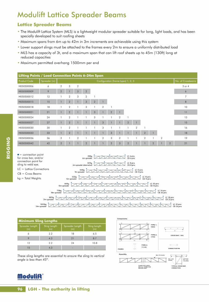
96
RIG
GIN
G
Modulift Lattice Spreader BeamsLattice Spreader Beams• The Modulift Lattice System (MLS) is a lightweight modular spreader suitable for long, light loads, and has been
specially developed to suit roofing sheets
• Maximum spans from 6m up to 42m in 3m increments are achievable using this system
• Lower support slings must be attached to the frames every 2m to ensure a uniformly distributed load
• MLS has a capacity of 3t, and a maximum span that can lift roof sheets up to 45m (130ft) long at reduced capacities
• Maximum permitted overhang 1500mm per end
Lifting Points / Load Connection Points 6–24m Span
Product Code Spreader (m) Configuration (frame types) 1, 2, 3 No. of Crossbeams
H050500006 6 2 3 2 3 or 4
H050500009 9 2 1 3 2 6
H050500012 12 1 2 3 2 1 7
H050500015 15 1 2 1 3 2 1 8
H050500018 18 1 2 1 3 1 2 1 10
H050500021 21 1 2 1 1 3 1 2 1 11
H050500024 24 1 2 1 1 3 1 1 2 1 13
H050500027 27 1 2 1 1 1 3 1 1 2 1 15
H050500030 30 1 2 1 1 1 3 1 1 1 2 1 16
H050500033 33 1 2 1 1 1 1 3 1 1 1 2 1 18
H050500036 36 2 1 2 1 1 2 3 2 1 1 2 1 2 19
H050500042 42 2 1 1 2 1 1 2 3 2 1 1 2 1 2 21
Minimum Sling LengthsSpreader Length
(m)Sling Length
(m)Spreader Length
(m)Sling Length
(m)
6 2.2 18 6.5
9 4.3 21 8.7
12 2.2 24 10.8
15 4.3 - -
These sling lengths are essential to ensure the sling to vertical angle is less than 45º.
318kg 6m spreader
= connection point for cross bar, and/or connection point for sling to weld eye.
LC = Lattice Connections
CB = Cross Beams
327kg 6m spreader (alternative)
444kg9m spreader
552kg12m spreader
661kg15m spreader
778kg18m spreader
887kg21m spreader
1005kg24m spreader
LC: 6 pins CB: 6 pins
LC: 8 pins CB: 8 pins
LC: 12 pins CB: 12 pins
LC: 16 pins CB: 14 pins
LC: 20 pins CB: 16 pins
LC: 24 pins CB: 20 pins
LC: 28 pins CB: 22 pins
LC: 32 pins CB: 26 pins
= connection point for cross bar, and/or connection point for sling to weld eye.
LC = Lattice Connections
CB = Cross Beams
kg = Total Weights
Personnel using this system should be suitably trained, competent and have a clear understanding of Safe Slinging procedures, in accordance with the procedures laid down in ‘Lifting Operations and Lifting Equipment Regulations 1998’ (LOLER). THE SLING LENGTH IS CRITICAL TO THE SAFE USE OF THE SPREADER - THE ‘SLING TO VERTICAL’ ANGLE, b, MUST NOT BE MORE THAN 45 DEGREES. DO NOT EXCEED 2 TONNES. The number of lifting points must not be less than shown in the diagram overleaf.
The Modulift Lattice System (MLS) is a light-weight modular spreader suitable for long, light loads, and has been specially developed to suit roofing sheets.Maximum spans from 6m up to 36m in 3m increments are achievable using this system. Lower support slings can be attached to the frames every 2m to ensure a uniformly distributed load.
Spreader Specification. Rated at 2 tonnes WLL - Uniformly Distributed Load only (Up to 27m span). ‘Sling to Vertical’ angle, b, 45 degrees or less. Lifting points: Slings can be connected to weld eyes on ends of 1m span cross bars, or to weld eyes on underside of frames. Maximum 33m roofing sheet to be lifted with this configuration
3m
3m
1m
WARNING!
MODULIFT · 11 NEW FIELDS BUSINESS PARK · STINSFORD RD · POOLE · DORSET · BH17 0NF · UKTel:+44(0)1202 621511 Fax: +44 (0)1202 632811 Email: [email protected] Web: www.modulift.co.uk
Components.
TYPE 1:100KG
TYPE 2:137KG
CROSS BAR: 7.5KG
FRAMES
TYPE 3:17.5 KG
CONNECTION PIN
Assembly.
CONNECTION JOINTS -USE 4 no. CONNECTION PINS PER JOINT.
Max. 6.5t shackle
Max. 3.25t shackle
TYPICAL CROSS BAR CONNECTION
ConnectionPins - 2 perCross Beam
USER INSTRUCTIONS- LATTICE SPREADER: 27m
LGH - The authority in lifting

www.lgh.co.uk | 03704 247 247 97
RIG
GIN
G
Modulift Lattice Spreader BeamsLattice Spreader Beams / Assembly Details
Assembled 30m Lattice Spreader BeamTop sling min. length = 15m
Use round/webbing sling to connect chain block and spreader beam
Centred sling supportWire rope
Chain block
Total weight = 1231kg
Top sling min. length = 17.5m
Centred sling supportWire rope
Chain block
Total weight = 1347kg
Use round/webbing sling to connect chain block and spreader beam
22m 18m 22m18m13m
2.6mTop sling min. length = As shown above
Total weight = 1604kg
37m 37m33.5m 33.5m29m3m
3 leg assyTop sling min. length = As shown above
Total weight = 1822kg
3 leg assy
Assembled 27m Lattice Spreader Beam
Top sling min. length = 13m
Total weight = 1121kg
Assembled 33m Lattice Spreader Beam
Top sling min. length = 15mUse round/webbing sling to connect chain block and spreader beam
Centred sling supportWire rope
Chain block
Total weight = 1231kg
Top sling min. length = 17.5m
Centred sling supportWire rope
Chain block
Total weight = 1347kg
Use round/webbing sling to connect chain block and spreader beam
22m 18m 22m18m13m
2.6mTop sling min. length = As shown above
Total weight = 1604kg
37m 37m33.5m 33.5m29m3m
3 leg assyTop sling min. length = As shown above
Total weight = 1822kg
3 leg assy
Assembled 36m Lattice Spreader Beam
Top sling min. length = 15mUse round/webbing sling to connect chain block and spreader beam
Centred sling supportWire rope
Chain block
Total weight = 1231kg
Top sling min. length = 17.5m
Centred sling supportWire rope
Chain block
Total weight = 1347kg
Use round/webbing sling to connect chain block and spreader beam
22m 18m 22m18m13m
2.6mTop sling min. length = As shown above
Total weight = 1604kg
37m 37m33.5m 33.5m29m3m
3 leg assyTop sling min. length = As shown above
Total weight = 1822kg
3 leg assy
Assembled 42m Lattice Spreader Beam
Top sling min. length = 15mUse round/webbing sling to connect chain block and spreader beam
Centred sling supportWire rope
Chain block
Total weight = 1231kg
Top sling min. length = 17.5m
Centred sling supportWire rope
Chain block
Total weight = 1347kg
Use round/webbing sling to connect chain block and spreader beam
22m 18m 22m18m13m
2.6mTop sling min. length = As shown above
Total weight = 1604kg
37m 37m33.5m 33.5m29m3m
3 leg assyTop sling min. length = As shown above
Total weight = 1822kg
3 leg assy
2m chain sling c/w shortener on bottom of all legs
2m chain sling c/w shortener on bottom of all legs

98
RIG
GIN
G
Crane Forks & Material SkipsSelf Balancing Crane Fork• Fork spacing infinitely adjustable manually from
450mm to 950mm
• Bearing ring for weight compensation infinitely adjustable manually or automatically by compression spring
• Working height adjustable by pin system from 1570mm to 1830mm
• Load capacities are quoted for a distance of 680mm between the bale arm and the centre of gravity of the load
Self-Discharge Boat Skip• Specifically designed to meet the specific needs of moving waste
around site with health and safety in mind
• Bespoke lock and release mechanism on the lifting arm this skip negates the need for personnel to be in the “danger area” while in use
• Automated tipping will increase efficiency and productivity
Product Code Load Cap. (kg)
Prong Cross Section (mm)
Effective Height (mm)
Height Under Load (mm)
Prong Length (mm)
Weight (kg)
H520010006 600 40/120 1100-1700 995 1000 160.0
H520010010 1000 40/90 1100-1700 995 1000 185.0
H520010015 1500 40/100 1100-1700 1010 1000 195.0
H520010020 2000 40/120 1100-1700 1065 1000 235.0
H520010030 3000 50/120 1100-1700 1065 1000 270.0
Product Code Model SWL(kg)
Capacity (l)
Length (mm)
Width (mm)
Height (mm)
Weight (kg)
H560100500 1045-500 1000 500 1960 1350 550 130.0
H560100750 1045-700 1500 750 2100 1350 645 165.0
H560101000 1045-1000 2000 1000 2200 1600 650 275.0
H560101500 1045-1500 3000 1500 2250 1750 950 425.0
H560102000 1045-2000 4000 2000 2600 1750 950 540.0
H560103000 1045-3000 6000 3000 3100 1950 1000 800.0
H560104000 1045-4000 8000 4000 3250 2050 1200 1320.0
Delivering excellence in lifting throughout the UK
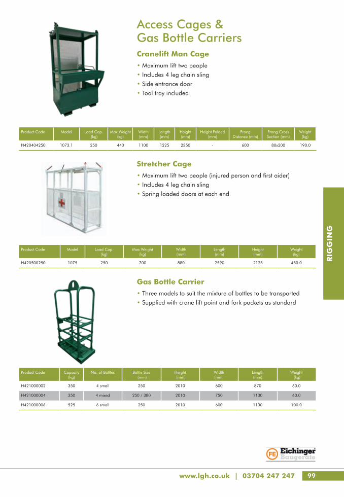
www.lgh.co.uk | 03704 247 247 99
RIG
GIN
G
Access Cages & Gas Bottle CarriersCranelift Man Cage• Maximum lift two people
• Includes 4 leg chain sling
• Side entrance door
• Tool tray included
Stretcher Cage• Maximum lift two people (injured person and first aider)
• Includes 4 leg chain sling
• Spring loaded doors at each end
Product Code Capacity (kg)
No. of Bottles Bottle Size (mm)
Height (mm)
Width (mm)
Length (mm)
Weight (kg)
H421000002 350 4 small 250 2010 600 870 60.0
H421000004 350 4 mixed 250 / 380 2010 750 1130 60.0
H421000006 525 6 small 250 2010 600 1130 100.0
Product Code Model Load Cap. (kg)
Max Weight (kg)
Width (mm)
Length (mm)
Height (mm)
Weight (kg)
H420500250 1075 250 700 880 2590 2125 450.0
Product Code Model Load Cap. (kg)
Max Weight(kg)
Width(mm)
Length(mm)
Height(mm)
Height Folded (mm)
Prong Distance (mm)
Prong Cross Section (mm)
Weight(kg)
H420404250 1073.1 250 440 1100 1225 2350 - 600 80x200 190.0
Gas Bottle Carrier• Three models to suit the mixture of bottles to be transported
• Supplied with crane lift point and fork pockets as standard

100
RIG
GIN
G
Block GrabsScissor Block Grab SG-80A mechanical grab universally suitable for use on building sites engaged in civil engineering work and paving work.
• The SG grab handles pack sizes without any gripping width adjustment
• Safe and easy transporting of un-palletised building materials such as vertically steel-strapped paving blocks, slabs and kerb stones
• Fork sleeves with manual turning device also available
FTZ-UNI Block GrabsUniversal clamp for all kinds of precast elements.
• Gripping width adjustment by spring loaded bolt• Suspension bolt for lifting device• Automatic release for fully automatic switch-over from
“full” to “empty”• Exchangeable rubber grippers
TSZ-UNISuitable for handling steps, kerb stones and L-stones in conjunction with a lifting device. Easily adjustable opening width by means of a spring-loaded bolt.
• Lifting eye for attaching to the crane hook
• Automatic release for fully automatic switch-over from “full” to “empty”
• Exchangeable profiled rubber seals
TSVUniversal handles due to a large adjustable opening range. Suitable for steps, kerbs, L-stones etc.
• Lifting eye for attaching to crane hook
• Semi-automatic - for manual switch-over from “full” to “empty”
• Carrying handle turnable by 90º according to the working space
• Exchangeable rubber grippers
Product Code Model Gripping Range (mm)
Inside Height (mm)
Gripper Length (mm)
Working Load Limit (kg)
Weight (kg)
H540310018 SG-80 400 - 1100 800 1200 1800 210.0
Product Code Model Gripping Range (mm)
Inside Height (mm)
Gripper Length (mm)
Working Load Limit (kg)
Weight (kg)
H621020250 TSV 70 - 500 125 200 250 18.0
Product Code Model Gripping Range (mm)
Inside Height (mm)
Gripper Length (mm)
Working Load Limit (kg)
Weight (kg)
H540320015 FTZ-UNI-1.5 0 - 750 255 420 1500 85.0
H540320050 FTZ-UNI-5.0 0 - 850 200 720 5000 245.0
Product Code Model Gripping Range (mm)
Inside Height (mm)
Gripper Length (mm)
Working Load Limit (kg)
Weight (kg)
H621010600 TSZ-UNI 50 - 600 185 350 600 29.0
LGH - puts safety first

www.lgh.co.uk | 03704 247 247 101
RIG
GIN
G
Stone MagnetsSM400/600 Vacuum Lifting Device
Easy to handle, robust, independent of main power supply with load-bearing capacity of up to 600kg. Flexible, fast and secure installation of primarily vacuum-dense elements, e.g. granite. Powered by rechargeable, exchangeable 12V battery.
• In seconds, various suction plates can be fitted to the SM via a quick release locating pin, enabling it to be used for many different purposes and loads - see options in table below
• Optional trolley (UM-SM) available to enable use where hoisting equipment is not available and/or provide greater manoeuvrability
Product Code Model Capacity (kg)
Battery Power (V)
Weight (kg)
H631010002 SM-400 400 12 35.0
H631010001 SM-600 600 12 35.0
Product Code Model Power: Petrol Engine (kW)
Working Load Limit (kg)
Weight (without suction plate) (kg)
H632010025 SH-2500-UNI-B 2.9 2500 100.0
Product Code Model To Suit Device
Length x Width (mm)
Capacity(kg)
H631020100 SM-SPS100 SM400 / 600 900x90 100
H631020200 SM-SPS200 SM400 / 600 580x280 200
H631020400 SM-SPS400 SM400 / 600 750x270 400
H631020600 SM-SPS600 SM600 950x340 600
H632020200 SPS200 SH2500 370x370 200
H632020400 SPS400 SH2500 750x275 400
H632020500 SPS500 SH2500 670x400 500
H632021000 SPS1010 SH2500 840x570 1010
H632021200 SPS1200 SH2500 960x580 1200
H632021500 SPS1500 SH2500 800x750 1500
H632022500 SPS2500 SH2500 1430x780 2500
Vacuum Lifting Device SH-2500-UNI-B (petrol)For the easy and efficient handling and laying of natural stone, concrete and marble slabs, pipes and steps.
• Specially designed and equipped for heavy-duty work on the building site
• Can hang from any carrier by means of load hooks, chains and cables
• Can be adapted by means of additional devices such as the Micro MJ and used to lay lighter slabs (such as patio blocks)
• In seconds, various suction plates can be fitted to the SH via a quick release locating pin, enabling it to be used for many different purposes and loads - see options in table below
Suction Plates to suit SM400/600 & SH2500
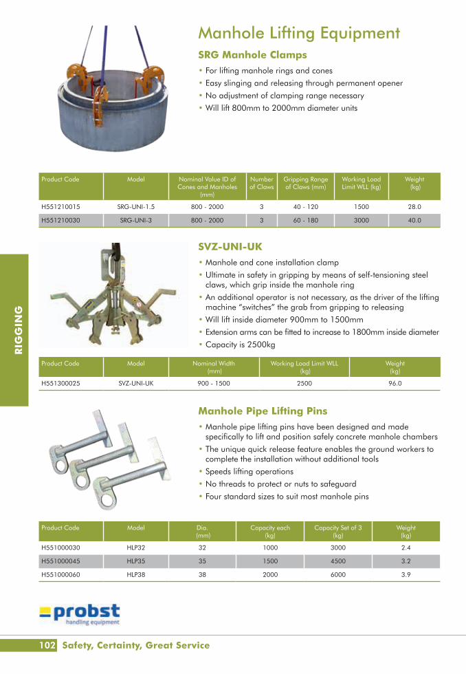
102
RIG
GIN
G
Manhole Lifting EquipmentSRG Manhole Clamps• For lifting manhole rings and cones
• Easy slinging and releasing through permanent opener
• No adjustment of clamping range necessary
• Will lift 800mm to 2000mm diameter units
SVZ-UNI-UK• Manhole and cone installation clamp
• Ultimate in safety in gripping by means of self-tensioning steel claws, which grip inside the manhole ring
• An additional operator is not necessary, as the driver of the lifting machine “switches” the grab from gripping to releasing
• Will lift inside diameter 900mm to 1500mm
• Extension arms can be fitted to increase to 1800mm inside diameter
• Capacity is 2500kg
Manhole Pipe Lifting Pins• Manhole pipe lifting pins have been designed and made
specifically to lift and position safely concrete manhole chambers
• The unique quick release feature enables the ground workers to complete the installation without additional tools
• Speeds lifting operations
• No threads to protect or nuts to safeguard
• Four standard sizes to suit most manhole pins
Product Code Model Nominal Width (mm)
Working Load Limit WLL (kg)
Weight (kg)
H551300025 SVZ-UNI-UK 900 - 1500 2500 96.0
Product Code Model Dia. (mm)
Capacity each(kg)
Capacity Set of 3(kg)
Weight (kg)
H551000030 HLP32 32 1000 3000 2.4
H551000045 HLP35 35 1500 4500 3.2
H551000060 HLP38 38 2000 6000 3.9
Product Code Model Nominal Value ID of Cones and Manholes
(mm)
Number of Claws
Gripping Range of Claws (mm)
Working Load Limit WLL (kg)
Weight (kg)
H551210015 SRG-UNI-1.5 800 - 2000 3 40 - 120 1500 28.0
H551210030 SRG-UNI-3 800 - 2000 3 60 - 180 3000 40.0
Safety, Certainty, Great Service

www.lgh.co.uk | 03704 247 247 103
RIG
GIN
G
Lifting ClutchesDeha KKT Lifting Clutches• Designed to lift Deha spherical head anchors
• Load capacities up to 45t
• Impossible to mismatch lifting anchor and lifting clutch load groups
Frimeda TPA Lifting Clutches• Designed to lift TPA Frimeda anchors
• Easy operation lifting clutch with locking bolt designed for safety and fast connection / removal
• Load capacities up to 26t
• Impossible to mismatch lifting anchor and lifting clutch load groups
Product Code Model Capacity (t)
Fits Anchor Sizes Weight (kg)
H551110013 6102 - 1,3 1.3 1.3 0.9
H551110025 6102 - 2,5 2.5 2.5 1.4
H551110050 6102 - 5,0 5 4, 5 3.4
H551110100 6102 - 10,0 10 7.5, 10 9.1
H551110200 6102 - 20,0 20 15, 20 21.0
H551110320 6102 - 32,0 32 32 47.0
H551110450 6102 - 45,0 45 45 59.0
Product Code Model Capacity (t)
Fits Anchor Sizes Weight (kg)
H551120025 TPA R1 2,5 2.5 0.7, 1.4, 2, 2.5 1.6
H551120050 TPA R1 5,0 5 3, 4, 5 3.6
H551120100 TPA R1 10,0 10 7.5, 10 9.2
H551120260 TPA R1 26,0 26 12.5, 14, 17, 22, 26 25.8
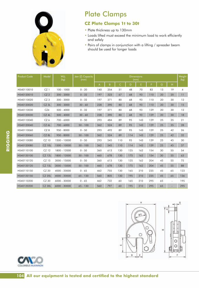
104
RIG
GIN
G
Plate ClampsCZ Plate Clamps 1t to 30t• Plate thickness up to 130mm
• Loads lifted must exceed the minimum load to work efficiently and safely
• Pairs of clamps in conjunction with a lifting / spreader beam should be used for longer loads
Product Code Model WLL (kg)
Jaw (Z) Capacity(mm)
Dimensions (mm)
Weight(kg)
A B C D E F G H
H540110010 CZ 1 100 - 1000 0 - 20 140 254 51 48 70 83 13 19 4
H540120010 CZ 2 200 - 2000 0 - 32 197 323 67 68 93 110 20 20 11
H540110020 CZ 3 300 - 3000 0 - 32 197 371 80 68 93 110 20 30 12
H540120020 CZ 3L 300 - 3000 30 - 60 228 390 80 68 93 110 20 30 15
H540110030 CZ4 500 - 4000 0 - 32 197 371 80 68 93 129 20 30 12
H540120030 CZ 4L 500 - 4000 30 - 60 228 390 80 68 93 129 20 30 18
H540110040 CZ 6 700 - 6000 0 - 50 293 484 89 95 143 129 25 35 21
H540120040 CZ 6L 700 - 6000 50 - 100 362 524 89 95 143 129 25 35 28
H540110060 CZ 8 950 - 8000 0 - 50 293 492 89 95 143 129 25 42 26
H540120060 CZ 8L 950 - 8000 50 - 100 362 524 89 114 143 129 25 42 32
H540110080 CZ 10 1500 - 10000 0 - 50 293 545 110 95 143 139 25 45 30
H540120080 CZ 10L 1500 - 10000 50 - 100 362 545 110 114 143 139 25 45 37
H540110100 CZ 12 1800 - 12000 0 - 50 360 613 130 125 162 154 30 55 54
H540120100 CZ 12L 1800 - 12000 50 - 100 460 678 130 175 162 154 30 55 63
H540110120 CZ 15 3000 - 15000 0 - 50 360 613 130 125 162 204 45 55 75
H540120120 CZ 15L 3000 - 15000 50 - 100 460 678 130 175 162 204 45 55 88
H540110150 CZ 20 4000 - 20000 0 - 65 462 755 130 165 210 235 45 65 123
H540120150 CZ 20L 4000 - 20000 65 - 130 560 805 130 195 210 235 45 65 136
H540110200 CZ 30 6000 - 30000 0 - 65 462 732 60 165 210 295 65 - 195
H540120200 CZ 30L 6000 - 30000 65 - 130 560 797 60 195 210 295 65 - 295
All our equipment is tested and certified to the highest standard

www.lgh.co.uk | 03704 247 247 105
RIG
GIN
G
Product Code Model Nominal Lifting Capacity* (kg) Minimum Thickness
(mm)
Round Material Dia.min / max (mm)
Length x Width(mm)
Material Dia.Lifting Eye
(mm)
Weight (kg)
Flat Material Round Material
H633010150 NEO150 150 65 2 40 - 100 93 x 60 10 3.0
H633010300 NEO300 300 150 4 60 - 200 152 x 100 16 10.0
H633010600 NEO600 600 300 6 65 - 270 246 x 120 20 21.0
H633011000 NEO1000 1000 500 10 100 - 300 306 x 146 20 40.0
H633011500 NEO1500 1500 750 15 150 - 350 410 x 165 20 66.0
H633012000 NEO2000 2000 1000 15 150 - 350 480 x 165 20 90.0
Product Code Model Nominal Lifting Capacity* (kg) Base Length x Width(mm)
Height to Crane Hook (mm)
Weight (kg)
Flat Material Round Material
H633021350 BM1350 1350 - 272 x 242 460 60.0
H633022500 BM2500 2500 - 400 x 242 460 72.0
H633023600 BM3600 3600 - 1050 x 240 460 180.0
H633025000 BM5000 5000 - 1200 x 300 460 203.0
H633021800 BMP1800 1800 1100 470 x 242 610 167.0
H633023601 BMP3600 3600 2200 760 x 262 610 420.0
Lifting MagnetsPermanent Lifting Magnets - Up to 2t Capacity
The BUX™ NEO range is ideal for lifting and transportation of loads up to 2000kgs. The NEO range of magnets are manually actuated for individual use.
• The only magnet on the market to safely lift thin plate
• Single handed switching operation
• Lock plate design for on/off position
• Extremely compact, robust and low maintenance
• Powerful Neodymium magnets ensure a maximum lifting capacity on uneven and rough contact surfaces
Battery Powered Lifting Magnets
The BUX™ Battery magnet range is ideal for lifting and transportation of loads up to 5000kgs.
• Self-contained lifting magnet
• BM3600 specifically designed for handling sheets
• Handling of loads with poor accessibility (remote control)
• Hand-held IR remote control unit allows operation from up to 10m
• Handling sheets, wherein using the tip-off tool allows to drop excess plates in case multiple plates are picked up from the stack
*Performance rating on ground, 50mm thick S235 JR/AISI 1020 steel plateWLL Performance: Nominal lift capacity includes a safety factor of at least 3. Capacity varies with workpiece material thickness and surface quality
*Performance rating on ground, 50mm thick S235 JR/AISI 1020 steel plate

106
RIG
GIN
G
Product Code Model Working Load
Limit (t)
Body dia (mm)
Pin Dia. (mm)
Eye Dia. (mm)
Inside Width(mm)
Inside Length(mm)
Bow Width (mm)
Weight Each (kg)
H550200005 Screw0.5 7 8 16.5 12 29 20 0.06
H550210005 Safety
H550200007 Screw0.75 9 10 20 13.5 32 22 0.11
H550210007 Safety
H550200010 Screw1 10 11 22.5 17 36.5 26 0.16
H550210010 Safety
H550200015 Screw1.5 11 13 26.5 19 43 29 0.22
H550210015 Safety
H550200020 Screw2 13.5 16 34 22 51 32 0.42
H550210020 Safety
H550200032 Screw3.25 16 19 40 27 64 43 0.74
H550210032 Safety
H550200047 Screw4.75 19 22 46 31 76 51 1.2
H550210047 Safety
H550200065 Screw6.5 22 25 52 36 83 58 1.8
H550210065 Safety
H550200085 Screw8.5 25 28 59 43 95 68 2.6
H550210085 Safety
H550200095 Screw9.5 28 32 66 47 108 75 3.7
H550210095 Safety
H550200120 Screw12 32 35 72 51 115 83 4.9
H550210120 Safety
H550200135 Screw13.5 35 38 80 57 133 92 6.5
H550210135 Safety
H550200170 Screw17 38 42 88 60 146 99 8.2
H550210170 Safety
H550200250 Screw25 45 50 103 74 178 126 14.2
H550210250 Safety
H550200350 Screw35 50 57 111 83 197 138 19.9
H550210350 Safety
H550200425 Screw42.5 57 65 130 95 222 160 28.3
H550210425 Safety
H550200550 Screw55 65 70 145 105 260 180 39.6
H550210550 Safety
H550200850 Screw85 75 83 162 127 329 190 62.0
H550210850 Safety
Alloy Bow ShacklesStandard Green Pin Alloy Shackles• Body and pin high tensile steel, Grade 6, quenched and tempered
• Screw pin and Safety pin options
• Safety Factor: MBL equals 6 x WLL
• Hot dipped galvanised
• Temp -20°C to 200°C
• EC declaration of conformity. (Upon request basic raw material cert, manufacturer test cert, inspection cert & DNV cert.)
LGH - The authority in lifting

www.lgh.co.uk | 03704 247 247 107
RIG
GIN
G
Heavy Duty Bow ShacklesHeavy Duty Green Pin Bow Shackle• Body and pin high tensile steel, Grade 8, quenched and tempered
• Safety Factor: MBL equals 5 x WLL
• EC declaration of conformity
• Plus 5% forging tolerance on inside width and length
Wide Body Sling Shackles• Bow and pin alloy steel, grade 8, quenched and tempered
• Safety Factor: MBL equals 5 x WLL
• Temperature Range: -20˚C up to +200˚C
• Wide body profile to protect slings
Product Code Working Load Limit
(t)
Body Dia. (mm)
Pin Dia. (mm)
Eye Dia. (mm)
Inside Width (mm)
Inside Length (mm)
Bow Width (mm)
Overall Length (mm)
Bolt Length (mm)
Overall Width (mm)
Weight Each (kg)
H550211200 120 95 95 208 147 400 238 667 440 428 110.0
H550211500 150 105 108 238 169 410 275 688 490 485 160.0
Product Code Working Load Limit
(t)
Body Dia. (mm)
Pin Dia. (mm)
Eye Dia.
(mm)
Inside Width (mm)
Inside Length (mm)
Bow Width (mm)
Overall Length (mm)
Bolt Length (mm)
Overall Length (mm)
Weight Each (kg)
H550220075 75 68 70 125 110 290 185 473 327 317 48
H550220125 125 85 80 154 137 366 220 583 426 390 92
H550220150 150 94 95 179 147 391 253 645 435 434 140
H550220200 200 110 105 199 158 481 280 759 470 482 205
H550220250 250 126 120 227 179 542 300 859 519 530 264
H550220300 300 135 134 245 195 601 350 947 575 620 360
H550220400 400 160 160 293 231 576 370 985 675 690 580
H550220500 500 170 180 328 263 681 450 1131 748 790 780
H550220600 600 190 200 348 289 741 490 1234 809 865 980
H550220700 700 200 215 392 315 751 540 1284 879 901 1360
H550220800 800 218 230 420 342 851 554 1426 942 947 1430
H550220900 900 242 255 466 368 851 580 1488 1023 1023 1650
H550221000 1000 260 270 490 399 851 614 1532 1103 1107 2970
H550221250 1250 285 300 510 452 931 650 1666 1227 1182 3700
H550221550 1550 285 320 550 483 950 680 1710 1300 1253 4000
*These sizes are utilised for the digital load indicators on page 116

108
RIG
GIN
G
Super Alloy ShacklesPolar/Super Green Pin Alloy Shackle • Body and pin high tensile steel, Grade 8, quenched and tempered
• Safety Factor: MBL equals 5 x WLL
• EN 13889 & meets performance requirements of US Fed Spec RR-C-271,Type IVA Class 3, Grade B
• Hot dipped galvanised
• Temp -40°C to 200°C
• EC declaration of conformity. (Upon request basic raw material cert, manufacturer test cert & works cert.)
Product Code Working Load Limit
(t)
Body Dia. (mm)
Pin Dia. (mm)
Eye Dia. (mm)
Inside Width (mm)
Inside Length (mm)
Bow Width (mm)
Overall Length (mm)
Bolt Length(mm)
Overall Width (mm)
Weight Each (kg)
H550230033 3.3 13.5 16 34 22 51 32 89 82 58 0.5
H550230050 5 16 19 40 27 64 43 110 98 75 0.8
H550230070 7 19 22 46 31 76 51 129 114 89 1.3
H550230095 9.5 22 25 52 36 83 58 144 130 102 1.9
H550230125 12.5 25 28 59 43 95 68 164 150 118 2.8
H550230150 15 28 32 66 47 108 75 185 166 131 3.9
H550230180 18 32 35 72 51 115 83 201 178 147 5.2
H550230210 21 35 38 80 57 133 92 227 197 162 6.9
H550230300 30 38 42 88 60 146 99 249 202 175 8.8
H550230400 40 45 50 103 74 178 126 300 249 216 15.0
H550230550 55* 57 57 117 83 197 138 341 286 252 22.7
H550230850 85* 70 70 143 105 260 180 437 344 320 43.2
H550231200 120* 83 83 162 127 329 190 535 403 356 70.5
H550231500 150* 95 95 208 147 400 238 647 511 428 110.0
H550231750 175 105 108 238 169 410 275 688 561 485 160.0
Delivering excellence in lifting throughout the UK
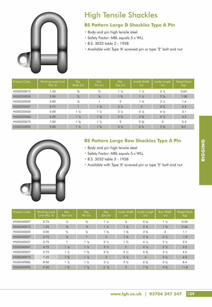
www.lgh.co.uk | 03704 247 247 109
RIG
GIN
G
High Tensile ShacklesBS Pattern Large D Shackles Type A Pin• Body and pin high tensile steel
• Safety Factor: MBL equals 5 x WLL
• B.S. 3032 table 2 - 1958
• Available with Type ‘A’ screwed pin or type ‘E’ bolt and nut
Product Code Working Load Limit WLL (t)
Dia. Body (in)
Dia. Pin (in)
Dia. Eye (in)
Inside Width (in)
Inside Length (in)
Weight Each (kg)
H550220015 1.50 5/8 3/4 1 1/2 1 1/4 2 1/2 0.63
H550220020 2.00 3/4 7/8 1 3/4 1 1/2 2 7/8 1.00
H550220030 3.00 7/8 1 2 1 3/4 3 1/4 1.6
H550220037 3.75 1 1 1/8 2 1/4 2 3 3/4 2.2
H550220050 5.00 1 1/8 1 1/4 2 1/2 2 1/8 4 1/8 3.1
H550220060 6.00 1 1/4 1 3/8 2 3/4 2 3/8 4 1/2 4.3
H550220070 7.00 1 3/8 1 1/2 3 2 5/8 5 5.3
H550220095 9.50 1 1/2 1 3/4 3 1/2 2 3/4 5 3/8 8.5
BS Pattern Large Bow Shackles Type A Pin • Body and pin high tensile steel
• Safety Factor: MBL equals 5 x WLL
• B.S. 3032 table 3 - 1958
• Available with Type ‘A’ screwed pin or type ‘E’ bolt and nut
Product Code Working Load Limit WLL (t)
Dia.Bow (in)
Dia.Pin (in)
Dia.Eye (in)
Inside Width (in)
Inside Length (in)
Bow Width (in)
Weight Each (kg)
H550240007 0.75 1/2 5/8 1 1/4 7/8 2 1/8 1 1/4 0.34
H550240012 1.25 5/8 3/4 1 1/2 1 1/8 2 3/4 1 5/8 0.65
H550240020 2.00 3/4 7/8 1 3/4 1 3/8 3 3/8 2 1.1
H550240027 2.75 7/8 1 2 1 5/8 3 7/8 2 1/4 1.8
H550240037 3.75 1 1 1/8 2 1/4 1 3/4 4 1/4 2 1/2 2.5
H550240047 4.75 1 1/8 1 1/4 2 1/2 2 4 7/8 2 7/8 3.5
H550240057 5.75 1 1/4 1 3/8 2 3/4 2 1/4 5 3/8 3 1/4 4.6
H550240072 7.25 1 3/8 1 1/2 3 2 1/2 6 3 1/2 6.0
H550240085 8.50 1 1/2 1 3/4 3 1/2 2 3/4 6 5/8 3 7/8 8.4
H550240095 9.50 1 5/8 1 7/8 3 3/4 3 7 3/8 4 3/8 11.8

110
RIG
GIN
G
Lifting PointsVRS Starpoint • Clearly marked with the minimum (worst case) WLL for all
loading directions• Fitted with ICE bolt• Starpoint adjusts to the direction of pull• Distinctive design ensures this product is not mistaken for inferior
type standard eyebolts• Metric coarse threads supplied as standard – Metric fine, UNC,
UNF also available
0.1t 0.3t 0.4t 0.75t 1.5t 2.3t 3.2t 4.5t 7t 9t 12t Capacity
M6 M8 M10M12 M16 M20 M24 M30
M36 M42 M48 Thread sizeM14 M18 M22 M27 M33
1/4" 5/16" 3/8" 1/2" 5/8" 3/4" 1"-1 1/8" 1 1/4"1
1/2"1
3/4"2" Angle
Number of Legs
Mode
0.5 1.0 1.0 2.0 4.0 6.0 8.0 12.0 16.0 24.0 32.0 0° 1
1.0 2.0 2.0 4.0 8.0 12.0 16.0 24.0 32.0 48.0 64.0 0° 2
0.1 0.3 0.4 0.75 1.5 2.3 3.2 4.5 7.0 9.0 12.0 90° 1
0.2 0.6 0.8 1.5 3.0 4.6 6.4 9.0 14.0 18.0 24.0 90° 2
0.14 0.42 0.56 1.0 2.1 3.22 4.48 6.3 9.8 12.6 16.8 0-45° 2
0.1 0.3 0.4 0.75 1.5 2.3 3.2 4.5 7.0 9.0 12.0 45-60° 2
0.1 0.3 0.4 0.75 1.5 2.3 3.2 4.5 7.0 9.0 12.0Non
symmetrical2
0.21 0.63 0.84 1.6 3.15 4.83 6.7 9.4 14.7 18.9 25.2 0-45° 3+4
0.15 0.45 0.6 1.12 2.25 3.45 4.8 6.7 10.5 13.5 18.0 45-60° 3+4
0.1 0.3 0.4 0.75 1.5 2.3 3.2 4.5 7.0 9.0 12.0Non
symmetrical3+4
Further thread types and special lengths on request
G
G
G
G
G
G
G
G
G
G
G
G
G
G
G
G
G
G
G
G
G
G
G
G
G
G
G
G
G
G
G
G
G
G
G
G
G
G
G
G
G
G
G
G
G
G
G
G
G
G
G
G
G
G
G
G
G
G
G
G
G
G
G
G
LGH - puts safety first

www.lgh.co.uk | 03704 247 247 111
RIG
GIN
G
Product Code Model WLL F (t)
Dimensions(mm)
Weight (kg)
A B C E G K L M N S
S880010006 VRS-M6 0.1 27 9 7 23 28 37 9 6 6 13 0.06
S880010008 VRS-M8 0.3 34 11 8.5 25 32 47 12 8 6 16 0.1
S880010010 VRS-M10 0.4 34 11 8.5 25 32 47 15 10 6 16 0.1
S880010012 VRS-M12 0.75 42 13 10 30 34 56 18 12 8 20 0.2
S880010014 VRS-M14 0.75 42 13 10 30 34 56 18 14 8 20 0.2
S880010016 VRS-M16 1.5 49 15 14 35 40 65 24 16 10 23.5 0.3
S880010018 VRS-M18 1.5 49 15 15 35 40 65 24 18 10 23.5 0.3
S880010020 VRS-M20 2.3 57 17 16 42 50 75 30 20 12 29 0.5
S880010022 VRS-M22 2.3 57 17 16 42 50 75 30 22 12 29 0.5
S880010024 VRS-M24 3.2 70 21 19 50 60 90 36 24 14 35 0.9
S880010027 VRS-M27 3.2 70 21 19 48 60 90 36 27 14 35 0.9
S880010030 VRS-M30 4.5 86 26 24 60 75 112 45 30 17 44 1.7
S880010033 VRS-M33 4.5 86 36 24 60 75 112 45 33 17 41.5 1.8
S880010036 VRS-M36 7.0 103 32 29 75 90 135 54 36 22 53 2.9
S880010042 VRS-M42 9.0 120 38 34 85 105 158 63 42 24 61.5 4.6
S880010048 VRS-M48 12.0 137 43 38 100 120 180 72 48 27 70.5 7.0
S880020006 VRS - 1/4”- 20UNC 0.1 27.5 9 7 23 27 37 9 1/4” 7/32” 13 0.06
S880020008 VRS - 5/16”- 18UNC 0.3 34 11 8.5 25 28 47 12 5/16” 1/4” 14 0.1
S880020010 VRS - 3/8”- 16UNC 0.4 34 11 8.5 25 28 47 15 3/8” 1/4” 15 0.1
S880020011 VRS - 7/16”- 14UNC 0.4 34 11 8.5 25 28 47 15 7/16” 1/4” 15 0.12
S880020013 VRS - 1/2”- 13UNC 0.75 42 13 10 30 34 56 18 1/2” 5/16” 18 0.2
S880020016 VRS - 5/8”- 11UNC 1.5 49 15 14 35 40 65 24 5/8” 3/8” 22 0.3
S880020020 VRS - 3/4”- 10UNC 2.3 57 17 16 40 50 75 30 3/4” 1/2” 27.5 0.5
S880020022 VRS - 7/8”- 9UNC 2.3 57 17 16 40 50 75 32 7/8” 1/2” 27.5 0.6
S880020024 VRS - 1”- 8UNC 3.2 69 21 19 48 60 90 36 1” 9/16” 33 0.9
S880020030 VRS - 1 1/4”- 7UNC 4.5 86 26 24 60 75 112 45 1 1/4” 5/8” 41.5 1.7
S880020036 VRS - 1 1/2”- 6UNC 7.0 103 32 29 75 90 135 54 1 1/2” 7/8” 49.5 2.9
S880020045 VRS - 1 3/4”- 5UNC 9.0 120 38 34 85 105 158 63 1 3/4” 1” 58 4.6
S880020050 VRS - 2”- 4.5UNC 12.0 137 43 38 100 120 180 72 2” 1 1/8” 66 7.0

112
RIG
GIN
G
Lifting RingsVLBG Plus Load Ring• Clearly marked with the minimum (worst case) WLL for all
loading directions
• Lifting point rotates through 360º
• Suspension ring pivots through 180º
• ICE bolt
• Metric coarse threads supplied as standard – Metric fine, UNC, UNF also available
• Variable bolt lengths available for tapped or through holes
0.63t 0.9t 1.35t 1.2t 2t 2t 3.5t 4.5t 6.7t 8t 10t 15t 20t Capacity
M8 M10 M12 M14 M16 M18 M20 M24 M30 M36 M42 M42 M48 Thread size
3/8" 1/2" 5/8" 3/4" 1"1
1/4"1
1/2"2" Angle
Number of Legs
Mode
0.63 0.9 1.35 1.2 2.0 2.0 3.5 4.5 6.7 8.0 10.0 15.0 20.0 0° 1
1.26 1.8 2.7 2.4 4.0 4.0 7.0 9.0 13.4 16.0 20.0 30.0 40.0 0° 2
0.63 0.9 1.35 1.2 2.0 2.0 3.5 4.5 6.7 8.0 10.0 15.0 20.0 90° 1
1.26 1.8 2.7 2.4 4.0 4.0 7.0 9.0 13.4 16.0 20.0 30.0 40.0 90° 2
0.88 1.3 1.9 1.68 2.8 2.8 4.9 6.3 9.4 11.2 140 21.0 28.0 0-45° 2
0.63 0.9 1.35 1.2 2.0 2.0 3.5 4.5 6.7 8.0 10.0 15.0 20.0 45-60° 2
0.63 0.9 1.35 1.2 2.0 2.0 3.5 4.5 6.7 8.0 10.0 15.0 20.0Non
symmetrical2
1.32 1.9 2.8 2.52 4.2 4.2 7.4 9.5 14.2 16.8 21.0 31.5 42.0 0-45° 3+4
0.95 1.35 2.0 1.8 3.0 3.0 5.25 6.75 10 12.0 15.0 22.5 30.0 45-60° 3+4
0.63 0.9 1.35 1.2 2.0 2.0 3.5 4.5 6.7 8.0 10.0 15.0 20.0Non
symmetrical3+4
Further thread types and special lengths on request
G
G
G
G
G
G
G
G
G
G
G
G
G
G
G
G
G
G
G
G
G
G
G
G
G
G
G
G
G
G
G
G
G
G
G
G
G
G
G
G
G
G
G
G
G
G
G
G
G
G
G
G
G
G
G
G
G
G
G
G
G
G
G
G
Safety, Certainty, Great Service

www.lgh.co.uk | 03704 247 247 113
RIG
GIN
G
Standardtype
Max. length with washer and nut
Product Code Model WLL (t)
Dimensions (mm)
H stand.
H max.
Dimensions (mm)
L stand.
L max.
Dimensions (mm)
Weight (kg)
A B C D E F G J K M N SW R T DB
S880110008 VLBG - M8 0.63 30 54 34 35 40 10 29 11 76 75 45 40 105 8 5 13 32 75 24 0.3
S880110010 VLBG - M10 0.9 30 54 34 36 39 10 29 16 96 75 45 45 125 10 6 17 32 75 24 0.32
S880110012 VLBG - M12 1.35 32 54 34 37 38 10 29 21 116 75 45 50 145 12 8 19 32 75 26 0.33
S880110014 VLBG - M16 2.0 33 56 36 46 39 13.5 36 24 149 86 47 60 185 16 10 24 38 85 30 0.55
S880110016 VLBG - M20 3.5 50 82 54 55 55 16.5 43 32 187 113 64 75 230 20 12 30 48 110 45 1.3
S880110018 VLBG - M24 4.5 50 82 54 58 67 18 43 37 222 130 78 80 265 24 14 36 48 125 45 1.5
S880110020 VLBG - M30 6.7 60 103 65 80 67 22.5 61 49 279 151 80 110 340 30 17 46 67 147 60 3.3
S880110024 VLBG - M36 8.0 77 122 82 100 97 26.5 77 63 223 205 110 140 300 36 22 55 87 197 70 6.2
S880110027 VLBG - M42 10.0 77 122 82 103 94 26.5 77 73 273 205 110 150 350 42 24 65 87 197 70 6.7
S880110030 VLBG - M42 15.0 95 156 100 113 109 36 87 63 263 230 130 150 350 42 24 65 100 222 85 11.2
S880110036 VLBG - M48 20.0 95 156 100 117 105 36 87 73 303 230 130 160 390 48 27 75 100 222 95 11.6
S880110043 VLBG - 3/8” - 16UNC
0.63 30 54 34 36 39 10 29 16 96 75 45 45 125 3/8” 1/4” 9/16” 32 75 24 0.32
S880110048 VLBG - 1/2” - 13UNC
1.0 32 54 34 38 37 10 29 22 121 75 45 50 150 1/2” 5/16” 3/4” 32 75 26 0.33
S880130016 VLBG - 5/8” - 11UNC
1.5 33 56 36 46 38 13.5 36 24 148 87 47 60 184 5/8” 3/8” 15/16” 38 85 30 0.55
S880130018 VLBG - 3/4” - 10UNC
2.5 50 82 54 56 54 16.5 43 28 187 113 64 71 230 3/4” 1/2” 11/8” 48 110 45 1.3
S880120010 VLBG - 7/8” - 9UNC
2.5 50 82 54 58 52 16.5 43 27 211 113 64 70 254 7/8” 1/2” 15/16” 48 110 45 1.3
S880120012 VLBG - 1” - 8UNC
4.0 50 82 54 61 64 18 43 41 211 130 78 84 254 1” 9/16” 11/2” 48 125 45 1.5
S880120016 VLBG - 11/4” - 7UNC
5.0 60 103 65 80 64 22.5 61 41 279 151 80 102 340 11/4” 5/8” 17/8” 67 147 60 3.3
S880120020 VLBG - 11/2” - 6UNC
8.0 77 122 82 100 97 26.5 77 39 270 205 110 116 347 11/2” 7/8” 21/4” 87 197 70 6.2
S880120021 VLBG - 2” - 4 1/2UNC
20.0 95 156 100 117 105 36 87 77 303 230 130 164 390 2” 11/8” 3” 100 222 95 11.6
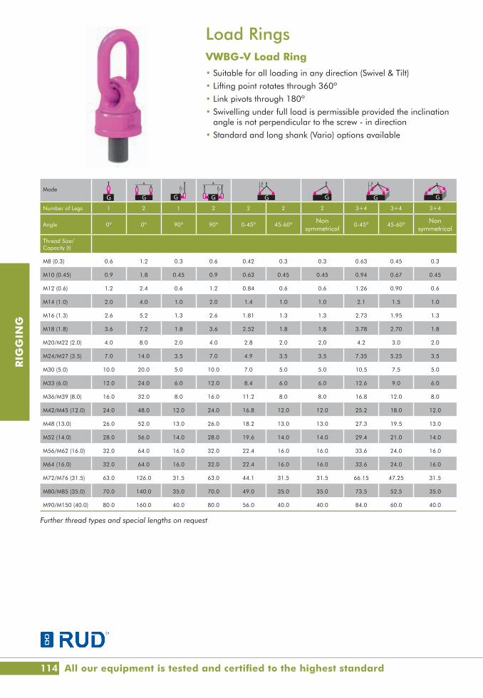
114
RIG
GIN
G
Load RingsVWBG-V Load Ring• Suitable for all loading in any direction (Swivel & Tilt)
• Lifting point rotates through 360º
• Link pivots through 180º
• Swivelling under full load is permissible provided the inclination angle is not perpendicular to the screw - in direction
• Standard and long shank (Vario) options available
Mode
Number of Legs 1 2 1 2 2 2 2 3+4 3+4 3+4
Angle 0º 0º 90º 90º 0-45º 45-60ºNon
symmetrical0-45º 45-60º
Nonsymmetrical
Thread Size/Capacity (t)
M8 (0.3) 0.6 1.2 0.3 0.6 0.42 0.3 0.3 0.63 0.45 0.3
M10 (0.45) 0.9 1.8 0.45 0.9 0.63 0.45 0.45 0.94 0.67 0.45
M12 (0.6) 1.2 2.4 0.6 1.2 0.84 0.6 0.6 1.26 0.90 0.6
M14 (1.0) 2.0 4.0 1.0 2.0 1.4 1.0 1.0 2.1 1.5 1.0
M16 (1.3) 2.6 5.2 1.3 2.6 1.81 1.3 1.3 2.73 1.95 1.3
M18 (1.8) 3.6 7.2 1.8 3.6 2.52 1.8 1.8 3.78 2.70 1.8
M20/M22 (2.0) 4.0 8.0 2.0 4.0 2.8 2.0 2.0 4.2 3.0 2.0
M24/M27 (3.5) 7.0 14.0 3.5 7.0 4.9 3.5 3.5 7.35 5.25 3.5
M30 (5.0) 10.0 20.0 5.0 10.0 7.0 5.0 5.0 10.5 7.5 5.0
M33 (6.0) 12.0 24.0 6.0 12.0 8.4 6.0 6.0 12.6 9.0 6.0
M36/M39 (8.0) 16.0 32.0 8.0 16.0 11.2 8.0 8.0 16.8 12.0 8.0
M42/M45 (12.0) 24.0 48.0 12.0 24.0 16.8 12.0 12.0 25.2 18.0 12.0
M48 (13.0) 26.0 52.0 13.0 26.0 18.2 13.0 13.0 27.3 19.5 13.0
M52 (14.0) 28.0 56.0 14.0 28.0 19.6 14.0 14.0 29.4 21.0 14.0
M56/M62 (16.0) 32.0 64.0 16.0 32.0 22.4 16.0 16.0 33.6 24.0 16.0
M64 (16.0) 32.0 64.0 16.0 32.0 22.4 16.0 16.0 33.6 24.0 16.0
M72/M76 (31.5) 63.0 126.0 31.5 63.0 44.1 31.5 31.5 66.15 47.25 31.5
M80/M85 (35.0) 70.0 140.0 35.0 70.0 49.0 35.0 35.0 73.5 52.5 35.0
M90/M150 (40.0) 80.0 160.0 40.0 80.0 56.0 40.0 40.0 84.0 60.0 40.0
Further thread types and special lengths on request
G
G
G
G
G
G
G
G
G
G
G
G
G
G
G
G
G
G
G
G
G
G
G
G
G
G
G
G
G
G
G
G
G
G
G
G
G
G
G
G
G
G
G
G
G
G
G
G
G
G
G
G
G
G
G
G
G
G
G
G
G
G
G
G
All our equipment is tested and certified to the highest standard

www.lgh.co.uk | 03704 247 247 115
RIG
GIN
G
Product Code Model Dimensions (mm)
A B C D F stand F vario G K M I
S880210008 VWBG - V M8 (0.3) 8 31 29 30 13 8-102 - 28 8 76
S880210010 VWBG - V M10 (0.45) 8 31 29 36 17 10-122 - 30 10 78
S880210012 VWBG - V M12 (0.6) 10 49 35 42 21 12-140 - 36 12 107
S880210014 VWBG - V M14 (1.0) 13 46 38 48 21 14-65 - 41 14 113
S880210016 VWBG - V M16 (1.3) 13 46 38 48 25 16-180 - 41 16 113
S880210018 VWBG - V M18 (1.8) 13 54 35 62 27 18-83 - 55 18 137
S880210020 VWBG - V M20 (2.0) 13 54 35 62 33 20-223 - 55 20 137
S880210022 VWBG - V M22 (2.0) 13 54 35 62 33 22-94 - 55 22 137
S880210024 VWBG - V M24 (3.5) 18 66 40 81 40 24-255 - 70 24 173
S880210027 VWBG - V M27 (3.5) 18 66 40 81 40 27-92 - 70 27 173
S880210030 VWBG - V M30 (5.0) 22 90 50 99 59 30-330 - 85 30 221
S880210033 VWBG M33 (6.0) 22 86 50 90 - 33-300 94 80 33 208
S880210036 VWBG M36 (8.0) 22 86 50 90 54 36-300 94 80 36 208
S880210039 VWBG M39 (8.0) 22 86 50 90 54 36-300 94 80 39 208
S880210042 VWBG M42 (12.0) 26 111 65 98 63 42-300 96 85 42 235
S880210045 VWBG M45 (12.0) 26 111 65 98 67 - 96 85 45 235
S880210048 VWBG M48 (13.0) 26 111 65 98 68 48-300 96 85 48 235
S880210052 VWBG M52 (14.0) 32 119 70 120 78 52-300 120 95 52 274
S880210056 VWBG M56 (16.0) 32 119 70 120 84 56-300 120 95 56 274
S880210062 VWBG M62 (16.0) 32 119 70 120 84 56-300 120 95 62 274
S880210064 VWBG M64 (16.0) 32 119 70 120 94 64-300 120 95 64 274
S880210072 VWBG M72 (31.5) 46 130 90 170 108 72-300 159 145 72 338
S880210076 VWBG M76 ( 31.5) 46 130 90 170 108 72-300 159 145 76 338
S880210080 VWBG M80 (35.0) 46 130 90 170 120 80-300 159 145 80 338
S880210085 VWBG M85 (35.0) 46 130 90 170 120 80-300 159 145 85 338
S880210090 VWBG M90 (40.0) 46 130 90 170 135 90-300 159 145 90 338
S880210150 VWBG M150 (40.0) 46 170 110 170 135 90-300 159 145 150 378
X* Y Z
F var
ioB
Nominal WLL -worst case.Ring not adjusted to pull direction
Manually adjusted - increased WLL -( )-values.
Vertical load (straight pull) - double nominal WLL -
Load direction
X* Y ZB
G
Nominal WLL - worst case. Ring not adjustedto pull direction
Manually adjusted- increased WLL -( )-values.
Vertical load (straight pull)
Load direction
X* Y Z
F var
ioB
Nominal WLL -worst case.Ring not adjusted to pull direction
Manually adjusted - increased WLL -( )-values.
Vertical load (straight pull) - double nominal WLL -
Load direction
X* Y Z
BG
Nominal WLL - worst case. Ring not adjustedto pull direction
Manually adjusted- increased WLL -( )-values.
Vertical load (straight pull)
Load direction
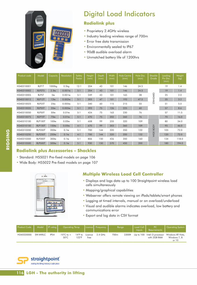
116
RIG
GIN
G
Digital Load Indicators Radiolink plus
• Proprietary 2.4GHz wireless
• Industry leading wireless range of 700m
• Error free data transmission
• Environmentally sealed to IP67
• 90dB audible overload alarm
• Unmatched battery life of 1200hrs
Product code Model Capacity Resolution Safety Factor
Height(mm)
Depth (mm)
Width(mm)
Hole Centre (mm)
Hole Dia. (mm)
Shackle Grade
Loading Pin Dia. (mm)
Weight (kg)
H340310001 RLP1T 1000kg 0.5kg 12:1 204 43 101 146 24.5
STA
ND
ARD
19 1.4
H340310002 RLP2T5 2.5te 0.001te 5:1 204 43 101 146 24.5 19 1.4
H340310005 RLP5T 5te 0.001te 5:1 249 43 101 165 38 25 2.0
H340310012 RLP12T 12te 0.002te 5:1 305 47 101 193 47.5 35 3.2
H340310025 RLP25T 25te 0.005te 5:1 340 60 115 215 55 51 5.0
H340310035 RLP35T 35te 0.005te 5:1 393 75 126 225 60 57 8.6
H340310050 RLP50T 50te 0.01te 5:1 424 75 163 230 76 57 11.5
H340310075 RLP75T 75te 0.01te 5:1 470 75 202 260 76
WID
E BO
DY
70 16.0
H340310100 RLP100T 100te 0.05te 5:1 608 99 255 320 109 80 34.0
H340310150 RLP150T 150te 0.05te 4:1 670 99 303 360 109 95 46.0
H340310200 RLP200T 200te 0.1te 5:1 700 144 320 350 132 105 72.0
H340310250 RLP250T 250te 0.1te 4:1 700 144 320 350 132 120 72.0
H340310300 RLP300T 300te 0.1te 5:1 806 150 426 350 160 134 118.0
H340310500 RLP500T 500te 0.1te 5:1 930 150 570 450 200 180 194.0
Product Code Model IP rating Operating Temp Licence Frequency Range Load Cell Inputs
PC Requirements
Operating System
H340320000 SW-MWLC IP54 -10°C to + 50°C
14°F to 122°F
Licence free
2.4 GHz 700m 2300ft Up to 100 Intel i3 processor with 2GB RAM
Windows XP, Vista, Windows 7, 8
or 10
Multiple Wireless Load Cell Controller • Displays and logs data up to 100 Straightpoint wireless load
cells simultaneously
• Mapping/graphical capabilities
• Webserver offers remote viewing on iPads/tablets/smart phones
• Logging at timed intervals, manual or on overload/underload
• Visual and audible alarms indicates overload, low battery and communications error
• Export and log data in CSV format
Radiolink plus Accessories – Shackles• Standard: H55021 Pre-fixed models on page 106
• Wide Body: H55022 Pre-fixed models on page 107
LGH - The authority in lifting
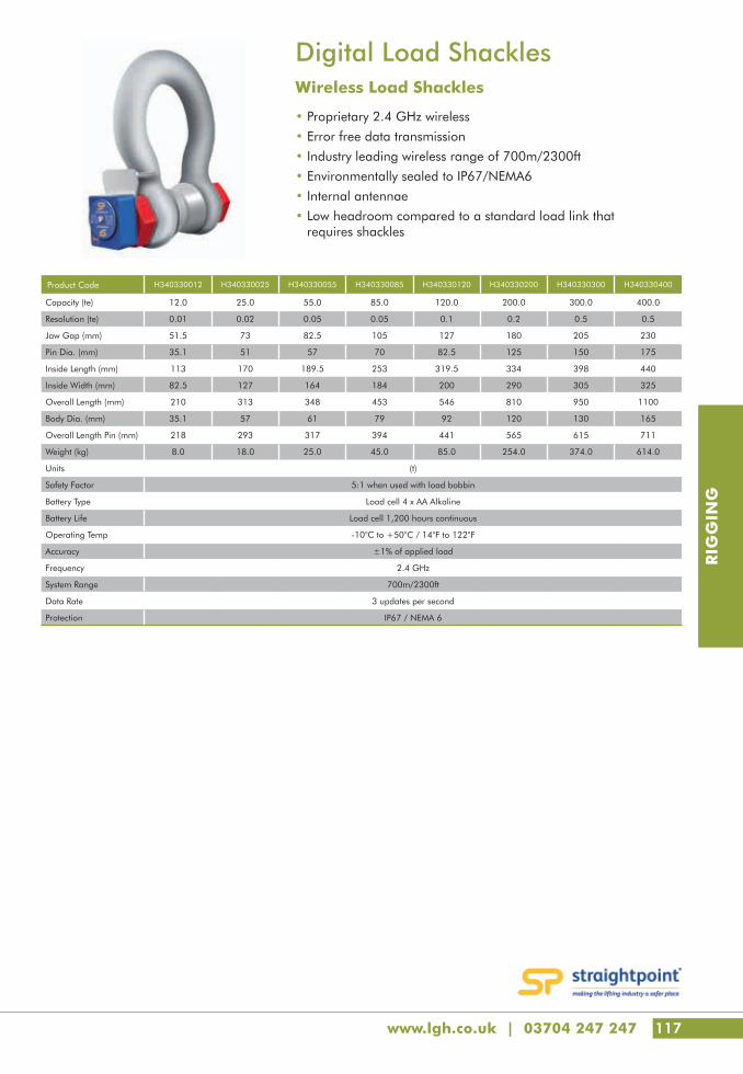
www.lgh.co.uk | 03704 247 247 117
RIG
GIN
G
Digital Load Shackles Wireless Load Shackles
• Proprietary 2.4 GHz wireless
• Error free data transmission
• Industry leading wireless range of 700m/2300ft
• Environmentally sealed to IP67/NEMA6
• Internal antennae
• Low headroom compared to a standard load link that requires shackles
Product Code H340330012 H340330025 H340330055 H340330085 H340330120 H340330200 H340330300 H340330400
Capacity (te) 12.0 25.0 55.0 85.0 120.0 200.0 300.0 400.0
Resolution (te) 0.01 0.02 0.05 0.05 0.1 0.2 0.5 0.5
Jaw Gap (mm) 51.5 73 82.5 105 127 180 205 230
Pin Dia. (mm) 35.1 51 57 70 82.5 125 150 175
Inside Length (mm) 113 170 189.5 253 319.5 334 398 440
Inside Width (mm) 82.5 127 164 184 200 290 305 325
Overall Length (mm) 210 313 348 453 546 810 950 1100
Body Dia. (mm) 35.1 57 61 79 92 120 130 165
Overall Length Pin (mm) 218 293 317 394 441 565 615 711
Weight (kg) 8.0 18.0 25.0 45.0 85.0 254.0 374.0 614.0
Units (t)
Safety Factor 5:1 when used with load bobbin
Battery Type Load cell 4 x AA Alkaline
Battery Life Load cell 1,200 hours continuous
Operating Temp -10°C to +50°C / 14°F to 122°F
Accuracy ±1% of applied load
Frequency 2.4 GHz
System Range 700m/2300ft
Data Rate 3 updates per second
Protection IP67 / NEMA 6

118
RIG
GIN
G
Eyebolt TesterHydrajaws Model 2000• The Model 2000 pull-out tester is a purpose made kit for testing
eyebolts and threaded anchors up to M20
• It allows for accurate proof testing and validating of anchors and eyebolts up to 25kN
• The resulting load value is indicated on the dial type analogue gauge or optional digital gauge
Product Code Model Pull-out load
range (kN/lb/f)
Stroke scale (mm)
Effective stroke (mm)
Ranges available Accuracy Working Temperature
Weight
Digital (kN)
Analogue (kN)
Digital (to +/- % fsd)
Analogue (to +/- %
fsd)
Digital (°C)
Analogue (°C)
Tester only (kg)
Packaged weight
(kg)
H340400025 2000 0-25 0-50 50 0-25 0-25 0.5 2.5 -30 to +85
-20 to +60
2.2 8.0
HYDRAJAWSL I M I T E D
• Pull-out load range: 0-25kN/lb/f• Weight Tester: Only 2.2kg
Packaged weight 8kg (will vary)• Stroke scale: 0-50mm• Effective stroke: 50mm• Load gauge: fixed or interchangeable• Casing: Aluminium• Loading jaw pivotable through 360° with spring return• Operating handle standard size with integrated
22mm operating nut for confined spaces
• Bolt Tester Adaptor• 6x Threaded button adaptors M4 - M12• 6x Slotted button adaptors 4.5mm to 12.5mm• M16 and M20 Threaded Stud Adaptor• Turning Handle with 22mm integrated nut (for use
in confined spaces)• M12 Ringbolt Adaptor Clevis• 150mm Load Spreading Bridge with 75mm Hex
extension legs with 25mm of threaded adjustment• Calibration certificate (valid for 12 months)• Robust carry case
Load Gauges• Ranges available: Digital: 0-25kN Analogue: 0-25kN.• Accuracy: Analogue to +/-2.5% fsd Digital to +/-
0.5% fsd• Indication of pull-out load• Calibrated in kN• Traceable UKAS calibration certificate supplied with
each gauge• Protective rubber cover (analogue only)• Impact resistant glass• P rotection against sudden load relief (i.e. sudden failure of fixing)• Analogue and Digital: Peak hold memory• Working Temperature: Analogue: -20°C to +60ºC
Digital: -30°C to +85°C
TECHNICAL SPECIFICATIONS
KIT CONTENTS
Delivering excellence in lifting throughout the UK

www.lgh.co.uk | 03704 247 247 119
RIG
GIN
G
Model 2000 Footprint measurements
For example:
186mm7.3”
92mm3.6”
46mm1.8”93mm
3.7”
115mm4.5”
115mm4.5”
18mm0.7”
Min distance from centre of �xing to wall is 46mm(1.8”)
Tester legs&
Tester body
Model 2000 Footprint measurements
For example:
186mm7.3”
92mm3.6”
46mm1.8”93mm
3.7”
115mm4.5”
115mm4.5”
18mm0.7”
Min distance from centre of �xing to wall is 46mm(1.8”)
Tester legs&
Tester body
HYDRAJAWSL I M I T E D
The 2000 Model gauge can be upgraded to a detachable 30kN digital gauge with Bluetooth capability offering a variety of additional benefits.
• Results are visual and recorded with time, date and GPS location
• Reports can be provided electronically onsite direct from Android or Apple device - saving time and increasing productivity
• Force displacement option for increased data accuracy
BRIDGE FOOTPRINT MEASUREMENTS
HYDRAJAWSDIGITAL

120
RIG
GIN
G
Test Weights & AccessoriesHand Test Weights, Baskets & Trolleys• Ideal for lift testing, the baskets are designed to take 4 x 20kg
hand test weights which with a self-weight also of 20kg provides a precise 100kg total weight
• The test weight trolley is specifically designed to transport a loaded basket with ease
• Lockable baskets also available to prevent removal of individual 20kg test weights
Roller Test Weights (Counterbalanced)• Ideal for general testing
• Counterbalanced handles fitted for ease of lifting and handling
Cheese Weights, Lifting Poles & Beams• Ideal for mid to heavy testing, weights are available in increments
of 500kg & 1000kg
• Lifting poles to suit are available in two models to carry up to 5 (5t) or 10 (10t) weights as required
• For multiple lifts a variety of beam assemblies can be provided bespoke to requirement
Test Weight Cradles & Slab Weights• Ideal for heavy testing to carry a broad range of slab weights to
make up your desired load
• A wide rage of capacities 5t, 25t, 50t, 100t, 200t & 350t
• All provided complete with lifting slings and shackles
Product Code Model
H700100020 Hand Test Weight (20kg)
H700110000 Test Weight Basket (capacity 4 x 20kg weights) / Basket Self Weight 20kg
H700120000 Test Weight Trolley
Product Code Model
H700010050 500kg Cheese Weight
H700011000 1000kg Cheese Weight
H700020001 Lifting Pole to suit up to 5x weights (5,000 kg capacity)
H700020002 Lifting Pole to suit up to 10x weights (10,000 kg capacity)
Product Code Model Dia. (mm) Depth (mm) Height (mm)
H700060250 250kg 455 300 680
H700060500 500kg 555 365 780
LGH - puts safety first

www.lgh.co.uk | 03704 247 247 121
RIG
GIN
G
121MaterialHandling
122 Material Lifts
123 Material Lift Accessories
124 Material Lifts & Gas Hoist
125 Counterbalanced Material Lifts
126 Glass Handling Cranes
127 Glass Handling Attachments
128 Roust-A-Bout & Panel Lifter
129 Skoots & Stairclimbers
130 Trucks & Trolleys
132 Pallet Trucks
134 Stone Handles, Extractors & Clamps
135 Manhole Cover Lifters
136 Forklift Accessories
138 Bumpa Hoists
139 Shifta Conveyors
140 Building Hoists
142 Skips

122
MA
TER
IAL
HA
ND
LIN
G
Material LiftsGenie Superlift AdvantageChoose base, mast height, winch speed & load handling attachments to configure the exact material lift for your work site.• Heavy-duty design• Patented telescoping mast system with mast brake• Rolls easily through single door in upright position• Quick set up requires no tools• Compact design, legs fold up for easy storage• Roller wheels allow easy transport in stowed position• Easy to load and unload on or off a vehicle for transport
Product Code H450010010 H450010015 H450010020 H450010025
Model SLA-10 SLA-15 SLA-20 SLA-25
Measurements Metric Metric Metric Metric
Working Height: Standard Forks - Down 2.97m 4.46m 5.94m 7.42m
Working Height: Standard Forks - Up 3.49m 4.98m 6.46m 7.94m
Working Height: Adjustable Forks - Down 2.97m 4.46m 5.94m 7.42m
Working Height: Adjustable Forks - Up 3.49m 4.98m 6.46m 7.94m
Working Height: Flat Forks 2.97m 4.46m – –
Working Height: Boom 3.28m 4.76m 6.25m 7.42m
Working Height: Load Platform - Forks Down 2.97m 4.46m 5.94m 7.42m
Working Height: Load Platform - Forks Up 3.49m 4.98m 6.46m 7.94m
Height - Stowed 2.0m 2.0m 2.0m 2.0m
Length - Stowed 74cm 74cm 74cm 79cm
Length - Operating 1.51m 1.88m 2.08m 2.08m
Width - Stowed 80cm 80cm 80cm 80cm
Width - With Stabilisers Lowered 1.85m 1.85m 1.85m 1.85m
Width - Straddle Base Minimum 80cm 80cm – –
Width - Straddle Base Maximum 1.47m 1.47m – –
Width - Straddle Base Maximum Inside 1.27m 1.27m – –
Ground Clearance 5cm 5cm 5cm 5cm
Load Height Minimum 15cm 15cm 15cm 15cm
Front Casters 10cm 10cm 10cm 10cm
Rear Casters 13cm 13cm 13cm 13cm
Load Capacity 46cm (18in) Load Centre 454kg 363kg 363kg 295kg
Load Capacity 61cm (24in) Load Centre 454kg 363kg 272kg 204kg
Load Capacity 107cm (42in) Load Centre 181kg 227kg 159kg 113kg
Average Cranks Standard Winch 27.8 cranks/m 27.8 cranks/m 27.8 cranks/m 27.8 cranks/m
Weight Standard 118kg 151kg 184kg 204kg
Weight Straddle Base 137kg 163kg – –
Sales · Parts · Service
A variety of general loads. Get an additional 21in (53cm) of lift by turning over and re-pinning the forks.
Standard Forks (Down)
Safety, Certainty, Great Service

www.lgh.co.uk | 03704 247 247 123
MA
TER
IAL
HA
ND
LIN
G
Material Lift AccessoriesA range of interchangeable load handling attachments to cater for a large variety of requirements to ensure that your Genie SLA is equipped correctly for the job in hand.
Load Handling Attachments
Product Code Model Dimensions L/W/D(mm)
Weight (kg)
H450020001 Boom 1070 x 40 x 165 18.0
H450020002 Pipe Cradle 700 x 620 x 150 4.5
H450020003 Fork Extensions (Attached) 640 x 50 x 80 2.0
H450020004 Adjustable Forks 700 x 760 x 60 24.0
H450020005 Flat Forks 810 x 790 x 38 36.0
H450020006 Load Platform 700 x 580 x 70 14.0
Sales · Parts · Service
Load PlatformFits over the forks to handle odd-sized or heavy objects — no tools required for installation.
Adjustable ForksWiden from 11.5in to 30in (29cm to 76cm) to accommodate diverse loads.
BoomOption transforms your lift into a mobile, vertical crane or hoist to position tooling fixtures, circuit breakers, engines and more.
Flat ForksWiden from 16in to 31in (41cm to 79cm) to provide proper support, allow you to easily lift your load off of flat surfaces.
Fork ExtensionsInsert onto standard forks for an additional 25in (64cm) of length.
Pipe CradleAn ideal accessory for lifting round pipes and/or odd shaped items into position.

124
MA
TER
IAL
HA
ND
LIN
G
Product Code H450030008 H450030010 H450030012
Model GL-8 GL-10 GL-12
A Height - Stowed (mm) 1720 2000 2310
Maximum Forks Down (mm) 2500 3010 3660
Maximum Forks Up (mm) 3060 3560 4200
Minimum Forks Down (mm) 90 50 50
Length - Operating (mm) 720 720 –
Width - Stowed (mm) 730 730 –
Maximum (mm) 1110 1110 –
Maximum Inside (mm) 910 910 –
Load Height Minimum (mm) 90 90 90
Ground Clearance - Centre (mm) 20 20 20
Average Cranks - Standard Winch per mm 38 38 38
Fork Length (mm) 570 570 570
Fork Width (mm) 520 520 520
Load Platform Length (mm) 580 580 580
Load Platform Width (mm) 560 560 560
Load Capacity at 300mm Load Centre (kg) 181 159 159
Boom Length (mm) 510 510 510
Boom Attachment Points (mm) 340/480 340/480 340/480
Weight - Standard Caster Options (kg) 186.0 196.0 –
Material Lifts & Gas HoistGenie GL Lift - Counterweight BaseThree base models and many accessories to choose from.
• The GL-8 that lifts up to 181kg to 3.0m, to the GL-12 that lifts up to 159kg to heights up to 4.2m
• The Genie Lift is well suited for shipping/receiving, lifting heavy material to or from shelves, installing and repairing HVAC components, lifting and moving automotive parts, and other manufacturing applications
• Compact, versatile and easily transported
Genie Gas Hoist
• A unique portable pneumatic lift
• Incredibly compact, easy-to-use design
• This portable telescoping pneumatic hoist uses CO2 or compressed air to lift up to 136kg to heights of 3.8m or up to 113kg up to 5.6m
Product Code Model Height Platform Length (mm)
Width Load Capacity
(kg)
Storage Dimensions
(mm)
Wheels Diameter
(mm)
Recommended psi
(bar)
Weight (kg)
Stowed (mm)
Lift height (mm)
Platform (mm)
Base (mm)
H450040038 GH-3.8 1040 3800 480 610 1.350 136 360 x 360 x 1000 200 5.86 34.0
H450040056 GH-5.6 1370 560 480 610 1.350 113 360 x 360 x 1000 200 5.86 37.0
Sales · Parts · Service
All our equipment is tested and certified to the highest standard

www.lgh.co.uk | 03704 247 247 125
MA
TER
IAL
HA
ND
LIN
G
Product Code H450050010 H450050015 H450050020 H450050025
Model SLK10 SLK15 SLK20 SLK25
Lifting Height - Standard Forks Up (mm) 3500 5000 6500 7900
Height - Stowed (mm) 2040 2040 2040 2040
Length - Stowed (mm) 900 900 960 1020
Length - Working Position (mm) 1500 1800 2220 2220
Width - Stowed (mm) 800 800 800 800
Width - Working Position (mm) 2200 2200 2200 2200
Ground Clearance - Working Position (mm) 80 80 80 80
Loading Height min (mm) 270 270 270 270
Pay Load (kg) 450 360 360 300
Weight Basic Chassis (kg) 118.0 144.0 184.0 204.0
Weight Complete with Counterbalance Weights (kg) 246.0 272.0 312.0 332.0
Counterbalanced Material LiftsSLK• Integral counterweights avoid the need for forward outriggers
allowing the user to bring loads directly to walls or high lying porches
• Ideal for handling awkward loads into place such as window panes and glazing
• Specialist accessories and functionality for handling glass are available on request
• All standard Superlift accessories are available
Heavy Capacity Counterbalanced Material LiftsGML800+• Simple to transport, set up and use• Vastly increased lifting capacity over the standard Superlift range
- up to 900kg dependant on model and load centre position• Integral counterweights avoid the need for forward outriggers
allowing the user to bring loads directly to walls or high lying porches• All standard Superlift accessories are available• Specialist accessories and functionality for handling glass are
available on request
Product Code Model Working Height Standard Forks Up
(mm)
Transport Position Height/Length/Width
(mm)
Working Position Height/Length/Width
(mm)
Safe Working Load (kg)
Weight Chassis + Outriggers
(kg)
H450060010 GML800+/10 3490 1980/1000/0780 1980/1940/0780 900 237.0 - 273.0
H450060015 GML800+/15 4980 1980/1000/0780 1980/1940/0780 850 260.0 - 296.0
H450060020 GML800+/20 6460 1980/1000/0780 1980/1940/0780 850 293.0 - 329.0
H450060025 GML800+/25 7940 1980/1000/0780 1980/1940/0780 800 316.0 - 352.0

126
MA
TER
IAL
HA
ND
LIN
G
Glass Handling CranesMini Floor Crane• Max Capacity 900kg• Max lifting height below the hook 3050mm• Two long outriggers are back-wards mounted and are fitted with
two counterweights boxes containing 14 counterweights each achieves max capacity and lifting height.
LGH - The authority in lifting
Product code Model Transport Position Working Position Loading Height
Min. (mm)
Boom Extention
each Position (mm)
Boom Length Max (mm)
Weight of chassis inc Boom (kg)
Height (mm)
Length (mm)
Width (mm)
Height (mm)
Length (mm)
Width (mm)
H210130750 MFC750/K 1000 - 1920
1200 650 1920 1800 680 850 120 1200 160
Load below the hook (kgs)
MFC 750/K +/L
MFC 750/Ks
Load Chart
900
800
700
600
500
400
300
200
100
52 64 76 88 100
Distance Front Wheels : Hook (cms)

www.lgh.co.uk | 03704 247 247 127
MA
TER
IAL
HA
ND
LIN
G
Glass Handling AttachmentsDSZ2 – 12V Slimliner• Vacuum Glass Lifter based on two circle system
• In the case of a failure in one circle, the second will hold the glass safely in position
• Max Capacity 900kg
DSKE2- 12V Disc Butler• Vacuum Glass Lifter based on two circle system
• In the case of a failure in one circle, the second will hold the glass safely in position
• This system rotates 360˚
Product Code Model Payload Frame Set up Operation Functions Rotate Tilting Include Weight Fits to
H453270450 DSZ2-12V
900kg (with 12 Suction Cups)750kg (with 10 Suction Cups)600kg (with 8 Suction Cups)450kg (with 6 Suction Cups)
6 Suction Cups in 2
rows
6+26+46+6
12V Pump incl.
Charger Unit
Absorb/Detach
by remote control
360˚ manually
90˚ manually
Charger Unit
Cable Remote Control
Approx. 140kg
(with 12 Suction Cups)
MFCSLKGML
Product Code Model Payload Frame Set up Operation Functions Rotate Tilting Include Weight Fits to
H453290450 DSKE2 - 12V
450kg (with 6 Suction Cups)300kg (with 4 Suction Cups)
4 Suction Cups in a
row
4+14+2 in a
Line or Cross Shape
12V Pump incl.
Charger Unit
Absorb/Detach
by remote control
360˚ manually
90˚ manually
Charger Unit
Cable Remote Control Carrier
with Casters
Approx. 60kg
(with 6 Suction Cups)
MFCSLKGML
Awaiting Image
Awaiting Images
Awaiting Images
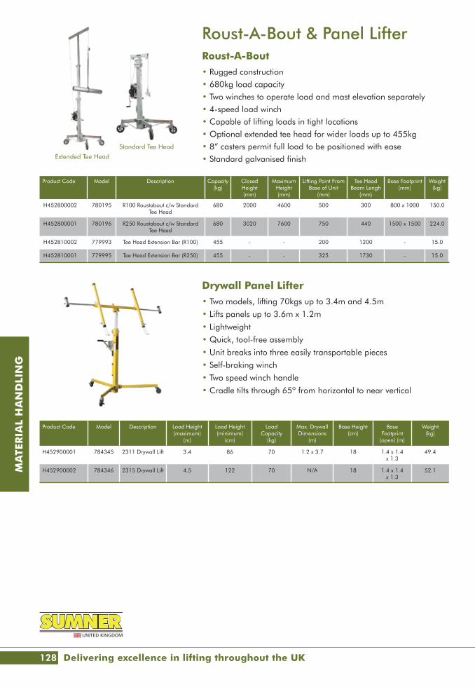
128
MA
TER
IAL
HA
ND
LIN
G
Drywall Panel Lifter• Two models, lifting 70kgs up to 3.4m and 4.5m
• Lifts panels up to 3.6m x 1.2m
• Lightweight
• Quick, tool-free assembly
• Unit breaks into three easily transportable pieces
• Self-braking winch
• Two speed winch handle
• Cradle tilts through 65º from horizontal to near vertical
Roust-A-Bout & Panel LifterRoust-A-Bout• Rugged construction• 680kg load capacity• Two winches to operate load and mast elevation separately• 4-speed load winch• Capable of lifting loads in tight locations• Optional extended tee head for wider loads up to 455kg• 8” casters permit full load to be positioned with ease• Standard galvanised finish
Product Code Model Description Load Height (maximum)
(m)
Load Height (minimum)
(cm)
Load Capacity
(kg)
Max. DrywallDimensions
(m)
Base Height(cm)
Base Footprint
(open) (m)
Weight(kg)
H452900001 784345 2311 Drywall Lift 3.4 86 70 1.2 x 3.7 18 1.4 x 1.4 x 1.3
49.4
H452900002 784346 2315 Drywall Lift 4.5 122 70 N/A 18 1.4 x 1.4 x 1.3
52.1
Product Code Model Description Capacity(kg)
Closed Height(mm)
Maximum Height(mm)
Lifting Point From Base of Unit
(mm)
Tee Head Beam Lengh
(mm)
Base Footprint(mm)
Weight(kg)
H452800002 780195 R100 Roustabout c/w Standard Tee Head
680 2000 4600 500 300 800 x 1000 150.0
H452800001 780196 R250 Roustabout c/w Standard Tee Head
680 3020 7600 750 440 1500 x 1500 224.0
H452810002 779993 Tee Head Extension Bar (R100) 455 - - 200 1200 - 15.0
H452810001 779995 Tee Head Extension Bar (R250) 455 - - 325 1730 - 15.0
Extended Tee Head
Standard Tee Head
Delivering excellence in lifting throughout the UK

www.lgh.co.uk | 03704 247 247 129
MA
TER
IAL
HA
ND
LIN
G
Skoots & StairclimbersSkoots Moving System• Economic, simple, manoeuvrable and safe, Skoots are simple to
operate and requires minimal training
• Secure the load to the eyebolts fitted to the Skoots frame using both straps supplied
• Pump the handle on the hydraulic jack to raise the load
• Move the load into position, using the directional locks on the castor if required
• Lower the load with accuracy using the valve wheel on the jacks
L1 & M1 Stairclimbers• Speeds loading and delivery
• Operates on tight landings
• Eliminates product and premises damage
• Minimises physical effort and strain
• One-man operation reduces manpower
• In-transit charging kit
MTK Series Stairclimbers• Highly portable
• Push button control
• Quick connect safety straps
• Removable battery for easy changing
• Adjustable handle for varying load heights
• One man operation reduces manpower
Product Code Model Maximum Capacity
(kg)
Maximum Height Deck / Dock
(mm)
Toe Plate (mm)
Overall Width (WxDxH)
(mm)
Electronic Charger (V/amp)
Truck Construction
WheelsDia. (mm)
Gel Filled Leak Proof Battery
(V/amp)
Weight (kg)
H410920295 L1 295 840 600x100 610x420x1520 220/240 – 4amp Aluminium 200 12/20 45.0
H410930680 M1 680 840 610x150 685x430x1520 220/240 – 4amp Steel 200 12/30 75.0
Product Code Model Maximum Capacity
(kg)
Overall Height (mm)
Overall Height (folded) (mm)
Overall Width (mm)
Pneumatic Tyres (mm)
Battery Weight Excluding Battery
(kg)
H410910190 MTK190 190 1520 1100 510 260 x 85 24V 6.5AH 32.0
H410910310 MTK310 310 1620 1100 580 260 x 85 24V 6.5AH 35.0
Product Code Model Lifting Height (mm)
Castors Single Solid Nylon
Wheels (mm)
Castors Twin Solid Nylon
Wheels (mm)
Strap Length
(m)
Hydraulic Jack Max Lift (mm)
Toe Plate Size (mm)
Load Capacity
(kg)
Height (mm)
Width (mm)
Weight Pair (kg)
H250300002 SK2000 400 125 - 3.8 400 380 x 120 2000 1160 510 102.0
H250300005 SK5000 200 - 150 4.5 200 600 x 150 5000 1170 790 232.0

130
MA
TER
IAL
HA
ND
LIN
G
Turntable Truck - 2tAn anti-friction turntable provides easy steering and manoeuvrability. This turntable platform truck has numerous uses within factories, warehouses and general industrial environments.
• Trolley Bed 2000 x 1000
• 18mm Thick Plywood
• Weight capacity of 2000kg
• Precision turntable steering and large loop handle
• Wheels Solid Rubber
Product Code Depth (mm)
Height (mm)
Width (mm)
H410300002 760 485 1760
Trucks & TrolleysTurntable Truck - 1tHeavy duty turntable truck capable of holding up to 1000kg.Featuring an 18mm plywood base. Supported by box section and steel angle with solid wheels.
• Trolley Bed 1525 x 760
• 18mm Thick Plywood
• Weight capacity of 1000kg
• Anti-friction turntable
• Supported by box section and steel angle with solid wheels
Product Code Length (mm)
Height (mm)
Width (mm)
H410300001 2100 485 1000
Board Trolley - 4 WheelFour wheel panel/board trolley designed as an effective aid in manual handling of common building sheets (excluding glass).
• Manufactured with a square section base and tubular steel top frame
• Designed for easy handling and moving of wooden panels, fencing panels plywood sheet, plaster board and other similar sheet items
Product Code Safe Working Load (kg)
Board Load Width (mm)
Height (mm)
Width (mm)
Length (mm)
H453140350 350 350 1500 700 1500
LGH - puts safety first

www.lgh.co.uk | 03704 247 247 131
MA
TER
IAL
HA
ND
LIN
G
Trucks & TrolleysSack TruckMulti-load Sack Truck will address many different uses within the working environment or even at home.
• Straight Back Lattice Frame - this style of frame is designed to handle a wide range of small packages
• Double Grip Handles make steering easy
• Toe Plate - Lattice - is designed to provide support and balance
• Carries up to 150kg
Product Code Length (mm)
Height (mm)
Width (mm)
H420300200 380 x 220 1160 450
Pipe BogeyThis Skate is designed to carry long lengths of material such as drainage pipes and steel pipe sections.
• Up to 500kg carrying capacity
• Pipes up 450mm diameter
• Rubber ‘snubbers’ to protect the load
WEHA Slab TrolleyWith a special mechanism which grips the slab automatically, this trolley enables easier and safer movement of slabs.
• Up to 500kg load capacity
• Pole for easy movement
• Clamps and bearing surface covered in rubber
• Weight 28kg
Product Code Length (mm)
Height (mm)
Width (mm)
H453000500 760 500 570
Product Code Length of contact Surface (mm)
Height (mm)
Clamp Width (mm)
H420301500 540 860 20-160

132
MA
TER
IAL
HA
ND
LIN
G
Pallet TrucksA quality range of strong and durable pallet trucks to meet the majority of requirements. All trucks can be turned through 210º in either direction via the comfortable ergonomic handle.
• Smooth and quiet motion• Easy handling• Precisely adjustable raise and lower• One-hand control• Ergonomic handlebar• Reinforced pallet entry rollers
Product Code H410100025 H410102025 H410103020
Model Standard Wide Long
Lifting Capacity (t) 2.5 2.5 2.0
Wheel Size (Front) (mm) 200 x 50 200 x 50 200 x 50
Load Wheel Size (Rear) (mm) 80 x 70 80 x 70 80 x 70
Number of Wheels Front/Rear 4/2 4/2 4/2
Lifting Height (mm) 115 115 115
Load Centre (mm) 600 600 600
Steering Handle Height (mm) 1230 1230 1230
Fork Height When Lowered (mm) 85 85 85
Total Unit Length (mm) 1555 1555 2405
Useable Fork Length (mm) 1150 1150 2000
Fork Width (mm) 160 160 160
Fork Thickness (mm) 48 48 48
Inside Of Forks (mm) 220 365 220
Outside Fork Width (mm) 540 685 540
Floor/Ground Clearance (mm) 37 37 37
Weight (kg) 68.0 73.0 97.0
Other capacities and fork width/lengths available on request
Safety, Certainty, Great Service

www.lgh.co.uk | 03704 247 247 133
MA
TER
IAL
HA
ND
LIN
GProduct Code Model Maximum Pallet Length (mm)
Fork Range Working Load Limit WLL (kg)
Weight (kg)
H410111012 PW-III-E 1,250 Fully adjustable 1,200 226.0
Product Code Model Maximum Pallet Length (mm)
Fork Range Working Load Limit WLL (kg)
Weight (kg)
H410110012 PW-III 1250 Fully Adjustable 1500 195.0
All Terrain Pallet TrucksManualFor the transportation of palletised products on the building site.
• With large rubber wheels for easy movement
• The fork ends are driven under the pallet, the two main wheels are then located on the pallet’s left and right sides. The load is raised using the hand pump and hydraulic cylinder
ElectricPallet cart with electrical drive for easy transport of stone packs with pallets on the construction site.
• Powered by rechargeable battery with integrated charger
• Drive motor 24V/500W
• Lifting hydraulics 24V/800W
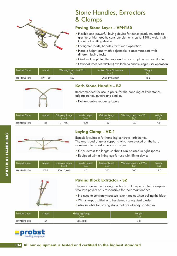
134
MA
TER
IAL
HA
ND
LIN
G
Kerb Stone Handle - BZRecommended for use in pairs, for the handling of kerb stones, edging stones, gutters and similar.
• Exchangeable rubber grippers
Laying Clamp - VZ-1Especially suitable for handling concrete kerb stones. The one-sided angular supports which are placed on the kerb stone enable an extremely narrow joint.
• Grips across the length so that it can be used in tight spaces
• Equipped with a lifting eye for use with lifting device
Product Code Model Gripping Range (mm)
Inside Height (mm)
Gripper Length (mm)
Working Load Limit WLL (kg)
Weight (kg)
H621060150 BZ 0 – 400 200 150 150 4.0
Product Code Model Gripping Range (mm)
Inside Height (mm)
Gripper Length (mm)
Working Load Limit WLL (kg)
Weight (kg)
H621050100 VZ-1 500 - 1,045 40 100 100 12.0
Stone Handles, Extractors & ClampsPaving Stone Layer – VPH150• Flexible and powerful laying device for dense products, such as
granite or high quality concrete elements up to 150kg weight with the aid of a lifting device
• For lighter loads, handles for 2 man operation
• Handle height and width adjustable to accommodate with different laying tasks
• Oval suction plate fitted as standard - curb plate also available
• Optional wheelset (VPH-RS) available to enable single user operation
Product Code Model Working Load Limit WLL (kg)
Suction Plate Dimension (mm)
Weight (kg)
H611000150 VPH-150 150 Oval 440 x 250 16.5
Paving Block Extractor - SZThe only one with a locking mechanism. Indispensable for anyone who lays pavers or is responsible for their maintenance.
• No need to constantly squeeze lever handles when pulling the block
• With sharp, profiled and hardened spring steel blades
• Also suitable for paving slabs that are already sanded in
Product Code Model Gripping Range (mm)
Weight (kg)
H621070000 SZ 90 – 330 4.0
All our equipment is tested and certified to the highest standard
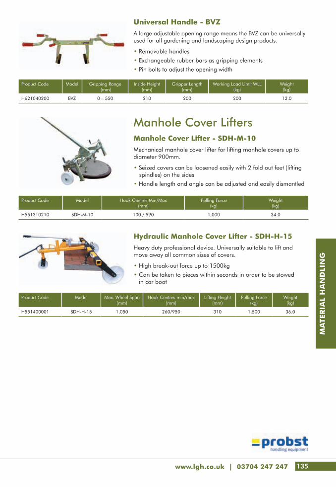
www.lgh.co.uk | 03704 247 247 135
MA
TER
IAL
HA
ND
LIN
G
Universal Handle - BVZA large adjustable opening range means the BVZ can be universally used for all gardening and landscaping design products.
• Removable handles
• Exchangeable rubber bars as gripping elements
• Pin bolts to adjust the opening width
Product Code Model Gripping Range (mm)
Inside Height (mm)
Gripper Length (mm)
Working Load Limit WLL (kg)
Weight (kg)
H621040200 BVZ 0 – 550 210 200 200 12.0
Manhole Cover LiftersManhole Cover Lifter - SDH-M-10Mechanical manhole cover lifter for lifting manhole covers up to diameter 900mm.
• Seized covers can be loosened easily with 2 fold out feet (lifting spindles) on the sides
• Handle length and angle can be adjusted and easily dismantled
Hydraulic Manhole Cover Lifter - SDH-H-15Heavy duty professional device. Universally suitable to lift and move away all common sizes of covers.
• High break-out force up to 1500kg
• Can be taken to pieces within seconds in order to be stowed in car boot
Product Code Model Hook Centres Min/Max (mm)
Pulling Force (kg)
Weight (kg)
H551310210 SDH-M-10 100 / 590 1,000 34.0
Product Code Model Max. Wheel Span (mm)
Hook Centres min/max (mm)
Lifting Height (mm)
Pulling Force (kg)
Weight (kg)
H551400001 SDH-H-15 1,050 260/950 310 1,500 36.0

136
MA
TER
IAL
HA
ND
LIN
G
Forklift AccessoriesForklift Load Hooks• The fork mounted load hook enables the conversion of any
forklift unit into a simple mobile crane unit allowing the lifting of items by chains and slings in a secure and safe manner
• As with all Eichinger fork mounted units the 2084 is secured to the forklift by a heel pin NOT chain
• Always use the load hook in relation to the load capacity of the forklift truck
Forklift Extending Jib• Designed to convert a standard forklift truck into a
universal mobile crane unit
• Heavy duty telescopic jib, extends in 7 steps
• Heel pin assembly for secure attachment to the forklift
Product Code Model Load Cap.(t)
Length(mm)
Width(mm)
Height(mm)
Distance Between Forks
(mm)
Fork Pocket Size(mm)
Weight(kg)
H530020020 2084.2 2.0 940 645 270 300 165 x 65 44.0
H530020030 2084.3 3.0 940 735 270 300 200 x 80 60.0
H530020050 2084.4 5.0 940 735 320 300 200x80 62.0
Product Code Model Load Cap (t)
Extendable Range (mm)
Width (mm)
Height (mm)
Fork Pocket Size (mm)
Prong Cross Section(mm)
Weight (kg)
H530010025 2081.1 2.5 700 - 3700 520 430 190 x 90 150 220.0
H530010050 2081.2 5.0 700 - 3700 520 510 190 x 90 180 250.0
LGH - The authority in lifting

www.lgh.co.uk | 03704 247 247 137
MA
TER
IAL
HA
ND
LIN
G
Forklift AccessoriesFork Extensions• Available in two sizes to enable the safe and efficient
transportation of oversized items
• These items are manufactured from high grade steel, secured by fork retaining pins
Product Code Model Length (mm)
Min. Fork Length(mm)
Fork Pocket Size(mm)
Load Cap.(kg)
Weight (kg)
H530031400 2111.1 1400 1000 140 x 80 3000 70.0
H530031830 2111.2 1800 1400 180 x 100 4000 100.0
Big Bag Spreader Beam• The Big Bag Lifting Frame is a universal piece of
equipment for use with either a crane or forklift truck
• Available from 1000kg to 3000kg SWL
Product Code Model Load Cap. (kg)
Length (mm)
Width (mm)
Height (mm)
Fork Pocket Size(mm)
Weight (kg)
H530110100 1097.1 1000 930 915 440 190x90 68.0
H530110150 1097.2 1500 930 915 440 190x90 72.0
H530110200 1097.3 2000 930 915 440 190x90 80.0
H530110300 1097.4 3000 930 915 445 190x90 92.0

138
MA
TER
IAL
HA
ND
LIN
G
Bumpa HoistsElectric & Petrol• Simple to use
• Quick to erect, simply unloaded from your truck and running within 4 minutes
• Up to 1,000 tiles can then be loaded onto any roof in under 25 minutes
• Powered reverse to strip a valuable salvage down easily, straight from the roof into the back of the truck
• 5 Kva transformer required for electric model
• Reliable Honda petrol engine supplied with petrol model
Product Code Model Power Maximum Working Height
(m)
Maximum Payload Overall
(kg)
Maximum Carrier Payload
(kg)
Belt Speed (m/min)
Maximum Angle
(°)
Electric Motor (kW)
Machine Weight
(kg)
H581020060 Hoddi 5m Electric 5.0 80 20 20 65 0.75 87.0
H581010060 Bumpa 6m Petrol 5.0 80 20 20 65 0.75 87.0
H581020080 Bumpa 8m Electric 7.0 80 20 20 65 0.75 103.0
H581010080 Bumpa 8m Petrol 7.0 80 20 20 65 0.75 103.0
H581020100 Bumpa 10m Electric 9.0 80 20 20 65 0.75 119.0
H581010100 Bumpa 10m Petrol 9.0 80 20 20 65 0.75 119.0
Product Code Model
H581190008 Stand
Accessories
Delivering excellence in lifting throughout the UK

www.lgh.co.uk | 03704 247 247 139
MA
TER
IAL
HA
ND
LIN
G
Shifta Conveyors• Suitable for demolition, excavation and landscaping
• 100V working singularly or as part of a series of conveyors
• Maximum belt loading 200kg at 40º subject to the types of material being moved
• Forward/reverse operation
• Emergency stop
• Twin speed
Product Code Model
H581190007 Hopper
Product Code Model
H581190008 Stand
Product Code Model
H581190009 Link Cable
Product Code Length (m)
Belt Width (mm)
Maximum Belt Load
(kg)
Belt Speed Maximum Angle
(°)
Drum Motor (kW)
StorageDimensions - Flat
(m)
Noise Emissions (A weighted)
(dB)
Machine Weight
(kg)Fast (m/min)
Slow (m/min)
Mod
el 3
00 H581130032 3.2 300 150 20 28 N/A 0.55 0.27 x 3.2 x 0.6 75 103.0
H581130044 4.4 300 150 20 28 N/A 0.55 0.27 x 4.4 x 0.6 75 126.0
H581130054 5.4 300 150 20 28 N/A 0.55 0.27 x 5.4 x 0.6 75 140.0
Mod
el 4
50 H581140032 3.2 450 200 20 28 N/A 0.75 0.27 x 3.2 x 0.75 75 116.0
H581140044 4.4 450 200 20 28 N/A 0.75 0.27 x 4.4 x 0.75 75 160.0
H581140054 5.4 450 200 20 28 N/A 0.75 0.27 x 5.4 x 0.75 75 180.0
Accessories

140
MA
TER
IAL
HA
ND
LIN
G
Building HoistsGEDA Ladder Hoist• GEDA Ladder, the inclined hoist for everything that has to be transported up or down• Hoisting speeds of 22m to 30m/min dependent on model/load• An extensive range of attachments and accessories available to safely transport plaster board, solar panels,
tiles, bricks, rolls of felt etc• Lift height of 19m to eaves, with further transport run enabled past the knuckle section to another 21m• A site survey is recommended prior to installation to verify that the specification offered fully meets the
requirement of the job
1) Tile holder especially designed for tilers with hinged safety guard and tile cart
2) You can also tile the roof below the ladder using the roof trestle, which is variably adjustable between 37cm and 60cm
3) Multi-purpose platform with folded lateral protection for the transport of a large variety of building materials (picture with bucket receptacle and buckets)
4) Multi-purpose platform with closed lateral protection-the Multi-purpose transport device
5) Multi-purpose platform with folded lateral protection and front flap
6) Multi-purpose platform with extracted lateral protection, which also allows transport of bulky goods
7) Twin variants of the continuously adjustable angle track section are available with long and short blades or equally long blades
8) The varioplatform with its foldable lateral protection allows transport of bulky goods without any problems. The inclination of the platform can be adjusted
9) The tipping skip for the standard trolley is automatically emptied by the tipping device, which can also be used inside the building. The adjustable prop is contained in the delivery
10) You can easily transport the winch using a cart. This allows for the components of the dismantled lift to be easily moved and stored in a space saving manner
11) Easy to work on the roof due to the roof tile batten trolley
12) The liftable trolley can make the skip tilt up 130º
13) Using the titling trolley with the sheet carrier, you can easily unload large boards
14) Inforced ladders for up to 250kg
15) Ladders for up to 200kg load capacity
Product Code Model Load Cap. (kg)
Max. Ladder Rail Length up to the Eaves
(m)
Max. Overall Ladder Length
(m)
Rope Length (m)
Electrical (kW)
Power Supply (V/Hz)
H010810001 Lift 250 250 19 40 43, 63, 83 1.3 110/50
3
5
7
9
1
4
6
8
2
LGH - puts safety first

www.lgh.co.uk | 03704 247 247 141
MA
TER
IAL
HA
ND
LIN
G
Building HoistsGeda Rack and Pinion Hoists• Delivering products up to 100m, the GEDA product range now includes matching landing-level safety doors for
every construction hoist • Doors are directly fastened to the scaffolding and will only open when the lift comes into contact with the
landing-level safety doors and the specially designed locking device can be released
• A site survey is recommended prior to installation to verify that the specification offered fully meets the requirement of the job
Product Code Model Load Cap. (kg)
Max. Lift (m)
Lift Speed (m/min)
Electrical (V)
Power Supply (V/Hz)
H010820200 200z 200 50 20 230 230/50
H010820330 300z 300 100 30 230 230/50
H010820500 500z 500 100 30 400 400/50

142
MA
TER
IAL
HA
ND
LIN
G
SkipsRoll Forward Tipping SkipsThe forklift Tipping Skip is the ideal solution when moving waste around your site. With four way fork pocket entry the units can be placed where required. Each unit is supplied with a fixed heel pin and safety catch to ensure the skip doesn’t discharge during transit.
• Roller system with automatic release
• Can be tipped from any position by cable pull from the driver's seat
Product Code Model Capacity(l)
Load Cap.(kg)
Length(ext.)(mm)
Width(ext.)(mm)
Height(ext.)(mm)
Length(int.)(mm)
Width(int.)(mm)
Height(int.)(mm)
Fork Pocket Length(mm)
Fork Pocket Size(mm)
Weight (kg)
H589910300 2013.6 300 1000 1350 880 920 1060 800 640 420 190x85 190.0
H589910500 2013.8 500 1000 1370 980 1060 1235 900 780 580 190x85 210.0
H589910600 2013.9 600 1000 1370 1080 1060 1235 1000 780 580 190x85 220.0
H589910750 2013.10 750 1000 1370 1180 1060 1235 1100 780 580 190x85 230.0
H589911000 2013.12 1000 1000 1370 1580 1060 1235 1500 780 580 190x85 245.0
H589911200 2013.13 1200 1500 1670 1340 1300 1545 1250 1020 580 190x85 315.0
H589911500 2013.14 1500 1500 1670 1590 1300 1545 1500 1020 580 190x85 340.0
Safety, Certainty, Great Service

www.lgh.co.uk | 03704 247 247 143
MA
TER
IAL
HA
ND
LIN
G
Safety
143
146 Safety Harnesses
147 Lanyards
148 Fall Arrest Blocks
149 Lifelines & Anchors
150 Confined Space Equipment
151 Man-Riding Davits
151 Gas Detection & Breathing Apparatus
152 Porta Gantry Rapide

144
SAFE
TY
WebbingLook for cuts, tears,
abrasions, chemical damage,
discolouration, by visual
and tactile means.
IN
CHECKMATE
CHECKMATE SAFETY HARNESSES
Would your harness pass the test?
BucklesLook for deformation, damage such as
corrosion, sharp edges and cracks.
Check functionality – does it
work as it should.
AttachmentsLook for deformation, distortion,
cracks and or corrosion
by visual and tactile means.
Webbing KeepersLook for cuts, breaks and damage by visual
and tactile means. Are they missing? IN
Back PlateLook for cuts, tears,
abrasions, chemical damage,
discolouration, by visual
and tactile means.
IN
LabellingTraceability of the product is a
legal requirement. All relevant
information MUST be
present and legible.
CHECKUSOUT:www.checkmateuk.com
StitchingLook for cuts, tears,
frays, chemical damage,
discolouration, by visual and
tactile means.
AVA
ILABLE FOR HIRE
AVAILABLE FOR HIRE
Hire from LGH and we'll do the inspecting for you.

www.lgh.co.uk | 03704 247 247 145
SAFE
TY
IS THE MAGIC NUMBER
TR3
THE TR3 CAN PROVIDE MOBILE
ACCESS OR FALL PROTECTION IN ANY
CONFINED SPACE ENVIRONMENT
CHECKITOUT:checkmateuk.com/height-safety/products/anchors/TR3
THE TR3 TRIPOD HAS A DURABLE ALLOY CONSTRUCTION THAT MAKES IT BOTH INCREDIBLY TOUGH AND INCREDIBLY LIGHTWEIGHT
AVAILABLE FOR HIRE
AVAILABLE FOR H
IRE

146
SAFE
TY
Safety Harnesses We have a wide range of Safety Harnesses, designed to cover the majority of requirements in the markets we serve.
Standard Features:
• Front & Rear “D” attachment points
• Shock absorbing rear dorsal
• Wear pads on buckle connections
• Wear indicator webbing
• Fall indicator deployment flag
Product Code Description
H440110001 Two-Point Fall Arrest Harness, with rear “D” and front chest attachment points. Front “D” is centrally located ensuring loads re-spread evenly. Four points of adjustment ensuring a better fit. The most popular harness, simple, versatile and ensures there is a separate connection for rescue.
Product Code Description
H440110002 Four-Point Fall Arrest Safety Harness with front and rear “D” attachment points, waist belt with two side attachment points. Suitable for work positioning, telecommunications, pole and tower work.
Product Code Description
H440210001 Rescue Fall Arrest Safety Harness, similar to the PBH02 model but with the addition of an integrated rescue yoke and strop. Used for rescue and in confined spaces.
Product Code Description
H440110003 Rapid Don Fall Arrest Harness with front and rear “D” attachment points, shoulder yoke and padded leg loops and click lock buckles. A popular harness due to ease and speed of fitment and suitable for most applications.
All our equipment is tested and certified to the highest standard
PBH02
PBH04
PBH06Y
PBH10

www.lgh.co.uk | 03704 247 247 147
SAFE
TY
Lanyards Restraint Lanyards
Fixed and adjustable length webbing lanyards offering a variety of uses where the user needs to work without the risk of falling.
Shock Absorbing Lanyards
Fixed Length Webbing Lanyards with Shock Pack available with single or twin leg options to offer 100% tie off when moving around structures.
Product Code Model Description
H440310010 LR1.0BB Fixed Length c/w Karabiner Hooks at each end – 1,000mm long
H440310020 LR2.0BB Fixed Length c/w Karabiner Hooks at each end – 2,000mm long
H440320012 LRA1.2BB Adjustable Length c/w Karabiner Hooks at each end – 8,50mm to 1,200mm long
H440320020 LRA2.0BB Adjustable Length c/w Karabiner Hooks at each end – 1,250mm to 2,000mm long
Product Code Description
H440110002 Four-Point Fall Arrest Safety Harness developed with the goal of eliminating harness induced 'Suspension Trauma' after a fall. By attaching to the sternum D, the SUPINE Harness becomes a very comfortable sit harness for carrying out work tasks when suspended for long periods of time.
Product Code Model Description
H440310010 SAL2C-1.75 Single leg c/w Scaffold Hook – 1,750mm long
H440310020 SAL4C-1.75 Twin leg c/w Scaffold Hook – 1,750mm long
PBH14

148
SAFE
TY
Fall Arrest BlocksFAB3WThe FAB3W is a lightweight palm-sized Fall Arrest Block and is so light it can be mounted directly onto the user's harness via the rear D connector. Also available as a dual assembly for 100% tie off whilst moving between anchorages whilst moving around a structure.
FABX1-10CThe FABX1 is available with galvanised or stainless steel cable, Dyneema fibre rope or Dyneema webbing. Up to 10m (33ft) in length the FABX1 offers lightweight handling, excellent serviceability and exceptional performance.
FABX2-15C & FABX2-18CThe FABX2 is available with galvanised or steel cable. Up to 18m in length the FABX2 offers lightweight handling, excellent serviceability and exceptional performance.
Product Code Model Length (m)
Length(ft)
Description Weight (kg)
H440600003 FAB3W 3 10 Fall Arrest Block (EN) 1.1
Product Code Model Length (m)
Length (ft)
Description Weight (kg)
H440600010 FABX1-10C 10 33 Fall Arrest Block Galvanised Wire (EN) 4.1
Product Code Model Length (m)
Length (ft)
Description Weight (kg)
H440600015 FABX2-15C 15 49 Fall Arrest Block Galvanised Wire (EN) 6.2
H440600018 FABX2-18C 18 59 Fall Arrest Block Galvanised Wire (EN) 6.4
LGH - The authority in lifting

www.lgh.co.uk | 03704 247 247 149
SAFE
TY
Product Code Model Description Weight (kg)
H441010001 ECO-ANCHOR EcoAnchor 11.4
Product Code Model Description Weight (kg)
H441000001 WEIGHTANKA Portable Man Anchor (KEE) 250.0
EcoAnchor Portable Water Filled AnchorThe EcoAnchor can be easily installed without the need to carry steel weights traditionally required for this application.
Standard Features:• Up to 15º incline allowed• Fill and drain point• Pressure release vent• 360º swivel• Maximum user weight 100kg
Weightanka Portable Man Anchor (KEE)Designed for use where collective protection or permanent anchorage is not available. This fully modular system weighs only 250kg in its basic set up with no component weighing more than 25kg.Standard Features:• Pedestal• Standard weights with carrying handle• Rubber base weights for improved grip• Stabiliser and cross arma• Maximum user weight 100kg
Lifelines & AnchorsHLL1 and HLL1WK• A temporary life line designed to be used for restraint or
fall arrest applications• Spanning up to 20m the system can accommodate
2 users at a maximum combined weight of 200kg• The lanyard length is measured between the bearing points of
the hooks • Exchanging a karabiner for a scaffold hook could lengthen
a lanyard beyond the maximum allowable length under the relevant EN standard
Product Code Model Description Weight (kg)
H440510020 HLL1 25m of 16mm dia. Fibre Rope with Rope Vice Tensioner and Swivel Socket Karabiner Hooks at each end 4.0
H440500020 HLL1WK 20m Polyester Webbing Ratchet Life Line with Swivel Load Indicator Karabiners 3.0
HLL1 HLL1WK

150
SAFE
TY
Product Code Model Capacity Description Height Weight (kg)
Overall (mm) Lifting Point (mm)
H440710001 TR3 250kg Height Adjustable Tripod 1400 - 2400 1200 - 2200 14.7
Product Code Model Description Weight (kg)
H440410001 FABXR-18C 18m/60ft Fall Arrest Block with recovery (galv wire) 9.4
H440410002 FABXLR 40m/130ft Fall Arrest Block with recovery (galv wire) 16.5
Product Code Model Description Weight (kg)
H440810001 PPEW2000 Man Riding / Material Winch 8.5
Confined Space EquipmentTR3 Height Adjustable TripodUltra lightweight, tough, and with a durable alloy construction, the TR3 Tripod is primarily to be used as personal protective equipment, to provide access or fall protection in confined space environments.
• Pulleys are protected from damage by an extended crown
• Spring Loaded Sliding Pulleys for ease of setup and retaining pin to prevent cable coming off the pulley
• Automatic leg lock out catches with trigger release
PPEW2000 Man Riding / Material WinchThe PPEW2000 functions as a secondary back up device where there is no assistance for the descent such as a ladder. An essential piece of equipment to meet the requirements of the EN 795 Class B Standard.
• 250kg capacity
• 20m lift
• Harken lokhead fibre rope capstan winches are also available for longer lengths. Hoisting speed can be increased by using a portable power tool
FABX2R & FABXLR Recovery Blocks• The FABX2R & FABXLR function as standard Fall Arrest Block,
but in the event of a fall, the rewind/rescue mechanism can be engaged to raise and/or lower a fallen worker
• Fitted as standard with a bracket to suit either the TR3 Tripod or the PGR Porta Gantry Rapide
Delivering excellence in lifting throughout the UK
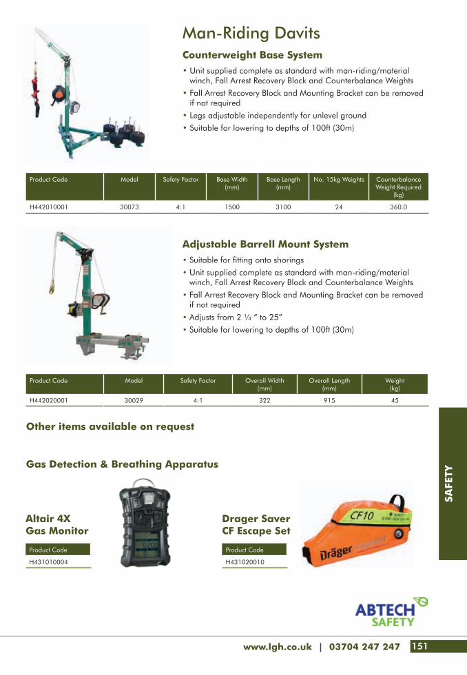
www.lgh.co.uk | 03704 247 247 151
SAFE
TY
Adjustable Barrell Mount System• Suitable for fitting onto shorings
• Unit supplied complete as standard with man-riding/material winch, Fall Arrest Recovery Block and Counterbalance Weights
• Fall Arrest Recovery Block and Mounting Bracket can be removed if not required
• Adjusts from 2 ¼ “ to 25”
• Suitable for lowering to depths of 100ft (30m)
Gas Detection & Breathing Apparatus
Product Code Model Safety Factor Overall Width(mm)
Overall Length(mm)
Weight (kg)
H442020001 30029 4:1 322 915 45
Product Code
H431010004
Product Code
H431020010
Man-Riding DavitsCounterweight Base System• Unit supplied complete as standard with man-riding/material
winch, Fall Arrest Recovery Block and Counterbalance Weights
• Fall Arrest Recovery Block and Mounting Bracket can be removed if not required
• Legs adjustable independently for unlevel ground
• Suitable for lowering to depths of 100ft (30m)
Product Code Model Safety Factor Base Width(mm)
Base Length(mm)
No. 15kg Weights Counterbalance Weight Required
(kg)
H442010001 30073 4:1 1500 3100 24 360.0
Altair 4X Gas Monitor
Other items available on request
Drager Saver CF Escape Set

152
SAFE
TY
Product Code Model Dimensions (mm) WLL Weight(kg)
A Beam Length
BMax
C Min
C Max
D Min
D Max
E Min
E Max
F Min
F Max
G H Min
H Max
J Goods Capacity
(kg)
Fall Arrest Capacity* (persons)
Personnel* (kg)
H050410000 PGRS20 2000 2076 1100 1500
1738
1938
1914
2114
2064
2264
1158
1850
2050
2190 500 3 250 33.0
H050410001 PGRS23 2300 2376 1200 1800 2376 400 2 200 34.0
H050410002 PGRS40 4000 4076 2700 3500 4076 250 1 125 40.0
H050410003 PGRM20 2000 2076 1100 1500
1642
2042
1818
2218
1968
2368
1215
1755
2155
2076 400 2 200 34.0
H050410004 PGRM23 2300 2376 1200 1800 2376 400 2 200 34.0
H050410005 PGRM40 4000 4076 2700 3500 4076 250 1 125 40.0
H050410006 PGRT20 2000 2076 1100 1500
1916
2816
2092
2992
2242
3142
1586
2028
2928
2631 250 1 125 38.0
H050410007 PGRT23 2300 2376 1200 1800 2631 250 1 125 39.0
H050410008 PGRT40 4000 4076 2700 3500 4076 250 1 125 44.0
Product Code Model Capacity
Materials (kg) Personnel (kg)
H050420001 PGR Trolley c/w Masterlink 500 250
H050420002 PGR Trolley Close Coupled 500 250
H050420003 PGR Sheave Carrier (Double)
500 250
H440410001 FAB X2R x 18m - -
H440810001 PPEW2000 Winch 250 125
415
D E F
J
440
415
BAC
H
125
G
100
Porta Gantry Rapide (PGR)Lightweight, PORTA-GANTRY• Extremely light, the PGR gantry has a unique rapid deployment
system that is quick to erect in less than a minute
• Meets the full requirements of EN795* Class B to enable use for both materials and personnel lifting/man-riding
• The basic gantry assembly can be equipped with numerous accessories and trolley types as detailed below dependant on the task in hand
• All of our PGR Gantries are specifically equipped with a pair of winch brackets and end sheaves to suit either the FABXR Recovery blocks, the PPEW2000 man-riding/materials winch or both if required
PGR Trolley c/w Masterlink
PGR Sheave Carrier (Double)
PPEW2000 Winch
PGR Trolley Close Coupled
FAB X2R x 18m
Frames easily fold onto beam forming compact, stowable unit. Fits into a typical service van.
LGH - puts safety first

www.lgh.co.uk | 03704 247 247 153
SAFE
TY
154 Technical Info
158 Index
Technical Info
153

TEC
HN
ICA
L IN
FO
154
Pre Lift GuideLOAD• Weight and centre of gravity has been determined• Anything inside/outside the load that could shift during the lift?• Determine if the load needs protection against damage
from the rigging• All anchor bolts, hold downs, or fasteners have been removed• Potential for binding - are load cells required to verify the
load is free?• Attachment points designed to take the load weight• Is the load structurally capable of being lifted?
(bending/twisting issues)
RIGGING• Determine the additional tensions based on the sling angles• Ensure all rigging has adequate capacity for the
additional tension• Are shackles correctly sized for the sling eyes?
D/d requirements met?
PERSONNEL• The roles, responsibilities and qualifications for personnel
have been defined (P.I.C., Riggers, Signalperson, Crane Operator, etc.)
• A pre-lift meeting has been held with all personnel
AREA PREPARATION• The location for landing the load has been selected
and prepared• Blocking or cribbing is available to set the load on• A travel path has been determined and cordoned off• Other personnel in the area have been notified of the lift
CRANE CONSIDERATIONS (Mobile Cranes)• Is the lift within the crane’s rated capacity
(boom height/radius)?• Have boom deflections been considered?• Have any potential crane boom obstructions been identified?• What are the limits on wind speed for making this lift?• Have the ground bearing support conditions been met?• Power lines in the area? Clearance and a
spotter established?• Counterweight swing area of the crane barricaded?
Hoisting GuidePRIOR TO THE LIFT• The rigging has been inspected before use• The crane hook is positioned directly over the load’s centre
of gravity• Softeners are used to protect the rigging where it could
be damaged• The slings and rigging hardware positioned correctly?• Rigging provides positive control of the load?
(no slipping/shifting)• Safe load paths have been established• Tag lines are being used to control the load
(where appropriate)• Communications between signalperson and crane
operator have been established
Basic Hitches
-- Page 5 --
ACRA Enterprises, Inc. 800-992-0689 www.acratech.com
Basic Hitches
120°
eye & eye endless
CHOKER
BASKET
VERTICAL
Wire
rope
/ W
eb S
ling
Chai
n Sl
ing
Web
/ Ro
unds
ling
Working Load Limits shown on
sling tags and other charts are
based on the angle of choke to be 120 degrees
or greater.
90°
90°
Working Load Limits shown on sling tags and other charts are based on both legs being vertical within 5 degrees.
-- Page 6 --
©2016 ACRA Enterprises, Inc - all rights reserved v5 - 5/16
Hitch Reductions
CHOKER
BASKET
VERTICAL
90°
120°
29°
100% 87% 49%
120°
50% reduction100%
100%87% 50%
60°30°
Low horizontal angles
the hitch capacity!
90°
When angles, a smaller D/d ratios, or a tight choke is used, the capacity of the hitch is MUCH LESS than what is shown on the tag!
2 slings @ 30 degrees horizontal angle
10,000 kgWLL
VERTICAL CHOKER BASKET
20,000 kgWLL
7,500 kgWLL
DURING THE LIFT• Tension is gradually applied to the slings and rigging
is re-checked• Lift and hold the load to verify the centre of gravity and
load stability• Personnel are not under the load or travel path (includes
hands/feet)• Personnel avoid being in the ‘line of re’ of tensioned rigging• Lifted load is kept as close to the ground as possible• Loads lifted high require extra distance for personnel
(potential for the load to swing or bounce if rigging fails and the load falls)
AFTER THE LIFT• A post-lift inspection performed on the load and rigging
(in the locations subjected to forces applied from the lifting and/or near softeners or where slings came in physical contact with the load)
• A post-lift meeting is held (if applicable)• Rigging equipment stored appropriately in proper location(s)
Safety, Certainty, Great Service

TEC
HN
ICA
L IN
FO
www.lgh.co.uk | 03704 247 247 155
Choke Reduction
Tension Calc Using Angles Drifting Loads
Tension Calc Using Angles-- Page 50 --
©2016 ACRA Enterprises, Inc - all rights reserved v5 - 5/16
Choke Reduction
Choker rating on tag: 5,000 kg
Reduced rating: 2,450 kg
Exampleless than 30°
49% reduction
5000 x .49 = 2450
To calculate adjusted choker ratings:
RC = C x R C : Choker ratingR : Rated CapacityRC : Reduced choker rating
hctihrekohC
tnemtsujdayticapacdetaR
ekohcfoelgnAseergedni
detaRyticapac
021revO %001
021-09 %78
98-06 %47
95-03 %26
92-0 %94
-- Page 39 --
ACRA Enterprises, Inc. 800-992-0689 www.acratech.com
It is recommended that you consider that only 2 legs will carry the load, even when using 3 and 4
that all legs will carry an equal share of the load.
SH
Tension Calcusing measurments
It's hard to determine the exact angle when working
following formula provides accurate calculations by
(Weight ÷ No of legs) X (S ÷ H)
Example: The load weight is 6,000 kg and two (2) slings are used. You measure up the sling 36" (this is the "S" dimension) then measure straight down and obtain a 24" measurment (this is the "H" dimension).
(6000 ÷ 2) x (36 ÷ 24) = 4,500 kg of tension per leg
You can also use the sling length and the vertical
height
3000 x 1.5 = 4,500 kg of tension per leg
-- Page 40 --
©2016 ACRA Enterprises, Inc - all rights reserved v5 - 5/16
Drifting Loads
Tension on Chainfall "B"
Tension on Chainfall "A"
LBLA
H
D2D1
D3
LOAD
To determine how much tension will be placed upon chainfalls used in angular rigging situations, use the following formula:
Tension on Chainfall "A" = (Load weight × D2 × LA) ÷ (H × D3)
Tension on Chainfall "B" = (Load weight × D1 × LB) ÷ (H × D3)
NOTE: This formula assumes that both chainfalls are positioned at the same elevation.
-- Page 38 --
©2016 ACRA Enterprises, Inc - all rights reserved v5 - 5/16
It is recommended that you consider that only 2 legs will carry the load, even when using 3 and 4
that all legs will carry an equal share of the load.
HorizontalAngle
HorizontalAngle
Tension Calcusing angles
To determine the amount of tension on a sling used at angles other than 90 degrees (vertical), use the table at the right to obtain the Load Angle Factor (L.A.F.) and following formula:
(Weight ÷ No of legs) x L.A.F.
Example: If the load weight is 4,000 kg, and two (2) slings are used at a 40 degree angle each.
(4000 ÷2) x 1.555 = 3,110
Therefore, each leg will have 3,110 kg of tension.
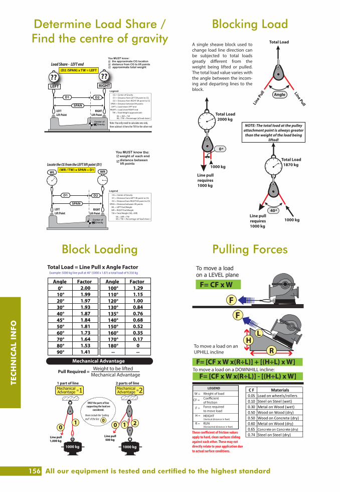
TEC
HN
ICA
L IN
FO
156
Determine Load Share / Find the centre of gravity
Block Loading Pulling Forces
Blocking Load
-- Page 41 --
ACRA Enterprises, Inc. 800-992-0689 www.acratech.com
Load Share - LEFT end(D2 /SPAN) x TW = LEFT
Center ofGravity
D2D1
SPANLEFTLift Point
RIGHTLift Point
LEFT RIGHT
WL + WR = TW
WL = LEFT End WeightWR = RIGHT End Weight
SPAN = Distance between lift points
TW = Total Weight (WL+WR)
CG = Center of GravityD1 = Distance from LEFT lift point to CGD2 = Distance from RIGHT lift point to CG
WL / TW = Percentage (of load share )Center ofGravity
WRWL
D2D1
SPAN
LEFTLift Point
RIGHTLift Point
Locate the CG from the LEFT lift point (D1)(WR / TW) x SPAN = D1
-- Page 43 --
ACRA Enterprises, Inc. 800-992-0689 www.acratech.com
Pull Required = Weight to be liftedMechanical Advantage
1000 kg
Line pull1,000 kg
Line pull500 kg
1 part of line 2 parts of line
ONLY the parts of line supporting the load are
considered.
Never include the “pulling end” of the line
Mechanical Advantage
0
0 01 21
1000 kg
Angle Factor Angle Factor0° 2.00 100° 1.29
10° 1.99 110° 1.1520° 1.97 120° 1.0030° 1.93 130° 0.8440° 1.87 135° 0.7645° 1.84 140° 0.6850° 1.81 150° 0.5260° 1.73 160° 0.3570° 1.64 170° 0.1780° 1.53 180° 090° 1.41 -- --
Total Load = Line Pull x Angle FactorExample: 5000 kg line pull at 40° (5000 x 1.87) a total load of 9,350 kg
-- Page 44 --
©2016 ACRA Enterprises, Inc - all rights reserved v5 - 5/16
Pulling Force
F
F
RH
F= CF x W
To move a load on a LEVEL plane
L
C F Materials0.05 Load on wheels/rollers0.10 Steel on Steel (wet)0.30 Metal on Wood (wet)0.50 Wood on Wood (dry)0.50 Wood on Concrete (dry)0.60 Metal on Wood (dry)0.65 Concrete on Concrete (dry)0.74 Steel on Steel (dry)
W =
CF =
F =
H =
R = RUN(Horizontal distance in feet)
HEIGHT(Vertical distance in feet)
Force required to move load
Coe�cient of friction
Weight of load
LEGEND
These coe�cient of friction values apply to hard, clean surfaces sliding against each other. These may not directly relate to your application due to actual surface conditions.
To move a load on an UPHILL incline
To move a load on a DOWNHILL incline:
-- Page 42 --
©2016 ACRA Enterprises, Inc - all rights reserved v5 - 5/16
A single sheave block used to change load line direction can be subjected to total loads
weight being lifted or pulled. The total load value varies with the angle between the incom-ing and departing lines to the block.
Angle
Total LoadLine PullLi
ne Pull
40º
1000 kgLine pullrequires1000 kg
Total Load1870 kg
0º
1000 kg
Line pullrequires1000 kg
Total Load2000 kg
Block Loading
NOTE: The total load at the pulley attachment point is always greater
than the weight of the load being lifted!
All our equipment is tested and certified to the highest standard

TEC
HN
ICA
L IN
FO
www.lgh.co.uk | 03704 247 247 157
Shackle Use
Eye Bolt Use Hook Use
Shackle Use-- Page 46 --
©2016 ACRA Enterprises, Inc - all rights reserved v5 - 5/16
includedangle
30° 30°120°
“Multiple slings in the body of a shackle shall not exceed 120 degree included angle”
Shackle Use
SideLoading
45°
90°
0°5°
No Reduction
30% Reduction
50% Reduction
NEVER side load
Round Pin Shackles
If the shackle is to be side loaded (with a SINGLE sling) the rated load shall be reduced according to the recommendations of the manufac-turer or a quali�ed person. ASME B30.26 recommends reducing the capacity of a side loaded shackle from 30% to 50% as shown below.
-- Page 48 --
©2016 ACRA Enterprises, Inc - all rights reserved v5 - 5/16
Eye Bolt Use
Right Wrong!
Yes
Always load in the plane of the eye will bend!
Eye bolts and Hoist Rings should be threaded into the surface a minimum
of 1.5 times the thread diameter*
1" dia
1-1/2" 1"
1/2" * per ASME B30.26-2.9.4.2 “when used in a tapped blind hole, the e�ective thread length shall be at least 1-1/2 times the diameter of the bolt for engagement in steel ... For other thread engagements or in other materials, contact the eyebolt manufacturer or a quali�ed person.”
Spacers or washers SHALL NOT be used between the bushing �ange and the mounting surface
dia
1-1/2x dia
Flat washers may be used under the shoulder to position the plane of
the eye
YES
YES
YES
Only Shoulder Eyebolts can be side loaded
vertical pull
only!
-- Page 49 --
ACRA Enterprises, Inc. 800-992-0689 www.acratech.com
45°
90°
45°
Duplex hooks should be loaded equally on
both sides
A hook latch (if required) must be operational; otherwise it shall be removed
from service.
Use a shackle when lower
horizontal angles are encountered.
90° MAXIMUMincluded angle
for hooks
NO!NO!
The width of the hook should not
be wider than one half the length of
the eye
1/2
Hook Use
-- Page 47 --
ACRA Enterprises, Inc. 800-992-0689 www.acratech.com
Shackles must be large enough to
avoid pinching of synthetic web slings
The shackle size should be the same diameter or larger than
the wire rope size
1”
NO!YES!
NO!YES!
NO!
1”
Shackle Use

IND
EX
158
A
Access Cages ������������������������������99
Adjustable Beam Trolleys ��������������22
Air Chain Hoists ��������������������� 32-34
Air Chain Hoists Accessories and Controls �������������������������������35
All Terrain Pallet Trucks ���������������133
Aluminium Gantries ���������������������40
Aluminium Jacks ��������������������������56
Angle Clamps ������������������������������21
B
Beam Clamps ������������������������ 20-21
Beam Trolleys ������������������������� 22-24
Big Bag Spreader Beam ��������������137
Block Extractor ���������������������������134
Block Grabs ������������������������������100
Blocstops �������������������������������������39
Board Trolley �����������������������������130
Boat Skips �����������������������������������98
Bottle Jacks ����������������������������������56
Builder’s Gantry Hoists �����������������36
Bumpa Hoists ����������������������������138
C
Cable Drum Jacks ������������������������49
Cable Pulling Winch ���������������������48
Caterpillar Skates �������������������������52
Chain Blocks ������������������������� 18-19
Chain Hoists �������������������������� 18-19
Chain Slings ��������������������������������74
Cheese Weights �������������������������120
Clamps - Beam ���������������������� 20-21
Clamps - Plate ���������������������������104
Clutches ������������������������������������103
CMOD Spreader Frames ���������������94
Combination Chain Hoists ������ 25-26
Compression Load Cells ���������������69
Control Valves �����������������������������67
Conveyors ���������������������������������139
Counterbalanced Davits �������������151
Counterbalanced Floor Cranes �����42
Counterbalanced Material Lifts ����125
Cradles �������������������������������������120
Crane Forks ���������������������������������98
Cranelift Man Cage ���������������������99
Cylinders ������������������������������� 57-65
D
Deha Clutches ���������������������������103
Digital Load Indicators ����������������116
Digital Load Shackles �����������������117
Duplex Slings ������������������������� 76-77
E
EcoAnchor ���������������������������������149
Electric Chain Hoists ��������������� 29-31
Electric Pumps - Hydraulic �������������66
Endless Webslings ������������������������76
Escape Set ���������������������������������151
Eyebolt Tester �����������������������������118
Eyebolts ����������������������������� 110-115
F
Fall Arrest Blocks ������������������������148
Floor Cranes �������������������������������42
Fork Extensions ��������������������������137
Forklift Accessories ������������� 136-137
Forklift Extending Jib �������������������136
Forklift Load Hooks ��������������������136
Frimeda Clutches �����������������������103
G
Gantries ������������������������ 40-41, 152
Gas Bottle Carrier ������������������������99
Gas Hoists ���������������������������������124
Gas Monitors �����������������������������151
Gauge Mounting Blocks ���������������68
Gauges - Pressure ������������������������68
Genie Lifts ������������������������� 122-124
Glass Handling Equipment � 126-127
H
Hand Chain Block ������������������ 18-19
Hand Chain Hoists ����������������� 18-19
Hand Test Weights ����������������������120
Hoists - Manual ���������� 18-19, 27-28
Hoists - Powered �����29-39, 140-141
Hollow Cylinders �������������������� 60-61
Hoses - Hydraulic �������������������������67
Hydra-Slide Systems ��������������� 50-51
Hydraulic Cylinders ���������������� 57-65
Hydraulic Gauges ������������������������68
Hydraulic Hoses ���������������������������67
Hydraulic Pumps ��������������������������66
Hydraulic Rams ���������������������� 57-68
Hydraulic Tirfor ����������������������������45
Hydraulic Toe Jacks ���������������� 54-55
Hyrdaclaw Jacks ��������������������������54
J
Jacks ������������������������������������� 54-56
K
Kerb Stone Handles ��������������������134
L
Ladder Hoists �����������������������������140
Lanyards ������������������������������������147
Lattice Spreader Beams ���������� 96-97
Laying Clamp ����������������������������134
Lever Hoists ��������������������������� 27-28
Lifelines �������������������������������������149
Lifting and Pulling Machines ����������44
Lifting Clutches ��������������������������103
Lifting Points ����������������������� 110-115
Load Cells - Compression �������������69
Load Cells - Tensile ��������������������116
Load Indicators ������������������ 116-117
Load Rings ������������������������� 114-115
M
Magnets - Steel ��������������������������105
Magnets - Stone �������������������������101
Man Anchors �����������������������������149
Manhole Clamps �����������������������102
Manhole Cover Lifters ����������������135
Manhole Grabs �������������������������102
Manhole Lifting Equipment ���������102
LGH - The authority in lifting
IND
EX
www.lgh.co.uk | 03704 247 247 159
Manhole Pipe Lifting Pins ������������102
Manifolds ������������������������������������67
Man-Riding Davits �����������������������151
Man-Riding Pulleys �����������������������39
Man-Riding Tripods ��������������������150
Man-Riding Winch ����������������������150
Manual Pumps - Hydraulic ������������66
Material Lifts - Counterbalanced �125
Material Winch ��������������������������150
Mechanical Rack Jacks �����������������54
Minifor Hoists ������������������������������37
Modular Spreader Beams ������� 78-93
Modular Spreader Frames ������� 94-95
Moving Systems ���������������������������52
N
Nylon Skates ��������������������������������52
P
Pad Cylinders �������������������������������57
Pallet Trucks ����������������������� 132-133
Panel Lifter ���������������������������������128
Paving Block Extractor �����������������134
Paving Stone Layer ���������������������134
Pipe Bogey ��������������������������������131
Plate Clamps �����������������������������104
Porta-Gantries �����������������������������40
Porta-Gantry Rapide �������������������152
Pressure Gauges ��������������������������68
Pull Cylinders �������������������������������65
Q
Quadplex Slings �������������������� 76-77
R
Rack and Pinion Hoists ���������������141
Ratchet Jacks �������������������������������54
Recovery Blocks �������������������������150
Rescue Harnesses �����������������������146
Restraint Lanyards �����������������������147
Roll-Forward Tipping Skips ����������142
Roller Pinch Bars ��������������������������52
Roller Test Weights ����������������������120
Rope Blocks ���������������������������������47
Rotational Toe Jacks ���������������������55
Roundslings ���������������������������������77
Roust-A-Bouts ����������������������������128
S
Sack Trucks ��������������������������������131
Safety Harnesses ������������������������146
Scaffold Hoists ������������������������������36
Shackles ���������������������������� 106-109
Shock Absorbing Lanyards ����������147
Shut Off Valves ����������������������������67
Skates �����������������������������������������52
Skips - Boat ���������������������������������98
Skips - Roll-Forward Tipping ��������142
Skips - Tipping ���������������������������142
Skoots ���������������������������������������129
Slab Weights ������������������������������120
Slings - Round ������������������������������77
Slings - Chain ������������������������������74
Slings - Webslings ������������������������76
Slings - Wire Rope ������������������������75
Snatch Blocks ������������������������������47
Spreader Beams ��������������������� 80-97
Stairclimbers ������������������������������129
Star Points ����������������������������������110
Stone Handles ���������������������������134
Stone Magnets ���������������������������101
Stretcher Cage �����������������������������99
Suction Plates ����������������������������101
Superlifts (SLA Genie) ��������� 122-123
T
Test Weights �������������������������������120
Test Weights Cradles ������������������120
Tipping Skips �����������������������������142
Tirak Hoists ���������������������������� 38-39
Tirfor Machines ���������������������� 44-45
Tripods ��������������������������������������150
Trolleys ���������������������������������� 22-24
Turntable Trucks �������������������������130
U
Universal Handles ����������������������135
V
Vacuum Lifting Devices ���������������101
Valves ������������������������������������������67
W
Wear Sleeves �������������������������������77
Webslings ������������������������������ 76-77
Weights �������������������������������������120
Wire Rope Blocks �������������������������47
Wire Rope Slings ��������������������������75
Wireless C of G System ����������������70
Wireless Load Shackles ���������������117

The lifting gear hire specialists you can depend on for safety, certainty & great service.
Enquire at our customer contact centre on:Tel. 03704 247 247 Web. www.lgh.co.uk Email. [email protected] Bolton Road, Atherton, Manchester, M46 9JZ