InstalL Instructions - Trail-Gear
12
Suzuki Jimny Trail-Safe ™ Knuckle Ball Wiper Seal Kit 5356 PINE AVE • FRESNO, CA • 93727 USA TOLL FREE: 877.4X4.TOYS • WORLDWIDE: 559.252.4950 WWW.TRAIL-GEAR.COM InstalL Instructions 304963-3-ins 304921-3-KIT (1998-2017 Suzuki Jimny SN413/415) (1998-2017 Suzuki Jimny JB23) (1998-2005 Suzuki Jimny JB33) (1998-2017 Suzuki Jimny JB43) kit contents
-
Upload
khangminh22 -
Category
Documents
-
view
7 -
download
0
Transcript of InstalL Instructions - Trail-Gear

Suzuki Jimny Trail-Safe™ Knuckle Ball Wiper Seal Kit
5356 PINE AVE • FRESNO, CA • 93727USA TOLL FREE: 877.4X4.TOYS • WORLDWIDE: 559.252.4950
WWW.TRAIL-GEAR.COM
InstalL Instructions
304963-3-ins
304921-3-KIT (1998-2017 Suzuki Jimny SN413/415)(1998-2017 Suzuki Jimny JB23)(1998-2005 Suzuki Jimny JB33)(1998-2017 Suzuki Jimny JB43)
kit contents

InstalL Instructions (cont'd.)
caution1. Read all instructions completely and carefully before you begin. If anything is not clear, please call our tech support line at 1.877.4X4.TOYS or 559.252.4950 or email [email protected] before proceeding.
2. Check to make sure the kit is complete and that no parts are missing (refer to the Kit Contents Section on the �rst page of these instructions). If anything is missing, please con-tact Trail-Gear at 1.877.4X4.TOYS or 559.252.4950 or email [email protected].
3. Park vehicle on a clean, dry, �at, level surface and block the tires so the vehicle cannot roll in either direction.
4. This kit is for off-road use only. It is recommended that the installation steps below be performed by a competent mechanic. Buyers and users of this product hereby expressly assume all risks associated with the installation and use of this kit.
5. This installation is typical for most Suzuki Jimny vehicles. Some years or models may vary. If necessary, refer to the proper Factory Service Manual for the year and model of your Jimny.
recommended toolsRatchet & Socket Set
Screwdriver Set
Torque Wrench
Retaining Ring Pliers
Floor Jack
Jack Stand
API GL5 SAE 80W-90 Hypoid Gear Oil
Drain Pan
Wheel Bearing Grease
Lithium Grease
Ball Peen Hammer
Small Punch
Drift Punch
(2) M8 Hex Head Screws
Slide Hammer
Safety Glasses
Degreasing Compound (e.g. Brake Cleaner)
Slip Joint Pliers
Length of Wire or Wire Hook
Suzuki Special Service Tool #09944-77020(Wheel Bearing Locknut Removal Tool)
Tie Rod End Remover (Suzuki Special Service Tool #09913-65210 or Equivalent)

InstalL Instructions (cont'd.)
step 1Lift up the front end of the vehicle with a �oor jack and place jack stands under the front end on both sides of the frame.
step 4Remove the brake calipers by loosening and removing the mounting bolts. Hang the caliper from the frame using as length of wire as shown to avoid stretching the brake lines. Save the bolts for reinstallation. Use care to make sure that the brake hose does not get twisted or stretched. DO NOT depress the brake pedal, or the piston will pop out of the caliper.
step 2 step 3Place a drain pan underneath the transfer case. Remove the �ll plug. Remove the drain plug and allow the transfer case to drain completely. Save both plugs for reinstallation. Discard the used oil in accordance with all local laws. Many auto parts stores will accept used oil for little or no cost.
Loosen the (5) lug nuts securing the driver’s side wheel to the axle. Raise the front end with a �oor jack and place a jack stand under the frame. Remove the (5) lug nuts and remove the wheel from the axle. Save the wheel & lug nuts for reinstallation.

InstalL Instructions (cont'd.)
step 5Remove the brake rotor from the hub. If the rotor cannot be removed by hand, use (2) M8 bolts to remove the rotor as shown.
step 6
step 7Disconnect the locking hub vacuum hoses from the wheel spindle. Place match marks on one of the hoses and the corresponding location on the spindle so they can be reassembled correctly.
step 8Remove the cotter pin securing the tie rod end castle nut. Remove the castle nut from the tie rod end. Disconnect the tie rod end from the knuckle using a tie rod end remover or Suzuki Service Tool 09913-65210. Save the cotter pin and castle nut for reinstallation.
step 9Loosen & remove the (6) screws securing the pneumatic locking hub to the wheel hub. Remove the pneumatic locking hub. Save the pneumatic locking hub and all hardware for reinstallation.
If your vehicle is equipped with anti-lock brakes (ABS), remove the wheel speed sensor. Save all parts for reinstallation. If you do not have ABS, skip to the next step.
step 10Remove the retaining ring from the front axle shaft using retaining ring pliers. Remove the spindle thrust washer. Save both parts for reinstallation.

InstalL Instructions (cont'd.)
step 14Loosen and remove the upper and lower bearing cap bolts. Remove the bearing caps and shims. On each bearing cap, mark the bearing caps in such a manner that you can distinguish which one came from the top of the knuckle and vice versa. Make sure you keep any shims that were installed under each bearing cap with the corresponding bearing cap, similar to the illustration below. Save all parts for reinstallation.
step 11
step 12Remove the wheel hub assembly from the spindle. If the wheel hub cannot be removed by hand, use a slide hammer to remove the wheel hub. Save the wheel hub for reinstallation.
step 13
Using a �at-head screwdriver or punch and hammer, carefully remove the staking from the wheel bearing lock nut. Loosen and remove the wheel bearing lock nut using Suzuki Service Tool 09944-77020. Remove the wheel bearing lock nut washer. Save all parts for reinstallation.
Loosen and remove the (8) bolts on the knuckle seal cover. Remove the knuckle seal cover, knuckle seal, and knuckle seal retainer from the knuckle. Discard the (8) bolts, knuckle seal cover, knuckle seal, and knuckle seal retainer.

step 15Remove the entire knuckle/spindle/brake dust cover assembly from the axle. Remove the kingpin bearings from the knuckle ball. Mark the kingpin bearings in such a manner that you can distinguish which one came from the top of the knuckle ball and vice versa. Save all parts for reinstallation.
step 16Carefully remove the axle shaft and bir�eld joint from the axle housing. Save the axle shaft and bir�eld joint for reinstallation.
step 17Clean and degrease the outer surface of the knuckle ball.
InstalL Instructions (cont'd.)
step 18 step 19The side of the seal with the (4) ejector-pin marks faces the differential when installed.
Apply wheel bearing grease to the entire inner diameter of both sealing lips.

step 20Carefully work the seal over the bottom lip of the knuckle ball as shown. Remember, the side with the (4) ejector-pin marks will be facing towards the differential when installed.
step 21Pull the seal up towards the top of the knuckle ball as shown. Work the seal up towards the top of the knuckle ball equally with both hands until the seal is tight.
step 22Using a small screwdriver or pry tool, place the tool between the seal and the top of the knuckle ball. Gently pry the seal onto the knuckle ball. Use care not to damage the seal or the outer surface of the knuckle ball with the pry tool.
step 23Smooth the seal out, making sure that there are no kinks or dents in the seal.
step 24Install the one-piece split metal backing ring over the knuckle ball
InstalL Instructions (cont'd.)

InstalL Instructions (cont'd.)
step 25
step 27Reinstall the knuckle/spindle/brake dust cover assembly onto the knuckle ball. Install the bearing caps and shims back onto the knuckle. Make sure to install the bearing caps and any shims to the same location that they were removed from. Apply wheel bearing grease to the bearing cap pins before installing them onto the knuckle. Reinstall the bearing cap bolts. Torque each bearing cap bolt to 18 ft-lbs (25 N-m) or to the torque speci�ed in the Suzuki Jimny Factory Service Manual.
step 28Install the one-piece split metal backing ring into the counterbore on the back of the knuckle. Make sure that the relief slots in the backing ring align with the kingpin bearing races on the knuckle ball.
step 29Install the seal over the one-piece split metal backing ring, trapping the split metal backing ring between the knuckle and the seal.
step 26Reinstall the axle shaft and bir�eld joint back into the axle housing.
Apply wheel bearing grease to the kingpin bearing rollers. Install the kingpin bearings onto the knuckle ball, making sure to install each kingpin bearing in the same location it was removed from.

InstalL Instructions (cont'd.)
step 30Install the rock rings over the wiper seal and secure with the M6 bolts and lock washers provided in the kit. Torque the bolts to 7.5 ft-lbs (10 N-m).
step 32Apply wheel bearing grease to inner diameter of the wheel bearings. Reinstall the front wheel hub onto the spindle.
step 31Reconnect the tie rod end to the steering knuckle. Secure with the castle nut. Torque the castle nut to 31.5 ft-lbs (43 N-m) or to the torque speci�ed in the Suzuki Jimny Factory Service Manual. Reinstall the cotter pin to secure the castle nut.
step 33Reinstall the wheel bearing washer. Reinstall the wheel bearing lock nut. Using Suzuki Service Tool 09944-77020, torque the wheel bearing lock nut to 160 ft-lbs (220 N-m) or to the torque speci�ed in the Suzuki Jimny Factory Service Manual.
step 34Using a ball peen hammer and a drift punch, stake the wheel bearing lock nut into the spindle groove.

InstalL Instructions (cont'd.)
step 37Clean the mating surfaces of wheel hub and the pneu-matic locking hub. Reinstall the (6) screws to secure the pneumatic locking hub to the wheel hub. Torque the screws to 35 ft-lbs (48 N-m) or to the torque speci�ed in the Suzuki Jimny Factory Service Manual.
step 38If your vehicle has ABS, reinstall the wheel speed sensor. Torque the mounting screw to 7.2 ft-lbs (10 N-m) or to the torque speci�ed in the Suzuki Jimny Factory Service Manual. If you do not have ABS, skip to the next step.
step 39Reconnect the locking hub vacuum hoses to the wheel spindle.
step 40Reinstall the brake rotor onto the wheel hub.
step 35Apply lithium grease to both sides of the thrust washer. Reinstall the thrust washer.
step 36Install an M8 hex head screw into the axle shaft and pull the shaft out until the retaining ring groove is accessible. Reinstall the retaining ring into the groove on the axle shaft.

step 41
step 43Repeat Steps 1-42 for the other side of the vehicle.
step 45Lower the vehicle. Take the vehicle for a short test drive. After the test drive, check the torque on all hardware and tighten as necessary.
Reinstall the brake caliper. Torque the mounting screw to 61.5 ft-lbs (85 N-m) or to the torque speci�ed in the Suzuki Jimny Factory Service Manual.
step 42Reinstall the wheel and lug nuts. Torque the lug nuts 69 ft-lbs (95 N-m) or to the torque speci�ed in the Suzuki Jimny Owner’s Manual.
step 44Replace the differential drain plug and torque to 19.5 ft-lbs (27 N-m) or to the torque speci�ed in the Suzuki Jimny Factory Service Manual. Re�ll the differential with gear oil. Replace the �ll plug and torque to 36.5 ft-lbs (50 N-m) or to the torque speci�ed in the Suzuki Jimny Factory Service Manual.
InstalL Instructions (cont'd.)
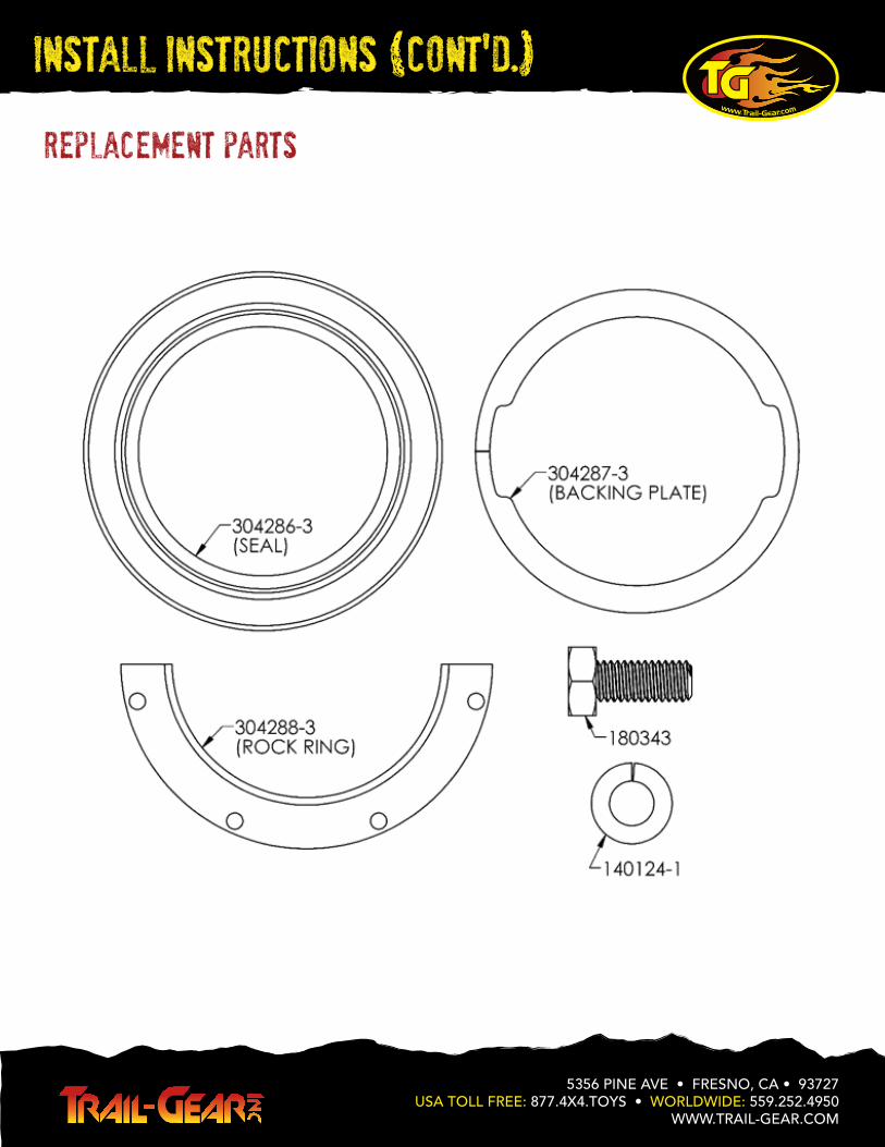
replacement parts
5356 PINE AVE • FRESNO, CA • 93727USA TOLL FREE: 877.4X4.TOYS • WORLDWIDE: 559.252.4950
WWW.TRAIL-GEAR.COM
InstalL Instructions (cont'd.)