Crowned tooth gear couplings
35
N" 1707-1 couplings Crowned tooth gear couplings model MT
-
Upload
khangminh22 -
Category
Documents
-
view
5 -
download
0
Transcript of Crowned tooth gear couplings

N" 1707-1
couplings
Crowned tooth gear couplings model MT

Jaure's competence in power transmission systems is based on more than 40 years of experience in the development and manufacture of couplings and other power transmission elements. Th is is particularly testified by the most extensive supply of gear couplings all over the world , being one of the world 's leaders in the fields of power transmission . Computer-aided designs and the latest manufacturing CNC machines and testing equipment ensure that our products always reflect the state of the
L of drive components. s know-how enable us to introduce
the new crowned tooth gear couplings JAURE's MT series.
Improvements and general features
The new MT series excels thanks to technical and production improvements based on our mentioned experience and thus gives:
• Very large torque capacity, without the sacrifice in safety factors or life expectancy. • Higher permissible additional loads, an important feature for appli:ations with large starting torque, or
1e short-ci rcuit conditions . .... arger than usual hub bores ,
which allows more favourable size selection of the coupling for a certain shaft diameter. This also means that you can select a most economical coupling for your particular application. • DNV Type Approval certificates for our standard MT range certify that our MT gear couplings are found to comply with DET NORSKE VERITAS·rules for classification of ships and Mobile Offshore Units, High Speed and Light Crafts. Our couplings are accepted both for the main propulsion and auxiliary equipment. • A Real Complete Range, offers a comprehensive and simplified selection of crowned tooth gear couplings
widely varying range.
Gear couplings to cover all different
2
JAURE's MT Series: a New Crowned - Tooth Gear coupling
2
industrial applications needs. Even though most applications can use standard couplings, there are numerous applications that are unique, and require special solutions. However, our final target is always to provide our customers with the best technical solutions at optimum economy, offering the:
Highest quality
The design, manufacturing and sales of all of our gear couplings and drive components are integrated into our Quality System, according to UNEEN-ISO 9001 : 94 certified by DET NORSKE VERITAS (DNV) . This Quality Policy covers all the different departments at JAURE.
3
Inventory of standard products and of materials. Quick Service.
In order to provide the quickest delivery, we maintain an ample inventory of standard components and of special materials required for most special orders. Our inventory includes our basic designs (MT, MTX, MTD, MTN, etc.) for all sizes up to 260 mm. bores. However, we also stock semi-finished material to manufacture larger sizes or special designs on a quick turnaround. Even couplings subjected to acceptance by different classification societies like LRS, GL, DNV, BV and RINA to mention

4
some of them, are not except from this. Our stock of components and materials allow us to offer the most rapid
. .,tery, the quickest service and support ..:ase of a break down or event of
coupling damage.
Compliance with AGMA standard. Interchangeability.
7
B
Jaure·s line of MT couplings complies with AGMA standard related to flange and bolt holes. We can therefore supply couplings for replacement of competitor products manufactured to AGMA standards. Not only that, our couplings are interchangeable with other manufacturer products, but also our inventory ensures quick delivery at competitive prices. (See the table of MT flange dimensions based on AGMA standards on page 24) .
Special designs
Both modif ied standard types and special designs are available in any required size irrespective of quantity. Modified types essent ially consists of elements of the basic series which have been sli ghtly changed or equipped with additional components . On the other hand, pure special designs are normally un ique designs to a certain application. Jaure ·s Engineering Department closely
5
V-'" l 'll,
cooperates with customer's engineers to create the best product for their needs. A few examples of our special designs and custom -made solutions are shown on page 25.
Maybe the best example of special designs are the roll mill drives known as "spindles" in the jargon (spindle gear couplings). These components must be designed and manufactured so they will be prepared to cope with: -The extremely reduced space in diameter with regard to the power to be transmitted. -The great shaft-to-shaft span, which can be as much as 7 meters. - High angular misalignment ability (up to about 4°) under rated torque. - High angular misalignment ( up to about 6°) when unloaded. - The need for safe and special sealing joint systems, that can retain the lubricant and prevent the entrance of contaminants even under very severe conditions . These special couplings are made of highly alloyed steels, and the teeth are both through hardened and superficially treated (either by nitriding, carburizing or induction hardening ) and include special systems of floating joints. Jaure·s Engineering Department will be glad to work with you to design couplings to fit your most demanding applications.
1. Partial workshop view.
2. Gear hobbing machine.
3. Gear shaping machine.
4. Couplings ready for expedition.
5. Inventory of standard components.
6. ISO 9001 certified firm & Type
Approvals from DNV.
7. Gear sleeve inspection .
B. View of JAURE "s faci lities.
3

Summary of Contents
• ~oupling description
• Coupling selection
• Coupling types:
~· ~
4
Type Series
MT
MTCL
MTX
MTD
MTS
MTV
MTF
MTFE
Version
Basic Design
With Longer Hubs
Design with Intermediate
Spacer
With Floating Shaft
Continuous Sleeve Design
Vertical Coupling
· Version with Intermediate
Brake Drum
Version with side Brake
Drum
Page
6
7- 8
9
10 .
11
12
. 13
14
15
16

.. ,_oupling types (conL):
~·· Type Series
MTFS
MTCO
•etp . . . .
. : . . ~ . . . .
MTB, MTBR
MTST-B
MTSR-P
.~·. MTES
MTN
• Equivalences with former JAURE gear couplings
• Flange dimensions. AGMA standard
• Special designs
• R~ommendations for shaft/bore fits
• · Critical speeds
"' Keyway and puller hole data
Installation and m~intenance instructions
• Applications
Version
Version with Brake Disc
Extended Sleeve Coupling
Safety Couplings
(Shear Pins)
Safety Coupling ·
(Voith Safeset® Coupling)
Safety Coupling
(Voith Safeset® Coupling)
Disengaging Coupling
Full Range with covers
17
18
19
20
21
22
23
24
24
25-27
28
28
29
30-32
33- 35
5

Coupling Description
1 ne MT gear coupling is a steel double-jointed coupling . The coupling is flexible to accomodate misalignment, but torsionally stiff.
It is formed by two Item 1 hubs which engage a flanged sleeve with internal straight parallel teeth. Item 2-3 (4-5) . As a result of the teeth curvature, if shafts misalignment occurs, the hubs can oscillate in the flanged sleeve. It is nearly impossible to have corner pressure on the teeth or stiffness on the coupling parts, because the coupling acts as a double joint.
High pressure grease lubrication supplied by centrifugal force is provided for diminished teeth friction and wearing . Good sealing is achieved with toroidal gaskets.
The teeth are machined with precision gear machines in a process which guarantees uniform contact on all the teeth.
~ . •rved face teeth couplings are flexible enough to com;sate all types of misalignments and axial movements.
Three types of misalignment must be effectively accommodated by a flexible coupling .
1. Paral lel Offset- axes of connected shafts are parallel, but not in the same straight line.
•·:/ Io ' ~ \
I ,/
2. Angular - axes of shafts intersect at center point of Fig. 1: Detail of the crowned tooth with angular misalignment. coupling, but not in the same straight line
3. Combined Angular Offset- axes of shafts do not intersect at point of coupling and are not parallel.
Fig. 2: Coupling components.
1"""~---, ! -~. -· -· -: . ..,.., -, ' r ~~ :
~--~~
i
End float Offset
Fig. 3: Shaft misalignment.
6
rT r L } } \ ! ~~~~~
Angular
1) Hub 2) Sleeve 3) Sleeve (foro-ring) 4) Sleeve (male) 5) Sleeve (female) 6) 0 -ring 7) Cover 8) Gasket 9) Oil Plug
10) 0-ring 11) Bolt 12) Self Locking Nut 13) Lock washer 14) Nut 15) Bolt 16) Lock washer 17) 0-ring
End ftoat, offset and angular
Technical modifications reserved

Coupling Selection
Coupling size for a certain drive depends not only on the drive unit power and speed but also on the angula r misalignment and the type of machines to be coupled.
When couplings are well aligned, every tooth transmits equally the torque.
If there is an angular shaft misalignment the tooth pressure is uneven, reducing the capacity of the coupling.
The power rating of our couplings have been calculated for an 0°30' angle for each coupling half. The allowed capacity is ±1 o for each half. In special cases and according to specific demands higher-angular misa lignment can be allowed.
c en c
~
r.'..;.
Fig. 4: Torque vs. misalignment.
Angular misalignment
In Fig. N° 4 we give you a statistic curve example of the power diminishing while the misalignment of shaft increases. For ·' the power capacity is reduced by 60% approximately. This rate varies according to the rotation speed.
Selection of size
1) Estimated nominal torque TN (Nm)
TN == 9550~K n
PN = Max. actual power in (Kw) n ==Coupling speed in (r.p.m.) K = Service factor
Alternatively, multiply max. torque (Nm) by service factor and choose in both cases a listed coupling size with a higher rating, or respectively higher torque rating.
2) Should driven shafts be larger in diameter than the max. admissible bore for the chosen coupling, select the next larger size.
3) When using keyway system, verify pressure stresses on it in order to decide if more than one key or longer hubs are necessary.
Listed speeds are max. values for unbalanced couplings. For higher operation speed, the coupling must be dynami~ally balanced. Consult our technical department in th is case.
Technical modifications reserved 7

Coupling Selection -._, .<ecommended Service Factors (S.F.): In order to provide for the dynamic torque which must be transmitted, it may be necessary to increase the horsepower to be transmitted by a factor which will allow for momentary increases in torque due to the characteristics of the equipment. The service factors shown in the table below provide a basis for estimating this allowance for specific combination of connected equipment.
These factors are derived from lengthy field experience with average applications and they are to be considered as a general guide. For conditions not covered by the table, good judgement must be exercised and a factor selected by referring to the type of equipment most closely related to the type of application being considered, or by detailed analysis of the dynamics of the equipment.
Example:
Find a coupling to connect a gearbox with the drum of a conveyor (not uniformly loaded) Motor power PN = 30 Kw. Drum speed n = 100 r. p. m. Gearbox shaft d1 = 80 mm. Drum - side shaft d2 = 100 mm.
Solution:
- rvice factor K = 1 ,4 T = 9550___1Q_ 14 = 4010 Nm N 100 '
As drum - side shaft d2 = 100 mm. we are forced to select coupling size MT - 1 00. Resulting service factor is:
Service factor K = 11700 = 2 g 4010 '
LOAD TYPE DUTY FEATURES DRIVEN EQUIPMENT
Continuous duty without overloads Electric generators UNIFORM or shocks. Centrifugal pumps
Occasional starts-up Light fans Continuous duty with light overloads Multistage centrifugal blowers and shocks for a short time and not Reciprocating pumps frequently. Large fans (heavy duty)
Agitators for liquids LIGHT Agitators for sol ids
Textile machinery Machine tools Conveyor belts Elevators
Intermittent duty with frequent light Reciprocating compressors shocks, medium overloads for a short Cranes (travel or trolley motion) time. Hoisting equipment
MEDIUM Calenders for rubber and plastic Flattening machines Rolling mill drives Non-reversing cold rolling mills
Duty with very high and frequent shocks. Bridge cranes for steel industry Frecuent reversal of the load. Mixers for rubber and plastic High safety degree. Cranes (heavy duty)
Pulp grinders
HEAVY Marine drives Equipment for passengers transport Mine fans Mill delivery and runout tables Non-reversing cold roll ing mills
Extremely high shocks and overloads Reversing cold mills with frequent and momentary reversals. Hot rolling mills
Reversing rolling mill drives
EXTRA Heavy duty in steel industry HEAVY Slitting machines
Grinders Shear and croppers
I Stone crushers
8
Electric motor or Turbine
1
1,4
1,8
2,2
2,5
TYPE DRIVER Hidraulic Reciprocating motor Engine
1,25 1,5
1,75 2
2 2,25
2,5 2,75
3 3,5
Technical modifications reserved

Coupling Types , pe MT Basic design
s s s .. _____________ l _____________ ,lL 1
l l ' L±3§t i I -H- I: i ~ "' % ' ' . ' ' ' 1;]--------
l ~~ 11 a 12
N ~
,---,-- -,-- -,---- -,--- N ~
0 u ""0 0 0
r I
I i I
ul 0 Nl o ,
e $ r--
Size MT 42-260 Size MT 280-800
(1) (2) Max..Speed DIMENSIONS (mm.)
Size PN(KW) TN Nominal n max..(3)
n (Nm) (r.p.m.)
(4) d, - d2 D o, 0 2 11 - 12 s (5)
min. a
max.
42 ' 0.107 1.025 8.600 44 13 . 116 80 60 55 6 75
55 0.225 2.150 6 .600 58 16 152 100 79 70 6 90
. 70 : 0.440 4.200 5.600 . 75 20 178 . 125 101 80 6 108
90 0.754 7.200 4.700 95 25 213 148 124 95 8 124
100 1.225 11.700 4.200 105 30 240 173 143 105 8 136
125 1.80 17.200 3.600 130 35 279 204 170 120 8 158
: 145 2.88 27.500 3.150 150 45 318 242 205 135 10 172
165 3.98 38.000 2.860 165 55 346 268 216 150 10 192
185 5.36 51.200 2.580 190 60 389 302 250 170 10 210
205 7.05 67 .300 2.320 210 70 425 327 275 185 12 230
230 9.21 88.000 2.200 230 100 457 354 300 200 12 250
260 14.08 134.500 2.000 260 115 527 410 340 230 12 280
280 18.85 180.000 1.800 280 140 540 465 370 250 16 300
310 26.2 250.000 1.600 310 160 585 505 410 270 16 320
345 33.5 320.000 1.500 345 180 650 548 450 290 16 340
370 41 .8 400.000 1.400 370 210 690 588 490 325 20 370
390 53.4 510.000 1.300 390 230 760 640 520 345 20 400
420 69.1 660.000 1.200 420 250 805 690 560 365 20 420
460 81.7 780.000 . 1.100 460 275 850 730 600 . 400 20 450
500 104.7 1.000.000 1.050 500 300 930 780 650 410 25 490
550 125.7 1.200.000 950 550 325 .995 850 710 430 25 520
590 167.5 1.600.000 900 590 350 1.055 910 760 470 25 550
620 188.5 1.800.000 850 620 375 1.140 970 810 500 30 600
650 199.0 1.900.000 800 650 400 1.190 1.020 840 520 30 630
680 219.9 2.100.000 750 680 425 1.250 1.080 890 540 30 650
730 277.3 2.600.000 700 730 450 1.300 1.150 950 570 30 680
800 397.9 3.800.000 660 800 475 1.420 1.270 1.050 600 30 725
(1) PN =Nominal Power rn (Kw); n = r.p.m. (2) TN = Nominal Torque in Nm; During start up the coupling can be loaded at 200% of nomina l torque capacity. (3) Consult JAURE for couplings operating at higher speeds.
J (6) (7)
(Kgm2)
0,0055
0,021
0,048
0,125
0,200
0,48
0,93
1,55
2,70
4,10
5,55
9,15
14,83
22,30
36,78
52,6
78,8
110,8
152,4
213 ,8
309,8
422
677
762
850
1.210
1.620
14) Max. admissible bore for couplings with DIN 6885/1 keys. For other types of keys or connections please consult JAURE. In case pulling holes are used verify page 29 for maximum shaft diameter.
1 Clearence to align coupling hubs and replacement of sealing rings. (6) GD2 = 4J. (7) J and Weight are given for minimum bore.
Technical modifications reserved
s
I w
N 0 u
Weight Lubricant (7)
(Kg.) (Kg.)
5 0,04
10 0,06
17 0,17
28 0,24
40 0,36
65 0,50
95 0,70
134 1,30
185 1,75
240 2,2
273 2,8
412 4,5
525 3,0
750 3,6
890 4,8
1.275 5,0
1.390 9,0
1.660 9,8
2.010 11 ,5
2.460 11,5
3.070 14,5
3.410 23
4.550 23
5.035 30
6.270 36
6.910 38
9.750 46
9

Coupling Types . ,Je MTCL · Longer hubs
s ·-·-·----··-~--------··· .. ;
hr ' ~·~
V ///////.7 ~,>, '<', "'"' "'"-;
~ 11 a 12
N - r--- r-- - N 0 0 u 0 0
$$ '----
Size MTCL 42-260 Size MTCL 280-800
(1) (2) Speed (3) DIMENSIONS (mm.)
P11 (KW) TN Nominal n max. ,ze n d,- d2 (4) (Nm) (r.p.m.) D D, 0 2 11 - 12 a s (5)
max. min.
42 0.107 1.025 8 .600 44 13 116 80 60 110 6 130
55 0.225 2.150 6 .600 58 16 152 100 79 110 6 130
70 0.440 4.200 5.600 75 20 178 125 101 140 6 170
90 0.754 7.200 4.700 95 25 213 148 124 170 8 200
100 1.225 11 .700 4.200 105 30 240 173 143 170 8 200
125 1.80 17.200 3.600 130 35 279 204 170 210 8 250
145 2.88 27.500 3 .150 150 45 318 242 205 250 10 290
165 3.98 38.000 2.860 165 55 346 268 216 250 10 290
185 5.36 51.200 2.580 190 60 389 302 250 310 10 350
205 7.05 67.300 2.320 210 70 425 327 275 310 12 350
230 9.21 88.000 2.200 230 100 457 354 300 350 12 400
260 14.08 134.500 2.000 260 115 527 410 340 440 12 490
280 18.85 .18o:ooo 1.800 280 . 140 540 465 370 440 16 490
310 26.2 250.000 1.600 310 160 585 505 410 440 16 490
145 33.5 320.000 1.500 345 180 650 548 450 560 16 610
370 41 .8 400 .000 1.400 370 210 690 588 490 560 20 610
390 53.4 510.000 1.300 390 230 760 640 520 700 20 760
420 69.1 660.000 1.200 420 250 805 690 560 700 20 760
460 81.7 780.000 1.100 460 . 275 850 730 600 860 20 940
500 104.7 1.000.000 1.050 500 300 930 780 650 860 25 940
. 550 125.7 1.200.000 950 550 325 995 850 710 860 25 940
590 167.5 1.600.000 900 590 350 1.055 910 760 860 25 940
620 188.5 1.800.000 85o 620 375 1.140 970 810 1.000 30 1.100
650 199.0 1.900.000 800 650 400 1.190 1.020 840 1.000 30 1.100
680 219.9 2.100.000 750 680 425 1.250 1.080 890 1.000 30 1.100
730 277.3 2.600.000 700 730 450 1.300 1.150 950 1.000 30 1.100
800 397.9 3 .800.000 660 800 475 1.420 1.270 1.050 1.000 30 1.100
(1) PN = Nominal Power in (Kw); n = r.p.m. (2) TN= Nominal Torque in Nm; During start up the coupling can be loaded at 200% of nominal torque capacity. (3) Consult JAURE for couplings operating at higher speeds.
J (6) (7)
(Kgm2)
0,066
0,021
0,057
0,152
0,242
0,596
1,242
1,884
3,54
5,20
7,40
13,4
20,2
29,5
53,4
72,8
99,1
160
. 240
332
470
614
994
1.110
1.272
1.723
2.338
(4) Max. admissible bore for couplings with DIN 6885/1 keys. For other types of keys or connections please consult JAURE. In case pulling holes are used verify page 29 for maximum shaft diameter. Clearence to align coupling hubs and replacement of sealing rings.
I GD2 = 4J. (7) J and weight are given for minimum bore.
Weight (7)
(Kg.)
7,1 :
12,9
24,0
41,6
55,6
95,7
152
188
286
349
421
677
800
1.048
1.456
1.843
1.990
2.697
3.622
3.304
5.182
5.598
7.728
8 .263
9.738
10.620
14.074
0
Lubricant
(Kg.)
0,04
0,06
0,17
0,24
0,36
0,50
0,70
1,30
1,75
2,2
2,8
4,5
3,0
3,6
4,8
5,0
9,0
9,8
11 ,5
11 ,5
14,5
23
23
30
36
38
46
10 Technical modifications reserved
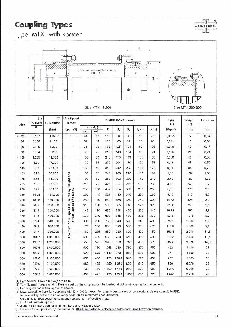
Coupling Types , pe MTX with spacer
-'ize
42
55
70
90
100
125
145
165
i 0 N! o :
!
(1)
PN (KW) n
0.107
0.225
. 0.440
0.754
1.225
1.80
2.88
3.98
185 . 5.36
205 7.05
230 9.21
260 14.08
280 18.85
310 26.2
345 33.5
370 41 .8
390 53.4
420 69.1
460 81.7
500 104.7
550 125.7
590 167.5
620 188.5
650 199.0
680 219.9
730 277 .3
800 397.9
s
(2) Max.Speed
TN Nominal n max.
(Nm) r.p.m.(3)
1.025
2.150
4.200
7.200
11.700
17.200
27.500
38 .000 'C r::
"' 51.200 ·. .... .r::
67 .300 .!:!> "' ::
88.000 >...: .0 Q)
(.)
134 .500 'C <0
"' c. -~ tJ)
180.000 E-:: .. o 250 .000 IJ)'C
·- Q) 'C Q)
320.000 Q)C. Q) II)
400.000 a.-II) <0 . -~ E~
510.000 .....
C.'-' ..:
660.000 >( <0
780.000 E Q)
1.000.000 t: 1.200.000
1.600.000
1.800.000
1.900.000
2.100.000
2.600.000
3.800.000
(1) PN =Nominal Power in (Kw); n = r.p.m.
s
J " I o
'
Size MTX 42-260
DIMENSIONS (mm.)
d1 - d2 (4) D 01 02 11 - 12 s (5)
max. min.
44 13 116 80. 60 55 75
58 16 152 100 79 70 90
75 20 178 125 101 80 108 .
95 25 213 148 124 95 124
105 30 ;240 173 143 105 136
130 35 279 204 170 120 158
150 45 318 242 205 135 172
165 55 346 268 216 150 192
190 60 389 302' 250 170 210
210 70 425 327 275 185 230
230 100 457 354 300 200 250
260 115 527 410 340 230 280
280 140 540 465 370 250 300
310 160 585 505 410 270 320
345 180 650 548 450 290 340
370 210 690 588 490 325 370
390 230 760 640 520 345 400
420 250 805 690 560 365 420
460 275 850 730 600 400 450
500 300 930 780 650 410 490
550 325 995 850 710 430 520
590 350 1.055 910 760 470 550
620 375 1.140 970 810 500 600
650 400 1.190 1.020 840 520 630
680 425 1.250 1.080 890 540 650
730 450 1.300 1.150 950 570 680
800 475 1.420 1.270 1.050 600 725
(2) TN = Nominal Torque in Nm; During start up the coupl ing can be loaded at 200% of nominal torque capacity. (3) See page 28 for critical speed of spacer.
Size MTX 280-800
J (6) Weight Lubricant (7) (7)
(Kgm2) (Kg.) (Kg.)
0,0055 5 0,04
0,021 10 0,06
0,048 17 0,17
0,125 28 0,24
0,200 40 0,36
0,48 65 0,50
0,93 95 0,70
1,55 134 1,30
2,70 185 1,75
4,10 240 2,2
5,55 273 2 ,8
9, 15 412 4,5
14,83 525 3,0
22,30 750 3,6
36,78 890 4,8
52,6 1.275 5,0
78,8 1.390 9,0
110,8 1.660 9,8
152,4 2.010 11 ,5
21 3,8 2.460 11 ,5
309,8 3.070 14,5
422 3.410 23
677 4.550 23
762 5.035 30
850 6.270 36
1.210 6.910 38
1.620 9.750 46
(4) Max. admissib le bore for couplings with DIN 6885/1 keys. For other types of keys or connections please consult JAURE. In case pulling holes are used verify page 29 for maximum shaft diameter. Clearence to align coupling hubs and replacement of sealing rings.
, ... ) G02 = 4J. Without spacer. (7) J and weight are given for minimum bore and without spacer. (8) Distance to be specified by the customer. DBSE is distance between shafts ends. not between flanges.
Technical modifications reserved 11

Coupling Types ., pe MTD with floating shaft
(Distance Between Shafts Ends) OBSE (3)
----~
t---------->+J<------->1 N I "' U j 0
Size MTD 42-260
(1 ) (2) Max Speed DIMENSIONS (mm.)
Size PN (KW) TN Nominal n m ax.
n d (4) (4)~-dz (Nm) 0 0 1 02 0 3 11 - 12 max. min. max.
. 42 0.107 1.025 44 13 . 55 116 80 60 80 55
55 0.225 2.150 58 16 70 152 100 79 100 70
70 0.440 .. 4.200 75 20 90 178 125 101 125 80
90 0.754 7.200 95 25 105 213 148 124 148 95
. 100 1.225 11 .700 105 30 120 240 173 143 173 105
125 1.80 17.200 130 35 145 279 204 170 204 120
145 2.88 27.500 . 150 45 170 318 242 205 242 135 ..
165 3.98 38.000 "0 165 55 190 346 268 216 268 150 <:::
"' 185 5.36 51.200 - 190 60 215 389 302 250 302 170 ,t;; 0)
205 7.05 67.300 ·a; . 210 70 230 425 327 275 327 185 :;~
230 9.21 88.000 ,.,..c:: • 230 100 250 457 354 300 354 200 .ocnw 260 14.08 134.500
"0 Cl 0:: 260 115 290 527 410 340 410 230 "' .:: ~
. 280 18.85 180.000 · ~tO.,
280 140 290 540 465 370 410 250 =~~ 310 26 .2 250.000
Cl) :::1 31 0 160 350 585 505 410 460 270 ·- 0 ~
"0 'C 0 345 33.5 320.000 Q) Q) 0 345 180 380 .650 548 450 500 290
"' Q) . O.c.Ol 370 41.8 400.000 <r> en <r> 370 21 0 410 690 588 490 540 325 . "' E - "' co-390 53 .4 510.000 • 0 0.. 390 230 450 760 640 520 590 345 0.·-
...: ~ 420 69.1 660.000 x o 420 250 480 805 690 560 630 365
"' 460 81.7 780.000 E 460 275 520 850 730 600 680 400 Q)
500 104 .7 1.000.000 ..c::
500 300 560 930 780 650 730 410 f-
550 125.7 1.200.000 550 325 600 995 850 710 790 430
590 167.5 1.600.000 590 350 650 1.055 910 760 850 470
620 188.5 1.800.000 . 620 375 680 .1.140 970 810 890 500
650 199.0 1.900.000 650 400 710 1.190 1.020 840 930 520
680 21 9.9 2.100.000 680 425 770 1.250 1.080 890 1.010 540
730 277.3 2.600.000 730 450 810 1.300 1.150 950 1.060 570
. 800 397.9 3.800.000 800 475 900 1.420 1.270 1.050 1.170 600
(1) PN =Nominal Power in (Kw); n = r. p.m. (2) TN= Nominal Torque in Nm; During start up the coupling can be loaded at 200% of nominal torque capaci ty. (3) Distance to be specified by the customer. DBSE is distance between shafts ends. not between flanges.
Size MTD 280-800
J (5) Weight Lubricant (6) (6)
a (Kgmz) (Kg.) (Kg.)
7 0,011 95 11 0,04
7 0,0443 22 0,06
7 0,100 36 0,17
8 0,248 60 0,24
8 0,426 100 0,36
8 1,000 138 0,50
10 1,94 205 0,70
10 3,14 280 1,30
10 5,70 400 1,75
11 8,56 510 2,2
11 11,45 590 2,8
12 21,23 890 4 ,5
14 28,53 1.045 3,0
14 43 ,94 1.430 3,6
16 71,20 1.770 4,8
18 103,40 2.390 5,0
18 140 2.590 9,0
18 216 3.344 9,8
18 300 4 .075 11 ,5
22 420 4.930 11 ,5
22 608 6.120 14,5
22 850 7.190 23
25 1.140 9.014 23
25 1.470 10.135 30
25 1.820 12.400 36
25 2.430 13.960 38
25 3.500 18.800 46
'4) Max. admissible bore for coupl ings with DIN 6885/1 keys. For other types of keys or connections please consult JAURE. In case pulling holes are used veri fy page 29 for maximum shaft diameter.
,JJ GDZ = 4J. Without intermediate shaft. (6) J and weight are given for minimum bore and without shaft The coupling is supplied with a sealing compound on the intermediate shaft keyways.
12 Technical modifications reserved

Coupling Types , pe MTS with continuous sleeve
s
0
B R
Size MTS 22-260 Size MTS 280-800
22
32
38
50
55
70
90
100
125 145
165
185
205
230
260
280
310
345
370
390
420
460
500
550
590
620
. 650
680
730
800
(1) (2) Speed
PN (KW) TN Nominal n max. (3)
n
0,053
0,068
0,079
0,120
0,225
0,440
0,754
1,225
1,80
2,88
3,98
5,36
7,05
9,21
14,08
18,85
26,2
33,5
41 ,8
53,4
69,1
81,7
104,7
125,7
167,5
188,5
199,0
219,9
277,3
397,9
(Nm) (r.p.m.)
500
650
750
1 .150
2 .150
4 .200
7 .200
11 .700
17.200
27.500
38.000
51 .200
67.300
88.000
134.500
180.000
250.000
320.000
400.000
510.000
660 .000
780 .000
. 1.000.000
1.200.000
1.600.000
1.800.000
1.900.000
2 .100.000
2 .600.000
3.800.000
12.000
10.500
9.500
9.000
7.000
5.600
4.700
4 .200
3,600
3 .150
2.860
2.580
2.320
2.200
. 2.000
1.800
1.600
1.500
1.400
1.300
1.200
1.100
. 1.050
950
900
850
800
750
700
660
(1) PN =Nominal Power in (Kw); n = r.p.m.
max. min.
22
32
38
50
8
10
14
18
20
20
25
30
35
45
55
60
70
100
115
140
160
180
210
230
250
275
300
325
350
375
400
425
450
DIMENSIONS (mm.)
D
56
70
80
96
112
140
164
185
215
255
280
317
345
374
414
465
505
548
588
640
690
730
780
850
910
970
1.020
1.080
1.150
36.. 30
48 40
56 45
68 55
80 70
101 80
124 . 95
143 105
170 120
205 135
216 150
250 170
275 185
300 200
340 230
370 250
410 270
450 290
490 325
520 345
560 365
600 400
650 410
710 430
760 470
810 500
840 520
890 540
950 570
4
4
4
6
6
6 8 .
8
8
10
10
10
12
12
12
16
16
16
20
20
. 58
75
95
105
130
150
165
190
210
230
260
280
310
345
370
390
420
460
500
550
590
620
650
680
730
800 475 1.270 1.050 600
. 20
20
25
25
25
30
30
30
30
30
s (5)
57
71
84
91
108
130
145
150
165
195
215
245
275
295
355
345
375
400
450
480
510
560
570
600
660
700
730
755
800
850
B
47
56
68
74
85
106
116
120
130
150
170
190
210
226
266
275
295
315
350
370
390
430
440
460
500
530
550
574
604
634
(2) TN= Nominal Torque in Nm; During start up the coupling can be loaded at 200% of nominal torque capacity. (3) Consult JAURE for couplings operating at higher speeds.
J (6) (7)
(Kgm2)
0,0005
0,0010
0,0020
0,0037
0,0086
0,0342
0,0753
0,129
0,268
0,631
0,952
1,830
2,865
4 ,225
7,50
11 ,1 2
16,21
25,00
37,50
53,25
77,5
114
146
218
308
430
532
668
922
1.455
'I Max. admissible bore for couplings with DIN 6885/1 keys. For other types of keys or connections please consult JAURE. In case pull ing holes are used verify page 29 for maximum shaft diameter.
t::>) Clearence to align coupling hubs and replacement of sealing rings. (6) GD2 = 4J. (7) J and weight are given for minimum bore.
Technical modifications reserved
Weight (7)
(Kg.)
0,81
1,72
2,52
3,75
7,12
15,26
24,8
34
52,6
86
108
162
211
256
366
446
558
712
906
1.100
-1.360
1.715
1.958
2.464
3.050
3 .720
4 .160
4.720
5.730
7 .520
Lubricant
(Kg .)
0,004
0,008
0,010
0,022
0,034
0 ,050
0,070
0 ,085
0,115
0,16
0,30
0,40
0,50
0,60
1,25
3,50
3,90
4 ,80
6,00
8,80
9,50
11 ,0
12,5
17
22
24
30
38
42
50
13

Coupling Types . , ,Je MN for vertical installation
(/)
(/)
(1) (2) Speed (3)
Size PN (KW) TN Nominal n max.
n (Nm) (r.p.m .)
42 0.1 07 1.025 8.600
55 0 .225 2.150 6 .600
70 0.440 4.200 5.600
90 0 .754 7.200 4.700
100 1.225 11.700 4.200
125 1.80 17.200 3.600
145 2.88 27.500 3.150
165 3.98 38.000 2.860
185 5.36 51 .200 2.580
205 7.05 67.300 2.320
230 9.21 88.000 2.200
260 14.08 134.500 2.000
(1) PN =Nominal Power in (Kw); n = r.p.m.
r
---------------- _____ _Q __________________ _
02
d1
I I ~"I
d2
! 01 j'(-----------------------
DIMENSIONS (mm.)
d,- d2 (4) D D, 0 2 11 - 12 a
max. min .
44 13 116 80 60 55 8
58 16 152 100 79 70 8
75 20 178 125 101 80 8
95 25 213 148 124 95 9
105 30 240 173 143 105 9
130 35 279 204 170 120 12
150 45 318 242 205 135 13
165 55 346 268 216 150 13
190 60 389 302 250 170 14
210 70 425 327 275 185 16
230 100 457 354 300 200 16
260 115 527 410 340 230 16
s (5)
75
90
108
124
136
158
172
192
210
230
250
280
(2) TN= Nominal Torque in Nm; During start up the coupling can be loaded at 200% of nominal torque capacity. (3) Consult JAU RE for couplings operating at higher speeds.
J (6) Weight (7) (7)
F (Kgm2) (Kg.)
3 0,006 5
3 0,021 10
3 0,048 17
3 0,125 29
3 0 ,20 44
5 0,48 68
5 0,90 100
5 1,45 134
5 2,70 190
6 4,15 255
6 5 ,60 285
6 9 ,35 420
(4) Max. admissible bore for couplings with DIN 6885/1 keys. For other types of keys or connections please consult JAURE. In case pulling holes are used verify page 29 for maximum shaft diameter. Clearence to align coupling hubs and replacement of sealing rings.
I GD2 = 4J. (7) J and weight are given for minimum bore. For lubricant quantity and method for MTV, please consult JAURE.
14 Technical modifications reserved

Coupling Types , 2e MTF with intermediate brake drum
lL 0
8
/
I ~J I
-·--·--~'f.
-----·---'------ ...J
(1) (2) Speed DIMENSIONS (mm.)
Size PN (KW) TN Nominal n max.(3)
n d1 - d2 (4) (Nm) (r.p.m.) D 01 0 2 12 - 11 a
max. min.
42 0.107 1.025 2.850 . 44 13 116 80 60 55 16
2.850 16
55 0.225 2.150 2.300 58 16 152 100 79 70 16
1.800 18
2.300 16
1.800 18 70 . 0.440 4.200 75 20 178 125 101 80
1.650 18
1.450 22
1.800 20
90 0.754 7.200 1.650 95 25 213 148 124 95 22
1.450 22
1.800 20
1.650 22 100 . 1.225 11 .700 105 30 240 173 143 105
1.450 22
1.300 22
1.450 22
125 1.80 17.200 1.300 130 35 279 204 170 120 22
1.150 22
1.150 25
145 2.88 27.500 1.100 150 45 318 242 205 135 25
1.000 28
1.1 50 25
1.100 25 165 3.98 38.000 165 55 346 268 216 150
1.000 28
800 28
(1) PN =Nominal Power in (Kw); n = r.p.m.
0
s (5) OF
75 200
200
90 250
315
250
315 108
350
400
315
124 350
400
315
350 136
400
450
400
158 450
500
500
172 530
630
500
530 192
630
710
(2) TN= Nominal Torque in Nm; During sta rt up the coupling can be loaded at 200% of nominal torque capacity. (3) Consult JAURE for couplings operating at higher speeds.
J (6) (7)
B (Kgm2)
75 0,045
75 0,054
95 0,110
11 8 0,340
·e5 0,120
118 0,360
130 0,500
150 0,96
11 8 0,41
130 0,56
150 1,00
118 0,45
130 0,60
150 1,10
170 1,55
150 1,40
170 2,00
190 2,95
190 3,40
195 4,15
236 8,45
190 3,9
195 4,6
236 9,0
265 15,8
(4) Max. admissible bore for couplings with DIN 6885/1 keys. For other types of keys or connections please consult JAURE. In case pulling holes are used verify page 29 for maximum shaft diameter .
. , Clearence to align coupling hubs and replacement of sealing rings. GD2 = 4J.
(7) J and weight are given for minimum bore.
Technical modifications reserved
Weight Lubricant (7)
(Kg.) (Kg.)
' 10 . 0,04
14
18 0,06
24
24
31
35 0,17
42
42
46 0,24
56
54
59 0,36
69
74
93
98 0,50
11 3
143
153 0,70
193
182
192 1,30
232
277
15

Coupling Types . , ,.:>e MTFE with side brake drum
(1)
Size PN (KW) n
42 0.107
55 0.225
70 0.440
90 0.754
100 1.225
125 1.80
145 2.88
165 3.98
(2)
TN Nominal
(Nm)
1.025
2.150
4.200
7.200
11.700.
17.200
27.500
38.000
lL 0
Speed
n max.(3)
(r.p.m .)
2.850
2.850
2.300
1.800
2.300
1.800
1.650
1.450
1.800
1.650
1.450
1.800
1.650
1.450
1.300
1.450
1.300
1.150
1:150
1.100
1.000
1.150
1.100
1.000
800
(1) PN = Nominal Power in (Kw); n = r.p.m.
B
11
d, -d2 (4) max. min.
44 13
58 16
75 20
95 25
105 30
130 35
150 45
165 55
/
D
116
152
178
213
240
279
318
346
N , N 0
I
01 I i
----···--·--- - 'f-
DIMENSIONS (mm.)
D, 0 2 I, 12 a s (5) OF
80 60 95 55 6 75 200
115 200
100 79 125 70 6 90 250
140 315
130 250
145 315 125 101 80 6 108
145 350
160 400
155 315
148 124 155 95 8 124 350
170 400
155 315
155 350 173 143 105 8 136
170 400
180 450
200 400
204 170 210 120 8 158 450
220 500
220 500
242 205 220 135 10 172 530
250 630
235 500
235 530 268 216 150 10 192
265 630
280 710
(2) TN= Nominal Torque in Nm; During start up the coupling can be loaded at 200% of nominal torque capacity. (3) Consult JAURE for couplings operating at higher speeds.
0
J (6) Weight Lubricant (7) (7)
B (Kgm2) (Kg.) (Kg.)
75 0,046 12 0,04
75 0,055 17
95 0,113 22 0,06
118 0,353 35
95 0,140 28
118 0,380 42
130 0,530 46 0,17
150 1,00 57
118 0,44 53
130 0,60 57 0,24
150 1,07 71
118 0,51 65
130 0,66 69
150 1,13 84 0,36
170 1,60 . 94
150 1,45 108
170 2,03 119 0,50
190 3,00 129
190 3,50 159
195 4,35 171 0,70
236 8,75 221
190 4,3 198
195 5,1 211
236 9,5 260 1,30
265 16,5 312
14) Max. admissible bore for couplings with DIN 6885/1 keys. For other types of keys or connections please consult JAURE. In case pulling holes are used verify page 29 for maximum shaft diameter.
,- J Clearence to align coupling hubs and replacement of sealing rings. (6) GD2 = 4J. (7) J and weight are given for minimum bore.
16 Technical modifications reserved

Coupling Types . , ~e MTFS with brake disc
I id
I Ni I N u
0 01 0 "0!
I
X Optional:
13 12 Self Ventilated disc
Speed DIMENSIONS (mm.) Bolt Data J (3) Weight(3)
Size TN Nominal n max.(1) pos . A (4) (4)
(Nm) (r.p.m.) d,(2) d2 (2)
D D, 02 03 o. Ds I, 12 13 X Z-M Nm (Kgm2) (Kg.) max. max.
3.000 50 315 124 105 85 82 107 117 102 9-M10 49 0,23 32
2.700 60 355 145 125 105 100 107 117 102 9-M12 86 0,37 38 55 2.1 50 58 152 70
2.400 70 395 165 140 115 110 107 117 102 9-M14 135 0,54 46
2.100 70 445 175 146 120 112 140 117 135 12-M16 210 0,82 51
2.400 70 395 165 140 115 110 107 117 102 9-M14 135 0,56 53
2.100 70 445 175 146 120 112 140 130 135 12-M16 210 0,87 57 70 4.200 75 178 80
1.900 100 495 218 190 160 155 140 145 135 12-M18 290 1,42 81
1.800 100 550 218 190 160 155 140 145 135 12-M18 290 1,88 88
2.100 70 445 175 146 120 11 2 140 145 135 12-M16 210 0,95 71
1.900 100 495 218 190 160 155 140 164 135 12-M18 290 1,47 94 90 7.200 95 213 95
1.800 100 550 218 190 160 155 140 164 135 12-M18 290 1,92 103
1.500 105 625 238 205 170 168 140 164 135 12-M20 410 3,33 130
1.900 100 495 218 190 160 155 140 180 135 12-M18 290 1,57 109
1.800 100 550 218 190 160 155 140 180 135 12-M 18 290 1,97 117 100 11 .700 105 240 105
· 1.500 105 625 238 205 170 168 140 180 135 12-M20 410 3,43 140
1.300 120 705 268 230 195 190 140 180 135 12-M22 550 5,73 171
1.500 105 625 238 205 170 168 140 196 135 12-M20 410 3,73 166
125 17.200 1.300 120 130 705 268 230 195 190 279 140 120 196 135 12-M22 550 5,93 194
1.200 135 795 300 260 220 216 140 196 135 12-M24 710 9,42 241
1.500 105 625 238 205 170 168 140 223 135 12-M20 410 4,13 200
145 27.500 1.300 120 150 705 268 230 195 190 318 140 135 223 135 ~2-M221 550 6,23 236
1.200 135 795 300 260 220 216 140 223 135 12-M24 710 9,82 275
1.300 120 705 268 230 195 190 140 238 135 12-M22 550 6,88 271 165 38.000 165 346 150
1.200 135 795 300 260 220 216 140 238 135 12-M24 710 10,32 315
(1) Consult JAURE for couplings operating at higher speeds. (2) Max. admissible bore for couplings with DIN 6885/1 keys. For other types of keys or connections please consult JAURE.
In case pulling holes are used verify page 29 for maximum shaft diameter. ' GD2 = 4J. (Values with solid disc.) , J and weight are given for minimum bore and with solid brake disc.
Technical modifications reserved
Lubricant
(Kg.)
0,06
0,17
0,24
·.
0,36
0,50
0,70
1,30
17

Coupling Types
I
. , r->e MTCO with extended sleeve
N 0 0 N [ ~ "0 Oi
! ;
(1) (2) Speed (3) DIMENSIONS (mm.)
Size PN (KW) TN Nominal n max.
n d1- d2 (4) (Nm) (r.p.m.) D 01 02 11 - 12 a a1
max. min.
42 0.107 1.025 8.600 44 13 116 80 . 60 55 6 16
55 0.225 2.150 6.600 58 16 152 100 79 70 6 21
70 0.440 4 .200 5.600 75 20 178 125 101 80 " 6 26
90 0.754 7.200 4 .700 95 25 213 148 124 95 8 33
100 1.225 11.700 4.200 105 30 240 173 143 105 8 48
125 1.80 17.200 3 .600 130 35 279 204 170 120 8 50
145 2.88 27.500 3.150 150 45 318 242 205 135 10 56
165 3.98 38 .000 2.860 165 55 346 268 216 150 10 66 . .
185 5.36 51.200 2.580 190 60 389 302 250 170 10 78
205 7.05 67.300 2.320 210 70 425 327 275 185 12 90
230 9.21 88.000 2.200 230 100 457 354 300 200 12 96
260 14.08 134.500 2.000 260 115 527 410 340 230 12 112
(1) PN =Nominal Power in (Kw); n = r.p.m. (2) TN= Nominal Torque in Nm; During start up the coupling can be loaded at 200% of nominal torque capacity. (3) Consult JAURE for couplings operating at higher speeds.
N 0 "0
j (5) Weight Lubricant (6) (6)
a2 (Kgm2) (Kg .) (Kg.)
26 0,0055 5 0,04
36 0,021 10 0,06
46 0,048 17 0,17
58 0 ,125 28 0,24
88 0,200 40 0,36
92 0,48 65 0,50
102 0,93 95 0,70
122 1,55 134 1,30
146 2,70 185 1,75
168 4,10 240 2 ,20
180 5,55 273 2,80
212 9,15 412 4,50
14) Max. admissible bore for couplings with DIN 6885/1 keys. For other types of keys or connections please consult JAURE. In case pulling holes are used verify page 29 for maximum shaft diameter.
. 1 GD2 = 4J. (6) J and weight are given for minimum bore.
18 Technical modifications reserved

Coupling Types , .ear pin types MTB / MTBR
I
Size MTB
$ 1- ' _ I
I -,..- ·-------···---·--····r----·-··---1
TYPE MTB
(1) (2) Speed (3)
PN (KW) TN Nominal n max.
n (Nm) (r.p.m.)
max. min. D
! 0 5 El l
DIMENSIONS (mm.)
OSSE
TYPE MTBR
L a D.B.C
12
J (6) (7)
(Kgm2)
55
70
9·o
0.225. • . . :2.150 . 4.400
4.000
3 .500
3.000
2.600
2.400
2.200
1.800
1.700
1.600
1.500
58
75
95
105
130
150
165
190
210
230
260
16 152 100 79 220 70 182 42 185 0,082
100
125
145
165
185
205
230
260
Size IVITBR
42 •
55
70
90
100
125
145
165
185
205
230
260
0.440 4.200
0.754 7.200
1.225 11 .700
1.80 17.200
2.88
3.98
5.36
7.05
9.21
14.08
(1}
PN (KW) n
0.136
0.262
0 .450
0.733
· 1.215
1.990
2.827 .
4.084
5.654
7.225
10.262
13.612
27.500
38.000
51.200
67.300
88 .000
134.500
(2}
TN Nominal
(Nm)
1.300
2.500
. 4.300
7 .000
11 .600
19.000
27.000
39.000
54.000
69.000
98.000
130.000
Speed (3)
n max.
(r.p.m.)
6490
5770
5140
4310
381 0
3420
3000
2750
2450
2300
2020
1870
(1) PN = Nominal Power in (Kw); n = r.p.m.
d1 max.
48
60
70
85
100
120
140
160
180
200
220
250
20 178 125 101 250 80 202 42 215 0,15
25 213 148 124 285 95 232 42 250 0,30
30 240 173 143 335 105 275 65 285 0,79
35 279 204 170 370 120 305 65 320 1,36
45 318 242 205 410 135 337 67 360
55 346 268 216 435 150 367 67 385
60 389 302 250 520 170 424 84 450
70 425 327 275 560 185 456 86 490
100 457 354 300 590 200 486 86 520
115 527 41 0 340 660 230 546 86 590
DIMENSIONS (mm.)
(4) d2 (4) DBSE D D1 D2 DJ D4 11 - 12 s (5 min. max.
13 55 145 11 3 65 80 153 55 123±1 80
16 65 164 126 80 95 172 70 134±1 90
20 80 184 147 95 112 193 80 145±2 100
25 95 220 176 112 135 230 95 156±2 130
30 110 240 200 135 160 260 105 186±2 140
35 130 270 230 160 185 290 120 195±2 150
45 145 310 256 185 210 330 135 ~10±2 160
55 160 340 292 210 230 360 150 242±3 190
60 180 380 315 230 255 405 170 [265±3 210
70 205 405 340 255 290 432 185 300±3 230
100 225 445 377 290 320 490 200 ~20±3 250
115 250 490 415 320 360 530 230 354±3 280
2,26
3 ,24
6,76
9 ,56
12,28
19,68
J (6) (7)
(Kgm2)
0,035
0 ,055
0,10
0,23
0,42
0 ,70
1,45
2,25
3,75
5,70
9,75
15,00
(2) TN = Nominal Torque in Nm; During start up the coupling can be loaded at 200% of nominal torque capacity. (3) Consult JAURE for couplings operating at higher speeds. ,.) Max. admissible bore for couplings with DIN 6885/1 keys. For other types of keys or connections please consult JAURE.
Clearence to align coupling hubs and replacement of sealing rings. ,,) GD2 = 4J. (7) J and Weight are given for minimun bore.
Technical modifications reserved
Weight (7)
(Kg.)
20
30
45 82
11 6
158
205
305
380
428
605
Weight (7)
(Kg.)
13,8
19,5
30
53
68
96
137
192
264
333
460
598
Lubricant
(Kg.)
0,06
0,17
0,24
0,36
0,50
0,70
1,30
1,75
2,2
2,8
4,5
Lubricant
(Kg.)
0,07
0,10
0,12
0,22
0,30
0,40
. 0,60
1,00
1,1 0
1,60
2,00
1,30
19

Coupling Types ., ~e MTST-B with Safeset® safety element
rv1 (4x)
Size MTST-B 70/60-260/190
Size MTST-B 280/200-31 0/220
T DIMENSIONS (mm.)
Size Torque Range
(Nm) d3 13 d2 (1) D 01 0 2 03 12 a s (2) d4 max. min.
70/60 1.800-3.600 60 . 137 75 20 178 125 101 136 . 80 15 108 40
90/70 3.000-6.000 70 150 95 25 213 148 124 148 95 18 124 50
100/80 3.900-7.800 80 166 105 30 240 173 143 157 105 18 136 50
. 25/90 5.000-10.000 90 184 130 35 279 204 170 168 120 22 158 65
+5/100 7.500-15.000 100 206 150 . 45 318 242 205 183 135 25 172 70
145/110 10.000-20.000 110 208 150 45 318 242 205 201 135 25 172 80
165/120 13.000-25.000 120 237 165 55 346 268 216 209 150 26 192 90
185/130 17.000-33.000 130 250 190 60 389 302 250 218 170 26 210 100
185/140 20.000-40.000 140 261 190 60 389 302 250 228 170 26 210 105
205/150 23.000-46.000 150 275 210 70 425 327 275 238 185 28 230 115
230/160 36.000-71 .000 160 300 230 100 457 354 300 253 200 28 250 120
230/170 39.000-78.000 170 300 230 100 457 354 300 258 200 30 250 130
260/180 49.000-98.000 180 300 260 115 527 410 340 273 230 30 280 135
260/190 63.000-126 .000 190 350 260 115 540 465 340 286 230 30 280 145
280/200 70.000-140.000 200 350 280 140 585 505 370 296 250 34 300 150
310/220 85.000-170 .000 220 350 310 160 650 548 410 320 270 34 320 175
M b
M6 13
M6 13
M6 13
M8 18
M8 18
M8 18
M8 18
M8 18
M10 23
M10 23
M10 23
M10 23
M10 23
M10 23
M10 23
M10 23
N "0
N a
J (3) (4)
(Kgm2)
0,060
0,145
0,225
0,517
0,995
1,025
1,670
2,84
2,89
4,33
5,87
5,92
9,61
9,81
15,58
23,23
0 0
Weight Lubricant (4)
(Kg.) (Kg.)
21,9 0,17
34,6 0,24
47,6 0,36
74,2 0,50
109 0,70
11 0,70
153 1,30
206 1,75
209 1,75
267 2,20
305 2,80
307 2,80
450 4,50
462 3,00
578 3,00
807 3,60
(1) Max. admissible bore for couplings with DIN 6885/1 keys. For other types of keys or connections please consult JAURE. In case pulling holes are used verify page 29 for maximum shaft diameter.
(2) Clearence to align coupling hubs and replacement of sealing rings. ''\ GD2 = 4J.
J and Weight are given for minimum bore.
Safeset® is a trade mark from Voith.
20 Technical modifications reserved

Coupling Types ./ ~e MTSR-P with Safeset® safety element
s
0
T
Size Torque Range
(Nm)
42 700-1500
55 1.600-.3200
70 2.900-5.800
90 5.400-10.800
100 8.200-16.400
125 12.600-25.200
145 20.500-41 .000
165 28.000-56.000
185 39.000-78.000
205 58 .000-116 .000
230 111 .000-222.000
260 142.000-284.000
280 200.000-390.000
310 244.000-488.000
345 290 .000-580.000
Size MTSR-P 42-260
DIMENSIONS
d1- d2 (1) D D1 D2 max. min.
44 13 116 80 60
58 16 152 100 79
75 20 178 125 101
95 25 213 148 124
105 30 240 173 143
130 35 279 204 170
150 45 318 242 205
165 55 346 268 216
190 60 389 302 250
210 70 425 327 275
230 100 457 354 300
260 115 527 410 340
280 140 540 465 370
310 160 585 505 410
345 180 650 548 450
s
N "0
Size MTSR-P 280-345
(mm.)
11 -12 DBSE
55 111
70 121
80 119
95 143
105 169
120 181
135 203
150 209
170 216
185 252
200 342
230 321
250 401
270 401
290 403
IJ[liJJ7
J (3) Weight (4) (4)
s (2) (Kgm2) (Kg.)
75 0,075 14
90 0,046 24
108 0,1 04 39
124 0,262 67
136 0,432 92
158 0,989 150
172 1,969 230
192 2,979 286
210 5,624 425
230 8,442 536
250 12,473 700
280 21 ,587 1.017
300 32,200 1.365
320 47,246 1.613
340 79,371 2. 140
(1) Max. admissible bore for couplings with DIN 6885/1 keys. For other types of keys or connections please consult JAURE. In case pulling holes are used verify page 29 for maximum shaft diameter.
:2) Clearence to align coupling hubs and replacement of sealing rings . • , GD2 = 4J.
J and Weight are given for minimum bore.
Safeset®is a trade mark from Veith.
Technical modifications reserved
Lubricant
(Kg.)
0,04
0,06
0,17
0,24
0,36
0,50
0,70
1,30
1,75
2,20
2,80
4,50
3,00
3,60
4,80
21

Coupling Types ·, ,Je MTES disengaging coupling
0
p
(1) (2) Speed (3) DIMENSIONS (mm.)
Size PN (KW) TN Nominal n max.
n d1 - d2 (4) (Nm) (r.p.m.) D D, I, lz a A h p max. min.
42 0.107 1.025 3.000 44 13 100 60 55 55 6 104 12 12
55 0.225 2.150 2.500 60 16 120 79 70 70 6 124 14 14
70 0.440 4.200 2.000 75 20 150 101 80 80 6 154 16 16
90 0.754 7.200 1.700 95 25 177 124 95 95 8 187 16 16
100 1.225 11 .700 1.500 105 30 200 143 105 105 8 2)0 18 18
125 1.80 17.200 1.300 130 35 226 170 120 120 8 240 20 20
. 145 2.88 27.500 1.150 150 .45 264 205 135 135 10 280 20 20
165 3.98 38.000 1.050 165 55 290 216 150 150 10 300 22 22
185 5.36 51.200 950 190 60 325 250 170 170 10 330 24 24
205 7.05 67.300 850 210 70 353 275 185 185 12 368 26 26
230 9.21 88.000 800 230 100 377 300 200 200 12 390 26 26
260 14.08 134.500 700 260 115 435 340 230 230 12 450 30 30
280 18.85 180.000 650 280 140 470 370 250 250 16 485 30 30
(1) PN =Nominal Power in (Kw); n = r.p.m. (2) TN= Nominal Torque in Nm; During start up the coupling can be loaded at 200% of nominal torque capacity. (3) Consult JAURE for couplings operating at higher speeds.
J (5) Weight Lubricant (6) (6)
R c (KgmZ) (Kg.) (Kg.)
24 18 0,006 4,5 0,04
33 20 0,016 7,8 0,05
40 25 0,048 14,5 0,14
so 28 0,103 22 0,2
56 32 0,19 32 0,24
62 35 0,33 42 0,33
70 . 40 0,70 65 0,45
72 42 1,09 82 0,8
77 44 1,90 115 1,0
81 48 2,75 140 1,2
86 52 3,75 165 1,4
102 60 7,66 252 2,7
102 60 11,05 315 3,0
(4) Max. admissible bore for couplings with DIN 6885/1 keys. For other types of keys or connections please consult JAURE. In case pulling holes are used verify page 29 for maximum shaft diameter. GD2 = 4J.
, ,_,) J and Weight are given for minimum bore.
22 Technical modifications reserved

Coupling Types ., ,Je MTN with covers
0
(1)
Size PN (KW)
n
42 0.136
55 0.262
70 0.450
90 0.733
100 1.215
125 1.990
145 2.827
165 4.084
185 5.654
205 7.225
230 10.262
260 13.612
N 0
(2)
TN Nominal
lt.l - \ \f'II IIIJ
1.300
2.500
4.300
7.000
11 .600
19.000
27.000
39.000
54.000
69.000
98.000
130.000
Speed (3)
n max.
(r.p.n1.j
6.950
6. 150
5.480
4 .580
4 .200
3.730
3 .250
2.965
2.650
2.490
2.265
2.060
(1) PN = Nominal Power in (Kw); n = r.p .m.
s
11 a 12
DIMENSIONS (mm.)
d,- d 2 (4) D D, D2 i, - 12 a 5(5)
max. min.
48 13 145 113 65 55 6 80
60 16 164 126 80 70 6 90
70 20 184 147 95 80 6 100
85 25 220 176 112 95 8 130
100 30 240 200 135 105 8 140
120 35 270 230 160 120 8 150
140 45 310 256 185 135 10 160
160 55 340 292 210 150 10 190
180 60 380 315 230 170 10 210
200 70 405 340 255 185 12 230
220 100 445 377 290 200 12 250
250 115 490 415 320 230 12 280
(2) TN= Nominal Torque in Nm; During start up the coupling can be loaded at 200% of nominal torque capacity. (3) Consult JAURE for couplings operating at higher speeds.
N "C
J (6) (7)
(Kgm2)
0,0175
0,0275
0,0475
0 ,1150
0,200
0,325
0,675
1,250
1,975
2 ,80
4 ,60
7,3
:4) Max. admissible bore for couplings with DIN 6885/1 keys. For other types of keys or connections please consult JAURE. " ;) Clearence to align coupling hubs and replacement of seal ing rings.
GD2 = 4J. ,. J J and Weight are given for minimum bore .
Technical modifications reserved
0
Weight Lubricant (7)
(Kg.) (Kg.)
7,3 0 ,07
10,4 0 ,10
15 0 ,12
26 0 ,22
36 0 ,30
52 0,40
72 0,60
107 1,00
145 1 > 10
185 1,60
250 2,00
325 1,30
23

Equivalences between MT Gear coupling '"--•1d previous JAURE Gear couplings Series.
MT HA MS
42 10 5
55 15 10
70 20 20
90 25 35
100 30 60
125 35 105
145 40 150
165 45 210
185 50 . 325
205 55 430
230 60 600
260 70 800
280 1.150
310 1.500
345 ' 2.100
370 2.650
390 3.400
420 4.200
460 5.250
500 6.500
MN
5
10
2o 35
60
105
150
210
325
430
600
800
1.150
• MT: with covers from 260 upwards. • MS: without covers from MS-5 up to MS-325. • MN: with covers for all sizes (M N=MS from MS-430 upwards). • HA according to AGMA standard for Flange d imensions. • MT according to AGMA standard from size 42 up to 260
included (except type MTN).
Flange dimensions (mm.) A.G.M.A. standard
Flange for shrouded bolts .
Size D 0 3 U =Quantity dl T D4 Z =Quantity d4 ds X D5 (H7) b
. 42 116 95.25 6 6.5 14 95.25 6 14 6.5 9 73 2
55 152 122.23 8 9.5 19 122.23 8 21 9.5 12.5 92 2.5
70 178 149.22 6 12.75 19 147.63 10 21 9.5 12.5 117 2.5
90 213 180.97 6 16 22 177.8 10 27 12.75 14 142 2.5
100 240 206.37 8 16 22 203.2 12 27 12.75 14 164 2.5
125 279 241 .3 8 19 29 235.74 12 33.5 16 19.5 190 2.5
145 317.5 279.4 8 19 29 269.88 14 33.5 16 19.5 225 4.5 ' T
165 346 304.8 10 19 29 298.5 14 33.5 16 19.5 250 5
185 389 342.9 8 22.25 38 334.96 14 40 19 23.5 280 5
205 425 368.3 14 22.25 38 366.71 16 40 19 23.5 308 6
230 457 400 14 22.25 26 - - - - - 340 6
260 527 463.5 16 25.5 29 - - - - - 396 6
Sizes above MT-260 are not according to AGMA standard. Flange for exposed bolts .
24 Technical modifications reserved

Special designs
Here below are some standard and special coupling paterns manufactured by us. Do not hesitate consulting us for any coupling solution. Our Engineering Department is at your service.
Type MTK Mill Motor Coupling
Type MTP
I With Flange
---- - - -
Type MTAE With Electrical insulation
Technical modifications reserved
Type MTSD Horizontal Floating shaft
Type TE '~-Gear Coupling for lifting gear drums
----- ------------·------'
l ..•. ~ ...... , ..... -""- ··~----- -~-....- ._,....~
Type MTEN Disengaging Coupling
25

Special designs
Type MTET Disengaging Coupling
Type MTVS Vertical Coupling
·-~ ]•·_-···· ······--- .-1- r_- --i_·
•. ® !~ 1'1 jl:i Type MTL··- ' ..... -···! 1 t· ..... ........ ,, Limited end Float
~------------··------·
I
. ~ -~ .
Type MTBC Shear pin Coupling
L___ --------·-------------------------------------
26
Type MTEL Disengaging Coupling
Type MTCO special Telescopic Coupling
r ; 1' -_, -.. r
~~~--- ---- '!'- .... .,~ - r ... :-·· ' i ' f .• ., I .
. ~
Type MTFD Disc Brake Coupling
~------·--·---··--
Type MTDMM 1
1_·
i Combination gear-elastic coupling ,
~-------·------·-··--····---········---···---·-·-----··---------------'
Technical modifications reserved

Special designs
· ~~~ ------tr·---r ~~ r·---, ~~r f----i: H 1$~
! . ;
L.LJ
Type MTBX Spacer Shear pin Coupl ing
Type SID Metallurgy Standard (F)
Type AVLI High Speed Oil Lubrication
Type ALD Spindle Coupling (Rolling Mill)
Technical modifications reserved
I
I I I I I I I I
I
Type MTBRX Spacer Shear pin Coupling
! il ,,!q
,- ~ 11 H l l '; 1--- ··lit.
t .. - ~
1 r 1 ~ -1 ;
i.L)
Type AVLE High Speed Oil Lubrication
~ I •
~
Type ALT Spindle Coupling (Rolling Mill)
Type ALST
i l t
Telescopic Spindle Coupling (Rolling Mill)
27

Recommendations for shaft/bore fits
The following recommendations, according to ISO, are given for shafUbores fits .
TYPE OF FIT SHAFT BORE TOLERANCES TOLERANCES
h 6 S?
Interference k6 M?
fits with parallel m6 K7
key n6 J7
p6 H?
Shrink fits• u6
without parallel v6 H7
key x6
* The stresses on hub must be checked .
For other types of connections please consult our technical department.
Critical Speeds
Critical speeds for spacer MTX coupling.
xder to check the critical speed of the spacer the following formula must be applied:
Where,
N = 1,082 X td Jdo2
+ di2
u
N =critical speed for the spacer coupling (rpm) L = spacer length (mm) do =Outside diameter of steel tube (mm) di = Inside diameter of steel tube (mm)
In order to avoid any lateral vibrations due to the spacer, the running speed must be at least 20% lower than the critical speed.
28 Technical modifications reserved

Keyway and puller hole data
Size
42
55
. 70
90
. 100
125
145
165
185
205
230
260
280
310
345
370
390 .
420
460
500
. 550
590
620
650
680
730
800
N
0
Dz
60
79
101
124
143
170
205
216
250
275
300
340
370
410
450
490
520
560
600
650
710
760
810
840
890
950
ci ai ci
1.050
d1 - dz max.
42
55
70
85
100
120
145
155
175
195
205
240
240
260
285
310
350
380
410
440
470
510
550
580
610
640
720
Second keyway on request
Puller hole data (mm)
D. B. C. M B z d1 . d2 above- to
51 M6 9 1 8-10
67 M8 12 2 10-12
85 M10 15 2 12-17
105 M12 18 2 17-22
122 M14 21 '' 2 22-30
145 M16 24 3 30-38
175 M16 . 24 3 38-44
185 M20 30 3 44-50
212 M20 30 3 50-58
235 M20 30 3 58-65
248 M24 36 4 65-75
290 M24 36 4 75-85
305 M30 45 4 85-95
335 M30 45 4 95-110
370 M30 45 4 110-130
400 M36 54 4 130-150
435 M36 54 4 150-170
470 M42 63 5 170-200
505 M42 63 5 200-2:30
545 M42 63 5 230-260
590 M48 72 5 260-290
635 M48 72 6 290-330
680 M48 72 6 330-380
710 M48 72 6 380-440
750 M56 84 8 440-500
795 M56 84 8
885 M56 84 8
(1) The tolerance zone for the hub keyway width b for para llel keys is ISO P9.
b
Keyway ace. to DIN-6885/1 (mm)
b (1) t1 tz rz
3 1.8 1.4 0.08-0.16:
4 2.5 1.8 0.16-0.25
5 3 . 2.3 0.16~0.25
6 3.5 2.8 0.16-0.25
· 8 4 3.3 Q.25~0.4
10 5 3.3 0.25-0.4
12 5 3.3 0.25-0.4
14 5.5 3.8 0.25-0.4
16 6 4.3 0.25-0.4
18 7 4.4 0.4-0.6
20 7.5 4.9 0.4-0.6
22 9 5.4 0.4-0.6
25 9 5.4 0.4-0.6
28 10 6.4 0.4-0.6
32 11 7.4 0.7-1 .0
36 12 8.4 0.7-1 .0
40 13 9.4 0.7-1.0
45 15 10.4 0.7-1.0
50 17 11.4 1.2-1 .6
56 20 12.4 1.2-1 .6
63 20 12.4 1.2-1.6
70 22 14.4 2-2.5
80 25 15.4 2-2.5
90 28 17.4 2-2.5
100 31 19.5 2-2.5
•!ling holes are supplied optionally. Please verify maximum bore (d1- d2) when pulling holes are used ..
Technical modifications reserved
Key
3x3
4 x 4
5)( 5
6x6
8x7
10 X 8
12 X 8 .
14 X 9
16 X 10
18 X 11
20 X 12
22 X 14
2~ X 14
28 X 16
32 .X 18
36 X 20
40 X 22
45 X 25
50 X 28
56 X 32
63x 32
70 X 36
80 X 40
90 X 45
100 X 50
29
Installation and Maintenance Instructions - 'e coupling parts in page 6)
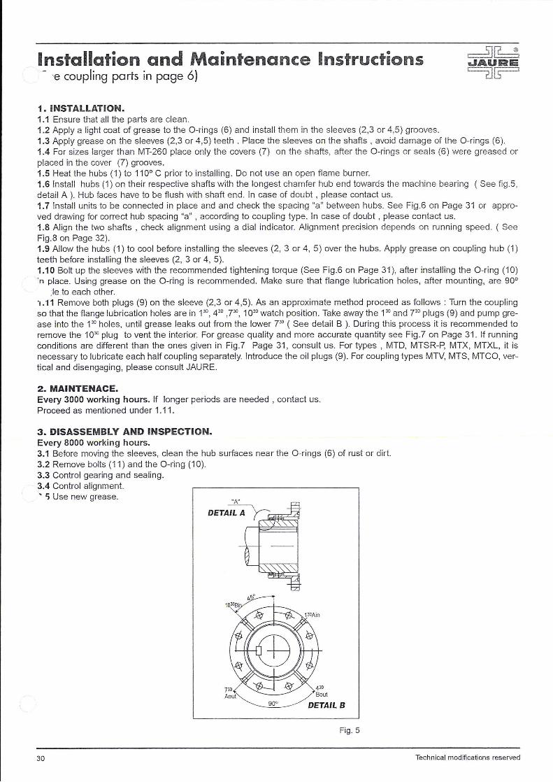
1. INSTALLATION. 1.1 Ensure that all the parts are clean. 1.2 Apply a light coat of grease to the 0-rings (6) and install them in the sleeves (2,3 or 4,5) grooves. 1.3 Apply grease on the sleeves (2,3 or 4,5) teeth . Place the sleeves on the shafts , avoid damage of the 0-rings (6). 1.4 For sizes larger than MT-260 place only the covers (7) on the shafts, after the 0-rings or seals (6) were greased or placed in the cover (7) grooves. 1.5 Heat the hubs ( 1) to 11 0° C prior to installing. Do not use an open flame burner. 1.6 Install hubs (1) on their respective shafts with the longest chamfer hub end towards the machine bearing ( See fi g.S, detai l A). Hub faces have to be flush with shaft end. In case of doubt , please contact us. 1.7 Install units to be connected in place and and check the spacing "a" between hubs. See Fig .6 on Page 31 or approved drawing for correct hub spacing "a" , according to coupling type. In case of doubt , please contact us. 1.8 Align the two shafts , check alignment using a dial indicator. Alignment precision depends on running speed. ( See Fig.8 on Page 32). 1.9 Allow the hubs (1) to cool before installing the sleeves (2, 3 or 4, 5) over the hubs. Apply grease on coupling hub (1) teeth before installing the sleeves (2, 3 or 4, 5). 1.1 0 Bolt up the sleeves with the recommended tightening torque (See Fig.6 on Page 31), after installing the 0-ring (10) ·n place. Using grease on the 0-ring is recommended . Make sure that flange lubrication holes, after mounting, are 90°
;le to each other. ·1.11 Remove both plugs (9) on the sleeve (2,3 or 4,5). As an approximate method proceed as follows : Turn the coupling so that the flange lubrication holes are in P 0
, 430 ,730, 1030 watch position. Take away the 130 and 730 plugs (9) and pump gre
ase into the 130 holes, until grease leaks out from the lower 730 ( See detail B ). During this process it is recommended to
remove the 1030 plug to vent the interior. For grease quality and more accurate quantity see Fig .? on Page 31. If running conditions are different than the ones given in Fig.? Page 31 , consult us. For types , MTD, MTSR-P, MTX, MTXL, it is necessary to lubricate each half coupling separately. Introduce the oil plugs (9). For coupling types MTV, MTS, MTCO, vertical and disengaging, please consult JAURE.
2. MAINTENACE. Every 3000 working hours. If longer periods are needed , contact us. Proceed as mentioned under 1.11 .
3. DISASSEMBLY AND INSPECTION. Every 8000 working hours. 3.1 Before moving the sleeves, clean the hub surfaces near the 0-rings (6) of rust or dirt. 3.2 Remove bolts (11) and the 0 -ring (1 0). 3.3 Control gearing and sealing. 3.4 Control alignment. ' 'i Use new grease.
DETAILS
Fig. 5
30 Technical modifications reserved
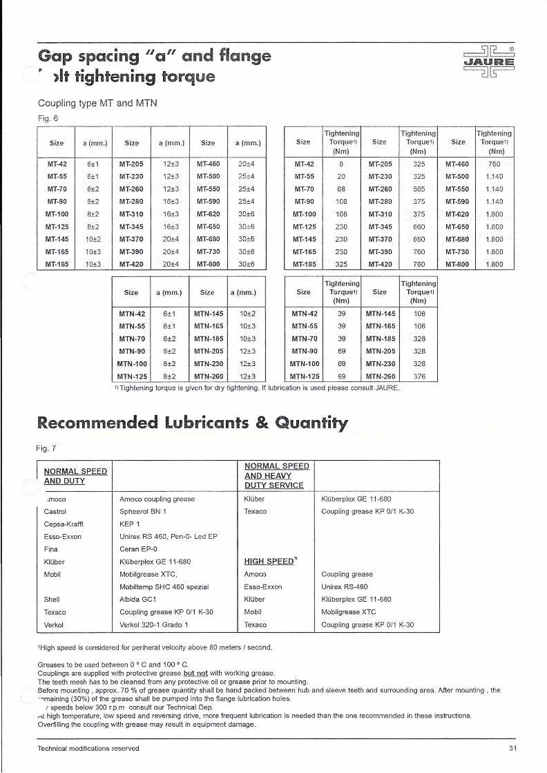
Gap spacing ua" and flange " >It tightening torque
Coupling type MT and MTN
Fig. 6
Tightening Tightening Tightening
Size a(mm.) Size a(mm.) Size a(mm.) Size Torque11 Size Torque 11 Size Torque11
(Nm) (Nm) (Nm)
MT-42 6±1 MT-205 12±3 MT-460 20±4 MT-42 . 8 MT-205 325 MT-460 760
MT-55 6±1 MT-230 12±3 MT-500 25±4 MT-55 20 MT-230 325 MT-500 1.140
MT-70 6±2 MT-260 12±3 MT-550 25±4 MT-70 68 MT-260 565 MT-550 1.140
MT-90 8±2 MT-280 16±3 MT-590 25±4 MT-90 108 MT-280 375 MT-590 1.140
MT-100 8±2 MT-310 16±3 MT-620 30±6 MT-100 108 MT-310 375 MT-620 1.800
MT-125 8±2 MT-345 16±3 MT-650 30±6 MT-125 230 MT-345 660 MT-650 1.800
MT-145 10±2 MT-370 20±4 MT-680 30±6 MT-145 230 MT-370 660 MT-680 1.800
MT-165 10±3 MT-390 20±4 MT-730 30±6 MT-165 230 MT-390 760 MT-730 1.800
MT-185 10±3 MT-420 20±4 MT-800 30±6 MT-185 325 MT-420 760 . MT-800 1.800
Tightening Tightening Size a(mm.) Size a (mm.) Size Torque11 Size Torque11
(Nm) (Nm)
MTN-42 6±1 MTN-145 10±2 MTN-42 39 MTN-145 108
MTN-55 6±1 MTN-165 10±3 MTN-55 39 MTN-165 108
MTN-70 6±2 MTN-185 10±3 MTN-70 39 MTN-185 328
MTN-90 8±2 MTN-205 12±3 MTN-90 69 MTN-205 328
MTN-100 8±2 MTN-230 12±3 MTN-100 69 MTN-230 328
MTN-125 8±2 MTN-260 12±3 MTN-125 69 MTN-260 376
11Tightening torque is given for dry tightening . If lubrication is used please consult JAURE.
Recommended Lubricants & Quantity Fig. 7
I NORMAL SPEED NORMAL SPEED
AND HEAVY AND DUTY
DUTY SERVICE
.moco Amoco coupling grease Kli.iber KIOberplex GE 11 -680
Castro! Spheerol BN 1 Texaco Coupling grease KP 0/1 K-30
Cepsa-Kraffl KEP 1
Esso-Exxon Unirex RS 460 , Pen-0- Led EP
Fina Ceran EP-0
Kli.iber Kli.iberplex GE 11 -680 HIGH SPEED'1
Mobil Mobilgrease XTC, Amoco Coupling grease
Mobiltemp SHC 460 spezial Esso-Exxon Unirex RS-460
Shell Albida GC1 Kli.iber KIOberplex GE 11-680
Texaco Coupling grease KP 0/1 K-30 Mobil Mobilgrease XTC
Verkol Verkol 320-1 Grado 1 Texaco Coupling grease KP 0/1 K-30
' High speed is considered for periheral velocity above 80 meters I second.
Greases to be used between 0 ° C and 100 ° C. Couplings are supplied with protective grease but not with working grease. The teeth mesh has to be cleaned from any protective oil or grease prior to mounting . Before mounting • approx. 70 % of grease quantity shall be hand packed between hub and sleeve teeth and surrounding area . After mounting , the -~maining (30%) of the grease shall be pumped into the flange lubrication holes.
r speeds below 300 r.p .m consult our Technical Dep. r\t high temperature, low speed and reversing drive, more frequent lubrication is needed than the one recommended in these instructions. Overfilling the coupling with grease may result in equipment damage.
Technical modifications reserved 3 1
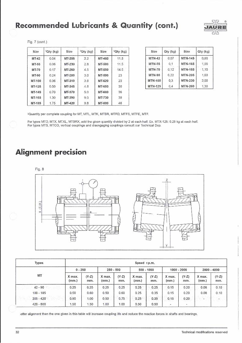
Recommended Lubricants & Quantity {cont.)
Fig. 7 (cont. )
Size 'Qty {kg) Size 'Qty (kg) Size ' Qty (kg) Size Qty (kg) Size Qty (kg)
MT42 0.04 MT-205 2_2 MT-460 11.5 MTN-42 0,07 MTN-145
MT-55 0.06 MT-230 2.8 MT-500 11.5 MTN-55 0,1 MTN-165
MT-70 0. 17 MT-260 4.5 MT-550 14.5 MTN-70 0,12 MTN-185
MT-90 0.24 MT-280 3.0 MT-590 23 MTN-90 0,22 MTN-205
MT-100 0.36 MT~310 3.6 MT-620 23 MTN-1 00 0,3 MTN-230
MT-125 0.50 MT-345 4.8 MT-650 30 MTN-125 0,4 MTN-260
MT-145 0.70 MT-370 5.0 MT-680 36
MT-165 1.30 MT-390 9.0 MT-730 38
MT-185 1.75 MT-420 9.8 MT-800 46
2Quantity per complete coupling for MT, MTL, MTK, MTBR, MTFD, MTFS, MTFE, MTF.
For types MTD, MTX, MTXL, MTBRX, add the given quantity divided by 2 at each half. Ex. MTX-125: 0,25 kg at each half. For types MTS, MTCO, vertica l couplings and disengaging couplings consult our Technical Dep.
Alignment precision
Fig. 8
ri t.. X
Types
y
Speed r.p.m.
0,60
1,00
1,10
1,60
2,00
1,30
0-250 250- 500 500 - 1000 1000-2000 2000-4000
MT X max. (Y-Z) X max. (Y-Z) X max. (Y-Z) X max. (Y-Z) X max. (Y-Z) {mm.) mm. (mm.) mm. (mm.) mm. (mm.) mm. (mm.) mm.
42-90 0.25 0.25 0.25 0.25 0.25 0.25 0.15 0.20 0.08 0.10
100- 185 0.50 0.60 0.50 0.60 0.25 0.35 0.15 0.20 0.08 0.10
205-420 0.90 1.00 0.50 0.75 0.25 0.35 0.15 0.20 - -
420-800 1.50 1.50 1.00 1.00 0.50 0.50 - -
,etter alignment than the one given in this table will increase coupling life and reduce the reaction forces in shafts and bearings.
32 Technical modifications reserved

~~ JA.UAE ~~
JAURE, S.A. Couplings and transmission elements.
ml RECORD Flexible Spring Coupling. JAUFLEX® Flexible elastic coupling. [II Gear spindles for rolling mills.
DET NORSKE VERITAS
TYPE APPROVAL CERTIFICATE Certificate No. M-8528 THIS IS TO CERTIFY
Tooth Couplings Type; Mf. MTD and MTX
' io bidea, s/n- 20150 ZIZURKIL (Guipuzcoa) SPAIN ne: +34 943 69.00.54 - Fax: +34 943 69.02.95
, ax Tech. Dept.: +34 943 69.03 .17 Post address: P.O. Box, 47 - 20150 VILLABONA (Guipuzcoa) SPAIN e-mail:[email protected] • http:/ /www.jaure.com
WORLDWIDE Sales and Service
Contact your nearest JAURE representative
D
E
F
_. !Z< V1
ln
Q!2 .... w ..... :z:
~~ ~iE ga.. ""~
""i3 ~ ...
... ,_ 5 z "-Cl '"' "" v; :r:: .....
~ i:5 ...... a
"' :s:: ~ .... Q w ~
~~~dl 11!11~
DETAIL X ~18
L.tl cc ..--
,
00
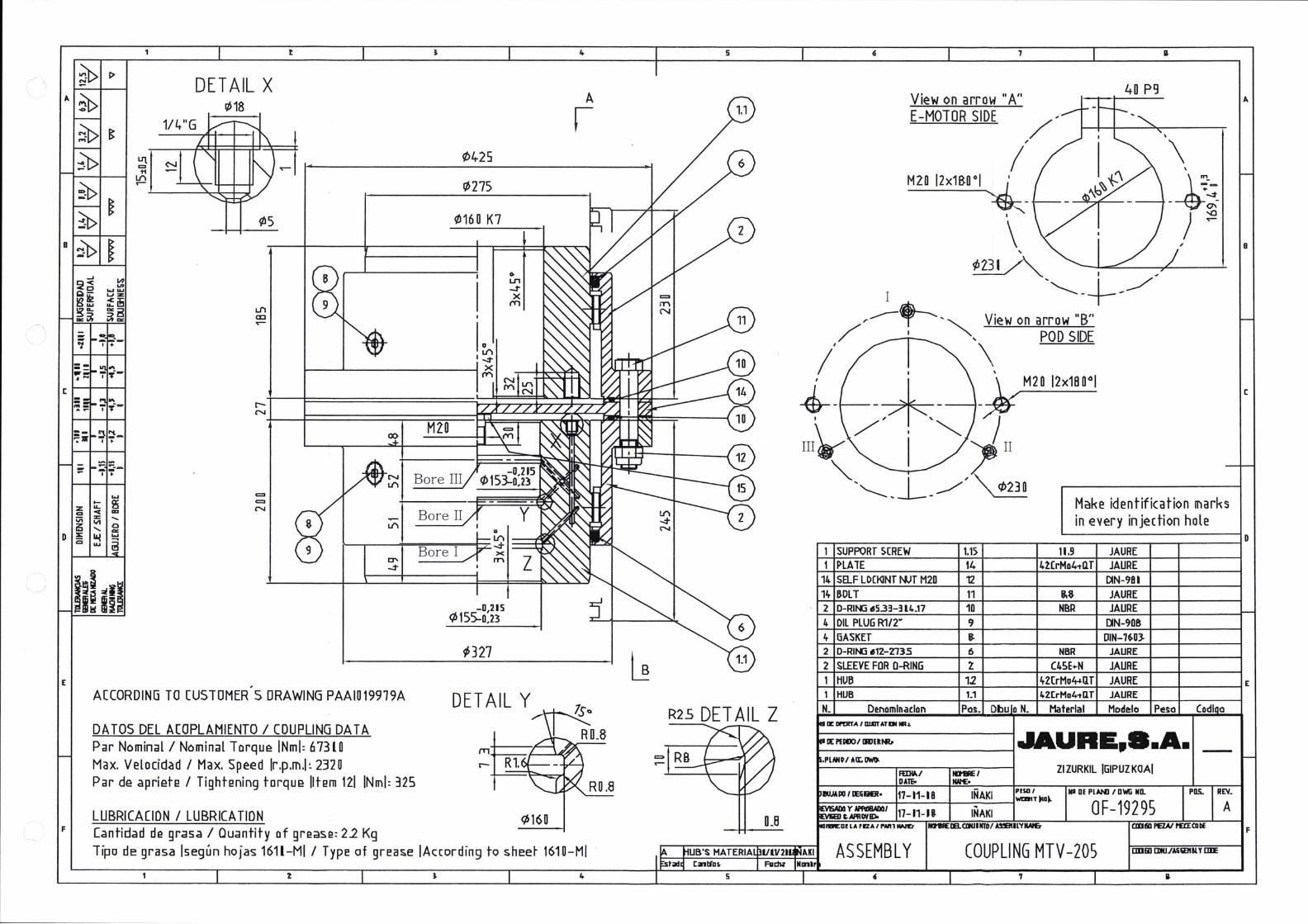
ACCORDING TO CUSTOMER S DRAWING PAAIO 19919A
DATOS DEL ACOPLANIENTO I COUPLING DATA Par Nominal I Nominal T orqu!:! INml: 6 7310 Max. Velocid.ad I Max. Speed lr.p.m.l ~ 232 0 Par de apriete I Tightening tcrque litem 121 INml: 325
LUBRICACIDN I LUBRICATION [antidad de grasa I Quantity of grease: 22 Kg
4
A
f ¢425
rt> 275
~16 0 K7
c> Ln -T X
(Y1
-0,215 ¢155-0,23
1> 327
DETAIL Y
¢160
Tipo de grasa lsegun hojas 161l-MI I TypE! of grE!ase !According to shee~ 1610-MI
4
5
R2S DETAIL Z
0.8
UB'S MATERIA [;ntlas.
5
7
View on arrow "A" E-MOTOR SIDE
40 pg
, a
Make identification ll'larks in every injection hole
[
o-r-------------~~------r-----~----~--~----~0 1 SUPPORT ~[REW 1.15 11.9 JAURE 1 I> LA lE 14 42CrMo4-tll T JAURE
14 SELF LDCKINT NJT M2D 12 ~N-981
14 BOLT 11 JAURE 2 0-RIN:J 11!1533-314.17 10 NBR JAURE 4 DIL PLUG R1/2w 9 [)N-90B 4 GASKET 5- DIN-7~03-
2 0-RIN:l i!I12-Z735 6 NBR JAURE
2 SLEEVE FOR D-RING 2 C4SE .. N JAURE
~1rH~UB~----------4r1~2,_ ____ -r4~Z(~rM~o~~~ij~f~J~A~UR~E~---r----~E HUB 1.1 4Z[rMu4-tll T JAURE
Denomination Pas. Dbu o N. Material Modele Pes a IE Dl'ml'A I D.LIJUT Dlllh.
~I DAlEo
IO'IIRE I IW'£·
~------~1_7-_11_-_IB~ ___ IN_A_KI~~~~~ 17-11-IJ INAKI
IICtM:IS.aKIIIITO/ AS!EIIILYIIAI&
Zl ZURKIL IGIPUZ KOAI
Ill DE PLAN! I DW!i NO.
OF-19295
Codl a
PDS.. REV.
A
ASSEMBLY COUPLING MTV -205 [IIIIi! J:DIJ ./AS &DillY £DE
' 7
F

8
A
r------------------------------------------------------------------------zj_'--~-------------------------------------------------------------------------,
l
f !
1) Start mount;ng the coupl;ng halves by remov;ng the hexagon head screws and nuts.
Support Coupl1ng to be mounted flush with shaft end
1--t.- 2) Guard ;n a secure and clean place the ;n termed/ate nng
3) Before mount;ng the coupl;ng halves, sl;de the half cover (;ncl ud;ng the seal) of the coupl;ng over the shaft.
~ ~Half cover 1nclud1ng seal
For dimensions of coupling: see draw1ng of coupl1ng
I -I--------------1 - r 1
I , , I
l i I ~ '
Half cover including sea Coupling to be mounted flush with shaft end
MOUNTING COUPLING HALF ON ELECTROMOTOR SHAFT.
Shrink surfaces to be free of impurities.
The coupl1ng half to be mounted on the shaft of the electromotor 1s to be heated to approx. 100 oc above ambient temperature by an Induction heater or an oven or a special nng gas burner.
electric
I D l I
~ ~ I ' J -----,~ I ~,----~
----_J___L --~-
1
MOUNTING COUPLING HALF ON POD SHAFT.
Shnnk-surfaces to be free of impurities.
The coupling half to be mounted on the p1nion shaft is to be heated to approx. 220 oc above ambient temperature by an Induction heater or an electric oven or special nng-gasburner.
After cool1ng down to ambient temperature mount the support screw 1n the shaft of the pod.
Curved tooth coupl;ng
OUANr!TY PQS. ll.HJER
lXSCRIPTICII
X BASIC MATERIAL
GENERAL MACHINING REQUIREMENTS AND TOLERANCES FOR NON TOLERATED D!HENSIONS ( DERIVED FROM ISO 2168-1 class m I
- TOLERANCE FOR ANGLE OVER 0 3 6 30 120 4()() 1000 2()()0 4000
DIM. ACC. IS02168-I CL. n DIMENSIONS
- TOLERANCE FOR UP TO AND INCLUDING 3 6 30 120 4()() 1000 2()()0 4000 8000
METRIC THREAD 6H/6g FOR MACHINING OPERATIONS tO. I tO. I t0.2 .o.3 t0,5 t0.8 t(2 t2 t3 - INTERNAL RADtl 0.2 :t 0,2 TOLERANCE - REMOVE SHARP EDGES FOR ALL OTHER OPERATIONS -- t0.5 tl t(5 t2.5 t4 t6 t8 t8
fa
~ TITLE
IS Haunting_ COU[!_Iinq_ ~ ~ t1onfBge koppeling ~
WA~TSILA 0/I"ENSifJIS SCALE ONf
~ IN HILLI/'£TUIS
' ~ F/T?ST AIG..£ PRO.ECTICII U?AWN 1 : ~5
$ 5U?F A(f Ra.Q#o£5£
~ w edii -£3- CfNTRf LI1E AlfRACI
~~ /C.L.A.IINII" O£t:KED I fXAH'I.£5 I W. Kars 2008.02.28 <:>:i;::;
~~ ~~ ALL R/Cl1TS liESERYfD. THIS fRAW/Mj REMAINS T/£ Pf/WERTY IF APPROVED
2008.03.00 'ffF':J1~':tJY"t//:o '*rf:TI!n:::J5P!:i!:S~ MA/t ~~~Jo 'f:,JJ5~~i:s ';& 0';;%(})'(: N. Dekker
PAA/030888 ::.: ~ DEPARTMENT PROJECT NUMBER ORA WING MJMBER
8000 12000 1600(]
12000 16000 200()()
t4 t5 t6
tiO t12 t12
TYPE
DERIVED FROM
wo AI REV.:
AJ REVISION SIZE
8
-
A