
503 Series - The Pneumatic Store
64
Solenoid Pilot Actuated Valves 503 Series www.numatics.com
-
Upload
khangminh22 -
Category
Documents
-
view
0 -
download
0
Transcript of 503 Series - The Pneumatic Store

Solenoid Pilot Actuated Valves503 Series
w w w . n u m a t i c s . c o m

Numatics, Inc. is a leading manufacturer of pneumatic products and motion control products. Our broad spectrum of standard, custom developed products and application components,
have made a significant impact on pneumatic innovation as well as pneumatic and motion control
technology. Our company has an extensive history of generating innovative concepts and technological
breakthroughs. Many of today’s standard features in pneumatic technology were industry firsts from
Numatics. We continue our innovative approach to product development by developing electric motion
control solutions and enhancing our embedded Fieldbus and I/O products to continually meet and solve
our customer’s application requirements.
Today Numatics is proud to
be a part of the Industrial
Automation Division of
Emerson Electric Co.
Emerson (NYSE:EMR), based
in St. Louis, Missouri (USA), is a
global leader in bringing technol-
ogy and engineering together to
provide innovative solutions for
customers in industrial, com-
mercial, and consumer markets
through its network power, pro-
cess management, industrial auto-
mation, climate technologies, and
appliance and tools businesses.
For more information, visit
www.Emerson.com.

We are committed to providing you with an unmatched level of customer service, quality, and reliability. If you cannot locate the specific product for your application or need additional product specifications, visit www.numatics.com or call 888-686-2842.
†As industry requirements change, Numatics reserves the right to modify the contents of this catalog and program without notification. Updates on this program can be obtained from the Numatics website www.numatics.com or by calling 888-686-2842, or by contacting your local Numatics representative or distributor and referencing the Numatics Express program.
Numatics Express 2Day and 3Day Shipping Program guarantees† product shipment in two or
three business days. Unlike most traditional quick ship programs, the Numatics Express Shipping Program includes the most comprehensive offering in the industry. This program encompasses the range and options that you require!
Numatics is committed to offering you the highest level of customer service, quality and performance.
Numatics Express 2 Day shipping program guarantees† product shipment in two business days. The program includes the most popular configurations of the 2000, Mark and L Series valves, including individual bases, manifold blocks, sandwich regulators, particulate filters, coalescing filters, regulators, lubricators, filter-regulators, solenoid soft start quick exhaust valves, shut-off valves, and diverter blocks. Additionally, A Series N.F.P.A. Interchange cylinders, M Series Round Body Interchangeable air cylinders, SH Series Linear Slides, and applicable switches and mounting accessories are offered in the Numatics 2 Day shipping program.
Numatics guarantees† to ship any order received before 3 pm EST for up to 10 of the valve assemblies, and air preparation components, cylinders configured from this catalog in two business days. Saturdays, Sundays, and Holidays are excluded. Numatics Express orders cannot be cancelled or adjusted once entered.
In addition the Numatics Express shipping program offers a 3Day shipping program that guarantees† product shipment of a fully as-sembled and tested valve manifold in 3 business days. The program includes the most popular manifold configurations of the 2000 and Mark series valves:• Sub D, Terminal Strip and Device Net Electronic Options• Can be configured for Din Rail Mounting and Muffled Exhaust• Shipped complete and 100% tested
The 3Day Express shipping program enables you to create a 2 to 8 station manifold assembly complete with any combination of valves, regulators, and blank stations that can be configured from the valve model charts in this catalog.
Numatics guarantees† to ship any order received before 3 pm EST for up to 5 manifold assemblies configured from this catalog in three busi-ness days or Numatics pays the shipping cost. Saturdays, Sundays, and Holidays are excluded. Numatics Express orders cannot be cancelled or adjusted once entered.

Welcome to the World of Fluid Automation...
CAD Modeling Save critical developmenttime with the most innovative CAD configuration pro-gram in the pneumatic component industry. Numatics in 3D eliminates the time consum-ing process associated with designing components from scratch based on information found in conven-tional paper catalog. The models are available in 85 different native CAD formats in 2D drawings and 3D models, including all the popular formats including Catia, I-DEAS, Pro/Engineer, SolidWorks, Unigraphics and more.
Numasizing Developed by Numatics, Numasizing offers a whole new level of fluid power system optimization. Compare large amounts of component and process data against user objectives and industry benchmarks for the best possible size, pneumatic pressure, actua-tor stroke velocities and other part and process variable determina-tions.
Since 1945, Numatics has emerged as the prominent specialist in developing and manufacturing pneumatic and fluid power components for a widely diverse field of automated industry. From idea to implementation, leading engineers choose Numatics as their single source for:
•QualityFluidPowercomponents •Technologicallyadvanceddesignresources •Quickresponsetimeindelivery and service from around the world

Table of Contents
503 Series Technical and Operating Data 6
How to Order 7
Sandwich Pressure Regulators 7-8
Valve Regulator/Speed Control Plug-in Assembly 9
Regulator Service Kits and Parts 9
Sandwich Pressure Regulator Dimensions 10
Manifold Assemblies 11
Valve on Manifold Block 11-12
Individual Base Assembly Kit 12
Internal/External Pilot Supply 12
Valve on Individual Base Dimensions 13-15
Sandwich Shut Off Block 16
Sandwich Pressure Block 16
Sandwich Exhaust Block 17
Blank Station Plate 17
Speed Control Kit 17
DIN Rail Clamp Kit 18
Blocking Discs 18
End Plate Kits 18
Manifold Assembly 19
Internal/External Pilot Selection 20
Internal Muffler 20
G3 Electronics Features and Benefits 22-23
G3 Platform Distribution Options 24-25
DeviceNet™ 26
Ethernet 27
Profibus-DP® 28
PROFINET® 29
CANopen® 30
DeviceLogix™ 31
Ethernet POWERLINK 32
EtherCAT and EtherNet/IP DLR 33-34
I/O Modules 35-37
Sub-Bus Modules 38
Miscellaneous Modules & Accessories 39-40
Dimensional Drawing - G3 Fieldbus Communication Assembly 41-42
How to Order - G3 Assembly Kit & G3 Electronics 43-44
How to Order Complete G3 Manifold Assemblies 45
Cables and Connectors 46-58
Assembly Kits How to Order 59
25 or 37 Pin Sub-D 60
1-16 or 1-32 Terminal Strip 61
19 Pin Round Connector 61

Information subject to change without notice. For ordering information or regarding your local sales office visit www.numatics.com.6
503SERIES
503
Ser
ies
5 Ported, 2 and 3 position, 4-way, Spool & Sleeve and Rubber
Seal, Cv: 1.2 - 1.4
•Solenoid air pilot actuated
•Low wattage – 1.7 watt for DC application
•DC solenoids polarity insensitive with surge suppression
Plug together circuit boards eliminate internal wiring
• Integral recessed gaskets
• IN Fittings to accommodate various tube sizes
•Simple conversion from internal to external pilot
•G3 Fieldbus electronics
• IP65 Certified
Performance Data
Operating Data
Valve Data Min. Max.
Pilot Pressure Range 29 PSI (2 Bar) 115 PSI (8 Bar)
Valve Operating Pressure Range 28" HG Vacuum 115 PSI (8 Bar)
Ambient Temperature Range - 10°C (- 14°F) 50 °C (122 °F)
ISO Proprietary
Valve Flow Data CvNL/m
(6 - 5 Bar)Cv
NL/m (6 - 5 Bar)
5/2, Double Solenoid & Single Solenoid, Spring Return (Spool & Sleeve)
1.1 1100 1.2 1200
5/2, Double Solenoid & Single Solenoid, Spring Return (Rubber Seal)
1.2 1200 1.4 1400
2X 3/2 NC-NC 0.9 900 1.0 1000
2X 3/2 NO-NO 0.9 900 1.0 1000
Double Solenoid, 3 pos. 4 way, Spring Centered- Open to 4 and 2 in center
0.6 600 0.6 600
Double Solenoid, 3 pos. 4 way, Spring Centered - Open Center
1.1 100 1.3 1300
Double Solenoid, 3 pos. 4 way, Spring Centered - Closed Center
1.2 1200 1.4 1400
All Solenoids Are Continuous Duty Rated 24 VDC
Power (Watts) 1.7
Holding Current (Amps.) 0.10
Response Time (ms)Spool & Sleeve Rubber Seal
Energize Deenergize Energize Deenergize
5/2, Single Solenoid, Spring Return 20 60 20 60
5/2, Double Solenoid 15 N/A 20 N/A
5/3 Spring Centered – – 15 20
2x3/2 NC – – 15 25
2 X3/2 NO – – 15 20
1412
3 1 5
2 4
1412
3 1 5
2 4
1412
3 1 5
2 4
1412
3 1 5
2 4
1214 24
3 1 5
single solenoid air pilot2 position 4-way
double solenoid air pilot2 position 4-way
double solenoid air pilot3 position 4-way
open center
double solenoid air pilot3 position 4-way
closed center
double solenoid air pilot3 position 4-waypressure center
12 142 4
3 1 5
12 142 4
3 1 5
double solenoid2 position dual 3-way
“14” & “12” NO
double solenoid2 position dual 3-way
“14” & “12” NC

Information subject to change without notice. For ordering information or regarding your local sales office visit www.numatics.com.7
503SERIES
503
Ser
ies
4503 A B
Product Series503 = 26 mm Valve
RevisionA = Initial Release
Actuation1 = Spool and Sleeve*2 = Rubber Packed
Valve Type
Function
B = Solenoid Pilot with Flush Non-Locking Override
1 = 2 Position 4-Way (5/2), Spring Return 4 = 2 Position 4-Way (5/2), Dual Solenoid5 = 3 Position 4-Way (5/3), Open Center6 = 3 Position 4-Way (5/3), Blocked Center7 = 3 Position 4-way (5/3), Open to A & B in CenterA = Dual 3-way (2 x 3/2), A normally open - B normally openD = Dual 3-way (2 x 3/2), A normally closed - B normally closedN
*Available with Functions 1 + 4 only
= 2 Position 4-Way (5/2), Differential Air Return w/o Spring
VoltageF1 = 24 VDC
OptionsA00 = Standard (No Options)11B = Flush Locking Manual Override11M = Without Manual Override
ElectricalM = Plug-in, w/ Light, VDCN = M12 Connector Pin#1=unused, #2=Coil 12,
#3=Common, #4=Coil 14
Port Size0 = No Port Size
2 0 A00 F1R M
1503 A S
Product Series503 = 26 mm Valve
RevisionA = Initial Release
Product TypeR = Regulator
Regulator Type
Pressure Range
S = Single Reg. - Pressure to Port 1
1 = 10 - 130 PSIG (0.7 - 9 bar) 3 = 3 - 30 PSIG (0.2 - 2 bar)4
*For Regulator Type “E” must select ‘O’ wiring option + ‘O’ Interface
= 5 - 60 PSIG (0.3 - 4.1 bar)
D = Double Reg. - Pressure to Ports 5 & 3E = Double Reg. - Pressure to Ports 4 & 2, w/o Valve*T = Double Reg. - Pressure to Ports 1 & 3, 2
Pressure Selector
Interface
OptionsA00 = Standard (No Options)16N = Jumper for Supply Pressure to Valve, 14 End16P = Jumper for Supply Pressure to Valve, 12 End
1 = Proprietary2 = ISO 15407-20 = No Interface*
Wiring OptionJ = Plug-in, Receptacle Assembly0 = Non-Plug-in*
2 = bar
Gauge Type1 = PSI
R 1 A00 1R 0J
Reserved
How to Order
Valves
Regulators
Information subject to change without notice. For ordering information or regarding your local sales office visit www.numatics.com.8
503SERIES
503
Ser
ies
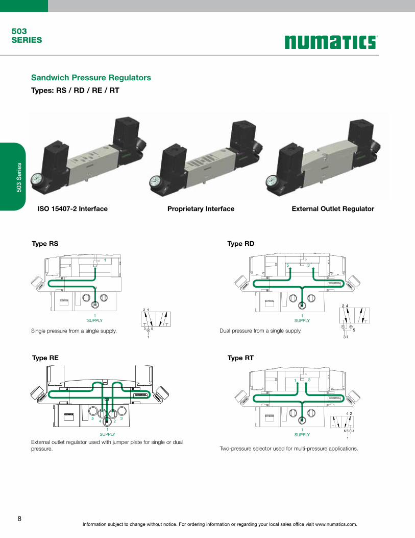
Sandwich Pressure Regulators
Types: RS / RD / RE / RT
Type RS Type RD
ISO 15407-2 Interface Proprietary Interface External Outlet Regulator
Two-pressure selector used for multi-pressure applications.External outlet regulator used with jumper plate for single or dual pressure.
42
53
1
5
13
2 4
3524
1SUPPLY
Type RE Type RT
Dual pressure from a single supply.
1
1SUPPLY
5 3
1SUPPLY
31
1SUPPLY
Single pressure from a single supply.

Information subject to change without notice. For ordering information or regarding your local sales office visit www.numatics.com.9
503SERIES
503
Ser
ies
Valve Regulator / Speed Control Plug-in Assembly
Regulator Kits and Service Parts
Regulator Service Kit
REGULATOR
VALVE
SPEED CONTROL
MOUNTING
Regulator Unit Kits(includes regulator assembly, gaskets, screws)
Part Number Description
M503AR428759001 3-30 PSIG Regulator Kit
M503AR428759002 5-60 PSIG Regulator Kit
M503AR428759003 10-130 PSIG Regulator Kit
M503AR428759004 0.2-2.0 Bar Regulator Kit
M503AR428759005 0.3-4.0 Bar Regulator Kit
M503AR428759006 0.7-9.0 Bar Regulator Kit
R503A2B10MA00F1
R503ARS11JA0010
R503AS425575002
8503AMM22MA0010
Information subject to change without notice. For ordering information or regarding your local sales office visit www.numatics.com.10
503SERIES
503
Ser
ies
A
B
C
D
F
E
A
B
C
D
F
E
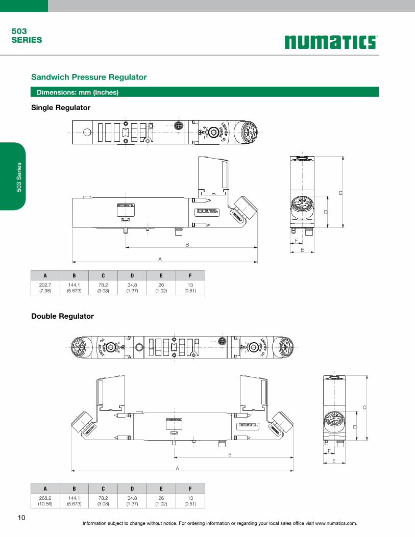
Sandwich Pressure Regulator
Single Regulator
Double Regulator
Dimensions: mm (Inches)
A B C D E F
202.7(7.98)
144.1(5.673)
78.2(3.08)
34.8(1.37)
26(1.02)
13(0.51)
A B C D E F
268.2(10.56)
144.1(5.673)
78.2(3.08)
34.8(1.37)
26(1.02)
13(0.51)

Information subject to change without notice. For ordering information or regarding your local sales office visit www.numatics.com.11
503SERIES
503
Ser
ies
S2503 A
Port Type8 = NPTF*1
Product Series503 = 26 mm Valve
G = ISO228/1-G*1
K = Push-in Fittings
RevisionA = Initial Release
A = Individual Base
Product Type
Mounting
M = Manifold Base
Z = Mid Station Supply*4
S2 = Manifold Base, 2 Stations, Side Ports, Single Z-BoardM2 = Manifold Base, 2 Stations, Side Ports, Double Z-BoardV2
*4 Only available with M2 and V2 mountings
*5 Not available with V2 mounting
*6 Not available with proprietary mounting
*1 Port Type ‘8’ + ‘G’ only available in 1/4 size
*2 Only available with ISO 15407-1 Interface
*3 Available with 3A mounting only
= Manifold Base, 2 Stations, Side Ports*2
3A = Individual Base, Side Ports, Individual Exhaust*6
Interface1 = Proprietary
OptionsA00 = Standard (No Options)14X = External Pilot Supply from Port # 14*3
56Y = 4-Pin Straight M12 Connector in Mounting*3
Pin 1= Not Used; 2= 12+(B+); 3 = COM; 4=14+(A+)59W = 14X + 56Y*3
2 = ISO 15407-23 = ISO 15407-1
Wiring OptionM = Plug-in, Receptacle Assembly*5
0 = Non-Plug-in*2
3 = 3/8
K = 10 mmH = 8 mm
Port Size2 = 1/4
M 2 A00 18 0M
Reserved
How to Order
Manifold Assemblies and Individual Bases
G
FE
D
H
A
B
C
Plug in Valve Mounted
Dimensions: mm (Inches)
A B C D E F G H
112.9(4.445)
44.9(1.768)
14.2(0.56)
54(2.13)
43.7(1.72)
16.7(0.66)
53.3 (2.098)
136(5.35)
Information subject to change without notice. For ordering information or regarding your local sales office visit www.numatics.com.12
503SERIES
503
Ser
ies
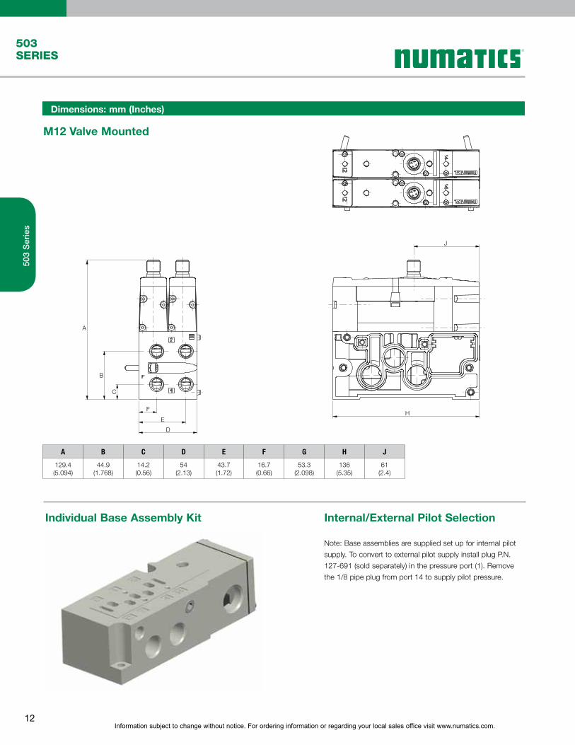
Individual Base Assembly Kit Internal/External Pilot Selection
Dimensions: mm (Inches)
M12 Valve Mounted
A B C D E F G H J
129.4(5.094)
44.9(1.768)
14.2(0.56)
54(2.13)
43.7(1.72)
16.7(0.66)
53.3(2.098)
136(5.35)
61(2.4)
A
B
C
F
E
D
H
J
Note: Base assemblies are supplied set up for internal pilot
supply. To convert to external pilot supply install plug P.N.
127-691 (sold separately) in the pressure port (1). Remove
the 1/8 pipe plug from port 14 to supply pilot pressure.
Information subject to change without notice. For ordering information or regarding your local sales office visit www.numatics.com.13
503SERIES
503
Ser
ies
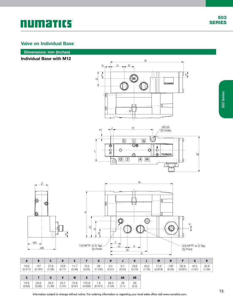
Dimensions: mm (Inches)
Individual Base with M12
Valve on Individual Base
Ø5.35(2) Holes
1/8 NPTF or G Tap(2) Ports
3/8 NPTF or G Tap(5) Ports
TU V
WX
P
NZ
E
AA
AB
ML
HJ K
GF
A C
B
E
D
QR
S
Y
S T U V W X Y Z AA AB
16.6(0.65)
20.9(0.82)
34.5(1.36)
25.7(1.01)
73.9(2.91)
122.8(4.835)
1.8(0.071)
26.3(1.04)
28(1.1)
56(2.2)
A B C D E F G H J K L M N P Q R
10.6(0.417)
147(5.787)
27.8(1.09)
19.6(0.77)
11.7(0.46)
13.5(0.53)
29(1.142)
5.4(0.21)
6.1(0.24)
79.6(3.13)
45.3(1.78)
71.6(2.819)
136(5.35)
92.9(3.657)
42.5(1.67)
32.8(1.29)
Information subject to change without notice. For ordering information or regarding your local sales office visit www.numatics.com.14
503SERIES
503
Ser
ies
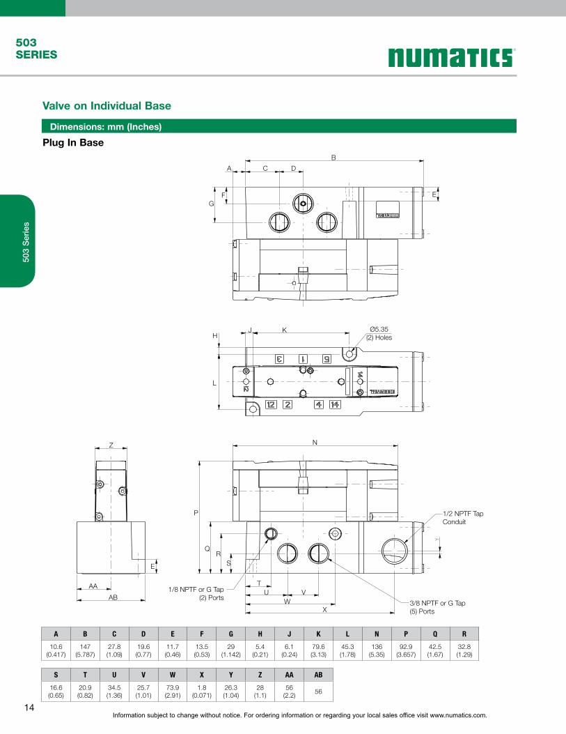
Dimensions: mm (Inches)
Plug In Base
Valve on Individual Base
Ø5.35(2) Holes
1/8 NPTF or G Tap(2) Ports
3/8 NPTF or G Tap(5) Ports
AA
AB
E
Z
TU V
WX
P
N
1/2 NPTF TapConduit
QR
S
GF E
KJH
L
A C
B
D
A B C D E F G H J K L N P Q R
10.6(0.417)
147(5.787)
27.8(1.09)
19.6(0.77)
11.7(0.46)
13.5(0.53)
29(1.142)
5.4(0.21)
6.1(0.24)
79.6(3.13)
45.3(1.78)
136(5.35)
92.9(3.657)
42.5(1.67)
32.8(1.29)
S T U V W X Y Z AA AB
16.6(0.65)
20.9(0.82)
34.5(1.36)
25.7(1.01)
73.9(2.91)
1.8(0.071)
26.3(1.04)
28(1.1)
56(2.2)
56

Information subject to change without notice. For ordering information or regarding your local sales office visit www.numatics.com.15
503SERIES
503
Ser
ies
Dimensions: mm (Inches)
Non Plug In Base
Valve on Individual Base
A
GF E
C D
B
KØ5.35
(2) HolesJ
N
P
Z
E
AA1/8 NPTF or G Tap
(2) Ports
3/8 NPTF or G Tap(5) PortsAB
QR
S
TU V
W
H
L
A B C D E F G H J K L N P Q R S T U V W Z AA AB
10.6(0.417)
91.7(3.61)
27.8(1.09)
19.6(0.77)
11.7(0.46)
13.5(0.53)
29(1.142)
5.4(0.21)
6.1(0.24)
79.6(3.13)
45.3(1.78)
136(5.35)
109.4(4.307)
42.5(1.67)
32.8(1.29)
16.6(0.65)
20.9(0.82)
34.5(1.36)
25.7(1.01)
73.9(2.91)
26.3(1.04)
28(1.1)
56(2.2)

Information subject to change without notice. For ordering information or regarding your local sales office visit www.numatics.com.16
503SERIES
503
Ser
ies
•Used to shut-off pressure when mounted
below valve.
•Allows easy maintenance without the need to
shut-off pressure to the entire manifold.
XE
XE
EB(3)
(3)EB
B(2)
(2)B
(1)P
P(1)
A(4)
(4)A
(5)EA
EA(5)
X
X
Sandwich Shut Off Block
Dimensions: mm (Inches)
Dimensions: mm (Inches)
A B C D
157.3(6.193)
58.6(2.307)
33(1.3)
26.5(1.04)
A B C D
148.8(5.858)
58.6(2.307)
33(1.3)
26.5(1.04)
A
B
C
D
A
1
C
B
D
Sandwich Pressure Block
Sandwich Pressure Block Kit
•Used to supply a separate pressure to a single
valve station without needing blocking disks.
Part Number Port Type Description
8503AW428300004 1/4 NPTFProprietary Sandwich Pressure Block
G503AW428300004 G 1/4Proprietary Sandwich Pressure Block
8503AW428300003 1/4 NPTFISO 15407-2 Sandwich Pressure Block
G503AW428300003 G 1/4ISO 15407-2 Sandwich Pressure Block
Part Number Description
R503AY426707002 Proprietary Sandwich Shut Off Kit
R503AY426707001 ISO 15407-2 Sandwich Shut Off Kit

Information subject to change without notice. For ordering information or regarding your local sales office visit www.numatics.com.17
503SERIES
503
Ser
ies
Dimensions: mm (Inches)
Dimensions: mm (Inches)
Dimensions: mm (Inches)
A B C D
159.2(6.268)
70.2(2.764)
33(1.3)
26.5(1.04)
A B C D
142(5.591)
58(2.283)
33(1.3)
26(1.02)
A B C
136(5.354)
26(1.024)
14.8(0.58)
Part Number Port Type Description
8503AX428300002 1/4 NPTFProprietary Sandwich Exhaust Block
G503AX428300002 G 1/4Proprietary Sandwich Exhaust Block
8503AX428300001 1/4 NPTFISO 15407-2 Sandwich Exhaust Block
G503AX428300001 G 1/4ISO 15407-2 Sandwich Exhaust Block
Part Number Description
R503AS425575002 Proprietary Sandwich Speed Control
R503AS425575001 ISO 15407-2 Sandwich Speed Control
Sandwich Exhaust Block Kit
•Used to isolate the exhaust of a single valve
station from the manifold.
•Allows faster exhaust response by re-routing
exhaust externally to the manifold.
Sandwich Exhaust Block
A
B
C
D
53
A
D B
C
•Used to block off a manifold station block for
future use
Blank Station Plate Kit
P503AB428359001A
B
C
Speed Control Kit

Information subject to change without notice. For ordering information or regarding your local sales office visit www.numatics.com.18
503SERIES
503
Ser
ies
DIN Rail Clamp Kit
239-980
Port Type NPTF G PUSH IN PUSH IN PUSH IN PUSH IN
Port 1 3/5 X,XE 1 3/5 X,XE 1 3/5 X,XE 1 3/5 X,XE 1 3/5 X,XE 1 3/5 X,XE
Port Size 3/8 3/8 1/8 3/8 3/8 1/8 3/8 3/8 1/8 1/2 1/2 1/8 10mm 10mm 6 mm 12mm 12mm 6 mm
Vertical w/o muffler, w/o DIN
8503AK428327001 G503AK428327013 K503AK428327003 K503AK428327005 K503AK428327015 K503AK428327017
Vertical w/o muffler, w/DIN
8503AK428327002 G503AK428327014 K503AK428327004 K503AK428327006 K503AK428327016 K503AK428327018
Veritcal w/muffler, w/o DIN
8503AK428327007 G503AK428327019 K503AK428327009 K503AK428327011 K503AK428327021 K503AK428327023
Vertical w/muffler, w/DIN
8503AK428327008 G503AK428327020 K503AK428327010 K503AK428327012 K503AK428327022 K503AK428327024
Hortizonal, w/o muffler, w/o DIN
8503AK428304001 G503AK428304004 K503AK428304002 K503AK428304003 K503AK428304005 K503AK428304006
End Plate Kit - Threaded
Ports Part
1 P503A431191001
3 P503A431191002
5 P503A431191003
1 + 3 P503A431191004
1 + 5 P503A431191005
3 + 5 P503A431191006
1, 3, 5 P503A431191007
Blocking Disc Kits
(Includes tag to label ports blocked)

Information subject to change without notice. For ordering information or regarding your local sales office visit www.numatics.com.19
503SERIES
503
Ser
ies
Manifold Assembly
Dimensions: mm (Inches)
A B C D E F G H J K L M N P Q R S T U V W X Y
136(5.354)
53(2.087)
55.1(2.17)
7.5(0.3)
75.8(2.98)
39.1(1.54)
112.9(4.445)
12(0.47)
54(2.13)
17.5(0.69)
19.8(0.78)
101.1(3.98)
69.5(2.74)
46.8(1.843)
44.9(1.77)
24.4(0.96)
14.2(0.56)
12.3(0.48)
6.4(0.25)
23.8(0.94)
58(2.28)
85(3.346)
125.4(4.937)
A
B
J
G
H
Y
X
W
V
U T SR
Q P
N
M
A Ref.
K L
Ø6.4
F
E
D
6.3 Wide Slot(2) Places
C

Information subject to change without notice. For ordering information or regarding your local sales office visit www.numatics.com.20
503SERIES
503
Ser
ies
Internal Muffler
Internal Pilot External Pilot
Muffler
For External Pilot Supply Plug Location
Internal PilotSupply Plug Location

G3 FieldbusElectronics and I/O
Table of Contents
G3
Ele
ctro
nics
Section 1
Features and Benefits 22-23
G3 Platform Distribution Options 24-25
DeviceNet™ 26
Ethernet 27
Profibus-DP® 28
PROFINET® 29
CANopen® 30
DeviceLogix™ 31
Ethernet POWERLINK 32
EtherCAT and EtherNet/IP DLR 33-34
I/O Modules 35-37
Sub-Bus Modules 38
Miscellaneous Modules & Accessories 39-40
Dimensional Drawing - G3 Fieldbus Communication Assembly 41-42
Section 2 - How to Configure & Order G3 Electronics
How to Order - G3 Assembly Kit & G3 Electronics 43-44
How to Order Complete G3 Manifold Assemblies 45
Cables and Connectors 46-58

Information subject to change without notice. For ordering information or regarding your local sales office visit www.numatics.com.22
G3Electronics
G3
Ele
ctro
nics
G3 Fieldbus Communications ElectronicsWhy use Numatics Fieldbus communication electronics?
Modular Reality...
• No internal wiring simplifies assembly
• SPEEDCON M12 connector technology allows for fast and efficient ½ turn I/O connector attachment.
• Power connector allows output power to be removed while inputs and communication are left active.
• IP65 & IP67 protection
• Up to 1200 Input / 1200 Output capability with one communication node! (Present physical I/O combinations allows 1200 I / 544 O)
• 32 valve solenoids per manifold up to 17 manifolds per communication node!
• One node supports 16 I/O modules – Analog I/O, Digital I/O (NPN & PNP) and Specialty
• Innovative clip design allows easy module removal/replacement without dismantling manifold
• Auto Recovery Module (ARM) protects configuration information during a critical failure. Allows configuration information to be saved and reloaded to replacement module automatically.
G3 Fieldbus - Electronics Made Easy!
Innovative Graphic Display is used for easy commissioning, visual status & diagnostics.
Graphic Display forconfiguration & diagnostics
Highly Distributable
Auto Recovery Module
Easy, Robust Connections
Commissioning Capabilities
• Set network address (including IP & Subnet mask for Ethernet)
• Set baud rate• Set auto or manual I/O sizes• Set fault/idle output states• Set brightness• Set factory defaults
Visual Diagnostics
• Shorted and open load detection
• Shorted sensor/cable detection• Low & missing power detection• Missing module detection• Self-test activation• Log of network errors• Distribution errors
Supported Protocols
• DeviceNet™
• DeviceNet™w/QuickConnect
• DeviceNet™ w/DeviceLogix™
• Ethernet
• PROFIBUS®-DP
DeviceNetTM is a trademark of ODVA.ControlNet is a trademark of ControlNet International, Ltd.DeviceLogix is a trademark of Rockwell Automation.AS-interface is a registered trademark of AS-International.PROFIBUS and PROFINET are registered trademarks of Profibus International.POWERLINK is an Ethernet protocol under the control of EPSG (Ethernet Powerlink Standardization Group)EtherCAT is a registered trademark of Beckhoff Automation GmbH
• CANopen®
• PROFINET®
• POWERLINK
*
*Numatics I/O with SPEEDCON technology
• 1/2 turn for faster I/O connections
• Backwards compatible with standard M12 cables/connectors
• Meets the same IP/NEMA standards as M12/Micro cables/connectors
• Same cost as standard M12/Micro cables/ connectors
• See pages 50 & 51 for cables with SPEEDCON connector technology
Information subject to change without notice. For ordering information or regarding your local sales office visit www.numatics.com.23
G3Electronics
G3
Ele
ctro
nics
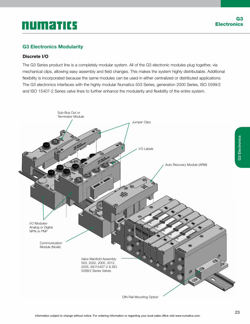
G3 Electronics Modularity
Discrete I/O
The G3 Series product line is a completely modular system. All of the G3 electronic modules plug together, via
mechanical clips, allowing easy assembly and field changes. This makes the system highly distributable. Additional
flexibility is incorporated because the same modules can be used in either centralized or distributed applications.
The G3 electronics interfaces with the highly modular Numatics 503 Series, generation 2000 Series, ISO 5599/2
and ISO 15407-2 Series valve lines to further enhance the modularity and flexibility of the entire system.
Valve Manifold Assembly503, 2002, 2005, 2012, 2035, ISO15407-2 & ISO 5599/2 Series Valves
Communication Module (Node)
I/O Modules- Analog or Digital NPN or PNP
DIN Rail Mounting Option
Auto Recovery Module (ARM)
I/O Labels
Jumper Clips
Sub-Bus Out or Terminator Module

Information subject to change without notice. For ordering information or regarding your local sales office visit www.numatics.com.24
G3Electronics
G3
Ele
ctro
nics
G3 Platform Distribution Options
Easy, Cost Effective Solutions for Digital I/O and Valve Automation using G3 Electronics
Main Fieldbus Manifold
Sub-Bus
Sub-Bus Out
Sub-Bus OutSub-Bus In
Sub-Bus
I/O Only Sub Manifold with I/O & Valves
Sub Manifold with Valves
24 VDCPower Supply
24 VDC Power Supply (optional)
24 VDCPower Supply
•Unique distribution system allows system efficiency by allowing the same modules to be used in
either centralized or distributed applications
•Distribution options include:
Inputs OR Outputs
Inputs AND Outputs
Valves with Inputs AND Outputs
Valves with Inputs OR Outputs
Valves Only
•Maximum Sub-Bus length not to exceed 30 meters. Maximum Sub-Bus cable current not to
exceed 4 amps or excessive cable voltage drops per segment. Auxiliary power connections
available for currents above 4 amps. Consult factory for possible deviations.

Information subject to change without notice. For ordering information or regarding your local sales office visit www.numatics.com.25
G3Electronics
G3
Ele
ctro
nics
G3 Platform Distribution Options
Typical Main Fieldbus Manifold
Comm. Module
Comm. Module
The G3 platform is flexible to the point that there are a virtually infinite number of I/O distribution options using the few
basic G3 modules. The following basic rules should be followed in the configuration of your control architecture.
Valve Side
•Up to a total of 32 valve solenoids can be driven in a
manifold assembly integrated into the Main Fieldbus
Manifold. This can be any number of single or double
solenoid valves with a total number of solenoids not to
exceed 32.
•A Valve side output module is available. If a valve side
output module is used, 16 outputs are allocated to the
solenoids in the integral manifold and 16 are allocated
to the output module in the manifold.
I/O Side Distribution
•A total of 16 modules can be integrated into
the network and controlled by the main fieldbus
communication module (Node)
•Modules include analog and digital I/O modules
providing addressing capacity for up to 1200 Inputs /
1200 Outputs per node.
•Unique distribution system allows system efficiency
by allowing the same modules to be used in either
centralized or distributed applications
•Distribution options include Inputs only, Outputs only,
I/O only, valves with Inputs, valves with Outputs and
valves with I/O
•Configuration can include up to 16 of the following
modules: •DigitalI/Omodules
•Sub-Busvalvemodules
•AnalogI/Omodules
I/O Side
I/O Side
Valve Side
16 Modules can be supported on this side of the comm. module
Comm. Module
Information subject to change without notice. For ordering information or regarding your local sales office visit www.numatics.com.26
G3Electronics
G3
Ele
ctro
nics
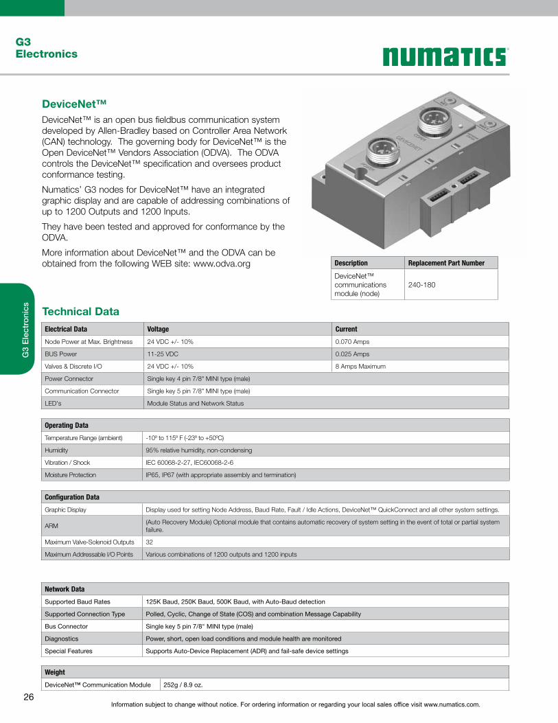
DeviceNet™DeviceNet™ is an open bus fieldbus communication system developed by Allen-Bradley based on Controller Area Network (CAN) technology. The governing body for DeviceNet™ is the Open DeviceNet™ Vendors Association (ODVA). The ODVA controls the DeviceNet™ specification and oversees product conformance testing.
Numatics’ G3 nodes for DeviceNet™ have an integrated graphic display and are capable of addressing combinations of up to 1200 Outputs and 1200 Inputs.
They have been tested and approved for conformance by the ODVA.
More information about DeviceNet™ and the ODVA can be obtained from the following WEB site: www.odva.org
Technical Data
Electrical Data Voltage Current
Node Power at Max. Brightness 24 VDC +/- 10% 0.070 Amps
BUS Power 11-25 VDC 0.025 Amps
Valves & Discrete I/O 24 VDC +/- 10% 8 Amps Maximum
Power Connector Single key 4 pin 7/8" MINI type (male)
Communication Connector Single key 5 pin 7/8" MINI type (male)
LED's Module Status and Network Status
Operating Data
Temperature Range (ambient) -10º to 115º F (-23º to +50ºC)
Humidity 95% relative humidity, non-condensing
Vibration / Shock IEC 60068-2-27, IEC60068-2-6
Moisture Protection IP65, IP67 (with appropriate assembly and termination)
Description Replacement Part Number
DeviceNet™ communications module (node)
240-180
Configuration Data
Graphic Display DisplayusedforsettingNodeAddress,BaudRate,Fault/IdleActions,DeviceNet™QuickConnectandallothersystemsettings.
ARM(Auto Recovery Module) Optional module that contains automatic recovery of system setting in the event of total or partial system failure.
Maximum Valve-Solenoid Outputs 32
Maximum Addressable I/O Points Various combinations of 1200 outputs and 1200 inputs
Network Data
Supported Baud Rates 125K Baud, 250K Baud, 500K Baud, with Auto-Baud detection
Supported Connection Type Polled, Cyclic, Change of State (COS) and combination Message Capability
Bus Connector Single key 5 pin 7/8" MINI type (male)
Diagnostics Power, short, open load conditions and module health are monitored
Special Features Supports Auto-Device Replacement (ADR) and fail-safe device settings
Weight
DeviceNet™ Communication Module 252g / 8.9 oz.

Information subject to change without notice. For ordering information or regarding your local sales office visit www.numatics.com.27
G3Electronics
G3
Ele
ctro
nics
Ethernet (Ethernet/IP & Modbus TCP/IP)Ethernet used throughout the world to network millions of PC’s has now evolved into a viable industrial network. Ethernet is an open architecture high-level communication network that meets the demands of today’s industrial applications requiring high-speed (10/100 Mbit/s), high-throughput and flexibility. Various application layers for this protocol including EtherNet/IP and Modbus TCP. Additionally, Ethernet technology can integrate an on-board Web server, which can make the node readily accessible to any standard Web browser for configuration, testing and even retrieval of technical documentation.
Numatics’ G3 nodes for Ethernet have an integrated graphic display and are capable of addressing combinations of up to 1200 Outputs and 1200 Inputs.
The G3 Ethernet/IP nodes have been tested and approved for conformance by the ODVA.
More information about Ethernet/IP and the ODVA can be obtained from the following WEB site: www.odva.org
Technical Data
Electrical Data Voltage Current
Node Power at Max. Brightness 24 VDC +/- 10% .091 Amps
Valves & Discrete I/O 24 VDC +/- 10% 8 Amps maximum
Power Connector Single key 4 pin 7/8" MINI type (male)
Communication Connector D-coded 4 pin M12 type (female)
LED's Module Status, Network Status and Activity/Link
Operating Data
Temperature Range (ambient) -10º to 115º F (-23º to +50ºC)
Humidity 95% relative humidity, non-condensing
Vibration / Shock IEC 60068-2-27, IEC60068-2-6
Moisture Protection IP65, IP67 (with appropriate assembly and termination)
Description Replacement Part Number
Ethernet/IPcommunications module (node)
240-181
Modbus TCP/IPcommunications module (node)
240-292
Configuration Data
Graphic Display Display used for setting IP Address, Subnet mask, Fault / Idle Actions, DHCP / BootP and all other system settings.
ARM(Auto Recovery Module) Optional module that contains automatic recovery of system setting in the event of total or partial system failure
Maximum Valve-Solenoid Outputs 32
Maximum Addressable I/O Points Various combinations of 1200 outputs and 1200 inputs
Network Data
Supported Baud Rates 10 Mbit / 100 Mbit
Bus Connector D-coded 5 pin M12 type (female)
Diagnostics Power, short, open load conditions and module health are monitored
Special Features Integrated web server, fail-safe device settings, HTTP, FTP, and UNICAST (for EtherNet/IP)
Weight
Ethernet Communication Module 255g / 9 oz.
Information subject to change without notice. For ordering information or regarding your local sales office visit www.numatics.com.28
G3Electronics
G3
Ele
ctro
nics
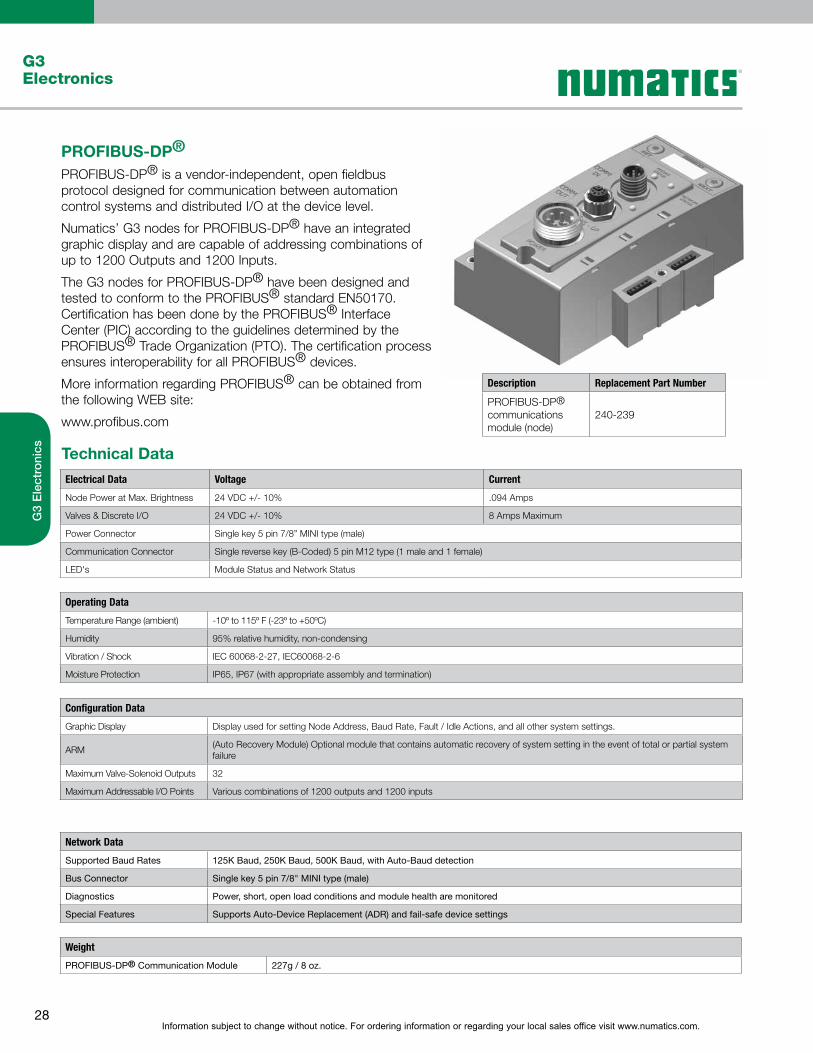
PROFIBUS-DP®
PROFIBUS-DP® is a vendor-independent, open fieldbus protocol designed for communication between automation control systems and distributed I/O at the device level.
Numatics’ G3 nodes for PROFIBUS-DP® have an integrated graphic display and are capable of addressing combinations of up to 1200 Outputs and 1200 Inputs.
The G3 nodes for PROFIBUS-DP® have been designed and tested to conform to the PROFIBUS® standard EN50170. Certification has been done by the PROFIBUS® Interface Center (PIC) according to the guidelines determined by the PROFIBUS® Trade Organization (PTO). The certification process ensures interoperability for all PROFIBUS® devices.
More information regarding PROFIBUS® can be obtained from the following WEB site:
www.profibus.com
Technical Data
Electrical Data Voltage Current
Node Power at Max. Brightness 24 VDC +/- 10% .094 Amps
Valves & Discrete I/O 24 VDC +/- 10% 8 Amps Maximum
Power Connector Single key 5 pin 7/8” MINI type (male)
Communication Connector Single reverse key (B-Coded) 5 pin M12 type (1 male and 1 female)
LED's Module Status and Network Status
Operating Data
Temperature Range (ambient) -10º to 115º F (-23º to +50ºC)
Humidity 95% relative humidity, non-condensing
Vibration / Shock IEC 60068-2-27, IEC60068-2-6
Moisture Protection IP65, IP67 (with appropriate assembly and termination)
Description Replacement Part Number
PROFIBUS-DP®communications module (node)
240-239
Configuration Data
Graphic Display Display used for setting Node Address, Baud Rate, Fault / Idle Actions, and all other system settings.
ARM(Auto Recovery Module) Optional module that contains automatic recovery of system setting in the event of total or partial system failure
Maximum Valve-Solenoid Outputs 32
Maximum Addressable I/O Points Various combinations of 1200 outputs and 1200 inputs
Network Data
Supported Baud Rates 125K Baud, 250K Baud, 500K Baud, with Auto-Baud detection
Bus Connector Single key 5 pin 7/8" MINI type (male)
Diagnostics Power, short, open load conditions and module health are monitored
Special Features Supports Auto-Device Replacement (ADR) and fail-safe device settings
Weight
PROFIBUS-DP® Communication Module 227g / 8 oz.

Information subject to change without notice. For ordering information or regarding your local sales office visit www.numatics.com.29
G3Electronics
G3
Ele
ctro
nics
PROFINET®
PROFINET® is the innovative open standard for Industrial Ethernet, development by Siemens and the Profibus® User Organization (PNO). PROFINET® complies to IEC 61158 and IEC 61784 standards. PROFINET® products are certified by the PNO user organization, guaranteeing worldwide compatibility.
Numatics’ G3 nodes for PROFINET IO (PROFINET RT) have an integrated graphic display and are capable of addressing combinations of up to 1200 Outputs and 1200 Inputs.
PROFINET® is based on Ethernet and uses TCP/IP and IT standards and complements them with specific protocols and mechanisms to achieve Real Time performance.
More information regarding PROFINET® can be obtained from the following WEB site: www.profibus.com
Technical Data
Electrical Data Voltage Current
Node Power at Max. Brightness 24 VDC +/- 10%
Valves & Discrete I/O 24 VDC +/- 10% 8 Amps Maximum
Power Connector Single key 5 pin 7/8” MINI type (male)
Communication Connector Two D-coded 4 pin M12 type (female)
LED's Module Status, Network Status and Activity/Link
Operating Data
Temperature Range (ambient) -10º to 115º F (-23º to +50º C)
Humidity 95% relative humidity, non-condensing
Vibration / Shock IEC 60068-2-27, IEC60068-2-6
Moisture Protection IP65, IP67 (with appropriate assembly and termination)
Description Replacement Part Number
PROFINET®communications module (node)
240-240
Configuration Data
Graphic Display Display used for setting IP Address, Subnet Mask, Fault / Idle Actions, and all other system settings.
ARM(Auto Recovery Module) Optional module that contains automatic recovery of system setting in the event of total or partial system failure.
Maximum Valve-Solenoid Outputs 32
Maximum Addressable I/O Points Various combinations of 1200 outputs and 1200 inputs
Network Data
Supported Baud Rates 10 Mbit / 100 Mbit
Bus Connector Two D-coded 4 pin M12 type (2-Female)
Diagnostics Power, short, open load conditions and module health and configuration are monitored
Special Features Integrated web server, Integrated 2 port switch, fail-safe device settings, and FSU
Weight
PROFINET® Communication Module 227g / 8 oz.

Information subject to change without notice. For ordering information or regarding your local sales office visit www.numatics.com.30
G3Electronics
G3
Ele
ctro
nics
CANopen®
CANopen® is an open protocol based on Controller Area Network (CAN). It was designed for motion oriented machine control networks but has migrated to various industrial applications. CAN in Automation (CIA) is the international users’ and manufacturers’ organization that develops and supports CAN-based protocols. Numatics’ G3 nodes for CANopen® have an integrated graphic display and are capable of addressing combinations of up to 1200 Outputs and 1200 Inputs.
More information regarding this organization can be found at: www.can-cia.org
Technical Data
Electrical Data Voltage Current
Node Power at Max. Brightness 24 VDC +/- 10% 0.070 Amps
BUS Power 11-25 VDC 0.025 Amps
Valves & Discrete I/O 24 VDC +/- 10% 8 Amps maximum
Power Connector Single key 4 pin 7/8” MINI type (male)
Communication Connector Single key 5 pin 7/8” MINI type (male)
LED's Module Status and Network Status
Operating Data
Temperature Range (ambient) -10º to 115º F (-23º to +50º C)
Humidity 95% relative humidity, non-condensing
Vibration / Shock IEC 60068-2-27, IEC60068-2-6
Moisture Protection IP65, IP67 (with appropriate assembly and termination)
Description Replacement Part Number
CANopen®communications module (node)
240-291
Configuration Data
Graphic Display Display used for setting Node Address, Baud Rate, Fault / Idle Actions, and all other system settings.
ARM(Auto Recovery Module) Optional module that contains automatic recovery of system setting in the event of total or partial system failure.
Maximum Valve-Solenoid Outputs 32
Maximum Addressable I/O Points Various combinations of 1200 outputs and 1200 inputs
Network Data
Supported Baud Rates 125K Baud, 250K Baud, 500K Baud, 1M Baud
Bus Connector Single key 5 pin 7/8” MINI type (male)
Diagnostics Power, short, open load conditions and module health are monitored and fail-safe device settings
Weight
CANopen® Communication Module 252g / 8.9 oz.

Information subject to change without notice. For ordering information or regarding your local sales office visit www.numatics.com.31
G3Electronics
G3
Ele
ctro
nics
DeviceLogix™DeviceLogix™ is a Rockwell Automation technology that allows a DeviceNet™ node to be programmed to execute a sequence independently from the control for the main PLC/IPC. A DeviceLogix™ enabled DeviceNet™ node can be used in conjunction with a standard DeviceNet™ network, providing simple distributed control functionality. Additionally it can also be used in a standalone application, without a network connection or PLC/IPC, to sequence pneumatic valves and control I/O. Numatics has integrated this licensed technology into its DeviceNet™ compatible valve manifold series, which combine the functionality of a modular pneumatic valve system with integrated I/O.
Programming of the DeviceLogix™ enabled node is done using the industry standard DeviceNet™ commissioning software tool RSNetWorx™ for DeviceNet™ from Rockwell Automation. The programming software features an easily understandable graphics environment where the users can simply “drag and drop” logic function blocks (i.e. AND, NAND, OR, NOR, XOR, XNOR, RS LATCHES, COUNTERS and TIMERS) onto a page and interconnect them to develop the required sequence, or ladder logic programming can be used to develop a sequence. The programmed sequence is downloaded to the node via standard DeviceNet™ communication connection, thus multiple nodes can be programmed on the same network.
Technical Data
Electrical Data Voltage Current
Node Power at Max. Brightness 24 VDC +/- 10% 0.070 Amps
BUS Power 11-25 VDC 0.025 Amps
Valves & Discrete I/O 24 VDC +/- 10% 8 Amps Maximum
Power Connector Single key 4 pin 7/8” MINI type (male)
Communication Connector Single key 5 pin 7/8” MINI type (male)
LED's Module Status and Network Status
Operating Data
Temperature Range (ambient) -10º to 115º F (-23º to +50º C)
Humidity 95% relative humidity, non-condensing
Vibration / Shock IEC 60068-2-27, IEC60068-2-6
Moisture Protection IP65, IP67 (with appropriate assembly and termination)
Description Replacement Part Number
DeviceLogix™communications module (node)
240-293
Configuration Data
Communication Module Display used for setting Node Address, Baud Rate, Fault / Idle Actions, and all other system settings.
ARM(Auto Recovery Module) Optional module that contains automatic recovery of system setting in the event of total or partial system failure including embedded DeviceLogix™ logic instructions.
Maximum Valve-Solenoid Outputs 32
Network Data
Supported Baud Rates 125K Baud, 250K Baud, 500K Baud, with Auto-Baud detection
Supported Connection Type Polled, Cyclic, Change of State (COS) and combination Message Capability
Bus Connector Single key 5 pin 7/8” MINI type (male)
Diagnostics Power, short, open load conditions and module health are monitored and fail-safe device settings
Special Features Supports function block diagram and ladder logic programming
Weight
DeviceLogix™ Communication Module
252g / 8.9 oz.

Information subject to change without notice. For ordering information or regarding your local sales office visit www.numatics.com.32
G3Electronics
G3
Ele
ctro
nics
Ethernet POWERLINK®
Ethernet POWERLINK® is an open fieldbus protocol designed by B&R for communication between automation control systems and distributed I/O at the device level.
Numatics' G3 Ethernet POWERLINK® nodes have an integrated graphic display and are capable of addressing combinations of up to 512 Inputs / Outputs.
The G3 Ethernet POWERLINK® nodes have been designed and tested to conform to the Ethernet POWERLINK® specifications available at EPSG group (Ethernet Powerlink® Standardization Group). The certification process ensures interoperability for all Ethernet POWERLINK® devices and compatible with B&R systems.
More information regarding Ethernet POWERLINK® can be obtained from the following WEB site. www.ethernet-powerlink.org
Technical Data
Electrical Data Voltage Current
Node Power at Max. Brightness 24 VDC +/- 10%
Valves & Discrete I/O 24 VDC +/- 10% 8 Amps maximum
Power Connector Single key 5 pin 7/8” MINI type (male)
Communication Connector Two D-coded 4 pin M12 type (female)
LED'sModule Status, Network Status and Activity/Link
Operating Data
Temperature Range (ambient) -10º to 115º F (-23º to +50º C)
Humidity 95% relative humidity, non-condensing
Vibration / Shock IEC 60068-2-27, IEC60068-2-6
Moisture Protection IP65, IP67 (with appropriate assembly and termination)
Description Replacement Part Number
POWERLINK®
communications module (node)
240-309
Configuration Data
Graphic Display Display used for setting IP Address, Subnet Mask, Fault / Idle Actions, and all other system settings.
ARM(Auto Recovery Module) Optional module that contains automatic recovery of system setting in the event of total or partial system failure.
Maximum Valve-Solenoid Outputs 32
Maximum Addressable I/O Points Various combinations of 1200 outputs and 1200 inputs
Network Data
Supported Baud Rates 10 Mbit / 100 Mbit
Bus Connector Two D-coded 4 pin M12 type (2-Female)
Diagnostics Power, short, open load conditions and module health and configuration are monitored
Special Features Integrated web server, Integrated 2 port switch and fail-safe device settings
Weight
POWERLINK® Communication Module
227g / 8 oz.
®

Information subject to change without notice. For ordering information or regarding your local sales office visit www.numatics.com.33
G3Electronics
G3
Ele
ctro
nics
EtherCAT®
EtherCAT® is an open ethernet based fieldbus protocol developed by Beckhoff. EtherCAT® sets new standards for real-time performance and topology flexibility with short data update/cycle times and low communication jitter.
Numatics’ G3 EtherCAT® node has an integrated graphic display for simplified commissioning and diagnostics. It is capable of addressing combinations of up to 1200 outputs and 1200 inputs.
The G3 nodes for EtherCAT® have been designed and tested to conform with EtherCAT® specifications set forth by the ETG.
More information regarding EtherCAT® can be obtained from the following web site: www.ethercat.org
Technical Data
Electrical Data Voltage Current
Node Power at Max. BrightnessValves and Discrete I/O
24 VDC +/- 10%24 VDC +/- 10%
8 Amps Maximum
Power Connector Single key 5 pin 7/8” MINI type (male)
Communication Connector Two D-coded 4 pin M12 type (female)
LED's Module Status, Network Status and Activity /Link
Operating Data
Temperature Range -10º to 115º F (-23º to +50º C)
Humidity 95% relative humidity, non-condensing
Vibration / Shock IEC 60068-2-27, IEC 60068-2-6
Moisture IP65, IP67 (with appropriate assembly and termination)
Description Replacement Part Number
EtherCAT® communications module
240-310
Configuration Data
Graphic Display Display used for setting IP address, Subnet Mask, Fault / Idle Actions, and all other system settings.
ARM(Auto Recovery Module) Optional module that contains automatic recovery of system settings in the event of total or partial system failure.
Maximum Valve Solenoid Outputs 32
Maximum Sub-Bus I/O Points Various combinations of 1200 outputs and 1200 inputs
Network Data
Supported Baud Rates 10 Mbit / 100 Mbit
Bus Connector Two D-coded 4 pin M12 type (female)
Diagnostics Power, short, open load conditions and module health and configuration are monitored
Special Features Integrated web server, fail-safe device settings.
Weight
EtherCAT® communications module 227g / 8 oz
Information subject to change without notice. For ordering information or regarding your local sales office visit www.numatics.com.34
G3Electronics
G3
Ele
ctro
nics
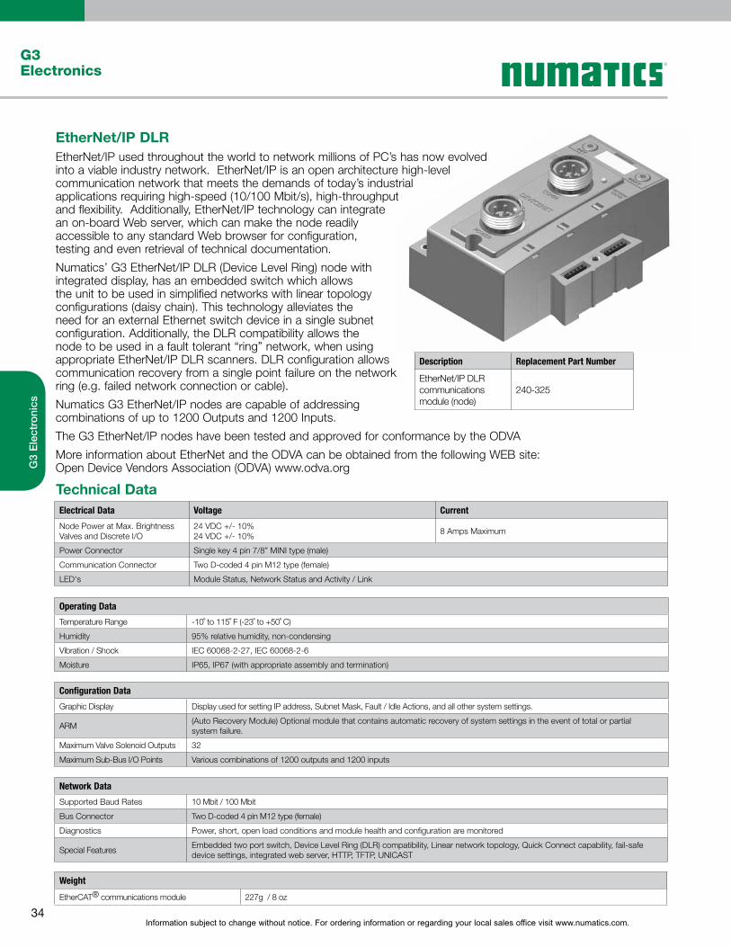
EtherNet/IP DLREtherNet/IP used throughout the world to network millions of PC’s has now evolved into a viable industry network. EtherNet/IP is an open architecture high-level communication network that meets the demands of today’s industrial applications requiring high-speed (10/100 Mbit/s), high-throughput and flexibility. Additionally, EtherNet/IP technology can integrate an on-board Web server, which can make the node readily accessible to any standard Web browser for configuration, testing and even retrieval of technical documentation.
Numatics’ G3 EtherNet/IP DLR (Device Level Ring) node with integrated display, has an embedded switch which allows the unit to be used in simplified networks with linear topology configurations (daisy chain). This technology alleviates the need for an external Ethernet switch device in a single subnet configuration. Additionally, the DLR compatibility allows the node to be used in a fault tolerant “ring” network, when using appropriate EtherNet/IP DLR scanners. DLR configuration allows communication recovery from a single point failure on the network ring (e.g. failed network connection or cable).
Numatics G3 EtherNet/IP nodes are capable of addressing combinations of up to 1200 Outputs and 1200 Inputs.
The G3 EtherNet/IP nodes have been tested and approved for conformance by the ODVA
More information about EtherNet and the ODVA can be obtained from the following WEB site: Open Device Vendors Association (ODVA) www.odva.org
Technical DataElectrical Data Voltage Current
Node Power at Max. BrightnessValves and Discrete I/O
24 VDC +/- 10%24 VDC +/- 10%
8 Amps Maximum
Power Connector Single key 4 pin 7/8” MINI type (male)
Communication Connector Two D-coded 4 pin M12 type (female)
LED's Module Status, Network Status and Activity / Link
Operating Data
Temperature Range -10˚ to 115˚ F (-23˚ to +50˚ C)
Humidity 95% relative humidity, non-condensing
Vibration / Shock IEC 60068-2-27, IEC 60068-2-6
Moisture IP65, IP67 (with appropriate assembly and termination)
Description Replacement Part Number
EtherNet/IP DLR communications module (node)
240-325
Configuration Data
Graphic Display Display used for setting IP address, Subnet Mask, Fault / Idle Actions, and all other system settings.
ARM(Auto Recovery Module) Optional module that contains automatic recovery of system settings in the event of total or partial system failure.
Maximum Valve Solenoid Outputs 32
Maximum Sub-Bus I/O Points Various combinations of 1200 outputs and 1200 inputs
Network Data
Supported Baud Rates 10 Mbit / 100 Mbit
Bus Connector Two D-coded 4 pin M12 type (female)
Diagnostics Power, short, open load conditions and module health and configuration are monitored
Special FeaturesEmbeddedtwoportswitch,DeviceLevelRing(DLR)compatibility,Linearnetworktopology,QuickConnectcapability,fail-safedevice settings, integrated web server, HTTP, TFTP, UNICAST
Weight
EtherCAT® communications module 227g / 8 oz
Information subject to change without notice. For ordering information or regarding your local sales office visit www.numatics.com.35
G3Electronics
G3
Ele
ctro
nics
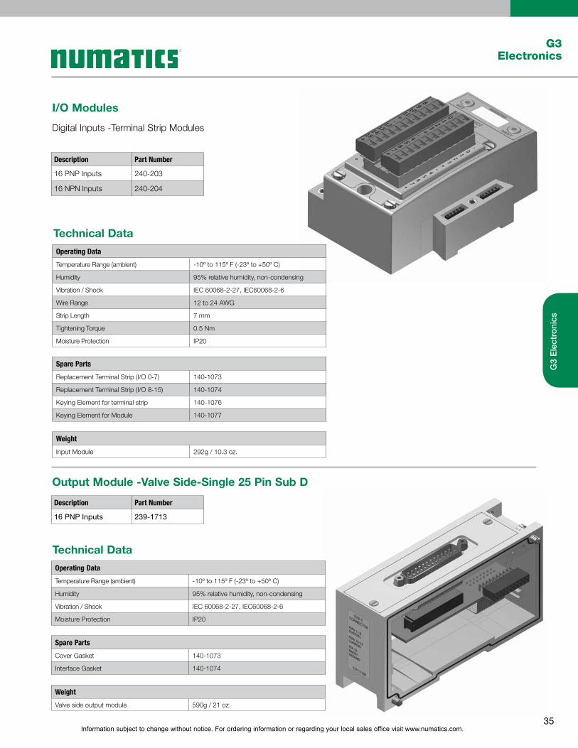
I/O Modules
Digital Inputs -Terminal Strip Modules
Output Module -Valve Side-Single 25 Pin Sub D
Description Part Number
16 PNP Inputs 240-203
16 NPN Inputs 240-204
Description Part Number
16 PNP Inputs 239-1713
Technical Data
Technical Data
Operating Data
Temperature Range (ambient) -10º to 115º F (-23º to +50º C)
Humidity 95% relative humidity, non-condensing
Vibration / Shock IEC 60068-2-27, IEC60068-2-6
Wire Range 12 to 24 AWG
Strip Length 7 mm
Tightening Torque 0.5 Nm
Moisture Protection IP20
Operating Data
Temperature Range (ambient) -10º to 115º F (-23º to +50º C)
Humidity 95% relative humidity, non-condensing
Vibration / Shock IEC 60068-2-27, IEC60068-2-6
Moisture Protection IP20
Spare Parts
Replacement Terminal Strip (I/O 0-7) 140-1073
Replacement Terminal Strip (I/O 8-15) 140-1074
Keying Element for terminal strip 140-1076
Keying Element for Module 140-1077
Spare Parts
Cover Gasket 140-1073
Interface Gasket 140-1074
Weight
Input Module 292g / 10.3 oz.
Weight
Valve side output module 590g / 21 oz.
Information subject to change without notice. For ordering information or regarding your local sales office visit www.numatics.com.36
G3Electronics
G3
Ele
ctro
nics
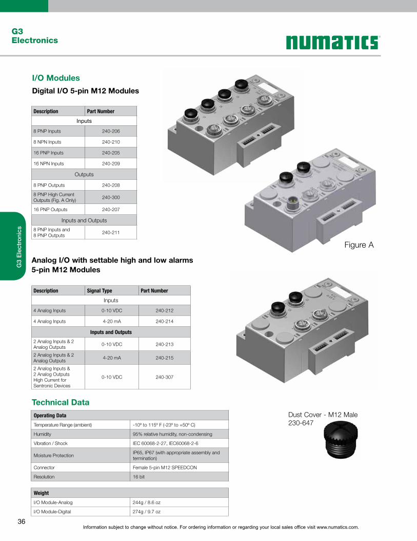
I/O Modules
Digital I/O 5-pin M12 Modules
Description Part Number
Inputs
8 PNP Inputs 240-206
8 NPN Inputs 240-210
16 PNP Inputs 240-205
16 NPN Inputs 240-209
Outputs
8 PNP Outputs 240-208
8 PNP High CurrentOutputs (Fig. A Only)
240-300
16 PNP Outputs 240-207
Inputs and Outputs
8 PNP Inputs and 8 PNP Outputs
240-211
Analog I/O with settable high and low alarms 5-pin M12 Modules
Description Signal Type Part Number
Inputs
4 Analog Inputs 0-10 VDC 240-212
4 Analog Inputs 4-20 mA 240-214
Inputs and Outputs
2 Analog Inputs & 2 Analog Outputs
0-10 VDC 240-213
2 Analog Inputs & 2 Analog Outputs
4-20 mA 240-215
2 Analog Inputs & 2 Analog Outputs High Current for Sentronic Devices
0-10 VDC 240-307
Dust Cover - M12 Male 230-647
Figure A
Technical DataOperating Data
Temperature Range (ambient) -10º to 115º F (-23º to +50º C)
Humidity 95% relative humidity, non-condensing
Vibration / Shock IEC 60068-2-27, IEC60068-2-6
Moisture ProtectionIP65, IP67 (with appropriate assembly and termination)
Connector Female 5-pin M12 SPEEDCON
Resolution 16 bit
Weight
I/O Module-Analog 244g / 8.6 oz
I/O Module-Digital 274g / 9.7 oz

Information subject to change without notice. For ordering information or regarding your local sales office visit www.numatics.com.37
G3Electronics
G3
Ele
ctro
nics
G3 RTD Temperature ModuleThe RTD module is for use with RTD (Resistive Temperature Detectors), supporting up to four RTD devices simultaneously. The module supports various RTD types including: Pt100, Pt200, Pt500, Pt1000, Ni100 and Ni1000.
Technical Data
Electrical Data
Voltage 24 VDC Module Supply (Via G3 System Aux. Power Connection)
Input Type RTD (Resistive Temperature Detector), 4 per Module
Supported Sensor Type Pt100, Pt200, Pt500, Pt1000, Ni100, Ni1000
Supported Temperature Coefficients .00385; .00392; ….Ω/Ω/°C
Resolution 15 bits plus sign.
Data Format Signed Integer
CalibrationFactory CalibratedField Calibration w/ high tolerance (± .005%) 100 ohm and 350 ohm resistors.
Input Update (filter) Rate Adjustable (5-20mS), factory default: 5ms
Accuracy 0.1% of full scale @ 25° C
Mechanical Data
I/O Connector M12 4 Pin Female (Accepts 5 Pin)
Mass 247g / 8.7 oz
Operating Data
Temperature Range -10º to 115º F (-23º to 46º C)
Humidity 95% relative humidity: non-condensing
Ingress Protection IP65 (with appropriate assembly and terminations)
240- 317 G3 [Ex ia] NAMUR Input ModuleThe [Ex ia] module is for use with NAMUR certified intrinsically safe (IS) sensors.
Technical Data
Electrical Data
Voltage24 VDC Module SupplySensor Supply = 8.2 VDC Nominal
Input Type
NC (Normally Closed)
NAMUR Signal Current (0) ≥ 2.1 mA Signal Current (1) ≤ 1.2 mA Short Circuit Monitoring < 100 Ω Open/Broken Wire Detection < 0.05 mA
Safety ParameterOutput Maximums
Uo ≤ 9.6 VIo ≤ 13 mAPo ≤ 31 mW
Diagnostics Open (broken wire) and Short Circuit
Certification
Module Marking (ATEX) II(1)GD[Ex ia Ga] IIC [Ex ia Da] IIIC
Mechanical Data
I/O Connector M12 4 Pin Female (Compatible with 5 Pin)
Mass 284g / 10.0 oz
Operating Data
Temperature Range -10º to 115º F (-23º to 46º C)
Humidity 95% relative humidity: non-condensing
Ingress Protection IP65 (with appropriate assembly and terminations)
Information subject to change without notice. For ordering information or regarding your local sales office visit www.numatics.com.38
G3Electronics
G3
Ele
ctro
nics
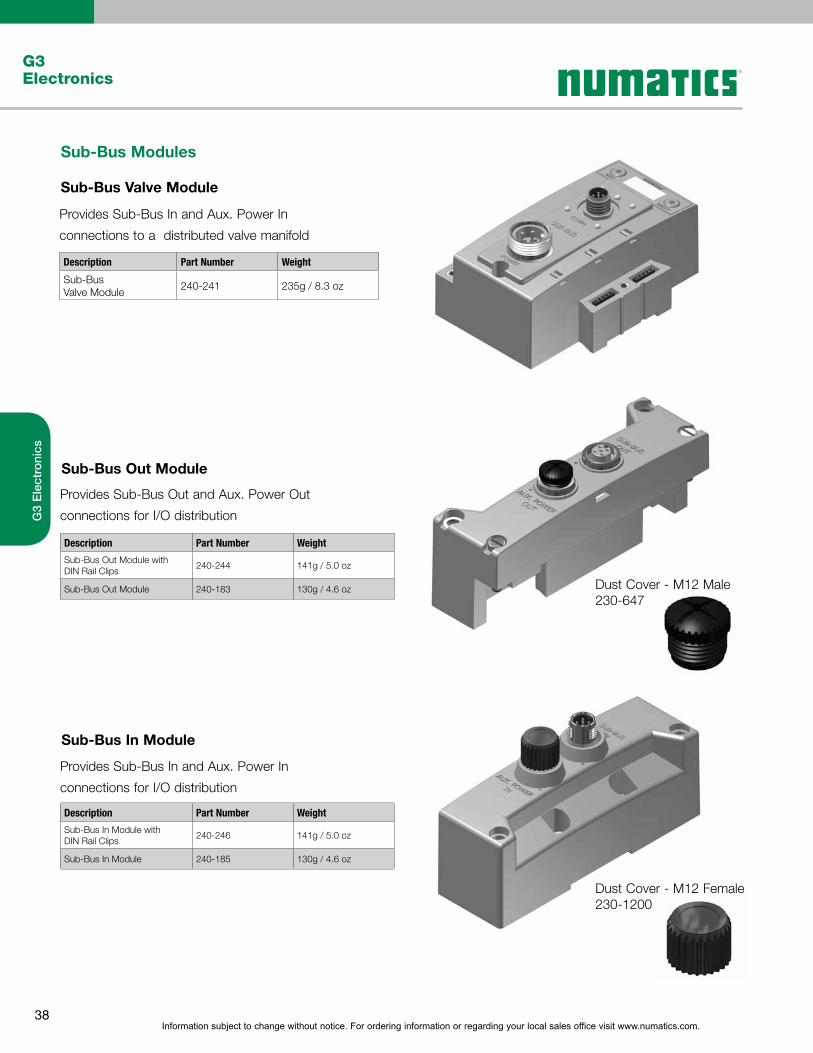
Sub-Bus Modules
Sub-Bus Valve Module
Description Part Number Weight
Sub-Bus Valve Module
240-241 235g / 8.3 oz
Provides Sub-Bus In and Aux. Power In
connections to a distributed valve manifold
Sub-Bus Out Module
Sub-Bus In Module
Description Part Number Weight
Sub-Bus Out Module with DIN Rail Clips
240-244 141g / 5.0 oz
Sub-Bus Out Module 240-183 130g / 4.6 oz
Description Part Number Weight
Sub-Bus In Module with DIN Rail Clips
240-246 141g / 5.0 oz
Sub-Bus In Module 240-185 130g / 4.6 oz
Provides Sub-Bus Out and Aux. Power Out
connections for I/O distribution
Provides Sub-Bus In and Aux. Power In
connections for I/O distribution
Dust Cover - M12 Male 230-647
Dust Cover - M12 Female 230-1200

Information subject to change without notice. For ordering information or regarding your local sales office visit www.numatics.com.39
G3Electronics
G3
Ele
ctro
nics
Miscellaneous Modules
Auto Recovery Module (ARM)
Terminator Module
Description Part Number Weight
ARM Module 240-182 127g / 4.5 oz
Description Part Number Weight
Terminator Modulew/ DIN Rail Clips
240-245 102g / 3.6 oz
Terminator Module 240-184 91g/ 3.2 oz
Protects configuration information during a critical
failure. Allows configuration information to be saved
and reloaded to replacement module automatically.
Provides termination for the sub-bus. Must be installed
after the last I/O module or after the communication
module if there are no I/O modules installed.
Jumper Clip
Description Part Number Weight
Jumper Clip 240-179 45g / 1.6 oz
Provides electrical connections between modules

Information subject to change without notice. For ordering information or regarding your local sales office visit www.numatics.com.40
G3Electronics
G3
Ele
ctro
nics
Valve Driver Module
Generation 2000, ISO 5599/2 and ISO 15407-2 Series
503 Series
Right Hand Mounting Cover
Description Part Number Weight
Valve Driver Modulew/ DIN Rail Clips
219-858 147g / 5.2 oz
Valve Driver Module 219-828 136g / 4.8 oz
Description Part Number
Valve Driver Module P599AE425188001
Valve Driver Modulew/ DIN Rail Clips
P599AE425188002
Description Part Number Weight
Right Hand Mounting Cover w/ DIN Rail Clips
240-290 82g / 2.9 oz.
Right Hand Mounting Cover
240-255 71g / 2.5 oz.
* Not for use in combination with ARM Module
Provides connections between the communication
module or Sub-Bus valve module and the valve manifold
Used when a communication module is used
without local valves installed
For use with Murrplastik© Type 20 Software
Miscellaneous Modules
Accessories
Labels - 122-1251
Technical Data
Material Polycarbonate (PC)
Color White
Temperature Range 40º - 140º C
Label Dimensions 0.19" x 0.39"
Label - Printable Area 0.19" x 0.39"
{

Information subject to change without notice. For ordering information or regarding your local sales office visit www.numatics.com.41
G3Electronics
G3
Ele
ctro
nics
Dimensional Drawing - G3 Fieldbus Manifold Assembly
503 Series Valve Manifold Assembly with G3 Electronics and Sub-Bus Output
A B C D E F G H J K L M N P
105.5(4.154)
6.3(0.248)
38(1.5)
52.8(2.08)
33.8(1.33)
7(0.28)
57.5(2.264)
67.5(2.66)
71.7(2.82)
–39.1(1.54)
75.8(2.984)
68.1(2.68)
56.3(2.217)
Q R S T U V W X Y Z AA AB AC AD
54(2.13)
24.8(0.98)
67.5(2.66)
36.9(1.45)
221.3(8.713)
368.6(14.51)
12.5(0.49)
24.8(0.976)
53(2.087)
–55.1(2.17)
101.1(3.98)
112.9(4.445)
207(8.2)
G
W
S TR
U
V
X
Y Z AA
H
AD
BA M
L
NP Q
AB A
C
CD
E
F J K
6.3 Wide Slot(2) Places
Ø5.4
Dimensions: mm (Inches)
* - For valve manifold dimensions refer to Valve Series product catalogs

Information subject to change without notice. For ordering information or regarding your local sales office visit www.numatics.com.42
G3Electronics
G3
Ele
ctro
nics
A B C D E F G H J K L M N P R S T U
1.82(46.35)
2.66(67.50)
2.26(57.50)
0.27(6.90)
4.15(105.50)
1.50(38.00)
1.33(33.75)
0.25(6.25)
7.29(185.25)
0.53(13.50)
2.65(67.25)
1.45(36.75)
2.13(54.00)
0.49(12.50)
2.46(62.50)
0.20(5.05)
2.32(59.00)
4.65(118.00)
Dimensional Drawing - G3 Fieldbus I/O Assembly
I/O Assembly with G3 Electronics and Sub-Bus Input
A B C
E
P
N R
K L M
J
T U
VIEW SHOWN WITH OPTIONAL DINRAIL HARDWARE AND 35mm DIN
RAIL
S
ADDITIONAL MOUNTING HOLES (4) FOR USE WITH M5 OR #10 SCREWS
F
FOR USE WITH OPTIONALDIN RAIL HARDWARE
G
H D
Dimensions: Inches (mm)

Information subject to change without notice. For ordering information or regarding your local sales office visit www.numatics.com.43
G3Electronics
G3
Ele
ctro
nics
Manifold Assembly How to Order
B503 A 3
Port Type8 = NPTF1
Product Series503 = 26 mm Valve
G = ISO228/1-G1
K = Push-in Fittings
RevisionA = Initial Release
Product Type
Electronics
V = Valve Manifold Assembly
3 = G3 Fieldbus Electronics
Number of Valve StationsB = 2D = 4F = 6
J = 10L = 12
H
1 Port Type ‘8’ + ‘G’ only available in Port Size 3/82 Horizontal end plates only available with Electroincs option ‘O’ - No Electronics
= 8
N = 18P = 20R = 22
V = 26X = 28
T = 24
Z = 263 = 285 = 307 = 32
OptionsA00 = Standard (No Options)MUF
DWM
= Muffler in End PlatesDRM = DIN Rail Mount
14X= DIN Rail with MUF
D12= External Pilot Supply from Port # 14
F06
= (14X) External Pilot Supply from Port # 14 and (DRM) DIN Rail Mount
D14
= (14X) External Pilot Supply from Port # 14 and (MUF) Muffler in End Plates
= (14X) External Pilot Supply from Port # 14, (MUF) Muffler in End Plates, and (DRM) DIN Rail Mount
End Plate StyleV = Vertical
3 = 3/8
K = 10 mmH = 8 mm
End Plate Port Size2 = 1/4
V 2 V A000 08

Information subject to change without notice. For ordering information or regarding your local sales office visit www.numatics.com.44
G3Electronics
G3
Ele
ctro
nics
E
Electrical / ElectronicType & Location3 = G3 Electronics
Valve Series*0 N/A6 2002 - 02/R2E 2005G 2012B 2035W ISO 15407-2 18 mmX ISO 15407-2 26 mmQ ISO 5599/2 Size 1R = ISO 5599/2 Size 2S
========
= ISO 5599/2 Size 3
Number of Valve StationsA 1B 2C 3D 4E 5F 6G 7H
======== 8
KA 3 0 0
Special OptionsSTD = StandardDRM = DIN Rail Mounting - Not available w/2035 and
ISO 5599/2MUF = Muffler - Not available with ISO 5599/2DW M= DIN Rail w/ Muffler - Not available w/2035 and
ISO 5599/2
End Plate Port TypeL Push-In FittingN NPTF Pressure Ports
(NPTF Conduit Ports if Applicable)G
==
= ISO 228/1-G Tap Pressure Ports(ISO 228/1-G Conduit Ports if Applicable)
End Plate Port Size2 1/43 3/84 1/26 1H 8 mm (5/16)K 10 mmX
======= Two or more valve groups resulting in
different standard end plate port sizes.
0 0
I 9J 10K 11L 12M 13N 14O 15P
======== 16
Q 17R = 18S 19T 20U 21V 22W 23X
=
====== 24
Y 25Z 262 273 284 295 306 317
======== 32
D 3 L STD
STD
Electronics ProtocolsCO1 = CANopenDL1 = Device LogixDN1 = DeviceNet
EM1 = Ethernet Modbus - TCP
PL1 = Ethernet POWERLINKEP1 = EtherNet/IP
EC1 = EtherCATED1 = EtherNet/IP DLR
PT1 = PROFIBUS-DPPN1 = PROFINETDS2 = Sub-Bus Valve ManifoldDS3 = Sub-Bus I/O Assembly
Number of I/O Modules00 = 001 = 102 = 203 = 304 = 405 = 506 = 607 = 708 = 809 = 910 = 1011 = 1112 = 1213 = 1314 = 1415 = 1516 = 16
Left MountingD w/ Sub-Bus OutR
== w/ Terminating Resistor
G3 EP1
Special OptionsSTD = StandardDRM = DIN Rail MountingE23 = Fieldbus assembly without valvesE28 = Valve Side 25 pin Sub D NPN outpu moduleE40 = Auto Recovery Module
G32 = DRM-DIN Rail MountingE40-Auto Recovery Module
G33 = DRM-DIN Rail MountingE28-Valve Side 25 pin Sub D NPN output module
G34 = E28-Valve Side 25 pin Sub D NPN output moduleE40-Auto Recovery Module
G36 = E23-Fieldbus assembly without valvesDRM-DIN Rail Mounting
J32 = DRM-DIN Rail MountingE28-Valve Side 25 pin Sub D NPN output moduleE40-Auto Recovery Module
Modification0 = Initial Release
0R00
How To Order
G3 Assembly Kit
How To Order
G3 Electronics
*For manifold assembly with multiple valve series - Consult Factory
Information subject to change without notice. For ordering information or regarding your local sales office visit www.numatics.com.45
G3Electronics
G3
Ele
ctro
nics
Ordering Valve Manifold Assemblies with G3 Electronics & Discrete I/O
For valve series 2002, 2005, 2012, 2035, ISO 15407-2 & ISO 5599/2 (2005 shown)
Example Order - 2005 Shown
Assy Kit AK3EP00003LMUFStation 1 052BB4Z2ML00061Station 2 052BB4Z2ML00061Station 3 052BB4Z2ML00061Station 4 052BB4Z2ML00061Station 5 052BB4Z2ML00061Station 6 052BB4Z2ML00061Station 7 052BB4Z2ML00061Station 8 052BB4Z2ML00061Station 9 052BB4R2ML00061Station 10 052BB4Z2ML00061Station 11 052BB4Z2ML00061Station 12 052BB4Z2ML00061Station 13 052BB4Z2ML00061Station 14 052BB4Z2ML00061Station 15 052BB4Z2ML00061Station 16 052BB4Z2ML00061Electronics G3DN116R0E40Station 1 240-205Station 2 240-205
Station 15 240-205Station 16 240-205
Example Order - I/O assembly
with Sub-Bus in and Sub-Bus out modules
Electronics G3DS316D0STD
Station 1 240-205
Station 2 240-205
Station 15 240-205
Station 16 240-205
116
16 1 1 152 3 16
How To Order
G3 Electronics
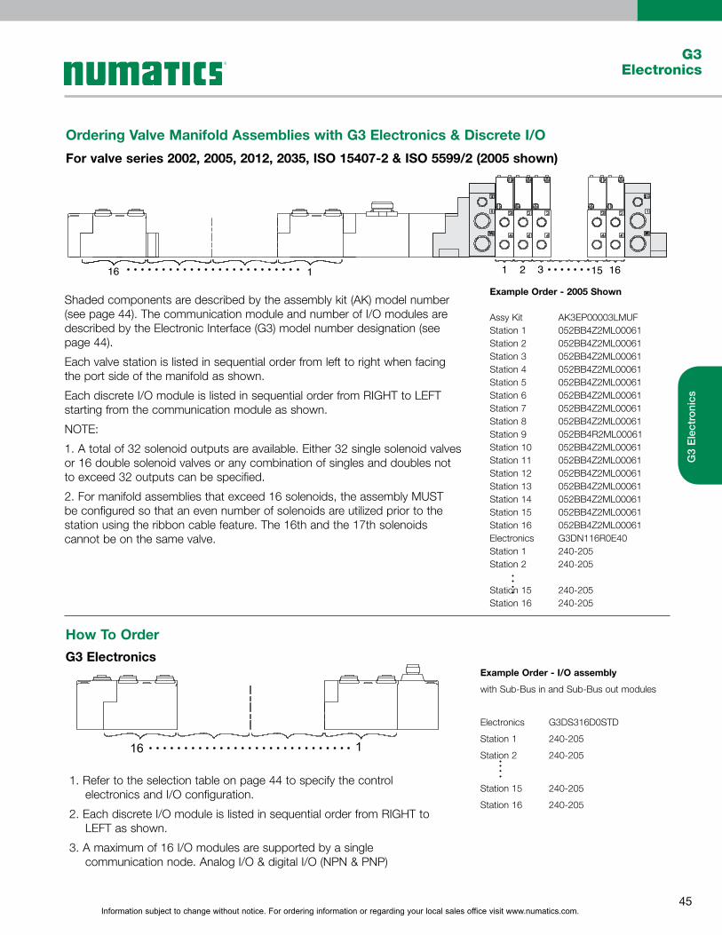
Shaded components are described by the assembly kit (AK) model number (see page 44). The communication module and number of I/O modules are described by the Electronic Interface (G3) model number designation (see page 44).
Each valve station is listed in sequential order from left to right when facing the port side of the manifold as shown.
Each discrete I/O module is listed in sequential order from RIGHT to LEFT starting from the communication module as shown.
NOTE:
1. A total of 32 solenoid outputs are available. Either 32 single solenoid valves or 16 double solenoid valves or any combination of singles and doubles not to exceed 32 outputs can be specified.
2. For manifold assemblies that exceed 16 solenoids, the assembly MUST be configured so that an even number of solenoids are utilized prior to the station using the ribbon cable feature. The 16th and the 17th solenoids cannot be on the same valve.
1. Refer to the selection table on page 44 to specify the control electronics and I/O configuration.
2. Each discrete I/O module is listed in sequential order from RIGHT to LEFT as shown.
3. A maximum of 16 I/O modules are supported by a single communication node. Analog I/O & digital I/O (NPN & PNP)

Information subject to change without notice. For ordering information or regarding your local sales office visit www.numatics.com.46
G3Electronics
G3
Ele
ctro
nics
4 Pin Cables for DeviceNetTM, DeviceLogix, Ethernet, Modbus TCP, CANopen, and Sub-Bus
4 Pin Connectors for DeviceNetTM, DeviceLogix, Ethernet, Modbus TCP, CANopen, and Sub-Bus
5 Pin Connectors for PROFIBUS DP, PROFINET and POWERLINK
7/8" MINI Cables
7/8" MINI Field Wireable Connectors
5 Pin Cables for PROFIBUS DP, PROFINET and POWERLINK
7/8" MINI Straight 4 Pin Female Single Ended Cable, Euro Color Code
MC0405MAC0000000 – 5 Meter
MC0410MAC0000000 – 10 Meter
7/8" MINI 90° 4 Pin Female Single Ended Cable, Euro Color Code
MD0405MAC0000000 – 5 Meter
MD0410MAC0000000 – 10 Meter
7/8" MINI Straight 5 Pin Female Single Ended Cable, Euro Color Code
MC0505MAG0000000 – 5 Meter
MC0510MAG0000000 – 10 Meter
7/8" MINI 90° 5 Pin Female Single Ended Cable, Euro Color Code
MD0505MAG0000000 – 5 Meter
MD0510MAG0000000 – 10 Meter
7/8" MINI Straight 4 Pin Female Field Wireable Connector
MC04F90000000000 –Cable Gland – One size fits all
7/8" MINI Straight 5 Pin Female Field Wireable Connector
MC05F90000000000 – Cable Gland – One size fits all
7/8" MINI 90° 4 Pin Female Field Wireable Connector
MD04F20000000000 – PG 9 Cable Gland
7/8" MINI 90° 5 Pin Female Field Wireable Connector
MD05F20000000000 – PG 9 Cable Gland

Information subject to change without notice. For ordering information or regarding your local sales office visit www.numatics.com.47
G3Electronics
G3
Ele
ctro
nics
4 Pin Cable for Sub-Bus Power
4 Pin Cables for Sub-Bus Power
4 Pin Connectors for Sub-Bus Power
M12 to 7/8" MINI Cable
M12 Cables
M12 Field Wireable Connectors
M12 Straight 4 Pin Male to 7/8" MINI 4 Pin Female Extension
TA0401MA0MC0471T – 1 Meter
TA0405MA0MC0471T – 5 Meter
TA0410MA0MC0471T – 10 Meter
M12 Straight 4 Pin Male to Female Cable Extension
TC0401MAETA04000 – 1 Meter
TC0405MAETA04000 – 5 Meter
TC0410MAETA04000 – 10 Meter
M12 Straight 4 Pin Female Single Ended Cable, Euro Color Code
TC0405MAE0000000 – 5 Meter
TC0410MAE0000000 – 10 Meter
M12 Straight 4 Pin Female Field Wireable Connector
TC04F10000000000 – PG 7 Cable Gland
TC04F20000000000 – PG 9 Cable Gland
M12 90° 4 Pin Female Field Wireable Connector
TD04F10000000000 – PG 7 Cable Gland
TD04F20000000000 – PG 9 Cable Gland
M12 90° 4 Pin Female Single Ended Cable, Euro Color Code
TD0405MAE0000000 – 5 Meter
TD0410MAE0000000 – 10 Meter

Information subject to change without notice. For ordering information or regarding your local sales office visit www.numatics.com.48
G3Electronics
G3
Ele
ctro
nics
Pin Out and Technical Data
M12 Cable - Pin Out / Euro Color Code(Male View)
7/8" MINI Cable - Pin Out / Euro Color Code(Male View)
Technical Data M12 7/8" MINI
Molded Body / Insert Cable = PVC Field Wireable = Polyamide Cable = PVC Field Wireable = Polyamide or PBT
Coupling Nut Nickel Copper Alloy Black Anodized Aluminum
Cable Jacket Material PVC PVC
Cable O.D. 7.4mm 7.4mm (4 Pin & 5 Pin)
Voltage Rating (Nominal) 250 V Max. @ 105° C 250 V Max. @ 105° C
Current Rating Cables = 4.0 Amps Field Wireable = 4.0 Amps Cables = 5.5 Amps Field Wireable = 8.0 Amps
Degree of Protection IP67 (mated) IP67 (mated)
Operating Temperature -25° C - 85° C -40° C - 85° C
Conductor Gauge Cable = 18 AWG Cable = 18 AWG
Bend Radius Cable = 74mm Cable = 74mm (4 Pin & 5 Pin)
Maximum Wire AWG Field Wireable = 18 AWG Field Wireable = 16 AWG
Wire Connection Field Wireable = Screw Terminal Field Wireable = Screw Terminal
PG 7 Range 4-6 mm N/A
PG 9 Range 6-8 mm 5-13 mm – One size fits all
PG 13.5 Range N/A 5-13 mm – One size fits all
1
2
3
4
1
2
3
4
1
2
3
4
5

Information subject to change without notice. For ordering information or regarding your local sales office visit www.numatics.com.49
G3Electronics
G3
Ele
ctro
nics
7/8" MINI Drop Cables
M12 Drop Cables
7/8" MINI 3 Way “T”
Terminating Resistors “TR”
7/8" MINI Field Wireable Connectors
MINI Cable - Pin Out / Color Code (Male View)
M12 Cable - Pin Out / Color Code (Male View)
7/8" MINI Straight 5 Pin Female Single Ended Cable - Shielded
MC0505MGD0000000 – 5 Meter
MC0510MGD0000000 – 10 Meter
M12 Straight 5 Pin Female Single Ended Cable - Shielded
TC0505MGD0000000 – 5 Meter
TC0510MGD0000000 – 10 Meter
3 Way 7/8" MINI “T”
MC0500000MT05000
7/8" MINI & M12 Straight 5 Pin Male Terminators
TA05TR0000000000 – M12 Male
MA05TR0000000000 – MINI Male
7/8" MINI Straight 5 Pin Field Wireable Connectors
MC05F90000000000 - Female - Cable Gland - One size fits all
MA05F90000000000 - Male - Cable Gland - One size fits all
Technical Data Cable T & TR Field Wireable
Molded Body / Insert PVC PVC Body = Glass Filled Polyamide
Coupling NutNickel Plated Brass or Anodized Aluminum
Clear Anodized Aluminum
Black Anodized Aluminum
Cable Jacket Material PVC N/A N/A
Cable O.D. MINI = 8mm M12 = 8mm N/A 5-13mm – One size fits all
Voltage Rating (Nominal) 150 Volts T =300 Volts 600 Volts
Current RatingMINI =4.0 Amps MR = 3.0 Amps
T = 8.0 Amps TR = NA
8.0 Amps
Degree of Protection IP65 (mated) IP65 (mated) IP65 (mated)
Operating Temperature -40° C - 80° C -40° C - 105° C -40° C - 90° C
Conductor Gauge22 AWG Power 24 AWG Signal
N/A 16-22 AWG
Bend Radius Cable = 72mm N/A N/A
Wire Connection NA N/A Screw Terminal
V+ (RED)
DRAIN
V- (BLACK)
CAN_H (WHITE)
CAN_L (BLUE)

Information subject to change without notice. For ordering information or regarding your local sales office visit www.numatics.com.50
G3Electronics
G3
Ele
ctro
nics
M12 D-Coded Cables
M12 D-Coded Field Attachable CONNECTORS
RJ45 Field Attachable CONNECTOR
M12 D-Coded Cable - Pin Out / Color Code (Male View)
M12 Straight 4 Pin Male D-Coded Single Ended Cable
QA0405MR00000000–5Meter
QA0410MR00000000–10Meter
M12 Straight 4 Pin Male D-Coded Field Wireable Connector
QA04F20000000000–PG9CableGland–ScrewTerminal
RJ45 Field Wireable Connector with IDC
VA08F200R000071N – PG 9 Cable Gland
M12 Straight 4 Pin Male D-Coded Double Ended Cable
QA0405MR0QA04000–5Meter
QA0410MR0QA04000–10Meter
M12 Straight 4 Pin Male D-Coded Field Wireable Connector W/IDC
QA04F200R000071N–PG9CableGland-IDC
M12 Straight 4 Pin Male D-Coded to Male RJ45 Cable
QA0405MR0VA04000–5Meter
QA0410MR0VA04000–10Meter
M12 Straight 4 Pin Male D-Coded to RJ45 Female Socket Convertor
QA04D2MK0VC04000–0.2Meter
Technical Data Cable RJ45 Field Attachable M12 Field Attachable
Molded Body / Insert TPU Housing = PA Carrier = PC Body = Nickel Plated Zinc
Insert = PA 66
Coupling Nut Nickel Plated Zinc N/A Nickel Plated Brass
Cable Jacket Material PVC N/A N/A
Cable O.D. 6.5 to 7.4 mm Accepts 4.5 to 8.0 mm Accepts 6.0 to 8 mm
Voltage Rating (Nominal) 250 Volts N/A 60 Volts
Current Rating 4.0 Amps 1.75 Amps Screw 4.0 Amps IDC 1.75 Amps
Degree of Protection IP65 (mated), RJ45 – IP20 IP20 IP 65 (mated)
Operating Temperature -25° C - 60° C -10° C - 60° C -40° C - 85° C
Conductor Gauge 22 & 24 AWG 22 AWG Solid/Stranded Screw 24-18 AWG IDC 26-22 AWG
Bend Radius Minimum 19.5mm (fixed) 45.5mm (Flexible) N/A N/A
Wire Connection NA IDC Screw Terminal, IDC
4 3
1 2
YE
WH
OG
BU
2
1
4
3

Information subject to change without notice. For ordering information or regarding your local sales office visit www.numatics.com.51
G3Electronics
G3
Ele
ctro
nics
M12 D-Coded Cables
M12 D-Coded Field Attachable CONNECTORS
RJ45 Field Attachable CONNECTOR
M12 D-Coded Cable & RJ45
Pin Out / Color Code (Male View)
M12 Straight 4 Pin Male D-Coded Field Wireable Connector
QA04F20000000000–PG9CableGland–ScrewTerminal
RJ45 Field Wireable Connector with IDC
VA08F200R000071N – PG 9 Cable Gland
M12 Straight 4 Pin Male D-Coded Double Ended Cable
QA0405MS0QA04000–5Meter
QA0410MS0QA04000–10Meter
M12 Straight 4 Pin Male D-Coded Field Wireable Connector W/IDC
QA04F200R000071N–PG9CableGland-IDC
M12 Straight 4 Pin Male D-Coded to Male RJ45 Cable
QA0405MS0VA04000–5Meter
QA0410MS0VA04000–10Meter
M12 Straight 4 Pin Male D-Coded to RJ45 Female Socket Convertor
QA04D2MK0VC04000–0.2Meter
Technical Data Cable RJ45 Field Attachable M12 Field Attachable
Molded Body / Insert N/A Housing = PA Carrier = PC Body = Nickel Plated Zinc
Insert = PA 66
Coupling Nut Nickel Plated Zinc or Brass N/A Nickel Plated Brass
Cable Jacket Material PUR N/A N/A
Cable O.D. 6.5 mm Accepts 4.5 to 8.0 mm Accepts 6.0 to 8 mm
Voltage Rating (Nominal) N/A N/A 60 Volts
Current Rating N/A 1.75 Amps Screw 4.0 Amps IDC 1.75 Amps
Degree of Protection IP65 (mated), RJ45 – IP20 IP20 IP 65 (mated)
Operating Temperature -25° C - 60° C -10° C - 60° C -40° C - 85° C
Conductor Gauge 22 AWG 22 AWG Solid/Stranded Screw 24-18 AWG IDC 26-22 AWG
Bend Radius Minimum 45.5mm N/A N/A
Wire Connection N/A IDC Screw Terminal, IDC
4 3
1 2
1234
RJ45 to M12
1
2
3
4
1yellow
shield
orange
white
blue
2
3
4
M12 to M12
1
2
3
4
1yellow
shield
orange
white
blue2
3
4
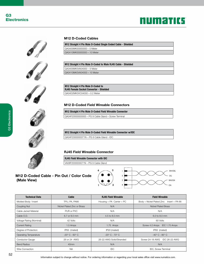
Information subject to change without notice. For ordering information or regarding your local sales office visit www.numatics.com.52
G3Electronics
G3
Ele
ctro
nics
M12 D-Coded Cables
M12 D-Coded Field Wireable Connectors
RJ45 Field Wireable Connector
M12 D-Coded Cable - Pin Out / Color Code (Male View)
M12 Straight 4 Pin Male D-Coded Single Ended Cable - Shielded
QA0405MK00000000–5Meter
QA0410MK00000000–10Meter
M12 Straight 4 Pin Male D-Coded to Male RJ45 Cable - Shielded
QA0405MK0VA04000–5Meter
QA0410MK0VA04000–10Meter
M12 Straight 4 Pin Male D-Coded to RJ45 Female Socket Convertor - ShieldedQA04D2MK0VC04000–0.2Meter
M12 Straight 4 Pin Male D-Coded Field Wireable Connector
QA04F20000000000–PG9CableGland–ScrewTerminal
M12 Straight 4 Pin Male D-Coded Field Wireable Connector w/IDC
QA04F2000000071N–PG9CableGland-IDC
RJ45 Field Wireable Connector with IDC
VA08F2000000071N – PG 9 Cable Gland
Technical Data Cable RJ45 Field Wireable Field Wireable
Molded Body / Insert TPU, PA, PA66 Housing = PA Carrier = PC Body = Nickel Plated Zinc Insert = PA 66
Coupling Nut Nickel Plated Zinc or Brass N/A Nickel Plated Brass
Cable Jacket Material PUR or PVC N/A N/A
Cable O.D. 6.7 or 8.0 mm 4.5 to 8.0 mm 6.0 to 8.0 mm
Voltage Rating (Nominal) 42 Volts N/A 60 Volts
Current Rating 1.5 Amps 1.75 Amps Screw 4.0 Amps IDC 1.75 Amps
Degree of Protection IP65 (mated) IP20 (mated) IP65 (mated)
Operating Temperature -20° C - 60° C -20° C - 70° C -40° C - 85° C
Conductor Gauge 26 or 24 AWG 26-22 AWG Solid/Stranded Screw 24-18 AWG IDC 26-22 AWG
Bend Radius 40mm N/A N/A
Wire Connection NA IDC IDC, Screw Terminal

Information subject to change without notice. For ordering information or regarding your local sales office visit www.numatics.com.53
G3Electronics
G3
Ele
ctro
nics
Technical Data Cable TR Field Wireable
Molded Body / Insert TPU TR = TPU Body = Nickel Plated Zinc
Insert = PA 66
Coupling Nut Nickel Plated Zinc Nickel Plated Zinc or Brass Nickel Plated Brass
Cable Jacket Material PUR N/A N/A
Cable O.D. 7.4 mm N/A 8.5 mm Max.
Voltage Rating (Nominal) 250 volts 60 Volts 60 Volts
Current Rating 4.0 Amps 4.0 Amps 4.0 Amps
Degree of Protection IP65 (mated) IP65 (mated) IP 65 (mated)
Operating Temperature -20° C - 80° C -20° C - 80° C -40° C - 85° C
Conductor Gauge 24 AWG N/A 18 AWG Maximum
Bend Radius Cable = 78mm N/A N/A
Wire Connection N/A N/A Screw Terminal
M12 Reverse Key B-Coded Cables
M12 Reverse Key B-Coded Field Wireable Connectors
M12 Reverse Key B-Coded Terminating Resistor
M12 Reverse Key B-Coded Cable Pin Out / Color Code (Male View)
M12 Straight 5 Pin Male Reverse Key Single Ended Cable - Shielded
RA0505MHP0000000 – 5 Meter
RA0510MHP0000000 – 10 Meter
M12 Straight 5 Pin Male Reverse Key Field Wireable Connector
RA05F200P0000000 – PG 9 Cable Gland
M12 Straight 5 Pin Male Reverse Key Terminating Resistor
RA05TR0000000000 - Male
M12 Straight 5 Pin Female Reverse Key Field Wireable Connector
RC05F200P0000000 – PG 9 Cable Gland
M12 Straight 5 Pin Female Reverse Key Single Ended Cable - Shielded
RC0505MHP0000000 – 5 Meter
RC0510MHP0000000 – 10 Meter
M12 Straight 5 Pin MALE TO FEMALE Reverse Key EXTENSION CABLE
RC0505MHPRC05000 – 5 Meter
RC0510MHPRC05000 – 10 Meter

Information subject to change without notice. For ordering information or regarding your local sales office visit www.numatics.com.54
G3Electronics
G3
Ele
ctro
nics
I/O Cables with SPEEDCON Connector Technology
I/O Connectors
I/O Splitters
M12 Straight 4 Pin Male Single Ended Cable, Euro Color Code
TA04E5MIE000071P – 1.5 Meter
TA0403MIE000071P – 3 Meter
TA0405MIE000071P – 5 Meter
M12 Straight 4 Pin Male Field Wireable Connector, IDC Connection
TA04F2000000081E – PG 9 Cable Gland w/ SPEEDCON connector technology
M12 to M12 “Y” Splitter, 21mm Spacing
TA0500000JC05000
M12 to M8 “Y” Splitter
TA0400000KC03000
M12 90° 4 Pin Male Single Ended Cable, Euro Color Code
TB04E5MIE000071P – 1.5 Meter
TB0403MIE000071P – 3 Meter
TB0405MIE000071P – 5 Meter
M12 Straight 4 Pin Male to Female Cable Extension
TC04E5MIETA0471P – 1.5 Meter
TC0403MIETA0471P – 3 Meter
M12 Straight 3 Pin Male to M8 3 Pin Straight Female Extension
TC03E5MIEPA0371P – 1.5 Meter
TC0303MIEPA0371P – 3 Meter
M12 Straight 4 Pin Male Field Wireable Connector, Screw Terminal
TA04F10000000000 – PG 7 Cable Gland
TA04F20000000000 – PG 9 Cable Gland
M12 90° 4 Pin Male Field Wireable Connector, Screw Terminal
TB04F10000000000 – PG 7 Cable Gland
TB04F20000000000 – PG 9 Cable Gland

Information subject to change without notice. For ordering information or regarding your local sales office visit www.numatics.com.55
G3Electronics
G3
Ele
ctro
nics
M12 Cable Splitter, 2 Straight M12 Female Connectors
TA04D3MIEJC04000 – 0.3 Meter
TA04E5MIEJC04000 – 1.5 Meter
TA0403MIEJC04000 – 3.0 Meter
M12 Cable Splitter, 2 Straight M8 Female Connectors
TA04D3MIEKC03000 – 0.3 Meter
TA04E5MIEKC03000 – 1.5 Meter
TA0403MIEKC03000 – 3.0 Meter
Wire Stripper Tool
140-1097
I/O Cable Connector Pin Out Diagrams
M12 Cable - Pin Out / Color CodeTA04XXMIE0000000, TB04XXMIE0000000(Male View)
M12 Cable - Pin Out / Color CodeTC03XXMIEPA0371P(Male to Female View)
M12 Cable - Pin Out / Color CodeTC03XXMIEPA0371P(Male to Female View)
M12 to M12 "Y" Splitter - Pin Out TA0500000JC05000(Male to Female View)
M12 to M12 Cable Splitter - Pin Out TA04XXMIEJC04000(Male to Female View)
M12 to M8 "Y" Splitter - Pin Out TA0400000KC03000(Male to Female View)
M12 Field Wireable (IDC) - Pin Out TA04F2000000081E (SPEEDCON)(Male View)
M12 to M8 Cable Splitter - Pin Out TA04XXMIEKC03000(Male to Female View)
Note:XX denotes allowable length See pages 46 and 47.

Information subject to change without notice. For ordering information or regarding your local sales office visit www.numatics.com.56
G3Electronics
G3
Ele
ctro
nics
Technical Data M12 Cables M12/M8 Cables M12 Connectors
Molded Body / Insert TPU TPU Polyamide (or) PA 66
Coupling Nut Nickel Plated Zinc Nickel Plated Zinc Nickel Plated Zinc
Cable Jacket Material PUR PUR NA
Cable O.D. 4.70 mm 4.70 mmPG7 4.0 to 6.0 mmPG9 4.0 to 8.0 mm
Voltage Rating 250 Volts 60 Volts 50 Volts
Current Rating (Cond.) 4.0 Amps 3.0 Amps 4.0 Amps
Degree of Protection IP65 (mated) IP65 (mated) IP67 (mated)
Operating Temperature -25º C to 80º C (fixed instl.) -25º C to 80º C (fixed instl.) -25º C to 80º C
Conductor Gauge 22 AWG 22 AWG 22 AWG Min. 18 AWG Max.
Bend Radius 47 mm 47 mm NA
Technical Data I/O "Y" Splitter I/O Cable Splitter
Molded Body / Insert TPU TPU
Coupling Nut Nickel Plated Zinc Nickel Plated Zinc
Cable Jacket Material NA PUR
Cable O.D. NA 4.40 mm
Voltage Rating 60 Volts 60 Volts
Current Rating (Cond.) 3.0 Amps 3.0 Amps
Degree of Protection IP67 (mated) IP67 (mated)
Operating Temperature -25º C to 90º C -25º C to 80º C
Conductor Gauge NA 22 AWG or 24 AWG
Bend Radius NA 44 mm
Technical Data Wire Stripper
Use with PVC Insulation
Stripping Range 28 AWG to 10 AWG
Cutting Range (Flexible) 10 AWG
Cutting Range (Rigid) 12 AWG
Cable and Connector Technical Data

Information subject to change without notice. For ordering information or regarding your local sales office visit www.numatics.com.57
G3Electronics
G3
Ele
ctro
nics
Sub-Bus Cables
M12 Straight 5 Pin Male to Female Sub-Bus Cable - Shielded
TA0501MGDTC0571P – 1 Meter
TA0505MGDTC0571P – 5 Meter
TA0510MGDTC0571P – 10 Meter
M12 Straight 5 Pin Female FIELD WIREABLE CONNECTOR, SPRING CAGE
TC05F2000000071V – PG9 Cable Gland
M12 Straight 5 Pin Male FIELD WIREABLE CONNECTOR, SPRING CAGE
TA05F2000000071V – PG9 Cable Gland
M12 90º 5 Pin Female FIELD WIREABLE CONNECTOR, SPRING CAGE
TD05F2000000071V – PG9 Cable Gland
M12 90º 5 Pin male FIELD WIREABLE CONNECTOR, SPRING CAGE
TB05F2000000071V – PG9 Cable Gland
Bulk Sub-Bus Cable *NOTE
000550MGD0005000 – 50 Meter Length
0005A0MGD0005000 – 100 Meter Length
Technical Data Cable Connectors Bulk Cable
Molded Body / Insert TPU Zinc - Nickel Plated N/A
Coupling Nut Zinc - Nickel Plated Brass - Nickel Plated N/A
Cable Jacket Material PUR N/A Gray RAL 7001
Cable O.D. 6.70 mm N/A 6.70 mm
Voltage Rating (Nominal) 60 Volts 60 Volts 60 Volts
Current Rating 4.0 Amps 4.0 Amps 4.0 Amps
Degree of Protection IP65 (mated) IP65 (mated) IP65 (terminated)
Operating Temperature -40° C - 80° C -40° C - 80° C -20° C - 75° C
Conductor Gauge24 AWG Signal22 AWG Power
26-20 AWG24 AWG Signal22 AWG Power
Bend Radius 67 mm N/A 67 mm
No. of Bending Cycles 5 Million N/A 5 Million
Technical Data
Note:Length of field wired cables should not exceed the maximum length of 30 meters for total sub-bus communications link. See appropriate technical manual for sub-bus length requirements. The cable assemblies and Bulk cable are the only approved cables for the G3 Sub-Bus link. See technical document TDG3SBWD1-0EN for proper installation and wiring of field wireable connectors.
*
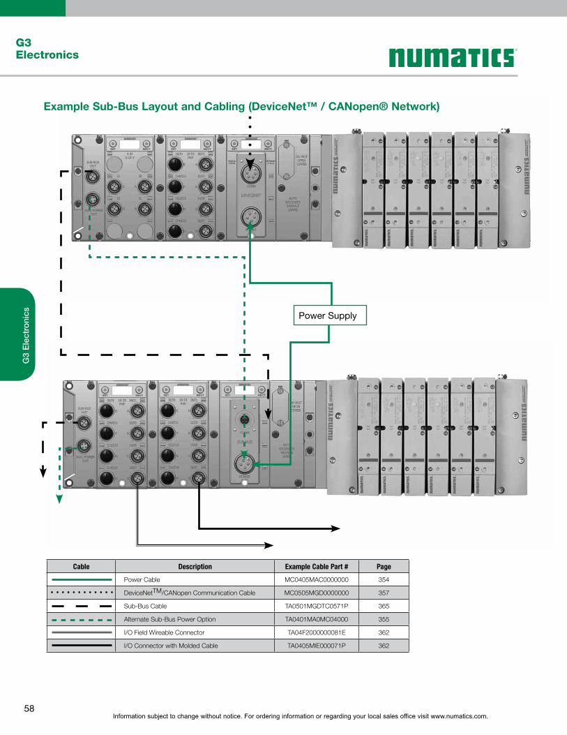
Information subject to change without notice. For ordering information or regarding your local sales office visit www.numatics.com.58
G3Electronics
G3
Ele
ctro
nics
Example Sub-Bus Layout and Cabling (DeviceNet™ / CANopen® Network)
Cable Description Example Cable Part # Page
Power Cable MC0405MAC0000000 354
DeviceNetTM/CANopen Communication Cable MC0505MGD0000000 357
Sub-Bus Cable TA0501MGDTC0571P 365
Alternate Sub-Bus Power Option TA0401MA0MC04000 355
I/O Field Wireable Connector TA04F2000000081E 362
I/O Connector with Molded Cable TA0405MIE000071P 362
Power Supply
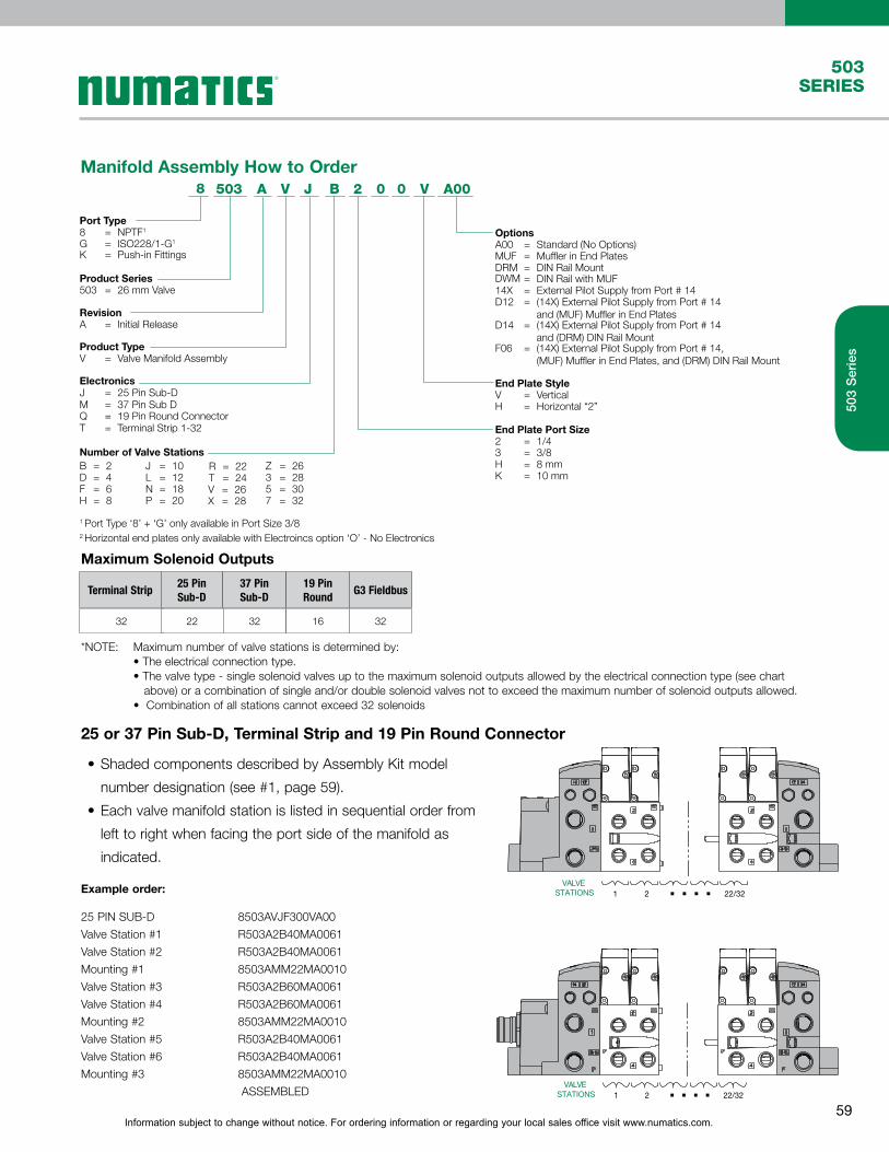
Information subject to change without notice. For ordering information or regarding your local sales office visit www.numatics.com.59
503SERIES
503
Ser
ies
Manifold Assembly How to Order
*NOTE: Maximum number of valve stations is determined by: •Theelectricalconnectiontype. •Thevalvetype-singlesolenoidvalvesuptothemaximumsolenoidoutputsallowedbytheelectricalconnectiontype(seechart above) or a combination of single and/or double solenoid valves not to exceed the maximum number of solenoid outputs allowed. •Combinationofallstationscannotexceed32solenoids
Maximum Solenoid Outputs
32 22 32
Terminal Strip25 PinSub-D
37 PinSub-D
16 32
19 Pin Round
G3 Fieldbus
B503 A J
Port Type8 = NPTF1
Product Series503 = 26 mm Valve
M = 37 Pin Sub D
G = ISO228/1-G1
K = Push-in Fittings
RevisionA = Initial Release
Product Type
Electronics
V = Valve Manifold Assembly
J = 25 Pin Sub-D
T = Terminal Strip 1-32Q = 19 Pin Round Connector
Number of Valve StationsB = 2D = 4F = 6
J = 10L = 12
H
1 Port Type ‘8’ + ‘G’ only available in Port Size 3/82 Horizontal end plates only available with Electroincs option ‘O’ - No Electronics
= 8N = 18P = 20
R = 22
V = 26X = 28
T = 24Z = 263 = 285 = 307 = 32
OptionsA00 = Standard (No Options)MUF
DWM
= Muffler in End PlatesDRM = DIN Rail Mount
14X= DIN Rail with MUF
D12= External Pilot Supply from Port # 14
F06
= (14X) External Pilot Supply from Port # 14 and (DRM) DIN Rail Mount
D14
= (14X) External Pilot Supply from Port # 14 and (MUF) Muffler in End Plates
= (14X) External Pilot Supply from Port # 14, (MUF) Muffler in End Plates, and (DRM) DIN Rail Mount
End Plate StyleV = Vertical
3 = 3/8
K = 10 mmH = 8 mm
End Plate Port Size2 = 1/4
H = Horizontal “2”
V 2 V A000 08
VALVESTATIONS 1 2 22/32. . . .
VALVESTATIONS 1 2 22/32. . . .
25 or 37 Pin Sub-D, Terminal Strip and 19 Pin Round Connector
•Shaded components described by Assembly Kit model
number designation (see #1, page 59).
•Each valve manifold station is listed in sequential order from
left to right when facing the port side of the manifold as
indicated.
Example order:
25 PIN SUB-D 8503AVJF300VA00
Valve Station #1 R503A2B40MA0061
Valve Station #2 R503A2B40MA0061
Mounting #1 8503AMM22MA0010
Valve Station #3 R503A2B60MA0061
Valve Station #4 R503A2B60MA0061
Mounting #2 8503AMM22MA0010
Valve Station #5 R503A2B40MA0061
Valve Station #6 R503A2B40MA0061
Mounting #3 8503AMM22MA0010
ASSEMBLED

Information subject to change without notice. For ordering information or regarding your local sales office visit www.numatics.com.60
503SERIES
Ass
emb
ly K
its
Assembly Kits
37 Pin Sub-D Connector Kit
25 Pin Sub-D Connector Kit
NOTE: External fusing or output protection recommended.
NOTE: External fusing or output protection recommended.
37 Pin Sub-D Connector Housing Kits
P599AE42844200137 PIN SUB-D ASSEMBLY
WITHOUT DIN RAIL
P599AE42844200237 PIN SUB-D ASSEMBLY WITH
DIN RAIL
25 Pin Sub-D Connector Housing Kits
P599AE42844100125 PIN SUB-D ASSEMBLY
WITHOUT DIN RAIL
P599AE42844100225 PIN SUB-D ASSEMBLY WITH
DIN RAIL
A
B C
Ø5.5
G
H
J
K
F
E D
Dimensions: mm (Inches)
A B C D E F G H J K
46.4(1.827)
17(0.669)
6.7(0.26)
118(4.65)
37.5(1.48)
59(2.32)
40.2(1.58)
40.2(1.58)
68.1(2.68)
24.4(0.96)
A
B C
Ø5.5
G
H
J
K
F
E D
Dimensions: mm (Inches)
A B C D E F G H J K
46.4(1.827)
17(0.669)
6.7(0.26)
118(4.65)
37.5(1.48)
59(2.32)
40.2(1.58)
40.2(1.58)
68.1(2.68)
24.4(0.96)
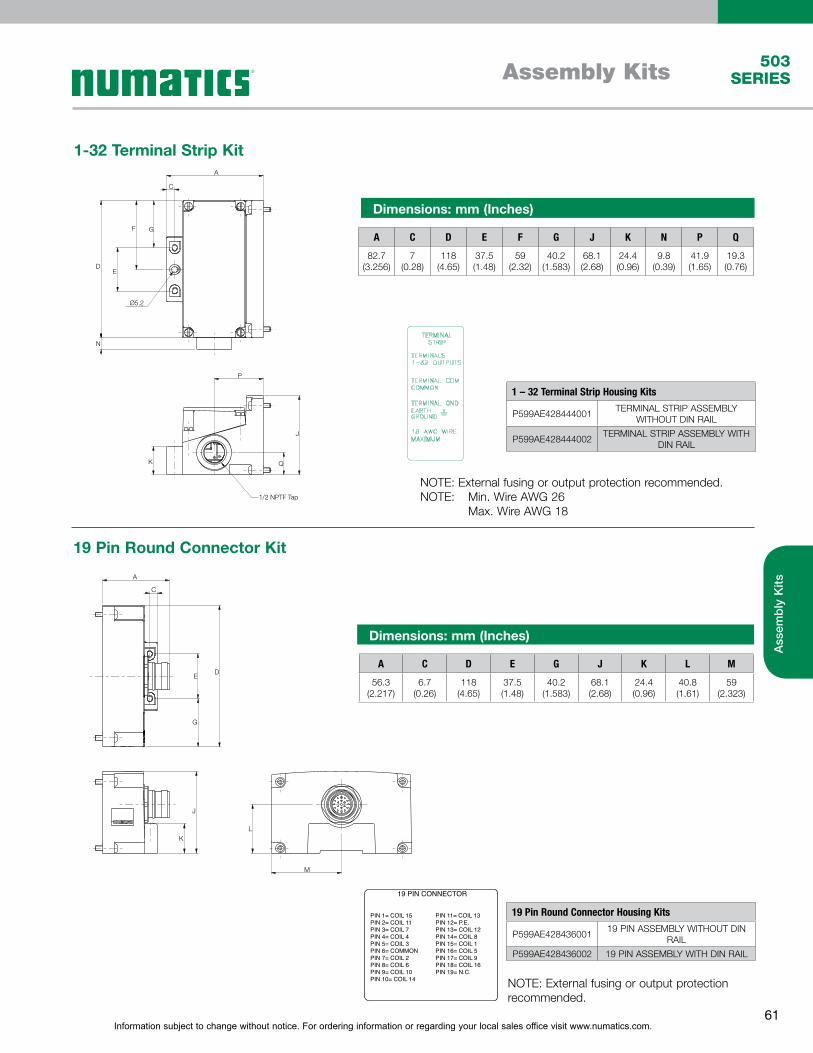
Information subject to change without notice. For ordering information or regarding your local sales office visit www.numatics.com.61
503SERIES
Ass
emb
ly K
its
Assembly Kits
1-32 Terminal Strip Kit
NOTE: External fusing or output protection recommended.NOTE: Min. Wire AWG 26 Max. Wire AWG 18
1 – 32 Terminal Strip Housing Kits
P599AE428444001TERMINAL STRIP ASSEMBLY
WITHOUT DIN RAIL
P599AE428444002TERMINAL STRIP ASSEMBLY WITH
DIN RAIL
19 Pin Round Connector Housing Kits
P599AE42843600119 PIN ASSEMBLY WITHOUT DIN
RAIL
P599AE428436002 19 PIN ASSEMBLY WITH DIN RAIL
19 Pin Round Connector Kit
19 PIN CONNECTOR
PIN 10= COIL 14PIN 9= COIL 10PIN 8= COIL 6PIN 7= COIL 2PIN 6= COMMONPIN 5= COIL 3PIN 4= COIL 4PIN 3= COIL 7PIN 2= COIL 11PIN 1= COIL 15
PIN 19= N.C.
PIN 11= COIL 13PIN 12= P.E.PIN 13= COIL 12PIN 14= COIL 8PIN 15= COIL 1PIN 16= COIL 5PIN 17= COIL 9PIN 18= COIL 16
81 4 6 5
3
9
2
7
NOTE: External fusing or output protection recommended.
Ø5.2
A
C
D
N
P
K Q
J
1/2 NPTF Tap
E
F G
Dimensions: mm (Inches)
A C D E F G J K N P Q
82.7(3.256)
7(0.28)
118(4.65)
37.5(1.48)
59(2.32)
40.2(1.583)
68.1(2.68)
24.4(0.96)
9.8(0.39)
41.9(1.65)
19.3(0.76)
A
C
E
G
D
K
J
L
M
Dimensions: mm (Inches)
A C D E G J K L M
56.3(2.217)
6.7(0.26)
118(4.65)
37.5(1.48)
40.2(1.583)
68.1(2.68)
24.4(0.96)
40.8(1.61)
59(2.323)

Information subject to change without notice. For ordering information or regarding your local sales office visit www.numatics.com.62
503SERIES Notes

Information subject to change without notice. For ordering information or regarding your local sales office visit www.numatics.com.63
503SERIESNotes

World Class Supplier of Pneumatic Components
World Headquarters
Numatics, Inc. | Tel (248) 596-3200 | www.numatics.com | email: [email protected] Rev 09/12 10M-Walsworth-09/12© Numatics Inc. 2012 Numatics® is registered in the United States and elsewhere
USA Numatics, Incorporated46280 Dylan DriveNovi, Michigan 48377
P: 248-596-3200 F: 248-596-3201
Canada Numatics, LtdP: 519-758-2700 F: 519-758-5540
Brazil Ascoval Ind.e Comercio LtdaP: (55) 11-4208-1700 F: (55) 11-4195-3970
Mexico Numatics de Mexico S.A. de C.V.P: (55) 58 09 56 40 (DF y Area metropolitana)P: 01 800 000 27 26 (Interior de la República) F: (52) 55 58 09 56 60