Failure analysis of an exploded gas cylinder
15
Failure analysis of an exploded gas cylinder Majid Mirzaei * Department of Mechanical Engineering, Tarbiat Modares University, Tehran, Iran Received 14 November 2007; accepted 17 November 2007 Available online 3 December 2007 Abstract This paper reports the major activities carried out during the failure analysis of an exploded cylinder containing hydro- gen. The general cracking pattern of the cylinder, the fractographic features, and the stress analysis results were all indic- ative of an internal gaseous detonation. Accordingly, several specific characteristics of detonation-driven fracture of closed-end cylindrical tubes were identified. These characteristics were analyzed through detailed examinations of the frac- ture surfaces, cracking patterns, and dynamic stress analysis of the cylinder using a transient analytical model. Based on the size and location of special markings found on the shear lips, and using the time duration of flexural waves, the crack growth increments and speed were computed. Consequently, the basic features of the gaseous detonation and the compo- sition of the original gas mixture were identified. The results indicated that the detonation of a low-pressure oxygen-rich mixture of hydrogen and oxygen was the cause of this failure. The presence of oxygen was attributed to an improper usage of an oxygen cylinder for hydrogen storage. Ó 2007 Elsevier Ltd. All rights reserved. Keywords: Crack growth; Fractography; Dynamic stress analysis; Hydrogen; Explosion 1. Introduction Commercial gas cylinders are ordinary pressure vessels which their proper design, manufacture, quality control, transportation, and implementation are specified by various standards and regulations [1]. Hence, they are generally considered to be safe to such an extent that divers strap them to their bodies, some patients or even elderly adults regularly use them for medical oxygen supply, and many people carry them in their car trunk as fuel storage. Nevertheless, accidental burst or even explosion of these cylinders is possible and can be devastating. These accidents are quite rare but the price we pay for what we learn from them can be quite high. Thus, a thorough investigation of each and every accident is necessary and the results should be lucidly pre- sented to raise the public awareness. In 2006, a commercial gas cylinder containing hydrogen exploded in a laboratory in Iran. As a result, the cylinder fractured into seven pieces and caused the death of a lab resident and partial destruction of the lab. 1350-6307/$ - see front matter Ó 2007 Elsevier Ltd. All rights reserved. doi:10.1016/j.engfailanal.2007.11.005 * Fax: +98 21 88005040. E-mail address: [email protected] Available online at www.sciencedirect.com Engineering Failure Analysis 15 (2008) 820–834 www.elsevier.com/locate/engfailanal
-
Upload
independent -
Category
Documents
-
view
2 -
download
0
Transcript of Failure analysis of an exploded gas cylinder
Available online at www.sciencedirect.com
Engineering Failure Analysis 15 (2008) 820–834
www.elsevier.com/locate/engfailanal
Failure analysis of an exploded gas cylinder
Majid Mirzaei *
Department of Mechanical Engineering, Tarbiat Modares University, Tehran, Iran
Received 14 November 2007; accepted 17 November 2007Available online 3 December 2007
Abstract
This paper reports the major activities carried out during the failure analysis of an exploded cylinder containing hydro-gen. The general cracking pattern of the cylinder, the fractographic features, and the stress analysis results were all indic-ative of an internal gaseous detonation. Accordingly, several specific characteristics of detonation-driven fracture ofclosed-end cylindrical tubes were identified. These characteristics were analyzed through detailed examinations of the frac-ture surfaces, cracking patterns, and dynamic stress analysis of the cylinder using a transient analytical model. Based onthe size and location of special markings found on the shear lips, and using the time duration of flexural waves, the crackgrowth increments and speed were computed. Consequently, the basic features of the gaseous detonation and the compo-sition of the original gas mixture were identified. The results indicated that the detonation of a low-pressure oxygen-richmixture of hydrogen and oxygen was the cause of this failure. The presence of oxygen was attributed to an improper usageof an oxygen cylinder for hydrogen storage.� 2007 Elsevier Ltd. All rights reserved.
Keywords: Crack growth; Fractography; Dynamic stress analysis; Hydrogen; Explosion
1. Introduction
Commercial gas cylinders are ordinary pressure vessels which their proper design, manufacture, qualitycontrol, transportation, and implementation are specified by various standards and regulations [1]. Hence,they are generally considered to be safe to such an extent that divers strap them to their bodies, some patientsor even elderly adults regularly use them for medical oxygen supply, and many people carry them in their cartrunk as fuel storage. Nevertheless, accidental burst or even explosion of these cylinders is possible and can bedevastating. These accidents are quite rare but the price we pay for what we learn from them can be quite high.Thus, a thorough investigation of each and every accident is necessary and the results should be lucidly pre-sented to raise the public awareness.
In 2006, a commercial gas cylinder containing hydrogen exploded in a laboratory in Iran. As a result, thecylinder fractured into seven pieces and caused the death of a lab resident and partial destruction of the lab.
1350-6307/$ - see front matter � 2007 Elsevier Ltd. All rights reserved.
doi:10.1016/j.engfailanal.2007.11.005
* Fax: +98 21 88005040.E-mail address: [email protected]

Nomenclature
a half crack length, mC half major axis of semielliptical crack, mD shear lip depth, md penetration depth of semielliptical crack, mh thickness, mH step functionKc plane stress fracture toughness, MPa
ffiffiffiffimp
KI stress intensity factor (mode I), MPaffiffiffiffimp
KIc plane strain fracture toughness, MPaffiffiffiffimp
L cylinder length, mM1 dimensionless parameterM2 dimensionless parameterM3 dimensionless parameterP1 pre-detonation pressure, MPaP2 maximum-detonation pressure, MPaP3 post-shock pressure, MPaPatm atmospheric pressure, MPaQ dimensionless parameterry crack tip plastic zone radius, mR mean tube radius, mt time variable, sT exponential decay factor, sVcj Chapman–Jouguet velocity, m/sx distance variable, mU dynamic amplification factorr far field stress, MParu ultimate strength, MParys yield strength, MPav dimensionless parameter
M. Mirzaei / Engineering Failure Analysis 15 (2008) 820–834 821
Fig. 1 shows the schematic of the cylinder along with the pictures of the fragments collected from the acci-dent scene. This paper reports the major activities carried out to determine the cause of this incident. Itshould be emphasized that this is an independent scientific investigation and is not related to any judicialprocess.
As will be discussed in the sequel, the cracking pattern of the cylinder (along with other evidences) wasindicative of an internal gaseous detonation. Detonations are combustion events in which the speed of thecombustion wave front is supersonic.
A detonation explosion is more severe than a deflagration explosion (with subsonic wave front) since thepressure waves are much stronger. A deflagration of hydrogen can result in a detonation depending onthe hydrogen concentration, the degree of space confinement, the conditions that promote turbulence inthe gas, and the strength of the ignition source. However, the occurrence of internal detonation in an ordinarygas cylinder seems peculiar because, (a) such detonation needs a proper mixture of hydrogen and oxygen, and(b) some sort of ignition is required to trigger the process. Moreover, in this particular case, the initial reportsindicated that the cylinder was nearly empty and the operator was trying to replace it with a new one beforethe accident happened. Another complex issue in these types of failure analysis is the nature of the fractureitself. Detonation-driven fracture of cylindrical tubes is distinguished from quasi-statically loaded tube frac-ture because of two main characteristics. First, the structural waves caused by detonation loading can resultin oscillatory strains whose amplitudes are dependent on the speed of the traveling load and can be

Fig. 1. Left: schematic of the cylinder. Right: remains of the exploded cylinder.
822 M. Mirzaei / Engineering Failure Analysis 15 (2008) 820–834
significantly higher than those predicted by static formulas. Second, dynamic fracture parameters can be quitedifferent from equivalent static forms.
There have been several studies concerning the structural response of tubes to shock or detonation loading[2–10]. These studies were carried out on flawless tubes, so the results can only be used for stress analysis anddetermination of the critical locations for crack initiation in the tube. In contrast, there was no report in theopen literature about the fracture of tubes caused by gaseous detonations, prior to the experimental studyreported by Chao and Shepherd [11,12]. Their study was primarily motivated by accidents like those occurredin the nuclear power plants in Japan and Germany in 2001 [12,13]. In both incidents, sections of steel steampipes were fragmented due to combustion of hydrogen–oxygen mixtures created by radiolysis. One of the mostimportant questions that arose during the accident investigation was whether the type of accidental combus-tion can be deduced from the fracture patterns. At that time, it seemed that the state of knowledge on deto-nation-driven fracture was not adequate to answer this question [13]. Mirzaei and Karimi carried out finiteelement simulations of detonation-driven fracture of a thin aluminum tube using the crack tip opening angle(CTOA) [14] and cohesive element methods and compared the results with the experimental work of Chao andShepherd [11,12]. These studies showed that an important characteristic of the detonation-driven fracture oftubes is that the crack propagation phase can be mostly or entirely driven by the structural waves. Thus, thewhole cracking process and fragmentation can occur after the passage of detonation front. Among other fea-tures of detonation-driven fracture are a specific flap bulging process and the resultant crack curving andbranching. In the current study, it will be shown that some special markings may also be found on the fracturesurface which can be used to quantify the crack growth increments and calculate the crack speed.
As mentioned above, reports on incidents involving gaseous detonation are quite rare. Although the pro-spective usage of hydrogen as a clean fuel and the safety concerns has lead to several investigations [15,16], thelack of substantial data on hydrogen-related accidents, tests, and simulations has so far prevented detailedassessments of hydrogen safety in specific realistic conditions [16]. In a recent hydrogen accident, an unautho-rized installation of an adapter for connecting a hydrogen tube trailer manifold to an oxygen manifold at afacility for filling compressed-gas cylinders led into a detonation that ruptured the tube [17]. It was reportedthat the far end of the tube was folded out like the petals of a flower. The analysis of the cause of the explosionof an acetylene cylinder, which occurred in 1993 in Sydney, was reported by Price [18]. In his paper, Price also

M. Mirzaei / Engineering Failure Analysis 15 (2008) 820–834 823
referred to two other incidents, one was related to an acetylene cylinder where oxygen was present in Munich(1992), and another was the explosion of an oxygen cylinder in Texas (1963) [18]. The Sydney incident causedsevere fragmentation of the cylinder and a fatality and property damage. This failure was also attributed tointernal gaseous detonation and was announced as outstanding in two respects, (a) the violence of the failure,and (b) the fact that the explosion occurred where there were no apparent ignition sources present [18]. Hence,the only possible cause of initiation seemed to be impacts on the cylinder caused by handling the cylinder on atruck, but the energy available from such an initiator is very low. However, it was suggested that in acetylenegas, there appears to be the possibility of a direct initiation, where the deflagration step is either very small oris omitted [19]. Price also suggested that the pressure transient in the fluid must travel faster than the speed ofsound in the metal to cause very small fragments. However, the analyses carried out by Mirzaei and Karimi[14] and the evidences presented in the current study show that the crack propagation phase can be essentiallygoverned by the structural waves. Thus, the traveling of high-pressure detonations at much lower speeds(1000–3000 m/s) can cause fragmentation of tubes. In the following sections, the above mentioned aspectsare treated in detail.
2. Examination of deformation pattern and fracture surfaces of fragments
The visual inspection and measurements of the periphery of the unbroken part of the cylindrical portionindicated a uniform permanent radial expansion with no bulging. This was in contrast to the bulging ofclosed-end cylindrical pressure vessels under static internal pressures. This particular type of radial expansionwas attributed to a moving local pressure. This was the first clue for the hypothesis of occurrence of an internalgaseous detonation in the cylinder.
In the next step, the very well-developed chevron markings on the fracture surfaces were followed and twoseparate sites of crack initiation were identified. The first one was in the upper portion of the cylindrical partand the second one was at the center of the bottom cap. In continuation, the cracking pattern of the cylinderand the original locations of all the fragments were specified as depicted in Fig. 2.
2.1. Examination of the fracture surfaces of the upper cracking zone
In this zone, the chevron markings clearly showed that the location of crack initiation was at the border ofthe cylindrical and conical portions, 100 mm below the neck (see Fig. 3). The examination of the initial crackshowed no evidence of pre-cracking caused by fatigue, stress corrosion, material defects, or manufacturingflaws. In fact, the appearance of this 6-mm through-thickness crack was indicative of a local rupture caused
Fig. 2. Schematic of the cylinder showing the original location of the collected fragments. The sketch is not to scale.

Fig. 3. The overall cracking pattern of the upper portion of the cylinder. The sketch is not to scale.
824 M. Mirzaei / Engineering Failure Analysis 15 (2008) 820–834
by excessive shear (see Fig. 4). The direction of chevron markings indicated that this crack grew in a self-sim-ilar fashion in both directions towards the head and the bottom of the cylinder. The upper growing frontbranched into two new fronts by curving towards right and left. The lower growing front in turn branchedinto two new fronts at a distance of 292 mm below the neck. The growth of the upper-left and the lower-leftbranches towards each other caused the formation of the fragment No. 5. Similarly, the growth of the upper-right and the lower-right branches towards each other and the final rupture of the ligament by bending led tothe formation of the fragment No. 6, from which the fragment No. 7 was already separated. In fact, the frag-ment No. 7 was formed as a result of a second branching and the final rejoin of this branch with the lower partof the main crack path. At first, this fragment was not considered as a part of the cylinder because it had been
Fig. 4. The upper crack initiation site and special markings on conjugate fracture surfaces of fragments Nos. 5 and 7.

M. Mirzaei / Engineering Failure Analysis 15 (2008) 820–834 825
discolored by chemicals. However, this was one of the most important fragments as it contained on of the twosurfaces of the initial crack.
By further examination of the fracture surfaces, special markings were found on the very well developedshear lips in this region (see Fig. 4). In fact, the existence of these markings was a clear indication of a periodiccrack growth caused by flexural waves. On the one hand, these markings are like ‘‘fatigue striations”, sincethey represent the increments of crack growth caused by vibrational strains. On the other hand, they canbe considered as ‘‘arrest markings”, since they represent the arrest locations of a growing crack under displace-ment control. Nevertheless, these markings have some special features, like being visible to the naked eye or bya magnifying glass, and they only exist on the shear lips. In order to distinguish them from similar markingsand because of their unique appearance, they will be referred to as ‘‘staircase markings” in this article.
2.2. Analysis of deformation and fracture of the upper cracking zone
The most important effect of internal gaseous detonation on cylindrical tubes is the development of flexuralstructural waves [7–14]. According to the schematic depicted in Fig. 5, the passage of detonation front (as alocal narrow overpressure) results in local radial displacements. Because of the dynamic effects of this high-speed moving load, these displacements are oscillatory. The result is a pattern of fluctuating circumferential(hoop) strains which exist even after the detonation loading dies out. In presence of an axial trough-thicknesscrack, the points on the crack surface can continue to oscillate radially. However, because the crack surface istraction free, these points also tend to displace circumferentially under the influence of stresses imposed by the
Fig. 5. Formation of flexural waves by a moving detonation front and the resulting flap bulging. The picture of the finite elementsimulation [14] is for an aluminum tube.

826 M. Mirzaei / Engineering Failure Analysis 15 (2008) 820–834
neighboring material. The outcome is that the points on the crack surface are forced to displace in the resul-tant direction. The continuation of this effect, which is maximum at the crack center and minimum at the cracktips, results in the bulging of crack flaps.
Note that the crack growth by flexural waves is in fact controlled by the far-field displacements, so the growth isstable and incremental. In fact, the development of the staircase markings is indicative of this type of growth. Ofcourse the amplitude of oscillating displacements in the far-field area decreases as a result of crack growth. Thiseffect if more pronounced for tubes with smaller diameters and thinner wall thicknesses. However, the effect ispartially counterbalanced by the increase of the crack driving force with the crack length.
With the extension of the bulged area, large tensile stresses (equivalent to yield stress) develop in the bulgedregion in the axial direction of the tube. Since cracks usually tend to grow perpendicular to the largest prin-cipal stress directions, the initial self-similar growth changes into a circumferential growth by curving aroundthe bulged region. The occurrence of branching at this point is also possible for the cases that the energyrelease rate of the crack is high enough to support two crack fronts.
2.3. Fracture of the bottom cap
A number of important issues should be considered in the fracture analysis of the bottom cap. The first oneis that the central region of the cap is a unique location. Since the membrane stresses are all equal in thisregion, every meridional direction is a principal direction. The observed multiple cracking in this region isin fact the result of this state of stress (see Fig. 6). However, for locations further from the center point,the direction of the first principal stress is the hoop direction. The first principal stress at these points is in factcaused by the flexural waves transmitted into the cap and formation of circumferential wrinkles. The direc-tions of cracking of the paint on the convex side of the cap are clear indications of the above argument. Inthis area, the white paint acted like a brittle coating. The latter is often used in experimental stress analysisfor determination of the direction of principal stresses.
Fig. 6. Top: principal directions on the bottom cap. Bottom: multiple cracking at the center point of the bottom cap.

Fig. 7. Cracking pattern of fragments Nos. 3 and 4.
Fig. 8. Chevron markings, radiating from the crack initiation site, point back towards the initial semielliptical crack (fragment No. 4). Thecolors of this picture have been changed to increase the contrast of the crack surface features.
M. Mirzaei / Engineering Failure Analysis 15 (2008) 820–834 827
The chevron markings showed that the locations of the two major initial cracks, that caused the fracture ofthe cap, were 10 mm further from the center point. From these two initiation sites, three cracks grew in dif-ferent directions towards the periphery of the cap. Thereby, the cab was divided into three fragments whichwhere still clinging to the main cylinder through their curved edges. Next, each radial crack branched and cre-ated two new fronts which grew circumferentially in opposite directions. As a result, the curved edge of eachfragment was cut from both sides and reduced into a ligament. Fig. 7 shows the cracking pattern of the frag-ments Nos. 3 and 4 (No. 2 behaved similarly). Another important issue is that the final separation of eachfragment occurred through its rotation that caused the rupture of the ligament. Thus, the bottom of the cyl-inder folded out like the petals of a flower. The driving force required for the cracking and folding was main-tained solely by the structural waves. It should be noted that this cracking pattern is specific to internalgaseous detonation. Fig. 8 shows the magnified image of one of the initiation sites at the center of the bottomcap. The initial crack was in the form of a semielliptical surface crack with the dimensions of d = 2.5 mm and2C = 6 mm, slanted with respect to both the fracture surface and the cap outer surface. There was no sign ofcorrosion products, fatigue markings, or material defects on the surface of the initial crack and it was clearthat it initiated naturally as a result of an intense local shear stress.
3. Dynamic stress analysis of the gas cylinder
Having determined the type of the pressure loading, the next step was the calculation of the stress levels whichcaused the deformation and fracture of various parts of the cylinder. The aim was to use the results of the stressanalysis to find the two major characteristics of the detonation front, i.e., the peak pressure and the velocity.

Table 1Measured mechanical properties for the cylinder material (carbon steel)
Yield strength (MPa) Ultimate strength (MPa) Elongation (%)
598 700 23
828 M. Mirzaei / Engineering Failure Analysis 15 (2008) 820–834
First, the tensile properties of the material (carbon steel) were measured using testing coupons extractedfrom the cylinder. Table 1 shows the average tensile properties of the cylinder obtained from different samples.
It should be mentioned that properties like yield strength are rate-sensitive and their application to a highstrain rate of 102 s�1 usually requires a correction factor of 1.28 [20]. However, since the measured values wereobtained by testing a plastically deformed material that had actually yielded and work hardened under thesame strain rate, the above correction was not necessary.
3.1. Determination of the fracture toughness
An accurate estimation of the fracture resistance of the material was required to calculate the amplitudes ofthe stress waves that drove the crack at different locations along the cylinder. Since the facture resistance issensitive to the strain rate and the state of stress, an indirect approach was implemented to estimate thedynamic fracture toughness as follows.
The staircase markings indicated that the initial crack of the cylindrical portion had been able to propagateunder the first stress cycle with the magnitude of 700 MPa. The initial estimation of the length of the flexuralstress cycle was 200 mm. Since this value was quite larger than the initial crack length (2a = 6 mm), the stressintensity expression for a through-thickness axial crack in a cylinder under internal pressure [21] was used andthe value of fracture toughness was calculated as
KI ¼ rffiffiffiffiffiffipap ffiffiffiffiffiffiffiffiffiffiffiffiffiffiffiffiffiffiffiffiffiffiffiffiffiffiffiffiffiffiffiffiffiffiffiffiffiffiffiffiffiffiffiffiffiffiffiffiffiffiffiffiffiffiffiffiffiffiffi
1þ 0:52vþ 1:29v2 � 0:074v3p
; v ¼ affiffiffiffiffiffiRhp ) Kc ¼ 72 MPa
ffiffiffiffimp
ð1Þ
in which, KI is the mode I stress intensity factor, r is the hoop stress, a is half the crack length, R is the meanradius, h is the thickness, and Kc is the fracture toughness. Another estimation of the fracture toughness wasmade based on the size of the shear lips [22]. The average amount of the shear lip depth, measured at differentlocations, was 1.75 mm. The average thickness along the main crack path was measured as 5 mm (due to thethinning caused by flap bulging). Thus, the shear lip depth value was multiplied by 6/5 and Kc was calculated as
D � ry �1
2pKrys
� �2
) Kc � 69 MPaffiffiffiffimp
ð2Þ
in which, D is the shear lip depth, ry is the crack tip plastic zone radius, and rys is the yield strength. The esti-mated value was quite consistent with the value of 72 MPa
ffiffiffiffimp
calculated using Eq. (1). In fact, these valuesrepresent the plane stress fracture toughness for the thickness of 6 mm. Nevertheless, the situation was quitedifferent for the initial crack at the bottom cap for which the crack front was predominantly in a state of planestrain. Using the stress intensity calibration for a semi-elliptical surface crack under remote tensile stress [23],the value of plane strain fracture toughness was calculated as follows:
KI ¼ r
ffiffiffiffiffiffipdQ
sH
H ¼ M1 þM2
dh
� �2
þM3
dh
� �4
; Q ¼ 1þ 1:464dC
� �1:65
M1 ¼ 1:13� 0:09dC
� �; M2 ¼
0:89
0:2þ dC
� �� 0:54
M3 ¼ 0:5� 1:0
0:65þ dC
� �þ 14 1:0� dC
� �� �24
) KIc ¼ 46 MPaffiffiffiffimp
ð3Þ
M. Mirzaei / Engineering Failure Analysis 15 (2008) 820–834 829
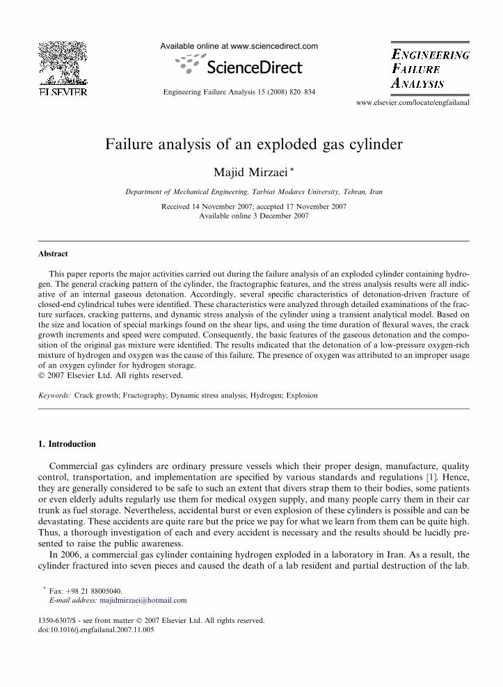
In the above expressions, d is the deepest point of crack penetration and C is half the major axis of the ellipse.In order to compare the obtained values for the two cracking locations, the expression proposed by Irwin [24]was used to calculate the plane stress fracture toughness for the thickness of 6 mm based on the value of KIc
calculated above.
Kc ¼ KIc 1þ 1:4
h2
KIc
rys
� �4" #0:5
Kc ¼ 70 MPaffiffiffiffimp
ð4Þ
The obtained value agreed very well with the value of 72 MPaffiffiffiffimp
for the upper crack. It should be noted thatall the values calculated above in fact represent the fracture resistance of the material under dynamic loadingwith a strain rate of 102 s�1.
3.2. Specification of the characteristics of detonation loading
One of the essential steps towards determination of the cause of this incident was the specification of thecharacteristics of the detonation loading. The pressure history for gaseous detonation loading may be repre-sented by an exponential approximation to the Taylor–Zeldovich model and can be characterized by the initialpressure of the gas mixture p1, the peak pressure p2, the final pressure p3, the exponential decay factor T, andthe Chapman–Jouguet velocity Vcj as follows [7,8]:
pðx; tÞ ¼ ðp1 � patmÞ þ ðp3 � p1Þ þ ðp2 � p3Þe�tT
� ½1� Hðx� V cjtÞ� ð5Þ
In the above equation, patm is the atmospheric pressure, x is the distance variable, t is the time variable, and H
is the step function. In practice, the peak pressure (p2) had to be large enough to cause fracture at the higherportion and yielding at the lower portion of the cylinder. As there was no initial clue to the characteristics ofthe gas mixture, a number of choices had to be examined. Since the initial reports indicated that the cylinderwas nearly empty, naturally the first choice was a load moving at the first critical speed to cause maximum
dynamic amplification (the ratio of dynamic strains to equivalent static strains) [7,8,10]. The computed valuefor the first critical speed was 1165 m/s and a value of 3.7 was considered for the dynamic amplification factor[10]. Using the simple formula for the hoop stress in thin cylinders, the peak pressure was estimated as
p2 ¼1
U
� �ruhR¼ 19 MPa ð6Þ
In the above expression, ru is the ultimate tensile strength, h is the thickness, R is the mean radius, and U is thedynamic amplification factor. Since the pressure ratio (p2/p1) for a gaseous detonation is usually between 15and 20, the initial pressure (p1) was estimated as 1.1 MPa, and because of a relative low value of Vcj (1165 m/s),the value of T was set as T = 4.34 � 10�4 s [7,8]. Next, an analytical solution for the transient elastodynamicresponse of cylindrical tubes to gaseous detonation [10] was used to determine the time-dependent distributionof stress in the cylinder. As depicted in Fig. 9, the detonation loading can cause a spectrum of stress fluctu-ations whose amplitudes are dependent on the speed of the traveling load. It is clear that the stress distributioncaused by the assumed loading (Vcj = 1165 m/s) creates elastic deformation at the upper half, plastic deforma-tion at the lower half, and fracture near the bottom cap at a distance of 700 mm from the upper neck. Obvi-ously, this pattern does not agree at all with the actual pattern of deformation and fracture of the cylinder. Itshould be emphasized that the speeds of detonable mixtures of hydrogen and oxygen are much higher than thecritical speed of 1165 m/s. In fact, the latter is possible only in presence of an inert diluting gas (like nitrogen).Thus, the search for the correct loading profile was directed towards examination of various mixtures ofhydrogen with pure oxygen. The software CEA2 [25] was used for determination of the features of the burnedgas for each mixture. In practice, it was found that the loading profiles caused by hydrogen-rich mixtures werenot able to cause the expected damage because of their relative high velocities. Finally, a narrow range of load-ing profiles that matched all of the specified requirements was found for the mixtures with 35–45 vol% hydro-gen, and the initial pressure of p1 � 2 MPa. The detonation of these mixtures is able to produce a peakpressure of p2 � 37 MPa, traveling at the speed of 2100–2300 m/s [25]. For these speeds the value of T was

Fig. 9. Time-dependent distributions of stress in the cylinder caused by gaseous detonation loading: (a) speed of 1165 m/s and (b) speed of2300 m/s.
830 M. Mirzaei / Engineering Failure Analysis 15 (2008) 820–834
set as T = 1.5 � 10�4 s [12]. Fig. 9b shows the time-dependent distribution of stress caused by the upper boundof this loading range and indicates that the amount of the hoop stress at the location of the initial crack(100 mm below the neck) was 715 MPa. The results showed that the amount of the hoop stress from50 mm to 100 mm was slightly higher. However, it should be noted that in this region, the cylinder has a con-ical shape which means that the diameters are lower and the thicknesses are higher. Beyond the 100 mm-point,the computed values for the maximum fluctuations of the hoop stress remained above the yield and below theultimate strengths. Measurements of the periphery of the cylinder showed the same pattern of permanent ra-dial expansion. The conclusion was that the ability of the detonation loading to initiate an axial crack in thecylinder was quite marginal. In fact, the calculations indicated that, had the initial pressure of the mixture beenslightly (0.2 MPa) lower, at least the cylindrical portion could have survived the blast.
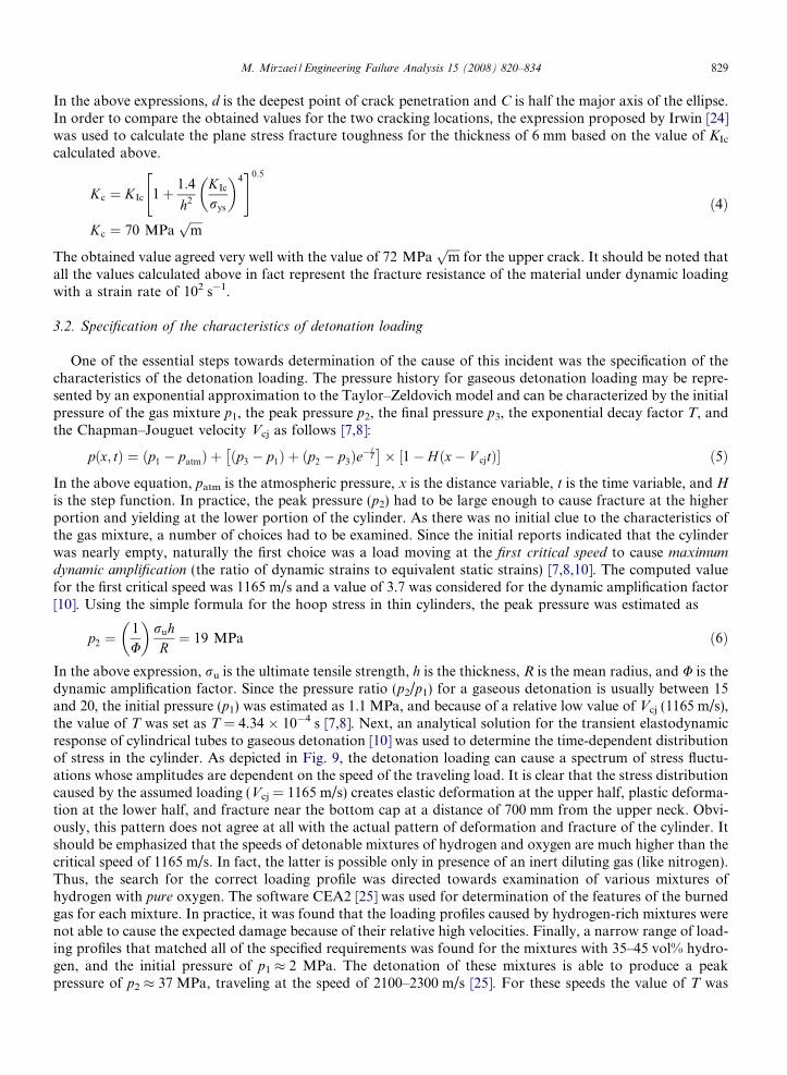
Fig. 10 shows the variation of the hoop stress with time at three different locations, during a time period of3.1 ms after the start of detonation. The amplification of the stresses due to the interference between the for-ward traveling waves and the waves reflected at both ends of the cylinder are clearly visible in the results forthe middle part of the cylinder.
3.3. Determination of the crack speed
Having found the pattern of fluctuating stresses, the stress wave characteristics like frequency and wavelength were calculated and the time period for each loading cycle was determined as 8.2 � 10�2 ms. Accord-ingly, the crack speed during each increment of growth was calculated. Also the average crack speed for the
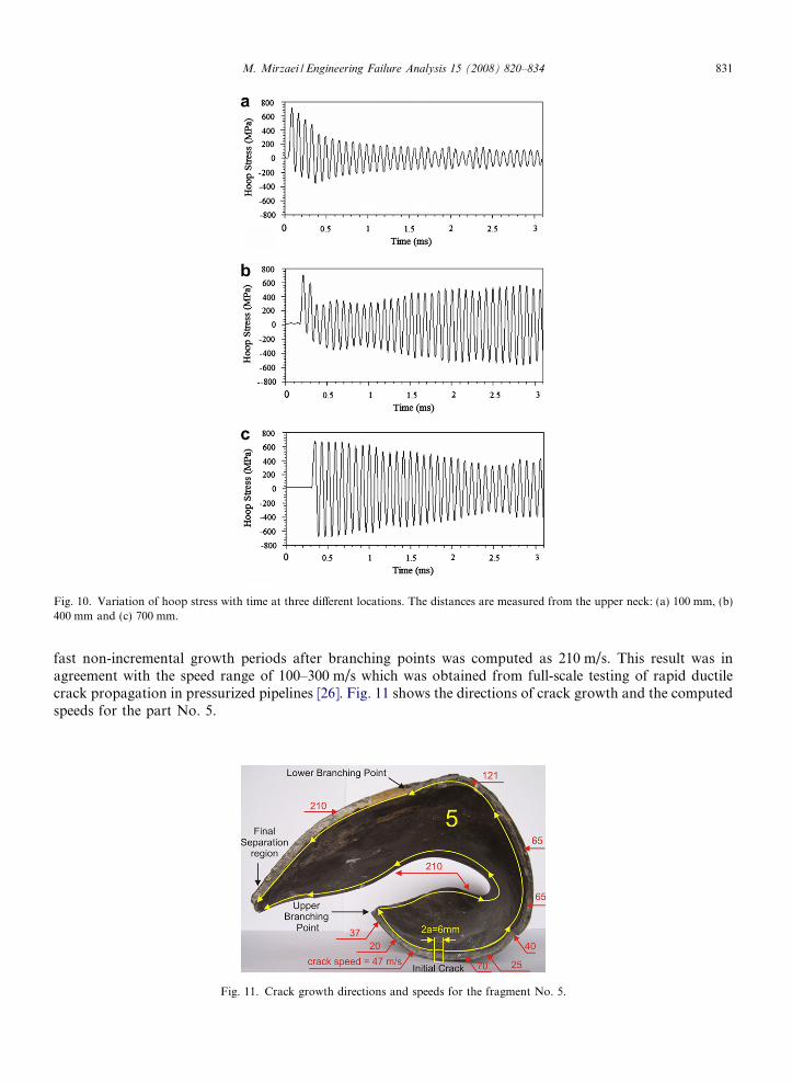
Fig. 10. Variation of hoop stress with time at three different locations. The distances are measured from the upper neck: (a) 100 mm, (b)400 mm and (c) 700 mm.
M. Mirzaei / Engineering Failure Analysis 15 (2008) 820–834 831
fast non-incremental growth periods after branching points was computed as 210 m/s. This result was inagreement with the speed range of 100–300 m/s which was obtained from full-scale testing of rapid ductilecrack propagation in pressurized pipelines [26]. Fig. 11 shows the directions of crack growth and the computedspeeds for the part No. 5.
Fig. 11. Crack growth directions and speeds for the fragment No. 5.

832 M. Mirzaei / Engineering Failure Analysis 15 (2008) 820–834
4. The overall scenario
In this section, the sequence of events which occurred during this incident is briefly reviewed. The intentionis to present a unified picture of the various aspects of this investigation.
The operator of an experimental apparatus borrowed a hydrogen cylinder to run a test which involved pro-ducing a candle flame with a mixture of hydrogen and air (9.1 vol% hydrogen). Although the color of the cyl-inder indicted that it was originally used for medical oxygen supply, the operator trusted a H2 markingpainted by ink on the cylinder. The results of this investigation showed that the content of the cylinder wasin fact a mixture of hydrogen and oxygen (35–45 vol% hydrogen) with an approximate initial pressure of2 MPa. As a result of diluting the initial mixture with air (90.9 vol% air), the content of hydrogen fell belowthe lower flammability limit of hydrogen (4 vol%). Thus, the operator was not able to get the candle flame.This was later confirmed by the reports issued by the lab authorities. As the operator attempted to replacethe cylinder with a new one, the initial mixture was somehow detonated at the top of the cylinder. The exactnature of the triggering process is not clear. There are many literature accounts of accidental hydrogen leaksigniting for no apparent reason [27]. It is usually assumed that these were caused by small static electricitydischarges. A weak electrostatic spark from the human body releases about 10 mJ of energy, which is capableof setting fire to a majority of common fuels [16].
As the detonation started, a shock wave with an approximate peak pressure of 37 MPa traveled down thecylinder with a velocity between 2100–2300 m/s, resulting in a dynamic amplification factor of 1.9 on the hoopstress. At a distance of 100 mm below the neck, the hoop stress slightly exceeded the ultimate tensile strengthof the material. Consequently, a small through-thickness crack was created in the axial direction by shear. Thestress intensity factor caused by the same stress cycle that created the crack was enough to advance it still fur-ther (13 mm in the forward direction and 7 mm in the backward direction). About 1.7 ms after the creation ofthe initial crack, the backward crack tip reached a point (40 mm below the neck) where the tensile axial stres-ses caused by flap bulging were significant enough to divert the crack and cause branching. The speed of crackgrowth after the branching point was estimated as 210 m/s. It took 3 ms before the forward tip reached thelower branching point. The axial growth of the initial crack and the circumferential growth of the brancheswere totally in mode I. The final separation of the fragments was caused by the growth of branches in axialdirections towards each other with a combination of bending and tearing (mixed mode I and III). Duringthe separation of the fragments from the main body of the cylinder, the elastic energies stored during the flap
Fig. 12. Various stages of deformation and fracture of the gas cylinder. Double-head arrows represent tensile stresses and curved arrowsrepresent bending. The sketch is not to scale.

M. Mirzaei / Engineering Failure Analysis 15 (2008) 820–834 833
bulging were suddenly released. As a result, these thin fragments suffered severe plastic deformation by twist-ing and folding.
On the other hand, the traveling of the detonation front down the cylinder caused a uniform permanentradial expansion. Upon reaching the bottom, the ensuing impact on the cap drastically pushed it throughthe cylinder stand. The resulting friction heated the lower segment of the cylinder and blackened a lengthof about 50 mm and left visible longitudinal scars on the surface of this region. At the same time, several smallcracks initiated at central region of the cap due to the stress waves created by detonation impact. Conse-quently, three cracks grew from two distinct semielliptical initial cracks. The growth, branching, and rejoiningof these cracks divided the cap into three fragments. The time that was required for the cap to collide with thefloor was estimated as 15 ms. This was quite longer than the cracking events that took place at the top and thebottom of the cylinder. Fig. 12 schematically shows the various stages of deformation and fracture of the cyl-inder. The striking fact is that the initial pressure of the gas mixture that caused all this damage was only 9% ofthe working pressure of the cylinder.
The reason for the existence of an oxygen-rich mixture in a cylinder which was supposed to have ‘‘pure”
hydrogen is not clear. One possibility is that, during the last filling, the cylinder was mistakenly filled with oxy-gen because of its color.
5. Conclusions
The aim of this investigation was the determination of the cause of the explosion of a commercial gas cyl-inder containing hydrogen. The general cracking pattern of the cylinder, the fractographic features, and thestress analysis results were all indicative of an internal gaseous detonation. Consequently, a number of specificfeatures of the detonation-driven fracture of cylindrical tubes with closed ends were identified. These featuresincluded: flap bulging, crack curving and branching adjacent to the bulged area, formation of staircase mark-ings on shear lips, and multiple cracking at the cap center. The investigations indicated that the initial crackswere created by local excessive shear and the crack propagations were almost entirely governed by structuralwaves.
Based on the above observations and using the results of the dynamic stress analysis of the cylinder, themain characteristics of the gaseous detonation such as the initial and peak pressures and the traveling speedwere estimated and the composition of the initial gas mixture was specified. The results showed that the con-tent of the cylinder was a detonable mixture of hydrogen and oxygen (35-45 vol% hydrogen) with an approx-imate pressure of 2 MPa (9% of the working pressure of the cylinder).
The reason for the existence of an oxygen-rich mixture in the cylinder is not known. However, a plausiblescenario is that during the last filling, the cylinder with some remaining hydrogen was mistakenly filled withoxygen because of its color.
Acknowledgements
The author wishes to express his appreciation to his colleagues, Professor Mazaheri, Professor Malek, andhis graduate student, Mr. Amir Harandi, for their valuable and continuous help during the course of thisinvestigation.
References
[1] Guide to gas cylinders. Explosive and Dangerous Goods Division, Department of Labour, New Zealand, Revision 1992.[2] Tang S. Dynamic response of a tube under moving pressure. In: Proceedings of the American Society of Civil Engineers, vol. 5.
Engineering Mechanics Division; 1965. p. 97–122.[3] Reismann H. Response of a pre-stressed cylindrical shell to moving pressure load. In: Ostrach S, Scanlon R, editors. Eighth midwest
mechanics conference. Pergamon Press; 1965. p. 349–63.[4] de Malherbe M, Wing R, Laderman A, Oppenheim A. Response of a cylindrical shell to internal blast loading. J Mech Eng Sci
1966;8(1):91–8.[5] Simkins T. Resonance of flexural waves in gun tubes. Tech. Rep. ARCCB–TR–87008, US Army Armament Research, Development
and Engineering Center, Watervliet, NY 12189–4050, July 1987, PVT-03-1045 18.

834 M. Mirzaei / Engineering Failure Analysis 15 (2008) 820–834
[6] Thomas G. The response of pipes and supports generated by gaseous detonations. J Pressure Vessel Technol 2002;124:66–73.[7] Beltman W, Burcsu E, Shepherd J, Zuhal L. The structural response of cylindrical shells to internal shock loading. J Pressure Vessel
Technol 1999;121:315–22.[8] Beltman W, Shepherd J. Linear elastic response of tubes to internal detonation loading. J Sound Vib 2002;252(4):617–55.[9] Mirzaei M, Mazaheri K, Biglari H. Analytical modeling of the elastic response of tubes to internal detonation loading. Int J Pressure
Vessels Piping 2005;82(12):883–95.[10] Mirzaei M, Biglari H, Salavatian M. Analytical and numerical modeling of the elastodynamic response of a cylindrical tube to
internal gaseous detonation. Int J Pressure Vessels Piping 2006;83(7):531–9.[11] Chao TW, Shepherd JE. Fracture response of externally flawed aluminum cylindrical shells under internal gaseous detonation
loading. Int J Fracture 2005;134(1):59–90. July.[12] Tong Wa Chao. Gaseous detonation-driven fracture of tubes. PhD thesis, Pasadena, California: California Institute of Technology;
2004 [March].[13] Naitoh M, Kasahara F, Kubota R, Ohshima I. Analysis of pipe rupture of steam condensation line at Hamoaka-1, (I) accumulation
of non-condensable gas in a pipe. J Nuclear Sci Technol 2003;40(12):1032.[14] Mirzaei M, Karimi R. Crack growth analysis for a cylindrical shell under dynamic loading. In: Proceedings of ASME PVP 2006/11th
international conference on pressure vessel technology, ICPVT-11, Canada: Vancouver; 2006.[15] Failure modes and effects analysis for hydrogen fueling options, Report to California Energy Commission, Prepared by TIAX LLC,
November 2004.[16] Ricci M. Experts’ assessments and representations of risks associated with hydrogen. Institute for Social, Cultural and Policy
Research, University of Salford; 2005, UKSHEC Social Science Working Paper No. 12 [July].[17] Hydrogen Incidents reports at www.h2incidents.org.[18] Price WH. An acetylene cylinder explosion: a most probable cause analysis. Eng Failure Anal 2006;13:705–15.[19] Baker WE, Tang J. Gas, dust, and hybrid explosions. Amsterdam: Elsevier; 1991.[20] Alder JF, Phillips KA. The effect of strain rate and temperature on the resistance of aluminum, copper, and steel to compression. J
Inst Met 1954;83:80.[21] Zahoor A. Closed form expressions for fracture mechanics analysis of cracked pipes. J Pressure Vessel Technol 1985;107:203–5.[22] Hertzberg WH. Deformation and fracture mechanics of engineering materials. 4th ed. John Wiley & Sons, Inc.; 1996. p. 702–3.[23] Newman Jr JC, Raju IS. An empirical stress-intensity factor equation for the surface crack. Eng Fracture Mech 1981;15(1–2):185–92.
52, 54.[24] Irwin GR. Fracture mode transition for a crack traversing a plate. J Basic Eng 1960;82:417–25.[25] CEA2, Chemical equilibrium with applications, version 2. NASA Glenn’s computer program.[26] Kanninen MF, Popelar CH. Advanced fracture mechanics. Oxford University Press, Inc.; 1985. p. 250–3.[27] Zalosh R, Short T. Compilation and analysis of hydrogen accident reports. Factory Mutual Research Corp Final Report C00-4492-4
for DOE; 1978 [October].