ZBD 1001 Differential Cylinder
17
ZBD 1001 Differential Cylinder Data sheet 09.20/DS13210
-
Upload
khangminh22 -
Category
Documents
-
view
0 -
download
0
Transcript of ZBD 1001 Differential Cylinder
ZBD 1001 Differential Cylinder Data sheet 09.20/DS13210

Differential Cylinder ZBD 1001
2
This series represents the logical and consistent supplementation of already ISO 6022 (250 bar) and ISO 6020/1 (160
bar) standard series. The consistent application of these standards enables standardized attachments can already be
used in all rows of cylinders in accordance with DIN 24333, ISO 6022, ISO 6020/1 and DIN 24336.
In order to use the wide range of applications of a 100-bar-cylinder, 10 mounting types have been standardized.
The Storz hydraulic cylinders of ZBD 1001 series have dimensioned according to DIN 24336 and are therefore fully
interchangeable with other brands under this standard.
There are the same mounting dimensions for cylinders with and without cushioning.
Attachments must be ordered separately.
Nominal pressure: 100 bar (10 MPa)
Static test pressure: 150 bar (15 MPa)
Piston-ø: 25 – 100 mm (others on request)
Area ratio: 1,25
Temperature range: -20 °C … +80 °C
Viscosity range: (10 … 600) 10-6 m²/s
Stroke speed range: 0 – 0,5 m/s
Hydraulic fluid: Mineral oil according to DIN 51524, HFD fluids
Description:
Technical Specifications:

Differential Cylinder ZBD 1001
3
Pres
sure
[kN
]
Pull
[kN
] A BCA
CBCAA
CC
CD
DA
DBEA
Form
B
12
18
14
22
18
28
22
36
28
45
36
56
45
700,04126,9 27,2 26,0 23,7 36,0 0,041
0,032 0,032
100 78,5 62,6 78,5 62,6 22,0 22,2 26,0
15,9 16,3 16,6 15,8 14,3 19,8
13,9 0,018 0,022
80 50,2 40,1 50,2 40,1 18,0 13,5
9,0 10,5 11,4 11,6 10,7 9,363 31,2 25,0 31,2 25,0 16,0
6,6 6,1 5,4 8,5 0,011 0,014
0,011
50 19,6 15,8 19,6 15,8 12,0 5,3 6,2 6,5
4,7 4,8 4,5 3,9 5,9 0,008
0,006 0,007
40 12,6 10,0 12,6 10,0 12,0 3,9 4,5
2,5 2,7 2,7 2,5 2,2 3,3
2,6 0,005 0,005
32 8,0 6,5 8,0 6,5 10,0 2,2
1,8 2,0 2,2 2,3 2,1 1,825 4,9 3,8 4,9 3,8 10,0
per 1 mm
Stroke
G1 [kg]
Type of mounting
Forc
e at
100
bar
1)
Pis
ton-
ø (m
m)
Rod
-ø M
M (m
m)
Pist
on a
rea
A1
(cm
²)
Ann
ular
are
a A
2 (c
m²)
Att
enua
tion
leng
th
G2 [kg/mm]
1) Theoretically static cylinder force (without consideration of efficiency and permissible loads on the attachments) 2) Stroke speed
The weight is calculated as follows: G = G1 + G2 x Hub
Recommended average flow rate of the hydraulic fluid in the connection cross-sections
Suction pipeReturn
pipe
Pressure pipe
up to 25 bar25 - 63 bar 63 - 160 bar 160 - 250 bar > 250 bar
Flow rate
(Approximate
value)
≤ 1,5 m/s ≤ 3 m/s ≤ 3 m/s 3 - 5 m/s 4 - 6 m/s 5 - 8 m/s ≤ 10 m/s
Locating connectors:
Technical specifications:

Differential Cylinder ZBD 1001
4
Mounting types:
A Basic form (p. 5)
B Trunnion (p. 6) CA Round flange at head (p. 7)
CAA Round flange on the cylinder head with rear centering (p. 8)
CB Round flange at base (p. 9) CC Rectangular on the cylinder head (p. 10) CD Rectangular on the cylinder base (p. 11) DA Swivel eye at base (p. 12)
DB Spherical bearing at base (p. 13)
EA Foot mounting (p. 14)

Differential Cylinder ZBD 1001
5
Mounting type A – Basic form
Pis
ton
-ø (
mm
)
Ro
d-ø
d (
mm
)
Pis
ton
are
a A
1 (
cm²)
An
nu
lar
area
A2
(cm
²)
L1
+ S
tro
ke
Pip
e co
nn
ecti
on
d3
Wh
itw
ort
h p
ipe
thre
ad /
Met
ric
thre
ad
Ro
d t
hre
ad a
b js
15
ø c
c1
c2
ø c
4
d4
ø i
j13
l4 l6 l13
ø n
f8
R2
max
.
Min
imu
m s
tro
ke1
)
12
18
14
22
18
28
22
36
28
45
36
56
45
70121122 30 46 24 100 7345 145 22 86 115 M12
20 82 67 91
100 78,5 62,6 200G3/4
M27x2M33x2
71 95 M10 102 24 37
79
80 50,2 40,1 175G1/2
M22x1,5M27x2 36 120 19
83 24 37 20 63 5828 100 19 70 75 M10
16 56 51 58
63 31,2 25,0 165G1/2
M22x1,5M20x1,5
58 60 M8 72 20 33
47
50 19,6 15,8 142G3/8
M18x1,5M16x1,5 22 85 15
58 17 27 14 45 4718 75 15 54 50 M6
14 35 39 32
40 12,6 10,0 132G3/8
M18x1,5M14x1,5
52 40 M6 48 15 25
22
32 8,0 6,5 124G1/4
M14x1,5M12x1,25 16 60 12
42 13 23 12 30 3714 55 12 44 33 M525 4,9 3,8 114G1/4
M14x1,5M10x1,25
1) Production-related minimum stroke. Shorter stroke lengths by using a spacer sleeve possible
Differential Cylinder ZBD 1001
6
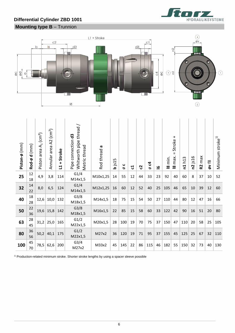
Mounting type B – Trunnion
Pis
ton
-ø (
mm
)
Ro
d-ø
d (
mm
)
Pis
ton
are
a A
1 (
cm²)
An
nu
lar
area
A2
(cm
²)
L1
+ S
tro
ke
Pip
e co
nn
ecti
on
d3
Wh
itw
ort
h p
ipe
thre
ad /
Met
ric
thre
ad
Ro
d t
hre
ad a
b js
15
ø c
c1
c2
ø c
4
l6 n1
h1
3
n2
js1
6
R2
max
øv
f8
Min
imu
m s
tro
ke1
)
12
18
14
22
18
28
22
36
28
45
36
56
45
70150 32 73 40 130
32 110
100 78,5 62,6 200G3/4
M27x2M33x2 45 145 22 86 115 46 182 55
155 45 125 25 67
20 58 25 105
80 50,2 40,1 175G1/2
M22x1,5M27x2 36 120 19 71 95 37
75 37 150 47 110M20x1,5 28 100 19 7063 31,2 25,0 165G1/2
M22x1,5
90 16 51 20 80
16 66
50 19,6 15,8 142G3/8
M18x1,5M16x1,5 22 85 15 58 60 33 122 42
110 44 80 12 47
10 39 12 60
40 12,6 10,0 132G3/8
M18x1,5M14x1,5 18 75 15 54 50 27
40 25 105 46 65M12x1,25 16 60 12 5232 8,0 6,5 124G1/4
M14x1,5
60 8 37 10 52
l8 m
in.
l8 m
ax. =
Str
oke
+25 4,9 3,8 114
G1/4
M14x1,5M10x1,25 14 55 12 44 33 23 92 40
1) Production-related minimum stroke. Shorter stroke lengths by using a spacer sleeve possible
Differential Cylinder ZBD 1001
7
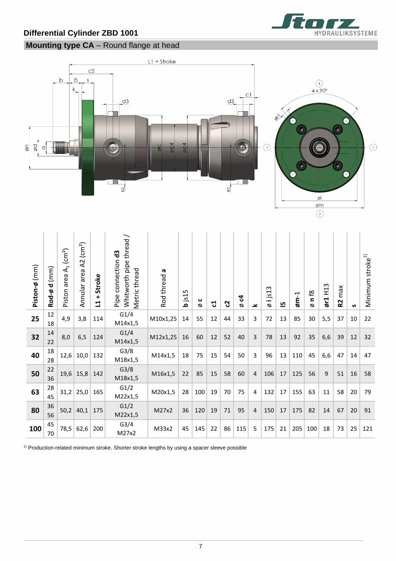
Mounting type CA – Round flange at head
Pis
ton
-ø (
mm
)
Ro
d-ø
d (
mm
)
Pis
ton
are
a A
1 (
cm²)
An
nu
lar
area
A2
(cm
²)
L1
+ S
tro
ke
Pip
e co
nn
ecti
on
d3
Wh
itw
ort
h p
ipe
thre
ad /
Met
ric
thre
ad
Ro
d t
hre
ad a
b js
15
ø c
c1
c2
ø c
4
k ø i
js1
3
l5 øm
-1
ø n
f8
ør1
H1
3
R2
max
s Min
imu
m s
tro
ke1
)
12
18
14
22
18
28
22
36
28
45
36
56
45
7025 121175 21 205 100 18 7345 145 22 86 115 5100 78,5 62,6 200
G3/4
M27x2M33x2
175 82 14 67 20 9119 71 95 4 150 17
20 79
80 50,2 40,1 175G1/2
M22x1,5M27x2 36 120
132 17 155 63 11 5828 100 19 70 75 463 31,2 25,0 165G1/2
M22x1,5M20x1,5
125 56 9 51 16 5815 58 60 4 106 17
14 47
50 19,6 15,8 142G3/8
M18x1,5M16x1,5 22 85
96 13 110 45 6,6 4718 75 15 54 50 340 12,6 10,0 132G3/8
M18x1,5M14x1,5
92 35 6,6 39 12 3212 52 40 3 78 13
10 22
32 8,0 6,5 124G1/4
M14x1,5M12x1,25 16 60
72 13 85 30 5,5 3714 55 12 44 33 325 4,9 3,8 114G1/4
M14x1,5M10x1,25
1) Production-related minimum stroke. Shorter stroke lengths by using a spacer sleeve possible

Differential Cylinder ZBD 1001
8
Mounting type CAA – Round flange on the cylinder head with rear centering
Pis
ton
-ø (
mm
)
Ro
d-ø
d (
mm
)
Pis
ton
are
a A
1 (
cm²)
An
nu
lar
area
A2
(cm
²)
L1
+ S
tro
ke
Pip
e co
nn
ecti
on
d3
Wh
itw
ort
h p
ipe
thre
ad /
Met
ric
thre
ad
Ro
d t
hre
ad a
b js
15
ø c
c1
c2
ø c
4
k ø i
js1
3
l14
øm
-1
ø n
3 f
8
ør1
H1
3
R2
max
s Min
imu
m s
tro
ke1
)
12
18
14
22
18
28
22
36
28
45
36
56
45
7025 121175 41 205 146 18 7345 145 22 86 115 5100 78,5 62,6 200
G3/4
M27x2M33x2
175 125 14 67 20 9119 71 95 4 150 33
20 79
80 50,2 40,1 175G1/2
M22x1,5M27x2 36 120
132 33 155 106 11 5828 100 19 70 75 463 31,2 25,0 165G1/2
M22x1,5M20x1,5
125 86 9 51 16 5815 58 60 4 106 29
14 47
50 19,6 15,8 142G3/8
M18x1,5M16x1,5 22 85
96 24 110 78 6,6 4718 75 15 54 50 340 12,6 10,0 132G3/8
M18x1,5M14x1,5
92 64 6,6 39 12 3212 52 40 3 78 22
10 22
32 8,0 6,5 124G1/4
M14x1,5M12x1,25 16 60
72 20 85 60 6 3714 55 12 44 33 325 4,9 3,8 114G1/4
M14x1,5M10x1,25
1) Production-related minimum stroke. Shorter stroke lengths by using a spacer sleeve possible
Differential Cylinder ZBD 1001
9
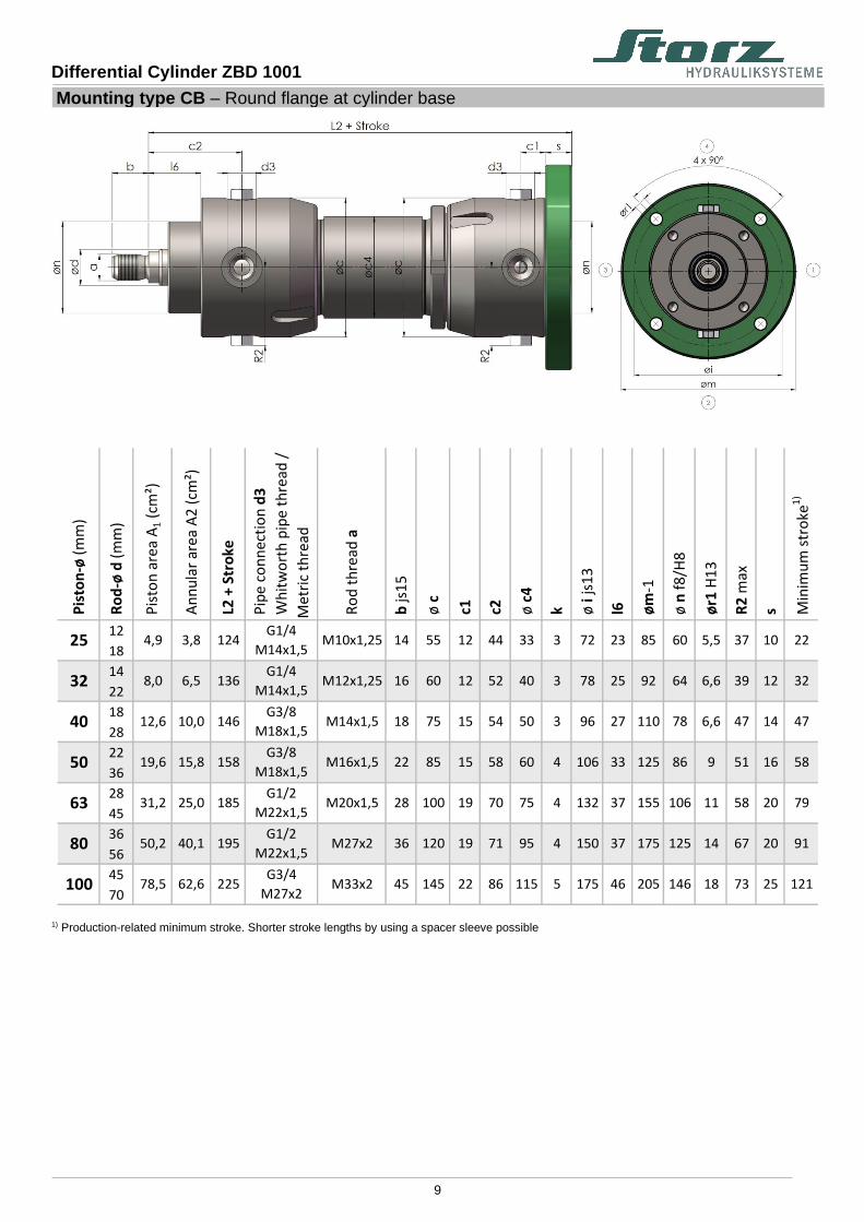
Mounting type CB – Round flange at cylinder base
Pis
ton
-ø (
mm
)
Ro
d-ø
d (
mm
)
Pis
ton
are
a A
1 (
cm²)
An
nu
lar
area
A2
(cm
²)
L2
+ S
tro
ke
Pip
e co
nn
ecti
on
d3
Wh
itw
ort
h p
ipe
thre
ad /
Met
ric
thre
ad
Ro
d t
hre
ad a
b js
15
ø c
c1
c2
ø c
4
k ø i
js1
3
l6 øm
-1
ø n
f8
/H8
ør1
H1
3
R2
max
s Min
imu
m s
tro
ke1
)
12
18
14
22
18
28
22
36
28
45
36
56
45
7025 121175 46 205 146 18 7345 145 22 86 115 5100 78,5 62,6 225
G3/4
M27x2M33x2
175 125 14 67 20 9119 71 95 4 150 37
20 79
80 50,2 40,1 195G1/2
M22x1,5M27x2 36 120
132 37 155 106 11 5828 100 19 70 75 463 31,2 25,0 185G1/2
M22x1,5M20x1,5
125 86 9 51 16 5815 58 60 4 106 33
14 47
50 19,6 15,8 158G3/8
M18x1,5M16x1,5 22 85
96 27 110 78 6,6 4718 75 15 54 50 340 12,6 10,0 146G3/8
M18x1,5M14x1,5
92 64 6,6 39 12 3212 52 40 3 78 25
10 22
32 8,0 6,5 136G1/4
M14x1,5M12x1,25 16 60
72 23 85 60 5,5 3714 55 12 44 33 325 4,9 3,8 124G1/4
M14x1,5M10x1,25
1) Production-related minimum stroke. Shorter stroke lengths by using a spacer sleeve possible

Differential Cylinder ZBD 1001
10
Mountring type CC – Rectangular on the cylinder head
Pis
ton
-ø (
mm
)
Ro
d-ø
d (
mm
)
Pis
ton
are
a A
1 (
cm²)
An
nu
lar
area
A2
(cm
²)
L1
+ S
tro
ke
Pip
e co
nn
ecti
on
d3
Wh
itw
ort
h p
ipe
thre
ad /
Met
ric
thre
ad
Ro
d t
hre
ad a
b js
15
ø c
c1
c2
ø c
4
s ø i
js1
3
l5 k ø n
f8
ør1
H1
3
R2
max
e js
13
e1
js1
3
f f1
Min
imu
m s
tro
ke1
)
12
18
14
22
18
28
22
36
28
45
36
56
45
7067 161,7 150 190 121175 21 5 100 18 7345 145 22 86 115 25100 78,5 62,6 200
G3/4
M27x2M33x2
67 57,4 138,6 125 165 9120 150 17 4 82 14M27x2 36 120 19 71 95
50,5 121,9 100 145 79
80 50,2 40,1 175G1/2
M22x1,5
132 17 4 63 11 5828 100 19 70 75 2063 31,2 25,0 165G1/2
M22x1,5M20x1,5
51 40,6 98 80 120 5816 106 17 4 56 9M16x1,5 22 85 15 58 60
36,7 88,7 70 105 47
50 19,6 15,8 142G3/8
M18x1,5
96 13 3 45 6,6 4718 75 15 54 50 1440 12,6 10,0 132G3/8
M18x1,5M14x1,5
39 29,8 72,1 60 85 3212 78 13 3 35 6,6M12x1,25 16 60 12 52 40
27,5 66,5 55 80 22
32 8,0 6,5 124G1/4
M14x1,5
72 13 3 30 5,5 3714 55 12 44 33 1025 4,9 3,8 114G1/4
M14x1,5M10x1,25
1) Production-related minimum stroke. Shorter stroke lengths by using a spacer sleeve possible
Differential Cylinder ZBD 1001
11
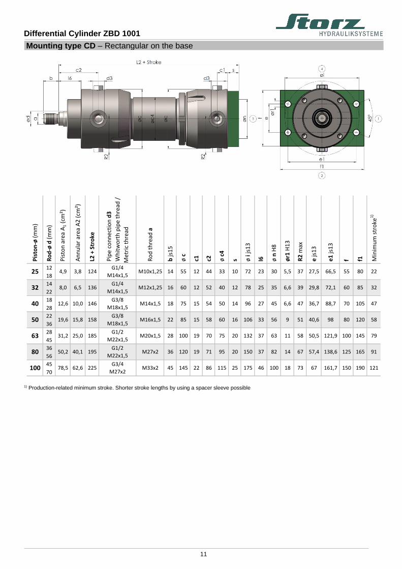
Mounting type CD – Rectangular on the base
Pis
ton
-ø (
mm
)
Ro
d-ø
d (
mm
)
Pis
ton
are
a A
1 (
cm²)
An
nu
lar
area
A2
(cm
²)
L2
+ S
tro
ke
Pip
e co
nn
ecti
on
d3
Wh
itw
ort
h p
ipe
thre
ad /
Met
ric
thre
ad
Ro
d t
hre
ad a
b js
15
ø c
c1
c2
ø c
4
s ø i
js1
3
l6 ø n
H8
ør1
H1
3
R2
max
e js
13
e1
js1
3
f f1
Min
imu
m s
tro
ke1
)
12
18
14
22
18
28
22
36
28
45
36
56
45
70161,7 150 190 121175 46 100 18 73 6745 145 22 86 115 25
138,6 125 165 91
100 78,5 62,6 225G3/4
M27x2M33x2
150 37 82 14 67 57,436 120 19 71 95 20
121,9 100 145 79
80 50,2 40,1 195G1/2
M22x1,5M27x2
132 37 63 11 58 50,528 100 19 70 75 20
98 80 120 58
63 31,2 25,0 185G1/2
M22x1,5M20x1,5
106 33 56 9 51 40,622 85 15 58 60 16
88,7 70 105 47
50 19,6 15,8 158G3/8
M18x1,5M16x1,5
96 27 45 6,6 47 36,718 75 15 54 50 14
72,1 60 85 32
40 12,6 10,0 146G3/8
M18x1,5M14x1,5
78 25 35 6,6 39 29,816 60 12 52 40 12
66,5 55 80 22
32 8,0 6,5 136G1/4
M14x1,5M12x1,25
72 23 30 5,5 37 27,514 55 12 44 33 1025 4,9 3,8 124G1/4
M14x1,5M10x1,25
1) Production-related minimum stroke. Shorter stroke lengths by using a spacer sleeve possible

Differential Cylinder ZBD 1001
12
Mounting type DA – Swivel eye at base
Pis
ton
-ø (
mm
)
Ro
d-ø
d (
mm
)
Pis
ton
are
a A
1 (
cm²)
An
nu
lar
area
A2
(cm
²)
L3
+ S
tro
ke
Pip
e co
nn
ecti
on
d3
Wh
itw
ort
h p
ipe
thre
ad /
Met
ric
thre
ad
Ro
d t
hre
ad a
b js
15
ø c
c2
c3
ø c
4
l6 l7 n4
h1
2
øg
H9
R1
max
R2
max
Min
imu
m s
tro
ke1
)
12
18
14
22
18
28
22
36
28
45
36
56
45
7040 40 40 50 73 12145 145 86 62 115 46100 78,5 62,6 240
G3/4
M27x2M33x2
33 32 32 40 67 9136 120 71 52 95 3780 50,2 40,1 208G1/2
M22x1,5M27x2
29 25 25 32 58 7928 100 70 48 75 3763 31,2 25,0 194G1/2
M22x1,5M20x1,5
22 20 20 25 51 5822 85 58 37 60 3350 19,6 15,8 164G3/8
M18x1,5M16x1,5
18 16 16 20 47 4718 75 54 33 50 2740 12,6 10,0 150G3/8
M18x1,5M14x1,5
16 12 12 16 39 3216 60 52 28 40 25322) 8,0 6,5 140G1/4
M14x1,5M12x1,25
14 10 10 14 37 2214 55 44 26 33 23252) 4,9 3,8 128
G1/4
M14x1,5M10x1,25
1) Production-related minimum stroke. Shorter stroke lengths by using a spacer sleeve possible 2) Without grease nipple

Differential Cylinder ZBD 1001
13
Mounting type DB – Spherical bearing at base
Pis
ton
-ø (
mm
)
Ro
d-ø
d (
mm
)
Pis
ton
are
a A
1 (
cm²)
An
nu
lar
area
A2
(cm
²)
L3
+ S
tro
ke
Pip
e co
nn
ecti
on
d3
Wh
itw
ort
h p
ipe
thre
ad /
Met
ric
thre
ad
Ro
d t
hre
ad a
b js
15
ø c
c2
c3
ø c
4
l6 l7 n4
h1
2
øg
H7
R1
max
R2
max
Min
imu
m s
tro
ke1
)
12
18
14
22
18
28
22
36
28
45
36
56
45
7040 40 40 50 73 12145 145 86 62 115 46100 78,5 62,6 240
G3/4
M27x2M33x2
33 32 32 40 67 9136 120 71 52 95 3780 50,2 40,1 208G1/2
M22x1,5M27x2
29 25 25 32 58 7928 100 70 48 75 3763 31,2 25,0 194G1/2
M22x1,5M20x1,5
22 20 20 25 51 5822 85 58 37 60 3350 19,6 15,8 164G3/8
M18x1,5M16x1,5
18 16 16 20 47 4718 75 54 33 50 2740 12,6 10,0 150G3/8
M18x1,5M14x1,5
16 12 12 16 39 3216 60 52 28 40 25322) 8,0 6,5 140G1/4
M14x1,5M12x1,25
14 9 10 14 37 2214 55 44 26 33 23252) 4,9 3,8 128
G1/4
M14x1,5M10x1,25
1) Production-related minimum stroke. Shorter stroke lengths by using a spacer sleeve possible 2) Without grease nipple

Differential Cylinder ZBD 1001
14
Mountring type EA – Foot mounting
Pis
ton
-ø (
mm
)
Ro
d-ø
d (
mm
)
Pis
ton
are
a A
1 (
cm²)
An
nu
lar
area
A2
(cm
²)
L5
+ S
tro
ke
Pip
e co
nn
ecti
on
d3
Wh
itw
ort
h p
ipe
thre
ad /
Met
ric
thre
ad
Ro
d t
hre
ad a
b js
15
ø c
c1
c2
ø c
4
s1
l11
l12
f2
f3
e2
js1
3
n6
ør2
H1
3
Min
imu
m s
tro
ke1
)
12
18
14
22
18
28
22
36
28
45
36
56
45
7022 12126 20 232 150 195 7545 145 22 86 115 40100 78,5 62,6 194
G3/4
M27x2M33x2
180 121 150 63 18 9119 71 95 35 19,5 17,5
16 79
80 50,2 40,1 173G1/2
M22x1,5M27x2 36 120
21 16 170 101 140 5528 100 19 70 75 3263 31,2 25,0 160G1/2
M22x1,5M20x1,5
140 86 110 45 14 5815 58 60 32 17 16
11 47
50 19,6 15,8 141G3/8
M18x1,5M16x1,5 22 85
14,5 12,5 120 74 95 4018 75 15 54 50 2540 12,6 10,0 130G3/8
M18x1,5M14x1,5
100 59 80 32 9 3212 52 40 20 15 10
6,6 22
32 8,0 6,5 119G1/4
M14x1,5M12x1,25 16 60
13 10 80 52 68 3014 55 12 44 33 2025 4,9 3,8 111G1/4
M14x1,5M10x1,25
1) Production-related minimum stroke. Shorter stroke lengths by using a spacer sleeve possible
Differential Cylinder ZBD 1001
15
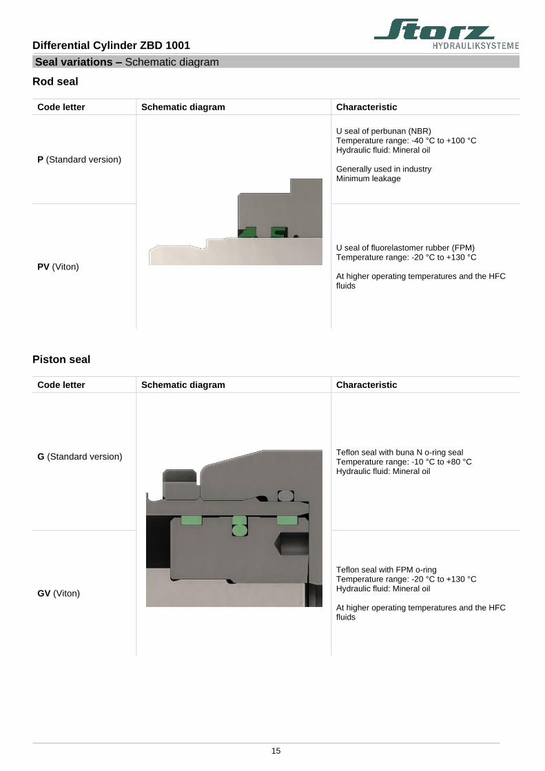
Seal variations – Schematic diagram
Rod seal
Code letter Schematic diagram Characteristic
P (Standard version)
U seal of perbunan (NBR) Temperature range: -40 °C to +100 °C Hydraulic fluid: Mineral oil Generally used in industry Minimum leakage
PV (Viton)
U seal of fluorelastomer rubber (FPM) Temperature range: -20 °C to +130 °C At higher operating temperatures and the HFC fluids
Piston seal
Code letter Schematic diagram Characteristic
G (Standard version)
Teflon seal with buna N o-ring seal Temperature range: -10 °C to +80 °C Hydraulic fluid: Mineral oil
GV (Viton)
Teflon seal with FPM o-ring Temperature range: -20 °C to +130 °C Hydraulic fluid: Mineral oil At higher operating temperatures and the HFC fluids

Differential Cylinder ZBD 1001
16
Model code:
/ - - - .
Double-acting hydraulic cylinderNominal Pressure 100 bar (10 Mpa)
optional ly with or without cushioning
Piston diameter in mm
Piston rod diameter in mm
Mounting typeA Bas ic form
B Trunnion (XV dimens ion to be s tadet when ordering)
CA Round flange at head
CAA Round flange on the cyl inder head with rear centering
CB Round flange at cyl inder base
CC Rectangular on the cyl inder head
CD Rectangular on the cyl inder base
DA Swivel eye at base
DB Spherica l bearing at base
EA Foot mounting
Stroke in mm
Sealing variantPG Standard vers ion, U sea l / Teflon sea l
PVGV Viton vers ion, U sea l / Teflon sea l
Cushioning0 without
1 both s ides
2 only on the cyl inder head s ide
3 only on the cyl inder base s ide
Surface of piston rodB Standard vers ion, hard-chrome plated
C Induction hardened and hard-chrom plated
Piston rod end1 External thread
Material of piston rodC Standard vers ion, s tructura l s teel / heat treatable s teel
N Sta inless s teel
Pipe connectionG Standard vers ion, Whitworth pipe thread
M Metric thread
Construction Code (to be ass igned by the manufacturer)
ZBD 1001 -

Differential Cylinder ZBD 1001
17
Hydraulic cylinder standard Hydraulic telescopic cylinders Hydraulic cylinders with displacement encoder Hydraulic adjustment cylinder Testing cylinders Special cylinders for all applications Standardized mounting parts Hydraulic power units and components