Numerical inversion of the dynamic model of a single-cylinder diesel engine
Upload
khangminh22Category
view
1download
0
REPAIR MANUAL
L...--------.-------~----. . FRO NT WHEEL OR IVE ··
CITROEN CARS LIMITED. SIX CYLINDER MODEL TRADING ESTATE • _
SLOUGH, FRENCH DESIGNATION ................ 15-SIX ..... (ISCV) --.-ENG. BRITISH DESIGNATION ........... ~~SIX.~~-(22._6 .. H.P.).·-
'
SF.PTEMBER
--195_·_'1 . :.1--·
._____,____..__...______ ....._____ ~......__,-----;..-o-. · ILL USTRAT I 0 NS ___....,...-~-: -- ----~---------------- ------

:RRATA.
lrawing No.
Six Cylinder Repair Manual
Modification
Add to Index of Illustrations g 11 l24A- Spanner for holding intermediate shaft.n
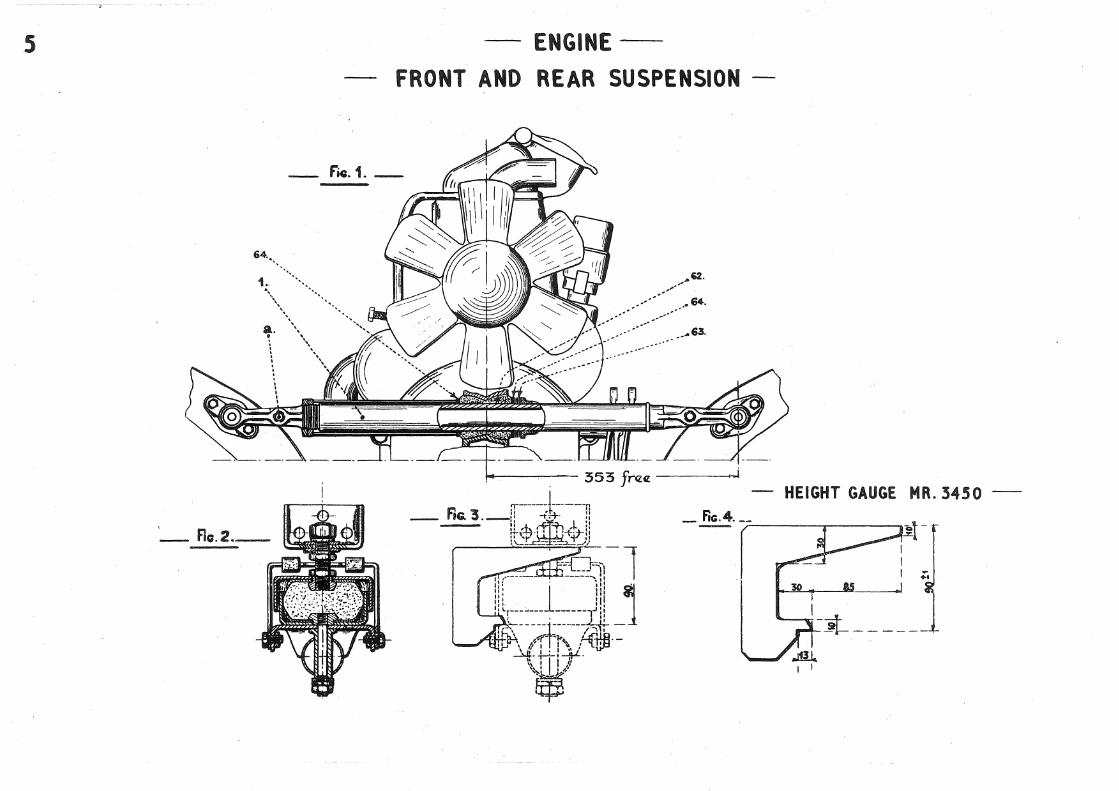
5 Read dimension : 11 368 ±. 0. 25u instead of : 11 353 free. 11
57 Read : 11 Steel type 819 quenched and ternperedu instead of 11Mild steel, case hardened and ground. 11
69 Steering rod is solid, not tubular as shown.
71 Add : 11washer 602345n 1 between distance piece 34 and spring; 35.
123 Alter threads on nuts (241) and (251) to indicate R.H. threads.
126 Alter distance pieces (304), (305), (306), and (307) to show slots bearing against forks.
ILLUSTRATIONS
139 Show adjusting washers ( 161) between lockwasher ( 146) and link arm. Delete washer shown under spring ( 125).

Section Dr a No.
ENGINE l 2 4 5 6 8 9 ll 12 13 15 16 17 18 19 20 21
AIR INTAKE SILENCER 23
PETROL PUl'IP 21 25
CLUTCH 26 27 28
GEA.RBOX 37
FRONT AXLE 46 47 48 50 51 53 54 55
'56
"•'
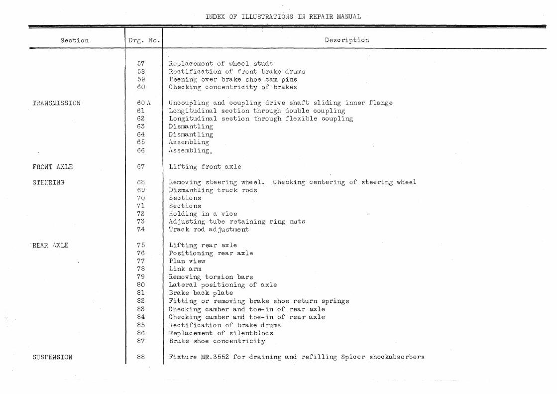
INDEX OF ILLUSTRATIONS IN REPAIR MANUAL
Various tools Lifting engine Engine stand Frvnt and rear suspension Dismantling damper hub Replacement of valve guide seats Oil pump Spring testing Fitting spark plug housings 'resting oil pump Crankshaft
Description
Fitting gudgeon pin cirolips and locking connecting rod nuts Gauging height of cylinder barrels 1'ightening cylinder head Fitting main bearing cap gaskets and fitting pistons Setting timing wheels Assembly of double pulley
Sectional views
Section throug)l S. E. V. type pump Checkini; for leaks
Hemoving and fitting Assembly Clutch adjustment
Differential
l\r;uunting lower link Section on pivot centre line Iv.i.andrels Spanners for upper link Extracting upper link spindle Brake back plate Dismantling hub bearings Spanners Assembly of upper 'link· silentbloc
Section
TRANSMISSION
FRONT AXLE
STEJt~RING
'REAR AXLE
SUSPENSION
INDEX OF ILLUSTRATIONS IN REPAIR NlANUAL
Drg. No. Description
57 Replacement of wheel .studs 58 Rectification of front brake drums 59 Peenint-,; over brake shoe cam pins 60 Check~ng concentricity of brakes
60A 61 62 63 64 65 66
67
68 69 70 71 72 73 74
75 76 77 78 79 80 81 82 83 84 85 86 87
88
Uncoupling and coupling drive shaft sliding inner flange Longitudinal section through double coupling Longitudinal section through flexible coupling Dismantling Dismantling Assembling Assembling,
Lifting front axle
Removing steering wheel. Checking centering of steering wheel Dismantling track rods Sections Sections Holding in a vice Adjusting tube retaining ring nuts Track rod adjustment
Lifting rear axle Positioning rear axle Plan view Link arm Removing torsion bars Lateral positioning of axle Brake back plate Fitting or removing brake shoe return springs Checking camber and toe-in of rear axle Checking camber and toe- in of rear axle H.ectification of brake drums Replacement of silentblocs Brake shoe concentricity
Fixture MR.3552 for draining and refilling Spicer shockabsorbers

Section
BRAKE8
ELECTRICAL EQ.UIPJMENT
ADJUSTMENTS
BODY'VWRK
ELECTRICAL
ENGINE
CARBURETTOR
CLUTCH
INDEX OF ILLUSTRATIONS IN REPAIR lMNUAL
Drg. No. Description
88A Draining and refilling Spicer shockabsorbers
90 91 92
93 94
Handbrake control Removing and fitting master cylinder Section through master cylinder
Section of distributor Distributor automatic advance curve
95 Section through dynamo 96 Cross sectional views of dynamo 97 Dismantling and refitting dynamo and starter motor pole pieces 98 Section through starter motor 99 End views of starter motor
100 101 102 103 104 105 106
107 108
110
116 117 118 119
120
l20A l20B
Checking caster angle Checking length of track rod Checking steering lock Checking wheel camber Checking wheels Checking balance of wheels Headlamp adjustment
Realignment of hull Realignment of hull
Wiring diagram
Longitudin&l section Transverse section Water pump Engine stand
Various views
Assembly Simplified fixture for clutch toggle adjustment

Section
GEA.RBbX
FRONT AXLE
GEAR GRANGE
ELECTRICAL EQUIPMENT
INDEX OF ILLUSTRATIONS IN REPAIR MANUAL
Drg. No.
Stand for gearbox Longitudinal section Sections Various views
Section
121 122 123 124 124A 125 126 127 128
Spanner for holding intermediate gear shaft Section through reverse gear intermediate train Adjustment of contrql levers Various tools Various tools
129 Extractors 130 Holding bevel pinion 131 Extraction of rear bearing from bevel pinion 132 Section through oilways 133 Differential 134 Gearbox cover 135 F'i ttinr; synchromesh gear 136 Bevel pinion adjustment 137 Adjustment of synchromesh 138 Tightening differential bearing lock nuts
139 140
141
142 143
Upper link Lower link
Selector
Section through Bendix gea:r Starter motor

2200-T EXTRACTOR FOR BATTERY
CABlE TERMINAl
Aa.1.
~- ---------------, I
I I ' 0 0
I
--J I ' I' ;/ ' I
r
--ENGINE--"---- VARIOUS TOOLS--
1626-T SPANNER FOR NUTS FIXING EXHAUST
PIPES TO MANIFOLD
I
1621-T SPANNER FOR NUTS
FIXING CARBURETTOR
t,,al
11.: __. I /,;;
WQld/ I
fio .. 2. tp .. 13 0
If') ~
1626-T SPANNER FOR ,, NUTS FIXING EXHAUST <0[ . PIPES TO MANIFOLD
I I (.AJ~td
~-=--r II II '- - - - _'lJ - - - - - - - - ! .... -
I
14!
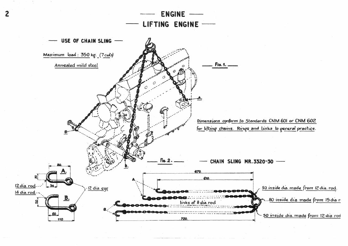
2 ENGINE LIFTING ENGINE
USE Of CHAIN SLING -· -
Maximum load : 350 kg._ (7~~
Anncza(czd mild ste~l
2L. ~~~
12 dia. rod .. __.!
14 dta. rod- .....
110
-~
A. ,,_ \ -\ \ \
\ \ \
_ fla.1.-
Dim«nsions conform ,to Standards CNM 601 or CNM 602
for lifttnq- cmuns. Rtn~s and link5 to g¢114ral pradtc«.
CHAIN SLING MR. 3320-30
ezo. 6tc).
SO inside de~. madtL from 12dta. rod.
80 insider. d\a. mada from 15dta.r' links of 8 dta. rod . •• • a •• o a •• :.::::':-::.::.:.:=:~;:--·-:-:::.'"::".".: :·'..:.:::-::::.::J_ .. .-0 ._ B _ .. · . ·---1: ... · .... _•_•_•_•_• oeoe a..-.::·:..::::~::-:::::::.::.-:::::·:-::::::::::_:__
,.. ·CFV· so insidcz dta. made from lc dta. rod

-ENGINE
ENGINE STAND -
~-Qt (~}~~ I
I ' ' . L.-,-- -------- -·- .............. - ...... ---,.....J:
' , ! I 8 :· t :
_: ~---------.----·
STAND MR .. 3300-20 - - USE OF STAND MR. 3300-20 -
Matn d1mensaons
4
s
64 .• •,
a. ~ . \ •
'- flc.2._. _
ENGINE-
FRONT AND REAR SUSPENSION
- f'i.G.1.-
,.-... .. 102.
•• •• .• 64.
HEIGHT GAUGE MR. 3450
.........
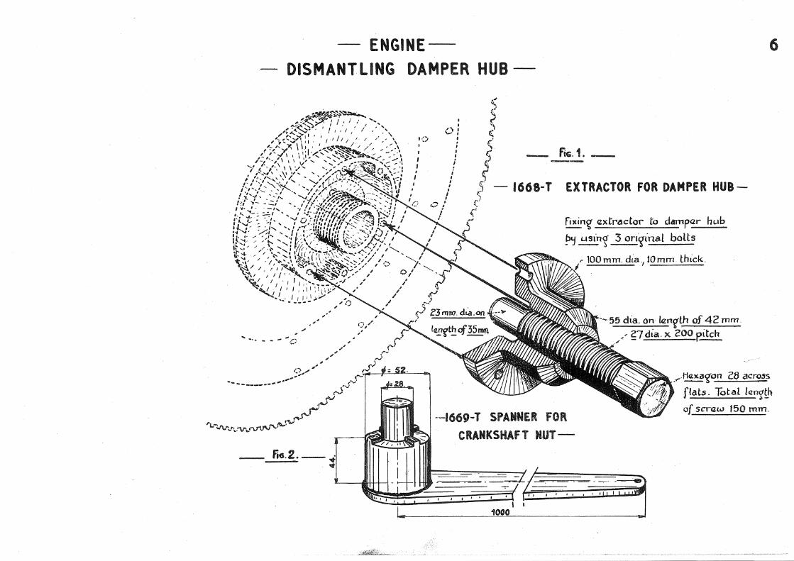
ENGINEDISMANTLING DAMPER HUB
I I ,
I
I I
'v B '-' '
' ' ' i
fiG. 1.
1668~T EXTRACTOR FOR DAMPER HUB-
fixin~ axtrador to dampar ht.ab
p~ usin<[ 3 on~inat bolts
r 100 mm. dLa., Wmm thick.
--55 dla. on lan~th of 42 mm. •' ?_7 dia. X 200 eitch
6
--1669-T SPANNER fOR CRANKSHAfT NUT---
.<" ~<San c8 across
flats. Tot at lcm~tn of scraw 150 mm.
__ fico.2.--
L.. 1000
· __ udfiit!:f;;) . ___ _

8 -ENGINE-_
-REPLACEMENT OF VALVE SEATS AND GUIDES-
-REPLACEMENT Of A VALVE SEAT-
_fie.1.-
MR.309.8·B MANDREL
- fic;.2._
-REPLACEMENT OF A VALVE GUIDEMANDREL& fERRULE FOR FITTING GUIDES
MANDREL MR.I620-I -Fic. 4.-
~ n II
i II . ,.£:16.
I I
I 0 ~
I I
:l _.&:8,&
-USE OF MANDREL MR.I6ZO-
= :~}-----~---

- fiG. I.
to .• -----
II .• --------
M .•.. -"
)5 .•. ,',,,
7.
s/
........ ----
', ',,'",,
---
--ENGINEOIL PUMP-
-fiG.Z.-
16 ••.
--------- _____ .15.
'i !
9
- fiG.3 .. -
37.·-
36:-------
38:--------
'-~--- -·· --
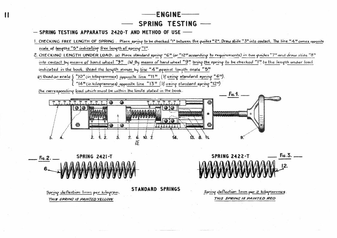
-ENGINE-SPRING TESTING
-SPRING TESTING APPARATUS 2420·T AND METHOD Of USE-
I. CHECKING FREE lENGTH OF SPRING . Placa t~prin'?to be ch~Zek4ld. "l" b4ZtWe:lln tha ~uaCLu "'2". Draw slldQ; .. 3"anto contact. Tha. ltruz ... 4'' com.es opposite
scal,z of ianCZ'I:hs ••5n indtcahi-r~ frcz¢ l«;n"fth of spr'n':{••t".
e. CHECKING lENGTH UNO£R lOAD. (a) Plac" stal""!daf'"d spnnr •• 6" (or .. 12"ac:a;>rding to r.5uinz:m,znf:s) L'n two jf<-~ldczs "7'1-and .ir-6-W sh"d<L "8"
into cont,:~d b~ m,zans 9f hzmd wh«czl ··~~· (b)_B~ m«ans of hand £oJhul .. 9'; l:mi-1.~ the: sprin'.? to P<L .ch<Lcked M>l'~ ba tha. lczn.'{th t.m.d.;z;r load
indt-Cd ted in tn« book. Raad the len~th :>hown b'j llruz '"4" a~.:11nst \:z"':?th seale "'5~
~) R<~.ada«? scala { :10" (i~ ki~ogramm~~~:s-) .9P~~ita ~in<~Z. .~'1P' (If us.tn~ standa-rd ~e~~n~ u;6").
14'9 (m ktlo'lramm¢s)_apfostte: hn~.t 13 '' (lf ~n~ standard sp12n~ J.?") tha. cotT<lS~ndtn~ loacl u1t-ud1 must t;Je '-•lllhi.n 'l:he li."mits stated ;n the book.
' ' I
' . ' '
! ' J
5.
- fic;.2,_
' ' i. ' ' 0 : '
2.. . ;
1. 2. 3.
SPRING 2421--T
?pring deflectLon 1rrun. pe.,.. k,·lcJ~~_!!l·
THI:S SPRING IS PAINTED YELLOW
I I ' 0 0 . .. • .
7. 6. 10. 1. or IZ.
STANDARD SPRINGS
_f'iG.i._
.§pnn~ deftttction 1 mm. ~r 2 kal~ammes.
THIS .SPRING IS PAINTED RED

-ENGINE-
FITTING SPARK PLUG HOUSINGS
TOOL 1604-T
!3ush bod~ t'6" into g~rl< p~·~ housin~: Scrcr.w cone ••A" into thruded hohz fo.!_spark p~~ in oi"dczr to CZJ'C¢rt pr<usurGt on lil«i: balls-. ~j means of a sp~~r, 19mm. across flats, rotat¢ bod~ "B'' one revoltttio!'7. Scra.Lu Ln cone .. A .. ayam and l:hczn rotate~: body ~B" anotnar turn. In ~~t, two ·turns arcz sufficuznt to lln'Sunz a watca:r· tt'{hl: fit.
12

----------------
13
(:?ipe for d\schar'{~j~t ..
16. PI 1.1 «{ for r-dcza scz voal.,e controt
.... f.
·, ' ' I \ I
\ I ' I \I
\\
-ENGINETESTING OIL PUMP
SIMPLIFIED RIG. MR.I811 ASSEMBLY Of JET LIMITING DISCHARGE
__ Standard pre~6ure ~~~fl 0 to 57 lbs.f .. !l'n- or, :' if avail a b l~~;, standard g-~~cz from C4 or 10 A.
' \ ' \ -' '< .-- -~(
/ ' \
\ \
\ \
~-p~lg_~ith conne.c:tion f~g~cs~:' ll1be 470097Is 5uitab!cz. f~ / this purp~-'
The p~p -~st<U:i [$ fitta.d ~an en~i~<£.._9Ump_ liln~...!'!~_tv,zn b ~<"~ _•z.£::<::':!:!:2 d.-ill at a sp~~:<t:d bq.tW~fl:n JOOO and 1500 r:p-!!1: (~2f~cJ afmacl~~-~:an!.! u:;uat!!1 mark:!ld an m(Jikers natn!l platll). !.IS!l winta.r ~ado<: oil similar to "MOf!ilO!l ARCTIC~ ~lf_possibla h~Zat oil to 140" f: :t 9" F.
Thcz :?~g~ pr-<Zssure must b<t J5 lbs-L !:'}·tn. J f tilts L~ not pos1ibl~~: bnnq 2i1 to zo.,. F. ~ pnu;su-rtl. thtl.n ll'ust b<z 40 lbsJ~"t·0·
To bn·n~.p~nur-efSct'<Zwup_p~~ ~frekas<LI(e>lve to incra:a:;-cz P.11Z-~":.'-'.~'<tZ. l:o correct J}c_r"'~ l_Un.:!IC:f'ctw P~'r ••IG" of nz.laas« valva to nz.duca pr-a~sur.-;;"
-FIG.3.-- OIL PUMP BRACKET Main dlm~nsiorts to allow fitti.rt.f on Sue C':tlinder or f'iftaen sump..;
~-------------------------=22:2~-----------

-ENGINE-
CRANKSHAFT-
- BORING OIL BAFFlES-
BORING TOOL 1665 .. T
_ f'K;.1._
.a.
There are thrtto~Z sczts of bush<Zs ~c· I : Outsida da-~mcztar 50 (for_l,urin~s to thcz ori«[lnal sizll. of cranksh.,ft. l : Outsic;l€ d\~m.etar 49, ~ (for bea:m~~f f1"rst ra.~rl~d of crankshaft. 3 ; Outsa.d£ dlamc:tcl:.r 49 (for b<Zarm<gs of second t'e'{rmd of cranksnaft
FITTING MAIN BEARING CAPS
FiG. 2. _
b .
15
..-------

16 ENGINE-
- FITTING GUDGEON PIN CIRCLIPS- -LOCKING CONNECTING ROD NUTS-
USE Of SPANNER MRJ610 _Fio.1._
_ fiG.3 . _ SPANNER MR.I610 r ---~
.I 1 ---~---
' I I ..,____ ___ --LZ.u...O. _____ ,....1
- fj(;.2._.
Tab ''T" of q;ach lock(oJasn«.r must butt at "H '' in .ord.z.r to prevotnt nuts tumt~CS'" tn th,z. dir<Z.ch.on af la<'s«.n c.'nog:

ENGINE-GAUGING HEIGHT OF CYLINDER BARRELS --
_ fico.1._
- fiG.3.-
MEASURING THE DISTANCE Of THE BARREl BELOW BLOCK flANGE
APPARATUS MR.3377 .
MEASURING THE AMOUNT THE BARREL STANDS PROUD Of BLOCK fLANGE AFTER fiTTING lOWER JOINT
I. P~EPARINC APPARATUS. Place brack~t- MR3377 fittad with a dock.~au~,on a surface P-latE:_ or- ~-4{~f(l; . hh:th th~r. clock~~~«. na.a.dlC?. indicat~nl{ abQut ~ mm., bn'n<s ffiq,. da.'al to Z04ro.
Z,. MEMWR.!NG OIS'TANCE Of BAR~E.L BELOW CYLINDER BlOCK FLANO'=. (without low.zr Jo{nt) ~
P!ac:~J: the apparab.1!J 1 ~prepared a bolla, oo l:ha c~linclar block ~r.»ith th ~ clock ~auy!_poinl:ar bean i-t~'{ on tha. top_,facq;, qf th<t Debrre l. Tz:t~ readin~s at Jo~.~v cardtn~l P2inh on l::.alB'ToQ.!lan&J~·nd thtt avera~e o} th<& kur.
3. MEAfURINQ HEIGHT OF 6ARREL(Iower.Jo&ntf4tted) fl~-2. Piaca ap~8lrah4~ on barnLL with pointar contachny-.£':fltnder b ock.
~Tha indi<."ata:d hat~ht mulJ/; b~~: bahua'UI 0,08 mM.. and 0, IZ mm.

18
-FiG.1.--
.!
6. 14. 10.
ENGINETIGHTENING CYLINDER HEAD
16. 1. 17. 1. 13.
{ 1st tlcrht.:znini : e trt.k~-- (~~ foot""P.2und•) .
TIGHTNESS OF" C-v:LINDI':R t"IEAD NUTS. Znd. ti~htczntni ~f·-(.3~J!7 _f~f?'!!unds) ]i~htczmn~ when hot: 5 rn.k<1:_(3~ 1_7..~t-~unds)
It ~s ra:com":'ended to h~tczn. tfuz c:-!fllnda:r hcta~ nuts in t~e ord4r md,·ca~fld ibovcz. yna d~r~of -:l··~htn«.:J~ lllust b4 stn"etly adhc:tt'ed t~. It tS ess¢nhal ~o use a l:orston wr-a.nch. Thu; wrcznch ~s fraduatc:d ~n metef"- k1locgrams for dtf'llet r11.~dtn~ and has a S~(..lal"¢ shaf~f'f_!21)mrn. whtch accommodate" eithar f. A.C.O.M. or SNAP-ON ~pes ~socket:. tt.lhan effort !taG rea~luzc:l corl"ect p,o1i1lon fY.adttalton, enct artl"cutafton "•A"ff.!ld~ G/:".<>e.fiFflltrmnr.. Arl:t'c-vlalton ~A 111 must rtavar eorr.tt!lct bod!l~oj_$"ptmner at *•B"..
-'---- FiG. 2. --
TORSION WRENCH 2470·T • . •
\A.

--ENGINE·--
-FITTING MAIN BEARING CAP GASKETS--
- fiG.1. --
GUIDE BUSH FOR PISTON
RINGS 1656 T
- fiG.3 .. -,·-
19
-FITTING PISTONS-
-·--------

20 ENGINE~-
SETTING TIMING WHEELS--
The ~d c.~ltitdcT"s bcztn~ at approx.imat.~<J~ _lop dead centre1 th~ ectntr<~Zs of both wh«e.ls and mark "a'' (ccntrctP.unch) on camshaft wh<IZ¢l must b<IZ '"a stra~ht lin~ Th~Z crankshaft whed is mark<td ( ~'.f llnq or cantre-pond,_} :-
1. On a tooth as at "b• Z or betc.uzcn hzc.th as at "C "
frt tha ft-,.st castt "b- thtt mark ts offset ltatf a tooth to the rcyht 9f thct l.n<~Z bctu.~ez.cz:n wh.ut c::a.nt~cs. In tha 3ctc:ond casa "e" tha rn4rk comc.tdcts with tha ltn<1. b«b•ICten whctctl cer.nt-i-¢s.

. ~ENGINE-
MR. 3421 CENTRALIZING BU~-ASSEMBLY OF DOUBLE PULLEY-FOR OIL SEALING CAP r-----~-· _ ____. - fiG. I. -
-+ L.--.~~~~~~
Qy~~:.!.9 J'i.!f'.l~'{_:_J_tw.:f. ~-~ ......... "'
I I
I I I
I I ~
56 ... __
21
- fiG • .2._

23 -AIR INTAKE SILENCER--SECTIONAL VIEWS-,
----- --, fiG. I. ----4 .. --.r
S.e--'-----------
__ ... 2.
--------.3.
-- fiG.2. --- ~ fiG.3._
--.... 4.
- F'ia.4_ DETAILS OF LOUVRE a - -----. 5.

-PETROL PUMP---
SECTION THROUGH S.E.V. TYPE PUMP
--..- ... ... _____ ... -
3 .•.. -- -·---. ----
14 .•... ----- .. -·--·-- --·
15 ...... -·--- .•. ------
4·~-----
u. ~ ...... -------- .. ····· -- ....... ---..... -.. ~ ao .• -...... -----
....... -
---
24
-- ..... -------- .......
--. ...... -~ ....... ·····-- ---- "" 2.
---
...... ··-- .. ···-. ----.----- - --- ........ -~(iii,.
........ _ -------------~ '1.

25
fAULTY ASSEMBLY
l'l.ak at ~mp_jo,.nl: or b£tw.ra.n '{la5s col/(l..r and pll.rnp
PETROL PUMP~-
CHECKING FOR LEAKS-
fAULTY MEMBRANE
L~Zak at opa.rattn~ a1'W>
_?rtf&£.~-·

USE OF CL :'}.MP MfL34S:l
REMOVING AND FITTING-
ClAMP HR. 3451 Mild Steel 3,5 mm. to 4mm. th 'Ck
Th~ps and thr;z;q; sev·,zws:
~~~'juanzd for ~<Zt
~---m. ------ll>1
I ~~-----, I I I I I
-- -1
~ -------.~----- ~
______ 3""7~ ____ .,.
26

27
_fiG.1._·_
LONGITUDINAL SECTION
-- ... -6 .• -----·--··
17. ••.•...••.••••.•
/
e.i/ ..--114.···· .--· _______ ,.-··
10. , .. ------
.s····
~- / .,•
13:./:~:~: ..... 4.···---3.······
z······
~/ ..... ~···· .·
.-· ---
- F'iG.3.
-CLUTCHASSEMBLY-
-fiG. 2.-
VIEW OF TOGGlES
- Flc..4.
.. ------- ·- -----6.
---------- -· 7.
--- --~--- ----__ s.
I I r----'"----11.
/ /
,!' ,/
_/, .. ,./ - rtG. 6. _..:....

~fo-r d<£~liS<~ to~~~s (nzmao1a: whan adjushi-r~
,.,!.?~-,-"
fa~ plat..: ''A" f•ud tc be:nch b<.J
coach~.s,~.· ·~b<Z • 5" fm~d throu'{~cz.n,Eh toP'_ ~ct bllddttd trl .f~.!' Qparat1~'i:' ~a: supyh~d ~£!!> th~ ftx!ur~:
CLUTCH CLUTCH ADJUSTMENT-
FIG.I. ADJUSTING fiXTURE
1701 .. T
fiG. 3. CHECKING ADJUSTMENT
Wha.n r.lvot<Z.d, f!:!:!'f" .. "C "m.u st :sltd<!; av_a"(" up~Ja.~.~ of .t_..,~:g~o~!_ nna. -:>-
_-_-_·::~----~ -~/~?~\ ~t!i;f~;fE;~jJ <::.:::
- . ~ -. -,., .... - . ~ -
..... --.
28
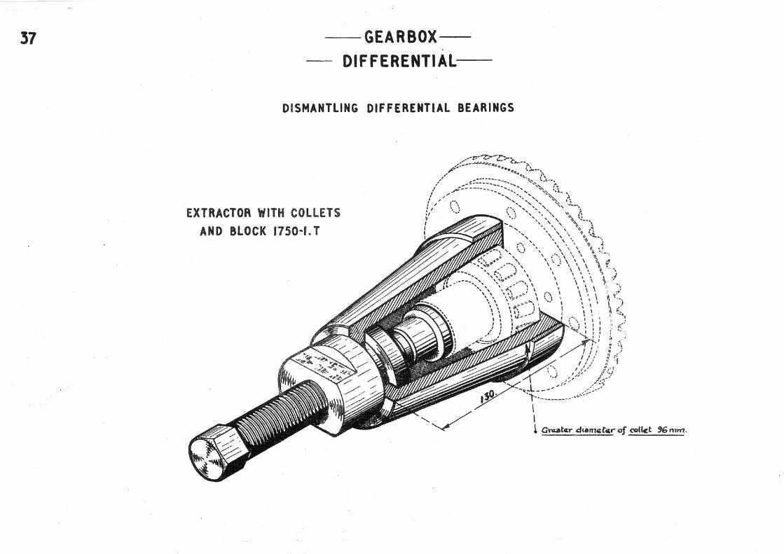
37 GEARBOX-DIFFERENTIAL-
DISMANTLING
EXTRACTOR WITH COLLETS AND BlOCK 1750 .. L T
DIFF£RENT1Al BEARINGS
/ ' /
/ /
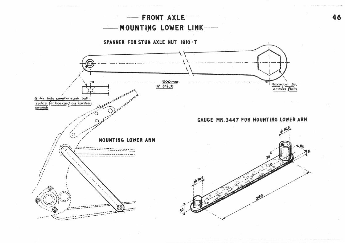
-FRONT AXLE -MOUNTING LOWER LINK-
SPANNER FOR STUB AXL:E NUT 1810 • T
~ ·. ~~ = -- -----------~----- ---\\_ ___________ _ / . \\
/f. / \
'
[~rj< J rooo·mm.
12 thick.
GO dLa. hoi.: c.aunl:ersunk both
'
I ' 'I \I I .
I
' I :
MOUNTING lOWER ARM
GAUGE MR. 344 7 fOR MOUNTING LOWER ARM
) :3¢ / I
I
I : I I I I
46

65 ""' "3 &.'2 101 f>.O Z.J ~4- ~1
. \.. .. '
' ' ' '
' I , / 41
'-------
2tl 4,10 2~ /~ /
, /
/ ,/
/ ~~--"",.
": .. ~:~~/ ..
2f ,'
--..... --. ····•··· .. ,
.... .. ~
' .. . , '• ..
·'36.

MANDREL MR.34:52 FOR REMOVING lOWER liNK SPLINED SHAFT.
I ~-~ I
~~------l l
5 X 4So chan-;f<tv-~~0'------ .1 __ 1
- FRONT AXLE·---
- MANDRELS-
MANDREl MR. 3436 FOR REMOVING
FRONT HUB
MANDREl MR. 3431 FOR REMOVING
BAll PIN lOWER BEARING.
- fiG.3 -·
48

so - FRONT AXLE-
- SPANNERS FOR UPPER LINK-
-FaG. f.- SPANNER FOR UPPER LINK SPINDLE SLOTTED RING NUT, 1861· T.
I
. Q
.13 eQ

FIG.2.
-FRONT AXLE
EXTRACTING UPPER LINK SPINDLE-
FIG. I. USE Of EXTRACTOR
""r::.; :.-.-.: .-: :. -::.:. :..: :-::.-.::: ;:.-.: :-tl:J! r;,-b : : tL-1L...J.I· '! i
: .. - -- ---- -----i . . /' . G G ~ I
a I ' • I I \ : I
I k ' I ' • ·. ·.... ! ' I a ", ..., .., t i o ........... "' '\.. , ...... i I
~~~~~~~ I ·l::.._ ______ .,: ____ J : : p ~ I I ~------~--------: : &iM:'[I
-ti.BII~~~~~~~~~~~~~~--~--~r-+" +- ------,- --.--•m••!:J,'Ir""'"-: i:,-.:.::.::-::.::·:::.·.·:::-.-.• :: .. ·.:;i : lli!io<Wt.riJI"
' t., ... ,.· '' .. ,___; • : . '\. .., : I ' 'I I ' ; . ', ' 6 "', ' I '\. I
: .. ,~ ! I e '•: I : '1 I ri :...._ ___________ .., _____ ,,-': j
EXTRACTOR MR.3442 ~~ ;-------------~----------! h n--t-- - . -. - - -- -Ht ~ ~--------·-···------------i :1
·- ---
:uo. _..J
I I I I I : I : i I I 1
'-·.J------ ····-- ····-- ---- ----W
~pac~l" tub~ C<tntra; rod
290. •• ___ _ . . .
'
51

53 -FRONT AXLE-
BRAKE BACK PLATE-
FiG 1. flo. 2. _
---------·so.
____ .i4 _
____ .so 48.·-
- fiG.4.--- fiG.3. --
-------52.
I \
' \
/ I \ .
IS. si. 10. 19. IS. 17. 16. IZ. 1!'». 49.
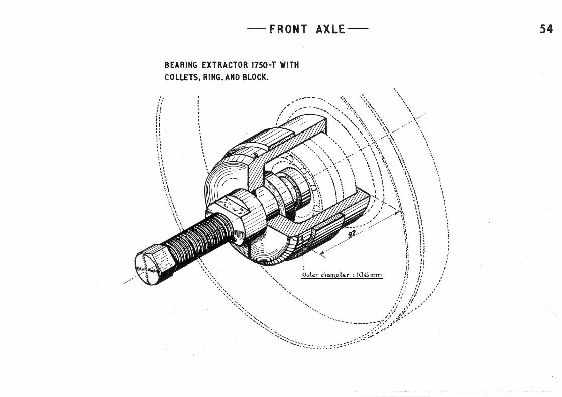
-FRONT
BEARING EXTRACTOR 1750-T WITH COllETS, RING, AND BLOCK.
. : ., 
55 AXLE-SPANNERS -·-
.. ·~~·:.:~;~r~=~=~~,~~~~~~,./~"-L:'L:~~ i-l ..., .. ;_· ;_ .. _. _._·"...;.··'-'·,,...;..""'"L..'' ---"-""_:...!';._,•·: • ._·_~~·-~"""· .!.!·; '.c:··:.:...:·, ..!l).;;.l'·'....!.··:....·ti~~~,L::··_,~~..,; •• :-' .... : +l·..~..·~icci__J-~, . ---------~i_\_)0. ------ ·-----
i854- T SPANNER FOR CASTER ANGLE ADJUSTMENT.
ti::OR UlWER
T.
<t·-'Lts I

- FRONT AXLE-- 56 -ASSEMBLY OF UPPER LINK SILENTBLOC-
DISMANTLING
~ ..
~ :4• 1::1• I..~
dl t~
~t
~~J
t-::==:=•~_1
MR.3440 SLEEVE AND RAM
110 I l>t--f'
-·-· Fi&.Z ~
ASSEMBLING
........................ ··-~-~~~~~~~~-

57 -FRONT AXLEREPLACEMENT OF WHEEL STUDS-
. FIG.I. USE OF FIXTURE FIG.2. FIXTURE MR.3445 FOR REPLACEMENT
OF WHEEL STUDS.
...;. __ .____________ -----.--------..:..-----·~
_f"i&.Z_
HOLLOW PUNCH MR. 3445-4 FOR LOCKING STUDS
Mild st4czl, ~ hardcn<~:d f ~round.i
I I''
I II I~' 1 sharoootnctr ·:12,1_r_ I .
~·: 17,5 ~

-~FRONT AXLE--- RECTIFICATION Of FRONT BRAKE DRUMS-
NOT_E: Dlamat«r 90'*' to bcz fi~_ishll:d aftq;r ':l..n.'? li_ pr<Zssa:d ort shaft. Fac~Z f\ !~o b<l truad Uf' lik«WlS«. J)tamatar ~O*must ~l{ood fittin'? .2f nn~ 011 a. ~~l.j O~Z<H'"m~.
- F"iG.2- MANDREl HR.3441
A.
I
I J
: Ch.'!!!:'~l" 1,5_,< ~- .J..__ __ ~ ------~~~E~=:~ !.........-~----· ---~- -----------=
FIG.I. USE OF MANDREl
.... · .. ~.-: ....... ~~ _: ·t... ---~--==----- -- --~--- -· ----· "'
- - - - - . ..; -' - - -- - - ---·- -{\~~'-!~ 0: v~-~-------~-------- .
. I I I I
13.2 ----1
Proi:Ai.ct CtZ.nlr<i:
at a:ac.t-. <Z:nd .
58

59 -FRONT AXLE-- PEENING OVER BRAKE SHOE CAM PINS-
FIG.2.
FIG.I. USE OF FIXTURE FIXTURE MR.3444.
MR.3444.
Rcz.movcz: sharp ll.Cl<[~ --
FIG.3. USE OF FIXTURE MR.3354.
FIG.4. FIXTURE MR.3354.
Punch stcz:Ci:t !~pa Bl9. Qucz:nchcz:d and.
tcz:rnr.czJ"ClcL
Ra.mavcz: sharP. c:d'l'{S . . .... _ '• ,
__ ,
l<nurlcz:d.
20 dia. rou~!J knurla:d.
Socket, st«.ll.l t~P-cz: 819. Qucz:11ch~~:d and bz.mpa.r-W.

FRONT AXLE --
- CHECKING CONCENTRICITY OF BRAKES FIG.I. CHECKING BRAKE DRUM DIAMETER. Plac<Z. fc~JCtut"e on b<Z.an'ny. Br~n~ ;ndicalor "a" tnto contact toith drutn and dcz.5cn.be a carnpkbz c1rck. Lo'!.k ind1'cator ir th-z s~~;t positton b~ ~ofscr.a:w b.
fiG.2. CHECKING CONCENTRICITY OF liNINGS.
<;lf'":':!:~tton, ·:::.==;_:::.:..;::.;::..:: .. _:::.c.;,~· r~~.!.::«•t'n •'n contact_ t~f.9...':!<jh~ .. :f!rC~~!'f~n<.r.'.~<iZ·. ( r,_. u•r:!Jer to <Jht~<J.!i!!£..!::0''dtlum, a'c{fiat !!...mnyt P.'l3cc€nlrzc bca;~:c~ <ftnd ad,iust.tn'i(... eams ?_t fYZ'!!2 o.fbackpleli.e~ not ~ho<AJn) R~Jrnova burrs and luf'lz Sf?_ol§/!:-orn ~~l'j'$' Wl "t-h
~e.·
60

50 A TRANSMISSION UNCOUPLING AND COUPLING DRIVE SHAFT SLIDING JNNER FLANGE
fiG.I.LEFT SIDE
/
I
' I / I
I I / /
SPANNER 1832· T
{
FIG.2. RIGHT SIDE
.......... :· ........................... __________ .......... . ...................................... .., ........................................ .
\ \ \
\ \ ,/
········:····,, . .... , ........... ~
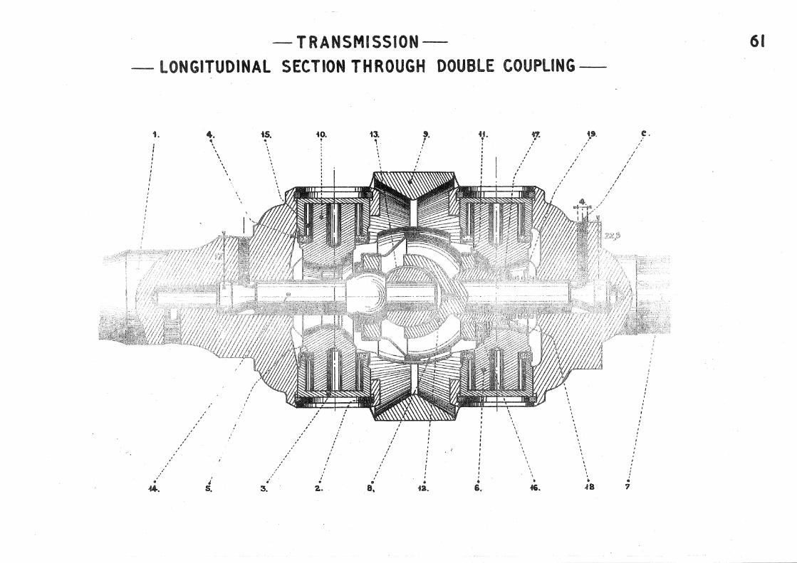
-TRANSMISSION-- LONGITUDINAL SECTION THROUGH DOUBLE COUPLING-
I
' I
I I I
I I
I I
1.
/
•
I
I
I
4. \
J s.
' \
' ' ' '
' '
I I
tS. • ' '
. 3.
' I
/
iO. !
/
' . 2,.
I
' ' '
13.
'
• a.
\
' I
'
'
' / I
I
I
' /
• i3.
' • i.
I I
' . I
I
I
? I
I I
I I
I
' ' ' ' ' ' '
~9. I
I
' ' ' ' \ ' ' • 48
f
I /
I
I
I
/ I
I I
I I
I I
I
' .. I
'
' ' ' I
' '
.,
c.
' ' I
61

62
-- "'fR~NSM\SS\ON---LONGlTUO\NAL SEt'T\Ot' 'THROUGH FLE~\SLE tOUPL\NG-
' ' ' ' ' ' ' '
' ' ' ' ' '
' ' ' I I I ' I I
// /
/ /
:
d. i ' :
I
' '
'
' '
!4. • '
1. T ' I I I I I I
' ' I I I I
I I
' ' ' j I
i ' I

-TRANSMISSION-- DISMANTLING-
fiG.I. REMOVING CIRCUPS
FIG.3. REMOVING STUB AXLE
FIG. 2. REMOVING NEEDlE BEARING CUPS.
3. , . \ I .
FIG. 4. REMOVING DOUBlE YOKE
j i. • 40.
63
64
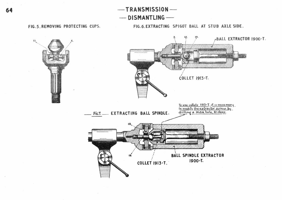
FIG. 5. REMOVING PROTECTING CUPS.
~. TRANSMISSION
-DISMANTLING-FIGd). EXTRACTING SPIGOT BAtt AT STUB AX.lE SIDE.
f:. 1;'· /'BA EXTRACTOR 19 ·n~~n~~~n~n~'7-~7:'77777TI7~
_ F16.1. _ EXTRACTING BAll SPINDLE.
To us"' collds 1':31:~-T, i~ I'> na..::-~'1>'5.:n·lj_ tQ trt<>dtf'1 th"-~Z.Xtracl:i:::u·· Sci"'!Z.w by_ driUin~~i4dia. hol~p_:
. . I
BALL SPINDLE EXTRACTOR 1900~ T.

FIG. 9.FITTING CROSS HEAD.
a. --....................... _
7 ·- ---------
-TRANSMISSION~ ASSEMBLING -
FIG.IO. FITTING BALL· PIN.
... &. ,.
__ .i7.
FIG.I2.CHECKING POSITION OF INNER BALL. ___ fJ.
----· .
_ FiG.iZ._
' . BEARING HOUSING GAUGE
1910-T.
--- ___ 4t..
65
FIG.Il. MODIFIED BALL SPINDLE.
FIG.I3. FITTING CROSSHEAD.
... ----.... - .40. ---
--- ---·"·
'• ~,: .. __ .. ::.~. ·.,.:;,..

66 -TRANSMISSION --ASSEMBLING-
FITTING BALL PIN SPINDLE FITTING DOUBLE YOKE
- f"tG.44.-·· . ·· ~ -. ___.,...,:..... SmaH d.:am.~te'f'
- faG.f5.- · fiTTING DRIVE SHAFT
_fa'G.16._ 9 .•
SOCKET 1904 .. T
I
:.,c tar~¢ diamtlt<tr -'1.. __
-- ----~-
FITTING CUPS AND CORK WASHERS CHECKING FITTING Of CIRCLIPS
-fiG.11.-· F'IG.18.-
2.~----
GAUGE 1909·T

' ' I ~---- -------------- ·-------~ I l \----------- ... ------------ ... 1 ' I ' I \ I
•, I
-- ---. I
I
' • t
,,,.-- ..... ', --- ' --,
I ' I
....... ,\
l-:.:: :::.:::.;.;:: :·.:~:::::)~ I
- FRONT AXLE
LIFTING FRONT AXLE
APPliCATION
SPECIAL JACK HEAD MR.3300-90 ___________ so, __ ~-----
--e.! I I
67

68 -STEERING-- REMOVING STEERING WHEELS. CHECKING CENTERING OF STEERING WHEEl-
lOCATING BUSH MR.3102.
t-el-a------'ff-'-: .=.54 .. :~_\4ri<Zfi - ------j C· A I ""' • ;250. __ . -. --~ II
- riG.t,-
__ ... li.Arn arrow towards bot torn
Steozrln'5 column mll3{ turn in. bonz of bush without touchtn'{·
wha.n chczckinos·.
' / /
/ /
' /
/ ' '
' ' / '
' ' ' ' /
/ ' /
USE OF STEERING WHEEL EXTRACTOR.
STEERING WHEEL EXTRACTOR 1950 • T
- Fi6.4.-

- f"iG.i.-
-STEERINGDISMANTLING TRACK RODS-
&All PIN EXTRACTOR 1964-T USE OF EXTRACTOR
_......--·
-r) ... j l
/ ,.---L-~J, . '/' ~ ... -[- ....... \.\
. , (I \ 'W""....::..-..s-.s.-.:.::=------------... . .. ~:·~e,--· --;~:\:
t I l I ~------- 1 ' , .... -,--------:-~ .... -~---------· ---; \ . I \ :r,\• ,,, '/ . \ \ \ \j : '. -~"' ~ \\/--·--.·--·--·---r-·--.·--·--·---. ~--
y • : I
:~- .. -------------------;,/-·- ---:,-----t__--------,----------..::---------- \·-------' ,, .. , '.. I / ', '',, .._ _________ _, , .. --..-' l
,/ ',, ...... ___________ t.j' ""',, : ~, ' I' 1
f . '\.,\. t \......__---L' I
'----------------t . , I __ ) c~~~:----.:r·-~r~:; .. ) -----t---- ... _ ...
69 .
-fi&.Z.-

70
' : '
~·· ! /
41. •
_ fiG.1.-
t.. •. ', ',
- Fi&.3.- Fl TTING OF BRACKET
STEERING
SECTIONS
LONGITUDINAL SECTION
ts,. ••· ar.. u. ~ " •, I ~ '- • ~
I ' \ \ .. \ \ . \
'.\ ', I
. ,· Fi. z TRANSVERSE SECTION THRU
~ __!!:_::- PINION HOUSING
_ ••.• zs .
............. ......... .... ~ ......... ------------- ____ ------·-····a7.
- -~::: :~:::~-,-_-_·::~~~ ---- ------ ... ·----3f. ------------..... --30 • ....... __ _ ----...... ·- ~ .. ----------40.

34. ? ' ' ' . . : . ' .
-STEERING--SECTIONS-
- FiG.1.- SECTION THROUGH &All PINS
fiG.2. TRANSVERSE SECTION JS. 33. 31 38. t3. 18. 16. , 9
' r 1 ! , . ' ' I ! . ' '
. . I I . I . . . . .. . . . ' . . I i ' . : . .
I ' I I ' I . • I .' . ,
' I
I I : ' . : . '
! . .
I . . . ,· : . . I . I
I I I I I .
l . I .' I I
:t I
- rts~3.-
CHECKING TOLERANCE OF BAll NUT
····2..
. . // I
/ • • 26. f5.
f9. , ! . . .
' . I j . . .
j . . . .
I
I
37. J7. za. ts. Z9. y : . .
i ~ ,
' ' : I . ' ' 1 .
I
·- FIG.4.-
5EtTION THROUGH END BAll PINS OF TRACK RODS
··-
. .....• az.
G . ~ .. , .. ~~
·-.s.
t9. r
.••....• -ZO .
------·22..
71

72 -. STEERING-.f>
-HOLDING IN A VICE-
USE OF FIXTURE
I I •
~- -f I ~ .~
' " '
.. i~ 111'\ i I i'il i: i lj I i '111 1
lllllllllllllllllllll .
FIXTURE MR.IS61.
F:t,,t stul 30" 6 J
lao..

>PANNER 1976-T FOR )JUSTING TUBE RE ..
rAI Nl NG RING NUTS.
--STEERING-ADJUSTING TUBE RETAINING RING NUTS
- ADJUSTING. BALL PINS-
... 45.
/
,
SPAN HER 1870 ·T FOR ADJUSTING BALL PINS
/ /
/ '
73

74 STEERING-TRACK ROD ADJUSTMENT-·
USE OF GAUGE
I ·' "' 'I: [I II
r ,,
- Ao.2 - GAUGE MR. 3346
lfi'--'o---:!i..i-:::.,.-::z"11"·"'"1 . ;dl ,,11 1111 ,ii11 Iii .. 11!1, !:i,il:1 lli,d!lil' 1\ .II' I :IJ I 11 ~ 1 111 II, .IIIIi .Iii!. ll>ll'.1
'_'_1 __ 11 :~:~ 11!:ii;·Hmil' ___ 1!i_,, __ .!ll_lr_'_,~:;,:_, _1 1~1_'· __ ... 1' :!' __ :~:' 111!1 1, .;,, '1!1 '"' ··wp .,., .. ,.,,, .. ''' 11 I I I 111 ' II 1111• I 111· t t--Jll ·--,,,-. -~~-~~-, . --.. -~-1 -. -- • I
1 , , .,!"' "', " II 1 , , .. 11 11.. . . I , , •I .,111 , Jul · I .. ~! ! :! , Iii /. I " 111 : • , 1 , . .1 , , " 1 loqj• '1111'' IIIII' i'JII'' 'IIIII' ill... .IR Ill ll!jl' . . '''''" '"'"'' I: llilh f'lll' ~:;Ill' . I Ill" ':. "' I 111
~· To be madq from l"-v<ZrS 42G542-543 Mild stqel 30" G
B. To b« ~d<t from ball pin 6018~ or 427243-244
Thct cctntnzs of ~czs Tl and T2 rnust be p.a"t"allttl.
.tllol, .rio II,. ·!'". '11lt1.
To aHembll<: ~~~: f1'rst adjui"t a comp!.d:e track rod to th4Z 'hrn<ttUtons l{i~Off~p !::he partS' Band C to th«: track rod' and tack wco:ld th<Z-m to tha flat stnp..:. R.4mova:. tha track rocl at.d CoiT\pl<Zta. weldi!'1:. Qpa:Y"ate td4:nt\call~Jor the other S'tdel..
11\m--+-¥/j!IJII

-REAR AXLE-
- LIFTING REAR AXLE-
SPECIAl JACK HEAD MR. 3300-110
I I I \
\ \ ',
' ',,"--
R.S. channa.l to be ~<~ddctd to a s-tandard jack h~&d.
' Wao..d strip!_
1 __
_l_...r.-1-111
''• ···""'" f--- 1' 1 Loi• "t
I t:• 1!: '·· ------11 L-------
I I I .1
~25~
75

76 - REAR AXLE
POSITIONING REAR AXLE -
FIG.!. USE Of GAUGE
FIG.2. GAUGE
~ G~~~'j"""~~t~ : ='=---·---·-·-·-·-- -·- ~tftt~! : i~ 435. ~ : : I ~ 490. ,.j,s 60. :W!2·
I I SIO.

zg ·--------------- ---
3.--.--------- ----·
~ '·--
............. •,
s.-
REAR AXLEPLAN VIEW-
77

78 - fiG.f-
9,.,
s .. _ -..
-REAR AXLE
LINK ARM-USE OF FIXTURES
f"i&.2. -· - __ fio.J __
FIXTURES HR. 3336
-FIG.4.-
R.s. ancsla. 3o x 30

-~-- REAR AXlE --~···
REMOVING TORSION BARS--··
-- F~s.t_ USE OF DRIVING BlOCK ASSEMBlY
To nunove ~·--
l<n.ock
- FiG.2- DRIVING BLOCKS MR.I578.
~ 85. ...J
1'4-----'-"11"'-0 to.-=•2=0~. --1>1
iD ~ ll 14. I
79
·4 holts IZ dla. 50 to 55 long:.

80
FiGJ. --
_L __
-REAR AXLE -lATERAL POSITIONING Of AXLE
USE OF GAUGE
I '-.1
~ I
~--~"""~~~~--l
__ plate~ "C" bo;a>'" a15an1~ 'wt«.,- f~f brak<t ~~~-
Wi~h the 'S~~~p.p!t".z.d a'5a1nst tha hub, tl;ta ctrcolat" ma_v:~of.J!:'e movtn'S-P~n "8"' comas or.posil.-e on~Z of th.z chvlsions of~~ on. tn«. -suid~~:. Nol<Z_ t~.z lrlark rndz'at<Zd. Ap,.g!.:J-~<;Iu.JL'Sl'L to Utaogposite nub . .lj' the axla zs tn corrrz.ct ac!Jusllrl<l:nl:, H1.e. n0c:uLar mark wi£.. com-z or.posik tha. sarna. sc3la chilislon as- b,af~_)f tha:nz. ~~-~ <;,!iffa.ra.nc~Z. ba.tw<ta.n tha. two r~tadtn-ss_ (<Ctdl cQ't• :7f that axla. ts aut of.ab<jr~t), ~dju~d; tia- bav- to bnn 'S a:x:k l(.l corre:ct position.
GAUGE 2051 .. T.
-- ----- _ __.C.~-----·-. -- ...

REAR AXLE - 81 -BRAKE BACK PLATE-
2.2.. r . I I I
2.3. , ' r
---------·----~ 14.
--------- .... 11 •
. ----- -~Z4.
--------46.
--- --..18.
---- ______ __. zs.

82 REAR AXLE-
FITTING OR REMOVING BRAKE SHOE RETURN SPRINGS-
. . · . . ' ,
I , . , /
----- .. ··--·-·- - .... ~ ... :~--·- ____ ................ ·- .. ·-.. ..
FIG.2. PLIERS 2110-T
". " . ...... ...... ··. FIG.I. REMOVING A SPRING .
~oint<Z.d ttp _of~ ph·e~---:ptac<Z.d 1.n n<Li'l•~tst rrvtl.t hole .

-REAR AXLE-CHECKING CAMBER AND TOE·IN Of REAR AXLE--
FIG. I.- CHECKING CAMBER CAMBER
I" to I 0 301 ~LV~n~J,3~1,3mm. on whad nm diam,z.kr.
On. 5tub a:JCL<ts of 3C mm. dta. it is n.<tc«s10ar~ to fi~bush bcd:w_alln Sl:-44b axlcz and ~a~~<t boclj.
riG. 2.- CHECKING TOE· IN ToE- tN
o• to 0°15 1 ~t·vm'{ a to 2mrn. on wheotl rim ~tama;tq.r.
83

84 - REAR AXLE --CHECKING CAMBER AND TOE-IN OF REAR AXLE-
8 dia.x 125 pitch.
1440.
I Two'?~·~~ ~\nts musl: b.z. aclju:;tad to cz.xacl'J rh<Z samcz h~tfhf in rdahon to facq; "a" of hub an.d th<ZTl b<t to eked in posih.on b'j_pin·punch to pra: cz.nt ultimata: rn~sali',?Omeln•. Pointa.d. a:n.dS' onl~ to b¢ haT"ckru:r.d..
NUT FOR lOCKING ON STUB AXLE
--- ~l
215.
!BUSH FOR 30 M/M. DIA. AXLES
1• ... 45" chamfa:..-s at both ~nd5
5ami- hard steczl tr«ata:d
b -zfo~ '5.:,;.-,clincs
--------...1 I ·----~
,.

-.- REAR AXLE-- RECTIFICATION OF BRAKE DRUMS ~
MR.3381-'3 ---··--... ----- ...
Washcz.r 27 dta ~----- __ ---------
Nut 420525 o..- 42GS~1-· _ --------- -- ---
BUSH MR.3381-3
USE OF MANDREL
MR. 3381-2.
MANDREl MR. 3381-2
~ ·v;
iS ~~~~~~~~~~~~~~rr-JM-~
85

86 -REAR AXLE-- REPLACEMENT OF SILENTBLOCS-
_ Fi&.L-
fiTTING SllENTBlOC
Chamfe-r t-owar~• top_ "":... .........
- FiG.J.- PlUNGER MR.3335-f SOCKET MR.3335-2
-F"iG.Z.-
SILENTBlOC FITTED

-REAR AXLE-CHECKING BRAKE SHOE CONCENTRICITY
GAUGE 2103-T & 2104- T
- FiG.i.- CHECKING BRAKE DRUM DIA.
.b /
B.
' . 'poinhz.:r ZI04- T
Braka. drum ~'l~Lp.f<td with S. P. L oil seal, ~pldcz: ~·nn<tr Timk~n beann~ "6~ and outer rae~ onl'j3f outu Ttml<lln
bcz.ill"m~ .:..£. . Fit s(fZeve ~p·· and canlcal bush "f.". Fit brake d1um on ptllot "F~ Pla~e ort plVo 1 :u,;~ "G~ carr!:l~f_polnter: ~'\ _po"nter A tnto contact with fnc\:ton su-rf~ :1[ dt'orn and de.:serL'be a compla.t:e eL'rclcz:. Lo~ the ('2\.nter in th,s po~uhon b':1 m<~:ans of screw 'b~
CHECKING CONCENTRICITY - FiG.l.- OF LININGS
Do not US¢ sla.elf(l, "o:· Ple~ca. ~·u.t~e on stub axle. ~fer~_polnte.- "'a·;_ as set ~n tl-ie pra.vaou:J operatum, to brake hiuni"!· "flt.cz. rointer must. contact. linL'ncss ~hro':'~hout ~f<trence . (fn ord.i.zr /;o obfazn thz$' r~sult, ~usl'tt'mn't~by eccentrzc bushes "c: and.eu:lju.Ttlnf' cams at rf&ar"o/_oBckP.,Iac"'/ ~htcharv nof6'hown o~ dra· ,;..~).:..
R.<Hnov<t bc•c-rs an& h·~b_spots on h~1~S with a 1 a sf-:.
87

88 - SUSPENSION-
FIXTURE MR.3552 FOR DRAINING AND REFILLING SPICER SHOCK ABSORBERS-
T1..~0 loc~in'{ .£.ip1 . ptano L~Lnz 2mm.dta.
M.S. tub<Z, ~f/dt~., ~/dt·a., bar<ld tG,25d_0.

SUSPENSION-DRAINING AND REFILLING SPICER SHOCK ABSORBERS
To dY'a~n., tak~ oLLt pin ·a·, and turn sho~~ absorb~r 180° l:o br~rz!{_ ~.!)J~ee un..d.erneat~, thar4l:blj_ allow~~ oil EQ d.ram into a rac4i.l.V~r.
- fiG. I.- USE OF FIXTURE MR.3552. -
Ma>"k for 160 Cl-rt "5
- Mark for 140 cm3
FUNNEL MR.3382.
PLUG FOR FUNNEL
.Qperabz. sllod: absorb«r
t"' dratn or r~fLll.
88A

90
--- --I. .. __ _
II.~-·--- ------
__ ,,_
---------6. ······------------------------ -
-BRAKES-HAND BRAKE CONTROL-
--~·-··
'
_, ' ______________ ..
'
' I ' ' '
' ' '
. ' ' ' / / _.· ~ ,• .:.··
' ' .... ' .... ....
~- ..........
'·· ..... \
\'.,
/ --~·/..
/ /
/
· ... ·,
/ /
' · ....... .
,/
/ /
···~ ... /
/ /
/ /
,/
/ /
/
/
·' /''·.
/
~r: /
··.
/ /
/
/ /
/ /
/
,/
/
/ /
/
,/
/ · .... / ///'···· .....
/ /
/
/
/
/
/ /
/
'
/
/ /
/
/ /
)'4.
,.10. /
/' 3.
_.2. /

BRAKES-REMOVING AND FITTING MASTER CYLINDER -
_fiG.t- SPANNER 2131-T.
/ ./
r
~~uara .2, 7 across flats tosut FACO.M.b;jp~ S"ockczt.
FIG. Z SPANNER ZI30·T .
..
91

92 ~BRAKES-
- SECTION THROUGH MASTER CYliND·ER -
I 5. 2.

- ELECTRICAL EQUIPMENT - SECTION OF DISTRIBUTOR
- rio. I.- SECTIONAL VIEW
- Aa.2. - PLAN VIEW
-----.5.
·- ·--···-· -· ..... 6.
............... · .........
93
-----.... u,
.·
··.

94
- - - - -T- -I
I
I
I
45 ' I
I
I
I r-
+-1--I - - - - -t-- -
--t- -~----I
I r-- r-· 1- r--- -+
I r--- -·
I c--
! ' I
'--1---'-I
I
I
I --t- - - -t-
I -
I
I
I
. I
I
I
I
I
I -- - - - ·t- -
I
I
/. I/ v !/
0
-o--
--- -
-·- ELECTRICAL EQUIPMENT DISTRIBUTOR AUTOMATIC ADVANCE CURVE
- - - - - r--r- - - - - - - - ----~-- -- - - - -- - - - --r-- - - - - - -I I ' I I I
I I I
I I I -
I I I / I I I 1/ I I I / v I I I v v ·-
/, v v I I --1- -- --j ! I V- ~L. - -· -- -· ·- -t- ~-~ - - - - - - ·- -+- - - - - - - - ·-- - - ·-
I
- - -,..- - - - -I
I
I
I
l I
I
-- 1--I
H--- ·-··- --1--1--I -- ----+-- ·- ~··- -· -I br v i I/ 1- v l/ J,." -- ···- --1- ·-I-- f·- !-+·- -I- - -I I I
1-- -- -- 1-- 1--l" v V~
--··---- ---1--- ·~-· ··- 1-- -~--
' I I - ··--- -)~ v ~ ~ .. -f- ----- - 1---1-- -- -·--1-- -·-- ·-1-
I i /'
I + -- - -·· -~-~ - --- c-- 1-·- f-.--· I i / / / I
~-:-- '"''"' l : / i/ / ' \ -+- j,/ / /
-- r--- --·- ····· I I I
+--- .x; - ---· ~- ·- f.-- ·- ---r -\_ .. ~"A' I I
1-- r-- -·+-· r-- 1---r--I
;~ I ' - ·~,)/( c.~{ . ·~ - +- -1-- ··- f--·
I I I - - 1-- - - i--- -t- - - - ~+>r ~ '\.'-~ -· - - - ·- - - - -+- - - - - - - - - -+--- -· -- - -I
-·1--I ~11."(~ I-.,.~./ 1 I I
I ,/ ~ ~--<.:--~ I I I
I / / I I I
t/ I/ '/ I I I
VI v v I I I
v 7 1/ I 1 I
/ I ' I I
i/ I/ lA I I ' k-: ~ ~-
I I I I - ~,...-~ t7 I? _.j.__ - - - - - - - - -+- - - - - - -f-- - -+- - - - - - - - - -~- - - - -I ' I I
1/ v v I I I i I
~ " I I I '
/ ' I I I
1/ I I i I
500 i.OOO tsoo z.ooo Dlstr\butor R.P.M.

4. ... '.
\ \
\ '
z.~· ·~· ·~· \\ ..... ·. . .
\ . ' . ' ' \
! J,
$.
'
. i ' ' '
\
' ' ' • 9.
- ELECTRICAL EQUIPMENT--SECTION THROUGH DYNAMO
u. . . . I . . I .
.9. 2.3 ,• ~· . ' . .
' I ,' ,'
: /
' . ?..
. .
8.
'
' ' ' 7.
I I
II
'
' ' '
' !t\ \ '.\ ·\\
'- ·., ·-. \ . 20. t;t. 2.0. 3.
95
96
i4---- --
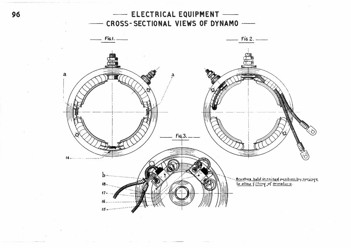
- ELECTRICAL EQUIPMENT -- CROSS- SECTIONAL VIEWS OF DYNAMO -
- F'iG.t.-
h.·------------------48 •. ____ _
~7 ·----
15 ·----------
/ ,'
' ' ' ' '
' '
' ' '
a •
- F'iG.2.-
---- .. Brush(is hel~ in ra.:sed p<:~sitton by~p~~t. to allow fithn~ _of aYIYiab..tnz.

ELECTRICAL EQUIPMENT- 97 -DISMANTLING AND REFITTING DYNAMO AND STARTER MOTOR POLE PIECES-
USE OF MANDREl
- fiG.t_
_ ft&.Z.- -.-----ldJ~----_Jliii!!!I.....-___ ---11!1~----
{
MR.I60I-I For start«.r motor MR lGOI-2
For cl'jnamo
MR.IGm-3
USE Of SCREWDRIVER
MANDRElS
MRJ601-I MR.I601- 2
Sllmt·hard staczi,_'J,uanched and ~round.
-fiG.3- Cast iron ---
-- MR. I GOI - 4
SCREWDRIVER MR.I601 u 4
I·
· _ ... }-lardaned
t•P..

98
- ftG.t.-
' \ . . I
I' . . I I ~
4.
' '
..... 2..
- ELECTRICAL EQUIPMENT-- SECTION THROUGH STARTER MOTOR -
3. T :
. I . '
' . '
,.
!
_ll I ~~ f
!_~J~ --- -----· --~--)
/
. s.

_ Ft'G.i.-. FIELD COILS
' ' ' \
ELECTRICAL EQUIPMENTEND VIEWS OF STARTER MOTOR -
__ F'iG.Z.- FITTING OF BRUSH GEAR
.. -_ .... -.. - ~ - ___ ..... 10.
---- ------ ..... _ _, 9.
B-rusha:'l; ar<Z h<Lkl in rats~Z.d pos~~t-on b';j_?prin'f[S to all"'L'' p.assa'5~of C'llnmutato.·' Wh4Zn ftthn'S a.rrnatui'"<Z.
99

100
fiG.i _
iO. '""I
I
-@)--
~,,,,,.
cslc. to 5 dia. both s(d«:s
ADJUSTMENTS CHECKING CASTER ANGLE-
USE OF APPARATUS
5!
FITTINC APPAR.AT!JS
Unscr~w "P.P.~r and lcw~r h"nk arm <rrczas~rs,
Fin.d w• dth across boss..:s.} _ As shown on
Moun.t thq; aP-paratus. · drat\1~-n~:
Adjust tha. lowll.r brae kat so that thcz plurnb !~ncz. Lt<:. s ~'5ainst bracl,a.t fo_c<Z towa.rds .. <Z.ntr<Z- of v.z:h~dcz..
Cl-ta.ck that th« plumb ltnoz f8: s bdW<Z<Zn th~ pa•r of_ ~!=IU'i!...!.'~ t ·nas cornz:spondin'S to th,z ~<~idth ac-ro5s
th"- bosscz.s (r.araf?:!JP!!_2J.
- f'iG.2.-- APPARATUS MR. 3449
(Jtdth of aY"m ac1·oss t~JJo
boss<ZS ..
0\m<Zns~ons und.z.-l;ntZ:d ar<~:. importcmt and must b<t adhcr<td to. fac4Ls 1nark11-d thu5 V'9' should bcz ~round ar1d chctci.;-zd from tim"' to tim~
Thar-C!: a.nz. two t~f>;OZ:!i of Lou.rll.r
knk. avm: ·da.nhf~':J th.a. (>1\dth ac• "ass thq, bos~q;.s_ 1hlS LS aA·hq;r 56 or sa.

Drawn rod
1£cl~a.
ADJUSTMENTS CHECKING LENGTH OF TRACK RODS
fiG. I. USE OF GAUGE ~~ths Land L4 must be <Zq..u.al wtti-Un 1 mrn.
rr-- -,, I II
________ L. Y T /-.--r 1:.h c- I : : _ / : I ~f..i
,~-m--, -=J.vfy'l'v"~''~''l',,t"'l\1,\=::===-.::;~:;:.::;-::=:-.:-=-=-=-===-'!', --:-1"'..,1'v1V1'v"'•<C:.:t;., 1==-----f: ~---------4. ;J.--t. _ _r ~ • , , , , . , , , , , • , , • , , ... -~ , ... , , r , , , • , ,, ,,, ~ , 1 . , 4 ''..J I tl 1 1tt~'''!l 1 : 1 d{}: )A, I I I 1111!1 11 1' ~ II \' I I I I I I I I "j I I ----""' - --, ... _____ I I I I I I I I I I I I I I \ , I I I !l....l...._
----~-:.-W--=.-::!--.J.LLU.JJ .L• ...JJ_L '/ '\-- t1-l.J.I.1LLU.J.LL•.J._j_ _________ llJ:·~---,-=---:..=.::;--'JLD, ./ '... ,;;, -- f? ' I I ----------------------------·--- ------- ______ _g:____________ /.:1 ' ):. i
------------·~-- ...... \ .. === \ l 1 I ',.._ _____ )
f'"IG.Z.- GAUGE MR.I590 _____ A_v_cz._ra'(<z. du'ocz.n-sion 375
_____ Ti-"u=b«. l<z.n~t!:t.:_::3o.:2=-5=------
......,
---------"1
I ]-> Slot 60 Lon'{ (.a.('pr-oJ<.} 1 6 wid<:<. I I---
/M.S. tub(l. 12 1/~IL_O/~· : f : : ./'
~-=~+~·=-:_-=~=~~~~=--=~£~=~~~::_. - P~nna.d or braz.<L.d.
r , I 1 1
; : :--75 aP-r.,..ox _"" ' 9.?-.EI~P.rox.-J f------,'!.dju>l<lbl<z. rod 150 _ _J
Dra<.un rod
12 elLa-
I
~: __i_
101

IOZ
..
--ADJUSTMENTS CHECKING STEERING LOCK
faG.t USE OF GAUGE
' . . '
·. . .. -........ --
SETTING OF GAUGE ACCORDING TO !EEL TYPE
Pilote wh.z..:ds 185 :>t 400. ____ . ___ .• R~Qd _1€( ~ B.M.whcz Is 185 X400. ···------·R<l 'tn\'~

-- ADJUSTMENTS --CHECKING WHEEL CAMBER-
-FiG. 1.- USE OF GAUGE
F!Go2. ENLARGED VIEW OF SCAlE
GAUGE 2314 -T
l200KTAf 7-11~15 IX
103

104
FIG.!. lOCATING HEAVY PART
a:. Ha.av~-P-art--· ------ __
FIG. J. POSITION OF WElDED . BAlAN ,E WEIGHT
\ ' ' \
\
' \ ' ' '
' '
- ADJUSTMENTS-· -CHECKING WHEELS- FIG.2.USE OF FIXTURE
__ ... Putt'j to b<llanc'"
h a.av!:f_ p.art
FIG.4. CHECKING DISTORTION OF RIM
' Ch4tck didorb.on · ·-- ... /
'!Iiiii! Ill// IIi IIi II !li!!fllll!!ldl

431176.
89461.<30x62xiU
~tYash'L"" <i:. 4:lrl024.
ADJUSTMENTS CHECKING BALANCE OF WHEELS
FIXTURE MR. 3396 IMPORTANT NOTE
In ord~tr to '{LVIl th~t. fix:lure max:~ mum ,sens-;bvLt';f, thcz. baLl- rac<Zs s-hou\d b«. l~o.brLcat«.d with. thin vas~l~ne on.l~·-Th.e f~-x:t~•rcz. onuS"!:. ba. p~-rfedl~ balanc-ed.
61'":lCk<zt:s rnada J!!:!!.l fLat mild ste~l .
Nota.: For hotdtnS" 13.M. ~~iii~iii whea:ls onfixtura. usa: nubs 39.:?548.
Goo~ f~t Ln bcz.a~m~hou>ln~ ~~~
~fit on stub a:Jela.
5)( 45.~
(iood flton stub a:d<l
lOS

1'06 CREEN MR,-1572.
S nro:x: ~.!.1'3~;:.0.;;;_0m_n_-z_. aP-r-~-l 1800mm. x Pan~
Ao.2. ---
\
\ \
\
\ \ 2 varhcal ul r~~:s
._ ____ .1.
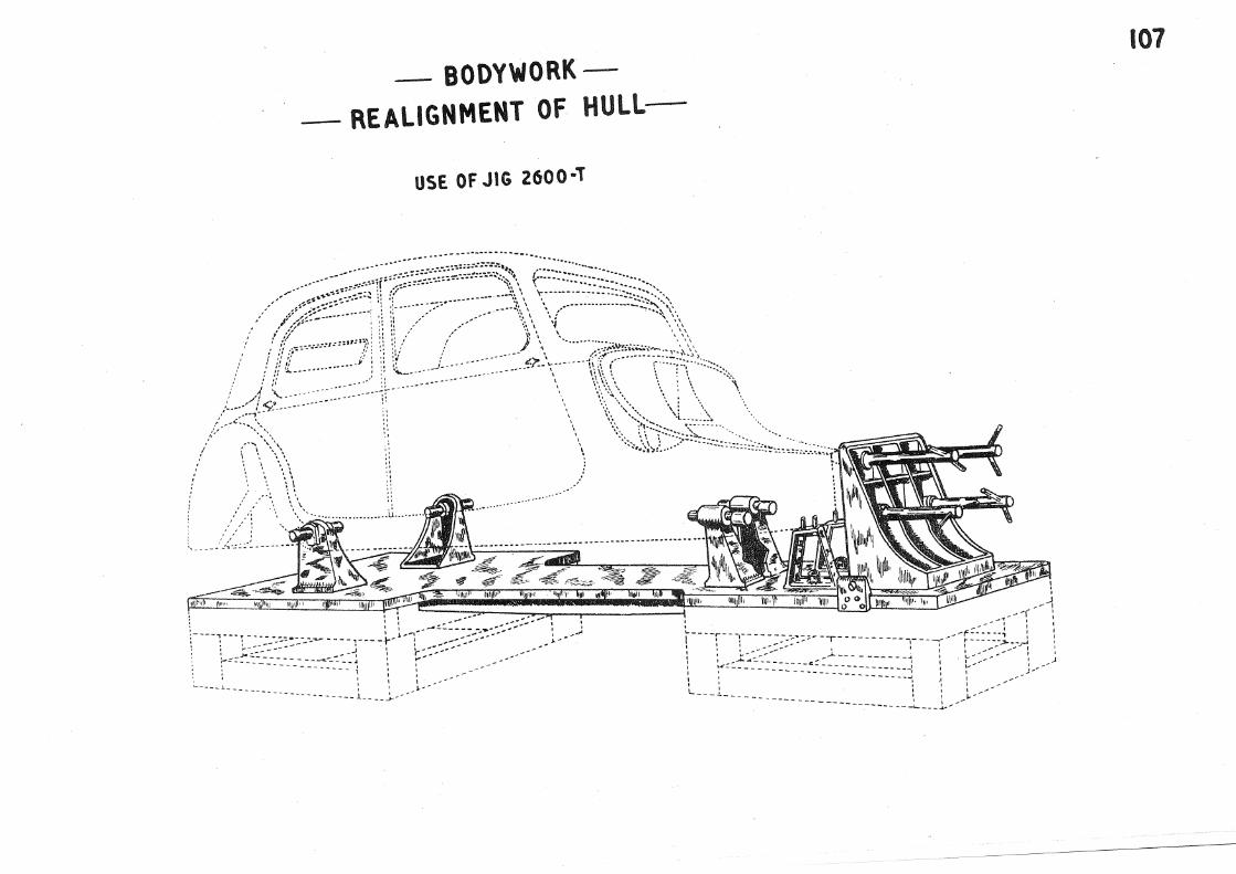
BODYWORK-
- REALIGNMENT OF HULL-
--~" ... "
\ \ - ·~ ~ I
\\
USE OF JIG 2600 ·l
~--·-- ... --- ----- __ .. _____ -.... -- ....
... ---
" "
,. ·' ·' ,, •' ,, .,
;l/ ·' ,. ·~-----
' I - -----l ____ ~----1.--
_J----
.........
' ' ' ' \
107

108
A 5
8ase lin.a.
C.znlr~ LLn« of.csuss~t fixin«J / h~Wl«p~.
sjG Saatu· 7/9 Sftatc.r
~)0 32!15 2439 Z6Z4
BODYWORKREALIGNMENT Of HULL-
. _ Ca.nt.!:_.z lLnt;Z. of holes.
fixin~ $t~<ZTltt~ column.
I. H<~.adlarnp R.tl.
211(/.~f'...!:J:!· 3.Ho~
4 Hom L.H.
5. Jw<d;~,.., box: ,front R .H.
6.Jundt~n bo"' fr-~-
J - V<~.llo<..t
Vi- p.__.,.pl<t V- Grczan
R Racl
N- Black
7 ·Win~ lamp~ 8. ~~ lamp L. H.
':I.Q.y·~ to.Stoplamp~-
11. §park plu~~ 12. O~stributor.
8. l ~
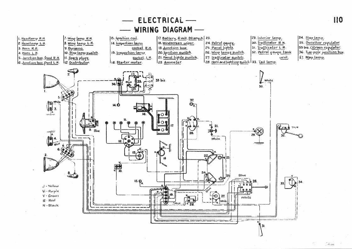
ELECTRICAl-- WIRING DIAGRAM -
13. Nnition. coiL 14. [ngpotclion lamr..
S<JCkcz.t I R -11.
15.lmrp<tdton tamp_
socket 1 '=.:!:!: tG. Starbzr motor.
17. Satt.z.r~, 6 voll:, ~e·"· 23. 18. Wil-.dse.nz.cz;n wip.!!!:; 24. Petrol ~~Uf'!t_; 19. Junct~n bo.>t' Z5. Pan<l'l h~hts. 20.j~nibon switch. 26. Wtnl{ lamps switch. 21. Panal h'~ts "'.Jitch. 27· I!:afftc(lt~r switch. 22. Ammetcz-r. 28. Hocnand lt~htmcrswiich.
35 bis.
29. fnbzr<or lamp.;
30. Trafficator R.l1.
31. I!::afficator L.H.
32. P<Z-trot '{~C(e tan..k unit.
33. T21H lamp_.
~Whlita 30.
I
uo 34. ~"'P. (amp_. 35. DucaUt~r ragulato.-: 55 bts. Citro(l.n nz.gu.~atar. 36. Two-pok junctton box.
~7- ~p Lamp_.

U6 ENGINELONGITUDINAL SECTION-

-ENGINE- 117 -TRANSVERSE SECTION-
__ FiG. 2~~ GRADUATION ~-"- 01 L GAUGE
GUIDE TUBE
1664- T

118
207. ___ ---
-ENGINE WATER PUMP
219.
I
.ZilL I
I I
I I
I
I I
,o217.
/ I
I
/ /
I
/ I
/ /
/ /
/
/ /
/ /
--
I /
214-. /
.A> 2.09.
--- ---... 213.

FiG.1_ REAR VIEW
FIG. 3. STAND MR.3300- 50
ENGINE- ENGINE STAND
USE Of STAND
FIG.2. FRONT VIEW
Thnzcz. blocks }tt tn rec~s cz.s 20mm c\IZ.ap Ln bas,z and a 12 securczd
_, .2':1 woodscr-cnvs.
119

120
i 2 .....
31! • ..__ ----27 ...... __ ---
33 . ..------
FiG.L __
14, 1 I I I I I I
FiG.2
- CARBURETTOR --VARIOUS VIEWS--
8. 5. 9. 4. t ' /'
I / I / I
/ I I
/ I I /
I I I I
I I I
I I
12 . .._- ·-
28 ...... ---
II. 35. , lfl I I
I I I
FiG.3.
I
1 16.
-------.1..
" ....
---i.
....
"
....
"
..... ii.
" "'20.

-CLUTCHASSEMBLY-
FIG. I. LONGITUDINAL SECTION
I. • .............. .
S.r .....
4 ............... .
12 .• ---
6··/
.. -...
13.•"'"""'" ..
...... --·· 10.··· A4A
~.
z ......... .. .... ~-
9.······ .. ·•·
........ '16 r 7 ................ t---~~
- rJG.3. --
... "''' ··~ Th~ outelr ,t~of th~t slot £or tha fulc-l"I,U'Y'l bracket_ rriUlilt be Chomf,;;,.ra;d.
FIG. 2. VIEW OF TOGGLES
-f'IG.4.-
Rctmove th<~: "ama. an1ount from both faces.
120A
-riG.S.-
• ..,-._ ·---- ... 3.

120 B
64,1
Studs
ClUTCH-
SIMPLIFIED fiXTURE FOR CLUTCH TOGGLE ADJUSTMENT-
fIG .I. USE OF FIXTURE
IL~t.z.n th.z; thr<l-a. nuts a succassiva.1':1 <lrld witn tltiZ. sama: m .. mb<l.r of tu'f'ns sufftctll-ntllj to lock Aft.a.r ttah t.z;m.n'? nuts rfl.ak.z sura that thabi~L ~ P.<Z jcctL'j on smooth su-rfa~.
Studs 7 dta 100 p(tch SO lono- Ends poti-tta.d.
/'--I>--- ---
_ fiG.2. _ BlOCKS MR. 3457-1
l_off_
. ~i I
36.1~005
For adjustmllent th"' cL~•tch ('s as-s.xmblcZ.d with th<Z
auxibsr'j_ f':ftoJh,zcl d .
a

FIG.I. USE OF STANO
GEARBOXSTAND FOR GEARBOX-
FIG.2. STANO HR. 3053-10
Two p~ns J2dta. at 36c«ntres.
Two locatin~-P-2~~-.~'S-..;;·- .....
FIG.3. GEARBOX FIXING
/ I /
-1/
....
85
J~
-:••4 hollls 12c:l;a.
I I I
Bolt, IB-d-la., wi~h slott&d nut and split P-in, to aUow rotahon of carrt~r plal4, nut is not tt~ht~n~td '-'f'..:.
121

122
240.' " .......
22G . ......_. '·,-...... "'-- .......
'-., '
:2J9 .... _
I 301.~
--.
"··,, "" .,,, " ,,
·--~.
'
I r- h.
-GEARBOX
LONGITUDINAL SECTION
\ "" \ "", 1 1 \ ". " 230. 231. 232. 233. 294.
I \ l \
229. 215.
\ \ \ \
\ \
\ \
'\. \. JOS. 214.
\ \ \ \
2GB.

294, ....
241 • ....
' '
...... .....
..... '
-· GEARBOX-. - 123 -SECTIONS--'---
___ fl!..!i=.G:.:.:.1- SECTION THROUGH BEVEL PINION (FORMING LAY SHAFT)
I 244.'
I I
245!
Fie. 2_ OIL PUMP
I I
~.247.
-----263.
----267.
--..... 266.
---------·---··---·---··-···-·- --------------

124
2 79.' I
I /
I
-GEARBOX-- VARIOUS VIEWS-
---.!.f~iG~·~1 SECTION THROUGH MAINSHAFT
255.o_ --
257 • ._ ---SECTION THROUGH ~NTERMEDIATE GEAR TRAIN
' '\ '\ '\ ,.
' 226.~

-GEARBOX- 124A - SPANNER FOR HOLDING INTERMEDIATE GEAR SHAFT--
.__, ________ 110 ------------1
I t 30 dia. 27dia.
I 35
62
20 30
10,5 ' ~ d. +0,018 - -'a·+ooo? - 9,8ta· t I
:to, 1
15,5dla.
SPANNER MR. :5792
Flat on pilot to d~Zar P.'·n.

125 -GEARBOX-- SECTION THROUGH REVERSE GEAR IN,TERMEDIATE TRAIN -
234. 281. 2.83. 282. , ' T f
I \ I I I \ I I
I \ I I I
\ I I I
I \ I I
I I
I
I I I I I I I I \ I I \ I I \
\
\
\ I I \ \
\ I \ \ -~
280+ • 237~ 235. 2.3G. 238.

30J.o"'
/ /
GEARBOX--___ :_ADJUSTMENT OF CONTROl lEVERS--·-
----·-----
126
------- ---"207.
-----

127 GEARBOXVARIOUS TOOLS-
SPANNER 1732-T FOR. MAirtSHAf"T
FRONT AI'CO REAR NUTS.
SPANNER 1731-T FOR INTERME-DIATE
5HAFT FRONT NUT-
SPANNER 1734-T FOR SPANNER. 1733-T FOR HOLOII
BEVEL PINION BY FLA.TS AT _
_ Fia.l_
. . ... ~
~~Ot1 501 ~ across flats.
I Thickn(l.SS 10mm-
_FiG.2_ szc
I
400
I
8£VEL, PINION FRONT MARlNG Cj!.!J.
Thl<:knczss to mm.
-. FiG.3_
Hcz:x:~~on 38.~
~r~-
MANDREL.
MR.-:5428
Ho::a~~'" 35,~
~flats
Ttuckn.zo:;s B mm.
400.
I _fiG.4 _
-~y~,~ !£~flats.
_FiG.5_
320
_ 6 dia. hoLll
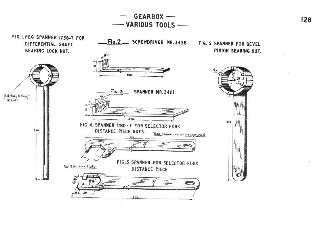
Fl G.l. PEG SPANNER 1758"'T FOR DIFFERENTIAL SHAFT BEARING LOCK NUT.
~.5dLa., 5lon'{ · rn.zl-ar.
-GEARBOX-- VARIOUS TOOLS --
_FiG .2 _ SCREWDRIVER MR. 3458.
FiG .3 SPANNER MR. 3461. ----:...!~.=:..
~ ,~: ~~ • 11111 ~~ m r ~~~rt~~.L~-, . .--------,~~-~~;;;=-------;::?t
J...._ _.....2.....,50c:__• -- ---.....;
FIG.4. SPANNER 1780- T FOR SELECTOR FORK
FIG.6:SPANNER FOR BEVEL PINION BEARING NUT.
290 DISTANCE PIECE NUTS. ~spannqr-s ara: ra.'i•-n.r-z:d.
I~S --..._. f)kt?E= :(:-£ ·~ ~~J /_,.~-~
.'/- ~ FIG.S.SPANNER FOR SELECTOR FORK '7 2GAacros$ Sl_sts.. DISTANCE PIECE.
175.
128

129
f I
I
I I
,.
/ '
f I
I I I I I I I \ \ \ \
' I
' '·
FiG.1_ USE OF EXTRACTORS.
---
GEARBOXEXTRACTORS
' '
FIG.2. EXTRACTOR MR 1
~85
__ fiG.:3_ EXTRACTOR MR. 3459

FIGJ. ~SE OF ClAMPS
' .... '
f. -~ :r-:,;~:·:v:t~·:
. : :_ ::·· ::; ...... .
A:~~l~,l)'
' ' \._ ' ' J '
' \ \
GEARBOX
HOLDING BEVEL PINION
FiG 2_
Wood block~ covenro with sto~t.d I
platcx.-
130
ClAMPS MR.3407

' ) _,
f~-:·~·~.:\
~:·.·.·.::\:·~
r:.::::·.-.-:::::~\
' ~ :-.:..
\: .. ;:..-,.. .. ~
.<:*".<.r?J:\:.:'<·.~ ~S:-~·~::-~:-::-.\._:·->'· ~ \ \
--
\ \
' j.;;&i:;j;jJ}"') ; ..... ·., -,--,.~~pl ( ':.-.:::::·::~:-.• :·· ,. .4\'il!f/1/i"t tllk~
~'\.~;:::::·~-~~: :·~-::_;·::::·~:~~~:-( ~~~ .. =··-, -~~' -~~~ ,fiL ~u r' ,.-'\ i .... , '·"""'·. ·"':·~~\'·~ ,1,,\1, 11 . ///'/,/,· '""'Z ' ...... .,.· ... : . . .. . . .. l\ \\1 ' I I /1' ~ ,,. .,M .. ,, ........ ,.... ...... :. 1\ ' I' I •" I
~- " ..... : \
,;~1;;;,;~ f ;lllf!J;;f/11 t-ii/Jj/flf;;;JI''',If;lj;;llfl, : \ ' \
~'~~\,,\\\ ~~~~~~~ ,lli\\\1\1, \1\ll\l\\1\l\ill\\\ \\11\\111 h\ \1 i\\1\1\\ ll\1\i!\IID\ I \
1 f" ·· . I \ \ ' ·· .. ::~:_;::;.,. . ..> :~~i"" I \ ] 1 \ I • I \ I 1 I f 1 \ I 1 1 / I I I I I I I \ : \ ' I 1 I I ~ I L ___ ..:y

-GEARBOX-. 132 - SECTION THROUGH OILWAYS -

133
_Fie.l_
211 • .-...._ -....__ -....__
-....__
SECTION ON CENTRE Ll NE
-....__
---
_ Rc.2_ SECTION THROUGH BEARING CAP
297.'
' '
-GEARBOX-- DIFFERENTIAL-
FIG.3. MANDREL MR. 3463
100
195
--. 298.
--262.
~-= -=. -= == -_ -i
===d ~; 60 I
.. I I .. ,

GEARBOXGEARBOX COVER-
SECTION THROUGH CHANGE SPEED lEVER SHAFT
! + \ \. ', . { \ --..\--- ....-'',
--r~ - · , (=:>-----,~ \ I I '
'\ \ I I ' . \ I I ' \ I I '
\ ' / ;f \ ', I / 1\
\ :............ 1: ...... --< / ', ' , 'I -- -- ' / ---------:~-;'77",.,..,~~ ........ ,,,./ ~~// :.:..==- -- ----::--- -~__.... ---- --.......
I -.. ,.,- -.. ......._ '-..........
r ) /"' ' --. I \,_/ ' ( )
I ' '- I I / \
I \ , \ I
-.,-, -+- -I \
\ \ \ I \ \ \ \ ,--' ' \ ' ) ",-
134

135 FITTING
GEARBOXSYNCHROMESH GEAR
FiG·, I •
n
MR-3464''~
Place s~nchrorn.z:sh hub ~n tooL. ~p1·1n~s and. balls trt post hon. Prus ,_,,,b into nn'?.
Plaea: <:JSSilmbly f~ic{- 1 on
2ynchrom.z.sh nn<5. Prczss hub tn to n'n~ and th-zr<lb':J .:~:~rr~ batl.'5 throu~!J·
Th~ toot ,·g madct by ~J~~~~ ~':lnchrom<Lsh rtn'g"..!!.! fo!lows.·-1. Annca.t part. . . 2 .. Ma~htn<t S 'S..-oovcz::r to nzca.wa. balls. 3. ~ff ttZ.a.th to~~ fr~e ftlttnl{ pf r'n'r on hub.
_FiG~3
\
MR-3464~
Push hub compla.bz('j tnto rin'l' in orcl<tr to fra:o. toot.
_Fh;,.4.,_
T~)O

GEARBOX BEVEL PINION ADJUSTMENT
_fiG.1_ AD i!STMENT OF PINION DEPTH.
APPARATUS 2040-T
FiG.3
'
PINION
~ Oti-rtansL.on tn i1un~d~hs__9f e. mm. for masfun'S da:ara.nc«:.
P'~nion a.cljustmcz:nt m.cz:asuremczrd:
__ FlG.2- ADJUSTMENT OF MESH
3RACI<ET 2041~T FOR CLOCK GAUGE
CROWN WHEEL
Expla.natton of tlLScnettons (on pinion and c.-own wh..z•d $'hownJ. 58, IO- P~nlo~ s~ttL·~ dt.m(tm;ton (<Ltched_ on ptnt"an). 25 - MesltH<lf cl<zaranc.z (<It<:: had on ptmon}.
4':J7 AA- Matchln:~ n.umb<Ir ( <rtd><Id on pmlotl and c.-own wh~Zal} ·
136

137
m~
I I
___ FiGJ.
GEARBOXADJUSTMENT OF SYNCHROMESH
\
I
I I I I I I
I . I I I '- ... I
' \
FiG. 2.
\
303~
' '
.... ~ : .... .:
I
' '
r I
I
!
I
'

GEARBOX TIGHT EN lNG Dlff ERENTIAl BEARING lOCK NUTS
-- ..... ~ ' '
' ' \ I \ \
I \ \
I \ \ ' I I I I I \ : ,' \ / /'
\ I I \ / I
'-..::: --..,
\
\ \
\ \
\
\ ............ ____ _
' ', ' ' ' \
\
' \ \ \ \ \
''\. ... \ ', ' ', \ '
I I I I ' I I
I
/ s:..-:..-....... , '' \
,' //
' I '\ \ I I \ '
/ I ' \
/ I \ \
/
I \ I I I I I I I I I I I I I I I I
\ \ I .
I /
/
' ' \ ' ~- ,.
f
-. I
/ 1/r- .... --- .... ~ ... -] ... /
--· -, CJj
SPANNER 17SI~T FOR DIFFERENTIAL HUT.
\ --
-;; .. ,~~~~
!,~~~?) .::---
138

139 -·/FRONT AXLE -UPPER LINK-
146.-- 4 --143.--
156 9---
5.--
155.,
----------

159. ~
-\
109.<1>-·---
1137--
I 160.~
.A 107.
- FRONT AXLE-· - LOWER liNK-
i31 • ..._-
\ \
\ 130.
140
37
141
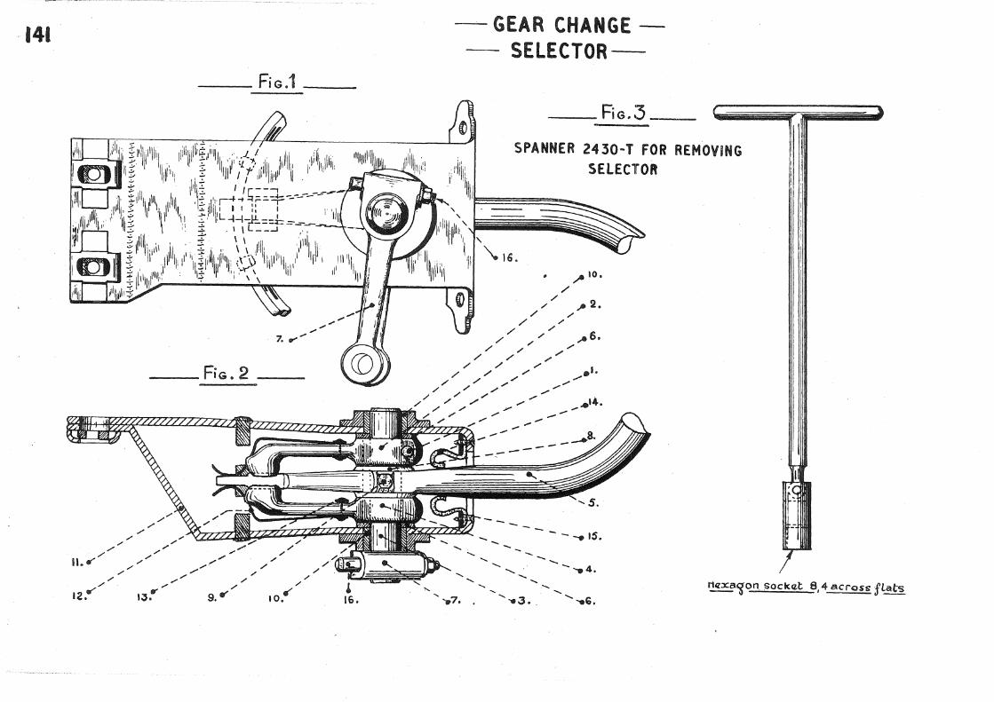
---'---.....:.F....:..i G:::_:·:.,:.1_ ---
___ FiG.2
/ ;'
/ / / / / /
/ / /
II.~ / / / / /
/ ;· / / / / /
/ / / / /
/ / / /
12.u IJ,v 9. V' I 0 ,'If'
-· GEAR CHANGE -- SELECTOR--
'\
~ 16.
__ FiG.3
,. 10.
/ /
/ ~ 2. / /
/ /
/ // .. 6. / / .--
/ / /
/ / .,""' / / /
/ / / / / /
/ / .... "" / / /
/ / / / /
/ /
- --15.
' ' ........
' ........ -....... ..... 4. .......
....... "-
..... ..... ..... '
....... -.7. '1!!13 •. ' -.G. ~'lon sockCLI:: 8, 4 across fLats
\ \
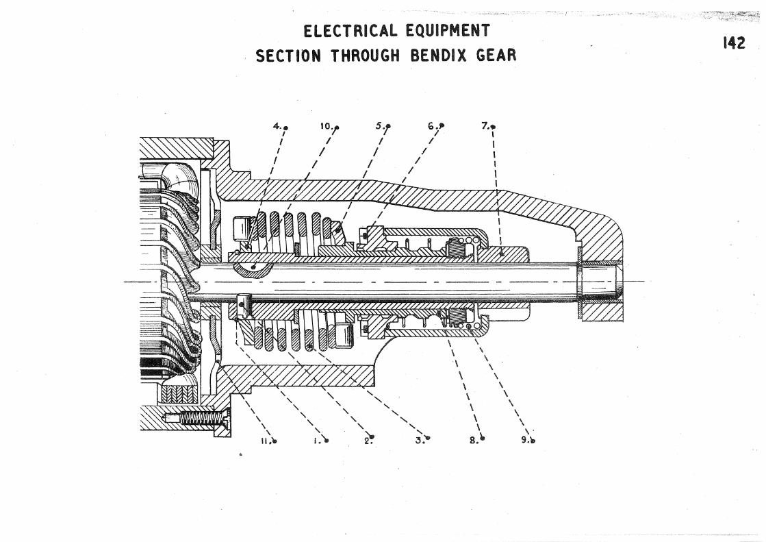
ELECTRICAL EQUIPMENT
SECTION THROUGH BENDIX GEAR
\ \
4 .•
' I I
I I
\.
' '
11.'-
' ' ' '
' ' !.'),
'
5., I
I I
I
' '
'
~
' '
I
' '
G.,. I
I I
I I
' ' J ....
\ \ \ \ \ \
1 •• I I \ ! I I
\ \ \
\ \
\ \
\ \
\ \
\ s.~
\ ,. 9.\D
·- ', /
142
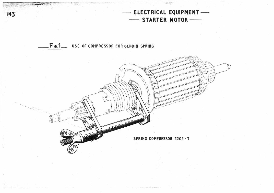
f43 - ELECTRICAL EQUIPMENT--STARTER MOTOR-
f"iG.1_ USE OF COMPRESSOR FOR BENDIX SPRING
SPRING COMPRESSOR 2202- T

~ flRATA. II Six Cy/indflr' Repair Manual. TEXT Pn.ge Paragraph Line .Modification
4
7
l4 l3d
)5 32
'56 8b
27
il 29a
·)2 29c
::)5 40a
40c
. Add under nGEi\RBOX11 : Hl24A - :Spanner for holding~ intermediate gear shaft - MR. 3792.
Add under 11 ADJUSTMENTS 11 ~ 11 Spanner for rear torsion bar adjusting rod nuts - 2304-T 11
4 Read 11 368 nun., plus or minus 0.25 nun. 11 instead of H363 mm., plus or minus 0. 25 rnm. 11
l Read 11 3 litres- 5-;t pints 11 instead of 11 3.5 litres- 6 pints."
1, 2 Read 11 ., •• holding the shaft (228) by means of a spanner (use spanner MR.3792, see Drawing 124A). 11 ins;tead of : 11 •••• holding the shaft ...• see Drawing 127, fig. 2).
2 Add in margin : "Spanner MR.3792. 11
1 Read : 11 First case : shaft without key. Fit washer (286) on shaft. Fit bearing (278) by means of a press. Grip the shaft in a vice fitted with soft jaws. Tighten nut (279), (using spanner 1731-T, see Drawing 127, fig. 2) so that it becomes flush with the front face of the shaft. This tightening determines the position of bearing (278). Secure nut with a split pir1 NOTE - Proceed in this marLYJ.er whether or not the shaft is chamfered. Second case : shaft with key. Proceed as above. :F'i t key in shaft. u
instead of existing paragraph.
2 Add after (291) 11 the face with the oil grooves must be opposite the pinion. 11
5 Add : 11 or centre punched at the bottom of the groove. 11
3 Add between parag;raphs a and b : 11 First case : shaft without key. 11
1 Read 11 shaft (228) 11 instead of : "front nut (279).
Read ~ 1 spanner MR.3792, see Drawing l24A 11 instead of: "spanner 1731-T, see Drawing i27, fig. 2). 11
Read in margin: 11 Spanner MRo3792 11 instead of: "Spanner 1731-'1'. 11
2 Add after paragraph 40c : nsecond case : shaft with key. (d) Introduce shaft (228), fitted with key, through front face of gearbox into rear bearing. If necessary use a copper mallet.

Page Paragraph Line Modification
.66
67
77
77
86
91
100
103
4ld
4le
l8b
19d
1
15b
(e) Engage two p1.n1.ons. Tighten up rear nut (226) and secure with split pin" Return two pinions to neutral position."
Add in margin ~ !!Box spanner 42. 11
1, 2,:3 Read l 11 To bring the crown wheel into conta0t with the bevel p1.n1.on move the differential assembly in the manner necessary to gil/e correct meshing clearance, 11 instead of : 11 Unscrew nuts • o o,," bevel pinion face. 11
2 Delete : 11 scre·w up second nut (300) and then. 1'
Add after 11 unscrew11 11 nut D. u
1 Add after "spring (125) 11 "adjusting washers (151) .''
2, 3 Head : nstop 11 instead of !\adjusting bolto 11
5 Add : 11 0btain eorrect adjustment by modifying thickness of adjustlng washers (161). Choose washers Qf the necessary thickness from those in the range sold by our Spare Parts Department.
4
2
1
Add: 11 To ensure 1ockinc; of the brake drum on the hub durinr; this operation, fit a vvasher 4 mm. thiok on each stud and secure with wheel nuts tightened to a tension of 5 mkgo (36 foot pounds)."
.a~dcl in margin : 11 Box spanner 32, 11
.1\.dd after : !!movable bracket (2) 11 1 11 This bracket has a tapped hole which must face to the rear. 11
15d 1, 2 Read : ''To fit this stud it is necessary to compress the spring (35). To do this, fit the damper spr.ing (29) in the retaining tube (15). Prov-isionally screw up this tube and fit the stud (18). Tie;hten up stud nut against a copper washer. Unscrew the retaining tube. Grease and fit ball pin (17) 11 instead of : 11 Tig;ht
15e 1
17 2
ld 2
stud nut .••... as far as ball pin cup (28). 11
Delete : 11 Fi t, retaining~ tube ( 15), damper spring ( 29) and 11
Add after : 11with a clock gauge. 11 11 To ensure locking of the brake drum on the hub during this operation fit a
Add
washer 4 nun. thick on each stud and secure with wheel nuts tightened to a tension of 5 mkr;. (36 foot pounds). 11
11 NOTE - The right-hand torsion bar fouls the radiator drain cock at the end of its withdrawal. To completely disengage the bar it is necessary to remove the front silentbloc. Completely disengage the 1: by hand by taking it downwards and towards the right of the v-ehicle. 11

Page
123
125
134
140
Paragraph Line Modification
2e
l4e
4
2
l
2
2
2
2
2
Add
Add
11 NOTE - See note under paragraph ld. u
11 NOTE 11 Transpose the three lines constituting this NOTE under the title "Para. 15, Prepare end plate carrying; brush gear. 11
Add after: "secure with nuts 11 : 11 tightened to a. tension of 4.5 mkg. (32~- foot pounds).''
Add : Engine speed must be in the region of 500 R.P.M.
6, 7 Read : 11 Front height is measured from centre of' the front torsion bar silentbloc to the ground. Rear height is measured from the underside of the rear floor, between the tubular orossmember and the axle beam, to
1, 2 Read
the ground. 11 instead of : 11 Front height is measured .••••• rear hull floor to the ground. 11
11 at the rear under. the body side seams and at the front under the axle cradle (use special jack head 1\iR. 3300-90, see Drawing 67). 11 instead of : 11 (using special jack •••••• see Drawing 67). 11
2 Delete in margin : 11 ~lR. 3300-110 and. 11
4 Add : "(Use spanner 2304-'r) . 11
4 !\.dd in margin 1 "Spanner 2304- T. 11


DDENDUM TO SIX CYLINDER REPAIR MANUAL - EDITION DECEMBER 1950. ADJUSTMENT OF SINGLE-DISC CLUTCH
I) Adjusthient of the machani sm. (Fig. I) When the assembly is in the "olutoh engaged" position, the measurements to be obtained are:
-ful- A : 44.5 mm. ~ 1.5. -~o : measured from the upper faoe of the toggle thrust ring to the lower .faoe of the
Adj\Hft,went: on the oa.r : (Fig. 2) (Left Hand Drl ve Models Only).
(a) Set the clutch pedal height to 165 ! 7 mm. (measured from. the lowest point of the metal pedal pad to the oarpet) ;
B;: 17.8
(b) Adjust the posit .ions of the single and double olutoh 32, 5
:mm • •
levers : to 33,5
- Unsor~w the adjusting soraw of the single laver several turns.
- Adjust the length of the Clutch Rod so that the lower end of the double le·ver is 32. 5 to 33.5 mm. from the edge of the metal stop.
pressure plata.
measured from the bearing faoe of the toggle plate to the lower face of the pressure-plate
_fig~-
l 'J: I
- Put a spacer, lo75 mm. ± 0.25 mm. thiok, under the end of the adjusting soraw. Sore-w the latter in until the graphite thrust ring touohes the toggle thrust rlngo
- Tighten the looknut of the adjusting soraw.
)',_,:

~~~~~~~~~~~~~~~~~~-----

CITROEN CARS LIMITED,
TRADING ESTATE,
SLOUGH,
ENG. .
SF.PTEMBER
FRONT WHEEL DRIVE
SIX CYLINDER MODEL ·FRENCH DESIGNATION ........... ...... . IS-SIX. ... ~(I.S CV}
BRITISH DESIGNATION ............. ~~SIX.~~ .(22• 6 .. H. P.)
TEXT

----------------------

FOREWORD
Ths r;1c;mbants of this Repa5.,;.~ Manual x·efe:r to the Six Cylinder Citrr:n:J:o '3a~c, 1=Jfi:: hand dri:ITi?"' Tfu'3.ncifaatu:rad i:o. FraD.o,s.,, British made Cit::{';;sn. Si:Jt Cylinders, r.·ight hand d:ri·ve., in•"lo:r.po:>::'ate a few dissimila;;oitl.es f:com the Frenr;h models and these a:t:>e no+.: dea1+; with in this ManuaL It must howeYer be n:;ted that the overwhelming majority of the oontents of the Manual apply equally to BX'.i1?ish a.nd French rnodelso
MODELS This manual (J<mtains inf,:•rmat:ion. relevant to Modei DV 1nanufactuK·ed after Max"oh l948o Although muoh of the infvi:".Ulation is
also applicaol,e; tJ the p:reYious models (Model Gn manufaatm~ad between 1938 and Oc·t;ober 1947. and Model DB.o manufaot}lred between October 1947 and March l948)p the French edition of the Manual should be consulted when undettaking repairs to the earlier typeso
USE OF REPAIRMANUAL ORDER OF OPERATIONS
The sequence of operations for :removing9 fitting, and re-assembling has been carefully outlined in orde:<' that best :results may be achieved in the shortest time. For example :
TOOLS
Adjustments are indicated in the sequence where they can be exe0uted in the easiesi~ way with the maximum precision" To save time, operations necessitating the same tools are groupedo
It is in your interest to follow strictly the sequence of operations as indic.atedo
Opposite each basic operation, tools to be used are shown in a separate column. (i) ORDINARY TOOLS such as hammer, screwdriver, pliers, etc., are not mentioned" but the size of appropriate spanners is givena (ii) SPECIAL CITROEN TOOLS are indicated by their number followed by the symbol 'T 1 a These t>;::.ols can be supplied, (iii) OTIJ:ER SPECIAL CITROEN TOOLS are indicated with their number preceded by the symbol if\IIR' " These can be made by Cit;roen Servi 1e
Agents themselv,9s and diagrams for this purpose are included in the Manual.
OBSERVATIONS Generally the most suitable spanner is indicated for each operation. Socket spanners, fitting var'ious types of handlss
are recommended. Flat set spanners and adjustable spanners, which damage nuts and set·-scl~ew heads, must be used as little as possible.

--------------------------------------------~--

Unit
ENGINE
CLUTCH
GEA.RBOX
FRONT 1\XLE
S'fEERING
REAR AXLE
.SUSPENSION
No.
701 702 703 704 705 '706 707 708 709 710 711 712
713 714
715 716 717
718 719 720 721
722 '723 724
725 726 727
728 729 730 731
INDEX OF OPERATIONS
Description
Removing and refitting engine and gearboxassembly. Removing and refitting engine aoces sories (engine· removed). Dismantling and assembling engine. Removing and refitting cylinder head. Removine;, dismam:-.ling, assembling and refitting; rocker shaft. Removing and :refitting inlet and exhaust manifolds. Removing and refitting water pump. Removing and rafi tt.ing oa.rburettor. Dismantling and assembling carburettor. Dismant1ing and ass,~mbling air intake silencer. Dismantling and assembling petrol pump type S.E.V. Cheoking petrol pump.
Removing and r,~fit'l'::l.ng c}utoh (engine not removed). Dismantling and assembling Glutoh.
Removing and refitting gearbox (with engine removed). Remuv1.ng and :r-efitting gearbox (without removing engine). Dismantling and assemblin1~ geacbox.
Removing and refitting f•:·ont axle. Dismantling and assembling front axleo Removing and refitting t :cansmis sion orJ oar. Dismantling and assemblin[:'; transmission.
Removing and refitting steering .. Removing and refitting steering oolumn fixed tube. Dismantling and assembling steering.
Removing and refitting rear axle. Removing and refitting rear axle beam (without removing link anus). Dismantling and assembling rear axle.
Removing and refitting a front torsion bar. Removing and refitting a rear torsion bar. Removing and refitting front and rear shookabsorbe.rs. Reconditioning SPICER shookabsorbers.
I
Page
9 13 16 31 33 34 35 36 37 39 40 41
42 44
47 52 56
72 74 82 83
86 88 90
94 96 98
103 107 109 llO

2 Unit
CONTROLS
BRAKES
EXHAUST SYSTEM
ELECTRICAL
MISCELLANEOUS
ADJUSTMENTS
BODY
No.
732 733 734 735
736 737
738
739 740 741 742 743 744
745 746
747 748 749 750
751
INDEX OF OPERATIONS
Description
Removing and refitting gear selector. Dismantling and assembling gear selector. Removing and refitting hand brake cross-shaft~ Removing and refitting pedal gear.
Removing and refitting master 0ylinder. Dismantling, cleaning and assembling master cylinder.
Removing and refitting exhaust pipes and silencer.
Removing, dismantling, assembling and refitting distributor. Removing and refitting dynamo. Dismantling and assembling dynruno. Removing and refitting starter motor.. Dismantling and assembling starter motor. Headlamp adjustment.
Removing and refitting front bodywork. Removing and refitting petrol tank.
Engine adjustments. Front axle adjustments. Adjusting and bl:eedin.g Lockheed sys~em (foot brake). Hand br8.'ke adjustment. Hull adjustments.
Repairs to hull.
111 n: ll~
114
11! 117
111
119 12: 12: 125 12r 12'
130 13:
133 13·-13 140
14.
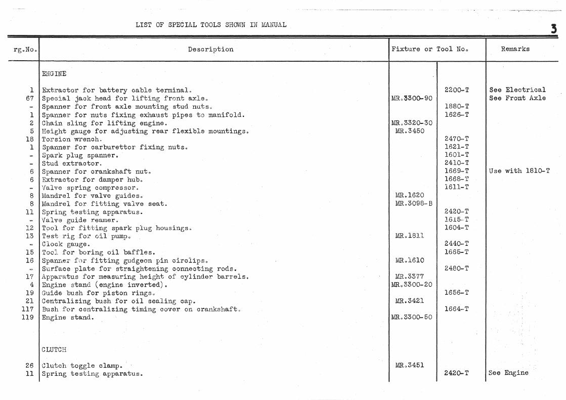
LIST OF SPECIAL TOOLS SHOV\JN IN :MANUAL
rg.No. Description
ENGINE
l Extractor for battery cable ter.minal. 67 Special jack head for lifting front axle.
Spanner for front axle mounting stud nutso l Spanner for nuts fixing exhaust pipes to manifold. 2 Chain sling for lifting engine. 5 Height gauge for adjusting rear flexible mountings.
18 Torsion wrench. 1 Spanner for carburettor fixing nuts.
Spark plug spanner. Stud extractor.
6 Spanner for crankshaft nut. 6 Extractor for damper hub.
Valve spring comprasso:r. 8 Mandrel for valve guides. 8 Mandrel for fitting valve seat. ll Spring testing apparatus.
\falve guide :reamer. 12 Tool for fitting spark plug housings. 13 'rest rig fo!:" oil pumpo
Clock gauge. 15 Too1 for boring oil baffles. 16 SpanD.e:c for fitting gudgeon pin circlips.
Surface plate for straightening connecting rods. 17 Apparatus for measuring heig;ht of cylinder barrels.
4 Engine stand (engine inverted). 19 Guide bush for piston rings. 21 Centralizing bush for oil sealing cap.
117 Bush for centralizing timing cover on crankshaft. 119 Engine stand.
CLUTCH
26 \Jlutch toggle clamp. 11 Spring testing apparatus.
Fixture or Tool Noo
MR.3320-30 MR.3450
MR.l620 JVIIL 3098- B
IvllL 1610
MR.3377 MRo3300-20
MR.342l
Ivffi. 3300-50
1880-T 1626-T
2470-T 1621-T 1601-T 2410-T 1669-T 1668-T 1611-T
2420-T 1.615- T 1604-T
2440-T 1665-T
2480-T
1656-T
1664-T
2420o..T
Remarks
See Electrical See Front Axle
Use with 1810-T
See Engine

4 LIST OF SPECIAL TOOLS SHOtVl'J IN .M.A.NUAL
Description
Clutch toggle adjusting fixtureo Simplified fixture for clutch toggle adjustmento
GEARBOX
37 Extractor, 37 Collets and block for diff,::J:cential extractor.
121 Stand for gearboxo 127 Spanner for inte:r'mediate shaft front nut" 127 Spanne:;.~ for mainshaft f:r.c'!i.t and :caaL" nutso 127 Spanner for h<;;lding bevel pinion by flats at end., 127 Spanner for bevel :pinion f:cont bea>.~ing mrs. 127 Mandrel for inserting i:nt;ermediate shaft plug., 128 Screwdriver for re·verse gear shaft plug., 128 Spanner for nut for intermediate re•J'e:t'se gear train" 128 Spanner for sc:;;leotor f0:rk distanca pierJe nu·bs. 128 Spanner for selector fork distance pieoe, 128 Spanner fr.r bevel pinion bearing nut .. 129 EJC'r;;:oactor for mainshaft. ~.29 Ext:\"actor fQr ::oeverse gear shaft. 130 Clamp for bavel pinion. 131 Socket fJr :r.·emovi:ng bev.:Jl pinion rear bearin1~" 133 Mandrel for differential Timken bearing. 135 Tool for a.:;sembling synchr,.:Jmesh gear.
67
50 46 48 54 54
60-A 55
FRONT AXLE - TRANSMISSION
Special jack head for lifting front axle. Spanner for adjusting heights. Spanner for upper link spindle slotted ring nut. Spanner for stub axle nut. Mandrel for removing lower link splined shafto Extractor. Collets, ring and block for front hub bearing extraction. Spanner for drive· shaft couplings. Spanner for upper link ball pin cap.
Fixture or Tool No,
MR .. 3457
MR,3053-l0
MR,,3428 WlR, 3458 MR., '3461
MR .. 3404 MR,3459 MR.3407 Iv1R.3460 MR.3463 Ivffi.o 3464
MRo3300-90
1701-T
1750-T 1753-T
173:-T 1732-T 1733-T 1704-T
1780- T ::.781--·T :.'757·~·T
2302-T 1861-T 1810-T
1750-T 1827-T 1832-T 1853-T
Remarks
Use with l750-T
·Use with 2472-T

rg. No.
48 56 55 55 57 58 59 60
55 46
64 64 65 65 66 66
67 68 69 68 72
73 73 74
75 76
l 79
LIST OF' SPECIAL TOOLS SROVYN LN MANUAL
Description
Mandrel for removing ball pin lower bearing. Sleeve and ram for upper link silentbloc. Spanner for lower link ball pin nut. Spanner for pivot lever nut. Fixture for replacement of wheel studs. Mandrel for rectification of front brake drums. Fixture for peening over brake shoe cam pins. Spanner for adjusting brake cams. Apparatus for checking centering of brake linings Spanner for eccentric .pin nut. Spanner for caster angle adjustment. Gauge for mounting lower link arm. Torsion gauge. Ball spindle extractor. Collet for spigot ·ball (stem 16). Three-point gauge for inner ball position. Bearing housing gauge. Socket for fitting ball pin spindle. ,Gauge for checking position of ciro:iips. '
STEERING
Special jack head for lifting front axle. Steering wheel extractor. Ball-pin extractor. Locating bush for steering column. Fixture for holding steering gear. Spanner for steering rack tube cap. Spanner for adjusting tube retaining ring nut. Spanner for adjusting ball pins. Gauge for adjusting length of track rods.
Special jack head for lifting rear axle. Gauge for positioning rear axle. Spanner for nuts fixing exhaust pipes to manifold Driving blocks for removing torsion bars.
Fixture or Tool No.
MR.3431 MR. 3440
MR.3445 IviR.3441 rvm. 3444
NllL 3447
MRo3300- 90
MR.3102 1VJ,R.l561
1\.lllL 3446
IVR. 3300-110 MR.3338
l.lllL 1578
1855-1' 1863-T
2120-T 2105-1' 2121-T 1854-T
2472-T 1900-T 1913-1' 1908-T 1910-T 1904-T 1909-T
1950-T 1964-1'
1975-T 1976-T 1870-T
1626- T
5
ll.ernarks
See front axle
See engine See suspension

6
Drg. No.
f,g
57 85 86 78 87 87 60
l 79 76
75 88A 88
l 91 Sl 68
l
LIST OF SPECii~L TOOLS SHOWN IN MANUAL
Description
Gauge for oheckine; lateral adjustment of axle. Pliers for fitting or removing brake shoe return spring, t\pparatus for checking camber and toe-- in of rear axle. Fixture for peening over brake shoe cam pins. Fixture for replacement of -wheel studs. Mandrel for rectification of brake drums. Socket and plunger for replacement of' silent blocs. Fixture for holding link arms during mounting. Gauge for checking concentricity of bralce linings. Pointer for gauge 2103-T. Spanner for adjusting brake cams.
SUSPENSI'ON
Spanner for adjusting heights. Spanner for nuts fixin£~ exhaust pipes to manifold. Driving blocks for removing torsion bars. Gauge for positioning rear axle. Weighing machine for checkine; weight distribution. Special jack head for lifting rear axle. Funnel for refilling SPICER shocka bsorbers. Fixture for draining and refilling SPICER shoclcabsorbers.
CONTROLS
Extractor for battery cable terminal. Spanner for master cylinder inlet union. Socket spanner for three-wa;y union bolt on master cylinder. Steering wheel extractor. Spanner for removing master cylinder.
EXHAUST
Spanner for nuts fixing exhaust pipes to manifold.
Fixture-or Tool No.
MR.3354 I\lffi. 3445
I~iR.3381-2
MR.3335 LR. 3336
lVdL 1578 MR.3338
MR.3300-ll0 MR. 3382 MR.3552
2051-'1' 2110--1' 2052-T
2103- '1' 2104-T 2120-T
2302-·1' 1626-T
2310-1'
2200-T 2130-1' 2131-1' 1950-T Ji,acom
1626-1'
Remarks
See front axle
See front axle See engine
See rear axle
See electrical
See steering Ideal type 240
See engine

[ g. No.
97 97
l 97 97
106 143
LIST OF SPECIAL TOOLS SH()'W'lJ IN MANUAL
Description
ELECTRICAL
Screwdriver for removing pole piece screw. Mandrel for packing dynamo field coils. Extractor for battery cable terminal, Mandrel for packing starter motor field coils. Socket dynamo and starter motor casings. Screen for headlamp adjustment. Compressor for starter motor bendix spring.
ADJUSTl\iENTS
100 Apparatus for checking caster angle. 55 Spanner for caster angle adjustment.
101 Gauge for checking track rod length. Spanner for steering rack tube cap.
102 Steering lock gauge'. 103 Gauge for checking wheel camber.
67 Special jack head. for lifting front axle. 75 Special jack head for lifting rear axle.
Lockheed sJ'stem drain pipe. Spanner for adjusting heights. Gauge for checking heights. Weighing machine for checking weight distribution.
105 Fixture for checking wheel balance.
BODYVVOR£\:
107 Jig for realignment of hull.
Fixture or Toql No.
MR.l60l-4 MR.l60l- 2
MR.l60l-1 MR.l60l-3
J\.!ffi .• l572
MR.3449
Iv1R.l590
Wi..li.. 3300-90 NJR. 3300-llO
MR.3396
2200-T
2202-T
1854-T
1975-T 1890-T 2314-T
2140-T 2302-T 2300-T 2310-1'
2600-T
7
Remarks
See front axle
See steering
See front axle .See rear axle
See front axle

~--------------------------

OPERATION 701 REMOVING AND REFITTING ENGINE AND GEARBOX ASSEMBLY
Rro~OVING ENGINE AND GEARBOX ASSEMBLY
1 Drain water from radiator, and meanwhile, take off the bonnet.
2
3
4
5
6
7
8
9
Take out the battery. (Use extractor 2200-T, see Drawing 1, fig. 1 for removing cables from terminals.) Take out the battery tray.
Remove air intake silencer. (Disconnect the pipe from the carburettor and remove fixing screws on hull.)
Jack up vehicle at the front. Block it up under lower link arms. (Use special jack head MR.3300-90, see Drawing 67.)
Disconnect wiring to horns, lamps, dynamo, starter motor, and ignition coil.
Remove the assembly of radiator shell and front wings.
Remove the assembly of bumper brackets and radiator without disconnecting radiator from the tiebar between bumper brackets. Unscrew the nuts from the front axle lower mounting studs. (Use spanner 1880-T). Uncouple radiator hoses at engine end.
Uncouple the two gear selector control rods from the relay levers (on timing case.) Disconnect clutch cable from lever at forward end.
Uncouple the drive shaft inner flanges from the gearbox coupling flanges but do not disengage. (Use spanner 1832-T, see Drawing 60.A.)
Extractor 2200-T Box spanner 12 Flat spanner 10
Flat spanner 12
Special jack head MR.3300-90
Flat spanners 8-14
Universal spanners 10-12-14 Brace spanner 10-12-14
Spanner 1880-T Box spanner 14-17
Flat spanner 10
Spanner 1832-T
10 Disconnect exhaust pipe from engine exhaust manifold. (Use spanner 1626-T, see Drawing 1, fig. 2) Spanner 1626-T Universal spanner 17
11
12
Disconnect accelerator control from carburettor by sliding off the spring retaining clip to release ball pin. Disconnect starter carburettor control wire, starter motor switch control wire, variable ignition control, and speedometer drive cable at gearbox end. Disconnect feed pipe from petrol pump.
Uncouple engine from rear rubber mountings and the engine front support tube from the front axle cradle.
Box spanners 8-10 Small adjustable spanner Flat spanners 8-14
Universal spanner 24 Flat spanner 26

OPERATION 701 REMOVING AND REFITTING ENGINE AND GEARBOX ASSEMBLY
13 Remove the engine and gearbox assembly from car. (Use chain sling MR.3320-30, see Drawing 2.) Chain sling MR.3320-30 To prevent fouling gear selector rods, place change speed lever in reverse position. (As the chains are not equal in length. the rear of the engine will disengage from the coque first.) Lift slowly and disengage rear suspension brackets from studs. Disengage drive shaft inner flanges from the gearbox coupling flanges one after the other. Pull the engine forward to disengage the
,~·4:'~ front support tube from the studs on the front axle cradle. Take out the engine completely.
14 Place the engine on a stand. (Use stand MR.3300-50, see Drawing 119). Remove the sling. Stand MR.3300-50
REFITTING ENGINE AND GEARBOX ASSEMBLY
15 Adjust the heights of the rear rubber mountings. (Use gauge 1'IR.3450, see Drawing 5, figs. 3 and 4~ Gauge MR.3450
16
17
18
19
20
Raise the vehicle at the front and block it up under the lower link arms. (Use special -jack head MR.3300-90, see Drawing 67.)
Sling the engine. (Use chain sling ~ffi.3320-30, see Drawing 2.)
Special jack head MR.3300-90
Chain sling MR.3320-~0
Offer up engine to hull, lower slowly and engage drive shaft inner flanges with gearbox coupling Flat spanner 26 flanges. Fit engine front support tube on studs on front axle cradle and screw on nuts, with Universal spanner 23 spring washers under, provisionally. Allow the engine to rest on rear brackets. Remove the chain sling. Tighten nuts fixing engine front support tube. Tighten nuts of re~.r suspension brackets. Between nut and bracket fit a plain washer and a spring washer (see Drawing 5, fig.2).
TIGHTE.H WELL THE NUTS OF THE DRIVE SHAFT COUPLINGS, fitting a 'Bloefort' type washer under each n:ut. (Use spanner 1832-T, see Drawing 60.A.)
Fit the exhaust pipe with a C and A gasket between flanges. TIGHTEN NU'l'S 1JilELL. (Use spanner 1626-T, see Drawing 1, fig. 2.)
Spanner 1832-T
Spanner 1626-T
21 Offer up the clutch cable. Adjust its length to obtain an idle pedal movement of 15 ®n. to 20 mm. Flat spanner 14 before graphite bush (206) of clutch fork strikes toggle thrust plate (205) (see Drawing 126.)
22 Connect two gear selector rods to relay levers. Set rods to correct length so that there is no Flat spanners 10-14 pull on the levers when fitting. Ensure that the change speed lever does not foul in the selector on lateral movement. Fit split pins to clevis pins.
23 Fit speedometer drive cable, tightening fixing screw fitted with a spring washer under head. Fit Flat spanners 8-14 variable ignition control. Connect ignition coil leads. Fit flexible metal braided pipe to petrol pump. Fit starter carburettor control. Connect the accelerator control rod. Fit starter motor switch control. .., .. "

24
25
26
27
OPE."'RATION 701 REMOVING AND REFITTING ENGINE AND GEARBOX ASSEMBLY
Fit the assembly of radiator block and bumper brackets. Tighten bolts fixing bumper brackets after fitting a plain and a spring washer under each nut. Tighten nuts~ fitted with spring washer~ on front·axle lower mounting studs. (Use spanner 1880-T). Line up starting handle opening in radiator by adjusting its position on tie-rod betvreen burnper brackets. Tighten 'U' bolts fixing radiator. Tighten radiator upper fixing plates. Connect hoses to radiator and fit and tighten hose clips. Make sure that the radiator drain cock is closed. Fill radiator with water.
Place the group of headlamp and horn wires along the engine front support tube and fix by means of clips. Tighten the two earth wires under one of the bumper bracket fixing bolts.
Fit the assembly of wings and radiator shell. With a flat washer and spring washer fitted under each screw, tighten by hand only. Offer up the bonnet and position wings and radiator shell assembly in correct relation. With wing piping correctly fitted tighten screws fixing wings and shell. Remove the bonnet.
Connect WH'J.ng to headlamps~ horns, dynamo~ and starter motor (see Drawing 110)" Fit battery and connect cables.
28 Fit air intake silencer Fit a Hugo-Reintz joint between manifold (4) and carburettor air intake flange" Tighten the screws. Tighten silencer fixing· brackets between two rubber washers and fit split pins in fixing bolts.
29
30
Fit oar interior heating tube. .io·
SET IGNITION ~DVANCE Remove air vent cover on clutch housing. Turn engine to bring it to the end of compression stroke. Rotate slowly in reverse direction. Introduce a 6 mm. diameter pin in the hole provided in the clutch housing. Slowly turn the engine in the direction of its normal rotation sufficiently for the pin to drop into slot in engine flywheel marked 'ALLU'. NOTE. THERE ARE HOLES IN THE FLYWHEEL FOR BALANCING PURPOSES. TAKE CARE THAT THE PIN DOES NOT FALL INTO ONE OF THESE. At this point the engine is at 8 deg. advance. Connect a test lamp lead to the distributor condenser terminal and earth the lamp holder. Close the contacts. Turn the distributor body until the segment for No.1 plug lead corresponds with the rotor face. Next find the exact point of opening of contacts, at which moment the lamp will light. Set the slot in the bracket in the mid-way position and tighten.the bracket. Remove the test lamp.
IMPORTANT NOTE. REMOVE LOCATING PIN.
Spanner 1880-T Universal spanner 17 Flat spanner 17 Box spanners 10-14-17
Box and flat spanners 14
Flat spanner 14 Box spanners 10-12-14
Box spanners 8-12 Flat spanner 14
Flat and box spanners 12
Flat spanner 12 Box and flat spanners 10

12 OPERATION 701 REMOVING AND REFITTING ENGINE AND GEARBOX ASSEMBLY
31 Lower vehicle to the grounct. (Use special jack head MRo3300-90, see lJ:rawing 67.)
( l 32 Fill the engine with oil 7 litres - 12~1 pints.)
33 Fill the gearbox with oil ( 3~ lit res - 6 pints o) USE ONLY SPECIAL OIL FOR HYFOID GEARS (similar to Mobiloil GX.)
34 Start the engine and let it idle (500 R.P.M, approx.) _for fifteen minutes.
35
36
Remove the cylinder head cover. Retighten the cylinder head bolts in the order advised (see Drawing 18) to a tension of 5 mkg. (Use torsion wrench 2470-T, see Drawing 18, figo2.)
Adjust valve tappet clearances to 0.15 mm. (Oo006 ins.) for inlet and 0,20 1nm, (0,008 inso) for exhaust. Fit cylinder head cover.
37 Adjust ca.rburettor for slow running (see Operation 747- CARBURETTOR ADJUSTMENT.)
38 Fit the bonnet.
Special jack head NIRo3300-'90
Flat spanner 21
Box spanner 12 Torsion wrench 2470-T Socket 1'7
Box spanner 12 Flat spanner 14 Set of feeler gaugeso

1
2
3
4
5
6
7
OPERATION 702 REMOVING AND REFITTING ENGINE ACCESSORIES (ENGINE REMOVED)
REMOVING ENGINE ACCESSORIES (see Drawing 122)
Suspend the engine and gearbox assembly (use chain sling wffi.3320, see Drawing 2.)
Drain oil from engine.
Place engine on stand (use stand 1~.3300-50, see Drawing 119.)
Remove the two rods between gear levers, petrol pipe between purnp and carburettor, petrol drain pipe, and petrol pump.
Remove the carburettor (use spanner 1621-T, see Drawing 1, fig.3.) Remove carburettor shield.
Remove distributor by unscrewing bolt fixing bracket to socket. Remove spark plugs. (Use spanner 1601-T.)
Remove dynamo and starter motor.
Chain sling MR.3320-30
Adjustable spanner 50
Engine stand MR.3300-50
Flat spanners 12-14
Spanner 1621-T Flat spanner 8
Spanner 1601- T
Flat spanner 17 Universal spanner 21
8 Remove cap (201) forming support for starting handle. (NOTE: DO NOT DISPERSE ADJUSTING SHIMS Brace spanner and
9
10
11
(202)). Remove circlip (203), with the aid of round nose pliers, and disengage the mainshaft (204) extension 12 towards the front.
Remove clutch housing cover. Unhook return spring from clutch withdrawal fork lever. Remove clutch withdrawal fork with thrust bush assembled.
Uncouple gearbox from cylinder block and from distance piece of sump.
Remove the clutch. Check, before removing, that the position of the clutch in relation to the flywheel is indicated by markings (letter or figure). If no indication of position is evident mark the position as the assembly is balanced during manufacture, Remove the clutch discs, intermediate pressure plate, and pressure plate springs.
REFITTING ENGINE ,f),CCESSORIES
Brace spanner and extension 17
Universal spanner 21 Flat spanner 17
Brace spanner 12
12 FIT mE CLUTCH (see Drawings 27 and 122). (a) Ensure that the pressure faces on the flywheel, intermediate pressure plate, and clutch plate are J.n perfect condition. Ensure that the intermediate pressure plate slides freely between the flyvvheel driving pegs. Mark the position giving the best sliding, to be noted on
13

~------------- -----------
14
13
14
15
OPERATION 702 REMOVING AND REFITTING ENGINE ACCESSORIES (ENGINE REMOVED)
assembly. NOTE. For precautions when assembling see Operation 714, paragraph 6, Remark, and paragraph 8. (b) Fit spring (1). locating intermediate pressure plate 9 between two flywheel driving pegs (see fig.6). Fit the first clutch disc (2) with offset plate, and position as indicated in fig.l. Fit the intermediate pressure plate, previously marked (see paragraph l2a), offer up the second clutch disc (3) • with .flat plate, and position as indiGated in fig.L Engage a mandrel or p;earbox mainshaft in the clutch discs for centering in relation with the flywheel bearing. Fit the clutch in the position previously determined and marked. Tighten holding bolts (4). fitted with spring washers, to a tension of 2 mkg., plus Oo250 mkgo, minus 0 mkiT,· (l4l foot-pounds, pius 2 foot-pounds, minus 0). During tightening, ensure that the mandrel (or shaft) slides freely, thereby indioating correct centering of discs. Remove mandreL
FIT THE GEARBOX.. If the box or distance piece has been replaced, unscrew the bolts from the sump. (a) Fit the locating dowels in.the cylinder block. Offer up the gearbox to cylinder block, engage on dowels, fit two fixing bolts but do not tighten. Fit distance piece and all fixing bolts. Fit spring washers and nuts to bolts and tighten. If necessary tighten sump bolts.
(b) Fit the clutch withdrawal fork with thrust piece assembled, SO THAT GRAPHITE THRUST BUSH FACES TOGGLE THRUST RING. and the lower end of double lever (208) is to the front of outer gear lock control lever (see Drawing 27, figol and Drawing 126).
(c) Fit gearbox rnainshaft (204) turning by hand to engage with splines in clutch disc hubs. Fit mainshaft retaining spring and circlip (203) with the aid of round nose pliers.
(d) Position the engine front SUJ::lport tube. Turn the tube so that threaded holes 'a' for radiator block upper fixing plates are towards the f:ront. Check that the dimension from the cent:re of the rubber bush (62) to the centre line of the left hand fixing eye on the tube is 363 mm., plus or minus 0.25 mm. Obtain this dimension by using packing washers (63) (sold by our Spare Parts Department) between thrust washer (64) and welded collar (see Drawing 5, fig.l).
(e) Fit clutch housing cover. Coat with 1 Hermetical', the three forward fixing screws and the box flange in the screw zone. Fit bolts with spring washers under heads and tighten. AFTER TIGHTENING '3CREWS ENSURE THAT TH.E '\YITHDRAWAL FORK SHAFT TURNS FREELY.·
Fit mainshaft front bearing cap (201) AND, IF NECESSARY, FIT SHIMS (202) REMOVED WITH CAP. Coat paper gaskets with 1 ::'Iermetical 1 • Tighten screws.
Fit the starter motor', tighten nuts, turn back tabs of lockwashers. Fit the dynamo, tighten nuts with a plain and spring washer fitted under each. Adjust the fan belt without excessi-ve tension. Fit the petrol pump with a paper gasket. Tighten nuts with spring washers under. Fit hose between water pump and water inlet pipe.
Shouldered mandrel, small dia. 17. length 25, la~ge dia. 21, length 300 Brace spanner 12
Uniirersal spanner 21 Flat spanners 17-21
Universal spanner 17
Brace spanner with extension 12
Flat spanners 12-17 Box spanner 21

16
OPERATION 702 REMOVING AND REFITTING ENGINE ACCESSORIES (ENGINE REMOVED)
(a) Fit carburettor shield and tighten two fixing r;tuts on inlet manifold studs. (b) Position the lower fi:iing strap and tigh:ten the nuts fitted with shakeproof washers. (c) Fit and tighten bolts assembling shield ahd fixing strap. (d) Plaae.on the inlet manifold flange in the fo~lowing order:-
1 Hugo-Reintz gasket (centres of inlet holes 38 mm") 1 thick distance piece (on this part the inlet holes are cut obliquely" Fit the faM.with
the inlet hole centres at 38 mm. against the preceding gasket.) 1 Hugo-Reintz gasket (centres of inlet holes 35 mm.)
(e) Offer up the carburettor and tighten fixing nuts with shakeproof washers under. (Use spanner 1621-T, see Drawing 1, fig.3). (f) Fit petrol pipe, with a fibre washer either side of banjo union, and tighten unions.
1'7 FIT THE DISTRIBUTOR
18
19
Remove the distributor head. Fit the distributor in socket and turn the rotor to ensurefuat the driving dog is correctly seated in slot on drive shaft. Tighten fixing screw. (If the distributor has been dismantled or changed, it will be necessary to set the ignition timing after refitting (see Operation 701, paragraph 30.)
Fit spark plugs. (Use spanner 1601-T.) T:fE FIRING·ORDER IS 1-4-2-6-3-5.
ADJUST THE CLUTCH· (see Drawing 126) (a) Bring the graphite bush (206) into contact with the to~gle thrust plate (205) and keep in this position with the clutch fork. (b) Screw the adjusting stud (207) to obtain a clearance 'a' of 27 mm., plus or minus 1 mm., between the face of the lower end of the double lever (208) and the notch on bracket (209). Tighten locknut of adjusting. stud (207). and hc:>ok on return spring (210).
20 Fit the two gear lever rods to the relay levers at the rear only. Fit split pins t.o clevis pins.
Flat spanne~s 14-18 Spanner 1621-T Flat spanner 8
Spanner 1601-T
Flat spanner 17
15

1
3
5
6
OPER.I\.TION '703 DISMANTLING·ANb.ASSEMBLING
DISMANTLING ENGINE (see DTawing;;. 116 and 1~.7 )
Place the eng:i.'l.e, with a<-0essories r·emoved (see Operat1on 702), on a stand, (Use stand NiH 3300-50 Stand MR.3300-50 see Drawing 119.)
Remove exhaust >md inlet manifc lds, ·Braoe spanner 12
Romsve th,, water pump with 1·10ses as sembled. Take off drive. belt.
RemoYe cylincler head cover, lubrication pipe, cylinder head nuts and washers, cylinder head, push rods and tappet cups,
Unscrew ylinder head studs. (Use extractor 2410-T.)
Imr'.'lrt the engine and rest it on top flange. Remove the sump.
RemoYe the.oil pump with pipes, disengage conical unions from cylinder block.
Flat spanner 17 Braoe spanners 12-17
Brace spanne:rs 12-17
Stud extractor. 2410-T
Brace spanner with extension 12
·Flat spanners 14-16-17-26
8 pla<Je a wood block between cylinder block and a crankshaft web to prevent the latter from turning.
9
1(
11
12
13
14
R~:mcnre the spider (201), carr;ying the starter gear ring, but unscrewing nut (202. (Use spanner 1669-T, se~ Drawing 6, fig;. 2). RemoYe the damper. (Use extractor 1668-T, see Drawing 6, fig. l if the part is difficult to remove.
R move the timing ·::oYer, key for spider hub (203), and oil baffle (204).
Unscr·ew nut (205) at rear end of Gamshaft also nut of double pulley at front end. Remove both timing wheels and chain as an assembly (with the aid of a screwdriver or small lever.) Remove th0 oil baffle (56), key. and oil baffle washer (57) (see Drawing 21, fig"2.) (TAKE CARE OF THE PACKING WASHERS '~l'lHICH POSITION THE DOUBLE PULLEY AS THEIR THICKNESS HAS BEEN CAREFULLY DETERMINED D1TRING MANUFACTURE ) Remove the camshaft th..::ust flange and take out the camshaft,
R,;move the engine flywheel. Take out wood block.
Remove the main bearing caps (mark caps and housings according to Disengage the crankshaft, connecting rods, and pistons assembly. side and remove cylinder barrels.
assembly.) Lay the cylinder block on one
Remove oil baffle halves from cylinder block and beari:n.g; cap. Unscrew front and rear oil
Brace spl'l.nner 14 Extra0to 1668-T Spanner 1669- T
Bx-ace spanner 12
Cranked spanners 26-38 Bra<)€ spanner 12
Bra,.ce spanner 14
Urtiversal spanner 23
Universal spanner 19-21
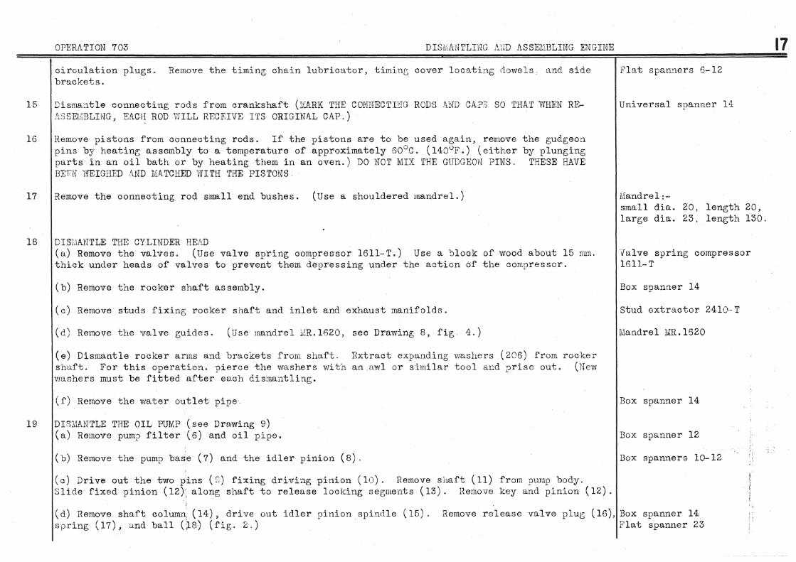
15
16
17
18
19
OPERATION 703 DISiv,ANTLING A~1D ASSEMBLING ENGINE
circulation plugs. Remove the timing chain lubricator, tirninr; cover locating dowels, and side brackets.
Dismantle connecting rods from crankshaft (N&RK THE COHNECTI'-'TG RODS AND CAPS SO THAT WHEN REASSEMBLING • EACH ROD VfiLL RECEIVE ITS ORIGINAL CAP.)
Remove pistons from connecting rods. If the pistons are to be used again, remove pins b;y heating assembly to a temperature of approximately 60°C. (l40°F.) (either parts in an oil bath or by heating them in an oven.) DO NOT MIX THE GUDGEON PINS. BEEN 'NEIGHED /1.ND MATCHED WITH 'rHE PISTONS.
Remove the connecting rod small end bushes. (Use a shouldered mandrel.)
DIS!:JAi'TTLE THE CYLINDER HEAD
the gudgeon by plunging
THESE HAVE
(a) Remove the valves. (Use valve spring compressor 1611-T.) Use a block of wood about 15 nun. thick under heads of valves to prevent them depressing under the action of the compressor.
(b) Remove the rocker shaft assembly.
(c) Remove studs fixing rocker shaft and inlet and exhaust manifolds.
(d) Remove the valve guides. (Use mandrel lvlR.l620, see Drawing 8, fig 4.)
(e) Dismantle rocker arms and brackets from shaft. Extract expanding washers (206) from rocker shaft. For this operation. pierce the washers with an awl or similar tool a1::d prise out. (Hew vrashers must be fitted after each dismantling.
(f) Remove the water outlet pipe ..
DIS.l'lAl'JTLE THE OIL PUMP (see Drawing 9) (a) Remove pump filter (6) and oil pipe.
(b) Remove the pump base (7) and the idler pinion (8).
(c) Drive out the two pins (s;) fixing driving pinion (10). Remove shaft (11) from pump body. Slide fixed pinion ( 12)' along shaft to release loc.king segments ( 13). Hemove key and pinion ( 12).
Flat spanners 6-12
Universal spanner 14
Mandrel:-small dia. 20, length 20, large dia. 23, length 130.
valve spring compressor 1611-T
Box spanner 14
Stud extractor 2410-T
Mandrel MR.l620
Box spanner 14
Box spanner 12
Box spanners l0-12
i-1
(d) Remove shaft column1 ( 14) • drive out idler pinion spindle ( 15). spring (17), and ball Os) (fig. 2.)
Remove release valve plug (16), Box spanner 14 Flat spanner 23
17

18 DIS?;IANTLING AND ASSEMBLING ENGINE
(e) Remove bush ( 19) from shaft c;olur:m with the aid of a mandrel and holding the column lightly clamped L1 a vice.
20 DISMANTLE THE \YATER PUMP (see Drawing 118)
21
22
23
24
(a) Remove the water inlet pipe by disconnecting the hose from the pump.
(b) Take off the pump cover (207), Unscrew nut (209). Remove pulle;,• (210) (by hand), and take out key. Remove bearing cap (208).
(c) Drive shaft ( 211) for 5 mm. to 6 rmn. towards the bearing and then return the shaft to original position, (This operation allows the fitting: of the extractor on the bearing.) the bearing ( 212.) (Use battery cable terminal extractor 2200- T, see Drawing 1, fie;, l.) locking ring retainer (213), loc/.:ing ring halves (214), and take out the shaft.
(d) Remove the sealing ring (215) from the shaft (by hand,)
its Extract Remove
(e) Knock out bush (216) from pump casting with the aid of a shouldered mandreL Take out the greaser ( 217) and water circulation union ( 218.) ·· Remove belt tension adjusting screw ( 219.)
Disconnect the damper from the hub of the starter gear ring carrier. starter gear ring in relation to the carrier (or spider), so that the determined during manufacture, will be mai'ltained when re-assemblin[:~· rine; Knock out silentblocs from geu.r ring.
Remove the sump inspection plate. Remove drain plug.
Remove the oil level float.
Disconnect the inlet and exhaust manifolds.
Mark the position of the balance of the assembly,
Remove the starter gear
25 Clean parts.
I\lanclre 1 15 dia , , 2 50 long;
Brace spanner 12 Box spanner 17
Extractor 2200-T
Shouldered mandrel small dia. 14.75, large clia.1 Flat spanners 11-21 Brace spanner 17
Box Sflanner 17 Brace spanner 12
Brace spanner 12 i\.cljustable spanner 50
Box spanner 12
Box spanner 12

26
OPERA'riOl'if 703 DISMANTLING AND ASSEMBLING ENGINE
ASSErmLING ENGINE
ASSEMBLE ROCKER SHAFT (see Drawing 116) (a) Carefully clean the bore of the shaft with the aid of a wire brush and ensure that oil holes and those of the rocker arms are clear.
(b) Coat the seatings of the expanding washers ( 206) with Hermetical. Fit the washers in the ends of the shaft and lock them in position by flattening with a hammer.
(c) Oil the shaft and then fit brackets, rocker arms, springs, and washers in the order indicated below. The end of the shaft with the ke;)'1'1fay is fitted at the rear (this end also has the oil inlet hole.) THE HOLES IN THE SHAFT FOR LUBRICATING THE ROCKER ARMS FACE DuvTm'·iARDS. THE BRACKETS ARE FITTED SO THAT THE SLO'fS li..RE 1'0\IIARDS THE SPARKING PLUG HOLE~). COJmnence building up at the rear end:-l. One bracket 25n One bracket (centre) 2" One washer l mmo thick 26. One distance piece 3 . [) !lliflo thick 3, One rocker arm, RoH. 27. One rocker ar.rn ·' · .1{" ;I, 4. One washer 1 rmn') thick 28 One washer l rnrn o thick 5, One spring 29. One spring 6. One ·washer 1 lTUll 0 thick 30. One v•asher 1 JllJllo thick 7. One rocker arm, L.IL "' ,,) j_" One c ~:-' '·. · .~::;J r a rrn ~ IJo 8. One distance piece 3.5 mm. thick 32. One distance piece 18.5 llllll. long 9. One bracket 33. One bracket
10. One distance piece 3.5 mm. thick 34n One distance piece 18.5 HUll, long ll. One :rocker a:rm, R,IL 35. One rocker arm, R0IL 12. One vvasher 1 mm. thir;k 36. One washer 1 mm. thick 13 .. One spring 37. One spring 14, One ·washer 1 mm. thick 38. One washer 1 mm. thick 15. One rocker arm, L,H. 39a One rocker arm, LoiL 16, One distance piece 18.5 rmn. long 40. One distance piece 3,5 1mn. thick 17. One bracket 41. One bracket 18 One distance piece 18.5 mm. long 42. One distance piece 3.5 mm. thick 19. One rocker arm. R.FL 43. One rocker arm, R.H. 20. One washer 1 mm. thick 44. One washer 1 mm. thick 21. One spring 45. One sprinp; 22. Ono washer 1 mm. thick 46. One washer 1 rnrn. thick 23 One rocker arm, LI'r. 47. One rocker arm, L.H. 24. One distance piece 3.5 mm. thick 48. One washer 1 mm. thick
49. One bracket
19
Wire brush

---------- ------
20 OPERATION 703 DISMANTLING ./\.ND t1.SSErLBLING ENG nm
27 ASSEf@LE CYLINDER IIE,~.D:
(a) Fit the valve guides. (Use mandrel MRol620, see Drawing 8, fig. 5). This mandrel limits Liandrel I'.:IR.l620-l the projecting portion of the r;uides to 17 rmn., plus or minus 0. 25 rrrrn., measured from the seating Ferrule T.IR.l620·-4 face of the valve spring. Turn the chamfered portion of the g~uide tovmrds the combustion chamber (the conical portion of the guide then stands above the upper faoe of the cylinder head.)
(b) Ream the inlet and exhaust valve guides to 9 nun., plus 0.015 mm., minus OoOlO nun. (Use an Expanding reamer 8 mm. expanding reamer.) If a 'GO' and 'NOT-GO' gauge is not available, check the reaming with a valve stem. (Excessive clearance in the guides is likely to increase the oil consumption.)
(c) Rectify the valve seats. The width of the seat face must be between 1. 7 mm. and 2.1 mm. for inlet and between 2.2 Mn. and 2.5 mm. for exhaust valves. If the seat face is too wide, cut down the upper portion with a 150° grinding wheel or milling cutter of the same angle, and reduce the lower portion with a 60° r,rinding whee 1 or cutter (see Dra·wing 8 fig. 3.)
(d) Reface the valves. (Use a valve rectifying tool similar to the Black and Decker type)
Valve seat rectifying tool of the "Vibro-Centric'' type Grinding wheel 40 dia., 120° anr;le Grinding wheel 40 dia., 150° angle Grinding wheel 40 dia., 60° angle
Valve rectifying tool
(e) Grind in the valves. portable electric tool.)
(Use valve grinder l615·T. This can be operated by hand or driven by a Valve grinder and suction cup 1615-T
(f) CAREFULLY CLEAN THE CYLINDER HEAD, AND E'NSURE THAT THERE ARE NO 'l'RACES OF E:fuiERY DUST IN THE COMBUSTION CHAMBERS AND PORTS Too much care cannot be taken over this operation, as the presence of emery dust in the engine will cause rapid wearing of parts.
(g) To extract a valve seat insert (only in the case of the part being broken or bent) see Drawing 8, fig. 1. AT ONE POHTT ONLY, heat the insert to be extracted with a blow-pipe fitted with a 350 jet. Stop heating when the insert begins to melt. Allow to cool for approximately three minutes then extract the insert by leve.ring out v:ith a screwdriver (bent if necessary.)
(h) To fit a new valve seat insert. Mandrel :1!~.3098-B Ensure that the recess and the insert are quite clean and remove all burrs. Dip the new insert for fifteen minutes in liquid nitrogen. Do not touch the liquid with the fingers. Fit the insert in place. (Use mandrel lviR.3098-B, see Drawing 8, fig. 2). 'NIIENEVER A NEiY INSER'r IS FITTED t'I.VNAYS RE8TIFY THE SEATING FACE.

OPERATION 703 DISivlANTLING AND ASSEMBLING ENGINE
( i) F'it the exhaust and inlet manifold studs and also those for the rocker shaft brackets.
Cl) Test the valve springs. (Use spring; testing a~;paratus 2420-T. see Drawing 11.) The free length of the INNER SPRING should be 43 rnm. Under a load of 16 kg., ?lus or minus 0.750 kg. (35~ lbs., plus or minus l}lbs.), tbe length should be 37 rrun. The free lensrth of the OUTER SPRING should be 46.5 rom. Under a load of 29t kg., plus or minus 2 kf;. (65 lbs., ~lus or minus 4~ lbs.), the len~th should be 29 rnm. and under a load of 14.6 lcf';., plus or minus 1 kg. (32 lbs., plus or minus 2-::t lbs.), the length should be 37 rom.
(k) Fit the rocker shaft assembly. Fit a paper gasket under each rocker shaft bracket and a spacing washer in the slots in the brackets. THE· BRACKETS MUST BE FIT ~ED SO THA'l' THE SLOTS FACE TOWL\..H.DS THE PUSH RODS. Tighten the nuts to a tension of l. 2 rnkg. ( 81.J foot- pounds) . Turn back lock:washer tabs against flat of nuts.
Stud extractor 2410-· T
Spring testing apparatus 2420-T
Box spanner 12
21
(1) Fit the valves having first oiled the stems and valve seats, Fit the valve spring cups and Valve spring compressor 1611-T valve springs. (Use S~Jring contpressor 1611-T). Ensure that the valve cotters are well positioned
(rn) li'i t the washer outlet pipe. Coat the joint with Hermetical. Tighten nuts. Turn back locl~ washer tabs against flat of each nut.
(n) Reset the spark pluf; housings. (Use tool 1604--T_, see Drawing 12). This operation need only be carried out in the case of oil leaking into the spark plug recess.
28 ASSE!V[BLE OIL PUMP (see Drawing 9) (a) F'it bush (19) into ·shaft column (14). (Use a screw press).
(b) Use a mallet to drive the idler pJ.n1on spindle ( 15) into the pump body, Fit the idler pinion (8), ensuring that it turns freely. Offer up the fixed pinion (12). Place a straight edge across the lower flange face of the pump body. By means of feeler gauges measure the clearance between the lower faces of the pinions and the straight edge. The clearance should not exceed 0. 05 rnm. Remove the fixed pinion ( 12) .
(c) Fit the key for the fixed pinion in the shaft ( 11). Slide the fixed pinion along; the shaft sufficiently to allow the fitting of the locking segments (13). After fitting the segments return the pinion (12) to its normal position. Engage the shaft (11) into the pump body. Fit the shaft column (14), tighten the pump body. clamp bolt nut to a tension of 2.5 mkg. (18 foot-pounds) and secure with a split pin.
(d) ?it the driving plm.on ( 10) on the shaft ( 11). If the shaft has been replaced it will be ecessary to drill it for the fitting of the driving pinion fixing pins Position the pinion so a o obtain a clearance of 0.2 nml. between the pinion and the bush (19). Drive in the pinion
fixing pins. Ensure that shaft rotates normally and that the end play does not exceed 0.2 rnm.
Box spanner 12
Tool 1604-T
Straight edge Set of feeler gauges
Box spanner 14

22 OPERATION 703 DISMANTLING AND ASSElliiBLING ENGINE
After checking rivet over the ends of the driv~ng pinion fixing pins.
(e) Between the lower flange of the pump body (35) and the rectangular plate (36), fit a gasket (37) the same shape as the pump body flange. Between the rectangular plate (36) and the pump base (7), fit a gasket (38) the same shape as the pump base flange. Fit screws with spring washers and t'igh·ce:.l to a tension of 1.3 mkg. (9·~ foot-pounds).
(f) To the pump base intake orifice fit a cork gasket, filter. upper cover (39), upper plate (40) for filter (w4_th six 30 rnm. diameter holes), upper filter (with 30 nun. diameter eyelet), filter spacer (41), lower hlter (with 11 rnm. diameter eyelet), and lower plate (42) for filter (with six triangula~ holes), Tighten the central bolt to a tension of 1.3 mkg. (~ foot-pounds) and secure with look nut.
(g) Fit ball (18), spring (17), and adjusting plug (16).
(h) Adjust the pt'ITJP on a test bench. With oil at a temperature of 60°C. , plus or minus 5°C. , (140°F., plu& or minus 16°F.), adjust the plug (16) to obtain an oil pressure of 2.500 kilograms per square centimeter (35.5 lbs. per square inch) at 1,000 R.P.M., with the pump discharging through a 2.8 mm. jet. Tighten the plug lock nut and turn back lock washer tab against flat of nut. (if a t.<:;st bench is not available use the simplified rig MR.l811, see Drawing 13).
(i) Connect oil pipes to pump fitting a 1 Vellumoid' gasket between pipe and pump flanges. Tighten screws and turn back lockwasher tabs.
Box spanner 12
Box spanner 12
Test rig r.ffi. 1811
Box spanner 12
29 ASSEMBLE WATER PUMP (see Drawing 118) NOTE. The water pump bush is of porous bronze. Before fitting, soak the bush for about twenty four hours in a bath of engine oil, or similar oil, to thoroughly imprecnate the bronze.
(a) Fit bush (21G) in the pump body using a shouldered mandrel. The bush should extend 1.5 nun., plus or minus 0 5 mm. beyond the inner face of the pump body.
NO'fE. · The bush (216) should not be reamed as this will destroy the qualities of permeability of the material. THE BUSH i\':UST NOT BE DRILLED.
Shouldered mandrel small dia. 14o75 mm. large dia. 18 rnm.
(b) To the water p•;.mp shaft, fit sealing ring (215) (see Drawing 118 for position). Oil the shaft Tube inside diao 16 rnm., and fit into pump 'Jody. Stick the locking ring halves (214) into the shaft groove with grease and 100 rnmo long fit retainer (213). Lubricate bearing (212), with grease similar to Mobilgrease 5, and fit by means of a press e.nd tube. !{nocking the bearing in position is liable to cause the locking ring halves to jumr out

OPERATION 703 DISMANTLING AND ASSEMBLING ENGINE
(c) Fit the bearing cao (208)) coat the ;;asket with Eermetical, tighten bolts, turn back lock washer tabs. Fit the ~ump cover (207}, coat the gasket with Jicrmotic::\1, ti2;hten nuts.
(d) Fit pulle;y key in keyway on shaft. Fit pulley (210) (see Drawing.llB for position), tighten nut (200), turn back lockv;rasher tab.
(e) F'it g;reaser (217), watAr circulation union (218) with a C. and \. r;asket, apd belt tension adjust~ng screw (219).
(f) Fit water inlet pipe without tightening hosA clips.
Box spanner 12
J3o:x: spanner 17
Flat spanners 11-17-21
3"' Fit silentblocs (220) in the starter gear ring. The front face of the silent'Jlocs must be on a Box spanners 12-17 level with the front face of the gear ring· (that is the side of engageme·nt ~f the teeth). Fit th$ ,~:ear rinc ac:.Jordinc; to the position marked when dismantling Fit the damper on the gear ring carrier spider, tighten bolts, turn back lockvmsher tabs.
P'tFP~cRATIOi:J OF PARTS FOR BUILDING UP CRANKSHAFT ASSEMBLY Any work on the connecting rods, bearin[~S or crankshaft, :D.ffi:)T ONLY BE UNDERT .. \;{EN ~;\TliEN PROPEl1 E~UIPME'TL' FOR THIS CLA.SS OF VWRK IS AVAILABLE to give precision finish of parts ('GO' and NOT-G0 1
r;ac~p;es for connect in[_; rods and bearL1gs, borin£; bar for bearinp~s, and alignine; rod). Failin[; this, it is preferable to replace the parts by a new assembly, obtainable from our Spare PaY"ts Department and ready to be fitted. It is better still to exchange the entire engine for another overhauled by us If the bearing cups have been carelessly filed it is not possible to fit a standard assS)mbly. In this case the cylinder block should be replaced or the beurine;s rebored in line. For this, proceed as follows:-
31 On a surface table check tlle bearing cap joint faces to see if they are both in the same plane. Torsion wrench ;~470- T If necessary file or better still, mill the f1.cces to give the necessary conditiurt. Fit the beari socket 23. cars (without bearings) to the cylinder block and ti(;1Lten nuts to a tension of 12 mkc;. Clock g;auge 2440--T (87 foot-pounds). l:ieasure the diameter 11 a 11 (see Drawing 15, fie;. 2). (Use clock p;aug;e 2440-'I'). The dimension 11 a 11 measured at one end of the bearing. should be the same as dimension 11 b 11 measured at the opposite end. If this is not so the bearin~ cap joint faces are not parellel to the crankshaft centre-line. If necessary correct the b6aring cap by filing or, better still, milling. The difference between the two dimensions "a 11 and 11bll must not exceed 0. 01· wm. \fter rectification take a new mearJurement at tlatt. The difference between this last reading "a11
and the original dime11sion of '35.~:14 mm., plus 0.025 nun., minus O.mm. gives the thickness of shims nett to be fitted .between the bearing cap and cylinder block.
+ o. 025 e = 65o0l4. 0 - a
23

24 OPERATION 703 DL ... \NTLING AND ASSEMBLING El'JGINE
The shims must be very carefully ma('hined. Their faces must be parallel within 0"01 nun. Fit the bearing caps acain (without bearings) but with shims in Dosition. Tighten the oap nuts to a tension of 12 mkg. (87 foot-puuncls) and take a new rne:..csurem~nt nan.. This should be 65.014 mm., plus 0.025 mm., minus 0 mrrt. If othervrise touc u~J the shims the llE'cessary amount to give the correct figure Yle stronr~ly advise this method, while though appearin1r, 1engthy, will enable the fitting; of the standurd cranlcsrw.ft assembly available from our Spare Parts Department. <Ne strongly advise against any alteration of the c;tandard to1er~.nces, which have been established durint; manufacture, as ti1ere will be a risk of breakdown.
(a) H.ebore the oil baffles (see Drawing 15, fig. 1). T!~1POHT'· .. 'JT NOTE - The leak of oil from the engine, fl;yvvheol end, can only ·be ensured ag;ainst if tb.e oil baffle bores are concentric with the crankshaft, and if the clearance behveen the crankshaft and baffle is vli thin the tolerance allowed during~ manufacture. Never must the portion of the crankshaft that corresponds to the oil baffle be reduced in diameter. The original dimension of this portion holds during the life of the crankshaft. Because of this, and the oil baffle having a constant bore, it has been possible to provide a milling cutter corresponding to the diameter of the baffle bore of 55.1 mm., plus Q,l mm. I'l' IS NECE:::;:::ARY TO REPL.'\CE 'rHE OIL Bl\Ji'FLE rrALVES AT EACH REGTIFIC/\.TION OR REPLACE?EENT OF THE CR/\.NKSHWT, OIL BAFFLE l:IA.LVES SUPPLIED BY OUR SPARE PARTS DEPARTMEN'f SUST DE DORED A:F''I'EH. FITTING. The boring of the baffles must only be undertaken after the cranks haft main bearin[r,s have been fitted.
(b) Fit the oil bu.ffle halves (221 and 222) (see Drawing 115) with cork gasket, tighten the screws Box spanner 12 at opposite points to a tension of 1. 3 mkg. ( 9}; foot pounds), and turn back lock washer tabs against flats of nuts
(c) Fit bushes 11 c 11 of tool l 1SG5-T in main bearings, fit a paper gasket between two halves of oil baffles, tit;hten bearin~:; caps, ream oil baffles. Hemove bearinc; ca?s, bushes and bearings (see lJrawine; 15, fig. 1).
Tool lt365- T Universal joint spanner 23
32 FIT CON>JECTING r~OD SMALL END BUSHES Fit bushes b~r press and ream. (Use a 20 mm. diameter expanding reamer). If a ":C~0 11 and tt;'WT-G0 11
gauge is not avau.able check the reaminc 'Nith a new c;udgeon ~.lin. The bore of the bushes must be 20 nml., Jlus O.Olf( rnm., ,:,l:Js (). 1J(_:C nnlL,, and this can only be guaranteed 1)y the use of r.lrecision tools.
33 FIT PISTONS TO CONNEGTING 7C!D:3 As the gudgeon piCJ. is a slight taper fit in the piston, cure must be tu:cen to fit the pin thecorreJt Spanner i'ilRol610 way. The piston boss with the large bore bears a mark in g;reasy crayon, and the larger end of Surf~we plate 248C-'l'

OPFRI\TION 703 DISMA.NTLliJG AND ASSEMBLING ENGINE
t;udgeon pin is marked likewise at the end. When assembling make sure that the markings coincide. ··aarm the pistons to about r:i0°~. ( 14C: 0 1".) by dippinp; in an oil bath or placing in ::.m oven. This will allow the g;udg;eon pin, previously oiled, to be fitted by hand. (DO NOT MIX THE GUDGEON PDJS AS THEY HAVE BEEN WEIGHED A.ND flAIRED 'WITH THE PIS'rONS.) Fit the g;udgeon pin circlips. (Use spanner MR.l610, see Drawing 16, figs. 1 and 3.) Ensure that the circli;)s are right home in the piston recesses. Check the a1ig;nment of connecting rods and pistons. (Use surface plate 2480-· T).
34 FIT II.ND ADJUST HEIGHT OF CYLINDER BAHRELS. FIT CYLDrDER HE/\.D. (a) Ensure the seatings in the cylinder block and also on the barrels are smooth and perfectly clean. The cylin~er barrel height is of very great importance. If the barrels are too high above the cylinder block ton flange they will be distorted when the cylinder head is tightened do·wn. On the contrary, if they are too low, there will be a leak of water or gas.
(b) Offer up the barrels without seating joints and check to ensure that they do not bind in the top flange and that they have a slight clearance in the lower bores of the cylinder block.
(c) Check that the top faces of the barrels are from 0.41 mm. to 0.43 mm. below the upper surface of tho cylinder block flange and that the faces of both block and barrels are parallel within a tolerance of O.OE mm. For this, a good straight ede;e and feeler g;auges should be used. Check successively with the straif.:;ht edge placed on the. longitudinal and transverse centre lines of the cylinder block. It is much better to use a rig fitted with a clock gauge. (Use apparatus ti'IR.3377, see Drawing 17, fie;s. 1 and 3.)
(d) USE ONLY HUGO-REINTZ JOINTS sold by our Spare Parts Dep<trtment. Choose joints of a necessary t.bickness TO ALLOW THE BARREV-3 TO STAND FROM 0. 02 MM. TO 0.12 1\ifM. ABOVE THE FACE OF THE CYLINDER BLOCK UPPER FLANGE Carefully measure the amount the barrels stand proud. (Use apparatus MR. 3377, see Drawing 17, fig. 2.) Pair up the barrels and fit the Hugo-Reintz joints lightly coated with linseed oil. Engage the barrels in the cylinder block in pairs. The barrels must fall into position under tr1eir ovm weight and without restriction from the joints.
(e) :Cit the cylinder head studs and ti[;hten to a tension of 2 mkg. (14~ foot pounds.) (Use stud extractor 2410-T.) The shorter length of stud thread is screwed into the cylinder block.
(f) After oiling the bearing surfaces, fit the camshaft. screws (224) to a tension of 2.5 mkg~ (18 foot pounds.) of screw heads. Oil the tappets and fit into cylinder block.
Fit the thrust plate (223), tighten Turn back lockwasher tabs against flats
Straight edge Set of feeler gauges Apparatus MR.3377
Stud extractor 2410-T
Box spanner 12
25

26
35
JPERATLm 703 DISMANTLING AND ASSEJVlBLING ENGINE
(g) Fit the cylinder head locating dowel. Coat the cylinder head gasket with engine oil and fit witrt the smooth side on the cylinder barrels. "'it the cylinder nead, which must fall into position under its own weight, and then spring wasl1ers on the studs. Ti1~hten cylinder head nuts according to the order shovm on Drawing 18. (First tightening to 2 rnk[~· (14~ foot pounds) tension, second tightening to 5 mkg. (36 foot pounds) tension.) 'l'he correct tightening is of great importance and for this reason it is most necessary to use a torsion wrench. (Use torsion wrench 2478-T, see Drawing: 18, fig. 2.) THE SEQUENCE OF TIGHTENING MUST BE ::l1'RIC'l'LY OBSERVED.
(h) Fit the push rods, after oiling the balls and cups, by depressing the valves. (Use valve spring compressor 1611-T.)
(i) Invert the engine and place it on a stand. (Use stand i'AR.3300·-20, see Drawing 4 figs. 1 and 2.)
(j) Check the cylinder barrels for distortion. (Use clock gauge 2440-T). bores of the barrels must not exceed 0.03 mrn. except in the bottom 20 nun. distortion is permitted. If distortion is in excess of these tolerances, head and fit thinner cylinder barrel joints. Refit the cylinder head and distortion ..
Any distortion of the Wi1ere 0.05 mm. remove the cylinder again check for
When correct fitting of the barrels has been achieved DO NOT REMOVE THE CYLINDER HEAD AGAIN. The clearance between the piston and barrel must be between 0.05 nurt. and 0.07 mm. The measurement of this clearance entails the use of a high precision instrument (such as a fluidometer) as used during manufacture. UNDER NO CIRCUMSTANCES MUST A PISTON AND BARREL ASSEMBLY, sold by our :Spare Parts Department, BE DIS11JANTLED AND PAIRED UP WITH OTHER PISTONS OR BARRELS ..
FIT CONNECTING RODS TO CRANKSHAFT. Oil the journals WITH A CAN (Using oil similar to Mobiloil BB ) Never apply oil with a brush as it may carry impurities and have loose bristles, Fit the connecting rods so that the slot in the pistons is on the camshaft side. FIT LOCKWASHERS ON BOLTS OF CONNECTING ROD CAPS SO THAT 'rHEY WILL PREVENT THE NUTS TUIUHNG r:J THE DIRECTION OF UNSCREWING (see Drawing 16, fig. 2 ) Tighten nuts to a tension of 3 mkg. to 4 mkg. ( 21-~ foot pounds to 29 foot pounds.) Turn back rounded tab of lockwashers a~:,ainst flat of nuts.
36 FIT CRANKSIJ!1FT AND PISTONS ASSEMBLY IN CYLINDER BLOCK (a) Fit the main bearing uqper halves after ensuring that the housings are smooth and olean. Oil tJ:1e bearings WITH fl.. CAN (using oil similar to Mobiloil BB.)
(b) Oil the pistons (WITH A CAN.) Turn the second and fourti:l piston ringro so that the gaps are at 15n~ to those of the first and third rings. Fit piston ring guide bushes (Use busnes 1655-1', .we i:rawing 19, fig. 2.)
Torsion wrench 2470-'J' socket 17
Valve spring compressor 1611-'l'
Stand ii:R.3300-20
Clock gauge 2440-T
Torsion wrench 2470-'l' socket 14
Piston ring guide bush 1656-T
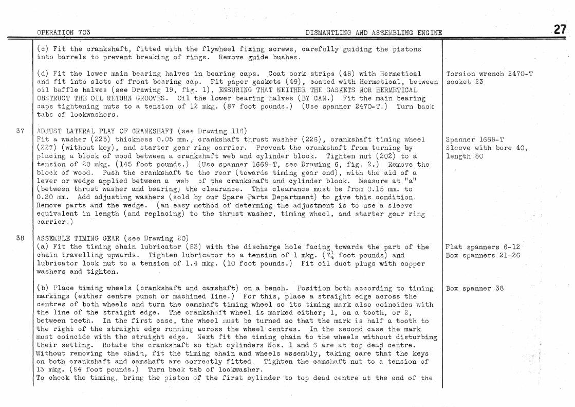
37
38
OPERATION 703 DISMANTLil'W AND ASSEMBLING ENGINE
(c) Fit the crankshaft, fitted with the flywheel fixing screws, carefully guiding the pistons into barrels to prevent breaking of rings. Remove guide bushes,
(d) Fit the lower main bearing halves in bearing caps. Coat cork strips (48) with Hermetical Torsion wrench 2470-T and fit into slots of front bearing cap. Fit paper gaskets (4·9), coated with Hermetical, between socket 23 oil baffle halves (see Drawing 19, fig;. 1), ENSURING THJ\T NJHTHER THE GASKETS NOH HERMETICAL OBSTRUCT THE OIL RETURN GROOVES. Oil the lower bearing halves (BY CAN.) Fit the main bearing caps tightening; nuts to a tension of 12 mkg. (87 foot pounds.) (Use spanner 2470-T.) Turn back tabs of locbrashers.
:\D<TUST LATERAL PLAY OF CRANKSHAFT (see Drawing 116) Fit a washer (225) thickness 0.05 mm., crankshaft thrust washer (226), crankshaft timing wheel (227) (without key), and starter gear rint carrier. Prevent the crankshaft from turning by plucing a block of wood between a crankshaft web and cylinder bloc~c. Tighten nut (202) to a tension of 20 mkg. (145 foot pounds.) (Use spanner 1669-T, see Drawing; 6, fig. 2.) Remove the block of wood. Push the crankshaft to the rear (towards timing gear end), with the aid of a lever or wedge applied between a web )f the crankshaft and cylinder block. Measure at ua 11
(between thrust washer and bearing) the clearance. This clearance must be from 0.15 nlffi, to 0. 20 rmn. Add adjusting washers (sold by our Spare Parts Department) to give this condition. Remove parts and the wedge. (an easy method of determing the adjustment is to use a sleeve equivalent in length (and replacing) to the thrust washer, timing wheel, and starter gear ring carrier,)
ASSEMBLE TIMING GEP.R (see Drawing 20) (a) Fit the timing chain lubricator (53) with the discharge hole facing towards the part of the chain travelling upwards. Tighten lubricator to a tension of 1 rnkg. (7t foot pounds) and lubricator look nut to a tension of 1. 4 mkg. ( 10 foot pounds.) Fit oil duct plugs with copper washers and tighten.
Spanner 1669-T Sleeve with bore 40, length 80
Flat spanners 6-12 Box spanners 21-26
(b) Place timing wheels (crankshaft and camshaft) on a bench. Position both according to timing Box spanner 38 markings (either centre punch or machined line.) For this, place a straight edge across the centres of both wheels and turn the camshaft timing wheel so its timing mark also coincides with the line of the straight edge. The crankshaft wheel is marked either; 1, on a tooth, or 2, between teeth. In the first case, the wheel :rmst be turned so that the mark is half a tooth to the right of the straight edge running across the wheel centres. In the second case the mark must coincide with the straight edge. Next fit the timing chain to the wheels without disturbing their setting. Rotate the crankshaft so thELt cylinders Nos. 1 and f:i are _at top dea£l centre. Without removing the cli.ai'l, fit the timing chain and wheels assem':.)ly, taking care that the keys on both crankshaft and camshaft are correctly fitted. Tighten the camshaft nut to a tension of 13 mkg. (94 foot poundE;.) Turn back tab of lookwasher. To check the timing, bring the piston of the first cylinder to top dead centre at the end of the
27

28
39
40
OPERATION 703 DISMANTLING AND ASSEIJBLING ENGINE
compression stroke. Timing marks should now li::1e up according to Drd.Wint::, 20.
IMPORTANT NOTES (see Drawings llt'3 and 21) The oil tightness of the engine at the point where the crankshaft pssses througl:1 the timinfs c ver can only be ensured if the hole in the cover is concentrio with the c il return e~rooves (ma•,hi.:J.ed in the starter gear ring carrier ( 201.) lt is therefore essential to ensure concentricity when fitting the timing cover. It is equally essential that the sealing cap (56) is concentric with the oil thrower of the camshaft pulley (58) in order to prevent leakage.
(c) FIT TIMING COVER To the crankshaft fit oil return washer ( 204) see Drawing 116.) Fit locatinr~ dowels for the tin1ing cover into the cylinder block. Coat the cylinder block timing cover flange and also the flange of the actua}· timin11: cover with Hermetical, Fit the paper gasket. Offer up the timi::1g cover and screw in fixing bolts BUT DO NOT TIGH'l'EN. Fit tl1e locating bush. (Use bush 1664 1, see Drawing 117.) Tighten screws and remove the bush.
(d) To the front of the camshaft (double pulley end) fit oil thrower (55) (see Drawing 21) u.r·.d the key. Fit the sealing cap (5G) with a paper gasket coated with Hermetical, and centralize. (Use centralizinr-•; bush MIL342l, see Drawing 21, fie;. l.) Tighten screws and turn back tabs of lockw~tshers.
Fit a number of pacKing washers (57) identical to those removed durin~; dismantling. The amount taken up by these washers has been determined duri :1[~ manufacture. They serve to ensure correct aligmnent of the double pulley vrith the dynamo pulley and give also a dimensio11 of 95.5 rnm., plus or minus 0.25 mm., from the centre line of the large pulley groove to the centre line of dynamo fixing studs on the clutch housing cover (see Drawing 21, fi~~· 2 ) Fit the double pulley (58) and the lock:vvasher. Tighten nut to a tension of 5.5 mkg. (40 foot pounds.) 'l'urn back lockwasher tab against flat of nut.
FIT THE STAHTER GEAR RING CARRIER with damper connected. Tighten the slotted nut (202) to a tension of 30 mkg. (217 foot pounds.) (Use spanner 1669-T, see Drawing 6, fig;. 2.) Fit the lock-washer and lock it. on damper. Turn back a tongue of the lockwc.sher into a slot of nut (202).
FIT THE ENGINE FLYWHEEL (its location determined by an offset bolt.) Fit bearing (228) after lubricatin~ with grease (similar to Mobilgrease 5.) Fit the bearing retaining circlip, lockplate (229), and tighten nuts to a tension of 2.5 mkg., plus 0.25 mkg., minus Q mkg. (18 foot pounds, plus l·~ foot pounds, minus 0 foot pounds.) Turn back lockplate tabs agai-;J.st flats of nuts. NOTE. On certain engines the flywheel is fixed by bolts. This must be tightened to the same tension as the nuts.
Bush 1664-T Brace spanner 12
Centralising; bush MR.342l Brace spanner 12 Box spanner 26
Spanner 166 9- T
Torsion wrench 2470-T Extension 14

DISMANTLING AND ASSEMBLLIJG ENGINE
41 FIT OIL PUMP (see Drawing 116) (a) H.otate crankshaft to bring engine at tor dead centre on first cylinderat the end of compression stroke. Fit conical unions in cylinder block.
(b) Fit the oil pump so that the slot of the driving pinion (230) is parallel to the engine centre Flat spa:nners 14~16-17-26 lL1e and is offset towards the engine. 'l'ighten pointed screw to a maximum tension of l. 5 mkg.
42
( loi~ foot pounds) to prevent crushing the column, and tig;hten lock nU:t to a tension of 3 mkg. (21~ foot pounds.) Tighten union nuts to a tension of 6 mkg. (431 foot pounds), and lock nuts to a tension of 4 mkg. (29 foot pounds.)
Fit the sump cork gasket, offer up the sump and fit screws with lockwashers but do not tighten (the tightening will be carried out after the gearbox is fitted.) Fit the inspection plate with a cork gasket, and tighten nuts fitted with spring washers. Fit drain plug with a C. and A. washer and tighten.
43 Return engine to its normal position and place on a workshop stand.
44
45
Provisionally adjust the tappets to 0.20 mm. (0.008 in.) for inlet and 0.25 mm. (0.010 in.) for exhaust (the final setting of 0.15 rrrrn. (0.006 in.) and 0.20 rrrrn. (0.008 in.) respectively is made after tightening the cylinder head with the engine hot.)
Oil the valve springs and tapret balls. Fit the cylinder head cover with the joint coated with Hermetical on the cover side only.
46 FIT WATER Pm~P (see Drawing 118) (a) Fit the dynamo driving belt in the larger groove of the double pulley. ~ext fit the water purap driving belt.
Brace spanner with extension 12 Adjustable spanner 50
Flat spanner 14 Set of £eeler gauges
Box spanner 12
(b) Offer up water pmnp, fitted with water inlet pipe, in housings. Fit a Klingerite gasket Brace spanner 12 coated with Uermetical between the flanges. Tighten flange nuts with spring washers fitted under.
(c) Fit the rear housing cap and provisionally tighten the nuts. (The housing cap receiving the eccentric screw is mounted at the front.) Tension the belt correctly by means of adjusting screw (219). Line up, by use of a straight edg;e, the water pump pulley with the driving pulley by adjusting pump in its housings. Tighten the rear housing cap and lock nut of adjusting screw (219).
(d) 'l'urn the eccentric screw so that the point protrudes about 3 rrrrn. on the inside of the front housiYJ.['; cap. Offer up the housing cap and turn the screw so that it registers in the circular groove of the tubular portion of the pump. Tighten the cap. Tighten the lock nut of the eccentric screw at the same time holding the flats of the latter.
Box spanners 12~ :p
29

30 OPERATION '703 DISMANTLING AND ASS~:BLI~G ENGINE
(e) Tighten clips of pump hose connectionso
4'7 FIT EXHAUST AND INLET MANIFOLDS .,
Assemble the two manifolds fitting the steel plate between the two nugo-Reintz gaskets. Tighten bolts with spring washers under ho:Jadso The faces of the nine flanges must be in the same plane. Check for alignment with the aid of a straight edge ·and set of feeler gauges. If the faces are more than Oo 1 mm. out of line, true up with a g;r.inder or a file. (After trueing up the faces remove all traces of swarf and emery dust frorn the ports by compressed air.) Fit the manifold assembly using gasket between flanges and cylinder head. Tighten nuts.
48 Fit the oil float tightening the nuts fitted with spring washers under. ENSURE THAT THE ROD SLIDES FREELY IN THE GUIDE TUBE. Ensure that the graduations are according to the dimensions indicated on Drawing 117, fig. 2 .
49
50
. :f.'it the breather pipe, pointinr; dowmvards, with the flange shield fitted between two paper ·gasketso Tighten bolts. Fit side suspension brackets. Tighten bolts fitted with spring washers under heads.
Fit the oil feed pipe to the cylinder head placing a vellumoid gasket between pipe flange and head. Fit screws with spring washers and tighten to a tension of 2 mkg. (14i foot pounds.) Tighten union nut fitted with fibre washers to the same tension.
51 Paint engine.
Box spanner 12 Straight edge Set of feeler gauges
Box spanner 12
Universal joint spanner 21 Box spanner 12
Box spanners 12-17
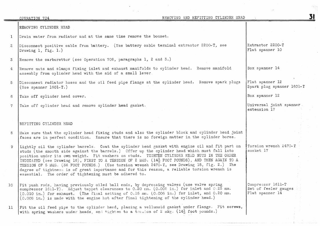
OPEflATION 704 REMOVING AND REFITTING CYLINDER HEAD
REJIJIOVING CYLINDER HEAD
l Drain water from radiator and at the same time remove the bonnet.
2 Disconnect positive c:able from battery. (Use battery cable terminal extractor 2200.,-:T, see Drawing l, fig. 1.)
3 Remove the c:arburettor (see Operation 708, paragraphs 1. 2 and 3.)
4
5
6
7
Remove nuts and clam;.)s fixing inlet and exhaust manifolds to cylinder head. Remove manifold assembly from cylinder head with the aid of a small lever
Disconnect radiator hoses and the oil feed pipe flange at the cylinder head. Remove spark plug;s (Use spanner 1601-T.)
Take off cylinder head cover.
'l'ake off cylinder head and remove cylinder head gasket.
REFITTING CYLINDER HEAD
8 Make sure that the cylinder head fixing studs and also the cylinder block and cylinder head joint faces are in perfect condition. Ensure that there is no foreign matter in the cylinder bores,
9
10
Lightly oil the oylinde.r barrels, Coat the cylinder head r;asket with engine oil and fit part on studs (the smooth side against the barrels.) Offer up the cylinder head which must fall into position under its own weight. Fit washers on studs. TIGHTEN CYLINDER HEW NUTS IN THE ORDER INDICATED (see Drawing 18), FIRST TO A TENSION OF 2 MKG. ( 14~ FOOT POUNDS), AND THEN AGAIN TO A TENSION OF 5 MKG" (36 F001' POUNDS.) (Use torsion wrench 2470-T, see Drawing 18, fig. 2.) The degree of tightnes;; is of great importance and for this reason, a reliable torsion wrench is essentiaL The order of tightening must be adhered to.
Fit push rods, having previously oiled ball ends 3 by depre~>sing valves (use valve sp:cing compressor 1611-1') 0 AdJUSt tappet clearances to 0.20 J;llrt. (O.OOf. inu) for inlet and 0 25 mmo (0,.010 ina) for exhaust. (The final satting of 0,15 rmn, (0"006 in,) for inlet. and 0,20 mm. (0.008 in.) is made with the engine hot after final tightening of the cylinder head.)
ll Fit the oil feed pipe to the cylinder heed, placing a vellumoid gasket under flange.. Fit screws, with spring washers under heads, an +.it;h'ten to a t.':L;.;c_on of 2 rnkg;o (14-$ foot pounds.)
Extractor 2200-T Flat spanner 10
Box spanner 14
Flat spanner 12 Spark plug spanner 1601-1'
Box spanner 12
Universal joint spanner. extension 17
Torsion wrench 2470-T socket 17
Compre::;sor 1611-T Set of feeler gauges Flat spanner 14
:St

32 12
OPERATION 704 REiviOVING AND REFITTING CYLINDER HEAD.
Fit manifold gasket and then manifold assembly on studs. Fit spring washers and fixing nuts, and tighten down.
13 Fit the carburettor (see Operation 708, parag;rapns 4, 5 and 6.)
Box spanner 14
14 Fit water hoses. Fit spark plugs. (Use spanner 1601'-1'), Connect positive cable to the battery. Spark plug spanner 1601-T Flat spanner 12
15 Make sure that drain tap is shut and then fill radiator with water.
16 Start engine,and let it idle (approximately 500 R.P.M.) for fifteen minutes.
17
18
19
Finally tighten cylinder head nuts in the order indicated (see Drawing 18) to a tension of 5mkg. (36 foot pounds.) (Use torsion wrench 2470-T, see Drawing 18~ fig. 2.)
Adjust valve tappet clearances to 0.15 mm. (0.006 in.) for inlet and 0.20 mm. (0.008 in.) for exhaust.
Fit cylinder head cover, with the cork gasket coated with Hermetical on the cover side only.
20 Fit the bonnet.
Torsion wrench 2470-X socket 17
Flat spanner 14 Set of feeler gauges
Box spanner 12

RE!'lOVING ROCKER SHAfT
1 Remove cylinder head cover.
2 Remove rocker shaft assembly.
DIS.\I.'IANTLING ROCKER SHAFT
3 See Operation 703, paragraph l8e"
ASSEMBLING ROCKER SHAFT
4 See Operation 703, paragraph 26.
6
REFITTING ROCKER SHAFT
(a) Fit a paper gasket under each rocker shaft bracket and a spacing washer in the bracket clamping slots. Tighten bracket fixing nuts to a tension of l. 2 mkg. ( 8% foot pounds.) Turn back look washer tabs against flat of nuts.
(b) Adjust tappet clearances to Ool5 mm. (0.006 in.) for inlet valves t,md 0.20 rrrrno (Oo008 in.) for exhaust valves.
Fit cylinder head cover with the cork joint coated with Hermetical on the cover side only.
Box spanner 12
Box spanner 14
Box spanner 14
Flat spanner 12 Set of feeler gauges
Box spanner 12

34 OPERATION 706 REMOVHG /\.-,:n REFITTING INLET _}l"D FX.:i!\UEiT :li''!A::HFOLDS
REMOVING MANIFOLDS
1 'l'alce off the carburettor (see Operation 708·, parar;rap'1s 1, 2, and 3.) ·
2
3
4
Disconnect manifold flanges from cylinder head. (Use spanner 1626-T. see Drawing l, fig. 2.) Disconnect exhaust pipes and let them resi on t~e floor.
3.emove petrol draio. pipe. Remove manifold assembly from the ene;ine.
Disconnect inlet manifold from exhaust manifold.
REFI'l'TTtiG MANIFOLDS
5 P"B.E?A.RE l;LL'~.NIF\JLDS
Spanner lG::'.o-1'
Flat spanner 12 Do.x: Sf1~rmer .111
Box spanner 14
(a) l~ssemble the two manifolds fitting a steel gas,;cet between the two Hugo-1\eintz flange gaskets. Box spanner 14 Tighte:J. bolts fitted with sprine; washers un<ler t1eads.
6
8
(b) The f;;.ces of the nine flanges must be in the same ~Jla'Cle. Check for any misalignment by usi::g a stru.ight edge and feeler gauges or on a surface .,late. If the assembly ls more than 0.1 nun. out of alignment true u~J the faces by g;rind.1.n;; or vii th 11: file. A.fter trueing: U 1J remove all· tra;.;es of swarf or emery dust with a compressed air blower
l''it the manifold C. and .\. gasket on the m"'nii'o}d wwris. !'it the assembly of manifolds and tighten fixing nuts, fitted with spring washers
Fit exhaust pipes to exhaust manifold using J. and P;'8.skets between the flanr;es. SECURELY· TIGHTEN THE NUTS. (Use spanner 1626-T see Drawi 11;:_: l . fig. 2.)
Fit petrol drain pipe
Fit carburettor (see Opor,~tion 708, parae;rapn:: 4. 5 lld .G.)
Strai.:_)lt edr;e Set of feeler gauges
Box s ,anner 14
S;:>anm'r 1626-T
Flat spanner 12

REMOVING WATER PUMP (see Drawing 118.)
1 Drain water front radiator.
2
3
Remove the air intake silencer. Remove the pipe (4) from the oarburettor and the fixing on the hull (see Drawing 23).
Disconnect hoses and the pipe between pump and cylinder head.
4 Unscrew adjusting bolt (219). Remove housing caps fixing pump and take out pump.
REFITTING WATER PUMP
Flat spanner 12
Flat spanner 17 Box spanner 12
5 Offer up the water pump in its housing, fit the rear housing cap, provisionally tightening the Box spanners 12-17 nuts. (The cap with the eccentric bolt is fitted at the front.) Ensure correct tensioning of driving belt by operating; adjusting screw (219). Line up, with the aid of a straight edge, t11e water pump pulley with the driving pulley by moving the pump backwards or forwards in its housing:-Tighten nuts of rear housinr; cap and lock nut of adjusting sc:tew ( 219). Turn the eccentric screw so that the point protrudes about 3 mm. on the inside of the front housing; cap. Offer up the housing cap and tur:2 the screw so.that it registers .in the circular groove of the tubular portion of the pump. Tighten nuts fixing the cap. Tighten the lock nut of the eccentric screw at the same time holding the flats of the latter.
6 Fit the hose connections and the pipe between pump and cylinder head (without using Hermetical).
7
Tighten hose clips.
Fit the air intake silencer. Fit a Hugo-Reintz gasket between pipe (4) and the carburettor. Fix brackets between two rubber washers and split pin the bolts (see Drawing 23).
8 Fill the radiator with water.
NOTE. To overhaul pump see Operation 703, paragraphs 20 and 29.
Flat spannt.:· 12

36 OPERATION 708 REMOVING AND REFITTING CARBURETTOR
REMOVING CARBURETTOR
1 Remove pipe between carburettor and air intake silencer.
2 Disconnect petrol pipe from carburettor, starter carburettor control (choke). Disconnect throttle Flat spanners 8-14-18 control at oarburettor end by sliding spring to free ball pin. ·
3 Take off· the carburettor. (Use spanner 1·521-T, see Drawing 1, fig. 3).
REFITTING CARBURETTOR
4 FIT THE CARBURETTOR (a) With the aid of a straight edge or surface plate make certain that the carburettor flange is true. If necessary, touch up the flane;e face with a file after stuffing the main orifice with a rag.
(b) F'it the carburettor shield and tighte>J. two fixing nuts on inlet manifold studs.. Position the shield lower fixine; strap and tighten nuts fitted with shakeproof washers. Fit and tighten bolts assernbline; shield and fixing; strap. Place on inlet manifold in the following order:-
One Hugo- )l.eintz gasket (centres of inlet holes 38 rum.) One thick distance piece (on this part the inlet holes are cut obliquely. Fit the face with
centres of inlet holes at 38 mrn. against the preceding; gasket). One Hugo-Reintz gasket (centres of inlet holes 35 mm.)
Offer up carburettor and tighten fixing nuts with shakeproof washers under. (Use spanner 1621-T, see Drawine; 1, f'i g. 3) .
Spanner 1621-T
Flat spanner 14 Spanner 1621-1'
5 Fit petrol pipe, starter carburettor control, and throttle control. l<'lat spanners 8-18
6 Fit pipe between carburettor and air intake silencer using a round Hugo-Reintz gasket. Tighten the screws.

01.wlU~TION 709 DISMANTLING AND ASSEMBLING CARBURETTOR
DISMANTLING CARBU1<.ETTOR (see Drawing 120)
l Remove the float chamber cover (1), take out the float (31) by removing screw (2). Flat spanner 10
2 Remove pump injectors (3), disengage paper gasket and two balls (4). Remove screws (6) to pennit Flat spanners 8-12 taking out choke tubes (5). Take out correction jets (1) and emuls:i..on tubes (8). Remove air jets (9), slow running jets (10) and pump jet (11).
3 Remove main jet carrier plugs (12) and unscrew main jets (13). Remove starter petrol jet (14).
4 Remove split pin from rod (15) and disengage rod from pump lever (16).
5 Disconnect throttle chamber (17) from .float chamber.
6 Remove pump valve (18). Remove the pump (19) by takin~; out four screws (20). Take off paper gasket (32). R<:·move starter air jet (21). Remove starter (22) by taking out :four screws (23).
7 DISMANTLE BUTTERFLY VALVES FROM THROTTLE SPINDLE (a) Remove the screws ( 25) fixing butterfly valves. Take out valves ( 26). Unscrew tb.e two mixture screws (29).
(b) Take off the throttle lever (27) from the throttle sp:i..ndle (24).
(c) Take out spindle (24), and remove pump control lever (28).
8 Remove needle valve (30). Take off paper gasket (35) fixed by two screws to the float chamber cover (1).
9 Clean parts. Use compressed air to blow out ducts and jets.
ASSEMBLING CARBURETTOR (see Drawing 120)
10 Screw needle valve (30), :fitted w:i..th a fibre washer, into float chamber cover (1). Fit the paper gasket ( 35) to the f'loat chamber co<rer and fix by two screws.
11 ASSEIVIBLE BUTTERFLY VALVES AND 'fHROTTLE SPINDLE
Flat spanner 14
Flat spanner 12
(a) Fit lever (28) to spindle (24) and tighten nut. Flat spanner 12
(b) Engage spindle (24) into throttle cb.amber (17), assemble butterfly valves (26), tighten screws ( 25)
37

38 OPERATION 709 DISMANTLING AND ASSEMBLING CARBURETTOR
(c) Fit bracket (33) fCJr throttle stop screws on spindle, fit lever (27), tighten nut and lock nut ..
12 Provisionally screw .~. .l the mixture screws (29). Fit the starter (22) and tighten tnc four scre0s (23). · Screw in the air ~et (21).
13 Fit the pump (19) aLd tig;hten four screws (20). ;:)crew in the pump jet (11), ftttec< with a fibre wash• r, and screw i:l 'Ju.1ve (H:). Screw in starter petrol jet (11). fitted wittt a fibre washer, slow runninr; air jets ( 9.), and slow runnine; jets ( 10). Screw main jets ( 13) into carrier
14
15
plugs (12). Fit the plurs (12) with fibre washers. Fit in place the bro ;1mulsion tubes ( f<), and screw in the correction jets ( 7). Place the float (31) into the float chamber and tighten screw (2). Fit t:1e two choke tuber; (5) and tighten screws (6). Fit the two balls (4) of the injectors (3). Fit the injectors (3) using a paper gasket.
Connect the throttle chawber ( 17) to the flou.t chamber usi1e; a pD.[Jer gasket ( 3C.). fi ttccl with a small ';~>ring, in pump control lever ( 16). Tighten the four assembly pin t:le rod ( 15).
Fit t 18 float cham.br'r cover ( 1) a;1d tighten screws.
E:ngage rod ( l.S), screws. SpL :;
NOTE If after cons -clerable service the pump appears to :1e defective, general r1::.u:se being a hole i , or leak at. th r)ump base, at first wuke sure that a b 1 oc\:ed pum:l jet ( 11: or injector ( ) is the cause ( s~·:o ·par:<c;l·apn 13). If the ?urnp has reail;y deteriorated, do uut try to disman· e or repair it as it in preferab:Le1 to replace the unit by a ncvr puwp complete.
Flat spanner 14
Si anner 10

l
OPJi'RA1'ION 710 DISMANTLING AND ASSEMBLING AIR INTAKE SILENCER
DISliJ\NTLING SILENCER (See Dr,t.·: ing 23)
NOTE. It is important to clean the filter and felt constituting the filtering and silencing elements every 6,000 krn. (3,700 miles).
Take off end plate ( l) by unscrewing the nuts (2). Taice out the filter (3).
2 Remove pipe (4) and hose (5) by taking off hose clips.
3 Clean parts. Clean the felt (7) with a wire brush and remove all dust with a compressed air blower. ~;.-ash the perforated tube (8) and the filter (3) in petrol and finish off cleaning with compressed air. Make sure that the vents in the cylindrical casing are clear and have an opening of 2.5 mm. (see fig. 4).
ASSEMBLING SILENCER
4 Fit the filter (3), end plate (1), and tighten nuts (2) fitted with spring washers.
5 Fit hose (5) to casinE outlet, fit pipe (4) in hose, and tiB;hten both clips (6).
39
Box spanner 8
Box spanner 8

40
l
2
OPERATION 711 DISMA1JTLI1'if 1; '.ND ASSEMBLING PETROL FU..P l'PE S.E.V.
DISNlANTLING PETROL PU.MP (see Drawing 24
Take off the glass cover (1), remove filter (2), and clisc_,nnect t,alves of pump (3 and 4).
Using a screwdriver, extract lockwashers ( !')) of the two primin:· lPver _guide nuts ( 6). Unscrew the two nuts, take out the priminp lever (7), the actuating lever (B) and its fork (9).
Flat s;Janner lC
Flat spanner 12
3 Dismantle diaphragm from pump actuo.ting rod ( 10), remove resin-coated washers ( 11), and spring (15). Flat and box spLtnners 10
4 Remove retaining plate (12) for flow (13) and return (14) valves. i(emove valves and r;pri.1gs.
ASSEMBLING PETROL PUMP (see Drawing 24:
5 Fit flow (13) and return (14) valves, fit cork gasket for retainitg ;;late (vrithout u:c.j_ng Hermetical or similar compc.JUnd), fix the plate by three screws.
6
7
Fit set of diaphragms to actuatinG rod (lJ), tighten nut, and turn h;ck lockwasher tab. To prevent petrol seeping through the nut thread, load a little solder to the face of the nut (as at 11 a"). Fit the regulator spring (15) and cup. Then fit resin coatef washers (11) to ensure petrol proofing. These washers are slit for easy assembly. \'!hen assemblin:, do not allow slits to coincide, each should be c;taggered at about one third of the circumference.
Place actuating lever spring (16) on locating boss in pump cCJ.sting, fit-: diaphragm ussembly, Lovk actuating lever (8) on actuating rod (10). Fit lever fork (9), fit priming; lever (7), tighten guide nuts (6), fit lockwashers (5), drive in the rivets.
8 Connect two halves of pump (3 and 4). TEE DIAPHRAGM fuiDST DE FITTED WITHOUT USING Hl~RMETICAL OR SIMILAR COMPOUND. Tighten as sembling screws.
9 Fit the filter (2), cork washer (WITHOUT USING BETtMETICi\L), glass cover (1), and tighten locking screw.
NOTE. hfter every re-assembly of pump check for leaks (see Operation 712).
Flat and box ~;panners 10
Flat spanner 12
Flat spanner 10

OPERATION 712 CHECKING PETROL PUMP
CHECKING FOR LEAKS (see Drawing 25)
l Use a plug threaded 12 dia., 100 pitch to close the pump outlet to the carburettor.
2 Fit a petrol pipe to the pump inlet from petrol tank. Tighten the pipe with a biconical union and union nut as normally used on the car.
3 Totally submerge the pump in a suitable receptacle containing petrol only.
1 :i.pply compressed air at a pressure of 100 to 300 grams per sqo cmo ( l]x to 4 pounds per sq. in.) via. the petrol pipe. At first air bubbles may occur due to movement of the diaphragm.
5 Maintain air pressure for a while. If air bubbles escape from the actuating lever recess the diaphragm is faulty and nrust be replaced. If air bubbles escape at the joint of pump halves or from the screws assembling halves of pump, either the joint faces are defective or the diaphragm is not properly tightened. If air bubbles escape between the glass cover and pump, either the cork washer is faulty or the cover is not sufficiently tigl~ened.
41

42 OPERATION 713
REMOVING CLUTCH (see Drawings 122 and 126)
1 Drain water from radiator. Meanwhile remove the bonnet.
2
3
Remove radiator shell and radiator lower shield.
Disconnect right and left hand side brackets from radiator. Slacken the bolts fixing brackets to engine suspension tube in order to disengage radiator. Remove lower radiator hose arid disconnect upper radiator hose. Remove "U11 bolts fixing radiator to bumper bracket spacing bar. Remove the radiator.
4 Remove dynamo without diso6nneoting leads and place it on right of engine.
5 Remove clutch housing cover. Remove front bearing cap (201). NOTE. DO NOT DISPERSE ADJUSTING SHIMS (202). Take out circlip (203) retaining spring, with the aid of round nose pliers. Disengage mainshaft (204) by pulling forwards.
6 Unhook return spring (210). Take out clutch fork and thrust race assembly.
Box spanners 10-12 Flat spanners 12-14
Box spanner 12 Universal joint spanner with extension 16 Flat spanner 17
Brace spanner with extension 12
7 Fit clamps to r"etain clutch toggles. (Use clamps MR:o3451~ see Drawing 26). Take out the clutch. Clamps MR.3451 (Before removing, ascertain the position of the clutch, this being indicated by either a letter or, Universal joint spanner 12 figure. If there is no indication mark the position of the clutch so that it can be re-assembled in the same location and so preserve the balance determined during manufacture.) Take out clutch discs and intermediate pressure plate.
REFITTING CLUTCH
8 FIT THE CLUTCH (see Drawings 27 and 122) (a) Make sure that the thrust faces of the flJrwheel, intermediate pressure plate, and clutch plate are in perfect condition. Ensure that the intermediate pressure plate slides freely between the flywheel driving studs., Mark the position giving the best result for re-assembling.
(b) Fit clamps to retain toggles. (Use clamps MR.3451, see Drawing 26). Fit pressure plate retaining spring (1) between two flywheel driving studs (see fig. 6).
Fit offset clutch disc (2) in flywheel, positioned as indicated in fig. 1. Fit intermediate pressure plate in position already determined (see paragraph 8a), fit flat clutch plate (3) also according to position. indicated in fig.L Engage a mandrel or spare gearbox mainshaft in order to locate the clut·c~ discs in relation to the crankshaft bearir;tg. Fit the clutch pressure plate assembly by lining up markings on pressure plate and flywheel. Tighten bolts (4), fitted with
Clamps MR.3451 Shouldered mandrel small dia. 17, length 2:5, large dia. 21, length 300 Brace spanner 12

OPERATION 713 REMOVING AND REFITTING CLUTCH (ENGINE NOT REMOVED)
spring washers under heads, to a tension of 2 mkg., plus 0. 250 mkg •• minus 0 mkg. ( 14-~ foot pounds, plus 1~ foot pounds, minus 0 foot pounds). During tightening make sure that the mandrel (or mainshaft) slides freely, and thus indicates correct centering of discs. Remove mandrel and take off clamps MR. 3451.
9 Fit clutch fork and thrust race assembly WITH THE GRAPHITE BUSH FACING .. THE TOGGLE THRUST RING. Place the end of the double lever on the clutch fork shaft in front of the outer gear look control lever.
10 Fit the gearbox mainshaft and turn by hand to engage splines. With the aid of round nose pliers fit circlip (203) for spring retaining mainshaft.
11
12
Fit clutch housing cover. Coat the threads of the three forward fixing screws and the flange face in the corresponding zone with Hermetical. Fit spring washers under heads of bolts, and tighten. MAKE CERTAIN, THAT AFTER TIGHTENING, CLUTCH FORK SHAFT TURNS FREELY.
Fit front bearing cap (201), AFTER REPLACING SHIMS (202) TAKEN OUT DURING DISNlANTLING. Coat paper gaskets with Hermetioal and tighten bolts.
13 ADJUST CLUTCH OPERATION (see Drawing 126) (a) Bring olutch for~ thrust ring (206) into oontaot with toggle thrust ring (205) and keep in this position with the olutch fork.
(b) Turn the adjusting screw (207) to obtain a clearance 11 a 11 of .27 mm., plus or minus 1 mm., between the end of the double lever (208) and the stop on plate (209). Tighten lock nut of adjusting screw (207). Hook on' return spring (210).
14 Fit the dynamo. Tighten nuts, each fitted with a plain and a spring washer. Adjust tension of driving belt.
15 Fit the radiator and, after locating in relation with the starting handle sleeve, tighten up fixing. Fit radiator hoses and tighten clips.
16 Fill radiator with'water.
17 Fit radiator shell and adjust wing piping.
18 Fit the bonnet.
Universal joint spanner 17
Brace spanner with extension 12
Flat spanner 17
Flat spanners 12-14 Box spanner 10
43

4 4 OPERATION 714 DISMANTLING AND ASSEMBLING CLUTCH
DIS!viANTLING CLUTCH (see Drawing 120A)
1 Uncouple auxiliary flywheel (1) from clutch carrier plate (2) by removing the four bolts (3). (see fig. 5).
2 With a hack saw remove metal from the nuts (4) punched into slots of toggle bolts (5). Remove clutch toggles (6) by unscrewing adjusting nuts (4).
3 Remove clutch pressure plate (10), springs (8), and cups (9).
4 Remove thrust ring (10) from toggles by unhooking springs (11) from the carr~er plate and toggles. Remove toggle thrust ring plate (13).
ASSEMBLING CLUTCH (see Drawing 120A) .
5 True up surface of clutch plate (7) in a lathe. (It is preferable to use a grinding attaohment but the work can be carried out with a finishing tool).
NOTE. 1. Any metal removed from the pressure surface causes a decrease in pressure from the clutch springs. Consequently shims, corresponding in thickness to the amount of metal removed, must be fitted under the springs. On a new plate the dimension at "att is 11 mm., minus 0.3 mm., plus 0 mm.
2. CHECK THE DIAMETER OF THE HOLES IN THE PRESSURE PlJ~TE FOR THE TOGGLE BOLTS (5). THESE SHOULD BE 8.6 mm. DIA., PLUS 0~ MINUS 0.1 mm. IF HOLES ARE UNDERSIZE OPEN OUT WITH P~ 8.5 mm. DIA REAMER.
6 True up the intermediate pressure plate in a lathe.
NOTE. We advise against carrying out this operation however. It is essential that the tw9 thrust faces be parallel (within 0.05 mm.) and that the slots for the driving studs be strictly square with the pressure surfaces. These conditions can only be obtained by using a special fixture. If the plate is scored it is preferable to replace it. If the plate has been rectified, fit washers under the pressure springs equivalent in thickness to the amount of metal removed in order to maintain spring pressure. The original thickness 9f the plate is 10.5 m:m •• plus 0.1 mm., minus 0 nun.
7 True up engine flywheel (according to instructions in paragraph 5 for the clutch plate).
NOTE. When the flywheel pressure surface is macr1ined in a lathe a corresponding amount of metal · must be re1noved from tht? face of the flange which the auxiliary flywhee 1 fits against (see fig. 4). Both surfaces must be machined at the same lathe setting in order to preserve the parallelism of
Box spanner 14

DISMANTLING AND ASSEMBLING CLUTCH
both faces, Dimension "B 11 must be 44.1 mm. ,. plus 0. 2 rnm., minus 0 mm.
8 Carefully clean and polish with emery paper, the inner bore of' the flywheel between driving pegs, and also the peg faces. This operation is necessary to ensure good sliding of the intermediate pressure plate in the fly.vheel. Offer up the pressureplate in the flywheel and select the position giving the best sliding. Mark this position for reference when finally assembline;.
9 Check clutch springs. (Use spring; testing apparatus 2420-T, see Drawing 11). IT IS NECESSARY ON THIS TYPE OF CAR TO USE ONLY SPRINGS PART NO. 491053 WHICH CARRY A BLACK IDENTIFICA'riON 1\fJ\RIL These springs have a·free length of 44 mm., plus or minus 1 mm., and a length of 29.5 mm., under a load of 68 kg., plus or minus 2 kg. (150 lbs., plus or minus 4~ lbs.). In the absence of suitable checking apparatus the springs should be replaced at each dismantling of the clutch.
IMPORTANT NOTE. TO PRESE:NT CLUTCH SLIP IT IS ABSOLUTELY ESSENTIAL TO USE ONLY MODIFIED TOGGLES (SOLD EXCLUSIVELY BY OUR SPA.RE PARTS DEPARTMENT). TO IDENTIFY 'l'HESE SEE DRAWING 120A, FIG. 3. IT IS EQ.UALLY IMPORTANT TO USE THE NbW TYPE CLUTCH CARRIER PLA'l'E, that is to say, the carrier plate with square fulcr1:m brackets for the modified toggles (see Drawinr; l20A. fig. 1).
10 Hook return springs (11) on carrier plate, fit toggle thrust ring and hook on springs (11). Assemble auxiliary flywheel (l) and carrier plate (2). Tighten screws (3). Fit clutch springs ( 8) on pressure plate ( 7). Fit if required on the spring;s, washers of the thickness established in paragraphs 5 and 6 and the spring cups (9). Offer up the auxiliary flywheel and carrier plate assembly on the springs. Put in place the tog;gles ( 6) and fit the plate (13) between toggle thrust ring and the toggles.
11 Offer up the whole assembly on an assembly and adjusting fixture. (Use the fixture 1701-T, Box spanner 14 see Drawing 28, fig. 1). Compress the assembly and fit on the toggle bolts the pivot washers ( 12). Fixture 1701-T Tighten nuts (4) to bring th$ toggle thrust ring into contact with the central pivoting finger Box spanner 14 of the fixture (see Drawing 28, figo 3). Under these conditions (clutch engaged with engine) the Fixture Nffio3457 dimensions obtained are, 44.1 run. between face of thrust ring and face of pressure plate, and 16.1 Wtl. between face of pressure plate and face of carrier plate (see Drawing 120A, fig.1). Lock the toggle bolt nuts by punching metal from nuts into slots of togg:le bolts. NO'l'E. If fixture 1701-T is not available, it is possible to obtain the correct adjustment by using the sirr.plified fixture ~JiR.3457 (see Drawing l20B). It is necessary to ensure correct positioning of toggles. Before lockinr.:: the adjusting nuts compress and then allow the toggles to return to the normal position. (Use a screw press or drilling machine).
45

--------------
46 OPERATION 714 DISMANTLING AND ASSEMBLING CLUTCH
IMPORTANT NOTE.
THE CLUTCH CAN ONLY BE ADJUSTED VV1IEN UNDER NORMAL OP~'RATING CONDITIONS.· These conditions are obtained by using the fixtures shown on Drawings 28 and l20Bo THE DIMENSIONS INDICATED CAN ONLY BE OBTAIN:E:D WITH THE AID OF THE FIXTURES. When the clutch is not in one of the fixtures, THE TOGGLE THRUST RING MAY H.EST ON AN UNEVEN SURFACE AND ACCURATE DIMENSIONS WILL NO'r BE OBTAINABLE. Any attempt at adjusting; the clutch must not be made when the unit is fitted to the engine.
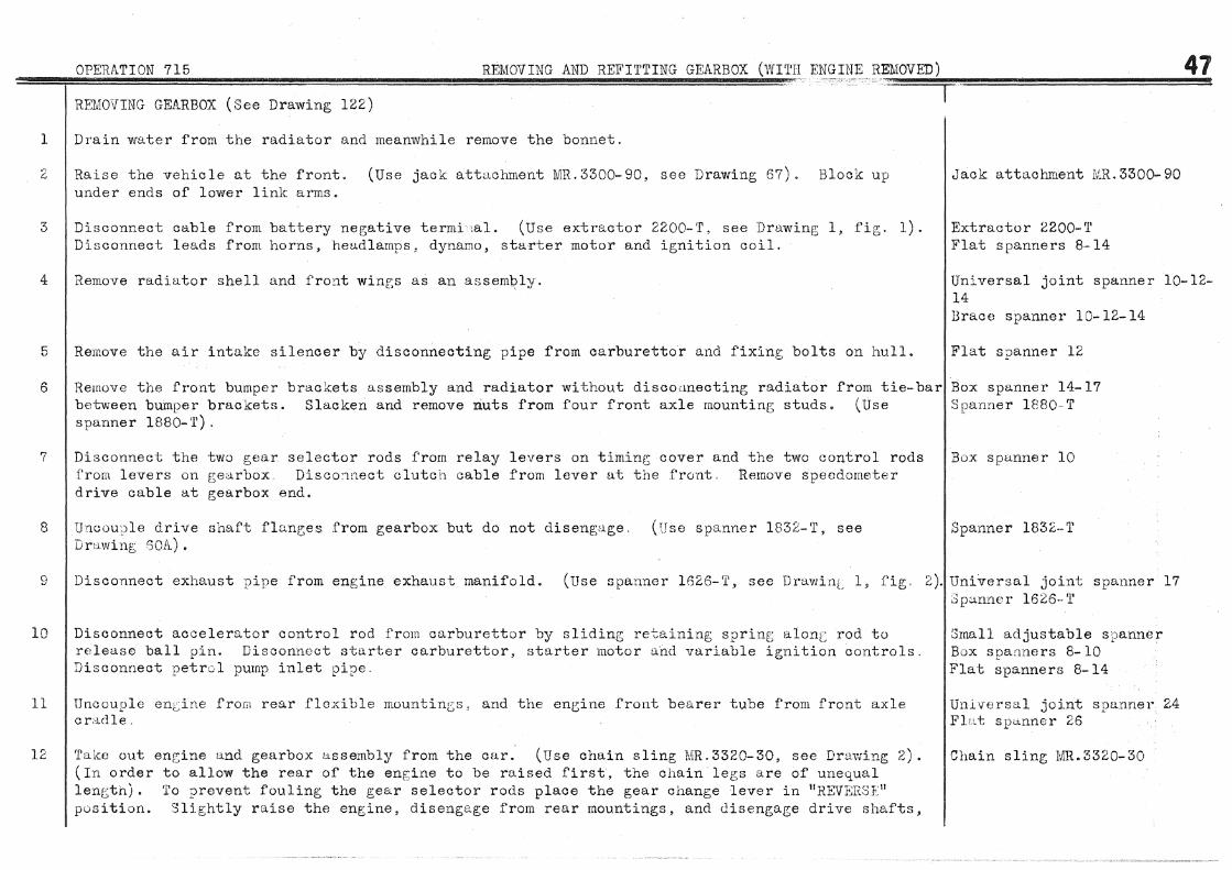
OPERATION 715 REMOVING AND REFITTING GEARBOX (WI'l'H EN.:~~~J}<;. RE1~10~V~ED~)~~~~~~~~~~~~4~7 RET~10VING GEARBOX (See Drawing 122)
1 Drain water from the radiator and meanwhile remove the bonnet.
2
3
4
5
Raise the vehicle at the front. (Use jack attachment MR.3300-90, see Drawing 67). Block up under ends of lower link arms.
Disconnect cable from battery negative termi lal. (Use extractor 2200-T, see Drawing 1, fig. 1). Disconnect leads from horns, heu.dlamps, dynamo, starter motor and ignition coil.
Remove radiu.tor shell and froc1t winr;s as an assemt?ly.
Remove the air intake silencer by disconnecting pipe from carburettor and fixing bolts on hull.
Jack attachment MR.3300-90
Extractor 2200-T Flat spanners 8-14
Universal joint spanner 10-12-14 Brace spanner 10-12-14
Flat spanner 12
6 Remove the front bumper brackets assembly and radiator without discocmecting radiator from tie-bar Box spanner 14-17
7
8
between bumper brackets. Slacken and remove nuts from four front axle mounting; studs. (Use Spanner HmO T spanner 1880-'1').
Disconnect the two gear selector rods from relay levers on timing cover and the two control rods from levers on gearbox. Disco:mect clutch cable from lever at the front. Remove speedometer drive cable at ~earbox end.
Uncounle drive shaft flanEes from gearbox but do not disengu.ge. (Use spanner 1832-T, see Drawil;g SOA) •
Box spanner 10
Spanner 1832-T
9 Disconnect exhaust pipe from engine exhaust manifold. (Use spanner 1626-'I', see Drawinc 1, fig. 2). Universal joint spanner 17
10
11
12
Disconnect accelerator control rod from carburettor by sliding retaining spring; alone rod to releu.se ball pin. Disconnect starter carburettor, starter motor a·nd variable ignition controls. Disconnect petrc·l pump inlet pipe.
Uncouple ensine from rear flexible mountincs, and the encine front bearer tube from front axle cr:-J.dle.
'l.'ake out engine and gearbox assembly from the car. (Use chain sling MR. 3320-30, see Drawing 2). (In order to allow the rear of the engine to be raised first, the chain legs are of unequal lenr:;th) . To prevent fouling the gear selector rods place the gear change lever in 11 Rl'NEI~SE 11
position. Slightly raise the engine, disengage from rear mountings, and disengage drive shafts,
8p;;.mner 1626-" T
:3mall adjustable spanner Box spanners 8-10 Flat spanners 8-14
Universal joint spanner 24 Fltct spL;.nner 26
Chain sling MIL 3320-30

48 OPERATION 715 . REMOVING AND REFITTING GEARBOX (WITH ENGINE REMOVED)
one after the other, from gearbox flanges. Pull engine forward to disengage the front bearer tube from studs on front axle cradle. Completely disengage unit from vehicle
13 Place the engine on a stand. (Use stand ~ffi.3300-50, see Drawing 119).
14 'fake off the dynamo.
15 Remove bearing cap (201) forming bracket for starting handle. NOTE. TAKE CARE NOT TO DISPERSE THE SHIMS (202) THAT MAY BE FITTED. With the aid of a pair of round nose pliers take out ~irclip (203) retaining the spring. Disengage the mainshaft by pullinE forwards.
16 Take off clutch housing cover, unhook return spring from clutch fork lever, and remove clu.tch fork with thrust ring;
17 Unoou;_:>le gearbox from cylinder block.
18
REFITTING GE!RBOX (see Drawing 122)
NOTE. If the gearbox or spacer has been replaced, it is essential to slacken the sump fixing bolts to refit the gearbox. This Ol)eration is necessary to avoid any strain on the gearbox fixing plates or the sump. Tightening of the sump fixing bolts will be carried out after tightening bolts fixing gearbox and spacer.
Make sure that the gearbox locatinc; dowels are correctly fitted in the cylinder block. Offer up the gearbox, engage it on locating dowels, fit tvvo bolts but do not tighten. Fit the spacer, put all fixing bolts in position, fit spring washers under nuts, and tighten. If necessary, tighten sump fixing bolts.
19 Fit the clutch withdrawal fork, with thrust ring assembled., .SO THAT THE GRAPHITE BUSH FACES THE CLUTCH TOGGLE THRUST RING, and the end of the double lever is in front of the outer locking oontrol lever.
20 Fit mainshaft pinion. Encage pinion wi t!t splines of mains haft by turning the latter by hand. Fit the circlip for retaining spring (203) by using a JUir of round nose pliers.
Fit the bearing; ca;_) (201) formintj startine; handle bracket, FITTING, IF NECESSARY, SHIMS (202) TAKEN OUT DURING GEARBOX REMOVAL. Coat the paper gasket with Hermetical and tighten bolts fixint; bearing c.aps ..
iJ'···.
Stand MR.3300-50
Flat spanner 17
Brace spanner and extension 12
Drace sptuner a.:1d extension 17
Universal joint spanner 21 Flat spanner 17
.Universal joint spanner 21 Flat spanners 17-21
Brace spanner and extension 1:::

OPE."'RJ\TION 715 REMJVING AND REFITTING GEARBOX (WITH ENGINE REMOVED
:2 Fit the engine front bearer tube (see Drawing 5, fig. 1). 1'urn the tube so that the threaded holes 11 att for bolts fixing radiator upper brackets are to ... vards the front. Make sure that the distance between the centre of the rubber bush (62) and the centre of the left hand fixing eye of the tube is 353 mm. If necessary, use packing washers, sold by our Spare Parts Department, between thrust washer (64) and ring welded on tube, to obtain this dimension.
·~3 Fit the clutch housing cover. Coat the threads of the three forward fixing screws and the flange Universal joint spanner 17 in the corresponding zone with Hermetical. Fit spring washers under heads of bolts and tighten. MAKE CERTAIN, THAT AFTER TIGHTENING, CLUTCH FORK SHAFT TURNS FREELY.
Fit the dynamo. Fit a plain and a spring washer under each nut, and tighten.
25 ADJUST DOUBLE IJWER (208)·(see Drawing 126)
26
27
28
29
30
(a) Position double lever (208) to obtain a dimension 11 a 11 of 27 nun., plus or minus l rnm. betvmen the ond of lever and stop on plate (209).
(b) Adjust screw (207) so that with the double lever in the above position the graphite bush of the clutch fork thrust ring is in contact with the toggle thrust ring.
(o) Tighten adjusting screw look nut. Hook on return spring (210).
NOTE. Clutch toggle clearance is obtained by adjustment of the clutch pedal after the engine is in position in oar.
Check and adjust the height of the engine rear flexible mountings. (Use template IiR.3450, see rawing 5, figs. 3 and 4).
aise the vehicle at the front. (Use jack attachment 1ffi.3300-90, see Drawing 67). Block it up nder ends of lower linkarms.
'uspend the engine. (Use chain sling MR.3320-30, see Drawing 2).
Lower engine into hull. Engage drive shaft couplings with gearbox flanges. Fit engine front bearer tube on studs on front axle cradle, provisionally screwing nuts, with spring washers under, on studs. Lower engine on rear mountings. Remove the chain sling. Tighten front bearer tube nuts. Tighten engine rear mounting nuts. Fit a plain and spring washer between nut and ounting bracket.
HELL TIGHTEN nuts of drive shaft flanges using a "Blocforttt locb'\Jasher under each nut (Use spanner 1832-T, see Drawing 60A).
Flat spanner 17
Fla,t spanner 17
Template MR.3450
Jack attachment NiR.3300-90
Sling MR.3320-30
_Flat spanner 26 Universal joint spanner 23
Spanner 1832-T
49

so 31
OPERATION 715 REMOVING A.ND REFITTING GEARBOX WITH ENGINE REMOVED
Fit exhaust pipe using a C. and A. gasket between pipe and manifold flanges. TIGHTEN THE NUTS WELL. (Use spanner 1626-T, see Drawing 1, fig. 2).
Spanner 1626-T
32 Connect clutch cable. Adjust cabl<;l to give an idle movement of 15 mm. to 20 Illlno to the highest Flat spanner 14 position of the clutch pedal. This movement corresponds to a necessary clearance of L 5 nun. to to 2 nun. between clutch fork graphite bush and the toggle thrust ring. After adjusting the cable tighten the lock nut and fit split pin to trunnion pin.
33 Connect the two gear control rods and fit split pins to fork and pins. Connect the two gear selector rods to the relay levers. Set these rods to an exact length so that no pull is applied to the levers. Make sure that the gear change lever does not catch in its lateral movement
34
35
36
37
38
in the selector. Fit split pins to the fork end pins.
Fit speedometer drive cable and tighten bolt with a spring washer fitted under head. Fit variable ignition, starter motor, and starter carburettor controls. Connect ignition coil wires. Fit flexible pipe on petrol pump. Connect aocelerator control.
Fit the assembly of radiator and front bumper brackets. Tighten bumper brackets, using a plain washer and a spring; washer under each bolt. Fit shouldered bushes, previously oiled, for aligning front axle cradle. Tighten front axle cradle fixing nuts with spring washers under. (Use spanner 1880-T) Line up the radiator with the gearbox bearing cap, which forms the starting handle bracket, by positioning radiator on bumper bracket tie-bar. Tighten 11 U11 bolts and ,radiator upper fixing plates. Tighten hose clips. After making sure that drain plug is shut, fill the radiator with water.
Clip the group of headlamps and horn wires to the engine front bearer tube. Connect the two earth wires under one of the bolts under each bumper bracket.
Fit the assembly of radiator shell and front wings. Fit a plain washer and a spring washer under all the fixing bolts and screw in a few turns only. Offer up the bonnet and line up parts in relation to one another. Fit wing piping and tighten the fixing bolts.
Connect wiring to headlamps, horns, dynamo, and starter motor. Connect positive and negative cables to battery.
Small adjustable spanner Flat spanners 8-14
Spanner 1880-T Universal joint spanner 17 Box spanners 10-14-17
Box and flat spanners 14
Flat spanner 14 Box spanners 8=12
Box and flat spanners 12
39 Fit the air intake silencer. Use a Hugo-Reintz gasket between the upper flange of the carburettor Flat and box spanners 12 and the inlet silencer. Fit the silencer fixi~g plates with a rubber washer on either side. Fit screv1s and secure with split pins.
40 Fit interior heater tube. Flat spanner 12

42
OPEH.ATION 715. REMOVING AND REFITTING GEARBOX (WITH ENGINE REMOVED)
Lower vehicle to the g:round. (Use jack attachment MR.3300-90, see Drawing 67).
Fill gearbox with oil (3.5 litres- 6 pints approximately). Use only special hypoid gear oil (similar to Mobiloil GX). Tighten filler plug fitted with a C. and A. washer.
51 Jack attachment MlL3300-90
Flat spanner 21

------------------~-------~-~------
S2 OPERATION 716 REMOVING AND REFITTING GEARBOX (WITHOUT REMOVING ENGINE)
:-===~===-==============------==~====-===-====-------------------------------------~--------------------... _) NOTE. It is recommended to remove the engine in order to detach the gearbox. However it is possible to remove the gearbox only if means are not available for taking out the-.engine (for example, absence of suitable lifting tackle). In this case the clutch must be r·E?moved as well.
REMOVING GEARBOX (see Drawing 122)
1 Drain water from the radiator and meanwhile remove the bonnet.
2
3
Raise the vehicle at the front. (use jack attachment MR.3300-90, see Drawing 67). Block up under ends of lower link arms.
Disconnect positive· cable from battery. (Use extractor 2200-T, see Drawing 1, fig. 1). Dis-eonnect horn, headlamp, and dynamo wires.
4 Remove the assembly of wings and radiator Shell.
5
6
7
8
Remove the air intake silencer. (Disconnect pipe from carburettor and remove fixing bolts from hull).
Remove the front bumper. brackets and radiator brackets as an assembly without dismantling radiator block from bumper bracket tie bar. Unscrew for four nuts on front axle cradle fixing studs. (Use spanner lseo-T).
Uncouple the two gear control rods from levers on gearbox. Disconnect clutch cable from front iever. Disconnect speedometer drive cable from gearbox.
Remove the dynamo.
9 Block up the engine under the sump with a hand operated jack. Apply the jack between the steering rack tube and tie bar across hull, USING A BLOCK OF WOOD BETWEEN SUMP AND JACK H~~.
10
11
Take off clutch housing cover.
Remove front bearing cap (201). TAKE CARE NOT TO DISPERSE SHIMS. With the aid of a pair of round nose pliers remove the ciro.lip. (203) of the spring. Diseng_ag.e mainshaft (204) by pul~ing towards the front.
12 Unhook return spring and take out the clutch fork with its thrust 'ring.
Jack attachment 1~.3300-90
Extractor 2200-T Flat spanners 8-14
Universal joint spanners 10-12-14 Brace spanners 10-12-14_
Flat spanner 12
Box spanner 14-17 Spanner 1880-T
Box spanner 10
F:Iat spanner 17
Brace spanner with extension 17
Brace spanner with extension 12

13
14
15
OP:E.'RATIOH 716 Rll~OVING AND REFITTING GEARBOX WITHOUT REMOVING ENGINE
Fit clamps to hold olutch toggles. ·(Use clamps MRa3451, see Drawing 26). Remove the clutch. Make sure before removing if the clutch position~ in relation to the flywheel, is indicated (either by a letter or figure). If there is no indication of location mark the position of the clutch so that it can be re-assembled in the same position and thus preserve the balance established during manufacture. Take out clutch discs and pressure plate.
Remove the engine fly.vhee 1. Hold the flywheel with a pin engaged in one of the balancine; holes when slackening nuts or bolts fixing flywheel.
Disconnect drive shafts from gearbox flanges. (Use spanner 1832-T, see Drawing 60A). Disconnect drive shafts at the flexible coupling by tapping the parts lightly with a mallet, and if necessar prising apart with a screwdriver or small lever.
Clamps MRo3451 Universal joint spanner 12
Universal joint spanner 12
F'lat spanner 14 Spanner 1832-T
53
16 Disconnect fro1n cylinder block WITHOUT UNCOUPLING SUMP SPACER. Take out all gearbox fixing bolts. Universal joint spanner 21 Flat spanner 21
17 Take out gearbox from oar. To do so, disengage gearbox drive shaft flanges from front axle cradle one after the other •
18
19
20
. REFITTING GEARBOX
Offer up gearbox to oar by engagine; drive shaft flanges in front axle cradle one after the other. Fit engine front support tube (see Operation 702 paragraph l3d for position and adjustment). Couple up gearbox, fit spring washers under nuts and tighten. Tighten the front support tube.
Connect drive shafts to gearbox flanges. TIGHTEN SECURELY THE NUTS OF THE UNIVERSAL COUPLING FLANGES, using a 'Blocfort' type washer under each nut. (Use spanner 1832-T, see Drawing 60A). Connect drive shafts at the flexible coupling. To ensure constant velocity of the universal joints the crosshead pins of the single joint must be parallel with those in the double joint. 'l'ighten up bolts using a 'Blocfort 1 type washer under heads.
Fit the engine flJ~heel (position located by an offset bolt). Fit lockwasher, tighten nuts to a tension of 2.500 mkg., plus 0.250 mkg., minus 0 mkg. (18 foot pounds, plus 1~- foot pounds, minus 0 foot pounds). (Use torsion wrench 2470-T, see Drawing 18). Turn back lockwasher tabs against flats of nuts.
21 FIT THE CLUTCH (see Drawing 27) (a) !take certain that the thrust faces on the flywheel,~ intermediate pressure plate. and clutch pressure plate are in perfect condition. Ensure that. the intermediate pressure plate slides freely between the flywheel driving studs. Mark the position which gives the best result for re-assembling.
Universal joint spanner 21-24 Flat spanner 21
Spanner 1832-T
Flat spanner 14
Torsion wrenoh 2470-T and socket 14

54
22
23
·OPERATION 716 REMOVING AND REFITTING GEARBOX (WITHOUT REMOVING ENGINE)
(b) Fit the intermediate pressure plate retaining spring (1) between two flywheel driving studs (see fig. 6). Fit the first clutch disc (2), with offset hub, positioned acc9rding to figo 1. Fit the intermediate pressure plate in the position previously marked (see paragraph 21a). Offer
·up the second clutch disc (3), flat type, positioned according to fig. 1. To centre the clutch discs in relation to the flywheel bearing use a mandrel or spare gearbox mainshaft. Fit the clutch so that markings on plate and flywheel register. Fit bolts (4), with spring washers under ~eads, and tighten to a tension of 2 mkg., plus 0. 250 mkg., minus 0 mkg. ( 14·~ foot pounds, plus Et foot pounds, minus 0 foot pounds. Durinr~ tightening make cert~;~.in that the mandrel (or mainshaft) slides freely and so indicating correct centering of discs. Remove the mandrel and toggle clamps l!ER.3451.
(c) Fit the clutch fork, with thrust ring assembled, SO TII/\T GRAPHITE BUSH FACES THE TOGGLE THRUST RING, and the end of the double lever is in front of the outer locking lever.
(d) Engage the gearbox mainshaft by turning by hand to engage the splines. Fit the shaft retaining spring ciralip by using a pair of round nose pliers.
Fit the clutch housing cover. Coat the threads of the three forward fixing bolts and the flange face in the corresponding zone with Hermetical. Fit boltsp with spring washers under heads, and tighten. AFTER TIGHTENING, MAKE SURE THAT THE CLUTCH l<'ORK SHAFT TURNS FREELY.
Stick the front bearing ca;) paper gasket to the gearbox flange with Hermetical. Fit the front bearing cap, 'HTH THE SHIMS REMOVED DURING DISM,:\.NTLING. Coat the bearing cap flange with Hermetical, fit, and tighten fixing screws.
Shouldered mandrel, small diao 17, length 25, large diav 21, length 300. Brace spanner 12
Universal joint spanner 17
Brace spanner with extension 12
24 ADJUST CLUTCH TOGGLE CLEARANCE (see Drawing 126)
25
26
(a) Bring the clutch fork thrust ring (206) into contact with the clutch toggle thrust ring (205) and keep in this position with the clutch fork.
(b) Screw the adjusting stud (207) to give a clearance na11 of 27.5 mmo between the end of the Flat spanner 17 double lever (208) and the stop on thrust plate (20~J). Tighten the locknut of stud (207). Hook on return spring (210).
(c) Connect the clutch cable and adjust length so that there is 15 nun. to 20 mmo idle movement Flat spanner 14 on the pedal before clutch fork thrust ring (205) operates against toggle thrust ring.
Fit the dynamo andtighten nuts after fitting plain washers and spring washers under each. Adjust the driving belt without excessive tension. Fit the speedometer cable.
Fit the assembly of radiator and front bumper bracke'ts. Tighten nuts fixing bumper brackets
Flat spanners 10=17
Spanner TBSO- T

27
28
29
30
31
32
OPERATION 716 REMOVING AND REFITTING GEARBOX (WITHOUT REMOVING ENGINE)
after fitting a plain washerand a spring washer under each. Using a spring washer under each, fit the four nuts on fro~t axle cradle studs and tighten up. (Use spanner 1880-T). Position the radiator on the buinper brac~et tie bar in order to line up the starting handle opening with the front bearing oa~1. Tighten 'U' bolts f'ixing radiator to tie bar. Tighten radiator upper fixing plates. Fit and tighten r~diator hose clips. After making sure that ·the drain tap is closed; fill the radiator with water.
Train the group of headlamp and horn wires along.the engine front.bearer tube and use clips to keep them in position. Connect the tvio earth wires under one bolt of each bumper bracket.
Fit the assembly of wings and radiator shell. Fit a plain washer and spring washer under the heads of all the fixing bolts and engage the latter for a few threads only. Offer up the bonnet and line up parts in relation to one another, and after correctly positioning the wing piping, tighten the fixing bolts. Take off the bonnet.
Connect wiring to horns, l1eadlamps, dynamo, and battery positive terminal.
Fit the air intake silencer. Use a Hugo-Reintz gasket between the upper flange of the carburetto and the air intake tube (4) (see Drawing 23). Tighten the screws. Tighten fixing plates fitted between two rubber washers. Tighten up nuts and fit split pins.
Lower the vehicle to the ground. (Use jack attachment MR.3300-90, see Drawing 67).
Fill gearbox with oil (3.5 litres- 6 pints). USE ~XCLUSIVELY SPECIAL OIL FOR HYPOID AXLES (oil similar to Mobiloil GX).
33 Fit the bonnet.
. "~
Universal joint spanner 17 Flat spanner 17 Box spanners 10-14-17
Flat and box spanners 14
F'lat spanner 14 Box spanners 10-12-14
Flat spanners 8-12-14
Flat and box spanners 12
Attachment MR.3300-90
Flat spanner 21
55
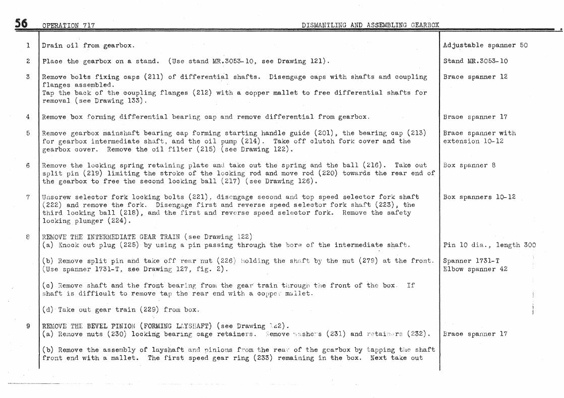
56
1
2
3
4
5
6
7
8
9
OPERATION 717 DISMANTLING AND ASSEMBLING GEARBOX
Drain oil from gearbox.
Place the gearbox on a stand. (Use stand l\ffi..3053-l0, see Drawing 121).
Remove bolts fixing caps (211) of differential shafts. Disengage caps witl1 shafts and coupling flanges assembled. Tap the back of the coupling flanges (212) with a copper mallet to free differential shafts for removal (see Drawing 133).
Remove box forming differential bearing cap and remove differential from gearbox.
Remove gearbox mainshaft bearing cap forming starting handle guide (201), the bearing cap (213) for gearbox intermediate shaft, and the oil pump ( 214). Take off clutch forlc cover and the gearbox cover. Remove the oil filter (215) (see Drawing 122).
Remove the locking spring retaining plate ancl take out the spring and the ball (216). Take out split pin (219) limiting the stroke of the locking rod and move rod (220) towards the rear end of the gearbox to free the second locking ball (217) (see Drawing 126).
Unscrew selector fork locking bolts (221). disengage second and top speed selector fork shaft (222) and remove the fork. Disengage first and reverse speed selector fork shaft (223), the third locking ball (216), and the first and reverse speed selector fork. Remove the safety locking plunger (224).
REMOVE THE INTERMEDIATE GEAR TRAIN (see Drawing 122) (a) Knock out plug (225) by using a pin passing through the borA of the intermediate shaft.
(b) Remove split pin and take off rear nut (226) holding the shu.ft b;y the nut (279) at the front. (Use spanner 1731-T, s.ee Drawini~ 127, fig. 2).
(c) Remove shaft and the front bearinp; from the gear·· train t11rougn the front of the box If shaft is difficult to remove tap the rear end vri th a coppe :- m~llet.
(d) Take out gear train (229) from box.
REMOVE THE BEVEL PINION (FORMING Li\YSIIAFT) (see Drawing ·.G2). (a) Remove nuts (230) locking bearing cage retainer-s. emove ·· ::.shc~s (231) and r·etaii: rs (232).
(b) Remove the assembly of ln.yshaft a.ncl pinions f:r·om the rea( of the gearbox by tapping tlw shaft front end with a mallet. The first speed gear ring (233) remaining in the box. Next take out
Adjustable spanner 50
Stand MR.3053-10
Brace spanner 12
Brace spanner 17
Brace spanner with extension 10-12
Box spanner 8
Box spanners 10-12
Pin 10 dia., length 300
Spanner 1731-T Elbow spanner 42
Brace spanner 17

OPERATION 717 DISMANTLING AND ASSEMBLING .GEARBOX
first speed gear ring.
10 Take out gear train of primary shaft from the box. (If necessary, use extractor MR.3404, see Drawing 129, figs. 1 and 2).
11 REMOVE THE REVERSE GEAR TRAIN (see Drawing 125) (a) Unscrew locknut (234) and take out reverse gear shaft thrust plug (235). (Use screwdriver M.R.3458, see Drawing 128, fig. 2).
(b) Withdraw the revers·e gear shaft (236). (Use extractor MR.3459, see Drawing 129, figs. 1 and 3).
(c) Disengage pinion (237) and thrust washer (238) from the box.
Extractor MR.3404
Screwdriver MR.3458 Elbow spanner 35
Extractor MR.3459
12 Remove the rear bearing (239) of the intermediate shaft from its seating~ in gearbox. Remove front Brace spanner 12-14 and rear oirclips (240). Remove the oil duct plug and the two covers of the gearbox air inlet
13
orifices. (See Drawing 122).
DISMANTLE THE BEVEL PINION (FORMING LAYSHAFT) (see Drawing 123, fig. 1) (a) Hold the assembly in a vice. (Use clamps MR.3407, see Drawing 130, figs. 1 and 2). Clamps MR.3407
(b) Remove bearing locknut (241). (Use spanner 1734-'l', see Drawing 127, fig, 3). Grip the shaft Spanners 1733-T and 1734-T on flats at end. (Use spanner 1733-T, see Drawing 127, fig. 4).
(c) Remove bearing (242) from shaft. (Use extractor 1750-T with collets 1753-T, see Drawing 37). Remove thrust washer (243), top speed pinion (244), spacing washer (245), and synchromesh (246).
(d) Remove the second speed pinion (247). To do this, press down with a small thin screwdriver, the locking plunger (248) which is visible in a spline of the front thrust washer (296). Turn the thrust washer to bring its splines to coincide with those in the shaft. Remove the thrust washer KEEPING THE PINION (247) IN POSITION ON THE SHAFT. Take out the looking plunger (248) and its spring. AT THIS POINT ONLY remove the pinion (247), and afterwards, the washer (295). NOTE. THIS ORDER OF DIS~~NTLING 1IDST BE RIGIDLY ADHERED TO because if the pinion is slid along the shaft with the washer without removing the plunger, the latter, under pressure of its spring, will jam between the two pinion bushes. IT i~LL NOT THEN BE POSSIBLE TO REMOVE THE PINION FROM THE SHAFT.
Extractor 1750-T Collets 1753-T
(e) Take out split pin and remove slotted ring nut (249) looking bearing. (Use spanner 1757-T, Spanner 1757-T see Drawing 128, fig. 6). Disengage bevel pin from bearing cage. (Take care not to disperse the rollers).
57

58
14
OPERATION 717 DISMANTLING AND ASSEMBLING GEARBOX
(f) Remove screw (250) locking bearing locknut (251). Remove bearing look nut (251). (Use spanner 1734-T, see Drawing 127, fig. 3).
(g) Remove the bearing inner races from the bevel pinion shaft by means of a press. (Use socket MR.3460, see Drawing 131, figs. 1 and 2).
DISMANTLE THE DIFFERENTIAL (see Drawing 133) (a) Extract the tapered roller bearings. (Use extractor 1750-T with collets 1753-'1', see Drawing 37) •
(b) Cut the looking wire of the assembly bolts and remove crown wheel from differential housing.
(c) Remove planet wheels (252), satellite wLeels (253), and. spindle (254) from housing.
15 DIS}AANTLE ~~INSHAFT PINION (see Drawing 124) (fig. 1) (a) Hold the assembly on an old nlB.inshaft gripped in a vice and remove successively the nuts (255 and 256). (Use spanner 1732-T, see Drawing 127, fig. l).
(b) Remove bearing (257). Do this in a press with the ram bearing on the front end of the mainshaft and with two plates or a socket fork bearing behind outer race of bearing.
(c) Remove the rear bearing (258). Do this in a press with the ram bearing on the rear end of the pinion spigot and the bearing resting on two steel plates, 7 mm. thick, fitted between pinion and bearing.
16 DISMANTLE DIFFERENTIAL SHAFTS AND CAPS (see Drawing 133). (a) Remove coupling flange (212) from shaft.
(b) 'Remove shaft ( 259) from bearing ( 260) by means of a press.
(c) Remove bearing locknut (261). (Use spanner 1758-T, see Drawing 128, fig. 1). Take out bearing (260) from cap (it is easily removed).
(d) Knock out oil seal (S.P.I. joint) from cap.
17 DISNIANTLE 'l'HE OIL. PUMP (see Drawing 123, fig. 2) . (a) Take off pump cover (263), speedometer cable socket (264), and take out drive pinion.
(b) Take out the pump impeller blade, remove speedometer drive worm circlip (266), and remove
Spanner 1734-T
Socket MR.3460
F:xtractor 1750-T Collets 17 53- T
Universal joint spanner 19
Spanner 1732-T
Universal joint spanner with socket 26
Spanner 1758-T
'

OP'F:HATION 717 DISMANTLING AND ASSEMBLING GEARBOX.
worm (267) by knocking out the spindle (2GB) from the pump body" Take out key (26S) from its receBs.
18 DISMANTLE THE SYNCHROMESH
19
(a) ·wrap the synchromesh assembly in a cloth to prevent dispersal of balls and springs when dismantlinf;.
(b) Disengage synchromesh hub by pressing out by hand.
DISMANTLE GEARBOX COVER (see Drawing 134) . (a) Take off outer selector levers (270 and 271). Disengage inner levers (272 and 273) from cover.
Box spanner 12
(b) Take off inner locking lever (274) and disene:;age outer lever (275) from cover (see Drawing 126) Flat spanner 12
20
(c) Remove the oil filler plug.
(d) Knock out bushes (276) from inner lever ( 273). (Use a shouldered mandrel).
(e) Knock out bushes (277) from cover. (Use a shouldered mandrel).
Remove front bearing (278) from intermediate shaft (see Drawing 124, fig. 2) by unscrewing nut (279). (Use spanner 1731-T, see Drawing 127, fig. 2). Remove shaft (228) from bearing~ by means of a press.
21 DISMANTLE REVERSE GEAR TRAIN (see Drawing 125)
22
(a) Remove metal from the nut punched into the two pinion slots either with an awl or small punch.
(b) Unscrew nut (280) with a hammer and chisel. The nut must be replaced by a new one after each dismantling.
(c) Take out bearin[~S ( 281 and 282) from the pinion (these are readily removed)" and the distance piece (283).
Remove differential nut covers. Remove locking plates (284) of' differential nuts, (See DrawingJ33, fig, 2).
23 Remove gearbox casing from stand.
Box spanner 21
Mandrel, small dia. 16 large dia. 18, length 150
Mandrel, small dia. 24 large dia. 26, length 150
Spanner 1731- T
Brace spanner 12
59

60 OPERATION 717 DISMANTLING AND ASSEMBLING GEARBOX
24 Clean the parts.
ASSEMBLING GEARBOX
IMPORTANT NOTE. IN CASES WHERE THE PINION BUSHES ARE WORN IT IS NECESSARY ·ro REPLACE THE PINIONS. IT IS ESSENTIAL FOR THE BORE OF THE BUSHES TO BE EXACTLY CONCENTRIC WITH THE PINION PXTCH DIAl~TER. THE MANUFACTURE OF "THESE PARTS IS SUCH THAT THE BORE OF THE BUSHES IS NOT CONCENTRIC WITH THE PINION PITCH DIAMETER. We give herewith a method to be strictly adhered to when replacing bushes.
Set up the pinion to be rectified on a mandrel FITTING THE WORN BUSH. (In the case of excessive ovality the pinion cannot be rectified). True up the outside diameter of the pinion. Remove the mandrel and change the bushes. Centre the pinion in lathe using the rectified portion as a basis for concentricity.
Use lathe tool to bore the bushes.
25 PREPARE INTERMEDIATE R~vERSE GEAR TRAIN (see Drawing 125) (a) Fit bearing (281) into pinion, using a press if necessary.
(b) Fit distance piece (283) and bearing (282).
(c) Sore!' up and look nut (280). (Use spanner MR.346l, see Drawing 128, fig. 3). Use a chisel or punch to force metal from the nut into the two slots in the pinion .•
26 PREPARE fflAHJSHAFT PINION (see Drawing 124, fig. 1) , (a) Fit bearings (257 and 258) to pinion with the aid of a press.
(b) Fit oil retaining washers and then lock washers on spigot ends of pinion. Engage tongues of lock washers into grooves and screw on nuts (255 and 256).
(c) Mount the assembly on an old mainshaft and hold the latter in a vice in order to prevent damage to the pinion teeth. Tighten nuts (255 and 256). (Use spanner 1732-T, see Drawing 127, fig. 1). Turn back lookwasher tabs against flats of both nuts.
27 PREPARE THE INTERMEDIATE SHAFT (see Drawing 124, fig. 2) Fit washer (286) to shaft. By means of a press fit bearing (278). Grip the shaft in a vice, tighten nut (279) to a tension of 10 mkg. (72i foot pounds). and fit split pin. (Use spanner 1731-T, see Drawing 127, fig. 2).
Spanner 1732-T
Spanner 1731-T

28
OPERATION 717 DISMANTLING AND ASSEMBLING- GEARBOX
PitEPARE SYNCHROMESH (see Drawing 135) (a) Use modified synchromesh ring :11.1\Ro 3464 (fig;. 4)
(b) Place springs ( 287) in position. F'i t synchromesh hub ( 288) in tool l\ffio 3464. Engage the balls (289). Push the hulJ down until balls look.
NOTE TilE SYNCIIROMESH HU 13 AND RING ARE MARKED ACCORDING TO Iv!ACHDJING ~ THE MARKING SYMBOL+ IS STA.MPED ON THE FACE NEAREST THE SELECTOR FORK GROOVE. WHEN RE-ASSEMBLING THE MAJiKINGS MUST COINCIDE IN ORDER ·ro ENSURE C:ONCENTRICITY OF' THIS TWO PAR'rS AND CORREC'I'LY LOCATE TliE SYNCJIHOMeSH CONES (THE T"vVO CONE; ANGLES DIFFI£'R).
(c) Place the assembly as made i:J. paragraph 28(b) on synchromesh ring; (290) previously oiled. Keep the parts together, to prevent the Th:alls escapinr;, and slide the hub (288) right into the rint~ ( 290).
29 PREPARE: THE BEVEL PINION (see Drawiur; 123, fil~· 1) (a) Fit bearings (291 and 292) and c~ge (293). Proceed as follows:-
1. Fit to bevel pinion (294), the inner race "b" of roller bearing (291) and then the inner race of thrust bearing (292), by means of a press.
2. Tighten bearing locknut (251) and lock the nut with screw (250). (Use spanner 1734-T, see Drawing 127, fig. 3).
3. Hold. the cage (293) in a vice. (Use clamps Ii'ffi.3407, see Drawing 130). Tighten vice moderately only to prevent distorting cage.
4.
5.
(b) FIT l.
Hold the bevel pinion vertically, the pinion end at the top. Position half rinf; 11 a. 11 of thrust bearing (292). Stick in place with a little gre~se the rollers of bearing (291) to the inner race "b11 , and fit the outer race 11 c 11 over the rollers.
Introduce the assembly into cage (2.&3), Fit the second half ring 11 d 11 of the thrust bearing (292) and tighten nut (249). (Use spanner 1757-T, see Drawing 128, fig. 6). Fit the split pin and FORCE THE HEAD YifELL INTO THE HOLE IN THE CAGE SO THAT IT DOES NO'l' STAND PROUD. Open out ends of pin.
AND ADJUST SECOND SPEED IDLER PINION (see Drawing 123, fig. 1) Fit second speed pinion adjusting washer (295) on shaft (the grease grooves on the pinion side). Fit second speed pinion (247) and the splined front thrust washer (2.Q6) turning the latter so that it is locked :)y the shaft splines.
Tool MRo3464
Spanner 11'34-T Flat spanner 7
Clamps T:IJ.'H. 3407
61
2. Use feeler gauges to measure the clearance between washer (295) and the pi:'lion. The Set of feeler gaur:;es clearance should be between Q. 05 O:ilii. and 0.15 nun. and is arrived at by using a washer (295)
~--------------
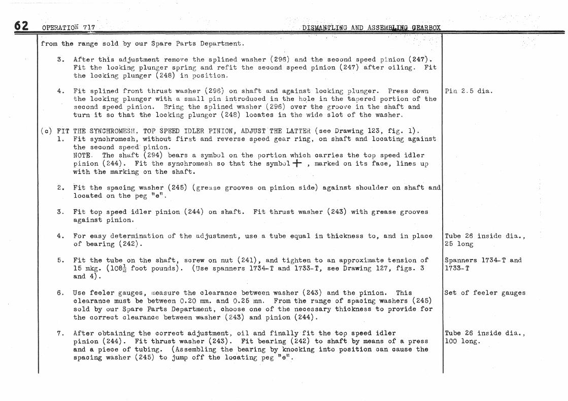
62 OPERATION 717
from the range sold by our Spare Parts Department.
3. After this adjustment remove the sp1ined washer (296) and the second speed plnl.on (247). Fit the looking plunger spring; and refit the second speed pinion (2,17) after oiling. Fit the locking plunger (248) in position.
4. Fit sp1ined front thrust washer (296) on shaft and against locking plunger. Press down Pin 2.5 dia. the locking plunger with a small pin introduced in the ho,1e in the tapered portion of the second speed pinion. Bring; the splined washer (296) over the grooiTe in the shaft and turn it so that the locking plunger (248) locates in the wide slot of the washer.
(c) FIT THE SYN"CHROMESH, TOP SPT£ED IDLER PINION·, ADJUST THE LUTEH (see Drawing 123, fig. l). 1. Fit synchromesh, without first and reverse speed gear ring, on shaft and locating against
the second speed pinion. NOTE. The shaft (294) bears a symbol on the oortion which carries the top speed idler pinion (244). Fit the synchromesh so that th~ symbul + , marked on its face, lines up with the marking on the shaft.
2. Fit the spacing.washer (245) (gre~se grooves on pinion side) against shoulder on shaft and located on the ~eg "e".
3. Fit top speed idler pinion (244) on shaft. Fit thrust washer (243) with grease grooves against pinion.
4. For easy determination of the adjustment, use a tube equal in thickness to, and in place of bearing (242).
5. Fit the tube ort the shaft, screw on nut (241), and tighten to an approximate tension of 15 mkg. (10&~ foot pounds). (Use spanners 1734-T and 1733-T, see Drawing 127, figs. 3 and 4).
6. Use feeler gauges, measure the clearance between washer (243) and the p1n1on. This clearance must be between 0.20 mm. and 0.25 mm. From the range of spacing washers (245) sold by our Spare Parts Department, choose one of the necessary thickness to provide for the correct clearance between washer (243) and pinion (244).
7. After obtaining the correct adjustment, oil and finally fit the top speed idler pinion (244). Fit thrust washer (243). Fit bearing (242) to shaft by means of a press and a piece of tubing. (Assembling the bearing by knocking into position oan cause the spacing washer (245) to jump off the locating peg 11 en.
Tube 26 inside dia., 25 long
Spanners 1734-T and 1733-T
Set of feeler gauges
Tube 26 inside dia., 100 long.

OPERATtOI'l' 717 DIS)IIANTLTNG AND ASSEMBLING GEARBOX
8. Hold the assembly in a vice using clamps Jiffi.3407 (see Drawing 130), fit locbrasher on end of shaft with tonf;ue engage in shaft groove. Screw on nut (241) and tighten to a tension of 15 mkg. ( 108~ foot pounds). (Use spanners 1734- T and 1733- '1', see Drawing 127, figs. 3 and 4). TURN BACK ALL LOCK1NA.SHER TABS against flats of nuts.
9. Remove the assembly from vice.
30 PHEP'l.Rl~ THE DIFFERENTIAL (see Drawing 133) NOTE. As the differential housin&;, planet and satellite wheels are precision machined, these parts can be fitted without the need of adjustment (tooth meshing or clearance). As it has not been possible to foresee the amount of wear in the assembly over a long period of use, we have not been able to determine sizes of packing washers that might be needed to take up any play that could possible occur.
(a) Hold the dif'ferential housing in a vice.
(b) Oil the satellite pinions and shaft (254),
(c) Mount planet wheel (252) and two satellite wheels (253) in the housing, press in the shaft (254), positioned so that the hole nfu lines up with the hole for locking screw (297).
(d) 'l'urn the planel wheel by the shaft and make sure there are no high spots in the. meshing. If there is tightness, find which satellite wheel has no tooth clearance and replace it. Make sure that the new wheel gives free rotation. If the high spot remains it may be caused by the planet wheel. In this case try another planet wheel.
Spanners 1734- T and 1733-T
(e) Mount the second planet wheel in the housing. Fit the crown wheel and tighten assembly bolts Universal joint spanner 19 to a tension of 7.5 mkg. (54jk- foot pounds). Turn the planet wheel and if high spots are present try another.
(f) Look the bolts assemblinf; the crown wheel with iron wire fitted so as to prevent any chance of loosening.
(g) Fit the taper roller bearinv,s using a press. (Use mandrel MR.3463, see Drawing 133, fig. 3). Mandrel MR.3463
31 PH.EPARE DIFFEHENTIAL BEARING CAPS AND SHAF"l'S (see Drawinf; 133) (a) F'it the oil seal (262) in cap (211) by using a press. The leather rim of the oil seal faces towards the inside of the cap.
(b) Use a press to fit bearing (260) on shaft (259).
63

64 OPERATION 717 . DISMANTLING AND ASSEMBLil'm GEARBOX
(o) Fit shaft with bearing ass.embled into cap (if necessary tap the end of the shaft with a mallet to o ompiete the fitting) .
(d) Tighten bearing locknut (261). (Use spanner 1758-T, see Drawing 128, fig. 1). Look the nut (261) by using a chisel to punch some of the nut threads into the cap groove.
(e) Fit coupling flange (212) on shaft. Fit thrust washer (298) by centering in the recess in the flange. Hold the flange in a vice and tighten nut to a tension of 20 mkg. (144 foot pounds). Secure nut with a split pin.
32 PREPARE THE OIL PUMP (see Drawing 123, fig. 2). (a) Place key (269) in shaft (268). Oil shaft and engage it in pump body. Fit the impeller (265) so that front edge marked 11AV 11 is located aocording to fig. 2).
(b) Fit pump cover with a paper gasket, coated with Hermetical, under. Tighten fixing bolts fitted with spring washers under the heads.
(c) Fit the speedometer drive worm (267) making sure that the key has not slipped out of the shaft meanwhile. Fit oirolip (266).
33 PREPARE THE GE~RBOX COVER (see Drawing 134).
34
(a) Fit bronze bushes (277) in bore in cover. (Use a shouldered mandrel).
,; (b) Fit bronze bushes (276) in bore of first and reverse speed selector fork lever (273). i (Use a shouldered mandrel).
~
~(c) Oil and fit levers (272 and 273). Provisionally fit the outer levers (271 and 270). (The ·position of these levers will be determined when the cover is fitted to the gearbox).
(d) Fit lever (275). Fit gear lock control lever (274), tighten the nut, turn back ta.bs of ~ lockwasher (see Drawing 126).
(e) Provisionally sc-rew in oil filler plug using a C. and A. washer under.
Place the gearbox casing on stand ~ffi.305~-10 (see Drawing 121, fig. 1).
35 Fit oirolips (240) for retaining intermediate shaft bearings in box (see Drawing 122).
36 'Fit intermediate shaft rear bearing (239) in box. Tap the bearing outer race lightly, with a
; $panner 1758-T
Universal joint spanner with extension 26
Box spanner 12
Mandrel, small dia. 24, length 20 large dia. 26, length 130
Mandrel, small dia. 16 length 20 large dia. 18 length 130
Flat spanner 12
Stand MR.3053-·10

OPERATION 717
copper mallet. until bearing rests against the circlip (240).
37 FIT THE Il'if'fERMEDIATE REVERSE GEAR TRAIN (see Drawing 12 5) (a) Oil the shaft (236).
DIS:MANTLING AND ASSEMBLI~G GEARBOX
(b) Offer up the reverse gear train in the box, position thrust washer (238) and hold it in place with the gear train.
(c) Fit the shaft (236) and turn it by hand to eneage it in the thrust washer (238). The shaft Screwdriver MIL3458 has a chamfer at the end). Complete the fitting of the shaft by screwing in the plug (235). Elbow spanner 35 (Use screwdriver MR,3458, see Drawing 128, fig. 2), Fit on the plug the double tabbed lockwasher. Turn one tab against stop of gearbox. Screw on nut (234) and tighten. Turn back second lockwasher tab against flat of nut.
38 FIT THE MAINSHAF'f GEAR TRAI'1 (see Drawing 122) . (a) Oil the bearings.
(b) Offer up the assembly squarely with the gearbox bore and push in until it comes against the stop. If necessary, use a mallet 'to drive the assembly into position.
39 FIT AND ADJUST THE POSITION OF THE B1'VEL PINION (see Drawing 122) NO'fE, THE ADJUSTING OF THE BEVEL PINION POSITION IS OF VERY GREAT IMPORTANCE. By giving the teeth correct meshing. silence and long service is assured.
(a) Etched on the bevel pinion face is a dimension (in millimetres) see Drawing 136 9 fig. 3) indicating the height of the bevel apex determined during machining. (The figure represents ti:te distance 11 h11 betweei1 the differential centre line and the end face of the bevel pinion).
(b) Fit the layshaft.assembly (as prepared according to paragraph 29) in the box. On each fixing Brace spanner 17 stud fit a retainer (232) and a thrust washer (231). Screw on and tighten nuts (230).
(c) Set up the apparatus 2040-T (see Drawing 136, fig. 1), establishing the.dimension 11 h11 • Fit shims, chosen from the range listed by our Spare Parts Department, between the cage (293) and the box so that the measured dimension tth11 is the same as that etched on the pinion. The adjustment must be made with the greatest precision, THE PART OF THE DI!VIENSIOJIJ IN EUNDRI';DTHS OF A MM. MUST BE RIGIDLY OBSERVED This justifies the use of a clock gauge SET UP ON A FIXTURE MOUNTED IN THE BORES Oli' THE DIFFERENTIAL BEARIJIJGS. Do not measure from the flanges of the box as the machining tolerance here is several tenths of a millimetre.
(d) After establishing the correct adjustment, remove the layshaft assembly from the box.
65

66 OPERATION 717 DISMANTLING AND ASSEMBLING GEARBOX
To ensure concentricity when assembled, the first and reverse speed gear ring and the synchromesh are marked to indicate correct fitting. BOTH PARTS ARE CORRECTLY ASSEMBLED WHEN THE MARKINGS COINCIDE. Having determined the positioning of the parts, use chalk to mark the teeth of both items so they can be correctly mated on assembly. (On certain vehicles the parts are not marked).
(e) Offer up the layshaft assembly, with shims (299) fitted on cage (293), in bore of box. Introduce into the box, by way of the gearbox cover opening, the first and reverse speed gear ring, and engage it on the synchromesh. The teeth must mesh correctly in the way aiready determined and indicated by the chalk marks. Complete the fitting of the la.yshaft assembly by tapping the end of the bevel pinion with a mallet.
(f) On each fixing stud fit a retainer (232) and thrust washer (231). Tighten nuts (230) and secure with split pins.
40 FIT THE INTERMEDIATE GEim TRAIN (see Drawing 122) (a) Engage the intermediate gear train (229) in the box, by inserting through cover opening, and hold in line for fitting shaft.
(b) Fit shaft (228) (prepared according to paragraph 27) through front end of box and in gear train (229). Use a mallet to tap the front end until front bearing rests against circlip (240).
(c) Hold the front nut (279). (Use spanner 1731-T, see Drawing 127, fie;. 2). Tighten rear nut (226) and secure with split pin.
41 FIT THE DIFFERENTIAL, ADJUST TOOTH CLEARANCE (see Drawing 136, fig. 2 and Drawing 133) (a) Read on the face of the pinion the dimension, expressed in hundredths of a millimetre, indicating the bevel pinion and crown wheel tooth clearance to be realised by adjustment (see fig. 3).
(b) Offer up the differential in housings in box with bea.rine;s fitted with outer races. Place bearing locknuts (300) on threads of bores in e;ea.rbox and against bearing outer races. Make sure that the threads are correctly engaged and that the locating dowels are fitted properly in the box. Coat the flange faces of the box and cover with Hermetical. Fit the differential box. Fit a spring washer on each stud, screw on nuts but do not tighten.
(c) Mount a clock gaug;e. (Use clock gauge bracket 2041-T. see Drawing 136, fig. 2).
(d) Tighten the two bearing locknuts (300). (Use spanner 1751-T, see Drawing 138). Unscrew nuts a. quarter of a turn, and then screw up the one which will p;ive the tooth clearance figure etched on the bevel pinion face. The clearance is measured by the clock gauge on the outside diameter of the crown wheel and tangentically to the flank of a tooth. Make four readinr;s,
Universal joint spanner with extension 17
Spanner 1731- T Elbow spanner 42
Universal joint spanner 17
Clock gauge bracket 2041-T
Spanner 17 51-1'

OPERI\TlON 717 DISMANTLING AND ASSEMBLING GEARBOX
spaced at approximately 90°, and take the average of the four. The difference between any two readings must not exceed 0.1 mm. Remove the clock gauge bracket.
(e) The Tirnken bearings must be fitted with slig,ht clearance. Without al teriw~ the adjustment, screw up the ::;econd nut (300) and then unscrew one notch (equivalent to approximately 5 mrn. on the outer circumference of the nut). (Use spanner 1751-T, see Drawing 138).
(f) Finally tir;hten nuts of differential box.
Spanner 1751-T
Universal joint spanner 17
(g) On the differential box, coat the lock plate (284) and closing plate (301) seatine; faces Universal joint spanner 12 with Hermetical. Fit paper gaskets, and also coat the seating faces of the plates with Hermetical. Fit the lock plates by positioning the locking peg in one of the bearing locknut (300) castellations. Fit the closing plate (301). Coat the threads of the fixing screws with Hermetical and tip;hten screws after fitting spring washers under heads (see Drawin§~S 122 and 133).
42 FI1' THE DIFFERENTIAL SHAFTS (see Drawing 133)
43
(a) Coat the flanges of' the differential shaft bearint; caps and the corresponding flanges on the box with Hermetical. Fit paper gaskets to the caps.
(b) Engage differential shafts in planet wheels, fit spring washers under heads of bearing cap fixing bolts, and tighten.
Coat the outer circumference of the intermediate shaft plug (225) with Hermetical and fit in place in box (see Drawing; 122). (Use mandrel l\IRo3428, see Drawing 127, fig. 5) ..
Universal joint spanner 12
!ftandrel MR. 3428
44 FIT AND ADJUST SELF:CTOR FOHKS. ADJUST POSITION OF SYNCHROMESH (see Drawing 126) NOTE. Some gearboxes have been built with locking rods (220). having an adjusting screw at one end. This screw is intended for adjusting the length of the rod to obtain positive locking of the forks. At present the locking rods are of a fixed length and have no adjusting screw.
(a) If the locking rod has an adjusting screw, engage the rod in its bore in the gearbox and push Flat spanner 10 right in until the head of the adjusting screw bears against the gearbox wall. By operating the adjusting screw obtain a sufficient lene;th of rod to give a dimension at 11 i 11 of 16.5 mm. plus or minus 0.5 mm. (see Drawing 126) between the flange of the box and the end of the rod. After adjusting ti1~hten locknut of so :rew.
(b) If the locking rod has no adjusting screw, oil the rod and fit into gearbox so that the front end of the rod 11 k11 is flush with face "j 11 of the gearbox flange.
(c) Fit ball (218) in ~Josition by inserting: it by way of the bore for the second and top speed selector for~ shaft (222).
67

68 OPERATION 717 DISMANTLING AND ASSEMBLING GEARBOX:
(d) Fit the first and reverse speed selector fork ( 202) in the groove of the first and reverse speed gear ring carried by the synchromesh. Fit the second and top speed selector fork (303) in groove of the synchromesh. (The first and reverse speed _gear ring and the synchromesh having previously been placed in the neutral position).
(e) Oil the gearbox and location). positioning
second and top speed selector fork shaft (222). Fit the shaft into its boring in the force into place by fitting the short distance piece (304) (see Drawing 126 for Engage the shaft in the selector fork (303) and then in the long distance piece (305) the latter as indicated on Drawing 126.
(f) Fit the locking split pin (219) in the locking rod and open out ends. (The split pin is fitted to locking rods having no adjusting screw).
(g) Fit the locking plunger (224) in position, using a little grease to hold it, by pushing it in with a 6 mrr1. diameter rod.
(h) Fit ball (217) in place, using a little grease to hold it, by pushing it in with a 6 mm. diameter rod.
( i) Oil the first and reverse speed selector fork shaft ( 223) and fit in gearbox. Force shaft into place by fitting the .long distance piece (306) (see Drawing 126 for location). Engage the shaft into selector fork (302) and then in the short distance piece (307) positioning the latter as indicated on Drawing 126.
(j) Fit ball (216) and its spring. Fit plate retaining the spring, tighten fixing bolt with a spring washer fitted under head.
Rod 6 mrn. diameter
Rod 6 mrn. diameter
Box spanner 12
(k) Tighten the pointed screw (221) fixing first and reverse speed selector fork (302). Lock the Flat spanner 10 screw with wire SO A.S TO PREVENT IT SLACKENING. Make sure that the wire does not foul BET'NEEN THE SELECTOR FORK AND THE DISTANCE PIECES.
(1) Adjust the position of the synchromesh.
NOTE. The synchromesh has approximately 4 rnm. clearance from the cones of the second and top speed p1.n1.ons. This is necessary to prevent any possibility of .friction between the cones when gears are in the neutral position. On the other hand, it is necessary to position the synchromesh at the mean point of its travel. Position the synchromesh according to the following operation (see Drawing 137).
(m) Free the selector fork adjusting screw (221) and place the gear locking rod in the neutral position.
Flat spanner 10
OPERATION 717 DISMANTLING AND ASSEMBLING GEARBOX
By means of selector fork (303) slide the synchromesh towards the top speed pinion (244). Using a caliper gaugt:J~ measure the distance 1'1 11 between the front face of the gearbox ( 11 m11 ) and the front inner wall of the throat of the selector, ·at 11 n11 (see fig. 1). Say for {3Xample 11 111 = 84 nun. Next, again by means of the selector fork (303) slide the synchromesh towards the second speed pinion (247). Take a fresh dimension 11 p" between points 11 m" and n~~~. and say. for example, "p11 = 88 mm. The average of the two measurements is 11 1'' + 11 p11 divided by 2, say from the preceding examples 84 "·" 88 divided by 2 = 86 rnrn. This figure represents the distance from the front face of the bo:x: um11 to the front inner wall of the throat of the selector fork "n11 when the synchromesh is at the mid-point of its travel. Alter the position of the synchromesh, by turning the selector fork adjusting screw (one complete turn of the screw moves the synchromesh approximately 0.7 rnrn.), so as to obtain a dimension between points 11 m11 and 11 n11 " measured with a caliper gauge, equivalent to l + p divided by 2 as in the preceding example, 86 mrn
(n) Engage successively top speed and then second speed. Make sure that in these positions tbe flanks of the synchromesh do not rub against the second and top speed pinions of the intermediate gear traino If there is fouling correct the positioning by the selector fork adjusting screw.
(o) Return gears to the neutral position. Turn the layshaft (294) and make sure that the synchromesh doe.s not i'oul the second or top speed oinions (244 and 247). Look the selector fork adjusting screws (221) with wire in such a way SO AS TO PREVENT ANY POSSIBILITY OF SLACKENING. Make sure that the wire does not FALL IN BET'NEEH THE SELECTOR FORK AND DISTANCE PIECES.
(p) Adjust the second and top speed selector fork distance pieces (see Drawing 123, fig. 1 and Drawing 126). With the aid of a lever, push the synchromesh towards. the top speed pinion ( 244) far enough to lock the shaft 222 with the ball. Lock the shaft by operating the locking rod. In this position, adjust the length of distance piece (304) so that the .clearance between distance pieqe and face 11 r" of the gearbox is from 0.1 mm. to Oo2 mm. (Use two spanners 1780-T and one spanner 1781- T, see Drawing 128, figs. 4 and 5). . Withdraw the locking device. Push the synchromesh towards the SE.lCOnd speed pinion (247) far enough for the selector shaft to be locked by the ball. Lock in position with the locking rod and adjust the length of distance piece (305) by the same method as before.
(q) Adjust the first and reverse ~?e~d selector fork distance pi,eces. (Operations are the same · as for those of the second and top: Sp~ed selector fork).
(r) Fit the selector fork shaft protecting plate. Coat the gasket with Hermetical, tighten fixing screws using spring washers under the heads.
Spanners 1780- T and 1781-.T
Spanners 1780..: T and l78l:..T
Box spanner 10
69
70 OPERATION 717 DISMANTLING AND ASSEMBLING GEARBOX
45 FIT THE OIL PUMP (see Drawing 122) (a) Fit the cork gasket (308) on the filter (215) and engage the latter in the gearbox.
(b) Stick the pump paper gasket on the face of ithe box with HElrmetical.
(c) Coat the exposed face of the gasket on the .box with Hermetical. Turn t:he .pump shaft (268) so Universal joint spanner 12 that its slot· is in line with the tongue on the end of the layshaft (294). Fit the pump. Coat threads of fixing screws with Hermetical and tighte~up.
46 FIT INTERMEDIATE SHAFT FRONT BEARING CAP (see Drawing 122) (a) Stick the paper gasket to the face of the box with Hermetical.
(b) Make sure that the front bearing (278) is seating correctly against circlip (240) in the gearbox.
(;::)Measure the amount, the bearing stands proud from the face of the gearbox. (Use a clock gauge. mounted on bracket lVIR. 3377, see Drawing 17, fig, 3). Place the straight edge on the bearing and let the finger of the.gauge bear against the paper gasket previously stuck on the gearbox flange.
(d) r!:easure the depth of the bearing housing in cap (213).
(e) If the depth of the bearing housing is greater than the amount the bearing stands proud, um .. r \l ''al joint spanner 12 choose adjusting washers from the range listed by our Spare Parts Department to take up t:he difference. ·use grease to stick the washers in recess of cap. Fit cap (213)" Coat the cap and the threads of the fixing screw with Hermetical. Tighten the screws.
47 FIT lviAINSHAFT FRONT BFARING CAP (201) FORMING STARTING HANDLE GUIDE (see Drawing 122). (a) Stick paper gasket to gearbox flange with Hermetical. ·
(b). Make sure that the front bearing (257) is correctly posit~oned in the bo:ic.
(c) I\Ieasure the amount the bearing stands proud, and the. depth. of its recess in cap (201) in the manner described in paragraphs 44(c) and (d).
(d) Choose adjusting washers from the range iisted by our Spare ;Parts Department to take up ·the difference Ln measurements. Use grease to stick the washers in ·the bearing cap (201) •. ProVisionall "'it the bearine; cap (the final fitting is carried out after.gearbox is connected to the e:p.gine. . .
48 FIT TEE \iYi\.RB~~··{ :;;:JVFR. ,".DJUST POSITION OF LYvERS (see Drawings 126 and 134) (a) Set the selector forks in the neutral positi,Jn.
,.

49
OPERATION 717 DISllliANTLING AND ASSEMBLING G I
(b) Stick the paper gasket to the gearbox with HermeticaL Coat the cover flange with Hermetical Fit plain washers on bolts fixing the. cover.
(c) Offer up the cover, engage (274) in notch in gear looking gear lock and the plate fixing; return spring.
inner levers ( 272 and 273) rod (220); Fit the thrust looking rod return spring.
in selector forks 9 and control lever bracket (209) (see Drawing 126) for the
Tighten bolts fixing cover. Hook on
(d) Adjust the position of the outer control lever. With the selector forks .in the neutral position, the centres of the holes ''s 11 in the upper bosses of the levers must be 26 mm. plus or minus 4 rnm. forward of a vertical line passing through the centres of the lower bosses of the levers. Tighten the lever clamp bolts fitted with spring washers under heads.
Fit the oil circulation plug using a C. and A. gasket. Fit the two covers to the air inlet orifices.
50 Paint the unit.
51 Remove gearbox from stand.
52 Tighten the drain plug fitted with a C. and A. gasket.
71
Box spanner 12
Box spanner 12.and 14
Adjustable spanner 50

72 OPERATION 718 REMOVING A!:iD REFITTING FRQNT AXLE
RENIOVING THE FRONT AXLE
1 Remove the engine and gearbox assembly (see Operation 701, paragraphs 1 to 14).
2
3
4
5
6
Block up the vehicle at a point under the scuttle pillars. (Use special jack head MR.3300=90) (Drawing 67).
Take off the front wheels.
Disconnect track rods from axle pivot levers. (Use ball pin extractor 1964-T, see Drawing 69).
Disconnect Lockheed pipes from unions on fixing plates on front axle cradle. Unscrew the nuts fixing; the front axle cradle. (Use spanner 1880- T) .
Unscrew the front torsion bar ball-headed adjusting screws. (Use spanner 2302-T). Remove circlips from rear end of torsion bars.
7 Remove the front axle from the four mounting studs. If necessary, use a large lever to assist the removal.
REFITTING THE FRONT AXLE
8 Fit the torsion bars \in the orossmember under engine (right hand bars have one paint identification mark and the left hand two) pushing them rtght through until they touch the hull closing plate. Fit circlip in the groove at rear end of bars. Fit also circlips at front end of bars.
9 Oil the four front axle. mounting studs on hull. Engage the front axle on the studs, guide the Lockheed brake pipes through the cradle, fit the upper centering bushes on mounting studs, fit spring washers under nuts and provisionally tighten the latter. (Use spanner 1880-T).
10 FIT THE TORSION BARS
11
Using a large lever, lower one of the axle link arm and pivot assemblies in the limit permitted (approximately two spli:tJ.es), and engage the corresponding torsion bar in the forward splines (MAKE SU:lE TFII\T THE BALt HEADED ADJUSTING SCRE\i\f IS FULLY UNSCRF'NED AND IS BEARING ON THE ADJUSTING LEVER AT THE :fOMENT THE TORSION BAR IS ENGAGED IN'rO FORWI\RD SPLINlSS). Ca.rry out the same operation at the other side. Fit in place the oirclips at the front end of the torsion bars.
Connect Lockheed brake pipes.
Special jack head r.1R. 33 oo- 90
'W"heelbrace
Universal joint spanner 21 Ball pin extractor 1964-T
Spanner 1880-T
Spanner 2302- T
Spanner 1880- T
Flat spanner 14

OPERATION 718 REMOVING AND REFITTING FRONT AXLE
12 FIT TRACK RODS (see Drawing 71) Fit dust covers (5), with Belleville type washers and rubber washers, on tapers of track rod ball pins (4) (see fig. 4). Engage ball pins in tapered bores of axle pivot steering arms. Using feeler gauges, measure clearance ttan between lever boss face and the Belleville type washers. Fit at this point shims (6) to give a clearance of Orrm. to 0.25 mm. Tighten ball pin nuts and secure with split pins.
13 Adjust brake shoes eccentric pins (see Operation 749, paragraph 2).
14 Bleed the Lockheed brake system (see Operation 749, paragraph 5).
15 Fit front wheels.
16 Fit engine in vehicle (see Operation 701, paragraphs 15 and 17 to 25).
17 Adjust body heights under hull (see Operation 750, paragraphs 1, 2, and 3).
18 Adjust weight distribution (see Operation 750, paragraphs 4, 5, and 6).
19 Adjust caster angle (see Operation 748, paragraphs 1, 2, and 3).
20 Adjust toe-out of axle (see Operation 748, paragraphs 4 and 5).
21 Adjust steering look (see Operation 748, paragraphs 6, 7, 8, and 9).
22 Tighten slotted ring nuts ( 4) (see Drawing 139) locking upper link spindles (THE VEHICLE STANDING ON GROUND). (Use spanner 1861-T, see Drawing 50). Tighten nuts locking cradle on upper mounting studs (use spanner 1880-T).
23 Fit the assembly of front wings and radiator shell (see Operation 701, paragraph 26).
Whee1braoe
Spanner 1861-T Spanner 1880- T
24 Connect wiring to headlamps, horns, dynamo, and starter motor (see Drawing 110). connect cables.
Fit battery and Box spanners 8-12 Flat spanner 14
25
26
Fit air intake silencer, using rubber washers on both sides of fixing plates. Tighten nuts and secure with split pins.
Fit interior heater tube.
27 Fit the bonnet.
Flat spanner 12
Flat spanner 12
73

74 OPERATION 719 DISMANTLING AND ASSEMBLING FRONT AXLE
2
Fix the axle firmly in a suitable stand.
Remoi]'e Lockheed brake pipes and brackets. :':}.
3 Take off the shockabsorbers.
4 TAKE OFJ' IDJB AND BRAKE DRUM ASSEMBLIES ~ (a) Unscrew the slotted hub fixing nuts .. (Use spanner 1810-T, see Drawing 46). The nut for the
·~ left hand hub is threaded right hand and the nut for the right hand hub left hand ..
(b) Unscrew the eight bolts ( 1) fixing bearing thrust, plate (2). Use a box spanner passing through one of the holes '•au in the brake drum for this purpose.
(c) Remove the transmission assembly from the drum by hand.
(d) Remove the brake drum. When it is difficult to remove, tap the hub from. the inside. (Use mandrel MR.3436, see Drawing 48).
Take off the brake back plate assemblies.
6 Take off the pivots by unscrewing the ball pin locking nuts (3). The stem of the ball pins is easily removed from the parallel bores of the upper and lower link arms.
7 TAKE OFF THE UPPER LINK ARMS (see Drawing 139). Unscrew the slotted nut (4) from the spindle ( 5). (Use spanner 1861- T, see Drawing 50). Withdraw the spindle. (Use extractor MR.3442, see Drawing 51).
8 TAKE OFF THE LOVVER LINK.ARMS (see Drawing 140) (a) Remove the bolts ( e} fixing silentblocs (187)
(b) Remove bolt (108) fixing splined shaft (see fig. 2)
(c) Knock out splined shaft (9). (Use mandrel rlR.3432, see Drawing 48, fig. 1). Knock out shaft from second silen~bloc.
9 DISMANTLE THE BRAKE BACK PLATES (see Drawing 53) (dismantle both plates successively). (a) Remove the brake shoe anchor pins (10).
Flat spanners 10-14-17-19-21 Universal joint spanner 21
Spanner 1810-T
Box spanner 14
Mandrel MR.3436
Universal joint spanner 17 Flat spanner 17 Box spanner 12
Elbow spanner 29
Spanner 1861-T Extractor MR.3442
Universal joint spanner ;17
Flat spanner 17
Mandrel MR.3432
Universal joint spanners 17-~i Flat spanner 17

10
I
PERATION 719 DISMANTLING AND ASSEMBLING FRONT AXLE
(b) Unhook the brake sho'e return springs.
(c) Remove bolts ( 11) fixing upper wheel cylinder.
(d) Take off the wheel cylinder outer plate (12), distance piece (13) between _Dlates, and the two wheel cylinders assembled with connecting pipe.
(e) Clean off riveting and remove eccentric adjv.sting pins ( 15).
);ismantle the wheel cylinders. (All parts can ·be removed by }land). 3.emove dust cover ( 16), piston ( 17), cup (18), -Jnd spring ( 19).
ll I y··~ thJi";:C.·r >:'v1 >ub bea.rin{; r ... :·:)·~1c 1P.2:-/ ·T.; see Cr·nJ.vil~f2.~
1 ;:c:·' (?''''
·:17) :see iJr.a:wing; 1?. (Use extr~::>(c't'n·· 1750-·T with collets, ring, e.nd 54). Ta:ce c·u.t bca~:"'•ru, thx•.:st ~)1at·~ (2) and from it r•emove· the oil
Ext :rae tor l'7 50- T Collets, ring and block 1827- T i . '• "' -i
I DI~1I'1!\NTLE 'J.'~'~E UPP'BR LIKK t R:·D~ (see Drawing: 1;~(;: (c..) Hemcve t;ha sc:cen.t:c:i.·~ ::in ( 12J), rcmo,re t1y, f'·-,-,~,t ).:r'm (23 (by lw.nd).
(, 'r1~l T ... ·.·.··_n •. sc.rEe",' t.'.•·,.e 1)'~""" ····•'(' 0 '·' r ( i ·>,• \ +>or' t' 'tl"' "'"' "! ' ,.,l·.· .. _. ~-- ,.., -~· • • - \' 1 l .. tJ,:. ·~'.·.,A~. ~ "-' O:J.._} ,.1.(-% . .l. - .1. .._. '.)C:,_.L .: .'' .!.1• C; i:) ·- ..t..J...:..b <>
Take out sp::-5.ne.: ( 12.5) aGd IJ9:Je!' bearing ( 126) of b~,.:l]. pin;
<~nd take out ~.djustment eceent.ric
(Use spanner 1853~T, see Drawing 5'5). Untversal joint ~pani1er.17 Spanner 1853'-1'
(c) ~{nock out the ball pin 1cwer bearing (27). (Usp, mandrel Y.H .• 343l, see Drawing 48, fig. 3). Mandrel Lm. 3431
(d) Use a pre8s to ren,.<we s:Urmtblocs (28). (Use sleeye and ra;11 ~i?-.3440, see Drawing 56). Sleeve and ram KR.3440
13 DISitJI.NTLE THE L0".1fER LI\TJC \Rii:<1 (see Drnwings 47 and 14C) (a) By means of a chisel remove metal of nut (130) reened into grooves of link arm (the nut is replaced by a new one each time after dismantling)_
(b) Unscrew bee. ring locknut ( 13'J). (Use spanner 1855-T, see Dra·wing 55). Take out ball pin ( 131) Spanner 1855-T and lower bearing ( 132) •
(c) Prise out the expanding oil seal washer with a scraper. Remove the ball pin upper bearing ' by loading the bore with grease o.nd sharply tapping in a good fitting bronze rod. '·
(d) Remove shookabsorber pin (34) by unscrewing nut (35). Universal joint. spanner. 17 ,,

76 OPERATION 719 DISMANTLING AND ASSEMBLING FRONT AXLE
(e) Take out jacking- pad (36) forming distance piece by cutting away fillet of weld with a chisel. Remove bolt (37) assembling the two arms.
(f) Unscrew ball joint greaser (38).
Universal joint spanner 17
Flat spanner 11
14 Remove steering arm (39) from pivot by unscrewing nut (40). (Use spanner 1863-T, see Drawing 55). Spanner 1863-T Knock out the oil seal ( 41). (See Drawing 47).
15 Clean the parts.
ASSEMBLING FRONT AXLE
16 PREPARE THE PIVOTS (seeDrawing 47). (a)Fit steering arm (39). Use alcohol to clean grease from tapers of pivot bore and arm pin. Spanner 1863--'r Tighten nut (40) to a tension of 10 mkg. (72Q foot pounds). (Use spanner 1863-T, see Drawing 55).
17
Secure nut with a split pin.
(b) Fit the oil seal (41) in the pivot, the leather flange towards inside.
PREPARE THE LO'NER LIUK ARMS (see Drawings 47 and 140) (a) Fit ball pin tipper bearing (33) in bore in link arm. (Use mandrel I•ilR.3431, see Drawing 48, fig. 3).
(b) Oil and fit the bail pin (131), fit ball pin lower bearing (132), and tighten th~· bearing locknut ( 130) to a tension of 0. 3 mkg. to 0. 5 rnkg. (2{- to 3l foot pounds), The ball pin must rotate without play or evidence of high spots. (Use spanner 1855-T, see Drawing 55). Punch metal of the nut ( 130) ·into the two grooves in the link arm.
(c) Coat the seatings 9f the expanding washer with Hermetical and fit into ann. Lock the washer by flattening with a hammer. Fit greaser (38).
•,
(d) Connect the front and rear anns with the assembling bolt (37) and provisionally tighten the nut.
(e) Fi:t the.jacking pad (36) forming distance- piece. . play which would cause distortion when tightening up. only be made !3.fter the arm is as sembled to the axle. nuts (35 and 42) provisionally.
The pad must .. fit. between the arms without The adjustment by means of a washer can
Fit the shockabsorber pin (34) and tighten
Mandrel fulR.o 3431
Spanner 1855-T
( '·'
OPERI\TION 719 DIS:Uf.ANTLING AHD ASSE11:1BLING FRONT A:X:LE
18 P1\.EPArm THE UPPER LINK .ARMS (see Drawing 139) (a) Fit ball pin lower bearing; (27) in bore of link arm by use of mandrel MR.343l, see Drawing; 48 !•.-:andrel MR.3<131 nc. 3.
(b) ·)il and fit ball pin (H3), fit ball ~:Jin UEJ[ler bearing (126). spring (125), lock washer (H6) and tie;hten pre~c;sure ca;p (124). (Use spanner 1853-T, see Drawing 55). Screw up adjusting bolt ( 147) and then sl\lclcen a quarter of a turn. _qold the adjustj.n[; screw and securely tighten locknut (148). (The movement of the ball pin measured during manufacture is from 0.2 mkg. to 0. 3 mkg. ( lili to 2 foot· pounds) ..
(c) Fit silentbloos (28) in arms by means of a press. (Use sleeve and ram iViR.3440 allowing the silentbloc bush to stand proud 7 nun., plus 0. 6 mm., minus 0 rran. (see Dravling 56, fig, 2).
Spanner 1853-T Flat spanners 12-23
Sleeve and ram NiR. 3440
77
(d) Assemble front and rear arms, oil and fit eccentric ( 122) in arin. Oil and fit pin ( 121) for eccentric, tighten nut with a spring washer fitted under.
Universal joint spanner 17
19 PREPARE HUB -'I.ND BR$\.(\E PRUI\'1 .;\.;iSEi\JiBLH~S (see Drawing 47) (a) Replace the wheel studs. (Use fixture i'£R.3445, see Prawing 57). 'rhis fixture is necessary in order to ensure correct bearing of the drum when driving out studs and to prevent breaking the casting. NEVER COMPLETELY DL3ENG'\GE THE HUB FROM THE BR1'.:S:E DRUM, REPLfi •. CE ONLY ONE OR TWO STUDS l\.T A TUllE. Brake drums ani trued u[J during manufacture with grea1~ precision and with the parts assembled. Faulty centering of the drum will cause the brakes to judder Clinch in the wheel studs using a press of 8 to 10 tons capacity. (The studs may also be clinched over by hand usine; a han:rner, though this m.ethod is not recormnended.)
(b) Drill hole for vvhe<;ll stud dowel diametrically opposite to the old position. ;;:ake sure that dowel fits flush. Lock dowel with a centre punch.
(c) Fit oil seal (20) in bearing~ thrust plate (2) (the leather flange towards the inside). Place the bearing thru.st plate on the hub and, by means of a press, fit bearing ( 47). {Fierst lubricate the bearing with grease similar to Mobilgrease 5).
(d) True up the brake &rum in a lathe. (Use mandrel l\~R.3441, see Drawing 5f3). THIS MANDREL CENTRES THE DRUM IN RElli.TIOU TO THE BEARINGS and not a ceo r·ding to splined bore of hub. The maximum tolerance of ?~ality is 0.05 nun. ,\lever increase the original diameter of 305 rnm., plus or minus 0. 1 mm., by more than 2 nrrn.
20 PREPARE THE YJHEEL CYL.INDERS Use only alcohol or Lockheed fluid when cleanirig the parts -as ariy other substance v1ill cause rapid deterioration of the rubber cups. Lubricate the cylinder and rubber cups with Lockheed
Fixture i'JR. 34'15
1Viandrel :NiR. 3441

78
21
OPERATION 719 DISMANTLING AND ASSEMBLING FRONT AXLE
fluid before re7 assembling. All items can be assembled by hand (see Drawing 53 9 figs. 2 and 3, for position of parts).
PREPARE THE BRAKE BACK PLATES. (Assemble both plates successively, see Drawing 53). (a) Fit connecting pipe (14), between upper and lower wheel cylinders, and pipe (48) from lower lower cylinder to axle pivot.
(b) Fit the eccentric adjusting pins (15) and peen over. (Use fixture MR.3444, see Drawing 59, figs. 1 and 2) .
(c) 'fo the inner plate ( 49) fit the wheel cylinder assembly. Fit distance piece ( 13) and pins (50) for return springs. Fit the outer plate (12) and fit and tighten the two fixing bolts (II) of the upper wheel cylinder. Use spring washers under heads of bolts and under nuts_ During tightening make sure that the holes in the distance piece and the plates are in line.
(d) Fit the brake shoes and eccentric bushes (51), previously oiled. Hook on the return springs (springs can be easily hooked on with a pair of universal pliers)
(e) Fit the assembly of plates and. shoes on the brake back plate. Oil and fit the anchor pins ( 10) in the eccentric bushes (51). So that the eccentric bushes may be turned to adjust the brake shoes only tighten up the anchor pin nuts moderately. Fit the brake pipe protecting rubber washer (52). ·
(f) Fit the back plate on the pivot and tighten bolts with spring washers fitted under heads.
(g) Centre the brake shoes. (Use the checking fixture 2105-T and the adjusting spanner 2120-T, see Drawing 60). Tighten the anchor pin nuts using spanner 2121-T, Secure nuts with split pins.
22 FIT THE UPFER LINK ARMS (see Drawing 139)
(a) Turn up a pin with a pointed end.
(b) Use grease to stick washers with studs (53) in the cradle.
(c) Offer up the arms to the cradle. Fit a thrust washer (155), distance piece (156), and a second thrust washer (155). Keep the parts in position with the pin turned with a pointed end. Determine the thickness of shims ( 157) to be placed be"b.r•een distance piece ( 156) and thrust washer (155)so that there is no end play and the arms have no play in the cradle. Choose
Flat spanners 12-17
lt'ixture MR. 3444
Box spanner 17 Flat spanners 12-17
Fixture 2105-T Spanner 2120-T Spanner 2121-T
Pin 35.8 mm. dia., 300 mm. long

OPERATION 719 DISMANTLING AND ASSEMBLING FRONT AXLE
shims (157) from the range sold by our Spare Parts Department (see Drawing 139).
(d) Remove the pin and the assembly of link arms, washers and distance piece.
(e) For easy assembly open out the cradle a few millimetres by means of a jack placed between the cradle inner flanges at a height where the arms are to be fitted.
(f) Finally fit the arms. To facilitate the operation engage the pin progressively while building up the parts. It is preferable to divide up the shims (157) selected on each side of the distance piece so that the arms are centralized in the cradle. Remove the jack and withdraw the pin.
(g) Fit the upper link spindle (5) and screw on spindle nut (4) without tightening. (Use spanner 1861-T, see Drawing 50). The final tightening will be made with the axle fitted to the car after the adjustment of body heights. This is in order to equalize the angular loading of the silentblocs.
(h) With a straight edge placed on the rear face of the collar 11 m11 , measure the distance 11 b 11
(see Drawing 139). This dimension must be 40 mmo~ plus Oo9 mmo$ minus Oo4 oon., and is obtained by adjusting the eccentric ( 122). (Use spanner 1854- T, see Drawing 55). Tighten the nut of the eccentric pin (121) with a spring washer fitted under.
23 FIT THE LOWER LINK ARMS (see Drawing 140) (a) Oil the splined shaft (109) and engage in arms so that it protrudes 5 mn:. to 6 oon. at the other end.
(b) Offer up the shaft and arms assembly in the cradle and. complete engagement of shaft in arms. (Use mandrel MR.3432, see Drawing 48, fig. 1). Fit shaft clamp bolt (108) using a lock:washer under head of bolt and under nut. Tighten the nut and turn back loc~asher tabs.
(c) Position the arms (use gauge MR.3447, see Drawing 46, to obtain a dimension of 340 mm. between centres of upper link spindle and the lower shockabsorber pin.
(d) Fit the rear silentbloc on the shaft using three shims (159), thickness 0.2 rom. betweEin flange of silentbloc and the cradle. Provisionally tighten fixing bolts.
(e) Place the front silentbloc on the shaft but do not fix.
(f) Hold the link arm assembly with it resting on the rear silentbloc (107). Place a. straight edge on the rear face of the lower mounting stud tube. Measure distance 11 c 11 between the straight edge and the machined boss on the arm. This dimension must be 40 mm., plus 0. 9 nrrn.,
79
Spanner 1861-T
Universal joint spanner 17 Spanner 1854-T
Mandrel MR.3432 Flat and box spanners 12
Gauge MR.3447

80 OPERATION 719 DISMANTLI~G ,\ND ASSEMBLING FROlifT &"'\:LE
minus 0.4 mm. and is obtained by varying the number of shims (159).
(g) Push the front silentbloc ( 187) ae;ainst the arrn. keasure the clearance between the flange of the silentbloo collar and the cradle. 'l'~is clearance must be between 0.4 mm. and 2 mm. If there is need to moclif;-l' the clearance fit shims (1130) between the collar and the or:J.dle. NOTE. Carefullv observe this cle~,rance to ensure the necessary tightness of the link arms bet.,. ween silentbloc; (107 and 187). On the other hand do not damag;e the silentbloc rubbers witn excessive tightness.
(h) Finally tighten the silentbloc fixing bolts using spring washers under the nuts.
( i) Check the new dimension non. This must be the same as determined previously (in paragraph Hf) If it is not too strong a pressure will be exerted on silentbloc hubs, and the thickness of the shims (160) must be corrected.
24 FIT THE PIVOTS (see Drawing 47) (mount pivots succe~Jsively). (a) Fit dust cover (60), rubber bush (61) and bush cup on ball pin stern.
(b) Fit pivot on ball pins, fit ball pin lockwasher (63), and tighten ball pin locking nuts (3) to a tension of 19 mkg., plus or minus 2 mkg. (137 foot pounds, plus or minus 14~ foot pounds). Never slacken the nut when fitting split uin. Turn back tab of locJGII[asher against flat of upper ball pin nut. Secure the lower ball pin nut with a split pin taking care not to damage tl1e pins of the latter when opening.
25 FIT 'l'HE HUB 1\.ND BRAKE DRUM M)SEMJ3LY (see Drawing 47) (a) Stick the naper gasket (64) on the front face of the pivot bearing housing by using Her::netical.
(b) Fit the hub and braKe drum assembly giving it a few light taps with a mallet to drive it rie;ht home if necessary.
Flat and box spanners 17
Elbow spanner 29
(c) Tighten the bolts (1), fixin1; the bearinc; thrust plate, to a tension of 3 mlq;. (21~ foot Dox spanner 14 pounds) using spring washers under heads. (Use a box spanner passing through one of the holes 11 a" provided in the brake drum.
26 FIT T~iE TRANSMISSION Eng:.:~.ge the transmission shafts (splines lig;htly oiled) in the hubs. Grease the face of the nut and tighten to a tension of 30 wkg. (217 foot pounds). (Use spanner 1810-T and torsion gauge 2472-T, see Drawing; 46). Se.~;n·e nuts with split pins which must be opex1ed out against flats of nuts.
Spanner 1810- T Torsion gauge 2472-T

27 it tl-1<; c;hock:absorbers with silentblocs between two plain washers. 'l'ig;hten nuts to a tension o:f.' 7" JilJ·~:;:.~.: .. \ bU ·J .. 'uot. _'~0\)nCi_', i .-l ,:,.!'] :·:e.o11re \'._rit spl1t :-Jl_n8 ..
28 Fit bracKets for iJLJU .chcc
;c.~_:~ove axlr'! fr.J w·or.:.:·;: u
U!li-rersal ~ioiirt. spa met: :-.1 Box :•;;[clnner 17
. •lu,, s .. 1u ;en; l.i-11-1';-"1':-.:1

,~---------------
82 OPERATION 720 REMOVING AND REFIT'l'ING TRANSMISSION ON CAR
RELJYI ~: .: TRANSMISSION (see Drawing 62)
1 Remove hub cap from wheel. Unscrew hub nut. (Use spanner 1810-'l'. see Drawing 46).
2 Jack up vehicle at the front and block it up under lower link arms.
3 Unscrew bolts (::>±) assembling; drive shaft and flexible coupling, and also the nuts fixing couplin~' flange to driving flange on gearbox. (Use spanner 1832-T, see Dra:,-;ing ~lOA).
4 Separate the drive 3!taft ( l) from the flexible couplin[r,. \"!hen necessary, dismantle the parts by tappinv; li(~htl-,y with a mallet and if necessary finally clii>ene;ag;e with a screwdriver or small lever.
5 Ulsen;;p.r:;e the drive shaft frora the hub and br•c,_ke drum assembly. Next disene;ac;e the flexible coupling assen1bly and the sliding coupling.
6
FITTI~JG TRANSL.HSSION (see Drawing 62)
Fit the flexible coupli11[; assembly and the sliding coupling to the g;earbox driving flange and provisionally tighten nuts fitted with shakeproof washers under each.
7 Engage drive shaft ( l) in huiJ and brake drum assembly after having lightly oiled the stub axle splines. ( 'l'o ensure constant velocity of the transmission joints, it is essential for one of the crosshead pins in the single cardan coupling to be parallel with one of the double cardan coupling).
8
9
Fit drive shaft to flexible coupling, tighten bolts (24), and turn back lookwasher tabs.
'riGHTEN UP IIARD THE NUTS FIXING COUPLING FLANGE to the gearbox driving flange. (Use spanner 1832-T, see Drawing 60A).
10 Lower vehicle to the ground.
11 Lightly oil the face of the hub nut and ti[;hten to a tension of 30 mtC2> \217 foot pounds). (Use soanner 1810- T and torsion r~auge 2472- T). Se;ure nut with a split pin.
12 Fit hub cap to wheel.
Box spanner 16 Spanner 1810-T
Spanner Ul32- 'l' Flat spanners 14-17
Flat spanner 17
Flat spanner 14
Flat spanner 17 Spanner 1832- T
Spanner 1810-1' Torsion gauge 2472-T

OP:ERATION 721 DISM!l.NTLING AND ASSEMBLING TRANSMISSION
DISlviANTLI.i\JG TRANSl\/IISSION (see Drawing-s 61, 63, and 64)
1 Disconnect drive shaft ( 1) from 11 Bibax11 (flexible coupling).
2 DISMANTLE SLIDING COUPLING FROM STUB AXLE Eold the assem.bly in a vice. Remove the four circlips (2) retaining the bearing cups (3) on the stub axle side. With a scraper remove burrs of metal and paint likely to impede the extraction of bearing cups (seefig. 1). By means of a bent screwdriver prise out the four sheet steel cups (4), thereby disengaging the needle bearing cups (3). Hemove bearinr~; cups with needles. (See fig. 2). Do not forget to remove the cork washers ( 5) fitted in cups ( 4), as well as the cups or the dismantling of the assembly will be obstructed (see Drawing 61). Tilt the crosshead (6) so that its trunnions emerge from the double yoke by way of the release aperture. The crosshead being free, draw out stub axle (7) together with crosshead (6) and the ball joint assembly (8) (see fig. 3).
3 Remove drive shaft yoke. Remove bearing cups according to paragraph 2 (see figs. l and 2.) hemove the double yoke (9) by tilting crosshef!.d (10}, the latter remaining on the drive shaft (1) (see fig. '1).
4 Remove crosshead ( 6) from stub axle (see Drawing 64). Unsolder cup ( 11) from the ball joint protecting cups at the stub axle side. This cup is soft soldered. Remove grease retaining cups to allow use of ball joint extractor. If protecting cups are unsoldered at the central joint
5
6
it is still necessary to unsolder cup (11) (fig. 5). NOTE. THE BALL PINS ARE LOCKED BY EITHER DO'JHL PINS OR GRUB SCREWS. THE PDJ3 SHE!\.R THEMSELVES WIT::IOUT DIFFICULTY AT THE MOMENT OF EXTRACTION OF BALL PINS. GRUB SCREWS JVIUST BE REMOVED BEFORE EXTR:\CTING BALL PINS. (Grub screws are locked by centre punching at two points).
Remove the ball pin ( 12) with ball ( 13) rerna1mng in ball pin cup. (Use extractor 1900-T together with collets 1913-T, see fig. 6). To prevent distortion, place two bearing cups (3) without needles into bearing cup housings (see fig. 6).
Remove the crosshead (10) from drive shaft end. Use the method described in paragraph 5. (Use extractor 1900-T with collets 1913-T (see fig. 7).
M>SEMBLING TRANSMISSION (see Drawings 61-64-65-56)
PREPARE NEEDLE BEAIUNG CUPS (3)
Box spanner 14
Extractor 1900-T Collets 1913-T
Extractor 1900-T Collets 1913-'I'
83

84 Ol)l'.:HA'l'IOH 721 DISh·Th>T'rLING i\NJ; \SSEMBLING TRli"JS;.nsSION
Fill each needle bearing cup with grease similar to Mobilcompound. Fit twenty-five needles (15) in each cup.
8 PREPAHE GHOSSH&\DS ( 6 and 10).
9
Fill the lubrication holes in each crosshead with p·ease similar to iiiobilcompound.
PltE'PI\RE THE STUB AXLE (see Drawing 65) Fit the orosshead (6). The hollow face 11 aH must be facing away from the stub axle (see fig" 9). Fit to the ball pin (12), equipped with its protecting cups (assembly (8) sold by our Spare Parts Department), the sliding ball (lt5), cork washer (17), plain washer (18), and the spring (19) (see fig. 10). Make sure that the central hole in the stub axle and the stem of the ball pin (12) are perfectly clean. By means of a press fit the ball pin (12) so that it is rig;ht home in stub axle (the pressure required may be as much as 12 tons). Use an old ball pin spindle ( 14) that has been modified. Grind down the diameter of the spindle ball so that it will pass easily into the protecting cups. Also g;rind u.way the corner radius at 11 b 11 to prevent the modified spindle seizing in the inner ball ( 13) on assembly (see fig;. ll) . FIT THE ASSEi\cBLY IN THE VERTICAL POSITION TO PHEvENT STHESS IN THE BALL PIN Wl.'E!Vi. Check the position of the inner ball (13). (Use three-point gauge l9C?-T and two bearinr; cup housing gaue;es Hl10-T, see fig. 12). If the l)all pin is locked by a dowel, drill hole 11 c 11 into centre of stub axle. (Use a 4 mm.
diameter drill and drill to 22.5 mrn. deep (see Drawinr~ 61). Drive in dowel pin and file off flush. If the ball pin is locked by a e;rub screw, surew it rig;ht home and secure by centre-punching at two points. Fill the protecting cups (8) with e;rease similar to Mobilcornpound.
10 PREPARE TEE' DRIVE SiiAFT (see Drawin§~s 65 and 66)
Three-point gauge 1908-T Bearing housing gauge HJlO- T
Fit the crosshead ( 10). The hollow part 11 a 11 must be facinr; away from the c~rive shaft (see fig;.l3) Socket 1904-T Press the ball pin spindle ( 14) right home. (Use socket 190'1- T, see fig. 14). FIT THE SPINDLE IN 'l"rlE VERTICAL POSITION 1'0 PREVENT STRESS IN THE STEM. Drill hole f'or dowel ( 4 nun. diameter drill to a depth of 17 mrn.) or fit grub screw (see parag;raph 4) .
ll FIT THE DOUBLE YOKI~:
f.,it the yoke ( 9) on the stub axle ( 7). If the double yoke has two different outside diameters fit it for preference with the larger diameter at the stub axle side (see fig. 15).
12 FIT THE DHIVE SHAFT Fit drive (l) to the double yoke (r!). This operation is best unc.ertaken holding the parts vertically in a vice. Introduce a trunnion of the crosshead (10) on the drive shaft side into
13
OPERATION 721 DISMANTLING AND ASSEMBLING TRANSMISSION
the corresponding bearing; cup housing of the double yoke ( 9) o At the same time engage the ball pin spindle (14) into the inner ball (1~-s) and position the second trunnion of the crosshead (10). This is a delicate oper~tion and force must not be used. Make sure that the inner ball (13) is positioned correctly to receive the stem of spindle (14) (see fig. 16)~
FIT TIIE NELDLE BEARING CUPS (see figo 17) :;n_th the aid of a tube fit a sheet steel' cup ( 4) fitted with a cork washer ( 5) coated with licrmeticaL Fit the bearing cup MAKING SURE THAT THE NEEDLE BEARINGS /\ .. RE CORRECTLY PLACED. Fit circlip (2) and make sure that it is correctly seated. (Use gaug;e 1909-T, see fiE;, 18). Hepeat these operations for the other bearing cups. Nfake sure, by operating by hand, that there is no play or tightness in the coupling.
RECONDITIONinG CARDAN COUPLING ON GEARBOX SIDE
14 DIS~,TANTLE COUPLING Eemove bearing cups, coh: washers, sheet steel cups, and c ros shead using the same method as for the drive shaft (see Drawing 63, figs. 1, 2 and 3, and paragraph 2).
15 A:3SEllBLE COUPLING Use same method as for assembling a drive shaft crosshead (see Drawing 66, figs. 17 and 18., and paragraphs 7, 8 and 13)1
F'it 11 Llibax'' flexible coupling to drive shaft (see Dn1.wing 62) F'it washer (20) for securing pins. Fit spring washers under heads of bolts and tighten. Fill th bore 11 d 11 of the sliding coupling with grease of the r:~obilcompouncl type. Grease also the sliding coupling splines. Engage sliding coupling in flexible coupling;. 'l'o ensure constant velocity of couplings, IT IS ESSENTIAL that one of the crosshead oins of the single yoke is parallel,with a c:rosshead pin of the double yoke. Ti1~hten cap (21) fitted with felt ·washer (22) and splined washer (23). Lock the cap by centre punching on the outside diameter of the threaded portion.
Tube 20 x 24 x 100 Gaug;e 1909-T
85
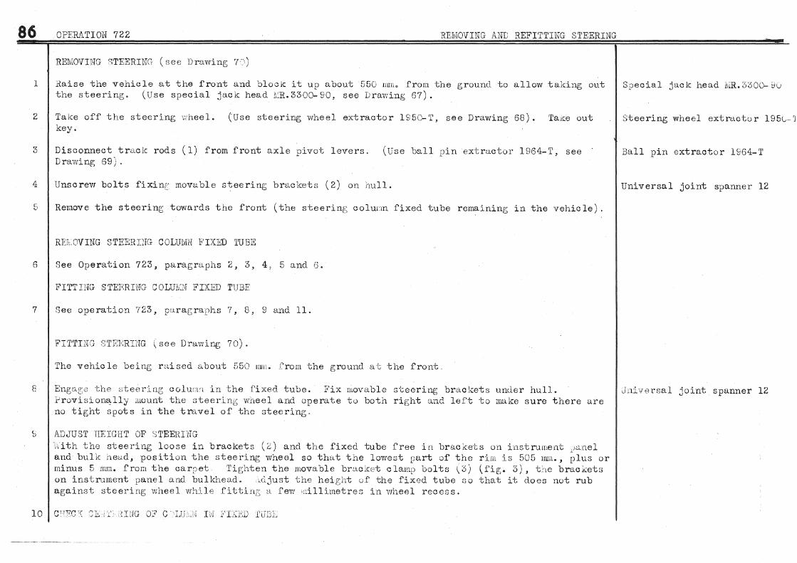
86
l
2
3
4
OPERA'riON 722 REMOVING AND REFITTING S1'EERING
REMOVING STEER.ING (nee Drawing 7·:,)
Raise the vehicle at the front and bloclc it up about 55C mm. from the ground to allow taking out the steering. (Use special jack head 1\~R. 3300-90, see Lrawing 67).
Take off the steering wheel. (Use steering wheel extractor 1950-T, see Drawing 68). TaKe out key.
Disconnect tro.ck rods ( 1) from front axle pivot levers. (Use ball pin extractor 1964-T, see Drawing 69).
Unscrew bolts fixinf~ movable steering brackets ( 2) on !1ull.
5 Remove the steering towards the front (the steerinf:; coluun fixed tube remaining in the vehicle).
REldJVING STEEREJG COLUMN FIXED 'I'UBE
6 See Operation 723, paragraphs 2, 3, 4., 5 and 'J·
FITTING STETmHTG GOLUiv:N FIXED TUBE
7 See operation 723, paragraphs 7, B, 9 and 11.
8
FI'rTnJG ~:n•m,:RDJG (see Dra·wing 70).
The vehicle being raised about 55() nun. from the ground at the front.
Engclt:<) ·the ;,,teering column in the fixed tube. Io'ix movable s·ceering brackets under hull. .i:'rovisiona,lly mount the steering wheel and operate to both rir;ht and left to make sure there <:J.re no tig;ht spots in the travel of the steering.
b ADJUST HEIGHT OF ':l'l'EElUNG ',dth the steering loose in brackets (::;) and the fixed tube free in lJracl<:ets on instrument tJz).nel and bulk heu.cl, position the steering wheel so that the lowest part of the rim is 505 mm., plus or minus 5 mm. frora the oarret 'l'if•;hten the movable bracket clamp bolts \3) (fig;. 3), the brackets on instrument panel and bulkhead. :,cljust the heig;ht of the fixed tube r;o that it does not rub against steerin1; wheel while fittirtt:';. a fe1N ·dllimetrerJ in wheel recerJs.
Special jack head ~,J.R, :'i300- ~u
Steering wheel ext rae tor 195l-'J
Ball pin extractor 1964-T
Universal joint spanner 12
Un:Lversal joint spanner 12

OPERATION 722 REEOVIN"G AND REFITT'ING STEEIUNG
(a) Check centerin[:> (Use bush ~;;R.3102, see Dra:wing 68, figs. 1 and 2). Eccentricity must not exceed 4 mr.t. If necessary correct by adjusting fixed tube.
(b) Lock the movable bracket clamp bolts (3), and again operate the steering. Any ti:::htness can only be caused through faulty centering of the column in the fixed tube. If necessary check centerinr; acain.
11 FIT l'RAC:C "RODS (see Drawing 71)
Box spanners 14-17 Bush ~.iR. 3102
Box spanners 14-17
To the ball pin sterns (4) (see fig. 4), fit dust covers (5) assembled with Belleville type washer Box spanner 21 and rubber washer. Fit ball [Jin in tapered hole of lever. By means of feeler t_:auges measure the clearance 11 a 11 between face of lever and Belleville type washer. At this point fit si1ims (6) to leave a clearance of 0 m;; .• to 0.25 mm. Tighten nuts and use split pins to secure.
12 FIT STEERUG ,·r::EEL Tun1 the front whcclc; straig;ht ahead. Fit the steering wheel with the key engaf;ed in the keyvvay corresponding to a steering v,rheel arm. Tighten steering wheel nut. The two up;Jer arms of the steering wheel should permit clear vision of the instruraents.
13 Fit combined horn and lip;hting switch.
14 Adjust front wheel "toe-out 11 (see O:Jeration 748, paragraphs 4 and 5).
15 Adjust steering; lock (see Operation 748, paragro..phs 6, 7, 8 and 9).
Box span,ner 32
87

88 23 REMOVING AND REFITTING S'I'EERING COLUMN FIXED TUBE
REMOVING FIXED TUBE
l Take off the steering wheeL (Use extractor 1:150-'l', see Drawing 68, fie:;so 3 and 4).
2 Remove combined horn and lighting switch.
3 Unscrew nuts fixing steering column bracizet to instnunent panel. Unscrew bolts fixing halfbrackets on buLchead, thereby releasing the rubber bush and permitting easy disengagement of tube. :::temove steering column fixed tube.
4 Remove instru.ment panel bracket from tube (by hand).
5 Remove half- brackets from bulld1.ead.
6 X:nock out inner rubber bush of fixed tube.
FITTING STEF.lUNG COLUMN FIXFD TUBE
7 Fit half- brackets with rubber bush on bulkhead. (In order to allow fitting of fixed tube do not tighten bolts).
8 Fit the instrument panel bracket, with its rubber bush, on the fixed tube. Place bracket about iso nn,t. from top end of' tube.
Box spanner 32 Steering wheel extractor lSE~ ..
Box spanner 14
9 Fit the fixed tube and tighten up brackets on bulkhead and instrument panel. lso-Ji _spanner 14
10 Check the centering of tpc steering column in the fixed tube. (Lse buslJ 1!IR .• 3102, see Drawing 68, Bush iviR.blo2 figs. l and 2), Eccentricity must not exceed 4 nun. If necessary correct by adjusting the fixed tube.
11 Fit the rubber bush in the fixed tube after coating with Lockheed fluid ·(bush can be fitted b;y hand).
12 Provisionally fit the steering wheel so that it does not rub on the tube. The tube must engag~e however, several millimetres in the wheel hub recess. If necessary, correct b~/ slackening brackets on bulkhead and adjusting tube position.
13 Fit the steering wheel (see Operation 722, paragraph 12). Box spanner 32

OP1WI.TION 72'6 REMOVING AND REFITTING STEERING COLUNiN FIXED TUBE 89
14 Fit oombined horn and lif;htlnp; switch

90
1
2
3
4
5
6
OPERATION 724 DISMANTLING AND ASSEMBLING STEERING
DISlftANTLING STEERING (see Drawings 70 and 71).
Hold the steering in a vice" (Use fixtur,s 1viR.,l561, see Drawing 72).
Remove right and left hand t r:wk rod::,, C J · 8 ba.: ~ pin ext:racd~or 1964-T" see Drawing 6(;).
Remove grease retaining; rubber bush (8) from s·t;c-OJ,:,rLi.b r·(>l:;n~m. i{emove the steering colurnn (8) ,,
Remove rack guide ( 9) and cover plate ( 10) ..
Remove thrust caps ( 11 and 12) , (Use spanners 197 5- T for removine; cap ( 12) .
Take off movable steering bracket (2) and the right hand rubber dust cover (r~.c<cordion), tl.emove ball pin protector (13).
Fixture 1ViiL 1561
Box spanner 21 Ball pin extractor l\:!64- T
Box spanner 14
Box spanner l'l
>lpanners H175-· T Flat spanner 14:
Box spanner 17
7 Slide the Tack to the rig.i.1t. itemove split pin and unscrew slotted nut forming ball \1'1). ·'3ox spanner lC Disene;ag;e tube (Hi'i retaining baLL pin cups, (Use spanner 1976-T, see l)ravving 73, fit> 1) .';panner 19'7\5-T Remove fj[lll pin GOve; rJi.A.tS ( 1 1) and disEm[1;Cl..[':e right hand ball pin (l7)c Bring; stud (:u:) of :t'a<:dc sliding dust cover opposJ.te K'<31c:,s·::: nc ... E, '·1b'1 :Ln rac•k tnbe. T\.emove stud, take out left h<lnd ba1J. pin as well as the ~uok and sliding aust over (lS)
8 Eemove left hand. rubber dust. o over· ( at'cordion).
9
10
REMOVE LJ\'iEH BE!\.Ii.ING CUP FROM STEERING BOX .t;loderate1.y heat outside of aluminium steering box usi.:og a blovr pipe at the level of the bea,:·ing; CUi_), Slight expansion of the box will permit free withdrawal of 011p without the use of a tool.
DISJiiiANTLE RIGHT ANiJ LEFT H/~ND TRACK RODS Remove ball pin adjusting nuts (20), (Use spanne:c 1870··1', see Dra:wing '/3,. fig. 2). Take out cups (21) and unscrew traok rod adjustable ends (22) o
ll Clean parts.
ASSEMBLING STEERING (see Drawings ?0 and 71)
12 By mea..ns of' a bronze drift fit the lower bearing cup in the steering boxo MAKE SURE THAT THIS CUP IS. COB.RECTLY SEATED IN 'l'liE STEERii.'JG BOX /\.ND H/\.S NOT CHIPPED DURING FITTING.
Blow pipe
Box spanner 'l<l S panrwr 18 7 Q ... T

OPERATION 724 DISMANTLING AND ASSEMBLING STEERING
Fit thrust bearing on cup.
13 Hold the steering box in a vice. (Use fixture L:Ro 1561, see Drawing 72).
14 FIT AND ADJUST S'TEERING COLUiliN (see Drawing 70, fig. 2). (a) Fit column (8) in box and then upper thrust bearing and cup (23). Adjust the bearings so the;y are FREE BUT WITHOUT PLAY. 'Nith the aid of feeler gauges, determine the thickness of shims to be placed between box flange and cover plate (25) to give correct bearing adjustment. (Choose shims from the range listed in our Spare Parts Catalogue).
(b) After adjustment fill the bearings with grease similar to Mobilcompound. Fit the cover plate (25). ONE FACE ONLY OF 1'HIS PLATE IS 1:.1'\.CHINED AND THIS MUST BE FITTED AGAINST THE UPPER BEARING CUP. Fit felt washer and retainer and tighten nuts fitted with spring washers.
15 FIT THE STEERING Rt\.CK (see Drawings 70 and 71) (a) If the ball nut ( 14) or the steering box has been replaced, make certain there is 0. 05 mm. clearance between ball (14) and tube (26). UndertaJ.ce the following operation (see Drawing 71, fig. 3). Provisionally fit and lock movable bracket (2) on tubular steering box and screw ball nut (14) on retaining tube ( 15). At the same time introduce a shim o. 05 mm. thick and 8 mm. wide into the box. The tube ( 15) serves to carry the ball nut and shim along a distance of a bout 140 mm. 1'his distance represerrl:;s the amount of rack travel). 'The ball nut and shim must slide freely but without play and there must be no tightness at the point where the movable bracket is clamped on the tube. Take off movable bracket ( 2).
(b) Fit the left hand movable bracket (2). Fit rubber dust cover (accordion) with small diameter against the bracket.
(c) Lubricate the rack (with grease similar to Mobil compound) and fit. Fit sliding dust cover (1~ (elongated hole on ri:_ht hand side). Fit distance piece (34), washer 602345, spring (35), ball pin cup (28), ball pin (36), previously oiled, ball pin cup (37), with circumferential groove, and distance piece (38).
(d) :ft'i t stud ( 18) of dust cover ( 19). Tighten stud nut against a copper washer. Fit ball pin cup (37), with ciroumfererrl:;ial groove, ball pin (17), and ball pin cup (28).
(e) Fit retaining tube (15), damper spring (29), and tighten up tube (15). (Use sparrner 1976-T, see Drawing 73). 'I'ighten right up and then slacken one sixth of a turn. Check t:i.ghtening of ball pins which must turn by hand without obstruction. Eold the retaining tube ( 15) and tighten ball nut ( 14). (Use spanner 1~!76-T • see Drawing 73, fip;. l). FI1' SPLI'I' PIN WI'l'HOU'l' SLACKENING NUT. If existing split pin hole does not correspond
91
Fixture MR. 1561
l3ox sparrner 14
Box spanner 10
Spanner 1976-T

92 OPE."'RATION 724 DISMANTLING AND ASSEMBLING STEERING
to a slot in the nut drill a new hole in line with the slot farthest from original hole. Prevent drilling f;warf falling into steerine; box by plugging the tube aperture ·with a rag.
16 ADJUST MF.SHING OF RliCK AND PINION. POSITION S TEER.ING WHEEL In order to obtain clear vision of the instrument panel between two arms of the steering wheel, adjust meshing in the following manner. (a) Fit steering wheel on column wi·th key engaged in keyway in line with one of the steering wheel spokes.
(b) Turn v,rheel so that this spoke is vertical and pointing downwards.
(c) 2Jlesh rack with pinion and turn steering ·wheel one and a half turns. At this point, if meshing is correct, the end of the !:"ack will protrude 37 mrn., plus orminus 2 nun" beyond flange of steering box tube (as at nc 11 see Dru:win[; 70, figo 1) o If end of rack does not fall within this dimension set meshing baclDN'ards or forwards as required. by one tooth.
17 ADJm"::T RAC?I: GUIDE Engag;e rack guide ( 9). in steering box WITHOUT SPRING. Fit cover plate ( 10) with machined faee against the box, Fit shims (30) to give normal meshing without play or obstruction. Howe,rer" a play of Ool mmc. to 0,2 mrno is ne0essary to p:revent fouling at bottom of.teeth. Therefore add a shim 0.,1 mm., to 0.2 rmrto thick to those already selectedo l\ernove plate (10) and refit it with spring (31), J?it spring washers tmde:c heads of fixing bolts and tighten up. If the spring prer:;sure is insufficient (steering too light)" add washers ( 27) between spring and guide. If the pressure is too great (steering too heavy) it will be necessary to add another shim (30) between cover plate ( 10) and the steering box.
18 Fit the ball pin cover plate (16) ,, the longer part .to the right),, Fit upper and lower ball pin protectors. After fitting_, pinch and turn down slide ends of upper cover so that the lower sJ.ide i.s carried along by the upper with rack movement. Fit right hand rubber dust oover, small diameter against movable braoket,, and movable bracket (2) but do not tighten as its position is determined when steering is mounted on oar, Tighten rubber dust covers without use of a pin, to prevent scoring. Fit the dust 0(Y'irer elips :ln such a way that heads of tightening split pins protrude away from rubbers (as at 11 d 11 Drawing 70, fj_g, 1), This is necessary to avoid tearing rubber when tightening split pins ...
Box spanner 14
19 Fit locknuts (32) for thrust cap and use a lockwasher between nuts and cap, Fill thrust cap (12) Flat spanner l4 with grease (similar to .Mobilcompound) and screw on provisionally.. H.!l~LF FILL ONLY, with grease o the same type, thrust cap ( ll). Fit this oap using a paper gasket and tighten bolts fitted with spring washers under heads. NOTE. The quanti ties of g;rease packed into the caps (340 granunes approximately, about twelve ounces) must not be exceeded or the st-aer:l.ng will leak when working, Fit steering column greas<?

OPERATION 724 DISMANTLING AND ASSEMBLING STEERING
retaining rubber bush ( 7). Fit olip with split pin head away from the bush.
20 PREPARE TRACK RODS (see Drawing 71~ fig. 4). too sen and articulate the adjustable sookets on the rods (if necessary touch up threads of rods and sockets using thread files and taps). Oil the traok rod threads. Sorew on the sockets as follows. (a) Provisionally adjust to give a centre distance of 557 mm. plus or minus 0.2 mm. » between ball pins. (Use gauge MR.3446. see Drawing 74).
(b) The amount of thread engaged and <n:tps (21) ~ previously oiled. nuts (20) to a. tension of 8 mkg. Unscrew nuts to a maximum of one
21 FIT TRJ\Cte RODS (see Drawing 71)
in sockets should be the same at both ends. Fit ball pins ( 4) Fit spring re~aining ball pin cups. Tighten the adjusting
(58 foot pounds). (Use spanner 1870-T» see Drawing 73, fig. 2). eighth of a turn and fit split pins.
Fit rubber sealing washers (33) on stems of steering rack ball pins. Use alcohol to olean tapers of ball pins and bores of sockets. Fit track rods» tighten nuts and secure with split pins.
22 Remove steering from fixture MR.l561.
Taps and thread files 22 die..» 100 pitoh
Gauge MR.3446
Spanner 1870- T
Flat spanner 21
93

REMOVING AND REFITTI~N=G~R~EA~R~AX==L~E====~~~~~~~~~~ ............... = ......... == =~=
1
2
3
4
5
6
7
REMOVING REAR AXLE (see Drawings '7'1 and 78)
Ja0k up the vehicle. (Use speGial jack head MR,3300=llO. see Drawing 75). Block up oar at a · point approximate to the rear pillars.
Remove both rear wheels.
Remove both rear shockabsorbers" replacing them with gauges MR.3338 (see Drawing 76), The axle assembly is held in balance better this way than with a jack,
Remove the exhaust pipe. (Use spanner l626~T, see Drawing 1, fig. 2) and silencer assembled, the tail pipe remaining fixed on the car,
Disconnect Lockheed feed pipe to three~·way union on the tubular crossmembero Disconnect wheel cylinder feed pipes from brackets on rear axle arms.
R€move rear axle tie rodo
Remove torsion bar retaining plates (1). Disengage one torsion bar from Qentre bracket. (Use driving block assembly MRo 1578, see Drawing 79)" Repeat the method for the s ecwnd bar, Remove bolts fixing rear link silentbloc brackets.
8 Remove axle from car.
9
REMOVII~G TUBUlAR CROSSMEMBER
Disconnect patrol pipe from union and olip on hull and disengage towards the outside of the vehicle to give olearanoe for the crossmember.
10 Remove trimming from both rear door sills.
Speo:tal jaok head MRo3300-llU
Wheel brace
Gauges MR.,,3338 Universal joint spanner 21
Spanner 1626~T Flat spanners 12~14
Flat spanners 12~14
Flat spanners 21=23
Box spanners 14= lt~ Universal joint spanner with socket 16 Block assembly !.JJIL 1578
Flat spanner 14
11 Remove bolts fixing orossmember to hull (three bolts on each flange removed from inside vehicle). Box spanners 17=26=35
12 By means of a lever disengage tubular crossmember from hull.
FITTING TUBULAR CROSSMEMBER
13 Fit tubular orossmember in hulL TJ.ghten fixing bolts with spring washers fitted under heads.

PERATION 725 REMOVING AND REFITTING REAR AXLE
14 Fit trimming to both rear door sills.
FITTING REAR AXLE (see Drawing 77)
15 Fit torsion bars in hubs ( 3) of xorea.r link silentbloo bra.oketso Right hand torsion bars have one painted identif'ic:a.tion mark and the left hand bars two marks,
16 Position axle assembly under vehic:leo Locate the lower shookabsorber pins in the intermediate holes of gaug(flls MRo3338 (see Drawing 76), IN THIS POSITION fit the rear link silentbloc: bra.okets to the tubular eo rossmembero Tighten fixing bolts using spring washers under heads,
17 FIT THE TOHSION BARS (a) Posi·tion lower shoc:kabsorber pins in the gauge slots.
(b) With the torsion bars already engaged in. hubs of rear link sihmtbloo bxoMkets. raise the rear axle so that lower sho~ka.bso~ber pins are at the top of the gauge slots, At this point engage the tors1.on bars in the splines of the c:entre brac:ket of the crossmember, If necessary fo:c engagement move the axle in the traverse permitted by the gauge slots. Complete fitting of torsion ba.rso (Use driving block assembly MRol578, see Drawing 79)
Gauges MRo3338 Universal joint spanner with socket 16
BloClk assembly M1Ll578
95
(c) Fit torsion bar retaining plates (l). Tighten nut securing bo1t using a spring washer under. Box spanner 14
18
19
20
21
22
Fit tie rod (4). Fit securing split pins.
Fit Lockheed brake pipes, petrol pipe, exhaust pipe and silencer, SECURE:LY TIGH'l'EN FLANGE NUTS. (Use spanner 1626- T, see Drawing 1, figo 2).
Fit and adjust handbrake cablesc (Sea operation 749~ paragraph 3).
Remove gauges MR,3338. Fit shockabsorbers.
Adjust transverse location of rear axleo (Use gauge 205l=T" see Drawing 80).
23 Ble~d the Lockheed brake system. (See operation 749~ paragraph 5).
Flat spanners 21=29
Spanner 1626-T .
Flat spanner 12
Universal joint spanner 21
Flat spanners 21-29 Gauge 2051-T
24 Fit the two rear wheels. Wheelbraoe
25 Lower the vehicle to the ground. (Use special jack head MRo3300=llOs see Drawing 75) o Special jaok head MRo 3300= 110
26 Adjust body heights (see operation 750 9 para.gi"tiphs 1~ 2 and 3).

2!. ...... .Q'fWTION 726 __ ... _ -··
1
2
3
4
5
6
7
8
9
10
11
12
REMOVING REAR AXLE BF.AM (see Drawing 77)
Jack up the vehicle. (Use special jack head MRo3300~llO, see Drawing 75). Block up vehiGle at a point approximate to the front end of the rear wings.
Remove wheels and hub and brake drum assemblies.
Disconnect Lockheed brake pipes and unions from brackets on link arms.
Remove brake back plates from axle (without taking off brake shoes and wheel cylinders). Use a wire brush to olean the brake cable sheaths and oil them to allow easy sliding in the guides. Remove back plates from axle without disconnecting brake. cables.
Remove axle tie rod (4).
Disconnect shookabsorbers from the axle only.
By means of a screwdriver, prise off the link arms from fixing studs on the axle. Locate a bodymakers screw jack with the jack heads bearing against the brake cable guide brackets. Open out the link arms by operation of the jack. Remove the axle beam and then take out the jack,
FITTING REAR AXLE BEAM
Locate a bodyrnakers screw jack as during the dismantling operation. Engage rear axle beam between link arms and remove the jack.
Fit tie rod ( 4). Fit securing split pins.
Fit shockabsorbers to axle.
Fit brake back plates. Fit Lockheed brake pipes and unions.
Fit hub and brake drum assemblies. Tighten nuts to a tension of 10 mkg. ( 72~ foot pounds) and then slacken about a quarter of a turn to g;ive an end play of 0.05 mm. to 0.17 mm., v'VHICH ALLOWS THE NUTS TO BE TURNED BY HAND. Secure nuts with split pins. Fill each hub cap with 0.080 kg. (2~ ounces approximately) of grease of the Mobilgrease 5 typeo
Special jack head MRo3300~110
v'lfhee l brace Adjustable spanner
Flat spanners 17-19-21
Brace spanner with extension 14 Wire brush
Flat spanners 21-23
Universal Joint Spanner 21
Bodymakers screw jack, capacity 1200 mm.
Bodymalcers screw jack capacity 1200 mm.
Flat spanners 21~29
Universal joint spanner 21 Flat spanners 17-19~21
Brace spanner with extension 14

PE.'RA.TION 726 REMOVING AND REFITTING REAR AXLE BEAM WITHOUT REMOVING LINK ARHS
Ti( ten hub -.aps to a ten \on of 5 or 6 mkgo (36 '.-r 43 foot pounds).
l 3 Adju -;~ transverse looatiun of re axle. · (Use gauge 2051-T. ee D:raw~ng; 80).
Bleed the Lockheed brake system (See Operation 749s paragraph 5).
15 Pair~t the axle.
A~just,,ble spanner
Flat spanner 2c· Gauf!;-:: :2051-T
16 Fit the:; two rear wheel Whae1braoe
17 Lower the vehicle to t '1,round.
97

98 OPF.::RATION 727 DISJ\1A.NTLING AND ASSEMBLING REAR .1\XLE
DISMANTLING RE.l\.R AXLE (see Drawings 77" 78 and 81)
l T'lace the rear axle assembly on a convenient stand ..
2 Ta1ce off the Looi.d1eed brake pipes o Remove the rear axle buffers o
3 R.emove the ;,ub ar:d hrak(-; druw assemblieso
4 Hemove the brake '0.ck l,.J:I:J.te (6) o (Use a wire brush to c.lean the brake oable sheaths and oil them to allo-w easy slidi in the guides), Remove the link arms from the axle,
5 RE.lviOVE LIN:{ Alli'V1 SILLNXDJ/.'~ BRACKETS (see Drawings 77 and 78).
6
7
(a) Remove circlips (''7) retain:l.ng; pins (8 and 9) of adjusting :rods (10) o Knock out the pins.
(b) Remove "C" type circlips (11) retaining silentbloc bracket nuts. Unscrew the nuts (12) and with the aid of a mallet.c. knock out the hub (3).
DISMli.N'TLE THE BRAKE BACK PLATES (see Drawing 81). (Dismantle plates suc:cess:'urely) (a) Unhook the x-etun1. spring ( 14) (Use pliers 2110~T see Drawing 82)" Remove the brake shoes ( 15 and 161, the whee:t c:ylinder' and the brake oab:.e ..
(b) Remov•J -:-he gt-"ide s·~·,;.ds n.nd r;~djnstln1 •; cams ( 17) from shoe ( 16) and the rod ( 19),
DI;3l11Al·LCLi', 'I'HE ·."iEEEJ:, CYLINDERS
Disconnect the handbr.ake cable lever ( 18)
(All purts can :.)e "?r:~o· .c-ed by hand) sp~·inr~ \G:').
:?.em.ove dust covers (20)" pistons (21) P cups (22), and
8 DI )J,JI.NTLE 'I'lL HUB AND BRAKE Dli1.L'ii ASSE:t,ULIES
10
Knock o:_,t the :t.nner-' bearing (which carr1es out the oil seal), Use a d:('ift to knock out the bearing r,L:i:;s ..
CHEGKr:;rG CAMBER AND TOE- IN OF Cl'mCIFORM AXLE ?E.Ii..H ( sae Drawings 83 and 84)
CiiEGK THE CA1'V1BER (see Drawing n3) (a) Set up the axle to be c.h.;v;ked in a lathe with CH..mtx'es at l<ew.st 2.2.6 mm- above the bed and a oapa -:Lcrcy of 1800 mm between oent:('es. On one of the flanges ·tiiThtn'e th<"; Ltnk ann is fitt-':ld. mou.nt apparatus 2052~1' (see Drawing 84) VERTICALLY~ the axle being in its normal position. that is to say with buffers at the top.
Flat spanners 12~14-17--19-2]
Adjustable spanner
Br'ace spanner with extensior .I W'ire brush
Flat spanner 23 AdJustable spanner
Box spanners 10~14,~21 Pliers 2110 1'
Apparatus 2052-T

OPERATION '727 DIS.MANTLING AND ASSEMBLING REAR AXLE
(b) Rotate the axle a quarter of a turn to bring the lower arm of the straight edge of apparatus 2052~T into contac:t with a.n index plate mounted in the tool post.
(c) Rotate the axle an additional half turn to bring the other end of the straight edge opposite the index plate. Measure the gap between the straight edge finger and the index plate. This should be lL 3 mmo, plus 0 rnm", minus 4 rnm,. for a straight edge of 430 nun. long. This dimension corresponds to an angle of 1° to 1° 30~.
(d) If the required dimension is not realised, remove the axle from the lathe, and in the cold state, beat out the upper web if the camber is insufficient or the lower web if it is too great.
(e) Treat the other end of the axle in a similar manner.
ll CHECK THE TOE-IN (see Drawing 84) (a.) Set up the axle again in the lathe in its normal position (with buffers a.t the top) and mount apparatus 2052- T HORIZONTALLY on one of the link arm flanges.
(b) Bring the forward arm of the straight edge into contact with the index plate in the tool post"
( o) Rotate the axle half a turn to bring the other end of the straight edge opposite the index plate. The gap between the straight edge finger and the index plate should be 0 mmo to Oo5 mm.
, If necessary, set the beam by beating out, in the oold state, the rear web if the toe-in is insufficient and the front web if the toe~in is too great.
(d) Treat the other end of the axle in a similar mannero
1 IM.PORTt,:~T NOTE. REINFORCED AXLE!S CAN ONLY BE CORRECTED IN THE COLD STI\TE BY MEANS OF A PRESS o
:On certain axles the brake back plates are fixed by bolts instead of studs. In this case use one I of the bolts for setting up apparatus 2052-To I
ASSEMBLING R~~R AXLE . .,.,
12 REPLACE SHOCKABSORBrm PINS (a" Chisel off fillets of arc welding.
(b) Unscrew pin
(o) Fit new pin and tighten up hard (tension 15 mkgo a.pprox. - l08o5 foot pounds).
(d) Lock pin by a. fillet of arc welding to avoid heating the axle.
99
Flat spanner 26
Flat spanner 26

100 OPERATION 727 DISMANTLING AND ASSEMBLING REAR AXLE
13 PREPARE VffiEEL CYLINDERS
14
Use only alcohol or Lockheed fluid to clean the parts as any other substance will cause a rapid deterioration of the rubber cupso Lubricate cylinder and cups with Lockheed fluid (see Drawing81 for order of re-assembling parts).
PREPARE BRAKE BACK PLATES (Build up eaoh plate successively (see Drawing 81). (a) Fit adjusting cams (17).o rivet over pinso (Use fixture MR.3354, see Drawing 59, figs. 3 and 4). FLt guide studs (24), anchor pins (25), brake cable" and rod (19) to lever (18). Fit laver to brake shoe (16), tighten nut and secure with a split pin"
(b) Fit brake shoes (15 and 16) (the linings must be perfectly dry and have no grease spots). Lightly oil adjusting washers (26) of the guide studs. Tighten nuts of anchor pins (25) to a tension of 3 mkg. (21~! foot-pounds) and secure with split pins.
Fixture Iv1Ru3354 Box spanners 10=12=14
(c) Fit the wheel r:ylinder" Hook on the brake shoe return spring (14). (Use pliers 2110=T, see Box spanner 14 Drawing 82)" Make sure that the shoes articulate normally and that there is sufficient thrust by
15
the guide stud washers.
REPLACE WHEEL STUDS IN BRAKE DRUM (a) Use fixture JI,'JRo3445 (see Drawing 57) in order to ensure correct bearing of the dlfum when driving out studs and to prevent breaking the casting. NEVER COMPLETELY DISENGAGE BRAKE DRUM FROM HUB. REPlACE STUDS ONLY ONE OR TWO AT A TIME. The drum, after being assembled to the hub during manufacture, is machined with the utmost precision. Faulty centerine~ of the drum will cause the brakes to judder. Clinch in the wheel studs by means of a press of 8 to 10 tons capacity. Although it is not recommended the studs may be clinched over with a hammer if a press is not available.
(b) Drill hole for wheel stud dowel diametrically opposite to the old position. Drive in dowel and r~ke sure that it fits flush. Lock dowel with a centre punch.
16 Fit bearing cups in hub with the aid of a drift, Make sure that cups are correctly seated.
17 RECTIFY BRli .. KE DRUMS True up drum in a lathe. (Use Mandrel MRo3381=2, see Drawing 85). The maximum eccentricity allowed is 0.04 mn1. This should be checked with a clock gauge. Never increase the original diameter of 305 mm., plus or minus 0.1 mm. 9 by more than 2 mn.
18 Pack the inner bearing (27) with grease (grease similar to Mobilgrease5) and fit. By means of a press, fit the oil seal (28) with the leather flange against the bearing (see Drawing 77).
Fixture MR.3445

19
OPERAl'ION 727 DISNJANTLING AND ASSEMBLING REAR AXLE 101
PREPARE LINK ARMS (see Drali'J·ings 77 and 78) (a) The silentblocs (29) are removed and fitted by means of a press" (Use so .. ket and plunger MR, 3335, see Drawing 86),
Socket and plunger MRo 3335
(b) Fit link arm (30) on hub (3), (The hub is positioned so that the inner splines are towards the outside)o On both sides of the link arm fi.t levers (31). adjusting rod (10) 9 with its pin(7), friction washers ( 32) (with chamfers facing hub splines). silent bloc brackets ( 33) ,, and the locking nuts (12).
(c) Mount fixtures MR. 3336, to hold silentbloo brackets during tightening so that their flanges are at an angle of 104° with the link arm centre line (see Drawing 78, figs, 2, 3 and 4,)
Fixtures l\.'IIL 3336
(d) Tighten the silentbloc bracket locking nuts to a minimum tension of 25 mkgo (180 foot pounds), Adjustable spanner After tightening make sure that the hub threads protrude an equal amount at each end.
(e) ltemove the fixtures. Fit adjusting rod pin (8) and the circlips (7),
(f) Drill the silentbloc hub for fitting ·the 1\cu type circlip ( 11).
20 FIT TEE LINK ARMS AND BRAKE BACKPLATES
21
22
23
(a) Oil the brake cable sheaths and fit in guwes on link arms, Tie;hten nuts fixing brackets for cable sheaths to a tension of 2 mkgo ( 14-~ foot pounds{ using a spring washer under each. Tighten nuts fixing backplates to a tension of 2 mkgo ( 142· foot pounds) using a spring washer under each.
(b) POSITION THE BRAKE SHOES Use gauge 2103~.T and pointer 2104-T,. see Drawing 87o Adjust cam pins (use spanner· 2120c,'l\ see Drawing 60 9 fig, 3).
F'I'l' TlUB AND BRAKE DRUM ASSEMBLIES Before fitting, pack the hub with Oo 100 kgo (3-~ ounces) of grease simHar to Mobilgrease 5. Fit the outer Timken bea:rin[; also nacked with greaseo Tighten the hub nut to a tension of 10 mkg, (72,1 foot pounds) and then unscrew about a quarter of a turn to give an end play of 0,.05mmJ to Oo 07 nuno which will allow the nut to be turned by hand. Secure nut with a split pin. Fill hub caps with Oo080 kg .. (2·~ ounces) of grease similar to Mobilgrease 5. Tighten the hub caps to a tension of 5 or 6 mkg. (36 to 43 foot pounds).
Fit the Lockheed brake pipes.
Fit the rear axle buffers, tighten bolts and turn back lockwasher tabs.
Spanner 2120.-'l' Gauge 2103-T Pointer 2104-1'
Adjustable spanner
Flat spanners 14-17-19-21
Box spanner 12
102 OP:f~RATION 727 DISMANTLING AND ASSEMBLING REAR AXLE
24 Paint the unit.
25 Remove the assembly from the stando

OP1"'RATION 728 REMOVING AND REFITTING A FRONT TORSION BAR
REMOVING A TORSION BAR
Torsion bar splines slide more or less easily in the silentbloc. According to the case the bar can be removed by three different methods.
FIRST CASE: torsion bar slidinr; easily.
l (a) Jack up the vehicle at the front and block it up at a point level with the scuttle pillars so that there is no load on the torsion bar to be removed.
(b) Remove the rearmost circlip !'rom the torsion bar. Completely unscrew the ball·- headed screw of the adjusting lever, (Use spanner 2302-T.)
(c) Knock the bar towards the front of the car by striking the rear end with a hammer and drift (bent if necessary).
(d) Remove the second circlip and completely disengage the torsion from the front through the silentbloc splines.
SECOND CASE: to be adopted when the method above is not successful.
2 (a) Jack up the vehicle at the front and block it up at a point level with the scuttle pillars so that there is no load on the torsion bar to be removed.
(b) Remove the trimming from the hull bulk head and take out seat cushion on the side the torsion bar is to be removed.
(c) Cut a 45 nuno diameter hole in the hull bulkhead in line with the torsion bar to be removed,, The centre of this hole should be approximately 225 mmo £:rom the car longitudinal centre line and 45 mmo above the floor.
(d) Remove the rearmost torsion bar cirqlip and knock out bar towards the front using a drift passing through the hole cut in the bulkhead.
(e) Remove the second circlip and completely disengage the torsion bar from the front through the silentbloo splines.
THIRD CASE: If the torsion bar cannot be removed by the methods above.
(a) Jack up the vehicle at the front and block it up at a point level with the scuttle pillars so that there is no load on the torsion bar to be removed.
103
Spanner 2302-T

104 OPERATION 728 REMOVING AND REFITTING A FRONT TORSION BAR
(b) Remove the rearmost c irGlip from the torsion baro Completely unscrew the ball-headed screw of the adjusting lever. (Use spanner 2302-T)"
(c) Remove the trimming from the hull bulkhead and take out seat cushion on the side the torsion bar is to be removed"
(d) Cut a 45 mmo diameter hole in the hull bulkhead in line with the torsion bar to be removed. The centre of this hole should be approximately 225 mmo from the car longitudinal centre line and 45 mmo above the floor.
(e) Disconnect exhaust pipe from exhaust manifold on engine (use spanner 1626-T, see Drawing 1. fig. 2) and let the exhaust pipe rest on the ground"
(f) Remove the rear plate of the crossmember under engine carrying torsion bar rear end. Disconnect handbrake rod to relay lever at the front end to allow removal of crossmember rear plate. Remove the remaining torsion bar circlip.
(g) Knock out the torsion bar towards the rear using a steel bar. approximately 800 mmo long and 25 mmo diameter. passing through front silentbloc splines. Take out bar from inside of vehicle.
FITTING A TORSION BAR
Right hand torsion bars have one identification paint mark and the left hand two.
FIRST CASE
4 (a) The vehicle being still blocked up under the scuttle pillars. insert the torsion bar to be fitted through the splines of the front silentbloc. Fit the front oirolip to the bar.
(b) Use a large lever to lower the pivot and link arms assembly approximately two splines.
(c) Oil the torsion bar splines and engage bar in the adjusting lever making sure that the lever bears against the ball-headed adjusting screw which has been fully unscrewed.
(d) Fit the torsion bar rear oirolip.
(e) Lower the car to the ground.
(f) Adjust body heights (see Operation 750, paragraphs 1, 2 and 3).
Spanner 2302-T
Spanner 1626-T
Box spanner 14
Steel bar 800 mmo long,

OPERATION 728 REMOVING AND REFITTING A FRONT TORSION BAR
(g) Adjl;:st weight dist1ribution (see Op(e:\:'ation. 750~ paragraphs 4 9 5 and 6).
5 (a) 1'he vehic,le being; si~ill blooked up under the scuttle pillars> insert; the torsion bar to be fitted through the splines of the front silentbloc, Fit the front oi:rclip to the bar,
(b) Use a large lever tn ::ow'''I !he pivot and link arms assembly approximately two splines.
(c) Oil the torsJi.on bar sp1ir.·~~s and engage bar in the adjusting lever making sun~; that the laver beaX"s against the ball-headed adjustro.g screw whiGh has been fully unscrewed,
(d) Fit the torsion bar· r"'·;tY ,. L·>
(e) Lower the car to the (~~·ouuci"
(f) FX"orn a sheet of st8--C: milL i-:h] k, cut a plate 65 mm. diameter. Also out a joint of the same diameter from ntbbe"V or -:,a:tdboa:rd, Place the plate and th•e ;joint over the hole cut hl the buL-dload (see paragraph 2~ r,) and f~x with two P JL type sc.n:oews, Replace the bulkhead t:~'imming and the seat oushion,
(g) Adjust body heights (see Ope:r'a+ion 7 50, pa:-:"agraphs 1_, 2 and 3)"
(h) .1\djust weight dist:dbution (see Operat:i.on 750" paragrapi1.s 4, 5 and 6),
THIRD CASE
6 (a) Fit the r'•~w.r plate of the crossmembe:c under engine carrying torsion bar :rear ~l'l.d,o 'r\ghten up bolts ·using spring washers und'l!r heads. Conn.ec't r'od f:r:"om handbrake relay lever at the front end, seouring 0 leYis pin with a split pin.
(b) The vehicle being still blocked up under the scuttle pillars,, insert the torsJ.on bar to be fitted through the splines of the fr.'o:o.t silentbloc, Fit the front c irrllip to the bar.
(c) Use a large lever to lower the pivot and link arms assembly approximately two splines. Oil the torsion bar splines and engage bar :i.n the adjusting lever making sure that the lever bears against the ballo-headed adjusting sorevt wh:l.oh has been fully unscrewed. Fit the to:r.s5.on bar rear eire lip,
(d) Connect the exhaus":: p:Lpe to -Gh'o manifold using a C. and Ao gasket between the flanges. TIGHTEN NUTS UP HARD. (Use sparme:r 162 6 'f, see Drawing 1, fig, 2),
105

106 OPERATION 728 REMOVING AND REFITTING A FRQNT TORSION BAR
(e) From a sheet of steel» 1 mmo thick. out a piate 65 mmo diametero Also out a joint of the same diameter from rubber or cardboard. Place the plate and the joint over the hole out in the
-bulkhead (see paragraph 2=o) and fix with two P.K. type screws. Replace the bulkhead trimming and the seat cushion.
(f) Lower the vehicle to the ground.
(g) Adjust body heights (see Operation 750, paragraphs 1, 2 and 3).
(h) Adjust weight distribution (see Operation 750 9 paragraphs 4. 5 and 6).
::

OPERATION 729 REMOVING AND REfiTTING A RE4R TORSIQN BAR
REMOVING A TORSION BAR (see Drawings 77 and 78)
1 Jack up the vehicle on the side the torsion bar is to be removed. Block up under the rear of the body and under the axle.
2 Remove a wheel and shockabsorbe:r on the side the torsion bar has to be removed. If taking out r;i.ght-hand bar disconneot the exhaust pipe uride·r hull from the tubular crossmember and the ··
. silencer from the tail pipe. Let the. M!haust pipe and silencer assembly rest on the ground. If removing .. ~ left-hand torsion bar 9 disconnect the tie .. rod (4) at the axle end only.
3 Remove the torsion bar retaining plates ( 1).
4 Disengage the torsion bar from the hub at centre of tubular crossmember. (Use block assembiy MRo 1578 1 see Drawing 79).
5 Fit a gauge MR.3338 between upper and lower shockabsorber pins to hold the axle in position (see Drawing 76) .
6 Remove silentbloo bracket from tubular crossmember by unscrewing the bolts (2).
7 Remove the torsion bar and take off :t;he block assembly IIIR.l578. In cases where the torsion bar is broken close to the aentral hub it will be necessary to remove the second bar$ in order to knock out the portion remaining.
8
9
10
11
REFITTING A TORSION BAR (see Drawings 77 and 78).
Engage torsion bar in the silentbloc bracket., (33) and let the out~r spli:hed end protrude from the bracket. Connect the silentbloc bracket to the tubular orossmember.
Locate the lower shockabsorber pin in the s.lot of the gauge MR.3338 by applying a heavy load on the link arm {see Drawing 76).
Engage the torsion bar in the central hub by moving the axle up and down~ in the limit determined by the gauge slot~ in order to engage splines. Fit the retaining plates (l)j and tighten the bolts after fitting spring washers under nuts. In oases where the splines do not slide f,)"eely use block assembly MR. 1578 to complete the engagement of the boss (see Drawing 79).
Connect the tie (4) to the axle (when left~hand bar has been refitted).
Wheel brace Flat spanners 12-M Box spanner 21
Box spanner 14
Block assembly MRo 1578
Gauge MR.3338
Universal joint spanner with extension 16
Universal joint spanner . with extension 16
Gauge MR.3338
Box spanner 14 .. , .Blook assembly MR. 1578
Box sp~:mner 21
107

108 OPERATION 129 REMOVING AND REFITTING A REAR TORSION BAR
12 Remove gauge MR.3338 and fit shookabsorbers,
13 Fit the exhaust pipe and silencer assembly (when right=hand bar has been fitted.).
14 Fit the wheel.
15 Lower the vehicle to the ground.
16 Adjust body heights (see Operation 750~ paragraphs 1, 2 and 3).
17 Cheak the weight distti bution (see Operation 750$ paragraphs 4, 5 and 6).
Universal joint spanner 21
Flat spanners 12=14
Wheelbraoe
Weighing machines 2310-T
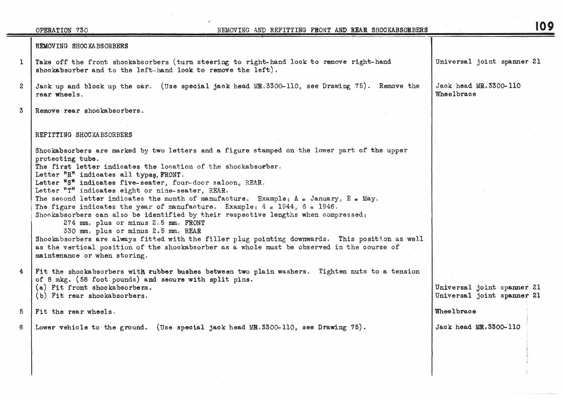
1
2
OPERATION 730 REMOVING AND REFITTING FRONT AND ~EAR SHOCKABSORBERS
REMOVING SHOCKABSORBERS
Take off the front shockabsorbers (turn steering to right-hand look to remove right~hand shookabsorber and to the left<~hand look to remove the left).
Jaok up and block up the car" (Use special jaok head MIL330~110, see Drawing 75). Remove the rear wheels.
3 Remove rear shockabsorbers.
4
5
6
REFITTING SHOCKABSORBERS
Shookabsorbers are marked by two letters and a figure stamped on the lower part of the upper protecting tube. The first letter indicates the location of the shockabso~bero Letter 11Ru indicates all typatJ,FRONT. Letter ugn indicates five-seater, four~door saloon. REAR. Letter "T" indicates eight or nine-seater, REAR .
. The second letttSr indicates the month of manufaoture o Example & A = January·" E = May. I The figure indicates the yealf of manufactureo Example: 4 "" 1944, 6 ~ 1946. i Shoclcabsorbers can also be identified by their respective lengths when r.lompressed:
274 IDIDo plus or minus 2o5 mmo FRONT 330 mmo plus or minus 2.5 mm. REAR
Shockabsorber>s are always fitted with the filler plug pointing; downwardso This posit~.on as well as the vertical position of the shockabsorber as a whole must be observed in the course of maintenance or when storing.
Fit the shockabsorbers with :rubber bushes between two plain washerso Tighten nuts to a. tension. of 8 mkg. (58 foot pounds) and secure with split pins. (a.) Fit front shookabsorber.s. (b) Fit rear shookabsorbers.
Fit the rearwheels.
Lower vehicle to the ground. (Use special jack head MR.3300-ll0, see Drawing 75).
109
Universal joint spanner 21
Jack head MRo3300-110 Wheel brace
Universal joint spanner 21 Universal joint spanner 21
Wheel brace
Jack head MRo3300-llO
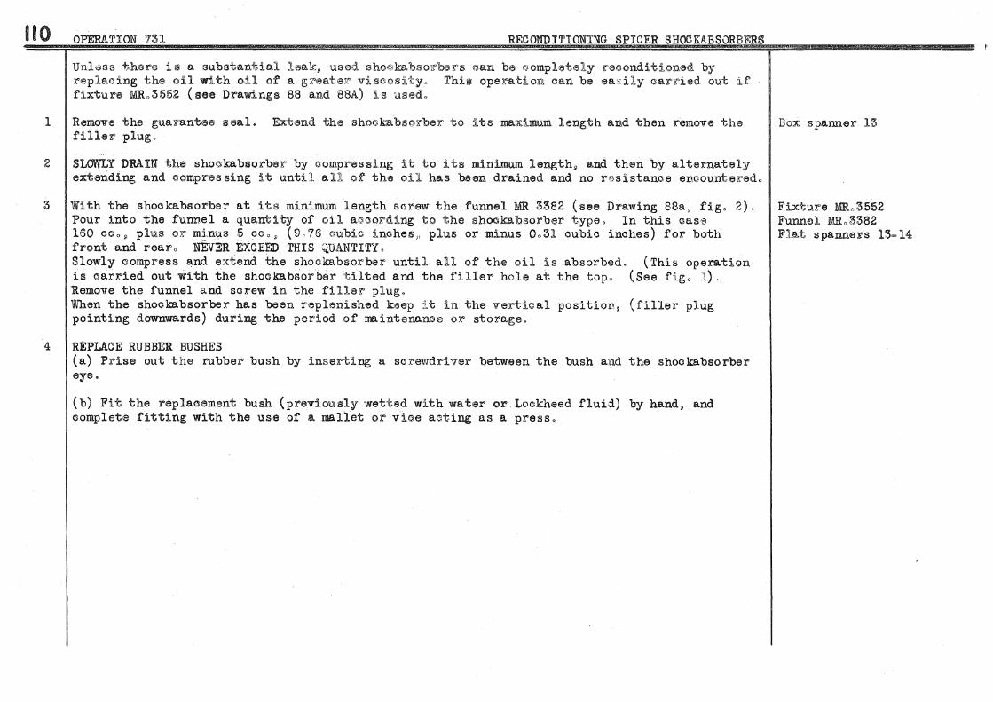
110 OPERATION ?3Jl RECONDITIONING SPICER SHOGKABSORBERS , !!l!!l!ll Nlmfl'.iiliw .. &lil!JIIli\liiUFi,..... !iljjWiim'l.~!i'12£'®!'2~•*ii ====tzs :zes z
l
Unldss there is a substantial lsak" used sho©kabso~~~s ©an b® ~ompl~t~ly reaonditionad by replacing the oil with oil of a gli"<eataZ" Yi sc:osi"~y., ThirB opelration aan be ea:; ily CI&X"ltied out if' fixture M:Ro3552 (see Drawings 88 and 88A) is used.,
Remove the guarantee seal. Extend the shoakabsorber to its maximum length and then remove the filler plug,
2 SLOWLY DRAIN the shookabsorbell" by compres si.ng it to its m1.n~mum length~ and then by a.l ternately extending and (':JOmpres sing it until aU of' tha oil has been drained and no resistanoe encounteredo
3 With the shookabsorber at its minimum length sorew the funnel MR 3382 (see Drawing 88a, figo 2). Pour into the funnel a quantity of oil a©col"ding to the :shockabsorber typeo In this cas,;, 160 Mo~ plus or minus 5 ceo" (9o76 cubic inches,, plus or minus Oo31 cubic inches) for both front and rearo NEvER EXCEED THIS QUANTITY. Slowly compress and extend the shockabsorber until all of the oil is absorbed.. (This operation is oarried out with the shockabsorbe:r ti.lted and the filler hole at the topo (See figo l), Remove the funnel and screw in the filler plug. 'When the shockabso:rber has been replenished keep it in the vertical position, (filler plug pointing downwards) during the period of maintenance or storage.
4 REPLACE RUBBER BUSHES (a) Prise out the rubber bush by inserting a screwdriver between the bush and the shocka.bsorber eye.
(b) Fit the replacement bush (previously wetted with water or. Lockheed fluid) by hand, and complete fitting with the use of a mallet oX' vice aGting as a press.
Box spanner 13
Fixture MRo3552 Funnel MRo3382 Flat spanne:rs 13=14

OPERATION 732 REMOVING AND REFITTING GEAR SELECTOR
REMOVING SELECTOR
l Remove the bonnet.
2
3
4
5
6
7
Remove the ba.tteryo (Use battery cable t®rminal extraGto~ 2200~T 9 see Drawing 1, figo l)o
Disoonneot relay lever rods from seleGtor leverso Unscrew knob from gear change lever.
Remove the seleotoro Unscrew the two nuts f'i:Jdng selector from behind the instrument paneL (Use spanner 2430=T" see Drawing 141, fig,, 3, pas sing through holes in battery tlfay). Unscrew two bolts on left=hand side of battery tray fixing the selector to the hull.
REFITTING SELECTOR
Engage the selector by passing under the instrument panel o First tighten the two nuts behind the instrument panel (use spanner 2430=T) and then the two bolts on the hulL
Connect the rods from the relay leYers to the gear selector levers. With the gear CJhange lever in the neutral position as well as the gearbox control rods, adjust the length of the relay 1t'ods so that th~Sy oan be oonnec:ted without mov;ing "cha:~.ear oha.nge lever and gaarbox cont:&"ol rods. After this adjustmeut make surra that the 'ge~r Ql'nartge lever does not cat©h in its lateral movement.
Fit the battery.
8 Fit the bonnet.
Extractor 2200-T Flat spanner 10 Box spanner 12
Box spanner 10
Spanner 2430=T
Spanner 2430- T Box spanner 14
Flat spanner 14 Box spanner 10
Flat spanner 10 Box spanner 12.
II I

112 DISMANTLING GEAR SELECTOR (see Drawing 141)
1 Remove cotter (1) from seGond and top speed lever (2) in selector.
2 Remove the lever shaft (3), take out the two levers (2 and 4)D change speed lever (5) and the thrust washers (6).
3 Remove outer lever (7) from shaft (3) by taking out the cotter (16).
4 Remove bronze ball (8) from the gear change lever by unscrewing the two pegs (9).
5 Use a shouldered mandrel to remove the two graphite bushes (10) from the bracket (11) and from first and reverse speed lever (4).
6 Remove the looking springs (12) by punching of the rivets (13).
7 Remove the rubber protector ( 14) by taking off plate ( 15).
ASSEMBLING GEAR SELECTOR (see Drawing 141)
8 Fit the loa king springs ( 12) to the levers, and peen over rivets (13) o
Box spanner 8
Box spanner 8
Shouldered mandrel small diao 14" length 20 _, large dia. 17, length 100.
9 By means of a bench press and the mandrel used for dismantling, press in graphite bushes (10) Shouldered mandrel into the bracket ( 11) and the first and reverse speed lever ( 4)" Ream the bushes to 14.1 nun. dia. small diao 14, length 20, (Use a shaft for gauging). large dia. 17, length 100
10 Fit the bronze ball (8) on the lever (5)P tighten the two pegs (9) and turn back tabs of lockwashers.
li Fit the outer lever (7) on shaft (3). Fit the cotter (16) and tighten nut.
12 Fit rubber protector (14) and tighten plate (15).
13 Oil the shaft (3) and engage in braoketo Fit one thrust washer (6), inner lever (4) for first and reverse speed, change speed lever ( 5). second and top speed lever ( 2). and a thrust washer ( 6). Fit cotter (1) into the second and t9p speed lever (2). Tighten the cotter nut using a plain washer under.
Box spanner 8
Box spanner 8

113 OPERATION 734 REM.OVING AND REFITTING HANDBRAKE CROSS·~SHAFT ~~~~====~~~~~~~~~~==~~~~~~~~~~~~====~==r=====~· ----~~---~· ~~
REMOVING HANDBRA.KE CROSS-SHAFT (see Drawing 90)
1 Disconnect brake cables ( 1)" unhook return spring (2) • from handbrake lever, disconnect relay rod (3) by removing pin (4) at cross-shaft end.
2
3
Remove caps (5) from brackets of cross-shaft (6). Remove the shaft and take out brackets (7).
REFITTING HAND BR~KE CROSS-SHAFT (see Drawing 90).
Fit the two cross- shaft brackets ( 7) on fixing bolts on hull. Fit shaft ( 6) in bracket, fit caps (5), tighten nuts.
4 Adjust the handbrake (see Operation 749, paragraph 3).
Box and flat spanners 12
Box spanner 12
Box spanner 12

114 OPERATION 735 REMOVING AND REFITTING PEDAL GEAR
REMOVING PEDAL GEAR
l Remove gear control rods from relay levers on timing oovero Remove the clutch ©a.bl~ and stop lamp switch operating rod.
2
3
4
5
6
7
8
Remove pedal gear reinforcement.
Remove the Lockheed reservoir cap and introduce a conically pointed pin to plug the outlet union in order to prevent loss of fluid when disconnecting feed pipe.
Remove feed pipe fl"om resenroir to master 'Jylindero (Use spanner 2130-T, see Drawing 91, figo2) 0
Unscrew the bolt fixing master cylinder three-way union. (Use spanner 213l=T, see Drawing 91, figo 1) o
Unscrew bolt fixing pedal shaft (master cylinder bracket end) and bolts fixing master cylinder on hulL
SlaCJken the master cylinder and c:lutoh 0ontrol levers o Disengage master cylinder with bracket and both control levers. Remove keys from keyways.
Unscl"ew bolt fixing pedal shaft (pedal end) and disengage pedal springs and shaft.
REMOVE PEDAL GEAR BRACKET FROM BULKHEAD (for this operation it is necessary to :remove the steering wheel and fixed tubular column with bracket from bulkhead). (a) Remove the steering wheeL (Use steering wheel extJmctol" l950=T~ see Drawing 68, fig. 3).
(b) Remove the combined lighting and horn switch.
( o) Remove fixed tubular column and bracket from bulkhead.
(d) Remove pedal gear bracket from bulkhead.
FITTING PEDAL GEAR
IN CASES VVHERE THE PEDAL GEAR BRACKET HAS BEEN REMOVED
;
Flat spanner 12
Box spanner 12
Pin 10 dia.
Flat spanner 16 Spanners 2130=T and 213l~T
Box and flat spanners 12 Flat spanner 21
Flat and box spanners 12
Flat spanner 21
Extwacrtoli l950=T Box spanner 32
Box spanner 14
1
Box spanner 12
I :r
9 Fit pedals to bracket. Tighten left:..hand bolt fixing pedal shaft and turn back tab of look.washer.i
10 Offer up the assenilily to the bulkhead without fixing so as tc allow passage for the fixed tubular Flat spanner 21 oolumn bracket.

OPERATION 735 REMOVING AND REFITTING PE.DAL GEAR
11 Fit the fixed tubular "olumn and bracket to bulkhead. Check the centering of the steering Box spanner 14 column proper in the tube. (Use bush MRc3102, see Drawing 68. ·fig. l). The ecc:entri,o:$,ty must not be more than 4 mm. If necessary. correct the centering of the tube by repositioning the column fixing bracket on the instrument panel. Fit the combined lighting and horn switch.
12 Fit the steering Wheel. Set the front wheels in straight ahead position. Fit key in keyway on Box spanner 32 steering column and fit the wheel so that the key engages in hub keyway in line with one of the spokes. Tighten nut. The two upper spokes must allow the driver olea.r vision of the instrument. panel.
13 Tighten bolts fixing pedal gear bracket to bulkhead. Box spanner 12
IN CASES WHERE THE PEDAL GEAR BRli.CKET HAS NOT BEEN REl\/iOVED
14 Oil the pedal shaft and offer up in bracket the pedals and springs mounted on shaft. Tighten the left=ha.nd fixing bolt and turn back tab of' lockwasher~
15 Fit the contlfol levers in th.e following orderg= tbrustwa.slier lever key, master cylinder control lever, spacing washer, key and clutoh c.ontrol lever. Tighten lever clamp bolts using spX'ing washers under nuts.
Flat and box spanners 12
16 Fit the bracket and master cylinder as sembled~ making sure that the rubber protector is positionOO. Flat spanners 12=21 correctly. Tighten the bolts fixing the bracket using a. sp:ring washer under each nuto Fit the Box spanner 12 pedal gear reinforcement. Tighten the pedal shaft right-hand fixing bolt and turn back tab of lockwa.sher.
17 Flat spanner 16
liS
Fit the Lockheed pipe. (Use spanner 2130=T. see Drawing 91. f'igo 2). Tighten bolt fixing master cylinder thr.ee=wa.y uniono (Use spanner 213l=T • see Drawing 9'1. figo 1). Spanners 2130-T and 2131-T
18 Fit the clutch cable and stop lamp switoh operating rod. Fit gear control rods using split pins to retain clevis pins.
19 Remove plug from Lockheed reservoiro Bleed the brake system. (See Operation 74'9, paragraph 5).
Flat spanner 12

116
l
OPERATION 736 REMOVING AND REFITTING ~~STER CYLINDER
REMOVING MASTER CYLINDER
Remove the Lookheed reservoir oap and introduce a ©onioally pointed pin to plug the outlet union in order to prevent loss of fluid when disconnecting feed pipe.
Pin 10 dia.
2 Remove feed pipe from reservoir to master cyli.ndero (Use spanner 2130-T, see Drawing 91. figo2) o Spanner 2130=T Flat spanner 14
3 Take out clevis pin at the front end of the olut©h oableo Pull up the clutch c-able without disconnecting it at the pedal end and lay it on hull. Loosen the pedal gear re~inf.ore'lement. Take out the bolt fixing it to the hull" and (without removing its fixing bolt on the pedal gear) let reinforcement rest against hull closing plate.
4 Unscrew bolt fixing master cylinder three·~way uniono (Use spanner 213l""T• see Drawing 91, figol) Box spanner 12 Spanner 213l=T
5
6
7
Remove master cylinder from its bracket.
FITTING MASTER CYLINDER
Fit cylinder to bracket and at the same time fit the push rod. Make sure that the rubber protector is correctly positioned" Tighten nuts using spring washers under.
Screw in plug fixing master cylinder three-way uniono (Use spanner 213l~T. see Drawing 91, figo 1).
8 · Fit pedal gear reinforcement and connect clutch cable.
9 Fit feed pipe from Lockheed fluid reservoir to the master cylinder o (Use spanner 2130-T. see Drawing 91, figo 2).
10 Bleed the brake system (see Operation 749, paragraph 5).
Spanner 11 Facom type Ideal11 240 x 12
Spanner. 11 Facom type Ideal" 240 x 12
Spanner 213l~T
Box spanner 12
Spanner 2130-T

OPERATION 737 DISMANTLING, CLEANING AND ASSEMBLING MASTER CYLINDER
DISMANTLING (see Drawing 92)
1 Take out cirolip (1) retaining the piston but hold the latter in place to prevent dispersion of parts under pressure from the spring.
2 Take out piston (2)~ oup (3). spring (4) and valve (5). Unscrew the union (6).
CLEANING
3 Use alcohol only to clean the parts. There must be no traces of rust or scoring in the master cylinder bore. If the bore is defective replace the casting. Make sure that the holes nan and 11 b 11 are perfectly clear.
4 With all the parts in perfect order r·e-assemble the master cylinder after dipping components in Lockheed fluid.
5
ASSEMBLING
Fit valve (5), spring (4)~ cup (3) and piston (2) fitted with cup (7). Fit washer (8) and cirolip (1). Tighten the union (6).
117
Flat spanner 23
Flat spanner 23

118 OPERATION '738 REMOVING AND REFITTING EXHAUST PIPES AND SILENCER
1 REMOVE THE TAIL PIPE Remove the bolt fixing the rear clip. Dis<'lonnect tail pipe flange f:>:"om silencer and remove pipeo Box spanner 14
2 REMOVE THE SILENCER Disconnect silence:>:" inlet flange fX'om exhaust pipes under hulL Disconnect silencer outlet flange from tail pipe and take out silencer.
3 REMOVE EXHAUST PIPE BETViEEN ENGINE AND SILENCER Disconnect exhaust pipe front flanges from exhaust manifold. (Use spanner 1626-T~ see Drawing l, figo 2) o 1lemo~re the bracket under hull and disconnect exhaust pipe rear flange from silencer inlet.
4 FIT EXHAUST PIPE BET\1\fEEN ENGINE AND SILENCER
5
6
Use Co and A. type gaskets between both pairs of flanges. Tighten bolts on silencer inlet flange using spring washers under nuts o TIGHTEN UP HARD THE NUTS FIXING F.XHAUST PIPE FLANGES TO MANIFOLD. (Use spanner 1626-T, see Drawing 1, fig" 2). Fit the exhaust pipe bracket under hull.
FIT THE SILENCER Use Co and Ao type gaskets at flanges. Fit spring washers under nuts and tighten.
FIT TRE TAIL PIPE Use a Co and Ao type gasket between the flanges. Fit spring washers under the flange nuts and tighten. Fit bolt for rear clip using a spring washer and plain washer.
Flat and box spanners 14
Spanner 162 6- T Box spanners 12-14
Spanner 1626-T Box spanners 12-14
Box and flat spanners 14
Box spanner 14

REMOViNG" DISMANTLING .ASSEMBLING AND REFITTING D.ISTRI:SUTOR
REMOVING DISTRIBUTOR
1 Disconnect ignition coil and spark plug leads. Box spanner 8
2 Slacken clamp screw and take out distributor. Flat and box spanners lo
DISMANTLING DISTRIBUTOR (see Drawing 9:3) .
3 Dismantle the distributor head by removing screws ( 1) and terminal (~) ~ Remove the condenser. Flat spanner 9
4 Knock out pin (3) fixing driving dog. Disengage the shaft and centrifugal advance weights (4) by Pin punch 3 unhooking springs (5).
5 Disconnect wires from distributor cap.
6 Clean the parts.
~SSEMBLING DISTRIBUTOR (see Drawing 93)-
7 Fit the centrifugal advance weights (4) and hook on springs (5). Offer up the shaft in distributo body and make sure there is no play in the bushes. If there is play replace the distributor body.
8 FIT THE SHAFT (a) Oil the shaft and engage' it in distributor body.
(b) Fit a spacing washer on the lower end of the shaft and then the driving dog (6). THE DRIVING DOG TONGUE IS OFFSET. .THE PART MUST BE FITTED SO THAT THE TONGUE IS OFFSET TOWARDS THE SIDE OPPOSITE THE CAM SLOT. "Nith the driving dog fitted make sure that the shaft turns freely without end play. Should there. be end play in the shaft take this up by using a thicker spacing washer. Peen over both ends of pin (3).
9 Fit the contact carrier pl~te and the toggles. Adjust the contact gap to 0.4 mm., plus or Flat spanner 9 minus 0.05 nun. Fit the condenser.
10 Fit the spark plug and ignition coil leads to the distributor cap. Fit cap to distributor.
11 BENCH TEST DISTRIBUTOR · (a.) Set up on the test bench and ignition coil of the same type as the distributor to be tested.
.tl9:

120 OPERATION 739 REMOVING, DIS1~NTLING, ASSEMBLING AND REFITTING DISTRIBUTOR
Connect the negative terminal of the coil to the distributor primary terminal.
(b) Check the insulation of the secondary circuito Set the test bench contacts gap to 15 mm. Connect ignition coil secondary terminal to the central terminal of the distributor cap. Connect the spark plug leads to the test bench contacts" Rotate the distributor for fifteen minutes at 1000 R.P.M.
(c) Check the firing pointso The angular differences of the firing points read on the degree scale must not exceed 1°5 1 at all speedso (lViaximum speed of distributor is 2000 R.P M.)
(d) Check the adjustment of the automatic advance curve . The curve is as follows:-00 at 250 R.P.M. (distributor speed) and l4o5° at 2000 RoP.M. (see Drawing 94 for tolerance). To obtain this curve it is possible to rnodify the tension of the centrifugal weights by bending the spring carrier plates.
(e) Check the insulation of the primary circuit. Heat the distributor, WITHOUT CONDENSER to a temperature of 60° C 0 ( 140° F o). With the contact breaker open, apply an alternating current of 110 volts, 50 cyles, between positive terminal and earth with a lamp in series. Keep voltage applied for one minute. If lamp lights the insulation is faulty.
FITTING DISTRIBUTOR
12 See Operation 701, paragraph 30, and Operation 702, paragraph 17.

OPERATION 740 REMOVING AND REFITTING DYNAMO
NOTE. Certain oars are fitted with fans that have the blades equally spaced. On these models, to remove the dynamo, it may be necessary to remove the air intake silencer, the air heater tube, and also to free the radiator on its brackets to move it a little forward.
REMOVING DYNAMO
1 Remove the air intake silencer. Disconnect the pipe from the carburettor intake and the silencer Flat spanners 12 brackets from hull.
2 Disconnect wires on dynamo.
3 Remove nuts fixing dynamo bracket on clutch housing cover.
4 Take out the dynamo from the right of the engine. Turn the fan so that blades that are wider spaced clear the radiator.
FITTING DYNAMO
5 Fit the dynamo from the right of the engine. Turn the fan so that blades that are wider spaced clear the radiator.
6
7
8
Fit belt on dynamo pulley and adjust without excessive tension. Tighten the dynamo bracket fixing nuts after fitting one plain washer and one spring washer under each.
Connect dynamo wires.
Fit the air intake silencer with the fixing plates between two rubber washers. Split pin the fixing bolts.
Box spanners 8=14
Flat spanner 17
Flat spanner 17
Box spanners 8-14
Flat spanner 12
121

122 OPERATION 741 DISMANTLING AND ASSEMBLING DYNAMO
DISMANTLING DYNAMO (see Drawing 95)
1 Remove the driving pulley (1), dust cover band (2), fan (3), and the end plate (4) (fan end), Box spanners 8-21 together with armature. Remove end plate (5) carrying brush gearo
2 Remove the dynamo bracket. Flat spanner 21
3 Remove pole-piece fixing screws (6). (Use special screwdriver MRol601-4 fitted in a bench press, Screwdriver MRol601-4 see Drawing 97)o Remove the pole=pieces {7), take out the terminals (8) and remove the field Bench press coils.
4 Remove the end plate (4) from the armature by means of·the bench press.
5 Dismantle-the end plate (5) carrying brush gear.
6 Remove the bearing (12) from end plate (4) (fan end), by taking off the closing plate (13).
7 Unsolder connections ttatt of field coil leads (see Drawing 96).
8 Clean parts.
ASSEMBLING DYNAMO
9 Check the armature with suitable apparatus.
10 True up the commutator. Do not decrease by more than 2 mm. the original diameter of 45 mm.
11 After machining the commutator use a scraper or a piece of saw blade. ground to the width of the segment insulators, to clean the insulators and thus prevent ''shorting" of the segments.
12 Cheok the field coils with the aid of a test lamp.
13
14
REPlACE DEFECTIVE FIELD COILS (a) When solderin~ field coil connections use only a resin paste flux. (spirits of salts).
NEVER USE ZINC CHLORIDE
(b) When fitting the field coils take care not to break or kink the connections.
FIT THE FIELD COILS AND POLE PIECES (see Drawing 96) Make sure that the coils and pole pieces are correctly positioned in the dynamo casing (Use Mandrel MRol601-2

OPERATION 741 DISMANTL!NG AND ASSE.I\ffiLING DYNAMO
Mandrel MR.l601-2, see Drawing 97). This mandrel will establish a clearance of 0.05 mm; between armature and pole pieces and thus prevent fouling.
(a) Fit the field coils and the insulating strips (14). Provisionally tighten the pole piece fixing screws (7). (See Drawing 95).
(b) Completely engage mandrel MR.l60l-2 between the pole pieces by means of a press (see Drawing 97).
(c) Tigr1ten the pole piece fixing screws. (Use screwdriver MR.l601-4 fitted in a bench press, see Drawing 97).
(d) Take out the mandrel from the end opposite to its entry.
(e) Twist and solder the field coil leads (see Drawing 96), and connect to the terminals.
No greasers are fitted for the bearings. Before assembly coat the bearings with vaseline. No other lubrication should be necessary during the life of the dynamo. (Lubricatation points are not provided in order that neither oil or grease can cause dirty brushes or commutator).
15 PREPARE END PLATE CARRYING BRUSH GEAR (see Drawings 95 and 96). (a) Rivet the negative brush holder (15) with its packing (16) and the positive brush holder (17) with its insulating plate (18). Use insulating on the rivets.
(b) Fit in the bearing housing of the end plate, oil retaining washer (11), bearing (lO)D a second oil retaining washer (11), bearing retaining washer (19) and circlip (9).
(c) Fit the brushes and brush springs. To allow the commutator to be fitted between the brushes hold the brushes in a 11 raised position" by the springs (as indicated on Drawing 96, fig. 3).
16 PREPARE END PLATE (4), FAN END (see Drawing 95). (a) Fit in the bearing housing of end plate. oil retaining washer (20), bearing (12), a second oil retaining washer (20), paper gasket for closing plate and the closing plate (13). Tighten the three so rews.
(b) Fit the thrust bush (21) on the armature, and fit the end plate with the aid of a small press.
(o) Engage the armature in the dynamo casing and fix the end plate by screws. Lock the screws by punching metal from the end plate into the slots of screw heads.
Screwdriver 1ffi.l60l-4
(d) Fit the fan (3) and tighten nut using a spring washer under. Box spanner 21
123,

124 OPERATION 741 DISJ\flANTLING AND ASSEMBLING DYNAMO
17 Fit thrust bush (23) on armature and fit the brush gear end plate. Tighten the fixing screws. Connect the field coil wires to the positive brush as at 11 b 11 •
18 Fit the driving pulley (1) to shaft. Make sure that the shaft turns freely BUT WITHOUT END PLAY. Box spanners 8-21 If it is necessary to take u.p end play fit an adjusting washer (22) between bearing and pulley. Use a spring washer under the pulley nut and tighten the latter. Engae;e brushes with conunutator. Fit the dust cover band (2).
19 Fit the dynamo bracket to the casing. Use spring washers under nuts and tighten.
20 Check the output on a test bench. The dynamo commences charging at 700 to 800 R.P.lVI. The output at 2500 R.P.M. should be between 14.5 and 15 amperes the corresponding voltage being 6.2 to 7" 2 volts, the dynamo discharging into a battery.
21 Paint the unit.
Flat spanner 21
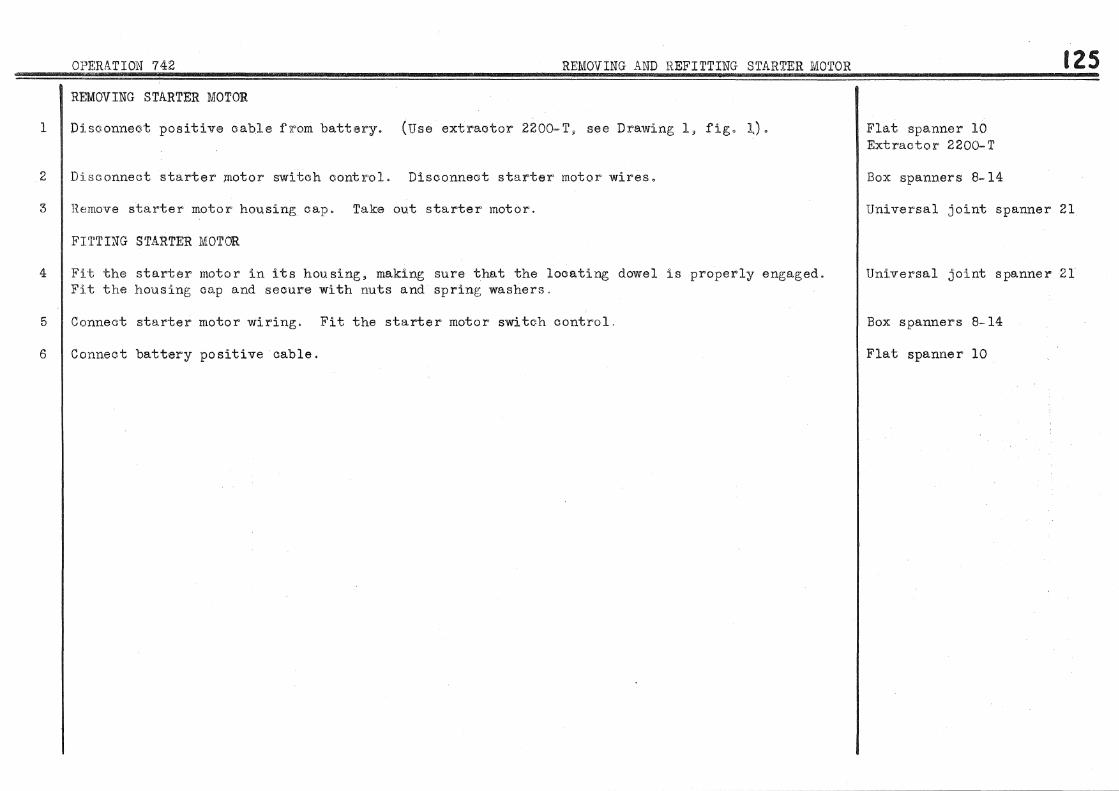
1
2
3
4
5
6
OPERATION 742 REMOVING AND H.EFITTING STARTER MOTOR
REMOVING STARTER MOTOR
Disconnect positive cable i'll"om battery. (Use extractor 2200~T, see Drawing l, figo l).
Disconnect starter ;motor switch control. Disconnect starter motor wires.
Remove starter motor housing cap. Take out starter motor.
FITTING STARTER MOTOR
Fit the starter motor in its housing, making sure that the locating dowel is properly engaged. Fit the housing cap and secure with nuts and spring; washers.
Connect starter motor wiring. Fit the starter motor switch control.
Connect battery positive cable.
Flat spanner 10 Extractor 2200-T
Box spanners 8-14
125
Universal joint spanner 21
Universal joint spanner 21
Box spanners 8-14
Flat spanner 10

126 OPERATION 743 DISMANTLING AND ASSEMBLING STARTER MOTOR
DISMANTLING STP~TER MOTOR (see Drawing 98)
1 Remove the switch, dust cover band (16), bendix housing (1), take out the armature and remove Flat spanners 8-12 end plate (2) carrying brush gear.
2 Remove the pole=pieces. (Use screwdriver ~ffi.l60l-4 fitted in a small bench press, see Drawing 9~ Screwdriver MR.l60l-4 Unsolder field coil and terminal (3) connecting strips and take out field coils (see Drawing 99, Soldering iron
3
fig. 1).
DIStriANTLE BEliDIX GEAR FROM ARMATURE SHAFT (see Drawing 142) (a) Compress the spring (3). (Use compressor 2202-T, see Drawing 143). Remove circlip (1), extract pin (2) with the aid of a pair of flat nose pliers (the pin comes out easily). Free the bendix assembly from the shaft. Remove the plate (11) for the intermediate bearing.
(b) Remove compressor 2202-T from the spring. Remove washer (4) for spring (3). Unhook spring (3) from washer (5).
(c) Remove circlip (6), disengage pinion (7) from shaft (8), take out spring (9) from bore of pinion (7).
4 Dismantle the brush gear end plate (2). Use a mandrel to knock out bushes (4 and 5) from end plate and bendix housing respectively.
5 Dismantle the switch.
6 Clean the parts.
7
ASSEMBLING STARTER MOTOR
Check the armature shaft b~tween cent res. and the field coils with a test lamp.
Check the armature windings on suitable test apparatus
8 True up the conunutator. (NEVER DECREASE THE ORIGINAL DIAMETER OF THE COMMUTATOR, WHICH IS 45 mm. BY :MORE THAN 2 mm.)
9 After rectification of the commutator clean out the insulators between the segments to ensure against 11 shorting 11 • For this purpose use a scraper or piece of saw blad~ ground to the width of the insulating plates.
10 BUilD UP THE END PLATE CARRYING BRUSH GEAR li.ND THE BENDIX HOUSING (see Drawing 98 and 99).
Compressor 2202-T
Punch 3 dia. Mandrel 15 x 17 x 150
Flat spanner 14 Box spanner 8

The bushes for the end plate and bendix housing are made of porous bronzeo Before assembling soak the bushes for approximately twenty four hours in an oil bath (engine or similar oil) to thoroughly impregnate themo No means of lubricating the bushes after assembly is provided and the above method should suffice throughout the life of the machine. (The reason for this method is to prevent oil penetrating to the conrrnutator and brushes).
(a) Fit the lubricated bearings (4 and 5) by means of a small bench pres:a;.
(b) To the end plate carrying brush gear rivet on negative brush holders (6) with paokings (7) and the~ brushes (8)" Rivet on positive brush holders (9) with insulating plates (10) using insulating sleev·es (11) on rivetso Fit the positive brushes (15) and tighten scn::•ewso
(c) To allow the conunutator to be fitted hold the brushes out as indicated on Drawing 99, fig;o 2
11 FIT FIELD COILS AND POLE PIECES
12
IViake sure that the field c.oi1s and pol,~ pieces a;re correctly positioned in the starter. motor casing. (Use mandrel I\\R" 1601·~ 1 see Drawing 97). This mandrel will establish a clearanc"e of clearance of Oo 7 rnrrlo maximum between armature and pole pieces and thus prevent fouling.
(a) Fit the field ooi1s., insulating stdps (12) ~ screws fixing pole pieces and provisionally tighten.
(b) Pla0e the termi.na~. (3) with its insulating washers and solder field coil connecting strips (see Drawing 99 1, figo 1)
(c) Completely engage mandr&l MR, 1601·= l betwe(en pole pieces by means of a press (see Drawing 97 ." figu 1) o
(d) Tighten the pole piece fixing screws using screwdriver MR, 1601~ 4 fitted in a small press (see Drawing 97" figo 2)"
(e) Take out the mandrel from the end opposite to its entry.
ASSEMBLE SWITCH (see Drawings 98 and 99)o Fit tenninal (3) with its insulating washers. Fit the spring, positioned according to drawing, to ens-ure bearing against the cam (13)o Fit the oam,, retaining tube, and control lever.
13 FIT BENDIX GEAR TO ARMATURE SHAFT (see Drawing; 142) (a) Fit spring (9) in bore of pinion ('7) ,, Fit pinion on sleeve (8) and fit drc;lip (6).
(b) Fit the spring (3) by engaging +h·3 b3nt Bnd in slot in wash<9r ( 6) Fit washer (4) (with
Mandrel MR.,l60l~l
F1a.t spanner 12
Screwdri>rer lvJlo 1601-4
Flat spanners 6-14-16 ,

128 OPERATIOl~ 743 DISMANTLING AND ASSEMBLING STARTER MOTOR
the conical portion on the spring side) by introducing the bent end of spring (3) in washer slot.
(c) Compress the spring (3) o (Use compressor 2202-T, see Drawing 143). Fit circlip (1) in groove of sleeve (8).
(d) Put in position the intermediate bearing (11) and then the key (10) in keyway on shaft.
(e) Offer up the bendix assembly on armature shaft and fit pin (2) in its seating. Turn the ciclip (1) in grooye on sleeve (8) to lock the pin (2), :rtemove compressor 2202-T.
Compressor 2202- T
14 Fit the end plate ( 2) on starter motor casing, Connect the field coil terminal strit1s to the Flat spanner 8 positive brushes ( 15). Ti(~hten the screws using spring washers under headso Engage the armature, fitted with thrust washers at both ends, and fit the bendix housing;(l). I£.ake sure that the armature turns freely without fouling and has an end play of 0. 2 mm'. to 1 .'3 mm, If necessary use thrust washers of a different thickness to give the correct end play. Bring brushes into contact with commutator. Fit the dust cover band (16). Fit the contact leaf (14) to the terminal and look contact by turning back corners against flats of nut. Fit the switch TAKING CARE THAT CONTAC~' LEAF IS ABOVE TB:E SWITCH TERJ\!IINAL.
15 Bench test motor. Current consumption under load is 180 to 200 amperes and with no load 50 to 75 amperes.
16 Paint unit.

OPERATION 744 HEADLAMP ADJUSTMENT 129 HEADLA1~ ADJUSTMENT
Use the screen Iv!Rol572 according to instructions on Drawing l06o Screen MRol572

130 OPERATION 745 REMOVING AND REFITTING FRONT BODYWORK
1
REMOVING FRONT WINGS AND RADIATOR SHELL ASSEMBLY
Remove the bonnet. Drawing 1 9 figo 1).
Disconnect cable from batt<Bry positive terminal. (Use extractor 2200,T, see Disconnect feed wires 'to lamps and horns from terminal blocks.
2 Remove bolts fixing wings to hull and to brack!ats. Remove bolts fixing radiator shell front paneL Disengage the assembly of wings and radiator shell from the oar.
I FITTING FRONT WlNGS AND RADIATOR SHELL ASSEMBLY
3 Offer up the assembly to the car. Using a plain washer and a spring washer under the heads of the bolts screw in the latter a few turns onJ.y. Offer up the bonnet and, after adjusting the parts in relation to one another and correctly fitting the wing piping, tighten the fixing bolts.
4 Connect headlamp and horn wiring. Connect positive cable to battery.
REMOVING RADIATOR SHELL
5 Remove the bonnet.
6
7
Remove bolts fixing radiator shell to wines also those fixing radiator shell lower front panel to radiator.
FITTING HADIATOR SHELL
Fit the radiator shell. Position the wing piping and tighten bolts using a plain washer and a spring washer under heads.
8 Fit the bonnet.
9
REMOVING A FRONT i.''fiNG
Disconnect cable from battery positive terminal. (Use extractor 2200-T, see Drawing 1, fig. 1). Disconnect headlamps and horn wiring.
Fla. t spanner 10 Extraotor 2200-T Box spanner 8.-10
F1at spanner 10 Box spanners 12-14
Flat spanner 10 Box spanners 12-14
Flat spanner 10 Box spanners 8-10
Box spanners 10-·12 Flat spanners 12-14
Box spanners 10-12 Flat spanners 12-14
Box spanners 8-10 Extractor 2200-T Flat spanner 10

10
11
12
OPERATION 745 REMOVING AND REFITTING FRONT BOD~~ORK
Remove bolts fixing wing to radiator shell, hull and wing bracket.
FITTING A FRONT WING
Offer up the wing on the car" Using a plain washer and a spring washer under the heads of the bolts sorew in the latter a few turns only. Correctly position the wing piping and tighten the fixing l:Jol ts.
0onnect headlamp and horn wiring, Connect positive cable to battery.
Flat spanner 10 Box spanners 12-14
Flat spanner 10 Box spanners 12-14
Box spanners 8-10 Flat spanner 10
131

132
1
2
3
4
5
6
7
OPERATION 746 REMOVING AND REFITTING PETROL TANK
REr.WVING PETROL TANK
Jac;:{ uo the vehicle at the rear and block up under rear link arms. · (Use special jaok head MRo 3300-110 ~ see Drawing 75) .
Remove the inspection plate in the rear luggage comp1trtJnent floor. Disconnect wires on petrol gauge tank unit. Unscrew terminal nut from petrol tank outlet pip<:J and remove feed pipe from outlet pipe. Remove rubber grommet from petrol tank filler neck.
Disconnect the two straps holding the tank. RemoYe petrol tank.
Unscrew the petrol tank outlet pipe. Remrnre the petrol tan'6: gauge unit. 1'ake off lower rubber grommet from tank filler neck.
FITTING PETROL TAliK
Fit the tank gauge unit with a cork gasket and tighten the three screws. Fit thd petrol tank outlet pipe using a fibre washer on. the tank flange. Fit the lower rubber gronnnet to the filler neck.
Fit the tank to the car and tighten :the straps.
Fit the petrol feed pipe and connect wires to gauge unit (vd.res and gauge unit termina.J.s are coloured blue and yellow according to way of oonnecting). Fit the inspection plate. Fit the upper ~~bber grommet to the filler neck.
8 Lower vehicle to the ground.
Special jack head MR" 3300-110
Box spanner 16
Box and flat spanners 14
J?lat spanner 16
Flat spanner 16
Box and flat spanners 14
Box spanner 16

OPERATION 747 ENGINE ADJUS~IENTS
VALVE TIMING
Crankshaft and oam~haft timing wheels are marked. With the engine at top dead centre on number one cylinder at the end of the compression stroke 9
the two marks and the centres of both wheels must be on the same straight line. Check with a straight edge (see Drawing 20). For record purposes the valve timing is as follows~-
Inlet Valve Inlet Valve Exhaust Valve Exhaust \Talve Opens Closes Opens Closes
In degrees on flywheel 30 before 'r.D. C, 45° after B.D.C. 45° before B.D.C. 110 after T.D.C. In mlllimetres on piston Ool 88.7 88.7 1.2
~·
These figures are measured assuming a theoretical clearance of 0.34 rom. on inlet valves and 0.41 mm. on exhaust valves. No procedure for obtaining the above setting is. given here as this veey delicate opel!"ation requires precision instruments.
VALVE TAPPET ADJUSTMENT
After the engine has idled for about fifteen minutes (speed 500 R.P.M. approx.) adjust the tappets to 0.15 mn. clearance on inlet and 0.20 mm. clearance on exhaust valves.
IGNITION ADVANCE ADJUSTivmNT
Remove air vent cover on clutch housing. Crank engine slowly to bring the first cylinder to end of compression stroke and.then turn back slightly. Insert a 6 tnm. diameter pin in the hole ptovidf3d in the right-hand side of the olutoh housing cover and then tu~ engine again slowly in the.normal direction of rotation until the pin falls in the flywheel slot marked ALLU •. The engine is now at 8° advance on flywheel. NOTE. THE FLYWHEEL HAS VARIOUS HOLES FOR BALANCnm. PURPOSES, MAKE SURE THAT THE PIN DOES NOT FALL INTO ONE OF THESE. Fit a test lamp on the distributor and. connect lead from lamp to condenser terminal. Turn the distributor body so as to bring contact piece of first cylinder plug lead facing rotor. Close the contacts. Now turn distributor to find the exact point of opening which is at the moment the test lamp lights. Set the distributor bracket in the mid-position of its travel and tighten. Engine firing order is 1-4-2-6-3-5 ..
133
Flat spanner 14 Set of feeler gauges

134 OPERATION 74? ENGINE ADJUSTMENTS
VERY IMPORTANT NOTE: WITHDRAW THE GAUGE PIN
CARBURETTOR ADJUSTMENT (see Drawing 120).
NOTEo The method of adjusting the SOLEX twin-carburettor is the same as for the single type. The twin-carburettor has only one float and starter section for feeding the two chambers, but the sections for adjusting slow-running and normal running are in duplicate. The 90LEX downdraught twin-carburettor is fitted with a mechanically operated pump which has the function of supplying an extra quantity of petrol at the point of acceleration in order to overcome the 11 flat spot" when passing from slow to nonnal running. The carburettor also has a progressive starter and complementory correction device which has the purpose of reducing the richness of the mixture when the throttle is fully open, The slow running screw operates on THE QUANTITY OF PETROL and not on the quantity of air. Typical settings of the 30 P.A.A.I. type carburettor are as follows:-
Slow- running Starter jets Pump Main Corrootion jets Float Choke Needle Jet
Jet Jet Petrol Air Petrol Air Weight Petrol
24 120 280 45 100 140 5.5 21 2.5 50 grammes
IT IS STRONGLY RECOMMENDED NOT TO MODITY THESE SETTINGS AS THEY HAVE BEEN DETERMINED AFTER C01~EHENSIVE TESTS.
(a) SLO'lT RUNNING ADJUSTMENT. Slow running adjustment is effected by:-1. Adjusting screw (34) which will vary the engine speed.
Pump Air
100
2. Adjusting mixture regulating screws ( 29) which vary T:L-IE QUANTITY OF PETROL fed through the slow running jets. The action of these screw$ is very sensitive, therefore the adjustment must be made slowly and carefully. With the engine stopped, screw the two mixture regulating screws (29) right home and then unscrew one complete turn. Start the engine and wait until it has warmed up. If the engir1e 1tracesn the mixture is too rich and both screws must be tightened THE SAME AMOUNT. On the contrary, if the engine •'stalls" or stops easily, the richness must be increased by slackening both screws THE SA!!~ AMOUNT. NOTE. The mixture regulating s·crews (29) must never be screwed right home. Never modify the air jets ( 9), as their output depends on the bore size.
(b) SOME INDICATIONS OF POOR ADJUSTMENT 1. Spark plug colour wlli te, ertgine backfires into carburet tor; overheats and does not pull;
MIXTURE TOO WEAK.
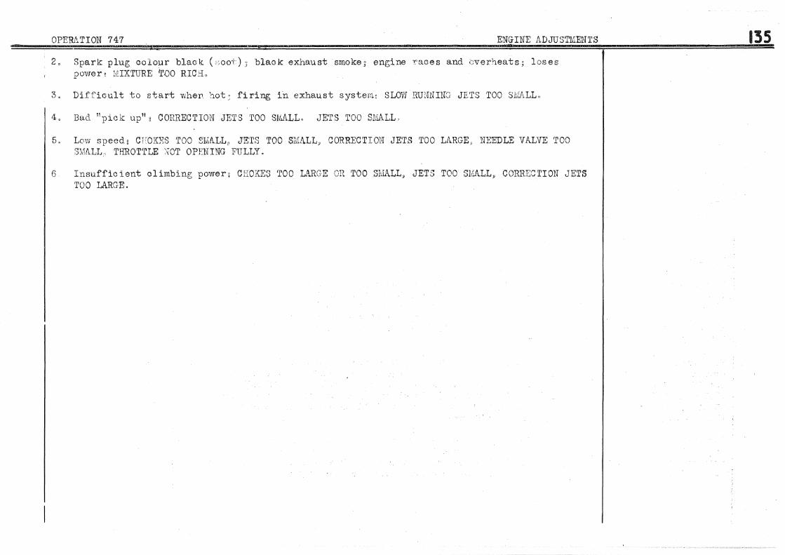
OPERA'riON '747 ENGINE ADJUSTMENTS
2o Spark plug colour black ('.oo-t) black exhaust smoke; engine "races and i:Jverheats; loses power 1 :UXTURE tl'DO RICi:L
3. Diff'icul t to start wheD ~'lot~ firing in exhaust systeril~ SLOVJ RUNNING JETS TOO SMALL a
4. Bad. 11 pick up 11 g COJJRECTION JETS TOO SN,.I\LL, JETS TOO SlvJALL,
5" Lcn.v speed: CFOKES TOO ~:ru1ALL., JETS TOO SMALL" CORRECTION JETS TOO LARGE.,, NEEDLE VALVE TOO 3'!l1ALL, THROTTLE :~OT OPENING FULLY.
6 Insufficient climbing power: CHOKES TOO LARGE OR TOO SMALL, JETS TOO S~.:IALL~ CORRECTION JETS TOO LA.RGE.
135

!.!~-Q!ERATION 748 FRONT AX:IJLA!?J"·-::U::STME=··=.:.N~TS~=-=======~~~~==-
r-CASTER ANGLE ADJUSTMENT (see Drawing 100)
1 I With front and rear body heights adjusted (see Operation 750" paragraphs 1. 2 and 3) and the I tyres at correct pressure, plac:e the vehicle on a LEVEL surface or elevated platform.
2
3
Hemove the greasers on the upper and lower link arms (greasers for lubricating pivot ball joint). k'it the apparatus IvlR.3449 (see Drawing 100) by using the Ereaser holes. The pl~mb line must lie between the maximum and minimum gauge marks. The caster angle will then be 0° - 15 1 •
If plumb line does not fall within gauge marks, correct the caster angle. To do this (see Drawing 139) unscrew the nut of the eccentric pin (121) and turn the adjusting eccentric (122) in the direction :::1ecessary to correct the plumb line reading. (Use spanner 1854-T, see Drawing 55). After adjusting tighten the eccentric pin nut. Proceed in the same manner for the other side of the axle.
'·'TOE- OUT" ADJUSTMEI'lT
This adjustment must only be made after adjusting the caster angle. Use a gauge of the type commonly used in the trade for this purpose. At the height of the wheel centres measure the distance between the inner flanges of the wheel rims at the front. Mark the points measured with chalk. Rotate both wheels half a turn and measure, now at the rear, the distance between the chalk marks on the rim flange. THE WHEELS rJiUST "TOE-OUT 11 , THE DIFFERENCE BETIVEEN THE FRONT AND REAR ME!\SUREMENTS BEING 0 nun. to 4 mm.
Apparatus MR.3449
Spanner 1854-T Box spanner 21
4 To correct ntoe-out11 • jack up the vehicle at the front. (Use special jack head MR.3300-90, see Gauge MR.l590 Drawing 67). Slacken the clamp screws of the track rod adjustable sockets. Using a wrench of the nSTILLSON11 type turn both track rods an equal amount. ('WHEN ADJUSTED THE DIFFERENCE IN LENGTH OF THE TV'lO TRACK RODS MUST NOT EXCEED 1 mme) Check track rod lengths. (Use gauge MR.l590, sre Drawing 101). l\iake sure that the steering rack ball joints do not move during this operation or the adjustmen~ will be affected.
5 Lower the vehicle to the ground. Check adjustment as before. Before lockJ .. ng track rod adjustable socket clamp screws make sure that steering rack ball pins are horizontal :in order to prevent "jamming'' of steering on full lock. The machined part visible of both track rods must be equal in lenp;th within 1 mm. in order to ensure correct distribution of threads.

OPERATION 748 FRONT AXLE ADJUSTMENTS
STEERING LOCK ADJUSTMENT
To prevent undue strain upon the transmission, the steering; _look angle must not exceed 34°. The right-hand steering lock is adjusted by the stop screw (39) on the left=hand end oap of the steering rack. The left-hand look is adjusted by the aluminium cover (12) on the right-hand end of the steering rack, (See Drawing 70). (Use spanners 1975-T).
6 To adjust steering lock" jack up the vehicle at the front and turn steering to full lock on one side Lovrer the vehicle to the ground.
Flat spanner 17 Spanners 1975- T
7 Set the length of the steering lock gauge 1890- T according to the wheel si:;;e (HOT THE TYRE SIZE). Gauge 1890-T (:iee Drawing; 102).
8 Offer un the gauge. Engage the locating end into the bore of the lower silent bloc. 'fhe pointed end rm.,st then touch the inner :d.m of the wheel at the stub axle ~le~_ght. If rim and pointer do net co:i ncid.e, jack up the V:Jbi0le ;;;.gain and adjust either the st~)p screw or the aluminium coirer accordine; to the side being checked. Lower vehi3le to the (!;rcn, Gd acp.in and check once more with the 1;auge.
9 Ti[~hten the stop screw J.ooknut D.nd the locknuts of' the aluminium cover. Turn back tabs of lockwasher ( lochvasher being fitted between cover and first locknut) on both sides against flats.
WHEEL C!\Iv'IBER INSPECTION
10 Wheel oamber cannot be adjusted. It must be 1°. plus or minus 0°30 1 • To check this the 'auge 2314-T vehicle must be standing on a l'1vcl surface. The tyres must al1 l)e exactly at the same pressure and the body heights under hull carefully adjusted. (Use gauge 2311.-T, see DrawinJ~ 103). If' the camber is incorrect 9 check the front axle parts and the alignment of the hull.
137

138
1
OPERATION 749 ADJUSTING AND BLEEDIHG LOCKHEED SYSTEM (FOOT BRAKE). HANDBRAKE ADJUSTMENT
Jack up the vehiol<:l at th;;, f-r'on+: and r::><:t:>:' and pl~l.ce it on blocks. (Use special jack heads 1\ffio3300·-90 and ~\$o3'300-ll0, see Drawings 6'7 and "'5.)
ADJUSTIV\ENT OF CAMS
Special jack heads NJR, 3300°" 90 and MR, 3300-110
2 Turn the adjl).sting; cam TJin (b.exagon head on rear vYh-:::e: ,s .. squo.re head on front wheels) in the F1at spanner 10 direction indicated on DrawiT2e; S~:Sj fig, 4_, :c•nd at t;Je same time re7oi.V•3 th:3 wheel by hand, 'nJversal Joint spanner 17 i.djust ::lin sufficiently to l:wing; brake .shoe just: into c,ontaot with d.:l:"u.rn. Tu:r-c. pin back s1ie;htl:y j~o free th3 wheel, and. then r_;r;;_J~efu1ly f'Grward agG.ir .. untiJ there Ls slig;ht f'r.J.ct3.on between the brak:; lining and the drum (never finish the adjustm-::nt ()n th8 bn''·kward movement of the bra.':::e shoe) 1Jlhe l:)rak:e ~~l1oe 1nust be set; SJ~ closel,I Ct;::J .:~~ossjJ .. Jl:-; 1~:) -t1-v~ drurn so ·!:.;lLat. ped.al tra1rol is sl·1o:rt~
Carry out th,3 .sama 0peration on th!:J otin1· shoe an;l -'-:c +;ha other whaals,
(e) Y?:i.th the t)able (10) havine; neither tension u::' sle.nkness" adjus+: -l~he !,3n1e;th ::)f the r.sJ.ay rod (3) so that there is no pu11 on tha ~·rDs;::;,shaf·t
(d) SI.Acoessi\rel~T a . .:_1Just tl1e tf.n1sion of tl1-c; 1Jrc:.}:e :·.~~l-1:-;J._e,:s hry the :.1ute (~_]_): .~)!) ~:.hc.t v:hen tr.~.c 1-.~an.d~- ·-~:~ .. .:1.t spann·:;r 12 ·!:!:rake control is in the third no·tch thA rear '\·V.her."?.l.i:~ ~T~:"J.Jc;:~ evenl~y·.) ~J~D.d ·: .. \rll8r:t :L.a tha fourtl1 no"t0b the ;,-,rheels lock.
FOOTBR:\KE: ?I·DAL c'..DJUSTMENT
·~ The nece3sar;y claarance between push rod ~ud mast·:Jr cylinder piston is obtained by adjusting the stop screw on the pedal. 1'hc clearance T-IiU td1ow the piston to return tc- its rearmost position and so ;~lear the oil feed hole, The LLdjustment must giiTe an idle pedal movement of 10 mmo before the push rod strikes the piston.
5
BLEEDING LOCKHEED BRAKE SYSTEM (see Drawing 47).
'l'o ensure efficiency of the brakes it is absolutely essential that no air bubbles remain in the system.
(a) Fill the Lockheed reservoir, check level of fluid, and if necessary, top up. (the vehicle being still jacked up), remove the plug ( 66) f:rom the pointed screw wheel cylinder, and fit drain pipe 2140-T (rubber pipe with threaded end piece).
On each wheel ( 65) of the Arrange for the
rain pipe 2140,~T • lat spanners 10..12

OPERATION 749 ADJUSTING AND BLEEDING LOCI\HEED SYSTEM (FOOT BRAKE). ILli..NDBRAKE ADJUSTMENT
pipe to drain into a container, transparent for preference (glass or a bottle), and already containing a little Lockh~ed fluid.
(b) Slacken the pointed screw (65) half a turn. Have the brake pedal operated slowly by an assistant. With each pedal stroke a certain quantity of fluid will escape from the drain pipe carrying with it any air biil.bbles from the system, These bubbles can be observed in the fluid drained into the receptacle. Continue pedal action until no further bubbles emerge from the pipe. At this moment, WITH THE PEDAL STILL DBPH.ES~ED AND THE END OF THE DRAIN PIPE BELOW 1'HE SURFACE OF THE FLUID IN THE RECEPTACLE, tighten the poiuted screw ( 65).
(c) Remove the drain pipe amd replace plug ( 65).
(d) Carry out the same opera.ti ons to ea..<llh wheel.
DO NOT FORGET TO TOP UP LEVEL OF FLUID IN RESERVO:Ei?.
(e) After topping up it is necessary to check the sealing of the system. In the absence of special check instruments, used only by the manufacturers, press pedal down as hard as possible with the foot for thirty seconds to a. minute. lf the pedal resists to pressure there is no leak. If, on the other hand, the pedal sinks bit by bit (more or less rapidly}, a. leak exists, probably at a union or in one of the pipes.
(f) Check also the Lockheed reservoir. If t.b.e fluid is forced back into the reservoir the master cylinder retaining o~;p is defective. It is then necessary to dismantle the master cylinder inunediately.
(g) Lower the vehicle to the ground. (Use special jack hea.d:s JIJIR.3300~90 and MR.3300-ll0, see Drawings 67 and 75).
139
lat spanners 10-12
Special jack heads MR.3300- 90 and MR. 3300~110

140. OPERATION 750 HULL ADJUSTMENTS
ADJUSTMENT OF HEIGHTS UNDER HULL
1 The heights are measured with the vehicle complete for the road but without passengers. Make Gauge 2300-T
2
sure that tyre pressures are normal. FOR 11 PILOTE" TYRES lf,fi x 400, the pressures are~ FRONT - 1.400 kgo per sq. em. (20 lbs. per square inch), and REAR- 1.500 kg. per sq. om. (22 lbs. per square inch). Run the vehicle on to a level surface. Use gauge 2300-T to check the heights. Front height is measured from the torsion bar centre line to the ground. Rear height is measured from the underside of the rear hull floor to the ground. The following are the heights appropriate to the type of oar.
"Saloon11 ( 5 and 6 seater) - Front 275 mm., plus 5 rnm., rriinus 0 rom. Rear 295 mm., plus 11.5 mm., minus 0 mm.
nFamily11 ( 7 and 9 seater) - Front 275 mm., plus 5 mrn., minus 0 mrn. Rear 313 mm., plus 11.5 mm., minus 5 mm. ·
The tyre size of both models is 185 x 400.
If the heights need adjustment, jack up the vehicle (using special jack heads :Will;3300-110, see Drawing 75, and ~ffi.3300-90, see Drawing 67) in order to take the load off the torsion bars. This will allow easy turning of the ball-headed adjusting screws of the front torsion bars (by using spanner 2302-T), and of the nuts of the rear torsion bar adjusting rods.
3 Lower the vehicle to the ground, rock to bring torsion bars into action and then check heights again. For each adjustment, the vehicle has to be jacked up, adjusted, lowered and rooked before heights can be checked.
ADJUSTMENT OF WEIGHT D.ISTRIBUTION
4 Check tyre pressure and correct if necessary.
5 Run the vehicle on to a level surface.
6 With heights under hull correct, place weighing machines (2310-T) under each wheel. Centre the wheels very carefully on the machine platforms. If only one weighing machine is available, a block the same thickness as the machine MUST BE PLACED under the other wheel of the same axle. Note the weight indicated on the machine scale. The difference in weight between two wheels on the same axle ~IDST NOT EXCEED 30 kg. (66.6 lbs). If weights differ by more than this amount it is necessary to adjust the torsion bars.
Special jack heads :MR.3300-110 and MR.3300-90 Spanner 2302-T Flat spanner 23
Weighing Machines 2310-T Flat spanner 23 Spanner 2302- T

OPERATION 750 HULL ADJUSTMENTS
Example: vehicle is heavier on front left-hand wheel. (a) Slacken front left-hand torsion bar adjusting screw one or two turns depending on the amount of weight variaton.
(b) Tighten front right-hand torsion bar adjusting screw half the amount by which the left-hand screw has been slackened.
(c) Slacken rear right-hand torsion bar adjuster as for the front left-hand.
(d) Tighten rear left-hand torsion bar adjuster as for the front right-hand.
If the vehicle is heavier on the front right-hand wheel the above procedure must be reversed. The same operation applies equally to the rear axle. THE LOAD DISTRIBUTION ON EACH WHEEL IS OF GREA.T IMPORTANCE IN THE MATTER OF ROAD HOLDING, BRAKING AND TYRE WEAR. After any adjustment involving torsion bars or hull, load distribution must be checked, and if necessary, adjusted. Load distribution is of greater importance than body heights. One must however, ensure that the minimum heights stated are observed. If it is impossible to realise these conditions the hull is out of square.
CHECXING WHEELS (see Drawings 104 and 105)
7 CHECK WHEELS FOR DISTORTION AND ECCENTRICITY (see Drawing 104, fig. 4). By means of a suitable rig check:(a) The eccentricity of the rim well,
(b) and that the distortion of the inrie:t- faces of the rim does not exceed 4 mm. If the wheel exceeds the tolerance allowed it must not be fitted on the front axle. Excessive eccentricity or distortion will cause wheel wobble in the same way as a badly balanced wheel.
8 WHEEL BALANCE The method of detecting and correcting badly balanced wheels is given herewith. (Use fixture MR.3396, see Drawing 105). A wheel must only be balanced when under normal tyre pressure and after being run for several miles to a1law correct seating of outer cover and tube. Carefully ciean wheel and tyre. Fit the wheel on fixture (see Drawing 104, f'ig. 2). Af'ter several oscillations the wheel wiil come to rest with the heaviest part at the lowest point "a" (see fig.l). At a point diametrically opposite stick a lump of bituminous putty large enough to balance the wheel.
141

142 OPERATION 750 HULL ADJUSTIV.;ENTS
Mark the po si ti on of the, putty "b 11 (see fig o 1) o Weigh the puttyo Apply solder to the point "b11 ( s~e figo 3) equivalent in weight to the putty, or if the wheel
· is considerably out of balance make up a steel plate of the necessary weight requi~ed to provide correct balance, and either arc weld or rivet the plate to the rim. · The added weight must always be as near as possible to the centre line of the rlfu. It is necessary to balance the wheel after each tyre change.

OPERATION 751 REPAIRS TO HULL
REPAIRS TO HULL
Straightening or r'eplaoement of hull parts can only be c:arried out if a special jig is available¢ (Use jig 2600=T~ see Drawing 107). The main dimensions locating the principle units are given on Drawing 108.
143
Copyright © 2022 FDOKUMEN