Smooth Cylinder/Low Speed Cylinder
138
Series C Y/C X Smooth Cylinder/Low Speed Cylinder Series Variations Action CQSY CQ2Y CM2Y CG1Y CA2Y CS2Y Bore size (mm) Minimum operating pressure (MPa) 0.03 0.02 0.02 0.01 0.02 0.02 0.01 0.02 0.01 0.005 Page 12, 16 20, 25 32, 40 50, 63, 80, 100 20, 25, 32, 40 20, 25, 32, 40 50, 63, 80, 100 40 50, 63, 80, 100 125, 140, 160 Double acting Series Action CJ2X CUX CQSX CQ2X CM2X Bore size (mm) Minimum operating speed (mm/s) Page 10, 16 20, 25, 32 12, 16 20, 25 10, 16 32, 40, 50, 63, 80, 100 20, 25, 32, 40 1 0.5 1 0.5 1 0.5 0.5 Double acting Series Smooth Cylinder Smooth Cylinder CQSY/CQ2Y/CM2Y/CG1Y/CA2Y/CS2Y ································P. 1167 Low Speed Cylinder Low Speed Cylinder CJ2X/CUX/CQSX/CQ2X/CM2X ················································P. 1243 P.1168 P.1176 P.1203 P.1214 P.1228 P.1189 P.1256 P.1261 P.1246 P.1268 P.1280 1163 REA REB REC MQ RHC RZQ D- -X CX CY
-
Upload
khangminh22 -
Category
Documents
-
view
0 -
download
0
Transcript of Smooth Cylinder/Low Speed Cylinder

Series CY/CXSmooth Cylinder/Low Speed Cylinder
Series Variations
Action
CQSY
CQ2Y
CM2Y
CG1Y
CA2Y
CS2Y
Bore size (mm) Minimum operating pressure (MPa)
0.03
0.02
0.02
0.01
0.02
0.02
0.01
0.02
0.01
0.005
Page
12, 16
20, 25
32, 40
50, 63, 80, 100
20, 25, 32, 40
20, 25, 32, 40
50, 63, 80, 100
40
50, 63, 80, 100
125, 140, 160
Double acting
Series
Action
CJ2X
CUX
CQSX
CQ2X
CM2X
Bore size (mm) Minimum operating speed (mm/s) Page
10, 16
20, 25, 32
12, 16
20, 25
10, 16
32, 40, 50, 63, 80, 100
20, 25, 32, 40
1
0.5
1
0.5
1
0.5
0.5
Double acting
Series
Smooth CylinderSmooth Cylinder CQSY/CQ2Y/CM2Y/CG1Y/CA2Y/CS2Y ································P. 1167
Low Speed CylinderLow Speed Cylinder CJ2X/CUX/CQSX/CQ2X/CM2X ················································P. 1243
P.1168
P.1176
P.1203
P.1214
P.1228
P.1189
P.1256
P.1261
P.1246
P.1268
P.1280
1163
REA
REB
REC
CY
CX
MQ
RHC
RZQ
D-
-X
CX
CY

0.07
0.06
0.05
0.04
0.03
0.02
0.01
0
Min
imum
ope
ratin
g pr
essu
re M
Pa
1 10 100 1000
Large
Sliding resistance
Small
Piston speed mm/s
Low speed operation (from 5 mm/s) Low pressure operation Pressure on both sides
• Pressing force control• Balance control of winders, etc.• General low-speed operating applications• Tension control
Low speed cylinder (New model) Low speed operation (from 1 mm/s) Low pressure operation Pressure on both sides Reducing adhesion
• Load transfer without a lateral load (Lightweight trays, etc.)• Transfer with less adhesion (Wafers, etc.)• Higher-accuracy pressing force control
Standard non-lube cylinder
1 Smooth cylinderFunction
q Low pressure operation
w Low speed operation
e Reducing adhesion
r Reducing protrusion
t Pressing force control
y Low sliding
Low speed cylinder(New model)
CJ2X, CUX10 : xOthers :
CJ2X, CUX10 : xOthers :
Low speed cylinder(Conventional model)
Low friction cylinder Standard non-lube
cylinder
: Excellent : Good : Usable x: Handle with caution
Smooth cylinder
Low speed cylinder (Conventional model) Low friction cylinder
Superiority in low speed/low friction
Low speed operation General applications Low pressure operation Pressure on a single side
Low speed cylinder(Conventional model)
(Example: –XB9, XB13)Standard cylindert
Low pressure operation
Low speed operation
Smooth cylinder (Example: CM2Y)• Wide operating speed range• Reduce the minimum operating pressure with low friction
Replaceable with the conventional low friction cylinder or the conventional low speed cylinder
Low speed cylinder (New model)Reducing adhesion (Example: CM2X)
Smooth Cylinder/Low Speed CylinderSmooth Cylinder/Low Speed Cylinder
2 34
5
Low friction cylinder(Example: CM2Q)
r
e
q
w
q w
e r t
1164

Cylinder full stroke (length) divided by air pressure operating time.Protrusion or delay occurs when cylinders are not operated for long hours.Control the pressing force by controlling air pressure in the cylinder.Cylinders move along with the moving workpiece.The speed of an air cylinder moving along with the workpiece at a small stroke.
Calculate the cylinder thrust multiplying piston area by pressure. Piston area varies depending on models and bore sizes.
Glossary explanationAverage piston speedAdhesive phenomenon Thrust controlBalancerBalancer follow-up speedCalculating thrust controlled.
Selection Procedures
Not required
Low adhesion
Required
Balancer
Not required
Transfer Thrust control, handling, pressing
Less than 500 mm/s
Less than 100 mm/s
Follow-up speed
Low adhesion
(Except CJ2X and CUX10)
Required
Less than the min. operating pressure
Over the min. operating pressure 500 mm/s
or more
100 mm/s or more
Low pressure, low thrust
Average piston speed
Over the min. operating pressure
Thrust control lengthshorter than 2 mm
Thrust control length2 mm or longer
Less than the min. operating pressure
Control stroke
Low pressure, low thrust
Not required
With balanceror
thrust control
Low adhesionRequired
50 mm/s or more
Less than50 mm/s Without balancer
orthrust control
Average piston speed
Low sliding
Purposes
1 Consider using the smooth cylinder.2 Consider using the low speed cylinder (new model).3 Consider using the low speed cylinder (conventional model).4 Consider using the low friction cylinder5 Consider using the standard non-lube cylinder6 Consult with SMC.
: Standard ∗ : Change this to a smooth cylinder. ∗∗ : Change this to a smooth cylinder (CS2).
Applicable Model/Size
Smoothcylinder
Repre-sentative
model
Low speed cylinder
(New model)
Low speed cylinder
(Conventionalmodel)
Lowfrictioncylinder
Compact
Round
Tie-rod
SmallFree mount
Type
CQSCQ2CM2CG1MBCA2CS1CS2CJ2CU
Smooth cylinder Low speed cylinder (New model)
ø10ø12ø16ø20ø25ø32ø40ø50ø63ø80
ø100ø125ø140ø160Model
Boresize(mm) Compact Round Compact Round SmallTie-rod Free
mount
P. 1168 P. 1176 P. 1189 P. 1203 P. 1214
CQSY CQ2Y CM2Y CG1Y CA2Y CQSX CQ2X CM2X CJ2X CUXCS2Y
P. 1228 P. 1261 P. 1268 P. 1280 P. 1246 P. 1256
Smooth Cylinder/Low Speed Cylinder
12 1 243
1
1
qe
q
w
qr
y
t
y
w
y
t
w
q
1165
REA
REB
REC
CY
CX
MQ
RHC
RZQ
D-
-X
CX
CY

Overall width shortened. Compact foot bracket
Compact foot bracket has the same width as the cylinder. Overall width reduced by up to 43% (for ø12).
Applicable Cylinders: CQSY, CQ2Y (Smooth Cylinder), CQSX, CQ2X (Low Speed Cylinder)
Series CY/CXSmooth Cylinder/Low Speed Cylinder
Added compact type foot brackets.
More compact installation space possible¡Short pitch mounting is possible. ¡Allows installation close against a wall.
Existing model
Installed stateNew Shortened installation width
1166

Stable operation possible even at a low speed of 5 mm/s (Measurement based on JIS B 8377)
Application Example
Smooth operation with less sticking and slipping
Sliding resistanceBi-directional low-friction operation possible.Pressure can be controlled regardless of its direction.
Smooth cylinder combined with precision regulator (e.g. Series IR)
0.0200.0180.0160.0140.0120.0100.0080.0060.0040.0020.000
0.0 0.1 0.2 0.3 0.4 0.5 0.6 0.7Pressure MPaP
ress
ure
equi
vale
nt to
slid
ing
resi
stan
ce M
Pa
CA2YD50-200
CA2D50-200NCQSYB12-30DCM Average speed
2.60mm/s
Operatingdirection OUT
5 seconds
Operatingdirection IN
Average speed2.52mm/s
Sp
eed
mm
/sDi
spla
cem
ent m
m
3.0
0
-3.0
30
15
0
Speedwave form
Displacementwave form
CG1YB20-200Measurement conditions Horizontal, lateral No-load
Measurementpressure 0.1 MPa
Disp
lace
men
t mm
Sp
eed
mm
/s 3.0
0
-3.0
Average speed
2.36 mm/s
Operatingdirection OUT Operating
direction IN
Average speed2.12 mm/s
20 seconds
200
100
0
Speedwave form
Displacement wave form
Example A
Driving roller Winding roller
Precision regulatorPrecision regulator
(Transfer object)
f
Example B
0.04
0.03
0.02
0.01
0.005
0
Bore size mm
Min
imum
ope
ratin
g pr
essu
re M
Pa
(Measurement based on JIS B 8377)
0 10 20 30 40 50 60 70 80 90 100 110 120 130 140 150 160
12
20 25 32 40
50 63 80 100
125 140 160
16
Minimum 0.005 to 0.03 MPaoperating pressureMinimum 0.005 to 0.03 MPaoperating pressure
ø12 to ø25 ø32 to ø100 ø20 to ø40 ø20 to ø100 ø40 to ø100 ø125 to ø160
Smooth CylinderSeries CQSY/CQ2Y/CM2Y/CG1Y/CA2Y/CS2Y
1167
REA
REB
REC
CY
CX
MQ
RHC
RZQ
D-
-X
CY

How to Order
CQSY
CDQSYWith auto switch
B
B D
D30
Through-hole/Both ends tapped (Standard)Foot style Note)
Rod side flange styleHead side flange style
Double clevis style
Mounting styleBLFGD
12 mm16 mm20 mm25 mm
Bore size12162025
Cylinder stroke (mm)Refer to "Standard Stroke" on page 1169.
With auto switch(Built-in magnet)
M9BW
C
C
20
20 30
∗ Mounting brackets are not mounted and are supplied loose at the time of shipment.Note) A compact foot style with the
overall width shortened is newly added. For details, refer to page 1294.
Double acting
ActionD
Rubber bumper &Rod end male thread
Bumper/Rod end thread
C
CM
Rubber bumper &Rod end female thread
Auto switchNil Without auto switch
∗ For the applicable auto switch model, refer to the table below.
2 pcs.1 pc.n pcs.
Number of auto switchesNilSn
∗ Lead wire length symbols: 0.5 m ············ Nil (Example) M9NW1 m ············ M (Example) M9NWM3 m ············ L (Example) M9NWL5 m ············ Z (Example) M9NWZ
∗ : Manufactured upon receipt of order.∗∗ D-P3DW is compatible with ø25.
It is mounted away from the port side to avoid interference with fittings.
Applicable Auto Switches/Refer to pages 1893 to 2007 for further information on auto switches.
Built-in Magnet Cylinder ModelIf a built-in magnet cylinder without an auto switch is required, there is no need to enter the symbol for the auto switch.(Example) CDQSYL25-30DC
∗ In addition to the models in the above table, there are some other auto switches that are applicable. For more information, refer to page 1175.∗ Refer to pages 1960 and 1961 for details of auto switches with a pre-wired connector. For D-P3DW, refer to pages 1948 and 1949.∗ Auto switches are not mounted and are supplied loose at the time of shipment.Note) Please also confirm whether the selected auto switch can be mounted at the desired position. Auto switches of models D-A9V, M9V, M9WV and
M9AV may not be mounted on the side with ports due to the cylinder stroke or the size of the fittings.
∗∗∗ Water resistant type auto switches can be mounted on the above models, but in such case SMC cannot guarantee water resistance.Consult with SMC regarding water resistant types with the above model numbers.
Smooth Cylinder
Series CQSYø12, ø16, ø20, ø25
A96V
A93VA90V
M9NVM9PVM9BV
M9NWVM9PWVM9BWV
M9NAV∗∗∗M9PAV∗∗∗M9BAV∗∗∗
—
A96
A93A90
M9NM9PM9B
M9NWM9PWM9BW
M9NA∗∗∗M9PA∗∗∗M9BA∗∗∗P3DW∗∗
Type Special function
3-wire(Equiv. NPN)
—Grommet
24 V
24 V
2-wire
3-wire (NPN)3-wire (PNP)
2-wire3-wire (NPN)3-wire (PNP)
2-wire3-wire (NPN)3-wire (PNP)
2-wire2-wire (Non-polar)
No
Grommet
Electricalentry
Load voltageWiring
(Output)Pre-wiredconnector Applicable load
DC AC
Auto switch model Lead wire (m)
Perpendicular In-line0.5(Nil)
3(L)
5(Z)Ind
icator
light
Diagnostic indication(2-color)
Water resistant (2-color indication)
Magnetic field resistant(2-color indication)
—
100 V100V or less
—
—
——
—
—
1(M)
—
——
—
IC circuit
—IC circuit
IC circuit
—
IC circuit
—
IC circuit
—
—
Relay,PLC
Relay,PLC
—
—
5 V
12 V
5 V, 12 V
12 V
5 V, 12 V
12 V
5 V, 12 V
12 V—
Yes
Yes
Ree
dau
to s
witc
hS
olid
sta
te a
uto
sw
itch
1168

Smooth Cylinder Series CQSY
Symbol
Rubber bumperUnit: MPa
Minimum operating pressureBore size (mm)
Bore size (mm)
12 16 20 25
12 16 20 25
Unit: N
Bore size(mm)
12
16
20
25
Rod size(mm)
6
8
10
12
Operatingdirection
IN
OUT
IN
OUT
IN
OUT
IN
OUT
Piston area(mm2)
84.8
113
151
201
236
314
378
491
Operating pressure (MPa)
0.3
25
34
45
60
71
94
113
147
0.5
42
57
75
101
118
157
189
245
0.7
59
79
106
141
165
220
264
344
Pneumatic (Non-lube)
Double acting, Single rod
Air
1.05 MPa
0.7 MPa
Without auto switch –10 to 70°C (with no freezing)
With auto switch –10 to 60°C (with no freezing)
Rubber bumper
Female thread
5 to 500 mm/s
0.5 L/min (ANR) or less
TypeActionFluidProof pressureMaximum operating pressureAmbient andfluid temperatureCushionRod end threadStroke length toleranceOperating piston speedAllowable leakage rate
+1.0 mm0
Note)
OUT IN
MethodModel no.
Standardstroke
Example
Method
Stroke range
Installation of spacer on standard stroke body.Refer to page 1168 for standard model no.Intermediate strokes at 1 mm intervals are available by using spacers with standard stroke cylinders.
Part no.: CQSYB25-47DCCQSYB25-50DC with 3 mm width spacer inside.B dimension is 77.5 mm.
Calculation:ø25, B dimension 27.5 mm (without auto switch)27.5 (B dimension) + 50 (st) = 77.5 (mm)
Stroke range (mm)1 to 291 to 49
Bore size (mm)12, 1620, 25
Minimum Operating Pressure
Standard Stroke
Theoretical Output
Standard stroke (mm)
5, 10, 15, 20, 25, 30
5, 10, 15, 20, 25, 30, 35, 40, 45, 50
When only grease for maintenance is necessary, please order by the following part numbers.Grease pack part no.: GR-L-005 (5 g) GR-L-010 (10 g) GR-L-150 (150 g)
Bore size(mm)
12162025
Kit no.
CQSY12-PSCQSY16-PSCQSY20-PSCQSY25-PS
Contents
Piston seal 1 pc.Rod seal 1 pc.Tube gasket 1 pc.Grease pack (10 g) 1 pc.
0.03 0.02
Bore size (mm)
12, 1620, 25
Note) Stroke length tolerance does not include the amount of bumper change.
Intermediate Stroke
Replacement Parts: Seal Kit
Specifications
1169
REA
REB
REC
CY
CX
MQ
RHC
RZQ
D-
-X
CY

Series CQSY
Weight/Without Auto Switch (g)
Bore size(mm)
12
16
20
25
Cylinder stroke (mm)
5
37
49
75
109
10
43
57
88
125
15
50
66
101
140
20
57
74
114
156
25
63
83
127
172
30
70
92
140
188
35
—
—
153
204
40
—
—
165
220
45
—
—
178
236
50
—
—
191
252
Weight/With Auto Switch (Built-in magnet) (g)
12
16
20
25
Cylinder stroke (mm)
5
45
59
106
151
10
51
67
119
167
15
58
76
132
183
20
65
85
145
199
25
71
94
157
215
30
78
103
170
231
35
—
—
183
246
40
—
—
195
262
45
—
—
208
278
50
—
—
221
294
Additional Weight (g)
Male thread
NutRod end male thread
Foot style (Including mounting bolt)
Rod side flange style (Including mounting bolt)
Head side flange style (Including mounting bolt)
Double clevis style (Including pin, snap ring, bolt)
Bore size (mm)
1.5
1
55
58
56
34
12
3
2
65
70
66
40
16
6
4
159
143
137
92
20
12
8
181
180
171
127
25
Bore size(mm)
CQSYB12-5DC-10DC-15DC-20DC-25DC-30DC
CQSYB16-5DC-10DC-15DC-20DC-25DC-30DC
CQSYB20-5DC-10DC-15DC-20DC
Cylinder model C
6.5
6.5
6.5
D30354045505530354045505530354045
Mounting bolt part no.
CQ-M3 x 30L x 35L x 40L x 45L x 50L x 55L
CQ-M3 x 30L x 35L x 40L x 45L x 50L x 55L
CQ-M5 x 30L x 35L x 40L x 45L
CQSYB20-25DC-30DC-35DC-40DC-45DC-50DC
CQSYB25-5DC-10DC-15DC-20DC-25DC-30DC-35DC-40DC-45DC-50DC
Cylinder model C
6.5
8.5
D50556065707535404550556065707580
Mounting bolt part no.
CQ-M5 x 50L x 55L x 60L x 65L x 70L x 75L
CQ-M5 x 35L x 40L x 45L x 50L x 55L x 60L x 65L x 70L x 75L x 80L
Mounting method: Mounting bolt for through-hole mounting style of CQSYB is available as an option.
Refer to the following for ordering procedures.Order the actual number of bolts that will be used.
Example) CQ-M3x30 L 4 pcs.
CDQSYB12-5DC-10DC-15DC-20DC-25DC-30DC
CDQSYB16-5DC-10DC-15DC-20DC-25DC-30DC
CDQSYB20-5DC-10DC-15DC-20DC
Cylinder model C
6.5
6.5
6.5
D35404550556035404550556040455055
Mounting bolt part no.
CQ-M3 x 35L x 40L x 45L x 50L x 55L x 60L
CQ-M3 x 35L x 40L x 45L x 50L x 55L x 60L
CQ-M5 x 40L x 45L x 50L x 55L
CDQSYB20-25DC-30DC-35DC-40DC-45DC-50DC
CDQSYB25-5DC-10DC-15DC-20DC-25DC-30DC-35DC-40DC-45DC-50DC
Cylinder model C
6.5
8.5
D60657075808545505560657075808590
Mounting bolt part no.
CQ-M5 x 60L x 65L x 70L x 75L x 80L x 85L
CQ-M5 x 45L x 50L x 55L x 60L x 65L x 70L x 75L x 80L x 85L x 90L
Mounting method: Mounting bolt for through-hole mounting style of CDQSYB is available as an option.
Refer to the following for ordering procedures.Order the actual number of bolts that will be used.
Example) CQ-M3x35 L 4 pcs.
Mounting Bolt for CQSYB without Auto Switch
Mounting Bolt for CDQSYB with Auto Switch
Material: Chromium molybdenum steelSurface treatment: Zinc chromated
Material: Chromium molybdenum steelSurface treatment: Zinc chromated
For standard strokesCalculation: (Example) CQSYD20-20DCM• Basic weight: CQSYB20-20DC ······················ 114 g• Additional weight: Rod end male thread ·········· 10 g : Double clevis style ················ 92 g 216 g
Note) When mounting a cylinder with through-hole, be sure to use the attached plain washer.
Note) When mounting a cylinder with through-hole, be sure to use the attached plain washer.
Mounting bolt
Mounting bolt
1170

Dimensions/ø12 to ø25
SMC
Series CQSY
Rod End Male ThreadBore size (mm)
12162025
B1
8101317
C1
9101215
H1
4556
MMM5 x 0.8M6 x 1.0M8 x 1.25
M10 x 1.25
L1
1415.518.522.5
X10.5121417.5
Basic Style
Basic style (Through-hole/Both ends tapped):CQSYB/CDQSYB
Bore size(mm)
Stroke range(mm) A
25.525.529
32.5
B2222
24.527.5
A30.530.539
42.5
B2727
34.537.5
C
68712
D
681012
E
25293640
F
55
5.55.5
H
M3 x 0.5M4 x 0.7M5 x 0.8M6 x 1.0
I
32384752
K
56810
L
3.53.54.55
M
15.520
25.528
N
3.53.55.45.4
OA
M4 x 0.7M4 x 0.7M6 x 1.0M6 x 1.0
OB
6.56.599
Q
7.57.589
RA
771010
RB
4477
T
0.50.511
12162025
5 to 305 to 305 to 505 to 50
Without auto switch With auto switch
Note ) Threaded through hole is used for the standard of ø20 with 5 to 10 mm strokes and ø25 with a 5 mm stroke.
Rod end male thread
H1
C1
XL1
Width across flats B1
MM
2 x M5 x 0.8
FQ
øD
L
T
K
ME
M E
øI
4 x
øN
thro
ugh
Plain washer
Auto switchLead wire min. bending
radius 10
B + Stroke
A + Stroke
2 x 4 x OA effective depth RA Note)
H thread effective depth C2 x 4 x øOBcounterbore depth RB
ø20, ø25
ø16
ø12
1172

L1
B + Stroke
LT LGXYYX
LS + Stroke
L
A + Stroke
Special cap bolt
LY
LH
LZLX 4 x øLD
Smooth Cylinder Series CQSY
Bore size(mm)
Stroke range(mm)
Bore size(mm)
Stroke range(mm)
Bore size(mm)
Without auto switch With auto switch
Without auto switch With auto switch
12162025
12162025
12162025
5 to 305 to 305 to 505 to 50
40.340.346.249.7
13.513.514.515
5 to 305 to 305 to 505 to 50
L L1 LD LG LH LT LX LY LZ X Y
2425.528.532.5
4.54.56.66.6
2.82.844
17192426
22
3.23.2
34384852
29.533.54246
44486266
88
9.210.7
4.55
5.85.8
A
35.535.539
42.5
A2222
24.527.5
B40.540.549
52.5
A2727
34.537.5
B
B LS A B LS2222
24.527.5
1010
12.512.5
45.345.356.259.7
2727
34.537.5
1515
22.522.5
Foot Style
Rod Side Flange Style
Bore size(mm)
12162025
4.54.56.66.6
FD
5.55.588
FT
25303942
FV
45454852
FX
55556064
FZ
13.513.514.515
L
2425.528.532.5
L1
Bore size(mm)
Stroke range(mm)
Without auto switch With auto switch
12162025
5 to 305 to 305 to 505 to 50
313137
40.5
A2222
24.527.5
B363647
50.5
A2727
34.537.5
B
Head Side Flange Style
Bore size(mm)
12162025
4.54.56.66.6
FD
5.55.588
FT
25303942
FV
45454852
FX
55556064
FZ
3.53.54.55
L
1415.518.522.5
L1
Bore size(mm)
Stroke range(mm)
Without auto switch With auto switch
12162025
5 to 305 to 305 to 505 to 50
45.546.556
62.5
A2222
24.527.5
B39.540.547
52.5
CL50.551.566
72.5
A2727
34.537.5
B44.545.557
62.5
CL
Double Clevis Style
Bore size(mm)
12162025
55810
CD
4455
CT
7101214
CU
14151820
CW
56.5810
CX
10121620
CZ
3.53.54.55
L
1415.518.522.5
L1
669
10
RR
12142024
CB
Double clevis bracket material: Carbon steelSurface treatment: Nickel plated
Flange bracket material: Carbon steelSurface treatment: Nickel plated
Foot bracket material: Carbon steelSurface treatment: Nickel plated
Flange bracket material: Carbon steelSurface treatment: Nickel plated
Foot style: CQSYL/CDQSYL
Rod side flange style: CQSYF/CDQSYF
Head side flange style: CQSYG/CDQSYG
Double clevis style: CQSYD/CDQSYD
Rod end male thread
Rod end male thread
Rod end male thread
Rod end male thread
∗ For details about the rod end nut and accessory brackets, refer to page 1274.
B + Stroke
Rod end nut ∗L1
LFT
FX
FV
FZ A + Stroke
2 x øFD
B + Stroke
Rod end nut ∗L1
L FT FX
FV
FZA + Stroke2 x øFD
B + Stroke
Rod end nut ∗
Cap bolt
+0.4+0.2−0.1−0.3
L1
L RRCT CU
CW
A + Stroke
CL + Stroke
øCBøCD hole H10
CX
CZ
Rod d9
1173
REA
REB
REC
CY
CX
MQ
RHC
RZQ
D-
-X
CY

Auto Switch Proper Mounting Position (Detection at Stroke End) and Its Mounting Height
ø12
D-A9
D-A9VD-M9VD-M9WVD-M9AV
D-P3DW
a) b)Mounting
ø16 to ø25
ø25
a) b)Mounting
≅Hs
A
B
D-M9D-M9WD-M9A
Minimum Auto Switch Mounting Stroke(mm)
D-A9VD-M9WVD-M9AV
D-M9WD-M9AD-M9VNumber of auto switches
1 pc.
2 pcs.
5
5
5
10
10
10
D-A9
10 (5)
10
15 (10)
15 (10)
D-M9
15 (5)
15 (5)
D-P3DW Note 1)
15
15
Note 1) ø25 is only applicable for D-P3DW.Note 2) The dimensions stated in ( ) shows the minimum stroke for the auto switch mounting when the auto switch does not project
from the end surface of the cylinder body and hinder the lead wire bending space. (Refer to the figure on the right.)Order auto switches separately.
Series CQSYAuto Switch Mounting
Note 1) [ ]: Denotes the values of D-A93.Note 2) Adjust the auto switch after confirming the operating conditions in the actual setting.Note 3) The product is shipped out of the factory in installation state “a)”. To change the electrical entry direction of the switch on the head, refer to installation state “b)”.Note 4) Negative figures for W indicate an auto switch is mounted inward from the edge of the cylinder body.
12
162025
1.5
2
6
7
0
0
3.5
5.5
1.5 [4] [5]
2 [4.5]
–1.5 [1]
–3.5 [–1]
1.5
2
6
7
0
0
3.5
5.5
17
19
22.5
24.5
5.5
6
10
11
3.5
4
7.5
9.5
5.5
6
2.5
0.5
5.5
6
10
11
3.5
4
7.5
9.5
7.5
8
4.5
2.5
5.5
6
10
11
3.5
4
7.5
9.5
19.5
21.5
25
27
—
—
—
1.5
—
—
—
0
—
—
—
32
Auto Switch Proper Mounting PositionAuto switch model
A B W B W A BA Hs Hs A B HsB A B WA
D-A9VD-M9V/M9WV
D-M9AVD-P3DWD-M9/M9W D-M9AD-A9
Bore size
(mm)
≅Hs ≅Hs
1174

Auto Switch Mounting Series CQSY
Operating Range
Auto switch modelBore size (mm)
126
3
—
167.5
3.5
—
2010
5.5
—
2510
4.5
5.5
D-A9/A9V
D-P3DW
D-M9/M9VD-M9W/M9WVD-M9A/M9AV
(mm)
∗ Since this is a guideline including hysteresis, not meant to be guaranteed. (assuming approximately ±30% dispersion.)There may be the case it will vary substantially depending on an ambient environment.
Besides the models listed in How to Order, the following auto switches are applicable.∗ For solid state auto switches, auto switches with a pre-wired connector are also available. Refer to pages 1960 and 1961 for details.∗ Normally closed (NC = b contact), solid state auto switch (D-F9G/F9H type) are also available. For details, refer to page 1911.
Precautions
• If the cylinder is used in an application in which a magnetic material is placed in close contact around the cylinder as shown in the graph on the right (including cases in which even one of the sides is in close contact) the operation of auto switches could become unstable. Therefore, please check with SMC for this type of application.
Be sure to read before handling.Refer to front matter 39 for Safety Instructions and pages 3 to 12 for Actuator and Auto Switch Precautions.
Magnetic substance (Iron plate, etc.)
Magnetic substance (Iron plate, etc.)
1175
REA
REB
REC
CY
CX
MQ
RHC
RZQ
D-
-X
CY

Auto switch mounting grooveZ 4 surfaces
Yes
So
lid s
tate
au
to s
wit
ch
Grommet
3-wire (NPN)3-wire (PNP)
2-wire 3-wire (NPN)3-wire (PNP)
2-wire 3-wire (NPN)3-wire (PNP)
2-wire 2-wire (Non-polar)
24 V
5 V,12 V12 V5 V,12 V12 V5 V,12 V12 V—
Relay,PLC
—Diagnostic indication (2-color indication)
Water resistant (2-color indication)
Magnetic field resistant (2-color indication)
—
Type Special function Electricalentry
Indica
tor lig
ht
Wiring(Output)
Load voltage
DC AC
Lead wire (m)
0.5(Nil)
1(M)
3(L)
5(Z)
None(N)
Applicableload
Pre-wiredconnector
Auto switch model
Perpendicular In-line
No
Yes
Reed
auto
switc
h
Grommet—
100 V100 V or less
3-wire (NPN equivalent)
2-wire 24 V
5 V12 V
5 V, 12 V
——
—
Relay,PLC
IC circuit—
IC circuit
———
———
——
A96VA93VA90V
A96A93A90
—
—————————————
IC circuit
—
IC circuit
—
IC circuit
——
M9NVM9PVM9BV
M9NWVM9PWVM9BWVM9NAV∗∗M9PAV∗∗M9BAV∗∗
—
M9NM9PM9B
M9NWM9PWM9BW
M9NA∗∗M9PA∗∗M9BA∗∗P3DW
Applicable Auto Switches/Refer to pages 1893 to 2007 for further information on auto switches.For D-P3DW, refer to pages 1948 and 1949.
How to Order
Body optionNilM
Standard (Rod end female thread)Rod end male thread
CQ2Y
CDQ2YWith auto switch
B
B M9BW
32
32
30
30
D
D
C
C
Number of auto switchesNilSn
2 pcs.1 pc.n pcs.
With auto switch(Built-in magnet)
Auto switchNil Without auto switch
ActionD Double acting Cushion
C Rubber bumper
Mounting styleBALFGD
Through-hole (Standard)Both ends tapped
Foot style Note)
Rod side flange styleHead side flange style
Double clevis style
Bore size3240506380100
32 mm40 mm50 mm63 mm80 mm100 mm Cylinder stroke (mm)
Refer to "Standard Stroke" on page 1177.
Thread typeNilTNTF
RcNPT
G ∗ For the applicable auto switch model, refer to the table below.
Smooth Cylinder
Series CQ2Yø32, ø40, ø50, ø63, ø80, ø100
Built-in Magnet Cylinder ModelIf a built-in magnet cylinder without an auto switch is required, there is no need to enter the symbol for the auto switch.(Example) CDQ2YL40-50DCZ
∗ Mounting brackets are not mounted and are supplied loose at the time of shipment.
Note) A compact foot style with the overall width shortened is newly added. For details, refer to page 1294.
Z
Z
∗ Lead wire length symbols: 0.5 m ············ Nil (Example) M9NW1 m ············ M (Example) M9NWM3 m ············ L (Example) M9NWL5 m ············ Z (Example) M9NWZ
∗ : Manufactured upon receipt of order.
∗ In addition to the models in the above table, there are some other auto switches that are applicable. For more information, refer to page 1188.∗ Refer to pages 1960 and 1961 for details of auto switches with a pre-wired connector.
∗∗ Water resistant type auto switches can be mounted on the above models, but in such case SMC cannot guarantee water resistance.Consult with SMC regarding water resistant types with the above model numbers.
1176

SymbolRubber bumper
Smooth Cylinder Series CQ2Y
100Bore size (mm)
Unit: MPa
Pneumatic (Non-lube)
Air
1.05 MPa
0.7 MPa
Without auto switch –10 to 70°C (with no freezing)
With auto switch –10 to 60°C (with no freezing)
Rubber bumper (Standard)
5 to 500 mm/s
0.5 L/min (ANR) or less
TypeFluidProof pressureMaximum operating pressureAmbient andfluid temperatureCushionStroke length toleranceOperating piston speed rangeAllowable leakage rate
Intermediate Stroke
Standard stroke (mm)
5, 10, 15, 20, 25, 30, 35, 40, 45, 50, 75, 100
10, 15, 20, 25, 30, 35, 40, 45, 50, 75, 100
When only grease for maintenance is necessary, please order by the following part numbers.Grease pack part no.: GR-L-005 (5 g) GR-L-010 (10 g) GR-L-150 (150 g)
Bore size(mm)
3240506380
100
Kit no.
CQ2Y32-PSCQ2Y40-PSCQ2Y50-PSCQ2Y63-PSCQ2Y80-PS
CQ2Y100-PS
Contents
Piston seal 1 pc.Rod seal 1 pc.Gasket 1 pc.Grease pack (10 g) 1 pc.
Replacement Parts: Seal Kit
32 40 50 63 80 100 Bore size (mm)Minimum operating pressure
MethodModel no.
Part no.: CQ2YB50-57DCZCQ2YB50-75DCZ with 18 mm width spacer inside.B dimension is 125.5 mm.
Intermediate strokes at 1 mm intervals are available byusing spacers with standard stroke cylinders.Standard
stroke
Method
Stroke rangeBore size (mm)
32 to 100
Stroke range (mm)
1 to 99
Example
Installation of spacer on standard stroke body.
Refer to page 1176 for standard model no.
0.010.02
Minimum Operating Pressure
Standard Stroke
Theoretical Output
IN
OUT
IN
OUT
IN
OUT
IN
OUT
IN
OUT
IN
OUT
Unit: N
32
40
50
63
80
100
Bore size(mm)
Operatingdirection
Operating pressure (MPa)
0.3 0.5 0.7
OUT IN
181
241
317
377
495
589
841
935
1361
1508
2144
2356
302
402
528
628
825
982
1402
1559
2268
2513
3574
3927
422
563
739
880
1155
1374
1962
2182
3175
3519
5003
5498
Calculation:ø50, B dimension 50.5 mm (without switch)50.5 (B dimension) + 75 (st) = 125.5 (mm)
Bore size (mm)32, 4050, 63, 80, 100
32 40 50 63 80
Note) Stroke length tolerance does not include the amount of bumper change.
Specifications
+1.0 mm0
Note)
1177
REA
REB
REC
CY
CX
MQ
RHC
RZQ
D-
-X
CY

Mounting Bolt
Mounting method: Mounting bolt for through-hole mounting style of CQ2YB is available as an option.
Refer to the following for ordering procedures.Order the actual number of bolts that will be used.
Example) CQ-M5x40L 2 pcs.
Mounting Bolt for CQ2YB without Auto Switch
Series CQ2Y
Cylinder model C D Mounting bolt part no.
9
7.5
40455055606570758085
12014545505560657075808590
125150556065707580859095
130155
CQ-M5 x 40Lx 45Lx 50Lx 55Lx 60Lx 65Lx 70Lx 75Lx 80Lx 85L
x 120Lx 145L
CQ-M5x 45Lx 50Lx 55Lx 60Lx 65Lx 70Lx 75Lx 80Lx 85Lx 90L
x 125Lx 150L
CQ-M6 x 55Lx 60Lx 65Lx 70Lx 75Lx 80Lx 85Lx 90Lx 95L
x 130Lx 155L
CQ2YB32- 5DC- 10DC- 15DC- 20DC- 25DC- 30DC- 35DC- 40DC- 45DC- 50DC- 75DC-100DC
CQ2YB40- 5DC- 10DC- 15DC- 20DC- 25DC- 30DC- 35DC- 40DC- 45DC- 50DC- 75DC-100DC
CQ2YB50- 10DC- 15DC- 20DC- 25DC- 30DC- 35DC- 40DC- 45DC- 50DC- 75DC-100DC
12.5
Cylinder model C D Mounting bolt part no.
14.5
15
6065707580859095
10013516065707580859095
1001051401657580859095
100105110115150175
CQ-M8 x 60Lx 65Lx 70Lx 75Lx 80Lx 85Lx 90Lx 95L
x 100Lx 135Lx 160L
CQ-M10 x 65Lx 70Lx 75Lx 80Lx 85Lx 90Lx 95L
x 100Lx 105Lx 140Lx 165L
CQ-M10 x 75Lx 80Lx 85Lx 90Lx 95L
x100Lx 105Lx 110Lx 115Lx 150Lx 175L
CQ2YB63- 10DC- 15DC- 20DC- 25DC- 30DC- 35DC- 40DC- 45DC- 50DC- 75DC-100DC
CQ2YB80- 10DC- 15DC- 20DC- 25DC- 30DC- 35DC- 40DC- 45DC- 50DC- 75DC-100DC
CQ2YB100- 10DC- 15DC- 20DC- 25DC- 30DC- 35DC- 40DC- 45DC- 50DC- 75DC-100DC
15.5
Material: Chromium molybdenum steelSurface treatment: Zinc chromated
Mounting bolt
1178

Mounting Bolt for CDQ2YB with Auto Switch (Built-in Magnet)
Smooth Cylinder Series CQ2Y
Cylinder model C D Mounting bolt part no.
9
7.5
50556065707580859095
120145556065707580859095
10012515065707580859095
100105130155
CQ-M5 x 50Lx 55Lx 60Lx 65Lx 70Lx 75Lx 80Lx 85Lx 90Lx 95L
x 120Lx 145L
CQ-M5 x 55Lx 60Lx 65Lx 70Lx 75Lx 80Lx 85Lx 90Lx 95L
x 100Lx 125Lx 150L
CQ-M6 x 65Lx 70Lx 75Lx 80Lx 85Lx 90Lx 95L
x 100Lx 105Lx 130Lx 155L
CDQ2YB32- 5- 10- 15- 20- 25- 30- 35- 40- 45- 50- 75-100
CDQ2YB40- 5- 10- 15- 20- 25- 30- 35- 40- 45- 50- 75-100
CDQ2YB50- 10- 15- 20- 25- 30- 35- 40- 45- 50- 75-100
12.5
Cylinder model C D Mounting bolt part no.
14.5
15
707580859095
1001051101351607580859095
100105110115140165859095
100105110115120125150175
CQ-M8 x 70Lx 75Lx 80Lx 85Lx 90Lx 95L
x 100Lx 105Lx 110Lx 135Lx 160L
CQ-M10 x 75Lx 80Lx 85Lx 90Lx 95L
x 100Lx 105Lx 110Lx 115Lx 140Lx 165L
CQ-M10 x 85Lx 90Lx 95L
x 100Lx 105Lx 110Lx 115Lx 120Lx 125Lx 150Lx 175L
CDQ2YB63- 10- 15- 20- 25- 30- 35- 40- 45- 50- 75-100
CDQ2YB80- 10- 15- 20- 25- 30- 35- 40- 45- 50- 75-100
CDQ2YB100- 10- 15- 20- 25- 30- 35- 40- 45- 50- 75-100
15.5
Material: Chromium molybdenum steelSurface treatment: Zinc chromated
1179
REA
REB
REC
CY
CX
MQ
RHC
RZQ
D-
-X
CY

RR
ø32 to ø50 (Types with auto switch and without auto switch only differ in the A and B dimensions. Please refer to the table below.)
Z M E
JW
EMK
H1
C1
XL1
øD
FQ
L B + Stroke
A + Stroke
Width across flats B1
MM
H thread effective depth C Auto switchLead wire min. bendingradius 10
4 x øN through8 x øO counterbore
2 x P (Rc,NPT,G)(Port size)
Rod end male thread
Series CQ2Y
32
40
50
8
8
11
28.5
28.5
33.5
23.5
23.5
28.5
M14 x 1.5
M14 x 1.5
M18 x 1.5
Bore size(mm)
Rod End Male Thread (mm)
H1 L1
20.5
20.5
26
C1
22
22
27
B1 MM X
32
40
50
5 to 50
75, 100
5 to 50
75, 100
10 to 50
75, 100
40
50
46.5
56.5
48.5
58.5
33
43
39.5
49.5
40.5
50.5
43
49.5
50.5
50
56.5
58.5
13
13
15
16
16
20
45
52
64
7.5
7.5
10.5
M8 x 1.25
M8 x 1.25
M10 x 1.5
4.5
5
7
14
14
17
7
7
8
34
40
50
5.5
5.5
6.6
9depth 7
9depth 7
11depth 8
1/8
1/8
1/4
10
12.5
10.5
14
14
19
(mm)
C D E F H J K L M N O P Q
49.5
57
71
W ZBore size(mm)
Stroke range(mm)
Without auto switch With auto switch
A B A B
32
40
50
M6 x 1.0
M6 x 1.0
M8 x 1.25
10
10
14
Bore size(mm)
Both Ends Tapped (mm)
O1 R
Through-hole: CQ2YB/CDQ2YB Both ends tapped style: CQ2YA/CDQ2YA
CDQ2YA
O1 thread
1180
L1
FTL
M FV
FXFZ
L1
FTL
MFV
FX
FZ
L1
CT
CURRCWL
Smooth Cylinder Series CQ2Y
LG
L
LT Y XYX
LH
LY
LXLZ
4 x øLD
L1
B + Stroke
A + Stroke
B + Stroke
LS + Stroke
A + Stroke
Special cap bolt
4 x øFD
Special cap bolt
A + Stroke
B + Stroke
CXB + StrokeCL + Stroke
A + Stroke
Special cap bolt
4 x øFD
Axis d9
Cap bolt
øCD hole H10
4 x N
+0.4+0.2
CZ –0.1–0.3
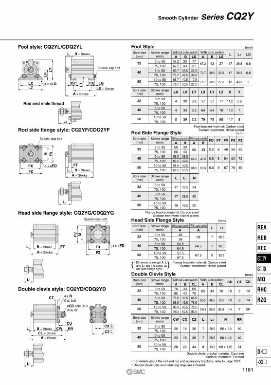
Foot StyleBore size
(mm)Stroke range
(mm)
32
40
50
5 to 5075, 1005 to 5075, 10010 to 5075, 100
57.267.263.773.766.776.7
3343
39.549.540.550.5
1727
23.533.517.527.5
L
17
17
18
A
67.2
73.7
76.7
B
43
49.5
50.5
LS
27
33.5
27.5
L1
38.5
38.5
43.5
LD
6.6
6.6
9
Bore size(mm)
Stroke range(mm)
32
40
50
5 to 5075, 1005 to 5075, 10010 to 5075, 100
LG
4
4
5
LH
30
33
39
LT
3.2
3.2
3.2
LX
57
64
79
LY
57
64
78
LZ
71
78
95
X
11.2
11.2
14.7
Y
5.8
7
8
Rod Side Flange StyleBore size
(mm)Stroke range
(mm)
32
40
50
5 to 5075, 1005 to 5075, 10010 to 5075, 100
5060
56.566.558.568.5
3343
39.549.540.550.5
A
60
66.5
68.5
B
43
49.5
50.5
Bore size(mm)
Stroke range(mm)
32
40
50
5 to 5075, 1005 to 5075, 10010 to 5075, 100
FD
5.5
5.5
6.6
FT
8
8
9
FV
48
54
67
FX
56
62
76
FZ
65
72
89
L
17
17
18
L1
38.5
38.5
43.5
M
34
40
50
Bore size(mm)
Stroke range(mm)
32
40
50
5 to 5075, 1005 to 5075, 10010 to 5075, 100
4858
54.564.557.567.5
AL
7
7
8
A
58
64.5
67.5
L1
28.5
28.5
33.5
Head Side Flange Style
(mm)
(mm)
(mm)
( )Double Clevis StyleBore size
(mm)Stroke range
(mm)
32
40
50
5 to 5075, 1005 to 5075, 10010 to 5075, 100
7080
78.588.590.5100.5
3343
39.549.540.550.5
6070
68.578.576.586.5
A
80
88.5
100.5
B
43
49.5
50.5
CD
10
10
14
CL
70
78.5
86.5
CT
5
6
7
Bore size(mm)
Stroke range(mm)
32
40
50
5 to 5075, 1005 to 5075, 10010 to 5075, 100
CX
18
18
22
CZ
36
36
44
CU
14
14
20
CW
20
22
28
L
7
7
8
L1
28.5
28.5
33.5
N
M6 x 1.0
M6 x 1.0
M8 x 1.25
RR
10
10
14
(mm)
∗ For details about the rod end nut and accessory brackets, refer to page 1274.∗ Double clevis pins and retaining rings are included.
A B LSWithout auto switch With auto switch
Without auto switch With auto switch
Without auto switch With auto switch
Without auto switch With auto switch
A B
A B CL
Foot bracket material: Carbon steelSurface treatment: Nickel plated
Flange bracket material: Carbon steelSurface treatment: Nickel plated
Flange bracket material: Carbon steelSurface treatment: Nickel plated
Double clevis bracket material: Cast ironSurface treatment: Painted
Foot style: CQ2YL/CDQ2YL
Rod side flange style: CQ2YF/CDQ2YF
Head side flange style: CQ2YG/CDQ2YG
Double clevis style: CQ2YD/CDQ2YD
∗ Dimensions except A, L and L1 are the same as rod side flange style.
Rod end male thread
1181
REA
REB
REC
CY
CX
MQ
RHC
RZQ
D-
-X
CY

RRO1 thread
ø63 to ø100
J
øD
FQ
L B + Stroke
A + Stroke
Z M E
KMEW
H1
C1
XL1
Lead wire min. bendingradius 10
Auto switch
2 x P (Rc,NPT,G)(Port size)
H thread effective depth C
Width across flats B1
MM
Rod end male thread
Series CQ2Y
Through-hole: CQ2YB/CDQ2YB Both ends tapped style: CQ2YA/CDQ2YA
63
80
100
11
13
16
33.5
43.5
43.5
28.5
35.5
35.5
M18 x 1.5
M22 x 1.5
M26 x 1.5
Bore size(mm)
Rod End Male Thread (mm)
H1 L1
26
32.5
32.5
C1
27
32
41
B1 MM X
(mm)
Bore size(mm)
Stroke range(mm)
63
80
100
10 to 50
75, 100
10 to 50
75, 100
10 to 50
75, 100
54
64
63.5
73.5
75
85
46
56
53.5
63.5
63
73
A
64
73.5
85
B
56
63.5
73
C
15
21
27
D
20
25
30
E
77
98
117
F
10.5
12.5
13
H
M10 x 1.5
M16 x 2.0
M20 x 2.5
J
7
6
6.5
K
17
22
27
L
8
10
12
M
60
77
94
N
9
11
11
O
14depth 10.5
17.5depth 13.5
17.5depth 13.5
Q
15
16
23
W
84
104
123.5
Z
19
25
25
A BWithout auto switch With auto switch
P
1/4
3/8
3/8
(Types with auto switch and without auto switch only differ in the A and B dimensions. Please refer to the table below.)
63
80
100
M10 x 1.5
M12 x 1.75
M12 x 1.75
18
22
22
Bore size(mm)
Both Ends Tapped (mm)
O1 R
8 x øO counterbore4 x øN through
1182

FTL B + Stroke
A + Stroke
FXFZ
M FV
L1
Special cap bolt
4 x øFD
FTL B + Stroke
A + Stroke
L1
FXFZ
MFV
CT
CURRCWL B + Stroke
CL + Stroke
A + Stroke
L1
Special cap bolt
4 x øFD
4 x NCap bolt
LH
LY
LXLZ
4 x øLD LT LG
L B + Stroke
Y XYXLS + Stroke
A + Stroke
Special cap bolt
L1
Smooth Cylinder Series CQ2Y
Foot style: CQ2YL/CDQ2YL
Rod side flange style: CQ2YF/CDQ2YF
Head side flange style: CQ2YG/CDQ2YG
Double clevis style: CQ2YD/CDQ2YD
Foot Style
63
80
100
10 to 5075, 10010 to 5075, 10010 to 5075, 100
72.282.2859598
108
4656
53.563.56373
2030
23.533.52939
A
82.2
95
108
B
56
63.5
73
LS
30
33.5
39
L
18
20
22
L1
43.5
53.5
53.5
63
80
100
10 to 5075, 10010 to 5075, 10010 to 5075, 100
LT
3.2
4.5
6
LH
46
59
71
LG
5
7
7
LD
11
13
13
LX
95
118
137
LY
91.5
114
136
LZ
113
140
162
X
16.2
19.5
23
Y
9
11
12.5
Rod Side Flange Style
63
80
100
10 to 5075, 10010 to 5075, 10010 to 5075, 100
6474
73.583.58595
4656
53.563.56373
A
74
83.5
95
B
56
63.5
73
63
80
100
10 to 5075, 10010 to 5075, 10010 to 5075, 100
L
18
20
22
FZ
108
134
154
FX
92
116
136
FV
80
99
117
FT
9
11
11
FD
9
11
11
L1
43.5
53.5
53.5
M
60
77
94
63
80
100
10 to 5075, 10010 to 5075, 10010 to 5075, 100
6373
74.584.58696
A
73
84.5
96
AL
8
10
12
L1
33.5
43.5
43.5
Head Side Flange Style
Double Clevis Style
(mm)
(mm)
(mm)
63
80
100
10 to 5075, 10010 to 5075, 10010 to 5075, 100
98108119.5129.5142152
4656
53.563.56373
8494
101.5111.5120130
A
108
129.5
152
B
56
63.5
73
CL
94
111.5
130
63
80
100
10 to 5075, 10010 to 5075, 10010 to 5075, 100
CX
22
28
32
CW
30
38
45
CU
20
27
31
CT
8
10
13
CD
14
18
22
CZ
44
56
64
L
8
10
12
L1
33.5
43.5
43.5
N
M10 x 1.5
M12 x 1.75
M12 x 1.75
RR
14
18
22
(mm)
A B LS
A B
A B CL
( ) Flange bracket material: Carbon steelSurface treatment: Nickel plated
∗ Dimensions except A, L and L1 are the same as rod side flange style.
Foot bracket material: Carbon steelSurface treatment: Nickel plated
Flange bracket material: Carbon steelSurface treatment: Nickel plated
∗ For details about the rod end nut and accessory brackets, refer to page 1274.∗ Double clevis pins and retaining rings are included.
Double clevis bracket material: Cast ironSurface treatment: Painted
Bore size(mm)
Stroke range(mm)
Without auto switch With auto switch
Bore size(mm)
Stroke range(mm)
Bore size(mm)
Stroke range(mm)
Bore size(mm)
Stroke range(mm)
Without auto switch With auto switch
Bore size(mm)
Stroke range(mm)
Bore size(mm)
Stroke range(mm)
Bore size(mm)
Stroke range(mm)
Without auto switch With auto switch
Without auto switch With auto switch
Axis d9øCD hole H10
CX+0.4+0.2
CZ–0.1–0.3
1183
REA
REB
REC
CY
CX
MQ
RHC
RZQ
D-
-X
CY

Additional Weight (g)
Bore size (mm) 1008063504032
45
175
116
1057
1365
1309
1887
45
120
49
690
1056
1017
1109
19
53
32
320
559
534
554
6
53
32
243
373
348
393
6
27
17
154
214
198
196
6
26
17
142
180
165
151
32
40
50
63
80
100
134
211
—
—
—
—
556
689
1073
1386
2281
3494
Bore size(mm)
Cylinder stroke (mm)
Weight/Without Auto Switch (g)
5 100
457
577
902
1189
1985
3086
75
311
404
632
862
1465
2354
50
291
383
598
824
1405
2274
45
272
361
566
786
1345
2194
40
252
340
533
747
1284
2113
35
233
318
500
709
1224
2033
30
213
297
467
671
1164
1952
25
193
275
435
633
1104
1872
20
174
254
402
595
1043
1792
15
154
232
369
557
983
1711
10
Foot style (Including mounting bolt)
Rod side flange style (Including mounting bolt)
Head side flange style (Including mounting bolt)
Double clevis style (Including pin, retaining ring, mounting bolt)
45
175
116
1057
1365
1309
1887
Bore size (mm)
Additional Weight (g)
100
45
120
49
690
1056
1017
1109
80
19
53
32
320
559
534
554
63
6
53
32
243
373
348
393
50
6
27
17
154
214
198
196
40
6
26
17
142
180
165
151
32
Male thread
Nut
Weight
32
40
50
63
80
100
5
191
284
—
—
—
—
10
211
305
480
710
1229
2070
15
230
327
513
748
1289
2150
20
250
348
546
787
1350
2231
25
270
369
579
825
1410
2311
30
289
391
611
863
1470
2391
35
309
412
644
901
1530
2472
40
329
434
677
939
1591
2552
45
348
455
710
977
1651
2633
50
368
477
743
1015
1711
2713
75
468
589
915
1211
2008
3121
100
567
701
1087
1408
2305
3529
Bore size(mm)
Cylinder stroke
Weight/With Auto Switch (Built-in magnet) (g)
32 40 50 63 80 100
6
26
17
142
180
165
151
6
27
17
154
214
198
196
6
53
32
243
373
348
393
19
53
32
320
559
534
554
45
120
49
690
1056
1017
1109
45
175
116
1057
1365
1309
1887
Bore size (mm)
Additional Weight (g)
Add each weight of auto switches when auto switches are mounted.
Series CQ2Y
Both ends tapped style
Rod end male thread
Calculation: (Example) CQ2DS32-20DCMZ• Basic weight: CQ2BS32-20DCZ ···················· 193 g• Additional weight: Both ends tapped style ········· 6 g
Rod end male thread ·········· 43 gDouble clevis style ············ 151 g
393 g
Male thread
Nut
Foot style (Including mounting bolt)
Rod side flange style (Including mounting bolt)
Head side flange style (Including mounting bolt)
Double clevis style (Including pin, retaining ring, mounting bolt)
Both ends tapped style
Rod end male thread
Calculation: (Example) CQ2DS32-20DCMZ• Basic weight: CQ2BS32-20DCZ ····················250 g• Additional weight: Both ends tapped style ········· 6 g
Rod end male thread ·········· 43 gDouble clevis style ············ 151 g
450 g
Foot style (Including mounting bolt)
Rod side flange style (Including mounting bolt)
Head side flange style (Including mounting bolt)
Double clevis style (Including pin, retaining ring, mounting bolt)
Male thread
Nut
Both ends tapped style
Rod end male thread
1184

ø32 to ø100
ø32 to ø100D-A7D-A80D-A7HD-A80HD-F7D-J79D-F7WD-J79WD-F79F
ø32 to ø100D-P3DW
D-F7NTD-A73CD-A80CD-J79CD-A79WD-F7WVD-F7V
D-A9D-M9D-M9WD-M9AD-A9VD-M9VD-M9WVD-M9AV
Auto Switch Proper Mounting Position (Detection at Stroke End) and Its Mounting Height
Auto Switch Proper Mounting Position
Auto Switch Mounting Height
32 40 50 63 80100
12.516 13.516 19 22
7.5 10.514 17 21.528
A B15.518.522 25 29.536
B15 18.516 18.521.524.5
10 13 16.519.524 30.5
A BA18 21.519 21.524.527.5
B13 16 19.522.527 33.5
A14 17.515 17.520.523.5
B9
12 15.518.523 29.5
(mm)
Bore size
Auto switchmodel
Note) Adjust the auto switch after confirming the operating conditions in the actual setting.
D-A73D-A80 D-A79WD-A9
D-A9V
D-M9/D-M9VD-M9WD-M9WVD-M9AD-M9AV
D-F7NT
8 11.5 9.512 15 18
3.5 6.5 9.5 12.517 24
A B
D-P3DW
D-A72/A7H/A80HD-A73C/A80C/F7D-F79F/J79/F7VD-J79C/F7WD-J79W/F7WV
10.513.517 20 24.531
B15.519 16.519 22 25
A20.524 21.524 27 30
A
A B≅U
≅U
BA
A B≅U
32 40 50 63 80100
U36 38 43.548.557 65.5
U36.540 45 50.559 67
U39.542.548 53.561.570
U34 37.543 48 56.564.5
U40.543.549 54.562.571
U37.540.546 51.559.568
U30 32 37.542.551 59
U27.530 35 40.549 57
D-F7/J79D-F7W/J79WD-F7BAD-F79F/F7NTD-A7H/A80H
D-F7VD-F7WV D-J79C D-A7
D-A80D-A73CD-A80C D-A79WD-M9V D-A9V
(mm)
D-P3DW
U33 36.542 47 55.565.5
Bore size
Auto switchmodel
Series CQ2YAuto Switch Mounting 1
1185
REA
REB
REC
CY
CX
MQ
RHC
RZQ
D-
-X
CY

Minimum Auto Switch Mounting Stroke
Operating Range
Number of auto switches
1 pc.
2 pcs.
5
5
5
10
10
15
15 (5)
15 (5)
15 (10)
15
15 (5)
15 (10)
15
20
20 (10)
20 (15)
(mm)
D-M9VD-F7VD-J79C
D-A9VD-A7D-A80D-A73CD-A80C
D-M9WVD-M9AVD-F7WV
D-M9WD-M9A
D-A7HD-A80H
D-M9D-F7D-J79
D-A79W
D-F7WD-J79WD-F79FD-F7NT
15
15
D-P3DW
10 (5)
10
D-A9
∗ Since this is a guideline including hysteresis, not meant to be guaranteed. (assuming approximately ±30% dispersion.)There may be the case it will vary substantially depending on an ambient environment.
∗ Auto switch mounting brackets BQ2-012 are not used for sizes over ø32 of D-A9(V)/M9(V)/M9W(V)/M9A(V) types. The above values indicate the operating range when mounted with the conventional auto switch installation groove.
Note) The dimensions stated in ( ) shows the minimum stroke for the auto switch mounting when the auto switch does not project from the end surface of the cylinder body and hinder the lead wire bending space. (Refer to the figure below.)Order auto switches and auto switch mounting brackets separately.
Auto switch modelBore size (mm)
32 40 50 63 80 100
D-A9(V)
D-M9(V)D-M9W(V)D-M9A(V)
D-A79W
D-P3DW
(mm)
D-A7(H)(C)D-A80(H)(C)
D-F7(V)D-J79(C)D-F7W(V)D-F7NTD-F79F
9
5
10.5
14
5
3
9.5
5
11.5
15.5
5
4.5
9.5
6
11
14.5
5
4.5
11
6.5
13
17
6
6
10.5
7
11.5
15
7
5.5
10.5
7.5
11.5
15.5
8
6.5
Series CQ2YAuto Switch Mounting 2
1186

Auto Switch Mounting Brackets/Part No.
Port side
A
B
C
Hexagon socket head cap screw(attached to the auto switch)
(M 2.5 x 9.5 L)
Auto switch mounting screw(M3 x 0.5 x 8 L)
Hexagon socket head cap screw(M2.5×6L)
Auto switchmounting bracket
Auto switch fixing screw (M 2.5 x 0.45 x 10 L)
Auto switch mounting nut
Auto switch spacer
Auto switch
Auto switchmounting screw
Auto switch
Applicable Cylinder Series: CDQ2
D-M9/M9VD-M9W/M9WVD-M9A/M9AVD-A9/A9V
D-F7/F7V/J79/J79C/F7WJ79W/F7WV/D-F7BA/F7BAVF79F/F7NT/D-A7/A80/A7HA80H/A73C/A80C/A79W
D-P3DWApplicableauto switch
Auto switchmounting bracket
fitting partslineup/Weight
Auto switch mountingbracket part no.
Auto switchmounting surface
Mounting ofauto switch
Bore size (mm)
�
�
BQ5-032
¡Auto switch fixing screw (M2.5 x 10L)¡Auto switch mounting screw (M3 x 8L)¡Auto switch spacer¡Auto switch mounting nutWeight: 3.5 g
¡Hexagon socket head cap screw (M 2.5 x 6L)¡Auto switch mounting bracket (nut) Weight: 5 g
ø32 to ø100
BQ6-032S
Surfaces with auto switch mounting slot A/B/C side except port side Surfaces with auto switch mounting slot
¡When tightening the auto switch mounting screw, use a watchmakers' screwdriver with a handle 5 to 6 mm in diameter.
Tightening torque for autoswitch mounting screw
Auto switch model Tightening torque
D-M9(V)D-M9W(V)D-M9A(V)
D-A9(V)
0.05 to 0.15
0.10 to 0.20
(N·m)
qInsert the nut into the auto switch mounting slot on the cylinder tube, and place it in the roughly estimated setting position.
wWith the lower tapered part of the auto switch spacer facing the outside of the cylinder tube, line up the M2.5 through hole with the M2.5 female thread of the auto switch mounting nut.
eGently screw the auto switch mounting nut fixing screw (M2.5) into the thread of the auto switch mounting nut through the mounting hole.
rEngage the ridge on the auto switch mounting arm with the recess in the auto switch spacer.
tTighten the auto switch mounting screw (M3) to fix the auto switch. The tightening torque of the M3 screw must be 0.35 to 0.45 N·m.
yConfirm where the mounting position is, and tighten the auto switch fixing screw (M2.5) to f ix the auto swi tch mount ing nut . The tightening torque of the M2.5 screw must be 0.25 to 0.35 N·m.
uThe detection position can be changed under the conditions in step t.
qFix the auto switch and the auto switch mounting bracket temporarily by tightening the hexagon socket head cap screw (M2.5 x 9.5L) attached to the auto switch 1 to 2 turns.
wInsert the temporarily tightened mounting bracket into the mating groove of the cylinder tube, and slide the auto switch onto the cylinder tube through the groove.To insert the auto switch onto the cylinder/actuator through the groove, first hold the back of the auto switch (lead wire side) and the back of the auto switch mounting bracket together.
eCheck the detecting position of the auto switch and fix the auto switch firmly with the hexagon socket head cap screw (M2.5 x 6L, M2.5 x 9.5L).∗
rIf the detecting position is changed, go back to step w.∗ The hexagon socket head cap screw (M2.5 x 6L) is
used to fix the mounting bracket and cylinder tube. This enables the replacement of the auto switch without adjusting the auto switch position.
Note 1) Ensure that the auto switch is covered with the mating groove to protect the auto switch.
Note 2) The tightening torque of the hexagon socket head cap screw (M2.5 x 6L, M2.5 x 9.5L) must be 0.2 to 0.3 N·m.
Note 3) Tighten the hexagon socket head cap screws evenly.
Note) Auto switch mounting bracket and auto switch are enclosed with the cylinder for shipment. Auto switch mounting bracket for the D-F7BA(V) type uses BQ5-032 normal specifications (metal screw).
When requesting the enclosure of the auto switch mounting brackets (2 pcs.)with the cylinder for shipment, add “-BQ” to the end of the cylinder model number.Standard model no. + BQ Example) CDQ2B32-30DZ-BQ
Auto Switch Mounting Series CQ2Y
1187
REA
REB
REC
CY
CX
MQ
RHC
RZQ
D-
-X
CY

∗ With pre-wired connector is available for solid state auto switches. For details, refer to pages 1960 and 1961.∗ Normally closed (NC = b contact), solid state auto switches (D-F9G, F9H type) are also available. For details, refer to page 1911.∗ Trimmer auto switch (D-F7K) and heat resistant solid state auto switch (D-F7NJ) are not available.
Auto switch type Model FeaturesElectrical entry (Direction)
D-A72
D-A73
D-A80
D-A79W
D-A73C
D-A80C
D-A72H
D-A73H, A76H
D-A80H
D-F7NV, F7PV, F7BV
D-F7NWV, F7BWV
D-F7BAV
D-J79C
D-F79, F7P, J79
D-F79W, F7PW, J79W
D-F7BA
D-F79F
D-F7NT
�
�
Without indicator light
Diagnostic indication (2-color indication)
�
Without indicator light
�
�
Without indicator light
�
Diagnostic indication (2-color indication)
Water resistant (2-color indication)
�
�
Diagnostic indication (2-color indication)
Water resistant (2-color indication)
With diagnostic output (2-color indication)
With timer
Applicable bore size
ø12 to ø100ø125 to ø160
Grommet (Perpendicular)
Connector (Perpendicular)
Grommet (In-line)
Grommet (Perpendicular)
Connector (Perpendicular)
Grommet (In-line)
Reed
Solid state
Series CQ2YAuto Switch Mounting 3
Other than the applicable auto switches listed in “How to Order”, the following auto switches can be mounted.For detailed specifications, refer to pages 1893 to 2007.
1188

Applicable Auto Switches/Refer to pages 1893 to 2007 for further information on auto switches.
5 V, 12 V
12 V
5 V, 12 V12 V
5 V, 12 V
12 V
5 V, 12 V
12 V5 V, 12 V
5 V
12 V
12 V
—
Yes
NoYesNoYesNo
Yes
Yes
Type
Ree
d a
uto
sw
itch
So
lid s
tate
au
to s
wit
ch
Special functionElectrical
entry
Grommet
Connector
Grommet
Grommet
Connector
DIN terminal
Terminalconduit
Grommet
Terminalconduit
Indica
tor lig
ht
—100 V
100 V or less100 V, 200 V200 V or less
—24 V or less
—
100 V, 200 V
—
Wiring (Output)
3-wire (NPN)3-wire (PNP)
2-wire
3-wire (NPN)2-wire
3-wire (NPN)3-wire (PNP)
2-wire3-wire (NPN)3-wire (PNP)
2-wire4-wire(NPN)
3-wire (NPN equivalent)
2-wire
Load voltage
DC
24 V
�
24 V
AC Perpendicular In-line
Lead wire length (m)
—————
—————
—————————
————————————————
——————————————
Applicable loadPre-wiredconnector
Auto switch model
IC circuit
—
IC circuit—
IC circuit
—
IC circuit
—IC circuitIC circuit
�IC circuit
—
IC circuit
—
Relay,PLC
Relay,PLC
Relay,PLC Diagnostic indication
(2-color indication)
Water resistant (2-color indication)
With diagnostic output (2-color indication)
Diagnostic indication (2-color indication)
M9NM9PM9BH7C
G39AK39AM9NWM9PWM9BW
M9NA∗∗∗M9PA∗∗∗M9BA∗∗∗
H7NFA96A93A90B54B64
C73CC80CA33AA34AA44AB59W
M9NVM9PVM9BV
———
M9NWVM9PWVM9BWV
M9NAV∗∗∗M9PAV∗∗∗M9BAV∗∗∗
—A96VA93VA90V
————————
—
PLC
—
0.5(Nil)
3(L)
——————————————————
1(M)
5(Z)
None(N)
Auto switch mounting bracket Note)
Note) This symbol is indi-cated when the D-A9 or M9 type auto switch is specified.This mounting bracket does not apply to other auto switches (D-C7 and H7, etc.) (Nil)
CM2Y
CDM2YWith auto switch
L
L
150
150With auto switch
(Built-in magnet)
M9BW
40
40
Basic style
Axial foot style
Rod side flange style
Head side flange style
Single clevis style
Double clevis style
Rod side trunnion style
Head side trunnion style
Integral clevis style
Boss-cut basic style
Boss-cut rod side flange style
Boss-cut rod side trunnion style
Mounting styleBLFGCDUTE
BZFZUZ
Cylinder stroke (mm)Refer to "Standard Stroke" on page 1190.
∗∗∗ Water resistant type auto switches can be mounted on the above models, but in such case SMC cannot guarantee water resistance.Consult with SMC regarding water resistant types with the above model numbers.
∗ Lead wire length symbols: 0.5 m ············ Nil (Example) M9NW1 m ············ M (Example) M9NWM3 m ············ L (Example) M9NWL5 m ············ Z (Example) M9NWZNone ········· N (Example) H7CN
∗ : Manufactured upon receipt of order.∗ Do not add the suffix (N) indicating “no lead wire” to the part numbers of models D-A3A, A44A, G39A and K39A.
∗ In addition to the models in the above table, there are some other auto switches that are applicable. For more information, refer to page 1202.∗ Refer to pages 1960 and 1961 for details of auto switches with a pre-wired connector.∗ D-A9(V)/M9(V)/M9W(V)/M9A(V) auto switches are shipped together (not assembled). (Only auto switch mounting brackets are assembled before shipped.)∗ D-C7/C80/H7 auto switches are assembled at the time of shipment.
Number of auto switches
Nil
Sn
2 pcs.
1 pc.
n pcs.
Auto switchWithout auto switchNil
∗ For the applicable auto switch model, refer to the table below.
Nil
TNTF
Rc
NPT
G
Thread type
Bore size20253240
20 mm
25 mm
32 mm
40 mm
Made to Order For details, refer to page 1190.
How to Order
Built-in Magnet Cylinder ModelIf a built-in magnet cylinder without an auto switch is required, there is no need to enter the symbol for the auto switch.(Example) CDM2YB20-100
Smooth Cylinder
Series CM2Yø20, ø25, ø32, ø40
C
1189
REA
REB
REC
CY
CX
MQ
RHC
RZQ
D-
-X
CY

SymbolDouble acting: Single rod, Rubber bumper
Series CM2Y
Unit: MPaBore size (mm)
Minimum operating pressure20 25 32 40
Double acting, Single rod
5 to 500 mm/s
Air
1.05 MPa
0.7 MPa
Without auto switch –10 to 70°C (with no freezing)
With auto switch –10 to 60°C (with no freezing)
Non-lube
Rubber bumper
0.5 L/min (ANR) or less
ActionPiston speedFluidProof pressureMaximum operating pressureAmbient and fluidtemperatureLubricationStroke length toleranceCushionAllowable leakage rate
Specifications
Minimum Operating Pressure
Mounting Bracket Part No.
Grease Pack for Maintenance
When only grease for maintenance is necessary, please order by the following part numbers.Grease pack part no.: GR-L-005 (5 g) GR-L-010 (10 g) GR-L-150 (150 g)
Standard Stroke
Bore size (mm)
20, 25, 32, 40Standard stroke (mm)
25, 50, 75, 100, 125, 150, 200, 250, 300
Note 1) Manufacture of intermediate strokes at 1 mm intervals is possible. (Spacers are not used.)Note 2) As the stroke increases, more sliding resistance may result due to the deflection of the
piston rod and other factors. Take measures such as the installation of a guide.
+1.4 0 mm
20 25 32 40
0.02
Accessory
Mounting
Basic styleAxial foot styleRod side flange styleHead side flange styleIntegral clevis styleSingle clevis styleDouble clevis style Note 3)
Rod side trunnion styleHead side trunnion styleBoss-cut basic styleBoss-cut flange styleBoss-cut trunnion style
Standard Option
Mountingnut
(1 pc.)
(2)
(1)
(1)
— Note 1)
— Note 1)
— Note 1)
(1)Note 2)
(1)Note 2)
(1)
(1)
(1)
Rod endnut
Clevispin
—————— Note 5)
—————
Singleknuckle
joint
———————————
—
—
—
—
—
—
—
Note 1) Mounting nuts are not attached to the integral clevis, single clevis and double clevis types.Note 2) Trunnion nuts are mounted on the rod side trunnion style and head side trunnion style.Note 3) Pins and retaining rings (cotter pins in case of ø40) are packed with the double clevis and double knuckle joint styles.Note 4) Pins and retaining rings are packed with clevis brackets.Note 5) Retaining rings (cotter pins for ø40) are included in clevis pins.Note 6) Pivot brackets come with pins and retaining rings.Note 7) Pivot bracket pins come with retaining rings.
Replacement Part: Rod Seal
Bore size(mm)
20253240
Part no.
KB01587KB01588KB01590KB01592
Precautions
Warning
Handling Precautions
Caution
Made to Order(For details, refer to pages 2009 to 2152.)
Symbol SpecificationsChange of rod end shapeSpecial port locationMade of stainless steelAdjustable stroke cylinder/adjustable retraction typeAuto switch rail mounting styleHead cover axial port
-XA-XC3-XC6-XC9-XC13-XC20
Bore size (mm)
Mounting Bracket and Accessory
Axial foot∗
Flange
Single clevis∗∗
Double clevis (with pin) ∗∗, ∗∗∗
Trunnion (with nut)
Mounting bracket Description (when ordering a minimum number)
Bore size (mm)Minimumorder 20 25 32 40
CM-L020B
CM-F020B
CM-C020B
CM-D020B
CM-T020B
2
1
1
1
1
CM-L032B
CM-F032B
CM-C032B
CM-D032B
CM-T032B
CM-L040B
CM-F040B
CM-C040B
CM-D040B
CM-T040B
Foot 2 pcs., Mounting nut 1 pc.
Flange 1 pc.
Single clevis 1 pc., Liner 3 pcs.
Double clevis 1 pc., Liner 3 pcs.,
Clevis pin 1 pc., Retaining ring 2 pcs.
Trunnion 1 pc.,
Trunnion nut 1 pc.
∗ When ordering foot brackets, order 2 pieces per cylinder unit.∗∗ Three liners are included in the clevis bracket for adjusting an angle when mounting it.∗∗∗ Clevis pins and retaining rings (cotter pins for ø40) are included.
Be sure to read before handling.Refer to front matter 39 for Safety Instructions and pages 3 to 12 for Actuator and Auto Switch Precautions.
Doubleknuckle
jointClevisbracket
Note 3) Note 4)
Pivot bracket
Pivot bracket
pin
Note 6) Note 7)
1. Do not rotate the cover• When installing a cylinder or screwing a fitting into
the port, the coupling portion of the cover may be damaged if the cover rotates.
1. Be careful of the retaining ring to pop out.• When replacing the rod seal, be careful of the
retaining ring not to pop out while removing it.
Integral clevis
1190

Smooth Cylinder Series CM2Y
Low Friction Cylinder Mounting
In order to adjust the mounting dimensions of the low friction cylinder (CM2Q), extend the longitudinal dimension (S, ZZ) by 3 mm.
Mounting style Bore size Stroke X1854CM2Y
Same mounting specification as CM2Q
WeightCalculation: (Example) CM2YL32-100 • Basic weight·················0.44 (Foot style, ø32) • Additional weight··········0.08/50 stroke • Cylinder stroke·············100 stroke 0.44 + 0.08 x 100/50 = 0.60 kg
Bore size (mm)
(kg)
Basicweight
Optionbracket
Basic style
Axial foot style
Flange style
Clevis integrated style
Single clevis style
Double clevis style
Trunnion style
Boss-cut basic style
Boss-cut flange style
Boss-cut trunnion style
Clevis bracket (With pin)
Single knuckle joint
Double knuckle joint (With pin)
Additional weight per each 50 mm of stroke
20
0.14
0.29
0.20
0.12
0.18
0.19
0.18
0.13
0.19
0.17
0.04
0.07
0.06
0.07
25
0.21
0.37
0.30
0.19
0.25
0.27
0.28
0.19
0.28
0.26
0.06
0.07
0.06
0.07
32
0.28
0.44
0.37
0.27
0.32
0.33
0.34
0.26
0.35
0.32
0.08
0.14
0.06
0.07
40
0.56
0.83
0.68
0.52
0.65
0.69
0.66
0.53
0.65
0.63
0.13
0.14
0.23
0.20
Bore size (mm)
20
25
32
40
S
65
65
67
91
ZZ
119
123
125
157
∗ Add 3 mm to S and ZZ dimensions of the double acting, single rod type on pages 1192 to 1196 for the dimensions for each mounting bracket other than the basic style.
Double acting, Single rod
Dual directions
Air
1.05 MPa
0.7 MPa
Specifications
Action
Direction of low friction
Fluid
Proof pressure
Maximum operating pressure
Cylinder bore size (mm) 20 25 32 40
∗ Low friction operates in dual directions.
ZZ + Stroke
S + Stroke
Dimensions
1191
REA
REB
REC
CY
CX
MQ
RHC
RZQ
D-
-X
CY

Series CM2Y
∗ Mounting bracket is shipped together with the product.
CM2YB Bore size Stroke
Boss-cut
Bore size (mm)
20
25
32
40
Bore size (mm)
20
25
32
40
A
18
22
22
24
AL
15.5
19.5
19.5
21
B1
13
17
17
22
B2
26
32
32
41
D
8
10
12
14
E
20
26
26
32
F
13
13
13
16
G
8
8
8
11
H
41
45
45
50
H1
5
6
6
8
H2
8
8
8
10
I
28
33.5
37.5
46.5
K
5
5.5
5.5
7
FL
10.5
10.5
10.5
13.5
KA
6
8
10
12
MM
M8 x 1.25
M10 x 1.25
M10 x 1.25
M14 x 1.5
N
15
15
15
21.5
NA
24
30
34.5
42.5
NN
M20 x 1.5
M26 x 1.5
M26 x 1.5
M32 x 2
P S
62
62
64
88
ZZ
116
120
122
154
0–0.033 0–0.033 0–0.03300.039
103
107
109
138
ZZ
(mm)Boss-cut
Basic Style (B)
CM2YL Bore size Stroke
Bore size (mm)
20
25
32
40
A
18
22
22
24
AL
15.5
19.5
19.5
21
B
40
47
47
54
B1
13
17
17
22
B2
26
32
32
41
D
8
10
12
14
F
13
13
13
16
FL
10.5
10.5
10.5
13.5
G
8
8
8
11
H
41
45
45
50
H1
5
6
6
8
H2
8
8
8
10
I
28
33.5
37.5
46.5
K
5
5.5
5.5
7
KA
6
8
10
12
LC
4
4
4
4
LD
6.8
6.8
6.8
7
LH
25
28
28
30
LS
102
102
104
134
LT
3.2
3.2
3.2
3.2
LX
40
40
40
55
LZ
55
55
55
75
MM
M8 x 1.25
M10 x 1.25
M10 x 1.25
M14 x 1.5
N
15
15
15
21.5
NA
24
30
34.5
42.5
NN
M20 x 1.5
M26 x 1.5
M26 x 1.5
M32 x 2
P S
62
62
64
88
X
20
20
20
23
Y
8
8
8
10
Z
21
25
25
27
ZZ
131
135
137
171
Axial Foot Style (L)
(mm)
(mm)
2 x P(Rc, NPT, G)
1.5 1.5
Width across flats B1
Width across flats B2
S + Stroke FHZZ + Stroke
H1
H2 GG
øD
Width across flats KAMM AL
A F N NK
2 x NN
Effective thread length2 x FL
2 x
øE
h8
NA
NA
øI
Width across flats B1
Width across flats B2 S + StrokeLS + Stroke
ZZ + Stroke
H1
H2
G
øD
MM
LT
AL
Z
FKAH
NX
N
G F
X YY
BL
H
LXLZ
2 x P(Rc, NPT, G)
Width across flats NA
2 x NN(Effective thread length 2 x FL)Width across flats KA
4 x øLD2 x øLC
øI
ZZ + Stroke
1192

Smooth Cylinder Series CM2Y
Bore size (mm)
20
25
32
40
A
18
22
22
24
AL
15.5
19.5
19.5
21
B
34
40
40
52
B2
26
32
32
41
B1
13
17
17
22
C2
30
37
37
47.3
D
8
10
12
14
E F
13
13
13
16
FL
10.5
10.5
10.5
13.5
FD
7
7
7
7
FT
4
4
4
5
FX
60
60
60
66
FY
—
—
—
36
FZ
75
75
75
82
G
8
8
8
11
H
41
45
45
50
H1
5
6
6
8
H2
8
8
8
10
I
28
33.5
37.5
46.5
K
5
5.5
5.5
7
KA
6
8
10
12
MM
M8 x 1.25
M10 x 1.25
M10 x 1.25
M14 x 1.5
N
15
15
15
21.5
NA
24
30
34.5
42.5
NN
M20 x 1.5
M26 x 1.5
M26 x 1.5
M32 x 2
P S
62
62
64
88
Z
37
41
41
45
ZZ
116
120
122
154
20
26
26
32
0–0.033
0–0.033
0–0.033
0–0.039
Bore size (mm)
20
25
32
40
103
107
109
138
ZZ
(mm)
(mm)
Boss-cut Style
ø20 to ø32
ø40
CM2YF
Rod Side Flange Style (F)
Bore size Stroke
∗ Mounting bracket is shipped together with the product.
Boss-cut style
Width across flats B1
Width across flats B2
S + StrokeZZ + Stroke
ZZ + Stroke
H1H2 G
MM AL
NZK FTA
H
N
G
F
Width across flats NA
øI
2 x P(Rc, NPT, G)
2 x NN
Width acrossflats KA
Effective thread length2 x FL
1.5
øD
øE
h8
FY B
FXFZ
C2
4 x øFDMounting hole
Mounting hole2 x øFD
1193
REA
REB
REC
CY
CX
MQ
RHC
RZQ
D-
-X
CY

Series CM2Y
CM2YG
Bore size (mm)
20
25
32
40
Bore size (mm)
20
25
32
40
A
18
22
22
24
AL
15.5
19.5
19.5
21
B
34
40
40
52
B1
13
17
17
22
B2
26
32
32
41
C2
30
37
37
47.3
D
8
10
12
14
E F
13
13
13
16
FL
10.5
10.5
10.5
13.5
FD
7
7
7
7
FT
4
4
4
5
FX
60
60
60
66
FY
—
—
—
36
FZ
75
75
75
82
G
8
8
8
11
H
41
45
45
50
H1
5
6
6
8
H2
8
8
8
10
I
28
33.5
37.5
46.5
K
5
5.5
5.5
7
MM
M8 x 1.25
M10 x 1.25
M10 x 1.25
M14 x 1.5
N
15
15
15
21.5
NA
24
30
34.5
42.5
NN
M20 x 1.5
M26 x 1.5
M26 x 1.5
M32 x 2
P S
62
62
64
88
Z
107
111
113
143
ZZ
116
120
122
154
20
26
26
32
KA
6
8
10
12
(mm)
(mm)
(mm)
Head Side Flange Style (G)
Bore size (mm)
20
25
32
40
A
18
22
22
24
AL
15.5
19.5
19.5
21
B1
13
17
17
22
CI
24
30
30
38
CD
9
9
9
10
CX
10
10
10
15
D
8
10
12
14
F
13
13
13
16
G
8
8
8
11
FL
10.5
10.5
10.5
13.5
H
41
45
45
50
H1
5
6
6
8
I
28
33.5
37.5
46.5
L
30
30
30
39
K
5
5.5
5.5
7
KA
6
8
10
12
MM
M8 x 1.25
M10 x 1.25
M10 x 1.25
M14 x 1.5
N
15
15
15
21.5
NA
24
30
34.5
42.5
NN
M20 x 1.5
M26 x 1.5
M26 x 1.5
M32 x 2
P RR
9
9
9
11
Z
133
137
139
177
U
14
14
14
18
S
62
62
64
88
ZZ
142
146
148
188
E
20
26
26
32
CM2YC
Single Clevis Style (C)
Bore size Stroke
Bore size Stroke
0–0.033
0–0.033
0–0.033
0–0.039
0–0.033
0–0.033
0–0.033
0–0.039
ø40
ø20 to ø32
∗ Mounting bracket is shipped together with the product.
Width across flats B1Width across flats B2
S + Stroke
ZZ + StrokeZ + Stroke
H1H2G
MM ALFK NA
H
N
G
FT
Width across flats NA
øI
1.5
øD B FY
FXFZ
C2 Mounting holeMounting hole
Width across flats KA
2 x P(Rc, NPT, G)
Effective thread length 2 x FL
2 x NN4 x øFD2 x øFD
NA
RR
NA
øI
øE
h8
Width across flats B1
S + Stroke
ZZ + StrokeZ + Stroke
H1 G
MM ALFK NA
HN U
G
L
+0.058 0
øC
I
1.5
øD
øE
h8
Width across flats KA
2 x P(Rc, NPT, G)
NNEffective thread length FL øCDH10
–0.1–0.2CX
1194

Smooth Cylinder Series CM2Y
Bore size (mm)
20
25
32
40
A
18
22
22
24
AL
15.5
19.5
19.5
21
B1
13
17
17
22
CD
9
9
9
10
CI
24
30
30
38
CL
25
25
25
41.2
CX
10
10
10
15
CZ
19
19
19
30
D
8
10
12
14
F
13
13
13
16
FL
10.5
10.5
10.5
13.5
G
8
8
8
11
H
41
45
45
50
H1
5
6
6
8
I
28
33.5
37.5
46.5
K
5
5.5
5.5
7
KA
6
8
10
12
L
30
30
30
39
N
15
15
15
21.5
NA
24
30
34.5
42.5
P RR
9
9
9
11
S
62
62
64
88
U
14
14
14
18
Z
133
137
139
177
ZZ
142
146
148
188
MM
M8 x 1.25
M10 x 1.25
M10 x 1.25
M14 x 1.5
NN
M20 x 1.5
M26 x 1.5
M26 x 1.5
M32 x 2
E
20
26
26
32∗ Clevis pin and snap ring (cotter pin for bore size ø40) are shipped together.
CM2YD
Double Clevis Style (D)
Boss-cut style
Bore size (mm)20253240
Bore size (mm)20253240
A18222224
AL15.519.519.521
B1
13171722
B2
26323241
D8101214
F13131316
G88811
H41454550
H1
5668
I28
33.537.546.5
S62626488
TD89910
TT10101011
TX32404053
TY32404053
TZ52606077
Z364040
44.5
ZZ116120122154
(mm)
E20262632
K5
5.55.57
FL10.510.510.513.5
KA681012
MMM8 x 1.25M10 x 1.25M10 x 1.25M14 x 1.5
N151515
21.5
NA2430
34.542.5
NNM20 x 1.5M26 x 1.5M26 x 1.5M32 x 2
P
Bore size (mm)20253240
ZZ103107109138
(mm)
(mm)
(mm)
Boss-cut Style
CM2YU
Rod Side Trunnion Style (U)
Bore size Stroke
Bore size Stroke
0–0.033
0–0.033
0–0.033
0–0.039
0–0.033
0–0.033
0–0.033
0–0.039
∗ Mounting bracket is shipped together with the product.
Width across flats B1
Width across flats B2
S + StrokeZZ + Stroke
ZZ + Stroke
H1
G
MMAL
NZK TTA
HN
G
F
Width across flats NA
øI
1.5
øD
øE
h8
2 x P(Rc, NPT, G)
2 x NN
Width across flats KAEffective thread length
2 x FL
Width across flats KA
2 x P(Rc, NPT, G)
Effective thread length FL
NA
RR
CL
CZNA
øIWidth across flats B1
S + Stroke
ZZ + StrokeZ + Stroke
H1 G
MM ALFK NA
H
N U
G
L
øC
I
1.5
øD
øE
h8
+0.2+0.1CX
NN
+0.058 0øCD hole H10
–0.040–0.076Axis d9
øTY
TZTX
–0.0
25–0
.061
øT
De9
1195
REA
REB
REC
CY
CX
MQ
RHC
RZQ
D-
-X
CY

Series CM2Y
∗ Mounting bracket is shipped together with the product.
Bore size (mm)
20
25
32
40
Bore size (mm)
20
25
32
40
A
18
22
22
24
AL
15.5
19.5
19.5
21
B1
13
17
17
22
B2
26
32
32
41
D
8
10
12
14
F
13
13
13
16
FL
10.5
10.5
10.5
13.5
G
8
8
8
11
H
41
45
45
50
H1
5
6
6
8
I
28
33.5
37.5
46.5
S
62
62
64
88
TD
8
9
9
10
TT
10
10
10
11
TX
32
40
40
53
TY
32
40
40
53
TZ
52
60
60
77
Z
108
112
114
143.5
ZZ
118
122
124
154
(mm)
(mm)
(mm)
E
20
26
26
32
K
5
5.5
5.5
7
KA
6
8
10
12
MM
M8 x 1.25
M10 x 1.25
M10 x 1.25
M14 x 1.5
N
15
15
15
21.5
NA
24
30
34.5
42.5
NN
M20 x 1.5
M26 x 1.5
M26 x 1.5
M32 x 2
P
CM2YT
Head Side Trunnion Style (T)
Bore size (mm)
20
25
32
40
Bore size (mm)
20
25
32
40
A
18
22
22
24
AL
15.5
19.5
19.5
21
B1
13
17
17
22
D
8
10
12
14
CD
8
8
10
10
CI
20
22
27
33
CX
12
12
20
20
F
13
13
13
16
FL
10.5
10.5
10.5
13.5
G
8
8
8
11
H
41
45
45
50
H1
5
6
6
8
I
28
33.5
37.5
46.5
RR
9
9
12
12
(mm)
E
20
26
26
32
S
62
62
64
88
U
11.5
11.5
14.5
14.5
Z
115
119
124
153
ZZ
124
128
136
165
K
5
5.5
5.5
7
KA
6
8
10
12
L
12
12
15
15
MM
M8 x 1.25
M10 x 1.25
M10 x 1.25
M14 x 1.5
N
15
15
15
21.5
NA
24
30
34.5
42.5
NN
M20 x 1.5
M26 x 1.5
M26 x 1.5
M32 x 2
P
Refer to page 1198 for detailsof clevis pivot bracket.
CM2YE
Clevis Integrated Style (E)
Bore size Stroke
Bore size Stroke
0–0.033
0–0.033
0–0.033
0–0.039
0–0.033
0–0.033
0–0.033
0–0.039
Width across flats B1
Width across flats B2
S + Stroke
ZZ + Stroke
Z + Stroke
H1G
MM ALFK
HA N N
G
Width across flats NA1.5
øD øI
øE
h8
øTY
TZTX
TT
–0.0
25–0
.061
øT
De9
Width across flats KA
2 x P(Rc, NPT, G)
2 x NNEffective thread length 2 x FL
Width across flats KA
2 x P(Rc, NPT, G)
Effective thread length FL2 x øLD
NA
LH
LT
RRLP
LFLY
LG
NA
LV
Width across flats B1
S + Stroke
ZZ + StrokeLZ + Stroke
Z + Stroke
H1
G
MM
ALFK NA
HN UG
L+0.058 0
øC
I
1.5
øE
h8
NN
øCDH10 0–0.1CX
øI
øD
1196

Series CM2YAccessory Bracket Dimensions
Single Knuckle Joint Single Knuckle Joint
Double Clevis Pin/Material: Carbon steel Double Knuckle Pin/Material: Carbon steel
I-020B, 032B Material: Rolled steel I-040B Material: Free cutting sulfur steel
Bore size
2025, 32
40
A18
22
24
H41
45
50
MMM8 x 1.25
M10 x 1.25
M14 x 1.5
9
9
12
+0.0580
+0.0580
+0.0700
NX1
9
9
16
U1
14
14
20
R2
10
10
14
Y11
14
13
Z66
69
92
NDH10
Double Knuckle Joint
Double Knuckle Joint
(mm)
(mm)
U1
14
14
20
Part no.
I-020BI-032BI-040B
Applicable boresize (mm)
2025, 32
40
A46
48
69
A1
16
18
22
E1
20
20
24
L1
36
38
55
MMM8 x 1.25
M10 x 1.25
M14 x 1.5
9
9
12
+0.0580
+0.0580
+0.0700
NX–0.1–0.2
–0.1–0.2
–0.1–0.3
–0.1–0.2
–0.1–0.2
–0.1–0.3
9
9
16
NDH10 R1
10
10
15.5
Bore size
2025, 32
40
A18
22
24
H41
45
50
L25
25
49.7
MMM8 x 1.25
M10 x 1.25
M14 x 1.5
NX2+0.2+0.1
+0.2+0.1
+0.3+0.1
9
9
16
R2
10
10
13
U2
14
14
25
Y11
14
13
Z66
69
92
ND9
9
12
Y-020B, Y-032B Material: Rolled steel Y-040B Material: Cast iron
Part no.
Y-020BY-032BY-040B
A46
48
68
A1
16
18
22
E1
20
20
24
L25
25
49.7
L1
36
38
55
MMM8 x 1.25
M10 x 1.25
M14 x 1.5
NX+0.2+0.1
+0.2+0.1
+0.3+0.1
9
9
16
NZ18
18
38
R1
5
5
13
U1
14
14
25
CDP-1
CDP-1
CDP-3
size
Type C 9 for axis
Type C 9 for axis
ø3 x 18 L
ND9
9
12
Applicable boresize
20
25, 32
40
Retaining ringCotter pin
∗ Clevis pin and retaining ring (cotter pin for ø40) are attached.
∗ Retaining rings (cotter pins for ø40) are included. ∗ Retaining rings (cotter pins for ø40) are included.
Bore size: ø20, ø25, ø32
CDP-1 CDP-2Bore size: ø40 Bore size: ø20, ø25, ø32
CDP-1 CDP-3Bore size: ø40
Retaining ring: Type C9 for axis Cotter pinø3 x 18 L
Cotter pinø3 x 18 L
Retaining ring: Type C9 for axis
øø
ø
ø
ø
ø
2 x ø3Through hole
2 x ø3Through hole
Applicable pinpart number
(mm)
(mm)
(mm)
(mm)
A1 U1L1A
A1 U1
L1
A
øNDH10
øNDH10
øNDH10
NX1
R2
U1
Y (Max.)
HA
MM
MM
MM
NX
NXZ (Min.)
øND hole H10Axis d9
NX2
R2
U2
Y (Max.)
HAL
MM
Z (Min.)
øND hole H10Axis d9
øND hole H10Axis d9
L1A1 U1
NZNX
A
L
MM
øE
1
øE
1
R R1
øE
1
R R1
L1A1 U1
NZ
NX
A
L
MM
øE
1
R R1
R R145°
1197
REA
REB
REC
CY
CX
MQ
RHC
RZQ
D-
-X
CY

Refer to page 2048 (–XB12: External stainless steel cylinder) for stainless steel mounting brackets and accessories (some are not applicable.)
Refer to Best Pneumatics No.2 for pivot brackets.
Rod End Nut
Trunnion Nut
Mounting Nut
Clevis Pivot Bracket (For CM2E)
Clevis Pin (For CM2E)
Material: Carbon steel Material: Rolled steel plate
Material: Carbon steel
Material: Carbon steel
Material: Carbon steel
Part no.
NT-02NT-03NT-04
Applicable boresize (mm)
2025, 32
40
B13
17
22
C15.0
19.6
25.4
D12.5
16.5
21.0
dM8 x 1.25
M10 x 1.25
M14 x 1.5
H5
6
8
Part no.
SN-020BSN-032BSN-040B
Applicable boresize (mm)
2025, 32
40
B26
32
41
C30
37
47.3
D25.5
31.5
40.5
dM20 x 1.5
M26 x 1.5
M32 x 2.0
H8
8
10
Part no.
TN-020BTN-032BTN-040B
Applicable boresize (mm)
2025, 32
40
B26
32
41
C28
34
45
D25.5
31.5
40.5
dM20 x 1.5M26 x 1.5M32 x 2
H10
10
10
Applicable pinpart no.
Part no.
CM-E020BCM-E032BNote 1) Clevis bracket pins and retaining rings are included.Note 2) It cannot be used for single clevis style (CM2C) and double clevis style (CM2D).
Note) Retaining rings are included.
20, 2532, 40
Applicable boresize (mm)
Dd9
–0.040–0.076
8
10
–0.040–0.076
LD
6.8
9
LC
8
10
L
24.5
34
LE
22
25
LF
15
15
LG
30
40
LH
30
40
LR
10
13
LT
3.2
4
LX
12
20
LY
59
75
LV
18.4
28
CD-S02
CD-S03
Part no.
CD-S02CD-S03
Applicable boresize (mm)
20, 2532, 40
d
7.6
9.6
L
24.5
34
L1
19.5
29
m
1.6
1.35
t
0.9
1.15
Applicable retainingring part no.
Type C 8 for axis
Type C 10 for axis
(mm)
(mm)
(mm)
(mm)
(mm)
øD C
H B
døD C
H B
d
øD
øC
H
B
d
øD
d9
ød
m m
t tLL1
øLC holeAxis
2 x øLD
LRR
LLVLX
LFLE
LY
LT L
H
LG
+0.15+0.05–0.040–0.076
1198
Series CM2Y

D-M9D-M9W D-M9A
( ): Values for D-A96A and B are the dimensions from the end of the head
cover/rod cover to the end of the auto switch.
( ): Values for D-M9AA and B are the dimensions from the end of the head cover/rod cover to the
end of the auto switch.
D-A9
Series CM2YAuto Switch Mounting 1
AA
≅Hs
22(24)
B
≅Hs
16
24.5(22)
B
16
Auto Switch Proper Mounting Position (Detection at Stroke End) and Its Mounting Height
≅Hs
≅Hs
≅Hs
≅Hs
≅Hs
Auto switch
Auto switch
Reed auto switch Solid state auto switch
D-C7/C8
D-B5/B6/B59W
D-A33A/A34A
D-A44A
D-C73C/C80C
D-H7/H7W/H7NF
D-G5NT
D-G39A/K39A
D-H7C
Auto switch Auto switch
Auto switch Auto switch
Auto switch
G 1/2 (Applicable cable O.D.ø6.8 to ø11.5)
G 1/2 (Applicable cable O.D.ø6.8 to ø9.6)
Auto switch
Auto switch
G 1/2 (Applicable cable O.D.ø6.8 to ø9.6)
≅Hs
≅Hs
≅Hs
≅Hs
1199
REA
REB
REC
CY
CX
MQ
RHC
RZQ
D-
-X
CY

Auto Switch Mounting HeightAuto switch
model
Bore size(mm)
20253240
Hs25.5
28
31.5
35.5
Hs22.5
25
28.5
32.5
Hs25
27.5
31
35
Hs60
62.5
66
70
Hs69.5
72
75.5
79.5
D-M9D-M9WD-M9AD-A9D-C7D-C80D-H7D-H7WD-H7NF
D-A3AD-G39AD-K39A
D-C73CD-C80C D-A44A
Hs23.5
26
29.5
33.5
D-A9VD-M9VD-M9WVD-M9AV
D-B5D-B64D-B59WD-G5NTD-H7C
(mm)
Auto Switch Proper Mounting PositionAuto switch
model
Bore size(mm) A
7
7
8
13
B 6
6
7
12
A 4
4
5
10
B3
3
4
9
A0.5
0.5
1.5
6.5
B0
0
0.5
5.5
A 6
6
7
12
B 5
5
6
11
A2.5
2.5
3.5
8.5
B1.5
1.5
2.5
7.5
D-C7D-C80D-C73CD-C80C
A1
1
2
7
B0
0
1
6
D-B5D-B64
A 6.5
6.5
7.5
13.5
B 5.5
5.5
6.5
11.5
D-A9 (V)D-M9 (V)D-M9W (V)D-M9A (V)
D-B59W
D-H7D-H7CD-H7WD-H7NF
D-G5NT
Note) Adjust the auto switch after confirming the operating conditions in the actual setting.
A10.5
10.5
11.5
17.5
B 9.5
9.5
10.5
15.5
D-A3AD-G39AD-K39AD-A44A
(mm)
20253240
Series CM2YAuto Switch Mounting 2
Auto Switch Proper Mounting Position (Detection at Stroke End) and Its Mounting Height
1200

A 15
B
3.5
Auto switch modelBore size (mm)
20 25 32 40
(mm)
n: No. of auto switch (mm)
35 + 30 (n-2)
(n=2, 3, 4, 5···)
15 + 45
(n=2, 4, 6···) Note 3)
(n-2)2
15 + 45
(n=2, 4, 6···) Note 3)
(n-2)2
15 + 50
(n=2, 4, 6···) Note 3)
(n-2)2
15 + 50
(n=2, 4, 6···) Note 3)
(n-2)2
20 + 50
(n=2, 4, 6···) Note 3)
(n-2)2
Auto Switch Mounting Series CM2Y
D-M9
D-M9W
D-M9A
D-A9
D-M9V
D-A9V
1 pc.2 pcs.
Different surfacesn pcs.
No. of auto switch mounted
5
10
10
5
5
5
10
10
10
10
10
15
10
20
20
25
15
20
15
20
15
15
15
15
20
35
Same surface
55
55
60
50
35
25
35
50
60
65
75
75
100
Same surface
55 + 35 (n-2)
(n=2, 3, 4, 5···)
55 + 35 (n-2)
(n=2, 3, 4, 5···)
60 + 35 (n-2)
(n=2, 3, 4, 5···)
50 + 35 (n-2)
(n=2, 3, 4, 5···)
35 + 35 (n-2)
(n=2, 3, 4, 5···)
25 + 35 (n-2)
(n=2, 3, 4, 5···)
35 + 35 (n-2)
(n=2, 3, 4, 5···)
50 + 45 (n-2)
(n=2, 3, 4, 5···)
60 + 45 (n-2)
(n=2, 3, 4, 5···)
65 + 50 (n-2)
(n=2, 3, 4, 5···)
75 + 55 (n-2)
(n=2, 3, 4, 5···)
75 + 55 (n-2)
(n=2, 3, 4, 5···)
100 + 100 (n-2)
(n=2, 3, 4, 5···)
Different surfaces
20 + 35
(n=2, 4, 6···) Note 3)
(n-2)2
20 + 35
(n=2, 4, 6···) Note 3)
(n-2)2
25 + 35
(n=2, 4, 6···) Note 3)
(n-2)2
15 + 35
(n=2, 4, 6···) Note 3)
(n-2)2
20 + 35
(n=2, 4, 6···) Note 3)
(n-2)2
20 + 35
(n=2, 4, 6···) Note 3)
(n-2)2
15 + 35
(n=2, 4, 6···) Note 3)
(n-2)2
Note 1) Auto switch mounting
Note 2) Minimum stroke for auto switch mounting in styles other than those in Note 1.
Auto switch model
With 2 auto switches
Different surfaces Same surface
D-M9D-M9W
Less than 20 stroke Note 2) Less than 55 stroke Note 2)
The auto switch is mounted by slightly displacing it in a direction (cylinder tube circumferential exterior) so that the auto switch and lead wire do not interfere with each other.
Correct auto switch mounting position is 3.5 mm from the back face of the switch holder.
D-M9A
D-A9Less than 25 stroke Note 2)
—
Less than 60 stroke Note 2)
Less than 50 stroke Note 2)
D-M9WVD-M9AV
D-H7D-H7WD-H7NF
D-C7D-C80
D-C73CD-C80CD-H7C
D-B5/B64D-G5NT
D-B59W
D-A3A/G39AD-K39A/A44A
6
3
8
9
6
3.5
8
9
6
3
8
8
6
3.5
7
8
Auto switch modelBore size (mm)
20 25 32 40
(mm)
13
5
10 9
13
4.5
9 9
12
4
8.59
12
4
7 8
∗ Since this is a guideline including hysteresis, not meant to be guaranteed. (Assuming approximately ±30% dispersion)There may be the case it will vary substantially depending on an ambient environment.
Note) D-A9 and D-A9V cannot be mounted on ø50.
Note 3) When “n” is an odd number, an even number that is one larger than this odd number is used for the calculation.
Minimum Auto Switch Mounting Stroke
Auto switch model
Operating Range
1201
REA
REB
REC
CY
CX
MQ
RHC
RZQ
D-
-X
CY

qBJ-1: A set of a and b in the figure.wBM2-A (S): A set of c and d in the
figure.Band (c ) i s mounted so tha t the projected part is on the internal side (contact side with the tube).BJ4-1 (Switch bracket: White)BJ5-1 (Switch bracket: Transparent)
Switch bracket(Resin)
Auto switch
a
Switch holder(Zinc)
b
Auto switch mounting screwd
Auto switch mounting bandc
Auto switch modelBore size (mm)
D-C7/C80D-C73C/C80CD-H7D-H7WD-H7NF
D-B5/B64D-B59WD-G5NT
D-A3A/A44AD-G39A/K39A
20
BM2-020A
BA2-020
BM3-020
25
BM2-025A
BA2-025
BM3-025
32
BM2-032A
BA2-032
BM3-032
40
BM2-040A
BA2-040
BM3-040
Series CM2YAuto Switch Mounting 3
D-M9 (V)D-M9W�(V)D-A9 (V)
D-M9A (V)
Note 1)
BM5-020Note 1)
BM5-025Note 1)
BM5-032Note 1)
BM5-040
Note 2)
BM5-020SNote 2)
BM5-025SNote 2)
BM5-032SNote 2)
BM5-040S
Note 1) Set part number which includes the auto switch mounting band (BM2-A) and the holder kit (BJ5-1/Switch bracket: Transparent).Since the switch bracket (made from nylon) is affected in an environment where alcohol, chloroform, methylamines, hydrochloric acid or sulfuric acid is splashed over, so it cannot be used. Please consult SMC regarding other chemicals.
Note 2) Set part number which includes the auto switch mounting band (BM2-AS) and the holder kit (BJ4-1/Switch bracket: White).
Note 3) For the D-M9A (V) type auto switch, do not install the switch bracket on the indicator light.
[Stainless Steel Mounting Screw Kit]The following set of stainless steel mounting screws is available. Use them in accordance with the operating environment.(Since auto switch brackets are not included, order them separately.)
BBA4: For D-C7/C8/H7 typesNote 4) Refer to page 1990 for the details of BBA4 screws.The above stainless steel screws are used when a cylinder is shipped with D-H7BA type auto switches.When only a switch is shipped independently, BBA4 screws are attached.
Other than the applicable auto switches listed in “How to Order”, the following auto switches can be mounted.For detailed specifications, refer to pages 1893 to 2007.
Auto switch type Model FeaturesElectrical entry (Direction)
D-H7A1, H7A2, H7B
D-H7NW, H7PW, H7BW
D-H7BA
D-G5NT
D-B53, C73, C76
D-C80
—
Diagnostic indication (2-color indication)
Water resistant (2-color indication)
With timer
—
Without indicator light
Grommet (In-line)
Reed
Solid state
∗ With pre-wired connector is available for solid state auto switches. For details, refer to pages 1960 and 1961.∗ Normally closed (NC = b contact), solid state auto switches (D-F9G, F9H type) are also available. For details, refer to page 1911.∗ Wide range detection type, solid state auto switches (D-GNB type) are also available. Refer to page 1953 for details.
Auto Switch Mounting Bracket Part No.
1202

CG1Y
CDG1YWith auto switch
L
L M9BW
25
25
100
100Made to Order
For details, refer to page 1204.
Applicable Auto Switches/Refer to pages 1893 to 2007 for further information on auto switches.
C
Note) This symbol is indicated when the D-A9 or M9 type auto switch is specified.This mounting bracket does not apply to other auto switches (D-C7 and H7, etc.) (Nil)
Auto switch mounting bracket Note)
Yes
NoYesNoYesNoYes
Type Special functionElectrical
entry
—100 V
100 V or less100 V,200 V200 V or less
—24 V or less
—
Wiring (Output)
Indi
cato
r lig
ht
Load voltage
DC
—
24 V
AC
Lead wire length (m)
0.5(Nil)
3(L)
1(M)
5(Z)
None(N)
Applicable loadPre-wiredconnector
Relay,PLC
—
Auto switch modelApplicable bore size
Perpendicular In-line In-lineø20 to ø63 ø80, ø100
Yes
3-wire (NPN)
3-wire (PNP)
2-wire
3-wire (NPN)
3-wire (PNP)
2-wire
3-wire (NPN)3-wire (PNP)
2-wire
4-wire (NPN)3-wire (NPN equivalent)
2-wire
24 V
5 V, 12 V
12 V
5 V, 12 V
12 V
5 V, 12 V
12 V
5 V, 12 V5 V
12 V
—
—————————————————
————
———————————————————————
—————————
IC circuit
—
IC circuit
—
IC circuit
—
IC circuitIC circuit
—IC circuit
—
IC circuit—
Relay,PLC
—G59—
G5P—
K59——
G59W—
G5PW—
K59W———
G5BA∗∗∗G59F
———
——
M9N—
M9P—
M9B—
H7CM9NW
—M9PW
—M9BW
—M9NA∗∗∗M9PA∗∗∗M9BA∗∗∗
—H7NFA96A93A90
C73CC80C
M9NV—
M9PV—
M9BV——
M9NWV—
M9PWV—
M9BWV—
M9NAV∗∗∗M9PAV∗∗∗M9BAV∗∗∗
——
A96VA93VA90V
—————
—
∗∗∗ Water resistant type auto switches can be mounted on the above models, but in such case SMC cannot guarantee water resistance.Consult with SMC regarding water resistant types with the above model numbers.
Diagnostic indication (2-color indication)
Water resistant (2-color indication)
With diagnostic output (2-color indication)
Diagnostic indication (2-color indication)
Grommet
Connector
Grommet
Grommet
Connector
Grommet
B54B64
B59W
Number of auto switchesNilSn
2 pcs.1 pc.n pcs.
With auto switch(Built-in magnet)
Auto switchMounting style
BLFG
U ∗ T ∗
D
Basic styleAxial foot style
Rod side flange styleHead side flange styleRod side trunnion styleHead side trunnion style
Clevis style
Bore size20253240506380100
20 mm25 mm32 mm40 mm50 mm63 mm80 mm100 mm
Cylinder stroke (mm)Refer to "Standard Stroke" on page 1204.
∗ For the applicable auto switch model, refer to the table below.
Nil Without auto switch
Port thread type
∗ Not available at ø80 and ø100.Note) Mounting brackets are not mounted and are supplied loose at the time of shipment.
∗ Lead wire length symbols: 0.5 m ············ Nil (Example) M9NW1 m ············ M (Example) M9NWM3 m ············ L (Example) M9NWL5 m ············ Z (Example) M9NWZNone ········· N (Example) H7CN
∗ : Manufactured upon receipt of order.
∗ In addition to the models in the above table, there are some other auto switches that are applicable. For more information, refer to page 1213.∗ Refer to pages 1960 and 1961 for details of auto switches with a pre-wired connector.∗ D-A9(V)/M9(V)/M9W(V)/M9A(V) auto switches are shipped together (not assembled). (Only auto switch mounting brackets are assembled before shipped.)
Smooth Cylinder
Series CG1Yø20, ø25, ø32, ø40, ø50, ø63, ø80, ø100
Nil
TN
TF
Rc
NPT
M5 x 0.8
G
ø20 to ø100
ø20 to ø100
ø20, ø25
ø32 to ø100
How to Order
Built-in Magnet Cylinder ModelIf a built-in magnet cylinder without an auto switch is required, there is no need to enter the symbol for the auto switch.(Example) CDG1YB32-150
So
lid s
tate
au
to s
wit
chR
eed
au
to s
wit
ch
1203
REA
REB
REC
CY
CX
MQ
RHC
RZQ
D-
-X
CY

Rubber bumper
Unit: MPaBore size (mm)
Minimum operating pressure
Double acting, Single rod
Non-lube
Air
1.05 MPa
0.7 MPa
Without auto switch –10 to 70°C (with no freezing)
With auto switch –10 to 60°C (with no freezing)
5 to 500 mm/s
Up to 300 mm
Rubber bumper
0.5 L/min (ANR) or less
ActionTypeFluidProof pressureMaximum operating pressureAmbient andfluid temperatureOperating piston speedStroke length toleranceCushion
Mounting
Allowable leakage rate
Specifications
Minimum Operating Pressure
Replacement Parts: Seal Kit
When only grease for maintenance is necessary, please order by the following part numbers.Grease pack part no.: GR-L-005 (5 g) GR-L-010 (10 g) GR-L-150 (150 g)
Standard Stroke
2025, 32, 40, 50, 63, 80, 100
Standard stroke (mm) Note 1)
25, 50, 75, 100, 125, 150, 20025, 50, 75, 100, 125, 150, 200, 250, 300
Note 1) Manufacture of intermediate strokes at 1 mm intervals is possible. (Spacers are not used.)Note 2) Please consult with SMC for strokes outside the above ranges.Note 3) As the stroke increases, more sliding resistance may result due to the deflection of the
piston rod and other factors. Take measures such as the installation of a guide.
Bore size(mm)
20253240
Kit no.
CG1Y20-PSCG1Y25-PSCG1Y32-PSCG1Y40-PS
Contents
Piston seal 1 pc.Rod seal 1 pc.Tube gasket 2 pcs.Grease pack (10 g) 1 pc.
Made to Order(For details, refer to pages 2009 to 2152.)
Symbol SpecificationsChange of rod end shapeMade of stainless steelHead cover axial port
-XA-XC6-XC20
0.02 0.01
Symbol∗ Rod side trunnion and head side trunnion styles are not available at ø80 and ø100.
Basic, Axial foot, Rod side flange,Head side flange, Rod side trunnion,Head side trunnion, Clevis(in case of 90° change in port location)
20 25 32 40 50 63 80 100
20 25 32 40 50 63 80 100
st + 1.4 0
Bore size (mm)
Bore size (mm)
1204
Series CG1Y

Mountingbracket Description
Min.order
Bore size (mm)
Foot
Flange
Trunnion pin
Clevis
Pivot bracket
2Note)
1
1
1
1
20
Note) Order two foot brackets per cylinder.
Mounting Bracket Part No.
CG-L020
CG-F020
CG-T020
CG-D020
CG-020-24A
25
CG-L025
CG-F025
CG-T025
CG-D025
CG-025-24A
32
CG-L032
CG-F032
CG-T032
CG-D032
CG-032-24A
40
CG-L040
CG-F040
CG-T040
CG-D040
CG-040-24A
50
CG-L050
CG-F050
CG-T050
CG-D050
CG-050-24A
63
CG-L063
CG-F063
CG-T063
CG-D063
CG-063-24A
80
CG-L080
CG-F080
—
CG-D080
CG-080-24A
100
CG-L100
CG-F100
—
CG-D100
CG-100-24A
Foot x 2, Bracket mounting bolt x 8Flange x 1, Bracket mounting bolt x 4Trunnion pin x 2, Trunnion pivot bracket x 2, Flat washer x 2Clevis x 1, Bracket mounting bolt x 4, Clevis pin x 1, Retaining ring x 2
Pivot bracket x 1
WeightBore size (mm)
Basic styleAxial foot styleFlange styleTrunnion styleClevis style
Pivot bracketSingle knuckle jointDouble knuckle joint (With pin)Additional weight per each 50 mm of stroke
200.110.220.190.120.160.080.050.050.05
250.180.310.280.200.260.090.090.090.07
320.280.440.420.310.430.170.090.090.09
400.440.660.640.490.670.250.100.130.15
500.831.311.170.971.230.440.220.260.22
631.171.891.671.311.850.800.220.260.26
802.233.192.94—
2.940.980.390.640.35
1003.435.184.78—
4.711.750.571.310.49
Precautions
Operating Precautions
1. Operate within the specified cylinder speed.Otherwise, cylinder and seal damage may occur.
2. When operating a cylinder as a single side fixed (Basic/flange style), a bending moment generated at the stroke end due to vibration will be applied to the cylinder, which may damage it. In such cases, install a bracket to prevent vibration or lower the piston speed until the cylinder does not vibrate at the stroke end.
Warning
1. Tighten clevis bracket mounting bolts with the proper tightening torque shown listed below. ø20: 1.5 N·m, ø25 to 32: 2.9 N·m, ø40: 4.9 N·m, ø50: 11.8 N·m, ø63 to 80: 24.5 N·m, ø100: 42.2 N·m
Caution
Disassembly/Replacement
1. Do not replace the bushings.The bushings are press-fit. To replace them, they must be replaced together with the cover assembly.
2.To replace a seal, apply grease to the new seal before installing it.If the cylinder is put into operation without applying grease to the seal, it could cause the seal to wear significantly, leading to premature air leakage.
3. Those with a bore of ø50 or more cannot be disassembled.When disassembling cylinders with bore sizes of ø20 through ø40, grip the double flat part of either the head cover or the rod cover with a vise and loosen the other side with a wrench or a monkey wrench, etc., and then remove the cover. When re-tightening, tighten approximately 2 degrees more than the original position. (Cylinders with ø50 or larger bore sizes are tightened with a large tightening torque and cannot be disassembled. Please contact SMC when disassembly is required.)
Caution
Mounting Procedure
Be sure to read before handling.Refer to front matter 39 for Safety Instructions and pages 3 to 12 for Actuator and Auto Switch Precautions.
Bas
ic w
eigh
t
Calculation: (Example) CG1YL20-100 (Foot style, ø20, 100 st)
• Basic weight················ 0.22 (Foot, ø20)• Additional weight········· 0.05/50 stroke• Cylinder stroke············· 100 stroke• 0.22 + 0.05 x 100/50 = 0.32 kg
ø20 to ø63
Mounting procedure for trunnionFollow the procedures below when mounting a pivot bracket on the trunnion.
ø20 to ø63
Mounting procedure for clevisFollow the procedures below when mounting a pivot bracket on the clevis style.
ø80, ø100
Cylinder body
Flat washer
Trunnion bolt (With scotch grip) 4 or 5 times remounting possible
Trunnion pin(Put grease on the exterior.)
Pivot bracket
Cylinder body
Pivot bracket
Pivot bracket
Clevis pin (Put grease) Retaining ring
Cylinder bodyClevis pin (Put grease)
Retaining ring
(mm)
Retaining ring
Retaining ring
Smooth Cylinder Series CG1Y
1205
REA
REB
REC
CY
CX
MQ
RHC
RZQ
D-
-X
CY

Dimensions: ø20 to ø100
Basic style: CG1YB
Section TA/TB
(mm)
(mm)
Bore size(mm)
Stroke range(mm)
20253240506380
100
A AL B1 C D E F
18
22
22
30
35
35
40
40
15.5
19.5
19.5
27
32
32
37
37
13
17
17
19
27
27
32
41
14
16.5
20
26
32
38
50
60
Up to 200
Up to 300
Up to 300
Up to 300
Up to 300
Up to 300
Up to 300
Up to 300
H H1 I
12
14
18
25
30
32
40
50
2
2
2
2
2
2
3
3
8
10
12
16
20
20
25
30
K KAJ MM
Section TA/TB (mm)
Bore size(mm)
202532405063
5.5
6.5
7.5
8.5
10
14.5
TG
0.5
1
1
1.25
2
3
TF
4
5
5.5
6
7.5
11.5
TE
M5 x 0.8
M6 x 0.75
M8 x 1.0
M10 x 1.25
M12 x 1.25
M14 x 1.5
TC∗ TDH9
8
10
12
14
16
18
+0.08 0
+0.08 0
+0.08 0
+0.08 0
+0.08 0
+0.08 0
∗ Trunnion mounting taps for the width across flats NA are not attached to ø80 and ø100 types.
Bore size(mm)
Stroke range(mm)
20253240506380
100
Up to 200
Up to 300
Up to 300
Up to 300
Up to 300
Up to 300
Up to 300
Up to 300
H1
KA
MM
ALA TA TB4 x TCK F
FH
GA GB
NAC±0.1
øE ø
D øI
0 –0.0
5
øTD
8 x J
Widthacrossflats B1
2 x P(Port size)(Rc, NPT, G) 2 x TC
TETFTG
NAS + Stroke
ZZ + Stroke
øE
0 –0.0
5
35
40
40
50
58
58
71
71
5
6
6
8
11
11
13
16
26
31
38
47
58
72
89
110
5
5.5
5.5
6
7
7
10
10
M4 x 0.7 depth 7
M5 x 0.8 depth 7.5
M5 x 0.8 depth 8
M6 x 1 depth 12
M8 x 1.25 depth 16
M10 x 1.5 depth 16
M10 x 1.5 depth 22
M12 x 1.75 depth 22
6
8
10
14
18
18
22
26
M8 x 1.25
M10 x 1.25
M10 x 1.25
M14 x 1.5
M18 x 1.5
M18 x 1.5
M22 x 1.5
M26 x 1.5
NA
24
29
35.5
44
55
69
80
100
S TB
77
77
79
87
102
102
122
122
TA
11
11
11
12
13
13
—
—
11
11
11
12
13
13
—
—
ZZ
114
119
121
139
162
162
196
196
GA12
12
12
13
14
14
20
20
GBRc, NPT port
12
12
12
13
14
14
20
20
P1/8
1/8
1/8
1/8
1/4
1/4
3/8
1/2
GA12
12
10
10
12
12
17
17
GBG port
12
12
10
10
12
12
17
17
PM5 x 0.8
M5 x 0.8
1/8
1/8
1/4
1/4
3/8
1/2
1206
Series CG1Y

Axial foot style: CG1YL
Rod side flange style: CG1YF
Head side flange style: CG1YG
With Mounting Bracket
Axial Foot Style
20253240506380100
Bore size (mm) B34
38.545
54.570.582.5101121
LC44445566
LD6677
10121114
LH2022253040455565
LS5353536067677474
LT3333
4.54.54.56
LX323644546682
100120
LZ4449587186
106125150
M3
3.53.545557
W10101010
17.517.52020
X151516
16.52222
28.530
Y778
8.511131416
Z475253
63.575.575.59595
ZZ118
123.5125.5144
169.5169.5202.5206
Flange Style
20253240506380100
Bore size (mm) B E F FX FD FT H
404453617692
104128
1214182530324050
22222233
28323846587082
100
5.55.56.66.69
111114
677899
1114
3540405058587171
Head side flangeZZ120126128147171171207210
Note) End boss is machined on the flange for øE.∗ Other dimensions are the same as basic style.
∗ Other dimensions are the same as basic style.
(mm)
(mm)
B
FX ±0.15
FX
±0.
15
4 x øFDFTF
H
B
B
FX ±0.15
FX
±0.
15
B
øE
0 –0.0
5
4 x øFD
øE
0 –0.0
5
ZZ + StrokeH FFT
4 x øLD
2 x øLC
LT
(Knock pin position)
ZZ + StrokeLS + Stroke
MW W
X Y XYZLX
LH
B
LZ
1207
Smooth Cylinder Series CG1Y
REA
REB
REC
CY
CX
MQ
RHC
RZQ
D-
-X
CY

Head side trunnion style: CG1YT
With Mounting Bracket
Rod side trunnion style: CG1YU
2 x
øT
De8
Bracket mounting range
(Pin
O.D
.)
Z
Z + Stroke
TRTS
TZ
∗
2 x
øT
De8
(Pin
O.D
.)
TRTS
TZ
∗
Clevis style: CG1YD
ø20 to ø63
ø80, ø100
(The above shows the case port location is changed by 90°.)
∗ Clevis pin and retaining ring are attached for the clevis style.
ZZ + StrokeZ + Stroke
TTCZ
C ±0.1RRL
TZ
C ±
0.1
øCD hole H10Axis d9
øCD hole H10Axis d9
8 x J
ZZ + StrokeZ + Stroke CX+0.5
+0.3
TZCZ
RRLV
20253240506380
100
Boresize(mm)
Note) Refer to page 1209 for pivot bracket. ∗ Other dimensions are the same as basic style.
Clevis Style (mm)
20253240506380
100
Boresize(mm)
CD
810121416181822
CX
——————2832
CZ
2933404960745664
L
1416202225303543
RR
1113151820221822
V
——————2632
TZ
43.448
59.471.486
105.46472
Z
126133139159185190228236
ZZ
137146154177205212246258
CD-G02CD-G25CD-G03CD-G04CD-G05CD-G06IY-G08IY-G10
Applicable pinpart no.
202532405063
202532405063
Bore size(mm)
Bore size(mm)
TDe8 TR TS
81012141618
3943
54.565.5809
283340496074
−0.025−0.047
−0.025−0.047
−0.032−0.059
−0.032−0.059
−0.032−0.059
−0.032−0.059
TZ
47.653
67.778.798.6119.2
Z465151627171
Z101106108125147147
Rod side Head side
Bracket mounting range
Trunnion Style (mm)
∗ Consists of trunnion pin, flat washer and hexagon socket head cap bolt.
Note) Refer to page 1209 for pivot bracket. ∗ Other dimensions are the same as basic style.
1208
Series CG1Y

Single Knuckle Joint
Rod End Nut
Clevis Pin
Knuckle Pin
Double Knuckle Joint
I-G02/G03
ø
I-G04/G05/G08/G10Material: Cast iron
Y-G02/G03Material: Rolled steel Material: Cast iron
Y-G04/G05/G08/G10
ø
I-G02I-G03I-G04I-G05I-G08I-G10
Part no. A A1 E1 L1 MM R1 U1Applicablebore (mm)
2025,32
4050,63
80100
NX
81018222832
–0.2–0.4
–0.2–0.4
–0.3–0.5
–0.3–0.5
–0.3–0.5
–0.3–0.5
NDH10
81010141822
+0.058 0
+0.058 0
+0.058 0
+0.070 0
+0.070 0
+0.084 0
Material: Rolled steel
Y-G02Y-G03Y-G04Y-G05Y-G08Y-G10
Part no. A
344142567179
A1
8.510.516202324
E1
1620ø22ø28ø38ø44
L1
253030405055
NZ
162036445664
L
2125.641.650.66472
MM
M8 x 1.25M10 x 1.25M14 x 1.5M18 x 1.5M22 x 1.5M26 x 1.5
R1
10.312.812162124
U1
11.51414202731
ND
81010141822
Applicable pin part no.
2025, 32
4050, 63
80100
IY-G02IY-G03IY-G04IY-G05IY-G08IY-G10
NX
81018222832
+0.4+0.2+0.4+0.2+0.5+0.3+0.5+0.3+0.5+0.3+0.5+0.3
∗ Knuckle pin and retaining ring are shipped together.
Applicablebore
(mm)
ø ø
L2
L2
ø ø
ø
IY-G02IY-G03IY-G04IY-G05IY-G08IY-G10
Part no. L
2125.641.650.66472
d
7.69.69.613.41721
L2
16.220.236.244.256.264.2
m
1.51.551.552.052.552.55
t
0.91.151.151.151.351.35
Applicablebore (mm)
Applicable retaining ring
2025, 32
4050, 63
80100
Type C 8 for axisType C 10 for axisType C 10 for axisType C 14 for axisType C 18 for axisType C 22 for axis
81010141822
–0.040–0.076
–0.040–0.076
–0.040–0.076
–0.050–0.093
–0.050–0.093
–0.065–0.117
Dd9
Material: Carbon steel
CD-G02CD-G25CD-G03CD-G04CD-G05CD-G06
Part no. L
43.448
59.471.486
105.4
d
7.69.611.513.415.217
L2
38.642.65465
79.697.8
m
1.51.551.552.052.052.45
t
0.91.151.151.151.151.35
Applicablebore (mm)
Applicable retaining ring
202532405063
Type C 8 for axisType C 10 for axisType C 12 for axisType C 14 for axisType C 16 for axisType C 18 for axis
81012141618
–0.040–0.076
–0.040–0.076
–0.050–0.093
–0.050–0.093
–0.050–0.093
–0.050–0.093
Dd9
Material: Carbon steel
∗ Retaining rings are shipped together.∗ Clevis pin and knuckle pin are common for bore size ø80 and ø100.
∗ Retaining rings are shipped together.
NT-02NT-03NT-G04NT-05NT-08NT-10
Part no. Applicable bore (mm)
2025, 32
4050, 63
80100
d
M8 x 1.25M10 x 1.25M14 x 1.5M18 x 1.5M22 x 1.5M26 x 1.5
H1
568111316
B1
131719273241
C
(15)(19.6)(21.9)(31.2)(37.0)(47.3)
D
12.516.518263139
Material: Rolled steel
LNZ
NX
øND hole H10Axis d9
E1
L1
U1A1
A
R1
MM
E1
U1
L1
A
A1
LNZ
NX
øND hole H10Axis d9
R1
MM
Pivot Bracket (Order separately)
Material: Rolled steel
ø20 to ø63
ø80, ø100Material: Cast iron
.
ø x
x
øKnock pin hole
ø ø
ø
CG-020-24ACG-025-24ACG-032-24ACG-040-24ACG-050-24ACG-063-24ACG-080-24ACG-100-24A
Part no. TB
3643505870827390
Td
810121416181822
TE
101010102020——
TF
5.55.56.66.691111
13.5
TH
2530354050605565
TN
(29.3)(33.1)(40.4)(49.2)(60.4)(74.6)28 –01
32 –01
TT
3.23.24.54.568
1112
TR
1315172124263650
Applicable bore (mm)
20253240506380100
–03
–03
CG-020-24ACG-025-24ACG-032-24ACG-040-24ACG-050-24ACG-063-24ACG-080-24ACG-100-24A
Part no. TU
(18.1)(20.7)(23.6)(27.3)(29.7)(34.3)——
TV
(35.8)(39.8)(49.4)(58.4)(72.4)(90.4)——
TW
4242485664747293
TX
16202230364685100
TY
2828283036464560
8d9
10d9
12d9
14d9
16d9
18d9
18d9
22d9
TZ
38.342.153.864.679.297.2110130
Applicable bore (mm)
20253240506380100
Applicablepin O.D.
–0.040–0.076–0.040–0.076–0.050–0.093–0.050–0.093–0.050–0.093–0.050–0.093–0.050–0.093–0.065–0.117
11.51414202731
10.312.812162124
M8 x 1.25M10 x 1.25M14 x 1.5M18 x 1.5M22 x 1.5M26 x 1.5
253030405055
1620ø22ø28ø38ø44
8.510.514182121
344142567179
Series CG1YAccessory Bracket Dimensions
(mm)
(mm)
(mm)
(mm)
(mm)
(mm)
ø
1209
REA
REB
REC
CY
CX
MQ
RHC
RZQ
D-
-X
CY

D-M9D-M9Wø20 to ø63
D-A9ø20 to ø63
(mm)
Note) Adjust the auto switch after confirming the operating conditions in the actual setting.
Auto Switch Proper Mounting Position
Bore size(mm)
Auto switchmodel
20
25
32
40
50
63
80
100
D-M9 (V)D-M9W (V)D-M9A (V)
A B
D-A9 (V)
A B
28
28
29
32
40
40
—
—
D-H7D-H7CD-H7WD-H7NF
D-C7/C8D-C73CD-C80C
A B A B A B A A
33
33
34
39
46
46
—
—
29
29
30
35
42
42
—
—
29.5
29.5
30.5
35.5
42.5
42.5
—
—
23.5
23.5
24.5
29.5
36.5
36.5
46.5
46.5
26.5
26.5
27.5
32
39.5
39.5
49.5
49.5
28.5
28.5
29.5
34.5
41.5
41.5
—
—
25
25
26
31
38
38
48
48
B B
32
32
33
36
44
44
—
—
28.5
28.5
29.5
32.5
40.5
40.5
—
—
22.5
22.5
23.5
26.5
34.5
34.5
44.5
44.5
25.5
25.5
26.5
29.5
37.5
37.5
47.5
47.5
27.5
27.5
28.5
31.5
39.5
39.5
—
—
24
24
25
28
36
36
46
46
D-B5D-B6 D-B59W
D-G5WD-K59WD-G59FD-G5D-K5D-G5NT
Hs
24.5
27
30.5
35
40.5
47.5
—
—
Hs
25.5
28
31.5
36
41.5
48.5
—
—
Hs
27
29.5
33
37.5
43
50
—
—
Hs
27.5
30
33.5
38
43.5
50.5
59
69.5
Auto Switch Mounting Height (mm)
D-M9D-M9WD-M9AD-A9D-H7D-H7WD-H7NFD-C7/C8
D-C73CD-C80C
D-B5/B6D-B59WD-G5/K5D-G5W
D-K59WD-G5NTD-G59FD-H7C
D-M9 (V)D-M9W (V)D-M9A (V)D-A9 (V)
Bore size(mm)
Auto switchmodel
20
25
32
40
50
63
80
100
Series CG1YAuto Switch Mounting 1
Auto Switch Proper Mounting Position (Detection at Stroke End) and Its Mounting Height
Reed auto switch Solid state auto switch
≅Hs
16
A 22(24)
B
≅Hs
16
A 24.5(22)
B
( ): Values for D-A96A and B are the dimensions from the end of the head cover/rod cover to the end of the auto switch.
( ): Values for D-M9AA and B are the dimensions from the end of the head cover/rod cover to the end of the auto switch.
D-C7, C8ø20 to ø63
D-H7, H7WD-H7NFø20 to ø63
D-B5, B6, B59Wø20 to ø100
D-H7Cø20 to ø63
D-C73C, C80Cø20 to ø63
D-G5, K5, G5WD-K59W, D-G59F, D-G5NTø20 to ø100≅Hs
≅Hs
≅Hs ≅Hs
≅Hs
≅Hs
24.5
1616
1616
24.5
B26A
8.5Auto switch
B36.7A
8.5Auto switch
B33A
12 Auto switch
B38.2A
8.5 Auto switch
B29A
8.5Auto switch
B33A
12 Auto switch
1210

A
B
15
3.5
D-H7D-H7WD-H7NF
D-C7D-C80
D-B59W
D-B5D-B64D-G5D-K59
15 + 45
(n=2, 4, 6···) Note 3)
(n-2)2
15 + 45
(n=2, 4, 6···) Note 3)
(n-2)2
15 + 50
(n=2, 4, 6···) Note 3)
(n-2)2
20 + 50
(n=2, 4, 6···) Note 3)
(n-2)2
15 + 50
(n=2, 4, 6···) Note 3)
(n-2)2
D-C73CD-C80C
D-M9
D-M9W
D-M9A
D-A9
D-M9V
D-A9V
5
10
10
5
5
5
10
10
10
10
10
15
15 Note 1)
15 Note 1)
25
15
20
15
20
15
15
15
15
20
40 Note 1)
40 Note 1)
40 Note 1)
30 Note 1)
35
25
35
50
60
65
75
75
55 + 35(n-2)
(n=2, 3, 4, 5···)
55 + 35(n-2)
(n=2, 3, 4, 5···)
60 + 35(n-2)
(n=2, 3, 4, 5···)
50 + 35(n-2)
(n=2, 3, 4, 5···)
35 + 35(n-2)
(n=2, 3, 4, 5···)
25 + 35(n-2)
(n=2, 3, 4, 5···)
35 + 35(n-2)
(n=2, 3, 4, 5···)
50 + 45(n-2)
(n=2, 3, 4, 5···)
60 + 45(n-2)
(n=2, 3, 4, 5···)
65 + 50(n-2)
(n=2, 3, 4, 5···)
75 + 55(n-2)
(n=2, 3, 4, 5···)
75 + 55(n-2)
(n=2, 3, 4, 5···)
20 + 35
(n=2, 4, 6···) Note 3)
(n-2)2
20 + 35
(n=2, 4, 6···) Note 3)
(n-2)2
25 + 35
(n=2, 4, 6···) Note 3)
(n-2)2
15 + 35
(n=2, 4, 6···) Note 3)
(n-2)2
20 + 35
(n=2, 4, 6···) Note 3)
(n-2)2
15 + 35
(n=2, 4, 6···) Note 3)
(n-2)2
20 + 35
(n=2, 4, 6···) Note 3)
(n-2)2
D-M9WVD-M9AV
Note 2) Minimum stroke for mounting auto switches in the other mounting styles mentioned in note 1.
Note 1) Auto switch mounting
D-M9AD-A9
Less than 20 stroke Note 2)
—
Less than 60 stroke Note 2)
Less than 50 stroke Note 2)
D-M9D-M9W
Auto switch model
With 2 auto switches
Different surfaces
Less than 20 stroke Note 2)
Same surface
Less than 55 stroke Note 2)
Correct auto switch mounting position is 3.5 mm from the back face of the switch holder.
Note 3) When "n" is an odd number, an even number that is one larger than this odd number is used for the calculation.
Minimum Auto Switch Mounting Stroke(mm)
Auto switch model1 pc.
2 pcs.
Different surfaces
n pcs.
No. of auto switch mounted
Same surface Same surfaceDifferent surfaces
The auto switch is mounted by slightly displacing it in a direction (cylinder tube circumferential exterior) so that the auto switch and lead wire do not interfere with each other.
1211
Auto Switch Mounting Series CG1Y
REA
REB
REC
CY
CX
MQ
RHC
RZQ
D-
-X
CY

qBJ-1: A set of a and b in the figure.BJ4-1 (Switch bracket: White) BJ5-1 (Switch bracket: Transparent)
wBM2-A (S) : A set of c and d in the figure.Band (c) is mounted so that the projected part is on the internal side (contact side with the tube).
Switch bracket Auto switch
a
Switch holderb
Auto switchmounting screw
d
Auto switch mounting bandc
Auto switch model
Auto Switch Mounting Bracket Part No.
Bore size (mm)
D-C7/C80D-C73CD-C80CD-H7D-H7WD-H7NFD-B5/B64D-B59WD-G5/K59D-G5W/K59WD-G59FD-G5NTD-G5NB
20 25
BMA2-020A BMA2-025A
32
BMA2-032A
BA-01 BA-02 BA-32
40
BMA2-040A
BA-04
50
BMA2-050A
BA-05
63
BMA2-063A
BA-06
80
—
BA-08
100
—
BA-10
18
Auto switch modelBore size
8
4
13
8
7
4
4 35
20
40
10
4
13
10
8.5
4
4
25
9
4.5
14
9
9
4.5
4.540
32
10
5
14
10
10
5
545
40
10
6
14
10
9.5
6
645
50
11
6.5
17
11
10.5
6.5
6.545
63
11
—
16
—
—
6.5
6.545
80
11
—
—
—
7
750
100
(mm)
Series CG1YAuto Switch Mounting 2
7
4.5
—
—
—
—
9
5.5
8
5
8
5.5
8
4.5
6
5
D-H7C
D-C7/C80D-C73C/C80C
D-H7/H7mWD-H7NF
D-G5/G5W/G59FD-G5BA/K59/K59W
D-A9 (V)D-M9 (V)D-M9W (V)D-M9A (V)
D-B5/B64D-B59W
D-G5NTD-G5NB
D-M9 (V)D-M9W (V)D-A9 (V)
D-M9A (V)
Note 1)
BMA3-020
Note 2)
BMA3-020SNote 2)
BMA3-025SNote 2)
BMA3-032SNote 2)
BMA3-040SNote 2)
BMA3-050SNote 2)
BMA3-063S
Note 1)
BMA3-025Note 1)
BMA3-032Note 1)
BMA3-040Note 1)
BMA3-050Note 1)
BMA3-063 — —
— —
[Stainless Steel Mounting Screw Kit]The following set of stainless steel mounting screws is available. Use them in accordance with the operating environment. (Since auto switch brackets are not included, order them separately.)
BBA3: For D-B5/B6/G5/K5 typesBBA4: For D-C7/C80/H7 types
Note 4) Refer to page 1989 for the details of BBA3 screws.The above stainless steel screws are used when a cylinder is shipped with D-H7BA type and G5BA type auto switches.When only a switch is shipped independently, BBA3 screws or BBA4 screws are attached respectively.
Note 1) Set part number which includes the auto switch mounting band (BMA2-A) and the holder kit (BJ5-1/Switch bracket: Transparent).Since the switch bracket (made from nylon) is affected in an environment where alcohol, chloroform, methylamines, hydrochloric acid or sulfuric acid is splashed over, so it cannot be used. Please consult SMC regarding other chemicals.
Note 2) Set part number which includes the auto switch mounting band (BMA2-AS) and the holder kit (BJ4-1/Switch bracket: White).Note 3) For the D-M9�A (V) type auto switch, do not install the switch bracket on the indicator light.
Operating Range
∗ Since this is a guideline including hysteresis, not meant to be guaranteed. (Assuming approximately ±30% dispersion)There may be the case it will vary substantially depending on an ambient environment.
1212

∗ With pre-wired connector is available for solid state auto switches. For details, refer to pages 1960 to 1961.∗ Normally closed (NC = b contact), solid state auto switches (D-F9G, F9H type) are also available. For details, refer to page 1911.∗ Wide range detection type, solid state auto switches (D-G5NB type) are also available. Refer to page 1953 for details.
Auto switch type Model FeaturesElectrical entry (Direction)
D-H7A1, H7A2, H7B
D-H7NW, H7PW, H7BW
D-H7BA
D-G5NT
D-C73, C76
D-C80
D-B53
—
Diagnostic indication (2-color indication)
Water resistant (2-color indication)
With timer
—
Without indicator light
—
Applicable bore size
ø20 to ø63
ø20 to ø100
ø20 to ø63
ø20 to ø100
Grommet (In-line)
Other than the applicable auto switches listed in “How to Order”, the following auto switches can be mounted.For detailed specifications, refer to pages 1893 to 2007.
Reed
Solid state
Cylinder Bracket by Stroke/Auto Switch Mounting Surface
∗ Trunnion style is not available for bore sizes ø80 and ø100.
Switch mountingsurface
Switch type
D-C7/C8
D-H7/H7WD-H7NF
D-C73C/C80C/H7C
D-B5/B6/G5/K5D-G5W/K59WD-G59F/G5NT
D-B59W
10 st or more
10 st or more
10 st or more
10 st or more
15 st or more
15 to 49st
15 to 59st
15 to 64st
15 to 74st
20 to 74st
50 st or more
60 st or more
65 st or more
75 st or more
75 st or more
10 st or more
10 st or more
10 st or more
10 st or more
15 st or more
15 to 49 st
15 to 59 st
15 to 64 st
15 to 74 st
20 to 74 st
50 st or more
60 st or more
65 st or more
75 st or more
75 st or more
Port surface Port surface Port surface
(mm)
No. of auto switches
Basic style, Foot style, Flange style, Clevis style
1(Rod cover side)
2(Different surfaces)
2(Same surface)
1(Rod cover side)
2(Different surfaces)
2(Same surface)
Trunnion style
D-M9 (V)D-M9W (V)D-M9A (V)D-A9 (V)
10 st or more 15 to 44st 45 st or more 45 st or more15 to 44 st10 st or more
Auto switch mounting surface varies depending on mounting brackets and cylinder strokes. Refer to the table below.
1213
Auto Switch Mounting Series CG1Y
REA
REB
REC
CY
CX
MQ
RHC
RZQ
D-
-X
CY

∗∗∗ Water resistant type auto switches can be mounted on the above models, but in such case SMC cannot guarantee water resistance.Consult with SMC regarding water resistant types with the above model numbers.
How to Order
CA2Y
CDA2YWith auto switch
L
L
150
40 mm50 mm63 mm80 mm
100 mm
Bore size40506380
100
With auto switch(Built-in magnet)
M9BW
40
40 150
Auto switchNil Without auto switch
∗ For the applicable auto switch model, refer to the table below.
2 pcs.1 pc.3 pcs.n pcs.
Number of auto switchesNilS3n
RcNPT
G
Thread typeNilTNTF
Basic styleAxial foot style
Rod side flange styleHead side flange style
Single clevis styleDouble clevis style
Center trunnion style
Mounting styleBLFGCDT Cylinder stroke (mm)
Refer to "Standard Stroke" on page 1215.
Made to Order For details, refer to page1215.
∗ Lead wire length symbols: 0.5 m ············ Nil (Example) M9NW1 m ············ M (Example) M9NWM3 m ············ L (Example) M9NWL5 m ············ Z (Example) M9NWZ
∗ : Manufactured upon receipt of order.∗∗ D-A9/A9V types cannot be mounted on ø50.
∗ In addition to the models in the above table, there are some other auto switches that are applicable. For more information, refer to page 1228.∗ Refer to pages 1960 and 1961 for details of auto switches with a pre-wired connector. For D-P3DW, refer to pages 1948 and 1949.∗ D-A9/M9/P3DW auto switches are shipped together (not assembled). (Only auto switch mounting brackets are assembled before shipped for
D-A9 and M9.)
Smooth Cylinder
Series CA2Yø40, ø50, ø63, ø80, ø100
Built-in Magnet Cylinder ModelIf a built-in magnet cylinder without an auto switch is required, there is no need to enter the symbol for the auto switch.(Example) CDA2YB40-100
Applicable Auto Switches/Refer to pages 1893 to 2007 for further information on auto switches.
M9N—
M9P—
M9B—
J51G39CK39CM9NW
—M9PW
—M9BW
—M9NA∗∗∗M9PA∗∗∗M9PA∗∗∗
F59FP3DWP4DW
—G59
—G5P
—K59—
G39K39—
G59W—
G5PW—
K59W———
G59F——
Type Special function
24 V
—
24 V
3-wire (NPN)
3-wire (PNP)
2-wire
3-wire (NPN)2-wire
3-wire (NPN)
3-wire (PNP)
2-wire
3-wire (NPN)3-wire (PNP)
2-wire4-wire(NPN)
Yes
Grommet
Terminalconduit
Grommet
Diagnostic indication (2-color)
Water resistant (2-color indication)
With diagnostic output (2-color)
Electricalentry
Load voltage Pre-wiredconnector Applicable load
DC AC
Auto switch model Lead wire (m)Tie-rod
mountingBand
mounting0.5(Nil)
3(L)
5(Z)
100 V, 200 V
—
—
———
——
1(M)————————————
——
———
IC circuit
—
IC circuit
—
IC circuit
—IC circuit
—
Relay,PLC
5 V, 12 V
12 V
—
12 V
5 V, 12 V
12 V
5V,12V
12V5 V, 12 V
—
—
A96∗∗
A93∗∗A90∗∗A54A64
A33CA34CA44CA59W
—
——
B54B64A33A34A44
B59W
Grommet
3-wire(Equiv. NPN)
—
24 V2-wire
Yes
Yes
NoYesNo
Diagnostic indication (2-color)
Terminalconduit
DIN terminalGrommet
5 V —
100 V100 V or less100 V, 200 V200 V or less
—
100 V, 200 V
—
———
———
—
————————
—
——————
—
————————
IC circuit
—IC circuit
—
—
Relay,PLC
PLCRelay,PLC
12 V
—
—
Magnetic field resistant(2-color)
2-wire(Non-polar)
Ree
d a
uto
sw
itch
So
lid s
tate
au
to s
wit
ch
Wiring(Output)
Indica
tor ligh
t
1214

Without cushion
5040 63 80 100
Unit: MPaBore size (mm)
Minimum operating pressure5040
0.02 0.0163 80 100
Minimum Operating Pressure
Replacement Parts: Seal Kit
Note 1) Intermediate strokes not listed above are also available.Please consult with SMC for strokes outside the above ranges.
Note 2) As the stroke increases, more sliding resistance may result due to the deflection of the piston rod and other factors. Take measures such as the installation of a guide.
When only grease for maintenance is necessary, please order by the following part numbers.Grease pack part no.: GR-L-005 (5 g) GR-L-010 (10 g) GR-L-150 (150 g)
Bore size(mm)
40506380
100
Kit no.
CA2Y40-PSCA2Y50-PSCA2Y63-PSCA2Y80-PS
CA2Y100-PS
Contents
Rod seal 1 pc.
Piston seal 1 pc.
Cylinder tube gasket 2 pcs.
Grease pack (10 g) 1 pc.
Made to Order(For details, refer to pages 2009 to 2152.)
Symbol SpecificationsChange of rod end shape
Adjustable stroke cylinder/adjustable retraction typeChange of trunnion bracket mounting positionChange of tie-rod length
Compact flange made of SS400Double knuckle joint with spring pinRod side trunnion-XC6 + -XC7
Made of stainless steel
Tie-rod, cushion valve and tie-rod nut made of stainless steel
Double clevis and double knuckle joint pins made of stainless steel
Symbol
Specifications
Standard Stroke
Accessory
ActionOperating piston speedFluidProof pressureMaximum operating pressureAmbient andfluid temperatureCushionLubrication
Mounting
Allowable leakage rate
Double acting
5 to 500 mm/s
Air
1.05 MPa
0.7 MPa
Without auto switch –10 to 70°C (with no freezing)
With auto switch –10 to 60°C (with no freezing)
None
Not required (Non-lube)
0.5 L/min (ANR)
Basic, Axial foot, Front flange,Rear flange, Single clevis, Double clevisCenter trunnion
Bore size (mm)
40
50, 63
80, 100
Standard stroke (mm)
25, 50, 75, 100, 125, 150, 175, 200, 250, 300, 350, 400, 450, 500
25, 50, 75, 100, 125, 150, 175, 200, 250, 300, 350, 400, 450, 500, 600
25, 50, 75, 100, 125, 150, 175, 200, 250, 300, 350, 400, 450, 500, 600, 700
Mounting
Standard
Option
Rod end nutClevis pinSingle knuckle joint
—
—
—
—
—
Double knuckle joint(with pin)
—
-XA
-XC9-XC14-XC15
-XC28-XC29-XC30-XC65
-XC6
-XC27
-XC7
Bore size (mm)
Basic Foot Frontflange
Rearflange
Singleclevis
Doubleclevis
Centertrunnion
1215
Smooth Cylinder Series CA2Y
REA
REB
REC
CY
CX
MQ
RHC
RZQ
D-
-X
CY

Low Friction Cylinder Mounting (Accessory)
In order to adjust the mounting dimensions of the low friction cylinder (CDA2Q), extend the longitudinal dimension (S, ZZ) by 10 mm.∗ Cylinders without a built-in magnet can be interchangeable.
X1854CDA2Y
Same mounting specification as CDA2Q
WeightBore size (mm)
(kg)
Basicweight
Accessory
Basic style
Axial foot style
Flange style
Single clevis style
Double clevis style
Trunnion style
Single knuckle
Double knuckle (With pin)
Additional weight per each 50 mm of stroke
40
0.89
1.08
1.26
1.12
1.16
1.25
0.22
0.23
0.37
50
1.36
1.58
1.81
1.70
1.79
1.84
0.28
0.26
0.43
63
2.00
2.34
2.79
2.63
2.79
2.80
0.37
0.26
0.43
80
3.48
4.15
4.93
4.59
4.88
5.03
0.52
0.60
0.87
100
4.87
5.86
6.79
6.65
7.17
7.15
0.65
0.83
1.27
Bore size (mm)
40
50
63
80
100
S
94
100
108
126
136
ZZ
156
169
180
214
225
∗ Add 10 mm to S and ZZ dimensions of the double acting, single rod type on pages 1217 to 1221 for the dimensions for each mounting bracket other than the basic style.
S + Stroke
ZZ + Stroke
Dimensions
Calculation: (Example) CA2YL40-100/Axial foot • Basic weight···············1.08 kg • Additional weight········0.22/50 stroke • Cylinder stroke···········100 stroke 1.08 + 0.22 x 100/50 = 1.52 kg
Mounting style Bore size Stroke
1216
Series CA2Y

Axial foot: CA2YL
Bore size(mm)
40506380
100
A
30
35
35
40
40
Bore size(mm)
40506380
100
MM
M14 x 1.5
M18 x 1.5
M18 x 1.5
M22 x 1.5
M26 x 1.5
N
27
30
31
37
40
S
84
90
98
116
126
X
27
27
34
44
43
H
51
58
58
71
72
ZZ
175
188
206
247
258
Y
13
13
16
16
17
AL
27
32
32
37
37
B
60
70
85
102
116
B1
22
27
27
32
41
C
44
52
64
78
92
D
16
20
20
25
30
E
32
40
40
52
52
F
10
10
10
14
14
G
15
17
17
21
21
H1
8
11
11
13
16
J
M8 x 1.25
M8 x 1.25
M10 x 1.25
M12 x 1.75
M12 x 1.75
K
6
7
7
10
10
KA
14
18
18
22
26
LD
9.0
9.0
11.5
13.5
13.5
LH
40
45
50
65
75
LS
138
144
166
204
212
LT
3.2
3.2
3.2
4.5
6.0
LX
42
50
59
76
92
LY
70
80
93
116
133
P
1/4
3/8
3/8
1/2
1/2
(mm)
LS + Stroke
LT
ZZ + Stroke
YXXYN
GG
øE
øD
H1
ALKA
N
F
S + Stroke
H
4 x øLD
MM
Width across flats KA
LH
LY
LX
BC
B1 4 x J2 x P(Rc, NPT, G)
Bore size(mm)
40506380
100
Strokerange
Up to 500Up to 600Up to 600Up to 700Up to 700
A
3035354040
AL
2732323737
B
60 70 85102116
B1
2227273241
C
4452647892
D
1620202530
E
3240405252
F
1010101414
G
1517172121
H
5158587172
H1
811111316
J
M8 x 1.25M8 x 1.25M10 x 1.25M12 x 1.75M12 x 1.75
K
6 7 71010
KA
14 18 18 2226
M
1111141717
MM
M14 x 1.5M18 x 1.5M18 x 1.5M22 x 1.5M26 x 1.5
N
2730313740
S
84 90 98116126
ZZ
146159170204215
(mm)
P
1/43/83/81/21/2
H1
N
GG
øE
øD
ALKA NF
MS + StrokeHZZ + Stroke
MMWidth across flats KA
BCB1
4 x J 2 x P(Rc, NPT, G)
Dimensions: ø40 to ø100
Basic style: CA2YB
1217
Smooth Cylinder Series CA2Y
REA
REB
REC
CY
CX
MQ
RHC
RZQ
D-
-X
CY

Rod Side Flange Style: CA2YF
Bore size(mm)
40
50
63
80
100
A
30
35
35
40
40
AL
27
32
32
37
37
FB
71
81
101
119
133
B
60
70
85
102
116
B1
22
27
27
32
41
C
44
52
64
78
92
D
16
20
20
25
30
E
32
40
40
52
52
FV
60
70
86
102
116
FD
9.0
9.0
11.5
13.5
13.5
FT
12
12
15
18
18
FX
80
90
105
130
150
FY
42
50
59
76
92
FZ
100
110
130
160
180
G
15
17
17
21
21
H1
8
11
11
13
16
J
M8 x 1.25
M8 x 1.25
M10 x 1.25
M12 x 1.75
M12 x 1.75
Bore size(mm)
40
50
63
80
100
K
6
7
7
10
10
KA
14
18
18
22
26
M
11
11
14
17
17
MM
M14 x 1.5
M18 x 1.5
M18 x 1.5
M22 x 1.5
M26 x 1.5
N
27
30
31
37
40
S
84
90
98
116
126
H
51
58
58
71
72
ZZ
146
159
170
204
215
P
1/4
3/8
3/8
1/2
1/2
Head Side Flange Style: CA2YG
Bore size(mm)
40
50
63
80
100
A
30
35
35
40
40
AL
27
32
32
37
37
FB
71
81
101
119
133
B
60
70
85
102
116
B1
22
27
27
32
41
C
44
52
64
78
92
D
16
20
20
25
30
E
32
40
40
52
52
F
10
10
10
14
14
FV
60
70
86
102
116
FD
9.0
9.0
11.5
13.5
13.5
FT
12
12
15
18
18
FX
80
90
105
130
150
FY
42
50
59
76
92
FZ
100
110
130
160
180
G
15
17
17
21
21
H1
8
11
11
13
16
J
M8 x 1.25
M8 x 1.25
M10 x 1.25
M12 x 1.75
M12 x 1.75
Bore size(mm)
40
50
63
80
100
MM
M14 x 1.5
M18 x 1.5
M18 x 1.5
M22 x 1.5
M26 x 1.5
N
27
30
31
37
40
S
84
90
98
116
126
H
51
58
58
71
72
ZZ
147
160
171
205
216
K
6
7
7
10
10
KA
14
18
18
22
26
P
1/4
3/8
3/8
1/2
1/2
FV
FYB
FZ
FT
FXB
øE
N
GG
øD
H1
ALKA N
MS + StrokeHZZ + Stroke
C
Width across flats B1
4 x øFD
MMWidth across flats KA
4 x J
B1
FV
FYB
FZFXBC
4 x øFD4 x J
ZZ + StrokeFT
N
GG
øE
øD
H1
ALKA NF
S + StrokeH
MMWidth across flats KA
2 x P(Rc, NPT, G)
2 x P(Rc, NPT, G)
(mm)
(mm)
1218
Series CA2Y

Single Clevis Style: CA2YC
Bore size(mm)
40
50
63
80
100
A
30
35
35
40
40
AL
27
32
32
37
37
B
60
70
85
102
116
B1
22
27
27
32
41
C
44
52
64
78
92
D
16
20
20
25
30
E
32
40
40
52
52
F
10
10
10
14
14
G
15
17
17
21
21
H1
8
11
11
13
16
J
M8 x 1.25
M8 x 1.25
M10 x 1.25
M12 x 1.75
M12 x 1.75
K
6
7
7
10
10
KA
14
18
18
22
26
Bore size(mm)
40
50
63
80
100
N
27
30
31
37
40
RR
10
12
16
20
25
S
84
90
98
116
126
L
30
35
40
48
58
MM
M14 x 1.5
M18 x 1.5
M18 x 1.5
M22 x 1.5
M26 x 1.5
(mm)
(mm)
U
16
19
23
28
36
H
51
58
58
71
72
Z
165
183
196
235
256
ZZ
175
195
212
255
281
P
1/4
3/8
3/8
1/2
1/2
CDH10
10
12
16
20
25
+0.058 0
+0.070 0
+0.070 0
+0.084 0
+0.084 0
CX
15.0
18.0
25.0
31.5
35.5
–0.1–0.3
–0.1–0.3
–0.1–0.3
–0.1–0.3
–0.1–0.3
Double Clevis Style: CA2YD
Bore size(mm)
40
50
63
80
100
A
30
35
35
40
40
AL
27
32
32
37
37
B
60
70
85
102
116
B1
22
27
27
32
41
C
44
52
64
78
92
CZ
29.5
38
49
61
64
D
16
20
20
25
30
E
32
40
40
52
52
F
10
10
10
14
14
G
15
17
17
21
21
H1
8
11
11
13
16
J
M8 x 1.25
M8 x 1.25
M10 x 1.25
M12 x 1.75
M12 x 1.75
K
6
7
7
10
10
KA
14
18
18
22
26
Bore size(mm)
40
50
63
80
100
L
30
35
40
48
58
MM
M14 x 1.5
M18 x 1.5
M18 x 1.5
M22 x 1.5
M26 x 1.5
N
27
30
31
37
40
RR
10
12
16
20
25
S
84
90
98
116
126
U
16
19
23
28
36
H
51
58
58
71
72
Z
165
183
196
235
256
ZZ
175
195
212
255
281
P
1/4
3/8
3/8
1/2
1/2
CD
10
12
16
20
25
+0.058 0
+0.070 0
+0.070 0
+0.084 0
+0.084 0
CX
15.0
18.0
25.0
31.5
35.5
+0.3+0.1
+0.3+0.1
+0.3+0.1
+0.3+0.1
+0.3+0.1
∗ Clevis pins, flat washers and cotter pins are included.
∗ Double clevis pins, double knuckle pins and retaining rings are shipped together.
CX
Z + StrokeCB
U
ZZ + StrokeRR
LN
GG
øE
øD
H1
ALKA NF
S + StrokeH
Width across flats B1
øCDH10
4 x J
MMWidth across flats KA
CXCZCBZZ + Stroke
Z + Stroke RR
UL
N
GG
øE
øD
H1
ALKA NF
S + StrokeH
Width across flats B1
4 x JRod dia.: øCDd9 Hole dia.: øCDH10
MMWidth across flats KA
2 x P(Rc, NPT, G)
2 x P(Rc, NPT, G)
1219
Smooth Cylinder Series CA2Y
REA
REB
REC
CY
CX
MQ
RHC
RZQ
D-
-X
CY

Center Trunnion Style: CA2YT
Bore size(mm)
40
50
63
80
100
A
30
35
35
40
40
AL
27
32
32
37
37
B
60
70
85
102
116
B1
22
27
27
32
41
C
44
52
64
78
92
D
16
20
20
25
30
E
32
40
40
52
52
F
10
10
10
14
14
G
15
17
17
21
21
H1
8
11
11
13
16
J
M8 x 1.25
M8 x 1.25
M10 x 1.25
M12 x 1.75
M12 x 1.75
K
6
7
7
10
10
KA
14
18
18
22
26
MM
M14 x 1.5
M18 x 1.5
M18 x 1.5
M22 x 1.5
M26 x 1.5
N
27
30
31
37
40
Bore size(mm)
40
50
63
80
100
TT
22
22
28
34
40
TX
85
95
110
140
162
TY
62
74
90
110
130
TZ
117
127
148
192
214
H
51
58
58
71
72
Z
93
103
107
129
135
ZZ
140
154
162
194
206
P
1/4
3/8
3/8
1/2
1/2
Z + 1/2 Stroke
TT N
GG
øE
øD
H1
ALKA NF
S + StrokeHZZ + Stroke
MM
øT
De8
TXTZ
TY
BCB1
4 x J2 x P(Rc, NPT, G)
S
84
90
98
116
126
TDe8
15
15
18
25
25
–0.032–0.059
–0.032–0.059
–0.032–0.059
–0.040–0.073
–0.040–0.073
∗ Do not disassemble the trunnion style. It is extremely difficult to align the axial center of the trunnion with the axial center of the cylinder. Thus, if this style of cylinder is disassembled and reassembled, it is likely that the required dimensional accuracy cannot be attained, which may cause malfunction.
Width across flats KA
(mm)
1220
Series CA2Y

Double clevis bracketMaterial: Cast iron
• Strength is the same as cylinder brackets.
DescriptionBore size
Trunnion mounting bracket
Double clevis bracket
CA2-S04
CA2-B04 CA2-B05 CA2-B06 CA2-B08 CA2-B10
CA2-S06 MB-S10
40 50 63 80 100
Part no.
CA2-S04
CA2-S06
MB-S10
40
50
63
80
100
TA
80
80
100
120
120
TL
60
60
70
90
90
TU
10
10
15
15
15
TC
102
112
130
166
188
TX
85
95
110
140
162
TE
119
129
150
192
214
TO
17
17
20
26
26
TR
9
9
11
13.5
13.5
TT
17
17
22
24
24
TS
12
12
14
17
17
TH
45
45
55
75
75
TF
60
60
73
100
100
TY
62
74
90
110
130
Z
93
103
107
129
135
TD-H10 (Hole)Bore size
(mm)
15
15
18
25
25
+0.070 0
+0.070 0
+0.070 0
+0.084 0
+0.084 0
Note) This assembly drawing is provided as a reference. The trunnion bracket must be ordered separately.
Part no.
CA2-B04
CA2-B05
CA2-B06
CA2-B08
CA2-B10
40
50
63
80
100
DA
57
57
67
93
93
Bore size (mm) A°
12°
B°
60°
A° + B° + 90°
162°
DL
35
35
40
60
60
DU
11
11
13.5
16.5
16.5
DC
65
65
80
100
100
DX
15
18
25
31.5
35.5
DE
85
85
105
130
130
DO
10
10
12.5
15
15
DR
9
9
11
13.5
13.5
DT
17
17
22
24
24
DS
8
8
10
12
12
DH
40
40
50
65
65
DF
52
52
66
90
90
B
60
70
85
102
116
Z
165
183
196
235
256
DDH10 (Hole)Bore size
(mm)
10
12
16
20
25
+0.058 0
+0.070 0
+0.070 0
+0.084 0
+0.084 0
Rotation
40to
100
øT
DT
H TF
TX TOTOTE Z + 1/2 stroke
TS
TY
TY
TC
4 x øTT
TATL TUTU
4 x øTR
90°
DD
DCDADL DU
4 x øDT
DUDE
DODO
DF
DH
DS
DXB
B
Z + stroke
B°
A°
4 x øDR
Trunnion and Double Clevis Mounting Bracket
Note) 1. The above brackets cannot be specified in the part number of the cylinder. 2. They must be ordered separately from the cylinder.3. When the trunnion brackets are specified, two pieces should be ordered for each
cylinder.
Trunnion bracketMaterial: Cast iron∗ This assembly drawing is
provided as a reference.The trunnion bracket must be ordered separately.
(mm)
(mm)
1221
Smooth Cylinder Series CA2Y
REA
REB
REC
CY
CX
MQ
RHC
RZQ
D-
-X
CY

Y Type Double Knuckle Joint
Clevis Pin/Knuckle Pin
I Type Single Knuckle Joint Rod End Nut (Standard option)
Series CA2YAccessory Dimensions
Part no.
Y-04D
Y-05D
Y-08D
Y-10D
40
50, 63
80
100
A1
22
27
37
37
E1
24
28
36
40
L1
55
60
71
83
D1
10
14
18
21
MM
M14 x 1.5
M18 x 1.5
M22 x 1.5
M26 x 1.5
RR1
13
15
19
21
U1
25
27
28
38
ND
12
12
18
20
NX NZ
38
38
55
61
L
55.5
55.5
76.5
83
Cotter pin size
ø3 x 18l
ø3 x 18l
ø4 x 25l
ø4 x 30l
Polished round 12
Polished round 12
Polished round 18
Polished round 20
Material: Cast ironApplicablebore size
(mm)
16
16
28
30
+0.3+0.1
+0.3+0.1
+0.3+0.1
+0.3+0.1
Flat washersize
∗ Knuckle pin, cotter pin and flat washer are included.
∗ Cotter pin and flat washer are included.
Part no.
CDP-2A
CDP-3A
CDP-4A
CDP-5A
CDP-6A
CDP-7A
Clevis
40
50
63
—
80
100
Knuckle
—
40, 50, 63
—
80
100
—
L
46
55.5
71
76.5
83
88
l
38
47.5
61
66.5
73
78
m
4
4
5
5
5
5
3
3
4
4
4
4
ø3 x 18l
ø3 x 18l
ø4 x 25l
ø4 x 25l
ø4 x 30l
ø4 x 36l
Polished round 10
Polished round 12
Polished round 16
Polished round 18
Polished round 20
Polished round 24
Material: Carbon steel
Dd9
10
12
16
18
20
25
–0.040–0.076
–0.050–0.093
–0.050–0.093
–0.050–0.093
–0.065–0.117
–0.065–0.117
Applicable bore size (mm) d drillthrough
Applicable cotter pin
Applicable flat washer
Applicable boresize (mm)Part no.
4050, 63
80100
NT-04NT-05NT-08NT-10
d
M14 x 1.5M18 x 1.5M22 x 1.5M26 x 1.5
H
8111316
B
22273241
C
25.431.237.047.3
D
21263139
Applicable boresize (mm)Part no.
4050, 63
80100
I-04AI-05AI-08AI-10A
A
697491105
A1
22273737
E1
24283640
L1
55607183
MM
M14 x 1.5M18 x 1.5M22 x 1.5M26 x 1.5
R1
15.515.522.524.5
U1
20202628
NDH10
12121820
+0.070 0
+0.070 0
+0.070 0
+0.084 0
NX
16162830
–0.1–0.3
–0.1–0.3
–0.1–0.3
–0.1–0.3
Material: Free cutting sulfur steel Material: Rolled steel
l
RR1
øD
1
L
L1
U1
NX
Rod dia. øNDH10
A1
NZ
øE
1
Flat washer Polished round
Cotter pinHole dia. øNDd9
MM
(mm)
(mm)
(mm)(mm)
øD
BH
C
d
A1 U1L1
A
NDH10
MM
NX
øE
1
R R1
øD
d92 x ød
mL
1222

Series CA2YAuto Switch Mounting 1
Auto switch(Applicable cable O.D. ø6.8 to ø11.5)
≅Hs
Auto switch ≅Hs≅H
t≅H
t
Auto switch ≅Hs
≅Ht
≅Ht
(Applicable cable O.D. ø6.8 to ø9.6)
≅Hs
B32A
≅Hs
≅Ht
≅Ht
Auto switch
Auto Switch Proper Mounting Position (Detection at Stroke End) and Its Mounting Height
<Band mount type> <Tie-rod mount type>D-B5/B64/B59W
D-A3D-G39/K39
D-G5/K59D-G5W/K59WD-G59F/G5NT
D-A44
D-A5/A6D-A59W
D-A3CD-G39C/K39C
D-F5/J5D-F5NTD-F5W/J59WD-F59F
D-A44C
D-P3DW
D-P4DW
D-Z7/Z80D-Y59/Y69/Y7P/Y7PVD-Y7W/Y7WV
D-A9/A9VD-M9/M9VD-M9W/M9WVD-M9A/M9AV
B20
A ≅Hs
≅Ht
≅Ht
Auto switch
Auto switch
ø6.8 to ø9.6
Auto switch
Auto switch
G 1/2 (Applicable cable O.D.)
ø6.8 to ø11.5G 1/2 (Applicable cable O.D.)
Auto switch
≅Hs
≅Hs
≅Hs
≅Hs
A
B
≅Hs
≅Ht
1223
REA
REB
REC
CY
CX
MQ
RHC
RZQ
D-
-X
CY

D-A9D-A9V
D-M9D-M9VD-M9WD-M9WVD-M9AD-M9AV
D-P4DW
D-B59WD-Z7D-Z80D-Y59D-Y69D-Y7PD-Y7PVD-Y7WD-Y7WV
D-B5D-B64
D-G5D-K59 D-G5NTD-G5WD-K59W D-G59F
D-A59W
D-F5D-J5 D-F59FD-F5WD-J59W
D-F5NT
Auto Switch Proper Mounting Position
Bore size
Auto switchmodel
6
—
8.5
12
13.5
A 40 50 63 80100
4
—
7.5
10
12.5
10
10
12.5
16
17.5
8
8
11.5
14
16.5
B3
3
5.5
9
10.5
A1
1
4
7
9
B 3.5
3.5
6
9.5
11
A 1.5
1.5
5
7.5
10
B A B
D-P3DW
6
5.5
3
6
8
3
3.5
1.5
4.5
6.5
A B A B
(mm)D-A5D-A6D-A3D-A3CD-A44D-A44CD-G39D-G39CD-K39D-K39C
0
0
2.5
6
7.5
0
0
1.5
4
6.5
A B0.5
0.5
3
6.5
8
0
0
2
4.5
7
A B 6.5
6.5
9
4.5
14
4.5
4.5
8
12.5
13
A B2
2
4.5
8
9.5
0
0
3.5
6
8.5
A B4
4
6.5
10
11.5
2
2
5.5
8
10.5
A B11.5
11.5
14
17.5
19
9.5
9.5
13
15.5
18
Auto Switch Mounting Height
Bore size
Auto switchmodel
D-A9D-M9D-M9WD-M9A
D-A9VD-M9VD-M9WVD-M9AV
30
34
41
49.5
56.5
Hs40506380
100
30
34
41
49
56
31
—
41.5
50
58.5
30
—
41
49
56
34
38
44
52.5
61
30
34
41
49
56
30
34
41
49.5
56.5
30
34
41
49
55.5
30
34
41
49.5
57.5
30
34
41
49
55.5
42.5
46.5
52
58.5
66
33
37.5
43
51.5
58.5
Ht
D-Z7D-Z80D-Y59D-Y7PD-Y7W
Hs Ht
D-Y69D-Y7PVD-Y7WV
Hs Ht38
42
49
56
65
30
34
41
49
56
Hs Ht
D-P4DWD-P3DW
Hs Ht37
42
49
57.5
68
Hs 71.5
76.5
83.5
92
102.5
Hs 81.5
86.5
93.5
102
112.5
Hs38.5
42
46.5
53.5
61.5
31.5
35.5
43
51
57.5
Hs Ht38
42
47
53.5
61
31.5
35.5
43
51
57.5
Hs Ht73
78.5
85.5
94
104
69
77
91
107
121
Hs HwHs Ht Hs Ht
(mm)
D-A3D-G39D-K39
D-A44D-A5D-A6D-A59W
D-F5D-J59D-F5WD-J59WD-F59F D-F5NT
D-A3CD-G39C D-K39C
D-A44C
D-B5D-B64 D-B59W D-G5 D-K59D-G5NTD-G5WD-K59W D-G59F
81
86.5
93.5
102
112
69
77
91
107
121
Hs Hw
Note 1) Adjust the auto switch after confirming the operating conditions in the actual setting.
Note 2) D-A9/A9V types cannot be mounted on ø50.
Note 2)
Note 2)
Note 2)
Series CA2YAuto Switch Mounting 2
Auto Switch Proper Mounting Position (Detection at Stroke End) and Its Mounting Height
1224

15
20
15
15
7590 100 110
20
7590
10
100 110
90 100 110
15 35100
90
103555
75100
80100
90100
80 90
25
15 + 55
(n = 2, 4, 6, 8···) Note 1)
90
90
90
110
90 + 55 (n – 4)2
(n = 4, 8, 12, 16···) Note 2)
100 + 55 (n – 4)2
(n = 4, 8, 12, 16···) Note 2)
110 + 55 (n – 4)2
(n = 4, 8, 12, 16···) Note 2)
120 + 55 (n – 4)2
(n = 4, 8, 12, 16···) Note 2)
75 + 50(n – 2)(n = 2, 3, 4, ···)
90 + 50(n – 2)(n = 2, 4, 6, 8, ···) Note 1)
100 + 50 (n – 2)(n = 2, 4, 6, 8, ···) Note 1)
110 + 50 (n – 2)(n = 2, 4, 6, 8, ···) Note 1)
75 + 50 (n – 2)(n = 2, 3, 4, ···)
90 + 50(n – 2)(n = 2, 4, 6, 8, ···) Note 1)
100 + 50 (n – 2)(n = 2, 4, 6, 8, ···) Note 1)
110 + 50 (n – 2)(n = 2, 4, 6, 8, ···) Note 1)
100
100
100
120
110
110
110
130
120
120
120
140
D-A5/A6D-F5/J5D-F5W/J59WD-F59F
75
10 80 9075
(n – 2)2
15
15 + 40
(n = 2, 4, 6, 8···) Note 1)
75
75 + 40 (n – 4)2
(n = 4, 8, 12, 16···) Note 2)
80 + 40 (n – 4)2
(n = 4, 8, 12, 16···) Note 2)
85 + 40 (n – 4)2 90 + 40 (n – 4)
2(n = 4, 8, 12, 16···) Note 2)
80 85 90
D-A9 (n – 2)2
10
10 + 30
(n = 2, 4, 6, 8···) Note 1)
50
50 + 30 (n – 4)2
(n = 4, 8, 12, 16···) Note 2)
55 + 30 (n – 4)2
(n = 4, 8, 12, 16···) Note 2)
60 + 30 (n – 4)2 65 + 30 (n – 4)
2(n = 4, 8, 12, 16···) Note 2)
55 60 65
D-A9V (n – 2)2
15
15 + 40
(n = 2, 4, 6, 8···) Note 1)
80
80 + 40 (n – 4)2
(n = 4, 8, 12, 16···) Note 2)
85 + 40 (n – 4)2
(n = 4, 8, 12, 16···) Note 2)
90 + 40 (n – 4)2 95 + 40 (n – 4)
2(n = 4, 8, 12, 16···) Note 2)
85 90 95D-M9D-M9WD-M9A
(n – 2)2
10
10 + 30
(n = 2, 4, 6, 8···) Note 1)
55
55 + 30 (n – 4)2
(n = 4, 8, 12, 16···) Note 2)
60 + 30 (n – 4)2
(n = 4, 8, 12, 16···) Note 2)
65 + 30 (n – 4)2 70 + 30 (n – 4)
2(n = 4, 8, 12, 16···) Note 2)
60 65 70D-M9VD-M9WVD-M9AV
(n – 2)2
(n = 2, 4, 6, 8···) Note 1)
90 + 55
(n = 4, 8, 12, 16···) Note 2)
100 + 55(n – 4)
2(n = 4, 8, 12, 16···) Note 2)
110 + 55(n – 4)
2(n = 4, 8, 12, 16···) Note 2)
120 + 55(n – 4)
2(n = 4, 8, 12, 16···) Note 2)
20 + 55 (n – 2)2
(n – 4)2
(n = 2, 4, 6, 8···) Note 1)
110 + 55
(n = 4, 8, 12, 16···) Note 2)
120 + 55(n – 4)
2(n = 4, 8, 12, 16···) Note 2)
100 + 50(n – 4)
2(n = 4, 8, 12, 16, ···) Note 2)
130 + 55(n – 4)
2(n = 4, 8, 12, 16···) Note 2)
110 + 50(n – 4)
2(n = 4, 8, 12, 16···) Note 2)
140 + 55(n – 4)
2(n = 4, 8, 12, 16···) Note 2)
25 + 55 (n – 2)2
(n = 2, 4, 6, 8, ···) Note 1)
15 + 50 (n – 2)2
(n – 4)2
90 + 50
(n = 4, 8, 12, 16, ···) Note 2)
(n – 4)2
100 + 50(n – 4)
2(n = 4, 8, 12, 16, ···) Note 2)
110 + 50(n – 4)
2(n = 4, 8, 12, 16, ···) Note 2)(n = 2, 4, 6, 8, ····) Note 1)
20 + 50 (n – 2)2 90 + 50
(n = 4, 8, 12, 16, ···) Note 2)
(n – 4)2
35 + 30 (n – 2)(n = 2, 3, 4, ···)
75 + 30 (n – 2)(n = 2, 4, 6, 8, ···) Note 1)
80 + 30 (n – 2)(n = 2, 4, 6, 8, ···) Note 1)
90 + 30 (n – 2)(n = 2, 4, 6, 8, ···) Note 1)
100 + 100 (n – 2)(n = 2, 3, 4, ···)
100 + 100 (n – 2)(n = 2, 4, 6, 8, ···) Note 1)
35 + 30 (n – 2)(n = 2, 3, 4, ···)
75 + 30 (n – 2)(n = 2, 4, 6, 8, ···) Note 1)
80 + 30 (n – 2)(n = 2, 4, 6, 8, ···) Note 1)
90 + 30 (n – 2)(n = 2, 4, 6, 8, ···) Note 1)
55 + 50 (n – 2)(n = 2, 3, 4, ···)
75 + 50 (n – 2)(n = 2, 4, 6, 8, ···) Note 1)
80 + 50 (n – 2)(n = 2, 4, 6, 8, ···) Note 1)
90 + 50 (n – 2)(n = 2, 4, 6, 8, ···) Note 1)
100 110
80 9075
(n = 4, 8, 12, 16···) Note 2)
(n = 4, 8, 12, 16···) Note 2)
(n = 4, 8, 12, 16···) Note 2)
(n = 4, 8, 12, 16···) Note 2)
D-A59W
D-F5NT
D-B59W
D-A44
D-B5/B64D-G5/K59D-G5WD-K59WD-G59FD-G5NT
D-A3D-G39D-K39
—
—
Minimum Auto Switch Mounting Stroke(mm)
Note 1) When "n" is an odd number, an even number that is one larger than this odd number is used for the calculation. Note 2) When "n" is an odd number, a multiple of 4 that is larger than this odd number is used for the calculation.
Minimum Auto Switch Mounting Stroke(mm)
Number of auto switch
Brackets other than center trunnion
Auto switchmodel ø40 ø50 ø63 ø80 ø100
Center trunnion
2 (Different surfaces andsame surface) With 1
2 (Different surfaces andsame surface) With 1
n (Same surface)
2 (Different surfacesand same surface)
n (Same surface)
1
n (Same surface)
Different surfacesSame surface
Different surfacesSame surface
Different surfaces
1
Same surface
1Different surfacesSame surface
1Different surfacesSame surface
1
2 (Different surfaces andsame surface) With 1
n
2 (Different surfaces andsame surface) With 1
n
2 (Different surfaces andsame surface) With 1
n
2 (Different surfaces andsame surface) With 1
n
Different surfaces
Same surface
Different surfaces
Same surface
Different surfaces
Same surface
With2
Withn
With2
Withn
With2
Withn
With2
Withn
1225
Auto Switch Mounting Series CA2Y
REA
REB
REC
CY
CX
MQ
RHC
RZQ
D-
-X
CY

(n – 4)2
D-A44C
D-P3DW
80 85
D-A3CD-G39CD-K39C
D-Z7/Z80D-Y59/Y7PD-Y7W
D-Y69/Y7PVD-Y7WV
90 + 40(n – 4)
2(n = 4, 8, 12, 16···) Note 2)
95 + 40
(n = 4, 8, 12, 16···) Note 2)
105 + 40(n – 4)
2(n = 4, 8, 12, 16···) Note 2)(n = 2, 4, 6, 8···) Note 1)
15 + 40 (n – 2)2 80 + 40
(n = 4, 8, 12, 16···) Note 2)
(n – 4)2 85 + 40
(n = 4, 8, 12, 16···) Note 2)
(n – 4)2
75 + 30(n – 4)
2(n = 4, 8, 12, 16···) Note 2)
80 + 30(n – 4)
2(n = 4, 8, 12, 16···) Note 2)
90 + 30(n – 4)
2(n = 4, 8, 12, 16···) Note 2)(n = 2, 4, 6, 8···) Note 1)
10 + 30 (n – 2)2 65 + 30
(n = 4, 8, 12, 16···) Note 2)
(n – 4)2
20100
10 75 80 90
75 80 90 20 55
20 + 35 (n – 2)(n = 2, 3, 4, ···)
100 + 100 (n – 2)(n = 2, 3, 4, 5···)
10 75 80 90
20 + 35 (n – 2)(n = 2, 3, 4, ···)
55 + 50 (n – 2)(n = 2, 3, 4, ···)
75 + 35 (n – 2)(n = 2, 4, 6, 8, ···) Note 1)
80 + 35 (n – 2)(n = 2, 4, 6, 8, ···) Note 1)
90 + 35 (n – 2)(n = 2, 4, 6, 8, ···) Note 1)
100 + 100 (n – 2)(n = 2, 4, 6, 8, ···) Note 1)
75 + 35 (n – 2)(n = 2, 4, 6, 8, ···) Note 1)
75 + 50 (n – 2)(n = 2, 4, 6, 8, ···) Note 1)
80 + 35 (n – 2)(n = 2, 4, 6, 8, ···) Note 1)
90 + 35 (n – 2)(n = 2, 4, 6, 8, ···) Note 1)
80 + 50 (n – 2)(n = 2, 4, 6, 8, ···) Note 1)
90 + 50 (n – 2)(n = 2, 4, 6, 8, ···) Note 1)
15 90 95
6510 75 80
105
90
85 + 50(n – 4)
2(n = 4, 8, 12, 16···) Note 2)(n = 2, 4, 6, 8···) Note 1)
15 + 50 (n – 2)2
15 85
D-P4DW130 + 65
(n – 4)2
(n = 4, 8, 12, 16···) Note 2)
140 + 65(n – 4)
2(n = 4, 8, 12, 16···) Note 2)(n = 2, 4, 6, 8···) Note 1)
15 + 65 (n – 2)2 120 + 65
(n = 4, 8, 12, 16···) Note 2)
(n – 4) 2
12015 130 140
75100
80100
90100
Series CA2YAuto Switch Mounting 3
Number of auto switch
Brackets other than center trunnion
Auto switchmodel ø40 ø50 ø63 ø80 ø100
Center trunnion
Note 1) When "n" is an odd number, an even number that is one larger than this odd number is used for the calculation. Note 2) When "n" is an odd number, a multiple of 4 that is larger than this odd number is used for the calculation.
Minimum Auto Switch Mounting Stroke(mm)
n
n
1
1
2 (Different surfaces andsame surface) With 1
2 (Different surfaces andsame surface) With 1
n
2 (Different surfaces andsame surface) With 1
n
2 (Different surfaces andsame surface) With 1
With2
Withn
With2
Withn
Different surfacesSame surface
Different surfaces
Same surface
Different surfacesSame surface
Different surfaces
Same surface
Operating Range
9 10 11 11
14
16
11
13
14
13
14
14
17
15
18
Bore sizeAuto switch model
D-A9/A9V
D-Z7/Z80
D-A3/A44D-A3C/A44C
D-A5/A6D-B5/B64D-A59WD-B59W
7
4.5
8.5
—
5
7.5
9
5.5
9.5
9
5
9.5
9
6
10.5
40 50 63 80 100
8 7 5.5 6.5 6.5
D-F5/J5/F5WD-J59WD-F5NT/F59F
Bore sizeAuto switch model
D-Y59/Y69D-Y7P/Y7VD-Y7W/Y7WV
D-G5/K59/G5WD-K59WD-G5NTL/G59F
4
5
9
4.5
4
4
6
9
5
4
4.5
6.5
10
6
4.5
4.5
6.5
10
5.5
4
4.5
7
11
6
4.5
40 50 63 80 100
(mm) (mm)
D-G39/K39D-G39C/K39C
D-P3DWD-P4DW
∗ Since this is a guideline including hysteresis, not meant to be guaranteed. (assuming approximately ±30% dispersion.)There may be the case it will vary substantially depending on an ambient environment.
Note ) D-A9/A9V types cannot be mounted on ø50.
D-M9/M9VD-M9W/M9WVD-M9A/M9AV
1226

Auto Switch Mounting Bracket/Part No.
D-A5/A6D-A59WD-F5/J5D-F5W/J59WD-F59F/F5NT
D-A9/A9VD-M9/M9VD-M9W/M9WVD-M9A/M9AV
D-A3C/A44CD-G39C/K39C
D-Z7/Z80D-Y59/Y69D-Y7P/Y7PVD-Y7W/Y7WV
D-P3DWD-P4DW
Auto switch modelBore size (mm)
40 50 63 80 100
BA7-040 BA7-040 BA7-063 BA7-080 BA7-080
BT-04
BA3-040
BA4-040
BMB9-050S
BAP2-040
BT-04
BA3-050
BA4-040
BMB9-050S
BAP2-040
BT-06
BA3-063
BA4-063
BA9T-063S
BAP2-063
BT-08
BA3-080
BA4-080
BA9T-080S
BAP2-080
BT-08
BA3-100
BA4-080
BA9T-080S
BAP2-080
<Tie-rod mounting>
<Band mounting>
• Mounting example of D-A9(V)/M9(V)/M9W(V)/M9A(V)
∗ Auto switch mounting brackets are included in D-A3C/A44C/G39C/K39C types. Indicate as follows depending on the cylinder size when ordering.(Example) ø40: D-A3C-4, ø50: D-A3C-5, ø63: D-A3C-6, ø80: D-A3C-8, ø100: D-A3C-10
Auto switch modelBore size (mm)
40 50 63 80 100
D-A3/A44D-G39/K39
D-B5/B64D-B59WD-G5/K59D-G5W/K59WD-G59FD-G5NT
BD1-04M
BA-04
BD1-05M
BA-05
BD1-06M
BA-06
BD1-08M
BA-08
BD1-10M
BA-10
∗ With pre-wired connector is available for solid state auto switches. For details, refer to pages 1960 and 1961.∗ Normally closed (NC = b contact) solid state auto switches (D-F9G/F9H/Y7G/Y7H types) are also available. Refer to pages 1911 and 1913 for details.∗ Wide range detection type, solid state auto switches (D-G5NB type) are also available. Refer to page 1953 for details.
D-A93V, A96V
D-A90V
D-A53, A56, B53, Z73, Z76
D-A67, Z80
D-M9NV, M9PV, M9BV
D-Y69A, Y69B, Y7PV
D-M9NWV, M9PWV, M9BWV
D-Y7NWV, Y7PWV, Y7BWV
D-M9NAV, M9PAV, M9BAV
D-Y59A, Y59B, Y7P
D-F59, F5P, J59
D-Y7NW, Y7PW, Y7BW
D-F59W, F5PW, J59W
D-F5NTL, G5NT
D-P5DW
—
Without indicator light
—
Without indicator light
—
Diagnostic indication(2-color indication)
Water resistant (2-color indication)
—
Diagnostic indication(2-color indication)
With timer
Magnetic field resistant (2-color indication)
ø40, ø63,ø80, ø100
ø40 to ø100
ø40 to ø100
Grommet (Perpendicular)
Grommet (In-line)
Grommet (Perpendicular)
Grommet (In-line)
Other than the applicable auto switches listed in “How to Order”, the following auto switches can be mounted.For detailed specifications, refer to pages 1893 to 2007.
Reed
Solid state
Auto switch type Model FeaturesElectrical entry (Direction) Applicable bore size
1227
Auto Switch Mounting Series CA2Y
REA
REB
REC
CY
CX
MQ
RHC
RZQ
D-
-X
CY

∗∗ Water resistant type auto switches can be mounted on the above models, but in such case SMC cannot guarantee water resistance.Consult with SMC regarding water resistant types with the above model numbers.
Smooth Cylinder
Series CS2Yø125, ø140, ø160
CS2
CDS2With auto switch
300
300160
160
Cylinder stroke (mm)Refer to page 1229 for the
“Maximum Stroke” table.
Bore size
M9BWWith auto switch
(Built-in magnet)Number of auto switchesNilS3n
2 pcs.1 pc. 3 pcs. “n” pcs.
Suffix for cylinderJKARHNil
Nylon tarpaulinHeat resistant tarpaulin
With double-side cushionWith rod cushion
With head cushionWithout cushion
Rod boot
With/withoutcushihon
∗ When more than one symbol is specified, indicate them in alphabetical order.
125140160
125 mm140 mm160 mm
L
L
MountingBasicFoot
Rod flangeHead flangeSingle clevisDouble clevis
Center trunnion
BLFGCDT
Smooth Cylinder
Y
Y
Built-in Magnet Cylinder ModelIf a built-in magnet cylinder without auto switch is required, there is no need to enter the symbol for auto switch. (Example) CDS2YL125-200
Port thread typeRc
NPTG
Nil
TNTF
Made to OrderFor details, refer to page 1229.
A96A93A90A54A64———
A59W
M9NM9PM9BJ51——
M9NWM9PWM9BW
M9NA∗∗M9PA∗∗M9BA∗∗
F59F—————
A33A34A44—
————
G39K39———————
—
24 V
24 V
—
24 V
Yes
Yes
Yes
NoYesNo
Load voltageWiring
(Output) DC AC
Auto switch modelTie-rod
mountingBand
mounting
—
100 V100 V or less100 V, 200 V200 V or less
—
100 V, 200 V
—
—
100 V, 200 V
—
IC circuit
—
—
IC circuit
IC circuit
—
IC circuit
—IC circuit
—IC circuit
IC circuit—
—
PLC
Relay,PLC
Relay,PLC
Relay,PLC
5 V12 V
5 V, 12 V
12 V
—
5 V, 12 V
12 V—
5 V, 12 V12 V
5 V, 12 V
12 V
5 V, 12 V
12 V5 V, 12 V
Applicable Auto Switches / For detailed auto switch specifications, refer to pages 1893 to 2007.
∗ Lead wire length symbols: 0.5 m ·········· Nil (Example) M9NW 1 m ··········· M (Example) M9NWM 3 m ··········· L (Example) M9NWL 5 m ··········· Z (Example) M9NWZ
∗ Solid state auto switches marked with “” are produced upon receipt of order.
∗ Since there are applicable auto switches other than listed, refer to page 1240 for details.∗ For details about auto switches with pre-wired connector, refer to pages 1960 and 1961.∗ D-A9, M9, M9W, M9A are shipped together (but not assembled). (Only auto switch mounting bracket is assembled at the time of shipment.)
How to Order
Auto switchNil Without auto switch
∗ Refer to the table below for the applicable auto switch model.
Type Special function
Grommet
Grommet
Terminalconduit
Grommet
Diagnostic indication(2-color indication)
Water resistant (2-color indication)
Diagnostic indication (2-color indication)
Electricalentry
Diagnostic indication (2-color indication)
Terminalconduit
—
—
DIN terminalGrommet
So
lid s
tate
au
to s
wit
chR
eed
au
to s
wit
ch
Indica
tor lig
ht
3-wire (NPN)3-wire (PNP)
2-wire
3-wire (NPN)2-wire
3-wire (NPN)3-wire (PNP)
2-wire3-wire (NPN)3-wire (PNP)
2-wire4-wire (NPN)
2-wire
3-wire(NPN equivalent)
Pre-wiredconnector
Applicable loadLead wire length (m)
0.5(Nil)
3(L)
5(Z)
1(M)
1228

Double acting/Without cushion
(Moving object)
Driving roller Winding roller
Precision regulator
Precision regulator
Bore size (mm) 125 140 160
Application Example
Low friction cylinder is used in combination with precision regulator (Series IR).
∗ If a cushion is used, this value will not include the operating pressure within the cushion stroke.∗ If an air cushion is not used, set the energy at the stroke end to 0.36J or less.
Action
Direction of low friction
Fluid
Proof pressure
Maximum operating pressure
Minimum operating pressure
Ambient and fluid temperature
Allowable leakage
Cushion
Lubrication
Mounting
Double acting, Single rod
Both directions
Air
1.05 MPa
0.7 MPa
0.005 MPa∗
Less than 0.5 L/min (ANR)
Without cushion∗∗ (manufacturable with cushion)
Not required (Non-lube)
Basic, Foot, Rod flange, Head flange,
Single clevis, Double clevis, Center trunnion
Without auto switch
With auto switch
0 to 70°C (No freezing)
0 to 60°C (No freezing)
(mm)
Tube material
Mountingbracket
Bore size(mm)
125
140
160
Aluminum alloy
Basic, Head flange,Single clevis, Double clevis,
Center trunnionRod flange
Basic, Head flange,Single clevis, Double clevis,
Center trunnion
1000 or less
1000 or less
1200 or less
Carbon steel tube
1000 or less
1000 or less
1200 or less
Foot,Rod flange
1600 or less
1600 or less
1600 or less
Designed with a low sliding resistance of the piston, this air cylinder is ideal for applica-tions such as contact pressure control, which requires smooth movements at low pressure.
Low sliding resistanceMin. operating pressure — 0.005 MPa
Auto switch mountingis possible
Symbol
-XA-XC3-XC14-XC15
-XC26
-XC27
-XC30
-XC68
-XC86
Change of rod end shape
Special port position
Change of trunnion bracket mounting position
Change of tie-rod length
With rod end bracket
Symbol Specifications
Double clevis pin and double knuckle pinmade of stainless steel
Double clevis pin/Double knuckle pin with split pin and flat washer
Made of stainless steel(With hard chrome plated piston rod)
Accessory
Mounting
Standard equipment Clevis pin
Rod end nut
Single knuckle joint
Basic FootRod
flangeHead flange
Singleclevis
Doubleclevis
Centertrunnion
Double knuckle joint(Knuckle pin, Split pin)
Made to Order specifications(For details, refer to pages 2009 to 2152.)
Specifications
Maximum Stroke
Option
Rod boot
• Minimum stroke for auto switch mounting• Auto switch proper mounting position
(detection at stroke end) and its mounting height
• Operating range• Auto switch mounting bracket part no.
For the specifications of cylinders with auto switch,please refer to pages 1238 to 1240.
Rod side trunnion mounted on the front of the rod cover
1229
Smooth Cylinder Series CS2Y
REA
REB
REC
CY
CX
MQ
RHC
RZQ
D-
-X
CY

Series CS2Y
Sliding Resistance
Rod Boot Material
Symbol
J
K
Material
Nylon tarpaulin
Heat resistant tarpaulin
Max. ambient temperature
70°C
110°C∗
∗ Maximum ambient temperature for the rod boot itself.
Pressure (MPa)
0 0.1 0.2 0.3 0.4 0.5 0.6 0.7
0.005
0.010
Slid
ing
Res
ista
nce
(MP
a)(C
onve
rted
into
cyl
inde
r op
erat
ing
pres
sure
)
ø125ø140
ø160
Mounting Bracket Part No.
Bore size (mm) 125CS2–L12
CS2–F12
CS2–C12
CS2–D12
140CS2–L14
CS2–F14
CS2–C14
CS2–D14
160CS2–L16
CS2–F16
CS2–C16
CS2–D16
∗ Order two foot brackets per cylinder.∗∗ When ordering the double clevis style, the clevis pin and 2 split pins are included as accessories.
Foot∗
Flange
Single clevis
Double clevis∗∗
Weight(kg)
Bore size (mm)
Basicweight
Additional weight per each 100 mm of stroke
Additional weight with magnet(With built-in magnet and auto switch)
Accessorybracket
Basic
Foot
Rod flange
Head flange
Single clevis
Double clevis
Trunnion
Single knuckle
Rod end nut
125 140 1605.46
7.49
8.51
8.51
8.53
8.99
9.59
0.07
1.55
0.91
1.37
0.16
6.50
9.50
12.03
12.03
10.79
11.54
12.23
0.07
1.67
1.16
1.81
0.16
9.07
12.45
15.80
15.80
14.56
15.41
15.47
0.08
2.23
1.56
2.48
0.23
Double knuckle (With Knuckle pin, Split pin)
Calculation: (Example) CS2Y160-500 • Basic weight ························· 12.45 (kg) • Additional weight ·················· 2.23 (kg/100 mm) • Cylinder stroke ····················· 500 (mm) • 12.45 + 2.23 x 500/100 = 23.60 (kg)
1230

Mounting Applicable max. stroke according to buckling strength (cm)Operating pressure
(MPa)Support bracket nominal symboland schematic diagram
Nominalsymbol
L, F
G
C, D
T
L, F
G
L, F
G
0.3
0.5
0.7
0.3
0.5
0.7
0.3
0.5
0.7
0.3
0.5
0.7
0.3
0.5
0.7
0.3
0.5
0.7
0.3
0.5
0.7
0.3
0.5
0.7
125
103
79
66
45
33
26
96
71
59
135
101
84
301
231
193
144
109
90
433
334
281
210
160
134
140
92
70
58
38
27
22
83
61
50
119
89
74
267
207
172
126
94
78
386
297
250
185
141
117
160
113
86
72
47
34
27
106
76
62
147
111
91
330
253
212
156
118
97
476
367
309
229
175
129
Foot: LRod flange:
FHead flange:
G
Foot: LRod flange:
FHead flange:
G
Foot: LRod flange:
FHead flange:
G
Center trunnion:TClevis: C, D
W W W
WW W
W W
WW
W
P
(cm)
Relation between Cylinder Size and Maximum Stroke
[Reference] If it is stopped with the external stopper on the cylinder extension side, even with a light load, the maximum generated force of the cylinder will act on the cylinder itself.
The below table shows the applicable maximum stroke (in cm units), found by calculation assuming the case where the force generated by the cylinder itself acts as buckling force on the piston rod, or piston rod and cylinder tube.Therefore, it is possible to find the applicable maximum stroke for each cylinder size using the relationship between the size of the operating pressure and the cylinder support type, regardless of the load ratio.
1231
Smooth Cylinder Series CS2Y
REA
REB
REC
CY
CX
MQ
RHC
RZQ
D-
-X
CY

!6 y q u i !7 @0 t e o r !8 !4!3@1 !2 w !1
Series CS2Y
!9 !5 !0
Construction
Component Parts
1
2
3
4
5
6
7
8
9
10
11
12
13
14
15
16
17
18
19
20
21
Description
Aluminum die-cast
Aluminum die-cast
Aluminum alloy
Aluminum alloy
Carbon steel
Oil-impregnated sintered alloy
Carbon steel
Rolled steel
Stainless steel
Rolled steel
Carbon steel
Carbon steel
Resin
—
Spring steel
NBR
Urethane
NBR
NBR
NBR
NBR
Chromated
Chromated
Hard anodized
Chromated
Hard chrome plated
Zinc chromated
Nickel plated
Nickel plated
Nickel plated
Nickel plated
Phosphate treatment
Rod cover
Head cover
Cylinder tube
Piston
Piston rod
Bushing
Tie-rod
Tie-rod nut
Cushion ring
Cushion valve
Piston nut
Flat washer
Wear ring
Magnet∗
Retaining ring
Rod seal
Cushion seal∗∗
Piston seal
Valve seal
Tube gasket
Piston gasket
∗ For types with built-in magnet or with auto switch.∗∗ Used with cushion only.
No. Material Note Bore size (mm)
125140160
Kit no.
CS2Y125A-PS
CS2Y140A-PS
CS2Y160A-PS
CS2Y125AR-PS
CS2Y140AR-PS
CS2Y160AR-PS
Content
Replacement Parts: Seal kit.
Without cushionConsists of Component Part Numbers !6, !8, and @0
With single-side cushionConsists of Component Part Numbers !6, !7 (one), !8 and @0.
125140160
CS2Y125AA-PS
CS2Y140AA-PS
CS2Y160AA-PS
With single-side cushionConsists of Component Part Numbers !6, !7 (two), !8, and @0
125140160
∗ Seal kit does not include a grease pack.Order with the following part number when only the grease pack is needed.Grease pack part number: GR-L-005 (5 g), GR-S-010 (10 g), GR-L-150 (150g)
1232

øe
ZZ1 + l + Stroke
h + l
l f
øE
GG
øD
F
HK
AAL
ZZ + Stroke
MS + Stroke
NN
MM
Width across flats KA2 x P(Rc, NPT, G)
VW
BC
4 x J Cushion valve
Port
ZZ1 + l + Stroke
h + lfl
øe
VW
LH
LY
BCLX
4 x J Cushion valve
Port
HK
AAL
F
S + Stroke
LT
ZZ + Stroke
YN XLS + Stroke
NXY
øE
B
GG
øD
4 x øLD
MM
Width across flats KA2 x P(Rc, NPT, G)
(mm)
Bore size(mm)
Stroke range(mm)
125140160
Up to 1000
Up to 1000
Up to 1200
A
50
50
56
AL
47
47
53
B
143
157
177
C
115
128
144
D
32
32
38
E
71
71
78.5
F
43
43
42
G
15
15
18
J
M14 x 1.5
M14 x 1.5
M16 x 1.5
V
15
15
15
W
17
17
20
K
15
15
17
KA
27
27
34
M
27
27
30.5
MM
M30 x 1.5
M30 x 1.5
M36 x 1.5
N
30.5
30.5
34.5
P
1/2
1/2
3/4
S
98
98
106
(mm)
Bore size(mm)
Without rod boot With rod boot
125140160
H110
110
120
ZZ235
235
256.5
e75
75
75
f40
40
40
h133
133
141
l1/5 stroke1/5 stroke1/5 stroke
ZZ1
258
258
277.5
∗ The minimum stroke with rod boot is 30 mm or more.∗∗ For auto switch mounting position and its mounting height, refer to page 1238.
∗∗∗ Refer to “Minimum Stroke for Auto Switch Mounting” on page 1239.
(mm)
Bore size(mm)
Stroke range(mm)
125140160
Up to 1600
Up to 1600
Up to 1600
A
50
50
56
AL
47
47
53
B
143
157
177
C
115
128
144
B
143
157
177
D
32
32
38
E
71
71
78.5
F
43
43
42
G
15
15
18
LH
85
100
106
LS
188
188
206
J
M14 x 1.5
M14 x 1.5
M16 x 1.5
V
15
15
15
W
17
17
20
K
15
15
17
KA
27
27
34
LD
19
19
19
LT LY
8
9
9
LX
100
112
118
(mm)
Bore size(mm)
Without rod boot With rod boot
125140160
H45
45
50
156.5
178.5
194.5
MM
M30 x 1.5
M30 x 1.5
M36 x 1.5
P
1/2
1/2
3/4
N
30.5
30.5
34.5
S
98
98
106
X
110
110
120
Y
20
30
25
ZZ273
283
301
e75
75
75
f40
40
40
h133
133
141
l1/5 stroke1/5 stroke1/5 stroke
ZZ1
296
306
322
∗ The minimum stroke with rod boot is 30 mm or more.∗∗ For auto switch mounting position and its mounting height, refer to page 1238.
∗∗∗ Refer to “Minimum Stroke for Auto Switch Mounting” on page 1239.
Basic: CS2YB
Foot: CS2YL
With rod boot
With rod boot
Dimensions
1233
Smooth Cylinder Series CS2Y
REA
REB
REC
CY
CX
MQ
RHC
RZQ
D-
-X
CY

Series CS2Y øe
ZZ1 + l + Stroke
h + l
l f FT
GG
øD
øE
øE
F
HK
AAL
ZZ + StrokeMS + Stroke
NN
MM
Width across flats KA
B FY
FZFX
VW
BC
4 x øFD4 x J
Cushion valve
Port
2 x P(Rc, NPT, G)
øe
ZZ1 + l + Stroke
h + l
l f
ZZ + Stroke
FT
GG
øD
F
HK
AAL
S + StrokeN
N
MM
Width across flats KA
B FY
FZFX
VW
BC
4 x øFD
4 x JCushion valve
Port
2 x P(Rc, NPT, G)
(mm)
(mm)
Bore size(mm)
Stroke range(mm)
125140160
Up to 1000
Up to 1000
Up to 1200
A
50
50
56
AL
47
47
53
B
143
157
177
B
145
160
180
C
115
128
144
D
32
32
38
E
71
71
78.5
F
43
43
42
FD
19
19
19
FT
14
20
20
FX
190
212
236
FY
100
112
118
FZ
230
255
275
G
15
15
18
V
15
15
15
J
M14 x 1.5
M14 x 1.5
M16 x 1.5
W K KA N P S
17
17
20
15
15
17
27
27
34
30.5
30.5
34.5
MM
M30 x 1.5
M30 x 1.5
M36 x 1.5
1/2
1/2
3/4
98
98
106
Bore size(mm)
Without rod boot With rod boot
125140160
H110
110
120
ZZ222
228
246
e75
75
75
f40
40
40
h133
133
141
l1/5 stroke1/5 stroke1/5 stroke
ZZ1
245
251
267
∗ The minimum stroke with rod boot is 30 mm or more.∗∗ For auto switch mounting position and its mounting height, refer to page 1238.
∗∗∗ Refer to “Minimum Stroke for Auto Switch Mounting” on page 1239.
(mm)
(mm)
Bore size(mm)
Stroke range(mm)
125140160
Up to 1600
Up to 1600
Up to 1600
A
50
50
56
AL
47
47
53
B
143
157
177
B
145
160
180
C
115
128
144
D
32
32
38
E
71
71
78.5
F
43
43
42
FD
19
19
19
FT
14
20
20
FX
190
212
236
FY
100
112
118
FZ
230
255
275
G
15
15
18
V
15
15
15
J
M14 x 1.5
M14 x 1.5
M16 x 1.5
W
17
17
20
K KA M MM N P S
15
15
17
Bore size(mm)
Without rod boot With rod boot
125140160
H110
110
120
98
98
106
1/2
1/2
3/4
30.5
30.5
34.5
M30 x 1.5
M30 x 1.5
M36 x 1.5
13
13
15
27
27
34
ZZ221
221
241
e75
75
75
f40
40
40
h133
133
141
ZZ1
244
244
262
l1/5 stroke1/5 stroke1/5 stroke
∗ The minimum stroke with rod boot is 30 mm or more.∗∗ For auto switch mounting position and its mounting height, refer to page 1238.
∗∗∗ Refer to “Minimum Stroke for Auto Switch Mounting” on page 1239.
Rod flange: CS2YF
Head flange: CS2YG
With rod boot
With rod boot
Dimensions
1234

ZZ1 + l + Stroke
øe
Z1 + l + Stroke
h + l
l fCX
VW
CBC
4 x J Cushion valve
Port
U
LRR
CT
ZZ + Stroke
Z + Stroke
GG
øD
øE
BøE
B
F
H
KA
AL
S + Stroke
NN
øCDH10MM
Width across flats KA2 x P(Rc, NPT, G)
ZZ1 + l + Stroke
øe
Z1 + l + Stroke
h + l
l f
CZ
CX
VW
CB
C
4 x J Cushion valve
Port
U
L
CT
ZZ + Stroke
Z + Stroke
GG
øD
F
H
KA
AL
S + Stroke
NN
øCD hole H10Shaft d9MM
Width across flats KA
RR
2 x P(Rc, NPT, G)
(mm)
Bore size(mm)
Stroke range(mm)
125140160
Up to 1000
Up to 1000
Up to 1200
A
50
50
56
AL
47
47
53
B
143
157
177
C
115
128
144
CB
145
160
180
CDH10 CT
17
17
20
CXD
32
32
38
E
71
71
78.5
V
15
15
15
F
43
43
42
W
17
17
20
G
15
15
18
J
M14 x 1.5
M14 x 1.5
M16 x 1.5
K KA L N P S U RR
15
15
17
27
27
34
65
75
80
MM
M30 x 1.5
M30 x 1.5
M36 x 1.5
30.5
30.5
34.5
1/2
1/2
3/4
98
98
106
35
40
45
29
32
36
(mm)
Bore size(mm)
Without rod boot
Single clevis Double clevis
With rod boot
125140160
H110
110
120
Z273
283
306
ZZ302
315
342
e40
40
40
f75
75
75
h133
133
141
l1/5 stroke1/5 stroke1/5 stroke
ZZ1
325
338
363
Z1
296
306
327
∗ The minimum stroke with rod boot is 30 mm or more.∗∗ For auto switch mounting position and its mounting height, refer to page 1238.
∗∗∗ Refer to “Minimum Stroke for Auto Switch Mounting” on page 1239.
25
28
32
+0.0840
+0.0840
+0.1000
CX–0.1–0.3
–0.1–0.3
–0.1–0.3
32
36
40
+0.3+0.1
+0.3+0.1
+0.3+0.1
32
36
40
CZ0
–0.2
0–0.2
0–0.2
64
72
80
Single clevis: CS2YC
Double clevis: CS2YD
With rod boot
With rod boot
Dimensions
1235
Smooth Cylinder Series CS2Y
REA
REB
REC
CY
CX
MQ
RHC
RZQ
D-
-X
CY

Series CS2Y
Z1 + l + 1/2 stroke
øe
ZZ1 + l + Stroke
h + l
l f
TY
øT
De8
R
TZ
TX
VW
B
C
4 x J Cushion valve
PortZ + 1/2 stroke
TT
øE
GG
øD
F
H
K
A
AL
ZZ + Stroke
MS + Stroke
NN
MMWidth across flats KA
2 x P(Rc, NPT, G)
MM
M30 x 1.5
M30 x 1.5
M36 x 1.5
M
13
13
15
(mm)
Bore size(mm)
Stroke range(mm)
125140160
25 to 1000
30 to 1000
35 to 1200
A
50
50
56
AL
47
47
53
B
143
157
177
C
115
128
144
D
32
32
38
E
71
71
78.5
F
43
43
42
G
15
15
18
J
M14 x 1.5
M14 x 1.5
M16 x 1.5
V
15
15
15
W
17
17
20
K
15
15
17
KA
27
27
34
N
P R TDe8 TT TX TY TZ
30.5
30.5
34.5
1/2
1/2
3/4
1
1.5
1.5
S
98
98
106
(mm)
Bore size(mm)
Without rod boot With rod boot
125140160
H Z ZZ e f h l1/5 stroke1/5 stroke1/5 stroke
ZZ1
244
244
262
Z1
182
182
194
∗ The minimum stroke with rod boot is 30 mm or more for ø125, ø140 and 35 mm or more for ø160.∗∗ For auto switch mounting position and its mounting height, refer to page 1238.
∗∗∗ Refer to “Minimum Stroke for Auto Switch Mounting” on page 1239.
32
36
40
–0.050–0.089
–0.050–0.089
–0.050–0.089
50
55
60
170
190
212
164
184
204
234
262
292
110
110
120
159
159
173
221
221
241
75
75
75
40
40
40
133
133
141
Center trunnion: CS2YT
With rod boot
Dimensions
1236

(mm) (mm)
(mm)
(mm)
ø
øø
ø
ø
L2
x
H1
L1
A
H
øND hole H10Shaft d9
Part no.
I-12AI-14AI-16A
125140160
A1
8
8
8
A2
54
54
60
E1
46
48
55
L1
100
105
110
MM
M30 x 1.5
M30 x 1.5
M36 x 1.5
RR1
27
30
34
U1
33
39
39
Applicablebore size
(mm)
Applicablebore size
(mm)NDH10
25
28
32
+0.0840
+0.0840
+0.10
NX
32
36
40
–0.1–0.3
–0.1–0.3
–0.1–0.3
Material: Cast iron Material: Carbon steel
IY-12IY-14IY-16
125140160
79.5
86.5
94.5
69.5
76.5
84.5
5
5
5
4
4
4
ø4 x 40
ø4 x 40
ø4 x 40
Dd9
25
28
32
–0.065–0.117
–0.065–0.117
–0.080–0.142
d(Drill through)
Applicablesplit pin
Part no.
Y-12AY-14AY-16A
125140160
A1
8
8
8
E1
46
48
55
L1
100
105
110
MM
M30 x 1.5
M30 x 1.5
M36 x 1.5
RR1
27
30
34
U1
42
47
46
Applicablebore size
(mm)NDH10
25
28
32
+0.0840
+0.0840
+0.10
NX
32
36
40
+0.3+0.1
+0.3+0.1
+0.3+0.1
NZ
64
72
80
–0.1–0.3
–0.1–0.3
–0.1–0.3
Material: Cast iron
Material: Rolled steel
NT-12NT-16
125, 140160
M30 x 1.5
M36 x 1.5
18
21
46
55
53.1
63.5
44
53
∗ Use a single knuckle joint or a double knuckle joint individually. (Screw it entirely over the rod end threads and tighten it.)
∗ Extend the dimensions of A, H. when using a single/double knuckle joint together with a rod end nut.(To extend dimensions A, H, refer to the below table, and specify the product as made-to-order -XA0.)
∗ A pin and split pin are included with the double knuckled joint.
∗ Split pin is included.
125140160
H
110
110
120
A
50
50
56
3.5
3.5
3.5
L1
100
105
110
H1
156.5
161.5
170.5
I type single knuckle
I-12A
I-14A
I-16A
Applicable knuckle joint part number
Bore size (mm)
125140160
A65
65
76
H125
125
140
Y type double knuckle
Y-12A
Y-14A
Y-16A
Symbol
A, H Dimensions when Mounting a Single/Double Knuckle Joint together with a Rod End Nut
I Type Single Knuckle Joint∗ Knuckle Pin / Clevis Pin
Rod End NutY Type Double Knuckle Joint∗
Single/Double Knuckle Joint
“Made to order” with rod end bracket (-XC86) is available when ordering cylinders and accessories together. Please refer to page 2147 for details.
Part no. L L2 m
Part no.Applicablebore size
(mm)d H B C D
Bore size (mm)
Series CS2YAccessory Bracket
(mm)
(mm)
1237
REA
REB
REC
CY
CX
MQ
RHC
RZQ
D-
-X
CY

36 B
49A
34
≈ Hs
30A
B
≈ Hs
≈ H
t≈
Ht
A
B
≈ H
t
≈ Hs
33A
B
≈ Hs
≈ H
t≈
Ht
B
34.5A
36
56
G1/2D-A44 type
D-A9D-A9VD-M9D-M9WD-M9A
Hs69
76
85
Ht69.5
76
85
D-M9VD-M9WVD-M9AV
Hs71.5
77.5
86
Ht69.5
76
85
D-Z7/Z80D-Y5/Y6D-Y7PD-Y7PVD-Y7WD-Y7WVD-Y7BA
Hs69
76
85
Ht69.5
76
85
D-A3D-G39D-K39
Hs116
124
134.5
D-A44
Hs126
134
144.5
D-A5D-A6D-A59W
Hs75.5
81
89
Ht69.5
76.5
87.5
D-F5D-J5D-F5WD-J59WD-F5BAD-F59FD-F5NTHs74.5
80
88
Ht70
76.5
87.5
125140160
(mm)
D-A9D-A9V
A9
9
9
B8
8
8
D-M9D-M9VD-M9WD-M9WVD-M9AD-M9AV
A13
13
13
B12
12
12
D-Z7/Z80D-Y5/Y6D-Y7P/Y7PVD-Y7WD-Y7WVD-Y7BA
A6.5
6.5
6.5
B5.5
5.5
5.5
D-A5D-A6D-A3D-A44D-G39D-K39
A3
3
3
B2
2
2
D-A59W
A7
7
7
B6
6
6
D-F5WD-J59WD-F5BAD-F5D-J5D-F59F
A9.5
9.5
9.5
B8.5
8.5
8.5
D-F5NT
A14.5
14.5
14.5
B13.5
13.5
13.5
125140160
(mm)
Auto switch
Auto switch
Auto switch
D-F5/J5/D-F5NT typeD-F5BA/F59F typeD-F5W/J59W type
D-A5/A6 type
Auto Switch Proper Mounting Position
Bore size
Autoswitchmodel
∗ Provided as guidelines for auto switch proper mounting position (detection at stroke end). When setting an auto switch, confirm the operation and adjust its mounting position.
Auto Switch Mounting Height
Bore size
Autoswitchmodel
Auto Switch Proper Mounting Position (Detection at stroke end) and Its Mounting Height
<Band mounting>D-A3 typeD-G3/K3 type
<Tie-rod mounting>D-A9/A9V typeD-M9/M9V typeD-M9W/M9WV typeD-M9A/M9AV type
D-Z7/Z80 typeD-Y59/Y69/Y7P/Y7PV typeD-Y7W/Y7WV typeD-Y7BA type
∗ The indicator light faces the inside.
Auto switch
Applicable cable O.D.ø6.8 to ø9.6G1/2
≈ Hs
Auto switch
Applicable cable O.D.ø6.8 to ø9.6
Series CS2Y Auto Switch Mounting 1
1238

Minimum Stroke for Auto Switch Mounting
D-A9
D-A9V
D-M9D-M9W
D-M9VD-M9WV
D-M9A
D-M9AV
Auto switchmodel
Center trunnion
n: Number of auto switches (mm)
100
ø125 ø140 ø160Number of auto switches
mounted
15
Mounting bracketsother than center trunnion
10
15
10
(n = 2, 4, 6, 8···)
15 + 40(n – 2)2
(n = 4, 8, 12, 16···)
100 + 40(n – 4)2
75
(n = 4, 8, 12, 16···)
75 + 30(n – 4)2
105
(n = 4, 8, 12, 16···)
105 + 40(n – 4)2
80
(n = 4, 8, 12, 16···)
80 + 30(n – 4)2
105
(n = 4, 8, 12, 16···)
105 + 40(n – 4)2
80
(n = 4, 8, 12, 16···)
80 + 30(n – 4)2
110
(n = 4, 8, 12, 16···)
110 + 40(n – 4)2
110
D-A5/A6D-A59WD-F5/J5D-F5WD-J59WD-F5BAD-F59F
12525
(n = 2, 4, 6, 8···)
25 + 55(n – 2)2
(n = 4, 8, 12, 16···)
125 + 55(n – 4)2
135
(n = 4, 8, 12, 16···)
135 + 55(n – 4)2
D-F5NT
14535
(n = 2, 4, 6, 8···)
35 + 55(n – 2)2
(n = 4, 8, 12, 16···)
145 + 55(n – 4)2
155
(n = 4, 8, 12, 16···)
155 + 55(n – 4)2
D-Z7D-Z80D-Y59D-Y7PD-Y7W
10515
(n = 2, 4, 6, 8···)
15 + 40(n – 2)2
(n = 4, 8, 12, 16···)
105 + 40(n – 4)2
110
(n = 4, 8, 12, 16···)
110 + 40(n – 4)2
115
(n = 4, 8, 12, 16···)
115 + 40(n – 4)2
9010
(n = 2, 4, 6, 8···)
10 + 30(n – 2)2
(n = 4, 8, 12, 16···)
90 + 30(n – 4)2
95
(n = 4, 8, 12, 16···)
95 + 30(n – 4)2
100
(n = 4, 8, 12, 16···)
100 + 30(n – 4)2
11520
(n = 2, 4, 6, 8···)
20 + 45(n – 2)2
(n = 4, 8, 12, 16···)
115 + 45(n – 4)2
120
(n = 4, 8, 12, 16···)
120 + 45(n – 4)2
125
85
115
85
(n = 4, 8, 12, 16···)
85 + 30(n – 4)2
90
(n = 2, 4, 6, 8···)
10 + 30(n – 2)2
(n = 2, 4, 6, 8···)
15 + 40(n – 2)2
(n = 2, 4, 6, 8···)
10 + 30(n – 2)2
D-A3D-G39D-K39
35100
35 + 30(n – 2)
15
100 + 100(n – 2)
110 + 30(n – 2)(n = 2, 4, 6, 8···)
110 + 100(n – 2)(n = 2, 4, 6, 8···)
110
110
D-A44
3555
35 + 30(n – 2)
15
55 + 55(n – 2)
110 + 30(n – 2)(n = 2, 4, 6, 8···)
110 + 50(n – 2)(n = 2, 4, 6, 8···)
110
110
D-Y69D-Y7PVD-Y7WV
D-Y7BA
(n = 4, 8, 12, 16···)
110 + 40(n – 4)2
(n = 4, 8, 12, 16···)
85 + 30(n – 4)2
(n = 4, 8, 12, 16···)
115 + 40(n – 4)2
(n = 4, 8, 12, 16···)
90 + 30(n – 4)2
(n = 4, 8, 12, 16···)
125 + 45(n – 4)2
20 115
(n = 4, 8, 12, 16···)
115 + 40(n – 4)2
120
(n = 4, 8, 12, 16···)
120 + 40(n – 4)2
(n = 2, 4, 6, 8···)
20 + 40(n – 2)2
15 90
(n = 4, 8, 12, 16···)
90 + 30(n – 4)2
95
(n = 4, 8, 12, 16···)
95 + 30(n – 4)2
(n = 2, 4, 6, 8···)
15 + 30(n – 2)2
With n pcs.
With n pcs.
With n pcs.
With n pcs.
With n pcs. (Same surface)
With n pcs. (Same surface)
With n pcs.
With n pcs.
With n pcs.
Different surfaces
Same surface
With 1 pc.
Different surfaces
Same surface
Different surfacesSame surface
With 1 pc.
Different surfaces
Same surface
With n pcs.
With 2 pcs. (Different surfaces, Same surface), With 1 pc.
With 2 pcs. (Different surfaces, Same surface), With 1 pc.
With 2 pcs. (Different surfaces, Same surface), With 1 pc.
With 2 pcs. (Different surfaces, Same surface), With 1 pc.
With 2 pcs. (Different surfaces, Same surface), With 1 pc.
With 2 pcs. (Different surfaces, Same surface), With 1 pc.
With 2 pcs. (Different surfaces, Same surface), With 1 pc.
With 2 pcs. (Different surfaces, Same surface), With 1 pc.
With 2 pcs. (Different surfaces, Same surface), With 1 pc.
With 2 pcs. (Different surfaces, Same surface), With 1 pc.
With 2 pcs. (Different surfaces, Same surface), With 1 pc.
With n pcs.
With
2 pc
s.W
ith n
pcs
.W
ith2
pcs.
With
n p
cs.
Auto Switch Mounting Series CS2Y
1239
REA
REB
REC
CY
CX
MQ
RHC
RZQ
D-
-X
CY

Note 1) Refer to page 1997 for the details of BBA1 screws.
Series CS2YAuto Switch Mounting 2
Operating Range
Bore sizeAuto switch model
D-A9/A9V
D-M9/M9VD-M9W/M9WVD-M9A/M9AV
D-Z7/Z80D-A3/A44D-A5/A6D-A59W
D-Y59/Y69D-Y7P/Y7PVD-Y7W/Y7WVD-Y7BA
D-F5/J5/F5WD-J59W/F5BAD-F5NT/F59F
D-G39/K39
12
6
14
10
17
12
5
11
12.5
6.5
14.5
10
17
13
5
11
11.5
6.5
13
10
17
7
5.5
10
125 140 160
(mm)
Auto Switch Mounting Bracket Part No.
Bore size (mm)Auto switch model
BS5-125
ø125
BS5-125
ø140
BS5-160
ø160D-A9/A9VD-M9/M9VD-M9W/M9WVD-M9A/M9AVD-A5/A6D-A59WD-F5/J5D-F5NTD-F5W/J59WD-F5BAL/F59F
BT-12
BS4-125
BT-12
BS4-125
BT-16
BS4-160
D-A3/A44D-G39/K39
D-Z7/Z80D-Y59/Y69D-Y7P/Y7PVD-Y7W/Y7WVD-Y7BA
BS1-125 BS1-140 BS1-160
∗ With pre-wired connector is available for solid state auto switches. For details, refer to pages 1960 to 1961.∗ Normally closed (NC = b contact), solid state switches (D-F9G, F9H, Y7G, Y7H type) are also available. For details, refer to pages 1911 and 1913.
Other than the applicable auto switches listed in “How to Order”, the following auto switches can be mounted.For detailed specifications, refer to pages 1893 to 2007.
D-A90VD-A93V, A96VD-Z73, Z76D-A53, A56D-A67D-Z80D-F59, F5P, J59D-Y59A, Y59B, Y7PD-F59W, F5PW, J59WD-Y7NW, Y7PW, Y7BWD-F5BAL, Y7BAD-F5NTD-M9NV, M9PV, M9BVD-Y69A, Y69B, Y7PVD-M9NWV, M9PWV, M9BWVD-Y7NWV, Y7PWV, Y7BWVD-M9NAV, M9PAV, M9BAV
Model FeaturesElectrical entry (Direction)Without indicator light
—
Without indicator light
—
2-color indication
Water resistant (2-color indication)With timer
—
2-color indication
Water resistant (2-color indication)
Grommet (Perpendicular)
Grommet (in-line)
Grommet (in-line)
Grommet (Perpendicular)
Type
Reed auto switch
Solid state auto switch
∗ Since this is a guideline including hysteresis, not meant to be guaranteed. (Assuming approximately ±30% dispersion.)There may be the case it will vary substantially depending on an ambient environment.
[Mounting screws set made of stainless steel]The following set of mounting screws made of stainless steel (including set screws) is also available. Use it in accordance with the operating environment. (Please order the auto switch mounting bracket separately, since it is not included.)
BBA1: For D-A5, A6, F5, J5 type“D-F5BA” auto switch is set on the cylinder with the stainless steel screws above when shipped. When only an auto switch is shipped independently, “BBA1” screws are attached.Note) When using the D-M9A/M9AV or Y7BA model, do not use the steel set screw which is included with the auto
switch mounting bracket in the above table (BS5-, BS4-). Please separately prepare the stainless steel screw set (BBA1), and select and use the M4 x 8L stainless steel set screw included in BBA1.
∗ Shows an example of mounting the D-A9 (V), M9 (V), M9W(V), M9A(V) model.
1240

Recommended Pneumatic Circuit
Meter-in speed controllers can reduce lurching while controlling the speed. The two adjustment needles facilitate adjustment.
Warning
Meter-in speed controller
Horizontal operation (Speed control)
Refer to the diagrams below when controlling speed with the smooth cylinder.
I II
(1) Speed is controlled by meter-out circuit. Using concurrently the meter-in circuit can alleviate the stick-slip.∗
(2) Depending on the size of the load, installing a regulator with check valve at position (b) can reduce lurching during descent and operation delay during ascent.As a guide,when W + P0a>P0A,adjust P1 to make W + P1a = P0A.
Vertical operation (Speed control)
I II
(1) Speed is controlled by meter-out circuit. Using concurrently the meter-in circuit can alleviate the stick-slip.∗
(2) Installing a regulator with check valve at position (c) can reduce lurching during descent and operation delay during ascent.As a guide,adjust P2 to make W + P2A = P0a.
W: Load (N) P0: Operating pressure (MPa) P1, P2: Reduced pressure (MPa) a: Rod side piston area (mm2) A: Head side piston area (mm2)
∗
∗
∗
∗
W
W
A
AP1
P0
P0
P2
(c)
(b)
a
a
Speed is controlled by meter-out circuit. Using concurrently the meter-in circuit can alleviate the stick-slip. More stable low speed operation can be achieved than meter-in circuit alone.
Dual speed controller
∗ ∗
Smooth CylinderSpecific Product Precautions 1Be sure to read before handling.Refer to front matter 39 for Safety Instructions and pages 3 to 12 for Actuator and Auto Switch Precautions.
1241
REA
REB
REC
CY
CX
MQ
RHC
RZQ
D-
-X
CY

Lubricant Air Source
Caution Caution1. Operate without lubrication.
Lubrication may cause malfunction.
2. Do not use grease not specified by SMC.Using grease other than that specified may cause malfunction. Order using the following part numbers when only
maintenance grease is needed.Grease
3. Do not wipe off grease from the sliding part of the air cylinder.Wiping grease from the sliding part of the air cylinder forcefully may cause malfunction.
1. Take measure to prevent pressure fluctuations.Pressure fluctuations may cause malfunction.
Volume
5 g
10 g
150 g
Part no.
GR-L-005
GR-L-010
GR-L-150
Smooth CylinderSpecific Product Precautions 2Be sure to read before handling.Refer to front matter 39 for Safety Instructions and pages 3 to 12 for Actuator and Auto Switch Precautions.
1242

Air Cylinder
Series CJ2XBore size
(mm)
10, 16
Minimum operatingpressure (MPa)
0.06 1
Minimum operatingpiston speed (mm/s)
Compact Cylinder
Series CQ2X
Air Cylinder
Series CM2XBore size
(mm)
20, 25, 32, 40
Minimum operatingpressure (MPa)
0.025 0.5
Minimum operatingpiston speed (mm/s)
Free Mount Cylinder
Series CUX
Bore size(mm)
32, 40
50, 63, 80, 100
Minimum operatingpressure (MPa)
0.025
0.01
0.5
0.5
Minimum operatingpiston speed (mm/s)
Bore size(mm)
10, 16
20, 25, 32
Minimum operatingpressure (MPa)
0.06
0.05
1
0.5
Minimum operatingpiston speed (mm/s)
Compact Cylinder
Series 10-/11-CQ2XAir Cylinder
Series 10-/11-CM2XCompact Cylinder
Series 10-/11-CQSX
Clean Series
Page
1246
1256
1268
1280
Compact Cylinder
Series CQSXBore size
(mm)
12, 16
20, 25
Minimum operatingpressure (MPa)
0.03
0.025
1
0.5
Minimum operatingpiston speed (mm/s)
1261
Low Speed CylinderSeries CJ2X/CUX/CQSX/CQ2X/CM2X
ø10, ø16 ø10 to ø32 ø12 to ø25 ø32 to ø100 ø20 to ø40
1243
REA
REB
REC
CY
CX
MQ
RHC
RZQ
D-
-X
CX

Low Speed Cylinder
Stable low speed operation even at 0.5 mm/s (1 mm/s for ø16 or smaller) is achieved. Operates smoothly with minimal stick-slip.
Improved low friction characteristics (CM2X, CQSX, CQ2X)Minimum operating pressure is reduced in half (compared to previous version).Stabilization of thrust has been realized.
Possible to transfer a workpiece which must avoid shocks at lower speeds.Smooth start with a little ejection even after being rendered for hours.
The dimensions of all models are the same as those of standard cylinders.
Low Speed Cylinder
Data conditions • Working fluid ·················· Air • Mounting orientation ······ Horizontal no-load • Operating pressure ········ 0.35 MPa • Operating circuit ············ Meter-in
CJ2XB10-60
Measurement circuit of cylinder outputrelative to supply pressure
CQ2B40-75D (Standard) CQ2XB40-75D (Low speed cylinder)
Time
Spe
ed(m
m/s
)D
ispl
acem
ent
(mm
)
20 sec.
Displacementwaveform
Acceleration curve
Operatingdirection IN
Operatingdirection OUT
Average speed 0.85 mm/s
Average speed 0.88 mm/s2.0
60
40
20
0
-2.0
0
→ Time
Spe
ed →
Str
oke →
CQSXB20-20D
Time
Spe
ed(m
m/s
)D
ispl
acem
ent
(mm
)
20 sec.
Displacementwaveform
Acceleration curve
OperatingdirectionIN
OperatingdirectionOUT
Average speed 0.43 mm/s
Average speed 0.43 mm/s2.0
20
0
-2.0
0
Note 1) Average speed is what the stroke is divided by piston rod’s transit time. Note 2) The OUT operating direction is considered to be positive with regard to speed.
Start after non-operation
Low speed cylinder
Low speed cylinder
Conventional cylinder
Conventional cylinder
Test cylinder Load converter
Pressureconverter
Pressure converter Regulator (IR2000)
ITV (Electro-pneumatic regulator)
Analyzing recorder
686
588
490
392
294
196
98
00 0.1 0.2 0.3 0.4
Head side supply pressure (MPa)
Rod side supply pressure: 0.025 MPa
Theoretical thrust
Actual thrust
Rod side supply pressure: 0.025 MPa
Thr
ust (
N)
Head side supply pressure (MPa)
Thr
ust (
N)
0.5 0.6 0.7
686
588
490
392
294
196
98
00 0.1 0.2 0.3 0.4 0.5 0.6 0.7
Theoretical thrust
Actual thrust
1244

Clean room specification has been added. (10-/11-CQSX, CQ2X, CM2X)Particulate generation data for microspeed cylinder with clean room specifications are measured using the following test method.[Example of test method] The test sample is in place in an acrylic chamber. The chamber is set up on a Class 100 clean bench. The solenoid valve is operated while supplying a volume of clean air equal to the intake volume of a laser dust monitor (28.3 L/min). The amount of particle generation is measured for a specific number of operating cycles.
Measuring Conditions 10-CQSXB20-50D
10-CM2XB20-50
Chamber volumePurity of air supplied to chamber
15 L
Same quality as supply air
Operating frequency: 30 cpmAverage piston speed: 100 mm/sMounting: Horizontal no-loadSupply pressure: 0.5 MPa
Sampling time: 5 minInterval time: 55 min
Hitachi ElectoronicsEngineering CorporationTS-6200 Min. measurable particle dia.: 0.1 µmIntake rate: 28.3 L/min
100
10
1
0.1
0.010.01 0.1
Evaluation of air purity inside chamber
Par
ticle
con
cent
ratio
n (p
artic
les/
ft3 )P
artic
le c
once
ntra
tion
(par
ticle
s/ft3 )
Particle diameter (µm)
Particle diameter (µm)
1 10
100
10
1
0.1
0.010.01 0.1
Evaluation of air purity inside chamber
1 10
Laser dust monitor
Cylinder operating conditions
Laser dust monitor setting conditions
Air cleaning system
Particle generation measuring circuit
Supply rate 15 L/min
∗ The symbol for the cylinder is SMC original symbol.
Laser dust monitor(intake rate 15 L/min)
Exhausted byrelief port
Clean bench (ISO Class 5 equivalent)
Clean gasfilter
Clean gasfilter
1245
REA
REB
REC
CY
CX
MQ
RHC
RZQ
D-
-X
CX

How to Order
∗ Lead wire length symbols: 0.5 m ············ Nil (Example) M9NW 1 m ············ M (Example) M9NWM 3 m ············ L (Example) M9NWL 5 m ············ Z (Example) M9NWZ
∗ Since there are other applicable auto switches than listed, refer to page 1255 for details.∗ For details about auto switches with pre-wired connector, refer to pages 1960 and 1961.
∗ Solid state auto switches marked with “” are produced upon receipt of order.∗ D-A9/M9/M9W/A7/A80/F7/J7 auto switches are shipped together (not assembled). (When D-A9/M9/M9W are specified, only auto switch mounting
brackets are assembled before shipped.)∗ D-C7/C80/H7 auto switches are assembled at the time of shipment.∗ Order auto switch mounting brackets separately when D-A9(V)/M9(V)/M9W(V)/M9A(V) types are mounted with a rail. Refer to page 1255 for details.
Applicable Auto Switches/Refer to pages 1893 to 2007 for further information on auto switches.
∗∗ Water resistant type auto switches can be mounted on the above models, but in such case SMC cannot guarantee water resistance.Consult with SMC regarding water resistant types with the above model numbers.
Low Speed CylinderDouble Acting, Single Rod
ø10, ø16Series CJ2X
TypeLoad voltage
DC AC
24 V —
M9NV—
M9PV—
M9BV——
M9NWV—
M9PWV—
M9BWV—
M9NAV∗∗M9PAV∗∗M9BAV∗∗
—
A96V
—A93VA90V
———
M9N—
M9P—
M9B—
H7CM9NW
—M9PW
—M9BW
—M9NA∗∗M9PA∗∗M9BA∗∗
H7NF
A96
—A93A90
C73CC80C
—
—F7NV
—F7PV
—F7BVJ79C
—F7NWV
———
F7BWV————
—
A72A73A80
A73CA80CA79W
—F79—
F7P—
J79——
F79W—
F7PW—
J79W———
F79F
A76H
A72HA73HA80H
———
————————
—
——————
—
———
——
——————
————————————————
—
————
�����������������
�
������
IC circuit
—
IC circuit
—
IC circuit
—IC circuit
IC circuit
—
IC circuit—
IC circuit—
—
24 V
Special function
Diagnostic indication (2-color indication)
Water resistant (2-color indication)
With diagnostic output (2-color indication)
Diagnostic indication (2-color indication)
Electricalentry
Grommet
Connector
Connector
Grommet
Yes
Yes
NoYesNoYes
Wiring (Output)
3-wire (NPN)
3-wire (PNP)
2-wire
3-wire (NPN)
3-wire (PNP)
2-wire
3-wire (NPN)3-wire (PNP)
2-wire4-wire (NPN)
3-wire (NPN equivalent)
2-wire
5 V,12 V
12 V
5 V,12 V
12 V
5 V,12 V
12 V5 V,12 V
5 V
—
12 V
—
—
200 V100 V
100 V or less—
24 V or less—
Auto switch model Lead wire length (m)Pre-wiredconnector
Applicable loadBand mounting Rail mounting 0.5(Nil)
1(M)
3(L)
5(Z)
None(N)Perpendicular In-line Perpendicular In-line
Relay,PLC
—
Relay,PLC
1016
CJ2X
With auto switch 16
16
CDJ2X L
L
With auto switch (Built-in magnet) Low speed cylinder
Standard stroke (mm)ø10ø16
15, 30, 45, 60, 75, 100, 125, 150
15, 30, 45, 60, 75, 100, 125, 150, 175, 200
∗ Intermediate stroke other than above is manufactured upon receipt of order.
Nil
Sn
2 pcs.
1 pc.
“n” pcs.
Number of auto switches
Port location on head cover
∗ For configuration, refer to page 1247.
Nil
RPerpendicular to axis
Axial direction
ø10, ø16Bore size
(mm)Symbol
Mounting styleBLFD
Basic style
Axial foot style
Rod side flange style
Double clevis style
Bore size1016
10 mm
16 mm
60
60
Built-in Magnet Cylinder Model
CDJ2XB10-45-A
CDJ2XB16-60-BExample
Rail mounting style
Band mounting style
Suffix the symbol “-A” (Rail mounting style) or “-B” (Band mounting style) to the end of part number for cylinder with auto switch.
∗ For the rail mounting type, screws and nuts for two auto switches are included in the rail.
M9BW
∗ For the applicable auto switch model, refer to the table below.
Auto switchWithout auto switchNil
C
Note) This symbol is indicated when the D-A9 or M9 t y p e a u t o s w i t c h i s specified.This mounting bracket does not apply to other auto switches (D-C7 and H7, etc.) (Nil)
Auto switch mountingbracket Note)
——
Grommet
——
Grommet
Indica
tor lig
ht
Ree
d a
uto
sw
itch
So
lid s
tate
au
to s
wit
ch
1246

Symbol
Double acting, Single rod/Rubber bumper
Action
Fluid
Proof pressure
Maximum operating pressure
Minimum operating pressure
Ambient and fluid temperature
Cushion
Lubrication
Stroke length tolerance
Piston speed
Allowable kinetic energyø10
ø16
Specifications
Double acting, Single rod
Air
1.05 MPa
10.7 MPa
0.06 MPa
+1.0 0
Bore size (mm)
10
16
Bore size (mm) 10 16
Standard stroke (mm)
15, 30, 45, 60, 75, 100, 125, 150
15, 30, 45, 60, 75, 100, 125, 150, 175, 200
Standard Stroke
Mounting Style and Accessory
Precautions
1. During installation, secure the rod cover and tighten by applying an appropriate tightening force to the retaining but or to the rod cover body.If the head cover is secured or the head cover is tightened, the cover could rotate, leading to the deviation.
2. Proper tightening torque for mounting thread should be within the range specified. Apply a Loctite® (no. 242 Blue) for mounting thread.
3. To remove and install the retaining ring for the knuckle pin or the clevis pin, use an appropriate pair of pliers (tool for installing a type C retaining ring). Especially with ø10, use ultra thin pliers, such as Super Tool Corp., CSM-07A.
4. For the auto switch mounting rail, do not remove the pre-equipped rail. Since the mounting thread is drilled through inside a the cylinder, it will result in air leakage.
Mounting
Caution
1. It might not be able to control by meter-out at a low speed operation.
Operating Precautions
Warning
1. For Series CJ2X, 0.1 N L/min is the values at maximum in terms of its construction and there is internal leakage (ANR).
Caution
∗ Pin and retaining ring are shipped together with double clevis and double knuckle joint.···Supplied with the product.···Please order separately.
∗ Manufacture of intermediate strokes at 1 mm intervals is possible. (Spacers are not used.)
Mounting
Mounting nut
Rod end nut
Clevis pin
Single knuckle joint
Double knuckle joint∗
T-bracket
Basicstyle
Axial footstyle
Rod sideflange style
Double∗
clevis style
Bore size(mm)
Proper tightening torque for mounting thread(N·m) (tightening torque for mounting nut)
1016
3.0 to 3.2
5.4 to 5.9
Port Location on Head Cover
For basic style, the port position in a head cover is available either perpendicular to the axis or in-line with the cylinder axis.
Axial direction Perpendicular
Mounting Bracket Part No.
Mountingbracket
Foot bracketFlange bracketT-bracket∗
Bore size (mm)
10CJ-L010BCJ-F010BCJ-T010B
16CJ-L016BCJ-F016BCJ-T016B
∗ T-bracket is used with double clevis (D).
Without auto switch: –10 to 70°C (No freezing)With auto switch: –10 to 60°C (No freezing)
Rubber bumper (Standard equipment)
Not required (Non-lube)
1 to 300 mm/s
0.035 J
0.090 J
Be sure to read before handling.Refer to front matter 39 for Safety Instructions and pages 3 to 12 for Actuator and Auto Switch Precau-tions.
Sta
ndar
deq
uipm
ent
Opt
ion
Series CJ2XLow Speed CylinderDouble Acting, Single Rod
1247
REA
REB
REC
CY
CX
MQ
RHC
RZQ
D-
-X
CX

Axial Foot Style (L)
CJ2XL10, 16
CJ2XL
B0
-0
.3
∗ For details of the mounting nut, refer to page 1250.
Basic Style (B)
CJ2XB
Port location on head cover: Axial location (R)
Port location on head cover: Axial location (R)
CJ2XB10, 16
B 0 -0
.3
∗ For details of the mounting nut, refer to page 1250.
Z74
75
Bore size (mm)
1016
A15
15
B12
18.3
C14
20
D4
5
F8
8
GA8
8
GB5
5
H28
28
MMM4 x 0.7
M5 x 0.8
NA12.5
12.5
NB9.5
9.5
NDh8 NNM8 x 1.0
M10 x 1.0
S46
47
T—
—
0–0.022
0–0.022
8
10
Bore size (mm)
1016
A15
15
B12
18.3
C14
20
D4
5
F8
8
GA8
8
GB5
5
H28
28
LB15
23
LC4.5
5.5
LH9
14
LT1.6
2.3
LX24
33
LY16.5
25
LZ32
42
MMM4 x 0.7
M5 x 0.8
NA12.5
12.5
NB9.5
9.5
NNM8 x 1.0
M10 x 1.0
S46
47
T—
—
X5
6
Y7
9
Z74
75
Bore size Stroke Port location on head cover
Bore size Stroke Port location on head cover
Mounting nut ∗
Rod end nut
Mounting nut ∗
Rod end nut
Piping port 2 x M5 x 0.8
Piping port 2 x M5 x 0.8
Piping port M5 x 0.8
Piping port M5 x 0.8
S + Stroke
Z + Stroke
S + Stroke
Z + Stroke
Cover surface
(mm)
Series CJ2X
1248

Rod Side Flange Style (F)
CJ2XF
CJ2XF10, 16
B0
-0
.3
Double Clevis Style (D)
CJ2XD
∗ Clevis pin and retaining ring are shipped together.
B0
-0
.3
CZ
0
-0.3
∗ For details of the mounting nut, refer to page 1250.
Bore size (mm)
1016
A15
15
Bore size (mm)
1016
TC4.5
5.5
TH29
35
TV40
48
TW22
28
TX32
38
TY12
16
B12
18.3
C14
20
CD (cd)3.3
5
CX3.2
6.5
CZ12
18.3
D4
5
GA8
8
GB18
23
H28
28
MMM4 x 0.7
M5 x 0.8
NA12.5
12.5
NB22.5
27.5
R5
8
S46
47
U8
10
Z82
85
ZZ93
99
T-bracket Dimensions
Bore size (mm)
1016
A15
15
B12
18.3
C14
20
D4
5
F8
8
FB13
19
FC4.5
5.5
FT1.6
2.3
FX24
33
FY14
20
FZ32
42
GA8
8
GB5
5
H28
28
MMM4 x 0.7
M5 x 0.8
NNM8 x 1.0
M10 x 1.0
NA12.5
12.5
NB9.5
9.5
S46
47
T—
—
Z74
75
For details, refer to page 1250.
Bore size Stroke Port location on head cover
Bore size Stroke
Cover surface
Mounting hole
Mounting nut ∗Rod end nut
Piping port 2 x M5 x 0.8
Piping portM5 x 0.8
S + Stroke
Z + Stroke
Z + Stroke
S + Stroke
ZZ + Stroke
Port location on head cover: Axial location (R)
T-bracket
Rod end nut
Piping port 2 x M5 x 0.8 Clevis pin
(mm)
(mm)
(mm)
Series CJ2XLow Speed CylinderDouble Acting, Single Rod
1249
REA
REB
REC
CY
CX
MQ
RHC
RZQ
D-
-X
CX

(mm) (mm) (mm)
(mm)
(mm)
(mm) (mm)
Single Knuckle Joint Clevis Pin Knuckle Pin
Double Knuckle Joint Mounting Nut Rod End Nut
Series CJ2XAccessory Bracket Dimensions
4 x øTC
Part no. A1 L1 MM NXNDH10
I-J010B
I-J016B
10
16
8
8
21
25
3.1
6.4
R1
8
12
U1
9
14
M4 x 0.7
M5 x 0.8
Applicablebore Part no.
CD-J010
IY-J015
10
16
Applicablebore
Part no. Dd9
CD-J010
CD-Z015
10
16
d
3
4.8
L
15.2
22.7
L1
12.2
18.3
m
1.2
1.5
t
0.3
0.7
Type C 3.2
Type C 5
Applicablebore
Applicable retaining ring
3.3
5.3
+0.0480
+0.048 0
3.3
5.3
–0.030–0.060
–0.030–0.060
∗ Retaining rings are packaged with clevis pins. ∗ For size ø10, clevis pin is diverted. ∗ Retaining rings are packaged with knuckle pins.
Material: Rolled steel Material: Stainless steel Material: Stainless steel
Dd9 d
3
4.8
L
15.2
16.6
L1
12.2
12.2
m
1.2
1.5
t
0.3
0.7
Type C 3.2
Type C 5
Applicable retaining ring
Part no.Y-J010B
Y-J016B
10
16
Part no. B
SNJ-010B
SNJ-016B
10
16
11
14
C
12.7
16.2
d
M8 x 1.0
M10 x 1.0
H
4
4
Applicablebore
Material: Rolled steel Material: Brass
Applicable bore A1
8
11
Part no.
Y-J010B
Y-J016B
NDd9 NDH10
L15.2
16.6
NX3.2
6.5
R1
8
12
U1
10
10
L1
21
21
MMM4 x 0.7
M5 x 0.8
3.3
5
–0.030–0.060
–0.030–0.060
3.3
5
+0.0480
+0.048 0
Part no. B
NTJ-010A
NTJ-015A10
16
7
8
C
8.1
9.2
d
M4 x 0.7
M5 x 0.8
H
3.2
4
Applicablebore
Material: Iron
∗ Knuckle pin and retaining ring are shipped together.
Part no.
CJ-T010B
CJ-T016B
10
16
TC
4.5
5.5
TH
29
35
TK
18
20
TN
3.1
6.4
TT
2
2.3
TU
9
14
TV
40
48
TW
22
28
TX
32
38
TY
12
16
TZ
8
10
Applicablebore TDH10
3.3
5
+0.0480
+0.048 0
Part no.
Flat type
CJ-CF010
CJ-CF016
ApplicableboreRound type
CJ-CR010
CJ-CR016
10
16
A
8
10
D
10
12
L
13
15
R
10
12
N
6
7
W
8
10
MM
M4 x 0.7
M5 x 0.8
Material: Polyacetal
Flat type/CJ-CF Round type/CJ-CR
1212
3.3
5.3
–0.030–0.060
–0.030–0.060
Double clevis style cylinder
∗ T-bracket includes a T-bracket base, single knuckle joint, hexagon socket head capscrew and spring washer.
hole
axis
T-bracket (mm)Rod End Cap
L1L1
1250

D-C7/C80
D-C73C/C80C
D-H7D-H7WD-H7NF
D-H7C
≅ Hs
Auto switchAuto switch
Auto switchAuto switch
≅ Hs
≅ Hs ≅ Hs
Auto Switch Proper Mounting Position (Detection at Stroke End) and Its Mounting Height
Reed auto switch<Band mounting style>
Series CJ2XAuto Switch Mounting 1
≅HS
16.5
A 24.5(22)
B
≅HS
16.5
A 22 B
D-A9
( ): Values for D-A96A and B are the dimensions from the end of the head cover/
rod cover to the end of the auto switch.
A and B are the dimensions from the end of the head cover/rod cover to the end of the auto switch.
D-A9V
Auto switch
Auto switch
≅HS
16.5
A 22(24)
B
≅HS
16.5
A 20(22)
B
( ): Values for D-M9AA and B are the dimensions from the end of the head cover/
rod cover to the end of the auto switch.
( ): Values for D-M9AVA and B are the dimensions from the end of the head cover/
rod cover to the end of the auto switch.
D-M9D-M9WD-M9A
D-M9VD-M9MV D-M9AV
Auto switch
Auto switch
Solid state auto switch<Band mounting style>
1251
REA
REB
REC
CY
CX
MQ
RHC
RZQ
D-
-X
CX

Series CJ2XAuto Switch Mounting 2
23.5A B
Auto switch
Auto switch
Auto switch
Auto switch
Auto switch
Reed auto switch<Rail mounting style>
D-A7/A80
D-A9
D-A9V
D-A7H/A80H
D-A73C/A80C
D-A79W
( ): Values for D-A96 ( ): Values for D-M9A
( ): Values for D-M9AV
12.5 12.5
≅ H
s≅
Hs
≅ H
s
≅ Hs
≅ H
s≅
Hs
12.5 12.5 26A B
Auto switch
(23.5) (25.5)
(23.5)
Minimum lead wirebending radius 10
Minimum lead wirebending radius 10
Minimum lead wire bending radius 10
≅ H
s
≅ H
s≅ H
s
Auto switch
Auto switch
Auto switch
D-F7/J79D-F7W/J79WD-F79F
D-F7V/F7WV
D-J79C
Solid state auto switch<Rail mounting style>
D-M9D-M9WD-M9A
D-M9V D-M9WVD-M9AV
14.514.5≅
Hs
21.5A B
Auto switch
≅ H
s
12.5 12.5 23.5A B
Auto switch
Auto Switch Proper Mounting Position (Detection at Stroke End) and Its Mounting Height
1252

Auto Switch Proper Mounting Position
Auto Switch Mounting Height
Auto switchmodel
Auto switchmodel
Boresize (mm)
Band mounting Rail mounting
Band mounting Rail mounting
Boresize (mm)
1016
1016
Hs17
20.5
Hs19.5
23
Hs20
23.5
Hs16.5
19.5
Hs23
26
Hs19
22
A2
2.5
B2
2.5
A6
6.5
B6
6.5
A2.5
3
B2.5
3
D-C7D-C80D-C73CD-C80C
D-M9D-M9VD-M9WD-M9WVD-M9AD-M9AV
D-M9D-M9VD-M9WD-M9WVD-M9AD-M9AV
A1.5
2
B1.5
2
D-H7D-H7CD-H7NFD-H7W
D-A79WD-F7NT
Note) Adjust the auto switch after confirming the operating conditions in the actual setting.
D-C73CD-C80C D-H7C D-A7
D-A80
Hs17
20.5
D-A9D-M9D-M9WD-M9A
Hs18
21
D-M9VD-M9WVD-M9AVD-A9V
D-J79C D-A79W
A0.5
1
B0.5
1
D-A9D-A9V
D-A9D-A9V
D-A7D-A80
A4.5
5
B4.5
5
A3
3.5
B3
3.5
D-A7H/A80HD-A73C/A80CD-F7/J79 D-F7W/J79WD-F7V/F7WVD-F79FD-J79C
A3.5
4
B3.5
4
A8.5
9
B8.5
9
A0.5
1
B0.5
1
Hs17.5
20.5
Hs23.5
26.5
Hs20
23
D-A7H/A80HD-F7/J79D-F7W/J79WD-F79FD-F7NT
Hs17.5
21
D-A9D-A9VD-M9D-M9VD-M9WD-M9WV
D-A73CD-A80C
D-F7VD-F7WV
D-C7D-C80D-H7D-H7WD-H7NF
(mm)
(mm)
Auto Switch Proper Mounting Position (Detection at Stroke End) and Its Mounting Height
Auto Switch Mounting Series CJ2X
1253
REA
REB
REC
CY
CX
MQ
RHC
RZQ
D-
-X
CX

Minimum Auto Switch Mounting Stroke
D-H7/H7WD-H7NF
D-C7D-C80
D-C73CD-C80CD-H7C
D-A7/A80D-A7H/A80HD-A73C/A80C
Auto switch mounting Auto switch model1 pc.
2 pcs.
Different surfaces
n pcs. (n: No. of auto switch)
No. of auto switch mounted
Same surface Same surface
Band mounting
Rail mounting
(mm)
Different surfaces
15 + 35
(n = 2, 4, 6···) Note 4)
(n-2)2
15 + 35
(n = 2, 4, 6···) Note 4)
(n-2)2
15 + 35
(n = 2, 4, 6···) Note 4)
(n-2)2
10 + 35
(n = 2, 4, 6···) Note 4)
(n-2)2
15 + 40
(n = 2, 4, 6···) Note 4)
(n-2)2
15 + 45
(n = 2, 4, 6···) Note 4)
(n-2)2
15 + 50
(n = 2, 4, 6···) Note 4)
(n-2)2
D-A7HD-A80H
D-A79W
D-F7D-J79
D-F7VD-J79CD-F7W/J79WD-F79FD-F7NT
D-F7WV
15 + 15 (n-2)(n = 4, 6···) Note 5)
15 + 10 (n-2)(n = 4, 6···) Note 5)
10 + 15 (n-2)(n = 4, 6···) Note 5)
15 + 15 (n-2)(n = 4, 6···) Note 5)
10 + 10 (n-2)(n = 4, 6···) Note 5)
15 + 20 (n-2)(n = 4, 6···) Note 5)
10 + 15 (n-2)(n = 4, 6···) Note 5)
D-M9V
D-A9V
D-M9D-A9D-M9WVD-M9AVD-M9WD-M9A
10 + 10 (n-2)(n = 4, 6···) Note 5)
10 + 15 (n-2)(n = 4, 6···) Note 5)
15 + 15 (n-2)(n = 4, 6···) Note 5)
15 + 15 (n-2)(n = 4, 6···) Note 5)
10
5
10
5
10
10
10
5
5
10 (5)
10
15 (10)
5
5
10
5
5
10
10
15 Note 1)
15 Note 1)
15 Note 1)
10
15
15
15
—
—
—
—
—
—
—
—
—
—
—
—
45 Note 1)
35
35
35
50
60
65
5
10
10
15
15
10
10
15
5
5
15
15
�—
�—
�—
�—
�—
�—
�—
�—
�—
�—
�—
�—
20 + 15 (n-2)(n = 4, 6···) Note 5)
Series CJ2XAuto Switch Mounting 3
D-M9/M9W/M9AD-A90/A93
Auto switch model
With 2 auto switches
Different surfaces Note 1)
Less than 20 stroke Note 2)
—
Same surface Note 1)
Less than 55 stroke Note 2)
Less than 50 stroke Note 2)
The auto switch is mounted by slightly displacing it in a direction (cylinder tube circumferential exterior) so that the auto switch and lead wire do not interfere with each other.
The proper auto switch mounting position is 5.5 mm inward from the switch holder edge.The above A and B indicate values for band mounting in the table of page 1253.
Note 2) Minimum stroke for auto switch mounting in styles other than those in Note 1.Note 3) The dimensions stated in ( ) shows the minimum stroke for the auto switch mounting when the auto switch does not project from the end surface of the cylinder
body and hinder the lead wire bending space. (Refer to the figure below.)These contents apply to the rail mounting with one or two auto switches.
Note 1) Auto switch mounting
B
A
Auto switchD-M9(V)D-M9W(V)D-M9A(V)
D-M9/M9WD-M9A/A9
D-M9V
D-M9WVD-M9AV
D-A9V
45 + 15 (n-2)(n = 2, 3, 4, 5···)
35 + 25 (n-2)(n = 2, 3, 4, 5···)
35 + 25 (n-2)(n = 2, 3, 4, 5···)
35 + 25 (n-2)(n = 2, 3, 4, 5···)
50 + 20 (n-2)(n = 2, 3, 4, 5···)
60 + 22.5 (n-2)(n = 2, 3, 4, 5···)
50 + 27.5 (n-2)(n = 2, 3, 4, 5···)
Note 4) When “n” is an odd number, an even number that is one larger than this odd number is used for the calculation. Note 5) When “n” is an odd number, an even number that is one larger than this odd number is used for the calculation.
However, the minimum even number is 4. So, 4 is used for the calculation when “n” is 1 to 3.
1254

∗ With pre-wired connector is available for solid state auto switches. For details, refer to pages 1960 to 1961.∗ Normally closed (NC = b contact), solid state auto switches (D-F9G, F9H type) are also available. For details, refer to page 1911.
Auto switch type Model FeaturesElectrical entry (Direction)
D-C73, C76
D-C80
D-H7A1, H7A2, H7B
D-H7NW, H7PW, H7BW
—
Without indicator light
—
Diagnostic indication (2-color indication)
Grommet (in-line)
Other than the applicable auto switches listed in “How to Order”, the following auto switches can be mounted. For detailed specifications, refer to pages 1893 to 2007.
Reed
Solid state
Operating Range Auto Switch Mounting Bracket/Part No.
Note 1) Two kinds of auto switch mounting brackets are used as a set.Note 2) Auto switch mounting brackets are shipped together with cylinders.Note 3) When mounting a compact auto switch on the ø10 or ø16 rail mounting type, order auto switch
mounting bracket shown in the table above. Order it separately from the cylinder.ExampleCDJ2BX10-60-A ····· 1 unitD-M9BWV ····· 2 pcs.BQ2-012 ····· 2 pcs.
Note 4) For the D-M9A (V) type auto switch, do not install the switch bracket on the indicator light.
Auto switch modelBore size (mm)
10 16 6
2.5
7
4
8
6
3
8
11
7
3
7
4
9
6.5
3.5
9
13
D-A9/A9V
D-H7/H7WD-H7NFD-H7CD-A9/A9V
D-M9/M9VD-M9W/M9WVD-M9A/M9AV
D-A7/A80/A7H/A80HD-A73C/A80C
D-F7/J79/F7W/J79WD-F7V/F7WV/F79FD-J79CD-F7NT
D-A79W
5 5
BJ2-010
Note 3)
BQ2-012Note 3)
BQ2-012
BJ2-016
D-M9/M9VD-M9W/M9WVD-M9A/M9AV
Auto switchmounting
Bore size
ø10 ø16Auto switch model
Bandmounting
Note 1), Note 2)
qBJ2-010 wBJ3-1Note 1), Note 2)
qBJ2-016 wBJ3-1
Railmounting
D-A9D-M9D-M9W
D-C7/C80D-C73C/C80CD-H7/H7WD-H7NF
D-A9D-A9VD-M9D-M9VD-M9WD-M9WVD-M9AD-M9AV
BQ2-012
Ban
d m
ount
ing
Rai
l mou
ntin
g
∗ Since this is a guideline including hysteresis, not meant to be guaranteed.
(Assuming approximately ±30% dispersion.) There may be the case it will vary substantially
depending on an ambient environment.
(mm)
Auto Switch Mounting Series CJ2X
Switch holder(Zinc die-casted)
d
Switch bracket(Resin)
c
Auto switch mounting banda
Auto switch mounting screwb
qBJ2-: A set of a and b in the figure.wBJ-1: A set of c and d in the figure.
BJ4-1 (Switch bracket: White)BJ5-1 (Switch bracket: Transparent)
D-C7/C80/C73C/C80C
1255
REA
REB
REC
CY
CX
MQ
RHC
RZQ
D-
-X
CX

How to Order
CUX
CDUX
D
DWith auto switch
10
10
With auto switch(Built-in magnet)
Low speed cylinder
Bore size1016202532
10 mm16 mm20 mm25 mm32 mm
Standard stroke (mm)10, 16
20, 25, 325, 10, 15, 20, 25, 305, 10, 15, 20, 25, 30, 40, 50
ActionD Double acting
30
M9BW30Number of auto switches
NilS
2 pcs. 1 pc.
Auto switchNil Without auto switch
∗ Lead wire length symbols: 0.5 m ············ Nil (Example) M9NW 1 m ············ M (Example) M9NWM 3 m ············ L (Example) M9NWL 5 m ············ Z (Example) M9NWZ
∗ Solid state auto switches marked with “” are produced upon receipt of order.
∗ Since there are other applicable auto switches than listed, refer to page 1260 for details.∗ For details about auto switches with pre-wired connector, refer to pages 1960 and 1961.∗ Auto switches are shipped together (not assembled).
Applicable Auto Switches/Refer to pages 1893 to 2007 for further information on auto switches.
∗ For the applicable auto switch model, refer to the table below.
A96V
A93VA90V
M9NVM9PVM9BV
M9NWVM9PWVM9BWVM9NAV∗∗M9PAV∗∗M9BAV∗∗
A96
A93A90
M9NM9PM9B
M9NWM9PWM9BW
M9NA∗∗M9PA∗∗M9BA∗∗
Type Special function
3-wire(NPN equivalent)
—
24 VGrommet
24 V
2-wire
3-wire (NPN)3-wire (PNP)
2-wire3-wire (NPN)3-wire (PNP)
2-wire3-wire (NPN)3-wire (PNP)
2-wire
Yes
No
Yes
Electricalentry
Load voltageWiring
(Output)Pre-wiredconnector
Applicable loadDC AC
Auto switch model Lead wire length (m)
Perpendicular In-line0.5(Nil)
5(Z)
Grommet
—
100 V100 V or less
—
—
——
—
—
1(M)
—
——
IC circuit
—IC circuit
IC circuit
—
IC circuit
—
IC circuit
—
—
Relay,PLC
Relay,PLC
—
—
Diagnostic indication(2-color indication)
Water resistant(2-color indication)
5 V
12 V
5 V, 12 V
12 V
5 V, 12 V
12 V
5 V, 12 V
12 V
3(L)
Port thread typeSymbol
Nil
TNTF
Type
M5 x 0.8Rc 1/8
NPT 1/8G 1/8
Bore sizeø10, ø16, ø20, ø25
ø32ø32ø32 Built-in Magnet Cylinder Model
If a built-in magnet cylinder without an auto switch is required, there is no need to enter the symbol for the auto switch.(Example) CDUX20-25D
Ree
dau
to s
witc
hS
olid
sta
teau
to s
wit
ch
Indica
tor lig
ht
∗∗ Water resistant type auto switches can be mounted on the above models, but in such case SMC cannot guarantee water resistance.Consult with SMC regarding water resistant types with the above model numbers.
Low Speed CylinderDouble Acting, Single Rod
ø10, ø16, ø20, ø25, ø32Series CUX
1256

Symbol
Specifications
Minimum Operating Pressure
Precautions
Mounting
Caution
1. It might not be able to control CUX10 by meter-out at a low speed operation.
1. Tightening the cylinder beyond the range of the indicated torque (shown in the table below) may affect operation. Apply Loctite® (no. 242, Blue) to the mounting threads.
Operating Precautions
Warning
1. For CUX10, up to 0.1 N L/min (ANR) of internal leakage is anticipated due to cylinder structure.
Caution
1. Replacement parts/Seal kitOrder it in accordance with the bore size.
2. Grease packWhen maintenance requires only grease, use the following part numbers to order. Grease pack part no.:GR-L-005 (5 g)GR-L-010 (10 g)GR-L-150 (150 g)
MaintenanceCaution
Bore size(mm)
Proper tightening torque(N·m) (Cylinder body)
1016
20, 2532
0.54 ±10%
1.23 ±10%
2.55 ±10%
4.02 ±10%
Hexagon sockethead (mm)
M3
M4
M5
M6
Bore size(mm)
Contents
16202532
Piston seal: 1 pc.
Rod seal: 1 pc.
Gasket: 1 pc.
Grease pack (10 g): 1 pc.
Kit no.
CUX16-PS
CUX20-PS
CUX25-PS
CUX32-PS
Fluid
Proof pressure
Maximum operating pressure
Ambient and fluid temperature
Lubrication
Piston speed
Cushion
Rod end thread
Stroke length tolerance
Mounting
Air
1.05 MPa
0.7 MPa
Not required (Non-lube)
ø10, ø16: 1 to 300 mm/sø20 to ø32: 0.5 to 300 mm/s
Rubber bumper on both ends
Male thread
Basic style
Without auto switch: –10 to 70°C (No freezing)With auto switch: –10 to 60°C (No freezing)
Bore size (mm)
Min. operating pressure (MPa)
Bore size (mm)
10, 16
20, 25, 32
Standard stroke (mm)
5, 10, 15, 20, 25, 30
5, 10, 15, 20, 25, 30, 40, 50
10
0.06
16
0.06
20
0.05
25
0.05
32
0.05
Bore size (mm) 10 16 20 25 32
Standard Stroke
Double acting, Single rod/Rubber bumper
∗ It is impossible to replace seals in bore size 10 mm.
Be sure to read before handling.Refer to front matter 39 for Safety Instructions and pages 3 to 12 for Actuator and Auto Switch Precautions.
+1.0 0
Note)
Note) Tolerance +1.0 0
Series CUXLow Speed CylinderDouble Acting, Single Rod
1257
REA
REB
REC
CY
CX
MQ
RHC
RZQ
D-
-X
CX

Series CUX
ø10
ø16 to ø32
Dimensions: Double Acting, Single Rod
Rod End Nut/Accessory
2 x ø P through
4 x NN
4 x NN
2 x M5 x 0.8
2 x M5 x 0.8 (ø32: Rc 1/8)
2 x øP through
2 x øP through
2 x øP through
4 x øT counterbore
4 x øT counterbore
Bore size(mm)
A
A’
B
C
D
E
GA
GB
H
J
K
L
MM
NN
P
Q
QA
1016202532
10 11 12
15.5 19.5
— 12.5 14 18 22
15 20 26 32 40
24 32 40 50 62
4 6 8
10 12
7 7 9
10 11
16.5 Note)16.5
19 21.5 23
10 11.5 12.5 13
12.5
16 16 19 23 27
11 14 16 20 24
18 25 30 38 48
— 5 6 8
10
M4 x 0.7M5 x 0.8M6 x 1.0
M8 x 1.25M10 x 1.25
M3 x 0.5 depth 5M4 x 0.7 depth 6M5 x 0.8 depth 8M5 x 0.8 depth 8M6 x 1.0 depth 9
3.2 4.5 5.5 5.5 6.6
— 4 9 9
13.5
— 2
4.5 4.5 4.5
Bore size(mm)
R
T
1016202532
9 12 16 20 24
6 depth 5 7.6 depth 6.5 9.3 depth 8 9.3 depth 9
11 depth 11.5
S 36 30 36 40 42
Z 52 46 55 63 69
S 36 40 46 50 52
Z 52 56 65 73 79
With auto switch Note) 5 stroke (CUX16-5D): 14.5 mm
Part no.Applicablebore (mm) d H1 B1
C1
NTP-010NTJ-015ANT-015ANT-02NT-03
1016202532
M4 x 0.7 M5 x 0.8 M6 x 1.0 M8 x 1.25M10 x 1.25
2.4 4 5 5 6
7 8
10 13 17
8.1 9.2 11.5 15.0 19.6
Material: Carbon steel
Auto switch
Auto switch
S + Stroke
S + Stroke
Z + Stroke
Z + Stroke
Rod end nut
Rod end nut
Width across flats L
Without auto switch
(mm)
1258

CDU Double Acting, Single RodBore size
(mm)
1016202532
A12.5
16
20
22.5
23.5
B3.5
4
6
7
8.5
W (-1.5)1
(-2)0.5
(-4)-1.5
(-5.5)-3
(-6.5)-4
A 16.5
20
24
26.5
27.5
B 7.5
8
10
11
12.5
W 2.5
1.5
0
-1.5
-2.5
A 16.5
20
24
26.5
27.5
W 0.5
-0.5
-2
-3.5
-4.5
B 7.5
8
10
11
12.5
D-A9, D-A9V D-M9, D-M9W D-M9V, D-M9WV
Note 1) Figures in the table above are used as a reference when mounting the auto switches for stroke end detection. In the case of actually setting the auto switches, adjust them after confirming their operation.
Note 2) Negative figures in the table W indicate an auto switch is mounted inward from the edge of the cylinder body.Note 3) In the case of the 5 stroke or the 10 stroke, there are times in which the auto switch will not turn OFF or 2 auto switches will turn ON simultaneously due to their movement
range. Therefore, set the position approximately 1 to 4 mm outward from the values given in the table above. Then, perform an operation inspection to make sure that the auto switches operate normally (if 1 auto switch is used, make sure that it turns ON and OFF properly; if 2 auto switches are used, make sure that both auto switches turn ON).
Note 4) ( ) in column W is the dimensions of D-A96.
Auto switch model Bore size (mm)
(mm)
∗ Since this is a guideline including hysteresis, not meant to be guaranteed. (assuming approximately ±30% dispersion.)There may be the case it will vary substantially depending on an ambient environment.
322520161014
7.5
12.5
7
11
7
9
5.5
6
4
D-A9, A9VD-M9, M9VD-M9W, M9WVD-M9A, M9AV
Auto Switch Proper Mounting Position (Detection at Stroke End) and Its Mounting Height
Operating Range
D-A9D-M9D-M9WD-M9A
D-A9VD-M9VD-M9WVD-M9AV
( ): Denotes the values of D-A9V.
20(22)
7.5(5)
(mm)
A 16.5
20
24
26.5
27.5
7.5
8
10
11
12.5
4.5
3.5
2
0.5
-0.5
16.5
20
24
26.5
27.5
7.5
8
10
11
12.5
2.5
1.5
0
-1.5
-2.5
W B A W B D-M9A D-M9AV
Series CUXAuto Switch Mounting 1
( ): Denotes the values of D-A93.
1259
REA
REB
REC
CY
CX
MQ
RHC
RZQ
D-
-X
CX

Series CUXAuto Switch Mounting 2
Bore size (mm)
1016202532
Mounting pitch L (mm)
30
33
40
46
56
Caution on Proximity Installation
Other than the applicable auto switches listed in “How to Order”, the following auto switches can be mounted. ∗ Normally closed (NC = b contact), solid state auto switches (D-F9G, F9H type) are also available. For details, refer to page 1911.
Material: Ferrite stainless steel, Thickness: 0.3 mmSince the back side is treated with adhesive, it is possible to attach to the cylinder.
18
36
Dimensions of shielding plate (MU-S025) that is sold separately are indicated as reference.
When free mounting cylinders equipped with auto switches are used, the auto switches could activate unintentionally if the installed distance is less than the dimensions shown in the table. Therefore, make sure to provide a greater clearance. Due to unavoidable circumstances, if they must be used with less distance than the dimensions given in the table, the cylinders must be shielded. Therefore, affix a steel plate or a magnetic shielding plate (MU-S025) to the area on the cylinder that corresponds to the adjacent auto switch. (Please contact SMC for details.) Auto switches may malfunction if a shield plate is not used.
L
1260

∗∗∗ Water resistant type auto switches can be mounted on the above models, but in such case SMC cannot guarantee water resistance.Consult with SMC regarding water resistant types with the above model numbers.
Low Speed CylinderDouble Acting, Single Rod
ø12, ø16, ø20, ø25Series CQSX
How to Order
CQSX
CDQSXWith auto switch
B
B D
D30
Through-hole/ Both ends tapped common (Standard)Foot style Note)
Rod side flange styleHead side flange style
Double clevis style
Mounting styleBLFGD
Double acting
ActionD
With auto switch(Built-in magnet)
M9BW
2 pcs. 1 pc.
“n” pcs.
Number of auto switchesNilSn
Standard (Rod end female thread)With rubber bumperRod end male thread
Cushion/Rod end threadNilCM
Auto switchNil Without auto switch
∗ For the applicable auto switch model, refer to the table below.
20
20 30
∗ Combination above is possible.
∗ Mounting brackets are shipped together (not assembled).Note) A compact foot style with the overall width shortened is
newly added. For details, refer to page 1294.
12 mm16 mm20 mm25 mm
Bore size12162025
Low speed cylinder
Standard stroke (mm)
• Manufacturing of intermediate strokeIntermediate strokes by the 1 mm interval are available by using spacers with standard stroke cylinders. The overall length of cylinder will be the same as the standard stroke with a longer one. Example) 3 mm width spacer is installed in the standard cylinder
CQSXB25-50D to make CQSXB25-47D.
Standard stroke5, 10, 15, 20, 25, 30
5, 10, 15, 20, 25, 30, 35, 40, 45, 50
Bore size12, 1620, 25
∗ Lead wire length symbols: 0.5 m ············ Nil (Example) M9NW 1 m ············ M (Example) M9NWM 3 m ············ L (Example) M9NWL 5 m ············ Z (Example) M9NWZ
∗ Solid state auto switches marked with “” are produced upon receipt of order.∗∗ D-P3DW is compatible with ø25.
It is mounted away from the port side to avoid interference with fittings.
∗ Since there are other applicable auto switches than listed, refer to page 1267 for details.∗ For details about auto switches with pre-wired connector, refer to pages 1960 and 1961. For D-P3DW, refer to pages 1948 and 1949.∗ Auto switches are shipped together (not assembled).Note) D-A9V/M9V/M9WV/M9AV auto switches may not be mounted depending on the cylinder stroke or fitting size for piping. Consult with SMC separately.
Applicable Auto Switches/Refer to pages 1893 to 2007 for further information on auto switches.
Built-in Magnet Cylinder ModelIf a built-in magnet cylinder without an auto switch is required, there is no need to enter the symbol for the auto switch.(Example) CDQSXL25-30D
A96V
A93VA90V
M9NVM9PVM9BV
M9NWVM9PWVM9BWV
M9NAV∗∗∗M9PAV∗∗∗M9BAV∗∗∗
—
A96
A93A90
M9NM9PM9B
M9NWM9PWM9BW
M9NA∗∗∗M9PA∗∗∗M9BA∗∗∗P3DW∗∗
Type Special function
3-wire(NPN equivalent)
—Grommet
24 V
24 V
2-wire
3-wire (NPN)3-wire (PNP)
2-wire3-wire (NPN)3-wire (PNP)
2-wire3-wire (NPN)3-wire (PNP)
2-wire2-wire (Non-polar)
No
Yes
YesGrommet
Electricalentry
Load voltageWiring
(Output)
Indica
tor lig
ht
Pre-wiredconnector
Applicable loadDC AC
Auto switch model Lead wire length (m)
Perpendicular In-line0.5(Nil)
3(L)
5(Z)
Diagnostic indication(2-color indication)
Water resistant(2-color indication)
Magnetic field resistant(2-color indication)
—
100 V100 V or less
—
—
——
—
—
1(M)
—
——
—
IC circuit
—IC circuit
IC circuit
—
IC circuit
—
IC circuit
—
—
Relay,PLC
Relay,PLC
—
—
5 V
12 V
5 V, 12 V
12 V
5 V, 12 V
12 V
5 V, 12 V
12 V—
Ree
dau
to s
witc
hS
olid
sta
teau
to s
wit
ch
1261
REA
REB
REC
CY
CX
MQ
RHC
RZQ
D-
-X
CX

Symbol
Series CQSX
Single rod/Without cushion
Single rod/Rubber bumper
Specifications
1.For installation and removal, use an appropriate pair of pliers (tool for installing a type C retaining ring).
2. Even if a proper plier (tool for installing type C retaining ring) is used, it is likely to inflict damage to a human body or peripheral equipment, as a retaining ring may be flown out of the tip of a plier (tool for installing a type C retaining ring). Be much careful with the popping of a retaining ring. Besides, be certain that a retaining ring is placed firmly into the groove of rod cover before supplying air at the time of installment.
Retaining Ring Installation/Removal
Caution1. Replacement parts/Seal kit
Order it in accordance with the bore size.
Maintenance
Caution
Bore size(mm)
Contents
12162025
Piston seal: 1 pc.Rod seal: 1 pc.Tube gasket: 1 pc.Grease pack (10 g): 1 pc.
Kit no.
CQSX12-PS
CQSX16-PS
CQSX20-PS
CQSX25-PS
Type
Action
Fluid
Proof pressure
Maximum operating pressure
Ambient and fluid temperature
Cushion
Rod end thread
Stroke length tolerance
Piston speed
Pneumatic (Non-lube)
Double acting, Single rod
Air
1.5 MPa
1.0 MPa
None, Rubber bumper
Female thread
ø12, ø16: 1 to 300 mm/sø20, ø25: 0.5 to 300 mm/s
Bore size (mm)Min. operating pressure (MPa)
120.03
160.03
200.025
250.025
Bore size (mm) 12 16 20 25
Minimum Operating Pressure
2. Grease packWhen maintenance requires only grease, use the following part numbers to order. Grease pack part no.:GR-L-005 (5 g)GR-L-010 (10 g)GR-L-150 (150 g)
Without auto switch: –10 to 70°C (No freezing)With auto switch: –10 to 60°C (No freezing)
Mounting Bracket Part No.Bore size
(mm) Foot (1) Flange
12162025
CQS-L012
CQS-L016
CQS-L020
CQS-L025
CQS-F012
CQS-F016
CQS-F020
CQS-F025
Double clevis
CQS-D012
CQS-D016
CQS-D020
CQS-D025
Note 1) When ordering foot bracket, order 2 pieces per cylinder.Note 2) Parts belonging to each bracket are as follows.
Foot or Flange: Body mounting bolts Double clevis: Clevis pin, Type C retaining ring for shaft, Body mounting bolts
Note) Stroke length tolerance does not include the amount of bumper change.
+1.0 0
Note)
PrecautionsBe sure to read before handling.Refer to front matter 39 for Safety Instructions and pages 3 to 12 for Actuator and Auto Switch Precautions.
1262

Note) The appropriate plain washer must be used for through-hole mounting.
Mounting method: Mounting bolt for through-hole mounting style of CDQSXB is available as an option.
Refer to the following for ordering procedures.Order the actual number of bolts that will be used.
Example) CQ-M3x30 L 4 pcs.
Mounting Bolt for CDQSX/With Auto Switch
AccessoryFor accessory bracket for Series CQS, refer to page 1274, since it is commonly used with Series CQ2.
• Single knuckle joint • Pin for knuckle• Double knuckle joint • Rod end nut
Mounting Bolt for CQSX/Without Auto Switch
Cylinder model C D Mounting bolt part no.
CQSXB12-5D
CQSXB00-10D
CQSXB00-15D
CQSXB00-20D
CQSXB00-25D
CQSXB00-30D
CQSXB16-5D
CQSXB00-10D
CQSXB00-15D
CQSXB00-20D
CQSXB00-25D
CQSXB00-30D
CQSXB20-5D
CQSXB00-10D
CQSXB00-15D
CQSXB00-20D
CQSXB00-25D
6.5
6.5
6.5
25
30
35
40
45
50
25
30
35
40
45
50
25
30
35
40
45
CQ-M3 x 25 L
x 30 L
x 35 L
x 40 L
x 45 L
x 50 L
CQ-M3 x 25 L
x 30 L
x 35 L
x 40 L
x 45 L
x 50 L
CQ-M5 x 25 L
x 30 L
x 35 L
x 40 L
x 45 L
Cylinder model C D Mounting bolt part no.
CQSXB20-30D
CQSXB00-35D
CQSXB00-40D
CQSXB00-45D
CQSXB00-50D
CQSXB25-5D
CQSXB00-10D
CQSXB00-15D
CQSXB00-20D
CQSXB00-25D
CQSXB00-30D
CQSXB00-35D
CQSXB00-40D
CQSXB00-45D
CQSXB00-50D
6.5
8.5
50
55
60
65
70
30
35
40
45
50
55
60
65
70
75
CQ-M5 x 50 L
x 55 L
x 60 L
x 65 L
x 70 L
CQ-M5 x 30 L
x 35 L
x 40 L
x 45 L
x 50 L
x 55 L
x 60 L
x 65 L
x 70 L
x 75 L
Material: Chromium molybdenum steelSurface material: Zinc chromated
Cylinder model C D Mounting bolt part no.
CDQSXB20-30D
35D
40D
45D
50D
CDQSXB25-5D
10D
15D
20D
25D
30D
35D
40D
45D
50D
6.5
8.5
60
65
70
75
80
40
45
50
55
60
65
70
75
80
85
CQ-M5 x 60 L
x 65 L
x 70 L
x 75 L
x 80 L
CQ-M5 x 40 L
x 45 L
x 50 L
x 55 L
x 60 L
x 65 L
x 70 L
x 75 L
x 80 L
x 85 L
Cylinder model C D Mounting bolt part no.
6.5
6.5
6.5
30
35
40
45
50
55
30
35
40
45
50
55
35
40
45
50
55
CQ-M3 x 30 L
x 35 L
x 40 L
x 45 L
x 50 L
x 55 L
CQ-M3 x 30 L
x 35 L
x 40 L
x 45 L
x 50 L
x 55 L
CQ-M5 x 35 L
x 40 L
x 45 L
x 50 L
x 55 L
Material: Chromium molybdenum steelSurface material: Zinc chromated
CDQSXB12-5D
10D
15D
20D
25D
30D
CDQSXB16-5D
10D
15D
20D
25D
30D
CDQSXB20-5D
10D
15D
20D
25D
Mounting method: Mounting bolt for through-hole mounting style of CQSXB is available as an option.
Refer to the following for ordering procedures.Order the actual number of bolts that will be used.
Example) CQ-M3x25 L 4 pcs.
Note) The appropriate plain washer must be used for through-hole mounting.
Mounting bolt
Mounting bolt
Series CQSXLow Speed CylinderDouble Acting, Single Rod
1263
REA
REB
REC
CY
CX
MQ
RHC
RZQ
D-
-X
CX

Series CQSX
(mm)
Bore size(mm)
12162025
Standardstroke(mm)
5 to 305 to 305 to 505 to 50
C
687
12
D
68
1012
E
25293640
F
55
5.55.5
H
M3 x 0.5M4 x 0.7M5 x 0.8M6 x 1.0
I
32384752
K
568
10
L
3.53.54.55
M
15.520
25.528
N
3.53.55.45.4
OA
M4 x 0.7M4 x 0.7M6 x 1.0M6 x 1.0
OB
6.56.599
Q
7.57.5911
RA
771010
RB
4477
T
0.50.511
Without auto switch With auto switch
20.520.524
27.5
1717
19.522.5
25.525.534
37.5
2222
29.532.5
A B A B
(mm)
Basic style (Through-hole/Both ends tapped common): CQSXB/CDQSXB
Rod end male thread
ø12
ø16
ø20, ø25
∗ For the auto switch mounting position and its mounting height, refer to page 1266.
• Length with intermediate strokeSpacer ··· The dimensions will be identical to those of the nearest long stroke.
Rod End Male Thread
Note 1) For the following bore/stroke sizes through-hole is threaded over the entire length: Basic style ø12 and ø16; 5 stroke, ø20; 5 to 15 stroke, ø25; 5 to 10 stroke, ø20 with auto switch built-in magnet; 5 stroke.
Note 2) Rubber bumper type has the same dimensions as those indicated above.∗ For details about the rod end nut and accessory brackets, refer to page 1274.
Basic Style
X
10.51214
17.5
Bore size(mm)
12162025
L1
1415.518.522.5
B1
8101317
C1
9101215
H1
4556
MM
M5 x 0.8M6 x 1.0M8 x 1.25M10 x 1.25
H1
C1
XL1
Width across flats B1
MM
SMC
Dimensions: ø12 to ø25
2 x 4 x øOB counterbore depth RB
H thread effective depth C 2 x M5 x 0.8
Auto switchMinimum lead wirebending radius 10
Flat washer4 pcs.
B + Stroke
A + Stroke
4 x
øN
thro
ugh
2 x 4 x OA effective depth RA Note 1)
1264

Series CQSXLow Speed CylinderDouble Acting, Single Rod
L1
B + Stroke
LT LGXYYX
LS + Stroke
L
A + Stroke
Special cap boltL
YL
H
LZLX 4 x øLD
2 x øFD
2 x øFDB + Stroke
B + StrokeCL + Stroke
A + Stroke
A + Stroke
A + StrokeB + Stroke
Rod end nut ∗
Rod end nut ∗
Rod end nut ∗
Cap bolt
øCD hole H10Axis d9
Bore size(mm)
Standardstroke (mm)
Without auto switch With auto switch
Without auto switch With auto switch
Without auto switch With auto switch
12162025
Bore size(mm)
12162025
Bore size(mm)
12162025
Bore size(mm)
L
12162025
5 to 305 to 305 to 505 to 50
Standardstroke (mm)
5 to 305 to 305 to 505 to 50
Bore size(mm)
12162025
Bore size(mm)
12162025
Standardstroke (mm)
5 to 305 to 305 to 505 to 50
262632
35.5
A
FD
4.54.56.66.6
FT
5.55.588
FV
25303942
FX
45454852
FZ
55556064
B A B1717
19.522.5
313142
45.5
2222
29.532.5
L
3.53.54.55
L1
1415.518.522.5
30.530.534
37.5
A1717
19.522.5
B35.535.544
47.5
A2222
29.532.5
B
35.335.341.244.7
A1717
19.522.5
B55
7.57.5
LS40.340.351.254.7
A2222
29.532.5
B1010
17.517.5
LS13.513.514.515
FD
4.54.56.66.6
FT
5.55.588
FV
25303942
FX
45454852
FZ
55556064
L
13.513.514.515
L1
2425.528.532.5
L1
2425.528.532.5
LD
4.54.56.66.6
LG
2.82.844
LH
17192426
LT
22
3.23.2
LX
34384852
LY
29.533.54246
LZ
44486266
X
88
9.210.7
Y
4.55
5.85.8
Foot Style
Rod Side Flange Style
Head Side Flange Style
Foot bracket material: Carbon steelSurface treatment: Nickel plated
Flange bracket material: Carbon steelSurface treatment: Nickel plated
Flange bracket material: Carbon steelSurface treatment: Nickel plated
∗ For details about the rod end nut and accessory brackets, refer to page 1274.
Foot style: CQSXL/CDQSXL
Rod end male thread
Rod end male thread
Rod end male thread
Rod end male thread
Rod side flange style: CQSXF/CDQSXF
Head side flange style: CQSXG/CDQSXG
Double clevis style: CQSXD/CDQSXD
(mm)
Without auto switch With auto switch
40.541.551
57.5
A
12142024
CB
558
10
CD
4455
CT
7101214
CU
14151820
CW
56.5810
CX
10121620
CZ
3.53.54.55
L
1415.518.522.5
L1
66910
RR
1717
19.522.5
B34.535.542
47.5
CL45.546.561
67.5
A2222
29.532.5
B39.540.552
57.5
CLBore size
(mm)
12162025
Bore size(mm)
12162025
Standardstroke (mm)
5 to 305 to 305 to 505 to 50
Double Clevis Style
Double clevis bracket material: Carbon steelSurface treatment: Nickel plated
(mm)
1265
REA
REB
REC
CY
CX
MQ
RHC
RZQ
D-
-X
CX

Minimum Auto Switch Mounting Stroke
Auto Switch Proper Mounting Position (Detection at Stroke End) and Its Mounting Height
ø12 ø16 to ø25
D-A9
D-A9VD-M9VD-M9WVD-M9A
D-M9D-M9WD-M9AV
a) b)Mounting
≅
a) b)Mounting
≅
D-P3DWø25
≅Hs
A
B
(mm)
D-M9WVD-M9AVD-A9V D-M9W
D-M9AD-M9VQty. of auto switchesmounted
1 pc.
2 pcs.
10
10
D-A9�
10(5)
10
5
10
15 (10)
15 (10)
D-M9�
15 (5)
15 (5)
D-P3DW Note 1)
15
15
5
5
Note 1) ø25 is only applicable for D-P3DW.Note 2) The dimensions stated in ( ) shows the minimum stroke for the auto switch mounting when the auto switch does not project
from the end surface of the cylinder body and hinder the lead wire bending space. (Refer to the figure on the right.)Order auto switches separately.
Series CQSXAuto Switch Mounting
12
162025
1.5
2
6
7
0
0
3.5
5.5
[1.5] 4
[2] 4.5
[−1.5] 1
[−3.5] −1
1.5
2
6
7
0
0
3.5
5.5
17
19
22.5
24.5
5.5
6
10
11
3.5
4
7.5
9.5
5.5
6
2.5
0.5
5.5
6
10
11
3.5
4
7.5
9.5
7.5
8
4.5
2.5
5.5
6
10
11
4.5
4
7.5
9.5
19.5
21.5
25
27
[ ]: Denotes the values of D-A96.
Auto Switch Proper Mounting PositionAuto switch
model
A B W B W A BA Hs HsB A B WA
D-A9V D-M9V/M9WVD-M9AV
—
—
—
1.5
—
—
—
0
—
—
—
32
A B Hs
D-P3DWD-M9/M9W D-M9AD-A9
Bore size
Note 1) Adjust the auto switch after confirming the operating conditions in the actual setting.Note 2) The product is shipped out of the factory in installation state “a)”. To change the electrical entry direction of the switch on the head, refer to installation state “b)”.Note 3) Negative figures for W indicate an auto switch is mounted inward from the edge of the cylinder body.
1266

Auto Switch Mounting Series CQSX
Operating Range
Auto switch modelBore size
126
3
�
167.5
4
�
2010
5.5
�
2510
4.5
5.5— — —
D-A9/A9V
D-P3DW
D-M9/M9VD-M9W/M9WVD-M9A/M9AV
(mm)
∗ Since this is a guideline including hysteresis, not meant to be guaranteed. (assuming approximately ±30% dispersion.)There may be the case it will vary substantially depending on an ambient environment.
Other than the applicable auto switches listed in “How to Order”, the following auto switches can be mounted.∗ With pre-wired connector is available for solid state auto switches. For details, refer to pages 1960 to 1961.∗ Normally closed (NC = b contact), solid state auto switches (D-F9G, F9H type) are also available. For details, refer to page 1911.
Precautions
• If the cylinder is used in an application in which a magnetic material is placed in close contact around the cylinder as shown in the graph on the right (including cases in which even one of the sides is in close contact) the operation of auto switches could become unstable. Therefore, please check with SMC for this type of application.
Be sure to read before handling.Refer to front matter 39 for Safety Instructions and pages 3 to 12 for Actuator and Auto Switch Precautions.
Magnetic substance (Iron plate, etc.)
Magnetic substance (Iron plate, etc.)
1267
REA
REB
REC
CY
CX
MQ
RHC
RZQ
D-
-X
CX

∗∗∗ Water resistant type auto switches can be mounted on the above models, but in such case SMC cannot guarantee water resistance.Consult with SMC regarding water resistant types with the above model numbers.
How to Order
CQ2X
CDQ2XWith auto switch
B
BNumber of auto switches
NilSn
2 pcs. 1 pc.
“n” pcs.
M9BW
40
40
30
30
D
D
With auto switch(Built-in magnet)
Auto switchNil Without auto switch
ActionD Double acting
Mounting styleBAL
Through-hole (Standard)Both ends tapped style
Foot style Note)
FGD
Rod side flange styleHead side flange style
Double clevis style
Bore size32 32 mm40506380
100
40 mm50 mm63 mm80 mm
100 mm
Standard stroke (mm)Refer to “Standard Stroke” on page 1269.
Cushion/Rod end threadNilCM
Standard (Rod end female thread)With rubber bumperRod end male thread
∗ Combination above is possible.
Low speed cylinder
Applicable Auto Switches/Refer to pages 1893 to 2007 for further information on auto switches.
∗ For the applicable auto switch model, refer to the table below.
∗ Mounting brackets are shipped together (not assembled).Note) A compact foot style with the overall width shortened is
newly added. For details, refer to page 1294.
NoYesNoYes
Yes
Yes
Type Special function Electricalentry
Grommet
Connector
Grommet
Connector
Grommet
Grommet
—
200 V100 V
100 V or less—
24 V or less—
Wiring(Output)
3-wire(NPN equivalent)
2-wire(Non-polar)
2-wire
3-wire (NPN)3-wire (PNP)
2-wire
3-wire (NPN)3-wire (PNP)
2-wire3-wire (NPN)3-wire (PNP)
2-wire4-wire
Load voltage
DC
24 V
24 V
5 V
—12 V
5 V, 12 V12 V
5 V, 12 V—
5 V,12 V
12V
5 V,12 V12 V
5 V, 12 V
12 V5 V, 12 V
—
AC
Lead wire length (m)
0.5(Nil)
—
1(M)
—
——————
—
———
3(L)
5(Z)
—
—
—
—
None(N)
—
———
—
———
—————————
—
——————
—
—
Applicable loadPre-wiredconnector
IC circuit
—
IC circuit—
IC circuit—
IC circuit
—
IC circuit
—
IC circuit
—IC circuit
—
Relay,PLC
Relay,PLC
A96V
A72A93VA90VA73CA80CA79W
M9NVM9PVM9BVJ79C
M9NWVM9PWVM9BWV
M9NAV∗∗∗M9PAV∗∗∗M9BAV∗∗∗
———
—
—
Auto switch model
Perpendicular
A96
A72HA93A90———
M9NM9PM9B
—M9NWM9PWM9BW
M9NA∗∗∗M9PA∗∗∗M9BA∗∗∗
F79FP3DW
P4DW∗∗
In-line
Diagnostic indication(2-color indication)
Diagnostic indication(2-color indication)
Water resistant(2-color indication)
With diagnostic output (2-color indication)
Magnetic field resistant(2-color indication)
—
—
∗ Without auto switch, ø32, 5 strokes: M threadThe symbol is Nil when ordering the M thread.
RcNPT
G
ø32 to ø100
Port thread typeNilTNTF
Built-in Magnet Cylinder ModelIf a built-in magnet cylinder without an auto switch is required, there is no need to enter the symbol for the auto switch.(Example) CDQ2XL32-50D
Indica
tor lig
ht
Ree
d a
uto
sw
itch
So
lid s
tate
au
to s
wit
ch
∗ Since there are other applicable auto switches than listed, refer to page 1279 for details.∗ For details about auto switches with pre-wired connector, refer to pages 1960 and 1961. For D-P3DW, refer to pages 1948 and 1949.∗ When D-A9(V)/M9(V)/M9W(V) types M9A(V) with ø32 to ø50 are mounted on a side other than the port side, order auto switch mounting brackets separately. Refer to page 1278 for details.∗ Auto switches are shipped together (not assembled).
∗ Solid state auto switches marked with “” are produced upon receipt of order.∗ D-P4DW is compatible with ø40 to ø100.∗ Only D-P4DW is assembled at the time of shipment.
∗ Lead wire length symbols: 0.5 m ············ Nil (Example) M9NW 1 m ············ M (Example) M9NWM 3 m ············ L (Example) M9NWL 5 m ············ Z (Example) M9NWZNone ············ N (Example) J79CN
Low Speed Cylinder: Standard TypeDouble Acting, Single Rod
ø32, ø40, ø50, ø63, ø80, ø100Series CQ2X
1268

Note) Stroke length tolerance does not include the amount of bumper change.
Type
Fluid
Proof pressure
Maximum operating pressure
Ambient and fluid temperature
Cushion
Rod end thread
Stroke length tolerance
Mounting
Piston speed
Specifications
Pneumatic (Non-lube)
Air
1.5 MPa
1.0 MPa
None, Rubber bumper
Female thread
Through-hole
0.5 to 300 mm/s
Minimum Operating Pressure
Standard Stroke
Min. operating pressure (MPa)
Bore size (mm) 32 40 50 63 80 100
Bore size (mm)
32, 40
50, 6380, 100
Standard stroke (mm)
5, 10, 15, 20, 25, 30, 35, 40, 45, 50, 75, 100
10, 15, 20, 25, 30, 35, 40, 45, 50, 75, 100
Caution1. For installation and removal, use an
appropriate pair of pliers (tool for installing a type C retaining ring).
2. Even if a proper plier (tool for installing type C retaining ring) is used, it is likely to inflict damage to a human body or peripheral equipment, as a retaining ring may be flown out of the tip of a plier (tool for installing a type C retaining ring). Be much careful with the popping of a retaining ring. Besides, be certain that a retaining ring is placed firmly into the groove of rod cover before supplying air at the time of installment.
1. Pressure supplied to cylinder should be set affordably. When the operating pressure is low, low speed operation may not be stable depending on a load condition. Besides, the maximum speed may be restricted depending on a pneumatic circuit, or operating pressure.
Retaining Ring Installation/Removal
Pneumatic Circuit
Caution
Maintenance
1. Replacement parts/Seal kitOrder it in accordance with the bore size.
Bore size(mm) Kit no. Contents
32
40
50
63
80
100
CQ2X32-PS
CQ2X40-PS
CQ2X50-PS
CQ2X63-PS
CQ2X80-PS
CQ2X100-PS
Piston seal: 1 pc.
Rod seal: 1 pc.
Gasket: 1 pc.
Grease pack (10 g): 1 pc.
Without auto switch: –10 to 70°C (No freezing)With auto switch: –10 to 60°C (No freezing)
32 40 50 63 80 100
2. Grease packWhen maintenance requires only grease, use the following part numbers to order. Grease pack part no.:GR-L-005 (5 g)GR-L-010 (10 g)GR-L-150 (150 g)
0.01
Mounting Bracket Part No.Bore size
(mm)Foot (1) Flange
3240506380100
CQ-L032CQ-L040CQ-L050CQ-L063CQ-L080CQ-L100
CQ-F032CQ-F040CQ-F050CQ-F063CQ-F080CQ-F100
CQ-D032CQ-D040CQ-D050CQ-D063CQ-D080CQ-D100
Double clevis
0.025
Note 1) When ordering foot bracket, order 2 pieces per cylinder.
Note 2) Parts belonging to each bracket are as follows.Foot or Flange: Body mounting boltsDouble clevis: Clevis pin, Type C retaining ring for shaft, Body mounting bolts
Note 3) For double clevis style, clevis pin and retaining ring are shipped together.
Bore size (mm)
• Manufacturing of Intermediate strokeIntermediate strokes by the 1 mm interval are available by using spacers with standard stroke cylinders. But, as for ø40 to ø100 with damper, please consult with SMC separately. Example) 18 mm width spacer is installed in the
standard cylinder CQ2XB40-75D to make CQ2XB40-57D.
Single rod/Without cushion
+1.0 mm 0
Note)
PrecautionsBe sure to read before handling.Refer to front matter 39 for Safety Instructions and pages 3 to 12 for Actuator and Auto Switch Precautions.
(3)
Symbol
Single rod/Rubber bumper
Series CQ2XLow Speed Cylinder: Standard TypeDouble Acting, Single Rod
1269
REA
REB
REC
CY
CX
MQ
RHC
RZQ
D-
-X
CX

RRO1 thread
øD
FQ
L B + Stroke
A + Stroke
Minimum lead wire bending radius 10Auto switch
(Port size)
2 x P (Rc, NPT, G)
Z M E
JW
øI
EMK
8 x øO counterbore4 x øN throughH thread effective
depth C
H1
C1
XL1
Width across flats B1
MM
Bore size
ø32 to ø50
Basic Style
R
101014
Both ends tapped
Bore size(mm)
324050
O1
M6 x 1.0M6 x 1.0M8 x 1.25
Rod End Male ThreadBore size
(mm)
324050
C1
20.5
20.5
26
H1
8
8
11
B1
22
22
27
L1
28.5
28.5
33.5
MM
M14 x 1.5
M14 x 1.5
M18 x 1.5
X
23.5
23.5
28.5
For the auto switch mounting position and its mounting height, refer to page 1276.
Bore size(mm)
32
40
50
Bore size(mm)
32
40
50
Stroke range(mm)
510 to 5075, 1005 to 5075, 10010 to 5075, 100
A
30
4036.546.538.548.5
B
23
3329.539.530.540.5
F5.5
7.5
8
10.5
Q11.5
10.5
11
10.5
A
40
46.5
48.5
B
33
39.5
40.5
C
13
13
15
Q
10.5
11
10.5
F
7.5
8
10.5
D
16
16
20
E
45
52
64
I
60
69
86
H
M8 x 1.25
M8 x 1.25
M10 x 1.5
P
1/8
1/8
1/4
PM5 x 0.8
1/8
1/8
1/4
J
4.5
5
7
K
14
14
17
L
7
7
8
M
34
40
50
N
5.5
5.5
6.6
O
9 depth 7
9 depth 7
11 depth 8
S
58.5
66
80
U
31.5
35
41
W
49.5
57
71
Z
14
14
19
Without auto switch With auto switch
Note 1) Dimensions for rubber bumper are same as the standard style above.∗ For details about the rod end nut and accessory brackets, refer to page 1274.Note 2) Refer to page 1269 for calculation of the longitudinal dimension of the intermediate
strokes since there is the spacer-installed type.
Basic style (Through hole type): CQ2XB/CDQ2XB
Rod end male thread
Both ends tapped style: CQ2XA/CDQ2XA
(mm)
(mm)
(mm)
Series CQ2X
1270

Foot StyleBore size
(mm)Standard
stroke (mm)
Bore size(mm)
Standardstroke (mm)
Rod Side Flange StyleBore size
(mm)Standard
stroke (mm)
Bore size(mm)
Standardstroke (mm)
Bore size(mm)
Standardstroke (mm)
Head Side Flange Style
Double Clevis StyleBore size
(mm)Standard
stroke (mm)
Bore size(mm)
Standardstroke (mm)
CT
CURRCWL B + Stroke
CL + Stroke
A + Stroke
Axis d9
Cap bolt
øCD hole H10
4 x N
LH
LY
LXLZ
4 x øLD LG
L B + Stroke
LT Y XYX
LS + Stroke
A + Stroke
Special cap bolt
L1
M FV
FXFZ
4 x øFD FTL B + Stroke
A + Stroke
L1
FTA + Stroke
L B + Stroke
MFV
FXFZ
4 x øFD
L1
L1
CZ –0.1–0.3
CX+0.4+0.2
Foot style: CQ2XL/CDQ2XL
Rod side flange style: CQ2XF/CDQ2XF
Rod end male thread
Head side flange style: CQ2XG/CDQ2XG
Double clevis style: CQ2XD/CDQ2XD
Rod end male thread
Rod end male thread
Rod end male thread
Applicable to Head side flange styleDouble clevis style
32
40
50
5 to 5075, 1005 to 5075, 10010 to 5075, 100
5 to 5075, 1005 to 5075, 10010 to 5075, 100
A47.257.253.763.756.766.7
B2333
29.539.530.540.5
LS717
13.523.57.517.5
A
57.2
63.7
66.7
B
33
39.5
40.5
LS
17
23.5
17.5
L
17
17
18
L1
38.5
38.5
43.5
LD
6.6
6.6
9
LG
4
4
5
LH
30
33
39
LT
3.2
3.2
3.2
LX
57
64
79
LY
57
64
78
32
40
50
5 to 5075, 1005 to 5075, 10010 to 5075, 100
32
40
50
5 to 5075, 1005 to 5075, 10010 to 5075, 100
A4050
46.556.548.558.5
B2333
29.539.530.540.5
A
50
56.5
58.5
B
33
39.5
40.5
FD
5.5
5.5
6.6
FT
8
8
9
FV
48
54
67
FX
56
62
76
FZ
65
72
89
L
17
17
18
L1
38.5
38.5
43.5
M
34
40
50
32
40
50
5 to 5075, 1005 to 5075, 10010 to 5075, 100
A
48
54.5
57.5
A3848
44.554.547.557.5
L
7
7
8
L1
28.5
28.5
33.5
∗ For details about the rod end nut and accessory brackets, refer to page 1274.∗ Clevis pin and retaining ring are shipped together.
32
40
50
5 to 5075, 1005 to 5075, 10010 to 5075, 100
5 to 5075, 1005 to 5075, 10010 to 5075, 100
A6070
68.578.580.590.5
B2333
29.539.530.540.5
CL5060
58.568.566.576.5
A
70
78.5
90.5
B
33
39.5
40.5
CL
60
68.5
76.5
CD
10
10
14
CT
5
6
7
CU
14
14
20
CW
20
22
28
CX
18
18
22
CZ
36
36
44
L
7
7
8
L1
28.5
28.5
33.5
Without auto switch With auto switch
Without auto switch With auto switch
Without auto switch With auto switch
Without auto switch With auto switch
32
40
50
LZ
71
78
95
X
11.2
11.2
14.7
Y
5.8
7
8
32
40
50
N
M6 x 1.0
M6 x 1.0
M8 x 1.25
RR
10
10
14
∗ Dimensions except A, L and L1 are the same as rod side flange style.
( )
Foot bracket material: Carbon steelSurface treatment: Nickel plated
Foot bracket material: Carbon steelSurface treatment: Nickel plated
Foot bracket material: Carbon steelSurface treatment: Nickel plated
Double clevis bracket material: Carbon steelSurface treatment: Painted
(mm)
(mm)
(mm)
(mm)
Series CQ2XLow Speed Cylinder: Standard TypeDouble Acting, Single Rod
1271
REA
REB
REC
CY
CX
MQ
RHC
RZQ
D-
-X
CX

RRO1 thread
øD
FQ
L B + Stroke
A + Stroke
Auto switch
(Port size)
2 x P (Rc, NPT, G)
J
øI
Z M E
KMEW
H thread effective depth C
8 x øO counterbore
4 x øN through
H1
C1
XL1
Width across flats B1
MM
Bore size
ø63 to ø100
Note 1) Dimensions for rubber bumper are same as the standard style above.∗ For details about the rod end nut and accessory brackets, refer to page 1274.Note 2) Refer to the Stroke Table on page 1269 for calculation of the longitudinal
dimension of the intermediate strokes.
R
182222
Both ends tapped
Bore size(mm)
6380100
O1
M10 x 1.5M12 x 1.75M12 x 1.75
Both ends tappedBore size
(mm)
6380100
C1
26
32.5
32.5
B1
27
32
41
L1
33.5
43.5
43.5
H1
11
13
16
MM
M18 x 1.5
M22 x 1.5
M26 x 1.5
X
28.5
35.5
35.5
Basic Style For the auto switch mounting position and its mounting height, refer to page 1276.
Bore size(mm)
63
80
100
Stroke range(mm)
10 to 5075, 10010 to 5075, 10010 to 5075, 100
A4454
53.563.56575
B3646
43.553.55363
A
54
63.5
75
B
46
53.5
63
C
15
21
27
D
20
25
30
E
77
98
117
F
10.5
12.5
13
H
M10 x 1.5
M16 x 2.0
M20 x 2.5
I
103
132
156
J
7
6
6.5
K
17
22
27
L
8
10
12
M
60
77
94
N
9
11
11
O
14 depth 10.5
17.5 depth 13.5
17.5 depth 13.5
P
1/4
3/8
3/8
Q
15
16
23
S
93
112.5
132.5
Without auto switch With auto switch
Bore size(mm)
63
80
100
U
47.5
57.5
67.5
W
84
104
123.5
Z
19
26
26
Basic style (Through hole type):
Both ends tapped style: CQ2XA/CDQ2XA
Rod end male thread
Minimum lead wire bending radius 10
Series CQ2X
(mm)
(mm)
(mm)
(mm)
1272

Series CQ2XLow Speed Cylinder: Standard TypeDouble Acting, Single Rod
CT
CURRCWL B + Stroke
CL + Stroke
A + Stroke
Axis d9
Cap bolt
øCD hole H10
4 x N
LH
LY
LXLZ
4 x øLD LT LG
L B + Stroke
Y XYXLS + Stroke
A + Stroke
Special cap bolt
L1 L1
FTL B + Stroke
A + StrokeFXFZ
MFV
4 x øFD
L1 L1
FXFZ
M FV
4 x øFDFT
L B + Stroke
A + Stroke
CX+0.4+0.2
CZ –0.1–0.3
Foot style: CQ2XL/CDQ2XL
Rod side flange style: CQ2XF/CDQ2XF
Rod end male thread
Rod end male thread
Head side flange style: CQ2XG/CDQ2XG
Double clevis style: CQ2XD/CDQ2XD
Rod end male thread
Rod end male thread
Foot StyleBore size(mm)
63
80
100
Standardstroke (mm)
10 to 5075, 10010 to 5075, 10010 to 5075, 100
Without auto switch With auto switchA
62.272.275858898
B3646
43.553.55363
LS1020
13.523.51929
A
72.2
85
98
LS
20
23.5
29
B
46
53.5
63
L
18
20
22
L1
43.5
53.5
53.5
LD
11
13
13
LG
5
7
7
LH
46
59
71
LT
3.2
4.5
6
Rod Side Flange StyleBore size(mm)
63
80
100
Standardstroke (mm)
10 to 5075, 10010 to 5075, 10010 to 5075, 100
FD
9
11
11
FT
9
11
11
FV
80
99
117
FX
92
116
136
FZ
108
134
154
L
18
20
22
L1
43.5
53.5
53.5
M
60
77
94
Head Side Flange StyleBore size(mm)
63
80
100
Standardstroke (mm)
10 to 5075, 10010 to 5075, 10010 to 5075, 100
L
8
10
12
L1
33.5
43.5
43.5
∗ For details about the rod end nut and accessory brackets, refer to page 1274.∗ Clevis pin and retaining ring are shipped together.
Double Clevis StyleBore size(mm)
63
80
100
Standardstroke (mm)
10 to 5075, 10010 to 5075, 10010 to 5075, 100
CD
14
18
22
CT
8
10
13
CU
20
27
31
CW
30
38
45
CX
22
28
32
Bore size(mm)
63
80
100
Standardstroke (mm)
10 to 5075, 10010 to 5075, 10010 to 5075, 100
LY
91.5
114
136
LX
95
118
137
LZ
113
140
162
X
16.2
19.5
23
Y
9
11
12.5
Without auto switch With auto switchA5464
63.573.57585
B3646
43.553.55363
A
64
73.5
85
B
46
53.5
63
Without auto switch With auto switchA5363
64.574.57686
A
63
74.5
86
Without auto switch With auto switchA8898
109.5119.5132142
B3646
43.553.55363
CL748491.5101.5110120
A
98
119.5
142
CL
84
101.5
120
B
46
53.5
63
Bore size(mm)
63
80
100
Standardstroke (mm)
10 to 5075, 10010 to 5075, 10010 to 5075, 100
L1
33.5
43.5
43.5
N
M10 x 1.5
M12 x 1.75
M12 x 1.75
RR
14
18
22
Foot bracket material: Carbon steelSurface treatment: Nickel plated
Foot bracket material: Carbon steelSurface treatment: Nickel plated
Foot bracket material: Carbon steelSurface treatment: Nickel plated
Double clevis bracket material:Cast iron
Surface treatment: PaintedCZ
44
56
64
L
8
10
12
∗ Dimensions except A, L and L1 are the same as rod side flange style.
( )
(mm)
(mm) (mm)
(mm)
1273
REA
REB
REC
CY
CX
MQ
RHC
RZQ
D-
-X
CX

Single Knuckle Joint
∗ Type C retaining rings for axis are included.
IY-G04IY-G05IY-G08IY-G10
Part no. L
41.650.66472
d
9.613.41721
L1
36.244.256.264.2
m
1.552.052.552.55
t
1.151.151.351.35
Applicablebore size
(mm)
Applicable retaining ring
32, 4050, 63
80100
NT-04NT-05NT-08NT-10
Part no. Applicable boresize (mm)
32, 4050, 63
80100
d
M14 x 1.5M18 x 1.5M22 x 1.5M26 x 1.5
H
8111316
B
22273241
C
25.431.237.047.3
Type C 10 for axisType C 14 for axisType C 18 for axisType C 22 for axis
10141822
–0.040–0.076
–0.050–0.093
–0.050–0.093
–0.065–0.117
Dd9
ø ø
Material: Carbon steelSurface material: Nickel platedMaterial: Carbon steel
(mm)(mm)
For Y-G012, Y-Z015AY-G02, Y-G03
For Y-G04, Y-G05Y-G08, Y-G10
Material: Carbon steelSurface material: Nickel plated
Material: Cast ironSurface material: Nickel plated
Y-G04Y-G05Y-G08Y-G10
Part no. A
42567179
A1
16202324
E1
ø22 ø28 ø38 ø44
L1
30405055
NZ
36445664
L
41.650.66472
MM
M14 x 1.5M18 x 1.5M22 x 1.5M26 x 1.5
RR1
12162124
U1
14202731
NDH10 NXApplicable
pin part no.
32, 4050, 63
80100
10141822
18222832
IY-G04IY-G05IY-G08IY-G10
+0.5+0.3
+0.5+0.3
+0.5+0.3
+0.5+0.3
+0.0580
+0.0700
+0.0700
+0.0840
∗ Knuckle pin and retaining ring are included.
Applicablebore size
(mm)
øND hole H10Axis d9
øND hole H10Axis d9
(mm)
For I-G012, I-Z015AI-G02, I-G03
For I-G04, I-G05I-G08, I-G10
Material: Carbon steelSurface material: Nickel plated
Material: Cast ironSurface material: Nickel plated
ø ø
I-G04I-G05I-G08I-G10
Part no. A
42567179
A1
14182121
E1
ø22ø28ø38ø44
L1
30405055
MM
M14 x 1.5M18 x 1.5M22 x 1.5M26 x 1.5
RR1
12162124
U1
14202731
NDH10 NXApplicablebore size
(mm)
32, 4050, 63
80100
10141822
18222832
–0.3–0.5
–0.3–0.5
–0.3–0.5
–0.3–0.5
+0.0580
+0.0700
+0.0700
+0.0840
(mm)
Double Knuckle Joint
Knuckle Pin (Common with double clevis pin) Rod End Nut
Series CQ2XAccessory Bracket Dimensions
1274

Accessory Bracket Dimensions Series CQ2X
M W
E
2 x øDT1U
VT2
FB
Joint
T1
T2V
B
RS
M WJ
E2 x øO counterbore2 x øD through
Joint
Simple Joint: ø32 to ø100
Joint and Mounting Bracket (Type A, Type B) Part No.
YA 03
YAYBYU
Type A mounting bracketType B mounting bracket
Joint
Applicable air cylinder bore03050810
For ø32, ø40For ø50, ø63
For ø80For ø100
Allowable Eccentricity
Material: Chromium molybdenum steel (Nickel plated)
Material: Chromium molybdenum steel (Nickel plated)
Material: Stainless steel
Eccentricity tolerance
Backlash
Bore size ø32 ø40 ø50 ø63 ø80 ø100
±1 ±1.5 ±2
0.5
Joint and Mounting Bracket (Type A, Type B) Part No.
Bore size(mm)
32, 40
50, 63
80
100
Joint part no.
YU-03
YU-05
YU-08
YU-10
Applicable mounting bracket
Type A mounting bracket
YA-03
YA-05
YA-08
YA-10
Type B mounting bracket
YB-03
YB-05
YB-08
YB-10
Part no.Applicable bor
size (mm) UA C d1 d2 H K L UT Weight(g)
25
40
90
160
YU-03
YU-05
YU-08
YU-10
17
17
22
26
11
13
20
26
15.8
19.8
24.8
29.8
14
18
23
28
M8 x 1.25
M10 x 1.5
M16 x 2
M20 x 2.5
8
10
13
14
7
7
9
11
6
6
8
10
Part no.
YA-03
YA-05
YA-08
YA-10
Bore size(mm)
32,40
50,63
80
100
B
18
20
26
31
D
6.8
9
11
14
E
16
20
25
30
F
6
8
10
12
M
42
50
62
76
T1
6.5
6.5
8.5
10.5
T2
10
12
16
18
Part no.
YA-03
YA-05
YA-08
YA-10
Bore size(mm)
32,40
50,63
80
100
U
6
8
10
12
V
18
22
28
36
W
56
67
83
100
Weight (g)
55
100
195
340
Type A Mounting Bracket
Type B Mounting Bracket
Part no.
YB-03
YB-05
YB-08
YB-10
32, 40
50, 63
80
100
80
120
230
455
B
12
12
16
19
D
7
9
11
14
E
25
32
38
50
J
9
11
13
17
M
34
42
52
62
øO
11.5 depth 7.5
14.5 depth 8.5
18 depth 12
21 depth 14
Bore size(mm)
Part no.
YB-03
YB-05
YB-08
YB-10
32, 40
50, 63
80
100
T1
6.5
6.5
8.5
10.5
T2
10
12
16
18
V
18
22
28
36
W
50
60
75
90
RS
9
11
14
18
Weight (g)Bore size(mm)
32, 40
50, 63
80
100
H
CUA
LUT
K (W
idth
ac
ross
flat
s ø)
ød
2
ød
1
(With locking)
Mounting bracket
<Ordering>• Joints are not included with the A or B type mounting brackets.
Order them separately.(Example)Bore size ø40 Part no.• Type A mounting bracket part no.······ YA-03• Joint··················································· YU-03
(mm)
(mm)
(mm)
1275
REA
REB
REC
CY
CX
MQ
RHC
RZQ
D-
-X
CX

D-A9D-M9D-M9WD-M9A
D-A9VD-M9VD-M9WVD-M9AV
Series CQ2XAuto Switch Mounting 1
Auto Switch Proper Mounting Position (Detection at Stroke End) and Its Mounting Height
≅ U
BA
ø32 to ø100
ø32 to ø100D-A7D-A80D-A7HD-A80HD-F7D-J79D-F7WD-J79W
D-F79FD-F7NTD-A73CD-A80CD-J79CD-A79WD-F7WVD-F7V
Auto Switch Mounting Height
32 40 50 63 80100
U31.535 41 47.557.567.5
U32.536 42 48.558.568.5
U38.542 48 54.564.574.5
U35 38.544.551 61 71
U38 41.547.554 64 74
U34 37.543.550 60 70
U27 30.536.540 50 60
U29 32.538.542 52 62
D-A7D-A80
D-A7HD-A80HD-F7/D-J79D-F7WD-J79WD-F79FD-F7NT
D-A73CD-A80C
D-F7VD-F7WV D-J79C D-A79W
U34.538 44 47.557.567.5
D-P3DWD-A9VD-M9VD-M9WVD-M9AV
(mm)
D-P4DW
U—
44 50 56.566.576.5
Bore size
Auto switchmodel
32 40 50 63 80100
(mm)
Bore size
Auto switchmodel
D-A73D-A80 D-F7NTD-A9
D-A9V
D-M9D-M9VD-M9WD-M9WVD-M9AD-M9AV
A14.518.516.519 22 26.5
B11.514 17 20 24.529.5
D-A79W
A 6.510.5 8.511 14 18.5
B 3.56 9
12 16.521.5
A 9 13 11 13.516.521
B6
8.511.514.519 24
A12 16 14 16.519.524
B9
11.514.517.522 27
A8
12 10 12.515.520
B5
7.510.513.518 23
D-A72/A7H/A80HD-A73C/A80C/F7D-F79F/J79/F7VD-J79C/F7WD-J79W/F7WV
A 9.513.511.514 17 21.5
B 6.59
12 15 19.524.5
Auto Switch Proper Mounting Position
Note) Adjust the auto switch after confirming the operating conditions in the actual setting.
—9 7
9.512.517
— 4.5 7.510.515 20
A B
D-P4DW
2.5 6.5 4.5
710 14.5
02
4.5 7.512 17.5
A B
D-P3DW
BA≅U
ø40 to ø100D-P4DW
BA≅U
ø32 to ø100D-P3DW ≅U
A
B
1276

Minimum Auto Switch Mounting Stroke
Operating Range
No. of autoswitchesmounted
1 pc.
2 pcs.
5
5
5
10
10
15
15(5)
15(5)
15
20
20(10)
20(15)
(mm)
D-M9VD-F7VD-J79C
D-A9VD-A7D-A80D-A73CD-A80C
D-M9WVD-M9AVD-F7WV
D-M9D-F7D-J79
15(10)
15
D-M9WD-M9A
15(5)
15(10)
D-A7HD-A80H D-A79W
D-F7WD-J79WD-F79FD-F7NT
15
15
D-P4DW
15
15
D-P3DW
10(5)
10
D-A9
∗ Since this is a guideline including hysteresis, not meant to be guaranteed. (assuming approximately ±30% dispersion.)There may be the case it will vary substantially depending on an ambient environment.
∗ Auto switch mounting brackets BQ2-012 are not used for sizes over ø32 of D-A9(V)/M9(V)/M9W(V)/M9A(V) types. The above values indicate the operating range when mounted with the conventional auto switch installation groove.
Note) The dimensions stated in ( ) shows the minimum stroke for the auto switch mounting when the auto switch does not project from the end surface of the cylinder body and hinder the lead wire bending space. (Refer to the figure below.)Order auto switches and auto switch mounting brackets separately.
Auto switch modelBore size
9.5
6 5.5 6.5 7.5 7.5 8.5
9.5 9.5 11.5 9 11.5
32 40 50 63 80 100D-A9(V)D-M9(V)D-M9W(V)D-M9A(V)
D-A79W
D-P3DW
(mm)
D-A7(H)(C)D-A80(H)(C)
D-F7(V)D-J79(C)D-F7W(V)D-F7NTD-F79F
12 11 10 12 12 13
13 14 14 16 15 17
6 6 6 6.5 6.5 7
6.5 6.5 5.5 7.5 7 8.5
D-P4DW — 5 5 5 5 5.5
Auto Switch Mounting Series CQ2X
1277
REA
REB
REC
CY
CX
MQ
RHC
RZQ
D-
-X
CX

Series CQ2XAuto Switch Mounting 2
Auto Switch Mounting Bracket/Part No.
Bore size (mm)Auto switch model
ø32
Note) When the cylinder is shipped, an auto switch mounting bracket and auto switch are included in the shipment. However, ø40 to ø100 D-P4DW are assembled at the time of shipment.
ø40 to ø100
D-A7/A80 D-A73C/A80CD-A7H/A80HD-A79WD-F7/J79D-F7VD-J79CD-F7W/J79WD-F7WVD-F79F/F7NT
D-P3DW
BQ-2
BQ6-032S
D-P4DW — BQP1-050
Auto Switch Mounting Bracket WeightApplicable cylinder bore size
ø32 to ø100
ø32 to ø100
ø40 to ø100
Weight (g)
1.5
5
16
Auto switch mounting bracket part no.
BQ-2
BQ6-032S
BQP1-050
D-A9D-A9VD-M9D-M9VD-M9WD-M9WVD-M9AD-M9AV
Auto switchmounting
surface
Auto switch model
Bore size (mm)
Auto switch mounting surface Auto switch mounting surface
Port side
No autoswitchmountingbracketnecessary.
qBQ-2wBQ2-012Two types of auto switch mountingbracket are used as a set.
No auto switch mounting bracket necessary.
A, B, C side Port, A, B, C side
ø32, ø40, ø50 ø63, ø80, ø100
q
w
Port side
B
C A
Port side
C
B
A
Set screw(not used)
Note 1) For CDQ232 to 50, when a compact auto switch is mounted on the three sides (A, B and C above) other than the port side of bore sizes ø32 to ø50, the auto switch mounting brackets above are required. Order them separately from cylinders. (It is the same as when mounting compact cylinders with an auto switch mounting rail, but not with a compact auto switch installation groove for CDQ263 to 100.)Example
CDQ2XB32-100DM-M9BW······1 unitBQ-2······2 pcs.BQ2-012······2 pcs.
Note 2) When the cylinder is shipped, an auto switch mounting bracket and auto switch are included in the shipment.
1278

Auto Switch Mounting Series CQ2X
Other than the applicable auto switches listed in “How to Order”, the following auto switches can be mounted.For detailed specifications, refer to pages 1893 to 2007.
∗ With pre-wired connector is available for solid state auto switches. For details, refer to pages 1960 to 1961.∗ Normally closed (NC = b contact) solid state auto switches (D-F9G/F9H/Y7G/Y7H types) are also available. Refer to pages 1911 and 1913 for details.
Auto switch type Model FeaturesElectrical entry (Direction)
D-A73
D-A80
D-A73H, A76H
D-A80H
D-F7NV, F7PV, F7BV
D-F7NWV, F7BWV
D-F79, F7P, J79
D-F79W, F7PW, J79W
D-F7NT
D-P5DW
—
Without indicator light
—
Without indicator light
—
Diagnostic indication (2-color indication)
—
Diagnostic indication (2-color indication)
With timer
Magnetic field resistant (2-color indication)
Applicable bore size
ø32 to ø100
ø32 to ø100
ø40 to ø100
Grommet (Perpendicular)
Grommet (in-line)
Grommet (Perpendicular)
Grommet (in-line)
Reed
Solid state
1279
REA
REB
REC
CY
CX
MQ
RHC
RZQ
D-
-X
CX

Low Speed CylinderDouble Acting, Single Rod
ø20, ø25, ø32, ø40Series CM2X
C
Note) This symbol is indicated when the D-A9 or M9 type auto switch is specified.This mounting bracket does not apply to other auto switches (D-C7 and H7, etc.) (Nil)
Auto switch mounting bracket Note)
150
150
40
40 M9BWNumber of auto switches
Bore size
Cylinder stroke (mm)Refer to "Standard Stroke" on page 1281.
Mounting style
Nil
Sn
2 pcs.
1 pc.
n pcs.
20253240
20 mm
25 mm
32 mm
40 mm
CM2X
CDM2X
L
LWith auto switch
Low speed cylinder
With auto switch(Built-in magnet)
BLFGCDU
TE
BZ
FZ
UZ
Basic style
Axial foot style
Rod side flange style
Head side flange style
Single clevis style
Double clevis style
Rod side trunnion style
Head side trunnion style
Clevis integrated style
Boss-cut basic style
Boss-cut rod sidetrunnion style
Boss-cut rod sideflange style
Auto switchWithout auto switchNil
∗ For the applicable auto switch model, refer to the table below.
Nil
TNTF
Rc
NPT
G
Thread type
∗ Lead wire length symbols: 0.5 m ············ Nil (Example) M9NW1 m ············ M (Example) M9NWM3 m ············ L (Example) M9NWL5 m ············ Z (Example) M9NWZNone ········· N (Example) H7CN
∗ Solid state auto switches marked with “” are produced upon receipt of order.∗ Do not add the suffix (N) indicating “no lead wire” to the part numbers of models D-A3A, A44A, G39A and K39A.
∗ In addition to the models in the above table, there are some other auto switches that are applicable. For more information, refer to page 1293.∗ Refer to pages 1960 and 1961 for details of auto switches with a pre-wired connector.∗ D-A9/M9 auto switches are shipped together (not assembled). (Only auto switch mounting brackets are assembled before shipped.)
5 V
12 V
—
5 V, 12 V
12 V
5 V, 12 V12 V
5 V, 12 V
12 V5 V, 12 V
Yes
NoYesNoYesNo
Yes
Yes
Grommet
Connector
Grommet
Grommet
Connector
DIN terminal
Terminalconduit
Grommet
Terminalconduit
—
100 V100 V or less100 V, 200 V200 V or less
—24 V or less
—
100 V, 200 V
—
3-wire(Equiv. NPN)
2-wire
3-wire (NPN)3-wire (PNP)
2-wire
3-wire (NPN)2-wire
3-wire (NPN)3-wire (PNP)
2-wire4-wire (NPN)
24 V
24 V
———
——
———
——
—
——————
——
—
—————
———————
—
——————————
———
IC circuit
—IC circuit
—
IC circuit
—
IC circuit
—
IC circuit—
IC circuit
—IC circuit
Relay,PLC
Relay,PLC
Relay,PLC
Diagnosticindication(2-color)
With diagnostic output (2-color)
Diagnostic indication (2-color)
—
PLC
—
—
—
——————————
———�
Applicable Auto Switches/Refer to pages 1893 to 2007 for further information on auto switches.
Type Special functionElectrical
entry
Load voltageWiring
(Output) DC AC
Indica
tor lig
ht Lead wire (m)
0.5(Nil)
3(L)
5(Z)
None(N)
Applicableload
Pre-wiredconnector1
(M)
Ree
d a
uto
sw
itch
So
lid s
tate
au
to s
wit
ch
How to Order
Built-in Magnet Cylinder ModelIf a built-in magnet cylinder without an auto switch is required, there is no need to enter the symbol for the auto switch.(Example) CDM2XF32-100
Auto switch model
Perpendicular In-line
M9NVM9PVM9BV
———
M9NWVM9PWVM9BWV
—
A96V
A93VA90V
————————
M9NM9PM9BH7C
G39AK39AM9NWM9PWM9BWH7NF
A96
A93A90B54B64
C73CC80CA33AA34AA44AB59W
1280

SymbolDouble acting, Single rod/Rubber bumper
—
—
—
—
—
—
—
Piston Speed
Bore size (mm)
Piston speed (mm/s)
Allowable kinetic energy (J)
20
0.27
25
0.4
32
0.65
40
1.2
20 25 32 40
0.5 to 300
Mounting Bracket Part No.
Axial foot∗
Flange
Single clevis∗∗
Double clevis (with pin)
Trunnion (with nut)
Mounting bracket Description (when ordering a minimum number)
Bore size (mm)Minimumorder 20 25 32 40
CM-L020B
CM-F020B
CM-C020B
CM-D020B
CM-T020B
2
1
1
1
1
CM-L032B
CM-F032B
CM-C032B
CM-D032B
CM-T032B
CM-L040B
CM-F040B
CM-C040B
CM-D040B
CM-T040B
Foot 2 pcs., Mounting nut 1 pc.
Flange 1 pc.
Single clevis 1 pc., Liner 3 pcs.
Double clevis 1 pc., Liner 3 pcs.,
Clevis pin 1 pc., Retaining ring 2 pcs.
Trunnion 1 pc.,
Trunnion nut 1 pc.
Standard Stroke
Bore size(mm)
Standard stroke (mm)
20
25
32
40
25, 50, 75, 100, 125, 150 200, 250, 300
Precautions
Warning
Operating Precautions
Caution
Caution
Maintenance
1. Replacement parts/Seal kitOrder it in accordance with the bore size.
Bore size(mm)
Kit no. Contents
2025
CM2X20-PS
CM2X25-PS
3240
CM2X32-PS
CM2X40-PS
Mounting Style and AccessoryAccessory
Mounting
Basic style
Axial foot style
Rod side flange style
Head side flange style
Clevis integrated style
Single clevis style
Double clevis style (3)
Rod side trunnion style
Head side trunnion style
Boss-cut basic style
Boss-cut flange style
Boss-cut trunnion style
Standard equipment Option
Mountingnut
Clevispin
Singleknuckle
joint
Double (3)
knucklejoint
Clevis (4)
bracketPivot (6)
bracket
Pivot (7) bracket
pin
Specifications
Type
Action
Fluid
Proof pressure
Maximum operating pressure
Minimum operating pressure
Ambient and fluid temperature
Cushion
Lubrication
Stroke length tolerance
Pneumatic
Double acting, Single rod
Air
1.5 MPa
1.0 MPa
0.025 MPa
Rubber bumper
Not required (Non-lube)+1.4 mm 0
Note 1) Mounting nut is not equipped with clevis integrated style, single clevis style and double clevis style.Note 2) Trunnion nuts are attached for rod side trunnion and head side trunnion styles. Note 3) Pin and retaining ring are shipped together with double clevis and double knuckle joint. (ø40 is
cotter pin.)Note 4) Pins and retaining rings are packed with clevis brackets.Note 5) Retaining rings (cotter pins for ø40) are included in the clevis pins.Note 6) Pivot brackets come with pins and retaining rings.Note 7) Pivot bracket pins come with retaining rings.
Without auto switch: –10 to 70°C (No freezing)With auto switch: –10 to 60°C (No freezing)
2. Grease packWhen maintenance requires only grease, use the following part numbers to order.Grease pack part no.:GR-L-005 (5 g)GR-L-010 (10 g)GR-L-150 (150 g)
∗ When ordering foot brackets, order 2 pieces per cylinder unit.∗∗ Three liners are included in the clevis bracket for adjusting an angle when mounting it.∗∗∗ Clevis pin and retaining ring (cotter pin for ø40) are shipped together.
Be sure to read before handling.Refer to front matter 39 for Safety Instructions and pages 3 to 12 for Actuator and Auto Switch Precautions.
Bore size (mm)
∗ Manufacture of intermediate strokes at 1 mm intervals is possible. (Spacers are not used.)
1. Do not rotate the cover.• When installing a cylinder or screwing a pipe
fitting into the port, the coupling portion of the cover could break if the cover rotated.
1. Be careful of the retaining ring to pop out.• When replacing the rod seal, take care that the
retaining ring does not spring out while you are removing it.
Rod seal:
Grease pack (10 g): 1 pc.
1 pc.
(1 pc.)
(2)
(1)
(1)
— Note 1)
— Note 1)
— Note 1)
(1)Note 2)
(1)Note 2)
(1)
(1)
(1)
Rod end nut
—
—
—
—
—
—
Note 5)
—
—
—
—
—
—
—
—
—
—
—
—
—
—
—
—
∗∗∗∗∗
Series CM2XLow Speed CylinderDouble Acting, Single Rod
1281
REA
REB
REC
CY
CX
MQ
RHC
RZQ
D-
-X
CX

Series CM2X
∗ Mounting bracket is supplied with the product.
CM2XB Bore size Stroke
Boss-cut style
Bore size (mm)
20
25
32
40
20
25
32
40
A
18
22
22
24
AL
15.5
19.5
19.5
21
B1
13
17
17
22
B2
26
32
32
41
D
8
10
12
14
E
20
26
26
32
F
13
13
13
16
G
8
8
8
11
H
41
45
45
50
H1
5
6
6
8
H2
8
8
8
10
I
28
33.5
37.5
46.5
K
5
5.5
5.5
7
FL
10.5
10.5
10.5
13.5
KA
6
8
10
12
MM
M8 x 1.25
M10 x 1.25
M10 x 1.25
M14 x 1.5
N
15
15
15
21.5
NA
24
30
34.5
42.5
NN
M20 x 1.5
M26 x 1.5
M26 x 1.5
M32 x 2
P S
62
62
64
88
ZZ
116
120
122
154
0–0.033 0–0.033 0–0.033 0–0.039
Bore size (mm)
103
107
109
138
ZZ
Boss-cut Style
Basic Style (B)
Bore size (mm)
20
25
32
40
A
18
22
22
24
AL
15.5
19.5
19.5
21
B
40
47
47
54
B1
13
17
17
22
B2
26
32
32
41
D
8
10
12
14
F
13
13
13
16
FL
10.5
10.5
10.5
13.5
G
8
8
8
11
H
41
45
45
50
H1
5
6
6
8
H2
8
8
8
10
I
28
33.5
37.5
46.5
K
5
5.5
5.5
7
KA
6
8
10
12
LC
4
4
4
4
LD
6.8
6.8
6.8
7
LH
25
28
28
30
LS
102
102
104
134
LT
3.2
3.2
3.2
3.2
LX
40
40
40
55
LZ
55
55
55
75
MM
M8 x 1.25
M10 x 1.25
M10 x 1.25
M14 x 1.5
N
15
15
15
21.5
NA
24
30
34.5
42.5
NN
M20 x 1.5
M26 x 1.5
M26 x 1.5
M32 x 2
P S
62
62
64
88
X
20
20
20
23
Y
8
8
8
10
Z
21
25
25
27
ZZ
131
135
137
171
Axial Foot Style (L)
CM2XL Bore size Stroke
(mm)
(mm)
(mm)
ZZ + Stroke
ø
2 x
øE
h8
2 x NN
NA
Effective thread length2 x FL
2 x P(Rc, NPT, G)
Width across flats KANA
G
S + StrokeFA
ALMM
HK N
GH2
H1
Width across flats B2
Width across flats B1
ZZ + Stroke
NF
øD
Width across flats B2
2 x øLC
2 x NN(Effective thread length 2 x FL)
4 x øLD
2 x P(Rc, NPT, G)
Width across flats KA
MM N NX X LX
LZ
YYZL
T
Width across flats NAS + Stroke
LS + StrokeZZ + Stroke
H1
H2
H
ALA K F G
G FWidth across flats B1
øD øI
LH
B
1282

Series CM2XLow Speed CylinderDouble Acting, Single Rod
∗ Mounting bracket is supplied with the product.
∗ Mounting bracket is supplied with the product.
CM2XF Bore size Stroke
Boss-cut style
Bore size (mm)
20
25
32
40
A
18
22
22
24
AL
15.5
19.5
19.5
21
B
34
40
40
52
B1
13
17
17
22
B2
26
32
32
41
C2
30
37
37
47.3
D
8
10
12
14
E F
13
13
13
16
FL
10.5
10.5
10.5
13.5
FD
7
7
7
7
FT
4
4
4
5
FX
60
60
60
66
FY
—
—
—
36
FZ
75
75
75
82
G
8
8
8
11
H
41
45
45
50
H1
5
6
6
8
H2
8
8
8
10
I
28
33.5
37.5
46.5
K
5
5.5
5.5
7
KA
6
8
10
12
MM
M8 x 1.25
M10 x 1.25
M10 x 1.25
M14 x 1.5
N
15
15
15
21.5
NA
24
30
34.5
42.5
NN
M20 x 1.5
M26 x 1.5
M26 x 1.5
M32 x 2
P S
62
62
64
88
Z
37
41
41
45
ZZ
116
120
122
154
20
26
26
32
0–0.033
0–0.033
0–0.033
0–0.039
Rod Side Flange Style (F)
20
25
32
40
Bore size (mm)
103
107
109
138
ZZ
Boss-cut Style
Bore size (mm)
20
25
32
40
Bore size (mm)
20
25
32
40
A
18
22
22
24
AL
15.5
19.5
19.5
21
B
34
40
40
52
B1
13
17
17
22
B2
26
32
32
41
C2
30
37
37
47.3
D
8
10
12
14
E F
13
13
13
16
FL
10.5
10.5
10.5
13.5
FD
7
7
7
7
FT
4
4
4
5
FX
60
60
60
66
FY
—
—
—
36
FZ
75
75
75
82
G
8
8
8
11
H
41
45
45
50
H1
5
6
6
8
H2
8
8
8
10
I
28
33.5
37.5
46.5
K
5
5.5
5.5
7
MM
M8 x 1.25
M10 x 1.25
M10 x 1.25
M14 x 1.5
N
15
15
15
21.5
NA
24
30
34.5
42.5
NN
M20 x 1.5
M26 x 1.5
M26 x 1.5
M32 x 2
P S
62
62
64
88
Z
107
111
113
143
ZZ
116
120
122
154
20
26
26
32
0–0.033
0–0.033
0–0.033
0–0.039
KA
6
8
10
12
Head Side Flange Style (G)
CM2XG Bore size Stroke
ZZ + Stroke
S + Stroke
ZZ + StrokeZ + Stroke
ø20 to ø32
ø40
(mm)
(mm)
(mm)
2 x P(Rc, NPT, G)
2 x NN
Effective thread length 2 x FL4 x øFD2 x øFD
C2
FXFZ
B FY
G
MM ALA F
HN
N
FTK
H1H2G
øD øI
øE
Width across flats NA
Width across flats B1Width across flats B2
Mounting hole
Mounting hole
ø20 to ø32
ø40
S + StrokeZZ + Stroke
2 x NNGG
MMALA
ZFTN
H
K N
F
H2H1
C2
FXFZ
Effective thread length2 x FL
1.5
2 x P(Rc, NPT, G)
4 x øFD
2 x øFD
øDB
øE ø
I
FY
Mounting hole
Mounting hole
Width across flats B1
Width across flats B2
Width acrossflats KA
Width across flats NA
Width acrossflats KA
1283
REA
REB
REC
CY
CX
MQ
RHC
RZQ
D-
-X
CX

Series CM2X
Bore size (mm)
20
25
32
40
A
18
22
22
24
AL
15.5
19.5
19.5
21
B1
13
17
17
22
CI
24
30
30
38
CD
9
9
9
10
CX
10
10
10
15
D
8
10
12
14
F
13
13
13
16
G
8
8
8
11
FL
10.5
10.5
10.5
13.5
H
41
45
45
50
H1
5
6
6
8
I
28
33.5
37.5
46.5
L
30
30
30
39
K
5
5.5
5.5
7
KA
6
8
10
12
MM
M8 x 1.25
M10 x 1.25
M10 x 1.25
M14 x 1.5
N
15
15
15
21.5
NA
24
30
34.5
42.5
NN
M20 x 1.5
M26 x 1.5
M26 x 1.5
M32 x 2
P RR
9
9
9
11
Z
133
137
139
177
U
14
14
14
18
S
62
62
64
88
ZZ
142
146
148
188
E
20
26
26
32
0–0.033
0–0.033
0–0.033
0–0.039
Single Clevis Style (C)
CM2XC Bore size Stroke
Bore size (mm)
20
25
32
40
A
18
22
22
24
AL
15.5
19.5
19.5
21
B1
13
17
17
22
CD
9
9
9
10
CI
24
30
30
38
CL
25
25
25
41.2
CX
10
10
10
15
CZ
19
19
19
30
D
8
10
12
14
F
13
13
13
16
FL
10.5
10.5
10.5
13.5
G
8
8
8
11
H
41
45
45
50
H1
5
6
6
8
I
28
33.5
37.5
46.5
K
5
5.5
5.5
7
KA
6
8
10
12
L
30
30
30
39
N
15
15
15
21.5
NA
24
30
34.5
42.5
P RR
9
9
9
11
S
62
62
64
88
U
14
14
14
18
Z
133
137
139
177
ZZ
142
146
148
188
MM
M8 x 1.25
M10 x 1.25
M10 x 1.25
M14 x 1.5
NN
M20 x 1.5
M26 x 1.5
M26 x 1.5
M32 x 2
E
20
26
26
32
0–0.033
0–0.033
0–0.033
0–0.039
∗ Clevis pin and retaining ring (cotter pin for bore size ø40) are shipped together.
Double Clevis Style (D)
CM2XD Bore size Stroke
S + Stroke
S + Stroke
(mm)
(mm)
Width across flats KA
2 x P(Rc, NPT, G)
NNEffective thread length FL
NA
Width across flats B1
MM
H1 G
ALA K F N N NAU
LRR
G
H
øD øC
I
øI
øCD
CX
øE
Width across flats KA
2 x P(Rc, NPT, G)
NN
Effective thread length FL–0.040–0.076
+0.058 0
NA
Width across flats B1
MM
H1 G G
ALA K F N
N U
LH
øD
øE
NACZ
CL
RR
øC
I
øI
øCD hole H10
Axis d9
CX
ZZ + StrokeZ + Stroke+1.2
0+1.2 0
ZZ + StrokeZ + Stroke+1.2
0+1.2 0
1284

Series CM2XLow Speed CylinderDouble Acting, Single Rod
∗ Mounting bracket is supplied with the product.
Boss-cut style
Bore size (mm)20253240
Bore size (mm)20253240
A18222224
AL15.519.519.521
B1
13171722
B2
26323241
D8101214
F13131316
G88811
H41454550
H1
5668
I28
33.537.546.5
S62626488
TD89910
TT10101011
TX32404053
TY32404053
TZ52606077
Z364040
44.5
ZZ116120122154
E20262632
0–0.033
0–0.033
0–0.033
0–0.039
K5
5.55.57
FL10.510.510.513.5
KA681012
MMM8 x 1.25M10 x 1.25M10 x 1.25M14 x 1.5
N151515
21.5
NA2430
34.542.5
NNM20 x 1.5M26 x 1.5M26 x 1.5M32 x 2
P
Rod Side Trunnion Style (U)
CM2XU Bore size Stroke
20253240
103107109138
ZZ
Boss-cut StyleBore size (mm)
(mm)
(mm)
(mm)
Width across flats B1 H1
MM ALTXTZ A
Z NTT
Width across flats NA
H
G
NF
G
K
S + StrokeZZ + Stroke
ZZ + Stroke
øD
øT
YøT
D
øE ø
I
2 x NN
Effective thread length2 x FL
2 x P(Rc, NPT, G)
Width across flats KA
Width across flats B2
1285
REA
REB
REC
CY
CX
MQ
RHC
RZQ
D-
-X
CX

Series CM2X
∗ Mounting bracket is supplied with the product.
Bore size (mm)
20
25
32
40
Bore size (mm)
20
25
32
40
A
18
22
22
24
AL
15.5
19.5
19.5
21
B1
13
17
17
22
B2
26
32
32
41
D
8
10
12
14
F
13
13
13
16
FL
10.5
10.5
10.5
13.5
G
8
8
8
11
H
41
45
45
50
H1
5
6
6
8
I
28
33.5
37.5
46.5
S
62
62
64
88
TD
8
9
9
10
TT
10
10
10
11
TX
32
40
40
53
TY
32
40
40
53
TZ
52
60
60
77
Z
108
112
114
143.5
ZZ
118
122
124
154
E
20
26
26
32
0–0.033
0–0.033
0–0.033
0–0.039
K
5
5.5
5.5
7
KA
6
8
10
12
MM
M8 x 1.25
M10 x 1.25
M10 x 1.25
M14 x 1.5
N
15
15
15
21.5
NA
24
30
34.5
42.5
NN
M20 x 1.5
M26 x 1.5
M26 x 1.5
M32 x 2
P
Head Side Trunnion Style (T)
CM2XT Bore size Stroke
(mm)
(mm)
Width across flats KA
2 x P(Rc, NPT, G)
2 x NNEffective thread length 2 x FL
Width across flats B1
Width across flats B2
H1
MM ALA
HF N
Width across flats NA
G
NTXTZ
TT
G
KS + Stroke
ZZ + StrokeZ + Stroke
øD øI
øE ø
TYø
TD
1286

Series CM2XLow Speed CylinderDouble Acting, Single Rod
Bore size (mm)
20
25
32
40
Bore size (mm)
20
25
32
40
A
18
22
22
24
AL
15.5
19.5
19.5
21
B1
13
17
17
22
D
8
10
12
14
CD
8
8
10
10
CI
20
22
27
33
CX
12
12
20
20
F
13
13
13
16
FL
10.5
10.5
10.5
13.5
G
8
8
8
11
H
41
45
45
50
H1
5
6
6
8
I
28
33.5
37.5
46.5
RR
9
9
12
12
E
20
26
26
32
0–0.033
0–0.033
0–0.033
0–0.039
S
62
62
64
88
U
11.5
11.5
14.5
14.5
Z
115
119
124
153
ZZ
124
128
136
165
K
5
5.5
5.5
7
KA
6
8
10
12
L
12
12
15
15
MM
M8 x 1.25
M10 x 1.25
M10 x 1.25
M14 x 1.5
N
15
15
15
21.5
NA
24
30
34.5
42.5
NN
M20 x 1.5
M26 x 1.5
M26 x 1.5
M32 x 2
P
Refer to page 1288 for detailsof clevis pivot bracket.
NA
Clevis Integrated Style (E)
CM2XE Bore size Stroke
(mm)
(mm)
Width across flats KA Effective thread length FL
H1
H
MMNN
ALA F N
LZ + Stroke
LPL
LF LGLYL
T LV
LH
UNG
RR
ZZ + StrokeZ + StrokeS + Stroke
GK
øD
øE
2 x P(Rc, NPT, G)
2 x øLD
øCD
øC
I
NACX
øI
Width across flats B1
1287
REA
REB
REC
CY
CX
MQ
RHC
RZQ
D-
-X
CX

Series CM2XAccessory Bracket Dimensions
Single Knuckle Joint Single Knuckle Joint
Double Clevis Pin/Material: Carbon steel Double Knuckle Pin/Material: Carbon steel
I-020B, 032B Material: Rolled steel I-040B Material: Free cutting sulfur steelY (Max.)
ø
ø
ø
ø
ø
Bore size (mm)
2025, 32
40
A18
22
24
H41
45
50
MMM8 x 1.25
M10 x 1.25
M14 x 1.5
9
9
12
+0.0580
+0.0580
+0.0700
NX1–0.1–0.2
–0.1–0.2
–0.1–0.3
9
9
16
U1
14
14
20
R2
10
10
14
Y11
14
13
Z66
69
92
NDH10
Double Knuckle Joint
Double Knuckle Joint
U1
14
14
20
Part no.
I-020BI-032BI-040B
Applicable boresize (mm)
2025, 32
40
A46
48
69
A1
16
18
22
E1
20
20
24
L1
36
38
55
MMM8 x 1.25
M10 x 1.25
M14 x 1.5
9
9
12
+0.0580
+0.0580
+0.0700
NX–0.1–0.2
–0.1–0.2
–0.1–0.3
9
9
16
NDH10 R1
10
10
15.5
Y (Max.)
(Min.)
øND hole H10Axis d9
øND hole H10Axis d9
øND hole H10Axis d9
Bore size (mm)
2025, 32
40
A18
22
24
H41
45
50
L25
25
49.7
MMM8 x 1.25
M10 x 1.25
M14 x 1.5
NX2+0.2+0.1
+0.2+0.1
+0.3+0.1
9
9
16
R2
10
10
13
U2
14
14
25
Y11
14
13
Z66
69
92
ND9
9
12
Y-020B, Y-032B Material: Rolled steel Y-040B Material: Cast iron
ø ø
Part no.
Y-020BY-032BY-040B
A46
48
68
A1
16
18
22
E1
20
20
24
L25
25
49.7
L1
36
38
55
MMM8 x 1.25
M10 x 1.25
M14 x 1.5
NX+0.2+0.1
+0.2+0.1
+0.3+0.1
9
9
16
NZ18
18
38
R1
5
5
13
U1
14
14
25
CDP-1
CDP-1
CDP-3
size
Type C 9 for axis
Type C 9 for axis
ø3 x 18 L
ND9
9
12
Applicable boresize (mm)
20
25, 32
40
Retaining ringCotter pin
∗ Clevis pin and retaining ring (cotter pin for ø40) are attached.
∗ Retaining rings (copper pins for ø40) are included. ∗ Retaining rings (copper pins for ø40) are included.
Bore size: ø20, ø25, ø32
CDP-1 CDP-2Bore size: ø40 Bore size: ø20, ø25, ø32
CDP-1 CDP-3Bore size: ø40
Retaining ring: Type C9 for axis Cotter pinø3 x 18 L
Cotter pinø3 x 18 L
Retaining ring: Type C9 for axis
øø
ø
ø
ø
2 x ø3Through hole
2 x ø3Through hole
ø
(Min.)
Applicable pinpart number
(mm)(mm)
(mm)
(mm)
(mm)(mm)
1288

Refer to Best Pneumatics No.2 for pivot brackets.
Accessory Bracket Dimensions Series CM2X
Rod End Nut
Trunnion Nut
Mounting Nut
Clevis Pivot Bracket (For CM2XE)
Clevis Pin (For CM2XE)
Material: Carbon steel Material: Rolled steel plate
Material: Carbon steel
Material: Carbon steel
Material: Carbon steel
ø
ø ø
Part no.
NT-02NT-03NT-04
Applicable boresize (mm)
2025, 32
40
B13
17
22
C15.0
19.6
25.4
D12.5
16.5
21.0
dM8 x 1.25
M10 x 1.25
M14 x 1.5
H5
6
8
Part no.
SN-020BSN-032BSN-040B
Applicable boresize (mm)
2025, 32
40
B26
32
41
C30
37
47.3
D25.5
31.5
40.5
dM20 x 1.5
M26 x 1.5
M32 x 2.0
H8
8
10
Part no.
TN-020BTN-032BTN-040B
Applicable boresize (mm)
2025, 32
40
B26
32
41
C28
34
45
D25.5
31.5
40.5
dM20 x 1.5M26 x 1.5M32 x 2
H10
10
10
ø ø
1
Applicable pinpart no.
Part no.
CM-E020BCM-E032BNote 1) Clevis bracket pins and retaining rings are included.Note 2) It cannot be used for single clevis style (CM2C) and double clevis style (CM2D).
Note) Retaining rings are included.
20, 2532, 40
Applicable boresize (mm)
Dd9
–0.040–0.076
8
10
–0.040–0.076
LD
6.8
9
LC
8
10
L
24.5
34
LE
22
25
LF
15
15
LG
30
40
LH
30
40
LR
10
13
LT
3.2
4
LX
12
20
LY
59
75
LV
18.4
28
CD-S02
CD-S03
Part no.
CD-S02CD-S03
Applicable boresize (mm)
20, 2532, 40
d
7.6
9.6
L
24.5
34
L1
19.5
29
m
1.6
1.35
t
0.9
1.15
Type C 8 for axis
Type C 10 for axis
Applicableretaining ring
part no.
Regarding mounting bracket, accessory made of stainless steel (Some are not available.), refer to page 2048 for -XB12, External stainless steel cylinder.
øLC holeAxis
2 x øLD
(mm)
(mm)
(mm)
(mm)
(mm)
ø
1289
REA
REB
REC
CY
CX
MQ
RHC
RZQ
D-
-X
CX

Series CM2XAuto Switch Mounting 1
Auto Switch Proper Mounting Position (Detection at Stroke End) and Its Mounting Height
Reed auto switch Solid state auto switch
D-A9
D-H7/H7W/H7NF
Auto switch
D-G5NT
Auto switch
D-G39A/K39A
Auto switch
G 1/2 (Applicable cable O.D.ø6.8 to ø9.6)
D-H7C
Auto switch≅Hs
≅Hs
≅Hs
≅Hs
D-C7/C8
D-B5/B6/B59W
D-A33A/A34A
D-A44A
D-C73C/C80C
Auto switch
Auto switch
G 1/2 (Applicable cable O.D.ø6.8 to ø9.6)
Auto switch
G 1/2 (Applicable cable O.D.ø6.8 to ø11.5)
Auto switch
≅Hs
≅Hs
≅Hs
≅Hs
≅Hs
Auto switch
A and B are the dimensions from the end of the head cover/rod cover to the end of the auto switch.
D-A9V
A
≅HS
16
22 B
( ): Values for D-A96A and B are the dimensions from the end of the head cover/rod cover to the end of the auto switch.
A
≅HS
16
24.5(22)
B
D-M9D-M9W D-M9A
D-M9VD-M9WV D-M9AV
( ): Values for D-M9AA and B are the dimensions from the end of the head cover/rod cover to the end of the auto switch.
( ): Values for D-M9AVA and B are the dimensions from the end of the head cover/rod cover to the end of the auto switch.
A
A
≅HS
22(24)
B
≅HS
16
20(22)
B
16
1290

Auto Switch Mounting Series CM2X
Auto Switch Mounting HeightAuto switch
model
Bore size(mm)
20253240
Hs25.5
28
31.5
35.5
Hs22.5
25
28.5
32.5
Hs25
27.5
31
35
Hs60
62.5
66
70
Hs69.5
72
75.5
79.5
D-C7D-C80D-H7D-H7WD-H7NF
D-A3AD-G39AD-K39A
D-C73CD-C80C D-A44A
Hs23.5
26
29.5
33.5
D-M9VD-M9WVD-M9AVD-A9V
D-B5D-B64D-B59WD-G5NTD-H7C
Auto switchmodel
Bore size(mm) A
7
7
8
13
B 6
6
7
12
A 4
4
5
10
B3
3
4
9
A0.5
0.5
1.5
6.5
B0
0
0.5
5.5
A 6
6
7
12
B 5
5
6
11
A2.5
2.5
3.5
8.5
B1.5
1.5
2.5
7.5
D-C7D-C80D-C73CD-C80C
A1
1
2
7
B0
0
1
6
D-B5D-B64 D-B59W
D-H7D-H7CD-H7WD-H7NF
D-G5NT
Note) Adjust the auto switch after confirming the operating conditions in the actual setting.
D-A3AD-G39AD-K39AD-A44A
20253240
Auto Switch Proper Mounting Position (Detection at Stroke End) and Its Mounting Height
Auto Switch Proper Mounting Position (mm)
(mm)
D-A9(V)D-M9(V)D-M9W(V)D-M9A(V)
A7
6
7.5
13.5
B 5.5
6
6.5
11.5
B 9.5
10
10.5
15.5
A11
10
11.5
17.5
1291
REA
REB
REC
CY
CX
MQ
RHC
RZQ
D-
-X
CX

A 15
B
3.5
Operating Range
Auto switch modelBore size (mm)
20 25 326
3.5
7
8
6
3
8
8
6
3.5
8
9
406
3
8
9
(mm)
Minimum Auto Switch Mounting Stroken: No. of auto switch (mm)
D-H7D-H7WD-H7NF
D-C7D-C80
D-C73CD-C80CD-H7CD-B5/B64D-G5NT
D-B59W
D-A3A/G39AD-K39A/A44A
Auto switch model1 pc.
2 pcs.
Different surfaces
n pcs.
No. of auto switch mounted
5
10
10
5
5
5
10
10
10
10
10
15
10
20
20
25
15
20
15
20
15
15
15
15
20
35
Same surface
55
55
60
50
35
25
35
50
60
65
75
75
100
Same surfaceDifferent surfaces
20 + 35
(n = 2, 4, 6···) Note 3)
(n-2)2
15 + 45
(n = 2, 4, 6···) Note 3)
(n-2)2
15 + 45
(n = 2, 4, 6···) Note 3)
(n-2)2
20 + 35
(n = 2, 4, 6···) Note 3)
(n-2)2
25 + 35
(n = 2, 4, 6···) Note 3)
(n-2)2
15 + 35
(n = 2, 4, 6···) Note 3)
(n-2)2
20 + 35
(n = 2, 4, 6···) Note 3)
(n-2)2
15 + 35
(n = 2, 4, 6···) Note 3)
(n-2)2
20 + 35
(n = 2, 4, 6···) Note 3)
(n-2)2
15 + 50
(n = 2, 4, 6···) Note 3)
(n-2)2
15 + 50
(n = 2, 4, 6···) Note 3)
(n-2)2
20 + 50
(n = 2, 4, 6···) Note 3)
(n-2)2
Series CM2XAuto Switch Mounting 2
D-M9
D-M9W
D-M9A
D-A9
D-M9V
D-A9V
D-M9WVD-M9AV
Note 1) Auto switch mounting
Note 2) Minimum stroke for auto switch mounting in styles other than those in Note 1.
Auto switch model
With 2 auto switches
Different surfaces Same surface
D-M9D-M9W
Less than 20 stroke Note 2) Less than 55 stroke Note 2)
The auto switch is mounted by slightly displacing it in a direction (cylinder tube circumferential exterior) so that the auto switch and lead wire do not interfere with each other.
Correct auto switch mounting position is 3.5 mm from the back face of the switch holder.
D-M9AD-A9
Less than 25 stroke Note 2)
—
Less than 60 stroke Note 2)
Less than 50 stroke Note 2)
D-A9(V)D-M9(V)D-M9W(V)D-M9A(V)D-C7/C80D-C73C/C80CD-B5/B64D-A3A/A44A
Auto switch modelBore size (mm)
20 25 3212
4
7 8
12
4
8.59
13
4.5
9 9
4013
5
10 9
(mm)
∗ Since this is a guideline including hysteresis, not meant to be guaranteed. (Assuming approximately ±30% dispersion)There may be the case it will vary substantially depending on an ambient environment.
D-B59WD-H7/H7WD-G5NT/H7NFD-H7CD-G39A/K39A
55 + 35 (n-2)(n = 2, 3, 4, 5···)
55 + 35 (n-2)(n = 2, 3, 4, 5···)
60 + 35 (n-2)(n = 2, 3, 4, 5···)
50 + 35 (n-2)(n = 2, 3, 4, 5···)
35 + 35 (n-2)(n = 2, 3, 4, 5···)
25 + 35 (n-2)(n = 2, 3, 4, 5···)
35 + 35 (n-2)(n = 2, 3, 4, 5···)
50 + 45 (n-2)(n = 2, 3, 4, 5···)
60 + 45 (n-2)(n = 2, 3, 4, 5···)
65 + 50 (n-2)(n = 2, 3, 4, 5···)
75 + 55 (n-2)(n = 2, 3, 4, 5···)
75 + 55 (n-2)(n = 2, 3, 4, 5···)
100 + 100 (n-2)(n = 2, 3, 4, 5···)
35 + 30 (n-2)
(n = 2, 3, 4, 5···)
Note 3) When “n” is an odd number, an even number that is one larger than this odd number is used for the calculation.
1292

qBJ-1: A set of a and b in the figure.wBM2-A(S): A set of c and d in the figure.
Band (c) is mounted so that the projected part is on the internal side (contact side with the tube).BJ4-1(Switch bracket: White)BJ5-1(Switch bracket: Transparent)
Switch bracket(Resin)
Auto switch
a
Switch holder(Zinc)
b
Auto switch mounting screwd
Auto switch mounting bandc
Auto Switch Mounting Bracket Part No.
Auto switch modelBore size (mm)
D-C7/C80D-C73C/C80CD-H7D-H7WD-H7NF
D-B5/B64D-B59WD-G5NTD-G5NB
D-A3A/A44AD-G39A/K39A
ø20
BM2-020
BA2-020
BM3-020
ø25
BM2-025
BA2-025
BM3-025
ø32
BM2-032
BA2-032
BM3-032
ø40
BM2-040
BA2-040
BM3-040
Auto Switch Mounting Series CM2X
D-M9(V)D-M9W(V)D-A9(V)
D-M9A(V)
Note 1)
BM5-020Note 1)
BM5-025Note 1)
BM5-032Note 1)
BM5-040
Note 2)
BM5-020SNote 2)
BM5-025SNote 2)
BM5-032SNote 2)
BM5-040S
Note 1) Set part number which includes the auto switch mounting band (BM2-A) and the holder kit (BJ5-1/Switch bracket: Transparent).Since the switch bracket (made from nylon) is affected in an environment where alcohol, chloroform, methylamines, hydrochloric acid or sulfuric acid is splashed over, so it cannot be used. Please consult SMC regarding other chemicals.
Note 2) Set part number which includes the auto switch mounting band (BM2-AS) and the holder kit (BJ4-1/Switch bracket: White).
Note 3) For the D-M9A (V) type auto switch, do not install the switch bracket on the indicator light.
D-B53, C73, C76
D-C80
D-H7A1, H7A2, H7B
D-H7NW, H7PW, H7BW
D-G5NT
Auto switch type Model FeaturesElectrical entry (Direction)
—
Without indicator light
—
Diagnostic indication (2-color indication)
With timer
Grommet (In-line)
Reed
Solid state
∗ With pre-wired connector is available for solid state auto switches. For details, refer to pages 1960 to 1961.∗ Normally closed (NC = b contact), solid state auto switches (D-F9G, F9H type) are also available. For details, refer to page 1911.∗ Wide range detection type, solid state auto switches (D-G5NB type) are also available. Refer to page 1953 for details.
Other than the applicable auto switches listed in “How to Order”, the following auto switches can be mounted.For detailed specifications, refer to pages 1893 to 2007.
1293
REA
REB
REC
CY
CX
MQ
RHC
RZQ
D-
-X
CX

Series CQSY/CQ2YSeries CQSX/CQ2XCompact Foot Type (Mounting bracket)
Overall width reduced by up to 43% (for ø12)
¡Compact foot bracket has the same width as the cylinder in order to shorten the overall width.
More compact installation space possible¡Short pitch mounting is possible.¡Allows installation close against a wall.
Added compact type foot brackets.
Bore size(mm)
Reduced width for shortpitch mounting (mm)
Compact foot type
width A (mm)
Existingfoot type
width B (mm)
121620253240506380100
25
29
36
40
45
52
64
77
98
117
44
48
62
66
71
78
95
113
140
162
1 unit
19
19
26
26
26
26
31
36
42
45
2 units
38
38
52
52
52
52
62
72
84
90
3 units
57
57
78
78
78
78
93
108
126
135
∗ Short pitch mounting is possible only without auto switch.Consult with SMC for mounting with auto switch.
NewNew
Height from the bottom of brackets to the center of a cylinder is the same as the existing model.
Existing foot bracketCompact foot bracket
LH2 = LH1
LH1LH2
New
Overall width shortened. Compact foot bracket
Installed state
Existing model
B
A
NewShortened installation width
1294

How to Order
Applicable series model no. Each series standard model no.LCMounting bracket
LC Compact foot
Model
C(D)Q2YC(D)Q2XC(D)QSYC(D)QSX
Smooth cylinder
Low-speed cylinder
Smooth cylinder
Low-speed cylinder
Action
Double acting, Single rod
Double acting, Single rod
Double acting, Single rod
Double acting, Single rod
Product name
Compact cylinder CQ2
CQS
Series
Compact cylinder/Compact type
Note 1) When ordering compact foot brackets, order 2 pieces per cylinder.Note 2) Body mounting bolts are included with compact foot brackets. (All models)
Dimensions
Action
Double acting, Single rodDouble acting, Single rod
Bracket part no.Bore size (mm)
12
CQS-LC012
16
CQS-LC016
20
CQS-LC020
25
CQS-LC025CQSYCQSXCQS
Compact Foot Bracket DimensionsBore size øLD LH LT LX LY LZ X Y
4.54.56.66.6
17192426
2 2 3.23.2
15.520 25.528
29.533.542 46
25293640
9.3 9.313.213.2
4.55 5.85.8
ø12ø16ø20ø25
ø12 to ø25
Applicable Cylinders/Compact Foot Mounting Bracket Part No.
ModelSeries
LZLX
LY
LH
YXCylinder lengthX
LT
Cylinder length + 2X
4 x øLD
Special cap bolt (Accessory)
Y
∗ Consult with SMC for details on combination with each cylinder series.
Applicable Cylinders/Compact Foot Mounting Bracket Part No.
Action
Double acting, Single rodDouble acting, Single rod
Bracket part no.Bore size (mm)
32
CQ-LC032
40
CQ-LC040
50
CQ-LC050
63
CQ-LC063
80
CQ-LC080
100
CQ-LC100CQ2YCQ2X
CQ2
Compact Foot Bracket DimensionsBore size øLD LH LT LX LY LZ X Y
6.6 6.69
11 13 13
303339465971
3.23.23.23.24.56
344050607794
57 64 78 91.5114 136
45 52 64 77 98117
13.713.716.718.222.524
5.87 8 9
11 12.5
ø32ø40ø50ø63ø80ø100
ø32 to ø100
ModelSeries
LZLX
LY
LH
X Cylinder length X YCylinder length + 2X
LT
4 x øLDY
Special cap bolt (Accessory)
Series CQSY/CQ2YSeries CQSX/CQ2XCompact Foot Type (Mounting bracket)
1295
REA
REB
REC
CY
CX
MQ
RHC
RZQ
D-
-X
CX
CY

Series 10-, 11-CQSX,CQ2X
Series 10-, 11-CQSX Series 10-, 11-CQ2X
The type which is applicable for using inside the clean room graded Class 100 by making an actuator’s rod section a double seal construction and discharging by relief port directly to the outside of clean room. Since the external dimensions and applicable auto switches are the same as standard type, refer to the separate catalog of “Pneumatic Clean Series”.
Clean Series1011
Relief typeVacuum type
C(D)QSX B 2010 30 M9BW
Cylinder stroke (mm)
12, 162025
Bore size(mm)
Standard stroke(mm)
5, 10, 15, 20, 25, 305, 10, 15, 20, 25, 30, 35, 40, 45, 50
With auto switch(Built-in magnet)
D
Low speed cylinder
Mounting style
SpecificationsBore size
(mm)
Ambient and fluid temperature
10- (Relief type)
Air1.5 MPa1.0 MPa
Without auto switch: –10 to 70°CWith auto switch: –10 to 60°C
1 to 200 mm/s
M5 x 0.8M5 x 0.8
Rod end threadFemale threadMale thread
Female threadMale thread
12
ø6M3 x 0.5M5 x 0.8
0.04 MPa 0.035 MPa
0.03 MPa
1 to 200 mm/s
0.025 MPa
0.5 to 200 mm/s
16
ø8M4 x 0.7M6 x 1.0
20
ø10M5 x 0.8M8 x 1.25
25
ø12M6 x 1.0
M10 x 1.25
B Through-hole/Both ends tapped common (Standard)
NilM
Standard (Rod end female thread)Rod end male thread
Action
Rod end thread
NilWithout auto switch
(Built-in magnet)
Auto switch
D Double acting
12 mm16 mm20 mm25 mm
Bore size12162025
2 pcs. 1 pc.
“n” pcs.
Number ofauto switchesNilSn
11- (Vacuum type)
Air1.5 MPa1.0 MPa
Without auto switch: –10 to 70°CWith auto switch: –10 to 60°C
M5 x 0.8M5 x 0.8
12
ø6M3 x 0.5M5 x 0.8
16
ø8M4 x 0.7M6 x 1.0
20
ø10M5 x 0.8M8 x 1.25
25
ø12M6 x 1.0
M10 x 1.25
+1.00 mm
+1.00 mm
How to Order
Clean Series Low Speed Cylinder Series 10-, 11-
Clean Series1011
Relief typeVacuum type
C(D)Q2XB 4010 30 J79W
Note) Only 5 stroke comes with M5 x 0.8 in the case of no auto switch on ø32.
Cylinder stroke (mm)
32, 40
50, 63
Bore size(mm)
Standard stroke(mm)
5, 10, 15, 20, 25, 30, 35, 40, 45, 50, 75, 100 10, 15, 20, 25, 30, 35,
40, 45, 50, 75, 100
With auto switch(Built-in magnet)
D
Low speed cylinder
Specifications10- (Relief type) 11- (Vacuum type)
Air1.5 MPa1.0 MPa
Without auto switch: –10 to 70°CWith auto switch: –10 to 60°C
M5 x 0.8
32 40 50 63 32 40 50 63
0.035 MPa
M5 x 0.8, 1/8 Note)
0.025 MPa
M5 x 0.8, 1/8 Note)
0.03 MPa
1/4
ø16 ø20M8 x 1.25M14 x 1.5
M10 x 1.5M18 x 1.5
0.02 MPa
1/4
ø16M8 x 1.25M14 x 1.5
ø20M10 x 1.5M18 x 1.5
1 to 200 mm/s 0.5 to 200 mm/s
Standard stroke
Nil Without auto switch(Built-in magnet)
Auto switch
32 mm40 mm50 mm63 mm
Bore size32405063
+1.00 mm
FluidProof pressureMaximum operating pressureMinimum operating pressure
Piston speedPiston rod size
Stroke tolerancePort sizeVacuum port, Relief port
Bore size(mm)
Ambient and fluid temperature
Rod end thread
FluidProof pressureMaximum operating pressureMinimum operating pressure
Piston speedPiston rod size
Stroke tolerancePort sizeVacuum port, Relief port
Female threadMale thread
Bore size(mm)
Ambient and fluid temperature
Rod end thread
FluidProof pressureMaximum operating pressureMinimum operating pressure
Piston speedPiston rod size
Stroke tolerancePort sizeVacuum port, Relief port
How to Order
Manufacturing of Intermediate strokeIntermediate strokes by the 1 mm interval are available by using spacers with standard stroke cylinders. The overall length of cylinder will be the same as the standard stroke with a longer one. Example) 3 mm width spacer is installed in
the standard cylinder 10-CQSXB25-50D to make 10-CQSXB25-47D.
Manufacturing of Intermediate strokeIntermediate strokes by the 1 mm interval are available by using spacers with standard stroke cylinders. But, as for ø40 with damper, please consult SMC separately. Example) 18 mm width spacer is installed
in the standard cylinder 10-CQ2XB40-75D to make 10-CQ2XB40-57D.
∗ Without auto switch, ø32, 5 strokes: M thread
RcNPT
G
ø32 to ø100
Port thread typeNilTNTF
∗ For the applicable auto switch model, refer to page 1261.
∗ Auto switches are shipped together, (but not assembled). Action
D Double acting
NilM
Standard (Rod end female thread)Rod end male thread
Rod end thread
∗ For the applicable auto switch model, refer to page 1268.
∗ Auto switches are shipped together, (but not assembled).
2 pcs. 1 pc.
“n” pcs.
Number ofauto switchesNilSn
1296

C
Note) This symbol is indicated when the D-A9 or M9 type auto switch is specified.This mounting bracket does not apply to other auto switches (D-C7 and H7, etc.) (Nil)
Auto switch mounting bracket Note)
Clean Series Low Speed Cylinder Series 10-, 11-CM2X
Clean Series1011
Relief typeVacuum type
C(D)M2X L 4010 150 M9BWWith auto switch
(Built-in magnet)
Low speed cylinder
Cylinder stroke (mm) Refer to “Standard Stroke” on the left.
Specifications
Standard Stroke
Bore size(mm)
10- (Relief type)
10-(Relief type)
Clean series Standard stroke (mm)
25, 50, 75, 100, 125, 150, 175, 200, 250, 300
Bore size(mm)
2025324020253240
11-(Vacuum type)
Air1.5 MPa1.0 MPa
Without auto switch: –10 to 70°CWith auto switch: –10 to 60°C
Rubber bumper
M5 x 0.8
20
ø8M8 x 1.25
0.035 MPa
1 to 200 mm/s
M10 x 1.25
0.025 MPa
0.5 to 200 mm/s
M10 x 1.25
25
ø10
1/8
32
ø12
40
ø14M14 x 1.5
1/4
BLFGBZ
FZ
Basic styleAxial foot style
Rod side flange styleHead side flange styleBoss-cut basic styleBoss-cut rod style
Flange style
NilWithout auto switch
(Built-in magnet)
Auto switch
Mounting style
20 mm25 mm32 mm40 mm
Bore size20253240
2 pcs. 1 pc.
“n” pcs.
Number ofauto switches
NilSn
+1.40 mm
11- (Vacuum type)20
ø8M8 x 1.25
25
ø10
1/8
32
ø12
40
ø14M14 x 1.5
1/4
How to Order
Precautions
Warning1. Do not rotate the cover.
• When installing a cylinder or screwing a pipe fitting into the port, the coupling portion of the cover could break if the cover rotated.
1. Grease packWhen maintenance requires only grease, use the following part number to order. Grease pack part no.: GR-X-005 (5 g)
Operating Precautions
Caution
Maintenance
1. Be careful of the snap ring to pop out.• When replacing the rod seal, take care that the snap ring does not
spring out while you are removing it.
Caution
Ambient and fluid temperature
FluidProof pressureMaximum operating pressureMinimum operating pressure
CushionPiston speedPiston rod sizeRod end threadStroke tolerancePort sizeVacuum port, Refief port
10-,11- CM2X Series
∗ Manufacture of intermediate strokes at 1 mm intervals is possible. (Spacers are not used.)
Nil
TNTF
Rc
NPT
G
Port thread type
Be sure to read before handling.Refer to front matter 39 for Safety Instructions and pages 3 to 12 for Actuator and Auto Switch Precautions.Refer to the Clean Series catalog separately for the precautions in clean environments.
∗ For the applicable auto switch model, refer to page 1280.
1297
REA
REB
REC
CY
CX
MQ
RHC
RZQ
D-
-X
CX

Related Products:Made to Order Specifications:-XB13: Low Speed Cylinder5 to 50 mm/s (CY1/CY3: 7 to 50 mm/s)
Symbol
-XB13Low Speed Cylinder
Low speed cylinder
XB13CY1CY3 Standard model no.
XB13MGP Standard model no.
XB13CG1 Standard model no.
XB13MGCM Standard model no.
XB13MB Standard model no.
XB13CX2 Standard model no.
XB13CXW Standard model no.
XB13CXS Standard model no.
XB13MXHMXU Standard model no.
Note) Operate without lubrication from a pneumatic system lubricator.
XB13MGGM Standard model no.
Low speed cylinder
Specifications
∗ No shock absorber is available for the Series MGGM.
Air cylinderStandard
Compactguide
cylinder
Guidecylinder
Slide bearing
Slide unit Dual rod cylinder Compact slidePlatformcylinder
Magneticallycoupledrodlesscylinder
CG1 MB MGP MGGM MGCM CX2 CXW CXS MXUMXH
Double acting, Single rod Double acting
20, 25, 3240, 50, 6380, 100
32, 4050, 6380, 100
CY3B: 6, 10, 15, 20, 25, 3240, 50, 63CY1S, CY1L: 6 to 40
12, 16, 2025, 32, 4050, 63, 80
100
20, 2532, 40
50
20, 25, 3240, 50, 6380, 100
10, 1525
10, 1620, 25
32
6, 1015, 2025, 32
6, 1015, 2025, 32
12, 1620, 2532, 40
6, 1016
6, 1016, 20
5 to 50 mm/s 7 to 50mm/s
5 to 50mm/s 5 to 50 mm/s
Rubberbumper
Aircushion
onboth ends
Rubber bumperRubber bumper(Basic cylinder)
Shock absorber
(CX2: Option)
Rubberbumper
Mountable
BasicFoot
FlangeTrunnion
Clevis
BasicFoot
FlangeClevis
Trunnion
Basic BasicBasicSlider
BasicFront mounting
Flange
Dimensions and specifications are the same as standard products of double acting.
ML
MLCY1
3MLCXSJM
L CXTML
XB13CXT
Standard model no.
ML
ML
ML
ML
CXSJML
Applicable cylinder
Series
Action
Bore size (mm)
Piston speed
Cushion
Auto switch
Mounting
Dimensions
Additional specifications
1298

Related Products:Speed Controller for Low Speed OperationThe effective area of controlled flow is approximately 1/10 of the standard type. These controllers are suitable for controlling the speed of microspeed cylinders. The dual type speed controller is especially suitable for cylinders with a small bore size.
ø1/8", ø5/32", ø3/16"ø1/4"
TubingO.D.
Controlled flow
Free flow
ø4
ø5/32"
130
2
ø6
ø3/16", ø1/4"
230
3.5
ø6
ø3/16"
290
4.5
ø8
ø1/4", ø5/16"
460
7
Note) Supply pressure: 0.5 MPa, Temperature: 20°C
Model AS1001FM
ø3.2, ø4, ø6
7
0.1
100
1.5
AS2001FM
12
0.2
AS2051FM
38
0.6
Metric size
Inch size
Air flow (L/min (ANR))
Effective area (mm2)
Flow rate (L/min (ANR))
Effective area (mm2)
Elbow/Universal Type
In-line Type
Elbow Type (Metal body)
Dual Type
Air Flow/Effective Area
ø1/8", ø5/32", ø3/16"ø1/4"
ø3/16", ø1/4"ø5/16"
TubingO.D.
Controlled flow
Free flow
ø3.2, ø4
ø1/8", ø5/32"
180
2.7
ø6, ø8
230
3.5
ø4
ø5/32"
260
4
ø6
ø3/16"
390
6
ø8, ø10
460
7
Note) Supply pressure: 0.5 MPa, Temperature: 20°C
Model AS121FM-M5 AS131FM-M5
ø3.2, ø4, ø6
7
0.1
100
1.5
AS221FM-01AS231FM-01
12
0.2
AS221FM-02AS231FM-02
38
0.6
Metric size
Inch size
Air flow (L/min (ANR))
Effective area (mm2)
Flow rate (L/min (ANR))
Effective area (mm2)
ø1/4", ø5/16"ø3/8"
Air Flow/Effective Area
Air Flow/Effective Area
Port size
Controlled flow
Free flow
Note) Supply pressure: 0.5 MPa, Temperature: 20°C
Cylinder side
Tube side
Model
Air flow (L/min (ANR))
Effective area (mm2)
Flow rate (L/min (ANR))
Effective area (mm2)
AS120M
7
0.1
105
1.6
AS220M-01
12
0.2
280
4.3
AS220M-02
38
0.6
420
6.5
M5 x 0.8 10-32 UNF NPT 1/8 NPT 1/4R 1/8
Rc 1/8
R 1/4
Rc 1/4
Air Flow/Effective Area
Note) Supply pressure: 0.5 MPa, Temperature: 20°C
Model
Tubing O.D.
Controlled flow
(Free flow)
Metric size
Inch size
Air flow (L/min (ANR))
Effective area (mm2)
ASD230FM-M5 ASD330FM-01 ASD430FM-02
ø4, ø6
7
0.1
ø6, ø8
12 38
0.60.2
ø8, ø10ø6
ø1/8", ø5/32"ø3/16", ø1/4"
ø1/4", ø5/16"ø3/8"
ø3/16", ø1/4" —
1299
REA
REB
REC
CY
CX
MQ
RHC
RZQ
D-
-X
CX

Low Speed CylinderSpecific Product Precautions 1Be sure to read before handling.Refer to front matter 39 for Safety Instructions and pages 3 to 12 for Actuator and Auto Switch Precautions.
Recommended Pneumatic Circuit
Warning
Dual speed controller
Horizontal Operation
I
Meter-in speed controller
II
Vertical Operation
I II
Warning
∗ ∗
∗
∗
∗
∗W
WA
AP1
P0
P0
P2
a
a
Selection Pneumatic Circuit
Caution Caution
(c)
(b)
W: Load (N) P0: Operating pressure (MPa) P1, P2: Reduced pressure (MPa) a: Rod side piston area (mm2) A: Head side piston area (mm2)
Speed is controlled by meter-out circuit. Using concurrently the meter-in circuit can alleviate the stick-slip. More stable low speed operation can be achieved than meter-in circuit alone.
Meter-in speed controllers can reduce lurching while controlling the speed. The two adjustment needles facilitate adjustment.
(1) Speed is controlled by meter-out circuit. Using concurrently the meter-in circuit can alleviate the stick-slip.∗
(2) Depending on the size of the load, installing a regulator with check valve at position (b) can deduce lurching during descent and operation delay during ascent.As a guide,when W + P0a>P0A,adjust P1 to make W + P1a = P0A.
(1) Speed is controlled by meter-out circuit. Using concurrently the meter-in circuit can alleviate the stick-slip.∗
(2) Installing a regulator with check valve at position (c) can reduce lurching during descent and operation delay during ascent.As a guide,adjust P2 to make W + P2A = P0a.
1. Operate within the standard strokes.Operating with the stroke exceeding the standard stroke may cause malfunction.
2. Provide a construction that does not apply a lateral load to the cylinder.Applying a lateral load to the cylinder may cause malfunction.
3. Do not use the product at a high frequency.Use it at 30 cpm or less as a guideline.
4. Do not wipe out the grease in the sliding part of the air cylinder.Doing so forcefully may cause malfunction.
1. The piping length between the speed controller and the cylinder port must be kept as short as possible.If the speed controller and the cylinder port are far apart, speed adjustment may be unstable.
2. Use a low speed controller to easily adjust for low speed operation or a dual speed controller (Series ASD) to prevent cylinders from popping out.(When the low speed controller is used, the maximum speed may be limited.)
Since CJ2X, CUX10 are subject to internal leakage due to their construction, the speed may not be fully controlled with the meter-out controller (∗) during low speed operation.
1300

Design
Caution1. Design the system to prevent vibration from being
applied to the cylinder.A malfunction may occur due to the vibration.
2. Avoid using a guide with obvious variations in operating resistance.Operation may become unstable when using a guide that manifests variations in operating resistance, or when the external load changes.
3. Avoid a system structure in which the mounting orientation changes.Operation may become unstable if the mounting orientation changes.
4. Avoid operation where the temperature fluctuates greatly. Also, when using at low temperatures, make sure that frost does not form inside the cylinder and on the piston rod.Operation may become unstable.
5. Adjust the speed in accordance with the operating environment.When the operating environment changes, the speed adjustment will be off unless it is reset to reflect operation in the new environment.
Operating Environment
Warning1. Do not use in environments where there is a danger
of corrosion.2. Do not use in dusty environments or where
exposure to water and oil spray or splash are expected.
Lubrication of Actuators
Caution1. The microspeed cylinder and the microspeed
cylinder with clean room specifications use different types of grease. For the microspeed cylinder with clean room specifications, use GR-X-005 (5g pack).
Air Supply
Warning1. Use clean air.
Do not use compressed air that is tainted with chemicals, synthetic oils containing organic solvents, salt or corrosive gases, as it can cause damage or malfunctions.
2. Take measures to prevent pressure fluctuation.Malfunctions may occur with the fluctuation of pressure.
Lubrication
Caution1. Operate without lubrication from a pneumatic
system lubricator.Malfunction may occur when lubricated in this fashion.
2. Only use the grease recommended by SMC.The microspeed cylinder and the microspeed cylinder with clean room specifications use different types of grease. The use of grease other than the specified type can cause malfunctions and particulate generation.
Cushion
Caution1. Readjust cushion using the cushion needle.
Cushions are adjusted at the time of shipment. However, the cushion needle on the cover should be readjusted when the product is put into service, based on factors such as the size of the load and the operating speed. When the cushion needle is turned clockwise, the restriction becomes smaller and the cushion's effectiveness is increased. Tighten the lock nut securely after adjustment is performed. A malfunction may occur when the restriction becomes smaller.
2. Do not operate with the cushion needle fully closed.This will cause damage to the seals.
Low Speed CylinderSpecific Product Precautions 2Be sure to read before handling.Refer to front matter 39 for Safety Instructions and pages 3 to 12 for Actuator andAuto Switch Precautions.
1301
REA
REB
REC
CY
CX
MQ
RHC
RZQ
D-
-X
CX