CAD LAB- - Jaipur Engineering College
46
LABORATORY MANUAL DEPARTMENT OF MECHANICAL ENGINEERING JEC GROUP OF COLLEGES PREFACE CAD (Computer Aided Design) provides a convenient mean to create designs for almost every engineering discipline. It can be used for architectural design, landscape design, interior design, civil and surveying, mechanical design, electrical engineering, plant design, industrial design, duct design, electronic circuit design, plumbing design, textile design and product design. The following are the main objectives of CAD Lab: · To present an overview of CADD and describe its applications in different fields. · To describe common terms associated with CADD hardware and software. · To outline the basic principles associated with CADD and to demonstrate common drafting techniques and shortcuts used by professionals. · To introduce the advanced capabilities of CADD and how they can be used to increase productivity. · To provide information about the CADD industry resources. · Model the 3-D geometric information of machine components including assemblies, and automatically generate 2-D production drawings · Understand the basic analytical fundamentals that are used to create and manipulate geometric models in a computer program, · Improve visualization ability of machine components and assemblies before their actual fabrication through modeling, animation, shading, rendering, lighting and coloring, Model complex shapes including freeform curves and surfaces. - HEAD OF DEPARTMENT
-
Upload
khangminh22 -
Category
Documents
-
view
2 -
download
0
Transcript of CAD LAB- - Jaipur Engineering College

LABORATORY MANUAL
DEPARTMENT OF MECHANICAL ENGINEERING
J E C GROUP OF COLLEGES
PREFACE
CAD (Computer Aided Design) provides a convenient mean to create designs for almost every engineering
discipline. It can be used for architectural design, landscape design, interior design, civil and surveying,
mechanical design, electrical engineering, plant design, industrial design, duct design, electronic circuit
design, plumbing design, textile design and product design.
The following are the main objectives of CAD Lab:
· To present an overview of CADD and describe its applications in different fields.
· To describe common terms associated with CADD hardware and software.
· To outline the basic principles associated with CADD and to demonstrate common drafting techniques
and shortcuts used by professionals.
· To introduce the advanced capabilities of CADD and how they can be used to increase productivity.
· To provide information about the CADD industry resources.
· Model the 3-D geometric information of machine components including assemblies, and automatically
generate 2-D production drawings
· Understand the basic analytical fundamentals that are used to create and manipulate geometric
models in a computer program,
· Improve visualization ability of machine components and assemblies before their actual fabrication
through modeling, animation, shading, rendering, lighting and coloring, Model complex shapes
including freeform curves and surfaces.
- HEAD OF DEPARTMENT

LABORATORY MANUAL
DEPARTMENT OF MECHANICAL ENGINEERING
J E C GROUP OF COLLEGES
S. No. List of Experiments Page No.
INDEX
Introduction and different features of the CAD software.�
�To study of 2-D drafting.�
�
To study of 3D modeling.�
�
To study of 3D advanced modeling.�
�
To study of Assembly modeling.�
�
To study of Feature modification and manipulation.�
�
To study of Detailing.�
�
To draft the sheet metal drawing.�
�To study surface modeling and drafting.�
Calculate maximum deflection and non voice stress.�
1.
2.
3.
4.
5.
6.
7.
8.
1-4
5-10
11-14
15-18
19-22
23-28
29-30
31-32
9. 33-36
10. 37-40

LABORATORY MANUAL
DEPARTMENT OF MECHANICAL ENGINEERING
J E C GROUP OF COLLEGES
01
Experiment No. 1AIM
Introduction and different features of the CAD Software
THEORY
INTRODUCTION Computer-aided design (CAD) is the use of computer systems to aid in the creation,
modification, analysis, or optimization of a design.CAD software is used to increase the productivity of the
designer, improve the quality of design, improve communications through documentation, and to create a
database for manufacturing.CAD output is often in the form of electronic files for print, machining, or other
manufacturing operations.
Computer-aided design is used in many fields. Its use in designing electronic systems is known as electronic
design automation, or EDA. In mechanical design it is known as mechanical design automation (MDA) or
computer-aided design (CAD), which includes the process of creating a technical drawing with the use of
computer software.
CAD may be used to design curves and figures in two-dimensional (2D) space; or curves, surfaces, and solids
in three-dimensional (3D) space.
CAD is an important industrial art extensively used in many applications, including automotive, shipbuilding,
and aerospace industries, industrial and architectural design, prosthetics, and many more. CAD is also widely
used to produce computer animation for special effects in movies, advertising and technical manuals, often
called DCC digital content creation. The modern ubiquity and power of computers means that even perfume
bottles and shampoo dispensers are designed using techniques unheard of by engineers of the 1960s.
Because of its enormous economic importance, CAD has been a major driving force for research in
computational geometry, computer graphics (both hardware and software), and discrete differential geometry.
In general, a Computer Aided Design (CAD) package has three components: a) Design, b) Analysis, and c)
Visualization, as shown in the sketch. A brief description of these components follows.
a)� Design: Design refers to geometric modeling, i.e., 2-D and 3-D modeling, including, drafting, part
creation, creation of drawings with various views of the part, assemblies of the parts, etc.
b)� Analysis: Analysis refers to finite element analysis, optimization, and other number crunching
engineering analyses. In general, a geometric model is first created and then the model is analyzed for loads,
stresses, moment of inertia, and volume, etc.
c)� Visualization: Visualization refers to computer graphics, which includes: rendering a model, creation of
pie charts, contour plots, shading a model, sizing, animation, etc.
Components of Computer Aided Design

LABORATORY MANUAL
DEPARTMENT OF MECHANICAL ENGINEERING
J E C GROUP OF COLLEGES
02
Each of these three areas has been extensively developed in the last 30 years. Several books are written on
each of these subjects and courses are available through the academic institutions and the industry.
CAD/CAM HistoryThe concept of CAD and CAM is relatively new. The usage is linked with the development of computers. The actual application of CAD/CAM in industry, academia and government is only approximately 30 years old. Formal courses in CAD and Finite Element Analysis (FEA) were introduced in 1970's. The major application thrust of CAD came in 1980's, with the availability of PCs and workstations. In its early stage of usage, very few engineering companies could afford the expense of mainframe computers; however, PCs and workstations have evolved into affordable and adequate platform to support comprehensive CAD packages that initially were designed to run on the mainframe platform. A brief history of the evolution of CAD/CAM, according to the decade and the major CAD/CAM developments, is outlined below.
Mechanical Engineering Applications of CADFollowing is a brief description of the applications of CAD in mechanical engineering.• Two Dimensional Drafting: This is the most common use of a CAD package. 2-D Drawings are used for
manufacturing a product.• Report Generating: To generate reports and bill of materials. Spreadsheets and Word-processors can
be linked to provide a report writing facility.• 3-D Modeling: To create the wireframe, surface and solid models. The 3-D models Are for concept
verification, manufacturing, FEA, etc.• Finite Element Analysis: FEA package is used for pre-processing, analysis, and Post-analysis of
structures. For this application, a CAD package contains both the Modeling and analysis modules.• Manufacturing: manufacturing software is usually called CAM, and contains CAD Software as one of the
components. CAM software provides capabilities of carrying Out 2 and 3-axes machining.
ResultSuccesfully Study about CAD Software.
Viva- voce
1. What is meant by engineering drawing?
2. What is meant by solid geometry?
3. How many axes do Cartesian coordinate system has?
4. What is meant by CAD?
5. What are the different softwares used for CAD?

LABORATORY MANUAL
DEPARTMENT OF MECHANICAL ENGINEERING
J E C GROUP OF COLLEGES
03

LABORATORY MANUAL
DEPARTMENT OF MECHANICAL ENGINEERING
J E C GROUP OF COLLEGES
04

LABORATORY MANUAL
DEPARTMENT OF MECHANICAL ENGINEERING
J E C GROUP OF COLLEGES
05
AIM
To Study of 2-D Drafting.
THEORY
INTRODUCTION
2-D Drafting may help in:
· Draft designs more quickly, without using stencils and technical drawing instruments
· Develop site plans, refine concepts, sketch technical drawings, and share your ideas
· Customize templates and drawings more precisely
· Collaborate with colleagues and clients using other compatible Autodesk software products
· Create, send, and receive compatible data files when using genuine DWG™ file formats to collaborate
with clients and associates
�Some important commands which is used in 2-d drafting
1. Point:- Points define exact coordinate locations. In addition to serving as coordinates for lines and other
entities, points can also be created as objects in most CAD programs. Points are helpful as a reference for
making constructions and placing other objects. They can typically be created with the Point command.
2. Line The Line command is the most frequently used command in a CAD program because lines are the : -
basic elements of most drawings. Each straight line requires information as to the placement of the first point
(one end) and the second point (other end).
3.circle:- The Circle command automates the creation of a circle object. Instead of drawing several small
straight-line segments to approximate a circle, this command draws an object based on the mathematical def
nition of a circle. Most CAD software allows you to select from several common methods of defining a circle.
Experiment No. 2

LABORATORY MANUAL
DEPARTMENT OF MECHANICAL ENGINEERING
J E C GROUP OF COLLEGES
06
These methods include
Center and radius.
Center and diameter.
Three points on the circle.
Two points on the circle.
Radius and two lines or two circles to which the circle should be tangent.
4. Arc:- An arc is a portion of a circle. Just as the Circle command automates the creation of a circle, the Arc
command automates the creation of an arc, Figure 4-6. Most CAD software allows you to select from several
methods of defining an arc. Examples include:
Three points on the arc.
Starting point, center, and endpoint.
Starting point, center, and included angle.
Starting point, center, and length of chord.
Starting point, endpoint, and radius.
Starting point, endpoint, and included angle.
Starting point, endpoint, and a starting direction.

LABORATORY MANUAL
DEPARTMENT OF MECHANICAL ENGINEERING
J E C GROUP OF COLLEGES
07
5. Ellipse:- An ellipse is a closed circular object with an oval shape. The arcs making up the shape are defi ned
by the intersection of a major axis and minor axis. The axes intersect at the center point of the object and divide
the ellipse into four quadrants. The Ellipse command draws the shape automatically based on points
specified for the major and minor axis endpoints.
6. Rectangle:- A square or rectangle can be drawn using the Line command. However, the Rectangle
command automates the process of creating a square or rectangle.Most CAD software provides at least two
methods for constructing a rectangle. These are specifying the width and height of the rectangle or specifying
opposite corners of the rectangle.
7. Spline:-A spline is a smooth curve that passes through a series of points. Usually, the points can be edited to
change the “fi t” of the curve after creating the spline. This provides greater accuracy for approximating
irregular curves and other shapes that are difficult to draw as arcs.
8. Polygon:- The Polygon command automates the construction of a regular polygon. A regular polygon is an
object with sides of equal length and included angles. The Polygon command can create an object with three
or more sides. A common approach used by many CAD programs is to either inscribe the polygon within a
circle or circumscribe it about a circle. The information required in these instances includes the radius of the
circle, method desired, and number of sides for the polygon. Another
method available in some CAD programs is to define the end points of one side of the polygon. The software
generates the remaining sides to create a regular polygon.
9. Hatch:- The Hatch command is used to hatch an area of a drawing. Areas to be hatched are selected with
the pointing device and elements within the boundary can be excluded, if desired.
10. Erase:- The Erase command permanently removes selected objects from the drawing. Many CAD
programs provide a “select” option in the command that allows you to select the objects to erase. Also, some
programs provide a “last” option that erases the last object drawn.

LABORATORY MANUAL
DEPARTMENT OF MECHANICAL ENGINEERING
J E C GROUP OF COLLEGES
08
Make Following Drawing Using AutoCAD
Viva- voce
1. What are the important hardware systems used for CAD?
2. What is absolute coordinates?
3. What is the difference between chamfer and Fillet?
4. Which is the direction for positive angle?
5. Which is the direction of negative angle?

LABORATORY MANUAL
DEPARTMENT OF MECHANICAL ENGINEERING
J E C GROUP OF COLLEGES
09

LABORATORY MANUAL
DEPARTMENT OF MECHANICAL ENGINEERING
J E C GROUP OF COLLEGES
10

LABORATORY MANUAL
DEPARTMENT OF MECHANICAL ENGINEERING
J E C GROUP OF COLLEGES
11
AIM
To Study of 3-D Modeling.
THEORY
INTRODUCTION
3D modeling in AutoCAD includes 3D solids, surfaces, meshes, and wireframe objects.
Types of 3D Models
Several types of 3D modeling are available in AutoCAD. Each of these 3D modeling technologies offer a
different set of capabilities.
Wireframe modeling is useful for initial design iterations and as reference geometry, serving as a 3D
framework for subsequent modeling or modification.
Solid modeling is efficient to use, easy to combine primitives and extruded profiles, and offers mass properties
and sectioning capabilities.
Surface modeling offers fine control over curved surfaces for precise manipulation and analysis.
Mesh modeling provides freeform sculpting, creasing, and smoothing capabilities
A 3D model can include combinations of these technologies, and you can convert between them. For
example, you can convert a primitive 3D solid pyramid to a 3D mesh to perform mesh smoothing. You can then
convert the mesh to a 3D surface or back to a 3D solid to take advantage of their respective modeling features.
Command which is used in 3-d modeling:-
1. Extruded:- this command is used to convert the sketches that you have drawn in sketcher in 3D model.
This tool is available in the features tool bar. After you have completed drawing and dimensioning the
closed sketch and convert it into a fully defined sketch, choose the extrude boss/base button from the
features toolbar.
2. Vertex: - the vertex option is used to specify a vertex as a reference for starting the extrude feature.
3. Offset: - to create the extrude feature away from the sketch plan then the offset option is used. This
option start the extrude feature at a distance from the plane on which the sketch is drawn.
4. Blind: - the blind option is selected by default and this option is used to define the termination of the
extruded base feature by specifying the depth of extrusion.
5. Revolved: - to create any cylindrical shape you can revolve your closed sketch about any line of
revolution.
Experiment No. 3

LABORATORY MANUAL
DEPARTMENT OF MECHANICAL ENGINEERING
J E C GROUP OF COLLEGES
12
Make Following 3-D Model Using AutoCAD & Solid Works

LABORATORY MANUAL
DEPARTMENT OF MECHANICAL ENGINEERING
J E C GROUP OF COLLEGES
13

LABORATORY MANUAL
DEPARTMENT OF MECHANICAL ENGINEERING
J E C GROUP OF COLLEGES
14
Result
Viva- voce
1. What is meant by Cartesian coordinate system ?
2. What is meant by dimensioning?
3. What is an ortho mode?
4. What is the use of OFFSET command?
5. What is the difference between UNDO & REDO?

LABORATORY MANUAL
DEPARTMENT OF MECHANICAL ENGINEERING
J E C GROUP OF COLLEGES
15
AIM
To Study of 3D Advanced Modeling
THEORY
INTRODUCTION- 3D modeling in AutoCAD includes 3D solids, surfaces, meshes, and wireframe objects.
Types of 3D Models
Several types of 3D modeling are available in AutoCAD. Each of these 3D modeling technologies offer a
different set of capabilities.
· Wireframe modeling is useful for initial design iterations and as reference geometry, serving as a 3D
framework for subsequent modeling or modification.
· Solid modeling is efficient to use, easy to combine primitives and extruded profiles, and offers mass
properties and sectioning capabilities.
· Surface modeling offers fine control over curved surfaces for precise manipulation and analysis.
· Mesh modeling provides freeform sculpting, creasing, and smoothing capabilities.
A 3D model can include combinations of these technologies, and you can convert between them. For
example, you can convert a primitive 3D solid pyramid to a 3D mesh to perform mesh smoothing. You can then
convert the mesh to a 3D surface or back to a 3D solid to take advantage of their respective modeling features.
View 3D Models
The most useful command to view 3D models dynamically is 3DORBIT.
Experiment No. 4

LABORATORY MANUAL
DEPARTMENT OF MECHANICAL ENGINEERING
J E C GROUP OF COLLEGES
16
In addition to changing views, you can right-click to display a shortcut menu that provides many options. The
most popular options include the following:
· Change between different visual styles such as Conceptual, Realistic and X-Ray
· Switch between parallel and perspective projection
· Choose between standard preset views such as Top, Front,
Apply 2D and 3D AutoCAD Commands
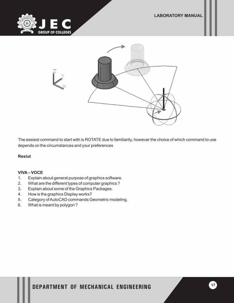
Most AutoCAD commands that are used for 2D operations can be applied to 3D models. For example, with the
ROTATE command, you can revolve a 3D solid about an axis that's parallel with the Z axis of the UCS. To
rotate the model about a different axis direction would require you to change the direction of the UCS Z axis.
There are also commands specialized for the 3D environment such as 3DROTATE, which displays a gizmo to
facilitate rotation about any major axis.
LABORATORY MANUAL
DEPARTMENT OF MECHANICAL ENGINEERING
J E C GROUP OF COLLEGES
17
The easiest command to start with is ROTATE due to familiarity, however the choice of which command to use
depends on the circumstances and your preferences
Reslut
VIVA – VOCE
1. Explain about general purpose of graphics software.
2. What are the different types of computer graphics ?
3. Explain about some of the Graphics Packages.
4. How is the graphics Display works?
5. Category of AutoCAD commands Geometric modeling.
6. What is meant by polygon ?

LABORATORY MANUAL
DEPARTMENT OF MECHANICAL ENGINEERING
J E C GROUP OF COLLEGES
18

LABORATORY MANUAL
DEPARTMENT OF MECHANICAL ENGINEERING
J E C GROUP OF COLLEGES
19
AIM
To Study of Assembly modeling.
THEORY
INTRODUCTION: - Assembly modeling is a technology and method used by computer-aided design and
product visualization computer software systems to handle multiple files that represent components within a
product. The components within an assembly are represented as solid or surface models.
The designer generally has access to models that others are working on concurrently. For example, several
people may be designing one machine that has many parts. New parts are added to an assembly model as
they are created. Each designer has access to the assembly model, while a work in progress, and while
working in their own parts. The design evolution is visible to everyone involved. Depending on the system, it
might be necessary for the users to acquire the latest versions saved of each individual components to update
the assembly.
The individual data files describing the 3D geometry of individual components are assembled together
through a number of sub-assembly levels to create an assembly describing the whole product. All CAD and
CPD systems support this form of bottom-up construction. Some systems, via associative copying of
geometry between components also allow top-down method of design.
Components can be positioned within the product assembly using absolute coordinate placement methods or
by means of mating conditions. Mating conditions are definitions of the relative position of components
between each other; for example alignment of axis of two holes or distance of two faces from one another. The
final position of all components based on these relationships is calculated using a geometry constraint engine
built into the CAD or visualization package.
The importance of assembly modeling in achieving the full benefits of PLM has led to ongoing advances in this
technology. These include the use of lightweight data structures such as JT that allow visualization of and
interaction with large amounts of product data, direct interface to between Digital Mock ups and PDM systems
and active digital mock up technology that unites the ability to visualize the assembly mock up with the ability to
measure, analyze, simulate, design and redesign.
Basic assembly tools
1. Coincident:- the coincident mate is generally applied to make the two planar faces coplanar. But you can
also apply the coincident mate to other entities.
Experiment No. 5

LABORATORY MANUAL
DEPARTMENT OF MECHANICAL ENGINEERING
J E C GROUP OF COLLEGES
20
Result
Viva- voce
1. What are the different methods for drawing an arc?
2. How to activate isometric axes in CAD?
3. Which is the latest version of SolidsWorks?
4. What is the use of extruded feature in Solidsworks?
5. How can we make a hole in a solid rectangle using Solidsworks?

LABORATORY MANUAL
DEPARTMENT OF MECHANICAL ENGINEERING
J E C GROUP OF COLLEGES
21

LABORATORY MANUAL
DEPARTMENT OF MECHANICAL ENGINEERING
J E C GROUP OF COLLEGES
22

LABORATORY MANUAL
DEPARTMENT OF MECHANICAL ENGINEERING
J E C GROUP OF COLLEGES
23
AIM
To Study of Feature modification and manipulation
THEORY
INTRODUCTION
Start Pro/E Wildfire.
Select [File] -> [Set Working Directory…] and navigate to your My Documents folder and your appropriate
folder and term and create a new Tutorial 4 folder (directory).
Choose [File] -> [Open], and find tutorial_2, the part designed in Tutorial 2.
Click [OK] Button.
First the part will be renamed. Right click on the branch labeled Extrude 1 on the model tree at the left of the
screen, as shown in Figure 6.1. The entire part should be highlighted.
Select [Rename] from the menu.
Fig. 6.1
Experiment No. 6

LABORATORY MANUAL
DEPARTMENT OF MECHANICAL ENGINEERING
J E C GROUP OF COLLEGES
24
Enter [right_support] into the textbox, and hit Enter.
Next the dimensions of the part will be modified and a reference will be added. Right click on the SKETCH 1
branch, and select Edit Definition.
Fig. 6.2
Select [Relations] from the TOOLS menu on the Menu Manager.
You will come up with a dialog box, type in the dialog box sd10=sd5-80 and click ok
Fig. 6.3

LABORATORY MANUAL
DEPARTMENT OF MECHANICAL ENGINEERING
J E C GROUP OF COLLEGES
25
You should notice that dimension sd1 has changed from 180 to 160.
Select [Modify] from the SKETCHER menu.
Select dimension sd5 and change it to 220.
You should notice that both dimension sd0 and sd1 change, as shown in Figure 6.4.
Fig. 6.4
Choose [Done] from Menu Manager.
Select [OK] from the Section menu, and click the check button.
Rotate the part to examine the modifications.
Next the chamfer will be deleted. Right click on the Chamfer branch of the model tree and select [Delete].
Select the OK button from the pop-up window. You should see the image shown in Figure 6.5.
Fig. 6.5

LABORATORY MANUAL
DEPARTMENT OF MECHANICAL ENGINEERING
J E C GROUP OF COLLEGES
26
Next a round will be added to the edges on the other side of the part. Right click on the Round branch of the
model tree and select [Edit Definition].
Rotate the part so that you can see the edges, which have not been rounded.
Use the left mouse button to select Edge1, Edge2, and Edge3 shown in Figure 6.6.
Fig. 6.6
Click the check button, and rotate the part to make sure all edges are rounded. You should see the image
shown in Figure 6.7.
Fig. 6.7

LABORATORY MANUAL
DEPARTMENT OF MECHANICAL ENGINEERING
J E C GROUP OF COLLEGES
27
Select [File] -> [Save a Copy] from menu bar.
Name the part [tutorial_4] and click OK.
Result
Viva-voce
1. What do you understand by manipulation ?
2. What are the solid modeling based applications ?

LABORATORY MANUAL
DEPARTMENT OF MECHANICAL ENGINEERING
J E C GROUP OF COLLEGES
28

LABORATORY MANUAL
DEPARTMENT OF MECHANICAL ENGINEERING
J E C GROUP OF COLLEGES
29
Aim
To Study of Detailing
Types of Doors
Battened and ledge door
Battened and braced door
Battened and framed door
Battened, ledge, and framed door
Framed and paneled door
Glazed door
Flush door
Louvered door
Wire gauged door
Revolving door
Sliding door
Swing door
Collapsible steel door
Rolling shutter door
Mild steel sheet door
Hollow metal door
PVC door
Types of Windows
Fixed
Pivoted
Double hung
Sliding
Casement
Sash
Louvered
Metal
Bay
Corner window
Dormer window
Gable window
Lantern
Results
Successfully Study About Detailing.
Experiment No. 7

LABORATORY MANUAL
DEPARTMENT OF MECHANICAL ENGINEERING
J E C GROUP OF COLLEGES
30
Viva-Voce
1. Explain the term detailing ?
2. What are the different types of doors ?
3. What are the different types of windows ?

LABORATORY MANUAL
DEPARTMENT OF MECHANICAL ENGINEERING
J E C GROUP OF COLLEGES
31
AIM
To draft the Sheet metal drawing.
Software Solid Works
Result
Viva- voce
1. How do you change a dimension value in solidsworks?
2. Is it possible to make a feature using an overdefined sketch?
3. What are the advantages of CAD software's?
4. What do you meant by GUI?
5. States some of the tool bars used in CAD.
Experiment No. 8

LABORATORY MANUAL
DEPARTMENT OF MECHANICAL ENGINEERING
J E C GROUP OF COLLEGES
32

LABORATORY MANUAL
DEPARTMENT OF MECHANICAL ENGINEERING
J E C GROUP OF COLLEGES
33
AIM
To Study Surfacing Modeling & drafting.
Software Solid works
Make Following Model Using Solid Works
Experiment No. 9

LABORATORY MANUAL
DEPARTMENT OF MECHANICAL ENGINEERING
J E C GROUP OF COLLEGES
34
Result
Viva- voce
1. States some of the commonly used commands in Cad software's.
2. What is the usage of ZOOM command?
3. What is need for setting LIMITS?
4. Differentiate First angle & Third angle Projection.
5. Differentiate orthographic and isometric projections.
6. What are the applications of CAD?

LABORATORY MANUAL
DEPARTMENT OF MECHANICAL ENGINEERING
J E C GROUP OF COLLEGES
35

LABORATORY MANUAL
DEPARTMENT OF MECHANICAL ENGINEERING
J E C GROUP OF COLLEGES
36

LABORATORY MANUAL
DEPARTMENT OF MECHANICAL ENGINEERING
J E C GROUP OF COLLEGES
37
AIM
Calculate Maximum Deflection and Non voice Stress
Given Data
Given a Cantilever beam and apply point load2Length of Beam (l) = 1000 mm Cross section Area(A) 10x10 = 100 mm
7 2Apply Force (P) = 100 N Modules of Elascity = 3x10 N/mm
Cross Section Area of Beam is Rectangular.
Cross Section Area of Beam is shown in following fig.
Length of section (L) = 10mm Breath of section = 10mm
(1) Solve by Ansys
(2) Solve to Mathematical Process
Using Following steps in Ansys
Step 1 : Ansys Utility Menu
File – clear and start new – do not read file – ok – yes
Step 2 : Anys Main Menu – Preferences
Select –STRUCTURAL –ok
Step 3: Preprocessor
Element type – Add/Edit/Delete – Add –BEAM- 2D elastic 3 – ok –close3Real constants – Add – ok –real constant set no – 1 c/s area - 10x10 moment of inertia – 10x10 /12 Total beam
height – 10 ok – close7 Material Properties – material models – Structural –Linear –Elastic-Isometric – Ex – 3x10 – ok –close.
Step 4: Preprocessor
Modeling – Create – Key points – In Active CS – Apply (first Key point is created) – x,y,z location in CS – 0 apply
Experiment No. 10

LABORATORY MANUAL
DEPARTMENT OF MECHANICAL ENGINEERING
J E C GROUP OF COLLEGES
38
(Second key point is created) – 1000 (x value w.r.t. first key point) – ok – close
Create – Lines – Straight line – pick point on key point – ok.
Meshing – Mesh tool – mesh – select to line – ok
Step 5: Preprocessor
Load – Define loads - apply – Structural – Displacement – on key point – pick key point 1 – apply – All DOFs to
be constrained – ok
Loads – Define loads apply – Structural – Force/Moment – on Key point 2 - apply –direction of Force/Moment
– FY –Force/Moment value - -100(-ve value) – ok.
Step 6: Solution
Solve –current LS – ok (Solution is done is displayed) – close.
Step 7: General Post Processor
Plot Results – Deformed Shape – Def+undeformed ok(Show Deformation in fig- 1)
Plot Ctrls – Style- Size and shape – Display on elements – on – ok.
Plot Results – Contour plot – Nodal Solution – Stress – Von-Mises stress(Show Von-Mises stress fig- : 10.2)
Fig. 10.1 Show to Maximum Deformation

LABORATORY MANUAL
DEPARTMENT OF MECHANICAL ENGINEERING
J E C GROUP OF COLLEGES
39
Fig. 10. 2 Show to Von-Mises stress
Mathematical process 3Moment of Inertia = I = bd /12
3 = 10x(10) /12
4 = 833.33 mm
3Max. Deflection = δ = Pl /3EImax. 3 7
= 100x(1000) /3x3x10 x833.33
= 1.33 mm
2 Stress = 6PL/bd = 6x100x1000/10x100
2 = 600 N/mm
Solve By ansys = Solve by Mathematical process.

LABORATORY MANUAL
DEPARTMENT OF MECHANICAL ENGINEERING
J E C GROUP OF COLLEGES
40
Result
Viva-voce
1. What is a cantilever beam ?
2. What do you know about deflection ?
3. Define the term stress ?
4. What is point load ?

LABORATORY MANUAL
DEPARTMENT OF MECHANICAL ENGINEERING
J E C GROUP OF COLLEGES
NAME OF THE LBORATORY:____________________________________ CODE:___________________
SEMESTER:______________NAME OF STUDENT:___________________ ROLL No:________________
Note: Lab citizenship covers Discipline, Punctuality, Lab Meeting Participation, Note book Record Keeping and contribution in up keeping of the lab
Date of Allotment
LAB PERFORMANCE APPRAISAL SHEET
Marks Awarded for
Total marks as per syllabus (M)= Z / 10
Experiment No & Title of the Experiment
Full Marks (Y)
Lab Performance
Viva-Voce Lab Citizenship
Total (X) Signature of Lab In charge
with Date
Total Marks from experiment No------ to ----- (Z)

LABORATORY MANUAL
DEPARTMENT OF MECHANICAL ENGINEERING
J E C GROUP OF COLLEGES
Note

LABORATORY MANUAL
DEPARTMENT OF MECHANICAL ENGINEERING
J E C GROUP OF COLLEGES
Note

LABORATORY MANUAL
DEPARTMENT OF MECHANICAL ENGINEERING
J E C GROUP OF COLLEGES
Note