Fan Type Ionizer - SMC Products/CAD Models
28
Extensive rapid static neutralization * Offset voltage (Ion balance) : ±5 V Slim design [mm] Model Thickness (Depth) Width Height IZF21 40 104 155 IZF31 144 195 Thinnest and Fastest Compact fan typesPage 18 0.5seconds * Rapid static neutralization 40mm Thickness 0 200 800 1600 2000 2400 Installation distance [mm] 2 s 4 s 6 s 8 s 0 300 –300 * When neutralizing static electricity from 1000 V to 100 V at a distance of 300 mm from the workpiece (front surface). When air flow of IZF31 is maximum. Fan Type Ionizer CAT.NAS100-113A Series IZF RoHS
-
Upload
khangminh22 -
Category
Documents
-
view
7 -
download
0
Transcript of Fan Type Ionizer - SMC Products/CAD Models

Extensive rapid static neutralization∗
Offset voltage(Ion balance) : ±5 V
Slim design [mm]
ModelThickness
(Depth)Width Height
IZF2140
104 155
IZF31 144 195
Thinnest and Fastest
Compact fan typesPage 18
0.5seconds
∗
Rapid staticneutralization40mm
Thickness
0 200 800 1600 2000 2400Installation distance
[mm]
2 s 4 s 6 s 8 s0
300
–300
∗ When neutralizing static electricity from 1000 V to100 V at a distance of 300 mm from the workpiece(front surface). When air flow of IZF31 is maximum.
Fan Type Ionizer
CAT.NAS100-113ASeries IZF
RoHS

1
Extensive Rapid Static Neutralization
Extensive static neutralization
Application Examples
Extensive static neutralization area can be covered with adjustable louver.Adjustable in 5-stagesfrom wide to narrow angle
90-degree rotation mountingavailable
(Adjustable in a vertical direction)
Extensive static neutralization
at close range
Long range
static neutralization
Option
Angle adjustment trimmerfor adjustable louver
123
4
Anglesetting 5
Anglesetting 1
54
32
For the IZF21. For details about the IZF31, refer to page 8. Refer to page 4 for flow rate adjustment and the description
below for angle adjustment of the adjustable louver.
At maximum flow rate
At maximum flow rate, with adjustable louver/largest angle At maximum flow rate, with adjustable louver/smallest angle
0 400 800 1200 1600 2000Installation distance [mm]
2 s 4 s
6 s
8 s0
0 400 800 1200 1600 2000Installation distance [mm]
2 s
4 s6 s
8 s0
0 400
0
300mm
–300 mm
300mm
–300 mm
300mm
–300 mm
2000 0 400 800 1200 1600 2000Installation distance [mm]
2 s
4 s6 s
8 s0
0 400 800 1200 1600 2000Installation distance [mm]
2 s 4 s 6 s 8 s0
300mm
–300 mm
300mm
–300 mm
2000 0 400 800 1200 1600 2000Installation distance [mm]
2 s
4 s6 s
8 s0
0 400 800 1200 1600 2000Installation distance [mm]
2 s 4 s 6 s 8 s0
300mm
–300 mm
300mm
–300 mm
Fan Type Ionizer Series IZF
2
Polarityexchanged
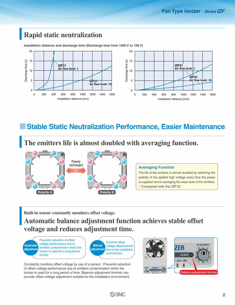
Stable Static Neutralization Performance, Easier Maintenance
The emitters life is almost doubled with averaging function.
Rapid static neutralization
Built-in sensor constantly monitors offset voltage.
Automatic balance adjustment function achieves stable offset voltage and reduces adjustment time.
Averaging Function The life of the emitters is almost doubled by switching the polarity of the applied high voltage every time the power is supplied hence averaging the wear level of the emitters.∗ Compared with the IZF10.
Constantly monitors offset voltage by use of a sensor. Prevents reductionof offset voltage performance due to emitters contamination when theionizer is used for a long period of time. Balance adjustment trimmer canprovide offset voltage adjustment suitable for the installation environment.
Installation distance and discharge time (Discharge time from 1000 V to 100 V)
Automaticadjustment
Manualadjustment
Polarity A Polarity B
Balance adjustment trimmer
+ +
+
++
+
+
+
−
− −
−
−
−−
−
0
5
10
15
20
0 200 400 600 800 1000 1200 1400 1600
Dis
char
ge ti
me
[s]
Dis
char
ge ti
me
[s]
Installation distance [mm]
0
5
10
15
20
0 200 400 600 800 1000 1200 1400 1600
IZF21Air flow level: 1
IZF21Air flow level: 10
Installation distance [mm]
IZF31Air flow level: 1
IZF31Air flow level: 10
0
5
10
15
20
0 200 400 600 800 1000 1200 1400 1600
Dis
char
ge ti
me
[s]
Dis
char
ge ti
me
[s]
Installation distance [mm]
0
5
10
15
20
0 200 400 600 800 1000 1200 1400 1600
IZF21Air flow level: 1
IZF21Air flow level: 10
Installation distance [mm]
IZF31Air flow level: 1
IZF31Air flow level: 10
Prevents reduction of offset voltage performance due to emitters contamination when the ionizer is used for a long period of time.
Corrects offset voltage displacement due to the installation environment.
Fan Type Ionizer Series IZF

3
Cleaning kitIZS30-M2
Related equipment
Emitter cartridge retaining screwM3 x 12 1 pc. (Provided by customer)
Emitter cartridge drop prevention
Emitter cartridge Emitter cartridge
Emitter cartridge is easily replaceable. (No tools are required.)
Cleaning arms are installed inside. Emitter cleaning is started by external input or operation button.
The emitter points are cleaned with a brush by the motor driven rotating cleaning arms, which reduces the emitters' contamination.
Stable Static Neutralization Performance, Easier Maintenance
Emitter contamination can be reduced by automatic cleaning function.
Contamination of the emitterscan be detected.
Cleaning arm
Cleaning brush
Cleaning arm
Automatic cleaning unit
Operation buttonEmitter
Motor
Emitter contamination level is constantly monitored.When maintenance is required, the user is alerted by a signal output and the LED turning ON. NDL lights up when
contamination of the emitters is detected.
Option
Fan Type Ionizer Series IZF

4
Visible
Visible
LED IndicatorsPower supply indicatorPWR
ION/HV
ALMNDL
Static neutralization operation/Incorrect high voltage indicatorError indicatorMaintenance indicator
Prevents ingress of lint and foreign matter to the motorand possibility of short-circuit between emitters!
Air suction side
FilterFilter holder
7 types of alarms are provided.
LED indicator can bechecked from 2 directions!
Filter
Flow Rate Adjustment Function
Flow rate is adjustable in 10 steps using the flow rate adjustment dial. The flowrate adjustment dial is removable to prevent unexpected changes of adjustment.
Flow rate adjustment dial
Option
Flow Rate Adjustment Range [m3/min]
ModelFlow rate adjustment level
1 2 3 4 5 6 7 8 9 10
IZF21 0.4 0.5 0.6 0.7 0.8 0.9 1.1 1.4 1.7 1.8
Power supply failure
CPU failure
Incorrect high voltage Fan motor failure
Automatic cleaning failure
Maintenance warning Emitter cartridge mounting failure
Fan Type Ionizer Series IZF

Fan Type Ionizer Series IZF
5
Neutralizing static electricity on PET bottlesTrip-resistance during conveying/Prevents adhesion of dust.
Static neutralization on a conveyorStatic neutralization in a narrow space
Neutralizing static electricity on film molded goodsSticking and scattering prevention on a conveyor
Neutralizing static electricity from parts feeder
Prevents clogging.
Neutralizing static electricity from filmsPrevents winding failure./Prevents adhesion of dust.
Static neutralization on packaging materialsmade from polystyrene foam.Darkening due to dust adhesion prevented
Neutralizing static electricity on anelectric substratePrevents element disruption due to discharge, and adhesion of dust.
Neutralizing static electricity on molded goodsImproves detachability of molded goods from a die.
Neutralizing static electricity from packing filmsPrevents the filled substance from adhering to the packing film and reduces packing mistakes.
∗ Based on ANSI/ESD-STM3.1-2006 standards
Application Examples
Compact fan type with simple functions Series IZF10 Page 18
Compact design (H x W x D): 80 mm x 110 mm x 39 mmWeight: 280 g2 types of fans available
Rapid static neutralizing fan: Discharge time (Static neutralization time)∗1.5 s (When neutralizing static electricity from 1000 V to 100 V at a distance of 300 mm from the workpiece (front surface))
Low-noise fan: 48 dB(A) (Measured at a distance of 300 mm from the workpiece), Rapid static neutralizing fan: 57 dB(A)
Offset voltage (Ion balance)∗: ±13 VWith alarmIncorrect high voltage, Emitter dirt detection
6
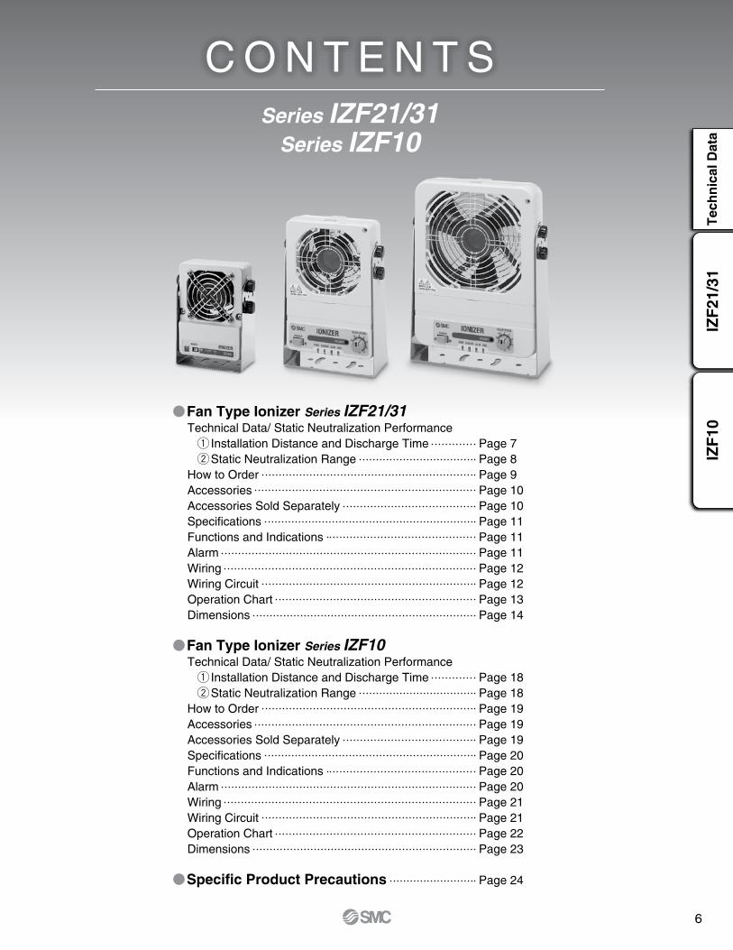
Fan Type Ionizer Series IZF21/31Technical Data/ Static Neutralization Performance q Installation Distance and Discharge Time Page 7 w Static Neutralization Range Page 8How to Order Page 9Accessories Page 10Accessories Sold Separately Page 10Specifications Page 11Functions and Indications Page 11Alarm Page 11Wiring Page 12Wiring Circuit Page 12Operation Chart Page 13Dimensions Page 14
Fan Type Ionizer Series IZF10Technical Data/ Static Neutralization Performance q Installation Distance and Discharge Time Page 18 w Static Neutralization Range Page 18How to Order Page 19Accessories Page 19Accessories Sold Separately Page 19Specifications Page 20Functions and Indications Page 20Alarm Page 20Wiring Page 21Wiring Circuit Page 21Operation Chart Page 22Dimensions Page 23
Specific Product Precautions Page 24
Series IZF21/31Series IZF10
C O N T E N T S
IZF
21/3
1T
ech
nic
al D
ata
IZF
10

7
0
5
10
15
20
0 200 400 600 800 1000 1200 1400 1600
Air flow level: Air flow level: 10
Air flow level: 1Air flow level: 1
Dis
char
ge ti
me
[s]
Installation distance [mm]
0
5
10
15
20
0 200 400 600 800 1000 1200 1400 1600
Air flow level: Air flow level: 10
Air flow level: Air flow level: 1
Dis
char
ge ti
me
[s]
Installation distance [mm]
0
5
10
15
20
0 200 400 600 800 1000 1200 1400 1600
Dis
char
ge ti
me
[s]
Installation distance [mm]
Air flow level: Air flow level: 10
Air flow level: Air flow level: 1
0
5
10
15
20
0 200 400 600 800 1000 1200 1400 1600
Air flow level: Air flow level: 10
Air flow level: Air flow level: 1
Dis
char
ge ti
me
[s]
Installation distance [mm]
0
5
10
15
20
0 200 400 600 800 1000 1200 1400 1600
Air flow level: Air flow level: 10
Air flow level: Air flow level: 1
Dis
char
ge ti
me
[s]
Installation distance [mm]
0
5
10
15
20
0 200 400 600 800 1000 1200 1400 1600
Dis
char
ge ti
me
[s]
Installation distance [mm]
Air flow level: Air flow level: 10
Air flow level: Air flow level: 1
Series IZF21/31
Technical Data
Static Neutralization Performance
q Installation Distance and Discharge Time (Discharge time from 1000 V to 100 V)
IZF21
IZF21-S (With automatic cleaning unit)
IZF21-U (With filter)
IZF31
IZF31-S (With automatic cleaning unit)
IZF31-U (With filter)
Note) Static neutralization performance is based on the data using the charged plate (size: 150 mm x 150 mm, capacitance: 20 pF) as defined in the U.S. ANSI standards (ANSI/ESD, STM3.1-2006). Use this as a guideline purpose only for model selection because the value varies depending on the material and/or size of a subject.

8
IZF
21/3
1T
ech
nic
al D
ata
IZF
10
0 400 800 1200 1600 2000
Installation distance [mm]
2 s 4 s 6 s 8 s0
300mm
–300 mm
0 400 800 1200 1600 2000
Installation distance [mm]
2 s
4 s6 s
8 s0
300mm
–300 mm
0 400 800 1200 1600 2000
Installation distance [mm]
2 s 4 s
6 s
8 s0
300mm
–300 mm
0 400 800 1200 1600 2000
Installation distance [mm]
4 s8 s
0
300mm
–300 mm
0 400 800 1200 1600 2000 2400 2800
Installation distance [mm]
2 s 4 s 6 s 8 s0
300mm
–300 mm
0 400 800 1200 1600 2000 2400 2800
Installation distance [mm]
2 s 4 s 6 s 8 s0
300mm
–300 mm
0 400 800 1200 1600 2000 2400 2800
Installation distance [mm]
2 s 4 s 6 s 8 s0
300mm
–300 mm
0 400 800 1200 1600 2000 2400 2800
Installation distance [mm]
2 s 4 s
6 s
8 s
0
300mm
–300 mm
IZF21-W With adjustable louver: Angle setting 1, Air flow level: 10
IZF21-W With adjustable louver: Angle setting 5, Air flow level: 10
IZF31-W With adjustable louver: Angle setting 1, Air flow level: 10
IZF31-W With adjustable louver: Angle setting 5, Air flow level: 10
IZF31 (Air flow level: 10)
Static Neutralization Performance
w Static Neutralization Range
IZF21 (Air flow level: 10)
IZF21 (Air flow level: 1) IZF31 (Air flow level: 1)
Technical Data Series IZF21/31Note) Static neutralization performance is based on the data using the charged plate (size: 150 mm x 150 mm,
capacitance: 20 pF) as defined in the U.S. ANSI standards (ANSI/ESD, STM3.1-2006). Use this as a guideline purpose only for model selection because the value varies depending on the material and/or size of a subject.

9
RoHSFan Type IonizerSeries IZF21/31
IZF 21 B
Symbol Max. air flow
21 1.8 m3/min
31 4.4 m3/min
Model
Nil NPN input/output
P PNP input/output
Input/Output specifications
How to Order
Nil With power supply cable (3 m)
Z With power supply cable (10 m)
Q With AC adapter (with AC cord)
R With AC adapter (without AC cord)
N None
Power supply cable, AC adapter
Nil None
S With automatic cleaning unit
W With adjustable louver
Y With automatic cleaning unit + adjustable louver
Automatic cleaning unit, Louver
Nil None
B With bracket
Bracket
Nil None
U With filter∗
Filter
∗ Filter + Filter holder
10
IZF
21/3
1Te
chni
cal D
ata
IZF
10
Fan Type Ionizer Series IZF21/31
21
21
21
21
21
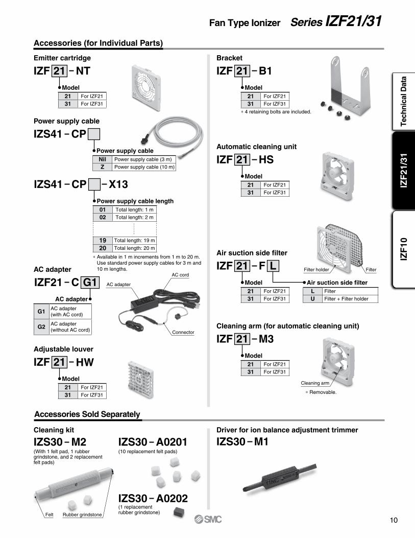
Accessories (for Individual Parts)
Accessories Sold Separately
Emitter cartridge
Power supply cable
Automatic cleaning unit
Adjustable louver
Air suction side filter
AC adapter
Bracket
Cleaning arm (for automatic cleaning unit)
IZF IZF
IZF
IZS41
IZF
IZF
IZF
IZF21
NT B1
M3
CP
HS
HW
F L
C G1
21 For IZF21
31 For IZF31
21 For IZF21
31 For IZF31
21 For IZF21
31 For IZF31
Nil Power supply cable (3 m)
Z Power supply cable (10 m)
L Filter
U Filter + Filter holder
G1 AC adapter(with AC cord)
G2 AC adapter(without AC cord)
Model
21 For IZF21
31 For IZF31
21 For IZF21
31 For IZF31
21 For IZF21
31 For IZF31
Model
Model
Model
Model
Model
∗ 4 retaining bolts are included.
∗ Removable.
Power supply cable
Air suction side filter
AC adapter
Cleaning kit Driver for ion balance adjustment trimmer
21
M2IZS30 M1IZS30A0201IZS30(10 replacement felt pads)(With 1 felt pad, 1 rubber
grindstone, and 2 replacement felt pads)
A0202IZS30(1 replacement rubber grindstone)Felt Rubber grindstone
Filter holder
Cleaning arm
Filter
Connector
AC cord
AC adapter
IZS41 CP X13
01 Total length: 1 m
02 Total length: 2 m
19 Total length: 19 m
20 Total length: 20 m
Power supply cable length
∗ Available in 1 m increments from 1 m to 20 m.Use standard power supply cables for 3 m and 10 m lengths.

11
Series IZF21/31
q w e rty u
Specifications
ModelIZF21- IZF21-P IZF31- IZF31-P
NPN PNP NPN PNPMaximum air flow 1.8 m3 /min 4.4 m3 /minApplied voltage ±5 kVIon generation method Corona discharge typeMethod of applying voltage DC typeOffset voltage (Ion balance) Note) ±5 VPower supply voltage 24 VDC ±10%Current consumption 0.9 A or less 1.3 A or less
Input signal
Ionizer stop signal Connect with 0 VVoltage range: 5 VDC or lessCurrent consumption: 5 mA or less
Connect with +24 VVoltage range: 19 VDC topower supply voltageCurrent consumption: 5 mA or less
Connect with 0 VVoltage range: 5 VDC or lessCurrent consumption: 5 mA or less
Connect with +24 VVoltage range: 19 VDC topower supply voltageCurrent consumption: 5 mA or less Cleaning input signal
Output signal
Maintenance signal Maximum load current: 100 mAResidual voltage: 1 V or less(Load current: 100 mA)Maximum applied voltage: 26.4 VDC
Maximum load current: 100 mAResidual voltage: 1 V or less(Load current: 100 mA)
Maximum load current: 100 mAResidual voltage: 1 V or less(Load current: 100 mA)Maximum applied voltage: 26.4 VDC
Maximum load current: 100 mAResidual voltage: 1 V or less(Load current: 100 mA)Error signal
Ambient temperature Operating: 32 to 122°F (0 to 50°C) Stored: 14 to 140°F (–10 to 60°C)Ambient humidity Operating, Stored: 35 to 80%RH (No condensation)Material Case: ABS/PBT/Stainless steel Emitter: TungstenImpact resistance 100 m/s2
Applicable standard/directive CE (EMC directive: 2014/30/EC)Note) Based on ANSI/ESD-STM3.1-2006 standards
Alarm
Input voltage 100 to 240V AC, 50/60Hz Output voltage 24 VDCOutput current 1.9 A maxAmbient temperature 32 to 104°F (0 to 40°C), Stored: –4 to 149°F (–20 to 65°C)Ambient humidity Operating, Stored: 5 to 95%RH (No condensation)Weight 375 g (including AC cord, connector)Applicable standard/directive CE/cUL
AC Adapter Specifications
Functions and Indications
No. Name Panel display Type Description1 Power supply switch POWER Switch Turns the ionizer ON/OFF.
2Power supply indicator
PWRLED
(Green/Red)
Green lights up when the power supply is ON. Green flashes if the power supply is abnormal. Red flashes if the CPU is abnormal.
3Static neutralization operation/Incorrect high voltage indicator
ION/HVLED
(Green/Red)
Green lights up when static neutralization is operated. Red lights up if incorrect high voltage is detected. Red flashes if the CPU is abnormal.
4 Error indicator ALM LED (Red)Red lights up if fan motor failure or automatic cleaning failure is detected. Red flashes if the CPU is abnormal.
5Maintenance indicator
NDLLED
(Green/Red)
Green lights up when emitters require cleaning.Green flashes when automatic cleaning is performed. Red flashes if emitter cartridge mounting failure, automatic cleaning failure or CPU failure is detected.
6 Balance adjustment ADJUST Trimmer Adjusts offset voltage (ion balance).7 Air flow adjustment BLOW SPEED Rotary switch Adjusts air flow with fan.
Alarm name Output signal LED ONLED
(Flashes at 1 Hz)Ionizer operation
after alarm generated
Description Action to reset alarm
Power supply failure Error signal OFF (B contact) — PWR (Green) Stop Connected power supply voltage is outside of specification. Reset automatically.
Incorrect high voltage Error signal OFF (B contact) ION/HV (Red) — StopIf an abnormal high voltage discharge occurs.
Input the ionizer stop signal or supply power again.
Fan motor failure Error signal OFF (B contact) ALM (Red) — StopIncorrect ionizer operation due to foreign matter in fan motor
Input the ionizer stop signal or supply power again.
CPU failure Error signal OFF (B contact) —
PWR (Red)ION/HV (Red)
ALM (Red)NDL (Red)
Stop CPU error due to noise etc. Supply power again.
Excess current on output circuit
Error signal OFF (B contact)Maintenance signal OFF (A contact)
— — ContinueIf excess current is present on the output circuit and protection circuit is activated.
Reset automatically.
Maintenance warning Maintenance signal ON(A contact)
NDL (Green) — ContinueWhen static electricity neutralization performance isreduced due to contamination, wear or damage to emitters.
Input the ionizer stop signal or supply power again.
Emitter cartridge mounting failure Error signal OFF (B contact) NDL (Red) — Stop Emitter cartridge is not mounted. Supply power again.Automatic cleaning failure Error signal OFF (B contact) ALM (Red) NDL (Red) Stop Error during automatic cleaning operation Supply power again.
Weights
IZF21 IZF31Body 430 g 605 gBracket 146 g 220 gAutomatic cleaning unit 96 g 127 gLouver 33 g 58 gFilter 15 g 26 g

12
IZF
21/3
1Te
chni
cal D
ata
IZF
10
Fan Type Ionizer Series IZF21/31Wiring
Wiring Circuit
Pin no. Cable color Signal name Signal direction DescriptionA1
Brown +24 VDC INConnect the power supply to operate the ionizer.
B1A2
Blue 0 V INB2A3 Green F. G. — Ground terminal with 100 Ω or less to use it as a reference electric potential for ionizer.
B3Yellowish
greenIonizer stop
signalIN
Signal input to turn ON/OFF the ventilation with fan and ion generation.NPN type: To stop fan and ion generation, connect to 0 V. (It operates when disconnected)PNP type: To stop fan and ion generation, connect to +24 VDC. (It operates when disconnected)
A4 Gray Cleaning signal IN When an automatic cleaning unit is fitted, cleaning of the emitters will start.
B4 YellowMaintenance
signalOUT
(A contact)
Turns ON when cleaning due to emitter contamination and/or replacement due to wear isrequired or when automatic cleaning is being performed (when an automatic cleaning unit is fitted). Turns off during output circuit over current error.
A5 Purple Error signalOUT
(B contact)
Turns OFF if power supply failure, incorrect high voltage, fan motor failure, CPU failure, excess current on the output circuit, emitter cartridge mounting failure, or automatic cleaning failure (for product with automatic cleaning function) is detected. (ON when there is no problem)
B5 White — — —
Inte
rnal
cir
cuit
Inte
rnal
cir
cuit
+24 V +24 V
0 V 0 VDC/DC
+24 V
INPUT PLC
INPUT
+24 V
+24 V
OUTPUT
Green F. G. F. G. Make sure to ground.Power supply
Make sure to ground.
or
or
Brown (2 pcs.) +24 VDC
Blue (2 pcs.) 0 V
Green F. G.
Brown (2 pcs.) +24 VDC
Yellowish greenIonizer stop signal
YellowMaintenance signal
PurpleError signal
Gray: Cleaning signal(When automatic cleaning unit is fitted)
Blue (2 pcs.) 0 V
Yellowish greenIonizer stop signal
YellowMaintenance signal
PurpleError signal
Gray: Cleaning signal(When automatic cleaning unit is fitted)
Shield
+24 V
0 V 24 VDC
F. G.
OUTPUT
+24 V +24 V
0 V 0 VDC/DC
+24 V
INPUT
PLC
INPUT+24 V
+24 V
OUTPUT
F. G. Make sure to ground.Power supply
Make sure to ground.
or
or
+24 V
0 V 24 VDC
F. G.
OUTPUT
Shield
A1 A5
B1 B5
13
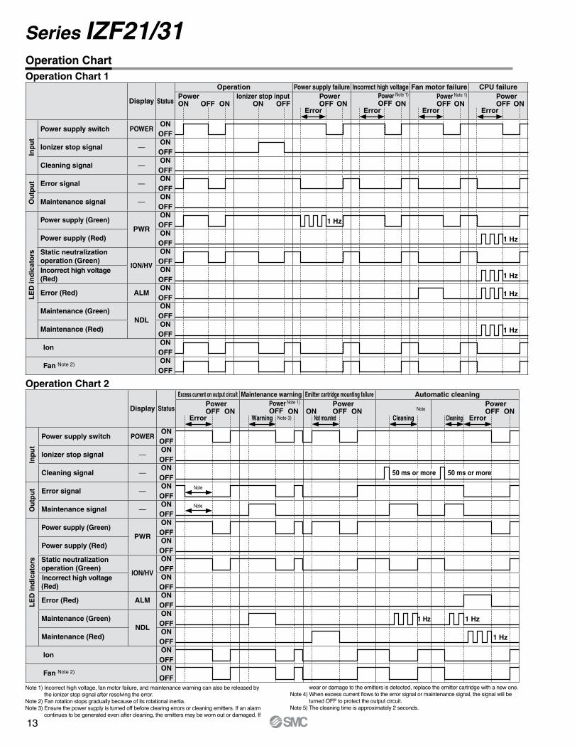
Series IZF21/31 Operation Chart
Display Status
Excess current on output circuit Maintenance warning Emitter cartridge mounting failure Automatic cleaning
Inp
ut
Power supply switch POWERONOFF
Ionizer stop signal —ONOFF
Cleaning signal —ONOFF
Ou
tpu
t Error signal —ONOFF
Maintenance signal —ONOFF
LE
D in
dic
ato
rs
Power supply (Green)PWR
ONOFF
Power supply (Red)ONOFF
Static neutralization operation (Green)
ION/HV
ONOFF
Incorrect high voltage (Red)
ONOFF
Error (Red) ALMONOFF
Maintenance (Green)NDL
ONOFF
Maintenance (Red)ONOFF
IonONOFF
Fan Note 2)ONOFF
Display Status
Operation Power supply failure Incorrect high voltage Fan motor failure CPU failure
Inp
ut
Power supply switch POWERONOFF
Ionizer stop signal —ONOFF
Cleaning signal —ONOFF
Ou
tpu
t Error signal —ONOFF
Maintenance signal —ONOFF
LE
D in
dic
ato
rs
Power supply (Green)PWR
ONOFF
Power supply (Red)ONOFF
Static neutralization operation (Green)
ION/HV
ONOFF
Incorrect high voltage (Red)
ONOFF
Error (Red) ALMONOFF
Maintenance (Green)NDL
ONOFF
Maintenance (Red)ONOFF
IonONOFF
Fan Note 2)ONOFF
Error Error Error Error
Ionizer stop inputON
PowerON OFF ON
PowerOFF ON ON
PowerOFF ONONOFF
Power Note 1)
OFFPower Note 1)
OFF
PowerOFF
PowerOFF
PowerOFFON ONON ONON
Error ErrorWarning Not mounted Cleaning CleaningNote 3)
Note
Operation Chart 1
Operation Chart 2
Power Note 1)
OFF
1 Hz
1 Hz
1 Hz
1 Hz
1 Hz
1 Hz 1 Hz
1 Hz
50 ms or more 50 ms or more
Note
Note
Note 1) Incorrect high voltage, fan motor failure, and maintenance warning can also be released by the ionizer stop signal after resolving the error.
Note 2) Fan rotation stops gradually because of its rotational inertia.Note 3) Ensure the power supply is turned off before clearing errors or cleaning emitters. If an alarm
continues to be generated even after cleaning, the emitters may be worn out or damaged. If
wear or damage to the emitters is detected, replace the emitter cartridge with a new one.Note 4) When excess current flows to the error signal or maintenance signal, the signal will be
turned OFF to protect the output circuit.Note 5) The cleaning time is approximately 2 seconds.

14
IZF
21/3
1Te
chni
cal D
ata
IZF
10
Fan Type Ionizer Series IZF21/31
2 x 5.5
16.6
122
(104)
171.
5
(155
)
107
3 x ø5.5
30 30
ø40
45°
47
143
124
90°
4 x 4.5
2 x ø25
(10.5) 20
40
155
104 2 x ø3.5, depth 1
4 x M4 x 0.7, depth 6(Female thread mounting)
12.5 35
25
139
Dimensions
Bracket
IZF21- -

15
Series IZF21/31 Dimensions
IZF31- -
4 x 4.5
90°2 x ø25
45°
3 x ø5.5
ø402 x 5.5
45 45
163
47
144
211.
5
162
148
(144)
(195
)
179
36.6
5525
2 x ø3.5, depth 1
4 x M4 x 0.7, depth 6(Female thread mounting)
(10.5)
40
2012
.5
195
144
Bracket
16
IZF
21/3
1Te
chni
cal D
ata
IZF
10
Fan Type Ionizer Series IZF21/31
87
(155
)
(104)
95.5
(45)
5(40)
14
(60)
(40)
89
(155
)
89
(104)
20.5
64
(40)(104)
113.
4
(155
)
126
134
(195
)
(144)(45)
5(40)
14 (40)
(60)
127
(195
)
(144)
127
20.5 (40)
64
153
(195
)
(144)
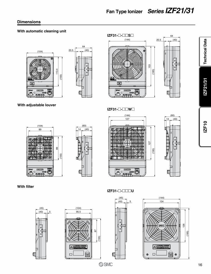
Dimensions
With automatic cleaning unitIZF31- - S
With adjustable louverIZF31- - W
With filterIZF31- - U

17
Series IZF21/31 16
.4
17.5
1
5
AB
ø6.
2
6047
L
Shield
1820 ±50
46.8
98.82144 +105 –100
2144 +105 –100 32.198.8
46.8
Inlet IEC60320-C6
Dimensions
Power supply cableIZS41-CP
AC adapterIZF21-CG1 (with AC cord)
IZF21-CG2 (without AC cord)
Part no. LIZS41-CP 3000 +60
0
IZS41-CPZ 9850 +100 0
18
IZF
21/3
1Te
chni
cal D
ata
IZF
10
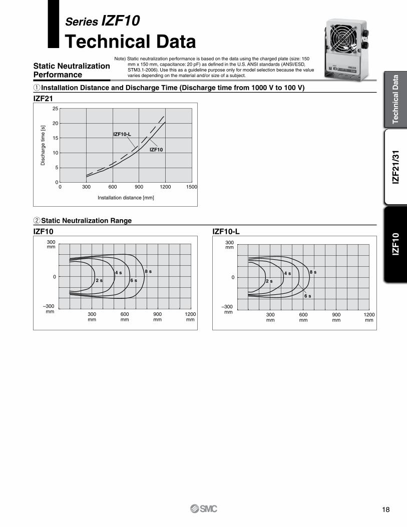
Series IZF10
Technical Data
Static NeutralizationPerformance
25
20
15
10
5
0
Dis
char
ge ti
me
[s]
Installation distance [mm]
IZF10
IZF10-L
300 150012009006000
IZF10 IZF10-L
600mm
300mm
900mm
1200mm
300mm
0
–300 mm
8 s
6 s
4 s
2 s
600mm
300mm
900mm
1200mm
300mm
0
–300 mm
8 s
6 s
4 s
2 s
q Installation Distance and Discharge Time (Discharge time from 1000 V to 100 V)
w Static Neutralization Range
IZF21
Note) Static neutralization performance is based on the data using the charged plate (size: 150 mm x 150 mm, capacitance: 20 pF) as defined in the U.S. ANSI standards (ANSI/ESD, STM3.1-2006). Use this as a guideline purpose only for model selection because the value varies depending on the material and/or size of a subject.

19
RoHSFan Type IonizerSeries IZF10
How to Order
Accessories (for Individual Parts)
Accessories Sold Separately
Power supply cable
e-con connector Cartridge case Bracket
IZF10
28ZS
C P
C
P Power supply cable (3 m)
PZ Power supply cable (10 m)
G1 AC adapter (with AC cord)
G2 AC adapter (without AC cord)
Power supply cable, AC adapter
AC adapter AC cord
AC adapterOutput
Air flow
Bracket
Power supply cable
Note) Option (H) is a supply connector for customers who prepare a cable.
Nil With power supply cable (3 m)
Z With power supply cable (10 m)
H Note) e-con connector
Q With AC adapter (with AC cord)
R With AC adapter (without AC cord)
N None
Nil None
B With bracketNil 0.66 m3/min
L 0.46 m3/min
Nil NPN output
P PNP output
Note) AC cord is only for use in Japan. (Rated voltage 125 V, Plug JIS C8303, Inlet IEC60320-C8)
Power supply cable
Note) Applicable wire size: AWG26 to 24, Conductor cross sectional area: 0.14 to 0.2 mm2, Finished outside diameter: ø0.8 to ø1.0 mm.
IZF10 IZF10A1 B1
AC adapter
AC cord
Note) 4 retaining bolts are included.
Cleaning kit Driver for ion balance adjustment trimmer
M2IZS30 M1IZS30A0201IZS30(10 replacement felt pads)
(With 1 felt pad, 1 rubber grindstone, and 2 replacement felt pads)
A0202IZS30(1 replacement rubber grindstone)Felt Rubber grindstone
Compactfan type
IZF10

20
IZF
21/3
1Te
chni
cal D
ata
IZF
10
Fan Type Ionizer Series IZF21/31
q w e r t y
Specifications
Model IZF10- IZF10-L- IZF10-P- IZF10-LP-Air flow 0.66 m3/min 0.46 m3/min 0.66 m3/min 0.46 m3/minIon generation method Corona discharge typeMethod of applying voltage DC typeApplied voltage ±5 kVOffset voltage (Ion balance) Note) Within ±13 VPower supply voltage 24 VDC ±10 (%)Power consumption 6.1 W or less 3.7 W or less 6.6 W or less 4.8 W or less
Switch output
NPN open collector outputMaximum load current: 80 mAResidual voltage: 1 V or less (Load current: 80 mA)Maximum load voltage: 26.4 VDC
PNP open collector outputMaximum load current: 80 mAResidual voltage: 1 V or less (Load current: 80 mA)
Ambient temperature Operating: 32 to 122°F (0 to 50°C), Stored: 14 to 140°F ( –10 to 60°C)Ambient humidity Operating, Stored: 35 to 80%RH (No condensation)Material Case: ABS/Stainless steel, Emitter: TungstenWeight 280 g (With bracket: 360 g)Applicable standard/directive CE (EMC directive: 2004/108/EC)
Note) Based on ANSI/ESD-STM3.1-2006 standards
Note) NPN/PNP open collector output
Input voltage 100 to 240 VAC, 50/60 Hz Output voltage 24 VDC
Output current 1 A max
Ambient temperature 32 to 104°F (0 to 40°C), Stored: –4 to 149°F (–20 to 65°C)
Ambient humidity Operating, Stored: 10 to 90%RH (No condensation)
Applicable standard/directive CE/cUL
AC Adapter (IZF10-CG1/IZF10-CG2)
Functions and Indications
No. Name Type Description1 Power supply switch Switch Turns the ionizer ON/OFF.
2Power supply indicator
LED(Green/Orange)
Turns ON (Green) when the power is supplied. Turns ON (Orange) if a high voltage error or excess current on the output is detected.
3 Error indicator LED (Red) Turns ON if an abnormal discharge continues for 100 ms or more.4 Maintenance indicator LED (Green) Turns ON when emitters require cleaning.5 Balance adjustment Trimmer Adjusts offset voltage (ion balance).6 Connector e-con Connects the power supply, F. G., and output.
Alarm
Alarm nameNote)
Output LEDIon generation during alarm
Fan rotation during alarm
DescriptionAction to
reset alarmExcess current on output circuit
Turns OFFif error occurs.
POWER (Orange) Continue ContinueIf excess current is present on the output circuit and protection circuit is activated.
Supply power again.
Incorrect high voltage
Turns OFFif error occurs.
POWER (Orange)ALARM (Red)
Stop ContinueIf an abnormal high voltage discharge continues for 100 ms or more.
Supply power again.
Maintenance warning
— NDL (Green) Continue ContinueWhen static neutralization performance is reduced due to contamination, wear or damage to emitters.
—

21
Series IZF10
1234
Inte
rnal
cir
cuit
Inte
rnal
cir
cuit
1: +24 VDC
2: 0 V
3: F. G.
4: OUTPUT (80 mA max)
Ionizer Power supply
PLC
INPUT
+24 V
24 VDC
Ionizer
1: +24 VDC
2: 0 V
3: F. G.
4: OUTPUT (80 mA max)
+24 V
Power supply
PLC
INPUT
+24 V
24 VDC
0 V
0 V
Wiring
Wiring Circuit
Number stamped on connector Signal name Description1 +24 VDC
Connect the power supply to operate the ionizer.2 0 V
3 F. G. Ground terminal to use it as a reference electric potential for ionizer.
4 Error signal
Turns OFF if any of the errors below occur (normally ON).· If an abnormal high voltage discharge continues for 100 ms or more.
· If excess current is present on the output circuit.
Number stamped on connector
NPN output
PNP output
22
IZF
21/3
1Te
chni
cal D
ata
IZF
10
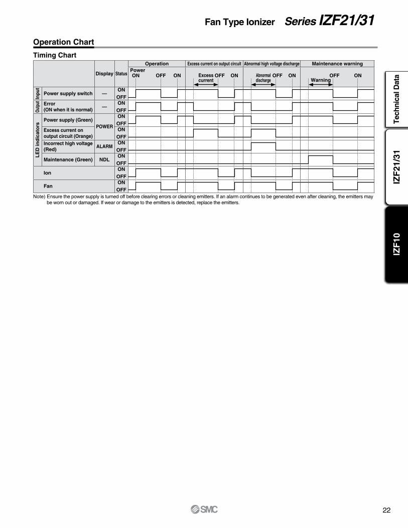
Fan Type Ionizer Series IZF21/31Operation Chart
Timing Chart
Display Status
Operation Excess current on output circuit Abnormal high voltage discharge Maintenance warning
Inpu
t
Power supply switch —ONOFF
Outp
ut Error (ON when it is normal)
—ONOFF
LE
D in
dic
ato
rs
Power supply (Green)POWER
ONOFF
Excess current on output circuit (Orange)
ONOFF
Incorrect high voltage(Red)
ALARMONOFF
Maintenance (Green) NDLONOFF
IonONOFF
FanONOFF
Note) Ensure the power supply is turned off before clearing errors or cleaning emitters. If an alarm continues to be generated even after cleaning, the emitters maybe worn out or damaged. If wear or damage to the emitters is detected, replace the emitters.
Excess current
Abnormaldischarge Warning
PowerON OFF OFF OFF OFFON ON ON ON
23
Series IZF10
5.5 5.5
R41
R76
90°ø25
Variable angle
1.9 (Power supply switch) 6 (With connector plugged in)
(Female thread mounting)
2 x ø3.5 depth 1
4 x M4 x 0.7 depth 6
Ion balance adjustment trimmer
1Holding bolt
Bracket
Power supply switchLED indicators
ø30 3 x 5.5 through
96
82
80
79
37
110
121
39
103
46
96.5 94
60.3
6.5
50°
(46)
23
30 30
(84)
19.5
37.5
66.8
2524
.5
12.5
33.5 1.54
(39)
+5 0
+105–100
+105–100
7 ±1
3 ±1
2144
2144
4444
96
96
AC adapter
AC adaptere-con connector
F.G.
AC cord
Inlet IEC60320-C8
1820 ±50
28
7 ±1
3 ±1
300
+5 0
300e-con connector
F.G.
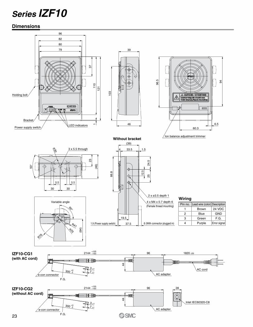
Dimensions
Wiring
Without bracket
IZF10-CG2(without AC cord)
IZF10-CG1(with AC cord)
Pin no. Lead wire (color) Description
1 Brown 24 VDC
2 Blue GND
3 Green F.G.
4 Purple Error signal

24
Selection
Warning
Caution
Mounting
Warning
Mounting
Caution
Wiring
Warning
Series IZFSpecific Product Precautions 1Be sure to read this before handling. Refer to the back cover for Safety Instructions.
1. This product is intended to be used with general factory automation (FA) equipment.If considering using the product for other applications (especially those stipulated on Safety Instructions), please consult SMC beforehand.
2. Use this product within the specified voltage and tempera-ture range.Using outside of the specified voltage can cause a malfunction,damage, electrical shock, or fire.
3. This product is not explosion-protected.Never use this product in locations where the explosion of dust is likely to occur or flammable or explosive gases are used. This can cause a fire.
1. Clean specification is not available with this product.
1. Reserve an enough space for maintenance and wiring.Install the product in consideration of the connector connection part and the emitter cartridge mounting part so that there is enough space for emitter maintenance, inspection and wiring. To avoid unreasonable stress applied to the connector mounting parts, bending of the cable should be more than the minimum bending radius. If the cable is bent in an acute angle or load is applied to the cable successively, it may cause a malfunction, broken wire or fire.
2. Mount this product on a plane surface.Mounting on an uneven surface will apply excess force to the frame or case, which leads to damage or failure. Do not drop the product or subject it to a strong impact. This may cause an injury or accident.
3. Avoid using in a place where noise (electromagnetic wave and surge) is generated.If the product is used in an environment where noise is generated, it may lead to deterioration or damage of the internal elements. Take measures to prevent noise at its source and avoid power and signal lines from coming into close contact.
4. Use a correct tightening torque.If the screws are tightened in excessive of the specified torque range, it may damage the mounting screws, mounting brackets, etc. If the tightening torque is insufficient, the mounting screws and brackets may become loose.
5. Do not adhere tape or sticker onto the product body.If the tape or sticker contains conductive adhesive or reflective paint, it is possible that due to the dielectric effect, charge could build up causing an electro-static discharge or electrical leakage.
6. Be sure to cut off the power supply before installing and adjusting the product.
1. Secure enough space on the rear side of the ionizer so that the air suction is performed with a fan.This product ventilates with an fan motor. If there are obstacles such as wall on the rear side (air suction side) of the ionizer, the ventilation will be obstructed, decreasing the static neutralization performance. Install the ionizer so that its rear surface is at least 20 mm (for IZF21) or 30 mm (for IZF31) away from the obstacles.
2. Be sure to check the effect of static neutralization after installation.The effect of the static neutralization varies depending on the surrounding installation and operating conditions. Check the effect of the static neutralization after installation.
3. When installing ionizers which operate in DC mode (one polarity, positive or negative) close together, they should be positioned at least 2 m away from each other.When an ionizer is used close to the ionizer which operates in DC mode, separate them by at least 2 m. The offset voltage (ion balance) may not be adjusted by the built-in sensor due to the ions discharged from the ionizer which operates in DC mode.
4. Do not apply an excessive external force to the finger guard on the air suction side.If an excessive external force is applied to the finger guard (including the filter holder) on the air suction side, it may be broken. Do not apply an external force of 50 N or more to the finger guard.
1. Before wiring, ensure that the power supply capacity is larger than the specification and that the voltage is within the specification.
2. To maintain product performance, the power supply shall be UL listed Class 2 certified by National Electric Code (NEC) or evaluated as a limited power source provided by UL60950.
3. To maintain the product performance, ground the product with an earth ground cable with a resistance of 100 Ω or less according to this catalog.
4. Be sure to turn off the power supply before wiring (includ-ing attachment/detachment of the connector).
5. When applying the power supply, pay special attention to the wiring and/or surrounding environment until the safety is confirmed.
6. Do not connect or remove any connectors including the power supply, while power is being supplied. Otherwise, the ionizer may malfunction.
7. If the power line and high-pressure line are routed togeth-er, this product may malfunction due to noise. Therefore, use a separate wiring route for this product.
8. Be sure to confirm that there are no wiring errors before starting this product. Faulty wiring will lead to product damage or malfunction.

25
Series IZFSpecific Product Precautions 2Be sure to read this before handling. Refer to the back cover for Safety Instructions.
Operating Environment/Storage Environment
WarningMaintenance
Warning
Danger High VoltageThis product contains a high-voltage generation circuit. When performing maintenance inspection, be sure to confirm that the power supply to the ionizer is turned off. Never disassemble or modify the ionizer, as this may not only impair the product’s functionality but could cause an electric shock or electric leakage.
Caution
1. Keep within the specified ambient temperature range.The specified ambient temperature range for ionizer is 32 to 122°F (0 to 50°C), and for AC adapter is 32 to 104°F (0 to 40°C). Avoid sudden temperature changes even within specified ambient temperature range, as it may cause condensation.
2. Do not use this product in an enclosed space.This product utilizes a corona discharge phenomenon. Do notuse the product in an enclosed space as ozone and nitrogenoxides exist in such places, even though in marginal quantities.
3. Environments to avoidNever use or store under the following conditions. These may cause a failure, fire, etc.a. Areas where ambient temperature exceeds the operating temperature range. b. Areas where ambient humidity exceeds the operating humidity range. c. Areas where abrupt temperature changes may cause condensa tion. d. Areas where corrosive gas, flammable gas or other volatile flammable substances are stored.e. Areas where the product may be exposed to conductive powder such as iron powder or dust, oil mist, salt, organic solvent, machining chips, particles or cutting oil (including water and any liquids), etc.f. Paths of direct air flow, such as air conditioners. g. Enclosed or poorly ventilated areas. h. Locations that are exposed to direct sunlight or heat radiation.i. Areas where strong electromagnetic noise is generated, such as strong electrical and magnetic fields or supply voltage spikes.j. Areas where the product is exposed to static electricity discharge. k. Locations where strong high frequency is generated. l. Locations that are subject to potential lightning strikes. m. In an area where the product may receive direct impact or vibration. n. Areas where the product may be subjected to forces or weight that could cause physical deformation.
1. Perform maintenance regularly and clean the emitters.It is recommended to perform maintenance every week or when the maintenance (NDL) LED turns ON.Check regularly if the product is operating with undetected failures or not. The maintenance must be performed by an operator who has sufficient knowledge and experience. If the product is used for an extended period of time with dust present on the emitters, the product’s ability to neutralize static electricity will be reduced.If the emitter becomes worn and the product's ability to neutralize static electricity is not restored after cleaning, replace the emitter cartridge.
2. Cleaning or replacing the emitters should never be performed while the power is supplied to the product.Fan rotates due to inertial force even when power supply is stopped. Confirm that the fan does not move before performing cleaning or replacing the emitters.Never perform cleaning or replacing the emitters when the product is energized. The fan rotation may cause injury.If the emitter is touched while the product is energized, it may cause an electric shock or accident.
3. Do not disassemble or modify the product.Disassembling or modifying the product may cause accidents such as electric shock, failure or fire. The product will not be guaranteed if it is disassembled and/or modified.4. Do not operate the product with wet hands.Never operate the product with wet hands. It may cause electric shock or other accidents.
1. Do not drop, hit or apply excessive shock (100 m/s2 or more) to the product when handling it.Even if the ionizer body is not damaged, the internal components may be damaged, leading to a malfunction.

Safety Instructions Be sure to read “Handling Precautions for SMC Products” (M-E03-3) before using.
CautionSMC products are not intended for use as instruments for legal metrology.Measurement instruments that SMC manufactures or sells have not been qualified by type approval tests relevant to the metrology (measurement) laws of each country. Therefore, SMC products cannot be used for business or certification ordained by the metrology (measurement) laws of each country.
Compliance Requirements
∗1) ISO 4414: Pneumatic fluid power – General rules relating to systems. ISO 4413: Hydraulic fluid power – General rules relating to systems. IEC 60204-1: Safety of machinery – Electrical equipment of machines. (Part 1: General requirements) ISO 10218-1: Manipulating industrial robots – Safety. etc.
Caution indicates a hazard with a low level of risk which, if not avoided, could result in minor or moderate injury.Caution:Warning indicates a hazard with a medium level of risk which, if not avoided, could result in death or serious injury.Warning:
Danger : Danger indicates a hazard with a high level of risk which, if not avoided, will result in death or serious injury.
Warning Caution1. The compatibility of the product is the responsibility of the
person who designs the equipment or decides its specifications.Since the product specified here is used under various operating conditions, its compatibility with specific equipment must be decided by the person who designs the equipment or decides its specifications based on necessary analysis and test results. The expected performance and safety assurance of the equipment will be the responsibility of the person who has determined its compatibility with the product. This person should also continuously review all specifications of the product referring to its latest catalog information, with a view to giving due consideration to any possibility of equipment failure when configuring the equipment.
2. Only personnel with appropriate training should operate machinery and equipment.The product specified here may become unsafe if handled incorrectly. The assembly, operation and maintenance of machines or equipment including our products must be performed by an operator who is appropriately trained and experienced.
3. Do not service or attempt to remove product and machinery/equipment until safety is confirmed.1. The inspection and maintenance of machinery/equipment should only be
performed after measures to prevent falling or runaway of the driven objects have been confirmed.
2. When the product is to be removed, confirm that the safety measures as mentioned above are implemented and the power from any appropriate source is cut, and read and understand the specific product precautions of all relevant products carefully.
3. Before machinery/equipment is restarted, take measures to prevent unexpected operation and malfunction.
4. Contact SMC beforehand and take special consideration of safety measures if the product is to be used in any of the following conditions. 1. Conditions and environments outside of the given specifications, or use
outdoors or in a place exposed to direct sunlight.2. Installation on equipment in conjunction with atomic energy, railways, air
navigation, space, shipping, vehicles, military, medical treatment, combustion and recreation, or equipment in contact with food and beverages, emergency stop circuits, clutch and brake circuits in press applications, safety equipment or other applications unsuitable for the standard specifications described in the product catalog.
3. An application which could have negative effects on people, property, or animals requiring special safety analysis.
4. Use in an interlock circuit, which requires the provision of double interlock for possible failure by using a mechanical protective function, and periodical checks to confirm proper operation.
1. The product is provided for use in manufacturing industries.The product herein described is basically provided for peaceful use in manufacturing industries. If considering using the product in other industries, consult SMC beforehand and exchange specifications or a contract if necessary. If anything is unclear, contact your nearest sales branch.
Limited warranty and Disclaimer/Compliance RequirementsThe product used is subject to the following “Limited warranty and Disclaimer” and “Compliance Requirements”.Read and accept them before using the product.
Limited warranty and Disclaimer1. The warranty period of the product is 1 year in service or 1.5 years after
the product is delivered, whichever is first.∗2)Also, the product may have specified durability, running distance or replacement parts. Please consult your nearest sales branch.
2. For any failure or damage reported within the warranty period which is clearly our responsibility, a replacement product or necessary parts will be provided. This limited warranty applies only to our product independently, and not to any other damage incurred due to the failure of the product.
3. Prior to using SMC products, please read and understand the warranty terms and disclaimers noted in the specified catalog for the particular products.
∗2) Vacuum pads are excluded from this 1 year warranty.A vacuum pad is a consumable part, so it is warranted for a year after it is delivered. Also, even within the warranty period, the wear of a product due to the use of the vacuum pad or failure due to the deterioration of rubber material are not covered by the limited warranty.
1. The use of SMC products with production equipment for the manufacture of weapons of mass destruction (WMD) or any other weapon is strictly prohibited.
2. The exports of SMC products or technology from one country to another are governed by the relevant security laws and regulations of the countries involved in the transaction. Prior to the shipment of a SMC product to another country, assure that all local rules governing that export are known and followed.
These safety instructions are intended to prevent hazardous situations and/or equipment damage. These instructions indicate the level of potential hazard with the labels of “Caution,” “Warning” or “Danger.” They are all important notes for safety and must be followed in addition to International Standards (ISO/IEC)∗1), and other safety regulations.
Safety Instructions
26

Global Manufacturing, Distribution and Service NetworkWorldwide Subsidiaries
U.S. & Canadian Sales Offices
AtlantaBirminghamBostonCharlotteNashvilleNew JerseyRochesterTampa
AustinDallasLos AngelesPhoenixPortlandSan Francisco
ChicagoCincinnatiClevelandDetroitIndianapolisMilwaukeeMinneapolisSt. Louis
EAST
MontrealTorontoVancouverWindsor
CANADA
CENTRAL
WEST
© 2015 SMC Corporation of America, All Rights Reserved.
All reasonable efforts to ensure the accuracy of the information detailed in this catalog were made at the time of publishing.However, SMC can in no way warrant the information herein contained as specifications are subject to change without notice.
Indianapolis
Austin
Livermore
Detroit
MontrealToronto
Sales Branches
Regional Distribution Centers
Central warehouse
TT-RRD-5M
EUROPEAUSTRIASMC Pneumatik GmbH (Austria)BELGIUMSMC Pneumatics N.V./S.A.BULGARIASMC Industrial Automation Bulgaria EOODCROATIASMC Industrijska Automatika d.o.o.CZECHSMC Industrial Automation CZ s.r.o.DENMARKSMC Pneumatik A/SESTONIASMC Pneumatics EstoniaFINLANDSMC Pneumatics Finland OYFRANCESMC Pneumatique S.A.GERMANYSMC Pneumatik GmbHGREECESMC Hellas EPEHUNGARYSMC Hungary Ipari Automatizálási Kft.IRELANDSMC Pneumatics (Ireland) Ltd.ITALYSMC Italia S.p.A.
LATVIASMC Pneumatics Latvia SIALITHUANIASMC Pneumatics Lietuva, UABNETHERLANDSSMC Pneumatics BVNORWAYSMC Pneumatics Norway A/SPOLANDSMC Industrial Automation Polska Sp.z.o.o.ROMANIA SMC Romania S.r.l.RUSSIA SMC Pneumatik LLC.SLOVAKIASMC Priemyselná Automatizáciá, s.r.o.SLOVENIASMC Industrijska Avtomatika d.o.o.SPAIN / PORTUGALSMC España, S.A.SWEDENSMC Pneumatics Sweden ABSWITZERLANDSMC Pneumatik AGUKSMC Pneumatics (U.K.) Ltd.
ASIACHINASMC (China) Co., Ltd.HONG KONGSMC Pneumatics (Hong kong) Ltd.INDIASMC Pneumatics (India) Pvt. Ltd.JAPANSMC CorporationMALAYSIASMC Pneumatics (S.E.A.) Sdn. Bhd.PHILIPPINESSMC Pneumatics (Philippines), Inc.SINGAPORESMC Pneumatics (S.E.A.) Pte. Ltd.SOUTH KOREASMC Pneumatics Korea Co., Ltd.TAIWANSMC Pneumatics (Taiwan) Co., Ltd.THAILANDSMC Thailand Ltd.
NORTH AMERICACANADASMC Pneumatics (Canada) Ltd.MEXICOSMC Corporation (Mexico) S.A. DE C.V.USASMC Corporation of America
SOUTH AMERICAARGENTINASMC Argentina S.A.BOLIVIASMC Pneumatics Bolivia S.R.L.BRAZILSMC Pneumaticos do Brazil Ltda.CHILESMC Pneumatics (Chile) S.A.PERUSMC Corporation Peru S.A.C.VENEZUELASMC Neumatica Venezuela S.A.
OCEANIAAUSTRALIASMC Pneumatics (Australia) Pty. Ltd.NEW ZEALANDSMC Pneumatics (N.Z.) Ltd.