Thermo-dryer - SMC Products/CAD Models
48
IDX-OM-W037-C PRODUCT NAME Thermo-dryer MODEL Original Instructions IDH4-10, IDH4-20, IDHA4-23 IDH6-10, IDH6-20, IDHA6-23 This manual is intended to explain the installation and operation of the product. Only people who understand the basic operation of the product, or have basic knowledge and ability to handle industrial machinery, are allowed to work on the product. Keep this manual available whenever necessary.
-
Upload
khangminh22 -
Category
Documents
-
view
0 -
download
0
Transcript of Thermo-dryer - SMC Products/CAD Models

IDX-OM-W037-C
PRODUCT NAME
Thermo-dryer
MODEL
Original Instructions
IDH4-10, IDH4-20, IDHA4-23 IDH6-10, IDH6-20, IDHA6-23
This manual is intended to explain the installation and operation of the product.
Only people who understand the basic operation of the product, or have basic
knowledge and ability to handle industrial machinery, are allowed to work on the
product.
Keep this manual available whenever necessary.

Dear Customers
Thank you for selecting SMC Air dryer.
This operation manual must be read and understood thoroughly before handling this product. It provides all
essential information for maximizing the product operating efficiency, as well as for safety and longer life.
For safe operation of SMC Thermo-dryer, thoroughly read and follow the safety instructions, as well as
regulations stated within ISO 4414*1 & JIS B 8370*2.
*1) ISO 4414: Pneumatic fluid power – General rules and safety requirements for systems and their
components
*2) J IS B 8370: Pneumatic fluid power – General rules relating to systems
This manual is intended to explain the installation and operation of the product. Only those who have
thorough understanding of the fundamental operating procedure or have basic knowledge and skills of
handling industrial products are qualified to perform installation and operation.
This operation manual and other documents provided with the product do not constitute a contract, and will
not affect any existing agreements or commitments.
Statements contained in this operation manual cannot be newly guaranteed or modify any existing
guarantee certificate.
It is strictly prohibited to copy this manual entirely or partially for use by a third party without prior
permission from SMC.
Note: The contents of this operation manual are subject to change without prior notice.

IDX-OM-W037 Thermo-dryer Table of Contents
Dear Customers
Chapter i. Safety Instructions
i.1 Warning: Before using the product .................................................. i - 1
i.1.1 Meaning of Signs: Caution, Warning, Danger ............................................ i - 1
i.2 Danger Classifications / Position of Danger Warning Labels ... i - 2
i.2.1 Danger Classification .................................................................................. i - 3
i.2.2 Hazards related to electricity ...................................................................... i - 3
i.2.3 Hazards related to high temperatures ........................................................ i - 3
i.2.4 Hazards related to rotating objects ............................................................. i - 3
i.2.5 Hazards related to Compressed Air Circuit ................................................ i - 4
i.2.6 Positions of Danger Warning Labels........................................................... i - 4
i.2.7 Hazards related to Refrigerant .................................................................... i - 4
i.2.8 Cautions for use .......................................................................................... i - 5
i.3 Disposal ....................................................................................................... i - 6
i.4 Limited warranty and Disclaimer / Compliance Requirements ...... i - 7
Chapter 1. Names and Functions of Parts
1.1 Names and functions of parts ........................................................... 1 - 1
Chapter 2. Transportation and Installation
2.1 Transportation .......................................................................................... 2 - 1
2.2 Installation ................................................................................................. 2 - 2
2.2.1 Location ..................................................................................................... 2 - 2
2.2.2 Anchorage .................................................................................................. 2 - 3
2.2.3 Air piping .................................................................................................... 2 - 4
2.2.4 Drain tube .................................................................................................. 2 - 4
2.2.5 Electrical Wiring ......................................................................................... 2 - 5
2.3 Cautions for reinstallation ................................................................... 2 - 6
Chapter 3. Operation/ Shutdown
3.1 Check points before operation .......................................................... 3 - 1
3.2 Operation .................................................................................................... 3 - 1
3.3 Functions and operation of the temperature controller ......... 3 - 2
3.4 Shutdown ................................................................................................... 3 - 3
3.5 Cautions for restart ................................................................................ 3 - 3
3.6 Check points before restart ................................................................ 3 - 3
3.7 Cautions for abnormal stop ................................................................ 3 - 3
3.8 Specifications of signals ..................................................................... 3 - 4
3.9 Remote control ........................................................................................ 3 - 4
Fig 3.8 Timing chart of signals……………………………………………… 3 - 5
Table of Contents
IDH Series Table of Contents

IDX-OM-W037 Thermo-dryer Table of Contents
3.10 Functions and operation of the temperature controller……....3 - 6
3.10.1 List of Functions……………………………………………………………….3 - 6
3.10.2 List of Key operations…………………………………………………………3 -8
3.10.3 List of parameters……………………………………………………………..3 - 8
3.10.4 Key lock………………………………………………………………………...3 - 8
3.10.5 Auto tuning……………………………………………………………………. 3 - 9
3.10.6 PID manual setting……………………………………………………………3 - 10
3.10.7 Switching of the temperature error alarm…………………………………..3 - 11
Chapter 4. Checks and Maintenance
4.1 Daily inspection ....................................................................................... 4 - 1
4.2 Periodical Maintenance ...................................................................... 4 - 1
4.2.1 Cleaning of filter at ventilation port (suction port) ...................................... 4 - 1
4.2.2 Cleaning the auto drain strainer ................................................................. 4 - 1
4.2.3 Replacement of case assembly ................................................................. 4 - 1
4.2.4 Maintenance of filter ................................................................................... 4 - 5
Chapter 5. Troubleshooting
5.1 Troubleshooting ...................................................................................... 5 - 1
Chapter 6. Reference Data
6.1 Specifications ........................................................................................... 6 - 1
6.2 Refrigerant with GWP reference ....................................................... 6 - 1
6.3 Dimensions ................................................................................................ 6 - 2
6.4 Electrical wiring diagrams .................................................................. 6 - 4
6.5 Air and refrigerant circuits & function explanation ................. 6 – 5
Chapter 7. Service Record
7.1 Service Record ........................................................................................ 7 – 1
IDH Series Table of Contents
IDH Series Table of Contents

IDX-OM-W037 Thermo-dryer i Safety Instructions
i - 1
Before using the product, be sure to read and
understand all the important actions highlighted
in this manual.
i . 1 Warning: Before using the product
This chapter is intended to specifically describe the safety related issues for handling the pro duct.
The THERMODRYER is installed on the downstream side of a compressed air source to remove moisture and
foreign matter, regulate the air pressure, and control the temperature of compressed air. SMC does not take
any responsibility for any problems that may arise from using the product for any other purpose.
This product is operated at high voltage, and contains components which become hot and rotate. If a
component needs to be replaced or repaired, contact a specialized vendor for parts and service .
All personnel who work with or around the product should read and understand the safety related information
in this manual carefully before starting work.
This operation manual is not a general safety manual which is practiced by safety training representat ives.
People who handle this product or work around this product need to be trained to understand its inherent risks
and measures for safety.
The safety manager is responsible for strictly observing safety standards, but responsibility in respect to safety
standards during daily work resides with each individual operator and maintainance personnel.
Operators and maintemance personnel should take the safety of the working place and work environment into
account.
It is necessary to think of the safety of the working place and work environment for each task.
Undergo sufficient safety training before the operation training. It is very dangerous to do operation training
without any safety training.
This manual must be kept available to operators whenever necessary.
i.1.1 Meaning of Signs: Caution, Warning, Danger
These safety instructions are intended to prevent hazardous situations and/or product damage. These
instructions indicate the level of potential hazard by signs “Danger”, “Warning” or “Caution”. Contents
with these signs are important instructions concerning safety. Confirm where those signs are, and read and
comprehend notices and cautionary notices fully before handling.
“Danger”, “Warning” or “Caution” are in order according to severity (Danger>Warning>Caution). The
meanings of these signs are as follows.
Danger
"Danger" indicates a hazard with a high level of risk, which will result in death or
serious injury if an operator performs incorrect handling during the operation and
maintenance of the product or does not follow the instructions necessary to avoid it.
Safety Instructions i
IDH Series i.1 Warning: Before using the Product

IDX-OM-W037 Thermo-dryer i Safety Instructions
i - 2
Warning
“Warning” indicates a hazard with a medium level of risk which will result in death or
serious injury if an operator does not follow the specified procedures during the
operation or maintenance of the product or does not follow the instructions necessary
to avoid it.
Caution
“Caution” indicates a hazard of a low level of risk which will result in minor and
moderate injury or damage to product and equipment if an operator does not follow the
specified procedures during the operation and maintenance of the product or does not
follow the instructions to avoid it.
i .2 Danger Classifications / Position of Danger Warning Labels To ensure the safety of the operator, potential hazards are classified and marked with warning labels. Confirm
the potential hazards and positions of the labels before operation.
Warning
This product should only be operated by trained personnel.
Transportation, installation, and maintenance involve risks and should only be carried
out by people who have sufficient knowledge and experience about the product and its
accessories.
The cover panel of this product should only be opened by service engineers or trained
personnel.
Warning Should any problem occur, take measures as instructed in this manual.
Identify problems according to “Chapter 5 Troubleshooting.”
Request repair and maintenance.
Warning
The product should not be operated in the event of any problems.
If failure occurs, immediately stop the product, and contact maintenance personnel or
a person who has sufficient knowledge and experience about the product and its
accessories.
IDH Series i.2 Danger Classifications / Position of Danger
Warning Labels

IDX-OM-W037 Thermo-dryer i Safety Instructions
i - 3
i.2.1 Danger Classifications
The specific danger classification of this product is as follows.
Hazards related to electricity
Since this product runs at hign voltage, there is a danger of electric shock. This symbol is
displayed with indications, “Caution”, “Warning” or “Danger,” on the product and this
manual.
Hazards related to heat
Since this product becomes hot while in operation, there is a danger of burns. This symbol is
displayed with indications, “Caution”, “Warning” or “Danger,” on the product and this
manual.
Hazards related to rotating objects
Since this product has parts that rotate while in operation, there is a danger of catching your
fingers or injury. This symbol is displayed with indications, “Caution”, “Warning” or
“Danger,” on the product and this manual.
i.2.2 Hazards related to electricity Inside of this product, there is power-supplying section with high voltage separated by the cover panel. Do not
operate the equipment without the cover panel.
Only trained qualified person should operate or inspect inside the power transmission sections.
Warning
Read with caution and pay attention to the notations on danger warning labels.
Do not remove or rub off danger warning labels.
Confirm the positions of danger warning labels.
i.2.3 Hazards related to high temperatures
Warning
Since this product has parts that become hot during operation, there is a danger of burns
resulting from contact with these parts. There is also a danger of burns due to residual heat after the
power supply is cut. Therefore, wait until the temperature of hot parts has fallen below 50oC.
i.2.4 Hazards related to rotating objects
Warning
Since this product has parts that rotate during operation, there is a danger of injury resulting
from contact with these parts. Also, the rotating parts might stop rotating temporarily and restart
during operation. Do not perform work during operation.
IDH Series i.2 Danger Classifications / Position of Danger
Warning Labels

IDX-OM-W037 Thermo-dryer i Safety Instructions
i - 4
i.2.5 Hazards related to Compressed Air Circuit
Warning
Be sure to release compressed air from the product and ensure the internal pressure is zero
before replacing or cleaning the parts of the product. If the compressed air is left in the
product, when some part is loosened, it may cause sudden lurching or other unexpected
accidents.
i.2.6 Positions of Danger Warning Labels
Warning
Read with caution and pay attention to the danger warning labels.
Do not remove or rub off danger warning labels.
Confirm the positions of danger warning labels.
i.2.7 Hazards related to Refrigerant
Caution
This product uses Fluorocarbon (HFC) as a refrigerant.
This product is categorized as category 1 under the fluorocarbon recovery and destruction
law in Japan.
It is strictly forbitten to emit Fluorocarbon to the atmosphere. Before you repair this
product, the refrigerant must be recovered and disposed of correctly. Only people who have
sufficient knowledge and experience about the product and its accessories are allowed to
recover the refrigerant.
Only a service engineer or qualified personnel should remove the cover panel of the
product.
The quantity and type of Fluorocarbon are described on the specification label.
Front
WARNING 警告!
1 Remove panels for maintenance only.
2 Never insert anything into product to ensure
safety.
3 Cut power prior to maintenance to prevent
electric shock.
4 Settle product to room temp.before main-
tenance toprevent burn or frostbite.
5 Ensure zero air pressure before replacing parts.
1 点検以外はパネルを取り外さないこと。
2 回転物があるので指、棒状の物を差し
込まないこと。
3 感電の恐れがあるので、点検の前には電源を
切ること。
4 火傷の恐れがあるので、点検の前には装置を
常温にすること。
5 部品交換の前には必ず、空気圧力を"0"に
すること。
!
IDH Series i.2 Danger Classifications / Position of Danger
Warning Labels

IDX-OM-W037 Thermo-dryer i Safety Instructions
i - 5
Front
i.2.8 Cautions for use
Warning
Read with caution and pay attention to the notations on the danger warning labels.
Do not remove or rub off danger warning labels.
Cimfirm the positions of danger warning labels.
Front
CAUTION 注意!
1 Read manual before operation.
2 Ensure vantilation and maintenance
space.
3 Keep water away from the product.
4 Secure In / Out connector with spanner
during piping.
5 Wait 3 minutes before restart.
6 Ensure Running Condition / Evaporating
Temp. in green zone.
1 ご使用前に必ず取扱説明書を読んでください。
2 通風、メンテナンススペースを確保して
ください。
3 雨や水滴がかからないようにしてください。
4 IN/OUTポートをスパナで固定して
配管してください。
5 再起動は運転停止3分後に行ってください。
6 RUNNING CONDITION・蒸発温度計は
グリーン帯で使用してください。
IDH Series i.2 Danger Classifications / Position of Danger
Warning Labels

IDX-OM-W037 Thermo-dryer i Safety Instructions
i – 6
i . 3 Disposal
When disposing of this product, the refrigerant enclosed in the refrigerant circuit must be recovered.
Caution
Dispose of the refrigerant and refrigerant oil according local laws or regulations.
Do not dispose of refrigerant oil together with domestic garbage, and, do not burn it in
unauthorized incinerators.
Only people who have sufficient knowledge and experience about the product and its
accessories are allowed to recover the refrigerant.
Only a service engineer or qualified personnel should remove the cover panel of the
product.
If anything is unclear, please contact SMC.
IDH Series i.3 Disposal
IDX-OM-W037 Thermo-dryer i Safety Instructions
i – 7
i . 4 Limited warranty and Disclaimer / Compliance Requirements
The product is used subject to the following “Limited Warranty and Disclaimer“ and “Compliance Requirements”.
Read and accept them before using the product.
Limited warranty and Disclaimer
1. The warranty period of the product is 1 year in service or 1.5 years after the product is delivered,
whichever is first.
Also, the product may have specified durability, running distance or replacement parts. Please consult
your nearest sales branch.
2. For any failure or damage reported within the warranty period which is clearly our responsibility, a
replacement product or necessary parts will be provided.
This limited warranty applies only to our product independently, and not to any other damage incurred
due to the failure of the product.
3. Prior to using SMC products, please read and understand the warranty terms and disclaimers noted in
the specified catalog for the particular products.
Compliance Requirements
1. The use of SMC products for the manufacture of weapons of mass destruction (WMD) or other
weapons is strictly prohibited.
2. The export of SMC products or technology from one country to another are governed by the relevant
security laws and regulation of those countries involved in the transaction. Prior to the shipment of a
SMC product to another country, ensure that all local rules governing that export are known and
followed.
Caution
This product is provided in the use of manufacturing industries.
The product herein described is basically provided for peaceful use in manufacturing industries.
If considering using the product in other industries, consult SMC beforehand and exchange
specifications or a contract if necessary.
If anything is unclear, contact your nearest sales branch.
IDH Series i.4 Limited warranty and Disclaimer /
Compliance Requirements

IDX-OM-W037
Thermo-dryer 1. Names and Functions of Parts
1-1
1.1 Names and Functions of Parts
Names and Functions of Parts 1
Pressure adjustment
handle
To set outlet air pressure.
Air pressure gauge
Displays the dryer outlet air
pressure.
表示します。
Evaporation thermometer
Displays the evaporation
temperature of the refrigerant.
While running, it is normal if it
displays within the green zone.
ON/OFF switch
Operation start/ stop control
switch. Green light is lit
during operation.
点灯します。
Temperature controller
For setting and display of the
dryer outlet air temperature.
For details, please refer to
Section 1.2
Filter inspection window
The state of the filter can be
checked.
Drain outlet
Discharges drainage.
Please connect with tube of
external diameter 10mm.
Ventilation air inlet
Inlet for cooling air for
condenser, with built-in dust
filter. Please ensure that
ventilation is not obstructed.
Ventilation air outlet
Outlet for cooling air for
condenser. Please ensure
that ventilation is not
obstructed by any object etc.
Main body
Back view
Air inlet connection
This is the air supply inlet.
Air outlet connection
This is the air outlet.
Please insulate piping after
this device.
Signal cord entry
Cable entry for operation and
failure signals. Wire of max
outer diameter 17mm can be
plugged in.
(Panel hole diameter Ø22mm)
Power cord entry
Cable entry for power supply
and earth wire. Wire of max
outer diameter 17mm can be
plugged in.
(Panel hole diameter Ø22mm)
IDH Series 1.1 Names and Functions of Parts

IDX-OM-W037
Thermo-dryer 1. Names and Functions of Parts
1-2
Accessories
The items below are included in the package.
- Operation Manual
- Drain tube (1m)
- Dedicated hexagon wrench (for the replacement of the filter element: only for the built-in filter type)
Side view (with panel removed)
Auto drain
Covered with insulation.
Please do not remove the
insulation during operation.
Air filter
Covered with insulation.
Please do not remove the
insulation during operation.
Ground fault circuit
interrupter
Set at OFF when shipped.
Please set to ON before
starting operation.
Terminal block
Terminal for power supply &
signals see 2.2.5.
IDH Series 1.1 Names and Functions of Parts

IDX-OM-W037
Thermo-dryer 1. Names and Functions of Parts
1-3
Temperature controller
Temperature setting is performed with the temperature controller.
Refer to 3.10.2 for button operation.
Operation parts Display
USER Key
◦ Press this key once in PV/SV display to switch between SV
display and MV display.
◦ Press this key once in operation control mode, channel-selection
mode , or setup mode to return to PV/SV display.
※ Pressing the USER button returns any screen to the initial
display (PV/SV).
SEL Key
◦ Press this key once in operation mode to move operation control
mode.
◦ Press and hold this key in operation mode to move to channel
selection mode.
◦ Press this key once in channel selection mode to move to setup
mode.
◦ Press and hold this key in setup mode to move to channel
selection mode.
◦ Press this key once in parameter selection submode of setup
mode to enter parameter editing submode.
◦ Press this key once in parameter editing submode to save the
change and return to parameter selection submode.
Key
◦ Use this key to select the digit when changing values.
Key
◦ Use this key to change SV value when in PV/SV screen.
◦ Change the displayed parameter or parameter setting.
(1) Process value (PV)
Air temperature at the outlet.
(2) Set point (SV)
The outlet air temperature set value.
(3) Screen No.
Shows screen No. when in parameter setting.
(4) OUT 1 indicator
Light / flashes when temperature adjustment heater operates.
(5) EV 1 indicator
Light when the alarm is generated
(6) Lock indicator
Lights during key lock.
(7) No. indicator
Lights during indicating screen No.
(8) AT indicator
Lights during auto tuning.
(9) MV indicator
Lights during MV is indicated on SV display.
(10) ℃ indicator
Shows the temperature unit under use.
(11)% indicator
% is shown to indicate the output condition of the heater.
USER Key
SEL Key Key
Key
(1)
(2) (3)
(4) (5)
(6)
(7)
(8)
(9)
(10)
(11)
IDH Series 1.1 Names and Functions of Parts
IDX-OM-W037 Thermo-dryer 2. Transportation / Installation
2 - 1
Warning - Use the product in the right way. Pay attention to personal safety during installation,
operation, maintenance, and inspection.
Caution - Transportation, installation, and maintenance including dangerous work must be done by
trained personnel with sufficient knowledge and experience of the equipment and the
system.
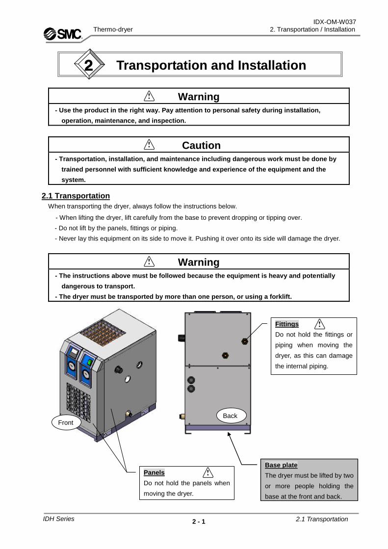
2.1 Transportation
When transporting the dryer, always follow the instructions below.
- When lifting the dryer, lift carefully from the base to prevent dropping or tipping over.
- Do not lift by the panels, fittings or piping.
- Never lay this equipment on its side to move it. Pushing it over onto its side will damage the dryer.
Warning - The instructions above must be followed because the equipment is heavy and potentially
dangerous to transport.
- The dryer must be transported by more than one person, or using a forklift.
Fittings
Do not hold the fittings or
piping when moving the
dryer, as this can damage
the internal piping.
Base plate
The dryer must be lifted by two
or more people holding the
base at the front and back.
Front Back
Panels
Do not hold the panels when
moving the dryer.
Transportation and Installation 2
IDH Series 2.1 Transportation

IDX-OM-W037 Thermo-dryer 2. Transportation / Installation
2 - 2
2.2 Installation
2.2.1 Location
The product should not be used or stored in the following environments.
Environment where the product is exposed to rainwater, moisture vapor, salt water, oil etc.
Locations exposed to excessive dust or particles.
Locations exposed to flammable or explosive gas.
Locations exposed to corrosive gas, solvent, or flammable gas.
Locations exposed to direct sunlight or radiant heat.
Locations where ambient temperature is outside of the following range:
During operation: 2 to 30oC
Storage: 0 to 50oC (when there is no drain
water inside of the piping)
Locations subjected to sudden changes in temperature.
Locations where strong electromagnetic noise is generated (locations where electromagnetic field, strong magnetic field, surge is generated)
Locations where static electricity is produced or discharged through the body of the equipment.
Locations where strong high frequency wave is generated.
Locations where there is a risk of lightning.
Mounted on vehicles, marine vessels, etc.
Locations at altitude of 2,000 meters or higher.
Location where the product is affected by strong vibrations or impacts.
Condition that applies external force or weight causing the product to be damaged.
Locations where the ventilation grille of the equipment can be blocked.
Locations where it could draw in hot air discharged from an air compressor or other dryers.
Condition which has sudden pressure/flow rate change
(2) If using the dryer in the following conditions or environments, please pay attention to safety measures
and confirm with SMC before usage.
- Conditions or environments beyond the stated specifications; outdoors or directly exposed to sunlight.
- In equipment with atomic energy, railway, air navigation, vehicles, medical equipment, equipment
that comes into contact with food or beverages, recreation equipment, emergency stop circuits,
clutch/ brake circuits for press, or safety equipment.
- Uses which may affect people or property, particularly applications in which safety is required.
- If using in an interlock circuit, please use a double interlock by providing a mechanical protection
function in case of breakdown. Carry out regular checks to confirm that it is working as required.
Hot air (such as exhaust
air of compressors)
Ventilation inlet
Ventilation outlet
IDH Series 2.2 Installation

IDX-OM-V018 Thermo-dryer 2. Transportation and Installation
2 - 3
2.2.2 Anchorage
- The product should be installed on a vibration-free, stable, horizontal flat surface.
- Refer to “Chapter 6 6-2 Dimensions” for the unit dimensions.
- We recommend using the anchor bolt set sold separately as accessories.
- If insufficient space is provided for ventilation, the performance will decrease and may cause
breakdown. Please install in the conditions illustrated below.
1 “Necessary installation space” is the space required to ensure performance and to be able to perform daily
checks.
2 “Necessary maintenance space” is the space required to check and repair the dryer if it breaks down.
Please install so that there is sufficient space for servicing.
Necessary installation space 1 Necessary maintenance space
2
(1) Top 600mm or more 600mm or more
(2) Front 600mm or more 600mm or more
(3) Right side 600mm or more 600mm or more
(4) Left side - 600mm or more
(5) Back - 600mm or more
(4) Left side (3) Right side
(2) Front
(5) Back
IDH Series 2.2 Installation

IDX-OM-V018 Thermo-dryer 2. Transportation and Installation
2 - 4
2.2.3 Air piping
- Connection to the inlet and outlet of compressed air should be made removable by using union etc.
- Hold the hexagonal fitting with a spanner, and connect the air piping fittings to the unit.
- Prevent the weight of the piping or unreasonable pressure that is caused in the process of piping from
acting on the product.
- Be careful not to let the vibration of the air compressor transmit.
- If the temperature of compressed air at the inlet side is higher than 50oC, place an after-cooler after the
air compressor outlet line.
- Use a material with low moisture absorption and dust generation, stainless steel, copper, fluoropolymer,
etc. for piping of the compressed air inlet and outlet. Be sure to insulate to the outlet the piping. If piping
is not insulated the controlled outlet air may be affected by piping outside temperature.
- If the air supplied to the dryer contains a lot of oil or foreign matter, this can cause deterioration in
performance. Please install a main line filter or mist separator in the compressed air supply line to this
dryer.
- Use pipes and fittings that are compatible with the operating pressure and temperature. Connect piping
and fittings firmly to prevent air leakage.
- Provide bypass-piping to make it possible to do maintenance without stopping the air compressor.
Be sure to install Valve 1 and Valve 2 as shown in “3.2 Operation”.
Recommend installing a silencer for the discharge of valve 1.
2.2.4 Drain Tube
- A polyurethane tube of 10mm external diameter is attached as a drain tube. The outlet end of the tube
is released to atmosphere.
- Condensate fluid will be drained regularly using compressed air pressure. Fix the draining end of the
tube firmly to prevent it from vibrating during draining.
- Do not use the drain tube in an upward direction.
- Do not bend or crush the drain tube.
Warning
During drainage work, follow your own procedure to ensure the safety of operators (e.g.
wear protective goggles, apron and gloves).
If the drained fluid contains oil, waste liquid treatment is necessary according to local laws
or regulations.
IDH Series 2.2 Installation

IDX-OM-V018 Thermo-dryer 2. Transportation and Installation
2 - 5
2.2.5 Electrical Wiring
Warning Wiring must be done by qualified personnel.
Before wiring, cut off the power supply for safety. Never work under energized conditions.
Ensure a stable power supply with no voltage surges.
Referring to “6-1 Specifications,” make sure to install an electric leakage breaker that has the
correct short circuit capacity and load capacity to prevent electric shock or burnout of the motor of
the refrigerator.
Use a power supply suitable for the specifications of the product.
The equipment should be grounded for safety.
Do not connect the earth to a water pipe, a gas pipe, or a lightening rod.
Do not plug too many leads into a single socket. This may cause exothermic heat or fire.
Do not convert the wiring to use.
In European countries, a ground fault circuit interrupter that meets the IEC standard should be
used for the supply power.
Wiring procedure The power cable should be supplied by others.
1. Remove the panel from the right-hand side of the dryer and lead the power cable from the power cable
entry on the back panel.
2. Lead the signal cable from the signal cable entry in the same way as the power cable.
3. Connect the power cable, earth wire and signal cable to the terminal block. (Tightening torque: 0.6 to 1Nm)
4. Turn the ground fault circuit interrupter on.
5. Mount the cover on the terminal block and mount the panel on the right-hand side.
Signal cable
entry (cable
diameter ø17)
Power supply
cable entry (cable
diameter ø17)
Customer connection side
Terminal connection screw: M3
Width of crimped terminal: 6.5mm or less
Suitable electric wire: 1.25mm2 or more
Cable entry Ground
Power supply
Operation-signal
Fault-signal N.C: Open at “Fault”
Fault-signal N.O: Close at “Fault”
Remote start/stop
LN
IDH Series 2.2 Installation

IDX-OM-V018 Thermo-dryer 2. Transportation and Installation
2 - 6
2.3 Cautions for reinstallation
Caution The product can only be reinstalled in a new location by someone with sufficient
knowledge and experience about the product and its accessories. The following
instructions must be followed.
If the product is moved and reinstalled in a new location after being operated (including trial assessment), the
instructions below must be followed in addition to the instructions in Chapter 2.
Disassembly of the power cable
Cut off the power source when you disassemble the power cable.
Disassembly of the air piping
Remove the seal tape completely after detaching the piping. If any tape is left, it may get inside the
equipment, causing cooling failure.
Compressed air residual pressure release procedure
1. Even while the dryer is removed, only open the bypass piping valve when compressed air is needed.
2. Close the compressed air inlet and outlet valve.
3. Remove the right side panel.
4. Open the residual pressure release cock of auto drain tube, and release compressed air pressure
left inside of the equipment. Refer to the method to clean the auto drain strainer in ”Chapter 4
Periodical maintenance” for detail.
Warning Wiring must be done by qualified personnel.
Before wiring, cut off the power supply for safety. Never work under energized
conditions.
Warning Air piping must be done by qualified personnel.
Separate the compressor from the product for safety before removing the piping. Do not
remove any piping when there is remaining compressed air pressure inside of it.
Case Assembly
Residual pressure release cock
(Open by turning in the direction
indicated by the arrow.)
IDH Series 2.3 Cautions for Reinstallation

IDX-OM-W037 Thermo-dryer 3. Operation/ Shutdown
3-1
Caution
Only personnel with sufficient knowledge and experience about the product and
its accessories should operate or shut down the equipment.
3.1 Check points before operation
Before trial assement, check the following points.
- Installation Condition
By visual inspection check that the equipment is installed in the upright position.
Make sure the product is fixed sufficiently with anchor bolts.
Do not place heavy items on the equipment or apply excessive load to piping etc.
- Wiring Connections
Power cord and earth wire should be connected firmly.
- Drain Tube
Drain tube should be connected correctly.
- Air piping
Check that the compressed air piping is connected correctly and flushing can be done as described
in 3.2. Check that the compressed air inlet and outlet of the dryer, and bypass piping valves, are
completely closed. Also, check that the compressed air inlet and outlet piping is insulated.
3.2 Operation
Start operation according to the procedure below.
(1) With Valve 2 (below) closed, open Valve 1 to perform flushing of the outlet piping.
(2) Turn on the main power supply breaker, then, turn on the ON/OFF switch.
(3) The operation lamp and temperature control PV value and SV value light up. After a moment,
the cooling fan will rotate, and hot air will be exhausted from the upper ventilation outlet.
(4) Set the outlet air temperature of the dryer. (See 3.3 for setting method.)
*If the difference between the set temperature and the ambient temperature is bigger than 5deg.C, the outlet air temperature stability might exceed the specified value. Depending on the operating conditions, the outlet air temperature and air cleanliness will stabilize in approximately 10 minutes.
If the outlet air temperature does not stabilize, set the PID value by auto tuning during operation.
Flushing air
End
equipment
Dryer outlet
End equipment inlet
Valve 1
Valve 2
Pressure increase
Pressure decrease
IDH Series 3.1 Check points before operation
Operation/ Shutdown 3
IDX-OM-W037 Thermo-dryer 3. Operation/ Shutdown
3-2
.
(5) Open Valve 2 and close Valve 1 to start using the compressed air.
(6) Slowly turn the pressure adjustment handle to set the pressure supplied to the end equipment.
The pressure is increased by turning clockwise, or decreased by turning anti-clockwise. The
supply pressure can be adjusted from around 0.15MPa lower than the dryer inlet air pressure.
*The pressure adjustment handle has a lock function. Initially it is in the locked state.
Before adjustment, pull the handle towards you to release the lock. After adjustment, push it
gently inwards to re-lock.
(7) Depending on the condition of compressed air or ambient temperature, the cooling fan may
alternate between start and stop. The operation of the chiller becomes continuous and the pointer
of the evaporating thermometer will indicate the green zone.
(8) Please use as it is in a continuously operating state.
Caution
- Avoid frequently switching the dryer on and off, as this may cause problems.
- The auto drain on this dryer has a Normally Open structure in which the valve closes when
the air pressure is 0.15MPa or above, so until the pressure increases, air will come out of the
drain discharge outlet. Note that the pressure may not increase if the compressor has low air
discharge.
- If the amount of compressed air used varies, the outlet air temperature of the dryer may
fluctuate.
- If the flow rate of the compressed air is less than the specified minimum flow rate, the
temperature sensor may not operate correctly, causing the heater of the product to overheat,
resulting in a halt in the operation with the protective device activating. Either keep
supplying compressed air at the flow rate higher than the minimum specified by using a
valve for flushing, or turn the product OFF.
- The performance display of this device shows the value at the outlet of this device, and is
not guaranteed to be the value at the customer's end equipment inlet. Please control
pressure and the temperature in the end equipment.
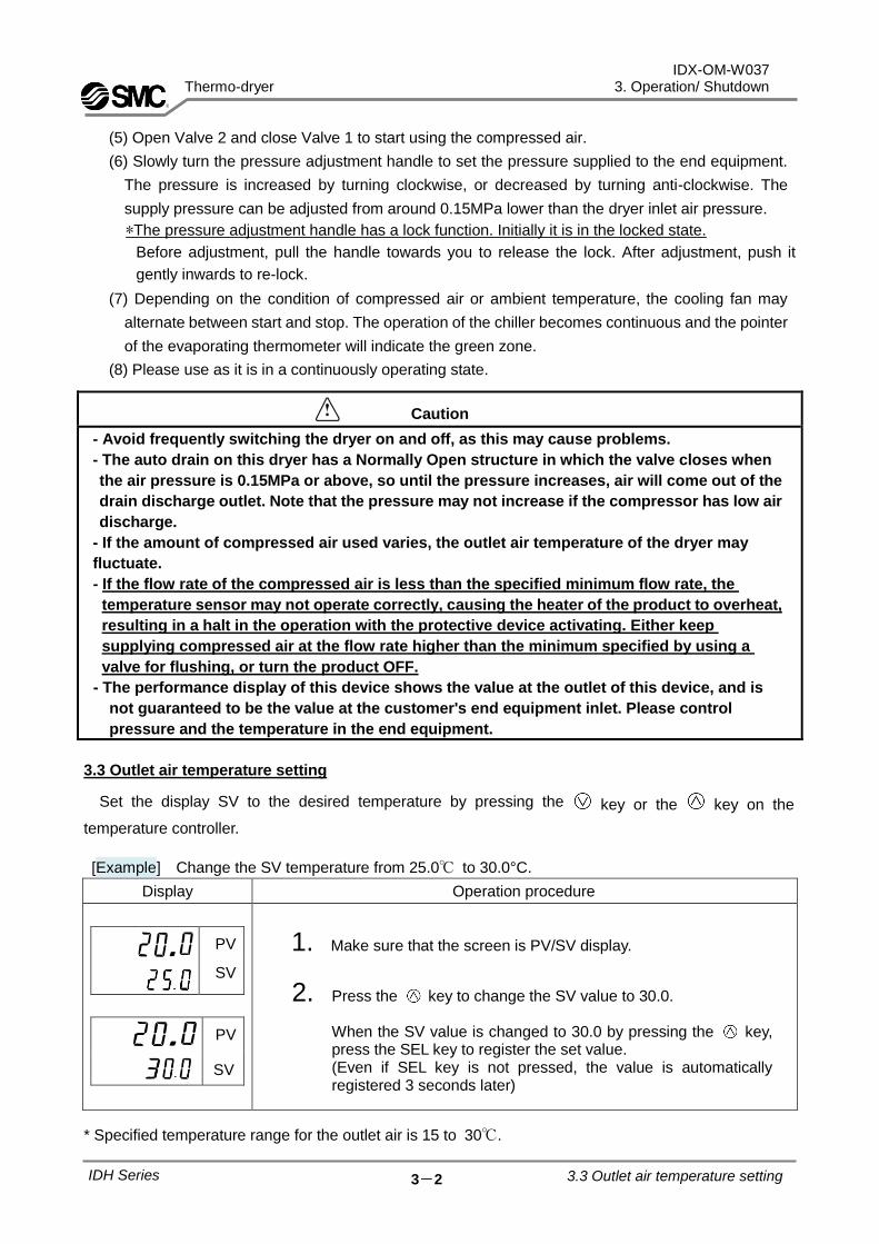
3.3 Outlet air temperature setting
Set the display SV to the desired temperature by pressing the key or the key on the
temperature controller.
[Example] Change the SV temperature from 25.0℃ to 30.0°C.
Display Operation procedure
PV
SV
PV
SV
1. Make sure that the screen is PV/SV display.
2. Press the key to change the SV value to 30.0. When the SV value is changed to 30.0 by pressing the key, press the SEL key to register the set value. (Even if SEL key is not pressed, the value is automatically registered 3 seconds later)
* Specified temperature range for the outlet air is 15 to 30℃.
.
IDH Series 3.3 Outlet air temperature setting
IDX-OM-W037 Thermo-dryer 3. Operation/ Shutdown
3-3
3.4 Shutdown
(1) Turn off the ON/OFF switch.
(2) The operation light and temperature controller display will go out, and operation will stop.
3.5 Cautions for restart
- Wait at least 3 minutes before starting the Thermo-dryer after it has been shut down. Restarting
within 3 minutes may activate the protective circuit so the lights will go out and operation is not
possible.
- When operation is restarted, the temperature controller will retain the set values from the time
when it was stopped immediately before restarting.
3.6 Check points before restart
Check the following points before starting operation. If any abnormailty occurs, stop operation
immediately. Turn off the ON/OFF switch and then turn off the breaker of the main power supply.
- There is no leakage of compressed air.
- The SV value of the temperature controller is set correctly.
- The PV value of the temperature controller is not displaying an error, and is not an abnormal value.
- The air pressure, temperature, flow rate and ambient temperature are within the specifications.
- Moisture is discharged from the drain tube.
- The pointer of the evaporating thermometer indicates the green zone.
- The dryer is not generating any abnormal sound, vibration or smell.
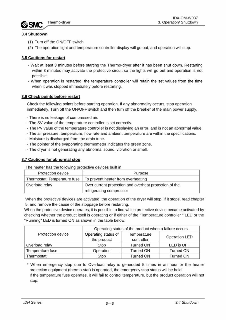
3.7 Cautions for abnormal stop
The heater has the following protective devices built in.
Protection device Purpose
Thermostat, Temperature fuse To prevent heater from overheating
Overload relay Over current protection and overheat protection of the
refrigerating compressor
When the protective devices are activated, the operation of the dryer will stop. If it stops, read chapter
5, and remove the cause of the stoppage before restarting.
When the protective device operates, it is possible to find which protective device became activated by
checking whether the product itself is operating or if either of the "Temperature controller " LED or the
"Running" LED is turned ON as shown in the table below.
Protection device
Operating status of the product when a failure occurs
Operating status of
the product
Temperature
controller Operation LED
Overload relay Stop Turned ON LED is OFF
Temperature fuse Operation Turned ON Turned ON
Thermostat Stop Turned ON Turned ON
* When emergency stop due to Overload relay is generated 5 times in an hour or the heater
protection equipment (thermo-stat) is operated, the emergency stop status will be held.
If the temperature fuse operates, it will fail to control temperature, but the product operation will not
stop.
IDH Series 3.4 Shutdown

IDX-OM-W037 Thermo-dryer 3. Operation/ Shutdown
3-4
Caution
・The protection devices are automatic return type. Please wait at least 3 minutes after
operation stops. If restarted within 3 minutes, the dryer may not operate, or may stop
again.
3.8 Specifications of signals
- Operation signal and fault signals contact type are non-voltage contacts. (Please refer to fig.3.8)
Signals Specifications of the signal mode
Operation-signal
(N.O.) The contact turns on 10 minutes after starting
Fault-signal (N.C.) - Switch on when alarm is generated by temperature controller
- Switch on when stopping operation or the protective device operates
Fault-signal (N.O.) - Switch off when alarm is generated by temperature controller
- Switch off when stopping operation or the protective device operates
- Contact capacity
Resistance load: 2A Induction load: 80VA Lamp load: 100W
Minimum current values: 5 VDC, 2mA
- Fault signal is generated when the protective device of the refrigerating compressor (overload
relay) or the protective device of the heater (thermostat) or alarm of Temperature Controller
operate. Be sure to remove the cause of the fault before restarting the dryer.
1) When the overload relay or thermostat is activated, the equipment stops operation.
2) When the alarm is generated by the temperature controller, the equipment does not stop
operation.
3.9 Remote control
- If remote controlling the dryer, remove the jump wire (#6 and #7) connected to the terminal block,
and connect to the switch, etc.
- Even if remote controlling the dryer, wait 3 minutes before restarting after the dryer has stopped. If
restarted within 3 minutes, it may not operate due to the protective device (overload relay)
operating.
- To prevent breakdown of the motor, frequency of start and stop should be within 5 times an hour.
IDH Series 3.8 Specifications of signals

IDX-OM-W037 Thermo-dryer 3. Operation/ Shutdown
3-5
Fig 3.8 Timing chart of signals
60
min
or
less
End o
f ala
rm o
f
tem
pera
ture
contr
oller
Au
tom
atic r
etu
rn
10
min
Ab
no
rma
l
sto
p 1
Ab
no
rma
l
sto
p 2
Ma
nu
al
rese
tA
uto
ma
tic r
etu
rn
Ab
no
rma
l
sto
p 3
Ab
no
rma
l
sto
p 5
Ala
rm o
f
tem
pera
tur
e c
ontr
oller
Th
e e
qu
ipm
en
t d
on
’t
sto
p o
pe
ratio
n.
10
min
Re
se
t a
co
un
ter
of
Ab
no
rma
l sto
p
60
min
Ab
no
rma
l
sto
p 4
Ab
no
rma
l
sto
p 3
Sta
rtin
g
op
era
tio
n
Ab
no
rma
l
sto
p 1
Ab
no
rma
l
sto
p 4
Ab
no
rma
l
sto
p 2
Op
era
tio
n-s
ign
al
Fa
ult
-sig
na
l
(N.O
)
Fa
ult
-sig
na
l
(N.C
)
Sh
ort
circu
it
Op
en
Sh
ort
circu
it
Op
en
Sh
ort
circu
it
Op
en
IDH Series Fig3.8 Timing chart of signals
【N
ote
s】
(1)
Th
e a
bn
orm
al sto
p w
ill b
e a
uto
ma
tica
lly r
ese
t u
ntil 4
tim
es w
ith
in 6
0 m
inu
tes,
but
the
5th
tim
e w
ill n
ot
be
au
tom
atically
re
set
in t
his
ca
se,
ple
ase
tu
rn o
ff th
e p
ow
er
on
ce in
ord
er
to r
ese
t.
(2)
Wh
en
th
e a
larm
is g
en
era
ted
by t
he
tem
pe
ratu
re c
on
tro
ller, th
e e
qu
ipm
en
t d
oes n
ot sto
p o
pe
ratio
n.

IDX-OM-W037 Thermo-dryer 3. Operation/ Shutdown
3-7
3.10.2 List of key operations
Operation mode
Mode for normal operation. Measured value (PV) or set value (SV) is displayed. Operation starts in this
mode when power is supplied. Set value (SV) can be changed.
The output of the heater (MV) is displayed by switching the screen.
Run mode
Alarm set values can be changed in Run mode.
Channel selection mode
Channel of desired parameters can be selected in the channel selection mode.
Setting mode
Parameters can be set in this mode. Mode can be switched between parameter selection and parameter
setting by pressing the SEL key. In parameter selection, displayed parameters can be switched with
and keys. In parameter setting, set values can be changed with and keys.
IDH Series 3.10 Functions and operation
of temperature controller
Operation
Mode
(Operation
Screen)
PV/SV display PV/MV display
AUTO/
MANUAL
Parameter Operation
control
mode Press
and hold
Channel
selection
mode
Channel
Setup
mode
Parameter ex) ch1 PID
PID PLT PRG MON
SYS MATH
ALM SET
COM DSP CFG PASS
Press
and hold
In the selected channel

IDX-OM-W037 Thermo-dryer 3. Operation/ Shutdown
3-6
3.10 Functions and operation of temperature controller
3.10.1 List of Functions
- The following items can be set by the temperature controller.
No. Function Outline Reference
page
1 Key-lock Keys can be locked to prevent the settings
being changed by mistake. 3.10.4
2 Auto-tuning failure When the outlet temperature is unstable, PID
values are automatically adjusted to the
optimum settings.
3.10.5
3 Manual tuning of PID When the outlet temperature is unstable, PID
values can be manually adjusted to the
optimum settings.
3.10.6
4 Switching of the temperature error alarm
This function changes alarm type or threshold
of temperature deviation, etc. 3.10.7
IDH Series 3.10 Functions and operation
of temperature controller

IDX-OM-W037 Thermo-dryer 3. Operation/ Shutdown
3-8
3.10.3 List of parameters
The temperature controller parameters are shown below.
[Initial values of the temperature controller]
Parameter symbol
Description of parameters
Set value Remarks
IDH*4-*** IDH*6-***
SV Set temperature 25.0 25.0 Unit [oC]
AT Auto-tuning failure oFF oFF “oFF ”: Auto tuning stop/ completed
P Proportional band 5.0 9.0 Unit: %
I Integral time 60 70 Unit: Second
D Derivative time 11.5 13.5 Unit: Second
LoC Key-lock oFF oFF “oFF”: Keys are not locked
A1TP Alarm type 10 10 Upper and lower deviation (with hold)
AL1 Temperature deviation 5 5 Unit: oC
A1HY Alarm hysteresis 1 1 Unit: oC
DLY1 Alarm delay time 20 20 Unit: Second
3.10.4 Key lock LoC (028)
Keys can be locked to prevent the settings being changed by mistake. There are 3 types of setting for key lock.
- oFF: Keys are not locked - ALL: All buttons are locked
-PARA: Operations other than SV change are locked
Channel menu can be displayed.
[Setting example ] Key lock setting
Display Operation procedure
PV
SV
PV
SV
SV
PV
SV
1. Make sure that the screen shows PV/SV display.
2. Press SEL key to return to the operation mode.
3. Press key to change from MAN to LoC.
4. Press SEL key to enter the Loc mode. ("oFF" of the lower level flashes.)
5. Press key to change oFF to ALL.
6. Press SEL key for setting. All keys are locked.
7. Press key to return to PV/SV display.
.
IDH Series 3.10 Functions and operation
of temperature controller

IDX-OM-W037 Thermo-dryer 3. Operation/ Shutdown
3-9
3.10.5 Auto tuning AT (005)
Optimum PID values are automatically set by auto tuning.
[Setting range] - oFF: Stop/ completed - oN: Auto tuning start (normal type) - L-oN: Auto tuning (low PV type) start
Low PV type reduces the overshoot during tuning.
- After the auto tuning is completed successfully, the automatically set PID values are maintained after
the power supply is cut. If the power supply is cut in the middle of auto tuning, the PID values are
not changed and the user should perform auto tuning again.
- The controller switches to ON-OFF operation (= 2-position operation) during auto tuning, so PV will
vary greatly depending on the process. Do not use auto tuning during a process in which a wide
variation of PV is not allowed.
- If SV is changed greatly the PV input type is changed, or controllability is worse because the
controlled item is changed, and the user should perform auto tuning again.
Note) ON-OFF operation is performed during auto tuning. There will be an overshoot for SV.
To reduce the overshoot, choose a low PV type and perform auto tuning.
[Example] Auto tuning setting
Display Operation procedure
PV
SV
PV
SV
SV
PV
SV
1. Make sure that the screen shows PV/SV display.
2. Press SEL key to return to the operation mode.
3. Press key to return to MAN mode.
4. oFF on the lower level flashes after pressing the SEL key.
5. Press key to change from oFF to oN.
6. Press SEL key. Auto-tuning is performed. (AT indicator at the bottom of the left side flashes)
7. Press key to return to PV/SV display.
.
IDH Series 3.10 Functions and operation
of temperature controller

IDX-OM-W037 Thermo-dryer 3. Operation/ Shutdown
3-10
3.10.6 PID manual setting
CH1 PID (control parameter) P Proportion band (050) i Integral time (051) d Derivative time (052)
PID(proportion band / integral time / derivative time) is manually set.
[ Setting range] P: 0.1 to 999.9% I: 0 to 3200 sec. D: 0.0 to 999.9
sec. - PID values are automatically set by auto tuning. - PID values set by auto tuning are considered to be the optimum. To change the response, adjust the
PID values manually. - PID values are set in advance. Use manual tuning only when auto tuning is not stable. - Generally, control becomes unstable if P is too small. Response becomes slow if P is too large.
[Example] For setting P=10.0%, I=100sec., D=20sec.
Display Operation procedure
PV
SV
PV
SV
PV
SV
SV
PV
SV
SV
PV
SV
SV
1. Make sure that the screen shows PV/SV display.
2. Press and hold the SEL key to switch to CH1 (PID control parameters).
3. Press and hold the SEL key. P (Proportion band) is displayed.
4. Press the [SEL] key. (The first digit of the lower level will start flashing.)
5. Press key change 5.0 to 10.0.
6. Press SEL key to set the value.
7. Press key to display i(integral time).
8. Press the [SEL] key. (The first digit of the lower level will start flashing.)
9. Press key change 60 to 100.
10. Press SEL key to set the value.
11. Press key to display d (derivative time).
12. Press the [SEL] key. (The first digit of the lower level will start flashing.)
13. Press key change 11.5 to 20.0.
14. Press SEL key to set the value.
15. Press key to return to PV/SV display.
.
.
.
IDH Series 3.10 Functions and operation
of temperature controller

IDX-OM-W037 Thermo-dryer 3. Operation/ Shutdown
3-11
3.10.7 Switching of the temperature error alarm
1) Change the alarm type and temperature deviation
Set the temperature alarm for SV value.
The figure on the right shows the default value.
- Alarm type A1TP (470): Upper and lower limit deviation
- Temperature deviation AL1 (009):+/- 5℃
- After the change of the alarm type, turn the power off and then on again.
* After changing the temperature alarm the error signal output specifications are changed. (Page 3-4).
* Even if PV is in the alarm triggering range
when power is supplied, the alarms above
do not generate an alarm immediately. An
alarm is generated if the PV value moves
out of the alarm triggering range once and
back into the range again.
[Example] Set the alarm type to upper limit deviation hold.
Display Operation procedure
PV
SV
PV
SV
PV
SV
SV
1. Make sure that the screen shows PV/SV display.
2. Press and hold the SEL key to switch to CH1 (PID control parameters).
3. Press key to display CH5 (alarm parameters).
4. Press the SEL key to enter CH5 (alarm parameters). A1TP (setting of alarm type) is displayed.
5. Press the [SEL] key. (The first digit of the lower level will start flashing.)
6. Press key to change 10 to 8 (upper limit deviation hold).
7. Press SEL key to set the value.
8. Press key to return to PV/SV display.
Set
value Alarm type Operation profile
0 No alarm -
3 Upper limit of the
absolute value
4 Lower limit of the
absolute value
8 Upper limit
deviation
9 Lower limit
deviation
10 Upper and lower
limit deviation
.
IDH Series 3.10 Functions and operation
of temperature controller
+5℃-5℃
LowSV
PV
High

IDX-OM-W037 Thermo-dryer 3. Operation/ Shutdown
3-12
[Example] Setting the temperature deviation within ±3℃.
Display Operation procedure
PV
SV
PV
SV
P
V
SV
SV
1. Make sure that the screen shows PV/SV display.
2. Press SEL key to return to the operation mode.
3. Press key to change MAN to AL1.
4. Press SEL key to enter the AL1 mode. (The first digit of the lower level will start flashing.)
5. Press key to change 5.0 to 3.0.
6. Press SEL key to set the value.
7. Press key to return to PV/SV display.
.
IDH Series 3.10 Functions and operation
of temperature controller
IDX-OM-W037 Thermo-dryer 3. Operation/ Shutdown
3-13
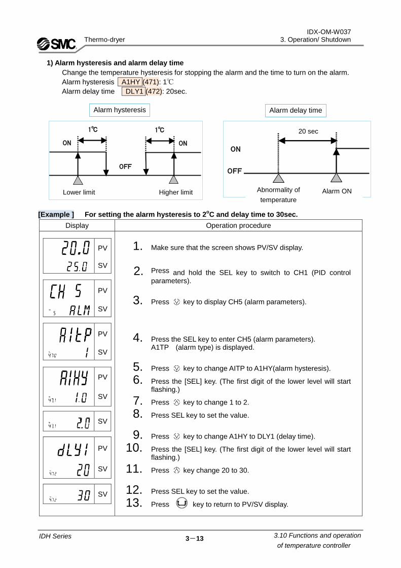
1) Alarm hysteresis and alarm delay time
Change the temperature hysteresis for stopping the alarm and the time to turn on the alarm.
Alarm hysteresis A1HY (471): 1℃
Alarm delay time DLY1 (472): 20sec.
[Example ] For setting the alarm hysteresis to 2oC and delay time to 30sec.
Display Operation procedure
PV
SV
PV
SV
PV
SV
PV
SV
SV
PV
SV
SV
1. Make sure that the screen shows PV/SV display.
2. Press and hold the SEL key to switch to CH1 (PID control parameters).
3. Press key to display CH5 (alarm parameters).
4. Press the SEL key to enter CH5 (alarm parameters). A1TP (alarm type) is displayed.
5. Press key to change AITP to A1HY(alarm hysteresis).
6. Press the [SEL] key. (The first digit of the lower level will start flashing.)
7. Press key to change 1 to 2.
8. Press SEL key to set the value.
9. Press key to change A1HY to DLY1 (delay time).
10. Press the [SEL] key. (The first digit of the lower level will start flashing.)
11. Press key change 20 to 30.
12. Press SEL key to set the value.
13. Press key to return to PV/SV display.
.
IDH Series 3.10 Functions and operation
of temperature controller
ON
OFF
ON
1℃ 1℃
上限下限
Alarm hysteresis Alarm delay time
ON
OFF
20秒
温度異常 警報ONLower limit Higher limit Abnormality of
temperature
Alarm ON
20 sec

IDX-OM-W037
Thermo-dryer 4. Checks and Maintenance
4 - 1
4.1 Daily Check Points Check the following points during normal operation. If you find any problems, immediately stop the operation
and refer to “Chapter 5 Troubleshooting”.
- There is no air leakage.
- The running lamp is on during operation.
- Moisture (condensate fluid) is being discharged from the drain tube.
- The pointer of the evaporation thermometer indicates in the green zone when it is running with
pressurized air supply.
- The pointer of the evaporation thermometer indicates about 3 to 10oC lower than the ambient
temperature when the equipment is suspended with no pressurized air supply.
- There is no abnormal sound or vibration coming from the equipment.
- There are no abnormal smell or smoke coming from the equipment.
4.2 Periodical Maintenance
4.2.1 Cleaning of filter at ventilation port (suction port)
To eliminate dust at the ventilation port (suction port), apply an electrical vacuum or air blow once every
month. Wear protective goggles and a mask to prevent dust from entering the eyes or throat during air
blow.
Part number
Part no. Description Model Qty.
IDF-S1249 Dust Protecting Filter IDH4 1
IDF-S1747 Dust Protecting Filter IDH6 1
4.2.2 Cleaning the auto drain strainer
Remove dust from the auto drain strainer once a month. Use a neutral detergent for cleaning. Also, if the
auto drain becomes heavily polluted replace it with a new one and shorten the next cleaning interval.
4.2.3 Replacement of case assembly
Replace the case assembly with a new one if the auto drain failure continues after cleaning it.
Checks and Maintenance 4
IDH Series 4.1 Daily Check Points

IDX-OM-W037
Thermo-dryer 4. Checks and Maintenance
4 - 2
- When replacing or cleaning parts of the air dryer, be sure to remove the compressed air pressure inside
the air dryer to “0”. Never remove the case assembly when the air dryer is operated or air pressure
remains inside. It is extremely dangerous if compressed air pressure remains inside the air dryer, as
parts may come flying off at speed when loosened, or other unexpected accidents.
- This product has parts that become hot during operation and a power supply with high voltage applied.
There is a risk of burns due to heat or electrification by high voltage. Even when operation is shut down
after switching off the air dryer’s illuminated light, there are also charging lines. When working on the
charged sections, be sure to switch off the earth leakage breaker installed before starting work.
- As some parts of the air dryer will remain hot, there is a risk of burns due to residual heat after the power
is switched off. Do not carry out replacement work until the temperature of these parts has fallen to
50oC or less. Wait approximately 10 to 15 minutes as a guide.
- When carrying out maintenance work on the auto drain strainer and auto drain, there is a risk of
touching the drain fluid during work. Please follow the safety procedure for operators specified by
customer. (Example: carry out work wearing safety glasses, apron and gloves to prevent discharged
fluid from touching the human body.)
- Use neutral detergent solution to clean parts such as the auto drain strainer and auto drain. Never use
solvent such as thinner.
- When removing the outer casing panel or case assembly of the auto drain, wear gloves to prevent
injuries.
[How to clean and replace the auto drain/strainer]
When carrying out maintenance work on the auto drain and auto drain strainer, please follow the steps below.
(1) Removal of the bowl assembly
1) Turn off the illuminated ON/OFF switch.
2) Disconnect the earth leakage breaker at the power supply or unplug the power plug from the socket.
3) Fully close the inlet and outlet valves. Only open the bypass when compressed air is required during
work.
4) Only remove the outer panels when necessary for work.
5) Open the residual pressure release cock at the drain tube connection port to release air and drain fluid
left in the product. (Leave the drain tube connected and hold it so that it does not get twisted.)
6) Take care because condensate fluid may spurt out due to residual air pressure in the product.
7) Remove the drain tube.
8) Pull out the tube while pushing up the drain tube release bush.
- Maintenance of the air dryer should only be carried out by someone with sufficient knowledge and
experience of air dryers and related equipment.
- Before carrying out maintenance, the important warnings in this manual must be thoroughly read
and understood.
Danger
Warning
IDH Series 4.2 Periodical Maintenance

IDX-OM-W037
Thermo-dryer 4. Checks and Maintenance
4 - 3
9) Loosen the vinyl tie fixing the bowl insulation and
remove the bowl insulation.
10) Hold the bowl assembly lightly and pull down
the lock button with thumb.
Then, turn the bowl assembly to the left (or right)
to 30o to align the marks.
Release your thumb from the lock button and
slowly pull down the bowl assembly (vertically)
to remove it.
11) Remove the auto drain strainer and clean it.
Take care not to cut your hand with the sharp edges
of the strainer.
12) Pour solution of neutral detergent into the assembly
and shake it well to clean.
(2) Mounting of the bowl assembly
1) Check the bowl packing for damage such as scratches,
twisting or foreign particles attached to it.
Then, apply grease thinly and fit it in the groove in the
bowl assembly.
2) Fit the auto drain strainer to the case assembly and fit it into the
drain separator body.
Turn it until the lock button clicks.
3) Try to turn the bowl assembly gently and check that it does not turn.
If it turns, start again from fitting the bowl assembly to the body.
4) Attach the bowl insulation to the bowl assembly and fix the bowl
assembly with the vinyl tie.
5) Close the residual pressure release cock and mount the
drain tube and front panel as they were.
6) When reapplying compressed air to the air dryer, first open the
valve on the inlet side slowly.
Check for compressed air leakage and if everything is all right,
open the valve on the outlet side.
7) If the auto drain strainer or case assembly is damaged or very
dirty, replace it with a new one.
IDH Series 4.2 Periodical Maintenance
Lock
button
Bowl
insulation
Drain separator
body
Auto drain
strainer
Bowl
packing
bowl
assembly
Drain tube
Open Close
Residual pressure release cock
Drain tube
release bush
Vinyl tie

IDX-OM-W037
Thermo-dryer 4. Checks and Maintenance
4 - 4
Part no. Description Qty. Applicable model Remarks
AD38-A
Bowl assembly
1 IDH*4,IDH*6
With bowl packing AD37-A 1
IDH*4,IDH*6 (Specification for Option E)
Note) The drain separator body can not replaced.
This bowl assembly product number only applies for products manufactured after March 2019.
Old and new product numbers are not interchangeable.
The product number of the bowl assembly manufactured before February 2019 (dryer SERIAL No.XP
or before), is "AD38"、"AD37".
See SMC WEB catalog for details.
Replacement part of Auto drain strainer and Bowl packing
Part no. Description Qty.
IDF-S0001 Auto drain strainer 1
C32FP-260S Bowl packing 1
Bowl insulation
Part no. Description Qty. Remarks
IDF-S1932 Bowl insulation 1 2 pieces per model
Replacement part of Auto drain
IDH Series 4.2 Periodical Maintenance

IDX-OM-W037
Thermo-dryer 4. Checks and Maintenance
4 - 5
OUTIN
1
4
3
2
5
キャップボルト
1
4
3
2
5
6
4.2.4 Maintenance of filter
For any product with a built in filter, the filter element should be replaced every 2 years.
(1) Micro mist separator with pre-filter element replacement procedure
1. Unscrew the 4 cap bolts and remove the housing. Cap bolts should be removed with a hexagonal
spanner of nominal size 5. (Do not remove anything apart from the insulation of the body (1).)
2. Remove the element from the housing, and the O ring and gasket from the body.
3. Mount a new O ring onto the body.
4. Mount a new gasket onto the body.
5. Insert a new element into the body with the holes upwards.
6. Firmly attach the housing with 4 cap bolts.
7. Carry out checks to confirm there is no air leakage.
(2) Super mist separator element replacement procedure
1. Unscrew the 4 cap bolts and remove the housing. Cap bolts should be removed with a hexagonal
spanner of nominal size 5. ((Do not remove anything apart from the insulation of the body (1).)
2. Remove the element from the housing, and the O ring and gasket from the body.
No Part name Part number
IDH4 IDH6
1 Body - -
2 Element Element assembly AMH-EL250
Element assembly AMH- EL350
3 Gasket
4 O ring
5 Housing Case assembly AM-CA250C-D [For Option E] AM-CA250C-C
Case assembly AM-CA350C-D [For Option E] AM-CA350C-C
6 Auto drain
Cap bolt
IDH Series 4.2 Periodical Maintenance

IDX-OM-W037
Thermo-dryer 4. Checks and Maintenance
4 - 6
3. Mount a new O ring onto the body.
4. Mount a new gasket onto the body.
5. Insert a new element into the body with the holes upwards.
6. Firmly attach the housing with 4 cap bolts.
7. Carry out checks to confirm there is no air leakage.
No. Part name Part number
IDH4 IDH6
1 Body - -
2 Element Element assembly AME-EL250
Element assembly AME-EL350
3 Gasket
4 O ring
5 Housing - -
3
5
2
4
1
IN OUT
5
2
4
3
1キャップボルトCap bolt
IDH Series 4.2 Periodical Maintenance

IDX-OM-W037
Thermo-dryer 5. Troubleshooting
5 - 1
5.1 Troubleshooting
Should any problem occur, consult the following table, and if the problem cannot be solved, shut off the
power supply and then contact your nearest sales office.
Problem Probable causes Action
Air dryer does not
operate and running
lamp does not come on,
even when switch is ON.
Power cord or plug is loosened or
has come out completely.
Connect the power cord and plug correctly.
Ground fault circuit interrupter is
OFF.
Confirm whether a circuit breaker of the correct capacity is
used.
It is not possible to restart the air dryer within 3 minutes after
shutdown. Wait for 3 minutes before restarting.
Resume the operation after resetting the circuit breaker to
ON. If the circuit breaker still trips to OFF, failure of electrical
insulation may have occurred. Remove the power supply and
contact SMC.
During operation, the
light goes out and the
chiller stops.
- Poor ventilation in installation
location.
- Ventilation grille is obstructed
by a wall or blocked with dust.
- The dust filter is blocked
- Improve ventilation by installing ducts etc.
- Install so that the front and the top ventilation ports are far
enough from walls. Page 2-3
- We recommend frequent cleaning of the ventilation grilles.
(Once a month as a guide)
- Ambient temperature is too high Reduce ambient temperature to within the specifications.
- Compressed air flow rate is too
low or not flowing, or is too
high
- Use with flow rate of compressed air within the specifications.
(If the flow rate is too low or not flowing, the heater may overheat,
activating the thermostat.)
- Adjust using the flushing valve. Pages 3-1 and 3-2
- Inlet air temperature is too high Improve the ventilation system around the air compressor, or
reduce the ambient temperature around the air compressor
to lower the temperature of discharge from the compressor.
- Large fluctuation of power
supply voltage.
Install a power supply transformer and review the power
supply to keep the voltage within the allowable value.
Allowable fluctuation of the power supply voltage is
-5~+10% of the rated voltage.
Evaporation
thermometer indicates
higher than green zone.
- Poor ventilation in installation
location.
- Ventilation grille is obstructed
by a wall or blocked with dust.
- The dust filter is blocked with
oil, foreign matter, dust etc.
- Improve ventilation by installing ducts etc.
- Install so that front and back ventilation ports are at least
600mm from walls. Page 2-3
- We recommend frequent cleaning of the ventilation grilles.
(Once a month as a guide)
- Clean or replace the dust filter.
- Ambient temperature is too high Reduce ambient temperature to within the specifications.
- Compressed air flow rate is too
high.
Use with flow rate of compressed air within the specifications.
- Inlet air temperature is too high Improve the ventilation system around the air compressor, or
reduce the ambient temperature around the air compressor
to lower the temperature of discharge from the compressor.
Troubleshooting 5
IDH Series 5.1 Troubleshooting

IDX-OM-W037
Thermo-dryer 5. Troubleshooting
5 - 2
Problem Probable causes Action
Large pressure drop. - The valve in the inlet/ outlet
piping is not fully opened.
- Be sure to use the dryer with the inlet/ outlet piping valve
fully opened.
- The air filter in the compressed
air piping is blocked.
- Replace the element of the air filter on the inlet side or
built-in to this product. Page 4-4
- Compressed air flow rate is too
high.
- Use with flow rate of compressed air within the
specifications.
Moisture is generated
downstream of the
compressed air line.
- The bypass valve is open. - Be sure to use the dryer with the bypass valve fully closed.
- Drainage fluid is not
discharged from the auto drain.
- Check that the drain tube is not trapped or bent.
- Check the auto drain.
- Check the auto drain strainer.
Page 4-1
- The piping converges with
piping from a separate air line
that does not have an air
dryer.
- Install an air dryer in the line that does not have one.
- Separate the two lines so they do not converge.
Compressed air does
not flow.
- The set pressure is too low. - Adjust the pressure with the pressure adjustment handle.
Page 3-2
- The inlet/ outlet valve is
closed.
- Open the inlet/outlet valve.
The air pressure
cannot be set.
- The pressure adjustment
handle is locked.
- Release the lock of the pressure adjustment handle.
Page 3-2
The outlet air
temperature is higher
than the set
temperature
- Air flow rate is too low or not
flowing
- Use with flow rate of compressed air within the specifications.
- Set temperature is too low. - Set the temperature within the setting range.
- Compressed air flow rate is too
high.
- Use with flow rate of compressed air within the
specifications.
- Inlet air temperature is too
high.
- Reduce the inlet air temperature to within the specifications by
reducing the ambient temperature or installing an after cooler.
The outlet air
temperature is lower
than the set
temperature
- Set temperature is too high.
- The air outlet piping is reverse
to the air Inlet piping.
- Temperature fuse is activated.
- Set the temperature within the setting range.
- Perform proper connection of piping.
Page 1-1
The outlet air
temperature
fluctuates.
- Inappropriate P.I.D setting value.
- There is voltage fluctuation.
- The difference between the
outlet air temperature setting
value and the ambient
temperature is greater than
+/-5 deg. C.
- Set P.I.D value manually or by auto-tuning. Page 3-9,3-10
- Connect to a power supply that can supply a steady voltage.
- Please set the outlet air temperature in the range of ambient
temperature +/-5 deg. C.
The temperature
controller buttons do
not work.
- The temperature controller key
lock is on.
- Release the key lock. Page 3-8
The temperature
controller display is:
- The contact of the temperature
sensor terminal is bad, or
wiring has been disconnected.
- Please contact your nearest sales office.
IDH Series 5.1 Troubleshooting

IDX-OM-W037
Thermo-dryer 6. Reference data
6-1
6.1 Specifications
Item Specification IDH4-10∗ IDH4-20∗ IDHA4-23∗ IDH6-10∗ IDH6-20∗ IDHA6-23∗
Note 1) 2)
Operating range
Fluid Compressed air Amount of air processed 100 to 500L/min (ANR) 200 to 800L/min (ANR) Inlet air temperature 5 to 40oC Inlet air pressure 0.3 to 1.0MPa Ambient temperature 15 to 35oC (Relative humidity 85% or less) Outlet air temperature adjustment range 15 to 30oC
Outlet air set pressure range 0.15 to 0.85MPa (The inlet air pressure should be at least 0.15MPa higher than the outlet air pressure.)
Rated conditions
Air flow capacity 400 L/min ANR 600 L/min ANR Inlet air pressure 0.7MPa Inlet air temperature 35oC Ambient temperature 30oC
Note 3) Rated
performance
Outlet air pressure dew point 10oC Outlet air temperature stabillity
Note 4) ±0.1oC
Outlet air temperature display accuracy
±0.5oC (including accuracy of the sensor)
Note 5)
Electrical specifications
Power supply Single phase
100VAC (50/60Hz)
Single phase 200VAC
(50/60Hz)
Single phase 230VAC
(50/60Hz)
Single phase 100VAC
(50/60Hz)
Single phase 200VAC
(50/60Hz)
Single phase 230VAC
(50/60Hz) Operating current 4.2A 2.1A 2.1A 9.4A 4.8A 4.8A Circuit Breaker 10A 5A 5A 15A 10A 10A Compressor input 180/200W 50/60Hz 385/440W 50/60Hz Heater input 220W 420W
Note 6)
Buili-in filter specifications
Nominal filtration rating 0.01μm (99.9% filtration efficiency)Note 6)
Cleanliness of the filter outlet side Particles of 0.3μm or more: 3.5 particles/L(ANR)or less Note 6)
Protective devices
Overcurrent protection Overload relay Heater overheat prevention Thermostat, temperature fuse
Temperature control method Heater operation, PID control Refrigerant type/Refrigerant charge R134a/0.14kg R134a/0.26kg Niose level (reference value) Note 7) 52dB (A) 55dB (A) Weight 26kg 37kg Applicable drain tube O.D. 10mm Coating colour Body panels:Urban white 1 Base:Urban gray 2 IP Class IP2X Overvoltage Category Category / IEC60664-1 Pollution Degree Degree 2 Applicable directive CE Marking
Note 1: ANR refers to conditions of 20°C, atmospheric pressure, 65% relative humidity. Note 2: The upper limit of the outlet air adjustment temperature depends on the operating conditions. Note 3: Rated performance is performance at rated conditions, when power supply voltage is as shown in electrical
specifications. Note 4: In case, the outlet air temperature is set in the range of the ambient temperature +/-5 deg. C. Note 5: Please use the running voltage within -5% to +10% of the rated value. Note 6: Depends on inlet air cleanliness. Filter performance only applies to the type with built-in filter. Note 7: Front:1m, height:1m, stable with no load
6.2 Refrigerant with GWP reference
Reference Data 6
Note1:This product is hermetically sealed and contains fluorinated greenhouse gases.
Note2:See specification table for refrigerant used in the product.
IDH Series 6.1 Specifications

IDX-OM-W037
Thermo-dryer 6. Reference data
6-2
270
297
244
56±2
455
15
15
284207
275±
180
80±
22
4
38970
498
18435
320
240±
2
6.3 Dimensions
IDH∗4
Units: mm
No
te :
Th
e f
ilte
r ch
eck p
ort
a
pp
lie
s t
o t
he
typ
e b
uilt-
in f
ilte
r.
T
he
typ
e w
ith
ou
t b
uilt-
in f
ilte
r d
oe
s n
ot
ha
ve
a c
he
ck p
ort
.
2
76
54
31
PE Ground
N2
L
Power supply
Terminal screw: M3
Suitable wire: 1.25mm or more
Detail of wiring
Connector width: 6.5mm or less
Fault-signal (N.O: Close at "Fault")
Fault-signal (N.C: Open at "Fault")
Operation-signal (N.O)
Remote start/stop
Jumper cord
(No
te)
IDH Series 6.3 Dimensions

IDX-OM-W037
Thermo-dryer 6. Reference data
6-3
306
240±
2
35 184
48
5
15
372
568
15
70
17±2392
80
321
223
30
0±
1
104±
231
244
270
IDH∗6
Units: mm
No
te :
Th
e f
ilte
r ch
eck p
ort
a
pp
lie
s t
o t
he
typ
e w
ith
bu
ilt-
in f
ilte
r.
T
he
typ
e w
ith
ou
t b
uilt-
in f
ilte
r d
oe
s n
ot
ha
ve
a c
he
ck p
ort
.
2
76
54
31
PE Ground
N2
L
Power supply
Terminal screw: M3
Suitable wire: 1.25mm or more
Detail of wiring
Connector width: 6.5mm or less
Fault-signal (N.O: Close at "Fault")
Fault-signal (N.C: Open at "Fault")
Operation-signal (N.O)
Remote start/stop
Jumper cord
(No
te)
IDH Series 6.3 Dimensions

IDX-OM-W037
Thermo-dryer 6. Reference data
6-4
6.4 Electrical Wiring Diagrams
Switch with Lamp
PTC Starter(Start Relay)
Temperature Controller
Temperature Sensor
Solid State Relay
Magnetic Contactor
SSR
PTC
TS
TC
DEVICE NAME
Overload RelayOLR
CM Refrigerating Compressor
Heater
Programable Logic Controller
Ground Fault Circuit Interrupter
Fuse
Thermostat
Terminal Block
THS
Fan Motor for Condenser
ILS
TB
H
F
PLC
GFCI
MC
FM
IDH Series 6.4 Electrical Wiring Diagrams
7654 N.O
遠隔運転
N.C3N.O1 2
運転信号 異常信号
MC
CM
THS
PTC
θTC
MCOLR
MC
PEL N
電源
TB
PLC
PLC
GFCI
ILS
CM
PTC
TS
H
C01
IDH6-10のみ適用
FM
FM1
IDH6/IDHA6のみ適用
F
TC
MC
PRS
P
IDH6/IDHA6のみ適用
SSR
PLC
Power Operation -Signal Fault Signal Remote
For IDH6-10
For IDH6/IDHA6
For IDH6/IDHA6

IDX-OM-W037
Thermo-dryer 6. Reference data
6-5
6.5 Air and refrigerant circuits & function explanation
Air circuit Warm, humid air that enters the dryer is cooled by the cooling compressor. At this time, condensate is separated from the air by the drain separator and automatically discharged. The pressure of the dry air is adjusted by the regulator, and oil mist and minute particles are removed by the micro mist separator with pre-filter and super mist separator Note 1). The dry and highly pure air Note 1) is temperature adjusted by the heater and supplied to the secondary side. Note 1: Does not apply to type without built-in filter Refrigerant circuit The fluorocarbon gas in the refrigerant circuit is compressed by the compressor and cooled by the condenser to become liquid. Then, as it goes through the capillary tube, the refrigerant pressure and temperature decrease. As it goes through the cooler, it draws heat from the compressed air, evaporates rapidly and is sucked into the cooler. The capacity adjustment valve opens if the compressed air is sufficiently cooled, and prevents freezing of the condensate due to over-cooling.
Note 1)
Note 1)Regulator
Drain separator Compressed air inlet Compressed air outlet
Capillary tube
Fan motor
Condenser
Refrigerating compressor
Capacity regulating valve
Cooler
Pressure switch
Evaporation thermometer
Micro mist separator with pre-filter
Super mist separator
Heater
Air pressure gauge
Drain outlet
IDH Series 6.5 Air refrigerant circuit & function explanation
For IDH6 / IDHA6

Thermo-Dryer 7 Service Record
7.1 Service Record 7 - 1
IDH Series
IDX-OM-W037
7 Service Record
7.1 Service Record I t is recommended to keep a maintenance/service record.
Parts No. Description Maintenance/Service Work Description Date

4-14-1, Sotokanda, Chiyoda-ku, Tokyo 101-0021 JAPAN Tel: + 81 3 5207 8249 Fax: +81 3 5298 5362 URL https://www.smcworld.com Note: Specifications are subject to change without prior notice and any obligation on the part of the manufacturer. © 2018 SMC Corporation All Rights Reserved
[Revision]
Revision C:September.2021