
Operation Manual Grain Dryer Controls
322
Operaon Manual 2019 MODELS: MSF - DP - DPSL - DPXSL - DPX4T - DPX8T - DPX12T - DPX16GT Grain Dryer Controls
-
Upload
khangminh22 -
Category
Documents
-
view
2 -
download
0
Transcript of Operation Manual Grain Dryer Controls

Operation Manual
2019 MODELS:
MSF-DP-DPSL-DPXSL-DPX4T-DPX8T-DPX12T-DPX16GT
Grain Dryer Controls


TABLE OF CONTENTS
General Instructions 3 Introduction 3 Use of Manual 3 Safety Code 3 Dryer Labels & Location 4 Serial Tag 6 Control Panel ID Tag 6 Service Information 7 Warranty Procedures 7 Warranty Statement 10 Dryer Controls 13 Overview 13 Navigation 14 Touch Screen Navigation 15 Startup Procedure 18 Stay-Kleen Operation & Maintenance 18 Fresh-Air Intakes 19 Power Switch 19 Safety Circuit 19 Starting Wet Fill 20 Starting Fans 21 Starting Burners 22 Starting Unload 23 Setting Initial Discharge Rate (AUTOMATIC / MANUAL) 23 Setting Discharge Rate after Shutdown 25 General Operation 26 Safety Status 26 Grain Handling Status 27 Fan Status 28 Burner Status 29 Burner Diagnostics 30 Calculate Discharge Rate 31 Sensor Calibration 32 Drying Averages 34 Bushel Counter 35
Trends 36 Limits 37 Notifications 38 Alarms 39 Dryer Configuration 43 Temperature Configuration 44 Ethernet Configuration 46 Dryer Settings 47 Engineering Functions 49 Removable Media 50 Diagnostics 51 Date & Time 52
Sunflower Drying 53 Shutdown Procedure 54 General Maintenance 55 Schematics / Drawings 58 Component Specifications / Charts 102 Component Literature 151

2

GENERAL INSTRUCTIONS 1
General Instructions Introduction Delux Manufacturing Company of Kearney, Nebraska has many years of experience in producing energy saving, high capacity continuous flow grain dryers for both farm and commercial applications. Delux grain dryers are designed and manufactured to produce quality grain at a profit. An ideal balance of holding capacity, air flow, heat and exposure time are provided. All dryers are designed for continuous flow operation. Grain enters the roof section of the dryer where it is preheated as it flows down into the columns where the drying process is started. Twelve (12) inch grain columns on each side of the dryer provide for maximum fuel efficiency and minimum grain moisture differential across the columns. As the grain enters the cooling chamber, outside ambient air is drawn through the warm grain reducing the dryer fuel consumption over competitive conventional dryers, thus completing the drying process and conditioning the grain for a long safe storage life.
Use of Manual This manual provides operation and service recommendations along with a replacement parts list for your Delux grain dryer. It is highly recommended that this manual be read thoroughly by those who are responsible for the operation and maintenance of this machine. Refer to the table of contents for the location of specific information.
Safety Code The design and manufacture of this dryer is directed toward operator safety. Use extreme caution in working around high speed fans, gas fired burners, discharge augers and conveyors, and auxiliary augers and conveyors, which may start without warning when the dryer is operating on automatic controls.
Continued safe, dependable operation of automatic equipment depends to a great degree upon the owner/operator. For a safe dependable drying system, follow the recommendations within the manual and make it a practice to regularly inspect the operation of the unit for any developing problems or unsafe conditions. Keep a clean grain dryer. Do not allow fine material to accumulate on the plenum or cooling floor or a trash fire can result. Checking the dryer at least every 24 hours and cleaning will help prevent problems. The dryer should not be left unattended for extended periods of time!
3

GENERAL INSTRUCTIONS 2
The operator should be aware of all caution, warning & startup labels located on the grain dryer. Make sure all labels are readable and not obscured. Replace the labels as necessary. The location of each label is listed in the below.
Dryer Labels & Location
4

GENERAL INSTRUCTIONS 3
5

GENERAL INSTRUCTIONS 4
Serial Tag The model and serial number of your grain dryer is stamped on an aluminum serial plate located in the Dryer Control Center. Please have this information ready when calling the factory for service and/or ordering replacement parts.
Control Panel ID Tag The Control Panel ID Tag contains important information regarding the electrical and fuel specifications of the grain dryer. It also includes the schematic number that the dryer is wired to. This information is helpful when determining power and fuel requirements from your local utility supplier.
6

GENERAL INSTRUCTIONS 5
Service Information
Our service department will provide consultation on the installation, operation, and maintenance to you. Also, information from you regarding encountered operation or service problems that are not covered in this manual will be greatly appreciated. Delux Manufacturing Company has trained service technicians available to assist you in the event you or your dealer cannot correct a problem. A phone call to Delux Manufacturing Company will provide an answer to your service problems.
Delux Manufacturing Company keeps a complete record of each customer order. However, valuable time can be saved if the information below is provided with your inquiry. It is suggested that you obtain the model number and serial number located in the electrical control box enclosure and keep it located for later reference.
Warranty Procedures
All warranty issues, parts and service requests should be handled through your local dealer. In the case no dealer or representative exists in your area, or a conflict of interest exists with your dealer and/or representative, please contact the department of engineering and service at Delux Manufacturing Company for procedures to follow.
Warranty on all defective parts manufactured by Delux Manufacturing Company will be limited to the specifications set forth by the information provided by Delux Manufacturing Company in its standard limited warranty policy. Warranty on all defective parts not manufactured by Delux Manufacturing Company is limited to the warranties provided by that part’s manufacturer. This includes, but is not limited to, electric motors, gear heads, valves, regulators and other parts. Delux Manufacturing Company is not responsible for defective parts not of its manufacture.
Authorization for credit or replacement under warranty for defective parts or material manufactured by Delux Manufacturing Company will not be issued unless strict compliance is given to the warranty parts return procedures listed below. When contacting Delux Manufacturing Company in regard to the policies and procedures set forth in this manual, direct all correspondence and calls to the department of engineering and service at Delux Manufacturing Company. Except as specified previously, refer all warranty claims to your dealer.
Warranty parts return and credit procedure:
1) Delux Manufacturing Company must be notified by writing or phone within fifteen (15) days after an alleged failure of a part manufactured by Delux Manufacturing Company is discovered. Failure to give such notice within the time specified shall be deemed an admission by the purchaser that the product is as represented and warranted by Delux
7

GENERAL INSTRUCTIONS 6
Manufacturing Company and free from all defects and Delux Manufacturing Company shall be released from any and all claims arising out of or in connection with the sale of the part or product.
2) Upon notification from purchaser that a part manufactured by Delux Manufacturing Company has allegedly failed, the failure is covered by the standard limited warranty and the original warranty registration card is on file with Delux Manufacturing Company at its Kearney, Nebraska headquarters, arrangements will be made by Delux Manufacturing Company to ship the replacement part to purchaser with freight charged at the standard ground shipping rate.
3) Once the replacement part has been shipped, purchaser will receive an invoice for the value of the equipment shipped plus the shipping charges. Purchaser must then fully complete a return parts tag identifying the alleged part failure and return said tag along with the allegedly failed part to Delux Manufacturing Company with freight prepaid by purchaser. No warranty credit shall be given to purchaser on allegedly failed parts that are not returned to Delux Manufacturing Company within thirty (30) days from date of the discovery of the alleged failure or within fifteen (15) days from the shipping date indicated upon the invoice sent with the replacement part, whichever date is later. Purchaser must use proper packing material to ensure against damage during shipping. Any shipping damage caused by improper packing is not covered under the standard limited warranty.
4) The invoice for the replacement part plus the freight charge remains payable by purchaser until such time as the allegedly failed part has been returned with a completed return parts tag attached and the part has been inspected by Delux Manufacturing Company to determine if the warranty claim is valid. Purchaser will then receive notification from Delux Manufacturing Company as to the receipt of the defective part and Delux Manufacturing Company’s findings on the warranty claim within a reasonable time thereafter.
5) If the part is found to be defective by Delux Manufacturing Company, Delux Manufacturing Company shall credit the amount owed under the invoice sent with the replacement part except for the freight incurred in shipping the replacement part to purchaser.
6) If the part returned by purchaser is found by Delux Manufacturing Company to be functional and operational and in compliance with the manufactured specifications, it will be returned upon request to purchaser at purchaser’s cost. If no request is received by purchaser, the part shall be destroyed after a period of ten (10) days. Delux Manufacturing Company’s charges for inspection of a non-defective Delux Manufacturing Co part will be subject to the standard hourly rate and zone charges.
7) No non-Delux Manufacturing Company labor or non-Delux Manufacturing Company replacement part will be authorized without first an estimate of the cost of part and
8

GENERAL INSTRUCTIONS 7
labor provided to Delux Manufacturing Company. Deviations from this estimate will be solely at the purchaser or dealer’s cost.
9

GENERAL INSTRUCTIONS 8
DELUX MANUFACTURING COMPANY STANDARD LIMITED WARRANTY
DELUX MANUFACTURING COMPANY’S WARRANTY OBLIGATIONS ARE LIMITED TO THE TERMS SET FORTH BELOW:
DELUX MANUFACTURING COMPANY WARRANTS TO THE ORIGINAL PURCHASER THAT IF ANY PART MANUFACTURED BY DELUX MANUFACTURING COMPANY IS PROVEN TO BE DEFECTIVE IN MATERIAL OR WORKMANSHIP WITHIN ONE (1) YEAR FROM DATE OF ORIGINAL INVOICE FROM DELUX MANUFACTURING COMPANY AND PURCHASER FOLLOWS THE ABOVE WARRANTY PARTS AND CREDIT PROCEDURE, DELUX MANUFACTURING COMPANY WILL, AT ITS OPTION, EITHER REPLACE OR REPAIR SAID PART AT ITS COST. THIS STANDARD LIMITED WARRANTY DOES NOT APPLY TO ANY DAMAGE RESULTING FROM NEGLIGENT USE, MISUSE, ACCIDENTAL DAMAGE, ABNORMAL OR UNUSUALLY HEAVY USE, NORMAL WEAR AND TEAR, NEGLECT, ABUSE, ALTERATION, IMPROPER INSTALLATION, UNAUTHORIZED REPAIR OR MODIFICATION, POOR OR IMPROPER MAINTENANCE OR USE BEYOND RATED CAPACITY. THIS WARRANTY AND THE REMEDY SET FORTH ABOVE ARE EXCLUSIVE AND IN LIEU OF ALL OTHERS, WHETHER ORAL OR WRITTEN, EXPRESSED, IMPLIED OR STATUTORY. DELUX MANUFACTURING COMPANY SPECIFICALLY DISCLAIMS TO THE MAXIMUM EXTENT PERMITTED BY LAW ANY AND ALL IMPLIED WARRANTIES OR CONDITIONS AS TO THE PRODUCTS OR ANY OTHER MATTER WHATSOEVER. IN PARTICULAR, BUT WITHOUT LIMITATION, DELUX MANUFACTURING COMPANY SPECIFICALLY DISCLAIMS ANY AND ALL IMPLIED WARRANTIES OR CONDITIONS OF SATISFACTORY QUALITY, MERCHANTABILITY, FITNESS FOR A PARTICULAR PURPOSE, DESCRIPTION, NON-INFRINGEMENT OF THIRD PARTY RIGHTS, ANY ADVICE, INSTRUCTION, RECOMMENDATION OR SUGGESTION PROVIDED BY AN AGENT, REPRESENTATIVE OR EMPLOYEE OF DELUX MANUFACTURING COMPANY REGARDING OR RELATED TO THE CONFIGURATION, INSTALLATION, LAYOUT, SUITABILITY FOR A PARTICULAR PURPOSE, OR DESIGN OF SUCH PRODUCT OR PRODUCTS, OR ANY OTHER WARRANTY ARISING FROM A COURSE OF DEALING OR USAGE OF TRADE. DELUX MANUFACTURING COMPANY RESERVES THE RIGHT TO MAKE DESIGN OR SPECIFICATION CHANGES AT ANY TIME. THIS STANDARD LIMITED WARRANTY DOES NOT APPLY TO, AND DELUX MANUFACTURING COMPANY MAKES NO WARRANTY TO THE PURCHASER WITH REGARD TO, PARTS AND PRODUCTS NOT MANUFACTURED BY DELUX MANUFACTURING COMPANY. IN THE EVENT AND TO THE EXTENT THAT APPLICABLE LAW DOES NOT ALLOW THE EXCLUSION OF IMPLIED WARRANTIES, THE ABOVE EXCLUSION WITH REGARD TO IMPLIED WARRANTIES MAY NOT APPLY. DELUX MANUFACTURING COMPANY SHALL NOT BE RESPONSIBLE OR LIABLE FOR ANY LOST PROFITS, DIRECT, INDIRECT, UNFORESEEABLE, SPECIAL, INCIDENTAL OR CONSEQUENTIAL DAMAGES HOWEVER CAUSED AND WHETHER OR NOT DELUX MANUFACTURING COMPANY WAS ADVISED OF THE POSSIBILITY OF SUCH DAMAGES, WHETHER BASED ON CONTRACT, IN TORT OR ANY OTHER LEGAL THEORY. THE REMEDY STATED HEREIN SHALL BE THE SOLE AND EXCLUSIVE REMEDY AVAILABLE UNDER THIS WARRANTY. DELUX MANUFACTURING COMPANY ASSUMES NO RESPONSIBILITY FOR FIELD MODIFICATIONS OR ERECTION DEFECTS WHICH CREATE STRUCTURAL OR STORAGE QUALITY PROBLEMS, MODIFICATIONS TO THE PRODUCT NOT SPECIFICALLY COVERED BY THE CONTENTS OF THE DELUX MANUFACTURING COMPANY SERVICE MANUAL WILL NULLIFY ANY PRODUCT WARRANTY THAT MIGHT HAVE BEEN AVAILABLE OTHERWISE. NO DELUX MANUFACTURING COMPANY DISTRIBUTOR, RESELLER, DEALER, AGENT OR EMPLOYEE IS AUTHORIZED TO MAKE ANY MODIFICATIONS, EXTENSION OR ADDITION TO THIS WARRANTY. DELUX MANUFACTURING COMPANY SHALL NOT BE RESPONSIBLE FOR ANY CHARGES INCURRED IN THE REPAIRING OR SERVICING OF ANY DELUX MANUFACTURING COMPANY PRODUCT OR PART EXCEPT AS SUCH REPAIRS ARE MADE BY AUTHORIZED DELUX MANUFACTURING COMPANY FIELD SERVICE PERSONNEL OR AS APPROVED IN WRITING FROM DELUX MANUFACTURING COMPANY. PRIOR TO INSTALLATION, PURCHASER IS RESPONSIBLE FOR RESEARCHING AND COMPLYING WITH ALL FEDERAL, STATE AND LOCAL STATUTES, REGULATIONS AND/OR CODES WHICH MIGHT APPLY TO THE LOCATION AND INSTALLATION OF THE DELUX MANUFACTURING COMPANY PRODUCT.
10

GENERAL INSTRUCTIONS 9
Additional disclaimer of warranty:
All manufacturer label products not manufactured by Delux Manufacturing Company are excluded from coverage under the Delux Manufacturing Company standard limited warranty.
No electric motor warranty:
Delux Manufacturing Company’s standard limited warranty does not cover any and all electric motors used by Delux Manufacturing Company in its products. Purchaser’s sole claim for warranty on these electric motors lies with the motor’s manufactures. In such event, purchaser’s dryer service manual contains a list of the motor manufacture’s service centers where all further inquiries regarding the motor and its warranty should be placed. Under no circumstances whatsoever will Delux Manufacturing Company be liable for an unauthorized electric motor repair by a local motor shop or electrician.
Return merchandise procedures:
1. CONTACT: DELUX MANUFACTURING COMPANY
4650 AIRPORT ROAD P.O. BOX 1027 KEARNEY, NE 68848-1027
PHONE: 308-237-2274 TOLL FREE: 800-658-3240 FAX: 308-234-3765 WEB: http://www.deluxmfg.com
Ask for an RMA #. In that request, identify the merchandise you wish to return, its condition and the invoice on which it was originally billed.
2. After receipt of the return parts tag, ship the item(s) with prepaid freight along with the return parts tag to Delux Manufacturing Company. A 15% restocking fee will be charged on all merchandise returned thirty (30) days after the original date of purchase.
3. Once the merchandise has been received and inspected by Delux Manufacturing Company, if appropriate a credit will be issued to your account.
4. Any merchandise returned that has been used or abused will not receive a credit to your account. Shipments of incorrect merchandise due to miss-ordering by the purchaser are also subject to a 15% restocking fee.
Out of warranty service:
Dryers requiring Delux Manufacturing Company repair work will be repaired at the standard service charges (hourly labor charge, trip charge (includes cost of lodging, meals, and mileage costs), plus parts). The repaired parts will carry a thirty (30) day limited warranty. The same exclusions and limitations of the Delux Manufacturing Company standard limited warranty policy referenced above also apply to this thirty (30) day limited warranty.
11

GENERAL INSTRUCTIONS 1 0
Terms:
Delux dryers requiring service for customers who have an established line of credit will be invoiced for services rendered. Customers not having an established line of credit will be on cash in advance or cash on completion of service basis. All service or repair work rendered by authorized Delux service personnel must be invoiced through an existing authorized Delux Manufacturing Company dealer.
12

DRYER CONTROLS 1
Dryer Controls
Overview This manual covers the controls and operation of all Delux Grain Dryers equipped with the MoistureLinkG2TM Dryer Control System. This manual should be read in its entirety to familiarize the user with the functionality of the dryer controls. The intent of this manual is to guide the user in the operation of the control; however it is recommended that the user consult a qualified dealer technician or the factory before servicing any components that are part of this system.
Shutdown & lockout power before removing any guards or covers to access mechanical parts that may be a part of this system.
The control of your grain dryer requires the operator to interact with the mechanical toggle switches as well as the touch screen (HMI/Human Machine Interface) of the DCC (Dryer Control Center). This control system utilizes a combination of a PLC/HMI, discrete input/output cards, analog input/output cards and interface relays.
The control voltage of the system is a combination of 24VDC and 120VAC. The 24VDC is commonly used as power through switches and auxiliary contacts and then used as an input returned back to the PLC. It is also used as output from the PLC to drive 24VDC interface relays. 120VAC is used to power the flame system(s), DC drive, temperature control & motor starter coils. Both 24VDC & 120VAC wires from the DCC are connected to wires coming from the high voltage ESC (Electrical Service Center).
13

DRYER CONTROLS 2
A
B
C
D
E
F
G
Navigation
A) MAIN POWER LIGHT: When illuminated, this indicates that both the DCC (Dryer Control Center) and ESC (ELECTRIAL SERVICE CENTER – HIGH VOLTAGE) have power.
B) POWER SWITCH: Turning the switch to RUN position energizes control panel power and the HMI screen. Momentarily switching to START position will prove the PRIMARY SAFETY circuit to start the dryer. The GREEN light is illuminated when the switch is in the RUN or START position.
C) FAN OPERATION SWITCH: Turning the switch to RUN and momentarily to START will start the fans inside the dryer. Hold in the START position until all fans have
DCC Control Panel
14

DRYER CONTROLS 3
I
A B C D E F G
H
J
K
L
M
N
O
P
Q
started. After all fans have started return the switch to the RUN position. The GREEN light is illuminated when the switch is in the RUN or START position.
D) LOAD OPERATION SWITCH: Turning the switch to the ON position energizes the dryer fill circuit. This includes any auxiliary load augers. The GREEN light is illuminated when the switch is in the ON position.
E) UNLOAD OPERATION SWITCH: Turning the switch to the ON position energizes the dryer discharge circuit. This includes any auxiliary discharge augers. Turning the switch to the METER position will start the metering system and the feedrolls will begin to turn. The GREEN light is illuminated when the switch is in ON or the METER positions.
F) BURNER OPERATION SWITCH: Turning the switch to the ON position energizes the burner control circuit and the dryer will start the ignition sequence.
G) USB PORT: This port is used to download drying and diagnostic data from the dryer.
The HOME SCREEN shows the operator an overview of the grain dryer. The screen is touch sensitive and the operator interacts with the system by touching the desired field or variable to change it. Fields that are GREEN are fields or variables in which the user may change. Fields that are ORANGE are fields or variables in which the user may not change and are READ-ONLY.
15

DRYER CONTROLS 4
A) PRIMARY SAFETY CIRCUIT: When illuminated, this indicates that the primary safety circuit is proven.
B) BURNER SAFETY CIRCUIT: When illuminated, this indicates that the burner safety
circuit is proven.
C) DRYER FILLL: When illuminated, this indicates that the dryer fill system is running and the high/low fill switch is in the LOW position. If the LOAD OPERATION switch is in the ON position and the light is not illuminated the switch is in the HIGH (full) position.
D) DRYER DISCHARGE: When illuminated, this indicates that the UNLOAD
OPERATION is on and the dryer is discharging grain.
E) AIR PROVEN: When illuminated, the fan(s) have proven airflow.
F) BURNER READY: When illuminated, the 30 second purge cycle has completed and the burner(s) are ready to be lit.
G) BURNERS PROVEN: When illuminated, burner(s) have proven flame.
H) PLENUN TEMP: The top temperature (ORANGE) is the current temperature inside the plenum. The bottom boxed number (GREEN) is the current set point for the plenum temperature. Adjust the plenum temperature set point by pressing it and entering a new value.
I) CURRENT DATE/TIME: This is the current system date and time. Since the dryer logs and graphs are based on this date and time, it is important that they are adjusted before the beginning of each drying season.
J) MODE: This indicates the drying mode the dryer is currently in. To change the mode press the field on the screen and use the UP/DOWN arrows to toggle between modes.
K) MOISTURE OUT: The (ORANGE) value on the left indicates the temperature of the grain exiting the dryer. The (ORANGE) value on the right indicates the instantaneous moisture value of the grain exiting the dryer. The bottom boxed number (GREEN) is the current set point for moisture exiting the dryer. Adjust the moisture set point by pressing the field on screen and using the UP/DOWN arrows to toggle between set points. Set points can only be set in 0.5% increments.
16

DRYER CONTROLS 5
L) MID-GRAIN TEMPERATURE: The (ORANGE) value indicates the grain temperature in the column, midway through the dryer. This value plays a significant role in keeping the desired moisture leaving the dryer. The (GREEN) boxed value is the current set point of the mid-grain temperature when the dryer is in AUTO mode only. When the dryer is in MANUAL mode the mid-grain temperature is still available to view but has no effect on final moisture.
M) DISCHARGE RATE: The discharge rate is shown in (ORANGE) and is a value of
percent of total output. It is also shown as a BPH rate relative the maximum discharge rate of the dryer. When the dryer is in AUTO mode, the rate is controlled by the automatic moisture control system and will change accordingly. When the dryer is in MANUAL mode, UP/DOWN arrow keys appear and the percent of total output rate can be increased or decreased. The discharge rate can also be adjusted by pressing the (GREEN) boxed value and entering a numeric value.
N) MAIN MENU KEY: Press this key to access the main menu for all other dryer
functions.
O) TRENDS KEY: Press this key to access the trend screen.
P) AVERAGE KEY: Press this key to access the moisture averages screen.
Q) HELP KEY: No function, for future firmware release.
The ALARM screen will give the operator a list of the most current ALARM activations. In the event of a dryer shutdown, the ALARM screen would give the reason for a shutdown. The time and date of each alarm is also stamped at the time of the alarm activation. To clear an alarm, press on the ALARM field and ACK or CLR the current alarms. The 4 HR TREND window gives the operator the opportunity to review the past four hours of the moisture output and graphs it against the desired moisture set point.
17

STARTUP PROCEDURE 1
Startup Procedure
Safety Considerations A clean dryer is an efficient dryer. Thorough inspection of the plenum heat chamber and vacuum cooling chamber and cleaning if necessary is recommended at least every 24 hours of operation. Install burner covers provided with dryer before cleaning to reduce amount of dust and foreign material falling into fan hubs and burners. Clean screens on inside of plenum
heat chamber, then remove dust and foreign material from plenum floor. Inspect cooling chamber and clean if necessary. Check the outside screens and clean if necessary. The area around dryer should also be kept clean. Accumulation of material on the heat deck, inner screens or cooling floor can lead to dryer fires! Do not assume that the dryer is staying clean on the inside. Check the dryer regularly and clean as needed. Do not leave the burner covers in the plenum while drying. They can interfere with the flow of air and foreign material through the Stay-Kleen system (see below). Stay-Kleen Operation & Maintenance
The Stay-Kleen design provides a path for the fines, dust and foreign material that enters into the heat and cool chambers of the dryer to escape back into the grain flow and discharge. Certain drying conditions and poor grain quality will affect the efficiency of the Stay-Kleen system. There are adjustable filler plates added to each side of the cooling floor cover. These allow you to narrow the gap between the center walk plate and the screen to keep larger, lighter weight foreign material from being drawn back up into the cooling section. The default setting for these plates is ¼” gap. Different grain conditions may influence the need to adjust this gap. Delux does not recommend more than a ¼” gap.
The Stay-Kleen system operates best with the fresh air intakes open as far as possible (See item 2 below). If it is necessary to close the intakes some to better cool the grain, be extra attentive to the cleanliness of the inner chambers. 1) Check dryer thoroughly before starting
1.1. Check and clean screens and plenum and cooling chambers. 1.2. Check metering system for foreign material and clean. 1.3. Check augers and auxiliary equipment for correct rotation.
18

STARTUP PROCEDURE 2
2) Fresh-air intake ports 2.1. Fresh-air intake ports are provided to allow fresh air to flow directly to the fan(s). The
fan(s) cannot receive enough air directly through the grain being cooled so fresh-air intake ports are provided. These ports allow the operator to have more control over the outgoing temperature of the product being dried.
2.2. Settings: Open the doors that are labeled ‘Full Open’, located directly on the fan(s), full open. Open other doors labeled ‘As Needed’ as far as possible while still cooling the grain as needed. When the grain is not cool enough close the doors down that are not located directly on the fan(s) - when grain is too cool open these doors. Keep all doors that are being adjusted the same as each other. When drying low moisture products, it may be necessary to adjust the plenum temperature down to get the product as cool as desired.
2.3. CAUTION: Having the fresh air intake doors closed too far can decrease capacity and cause excessive heat which could result in uneven moisture content of discharge grain and in extreme conditions, fires on the heat deck or cooling floor.
3) Turn all switches to the OFF position
4) Turn dryer main disconnect ON
4.1. Main power light will illuminate.
5) Turn on POWER SWITCH to the RUN position 5.1. Move the POWER SWITCH to the RUN position. Wait for the SAFETY STATUS screen
to appear on the HMI screen.
19

STARTUP PROCEDURE 3
5.2. After the screen appears, move and hold the POWER SWITCH to the START position. This proves the PRIMARY SAFETY circuit so the dryer can start. If the PRIMARY SAFETY circuit doesn’t check, the message “CHECK SAFETY CIRCUIT! TURN ALL SWITCHES TO OFF POSITION” will appear. Check to make sure that all the PRIMARY SAFETY indicators are illuminated and all of the switches (other than the power switch) are in the OFF position.
5.3. If the PRIMARY SAFETY circuit checks the HMI screen displays the HOME PAGE is
shown.
6) To fill with wet grain 6.1. Move LOAD OPERATION switch to the ON position. The load system circuit will be
activated and will fill the dryer. When the dryer is full of grain, the high grain shutdown will shut off all of the loading equipment automatically. (Leave LOAD OPERATION in "ON" position.) The filling cycle will continues as long as the LOAD OPERATION switch remains ON and the dryer is discharging grain. The DRYER FILL indicator on the HOME SCREEN will be illuminated when the fill cycle is in process.
7) To start fan(s) 7.1. Move and hold the fan switch to the START position until all fans start, then release
to the RUN position. A three second delay between fans starting should be expected.
20

STARTUP PROCEDURE 4
AIR PROVEN indicators will come on as each air switch proves. The PLENUM PURGING indicator will come on after fan(s) prove.
7.2. Once the 30 second purge cycle is complete, the BURNER READY indicator will be on.
The BURNER SAFETY circuit must be proven for the dryer to start the PURGE CYCLE. If the dryer will not go into the PURGE CYCLE check the HIGH LIMIT indicator or LOW GRAIN switches.
7.3. When the dryer completes the 30 second purge cycle, the HMI will return to the
HOME SCREEN automatically.
8) To start burner(s) 8.1. Turn on fuel supply to the dryer.
8.1.1. NATURAL GAS - Open manual valve. 8.1.2. LIQUID PROPANE - Open at supply tank. Open quick acting valve and ball valve
on dryer. 8.1.3. LP GAS NOTE: Dryer must be started on vapor until internal vaporizer is warm,
then switched to liquid. Tank must have both vapor and liquid draw available to dryer.
21

STARTUP PROCEDURE 5
8.2. Move BURNER OPERATION switch to the ON position.
8.3. After a short delay, the ignition firing light(s) will come on and the gas solenoid valves
are energized. (If equipped with a manual Maxon valve, the handle should always be back towards the dryer to start. When energized, pull the handle forward until ‘Open’ is indicated.)
8.4. Within a few seconds the burner proven indicator(s) will come on showing burner(s) have proven flame. As burner proven indicator(s) come on the ignition firing light(s) will go off.
8.5. Adjust fuel pressure 8.5.1. Natural Gas - 8 to 12 PSI - Do not exceed 20 psi. 8.5.2. LP Gas - 10 to 12 PSI - Do not exceed 20 psi.
8.6. Adjust plenum set point for desired operating temperature. Press the set point field on the HMI screen to change plenum temperature. (See table below for plenum temperatures for various crops.)
SUGGESTED PLENUM TEMPERATURES BARLEY 120-140 °F CORN 190-210 °F FLAX 120-130 °F MILO 160-180 °F MUSTARD SEED 110-130 °F OATS 120-140 °F RICE 115-125 °F RYE 120-140 °F SOYBEANS 140-160 °F SUNFLOWER 120-130 °F WHEAT 160-180 °F
22

STARTUP PROCEDURE 6
9) To start unload 9.1. Turn the UNLOAD OPERATION switch to ON to start the discharge auger and other
auxiliary handling equipment. Turn the switch to METER to active the DC metering roll system.
10) Setting discharge rate (AUTOMATIC/MANUAL MODE) 10.1. For the first batch of grain through the dryer at harvest, the operator should
input the approximate incoming moisture, temperature, desired output moisture, plenum temperature and commodity. The PLC then uses this information to start a MANUAL DRYING CYCLE through the dryer. After a complete cycle of grain has entered and exited the dryer, the operator will determine whether the discharge moisture content is stable and close enough to the target discharge moisture. If so, the operator can proceed to switching the system to AUTO mode. After the dryer is placed into AUTO mode, the controller captures the mid grain temperature and will vary the output from there on.
10.2. Press the MAIN MENU icon at the bottom of the HMI screen to view the MAIN MENU. Then press the CALCULATE SCREEN. The screen below is shown.
10.3. Enter the variables and press the CALCULATE key at the bottom of the screen.
23

STARTUP PROCEDURE 7
10.4. Press YES to start the manual drying cycle or NO to edit the variables or
abandon the calculation. 10.5. The operator may also use this calculation when the dryer isn’t responding to
efforts to effectively control the desired moisture output in AUTO mode. 10.6. Allow the dryer time to completely process the grain that was at top of the
dryer when the cycle was started. This can be calculated by using the BPH RATE that the dryer used to start the cycle and the total holding capacity of the dryer. For example, if the dryer started a cycle at the rate above of 563.3 BPH and the holding capacity for the dryer is 1000 bushels, the minimum time before the operator would want to make any adjustment would be 1.8 Hours or about 108 minutes (1000 Bu. / 563.3 BPH = 1.77) (For listed holding capacities, refer to literature or specification charts)
10.7. Once the dryer has been allowed to run a complete cycle of grain through, and the difference between the AVERAGE MINUTE MOISTURE and SET POINT MOISTURE is 0.5% or less, the dryer can be switched to AUTO mode from the HOME SCREEN.
10.8. If the moisture difference is larger than 0.5% adjust the discharge rate in MANUAL mode from the HOME SCREEN using the UP/DOWN arrow keys. Do not make more than a 10% speed rate adjustment at one time. Repeat until the moisture difference is 0.5% or less and the dryer is able to be placed in AUTO mode.
10.9. Another way of determining that the discharge moisture has “bottomed out” is by looking at the 4 HR TREND. When the red line (discharge moisture content) has flattened out, the rate can be changed. Adjust the discharge rate manually to get closer to the target moisture or the dryer can be placed in AUTO mode.
24

STARTUP PROCEDURE 8
11) Setting discharge rate (MANUAL MODE) 11.1. Follow the steps outlined in step 10 (above) except leave the dryer in MANUAL
mode when the desired output moisture has been achieved. Adjust with the UP/DOWN arrow keys on the HOME SCREEN as need for incoming moisture fluctuations.
12) Setting discharge rate (AFTER SHUTDOWN) 12.1. If the dryer had been running in AUTO mode prior to a shutdown, the mid grain
set point is still established and the dryer can startup in AUTO mode. Once the burner switch is on and the plenum has reached the desired operating temperature, the LOAD OPERATION switch can be turned METER. The feedrolls will slowly start to turn as the grain in the grain in the dryer starts to warm up. There will a slight over/under drying period while dryer begins to stabilize. Do not switch the controller to MANUAL mode at any point before or during the warm up period. This would void the original mid-grain set point from the previous AUTO drying period.
12.2. If the dryer had been running in MANUAL mode prior to shutdown, wait for the plenum temperature to reach the desired operating temperature. Then, turn the LOAD OPERATION switch to METER and continue running in MANUAL mode or use the CALCULATE button to start a MANUAL DRYING CYCLE.
25

GENERAL OPERATION 1
General Operation Safety Status
MAIN MENU → SAFETY STATUS
The Safety Status screen allows the operator to check the status of the safety circuit switches located in and around the dryer. This helps when troubleshooting problems with the dryer.
26

GENERAL OPERATION 2
Grain Handling Status
MAIN MENU → HANDLING STATUS
The Grain Handling Status Screen allows the operator to see the current state of the handling equipment. When the corresponding starter indicator(s) are active, output power from the PLC is signaling for that motor to start. When the corresponding interlock is active, power has passed through a set of normally open contacts on the starter and is being applied as an input to the PLC.
27

GENERAL OPERATION 3
Fan Status
MAIN MENU → FAN STATUS
The Fan Status Screen allows the operator to see the current state of each of the dryer fans. When the corresponding starter indicator(s) are active, output power from the PLC is signaling for that motor to start. When the corresponding interlock is active, power has passed through a set of normally open contacts on the starter and is being applied as an input to the PLC. When an AIR PROVEN indicator is active it signals that the airflow has been proven for that fan.
28

GENERAL OPERATION 4
Burner Status
MAIN MENU → BURNER STATUS
The Burner Status Screen provides information on the current state of each individual burner. When the IGNITION FIRING indicator is active the dryer is sending power to the ignition transformer and the spark plug ignites the fuel. The fuel manifold solenoids also open during this time period. When the BURNER PROVEN indicator is active the burner has lit and has proven flame. The ALARM indicator will be active the flame control is locked out for a specific reason. If the ALARM is active for one or more burners, press the RESET FLAME CONTROL button to reset the flame controls and start again.
29

GENERAL OPERATION 5
Burner Diagnostics
MAIN MENU → BURNER STATUS → BURNER DIAGNOSTICS
The Burner Diagnostics Screen gives the operator insight as to the burner performance and individual lockout codes. The FLAME SIGNAL is the strength of signal picked up from the flame sensor. The signal strength is relative to a maximum strength of 40. If signal strength declines it could signify a problem with the flame sensor or deterioration of the burner.
FLAME LOCKOUT CODES
1 L1-7 OPEN 21 LOCKOUT INTRLCK OPEN
2 FALSE FLAME 22 LOCKOUT INTRLCK CLOSED
3 STARTING BURNER 23 INTRLCK CLOSED
5 INTERLOCK OPEN 24 LOCKOUT OPTO FAILURE
6 LOCKOUT LINE FREQ NOISE 30 FALSE FLAME
7 LOCKOUT FLAME FAIL - PTFI 37 LOCKOUT FLAME FAIL - AUTO
8 UNIT ADDRESS 39 FUEL VALVE STATE CHANGE
9 MTFI 40 AIR FLOW CLOSED
10 IGNITION TIMING 49 LOCKOUT FLAME FAIL - PTFI
12 FLAME SIGNAL 54 LOCKOUT CHECK CHASSIS
13 CYCLE COMPLETE 55 LOCKOUT CHECK PROGRAMMER
14 OFF 56 LOCKOUT CHECK AMPLIFIER
16 LOCKOUT AMPLIFIER HIGH COUNT FAIL 58 LOCKOUT AMPLIFIER AUTO CHECK FAIL
19 LOCKOUT FLAME FAIL – MTFI 59 LOCKOUT CHECK BLOWN FUSE
20 LOCKOUT FALSE FLAME – STANDBY 76 LOCKOUT CHECK SCANNER
30

GENERAL OPERATION 6
Calculate Rate
MAIN MENU → CALCUALTE RATE
The Target Discharge Rate Screen aids the operator in determining where to set the discharge rate for desired moisture output. (See moisture setup for more information)
31

GENERAL OPERATION 7
Sensor Calibration
MAIN MENU → SENSOR CALIBRATION
The Sensor Calibration Screen is used to calibrate the discharge moisture sensor to an offline moisture tester. Calibration settings for the discharge sensor are set from factory, however changes in types of grains, test weight or grain quality may require the user to do a field calibration.
When taking a hand sample from the sample hole of the Discharge Sensor By-Pass Chute press the YELLOW sample button located near the point of discharge. This captures the value the sensor is reading as close as possible to the same time the hand sample is drawn. When the hand sample is tested with an offline moisture tester, return to the console and input the value of the tested sample in the ACTUAL MOISTURE field highlighted by the green box. After 6 consecutive samples over a period of time, the CALIBRATE button will appear and the operator will have two options to calibrate.
If the error in moisture reading from the console and an offline moisture tester is consistent across a range of moisture then doing a SIMPLE CALIBRATION may be all that is required.
If the error in moisture reading from the console and an offline moisture tester seem to have no correlation then an ADVANCED CALIBRATION is recommended.
Either calibration will show the new calculated slope and offset for the moisture equation when selected. However an additional R2 factor is shown for the advanced calculation. This value is based on a scale of 0-1.00 and represents how well the moisture samples that were taken fit the curve it calculates. R2 values that are < .50 are considered to be unsuccessful calibrations and the values shouldn’t be accepted. Values > .50 are considered to be successful calibrations and those values can be used. The closer the R2 values are to 1.00, the better the calibration will be.
All moisture calibration tests should be bracketed around the range of desired discharge moisture. In other words if the operator were drying corn and wanted an average moisture discharge of 15% an acceptable moisture calibration test bracket would be 13-14% on the low end and 16-17% on
32

GENERAL OPERATION 8
the high end. The operator may have to slow or speed up the dryer for a short time to achieve these moisture readings to reach the discharge sensor.
When taking a hand sample, take enough grain so that a minimum of three samples can be tested and averaged. The same hand sample of grain could have a difference of 1.0%
of moisture between readings taken. Therefore it is important that each of the six samples taken are an average of 3 individual tests of the same sample.
33

GENERAL OPERATION 9
Drying Averages
MAIN MENU → DRYING AVERAGES
The Drying Averages Screen shows the operator the current minute, hour and day (24HR) averages for both outgoing moisture content and grain temperature. Press the RESET key to clear any one average.
34

GENERAL OPERATION 1 0
Bushel Counter
MAIN MENU → BUSHEL COUNTER
The Bushel Counter Screen shows the operator the totalized bushel count that has passed through the dryer for a given period of time. The bushel counter function counts the revolutions of the feedrolls and uses a formula to totalize the number of bushels. Press the RESET key to reset the total bushel count.
The BUSHEL STOP, if active, will stop the dryer on a predetermined total bushel set point. This is helpful if there is a limited amount of storage left in a storage bin, and the operator will be away from the dryer for an extended amount of time. Enter a value in the green boxed value of the BUSHEL STOP and turn the feature ON by toggling it.
The BIN NUMBER field can be used to enter the number or name of the storage bin the grain being discharged is being fed in to. This information is also logged into the drying data folder for download later use.
35

GENERAL OPERATION 1 1
Trends
MAIN MENU → TRENDS
The Trends Screen illustrates the discharge moisture over the last 10 hour period in the current window. The operator can also choose to review historical moisture content by using the left or right arrow keys to pan, or open a specific time frame by pressing the OPEN key.
36

GENERAL OPERATION 1 2
Limits
MAIN MENU → LIMITS
The Limit Configuration Screen allows an operator to set certain limitations for grain exiting the dryer. When activated, the configured alarms will shut the dryer down if conditions exist outside of the predetermined limits. For example, suppose the operator wants to make sure that no grain makes it through the dryer more than 17.0% moisture or less than 11.5% moisture as shown in the illustration above. When the respective alarm is toggled ON, the dryer would shut down if conditions existed outside of this range. Before being toggled ON, the variable being monitored must already be inside of the limit range.
37

GENERAL OPERATION 1 3
Notification
MAIN MENU → NOTIFICATION
The Notification Setup Screen allows the operator to enter three contacts to send a text message or email on interval status updates and/or shutdowns. All messages are sent via email, but can be converted to a text message using a mobile phone number and cell carrier information.
Enter the contact information for operator notification of an event. All contacts are notified at the same time, and no single contact will have priority over the others in receiving notifications from the dryer. If the operator wants to be notified by a text message, the full phone number of the contact must be entered into the contact field followed by the appropriate SMS gateway that the carrier uses to deliver text messages. For example a contact listed on Verizon’s cellular network might look similar to this: [email protected]. Use the HELP key to determine the appropriate SMS gateway for another cellular carrier. Email addresses can also be entered as contact information for notification or shutdown. Common SMS gateways are found in a table below.
The operator can choose whether to receive messages for shutdowns, intervals or both by simply toggling the respective feature. The interval time is entered in tenths of an hour. For example, 0.1 hours would represent a 6 minute time interval.
AT&T [email protected] Boost [email protected] Cricket [email protected] Sprint [email protected]
T-Mobile [email protected] US Cellular [email protected] Verizon [email protected] Virgin Mobile [email protected]
38

GENERAL OPERATION 1 4
Alarms
MAIN MENU → ALARMS
The Alarm Screen gives important feedback as to the overall operation of the dryer. Should the dryer shutdown for any reason, the alarm screen would be the first place to look. A table of alarms can be found below.
ALARM TEXT DESCRIPTION REMEDY
ACCESS DOORS Plenum or cooling access doors are open
or have been open during operation Close door or investigate cause of door opening
AIR SENSOR 1 Fan 1 sail switch has opened during operation and shut the dryer down
Check sail switch for defects or corrosion
AIR SENSOR 2 Fan 2 sail switch has opened during operation and shut the dryer down
Check sail switch for defects or corrosion
AIR SENSOR 3 Fan 3 sail switch has opened during operation and shut the dryer down
Check sail switch for defects or corrosion
AIR SENSOR 4 Fan 4 sail switch has opened during operation and shut the dryer down
Check sail switch for defects or corrosion
39

GENERAL OPERATION 1 5
ALARM TEXT DESCRIPTION REMEDY
AUTO MODE Logged when the dryer is placed in
automatic mode None, for informational purposes only
AUX. INTERLOCK Customer installed interlock has shut the
dryer down Investigate why the interlock is open
AUX. LOAD MOTOR OVERLOAD
Aux. Load motor (S6) has been overloaded or has a short circuit
Reset overload on motor starter and investigate cause of overload or short circuit
AUX. UNLOAD MOTOR OVERLOAD
Aux. Unload motor (S8) has been overloaded or has a short circuit
Reset overload on motor starter and investigate cause of overload or short circuit
BURNER 1 ALARM Flame control alarm is active on burner 1 Determine the burner lockout code from the
burner diagnostics page and fix
BURNER 1 FLAME LOSS Flame on burner 1 was lost and shut the
dryer down Investigate the cause of the flame loss
BURNER 2 ALARM Flame control alarm is active on burner 2 Determine the burner lockout code from the
burner diagnostics page and fix
BURNER 2 FLAME LOSS Flame on burner 2 was lost and shut the
dryer down Investigate the cause of the flame loss
BURNER 3 ALARM Flame control alarm is active on burner 3 Determine the burner lockout code from the
burner diagnostics page and fix
BURNER 3 FLAME LOSS Flame on burner 3 was lost and shut the
dryer down Investigate the cause of the flame loss
BURNER 4 ALARM Flame control alarm is active on burner 4 Determine the burner lockout code from the
burner diagnostics page and fix
BURNER 4 FLAME LOSS Flame on burner 4 was lost and shut the
dryer down Investigate the cause of the flame loss
BUSHEL STOP Active when the dryer has dried a pre-
determined amount grain and then shuts down
None, for informational purposes only
DISCHARGE OVERFLOW Grain exiting the point of discharge is
plugged Check handling equipment to make sure grain is being taken away from the dryer quickly enough
40

GENERAL OPERATION 1 6
ALARM TEXT DESCRIPTION REMEDY
E-STOP Dryer emergency stop has been activated
and shut the dryer down Determine how emergency stop switch was
activated
EXHAUST LIMIT Exhaust air temperature from dryer
column has been exceed Check for grain columns that might be plugged
FAILED AIR SENSOR PRE-CHECK
Fan air sensors did not change state prior to fan(s) starting
Check sail switches for defects or corrosion
FAILED IGNITION SEQUENCE
At least one burner failed to ignite Check for water in burners, dirty burners, gas
supply or spark plug
FAN 1 OVERLOAD Fan 1 (S1) has been overloaded or has a
short circuit Reset overload on motor starter and investigate
cause of overload or short circuit
FAN 2 OVERLOAD Fan 2 (S2) has been overloaded or has a
short circuit Reset overload on motor starter and investigate
cause of overload or short circuit
FAN 3 OVERLOAD Fan 3 (S3) has been overloaded or has a
short circuit Reset overload on motor starter and investigate
cause of overload or short circuit
FAN 4 OVERLOAD Fan 4 (S4) has been overloaded or has a
short circuit Reset overload on motor starter and investigate
cause of overload or short circuit
FAN/BURNER CONFIGURATION ERROR
Dryer is not properly configured Consult factory
FEEDROLL MONITOR Active when the feedroll monitor has shut
the dryer down Investigate the cause of the feedrolls to stop
turning
HIGH LIMIT Active when the dryer has shut down for
plenum over temperature Reset and investigate the cause of the over
temperature
HIGH LIMIT - MOISTURE Outgoing moisture is has exceed outgoing
maximum moisture limit
Turn off moisture limit under alarm configuration or investigate the cause of high
moisture
HIGH LIMIT - TEMPERATURE
Outgoing moisture is has exceed outgoing maximum temperature limit
Turn off temperature limit under alarm configuration or investigate the cause of high
grain temperature
LOAD MOTOR OVERLOAD Load motor (S5) has been overloaded or
has a short circuit Reset overload on motor starter and investigate
cause of overload or short circuit
41

GENERAL OPERATION 1 7
ALARM TEXT DESCRIPTION REMEDY
LOW GRAIN - FILL END Dryer has run low on grain where the dryer
fills and shut down Fill dryer and restart
LOW GRAIN - MOTOR END Dryer has run low on grain opposite the
side the dryer fills and shut down Fill dryer and restart
LOW LIMIT - MOISTURE Outgoing moisture is has exceed outgoing
minimum moisture limit
Turn off moisture limit under alarm configuration or investigate the cause of low
moisture
LOW LIMIT - TEMPERATURE
Outgoing moisture is has exceed outgoing minimum temperature limit
Turn off temperature limit under alarm configuration or investigate the cause of low
grain temperature
MANUAL MODE Logged when the dryer is placed in manual
mode None, for informational purposes only
MASTER 120VAC BUS FAIL Master 120VAC relay has failed or did not
change state Replace master 120VAC bus relay
REMOTE DRYER SHUTDOWN
Active when the dryer has been shut down from a remote device
None, for informational purposes only
UNLOAD MOTOR OVERLOAD
Unload motor (S7) has been overloaded or has a short circuit
Reset overload on motor starter and investigate cause of overload or short circuit
42

GENERAL OPERATION 1 8
Dryer Configuration
MAIN MENU → DRYER CONFIG
1) Dryer Capacity (5PT): The rated capacity of the grain dryer in wet bushels per hour. This variable is configured from the factory and shouldn’t be changed unless instructed to do so.
2) Feedroll Bu/Rev: The amount of dry bushels metered through the dryer during one revolution of the metering roll. This is a nominal value set from the factory.
3) Max. Unload (Dryer): The maximum unload in dry bushels per hour that the dryer will discharge. This variable is set from factory and shouldn’t be changed.
4) Max. Unload (System): The maximum unload in dry bushels per hour that the handling system can move. This variable can be adjusted to compensate for the maximum flow capacities of any handling equipment the dryer is discharging in to. For example: The dryer is unloading into an air system and the maximum dry bushels the air system is rated for is 1500 BPH. The dryer however can discharge at a rate of 2000 BPH. The operator would want to set this variable to 1400 BPH, to stay well below the capacity of the air system. Therefore avoiding any potential problems with overloading the air system.
** The Maximum Unload of the System must always be equal to or less than the Maximum Unload of the Dryer. **
5) Dryer Hold Capacity: The number of bushels that the dryer can hold. 6) Feedroll Timer: The amount of time needed for the dryer to shut down in the event that
the feedrolls stop turning. 7) Min. Feedroll Output: The minimum amount of discharge power output to engage the
feedroll monitor safety.
43

GENERAL OPERATION 1 9
Temperature Configuration
MAIN MENU → TEMP CONFIG
1) High Limit Set Point: The temperature value at which the dryer will shut down due to
being over temperature. This value should normally be set no more than 30 degrees above your current drying temperature.
2) Output – Low Fire: This is the minimum output signal value to the temperature modulating motor. This value represents the minimum flame bypass setting for fuel flowing to the dryer or the minimum amount the temperature modulating motor will open relative to the output signal scale.
3) Output – High Fire: This is the maximum output signal value to the temperature modulating motor. This value represents the maximum amount the temperature modulating motor will open relative to the signal scale.
High Limit Status
The Temperature Configuration Screen shows the current status of the High Limit safety. If the High Limit safety has been triggered, reset and investigate the cause of
the over temperature before continuing use of the dryer.
Autotune Changes in fuel supply such as pressure or ambient temperature can cause the dryer to hunt for the plenum temperature set point. If the fluctuations are more than +/- 10 degrees the dryer should be auto tuned so that the temperature control system can gather the correct
44

GENERAL OPERATION 2 0
settings. Press the ACTIVATE button and wait for the process to complete. Depending on the system, it could take up to 5 minutes for the autotune to complete.
Motor & Butterfly Valve Linkage
*** The motor is preset to 90° rotation. DO NOT ADJUST. If something has happened that has changed this setting, call Delux Mfg. Co. for instructions. *** To connect the modulating motor and butterfly valve connecting linkage, follow the steps below closely: Errors in the linkage setup will cause temperature stability problems.
1) The dryer should not be running during this procedure, but main panel power must be present and Panel Power Switch to ‘ON’ (center) position. This sends power to the motor.
2) The motor should now be in its furthest counter‐clockwise position (closed). The motor crank should be at 45° upper right (1:30).
3) Hold the butterfly crank to the counterclockwise (closed) position. (The cranks should be parallel with each other.) Attach the connecting linkage into the toggle clamps on each crank as indicated in the illustration.
45

GENERAL OPERATION 2 1
Ethernet Configuration
MAIN MENU → ETHERNET CONFIG
The MoistureLink controller has two hardwired Ethernet ports for communication. The LAN1 port handles communication between the input & output cards located on the PLC rack, whereas the LAN2 port is the communication port for the cellular radio. IP addresses, subnets & gateways are set from the factory and should not be changed.
46

GENERAL OPERATION 2 2
Dryer Settings
MAIN MENU → DRYER SETTINGS
1) Fan Time Delay: Time period between fan(s) starting.
2) Output Moist Slope: The slope of the equation used for converting raw sensor data into a
readable grain discharge moisture. (THIS VALUE SHOULD NOT BE CHANGED)
3) Output Moist Offset: The offset of the equation used for converting raw sensor data into a readable grain discharge moisture. (THIS VALUE WILL CHANGE WHEN SENSOR A SENSOR CALIBRATION IS PERFORMED)
4) Output Temp Slope: The slope of the equation used for converting raw sensor data into a
readable grain discharge temperature. (THIS VALUE SHOULD NOT BE CHANGED)
5) Output Temp Offset: The offset of the equation used for converting raw sensor data into a readable grain discharge temperature. (THIS VALUE SHOULD NOT BE CHANGED)
6) Profiling Moist Coef.: The sensitivity of the moisture control system in AUTO mode. Set
from factory at 0.25%, the moisture control will not update the mid-grain setpoint unless the actual average discharge moisture varies +/- 0.25% from the target discharge moisture. (THIS VALUE SHOULD BE SET AT A MINIMUM OF 0.25%)
7) Profiling Temp Adj.: This is the temperature adjustment the system will make to the mid-
grain setpoint if the actual average discharge moisture is outside of the Profiling Moisture
47

GENERAL OPERATION 2 3
Coefficient boundaries. For conditions where the grain seems harder to dry, the temperature can be increased. In contrast, a higher temperature coefficient could result in the controller making too large of an adjustment and sending actual outgoing moisture content into an oscillation. (THIS VALUE SHOULD BE SET AT A MINIMUM OF 2.50 °F)
8) Profiling Mode: When profiling mode is “ON” the controller will automatically make
adjustments to the mid-grain temperature based on the Profiling Moisture Coefficient and Profiling Temperature Adjustment values. If the mode is “OFF” the controller will still operate in AUTO mode however the controller will not take into account the target moisture setpoint or the actual discharge moisture content.
48

GENERAL OPERATION 2 4
Engineering Functions
MAIN MENU → ENGINEERING FUNCTIONS
The Engineering Functions Screen should only be accessed if instructed by your dealer or the factory. It contains settings that do not affect the overall operation of the dryer.
49

GENERAL OPERATION 2 5
Removable Media
MAIN MENU → REMOVABLE MEDIA
The Removable Media Screen allows the operator to download drying data or diagnostic data to a USB device. To download drying data, insert a USB flash drive into the port on the front of the Dryer Control Center panel and press the screen icon to download the drying data to the USB. It is important not to remove the USB until the process is complete. The drying data is saved in by date as a CSV file that can be imported into an Excel spreadsheet. The screen also gives the status of the micro SD card. A green background on the MICRO SD CARD icon indicates that the card is present and in good working order. A yellow background indicates that there is an error with micro SD card. A red background indicates that no micro SD card is present in the device.
50

GENERAL OPERATION 2 6
Diagnostics
MAIN MENU → DIAGNOSTICS
The Diagnostics Screen gives helpful information when troubleshooting with a dealer or from the factory. It contains no useful information on the general operation of the dryer.
51

GENERAL OPERATION 2 7
Date & Time
SYSTEM MENU SOFT KEY → SET DATE/TIME
Due to the dryer being powered down most of the year, it is recommended that the real time clock be updated before each harvest. Use the arrow keys to highlight a field to be changed and press enter to accept.
52

GENERAL OPERATION 2 8
SUNFLOWER DRYING RECOMMENDATIONS FOR DELUX GRAIN DRYERS
The following information concerns the drying of sunflowers in Delux dryers. This material has been specially prepared to assist the operator in the safe and effective operation of the dryer for this purpose.
It is very important to completely read and understand these recommendations and precautions prior to attempting to dry sunflowers !!!
SUNFLOWER DRYING PRECAUTIONS
1. Refer to your service manual for suggested drying temperature settings.
2. Clean sunflowers prior to drying.
3. Harvest when seeds are below 20% moisture content. Moisture above 20% adversely affects the flow characteristics of the sunflower seeds.
4. Never leave dryer unattended while drying sunflowers.
5. All Delux dryers are equipped with meter roll unloading systems and should be checked for uniform grain movement by observing downward movement of sunflowers in the grain columns and by occasionally stopping the load operation to observe the level of the top surface of the grain. If movement is not uniform, open appropriate clean-out doors and inspect for possible obstructions or grain bridging. All Delux dryers should also be completely unloaded daily for cleaning and inspection inside the grain columns.
6. Keep the dryer clean. Periodically inspect and clean inside plenum and cooling chambers, along with the area surrounding the dryer. Fine hairs and fibers common to sunflowers can be drawn into the fan-heater unit(s), increasing the risk of fire.
7. Be prepared in case of fire. Have a hose and/or fire extinguisher near the dryer. Small fires (sometimes called flares) can be extinguished by shutting off the airflow and applying water to the overheated area. More excessive fires may require complete unloading of the dryer onto the ground. Do not unload into a storage bin.
8. Check the dryer for a buildup of waxy material that may accumulate on auger flighting and other surfaces when handling sunflowers (especially with higher moisture sunflowers). If buildup is excessive, it should be removed.
9. Do not over dry. Sunflowers dry easily and over drying can increase the risk of fire. Safe storage moisture content is 9% for sunflower seeds.
53

GENERAL OPERATION 2 9
SHUTDOWN PROCEDURE 1. Move Unload Operation selector switch to "OFF" position. 2. Move load switch to "OFF" position. 4. Move burner switch to "OFF" position. Holding the power switch to "START" position
momentarily while moving the burner switch to the "OFF" position will allow fans to continue to run. Otherwise moving burner switch to "OFF" position will shutdown entire dryer and restart of fans will be necessary to cool grain.
Note: To clear the lines of fuel - turn "OFF" fuel supply at tank or dryer with burner switch in
"ON" position. As soon as pressure gauge on dryer drops to zero, immediately switch burner switch to "OFF" as noted above to avoid burner safety lockout.
5. After dryer has cooled approximately 30 minutes and plenum thermometer reads
ambient temperature conditions, move power switch to "OFF". 6. Turn "OFF" manual fuel supply to dryer. 7. Return all switches to "OFF" position.
EMERGENCY SHUTDOWN
1. Activate EMERGENCY STOP switch. 2. Turn "OFF" manual fuel supply to dryer. 4. Turn “OFF” ALL OTHER SWITCHES. 3. Turn "OFF" main disconnect to dryer.
54

GENERAL OPERATION 3 0
GENERAL OPERATOR MAINTENANCE
The design and manufacture of this dryer is directed toward operator safety. Use extreme caution in working around high speed fans, gas fired burners, discharge augers, and auxiliary augers, which may start without warning when the dryer is operating on automatic controls. Continued safe, dependable operation of automatic equipment depends to a great degree upon the owner/operator. For a safe dependable drying system, follow the recommendations within the manual and make it a practice to regularly inspect the operation of the unit for any developing problems or unsafe conditions.
Keep a clean dryer Do not allow fine material to accumulate on the plenum floor or a trash fire can result. Checking the dryer at least every 24 hours and cleaning will help prevent problems. The dryer should not be left unattended for extended periods of time. Safety first! Use only approved ladders and walkways to gain access to the dryer.
Disconnect and lockout all energy sources to the dryer before repair or maintenance is performed.
Be sure all guards and shields are in place before operating the dryer.
Preparing dryer for operation Check all safety controls for proper operation. Check for worn or broken parts that need to be replaced. Lubricate per instruction literature located in section 14. Open air intakes doors. Check belts for wear and tension. Check chain tension and sprocket alignment.
55

GENERAL OPERATION 3 1
Run fans and discharge system to assure proper function. Clean fuel strainer-drain fuel lines.
During season
Inspect plenum and cooling chambers daily. Clean out any accumulation of dirt, chaff, fines, etc.
Check feedrolls for proper grain flow. Check chain and belt alignment daily. Inspect exterior screens for plugging--clean for effective drying.
Post season service Turn off all fuel and power to the dryer. Clean out plenum and cooling chambers, grain columns and augers. Clean exterior of dryer. Leave auger slide gates open for drainage. Clean fuel strainer-drain fuel lines. Lubricate per instructions - section 14. Apply protective coating to chain and sprockets. Inspect for worn/damaged parts that should be replaced. Keep all access doors closed.
General lubrication 1. Gear drives a. Lubrication levels to be checked on initial startup.
56

GENERAL OPERATION 3 2
b. Lubricate per instruction plate on gear head. 2. Auger bearings a. Bearings used are of the permanently lubricated type. 3. Auger hanger bearings a. Bearings used are of the permanently lubricated type. 4. Roller chain a. Spray with rust preventative lubricant at the end of each season. 5. Fan motor a. Follow manufacturer's instructions.
57

MAIN DISCONNECT PROTECTION TO BE PROVIDED BY OTHERSAND NOT MOUNTED ON OR WITHIN THE CONTROL BOX.
208V OR 240V DRYERS ONLY
TB4
ISOLATEDNEUTRAL
IN
WHT (12GA)FROM SOURCE
GRN(12GA)
(208V OR 240VONLY)
W333 WHT 12AWG
S1FAN #1
S2FAN #2
S3FAN #3
S4FAN #4
S5LOAD
S6AUX. LOAD
S7UNLOAD
S8AUX. UNLOAD
MAINTERMINAL BLOCK
ELECTRICAL SERVICECENTER
11
NN
F1
1
2
F2
1
2
XMFR1
X1
H1
X4
CB
1
1
2
L1
L2
L3
T1
BLK
T2
BLK
T3
BLK
T3
BLK
T1
BLK
T2
BLK
T3
BLK
T1
BLK
T2
BLK
T3
BLK
T1
BR
N
T2
OR
N
T3
YEL
T1
BLK
T2
BLK
T3
BLK
T1
BLK
T2
RED
T3
VIO
T1
BLK
T2
BLK
T3
BLK
BLK
BLK
BLK
BLK
BLK
BLK
BLK
BLK
BLK
BLK
BLK
BLK
BLK
BLK
BLK
BLK
BLK
BLK
BLK
BLK
BLK
BLK
BLK
BLK
T1
BLK
T2
BLK
M
3
M
3
M
3
M
3
M
3
M
3
M
3
M
3
W32
2 B
LK 1
2AW
G
W32
3 B
LK 1
2AW
G
W32
4 B
LK 1
2AW
G
W33
0 B
LK 1
2AW
G
W33
1 B
LK 1
2AW
G
W332 BLK 12AWG W33
3 W
HT 1
2AW
G
W33
3 W
HT 1
2AW
G
W33
4 B
LK 1
2AW
G
W33
4 B
LK 1
2AW
G
T1
BLK
T3
BLK
T2
BLK
T1
BLK
T3
BLK
T2
BLK
T1
BLK
T3
BLK
T2
BLK
T1
BLK
T3
BLK
T2
BLK
T1
BR
N
T3
YEL
T2
OR
N
T1
BLK
T3
BLK
T2
BLK
T1
BLK
T3
VIO
T2
RED
T1
BLK
T3
BLK
T2
BLK
ADDRESS
DRAWN BY DATE
TYPE
J. WEAVER 11/16/16DWGPROJECT
SCALE
ISSUE
TITLE
900-011372
OFSHEET
USA- START 2017SCHEMATIC/DIAGRAM MOISTURELINK G2
97 98 99 100
1
2
3
4
1 10
DELUXMFG. CO.KEARNEY, NE
TB1MAIN POWER
DISTRIBUITION BLOCK
TRANSFORMER:
LINE VOLTAGE TO
120V CONTROL
CIRCUIT 1.5KVA
380V 480V 575V
DRYERS ONLY
58

11/16/16 900-011372
USA- START 2017SCHEMATIC/DIAGRAM MOISTURELINK G2
MA
IN
TER
MIN
AL
BLO
CK
DR
YER
CO
NTR
OL
CEN
TER
77
5656
5555
5454
5353
5252
5151
5050
4949
4848
4747
4646
4545
4444
4343
4242
4141
4040
3939
3838
3737
3636
3535
3434
3333
3232
3131
3030
2929
2828
2727
2626
2525
2424
2323
2222
2121
2020
1919
1818
1717
1616
1515
1414
1313
1212
1111
1010
99
88
57575
5 -0V
DC
6060
5959
6565
6464
6363
6262
5858
6161
6868
6767
6666
IO1A1A2A3A4A5A6A7A8B1B2B3B4B5B6B7B8
C
IO2A1A2A3A4A5A6A7A8B1B2B3B4B5B6B7B8
C
IO4A1A2A3A4A5A6A7A8B1B2B3B4B5B6B7B8
C
IO3A1A2A3A4A5A6A7A8B1B2B3B4B5B6B7B8
C
ETH1PORT 1
DC
24V
GFGDC
24V
PORT 2
IO5A1A2A3A4A5A6A7A8B1B2B3B4B5B6B7B8
C+
IO7CH1 C
24V+-
CH1 SCH1 ECH2 CCH2 SCH2 ECH3 CCH3 SCH3 ECH4 CCH4 SCH4 E
IO6IN CH1+
24V+-
IN CH1 -IN CH2+IN CH2 -
OUT CH1+OUT CH1 -OUT CH2 +OUT CH2 -
OIRL1 COIL13-14+
OIRL2 COILA2A1
OIRL3 COILA2A1
OIRL4 COILA2A1
OIRL5 COILA2A1
OIRL6 COILA2A1
OIRL7 COILA2A1
OIRL8 COILA2A1
OIRL9 COILA2A1
OIRL10 COILA2A1
OIRL11 COILA2A1
OIRL12 COILA2A1
OIRL13 COILA2A1
OIRL14 COILA2A1
OIRL15 COILA2A1
OIRL16 COILA2A1
W00
1 B
RN
20A
WG
W00
1 B
RN
20A
WG
W00
2 B
LU 2
0AW
G
W00
2 B
LU 2
0AW
G
W055 ORN 20AWG
W055 ORN 20AWG
W057 ORN 20AWG
W057 ORN 20AWG
W058 ORN 20AWG
W058 ORN 20AWG
W059 ORN 20AWG
W059 ORN 20AWG
W060 ORN 20AWG
W060 ORN 20AWG
W061 ORN 20AWG
W061 ORN 20AWG
W062 ORN 20AWG
W062 ORN 20AWG
W063 ORN 20AWG
W063 ORN 20AWG
W064 ORN 20AWG
W064 ORN 20AWG
W065 ORN 20AWG
W065 ORN 20AWG
W066 ORN 20AWG
W066 ORN 20AWG
W067 ORN 20AWG
W067 ORN 20AWG
W068 VIO 20AWG
W06
8 V
IO 2
0AW
G
W069 VIO 20AWG
W06
9 V
IO 2
0AW
G
W070 VIO 20AWG
W07
0 V
IO 2
0AW
G
W071 VIO 20AWG
W07
1 V
IO 2
0AW
G
W072 VIO 20AWG
W07
2 V
IO 2
0AW
G
W073 VIO 20AWG
W07
3 V
IO 2
0AW
G
W074 BRN 20AWGW075 BRN 20AWG
W075 BRN 20AWGW076 BRN 20AWG
W076 BRN 20AWG
W077 BRN 20AWG
W077 BRN 20AWG
W078 BRN 20AWG
W078 BRN 20AWG
W079 BRN 20AWG W079 BRN 20AWGW080 BRN 20AWG
W080 BRN 20AWG
W081 BLU 20AWGW082 BLU 20AWG
W082 BLU 20AWGW083 BLU 20AWG
W083 BLU 20AWG
W08
7 B
RN
20A
WG
W087 BRN 20AWG
W184 VIO 20AWG
W18
4 V
IO 2
0AW
G
C2
CA
T5
BLU
C2 CAT5 BLU
W056 ORN 20AWG
W056 ORN 20AWG
ADDRESS
DRAWN BY DATE
TYPE
J. WEAVERDWGPROJECT
SCALE
ISSUE
TITLE
OFSHEET
41 42 43 44 45 46 47 48
1
2
3
4
5
6
7
8
2 10
BU
S J
UM
PER
BU
S J
UM
PER
DELUXMFG. CO.KEARNEY, NE
CO
NN
EC
T P
LC1
W003 YEL 20AWG
W00
3 Y
EL
20A
WG
W004 YEL 20AWG
W00
4 Y
EL
20A
WG
W005 YEL 20AWG
W00
5 Y
EL
20A
WG
W006 YEL 20AWG
W00
6 Y
EL
20A
WG
W007 YEL 20AWG
W00
7 Y
EL
20A
WG
W008 YEL 20AWG
W00
8 Y
EL
20A
WG
W009 YEL 20AWG
W00
9 Y
EL
20A
WG
W010 YEL 20AWG
W01
0 Y
EL
20A
WG
W011 YEL 20AWG
W01
1 Y
EL
20A
WG
W012 YEL 20AWG
W01
2 Y
EL
20A
WG
W013 YEL 20AWG
W01
3 Y
EL
20A
WG
W014 YEL 20AWG
W01
4 Y
EL
20A
WG
W015 YEL 20AWG
W01
5 Y
EL
20A
WG
W016 YEL 20AWG
W01
6 Y
EL
20A
WG
W017 YEL 20AWG
W01
7 Y
EL
20A
WG
W018 YEL 20AWG
W01
8 Y
EL
20A
WG
W019 YEL 20AWG
W01
9 Y
EL
20A
WG
W020 YEL 20AWG
W02
0 Y
EL
20A
WG
W021 YEL 20AWG
W02
1 Y
EL
20A
WG
W022 YEL 20AWG
W02
2 Y
EL
20A
WG
W023 YEL 20AWG
W02
3 Y
EL
20A
WG
W024 YEL 20AWG
W02
4 Y
EL
20A
WG
W025 YEL 20AWG
W02
5 Y
EL
20A
WG
W026 YEL 20AWG
W02
6 Y
EL
20A
WG
W027 YEL 20AWG
W02
7 Y
EL
20A
WG
W028 YEL 20AWG
W02
8 Y
EL
20A
WG
W029 YEL 20AWG
W02
9 Y
EL
20A
WG
W030 YEL 20AWG
W03
0 Y
EL
20A
WG
W031 YEL 20AWG
W03
1 Y
EL
20A
WG
W032 YEL 20AWG
W03
2 Y
EL
20A
WG
W033 YEL 20AWG
W03
3 Y
EL
20A
WG
W034 YEL 20AWG
W03
4 Y
EL
20A
WG
W035 YEL 20AWG
W03
5 Y
EL
20A
WG
W036 YEL 20AWG
W03
6 Y
EL
20A
WG
W037 YEL 20AWG
W03
7 Y
EL
20A
WG
W038 YEL 20AWG
W03
8 Y
EL
20A
WG
W039 YEL 20AWG
W03
9 Y
EL
20A
WG
W040 YEL 20AWG
W04
0 Y
EL
20A
WG
W041 YEL 20AWG
W04
1 Y
EL
20A
WG
W042 YEL 20AWG
W04
2 Y
EL
20A
WG
W043 YEL 20AWG
W04
3 Y
EL
20A
WG
W044 YEL 20AWG
W04
4 Y
EL
20A
WG
W045 YEL 20AWG
W04
5 Y
EL
20A
WG
W046 YEL 20AWG
W04
6 Y
EL
20A
WG
W047 YEL 20AWG
W04
7 Y
EL
20A
WG
W048 YEL 20AWG
W04
8 Y
EL
20A
WG
W049 YEL 20AWG
W04
9 Y
EL
20A
WG
W050 YEL 20AWG
W05
0 Y
EL
20A
WG
W051 YEL 20AWG
W05
1 Y
EL
20A
WG
W052 YEL 20AWG
W05
2 Y
EL
20A
WG
W053 YEL 20AWG
W05
3 Y
EL
20A
WG
W054 YEL 20AWG
W05
4 Y
EL
20A
WG
59

POWER RELAY
TO FAN #1STARTER COIL
TO FAN #2STARTER COIL
TO FAN #3STARTER COIL
TO FAN #4STARTER COIL
TO LOADSTARTER COIL
TO AUX. LOADSTARTER COIL
BURNER #1FLAME PROVEN
BURNER #2FLAME PROVEN
BURNER #3FLAME PROVEN
BURNER #4FLAME PROVEN
BURNER #1IGNITION FIRING
BURNER #2IGNITION FIRING
BURNER #3IGNITION FIRING
BURNER #4IGNITION FIRING
TO UNLOADSTARTER COIL
TO AUX. UNLOADSTARTER COIL
TO FLAME CONTROLSPOWER (TERM. 1)
TO FLAME CONTROLSSTART (TERM. 7)
FLAME CONTROL #1RESET
FLAME CONTROL #2RESET
FLAME CONTROL #3RESET
FLAME CONTROL #4RESET
TO DC DRIVEPOWER ON
11/16/16 900-011372
USA- START 2017SCHEMATIC/DIAGRAM MOISTURELINK G2
BU
S J
UM
PER
BU
S J
UM
PER
A2
14
A1
11
A2
14
A1
11
A2
14
A1
11
A2
14
A1
11
A2
14
A1
1112-AMP
A2
14
A1
11
A2
14
A1
11
A2
14
A1
11
OIRL2
1411
OIRL3
1411
OIRL4
1411
OIRL8
1411
OIRL9
1411
OIRL10
1411
OIRL11
1411
OIRL5
1411
OIRL12
1411
OIRL6
1411
OIRL13
1411
MA
IN
TER
MIN
AL
BLO
CK
DR
YER
CO
NTR
OL
CEN
TER
5151
9595
9494
9393
9292
9191
9090
8989
8888
8787
8686
8585
8484
8383
8282
8181
8080
7979
7878
7777
7676
7575
7474
7373
7272
7171
7070
5858
5757
5656
5555
5454
5353
5252
-0V
DC
66
55
44
33
22
11
6969
2222
OIRL7
1411
OIRL14
1411
OIRL15
1411
OIRL1612-AMP
15-AMP
15-AMP
15-AMP
15-AMP
15-AMP
15-AMP
15-AMP
15-AMP
15-AMP
15-AMP
15-AMP
15-AMP
15-AMP
15-AMP
15-AMP
1411
OIRL1
59
812
IIRL1
IIRL2
IIRL4
IIRL5
IIRL7IIRL3
IIRL6
IIRL8
W13
0 B
LK 1
4AW
G
W130 BLK 14AWG W131 BLK 14AWG
W131 BLK 14AWG W132 BLK 16AWG
W13
2 B
LK 1
6AW
G
W133 BLK 16AWG
W13
3 B
LK 1
6AW
G
W134 BLK 16AWG
W13
4 B
LK 1
6AW
G
W135 BLK 16AWG
W13
5 B
LK 1
6AW
G
W136 BLK 16AWG
W13
6 B
LK 1
6AW
G
W137 BLK 16AWG
W13
7 B
LK 1
6AW
G
W138 BLK 16AWG
W13
8 B
LK 1
6AW
G
W139 BLK 16AWG
W13
9 B
LK 1
6AW
G
W140 BLK 16AWG
W14
0 B
LK 1
6AW
G
W141 BLK 16AWG
W14
1 B
LK 1
6AW
G
W150 BLU 20AWG
W150 BLU 20AWG
W159 BLK 16AWG
W15
9 B
LK 1
6AW
G
W160 BLK 16AWG
W16
0 B
LK 1
6AW
G
W161 BLK 16AWG
W16
1 B
LK 1
6AW
G
W162 BLK 16AWG
W16
2 B
LK 1
6AW
G
W163 BLK 16AWG
W16
3 B
LK 1
6AW
G
W164 BLK 16AWG
W16
4 B
LK 1
6AW
G
W165 BLK 16AWG
W16
5 B
LK 1
6AW
G
W166 BLK 16AWG
W16
6 B
LK 1
6AW
G
W16
7 B
RN
20A
WG
W167 WHT 16AWG
W120 BLK 14AWG
W120 BLK 14AWG W121 BLK 14AWG
W12
1 B
LK 1
4AW
G
W32
6 B
LU 2
0AW
G
W326 BLU 20AWG
ADDRESS
DRAWN BY DATE
TYPE
J. WEAVERDWGPROJECT
SCALE
ISSUE
TITLE
OFSHEET
57 58 59 60 61 62 63 64
1
2
3
4
5
6
7
8
3 10
12-AMP
12-AMP
12-AMP
12-AMP
12-AMP12-AMP
12-AMP
12-AMP
DELUXMFG. CO.KEARNEY, NE
W142 YEL 20AWG
W14
2 Y
EL
20A
WG
W143 YEL 20AWG
W14
3 Y
EL
20A
WG
W144 YEL 20AWG
W14
4 Y
EL
20A
WG
W145 YEL 20AWG
W14
5 Y
EL
20A
WG
W146 YEL 20AWG
W14
6 Y
EL
20A
WG
W147 YEL 20AWG
W14
7 Y
EL
20A
WG
W148 YEL 20AWG
W14
8 Y
EL
20A
WG
W149 YEL 20AWG
W14
9 Y
EL
20A
WG
W151 YEL 20AWG
W15
1 Y
EL
20A
WG
W152 YEL 20AWG
W15
2 Y
EL
20A
WG
W153 YEL 20AWG
W15
3 Y
EL
20A
WG
W154 YEL 20AWG
W15
4 Y
EL
20A
WG
W155 YEL 20AWG
W15
5 Y
EL
20A
WG
W156 YEL 20AWG
W15
6 Y
EL
20A
WG
W157 YEL 20AWG
W15
7 Y
EL
20A
WG
W158 YEL 20AWG
W15
8 Y
EL
20A
WG
W325 YEL 20AWG
W32
5 Y
EL
20A
WG
60

PLENUM TEMPERATUREAND HIGH LIMIT CONTROL
VARIABLE SPEEDDC MOTOR DRIVE
KBMD-240D
11/16/16 900-011372
USA- START 2017SCHEMATIC/DIAGRAM MOISTURELINK G2
MA
IN
TER
MIN
AL
BLO
CK
DR
YER
CO
NTR
OL
CEN
TER
NN
55
44
33
22
11
-0V
DC
9999
66
77
9696
9797
9898
6565
6464
7676
7575
7474
6969
105
105
104
104
103
103
102
102
101
101
100
100
ISO1
- K+ M
+ J- G
- C+ A
DC1
L1L2GNDA+A-P2F-
TC1
9899F1H1T1S1R1T2S2R2L4K4CBCACC
W16
8 B
LK 1
6AW
G
W168 BLK 16AWG
W16
9 W
HT 1
6AW
G
W169 WHT 16AWG
W170 BLU 20AWG
W17
0 B
LU 2
0AW
G
W172 VIO 20AWG
W17
2 V
IO 2
0AW
G
W173 VIO 20AWG
W17
3 V
IO 2
0AW
G
W174 VIO 20AWG
W17
4 V
IO 2
0AW
G
W175 VIO 20AWG
W17
5 V
IO 2
0AW
G
W176 VIO 20AWG
W17
6 V
IO 2
0AW
G
W177 VIO 20AWG
W17
7 V
IO 2
0AW
G
W178 VIO 20AWG
W17
8 V
IO 2
0AW
G
W179 VIO 20AWG
W17
9 V
IO 2
0AW
G
W180 BLK 14AWG
W18
0 B
LK 1
4AW
G
W181 WHT 16AWG
W18
1 W
HT 1
6AW
G
W182 VIO 20AWG W182 VIO 20AWG
W183 VIO 20AWG W183 VIO 20AWG
W185 VIO 20AWG
W18
5 V
IO 2
0AW
G
W186 VIO 20AWG
W18
6 V
IO 2
0AW
G
W187 BLU 20AWG
W18
7 B
LU 2
0AW
G
W188 BRN 20AWG
W18
8 B
RN
20A
WG
W189 ORN 14AWG
W18
9 O
RN
14A
WG
W190 BLU 14AWG
W19
0 B
LU 1
4AW
G
C3 CAT5 YEL
C3
CA
T5
YEL
ADDRESS
DRAWN BY DATE
TYPE
J. WEAVERDWGPROJECT
SCALE
ISSUE
TITLE
OFSHEET
53 54 55 56
1
2
3
4
4 10
DELUXMFG. CO.KEARNEY, NE
GRN
ORN
WHT/ORN
CO
NN
EC
T P
LC1
W171 YEL 20AWG
W17
1 Y
EL
20A
WG
61

FLAME CONTROLBURNER #1
FLAME CONTROLBURNER #2
FLAME CONTROLBURNER #3
FLAME CONTROLBURNER #4
11/16/16 900-011372
USA- START 2017SCHEMATIC/DIAGRAM MOISTURELINK G2
WH
T 1
6AW
G
WHT 16AWG WHT 16AWG WHT 16AWGWHT 16AWG
MA
IN
TER
MIN
AL
BLO
CK
DR
YER
CO
NTR
OL
CEN
TER
11
1010
9595
9494
9393
9292
9191
9090
8989
8888
8383
8282
8181
8080
7979
7878
NN
8787
8686
8585
8484
110
110
109
109
108
108
107
107
106
106
FC1
S1S212345678AR1R2AB
FC2
S1S212345678AR1R2AB
FC3
S1S212345678AR1R2AB
FC4
S1S212345678AR1R2AB
W191 BLK 16AWG
W19
1 B
LK 1
6AW
G
W192 BLK 16AWG
W19
2 B
LK 1
6AW
G
W201 BLK 16AWG
W20
1 B
LK 1
6AW
G
W202 BLK 16AWG
W20
2 B
LK 1
6AW
G
W203 BLK 16AWG
W20
3 B
LK 1
6AW
G
W204 BLK 16AWG
W20
4 B
LK 1
6AW
G
W205 BLK 16AWG
W20
5 B
LK 1
6AW
G
W206 BLK 16AWG
W20
6 B
LK 1
6AW
G
W207 BLK 16AWG
W20
7 B
LK 1
6AW
G
W208 BLK 16AWG
W20
8 B
LK 1
6AW
G
W209 BLK 16AWGW209 BLK 16AWG
W210 BLK 16AWGW210 BLK 16AWG
W211 BLK 16AWGW211 BLK 16AWG
W212 BLK 16AWGW212 BLK 16AWG
W213 VIO 20AWG
W21
3 V
IO 2
0AW
G
W214 VIO 20AWG
W21
4 V
IO 2
0AW
G
W215 VIO 20AWG
W21
5 V
IO 2
0AW
G
W216 VIO 20AWG
W21
6 V
IO 2
0AW
G
W217 BLK 16AWG
W21
7 B
LK 1
6AW
G
W218 BLK 16AWGW218 BLK 16AWG
W219 BLK 16AWGW219 BLK 16AWG
W220 BLK 16AWGW220 BLK 16AWG
W221 BLK 16AWGW221 BLK 16AWG
W222 BLK 16AWGW222 BLK 16AWG
W223 BLK 16AWGW223 BLK 16AWG
C4 CAT5 YEL
C4
CA
T5
YEL
W339 VIO 20AWGW339 VIO 20AWGW340 VIO 20AWG
W340 VIO 20AWGW341 VIO 20AWG
W341 VIO 20AWG
W342 VIO 20AWGW342 VIO 20AWGW343 VIO 20AWG
W343 VIO 20AWGW344 VIO 20AWG
W344 VIO 20AWG
DWG NO
SH
REV
ADDRESS
DRAWN BY DATE
TYPE
J. WEAVERDWGPROJECT
SCALE
ISSUE
TITLE
OFSHEET
73 74 75 76
1
2
3
4
5 10
DELUXMFG. CO.KEARNEY, NE
CO
NN
EC
T P
LC1
W193 YEL 20AWG
W19
3 Y
EL
20A
WG
W194 YEL 20AWG
W19
4 Y
EL
20A
WG
W195 YEL 20AWG
W19
5 Y
EL
20A
WG
W196 YEL 20AWG
W19
6 Y
EL
20A
WG
W197 YEL 20AWG
W19
7 Y
EL
20A
WG
W198 YEL 20AWG
W19
8 Y
EL
20A
WG
W199 YEL 20AWG
W19
9 Y
EL
20A
WG
W200 YEL 20AWG
W20
0 Y
EL
20A
WG
62

11/16/16 900-011372
USA- START 2017SCHEMATIC/DIAGRAM MOISTURELINK G2
WWANPRIMARY
GND
PAIR
ANTENNA
COAX
5 AMP
F31
2
MA
IN
TER
MIN
AL
BLO
CK
DR
YER
CO
NTR
OL
CEN
TER
NN
3030
2929
2828
2727
2626
2525
2424
2323
55
44
33
22
11
-0V
DC
6969
2121
66
-0V
DC
7979
SW3
BURNER SWITCH
4 3
SW4
LOAD SWITCH
4 3
SW1
POWER SWITCH
2 1
4 3
2 1
SW2
FAN SWITCH
4 3
2 1
PS1
L1NPE++--
X1 X2
X1 X2
X1 X2
X1 X2
X1 X2
MAIN POWER
X1 X2
SW6
E-STOP SWITCH
21
21
PLC1
V-V+
MJ1/MJ2MJ3
LAN2LAN1
GATE1(RADIO)
+24VDC/ -VDC
LAN
CB
2
1
2
HR METER
L1
L2
SW5
UNLOAD SWITCH
4 3
2 1
W08
8 B
LK 1
4AW
G
W088 BLK 14AWGW
089
BLK
16A
WG
W089 BLK 16AWG
W09
0 B
LU 2
0AW
G
W090 BLU 20AWG
W091 BLK 14AWG
W09
1 B
LK 1
4AW
GW
092
BLK
16A
WG
W09
2 B
LK 1
6AW
G
W09
3 B
LU 2
0AW
G
W09
3 B
LU 2
0AW
G
W09
4 B
LK 1
4AW
G
W094 BLK 14AWG W095 BLK 14AWG
W09
5 B
LK 1
4AW
G
W096 BLK 16AWG
W096 BLK 16AWG W097 WHT 16AWG
W09
7 W
HT 1
6AW
G
W098 WHT 16AWG
W09
8 W
HT 1
6AW
G
W09
9 B
LU 2
0AW
G
W099 BLU 20AWGW100 BLU 20AWG
W100 BLU 20AWGW101 BLU 20AWG
W101 BLU 20AWGW102 BLU 20AWG
W102 BLU 20AWGW103 BLU 20AWG
W103 BLU 20AWGW104 BLU 20AWG
W104 BLU 20AWGW105 BLU 20AWG
W105 BLU 20AWGW106 BLU 20AWG
W106 BLU 20AWG
W11
9 B
LU 2
0AW
G
W119 BLU 20AWG
W122 YEL 20AWG
W122 YEL 20AWG
W12
3 B
RN
20A
WG
W123 BRN 20AWGW124 BRN 20AWG
W124 BRN 20AWGW125 BRN 20AWG
W125 BRN 20AWGW126 BRN 20AWG
W126 BRN 20AWGW127 BRN 20AWG
W127 BRN 20AWG
W129 BRN 20AWG
W12
9 B
RN
20A
WG
W335 BLU 20AWG
W33
5 B
LU 2
0AW
G
W336 BRN 20AWG
W33
6 B
RN
20A
WG
C1 CAT5 BLU
C1 CAT5 BLU
RED
RED
20A
WG
BLK
BLK
20A
WG
C2 CAT5 BLU
C2
CA
T5
BLU
C3 CAT5 YEL
C3
CA
T5
YEL
C4 CAT5 YEL
C4
CA
T5
YEL
W34
5 B
LK 1
6AW
G
W34
5 B
LK 1
6AW
G
W34
6 W
HT 1
6AW
G
W34
6 W
HT 1
6AW
G
ADDRESS
DRAWN BY DATE
TYPE
J. WEAVERDWGPROJECT
SCALE
ISSUE
TITLE
OFSHEET
49 50 51 52
1
2
3
4
6 10
G
G
G
G
G
W
DELUXMFG. CO.KEARNEY, NE
CO
NN
EC
T T
C1
CO
NN
EC
T F
C1
CO
NN
EC
T E
TH
1
W107 YEL 20AWG
W10
7 Y
EL
20A
WG
W108 YEL 20AWG
W10
8 Y
EL
20A
WG
W109 YEL 20AWG
W10
9 Y
EL
20A
WG
W110 YEL 20AWG
W11
0 Y
EL
20A
WG
W111 YEL 20AWG
W11
1 Y
EL
20A
WG
W112 YEL 20AWG
W11
2 Y
EL
20A
WG
W113 YEL 20AWG
W11
3 Y
EL
20A
WG
W114 YEL 20AWG
W11
4 Y
EL
20A
WG
W115 YEL 20AWG
W11
5 Y
EL
20A
WG
W116 YEL 20AWG
W116 YEL 20AWG
W117 YEL 20AWG
W117 YEL 20AWG
W118 YEL 20AWG
W118 YEL 20AWG
W128 YEL 20AWG
W128 YEL 20AWG
63

* ALL ITEMS OTHER THAN TERMINAL BLOCK ON THISSHEET ARE OUTSIDE OF THE ELECTRICAL PANELS.
FAN AIR SENSORS
FAN #1
FAN #2
FAN #3
FAN #4
NW
351
WH
T 1
6AW
G
SOLENOID-LIQUID LPOR PRIMARY NG
SOL2
A1 A2
SOL1
A1 A2W305 BLK 16AWG
W306 BLK 16AWG W351 WHT 16AWG
W350 WHT 16AWG
W30
6 B
LK 1
6AW
G
11/16/16 900-011372
USA- START 2017SCHEMATIC/DIAGRAM MOISTURELINK G2
SOLENOID-VAPOR LPOR SECONDARY NG
BURNER 1
1
FR
BURNER 2
1
FR
BURNER 3
1
FR
XMFR2
1 2
3
4
XMFR3
1 2
3
4
XMFR4
1 2
3
4
XMFR5
1 2
3
4
BURNER 4
1
FR
AS1
43
AS2
43
AS3
43
AS4
43
MA
IN
TER
MIN
AL
BLO
CK
ELE
CTR
ICA
L SER
VIC
E
CEN
TER
44
55
9595
9494
9393
106
106
5050
4949
4848
4747
66
NN
9292
109
109
108
108
107
107
110
110
6161
6060
5959
W28
5 B
LU 2
0AW
G
W285 BLU 20AWGW286 BLU 20AWG
W286 BLU 20AWGW287 BLU 20AWG
W287 BLU 20AWGW288 BLU 20AWG
W288 BLU 20AWG
W293 VIO 20AWG
W29
3 V
IO 2
0AW
G
W294 VIO 20AWG
W29
4 V
IO 2
0AW
G
W295 VIO 20AWG
W29
5 V
IO 2
0AW
G
W296 VIO 20AWG
W29
6 V
IO 2
0AW
G
W297 BLK 16AWG
W29
7 B
LK 1
6AW
G
W298 BLK 16AWG
W29
8 B
LK 1
6AW
G
W299 BLK 16AWG
W29
9 B
LK 1
6AW
G
W300 BLK 16AWG
W30
0 B
LK 1
6AW
G
W301 WHT 16AWG
W30
1 W
HT 1
6AW
G
W302 WHT 16AWG
W302 WHT 16AWGW303 WHT 16AWG
W303 WHT 16AWGW304 WHT 16AWG
W304 WHT 16AWG
W30
5 B
LK 1
6AW
G
W35
0 W
HT 1
6AW
G
DWG NO
SH
REV
ADDRESS
DRAWN BY DATE
TYPE
J. WEAVERDWGPROJECT
SCALE
ISSUE
TITLE
OFSHEET
93 94 95 96
1
2
3
4
7 10
FLAME ROD
IGNITOR
FLAME ROD
IGNITOR
FLAME ROD
IGNITOR
FLAME ROD
IGNITOR
DELUXMFG. CO.KEARNEY, NE
W289 YEL 20AWG
W28
9 Y
EL
20A
WG
W290 YEL 20AWG
W29
0 Y
EL
20A
WG
W291 YEL 20AWG
W29
1 Y
EL
20A
WG
W292 YEL 20AWG
W29
2 Y
EL
20A
WG
64

FAN #1 FAN #2 FAN #3 FAN #4
11/16/16 900-011372
USA- START 2017SCHEMATIC/DIAGRAM MOISTURELINK G2
S1 COILA2A1
S1 N/O CONTACT43
S2 COILA2A1
S2 N/O CONTACT43
S3 COILA2A1
S3 N/O CONTACT43
S4 COILA2A1
S4 N/O CONTACT43
MA
IN
TER
MIN
AL
BLO
CK
ELE
CTR
ICA
L SER
VIC
E
CEN
TER
4242
4141
4040
3939
7373
7272
7171
7070
1111
1010
99
88
NN
44
S1 OVERLOAD
3433
S2 OVERLOAD
3433
S3 OVERLOAD
3433
S4 OVERLOAD
3433
W22
4 B
LU 2
0AW
G
W224 BLU 20AWGW225 BLU 20AWG
W225 BLU 20AWGW226 BLU 20AWG
W226 BLU 20AWGW227 BLU 20AWG
W227 BLU 20AWGW228 BLU 20AWG
W228 BLU 20AWGW229 BLU 20AWG
W229 BLU 20AWGW230 BLU 20AWG
W230 BLU 20AWGW231 BLU 20AWG
W231 BLU 20AWG
W240 BLK 16AWG
W24
0 B
LK 1
6AW
G
W241 BLK 16AWG
W24
1 B
LK 1
6AW
G
W242 BLK 16AWG
W24
2 B
LK 1
6AW
G
W243 BLK 16AWG
W24
3 B
LK 1
6AW
G
W244 WHT 16AWG
W24
4 W
HT 1
6AW
G
W245 WHT 16AWGW245 WHT 16AWG
W246 WHT 16AWGW246 WHT 16AWG
W247 WHT 16AWGW247 WHT 16AWG
DWG NO
SH
REV
ADDRESS
DRAWN BY DATE
TYPE
J. WEAVERDWGPROJECT
SCALE
ISSUE
TITLE
OFSHEET
77 78 79 80
1
2
3
4
8 10
S1 STARTER S2 STARTER S3 STARTER S4 STARTER
DELUXMFG. CO.KEARNEY, NE
W232 YEL 20AWG
W23
2 Y
EL
20A
WG
W233 YEL 20AWG
W23
3 Y
EL
20A
WG
W234 YEL 20AWG
W23
4 Y
EL
20A
WG
W235 YEL 20AWG
W23
5 Y
EL
20A
WG
W236 YEL 20AWG
W23
6 Y
EL
20A
WG
W237 YEL 20AWG
W23
7 Y
EL
20A
WG
W238 YEL 20AWG
W23
8 Y
EL
20A
WG
W239 YEL 20AWG
W23
9 Y
EL
20A
WG
65

LOAD AUX. LOAD UNLOAD AUX. UNLOAD
11/16/16 900-011372
USA- START 2017SCHEMATIC/DIAGRAM MOISTURELINK G2
S6 EXTRA N/O CONTACT43
S8 EXTRA N/O CONTACT43
9578 RED 9578 RED 9578 RED 9578 RED
S5 COILA2A1
S5 N/O CONTACT1413
S6 COILA2A1
S6 N/O CONTACT1413
S7 COILA2A1
S7 N/O CONTACT1413
S8 COILA2A1
S8 N/O CONTACT1413
MA
IN
TER
MIN
AL
BLO
CK
ELE
CTR
ICA
L SER
VIC
E
CEN
TER
4646
4545
4444
4343
7777
7676
7575
7474
1515
1414
1313
1212
NN
44
S5 OVERLOAD9677
S6 OVERLOAD
9677
S7 OVERLOAD
9677
S8 OVERLOAD
9677
W24
8 B
LU 2
0AW
G
W248 BLU 20AWGW249 BLU 20AWG
W249 BLU 20AWGW250 BLU 20AWG
W250 BLU 20AWGW251 BLU 20AWG
W251 BLU 20AWGW252 BLU 20AWG
W252 BLU 20AWGW253 BLU 20AWG
W253 BLU 20AWGW254 BLU 20AWG
W254 BLU 20AWGW255 BLU 20AWG
W255 BLU 20AWG
W264 BLK 16AWG
W26
4 B
LK 1
6AW
G
W265 BLK 16AWG
W26
5 B
LK 1
6AW
G
W266 BLK 16AWG
W26
6 B
LK 1
6AW
G
W267 BLK 16AWG
W26
7 B
LK 1
6AW
G
W268 WHT 16AWG
W26
8 W
HT 1
6AW
G
W269 WHT 16AWGW269 WHT 16AWG
W270 WHT 16AWGW270 WHT 16AWG
W271 WHT 16AWGW271 WHT 16AWG
DWG NO
SH
REV
ADDRESS
DRAWN BY DATE
TYPE
J. WEAVERDWGPROJECT
SCALE
ISSUE
TITLE
OFSHEET
81 82 83 84
1
2
3
4
9 10
S5 STARTER S6 STARTER S7 STARTER S8 STARTER
DELUXMFG. CO.KEARNEY, NE
W256 YEL 20AWG
W25
6 Y
EL
20A
WG
W257 YEL 20AWG
W25
7 Y
EL
20A
WG
W258 YEL 20AWG
W25
8 Y
EL
20A
WG
W259 YEL 20AWG
W25
9 Y
EL
20A
WG
W260 YEL 20AWG
W26
0 Y
EL
20A
WG
W261 YEL 20AWG
W26
1 Y
EL
20A
WG
W262 YEL 20AWG
W26
2 Y
EL
20A
WG
W263 YEL 20AWG
W26
3 Y
EL
20A
WG
66

* ALL ITEMS OTHER THAN TERMINAL BLOCK ON THISSHEET ARE OUTSIDE OF THE ELECTRICAL PANELS.
PLENUMTEMPERATURE
SENSOR
MID-GRAINTEMPERATURE
SENSOR
PLENUMHIGH LIMITSENSOR
MODULATINGMOTOR
HW M7284A1004/U
DISCHARGE GRAINMOISTURE SENSOR
11/16/16 900-011372
USA- START 2017SCHEMATIC/DIAGRAM MOISTURELINK G2
PLENUM DOORCNO
COOLING DOORCNO
W084 BLU 20AWG
W277 YEL 20AWG
BLU LEAD
BLU LEAD
BRN LEAD
BRN LEAD
CORD-WHT
CO
RD
-BLK
YEL 16AWG
BLU 16AWG YEL 16AWG
BLK LEAD
2 AMP
GR
N/Y
EL
051
1
2
BR
N
WH
T
BL
U
BL
K
GR
YD
RA
IN 2
4AW
G
DR
AIN
24A
WG
WH
T 2
4AW
G
WH
T 2
4AW
G
GR
N 2
4AW
G
GR
N 2
4AW
G
BLK
24A
WG
BLK
24A
WG
RED
24A
WG
RED
24A
WG
BRN
WHT
BLU
BLK
BRN
WHT
BLU
BLK
M1
SAMPLING MOTOR
W317 BLK 20AWG
GRN 14AWGW318 WHT 20AWG
6363
6262
GN
D
66
-0V
DC
MAIN TERMINAL BLOCKDRYER CONTROL
CENTER
LOW GRAINMOTOR END
NOC
DISCHARGE OVERFLOWNCC
HIGH GRAINHIGH LEVEL
HIGH GRAINLOW LEVEL
LOW GRAIN - FILL ENDNOC
DISCHARGE SAMPLENOC
MA
IN T
ER
MIN
AL
BLO
CK
ELE
CTR
ICA
L SER
VIC
E
CEN
TER
44
55
3131
1919
1818
1717
1616
66
NN
3838
3737
3636
3232
105
105
104
104
103
103
102
102
101
101
100
100
9999
9898
9797
9696
22
6868
6767
6666
-0V
DC
6363
6262
7676
GN
D
MOD1
A1
A2
+
-
G
DC MOTOR 1A1+
A2-
TS2
WHT RED RED
TS3
RED WHT WHT
TS1
WHT RED RED
FEEDROLL PROX SW.
BR
N
WH
T
BL
U
BL
K
F41
2
EXHAUST LIMIT SW1NCC
EXHAUST LIMIT SW4NCC
EXHAUST LIMIT SW2NCC
EXHAUST LIMIT SW3NCC
W084 BLU 20AWG
W08
5 B
LU 2
0AW
G
W085 BLU 20AWG
CORD-GRN
BLU 16AWG
W27
3 B
LU 2
0AW
G
W273 BLU 20AWG
W27
4 B
LU 2
0AW
G
W27
4 B
LU 2
0AW
G
W27
5 B
LU 2
0AW
G
W275 BLU 20AWG
W30
9 B
LK 1
6AW
G
W309 BLK 16AWG
W31
0 W
HT 1
6AW
G
W310 WHT 16AWG
WH
T
WH
T
RED
2
BLK
RED
1
RED
WH
T
WH
T
RED
2
BLK
RED
1
RED
WH
T
WH
T
RED
2
BLK
RED
1
RED
W311 VIO 20AWG
W31
1 V
IO 2
0AW
G
W312 VIO 20AWG
W31
2 V
IO 2
0AW
G
W313 ORN 14AWGW
313
OR
N 1
4AW
G
W314 BLU 14AWG
W31
4 B
LU 1
4AW
G
W31
5 B
RN
20A
WG
W31
5 B
RN
20A
WG
W31
6 B
LK 1
6AW
G
W31
6 B
LK 1
6AW
G
W31
7 B
LK 1
6AW
G
GR
N 1
4AW
G
W31
8 W
HT 1
6AW
G
W347 BLU 20AWG
W34
9 B
LU 2
0AW
G
W349 BLU 20AWG
W319 BLU 20AWG W320 BLU 20AWG W321 BLU 20AWG
ADDRESS
DRAWN BY DATE
TYPE
J. WEAVERDWGPROJECT
SCALE
ISSUE
TITLE
DWG NO
SH
REV
OFSHEET
85 86 87 88
1
3
4
1010
DELUXMFG. CO.KEARNEY, NE
W27
7 Y
EL
20A
WG
W278 YEL 20AWG
W27
8 Y
EL
20A
WG
W27
9 Y
EL
20A
WG
W27
9 Y
EL
20A
WG
W280 YEL 20AWG
W28
0 Y
EL
20A
WG
W281 YEL 20AWG
W28
1 Y
EL
20A
WG
W282 YEL 20AWG
W28
2 Y
EL
20A
WG
W283 YEL 20AWG
W28
3 Y
EL
20A
WG
W284 YEL 20AWG
W28
4 Y
EL
20A
WG
W348 YEL 20AWG
W34
8 Y
EL
20A
WG
67
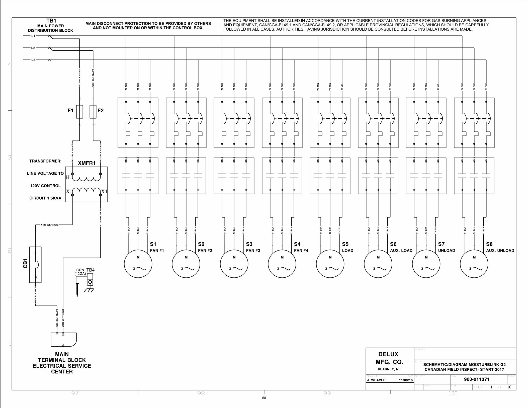
MAIN DISCONNECT PROTECTION TO BE PROVIDED BY OTHERSAND NOT MOUNTED ON OR WITHIN THE CONTROL BOX.
TB4GRN(12GA)
11/08/16
CANADIAN FIELD INSPECT- START 2017
THE EQUIPMENT SHALL BE INSTALLED IN ACCORDANCE WITH THE CURRENT INSTALLATION CODES FOR GAS BURNING APPLIANCESAND EQUIPMENT, CAN/CGA-B149.1 AND CAN/CGA-B149.2, OR APPLICABLE PROVINCIAL REGULATIONS, WHICH SHOULD BE CAREFULLYFOLLOWED IN ALL CASES. AUTHORITIES HAVING JURISDICTION SHOULD BE CONSULTED BEFORE INSTALLATIONS ARE MADE.
S1FAN #1
S2FAN #2
S3FAN #3
S4FAN #4
S5LOAD
S6AUX. LOAD
S7UNLOAD
S8AUX. UNLOAD
MAINTERMINAL BLOCK
ELECTRICAL SERVICECENTER
11
NN
F1
1
2
F2
1
2
XMFR1
X1
H1
X4
CB
1
1
2
L1
L2
L3
T1
BLK
T2
BLK
T3
BLK
T3
BLK
T1
BLK
T2
BLK
T3
BLK
T1
BLK
T2
BLK
T3
BLK
T1
BR
N
T2
OR
N
T3
YEL
T1
BLK
T2
BLK
T3
BLK
T1
BLK
T2
RED
T3
VIO
T1
BLK
T2
BLK
T3
BLK
BLK
BLK
BLK
BLK
BLK
BLK
BLK
BLK
BLK
BLK
BLK
BLK
BLK
BLK
BLK
BLK
BLK
BLK
BLK
BLK
BLK
BLK
BLK
BLK
T1
BLK
T2
BLK
M
3
M
3
M
3
M
3
M
3
M
3
M
3
M
3
W32
3 B
LK 1
2AW
G
W32
4 B
LK 1
2AW
G
W33
0 B
LK 1
2AW
G
W33
1 B
LK 1
2AW
G
W332 BLK 12AWG W33
3 W
HT 1
2AW
G
W33
3 W
HT 1
2AW
G
W33
4 B
LK 1
2AW
G
W33
4 B
LK 1
2AW
G
T1
BLK
T3
BLK
T2
BLK
T1
BLK
T3
BLK
T2
BLK
T1
BLK
T3
BLK
T2
BLK
T1
BLK
T3
BLK
T2
BLK
T1
BR
N
T3
YEL
T2
OR
N
T1
BLK
T3
BLK
T2
BLK
T1
BLK
T3
VIO
T2
RED
T1
BLK
T3
BLK
T2
BLK
ADDRESS
DRAWN BY DATE
TYPE
J. WEAVERDWGPROJECT
SCALE
ISSUE
TITLE
900-011371
OFSHEET
SCHEMATIC/DIAGRAM MOISTURELINK G2
97 98 99 100
1
2
3
4
1 10
DELUXMFG. CO.KEARNEY, NE
TB1MAIN POWER
DISTRIBUITION BLOCK
TRANSFORMER:
LINE VOLTAGE TO
120V CONTROL
CIRCUIT 1.5KVA
68

SCHEMATIC/DIAGRAM MOISTURELINK G2
900-01137111/08/16
CANADIAN FIELD INSPECT- START 2017
W327 YEL 20AWG
W32
7 Y
EL
20A
WG
W328 YEL 20AWG
W32
8 Y
EL
20A
WG
W329 YEL 20AWG
W32
9 Y
EL
20A
WG
MA
IN
TER
MIN
AL
BLO
CK
DR
YER
CO
NTR
OL
CEN
TER
77
5656
5555
5454
5353
5252
5151
5050
4949
4848
4747
4646
4545
4444
4343
4242
4141
4040
3939
3838
3737
3636
3535
3434
3333
3232
3131
3030
2929
2828
2727
2626
2525
2424
2323
2222
2121
2020
1919
1818
1717
1616
1515
1414
1313
1212
1111
1010
99
88
57575
5 -0V
DC
6060
5959
6565
6464
6363
6262
5858
6161
6868
6767
6666
IO1A1A2A3A4A5A6A7A8B1B2B3B4B5B6B7B8
C
IO2A1A2A3A4A5A6A7A8B1B2B3B4B5B6B7B8
C
IO4A1A2A3A4A5A6A7A8B1B2B3B4B5B6B7B8
C
IO3A1A2A3A4A5A6A7A8B1B2B3B4B5B6B7B8
C
ETH1PORT 1
DC
24V
GFGDC
24V
PORT 2
IO5A1A2A3A4A5A6A7A8B1B2B3B4B5B6B7B8
C+
IO7CH1 C
24V+-
CH1 SCH1 ECH2 CCH2 SCH2 ECH3 CCH3 SCH3 ECH4 CCH4 SCH4 E
IO6IN CH1+
24V+-
IN CH1 -IN CH2+IN CH2 -
OUT CH1+OUT CH1 -OUT CH2 +OUT CH2 -
OIRL1 COIL13-14+
OIRL2 COILA2A1
OIRL3 COILA2A1
OIRL4 COILA2A1
OIRL5 COILA2A1
OIRL6 COILA2A1
OIRL7 COILA2A1
OIRL8 COILA2A1
OIRL9 COILA2A1
OIRL10 COILA2A1
OIRL11 COILA2A1
OIRL12 COILA2A1
OIRL13 COILA2A1
OIRL14 COILA2A1
OIRL15 COILA2A1
OIRL16 COILA2A1
W00
1 B
RN
20A
WG
W00
1 B
RN
20A
WG
W00
2 B
LU 2
0AW
G
W00
2 B
LU 2
0AW
G
W055 ORN 20AWG
W055 ORN 20AWG
W057 ORN 20AWG
W057 ORN 20AWG
W058 ORN 20AWG
W058 ORN 20AWG
W059 ORN 20AWG
W059 ORN 20AWG
W060 ORN 20AWG
W060 ORN 20AWG
W061 ORN 20AWG
W061 ORN 20AWG
W062 ORN 20AWG
W062 ORN 20AWG
W063 ORN 20AWG
W063 ORN 20AWG
W064 ORN 20AWG
W064 ORN 20AWG
W065 ORN 20AWG
W065 ORN 20AWG
W066 ORN 20AWG
W066 ORN 20AWG
W067 ORN 20AWG
W067 ORN 20AWG
W068 VIO 20AWG
W06
8 V
IO 2
0AW
G
W069 VIO 20AWG
W06
9 V
IO 2
0AW
G
W070 VIO 20AWG
W07
0 V
IO 2
0AW
G
W071 VIO 20AWG
W07
1 V
IO 2
0AW
G
W072 VIO 20AWG
W07
2 V
IO 2
0AW
G
W073 VIO 20AWG
W07
3 V
IO 2
0AW
G
W074 BRN 20AWGW075 BRN 20AWG
W075 BRN 20AWGW076 BRN 20AWG
W076 BRN 20AWG
W077 BRN 20AWG
W077 BRN 20AWG
W078 BRN 20AWG
W078 BRN 20AWG
W079 BRN 20AWG W079 BRN 20AWGW080 BRN 20AWG
W080 BRN 20AWG
W081 BLU 20AWGW082 BLU 20AWG
W082 BLU 20AWGW083 BLU 20AWG
W083 BLU 20AWG
W08
7 B
RN
20A
WG
W087 BRN 20AWG
W184 VIO 20AWG
W18
4 V
IO 2
0AW
G
C2
CA
T5
BLU
C2 CAT5 BLU
W056 ORN 20AWG
W056 ORN 20AWG
ADDRESS
DRAWN BY DATE
TYPE
J. WEAVERDWGPROJECT
SCALE
ISSUE
TITLE
OFSHEET
41 42 43 44 45 46 47 48
1
2
3
4
5
6
7
8
2 10
BU
S J
UM
PER
BU
S J
UM
PER
DELUXMFG. CO.KEARNEY, NE
CO
NN
EC
T P
LC1
W003 YEL 20AWG
W00
3 Y
EL
20A
WG
W004 YEL 20AWG
W00
4 Y
EL
20A
WG
W005 YEL 20AWG
W00
5 Y
EL
20A
WG
W006 YEL 20AWG
W00
6 Y
EL
20A
WG
W007 YEL 20AWG
W00
7 Y
EL
20A
WG
W008 YEL 20AWG
W00
8 Y
EL
20A
WG
W009 YEL 20AWG
W00
9 Y
EL
20A
WG
W010 YEL 20AWG
W01
0 Y
EL
20A
WG
W011 YEL 20AWG
W01
1 Y
EL
20A
WG
W012 YEL 20AWG
W01
2 Y
EL
20A
WG
W013 YEL 20AWG
W01
3 Y
EL
20A
WG
W014 YEL 20AWG
W01
4 Y
EL
20A
WG
W015 YEL 20AWG
W01
5 Y
EL
20A
WG
W016 YEL 20AWG
W01
6 Y
EL
20A
WG
W017 YEL 20AWG
W01
7 Y
EL
20A
WG
W018 YEL 20AWG
W01
8 Y
EL
20A
WG
W019 YEL 20AWG
W01
9 Y
EL
20A
WG
W020 YEL 20AWG
W02
0 Y
EL
20A
WG
W021 YEL 20AWG
W02
1 Y
EL
20A
WG
W022 YEL 20AWG
W02
2 Y
EL
20A
WG
W023 YEL 20AWG
W02
3 Y
EL
20A
WG
W024 YEL 20AWG
W02
4 Y
EL
20A
WG
W025 YEL 20AWG
W02
5 Y
EL
20A
WG
W026 YEL 20AWG
W02
6 Y
EL
20A
WG
W027 YEL 20AWG
W02
7 Y
EL
20A
WG
W028 YEL 20AWG
W02
8 Y
EL
20A
WG
W029 YEL 20AWG
W02
9 Y
EL
20A
WG
W030 YEL 20AWG
W03
0 Y
EL
20A
WG
W031 YEL 20AWG
W03
1 Y
EL
20A
WG
W032 YEL 20AWG
W03
2 Y
EL
20A
WG
W033 YEL 20AWG
W03
3 Y
EL
20A
WG
W034 YEL 20AWG
W03
4 Y
EL
20A
WG
W035 YEL 20AWG
W03
5 Y
EL
20A
WG
W036 YEL 20AWG
W03
6 Y
EL
20A
WG
W037 YEL 20AWG
W03
7 Y
EL
20A
WG
W038 YEL 20AWG
W03
8 Y
EL
20A
WG
W039 YEL 20AWG
W03
9 Y
EL
20A
WG
W040 YEL 20AWG
W04
0 Y
EL
20A
WG
W041 YEL 20AWG
W04
1 Y
EL
20A
WG
W042 YEL 20AWG
W04
2 Y
EL
20A
WG
W043 YEL 20AWG
W04
3 Y
EL
20A
WG
W044 YEL 20AWG
W04
4 Y
EL
20A
WG
W045 YEL 20AWG
W04
5 Y
EL
20A
WG
W046 YEL 20AWG
W04
6 Y
EL
20A
WG
W047 YEL 20AWG
W04
7 Y
EL
20A
WG
W048 YEL 20AWG
W04
8 Y
EL
20A
WG
W049 YEL 20AWG
W04
9 Y
EL
20A
WG
W050 YEL 20AWG
W05
0 Y
EL
20A
WG
W051 YEL 20AWG
W05
1 Y
EL
20A
WG
W052 YEL 20AWG
W05
2 Y
EL
20A
WG
W053 YEL 20AWG
W05
3 Y
EL
20A
WG
W054 YEL 20AWG
W05
4 Y
EL
20A
WG
69

POWER RELAY
TO FAN #1STARTER COIL
TO FAN #2STARTER COIL
TO FAN #3STARTER COIL
TO FAN #4STARTER COIL
TO LOADSTARTER COIL
TO AUX. LOADSTARTER COIL
BURNER #1FLAME PROVEN
BURNER #2FLAME PROVEN
BURNER #3FLAME PROVEN
BURNER #4FLAME PROVEN
BURNER #1IGNITION FIRING
BURNER #2IGNITION FIRING
BURNER #3IGNITION FIRING
BURNER #4IGNITION FIRING
TO UNLOADSTARTER COIL
TO AUX. UNLOADSTARTER COIL
TO FLAME CONTROLSPOWER (TERM. 1)
TO FLAME CONTROLSSTART (TERM. 7)
FLAME CONTROL #1RESET
FLAME CONTROL #2RESET
FLAME CONTROL #3RESET
FLAME CONTROL #4RESET
TO DC DRIVEPOWER ON
SCHEMATIC/DIAGRAM MOISTURELINK G2
BU
S J
UM
PER
BU
S J
UM
PER
900-01137111/08/16
CANADIAN FIELD INSPECT- START 2017
A2
14
A1
11
A2
14
A1
11
A2
14
A1
11
A2
14
A1
11
A2
14
A1
1112-AMP
A2
14
A1
11
A2
14
A1
11
A2
14
A1
11
OIRL2
1411
OIRL3
1411
OIRL4
1411
OIRL8
1411
OIRL9
1411
OIRL10
1411
OIRL11
1411
OIRL5
1411
OIRL12
1411
OIRL6
1411
OIRL13
1411
MA
IN
TER
MIN
AL
BLO
CK
DR
YER
CO
NTR
OL
CEN
TER
5151
9595
9494
9393
9292
9191
9090
8989
8888
8787
8686
8585
8484
8383
8282
8181
8080
7979
7878
7777
7676
7575
7474
7373
7272
7171
7070
5858
5757
5656
5555
5454
5353
5252
-0V
DC
66
55
44
33
22
11
6969
2222
OIRL7
1411
OIRL14
1411
OIRL15
1411
OIRL1612-AMP
15-AMP
15-AMP
15-AMP
15-AMP
15-AMP
15-AMP
15-AMP
15-AMP
15-AMP
15-AMP
15-AMP
15-AMP
15-AMP
15-AMP
15-AMP
1411
OIRL1
59
812
IIRL1
IIRL2
IIRL4
IIRL5
IIRL7IIRL3
IIRL6
IIRL8
W13
0 B
LK 1
4AW
G
W130 BLK 14AWG W131 BLK 14AWG
W131 BLK 14AWG W132 BLK 16AWG
W13
2 B
LK 1
6AW
G
W133 BLK 16AWG
W13
3 B
LK 1
6AW
G
W134 BLK 16AWG
W13
4 B
LK 1
6AW
G
W135 BLK 16AWG
W13
5 B
LK 1
6AW
G
W136 BLK 16AWG
W13
6 B
LK 1
6AW
G
W137 BLK 16AWG
W13
7 B
LK 1
6AW
G
W138 BLK 16AWG
W13
8 B
LK 1
6AW
G
W139 BLK 16AWG
W13
9 B
LK 1
6AW
G
W140 BLK 16AWG
W14
0 B
LK 1
6AW
G
W141 BLK 16AWG
W14
1 B
LK 1
6AW
G
W150 BLU 20AWG
W150 BLU 20AWG
W159 BLK 16AWG
W15
9 B
LK 1
6AW
G
W160 BLK 16AWG
W16
0 B
LK 1
6AW
G
W161 BLK 16AWG
W16
1 B
LK 1
6AW
G
W162 BLK 16AWG
W16
2 B
LK 1
6AW
G
W163 BLK 16AWG
W16
3 B
LK 1
6AW
G
W164 BLK 16AWG
W16
4 B
LK 1
6AW
G
W165 BLK 16AWG
W16
5 B
LK 1
6AW
G
W166 BLK 16AWG
W16
6 B
LK 1
6AW
G
W16
7 B
RN
20A
WG
W167 WHT 16AWG
W120 BLK 14AWG
W120 BLK 14AWG W121 BLK 14AWG
W12
1 B
LK 1
4AW
G
W32
6 B
LU 2
0AW
G
W326 BLU 20AWG
ADDRESS
DRAWN BY DATE
TYPE
J. WEAVERDWGPROJECT
SCALE
ISSUE
TITLE
OFSHEET
57 58 59 60 61 62 63 64
1
2
3
4
5
6
7
8
3 10
12-AMP
12-AMP
12-AMP
12-AMP
12-AMP12-AMP
12-AMP
12-AMP
DELUXMFG. CO.KEARNEY, NE
W142 YEL 20AWG
W14
2 Y
EL
20A
WG
W143 YEL 20AWG
W14
3 Y
EL
20A
WG
W144 YEL 20AWG
W14
4 Y
EL
20A
WG
W145 YEL 20AWG
W14
5 Y
EL
20A
WG
W146 YEL 20AWG
W14
6 Y
EL
20A
WG
W147 YEL 20AWG
W14
7 Y
EL
20A
WG
W148 YEL 20AWG
W14
8 Y
EL
20A
WG
W149 YEL 20AWG
W14
9 Y
EL
20A
WG
W151 YEL 20AWG
W15
1 Y
EL
20A
WG
W152 YEL 20AWG
W15
2 Y
EL
20A
WG
W153 YEL 20AWG
W15
3 Y
EL
20A
WG
W154 YEL 20AWG
W15
4 Y
EL
20A
WG
W155 YEL 20AWG
W15
5 Y
EL
20A
WG
W156 YEL 20AWG
W15
6 Y
EL
20A
WG
W157 YEL 20AWG
W15
7 Y
EL
20A
WG
W158 YEL 20AWG
W15
8 Y
EL
20A
WG
W325 YEL 20AWG
W32
5 Y
EL
20A
WG
70

PLENUM TEMPERATUREAND HIGH LIMIT CONTROL
VARIABLE SPEEDDC MOTOR DRIVE
KBMD-240D
SCHEMATIC/DIAGRAM MOISTURELINK G2
900-01137111/08/16
CANADIAN FIELD INSPECT- START 2017
MA
IN
TER
MIN
AL
BLO
CK
DR
YER
CO
NTR
OL
CEN
TER
NN
55
44
33
22
11
-0V
DC
9999
66
77
9696
9797
9898
6565
6464
7676
7575
7474
6969
105
105
104
104
103
103
102
102
101
101
100
100
ISO1
- K+ M
+ J- G
- C+ A
DC1
L1L2GNDA+A-P2F-
TC1
9899F1H1T1S1R1T2S2R2L4K4CBCACC
W16
8 B
LK 1
6AW
G
W168 BLK 16AWG
W16
9 W
HT 1
6AW
G
W169 WHT 16AWG
W170 BLU 20AWG
W17
0 B
LU 2
0AW
G
W172 VIO 20AWG
W17
2 V
IO 2
0AW
G
W173 VIO 20AWG
W17
3 V
IO 2
0AW
G
W174 VIO 20AWG
W17
4 V
IO 2
0AW
G
W175 VIO 20AWG
W17
5 V
IO 2
0AW
G
W176 VIO 20AWG
W17
6 V
IO 2
0AW
G
W177 VIO 20AWG
W17
7 V
IO 2
0AW
G
W178 VIO 20AWG
W17
8 V
IO 2
0AW
G
W179 VIO 20AWG
W17
9 V
IO 2
0AW
G
W180 BLK 14AWG
W18
0 B
LK 1
4AW
G
W181 WHT 16AWG
W18
1 W
HT 1
6AW
G
W182 VIO 20AWG W182 VIO 20AWG
W183 VIO 20AWG W183 VIO 20AWG
W185 VIO 20AWG
W18
5 V
IO 2
0AW
G
W186 VIO 20AWG
W18
6 V
IO 2
0AW
G
W187 BLU 20AWG
W18
7 B
LU 2
0AW
G
W188 BRN 20AWG
W18
8 B
RN
20A
WG
W189 ORN 14AWG
W18
9 O
RN
14A
WG
W190 BLU 14AWG
W19
0 B
LU 1
4AW
G
C3 CAT5 YEL
C3
CA
T5
YEL
ADDRESS
DRAWN BY DATE
TYPE
J. WEAVERDWGPROJECT
SCALE
ISSUE
TITLE
OFSHEET
53 54 55 56
1
2
3
4
4 10
DELUXMFG. CO.KEARNEY, NE
GRN
ORN
WHT/ORN
CO
NN
EC
T P
LC1
W171 YEL 20AWG
W17
1 Y
EL
20A
WG
71

FLAME CONTROLBURNER #1
FLAME CONTROLBURNER #2
FLAME CONTROLBURNER #3
FLAME CONTROLBURNER #4
SCHEMATIC/DIAGRAM MOISTURELINK G2
WH
T 1
6AW
G
WHT 16AWG WHT 16AWG WHT 16AWGWHT 16AWG
900-01137111/08/16
CANADIAN FIELD INSPECT- START 2017
MA
IN
TER
MIN
AL
BLO
CK
DR
YER
CO
NTR
OL
CEN
TER
11
1010
9595
9494
9393
9292
9191
9090
8989
8888
8383
8282
8181
8080
7979
7878
NN
8787
8686
8585
8484
110
110
109
109
108
108
107
107
106
106
FC1
S1S212345678AR1R2AB
FC2
S1S212345678AR1R2AB
FC3
S1S212345678AR1R2AB
FC4
S1S212345678AR1R2AB
W191 BLK 16AWG
W19
1 B
LK 1
6AW
G
W192 BLK 16AWG
W19
2 B
LK 1
6AW
G
W201 BLK 16AWG
W20
1 B
LK 1
6AW
G
W202 BLK 16AWG
W20
2 B
LK 1
6AW
G
W203 BLK 16AWG
W20
3 B
LK 1
6AW
G
W204 BLK 16AWG
W20
4 B
LK 1
6AW
G
W205 BLK 16AWG
W20
5 B
LK 1
6AW
G
W206 BLK 16AWG
W20
6 B
LK 1
6AW
G
W207 BLK 16AWG
W20
7 B
LK 1
6AW
G
W208 BLK 16AWG
W20
8 B
LK 1
6AW
G
W209 BLK 16AWGW209 BLK 16AWG
W210 BLK 16AWGW210 BLK 16AWG
W211 BLK 16AWGW211 BLK 16AWG
W212 BLK 16AWGW212 BLK 16AWG
W213 VIO 20AWG
W21
3 V
IO 2
0AW
G
W214 VIO 20AWG
W21
4 V
IO 2
0AW
G
W215 VIO 20AWG
W21
5 V
IO 2
0AW
G
W216 VIO 20AWG
W21
6 V
IO 2
0AW
G
W217 BLK 16AWG
W21
7 B
LK 1
6AW
G
W218 BLK 16AWGW218 BLK 16AWG
W219 BLK 16AWGW219 BLK 16AWG
W220 BLK 16AWGW220 BLK 16AWG
W221 BLK 16AWGW221 BLK 16AWG
W222 BLK 16AWGW222 BLK 16AWG
W223 BLK 16AWGW223 BLK 16AWG
C4 CAT5 YEL
C4
CA
T5
YEL
W339 VIO 20AWGW339 VIO 20AWGW340 VIO 20AWG
W340 VIO 20AWGW341 VIO 20AWG
W341 VIO 20AWG
W342 VIO 20AWGW342 VIO 20AWGW343 VIO 20AWG
W343 VIO 20AWGW344 VIO 20AWG
W344 VIO 20AWG
DWG NO
SH
REV
ADDRESS
DRAWN BY DATE
TYPE
J. WEAVERDWGPROJECT
SCALE
ISSUE
TITLE
OFSHEET
73 74 75 76
1
2
3
4
5 10
DELUXMFG. CO.KEARNEY, NE
CO
NN
EC
T P
LC1
W193 YEL 20AWG
W19
3 Y
EL
20A
WG
W194 YEL 20AWG
W19
4 Y
EL
20A
WG
W195 YEL 20AWG
W19
5 Y
EL
20A
WG
W196 YEL 20AWG
W19
6 Y
EL
20A
WG
W197 YEL 20AWG
W19
7 Y
EL
20A
WG
W198 YEL 20AWG
W19
8 Y
EL
20A
WG
W199 YEL 20AWG
W19
9 Y
EL
20A
WG
W200 YEL 20AWG
W20
0 Y
EL
20A
WG
72

SCHEMATIC/DIAGRAM MOISTURELINK G2
WWANPRIMARY
GND
PAIR
ANTENNA
COAX
5 AMP
900-01137111/08/16
CANADIAN FIELD INSPECT- START 2017
F31
2
MA
IN
TER
MIN
AL
BLO
CK
DR
YER
CO
NTR
OL
CEN
TER
NN
3030
2929
2828
2727
2626
2525
2424
2323
55
44
33
22
11
-0V
DC
6969
2121
66
-0V
DC
7979
SW3
BURNER SWITCH
4 3
SW4
LOAD SWITCH
4 3
SW1
POWER SWITCH
2 1
4 3
2 1
SW2
FAN SWITCH
4 3
2 1
PS1
L1NPE++--
X1 X2
X1 X2
X1 X2
X1 X2
X1 X2
MAIN POWER
X1 X2
SW6
E-STOP SWITCH
21
21
PLC1
V-V+
MJ1/MJ2MJ3
LAN2LAN1
GATE1(RADIO)
+24VDC/ -VDC
LAN
CB
2
1
2
HR METER
L1
L2
SW5
UNLOAD SWITCH
4 3
2 1
W08
8 B
LK 1
4AW
G
W088 BLK 14AWGW
089
BLK
16A
WG
W089 BLK 16AWG
W09
0 B
LU 2
0AW
G
W090 BLU 20AWG
W091 BLK 14AWG
W09
1 B
LK 1
4AW
GW
092
BLK
16A
WG
W09
2 B
LK 1
6AW
G
W09
3 B
LU 2
0AW
G
W09
3 B
LU 2
0AW
G
W09
4 B
LK 1
4AW
G
W094 BLK 14AWG W095 BLK 14AWG
W09
5 B
LK 1
4AW
G
W096 BLK 16AWG
W096 BLK 16AWG W097 WHT 16AWG
W09
7 W
HT 1
6AW
G
W098 WHT 16AWG
W09
8 W
HT 1
6AW
G
W09
9 B
LU 2
0AW
G
W099 BLU 20AWGW100 BLU 20AWG
W100 BLU 20AWGW101 BLU 20AWG
W101 BLU 20AWGW102 BLU 20AWG
W102 BLU 20AWGW103 BLU 20AWG
W103 BLU 20AWGW104 BLU 20AWG
W104 BLU 20AWGW105 BLU 20AWG
W105 BLU 20AWGW106 BLU 20AWG
W106 BLU 20AWG
W11
9 B
LU 2
0AW
G
W119 BLU 20AWG
W122 YEL 20AWG
W122 YEL 20AWG
W12
3 B
RN
20A
WG
W123 BRN 20AWGW124 BRN 20AWG
W124 BRN 20AWGW125 BRN 20AWG
W125 BRN 20AWGW126 BRN 20AWG
W126 BRN 20AWGW127 BRN 20AWG
W127 BRN 20AWG
W129 BRN 20AWG
W12
9 B
RN
20A
WG
W335 BLU 20AWG
W33
5 B
LU 2
0AW
G
W336 BRN 20AWG
W33
6 B
RN
20A
WG
C1 CAT5 BLU
C1 CAT5 BLU
RED
RED
20A
WG
BLK
BLK
20A
WG
C2 CAT5 BLU
C2
CA
T5
BLU
C3 CAT5 YEL
C3
CA
T5
YEL
C4 CAT5 YEL
C4
CA
T5
YEL
W34
5 B
LK 1
6AW
G
W34
5 B
LK 1
6AW
G
W34
6 W
HT 1
6AW
G
W34
6 W
HT 1
6AW
G
ADDRESS
DRAWN BY DATE
TYPE
J. WEAVERDWGPROJECT
SCALE
ISSUE
TITLE
OFSHEET
49 50 51 52
1
2
3
4
6 10
G
G
G
G
G
W
DELUXMFG. CO.KEARNEY, NE
CO
NN
EC
T T
C1
CO
NN
EC
T F
C1
CO
NN
EC
T E
TH
1
W107 YEL 20AWG
W10
7 Y
EL
20A
WG
W108 YEL 20AWG
W10
8 Y
EL
20A
WG
W109 YEL 20AWG
W10
9 Y
EL
20A
WG
W110 YEL 20AWG
W11
0 Y
EL
20A
WG
W111 YEL 20AWG
W11
1 Y
EL
20A
WG
W112 YEL 20AWG
W11
2 Y
EL
20A
WG
W113 YEL 20AWG
W11
3 Y
EL
20A
WG
W114 YEL 20AWG
W11
4 Y
EL
20A
WG
W115 YEL 20AWG
W11
5 Y
EL
20A
WG
W116 YEL 20AWG
W116 YEL 20AWG
W117 YEL 20AWG
W117 YEL 20AWG
W118 YEL 20AWG
W118 YEL 20AWG
W128 YEL 20AWG
W128 YEL 20AWG
73

SCHEMATIC/DIAGRAM MOISTURELINK G2
FLAME ROD
IGNITOR
FLAME ROD
IGNITOR
FLAME ROD
IGNITOR
FLAME ROD
IGNITOR
BURNER 1
1
FR
BURNER 2
1
FR
BURNER 3
1
FR
XMFR2
1 2
3
4
XMFR3
1 2
3
4
XMFR4
1 2
3
4
XMFR5
1 2
3
4
BURNER 4
1
FR
AS1
43
AS2
43
AS3
43
AS4
43
MA
IN
TER
MIN
AL
BLO
CK
ELE
CTR
ICA
L SER
VIC
E
CEN
TER
44
55
9595
9494
9393
106
106
5050
4949
4848
4747
66
NN
9292
109
109
108
108
107
107
110
110
6161
6060
5959
W28
5 B
LU 2
0AW
G
W285 BLU 20AWGW286 BLU 20AWG
W286 BLU 20AWGW287 BLU 20AWG
W287 BLU 20AWGW288 BLU 20AWG
W288 BLU 20AWG
W289 YEL 20AWG
W28
9 Y
EL
20A
WG
W290 YEL 20AWG
W29
0 Y
EL
20A
WG
W291 YEL 20AWG
W29
1 Y
EL
20A
WG
W292 YEL 20AWG
W29
2 Y
EL
20A
WG
W293 VIO 20AWG
W29
3 V
IO 2
0AW
G
W294 VIO 20AWG
W29
4 V
IO 2
0AW
G
W295 VIO 20AWG
W29
5 V
IO 2
0AW
G
W296 VIO 20AWG
W29
6 V
IO 2
0AW
G
W297 BLK 16AWG
W29
7 B
LK 1
6AW
G
W298 BLK 16AWG
W29
8 B
LK 1
6AW
G
W299 BLK 16AWG
W29
9 B
LK 1
6AW
G
W300 BLK 16AWG
W30
0 B
LK 1
6AW
G
W301 WHT 16AWG
W30
1 W
HT 1
6AW
G
W302 WHT 16AWG
W302 WHT 16AWGW303 WHT 16AWG
W303 WHT 16AWGW304 WHT 16AWG
W304 WHT 16AWG
W30
5 B
LK 1
6AW
G
W35
0 W
HT 1
6AW
G
W35
2 B
LU 2
0AW
G
W35
8 Y
EL
20A
WG
W35
9 Y
EL
20A
WG
W36
0 Y
EL
20A
WG
* ALL ITEMS OTHER THAN TERMINAL BLOCK ON THISSHEET ARE OUTSIDE OF THE ELECTRICAL PANELS.
FAN AIR SENSORS
FAN #1
FAN #2
FAN #3
FAN #4
NW
351
WH
T 1
6AW
G
SECONDARY GASSOLENOID
PRIMARY GASSOLENOID
L.P. GAS SOLENOID
SOL2
A1 A2
SOL1
A1 A2W305 BLK 16AWG
W306 BLK 16AWG W351 WHT 16AWG
W350 WHT 16AWG
VALVE CLOSED SW - TEST FIRE VALVE31
VALVE CLOSED SW - SOL287
LOW GAS PRESSURE (4 PSI)NCC
HIGH GAS PRESSURE (20 PSI)NCC
LOW. POS. SW. - FLOW CONTROL VALVE 1
NOC
VALVE CLOSED SW - SOL387
SOL3
A1 A2
W307 BLK 16AWG
W307 BLK 16AWG
W361 WHT 16AWG
W361 WHT 16AWG
W352 BLU 20AWG W353 BLU 20AWG
W353 BLU 20AWG W354 BLU 20AWG
W354 BLU 20AWG W355 BLU 20AWG
W355 BLU 20AWG
W356 BLU 20AWG
W356 BLU 20AWGW357 BLU 20AWG
W357 BLU 20AWG
W358 YEL 20AWG
W359 YEL 20AWG
W360 YEL 20AWG
VENT VALVE SOLENOID
SOL4
A1 A2W308 BLK 16AWG W362 WHT 16AWG
W308 BLK 16AWG W362 WHT 16AWG
W30
6 W
HT 1
6AW
G
900-01137111/08/16
CANADIAN FIELD INSPECT- START 2017
DWG NO
SH
REV
ADDRESS
DRAWN BY DATE
TYPE
J. WEAVERDWGPROJECT
SCALE
ISSUE
TITLE
OFSHEET
93 94 95 96
1
2
3
4
7 10
DELUXMFG. CO.KEARNEY, NE
74

FAN #1 FAN #2 FAN #3 FAN #4
SCHEMATIC/DIAGRAM MOISTURELINK G2
900-01137111/08/16
CANADIAN FIELD INSPECT- START 2017
S1 COILA2A1
S1 N/O CONTACT43
S2 COILA2A1
S2 N/O CONTACT43
S3 COILA2A1
S3 N/O CONTACT43
S4 COILA2A1
S4 N/O CONTACT43
MA
IN
TER
MIN
AL
BLO
CK
ELE
CTR
ICA
L SER
VIC
E
CEN
TER
4242
4141
4040
3939
7373
7272
7171
7070
1111
1010
99
88
NN
44
S1 OVERLOAD
3433
S2 OVERLOAD
3433
S3 OVERLOAD
3433
S4 OVERLOAD
3433
W22
4 B
LU 2
0AW
G
W224 BLU 20AWGW225 BLU 20AWG
W225 BLU 20AWGW226 BLU 20AWG
W226 BLU 20AWGW227 BLU 20AWG
W227 BLU 20AWGW228 BLU 20AWG
W228 BLU 20AWGW229 BLU 20AWG
W229 BLU 20AWGW230 BLU 20AWG
W230 BLU 20AWGW231 BLU 20AWG
W231 BLU 20AWG
W240 BLK 16AWG
W24
0 B
LK 1
6AW
G
W241 BLK 16AWG
W24
1 B
LK 1
6AW
G
W242 BLK 16AWG
W24
2 B
LK 1
6AW
G
W243 BLK 16AWG
W24
3 B
LK 1
6AW
G
W244 WHT 16AWG
W24
4 W
HT 1
6AW
G
W245 WHT 16AWGW245 WHT 16AWG
W246 WHT 16AWGW246 WHT 16AWG
W247 WHT 16AWGW247 WHT 16AWG
DWG NO
SH
REV
ADDRESS
DRAWN BY DATE
TYPE
J. WEAVERDWGPROJECT
SCALE
ISSUE
TITLE
OFSHEET
77 78 79 80
1
2
3
4
8 10
S1 STARTER S2 STARTER S3 STARTER S4 STARTER
DELUXMFG. CO.KEARNEY, NE
W232 YEL 20AWG
W23
2 Y
EL
20A
WG
W233 YEL 20AWG
W23
3 Y
EL
20A
WG
W234 YEL 20AWG
W23
4 Y
EL
20A
WG
W235 YEL 20AWG
W23
5 Y
EL
20A
WG
W236 YEL 20AWG
W23
6 Y
EL
20A
WG
W237 YEL 20AWG
W23
7 Y
EL
20A
WG
W238 YEL 20AWG
W23
8 Y
EL
20A
WG
W239 YEL 20AWG
W23
9 Y
EL
20A
WG
75

LOAD AUX. LOAD UNLOAD AUX. UNLOAD
SCHEMATIC/DIAGRAM MOISTURELINK G2
S6 EXTRA N/O CONTACT43
S8 EXTRA N/O CONTACT43
900-01137111/08/16
CANADIAN FIELD INSPECT- START 2017
9578 RED 9578 RED 9578 RED 9578 RED
S5 COILA2A1
S5 N/O CONTACT1413
S6 COILA2A1
S6 N/O CONTACT1413
S7 COILA2A1
S7 N/O CONTACT1413
S8 COILA2A1
S8 N/O CONTACT1413
MA
IN
TER
MIN
AL
BLO
CK
ELE
CTR
ICA
L SER
VIC
E
CEN
TER
4646
4545
4444
4343
7777
7676
7575
7474
1515
1414
1313
1212
NN
44
S5 OVERLOAD
9677
S6 OVERLOAD
9677
S7 OVERLOAD
9677
S8 OVERLOAD
9677
W24
8 B
LU 2
0AW
G
W248 BLU 20AWGW249 BLU 20AWG
W249 BLU 20AWGW250 BLU 20AWG
W250 BLU 20AWGW251 BLU 20AWG
W251 BLU 20AWGW252 BLU 20AWG
W252 BLU 20AWGW253 BLU 20AWG
W253 BLU 20AWGW254 BLU 20AWG
W254 BLU 20AWGW255 BLU 20AWG
W255 BLU 20AWG
W264 BLK 16AWG
W26
4 B
LK 1
6AW
G
W265 BLK 16AWG
W26
5 B
LK 1
6AW
G
W266 BLK 16AWG
W26
6 B
LK 1
6AW
G
W267 BLK 16AWG
W26
7 B
LK 1
6AW
G
W268 WHT 16AWG
W26
8 W
HT 1
6AW
G
W269 WHT 16AWGW269 WHT 16AWG
W270 WHT 16AWGW270 WHT 16AWG
W271 WHT 16AWGW271 WHT 16AWG
DWG NO
SH
REV
ADDRESS
DRAWN BY DATE
TYPE
J. WEAVERDWGPROJECT
SCALE
ISSUE
TITLE
OFSHEET
81 82 83 84
1
2
3
4
9 10
S5 STARTER S6 STARTER S7 STARTER S8 STARTER
DELUXMFG. CO.KEARNEY, NE
W256 YEL 20AWG
W25
6 Y
EL
20A
WG
W257 YEL 20AWG
W25
7 Y
EL
20A
WG
W258 YEL 20AWG
W25
8 Y
EL
20A
WG
W259 YEL 20AWG
W25
9 Y
EL
20A
WG
W260 YEL 20AWG
W26
0 Y
EL
20A
WG
W261 YEL 20AWG
W26
1 Y
EL
20A
WG
W262 YEL 20AWG
W26
2 Y
EL
20A
WG
W263 YEL 20AWG
W26
3 Y
EL
20A
WG
76

* ALL ITEMS OTHER THAN TERMINAL BLOCKS AND F4 ONTHIS SHEET ARE OUTSIDE OF THE ELECTRICAL PANELS.
PLENUMTEMPERATURE
SENSOR
MID-GRAINTEMPERATURE
SENSOR
PLENUMHIGH LIMITSENSOR
MODULATINGMOTOR
HW M7284A1004/U
DISCHARGE GRAINMOISTURE SENSOR
SCHEMATIC/DIAGRAM MOISTURELINK G2
COOLING DOORCNO
W277 YEL 20AWG
BLU LEADBRN LEAD
CORD-WHT
CO
RD
-BLK
YEL 16AWG
BLU 16AWG YEL 16AWG
BLK LEAD
2 AMP
900-01137111/08/16
CANADIAN FIELD INSPECT- START 2017
1
GR
N/Y
EL
051
1
BR
N
WH
T
BL
U
BL
K
GR
YD
RA
IN 2
4AW
G
DR
AIN
24A
WG
WH
T 2
4AW
G
WH
T 2
4AW
G
GR
N 2
4AW
G
GR
N 2
4AW
G
BLK
24A
WG
BLK
24A
WG
RED
24A
WG
RED
24A
WG
BRN
WHT
BLU
BLK
BRN
WHT
BLU
BLK
M1
SAMPLING MOTOR
W317 BLK 20AWG
GRN 14AWGW318 WHT 20AWG
6363
6262
GN
D
66
-0V
DC
MAIN TERMINAL BLOCKDRYER CONTROL
CENTER
2
DISCHARGE OVERFLOWNCC
W084 BLU 20AWG W278 YEL 20AWG
W349 BLU 20AWG
PLENUM DOORCNO
W084 BLU 20AWG
BLU LEAD BRN LEAD
LOW GRAINMOTOR END
NOC
HIGH GRAINHIGH LEVEL
HIGH GRAINLOW LEVEL
LOW GRAIN - FILL ENDNOC
DISCHARGE SAMPLENOC
MA
IN T
ER
MIN
AL
BLO
CK
ELE
CTR
ICA
L SER
VIC
E
CEN
TER
44
55
3131
1919
1818
1717
1616
66
NN
3838
3737
3636
3232
105
105
104
104
103
103
102
102
101
101
100
100
9999
9898
9797
9696
22
6868
6767
6666
-0V
DC
6363
6262
7676
GN
D
MOD1
A1
A2
+
-
G
DC MOTOR 1A1+
A2-
TS2
WHT RED RED
TS3
RED WHT WHT
TS1
WHT RED RED
FEEDROLL PROX SW.
BR
N
WH
T
BL
U
BL
K
F41
2
EXHAUST LIMIT SW1NCC
EXHAUST LIMIT SW4NCC
EXHAUST LIMIT SW2NCC
EXHAUST LIMIT SW3NCC
W08
5 B
LU 2
0AW
G
W085 BLU 20AWG
CORD-GRN
BLU 16AWG
W27
3 B
LU 2
0AW
G
W273 BLU 20AWG
W27
4 B
LU 2
0AW
G
W27
4 B
LU 2
0AW
G
W27
5 B
LU 2
0AW
G
W275 BLU 20AWG
W30
9 B
LK 1
6AW
G
W309 BLK 16AWG
W31
0 W
HT 1
6AW
G
W310 WHT 16AWG
WH
T
WH
T
RED
2
BLK
RED
1
RED
WH
T
WH
T
RED
2
BLK
RED
1
RED
WH
T
WH
T
RED
2
BLK
RED
1
RED
W311 VIO 20AWG
W31
1 V
IO 2
0AW
G
W312 VIO 20AWG
W31
2 V
IO 2
0AW
G
W313 ORN 14AWGW
313
OR
N 1
4AW
G
W314 BLU 14AWG
W31
4 B
LU 1
4AW
G
W31
5 B
RN
20A
WG
W31
5 B
RN
20A
WG
W31
6 B
LK 1
6AW
G
W31
6 B
LK 1
6AW
G
W31
7 B
LK 1
6AW
G
GR
N 1
4AW
G
W31
8 W
HT 1
6AW
G
W347 BLU 20AWG
W34
9 B
LU 2
0AW
G
W319 BLU 20AWG W320 BLU 20AWG W321 BLU 20AWG
ADDRESS
DRAWN BY DATE
TYPE
J. WEAVERDWGPROJECT
SCALE
ISSUE
TITLE
DWG NO
SH
REV
OFSHEET
85 86 87 88
3
4
1010
DELUXMFG. CO.KEARNEY, NE
W27
7 Y
EL
20A
WG
W27
8 Y
EL
20A
WG
W27
9 Y
EL
20A
WG
W27
9 Y
EL
20A
WG
W280 YEL 20AWG
W28
0 Y
EL
20A
WG
W281 YEL 20AWG
W28
1 Y
EL
20A
WG
W282 YEL 20AWG
W28
2 Y
EL
20A
WG
W283 YEL 20AWG
W28
3 Y
EL
20A
WG
W284 YEL 20AWG
W28
4 Y
EL
20A
WG
W348 YEL 20AWG
W34
8 Y
EL
20A
WG
77

DELUX MFG. CO.KEARNEY, NE
ITEM PART NUMBER QTY DESCRIPTION1 006-010852 1 OCS - HORNER XL7e- HE-XW1E0 CONTROL CONSOLE2 010-010919 2 SWITCH-22MM-3 POS.-ON/OFF/MOM.3 010-010920 1 SWITCH-22MM-3 POS.-ON/OFF/ON4 010-010921 2 SWITCH-22MM-2 POS.-OFF/ON5 010-010924 5 SWITCH HOLDER-22MM ACT SWITCH6 010-010925 5 CONTACT-N/O-22MM ACT SWITCH7 010-010926 4 CONTACT-N/C-22MM ACT SWITCH8 012-010163 4 CABLE-CAT5E-7FT-SHIELDED-BLUE9 012-010932 1 USB PANEL MOUNT-FEMALE A TO MALE 1-0.5M W/CAP
10 016-006717 1 HOUR METER11 019-010381 1 INDICATOR LIGHT-22MM-WHITE12 019-010950 5 LIGHT-LED MODULE-GRN-24VDC SIE13 100-010931 1 SWITCH/HMI INSERT PANEL-XL7E MOISTURELINK G2
MASS: 507333064.458 PART NO.: 507-011001DESCRIPTION: ASS'Y-SWITCH PANEL-G2 / 1-4 BURNER-DCC-2016+
MODELED BY: J .WEAVER
THICKNESS:MATERIAL:SCALE: 0.375
DATE: Nov-13-15
ECO# LET DESCRIPTION DATE USED ON:TOLERANCE: DECIMAL .010 FRACTION 1/32 ANGLE 1 UNLESS OTHERWISE SPECIFIED
78

DELUX MFG. CO.KEARNEY, NE
ITEM PART NUMBER QTY DESCRIPTION1 006-010852 1 OCS - HORNER XL7e- HE-XW1E0 CONTROL CONSOLE2 010-010919 2 SWITCH-22MM-3 POS.-ON/OFF/MOM.3 010-010920 1 SWITCH-22MM-3 POS.-ON/OFF/ON4 010-010921 2 SWITCH-22MM-2 POS.-OFF/ON5 010-010924 5 SWITCH HOLDER-22MM ACT SWITCH6 010-010925 5 CONTACT-N/O-22MM ACT SWITCH7 010-010926 4 CONTACT-N/C-22MM ACT SWITCH8 012-010163 4 CABLE-CAT5E-7FT-SHIELDED-BLUE9 012-010932 1 USB PANEL MOUNT-FEMALE A TO MALE 1-0.5M W/CAP
10 016-006717 1 HOUR METER11 019-010381 1 INDICATOR LIGHT-22MM-WHITE12 019-010950 5 LIGHT-LED MODULE-GRN-24VDC SIE13 100-010931 1 SWITCH/HMI INSERT PANEL-XL7E MOISTURELINK G2
MASS: 507333064.458 PART NO.: 507-011001DESCRIPTION: ASS'Y-SWITCH PANEL-G2 / 1-4 BURNER-DCC-2016+
MODELED BY: J .WEAVER
THICKNESS:MATERIAL:SCALE: 0.375
DATE: Nov-13-15
ECO# LET DESCRIPTION DATE USED ON:TOLERANCE: DECIMAL .010 FRACTION 1/32 ANGLE 1 UNLESS OTHERWISE SPECIFIED
1
2
2
3
4
4
9
11
13
10
79

DELUX MFG. CO.KEARNEY, NE
ITEM PART NUMBER QTY DESCRIPTION1 006-010852 1 OCS - HORNER XL7e- HE-XW1E0 CONTROL CONSOLE2 010-010919 2 SWITCH-22MM-3 POS.-ON/OFF/MOM.3 010-010920 1 SWITCH-22MM-3 POS.-ON/OFF/ON4 010-010921 2 SWITCH-22MM-2 POS.-OFF/ON5 010-010924 5 SWITCH HOLDER-22MM ACT SWITCH6 010-010925 5 CONTACT-N/O-22MM ACT SWITCH7 010-010926 4 CONTACT-N/C-22MM ACT SWITCH8 012-010163 4 CABLE-CAT5E-7FT-SHIELDED-BLUE9 012-010932 1 USB PANEL MOUNT-FEMALE A TO MALE 1-0.5M W/CAP
10 016-006717 1 HOUR METER11 019-010381 1 INDICATOR LIGHT-22MM-WHITE12 019-010950 5 LIGHT-LED MODULE-GRN-24VDC SIE13 100-010931 1 SWITCH/HMI INSERT PANEL-XL7E MOISTURELINK G2
MASS: 507333064.458 PART NO.: 507-011001DESCRIPTION: ASS'Y-SWITCH PANEL-G2 / 1-4 BURNER-DCC-2016+
MODELED BY: J .WEAVER
THICKNESS:MATERIAL:SCALE: 0.375
DATE: Nov-13-15
ECO# LET DESCRIPTION DATE USED ON:TOLERANCE: DECIMAL .010 FRACTION 1/32 ANGLE 1 UNLESS OTHERWISE SPECIFIED
5
5
5 5
5
6
6 6 6 6 7 7 7
9
11
12
12 12 12 12
8
80

DELUX MFG. CO.KEARNEY, NE
ITEM PART NUMBER QTY DESCRIPTION1 010-010923 1 SW-E/STOP-40MM-ROT. SIE 3SU1001-1HB20-0AA02 010-010924 1 SWITCH HOLDER-22MM ACT SWITCH3 010-010926 2 CONTACT-N/C-22MM ACT SWITCH4 013-010898 1 ENCLOSURE-30” X 30” X 12”-CSD303012 W/WIN & SP5 018-010910 1 LABEL-"CAUTION - ACCUMULATION OF..HEAT DECK.."6 018-010912 1 LABEL-"WARNING - READ OWNER'S MANUAL"7 018-010918 1 LABEL - FAN & BURNER COVER - STAYKLEEN8 506-010958 1 ASS'Y-INSERT PANEL-G2-4 BURNER-DCC-2016+9 507-011001 1 ASS'Y-SWITCH PANEL-G2 / 1-4 BURNER-DCC-2016+
MASS: 4349931650.226 PART NO.: 508-011008DESCRIPTION: ASS'Y-DRYER CONTROL CENTER-4 BURNER-MLINK G2 2016+
MODELED BY: J. WEAVER
THICKNESS:MATERIAL:SCALE: 0.281
DATE: Dec-08-15
ECO# LET DESCRIPTION DATE USED ON:TOLERANCE: DECIMAL .010 FRACTION 1/32 ANGLE 1 UNLESS OTHERWISE SPECIFIED
4
9
1
2
3
5 6 7
8
81

DELUX MFG. CO.KEARNEY, NE
ITEM PART NUMBER QTY DESCRIPTION1 010-010923 1 SW-E/STOP-40MM-ROT. SIE 3SU1001-1HB20-0AA02 010-010924 1 SWITCH HOLDER-22MM ACT SWITCH3 010-010926 2 CONTACT-N/C-22MM ACT SWITCH4 013-010898 1 ENCLOSURE-30” X 30” X 12”-CSD303012 W/WIN & SP5 018-010910 1 LABEL-"CAUTION - ACCUMULATION OF..HEAT DECK.."6 018-010912 1 LABEL-"WARNING - READ OWNER'S MANUAL"7 018-010918 1 LABEL - FAN & BURNER COVER - STAYKLEEN8 506-010957 1 ASS'Y-INSERT PANEL-G2-3 BURNER-DCC-2016+9 507-011001 1 ASS'Y-SWITCH PANEL-G2 / 1-4 BURNER-DCC-2016+
MASS: 4090170769.537 PART NO.: 508-011007DESCRIPTION: ASS'Y-DRYER CONTROL CENTER-3 BURNER-MLINK G2 2016+
MODELED BY: J. WEAVER
THICKNESS:MATERIAL:SCALE: 0.281
DATE: Dec-08-15
ECO# LET DESCRIPTION DATE USED ON:TOLERANCE: DECIMAL .010 FRACTION 1/32 ANGLE 1 UNLESS OTHERWISE SPECIFIED
4
9
1
2
3
5 6 7
8
82

DELUX MFG. CO.KEARNEY, NE
ITEM PART NUMBER QTY DESCRIPTION1 010-010923 1 SW-E/STOP-40MM-ROT. SIE 3SU1001-1HB20-0AA02 010-010924 1 SWITCH HOLDER-22MM ACT SWITCH3 010-010926 2 CONTACT-N/C-22MM ACT SWITCH4 013-010898 1 ENCLOSURE-30” X 30” X 12”-CSD303012 W/WIN & SP5 018-010910 1 LABEL-"CAUTION - ACCUMULATION OF..HEAT DECK.."6 018-010912 1 LABEL-"WARNING - READ OWNER'S MANUAL"7 018-010918 1 LABEL - FAN & BURNER COVER - STAYKLEEN8 506-010956 1 ASS'Y-INSERT PANEL-G2-2 BURNER-DCC-2016+9 507-011001 1 ASS'Y-SWITCH PANEL-G2 / 1-4 BURNER-DCC-2016+
MASS: 3830409888.849 PART NO.: 508-011006DESCRIPTION: ASS'Y-DRYER CONTROL CENTER-2 BURNER-MLINK G2 2016+
MODELED BY: J. WEAVER
THICKNESS:MATERIAL:SCALE: 0.281
DATE: Dec-08-15
ECO# LET DESCRIPTION DATE USED ON:TOLERANCE: DECIMAL .010 FRACTION 1/32 ANGLE 1 UNLESS OTHERWISE SPECIFIED
4
9
1
2
3
5 6 7
8
83

DELUX MFG. CO.KEARNEY, NE
ITEM PART NUMBER QTY DESCRIPTION1 010-010923 1 SW-E/STOP-40MM-ROT. SIE 3SU1001-1HB20-0AA02 010-010924 1 SWITCH HOLDER-22MM ACT SWITCH3 010-010926 2 CONTACT-N/C-22MM ACT SWITCH4 013-010898 1 ENCLOSURE-30” X 30” X 12”-CSD303012 W/WIN & SP5 018-010910 1 LABEL-"CAUTION - ACCUMULATION OF..HEAT DECK.."6 018-010912 1 LABEL-"WARNING - READ OWNER'S MANUAL"7 018-010918 1 LABEL - FAN & BURNER COVER - STAYKLEEN8 506-010955 1 ASS'Y-INSERT PANEL-G2-1 BURNER-DCC-2016+9 507-011001 1 ASS'Y-SWITCH PANEL-G2 / 1-4 BURNER-DCC-2016+
MASS: 3570649008.161 PART NO.: 508-011005DESCRIPTION: ASS'Y-DRYER CONTROL CENTER-1 BURNER-MLINK G2 2016+
MODELED BY: J. WEAVER
THICKNESS:MATERIAL:SCALE: 0.281
DATE: Dec-08-15
ECO# LET DESCRIPTION DATE USED ON:TOLERANCE: DECIMAL .010 FRACTION 1/32 ANGLE 1 UNLESS OTHERWISE SPECIFIED
4
9
1
2
3
5 6 7
8
84

DELUX MFG. CO.KEARNEY, NE
ITEM PART NUMBER QTY DESCRIPTION1 006-009080 1 DC DRIVE - KB PENTA - KBMD-240D2 006-009888 1 TEMP. CONT.-(TEMP/H.LIMIT) PM6C1FA-ALEJAAA3 006-010049 1 I/O MODULE-ANALOG INPUT/OUTPUT 2CH/2CH4 006-010051 1 I/O MODULE-ANALOG INPUT 4CH RTD5 006-010059 1 CELLULAR GATWY-WR21 GOBI/4G6 006-010099 1 ANALOG SIGNAL CONV./ISOL. 0-10VDC IN/OUT7 006-010366 1 BASE-I/O MODULES-ETHERNET8 006-010914 4 I/O MODULE-DC INPUT 16IN9 006-010915 1 I/O MODULE-DC OUTPUT 16OUT10 007-000741 4 FLAME CONTROL - WIRING BASE FIREYE #61-306011 007-009335 4 FLAME CONTROL- PROGRAMMR FIREYE MEP10012 007-009336 4 FLAME CONTROL-AMPLIFIER FIREYE MERT413 007-010270 1 RELAY SOCKET-DPDT-15AMP-SIEMENS 3TX7144-4E614 007-010620 1 RELAY-DPDT-24VDC-15AMP- SIEMENS 3TX7114-5LC0315 007-010928 14 INTERFACE RELAY-6A-24VDC COIL RSL1PVBU16 007-010929 8 INTERFACE RELAY-12A-120VAC COIL RSB1A120F7S17 007-010949 1 INTERFACE RELAY-12A-24VDC COIL RSB1A120BDS18 007-011002 4 FLAME CONTROL-CHASSIS FIREYE MEC120RC19 008-010942 1 TRNSFMR-120VAC PRIM. / 24VDC SEC.-120W20 011-010446-13000 3 WIRE DUCT-1-1/2" X 2-1/4" X 13"21 011-010446-17000 1 WIRE DUCT-1-1/2" X 2-1/4" X 17"22 011-010446-22000 1 WIRE DUCT-1-1/2" X 2-1/4" X 20"23 011-010446-28000 1 WIRE DUCT-1-1/2" X 2-1/4" X 28"24 015-011004 1 CIRCUIT BREAKER-6 AMP 1-POLE 5SJ4106-7HG4125 016-008932-12750 3 DIN RAIL - 35MM X 12.75"26 016-008932-2500 1 DIN RAIL - 35MM X 2.5"27 016-008932-9500 1 DIN RAIL - 35MM X 9.5"28 016-010055 4 TERMINAL BLOCK-END CLAMP-6MM WAGO 249-11629 016-010056 1 TB-2 COND. W/FUSE-WAGO 2006-163130 016-010431 115 TERM. BLOCK-GRAY-RAIL MOUNT WAGO 2002-140131 016-010432 2 TERM. BLOCK-END/INTERM. PLATE WAGO 2002-149132 016-010433 5 TERM. BLOCK-2-WAY JUMPER WAGO 2002-40233 016-010456 2 TERM. BLOCK-YEL/GRN-RAIL MOUNT WAGO 2002-140734 016-010575 1 TB-END CAP/SEPERATOR - WAGO 2006-169135 018-009190 1 I.D. PLATE - DRYER MODEL, S/N, FUEL - .025 ALUM.36 100-010940 1 INSERT PANEL-DCC-MOISTURELINK G2-2015+37 100-011009 1 BRKT-CELLULAR RADIO INSERT MOUNT38 100-011292 1 BRACKET-WATLOW TEMP CONTROL-INSERT-G2
MASS: PART NO.: 506-010958DESCRIPTION: ASS'Y-INSERT PANEL-G2-4 BURNER-DCC-2016+
MODELED BY: J. WEAVER
THICKNESS:MATERIAL:SCALE: 0.875
A MOVED DC PS LOCATION;ORIENTATION OF CELL RADIO 01/11/18 DATE: Dec-07-15
ECO# LET DESCRIPTION DATE USED ON:TOLERANCE: DECIMAL .010 FRACTION 1/32 ANGLE 1 UNLESS OTHERWISE SPECIFIED
A
10 11 12 18
2
3
4
7
8
8
8
8
9
16
19
24
29
1
20
20
23
28
30
30
36
5
37
35
34
31
33
32
38
21
17
14
13
6

DELUX MFG. CO.KEARNEY, NE
ITEM PART NUMBER QTY DESCRIPTION1 006-009080 1 DC DRIVE - KB PENTA - KBMD-240D2 006-009888 1 TEMP. CONT.-(TEMP/H.LIMIT) PM6C1FA-ALEJAAA3 006-010049 1 I/O MODULE-ANALOG INPUT/OUTPUT 2CH/2CH4 006-010051 1 I/O MODULE-ANALOG INPUT 4CH RTD5 006-010059 1 CELLULAR GATWY-WR21 GOBI/4G6 006-010099 1 ANALOG SIGNAL CONV./ISOL. 0-10VDC IN/OUT7 006-010366 1 BASE-I/O MODULES-ETHERNET8 006-010914 4 I/O MODULE-DC INPUT 16IN9 006-010915 1 I/O MODULE-DC OUTPUT 16OUT10 007-000741 3 FLAME CONTROL - WIRING BASE FIREYE #61-306011 007-009335 3 FLAME CONTROL- PROGRAMMR FIREYE MEP10012 007-009336 3 FLAME CONTROL-AMPLIFIER FIREYE MERT413 007-010270 1 RELAY SOCKET-DPDT-15AMP-SIEMENS 3TX7144-4E614 007-010620 1 RELAY-DPDT-24VDC-15AMP- SIEMENS 3TX7114-5LC0315 007-010928 12 INTERFACE RELAY-6A-24VDC COIL RSL1PVBU16 007-010929 6 INTERFACE RELAY-12A-120VAC COIL RSB1A120F7S17 007-010949 1 INTERFACE RELAY-12A-24VDC COIL RSB1A120BDS18 007-011002 3 FLAME CONTROL-CHASSIS FIREYE MEC120RC19 008-010942 1 TRNSFMR-120VAC PRIM. / 24VDC SEC.-120W20 011-010446-13000 3 WIRE DUCT-1-1/2" X 2-1/4" X 13"21 011-010446-17000 1 WIRE DUCT-1-1/2" X 2-1/4" X 17"22 011-010446-22000 1 WIRE DUCT-1-1/2" X 2-1/4" X 20"23 011-010446-28000 1 WIRE DUCT-1-1/2" X 2-1/4" X 28"24 015-011004 1 CIRCUIT BREAKER-6 AMP 1-POLE 5SJ4106-7HG4125 016-008932-12750 3 DIN RAIL - 35MM X 12.75"26 016-008932-2500 1 DIN RAIL - 35MM X 2.5"27 016-008932-9500 1 DIN RAIL - 35MM X 9.5"28 016-010055 4 TERMINAL BLOCK-END CLAMP-6MM WAGO 249-11629 016-010056 1 TB-2 COND. W/FUSE-WAGO 2006-163130 016-010431 115 TERM. BLOCK-GRAY-RAIL MOUNT WAGO 2002-140131 016-010432 2 TERM. BLOCK-END/INTERM. PLATE WAGO 2002-149132 016-010433 5 TERM. BLOCK-2-WAY JUMPER WAGO 2002-40233 016-010456 2 TERM. BLOCK-YEL/GRN-RAIL MOUNT WAGO 2002-140734 016-010575 1 TB-END CAP/SEPERATOR - WAGO 2006-169135 018-009190 1 I.D. PLATE - DRYER MODEL, S/N, FUEL - .025 ALUM.36 100-010940 1 INSERT PANEL-DCC-MOISTURELINK G2-2015+37 100-011009 1 BRKT-CELLULAR RADIO INSERT MOUNT38 100-011292 1 BRACKET-WATLOW TEMP CONTROL-INSERT-G2
MASS: PART NO.: 506-010957DESCRIPTION: ASS'Y-INSERT PANEL-G2-3 BURNER-DCC-2016+
MODELED BY: J. WEAVER
THICKNESS:MATERIAL:SCALE: 0.875
A MOVED DC PS LOCATION;ORIENTATION OF CELL RADIO 01/11/18 DATE: Dec-07-15
ECO# LET DESCRIPTION DATE USED ON:TOLERANCE: DECIMAL .010 FRACTION 1/32 ANGLE 1 UNLESS OTHERWISE SPECIFIED
A
10 11 12 18
2
3
4
6
7
8
8
8
8
9
19
24
29
1
20
20
23
28
30
30
36
16
35
5
37
33
34
31
32
21
38
17
14
13
22

DELUX MFG. CO.KEARNEY, NE
ITEM PART NUMBER QTY DESCRIPTION1 006-009080 1 DC DRIVE - KB PENTA - KBMD-240D2 006-009888 1 TEMP. CONT.-(TEMP/H.LIMIT) PM6C1FA-ALEJAAA3 006-010049 1 I/O MODULE-ANALOG INPUT/OUTPUT 2CH/2CH4 006-010051 1 I/O MODULE-ANALOG INPUT 4CH RTD5 006-010059 1 CELLULAR GATWY-WR21 GOBI/4G6 006-010099 1 ANALOG SIGNAL CONV./ISOL. 0-10VDC IN/OUT7 006-010366 1 BASE-I/O MODULES-ETHERNET8 006-010914 4 I/O MODULE-DC INPUT 16IN9 006-010915 1 I/O MODULE-DC OUTPUT 16OUT10 007-000741 2 FLAME CONTROL - WIRING BASE FIREYE #61-306011 007-009335 2 FLAME CONTROL- PROGRAMMR FIREYE MEP10012 007-009336 2 FLAME CONTROL-AMPLIFIER FIREYE MERT413 007-010270 1 RELAY SOCKET-DPDT-15AMP-SIEMENS 3TX7144-4E614 007-010620 1 RELAY-DPDT-24VDC-15AMP- SIEMENS 3TX7114-5LC0315 007-010928 10 INTERFACE RELAY-6A-24VDC COIL RSL1PVBU16 007-010929 4 INTERFACE RELAY-12A-120VAC COIL RSB1A120F7S17 007-010949 1 INTERFACE RELAY-12A-24VDC COIL RSB1A120BDS18 007-011002 2 FLAME CONTROL-CHASSIS FIREYE MEC120RC19 008-010942 1 TRNSFMR-120VAC PRIM. / 24VDC SEC.-120W20 011-010446-13000 3 WIRE DUCT-1-1/2" X 2-1/4" X 13"21 011-010446-17000 1 WIRE DUCT-1-1/2" X 2-1/4" X 17"22 011-010446-22000 1 WIRE DUCT-1-1/2" X 2-1/4" X 20"23 011-010446-28000 1 WIRE DUCT-1-1/2" X 2-1/4" X 28"24 015-011004 1 CIRCUIT BREAKER-6 AMP 1-POLE 5SJ4106-7HG4125 016-008932-12750 3 DIN RAIL - 35MM X 12.75"26 016-008932-2500 1 DIN RAIL - 35MM X 2.5"27 016-008932-9500 1 DIN RAIL - 35MM X 9.5"28 016-010055 4 TERMINAL BLOCK-END CLAMP-6MM WAGO 249-11629 016-010056 1 TB-2 COND. W/FUSE-WAGO 2006-163130 016-010431 115 TERM. BLOCK-GRAY-RAIL MOUNT WAGO 2002-140131 016-010432 2 TERM. BLOCK-END/INTERM. PLATE WAGO 2002-149132 016-010433 5 TERM. BLOCK-2-WAY JUMPER WAGO 2002-40233 016-010456 2 TERM. BLOCK-YEL/GRN-RAIL MOUNT WAGO 2002-140734 016-010575 1 TB-END CAP/SEPERATOR - WAGO 2006-169135 018-009190 1 I.D. PLATE - DRYER MODEL, S/N, FUEL - .025 ALUM.36 100-010940 1 INSERT PANEL-DCC-MOISTURELINK G2-2015+37 100-011009 1 BRKT-CELLULAR RADIO INSERT MOUNT38 100-011292 1 BRACKET-WATLOW TEMP CONTROL-INSERT-G2
MASS: PART NO.: 506-010956DESCRIPTION: ASS'Y-INSERT PANEL-G2-2 BURNER-DCC-2016+
MODELED BY: J. WEAVER
THICKNESS:MATERIAL:SCALE: 0.875
A MOVED DC PS LOCATION;ORIENTATION OF CELL RADIO 01/11/18 DATE: Dec-07-15
ECO# LET DESCRIPTION DATE USED ON:TOLERANCE: DECIMAL .010 FRACTION 1/32 ANGLE 1 UNLESS OTHERWISE SPECIFIED
A
10 11 12 18
2
3
4
6
7
8
8
8
8
9
19
24
29
1
20
20
23
28
30
30
36
16
35
5
37
33
34
38
31
32
21
14
13
17
22

DELUX MFG. CO.KEARNEY, NE
ITEM PART NUMBER QTY DESCRIPTION1 006-009080 1 DC DRIVE - KB PENTA - KBMD-240D2 006-009888 1 TEMP. CONT.-(TEMP/H.LIMIT) PM6C1FA-ALEJAAA3 006-010049 1 I/O MODULE-ANALOG INPUT/OUTPUT 2CH/2CH4 006-010051 1 I/O MODULE-ANALOG INPUT 4CH RTD5 006-010059 1 CELLULAR GATWY-WR21 GOBI/4G6 006-010099 1 ANALOG SIGNAL CONV./ISOL. 0-10VDC IN/OUT7 006-010366 1 BASE-I/O MODULES-ETHERNET8 006-010914 4 I/O MODULE-DC INPUT 16IN9 006-010915 1 I/O MODULE-DC OUTPUT 16OUT10 007-000741 1 FLAME CONTROL - WIRING BASE FIREYE #61-306011 007-009335 1 FLAME CONTROL- PROGRAMMR FIREYE MEP10012 007-009336 1 FLAME CONTROL-AMPLIFIER FIREYE MERT413 007-010270 1 RELAY SOCKET-DPDT-15AMP-SIEMENS 3TX7144-4E614 007-010620 1 RELAY-DPDT-24VDC-15AMP- SIEMENS 3TX7114-5LC0315 007-010928 8 INTERFACE RELAY-6A-24VDC COIL RSL1PVBU16 007-010929 2 INTERFACE RELAY-12A-120VAC COIL RSB1A120F7S17 007-010949 1 INTERFACE RELAY-12A-24VDC COIL RSB1A120BDS18 007-011002 1 FLAME CONTROL-CHASSIS FIREYE MEC120RC19 008-010942 1 TRNSFMR-120VAC PRIM. / 24VDC SEC.-120W20 011-010446-13000 3 WIRE DUCT-1-1/2" X 2-1/4" X 13"21 011-010446-17000 1 WIRE DUCT-1-1/2" X 2-1/4" X 17"22 011-010446-22000 1 WIRE DUCT-1-1/2" X 2-1/4" X 20"23 011-010446-28000 1 WIRE DUCT-1-1/2" X 2-1/4" X 28"24 015-011004 1 CIRCUIT BREAKER-6 AMP 1-POLE 5SJ4106-7HG4125 016-008932-12750 3 DIN RAIL - 35MM X 12.75"26 016-008932-2500 1 DIN RAIL - 35MM X 2.5"27 016-008932-9500 1 DIN RAIL - 35MM X 9.5"28 016-010055 4 TERMINAL BLOCK-END CLAMP-6MM WAGO 249-11629 016-010056 1 TB-2 COND. W/FUSE-WAGO 2006-163130 016-010431 115 TERM. BLOCK-GRAY-RAIL MOUNT WAGO 2002-140131 016-010432 2 TERM. BLOCK-END/INTERM. PLATE WAGO 2002-149132 016-010433 5 TERM. BLOCK-2-WAY JUMPER WAGO 2002-40233 016-010456 2 TERM. BLOCK-YEL/GRN-RAIL MOUNT WAGO 2002-140734 016-010575 1 TB-END CAP/SEPERATOR - WAGO 2006-169135 018-009190 1 I.D. PLATE - DRYER MODEL, S/N, FUEL - .025 ALUM.36 100-010940 1 INSERT PANEL-DCC-MOISTURELINK G2-2015+37 100-011009 1 BRKT-CELLULAR RADIO INSERT MOUNT38 100-011292 1 BRACKET-WATLOW TEMP CONTROL-INSERT-G2
MASS: PART NO.: 506-010955DESCRIPTION: ASS'Y-INSERT PANEL-G2-1 BURNER-DCC-2016+
MODELED BY: J. WEAVER
THICKNESS:MATERIAL:SCALE: 0.875
A MOVED DC PS LOCATION;ORIENTATION OF CELL RADIO 01/11/18 DATE: Dec-07-15
ECO# LET DESCRIPTION DATE USED ON:TOLERANCE: DECIMAL .010 FRACTION 1/32 ANGLE 1 UNLESS OTHERWISE SPECIFIED
A
10 11 12
2
3
4
6
7
8
8
8
8
9
19
24
29
1
20
20
23
28
30
30
36
21
16
35
5
37
33
34
31
32
14
13
17

DELUX MFG. CO.KEARNEY, NE
DRAWN BY TITLE:
DATE
CHK'D USED ON:
NEXT ASS'Y:
SCALE MATL. SHEAR SIZE DRAWING NO.
ECO# LET DESCRIPTION DATE
TOLERANCE: DECIMAL .010 FRACTION 1/32 ANGLE 1 UNLESS OTHERWISE SPECIFIED
ITEM PART NUMBER QTY DESCRIPTION1 017-001033 1 PRESSURE GUAGE - 2-1/4" - 30# MAX2 017-008459 1 PRESSURE GUAGE - 2-1/4" - 60# MAX3 020-001103 3 PIPE TEE - 1-1/4" - SCH 40 - BLK4 020-003022 2 PIPE TEE - 1/2" - SCH 805 021-003023 7 PIPE ELBOW - 1/2" - 90° - SCH 806 023-001182 2 PIPE UNION - 1-1/4" - SCH 40 - BLK7 023-003024 4 PIPE UNION - 1/2" - SCH 808 024-001208 4 PIPE NIPPLE - 1/2" X 5" - SCH 809 024-001236 3 PIPE NIPPLE - 1-1/4" X 2" SCH 40 - 125# BLACK
10 024-001237 1 PIPE NIPPLE - 1-1/4" X 3" SCH 40 - 125# BLACK11 024-001238 2 PIPE NIPPLE - 1-1/4" X 4" SCH 40 - 125# BLACK12 024-001241 3 PIPE NIPPLE - 1-1/4" X 8" SCH 40 - 125# BLACK13 024-001244 1 PIPE NIPPLE - 1-1/4" X 12" SCH 40 - 125# BLACK14 024-002962 5 PIPE NIPPLE - 1/2" X 2" - SCH 8015 024-002963 3 PIPE NIPPLE - 1/2" X 3" - SCH 8016 025-001282 2 PIPE CAP - 1-1/4" - SCH 40 - BLK17 027-003025-10000 1 PIPE NIPPLE - 1/2" X 10" - SCH 8018 027-003025-12000 2 PIPE NIPPLE - 1/2" X 12" - SCH 8019 027-003025-19000 1 PIPE NIPPLE - 1/2" X 19" - SCH 8020 027-003025-24000 2 PIPE NIPPLE - 1/2" X 24" - SCH 8021 027-003025-40000 1 PIPE NIPPLE - 1/2" X 40" - SCH 8022 028-003012 1 REGULATOR - 1/2" HIGH TEMPERATURE23 028-003013 1 1/2" SNAP VALVE - QUICK ACTING24 028-003014 2 POP-OFF PRESSURE RELEASE VALVE25 028-003026 1 BALL VALVE - 1/2" FULL PORT26 028-003027 1 BALL VALVE - 1-1/4" - FULL PORT27 028-003097 1 SOLENOID VALVE 1/2" 120V28 028-003098 1 SOLENOID VALVE 1-1/4" 120V29 029-001331 2 HEX REDUCER BUSHING - 1/2" TO 1/4"30 029-001341 1 HEX REDUCER BUSHING - 1-1/4" TO 1/4"31 029-001343 1 HEX REDUCER BUSHING - 1-1/4" TO 1/2"32 031-003029 1 1/2" Y-STRAINER33 031-003093 1 VAPORIZER - 4 ROW - 10'34 400-010724 1 ASS’Y-MOD MTR-HNYWL/MAX. COMBO-1-1/4”
DRAWN BY TITLE:
DATE
CHK'D USED ON:
NEXT ASS'Y:
SCALE MATL. SHEAR SIZE DRAWING NO.
ECO# LET DESCRIPTION DATE
TOLERANCE: DECIMAL .010 FRACTION 1/32 ANGLE 1 UNLESS OTHERWISE SPECIFIED
ASS'Y - FUEL TRAIN1-1/4" DOMESTIC
MOD. VALVE / MAXON4R VAPORIZER
400-009869
02/08/11
.187
5 8 8 14
21
33
20 7
4
4
5
5
8
14
14
15
15
19
29
29
32
22
2
20
17
8
15
25
7
31
3
12
16 11 10 6 34 6 9 11 12 16 3 9 13
5
JGW 28
18 14 7
14
18
3
30
1
7
5
89

DELUX MFG. CO.KEARNEY, NE
ITEM PART NUMBER QTY DESCRIPTION1 017-001033 1 PRESSURE GUAGE - 2-1/4" - 30# MAX2 017-008459 1 PRESSURE GUAGE - 2-1/4" - 60# MAX3 020-001103 3 PIPE TEE - 1-1/4" - SCH 40 - BLK4 020-003022 2 PIPE TEE - 1/2" - SCH 805 021-003023 7 PIPE ELBOW - 1/2" - 90° - SCH 806 023-001182 2 PIPE UNION - 1-1/4" - SCH 40 - BLK7 023-003024 4 PIPE UNION - 1/2" - SCH 808 024-001208 2 PIPE NIPPLE - 1/2" X 5" - SCH 809 024-001236 3 PIPE NIPPLE - 1-1/4" X 2" SCH 40 - 125# BLACK10 024-001237 1 PIPE NIPPLE - 1-1/4" X 3" SCH 40 - 125# BLACK11 024-001238 2 PIPE NIPPLE - 1-1/4" X 4" SCH 40 - 125# BLACK12 024-001241 3 PIPE NIPPLE - 1-1/4" X 8" SCH 40 - 125# BLACK13 024-001244 1 PIPE NIPPLE - 1-1/4" X 12" SCH 40 - 125# BLACK14 024-002962 5 PIPE NIPPLE - 1/2" X 2" - SCH 8015 024-002963 3 PIPE NIPPLE - 1/2" X 3" - SCH 8016 024-008253 2 PIPE NIPPLE - 1/2" X 5" SCH 80 300# BLK17 025-001282 2 PIPE CAP - 1-1/4" - SCH 40 - BLK18 027-003025-10000 1 PIPE NIPPLE - 1/2" X 10" - SCH 8019 027-003025-12000 2 PIPE NIPPLE - 1/2" X 12" - SCH 8020 027-003025-20000 1 PIPE NIPPLE - 1/2" X 20" - SCH 8021 027-003025-24000 1 PIPE NIPPLE - 1/2" X 24" - SCH 8022 027-003025-40000 1 PIPE NIPPLE - 1/2" X 40" - SCH 8023 027-003025-8000 1 PIPE NIPPLE - 1/2" X 8" - SCH 8024 028-003012 1 REGULATOR - 1/2" HIGH TEMPERATURE25 028-003013 1 1/2" SNAP VALVE - QUICK ACTING26 028-003014 2 POP-OFF PRESSURE RELEASE VALVE27 028-003026 1 BALL VALVE - 1/2" FULL PORT28 028-003027 1 BALL VALVE - 1-1/4" - FULL PORT29 028-003097 1 SOLENOID VALVE 1/2" 120V30 028-003098 1 SOLENOID VALVE 1-1/4" 120V31 029-001331 2 HEX REDUCER BUSHING - 1/2" TO 1/4"32 029-001341 1 HEX REDUCER BUSHING - 1-1/4" TO 1/4"33 029-001343 1 HEX REDUCER BUSHING - 1-1/4" TO 1/2"34 031-003029 1 1/2" Y-STRAINER35 031-003095 1 VAPORIZER - 12 ROW - 30'36 400-010724 1 ASS’Y-MOD MTR-HNYWL/MAX. COMBO-1-1/4”
PART NO.: 400-009868DESCRIPTION: ASS'Y- 1-1/4" FUEL TRAIN-12R DOMESTIC-MAXON/MOD. VALVE-LP
MODELED BY: J. WEAVER
THICKNESS:MATERIAL:SCALE: 0.281
DATE: Apr-01-14
ECO# LET DESCRIPTION DATE USED ON:TOLERANCE: DECIMAL .010 FRACTION 1/32 ANGLE 1 UNLESS OTHERWISE SPECIFIED
3
3
4
4
5
5 5
5
5
16
16
8
8
9 9 10 11 11
12
12
13
14 14
14
15
15
15
17 17
18
20
21
22
23 24
25
29
30
31
31
33
34
35
6 36
6
7
27
7
26
26
5
12
14
14
19
19
1
2
28
9
7
5
32
90

DELUX MFG. CO.KEARNEY, NE
ITEM PART NUMBER QTY DESCRIPTION1 017-001033 1 PRESSURE GUAGE - 2-1/4" - 30# MAX2 017-008459 1 PRESSURE GUAGE - 2-1/4" - 60# MAX3 020-001103 3 PIPE TEE - 1-1/4" - SCH 40 - BLK4 020-003022 2 PIPE TEE - 1/2" - SCH 805 021-003023 7 PIPE ELBOW - 1/2" - 90° - SCH 806 023-001182 2 PIPE UNION - 1-1/4" - SCH 40 - BLK7 023-003024 4 PIPE UNION - 1/2" - SCH 808 024-001208 2 PIPE NIPPLE - 1/2" X 5" - SCH 809 024-001236 3 PIPE NIPPLE - 1-1/4" X 2" SCH 40 - 125# BLACK
10 024-001237 1 PIPE NIPPLE - 1-1/4" X 3" SCH 40 - 125# BLACK11 024-001238 2 PIPE NIPPLE - 1-1/4" X 4" SCH 40 - 125# BLACK12 024-001241 3 PIPE NIPPLE - 1-1/4" X 8" SCH 40 - 125# BLACK13 024-001244 1 PIPE NIPPLE - 1-1/4" X 12" SCH 40 - 125# BLACK14 024-002962 5 PIPE NIPPLE - 1/2" X 2" - SCH 8015 024-002963 3 PIPE NIPPLE - 1/2" X 3" - SCH 8016 024-008253 2 PIPE NIPPLE - 1/2" X 5" SCH 80 300# BLK17 025-001282 2 PIPE CAP - 1-1/4" - SCH 40 - BLK18 027-003025-10000 1 PIPE NIPPLE - 1/2" X 10" - SCH 8019 027-003025-12000 2 PIPE NIPPLE - 1/2" X 12" - SCH 8020 027-003025-16000 1 PIPE NIPPLE - 1/2" X 16" - SCH 8021 027-003025-19000 1 PIPE NIPPLE - 1/2" X 19" - SCH 8022 027-003025-24000 1 PIPE NIPPLE - 1/2" X 24" - SCH 8023 027-003025-40000 1 PIPE NIPPLE - 1/2" X 40" - SCH 8024 028-003012 1 REGULATOR - 1/2" HIGH TEMPERATURE25 028-003013 1 1/2" SNAP VALVE - QUICK ACTING26 028-003014 2 POP-OFF PRESSURE RELEASE VALVE27 028-003026 1 BALL VALVE - 1/2" FULL PORT28 028-003027 1 BALL VALVE - 1-1/4" - FULL PORT29 028-003097 1 SOLENOID VALVE 1/2" 120V30 028-003098 1 SOLENOID VALVE 1-1/4" 120V31 029-001331 2 HEX REDUCER BUSHING - 1/2" TO 1/4"32 029-001341 1 HEX REDUCER BUSHING - 1-1/4" TO 1/4"33 029-001343 1 HEX REDUCER BUSHING - 1-1/4" TO 1/2"34 031-003029 1 1/2" Y-STRAINER35 031-003094 1 VAPORIZER - 8 ROW - 20'36 400-010724 1 ASS’Y-MOD MTR-HNYWL/MAX. COMBO-1-1/4”
DRAWN BY TITLE:
DATE
CHK'D USED ON:
NEXT ASS'Y:
SCALE MATL. SHEAR SIZE DRAWING NO.
ECO# LET DESCRIPTION DATE
TOLERANCE: DECIMAL .010 FRACTION 1/32 ANGLE 1 UNLESS OTHERWISE SPECIFIED
JGW
02/04/11
.187 400-009867
ASS'Y - FUEL TRAIN1-1/4" DOMESTIC
MOD VALVE / ASCO8R VAPORIZER
35
5
7
16 14
20
23 16
4
4
8
14
15
15
31
31
34
22
25
2
5
5
7
8
14
15
18
21
24
27
3
3 6 9 10 11 11
12
12 17 17
33
6 9 13 34
26
30
5 14 19
1
32
3
14
19
7
7
12
9
28
91

DELUX MFG. CO.KEARNEY, NE
ITEM PART NUMBER QTY DESCRIPTION1 017-001033 2 PRESSURE GUAGE - 2-1/4" - 30# MAX2 020-001105 4 PIPE TEE 2" - SCH 40 - 125# BLACK3 021-001122 2 PIPE ELBOW 2" - 90° - SCH 40 - 125# BLACK4 023-001184 3 PIPE UNION 2" - SCH 40 - 125# BLACK5 024-001256 1 PIPE NIPPLE - 2" X CLOSE - SCH 40 - 125# BLACK6 024-001257 8 PIPE NIPPLE - 2" X 3" - SCH 40 - 125# BLACK7 024-001258 1 PIPE NIPPLE 2" X 4" SCH 40 125# BLK8 024-001259 1 PIPE NIPPLE 2" X 5" SCH 40 125# BLK9 024-001260 1 PIPE NIPPLE 2" X 6" SCH 40 125# BLK
10 024-001261 1 PIPE NIPPLE - 2" X 8" - SCH 40 - 125# BLACK11 024-001263 3 PIPE NIPPLE - 2" X 10" - SCH 40 - 125# BLACK12 025-001284 2 PIPE CAP 2" - SCH 40 - 125# BLACK13 028-004623 2 2" SOLENOID VALVE - 120V14 028-005362 2 BALL VALVE - BRASS - 2" - FULL PORT15 029-007850 2 PIPE REDUCER BUSHING - HEX - 2" TO 1/4"16 400-010725 1 ASS’Y-MOD MTR.-HNEYWL./MAXON COMBO-2”
PART NO.: 400-010744DESCRIPTION: ASS’Y- 2” FUEL TRAIN-NAT. GAS DOMESTIC-ASCO/MOD. VALVE
MODELED BY: J. WEAVER
THICKNESS:MATERIAL:SCALE: 0.187
DATE: Mar-12-14
ECO# LET DESCRIPTION DATE USED ON:TOLERANCE: DECIMAL .010 FRACTION 1/32 ANGLE 1 UNLESS OTHERWISE SPECIFIED
2
3
5
6
6 6 7
11
11
11
12
13
4
4
16
4
2
2 6 6 6
8
9
12
13 15
3
2 6 10 15 1 14
6 14
92

DELUX MFG. CO.KEARNEY, NE
ITEM PART NUMBER QTY DESCRIPTION1 017-001033 2 PRESSURE GUAGE - 2-1/4" - 30# MAX2 020-001103 4 PIPE TEE - 1-1/4" - SCH 40 - BLK3 021-001118 2 PIPE ELBOW 1-1/4" - 90° - SCH 40 - 125# BLACK4 023-001182 3 PIPE UNION - 1-1/4" - SCH 40 - BLK5 024-001236 9 PIPE NIPPLE - 1-1/4" X 2" SCH 40 - 125# BLACK6 024-001238 2 PIPE NIPPLE - 1-1/4" X 4" SCH 40 - 125# BLACK7 024-001240 1 PIPE NIPPLE - 1-1/4" X 6" SCH 40 - 125# BLACK8 024-001241 1 PIPE NIPPLE - 1-1/4" X 8" SCH 40 - 125# BLACK9 024-001243 2 PIPE NIPPLE - 1-1/4" X 10" SCH 40 - 125# BLACK
10 024-001244 1 PIPE NIPPLE - 1-1/4" X 12" SCH 40 - 125# BLACK11 025-001282 2 PIPE CAP - 1-1/4" - SCH 40 - BLK12 028-003027 2 BALL VALVE - 1-1/4" - FULL PORT13 028-003098 2 SOLENOID VALVE 1-1/4" 120V14 029-001341 2 HEX REDUCER BUSHING - 1-1/4" TO 1/4"15 400-010724 1 ASS’Y-MOD MTR-HNYWL/MAX. COMBO-1-1/4”
PART NO.: 400-010801DESCRIPTION: ASS’Y- 1-1/4” FUEL TRAIN-NAT. GAS DOMESTIC-ASCO/MOD. VALVE
MODELED BY: J. WEAVER
THICKNESS:MATERIAL:SCALE: 0.188
DATE: Jun-09-14
ECO# LET DESCRIPTION DATE USED ON:TOLERANCE: DECIMAL .010 FRACTION 1/32 ANGLE 1 UNLESS OTHERWISE SPECIFIED
2
2
2
3
5 5 5
5
5
5
5
6
6
7
9
9
10
11
11
13
4
15 4
4
14 1
1
2
3
5
5
8
14 12
12
93

DELUX MFG. CO.KEARNEY, NE
ITEM PART NUMBER QTY DESCRIPTION1 020-005673 2 PIPE TEE - 3/4" - SCH 802 021-005674 3 PIPE ELBOW - 3/4" - 90° - SCH 803 023-005675 3 PIPE UNION - 3/4" - SCH 804 024-005677 4 PIPE NIPPLE 3/4" X 2" SCH 80 300# BLK5 024-005678 1 PIPE NIPPLE 3/4" X 3" SCH 80 300# BLK6 024-005679 2 PIPE NIPPLE - 3/4" X 4" - SCH 807 027-003251-12500 1 PIPE NIPPLE 3/4" X 12-1/2" SCH 80 300# BLK8 027-003251-24000 1 PIPE NIPPLE 3/4" X 24" SCH 80 300# BLK9 027-003251-40000 1 PIPE NIPPLE 3/4" X 40" SCH 80 300# BLK
10 028-003014 2 POP-OFF PRESSURE RELEASE VALVE11 028-005482 1 3/4" SOLENOID VALVE - 120V12 028-005529 1 3/4" QUICK ACTING VALVE13 029-001333 2 HEX REDUCER BUSHING 3/4" X 1/4"14 031-005485 1 3/4" Y-STRAINER
PART NO.: 400-010746DESCRIPTION: ASS'Y-3/4" FUEL TRAIN-DPX4T-DOMESTIC
MODELED BY: J. WEAVER
THICKNESS:MATERIAL:SCALE: 0.140
DATE: Feb-11-14
ECO# LET DESCRIPTION DATE USED ON:TOLERANCE: DECIMAL .010 FRACTION 1/32 ANGLE 1 UNLESS OTHERWISE SPECIFIED
1
1
2
3 4 4 6 6
5
8
9
10
11
12
13 13
14
10
2
2 4 7 3
94

DELUX MFG. CO.KEARNEY, NE
26 REF
ITEM PART NUMBER QTY DESCRIPTION1 017-001033 1 PRESSURE GUAGE - 2-1/4" - 30# MAX2 020-001105 3 PIPE TEE 2" - SCH 40 - 125# BLACK3 021-006309 4 PIPE ELBOW - 2" 90° - SCH 804 023-001184 3 PIPE UNION 2" - SCH 40 - 125# BLACK5 023-006310 3 PIPE UNION 2" - SCH 80 - 300# BLACK6 024-001257 7 PIPE NIPPLE - 2" X 3" - SCH 40 - 125# BLACK7 024-001258 1 PIPE NIPPLE 2" X 4" SCH 40 125# BLK8 024-001261 3 PIPE NIPPLE - 2" X 8" - SCH 40 - 125# BLACK9 024-001264 1 PIPE NIPPLE - 2" X 12" SCH 40 - 125# BLACK10 024-006312 4 PIPE NIPPLE - 2" X 3" - SCH 80 - 300# BLACK11 025-001284 2 PIPE CAP 2" - SCH 40 - 125# BLACK12 027-006315-13500 1 PIPE NIPPLE - 2" X 13-1/2" SCH 8013 027-006315-21000 1 PIPE NIPPLE - 2" X 21" SCH 8014 027-006315-30000 1 PIPE NIPPLE 2" X 30" SCH 8015 028-004623 1 2" SOLENOID VALVE - 120V16 028-005362 2 BALL VALVE - BRASS - 2" - FULL PORT17 028-006316 1 2" HIGH TEMP PRESSURE REGULATOR - 8-20 PSI18 029-007850 1 PIPE REDUCER BUSHING - HEX - 2" TO 1/4"19 100-008964 1 PIPE NIPPLE - 2" X 16" - SCH 40 - 125# BLACK20 400-010725 1 ASS’Y-MOD MTR.-HNEYWL./MAXON COMBO-2”
PART NO.: 400-010743DESCRIPTION: ASS’Y- 2” FUEL TRAIN-W/VAP. DOM.-ASCO/MOD. VALVE-DPX4T
MODELED BY: J. WEAVER
THICKNESS:MATERIAL:SCALE: 0.250
DATE: Feb-11-14
ECO# LET DESCRIPTION DATE USED ON:TOLERANCE: DECIMAL .010 FRACTION 1/32 ANGLE 1 UNLESS OTHERWISE SPECIFIED
1
2 2
3
3
4
4
4
6
6
6 6 6
6
7
8
8
9
10
10
11 11
13
14
15
16
17
19
20
2
3
3
6
8
10 12
18
5
16
95

DELUX MFG. CO.KEARNEY, NE
ITEM PART NUMBER QTY DESCRIPTION1 020-005673 2 PIPE TEE - 3/4" - SCH 802 021-005674 3 PIPE ELBOW - 3/4" - 90° - SCH 803 023-005675 3 PIPE UNION - 3/4" - SCH 804 024-005677 4 PIPE NIPPLE 3/4" X 2" SCH 80 300# BLK5 024-005678 1 PIPE NIPPLE 3/4" X 3" SCH 80 300# BLK6 024-005679 2 PIPE NIPPLE - 3/4" X 4" - SCH 807 027-003251-12500 1 PIPE NIPPLE 3/4" X 12-1/2" SCH 80 300# BLK8 027-003251-39000 1 PIPE NIPPLE 3/4" X 39" SCH 80 300# BLK9 027-003251-40000 1 PIPE NIPPLE 3/4" X 40" SCH 80 300# BLK
10 028-003014 2 POP-OFF PRESSURE RELEASE VALVE11 028-005482 1 3/4" SOLENOID VALVE - 120V12 028-005529 1 3/4" QUICK ACTING VALVE13 029-001333 2 HEX REDUCER BUSHING 3/4" X 1/4"14 031-005485 1 3/4" Y-STRAINER
PART NO.: 400-010750DESCRIPTION: ASS'Y-3/4" FUEL TRAIN-DPX8T-DOMESTIC
MODELED BY: J. WEAVER
THICKNESS:MATERIAL:SCALE: 0.109
DATE: Feb-13-14
ECO# LET DESCRIPTION DATE USED ON:TOLERANCE: DECIMAL .010 FRACTION 1/32 ANGLE 1 UNLESS OTHERWISE SPECIFIED
1
1
2
4
4
5
6 6
8
9
11
12
14
10
10
3
13
2
2
4
4 7 3 3
96

DELUX MFG. CO.KEARNEY, NE
26 REF
ITEM PART NUMBER QTY DESCRIPTION1 017-001033 1 PRESSURE GUAGE - 2-1/4" - 30# MAX2 020-001105 3 PIPE TEE 2" - SCH 40 - 125# BLACK3 021-006309 4 PIPE ELBOW - 2" 90° - SCH 804 023-001184 3 PIPE UNION 2" - SCH 40 - 125# BLACK5 023-006310 3 PIPE UNION 2" - SCH 80 - 300# BLACK6 024-001257 7 PIPE NIPPLE - 2" X 3" - SCH 40 - 125# BLACK7 024-001258 1 PIPE NIPPLE 2" X 4" SCH 40 125# BLK8 024-001261 3 PIPE NIPPLE - 2" X 8" - SCH 40 - 125# BLACK9 024-001264 1 PIPE NIPPLE - 2" X 12" SCH 40 - 125# BLACK10 024-006312 4 PIPE NIPPLE - 2" X 3" - SCH 80 - 300# BLACK11 025-001284 2 PIPE CAP 2" - SCH 40 - 125# BLACK12 027-006315-13500 1 PIPE NIPPLE - 2" X 13-1/2" SCH 8013 027-006315-21000 1 PIPE NIPPLE - 2" X 21" SCH 8014 027-006315-45000 1 PIPE NIPPLE - 2" X 45" SCH 8015 028-004623 1 2" SOLENOID VALVE - 120V16 028-005362 2 BALL VALVE - BRASS - 2" - FULL PORT17 028-006316 1 2" HIGH TEMP PRESSURE REGULATOR - 8-20 PSI18 029-007850 1 PIPE REDUCER BUSHING - HEX - 2" TO 1/4"19 100-008964 1 PIPE NIPPLE - 2" X 16" - SCH 40 - 125# BLACK20 400-010725 1 ASS’Y-MOD MTR.-HNEYWL./MAXON COMBO-2”
PART NO.: 400-010749DESCRIPTION: ASS’Y- 2” FUEL TRAIN-W/VAP. DOM.-ASCO/MOD. VALVE-DPX8T
MODELED BY: J. WEAVER
THICKNESS:MATERIAL:SCALE: 0.218
DATE: Feb-13-14
ECO# LET DESCRIPTION DATE USED ON:TOLERANCE: DECIMAL .010 FRACTION 1/32 ANGLE 1 UNLESS OTHERWISE SPECIFIED
2 2
3
3
6
6
6 6 6
6
7
8
8
9
10
10
11 11
13
15
17
19
4 20
4
1
4
16
5
3
3
10
10
12 5
5
14
2
6
8
18
16
97

DELUX MFG. CO.KEARNEY, NE
DRAWN BY TITLE:
JGW DATE
07/07/11 CHK'D USED ON:
NEXT ASS'Y:
SCALE MATL. SHEAR SIZE DRAWING NO.
ECO# LET DESCRIPTION DATE .281 TOLERANCE: DECIMAL .010 FRACTION 1/32 ANGLE 1 UNLESS OTHERWISE SPECIFIED
ITEM PART NUMBER QTY DESCRIPTION1 009-005213 1 FAN SAIL SENSOR SWITCH - HONEYWELL #S437A2 012-003174-50000 1 WIRE - 16/2 SJOW CORD - 50"3 016-000976 1 CORD CONNECTOR - 1/2" PLASTIC4 016-001013 2 INSULATED FORK TERMINAL - 14-16 AWG - #8 STUD5 040-007395 1 COTTER PIN - 3/32" DIA. X 2"6 400-009147 1 ASS'Y - SAIL SWITCH PADDLE - REVERSE SOLID ALUM.
400-009148
TOP TERMINAL TO WHITE WIREBOTTOM TERMINAL TO BLACK WIRE
SAIL SWITCH SENSOR ASS'YGREENHECK & BEHLEN FANS
SOLID ALUM. (REVERSE)
1
2
3
6
5
4
98

DELUX MFG. CO.KEARNEY, NE
DRAWN BY TITLE:
JGW DATE
07/07/11 CHK'D USED ON:
NEXT ASS'Y:
SCALE MATL. SHEAR SIZE DRAWING NO.
ECO# LET DESCRIPTION DATE .281 TOLERANCE: DECIMAL .010 FRACTION 1/32 ANGLE 1 UNLESS OTHERWISE SPECIFIED
ITEM PART NUMBER QTY DESCRIPTION1 009-005213 1 FAN SAIL SENSOR SWITCH - HONEYWELL #S437A2 012-003174-60000 1 WIRE - 16/2 SJOW CORD - 60"3 016-000976 1 CORD CONNECTOR - 1/2" PLASTIC4 016-001013 2 INSULATED FORK TERMINAL - 14-16 AWG - #8 STUD5 040-007395 1 COTTER PIN - 3/32" DIA. X 2"6 400-008699 1 ASS'Y - SAIL SWITCH PADDLE - REVERSE PERF. GALV.
400-008700
TOP TERMINAL TO WHITE WIREBOTTOM TERMINAL TO BLACK WIRE
SAIL SWITCH SENSOR ASS'YGREENHECK & BEHLEN FANS
PERF. GALV. (REVERSE)
1
2 3
6
5
4
99

DELUX MFG. CO.KEARNEY, NE
DRAWN BY TITLE:
JGW DATE
07/06/11 CHK'D USED ON:
NEXT ASS'Y:
SCALE MATL. SHEAR SIZE DRAWING NO.
ECO# LET DESCRIPTION DATE .281 TOLERANCE: DECIMAL .010 FRACTION 1/32 ANGLE 1 UNLESS OTHERWISE SPECIFIED
ITEM PART NUMBER QTY DESCRIPTION1 009-005213 1 FAN SAIL SENSOR SWITCH - HONEYWELL #S437A2 012-003174-60000 1 WIRE - 16/2 SJOW CORD - 60"3 016-000976 1 CORD CONNECTOR - 1/2" PLASTIC4 016-001013 2 INSULATED FORK TERMINAL - 14-16 AWG - #8 STUD5 040-007395 1 COTTER PIN - 3/32" DIA. X 2"6 400-007229 1 ASS'Y - SAIL SWITCH PADDLE - REVERSE SOLID GALV.
400-007230
SAIL SWITCH SENSOR ASS'YGREENHECK & BEHLEN FANS
SOLID GALV. (REVERSE)
TOP TERMINAL TO WHITE WIREBOTTOM TERMINAL TO BLACK WIRE
6
1
2 3
5 4
100

DELUX MFG. CO.KEARNEY, NE
DRAWN BY TITLE:
JGW DATE
07/14/11 CHK'D USED ON:
NEXT ASS'Y:
SCALE MATL. SHEAR SIZE DRAWING NO.
ECO# LET DESCRIPTION DATE .281 TOLERANCE: DECIMAL .010 FRACTION 1/32 ANGLE 1 UNLESS OTHERWISE SPECIFIED
ITEM PART NUMBER QTY DESCRIPTION1 008-000755 1 IGNITION TRANSFORMER - 6000V2 011-000802-20000 1 CONDUIT - FLEXIBLE METAL 3/8"3 040-001449 4 SCREW - TCS - HEX - 1/4-20UNC X 1/2"4 100-005344 1 MOUNT PLATE - IGNITION TRANSFORMER
400-008955
IGNITION TRANSFORMER ASS'YWITH MOUNT PLATE
1
3
4
2
101

SPECS-2017-G2 1 OF 11
MODEL NO: LENGTH: FT SERIAL NO:
SPECIFICATIONS – 2-BOX DESIGN – G2
DP/DPSL/DPXSL/DPX4T/DPX8T/DPX12T/DPX16GT
SCHEMATIC: 900-011372 G2 CONTROLS – 2-BOX (2017)
FUEL: [ ] NG - NATURAL GAS [ ] LP - LIQUID PROPANE
VOLTAGE: [ ]230V-1P [ ]208V-3P [ ]240V-3P [ ]380V-3P(50HZ)[ ]480V-3P [ ]575V-3P
PHASE CONVERTER: [ ]YES [ ]NO CONTROL BOX DOOR LOCKS: AUSTIN - KEY #BP112
-------------------------------------------------------------------------------
CONTROL PANEL
PART DESCRIPTION - INFORMATION DELUX PART NUMBER
DISTRIBUTION BLOCK: 2 POLE 350 MCM 005-004765
DISTRIBUTION BLOCK: 3 POLE 350 MCM 005-003090
DISTRIBUTION BLOCK: 3 POLE 600 MCM 005-005724
DISTRIBUTION BLOCK: 3 POLE 500 MCM X 2 005-006018
STEP DOWN TRANSFORMER: GE - 1.5 KVA - 380V 008-006351
STEP DOWN TRANSFORMER: GE - 1.5 KVA - 480V 008-001928
STEP DOWN TRANSFORMER: GE - 1.5 KVA - 575V 008-007420
FUSE BLOCK: 2P – 600V – 30A 005-000683
FUSE: STEP DOWN TRANSFORMER: FRS 7 - 380V & 480V 000-000553
FUSE: STEP DOWN TRANSFORMER: FRS 5 - 575V 000-001862
CONTROL CIRCUIT BREAKER 015-010136
MAIN POWER LIGHT: WHITE 019-010381
POWER SWITCH: 22MM - ACT SWITCH - 3-POS. ON/OFF/MOM. 010-010919
FAN SWITCH: 22MM - ACT SWITCH - 3-POS. ON/OFF/MOM. 010-010919
BURNER SWITCH: 22MM - ACT SWITCH - 2-POS. OFF/ON 010-010921
LOAD SWITCH: 22MM - ACT SWITCH - 2-POS. OFF/ON 010-010921
UNLOAD SWITCH: 22MM - ACT SWITCH - 3-POS. ON/OFF/ON 010-010920
LIGHT-LED MODULE-GRN-24VDC 019-010950
SWITCH HOLDER: 22MM - ACT SWITCH 010-010924
SWITCH-E/STOP-40MM-ROT. RELEASE 010-010923
CONTACT: 22MM - ACT SWITCH – NORM. OPEN (N/O) 010-010925
CONTACT: 22MM - ACT SWITCH – NORM. CLOSED (N/C) 010-010926
AUTOMATIC TEMP/HL/MRTU: WATLOW EZ-ZONE (PM6C1FA-1LEJAAA) 006-009888
MOISTURELINK CONTROL MODULE; OCS-HORNER XL7e-HE-XW1E0 006-010852
TRANSFORMER – 120VAC PR. / 24VDC SEC. 120W 008-010942
BASE-I/O MODULES-ETHERNET SMARTRAIL-HORNER 006-010366
BASE-I/O MODULE-ANALOG INPUT/OUTPUT 2CH/2CH-SMARTRAIL -HORNER 006-010049
BASE-I/O MODULE- ANALOG INPUT 4CH RTD-SMARTRAIL -HORNER 006-010051
ANALOG SIGNAL CONVERTER/ISOLATOR 0-10VDC IN/OUT 006-010099
I/O MODULE-DC INPUT 16IN SMARTRAIL HORNER 006-010914
I/O MODULE-DC INPUT 16OUT SMARTRAIL HORNER 006-010915
CELLULAR GATEWAY-DIGI WR21 GOBI/4G 006-010059
FUSE - 2AMP - 1/4"X1-1/4 –FAST ACTING 000-010156
FLAME CONTROL(S): FIREYE – MicroM (TOTAL ASSEMBLY) 400-011368
CHASSIS MEC 120RC 007-011002
PROGRAMMER MODULE MEP 100 007-009335
AMPLIFIER MODULE MERT 4 007-009336
WIRING BASE: FLAME CONTROL 007-000741
102

SPECS-2017-G2 2 OF 11
HOUR METER (LOWER PANEL): HOBBS - 20001-18 016-006717
TERMINAL BLOCK – 2 CONDUCTOR WITH FUSE 016-010056
TERMINAL BLOCK END CAP 016-010575
FUSE - 3AMP - 1/4"X1-1/4 –FAST ACTING 000-010851
SCR CONTROL: KB DC DRIVE – MODIFIED 006-009080
FUSE: 15 AMP - SCR CONTROL (KB DC DRIVE) 000-004705
FUSE: 20 AMP - SCR CONTROL (KB DC DRIVE) 000-009326
POWER RELAY: (8)PIN - DPDT - 120V 007-000725
RELAY: DELAY ON, 120V 8-PIN 007-009166
RELAY SOCKET: 8 PIN 120V 007-008938
RELAY – DPDT-24VDC – 15A MINIATURE 007-010620
RELAY SOCKET – 15A – MINIATURE 007-010270
INTERFACE RELAY-6A-24VDC COIL 007-010928
INTERFACE RELAY-12A-120VAC COIL 007-010929
INTERFACE RELAY-12A-24VDC COIL 007-010949
-------------------------------------------------------------------------------
FAN SYSTEM
FAN SAIL SENSOR ASS'Y - SENSOR AND WIDE ALUM. PADDLE ASS'Y 400-009148
FAN SAIL SENSOR ASS'Y - SENSOR AND SOLID PADDLE ASS'Y 400-007230
FAN SAIL SENSOR ASS'Y - SENSOR AND PERF PADDLE ASS'Y 400-008700
FAN SAIL SENSOR(S): HONEYWELL - S437A 1009 009-005213
FAN SAIL SENSOR WIDE ALUM. PADDLE W/ ARM ASS'Y: 400-009147
FAN SAIL SENSOR SOLID PADDLE W/ ARM ASS'Y: 400-007229
FAN SAIL SENSOR PERFORATED PADDLE W/ ASS'Y: 400-008699
FAN SAIL SENSOR WIDE ALUM. PADDLE: 100-009039
FAN SAIL SENSOR SOLID PADDLE: 100-007228
FAN SAIL SENSOR PERFORATED PADDLE: 100-008698
FAN VACUUM SWITCH: BEC R72-C1-ID-192 009-003435
TUBE ASS’Y.- AIR SENSOR – COPPER W/MESH COVER 400-006729
ELBOW 90 DEG 1/4" TO 1/8" – BRASS 021-001137
FAN GREENHECK - 38" – ADJUSTABLE PITCH: 038-008298
FAN GREENHECK - 43" – ADJUSTABLE PITCH: 038-008299
SPINNER DOMED - FAN GREENHECK 21” (HUB) 038-008300
SPLIT TAPER BUSHING- QD-E X 1 3/8: FAN - 10HP 056-008704
SPLIT TAPER BUSHING- QD-E X 1 5/8: FAN - 15/20HP 056-008705
SPLIT TAPER BUSHING- QD-E X 1 7/8: FAN - 25/30HP 056-008706
SPLIT TAPER BUSHING- QD-E X 2 1/8: FAN - 40/50HP 056-008707
SPLIT TAPER BUSHING- QD-E X 2 3/8: FAN - 60HP 056-008708
NOTE: FOR MOTORS, FAN PITCH, STARTER SIZES, AND WIRE SIZES REFER TO CHARTS.
-------------------------------------------------------------------------------
BURNER AND IGNITION SYSTEM
FLAME SENSOR(S) ROD: AUBURN - FRS-4-6 031-001384
WIRE ASS'Y-FLAME SENSOR - 102" 400-006303
WIRE ASS'Y - GND BURNER - 102" 400-006304
103

SPECS-2017-G2 3 OF 11
IGNITION TRANSFORMER(S): ALLANSON - 120V 008-000755
IGNITION SPARK PLUG(S): CHAMPION - W95D 031-001955
WIRE ASS'Y-IGNITION TRANSFORMER TO SPARK PLUG - 109" 400-006302
IGNITION WIRE: (PER FOOT) 031-001366
BURNER (OCTAGON SHAPE) W/ ROUND TUBING 200-002951
PIPE STREET-ELL 1” 90 DEGREE 021-001116
ORIFICE PIPE 1” X 12” 100-003138
FLAME ROD MOUNTING TAB: USED TO MOUNT FLAME ROD FRS-4-6 100-005080
SPARK PLUG MOUNTING TAB: USED TO MOUNT SPARK PLUG W95D 100-003111
BURNER STANDOFF BRACKET 38": USED W/ 38" FANS 4 REQ'D 100-007362
BURNER STANDOFF BRACKET 43": USED W/ 43" FANS 4 REQ’D 100-003341
BOLT-WHIZ 3/8-16UNC X 1” ( FOUR –4 PER STANDOFF) 040-001483
NUT -WHIZ 3/8-16UNC X 1” ( FOUR –4 PER STANDOFF) 040-001460
BURNER COVER ASS'Y 38": USED W/ 38" & 43" FANS 400-003371
-------------------------------------------------------------------------------
WET LOAD SYSTEM (LEVELING AUGER OR DRAG CONVEYOR)
FILL 8” AUGER LEVEL CONTROL: HI-LO SWITCH DELUX 400-004198
FILL 10” AUGER LEVEL CONTROL: HI-LO SWITCH DELUX 400-006737
FILL AUGER LEVEL CONTROL SWITCH: TILT SWITCH 010-003392
LOW GRAIN SHUTDOWN CONTROL: DELUX - ASS'Y –PADDLE MOTOR END 400-009196
LOW GRAIN SHUTDOWN CONTROL: DELUX - ASS'Y –PADDLE FILL END (40’) 400-009197
LOW GRAIN SHUTDOWN CONTROL SWITCH: SIDE PLUNGER SWITCH(BZE6-2RN) 010-003386
LOW GRAIN LIGHT: GREEN 019-010379
LEVELING 8" AND 10" AUGER KITS W/ 1 1/4" SHAFTS (SUPER EDGE FLIGHTING)
INCLUDES: AUGER(S), SHAFTS 1 1/4" W/BOLTS-SPLIT BEARING(S)-END BEARINGS
LEVELING 8" AUGER SET W/1 1/4" SHAFTS 10FT:(SUPER EDGE FLIGHTING)035-006861
LEVELING 8" AUGER SET W/1 1/4" SHAFTS 15FT:(SUPER EDGE FLIGHTING)035-006862
LEVELING 8" AUGER SET W/1 1/4" SHAFTS 20FT:(SUPER EDGE FLIGHTING)035-006863
LEVELING 8" AUGER SET W/1 1/4" SHAFTS 25FT:(SUPER EDGE FLIGHTING)035-006864
LEVELING 8" AUGER SET W/1 1/4" SHAFTS 30FT:(SUPER EDGE FLIGHTING)035-006865
LEVELING 8" AUGER SET W/1 1/4" SHAFTS 40FT:(SUPER EDGE FLIGHTING)035-006866
LEVELING 10" AUGER SET W/1 1/4" SHAFTS 10FT:(SUPER EDGE FLIGHTING)035-007410
LEVELING 10" AUGER SET W/1 1/4" SHAFTS 15FT:(SUPER EDGE FLIGHTING)035-007411
LEVELING 10" AUGER SET W/1 1/4" SHAFTS 20FT:(SUPER EDGE FLIGHTING)035-007412
LEVELING 10" AUGER SET W/1 1/4" SHAFTS 25FT:(SUPER EDGE FLIGHTING)035-007413
LEVELING 10" AUGER SET W/1 1/4" SHAFTS 30FT:(SUPER EDGE FLIGHTING)035-007414
LEVELING 10" AUGER SET W/1 1/4" SHAFTS 40FT:(SUPER EDGE FLIGHTING)035-006867
LEVELING 8" AUGER SECTIONS FOR 1 1/4" SHAFTS (SUPER EDGE FLIGHTING)
INCLUDES: AUGER ONLY - NO 1 1/4" SHAFTS OR BOLTS
LEVELING 8" AUGER SECTION FOR 1 1/4" SHAFTS 10FT: 200-006834
USE ON 10FT DRYERS ONLY (SUPER EDGE FLIGHTING)
LEVELING 8" AUGER SECTION FOR 1 1/4" SHAFTS FRONT 10FT 200-006723
MOTOR END (SUPER EDGE FLIGHTING)
DISCHARGE/LEVELING 8" AUGER SECTION FOR 1 1/4" SHAFTS 10FT: 200-006724
INTERMEDIATE 10FT: (SUPER EDGE FLIGHTING)
LEVELING 8" AUGER SECTION FOR 1 1/4" SHAFTS REAR 5FT: 200-006721
104

SPECS-2017-G2 4 OF 11
NON MOTOR END (SUPER EDGE FLIGHTING)
LEVELING 8" AUGER SECTION FOR 1 1/4" SHAFTS REAR 10FT: 200-006720
NON MOTOR END (SUPER EDGE FLIGHTING)
LEVELING 10" AUGER SECTIONS FOR 1 1/4" SHAFTS (SUPER EDGE FLIGHTING)
INCLUDES: AUGER ONLY - NO 1 1/4" SHAFTS OR BOLTS
LEVELING 10" AUGER SECTION FOR 1 1/4" SHAFTS 10FT: 200-007639
USE ON 10FT DRYERS ONLY (SUPER EDGE FLIGHTING)
LEVELING 10" AUGER SECTION FOR 1 1/4" SHAFTS FRONT 10FT 200-006794
MOTOR END (SUPER EDGE FLIGHTING)
LEVELING 10" AUGER SECTION FOR 1 1/4" SHAFTS 200-006793
INTERMEDIATE 10FT: (SUPER EDGE FLIGHTING)
LEVELING 10" AUGER SECTION FOR 1 1/4" SHAFTS REAR 5FT: 200-007640
NON MOTOR END (SUPER EDGE FLIGHTING)
LEVELING 10" AUGER SECTION FOR 1 1/4" SHAFTS REAR 10FT: 200-006792
NON MOTOR END (SUPER EDGE FLIGHTING)
LEVELING 8" AND 10" AUGER PARTS FOR 1 1/4" SHAFTS
LEVELING AUGER SHAFT 1 1/4" FRONT: KEYED - MOTOR END 100-006727
LEVELING AUGER SHAFT 1 1/4" INTERMEDIATE: 100-006726
LEVELING AUGER SHAFT 1 1/4" REAR: NON-KEYED 100-006728
BOLT - HEX, 7/16-16UNC X 3” 040-005324
NUT – CROWN LOCK, 7/16-16UNC X 3” 040-006732
END BEARING – 2-BOLT FLANGE - 1 1/4" BORE: 044-001510
INTERMEDIATE HANGER ASS’Y- 8” LEVELING AUGER/TROUGH W/HARDWARE 400-006827
W/ 1-1/4” SPLIT BEARING
INTERMEDIATE HANGER ASS’Y- 8” LEVELING AUGER/TROUGH W/HARDWARE 200-007319
W/OUT 1-1/4” SPLIT BEARING
AUGER TROUGH HANGER - 8” LEVELING (10FT DRYER ONLY) 100-004700
INTERMEDIATE HANGER ASS’Y-10” LEVELING AUGER/TROUGH W/HARDWARE 400-006829
W/ 1-1/4” SPLIT BEARING
INTERMEDIATE HANGER ASS’Y-10” LEVELING AUGER/TROUGH W/HARDWARE 200-007320
W/OUT 1-1/4” SPLIT BEARING
HARDWARE NEEDED WITH EACH HANGER ASS’Y: (2) 042-001495 WASHER 5/16
(2) 040-001436 BOLT-HEX 5/16-18UNC X 1” (2) 040-004068 NUT- LOCK 5/16-18UNC
HANGER BEARING–SPLIT WOOD-TOP HALF 1 1/4": 044-006714
HANGER BEARING–SPLIT WOOD-BOTTOM HALF 1 1/4": 044-006713
HANGER BEARING SADDLE 1 1/4": 044-006715
LEVELING AUGER BELT: B82 049-003364
LEVELING AUGER BELT: B76 049-007874
LEVELING AUGER SHEAVE SINGLE GROOVE: 1-B18.4-QD 056-005370
LEVELING AUGER SHEAVE DOUBLE GROOVE: 2-B18.4-QD 056-005372
LEVELING AUGER SHEAVE TRIPLE GROOVE: 3-B18.4-QD 056-006832
LEVELING AUGER SHEAVE SINGLE GROOVE: 1-B15.4-QD 056-007871
LEVELING AUGER SHEAVE DOUBLE GROOVE: 2-B15.4-QD 056-007872
LEVELING AUGER SHEAVE TRIPLE GROOVE: 3-B15.4-QD 056-007873
LEVELING AUGER BUSHING: SK-1 1/4" BORE 056-006830
105

SPECS-2017-G2 5 OF 11
LEVELING MOTOR SHEAVE SINGLE GROOVE: 1-B3.4QD 056-005371
LEVELING MOTOR SHEAVE DOUBLE GROOVE: 2-B3.4QD 056-005373
LEVELING MOTOR SHEAVE TRIPLE GROOVE: 3-B3.4QD 056-006833
BUSHING LEVELING AUGER MOTOR: SH- 7/8" BORE 056-005375
BUSHING LEVELING AUGER MOTOR: SH-1 1/8" BORE 056-005376
BUSHING LEVELING AUGER MOTOR: SH-1 3/8" BORE 056-006344
LEVELING 8" AND 10" AUGER TROUGH SECTIONS (STANDARD FLIGHTING)
INCLUDES: TROUGH ONLY, NO HARDWARE.
LEVELING 8" AUGER TROUGH 5FT:10FT DRYER ONLY 200-007002
LEVELING 8" AUGER TROUGH INTERMEDIATE 10FT: 200-006992
LEVELING 8" AUGER TROUGH REAR 5FT: 200-007002
LEVELING 8" AUGER TROUGH REAR 10FT: 200-006993
LEVELING 10" AUGER TROUGH FRONT 5FT:10FT DRYER ONLY 200-007000
LEVELING 10" AUGER TROUGH INTERMEDIATE 10FT: 200-006999
LEVELING 10" AUGER TROUGH REAR 5FT: 200-007000
LEVELING 10" AUGER TROUGH REAR 10FT: 200-007379
-------------------------------------------------------------------------------
LEVELING DRAG CONVEYOR (OPTIONAL)
DRAG CHAIN: SIZE 8” 2-5/8” PITCH (STRAIGHT W/UHMW PADDLES-PER FT) 054-006838
DRAG CHAIN: CONNECTING LINK FOR 8” CHAIN STRAIGHT PADS 054-006836
DRAG CHAIN: SPROCKET 9 TOOTH, 1 15/16” BORE (2-5/8” PITCH) 054-006837
DRAG CHAIN: SPROCKET 14 TOOTH, 1 15/16” BORE (2-5/8” PITCH) 054-008206
UHMW PADDLE REPLACEMENT 2-5/8” PITCH STRAIGHT PADDLES 054-008743
DRAG CHAIN: ROLLER RETURN ASS'Y FOR 8" CHAIN 054-004508
DRAG SHAFT BEARINGS: FOUR(4) BOLT, 1 15/16" BORE 044-002067
DRAG SHAFT: HEAD - NON MOTOR END 100-004527
DRAG SHAFT: TAIL - MOTOR END 100-004546
COUPLING SPROCKET: 60 CHAIN, 18 TOOTH, 1 15/16" BORE
DRAG SHAFT - HEAD - MOTOR END 047-001931
COUPLING SPROCKET: 60 CHAIN, 18 TOOTH, 1 1/8” BORE
REDUCER – HEAD – MOTOR 047-008281
COUPLING SPROCKET: 60 CHAIN, 18 TOOTH, 1 1/4" BORE
REDUCER – HEAD – MOTOR 047-008282
COUPLING SPROCKET: 60 CHAIN, 18 TOOTH, 1 3/8” BORE
REDUCER – HEAD – MOTOR 047-006144
COUPLING SPROCKET: 60 CHAIN, 18 TOOTH, 1 1/2” BORE
REDUCER – HEAD – MOTOR 047-002779
COUPLING SPROCKET: 60 CHAIN, 18 TOOTH, 1 5/8” BORE
REDUCER – HEAD – MOTOR 047-001932
COUPLING SPROCKET: 60 CHAIN, 18 TOOTH, 1 3/4” BORE
REDUCER – HEAD – MOTOR 047-006145
COUPLING SPROCKET: 60 CHAIN, 18 TOOTH, 1 7/8” BORE
REDUCER – HEAD – MOTOR 047-008929
COUPLING CHAIN: DOUBLE WIDTH: SIZE # 6018 036-001930
-------------------------------------------------------------------------------
WET LOAD SYSTEMS (OPTIONAL)
GRAVITY FLOW GARNER CONTROL SYSTEM W HIGH / LOW SWITCHES
GRAIN LEVEL CONTROL SWITCH: ROTARY BINDICATOR 010-002655
106

SPECS-2017-G2 6 OF 11
-------------------------------------------------------------------------------
METERING ROLLS
MOTOR: 1 HP DC - 1750 RPM - 56C FR - 5/8" SH 004-001985
BRUSH KIT: 1HP DC BALDOR 004-006859 NOTE: CONTACT MOTOR MANUFACTURER FOR MOTOR WARRANTY OR SERVICE.
GEAR REDUCER: 1 HP DC 60:1 RATIO - 1" SH - 56C FR 052-003962
SPROCKET METERING ROLLS: 40 CHAIN - 32 TOOTH – 1" BORE 200-003035
IDLER SPROCKET: 40 CHAIN - 17 TOOTH – 1/2" BORE 047-002982
ROLLER CHAIN: SIZE # 40 (PER FOOT) 046-001548
ROLLER CHAIN: CONNECTING LINK # 40 046-001552
ROLLER CHAIN: OFFSET LINK # 40 046-001556
FEEDROLLS: TWO REQ'D PER FIVE(5) FOOT COLUMN (P/N = ONE) 100-000099
BOLT –HEX 1/4-20UNC X 2” (4 PER FIVE(5) FOOT COLUMN) 040-002178
NUT -HEX 1/4-20UNC (4 PER FIVE(5) FOOT COLUMN) 040-001455
WASHER –LOCK 1/4 (4 PER FIVE(5) FOOT COLUMN) 042-001498
FEEDROLL SHAFT 1" DIA – FRONT (KEYED) 100-000098
FEEDROLL SHAFT 1" DIA – INTERMEDIATE 100-000097
FEEDROLL SHAFT 1" DIA – REAR (NOT KEYED) 100-007990
FEEDROLL SHAFT BEARINGS: INSERT 1" W/O LOCK 044-001514
FEEDROLL SHAFT BEARINGS: 1” SPLIT-WOOD PR. 044-009102
BEARING HOLDERS: FLANGETTE TWO REQ'D PER BEARING EA. 044-001957
BOLT CARRIAGE 5/16-18UNC X 3/4" (3 PER INSERT BEARING) 040-005439
BOLT WHIZ LOCK 5/16-18UNC X 1/2" (3 PER WOOD BEARING) 040-006791
NUT WHIZ LOCK 5/16-18UNC (3 PER BEARING) 040-001459
FEEDROLL SHELF PLATE (GALV) 100-009065
-------------------------------------------------------------------------------
FEEDROLL MONITOR CONTROL (MOISTURELINK CONTROL)
FEEDROLL MONITOR COMPLETE ASS’Y 400-011034
SWITCH-PROXIMITY – FEEDROLL MONITOR (MoistureLink) 010-010098
-------------------------------------------------------------------------------
DRY UNLOAD SYSTEM (DISCHARGE 8" AUGER OR DRAG CONVEYOR)
DISCHARGE AUGER KITS- 8" W/ 1 1/4" SHAFTS
INCLUDES: AUGER(S), SHAFTS, BOLTS/NUTS, SPLIT BEARINGS & END BEARING
(DOES NOT INCLUDE EXTENSION AUGER – SEE BELOW FOR EXTENSIONS)
DISCHARGE AUGER SET- 8" W/1 1/4" SHAFTS 10FT: 035-006869
DISCHARGE AUGER SET- 8" W/1 1/4" SHAFTS 15FT: 035-006870
DISCHARGE AUGER SET- 8" W/1 1/4" SHAFTS 20FT: 035-006871
DISCHARGE AUGER SET- 8" W/1 1/4" SHAFTS 25FT: 035-006872
DISCHARGE AUGER SET- 8" W/1 1/4" SHAFTS 30FT: 035-006873
DISCHARGE AUGER SET- 8" W/1 1/4" SHAFTS 40FT: 035-006874
DISCHARGE AUGER SECTIONS - 8" FOR 1 1/4" SHAFTS
INCLUDES: AUGER ONLY NO SHAFTS OR BOLTS
DISCHARGE 8" AUGER SECTION: 5FT 200-006725
DISCHARGE/LEVELING 8" AUGER SECTION: 10FT 200-006724
107

SPECS-2017-G2 7 OF 11
DISCHARGE AUGER PARTS – 8” FOR 1 1/4" SHAFTS
DISCHARGE AUGER SHAFT 1 1/4" FRONT: KEYED - MOTOR END: 100-006727
DISCHARGE AUGER SHAFT 1 1/4" INTERMEDIATE: 100-006726
DISCHARGE AUGER SHAFT 1 1/4" REAR: NON-KEYED 100-006728
BOLT - HEX, 7/16-16UNC X 3” 040-005324
NUT – CROWN LOCK, 7/16-16UNC X 3” 040-006732
END BEARING – 2-BOLT FLANGE - 1 1/4" BORE: 044-001510
HANGER ASS’Y – DISCHARGE 8” AUGER FOR 1 1/4" SHAFTS 400-006852
INTERMEDIATE & REAR WITH SPLIT BEARING:
HANGER ASS'Y - DISCHARGE 8" AUGER FOR 1 1/4" SHAFTS 200-007322
INTERMEDIATE & REAR W/OUT SPLIT BEARING:
HANGER BEARING–SPLIT WOOD-TOP HALF 1 1/4": 044-006714
HANGER BEARING–SPLIT WOOD-BOTTOM HALF 1 1/4": 044-006713
HANGER BEARING SADDLE 1 1/4": 044-006715
ROLLER CHAIN: SIZE # 40 (PER FOOT) 046-001548
ROLLER CHAIN: CONNECTING LINK # 40 046-001552
ROLLER CHAIN: OFFSET LINK # 40 046-001556
DISCHARGE AUGER TROUGH SECTIONS W/ SLIDE GATES
INCLUDES: ONLY THE TROUGH W/ SLIDE GATES, NO HARDWARE
DISCHARGE 8" AUGER TROUGH SECTION 5FT FOR ALL DRYERS: 400-005496
DISCHARGE 8" AUGER TROUGH SECTION 10FT FOR ALL DRYERS: 400-005495
DISCHARGE AUGER TROUGH SECTIONS W/OUT SLIDE GATES
INCLUDES: ONLY THE TROUGH NO SLIDE GATES, NO HARDWARE
DISCHARGE 8" AUGER TROUGH SECTION 5FT FOR ALL DRYERS: 200-005499
DISCHARGE 8" AUGER TROUGH SECTION 10FT FOR ALL DRYERS: 200-005498
DISCHARGE AUGER TROUGH PARTS
SLIDE GATE: DISCHARGE 8” AUGER TROUGH: 100-005503
SLIDE GATE RAIL: DISCHARGE 8” AUGER TROUGH (TWO REQ’D) 100-005502
AUGER TROUGH DOOR ASS’Y: 400-007643
AUGER TROUGH COVER ANGLE: 100-005912
NOTE: P/N 040-001449 TCS 1/4” X 1/2” USED TO MTG. AUGER TROUGH
COVER ANGLE TO AUGER DOOR (QT’Y. PER DOOR 6)
108

SPECS-2017-G2 8 OF 11
------------------------------------------------
MOISTURELINK DISCHARGE AUGER EXTENSION
------------------------------------------------
MOISTURELINK - ASSEMBLIES
INCLUDES: AUGER, TROUGH, COVER, SHAFT, BOLTS/NUTS, BEARING
DISCHARGE EXTENSION – ASSEMBLY: 2’ 400-010114
DISCHARGE EXTENSION – ASSEMBLY: 3’ 400-010115
DISCHARGE EXTENSION – ASSEMBLY: 4’ 400-010116
DISCHARGE EXTENSION – ASSEMBLY: 5’ 400-010117
DISCHARGE EXTENSION – ASSEMBLY: 6’ 400-010118
MOISTURELINK - WELDED ASSEMBLY – 8” AUGER
INCLUDES: AUGER ONLY NO SHAFTS OR HARDWARE
DISCHARGE EXTENSION – AUGER: 2’ 200-006875
DISCHARGE EXTENSION – AUGER: 3’ 200-008779
DISCHARGE EXTENSION – AUGER: 4’ 200-008780
DISCHARGE EXTENSION – AUGER: 5’ 200-008781
DISCHARGE EXTENSION – AUGER: 6’ 200-008782
MOISTURELINK - WELDED ASSEMBLY – TROUGH
INCLUDES: TROUGH ONLY - NO TOP, AUGER, HARDWARE
DISCHARGE EXTENSION - TROUGH: 2’ 200-010108
DISCHARGE EXTENSION - TROUGH: 3’ 200-010109
DISCHARGE EXTENSION - TROUGH: 4 200-010110
DISCHARGE EXTENSION - TROUGH: 5’ 200-010111
DISCHARGE EXTENSION - TROUGH: 6’ 200-010112
MOISTURELINK - TOP (TROUGH COVER)
INCLUDES: TOP ONLY - NO TROUGH, AUGER, HARDWARE
DISCHARGE EXTENSION - TOP: 2’ 100-007902
DISCHARGE EXTENSION - TOP: 3’ 100-007903
DISCHARGE EXTENSION - TOP: 4 100-007904
DISCHARGE EXTENSION - TOP: 5’ 100-007905
DISCHARGE EXTENSION - TOP: 6’ 100-007906
-------------------------------------------------------------------------------
DISCHARGE DRAG CONVEYOR
DRAG CHAIN: SIZE 8” 2-5/8” PITCH (STRAIGHT W/UHMW PADDLES-PER FT) 054-006838
DRAG CHAIN: CONNECTING LINK FOR 8” CHAIN STRAIGHT PADS 054-006836
DRAG CHAIN: SPROCKET 9 TOOTH, 1 15/16” BORE (2-5/8” PITCH) 054-006837
DRAG CHAIN: SPROCKET 14 TOOTH, 1 15/16” BORE (2-5/8” PITCH) 054-008206
UHMW PADDLE REPLACEMENT 2-5/8” PITCH STRAIGHT PADDLES 054-008743
DRAG CHAIN: ROLLER RETURN ASS’Y FOR 8” CHAIN 054-004508
DRAG SHAFT BEARINGS: FOUR(4) BOLT, 1 15/16” BORE 044-002067
DRAG SHAFT: TAIL – NON MOTOR END 100-004527
DRAG SHAFT: HEAD - MOTOR END 100-004546
COUPLING SPROCKET: 60 CHAIN, 18 TOOTH, 1 15/16” BORE
DRAG SHAFT – HEAD – MOTOR END 047-001931
COUPLING SPROCKET: 60 CHAIN, 18 TOOTH, 1 1/8” BORE
REDUCER – HEAD – MOTOR 047-008281
COUPLING SPROCKET: 60 CHAIN, 18 TOOTH, 1 1/4" BORE
109

SPECS-2017-G2 9 OF 11
REDUCER – HEAD – MOTOR 047-008282
COUPLING SPROCKET: 60 CHAIN, 18 TOOTH, 1 3/8” BORE
REDUCER – HEAD – MOTOR 047-006144
COUPLING SPROCKET: 60 CHAIN, 18 TOOTH, 1 1/2” BORE
REDUCER – HEAD – MOTOR 047-002779
COUPLING SPROCKET: 60 CHAIN, 18 TOOTH, 1 5/8” BORE
REDUCER – HEAD – MOTOR 047-001932
COUPLING SPROCKET: 60 CHAIN, 18 TOOTH, 1 3/4” BORE
REDUCER – HEAD – MOTOR 047-006145
COUPLING SPROCKET: 60 CHAIN, 18 TOOTH, 1 7/8” BORE
REDUCER – HEAD – MOTOR 047-008929
COUPLING CHAIN: DOUBLE WIDTH: SIZE # 6018 036-001930
NOTE: FOR MOTORS, GEAR REDUCERS, STARTER AND WIRE SIZES REFER TO THE CHARTS.
BOTTOM COVER – INT. 5FT SECTION - 8” DRAG CONVEYOR 100-004531
BOTTOM COVER – INT. 4FT SECTION - 8” DRAG CONVEYOR 100-004562
BOTTOM COVER – 18” HEAD SECTION - 8” DRAG CONVEYOR 100-008730
BOTTOM COVER – TAIL SECTION - 8” DRAG CONVEYOR 100-008558
-------------------------------------------------------------------------------
AUTOMATIC MOISTURE CONTROL SYSTEM
MID GRAIN SENSOR(ONLY) MINCO – 100 OHM-RTD 3-WIRE LENGTH 9FT 009-007200
MID GRAIN SENSOR ASS'Y MINCO – 100 OHM-RTD 3-WIRE LENGTH 9FT 400-008027
MID GRAIN SENSOR(ONLY) MINCO – 100 OHM-RTD 3-WIRE LENGTH 19FT 009-007201
MID GRAIN SENSOR ASS'Y MINCO – 100 OHM-RTD 3-WIRE LENGTH 19FT 400-008028
MID GRAIN SENSOR(ONLY) MINCO – 100 OHM-RTD 3-WIRE LENGTH 29FT 009-007202
MID GRAIN SENSOR ASS'Y MINCO – 100 OHM-RTD 3-WIRE LENGTH 29FT 400-008029
MOISTURE LINK DISCHARGE SAMPLER ASSEMBLY W/MOTOR 400-010113
GEARMOTOR-TENV-PARALLEL SHAFT, 1/25HP/16RPM/120V 004-010867
CONDUIT BOX-AC GEARMOTOR 004-010094
RECEPTACLE-MALE-M12 EUROFAST-5 WIRE 016-010092
CABLE-EUROFAST-FEMALE-RA/MAL-ST 4 WIRE- 2 METER 012-010146
BEARING-MOUNTED-2 BOLT FLANGE- 1/2” SHAFT 044-010096
110

SPECS-2017-G2 10 OF 11
-------------------------------------------------------------------------------
AUTOMATIC TEMPERATURE CONTROL SYSTEM
TEMPERATURE CONTROL SENSOR: WATLOW 100Ω RTD STEM 009-007199
HIGH LIMIT SENSOR: WATLOW 100Ω RTD STEM 009-007199
TEMPERATURE/HIGH LIMIT SENSORS BOX ASSEMBLY 400-009304
QUICK ACTING VALVE: 1/2" 028-003013
QUICK ACTING VALVE: 3/4" 028-005529
HYDROSTATIC RELIEF VALVE W/ RAIN CAP 028-010730
LIQUID VALVE: ASCO 1/2" 028-003097
LIQUID VALVE: ASCO 3/4" 028-005482
REPLACEMENT COIL LIQUID VALVE: ASCO 1/2" & 3/4" 014-006291
REPLACEMENT DIAPHRAGM KIT LIQUID VALVE: ASCO 1/2" 028-005206
REPLACEMENT DIAPHRAGM KIT LIQUID VALVE: ASCO 3/4" 028-007150
VAPORIZER: 8” ROUND FIN (4-ROW) 031-003093
VAPORIZER: 16” ROUND FIN (8-ROW) 031-003094
VAPORIZER: 24” ROUND FIN (12-ROW) 031-003095
LIQUID PROPANE REGULATOR: REGO 1/2" MAX 30# 028-003012
LIQUID PROPANE REGULATOR: 2", 8-20# 028-006316
TEMP. CONTROL BUTTERFLY VALVE W/LINKAGE KIT: MAXON 1-1/4” 028-010346
TEMP. CONTROL BUTTERFLY VALVE W/LINKAGE KIT: MAXON 2” 028-010347
TEMPERATURE CONTROL MODULATING MOTOR: HONEYWELL M7284A2004/U 004-010348
PRESSURE GAUGE: MAX 30# 017-001033
PRESSURE GAUGE: MAX 60# 017-008459
BALL VALVE: 1/2" FULL PORT 028-003026
BALL VALVE: 1 1/4" FULL PORT 028-003027
BALL VALVE: 2" FULL PORT 028-005362
AUTOMATIC SHUTOFF VALVE: ASCO 1 1/4” 028-003098
REPLACEMENT COIL AUTOMATIC VALVE: ASCO 1 1/4" 014-000852
AUTOMATIC SHUTOFF VALVE: ASCO 2” 028-004623
REPLACEMENT COIL AUTOMATIC VALVE: ASCO 2" 014-000852
--- OR OPTIONAL ---
MANUAL SHUTOFF VALVE: MAXON 1 1/4" 028-001309
REPLACEMENT COIL MANUAL SHUTOFF VALVE: MAXON 1 1/4" 014-000853
MANUAL SHUTOFF VALVE: MAXON 2" 028-001311
REPLACEMENT COIL MANUAL SHUTOFF VALVE: MAXON 2" 014-000854
NOTE: FOR ORIFICE SIZES, MANIFOLD PIPE SIZES, LIQUID PIPE SIZES,
VAPOR PIPE SIZES, SOLENOID VALVE SIZES, BUTTERFLY VALVE SIZES,
LIQUID VALVE SIZES AND VAPORIZERS REFER TO CHARTS.
111

SPECS-2017-G2 11 OF 11
-------------------------------------------------------------------------------
ACCESS DOOR SAFETY SWITCH
LIMIT SWITCH-PLUNGER-NO/NC 010-010837
-------------------------------------------------------------------------------
DOOR HANDLES, LATCHES, HINGES AND MISC. ITEMS
DOOR HANDLE: LOCKING - PANEL BOX (BRAND: AUSTIN, KEY # BP112) 040-001476
CAM LATCH: UPPER DOOR - PANEL BOX 040-006707
CAM LATCH: LOWER DOOR - PANEL BOX 040-006848
DOOR LATCH: SPRING - SWITCH PANEL - PANEL BOX 040-002941
DOOR HANDLE LEFT HAND NON-LOCKING 040-004822
CAM / INSIDE HANDLE, 1" X 5 1/2" 040-010742
DOOR LATCH: RECLAIM DOOR 043-001503
VIEWING WINDOW – PLENUM 100-006167
VIEWING WINDOW HOLDER – PLENUM 100-006168
-------------------------------------------------------------------------------
(OPTIONAL FEATURE) EXHAUST LIMITS
SENSOR ONLY: 20FT 006-006925
-------------------------------------------------------------------------------
LABELS AND DECALS
DECAL: "DELUX" - 6" HIGH - BLUE 018-006813
LABEL: "CAUTION DO NOT ENTER" 018-002407
LABEL: "DANGER HIGH VOLAGE" 018-001070
LABEL: "START-UP PROCEDURE" 018-007949
LABEL: "FACTORY - SALES * SERVICE * PARTS 018-006254
LABEL: "WARNING "STOP" 018-004742
LABEL: "POWER BELT WARNING" 018-004743
LABEL: "WARNING POWER AUGER" 018-004744
LABEL: "CAUTION KEEP HANDS CLEAR" 018-001071
LABEL: "BURNER COVER" 018-003401
LABEL: "EMERGENCY SLIDE GATES" 018-006806
LABEL: "DO NOT WALK ON GARNER (ROOF)" 018-006809
LABEL: "OPEN FRESH AIR DOOR "FULL OPEN" 018-006808
LABEL: "OPEN FRESH AIR DOOR AS NEEDED" NOT LESS THAN.." 018-006807
-------------------------------------------------------------------------------
(OPTIONAL FEATURE) ALARM KIT
HORN: 120V SURFACE MOUNT 016-008037
LIGHT - STROBE - PIPE MOUNT 016-008038
112

2014
-SIE
ME
NS
ST
AR
TE
R C
HA
RT
1
02/
03/1
5
CO
MB
INA
TO
N S
TA
RT
ER
S –
SIE
ME
NS
(20
14+
)
SIE
ME
NS
CA
TA
LO
G N
UM
BE
R
----
----
----
----
----
----
----
----
----
----
----
----
----
----
----
----
----
----
----
----
----
----
----
----
----
----
----
----
----
----
DE
LU
X P
AR
T N
UM
BE
R
240V
3P
HP
C
OM
BIN
AT
ION
S
TA
RT
ER
T
ER
M. B
LO
CK
(F
OR
UL
508
TY
PE
E)
OV
ER
LO
AD
C
ON
TA
CT
*
AD
DIT
ION
AL
A
UX
. CO
NT
AC
T
FL
A
RA
NG
E
MO
TO
R
AM
PS
1 3R
A61
201C
P32
3R
V29
25-5
EB
IN
CL
. 3R
A69
11-1
A
1.0
– 4.
0 3.
0 00
1-01
0064
00
1-01
0074
00
1-01
0076
2 3R
A61
201D
P32
3R
V29
25-5
EB
IN
CL
. 3R
A69
11-1
A
3.0
– 12
.0
5.8
001-
0100
65
001-
0100
74
001-
0100
76
3 3R
A61
201D
P32
3R
V29
25-5
EB
IN
CL
. 3R
A69
11-1
A
3.0
– 12
.0
8.4
001-
0100
65
001-
0100
74
001-
0100
76
5 3R
A61
201E
P32
3RV
2925
-5E
B
INC
L.
3RA
6911
-1A
8.
0 –
32.0
13
.4
001-
0100
66
001-
0100
74
001-
0100
76
7.5
3RA
6120
1EP3
2 3R
V29
25-5
EB
IN
CL
. 3R
A69
11-1
A
8.0
– 32
.0
18.8
00
1-01
0066
00
1-01
0074
00
1-01
0076
10
3RA
6120
1EP3
2 3R
V29
25-5
EB
IN
CL
. 3R
A69
11-1
A
8.0
– 32
.0
24.0
00
1-01
0066
00
1-01
0074
00
1-01
0076
15
3RA
1135
-4FB
35-1
AK
6 N
A
INC
L.
3RH
1921
-1E
A11
28
– 4
0 36
.2
001-
0100
67
001-
0100
86
20
3RA
1145
-4JB
44-1
AK
6 3R
T19
46-4
GA
07
3RV
1901
-1A
3R
H19
21-1
EA
11
45 -
63
48.0
00
1-01
0070
00
1-01
0075
00
1-01
0137
00
1-01
0086
25
3RA
1145
-4K
B44
-1A
K6
3RT
1946
-4G
A07
3R
V19
01-1
A
3RH
1921
-1E
A11
57
– 7
5 60
.0
001-
0100
71
001-
0100
75
001-
0101
37
001-
0100
86
30
3RA
1145
-4L
B46
-1A
K6
3RT
1946
-4G
A07
3R
V19
01-1
A
3RH
1921
-1E
A11
70
- 9
0 76
.0
001-
0100
72
001-
0100
75
001-
0101
37
001-
0100
86
40
3RA
1145
-4M
B46
-1A
K6
3RT
1946
-4G
A07
3R
V19
01-1
A
3RH
1921
-1E
A11
80
- 1
00
96.0
00
1-01
0073
00
1-01
0075
00
1-01
0137
00
1-01
0086
HP
M
SP
(S
chn
eid
er)
AU
X. C
ON
TA
CT
/ L
UG
S
CO
NT
AC
TO
R
(Sie
men
s)
TE
RM
INA
L
BL
OC
K (
x 2)
F
LA
R
AN
GE
M
OT
OR
A
MP
S
50
GV
7RE
150
001-
0089
31
3RT
1055
-6A
F36
(15
0A)
3RT
1956
-4G
90
– 1
50
116.
0 00
1-00
8918
00
1-00
8927
(6)
00
1-00
8692
00
1-00
8695
60
GV
7RE
220
001-
0089
31
3RT
1055
-6A
F36
(15
0A)
3RT
1956
-4G
13
2 -
220
135.
0 00
1-00
8919
00
1-00
8927
(6)
00
1-00
8692
00
1-00
8695
* A
DD
ITIO
NA
L A
UX
. CO
NT
AC
T R
EQ
UIR
ED
FO
R L
OA
D S
TA
RT
ER
ON
AL
L D
RY
ER
S A
ND
UN
LO
AD
ST
AR
TE
R W
ITH
MO
IST
UR
EL
INK
.
113

2014
-SIE
ME
NS
ST
AR
TE
R C
HA
RT
2
02/
03/1
5
480V
3P
HP
C
OM
BIN
AT
ION
S
TA
RT
ER
T
ER
M. B
LO
CK
(F
OR
UL
508
TY
PE
E)
OV
ER
LO
AD
C
ON
TA
CT
*
AD
DIT
ION
AL
A
UX
. CO
NT
AC
T
FL
A
RA
NG
E
MO
TO
R
AM
PS
1 3R
A61
201C
P32
3R
V29
25-5
EB
IN
CL
. 3R
A69
11-1
A
1.0
– 4.
0 1.
5 00
1-01
0064
00
1-01
0074
00
1-01
0076
2 3R
A61
201C
P32
3R
V29
25-5
EB
IN
CL
. 3R
A69
11-1
A
1.0
– 4.
0 2.
9 00
1-01
0064
00
1-01
0074
00
1-01
0076
3 3R
A61
201D
P32
3R
V29
25-5
EB
IN
CL
. 3R
A69
11-1
A
3.0
– 12
.0
4.2
001-
0100
65
001-
0100
74
001-
0100
76
5 3R
A61
201D
P32
3R
V29
25-5
EB
IN
CL
. 3R
A69
11-1
A
3.0
– 12
.0
6.7
001-
0100
65
001-
0100
74
001-
0100
76
7.5
3RA
6120
1DP
32
3RV
2925
-5E
B
INC
L.
3RA
6911
-1A
3.
0 –
12.0
9.
4 00
1-01
0065
00
1-01
0074
00
1-01
0076
10
3RA
6120
1EP3
2 3R
V29
25-5
EB
IN
CL
. 3R
A69
11-1
A
8.0
– 32
.0
12.0
00
1-01
0066
00
1-01
0074
00
1-01
0076
15
3RA
6120
1EP3
2 3R
V29
25-5
EB
IN
CL
. 3R
A69
11-1
A
8.0
– 32
.0
18.1
00
1-01
0066
00
1-01
0074
00
1-01
0076
20
3RA
6120
1EP3
2 3R
V29
25-5
EB
IN
CL
. 3R
A69
11-1
A
8.0
– 32
.0
24.0
00
1-01
0066
00
1-01
0074
00
1-01
0076
25
3RA
1135
-4FB
35-1
AK
6 N
A
INC
L.
3RH
1921
-1E
A11
28
– 4
0 30
.0
001-
0100
67
001-
0100
86
30
3RA
1135
-4G
B35
-1A
K6
NA
IN
CL
. 3R
H19
21-1
EA
11
36 –
45
38.0
00
1-01
0068
00
1-01
0086
40
3RA
1135
-4H
B36
-1A
K6
NA
IN
CL
. 3R
H19
21-1
EA
11
40 -
50
48.0
00
1-01
0069
00
1-01
0086
50
3RA
1145
-4JB
44-1
AK
6 3R
T19
46-4
GA
07
3RV
1901
-1A
3R
H19
21-1
EA
11
45 –
63
58.0
00
1-01
0070
00
1-01
0075
00
1-01
0137
00
1-01
0086
60
3RA
1145
-4K
B45
-1A
K6
3RT
1946
-4G
A07
3R
V19
01-1
A
3RH
1921
-1E
A11
57
– 7
5 67
.8
001-
0100
71
001-
0100
75
001-
0101
37
001-
0100
86
*
AD
DIT
ION
AL
AU
X. C
ON
TA
CT
RE
QU
IRE
D F
OR
LO
AD
ST
AR
TE
R O
N A
LL
DR
YE
RS
AN
D U
NL
OA
D S
TA
RT
ER
WIT
H M
OIS
TU
RE
LIN
K.
114

2014
-SIE
ME
NS
ST
AR
TE
R C
HA
RT
3
02/
03/1
5
575V
3P
HP
C
OM
BIN
AT
ION
S
TA
RT
ER
T
ER
M. B
LO
CK
(F
OR
UL
508
TY
PE
E)
OV
ER
LO
AD
C
ON
TA
CT
*
AD
DIT
ION
AL
A
UX
. CO
NT
AC
T
FL
A
RA
NG
E
MO
TO
R
AM
PS
1 3R
A61
201C
P32
3R
V29
25-5
EB
IN
CL
. 3R
A69
11-1
A
1.0
– 4.
0 1.
2 00
1-01
0064
00
1-01
0074
00
1-01
0076
2 3R
A61
201C
P32
3R
V29
25-5
EB
IN
CL
. 3R
A69
11-1
A
1.0
– 4.
0 2.
4 00
1-01
0064
00
1-01
0074
00
1-01
0076
3 3R
A61
201C
P32
3R
V29
25-5
EB
IN
CL
. 3R
A69
11-1
A
1.0
– 4.
0 3.
3 00
1-01
0064
00
1-01
0074
00
1-01
0076
5 3R
A61
201D
P32
3R
V29
25-5
EB
IN
CL
. 3R
A69
11-1
A
3.0
– 12
.0
5.3
001-
0100
65
001-
0100
74
001-
0100
76
7.5
3RA
6120
1DP
32
3RV
2925
-5E
B
INC
L.
3RA
6911
-1A
3.
0 –
12.0
7.
6 00
1-01
0065
00
1-01
0074
00
1-01
0076
10
3RA
6120
1DP
32
3RV
2925
-5E
B
INC
L.
3RA
6911
-1A
3.
0 –
12.0
9.
6 00
1-01
0065
00
1-01
0074
00
1-01
0076
15
3RA
6120
1EP3
2 3R
V29
25-5
EB
IN
CL
. 3R
A69
11-1
A
8.0
– 32
.0
14.8
00
1-01
0066
00
1-01
0074
00
1-01
0076
20
3RA
6120
1EP3
2 3R
V29
25-5
EB
IN
CL
. 3R
A69
11-1
A
8.0
– 32
.0
19.2
00
1-01
0066
00
1-01
0074
00
1-01
0076
25
3RA
6120
1EP3
2 3R
V29
25-5
EB
IN
CL
. 3R
A69
11-1
A
8.0
– 32
.0
23.9
00
1-01
0066
00
1-01
0074
00
1-01
0076
30
3RA
6120
1EP3
2 3R
V29
25-5
EB
IN
CL
. 3R
A69
11-1
A
8.0
– 32
.0
29.0
00
1-01
0066
00
1-01
0074
00
1-01
0076
40
3RA
1135
-4G
B35
-1A
K6
NA
IN
CL
. 3R
H19
21-1
EA
11
36 –
45
39.0
00
1-01
0068
00
1-01
0086
50
3RA
1135
-4H
B36
-1A
K6
NA
IN
CL
. 3R
H19
21-1
EA
11
40 -
50
46.0
00
1-01
0069
00
1-01
0086
60
3RA
1145
-4JB
44-1
AK
6 3R
T19
46-4
GA
07
3RV
1901
-1A
3R
H19
21-1
EA
11
45 –
63
54.4
00
1-01
0070
00
1-01
0075
00
1-01
0137
00
1-01
0086
* A
DD
ITIO
NA
L A
UX
. CO
NT
AC
T R
EQ
UIR
ED
FO
R L
OA
D S
TA
RT
ER
ON
AL
L D
RY
ER
S A
ND
UN
LO
AD
ST
AR
TE
R W
ITH
MO
IST
UR
EL
INK
.
115

2014
-SIE
ME
NS
ST
AR
TE
R C
HA
RT
4
02/
03/1
5
380V
3P
HP
C
OM
BIN
AT
ION
S
TA
RT
ER
T
ER
M. B
LO
CK
(F
OR
UL
508
TY
PE
E)
OV
ER
LO
AD
C
ON
TA
CT
*
AD
DIT
ION
AL
A
UX
. CO
NT
AC
T
FL
A
RA
NG
E
MO
TO
R
AM
PS
1 3R
A61
201C
P32
3R
V29
25-5
EB
IN
CL
. 3R
A69
11-1
A
1.0
– 4.
0 1.
8 00
1-01
0064
00
1-01
0074
00
1-01
0076
2 3R
A61
201C
P32
3R
V29
25-5
EB
IN
CL
. 3R
A69
11-1
A
1.0
– 4.
0 3.
4 00
1-01
0064
00
1-01
0074
00
1-01
0076
3 3R
A61
201D
P32
3R
V29
25-5
EB
IN
CL
. 3R
A69
11-1
A
3.0
– 12
.0
4.4
001-
0100
65
001-
0100
74
001-
0100
76
5 3R
A61
201D
P32
3R
V29
25-5
EB
IN
CL
. 3R
A69
11-1
A
3.0
– 12
.0
8.6
001-
0100
65
001-
0100
74
001-
0100
76
7.5
3RA
6120
1EP3
2 3R
V29
25-5
EB
IN
CL
. 3R
A69
11-1
A
8.0
– 32
.0
11.2
00
1-01
0066
00
1-01
0074
00
1-01
0076
10
3RA
6120
1EP3
2 3R
V29
25-5
EB
IN
CL
. 3R
A69
11-1
A
8.0
– 32
.0
14.7
00
1-01
0066
00
1-01
0074
00
1-01
0076
15
3RA
6120
1EP3
2 3R
V29
25-5
EB
IN
CL
. 3R
A69
11-1
A
8.0
– 32
.0
22.0
00
1-01
0066
00
1-01
0074
00
1-01
0076
20
3RA
6120
1EP3
2 3R
V29
25-5
EB
IN
CL
. 3R
A69
11-1
A
8.0
– 32
.0
28.0
00
1-01
0066
00
1-01
0074
00
1-01
0076
25
3RA
1135
-4FB
35-1
AK
6 N
A
INC
L.
3RH
1921
-1E
A11
28
– 4
0 35
.0
001-
0100
67
001-
0100
86
30
3RA
1135
-4H
B36
-1A
K6
NA
IN
CL
. 3R
H19
21-1
EA
11
40 -
50
42.0
00
1-01
0069
00
1-01
0086
40
3RA
1145
-4JB
44-1
AK
6 3R
T19
46-4
GA
07
3RV
1901
-1A
3R
H19
21-1
EA
11
45 –
63
56.0
00
1-01
0070
00
1-01
0075
00
1-01
0137
00
1-01
0086
50
3RA
1145
-4K
B45
-1A
K6
3RT
1946
-4G
A07
3R
V19
01-1
A
3RH
1921
-1E
A11
57
– 7
5 67
.0
001-
0100
71
001-
0100
75
001-
0101
37
001-
0100
86
60
3RA
1145
-4L
B46
-1A
K6
3RT
1946
-4G
A07
3R
V19
01-1
A
3RH
1921
-1E
A11
70
- 9
0 80
.5
001-
0100
72
001-
0100
75
001-
0101
37
001-
0100
86
*
AD
DIT
ION
AL
AU
X. C
ON
TA
CT
RE
QU
IRE
D F
OR
LO
AD
ST
AR
TE
R O
N A
LL
DR
YE
RS
AN
D U
NL
OA
D S
TA
RT
ER
WIT
H M
OIS
TU
RE
LIN
K.
116

2014
-SIE
ME
NS
ST
AR
TE
R C
HA
RT
5
02/
03/1
5
208V
3P
HP
C
OM
BIN
AT
ION
S
TA
RT
ER
T
ER
M. B
LO
CK
(F
OR
UL
508
TY
PE
E)
OV
ER
LO
AD
C
ON
TA
CT
*
AD
DIT
ION
AL
A
UX
. CO
NT
AC
T
FL
A
RA
NG
E
MO
TO
R
AM
PS
1 3R
A61
201C
P32
3R
V29
25-5
EB
IN
CL
. 3R
A69
11-1
A
1.0
– 4.
0 3.
1 00
1-01
0064
00
1-01
0074
00
1-01
0076
2 3R
A61
201D
P32
3R
V29
25-5
EB
IN
CL
. 3R
A69
11-1
A
3.0
– 12
.0
6.0
001-
0100
65
001-
0100
74
001-
0100
76
3 3R
A61
201D
P32
3R
V29
25-5
EB
IN
CL
. 3R
A69
11-1
A
3.0
– 12
.0
9.0
001-
0100
65
001-
0100
74
001-
0100
76
5 3R
A61
201E
P32
3RV
2925
-5E
B
INC
L.
3RA
6911
-1A
8.
0 –
32.0
13
.9
001-
0100
66
001-
0100
74
001-
0100
76
7.5
3RA
6120
1EP3
2 3R
V29
25-5
EB
IN
CL
. 3R
A69
11-1
A
8.0
– 32
.0
21.0
00
1-01
0066
00
1-01
0074
00
1-01
0076
10
3RA
6120
1EP3
2 3R
V29
25-5
EB
IN
CL
. 3R
A69
11-1
A
8.0
– 32
.0
25.4
00
1-01
0066
00
1-01
0074
00
1-01
0076
15
3RA
1135
-4G
B36
-1A
K6
NA
IN
CL
. 3R
H19
21-1
EA
11
36 –
45
38.0
00
1-01
0068
00
1-01
0086
20
3RA
1145
-4JB
44-1
AK
6 3R
T19
46-4
GA
07
3RV
1901
-1A
3R
H19
21-1
EA
11
45 –
63
51.0
00
1-01
0070
00
1-01
0075
00
1-01
0137
00
1-01
0086
25
3RA
1145
-4K
B45
-1A
K6
3RT
1946
-4G
A07
3R
V19
01-1
A
3RH
1921
-1E
A11
57
– 7
5 63
.3
001-
0100
71
001-
0100
75
001-
0101
37
001-
0100
86
30
3RA
1145
-4L
B46
-1A
K6
3RT
1946
-4G
A07
3R
V19
01-1
A
3RH
1921
-1E
A11
70
- 9
0 78
.0
001-
0100
72
001-
0100
75
001-
0101
37
001-
0100
86
HP
M
SP
(S
chn
eid
er)
AU
X. C
ON
TA
CT
/ L
UG
S
CO
NT
AC
TO
R
(Sie
men
s)
TE
RM
INA
L
BL
OC
K (
x 2)
F
LA
R
AN
GE
M
OT
OR
A
MP
S
40
GV
7RE
150
001-
0089
31
3RT
1054
-6A
F36
(11
5A)
3RT
1956
-4G
90
- 1
50
102.
0 00
1-00
8918
00
1-00
8927
(6)
00
1-00
8691
00
1-00
8695
50
GV
7RE
150
001-
0089
31
3RT
1055
-6A
F36
(15
0A)
3RT
1956
-4G
90
– 1
50
128.
0 00
1-00
8918
00
1-00
8927
(6)
00
1-00
8692
00
1-00
8695
60
GV
7RE
220
001-
0089
31
3RT
1056
-6A
F36
(18
5A)
3RT
1956
-4G
13
2 -
220
149.
0 00
1-00
8919
00
1-00
8927
(6)
00
1-01
0087
00
1-00
8695
* A
DD
ITIO
NA
L A
UX
. CO
NT
AC
T R
EQ
UIR
ED
FO
R L
OA
D S
TA
RT
ER
ON
AL
L D
RY
ER
S A
ND
UN
LO
AD
ST
AR
TE
R W
ITH
MO
IST
UR
EL
INK
.
117

2014
-SIE
ME
NS
ST
AR
TE
R C
HA
RT
6
02/
03/1
5
230V
1 P
has
e
HP
C
OM
BIN
AT
ION
S
TA
RT
ER
T
ER
M. B
LO
CK
(F
OR
UL
508
TY
PE
E)
OV
ER
LO
AD
C
ON
TA
CT
*
AD
DIT
ION
AL
A
UX
. CO
NT
AC
T
FL
A
RA
NG
E
MO
TO
R
AM
PS
1 3R
A21
20-1
HA
24-0
AK
6 3R
V29
28-1
H
3RV
2901
-1A
3R
H29
21-1
DA
11
5.5
- 8
5.9
001-
0100
81
001-
0100
79
001-
0100
78
001-
0100
80
2 3R
A21
20-1
KA
24-0
AK
6 3R
V29
28-1
H
3RV
2901
-1A
3R
H29
21-1
DA
11
9 -
12.5
11
.5
001-
0100
82
001-
0100
79
001-
0100
78
001-
0100
80
3 3R
A21
20-4
AA
26-0
AK
6 3R
V29
28-1
H
3RV
2901
-1A
3R
H29
21-1
DA
11
11 -
16
14.0
00
1-01
0083
00
1-01
0079
00
1-01
0078
00
1-01
0080
5 3R
A21
20-4
CA
27-0
AK
6 3R
V29
28-1
H
3RV
2901
-1A
3R
H29
21-1
DA
11
17 -
22
19.1
00
1-01
0084
00
1-01
0079
00
1-01
0078
00
1-01
0080
7.5
3RA
1135
-4FB
35-1
AK
6 N
A
INC
L.
3RH
1921
-1E
A11
28
– 4
0 29
.0
001-
0100
67
001-
0100
86
10
3RA
1135
-4G
B36
-1A
K6
NA
IN
CL
. 3R
H19
21-1
EA
11
36 -
45
38.0
00
1-01
0068
00
1-01
0086
15
3RA
1145
-4K
B45
-1A
K6
3RT
1946
-4G
A07
3R
V19
01-1
A
3RH
1921
-1E
A11
57
- 7
5 60
.0
001-
0100
71
001-
0100
75
001-
0101
37
001-
0100
86
*
AD
DIT
ION
AL
AU
X. C
ON
TA
CT
RE
QU
IRE
D F
OR
LO
AD
ST
AR
TE
R O
N A
LL
DR
YE
RS
AN
D U
NL
OA
D S
TA
RT
ER
WIT
H M
OIS
TU
RE
LIN
K.
118

FAN PITCH CHART-GREENHECK-1750 01/01/15
FAN PITCH SETTINGS - ALL MODELS GREENHECK FANS
60Hz 1750 RPM 230V-1P; 208V-3P; 240V-3P; 480V-3P; 575V-3P
MODEL
FAN HP
FAN DIA.
FAN PITCH (DEG.)
MODEL FAN HP
FANDIA.
FAN PITCH(DEG.)
MSF-31010 10FT 10 38” 5
DPXSL 5030 10FT 30 38” 16 MSF-41515 10FT 15 38” 10
DPXSL 8050 15FT 25 38” 14 MSF-62520 15FT 20 38” 12
DPXSL 10060 20FT 30 38” 16 MSF-72525 15FT 25 38” 16
DPXSL 12560 25FT 30 43” 8
DPXSL 15090 30FT 30 38” 16 DP 2510 10FT 10 38” 3 1/2
DPXSL 200120 40FT 30 38” 16 DP 3015 (1P) 10FT 15 38” 8
DP 4020 15FT 10 38” 3 1/2
DPX4T 5630 10FT 30 43” 8 DP 5020 20FT 10 38” 3 1/2
DPX4T 8460 15FT 60 43” 21 DP 7530 30FT 10 38” 3 1/2
DPX4T 11260 20FT 30 43” 8 DP 10040 40FT 10 38” 3 1/2
DPX4T 140100 25FT 50 43” 16
DPX4T 16890 30FT 30 43” 8 DP 3015 (3P) 10FT 15 38” 8
DPX4T 224120 40FT 30 43” 8 DP 4025 15FT 25 38” 14
DP 6030 20FT 15 38” 8
DPX8T 6440 10FT 40 43” 13 DP 7550 25FT 25 38” 14
DPX8T 12880 20FT 40 43” 13 DP 9045 30FT 15 38” 8
DPX8T 160120 25FT 60 43” 21 DP 12060 40FT 15 38” 8
DPX8T 192120 30FT 40 43” 13
DPX8T 256160 40FT 40 43” 13 DPSL 3520 10FT 20 38” 10
DPSL 4530 15FT 30 38” 16
DPX12T 7250 10FT 50 43” 16 DPSL 7040 20FT 20 38” 10
DPX12T 10860 15FT 30 43” 8 DPSL 8560 25FT 30 38” 16
DPX12T 144100 20FT 50 43” 16 DPSL 10560 30FT 20 38” 10
DPX12T 175120 25FT 60 43” 21 DPSL 14080 40FT 20 38” 10
DPX12T 216150 30FT 50 43” 16
DPX12T 288200 40FT 50 43” 16 DPX 4525 10FT 25 38” 14
DPX 7040 15FT 20 38” 10
DPX16GT 8250 10FT 50 43” 16 DPX 9050 20FT 25 38” 14
DPX16GT 12360 15FT 30 43” 8 DPX 13575 30FT 25 38” 14
DPX16GT 164100 20FT 50 43” 16 DPX 180100 40FT 25 38” 14
DPX16GT 210120 25FT 60 43” 21
DPX16GT 246150 30FT 50 43” 16
DPX16GT 328200 40FT 50 43” 16
119

1 OF 2 FUEL TRAIN-MOD-RND FIN VPRZR.doc
1/18/2011
FUEL TRAIN W/MODULATING SYSTEM & ROUND FIN VAPORIZER PIPE SIZES
MODEL
FT
L.P. LIQUID VALVES & PIPE
L.P. VAPORIZER
SIZES ROUND FIN
L.P. VAPOR
REGULATOR, VALVES & PIPE
MANIFOLD SOLENOID
VALVE & PIPE
MANIFOLDBUTTERFLY
VALVE
MSF-31010-CF 10 1/2 24 1/2" 1/2 1 1/4 1 1/4 MSF-31010-AB 10 1/2 24 1/2" 1/2 1 1/4 1 1/4 MSF-41515-CF 10 1/2 24 1/2" 1/2 1 1/4 1 1/4 MSF-41515-AB 10 1/2 24 1/2" 1/2 1 1/4 1 1/4 MSF-62520-CF 15 1/2 24 1/2" 1/2 1 1/4 1 1/4 MSF-62520-AB 15 1/2 24 1/2" 1/2 1 1/4 1 1/4 MSF-72525-CF 15 1/2 24 1/2" 1/2 1 1/4 1 1/4 MSF-72525-AB 15 1/2 24 1/2" 1/2 1 1/4 1 1/4 DP 2510 10 1/2 4R 1/2 1 1/4 1 1/4 DP 3015 10 1/2 4R 1/2 1 1/4 1 1/4 DP 4020 15 1/2 8R 1/2 1 1/4 1 1/4 DP 5020 20 1/2 8R 1/2 1 1/4 1 1/4 DP 7530 30 1/2 12R 1/2 1 1/4 1 1/4 DP 10040 40 3/4 8R/8R 2 2 2 DP 3015 10 1/2 4R 1/2 1 1/4 1 1/4 DP 4025 15 1/2 8R 1/2 1 1/4 1 1/4 DP 6030 20 1/2 8R 1/2 1 1/4 1 1/4 DP 7550 25 1/2 12R 1/2 1 1/4 1 1/4 DP 9045 30 1/2 12R 1/2 1 1/4 1 1/4 DP 12060 40 3/4 8R/8R 2 2 2 DPSL 3520 10 1/2 4R 1/2 1 1/4 1 1/4 DPSL 4530 15 1/2 8R 1/2 1 1/4 1 1/4 DPSL 7040 20 1/2 8R 1/2 1 1/4 1 1/4 DPSL 8560 25 1/2 12R 1/2 1 1/4 1 1/4 DPSL 10560 30 1/2 12R 1/2 1 1/4 1 1/4 DPSL 14080 40 3/4 8R/8R 2 2 2
120

2 OF 2 FUEL TRAIN-MOD-RND FIN VPRZR.doc
1/18/2011
FUEL TRAIN W/MODULATING SYSTEM & ROUND FIN VAPORIZER PIPE SIZES
MODEL
FT
L.P. LIQUID VALVES & PIPE
L.P. VAPORIZER
SIZES ROUND FIN
L.P. VAPOR
REGULATOR, VALVES & PIPE
MANIFOLD SOLENOID
VALVE & PIPE
MANIFOLDBUTTERFLY
VALVE
DPX 4525 10 1/2 8R 1/2 1 1/4 1 1/4 DPX 7040 15 1/2 12R 1/2 1 1/4 1 1/4 DPX 9050 20 1/2 12R 1/2 1 1/4 1 1/4 DPX 13575 30 3/4 8R/8R 2 2 2 DPX 180100 40 3/4 12R/12R 2 2 2 DPXSL 5030 10 1/2 8R 1/2 1 1/4 1 1/4 DPXSL 8050 15 1/2 12R 1/2 1 1/4 1 1/4 DPXSL 10060 20 1/2 12R 1/2 1 1/4 1 1/4 DPXSL 12560 25 3/4 8R/8R 2 2 2 DPXSL 15090 30 3/4 8R/8R 2 2 2 DPXSL 200120 40 3/4 12R/12R 2 2 2 DPX4T 5630 10 1/2 8R 1/2 1 1/4 1 1/4 DPX4T 8460 15 1/2 12R 1/2 1 1/4 1 1/4 DPX4T 11260 20 3/4 8R/8R 2 2 2 DPX4T 140100 25 3/4 8R/12R 2 2 2 DPX4T 16890 30 3/4 8R/12R 2 2 2 DPX4T 224120 40 3/4 8R/8R/12R 2 2 2 DPX8T 6440 10 1/2 8R 1/2 1 1/4 1 1/4 DPX8T 9660 15 N/A - - - - DPX8T 12880 20 3/4 8R/8R 2 2 2 DPX8T 160120 25 3/4 8R/12R 2 2 2 DPX8T 192120 30 3/4 12R/12R 2 2 2 DPX8T 256160 40 3/4 8R/12R/12R 2 2 2 DPX12T 7250 10 1/2 12R 1/2 1 1/4 1 1/4 DPX12T 10860 15 3/4 8R/8R 2 2 2 DPX12T 144100 20 3/4 8R/12R 2 2 2 DPX12T 175120 25 3/4 8R/12R 2 2 2 DPX12T 216150 30 3/4 8R/8R/12R 2 2 2 DPX12T 288200 40 3/4 12R/12R/12R 2 2 2 DPX16GT 8250 10 1/2 12R 1/2 1 1/4 1 1/4 DPX16GT 12360 15 3/4 8R/8R 2 2 2 DPX16GT 164100 20 3/4 8R/12R 2 2 2 DPX16GT 210120 25 3/4 8R/12R 2 2 2 DPX16GT 246150 30 3/4 8R/8R/12R 2 2 2 DPX16GT 328200 40 3/4 12R/12R/12R 2 2 2
121

ORIFICE 1 10/01/13
ORIFICE CHART
DIA ---NATURAL GAS--- -LIQUID PROPANE-- MODEL FAN PART NUMBER DIA PART NUMBER DIA QTY MSF-31010-CF 10FT 38" 100-003146 3/8 100-003145 9/32 1 MSF-31010-AB 10FT 38" 100-003146 3/8 100-003145 9/32 1 MSF-41515-CF 10FT 38" 100-003146 3/8 100-003145 9/32 1 MSF-41515-AB 10FT 38" 100-003146 3/8 100-003145 9/32 1 MSF-62520-CF 15FT 38" 100-006961 29/64 100-006953 5/16 1 MSF-62520-AB 15FT 38" 100-006961 29/64 100-006953 5/16 1 MSF-72525-CF 15FT 38" 100-006962 15/32 100-006955 11/32 1 MSF-72525-AB 15FT 38" 100-006962 15/32 100-006955 11/32 1 MSF2 5217 TOP 10FT 36" 100-006953 5/16 100-006961 29/64 1 MSF2 5217 BOT 10FT 30" 100-003145 9/32 100-003146 3/8 1 MSF2 7825 TOP 15FT 36" 100-003146 3/8 100-006963 31/64 1 MSF2 7825 BOT 15FT 30" 100-003145 9/32 100-003146 3/8 1 MSF2 10435 TOP 20FT 42" 100-006957 25/64 100-003808 1/2 1 MSF2 10435 BOT 20FT 30" 100-003146 3/8 100-006962 15/32 1 MSF2 13050 TOP 25FT 42" 100-006958 13/32 100-006964 33/64 1 MSF2 13050 BOT 25FT 30" 100-003146 3/8 100-006963 31/64 1 DP 2510 10FT 38" 100-003146 3/8 100-003145 9/32 1 DP 3015 10FT 38" 100-003146 3/8 100-003145 9/32 1 DP 4020 15FT 38" 100-003146 3/8 100-003145 9/32 2 DP 5020 20FT 38" 100-003146 3/8 100-003145 9/32 2 DP 7530 30FT 38" 100-003146 3/8 100-003145 9/32 3 DP 10040 40FT 38" 100-003146 3/8 100-003145 9/32 4 DP 3015 10FT 38" 100-003146 3/8 100-003145 9/32 1 DP 4025 15FT 38" 100-006962 15/32 100-006955 11/32 1 DP 6030 20FT 38" 100-003146 3/8 100-003145 9/32 2 DP 7550 25FT 38" 100-003146 3/8 100-003145 9/32 2 DP 9045 30FT 38" 100-003146 3/8 100-003145 9/32 3 DP 12060 40FT 38" 100-003146 3/8 100-003145 9/32 4 DPSL 3520 10FT 38" 100-006961 29/64 100-006953 5/16 1 DPSL 4530 15FT 38" 100-006963 31/64 100-006956 23/64 1 DPSL 7040 20FT 38" 100-006961 29/64 100-006953 5/16 2 DPSL 8560 25FT 38" 100-006961 29/64 100-006953 5/16 2 DPSL 10560 30FT 38" 100-006961 29/64 100-006953 5/16 3 DPSL 14080 40FT 38" 100-006961 29/64 100-006953 5/16 4
122

ORIFICE 2 10/01/13
ORIFICE CHART DIA ---NATURAL GAS--- -LIQUID PROPANE-- MODEL FAN PART NUMBER DIA PART NUMBER DIA QTY DPX 4525 10FT 38" 100-006962 15/32 100-006955 11/32 1 DPX 7040 15FT 38" 100-006961 29/64 100-006953 5/16 2 DPX 9050 20FT 38" 100-006962 15/32 100-006955 11/32 2 DPX 13575 30FT 38" 100-006962 15/32 100-006955 11/32 3 DPX 180100 40FT 38" 100-006962 15/32 100-006955 11/32 4 DPXSL 5030 10FT 38" 100-006963 31/64 100-006956 23/64 1 DPXSL 8050 15FT 38" 100-006962 15/32 100-006955 11/32 2 DPXSL 10060 20FT 38" 100-006963 31/64 100-006956 23/64 2 DPXSL 12560 25FT 43" 100-006963 31/64 100-006956 23/64 2 DPXSL 15090 30FT 38" 100-006963 31/64 100-006956 23/64 3 DPXSL 200120 40FT 38" 100-006963 31/64 100-006956 23/64 4 DPX4T 5630 10FT 43" 100-006963 31/64 100-003146 3/8 1 DPX4T 8460 15FT 43" 100-006962 15/32 100-006959 27/64 1 DPX4T 11260 20FT 43" 100-006963 31/64 100-003146 3/8 2 DPX4T 140100 25FT 43" 100-006963 31/64 100-003146 3/8 2 DPX4T 16890 30FT 43" 100-006963 31/64 100-003146 3/8 3 DPX4T 224120 40FT 43" 100-006963 31/64 100-003146 3/8 4 _______________________________________________________________________ DPX8T 6440 10FT 43" 100-003808 1/2 100-006957 25/64 1 DPX8T 9660 15FT 43" N/A N/A N/A N/A N/A DPX8T 12880 20FT 43" 100-003808 1/2 100-006957 25/64 2 DPX8T 160120 25FT 43" 100-003808 1/2 100-006957 25/64 2 DPX8T 192120 30FT 43" 100-003808 1/2 100-006957 25/64 3 DPX8T 256160 40FT 43" 100-003808 1/2 100-006957 25/64 4 _______________________________________________________________________ DPX12T 7250 10FT 43" 100-006964 33/64 100-006958 13/32 1 DPX12T 10860 15FT 43" 100-006963 31/64 100-003146 3/8 2 DPX12T 144100 20FT 43" 100-006964 33/64 100-006958 13/32 2 DPX12T 175120 25FT 43" 100-006964 33/64 100-006958 13/32 2 DPX12T 216150 30FT 43" 100-006964 33/64 100-006958 13/32 3 DPX12T 288200 40FT 43" 100-006964 33/64 100-006958 13/32 4 _______________________________________________________________________ DPX16GT 8250 10FT 43" 100-006964 33/64 100-006958 13/32 1 DPX16GT 12360 15FT 43" 100-006963 31/64 100-003146 3/8 2 DPX16GT 164100 20FT 43" 100-006964 33/64 100-006958 13/32 2 DPX16GT 210120 25FT 43" 100-003809 33/64 100-006958 13/32 2 DPX16GT 246150 30FT 43" 100-006964 33/64 100-006958 13/32 3 DPX16GT 328200 40FT 43" 100-006964 33/64 100-006958 13/32 4 NOTE:
1. ORIFICE SIZE: OCCASIONALLY CONDITIONS MAY EXIST THAT REQUIRE ORIFICE SIZE TO BE MODIFIED.
123

ORIFICE 3 10/01/13
ORIFICE PART NUMBERS ORIFICE DIA PART NUMBER ORIFICE DIA PART NUMBER 1/8 (.125) 031-002168 7/16 (.421) 100-006960 1/4 (.250) 100-006950 29/64 (.453) 100-006961 17/64 (.265) 100-006951 15/32 (.468) 100-006962 9/32 (.281) 100-003145 31/64 (.484) 100-006963 19/64 (.296) 100-006952 1/2 (.500) 100-003808 5/16 (.312) 100-006953 33/64 (.515) 100-006964 21/64 (.328) 100-006954 17/32 (.531) 100-006965 11/32 (.343) 100-006955 35/64 (.546) 100-006966 23/64 (.359) 100-006956 9/16 (.562) 100-006967 3/8 (.375) 100-003146 37/64 (.578) 100-006968 25/64 (.390) 100-006957 19/32 (.593) 100-006969 13/32 (.406) 100-006958 39/64 (.609) 100-006970 27/64 (.421) 100-006959 5/8 (.625) 100-003809
124

1 OF 2 LEVSTDA-230V-240V-480V
01/01/13
STANDARD LEVELING (AUGER) SYSTEM
ALL MOTORS – 230V-1P – 240V-3P - 480V-3P
DELUX MODEL FT TYPE MOTOR DESCRIPTION MOTOR P/N. MSF 31010-CF 1P 10 AUGER-8” 1HP-1750RPM-60HZ-115/230V-1P-143T- 7/8-CLASS B 004-003236 MSF 31010-AB 1P 10 AUGER-8” 1HP-1750RPM-60HZ-115/230V-1P-143T- 7/8-CLASS B 004-003236 MSF 41515-CF 1P 10 AUGER-8” 1HP-1750RPM-60HZ-115/230V-1P-143T- 7/8-CLASS B 004-003236 MSF 41515-AB 1P 10 AUGER-8” 1HP-1750RPM-60HZ-115/230V-1P-143T- 7/8-CLASS B 004-003236 . MSF 41515-CF 10 AUGER-8” 1HP-1750RPM-60HZ-240/480V-3P-143T- 7/8-CLASS B 004-002355 MSF 41515-AB 10 AUGER-8” 1HP-1750RPM-60HZ-240/480V-3P-143T- 7/8-CLASS B 004-002355 MSF 62520-CF 15 AUGER-8” 2HP-1750RPM-60HZ-240/480V-3P-145T- 7/8-CLASS B 004-002673 MSF 62520-AB 15 AUGER-8” 2HP-1750RPM-60HZ-240/480V-3P-145T- 7/8-CLASS B 004-002673 MSF 72525-CF 15 AUGER-8” 2HP-1750RPM-60HZ-240/480V-3P-145T- 7/8-CLASS B 004-002673 MSF 72525-AB 15 AUGER-8” 2HP-1750RPM-60HZ-240/480V-3P-145T- 7/8-CLASS B 004-002673 . DP 2510 1P 10 AUGER-8” 1HP-1750RPM-60HZ-115/230V-3P-143T- 7/8-CLASS B 004-003236 DP 3015 1P 10 AUGER-8” 1HP-1750RPM-60HZ-115/230V-3P-143T- 7/8-CLASS B 004-003236 DP 4020 1P 15 AUGER-8” 2HP-1750RPM-60HZ-115/230V-1P-182T-1 1/8-CLASS B 004-007779 DP 5020 1P 20 AUGER-8” 2HP-1750RPM-60HZ-115/230V-1P-182T-1 1/8-CLASS B 004-007779 DP 7530 1P 30 AUGER-8” 3HP-1750RPM-60HZ- 230V-1P-184T-1 1/8-CLASS B 004-005417 DP 10040 1P 40 AUGER-8” 5HP-1750RPM-60HZ- 230V-1P-184T-1 1/8-CLASS B 004-004869 . DP 3015 10 AUGER-8” 1HP-1750RPM-60HZ-240/480V-3P-143T- 7/8-CLASS B 004-002355 DP 4025 15 AUGER-8” 2HP-1750RPM-60HZ-240/480V-3P-145T- 7/8-CLASS B 004-002673 DP 6030 20 AUGER-8” 2HP-1750RPM-60HZ-240/480V-3P-145T- 7/8-CLASS B 004-002673 DP 7550 25 AUGER-8” 3HP-1750RPM-60HZ-240/480V-3P-182T-1 1/8-CLASS B 004-002671 DP 9045 30 AUGER-8” 3HP-1750RPM-60HZ-240/480V-3P-182T-1 1/8-CLASS B 004-002671 DP 12060 40 AUGER-8” 5HP-1750RPM-60HZ-240/480V-3P-184T-1 1/8-CLASS B 004-002672 . DP-SL 3520 10 AUGER-8” 1HP-1750RPM-60HZ-240/480V-3P-143T- 7/8-CLASS B 004-002355 DP-SL 4530 15 AUGER-8” 2HP-1750RPM-60HZ-240/480V-3P-145T- 7/8-CLASS B 004-002673 DP-SL 7040 20 AUGER-8” 2HP-1750RPM-60HZ-240/480V-3P-145T- 7/8-CLASS B 004-002673 DP-SL 8560 25 AUGER-8” 3HP-1750RPM-60HZ-240/480V-3P-182T-1 1/8-CLASS B 004-002671 DP-SL 10560 30 AUGER-8” 3HP-1750RPM-60HZ-240/480V-3P-182T-1 1/8-CLASS B 004-002671 DP-SL 14080 40 AUGER-8” 5HP-1750RPM-60HZ-240/480V-3P-184T-1 1/8-CLASS B 004-002672 . NOTE: 1. ALL MOTORS SHOWN 240V/480V-3P UNLESS STATED (1P) INDICATING 230V-1P.
125

2 OF 2 LEVSTDA-230V-240V-480V
01/01/13
STANDARD LEVELING (AUGER) SYSTEM
ALL MOTORS – 230V-1P – 240V-3P - 480V-3P
DELUX MODEL FT TYPE MOTOR DESCRIPTION MOTOR P/N. DPX 4525 10 AUGER-8” 1HP-1750RPM-60HZ-240/480V-3P-143T- 7/8-CLASS B 004-002355 DPX 7040 15 AUGER-8” 2HP-1750RPM-60HZ-240/480V-3P-145T- 7/8-CLASS B 004-002673 DPX 9050 20 AUGER-8” 2HP-1750RPM-60HZ-240/480V-3P-145T- 7/8-CLASS B 004-002673 DPX 13575 30 AUGER-8” 3HP-1750RPM-60HZ-240/480V-3P-182T-1 1/8-CLASS B 004-002671 DPX 180100 40 AUGER-10” 10HP-1750RPM-60HZ-240/480V-3P-215T-1 3/8-CLASS B 004-002675 . DPX-SL 5030 10 AUGER-8” 1HP-1750RPM-60HZ-240/480V-3P-143T- 7/8-CLASS B 004-002355 DPX-SL 8050 15 AUGER-8” 2HP-1750RPM-60HZ-240/480V-3P-145T- 7/8-CLASS B 004-002673 DPX-SL 10060 20 AUGER-8” 2HP-1750RPM-60HZ-240/480V-3P-145T- 7/8-CLASS B 004-002673 DPX-SL 12560 25 AUGER-8” 3HP-1750RPM-60HZ-240/480V-3P-182T-1 1/8-CLASS B 004-002671 DPX-SL 15090 30 AUGER-8” 3HP-1750RPM-60HZ-240/480V-3P-182T-1 1/8-CLASS B 004-002671 DPX-SL 200120 40 AUGER-10” 10HP-1750RPM-60HZ-240/480V-3P-215T-1 3/8-CLASS B 004-002675 . DPX4T 5630 10 AUGER-8” 2HP-1750RPM-60HZ-240/480V-3P-145T- 7/8-CLASS B 004-002673 DPX4T 8460 15 AUGER-8” 2HP-1750RPM-60HZ-240/480V-3P-145T- 7/8-CLASS B 004-002673 DPX4T 11260 20 AUGER-8” 3HP-1750RPM-60HZ-240/480V-3P-182T-1 1/8-CLASS B 004-002671 DPX4T 140100 25 AUGER-8” 3HP-1750RPM-60HZ-240/480V-3P-182T-1 1/8-CLASS B 004-002671 DPX4T 16890 30 AUGER-8” 5HP-1750RPM-60HZ-240/480V-3P-184T-1 1/8-CLASS B 004-002672 DPX4T 224120 40 AUGER-10” 10HP-1750RPM-60HZ-240/480V-3P-215T-1 3/8-CLASS B 004-002675 . DPX8T 6440 10 AUGER-8” 2HP-1750RPM-60HZ-240/480V-3P-145T- 7/8-CLASS B 004-002673 DPX8T 9660 15 N/A DPX8T 12880 20 AUGER-8” 3HP-1750RPM-60HZ-240/480V-3P-182T-1 1/8-CLASS B 004-002671 DPX8T 160120 25 AUGER-8” 5HP-1750RPM-60HZ-240/480V-3P-184T-1 1/8-CLASS B 004-002672 DPX8T 192120 30 AUGER-8” 5HP-1750RPM-60HZ-240/480V-3P-184T-1 1/8-CLASS B 004-002672 DPX8T 256160 40 AUGER-10” 10HP-1750RPM-60HZ-240/480V-3P-215T-1 3/8-CLASS B 004-002675 . DPX12T 7250 10 AUGER-10” 2HP-1750RPM-60HZ-240/480V-3P-145T- 7/8-CLASS B 004-002673 DPX12T 10860 15 AUGER-10” 2HP-1750RPM-60HZ-240/480V-3P-145T- 7/8-CLASS B 004-002673 DPX12T 144100 20 AUGER-10” 3HP-1750RPM-60HZ-240/480V-3P-182T-1 1/8-CLASS B 004-002671 DPX12T 175120 25 AUGER-10” 5HP-1750RPM-60HZ-240/480V-3P-184T-1 1/8-CLASS B 004-002672 DPX12T 216150 30 AUGER-10” 5HP-1750RPM-60HZ-240/480V-3P-184T-1 1/8-CLASS B 004-002672 DPX12T 288200 40 AUGER-10” 10HP-1750RPM-60HZ-240/480V-3P-215T-1 3/8-CLASS B 004-002675 .
DPX16GT 8250 10 AUGER-10” 2HP-1750RPM-60HZ-240/480V-3P-145T- 7/8-CLASS B 004-002673 DPX16GT 12360 15 AUGER-10” 2HP-1750RPM-60HZ-240/480V-3P-145T- 7/8-CLASS B 004-002673 DPX16GT 164100 20 AUGER-10” 3HP-1750RPM-60HZ-240/480V-3P-182T-1 1/8-CLASS B 004-002671 DPX16GT 210120 25 AUGER-10” 5HP-1750RPM-60HZ-240/480V-3P-184T-1 1/8-CLASS B 004-002672 DPX16GT 246150 30 AUGER-10” 5HP-1750RPM-60HZ-240/480V-3P-184T-1 1/8-CLASS B 004-002672 DPX16GT 328200 40 AUGER-10” 10HP-1750RPM-60HZ-240/480V-3P-215T-1 3/8-CLASS B 004-002675 . NOTE: 1. ALL MOTORS SHOWN 240V/480V-3P UNLESS STATED (1P) INDICATING 230V-1P.
126

1 OF 2 LEVSTDA-380V
01/01/13
STANDARD LEVELING (AUGER) SYSTEM
ALL MOTORS – 380V-3P DELUX MODEL FT TYPE MOTOR DESCRIPTION MOTOR P/N. MSF 41515-CF 10 AUGER-8” 1HP-1450RPM-50HZ- 380V-3P-143T- 7/8-CLASS B 004-007853 MSF 41515-AB 10 AUGER-8” 1HP-1450RPM-50HZ- 380V-3P-143T- 7/8-CLASS B 004-007853 . MSF 62520-CF 15 AUGER-8" 2HP-1450RPM-50HZ- 380V-3P-145T- 7/8-CLASS B 004-007854 MSF 62520-AB 15 AUGER-8” 2HP-1450RPM-50HZ- 380V-3P-145T- 7/8-CLASS B 004-007854 . MSF 72525-CF 15 AUGER-8” 2HP-1450RPM-50HZ- 380V-3P-145T- 7/8-CLASS B 004-007854 MSF 72525-AB 15 AUGER-8" 2HP-1450RPM-50HZ- 380V-3P-145T- 7/8-CLASS B 004-007854 . DP 3015 10 AUGER-8” 1HP-1450RPM-50HZ- 380V-3P-143T- 7/8-CLASS B 004-007853 DP 4025 15 AUGER-8” 2HP-1450RPM-50HZ- 380V-3P-145T- 7/8-CLASS B 004-007854 DP 6030 20 AUGER-8” 2HP-1450RPM-50HZ- 380V-3P-145T- 7/8-CLASS B 004-007854 DP 7550 25 AUGER-8” 3HP-1450RPM-50HZ- 380V-3P-182T-1 1/8-CLASS B 004-007855 DP 9045 30 AUGER-8” 3HP-1450RPM-50HZ- 380V-3P-182T-1 1/8-CLASS B 004-007855 DP 12060 40 AUGER-8” 5HP-1450RPM-50HZ- 380V-3P-184T-1 1/8-CLASS B 004-007856 . DP-SL 3520 10 AUGER-8” 1HP-1450RPM-50HZ- 380V-3P-143T- 7/8-CLASS B 004-007853 DP-SL 4530 15 AUGER-8” 2HP-1450RPM-50HZ- 380V-3P-145T- 7/8-CLASS B 004-007854 DP-SL 7040 20 AUGER-8” 2HP-1450RPM-50HZ- 380V-3P-145T- 7/8-CLASS B 004-007854 DP-SL 8560 25 AUGER-8” 3HP-1450RPM-50HZ- 380V-3P-182T-1 1/8-CLASS B 004-007855 DP-SL 10560 30 AUGER-8” 3HP-1450RPM-50HZ- 380V-3P-182T-1 1/8-CLASS B 004-007855 DP-SL 14080 40 AUGER-8” 5HP-1450RPM-50HZ- 380V-3P-184T-1 1/8-CLASS B 004-007856 . NOTE: 1. ALL MOTORS SHOWN 380V-3P.
127

2 OF 2 LEVSTDA-380V
01/01/13
STANDARD LEVELING (AUGER) SYSTEM
ALL MOTORS – 380V-3P
DELUX MODEL FT TYPE MOTOR DESCRIPTION MOTOR P/N. DPX 4525 10 AUGER-8” 1HP-1450RPM-50HZ- 380V-3P-143T- 7/8-CLASS B 004-007853 DPX 7040 15 AUGER-8” 2HP-1450RPM-50HZ- 380V-3P-145T- 7/8-CLASS B 004-007854 DPX 9050 20 AUGER-8” 2HP-1450RPM-50HZ- 380V-3P-145T- 7/8-CLASS B 004-007854 DPX 13575 30 AUGER-8” 3HP-1450RPM-50HZ- 380V-3P-182T-1 1/8-CLASS B 004-007855 DPX 180100 40 AUGER-10” 10HP-1450RPM-50HZ- 380V-3P-215T-1 3/8-CLASS B 004-007857 . DPX-SL 5030 10 AUGER-8” 1HP-1450RPM-50HZ- 380V-3P-143T- 7/8-CLASS B 004-007853 DPX-SL 8050 15 AUGER-8” 2HP-1450RPM-50HZ- 380V-3P-145T- 7/8-CLASS B 004-007854 DPX-SL 10060 20 AUGER-8” 2HP-1450RPM-50HZ- 380V-3P-145T- 7/8-CLASS B 004-007854 DPX-SL 12560 25 AUGER-8” 3HP-1450RPM-50HZ- 380V-3P-182T-1 1/8-CLASS B 004-007855 DPX-SL 15090 30 AUGER-8” 3HP-1450RPM-50HZ- 380V-3P-182T-1 1/8-CLASS B 004-007855 DPX-SL 200120 40 AUGER-10” 10HP-1450RPM-50HZ- 380V-3P-215T-1 3/8-CLASS B 004-007857 . DPX4T 5630 10 AUGER-8” 2HP-1450RPM-50HZ- 380V-3P-145T- 7/8-CLASS B 004-007854 DPX4T 8460 15 AUGER-8” 2HP-1450RPM-50HZ- 380V-3P-145T- 7/8-CLASS B 004-007854 DPX4T 11260 20 AUGER-8” 3HP-1450RPM-50HZ- 380V-3P-182T-1 1/8-CLASS B 004-007855 DPX4T 140100 25 AUGER-8” 3HP-1450RPM-50HZ- 380V-3P-182T-1 1/8-CLASS B 004-007855 DPX4T 16890 30 AUGER-8” 5HP-1450RPM-50HZ- 380V-3P-184T-1 1/8-CLASS B 004-007856 DPX4T 224120 40 AUGER-10” 10HP-1450RPM-50HZ- 380V-3P-215T-1 3/8-CLASS B 004-007857 . DPX8T 6440 10 AUGER-8” 2HP-1450RPM-50HZ- 380V-3P-145T- 7/8-CLASS B 004-007854 DPX8T 9660 15 N/A DPX8T 12880 20 AUGER-8” 3HP-1450RPM-50HZ- 380V-3P-182T-1 1/8-CLASS B 004-007855 DPX8T 160120 25 AUGER-8” 5HP-1450RPM-50HZ- 380V-3P-184T-1 1/8-CLASS B 004-007856 DPX8T 192120 30 AUGER-8” 5HP-1450RPM-50HZ- 380V-3P-184T-1 1/8-CLASS B 004-002656 DPX8T 256160 40 AUGER-10” 10HP-1450RPM-50HZ- 380V-3P-215T-1 3/8-CLASS B 004-007857 . DPX12T 7250 10 AUGER-10” 2HP-1450RPM-50HZ- 380V-3P-145T- 7/8-CLASS B 004-007854 DPX12T 10860 15 AUGER-10” 2HP-1450RPM-50HZ- 380V-3P-145T- 7/8-CLASS B 004-007854 DPX12T 144100 20 AUGER-10” 3HP-1450RPM-50HZ- 380V-3P-182T-1 1/8-CLASS B 004-007855 DPX12T 175120 25 AUGER-10” 5HP-1450RPM-50HZ- 380V-3P-184T-1 1/8-CLASS B 004-007856 DPX12T 216150 30 AUGER-10” 5HP-1450RPM-50HZ- 380V-3P-184T-1 1/8-CLASS B 004-007856 DPX12T 288200 40 AUGER-10” 10HP-1450RPM-50HZ- 380V-3P-215T-1 3/8-CLASS B 004-007857 .
DPX16GT 8250 10 AUGER-10” 2HP-1450RPM-50HZ- 380V-3P-145T- 7/8-CLASS B 004-007854 DPX16GT 12360 15 AUGER-10” 2HP-1450RPM-50HZ- 380V-3P-145T- 7/8-CLASS B 004-007854 DPX16GT 164100 20 AUGER-10” 3HP-1450RPM-50HZ- 380V-3P-182T-1 1/8-CLASS B 004-007855 DPX16GT 210120 25 AUGER-10” 5HP-1450RPM-50HZ- 380V-3P-184T-1 1/8-CLASS B 004-007856 DPX16GT 246150 30 AUGER-10” 5HP-1450RPM-50HZ- 380V-3P-184T-1 1/8-CLASS B 004-007856 DPX16GT 328200 40 AUGER-10” 10HP-1450RPM-50HZ- 380V-3P-215T-1 3/8-CLASS B 004-007857 . NOTE: 1. ALL MOTORS SHOWN 380V-3P.
128

1 OF 2 LEVSTDA-575V
01/01/13
STANDARD LEVELING (AUGER) SYSTEM
ALL MOTOR - 575V-3P
DELUX MODEL FT TYPE MOTOR DESCRIPTION MOTOR P/N. MSF 41515-CF 10 AUGER-8" 1HP-1750RPM-60HZ- 575V-3P-143T- 7/8-CLASS B 004-007630 MSF 41515-AB 10 AUGER-8" 1HP-1750RPM-60HZ- 575V-3P-143T- 7/8-CLASS B 004-007630 MSF 62520-CF 15 AUGER-8" 2HP-1750RPM-60HZ- 575V-3P-145T- 7/8-CLASS B 004-007425 MSF 62520-AB 15 AUGER-8" 2HP-1750RPM-60HZ- 575V-3P 145T- 7/8-CLASS B 004-007425 MSF 72525-CF 15 AUGER-8" 2HP-1750RPM-60HZ- 575V-3P-145T- 7/8-CLASS B 004-007425 MSF 72525-AB 15 AUGER-8" 2HP-1750RPM-60HZ- 575V-3P-145T- 7/8-CLASS B 004-007425 . DP 3015 10 AUGER-8" 1HP-1750RPM-60HZ- 575V-3P-143T- 7/8-CLASS B 004-007630 DP 4025 15 AUGER-8" 2HP-1750RPM-60HZ- 575V-3P-145T- 7/8-CLASS B 004-007425 DP 6030 20 AUGER-8" 2HP-1750RPM-60HZ- 575V-3P-145T- 7/8-CLASS B 004-007425 DP 7550 25 AUGER-8" 3HP-1750RPM-60HZ- 575V-3P-182T-1 1/8-CLASS B 004-007615 DP 9045 30 AUGER-8" 3HP-1750RPM-60HZ- 575V-3P-182T-1 1/8-CLASS B 004-007615 DP 12060 40 AUGER-8" 5HP-1750RPM-60HZ- 575V-3P-184T-1 1/8-CLASS B 004-007629 . DP-SL 3520 10 AUGER-8" 1HP-1750RPM-60HZ- 575V-3P-143T- 7/8-CLASS B 004-007630 DP-SL 4530 15 AUGER-8" 2HP-1750RPM-60HZ- 575V-3P-145T- 7/8-CLASS B 004-007425 DP-SL 7040 20 AUGER-8" 2HP-1750RPM-60HZ- 575V-3P-145T- 7/8-CLASS B 004-007425 DP-SL 8560 25 AUGER-8" 3HP-1750RPM-60HZ- 575V-3P-182T-1 1/8-CLASS B 004-007615 DP-SL 10560 30 AUGER-8" 3HP-1750RPM-60HZ- 575V-3P-182T-1 1/8-CLASS B 004-007615 DP-SL 14080 40 AUGER-8" 5HP-1750RPM-60HZ- 575V-3P-184T-1 1/8-CLASS B 004-007629 . NOTE: 1 ALL MOTORS SHOWN 575V-3P.
129

2 OF 2 LEVSTDA-575V
01/01/13
STANDARD LEVELING (AUGER) SYSTEM
ALL MOTOR – 575V-3P
DELUX MODEL FT TYPE MOTOR DESCRIPTION MOTOR P/N. DPX 4525 10 AUGER-8" 1HP-1750RPM-60HZ- 575V-3P-143T- 7/8-CLASS B 004-007630 DPX 7040 15 AUGER-8" 2HP-1750RPM-60HZ- 575V-3P-145T- 7/8-CLASS B 004-007425 DPX 9050 20 AUGER-8" 2HP-1750RPM-60HZ- 575V-3P-145T- 7/8-CLASS B 004-007425 DPX 13575 30 AUGER-8" 3HP-1750RPM-60HZ- 575V-3P-182T-1 1/8-CLASS B 004-007615 DPX 180100 40 AUGER-10" 10HP-1750RPM-60HZ- 575V-3P-215T-1 3/8-CLASS B 004-007570 . DPX-SL 5030 10 AUGER-8" 1HP-1750RPM-60HZ- 575V-3P-143T- 7/8-CLASS B 004-007630 DPX-SL 8050 15 AUGER-8" 2HP-1750RPM-60HZ- 575V-3P-145T- 7/8-CLASS B 004-007425 DPX-SL 10060 20 AUGER-8" 2HP-1750RPM-60HZ- 575V-3P-145T- 7/8-CLASS B 004-007425 DPX-SL 12560 25 AUGER-8" 3HP-1750RPM-60HZ- 575V-3P-182T-1 1/8-CLASS B 004-007615 DPX-SL 15090 30 AUGER-8" 3HP-1750RPM-60HZ- 575V-3P-182T-1 1/8-CLASS B 004-007615 DPX-SL 200120 40 AUGER-10" 10HP-1750RPM-60HZ- 575V-3P-215T-1 3/8-CLASS B 004-007570 . DPX4T 5630 10 AUGER-8" 2HP-1750RPM-60HZ- 575V-3P-145T- 7/8-CLASS B 004-007425 DPX4T 8460 15 AUGER-8" 2HP-1750RPM-60HZ- 575V-3P-145T- 7/8-CLASS B 004-007425 DPX4T 11260 20 AUGER-8" 3HP-1750RPM-60HZ- 575V-3P-182T-1 1/8-CLASS B 004-007615 DPX4T 140100 25 AUGER-8" 3HP-1750RPM-60HZ- 575V-3P-182T-1 1/8-CLASS B 004-007615 DPX4T 16890 30 AUGER-8" 5HP-1750RPM-60HZ- 575V-3P-184T-1 1/8-CLASS B 004-007629 DPX4T 224120 40 AUGER-10" 10HP-1750RPM-60HZ- 575V-3P-215T-1 3/8-CLASS B 004-007570 . DPX8T 6440 10 AUGER-8" 2HP-1750RPM-60HZ- 575V-3P-145T- 7/8-CLASS B 004-007425 DPX8T 9660 15 N/A DPX8T 12880 20 AUGER-8" 3HP-1750RPM-60HZ- 575V-3P-182T-1 1/8-CLASS B 004-007615 DPX8T 160120 25 AUGER-8" 5HP-1750RPM-60HZ- 575V-3P-184T-1 1/8-CLASS B 004-007629 DPX8T 192120 30 AUGER-8" 5HP-1750RPM-60HZ- 575V-3P-184T-1 1/8-CLASS B 004-007629 DPX8T 256160 40 AUGER-10" 10HP-1750RPM-60HZ- 575V-3P-215T-1 3/8-CLASS B 004-007570 . DPX12T 7250 10 AUGER-10" 2HP-1750RPM-60HZ- 575V-3P-145T- 7/8-CLASS B 004-007425 DPX12T 10860 15 AUGER-10" 2HP-1750RPM-60HZ- 575V-3P-145T- 7/8-CLASS B 004-007425 DPX12T 144100 20 AUGER-10" 3HP-1750RPM-60HZ- 575V-3P-182T-1 1/8-CLASS B 004-007615 DPX12T 175120 25 AUGER-10" 5HP-1750RPM-60HZ- 575V-3P-184T-1 1/8-CLASS B 004-007629 DPX12T 216150 30 AUGER-10" 5HP-1750RPM-60HZ- 575V-3P-184T-1 1/8-CLASS B 004-007629 DPX12T 288200 40 AUGER-10" 10HP-1750RPM-60HZ- 575V-3P-215T-1 3/8-CLASS B 004-007570 . DPX16GT 8250 10 AUGER-10" 2HP-1750RPM-60HZ- 575V-3P-145T- 7/8-CLASS B 004-007425 DPX16GT 12360 15 AUGER-10" 2HP-1750RPM-60HZ- 575V-3P-145T- 7/8-CLASS B 004-007425 DPX16GT 164100 20 AUGER-10" 3HP-1750RPM-60HZ- 575V-3P-182T-1 1/8-CLASS B 004-007615 DPX16GT 210120 25 AUGER-10" 5HP-1750RPM-60HZ- 575V-3P-184T-1 1/8-CLASS B 004-007629 DPX16GT 246150 30 AUGER-10" 5HP-1750RPM-60HZ- 575V-3P-184T-1 1/8-CLASS B 004-007629 DPX16GT 328200 40 AUGER-10" 10HP-1750RPM-60HZ- 575V-3P-215T-1 3/8-CLASS B 004-007570 . NOTE: 1 ALL MOTORS SHOWN 575V-3P.
130

DATE: 05-10-13 DIS-LEV-DRAG-230V-240V-480V-LSN Page 1 of 2
OPTIONAL DRAG SYSTEM – DISCHARGE AND/OR LEVELING (FOR LEESON/OHIO GEAR GEAR REDUCERS) ALL MOTORS - 230V-1P – 240V-3P - 480V-3P
MODEL
FT
TYPE
MOTOR
MOTOR PART NUMBER
GEAR
REDUCER
GEAR REDUCER
PART NUMBER MSF-31010-CF 1P 10 DRAG-8" 1HP-1750RPM-60HZ-115/230V-1P
143TC- 7/8-CLASS B 004-006471 30:1 140TC-1 1/4 052-008863
MSF-31010-AB 1P 10 DRAG-8" 1HP-1750RPM-60HZ-115/230V-1P 143TC- 7/8-CLASS B
004-006471 30:1 140TC-1 1/4 052-008863
MSF-41515-CF 1P 10 DRAG-8" 1HP-1750RPM-60HZ-115/230V-1P 143TC- 7/8-CLASS B
004-006471 30:1 140TC-1 1/4 052-008863
MSF-41515-AB 1P 10 DRAG-8" 1HP-1750RPM-60HZ-115/230V-1P 143TC- 7/8-CLASS B
004-006471 30:1 140TC-1 1/4 052-008863
MSF-41515-CF 10 DRAG-8" 1HP-1750RPM-60HZ-240/480V-3P 143TC- 7/8-CLASS B
004-005415 30:1 140TC-1 1/4 052-008863
MSF-41515-AB 10 DRAG-8" 1HP-1750RPM-60HZ-240/480V-3P 143TC- 7/8-CLASS B
004-005415 30:1 140TC-1 1/4 052-008863
MSF-62520-CF 15 DRAG-8" 2HP-1750RPM-60HZ-240/480V-3P 145TC- 7/8-CLASS B
004-005416 30:1 140TC-1 1/4 052-008863
MSF-62520-AB 15 DRAG-8" 2HP-1750RPM-60HZ-240/480V-3P 145TC- 7/8-CLASS B
004-005416 30:1 140TC-1 1/4 052-008863
MSF-72525-CF 15 DRAG-8" 2HP-1750RPM-60HZ-240/480V-3P 145TC- 7/8-CLASS B
004-005416 30:1 140TC-1 1/4 052-008863
MSF-72525-AB 15 DRAG-8" 2HP-1750RPM-60HZ-240/480V-3P 145TC- 7/8-CLASS B
004-005416 30:1 140TC-1 1/4 052-008863
DP 2510 1P 10 DRAG-8" 1HP-1750RPM-60HZ-115/230V-1P 143TC- 7/8-CLASS B
004-006471 30:1 140TC-1 1/4 052-008863
DP 3015 1P 10 DRAG-8" 1HP-1750RPM-60HZ-115/230V-1P 143TC- 7/8-CLASS B
004-006471 30:1 140TC-1 1/4 052-008863
DP 4020 1P 15 DRAG-8" 1HP-1750RPM-60HZ-115/230V-1P 143TC- 7/8-CLASS B
004-006471 30:1 140TC-1 1/4 052-008863
DP 5020 1P 20 DRAG-8" 1HP-1750RPM-60HZ-115/230V-1P 143TC- 7/8-CLASS B
004-006471 30:1 140TC-1 1/4 052-008863
DP 7530 1P 30 DRAG-8" 2HP-1750RPM-60HZ-115/230V-1P 182TC- 7/8-CLASS B
004-007896 30:1 180TC-1 3/8 052-007922
DP 10040 1P 40 DRAG-8" 3HP-1750RPM-60HZ- 230V-1P 184TC-1 1/8-CLASS B
004-006473 20:1 180TC-1 1/4 052-008864
DP 3015 10 DRAG-8" 2HP-1750RPM-60HZ-240/480V-3P 145TC- 7/8-CLASS B
004-005416 30:1 140TC-1 1/4 052-008863
DP 4025 15 DRAG-8" 2HP-1750RPM-60HZ-240/480V-3P 145TC- 7/8-CLASS B
004-005416 30:1 140TC-1 1/4 052-008863
DP 6030 20 DRAG-8" 2HP-1750RPM-60HZ-240/480V-3P 145TC- 7/8-CLASS B
004-005416 30:1 140TC-1 1/4 052-008863
DP 7550 25 DRAG-8" 2HP-1750RPM-60HZ-240/480V-3P 145TC- 7/8-CLASS B
004-005416 30:1 140TC-1 1/4 052-008863
DP 9045 30 DRAG-8" 2HP-1750RPM-60HZ-240/480V-3P 145TC- 7/8-CLASS B
004-005416 30:1 140TC-1 1/4 052-008863
DP 12060 40 DRAG-8" 3HP-1750RPM-60HZ-240/480v-3P 182TC-1 1/8-CLASS B
004-001980 20:1 180TC-1 1/4 052-008864
DP-SL 3520 10 DRAG-8" 2HP-1750RPM-60HZ-240/480V-3P 145TC- 7/8-CLASS B
004-005416 30:1 140TC-1 1/4 052-008863
DP-SL 4530 15 DRAG-8" 2HP-1750RPM-60HZ-240/480V-3P 145TC- 7/8-CLASS B
004-005416 30:1 140TC-1 1/4 052-008863
DP-SL 7040 20 DRAG-8" 2HP-1750RPM-60HZ-240/480V-3P 145TC- 7/8-CLASS B
004-005416 30:1 140TC-1 1/4 052-008863
DP-SL 8560 25 DRAG-8" 2HP-1750RPM-60HZ-240/480V-3P 145TC- 7/8-CLASS B
004-005416 30:1 140TC-1 1/4 052-008863
DP-SL 10560 30 DRAG-8" 2HP-1750RPM-60HZ-240/480V-3P 145TC- 7/8-CLASS B
004-005416 30:1 140TC-1 1/4 052-008863
DP-SL 14080 40 DRAG-8" 3HP-1750RPM-60HZ-240/480v-3P 182TC-1 1/8-CLASS B
004-001980 20:1 180TC-1 1/4 052-008864
DPX 4525 10 DRAG-8" 2HP-1750RPM-60HZ-240/480V-3P 145TC- 7/8-CLASS B
004-005416 30:1 140TC-1 1/4 052-008863
DPX 7040 15 DRAG-8" 2HP-1750RPM-60HZ-240/480V-3P 145TC- 7/8-CLASS B
004-005416 30:1 140TC-1 1/4 052-008863
DPX 9050 20 DRAG-8" 2HP-1750RPM-60HZ-240/480V-3P 145TC- 7/8-CLASS B
004-005416 30:1 140TC-1 1/4 052-008863
DPX 13575 30 DRAG-8" 3HP-1750RPM-60HZ-240/480v-3P 182TC-1 1/8-CLASS B
004-001980 20:1 180TC-1 1/4 052-008864
DPX 180100 40 DRAG-8" STD. DIS.
3HP-1750RPM-60HZ-240/480v-3P 182TC-1 1/8-CLASS B
004-001980 20:1 180TC-1 1/4 052-008864
DATE: 05-10-13 DISDRAG-230V-240V-480V-LSN
131

Page 2 of 2 OPTIONAL DRAG SYSTEM – DISCHARGE AND/OR LEVELING
(FOR LEESON/OHIO GEAR GEAR REDUCERS) ALL MOTORS - 230V-1P – 240V-3P - 480V-3P
MODEL
FT
TYPE
MOTOR
MOTOR PART
NUMBER
GEAR
REDUCER
GEAR REDUCER PART
NUMBER DPX-SL 5030 10 DRAG-8" 2HP-1750RPM-60HZ-240/480V-3P
145TC- 7/8-CLASS B 004-005416 30:1 140TC-1 1/4 052-008863
DPX-SL 8050 15 DRAG-8" 2HP-1750RPM-60HZ-240/480V-3P 145TC- 7/8-CLASS B
004-005416 30:1 140TC-1 1/4 052-008863
DPX-SL 10060 20 DRAG-8" 2HP-1750RPM-60HZ-240/480V-3P 145TC- 7/8-CLASS B
004-005416 30:1 140TC-1 1/4 052-008863
DPX-SL 12560 25 DRAG-8" 3HP-1750RPM-60HZ-240/480v-3P 182TC-1 1/8-CLASS B
004-001980 20:1 180TC-1 1/4 052-008864
DPX-SL 15090 30 DRAG-8" 3HP-1750RPM-60HZ-240/480v-3P 182TC-1 1/8-CLASS B
004-001980 20:1 180TC-1 1/4 052-008864
DPX-SL 200120 40 DRAG-8" STD. DIS.
3HP-1750RPM-60HZ-240/480v-3P 182TC-1 1/8-CLASS B
004-001980 20:1 180TC-1 1/4 052-008864
DPX4T 5630 10 DRAG-8" 2HP-1750RPM-60HZ-240/480V-3P 145TC- 7/8-CLASS B
004-005416 30:1 140TC-1 1/4 052-008863
DPX4T 8460 15 DRAG-8" 2HP-1750RPM-60HZ-240/480V-3P 145TC- 7/8-CLASS B
004-005416 30:1 140TC-1 1/4 052-008863
DPX4T 11260 20 DRAG-8" 2HP-1750RPM-60HZ-240/480V-3P 145TC- 7/8-CLASS B
004-005416 30:1 140TC-1 1/4 052-008863
DPX4T 140100 25 DRAG-8" 3HP-1750RPM-60HZ-240/480v-3P 182TC-1 1/8-CLASS B
004-001980 20:1 180TC-1 1/4 052-008864
DPX4T 16890 30 DRAG-8" 3HP-1750RPM-60HZ-240/480v-3P 182TC-1 1/8-CLASS B
004-001980 20:1 180TC-1 1/4 052-008864
DPX4T 224120 40 DRAG-8" STD. DIS.
3HP-1750RPM-60HZ-240/480v-3P 182TC-1 1/8-CLASS B
004-001980 15:1 180TC-1 1/8 052-008865
DPX8T 6440 10 DRAG-8" 2HP-1750RPM-60HZ-240/480V-3P 145TC- 7/8-CLASS B
004-005416 30:1 140TC-1 1/4 052-008863
DPX8T 9660
15 N/A
DPX8T 12880 20 DRAG-8" 3HP-1750RPM-60HZ-240/480v-3P 182TC-1 1/8-CLASS B
004-001980 20:1 180TC-1 1/4 052-008864
DPX8T 160120 25 DRAG-8" STD. DIS.
3HP-1750RPM-60HZ-240/480v-3P 182TC-1 1/8-CLASS B
004-001980 20:1 180TC-1 1/4 052-008864
DPX8T 192120 30 DRAG-8" STD. DIS.
3HP-1750RPM-60HZ-240/480v-3P 182TC-1 1/8-CLASS B
004-001980 20:1 180TC-1 1/4 052-008864
DPX8T 256160 40 DRAG-8" STD. DIS.
3HP-1750RPM-60HZ-240/480v-3P 182TC-1 1/8-CLASS B
004-001980 15:1 180TC-1 1/8 052-008865
DPX12T 7250 10 DRAG-8" 2HP-1750RPM-60HZ-240/480V-3P 145TC- 7/8-CLASS B
004-005416 30:1 140TC-1 1/4 052-008863
DPX12T 10860 15 DRAG-8" 2HP-1750RPM-60HZ-240/480V-3P 145TC- 7/8-CLASS B
004-005416 30:1 140TC-1 1/4 052-008863
DPX12T 144100 20 DRAG-8" 3HP-1750RPM-60HZ-240/480v-3P 182TC-1 1/8-CLASS B
004-001980 20:1 180TC-1 1/4 052-008864
DPX12T 175120 25 DRAG-8" STD. DIS.
3HP-1750RPM-60HZ-240/480v-3P 182TC-1 1/8-CLASS B
004-001980 20:1 180TC-1 1/4 052-008864
DPX12T 216150 30 DRAG-8" STD. DIS.
3HP-1750RPM-60HZ-240/480v-3P 182TC-1 1/8-CLASS B
004-001980 15:1 180TC-1 1/8 052-008865
DPX12T 288200 40 DRAG-8" STD. DIS.
5HP-1750RPM-60HZ-240/480v-3P 184TC-1 1/8-CLASS B
004-001982 30:1 180TC-1 7/8 052-008866
DPX16GT 8250 10 DRAG-8" 2HP-1750RPM-60HZ-240/480V-3P 145TC- 7/8-CLASS B
004-005416 30:1 140TC-1 1/4 052-008863
DPX16GT 12360 15 DRAG-8" 2HP-1750RPM-60HZ-240/480V-3P 145TC- 7/8-CLASS B
004-005416 30:1 140TC-1 1/4 052-008863
DPX16GT 164100 20 DRAG-8" STD. DIS.
3HP-1750RPM-60HZ-240/480v-3P 182TC-1 1/8-CLASS B
004-001980 20:1 180TC-1 1/4 052-008864
DPX16GT 210120 25 DRAG-8" STD. DIS.
3HP-1750RPM-60HZ-240/480v-3P 182TC-1 1/8-CLASS B
004-001980 20:1 180TC-1 1/4 052-008864
DPX16GT 246150 30 DRAG-8" STD. DIS.
3HP-1750RPM-60HZ-240/480v-3P 182TC-1 1/8-CLASS B
004-001980 15:1 180TC-1 1/8 052-008865
DPX16GT 328200 40 DRAG-8" STD. DIS.
5HP-1750RPM-60HZ-240/480v-3P 184TC-1 1/8-CLASS B
004-001982 30:1 180TC-1 7/8 052-008866
NOTE: 1. ALL MOTORS SHOWN 240V/480V-3P UNLESS STATED (1P) INDICATING 230V-1P 2. DRAG CAPACITIES (DRYER BU/HR @ 5 POINTS) 30:1 UP TO 1200 BU/HR DRYER MAX. 2310 BU 2HP (DRAG 8” WIDE X 10” HIGH) 20:1 UP TO 1900 BU/HR DRYER MAX. 3465 BU 3HP (DRAG 8” WIDE X 10” HIGH) 15:1 UP TO 2560 BU HR DRYER MAX. 4620 BU 3HP (DRAG 8” WIDE X 10” HIGH 30:1 UP TO 2880 BU/HR DRYER MAX. 5355 BU 5HP (DRAG 8” WIDE X 14” HIGH) - DPX12T & DPX16GT ONLY 3. WHEN ORDERING GEAR REDUCERS STATE: BRAND – RATIO - FRAME - SHAFT DIAMETER.
132

DATE: 05-10-13 DIS-LEV-DRAG-380V-LSN Page 1 of 2
OPTIONAL DRAG SYSTEM – DISCHARGE AND/OR LEVELING (FOR LEESON/OHIO GEAR GEAR REDUCERS)
ALL MOTORS - 380V-3P
MODEL
FT
TYPE
MOTOR
MOTOR PART NUMBER
GEAR
REDUCER
GEAR REDUCER
PART NUMBER MSF-41515-CF 10 DRAG-8" 2HP-1450RPM-50HZ- 380V-3P
143TC- 7/8-CLASS B 004-007866 30:1 140TC-1 1/4 052-008863
MSF-41515-AB 10 DRAG-8" 2HP-1450RPM-50HZ- 380V-3P 143TC- 7/8-CLASS B
004-007866 30:1 140TC-1 1/4 052-008863
MSF-62520-CF 15 DRAG-8" 2HP-1450RPM-50HZ- 380V-3P
143TC- 7/8-CLASS B 004-007866 30:1 140TC-1 1/4 052-008863
MSF-62520-AB 15 DRAG-8" 2HP-1450RPM-50HZ- 380V-3P 143TC- 7/8-CLASS B
004-007866 30:1 140TC-1 1/4 052-008863
MSF-72525-CF 15 DRAG-8" 2HP-1450RPM-50HZ- 380V-3P
143TC- 7/8-CLASS B 004-007866 30:1 140TC-1 1/4 052-008863
MSF-72525-AB 15 DRAG-8" 2HP-1450RPM-50HZ- 380V-3P 143TC- 7/8-CLASS B
004-007866 30:1 140TC-1 1/4 052-008863
DP 3015 10 DRAG-8" 2HP-1450RPM-50HZ- 380V-3P
143TC- 7/8-CLASS B 004-007866 30:1 140TC-1 1/4 052-008863
DP 4025 15 DRAG-8" 2HP-1450RPM-50HZ- 380V-3P 143TC- 7/8-CLASS B
004-007866 30:1 140TC-1 1/4 052-008863
DP 6030 20 DRAG-8" 2HP-1450RPM-50HZ- 380V-3P 143TC- 7/8-CLASS B
004-007866 30:1 140TC-1 1/4 052-008863
DP 7550 25 DRAG-8" 2HP-1450RPM-50HZ- 380V-3P 143TC- 7/8-CLASS B
004-007866 30:1 140TC-1 1/4 052-008863
DP 9045 30 DRAG-8" 2HP-1450RPM-50HZ- 380V-3P 143TC- 7/8-CLASS B
004-007866 30:1 140TC-1 1/4 052-008863
DP 12060 40 DRAG-8" 3HP-1450RPM-50H- 380v-3P 182TC-1 1/8-CLASS B
004-007867 20:1 180TC-1 1/4 052-008864
DP-SL 3520 10 DRAG-8" 2HP-1450RPM-50HZ- 380V-3P
143TC- 7/8-CLASS B 004-007866 30:1 140TC-1 1/4 052-008863
DP-SL 4530 15 DRAG-8" 2HP-1450RPM-50HZ- 380V-3P 143TC- 7/8-CLASS B
004-007866 30:1 140TC-1 1/4 052-008863
DP-SL 7040 20 DRAG-8" 2HP-1450RPM-50HZ- 380V-3P 143TC- 7/8-CLASS B
004-007866 30:1 140TC-1 1/4 052-008863
DP-SL 8560 25 DRAG-8" 2HP-1450RPM-50HZ- 380V-3P 143TC- 7/8-CLASS B
004-007866 30:1 140TC-1 1/4 052-008863
DP-SL 10560 30 DRAG-8" 2HP-1450RPM-50HZ- 380V-3P 143TC- 7/8-CLASS B
004-007866 30:1 140TC-1 1/4 052-008863
DP-SL 14080 40 DRAG-8" 3HP-1450RPM-50H- 380v-3P 182TC-1 1/8-CLASS B
004-007867 20:1 180TC-1 1/4 052-008864
DPX 4525 10 DRAG-8" 2HP-1450RPM-50HZ- 380V-3P 143TC- 7/8-CLASS B
004-007866 30:1 140TC-1 1/4 052-008863
DPX 7040 15 DRAG-8" 2HP-1450RPM-50HZ- 380V-3P 143TC- 7/8-CLASS B
004-007866 30:1 140TC-1 1/4 052-008863
DPX 9050 20 DRAG-8" 2HP-1450RPM-50HZ- 380V-3P 143TC- 7/8-CLASS B
004-007866 30:1 140TC-1 1/4 052-008863
DPX 13575 30 DRAG-8" 3HP-1450RPM-50H- 380v-3P 182TC-1 1/8-CLASS B
004-001980 20:1 180TC-1 1/4 052-008864
DPX 180100 40 DRAG-8" STD.DIS.
3HP-1450RPM-50H- 380v-3P 182TC-1 1/8-CLASS B
004-007867 20:1 180TC-1 1/4 052-008864
DPX-SL 5030 10 DRAG-8" 2HP-1450RPM-50HZ- 380V-3P 143TC- 7/8-CLASS B
004-007866 30:1 140TC-1 1/4 052-008863
DPX-SL 8050 15 DRAG-8" 2HP-1450RPM-50HZ- 380V-3P 143TC- 7/8-CLASS B
004-007866 30:1 140TC-1 1/4 052-008863
DPX-SL 10060 20 DRAG-8" 2HP-1450RPM-50HZ- 380V-3P 143TC- 7/8-CLASS B
004-007866 30:1 140TC-1 1/4 052-008863
DPX-SL 12560 25 DRAG-8" 3HP-1450RPM-50H- 380v-3P 182TC-1 1/8-CLASS B
004-007867 20:1 180TC-1 1/4 052-008864
DPX-SL 15090 30 DRAG-8" 3HP-1450RPM-50H- 380v-3P 182TC-1 1/8-CLASS B
004-007867 20:1 180TC-1 1/4 052-008864
DPX-SL 200120 40 DRAG-8" STD.DIS.
3HP-1450RPM-50H- 380v-3P 182TC-1 1/8-CLASS B
004-007867 20:1 180TC-1 1/4 052-008864
133

DATE: 05-10-13 DIS-LEV-DRAG-380V-LSN Page 2 of 2
OPTIONAL DRAG SYSTEM – DISCHARGE AND/OR LEVELING (FOR LEESON/OHIO GEAR GEAR REDUCERS)
ALL MOTORS - 380V-3P
MODEL
FT
TYPE
MOTOR
MOTOR PART NUMBER
GEAR
REDUCER
GEAR REDUCER PART NUMBER
DPX4T 5630 10 DRAG-8" 2HP-1450RPM-50HZ- 380V-3P 143TC- 7/8-CLASS B
004-007866 30:1 140TC-1 1/4 052-008863
DPX4T 8460 15 DRAG-8" 2HP-1450RPM-50HZ- 380V-3P 143TC- 7/8-CLASS B
004-007866 30:1 140TC-1 1/4 052-008863
DPX4T 11260 20 DRAG-8" 2HP-1450RPM-50HZ- 380V-3P 143TC- 7/8-CLASS B
004-007866 30:1 140TC-1 1/4 052-008863
DPX4T 140100 25 DRAG-8" 3HP-1450RPM-50H- 380v-3P 182TC-1 1/8-CLASS B
004-007867 20:1 180TC-1 1/4 052-008864
DPX4T 16890 30 DRAG-8" 3HP-1450RPM-50H- 380v-3P 182TC-1 1/8-CLASS B
004-007867 20:1 180TC-1 1/4 052-008864
DPX4T 224120 40 DRAG-8" STD.DIS.
3HP-1450RPM-50H- 380v-3P 182TC-1 1/8-CLASS B
004-007867 15:1 180TC-1 1/8 052-008865
DPX8T 6440 10 DRAG-8" 2HP-1450RPM-50HZ- 380V-3P 143TC- 7/8-CLASS B
004-007866 30:1 140TC-1 1/4 052-008863
DPX8T 9660
15 N/A
DPX8T 12880 20 DRAG-8" 3HP-1750RPM-50H- 380v-3P 182TC-1 1/8-CLASS B
004-007867 20:1 180TC-1 1/4 052-008864
DPX8T 160120 25 DRAG-8" STD.DIS.
3HP-1450RPM-50H- 380v-3P 182TC-1 1/8-CLASS B
004-007867 20:1 180TC-1 1/4 052-008864
DPX8T 192120 30 DRAG-8" STD.DIS.
3HP-1450RPM-50H- 380v-3P 182TC-1 1/8-CLASS B
004-007867 20:1 180TC-1 1/4 052-008864
DPX8T 256160 40 DRAG-8" STD.DIS.
3HP-1450RPM-50H- 380v-3P 182TC-1 1/8-CLASS B
004-007867 15:1 180TC-1 1/8 052-008865
DPX12T 7250 10 DRAG-8" 2HP-1450RPM-50HZ- 380V-3P 143TC- 7/8-CLASS B
004-007866 30:1 140TC-1 1/4 052-008863
DPX12T 10860 15 DRAG-8" 2HP-1450RPM-50HZ- 380V-3P 143TC- 7/8-CLASS B
004-007866 30:1 140TC-1 1/4 052-008863
DPX12T 144100 20 DRAG-8" 3HP-1450RPM-50H- 380v-3P 182TC-1 1/8-CLASS B
004-007867 20:1 180TC-1 1/4 052-008864
DPX12T 175120 25 DRAG-8" STD.DIS.
3HP-1450RPM-50H- 380v-3P 182TC-1 1/8-CLASS B
004-007867 20:1 180TC-1 1/4 052-008864
DPX12T 216150 30 DRAG-8" STD.DIS.
3HP-1450RPM-50H- 380v-3P 182TC-1 1/8-CLASS B
004-007867 15:1 180TC-1 1/8 052-008865
DPX12T 288200 40 DRAG-8" STD.DIS.
5HP-1450RPM-50HZ- 380v-3P 184TC-1 1/8-CLASS B
004-007868 30:1 180TC-1 7/8 052-008866
DPX16GT 8250 10 DRAG-8" 2HP-1450RPM-50HZ- 380V-3P 143TC- 7/8-CLASS B
004-007866 30:1 140TC-1 1/4 052-008863
DPX16GT 12360 15 DRAG-8" 2HP-1450RPM-50HZ- 380V-3P 143TC- 7/8-CLASS B
004-007866 30:1 140TC-1 1/4 052-008863
DPX16GT 164100 20 DRAG-8" STD.DIS.
3HP-1450RPM-50H- 380v-3P 182TC-1 1/8-CLASS B
004-007867 20:1 180TC-1 1/4 052-008864
DPX16GT 210120 25 DRAG-8" STD.DIS.
3HP-1450RPM-50H- 380v-3P 182TC-1 1/8-CLASS B
004-007867 20:1 180TC-1 1/4 052-008864
DPX16GT 246150 30 DRAG-8" STD.DIS.
3HP-1450RPM-50H- 380v-3P 182TC-1 1/8-CLASS B
004-007867 15:1 180TC-1 1/8 052-008865
DPX16GT 328200 40 DRAG-8" STD.DIS.
5HP-1450RPM-50HZ- 380v-3P 184TC-1 1/8-CLASS B
004-007868 30:1 180TC-1 7/8 052-008866
NOTE: 1. ALL MOTORS SHOWN 380V-3P. 2. DRAG CAPACITIES @ 5 POINTS 30:1 UP TO 1200 BU/HR DRYER MAX. 2310 BU 2HP (DRAG 8” WIDE X 10” HIGH) 20:1 UP TO 1900 BU/HR DRYER MAX. 3465 BU 3HP (DRAG 8” WIDE X 10” HIGH) 15:1 UP TO 2560 BU HR DRYER MAX. 4620 BU 3HP (DRAG 8” WIDE X 10” HIGH 30:1 UP TO 2880 BU/HR DRYER MAX. 5355 BU 5HP (DRAG 8” WIDE X 14” HIGH) - DPX12T/DPX16GT ONLY 3. WHEN ORDERING GEAR REDUCERS STATE: BRAND – RATIO - FRAME - SHAFT DIAMETER.
134

DATE: 05-10-13 DIS-LEV-DRAG-575V-LSN Page 1 of 2
OPTIONAL DRAG SYSTEM – DISCHARGE AND/OR LEVELING (FOR LEESON/OHIO GEAR GEAR REDUCERS)
ALL MOTORS - 575V-3P
MODEL
FT
TYPE
MOTOR
MOTOR PART NUMBER
GEAR
REDUCER
GEAR REDUCER
PART NUMBER MSF-41515-CF 10 DRAG-8" 2HP-1750RPM-60HZ- 575V-3P
145TC- 7/8-CLASS B 004-007616 30:1 140TC-1 1/4 052-008863
MSF-41515-AB 10 DRAG-8" 2HP-1750RPM-60HZ- 575V-3P 145TC- 7/8-CLASS B
004-007616 30:1 140TC-1 1/4 052-008863
MSF-62520-CF 15 DRAG-8" 2HP-1750RPM-60HZ- 575V-3P 145TC- 7/8-CLASS B
004-007616 30:1 140TC-1 1/4 052-008863
MSF-62520-AB 15 DRAG-8" 2HP-1750RPM-60HZ- 575V-3P 145TC- 7/8-CLASS B
004-007616 30:1 140TC-1 1/4 052-008863
MSF-72525-CF 15 DRAG-8" 2HP-1750RPM-60HZ- 575V-3P 145TC- 7/8-CLASS B
004-007616 30:1 140TC-1 1/4 052-008863
MSF-72525-AB 15 DRAG-8" 2HP-1750RPM-60HZ- 575V-3P 145TC- 7/8-CLASS B
004-007616 30:1 140TC-1 1/4 052-008863
DP 3015 10 DRAG-8" 2HP-1750RPM-60HZ- 575V-3P 145TC- 7/8-CLASS B
004-007616 30:1 140TC-1 1/4 052-008863
DP 4025 15 DRAG-8" 2HP-1750RPM-60HZ- 575V-3P 145TC- 7/8-CLASS B
004-007616 30:1 140TC-1 1/4 052-008863
DP 6030 20 DRAG-8" 2HP-1750RPM-60HZ- 575V-3P 145TC- 7/8-CLASS B
004-007616 30:1 140TC-1 1/4 052-008863
DP 7550 25 DRAG-8" 2HP-1750RPM-60HZ- 575V-3P 145TC- 7/8-CLASS B
004-007616 30:1 140TC-1 1/4 052-008863
DP 9045 30 DRAG-8" 2HP-1750RPM-60HZ- 575V-3P 145TC- 7/8-CLASS B
004-007616 30:1 140TC-1 1/4 052-008863
DP 12060 40 DRAG-8" 3HP-1750RPM-60H- 575v-3P 182TC-1 1/8-CLASS B
004-007571 20:1 180TC-1 1/4 052-008864
DP-SL 3520 10 DRAG-8" 2HP-1750RPM-60HZ- 575V-3P 145TC- 7/8-CLASS B
004-007616 30:1 140TC-1 1/4 052-008863
DP-SL 4530 15 DRAG-8" 2HP-1750RPM-60HZ- 575V-3P 145TC- 7/8-CLASS B
004-007616 30:1 140TC-1 1/4 052-008863
DP-SL 7040 20 DRAG-8" 2HP-1750RPM-60HZ- 575V-3P 145TC- 7/8-CLASS B
004-007616 30:1 140TC-1 1/4 052-008863
DP-SL 8560 25 DRAG-8" 2HP-1750RPM-60HZ- 575V-3P 145TC- 7/8-CLASS B
004-007616 30:1 140TC-1 1/4 052-008863
DP-SL 10560 30 DRAG-8" 2HP-1750RPM-60HZ- 575V-3P 145TC- 7/8-CLASS B
004-007616 30:1 140TC-1 1/4 052-008863
DP-SL 14080 40 DRAG-8" 3HP-1750RPM-60H- 575v-3P 182TC-1 1/8-CLASS B
004-007571 20:1 180TC-1 1/4 052-008864
DPX 4525 10 DRAG-8" 2HP-1750RPM-60HZ- 575V-3P 145TC- 7/8-CLASS B
004-007616 30:1 140TC-1 1/4 052-008863
DPX 7040 15 DRAG-8" 2HP-1750RPM-60HZ- 575V-3P 145TC- 7/8-CLASS B
004-007616 30:1 140TC-1 1/4 052-008863
DPX 9050 20 DRAG-8" 2HP-1750RPM-60HZ- 575V-3P 145TC- 7/8-CLASS B
004-007616 30:1 140TC-1 1/4 052-008863
DPX 13575 30 DRAG-8" 3HP-1750RPM-60H- 575v-3P 182TC-1 1/8-CLASS B
004-007571 20:1 180TC-1 1/4 052-008864
DPX 180100 40 DRAG-8" STD.DIS.
3HP-1750RPM-60H- 575v-3P 182TC-1 1/8-CLASS B
004-007571 20:1 180TC-1 1/4 052-008864
DPX-SL 5030 10 DRAG-8" 2HP-1750RPM-60HZ- 575V-3P 145TC- 7/8-CLASS B
004-007616 30:1 140TC-1 1/4 052-008863
DPX-SL 8050 15 DRAG-8" 2HP-1750RPM-60HZ- 575V-3P 145TC- 7/8-CLASS B
004-007616 30:1 140TC-1 1/4 052-008863
DPX-SL 10060 20 DRAG-8" 2HP-1750RPM-60HZ- 575V-3P 145TC- 7/8-CLASS B
004-007616 30:1 140TC-1 1/4 052-008863
DPX-SL 12560 25 DRAG-8" 3HP-1750RPM-60H- 575v-3P 182TC-1 1/8-CLASS B
004-007571 20:1 180TC-1 1/4 052-008864
DPX-SL 15090 30 DRAG-8" 3HP-1750RPM-60H- 575v-3P 182TC-1 1/8-CLASS B
004-007571 20:1 180TC-1 1/4 052-008864
DPX-SL 200120 40 DRAG-8" STD.DIS.
3HP-1750RPM-60H- 575v-3P 182TC-1 1/8-CLASS B
004-007571 20:1 180TC-1 1/4 052-008864
135

DATE: 05-10-13 DIS-LEV-DRAG-575V-LSN Page 2 of 2
OPTIONAL DRAG SYSTEM – DISCHARGE AND/OR LEVELING (FOR LEESON/OHIO GEAR GEAR REDUCERS)
ALL MOTORS - 575V-3P
MODEL
FT
TYPE
MOTOR
MOTOR PART NUMBER
GEAR
REDUCER
GEAR REDUCER PART NUMBER
DPX4T 5630 10 DRAG-8" 2HP-1750RPM-60HZ- 575V-3P 145TC- 7/8-CLASS B
004-007616 30:1 140TC-1 1/4 052-008863
DPX4T 8460 15 DRAG-8" 2HP-1750RPM-60HZ- 575V-3P 145TC- 7/8-CLASS B
004-007616 30:1 140TC-1 1/4 052-008863
DPX4T 11260 20 DRAG-8" 2HP-1750RPM-60HZ- 575V-3P 145TC- 7/8-CLASS B
004-007616 30:1 140TC-1 1/4 052-008863
DPX4T 140100 25 DRAG-8" 3HP-1750RPM-60H- 575v-3P 182TC-1 1/8-CLASS B
004-007571 20:1 180TC-1 1/4 052-008864
DPX4T 16890 30 DRAG-8" 3HP-1750RPM-60H- 575v-3P 182TC-1 1/8-CLASS B
004-007571 20:1 180TC-1 1/4 052-008864
DPX4T 224120 40 DRAG-8" STD.DIS.
3HP-1750RPM-60H- 575v-3P 182TC-1 1/8-CLASS B
004-007571 15:1 180TC-1 1/8 052-008865
DPX8T 6440 10 DRAG-8" 2HP-1750RPM-60HZ- 575V-3P 145TC- 7/8-CLASS B
004-007616 30:1 140TC-1 1/4 052-008863
DPX8T 9660
15 N/A
DPX8T 12880 20 DRAG-8" 3HP-1750RPM-60H- 575v-3P 182TC-1 1/8-CLASS B
004-007571 20:1 180TC-1 1/4 052-008864
DPX8T 160120 25 DRAG-8" STD.DIS.
3HP-1750RPM-60H- 575v-3P 182TC-1 1/8-CLASS B
004-007571 20:1 180TC-1 1/4 052-008864
DPX8T 192120 30 DRAG-8" STD.DIS.
3HP-1750RPM-60H- 575v-3P 182TC-1 1/8-CLASS B
004-007571 20:1 180TC-1 1/4 052-008864
DPX8T 256160 40 DRAG-8" STD.DIS.
3HP-1750RPM-60H- 575v-3P 182TC-1 1/8-CLASS B
004-007571 15:1 180TC-1 1/8 052-008865
DPX12T 7250 10 DRAG-8" 2HP-1750RPM-60HZ- 575V-3P 145TC- 7/8-CLASS B
004-007616 30:1 140TC-1 1/4 052-008863
DPX12T 10860 15 DRAG-8" 2HP-1750RPM-60HZ- 575V-3P 145TC- 7/8-CLASS B
004-007616 30:1 140TC-1 1/4 052-008863
DPX12T 144100 20 DRAG-8" 3HP-1750RPM-60H- 575v-3P 182TC-1 1/8-CLASS B
004-007571 20:1 180TC-1 1/4 052-008864
DPX12T 175120 25 DRAG-8" STD.DIS.
3HP-1750RPM-60H- 575v-3P 182TC-1 1/8-CLASS B
004-007571 20:1 180TC-1 1/4 052-008864
DPX12T 216150 30 DRAG-8" STD.DIS.
3HP-1750RPM-60H- 575v-3P 182TC-1 1/8-CLASS B
004-007571 15:1 180TC-1 1/8 052-008865
DPX12T 288200 40 DRAG-8" STD.DIS.
5HP-1750RPM-60HZ- 575v-3P 184TC-1 1/8-CLASS B
004-007631 30:1 180TC-1 7/8 052-008866
DPX16GT 8250 10 DRAG-8" 2HP-1750RPM-60HZ- 575V-3P 145TC- 7/8-CLASS B
004-007616 30:1 140TC-1 1/4 052-008863
DPX16GT 12360 15 DRAG-8" 2HP-1750RPM-60HZ- 575V-3P 145TC- 7/8-CLASS B
004-007616 30:1 140TC-1 1/4 052-008863
DPX16GT 164100 20 DRAG-8" STD.DIS.
3HP-1750RPM-60H- 575v-3P 182TC-1 1/8-CLASS B
004-007571 20:1 180TC-1 1/4 052-008864
DPX16GT 210120 25 DRAG-8" STD.DIS.
3HP-1750RPM-60H- 575v-3P 182TC-1 1/8-CLASS B
004-007571 20:1 180TC-1 1/4 052-008864
DPX16GT 246150 30 DRAG-8" STD.DIS.
3HP-1750RPM-60H- 575v-3P 182TC-1 1/8-CLASS B
004-007571 15:1 180TC-1 1/8 052-008865
DPX16GT 328200 40 DRAG-8" STD.DIS.
5HP-1750RPM-60HZ- 575v-3P 184TC-1 1/8-CLASS B
004-007631 30:1 180TC-1 7/8 052-008866
NOTE: 1. ALL MOTORS SHOWN 575V-3P. 2. DRAG CAPACITIES @ 5 POINTS 30:1 UP TO 1200 BU/HR DRYER MAX. 2310 BU 2HP (DRAG 8” WIDE X 10” HIGH) 20:1 UP TO 1900 BU/HR DRYER MAX. 3465 BU 3HP (DRAG 8” WIDE X 10” HIGH) 15:1 UP TO 2560 BU HR DRYER MAX. 4620 BU 3HP (DRAG 8” WIDE X 10” HIGH 30:1 UP TO 2880 BU/HR DRYER MAX. 5355 BU 5HP (DRAG 8” WIDE X 14” HIGH) - DPX12T/DPX16GT ONLY 3. WHEN ORDERING GEAR REDUCERS STATE: BRAND – RATIO - FRAME - SHAFT DIAMETER.
136

1 OF 2 DIS-STD-230V-240V-480V-LSN
05/10/13
STANDARD DISCHARGE SYSTEM
(FOR LEESON/OHIO GEAR GEAR REDUCERS) ALL MOTORS – 230V-1P – 240V-3P - 480V-3P
MODEL
FT
TYPE
MOTOR
MOTOR PART
NUMBER
GEAR
REDUCER
GEAR REDUCER
PART NUMBER
MSF-31010-CF 1P 10 AUGER-8" 1HP-1750RPM-60HZ-115/230V-1P 143TC- 7/8-CLASS B
004-006471 5:1 140TC-7/8 052-008861
MSF-31010-AB 1P 10 AUGER-8" 1HP-1750RPM-60HZ-115/230V-1P 143TC- 7/8-CLASS B
004-006471 5:1 140TC-7/8 052-008861
MSF-41515-CF 1P 10 AUGER-8" 1HP-1750RPM-60HZ-115/230V-1P 143TC- 7/8-CLASS B
004-006471 5:1 140TC-7/8 052-008861
MSF-41515-AB 1P 10 AUGER-8" 1HP-1750RPM-60HZ-115/230V-1P 143TC- 7/8-CLASS B
004-006471 5:1 140TC-7/8 052-008861
MSF-41515-CF 10 AUGER-8" 1HP-1750RPM-60HZ-240/480V-3P 143TC- 7/8-CLASS B
004-005415 5:1 140TC-7/8 052-008861
MSF-41515-AB 10 AUGER-8" 1HP-1750RPM-60HZ-240/480V-3P 143TC- 7/8-CLASS B
004-005415 5:1 140TC-7/8 052-008861
MSF-62520-CF 15 AUGER-8" 1HP-1750RPM-60HZ-240/480V-3P 143TC- 7/8-CLASS B
004-005415 5:1 140TC-7/8 052-008861
MSF-62520-AB 15 AUGER-8" 1HP-1750RPM-60HZ-240/480V-3P 143TC- 7/8-CLASS B
004-005415 5:1 140TC-7/8 052-008861
MSF-72525-CF 15 AUGER-8" 1HP-1750RPM-60HZ-240/480V-3P 143TC- 7/8-CLASS B
004-005415 5:1 140TC-7/8 052-008861
MSF-72525-AB 15 AUGER-8" 1HP-1750RPM-60HZ-240/480V-3P 143TC- 7/8-CLASS B
004-005415 5:1 140TC-7/8 052-008861
DP 2510 1P 10 AUGER-8" DRIVES FROM DC
DP 3015 1P 10 AUGER-8" DRIVES FROM DC
DP 4020 1P 15 AUGER-8" 1HP-1750RPM-60HZ-115/230V-1P 143TC- 7/8-CLASS B
004-006471 5:1 140TC-7/8 052-008861
DP 5020 1P 20 AUGER-8" 1HP-1750RPM-60HZ-115/230V-1P 143TC- 7/8-CLASS B
004-006471 5:1 140TC-7/8 052-008861
DP 7530 1P 30 AUGER-8" 2HP-1750RPM-60HZ-115/230V-1P 182TC- 7/8-CLASS B
004-007896 5:1 180TC-1 1/8 052-008862
DP 10040 1P 40 AUGER-8" 3HP-1750RPM-60HZ- 230V-1P 184TC-1-1/8-CLASS B
004-006473 5:1 180TC-1 1/8 052-008862
DP 3015 10 AUGER-8" DRIVES FROM DC
DP 4025 15 AUGER-8" 1HP-1750RPM-60HZ-240/480V-3P 143TC- 7/8-CLASS B
004-005415 5:1 140TC-7/8 052-008861
DP 6030 20 AUGER-8" 1HP-1750RPM-60HZ-240/480V-3P 143TC- 7/8-CLASS B
004-005415 5:1 140TC-7/8 052-008861
DP 7550 25 AUGER-8" 2HP-1750RPM-60HZ-240/480V-3P 145TC- 7/8-CLASS B
004-005416 5:1 140TC-7/8 052-008861
DP 9045 30 AUGER-8" 2HP-1750RPM-60HZ-240/480V-3P 145TC- 7/8-CLASS B
004-005416 5:1 140TC-7/8 052-008861
DP 12060 40 AUGER-8" 3HP-1750RPM-60HZ-240/480V-3P 182TC-1-1/8-CLASS B
004-001980 5:1 180TC-1 1/8 052-008862
DP-SL 3520 10 AUGER-8" DRIVES FROM DC
DP-SL 4530 15 AUGER-8" 1HP-1750RPM-60HZ-240/480V-3P 143TC- 7/8-CLASS B
004-005415 5:1 140TC-7/8 052-008861
DP-SL 7040 20 AUGER-8" 1HP-1750RPM-60HZ-240/480V-3P 143TC- 7/8-CLASS B
004-005415 5:1 140TC-7/8 052-008861
DP-SL 8560 25 AUGER-8" 2HP-1750RPM-60HZ-240/480V-3P 145TC- 7/8-CLASS B
004-005416 5:1 140TC-7/8 052-008861
DP-SL 10560 30 AUGER-8" 2HP-1750RPM-60HZ-240/480V-3P 145TC- 7/8-CLASS B
004-005416 5:1 140TC-7/8 052-008861
DP-SL 14080 40 AUGER-8" 3HP-1750RPM-60HZ-240/480V-3P 182TC-1-1/8-CLASS B
004-001980 5:1 180TC-1 1/8 052-008862
DPX 4525 10 AUGER-8" 1HP-1750RPM-60HZ-240/480V-3P 143TC- 7/8-CLASS B
004-005415 5:1 140TC-7/8 052-008861
DPX 7040 15 AUGER-8" 1HP-1750RPM-60HZ-240/480V-3P 143TC- 7/8-CLASS B
004-005415 5:1 140TC-7/8 052-008861
DPX 9050 20 AUGER-8" 2HP-1750RPM-60HZ-240/480V-3P 145TC- 7/8-CLASS B
004-005416 5:1 140TC-7/8 052-008861
DPX 13575 30 AUGER-8" 3HP-1750RPM-60HZ-240/480V-3P 182TC-1-1/8-CLASS B
004-001980 5:1 180TC-1 1/8 052-008862
DPX 180100 40 DRAG-8" 3HP-1750RPM-60HZ-240/480V-3P 182TC-1-1/8-CLASS B
004-001980 20:1-180TC-1-1/4 052-008864
137

2 OF 2 DIS-STD-230V-240V-480V-LSN
05/10/13
STANDARD DISCHARGE SYSTEM
(FOR LEESON/OHIO GEAR GEAR REDUCERS) ALL MOTORS – 230V-1P – 240V-3P - 480V-3P
MODEL
FT
TYPE
MOTOR
MOTOR PART
NUMBER
GEAR
REDUCER
GEAR REDUCER PART
NUMBER
DPX-SL 5030 10 AUGER-8" 1HP-1750RPM-60HZ-240/480V-3P 143TC- 7/8-CLASS B
004-005415 5:1 140TC-7/8 052-008861
DPX-SL 8050 15 AUGER-8" 1HP-1750RPM-60HZ-240/480V-3P 143TC- 7/8-CLASS B
004-005415 5:1 140TC-7/8 052-008861
DPX-SL 10060 20 AUGER-8" 2HP-1750RPM-60HZ-240/480V-3P 145TC- 7/8-CLASS B
004-005416 5:1 140TC-7/8 052-008861
DPX-SL 12560 25 AUGER-8" 3HP-1750RPM-60HZ-240/480V-3P 182TC-1-1/8-CLASS B
004-001980 5:1 180TC-1 1/8 052-008862
DPX-SL 15090 30 AUGER-8" 3HP-1750RPM-60HZ-240/480V-3P 182TC-1-1/8-CLASS B
004-001980 5:1 180TC-1 1/4 052-008862
DPX-SL 200120 40 DRAG-8" 3HP-1750RPM-60HZ-240/480V-3P 182TC-1-1/8-CLASS B
004-001980 20:1-180TC-1-1/4 052-008864
DPX4T 5630 10 AUGER-8" 1HP-1750RPM-60HZ-240/480V-3P 143TC- 7/8-CLASS B
004-005415 5:1 140TC-7/8 052-008861
DPX4T 8460 15 AUGER-8" 2HP-1750RPM-60HZ-240/480V-3P 145TC- 7/8-CLASS B
004-005416 5:1 140TC-7/8 052-008861
DPX4T 11260 20 AUGER-8" 2HP-1750RPM-60HZ-240/480V-3P 145TC- 7/8-CLASS B
004-005416 5:1 140TC-7/8 052-008861
DPX4T 140100 25 AUGER-8" 3HP-1750RPM-60HZ-240/480V-3P 182TC-1-1/8-CLASS B
004-001980 5:1 180TC-1 1/8 052-008862
DPX4T 16890 30 DRAG-8" 3HP-1750RPM-60HZ-240/480V-3P 182TC-1-1/8-CLASS B
004-001980 20:1-180TC-1-1/4 052-008864
DPX4T 224120 40 DRAG-8" 3HP-1750RPM-60HZ-240/480V-3P 182TC-1-1/8-CLASS B
004-001980 15:1 180TC-1 1/8 052-008865
DPX8T 6440 10 AUGER-8" 1HP-1750RPM-60HZ-240/480V-3P 143TC- 7/8-CLASS B
004-005415 5:1 140TC-7/8 052-008861
DPX8T 12880 20 AUGER-8" 2HP-1750RPM-60HZ-240/480V-3P 145TC- 7/8-CLASS B
004-005416 5:1 140TC-7/8 052-008861
DPX8T 160120 25 DRAG-8" 3HP-1750RPM-60HZ-240/480V-3P 182TC-1-1/8-CLASS B
004-001980 20:1-180TC-1-1/4 052-008864
DPX8T 192120 30 DRAG-8" 3HP-1750RPM-60HZ-240/480V-3P 182TC-1-1/8-CLASS B
004-001980 20:1-180TC-1-1/4 052-008864
DPX8T 256160 40 DRAG-8" 3HP-1750RPM-60HZ-240/480V-3P 182TC-1-1/8-CLASS B
004-001980 15:1 180TC-1 1/8 052-008865
DPX12T 7250 10 AUGER-8" 1HP-1750RPM-60HZ-240/480V-3P 143TC- 7/8-CLASS B
004-005415 5:1 140TC-7/8 052-008861
DPX12T 10860 15 AUGER-8" 2HP-1750RPM-60HZ-240/480V-3P 145TC- 7/8-CLASS B
004-005416 5:1 140TC-7/8 052-008861
DPX12T 144100 20 AUGER-8" 2HP-1750RPM-60HZ-240/480V-3P 145TC- 7/8-CLASS B
004-005416 5:1 140TC-7/8 052-008861
DPX12T 175120 25 DRAG-8" 3HP-1750RPM-60HZ-240/480V-3P 182TC-1-1/8-CLASS B
004-001980 20:1-180TC-1-1/4 052-008864
DPX12T 216150 30 DRAG-8" 3HP-1750RPM-60HZ-240/480V-3P 182TC-1-1/8-CLASS B
004-001980 15:1 180TC-1 1/8 052-008865
DPX12T 288200 40 DRAG-8"
5HP-1750RPM-60HZ-240/480V-3P 184TC-1-1/8-CLASS B
004-001982 30:1 180TC-1-7/8 052-008866
DPX16GT 8250 10 AUGER-8" 1HP-1750RPM-60HZ-240/480V-3P 143TC- 7/8-CLASS B
004-005415 5:1 140TC-7/8 052-008861
DPX16GT 12360 15 AUGER-8" 2HP-1750RPM-60HZ-240/480V-3P 145TC- 7/8-CLASS B
004-005416 5:1 140TC-7/8 052-008861
DPX16GT 164100 20 DRAG-8" 3HP-1750RPM-60HZ-240/480V-3P 182TC-1-1/8-CLASS B
004-001980 20:1-180TC-1-1/4 052-008864
DPX16GT 210120 25 DRAG-8" 3HP-1750RPM-60HZ-240/480V-3P 182TC-1-1/8-CLASS B
004-001980 20:1-180TC-1-1/4 052-008864
DPX16GT 246150 30 DRAG-8" 3HP-1750RPM-60HZ-240/480V-3P 182TC-1-1/8-CLASS B
004-001980 15:1 180TC-1 1/8 052-008865
DPX16GT 328200 40 DRAG-8"
5HP-1750RPM-60HZ-240/480V-3P 184TC-1-1/8-CLASS B
004-001982 30:1 180TC-1-7/8 052-008866
NOTE: 1. ALL MOTORS SHOWN 240V/480V-3P UNLESS STATED (1P) INDICATING 230V-1P 2. DRAG CAPACITIES @ 5 POINTS 30:1 UP TO 1200 BU/HR DRYER MAX. 2310 BU 2HP (DRAG 8” WIDE X 10” HIGH) 20:1 UP TO 1900 BU/HR DRYER MAX. 3465 BU 3HP (DRAG 8” WIDE X 10” HIGH) 15:1 UP TO 2560 BU HR DRYER MAX. 4620 BU 3HP (DRAG 8” WIDE X 10” HIGH 30:1 UP TO 2880 BU/HR DRYER MAX. 5355 BU 5HP (DRAG 8” WIDE X 14” HIGH) - DPX12T/16GT ONLY 3. WHEN ORDERING GEAR REDUCERS STATE: BRAND – RATIO - FRAME - SHAFT DIAMETER.
138

1 OF 2 DIS-STD-380V-LSN
05/10/13
STANDARD DISCHARGE SYSTEM (FOR LEESON/OHIO GEAR GEAR REDUCERS)
ALL MOTORS – 380V-3P
MODEL
FT
TYPE
MOTOR
MOTOR PART NUMBER
GEAR
REDUCER
GEAR REDUCER
PART NUMBER MSF-41515-CF 10 AUGER-8" 1HP-1450RPM-50HZ- 380V-3P
143TC- 7/8-CLASS B 004-007865 5:1 140TC-7/8 052-008861
MSF-41515-AB 10 AUGER-8" 1HP-1450RPM-50HZ- 380V-3P 143TC- 7/8-CLASS B
004-007865 5:1 140TC-7/8 052-008861
MSF-62520-CF 15 AUGER-8" 1HP-1450RPM-50HZ- 380V-3P 143TC- 7/8-CLASS B
004-007865 5:1 140TC-7/8 052-008861
MSF-62520-AB 15 AUGER-8" 1HP-1450RPM-50HZ- 380V-3P 143TC- 7/8-CLASS B
004-007865 5:1 140TC-7/8 052-008861
MSF-72525-CF 15 AUGER-8" 1HP-1450RPM-50HZ- 380V-3P 143TC- 7/8-CLASS B
004-007865 5:1 140TC-7/8 052-008861
MSF-72525-AB 15 AUGER-8" 1HP-1450RPM-50HZ- 380V-3P 143TC- 7/8-CLASS B
004-007865 5:1 140TC-7/8 052-008861
DP 3015
10 AUGER-8" DRIVES FROM DC
DP 4025 15 AUGER-8" 1HP-1450RPM-50HZ- 380V-3P 143TC- 7/8-CLASS B
004-007865 5:1 140TC-7/8 052-008861
DP 6030 20 AUGER-8" 1HP-1450RPM-50HZ- 380V-3P 143TC- 7/8-CLASS B
004-007865 5:1 140TC-7/8 052-008861
DP 7550 25 AUGER-8" 2HP-1450RPM-50HZ- 380V-3P 145TC- 7/8-CLASS B
004-007866 5:1 140TC-7/8 052-008861
DP 9045 30 AUGER-8" 2HP-1450RPM-50HZ- 380V-3P 145TC- 7/8-CLASS B
004-007866 5:1 140TC-7/8 052-008861
DP 12060 40 AUGER-8" 3HP-1450RPM-50HZ- 380V-3P 182TC-1-1/8-CLASS B
004-007867 5:1 180TC-1 1/8 052-008862
DP-SL 3520
10 AUGER-8" DRIVES FROM DC
DP-SL 4530 15 AUGER-8" 1HP-1450RPM-50HZ- 380V-3P 143TC- 7/8-CLASS B
004-007865 5:1 140TC-7/8 052-008861
DP-SL 7040 20 AUGER-8" 1HP-1450RPM-50HZ- 380V-3P 143TC- 7/8-CLASS B
004-007865 5:1 140TC-7/8 052-008861
DP-SL 8560 25 AUGER-8" 2HP-1450RPM-50HZ- 380V-3P 145TC- 7/8-CLASS B
004-007866 5:1 140TC-7/8 052-008861
DP-SL 10560 30 AUGER-8" 2HP-1450RPM-50HZ- 380V-3P 145TC- 7/8-CLASS B
004-007866 5:1 140TC-7/8 052-008861
DP-SL 14080 40 AUGER-8" 3HP-1450RPM-50HZ- 380V-3P 182TC-1-1/8-CLASS B
004-007867 5:1 180TC-1 1/8 052-008862
DPX 4525 10 AUGER-8" 1HP-1450RPM-50HZ- 380V-3P 143TC- 7/8-CLASS B
004-007865 5:1 140TC-7/8 052-008861
DPX 7040 15 AUGER-8" 1HP-1450RPM-50HZ- 380V-3P 143TC- 7/8-CLASS B
004-007865 5:1 140TC-7/8 052-008861
DPX 9050 20 AUGER-8" 2HP-1450RPM-50HZ- 380V-3P 145TC- 7/8-CLASS B
004-007866 5:1 140TC-7/8 052-008861
DPX 13575 30 AUGER-8" 3HP-1450RPM-50HZ- 380V-3P 182TC-1-1/8-CLASS B
004-007867 5:1 180TC-1 1/8 052-008862
DPX 180100 40 DRAG-8" 3HP-1450RPM-50HZ- 380V-3P 182TC-1-1/8-CLASS B
004-007867 20:1-180TC-1-1/4 052-008864
DPX-SL 5030 10 AUGER-8" 1HP-1450RPM-50HZ- 380V-3P 143TC- 7/8-CLASS B
004-007865 5:1 140TC-7/8 052-008861
DPX-SL 8050 15 AUGER-8" 1HP-1450RPM-50HZ- 380V-3P 143TC- 7/8-CLASS B
004-007865 5:1 140TC-7/8 052-008861
DPX-SL 10060 20 AUGER-8" 2HP-1450RPM-50HZ- 380V-3P 145TC- 7/8-CLASS B
004-007866 5:1 140TC-7/8 052-008861
DPX-SL 12560 25 AUGER-8" 3HP-1450RPM-50HZ- 380V-3P 182TC-1-1/8-CLASS B
004-007867 5:1 180TC-1 1/8 052-008862
DPX-SL 15090 30 AUGER-8" 3HP-1450RPM-50HZ- 380V-3P 182TC-1-1/8-CLASS B
004-007867 5:1 180TC-1 1/8 052-008862
DPX-SL 200120 40 DRAG-8" 3HP-1450RPM-50HZ- 380V-3P 182TC-1-1/8-CLASS B
004-007867 20:1-180TC-1-1/4 052-008864
139

2 OF 2 DIS-STD-380V-LSN
05/10/13
STANDARD DISCHARGE SYSTEM (FOR LEESON/OHIO GEAR GEAR REDUCERS)
ALL MOTORS – 380V-3P
MODEL
FT
TYPE
MOTOR
MOTOR PART NUMBER
GEAR
REDUCER
GEAR REDUCER PART
NUMBER DPX4T 5630 10 AUGER-8" 1HP-1450RPM-50HZ- 380V-3P
143TC- 7/8-CLASS B 004-007865 5:1 140TC-7/8 052-008861
DPX4T 8460 15 AUGER-8" 2HP-1450RPM-50HZ- 380V-3P 145TC- 7/8-CLASS B
004-007866 5:1 140TC-7/8 052-008861
DPX4T 11260 20 AUGER-8" 2HP-1450RPM-50HZ- 380V-3P 145TC- 7/8-CLASS B
004-007866 5:1 140TC-7/8 052-008861
DPX4T 140100 25 AUGER-8" 3HP-1450RPM-50HZ- 380V-3P 182TC-1-1/8-CLASS B
004-007867 5:1 180TC-1 1/8 052-008862
DPX4T 16890 30 DRAG-8" 3HP-1450RPM-50HZ- 380V-3P 182TC-1-1/8-CLASS B
004-007867 20:1-180TC-1-1/4 052-008864
DPX4T 224120 40 DRAG-8" 3HP-1450RPM-50HZ- 380V-3P 182TC-1-1/8-CLASS B
004-007867 15:1 180TC-1 1/8 052-008865
DPX8T 6440 10 AUGER-8" 1HP-1450RPM-50HZ- 380V-3P 143TC- 7/8-CLASS B
004-007865 5:1 140TC-7/8 052-008861
DPX8T 9660
15 N/A
DPX8T 12880 20 AUGER-8" 2HP-1450RPM-50HZ- 380V-3P 145TC- 7/8-CLASS B
004-007866 5:1 140TC-7/8 052-008861
DPX8T 160120 25 DRAG-8" 3HP-1450RPM-50HZ- 380V-3P 182TC-1-1/8-CLASS B
004-007867 20:1-180TC-1-1/4 052-008864
DPX8T 192120 30 DRAG-8" 3HP-1450RPM-50HZ- 380V-3P 182TC-1-1/8-CLASS B
004-007867 20:1-180TC-1-1/4 052-008864
DPX8T 256160 40 DRAG-8" 3HP-1450RPM-50HZ- 380V-3P 182TC-1-1/8-CLASS B
004-007867 15:1 180TC-1 1/8 052-008865
DPX12T 7250 10 AUGER-8" 1HP-1450RPM-50HZ- 380V-3P 143TC- 7/8-CLASS B
004-007865 5:1 140TC-7/8 052-008861
DPX12T 10860 15 AUGER-8" 2HP-1450RPM-50HZ- 380V-3P 145TC- 7/8-CLASS B
004-007866 5:1 140TC-7/8 052-008861
DPX12T 144100 20 AUGER-8" 2HP-1450RPM-50HZ- 380V-3P 145TC- 7/8-CLASS B
004-007866 5:1 140TC-7/8 052-008861
DPX12T 175120 25 DRAG-8" 3HP-1450RPM-50HZ- 380V-3P 182TC-1-1/8-CLASS B
004-007867 20:1-180TC-1-1/4 052-008864
DPX12T 216150 30 DRAG-8" 3HP-1450RPM-50HZ- 380V-3P 182TC-1-1/8-CLASS B
004-007867 15:1 180TC-1 1/8 052-008865
DPX12T 288200 40 DRAG-8"
5HP-1450RPM-50HZ- 380V-3P 184TC-1-1/8-CLASS B
004-007868 30:1 180TC-1-7/8 052-008866
DPX16GT 8250 10 AUGER-8" 1HP-1450RPM-50HZ- 380V-3P 143TC- 7/8-CLASS B
004-007865 5:1 140TC-7/8 052-008861
DPX16GT 12360 15 AUGER-8" 2HP-1450RPM-50HZ- 380V-3P 145TC- 7/8-CLASS B
004-007866 5:1 140TC-7/8 052-008861
DPX16GT 164100 20 DRAG-8" 3HP-1450RPM-50HZ- 380V-3P 182TC-1-1/8-CLASS B
004-007867 20:1-180TC-1-1/4 052-008864
DPX16GT 210120 25 DRAG-8" 3HP-1450RPM-50HZ- 380V-3P 182TC-1-1/8-CLASS B
004-007867 20:1-180TC-1-1/4 052-008864
DPX16GT 246150 30 DRAG-8" 3HP-1450RPM-50HZ- 380V-3P 182TC-1-1/8-CLASS B
004-007867 15:1 180TC-1 1/8 052-008865
DPX16GT 328200 40 DRAG-8"
5HP-1450RPM-50HZ- 380V-3P 184TC-1-1/8-CLASS B
004-007868 30:1 180TC-1-7/8 052-008866
NOTE: 1. ALL MOTORS SHOWN 380V 3P (50HZ) 2. DRAG CAPACITIES @ 5 POINTS 30:1 UP TO 1200 BU/HR DRYER MAX. 2310 BU 2HP (DRAG 8” WIDE X 10” HIGH) 20:1 UP TO 1900 BU/HR DRYER MAX. 3465 BU 3HP (DRAG 8” WIDE X 10” HIGH) 15:1 UP TO 2560 BU HR DRYER MAX. 4620 BU 3HP (DRAG 8” WIDE X 10” HIGH 30:1 UP TO 2880 BU/HR DRYER MAX. 5355 BU 5HP (DRAG 8” WIDE X 14” HIGH) - DPX12T/16GT ONLY 3. WHEN ORDERING GEAR REDUCERS STATE: BRAND – RATIO - FRAME - SHAFT DIAMETER.
140

1 OF 2 DIS-STD-575V-LSN
05/10/13
STANDARD DISCHARGE SYSTEM (FOR LEESON/OHIO GEAR GEAR REDUCERS)
ALL MOTORS – 575V-3P
MODEL
FT
TYPE
MOTOR
MOTOR PART NUMBER
GEAR
REDUCER
GEAR REDUCER
PART NUMBER MSF-41515-CF 10 AUGER-8" 1HP-1750RPM-60HZ- 575V-3P
143TC- 7/8-CLASS B 004-007424 5:1 140TC-7/8 052-008861
MSF-41515-AB 10 AUGER-8" 1HP-1750RPM-60HZ- 575V-3P 143TC- 7/8-CLASS B
004-007424 5:1 140TC-7/8 052-008861
MSF-62520-CF 15 AUGER-8" 1HP-1750RPM-60HZ- 575V-3P 143TC- 7/8-CLASS B
004-007424 5:1 140TC-7/8 052-008861
MSF-62520-AB 15 AUGER-8" 1HP-1750RPM-60HZ- 575V-3P 143TC- 7/8-CLASS B
004-007424 5:1 140TC-7/8 052-008861
MSF-72525-CF 15 AUGER-8" 1HP-1750RPM-60HZ- 575V-3P 143TC- 7/8-CLASS B
004-007424 5:1 140TC-7/8 052-008861
MSF-72525-AB 15 AUGER-8" 1HP-1750RPM-60HZ- 575V-3P 143TC- 7/8-CLASS B
004-007424 5:1 140TC-7/8 052-008861
DP 3015
10 AUGER-8" DRIVES FROM DC
DP 4025 15 AUGER-8" 1HP-1750RPM-60HZ- 575V-3P 143TC- 7/8-CLASS B
004-007424 5:1 140TC-7/8 052-008861
DP 6030 20 AUGER-8" 1HP-1750RPM-60HZ- 575V-3P 143TC- 7/8-CLASS B
004-007424 5:1 140TC-7/8 052-008861
DP 7550 25 AUGER-8" 2HP-1750RPM-60HZ- 575V-3P 145TC- 7/8-CLASS B
004-007616 5:1 140TC-7/8 052-008861
DP 9045 30 AUGER-8" 2HP-1750RPM-60HZ- 575V-3P 145TC- 7/8-CLASS B
004-007616 5:1 140TC-7/8 052-008861
DP 12060 40 AUGER-8" 3HP-1750RPM-60HZ- 575V-3P 182TC-1-1/8-CLASS B
004-007571 5:1 180TC-1 1/8 052-008862
DP-SL 3520
10 AUGER-8" DRIVES FROM DC
DP-SL 4530 15 AUGER-8" 1HP-1750RPM-60HZ- 575V-3P 143TC- 7/8-CLASS B
004-007424 5:1 140TC-7/8 052-008861
DP-SL 7040 20 AUGER-8" 1HP-1750RPM-60HZ- 575V-3P 143TC- 7/8-CLASS B
004-007424 5:1 140TC-7/8 052-008861
DP-SL 8560 25 AUGER-8" 2HP-1750RPM-60HZ- 575V-3P 145TC- 7/8-CLASS B
004-007616 5:1 140TC-7/8 052-008861
DP-SL 10560 30 AUGER-8" 2HP-1750RPM-60HZ- 575V-3P 145TC- 7/8-CLASS B
004-007616 5:1 140TC-7/8 052-008861
DP-SL 14080 40 AUGER-8" 3HP-1750RPM-60HZ- 575V-3P 182TC-1-1/8-CLASS B
004-007571 5:1 180TC-1 1/8 052-008862
DPX 4525 10 AUGER-8" 1HP-1750RPM-60HZ- 575V-3P 143TC- 7/8-CLASS B
004-007424 5:1 140TC-7/8 052-008861
DPX 7040 15 AUGER-8" 1HP-1750RPM-60HZ- 575V-3P 143TC- 7/8-CLASS B
004-007424 5:1 140TC-7/8 052-008861
DPX 9050 20 AUGER-8" 2HP-1750RPM-60HZ- 575V-3P 145TC- 7/8-CLASS B
004-007616 5:1 140TC-7/8 052-008861
DPX 13575 30 AUGER-8" 3HP-1750RPM-60HZ- 575V-3P 182TC-1-1/8-CLASS B
004-007571 5:1 180TC-1 1/8 052-008862
DPX 180100 40 DRAG-8" 3HP-1750RPM-60HZ- 575V-3P 182TC-1-1/8-CLASS B
004-007571 20:1-180TC-1-1/4 052-008864
DPX-SL 5030 10 AUGER-8" 1HP-1750RPM-60HZ- 575V-3P 143TC- 7/8-CLASS B
004-007424 5:1 140TC-7/8 052-008861
DPX-SL 8050 15 AUGER-8" 1HP-1750RPM-60HZ- 575V-3P 143TC- 7/8-CLASS B
004-007424 5:1 140TC-7/8 052-008861
DPX-SL 10060 20 AUGER-8" 2HP-1750RPM-60HZ- 575V-3P 145TC- 7/8-CLASS B
004-007616 5:1 140TC-7/8 052-008861
DPX-SL 12560 25 AUGER-8" 3HP-1750RPM-60HZ- 575V-3P 182TC-1-1/8-CLASS B
004-007571 5:1 180TC-1 1/8 052-008862
DPX-SL 15090 30 AUGER-8" 3HP-1750RPM-60HZ- 575V-3P 182TC-1-1/8-CLASS B
004-007571 5:1 180TC-1 1/8 052-008862
DPX-SL 200120 40 DRAG-8" 3HP-1750RPM-60HZ- 575V-3P 182TC-1-1/8-CLASS B
004-007571 20:1-180TC-1-1/4 052-008864
141

2 OF 2 DIS-STD-575V-LSN
05/10/13
STANDARD DISCHARGE SYSTEM
(FOR LEESON/OHIO GEAR GEAR REDUCERS) ALL MOTORS – 575V-3P
MODEL
FT
TYPE
MOTOR
MOTOR PART
NUMBER
GEAR
REDUCER
GEAR REDUCER PART
NUMBER DPX4T 5630 10 AUGER-8" 1HP-1750RPM-60HZ- 575V-3P
143TC- 7/8-CLASS B 004-007424 5:1 140TC-7/8 052-008861
DPX4T 8460 15 AUGER-8" 2HP-1750RPM-60HZ- 575V-3P 145TC- 7/8-CLASS B
004-007616 5:1 140TC-7/8 052-008861
DPX4T 11260 20 AUGER-8" 2HP-1750RPM-60HZ- 575V-3P 145TC- 7/8-CLASS B
004-007616 5:1 140TC-7/8 052-008861
DPX4T 140100 25 AUGER-8" 3HP-1750RPM-60HZ- 575V-3P 182TC-1-1/8-CLASS B
004-007571 5:1 180TC-1 1/8 052-008862
DPX4T 16890 30 DRAG-8" 3HP-1750RPM-60HZ- 575V-3P 182TC-1-1/8-CLASS B
004-007571 20:1-180TC-1-1/4 052-008864
DPX4T 224120 40 DRAG-8" 3HP-1750RPM-60HZ- 575V-3P 182TC-1-1/8-CLASS B
004-007571 15:1 180TC-1 1/8 052-008865
DPX8T 6440 10 AUGER-8" 1HP-1750RPM-60HZ- 575V-3P 143TC- 7/8-CLASS B
004-007424 5:1 140TC-7/8 052-008861
DPX8T 9660
15 N/A
DPX8T 12880 20 AUGER-8" 2HP-1750RPM-60HZ- 575V-3P 145TC- 7/8-CLASS B
004-007616 5:1 140TC-7/8 052-008861
DPX8T 160120 25 DRAG-8" 3HP-1750RPM-60HZ- 575V-3P 182TC-1-1/8-CLASS B
004-007571 20:1-180TC-1-1/4 052-008864
DPX8T 192120 30 DRAG-8" 3HP-1750RPM-60HZ- 575V-3P 182TC-1-1/8-CLASS B
004-007571 20:1-180TC-1-1/4 052-008864
DPX8T 256160 40 DRAG-8" 3HP-1750RPM-60HZ- 575V-3P 182TC-1-1/8-CLASS B
004-007571 15:1 180TC-1 1/8 052-008865
DPX12T 7250 10 AUGER-8" 1HP-1750RPM-60HZ- 575V-3P 143TC- 7/8-CLASS B
004-007424 5:1 140TC-7/8 052-008861
DPX12T 10860 15 AUGER-8" 2HP-1750RPM-60HZ- 575V-3P 145TC- 7/8-CLASS B
004-007616 5:1 140TC-7/8 052-008861
DPX12T 144100 20 AUGER-8" 2HP-1750RPM-60HZ- 575V-3P 145TC- 7/8-CLASS B
004-007616 5:1 140TC-7/8 052-008861
DPX12T 175120 25 DRAG-8" 3HP-1750RPM-60HZ- 575V-3P 182TC-1-1/8-CLASS B
004-007571 20:1-180TC-1-1/4 052-008864
DPX12T 216150 30 DRAG-8" 3HP-1750RPM-60HZ- 575V-3P 182TC-1-1/8-CLASS B
004-007571 15:1 180TC-1 1/8 052-008865
DPX12T 288200 40 DRAG-8"
5HP-1750RPM-60HZ- 575V-3P 184TC-1-1/8-CLASS B
004-007631 30:1 180TC-1-7/8 052-008866
DPX16GT 8250 10 AUGER-8" 1HP-1750RPM-60HZ- 575V-3P 143TC- 7/8-CLASS B
004-007424 5:1 140TC-7/8 052-008861
DPX16GT 12360 15 AUGER-8" 2HP-1750RPM-60HZ- 575V-3P 145TC- 7/8-CLASS B
004-007616 5:1 140TC-7/8 052-008861
DPX16GT 164100 20 DRAG-8" 3HP-1750RPM-60HZ- 575V-3P 182TC-1-1/8-CLASS B
004-007571 20:1-180TC-1-1/4 052-008864
DPX16GT 210120 25 DRAG-8" 3HP-1750RPM-60HZ- 575V-3P 182TC-1-1/8-CLASS B
004-007571 20:1-180TC-1-1/4 052-008864
DPX16GT 246150 30 DRAG-8" 3HP-1750RPM-60HZ- 575V-3P 182TC-1-1/8-CLASS B
004-007571 15:1 180TC-1 1/8 052-008865
DPX16GT 328200 40 DRAG-8"
5HP-1750RPM-60HZ- 575V-3P 184TC-1-1/8-CLASS B
004-007631 30:1 180TC-1-7/8 052-008866
NOTE: 1. ALL MOTORS SHOWN 575V 3P 2. DRAG CAPACITIES @ 5 POINTS 30:1 UP TO 1200 BU/HR DRYER MAX. 2310 BU 2HP (DRAG 8” WIDE X 10” HIGH) 20:1 UP TO 1900 BU/HR DRYER MAX. 3465 BU 3HP (DRAG 8” WIDE X 10” HIGH) 15:1 UP TO 2560 BU HR DRYER MAX. 4620 BU 3HP (DRAG 8” WIDE X 10” HIGH 30:1 UP TO 2880 BU/HR DRYER MAX. 5355 BU 5HP (DRAG 8” WIDE X 14” HIGH) - DPX12T/16GT ONLY 3. WHEN ORDERING GEAR REDUCERS STATE: BRAND – RATIO - FRAME - SHAFT DIAMETER.
142

1 OF 2 SHEAVES-230-240-480-575V
01/01/13
SHEAVES & BUSHINGS STANDARD LEVELING SYSTEM
(AUGER) 230V-1P 240/480/575V-3P
MODEL
FT MOTOR AUGER
SHEAVE BUSHING SHEAVE BUSHING MSF-31010-CF 1P 10 1B3.4 SH 7/8 1B18.4 SK 1-1/4 MSF-31010-AB 1P 10 1B3.4 SH 7/8 1B18.4 SK 1-1/4 MSF-41515-CF 1P 10 1B3.4 SH 7/8 1B18.4 SK 1-1/4 MSF-41515-AB 1P 10 1B3.4 SH 7/8 1B18.4 SK 1-1/4 MSF-62520-CF 15 2B3.4 SH 7/8 2B18.4 SK 1-1/4 MSF-62520-AB 15 2B3.4 SH 7/8 2B18.4 SK 1-1/4 MSF-72525-CF 15 2B3.4 SH 7/8 2B18.4 SK 1-1/4 MSF-72525-AB 15 2B3.4 SH 7/8 2B18.4 SK 1-1/4 DP 2510 1P 10 1B3.4 SH 7/8 1B18.4 SK 1-1/4 DP 3015 1P 10 1B3.4 SH 7/8 1B18.4 SK 1-1/4 DP 4020 1P 15 2B3.4 SH 1-1/8 2B18.4 SK 1-1/4 DP 5020 1P 20 2B3.4 SH 1-1/8 2B18.4 SK 1-1/4 DP 7530 1P 30 2B3.4 SH 1-1/8 2B18.4 SK 1-1/4 DP 10040 1P 40 2B3.4 SH 1-1/8 2B18.4 SK 1-1/4 DP 3015 10 1B3.4 SH 7/8 1B18.4 SK 1-1/4 DP 4025 15 2B3.4 SH 7/8 2B18.4 SK 1-1/4 DP 6030 20 2B3.4 SH 7/8 2B18.4 SK 1-1/4 DP 7550 25 2B3.4 SH 1-1/8 2B18.4 SK 1-1/4 DP 9045 30 2B3.4 SH 1-1/8 2B18.4 SK 1-1/4 DP 12060 40 2B3.4 SH 1-1/8 2B18.4 SK 1-1/4 DPSL 3520 10 1B3.4 SH 7/8 1B18.4 SK 1-1/4 DPSL 4530 15 2B3.4 SH 7/8 2B18.4 SK 1-1/4 DPSL 7040 20 2B3.4 SH 7/8 2B18.4 SK 1-1/4 DPSL 8560 25 2B3.4 SH 1-1/8 2B18.4 SK 1-1/4 DPSL 10560 30 2B3.4 SH 1-1/8 2B18.4 SK 1-1/4 DPSL 14080 40 2B3.4 SH 1-1/8 2B18.4 SK 1-1/4 NOTE: 1. USE BELT P/N: 049-003364 (B82). 2. REFER TO SHEAVE-BUSHING-BELT PAGE FOR PART NUMBERS.
143

2 OF 2 SHEAVES-230-240-480-575V
01/01/13
SHEAVES & BUSHINGS STANDARD LEVELING SYSTEM
(AUGER) 230V-1P 240/480/575V-3P
MODEL
FT MOTOR AUGER
SHEAVE BUSHING SHEAVE BUSHING DPX 4525 10 1B3.4 SH 7/8 1B18.4 SK 1-1/4 DPX 7040 15 2B3.4 SH 7/8 2B18.4 SK 1-1/4 DPX 9050 20 2B3.4 SH 7/8 2B18.4 SK 1-1/4 DPX 13575 30 2B3.4 SH 1-1/8 2B18.4 SK 1-1/4 DPX 180100 40 3B3.4 SH 1-3/8 3B18.4 SK 1-1/4 DPXSL 5030 10 1B3.4 SH 7/8 1B18.4 SK 1-1/4 DPXSL 8050 15 2B3.4 SH 7/8 2B18.4 SK 1-1/4 DPXSL 10060 20 2B3.4 SH 7/8 2B18.4 SK 1-1/4 DPXSL 12560 25 2B3.4 SH 1-1/8 2B18.4 SK 1-1/4 DPXSL 15090 30 2B3.4 SH 1-1/8 2B18.4 SK 1-1/4 DPXSL 200120 40 3B3.4 SH 1-3/8 3B18.4 SK 1-1/4 DPX4T 5630 10 2B3.4 SH 7/8 2B18.4 SK 1-1/4 DPX4T 8460 15 2B3.4 SH 7/8 2B18.4 SK 1-1/4 DPX4T 11260 20 2B3.4 SH 7/8 2B18.4 SK 1-1/4 DPX4T 140100 25 2B3.4 SH 1-1/8 2B18.4 SK 1-1/4 DPX4T 16890 30 2B3.4 SH 1-1/8 2B18.4 SK 1-1/4 DPX4T 224120 40 3B3.4 SH 1-3/8 3B18.4 SK 1-1/4 DPX8T 6440 10 2B3.4 SH 7/8 2B18.4 SK 1-1/4 DPX8T 9660 15 2B3.4 SH 7/8 2B18.4 SK 1-1/4 DPX8T 12880 20 2B3.4 SH 7/8 2B18.4 SK 1-1/4 DPX8T 160120 25 2B3.4 SH 1-1/8 2B18.4 SK 1-1/4 DPX8T 192120 30 2B3.4 SH 1-1/8 2B18.4 SK 1-1/4 DPX8T 256160 40 3B3.4 SH 1-3/8 3B18.4 SK 1-1/4 DPX12T 7250 10 2B3.4 SH 7/8 2B18.4 SK 1-1/4 DPX12T 10860 15 2B3.4 SH 7/8 2B18.4 SK 1-1/4 DPX12T 144100 20 2B3.4 SH 7/8 2B18.4 SK 1-1/4 DPX12T 175120 25 2B3.4 SH 1-1/8 2B18.4 SK 1-1/4 DPX12T 216150 30 2B3.4 SH 1-1/8 2B18.4 SK 1-1/4 DPX12T 288200 40 3B3.4 SH 1-3/8 3B18.4 SK 1-1/4 DPX16GT 8250 10 2B3.4 SH 7/8 2B18.4 SK 1-1/4 DPX16GT 12360 15 2B3.4 SH 7/8 2B18.4 SK 1-1/4 DPX16GT 164100 20 2B3.4 SH 7/8 2B18.4 SK 1-1/4 DPX16GT 210120 25 2B3.4 SH 1-1/8 2B18.4 SK 1-1/4 DPX16GT 246150 30 2B3.4 SH 1-1/8 2B18.4 SK 1-1/4 DPX16GT 328200 40 3B3.4 SH 1-3/8 3B18.4 SK 1-1/4 NOTE: 1. USE BELT P/N: 049-003364 (B82). 2. REFER TO SHEAVE-BUSHING-BELT PAGE FOR PART NUMBERS.
144

1 OF 2 SHEAVES-380V
01/01/13
SHEAVES & BUSHINGS STANDARD LEVELING SYSTEM
(AUGER) 380V-3P
MODEL
FT MOTOR AUGER
SHEAVE BUSHING SHEAVE BUSHING MSF-41515-CF 10 1B3.4 SH 7/8 1B15.4 SK 1-1/4 MSF-41515-AB 10 1B3.4 SH 7/8 1B15.4 SK 1-1/4 MSF-62520-CF 15 2B3.4 SH 7/8 2B15.4 SK 1-1/4 MSF-62520-AB 15 2B3.4 SH 7/8 2B15.4 SK 1-1/4 MSF-72525-CF 15 2B3.4 SH 7/8 2B15.4 SK 1-1/4 MSF-72525-AB 15 2B3.4 SH 7/8 2B15.4 SK 1-1/4 DP 3015 10 1B3.4 SH 7/8 1B15.4 SK 1-1/4 DP 4025 15 2B3.4 SH 7/8 2B15.4 SK 1-1/4 DP 6030 20 2B3.4 SH 7/8 2B15.4 SK 1-1/4 DP 7550 25 2B3.4 SH 1-1/8 2B15.4 SK 1-1/4 DP 9045 30 2B3.4 SH 1-1/8 2B15.4 SK 1-1/4 DP 12060 40 2B3.4 SH 1-1/8 2B15.4 SK 1-1/4 DPSL 3520 10 1B3.4 SH 7/8 1B15.4 SK 1-1/4 DPSL 4530 15 2B3.4 SH 7/8 2B15.4 SK 1-1/4 DPSL 7040 20 2B3.4 SH 7/8 2B15.4 SK 1-1/4 DPSL 8560 25 2B3.4 SH 1-1/8 2B15.4 SK 1-1/4 DPSL 10560 30 2B3.4 SH 1-1/8 2B15.4 SK 1-1/4 DPSL 14080 40 2B3.4 SH 1-1/8 2B15.4 SK 1-1/4 DPX 4525 10 1B3.4 SH 7/8 1B15.4 SK 1-1/4 DPX 7040 15 2B3.4 SH 7/8 2B15.4 SK 1-1/4 DPX 9050 20 2B3.4 SH 7/8 2B15.4 SK 1-1/4 DPX 13575 30 2B3.4 SH 1-1/8 2B15.4 SK 1-1/4 DPX 180100 40 3B3.4 SH 1-3/8 3B15.4 SK 1-1/4 DPXSL 5030 10 1B3.4 SH 7/8 1B15.4 SK 1-1/4 DPXSL 8050 15 2B3.4 SH 7/8 2B15.4 SK 1-1/4 DPXSL 10060 20 2B3.4 SH 7/8 2B15.4 SK 1-1/4 DPXSL 12560 25 2B3.4 SH 1-1/8 2B15.4 SK 1-1/4 DPXSL 15090 30 2B3.4 SH 1-1/8 2B15.4 SK 1-1/4 DPXSL 200120 40 3B3.4 SH 1-3/8 3B15.4 SK 1-1/4 NOTE: 1. USE BELT P/N: 049-007874 (B76). 2. REFER TO SHEAVE-BUSHING-BELT PAGE FOR PART NUMBERS.
145

2 OF 2 SHEAVES-380V
01/01/13
SHEAVES & BUSHINGS
STANDARD LEVELING SYSTEM (AUGER) 380V-3P
MODEL
FT MOTOR AUGER
SHEAVE BUSHING SHEAVE BUSHING DPX4T 5630 10 2B3.4 SH 7/8 2B15.4 SK 1-1/4 DPX4T 8460 15 2B3.4 SH 7/8 2B15.4 SK 1-1/4 DPX4T 11260 20 2B3.4 SH 1-1/8 2B15.4 SK 1-1/4 DPX4T 140100 25 2B3.4 SH 1-1/8 2B15.4 SK 1-1/4 DPX4T 16890 30 2B3.4 SH 1-1/8 2B15.4 SK 1-1/4 DPX4T 224120 40 3B3.4 SH 1-3/8 3B15.4 SK 1-1/4 DPX8T 6440 10 2B3.4 SH 7/8 2B15.4 SK 1-1/4 DPX8T 9660 15 N/A N/A 2B15.4 N/A DPX8T 12880 20 2B3.4 SH 1-1/8 2B15.4 SK 1-1/4 DPX8T 160120 25 2B3.4 SH 1-1/8 2B15.4 SK 1-1/4 DPX8T 192120 30 2B3.4 SH 1-1/8 2B15.4 SK 1-1/4 DPX8T 256160 40 3B3.4 SH 1-3/8 3B15.4 SK 1-1/4 DPX12T 7250 10 2B3.4 SH 1-3/8 2B15.4 SK 1-1/4 DPX12T 10860 15 2B3.4 SH 1-3/8 2B15.4 SK 1-1/4 DPX12T 144100 20 2B3.4 SH 1-3/8 2B15.4 SK 1-1/4 DPX12T 175120 25 2B3.4 SH 1-3/8 2B15.4 SK 1-1/4 DPX12T 216150 30 2B3.4 SH 1-3/8 2B15.4 SK 1-1/4 DPX12T 288200 40 3B3.4 SH 1-3/8 3B15.4 SK 1-1/4 DPX16GT 8250 10 2B3.4 SH 1-3/8 2B15.4 SK 1-1/4 DPX16GT 12360 15 2B3.4 SH 1-3/8 2B15.4 SK 1-1/4 DPX16GT 164100 20 2B3.4 SH 1-3/8 2B15.4 SK 1-1/4 DPX16GT 210120 25 2B3.4 SH 1-3/8 2B15.4 SK 1-1/4 DPX16GT 246150 30 2B3.4 SH 1-3/8 2B15.4 SK 1-1/4 DPX16GT 328200 40 3B3.4 SH 1-3/8 3B15.4 SK 1-1/4 NOTE: 1. USE BELT P/N: 049-007874 (B76). 2. REFER TO SHEAVE-BUSHING-BELT PAGE FOR PART NUMBERS.
146

1 OF 2 SPROCKET-230-240-480-575V-MAN
06/17/13
SPROCKET CHART FOR 1 1/4” AUGER SHAFTS
230V-1P – 240V-3P – 480V-3P - 575V-3P
MODEL
FT METERING ROLLS
DC GEAR REDUCER
AUGER REDUCER
AUGER SHAFT
MSF 31010-CF 1P 10 4016-1 4012-1 4016-7/8 4016-1 1/4 MSF 31010-AB 1P 10 4016-1 4012-1 4016-7/8 4016-1 1/4 MSF 41515-CF 1P 10 4016-1 4012-1 4016-7/8 4016-1 1/4 MSF 41515-AB 1P 10 4016-1 4012-1 4016-7/8 4016-1 1/4 MSF 62520-CF 15 4016-1 4012-1 4016-7/8 4016-1 1/4 MSF 62520-AB 15 4016-1 4012-1 4016-7/8 4016-1 1/4 MSF 72525-CF 15 4016-1 4012-1 4016-7/8 4016-1 1/4 MSF 72525-AB 15 4016-1 4012-1 4016-7/8 4016-1 1/4 DP 2510 1P 10 4032-1 4012-1 & 4060-1 NONE 4015-1 1/4 DP 3015 1P 10 4032-1 4012-1 & 4060-1 NONE 4015-1 1/4 DP 4020 1P 15 4032-1 4012-1 4016-7/8 4024-1 1/4 DP 5020 1P 20 4032-1 4012-1 4016-7/8 4024-1 1/4 DP 7530 1P 30 4032-1 4012-1 4016-1 1/8 4016-1 1/4 DP 10040 1P 40 4032-1 4012-1 4024-1 1/8 4024-1 1/4 DP 3015 10 4032-1 4012-1 & 4060-1 NONE 4015-1 1/4 DP 4025 15 4032-1 4012-1 4016-7/8 4024-1 1/4 DP 6030 20 4032-1 4012-1 4016-7/8 4024-1 1/4 DP 7550 25 4032-1 4012-1 4016-7/8 4016-1 1/4 DP 9045 30 4032-1 4012-1 4016-7/8 4016-1 1/4 DP 12060 40 4032-1 4012-1 4024-1 1/8 4024-1 1/4 DPSL 3520 10 4032-1 4012-1 & 4060-1 NONE 4015-1 1/4 DPSL 4530 15 4032-1 4012-1 4016-7/8 4024-1 1/4 DPSL 7040 20 4032-1 4012-1 4016-7/8 4024-1 1/4 DPSL 8560 25 4032-1 4012-1 4016-7/8 4016-1 1/4 DPSL 10560 30 4032-1 4012-1 4016-7/8 4016-1 1/4 DPSL 14080 40 4032-1 4012-1 4024-1 1/8 4024-1 1/4 NOTE: 1.THE METERING IDLER SPROCKET 4017-1/2 IS THE SAME FOR ALL DRYERS. 2.REFER TO SPROCKET PAGE FOR PART NUMBERS.
147

2 OF 2 SPROCKET-230-240-480-575V-MAN
06/17/13
SPROCKET CHART FOR 1 1/4” AUGER SHAFTS
230V-1P – 240V-3P – 480V-3P - 575V-3P
MODEL
FT
METERING ROLLS
DC GEAR REDUCER
AUGER REDUCER AUGER SHAFT
DPX 4525 10 4032-1 4016-1 4016-7/8 4024-1 1/4 DPX 7040 15 4032-1 4016-1 4016-7/8 4024-1 1/4 DPX 9050 20 4032-1 4016-1 4016-7/8 4016-1 1/4 DPX 13575 30 4032-1 4016-1 4024-1 1/8 4024-1 1/4 DPX 180100 40 4032-1 4016-1 REFER TO DRAG CONVEYOR PARTS DPXSL 5030 10 4032-1 4016-1 4016-7/8 4024-1 1/4 DPXSL 8050 15 4032-1 4016-1 4016-7/8 4024-1 1/4 DPXSL 10060 20 4032-1 4016-1 4016-7/8 4016-1 1/4 DPXSL 12560 25 4032-1 4016-1 4024-1 1/8 4024-1 1/4 DPXSL 15090 30 4032-1 4016-1 4024-1 1/8 4024-1 1/4 DPXSL 200120 40 4032-1 4016-1 REFER TO DRAG CONVEYOR PARTS DPX4T 5630 10 4032-1 4024-1 4016-7/8 4024-1 1/4 DPX4T 8460 15 4032-1 4024-1 4016-7/8 4016-1 1/4 DPX4T 11260 20 4032-1 4024-1 4016-7/8 4016-1 1/4 DPX4T 140100 25 4032-1 4024-1 4024-1 1/8 4024-1 1/4 DPX4T 16890 30 4032-1 4024-1 REFER TO DRAG CONVEYOR PARTS DPX4T 224120 40 4032-1 4024-1 REFER TO DRAG CONVEYOR PARTS DPX8T 6440 10 4032-1 4024-1 4016-7/8 4024-1 1/4 DPX8T 9660 15 4032-1 4024-1 4016-7/8 4016-1 1/4 DPX8T 12880 20 4032-1 4024-1 4024-7/8 4024-1 1/4 DPX8T 160120 25 4032-1 4024-1 REFER TO DRAG CONVEYOR PARTS DPX8T 192120 30 4032-1 4024-1 REFER TO DRAG CONVEYOR PARTS DPX8T 256160 40 4032-1 4024-1 REFER TO DRAG CONVEYOR PARTS DPX12T 7250 10 4032-1 4026-1 4016-7/8 4016-1 1/4 DPX12T 10860 15 4032-1 4026-1 4016-7/8 4016-1 1/4 DPX12T 144100 20 4032-1 4026-1 4024-7/8 4024-1 1/4 DPX12T 175120 25 4032-1 4026-1 REFER TO DRAG CONVEYOR PARTS DPX12T 216150 30 4032-1 4026-1 REFER TO DRAG CONVEYOR PARTS DPX12T 288200 40 4032-1 4026-1 REFER TO DRAG CONVEYOR PARTS DPX16GT 8250 10 4032-1 4026-1 4016-7/8 4016-1 1/4 DPX16GT 12360 15 4032-1 4026-1 4016-7/8 4016-1 1/4 DPX16GT 164100 20 4032-1 4026-1 REFER TO DRAG CONVEYOR PARTS DPX16GT 210120 25 4032-1 4026-1 REFER TO DRAG CONVEYOR PARTS DPX16GT 246150 30 4032-1 4026-1 REFER TO DRAG CONVEYOR PARTS DPX16GT 328200 40 4032-1 4026-1 REFER TO DRAG CONVEYOR PARTS NOTE: 1. THE METERING IDLER SPROCKET 4017-1/2 IS THE SAME FOR ALL DRYERS. 2. REFER TO SPROCKET PAGE FOR PART NUMBERS.
148

1 OF 2 SPROCKET-380V-MAN
1/27/2011
SPROCKET CHART FOR 1 1/4” AUGER SHAFTS
380V-3P
MODEL FT
METERING ROLLS
DC GEAR REDUCER
AUGER REDUCER AUGER SHAFT
MSF 41515-CF 10 4016-1 4012-1 4020-7/8 4016-1 1/4 MSF 41515-AB 10 4016-1 4012-1 4020-7/8 4016-1 1/4 MSF 62520-CF 15 4016-1 4012-1 4020-7/8 4016-1 1/4 MSF 62520-AB 15 4016-1 4012-1 4020-7/8 4016-1 1/4 MSF 72525-CF 15 4016-1 4012-1 4020-7/8 4016-1 1/4 MSF 72525-AB 15 4016-1 4012-1 4020-7/8 4016-1 1/4 DP 3015 10 4032-1 4012-1 & 4060-1 NONE 4015-1 1/4 DP 4025 15 4032-1 4012-1 4016-7/8 4020-1 1/4 DP 6030 20 4032-1 4012-1 4016-7/8 4020-1 1/4 DP 7550 25 4032-1 4012-1 4020-7/8 4016-1 1/4 DP 9045 30 4032-1 4012-1 4020-7/8 4016-1 1/4 DP 12060 40 4032-1 4012-1 4024-1 1/8 4020-1 1/4 DPSL 3520 10 4032-1 4012-1 & 4060-1 NONE 4015-1 1/4 DPSL 4530 15 4032-1 4012-1 4016-7/8 4020-1 1/4 DPSL 7040 20 4032-1 4012-1 4016-7/8 4020-1 1/4 DPSL 8560 25 4032-1 4012-1 4020-7/8 4016-1 1/4 DPSL 10560 30 4032-1 4012-1 4020-7/8 4016-1 1/4 DPSL 14080 40 4032-1 4012-1 4024-1 1/8 4020-1 1/4 DPX 4525 10 4032-1 4016-1 4016-7/8 4020-1 1/4 DPX 7040 15 4032-1 4016-1 4016-7/8 4020-1 1/4 DPX 9050 20 4032-1 4016-1 4020-7/8 4016-1 1/4 DPX 13575 30 4032-1 4016-1 4024-1 1/8 4020-1 1/4 DPX 180100 40 4032-1 4016-1 REFER TO DRAG CONVEYOR PARTS DPXSL 5030 10 4032-1 4016-1 4016-7/8 4020-1 1/4 DPXSL 8050 15 4032-1 4016-1 4016-7/8 4020-1 1/4 DPXSL 10060 20 4032-1 4016-1 4020-7/8 4020-1 1/4 DPXSL 12560 25 4032-1 4016-1 4024-1 1/8 4020-1 1/4 DPXSL 15090 30 4032-1 4016-1 4024-1 1/8 4020-1 1/4 DPXSL 200120 40 4032-1 4016-1 REFER TO DRAG CONVEYOR PARTS NOTE: 1.THE METERING IDLER SPROCKET 4017-1/2 IS THE SAME FOR ALL DRYERS. 2.REFER TO SPROCKET PAGE FOR PART NUMBERS.
149

2 OF 2 SPROCKET-380V-MAN
1/27/2011
SPROCKET CHART FOR 1 1/4” AUGER SHAFTS
380V-3P
MODEL
FT
METERING ROLLS
DC GEAR REDUCER
AUGER REDUCER AUGER SHAFT
DPX4T 5630 10 4032-1 4024-1 4016-7/8 4020-1 1/4 DPX4T 8460 15 4032-1 4024-1 4020-7/8 4016-1 1/4 DPX4T 11260 20 4032-1 4024-1 4020-7/8 4016-1 1/4 DPX4T 140100 25 4032-1 4024-1 4024-1 1/8 4020-1 1/4 DPX4T 16890 30 4032-1 4024-1 REFER TO DRAG CONVEYOR PARTS DPX4T 224120 40 4032-1 4024-1 REFER TO DRAG CONVEYOR PARTS DPX8T 6440 10 4032-1 4024-1 4016-7/8 4016-1 1/4 DPX8T 9660 15 4032-1 4024-1 4020-7/8 4016-1 1/4 DPX8T 12880 20 4032-1 4024-1 4020-7/8 4020-1 1/4 DPX8T 160120 25 4032-1 4024-1 REFER TO DRAG CONVEYOR PARTS DPX8T 192120 30 4032-1 4024-1 REFER TO DRAG CONVEYOR PARTS DPX8T 256160 40 4032-1 4024-1 REFER TO DRAG CONVEYOR PARTS DPX12T 7250 10 4032-1 4026-1 4016-7/8 4024-1 1/4 DPX12T 10860 15 4032-1 4026-1 4016-7/8 4024-1 1/4 DPX12T 144100 20 4032-1 4026-1 4016-7/8 4024-1 1/4 DPX12T 175120 25 4032-1 4026-1 REFER TO DRAG CONVEYOR PARTS DPX12T 216150 30 4032-1 4026-1 REFER TO DRAG CONVEYOR PARTS DPX12T 288200 40 4032-1 4026-1 REFER TO DRAG CONVEYOR PARTS DPX16GT 8250 10 4032-1 4026-1 4016-7/8 4024-1 1/4 DPX16GT 12360 15 4032-1 4026-1 4016-7/8 4024-1 1/4 DPX16GT 164100 20 4032-1 4026-1 REFER TO DRAG CONVEYOR PARTS DPX16GT 210120 25 4032-1 4026-1 REFER TO DRAG CONVEYOR PARTS DPX16GT 246150 30 4032-1 4026-1 REFER TO DRAG CONVEYOR PARTS DPX16GT 328200 40 4032-1 4026-1 REFER TO DRAG CONVEYOR PARTS NOTE: 1.THE METERING IDLER SPROCKET 4017-1/2 IS THE SAME FOR ALL DRYERS. 2.REFER TO SPROCKET PAGE FOR PART NUMBERS.
150

151

152

E7
E
100 RegO Dr. P.O. Box 247 Elon, NC 27244 USA www.regoproducts.com Phone (336) 449-7707 Fax (336) 449-6594
Application7554S Series valves provide instant shut-off and fast opening control on LP-Gas crop driers. They are also ideal for charging manifold hoses, stationary fuel transfer hoses and other applications requiring quick, positive shut-off. They are not for use with delivery truck hoses because the handle could snag on the ground and open the valve as the hose is reeled back to the truck.
7554L Series valves feature a locking handle device to help prevent accidental opening of the valve. It is ideal for all the same applications as the 7554S Series and may be used on delivery trucks as it incorporates the locking handle design.
Both valve series must be installed so that flow through the valve is opposite to that of a conventional globe valve. This allows the inlet flow to assist in closing the valve and prevents the valve from being opened by high pump pressures.
Features
one-handed opening and closing.
packing to retighten or replace.
opening of the valve.
bleeding of trapped product to assure safe uncoupling.
longer service life.
Quick-Acting Valves for Crop Driers and Charging Manifold Hoses7554 Series
UL®
Ordering Information
MaterialsBody ................................................................................. Ductile IronBonnet ....................................................................................... Brass“V”-Ring ..................................................................................... TeflonStem ........................................................................... Stainless SteelSeat Disc ............................................................ Synthetic ElastomerACME Connector.......................................... Aluminum w/Steel InsertSeal Housing .............................................................. Stainless SteelLever........................................................................... Stainless Steel
1010REG
O PRODUCTS
10 YEAR WARRANTY
7554S
* To obtain approximate flow at other than 1 PSIG pressure drop, multiply flow in table by square root of pressure drop. Example: 7554LV @ 9 PSIG = 11.5 X 9 = 34.5 GPM/propane.
Part Number Inlet & Outlet Connection (F. NPT) Locking Handle Flow At 1 PSIG (Cv) Pressure Drop* (GPM/Propane)
7554SAV½”
No7.3
7554LAV Yes
7554SV¾”
No11.3
7554LV Yes
7554LV
153

D4
D
100 RegO Dr. P.O. Box 247 Elon, NC 27244 USA www.regoproducts.com Phone (336) 449-7707 Fax (336) 449-6594
Safety Warning — LP-Gas Pressure Relief Valves
Purpose
In its continuing quest for safety, REGO® is publishing safety warning bulletins explaining the hazards associated with the use, misuse and aging of REGO® Products. LP-Gas dealer managers and service personnel must realize that the failure to exercise the utmost care and attention in the installation, inspection and maintenance of these products can result in personal injury and property damage.
The National Fire Protection Association Pamphlet #58 - 2004 Edition, “Liquified Petroleum Gas Code” states in Section 1.5 that, “persons who transfer liquid LP-Gas, who are employed to transport LP-Gas, or whose primary duties fall within the scope of this code shall be trained in proper handling procedures. Refresher training shall be provided at least every three years. The training shall be documented. REGO® Warning Bulletins are useful in training new employees and reminding older employees of potential hazards.
This Warning Bulletin should be provided to all purchasers of REGO® and all personnel using or servicing these products. Additional copies are available from REGO® and your Authorized REGO® Distributor.
Scope
This bulletin applies to pressure relief valves installed on stationary, portable and cargo containers and piping systems utilized with these containers. This bulletin is not intended to be an exhaustive treatment of this subject and does not cover all safety practices that should be followed in the installation and maintenance of LP-Gas systems. Each LP-Gas employee should be provided with a copy of NPGA Safety Pamphlet 306 “LP-Gas Regulator and Valve Inspection and Maintenance” as well as the NPGA “LP-Gas Training Guidebooks” relating to this subject.
! WARNINGWhat You Must Do:
Warnings should be as brief as possible. If there is a simple warning, it is:
Inspect pressure relief valves regularly. Replace unsafe or suspect valves immediately. Use common sense.
154

D5
D
100 RegO Dr. P.O. Box 247 Elon, NC 27244 USA www.regoproducts.com Phone (336) 449-7707 Fax (336) 449-6594
To Properly Inspect A Pressure Relief Valve, Check For:
1. A rain cap. Check protective cap located in valve or at end of pipeaway for a secure fit. Protective caps help protect the relief valve against possible malfunction caused by rain, sleet, snow, ice, sand, dirt , pebbles, insects, other debris and contamination. REPLACE DAMAGED OR MISSING CAPS AT ONCE AND KEEP A CAP IN PLACE AT ALL TIMES
2. Open weep holes. Dirt, ice, paint and other foreign particles can prevent proper drainage from the valve body. IF THE WEEP HOLES CANNOT BE CLEARED, REPLACE THE VALVE.
3. Deterioration and corrosion on relief valve spring. Exposure to high concentrations of water, salt, industrial pollutants, chemicals and roadway contaminants could cause metal parts to fail. IF THE COATING ON THE RELIEF VALVE SPRING IS CRACKED OR CHIPPED, REPLACE THE VALVE.
A pressure relief valve discharges when some extraordinary circumstance causes an over pressure condition in the container. If a pressure relief valve is known to have discharged, the relief valve, as well as the entire system, should be immediately and thoroughly inspected to determine the reason for the discharge. In the case of discharge due to fire, the valve should be removed from service and replaced.
Replace Pressure Relief Valves In 10 Years Or Less
Inspect Regularly
Relief valves should be inspected each time the container is filled but no less than once a year. If there is any doubt about the condition of the valve, it must be replaced.
Eye protection must be worn when performing inspection on relief valves under pressure. Never look directly into a relief valve under pressure or place any part of your body where the relief valve discharge could impact it. In some cases a flashlight and a small mirror are suggested to assist when making visual inspections.
4. Physical damage. Ice accumulations and improper installation could cause mechanical damage. IF THERE ARE ANY INDICATIONS OF DAMAGE, REPLACE THE VALVE.
5. Tampering or readjustment. Pressure relief valves are factory set to discharge at specified pressures. IF THERE ARE ANY INDICATIONS OF TAMPERING OR READJUSTMENT, REPLACE THE VALVE.
6. Seat leakage. Check for leaks in the seating area using a noncorrosive leak detection solution. REPLACE THE VALVE IF THERE IS ANY INDICATION OF LEAKAGE. Never force a relief valve closed and continue to leave it in service. This could result in damage to the valve and possible rupture of the container or piping on which the valve is installed.
7. Corrosion and contamination. REPLACE THE VALVE IF THERE ARE ANY SIGNS OF CORROSION OR CONTAMINATION ON THE VALVE.
8. Moisture, foreign particles or contaminants in the valve.Foreign material such as paint, tar or ice in relief valve parts can impair the proper functioning of the valves. Grease placed in the valve body may harden over time or collect contaminants, thereby impairing the proper operation of the relief valve. DO NOT PLACE GREASE IN THE VALVE BODY, REPLACE THE VALVE IF THERE ARE ANY INDICATIONS OF MOISTURE OR FOREIGN MATTER IN THE VALVE.
9. Corrosion or leakage at container connection. Check container to valve connection with a non-corrosive leak detection solution. REPLACE THE VALVE IF THERE IS ANY INDICATION OF CORROSION OR LEAKAGE AT THE CONNECTION BETWEEN THE VALVE AND CONTAINER.
CAUTION: Never plug the outlet of a pressure relief valve. Any
container - raises serious safety concerns!
WARNING: Under normal conditions, the useful safe service life of a pressure relief valve is 10 years from the original date of manufacture. However, the safe useful life of the valve may be shortened and replacement required in less than 10 years depending on the environment in which the valve lives. Inspection and maintenance of pressure relief valves is very important. Failure to properly inspect and maintain pressure relief valves could result in personal injuries or property damage.
The safe useful life of pressure relief valves can vary greatly depending on the environment in which they live.
Relief valves are required to function under widely varying conditions. Corrosion, aging of the resilient seat disc and friction all proceed at different rates depending upon the nature of the specific environment and application. Gas impurities, product misuse and improper installations can shorten the safe life of a relief valve.
Predicting the safe useful life of a relief valve obviously is not an exact science. The conditions to which the valve is subjected will vary widely and will determine its useful life. In matters of this kind, only basic guidelines can be suggested. For example, the Compressed Gas Association Pamphlet S-1.1 Pressure Relief Device Standards — Cylinders, section 9.1.1 requires all cylinders used in industrial motor fuel service to have the cylinder’s pressure relief valves replaced by new or unused relief valves within twelve years of the date of manufacture of cylinder and within each ten years thereafter. The LP-Gas dealer must observe and determine the safe useful life of relief valves in his territory. The valve manufacturer can only make recommendations for the continuing safety of the industry.
For Additional Information Read:
1. CGA Pamphlet S-1.1 Pressure Relief Standards - Cylinders, Section 9.1.1.
2. REGO® Catalog L-500.
3. REGO® Warning # 8545-500.
4. NPGA Safety Pamphlet 306 “LP-Gas Regulator and Valve Inspection and Maintenance” and “LP-Gas Training Guidebooks”.
5. NFPA # 58, “Storage and Handling of Liquefied Petroleum Gases”.
6. NFPA # 59, “LP-Gases at Utility Gas Plants”.
7. ANSI K61.1 Safety Requirements for Storage and Handling of Anhydrous Ammonia.
155

D6
D
100 RegO Dr. P.O. Box 247 Elon, NC 27244 USA www.regoproducts.com Phone (336) 449-7707 Fax (336) 449-6594
Consult NFPA Pamphlet #58 for LP-Gas and ANSI #K61.1 for anhydrous ammonia, and/or any applicable regulations governing the application and use of pressure relief valves.
RegO® Pressure Relief ValvesRequirements for Pressure Relief Valves
Every container used for storing or hauling LP-Gas and anhydrous ammonia must be protected by a pressure relief valve. These valves must guard against the development of hazardous conditions which might be created by any of the following:
Hydrostatic pressures due to overfilling or the trapping of liquid between two points.
High pressures resulting from exposure of the container to excessive external heat.
High pressures due to the use of incorrect fuel.
High pressures due to improper purging of the container.
Operation of Pressure Relief ValvesPressure relief valves are set and sealed by the manufacturer to function at a specific “start-to-discharge” pressure in accordance with regulations. This set pressure, marked on the relief valve, depends on the design requirement of the container to be protected by the relief valve. If the container pressure reaches the start-to-discharge pressure, the relief valve will open a slight amount as the seat disc begins to move slightly away from the seat. If the pressure continues to rise despite the initial discharge through the relief valve, the seat disc will move to a full open position with a sudden “pop”. This sharp popping sound is from which the term “pop-action” is derived.
Whether the relief valve opens a slight amount or pops wide open, it will start to close if the pressure in the container diminishes. After the pressure has decreased sufficiently, the relief valve spring will force the seat disc against the seat tightly enough to prevent any further escape of product. The pressure at which the valve closes tightly is referred to as the “re-seal” or “blow-down” pressure. Generally, the re-seal pressure will be lower than the start-to-discharge pressure.The re-seal pressure can be, and in most cases is, adversely affected by the presence of dirt, rust, scale or other foreign particles lodging between the seat and disc. They interfere with the proper mating of the seat and disc and the pressure in the container will usually have to decrease to a lower pressure before the spring force embeds foreign particles into the resilient seat disc material and seals leak-tight. The degree by which the presence of dirt decreases the re-seal pressure, is, of course, dependent on the size of the interfering particles.
Once particles have been trapped between the disc and seat, the start-to-discharge pressure is also affected. For example, the pressure relief valve will start-to-discharge at some pressure lower than its original start-to-discharge pressure. Again, the pressure at which the valve will start to discharge is dependent on the size of the foreign particles.
In the case of a pressure relief valve that has opened very slightly due to a pressure beyond its start-to-discharge setting, the chances of foreign material lodging between the seat and disc is negligible although the possibility is always present. If the relief valve continues to leak at pressures below its start-to-discharge setting it must be replaced.
Relief valves which have “popped” wide open must also be checked for foreign material lodged between the seat and disc, as well as for proper reseating of the seat and disc. Continued leakage at pressures below the start-to-discharge setting indicate the relief valve must be replaced.
The pressure at which a pressure relief valve will start to discharge should never be judged by the reading of the pressure gauge normally furnished on the container.
The reasons for this are two-fold:
If the relief valve is called upon to open, the resulting discharge produces an increased vaporization of the product in the container with the result that the liquid cools to a certain extent and the vapor pressure drops. A reading taken at this time would obviously not indicate what the pressure was when the relief valve opened.
The pressure gauges usually on most containers provide somewhat approximate readings and are not intended to provide an indication of pressure sufficiently accurate to judge the setting of the relief valve.
Repair and Testing
RegO® Pressure Relief Valves are tested and listed by Underwriters Laboratories, Inc., in accordance with NFPA Pamphlet #58. Construction and performance of RegO® Pressure Relief Valves are constantly checked at the factory by U.L. inspectors. Therefore, testing of RegO® Pressure Relief Valves in the field is not necessary.
Any pressure relief valve which shows evidence of leakage, other improper operation or is suspect as to its performance must be replaced immediately using approved procedures.
Pipe-Away Adapters
Pipe-away adapters are available for most RegO® Pressure Relief Valves, where it is required or desirable to pipe the discharge above or away from the container. Each adapter is designed to sever if excessive stress is applied to the vent piping – thus leaving the relief valve fully operative.
Weep hole deflectors are available on larger relief valves. These deflectors provide protection against flame impinging on adjacent containers which could occur from ignition of LP-Gas escaping through the relief valve drain hole when the valve is discharging.
Selection of RegO® Pressure Relief Valves For ASME Containers
The rate of discharge required for a given container is determined by the calculation of the surface area of the container as shown in “Chart A” for LP-Gas and “Chart B” for anhydrous ammonia. See page D9.
Setting - The set pressure of a pressure relief valve depends upon the design pressure of the container. Refer to NFPA Pamphlet #58 for more information.
Selection of RegO® Pressure Relief Valves for DOT Containers
To determine the proper relief valve required for a given DOT container, refer to the information shown with each pressure relief valve in the catalog. This information will give the maximum size (pounds water capacity) DOT container for which the relief valve has been approved.
Setting - The standard relief valve setting for use on DOT cylinders is 375 PSIG.
156

D7
D
100 RegO Dr. P.O. Box 247 Elon, NC 27244 USA www.regoproducts.com Phone (336) 449-7707 Fax (336) 449-6594
RegO® Pressure Relief ValvesOrdering RegO® Pressure Relief Valves
When ordering RegO® Pressure Relief Valves, be sure you are certain that it will sufficiently protect the container as specified in the forewording information, NFPA Pamphlet #58 and any other applicable standards or specifications.
All adapters, protective caps and deflectors must be ordered separately, unless specified otherwise.
Part Number Explanation
Products carrying an “A” or “AA” prefix contain no brass parts and are suitable for NH3. Hydrostatic relief valves carrying an “SS” prefix are of stainless steel construction and are suitable for use with NH3. The products are also suitable for use with LP-Gas service except relief valves carrying an “AA” prefix. These are of partial aluminum construction and are listed by U.L. for NH3 service only.
Safety Information - Relief Valves Don’t Last Forever
RegO® Relief Valve for lift truck containers
The internal spring is protected from external contamination but the other external parts must be protected with a cap. Circular rubber seat disc ring seats on brass shoulder approximately
This article was prepared by the engineers of RegO® products, after technical consultation with valve manufacturers and other industry sources. Its purpose is to alert and remind the LP-Gas industry of the importance of proper maintenance of pressure relief valves. It applies most particularly to separate relief valves with emphasis on lift truck and motor fuel containers where the hazards of contamination are greatest.
Since the beginning of our industry, manufacturers of equipment and distributors of LP-Gas have worked diligently to provide a safe environment for employees and consumers. The history of the industry testifies to the success of their efforts.
But the industry is now entering its sixth decade and equipment installed years ago is failing because of age. Every year, additional equipment will fail unless it is replaced. Pressure relief valves are no exception. The valve manufacturers and LP-Gas dealers are naturally concerned about this situation.
Relief valves, over the years, may not function properly in several ways:
They may leak at pressures below the set pressure.
They may open and fail to properly reseat.
They may open at higher than the set pressure.
Causes of Relief Valve FailureA relief valve is designed to have a safe useful life of many years,but that life will vary greatly depending on the environment in which it “lives.” To attempt to estimate the safe useful life of a relief valve and the effect of environment on its performance, a brief discussion of the materials used and the nature of its performance should be helpful.
Relief valve bodies are generally made of brass or steel. Springs are made from various spring wires which are plated or painted, or made of stainless steel. Valve seat discs are made of synthetic rubber compounds which will remain serviceable in an atmosphere of LP-Gas. Relief valve stems, guides, etc. are generally made from brass or stainless steel.
These failures to function properly are due primarily to four “environmental’’ conditions:
1. Corrosion of metal parts (particularly springs) which result in the component parts failing to perform.
2. Deterioration of the synthetic rubber seat disc material.
3. Clogging or “cementing” of the movable relief valve components so that their movement is restricted.
4. Debris on the valve seat after the relief valve opens, effectively preventing the valve from reseating.
Corrosion is caused by water, corrosive atmospheres of salt and industrial pollutants, chemicals, and roadway contaminants. High concentrations can attack the metal parts vigorously. No suitable metals are totally resistant to such corrosion.
Synthetic rubber and seat disc materials can also be attacked by impurities in the gas and corrosive atmospheres, particularly those with sulphur dioxide. There are no suitable rubber materials which resist all contaminants.
“Cementing” of relief valve parts has been caused by normal industrial atmospheres containing particles of dirt, iron oxide, metal chips, etc. combined with water, oil, or grease. Ice collecting in recessed valves could cause relief valves to fail to open. Paint and tar in relief valves also cause failure to function properly.
157

D8
D
100 RegO Dr. P.O. Box 247 Elon, NC 27244 USA www.regoproducts.com Phone (336) 449-7707 Fax (336) 449-6594
Smaller Relief Valves
The industry’s requirement for a small full-flow safety relief valve challenged design engineers some years ago:
The valve must be leakproof before operating and must reseat leakproof each time after each operation. The only known satisfactory seat disc materials to accomplish this have been special synthetic rubber compounds.
Valve discharge settings are relatively high and require high spring loads to keep the valve closed.
Because of the small interior diameter of the valve, the round metal seating area is small.
Safety Information - Relief Valves Don’t Last ForeverDebris on valve seats which prevents reseating can occur whenever the valve collects material in the relief valve opening which is not blown out when the relief valve opens.
Inspection of Relief Valves
Unfortunately many of the above problems may not be easily observed because of the compact nature of some relief valve designs.
A casual visual inspection of a relief valve may not necessarily disclose a potential hazard. On the other hand, a visual inspection will often disclose leakage, corrosion, damage, plugging and contamination.
If additional light is required, a flashlight should be used.
If there is any doubt about the condition of the valve, or if there is a suspicion that the valve has not been protected by a cap for some time, it should be replaced before refilling the container.
Eye protection must be used when examining relief valves under pressure.
All of these parameters may result in the development of a significant indentation in the rubber seat disc after some years. The seat disc may have a tendency to cling to the metal seat. This may result in the relief valve not opening at the set pressure as the seat disc ages.
Test have been conducted on small LP-Gas relief valves of all the U.S. valve manufacturers. Valves over 10 years old were removed from service and tested to determine at what pressure the valves discharged. In many of the valves, the pressure required to open the valve exceeded the set pressure.
Because of the critical importance of proper functioning of relief valves, common sense and basic safety practice dictate that small relief valves should be replaced in about 10 years.
Some larger relief valves on bulk storage tanks can be replaced with rebuilt valves obtained from the manufacturers. Small relief valves cannot be rebuilt economically, thus, new valves are required. Most LP-Gas dealers find it impractical and costly to test relief valves and field repairing of relief valves is not sanctioned by the manufacturers, Underwriter’s Laboratories, or ASME.
Use of Protective Caps
Many of the problems that cause inoperative relief valves could be prevented if proper protective caps were kept in place at all times.
Collection of debris would be prevented. Contamination caused by corrosive atmospheres would be reduced. Water collection in thevalves would be eliminated. Relief valves protected with caps from the time of installation in the container would obviously have a much longer safe useful life, but they still should be replaced at some time because of the gradual deterioration of the rubber seat disc due to age alone.
NFPA 58 requires that protective caps must be kept in place as a protective cover on some relief valves. This is a mandatory requirement on several types of relief valves. The fact that use of caps may make inspection more time consuming should not be viewed as a reason for either not using the caps, or not making required periodic inspections.
In the event a relief valve has been used without the required cap, the relief valve should be thoroughly inspected and the required cap placed on the relief valve. If damage is noted to the relief valve, it should be replaced and the replacement valve should be capped. Relief valves with pipe-away adapters or deflectors used on lift truck containers have been found choked with debris. Inspection of relief valves with deflectors can only be accomplished by removing the deflector.
Similarly, larger relief valves with vent stacks have been found choked with debris and water. Valves have failed because springs rusted through. The weep hole was plugged. It was obvious that the relief valves had not been inspected in many years. These conditions must be alleviated by periodic inspections and replacement of relief valves as needed.
Summary RecommendationsPredicting the safe useful life of a relief valve is obviously not an exact science. The conditions to which the valve is subjected will vary widely and will largely control its life. In matters of this kind, only basic guidelines can be suggested. The LP-Gas dealer must observe and determine the safe useful life of relief valves in his territory. The valve manufacturers can only make recommendations for the continuing safety of the industry:
1. Make sure proper protective caps are in place at all times. Do not release a container for service or fill a container unless it has a protective cap in place.
2. Replace relief valves periodically, at least every 10 years. Every relief valve has the month and year of manufacture stamped on the valve. This is most particularly true of small separate relief valves.
3. Carefully inspect valves each time before the container is filled. Replace valves showing any signs of contamination, corrosion, damage, plugging, leakage, or any other problem. Eye protection must be used when examining relief valves under pressure.
158

MEGR-1630 HIGH FLOW GAS REGULATOR
Instruction Manual- Look Inside For: Description Installation
Overpressure Protection Startup and Adjustment
Shutdown Maintenance
Parts Ordering Parts List
Marshall Excelsior Company Marshall, MI 49068
269-789-6700 FAX 269-781-8340
www.marshallexcelsior.com
MEG
R-1630 Instruction M
anual
159

DESCRIPTION:
MEGR-1630 is a spring loaded, self operated pressure regulator for use with inlet pressures as high as 1500 PSIG and outlet pressures between 3 and 500 PSIG.
INSTALLATION:
Qualified personnel only should perform installation, operation and maintenance in accordance with NFPA 54 & 58 and other local, State and Federal Regulations.
WARNING!
Over-pressurizing the regulator or any of its adjacent piping could cause equipment damage, property damage, or personal injury as a result of the bursting of any of the pressure containing parts. It is highly recommended that a pressure limiting device (usually required by an appropriate code, regulation, or standard) be installed to prevent operating conditions from exceeding any limits.
The regulator can be mounted in any position. An arrow on the bonnet, above the nameplate, indicates the proper direction of the flow. Inspect the piping and the regulator for any contaminants before installing. Always apply pipe sealant to the male threads of the piping.
OVERPRESSURE PROTECTION:
The MEGR-1630 pressure regulator has rated outlet pressures that are lower than their rated inlet pressures. Pressure relief devices must be used if either the inlet or outlet pressure can exceed their rated limit. See the tables and notes below for those limits. After any overpressure condition, check the regulator and any piping for damage.
WARNING!
The use of a pressure-relieving device is recommended to ensure that both the inlet and outlet pressures do not exceed their rated limits. Damage to the regulator, or personal injury, could result from an overpressure condition.
Orifice Size Maximum Inlet Pressure (psig)
Maximum Pressure
Differential (psi) 1/8" and 3/16" 1500 1500
1/4" 1500 1000
3/8" 1000 500
1/2" 750 250
Outlet Pressure Range (psig)
Maximum Outlet Pressure (psig) Above the Pressure Setting
Maximum Emergency Outlet Pressure (psig)
27-50 200 550 46-95 200 550
90-150 200 550 200-275 200 550 275-500 200* 550
160

NOTE: The sum of the outlet pressure and the maximum pressure differential must be greater than the inlet pressure.
CAUTION: The maximum outlet emergency pressure (casing pressure) is 550 psig. This number takes precedence over the maximum outlet pressure above the pressure setting.
VENTS:
The MEGR-1630 pressure regulator is supplied with a screened vent assembly in the 1/4 NPT bonnet vent hole.
WARNING!
The vent should be inspected periodically to insure that it has not become plugged. Make sure the vent remains free from any foreign debris, or weather related contaminants. If the regulator is to be used in an enclosed area, vent lines should be piped to a ventilated area.
START UP:
To start up the regulator, open the upstream shut-off valve allowing gas pressure to enter. The use of gauges to monitor pressures is strongly advised. The outlet pressure range is noted on the nameplate. In the event that the desired pressure setting is outside the rated pressure range of the regulator, substitute the correct range spring. Make sure the nameplate is changed to reflect the new outlet pressure range.
WARNING!
To prevent placing the range spring under excessive stress, always use the correct adjustment screw for the range selected.
Dangerous conditions, which may damage internal components, may result from outlet pressures exceeding the set pressure by more than 200 psig. This excess pressure must never exceed the maximum casing pressure of 550 psig. To prevent overpressure conditions, make certain the new pressure setting does not exceed the limits of the range spring being used. The use of a pressure gauge when making adjustments is strongly recommended.
SHUTDOWN:
Slowly close the upstream shut-off valve and relieve the system of all pressure. The use of pressure gauges is recommended to ensure that there is no upstream or downstream pressure still applied to the regulator or pressure system.
MAINTENANCE:
During the course of the regulator's service it may become necessary to replace or repair certain components.
WARNING!
These procedures are for gaining access to the range spring, diaphragm assembly, and the lever. All spring pressure must be released from the regulator before these steps can be performed. While
161

following these procedures, refer to the diagram for item number locations unless otherwise directed. Assembly is the reverse of these procedures.
Replacing the Orifice, Valve Disk Assembly and Lever
1. Disconnect the piping from the inlet housing (item 19) 2. Remove 4 screws (item 18) and the housing 3. Remove the orifice (item 22), and the 2 gaskets (item 21) 4. If necessary, disconnect the remote vent pipe 5. Remove the 2 screws that attach the diaphragm housing (item 14) to the inlet body (item 20) and
separate 6. Remove the pin (item 16) and slide out the lever (item 15). When replacing the lever, make sure the
slot in the lever contacts the connector (item 13). 7. Remove the carrier assembly (item 24) from the inlet body. 8. Using a 3/4" socket wrench, remove the valve disk and holder assembly (item 23). 9. Replace those parts that show wear, and reassemble.
Note: New gaskets (item 17 and 21) should always be installed when rebuilding a MEGR-1630 Regulator.
Replacing the Diaphragm
1. Loosen locknut (item 4) and turn adjustment screw (item 3) counterclockwise until all spring compression is removed.
2. If necessary, disconnect the remote vent pipe. 3. To remove the bonnet (item 6), unscrew the nuts (item 11) and remove the bolts (item 12).
NOTE: Nuts will not be present on units with steel enclosures. 4. Separate the diaphragm assembly (items 8,9, 10 and 13) from the lever (item 15) and remove. 5. Unscrew the screw (item 8) from the connector assembly (item 13). 6. Install the new diaphragm, being certain that it is centered, and reassemble.
NOTE: Be careful not to twist the diaphragm/lever attachment during assembly. When installing the bonnet, install the screws finger tight, turn the adjusting screw clockwise to slightly compress the spring and take up any slack in the diaphragm, then finish tightening the screws and nuts.
Table 1
Spring Range (psig)
Adjusting Screw
Spring Color Code
27-50
Specify Spring Range when
Ordering
Red Stripe 46-95 Olive Drab
90-150 Silver 150-200 Green Stripe 200-275 Blue Stripe 275-500 Yellow Stripe
162

PARTS LIST
ITEM DESCRIPTION 1 Nameplate 2 Drive Screws (4 Req'd) 3 Adjusting Screw (See Table 1) 4 Hex Nut
5 Upper Spring Guide (0-275 psig Pressure Range) Upper Spring Guide (over 275 psig Pressure Range)
6 Bonnet - Iron 7 Spring (See Table #1) 8 Screw
9 Lower Spring Guide (0-275 psig Pressure Range) Lower Spring Guide (over 275 psig Pressure Range)
10 Diaphragm - Neoprene 11 Hex Nut (4 Req'd)
12 Build Screw (4 Req'd)
13 Connector Piston Assembly - Aluminum Trim
14 Diaphragm Housing - Iron 15 Lever Assembly 16 Pin 17 Gasket
18 Build Screw (4 Req'd) 2" Body
19
Inlet Adapter - 2" NPT Iron
20 Body - 2" NPT Iron 21 Body Gaskets (2 Req'd)
22
Orifice - 1/8" Orifice - 3/16" Orifice - 1/4" Orifice - 3/8" Orifice - 1/2"
23 Valve Disk Assembly-Nylon Disk 24 Valve Carrier 26 Vent Protector Assembly 27 Cap Screws (Body to Housing)
163

164

Gas Electro-mechanical Valves
w w w . m a x o n c o r p . c o mcombustion systems for industry
Maxon reserves the right to alter specifications and data without prior notice. © 2009 Copyright Maxon Corporation. All rights reserved.
10 - 30.1 - 5E - m - 10/09
Valve model number description
Every MAXON gas electro-mechanical valve can be accurately identified by the model number shown on the valve nameplate. The example below shows a typical gas electro-mechanical valve model number, along with the available choices for each item represented in the model number.
[1] -18°C minimum ambient temperature limit
Configured item number Valve body Actuator
Val
ve s
ize
Flo
w c
apac
ity
Val
ve ty
pe
Nor
mal
pos
ition
Are
acl
assi
ficat
ion
Bod
yco
nnec
tion
Bod
y se
als
&bu
mpe
rm
ater
ial
Bod
y m
ater
ial
Inte
rnal
trim
pack
age
Sol
enoi
d O
R c
ircui
t b
oard
vol
tage
Mot
or v
olta
geO
R h
andl
esi
de p
late
Mot
or ti
min
g(a
utom
atic
valv
es o
nly)
Sw
itch
optio
ns
Enc
losu
re r
atin
g
Inst
ruct
ion
lang
uage
300 C MA 1 1 - A A 1 1 - B B 2 0 A 0
Valve size075 - 3/4” (DN20)100 - 1” (DN25)125 - 1-1/4” (DN32)150 - 1-1/2” (DN40)200 - 2” (DN50)250 - 2-1/2” (DN65)300 - 3” (DN80)400 - 4” (DN100)600 - 6” (DN150)
Flow capacityS - StandardC - CP body constructionH - High capacity
Valve reset typeMA - MAXON automatic (motorized)
valveMM - MAXON manual valve
Normal position1 - Normally closed shut-off valve2 - Normally open vent valve
Area classification1 - General purpose2 - Non-incendive, Class I, II and III
Division 24 - Valve body only (400 & 600 high
capacity valves only)
Body connectionA - ANSI (NPT) threadedB - ANSI flanged (PN20)C - ISO 7/1 threadedD - DIN PN16 flangedE - Socket welded nippleF - Socket welded nipple w/Class 150
flange (ISO 7005 PN20)H - EN1092-1 PN16 flanged (ISO
7005-1 PN16)
Body seals & bumper materialA - Buna o-rings/Buna bumperB - Viton o-rings/Buna bumperC - Viton o-rings/Viton bumper [1]D - Ethylene Propylene o-rings/Ethyl-
ene Propylene bumper [1]E - Omniflex o-rings/Buna bumperF - Omniflex o-rings/Viton bumper [1]
Body material1 - Cast iron2 - Carbon steel5 - Stainless steel6 - Low temp carbon steel
Internal trim package1 - Trim package 12 - Trim package 24 - Trim package 2, oxy clean [1]
Solenoid OR circuit board voltageA - 115VAC 50 HzB - 115VAC 60 HzC - 230VAC 50 HzD - 230VAC 60 HzE - 208VAC 50 HzF - 24VDCG - 120VDC
Motor voltageA - 115VAC 50 HzB - 115VAC 60 HzC - 230VAC 50 HzD - 230VAC 60 HzE - 24VDC
Motor timing1 - 2.5 second2 - 6 second3 - 12 second* - N/A with manual
valves
OR Handle side plateA - Standard handleB - Tandem mainC - Tandem blockingD - Tandem overheadE - Wheel and chain
Switch optionsAutomatic valves0 - VOS1/none1 - VOS1/VCS12 - VOS2/VCS23 - VOS2/VCS14 - VOS1HC/VCS1HC
Manual valves0 - None1 - VOS1/VCS12 - VOS2/VCS23 - VOS2/VCS1
Enclosure ratingA - NEMA 4B - NEMA 4X
Instruction language0 - English
165

Gas Electro-mechanical Valves
w w w . m a x o n c o r p . c o mcombustion systems for industry
Maxon reserves the right to alter specifications and data without prior notice. © 2009 Copyright Maxon Corporation. All rights reserved.
10 - 30.1 - 6E - m - 10/09
Valve model cross reference
MAXON valve model numbers have changed to intelligent coded model numbers for easy identification and specification. Valves manufactured prior to October 1, 2008 will contain an older model number system which can be easily cross referenced with the chart below.
Normally-closed (shut-off) valvesGeneral purpose, NEMA 4 or 4X
Model number (prior to October 1, 2008) New model designation808
808 CP5000
5000 CP7000
SMM11CMM11SMA11CMA11HMA11
Normally-open (vent) valvesGeneral purpose, NEMA 4 or 4X
Model number (prior to October 1, 2008) New model designationSTO-MSTO-A
STO-A-CP
SMM21SMA21CMA21
Normally-closed (shut-off) valvesHazardous area classification
Model number (prior to October 1, 2008) New model designation808 NI
808 NI CP5000 NI
5000 NI CP
SMM12CMM12SMA12CMA12
Normally-open (vent) valvesHazardous area classification
Model number (prior to October 1, 2008) New model designationSTO-M-NI
STO-M-NI-CPSTO-A-NI
STO-A-NI-CP
SMM22CMM22SMA22CMA22
166

Gas Electro-mechanical Valves
w w w . m a x o n c o r p . c o mcombustion systems for industry
Maxon reserves the right to alter specifications and data without prior notice. © 2009 Copyright Maxon Corporation. All rights reserved.
10 - 30.1 - 7E - m - 10/09
Valve body assembly options & specifications
Normally-closed shut-off valves
Nominal pipe size
Flow capacity
Body connections available
Body materialTrim
package options
Cv ratingMOPD rating (mbar)
Special service MOPD rating
(mbar) [1]3/4” (DN20) S A, C 1, cast iron 1, 2, 4 19 8618 2068
1” (DN25)
S
A, C 1, cast iron
1, 2, 4 20 8618 2068A, C, E, F
2, 6, carbon steel5, stainless steel
1-1/4” (DN32)
S A, C 1, cast iron 1, 2, 4 45 6895 2068
1-1/2”(DN40)
S
A, C 1, cast iron
1, 2, 4 53 4826 1379A, C, E, F
2, 6, carbon steel5, stainless steel
2”(DN50)
SA, B, C, D, H 1, cast iron
1, 2, 4 86 4826 1034A, C, E, F
2, 6, carbon steel5, stainless steel
2-1/2”(DN65)
SA, B, C, D
1, cast iron 1 127 2758 689
CP1, cast iron
1, 2, 4 304 3447 1034B, D, H
2, 6, carbon steel
5, stainless steel
3”(DN80)
S A, C 1, cast iron 1 173 2068 345
CP
A, B, C, D, H 1, cast iron
1, 2, 4 423 2758 689B, D, H
2, 6, carbon steel5, stainless steel
4”(DN100)
CP
B, D, H
1, cast iron
1, 2, 4
490 2758 6892, 6, carbon steel5, stainless steel
HC
1, cast iron
719 4137 6892, carbon steel5, stainless steel
6”(DN150)
S
B, D, H
1, cast iron
1, 2, 4
869 1379Not
available2, carbon steel
5, stainless steel
HC
1, cast iron
1172 3447 6892,carbon steel5, stainless steel
[1] Special service fuels (see page 10-30.1-12): Valve maximum operating pressure differential (MOPD) to be reduced
Body connections:A - NPTB - ANSI flanged (ISO 7005 PN20)C - ISO 7-1 threadedD - DIN PN16 flangedE - Socket welded nippleF - Socket welded nipple w/Class 150 flange
(ISO 7005 PN20)H - EN1092-1 PN16 (ISO 7005-1 PN16)
Body material:1 - Cast iron2 - Carbon steel5 - Stainless steel6 - Low temp carbon steel
Trim package options and typical material:1 - 400 series stainless steel seat, hardened ductile iron disc, PEEK follower ring2 - 316SS seat, 316SS disc, PEEK follower ring4 - Oxy clean, trim 2
Body seals and bumper:- Buna o-rings/Buna bumper- Viton o-rings/Buna bumper- Viton o-rings/Viton bumper- Ethylene Propylene o-rings/Ethylene Propylene bumper- Omniflex o-rings/Buna bumper- Omniflex o-rings/Viton bumperRefer to valve body assembly gas compatibility for proper elastomer selection.
167

Gas Electro-mechanical Valves
w w w . m a x o n c o r p . c o mcombustion systems for industry
Maxon reserves the right to alter specifications and data without prior notice. © 2009 Copyright Maxon Corporation. All rights reserved.
10 - 30.1 - 8E - m - 10/09
Normally-open vent valves
Nominalpipe size
Flowcapacity
Body connectionsavailable
Body materialTrim
package options
Cv ratingMOPDrating(mbar)
Special serviceMOPD rating
(mbar) [1]3/4”
(DN20)S A, C 1, cast iron 1, 2, 4 19 8618 2068
1”(DN25)
S
A, C 1, cast iron
1, 2, 4 20 8618 2068A, C, E, F
2, 6, carbon steel5, stainless steel
1-1/2”(DN40)
S
A, C 1, cast iron
1, 2, 4 53 4826 1379A, C, E, F
2, 6, carbon steel5, stainless steel
2”(DN50)
S
A, B, C, D, H 1, cast iron
1, 2, 4 86 4826 1034A, C, E, F
2, 6, carbon steel5, stainless steel
2-1/2”(DN65)
CP
A, B, C, D 1, cast iron
1, 2, 4 304 3447 1034B, D, H
2, 6, carbon steel5, stainless steel
3”(DN80)
CP
A, B, C, D, H 1, cast iron
1, 2, 4 423 2758 689B, D, H
2, 6, carbon steel5, stainless steel
4”(DN100)
CP B, D, H
1, cast iron
1, 2, 4 490 2758 6892, 6, carbon steel5, stainless steel
[1] Special service fuels (see page 10-30.1-12): Valve maximum operating pressure differential (MOPD) to be reduced
Body connections:A - NPTB - ANSI flanged (ISO 7005 PN20)C - ISO 7-1 threadedD - DIN PN16 flangedE - Socket welded nippleF - Socket welded nipple w/Class
150 flange (ISO 7005 PN20)H - EN1092-1 PN16 (ISO 7005-1
PN16)
Body material:1 - Cast iron2 - Carbon steel5 - Stainless steel6 - Low temp carbon
steel
Trim package options and typical material:1 - 400 series stainless steel seat, hardened ductile iron disc,
PEEK follower ring2 - 316SS seat, 316SS disc, PEEK follower ring4 - Oxy clean, trim 2
Body seals and bumper:- Buna o-rings/Buna bumper- Viton o-rings/Buna bumper- Viton o-rings/Viton bumper- Ethylene Propylene o-rings/Ethylene Propylene bumper- Omniflex o-rings/Buna bumper- Omniflex o-rings/Viton bumperRefer to valve body assembly gas compatibility for proper elas-tomer selection.
168

Gas Electro-mechanical Valves
w w w . m a x o n c o r p . c o mcombustion systems for industry
Maxon reserves the right to alter specifications and data without prior notice. © 2009 Copyright Maxon Corporation. All rights reserved.
10 - 30.1 - 9E - m - 10/09
Valve actuator options
Automatic reset valves
Nominal pipe size
Flowcapacity
Normal position
Areaclassification
Solenoid ORcircuit board
voltage
Motorvoltage
Motortiming
Switchoptions
3/4” (DN20)
S 1, 212
A, B, C, D, E, F, GA, B, C, D, F, G
A, B C, D, EA, B, C, D
1, 21, 2
0, 1, 2, 3, 40 , 1, 2, 3
1” (DN25)
S 1, 212
A, B, C, D, E, F, GA, B, C, D, F, G
A, B, C, D, EA, B, C, D
1, 21, 2
0, 1, 2, 3, 40, 1, 2, 3
1-1/4”(DN32)
S 112
A, B, C, D, E, F, GA, B, C, D, F, G
A, B, C, D, EA, B, C, D
1, 21, 2
0, 1, 2, 3, 40, 1, 2, 3
1-1/2”(DN40)
S 1, 212
A, B, C, D, E, F, GA, B, C, D, F, G
A, B, C, D, EA, B, C, D
1,21,2
0, 1, 2, 3, 40, 1, 2, 3
2”(DN50)
S 1, 212
A, B, C, D, E, F, GA, B, C, D, F, G
A, B, C, D, EA, B, C, D
1, 21, 2
0, 1, 2, 3, 40, 1, 2, 3
2-1/2”(DN65)
S 112
A, B, C, D, E, F, GA, B, C, D, F, G
A, B, C, D, EA, B, C, D
1, 21, 2
0, 1, 2, 3, 40, 1, 2, 3
3”(DN80)
S 112
A, B, C, D, E, F, GA, B, C, D, F, G
A, B, C, D, EA, B, C, D
1, 21, 2
0, 1, 2, 3, 40, 1, 2, 3
2-1/2”(DN65)
C 1, 212
A, B, C, D, E, F, GA, B, C, D, F, G
A, B, C, D, EA, B, C, D
22
0, 1, 2, 3, 40, 1, 2, 3
3”(DN80)
C 1, 212
A, B, C, D, E, F, GA, B, C, D, F, G
A, B, C, D, EA, B, C, D
22
0, 1, 2, 3, 40, 1, 2, 3
4”(DN100)
C 1, 212
A, B, C, D, E, F, GA, B, C, D, F, G
A, B, C, D, EA, B, C, D
22
0, 1, 2, 3, 40, 1, 2, 3
4”(DN100)
H 1 1 A, B, C, D, G A, B, C, D 3 0, 1, 2, 3
6”(DN150)
H 1 1 A, B, C, D, G A, B, C, D 3 0. 1, 2, 3
Flow capacityS - StandardC - CP body constructionH - High capacity
Normal position1 - Normally-closed shut-off valve2 - Normally-open vent valve
Area classification1 - General purpose2 - Non-incendive, Class I, II and III, Division 2
Solenoid ORcircuit board voltageA - 115VAC 50 HzB - 115VAC 60 HzC - 230VAC 50 HzD - 230VAC 60 HzE - 208VAC 50 HzF - 24VDCG - 120VDC
Motor voltageA - 115VAC 50 HzB - 115VAC 60 HzC - 230VAC 50 HzD - 230VAC 60 HzE - 24VDC
Motor timing1 - 2.5 second2 - 6 second3 - 12 second
Switch options0 - VOS1/None1 - VOS1/VCS12 - VOS2/VCS23 - VOS2/VCS14 - VOS1HC/VCS1HC
169

Gas Electro-mechanical Valves
w w w . m a x o n c o r p . c o mcombustion systems for industry
Maxon reserves the right to alter specifications and data without prior notice. © 2009 Copyright Maxon Corporation. All rights reserved.
10 - 30.1 - 10E - m - 10/09
Manual reset valves
Nominalpipe size
Flowcapacity
Normal position
Areaclassification
Solenoidvoltage
Handle sideplate options
Switchoptions
3/4”(DN20)
S1
12
A, B, C, D, E, F, GA, B, C, D, F, G
A, B, C, D, EA, B, C, D, E
0, 1, 2, 30, 1, 2, 3
212
A, B, C, D, E, F, GA, B, C, D, F, G
A, EA, E
0, 1, 2, 30, 1, 2, 3
1”(DN25)
S1
12
A, B, C, D, E, F, GA, B, C, D, F, G
A, B, C, D, EA, B, C, D, E
0, 1, 2, 30, 1, 2, 3
212
A, B, C, D, E, F, GA, B, C, D, F, G
A, EA, E
0, 1, 2, 30, 1, 2, 3
1-1/4”(DN32)
S 112
A, B, C, D, E, F, GA, B, C, D, F, G
A, B, C, D, EA, B, C, D, E
0, 1, 2, 30, 1, 2, 3
1-1/2”(DN40)
S1
12
A, B, C, D, E, F, GA, B, C, D, F, G
A, B, C, D, EA, B, C, D, E
0, 1, 2, 30, 1, 2, 3
212
A, B, C, D, E, F, GA, B, C, D, F, G
A, EA, E
0, 1, 2, 30, 1, 2, 3
2”(DN50)
S1
12
A, B, C, D, E, F, GA, B, C, D, F, G
A, B, C, D, EA, B, C, D, E
0, 1, 2, 30, 1, 2, 3
212
A, B, C, D, E, F, GA, B, C, D, F, G
A, EA, E
0, 1, 2, 30, 1, 2, 3
2-1/2”(DN65)
S 112
A, B, C, D, E, F, GA, B, C, D, F, G
A, B, C, D, EA, B, C, D, E
0, 1, 2, 30, 1, 2, 3
3”(DN80)
S 112
A, B, C, D, E, F, GA, B, C, D, F, G
A, B, C, D, EA, B, C, D, E
0, 1, 2, 30, 1, 2, 3
2-1/2”(DN65)
C1
12
A, B, C, D, E, F, GA, B, C, D, F, G
A, B, C, D, EA, B, C, D, E
0, 1, 2, 30, 1, 2, 3
2 2 A, B, C, D, F, G A, E 0, 1, 2, 3
3”(DN80)
C1
12
A, B, C, D, E, F, GA, B, C, D, F, G
A, B, C, D, EA, B, C, D, E
0, 1, 2, 30, 1, 2, 3
2 2 A, B, C, D, F, G A, E 0, 1, 2, 3
4”(DN100)
C1
12
A, B, C, D, E, F, GA, B, C, D, F, G
A, B, C, D, EA, B, C, D, E
0, 1, 2, 30, 1, 2, 3
2 2 A, B, C, D, F, G A, E 0, 1, 2, 3
6”(DN150)
S 112
A, B, C, D, EA, B, C, D
A, B, C, D, EA, B, C, D, E
0, 1, 2, 30, 1, 2, 3
Flow capacityS - StandardC - CP body constructionH - High capacity
Normal position1 - Normally-closed shut-off valve2 - Normally-open vent valve
Area classification1 - General purpose2 - Non-incendive, Class I, II and III, Division 2
Solenoid voltageA - 115VAC 50 HzB - 115VAC 60 HzC - 230VAC 50 HzD - 230VAC 60 HzE - 208VAC 50 HzF - 24VDCG - 120VDC
Handle side plate optionsA - Standard handleB - Tandem mainC - Tandem blockingD - Tandem overheadE - Wheel and chain
Switch options0 - None1 - VOS1/VCS12 - VOS2/VCS23 - VOS2/VCS1
170

Gas Electro-mechanical Valves
w w w . m a x o n c o r p . c o mcombustion systems for industry
Maxon reserves the right to alter specifications and data without prior notice. © 2009 Copyright Maxon Corporation. All rights reserved.
10 - 30.1 - 11E - m - 10/09
Valve body assembly specifications
1) Body
2) Bonnet
3) Seat
4) Disc
5) Follower ring
6) Seat o-ring
7) Body o-ring
8) Wavy spring
9) Stem
10) Spring pin
11) Stem o-ring
12) Striker plate
13) Bumper
14) Flow direction
15) Typical stem/disc con-nection used with smaller sized valves Threaded CP body design shown
Body and bonnet materials
Item number
DescriptionMaterial code
1 2 5 6
1 Body Cast ironASTM A126, Class B
Carbon steelASTM A216, Gr. WCB
Stainless steelASTM A351 Gr. CF8M
Low temp carbon steelASTM A352 Gr. LCB2 Bonnet
Body seals and bumper material
Item number Description Material
6 Seat o-ring Buna o-rings/Buna bumperViton o-rings/Buna bumperViton o-rings/Viton bumper
Ethylene Propylene o-rings/Ethylene Propylene bumperOmniflex o-rings/Buna bumperOmniflex o-rings/Viton bumper
7 Body o-ring11 Stem o-ring
13 Bumper
Trim package materials
Item number
DescriptionInternal trim package
1 2
3 Seat 400 series stainless steel 316 stainless steel4 Disc Hardened ductile iron 316 stainless steel5 Follower ring PEEK PEEK
8 Wavy spring 300 series stainless steel9 Stem 17-4 PH stainless steel
10 Spring pin (when required) Carbon steel 400 series stainless steel
12 Striker plate 17-7 PH stainless steel
14
15
171

Gas Electro-mechanical Valves
w w w . m a x o n c o r p . c o mcombustion systems for industry
Maxon reserves the right to alter specifications and data without prior notice. © 2009 Copyright Maxon Corporation. All rights reserved.
10 - 30.1 - 12E - m - 10/09
Valve body assembly - gas compatibility
GasGascode
Suggested material optionsMOPDrating
Agency approvals and certifications
Body seals & bumper
Body & bonnet
Trimpackage
FMCSA[3]
CE [4] UL [3]GAD MD
Air AIR A, B, C, E, F 1, 2, 5, 6 1, 2 Std. X X X XAmmonia AMM A, D, E 1, 2, 5, 6 1, 2 Std. X X X
Butane gas BUT A, B, C, E, F 1, 2, 5, 6 1, 2 Std. X X X X X
Coke oven gas COKE C, F 1, 2, 5, 6 2 [5] X X XDelco DEL A, B, C, E, F 1, 2, 5, 6 1, 2 Std. X X X X
Digester [1] DIG Analysis required 5 2 [5] X X XEndothermic AGA ENDO A, B, C, E, F 1, 2, 5, 6 1, 2 Std. X X X X
Exothermic gas EXO A, B, C, E, F 1, 2, 5, 6 1, 2 Std. X X X X
Hydrogen gas HYD A, B, C, E, F 1, 2, 5, 6 1, 2 [2] X X XManufactured [1] MFGD Analysis required 5 2 Std. X X X
Natural gas NAT A, B, C, E, F 1, 2, 5, 6 1, 2 Std. X X X X X
Nitrogen NIT A, B, C, E, F 1, 2, 5, 6 1, 2 Std. X X X XNo. 1 fuel oil [6] NO1OIL A, B, C, E, F 1, 2, 5, 6 1, 2 Std. X X X XNo. 2 fuel oil [6] NO2OIL A, B, C, E, F 1, 2, 5, 6 1, 2 Std. X X X X
Oxygen high OXYH C, D, F 2, 5, 6 4 8.62 barg max X X XOxygen low OXYL C, D, F 1, 2, 5, 6 4 2.07 barg max X X X
Propane PROP A, B, C, E, F 1, 2, 5, 6 1, 2 Std. X X X X X
Refinery [1] REF Analysis required 5 2 [5] X X XSour natural [1] SOUR Analysis required 5 2 [5] X X X
Town gas [1] TOWN Analysis required 5 2 Std. X X X X
Land fill gas [1] LAND Analysis required 5 2 [5] X X X[1] Other body and trim packages may be acceptable pending fuel analysis. For pricing inquiries, Viton or Omniflex o-rings should be used.
Contact MAXON for details.[2] Valve maximum operating pressure differential (MOPD) to be reduced by 25% from standard ratings.[3] ISO connections are not recognized by CSA or UL standards[4] SMA11, CMA11, SMM11, CMM11, SMA21, CMA21, SMM21 Series electro-mechanical valves meet the essential requirements of the Low
Voltage (73/23/EEC), EMC (2004/108/EC) and Gas Appliance - GAD (90/396/EEC) Directives. The Gas Appliance Directive only covers the use of commercially available fuels (natural gas, butane, town gas and LPG). MD stands for Machinery Directive (98/37/EC).
[5] Special service fuels: Valve maximum operating pressure differential (MOPD) to be reduced from standard ratings[6] All electro-mechanical valves except HMA11 Series are approved for use with No. 1 and No. 2 fuel oils. Swinging gate style valves are pref-
erable for liquid service.
Body seals & bumper:A - Buna o-rings/Buna bumperB - Viton o-rings/Buna bumperC - Viton o-rings/Viton bumperD - Ethylene propylene o-rings/Ethylene pro-
pylene bumperE - Omniflex o-rings/Buna bumperF - Omniflex o-rings/Viton bumper
Body & bonnet:1 - Cast iron2 - Carbon steel5 - Stainless steel6 - Low temp carbon steel
Trim package:1 - Trim package 12 - Trim package 24 - Trim package 2, oxy clean
172

Gas Electro-mechanical Valves
w w w . m a x o n c o r p . c o mcombustion systems for industry
Maxon reserves the right to alter specifications and data without prior notice. © 2009 Copyright Maxon Corporation. All rights reserved.
10 - 30.1 - 13E - m - 10/09
Electrical data
General
MAXON shut-off valves are electrically actuated from a power source. Standard assemblies include an internal holding solenoid or clutch and printed circuit board.
Position switch wiring diagrams (reproduced below) are part of each valve assembly, summarizing electrical data and wiring for a valve equipped with terminal block and a full complement of optional switches.
Good practice normally dictates that auxiliary switches in valves should be used for signal duty only, not to operate additional safety devices.
Valve position switches are offered in SPDT (single pole/double throw). Recommended packages include one open switch and one closed switch (VOS1/VCS1). Additional auxiliary switches are designated by VOS2/VCS2.
VCS (valve closed switch) is actuated at the end of the closing stroke. VOS (valve open switch) is actuated at the end of the opening stroke.
Switch amperage ratings are shown on the schematic wiring diagrams below. DO NOT EXCEED rated amperage or total load shown. Diagrams show valve with a full complement of switches. For normally-closed valves, the wiring diagram illustrates the switch contact positions with the valve closed. For normally-open valves, the wiring diagram illustrates the switch contact position with the valve open.
Figure 1: Normally-closed shut-off valves
Standard and CPvalves
High capacityvalves
(4” & 6” sizes only)
1-31-3 4-5 4-6 7-8 7-97-87-9 10-11 10-12VOS-1 VOS-2 VCS-1 VCS-2
1 2 3 4 5 6 7 8 9 10 11 12L(+) N(-)
M
VOS-1 VOS-2 VCS-1 VCS-2
SPDT SPDT
DPDTDPDT
SPDTSPDT L N
1102216/NORMALLY CLOSED VALVE
125VAC 1 AMP28VDC 5 AMP
SPDT (HS)DIVISION 2 AREA
125VAC 15 AMP 125VAC 10 AMP 125VAC 10 AMP250VAC 15 AMP 125VDC 10 AMP 250VAC 10 AMP125VDC 0.5 AMP 250VDC 3 AMP 125VDC 0.3 AMP
PMA 51.0CDV052PMA 52.0CDV052
SPDT (HC)SPDT DPDTGENERAL PURPOSE AREA
1-3 4-5 4-6 7-8 7-9 10-11 10-12VOS-1
VOS-2VCS-1
VCS-2
12 11 10 9 8 7 6 5 4 3 2 1 L(+) N(-)
M
VOS-1VOS-2VCS-1VCS-2
SPDTSPDT
DPDT DPDT
SPDT SPDT L N
25643N
1 2 3 4
PRINTED CIRCUITBOARD 90 VDC
125VAC 15 AMP 125VAC 10 AMP 125VAC 10 AMP250VAC 15 AMP 125VDC 10 AMP 250VAC 10 AMP125VDC 0.5 AMP 250VDC 3 AMP 125VDC 0.3 AMP
PMA 51.0CDV052PMA 52.0CDV052
SPDT (HC)SPDT DPDTGENERAL PURPOSE AREA
NORMALLY CLOSED VALVE
173

Gas Electro-mechanical Valves
w w w . m a x o n c o r p . c o mcombustion systems for industry
Maxon reserves the right to alter specifications and data without prior notice. © 2009 Copyright Maxon Corporation. All rights reserved.
10 - 30.1 - 14E - m - 10/09
Figure 2: Normally-open valves
Standard and CPvalves
NORMALLY OPEN VALVE
1-31-3 4-5 4-6 7-8 7-97-87-9 10-11 10-12VCS-1 VCS-2 VOS-1 VOS-2
1 2 3 4 5 6 7 8 9 10 11 12L(+) N(-)
M
VCS-1 VCS-2 VOS-1 VOS-2
SPDT SPDT
DPDTDPDT
SPDTSPDTL N
26379P
125VAC 15 AMP 125VAC 10 AMP 125VAC 10 AMP250VAC 15 AMP 125VDC 10 AMP 250VAC 10 AMP125VDC 0.5 AMP 250VDC 3 AMP 125VDC 0.3 AMP
PMA 51.0CDV052PMA 52.0CDV052
SPDT (HC)SPDT DPDTGENERAL PURPOSE AREA
125VAC 1 AMP28VDC 5 AMP
SPDT (HS)DIVISION 2 AREA
174

Gas Electro-mechanical Valves
w w w . m a x o n c o r p . c o mcombustion systems for industry
Maxon reserves the right to alter specifications and data without prior notice. © 2009 Copyright Maxon Corporation. All rights reserved.
10 - 30.1 - 18E - m - 10/09
Dimensions and weights
Valve bodies: 3/4” (DN20) to 3” (DN80)
1) (2) 1/4” NPT test connection
Body connection A & C Body connection B, D & H
Body connection E Body connection F
Valvesize
Flowcapacity
BodyConnection
Body/bonnet material
Approximate dimensions (in mm) Approximate weight (in kg)
H K LNØ
PØ
RØ
S# of holes
Bodyassembly
Actuatorassembly
Totalweight
3/4”(DN20) S A, C Cast iron
51
48 96
N/A 3.6
5
8.6
1”(DN25) S
A, C Cast iron N/A 3.6 8.6
A, CCarbon steel & stainless steel
N/A 4 9
E 175 350 N/A 5 10
F 185 368 109 79 16 4 6.8 11.8
1-1/4”(DN32)
S A, C Cast iron 61
51 102
N/A 4 9
1-1/2”(DN40) S
A, C Cast iron
68
N/A 5 10
A, CCarbon steel & stainless steel
N/A 5 10
E 173 345 N/A 6 11
F 183 366 127 99 16 4 9.5 14.5
2”(DN50) S
A, C
Cast iron
84
56 112 N/A 7
6
13
B 89 178
152 122 194
12 18
D, H 165 124 18 12 18
A, CCarbon steel & stainless steel
56 112 N/A 8 14
E 175 350 N/A 10 16
F 185 368 152 122 19 4 15 21
2-1/2”(DN65) S
A, C
Cast iron
74 63 127 N/A 8.6 14.6
B 79 96 190
178 140 194
13.5 19.5
D, H 185 145 18 13.5 19.5
3”(DN80)
S A, C Cast iron 76 66 132 N/A 9 15
Flow capacity:S - StandardC - CP body constructionH - High capacity
Body connection:A - NPTB - ANSI flanged (ISO 7005 PN20)C - ISO 7-1 threaded
D - DIN PN16 flangedE - Socket welded nippleF - Socket welded nipple w/Class 150 flange (ISO 7005 PN20)H - EN 1092-1 PN16 (ISO 7005-1 PN16)
L K
H
1
R S
N
H
K L
P
1
L K
H
1
R S L
N
K
H
P
1
175

Gas Electro-mechanical Valves
w w w . m a x o n c o r p . c o mcombustion systems for industry
Maxon reserves the right to alter specifications and data without prior notice. © 2009 Copyright Maxon Corporation. All rights reserved.
10 - 30.1 - 19E - m - 10/09
Valve actuators: 3/4” through 1-1/2” valves
1) (2) 3/4” NPT conduit connection
2) (2) 1/4” NPT test connection
3) Terminal block cover
NOTE: 70 mm needed for terminal block cover removal
Automatic reset type (SMA11, SMA21, SMA12, SMA22)(formerly 5000, STO-A, 5000 NI, STO-A-NI)
Manual reset type (SMM11, SMM21, SMM12, SMM22)(formerly 808, STO-M, 808 NI, STO-M-NI)
Valvesize
Flowcapacity
Valvetype
Approximate dimensions (in mm)A B C D E F G H J K L
3/4”(DN20)
S
MM11, MM21
311
140 47
206
58 51
114 89
181 292 294MM12, MM22 139MA11, MA21
186 89
MA12, MA22 139
1”(DN25)
S
MM11, MM21
311 206 114
89 181 292 294
MM12, MM22 139
MA11, MA21 186
89MA12, MA22 139
1-1/4”(DN32)
S
MM11
325 220
114 89
181 292 308MM12 139MA11
186 89
MA12 139
1-1/2”(DN40)
S
MM11, MM21
338 232 114
89 181 292 320
MM12, MM22 139MA11, MA21
186 89
MA12, MA22 139
C
E
AD
F
G
HB
1
2
3
KJ
B C
D
E
L A
H G
F
1
2
3
176

Gas Electro-mechanical Valves
w w w . m a x o n c o r p . c o mcombustion systems for industry
Maxon reserves the right to alter specifications and data without prior notice. © 2009 Copyright Maxon Corporation. All rights reserved.
10 - 30.1 - 20E - m - 10/09
Valve actuators: 2” through 3” valves
1) (2) 3/4” NPT conduit connection
2) (2) 1/4” NPT test con-nection
3) Terminal block cover
NOTE: 70 mm needed for terminal block removal
Automatic reset type (SMA11, SMA21, SMA12, SMA22)(formerly 5000, STO-A, 5000 NI, STO-A-NI)
Manual reset type SMM11, SMM21, SMM12, SMM22)(formerly 808, STO-M, 808 NI, STO-M-NI)
Valvesize
Flowcapacity
Valvetype
Approximate dimensions (in mm)A B C D E F G H J K L
2”(DN50)
S
MM11, MM21
375
193 60 74
269
50
143 89
365 217 333MM12, MM22 137MA11, MA21
191 89
MA12, MA22 137
2-1/2”(DN65)
S
MM11
371 266 143
89 362 217 333
MM12 137MA11
191 89
MA12 137
3”(DN80)
S
MM11
377 272 143
89 368 217 333
MM12 137
MA11 191
89MA12 137
CDB
AE
G
HF
1
2
3
LKB D
C
EJ A
FG
H
3
177

Gas Electro-mechanical Valves
w w w . m a x o n c o r p . c o mcombustion systems for industry
Maxon reserves the right to alter specifications and data without prior notice. © 2009 Copyright Maxon Corporation. All rights reserved.
10 - 30.1 - 24E - m - 10/09
Available top assembly positions
The valve top assembly can be positioned on the body in four different orientations. See sketches below to determine the designation of the required orientation for your application.
Position “R” Position “L” Position “AW” Position “TO”
178

Gas Electro-mechanical Valves
w w w . m a x o n c o r p . c o mcombustion systems for industry
Maxon reserves the right to alter specifications and data without prior notice. © 2009 Copyright Maxon Corporation. All rights reserved.
10 - 30.1 - 27E - m - 10/09
Valve actuator spare part identification
MAXON nameplates include a model designation, which can be used to easily identify the exact components for each valve configuration.Standard flow and CP flow valve spare parts include the solenoid, motor, and switches as shown above.
High capacity valve spare parts include the clutch, motor and circuit board as shown above.
1) Nameplate
2) Solenoid
3) VOS motor limit/signal switch for normally-closed valve; VCS for normally-open valve
4) Motor
5) Printed circuit board (PCB)
6) Clutch
3/4” standard flow through 4” CP actuators
Manual reset actuator(side view)
Automatic reset actuator(side view)
4” & 6” high capacity actuators (automatic reset only)
23
1 1
4
6
4
4 3
1
5
179

Gas Electro-mechanical Valves
w w w . m a x o n c o r p . c o mcombustion systems for industry
Maxon reserves the right to alter specifications and data without prior notice. © 2009 Copyright Maxon Corporation. All rights reserved.
10 - 30.1 - 28E - m - 10/09
Please read the operating and mounting instructions before using the equipment. Install the equipment in compliance with the prevailing regulations.
Bedrijfs- en montagehandleiding voor gebruik goed lezen! Apparaat moet volgens de geldende voorschriften worden geïnstalleerd.
Lire les instructions de montage et de service avant utilisation! L’appareil doit imperativement être installé selon les règlementations en vigueur.
Betriebs- und Montageanleitung vor Gebrauch lesen! Gerät muß nach den geltenden Vorschriften installiert werden.
180

Gas Electro-mechanical Valves
w w w . m a x o n c o r p . c o mcombustion systems for industry
Maxon reserves the right to alter specifications and data without prior notice. © 2009 Copyright Maxon Corporation. All rights reserved.
10 - 30.1 - 29E - m - 10/09
Description
MAXON electro-mechanical valves are electrically actuated fuel shut-off valves. The valves are designed for a fast acting return to the at rest position upon removal of a control voltage signal. Motorized automatic and manual actuators are available depending on application needs. In addition, normally-closed and normally-open options are available. The normally-closed versions will shut off flow when de-energized and pass flow when energized. The normally-open versions will shut off flow when energized and pass flow when de-energized. Electro-mechanical valves are also offered in configurations that meet hazardous locations.
Nameplate and abbreviations
Consult the nameplate of your valve. This lists the maximum operating pressure, temperature limitations, voltage requirements and service conditions of your specific valve. Do not exceed nameplate ratings.
The installation, operation and maintenance instructions contain important information that must be read and followed by anyone operating or servicing this product. Do not operate or service this equipment unless the instructions have been read. IMPROPER INSTALLATION OR USE OF THIS PRODUCT COULD RESULT IN BODILY INJURY OR DEATH.
Abbreviation or symbol Description
M.O.P. Maximum operating pressureOPENING Valve opening time (for automatic valves only). Units shown in seconds.
Solenoid/clutch voltage and frequency
Motor voltage and frequency
TAMB Ambient temperature range
TF Fluid temperature range
SHUT Visual indication that valve is shutOPEN Visual indication that valve is open
SPDT (HS) Single pole double throw hermetically-sealed switch(es)SPDT Single pole double throw switch(es)
SPDT (HC)Single pole double throw high capacity switch(es) (used when DC motors are ordered)
DPDT Double pole double throw switch(es)
GENERAL PURPOSE AREA Designates components used in general purpose areasDIVISION 2 AREA Designates components used in Division 2 hazardous locations areas
Valve is shut
Valve is partially open
Valve is full open
VOS-1/2 Valve open switch(es)VCS-1/2 Valve closed switch(es); proof of closure
M
181
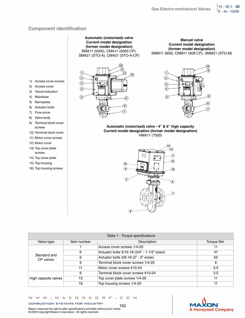
Gas Electro-mechanical Valves
w w w . m a x o n c o r p . c o mcombustion systems for industry
Maxon reserves the right to alter specifications and data without prior notice. © 2009 Copyright Maxon Corporation. All rights reserved.
10 - 30.1 - 30E - m - 10/09
Component identification
1) Access cover screws
2) Access cover
3) Visual indication
4) Mainbase
5) Nameplate
6) Actuator bolts
7) Flow arrow
8) Valve body
9) Terminal block cover screws
10) Terminal block cover
11) Motor cover screws
12) Motor cover
13) Top cover plate screws
14) Top cover plate
15) Top housing
16) Top housing screws
Automatic (motorized) valveCurrent model designation (former model designation)
SMA11 (5000), CMA11 (5000 CP), SMA21 (STO-A), CMA21 (STO-A-CP)
Manual valveCurrent model designation (former model designation)
SMM11 (808), CMM11 (808 CP), SMM21 (STO-M)
Automatic (motorized) valve - 4” & 6” high capacityCurrent model designation (former model designation)
HMA11 (7000)
Table 1 - Torque specifications
Valve type Item number Description Torque Nm
Standard and CP valves
1 Access cover screws 1/4-20 11
6 Actuator bolts 5/16-18 (3/4” - 1-1/2” sizes) 476 Actuator bolts 3/8-16 (2” - 6” sizes) 559 Terminal block cover screws 1/4-20 6
11 Motor cover screws #10-24 3.5
High capacity valves9 Terminal block cover screws #10-24 3.513 Top cover plate screws 1/4-20 11
16 Top housing screws 1/4-20 11
10
11 12
9
6
8
7
1
2
3
4
5
10
9
6
8
7
1
2
3
4
5
10
9
5
7
3
1314
15
16
6
8
182

Gas Electro-mechanical Valves
w w w . m a x o n c o r p . c o mcombustion systems for industry
Maxon reserves the right to alter specifications and data without prior notice. © 2009 Copyright Maxon Corporation. All rights reserved.
10 - 30.1 - 31E - m - 10/09
Installation
1. A gas filter or strainer of 40 mesh (0.6 mm) or smaller is recommended in the fuel gas piping to protect the downstream safety shut-off valves.
2. Properly support and pipe the valve in the direction of the flow arrow on the valve body. Valve seats are directional. Sealing will be maintained at full rated pressures in one direction only. Sealing will be provided in reverse flow only at reduced pres-sures.
3. Mount valve so that open/shut window indicator will be visible to your operating personnel. The open/shut window indicator should never face downward. The valve side plates should be located in a vertical plane for best performance. Valves are usually installed in horizontal piping; however, other orientations are acceptable, subject to the above limitations. The top assemblies of all MAXON valves are field rotatable to allow installations involving conflicts with these mounting restrictions.
4. Wire the valve in accordance with all applicable local and national codes and standards. In U.S. and Canada, wiring must conform to the NEC ANSI/NFPA 70 and/or CSA C22.1, Part 1.
Supply voltages must agree with valve’s nameplate voltage within -15%/+10% for proper operation. For electrical wiring schematic, see instructions or sample affixed inside valve terminal block cover.Grounding is achieved with a grounding screw, which is located in the top assembly.
Customer connections are provided via terminal blocks located in the top assembly.Main power wiring (120 VAC or 240 VAC) must be segregated from lower voltage 24 VDC signal wiring, when both are required.
5. Maintain integrity of the electro-mechanical actuator enclosures by using the appropriate electrical connectors for the (2) 3/4” NPT conduit threaded connections. The electrical enclosure is NEMA 4 rated with an option for NEMA 4X.
6. All access cover plate screws should be tightened using an alternate cross-corner tightening pattern to the values shown in Table 1 on page 10-30.1-31.
7. Verify proper installation and operation by electrically actuating the valve for 10-15 cycles prior to the first introduction of gas.
Auxiliary features
Non-adjustable proof of closure switch(es) with valve seal over travel interlock
Auxiliary switch for indication of full travel (open for normally-closed valves, closed for normally-open valves)
Operating environment
Actuators rated for NEMA 4 or optional NEMA 4X
Ambient and fluid temperature range of -28°C to 60°C for standard and CP flow constructionsAmbient and fluid temperature range of -28°C to 52°C for high capacity flow constructions
All valves for oxygen service or using Ethylene Propylene body seals are limited to a minimum ambient and fluid temperature of -18°C
183

Gas Electro-mechanical Valves
w w w . m a x o n c o r p . c o mcombustion systems for industry
Maxon reserves the right to alter specifications and data without prior notice. © 2009 Copyright Maxon Corporation. All rights reserved.
10 - 30.1 - 32E - m - 10/09
Actuator assembly rotation
1. Shut off all electrical power and close off upstream manual cock.2. Remove terminal block cover plate and disconnect power lead wires. (Tag carefully for later re-assembly.)3. Remove conduit and electrical leads.4. Note physical position of any signal switch actuator wands on auxiliary signal switches.5. Unscrew the two actuator bolts screwed up from the bottom to 6 mm. DO NOT completely remove. These bolts secure the
valve body to the valve’s top assembly housing.6. Gently lift the top assembly (not more than 6 mm in height); just enough to break the seal between the valve body assembly
and the rubber gasket adhering to the bottom of the top housing.
7. Remove the two actuator bolts screwed up from the bottom (were partially unscrewed in step 5).8. Carefully rotate top assembly to the desired position in a plane parallel to the top of the valve body casting. Rotate the top
housing about 30° beyond this position, and then rotate it back. Reposition the top housing back down onto the valve body casting. This should align the open/shut indicator with its window and provide proper alignment of the internal mechanism.
9. Realign holes in valve body casting with the corresponding tapped holes in the bottom of the top assembly housing. Be sure the gasket is still in place between the body and top housing.
10. Reinsert the actuator bolts up from the bottom through the body and carefully engage threads of the top assembly. Tighten securely.
11. Reconnect conduit and electrical leads, then check that signal switch wands are properly positioned and that the open/shut indicator moves freely. Failure to correct any such misalignment can result in extensive damage to the internal mechanism of your valve.
12. Energize valve and cycle several times from closed to full open position. Also electrically trip the valve in a partially opened position to prove valve operates properly.
13. Replace and secure terminal block cover plate and place valve in service.
MAXON electro-mechanical valves should be ordered in a configuration compatible with planned piping. If valve orientation is not correct, the actuator assembly can be rotated in 90° increments around the valve body centerline axis using the procedure below.
WARNING: Lifting too far may dislodge some small parts inside the top housing, requiring complex re-assembly and retesting by trained factory personnel.
184

Gas Electro-mechanical Valves
w w w . m a x o n c o r p . c o mcombustion systems for industry
Maxon reserves the right to alter specifications and data without prior notice. © 2009 Copyright Maxon Corporation. All rights reserved.
10 - 30.1 - 33E - m - 10/09
Field installation of valve position switch
General
Shut off fuel supply upstream of valve, then de-energize valve electrically.Remove terminal block and access cover to provide access, being careful not to damage gaskets.
Compare with illustrations below to identify your valve type.
Replacement switches
Note wand position and mounting hole location carefully, then remove 2 screws and lift existing switch. Install replacement switch in same mounting holes on bracket and verify correct wand position.Replace existing wiring one connection at a time, following original route and placement.
Add switches
NOTE: Instructions below are written for normally-closed valves. For normally-open valves, reverse switch nomenclature (VOS becomes VCS and vice versa).
Check illustrations below. If your valve uses a switch mounting bracket as in Fig. 1 & 2, mount switches to bracket using the mounting holes appropriate for valve type and size. For high capacity valves, mount switches on the support stand.Position bracket so VCS wand just touches top of actuator, then move downward slightly, depressing wand until switch clicks, then tighten mounting screws to hold this position.Pin bracket by drilling 3 mm diameter holes 6 mm deep into bracket mounting pad through drive pin holes, then tap drive pin in until flush (not required for high capacity valves).Route wires to wiring compartment as shown, then complete wiring connections and clean out metal drilling chips from previ-ous procedure.Cycle valve, checking switch actuation points carefully. (VCS actuates at top of stem stroke, VOS at bottom.) Simultaneously the valve body must be tested for switch continuity and seat leakage. Bend VOS switch wands slightly if necessary to insure valve is opening fully.Replace covers, then return valve to service.
Fig. 1Manual reset actuator3/4” - 3” standard flow
Fig. 2Automatic reset actuator
2-1/2” CP - 4” CP and 6” standard flow
Fig. 3Automatic reset actuator
4” & 6” high capacity
Reference mounting bracket A Reference mounting bracket B Switches mount on support stand
NCCOM#1 BLACK TO
#3 BLACK TO
BLACK TO MOTOR
TERMINAL #1
TERMINAL #3
NO
12
12 11 10 9 8 7 6 5 4 3 2 1
TO CLUTCH
185

Gas Electro-mechanical Valves
w w w . m a x o n c o r p . c o mcombustion systems for industry
Maxon reserves the right to alter specifications and data without prior notice. © 2009 Copyright Maxon Corporation. All rights reserved.
10 - 30.1 - 34E - m - 10/09
Wand position (for normally-closed valves)
Mounting brackets
VOS switch wand should be actuated from above
VCS switch wand should be actuated from below
Mounting bracket A Mounting bracket B
VCS switch mountson back of bracket
BracketMounting
Slots
2”-6”1-1/2”1-1/4”3/4”, 1”
Drive pins
VOS switch on front
3”, 4”, 6” (-2)3”, 4”, 6” (-2)2-1/2” (-2)2-1/2” (-1)
VCS switch on back
Bracket mounting
holes
VOS switchon front
186

Gas Electro-mechanical Valves
w w w . m a x o n c o r p . c o mcombustion systems for industry
Maxon reserves the right to alter specifications and data without prior notice. © 2009 Copyright Maxon Corporation. All rights reserved.
10 - 30.1 - 37E - m - 10/09
Maintenance instructions
MAXON electro-mechanical valves are endurance tested far in excess of the most stringent requirements of the various approval agencies. They are designed for long life even if frequently cycled, and to be as maintenance-free and trouble-free as possible. A valve operational test should be performed on an annual basis. If abnormal opening or closing is observed, the valve should be removed from service and your MAXON representative should be contacted. (See MAXON Technical Document 10-35.1.)
Valve leak test should be performed on an annual basis to assure continued safe and reliable operation. Every MAXON valve is operationally tested and meets the requirements of FCI 70-2 Class VI Seat Leakage when in good operable condition. Zero leakage may not be obtained in the field after it has been in service. For specific recommendations on leak test procedures, see MAXON Technical Document 10-35.2. Any valve that exceeds the allowable leakage, as set forth by your local codes or insurance requirements should be removed from service and your MAXON representative should be contacted.
Actuator assembly components require no field lubrication and should never be oiled.
Auxiliary switches, solenoids, motors, clutches or circuit boards may be replaced in the field.
If foreign material or corrosive substances are present in the fuel line, it will be necessary to inspect the valve to make certain it is operating properly. If abnormal opening or closing is observed, the valve should be removed from service. Contact your MAXON representative for instructions.
Operator should be aware of and observe characteristic opening/closing action of the valve. Should operation ever become sluggish, remove valve from service and contact MAXON for recommendations.
Address inquiries to MAXON. Local worldwide offices may be located at www.maxoncorp.com. Include valve serial number and nameplate information.
Do not attempt field repair of valve body or actuator. Any alterations void all warranties and can create potentially hazardous situations.
187

188

Flow Control Valves Page 7017
6/11
Capacities and SpecificationsSeries “CV” Control Valves and Series “BV” Balancing Valves
GeneralAll Maxon Flow Control Valves are designed forthrottling service only and are not intended fortight shut-off.
Series “CV” Valves are offered in four differentversions:1. Standard assemblies without connecting base and
linkage (CB & L) assembly (order CB & Lseparately)
2. UL (Underwriters Laboratory) listed assemblieswithout CB & L (CB & L ordered separately)
3. Standard assemblies with CB & L to accept electriccontrol operators, such as:A. Penn/Johnson #M-80 or #M-81B. Honeywell #M644, #M744, #M941, #M944 or
#M7044C. Barber-Colman #EA50
DesignationsBoth of these valve types are designated first by the
nominal pipe size (inlet and outlet) followed by theletters indicating the valve series.Example:
1" - Series “BV” Balancing Valve1-1/4" -U Series “CV” Control Valve
UL (Underwriters Laboratory) listed series “CV”Valve assemblies are available in all sizes for air,natural gas and liquefied petroleum gas service.
snoitacificepSevlaVlortnoC"VC"seireS)C°25(F°521:erutarepmettneibmamumixaM
)C°66(F°051:erutarepmetdiulfmumixaM
epyt-ylfrettuB"VC"seireS
eziSevlaV
wolFvCrotcaF
]1[
mumixaMerusserPtelnI
)GISP(
deriuqeReuqroT ]2[)sdnuop-hcni(
VC-"2/15
52
52
VC-U-"4/3 ]3[
VC-"4/311
VC-U-"1 ]3[
VC-"181
VC-U-"4/1-1 ]3[
VC-"4/1-1 24
VC-"2/1-1 08
VC-"2 83102
VC-"2/1-2 081
VC-"3 562 51
.sevlavnepo-ediwahguorhtwolfnodesabsrotcafvC]1[rewoltA.erusserpdetarmumixamrofnwohssideriuqereuqroT]2[
.deriuqerebyameuqrotssel,serusserp.stropdezisrednusetangised"U"]3[
snoitacificepSevlaVgnicnalaB"VB"seireS)C°25(F°521:erutarepmettneibmamumixaM
)C°66(F°051:erutarepmetdiulfmumixaM
seireSepyt-ylfrettuBeziSevlaV"VB"
rotcaFwolFvC ]1[telnImumixaM
erusserP )GISP(
VB-"2/1 5
52
VB-"4/3 11
VB-"1 81
VB-"4/1-1 24
VB-"2/1-1 08
VB-"2 83102
VB-"2/1-2 081
VB-"3 562 51
.evlavnepo-ediwahguorhtwolfnodesabsrotcafvC]1[
189

Page 7018 Flow Control Valves
Performance Data
Series “BV” and “CV” Gas Control Valves – Natural Gas Service
Note: The capacities andpressure drops indicated inthis chart are based onflow through a wide-openvalve. If valve is less thanfully open, higher dropsand lower flows will result.
[1] S.T.P. = StandardTemperature and Pressuredefined at: (60°F and 14.7PSIA and 15.6°C and 760mmHg)
Gas Valves are normallysized based on inletpressure and allowablepressure drop. Seeguidelines at left.
erusserPtelnIsaG porDerusserPdetsegguS
cw"5-cw"3 cw"5.1-cw"5.0
iso8-iso4 cw"2-cw"1
iso61-iso8 cw"5-cw"2
isp3-isp2 cw"01-cw"6
190

Flow Control Valves Page 7019
6/11
Series “BV” and “CV” Gas Control Valves – Propane Gas Service
Performance Data
Note: The capacities andpressure drops indicated inthis chart are based on flowthrough a wide-open valve.If valve is less than fullyopen, higher drops andlower flows will result.
[1] S.T.P. = StandardTemperature and Pressuredefined at: (60°F and 14.7PSIA and 15.6°C and 760mmHg)
Gas Valves are normallysized based on inletpressure and allowablepressure drop. Seeguidelines at left.
erusserPtelnIsaG porDerusserPdetsegguS
cw"5-cw"3 cw"5.1-cw"5.0
iso8-iso4 cw"2-cw"1
iso61-iso8 cw"5-cw"2
isp3-isp2 cw"01-cw"6
191

Page 7020 Flow Control Valves
Performance Data
Series “BV” and “CV” Gas Control Valves – Air Service
Note: The capacities andpressure drops indicated inthis chart are based on flowthrough a wide-open valve.If valve is less than fullyopen, higher drops andlower flows will result.
[1] S.T.P. = StandardTemperature and Pressuredefined at: (60°F and 14.7PSIA and 15.6°C and 760mmHg)
Air Valves are normally sized to match the combustion air pipe sizing.Pressure drops of 1" wc to 2.5" wc are typical. If supply pressures are higherthan required, smaller valves can be used, or travel limited to restrict maximumflow rate.
192

Flow Control Valves Page 7021
6/11
Dimensions (in inches)
Series “CV” Control Valves
Pipe threads on this page conform to NPT (ANSI Standard B2.1)
eziSA
B C D E GC-B ]1[ H-M ]2[
"2/1
91.4 26.4 60.3
61.387.1
87.0 85.1"4/3 98.1
"1 52.3 89.1 1 26.1
"4/1-1 83.3 49.1 91.1 96.1
"2/1-149.3 83.4 13.3 26.3 83.2 26.1 18.1
"2
"2/1-291.3 26.3 60.4
26.4 96.2 49.1 13.2
"3 5 60.3 13.2 5.2
namloC-rebraB]1[llewyenoH]2[
193

Page 7022 Flow Control Valves
Pipe threads on this page conform to NPT (ANSI Standard B2.1)
Series “BV” Balancing Valves
Dimensions (in inches)
eziS A B C D E
"2/1
52.152.2
61.3 57.052.1"4/3
"1 52.3 1
"4/1-1 83.1 83.3 91.1 44.1
"2/1-1 18.15.2 26.3
13.1 65.1
"2 88.1 26.1 88.1
"2/1-257.2 52.3
26.4 49.1 91.2
"3 5 13.2 65.2
194

Flow Control Valves Page 7023
6/11
Component IdentificationSeries “BV” Balancing Valves and Series “CV” Flow Control Valves
Series “BV” Balancing Valve
Series “CV” Control Valves
Typical internal construction(Series “CV” Valve shown)
Series “CV” Control Valve Nameplate
Order spare parts for Series “CV” and “BV” FlowControl Valves by identifying required items from thedrawings above and referencing information on valvenameplate (shown above).
195

INDUSTRIAL COMBUSTION EQUIPMENT AND VALVES
Maxon practices a policy of continuous product improvement. It reserves the right to alter specifications without prior notice.
Flow Control Valves Page 7000-S-1
6/11
lessens the chance of internal flow turbulence beingset-up in the piping manifolds and control valve.
– Check fluid flow direction through “-P” and “-O”poppet-type valves. It must flow only in directionmatching the arrow cast into valve body. If neces-sary, valve body may be rotated per instructionsgiven on page 7016.
– Install flow control valves carefully and maintainadequate dimensional clearance to allow fullstroke and travel of the valve’s control linkage.Internal drive mechanisms within a control motormay be damaged if linkage is restricted as to causebinding in high or low flow position.
CAUTION: All Flow Control Valves are designedfor throttling service only and are not intendedfor tight shut-off.
– Main system shut-off should always use amanual “leak-tight” upstream fuel cock.
– Support weight of piping independently. Do notplace any Maxon Flow Control Valve in a pipingbind. Provide pipe hangers and/or special supportfor related manifolds.
– Maxon connecting base and linkage assembliesare designed to locate and/or position thecontrol operator for its interaction with the FlowControl Valve assembly. They are not intended tosupport the weight of the control motor. Specialprovisions will be required to support the weight ofthe control operators.
– Use of pipe heavier than schedule #40 cancause interference with butterfly-type Flow ControlValves and restrict the valve from full opening.
– Flow Control Valves provide the means toadjust fluid and/or gas flows. They should beinstalled with at least four pipe diameter lengths ofstraight pipe before and after the valve. This
Mounting Instructions for motor operator on Series “CV” Flow Control Valves
For those Series “CV” Valve assemblies furnished withconnecting base and linkage, the accompanying diagramsillustrate mounting procedures relative to each specific typeoperator.
First, mount your control motor to connecting base inaccordance with diagrams at right.
Secondly, determine if your electric operator travelsthrough 90° or 180° rotations. Then arrange connectinglinkage and motor crank arm as shown below for yourspecific operator.
90° Control Motor 160° – 180° Control Motor
Honeywell#M644, M744,M941 or M944
(7616BR Crank)
Mount with four short boltsand nuts at indicated holes.
Barber-ColmanEA50
Mount with three short boltsand nuts at indicated holes.
Penn/JohnsonM80, M81
(MD3-600 Crank)
Mount with two short boltsand nuts and long boltscrewed into operator basethrough slotted hole.
Installation Instructions
Crank & Linkage Side
Crank & Linkage Side
Crank & Linkage Side
196

INDUSTRIAL COMBUSTION EQUIPMENT AND VALVES
Maxon practices a policy of continuous product improvement. It reserves the right to alter specifications without prior notice.
Page 7000-S-2 Flow Control Valves
Adjusting Instructions
Notice: Only generalized instructions can be providedhere. Detailed adjusting instructions are provided witheach individual Maxon burner and/or mixer system.
General InstructionsImportant: Do not discard packing materialsuntil all loose items are accounted for.
To prevent damage in transit, some connectingbase and linkage components may be packedseparately and shipped loose with your new MaxonFlow Control Valve.
The Flow Control Valve is normally only a part ofyour complete combustion system. Additional pipetrain accessories and control components may berequired for a complete system installation.
Read complete instructions before proceeding,and familiarize yourself with all the system’sequipment components. Verify that your equipmenthas been installed in accordance with the originalmanufacturer’s current instructions.
CAUTION: Initial adjustment and light-off ofburner systems should be undertaken only bytrained and experienced personnel familiar withcombustion systems, with control/safetycircuitry, and with knowledge of the overallinstallation. Instructions provided by thecompany and/or individuals responsible for themanufacture and/or overall installation ofcomplete system incorporating Maxon burnerstake precedence over these provided by Maxon.If Maxon instructions conflict with any codes orregulations, contact Maxon Corporation beforeattempting start-up.
For initial adjustment and/or burner start-up:1. Close all burner fuel valves and cocks. Make
preliminary adjustments to fuel gas regulators.2. Check all electric circuitry. Verify that all
control devices and interlocks are operable andfunctioning within their respective settings/ranges. Be sure all air and fuel manifolds aretight and that test ports are plugged if not beingused.
3. Check that any air handling dampers areproperly positioned and locked into operatingpositions.
4. Disconnect the automatic control motor’slinkage from your control valve’s operating crankarm by loosening the control motor’s connectingrod from the burner’s toggle linkage.
Initial adjustment should only beaccomplished during a “manual” controlmode.
5. Start all system-related fans and blowers.Check for proper motor rotation and impellerdirection. Verify that all control interlocks areworking. Allow air handling equipment to run foradequate purge of your manifolds.
CAUTION: Do not by-pass control panel timerstypically controlling sequential operations.
6. With MICRO-RATIO® Valve combinations ofair and fuel valves, the minimum differentialpressure setting is initially established withthe air valve only.A. By disconnecting the linkage between the air
butterfly valve and interconnected fuelvalve(s), the minimum and maximum limits oftravel on the air valve may be determined.For example, a combustion system may
need the air valve to be 15° open for the“minimum” setting and the “maximum”requirements are satisfied with the air valveopen to 60°. By marking these points on theair valve’s indicating strip, you are ready toreconnect the SYNCHRO Fuel Valve’slinkage to the air valve.
B. The next step involves adjusting theconnecting linkage between the air valveand the fuel valve(s) so that each fuel valvetravels its full quadrant range (i.e. fromminimum to maximum), while the air valveswings from its pre-determined minimum andmaximum positions.
C. With Series “CV” Flow Control Valves, theminimum flow position is set by their minimumstop screw. This adjustable stop is located atthe base of the crank arm of Series “CV”Valves. Screwing “in” on the minimum stopscrew produces a physical stop on thequadrant’s travel that prohibits valve frombeing completely closed off.
197

198

199

200

201

202

203

204

205

206

207

208

209

210

211

212

213

214

215

216

217

218

219

220

221

222

223

224

225

226

227
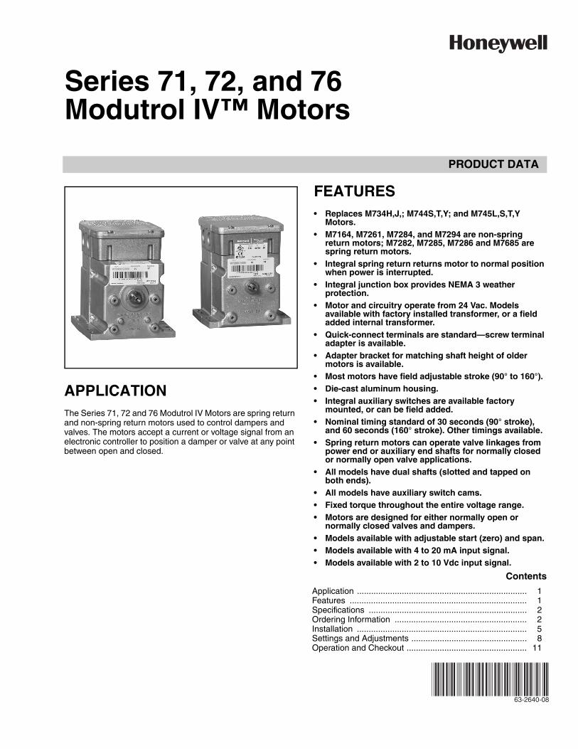
PRODUCT DATA
63-2640-08
Series 71, 72, and 76Modutrol IV™ Motors
APPLICATIONThe Series 71, 72 and 76 Modutrol IV Motors are spring return and non-spring return motors used to control dampers and valves. The motors accept a current or voltage signal from an electronic controller to position a damper or valve at any point between open and closed.
FEATURES• Replaces M734H,J,; M744S,T,Y; and M745L,S,T,Y
Motors.• M7164, M7261, M7284, and M7294 are non-spring
return motors; M7282, M7285, M7286 and M7685 are spring return motors.
• Integral spring return returns motor to normal position when power is interrupted.
• Integral junction box provides NEMA 3 weather protection.
• Motor and circuitry operate from 24 Vac. Models available with factory installed transformer, or a field added internal transformer.
• Quick-connect terminals are standard—screw terminal adapter is available.
• Adapter bracket for matching shaft height of older motors is available.
• Most motors have field adjustable stroke (90° to 160°).• Die-cast aluminum housing.• Integral auxiliary switches are available factory
mounted, or can be field added.• Nominal timing standard of 30 seconds (90° stroke),
and 60 seconds (160° stroke). Other timings available.• Spring return motors can operate valve linkages from
power end or auxiliary end shafts for normally closed or normally open valve applications.
• All models have dual shafts (slotted and tapped on both ends).
• All models have auxiliary switch cams.• Fixed torque throughout the entire voltage range.• Motors are designed for either normally open or
normally closed valves and dampers.• Models available with adjustable start (zero) and span.• Models available with 4 to 20 mA input signal.• Models available with 2 to 10 Vdc input signal.
Contents
Application ........................................................................ 1Features ........................................................................... 1Specifications ................................................................... 2Ordering Information ........................................................ 2Installation ........................................................................ 5Settings and Adjustments ................................................. 8Operation and Checkout ................................................... 11

SERIES 71, 72, AND 76 MODUTROL IV™ MOTORS
63-2640—08 2
ORDERING INFORMATIONWhen purchasing replacement and modernization products from your TRADELINE® wholesaler or distributor, refer to the TRADELINE® Catalog or price sheets for complete ordering number. If you have additional questions, need further information, or would like to comment on our products or services, please write or phone:
1. Your local Honeywell Environmental and Combustion Controls Sales Office (check white pages of your phone directory).2. Honeywell Customer Care
1885 Douglas Drive NorthMinneapolis, Minnesota 55422-4386
3. http://customer.honeywell.com or http://customer.honeywell.caInternational Sales and Service Offices in all principal cities of the world. Manufacturing in Belgium, Canada, China, Czech Republic, Germany, Hungary, Italy, Mexico, Netherlands, United Kingdom, and United States.
SPECIFICATIONSModels: TRADELINE models are selected and packaged to provide ease of stocking, ease of handling and maximum replacement value. TRADELINE model specifications are the same as those of standard models unless specified otherwise.
IMPORTANTThe specifications given in this publication do not include normal manufacturing tolerances. Therefore, an individual unit may not exactly match the listed specifications. Also, this product is tested and calibrated under closely controlled conditions and some minor differences in performance can be expected if those conditions are changed.
Modutrol IV Order Number Guide: See Table 4.
Dimensions: See Fig. 2.
Lifetime60,000 Full Stroke CyclesRepositions: 1.5 Million
Controller: These motors can be used with any electronic controller that provides a stable noise-free proportional current output as specified in Electrical Ratings, Input Range below.
Electrical Ratings:Power Consumption: See Table 1.Input Range:
Current, Nonadjustable: 4 to 20 mA nominal, 25 mA maximum.
Current, Adjustable: 4 to 20 mA adjustable, 50 mA maximum.
Zero/Null (Motor Closed): 0.0 to 18 mA.Span: 1.8 to 20 mA.Voltage, Nonadjustable: 2 to 10 Vdc.
Input Impedance:4 to 20 mA Input: 100 ohms.2 to 10 Vdc Input: 400K ohms.
Auxiliary Switch Ratings (in Amps): See Table 2.
Stroke: Most models available with field adjustable strokes from 90° to 160°. Stroke adjusted by means of potentiometers located in the wiring compartment.
Timing: Nominal 30 seconds for 90° stroke and 60 seconds for 160° stroke.
Dead Weight Load On Shaft: 200 lb (91 kg) on motor power or auxiliary end; maximum combined load of 300 lb (136 kg).
Ambient Temperature Ratings: -40 to 150°F (-40 to 66°C).
Shaft: 3/8 in. (9.5 mm) square.
Motor Rotation:Closed: Counterclockwise rotation limit as viewed from motor
power end.Mechanically Normally Closed: Spring return. Normally closed
motors rotate to closed position on power loss.Electrically Normally Closed: Both spring return and non-
spring motors return to closed position on minimum signal.
Table 1. Series 72 Modutrol IV Motor Power Consumption Ratings (at 120 Vac, 50/60 Hz).
Table 2. Auxiliary Switch Ratings (in Amps).
a 40 VA pilot duty, 120/240 Vac on opposite contact.
Approvals:Underwriters Laboratories Inc. Listed: File No. E4436; Guide
No. XAPX for USA and Canada.U.S. Patents: pending
Table 3. Primary 50017460-001 Color Code
Model
Power Consumption
VA Watts
M7261 15 13
M7282 20 18
M7284 15 13
M7285 20 18
M7286 20 18
M7294 15 13
One Contact Ratinga 120V 240V
Full Load 7.2 3.6
Locked Rotor 43.2 21.6
Lead Color Primary Voltage
Brown 24 VAC
White 120 VAC
Blue 230 VAC
Black Common

SERIES 71, 72, AND 76 MODUTROL IV™ MOTORS
3 63-2640—08
Fig. 1. Stroke
Table 4. Modutrol IV Motors Series 2 and 3 Model Number Guide.
a Adjustable zero and span.* Fixed stroke on M7284C1083, M7284C1091, M7284Q1082, and M7284Q1090
M Motor71 10.5 - 13.5 Vdc voltage input72 4-20 mA or 2-10 Vdc Control76 14-17 dc voltage control with minimum position capability
6 — 35 lb-in. Non-Spring Return7 — 75 lb-in. Non-Spring Return8 60 lb-in. Spring Return 150 lb-in. Non-Spring Return9 — 300 lb-in. Non-Spring Return
2 Dual-ended shaft Normally Closed Spring Return4 Non-Spring Return5 Normally Closed Spring Return
A 0 Auxiliary Switches Adjustable Stroke * Normally ClosedB 1 Auxiliary SwitchC 2 Auxiliary SwitchesD 0 Auxiliary Switch
Qa 2 Auxiliary Switches
M 72 8 4 A XXXX See Tradeline Catalog for Complete Model Number
FULLY OPEN90 DEGREE STROKE 160 DEGREE STROKE
M31079
VERTICALREFERENCE
FULLY CLOSED
160
10
VERTICALREFERENCE
FULLY CLOSED
90
10
FULLY OPEN
VERTICALREFERENCE
VERTICALREFERENCE
FULLY CLOSED
FULLY OPEN
FULLY CLOSED
FULLY OPEN
90 DEGREE STROKE 160 DEGREE STROKE
NON-SPRING RETURN MOTORS
160
10
90
45
SPRING RETURN MOTORS AND NON-SPRING RETURN MOTORS
ASYMMETRICAL MOTORS SYMMETRICAL MOTORS

SERIES 71, 72, AND 76 MODUTROL IV™ MOTORS
63-2640—08 4
Fig. 2. Series 72 Modutrol IV Motor dimensions in inches (mm).
M18998D
4-7/8(124)
5-1/2(140)
13/16(20)
4-1/16 (103)
1/4(7)
1-1/2 (37)
5-1/2 (140)
JUNCTIONBOX
MOTOR
AUXILIARYEND
POWEREND
ADAPTERBRACKET
2-9/16(66)
5-3/8(137)
6-7/16(164)
9/16 (15)
3/4(19)
TOP VIEW OF BRACKET TOP VIEW
4-5/8(116)
4-1/4(107)
2-5/16(58)
11/16(17)
4-7/8 (124)5-9/16 (141)
1/4 (7)
5-13/16(148)
1
POWER END
2
3
1-1/2 (37)
3/4(19)
SPRING RETURN MODEL SHOWNFOR 60 LB-IN. SPRING RETURN MODELS 8-3/4 (222). FOR NON-SPRING RETURN MODELS 7-5/16 (185).
FOR 60 LB-IN. SPRING RETURN MODELS (SHOWN).
FOR NON-SPRING RETURN MODELS.
1
2
3
13/16(20)

SERIES 71, 72, AND 76 MODUTROL IV™ MOTORS
5 63-2640—08
Accessories:220736A Internal Auxiliary Switch Kit; one switch.
Can be field-installed.220736B Internal Auxiliary Switch Kit; two switches, can be
field-installed on TRADELINE models.220738A Adapter Bracket raises motor shaft height by 3/4 in
(19 mm) to match that of previous Modutrol Motor models.220741A Screw Terminal Adapter converts the standard quick-
connect terminals to screw terminals.221455A Infinitely Adjustable Crank Arm, can rotate through
downward position and clear motor base without requiring an adapter bracket.
4074ERU Weatherproofing Kit provides NEMA 3 rating for Modutrol IV Motors mounted in position other than upright.
50017460-001 Internal Transformer; 24/120/230 Vac 50/60 Hz primary, 24 Vac secondary, quick connect terminals.
50017460-003 Internal Transformer; 120 Vac 50/60 Hz primary, 24 Vac secondary, quick connect terminals.
7617ADW Crank Arm, can rotate through downward position and clear motor base without requiring an adapter bracket.
Q100 Linkage connects Modutrol Motor to V51 Butterfly Valve. Requires the 220738A Adapter Bracket.
Q181 Auxiliary Potentiometer for sequence or unison control of 1 to 4 additional modulating (Series 90) motors.
Q209E,F Manual Potentiometer for Modutrol MotorsQ5001 Bracket and Linkage Assembly connects Modutrol IV
Motor to water or steam valve.Q605 Damper Linkage connects motor to damper. Includes
motor crank arm.Q607 External Auxiliary Switch controls auxiliary equipment as
a function of motor position.ES650-117 Explosion-Proof Housing encloses motor for use in
explosive atmospheres. Also required, a 7617DM coupling assembly from Honeywell to use with the cover. Not for use with Q5001 (or any other valve linkages). To order ES650-117, contact EGS Enclosures at (281) 449-6271, ask for the sales department and for distribution in your area.
INSTALLATION
When Installing this Product...1. Read these instructions carefully. Failure to follow them
could damage the product or cause a hazardous condition.
2. Check the ratings given in the instructions and on the product to make sure the product is suitable for your application.
3. Installer must be a trained, experienced service technician.
4. After installation is complete, check out product operation as provided in these instructions.
CAUTIONElectrical Shock or Equipment Damage Hazard.Can shock individuals or short equipment circuitry.Disconnect all power supplies before installation.Motors with auxiliary switches can have more than one disconnect.
CAUTIONEquipment Damage Hazard.Can damage the motor beyond repair.Never turn the motor shaft by hand or with a wrench.Forcibly turning the motor shaft damages the gear train and stroke limit contacts.
IMPORTANTAlways conduct a thorough checkout when installation is complete.
LocationAllow enough clearance for accessory installation and motor servicing when selecting a location (see Fig. 2). If located outdoors, use liquid-tight conduit connectors with the junction box to provide NEMA 3 weather protection. If mounted outdoors in a position other than upright, install a 4074ERU Weatherproofing Kit and liquid-tight connectors to provide NEMA 3 protection.
CAUTIONMotor Damage Hazard.Deteriorating vapors and acid fumes can damage metal parts.Install motor in areas free of acid fumes and other deteriorating vapors.
In excessive salt environments, mounting base and screws should be zinc or cadmium plated, not stainless steel or brass. Use the 220738A Adapter Bracket for mounting on these surfaces.
MountingUse the following guidelines for proper motor mounting:• Always install motors with the crankshaft horizontal.• Mounting flanges extending from motor housing base are
drilled for 1/4 inch (6.4 mm) machine screws or bolts.• Non-Spring Return Motors are shipped from the factory in
the closed position (at the counterclockwise rotation limit, as viewed from the motor power end).
• Spring Return Motors are shipped from the factory in their normal position.
• Normally closed models are shipped at the counterclockwise rotation limit, as viewed from the motor power end.
Adapter BracketThe 220738A Adapter Bracket, positioned between the motor and the equipment, raises motor shaft height by 0.75 in. (19 mm) to match that of previous Modutrol Motor models.
The following applications require this bracket:• Q607 External Auxiliary Switch.• Damper linkage applications requiring added clearance to
allow:— Crank arm rotation through the downward position.— Sufficient damper linkage to reach the motor shaft.
• All valve linkages except the Q5001.
NOTE: When the bracket is not used in a replacement application, the damper linkage requires adjust-ment for the new shaft position.
To mount the motor with the bracket:1. Mount the bracket to the equipment with existing or stan-
dard bolts.2. Using the provided bolts, mount the motor to the bracket
threaded holes. See Fig. 3.For valve linkage applications (other than the Q5001):
1. Mount the bracket to the linkage.2. Position the motor on the bracket to align the motor shaft
with the linkage.

SERIES 71, 72, AND 76 MODUTROL IV™ MOTORS
63-2640—08 6
3. Attach the motor to the bracket with the four bolts provided. See Fig. 4.
Fig. 3. Mounting the motor with an adapter bracket.
Damper LinkagesThe motor does not include a crank arm. Order the crank arm separately (see Accessories in the Specifications section). For detailed instructions on the assembly of specific linkages, refer to the Installation Instructions packed with the linkage.
CAUTIONEquipment Damage Hazard.Stalling a motor can damage the drive shaft.Ensure installation of motors and linkages allows the motor to drive through full stroke without obstruction.
Valve LinkagesThe Q100 Linkage requires a 220738A Adapter Bracket for all valve applications. Applications with the Q5001 Valve Linkage do not require the 220738A Adapter Bracket (see Fig. 4).
For detailed instructions on specific linkage assemblies, refer to the instruction sheet packed with the linkage. In general, check the following points when installing a motor and linkage:• Adjust valve and louver-type damper linkages so the damper
or valve moves through only the maximum required distance while the motor moves through its full stroke.
• With modulating control, maximum damper opening should be no more than 60 degrees. Little additional airflow is provided beyond this point.
• Do not exceed load and torque ratings in any application.
Junction BoxWhen used with liquid-tight conduit connectors, the junction box provides NEMA 3 weather protection for the motor. The junction box, standard with replacement motors, encloses the terminals and provides knockouts for wiring conduits. Housing an internal transformer or internal auxiliary switches requires using a junction box.
M18999
EQUIPMENTBASE
ADAPTERBRACKET
STANDARDBOLTS (4)
MOTOR
BOLTS PROVIDED (4)
WIRING BOX
NON-SPRING RETURN SPRING RETURN
1 #12 OR 1/4" ZINC PLATED MACHINE SCREWS OR BOLTS
1
POWER END
POWER END
POWER END

SERIES 71, 72, AND 76 MODUTROL IV™ MOTORS
7 63-2640—08
Fig. 4. Mounting the motor on a Q5001 Valve Linkage.
Wiring
CAUTIONElectrical Shock or Equipment Damage Hazard.Can shock individuals or short equipment circuitry.Disconnect all power supplies before installation.Motors with auxiliary switches can have more than one disconnect.
IMPORTANTAll wiring must agree with applicable codes, ordinances and regulations.
1. Ensure that the voltage and frequency stamped on the motor correspond with the power supply characteristics.
2. When connecting several motors in parallel, ensure that the power supply VA rating is large enough to provide power to all motors used without overloading.
3. Fig. 10 shows that motor terminals are quick-connects located on top of the printed circuit board.
4. To access the wiring compartment:a. Remove the four screws from the junction box top.b. Lift off the cover.
5. Refer to Fig. 5 through 8 for wiring.
Wire the motor as follows:1. Remove the wiring box cover by removing the four
screws holding the cover to the motor.2. Wire motor to system using quick-connect terminals in
wiring box.
3. Replace wiring box cover.
Fig. 5. Typical system wiring.
Fig. 6. Series 71 optional override switches to drive motor open or closed.
Fig. 7. M7685 Typical application wiring.
1/4-20 UNC1 in. LONGMOUNTINGBOLTS
Q5001VALVELINKAGE
M18994
MOTOR
JUNCTIONBOX
POWEREND OFMOTOR
VALVE
CONTROLLER
L1(HOT)
L2
POWER SUPPLY. PROVIDE DISCONNECT MEANS ANDOVERLOAD PROTECTION AS REQURED.
CONNECTING F TO – WILL DRIVE MOTOR TO FULLY OPEN.
1
M5778
1
-
MOTOR
2F
T1
T2
2
+
-
+
24V
POWER SUPPLY. PROVIDE DISCONNECT MEANS AND OVERLOAD PROTECTION AS REQUIRED.
M13726
L1
L2
R
MODULATINGDC VOLTAGESOURCE
1
L1
L2
(HOT)
+C
F
1
DAMPER MOTOR
1
2
3
T1
T2
C
R
4
3
1
L1
L2 (H OT )
+-
22
3
DAMPER MOTORS
WHITE
RED
MODULATING dc VOLTAGE SOURCE
MINIMUM POSITION POTENTIOMETER EXTERNAL
CONTROL
POWER SUPPLY. PROVIDE DISCONNECT MEANS AND OVERLOAD PROTECTION AS REQUIRED.
IF MINIMUM POSITION POTENTIOMENTER IS NOT USED,JUMPER TERMIALS 3 AND 4.
TRANSFORMER MAY BE INTERNAL OR EXTERNAL. M13727A

SERIES 71, 72, AND 76 MODUTROL IV™ MOTORS
63-2640—08 8
Fig. 8. Driving up to six motors from one 4 to 20 mA controller.
SETTINGS AND ADJUSTMENTS
Before Setting Stroke1. Remove the top cover from the motor.2. Disconnect the controller from the motor.3. For models with an internal transformer (line voltage
motors), ensure that power (and nothing else) remains connected to the motor.
IMPORTANTDetach linkage from motor before adjusting stroke.
CAUTIONCareless Installation Hazard.Use of excessive force while adjusting cams damages the motor.To avoid damaging motor end switches, set cams by moving only the screwdriver top.
CAUTIONEquipment Damage Hazard.Can damage the motor beyond repair.Never turn the motor shaft by hand or with a wrench.Forcibly turning the motor shaft damages the gear train and stroke limit contacts.
Adjustable StrokeAll models except for M7284C1083, M7284C1091, M7284Q1082, and M7284Q1090.When viewing from the power end of the motor, the stroke potentiometer is to the far left. To set the stroke to 160° (maximum position) turn the potentiometer fully clockwise
, using a 1/8 in. straight-blade screwdriver. To set the stroke at 90° (minimum position) turn the potentiometer fully counter-clockwise . Setting the potentiometer anywhere between fully clockwise and fully counter-clockwise will set the stroke between 160° and 90°.
Fig. 9. Stroke adjustment setup
4-20 mACONTROLLER
L1(HOT)
L2
POWER SUPPLY. PROVIDE DISCONNECT MEANS ANDOVERLOAD PROTECTION AS REQURED.
CONNECTING F TO – WILL DRIVE MOTOR TO FULLY OPEN.MOTORS FUNCTION INDEPENDENTLY.
1
M31109
1
MOTOR
MOTOR
+
-
MOTOR
2F
T1
T2
2F
T1
T2
2F
T1
T2
2
+-
+
+-
-
M13699
POWER ENDOF MOTOR
AUXILIARY SWITCH CAMS
ADJUSTABLESTROKE POTENTIOMETER

SERIES 71, 72, AND 76 MODUTROL IV™ MOTORS
9 63-2640—08
Zero and Span Adjustment for M7284Q, M7285Q, and M7294QM7284Q, M7285Q, and M7294Q actuators have the capability of adjustable zero and span. Fig. 10 shows the module with the zero and span potentiometers.
Zero: Sets input voltage to define the 0% angle of rotation. It is factory set to minimum position and can be adjusted to the maximum position of 20mA or 10V.
Span: Adjusts motor response to travel a full stroke through the selected input span. It is factory set to maximum position, and is adjustable from 4-20mA or 2-10Vdc.
1. Adjust the start potentiometer fully clockwise (maximum zero) and the span potentiometer fully counterclockwise (minimum span). See Fig. 10.
2. Set the controller current to the value required to drive the motor to the closed position.
3. Turn the start potentiometer slowly counterclockwise until the motor begins to open. This is defined as the start or zero setting.
4. Set the controller current to the value required to drive the motor to the fully open position. The motor will open.
5. Turn the span potentiometer clockwise until the motor starts to close. The difference between the fully open span position current and the zero position current is defined as the operating span.
6. Recheck the start and readjust the span potentiometer if necessary. Turn the start potentiometer clockwise to increase the zero position.
7. Recheck the span and readjust the span potentiometer if necessary. Turn it clockwise to increase the full span position.
8. For sequential operation, as shown in Fig. 11, repeat the above steps for each motor.
Fig. 10. Terminals and adjustments.
RIGHT/INNER AUXILIARY SWITCH
INNER AUXILIARYSWITCH CAM (BLUE)
POWEREND
OUTER AUXILIARYSWITCH CAM (RED)
LEFT/OUTER AUXILIARY SWITCH
NOTE: FEATURES AVAILABLE ON SOME MODELS ONLY.
M13648A
(+)
(-)
T2
T1
F
RIGHT/INNER AUXILIARY SWITCH
INNER AUXILIARYSWITCH CAM (BLUE)
POWEREND
OUTER AUXILIARYSWITCH CAM (RED)
LEFT/OUTER AUXILIARY SWITCH
NOTE: FEATURES AVAILABLE ON SOME MODELS ONLY.
Y(+)
T2
T1
F (TEST)
A B
V(-)
2 TO 10 VDC INPUT MOTORS 4 TO 20 mA NONADJUSTABLE INPUT MOTORS
NOTE: FEATURES AVAILABLE ON SOME MODELS ONLY.4 TO 20 mA ADJUSTABLE INPUT MOTORS
C SPAN ADJUST POTENTIOMETER
START ADJUST POTENTIOMETER
STA
RT
AD
JUS
TM
IN
MA
XS
PAN
AD
JUS
TM
IN
M
AX
RIGHT/INNER AUXILIARY SWITCH
INNER AUXILIARYSWITCH CAM (BLUE)
POWEREND
OUTER AUXILIARYSWITCH CAM (RED)
LEFT/OUTER AUXILIARY SWITCH
T1
T2
(–)
(+)
F
1
1 RESOLUTION POTENTIOMETER, 160 ON M7284C1083, M7284C1091, M7284Q1082, AND M7284Q1090

SERIES 71, 72, AND 76 MODUTROL IV™ MOTORS
63-2640—08 10
Fig. 11. Sequential operation of motors.
Enhanced ResolutionM7284C1083, M7284C1091, M7284Q1082, and M7284Q1090These four motors have enhanced resolution with 160 repositions (steps) from 90 degrees to 160 degrees stroke.
Auxiliary Switches
CAUTIONElectrical Shock or Equipment Damage Hazard.Can shock individuals or short equipment circuitry.Disconnect all power supplies before installation.Motors with auxiliary switches can have more than one disconnect.
CAUTIONEquipment Damage Hazard.Can damage the motor beyond repair.Never turn the motor shaft by hand or with a wrench.Forcibly turning the motor shaft damages the gear train and stroke limit contacts.
Adjustable cams actuate the auxiliary switches. These cams can be set to actuate the switches at any angle within the motor stroke. Select switch differential of 1° or 10°.
Motors with factory added auxiliary switches are shipped in the closed position (fully counterclockwise, as viewed from the motor power end) with auxiliary cams set to actuate switches 30° from the closed position and to provide 1° degree differential. With the motor in the closed (fully counter-clockwise) position, the auxiliary switch breaks contacts R-B. See Fig. 12 for auxiliary switch wiring.
Series 2 Motors are shipped with auxiliary switch cams that permit acceptance of 220736A,B Internal Auxiliary Switch Kits. Refer to form 63-2228 for 220736A,B Installation Instructions.
Auxiliary Switch Adjustment
IMPORTANTWhen adjusting the auxiliary switch cams use the following procedure:
1. Insert 1/8 in. screwdriver blade into a slot on cam and move the screwdriver top as far as possible in the required direction. See Fig. 12.
2. Repeat step 1 in successive cam slots until the cam is in the required position.
NOTE: Series 2 Motors are shipped with auxiliary switch cams that permit acceptance of 220736A,B Inter-nal Auxiliary Switch Kits. Refer to Form no. 63-2228 for 220736A,B Installation Instructions.
Use the following procedure to obtain the desired auxiliary switch settings:
1. Remove the top cover from the motor to gain access to the motor terminals and auxiliary cams.
2. Disconnect the controller from the motor.3. Connect a current source to the positive and negative
terminals.4. Drive the motor to the position where the auxiliary equip-
ment is to be switched by increasing or decreasing the current.
5. For a switch differential of 1°, check continuity of auxiliary switch contacts R-B and rotate the cam as follows:a. If the contacts are open, rotate the cam clockwise
until the R-B contacts close.b. If the contacts are closed, rotate the cam
counterclockwise until the R-B contacts open.6. For a switch differential of 10° rotate the cam
approximately 180° so the slow-rise portion of the cam actuates the switch.
7. Check continuity of the auxiliary switch contacts R-B.8. Rotate the cam as follows:
a. If the contacts are open, rotate the cam counterclockwise until the R-B contacts close.
b. If the contacts are closed, rotate the cam clockwise until the R-B contacts open.
c. Make final adjustment in the proper direction to obtain contact make or break at the desired position.
9. Check for the proper differential and switching of the aux-iliary equipment by driving the motor though the full stroke in both directions.
10. Disconnect power, remove current source, reconnect the controller, and replace the top cover on the motor.
NOTE: Changing the differential from 1° to 10° reverses the switching action. For example, with a 10° dif-ferential, switch contacts R-B make and R-W break on a counterclockwise (closed) rotation. With a 1° differential, switch contacts R-W make and R-B break on a counterclockwise (closed) rotation.
20(10)
16(8)
12(6)
8(4)
4(2)
0
CO
NT
RO
L O
UT
PU
Tm
A C
UR
RE
NT
(O
R V
OLT
S D
C)
CLOSED OPEN CLOSED OPEN CLOSED OPEN
MOTOR 1 MOTOR 2 MOTOR 3
1 3 3 3
1 MOTOR 1 PROPORTIONS BETWEEN 4 AND 12 mA; FULLYCLOSED AT 4 mA, FULLY OPENED AT 12 mA.
MOTOR 2 PROPORTIONS BETWEEN 8 AND 16 mA; FULLYCLOSED AT 8 mA, FULLY OPENED AT 16 mA.
MOTOR 3 PROPORTIONS BETWEEN 12 AND 20 mA SIGNAL; FULLY CLOSED AT 12 mA, FULLY OPENED AT 20 mA.
UP TO 6 MOTORS CAN BE DRIVEN SEQUENTIALY OR IN UNISON FROM ONE CONTROLLER.
ADJUST ZERO ADJUST AND SPAN ADJUST POTENTIOMETERS TO ACHIEVE DESIRED SEQUENCE.
2
2
3
SEQUENTIAL OPERATION
FOR ADJUSTABLE ZERO AND SPAN MODELS
M2893A

SERIES 71, 72, AND 76 MODUTROL IV™ MOTORS
11 63-2640—08
Fig. 12. Auxiliary switch adjustment.
OPERATION AND CHECKOUT
OperationThe internal shaft position feedback potentiometer in conjunction with the actuator microprocessor and modulating input circuit form a control loop. When the external controller’s output remains at a fixed amplitude the actuator’s shaft position is held at a position proportional to that input amplitude. When the value of the external controllers output changes the actuator responds by initiating movement of the motor to proportionately compensate for the change in input amplitude. When the motor reaches the control loop balance point the system is again in a static state and the actuator holds position until the next change of input from the external controller.
M7685 motor also have a minimum position feature. An external 130 ohm potentiometer wired to terminals 3 and 4 establishes a position beyond which the control input cannot close the motor. If power to the T1-T2 is interrupted the M7685 motor will spring close.
CheckoutAfter installation and linkage adjustment, operate the motor through the controller. Make sure that:• The motor properly operates the damper or valve.• The motor responds properly as the input is varied.• The auxiliary switch, if used, operates at the desired point of
motor rotation.
Inspect the motor, linkage, and valve or damper to see that all mechanical connections are correct and secure.
In damper installations, the pushrod should not extend more than a few inches past the ball joints. Check to see that there is adequate clearance for the linkage to move through its stroke without binding or striking other objects.
See controller or system instructions for additional checkout procedures.
Motor Operation Checkout
For motors with F, + and - terminals:To close the motor, open terminals +, -, and F.To open the motor connect terminal F to positive (+) or negative (-).NOTE: DO NOT SHORT + to -
M7164A1017 and M7164G1030 do not have + or – terminals, and operate as follows:The motor closes if it does not receive an input to F.To open the motor, short F to C.
M7685A1025 is a normally open motor, and operates as follows:To close the motor, short 3 to 4 or short 3 to C.The motor opens if it does not have an input to 3.
RIGHT/INNER AUXILIARYSWITCH
FAST RISEPORTION(APPROX. 1 DIFF.)
SLOW RISEPORTION(APPROX. 10 DIFF.)
INNERAUXILIARY
CAM(BLUE)
NOTE: CAMS ARE OFFSET VERTICALLY TO PROVIDE BETTER VIEW OF BACK CAM.
FAST RISEPORTION(APPROX. 1 DIFF.)
SLOW RISEPORTION(APPROX. 10 DIFF.)
MOTOR OPEN
MOTOR CLOSE
POWER END
OUTERAUXILIARY
CAM(RED)
LEFT/OUTERAUXILIARYSWITCH
M17101POWER ENDOF MOTOR
OUTER AUXILIARY CAM (RED)
INNER AUXILIARY CAM (BLUE)
RIGHT/INNERAUXILIARY SWITCH
LEFT/OUTERAUXILIARY SWITCH
MOVE SCREWDRIVER AT TOP ONLY TO ADJUST CAM.
1/8 INCH STRAIGHT-BLADE SCREWDRIVER

SERIES 71, 72, AND 76 MODUTROL IV™ MOTORS
Automation and Control SolutionsHoneywell International Inc.
1985 Douglas Drive North
Golden Valley, MN 55422
customer.honeywell.com
® U.S. Registered Trademark© 2012 Honeywell International Inc.63-2640—08 M.S. Rev. 10-12Printed in United States
By using this Honeywell literature, you agree that Honeywell will have no liability for any damages arising out of your use or modification to, the literature. You will defend and indemnify Honeywell, its affiliates and subsidiaries, from and against any liability, cost, or damages, including attorneys’ fees, arising out of, or resulting from, any modification to the literature by you.

240

241

242

243

1
FIREYEMODULAR
MicroMFLAME SAFEGUARD CONTROLS
WARNING: Selection of this control for a particular application should be made by a com-petent professional, licensed by a state or other government agency. Inappropriate applicationof this product could result in an unsafe condition hazardous to life and property.
DESCRIPTIONThe Fireye MicroM Series Flame Safeguard Control is a compact, microprocessor based, modularburner management system designed to provide automatic ignition and continuous flame monitoringfor commercial sizes of heating and process equipment firing any type of fuel.The MicroM is designed to be backward compatible with existing TFM, UVM and M-Series II con-trols. The MicroM MEC120 and MEC230 chassis with the appropriate MEP100, MEP200 andMEP500 series programmers provide operation similar to its predecessors and is usually directlyinterchangeable. The MEC320 and MEC480 chassis with the appropriate MEP300, MEP400 andMEP600 series programmers provide additional enhancements such as early spark termination, pilotproving, and interrupted pilot. The advantages of the MicroM are zero dependence on discrete components previously used for tim-ing functions. The MicroM, through the use of micro-controller technology, incorporates smart diag-nostic LED's, smart reset function for multi-burner applications, optional alpha-numeric displayoutput (ED510), and serial communications via a Modbus or E500 Communication Interface. TheMicroM system also provides additional amplifier selections. Along with the standard UV andFlame Rod amplifiers are UV self-check, Infrared, Cadmium Sulfide and a dry contact amplifier foruse with the Fireye Phoenix scanner. All amplifiers are available with flame failure response times of0.8 seconds or 3 seconds nominal (4 second maximum) and each provide a set of test jacks with auniform range of 0-10 VDC for the measurement of flame signal intensity.A complete MicroM system includes the appropriate flame detector, plug-in amplifier and program-mer modules which connect into a standard chassis and wiring base. Interchangeable programmerand amplifier modules allow for complete versatility in selection of control function, timing andflame scanning means. Functions such as relight, recycle, non-recycle, two stage capability, non-recycle air flow, proof of air flow open at start, purge timing, early spark termination, pilot provingand pilot cutoff are determined by the appropriate programmer module. Type of flame scanner (UV,Repetitive UV Self-Check, Flame Rod, IR or Cadmium Sulfide or dry contact) and the flame failureresponse time (FFRT) are determined by the amplifier module. Optional plug-in daughter boardsprovide additional features such as remote reset, alpha-numeric display and serial communications.The MicroM programmers are micro-controller based modules that control the sequence of opera-tion and also interface with plug-in amplifiers, meter boards, display drivers and external communi-cation devices. The programmers are available in an assortment of configurations necessary toresolve the application requirement. Current families of programmers for use with the MEC120 and
MC-5000MAY 10, 2017
APPROVED

2
MEC230 type chassis include the MEP100, MEP 200 and MEP500 series. Programmers for use withthe MEC320 and MEC480 type chassis include the MEP300, MEP400 and MEP600 series.Some programmer modules are equipped with a series of dipswitches to select Purge Timing, PilotTrial for Ignition (PTFI) timing, Proof of Air flow open at start, Post Purge, Recycle and Non-Recy-cle operation. LED indicators on the programmer modules indicate the current operating status of thecontrol and during a lockout condition displays the fault as a coded sequence, simplifying the trou-bleshooting of a shutdown.In the event of pilot ignition failure, or following a safety shutdown, the control locks out, activatingan alarm circuit and displays the cause of lockout on the integrated LED’s and on the optional ED510display. Unless otherwise specified, manual reset is required. Remote reset is available on theMEC120R, MEC120RC, MEC320RD, MEC230RC, MEC320R, MEC320RC and MEC320RDchassis. A detailed description of the various programmer, amplifier and chassis modules is foundlater in this document. A “run-check” switch, provided to assist in testing size, position and stabiliza-tion of the pilot, is provided on some specific models and all MEP500 and MEP600 series program-mers.Modular MicroM controls incorporate a safety checking circuit that is operative on each start. Ifflame (real or simulated) is detected prior to a start or during purge, the fuel valves will not be ener-gized and the unit will lock out.The modular MicroM controls use the same wiring base as the Fireye UVM, TFM and M- Series IIcontrols and are designed to be interchangeable with most models with little or no rewiring. SeeINSTALLATION OF CONTROL, SCANNERS AND FLAME DETECTORS (page 8 and 47) fortemperature and wiring requirements.
SPECIFICATIONSSupply: 120 VAC (min. 102, max. 132) 50/60 Hz. (MEC1XX, MEC3XX)
230 VAC (min. 196, max. 253) 50/60 Hz. (MEC2XX, MEC4XX)Power Consumption:12 VA (Operating)Shipping Weight (Approx): 3 lbs (1.4 kg)Operating Temperature:-40°F (-40°C) to 140°F (60°C)
Table 1: AMBIENT TEMPERATURE LIMITS
MAXIMUM MINIMUM
Control 140°F 60°C - 40°F - 40°C
Scanner UV1A, UV2, UV8A, 45UV3, UV90
200°F 93°C - 40°F - 40°C
45UV5-1007, 45UV5-1009;55UV5-1007, -1009
200°F 93°C - 40°F - 40°C
Photocell 45CM1 (OBSOLETE) 165°F 74°C - 40°F - 40°C
Flame Rod(Tip 2460 F)
1500°F 816°C - 40°F - 40°C
48PT2 140°F 60°C -40°F -40°C
CSIA5 140°F 60°C -40°F -40°C
NOTE: The individual MicroM modules, i.e. MEC chassis, MEP programmers and amplifiers arenot interchangeable with M-Series II modules, i.e. MC chassis, MP programmers and amplifiers.?

3
Table 2: LOAD RATINGS: All Ratings are 120V, 60 Hz
Table 3: ALTERNATIVE LOAD RATINGS:
Table 4: COMPOSITION OF EACH COMBINATION
Fireye Terminal Typical Load Maximum Rating @120V 60 Hz
3 or 4Individual or combined
Pilot valve(s)Solenoid valve
Ignition Transformer
125 VA pilot duty (solenoid valve) plus250 VA (Transformer)
5 Main Fuel Valve(s) 125 VA pilot duty (solenoid) or25 VA pilot duty (solenoid) and400 VA (opening) motorized, 250 VA hold
8 Motor or contactor Terminal 8 rated to energize and de-energize 9.8 FLA, 58.8 LRA on safety lockout.
A Alarm 125 VA, pilot duty
Minimum load requirement = 100mA
COMBINATION NUMBER PILOT FUEL TERMINAL 3
IGNITION TERMINAL 4 MAIN VALVE TERMINAL 5
1 C NO LOAD E
2 B NO LOAD E
3 NO LOAD NO LOAD E
4 E A E
5 NO LOAD A E
6 D A E
7 D A D
8 NO LOAD A D
A B C D E
4.5A Ignition 50 VA Pilot Duty plus 4.5A ignition
180 VA Ignition plus motor val-ues with: 600VA inrush., 360 VA open, 250 VA hold
2A Pilot Duty 65 VA Pilot Duty plus Motor valves with: 3850 VA in rush., 700 VA open, 250 VA hold

4
HOLE FOR3/4”
SIGHTINGPIPE
SCREW,1/4”-20 THD
2” (51) CLEARANCE REQUIRED TO REMOVE
2”(51)
1/2”-14STRAIGHT PIPE THD
8 1/4”(210)
45O
3/8”-18 NPT FORPURGE AIR CONNECTION
4” (102)1 11/16”
HEX(43)
1”-11 1/2 NPTFOR SIGHT
TUBE
UV2 UV SCANNER
UV SELF-CHECKSCANNER
TYPE 45UV5MODEL 1009
UV1A UV SCANNER
72” LEAD
2 7/8”(73)
2”(50.8)
1 5/8”(41)
3 1/4”(82)
UV SCANNERType: 45UV3Model: 1050
2 3/8”(60.3)
1 3/16”(30)
1/2”(12.7)
”L”
1/2”-14 NPT
13/16” HEX(20.6)
15/16” HEX(23.8)
”L” LENGTH AS SPECIFIED: 12”, 18”, 24” (304.8, 457.2, 609.6)
69ND1 FLAME ROD
2 1/2”(63.5)
5.04”:(128)WHEN ASSEMBLED
1 1/4” DIA.
1.063” DIA.
HEAT INSULATOR.345” (8.7) TC-ER CABLE
1/2”-14TAPEREDPIPE THD
1/2”-14STRAIGHT PIPE THD
48PT2-1000 SERIES INFRARED SCANNER
2 1/2”(63.5)
3.96” (100.6)WHEN ASSEMBLED
1 1/4” DIA.
1.02” DIA.(26.0)
HEAT INSULATOR
.345” DIA. (8.7) TC-ER CABLE
1/2”-14TAPEREDPIPE THD
2.13”(54.0)
1.46”(37.1)
13/32” (10)
48PT2-9000 SERIES INFRARED SCANNER
UV90 SCANNER
5 3/16”
5 3/16”
MOUNTING BASE
5 5/16”
4”
4” 1/2”’
1/2”
3/16” DIA. MOUNTING HOLES (4)
KNOCKOUTS (12)FOR 1/2”CONDUIT
μΜ
All dimensions in inches (millimeters in parentheses).
S1
7
S2
8
32/N5
A
4
1
6
3/16” MOUNTING HOLES
(4)
0.880"(22.3MM)
1.90(48.2MM)
1.406"(35.7MM)
1.48"(37.6MM)
0.875"(37.6MM)
3.75"(95.7MM)
0.5"(12.7MM)
UV90 MOUNTING BLOCK(Included with Scanner)
2.58”(50.8)
36” (1m APPROX.)TC-ER CABLE
3/8” PIPE THREAD
1.06” DIA.(27.0)
2.53”(64.3)
1/2-14 STRAIGHTFEMALE PIPE THREAD
1.06” DIA(27.0)
36” TC-ER CABLE (UV-1A-3)72” TC-ER CABLE (UV-1A-6)
2.5”(63.6)

5
APPROVALSUnderwriters Laboratories Inc.: MCCZ File MP 1537Controls, Primary Safety - ListedMCCZ2 File MP1537Controls, Primary Safety - ComponentMCCZ7 File MP1537Controls, Primary Safety Certified for CanadaMCCZ8 file MP1537Controls, Primary Safety Certified for Canada - ComponentFactory Mutual System (FM) Approved
UL approval does not apply to 230VAC operations.
WARNING: This equipment is a Class B digital apparatus which complies with the RadioInterference Regulations, CRC c.1374.
CAUTION: Published load ratings assume that no control be required to handle inrushcurrent more often than once in 15 seconds. The use of control switches, solenoids, relays,etc. which chatter will lead to premature failure. It is important to run through a testoperation (with fuel shut off) following the tripping of a circuit breaker, a blown fuse, orany instance of chattering of any external current consuming devices.
WARNING: Selection of programmer and amplifier type for a particular application shouldbe made by a competent professional, such as a Boiler/Burner technician licensed by a stateor government agency, engineering personnel of the burner, boiler or furnace manufacturer(OEM) or in the performance of duties based on the information from the OEM.
WARNING: This equipment generates and can radiate radio frequency energy, and if notinstalled and used in accordance with the instruction manual may cause interference toradio communications. It has been tested and found to comply with the limits for a Class Acomputing device pursuant to Subpart J of part 15 of FCC Rules, which are designed to pro-vide reasonable protection against such interference when operated in a commercial envi-ronment. Operation of this equipment in a residential area is likely to cause interference inwhich case the user, at his own expense, will be equipped to take whatever measures thatmay be required to correct the problem.
In order for the MicroM to gather and retain statistical and historic data such as burnerhours, burner cycles, system hours and average flame signal, it is necessary that Terminal 1be powered at all times. Removing power from Terminal 1 at the end of the firing cyclecauses all data gathered during the previous 16 hours or last 9 cycles to be lost. For conver-sions or upgrades from older TFM or M-Series II controls that use MART1 amplifiers, it isnecessary that Terminal 1 be directly powered with 120 VAC.
?

6
ORDERING INFORMATION
*Spark Igniter Sensing Period
MicroM Chassis Types (For use with MEP1XX, MEP2XX, and MEP5XX, includes dust cover)MEC120 120 VAC input with standard plug-in board.MEC120R 120 VAC input with remote reset capability.MEC120D 120 VAC input with alpha-numeric display interface to ED510.MEC120RD 120 VAC input with alpha-numeric display interface to ED510 and remote reset capability.MEC120C 120 VAC input with interface to E500 Communication Interface and Modbus capability.MEC120RC 120 VAC input with remote reset capability, alpha-numeric display interface to ED510, interface to E500 Communica-
tion Interface and Modbus capability.MEC230 230 VAC input with standard plug-in board.MEC230RC 230 VAC input with remote reset capability, alpha-numeric display interface to ED510, and Modbus capability.
MicroM Chassis Types (For use with MEP3XX, MEP4XX, and MEP6XX, includes dust cover)MEC320 120 VAC input with standard plug-in board.MEC320R 120 VAC input with remote reset capability.MEC320D 120 VAC input with alpha-numeric display interface to ED510.MEC320RD 120 VAC input with alpha-numeric display interface to ED510 and remote reset capability.MEC320C 120 VAC input with interface to E500 Communication Interface and Modbus capability.MEC320RC 120 VAC input with remote reset capability, alpha-numeric display interface to ED510, interface to E500 Communica-
tion Interface and Modbus capability.MEC320TS 120 VAC input with display interface to ED510, Modbus interface and auxiliary relay output with dry contact for con-
troller interface (MED8).MEC480 230 VAC input with standard plug-in board.MEC480RC 230 VAC input with remote reset capability, alpha-numeric display interface to ED510, and Modbus capability.
MicroM Programmer Models (For use with MEC120 and MEC 230 Chassis)MEP100 Relight operation, 10 sec. PTFI.MEP101 Relight operation, allow flame signal until 60 seconds after interlock closed.MEP102 Non-recycle on flame fail, 5 second PTFI.MEP103 Fixed 10 second SISP*, 10 second MTFI, re-try once on igniter failure, fixed 30 second post purge.MEP104 Non-recycle on flame fail, 10 second PTFI.MEP105 Non-recycle on flame fail, lockout on air-flow open with flame present, 10 second PTFI.MEP106 Same as MEP100. 12 second pre-purge, added reset from lockout via line voltage.MEP107 Same as MEP100. Force 5 minute purge delay after main flame fail.MEP108 Same as MEP100 with 0 second purge, 15 second PTFI, non-recycle on flame fail. Not FM approved.MEP109 Immediate ignition and pilot, 10 second fixed PTFI, 10 second MTFI, intermittent pilot, non-recycle on flame fail.MEP100P Relight operation, 10 sec PTFI, fixed 15 second post purge.MEP130 Same as MEP100, 30 second PTFI. Not FM approved.MEP230 Selectable purge timing (7, 30, 60, 90 sec.) 10 sec PTFI timing, recycle/non-recycle, post purge, prove air open at start.MEP230H Same as MEP230 with 8 second pilot stabilization.MEP235 Same as MEP230 with lockout on air flow open 10 seconds after the start of a cycle, selectable recycle/nonrecycle lockout
on air flow open after flame is proven and dedicated lockout after loss of flame.MEP236 Same as MEP230 with additional 6 second igniter on time with main fuel. To be used with intermittent pilot only.MEP237 Same as MEP230 with fixed PTFI timing and check/run switch. Used with MEDC2 amplifier to provide operation with 85
Series (Phoenix) and 95 Series (InSight) scanners.MEP238 Same as MEP230. Ignition de-energized 3 seconds after pilot flame detected. Provides 8 second pilot stabilization period. MEP290 Same as MEP230 except selectable post purge is 0 or 90 seconds.MEP560 Same as MEP230H, 10 second main trial for ignition, run-check switch.MEP561 Same as MEP560 without 8 second pilot stabilization. Selectable purge time of 7s, 10s, 15s, 30s.MEP562 Same as MEP560, lockout on loss of air flow, non-recycle operation only.MEP564 Same as MEP560. Selectable purge time of 7s, 30s, 60s, 240s.MEP536 Same as MEP230, 10 second main trial for ignition, run-check switch, will not lockout on air flow open during purge.MEP537 Same as MEP536 except provides one recycle on main flame failure.

7
MicroM Programmer Models (For use with MEC320 and MEC 480 Chassis)MEP300 Relight operation, 10 sec. fixed PTFI, 5 sec.pilot proving period, 5 second MTFI. lockout on flame fail during PTFI, pilot
proving and MTFI. Recycle on air flow open. No post purge. Reset on line voltage.MEP304 Non-recycle on flame fail, 5 sec. purge, 10 sec.fixed PTFI, 5 sec. pilot proving, 10 sec.MTFI, interrupted pilot, early
spark termination.MEP335 Non-recycle on flame fail, 30 second purge, 35 second hot surface ignition on terminal 4, 3 second PTFI on terminal 3,
5 second pilot proving period, intermittent pilot, 15 second post purge. Manual reset only.MEP397 Recycle on main flame fail, 15 sec. purge, 7 second fixed PTFI, 5 sec. pilot proving 5 sec. MTFI, early spark termination
and interrupted pilot. Recycle on air flow failure. No post purge, run/check switch. Reset on line voltage.MEP437 Recycle once on main flame failure, selectable 5 or 10 sec. fixed PTFI, selectable interrupted or intermittent pilot, 5 sec.
MTFI, selectable purge time to 240 seconds, main valve proof of closure, 15 sec. post purge. Reset on line voltage.MEP696 Provides 30 sec. pre-purge, lockout on airflow after 10 sec., 10 sec. PTFI, 5 sec. pilot proving, early spark termination,
5 sec. MTFI, interrupted pilot, selectable recycle/non-recycle on flame fail, 60 sec. post purge, selectable baud rate for communications, output for external controller operation.
MEP697 Provides dip-switch selectable pre-purge, selectable air flow proving at startup, selectable post purge, selectable 5/10 sec. PTFI, 5 sec. pilot proving early spark termination, 5 sec. MTFI, interrupted pilot, selectable recycle/non recycle on flame fail, output for external controller operation.
MicroM Amplifier Models:MEUV1 UV amplifier, 0.8 second FFRT, uses UV1A, UV2, UV8A, UV90 and 45UV3-1050 scanners.MEUV4 UV amplifier, 3 second FFRT, uses UV1A, UV2, UV8A, UV90 and 45UV3-1050 scanners.MEUVS1 UV Self-Check amplifier, 0.8 second FFRT, uses 45UV5-1009 scanner.MEUVS4 UV Self-Check amplifier, 3 second FFRT, uses 45UV5-1009 scanner.MERT1 Flame Rod amplifier, 0.8 second FFRT, uses 69ND1.MERT4 Flame Rod amplifier, 3 second FFRT, uses 69ND1.MEIR1 Infrared amplifier, 0.8 second FFRT, uses 48PT2 scanner.MEIR4 Infrared amplifier, 3 second FFRT, uses 48PT2 scanner.MECD1 Cadmium sulfide amplifier, 0.8 second FFRT, uses CS1A5 scanner.MECD4 Cadmium sulfide amplifier, 3 second FFRT, uses CS1A5 scanner.MEDC2 Contact input amplifier for use with MEP237 to provide operation with 85 Series (Phoenix) and 95 Series
(InSight) scanners
Optional Plug-In Board Modules:MED1 Standard local reset switch.
MED2 Same as MED1 with display output.MED3 Same as MED1 with remote reset.
MED4 Same as MED1 with display output and remote reset.MED5 Same as MED1 with display output and RS485 communications.
MED6 Same as MED1 with display output, remote reset and RS485 communications.MED7 Same as MED1 with RS485 communications.MED8 Same as MED1 with display output, RS485 Modbus interface and auxiliary relay output
with normally closed dry contact for controller interface.
MED9 Same as MED1 with display output, RS485 Modbus interface and auxiliary relay output with normally open dry contact for controller interface.
Wiring Base (Common for all Controls):61-3060 Closed wiring base, surface mounting.61-5042 Open wiring base, cabinet mounting.

8
FLAME SCANNERS
For a complete system, choose one of each of the following:
- Chassis - Flame Detector- Programmer Module - Wiring Base- Amplifier Module
AccessoriesED510 Two line by 16 character, back lit LCD display with keypad.
ED580-2, -4, -8 Remote display cable with RJ45 connection in 2, 4 or 8 foot long lengths. To be used with the appropriate daughter board.
EC485 RS232 to RS485 converter with power supply and RJ12 jack.UC485 USB to RS485 converter. Supplied with USB cable.
SMDK-1004 Serviceman’s display kit used for diagnosing MicroM system. Consists of ED510 equipped with back plate, MED daughter board and ED580-4.
129-145-1, -2, -3 ED510 remote display mounting kit with 4’, 8’ or 2’ cable respectively. Provides NEMA 4 protection.
IT1000 Monitoring device using cellular networks. Provides various reporting methods
CAUTION: The UV1A, UV2, UV8A, UV90 and 45UV3 ultra-violet flame scanners and asso-ciated amplifier modules are non self-checking UV systems and should be applied only toburners that cycle often (e.g.: a minimum of once per 12 hours) in order for the safety check-ing circuit to be exercised. If component checking is required during burner operation forconstantly fired burners, utilize the self-checking ultra-violet flame scanners (45UV5) withassociated amplifier module (MEUVS1, MEUVS4) or the infrared flame scanner (48PT2)with associated AutoCheck amplifier (MEIR1, MEIR4).

9
INSTALLATION OF CONTROL, SCANNERS AND FLAME DETECTORS
Wiring Base
Mount the wiring base on the burner or on a panel. The location should be free from excessive vibra-tion and within the specified ambient temperature rating. The base may be mounted in any angularposition.All wiring should comply with applicable electrical codes, regulations and local ordinances. Usemoisture resistant wire suitable for at least 90 degrees C. Good electrical wiring practice should befollowed to ensure an adequate ground system. Refer to Fireye Service Note SN-100 separately andGeneral Grounding Rules later in this document for grounding methods.A good ground system should be provided to minimize the effects of AC quality problems. A prop-erly designed ground system meeting all the safety requirements will ensure that any AC voltagequality problems, such as spikes, surges and impulses have a low impedance path to ground. A lowimpedance path to ground is required to ensure that large currents involved with any surge voltageswill follow the desired path in preference to alternative paths, where extensive damage may occur toequipment.Circuit recommendations are found on pages 38 through 43. Consult the factory for assistance withnon-standard applications.
WARNING: Installer must be trained and qualified. Follow the burner manufacturer’sinstructions, if supplied. Otherwise, proceed as follows:
WARNING: Controls require safety limits utilizing isolated mechanical contacts. Electronic limit switches may cause erratic operation and should be avoided.
Care must be taken to NOT route the high energy ignition wire in close proxim-ity to the flame sensor wiring, particularly when using MERT amplifier.

10
INSTALLING THE PROGRAMMER AND AMPLIFIER MODULES
FIGURE 1. .
Select the appropriate programmer and amplifier modules for your application. Remove the dustcover from the chassis. Insert the amplifier module into the slot in the corner of the chassis and gen-tly push the module into position. Insert the programmer module into the slot at the right side of thechassis and gently push the module into position.NOTE: Refer to programmer dipswitch settings on page 11 for the proper setting of the dipswitchesfor those programmers with this feature.
Replaceable Fuse
The chassis modules are designed with a field replaceable fuse. The fuse is located on the printed cir-cuit board below the transformer. In the event the fuse becomes OPEN, the Operating Control, PTFI,and Flame LED’s will light. However, KL or KF (Wiring Arrangements section on pages 33 through38) will not be energized and the control will lock out and indicate Lockout, Check Blown Fuse. Thefuse will blow as a result of an overload condition on Terminals 3, 4, or 5. To replace the fuse,remove power from the system and using a small screwdriver or similar tool, install a Fireye replace-ment fuse (P/N 23-197).FOR MEC230, ORDER FIREYE REPLACEMENT FUSE P/N 23-198 .
WARNING: Remove power from the control before proceeding.
PROGRAMMERAMPLIFIER
WARNING: Turn off the power when installing or removing the control.
WARNING: Disconnect power before servicing.

11
FIGURE 2.
PROGRAMMER DIPSWITCH SETTINGSNOTE: The dipswitch settings become permanently stored within the programmer’s eeprom memoryafter 8 hours of continuous electrical operation. The first 8 hours of continuous operation is determined from the value of system hours being accu-mulated by the MicroM. System hours are stored to memory (eeprom) automatically every 1,000minutes or at the occurrence of a lockout. Therefore, any lockout that occurs during the first 8 hourswill cause the system hour value to become the time when the last lockout occurred. If power isremoved and restored, the continuous 8 hours feature will be reduced by the time when the lockoutoccurred. This allows sufficient opportunity to make the appropriate selection, test and checkout the system.Once stored, the settings cannot be altered.
The MEP200 and MEP500 series programmers have a series of 6 dipswitches (see Figure 3) whichallow the user to program the purge timing, trial for ignition timing, enable post purge, enable proofof air flow open at start and select recycle/non-recycle operation.
MicroM Programmer Dip Switch Configuration
(see bulletin MC-3200 for MEP696 settings)
Note: C refers to switch closed position, closed position is when the switch is toward the printed circuit board. O refers to switch open position or when the switch is moved away from the printedcircuit board. Indicating arrow on top of programmer cover points toward closed position.
SWITCH FUNCTION NOTES
6 5 4 3 2 1 STD MEP561 MEP564
PURGE
TIME
SECONDS
C C 7 7 7
C O 30 10 30
O C 60 15 60
O O 90 30 240
C DISABLED POST*
PURGE
* The MEP290 Programmer module has
selectable post purge of 90 seconds.
O 15 SECONDS
C 5 PTFI
TIMEO 10
C DISABLE PROVE AIR FLOW OPEN AT START
O ENABLE
C RECYCLE
O NON-RECYCLE
ReplaceableFuse Location

12
Once the switches are set, they become permanently stored after 8 hours of continuous operation orthey can be manually set through the use of the optional ED510 display. Refer to the section usingthe optional ED510 display for detailed information.Where applicable, each MicroM programmer is shipped with dip-switch 6 set to non-recycle onflame fail, dipswitch 4 set to 5 second PTFI time, and dipswitches 1 & 2 set to the longest purgetime.
FIGURE 3.
Dipswitch Definitions
Purge Time: Begins after power is detected on Terminal #7 (limit control) and Terminal #6 (runninginterlock switch) and no flame (real or simulated) is detected.Post Purge: If enabled, Terminal #8 (blower motor or contactor) will remain energized for 15 sec-onds after terminal #7 or Terminal #6 is detected as open.PTFI Time: The maximum length of time that Terminal #3 and Terminal #4 will be energized afterthe pre-purge period to detect pilot flame. For all programmers, the MicroM forces a 3 second delaybefore advancing to the next logic module (Stabilization, MTFI or Auto) after flame is detectedduring the PTFI period. This is to allow establishment of a pilot and stabilization of the fuel flow.Prove Air Flow Open: After power is detected on Terminal #7 (limit control) and before energizingTerminal #8 (blower motor or contactor) no power must be detected on Terminal #6 (running inter-lock switch). If power is detected on Terminal #6, the MicroM will hold for 60 seconds after whichsafety lockout will occur. On recycle operation, if this is enabled, Terminal #8 will be de-energized toallow Terminal #6 to open.Recycle / Non-Recycle: Applies to flame failure during the Run condition. If a flame failure occurs,the control will de-energize Terminals #3 and #5 and if Recycle is selected a new prepurge periodwill begin. Lockout will occur immediately and the alarm will energize 15 seconds after flame fail-ure if Non-Recycle is selected. Unless otherwise stated (see Programmer Description), the MicroMrecycles on all occurrences of air flow failure. The MEP235 and MEP562 will always initiate a lock-out on flame failure.
LED INDICATOR LIGHTSAll MicroM Programmer Modules have 5 LED lights to indicate the operating status of the controland also to display the coded sequence under locked out conditions. The function of the lights undera normal operating condition is:Operating Control: This LED is energized whenever the burner control switch and all other variouslimit switches are closed and power is applied to Terminal #7.Interlock or Air Flow: This LED is illuminated whenever power is detected on Terminal #6, indi-cating the air flow switch or other running interlock is closed. If the operating control is closed andthe running interlock switch remains open, this LED will flash at a 1 second rate indefinitely for theMEP100 and MEP200 family. Lockout will occur if the switch remains open for 10 minutes in theMEP500 family. This LED will blink when configured as a flame switch and flame detected.
LED INDICATORS SWITCHES
(shown in closed or OFF position)
DIP

13
PTFI: This LED is illuminated only during the pilot trial for ignition period and the stabilizationperiod when so equipped.Flame: This LED is on whenever a flame signal is detected, and the control is not in a locked outstate.Alarm: This LED flashes when an alarm condition is detected and is used as an address indicator(see communication).During an alarm condition, the Alarm LED is made to flash at approximately a 1 second rate. Theremaining four LEDs are illuminated as a coded sequence identifying the reason for the lockout. Forinstance, for a LOCKOUT - FLAME FAIL- PTFI, the INTERLOCK, PTFI and FLAME LED’s willall be lit steady, with the Alarm LED flashing. This remains true if power is removed and thenrestored in a locked out condition. While in the Idle or Off state, the LEDs are made to flash sequentially to show the operational statusof the control every minute. The LEDs can be tested by pressing and releasing the Reset push button,while in the Idle or Off state.
LOCKOUT CODES
All LED’s Flashing indicates defective programmer.
All MicroM chassis are shipped with a convenient peel off label that can be applied to any surface (inside cover) for future reference.
MSGN DESCRIPTION OP CTRL
AIRFLOWINTLCK
PTFI FLAME ALARM
DEC HEX
6 6 Lockout Line Frequency Noise Detected 7 7 Lockout Flame Fail - PTFI 15 0F Lockout Fault Unknown 16 10 Lockout Amplifier High Count Fail 19 13 Lockout Flame Fail - MTFI 20 14 Lockout False Flame - STANDBY 21 15 Lockout Intrlck Open 22 16 Lockout Intrlck Closed 24 18 Lockout Chassis Opto 37 25 Lockout Flame Fail - AUTO 39 27 Lockout Fuel Valve State Change 54 36 Lockout Check Chassis 55 37 Lockout Check Programmer 56 38 Lockout Check Amplifier 58 3A Lockout Amplifier Auto Check Fail 59 3B Lockout Check BLOWN FUSE 76 4C Lockout Check Scanner N/A N/A System Error
= NOT LIGHTED
= LIGHTED
= FLASHING

14
DIAGNOSTIC MESSAGES - TROUBLESHOOTING GUIDE
PROGRAMMER DESCRIPTIONFor replacement of UVM, TFM and M-II type controls, refer to the cross-reference provided at the end ofthis section.
MEP100 SERIES
MEP100 and MEP101These programmers provide relight operation, in the event of a flame failure, pilot trial for ignition isreinitiated. The MEP101 will not lock out if flame signal is present during the Idle or Off cycle. Withflame signal present, lockout will occur 60 seconds after the start of a cycle and the air flow switch isclosed.
Pilot Ignited BurnersRefer to typical wiring arrangement beginning on page 38.
Normal Operation
With power applied and the limit operating control circuit (1-7) closed, the Operating Control LEDilluminates, the burner motor circuit is energized (Terminal 8).After the air flow proving switch (7-6) closes, the interlock (air flow) LED is illuminated and a shorttime delay period (3-5 seconds) begins.At the expiration of the safe start check period, a 10 second pilot trial for ignition (PTFI) period isinitiated, illuminating the PTFI Led. Power is applied to Terminal 3, energizing the pilot gas valveand to Terminal 4, energizing the spark ignition.At the detection of pilot flame, the FLAME LED is illuminated, and the programmer holds that posi-tion for 3 seconds to allow the to pilot stabilize.Power is then applied to Terminal 5 energizing the main fuel valve and removing power from Termi-nal 4, turning off the spark igniter. When the operating control opens, the control de-energizes Terminal 3 and Terminal 5 and the pro-grammer reverts back to an Idle state.
POSSIBLE CAUSE SOLUTION
Check Programmer Voltage on Terminal 5 at improper time. Inspect wiring to main fuel valve
Welded watchdog relay Replace MEC chassis
Internal diagnostic failure Replace MEP programmer
Check Chassis Voltage on Terminal 3 or 4 at improper time. Inspect wiring to pilot valve and igniter.
Welded watchdog relay Replace MEC chassis
Chassis Opto Opto-Coupler(s) short circuited Replace MEC chassis
Amplifier High Count Fail Amplifier signal level high Replace Amplifier module
Amplifier Auto Check Fail Flame signal too high Use orifice in sight pipe
Internal Amplifier diagnostic fault Replace Amplifier module
Check Scanner Defective shutter Inspect scanner wiring, replace scanner
UV tube false firing Replace UV tube or scanner
Check Blown Fuse No power detected on terminal 3 Inspect defective pilot valve or igniter
Defective fuse Replace fuse
Line Frequency Noise Detected Spikes detected on AC mains Check for SCR motors or DC drives
Inspect ground system
Fuel Value State Change Terminal 5 (main fuel) detected on during PTFI Check external wiring or replace MEC chassis
Check Amplifier Amplifier not passing diagnostic tests Replace Amplifier module
System Error Noise transient Check high energy ignition noise location. Be sure it is not arcing to chassis or wrapped
with scanner wiring.

15
Safety Shutdown
In the event pilot flame is not detected at the end of the 10 second PTFI period, the pilot gas valveand spark ignition are de-energized. A safety lockout occurs which de-energizes the burner motorand energizes the lockout alarm relay circuit, lighting the Alarm LED, 15 seconds after the safetylockout occurs. Manual reset is required.In the event of a flame failure during a firing period, the main fuel valve is de-energized (Terminal 5)and the spark ignition is re-energized (Terminal 4), the PTFI period begins again as described aboveunder Normal Operation.In the event of the interlock switch opening, the main fuel valve and pilot valve are de-energized.The control reverts back to the Idle state and begins again a new cycle starting with the safe startcheck period.
Direct Spark Ignited Burners
Refer to typical wiring arrangement illustrated on pages 40 and 41.
Normal Operation
With power applied and the limit operating control circuit (1-7) closed, the Operating Control LEDilluminates, the burner motor circuit is energized (Terminal 8).The interlock proving switch (7-6) closes, the INTRLCK LED is illuminated and a short time delayperiod (3 seconds) begins (safe start check period).At the expiration of the safe start check period, a 10 second PTFI period is initiated. The PTFI Led isilluminated, power is applied to Terminal 3, energizing the main fuel valve and to Terminal 4, ener-gizing the spark ignition.At the detection of main flame, the FLAME LED is illuminated, and the programmer holds that posi-tion for 3-5 seconds to allow the main flame to stabilize.Power is then removed from Terminal 4, turning off the spark igniter.When the operating control opens, the control de-energizes Terminal 3 and Terminal 5 and the pro-grammer reverts back to an Idle state. Terminal 8 is immediately de-energized.
Safety Shutdown
In the event the main flame is not detected at the end of a 10 second PTFI period, the main fuel valveand spark ignition are de-energized. A safety lockout occurs which de-energizes the burner motorand energizes the lockout alarm relay circuit, lighting the Alarm LED, 15 seconds after the safetylockout occurs. Manual reset is required.In the event of a flame failure during a firing period, the secondary fuel valve (if used) is de-ener-gized and the spark ignition is re-energized, the PTFI period begins again as described above underNormal Operation.In the event of the interlock switch opening, the main fuel valve and pilot valve are de-energized.The control reverts back to the Idle state and begins again a new cycle starting with the safe startcheck period.
MEP102 & MEP104
The MEP102 and MEP104 programmers operate the same as the MEP100, except the PTFI time islimited to 5 seconds and 10 seconds respectively, the relight feature is eliminated and instead, thecontrol will enter safety lockout on flame failure. Recycle to the start of safe start check period tobegin a new cycle will occur on air flow switch opening.
MEP103
The MEP103 programmer implements a fixed 10 second spark igniter sensing period (SISP) used todetect spark, followed by a 10 second main trial for ignition (MTFI). Safety lockout occurs on flamefailure during the main firing period (AUTO). Recycle occurs on air flow switch opening. If spark isnot detected during the spark igniter sensing period the control makes one attempt to establish pilot

16
following a post purge of 30 seconds and a safe start check. Failure to ignition spark on the secondattempt results in safety lockout.
MEP100P
The MEP100P programmers provides a fixed 15 second post purge period upon detection of theoperating Control (1-7) or Air Flow switch (7-6) opening.
MEP100 as FLAME SWITCH (refer to Figure 11)
For systems that require flame switch operation, that is, relay KF will toggle on with flame signaland off without flame signal, the MicroM provides this function when equipped with an MEP100programmer. To operate as a flame switch, Terminals 1 and 6 MUST be powered with 120 VACwhile Terminal 7 MUST be left unpowered. Terminals 3, 4, and 5 will provide an isolated (KL relaynot energized) set of contacts with Terminal 3 being the common input, Terminal 4 will be normallyclosed and Terminal 5 will be normally open. If Terminal 7 is powered or if Terminal 6 is non-powered and a flame signal is present, the MicroM will lockout after 1 minute and Terminals 4and 5 will no longer switch with flame signal. Refer to Figure 11 for configuration wiring. AirFlow LED will blink while flame is detected.
TIMING CHART
Terminal #5 is energized 3 seconds after flame is detected.Re-ignited PTFI on flame fail after Terminal 5 energized.Recycle on loss of interlock (air flow) after flame proven.
MEP101
Same as MEP100 but will tolerate flame signal during “Off” cycle.
MEP102
PTFI time limited to 5 seconds, lockout on flame fail.
MEP104
PTFI time limited to 10 seconds, lockout on flame fail.
MEP200 SERIESThe MEP200 Series programmers come equipped with a bank of dipswitches that allow user select-able prepurge timing, selectable PTFI timing, selectable post purge, selectable air flow proven openat start, and selectable recycle/non-recycle operation. Refer to PROGRAMMER DIPSWITCH SET-TINGS for detailed information.Recycle operation refers to flame failure during the main (AUTO) firing period. In the event of amain flame failure, power is removed from Terminal 3 and Terminal 5. If selected by the dipswitch,the control will enter a post purge period for 15 seconds and revert back to the Idle state where thepre-purge period begins.
TYPE MEP100PROGRAMMING SEQUENCE
L1/7ON
INTERLOCKAIR FLOWPROVEN
FIRINGPERIOD
L1/7OFF
PTFI10 SEC
SAFESTARTCHECKPERIOD
8TERMINALS
3
4
5

17
If non-recycle operation is selected, in the event of a main flame failure, power is removed from Ter-minal 3 and Terminal 5. The control will enter a forced post purge period of 15 seconds, after whichthe Alarm LED is illuminated and the alarm relay is energized putting power on Terminal A.The MEP230H programmer operates the same as the MEP230 with the exception of an additional 8second pilot stabilization. After flame is detected during the trial for ignition period, the powering ofTerminal 5 is delayed for eight (8) seconds. Terminal 4 remains powered during the stabilizationperiod. This function is offered primarily for two-stage light oil burners, to assure a specific delaybetween light off of the first and second stage, and to provide additional ignition timing to improveflame stabilization.The MEP290 programmer operates the same as the MEP230 with the exception that post purge isselectable from 0 to 90 seconds.
MEP235
The MEP235 programmer operates the same as the MEP230 except flame failure during the firingperiod causes lockout. Dipswitch #6 refers to Recycle/Non-Recycle on a loss of air flow (Terminal 6)after flame is proven. The running interlock circuit (Terminal 6) must be proven closed within 10seconds after start of a cycle.
MEP236
The MEP236 programmer provides a 3 second main flame stabilization period by keeping Terminal#4 (igniter) energized while the main fuel valve (Terminal #5) opens. The MEP236 is to be used onan intermittent pilot only.
TIMING CHARTS
Terminal #5 is energized 3 seconds after flame is detected.Selectable Recycle/Non-Recycle operation on loss of flame after Terminal 5 energized.Recycle on loss of interlock (air flow) after flame proven.Selectable air flow (interlock circuit) proven at start.Selectable purge times are 7, 30, 60 and 90 seconds.
TYPE MEP230
PROGRAMMING SEQUENCE
L1/7ON
PURGECOMPLETE
FIRINGPERIOD
L1/7OFF
SELECTABLE PTFI5 OR10 SEC
SELECTABLEPURGE
7, 30, 60, 90 Seconds
8TERMINALS
3
4
5
SELECTABLE POST PURGE
INTERLOCKAIR FLOWPROVEN

18
Terminal #5 is energized 3 seconds after the flame is detected.Selectable Recycle/Non-Recycle operation on loss of flame after flame is proven. Igniter remains on for 6 seconds after main valve opened.Intermittent pilot only.For interrupted pilot, use MEP536
Pilot Stabilization timing begins as soon as flame is proven.Selectable Recycle/Non-Recycle operation on loss of flame after Terminal 5 is energized.Selectable air flow (interlock circuit) proven at start.
MEP500 SERIESRefer to typical wiring arrangement illustrated on page 40.The MEP500 Series Programmers provide an additional relay used to control Terminal 4 separately.This allows the implementation of a pilot stabilization period as well as main trial for ignition period.They also come equipped with a bank of dipswitches that allow the user selectable prepurge timing,selectable PTFI timing, selectable post purge, selectable air flow proven open at start, and selectablerecycle/non-recycle operation. Refer to PROGRAMMER DIPSWITCH SETTINGS for detailedinformation.
TYPE MEP236
PROGRAMMING SEQUENCE
L1/7ON
PURGECOMPLETE
FIRINGPERIOD
L1/7OFF
SELECTABLE PTFI5 OR10 SEC
SELECTABLEPURGE
8TERMINALS
3
4
5
SELECTABLE POST PURGE
PILOT
IGNITER
MAIN VALVE
MFSP*6 SEC
*MAIN FLAME STABILIZATION PERIOD
INTERLOCKAIR FLOWPROVEN
TYPE MEP230H
PROGRAMMING SEQUENCE
L1/7ON
PURGECOMPLETE
FIRINGPERIOD
L1/7OFF
SELECTABLE PTFI5 OR10 SEC
SELECTABLEPURGE
8TERMINALS
3
4
5
SELECTABLE POST PURGE
STABILIZATION PERIOD8 SEC
INTERLOCKAIR FLOWPROVEN

19
A “run-check” switch is also provided to assist in testing size, position and stabilization of pilot inconjunction with the flame detector,For the MEP560 and MEP562, after pilot flame is detected, the control enters an 8 second pilot stabi-lization period with Terminal 3 and Terminal 4 energized. At the expiration of the stabilizationperiod, Terminal 5 is energized.
Pilot Stabilization timing begins as soon as flame is proven.Selectable Recycle/Non-Recycle operation on loss of flame after Terminal 5 is energized.Selectable air flow (interlock circuit) proven at start.Recycle on loss of air flow (interlock circuit) after flame is proven.
Selectable purge times are 7, 10, 15 and 30 seconds.10 second timing begins 3 seconds after flame is proven.Selectable Recycle/Non-Recycle operation on loss of flame after Terminal 5 is energized.Selectable air flow (interlock circuit) proven at start.Recycle on loss of air flow (interlock circuit) after flame is proven.
TYPE MEP560
PROGRAMMING SEQUENCE
L1/7 PURGECOMPLETE
FIRING L1/7
SELECTABLE PTFI5 OR10 SEC
SELECTABLEPURGE
8TERMINAL
3
4
5
SELECTABLE POST PURGE
STABLIZATION PERIOD8 SEC
MTFI10 SEC
INTERLOCKAIR FLOWPROVEN
TYPE MEP561
PROGRAMMING SEQUENCE
L1/7ON
PURGECOMPLETE
FIRINGPERIOD
L1/7OFF
SELECTABLE PTFI5 OR10 SEC
SELECTABLEPURGE
7, 10, 15, 30 Seconds
8TERMINALS
3
4
5
SELECTABLE POST PURGE
MTFI10 SEC
INTERLOCKAIR FLOWPROVEN

20
Pilot stabilization timing begins as soon as flame is proven.Lockout on loss of air flow (interlock circuit) after flame is proven.Lockout on flame fail.
MEP300/MEP600 SERIESThis programmer type must be used with the MEC320 or MEC480 type chassis. Refer to typicalwiring arrangement illustrated on page 41.The MEP300/MEP600 Series Programmers provide additional relays used to control Terminals3 and 4 separately. This allows the implementation of early spark termination, pilot proving periodand interrupted pilot operation. The MEP397, MEP696 and MEP697 programmers contain a “run-check” switch to assist in testing size, position and stabilization of pilot in conjunction with theflame detector.The MEP696 and MEP697 provide a control line used to energized and de-energize a relay locatedon the MED8 and MED9 daughter boards.
TIMING CHARTS
0 Second post purge on operating control open.15 Second post purge on flame fail during PTFI, Proving and MTFI.Lockout on flame fail during PTFI, Proving and MTFI.Relight operation on main flame fail.Recycle operation on air flow failure.Reset from lockout from pushbutton or line voltage.
TYPE MEP562
PROGRAMMING SEQUENCE
L1/7ON
PURGECOMPLETE
FIRINGPERIOD
L1/7OFF
PTFI5 OR10 SEC
SELECTABLEPURGE
8TERMINALS
3
4
5
SELECTABLE POST PURGE
MTFI10 SEC
STABLIZATION
8 SEC PERIOD
INTERLOCKAIR FLOWPROVEN
TYPE MEP300
PROGRAMMING SEQUENCE
L1/7ON
PURGECOMPLETE
FIRINGPERIOD
L1/7OFF
10 SECPTFI
5 SECONDPURGE
8TERMINALS
3
4
5
POST PURGE
INTERLOCKAIR FLOWPROVEN
5 SECPILOT
PROVING
5SECMTFI
INTERMITTENTPILOT

21
0 Second post purge on operating control open. 15 Second post purge on flame fail.Non-recycle operation on flame fail.Recycle operation on air flow failure.
15 Second post purgeNon-recycle operation on flame failure.Recycle operation on air flow failure.Reset from lockout from pushbutton.
TYPE MEP304
PROGRAMMING SEQUENCE
L1/7ON
PURGECOMPLETE
FIRINGPERIOD
L1/7OFF
10 SECPTFI
5 SECONDPURGE
8TERMINALS
3
4
5
POST PURGE
INTERLOCKAIR FLOWPROVEN
5 SECPILOT
PROVING
10 SECMTFI
INTERRUPTEDPILOT
TYPE MEP335
PROGRAMMING SEQUENCE
L1/7ON
PURGECOMPLETE
FIRINGPERIOD
L1/7OFF
35 SECHSI
30 SECONDPURGE
8TERMINALS
3
4
5
15 SECPOST PURGE
INTERLOCKAIR FLOWPROVEN
3 SECPTFI
5 SECPILOT
PROVING
INTERMITTENTPILOT

22
0 Second post purge on operating control open.15 Second post purge of flame fail during PTFI, Proving and MTFI.Lockout on flame fail during PTFI, Proving and MTFI.Relight operation on main flame fail.Recycle operation on air flow failure.Reset from lockout from pushbutton or line voltage.
Lockout on flame fail. Lockout occurs if air flow terminal 6 is not proven 10 seconds into purge. Modulate contacts on daughter board change state 1 second into Auto.
TYPE MEP397
PROGRAMMING SEQUENCE
L1/7ON
PURGECOMPLETE
FIRINGPERIOD
L1/7OFF
7 SECPTFI
1 5 SECONDPURGE
8TERMINALS
3
4
5
POST PURGE
INTERLOCKAIR FLOWPROVEN
5 SECPILOT
PROVING
5 SECMTFI
INTERRUPTEDPILOT
TYPE MEP696
PROGRAMMING SEQUENCE
L1/7ON
PURGECOMPLETE
FIRINGPERIOD(AUTO)
L1/7OFF
5/10 SECSELECTABLE
PTFI
30 SECONDPURGE
8TERMINALS
3
4
5
SELECTABLE POST PURGE
0/60 SEC
INTERLOCKAIR FLOWPROVEN
5 SECPILOT
PROVING
5 SECMTFI
INTERRUPTEDPILOT
MODULATE CONTACTS

23
Lockout on flame fail.Lockout on air flow switch opening while main flame energized.Recycle/Non-recycle dipswitch controls lockout on air flow switch not closing 10 seconds intopurge. Modulate contacts on daughter board change state 5 seconds into Auto.
OPTIONAL PLUG-IN BOARDS
Description
A family of optional plug-in boards are available separately for the MicroM chassis to provideremote reset, remote alpha-numeric display and serial communications as a stand alone or in combi-nation. Refer to ORDERING INFORMATION for MicroM Chassis types for units that have pre-installed functions.
FIGURE 4. PLUG -IN BOARD LOCATION AND INSTALLATION
Installation
For upgrading standard units or for replacing the installed plug-in board, grasp plug-in board at thetop and pull away from the chassis, freeing the unit from the retaining standoff. Lift plug-in board upand away from connector located on chassis board. Guide new plug-in board into the same connectorand push onto standoff.
TYPE MEP697
PROGRAMMING SEQUENCE
L1/7ON
PURGECOMPLETE
FIRINGPERIOD(AUTO)
L1/7OFF
5/10 SECSELECTABLE
PTFI
SELECTABLEPURGE
8TERMINALS
3
4
5
SELECTABLE POST PURGE
INTERLOCKAIR FLOWPROVEN
5 SECPILOT
PROVING
10 SECMTFI
INTERRUPTEDPILOT
MODULATE CONTACTS
STANDOFF
PLUG-IN BOARD(MED SERIES)
RELEASE DIRECTION
WARNING: Remove power when servicing the control.

24
FunctionAny MicroM chassis type with the appropriate plug-in board installed provides remote reset capabil-ities in the event of a lockout condition. A remote reset switch consists of a dry contact such as aremote momentary push-button wired to the two (2) terminals located on the plug-in board as shownin Figure 5. The reset switch will also force the MicroM to recycle if depressed and released duringthe purge or run period. A plug-in board (MED8) is pre-installed in the MEC320TS chassis to provide local reset, remotealpha-numeric display, serial communications and normally closed relays.
FIGURE 5. REMOTE RESET
ADVANCED RESET FUNCTIONSMultiple functions have been integrated into the reset push button located on the MicroM and pro-vided by way of the remote reset terminals. Among these are reset/recycle, reset from lockout only,recycle only and set unit address. The functions of the switch is determined by the length of timethe push button is depressed and released.
The MicroM allows the connection of the remote resets to be connected together, usually in a multi-burner system where multiple MicroM’s are mounted in a common panel. The reset push buttonlocated on the MicroM daughter board is in parallel with the remote reset terminals when providedby the other MED daughter boards.Normal OperationIf the push button is depressed and released for greater than 1/2 second but less than 3 seconds, theMicroM will either reset if in lockout, or shutdown and revert back to the start of the cycle. If theMicroM is in the Idle state, this action will cause the LED’s to sequence from the bottom to top andserves as a LED test. Smart ResetIf the push button is depressed and released greater than 3 seconds but less than 5 seconds, the
SERIAL COMMUNICATIONSA
B
REMOTE DISPLAYRJ45 JACK
REMOTE RESET
(RS485)
(+)(-)
SERIAL COMMUNICATIONS
REMOTE DISPLAYRJ45 JACK
RELAY CONTACTS
(RS485)B
A
MED8 - Normally ClosedMED9 - Normally Open (used only with MEP696/MEP697)
CAUTION: Remote reset is recommended only on a control solely for proved ignition pro-gramming (pilot ignited burner) or a control for use only with applications in whichunburned fuel cannot accumulate and that is intended for installation in inaccessible loca-tions such as open-flame, ceiling-suspended gas heaters. The remote reset location must bewithin sight and sound of the fired equipment.

25
MicroM will reset from the lockout state only. This is especially useful where, through the use ofremote reset daughter boards, all reset inputs can be connected together to a common reset pushbut-ton or intelligent device (PLC). If the push button is depressed as described above it will only causethe unit that is in lockout to reset and not effect any other units.Smart RecycleIf the push button is depressed and released greater than 5 seconds but less than 7 seconds, all con-nected MicroM units will recycle back to the beginning of purge. All units that are in lockout willremain in lockout. Address ModeIf the unit is in the Idle or Standby mode and the push button is depressed and released for greaterthan 10 seconds, the unit address of the MicroM will be displayed on the LED’s in a binary format.The range of the address is 0 to 31 and is used for Modbus or E500 communications. Because thedefault address is 0 and since address 0 would mean no LED’s would be lit; the ALARM LED ismade to flash when the address is 0. The OP CTRL LED is the least significant bit while the FLAMErelay is the most significant bit. The ALARM LED is used to indicate if the address is greater than orless than 16. If the ALARM LED is flashing, the address is less than 16 and conversely if theALARM LED is solid, the unit address is greater than 16. This only applies to the address. To incre-ment the address on the control, depress and release the RESET push button and observe the LEDpattern. If the RESET switch is untouched for 30 seconds, the current address displayed will bestored to memory and the MicroM will automatically exit the address mode.
REMOTE DISPLAYThe MicroM provides an interface to the optional ED510 display module. The ED510 connects tothe MicroM through the plug-in board using a ED580 cable. The ED580 cable is available in 2, 4, or8 foot lengths. Part number 129-145 -1 (4 ft.), -2 (8 ft.), -3 (2 ft.) is available for remote mounting theED510 Display Module and to provide NEMA 4 protection. ¤The ED510 Display Module is a backlit, 2 line by 16 character LCD display with keypad to provideboth current operation and historical information of the MicroM. The ED510 contains a keypad con-sisting of three push keys, SCRL, RESET and MODE. Remote reset is available through the ED510Keypad.The ED510 displays current burner status, first out annunciation in the event of a lockout condition,historical burner information, detailed lockout information of the last six (6) lockout conditions andprogrammer configuration information. Through the display the ability to program the unit addressfor communications, as well as resetting the stored information (cycles, hours, and lockouts) to zerois provided.Depending on the information being displayed, data is displayed on the ED510 screen in the follow-ing locations:
LED BINARY VALUE 0 1 2 3 4 5 6 7 8 9 10 11 12 13 14 15
16
OP CNTRL 1 - - - - - - - - -
Air Flow 2 - - - - - - - - -
PTFI 4 - - - - - - - - -
FLAME 8 - - - - - - - - -
ALARM 16
note: addresses 17-31 would repeat above pattern but with alarm LED steady on

26
At any time the MicroM is powered, the SCRL key is used to scroll through and display the totalnumber burner hours, burner cycles, burner lockouts and system hours on the bottom line of theED510 display. The top line will continue to show the current run mode of the control (e.g. PURGE,AUTO, etc.) Following the historical information, the SCRL key will display three (3) sub-menusproviding the following information and/or functions:
— Lockout History (with burner cycle and burner hour time stamp).— Program Setup (to display programmer type, purge timing, switch configuration, etc.) — System Information (values of average pilot and main flame signal, and reset burner his-
tory).The system sub-menus require the MODE key to gain access to the information associated with eachsub-menu. An arrow is displayed in the lower right hand corner of the display to indicate a systemsub-menu is available. Once within the sub-menu, pressing the SCRL key displays the next itemwithin the sub-menu, and pressing the MODE key will exit the sub-menu and return the display tothe top of the main menu.
Number of burner operating hours. (Terminal #5 energized).
Number of burner cycles.
Number of burner lockouts.
Number of hours the control has been powered.
Sub-menu to display the cause of the last 6 lockouts. The MODE key is required todisplay the actual lockouts.
Sub-menu to display various operating parameters of the programmer and ampli-fier. The MODE key is required to enter the sub-menu.
Sub-menu to display information pertaining to the operation of the control. TheMODE key is required to enter the sub-menu
PURGE 00:05STARTING BURNER
OPERATING STATUS(Standby, Purge, PTFI, Auto, etc.)
ADDITIONAL INFORMATION
(Flame Signal Strength, Cause of current Lockout, etc.) OR
BURNER HISTORY (SCRL key required)(Burner Cycles, Burner Lockouts, etc.) ORSUB-MENU HEADINGS (SCRL and MODE keys required)(Lockout History, Program Setup, etc.
ON OPERATING STATUS
TIMING(During Purge or PTFI) ORFLAME SIGNAL STRENGTH(During PTFI, MTFI, or Auto)
ARROW displayed whenMODE key is required toaccess sub-menus(Lockout, History, Program Setup, etc.)
AUTO 40BNR HOURS 673
AUTO 40BNR CYCLES 2784
AUTO 40BNR LOCKOUTS 21
AUTO 40SYS HOURS 1386
AUTO 40LOCKOUT HISTORY
AUTO 40PROGRAM SETUP
AUTO 40SYSTEM INFO

27
LOCKOUT HISTORY
The sub-menu “LOCKOUT HISTORY” will display the last six (6) lockouts, along with the burnercycle and burner hour when the lockout occurred. When the MODE key is pressed, the screen willdisplay the most recent lockout condition and the number of that lockout (e.g. LO #127 representsthe 127th lockout of that control). The SCRL key will display the Burner Hour, followed by theBurner Cycle when the lockout occurred. The SCRL key will advance to the next lockout, and repeatthe sequence listed above. The MODE key will exit the sub-menu.
PROGRAM SETUP
The sub-menu “PROGRAM SETUP” allows the user to review the various operational settings ofthe programmer module (e.g. programmer type, purge timing, etc.). The MODE key is used to enterthe “PROGRAM SETUP” sub-menu, and the SCRL key is used to advance through the sub-menu.
MODE AUTO 45 Programmer Type is an MEP230.PROGRAMR MEP230
SCRL AUTO 45 Software Engineering code of the programmer module is code 5.ENGR CODE NO. 5
SCRL AUTO 45 Amplifier module is an EUV1 or an ERT1.AMP. TYPE= MEUV
SCRL AUTO 45 Flame Failure Response Time (FFRT) is 3 seconds.FLAME FAIL TIME = 3s
SCRL AUTO 45 Purge timing (selected by the dipswitches) is 7 seconds. PURGE TIME = 7s
SCRL AUTO 45 Prove 7-6 open to start is disabled (selected by dipswitches).PROVE 7-6 OPEN = N
SCRL AUTO 45 Post purge time is 0 seconds (selected by dipswitches).POST PURGE = 0s
SCRL AUTO 45 Control recycles on flame fail (selected by dipswitches).TYPE RECYCLE
SCRL AUTO Unit Address is 00. Refer to section on communications.
PRESS SCREEN DISPLAYS DESCRIPTION
SCRL AUTO 45LOCKOUT HISTORY
Scrolling through the historical information.
MODE LO #127 PTFIFLAME FAIL
The latest (most recent) lockout condition. This is the 127th lockout of the control. History indicates the lockout occurred during PTFI.
SCRL LO #127 PTFI@ BNR HOURS 136
The last lockout occurred after 136 hours of burner operation.
SCRL LO #127 PTFI@ BNR CYCLE 744
The last lockout occurred at burner cycle 744.
SCRL LO #126 PURGEAIR FLOW OPEN
The second latest lockout condition. This is the 126th lockout of the con-trol. History indicates the lockout occurred during purge.
MODE AUTO 45FLAME SIGNAL
Screen has returned to the normal run message.

28
UNIT ADDRESS 00SCRL PRESS RESET TO Force storage of dipswitch settings before 8 hours time-out.
ACCEPT SETTINGS
MODE AUTO 45 Mode key returns to normal run message.
SYSTEM INFO
The sub-menu “SYSTEM INFO” allows the user to review information pertaining to the operation ofthe control (e.g. average main flame signal strength, status of the high fire and low fire end switches,etc.). The MODE key is used to enter the “SYSTEM INFO” sub-menu, and the SCRL key is used toadvance.
Press Screen Displays Description
SCRL AUTO 45 SCRL key advances through the historical information until SYSTEM INFO > “System Info” is displayed. Pressing and releasing
the MODE Key enters the sub-menu.
MODE AUTO 45 The average flame signal strength of the pilot flame = 22AVG. PILOT FLM 22
SCRL AUTO 45 The average flame signal strength of the main flame = 40.AVG. MAIN FLM 40
SCRL PRESS RESET TO Historical data will be cleared to 0. Must be done while CLEAR HISTORY terminal I-7 is open.
MODE AUTO 45 Mode key returns to run message. FLAME SIGNAL
COMMUNICATIONSThe protocol to be used is Modbus RTU. This is implemented by the master (PC, PLC, etc.) issuing apoll to the slave (MicroM) and the slave responding with the appropriate message.A typical format of a poll request is as follows:
DST refers to the logical address of the slave set but using reset pushbutton or ED510. FNC is the function being requested. FNC 03 is a read request.ADR is the message number or register number of the data being requested. In Modbus, registeraddresses begin at 40001 but is interpreted as address 00.DAT is the number of words being requested. A word is an integer consisting of 2 bytes.The normal response from a slave is as follows:
DBC is the data byte count being returned. It must be two times the DAT number from the pollrequest.DATA is the data returned and is always a series of 2 byte integers. If 4 words were requested thenDBC would be 8 and there would be 8 data bytes or 4 data words containing the requested data.
DST FNC ADRHI
ADRLO
DATHI
DATLO
CRCLO
CRCHI
DST FNC DBC DATA….Hi/Lo
CRCLO
CRCHI

29
The format of the data is 4800, N, 8, 1 meaning 4800 baud, no parity, and 1 stop bit.
Below is a table of currently available messages provided by the MicroM programmers, followed bya description where necessary.
Messages 00, 05, 08, 10, 15, 21 and 26 are unique in that a limited number of successive registerscan be combined with these requests. For example, a request to message 00 can contain up to 6 datawords. The response to this would contain STATUS, MSGN, GSTAT, TIMER, FLAME and LOG-STAT. If the requested data word count (DAT) were to be 2 then the response would contain STA-TUS and MSGN only. Message 15, last 6 lockouts, can return data ranging from 1 to 6, with 1referring to the most recent lockout.
MESSAGEADDRESS
WORDSREQUESTED
RESPONSE VALUE
00 1-6 STATUS 83 (053H) = RUN;202 (0CAH) = LOCKOUT
01 1 MSGN Current message being displayed (see Table 3)
02 1 GSTAT Defines Timer Type
03 1 TIMER Time, Flame, Address
04 1 FLAME Flame Signal
05 1-3 LOGSTAT Current logic module, PURGE, PTFI, AUTO (See Table 1)
06 1 INPUTS Input limits state
07 1 OUTPUTS Output relays state
08 2, 4 or 8 SYSMINS System on minutes
10 2 or 4 BNRMINS Burner on minutes
12 2 CYCLES Completed Burner Cycles
14 1 LOCKOUT COUNT Stored Lockout Count
15 1-6 LOCKOUT HISTORY Last 6 Lockouts, first word is most current lock-out
21 1-2 DEVTYP Programmer device type, 5=EP, 6=EPD, 7=MicroM
22 1 AMPTYP Amplifier Type; MECD=080H;MEUV=090H;MEIR=0A0H;MERT=0B0H;MEUVS=0C0H
23 1 PROGTYP Programmer Type (See Table 2)
24 2 FLAME SIGNAL AVERAGES
PTFI and Auto Flame Signal Averages
26 1-9 Combined Status See Description Below
35 6 Most Recent Lockout Data
Returns complete lockout description of stored lockout history. Includes lockout message,
lockout module, @ burner hours, and @ burner cycles
41 6 2nd Most Recent Lockout Data
47 6 3rd Most Recent Lockout Data
53 6 4th Most Recent Lockout Data
59 6 5th Most Recent Lockout Data
65 6 6th Most Recent Lockout Data

30
Message 26 returns the current operating status as well as stored burner hours and burner cycles as asnapshot of the entire MicroM system. When all 9 words are requested, the data returned consists ofSTATUS, MSGN, FLAME, INPUTS, OUTPUTS, BNRMINS, and BNRCYCS. The MSGN being transmitted is a numerical value and must be interpreted by the communicatingdevice, which actually is an advantage since this can be made to be whatever message text the enduser wants. In other words, it allows for programming custom messages without actually changingthe message in the programmer. The MicroM stores its burner on time (Terminal 5 powered) and system on time (L1 powered) inminutes. Internally, the programmer converts this to hours for display purposes, however the result isrounded down. The information being supplied by Modbus will be the actual time in minutes and itis up to the communicating device to do the conversion. Since the maximum value stored in theMicroM is 9,999,999 minutes, the maximum value in hex therefore, is 98967FH and comprises oftwo data words. The maximum cycle count is 999,999 decimal or 0F423FH, still two data words. Asan example, the System on Minutes data is transmitted from the MicroM to the interface as highword / low word as shown below:
Note: Data from address 9 cannot be accessed directly.
All values are represented in a HEX or base 16 format.GSTAT determines the type of value TIMER represents. TIMER can be a running timer such as isused in purge, a flame signal or meaningless. Only the lower nibble of GSTAT has any value. If thisvalue is 0 then the TIMER value has no meaning. The value in TIMER is a background minute timerin the MicroM and should be ignored. If GSTAT is between 4 and 7, the TIMER represents the cur-rent value flame signal. If GSTAT is a 1, 2, or 3 then TIMER represents a running timer value.The baud rate of the MicroM is fixed at 4800 bits per second. The format of the data is 8 data bits, noparity and 1 stop bit. Due to the RS485 format, the communication format is considered half-duplex.That is, only one user is permitted on the communication lines at a time.The information contained in INPUTS and OUTPUTS represents the status of the interlocks andrelays respectively. For the INPUTS, a 1 in the interlock position defines the interlock as being on orenergize where the 1 in any bit position in the OUTPUT register signifies the relay as being ener-gized.
Reset, Scrl and Mode represent the keypad located on the ED510 display. A ‘0’ in any of these posi-tions indicates the switch is depressed. A ‘1’ in the opto-coupler position indicates the opto-coupleris on or interlock closed.
A ‘1’ in any terminal position indicates the relay is energized. Term 4 indicates the state of K1 relay,located in the MEP500 series programmers.
MESSAGE ADDRESS 8 MESSAGE ADDRESS 9HIGH WORD LOW WORD
HIGH BYTE LOW BYTE HIGH BYTE LOW BYTE0 98H 96H 7FH
INPUTS
Term 5 Term 3 Term 6 Term 7
Reset Scrl Mode RF Pilot Intrlck OpCntrl Ref
OUTPUTS
Term 8 Term A Term 3 Term 5 Term 4
N/A N/A N/A Blower Alarm Pilot Main Fuel MTFI

31
It is suggested that repeated polling interval not be less than 200 mSec per request. Requestingdata such as burner minutes, system minutes and burner cycles be kept at a minimum due tothe amount of processing time required to gather that data.
Logstat represents the current software module the Flame-Monitor is currently executing. They arenamed as close to the logic module the actual burner sequence is in. For instance, in the Flame-Mon-itor, MPURGE represents High Fire Purge where MPOSTPURGE represents low fire start purge.MSHUTDWN1 represents the post purge period after a complete cycle or the cool down period aftera lockout.
MIDLE or STANDBY is the period of time where the operating control is open or the control is inlockout waiting for reset. On instances of false flame during the purge period, the control algorithmforces the control back to STANDBY until false flame ceases or lockout occurs.
MPREPURGE1 is the period of time prior to PURGE where the control checks the status of the airflow interlocks or in the case of the Flame-Monitor, high fire proving switch (D-8). If found open,the control will remain in this state until the respective switch closes or lockout occurs.
MTFI represents the pilot ignition stage of a burner sequence. MTFMF represents the main trial forignition period where main fuel is introduced along with pilot.
MAUTO is the run period of the burner sequence.
MPOSTIDLE and MSHTDWN2 are small periods of time where certain internal tests are conductedand general cleanup before and after a cycle is performed.
PROGTYP is represented by 1 data word. The upper byte identifies the family and the lower byterepresents the programmer type within the family. The data represented by PROGTYP can be usedto guard against the wrong programmer being installed in a system.
Table 1: Logic Dispatch
LOGIC DISPATCHER
VALUE MicroM
HEX DEC
45H 69 MPOSTIDLE
46H 70 MPREPURGE1
47H 71 MPURGE
48H 72 MTFI
49H 73 MSTABLE
4AH 74 MTFMF
4BH 75 MAUTO
4CH 76 MSHTDWN1
4DH 77 MSHTDWN2
4EH 78 MIDLE

32
Table 2: Program Module Identification
Programmer Module Identifier
MEP100 0H, 01H
MEP101 0H, 02H
MEP102 0H, 03H
MEP103 0H, 04H
MEP100P 0H, 05H
MEP109 0H, 06H
MEP130 0H, 08H
MEP104 0H, 09H
MEP105 0H, 0AH
MEP106 0H, 0BH
MEP107 0H, 0CH
MEP108 0H, 0DH
MEP230 1H, 01H
MEP230H 1H, 02H
MEP235 1H, 04H
MEP236 1H, 05H
MEP290 1H, 06H
MEP238 1H, 09H
MEP237 1H, 0AH
MEP560 2H, 01H
MEP561 2H, 02H
MEP562 2H, 03H
MEP536 2H, 04H
MEP537 2H, 05H
MEP300 0H, 01H
MEP304 0H, 09H
MEP397 0H, 0DH

33
Addressing Modes
For communication in a multi-burner or multi-control environment, each MicroM must have aunique address. The range of address allowed within the MicroM is 0 to 31 allowing for a possible32 units to be connected in a single multi-drop node. As shipped the default address is 0. The addressof the MicroM may be set using two methods. Using the ED510 display, it is necessary is SCRL tothe PROGRAM SETUP menu and enter that submenu with the MODE key. SCRL down until thedisplay indicates UNIT ADDRESS with the actual address of the MicroM being displayed on the top
Table 3: Message Description
DEC HEX MicroM Message
1 1 L1-7 OPEN
2 2 FALSE FLAME
3 3 STARTING BURNER
4 4
5 5 INTRLCK OPEN
6 6 LOCKOUT LINE FREQUENCY NOISE DETECTED
7 7 LOCKOUT FLAME FAIL - PTFI
8 8 UNIT ADDRESS
9 9 MTFI
10 0AH IGNITION TIMING
11 0BH
12 0CH FLAME SIGNAL
13 0DH CYCLE COMPLETE
14 0EH OFF
16 10H LOCKOUT AMPLIFIER HIGH COUNT FAIL
19 13H LOCKOUT FLAME FAIL – MTFI
20 14H LOCKOUT FALSE FLAME – STANDBY
21 15H LOCKOUT INTRLCK OPEN
22 16H LOCKOUT INTRLCK CLOSED
23 17H INTRLCK CLOSED (PROVING AIR FLOW OPEN AT START)
24 18H LOCKOUT OPTO FAILURE
30 1EH FALSE FLAME
37 25H LOCKOUT FLAME FAIL - AUTO
39 27H FUEL VALVE STATE CHANGE
40 28H AIR FLOW CLOSED
49 31H LOCKOUT FLAME FAIL - PTFI
54 36H LOCKOUT CHECK CHASSIS
55 37H LOCKOUT CHECK PROGRAMMER
56 38H LOCKOUT CHECK AMPLIFIER
58 3AH LOCKOUT AMPLIFIER AUTO CHECK FAIL
59 3BH LOCKOUT CHECK BLOWN FUSE
76 4CH LOCKOUT CHECK SCANNER

34
line of the display. Pressing and releasing the RESET key will cause the address to increment. Theaddress after 31 is 0. The second method is to use the local reset located on the plug-in board. It isfirst necessary to open the operating control (L1-7) to have the MicroM in the IDLE or STANDBYposition. Depressing the reset switch for greater than 10 seconds will cause the address of theMicroM to be displayed in a binary format on the LEDs located on the programmer board. Becausethe default is address 0, and since address 0 would mean no LEDs would be lit; the ALARM LED ismade to flash when the address is 0. The OP CTRL LED is the least significant bit while theALARM relay is the most significant bit. To increment the address counter, depress and release theRESET push button and observe the LED pattern. If the RESET switch is untouched for 30 secondsthe current address displayed will be stored to memory and the MicroM will automatically exit theaddress mode.
TEST JACK VOLTAGEFor all amplifiers, the MicroM provides a uniform 0-10 volt signal to represent the flame signalstrength. A signal reading greater than 4 volts is considered sufficient to provide reliable operation.This same signal is also available in a numerical format on the ED510 display. The chart below cor-relates the test jack voltage to the numerical value. The signal clamps at 10 volts at a numerical valuegreater than 42 and the numerical value clamps at 80.
0
1
2
3
4
5
6
7
8
9
10
6 16 20 24 28 32 36 40 60 80
AMPLIFIER TEST JACK VOLTAGE VS. ED510 DISPLAY BOARD
TES
T JA
CK
VO
LTA
GE

35
EXTERNAL METER CONNECTIONSThe test jacks are located on the amplifier card. If external access is desired for a panel meter theshown below will assist you in locating the position to drill through on the front cover. The holesizes should be large enough to accommodate the body of the meter probes. The tests accept meterprobes up to .080” or 2mm diameter.
INSTALLATION TESTING
New warning for Micro-M control product bulletin
WARNING!!Boiler operation, maintenance, and troubleshooting shall only be conducted by trained personal.Persons troubleshooting lockouts or resetting the control must respond properly to troubleshootingerror codes as described in this product bulletin.
Jumpers being used to perform static test on the system must be used in a controlled manner and must
be removed prior to the installation of the Micro-M on the wiring base and the operation of the control.
Such tests may verify that external controllers, limits, interlocks, actuators, valves, transformers,
motors and other devices are operating properly. Such test must be conducted with manual fuel valves
in the closed position only. Replace all limits and interlocks not operating properly, and do not bypass
limits or interlocks. Failure to follow these guidelines may result in an unsafe condition hazardous to
life and property.
Use of Test Meter (All Controls)
Testing the Fireye MicroM Controls requires the use of a test AC/DC multimeter, with a minimum1000 ohm/volt AC scale and 20,000 ohm/volt DC scale. With the test meter on the DC scale, and the test meter leads inserted into the test jacks on the ampli-fier (Red for positive (+) polarity, Black for minus (-) polarity), a DC voltage reading of 4.0 to 10volts for all amplifier types should be obtained when the control is detecting flame and 0 volts whenno flame is present. Wildly fluctuating readings are an indication of an unstable flame or flame sen-sor requiring maintenance. Inadequate flame signal may be improved by: 1. Assuring that the flame detector and wiring installations have followed the instructions begin-
ning on page 46.2. Assuring that the flame detector is clean and within the ambient temperature limits. 3. Assuring that the flame is sufficiently large to detect.4. Assuring that the flame quality (fuel to air ratio, combustion air velocity) is satisfactory. 5. Trying a shorter sight pipe or increasing the sight pipe diameter. (The burner manufacturer
should be consulted before mechanical changes are made).
μΜ
RECOMMEND5/16” TO 3/8” HOLESTO ACCOMMODATE
METER PROBES
2.9632 31/32
1.7591 3/4
3.1343 1/8
ADDING HOLES IN COVER TO ACCESS TEST JACKS

36
When using a flame rectification amplifier, a micro-ammeter may be connected in series with thewire to Terminal S2. Normal flame will produce a meter reading between 4 and 10 micro-amps.With the test meter on the AC scale, line and load voltages may be measured at the identified testpoints on the chassis.
Normal Pilot Flame Test (Programmers with Run/Check Switch)1. At pilot trial for ignition (PTFI) place the Run/Check switch in the Check position. 2. During the pilot flame test and adjustment period, if flame is not detected within 30 seconds, the
control will lock out and require manual reset to initiate another cycle.3. Observe the pilot flame signal on the test meter or the ED510 display. If the flame signal is
below 4.0 volts DC or a reading of 10 on a remote display, re-adjust the pilot flame or realignthe flame detector.
4. When using UV detection, a test is required to verify that UV radiation from the ignition sparkis not being detected. To accomplish this, manually shut off both the pilot and main fuels. Initi-ate a normal start-up. Observe the test meter which should read no more than 1/2 volt DC. Ifhigher levels are observed, realign the UV scanner, and/or shield the spark from the scanner’sview.
5. Move the Run/Check switch to the Run position, check pilot flame response time by manuallyshutting off the pilot fuel and initiate a normal start-up. With no pilot flame present, the controlwill de-energize the pilot assembly at the end of the trial for ignition interval (selectable by dip-switch #4) and go into safety shutdown.
Minimum Pilot Test
This test assures that the flame detector will not sense a pilot flame too small to light a the mainflame reliably. It must be made on every new installation as well as following the repositioning orreplacement of the flame detector. This procedure should not be used on a direct spark burner.1. Manually shut off the fuel to the main burner. 2. Place the Run/Check switch in the Check position. (MEP500 Series Programmers only). 3. Connect a test meter to the test jacks on the Amplifier Module or observe the reading on the
ED510 display. 4. Initiate a normal start-up. 5. Reduce the fuel to the pilot until the DC voltmeter reads 4.0 volts. This is the minimum pilot.
For flame rectification the flame signal for minimum pilot varies depending on the application.See WARNING below.
6. Return the Run/Check switch to the Run position (MEP500 Series Programmers only).7. Slowly turn on the main fuel and insure the main flame lights off promptly and normally.
Flame Failure Test1. Temporarily connect spark ignition and pilot to Terminal #3.2. Initiate a normal start-up.
WARNING: Before making a pilot flame test, manually shut off the fuel supply to the mainburner.
WARNING: DO NOT TOUCH a flame rectification rod with power applied.
WARNING: The minimum pilot test must be accomplished by a trained and qualifiedburner technician.
WARNING: If light off is delayed, shut off the power to the installation. Realign the flamedetector so a larger pilot flame is required before flame is detected. Repeat this test untilthe main flame lights reliably with minimum pilot.

37
3. Manually shut off all fuel and observe the loss of flame signal on the test meter. 4. If flame signal does not reduce to zero within the flame failure response time of the control
(FFRT determined by the selection of the amplifier), verify the UV flame detector is not actu-ated by the ignition spark. If spark is detected, a metallic shield or relocation of the UV detectoris required.
5. IMPORTANT: When the test is completed, reconnect the spark ignition to Terminal #4.

38
MAKE PROPERBURNER
ADJUSTMENT
DIDOPERATE
CONTROL LEDCOMEON?
DIDPTFI LED
COME ON AFTERSUITABLEDELAY?
DIDAIR FLOW
LEDCOME
O.C. ON
ALARM BLINKING
NO HEAT
INSTALL DC VOLTMETER
IN TEST JACKS
SHUT FUELSUPPLY COCK
WAIT5
MIN
RESET CONTROL
PROGRAMMER OR
MEC120 DEFECTIVE
MAKE ITCALL FOR HEAT
SEE SITUATION
SEE SITUATION
ISHEATBEING
CALLEDFOR?
ON?
#3
#2
YES
YES
YES
NO
SITUATION #1
NO
NO
NO
YES
YES
YES
YES
DID PTFI
IS
SYSTEMRUNNING?
ALIGN SCANNER
REPAIR WIRING
SUCCESSFULRESET
REPLACE PROGRAMMER
DIDFLAME
LED COMEON?
YES
MP100 4-7 SECONDS
MP230 PREPURGE DELAY TIME
NO YES
NORMAL LOCKOUT
NO
NO
NO
NO
NO
YES
AMPLIFIER
DEFECTIVE
OR MEC120 REPLACE SCANNER
REPEAT SITUATION #1
LED GO OFFAFTER SUITABLE
DELAY?
MicroMSERVICE GUIDE
TO RESET THE CONTROL THE CONTROL
POWER MUST BE ON. (L1-L2)
ISTHERE A
GOODFIRE?
ISPROPER
ACROSSS1 & S2
VOLTAGE
IS
WIRING &TERM. CONTACT
PRESSUREOK?
S1 S2
ISSCANNERPOSITION
OK?
PROPERPILOT VOLTAGE(120V) ACROSS
3, 2
YES
PROPERIGNITION
VOLTAGE (120V)ACROSS
4, 2
YES
PROPERMAIN VALVE
VOLTAGE (120V)ACROSS
5, 2
YES
CHECK FUSE IN CHASSIS
NO
CHECK OUTPUT
YES
WIRING
REPLACEMEC120
NO
REPLACEMEC120
NO
CHECK OUTPUT
YES
WIRING
CHECK OUTPUT
YES
WIRING
TESTJACKS
AMPLIFIER MODULE
ALL TYPES4-10 VDC

39
O.C
. ON
NO
YE
S
IS
PRES
ENT
8-
2?
O.C
. ON
ALA
RM
ON
YES
REPL
ACE
MEC
120
PROG
RAM
MER
ORM
C120
DEF
ECTI
VE
CHEC
K BL
OWER
SYST
EM
CHEC
K AI
R FL
OWSW
ITCH
AND
CH
ECK
WIR
ING
IS
BLOW
ERO
N?
IS12
0 VA
C PR
ESEN
T 6-
2?
FLA
ME
ON
YE
S
YE
S
NO
NO
SIT
UA
TIO
N #
2S
ITU
ATI
ON
#3
SIT
UA
TIO
N #
4
NO
HE
AT
NO
HE
AT
NO
YE
S
REPL
ACE
FUSE
ORRE
SET
BREA
KER
CHEC
KSY
STEM
WIR
ING
NO
YES
REPL
ACE
MEC
120
CORR
ECT
AMPL
IFIE
RPI
N PR
OBLE
M
IS F
USE
OK A
ND C
KT
BR
EAKE
RM
ADE?
NO
LED
’s
ON
YES
NON
O H
EA
T
IS
120V
ACPR
ESEN
T12
0VAC
AMP.
OR P
RO.
PINS
EN
GAGE
D
1-2
OR
ORPR
OGRA
MM
ERPI
NS
7-2?
REM
OVE
SCAN
NER
REPL
ACE
AMPL
IFIE
RNO
YE
S
NO
SEE
SITU
ATIO
N #1
RE
PLA
CE
AM
PLI
FIE
R
SEE
SITU
ATIO
N #1
PROG
RAM
MER
OR
DEFE
CTIV
E M
C120
REPL
ACE
SCAN
NER
SEE
SITU
ATIO
N #1
NO
YE
S
NO
YE
S
CHEC
K BU
RNER
WIR
ING
AND
FUEL
VALV
ES. F
LAM
E SH
OULD
NOT
BE T
HERE
.
ISFL
AME
LED
ON?
IS
THIS
A U
V
SYST
EM?
ISFL
AME
LED
ON?
YE
S
ISFL
AME
LED
ON?
ISFL
AME
PRES
ENT
IN B
URNE
R?
NO
TRO
UB
LES
HO
OTI
NG
TIP
S1.
Verif
y th
at th
ere
is a
sol
id e
arth
gro
und
wire
bro
ught
to th
e pa
nel t
hat t
he F
ireye
bas
e is
mou
nted
to.
2.In
a re
ctifi
catio
n sy
stem
, ver
ify th
at te
rmin
al S
1 is
sol
idly
ear
th g
roun
ded,
and
con
firm
that
the
flam
e ro
d is
alig
ned
so it
doe
sn’t
droo
p ne
ar th
e ig
nitio
n sp
ark.
3.Co
nfirm
that
ther
e is
no
mea
sura
ble
volta
ge p
rese
nt b
etw
een
the
grou
nd s
crew
and
term
inal
2 (n
eutra
l).4.
Conf
irm th
at th
e 12
0 vo
lt AC
sup
ply
has
its n
eutra
l leg
ear
th g
roun
ded
at th
e su
pply
, (flo
atin
g is
olat
ion
trans
form
ers
can
caus
e pr
ob-
lem
s).
5.Co
nfirm
that
the
igni
tion
trans
form
er’s
sec
onda
ry w
indi
ng is
sol
idly
ear
th g
roun
ded.
The
gro
undi
ng m
etho
d is
usu
ally
thro
ugh
the
trans
form
er c
ase.
Dirt
, pai
nt, l
oose
mou
ntin
g ha
rdw
are,
etc
., ca
n al
l be
fact
ors.
6.Th
ere
may
be
a pr
oble
m w
ith tr
ansi
ents
in th
e m
ain
pow
er s
uppl
y. If
you
thin
k th
is m
ay b
e th
e pr
oble
m, y
ou m
ay w
ant t
o ru
n a
grou
nd
wire
dire
ctly
from
the
pilo
t ass
embl
y ba
ck to
the
elec
trica
l pan
el w
here
the
Fire
ye c
ontro
l is
mou
nted
.
M-S
erie
s Fu
se
2AG
8 am
ps.
Fire
ye P
art N
umbe
r: 23
-176
or
PROG
RAM
MER
OR
DEFE
CTIV
E M
EC12
0

40
Wiring Arrangements
FIGURE 6. WIRING ARRANGEMENT FOR PILOT IGNITED BURNERS USING MEP100 AND MEP200 SERIES PROGRAMMERS
IMPORTANT: Use moisture resistant wire rated 90°C minimum.
CAUTION: When powered, 560 VAC across S1, S2 with MEUV4, MEUV1, MEUVS4 andMEUVS1; 260 VAC across S1, S2 with MERT4 and MERT1.
CAUTION: Control wiring procedures which deviate from those shown in the diagramsmay bypass safety functions designed in the control. Check with the Fireye Representativebefore deviating from the recommended wiring diagrams.
PV MV
S17
3 54
1
A
S2
INTERMITTENT MAIN VALVEBLOWER MOTORALARM
8
120VAC50/60Hz
T P
FLAME AMPLIFIER
SPARK
KL
KF-2 KF-1
PILOT VALVE IGNITION
*
H
N2
* For intermittent ignition, connect to terminal 3
FLAME SCANNER
ORCONTACTOR
OPERATINGCONTROLS
KBKA
(WATCHDOG)
AIR FLOW
INTERLOCK
F1
6FLAMEROD ONLY

41
FIGURE 7. WIRING ARRANGEMENT FOR PILOT IGNITED BURNERS AND PROVISION FOR MAIN FLAME STABILIZATION USING MEP236 SERIES PROGRAMMERS
FIGURE 8. WIRING ARRANGEMENT FOR DIRECT SPARK IGNITED BURNERS, TWO STAGE OPERATION USING MEP100 AND MEP200 SERIES PROGRAMMERS
PV MV
S17
3 54
1
A
S2
INTERMITTENT MAIN VALVEBLOWER MOTORALARM
8
120VAC50/60Hz
T P
FLAME AMPLIFIER
SPARK
K1 KF-1
PILOT VALVE IGNITION
*
H
2
FLAME SCANNER
ORCONTACTOR
OPERATINGCONTROLS
KBKA
AIR FLOW
INTERLOCK
FLAMEROD ONLY
KL(WATCHDOG)
F1
6
MV MV
S17
3 54
1
A
S2
PRIMARY SECONDARYBLOWER MOTERALARM
8
120VAC50/60Hz
T P
FLAME AMPLIFIER
SPARK
KF-2 KF-1
MAIN FUEL VALVE IGNITION
H
N2
FLAME SCANNER
MAIN FUEL VALVE(IF USED)
OR CONTACTOR
KA KB
OPERATING CONTROL
AIR FLOW
INTERLOCK
* For intermittent ignition, connect to terminal 3
*
FLAMEROD ONLY
KL(WATCHDOG)
F1
6

42
FIGURE 9. WIRING ARRANGEMENT FOR PILOT IGNITED BURNERS AND INTERRUPTED PILOT USING MEP500 SERIES PROGRAMMERS
FIGURE 10. WIRING ARRANGEMENT FOR DIRECT SPARK IGNITED BURNERS AND INTERRUPTED IGNITION USING MEP500 SERIES PROGRAMMERS
PV MV
S17
3 54
1
A
S2
INTERMITTENT BLOWER MOTERALARM
8
120VAC50/60Hz
T P
FLAME AMPLIFIER
INTERRUPTED
K1 KF-1
PILOT GAS VALVE
H
N2
FLAME SCANNER
MAIN FUEL OR
CONTACTORVALVE
AND IGNITIONTRANSFORMER
GAS PILOT VALVE
OPERATING CONTROL
KA KB
AIR FLOW
INTERLOCK
FLAMEROD ONLY
KL(WATCHDOG)
F1
6
PV MV
S17
3 54
1
A
S2
PRIMARY SECONDARY BLOWER MOTORALARM
8
120VAC50/60Hz
T P
FLAME AMPLIFIER
SPARK
K1 KF-1
MAIN FUEL VALVE IGNITION
*
H
N2
* For intermittent ignition, connect to terminal 3
FLAME SCANNER
ORCONTACTOR
MAIN FUEL VALVE(IF USED)
OPERATING CONTROL
KA KB
AIR FLOW
INTERLOCK
FLAMEROD ONLY
KL(WATCHDOG)
F1
6

43
FIGURE 11. WIRING ARRANGEMENT FOR FLAME SWITCHES USING MEP100 PROGRAMMERS
NOTE: Air Flow LED will blink while flame is detected and KF relay is energized.
FIGURE 12. WIRING ARRANGEMENT FOR PILOT IGNITED BURNERS USING MEP300, MEP400 AND MEP600 SERIES PROGRAMMERS.
V
S17
3 54
1
A
S2
VOLTAGE
8
120VAC50/60Hz
FLAME AMPLIFIER
KF-2 KF-1
H
N2
FLAME SCANNER
ENABLE/DISABLE
KA KB
SOURCE
ISOLATED SWITCHEDOUTPUTS
REFER TO LOAD RATINGOUTPUTS
INPUT
* FUSE F1 CAN BE REMOVED
FLAMEROD ONLY
KL(WATCHDOG)
F1
6
PV MV
S17
3 54
1
A
S2
PILOT VALVE BLOWER MOTORALARM
8
120VAC50/60Hz
T P
FLAME AMPLIFIER
SPARK
KI KF
IGNITION
H
N2
FLAME SCANNER
ORCONTACTOR
MAIN FUEL VALVE
OPERATING CONTROL
KA KB
AIR FLOW
INTERLOCK
FLAMEROD ONLY
KL(WATCHDOG)
F1
6
KP
MODULATE CONTACTS
MED8/MED9DAUGHTER BOARD
LOCATED ON
CONTROLLED BYMEP696/MEP697
ONLY

44
FIGURE 13. ALTERNATE WIRING ARRANGEMENT FOR MEP CONTROLS
S2
3
5
4
1
MAIN
IGNITION
7
8
2
A
6
STOP
PILOT
S1
START
LIMIT SW
FUEL VALVE
ALARM
ON-OFF
HOT
NEUTRAL
LR-1LR-2
LATCH
AIR FLOWSWITCH
A. FOR MANUAL
A START-STOP STATION MAY BE ADDED TO REQUIRE OPERATOR START-UP EACH TIME THE BURNER FIRES.
S2
3
5
4
1
IGNITION
7
8
2
A
6
PILOT
S1B. MULTIPLE BURNER SYSTEMS
S2
3
5
4
1
IGNITION
7
8
2
A
6
PILOT
S1
LIMIT
R
MANUAL RESET
MAIN GAS VALVE
ALARM
S.P.D.T.RA
ALARM SILENCESWITCH
G
R
STOPSTART
LR-1
AIR FLOW
BLOWEROR
LATCH
HOTNEUTRAL
MULTIPLE BURNER SYSTEMS UTILIZING SEMI-AUTOMATIC OPERATION INCORPORATE THE FIREYE MODULAR MI-CROM CONTROLS IN A CASCADING SEQUENCE WHEN PILOT #1 IS PROVEN. TRIAL FOR IGNITION FOR PILOT #2 BEGINS. WHEN ALL PILOTS ARE PROVEN THE SAFETY SHUTOFF VALVE MAY BE MANUALLY OPENED. FLAME FAILURE OF ANY BURNER WILL TRIP THE MAIN FUEL VALVE AND SOUND ALARM.
THE TOTAL CONNECTED LOAD MUST NOT EXCEED THE RATING OF THE FIRST CONTROL.
VALVE
RELAY COIL
MAIN GAS VALVE
GAS VALVE
RELAY
GAS VALVE
SWITCH
SWITCH
BLOWER OR
CONTACTOR
FIRST STAGE SECOND STAGE
CONTACTOR
IMPORTANT: Use moisture resistant wire rated 90°C minimum.

45
FIGURE 14. BACKWARD COMPATIBLE WIRING USING MEP100 AND MEP200 SERIES PROGRAMMERS (PILOT IGNITED BURNERS).
FIGURE 15. BACKWARD COMPATIBLE WIRING USING MEP500 SERIES PROGRAMMERS (PILOT IGNITED BURNERS)
PV MV
S17
3 54
1
A
S2
INTERMITTENT MAIN VALVEBLOWER MOTORALARM
8
120VAC50/60Hz
T P
FLAME AMPLIFIER
SPARK
KF-2 KF-1
PILOT VALVE IGNITION
*
H
N2
* For intermittent ignition, connect to terminal 3
FLAME SCANNER
ORCONTACTOR
OPERATINGCONTROL
KBKA
**
** Combined current from Terminal 8 must not exceed 9.8 Amps
AIR FLOW
INTERLOCK
FLAMEROD ONLY
KL(WATCHDOG)
F1
6
PV MV
S17
3 54
1
A
S2
INTERMITTENT MAIN FUEL
RUNNING
BLOWER MOTORALARM
8
120VAC50/60Hz
T P
FLAME AMPLIFIER
GAS PILOT VALVE
K1 KF-1
PILOT GAS VALVE AND IGNITION
*
H
N2
FLAME SCANNER
ORCONTACTOR
VALVETRANSFORMER
OPERATING CONTROL
**
INTERLOCKS
KBKA
* For intermittent ignition, connect to terminal 3
AIR FLOW
INTERLOCK
FLAMEROD ONLY
KL(WATCHDOG)
F1
6
** Combined current from Terminal 8 must not exceed 9.8 Amps

46
SUGGESTED GROUNDING RULESThe MicroM system, being microprocessor based, requires a ground system that provides a zero-voltage reference. The voltage measured from L2 to all other terminals except L1 should be 0 volts.1. The most effective ground is to run the ground wire in the same raceway as the hot and neutral
from the main distribution service panel (not intermediate sub-panels) to the burner controlpanel and insure that this ground wire is well bonded to the control panel.
2. The wiring base of the MicroM must have earth ground providing a connection between the sub-base and the control panel or the burner.
3. The earth ground wire must be capable of conducting the current to blow the 20A fuse in eventof an internal short circuit. A number 14 AWG copper conductor is adequate, wide straps orbrackets are preferred rather than lead wires.
4. The ground path needs to be low impedance (less than 1 ohm) to the equipment frame which inturn needs a low impedance to earth ground. For a ground path to be low impedance at RF fre-quencies, the connection must be made with minimum length conductors having maximum sur-face areas.
5. All connections should be free of nonconductive coatings and protected against rust.6. Utilizing conduit as a means of providing a ground must be avoided. 7. Installing ground rods at the burner control panel defeats the purpose of a single point ground as
described above and could also present a safety hazard.
INSTALLATIONDo not run high voltage ignition transformer wires in the same conduit with flame detection wiring.Do not run scanner wires in a conduit with line voltage circuits.Ensure the frame of the ignition transformer is securely connected to control panel frame or prefera-bly the burner frame.The MicroM chassis (MEC120) contains a transient suppressing device connected internally acrosshot and neutral and then to the internal bracket. For this to be effective the chassis must be screwedsecurely into the wiring subbase.
REMOTE DISPLAYWhen the ED510 is to be remotely mounted on the front of the control panel, the ED580 cable mustcontain a ferrite core, currently supplied by Fireye with the cable. The cable end with the ferrite coremust be mounted at the control end. High frequency currents flow more to the surface of the conduc-tor. The 60 Hz ground system, properly designed, has sufficient low-impedance at 60 Hz to maintainall metal surfaces at the same ground reference. But, this same system is unable to provide this athigher frequencies, because of the increased impedance caused by the ‘skin effect’. The purpose ofthe ferrite core is to provide a high-impedance at these higher frequencies and absorb or block thisunwanted energy.Care must be taken not to route the ED580 cable in close proximity to any starter motor contactorslocated in the control panel or across any high voltage ignition wires. Refer to Fireye bulletin E-8002for proper installation.

47
COMMUNICATIONSWhen interfacing Fireye controls to a communication system, be it an E500, PLC or other micropro-cessor based device, ferrite cores should also be utilized. Proper twisted shielded pair cable must beutilized. In a multi-drop system, the shields should be tied together within a cabinet and not to anyground point. The shield at the source end of the cable of the multi-drop connection can then be ter-minated to ground. Source end is defined as the originating end of the communication systemCare must be taken not to route communication cables in close proximity to any starter motor con-tactors located in the control panel or across any high voltage ignition wires. Refer to Fireye bulletinE-8002 for proper installation.
SCANNERSThe armored cable supplied with the Ultra-Violet and Infrared scanners should be connected toequipment by means of a good mechanical connection such as a conduit fitting. It may be necessaryto utilize heat insulator (P/N 35-69) to isolate the sensing end of the scanner from boiler ground.Care must be taken not to route the scanner cable across the high voltage ignition cable. The highenergy ignition cable should be checked periodically for cracking, connections and aging.In applications using flame rod units and the MERT amplifier, it may be beneficial to route a sepa-rate return wire from the S1 terminal to the flame rod assembly. This will minimize the effects oftransient currents flowing into the MicroM. In all cases, scanner wires should be routed in separate conduit and not joined with any high voltageAC or ignition cables.
MAINTENANCEPeriodically, the spark electrode should be inspected for proper gapping and cracked ceramics. Atignition time, the high energy from the ignition transformer will attempt to conduct to the point ofleast resistance and with an improper spark gap, where the conduction takes place will no longer becontrolled.The VA rating of the control transformer must be sized to handle the inrush currents of the pilot sole-noid and ignition transformer at PTFI and then the inrush currents of the main fuel valve assembly atMTFI time.Inspect neatness of wiring in junction boxes and cabinets. It is best to have connections short anddirect and also not having wires bunched up and tied off. Also, connections should be periodicallyinspected for tightness and corrosion.
INSTALLATION - UV SCANNERSWhere possible, obtain the burner manufacturer’s instructions for mounting the scanner. This infor-mation is available for most standard burners. The scanner mounting should comply with the follow-ing general instructions:1. Position the UV1A, UV2 scanner within 30 inches of the flame to be monitored; the 45UV5
within 72 inches, closer if possible.2. Select a scanner location that will remain within the ambient temperature limits of the UV Scan-
ner. If cooling is required, use an insulating coupling (Fireye P/N 35-69 for UV1A, UV2 Scan-ners, P/N 35-127-1 for 45UV5) to reduce conducted heat.
3. The UVlA, UV2, 45UV5 Scanners are designed to seal off the sight pipe up to 1 PSI pressure.Higher furnace pressures should be sealed off. To seal off positive furnace pressure up to 100PSI for UV1A, UV2 Scanners, install a quartz window coupling (#60-1257) For 45UV5 Scan-ners, use #60-1199 coupling. Add cooling air to reduce the scanner sight pipe temperature.
4. Install the scanner on a standard NPT pipe (UV1A: 1/2", UV2: 3/8", 45UV5: 1") whose positionis rigidly fixed. If the scanner mounting pipe sights through the refractory, do not extend it more

48
than halfway through. Swivel flanges are available if desired (#60-302 for UV1A, UV2 Scan-ners, #60-1664-3 for 45UV5). The sight pipe must permit an unobstructed view of the pilot and/or main flame, and both pilot and main flames must completely cover the scanner field of view.
5. Smoke or unburned combustion gases absorb ultraviolet energy. On installations with negativepressure combustion chambers, a small hole drilled in the UV1A, UV2 sight pipe will assist inkeeping the pipe clean and free from smoke. For positive pressure furnaces, provide clean air topressurize the sight pipe, if necessary.
6. Two UV1A or UV2 Scanners may be installed on the burner if it is necessary to view two areasto obtain reliable detection of the flame. They should be wired in parallel. Only one repetitiveself- checking 45UV5 Scanner may be installed on a burner.
To increase scanner sensitivity with UV1A, UV2 Scanners, a quartz lens permits location of thescanner at twice the normal distance. Use 1/2" x 1 1/2" pipe nipple between UV1A Scanner and thecoupling. Use 3/8" pipe nipple and a 1/2" x 3/8" bushing on UV2 installations.7. Request the assistance of any Fireye field office for recommendations of a proper scanner instal-
lation on a non-standard application.
TYPICAL SCANNER INSTALLATIONS
SCANNER MUST HAVE UNOBSTRUCTEDVIEW OF FLAME
NOT THIS NOT THIS BUT THIS
FLAME MUST COMPLETELY COVERSIGHT OPENING
NOT THIS NOT THIS BUT THIS
The maximum UV signal from a flame is found in the first one-third of the visible flame taken from the point where the flame begins. The scanner sight pipe should be aimed at this area.
DO NOT EXTENDMORE THANHALF-WAY INTOREFRACTORY
SCANNER
FORCEDCLEAN AIR(FROM DISCHARGEOF FAN)
METHODS OF COOLING SCANNER
INSULATINGTUBING
SEALING UNION FORCED
AIREXTEND SIGHTING TUBE6”(152.4) OR 8”(203.2)
DO NOT EXTEND MORE THANHALF-WAY INTO REFRACTORY

49
OPERATION — 45UV5 SELF-CHECKING UV SCANNERSelf-checking ultraviolet scanners should be used in applications where burner firing operation iscontinuous or where the burner is on for long periods of time without recycling. In addition, ultra-violet self-checking systems are mandatory in some locations.The operation of this type of system consists of maintaining the flame scanning capability at alltimes while also proving that the ultraviolet tube is firing properly. This is done periodically bymechanically closing off the sight of the UV tube and checking to make sure that the flame signalgoes away. A shutter assembly in the 45UV5 scanner performs this function. The diagram belowexplains the process further.If the shutter assembly in the scanner fails, the tube is faulty, or there is insufficient power to thescanner, the MicroM will LOCKOUT and display the following message LOCKOUT CHECKSCANNER. The ultraviolet tube is replaceable (P/N 4-314-1).A lockout will result if a minimum signal is detected for three consecutive shutter closed periods.
WIRING - UV SCANNERSTo connect the scanner to the control, the UV1A Scanner is supplied with 36” or 72” of flexiblecable.The 45UV5 is supplied with four 72 inch lead wires. Install them in a suitable length of flexiblearmor cable and connect it to the control. A conduit connector is supplied with the scanner. Connectblack wires (shutter) to terminals L1, L2; red wires (UV tube) to terminals S1, S2.If it is necessary to extend the scanner wiring, the following instructions apply:Scanner wires should be installed in a separate conduit. The wires from several scanners may beinstalled in a common conduit.1. Selection of Wire
a. Wiring: For extended scanner wiring up to 500 feet, and for shorter lengths to reduce signal loss, use a shielded wire (Belden 8254-RG62 coaxial cable, or equal) for each scanner wire of UV1A, UV2 and each red wire of the 45UV5. The ends of the shielding must be taped and not grounded.
b. Asbestos insulated wire should be avoided.c. Multiconductor cable is not recommended without prior factory approval.
2. High voltage ignition wiring should not be installed in the same conduit with flame detectorwires.
SHUTTER OPEN
SHUTTER CLOSED
3.7 SEC.
0.4 SEC. TIME

50
INSTALLATION—INFRARED SCANNER TYPE 48PT2Where possible, obtain the burner manufacturer’s instructions for mounting the scanner, otherwiseproceed as follows:A single scanner is used to detect both pilot and main flames. The sight pipe on which the scannermounts must be aimed so that the scanner sights a point at the intersection of main and pilot flames.Proper scanner positioning must assure the following:
1. Reliable pilot flame signal.2. Reliable main flame signal.3. A pilot flame too short or in the wrong position to ignite the main flame reliably, must not be
detected.4. Scanner must have an unobstructed view of flame being monitored.5. Flame being monitored must completely cover the scanner field of view.6. To avoid nuisance shutdowns, it is important to avoid sighting hot refractory and to keep scanner
temperature low (below 125° F) (50°C).When the proper position has been established, drill a hole through the furnace wall and install a 4"to 8" length of threaded 1/2" black iron pipe on which to mount the 48PT2 scanner.7. When satisfactory sighting position has been confirmed by operating tests, the sight tube should
be firmly welded in place.
Wiring
Attach the cable supplied with the scanner to a junction box. Splice the cable wires to a pair of wiresnot smaller than #l8. Install the complete run in a separate conduit to the control. Continuous con-duit bonding between scanner and the control is mandatory! Scanner may be located up to 100feet from control. Do not pass scanner wiring through any junction box containing other wires. Donot run other wires through scanner conduit. Asbestos insulated wire should be avoided.
Keeping the Scanner Cool
The Infrared Scanner (Temperature Limit 125° F) should never get too hot to grasp comfortably inthe hand. Keep the scanner cool by one or more of the following methods.1. Use 6" to 8" length of pipe between scanner and hot furnace front plate.2. Use insulating tube (P/N 35-69) on the end of the iron pipe.3. Force air into sighting tube. Use Fireye Sealing Union (P/N 60-801).4. Make sure sighting tube does not extend more than halfway into refractory wall.
CENTER LINEOF MAIN FLAME
SCANNERLINE-OF-SIGHT
SCANNER TARGETABOVE REFRACTORY
COMBUSTIONCHAMBER
PILOTBURNER
SCANNER
SCANNERSIGHTING TUBE
MAINBURNER
SCANNER MUST NOTSIGHT REFRACTORY

51
INSTALLATION - 69NDl FLAME RODThe 69NDl flame rod proves a gas pilot flame and/or main gas flame. It is a spark plug type unit con-sisting of 1/2" NPT mount, a KANTHAL flame rod, a glazed porcelain insulating rod holder and aspark plug connector for making electrical connections. The 69ND1 is available in 12", 18" or 24"lengths.The flame rod may be located to monitor only the gas pilot flame or both the gas pilot and main gasflames. It is mounted on a 1/2" NPT coupling.The following instructions should be observed:1. Keep flame rod as short as possible.2. Keep flame rod at least 1/2" from any refractory.3. Flame rod should enter the pilot flame from the side so as to safely prove an adequate pilot
flame under all draft conditions.4. If the flame is nonluminous (air and gas mixed before burning), the electrode tip should extend
at least 1/2" into the flame, but not more than halfway through.
5. If the flame is partly luminous, the electrode tip should extend only to the edge of the flame. It isnot necessary to maintain absolutely uninterrupted contact with the flame.
6. It is preferable to angle the rod downward to minimize the effect of sagging and to prevent itfrom coming in contact with any object.
7. An adequate grounding surface for the flame must be provided. The grounding surface in actualcontact with the flame must be at least four times greater than the area of the portion of theflame rod in contact with the flame. It is essential to adjust the flame rod and ground area ratioto provide a maximum signal reading.
NOTE: Interference from the ignition spark can alter the true signal reading by adding to, or sub-tracting from it. This trend sometimes may be reversed by interchanging the primary wires (line volt-age) to the ignition transformer. This interference can also be reduced by the addition of groundedshielding between the flame rod and ignition spark.8. Proven types of flame grounding adapters, as shown below, may be used to provide adequate
grounding surface. High temperature stainless steel should be used to minimize the effect ofmetal oxidation. This assembly may be welded directly over the pilot or main burner nozzle.
WRONG POSITIONOF ROD
INADEQUATE FLAME
PILOT BURNER
CORRECT POSITIONOF PILOT FLAME
CORRECTPOSITIONOF ROD
BOMB FIN GROUNDING ASSEMBLY THREADED ROD ASSEMBLY

52
MAINTENANCE
Type 48PT2 Infrared and Type UV1A, UV2 and 45UV5 Ultraviolet Scanners
The viewing area of the scanner must be kept clean. Even a small amount of contamination willreduce the flame signal reaching the detector by a measurable amount. Wipe the viewing area rou-tinely using a soft cloth dampened with concentrated detergent. — Type 48PT2 Scanners include a replaceable #4-263-1 Firetron cell. — Type 45UV5 Scanners include a replaceable #4-314-1 UV tube.
Type 69ND1 Flame Rod
The flame rod and its insulator should be kept clean by washing routinely with soap and water. Rodsshould be routinely replaced as they oxidize.
Flame Signal Strength
Routine observation of the flame signal strength will forewarn any deterioration in the capability ofthe flame detector or its application.
Contacts
There are no accessible contacts in the MicroM. Where contacts are used, their design assures longtrouble-free life when the load circuits are maintained within the published load ratings.
Humidity
In areas of high humidity, the control chassis should be removed and placed in a dry atmospherewhen the system is expected to be out of service for an extended period.
Periodic Safety Check
It is recommended that a procedure be established to test the complete flame safeguard system atleast once a month. This test should verify the proper operation of all limit switches and safety inter-locks as well as flame failure protection and fuel safety shutoff valve tightness.
Rotation
It is recommended that control and scanner units purchased as spares be installed periodically toensure proper operation.

53
FIGURE 16. Mounting 45UV5 Scanner
FIGURE 17. UV8A Scanner
2.75”(70)
#60-16641” SWIVEL MOUNT
#35-127HEAT INSULATING NIPPLE
STANDARD MOUNTINGFOR TYPES OF SCANNERS
AIR ENTRY(PURGE AND
COOLING)
#60-16641” SWIVEL MOUNT
#35-127HEAT INSULATING NIPPLE
MOUNTING FOR HIGH TEMP. APPLICATIONS
PURGE AIR ENTRYAIR/ENTRY
(PURGE ABD COOLING)#35-127
HEAT INSULATING NIPPLE
1” SIGHT PIPE(BY OTHERS)
AIR ENTRY(PURGE AND
COOLING)
ALTERNATE STANDARD MOUNTING(NOT ADJUSTABLE)
#60-16641” SWIVEL MOUNT
#35-127HEAT INSULATING NIPPLE
MOUNTING FOR SPECIALAPPLICATIONS — HIGH TEMP.
3/8” PLUG(BY OTHERS)
AIR/ENTRY(PURGE AND COOLING)
#35-127HEAT INSULATING NIPPLE
#35-127HEAT INSULATING NIPPLE
#60-1199-1, 2
SEALING COUPLING WITH QUARTZWINDOW. REQUIRED WHEN SCANNER
LENS IS EXPOSED TO EXCESSIVEFURNACE OR WINDBOX PRESSURE
APERTURE#53-121
#60-16641” SWIVEL MOUNT
RETAINER#34-181
2.75”(70)
2.75”(70)
2 1/4”(57.2mm)
UV1A3 3 FT. TC-ER CABLE
UV1A6 6 FT. TC-ER CABLE
1 1/2”(38.1MM)
UV8A
1/2 X 14 ST.PIPE
1 IN. DIA.(25.4mm)
2.53”(64.3mm)
SHIELDING OF 6 FT. (1830mm)LEADS IS REQUIRED
.700 DIA. FITTING (17.8mm)FOR WATER-TIGHT CONDUIT
WARNING: The leads from the UV8A Scanner to the control must be shielded to prevent electrical noise from generating a false flame signal to the control.
1.06 IN DIA(27.0mm)

54
FIGURE 18. Mounting UV1A/UV1B Scanners
UNION COUPLING#60-1257 WITH QUARTZ WINDOW
#60-1290 WITH QUARTZ LENS
2”(51)
1/2” NIPPLE
HEAT INSULATOR#35-69
1/2” SWIVEL MOUNT#60-302
MOUNTING WITH HEAT INSULATING NIPPLE
1/2” NIPPLE
1/2” SWIVEL MOUNT#60-302
STANDARD MOUNTING
BURNER FRONT PLATE1/2” UV SCANNER
TYPE UV-1A
1/2” NIPPLE
1/2” SWIVEL MOUNT#60-302
STANDARD MOUNTING WITH PURGING/COOLING AIR
1/2” NIPPLE 1/2” NIPPLE
TEE-PIECE
1/2” NIPPLE
1/2” SWIVEL MOUNT#60-302
MOUNTING FOR EXCESSIVE FURNACE OR WINDBOXPRESSURE WITH PURGING/COOLING AIR
1/2” NIPPLE
TEE-PIECE
1/2” NIPPLE
AIR/ENTRY(PURGE ABD COOLING)
1/2” SIGHT PIPE
AIR/ENTRY(PURGE AND COOLING)
2”(51)
2”(51)
2”(51)

55
M-SERIES TO M-SERIES II TO MICROM CROSS REFERENCE LISTING
M-SERIES M-SERIES II REPLACEMENT MODULES MicroM REPLACEMENT MODULES
Part Number
Chassis Amplifier Programmer
ProgrammerDipswitch #8
Chassis Amplifier Programmer ProgrammerDipswitch #6
UVM1D MC120 MAUV1T MP100 N/A MEC120 MEUV1 MEP100 N/A
UVM1F MC120 MAUV1 MP100 N/A MEC120 MEUV4 MEP100 N/A
TFM1D MC120 MART1T MP100 See Note #1 MEC120 MERT1 MEP100 N/A
TFM1F MC120 MART1 MP100 See Note #1 MEC120 MERT4 MEP100 N/A
UVM2 MC120 MAUV1 MP230 OFF MEC120 MEUV4 MEP230 C
TFM2 MC120 MART1 MP230 OFF MEC120 MERT4 MEP230 C
UVM3 MC120 MAUV1 MP230 ON MEC120 MEUV4 MEP230 O
TFM3 MC120 MART1 MP230 ON MEC120 MERT4 MEP230 O
UVM3H MC120 MAUV1 MP230H ON MEC120 MEUV4 MEP230H O
TFM3H MC120 MART1 MP230H ON MEC120 MERT4 MEP230H O
UVM5 MC120 MAUV1 MP560 ON MEC120 MEUV4 MEP560 O
UVM6 MC120 MAUV1 MP560 See Note #2 MEC120 MEUV4 MEP560 C- N/A — Not Applicable
- Programmer Dipswitches apply to MP230H, and MP560 only.- Dipswitch #8 sets Recycle / Non-Recycle Operation.
- MP560 Programmer Module has “Check-Run” Switch.- Note #1: For Standing Pilot, clip out red jumper on MP100. See fig 19
on page 55.- Note #2: Dipswitch #8 ON when red jumper of UVM6 is clipped.
- N/A — Not Applicable- Programmer Dipswitches apply to MEP200, and MEP500
Series Programmers- Dipswitch #6 sets Recycle / Non-Recycle Operation.
(O = Non-Recycle, C = Recycle)- MEP500 Series Programmer Module has “Check-Run”
Switch.
PURGE PTFI M-Series II PROGRAMMER DIPSWITCH SETTINGS MicroM PROGRAMMER DIPSWITCH SETTINGS
TIME TIME #1 #2 #3 #4 #5 #6 #7 #1 #2 #4
7 5 ON OFF OFF OFF OFF ON OFF C C C
7 5 OFF ON OFF OFF OFF ON OFF C C C
30 5 OFF OFF ON OFF OFF ON OFF O C C
7 10 OFF ON OFF OFF OFF OFF ON C C 0
90 5 OFF OFF ON ON OFF ON OFF O O C
30 10 OFF OFF ON OFF OFF OFF ON O C O
60 10 OFF OFF OFF ON OFF OFF ON C O 0
90 10 OFF OFF ON ON OFF OFF ON O O 0- Dipswitches #1 through #5 set Purge Timing
- Dipswitches #6 and #7 set TFI Timing- Dipswitches #1 through #2 set
Purge Timing- Dipswitch #4 sets TFI Timing
M-SERIES TIMING CARDS PURGE TIME PTFI TIMEMT55 5 5MT74 7 4MT304 30 4MT710 7 10MT904 90 4
MT3010 30 10MT6010 60 10MT9010 90 10

56
FIGURE 19. Red jumper wire
Red wire

57

NOTICEWhen Fireye products are combined with equipment manufactured by others and/or integrated intosystems designed or manufactured by others, the Fireye warranty, as stated in its General Terms andConditions of Sale, pertains only to the Fireye products and not to any other equipment or to the com-bined system or its overall performance.
WARRANTIESFIREYE guarantees for one year from the date of installation or 18 months from date of manufactureof its products to replace, or, at its option, to repair any product or part thereof (except lamps and pho-tocells) which is found defective in material or workmanship or which otherwise fails to conform tothe description of the product on the face of its sales order. THE FOREGOING IS IN LIEU OFALL OTHER WARRANTIES AND FIREYE MAKES NO WARRANTY OF MERCHANTABI-LITY OR ANY OTHER WARRANTY, EXPRESS OR IMPLIED. Except as specifically stated inthese general terms and conditions of sale, remedies with respect to any product or part number manu-factured or sold by Fireye shall be limited exclusively to the right to replacement or repair as aboveprovided. In no event shall Fireye be liable for consequential or special damages of any nature thatmay arise in connection with such product or part.
FIREYE MC-50003 Manchester Road MAY 10 2017Derry, New Hampshire 03038 USA Supersedes JUNE 9, 2015www.fireye.com

DC
Mot
or In
stal
latio
n –
Mai
nten
ance
Inst
ruct
ions
!
"!#$%&%'(
) !* !&+,%%-,( .
/ !
#-01* 2 !'* 3
.
Han
dlin
g/! 4
5
4 ! 6 7
8 !6 !
Rec
eivi
ng*! ! / !
!(
Safe
ty N
otic
e2 ! ! !
! 5
# #
#9:;7 !7 ! :!7
* 4! : 2
!<
$
!
!
;
: #
%
) !
!
=
7 !6!
1
-
/
! >
?
!
> 6 *! 6
! ! ! 6!
&
!
+
" ,
!
$0@ !
$$!!
!!!
$;A
6 6
Gu
ard
ing
Afte
r m
otor
inst
alla
tion
is c
ompl
ete,
a g
uard
of s
uita
ble
dim
ensi
ons
mus
t be
cons
truc
ted
and
inst
alle
d ar
ound
the
mot
or/g
earm
otor
.T
his
guar
d m
ust p
reve
nt p
erso
nnel
from
com
ing
in c
onta
ct w
ithan
y m
ovin
g pa
rts
of th
e m
otor
or
driv
e as
sem
bly
but m
ust a
llow
suffi
cien
t coo
ling
air
to p
ass
over
the
mot
or.
If a
mot
or m
ount
ed b
rake
is in
stal
led,
pro
vide
pro
per
safe
guar
dsfo
r pe
rson
nel i
n ca
se o
f bra
ke fa
ilure
.
Bru
sh in
spec
tion
plat
es a
nd e
lect
rical
con
nect
ion
cove
r pl
ates
or
lids,
mus
t be
inst
alle
d be
fore
ope
ratin
g th
e m
otor
.
Mot
or E
nclo
sure
2)
!
! /
!! 2
! , ! !
/"
!
,
4B *
! > !#
Mou
ntin
g
!
8 7 !
#<*!
6
!
"
9
!! !
! ! 6
! !
!
Wiri
ng *!
!
! /!
#
!!
6 *!
) <
6 ! !!
Adj
ustm
ent
/ 5
Noi
se"!! !9
)! !7 A /"7/"A
7 +10/! !
!!6
Vibr
atio
n/ #9:$) ?
Lubr
icat
ion
/ /
! !
! !!
Lubr
ican
tA )888*!
!6 A 7!
Rel
ubric
atio
n In
terv
als "
# !
B <
Tabl
e 1
Rel
ubric
atio
n In
terv
al#9*
( 7()
#9*
" 7>
%-00
$&00
$;00
+00
4;$0$%;
11003
$;0003
$&0003
;;0003
2;$0;&0$&0
%-003
+1003
$10003
$&0003
2;&0%-0;;1
C;;003
?=003
$;0003
$10003
2%-01000%00
C;;003
%1003
?=003
$01003
CB !-%$%-%$= %-0
1000! ;*!
! r
elub
ricat
ion
inte
rval;
276

Tabl
e 2
Ser
vice
Con
ditio
ns
°
!
"
#
$°
%
&
'
$°
(
)*
!+
,-.
°
((
C7
CC7
Tabl
e 3
Lub
ricat
ion
Inte
rval
Mul
tiplie
r
/0
0$
&
0
/
!+
/0
Tabl
e 4
Am
ount
of G
reas
e to
Add
"
1!
23
4
2
5
&
1*
&
3
6
"7
7
8
1*
&
3
6
""
7
1
3
.
9
:
/
01
/.:3
;.<
=:/
0.
1=0
30
;:0
6
:/
:=
01/=
3;.
///:
:>
0;/
1/<
03
/0:
.0>
6
:=
.;
01::
$3;.
/./
..
0=/
1:.
0/3
/0$
$0:
6
.;
$
01
.3
59
.::
:
$:0
/:1
;0
30
//.
0
7
?0
$
"
Pro
cedu
re ! !
*!
&0
°
9 ! / 5
6 ! 7
! 6$ 2
!;0 !
<D 8
Sam
ple
Rel
ubric
atio
n D
eter
min
atio
n/ #9;&-/*$&0
$?10() 8 ! !=%
°
$
/ $+100!
;
/ ; !! '7.
%
/ % !01!7
=
/ = $;%%+ !
#<
7 > !
Bru
shes
) !
*! $, ;
″!!
*!
/
(
A6 6
P.O
. Box
240
0F
ort S
mith
, AR
729
02–2
400
U.S
.A.
(479
) 64
6–47
11
BA10;+
$,0%
277

AC
Mot
or In
stal
latio
n –
Mai
nten
ance
Inst
ruct
ions
!
"!#$%&%'(
) !* !&+,%%-,( .
/ !
#011* 2 !'* 34
2)/"5)!.
Han
dlin
g/! 6
7
6 ! 8 9
5 !8 !
Rec
eivi
ng*! ! / !
!(
Safe
ty N
otic
e2 ! ! !
! 7
# #
#4:;9 !9 ! :!9
* 6! : 2
!<
$
!
!
;
: #
%
) !
!
0
9 !8!
=
-
/
! >
?
!
> 8 *! 8
! ! ! 8!
&
!
+
" ,
!
$1@ !
$$4!
59 5
$;A
8 8
Gu
ard
ing
Afte
r m
otor
inst
alla
tion
is c
ompl
ete,
a g
uard
of s
uita
ble
dim
ensi
ons
mus
t be
cons
truc
ted
and
inst
alle
d ar
ound
the
mot
or/g
earm
otor
.T
his
guar
d m
ust p
reve
nt p
erso
nnel
from
com
ing
in c
onta
ct w
ithan
y m
ovin
g pa
rts
of th
e m
otor
or
driv
e as
sem
bly
but m
ust a
llow
suffi
cien
t coo
ling
air
to p
ass
over
the
mot
or.
If a
mot
or m
ount
ed b
rake
is in
stal
led,
pro
vide
pro
per
safe
guar
dsfo
r pe
rson
nel i
n ca
se o
f bra
ke fa
ilure
.
Bru
sh in
spec
tion
plat
es a
nd e
lect
rical
con
nect
ion
cove
r pl
ates
or
lids,
mus
t be
inst
alle
d be
fore
ope
ratin
g th
e m
otor
.
Mot
or E
nclo
sure
2)
!
! /
!! 2
! , ! !
/"
!
,
6B *
! > !#
Mou
ntin
g
!
5 9 !
#<*!
8
!
"
4
!! !
! ! 8
! !
!
Wiri
ng /!
#
!!
8 *!
) <
8 ! !!
Adj
ustm
ent
/ 7 4
Noi
se"!! !4
)! !9 A /"9/"A
9 +=1/! !
!!8
Vibr
atio
n/ #4:$) ?
Lubr
icat
ion
/ /
! !
! !!
Lubr
ican
tA )555*!
!8 A 9!
Rel
ubric
atio
n In
terv
als "
# !
B <
Tabl
e 1
Rel
ubric
atio
n In
terv
al#4*
( 9()
#4*
" 9>
%-11
$&11
$;11
+11
6;$1$%;
==113
$;1113
$&1113
;;1113
2;$1;&1$&1
%-113
+=113
$=1113
$&1113
2;&1%-1;;=
C;;113
?0113
$;1113
$=1113
2%-1=111%11
C;;113
%=113
?0113
$1=113
CB !-%$%-%$0 %-1
=111! ;*!
! r
elub
ricat
ion
inte
rval;
278

Tabl
e 2
Ser
vice
Con
ditio
ns
°
!
"
#
$°
%
&
'
$°
(
)*
!+
,-.
°
((
C9
CC9
Tabl
e 3
Lub
ricat
ion
Inte
rval
Mul
tiplie
r
/0
0$
&
0
/
!+
/0
Tabl
e 4
Am
ount
of G
reas
e to
Add
"
1!
23
4
2
5
&
1*
&
3
6
"7
7
8
1*
&
3
6
""
7
1
3
.
9
:
/
01
/.:3
;.<
=:/
0.
1=0
30
;:0
6
:/
:=
01/=
3;.
///:
:>
0;/
1/<
03
/0:
.0>
6
:=
.;
01::
$3;.
/./
..
0=/
1:.
0/3
/0$
$0:
6
.;
$
01
.3
59
.::
:
$:0
/:1
;0
30
//.
0
7
?0
$
"
Pro
cedu
re ! !
*!
&1
°
4 ! / 7
8 ! 9
! 8$ 2
!;1 !
<D 5
Sam
ple
Rel
ubric
atio
n D
eter
min
atio
n/ #4;&-/*$&1
$?=1() 5 ! !0%
°
$
/ $+=11!
;
/ ; !! '9.
%
/ % !1=!9
0
/ 0 $;%%+ !
#<
9 > !
P.O
. Box
240
0F
ort S
mith
, AR
729
02–2
400
U.S
.A.
(501
) 64
6–47
11
BA=1;&
$,1$
279

Features
• 2-Way Normally Closed operation.
• For liquid petroleum gases (propane) in both liquified and gaseous states.
• Applications such as grain dryers, incinerators, space heaters, etc.
• Mountable in any position.
Solenoid Enclosures
Construction
(8210, 8214, 8262)RedHat II Molded Epoxy, Watertight, Types 1, 2, 3, 3S, 4 and 4X with 1/2” conduit hub. (226787-1)RedHat Metal, Explosion Proof, Types 3, 7C, 7D, 9E, F&G with 1/2” conduit hub.
Electrical
^ #
Approvals:UL listed to standard 429 “Electrically Operated Valves,” Guide YIOZ, File MP618, Safety Valves.
FM Approved to Class 7400 “Liquid and Gas Safety Shutoff Valves.”
CSA Certified to:1) Standard C22.2 No. 139 “Electrically Operated Valves,”
File 010381.
2) Automatic Gas Safety Shutoff Valves C/I (3.9), File 112872.(8210 & 8214)
3) Valves for Hazardous Locations, File 013976. (226787-1)
NC
LP Systems
Gas Shutoff Valves1/4" to 3/4" NPT
2/2SERIES821082148262
2267874
8.91
Valve Parts in Contact with Fluids
Series 8262 8210 8214 226787-1 Body Brass Brass Aluminum Brass Seals and Disc NBR NBR NBR NBR Core Tube 305 SS 305 SS 305 SS 305 SS Core Guide Brass Brass Brass Brass Core and Plugnut 430F SS 430F SS 430F SS 430F SS Springs 302 SS 17-7PH SS 17-7PH SS 302 SS Shading Coil Copper Copper Copper Copper Pipe Plug - - Zinc Plated Steel -
StandardCoil
Class of Insulation
Watt Rating and Power Consumption
AmbientTemp. ˚F
Spare Coil FamilyAC General Purpose Explosionproof
WattsVA
HoldingVA
Inrush AC ACF 10.1 25 70 -20 to 125 238610 238614F 17.1 40 93 -20 to 125 238610 238614F 15.05 28 55 32 to 125 - 064982
Standard Voltages: 24, 120, 240 volts AC, 60 Hz (or 110, 220 volts AC, 50 Hz).
280

Specifications
Dimensions: inches
Const. Ref. 1
NPTBOTH ENDS
1/2" NPT
TB
J
K
PH
L W
238432-8262-DIM
FLOW
4
Capabilities Chart
8.92
PipeSize(ins.)
OrificeSize(ins.)
CVFlow
GasCapacity ➀
Operating PressureDifferential (psi) Max. Fluid
Temp.˚F Catalog NumberConst.Ref.
AgencyWattage
Approx.ShippingWeight(lbs)Btu/hr. Min. Max. UL FM CSA
COMBUSTION (Fuel Gas) - NORMALLY CLOSED1/4 1/8 0.35 27,250 0 250 125 8262G232B 1 - 17.1 2.31/4 9/32 0.96 74,700 0 45 125 8262G210B 1 10.1 2.43/8 5/8 2.8 218,000 5 250 125 8210H105B 2 17.1 3.23/8 3/4 3.4 226,000 0 50 125 8214G010B 3 17.1 2.01/2 5/8 3.6 280,000 5 250 125 8210H106B 2 17.1 3.21/2 3/4 4.4 374,000 0 50 125 8214G020B 3 17.1 2.03/4 3/4 5.1 397,000 0 50 125 8214G030B 4 17.1 2.03/4 3/4 6.5 506,000 5 350 125 226787-1 5 - 15.05 3.5
= Safety Shutoff Valve. ➀ 1” W.C. Drop @ 2” W.C. Inlet Pressure, 2,300 Btu/cu.ft. or more, 1.6 Specific Gravity Gas.
Solenoid Options Base Catalog Number Resilient Materials Standard Rebuild Kit
NEMA Type 3-9 72" Leads High Temp. Wiring Box Screw Terminal Brass Aluminum NBR AC
EF L HB JKP 8262G232B - 304088
EF L HT JKF 8262G210B - 304088
EF L HB JKP 8210H105B - 316669
- L HB JKP - 8214G010B 316667
EF L HB JKP 8210H106B - 316669
- L HB JKP - 8214G020B 316667
- L HB JKP - 8214G030B 316667
- L - - 266787-1 - 310038
= Standard. Other options may be available. All option combinations may not be available.
Const. Ref. No. A B E H J K L N P R T W1 - 3.03 - 3.16 2.04 1.78 1.56 - 2.75 - 1.95 1.182 1.66 3.03 - 3.95 2.04 2.42 2.75 3.42 3.39 - 1.95 2.283 1.14 3.03 1.36 4.08 2.04 2.47 2.75 3.42 3.46 1.36 1.95 2.504 1.14 3.03 1.25 4.52 2.04 2.66 3.31 3.70 3.64 1.66 1.95 2.395 - 3.25 - 4.63 2.76 2.44 3.78 4.38 4.00 1.62 2.50 2.75
FLOW
1/2 NPT
NPT BOTHENDS
L
K
P
H
W
B
JT
N
A
1/2" NPT
PIPE PLUG2 PLACES
NPTBOTH ENDS
T
L
K
P
W
H
B
J
N
R A E
FLOW
Const. Ref. 3, 4
Const. Ref. 2 Const. Ref. 5
R
L
WJ
T
1/2 NPT
B
N
HP
K
2/2SERIES821082148262226787
281

2011 Service Manual Rev. A282

2011 Service Manual Rev. A283

2011 Service Manual Rev. A284

2011 Service Manual Rev. A285

2011 Service Manual Rev. A286

2011 Service Manual Rev. A287

2011 Service Manual Rev. A288

2011 Service Manual Rev. A289

2011 Service Manual Rev. A290

2011 Service Manual Rev. A291

2011 Service Manual Rev. A292

2011 Service Manual Rev. A293

2011 Service Manual Rev. A294