Carousel Plus Dryer - Conair Group
121
Carousel Plus Dryer W Series Models 600 through 5000 with DC-1 Controls Corporate Office: 724.584.5500 l Instant Access 24/7 (Parts and Service): 800.458.1960 l Parts and Service: 814.437.6861 USER GUIDE UGD035-1216 www.conairgroup.com
-
Upload
khangminh22 -
Category
Documents
-
view
0 -
download
0
Transcript of Carousel Plus Dryer - Conair Group
Carousel Plus DryerW Series Models 600 through 5000 with DC-1 Controls
Corporate Office: 724.584.5500 l Instant Access 24/7 (Parts and Service): 800.458.1960 l Parts and Service: 814.437.6861
U S E R G U I D E
UGD035-1216
www.conairgroup.com
Please record your equipment’smodel and serial number(s) andthe date you received it in thespaces provided.
It’s a good idea to record the model and serial number(s) of your equipment andthe date you received it in the User Guide. Our service department uses this infor-mation, along with the manual number, to provide help for the specific equipmentyou installed.
Please keep this User Guide and all manuals, engineering prints and parts liststogether for documentation of your equipment.
Date:
Manual Number: UGD035-1216
Serial Number(s):
Model Number(s):
See Screens 3 and 4 for Software Version
*Display Firmware Version:
*Control Firmware Version:
* NOTE: Displayed upon initialization, during power up, or on a data taginside the door.
DISCLAIMER: Conair shall not be liable for errors contained in this User Guide or for incidental,consequential damages in connection with the furnishing, performance or use of this information.Conair makes no warranty of any kind with regard to this information, including, but not limitedto the implied warranties of merchantability and fitness for a particular purpose.
Copy r i gh t 2016 l Cona i r l A l l r i gh t s r ese r ved
✐
Tab le o f Conten ts
1-1 I n t r oduc t i on
Purpose of the user guide . . . . . . . . . . . . . . . . . . . . . . . . . . . . . . . . 1-2
How the guide is organized . . . . . . . . . . . . . . . . . . . . . . . . . . . . . . 1-2
Using the Carousel Plus W Series as a central dryer . . . . . . . . . . . . 1-3
Your responsibilities as a user . . . . . . . . . . . . . . . . . . . . . . . . . . . . . 1-3
ATTENTION: Read this so no one gets hurt . . . . . . . . . . . . . . . . . . . 1-4
How to use the lockout device . . . . . . . . . . . . . . . . . . . . . . . . . . . . 1-6
2-1 Desc r i p t i on What is the Carousel Plus W Series Dryer? . . . . . . . . . . . . . . . . . . .2-2
Typical applications . . . . . . . . . . . . . . . . . . . . . . . . . . . . . . . . . . . . .2-2
How it works . . . . . . . . . . . . . . . . . . . . . . . . . . . . . . . . . . . . . . . . . .2-4
Specifications: Carousel Plus W Series Dehumidifying Dryer . . . . . . 2-7
Carousel Plus W Series Dehumidifying Dryer options . . . . . . . . . . . 2-8
3-1 I n s t a l l a t i on Unpacking the boxes . . . . . . . . . . . . . . . . . . . . . . . . . . . . . . . . . . . 3-2
Preparing for installation . . . . . . . . . . . . . . . . . . . . . . . . . . . . . . . . . 3-3
Positioning the dryer on the floor . . . . . . . . . . . . . . . . . . . . . . . . . . 3-4
Removing the cable tie from the desiccant wheel (W600-1000) . . . 3-4
Installing the regeneration exhaust cover . . . . . . . . . . . . . . . . . . . . 3-4
Installing the return air adapter . . . . . . . . . . . . . . . . . . . . . . . . . . . . 3-5
Installing the return air inlet and air outlet
adapters (W1600-5000) . . . . . . . . . . . . . . . . . . . . . . . . . . . . 3-6
Installing the overhead process air duct (W3200-5000) . . . . . . . . . 3-7
Connecting the main power . . . . . . . . . . . . . . . . . . . . . . . . . . . . . . 3-8
Tab le o f Con ten t s l i
Checking for proper air flow . . . . . . . . . . . . . . . . . . . . . . . . . . . . . . 3-9
Connecting the air hoses to a single hopper (W600-1000) . . . . . . 3-12
Connecting the air hoses to a single hopper (W1600-5000) . . . . . 3-13
Connecting the air hoses to a ResinWorks. . . . . . . . . . . . . . . . . . . 3-14
Connecting the dryer to the hopper . . . . . . . . . . . . . . . . . . . . . . . 3-15
Connecting the dryer to ResinWorks . . . . . . . . . . . . . . . . . . . . . . . 3-15
Connecting air hose adapters . . . . . . . . . . . . . . . . . . . . . . . . . . . . 3-16
Connecting the aftercooler and optional precooler (W600-1000) . . 3-17
Connecting the intercooler and optional precooler (W1600-5000) . 3-18
Mounting a loader on the hopper . . . . . . . . . . . . . . . . . . . . . . . . . 3-19
Testing the installation . . . . . . . . . . . . . . . . . . . . . . . . . . . . . . . . . 3-19
4-1 Opera t i on Carousel Plus W Series Dryer: control panel DC-1. . . . . . . . . . . . . . 4-2
Carousel Plus W Series Dryer DC-1 control functions . . . . . . . . . . . 4-3
Control function flow chart . . . . . . . . . . . . . . . . . . . . . . . . . . . . . . . 4-3
Control function descriptions. . . . . . . . . . . . . . . . . . . . . . . . . . . . . . 4-5
To start drying. . . . . . . . . . . . . . . . . . . . . . . . . . . . . . . . . . . . . . . . 4-15
To stop drying . . . . . . . . . . . . . . . . . . . . . . . . . . . . . . . . . . . . . . . . 4-16
Using the auto start countdown function . . . . . . . . . . . . . . . . . . . . 4-17
How to disable the auto start on the DC-1 control. . . . . . . . . . . . . 4-17
Using the dewpoint monitor and dewpoint control. . . . . . . . . . . . . 4-18
5-1 Main tenance Preventative maintenance checklist . . . . . . . . . . . . . . . . . . . . . . . . 5-2
Checking the dewpoint . . . . . . . . . . . . . . . . . . . . . . . . . . . . . . . . . . 5-3
Cleaning the hopper . . . . . . . . . . . . . . . . . . . . . . . . . . . . . . . . . . . . 5-5
Cleaning the process filter. . . . . . . . . . . . . . . . . . . . . . . . . . . . . . . . 5-6
i i l Tab l e o f Con ten t s
Cleaning the regeneration filter . . . . . . . . . . . . . . . . . . . . . . . . . . . . 5-8
Cleaning the aftercooler/intercooler coils . . . . . . . . . . . . . . . . . . . . 5-9
Cleaning the precooler coils . . . . . . . . . . . . . . . . . . . . . . . . . . . . . 5-11
Cleaning the volatile trap on the demister . . . . . . . . . . . . . . . . . . . 5-11
Inspecting hoses and gaskets . . . . . . . . . . . . . . . . . . . . . . . . . . . . 5-11
6-1 Troub leshoo t i ng Before beginning. . . . . . . . . . . . . . . . . . . . . . . . . . . . . . . . . . . . . . . 6-2
A few words of caution . . . . . . . . . . . . . . . . . . . . . . . . . . . . . . . . . 6-3
DIAGNOSTICS
How to identify the cause of a problem . . . . . . . . . . . . . . . . . . . . . 6-4
Alarms . . . . . . . . . . . . . . . . . . . . . . . . . . . . . . . . . . . . . . . . . . . . . 6-5
Dewpoint troubleshooting . . . . . . . . . . . . . . . . . . . . . . . . . . . . . . . 6-17
Poor material drying troubleshooting. . . . . . . . . . . . . . . . . . . . . . . 6-18
REPAIR
Replacing fuses. . . . . . . . . . . . . . . . . . . . . . . . . . . . . . . . . . . . . . . 6-23
Checking heater solid state relays. . . . . . . . . . . . . . . . . . . . . . . . . 6-24
Checking or replacing temperature sensors . . . . . . . . . . . . . . . . . 6-25
Replacing the regeneration heater (W600-1000). . . . . . . . . . . . . . 6-26
Replacing the regeneration heater (W1600-2400). . . . . . . . . . . . . 6-28
Replacing the regeneration heater (W3200-5000). . . . . . . . . . . . . 6-30
Replacing the desiccant wheel assembly (W600-1000). . . . . . . . . 6-32
Replacing the desiccant wheel motor (W600-1000) . . . . . . . . . . . 6-34
Replacing the desiccant wheel motor (W1600-5000) . . . . . . . . . . 6-35
Tab le o f Con ten t s l i i i
i v l Tab l e o f Con ten t s
A A ppend i x We’re here to help . . . . . . . . . . . . . . . . . . . . . . . . . . . . . . . . . . . . . A-1
How to contact customer service . . . . . . . . . . . . . . . . . . . . . . . . . . A-1
Before you call... . . . . . . . . . . . . . . . . . . . . . . . . . . . . . . . . . . . . . . A-1
Equipment guarantee . . . . . . . . . . . . . . . . . . . . . . . . . . . . . . . . . . A-2
Performance warranty . . . . . . . . . . . . . . . . . . . . . . . . . . . . . . . . . . A-2
Warranty limitations . . . . . . . . . . . . . . . . . . . . . . . . . . . . . . . . . . . . A-2
B A ppend i x Cleaning the precooler coils . . . . . . . . . . . . . . . . . . . . . . . . . . . . . . B-1
C A ppend i x Cleaning the volatile trap on the demister (W600-1000) . . . . . . . . C-1
Cleaning the volatile trap on the demister (W1600-3200) . . . . . . . C-2
I n t roduc t ion
Pu rpose o f t he use r gu ide . . . . . . . . . . . . . . 1 -2
Ho w the gu ide i s o rgan i zed . . . . . . . . . . . . . 1 -2
Us i ng t he Ca rouse l P l us W Se r i es
a s a cen t r a l d r ye r . . . . . . . . . . . . . . . . 1 -3
You r r espons ib i l i t i e s as a use r . . . . . . . . . . . 1 -3
ATTENT ION : Read t h i s so no one ge t s hu r t . . . . . . . . 1 -4
Ho w t o use t he l ockou t dev i ce . . . . . . . . . . . 1 -6
S E C T I O N
1
I n t r oduc t i on l 1-1
1Introduction
✐
Purpose o f the User Gu ideThis User Guide describes the Conair Carousel Plus W Series Dryer andexplains step-by-step how to install, operate, maintain, and repair thisequipment.
Before installing this product, please take a few moments to read the UserGuide and review the diagrams and safety information in the instructionpacket. You also should review manuals covering associated equipmentin your system. This review won’t take long, and it could save you valu-able installation and operating time later.
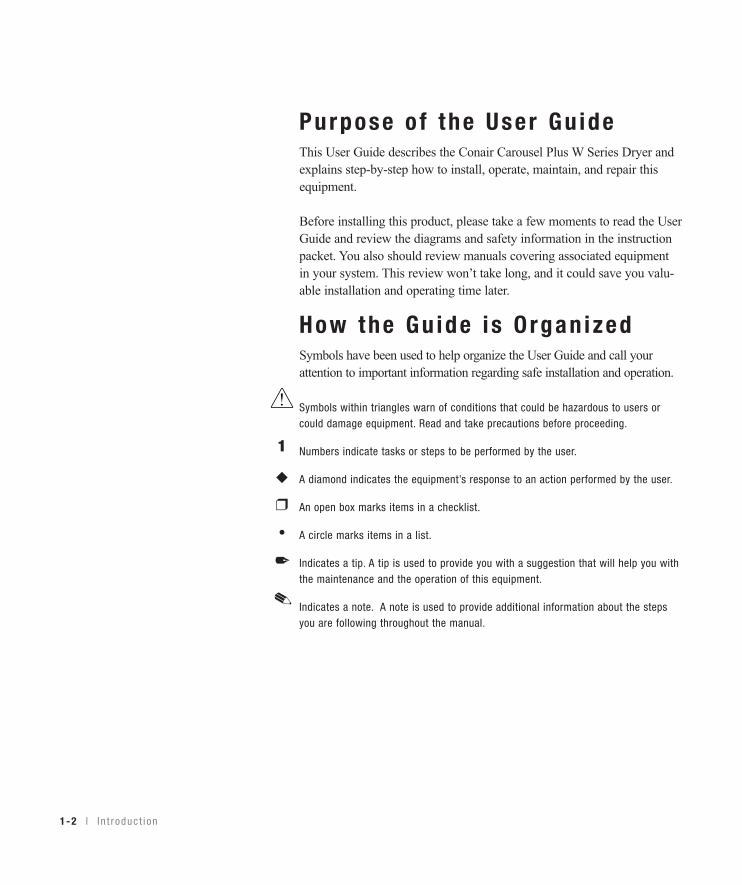
How the Gu ide i s O rgan izedSymbols have been used to help organize the User Guide and call yourattention to important information regarding safe installation and operation.
Symbols within triangles warn of conditions that could be hazardous to users orcould damage equipment. Read and take precautions before proceeding.
Numbers indicate tasks or steps to be performed by the user.
A diamond indicates the equipment’s response to an action performed by the user.
An open box marks items in a checklist.
A circle marks items in a list.
Indicates a tip. A tip is used to provide you with a suggestion that will help you withthe maintenance and the operation of this equipment.
Indicates a note. A note is used to provide additional information about the stepsyou are following throughout the manual.
1
◆
❒
•✒
1-2 l I n t r oduc t i on
I n t r oduc t i on l 1-3
Us ing the Carouse l P lus W Ser iesas a Cent ra l D r yerThe Conair Carousel Plus W600-5000 Series Dryers are factory configured tobe used as central dryers only. Therefore, this manual incorporates the informa-tion necessary to use these dryers for central drying applications.
Your Respons ib i l i t y as a UserYou must be familiar with all safety procedures concerning installation, opera-tion and maintenance of this equipment. Responsible safety procedures include:• Thorough review of this User Guide, paying particular attention
to hazard warnings, appendices and related diagrams.
• Thorough review of the equipment itself, with careful attention to voltage sources, intended use and warning labels.
• Thorough review of instruction manuals for associated equipment.
• Step-by-step adherence to instructions outlined in this User Guide.
1Introduction

ATTENT ION :Read th is so no one ge ts hur tWe design equipment with the user’s safety in mind. You can avoid the potentialhazards identified on this machine by following the procedures outlined below andelsewhere in the User Guide.
WARNING : Improper ins ta l l a t ion , opera t ion , o rse r v ic ing may resu l t i n equ ipment damage o rpersona l in ju r y.
This equipment should be installed, adjusted, and serviced by qualifiedtechnical personnel who are familiar with the construction, operation,and potential hazards of this type of machine.
All wiring, disconnects, and fuses should be installed by qualified elec-trical technicians in accordance with electrical codes in your region.Always maintain a safe ground. Do not operate the equipment at powerlevels other than what is specified on the machine serial tag and dataplate.
WARNING : Vo l tage hazard
This equipment is powered by three-phase alternating current, as specified on the machine serial tag and data plate.
A properly sized conductive ground wire from the incoming power supply must be connected to the chassis ground terminal inside theelectrical enclosure. Improper grounding can result in severe personalinjury and erratic machine operation.
Always disconnect and lock out the incoming main power source beforeopening the electrical enclosure or performing non-standard operatingprocedures, such as routine maintenance. Only qualified personnelshould perform troubleshooting procedures that require access to theelectrical enclosure while power is on.
1-4 l I n t r oduc t i on (continued)
1Introduction
I n t r oduc t i on l 1-5
ATTENT ION :Read th is so no one ge ts hur t (cont inued)
We design equipment with the user’s safety in mind. You can avoid the potentialhazards identified on this machine by following the procedures outlined below andelsewhere in the User Guide.
CAUTION : Ho t Sur faces .
Always protect yourself from hot surfaces inside the dryer and hopper.Also exercise caution around exterior surfaces that may become hotduring use. These include the hopper door frame, the exterior of anuninsulated hopper, the return air hose and the dryer’s process filterhousing and moisture exhaust outlet.
WARNING : Do no t p lace aeroso l , compressedgas o r f l ammable mate r ia l s on o r near th i sequ ipment .
The hot temperatures associated with the drying process may causeaerosols or other flammable materials placed on the dryer or hopper toexplode.
1-6 l I n t r oduc t i on
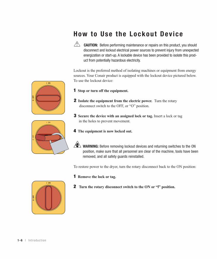
How to Use the Lockout Dev iceCAUTION: Before performing maintenance or repairs on this product, you shoulddisconnect and lockout electrical power sources to prevent injury from unexpectedenergization or start-up. A lockable device has been provided to isolate this prod-uct from potentially hazardous electricity.
Lockout is the preferred method of isolating machines or equipment from energysources. Your Conair product is equipped with the lockout device pictured below.To use the lockout device:
1 Stop or turn off the equipment.
2 Isolate the equipment from the electric power. Turn the rotarydisconnect switch to the OFF, or “O” position.
3 Secure the device with an assigned lock or tag. Insert a lock or tag in the holes to prevent movement.
4 The equipment is now locked out.
WARNING: Before removing lockout devices and returning switches to the ONposition, make sure that all personnel are clear of the machine, tools have beenremoved, and all safety guards reinstalled.
To restore power to the dryer, turn the rotary disconnect back to the ON position:
1 Remove the lock or tag.
2 Turn the rotary disconnect switch to the ON or “I” position.
Desc r i p t i on l 2-1
Descr ip t ion
Wha t i s t he Ca rouse l P l us W Se r i es D r ye r? . . 2 -2
Typ i ca l a pp l i ca t i ons . . . . . . . . . . . . . . . . . . 2 -2
Ho w i t wo rks . . . . . . . . . . . . . . . . . . . . . . 2 -4
Spec i f i ca t i ons : Ca rouse l P l us W Se r i es
Dehumid i f y i ng D r ye r . . . . . . . . . . . . . . . 2 -7
Ca rouse l P l us W Se r i es Dehumid i f y i ng
D r ye r op t i ons . . . . . . . . . . . . . . . . . . . 2 -8
S E C T I O N
22
Description
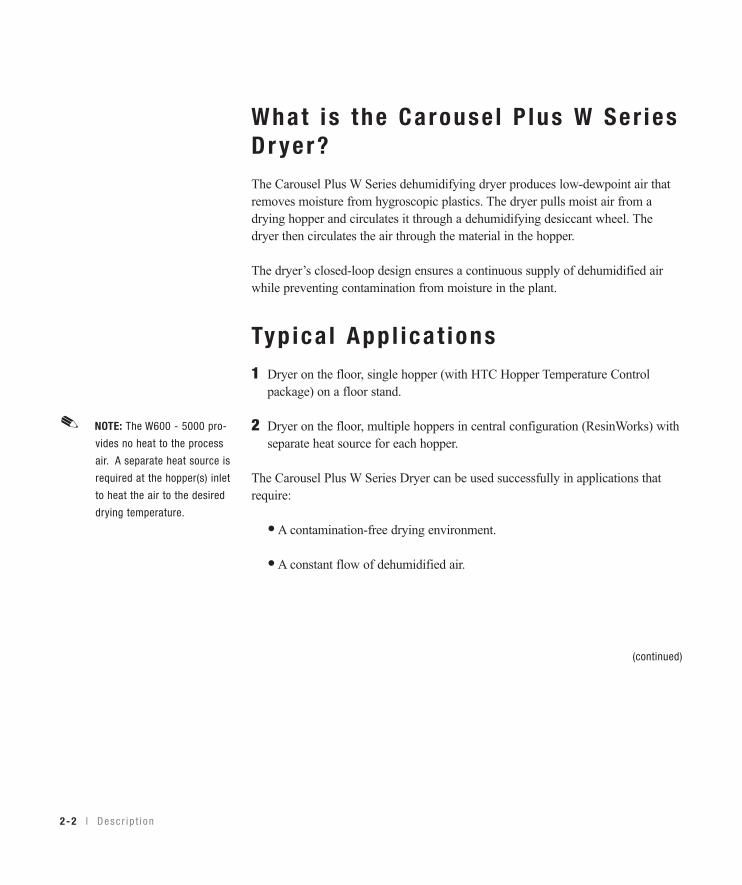
What i s the Carouse l P lus W Ser iesDr yer?The Carousel Plus W Series dehumidifying dryer produces low-dewpoint air thatremoves moisture from hygroscopic plastics. The dryer pulls moist air from adrying hopper and circulates it through a dehumidifying desiccant wheel. Thedryer then circulates the air through the material in the hopper.
The dryer’s closed-loop design ensures a continuous supply of dehumidified airwhile preventing contamination from moisture in the plant.
Typ ica l App l i ca t ions1 Dryer on the floor, single hopper (with HTC Hopper Temperature Control
package) on a floor stand.
2 Dryer on the floor, multiple hoppers in central configuration (ResinWorks) withseparate heat source for each hopper.
The Carousel Plus W Series Dryer can be used successfully in applications thatrequire:
• A contamination-free drying environment.
• A constant flow of dehumidified air.
2-2 l Desc r i p t i on
NOTE: The W600 - 5000 pro-
vides no heat to the process
air. A separate heat source is
required at the hopper(s) inlet
to heat the air to the desired
drying temperature.
✐
(continued)
Desc r i p t i on l 2-3
2D
escription
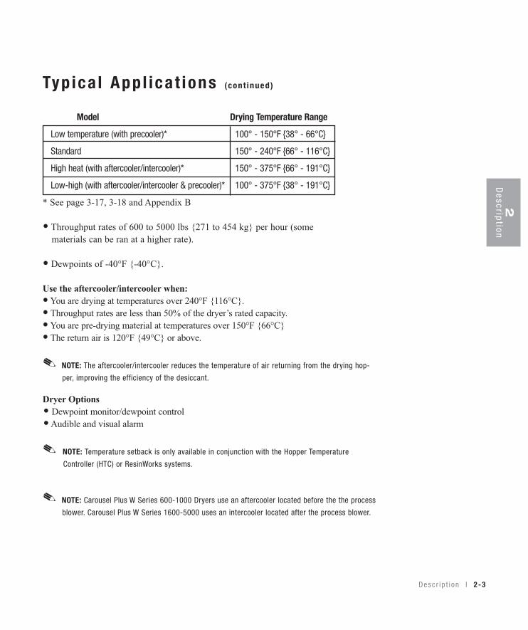
Typ ica l App l i ca t ions (cont inued)
Model Drying Temperature Range
Low temperature (with precooler)* 100° - 150°F {38° - 66°C}
Standard 150° - 240°F {66° - 116°C}
High heat (with aftercooler/intercooler)* 150° - 375°F {66° - 191°C}
Low-high (with aftercooler/intercooler & precooler)* 100° - 375°F {38° - 191°C}
* See page 3-17, 3-18 and Appendix B
• Throughput rates of 600 to 5000 lbs {271 to 454 kg} per hour (some materials can be ran at a higher rate).
• Dewpoints of -40°F {-40°C}.
Use the aftercooler/intercooler when:• You are drying at temperatures over 240°F {116°C}.• Throughput rates are less than 50% of the dryer’s rated capacity.• You are pre-drying material at temperatures over 150°F {66°C}• The return air is 120°F {49°C} or above.
Dryer Options• Dewpoint monitor/dewpoint control• Audible and visual alarm
NOTE: Temperature setback is only available in conjunction with the Hopper Temperature
Controller (HTC) or ResinWorks systems.
✐
NOTE: The aftercooler/intercooler reduces the temperature of air returning from the drying hop-
per, improving the efficiency of the desiccant.
✐
NOTE: Carousel Plus W Series 600-1000 Dryers use an aftercooler located before the the process
blower. Carousel Plus W Series 1600-5000 uses an intercooler located after the process blower.
✐
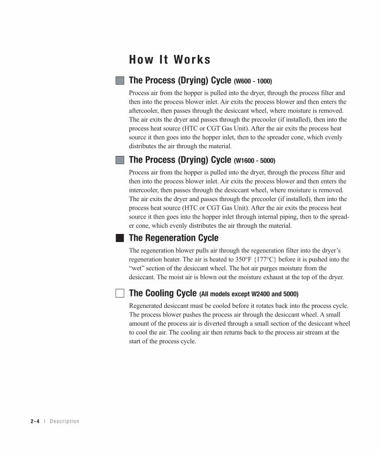
How I t Works
2-4 l Desc r i p t i on
The Process (Drying) Cycle (W1600 - 5000)
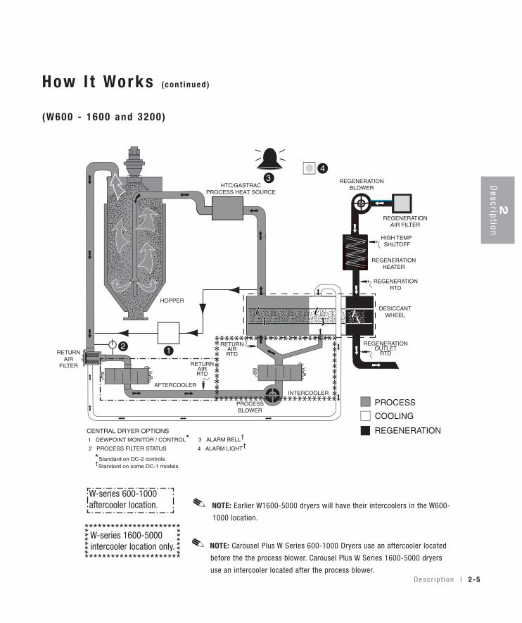
Process air from the hopper is pulled into the dryer, through the process filter andthen into the process blower inlet. Air exits the process blower and then enters theintercooler, then passes through the desiccant wheel, where moisture is removed.The air exits the dryer and passes through the precooler (if installed), then into theprocess heat source (HTC or CGT Gas Unit). After the air exits the process heatsource it then goes into the hopper inlet through internal piping, then to the spread-er cone, which evenly distributes the air through the material.
The Cooling Cycle (All models except W2400 and 5000)
Regenerated desiccant must be cooled before it rotates back into the process cycle.The process blower pushes the process air through the desiccant wheel. A smallamount of the process air is diverted through a small section of the desiccant wheelto cool the air. The cooling air then returns back to the process air stream at thestart of the process cycle.
The Regeneration CycleThe regeneration blower pulls air through the regeneration filter into the dryer’sregeneration heater. The air is heated to 350°F {177°C} before it is pushed into the“wet” section of the desiccant wheel. The hot air purges moisture from thedesiccant. The moist air is blown out the moisture exhaust at the top of the dryer.
The Process (Drying) Cycle (W600 - 1000)
Process air from the hopper is pulled into the dryer, through the process filter andthen into the process blower inlet. Air exits the process blower and then enters theaftercooler, then passes through the desiccant wheel, where moisture is removed.The air exits the dryer and passes through the precooler (if installed), then into theprocess heat source (HTC or CGT Gas Unit). After the air exits the process heatsource it then goes into the hopper inlet, then to the spreader cone, which evenlydistributes the air through the material.
2D
escription
How I t Works (cont inued)
(W600 - 1600 and 3200)
Desc r i p t i on l 2-5
W-series 1600-5000intercooler location only.
W-series 600-1000aftercooler location. NOTE: Earlier W1600-5000 dryers will have their intercoolers in the W600-
1000 location.
✐
NOTE: Carousel Plus W Series 600-1000 Dryers use an aftercooler located
before the the process blower. Carousel Plus W Series 1600-5000 dryers
use an intercooler located after the process blower.
✐**********************
**********************
******
******
2-6 l Desc r i p t i on
How I t Works (cont inued)
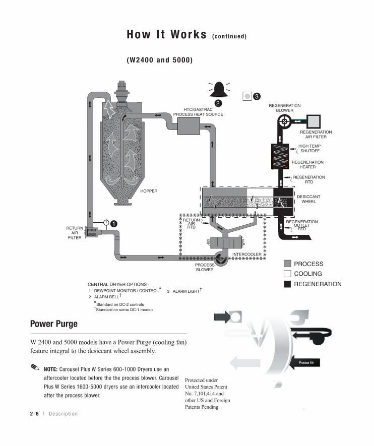
(W2400 and 5000)
Protected underUnited States PatentNo. 7,101,414 andother US and ForeignPatents Pending. .
NOTE: Carousel Plus W Series 600-1000 Dryers use an
aftercooler located before the the process blower. Carousel
Plus W Series 1600-5000 dryers use an intercooler located
after the process blower.
✐
Power Purge
W 2400 and 5000 models have a Power Purge (cooling fan)feature integral to the desiccant wheel assembly.

Spec i f i ca t ions : Carouse l P lus WSer ies Dehumid i fy ing Dr yers
C
A
B
Desc r i p t i on l 2-7
2D
escription
TPDS019-0311-REV
MODELS W600* W800* W1000* W1600*†† W2400*†† W3200*†† W5000*††
Performance characteristics (with full hopper)Drying temperature All models 100 - 375°F {38 - 191°C} with optionsDewpoint All models -40°F {-40°C}Dimensions inches {cm} A - Height 92.6 {235.2} 95.5 {242.6} 102.8 {261.1} B - Width 43.3 {109.9} 48.3 {122.7} 48.9 {124.2} C - Depth 57.6 {146.3} 86.2 {218.9} 112.0 {284.5} Outlet/inlet hose diameter 8 {20.3} 12 {30.5} 12 {30.5}Approximate weight lbs {kg}Installed 1300 {590} 1300 {590} 1400 {636} 1600 {726} 1600 {726} 2000 {907} 2000 {907}Shipping 1495 {678} 1515 {687} 1515 {687} 2100 {953} 2620 {1188} 3385 {1535} 3385 {1535}Voltage - Full load amps 400 V/3 phase/50 Hz† 37.2 37.2 37.5 64.7 73.7 122.3 128.0 460 V/3 phase/60 Hz 32.0 32.0 32.2 56.3 63.1 106.6 111.0 575 V/3 phase/60 Hz 25.6 25.6 25.7 45.0 50.5 85.3 89.1
Water requirements {for aftercooler/intercooler or optional precooler}§
Recommended temperature** 45° - 85°F {7- 29}Water flow gal./min. {liters/min.} 6-25 {22.7-94.6} 12-40 {45.4-151.4} 15-50 {56.8-189.3}Water connections NPT 1 1/2 in. NPT
SPECIFICATION NOTES:* Dryers W600-W5000 are central dryers and do not have process heaters. Hopper Temperature Controllers (HTC’s) or ResinWorks systems are used at the
hopper for heating the process air. See the Hopper Temperature Controller (HTC) specification sheet for additional information.
† Dryers running at 50 Hz will have 17% less airflow, and a 17% reduction in material throughput.
‡ Total kW listed at a regeneration temperature of 350°F {177°C}.
§ When drying below 150 °F {66°C} a precooler is required. When drying above 180°F {82°C} an aftercooler/intercooler and insulated drying hose isrequired.
** Temperatures above or below the recommended levels may affect dryer performance. Tower, chiller or municipal water sources can be used.
†† Models W1600-5000 do not have casters.
Specifications may change without notice. Consult a Conair representative for the most current information.
2-8 l Desc r i p t i on
Carouse l P lus W Ser iesDehumid i fy ing Dr yer Op t ions
• Volatile trap (only in conjunction with aftercooler/intercooler) - The volatile trap is recommended if drying materials that produce volitales that condense into a waxy or oily residue and/or if the material contains excessive fines.
• Precooler - The precooler reduces the temperature of air after the desiccant wheel and before the process heater, which enables the dryer to control temperatures at low setpoints, (100º - 150ºF {38º - 66ºC})
• Filter check - The filter check sensor will activate a passive alarm when the process filter is clogged or needs to be replaced.
NOTE: Temperature setback is only available in conjunction with the Hopper TemperatureController (HTC) or the ResinWorks system.
✐
I n s t a l l a t i on l 3-1
I ns ta l l a t ion
Unpack ing t he boxes . . . . . . . . . . . . . . . . . 3 -2
P repa r i ng f o r i n s t a l l a t i on . . . . . . . . . . . . . . 3 -3
Pos i t i on i ng t he d r ye r on t he f l oo r . . . . . . . . . 3 -4
Remov ing t he cab l e t i e f r om the
des i ccan t whee l (W600-1000 ) . . . . . . . . 3 -4
I n s t a l l i ng t he r egene ra t i on exhaus t cove r . . . 3 -4
I n s t a l l i ng t he r e tu rn a i r ada p te r . . . . . . . . . . 3 -5
I n s t a l l i ng t he r e tu rn a i r i n l e t and a i r ou t l e t
ada p te r s (W1600-5000 ) . . . . . . . . . . . . 3 -6
I n s t a l l i ng t he Ove rhead P rocess A i r Duc t
(W3200-5000 ) . . . . . . . . . . . . . . . . . . . 3 -7
Connec t i ng t he ma in po wer . . . . . . . . . . . . . 3 -8
Check ing f o r p rope r a i r f l o w . . . . . . . . . . . . 3 -9
Connec t i ng t he a i r hoses t o a s i ng l e
hoppe r (W600-1000 ) . . . . . . . . . . . . . . 3 -12
Connec t i ng t he a i r hoses t o a s i ng l e
hoppe r (W1600-5000 ) . . . . . . . . . . . . . 3 -13
Connec t i ng t he a i r hoses t o a
Res inWorks . . . . . . . . . . . . . . . . . . . . 3 -14
Connec t i ng t he d r ye r t o t he hoppe r . . . . . . 3 -15
Connec t i ng t he d r ye r t o Res inWorks . . . . . . 3 -15
Connec t i ng a i r hose ada p te r s . . . . . . . . . . 3 -16
Connec t i ng t he a f t e r coo l e r and op t i ona l
p r ecoo l e r (W600-1000 ) . . . . . . . . . . . . 3 -17 Connec t i ng t he i n t e r coo l e r and op t i ona l p r ecoo l e r (W1600-5000 ) . . . . . . . . . . . 3 -18
Moun t i ng a l oade r on t he hoppe r . . . . . . . . 3 -19
Tes t i ng t he i ns t a l l a t i on . . . . . . . . . . . . . . . 3 -19
S E C T I O N
33
Installation
3-2 l I n s t a l l a t i on
Unpack ing the BoxesThe Carousel Plus W Series Dryer comes in one to four boxes, depending on themodel and options ordered. The box(es) could include (depending on the optionsselected):
• Carousel Plus W Series Dryer
• Delivery air hose
• Return air hose
• User Guide
1 Carefully remove the dryer and components from their shippingcontainer(s). Note that the dryer is secured to its shipping container with metalbands that pass through the bottom of the dryer frame.
2 Unbolt any additional items secured to the shipping pallet, such as theregeneration exhaust cover and return air adapter. (Carousel Plus W Series1600-2400 Dryers will have a dry air delivery adapter. Carousel Plus W Series3200-5000 Dryers will have a dry air delivery adapter and an overhead processair duct.)
3 Remove all packing material, protective paper, tape, and plastic.
4 Cut and remove the desiccant wheel tie securing the wheel assembly.(W600-1000)✎
5 Carefully inspect all components to make sure no damage occurred duringshipping, and that you have all the necessary hardware.
I n s t a l l a t i on l 3-3
Unpack ing the Boxes (cont inued)
6 Take a moment to record serial numbers and electrical power specificationsin the blanks provided on the back of the User Guide’s title page. Theinformation will be helpful if you ever need service or parts.
7 You are now ready to begin installation. Follow the preparation steps on the next page, then choose one of the two
mounting options:• Dryer on the floor, single hopper (with HTC Hopper Temperature Control
package) on a floor stand.• Dryer on the floor, multiple hoppers in central configuration (ResinWorks)
with separate heat source for each hopper.
3Installation
NOTE: The W600 - 5000 provides no heat to the process air. A separate heat source isrequired at the hopper(s) inlet to heat the air to the desired drying temperature.
✐
Prepar ing fo r Ins ta l l a t ion
The Carousel Plus W Series Dryer is easy to install if you plan the location andprepare the mounting area properly.
1 Make sure the mounting area provides:
❒ A grounded power source supplying the voltage and correct currentfor your dryer model. Check the dryer’s serial tag (on the control box) forthe correct amps, voltage, phase, and cycles. Field wiring should be com-pleted by a qualified personnel to the planned location for the dryer. Allelectrical wiring should comply with your region’s electrical codes.
❒ A source of water, when using the aftercooler/intercooler and/or pre-cooler. The W Dryer’s aftercooler/intercooler and precooler requiretower, city, or chiller water at temperatures of 45° to 85°F {7° to 29°C}.Refer to the Specifications Sheet (page 2-7) for flow rate for your unit.Piping should be ran to the planned dryer location. Use flexible hose toconnect the water pipes to the aftercooler/intercooler and/or optional pre-cooler.
❒ Minimum clearance for safe operation and maintenance. You shouldmaintain 24 in. {61 cm} clearance on all sides of the dryer.
Material and conveying lines
installed. If you plan to use
vacuum or compressed air
loaders to fill the hopper,
install conveying lines to the
drying hopper location.
✒
NOTE: The aftercooler/inter-
cooler reduces the temperature
of air returning from the drying
hopper, improving the efficien-
cy of the desiccant.
✐
3-4 l I n s t a l l a t i on
Pos i t i on ing the Dr yer on the F loor1 Lift the dryer from the shipping container using a fork truck.
2 Position the dryer on the floor near the hopper or ResinWorks sled. Makesure the location allows for the connection of all hoses, keeping hose lengths asshort as possible.
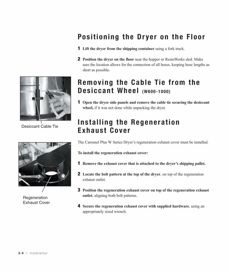
Remo v ing the Cab le T ie f rom theDes iccant Whee l (W600-1000)
1 Open the dryer side panels and remove the cable tie securing the desiccantwheel, if it was not done while unpacking the dryer.
I ns ta l l i ng the Regenera t ionExhaus t Co verThe Carousel Plus W Series Dryer’s regeneration exhaust cover must be installed.
To install the regeneration exhaust cover:
1 Remove the exhaust cover that is attached to the dryer’s shipping pallet.
2 Locate the bolt pattern at the top of the dryer, on top of the regenerationexhaust outlet.
3 Position the regeneration exhaust cover on top of the regeneration exhaustoutlet, aligning both bolt patterns.
4 Secure the regeneration exhaust cover with supplied hardware, using anappropriately sized wrench.
Desiccant Cable Tie
RegenerationExhaust Cover
3Installation
I n s t a l l a t i on l 3-5
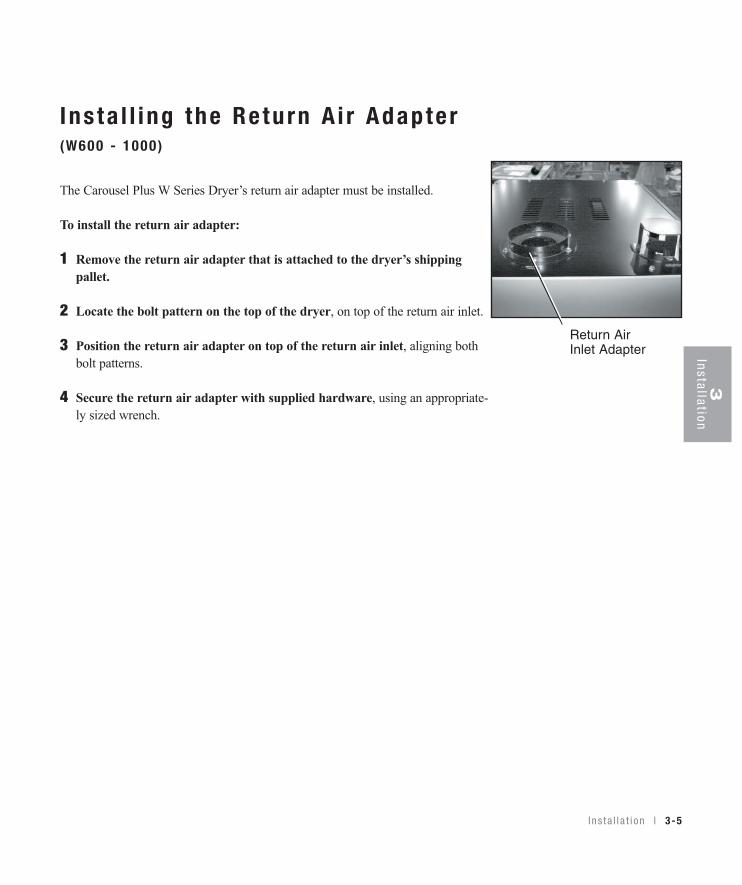
I ns ta l l i ng the Re turn A i r Adapte r(W600 - 1000 )
The Carousel Plus W Series Dryer’s return air adapter must be installed.
To install the return air adapter:
1 Remove the return air adapter that is attached to the dryer’s shippingpallet.
2 Locate the bolt pattern on the top of the dryer, on top of the return air inlet.
3 Position the return air adapter on top of the return air inlet, aligning bothbolt patterns.
4 Secure the return air adapter with supplied hardware, using an appropriate-ly sized wrench.
Return AirInlet Adapter
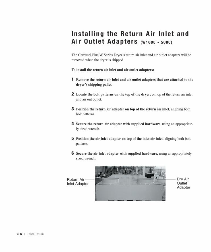
I ns ta l l i ng the Re turn A i r In le t andA i r Ou t le t Adapte rs (W1600 - 5000 )
The Carousel Plus W Series Dryer’s return air inlet and air outlet adapters will beremoved when the dryer is shipped
To install the return air inlet and air outlet adapters:
1 Remove the return air inlet and air outlet adapters that are attached to thedryer’s shipping pallet.
2 Locate the bolt patterns on the top of the dryer, on top of the return air inletand air out outlet.
3 Position the return air adapter on top of the return air inlet, aligning bothbolt patterns.
4 Secure the return air adapter with supplied hardware, using an appropriate-ly sized wrench.
5 Position the air inlet adapter on top of the inlet air inlet, aligning both boltpatterns.
6 Secure the air inlet adapter with supplied hardware, using an appropriatelysized wrench.
3-6 l I n s t a l l a t i on
Dry AirOutletAdapter
Return AirInlet Adapter
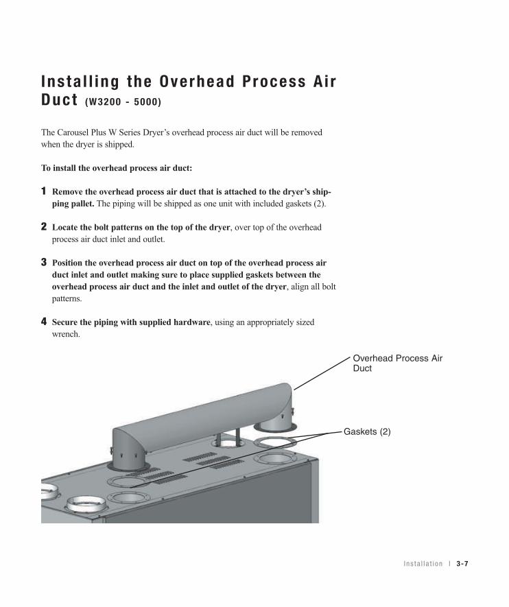
I ns ta l l i ng the Overhead Process A i rDuc t (W3200 - 5000 )
The Carousel Plus W Series Dryer’s overhead process air duct will be removedwhen the dryer is shipped.
To install the overhead process air duct:
1 Remove the overhead process air duct that is attached to the dryer’s ship-ping pallet. The piping will be shipped as one unit with included gaskets (2).
2 Locate the bolt patterns on the top of the dryer, over top of the overheadprocess air duct inlet and outlet.
3 Position the overhead process air duct on top of the overhead process airduct inlet and outlet making sure to place supplied gaskets between theoverhead process air duct and the inlet and outlet of the dryer, align all boltpatterns.
4 Secure the piping with supplied hardware, using an appropriately sizedwrench.
I n s t a l l a t i on l 3-7
Overhead Process AirDuct
Gaskets (2)
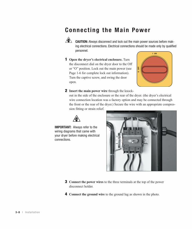
Connect ing the Ma in Power
CAUTION: Always disconnect and lock out the main power sources before mak-ing electrical connections. Electrical connections should be made only by qualified personnel.
1 Open the dryer’s electrical enclosure. Turnthe disconnect dial on the dryer door to the Offor “O” position. Lock out the main power (seePage 1-6 for complete lock out information).Turn the captive screw, and swing the dooropen.
2 Insert the main power wire through the knock-out in the side of the enclosure or the rear of the dryer. (the dryer’s electricalwire connection location was a factory option and may be connected throughthe front or the rear of the dryer.) Secure the wire with an appropriate compres-sion fitting or strain relief.
3-8 l I n s t a l l a t i on
IMPORTANT: Always refer to thewiring diagrams that came withyour dryer before making electricalconnections.
3 Connect the power wires to the three terminals at the top of the powerdisconnect holder.
4 Connect the ground wire to the ground lug as shown in the photo.
Auto Start
Dryer Status
Process Blower Regen. Blower
Regen. Heater
Set Point Actual
1 Process Temp.2 Regen. Temp.3 Return Air Temp.4 Auto Start5 Load Time (MDC)6 Activate Setback Temp.7 Setback Temp.(Process)8 Dewpoint
Shutdown AlarmsA1 Process High TempA2 Process Loop BreakA3 Process Heater High TempA4 Regen Heater High TempA7 Return Air High TempA49 Process Protection High TempA53 Process Blower OverloadA55 Wheel Rotation Failure
Passive AlarmsP1 Process Temp DeviationP3 Regen Temp DeviationP5 Return Air Mid High TempP17 MDC Conveying Demand
1000
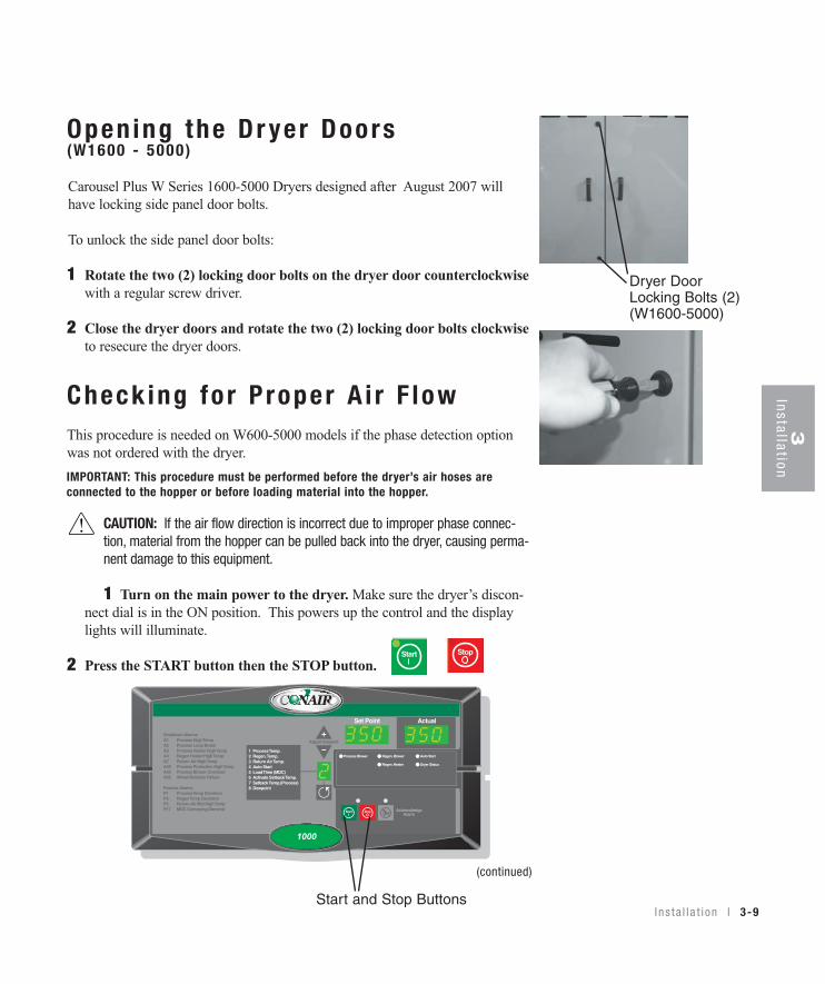
Open ing the Dr yer Doors (W1600 - 5000 )
Carousel Plus W Series 1600-5000 Dryers designed after August 2007 willhave locking side panel door bolts.
To unlock the side panel door bolts:
1 Rotate the two (2) locking door bolts on the dryer door counterclockwisewith a regular screw driver.
2 Close the dryer doors and rotate the two (2) locking door bolts clockwise to resecure the dryer doors.
Check ing fo r P roper A i r F lowThis procedure is needed on W600-5000 models if the phase detection optionwas not ordered with the dryer.
CAUTION: If the air flow direction is incorrect due to improper phase connec-tion, material from the hopper can be pulled back into the dryer, causing perma-nent damage to this equipment.
1 Turn on the main power to the dryer. Make sure the dryer’s discon-nect dial is in the ON position. This powers up the control and the displaylights will illuminate.
2 Press the START button then the STOP button.
(continued)
Start and Stop Buttons
StopStart
I n s t a l l a t i on l 3-9
3Installation
IMPORTANT: This procedure must be performed before the dryer’s air hoses areconnected to the hopper or before loading material into the hopper.
Dryer DoorLocking Bolts (2)(W1600-5000)
3-10 l I n s t a l l a t i on
Check ing fo r P roper A i r F low (cont inued)
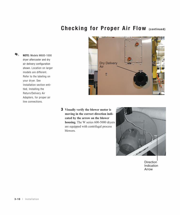
3 Visually verify the blower motor ismoving in the correct direction indi-cated by the arrow on the blowerhousing. The W series 600-5000 dryersare equipped with centrifugal processblowers.
Dry DeliveryAir
DirectionIndicationArrow
✐NOTE: Models W600-1000
dryer aftercooler and dry
air delivery configuration
shown. Location on largermodels are different.Refer to the labeling onyour dryer. SeeInstallation section enti-tled, Installing theReturn/Delivery AirAdapters, for proper airline connections.
I n s t a l l a t i on l 3-11
3Installation
Check ing fo r P roper A i r F low (cont inued)
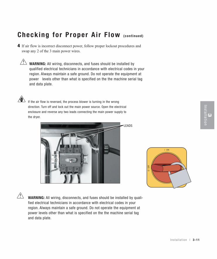
4 If air flow is incorrect disconnect power, follow proper lockout procedures andswap any 2 of the 3 main power wires.
If the air flow is reversed, the process blower is turning in the wrong
direction. Turn off and lock out the main power source. Open the electrical
enclosure and reverse any two leads connecting the main power supply to
the dryer.
WARNING: All wiring, disconnects, and fuses should be installed by quali-fied electrical technicians in accordance with electrical codes in yourregion. Always maintain a safe ground. Do not operate the equipment atpower levels other than what is specified on the the machine serial tagand data plate.
LEADS
WARNING: All wiring, disconnects, and fuses should be installed byqualified electrical technicians in accordance with electrical codes in yourregion. Always maintain a safe ground. Do not operate the equipment atpower levels other than what is specified on the the machine serial tagand data plate.
3-12 l I n s t a l l a t i on
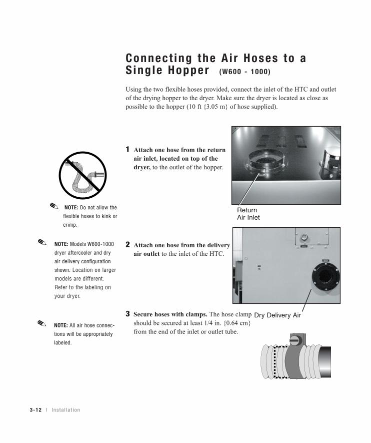
Connect ing the A i r Hoses to aS ing le Hopper (W600 - 1000 )
Using the two flexible hoses provided, connect the inlet of the HTC and outletof the drying hopper to the dryer. Make sure the dryer is located as close aspossible to the hopper (10 ft {3.05 m} of hose supplied).
1 Attach one hose from the returnair inlet, located on top of thedryer, to the outlet of the hopper.
2 Attach one hose from the deliveryair outlet to the inlet of the HTC.
3 Secure hoses with clamps. The hose clampshould be secured at least 1/4 in. {0.64 cm}from the end of the inlet or outlet tube.
NOTE: Do not allow the
flexible hoses to kink or
crimp.
✐ReturnAir Inlet
Dry Delivery Air
✐NOTE: Models W600-1000
dryer aftercooler and dry
air delivery configuration
shown. Location on largermodels are different.Refer to the labeling onyour dryer.
✐NOTE: All air hose connec-
tions will be appropriately
labeled.
I n s t a l l a t i on l 3-13
3Installation
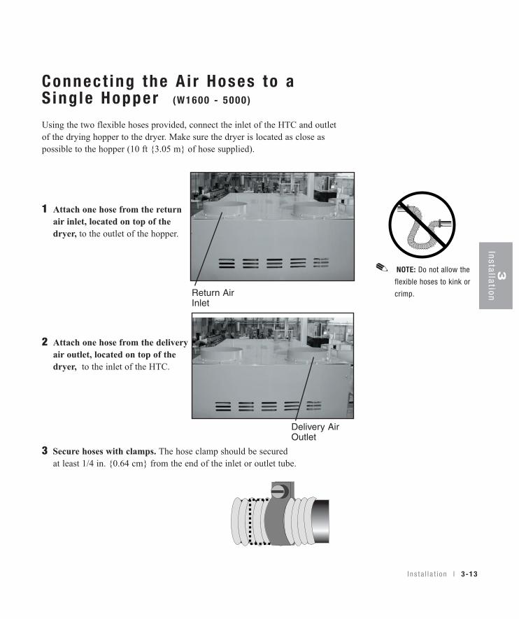
Connect ing the A i r Hoses to aS ing le Hopper (W1600 - 5000 )
Using the two flexible hoses provided, connect the inlet of the HTC and outletof the drying hopper to the dryer. Make sure the dryer is located as close aspossible to the hopper (10 ft {3.05 m} of hose supplied).
1 Attach one hose from the returnair inlet, located on top of thedryer, to the outlet of the hopper.
2 Attach one hose from the deliveryair outlet, located on top of thedryer, to the inlet of the HTC.
3 Secure hoses with clamps. The hose clamp should be securedat least 1/4 in. {0.64 cm} from the end of the inlet or outlet tube.
NOTE: Do not allow the
flexible hoses to kink or
crimp.
✐
Return AirInlet
Delivery Air Outlet
3-14 l I n s t a l l a t i on
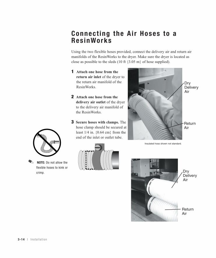
NOTE: Do not allow the
flexible hoses to kink or
crimp.
✐
Connect ing the A i r Hoses to aRes inWorksUsing the two flexible hoses provided, connect the delivery air and return airmanifolds of the ResinWorks to the dryer. Make sure the dryer is located asclose as possible to the sleds (10 ft {3.05 m} of hose supplied).
1 Attach one hose from the return air inlet of the dryer to the return air manifold of the ResinWorks.
2 Attach one hose from thedelivery air outlet of the dryerto the delivery air manifold ofthe ResinWorks.
3 Secure hoses with clamps. Thehose clamp should be secured atleast 1/4 in. {0.64 cm} from theend of the inlet or outlet tube.
Insulated hose shown not standard.
ReturnAir
DryDeliveryAir
ReturnAir
DryDeliveryAir
3Installation
I n s t a l l a t i on l 3-15
Connec t ing the Dr yer to the Hopper
If your dryer hose connection and your hopper HTC hose connection are not thesame size, you will need a hose adapter. Contact Conair Parts 1 800-458-1960.
Connect ing the Dr yer to
Res inWorks
If your dryer hose connection and the connection on your ResinWorks sled are notthe same size, you will need to use a hose adapter. Contact Conair Parts 1 800-458-1960.
NOTE: Because the W600 - 5000 models require a separate heat source for thedelivery air, all references to this heat source will be identified as “HTC” (HopperTemperature Controller). When using this dryer with a HTC, reference the UserGuide supplied with the HTC for installation instructions.
✐
NOTE: Because the W600 - 5000 models require a separate heat source for thedelivery air, all references to this heat source will be identified as ResinWorks.When using this dryer with a ResinWorks sled reference the User Guide suppliedwith the ResinWorks sled for installation instructions.
✐
3-16 l I n s t a l l a t i on
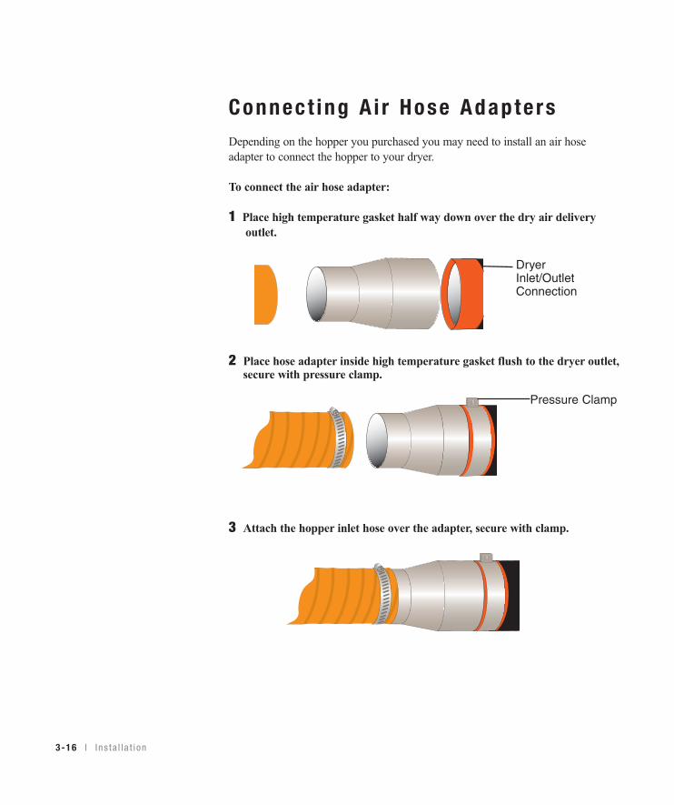
Connect ing A i r Hose Adapte rsDepending on the hopper you purchased you may need to install an air hoseadapter to connect the hopper to your dryer.
To connect the air hose adapter:
1 Place high temperature gasket half way down over the dry air delivery outlet.
2 Place hose adapter inside high temperature gasket flush to the dryer outlet,secure with pressure clamp.
3 Attach the hopper inlet hose over the adapter, secure with clamp.
DryerInlet/OutletConnection
Pressure Clamp

I n s t a l l a t i on l 3-17
3Installation
Connect ing the A f te rcoo le r andOpt iona l P recoo le r (W600 - 1000 )
The aftercooler and/or optional precooler require a source of city, tower, or chillerwater and a discharge or return line. You can use water at temperatures of 45 to85°F {7 to 29°C}. But the water flow should be at least 3 gal/min {11.4liters/min}.
1 Connect the water supply line to the aftercooler or precooler inlet.If a manual shut off valve is used, it should be mounted on the inlet line.
2 Connect the water discharge or return line with the pressure relief valve to the aftercooler or precooler outlet. Use the bracket supplied to secure the pressure relief valve to the back of the dryer.
IMPORTANT: Turn the water off when the dryer is not in use to preventcondensation.
Aftercooler Inlet
Aftercooler Outlet
✒TIP: Make the water supply and dis-
charge / return connections with
flexible hoses at least 24 in.
(61 cm) long. This allows you to
easily remove the aftercooler
assembly for cleaning.
✒TIP: If an optional flow control is
also being installed with the after-
cooler, the manual shut off valve
should be installed on the inlet line
for the flow control.
NOTE: Models W600-1000
dryer aftercooler and dry air
delivery configuration shown.
Location on larger modelsare different. Refer to thelabeling on your dryer.
✐
3-18 l I n s t a l l a t i on
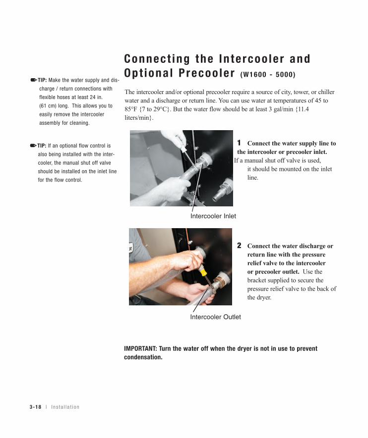
Connect ing the In te rcoo le r andOpt iona l P recoo le r (W1600 - 5000 )
The intercooler and/or optional precooler require a source of city, tower, or chillerwater and a discharge or return line. You can use water at temperatures of 45 to85°F {7 to 29°C}. But the water flow should be at least 3 gal/min {11.4liters/min}.
1 Connect the water supply line to the intercooler or precooler inlet.If a manual shut off valve is used, it should be mounted on the inlet line.
2 Connect the water discharge or return line with the pressure relief valve to the intercooler or precooler outlet. Use the bracket supplied to secure the pressure relief valve to the back of the dryer.
IMPORTANT: Turn the water off when the dryer is not in use to preventcondensation.
Intercooler Inlet
Intercooler Outlet
✒TIP: Make the water supply and dis-
charge / return connections with
flexible hoses at least 24 in.
(61 cm) long. This allows you to
easily remove the intercooler
assembly for cleaning.
✒TIP: If an optional flow control is
also being installed with the inter-
cooler, the manual shut off valve
should be installed on the inlet line
for the flow control.
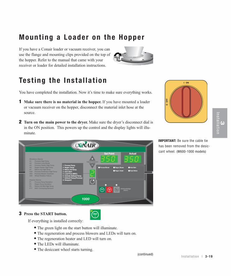
Mount ing a Loader on the Hopper If you have a Conair loader or vacuum receiver, you canuse the flange and mounting clips provided on the top ofthe hopper. Refer to the manual that came with yourreceiver or loader for detailed installation instructions.
Tes t ing the Ins ta l l a t ionYou have completed the installation. Now it’s time to make sure everything works.
1 Make sure there is no material in the hopper. If you have mounted a loaderor vacuum receiver on the hopper, disconnect the material inlet hose at thesource.
2 Turn on the main power to the dryer. Make sure the dryer’s disconnect dial isin the ON position. This powers up the control and the display lights will illu-minate.
3 Press the START button.If everything is installed correctly:
• The green light on the start button will illuminate.• The regeneration and process blowers and LEDs will turn on.• The regeneration heater and LED will turn on.• The LEDs will illuminate.• The desiccant wheel starts turning.
(continued)
Auto Start
Dryer Status
Process Blower Regen. Blower
Regen. Heater
Set Point Actual
1 Process Temp.2 Regen. Temp.3 Return Air Temp.4 Auto Start5 Load Time (MDC)6 Activate Setback Temp.7 Setback Temp.(Process)8 Dewpoint
Shutdown AlarmsA1 Process High TempA2 Process Loop BreakA3 Process Heater High TempA4 Regen Heater High TempA7 Return Air High TempA49 Process Protection High TempA53 Process Blower OverloadA55 Wheel Rotation Failure
Passive AlarmsP1 Process Temp DeviationP3 Regen Temp DeviationP5 Return Air Mid High TempP17 MDC Conveying Demand
1000
Start
IMPORTANT: Be sure the cable tiehas been removed from the desic-cant wheel. (W600-1000 models)
I ns t a l l a t i on l 3-19
3Installation
3-20 l I n s t a l l a t i on
Tes t ing the Ins ta l l a t ion (cont inued)
4 Press the STOP button. If everything is installed correctly:
• The blowers will continue running as needed to cool the heaters. (until regeneration heaters are less than 150°F {66°C})
5 The test is over. If the dryer performed the normal operating sequences asoutlined, you can load the hopper and begin operation. If it did not, refer tothe Troubleshooting section of the User Guide.
Stop
S E C T I O N
44
Operation
Opera t ion
Ca rouse l P l us W Se r i es D r ye r :
con t r o l pane l DC-1 . . . . . . . . . . . . . . . . 4 -2
Ca rouse l P l us W Se r i es D r ye r DC-1
con t r o l f unc t i ons . . . . . . . . . . . . . . . . . 4 -3
Con t r o l f unc t i on f l o w cha r t . . . . . . . . . . . . . 4 -3
Con t r o l f unc t i on desc r i p t i ons . . . . . . . . . . . 4 -5
To s t a r t d r y i ng . . . . . . . . . . . . . . . . . . . . 4 -15
To s t op d r y i ng . . . . . . . . . . . . . . . . . . . . . 4 -16
Us i ng t he au to s t a r t coun tdo wn func t i on . . . 4 -17
Ho w t o d i sab l e t he au to s t a r t on t he
DC-1 con t r o l . . . . . . . . . . . . . . . . . . . 4 -17
Us i ng dewpo in t con t r o l . . . . . . . . . . . . . . . 4 -18
Opera t i on l 4-1

4-2 l Ope ra t i on
Auto Start
Dryer Status
Process Blower Regen. Blower
Regen. Heater
Set Point Actual
1 Process Temp.2 Regen. Temp.3 Return Air Temp.4 Auto Start5 Load Time (MDC)6 Activate Setback Temp.7 Setback Temp.(Process)8 Dewpoint
Shutdown AlarmsA1 Process High TempA2 Process Loop BreakA3 Process Heater High TempA4 Regen Heater High TempA7 Return Air High TempA49 Process Protection High TempA53 Process Blower OverloadA55 Wheel Rotation Failure
Passive AlarmsP1 Process Temp DeviationP3 Regen Temp DeviationP5 Return Air Mid High TempP17 MDC Conveying Demand
1000
Carouse l P lus W Ser ies Dr yer : Con t ro l Pane l DC-1Setpo in tD isp lay
Shows the setpointvalue.
Menu L is tNumbers 2, 3, and 4 are standard items that willalways be present. Number 8 is a screen associat-ed with options. If the option is not installed, thescreens will not be displayed.
NOTE: #1 Process is not displayed whenthe unit is configured as a central dryer.
AcknowledgeA la rm But tonPress once tosilence the option-al audible alarmand display alarmmessages. Pressagain to clear thealarm. If pushedwhen no activealarm is present,the most recentalarm will bedisplayed.
Star t and S topBut tonsPress “Start” to start the dryer. Press “Stop” to stop the dryer.
I nc rement /DecrementBut tonsUsed to increase and/or decrease the set-point of a control function.
Actua lD isp lay
Shows the actualtemperature value.
MenuNumberD isp layDisplays themenu numbercorrespon-ding to whatis shown inthe setpointand actualdisplays.Can also dis-play lettersfor alarmsand setup.
Scro l lBu t tonPress toscrollthrough theclosed loopmenu list.Pressing theScroll buttonmoves youdown the list.
Alarm CodesSee Troubleshoot-ing section for amore complete list-ing of alarms.
NOTE: Process related alarms are not applicable when the unit is configured as a central dryer.
✐
✐

Carouse l P lus W Ser ies Dr yer DC-1Cont ro l Func t ionsDryer functions are values that you can set or monitor. Press the Scroll button toaccess the function within a Menu list until the function you want to set or monitorappears in the LED display.
NOTE: Grey shaded screens denote optional functions. If the options were not
purchased with the dryer, those screens will not appear.
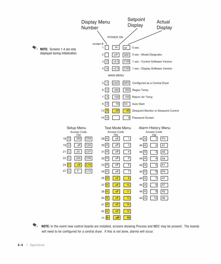
Cont ro l Func t ion F low Char tThe following flow chart provides a quick summary of the control functions. Foran explanation of each control function, see Control Function Descriptions (page4-5).
The Main Menu functions can be accessed by pressing the Scroll button when onScreen 5. To access the Setup, Test Mode, and Alarm History Menus, the appro-priate access code must be entered. Refer to the instructions for Screen 14 (page 4-7).
Opera t i on l 4-3
4O
peration
✐
POWER ON
screen #1 Pr up 5 sec
2 CP 600 5 sec - Model Disignator
3 C v2.0 3.00 1 sec - Control Software Version
4 d v2.0 3.00 1 sec - Display Software Version
5 1 CNT DRY Configured as a Central Dryer
6 2 350 350 Regen Temp
7 3 100 100 Return Air Temp
8 4 16 On Auto Start
13 9 -30 -40 Dewpoint Monitor or Dewpoint Control
14 0 0 Password Screen
754 755 75628 H off 1 44 A 1 P3
44 A 2 A130 H off 3
44 A 3 A5
18 C 350 C04
31 H off 4
44 A 4 A4
19 C off C05
32 H off 5
44 A 5 P133 H off 6
44 A 6 P5
21 C 20 C07
34 H off 7
44 A 7 A135 H off 8
44 A 8 A7
24 C off C10
44 A 9 A2
37 H off 10
44 A 10 A6
38 H off 11
40 H off 13
41 H off 14
42 H off 15
43 H off 16
Setup MenuAccess Code
Test Mode MenuAccess Code
Alarm History MenuAccess Code
47 C F C15
MAIN MENU
22 C 200 C08
4-4 l Ope ra t i on
NOTE: In the event new control boards are installed, screens showing Process and MDC may be present. The boards
will need to be configured for a central dryer. If this is not done, alarms will occur.
✐
Display MenuNumber
SetpointDisplay
ActualDisplay
NOTE: Screens 1-4 are onlydisplayed during initialization.
✐
4O
peration
O pe ra t i on l 4-5
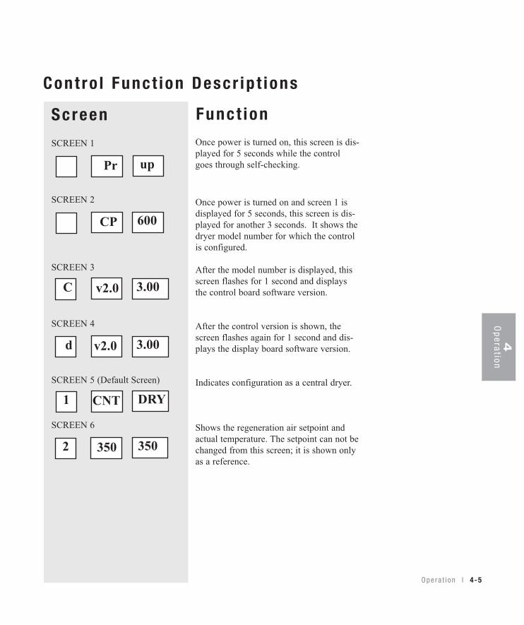
Once power is turned on, this screen is dis-played for 5 seconds while the controlgoes through self-checking.
Once power is turned on and screen 1 isdisplayed for 5 seconds, this screen is dis-played for another 3 seconds. It shows thedryer model number for which the controlis configured.
After the model number is displayed, thisscreen flashes for 1 second and displaysthe control board software version.
After the control version is shown, thescreen flashes again for 1 second and dis-plays the display board software version.
Indicates configuration as a central dryer.
Shows the regeneration air setpoint andactual temperature. The setpoint can not bechanged from this screen; it is shown onlyas a reference.
ScreenSCREEN 1
SCREEN 2
SCREEN 3
SCREEN 4
SCREEN 5 (Default Screen)
SCREEN 6
Pr
Funct ion
Cont ro l Func t ion Descr ip t ions
up
CP 600
v2.0 3.00C
v2.0 3.00d
350 3502
CNT DRY1
4-6 l Ope ra t i on
ScreenSCREEN 7
SCREEN 8
100
Funct ion
Cont ro l Func t ion Descr ip t ions (cont inued)
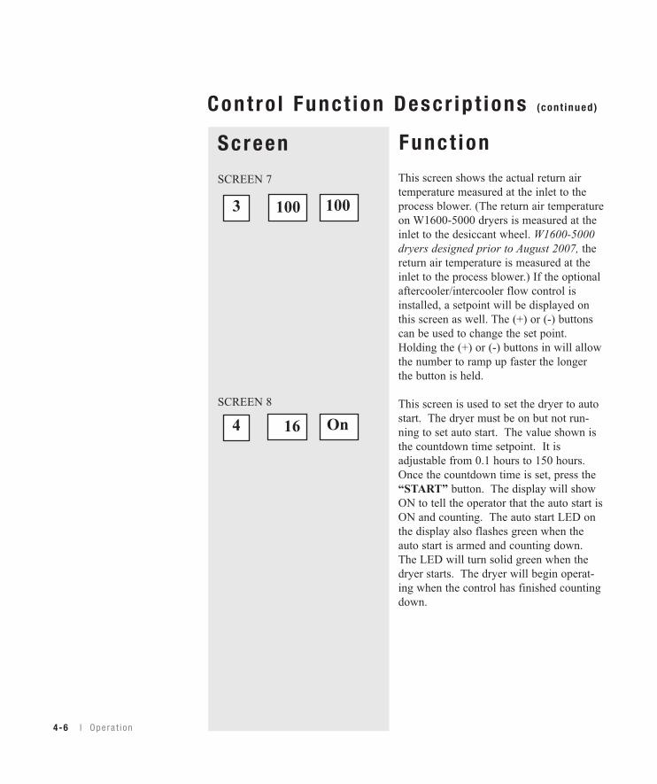
This screen shows the actual return airtemperature measured at the inlet to theprocess blower. (The return air temperatureon W1600-5000 dryers is measured at theinlet to the desiccant wheel. W1600-5000dryers designed prior to August 2007, thereturn air temperature is measured at theinlet to the process blower.) If the optionalaftercooler/intercooler flow control isinstalled, a setpoint will be displayed onthis screen as well. The (+) or (-) buttonscan be used to change the set point.Holding the (+) or (-) buttons in will allowthe number to ramp up faster the longerthe button is held.
This screen is used to set the dryer to autostart. The dryer must be on but not run-ning to set auto start. The value shown isthe countdown time setpoint. It isadjustable from 0.1 hours to 150 hours.Once the countdown time is set, press the“START” button. The display will showON to tell the operator that the auto start isON and counting. The auto start LED onthe display also flashes green when theauto start is armed and counting down.The LED will turn solid green when thedryer starts. The dryer will begin operat-ing when the control has finished countingdown.
1003
16 On4
Opera t i on l 4-7
Sc reenSCREEN 13 (Dewpoint Monitor/Dewpoint Control Option)
SCREEN 14
Funct ion
Cont ro l Func t ion Descr ip t ions (cont inued)
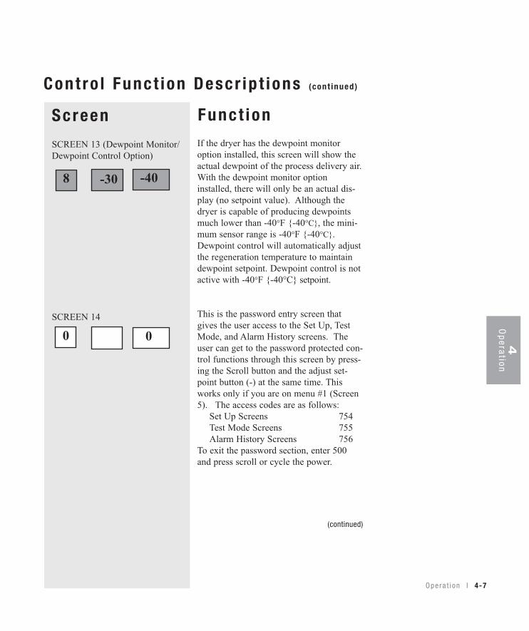
If the dryer has the dewpoint monitoroption installed, this screen will show theactual dewpoint of the process delivery air.With the dewpoint monitor optioninstalled, there will only be an actual dis-play (no setpoint value). Although thedryer is capable of producing dewpointsmuch lower than -40°F {-40°C}, the mini-mum sensor range is -40°F {-40°C}.Dewpoint control will automatically adjustthe regeneration temperature to maintaindewpoint setpoint. Dewpoint control is notactive with -40°F {-40°C} setpoint.
This is the password entry screen thatgives the user access to the Set Up, TestMode, and Alarm History screens. Theuser can get to the password protected con-trol functions through this screen by press-ing the Scroll button and the adjust set-point button (-) at the same time. Thisworks only if you are on menu #1 (Screen5). The access codes are as follows: Set Up Screens 754 Test Mode Screens 755 Alarm History Screens 756To exit the password section, enter 500and press scroll or cycle the power.
(continued)
-30 -408
00 4O
peration
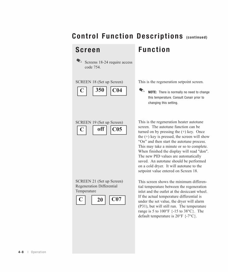
ScreenScreens 18-24 require access code 754.
SCREEN 18 (Set up Screen)
SCREEN 19 (Set up Screen)
SCREEN 21 (Set up Screen)Regeneration DifferentialTemperature
Funct ion
Cont ro l Func t ion Descr ip t ions (cont inued)
This is the regeneration setpoint screen.
NOTE: There is normally no need to change
this temperature. Consult Conair prior to
changing this setting.
This is the regeneration heater autotunescreen. The autotune function can beturned on by pressing the (+) key. Oncethe (+) key is pressed, the screen will show“On” and then start the autotune process.This may take a minute or so to complete.When finished the display will read "don".The new PID values are automaticallysaved. An autotune should be performedon a cold dryer. It will autotune to thesetpoint value entered on Screen 18.
This screen shows the minimum differen-tial temperature between the regenerationinlet and the outlet at the desiccant wheel.If the actual temperature differential isunder the set value, the dryer will alarm(P31), but will still run. The temperaturerange is 5 to 100°F {-15 to 38°C}. Thedefault temperature is 20°F {-7°C}.
350 C04C
off C05C
✐
✐
4-8 l Ope ra t i on
20 C07C
4O
peration
O pe ra t i on l 4-9
Sc reenScreens 18-24 require access code 754.
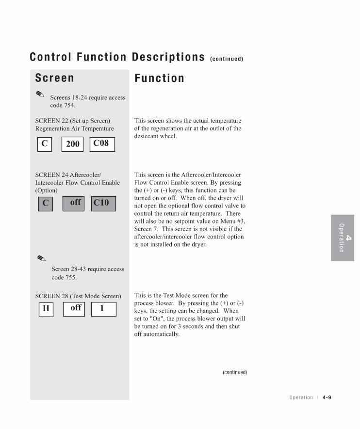
SCREEN 22 (Set up Screen)Regeneration Air Temperature
SCREEN 24 Aftercooler/Intercooler Flow Control Enable(Option)
Screen 28-43 require access code 755.
SCREEN 28 (Test Mode Screen)
Funct ion
Cont ro l Func t ion Descr ip t ions (cont inued)
This screen shows the actual temperatureof the regeneration air at the outlet of thedesiccant wheel.
This screen is the Aftercooler/IntercoolerFlow Control Enable screen. By pressingthe (+) or (-) keys, this function can beturned on or off. When off, the dryer willnot open the optional flow control valve tocontrol the return air temperature. Therewill also be no setpoint value on Menu #3,Screen 7. This screen is not visible if theaftercooler/intercooler flow control optionis not installed on the dryer.
This is the Test Mode screen for theprocess blower. By pressing the (+) or (-)keys, the setting can be changed. Whenset to "On", the process blower output willbe turned on for 3 seconds and then shutoff automatically.
(continued)
✐
off C10C
off 1H
200 C08C
✐
4-10 l Ope ra t i on
Cont ro l Func t ion Descr ip t ions (cont inued)
Sc reenScreen 28-43 require access code 755.
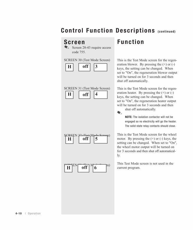
SCREEN 30 (Test Mode Screen)
SCREEN 31 (Test Mode Screen)
SCREEN 32 (Test Mode Screen)
SCREEN 33 (Test Mode Screen)
Funct ion
This is the Test Mode screen for the regen-eration blower. By pressing the (+) or (-)keys, the setting can be changed. Whenset to "On", the regeneration blower outputwill be turned on for 3 seconds and thenshut off automatically.
This is the Test Mode screen for the regen-eration heater. By pressing the (+) or (-)keys, the setting can be changed. Whenset to "On", the regeneration heater outputwill be turned on for 3 seconds and then
shut off automatically.
NOTE: The isolation contactor will not be
engaged so no electricity will go the heater.
The solid state relay contacts should close.
This is the Test Mode screen for the wheelmotor. By pressing the (+) or (-) keys, thesetting can be changed. When set to "On",the wheel motor output will be turned onfor 3 seconds and then shut off automatical-ly.
This Test Mode screen is not used in thecurrent program.
off 3H
off 5H
off 4H
✐
off 6H
✐
4O
peration
O pe ra t i on l 4-11
Sc reenScreen 28-43 require access code 755.
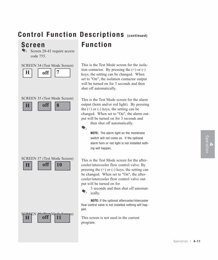
SCREEN 34 (Test Mode Screen)
SCREEN 35 (Test Mode Screen)
SCREEN 37 (Test Mode Screen)
SCREEN 38 (Test Mode Screen)
Funct ionCont ro l Func t ion Descr ip t ions (cont inued)
This is the Test Mode screen for the isola-tion contactor. By pressing the (+) or (-)keys, the setting can be changed. Whenset to "On", the isolation contactor outputwill be turned on for 3 seconds and thenshut off automatically.
This is the Test Mode screen for the alarmoutput (horn and/or red light). By pressingthe (+) or (-) keys, the setting can bechanged. When set to "On", the alarm out-put will be turned on for 3 seconds and
then shut off automatically.
NOTE: The alarm light on the membrane
switch will not come on. If the optional
alarm horn or red light is not installed noth-
ing will happen.
This is the Test Mode screen for the after-cooler/intercooler flow control valve. Bypressing the (+) or (-) keys, the setting canbe changed. When set to "On", the after-cooler/intercooler flow control valve out-put will be turned on for
3 seconds and then shut off automat-ically.
NOTE: If the optional aftercooler/intercoolerflow control valve is not installed nothing will hap-pen.
This screen is not used in the current program.
off 8H
off 7H
off 10H
✐
✐
off 11H
✐
4-12 l Ope ra t i on
ScreenScreen 28-43 require access code 755.
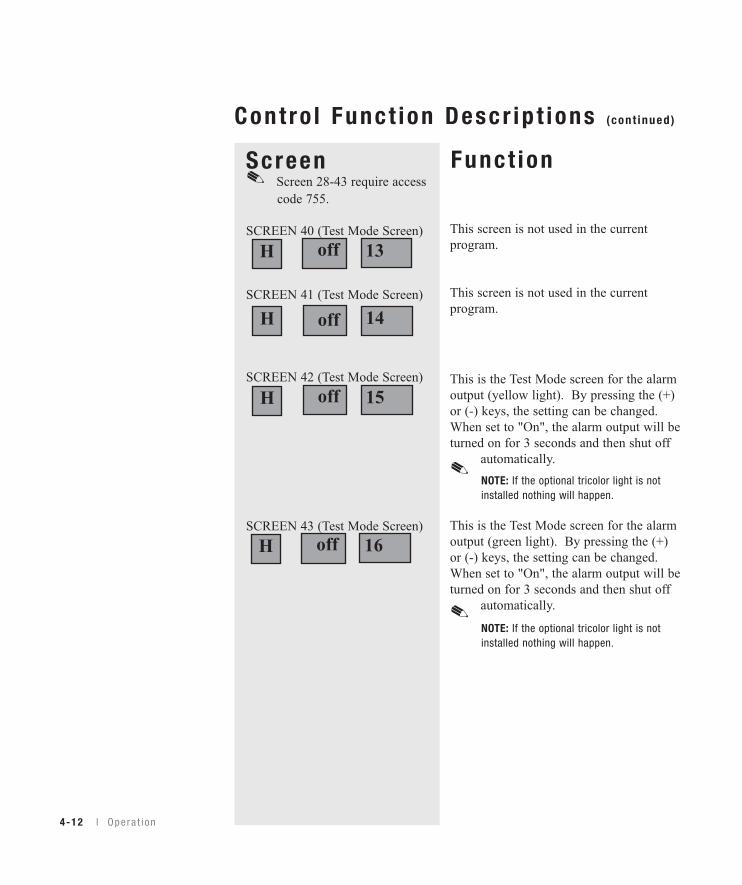
SCREEN 40 (Test Mode Screen)
SCREEN 41 (Test Mode Screen)
SCREEN 42 (Test Mode Screen)
SCREEN 43 (Test Mode Screen)
Funct ion
Cont ro l Func t ion Descr ip t ions (cont inued)
This screen is not used in the currentprogram.
This screen is not used in the currentprogram.
This is the Test Mode screen for the alarmoutput (yellow light). By pressing the (+)or (-) keys, the setting can be changed.When set to "On", the alarm output will beturned on for 3 seconds and then shut off
automatically.NOTE: If the optional tricolor light is notinstalled nothing will happen.
This is the Test Mode screen for the alarmoutput (green light). By pressing the (+)or (-) keys, the setting can be changed.When set to "On", the alarm output will beturned on for 3 seconds and then shut off
automatically.
NOTE: If the optional tricolor light is notinstalled nothing will happen.
off 13H
off 15H
off 14H
off 16H
✐
✐
✐
4O
peration
O pe ra t i on l 4-13
Sc reenAccess code 756 required.
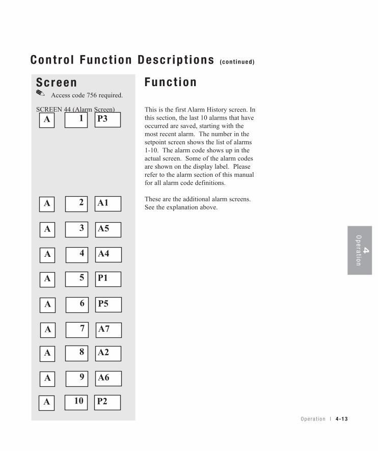
SCREEN 44 (Alarm Screen)
Funct ion
Cont ro l Func t ion Descr ip t ions (cont inued)
1 P3AThis is the first Alarm History screen. Inthis section, the last 10 alarms that haveoccurred are saved, starting with themost recent alarm. The number in thesetpoint screen shows the list of alarms1-10. The alarm code shows up in theactual screen. Some of the alarm codesare shown on the display label. Pleaserefer to the alarm section of this manualfor all alarm code definitions.
These are the additional alarm screens.See the explanation above.2 A1A
3 A5A
4 A4A
5 P1A
6 P5A
7 A7A
8 A2A
9 A6A
10 P2A
✐
4-14 l Ope ra t i on
ScreenScreen 47 require access code 754.
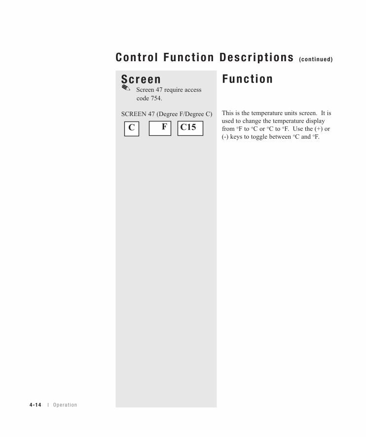
SCREEN 47 (Degree F/Degree C)
Funct ion
Cont ro l Func t ion Descr ip t ions (cont inued)
This is the temperature units screen. It isused to change the temperature displayfrom °F to °C or °C to °F. Use the (+) or(-) keys to toggle between °C and °F.
F C15C
✐
Opera t i on l 4-15
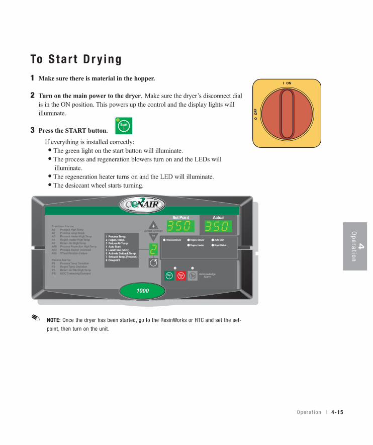
To S ta r t D r y ing1 Make sure there is material in the hopper.
2 Turn on the main power to the dryer. Make sure the dryer’s disconnect dialis in the ON position. This powers up the control and the display lights willilluminate.
3 Press the START button.If everything is installed correctly:
• The green light on the start button will illuminate. • The process and regeneration blowers turn on and the LEDs will illuminate. • The regeneration heater turns on and the LED will illuminate. • The desiccant wheel starts turning.
Auto Start
Dryer Status
Process Blower Regen. Blower
Regen. Heater
Set Point Actual
1 Process Temp.2 Regen. Temp.3 Return Air Temp.4 Auto Start5 Load Time (MDC)6 Activate Setback Temp.7 Setback Temp.(Process)8 Dewpoint
Shutdown AlarmsA1 Process High TempA2 Process Loop BreakA3 Process Heater High TempA4 Regen Heater High TempA7 Return Air High TempA49 Process Protection High TempA53 Process Blower OverloadA55 Wheel Rotation Failure
Passive AlarmsP1 Process Temp DeviationP3 Regen Temp DeviationP5 Return Air Mid High TempP17 MDC Conveying Demand
1000
NOTE: Once the dryer has been started, go to the ResinWorks or HTC and set the set-
point, then turn on the unit.
✐
Start
4O
peration
4-16 l Ope ra t i on
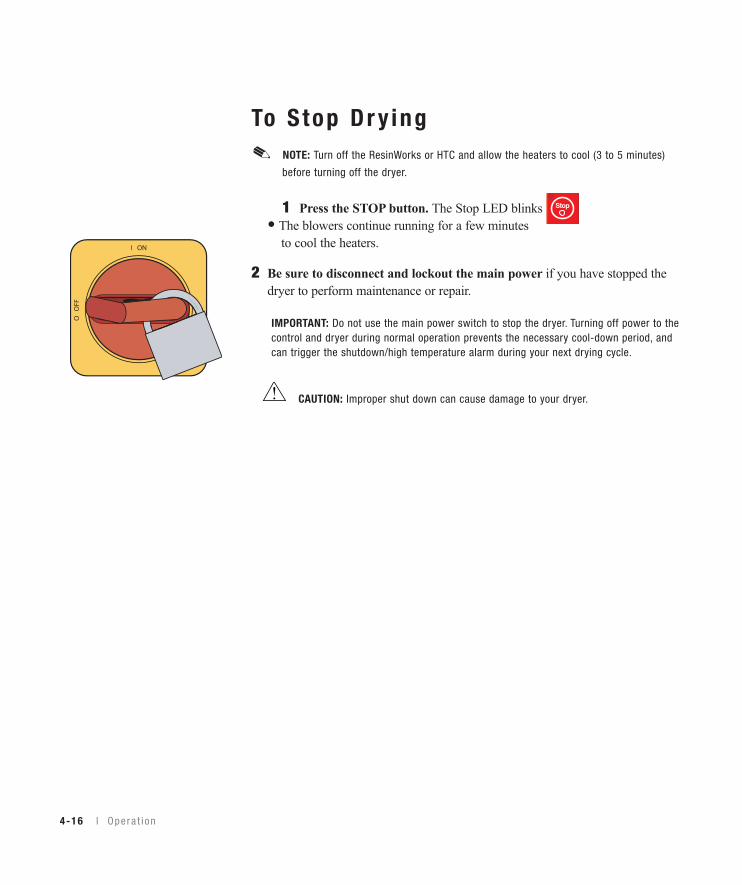
To S top Dr y ing
1 Press the STOP button. The Stop LED blinks red. • The blowers continue running for a few minutes
to cool the heaters.
2 Be sure to disconnect and lockout the main power if you have stopped thedryer to perform maintenance or repair.
IMPORTANT: Do not use the main power switch to stop the dryer. Turning off power to thecontrol and dryer during normal operation prevents the necessary cool-down period, andcan trigger the shutdown/high temperature alarm during your next drying cycle.
CAUTION: Improper shut down can cause damage to your dryer.
NOTE: Turn off the ResinWorks or HTC and allow the heaters to cool (3 to 5 minutes)
before turning off the dryer.
✐
Stop

Us ing the Auto S ta r t CountdownFunct ionThe countdown function allows the user to set the Carousel Plus W SeriesDryer to automatically start at a predetermined time. The countdown time canbe set from 0.1 to 150.0 hours.
To set the countdown time:
1 Use the Scroll button to access the function (Menu 4, Screen 8).
Auto Start
2 Use the Setpoint Adjust keys to set the desired countdown time in hours.
3 Press the Start button. The Auto Start LED will blink to indicate that Auto Start is armed.
How to D isab le the Auto S ta r t onthe DC-1 Cont ro l
To disable auto start once armed cycle the power off and on.
16 ON4
Opera t i on l 4-17
4O
peration
4-18 l Ope ra t i on
NOTE: For more information concerning specific dewpoint control screens, see Control
Function Descriptions, page 4-5.
✐
Us ing Dewpo in t Cont ro l
Dewpoint control is a feature that can help you to reduce energy consumption. Itdoes this by varying the temperature of the regeneration air from its default set-point of 350° F {177° C}, to maintain a setpoint that you have entered on theprocess dewpoint screen (Screen 11).
Example:
If your material is not difficult to dry, it may dry adequately with -20° F {-29° C} dewpoint air. When -20° F {-29° C} is entered as the setpoint (Screen11), the dryer will gradually lower the regeneration air temperature to a pointwhere the dryer’s delivery air is controlled at -20° F {-29° C} dewpoint.
The dewpoint control is active with setpoint values of -39° F {-39.4° C} andhigher. When the setpoint is -40° F {-40° C} or lower, the regeneration tempera-ture will be maintained at the default temperature of 350° F {177° C} and thedewpoint control is inactive.
Main tenance
P reven ta t i ve ma in tenance check l i s t . . . . . . . 5 -2
Check ing t he dewpo in t . . . . . . . . . . . . . . . . 5 -3
C l ean ing t he hoppe r . . . . . . . . . . . . . . . . . . 5 -5
C l ean ing t he p rocess f i l t e r . . . . . . . . . . . . . 5 -6
C l ean ing t he r egene ra t i on f i l t e r . . . . . . . . . . 5 -8
C l ean ing t he a f t e r coo l e r / i n t e r coo l e r co i l s . . . 5 -9
C l ean ing t he p recoo l e r co i l s . . . . . . . . . . . 5 -11
C l ean ing t he vo l a t i l e t r a p on t he demis te r . . 5 -11
I n spec t i ng hoses and gaske t s . . . . . . . . . . 5 -11
S E C T I O N
5M
aintenance
5
Main tenance l 5-1
5-2 l Ma in tenance
Preventa t i ve Ma in tenanceCheck l i s tRoutine maintenance will ensure optimum operation and performance of the W Series Carousel Plus Dryer. We recommend the following maintenanceschedule and tasks.
• Whenever you change mater ia ls ❒ Drain and clean the hopper.
• Week ly, o r as o f ten as needed ❒ Clean or replace the process and regeneration filters. You may need to clean filters more often than weekly. Frequencydepends on how much material you process and how dusty or full of fines it is.
❒ Inspect hoses and hose connections. Check for damage, kinks, or loose hose clamps. Replace any hoses that show signs of damage or wear. Reposition and tighten loose hose clamps.
• Month ly ❒ Clean the aftercooler/intercooler and optional precooler coils. You may need to clean the coils more often than monthly. Frequency will depend on the type and volume of material you process.
• Ever y s ix months ❒ Inspect gaskets for damage or wear. Damaged gaskets can allow moisture to seep into the closed-loop drying system. Replace any gasket that is torn or cracked. ❒ Inspect the overhead process air duct connections. (W3200-5000) Ensure that all connections are tighten properly and have . no air leaks.
❒ Verify dewpoint readout and performance with calibrated portable instrument. ❒ Measure current draw on all 3 legs of heater wires. This is to ensure that the heater is working properly.
5M
aintenance
Ma i n t enance l 5-3
✐NOTE: Portable dewpoint moni-
tors purchased from Conair are
provided with a male connector
that plugs into the dewpoint
check port. If you purchased
your portable instrument else-
where, the male connector is
available through the Conair
parts department.
NOTE: The dewpoint check port
was not included on early
dryers. It can be added easily.
Contact the Conair parts
department or follow the
alternate procedure.
✐
Replacement dewpointmonitors, male connectorsand dewpoint check portsare available from Conair.
Contact Conair Parts(800) 458 1960From outside of the United States, call:(814) 437 6861
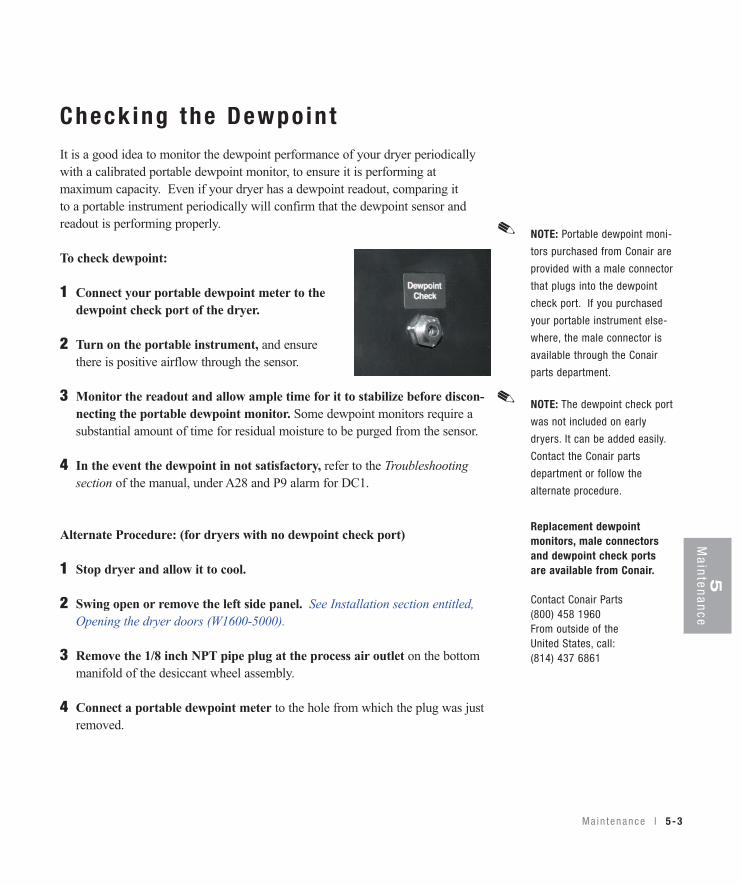
Check ing the Dewpo in tIt is a good idea to monitor the dewpoint performance of your dryer periodicallywith a calibrated portable dewpoint monitor, to ensure it is performing atmaximum capacity. Even if your dryer has a dewpoint readout, comparing itto a portable instrument periodically will confirm that the dewpoint sensor andreadout is performing properly.
To check dewpoint:
1 Connect your portable dewpoint meter to thedewpoint check port of the dryer.
2 Turn on the portable instrument, and ensure there is positive airflow through the sensor.
3 Monitor the readout and allow ample time for it to stabilize before discon-necting the portable dewpoint monitor. Some dewpoint monitors require asubstantial amount of time for residual moisture to be purged from the sensor.
4 In the event the dewpoint in not satisfactory, refer to the Troubleshootingsection of the manual, under A28 and P9 alarm for DC1.
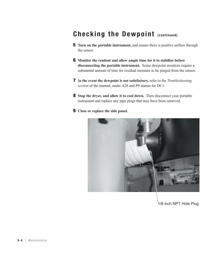
Alternate Procedure: (for dryers with no dewpoint check port)
1 Stop dryer and allow it to cool.
2 Swing open or remove the left side panel. See Installation section entitled,Opening the dryer doors (W1600-5000).
3 Remove the 1/8 inch NPT pipe plug at the process air outlet on the bottommanifold of the desiccant wheel assembly.
4 Connect a portable dewpoint meter to the hole from which the plug was justremoved.
Check ing the Dewpo in t (cont inued)
5 Turn on the portable instrument, and ensure there is positive airflow throughthe sensor.
6 Monitor the readout and allow ample time for it to stabilize beforedisconnecting the portable instrument. Some dewpoint monitors require asubstantial amount of time for residual moisture to be purged from the sensor.
7 In the event the dewpoint is not satisfactory, refer to the Troubleshootingsection of the manual, under A28 and P9 alarms for DC1.
8 Stop the dryer, and allow it to cool down. Then disconnect your portableinstrument and replace any pipe plugs that may have been removed.
9 Close or replace the side panel.
5-4 l Ma in tenance
1/8 inch NPT Hole Plug
5M
aintenance
Ma i n t enance l 5-5
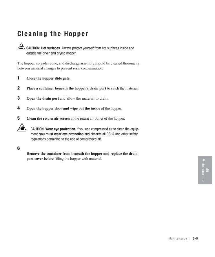
C l ean ing the Hopper
CAUTION: Hot surfaces. Always protect yourself from hot surfaces inside andoutside the dryer and drying hopper.
The hopper, spreader cone, and discharge assembly should be cleaned thoroughlybetween material changes to prevent resin contamination.
1 Close the hopper slide gate.
2 Place a container beneath the hopper’s drain port to catch the material.
3 Open the drain port and allow the material to drain.
4 Open the hopper door and wipe out the inside of the hopper.
5 Clean the return air screen at the return air outlet of the hopper.
6Remove the container from beneath the hopper and replace the drainport cover before filling the hopper with material.
CAUTION: Wear eye protection. If you use compressed air to clean the equip-ment, you must wear eye protection and observe all OSHA and other safetyregulations pertaining to the use of compressed air.
5-6 l Ma in tenance
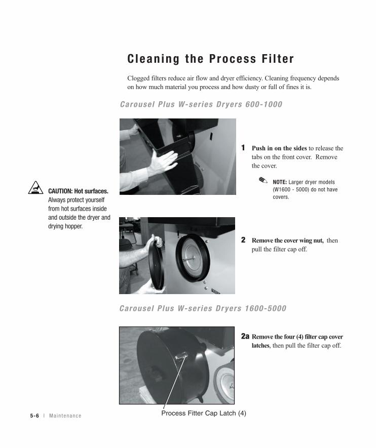
Clean ing the P rocess F i l t e rClogged filters reduce air flow and dryer efficiency. Cleaning frequency dependson how much material you process and how dusty or full of fines it is.
1 Push in on the sides to release the tabs on the front cover. Remove the cover.
NOTE: Larger dryer models (W1600 - 5000) do not have covers.
2 Remove the cover wing nut, then pull the filter cap off.
2a Remove the four (4) filter cap cover latches, then pull the filter cap off.
CAUTION: Hot surfaces.Always protect yourselffrom hot surfaces insideand outside the dryer anddrying hopper.
✐
Process Fitter Cap Latch (4)
Carouse l P lus W-ser ies Dr yers 600-1000
Carouse l P lus W-ser ies Dr yers 1600-5000
Main tenance l 5-7
5M
aintenance
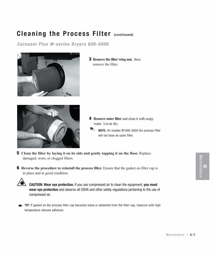
Clean ing the P rocess F i l t e r (cont inued)
3 Remove the filter wing nut, then remove the filter.
4 Remove outer filter and clean it with soapy water. Let air dry.
5 Clean the filter by laying it on its side and gently tapping it on the floor. Replacedamaged, worn, or clogged filters.
6 Reverse the procedure to reinstall the process filter. Ensure that the gasket on filter cap isin place and in good condition.
CAUTION: Wear eye protection. If you use compressed air to clean the equipment, you mustwear eye protection and observe all OSHA and other safety regulations pertaining to the use ofcompressed air.
TIP: If gasket on the process filter cap becomes loose or detached from the filter cap, resecure with high
temperature silicone adhesive.✒
Carouse l P lus W-ser ies Dr yers 600-5000
NOTE: On models W1600-5000 the process filter
will not have an outer filter.
✐
5-8 l Ma in tenance
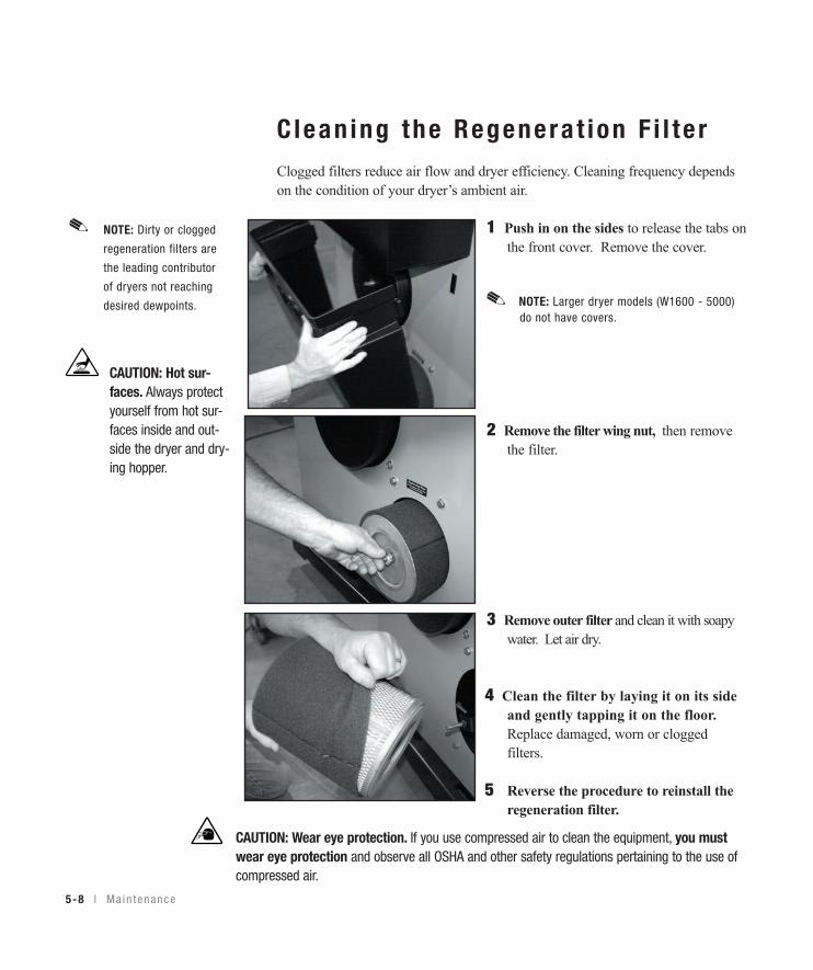
Clean ing the Regenera t ion F i l t e rClogged filters reduce air flow and dryer efficiency. Cleaning frequency dependson the condition of your dryer’s ambient air.
1 Push in on the sides to release the tabs onthe front cover. Remove the cover.
NOTE: Larger dryer models (W1600 - 5000)do not have covers.
2 Remove the filter wing nut, then remove the filter.
3 Remove outer filter and clean it with soapy water. Let air dry.
4 Clean the filter by laying it on its side and gently tapping it on the floor. Replace damaged, worn or clogged filters.
5 Reverse the procedure to reinstall the regeneration filter.
CAUTION: Wear eye protection. If you use compressed air to clean the equipment, you mustwear eye protection and observe all OSHA and other safety regulations pertaining to the use ofcompressed air.
✐
CAUTION: Hot sur-faces. Always protectyourself from hot sur-faces inside and out-side the dryer and dry-ing hopper.
NOTE: Dirty or clogged
regeneration filters are
the leading contributor
of dryers not reaching
desired dewpoints.
✐

Main tenance l 5-9
5M
aintenance
Clean ing the A f te rcoo le r /In te rcoo le r Co i l sYou need to clean the aftercooler/intercooler coils to keep them working efficient-ly. Cleaning frequency depends on the type and amount of material you process.
1 Stop the dryer and lockout the main power.
2 Turn off the water flow to the water supply line. Disconnect supply and return lines.
3 Remove the bolts securing the aftercooler/intercooler cover. Remove thecover.
4 Remove the aftercooler/intercooler by pulling it out of the aftercooler/inter-cooler housing.
W600 - 1000Models
W1600 - 5000Models
NOTE: If an optional flow control was added with the aftercooler/intercooler, remove the
compression fitting from the aftercooler/intercooler inlet. Loosen the fitting on the flow
control, then swing the copper water supply tube out and away from the
aftercooler/intercooler inlet.
✐
(continued)
Clean ing the A f te rcoo le r /In te rcoo le r Co i l s (cont inued)
5 Clean the assembly using a mild soap and water. Let the assemblydry thoroughly before installation.
NOTE: In cases of heavy volatiles, steam cleaning or the use of solvents, such
as acetone, may be necessary. Be sure to test a small area with the solvent
you have selected to be sure there is no adverse reaction.
6 Inspect the condition of the gasket. If it is damaged, replace thegasket.
7 Reassemble by repeating the steps in reverse order.
8 Connect the water supply line to the inlet. If a manual shut offvalve is used, it should be mounted on the inlet line as well.
9 Connect the outlet of the aftercooler/intercooler to the inlet of theflow control valve using the pre-shaped copper tubing and compres-sion fittings provided.
✐
5-10 l Ma in tenance
Clean ing the P recoo le r Co i l sYou need to clean the precooler cooling coils to keep them working efficiently. SeeAppendix B for details.
Clean ing the Vo la t i l e Trap onthe Demis te r If you have the optional volatile trap, you need to clean the trap to keep it workingefficiently. See Appendix C for details.
I nspec t ing Hoses and Gaske ts
Loose or damaged hoses and gaskets can allow moisture to seep into theclosed-loop drying system.
1 Follow the hose routing of all the hoses within the dryer and inspect allhoses, clamps, fittings, and gaskets.
2 Tighten any loose hose clamps or fittings.
3 Replace worn or damaged hoses and gaskets.
5M
aintenance
Ma i n t enance l 5-11

5-12 l Ma in tenance
Troub leshoot ing Be fo re beg inn ing . . . . . . . . . . . . . . . . . . . . 6 -2
A f ew words o f cau t i on . . . . . . . . . . . . . . 6 -3
D IAGNOST ICSHo w to i den t i f y t he cause o f a p rob l em . . . . 6 -4
A la rms . . . . . . . . . . . . . . . . . . . . . . . . . 6 -5
Dewpo in t t r oub l eshoo t i ng . . . . . . . . . . . . . 6 -17
Poo r ma te r i a l d r y i ng t r oub l eshoo t i ng . . . . . 6 -18
REPA IRRep lac ing f uses . . . . . . . . . . . . . . . . . . . . 6 -23
Check ing hea te r so l i d s t a t e r e l ays . . . . . . . 6 -24
Check ing o r r ep l ac i ng t empera tu re senso rs . 6 -25
Rep lac ing t he r egene ra t i on hea te r (W600 - 1000 ) . . . . . . . . . . . . . . . . . . 6 -26
Rep lac ing t he r egene ra t i on hea te r (W1600 - 2400 ) . . . . . . . . . . . . . . . . . 6 -28
Rep lac ing t he r egene ra t i on hea te r (W3200 - 5000 ) . . . . . . . . . . . . . . . . . 6 -30
Rep lac ing t he des i ccan t whee l assemb l y (W600 - 1000 ) . . . . . . . . . . . . . . . . . . 6 -32
Rep lac ing t he des i ccan t whee l mo to r (W600 - 1000 ) . . . . . . . . . . . . . . . . . . 6 -34
Rep lac ing t he des i ccan t whee l mo to r (W1600 - 5000 ) . . . . . . . . . . . . . . . . . 6 -35
S E C T I O N
66
Troubleshooting
Tr oub l eshoo t i ng l 6-1
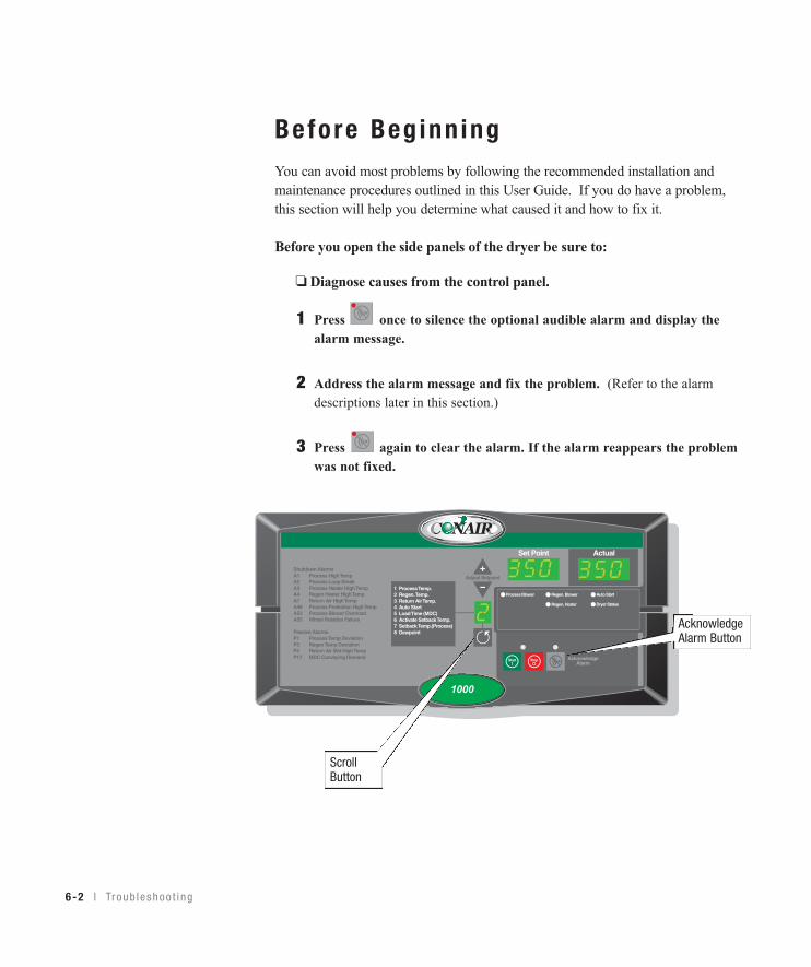
Before Beg inn ingYou can avoid most problems by following the recommended installation andmaintenance procedures outlined in this User Guide. If you do have a problem,this section will help you determine what caused it and how to fix it.
Before you open the side panels of the dryer be sure to:
❏ Diagnose causes from the control panel.
1 Press once to silence the optional audible alarm and display the alarm message.
2 Address the alarm message and fix the problem. (Refer to the alarm descriptions later in this section.)
3 Press again to clear the alarm. If the alarm reappears the problem was not fixed.
Auto Start
Dryer Status
Process Blower Regen. Blower
Regen. Heater
Set Point Actual
1 Process Temp.2 Regen. Temp.3 Return Air Temp.4 Auto Start5 Load Time (MDC)6 Activate Setback Temp.7 Setback Temp.(Process)8 Dewpoint
Shutdown AlarmsA1 Process High TempA2 Process Loop BreakA3 Process Heater High TempA4 Regen Heater High TempA7 Return Air High TempA49 Process Protection High TempA53 Process Blower OverloadA55 Wheel Rotation Failure
Passive AlarmsP1 Process Temp DeviationP3 Regen Temp DeviationP5 Return Air Mid High TempP17 MDC Conveying Demand
1000
AcknowledgeAlarm Button
ScrollButton
6-2 l Tr oub l eshoo t i ng
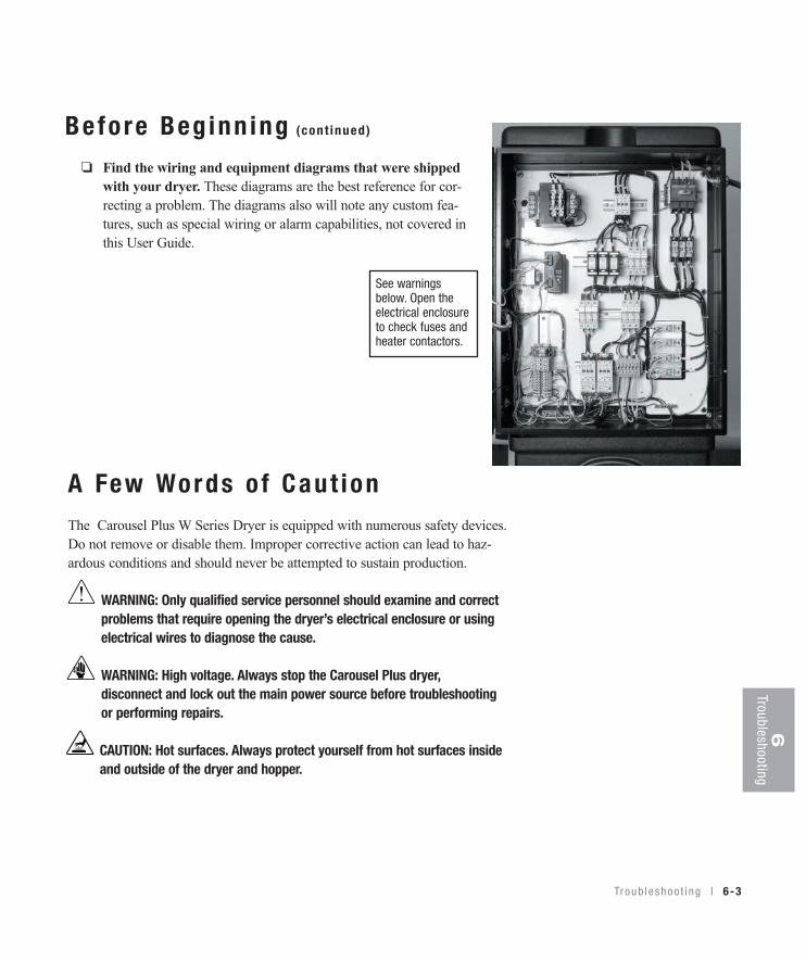
Before Beg inn ing (cont inued)
❏ Find the wiring and equipment diagrams that were shippedwith your dryer. These diagrams are the best reference for cor-recting a problem. The diagrams also will note any custom fea-tures, such as special wiring or alarm capabilities, not covered inthis User Guide.
6Troubleshooting
A Few Words o f Caut ionThe Carousel Plus W Series Dryer is equipped with numerous safety devices.Do not remove or disable them. Improper corrective action can lead to haz-ardous conditions and should never be attempted to sustain production.
WARNING: Only qualified service personnel should examine and correctproblems that require opening the dryer’s electrical enclosure or usingelectrical wires to diagnose the cause.
WARNING: High voltage. Always stop the Carousel Plus dryer, disconnect and lock out the main power source before troubleshootingor performing repairs.
CAUTION: Hot surfaces. Always protect yourself from hot surfaces insideand outside of the dryer and hopper.
See warningsbelow. Open theelectrical enclosureto check fuses andheater contactors.
Troub leshoo t i ng l 6-3
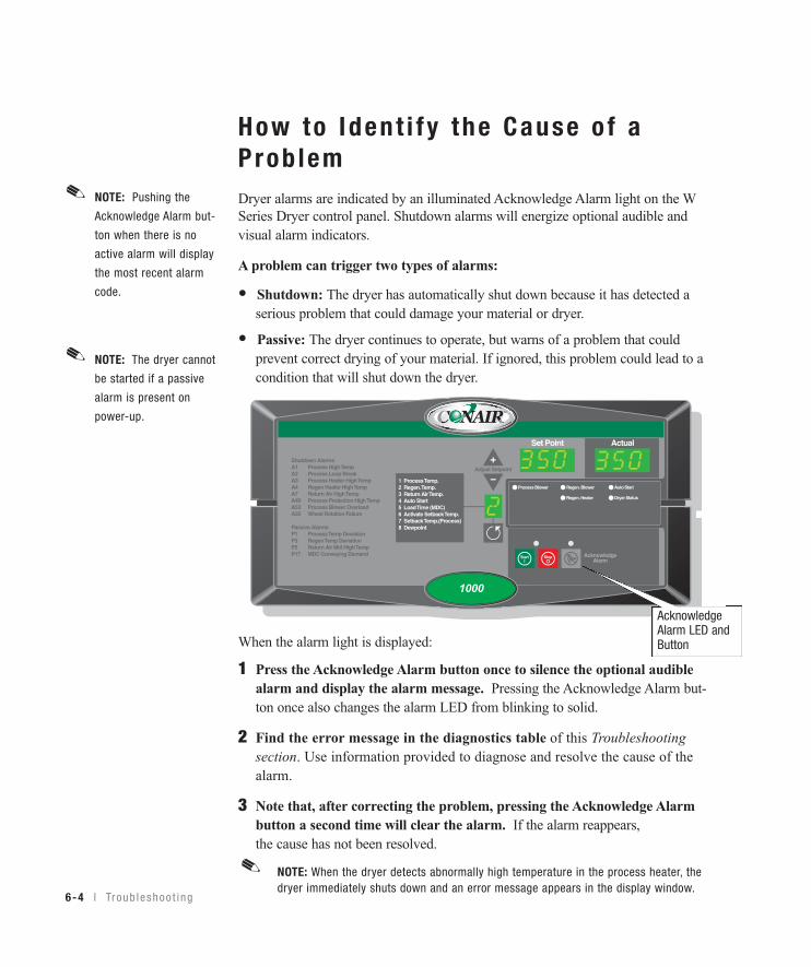
How to Iden t i f y the Cause o f aProb lemDryer alarms are indicated by an illuminated Acknowledge Alarm light on the WSeries Dryer control panel. Shutdown alarms will energize optional audible andvisual alarm indicators.
A problem can trigger two types of alarms:
• Shutdown: The dryer has automatically shut down because it has detected a serious problem that could damage your material or dryer.
• Passive: The dryer continues to operate, but warns of a problem that could prevent correct drying of your material. If ignored, this problem could lead to a condition that will shut down the dryer.
When the alarm light is displayed:
1 Press the Acknowledge Alarm button once to silence the optional audiblealarm and display the alarm message. Pressing the Acknowledge Alarm but-ton once also changes the alarm LED from blinking to solid.
2 Find the error message in the diagnostics table of this Troubleshootingsection. Use information provided to diagnose and resolve the cause of thealarm.
3 Note that, after correcting the problem, pressing the Acknowledge Alarmbutton a second time will clear the alarm. If the alarm reappears, the cause has not been resolved.
NOTE: When the dryer detects abnormally high temperature in the process heater, thedryer immediately shuts down and an error message appears in the display window.
6-4 l Tr oub l eshoo t i ng
Auto Start
Dryer Status
Process Blower Regen. Blower
Regen. Heater
Set Point Actual
1 Process Temp.2 Regen. Temp.3 Return Air Temp.4 Auto Start5 Load Time (MDC)6 Activate Setback Temp.7 Setback Temp.(Process)8 Dewpoint
Shutdown AlarmsA1 Process High TempA2 Process Loop BreakA3 Process Heater High TempA4 Regen Heater High TempA7 Return Air High TempA49 Process Protection High TempA53 Process Blower OverloadA55 Wheel Rotation Failure
Passive AlarmsP1 Process Temp DeviationP3 Regen Temp DeviationP5 Return Air Mid High TempP17 MDC Conveying Demand
1000
AcknowledgeAlarm LED andButton
✐
NOTE: Pushing the
Acknowledge Alarm but-
ton when there is no
active alarm will display
the most recent alarm
code.
✐
NOTE: The dryer cannot
be started if a passive
alarm is present on
power-up.
✐
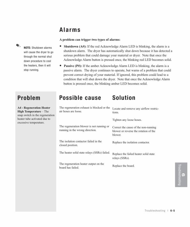
6Troubleshooting
Tr oub l eshoo t i ng l 6-5
A la rmsA problem can trigger two types of alarms:
• Shutdown (A#): If the red Acknowledge Alarm LED is blinking, the alarm is a shutdown alarm. The dryer has automatically shut down because it has detected a serious problem that could damage your material or dryer. Note that once the Acknowledge Alarm button is pressed once, the blinking red LED becomes solid.
• Passive (P#): If the amber Acknowledge Alarm LED is blinking, the alarm is a passive alarm. The dryer continues to operate, but warns of a problem that could prevent correct drying of your material. If ignored, this problem could lead to a condition that will shut down the dryer. Note that once the Acknowledge Alarm button is pressed once, the blinking amber LED becomes solid.
ProblemA4 - Regeneration HeaterHigh Temperature – Thesnap switch in the regenerationheater tube activated due toexcessive temperature.
Possible causeThe regeneration exhaust is blocked or theair hoses are loose.
The regeneration blower is not running orrunning in the wrong direction.
The isolation contactor failed in theclosed position.
The heater solid state relays (SSRs) failed.
The regeneration heater output on theboard has failed.
Solution
Locate and remove any airflow restric-tions.
Tighten any loose hoses.
Correct the cause of the non-runningblower or reverse the rotation of theblower.
Replace the isolation contactor.
Replace the failed heater solid staterelays (SSRs).
Replace the board.
NOTE: Shutdown alarms
will cause the dryer to go
through the normal shut
down procedure to cool
the heaters, then it will
stop running.
✐

6-6 l Tr oub l eshoo t i ng
Alarms• Shutdown (A#): The dryer has automatically shut down because it has detect- ed a serious problem that could damage your material or dryer.
• Passive (P#): The dryer continues to operate, but warns of a problem that could prevent correct drying of your material. If ignored, this problem could lead to a condition that will shut down the dryer.
ProblemA7 - Return Air HighTemperature – If the returnair temperature at the inlet tothe blower is greater than180°F {82°C}, it shuts downthe dryer. (The return air tem-perature on W1600-5000 dry-ers is measured at the inlet tothe desiccant wheel. W1600-5000 dryers designed prior toAugust 2007, the return airtemperature is measured atthe inlet to the process blow-er.)
A23 & P3 - RegenerationTemperature Deviation – Theregeneration temperatureexceeds the deviation band forthe specified time. Defaultvalues are 10°F {6°C} for 5seconds.
Possible causeThe hopper does not contain enoughmaterial.
You are drying at a high drying tempera-ture above 120°F {49°C} or you arerunning at low throughputs.
The aftercooler/intercooler does nothave enough water.
The aftercooler/intercooler coils aredirty.
One of the solid state relays (SSRs) failedin the closed position.
The heater has become defective.
The regeneration RTD is loose or hasfallen out.
The air hose connections are loose.
The output on the board has failed.
Solution
Make sure your material supply systemis working properly.
Ensure water flow to the aftercooler/intercooler.
Turn on the water supply, or fix anyleaks or blockages.
Clean the aftercooler coils. SeeMaintenance section entitled, Cleaningthe aftercooler/intercooler coils.
Replace the failed solid state relays(SSRs).
Check the heater fuses and resistanceacross each leg of the regenerationheater
Check the regeneration RTD and tightenif needed.
Tighten all air hose connections.
Replace the board.

6Troubleshooting
Tr oub l eshoo t i ng l 6-7
A la rms• Shutdown (A#): The dryer has automatically shut down because it has detect- ed a serious problem that could damage your material or dryer.
• Passive (P#): The dryer continues to operate, but warns of a problem that could prevent correct drying of your material. If ignored, this problem could lead to a condition that will shut down the dryer.
ProblemA25 & P5 - Return Air Mid-High Temperature – If thereturn air temperature isbetween 150 and 180°F{66 and 82°C}. (The returnair temperature on W1600-5000 dryers is measured atthe inlet to the desiccantwheel. W1600-5000 dryersdesigned prior to August2007, the return air tempera-ture is measured at the inletto the process blower.)
A26 & P6 - RegenerationHigh Temperature – If theregeneration temperatureexceeds the high temperaturelimit for the specified time.Default values are 400°F{204°C} for 20 seconds
A27 & P7 - RegenerationLow Temperature – Theregeneration temperature isless than the low temperaturefor the specified time (200°F{93°C} for 20 seconds).
Possible causeThe hopper does not contain enough material.
You are drying at a high drying tempera-ture above 120°F {49°C} or running atlow throughputs.
The aftercooler/intercooler does not haveenough water.
The aftercooler/intercooler coils aredirty.
One of the solid state relays (SSRs)failed in the closed position.
The output on the board has failed.
The regeneration heater has failed.
The output on the control board hasfailed or the fuse has blown.
The regeneration RTD is loose or hasfallen out.
SolutionMake sure your material supply systemis working properly.
Ensure water flow to the aftercooler/intercooler.
Turn on the water supply, or fix anyleaks or blockages.
Clean the aftercooler/intercooler coils.See Maintenance section entitled,Cleaning the aftercooler/intercoolercoils.
Replace the failed solid state relays(SSRs).
Replace the board.
Check the heater fuses, and resistanceacross each leg of the regenerationheater.
Replace the control board or the fuse.
Check the regeneration RTD and tightenif needed.

6-8 l Tr oub l eshoo t i ng
Alarms• Shutdown (A#): The dryer has automatically shut down because it has detect- ed a serious problem that could damage your material or dryer.
• Passive (P#): The dryer continues to operate, but warns of a problem that could prevent correct drying of your material. If ignored, this problem could lead to a condition that will shut down the dryer.
ProblemA28 & P9 - ProcessDewpoint – The dewpoint hasnot fallen below the setpoint.If the dewpoint goes belowthe setpoint for 180 secondsthe alarm should go away.
NOTE: The alarm is notactive for the first 5minutes.
A29 & P10 - Process FilterClogged (Option) – Theprocess filter differential pres-sure switch is tripped.
A33 & P26 - RegenerationRTD Integrity – If the regen-eration RTD is faulty, it shutsdown the dryer.
Possible causeDefective sensor.
The hose or wiring connections to thesensor block are loose or have fallen off.
Poor regeneration air flow.
Desiccant wheel not turning.
The desiccant wheel may be contaminat-ed.
Leaks in the process air stream.
Power Purge blower not running.(Models 2400 and 5000)
The process air filter is clogged.
There is a loose connection in thewiring leading to the RTD.
The connection of the RTD plug on thecontrol board is loose.
The regeneration RTD has failed.
The control board has failed.
SolutionReplace the sensor.
Check wiring and hose connections tothe sensor, resecure if needed.
Remove the air flow restrictions, dirtyfilters, etc.
See A55 & P31
Check the desiccant for contamination,replace if needed. See Troubleshootingsection, entitled Replacing the desiccantwheel assembly.
Install plasticizer/volatile trap for severesituations.
Check for worn or loose hoses.
Check fuse, wiring or replace blower.
Remove and clean or replace the processair filter.
Check the RTD plug connections,make necessary repairs.
Check the plug connection and tightenif needed.
Replace the regeneration RTD.
Replace the control board.
✐
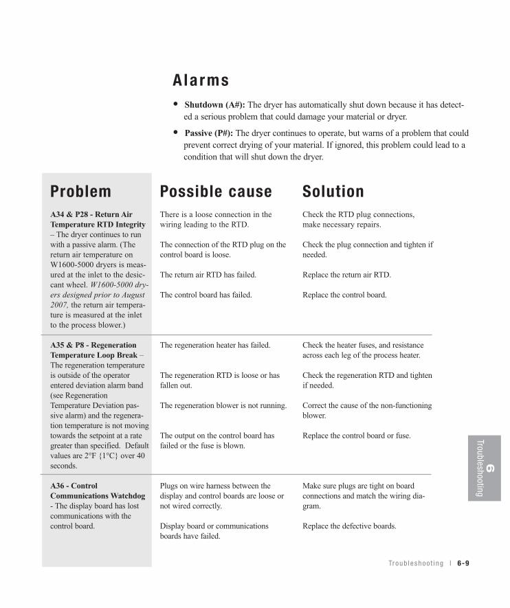
Troub leshoo t i ng l 6-9
6Troubleshooting
Alarms• Shutdown (A#): The dryer has automatically shut down because it has detect- ed a serious problem that could damage your material or dryer.
• Passive (P#): The dryer continues to operate, but warns of a problem that could prevent correct drying of your material. If ignored, this problem could lead to a condition that will shut down the dryer.
ProblemA34 & P28 - Return AirTemperature RTD Integrity– The dryer continues to runwith a passive alarm. (Thereturn air temperature onW1600-5000 dryers is meas-ured at the inlet to the desic-cant wheel. W1600-5000 dry-ers designed prior to August2007, the return air tempera-ture is measured at the inletto the process blower.)
A35 & P8 - RegenerationTemperature Loop Break –The regeneration temperatureis outside of the operatorentered deviation alarm band(see RegenerationTemperature Deviation pas-sive alarm) and the regenera-tion temperature is not movingtowards the setpoint at a rategreater than specified. Defaultvalues are 2°F {1°C} over 40seconds.
A36 - ControlCommunications Watchdog- The display board has lostcommunications with thecontrol board.
Possible causeThere is a loose connection in thewiring leading to the RTD.
The connection of the RTD plug on thecontrol board is loose.
The return air RTD has failed.
The control board has failed.
The regeneration heater has failed.
The regeneration RTD is loose or hasfallen out.
The regeneration blower is not running.
The output on the control board hasfailed or the fuse is blown.
Plugs on wire harness between the display and control boards are loose ornot wired correctly.
Display board or communicationsboards have failed.
SolutionCheck the RTD plug connections,make necessary repairs.
Check the plug connection and tighten ifneeded.
Replace the return air RTD.
Replace the control board.
Check the heater fuses, and resistanceacross each leg of the process heater.
Check the regeneration RTD and tightenif needed.
Correct the cause of the non-functioningblower.
Replace the control board or fuse.
Make sure plugs are tight on board connections and match the wiring dia-gram.
Replace the defective boards.

6-10 l Tr oub l eshoo t i ng
Alarms• Shutdown (A#): The dryer has automatically shut down because it has detect- ed a serious problem that could damage your material or dryer.
• Passive (P#): The dryer continues to operate, but warns of a problem that could prevent correct drying of your material. If ignored, this problem could lead to a condition that will shut down the dryer.
ProblemA38 - Phase Error (Optional) - One of the three powerwires is connected wrong.
A39 - EEProm Write Error
A48 & P22 -Aftercooler/Intercooler LoopBreak (Optional) - Indicatesreturn air temperature is notmoving towards the setpointwhen flow control option isinstalled.
Possible causeOne of the three power wires are out ofphase.
A fuse has blown.
Phase detection board has failed.
There is loose wiring between the phaseboard and the control board.
Internal control board problem.
No water to aftercooler/intercooler.
SolutionSwitch the position of two of the incom-ing lead power wires at the dryer.
Check and replace the fuse.
Replace the phase detection board.
Make sure wires are correct and secure.
Replace the control board.
Turn on water supply.
Ensure flow control valve is function-ing properly.
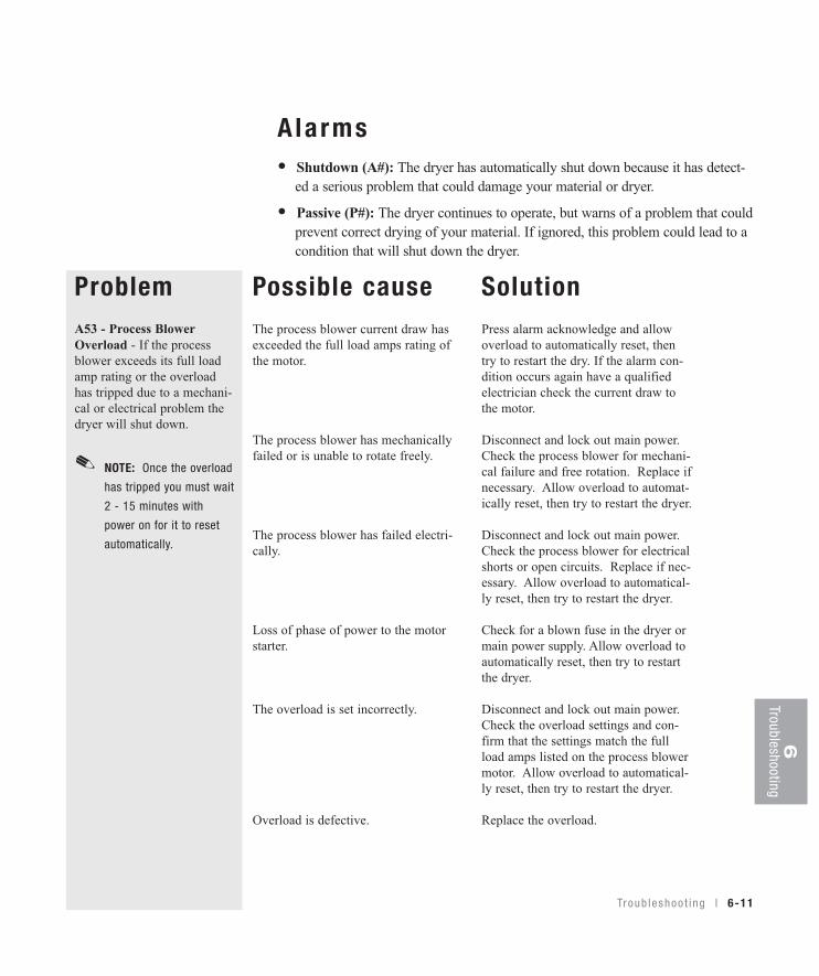
6Troubleshooting
Tr oub l eshoo t i ng l 6-11
A la rms• Shutdown (A#): The dryer has automatically shut down because it has detect- ed a serious problem that could damage your material or dryer.
• Passive (P#): The dryer continues to operate, but warns of a problem that could prevent correct drying of your material. If ignored, this problem could lead to a condition that will shut down the dryer.
ProblemA53 - Process BlowerOverload - If the processblower exceeds its full loadamp rating or the overloadhas tripped due to a mechani-cal or electrical problem thedryer will shut down.
Possible causeThe process blower current draw hasexceeded the full load amps rating ofthe motor.
The process blower has mechanicallyfailed or is unable to rotate freely.
The process blower has failed electri-cally.
Loss of phase of power to the motorstarter.
The overload is set incorrectly.
Overload is defective.
SolutionPress alarm acknowledge and allowoverload to automatically reset, thentry to restart the dry. If the alarm con-dition occurs again have a qualifiedelectrician check the current draw tothe motor.
Disconnect and lock out main power.Check the process blower for mechani-cal failure and free rotation. Replace ifnecessary. Allow overload to automat-ically reset, then try to restart the dryer.
Disconnect and lock out main power.Check the process blower for electricalshorts or open circuits. Replace if nec-essary. Allow overload to automatical-ly reset, then try to restart the dryer.
Check for a blown fuse in the dryer ormain power supply. Allow overload toautomatically reset, then try to restartthe dryer.
Disconnect and lock out main power.Check the overload settings and con-firm that the settings match the fullload amps listed on the process blowermotor. Allow overload to automatical-ly reset, then try to restart the dryer.
Replace the overload.
NOTE: Once the overload
has tripped you must wait
2 - 15 minutes with
power on for it to reset
automatically.
✐
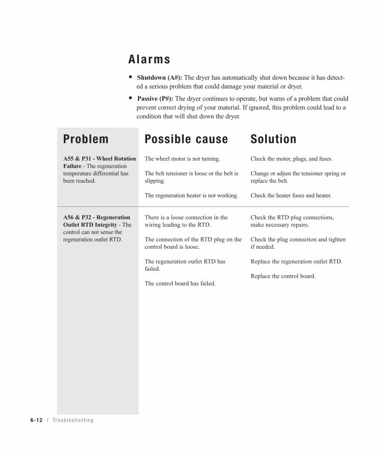
6-12 l Tr oub l eshoo t i ng
Alarms• Shutdown (A#): The dryer has automatically shut down because it has detect- ed a serious problem that could damage your material or dryer.
• Passive (P#): The dryer continues to operate, but warns of a problem that could prevent correct drying of your material. If ignored, this problem could lead to a condition that will shut down the dryer.
ProblemA55 & P31 - Wheel RotationFailure - The regenerationtemperature differential hasbeen reached.
A56 & P32 - RegenerationOutlet RTD Integrity - Thecontrol can not sense theregeneration outlet RTD.
Possible causeThe wheel motor is not turning.
The belt tensioner is loose or the belt isslipping.
The regeneration heater is not working.
There is a loose connection in thewiring leading to the RTD.
The connection of the RTD plug on thecontrol board is loose.
The regeneration outlet RTD hasfailed.
The control board has failed.
SolutionCheck the motor, plugs, and fuses.
Change or adjust the tensioner spring orreplace the belt.
Check the heater fuses and heater.
Check the RTD plug connections,make necessary repairs.
Check the plug connection and tightenif needed.
Replace the regeneration outlet RTD.
Replace the control board.
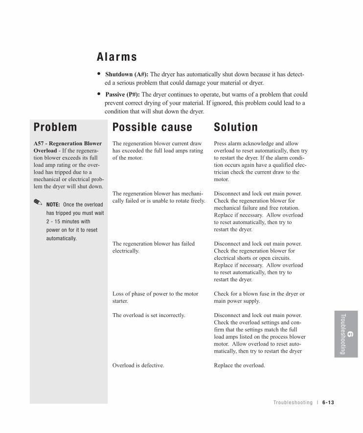
Troub leshoo t i ng l 6-13
6Troubleshooting
Alarms• Shutdown (A#): The dryer has automatically shut down because it has detect- ed a serious problem that could damage your material or dryer.
• Passive (P#): The dryer continues to operate, but warns of a problem that could prevent correct drying of your material. If ignored, this problem could lead to a condition that will shut down the dryer.
ProblemA57 - Regeneration BlowerOverload - If the regenera-tion blower exceeds its fullload amp rating or the over-load has tripped due to amechanical or electrical prob-lem the dryer will shut down.
Possible causeThe regeneration blower current drawhas exceeded the full load amps ratingof the motor.
The regeneration blower has mechani-cally failed or is unable to rotate freely.
The regeneration blower has failedelectrically.
Loss of phase of power to the motorstarter.
The overload is set incorrectly.
Overload is defective.
SolutionPress alarm acknowledge and allowoverload to reset automatically, then tryto restart the dryer. If the alarm condi-tion occurs again have a qualified elec-trician check the current draw to themotor.
Disconnect and lock out main power.Check the regeneration blower formechanical failure and free rotation.Replace if necessary. Allow overloadto reset automatically, then try torestart the dryer.
Disconnect and lock out main power.Check the regeneration blower forelectrical shorts or open circuits.Replace if necessary. Allow overloadto reset automatically, then try torestart the dryer.
Check for a blown fuse in the dryer ormain power supply.
Disconnect and lock out main power.Check the overload settings and con-firm that the settings match the fullload amps listed on the process blowermotor. Allow overload to reset auto-matically, then try to restart the dryer
Replace the overload.
NOTE: Once the overload
has tripped you must wait
2 - 15 minutes with
power on for it to reset
automatically.
✐
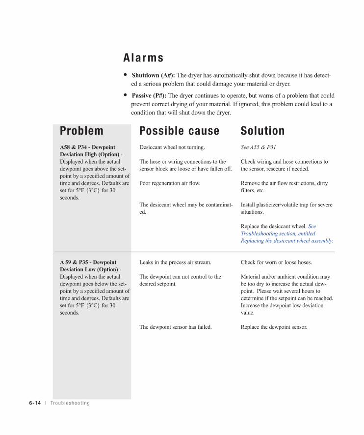
6-14 l Tr oub l eshoo t i ng
Alarms• Shutdown (A#): The dryer has automatically shut down because it has detect- ed a serious problem that could damage your material or dryer.
• Passive (P#): The dryer continues to operate, but warns of a problem that could prevent correct drying of your material. If ignored, this problem could lead to a condition that will shut down the dryer.
ProblemA58 & P34 - DewpointDeviation High (Option) -Displayed when the actualdewpoint goes above the set-point by a specified amount oftime and degrees. Defaults areset for 5°F {3°C} for 30seconds.
A 59 & P35 - DewpointDeviation Low (Option) -Displayed when the actualdewpoint goes below the set-point by a specified amount oftime and degrees. Defaults areset for 5°F {3°C} for 30seconds.
Possible causeDesiccant wheel not turning.
The hose or wiring connections to thesensor block are loose or have fallen off.
Poor regeneration air flow.
The desiccant wheel may be contaminat-ed.
Leaks in the process air stream.
The dewpoint can not control to thedesired setpoint.
The dewpoint sensor has failed.
SolutionSee A55 & P31
Check wiring and hose connections tothe sensor, resecure if needed.
Remove the air flow restrictions, dirtyfilters, etc.
Install plasticizer/volatile trap for severesituations.
Replace the desiccant wheel. SeeTroubleshooting section, entitledReplacing the desiccant wheel assembly.
Check for worn or loose hoses.
Material and/or ambient condition maybe too dry to increase the actual dew-point. Please wait several hours todetermine if the setpoint can be reached.Increase the dewpoint low deviationvalue.
Replace the dewpoint sensor.
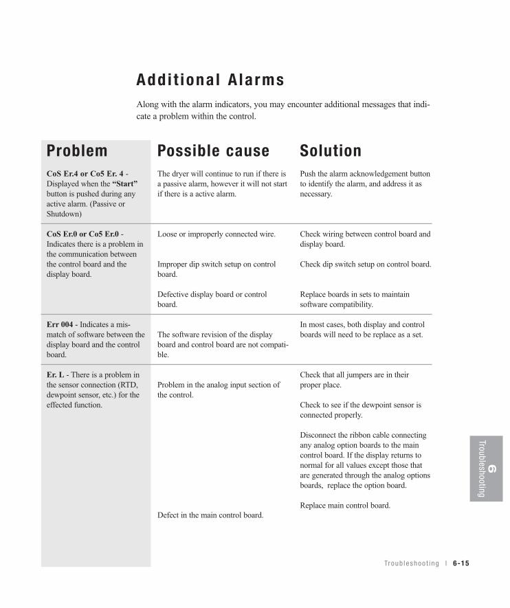
Troub leshoo t i ng l 6-15
Add i t i ona l A la rmsAlong with the alarm indicators, you may encounter additional messages that indi-cate a problem within the control.
ProblemCoS Er.4 or Co5 Er. 4 -Displayed when the “Start”button is pushed during anyactive alarm. (Passive orShutdown)
CoS Er.0 or Co5 Er.0 -Indicates there is a problem inthe communication betweenthe control board and thedisplay board.
Err 004 - Indicates a mis-match of software between thedisplay board and the controlboard.
Er. L - There is a problem inthe sensor connection (RTD,dewpoint sensor, etc.) for theeffected function.
Possible causeThe dryer will continue to run if there isa passive alarm, however it will not startif there is a active alarm.
Loose or improperly connected wire.
Improper dip switch setup on controlboard.
Defective display board or controlboard.
The software revision of the displayboard and control board are not compati-ble.
Problem in the analog input section ofthe control.
Defect in the main control board.
SolutionPush the alarm acknowledgement buttonto identify the alarm, and address it asnecessary.
Check wiring between control board anddisplay board.
Check dip switch setup on control board.
Replace boards in sets to maintainsoftware compatibility.
In most cases, both display and controlboards will need to be replace as a set.
Check that all jumpers are in theirproper place.
Check to see if the dewpoint sensor isconnected properly.
Disconnect the ribbon cable connectingany analog option boards to the maincontrol board. If the display returns tonormal for all values except those thatare generated through the analog optionsboards, replace the option board.
Replace main control board.
6Troubleshooting
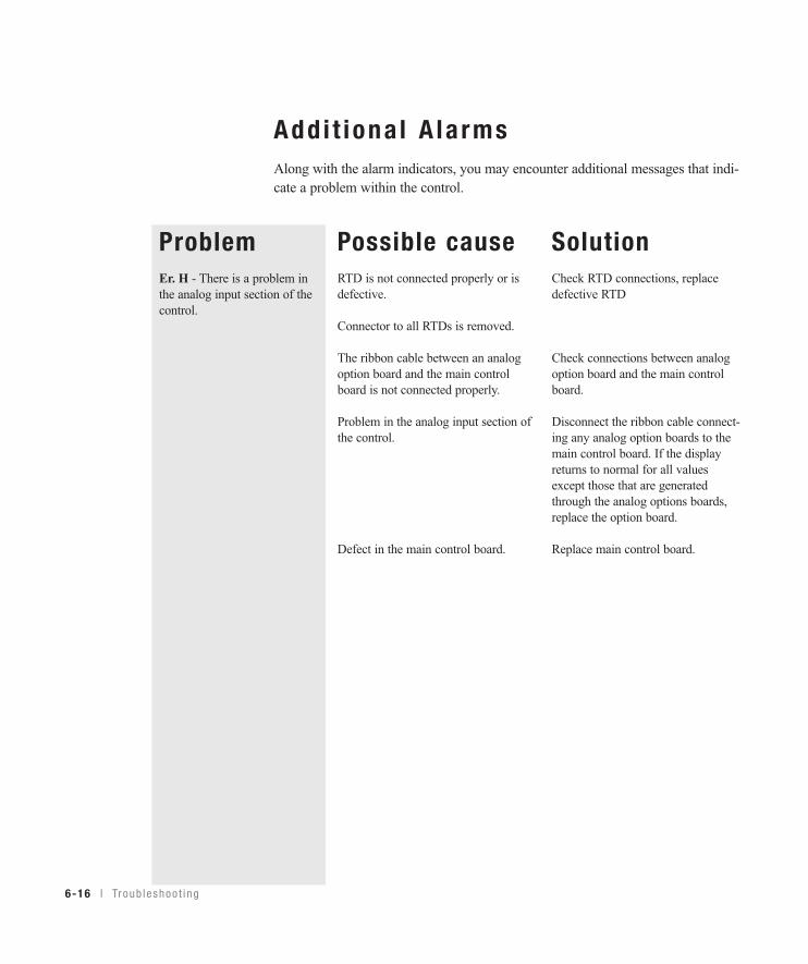
Add i t iona l A la rmsAlong with the alarm indicators, you may encounter additional messages that indi-cate a problem within the control.
ProblemEr. H - There is a problem inthe analog input section of thecontrol.
Possible causeRTD is not connected properly or isdefective.
Connector to all RTDs is removed.
The ribbon cable between an analogoption board and the main controlboard is not connected properly.
Problem in the analog input section ofthe control.
Defect in the main control board.
SolutionCheck RTD connections, replacedefective RTD
Check connections between analogoption board and the main controlboard.
Disconnect the ribbon cable connect-ing any analog option boards to themain control board. If the displayreturns to normal for all valuesexcept those that are generatedthrough the analog options boards,replace the option board.
Replace main control board.
6-16 l Tr oub l eshoo t i ng
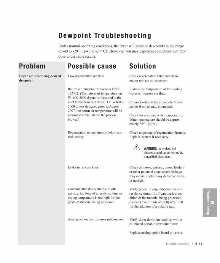
Dewpo in t Troub leshoot ingUnder normal operating conditions, the dryer will produce dewpoints in the rangeof -40 to -20° F {-40 to -29° C}. However, you may experience situations that pro-duce undesirable results.
ProblemDryer not producing desireddewpoint.
Possible causeLow regeneration air flow.
Return air temperature exceeds 125°F{52°C}. (The return air temperature onW1600-5000 dryers is measured at theinlet to the desiccant wheel. On W1600-5000 dryers designed prior to August2007, the return air temperature will bemeasured at the inlet to the processblower.)
Regeneration temperature is below nor-mal setting.
Leaks in process lines.
Contaminated desiccant due to off-gassing, too long of a residence time ordrying temperature is too high for thegrade of material being processed.
Analog option board/sensor malfunction
SolutionCheck regeneration filter and cleanand/or replace as necessary.
Reduce the temperature of the coolingwater or increase the flow.
Connect water to the aftercooler/inter-cooler if not already connected.
Check for adequate water temperature.Water temperature should be approxi-mately 85°F {29°C}.
Check amperage of regeneration heaters.Replace heaters if necessary.
Check all hoses, gaskets, doors, loadersor other potential areas where leakagemay occur. Replace any defective hosesor gaskets.
Verify proper drying temperatures andresidence times. If off-gassing is a con-dition of the material being processed,contact Conair Parts at (800) 458 1960for the addition of a volatile trap.
Verify dryer dewpoint readings with acalibrated portable dewpoint meter.
Replace analog option board or sensor.
WARNING: Any electricalchecks should be performed bya qualified electrician.
Troub leshoo t i ng l 6-17
6Troubleshooting
Poor Mate r ia l D r y ingTroub leshoot ingOccasionally, processing problems that are suspected of being caused by poor dry-ing are eventually determined to be the result of other issues in the process setup.The information can assist you in determining if your drying system is performingproperly. However, the only way to know definitely if your material is properlydried is to perform moisture analysis of small samples as it leaves the bottom ofthe hopper or just as it enters the process. Conair does not sell moisture-analyzingequipment, but there are many brands of this equipment available on the market.
You should also be aware that some processing problems may actually be theresult of over-drying material. Most materials will degrade to some extent if theyare exposed to their specified drying temperature for a time significantly longerthan the residence time specified by the supplier. If you want to maintain its dry-ness, it is recommended that you reduce the process air temperature. If your Conairdryer is equipped with the Setback feature, you should familiarize yourself with it,and make use of it. If not, you may want to contact Conair to determine if it can beadded to your dryer.
A majority of customer questions to Conair are related to dewpoint. It is importantto realize that dewpoint is one of four requirements that need to be satisfied.
There are four requirements, listed in order of importance, necessary toproperly dry hygroscopic plastic resins:
1 Drying temperature of the air entering the hopper must be at the proper drying temperature for your material, as specified by your material supplier.
2 Residence time is the time, determined by your material supplier, that the material in use must be heated to achieve proper drying temperature.
3 Airflow during the process drying circuit must be adequate to carry and distribute the heat throughout the entire bed of material inside the hopper.
4 Dewpoint of the process air must be low so it can efficiently collect the moisture as it is released from the heated material and carry it to the dryer to be removed in the desiccant.
6-18 l Tr oub l eshoo t i ng
NOTE: Concerns with drying
temperature may require
review of HTC or
ResinWorks controls.
✐
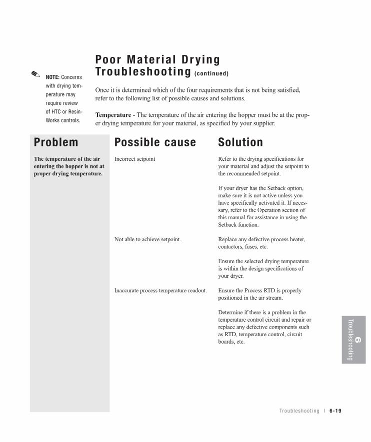
Poor Mate r ia l D r y ingTroub leshoot ing (cont inued)
Once it is determined which of the four requirements that is not being satisfied,refer to the following list of possible causes and solutions.
Temperature - The temperature of the air entering the hopper must be at the prop-er drying temperature for your material, as specified by your supplier.
ProblemThe temperature of the airentering the hopper is not atproper drying temperature.
Possible causeIncorrect setpoint
Not able to achieve setpoint.
Inaccurate process temperature readout.
SolutionRefer to the drying specifications foryour material and adjust the setpoint tothe recommended setpoint.
If your dryer has the Setback option,make sure it is not active unless youhave specifically activated it. If neces-sary, refer to the Operation section ofthis manual for assistance in using theSetback function.
Replace any defective process heater,contactors, fuses, etc.
Ensure the selected drying temperatureis within the design specifications ofyour dryer.
Ensure the Process RTD is properlypositioned in the air stream.
Determine if there is a problem in thetemperature control circuit and repair orreplace any defective components suchas RTD, temperature control, circuitboards, etc.
Troub leshoo t i ng l 6-19
6Troubleshooting
NOTE: Concerns
with drying tem-
perature may
require review
of HTC or Resin-
Works controls.
✐
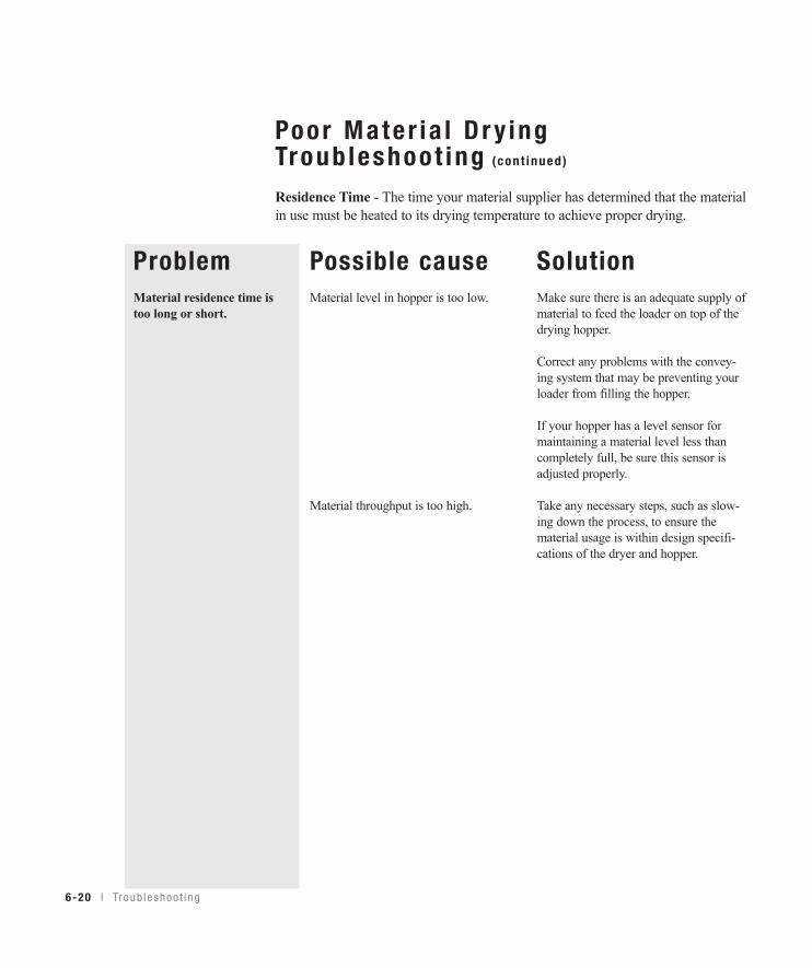
Poor Mate r ia l D r y ingTroub leshoot ing (cont inued)
Residence Time - The time your material supplier has determined that the materialin use must be heated to its drying temperature to achieve proper drying.
ProblemMaterial residence time istoo long or short.
Possible causeMaterial level in hopper is too low.
Material throughput is too high.
SolutionMake sure there is an adequate supply ofmaterial to feed the loader on top of thedrying hopper.
Correct any problems with the convey-ing system that may be preventing yourloader from filling the hopper.
If your hopper has a level sensor formaintaining a material level less thancompletely full, be sure this sensor isadjusted properly.
Take any necessary steps, such as slow-ing down the process, to ensure thematerial usage is within design specifi-cations of the dryer and hopper.
6-20 l Tr oub l eshoo t i ng
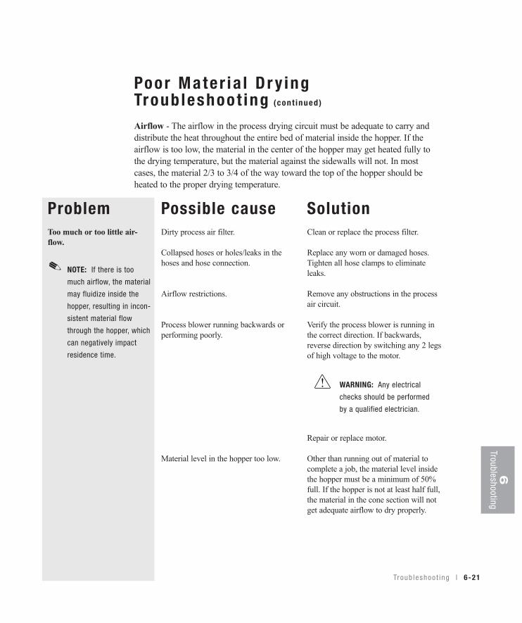
Poor Mate r ia l D r y ingTroub leshoot ing (cont inued)
Airflow - The airflow in the process drying circuit must be adequate to carry anddistribute the heat throughout the entire bed of material inside the hopper. If theairflow is too low, the material in the center of the hopper may get heated fully tothe drying temperature, but the material against the sidewalls will not. In mostcases, the material 2/3 to 3/4 of the way toward the top of the hopper should beheated to the proper drying temperature.
ProblemToo much or too little air-flow.
Possible causeDirty process air filter.
Collapsed hoses or holes/leaks in thehoses and hose connection.
Airflow restrictions.
Process blower running backwards orperforming poorly.
Material level in the hopper too low.
SolutionClean or replace the process filter.
Replace any worn or damaged hoses.Tighten all hose clamps to eliminateleaks.
Remove any obstructions in the processair circuit.
Verify the process blower is running inthe correct direction. If backwards,reverse direction by switching any 2 legsof high voltage to the motor.
Repair or replace motor.
Other than running out of material tocomplete a job, the material level insidethe hopper must be a minimum of 50%full. If the hopper is not at least half full,the material in the cone section will notget adequate airflow to dry properly.
NOTE: If there is too
much airflow, the material
may fluidize inside the
hopper, resulting in incon-
sistent material flow
through the hopper, which
can negatively impact
residence time.
✐
WARNING: Any electrical
checks should be performed
by a qualified electrician.
Troub leshoo t i ng l 6-21
6Troubleshooting

6-22 l Tr oub l eshoo t i ng
Poor Mate r ia l D r y ingTroub leshoot ing (cont inued)
Dewpoint - The process air must be at a low dewpoint so it can efficiently collectthe moisture as it is released from the heated material and carry it to the dryer to beremoved in the desiccant. In most cases, the dryer will dry your material satisfacto-ry if the dewpoint of the air is -20 to -40° F {-29 to -40° C}. If your dryer does nothave a dewpoint readout, you can check the dewpoint with a portable dewpointinstrument. Conair sells a variety of portable dewpoint meters. Contact ConairParts.Problem
Dryer dewpoint is notreaching proper setpoint.
Possible causeLow regeneration temperature.
Poor regeneration airflow.
High dewpoint, ambient air leaking intothe closed loop drying circuit.
Return air temperature to the dryer is toohigh. (The return air temperature onW1600-5000 dryers is measured at theinlet to the desiccant wheel. W1600-5000 dryers designed prior to August2007, the return air temperature ismeasured at the inlet to the processblower.)
Poor desiccant performance.
SolutionReplace or check defective heaters, fusesetc.
Clean or replace the regeneration filter.
Ensure the regeneration blower is oper-ating properly and rotating in the correctdirection. See Installation section enti-tled, Checking for proper airflow.
Remove obstructions in the air stream,such as crimped hoses, etc.
Replace damaged hoses and seal anyleaks in the process air circuit.
If using a vacuum loader on the hopper,ensure that the loader shroud is installedin the hopper and that the hopper iscompletely filled with material.
If partially filling your hopper, ensurethat the hopper loader is sealed againstambient air.
Install a gasket between the loader andthe top of the hopper.
Clean the aftercooler/intercooler coils.See Maintenance section entitled,Cleaning the aftercooler/intercoolercoils.
See Troubleshooting section entitled,Replacing the desiccant wheel assembly.
Replacement dewpointmonitors are available from Conair.
Contact Conair Parts(800) 458 1960From outside of the United States, call:(814) 437 6861
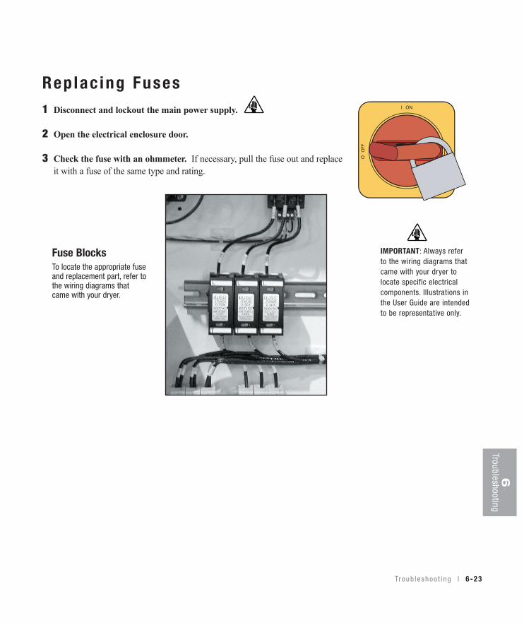
6Troubleshooting
Rep lac ing Fuses1 Disconnect and lockout the main power supply.
2 Open the electrical enclosure door.
3 Check the fuse with an ohmmeter. If necessary, pull the fuse out and replaceit with a fuse of the same type and rating.
Fuse BlocksTo locate the appropriate fuseand replacement part, refer tothe wiring diagrams thatcame with your dryer.
IMPORTANT: Always referto the wiring diagrams thatcame with your dryer tolocate specific electricalcomponents. Illustrations inthe User Guide are intendedto be representative only.
Troub leshoo t i ng l 6-23
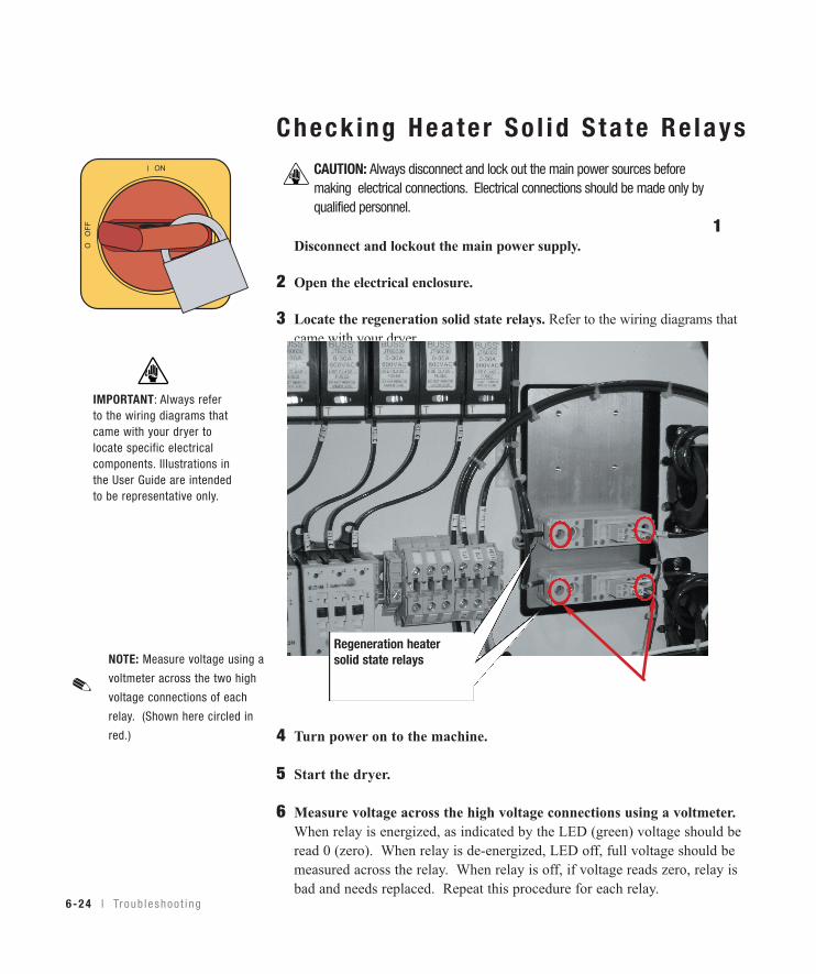
6-24 l Tr oub l eshoo t i ng
IMPORTANT: Always referto the wiring diagrams thatcame with your dryer tolocate specific electricalcomponents. Illustrations inthe User Guide are intendedto be representative only.
ON
O OFF
Check ing Hea te r So l id S ta te Re lays
1Disconnect and lockout the main power supply.
2 Open the electrical enclosure.
3 Locate the regeneration solid state relays. Refer to the wiring diagrams thatcame with your dryer.
4 Turn power on to the machine.
5 Start the dryer.
6 Measure voltage across the high voltage connections using a voltmeter.When relay is energized, as indicated by the LED (green) voltage should beread 0 (zero). When relay is de-energized, LED off, full voltage should bemeasured across the relay. When relay is off, if voltage reads zero, relay isbad and needs replaced. Repeat this procedure for each relay.
Regeneration heatersolid state relays
CAUTION: Always disconnect and lock out the main power sources beforemaking electrical connections. Electrical connections should be made only byqualified personnel.
✐NOTE: Measure voltage using a
voltmeter across the two high
voltage connections of each
relay. (Shown here circled in
red.)

6Troubleshooting
Tr oub l eshoo t i ng l 6-25
Check ing o r Rep lac ing Tempera tureSensorsThe Carousel Plus W Series Dryer uses RTD sensors to monitor the temperaturesof the return air, air into the desiccant, the regeneration outlet, and the regenerationinlet.
To check or replace an RTD sensors:
1 Disconnect and lockout the main power supply.
2 Remove dryer panels, as necessary. See Installation section entitled, Openingthe dryer doors (W1600-5000).
3 Locate the RTD sensors.
4 Check the sensor positions and conditions. Temperature readings will beincorrect, if the sensors are touching the wall of an air hose or pipe or if thesensor or wiring is damaged. The tip of the sensor should be centered within theair hose or pipe. Sensor wires should be attached to the appropriate connectionpoints on the dryer’s electrical enclosure or microprocessor board.
5 To check with ohm meter, measure the resistance across the RTDs. The resistance should be approximately 110 ohm at room temperature.
6 Replace the sensor, if necessary.
IMPORTANT: Always referto the wiring diagramsthat came with your dryerto locate specific electri-cal components.Illustrations in the UserGuide are intended to berepresentative only.
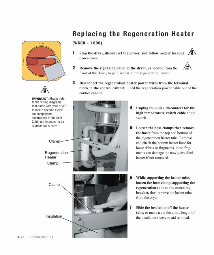
Rep lac ing the Regenera t ion Hea te r(W600 - 1000 )
1 Stop the dryer, disconnect the power, and follow proper lockoutprocedures.
2 Remove the right side panel of the dryer, as viewed from thefront of the dryer, to gain access to the regeneration heater.
3 Disconnect the regeneration heater power wires from the terminalblock in the control cabinet. Feed the regeneration power cable out of thecontrol cabinet.
4 Unplug the quick disconnect for the high temperature switch cable at the switch.
5 Loosen the hose clamps then remove the hoses from the top and bottom of the regeneration heater tube. Remove and check the bottom heater hose for loose debris or fragments, these frag- ments can damage the newly installed heater if not removed.
6 While supporting the heater tube, loosen the hose clamp supporting the regeneration tube to the mounting bracket, then remove the heater tube from the dryer.
7 Slide the insulation off the heater tube, or make a cut the entire length of the insulation sleeve to aid removal.
6-26 l Tr oub l eshoo t i ng
IMPORTANT: Always referto the wiring diagramsthat came with your dryerto locate specific electri-cal components.Illustrations in the UserGuide are intended to berepresentative only.
RegenerationHeater
Insulation
Clamp
Clamp
Clamp
Rep lac ing the Regenera t ion Hea te r(W600 - 1000 ) (cont inued)
8 Compare the markings on the outside of the regeneration heater tube toensure the new one has the same voltage and kW ratings as the original heatertube. This information is on the end nearest the wires.
9 Slide the original insulation over the new heater or, if the insulation wascut for removal, wrap the cut insulation sleeve around the new heater tube andsecure it with duct tape.
10 Make sure the cable end of the heater tube is to the bottom then securethe new heater tube to the mounting bracket with a hose clamp.
11 Connect the hoses to the top and bottom of the heater tube and securethem with hose clamps.
12 Connect the high temperature switch wires to the quick disconnects nearthe heater tube.
13 Route the heater power cable into the control cabinet and connect theleads to the original locations on the terminal block. Refer to the wiringdiagram for specific connection information.
14 Replace the side panel of the dryer.
15 Measure the resistance from each leg of the heater tube to the others andfrom each leg to ground. There should be +/- 5% resistance variationbetween all 3 legs, and high resistance from each leg to ground.
16 Connect the dryer to power and turn it on. Verify that the regenerationtemperature achieves the setpoint.
Troub leshoo t i ng l 6-27
6Troubleshooting

Rep lac ing the Regenera t ion Hea te r(W1600 - 2400 )
1 Stop the dryer, disconnect and lockout the main power.
2 Locate the heater. Open the side panels of the dryer locating theheater which is secured to the inlet of the desiccant wheel assembly byhard piping, brackets and clamps. See Installation section entitled, Openingthe dryer doors (W1600-5000).
3 Disconnect the main power leads at the junction box inside the frameof the dryer.
4 Disconnect the high temperature switch cable at the quick disconnect.
5 To remove the defective regeneration heater tube, loosen the pressureclamps at the top and bottom of the heater tube connection and slide theclamp and its silicon gasket back away from the heater tube. W1600-2400 model dryers lower clamp is attached to a bracket that is mountedto the desiccant wheel assembly, loosen clamp to remove it from thebracket. Remove and check the bottom heater hose for loose debris or frag-ments, these fragments can damage the newly installed heater if not removed.
6 Slide the insulation off the heater tube, or make a cut down the entirelength of the insulation sleeve to aid removal.
7 Compare the markings on the outside of the regeneration heater tube toensure the new one has the same voltage and kW ratings as the originalheater tube. This information is on the end nearest the wires.
(continued)6-28 l Tr oub l eshoo t i ng
IMPORTANT: Always referto the wiring diagramsthat came with your dryerto locate specific electri-cal components.Illustrations in the UserGuide are intended to berepresentative only.
HeaterTube
Bracket
Gasket
Clamp
Gasket
Clamp
6Troubleshooting
Tr oub l eshoo t i ng l 6-29
Rep lac ing the Regenera t ion Hea te r(W1600 - 2400 ) (cont inued)
8 Slide the original insulation over the new heater, or if the insulation was cutfor removal, wrap the cut insulation sleeve around the new heater tube andsecure it with heat tape.
9 Make sure the cable end of the new heater tube is to the bottom, thenconnect the hoses to the top and bottom of the heater tube and resecurewith pressure clamps and the lower heater tube bracket that was removed inStep 5.
10 Connect the high temperature switch cable to the quick disconnect.
11 Route the heater power wires into the junction box, and connect them tothe supply leads from the control box. Refer to the wiring diagram for spe-cific connection information.
12 To ensure all connections are correct, measure the resistance as in Step 3.You should measure the readings as noted for a good heater.
13 Close the side panel of the dryer.
14 Connect the dryer to power and turn it on. Verify the regeneration temper-ature achieves the setpoint.
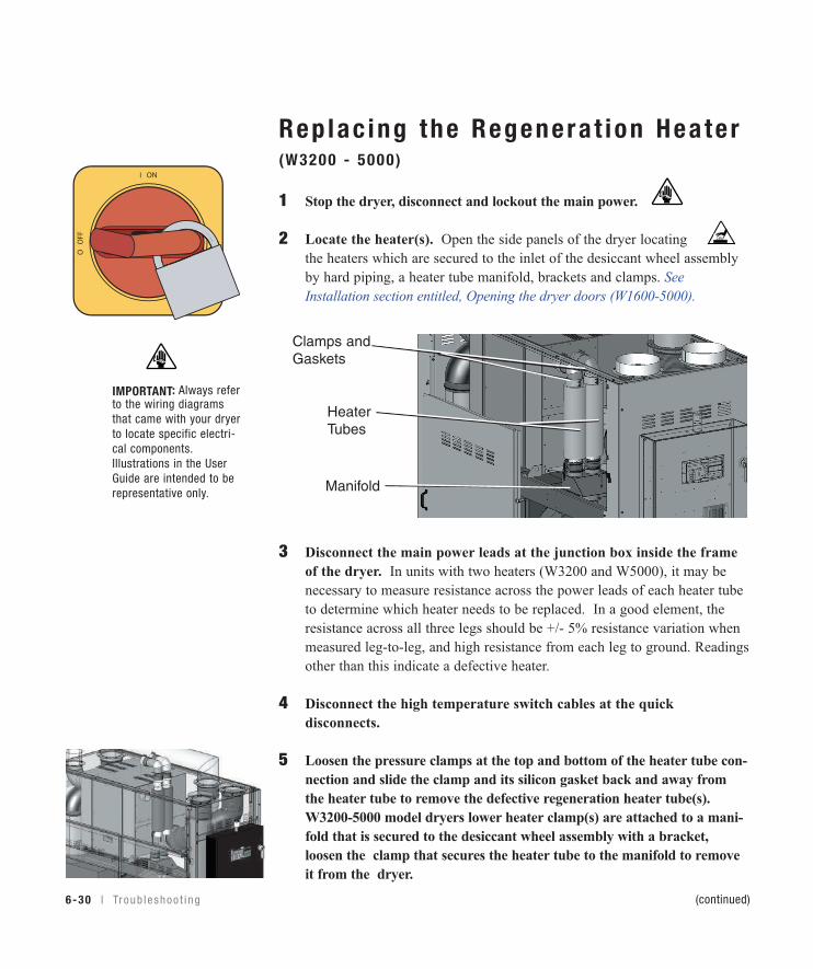
Rep lac ing the Regenera t ion Hea te r(W3200 - 5000 )
1 Stop the dryer, disconnect and lockout the main power.
2 Locate the heater(s). Open the side panels of the dryer locatingthe heaters which are secured to the inlet of the desiccant wheel assemblyby hard piping, a heater tube manifold, brackets and clamps. SeeInstallation section entitled, Opening the dryer doors (W1600-5000).
3 Disconnect the main power leads at the junction box inside the frameof the dryer. In units with two heaters (W3200 and W5000), it may benecessary to measure resistance across the power leads of each heater tubeto determine which heater needs to be replaced. In a good element, theresistance across all three legs should be +/- 5% resistance variation whenmeasured leg-to-leg, and high resistance from each leg to ground. Readingsother than this indicate a defective heater.
4 Disconnect the high temperature switch cables at the quickdisconnects.
5 Loosen the pressure clamps at the top and bottom of the heater tube con-nection and slide the clamp and its silicon gasket back and away fromthe heater tube to remove the defective regeneration heater tube(s).W3200-5000 model dryers lower heater clamp(s) are attached to a mani-fold that is secured to the desiccant wheel assembly with a bracket,loosen the clamp that secures the heater tube to the manifold to removeit from the dryer.
(continued)
IMPORTANT: Always referto the wiring diagramsthat came with your dryerto locate specific electri-cal components.Illustrations in the UserGuide are intended to berepresentative only.
6-30 l Tr oub l eshoo t i ng
HeaterTubes
Manifold
Clamps and Gaskets

Rep lac ing the Regenera t ion Hea te r(W3200 - 5000 ) (cont inued)
6 Loosen the two (2) lower clamps that secure the regeneration manifoldand tubing to the desiccant wheel bracket. Remove the regenerationmanifold and the tubing that is attached to the bottom of the manifold. Thenremove the tubing from the regeneration blower outlet and check for looseparticles within the tubing, clean as necessary. Reverse this procedure toreinstall the regeneration manifold and tubing.
7 Slide the insulation off the heater tube(s), or make a cut down the entirelength of the insulation sleeve to aid removal.
8 Compare the markings on the outside of the regeneration heater tube toensure the new one has the same voltage and kW ratings as the originalheater tube. This information is on the end nearest the wires.
9 Slide the original insulation over the new heater, or if the insulation was cutfor removal, wrap the cut insulation sleeve around the new heater tube andsecure it with heat tape.
10 Make sure the cable end of the new heater tube is to the bottom, thenreconnect the hoses to the top and bottom of the heater tube and resecurewith pressure clamps that were removed in Step 5.
11 Connect the high temperature switch cable to the quick disconnect.
12 Route the heater power wires into the junction box and connect them tothe supply leads from the control box. Refer to the wiring diagram forspecific connection information.
13 To ensure all connections are correct, measure the resistance as in Step 3.You should measure the readings as noted for a good heater.
14 Close the side panel of the dryer.
15 Connect the dryer to power and turn it on. Verify the regeneration temper-ature achieves the setpoint.
Troub leshoo t i ng l 6-31
6Troubleshooting
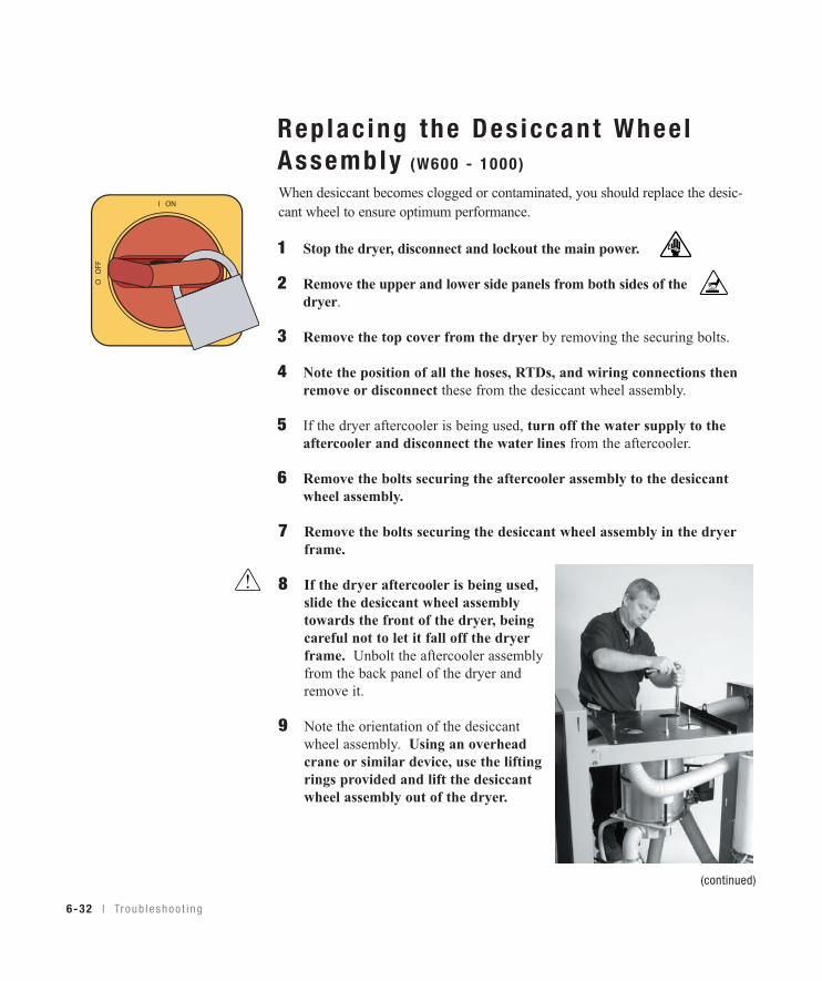
6-32 l Tr oub l eshoo t i ng
Rep lac ing the Des iccant Whee lAssembly (W600 - 1000 )
When desiccant becomes clogged or contaminated, you should replace the desic-cant wheel to ensure optimum performance.
1 Stop the dryer, disconnect and lockout the main power.
2 Remove the upper and lower side panels from both sides of thedryer.
3 Remove the top cover from the dryer by removing the securing bolts.
4 Note the position of all the hoses, RTDs, and wiring connections thenremove or disconnect these from the desiccant wheel assembly.
5 If the dryer aftercooler is being used, turn off the water supply to theaftercooler and disconnect the water lines from the aftercooler.
6 Remove the bolts securing the aftercooler assembly to the desiccantwheel assembly.
7 Remove the bolts securing the desiccant wheel assembly in the dryerframe.
8 If the dryer aftercooler is being used,slide the desiccant wheel assemblytowards the front of the dryer, beingcareful not to let it fall off the dryerframe. Unbolt the aftercooler assemblyfrom the back panel of the dryer andremove it.
9 Note the orientation of the desiccantwheel assembly. Using an overheadcrane or similar device, use the liftingrings provided and lift the desiccantwheel assembly out of the dryer.
(continued)
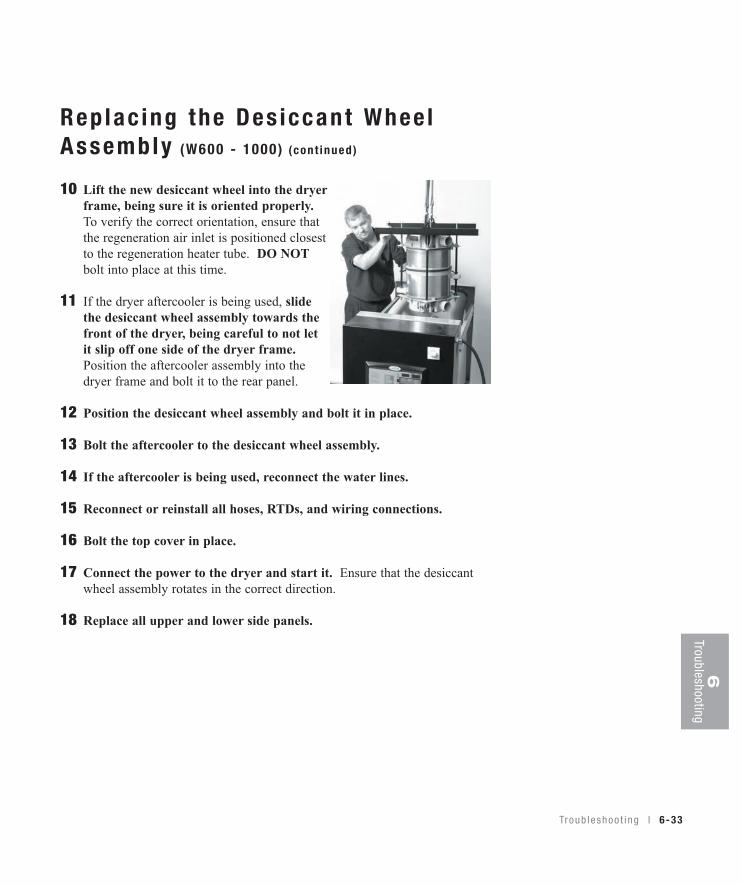
Rep lac ing the Des iccant Whee lAssembly (W600 - 1000 ) (cont inued)
10 Lift the new desiccant wheel into the dryerframe, being sure it is oriented properly.To verify the correct orientation, ensure thatthe regeneration air inlet is positioned closestto the regeneration heater tube. DO NOTbolt into place at this time.
11 If the dryer aftercooler is being used, slidethe desiccant wheel assembly towards thefront of the dryer, being careful to not letit slip off one side of the dryer frame.Position the aftercooler assembly into thedryer frame and bolt it to the rear panel.
12 Position the desiccant wheel assembly and bolt it in place.
13 Bolt the aftercooler to the desiccant wheel assembly.
14 If the aftercooler is being used, reconnect the water lines.
15 Reconnect or reinstall all hoses, RTDs, and wiring connections.
16 Bolt the top cover in place.
17 Connect the power to the dryer and start it. Ensure that the desiccantwheel assembly rotates in the correct direction.
18 Replace all upper and lower side panels.
6Troubleshooting
Tr oub l eshoo t i ng l 6-33
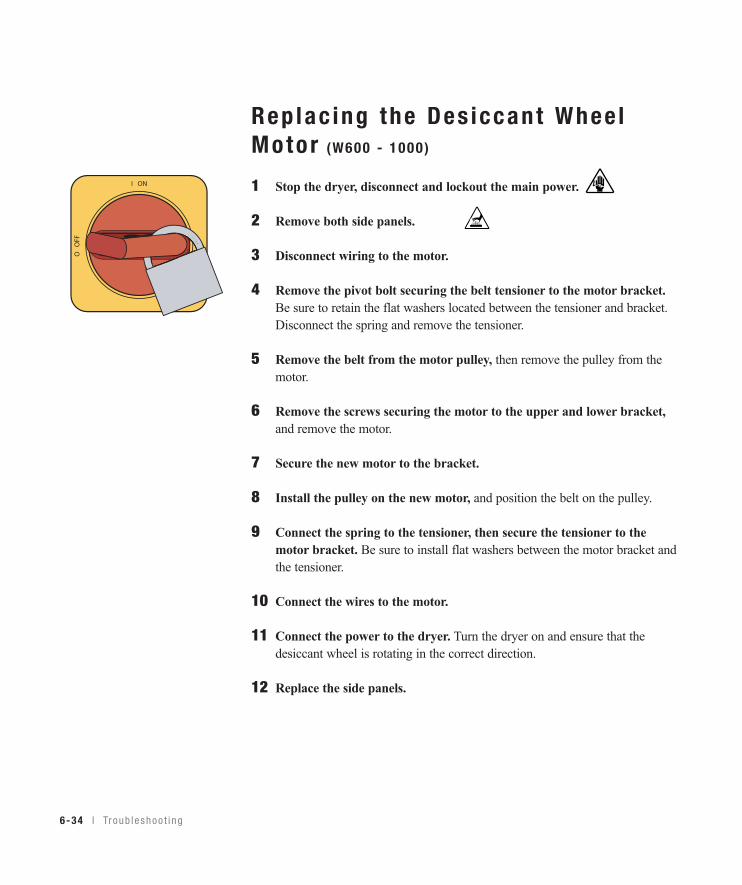
6-34 l Tr oub l eshoo t i ng
Rep lac ing the Des iccant Whee lMotor (W600 - 1000 )
1 Stop the dryer, disconnect and lockout the main power.
2 Remove both side panels.
3 Disconnect wiring to the motor.
4 Remove the pivot bolt securing the belt tensioner to the motor bracket.Be sure to retain the flat washers located between the tensioner and bracket.Disconnect the spring and remove the tensioner.
5 Remove the belt from the motor pulley, then remove the pulley from themotor.
6 Remove the screws securing the motor to the upper and lower bracket,and remove the motor.
7 Secure the new motor to the bracket.
8 Install the pulley on the new motor, and position the belt on the pulley.
9 Connect the spring to the tensioner, then secure the tensioner to themotor bracket. Be sure to install flat washers between the motor bracket andthe tensioner.
10 Connect the wires to the motor.
11 Connect the power to the dryer. Turn the dryer on and ensure that thedesiccant wheel is rotating in the correct direction.
12 Replace the side panels.
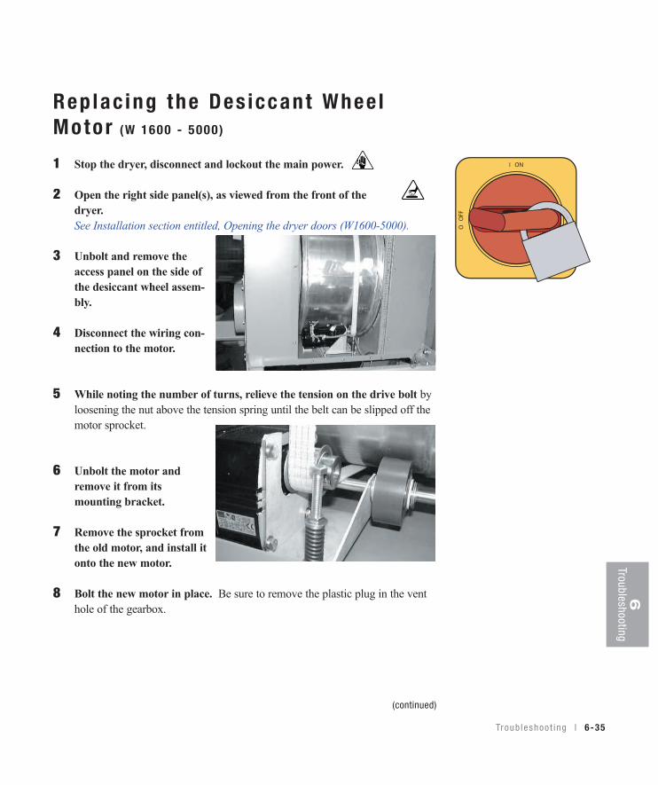
Troub leshoo t i ng l 6-35
6Troubleshooting
Rep lac ing the Des iccant Whee lMotor (W 1600 - 5000 )
1 Stop the dryer, disconnect and lockout the main power.
2 Open the right side panel(s), as viewed from the front of thedryer.See Installation section entitled, Opening the dryer doors (W1600-5000).
3 Unbolt and remove theaccess panel on the side ofthe desiccant wheel assem-bly.
4 Disconnect the wiring con-nection to the motor.
5 While noting the number of turns, relieve the tension on the drive bolt byloosening the nut above the tension spring until the belt can be slipped off themotor sprocket.
6 Unbolt the motor andremove it from its mounting bracket.
7 Remove the sprocket fromthe old motor, and install itonto the new motor.
8 Bolt the new motor in place. Be sure to remove the plastic plug in the venthole of the gearbox.
(continued)
6-36 l Tr oub l eshoo t i ng
Rep lac ing the Des iccant Whee lMotor (W1600 - 5000 ) (cont inued)
9 Slip the belt onto the sprocket, and adjust the tension spring nut to its original position.
10 Connect the wires to the new motor.
11 With the access panel still removed, connect the power to the dryer andstart it. Ensure the wheel turns in the correct direction. If the belt appearsto be slipping, it may be necessary to increase the tension on the drive beltslightly. Do not increase this tension any more than necessary to allow thewheel to rotate without slipping.
12 Bolt the access panel in place and close the side panel(s) on the dryer.
A ppend i x l A-1
We ’ re Here to He lpConair has made the largest investment in customer support in the plastics indus-try. Our service experts are available to help with any problem you might haveinstalling and operating your equipment. Your Conair sales representative also can help analyze the nature of your problem, assuring that it did not result frommisapplication or improper use.
How to Contac t Cus tomer Ser v iceTo contact CustomerService personnel, call:
You can commission Conair service personnel to provide on-site service bycontacting the Customer Service Department.
Before You Ca l l . . .If you do have a problem, please complete the following checklist before calling Conair:
❒ Make sure you have all model, control type and serial numbers from the serialtag, and parts list numbers for your particular equipment. Service personnel willneed this information to assist you..
❒ Make sure power is supplied to the equipment.
❒ Make sure that all connectors and wires within and between control systemsand related components have been installed correctly.
❒ Check the troubleshooting guide of this manual for a solution.
❒ Thoroughly examine the instruction manual(s) for associated equipment, especial-ly controls. Each manual may have its own troubleshooting guide to help you.
❒ Check that the equipment has been operated as described in this manual.
Additional manuals and prints foryour Conair equipment may beordered through the CustomerService or Parts Department for anominal fee. Most manuals canbe downloaded free of chargefrom the product section of theConair website.www.conairgroup.com
NOTE: Normal operating hours are 8:00 am - 5:00 pm (EST). After hours emergency
service is available at the same phone number.
✐
A-2 l A ppend i x
Equ ipment Guaran teeConair guarantees the machinery and equipment on this order, for a period asdefined in the quotation from date of shipment, against defects in material andworkmanship under the normal use and service for which it was recommended(except for parts that are typically replaced after normal usage, such as filters, liner plates, etc.). Conair’s guarantee is limited to replacing, at our option, the partor parts determined by us to be defective after examination. The customer assumesthe cost of transportation of the part or parts to and from the factory.
Per fo rmance War ran tyConair warrants that this equipment will perform at or above the ratings stated inspecific quotations covering the equipment or as detailed in engineering specifica-tions, provided the equipment is applied, installed, operated and maintained in therecommended manner as outlined in our quotation or specifications.
Should performance not meet warranted levels, Conair at its discretion will exercise one of the following options:
• Inspect the equipment and perform alterations or adjustments to satisfy performance claims. (Charges for such inspections and corrections will bewaived unless failure to meet warranty is due to misapplication, improper installation, poor maintenance practices or improper operation.)
• Replace the original equipment with other Conair equipment that will meet original performance claims at no extra cost to the customer.
• Refund the invoiced cost to the customer. Credit is subject to prior notice by thecustomer at which time a Return Goods Authorization Number (RGA) will beissued by Conair’s Service Department. Returned equipment must be well cratedand in proper operating condition, including all parts. Returns must be prepaid.
Purchaser must notify Conair in writing of any claim and provide a customerreceipt and other evidence that a claim is being made.
Warran ty L imi ta t ionsExcept for the Equipment Guarantee and Performance Warranty statedabove, Conair disclaims all other warranties with respect to the equipment,express or implied, arising by operation of law, course of dealing, usage oftrade or otherwise, including but not limited to the implied warranties of mer-chantability and fitness for a particular purpose.
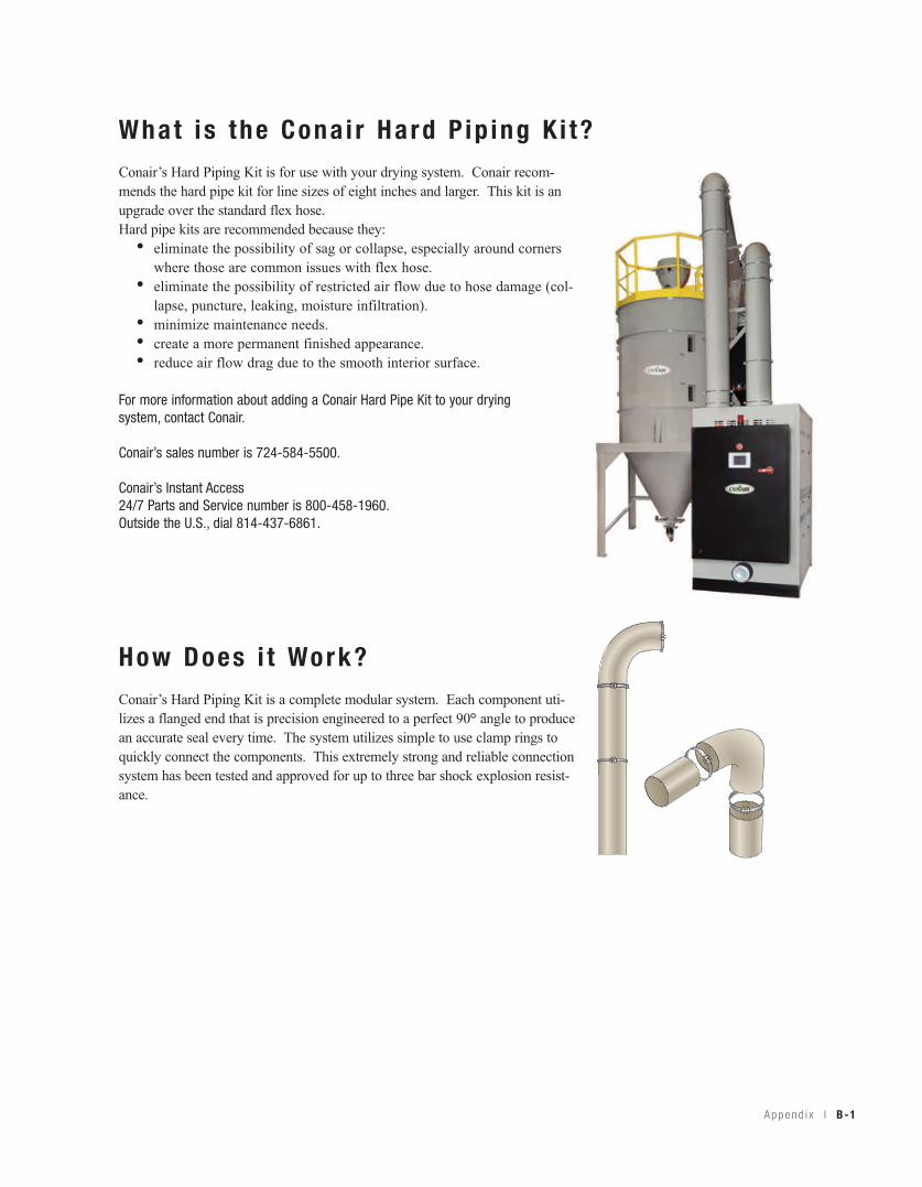
What i s the Cona i r Hard P ip ing K i t?Conair’s Hard Piping Kit is for use with your drying system. Conair recom-mends the hard pipe kit for line sizes of eight inches and larger. This kit is anupgrade over the standard flex hose. Hard pipe kits are recommended because they:
• eliminate the possibility of sag or collapse, especially around cornerswhere those are common issues with flex hose.
• eliminate the possibility of restricted air flow due to hose damage (col-lapse, puncture, leaking, moisture infiltration).
• minimize maintenance needs.• create a more permanent finished appearance.• reduce air flow drag due to the smooth interior surface.
How Does i t Work?Conair’s Hard Piping Kit is a complete modular system. Each component uti-lizes a flanged end that is precision engineered to a perfect 90° angle to producean accurate seal every time. The system utilizes simple to use clamp rings toquickly connect the components. This extremely strong and reliable connectionsystem has been tested and approved for up to three bar shock explosion resist-ance.
For more information about adding a Conair Hard Pipe Kit to your dryingsystem, contact Conair.
Conair’s sales number is 724-584-5500.
Conair’s Instant Access 24/7 Parts and Service number is 800-458-1960. Outside the U.S., dial 814-437-6861.
A ppend i x l B-1
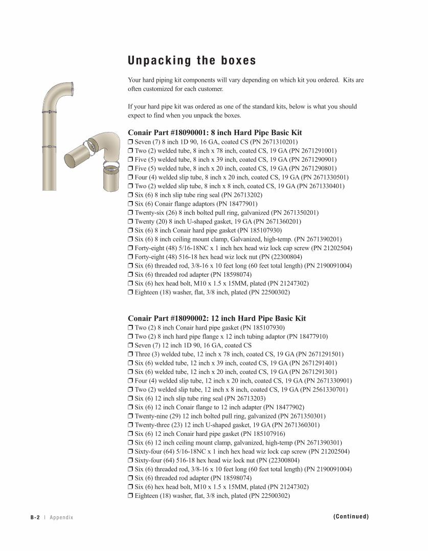
B-2 l A ppend i x
Unpack ing the boxesYour hard piping kit components will vary depending on which kit you ordered. Kits areoften customized for each customer.
If your hard pipe kit was ordered as one of the standard kits, below is what you shouldexpect to find when you unpack the boxes.
Conair Part #18090001: 8 inch Hard Pipe Basic Kit❒ Seven (7) 8 inch 1D 90, 16 GA, coated CS (PN 2671310201)❒ Two (2) welded tube, 8 inch x 78 inch, coated CS, 19 GA (PN 2671291001)❒ Five (5) welded tube, 8 inch x 39 inch, coated CS, 19 GA (PN 2671290901)❒ Five (5) welded tube, 8 inch x 20 inch, coated CS, 19 GA (PN 2671290801)❒ Four (4) welded slip tube, 8 inch x 20 inch, coated CS, 19 GA (PN 2671330501)❒ Two (2) welded slip tube, 8 inch x 8 inch, coated CS, 19 GA (PN 2671330401)❒ Six (6) 8 inch slip tube ring seal (PN 26713202)❒ Six (6) Conair flange adaptors (PN 18477901)❒ Twenty-six (26) 8 inch bolted pull ring, galvanized (PN 2671350201)❒ Twenty (20) 8 inch U-shaped gasket, 19 GA (PN 2671360201)❒ Six (6) 8 inch Conair hard pipe gasket (PN 185107930)❒ Six (6) 8 inch ceiling mount clamp, Galvanized, high-temp. (PN 2671390201)❒ Forty-eight (48) 5/16-18NC x 1 inch hex head wiz lock cap screw (PN 21202504)❒ Forty-eight (48) 516-18 hex head wiz lock nut (PN (22300804)❒ Six (6) threaded rod, 3/8-16 x 10 feet long (60 feet total length) (PN 2190091004)❒ Six (6) threaded rod adapter (PN 18598074)❒ Six (6) hex head bolt, M10 x 1.5 x 15MM, plated (PN 21247302)❒ Eighteen (18) washer, flat, 3/8 inch, plated (PN 22500302)
Conair Part #18090002: 12 inch Hard Pipe Basic Kit❒ Two (2) 8 inch Conair hard pipe gasket (PN 185107930)❒ Two (2) 8 inch hard pipe flange x 12 inch tubing adaptor (PN 18477910)❒ Seven (7) 12 inch 1D 90, 16 GA, coated CS❒ Three (3) welded tube, 12 inch x 78 inch, coated CS, 19 GA (PN 2671291501)❒ Six (6) welded tube, 12 inch x 39 inch, coated CS, 19 GA (PN 2671291401)❒ Six (6) welded tube, 12 inch x 20 inch, coated CS, 19 GA (PN 2671291301)❒ Four (4) welded slip tube, 12 inch x 20 inch, coated CS, 19 GA (PN 2671330901)❒ Two (2) welded slip tube, 12 inch x 8 inch, coated CS, 19 GA (PN 2561330701)❒ Six (6) 12 inch slip tube ring seal (PN 26713203)❒ Six (6) 12 inch Conair flange to 12 inch adapter (PN 18477902)❒ Twenty-nine (29) 12 inch bolted pull ring, galvanized (PN 2671350301)❒ Twenty-three (23) 12 inch U-shaped gasket, 19 GA (PN 2671360301)❒ Six (6) 12 inch Conair hard pipe gasket (PN 185107916)❒ Six (6) 12 inch ceiling mount clamp, galvanized, high-temp (PN 2671390301)❒ Sixty-four (64) 5/16-18NC x 1 inch hex head wiz lock cap screw (PN 21202504)❒ Sixty-four (64) 516-18 hex head wiz lock nut (PN (22300804)❒ Six (6) threaded rod, 3/8-16 x 10 feet long (60 feet total length) (PN 2190091004)❒ Six (6) threaded rod adapter (PN 18598074)❒ Six (6) hex head bolt, M10 x 1.5 x 15MM, plated (PN 21247302)❒ Eighteen (18) washer, flat, 3/8 inch, plated (PN 22500302)
(Cont inued)
A ppend i x l B-3
Unpack ing the boxes (cont inued)
Conair Part #18090003: 8 inch Hard Pipe GT Kit❒ Two (2) 8 inch 1D 90, 16 GA, coated CS (PN 2671310201)❒ One (1) welded tube, 8 inch x 78 inch, coated CS, 19 GA (PN 2671291001)❒ One (1) welded tube, 8 inch x 39 inch, coated CS, 19 GA (PN 2671290901)❒ One (1) welded tube, 8 inch x 20 inch, coated CS, 19 GA (PN 2671290801)❒ One (1) welded slip tube, 8 inch x 39 inch, coated CS, 19 GA (PN 2671330601)❒ One (1) welded slip tube, 8 inch x 20 inch, coated CS, 19 GA (PN 2671330501)❒ One (1) welded slip tube, 8 inch x 8 inch, coated CS, 19 GA (PN 2671330401)❒ Three (3) 8 inch slip tube ring seal (PN 26713202)❒ One (1) Conair flange adaptors (PN 18477901)❒ Nine (9) 8 inch bolted pull ring, galvanized (PN 2671350201)❒ Six (6) 8 inch U-shaped gasket, 19 GA (PN 2671360201)❒ Two (2) 8 inch hose, high temp (PN 2400071002)❒ One (1) 8 inch Conair hard pipe gasket (PN 185107930)❒ Four (4) 8 inch hose clamps (PN 24900124)❒ Six (6) 8 inch insulation (PN 25902417)❒ One (1) 8 inch 90° insulation (PN 18195701)❒ Eight (8) 5/16-18NC x 1 inch hex head wiz lock cap screw (PN 21202504)❒ Eight (8) 516-18 hex head wiz lock nut (PN (22300804)❒ Twenty-five (25) feet of 3 inch ASJ SSL insullation tape (PN 25910404) (insulation)
Conair Part #18090004: 12 inch Hard Pipe GT Kit❒ Two (2) 8 inch hose connection, coated CS, 19 GA (PN 2671400201)❒ Two (2) 8 inch hose, high temp (PN 2400071002)❒ Two (2) 8 inch Conair hard pipe gasket (PN 185107930)❒ Two (2) 8 inch hard pipe flange x 12 inch tubing adaptor (PN 18477910)❒ Four (4) 8 inch hose clamps (PN 24900124)❒ Two (2) 12 inch 1D 90, 16 GA, coated CS❒ One (1) welded tube, 12 inch x 78 inch, coated CS, 19 GA (PN 2671291501)❒ One (1) welded tube, 12 inch x 39 inch, coated CS, 19 GA (PN 2671291401)❒ One (1) welded tube, 12 inch x 20 inch, coated CS, 19 GA (PN 2671291301)❒ One (1) welded slip tube, 12 inch x 20 inch, coated CS, 19 GA (PN 2671330901)❒ One (1) welded slip tube, 12 inch x 39 inch, Coated CS, 19 GA (PN 2671331001)❒ One (1) welded slip tube, 12 inch x 8 inch, coated CS, 19 GA (PN 2561330701)❒ Three (3) 12 inch slip tube ring seal (PN 26713203)❒ One (1) 12 inch Conair flange to 12 inch adapter (PN 18477902)❒ Nine (9) 12 inch bolted pull ring, galvanized (PN 2671350301)❒ Six (6) 12 inch U-shaped gasket, 19 GA (PN 2671360301)❒ Two (2) 12 inch hose connection, coated CS, 19 GA (PN 2671400301)❒ One (1) 12 inch Conair hard pipe gasket (PN 185107916)❒ Six (6) 12 inch insulation (PN 25902418)❒ Two (2) 12 inch hose, high temp (PN 2400071102)❒ Four (4) 12 inch hose clamps (PN 24900126)❒ One (1) 12 inch 90° insulation (PN 18195702)❒ Twenty-four (24) 5/16-18NC x 1 inch hex head wiz lock cap screw (PN 21202504)❒ Twenty-four (24) 516-18 hex head wiz lock nut (PN 22300804)❒ Twenty-five (25) feet of 3 inch ASJ SSL insulation tape (PN 25910404)❒ One (1) 8 inch hard pipe flange x 12 inch tubing adapter (PN 1847791001)
For more information aboutadding a Conair Hard PipeKit to your drying system,contact Conair.
Conair’s sales number is724-584-5500.
Conair’s Instant Access 24/7 Parts and Servicenumber is 800-458-1960. Outside the U.S., dial 814-437-6861.
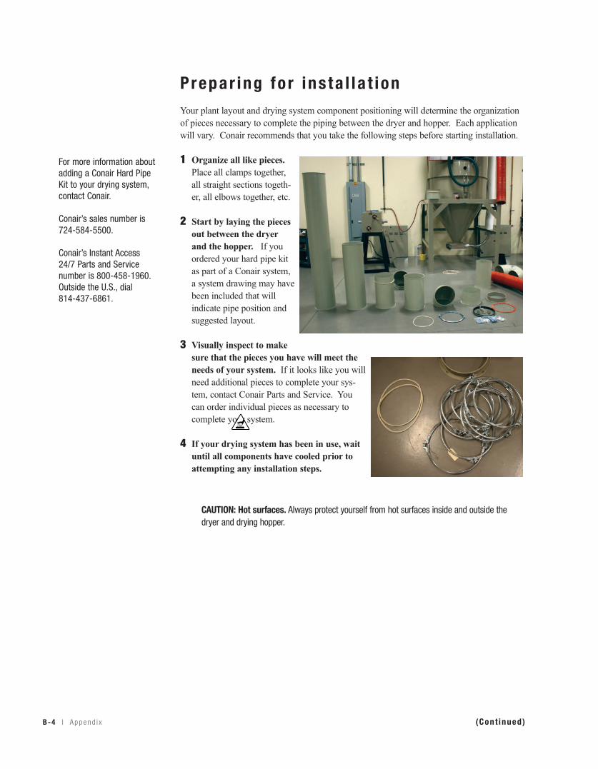
B-4 l A ppend i x
Prepar ing fo r ins ta l l a t ionYour plant layout and drying system component positioning will determine the organizationof pieces necessary to complete the piping between the dryer and hopper. Each applicationwill vary. Conair recommends that you take the following steps before starting installation.
1 Organize all like pieces.Place all clamps together,all straight sections togeth-er, all elbows together, etc.
2 Start by laying the piecesout between the dryerand the hopper. If youordered your hard pipe kitas part of a Conair system,a system drawing may havebeen included that willindicate pipe position andsuggested layout.
3 Visually inspect to makesure that the pieces you have will meet theneeds of your system. If it looks like you willneed additional pieces to complete your sys-tem, contact Conair Parts and Service. Youcan order individual pieces as necessary tocomplete your system.
4 If your drying system has been in use, waituntil all components have cooled prior toattempting any installation steps.
(Cont inued)
For more information aboutadding a Conair Hard PipeKit to your drying system,contact Conair.
Conair’s sales number is724-584-5500.
Conair’s Instant Access 24/7 Parts and Servicenumber is 800-458-1960. Outside the U.S., dial 814-437-6861.
CAUTION: Hot surfaces. Always protect yourself from hot surfaces inside and outside thedryer and drying hopper.
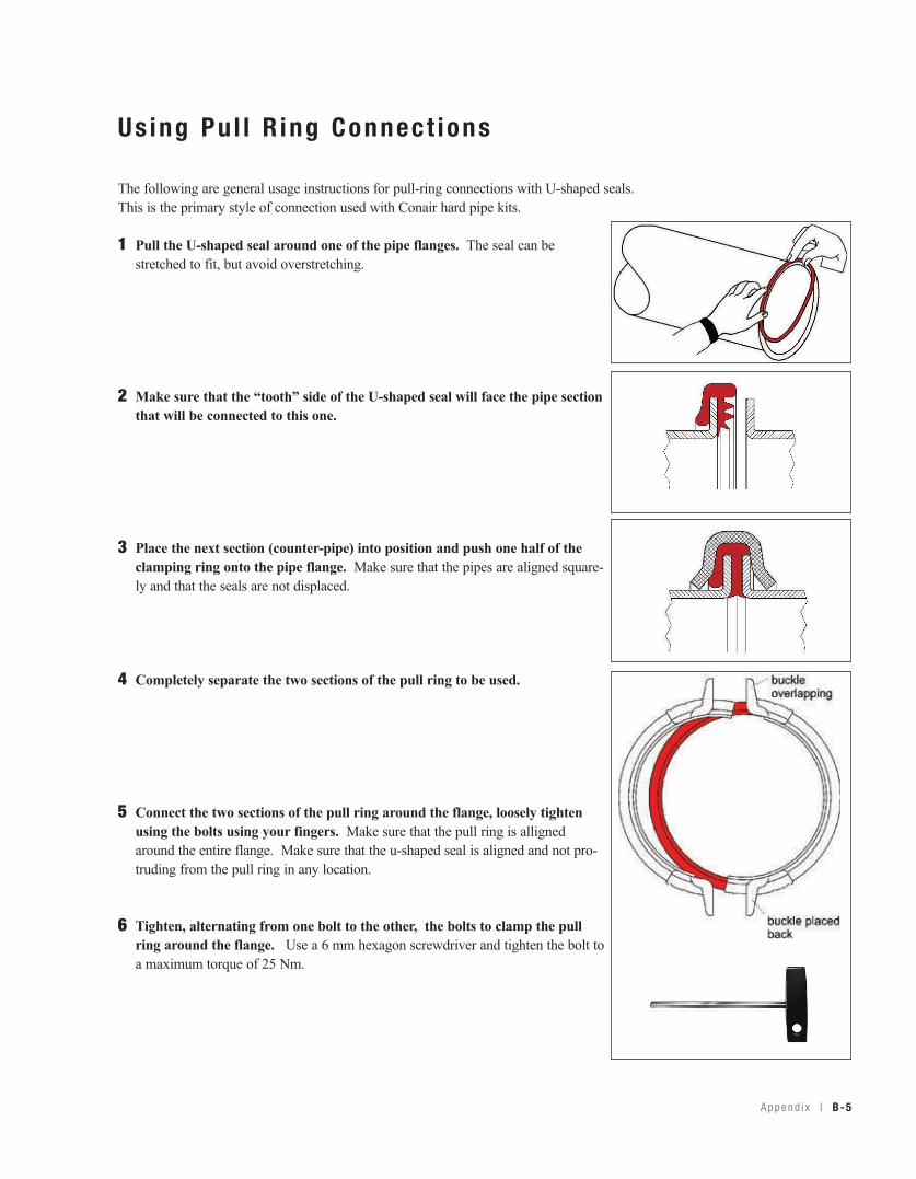
A ppend i x l B-5
Us ing Pu l l R ing Connec t ions
The following are general usage instructions for pull-ring connections with U-shaped seals.This is the primary style of connection used with Conair hard pipe kits.
1 Pull the U-shaped seal around one of the pipe flanges. The seal can bestretched to fit, but avoid overstretching.
2 Make sure that the “tooth” side of the U-shaped seal will face the pipe sectionthat will be connected to this one.
3 Place the next section (counter-pipe) into position and push one half of theclamping ring onto the pipe flange. Make sure that the pipes are aligned square-ly and that the seals are not displaced.
4 Completely separate the two sections of the pull ring to be used.
5 Connect the two sections of the pull ring around the flange, loosely tightenusing the bolts using your fingers. Make sure that the pull ring is allignedaround the entire flange. Make sure that the u-shaped seal is aligned and not pro-truding from the pull ring in any location.
6 Tighten, alternating from one bolt to the other, the bolts to clamp the pullring around the flange. Use a 6 mm hexagon screwdriver and tighten the bolt toa maximum torque of 25 Nm.
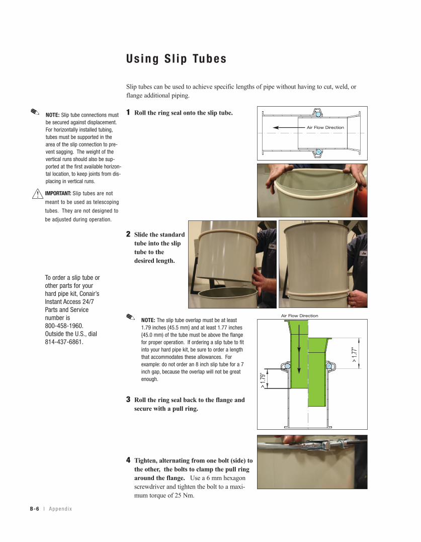
B-6 l A ppend i x
Us ing S l ip Tubes
Slip tubes can be used to achieve specific lengths of pipe without having to cut, weld, orflange additional piping.
1 Roll the ring seal onto the slip tube.
2 Slide the standardtube into the sliptube to thedesired length.
3 Roll the ring seal back to the flange andsecure with a pull ring.
4 Tighten, alternating from one bolt (side) tothe other, the bolts to clamp the pull ringaround the flange. Use a 6 mm hexagonscrewdriver and tighten the bolt to a maxi-mum torque of 25 Nm.
NOTE: Slip tube connections mustbe secured against displacement.For horizontally installed tubing,tubes must be supported in thearea of the slip connection to pre-vent sagging. The weight of thevertical runs should also be sup-ported at the first available horizon-tal location, to keep joints from dis-placing in vertical runs.
✐
IMPORTANT: Slip tubes are not
meant to be used as telescoping
tubes. They are not designed to
be adjusted during operation.
NOTE: The slip tube overlap must be at least1.79 inches {45.5 mm} and at least 1.77 inches{45.0 mm) of the tube must be above the flangefor proper operation. If ordering a slip tube to fitinto your hard pipe kit, be sure to order a lengththat accommodates these allowances. Forexample: do not order an 8 inch slip tube for a 7inch gap, because the overlap will not be greatenough.
✐
To order a slip tube orother parts for yourhard pipe kit, Conair’sInstant Access 24/7Parts and Servicenumber is 800-458-1960. Outside the U.S., dial 814-437-6861.
Air Flow Direction
Air Flow Direction
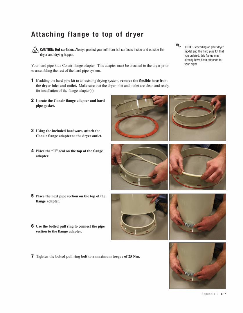
A ppend i x l B-7
A t tach ing f l ange to top o f d r ye r
Your hard pipe kit a Conair flange adapter. This adapter must be attached to the dryer priorto assembling the rest of the hard pipe system.
1 If adding the hard pipe kit to an existing drying system, remove the flexible hose fromthe dryer inlet and outlet. Make sure that the dryer inlet and outlet are clean and readyfor installation of the flange adapter(s).
2 Locate the Conair flange adapter and hardpipe gasket.
3 Using the included hardware, attach theConair flange adapter to the dryer outlet.
4 Place the “U” seal on the top of the flangeadapter.
5 Place the next pipe section on the top of theflange adapter.
6 Use the bolted pull ring to connect the pipesection to the flange adapter.
7 Tighten the bolted pull ring bolt to a maximum torque of 25 Nm.
NOTE: Depending on your dryermodel and the hard pipe kit thatyou ordered, this flange mayalready have been attached toyour dryer.
✐CAUTION: Hot surfaces. Always protect yourself from hot surfaces inside and outside thedryer and drying hopper.
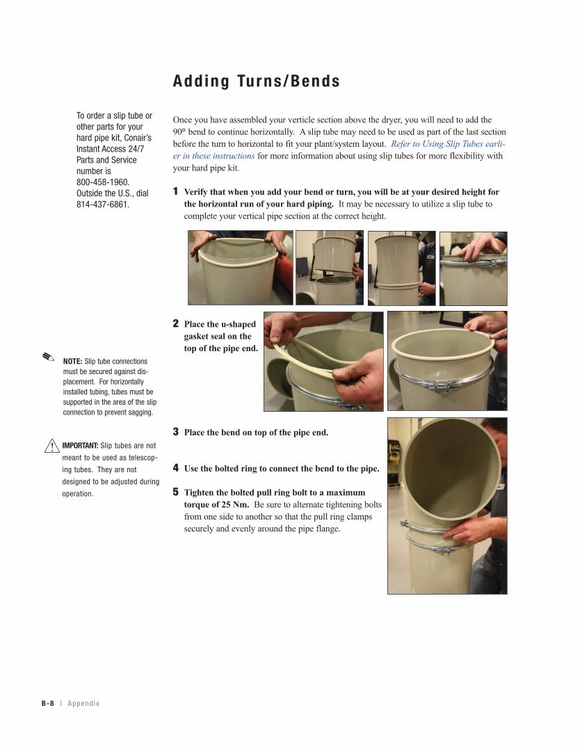
B-8 l A ppend i x
Add ing Turns/Bends
Once you have assembled your verticle section above the dryer, you will need to add the90° bend to continue horizontally. A slip tube may need to be used as part of the last sectionbefore the turn to horizontal to fit your plant/system layout. Refer to Using Slip Tubes earli-er in these instructions for more information about using slip tubes for more flexibility withyour hard pipe kit.
1 Verify that when you add your bend or turn, you will be at your desired height forthe horizontal run of your hard piping. It may be necessary to utilize a slip tube tocomplete your vertical pipe section at the correct height.
2 Place the u-shapedgasket seal on thetop of the pipe end.
3 Place the bend on top of the pipe end.
4 Use the bolted ring to connect the bend to the pipe.
5 Tighten the bolted pull ring bolt to a maximumtorque of 25 Nm. Be sure to alternate tightening boltsfrom one side to another so that the pull ring clampssecurely and evenly around the pipe flange.
To order a slip tube orother parts for yourhard pipe kit, Conair’sInstant Access 24/7Parts and Servicenumber is 800-458-1960. Outside the U.S., dial 814-437-6861.
NOTE: Slip tube connectionsmust be secured against dis-placement. For horizontallyinstalled tubing, tubes must besupported in the area of the slipconnection to prevent sagging.
✐
IMPORTANT: Slip tubes are not
meant to be used as telescop-
ing tubes. They are not
designed to be adjusted during
operation.
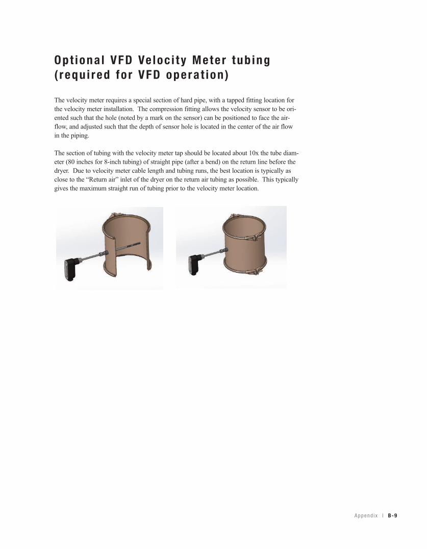
A ppend i x l B-9
Op t iona l VFD Ve loc i t y Mete r tub ing( requ i red fo r VFD opera t ion )
The velocity meter requires a special section of hard pipe, with a tapped fitting location forthe velocity meter installation. The compression fitting allows the velocity sensor to be ori-ented such that the hole (noted by a mark on the sensor) can be positioned to face the air-flow, and adjusted such that the depth of sensor hole is located in the center of the air flowin the piping.
The section of tubing with the velocity meter tap should be located about 10x the tube diam-eter (80 inches for 8-inch tubing) of straight pipe (after a bend) on the return line before thedryer. Due to velocity meter cable length and tubing runs, the best location is typically asclose to the “Return air” inlet of the dryer on the return air tubing as possible. This typicallygives the maximum straight run of tubing prior to the velocity meter location.
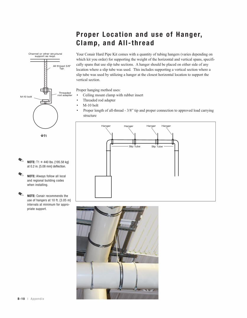
Proper Loca t ion and use o f Hanger,C lamp, and A l l - th readYour Conair Hard Pipe Kit comes with a quantity of tubing hangers (varies depending onwhich kit you order) for supporting the weight of the horizontal and vertical spans, specifi-cally spans that use slip tube sections. A hanger should be placed on either side of anylocation where a slip tube was used. This includes supporting a vertical section where aslip tube was used by utilizing a hanger at the closest horizontal location to support thevertical section.
Proper hanging method uses: • Ceiling mount clamp with rubber insert• Threaded rod adapter• M-10 bolt• Proper length of all-thread - 3/8” tip and proper connection to approved load carrying
structure
B-10 l A ppend i x
Slip TubeSlip Tube
Hanger Hanger Hanger Hanger
NOTE: T1 ✠ 440 lbs. {195.58 kg}at 0.2 in. {5.08 mm} deflection.
✐
NOTE: Always follow all localand regional building codeswhen installing.
✐
NOTE: Conair recommends theuse of hangers at 10 ft. {3.05 m}intervals at minimum for appro-priate support.
✐
Channel or other structuralsupport as reqd.
All thread 3/8”Typ.
Threadedrod adapter
M-10 bolt
!T1
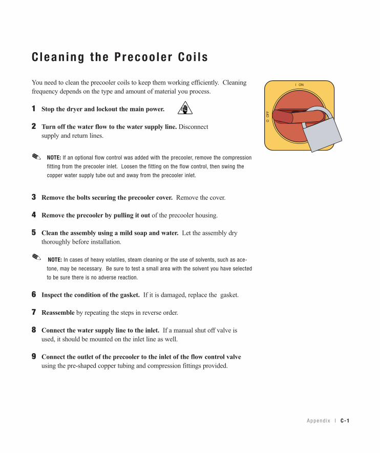
A ppend i x l C-1
C lean ing the P recoo le r Co i l s
You need to clean the precooler coils to keep them working efficiently. Cleaningfrequency depends on the type and amount of material you process.
1 Stop the dryer and lockout the main power.
2 Turn off the water flow to the water supply line. Disconnect supply and return lines.
3 Remove the bolts securing the precooler cover. Remove the cover.
4 Remove the precooler by pulling it out of the precooler housing.
5 Clean the assembly using a mild soap and water. Let the assembly drythoroughly before installation.
NOTE: In cases of heavy volatiles, steam cleaning or the use of solvents, such as ace-
tone, may be necessary. Be sure to test a small area with the solvent you have selected
to be sure there is no adverse reaction.
6 Inspect the condition of the gasket. If it is damaged, replace the gasket.
7 Reassemble by repeating the steps in reverse order.
8 Connect the water supply line to the inlet. If a manual shut off valve isused, it should be mounted on the inlet line as well.
9 Connect the outlet of the precooler to the inlet of the flow control valveusing the pre-shaped copper tubing and compression fittings provided.
NOTE: If an optional flow control was added with the precooler, remove the compression
fitting from the precooler inlet. Loosen the fitting on the flow control, then swing the
copper water supply tube out and away from the precooler inlet.
✐
✐
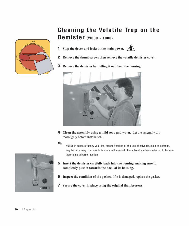
D-1 l A ppend i x
Clean ing the Vo la t i l e Trap on theDemis te r (W600 - 1000 )
1 Stop the dryer and lockout the main power.
2 Remove the thumbscrews then remove the volatile demister cover.
3 Remove the demister by pulling it out from the housing.
4 Clean the assembly using a mild soap and water. Let the assembly dry thoroughly before installation.
NOTE: In cases of heavy volatiles, steam cleaning or the use of solvents, such as acetone,
may be necessary. Be sure to test a small area with the solvent you have selected to be sure
there is no adverse reaction.
5 Insert the demister carefully back into the housing, making sure to completely push it towards the back of its housing.
6 Inspect the condition of the gasket. If it is damaged, replace the gasket.
7 Secure the cover in place using the original thumbscrews.
✐
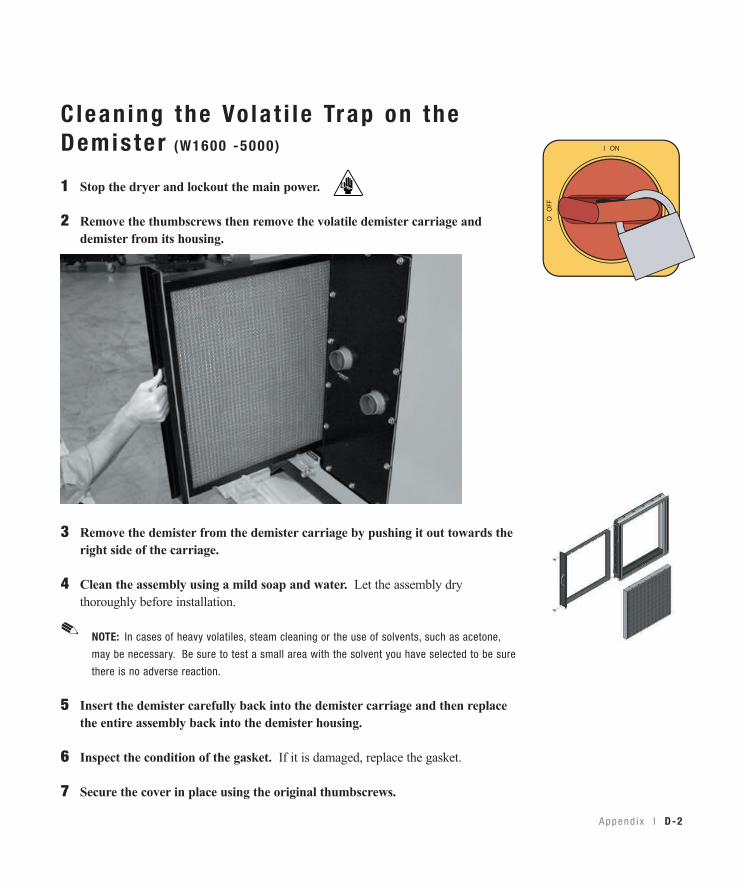
A ppend i x l D-2
C lean ing the Vo la t i l e Trap on theDemis te r (W1600 -5000)
1 Stop the dryer and lockout the main power.
2 Remove the thumbscrews then remove the volatile demister carriage anddemister from its housing.
3 Remove the demister from the demister carriage by pushing it out towards theright side of the carriage.
4 Clean the assembly using a mild soap and water. Let the assembly dry thoroughly before installation.
NOTE: In cases of heavy volatiles, steam cleaning or the use of solvents, such as acetone,
may be necessary. Be sure to test a small area with the solvent you have selected to be sure
there is no adverse reaction.
5 Insert the demister carefully back into the demister carriage and then replacethe entire assembly back into the demister housing.
6 Inspect the condition of the gasket. If it is damaged, replace the gasket.
7 Secure the cover in place using the original thumbscrews.
✐