Woodchip drying in a screw conveyor dryer
13
Woodchip drying in a screw conveyor dryer Ozgur Kaplan and Cenk Celik Citation: J. Renewable Sustainable Energy 4, 063110 (2012); doi: 10.1063/1.4766890 View online: http://dx.doi.org/10.1063/1.4766890 View Table of Contents: http://jrse.aip.org/resource/1/JRSEBH/v4/i6 Published by the American Institute of Physics. Related Articles Effects of volumetric dilution on anaerobic digestion of food waste J. Renewable Sustainable Energy 4, 063112 (2012) Numerical study on aerodynamic performances of the wind turbine rotor with leading-edge rotation J. Renewable Sustainable Energy 4, 063103 (2012) Actuation abilities of multiphasic electroactive polymeric systems J. Appl. Phys. 112, 094108 (2012) Smart textiles: Challenges and opportunities App. Phys. Rev. 2012, 10 (2012) Smart textiles: Challenges and opportunities J. Appl. Phys. 112, 091301 (2012) Additional information on J. Renewable Sustainable Energy Journal Homepage: http://jrse.aip.org/ Journal Information: http://jrse.aip.org/about/about_the_journal Top downloads: http://jrse.aip.org/features/most_downloaded Information for Authors: http://jrse.aip.org/authors Downloaded 13 Nov 2012 to 194.27.72.122. Redistribution subject to AIP license or copyright; see http://jrse.aip.org/about/rights_and_permissions
Transcript of Woodchip drying in a screw conveyor dryer

Woodchip drying in a screw conveyor dryerOzgur Kaplan and Cenk Celik Citation: J. Renewable Sustainable Energy 4, 063110 (2012); doi: 10.1063/1.4766890 View online: http://dx.doi.org/10.1063/1.4766890 View Table of Contents: http://jrse.aip.org/resource/1/JRSEBH/v4/i6 Published by the American Institute of Physics. Related ArticlesEffects of volumetric dilution on anaerobic digestion of food waste J. Renewable Sustainable Energy 4, 063112 (2012) Numerical study on aerodynamic performances of the wind turbine rotor with leading-edge rotation J. Renewable Sustainable Energy 4, 063103 (2012) Actuation abilities of multiphasic electroactive polymeric systems J. Appl. Phys. 112, 094108 (2012) Smart textiles: Challenges and opportunities App. Phys. Rev. 2012, 10 (2012) Smart textiles: Challenges and opportunities J. Appl. Phys. 112, 091301 (2012) Additional information on J. Renewable Sustainable EnergyJournal Homepage: http://jrse.aip.org/ Journal Information: http://jrse.aip.org/about/about_the_journal Top downloads: http://jrse.aip.org/features/most_downloaded Information for Authors: http://jrse.aip.org/authors
Downloaded 13 Nov 2012 to 194.27.72.122. Redistribution subject to AIP license or copyright; see http://jrse.aip.org/about/rights_and_permissions

Woodchip drying in a screw conveyor dryer
Ozgur Kaplan and Cenk Celika)
Department of Mechanical Engineering, Kocaeli University, 41380 Kocaeli, Turkey
(Received 26 May 2012; accepted 25 October 2012; published online 13 November 2012)
Moisture content of raw biomass materials is a crucial parameter for system
efficiency and the main purpose of the drying process is to reduce moisture content
of the wet biomass. In this study, the drying characteristics of woodchip dried in a
screw conveyor dryer had investigated experimentally. The experimental results
demonstrated that drying rate had increased with the increasing drying air temperature
and flow rate; however, the amount of volatile organic matters in the sample has kept
constant. Furthermore, the results have showed that the best drying conditions in this
study is 30 m3/h drying airflow rate, 200 �C drying air temperature, and co-current
dryer type. With these conditions, moisture content of woodchip decreased
from 60% to 27% (wet basis, mass %). VC 2012 American Institute of Physics.
[http://dx.doi.org/10.1063/1.4766890]
I. INTRODUCTION
Wood is thought to be the first source of energy of human kind. Today, wood is the most
important renewable source of energy in the world.1 In 2007, 13% of the energy consumed in
the world is generated from wood. 77% of the renewable energy is produced from biomass. In
total, 8.7% of the energy consumed in the world is produced from wood.2 In April 2009, the
European Parliament and Council adopted a Directive (2009/28/EC) on the promotion of the
use of energy from renewable sources, while the Europe 2020 strategy (approved in June 2010)
confirmed an EU target such that 20% of energy should come from renewable sources by
2020.3 Experts believe that biomass is likely to contribute half the 20% renewable energy
target.4
Wood can be converted to energy via various technologies. These technologies can be
divided into two main topics: thermochemical and biochemical processes. Digestion and
fermentation can be considered as biochemical processes. Biochemical processes operated in a
solution and moisture content of wood are not an issue in this energy conversion type. Thermo-
chemical processes consist of combustion, gasification, and pyrolysis.5 In combustion process,
higher moisture content of wood causes operational problems, decrease in the combustion tem-
perature, and combustion efficiency. In gasification process, higher tar concentration and
decrease in the lower heating value of the synfuel is a result of usage of wood with higher
moisture content.6 The moisture content of the biomass has a significant impact on pyrolysis
process. Moisture content of the wood affects the conversation efficiency and the quality of the
liquid product, in which final moisture content of the liquid product needs to be in a range of
5%–10%.5
Biomass materials can be dried with:
• through-circulation dryer (perforated floor dryer)• packed moving bed dryer• direct and indirect rotary dryer (rotary cascade dryer and steam-tube dryer)• fluidized bed dryer• pneumatic conveying dryer (flash dryer).
a)Author to whom correspondence should be addressed. Electronic addresses: [email protected] and [email protected].
Tel.: þ90 262 3033419. Fax:þ90 262 3033003.
1941-7012/2012/4(6)/063110/12/$30.00 VC 2012 American Institute of Physics4, 063110-1
JOURNAL OF RENEWABLE AND SUSTAINABLE ENERGY 4, 063110 (2012)
Downloaded 13 Nov 2012 to 194.27.72.122. Redistribution subject to AIP license or copyright; see http://jrse.aip.org/about/rights_and_permissions

Drying medium for these types of dryers can be hot air, flue gas, and superheated steam.
Woodchips are most commonly dried with packed moving bed dryers, rotary dryers, and pneu-
matic (or flash) dryers in the industry.5
Packed moving bed dryers are also known as conveyor dryers. Wet wood chips are fed
from the left side of the conveyor and create a loosely compacted bed on the conveyor that has
a perforated belt that lets hot air pass through the bed of woodchips and dries them. Drying
time can be controlled by controlling the speed of conveyor. Under stable operating conditions,
the volume of wet chips is fed at a constant mass flow rate and the drying time is controlled
based on the final moisture content.7
Most of the rotary dryers in industry are direct contact type dryers. Direct contact rotary
dryers consist of a hollow, rotational metal cylinder providing space for direct contact between
the material to be dried and the drying medium, usually hot air. During the direct contact, the
heat and mass transfer between those two streams is high. This transfer is increased by a series
of flights installed on the inner surface of cylinder. When the cylinder is rotating, the flights lift
the solid material within the cylinder from bottom to top. During the rotation, the materials are
dropped from top to the bottom through the hot air. In addition, uniform moisture content dis-
tribution of the dried product can be achieved, because every piece of the solid material has an
equal chance of contact with the hot air.8
Pneumatic dryers are gas–solid transport systems with continuous convective heat and mass
transfer process. This type of dryer can achieve rapid drying with short residence time by fully
immersing the material in a high velocity gas flow. In the dryer, the hot gas stream transports
the solid particles through a pipe or flow duct and makes direct contact with the material to be
dried. This gas stream is also a drying medium to supply the heat required for drying and car-
ries away the evaporated moisture.5
A detailed review about these dryers can be found in Pang et al.5 And also, further reading
about industrial dryers can be found in Mujumdar.9
Waje et al. conducted a series of experiments and published several papers about screw con-
veyor dryer.10–13 They investigated residence time distribution (RTD) and mean residence time
(MRT) in screw dryer conveyor and found out that with the increasing screw speed, degree of mix-
ing is increased but MRT is decreased. The flow in a screw conveyor dryer approaches plug flow
as the feed rate is increased, whereas an increase in the screw speed results in a mixed flow.10 The
MRT can be better controlled with screw speed rather than the solids flow rate. The discharge uni-
formity was found to be a strong function of the solids flow rate and the screw speed.11
In this paper, the drying characteristics of woodchip dried in a screw dryer have been
investigated and the optimum drying conditions have been determined.
II. EXPERIMENTAL
A. Materials
The wood used in the experiments has been provided from The General Directorate of
Forestry. It has been crushed and sifted to 0–2 mm woodchips at the Fuel Processing Laborato-
ries of The Scientific and Technological Research Council of Turkey (T€UB_ITAK), Marmara
Research Center, Energy Institute. Elemental analysis has been applied to the woodchip
samples using LECO Truspec CHN-S Elemental Analysis equipment. Carbon (C), hydrogen
(H), and nitrogen (N) contents of sample are investigated under ASTM 5373 standard and sul-
fur content investigated under ASTM D 4239 standards. Results of these analyses are given in
Table I.
TABLE I. Elemental analysis of sessile oak woodchip (dry basis, % mass).
Biomass type C (%) H (%) N (%) S (%) O (%)
Turkish pine 56.26 8.9 0.24 0 32,72
063110-2 O. Kaplan and C. Celik J. Renewable Sustainable Energy 4, 063110 (2012)
Downloaded 13 Nov 2012 to 194.27.72.122. Redistribution subject to AIP license or copyright; see http://jrse.aip.org/about/rights_and_permissions

The moisture content of the wet and dried woodchips is measured in each experiment. For
moisture content measuring, Sartorius MA100 thermogravimetric moisture content measurement
equipment is used.
Also, a proximate analysis (ASTM E-1755) is applied to the wet and dried biomass sam-
ples. The moisture content, volatile organic matter, fixed carbon, and ash content of wood chips
are obtained with this analysis to determine whether if any drying based volatile organic matter
emissions are releasing or not.
The experimental setup consists of an air blower, electrical heating unit, screw conveyor,
and air distribution pipes. Schematic of experimental setup is given in Fig. 1.
Ambient air is sent to the electrical heating system by a blower to heat the drying air. The
hot drying air is delivered to the screw conveyor where it meets with wet woodchips. Drying
air can be delivered to the screw conveyor from both sides with pipe 1 and pipe 2. Therefore,
the dryer can be operated in both co-current and counter-current conditions. Six thermocouples
are connected to the system. TT101 thermocouple measures air inlet temperature in co-current
flow direction and air outlet temperature in counter-current condition (Fig. 2). Similarly, TT
105 thermocouple measures air outlet temperature in co-current and air inlet temperature in
counter-current flow direction. TT106 thermocouple measures outside surface temperature of
conveyor housing (on the aluminum sheet that covers insulation material). TT102, TT103, and
TT104 thermocouples measure inside dryer temperature.
The air supply blower has an input power of 2.2 kW motor and delivers approximately 250
m3/h of air at a maximum head pressure drop of 280 mbar. A frequency modulator controls the
air flow rate. The air is heated by electrical heater, which has a power of 4.5 kW and is con-
trolled with contactors. A 0.37 kW electric motor and redactor set are used for rotating the
screw and it is controlled by a frequency modulator. The flow rate of air is measured with Bass
Instruments FOFT-025 orifice type flow meter. Humidity and temperature of ambient air are
measured with Kimo TH-300 humidity sensor. Thermocouples along the dryer and at the pipes
are NiCr-Ni type-K and have an accuracy of 0.1 �C. All the measurement equipments are con-
nected to Ahlborn Almemo MA 5690-1 data logger and data logger is connected to a PC via
FIG. 1. Schematic of experimental setup.
FIG. 2. Schematic of screw conveyor dryer.
063110-3 O. Kaplan and C. Celik J. Renewable Sustainable Energy 4, 063110 (2012)
Downloaded 13 Nov 2012 to 194.27.72.122. Redistribution subject to AIP license or copyright; see http://jrse.aip.org/about/rights_and_permissions

RS232 serial port. The data collected from measurement equipments are logged with an AMR
Win Control computer program.
Cylindrical housing of the screw conveyor is made from 5 in. drawn steel pipe. Screw of
the conveyor has an outside diameter of 120 mm and has 45 mm pitch. Length of screw is
1.5 m and drying zone (between the inlet and the outlet pipes) of the dryer is 1 m long.
Dimensions of the screw are given in Fig. 3. Air distribution pipes are made from 3 in.
drawn steel pipe. Both the housing of the conveyor and the air distribution pipes are insulated
with 50 mm ceramic wool.
B. Method
Experiments are conducted under F1¼ 20 m3/h and F2¼ 30 m3/h air flow rates. Three dif-
ferent air inlet temperatures (T1¼ 150 �C, T2¼ 175 �C, and T3¼ 200 �C) are selected for both
co-current and counter-current flow direction conditions. The test matrix is given in Table II.
Revolution of the screw is kept constant as 18 rpm and total of 1.5 kg wet woodchip is fed
to the bunker of drying system for each experiments. For both co-current and counter current
flow conditions, the wet biomass in the fuel bunker passes through the screw pipe, and delivers
to the storage tank at the exit. The one passing time of 1.5 kg of wet biomass inside the screw
conveyor is around 3.15 min at 18 rpm screw speed. Initial moisture of wood chips used in the
experiments is kept same as (60%, wet basis, % mass) for each set of experiments. 1.5 kg of
wet woodchip is fed to the dryer and dried four times in the same conditions and at the end of
each experiment, a sample is collected from dried woodchips for moisture content analysis.
Moisture content of this sample is measured on wet basis. Also, a short analysis (ASTM E-
1755) is applied to the four time dried woodchip sample and its volatile organic compound
(VOC) is investigated and compared with the original (non-dried) sample of woodchip.
III. RESULTS AND DISCUSSION
The effects of different drying conditions to the drying process are investigated in this
study. Bar graphics are drawn with the final (after drying four times) moisture content of wood-
chip. These graphics are useful to see the effects of dying conditions to drying process.
Fig. 4 shows the moisture content of four times dried wood chips at different drying condi-
tions (flow rates, drying air temperatures, and flow directions). As shown in this figure, the
moisture content of woodchips decreased for all cases with increasing drying air temperature.
TABLE II. The test matrix.
Co-current Counter current
T ( �C) 150 175 200 150 175 200
F1 (m3/h) 20 20 20 20 20 20
F2 (m3/h) 30 30 30 30 30 30
FIG. 3. Dimensions of the screw.
063110-4 O. Kaplan and C. Celik J. Renewable Sustainable Energy 4, 063110 (2012)
Downloaded 13 Nov 2012 to 194.27.72.122. Redistribution subject to AIP license or copyright; see http://jrse.aip.org/about/rights_and_permissions
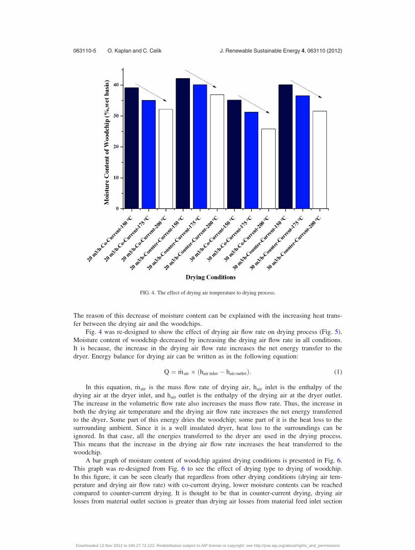
The reason of this decrease of moisture content can be explained with the increasing heat trans-
fer between the drying air and the woodchips.
Fig. 4 was re-designed to show the effect of drying air flow rate on drying process (Fig. 5).
Moisture content of woodchip decreased by increasing the drying air flow rate in all conditions.
It is because, the increase in the drying air flow rate increases the net energy transfer to the
dryer. Energy balance for drying air can be written as in the following equation:
Q ¼ _mair � ðhair inlet � hair outletÞ: (1)
In this equation, _mair is the mass flow rate of drying air, hair inlet is the enthalpy of the
drying air at the dryer inlet, and hair outlet is the enthalpy of the drying air at the dryer outlet.
The increase in the volumetric flow rate also increases the mass flow rate. Thus, the increase in
both the drying air temperature and the drying air flow rate increases the net energy transferred
to the dryer. Some part of this energy dries the woodchip; some part of it is the heat loss to the
surrounding ambient. Since it is a well insulated dryer, heat loss to the surroundings can be
ignored. In that case, all the energies transferred to the dryer are used in the drying process.
This means that the increase in the drying air flow rate increases the heat transferred to the
woodchip.
A bar graph of moisture content of woodchip against drying conditions is presented in Fig. 6.
This graph was re-designed from Fig. 6 to see the effect of drying type to drying of woodchip.
In this figure, it can be seen clearly that regardless from other drying conditions (drying air tem-
perature and drying air flow rate) with co-current drying, lower moisture contents can be reached
compared to counter-current drying. It is thought to be that in counter-current drying, drying air
losses from material outlet section is greater than drying air losses from material feed inlet section
FIG. 4. The effect of drying air temperature to drying process.
063110-5 O. Kaplan and C. Celik J. Renewable Sustainable Energy 4, 063110 (2012)
Downloaded 13 Nov 2012 to 194.27.72.122. Redistribution subject to AIP license or copyright; see http://jrse.aip.org/about/rights_and_permissions

in co-current. That could be the reason why with co-current dryer setup lower moisture contents
can be reached.
In total, 48 experiments are conducted in this project. In each experiment, a small amount
of sample is collected, and the moisture content and temperature of this woodchip are meas-
ured. The change of moisture content of woodchip against drying step-dryer length is presented
in Fig. 7. These curves were drawn under 20 m3/h drying air flow rate, co-current dryer setup,
and various drying air temperatures 150 �C, 175 �C, and 200 �C. The initial moisture content of
woodchip was 60% (wet basis, mass %). Similarly, Figs. 8–10 are drawn with different flow
rates and drying setups, the drying air temperatures were same as 150 �C, 175 �C, and 200 �C.
Change of the temperature of woodchip against drying step–dryer length is shown in Fig.
11. These curves are drawn under 20 m3/h drying air flow rate, co-current dryer setup, and vari-
ous drying air temperatures 150 �C, 175 �C, and 200 �C. The initial temperature of woodchip
was 13.5 �C. Similarly, Figs. 12 and 13 were drawn with different flow rates and drying setups,
the drying air temperatures are the same as 150 �C, 175 �C, and 200 �C.
In Figs. 7–10, moisture content against drying step-dryer length curves was given and it
tends to be in linear form. First-degree equations are fitted to these curves and it is found that
the lower coefficient of determination is 0.91442. The linear form of this curve shows that the
drying process takes place in the constant drying rate period.14
In the constant-rate period of drying, moisture movement within the solid is rapid enough
to maintain a saturated condition at the surface, and the rate of drying is controlled by the rate
of heat transferred to the evaporating surface. Drying proceeds by diffusion of vapor from the
saturated surface of the material across a stagnant air film into the environment. The rate of
mass transfer balances the rate of heat transfer, and the temperature of the saturated surface
remains constant.14
FIG. 5. The effect of drying air flow rate to drying process.
063110-6 O. Kaplan and C. Celik J. Renewable Sustainable Energy 4, 063110 (2012)
Downloaded 13 Nov 2012 to 194.27.72.122. Redistribution subject to AIP license or copyright; see http://jrse.aip.org/about/rights_and_permissions

FIG. 6. The effect of drying type to drying process.
FIG. 7. Change of moisture content of woodchip under 20 m3/h drying air flow rate, co-current dryer type, and various dry-
ing air temperatures.
063110-7 O. Kaplan and C. Celik J. Renewable Sustainable Energy 4, 063110 (2012)
Downloaded 13 Nov 2012 to 194.27.72.122. Redistribution subject to AIP license or copyright; see http://jrse.aip.org/about/rights_and_permissions

In Figs. 11–13, temperatures of woodchip against drying step-dryer length curves are also
given. In the all curves, in the first step of drying, there is a peak point. After that point,
temperature of woodchip decreases and stays constant. These results are consistent with the
theory.
FIG. 8. Change of moisture content of woodchip under 20 m3/h drying air flow rate, counter-current dryer type, and various
drying air temperatures.
FIG. 9. Change of moisture content of woodchip under 30 m3/h drying air flow rate, co-current dryer type, and various dry-
ing air temperatures.
063110-8 O. Kaplan and C. Celik J. Renewable Sustainable Energy 4, 063110 (2012)
Downloaded 13 Nov 2012 to 194.27.72.122. Redistribution subject to AIP license or copyright; see http://jrse.aip.org/about/rights_and_permissions
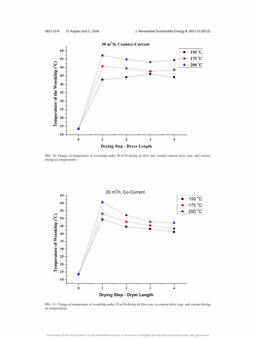
FIG. 10. Change of temperature of woodchip under 30 m3/h drying air flow rate, counter-current dryer type, and various
drying air temperatures.
FIG. 11. Change of temperature of woodchip under 20 m3/h drying air flow rate, co-current dryer type, and various drying
air temperatures.
063110-9 O. Kaplan and C. Celik J. Renewable Sustainable Energy 4, 063110 (2012)
Downloaded 13 Nov 2012 to 194.27.72.122. Redistribution subject to AIP license or copyright; see http://jrse.aip.org/about/rights_and_permissions

In Table III, short analysis (ASTM E-1755) results of both original (wet) and dried samples
are presented. Original (wet) woodchip sample consisted of 80.96% volatile organic compound
in its structure. Under all drying conditions, volatile organic compound amounts are nearly the
same. The biggest change in the amount of volatile organic matter was at 30 m3/h drying air
FIG. 12. Change of temperature of woodchip under 20 m3/h drying air flow rate, counter-current dryer type, and various
drying air temperatures.
FIG. 13. Change of moisture content of woodchip under 30 m3/h drying air flow rate, counter-current dryer type, and vari-
ous drying air temperatures.
063110-10 O. Kaplan and C. Celik J. Renewable Sustainable Energy 4, 063110 (2012)
Downloaded 13 Nov 2012 to 194.27.72.122. Redistribution subject to AIP license or copyright; see http://jrse.aip.org/about/rights_and_permissions
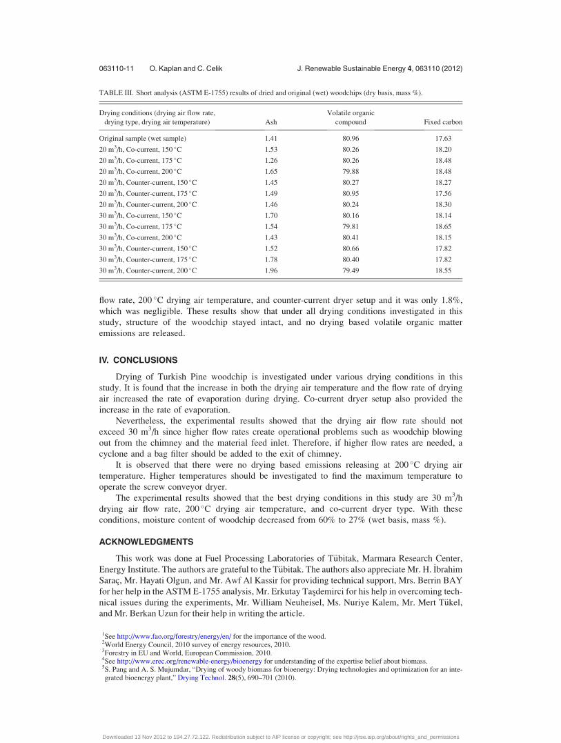
flow rate, 200 �C drying air temperature, and counter-current dryer setup and it was only 1.8%,
which was negligible. These results show that under all drying conditions investigated in this
study, structure of the woodchip stayed intact, and no drying based volatile organic matter
emissions are released.
IV. CONCLUSIONS
Drying of Turkish Pine woodchip is investigated under various drying conditions in this
study. It is found that the increase in both the drying air temperature and the flow rate of drying
air increased the rate of evaporation during drying. Co-current dryer setup also provided the
increase in the rate of evaporation.
Nevertheless, the experimental results showed that the drying air flow rate should not
exceed 30 m3/h since higher flow rates create operational problems such as woodchip blowing
out from the chimney and the material feed inlet. Therefore, if higher flow rates are needed, a
cyclone and a bag filter should be added to the exit of chimney.
It is observed that there were no drying based emissions releasing at 200 �C drying air
temperature. Higher temperatures should be investigated to find the maximum temperature to
operate the screw conveyor dryer.
The experimental results showed that the best drying conditions in this study are 30 m3/h
drying air flow rate, 200 �C drying air temperature, and co-current dryer type. With these
conditions, moisture content of woodchip decreased from 60% to 27% (wet basis, mass %).
ACKNOWLEDGMENTS
This work was done at Fuel Processing Laboratories of T€ubitak, Marmara Research Center,
Energy Institute. The authors are grateful to the T€ubitak. The authors also appreciate Mr. H. _Ibrahim
Sarac, Mr. Hayati Olgun, and Mr. Awf Al Kassir for providing technical support, Mrs. Berrin BAY
for her help in the ASTM E-1755 analysis, Mr. Erkutay Tasdemirci for his help in overcoming tech-
nical issues during the experiments, Mr. William Neuheisel, Ms. Nuriye Kalem, Mr. Mert T€ukel,
and Mr. Berkan Uzun for their help in writing the article.
1See http://www.fao.org/forestry/energy/en/ for the importance of the wood.2World Energy Council, 2010 survey of energy resources, 2010.3Forestry in EU and World, European Commission, 2010.4See http://www.erec.org/renewable-energy/bioenergy for understanding of the expertise belief about biomass.5S. Pang and A. S. Mujumdar, “Drying of woody biomass for bioenergy: Drying technologies and optimization for an inte-grated bioenergy plant,” Drying Technol. 28(5), 690–701 (2010).
TABLE III. Short analysis (ASTM E-1755) results of dried and original (wet) woodchips (dry basis, mass %).
Drying conditions (drying air flow rate,
drying type, drying air temperature) Ash
Volatile organic
compound Fixed carbon
Original sample (wet sample) 1.41 80.96 17.63
20 m3/h, Co-current, 150 �C 1.53 80.26 18.20
20 m3/h, Co-current, 175 �C 1.26 80.26 18.48
20 m3/h, Co-current, 200 �C 1.65 79.88 18.48
20 m3/h, Counter-current, 150 �C 1.45 80.27 18.27
20 m3/h, Counter-current, 175 �C 1.49 80.95 17.56
20 m3/h, Counter-current, 200 �C 1.46 80.24 18.30
30 m3/h, Co-current, 150 �C 1.70 80.16 18.14
30 m3/h, Co-current, 175 �C 1.54 79.81 18.65
30 m3/h, Co-current, 200 �C 1.43 80.41 18.15
30 m3/h, Counter-current, 150 �C 1.52 80.66 17.82
30 m3/h, Counter-current, 175 �C 1.78 80.40 17.82
30 m3/h, Counter-current, 200 �C 1.96 79.49 18.55
063110-11 O. Kaplan and C. Celik J. Renewable Sustainable Energy 4, 063110 (2012)
Downloaded 13 Nov 2012 to 194.27.72.122. Redistribution subject to AIP license or copyright; see http://jrse.aip.org/about/rights_and_permissions

6K. Svoboda, J. Martinec, M. Poho�rely, and D. Baxter, “Integration of biomass drying with combustion/gasification tech-nologies and minimization of emissions of organic compounds,” Chem. Pap. 63(1), 15–25 (2009).
7S. Pang and Q. Xu, “Drying of woody biomass for bioenergy using packed moving bed dryer: Mathematical modelingand optimization,” Drying Technol. 28(5), 702–709 (2010).
8Q. Xu and S. Pang, “Mathematical modeling of rotary drying of woody biomass,” Drying Technol. 26(11), 1344–1350(2008).
9A. S. Mujumdar, Handbook of Industrial Drying (CRC, 2006).10S. S. Waje, B. N. Thorat, and A. S. Mujumdar, Study of residence time distribution in a pilot scale screw conveyor dryer,
Drying Technol. 25(1), 249–259 (2007).11S. S. Waje, B. N. Thorat, and A. S. Mujumdar, “Hydrodynamic characteristics of a pilot scale screw conveyor dryer,”
Drying Technol. 25(4), 609–616 (2007).12S. S. Waje, B. N. Thorat, and A. S. Mujumdar, “Screw conveyor dryer: Process and equipment design,” Drying Technol.
25(1), 241–247 (2007).13S. S. Waje, B. N. Thorat, and A. S. Mujumdar, “An experimental study of the thermal performance of a screw conveyor
dryer,” Drying Technol. 24(3), 293–301 (2007).14H. R. Perry and W. D. Green, Perry’s Chemical Engineers’ Handbook, 7th ed. (McGraw Hill, 1999), pp. 12-31–12-32.
063110-12 O. Kaplan and C. Celik J. Renewable Sustainable Energy 4, 063110 (2012)
Downloaded 13 Nov 2012 to 194.27.72.122. Redistribution subject to AIP license or copyright; see http://jrse.aip.org/about/rights_and_permissions