Catalog - Conveyor Modules - Interroll
63
INSPIRED BY EFFICIENCY Catalog Conveyor Modules
-
Upload
khangminh22 -
Category
Documents
-
view
3 -
download
0
Transcript of Catalog - Conveyor Modules - Interroll

INSPIRED BY EFFICIENCY
CatalogConveyor Modules

Transporting and storing
Horizontal transport
Horizontal transport, in-cline/decline partially possible
Sorting and distributing
The Worldwide Interroll Group 4
The Heart of Internal Logistics 6
Interroll Platform for Conveyor Modules 8
Interroll Roller Conveyor 12
Non-powered 14
24 V drive 22
400 V drive 30
Interroll Belt Conveyor 38
24 V drive 40
400 V drive 44
Key products 58
Accessories 78
Appendix 88
Sorter 90
Application Notes 94
Index 122
Contents
"Inspired by Efficiency"
Smart handling of resources is mandatory for Interroll. Because we are convinced that efficiency
is a fundamental value. It drives us to constantly im-prove products and processes. Efficiency inspires our dai-
ly activities.
"Inspired by Efficiency" means: We develop products for internal logistics that perfectly adapt to the needs of our cus-tomers.
As global market leader in technology and innovation in our industry, we believe that strengthening the
business of our customers in a significant and lasting way is our responsibility. For Inter-
roll, the key to success is the consis-tent pursuit of efficiency.
Cardboard boxes
Containers
Load and workpiece carriers
Jackets, soft goods, bags

Interroll‘skey markets
Warehousing &Distribution
Food Processing
Airport
CourierExpress Postal
IndustrialProduction
Supermarket
HoldingGlobal Competence CentersSales/productionAgents/distributors
© 2018 INTERROLL 5
The Worldwide Interroll Group
The Interroll Group is one of the world's leading specialists for internal logistics.
The company, which is listed on the stock exchange and has its headquarters in Swit-zerland, employs some 2,000 people in 32 companies around the globe.
Our products can be found primarily in the food industry, in airport logistics, in the parcel, postal and courier sector, in distribution, and in various other industries. This includes: Easy-to-integrate drive solutions, such as drum motors for belt conveyors; conveyor rollers and DC drive rollers for roller conveyors; flow storage modules for compact pallet and container storage in distribution centers; crossbelt sorters, belt curves and other user-friendly conveyor modules for cost-efficient material flow systems.
With the acquisition of Portec in 2013, Interroll increases its cus-tomer presence and offers a greater product range in the air-port and package sectors.
Among the 23,000 Interroll customers overall are machine builders, system integrators and equipment manufacturers. Our products are in daily use at brands known throughout the world, such as Amazon, Bosch, Coca-Cola, Coop, DHL, Procter & Gamble, Siemens, Walmart, Yamaha, and Zalando.
Regional Centers of Excellence and production, global know-how, financial stability and a solid market reputation make Inter-roll a strong business partner and attractive employer.
Furthermore, Interroll initiates global research projects in the lo-gistics efficiency sector, and actively supports industry associa-tions in the development of standards and in the more efficient utilization of resources.
4 © 2018 INTERROLL
© 2018 INTERROLL 7
The Heart of Internal Logistics
With an experienced eye for the big picture, we offer you products that are versatile and essential building blocks in the portfolio of any success-ful planner or developer.
ConveyingVersatile and reliable core products ensure a dynamic, efficient material flow across all continents and in all industries:
· Conveyor rollers· Drum motors and idler pulleys· 24 V drives (RollerDrive)· Controllers for RollerDrive and drum motors
They are used to convey, accumulate, feed or remove goods. Powered or with the force of gravity. With or without dynamic pressure. Easy-to-install drive solutions for new plants or for re-furbishing existing plants. Excellent products that will pay for themselves and that you can rely on. In every respect.
Transporting and distributingMillions of different individual items travel through the world’s flow of goods every day and must be delivered on time to the correct destination. This is a trend that requires a perfor-mance-based logistics system with efficient material flow sys-tems. Interroll’s innovative conveyor modules and subsystems are always ready for key locations in customers' systems:
· Crossbelt sorters· Belt curves and belt merges· Conveyor modules with zero-pressure accumulation· Roller conveyors· Belt conveyors
Precisely pre-assembled and rapidly delivered units for fast, sim-ple integration into the complete system on site (plug and play). The conveyor modules and subsystems provide users with key assurances: excellent availability whilst being easy to use; out-standing efficiency even at low throughput volumes; efficient in-vestment with a short period of return on investment; adaptabil-ity in the event of change.
Storage and pickingEconomical and user-friendly: the dynamic storage solution that operates without power. It is designed for fast-moving goods (e.g. groceries) that have to be quickly picked and immediately conveyed to consumers. The principle is as simple as it is inge-nious. It is known as FIFO, First In – First Out, and guarantees that what has been stored first is also picked first. Or LIFO, Last In – First Out, when the pallet stored last is picked first. It means making maximum use of minimum space. And because the needs of our customers are as diverse as their products, our central and peripheral subsystems offer unlimited design options.
· Pallet flow· Carton flow
The picking times can scarcely be beaten. The return on invest-ment for the operator is two to three years and is integrated into "Just in Time".
6 © 2018 INTERROLL
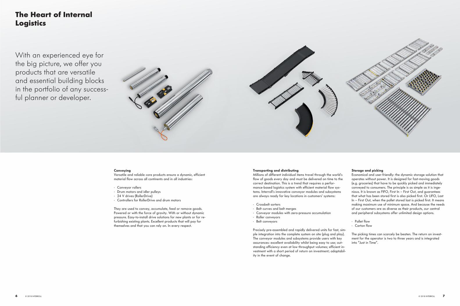
Merge 24 V
Roller Conveyor Straight 24 V
Roller Conveyor Curve 24 V
Belt Conveyor
Roller Conveyor Straight 460 V
Support
Merge 460 V
Transfer 24 V
Roller Conveyor Curve 460 V
HPD
· Flexible and modular concept· Energy-efficient 24 V conveyor technology· High throughput· Quick and easy installation· Extremely quiet operation· Easy maintenance· Straightforward planning
Roller conveyor, see page 12Belt conveyor, see page 38Key products, see page 58Accessories, see page 78Appendix, seepage 88Application notes, see page 94
© 2018 INTERROLL 9
Interroll Platform for Conveyor Modules
The new generation of mod-ules sets the standard for the efficient and state-of-the-art conveyor technology of the future.
The platform was developed by using an holistic approach to designing each process level – whether the ordering process, the planning of the conveyor system or its installation – as efficiently as possible. The modules themselves set a high standard for reliable and solid technical performance. This platform was designed for flexibility, modularity, attractive industrial design, simple handling during assembly and expansions.
Standardized modulesWith the new modules in three standard widths, all common ma-terials can be transported reliably. This keeps the expenses for combining different modules into a conveyor solution low and reduces the customer's stocking of spare parts to a minimum.
Efficient drive solutionsCustomer needs, conditions on site, and type of materials to be conveyed define the requirements for a system. The Interroll conveyor modules can be designed for the most efficient solu-tion for each task. Zero pressure accumulation conveying can be implemented with proven 24 V RollerDrive. For higher perfor-mance, efficient 24 V drives that enable efficient and fu-ture-proof zero pressure accumulation conveying are used to-gether with roller conveyors with 400 V flat belt drives. Pneumatics, which creates high operating costs, is completely omitted here.
Flexible and modular conceptRefined technical details and solutions offer lots of room for the flexibility of our customers. If changes to or expansions of the system should be necessary, the planning is simple. Thanks to the modular concept, the individual modules are perfectly matched and can be easily combined with each other.
Simplest layout creationThe Interroll Layouter gives you a menu-driven tool that pro-vides professional support in planning a conveyor system. Oper-ating the software is very intuitive and makes it possible to com-pile an extensive 3D layout in DWG format from all Interroll conveyor modules.
The new platform offers a wide selection of modules and key el-ements so that the material flow can be planned efficiently. Ev-erything from a single source and with expert consultation.
Application in deep freeze and chill areaThe deep freeze logistics with up to −30 °C poses special chal-lenges for material flow solutions. The 24-V roller conveyors and diverters enable an efficient zero pressure accumulation operation, even under these ambient conditions. Not only does this increase the work productivity, but it also facilitates installa-tion and maintenance.
Belt conveyors are also being used for the chill area, which is usually between 0 °C and +5 °C. Hence, it is possible to use a continual material flow solution at different ambient tempera-tures in a modular and flexible way.
Quick installationLargely pre-assembled modules accelerate the installation on site. Independently adjustable side guides, infinitely adjustable supports, integrated electrical conduits and an universally appli-cable master gauge for holes to attach add-on components are only a few of the details that reduce the installation effort.
Reliable operationThe robust and extensively tested design of the new modules re-duces the maintenance effort and ensures the reliable operation of a conveyor system.
8 © 2018 INTERROLL

Interroll Platform for Conveyor ModulesPerformance in Detail
Energy-efficient 24 V conveyor technology High throughput Scalability
The most efficient solution is selected for each conveyor task.
Powerful conveyor technology. Simple planning, implementation and ex-pansion of conveyor systems.
• Zero pressure accumulation conveying with 24 V drives
• Variant with 400 V main drive for high-performance applications
• Belt conveyor with Interroll drum motors• No pneumatics required
• Transport speed up to 2 m/s (400 fpm)• Distribution output up to 3,600 units/h
possible• Diverting without interrupting the mate-
rial flow
• Modular concept• Standard interfaces• Quick and easy installation
Ergonomics Control Continuous side profile design
Well thought-out solutions for convenient and safe work.
Future-oriented 24 V control concept for every need.
A side profile for all modules for flexible routing.
• Quiet operation (< 60 dBA without con-veyor belt)
• Safety due to 24 V technology• Minimized tool demand for the entire
platform
• Open interfaces with high-speed fieldbus• Internal logic for reduced control effort
• High-quality powder-coated steel profile• A multitude of fastening options on the
profile• Can be used as an electrical conduit
Crossbar Plastic clip for roller fixing Application in deep freeze area
Rigid connection of side profiles, which also serves as an electrical conduit.
Simple and quick roller assembly and main-tenance.
Interroll conveyor modules enable the mod-ular and flexible use of a continual material flow solution at different ambient tempera-tures.
• As an electrical conduit, usable for up to ten cables
• Sealable against dirt and contamination
• Assembly and disassembly of rollers from the top
• Multi-use clip• Simple subsequent adjustment of the
roller pitch
• Use of 24-V roller conveyors and divert-ers in the deep freeze area of up to −30 °C
• Additional use of belt conveyors in the chill area from 0 to +5 °C
Assembly from the top Universal supports and sensor holders Flexible side guides
Assembly and maintenance of all modules with little effort.
For quick, flexible installation and exact po-sitioning of side guides, sensors and reflec-tors for efficient material flow.
Flexible and safe guidance of products.
• Maintenance of roller and belt convey-ors from the top
• Easily accessible components and con-nections
• Tool-free roller assembly with roller clips
• Fixed and flexible universal supports• Reliable installation and protection of
sensors using sensor holders• Switching state always visible• Fast repositioning
• Simple conversion to other material di-mensions
• Flexible forming• Continuous height adjustment
© 2018 INTERROLL 1110 © 2018 INTERROLL

Interroll Roller Conveyor
Non-powered 24 V drive 400 V drive
Straight
RM 8110, page 14 RM 8310, page 22 RM 8210/8212, page 30
Curve
RM 8120, page 16 RM 8320, page 24 RM 8220, page 32
Merge
RM 8330, page 26 RM 8230, page 34
Alignment conveyor
RM 8340, page 28 RM 8240, page 36
Ball table
RM 8130, page 18
RM 8140, page 20
© 2018 INTERROLL 13

RM 8110Interroll Roller Conveyor Straight Non-Powered
Product descriptionThe non-powered straight roller conveyor transports materials either manually or via gravity down a slope and is used as an assem-bly and picking line.The magnetic speed controller MSC 50 can be installed for controlled speed regulation. These gearless, mechanical eddy current brakes reliably decelerate materials from 0.5 kg up to 35 kg, and increase functionality and safety in the workplace. For more infor-mation, please contact your Interroll contact person.
Technical data
General technical data Max. load capacity 100 kg/mIncline/decline Suitable for declines, but will have to be tested for the
respective material weightAmbient temperature* 0 to + 40°C
Roller Roller type Interroll Series 1100, Smooth-Running Conveyor Roller Interroll Series 1700, Universal Conveyor Roller
Roller diameter 50 mmRoller material Steel, zinc-plated
PVC
*We also offer this product for the temperature ranges Deep Freeze (−30 to 0 °C) and Chill (0 to 5 °C). Please contact your Interroll contact person.
Dimensions
LW
120
115
HSG
TW
40
BF
P
ML
BF Rated width 420, 620, 840 mm others on request
LW Lane width BF (+120/–90 mm per side with flexible side guide)ML Module length Max. 4080 mmTW Module width BF + 80 mmP Roller pitch 60/90/120 mmHSG Side guide height 35 − 65 mm
Scope of delivery· The module is fully assembled· Please order supports and end caps separately· Please order the magnetic speed controller MSC 50 separately
© 2018 INTERROLL 1514 © 2018 INTERROLL

RM 8120Interroll Roller Conveyor Curve Non-Powered
Product descriptionThe non-powered roller conveyor curve changes the transport direction of materials. Material is manually pushed around the curve. The alignment of the material is maintained within the side frames by tapered rollers.
Technical data
General technical data Max. load capacity 100 kg/mIncline/decline Not suitableAmbient temperature 0 to + 40°C
Roller Roller type Interroll Series 1700KXORoller diameter 50 mmRoller material Steel, with gray tapered polypropylene sleevesMax. number of rollers per zone 6 for 30°, 9 for 45°, 12 for 60°, 18 for 90°
Dimensions
α
r 825
LW
½ Pi
Pi
40½ P
P
BF
LW
120
HSG 11
5
BF Rated width 420, 620, 840 mm others on request
LW Lane width BF (+120/–90 mm per side with flexible side guide)a Angle 30°/45°/60°/90°TW Module width BF + 80 mmPi Roller pitch, inside ~72 mmP Roller pitch, outside ~(0.087 x LW) + Pi mmHSG Side guide height 35 − 65 mm
Scope of supply· The module is fully assembled· Please order supports and end caps separately
© 2018 INTERROLL 1716 © 2018 INTERROLL
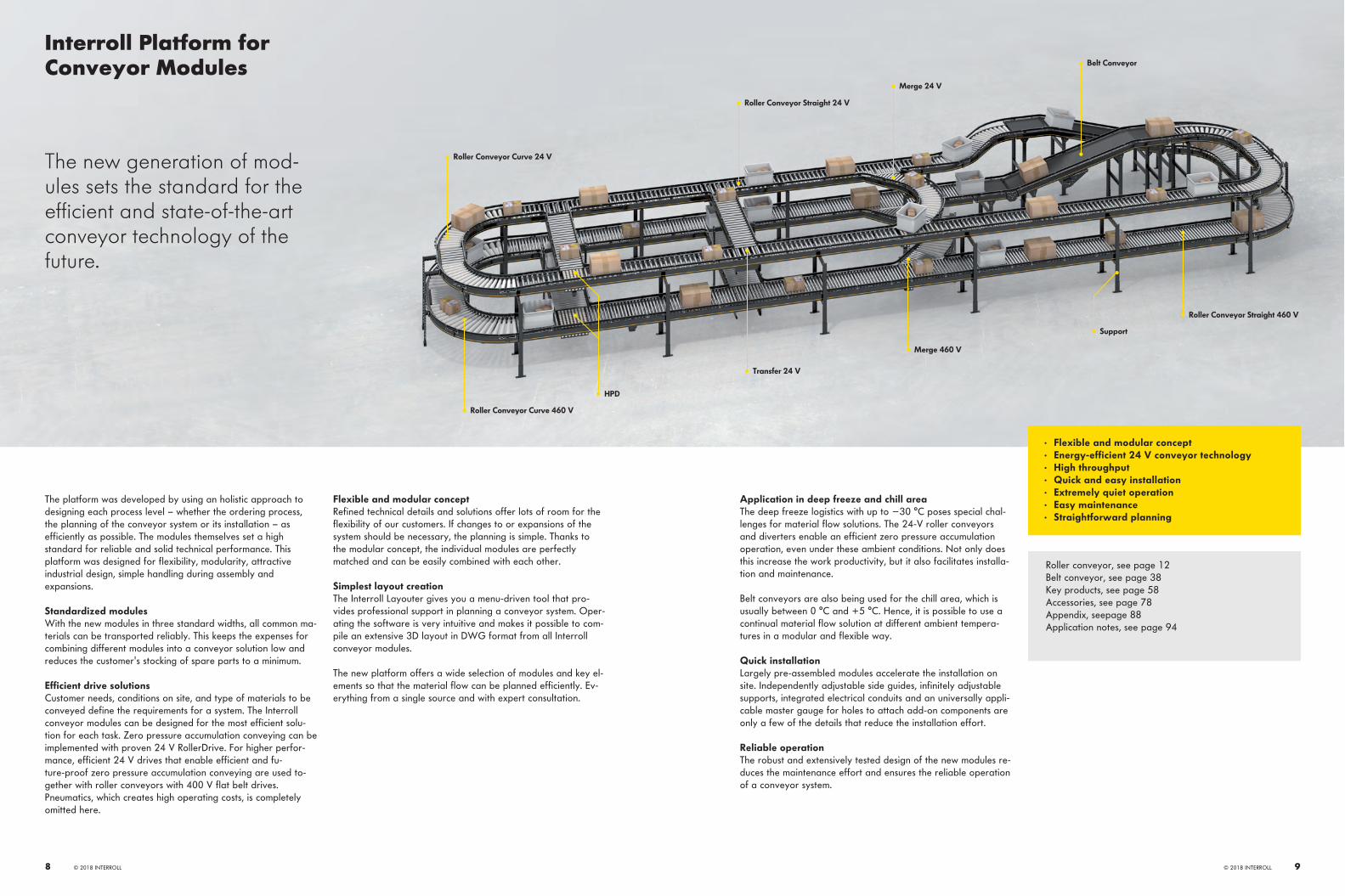
RM 8130Interroll Roller Conveyor Ball Table Non-Powered
Product descriptionThe ball table transports materials with a solid bottom in any direction using very little force. It is especially suitable for workstation & inspection areas. So that a ball table can be combined with other conveyors, it is installed in a standard side profile.
Technical data
General technical data Max. load capacity 100 kg/mIncline/decline Not suitableAmbient temperature –5 to +40 °C
Ball Ball type Interroll Series 5500Ball diameter 25.4 mm
Dimensions
LW
115
120
HSG
TW
40BF
62,5
ML
LW TW
60,0
BF Rated width 420, 620, 840 mm others on request
LW Lane width BF (+120/–90 mm per side with flexible side guide)ML Module length Max. 2040 mmTW Module width BF + 80 mmP Pitch 60 mmHSG Side guide height 35 − 65 mm
Scope of supply· The module is fully assembled· Please order supports and end caps separately
© 2018 INTERROLL 1918 © 2018 INTERROLL

RM 8140Interroll Roller Conveyor Omni Wheel Table Non-Powered
Product descriptionThe omni wheel table with multi-directional wheels is particularly well suited for workstation and inspection areas and for materials with soft bottoms that can be moved in all directions with very little force.
Technical data
General technical data Max. load capacity 60 kg/mIncline/decline Not suitableAmbient temperature –5 to + 50 °C
Roller Roller type Interroll Series 2800Roller diameter 48 mmRoller material Polyamide, polypropylene housing
Dimensions
LW
115
HSG
TW
40BF
120
LW
62,5
ML
62,5
TW
BF Rated width 420, 620, 840 mm others on request
LW Lane width BF (+120/–90 mm per side with flexible side guide)ML Module length Max. 2040 mmTW Module width BF + 80 mmP Pitch 62.5 mmHSG Side guide height 35 − 65 mm
Scope of supply· The module is fully assembled· Please order supports and end caps separately
© 2018 INTERROLL 2120 © 2018 INTERROLL

RM 8310Interroll Roller Conveyor Straight 24 V Powered
Product descriptionThe 24-V roller conveyor enables zero pressure accumulation transport of unit loads with the help of a controller. Each zone is pow-ered by a RollerDrive that is connected to a fixed number of idlers via PolyVee belts.
Technical data
General technical data Max. load capacity* 50 kg/zoneConveyor speed* 0.1 to 1.0 m/s (at 35 kg)
0.1 to 0.8 m/s (at 50 kg)Incline/decline Max. 4°Ambient temperature +5 to +40 °C
Roller Roller type Interroll Series 3500Roller diameter 50 mmRoller material Steel 1.5 mm, zinc-platedMax. number of rollers per zone 20
Drive Rated voltage 24 VMotor type Interroll RollerDrive EC310Drive medium PolyVee beltsTorque transmission Roller-to-RollerControl MultiControl
*The combination of maximum values is not always possible.
**We also offer this product for the temperature ranges Deep Freeze (−30 to 0 °C) and Chill (0 to +5 °C). Please contact your Interroll contact person.
Dimensions
LW
HSG
TW
40
120
115
BF
ML
ZL
D.O.T.
P
LW TW
BF Rated width 420, 620, 840 mm others on request
LW Lane width BF (+120/–90 mm per side with flexible side guide)ML Module length ZL x number of zones, max. 4080 mmZL Zone length Number of rollers x PTW Module width BF + 80 mmP Roller pitch 60/90/120/150 mmHSG Side guide height 35 − 65 mm
Scope of supply· Module is completely assembled and prewired· Supply incl. 1 sensor per conveyor/zone· Please order supports and end caps separately· Supply incl. bus (communication) cable
© 2018 INTERROLL 2322 © 2018 INTERROLL

RM 8320Interroll Roller Conveyor Curve 24 V Powered
Product descriptionThe 24-V roller conveyor curves change the direction of transport of the material. The conical rollers retain the alignment of the ma-terials between side frames. A controller enables zero pressure accumulation transport. Each zone is powered by a 24 V RollerDrive that is connected to a fixed number of idlers via round belts.
Technical data
General technical data Max. load capacity* 50 kg/zoneConveyor speed* 0.1 to 1.0 m/s (at 35 kg)
0.1 to 0.8 m/s (at 50 kg)Incline/decline Not suitableAmbient temperature** +5 to +40 °C
Roller Roller type Interroll Series 3500Roller diameter 50 mmRoller material Steel 1.5 mm, zinc-platedMax. number of rollers per zone 6 for 30°
9 for 45° 12 for 60° 18 for 90°
Drive Rated voltage 24 VMotor type Interroll RollerDrive EC310Drive medium Round beltTorque transmission Roller-to-RollerControl MultiControl
*The combination of maximum values is not always possible.
**We also offer this product for the temperature ranges Deep Freeze (−30 to 0 °C) and Chill (0 to +5 °C). Please contact your Interroll contact person.
Dimensions
α
r 825
LW
½ Pi
Pi
40½ P
P
BF
LW
120
HSG 11
5
BF Rated width 420, 620, 840 mm others on request
LW Lane width BF (+120/–90 mm per side with flexible side guide)a Angle 30°/45°/60°/90°TW Module width BF + 80 mmPi Roller pitch, inside ~72 mmP Roller pitch, outside ~(0.087 x LW) + Pi mmHSG Side guide height 35 − 65 mm
Scope of supply· Module is completely assembled and prewired· Supply incl. 1 sensor per conveyor/zone· Please order supports and end caps separately· Supply incl. bus (communication) cable
© 2018 INTERROLL 2524 © 2018 INTERROLL

RM 8330Interroll Roller Conveyor Merge 24 V Powered
Product descriptionThe merge merges two conveyor lines by placing products in the gaps in the material flow. Alternatively, the merge diverts products from a straight conveyor, e.g., by using an HPD (High Performance Divert).
Technical data
General technical data Max. load capacity* 50 kg/mConveyor speed* 0.1 to 1.0 m/s (at 35 kg)
0.1 to 0.8 m/s (at 50 kg)Incline/decline Not suitableAmbient temperature** +5 to +40 °C
Roller Roller type Interroll Series 3500Roller diameter 50 mmRoller material Steel 1.5 mm, zinc-plated
Drive Rated voltage 24 VMotor type Interroll RollerDrive EC310Drive medium PolyVee beltsTorque transmission Roller-to-RollerControl MultiControl
*The combination of maximum values is not always possible.
**We also offer this product for the temperature ranges Deep Freeze (−30 to 0 °C) and Chill (0 to +5 °C). Please contact your Interroll contact person.
Dimensions
HSG
115
BF
120
TW
ML
BF
FW
BF Rated width 420, 620, 840 mm others on request
LW Lane width BF (+120/–90 mm per side with flexible side guide)ML Module length See application notes page 111TW Module width BF + 80 mmFW Opening width See application notes page 111a Angle 30°/45°P Roller pitch 60 mmHSG Side guide height 35 − 65 mm
Scope of supply· Module is completely assembled and prewired· Supply incl. 1 sensor per conveyor/zone· Please order supports and end caps separately· Supply incl. bus (communication) cable
© 2018 INTERROLL 2726 © 2018 INTERROLL

RM 8340Interroll Roller Conveyor Alignment Conveyor 24 V Powered
Product descriptionThe 24 V alignment conveyor guides products diagonally to the transport direction to a side frame, and aligns them to the side guide if necessary. The side guide must be suitable for this purpose.
Technical data
General technical data Max. load capacity* 50 kg/mConveyor speed* 0.1 to 1.0 m/s (at 35 kg)
0.1 to 0.8 m/s (at 50 kg)Incline/decline Not suitableAmbient temperature +5 to +40 °C
Roller Roller type Interroll Series 3500Roller diameter 50 mmRoller material Steel 1.5 mm, zinc-plated
Drive Rated voltage 24 VMotor type Interroll RollerDrive EC310Drive medium Round beltTorque transmission Roller-to-rollerControl MultiControl
*The combination of maximum values is not always possible.
Dimensions
BF
LW
HSG
TW
40
120
115
ML
ZL
Pα
BF Rated width 420, 620, 840 mm others on request
LW Lane width BF (+120/–90 mm on one side)ML Module length ZL x number of zonesZL Zone length depending on angle and measure between framesTW Module width BF + 80 mmP Roller pitch 60 mma Angle of rollers 7°/15.2°HSG Side guide height 35 − 65 mm
Scope of supply· Supply incl. rolling or gliding side guides on one side· Module is completely assembled and prewired· Supply incl. 1 sensor per conveyor/zone· Please order supports and end caps separately· Supply incl. bus (communication) cable
© 2018 INTERROLL 2928 © 2018 INTERROLL

RM 8210/8212Interroll Roller Conveyor Straight 400 V Powered
Product descriptionThe roller conveyor powered by 400 V is available in 2 operating modes.The permanently powered flat belt conveyor RM 8210 serves as a transport conveyor that requires only one 400-V drive for long distances up to 15 m.With the use of electrical actuators, the conveyor can also be operated as zero pressure accumulation conveyor (RM 8212), either completely or partially. These actuators, which can also be retrofitted, are powered by 24-V drives and can be controlled by the Interroll controllers for zero pressure accumulation operation.
Technical data
General technical data Max. load capacity* 50 kg/mTransport conveyor speed* 0.1 to 2.0 m/s (at 50 kg/m or zone)Zero pressure accumulation conveyor speed* 0.1 to 1.4 m/sIncline/decline Not suitableAmbient temperature +5 to +40 °C
Roller Roller type Interroll Series 1700 Interroll Series 3500 (zone conveyor)
Roller diameter 50 mmRoller material Steel 1.5 mm, zinc-plated
Drive Rated voltage 400 VRated voltage, actuator 24 VDrive medium Flat belt (transport) PolyVee (zero pressure accu-
mulation)Torque transmission Roller-to-Roller (zero pressure accumulation)
*The combination of maximum values is not always possible.
Dimensions
BF
LW
HSG
TW
40
120
115
332
ML
ZL P
LW TW
BF Rated width 420, 620, 840 mm others on request
LW Lane width BF (+120/–90 mm per side with flexible side guide)ML Transport module length max. 12,000 mm
Zero pressure accumulation module length Max. 6000 mm, ZL x number of zones (max. 6 zones per 400 V drive)ZL Zone length (optional) Number of rollers x PTW Module width BF + 80 mmP Roller pitch 60/90/120 mmHSG Side guide height 35 − 65 mm
Scope of supply· Module is completely assembled, except for the flat belt· Please order supports and end caps separately· Zero pressure accumulation version is prewired· Supply incl. 1 sensor per conveyor/zone· Delivery without bus (communication) cable for zero pressure accumulation variant
Actuators for generating an accumulation zone can generally be retrofitted. When ordering, please remember that rollers with PolyVee head are required. If a slave curve is driven by a straight conveyor, the max. module length is reduced by 3000 mm, for 2 curves by 6000 mm.
© 2018 INTERROLL 3130 © 2018 INTERROLL

RM 8220Interroll Roller Conveyor Curve 400 V Powered Slave
Product descriptionThe roller conveyor curves change the direction of transport of the material. The alignment of the material is maintained within the side frames by tapered rollers. The flat belt-driven curve is driven either by an adjacent straight module or by a separate head drive. Accumulation mode is not possible in powered 400-V curves.
Technical data
General technical data Max. load capacity* 50 kg/mConveyor speed* 0.1 to 2.0 m/sIncline/decline Not suitableAmbient temperature +5 to +40 °C
Roller Roller type Interroll Series 1700Roller diameter 50 mmRoller material Steel 1.5 mm, zinc-platedMax. number of rollers per zone 6 for 30°
9 for 45° 12 for 60° 18 for 90°
*The combination of maximum values is not always possible.
Dimensions
α
r 825
LW
½ Pi
Pi
40½ P
P
BF
LW
120
HSG 11
5
BF Rated width 420, 620, 840 mm others on request
LW Lane width BF (+120/–90 mm per side with flexible side guide)a Angle 30°/45°/60°/90°TW Module width BF + 80 mmPi Roller pitch, inside ~72 mmP Roller pitch, outside ~(0.087 x LW) + Pi mmHSG Side guide height 35 − 65 mm
Scope of supply· Module is completely assembled, except for the flat belt· Supply incl. 1 sensor· Please order supports and end caps separately
© 2018 INTERROLL 3332 © 2018 INTERROLL

RM 8230Interroll Roller Conveyor Merge 400 V Powered Slave
Product descriptionThe merge is used for connecting lateral roller tracks at an angle (30° or 45°) to the main track. This can be used for moving materi-al off the track (e.g. with HPD (High Performance Divert)) or onto the track.
Technical data
General technical data Max. load capacity* 50 kg/mConveyor speed* 0.1 to 2.0 m/sIncline/decline Not suitableAmbient temperature +5 to +40 °C
Roller Roller type Interroll Series 1700 Interroll Series 3500
Roller diameter 50 mmRoller material Steel 1.5 mm, zinc-plated
*The combination of maximum values is not always possible.
Dimensions
HSG
115
BF
120
TW
ML
BF
FW
BF Rated width 420, 620, 840 mm others on request
LW Lane width BF (+120/–90 mm per side with flexible side guide)ML Module length See application notes Roller merge dimensionsTW Module width BF + 80 mmFW Opening width See application notes Roller merge dimensionsa Angle 30°/45°P Roller pitch 60 mmHSG Side guide height 35 − 65 mm
Scope of supply· Module is completely assembled, except for the flat belt· Please order supports and end caps separately· Supply incl. 1 sensor· Supply without bus (communication) cable
© 2018 INTERROLL 3534 © 2018 INTERROLL

RM 8240Interroll Roller Conveyor Alignment Conveyor 400 V Powered
Product descriptionThe alignment conveyor guides products diagonally to the transport direction to a side frame and aligns them to the side guide, if necessary. The side guide must be suitable for this purpose.
Technical data
General technical data Max. load capacity* 50 kg/mConveyor speed* 0.1 to 1.4 m/s (at 50 kg)Incline/decline Not suitableAmbient temperature –5 to + 50 °C
Roller Roller type Interroll Series 1700 Interroll Series 3500
Roller diameter 50 mmRoller material Steel, zinc-plated
Drive Rated voltage 400 VDrive medium Flat belt
*The combination of maximum values is not always possible.
Dimensions
BF
LW
HSG
40
120
115
TWML
LW
Pα
BF Rated width 420, 620, 840 mm others on request
LW Lane width BF (+120/–90 mm per side with flexible side guide)ML Module length Max. 2040 mmTW Module width BF + 80 mmP Roller pitch 60 mma Angle of rollers 7°/15.2°HSG Side guide height 35 − 65 mm
Scope of supply· Module is completely assembled, except for the flat belt· Supply incl. 1 sensor· Please order supports and end caps separately
© 2018 INTERROLL 3736 © 2018 INTERROLL

Interroll Belt Conveyor
24 V drive 400 V drive
Straight
BM 8350, page 40 BM 8410/8420, page 44
BM 8411/8421, page 46 BM 8432/8442, page 48
BM 8433/8443, page 50 BM 8434/8444, page 52
Curve
BM 8360, page 42 Interroll Portec Belt Curves, page 54
Merge
BM 4430/4445, page 56
© 2018 INTERROLL 39

BM 8350Interroll Belt Conveyor Straight 24 V Powered
Product descriptionThe Belt Conveyor Light is a belt conveyor that is divided into zones and operates with zero pressure accumulation; its drive is based on the 24 V RollerDrive. It is possible to transport and accumulate small products, as well as products not suitable for roller tracks. Not suitable for reversing operation.
Technical data
General technical data Max. load capacity per zone* 50 kgConveyor speed* Max. 0.8 m/sIncline/decline Max. 15°Ambient temperature +5 to +40 °C
Drive Rated voltage 24 VMotor type Interroll RollerDrive EC310Diameter of drive roller 50 mmControl MultiControl
Material Conveyor belt Polyester with PVC coatingSlider bed Rollers, Interroll Series 1700
*The combination of maximum values is not always possible.
Dimensions
LW
HSG
TW
40
Ø50
121
115
ML
BF
ZL
D.O.T.
BF Rated width 420, 620, 840 mm (min. 360 mm, max. 840 mm) others on request
LW Lane width BF (+120/–90 mm per side with flexible side guide)ML Module length ZL x number of zones, max. 4080 mmZL Zone length Number of rollers x P, max. 1980 mmTW Module width BF + 80 mmP Roller pitch 90 mm under the belt, 60 mm between the zonesHSG Side guide height 35 − 65 mm
Scope of supply· Module is completely assembled and prewired· Supply incl. 1 sensor per zone· Please order supports and end caps separately
© 2018 INTERROLL 4140 © 2018 INTERROLL

BM 8360Interroll Belt Conveyor Curve 24 V Powered
Product descriptionThe Belt Curve Light is a belt curve that is divided into zones and operates with zero pressure accumulation; its drive is based on the 24 V RollerDrive. It is possible to transport and store small products, as well as products not suitable for roller tracks. Not suitable for reversing operation.
Technical data
General technical data Max. load capacity per zone* 20 kgConveyor speed* Max. 0.5 m/sIncline/decline Not suitableAmbient temperature +5 to +40 °C
Drive Rated voltage 24 VMotor type Interroll RollerDrive EC310Number of zones (N) 1 at 45°
2 at 90°Control MultiControl
Material Conveyor belt Polyester with PVC coatingSlider bed Rollers, Interroll Series 1700
*The combination of maximum values is not always possible.
Dimensions
BF
121
HSG
115
LW
45˚
40LW
BF Rated width 420, 620 mm others on request
LW Lane width BF (+120/–90 with flexible side guide)a Angle 1 x 45°/90° (2 x 45°)TW Module width BF + 80 mmHSG Side guide height 35 − 65 mm
Scope of supply· Module is completely assembled and prewired· Supply incl. 1 sensor per zone· Please order supports and end caps separately
© 2018 INTERROLL 4342 © 2018 INTERROLL

BM 8410/8420Interroll Belt Conveyor Straight Head Drive
Product descriptionThe belt conveyor is used for the transport of unit loads that are not suitable for roller tracks, and for all types of unit loads in case of inclines and declines. The standard belt conveyor is equipped with a drum motor (BM 8420), a gear motor is available as an option (BM 8410). Not suit-able for reversing operation.
Technical data
General technical data Max. load capacity* 50 kg/mMax. load capacity per module* 220 kgConveyor speed* 0.1 to 2.5 m/sIncline/decline Max. 6°Ambient temperature** 0 to +40 °C
Drive Rated voltage 400 VElectrical power Max. 1.1 kWMotor type Drum motor/gear motor
Materials Conveyor belt Level: smooth, 2-layer, PVC Rising/falling gradient: grooved longitudinally
Slider bed Zinc-plated sheet steel 2.5 mm Zinc-plated sheet steel 3 mm (from measure between frames = 840 mm)
*The combination of maximum values is not always possible.
**We also offer this product for the Chill temperature range (0 to +5 °C). Please contact your Interroll contact person.
Dimensions
LW
HSG
TW
40
121,
5
BF
115
CL
D.O.T.
BF Rated width 420, 620, 840 mm others on request
LW Lane width BF (+120/–90 mm per side with flexible side guide)CL Module length 650 − 3000 mmTW Module width BF + 80 mmHSG Side guide height 35 − 65 mm
Scope of supply· The module is fully assembled· Supply incl. 1 sensor· Please order supports separately
© 2018 INTERROLL 4544 © 2018 INTERROLL

BM 8411/8421Interroll Belt Conveyor Straight Center Drive
Product descriptionThe belt conveyor is used for the transport of unit loads that are not suitable for roller tracks, and for all types of unit loads in case of inclines and declines. The standard belt conveyor is equipped with a drum motor (BM 8421), a gear motor is available as an option (BM 8411). Not suit-able for reversing operation.
Technical data
General technical data Max. load capacity* 50 kg/mMax. load capacity per module* 550 kgConveyor speed* 0.1 to 2.5 m/sIncline/decline Max. 18°Ambient temperature** 0 to +40 °C
Drive Rated voltage 400 VElectrical power Max. 3 kWMotor type Drum motor/gear motor
Materials Conveyor belt Level: smooth, 2-layer, PVC Rising/falling gradient: grooved longitudinally, 2-layer, PVC
Slider bed Zinc-plated sheet steel 2.5 mm Zinc-plated sheet steel 3 mm (from BF = 840 mm)
*The combination of maximum values is not always possible.
**We also offer this product for the Chill temperature range (0 to +5 °C). Please contact your Interroll contact person.
Dimensions
LW
HSG
TW
121
115
CL
⅔ ⅓
556
364
D.O.T.
BF Rated width 420, 620, 840 mm others on request
LW Lane width BF (+120/–90 mm per side with flexible side guide)CL Module length 1500 to 20,010 mmTW Module width BF + 80 mmHSG Side guide height 35 − 65 mm
Scope of supply· Module is completely assembled, maybe split into sections· Supply incl. 1 sensor· Please order supports and end caps separately
© 2018 INTERROLL 4746 © 2018 INTERROLL

BM 8432/8442Interroll Belt Conveyor Straight Center Drive + Top Arch
Product descriptionThe belt conveyor with top arch is used for transporting all types of unit loads in case of inclines or declines. The arch reduces noise and the impact of materials as they pass over it. The standard belt conveyor is equipped with a drum motor (BM 8442), a gear motor is available as an option (BM 8432). Not suit-able for reversing operation.
Technical data
General technical data Max. load capacity* 50 kg/mMax. load capacity per module* 550 kgConveyor speed* 0.1 to 2.5 m/s (at 50 kg)Incline/decline Max. 18°Ambient temperature** 0 to + 40 °C
Drive Rated voltage 400 VElectrical power Max. 3 kWMotor type Drum motor/gear motor
Materials Conveyor belt 2-layer, PVC, grooved longitudinallySlider bed Sheet steel 2 mm
*The combination of maximum values is not always possible.
**We also offer this product for the Chill temperature range (0 to +5 °C). Please contact your Interroll contact person.
Dimensions
TL
CL
556
364
D.O.T.
α
LW
HSG
TW
121
115
BF Rated width 420, 620, 840 mm others on request
LW Lane width BF (+120/–90 mm per side with flexible side guide)CL Module length 1500 to 20,010 mmTL Top length 720 to 2160 mmTW Module width BF + 80 mmHSG Side guide height 35 − 65 mma Incline/Decline angle 6°/9°/12°/15°/18°
Scope of supply· Module is completely assembled, maybe split into sections· Supply incl. 1 sensor· Please order supports and end caps separately
© 2018 INTERROLL 4948 © 2018 INTERROLL

BM 8433/8443Interroll Belt Conveyor Straight Center Drive + Feed
Product descriptionThe belt conveyor with feed is used for transporting all types of unit loads in case of inclines or declines. The feed enables a smooth transition at the lower kink of the belt conveyor, e.g., at the interface with a roller conveyor. The standard belt conveyor is equipped with a drum motor (BM 8443), a gear motor is available as an option (BM 8433). Not suit-able for reversing operation.
Technical data
General technical data Max. load capacity* 50 kg/mMax. load capacity per module* 550 kgConveyor speed* 0.1 to 2.5 m/s (at 50 kg)Incline/decline Max. 18°Ambient temperature** 0 to + 40 °C
Drive Rated voltage 400 VElectrical power Max. 3 kWMotor type Drum motor/gear motor
Materials Conveyor belt 2-layer, PVC, grooved longitudinallySlider bed Sheet steel 2 mm
*The combination of maximum values is not always possible.
**We also offer this product for the Chill temperature range (0 to +5 °C). Please contact your Interroll contact person.
Dimensions
BL
CL
556
364
D.O.T.
α
LW
HSG
TW
121
115
BF Rated width 420, 620, 840 mm others on request
LW Lane width BF (+120/–90 mm per side with flexible side guide)CL Module length 1500 to 20,010 mmBL Bottom length 720 to 1020 mmTW Module width BF + 80 mmHSG Side guide height 35 − 65 mma Incline/Decline angle 6°/9°/12°/15°/18°
Scope of supply· Module is completely assembled, maybe split into sections· Supply incl. 1 sensor· Please order supports and end caps separately
© 2018 INTERROLL 5150 © 2018 INTERROLL

BM 8434/8444Interroll Belt Conveyor Straight Center Drive + Top Arch + Feed
Product descriptionThe belt conveyor is used for transporting all types of unit loads in case of inclines and declines. Arch and feed allow a smooth and quieter transition at the upper and lower kink. The standard belt conveyor is equipped with a drum motor (BM 8444), a gear motor is available as an option (BM 8434). Not suit-able for reversing operation.
Technical data
General technical data Max. load capacity* 50 kg/mMax. load capacity per module* 550 kgConveyor speed* 0.1 to 2.5 m/s (at 50 kg)Incline/decline Max. 18°Ambient temperature** 0 to + 40 °C
Drive Rated voltage 400 VElectrical power Max. 3 kWMotor type Drum motor/gear motor
Materials Conveyor belt 2-layer, PVC, grooved longitudinallySlider bed Sheet steel 2 mm
*The combination of maximum values is not always possible.
**We also offer this product for the Chill temperature range (0 to +5 °C). Please contact your Interroll contact person.
Dimensions
BL
TL
CL
556
364
D.O.T.
α
LW
HSG
TW
121
115
BF Rated width 420, 620, 840 mm others on request
LW Lane width BF (+120/–90 mm per side with flexible side guide)CL Module length 1500 to 20,010 mmTL Top length 720 to 2160 mmBL Bottom length 720 to 1020 mmTW Module width BF + 80 mmHSG Side guide height 35 − 65 mma Incline/Decline angle 6°/9°/12°/15°/18°
Scope of supply· Module is completely assembled, maybe split into sections· Supply incl. 1 sensor· Please order supports and end caps separately
© 2018 INTERROLL 5352 © 2018 INTERROLL

Interroll Belt Curve
Product descriptionWith a conveyor speed of more than 2 m/s, the belt curve is designed for high performance and trouble-free operation in different applications. The curves are available in several widths, angles and weight classes.
The belt curves can be operated in higher and lower temperature ranges, which represents a significant advantage compared to common solutions, such as friction-driven conveyors. Another advantage is the fast belt change. Thanks to the sophisticated construc-tion, the drive station does not have to be removed for the belt change, thereby saving time.
Technical data
Portec Belt CurveGeneral technical data Max. load capacity* 75 kg/m
Rated voltage 400 VConveyor speed* Max. 2.85 m/sAmbient temperature −15 °C to 55 °C
Dimensions** Cam angle 30°/45°/60°/90°Inside radius 1000/800/800/800 mmConveying width 1100/900/700/500 mmConveyor length 1550/1250/1150/1050 mm
Material Conveyor belt FLEXAM EF 10/2 0+A22 BLACK AS FR others upon request
Slider bed 2.5 mm sheet steelColor All RAL colors are possible.
*The combination of maximum values is not always possible.
**Other sizes on request.
© 2018 INTERROLL 5554 © 2018 INTERROLL

BM 4430/4445Interroll Belt Conveyor Merge
Product descriptionThe belt merge is a belt conveyor with a 30° or 45° angled connecting edge. This conveyor element enables the merging of two conveyor lines at the corresponding angle. With the use of supplementary sorting elements, belt merges also enable the separation of conveyor flows. The conveying belts are available in widths of 90 mm and 40 mm for especially small materials. The belt merge has an especially low overall height at 270 mm.
Technical data
General technical data Max. load capacity* 50 kg/mMax. load capacity per module* 100 kgConveyor speed* 0.1 to 2.0 m/sIncline/decline Not suitableAmbient temperature –5 to +40 °C
Drive Rated voltage 400 V/50 Hz/3 phasesElectrical power 0.37 to 1.10 kWMotor type Geared motor 0.37 kW to 1.10kWDiameter of drive roller 92/120 mmDiameter of idler pulley, straight side 92/120 mmDiameter of idler pulley, angled side 70 mm
Materials Conveyor belt Structured surface Flame resistant in compliance with DIN EN 20340 (optional) Other surfaces on request Belt width 90 or 40 mm
Slider bed Polymer slide profiles
*The combination of maximum values is not always possible.
Dimensions
GH
BFα
BF
a Angle 30°/45°BF Rated width 420, 620, 840, 1020 mm
others on requestGH Overall height 270 mm
Medium length See application notes, page 121
Scope of supply· The module is fully assembled· Please order support stands, side profile and sensors separately
© 2018 INTERROLL 5756 © 2018 INTERROLL

Key products
RM 8711/8712, page 60 RM 8731, page 62 RM 8830, page 64
RM 6006, page 66 RM 6008, page 68 Spiral Lift, page 70
RM 8811, page 72 RM 8812, page 74 MultiControl, page 76
© 2018 INTERROLL 59

RM 8711 Interroll High Performance Divert (HPD) 24 V MasterRM 8712 Interroll High Performance Divert (HPD) 400 V Master
Product descriptionThe High Performance Divert (HPD) is used for diverting unit loads, preferably with smooth bottom surfaces, at different angles onto a lateral track to the right or to the left. The HPD is available in two drive variants:· HPD 24-V master, for which 24-V motors are used as travel and swivel drives· HPD 400 V master, for which the travel drive from the flat belt conveyor is used, and the swivel drive is powered by a separate
24 V motorOne HPD module can consist of several cassettes, each 120 mm long, depending on the size of the product.
Technical data
RM 8711 RM 8712General technical data Max. load capacity* 50 kg 50 kg
Max. wheel speed* 1.4 m/s Same as roller conveyorSwiveling time 0.3 s per 90° 0.3 s per 90°Diverting angle 30°/45°/90° 30°/45°/90°Ambient temperature +5 to +40 °C +5 to +40 °C
Swivel motor drive Rated voltage 24 V 24 VTravel motor drive Rated voltage 24 V Slave-driven from 400-V flat belt
conveyorControl variants MultiControl MultiControl
*The combination of maximum values is not always possible.
Dimensions
420
60
60 120
BF + 80
BF
420
60
RM 8712
RM 8711
60 120
BF + 80
BF
391
BF Rated width 420, 620, 840 mm others on request
ML Module length 120 mm x load-dependent number of cassettes
Scope of supply· Supply incl. fastening set, side guide kit and control card· When used in zone conveyor, supply incl. sensor kit and cable set· Supply without roller conveyor
© 2018 INTERROLL 6160 © 2018 INTERROLL

RM 8731Interroll Transfer 24 V
Product descriptionThe Transfer 24 V is used for diverting or merging onto a roller track suitable material at a 90° angle. In the process, the unit load changes direction and its orientation, i.e. the side of the product will now be the leading edge after the transfer.
Technical data
General technical data Max. load capacity* 50 kgBelt speed 1.0 m/sLifting time 0.3 sIncline/decline Not suitableAmbient temperature** +5 to +40 °C
Stroke and belt drive Rated voltage 24 V (drive motor and lift motor)Control MultiControl
*The combination of maximum values is not always possible.
**We also offer this product for the temperature ranges Deep Freeze (−30 to 0 °C) and Chill (0 to +5 °C). Please contact your Interroll contact person.
Dimensions
C2 C1
462
126,
5
244,
5 (+
0/+
20)
BF + 35
580 (PV)
379
BF Rated width 420, 620, 840 mm others on request
C1 to C5 Blade distance Flexible distances in multiples of 60 mm or 90 mmNumber of blades Max. 5
Scope of supply· Supply incl. fastening set, side guide kit and control card· When used in zone conveyor, supply incl. sensor kit and cable set· Supply without roller conveyor
© 2018 INTERROLL 6362 © 2018 INTERROLL

RM 8830Interroll Lift-Up Gate
Product descriptionThe lift-up gate swivels upward to provide a walkway, or access from one side of the conveyor to the other. This allows access to the rear of the conveyor, and the ability to plan quicker escape routes, in case of an emergency. The pivoting movement is operated by an innovative rotary mechanism.
Technical data
General technical data Max. load capacity* 100 kg (incl. fitted module)Ambient temperature –5 to +40 °CIncline/decline Not suitable
*The combination of maximum values is not always possible.
Dimensions
ML
BF
BF + 210
T.O.R
BF Rated width 420, 620, 840 mm others on request
T.O.R. Min. height of top edge of roller 700 mmML Module length 1000 to 1300 mm
Channel width ML – 240 mm
Scope of supply· The module is fully assembled· Please order fitted conveyor module separately
© 2018 INTERROLL 6564 © 2018 INTERROLL
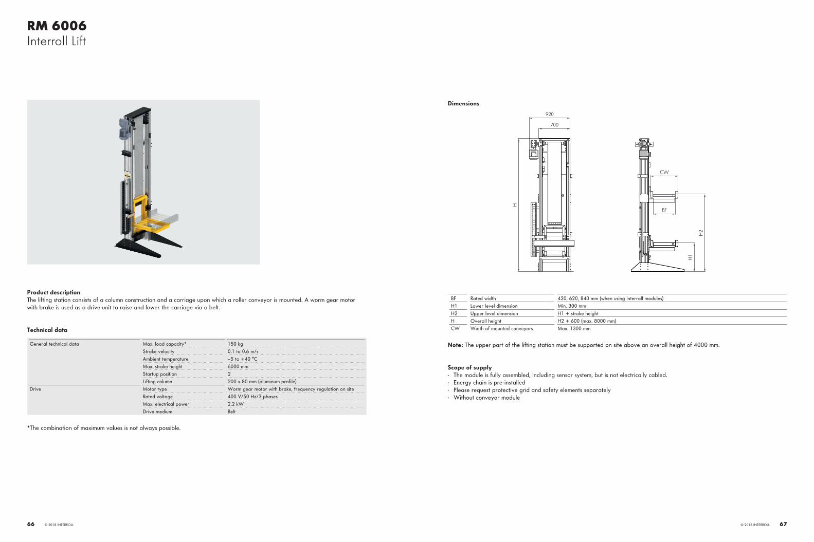
RM 6006Interroll Lift
Product descriptionThe lifting station consists of a column construction and a carriage upon which a roller conveyor is mounted. A worm gear motor with brake is used as a drive unit to raise and lower the carriage via a belt.
Technical data
General technical data Max. load capacity* 150 kgStroke velocity 0.1 to 0.6 m/sAmbient temperature –5 to +40 °CMax. stroke height 6000 mmStartup position 2Lifting column 200 x 80 mm (aluminum profile)
Drive Motor type Worm gear motor with brake, frequency regulation on siteRated voltage 400 V/50 Hz/3 phasesMax. electrical power 2.2 kWDrive medium Belt
*The combination of maximum values is not always possible.
Dimensions
700
920
H
CW
H1
H2
BF
BF Rated width 420, 620, 840 mm (when using Interroll modules)H1 Lower level dimension Min. 300 mmH2 Upper level dimension H1 + stroke heightH Overall height H2 + 600 (max. 8000 mm)CW Width of mounted conveyors Max. 1300 mm
Note: The upper part of the lifting station must be supported on site above an overall height of 4000 mm.
Scope of supply· The module is fully assembled, including sensor system, but is not electrically cabled.· Energy chain is pre-installed· Please request protective grid and safety elements separately· Without conveyor module
© 2018 INTERROLL 6766 © 2018 INTERROLL
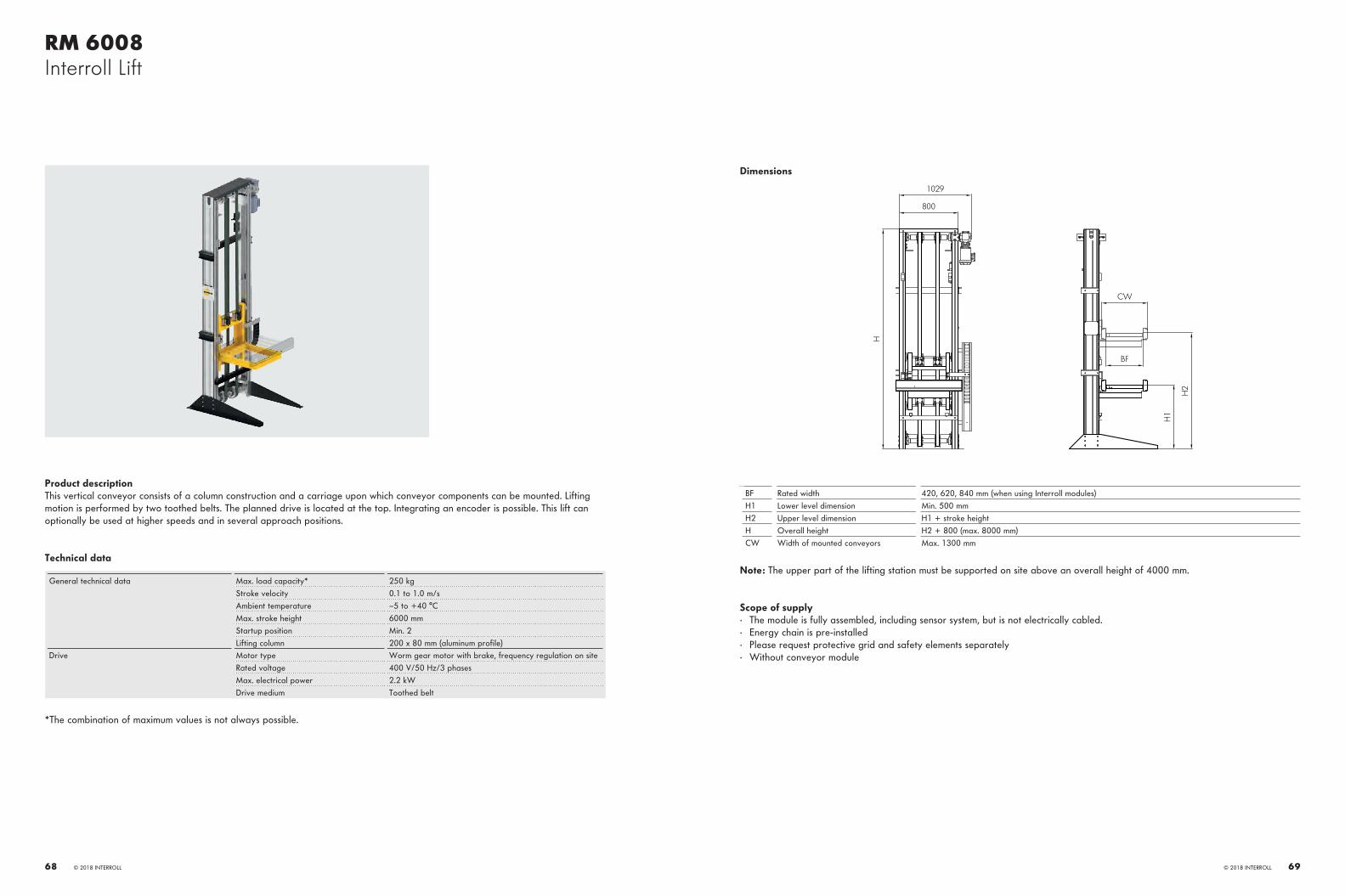
RM 6008Interroll Lift
Product descriptionThis vertical conveyor consists of a column construction and a carriage upon which conveyor components can be mounted. Lifting motion is performed by two toothed belts. The planned drive is located at the top. Integrating an encoder is possible. This lift can optionally be used at higher speeds and in several approach positions.
Technical data
General technical data Max. load capacity* 250 kgStroke velocity 0.1 to 1.0 m/sAmbient temperature –5 to +40 °CMax. stroke height 6000 mmStartup position Min. 2Lifting column 200 x 80 mm (aluminum profile)
Drive Motor type Worm gear motor with brake, frequency regulation on siteRated voltage 400 V/50 Hz/3 phasesMax. electrical power 2.2 kWDrive medium Toothed belt
*The combination of maximum values is not always possible.
Dimensions
800
1029
H
CW
BF
H1
H2
BF Rated width 420, 620, 840 mm (when using Interroll modules)H1 Lower level dimension Min. 500 mmH2 Upper level dimension H1 + stroke heightH Overall height H2 + 800 (max. 8000 mm)CW Width of mounted conveyors Max. 1300 mm
Note: The upper part of the lifting station must be supported on site above an overall height of 4000 mm.
Scope of supply· The module is fully assembled, including sensor system, but is not electrically cabled.· Energy chain is pre-installed· Please request protective grid and safety elements separately· Without conveyor module
© 2018 INTERROLL 6968 © 2018 INTERROLL

Interroll Spiral Lift
Product descriptionThe Interroll Spiral Lift transports boxes, containers and goods inn all shapes and sizes for a variety of industries. The Spiral Lift is available in 45° increments, is extremely quiet during operation and features a small footprint, which allows for an optimal utilization of space. The overlapping slats offer additional safety for the operator. The proven design with rolling friction and rubberized ball bearings allows less friction, which can lead to significant savings in energy. Thanks to its self-tensioning chain drive, the new Spiral Lift is extremely low in maintenance. Access to the chain mechanism is very easy so that the downtime can be reduced to a minimum.
Technical data
General technical data Speed 0.1 to 0.5 m/sMax. load capacity 30 kg/mMax. stroke height 4 m with one drive
Drive Motor type Drum motor or gear motorRated voltage 400 VAmbient temperature Drum motor: +5 to +40 °C;
gear motor: –5 to + 50 °C
Dimensions
CL
LW
H1
H2
CL Rated width 650 mmLW Lane width 500 mmH1 Height 1 Min. 650 mmH2 Height 2 H1 + max. 4000 mm
© 2018 INTERROLL 7170 © 2018 INTERROLL

RM 8811Interroll End Stop
Product descriptionThe end stop is a permanently mounted attachment, for stopping and accumulating of approaching material. The end stop is used at the end of sloped or friction roller conveyors, or as a secure termination of all other conveyor lines.
Technical data
General technical data Maximum accumulation pressure 300 N
Dimensions
115
40
130
BF
BF Rated width 420, 620, 840 mm others on request
Scope of supply· End stop, incl. fastening material
© 2018 INTERROLL 7372 © 2018 INTERROLL

RM 8812Interroll Blade Stop
Product descriptionThe Interroll blade stop is an electrically operated stop that is raised between the roller pitches in order to stop or accumulate mate-rial. Stops are often used in conjunction with conveyor components, such as transfers and pushers, to align products or coordinate processes.
Technical data
General technical data Maximum accumulation pressure 100 NAmbient temperature +5 to +40 °C
Drive Rated voltage 24 V
Dimensions
200
BF + 70
BF - 184
415
D.O.T.
BF Rated width 420, 620, 840 mm others on request
P Min. roller pitch 90 mmΔS Stroke 25 mm (5 mm below top edge of roller up to 20 mm above top of roller)
Scope of supply· Module is fully assembled, incl. sensor system and control card
© 2018 INTERROLL 7574 © 2018 INTERROLL

Interroll MultiControl
Product descriptionWith help of the MultiControl, sensors and RollerDrive are directly integrated in to the field bus level. No additional sensor / actua-tor level is necessary. Interroll 24 V conveyor modules equipped with MultiControl also contain the logic for zero pressure accumula-tion conveying.MultiControl is a certified network card for PROFINET, EtherNet/IP and EtherCat for controlling the RollerDrive EC310. With a single MultiControl, it is easy to choose any one of these different field buses. This offers enormous flexibility for stock management as well as for planning and installation of conveyors.
A standard ribbon cable is used for power wiring. Stopping connected RollerDrive without losing the position information of materi-als is possible if sensors and MultiControl are supplied via a second ribbon cable.
The MultiControl can control four conveyor zones, allowing four RollerDrive and four sensors. Even complex conveyor modules, such as Transfer or High Performance Divert, can be controlled by MultiControl. Four additional, individually configurable I/Os can be connected by using a y-shaped cable.The addressing and naming is done over PLC software, a web user interface, or with the Interroll Teach-In method. With the Teach-In method, automatic addressing and configuration of all MultiControls is possible. In addition, the sequence of all MultiControls in the conveying line can be determined. This saves time during the commissioning on site. The MultiControl communicates with the PLC in real time, is easy to handle and works for nearly all applications.
Benefits· Logic control for zero pressure accumulation conveying for Interroll conveyor modules· Easy handling – one control card for PROFINET, EtherNet/IP and EtherCat· Functional safety thanks to the certified network card· Independent power supply possible for RollerDrive and sensors· Also usable as individual controller for special applications· Plug & Play in case of replacements
Features· Connection of 4 RollerDrive EC310, 4 sensors and 4 additional inputs/outputs· Power supply via standard ribbon cable· Configuration of RollerDrive parameters such as speed, direction of rotation or start & stop ramps via a web user interface or PLC· All digital I/Os can be configured· IP54 protection rating· Ambient temperature from –30 °C to +40 °C· Status LEDs for all functions and I/Os· UL-certified
© 2018 INTERROLL 7776 © 2018 INTERROLL

Accessories
RM 8841 supports, page 80
Power supply, page 82 Sensor kit, page 82 Reflector kit, page 83
Universal support, fixed, page 83 Universal support, flexible, page 84 Side guide, page 84
Side guide holder, page 85 Side guide connector, page 85 End cap for side guide profile, page 86
End cap for side profile, page 86 Actuator, page 87 Magnetic Speed Controller 50, page 87
© 2018 INTERROLL 79

RM 8841Interroll Support
Product descriptionThe support is intended for fastening the conveyors to the floor or lift floor. The support foot is infinitely adjustable. A simple height adjustment via threaded spindle can be ordered as an add-on.
Technical data
General technical data Max. load capacity 200 kgMin. support height 450 mm
Side profile Dimensions 77 x 32 mmNumber of crossbars 1 for 450 to 800 mm height of roller top edge
2 for 800 to 1400 mm height of roller top edge 3 for 1400 to 2000 mm height of roller top edge
Dimensions
BF + 35
180
BF
TW
200
ToR
- 120
BF Rated width 420, 620, 840 mm others on request
TW Module width BF + 80 mmT.O.R. Top of roller height 450 to 2000 mm
Adjustment range +/–50 mm
Scope of supply· Support fully assembled· Infinite height adjustment with optional threaded spindle
As an alternative to the supports, Interroll also offers ceiling hangers. Please contact your customer representative.
© 2018 INTERROLL 8180 © 2018 INTERROLL

Accessories
Power supplyA power supply is available for 24 V and zero pressure accumulation 400 V conveyors. The power supply units are installed in a robust cabinet, and each power supply has a main switch and internal fuse.
Designation Dimensions Reference number
Power supply 24 V/20 A 380 x 380 x 211 mm 1015147Power supply 24 V/40 A 380 x 380 x 211 mm 1015148
Sensor kitSensors detect materials on the conveyors and determine their position. Reflex light barriers are used, which require a reflecting mirror (reflector) on the opposite side of the light barrier in order to return the light beam. The sensor kit consists of the sensor and the matching plastic housing, including fastening clip. The housing can be attached directly to the roller conveyor or to a universal support.
Designation Dimensions Reference number
Sensor kit, 3 m cable 43 x 26 x 18 mm (L x W x H) (H 26 mm with studs)
63104071
Sensor kit, 1 m cable 1.7 x 1 x 0.7” (L x W x H) (H 1” with studs)
63104072
Reflector kitThe reflector kit returns the light beam back to the sensor. The kit includes a fastening clip and can be attached directly to the roller conveyor or to an universal support.
Designation Dimensions Reference number
Reflector kit 54 x 18 x 30 mm (L x W x H) (H 39 mm with studs)
64000905
Universal support, fixedSide guides, sensors, reflectors and other add-on components, such as scanners, are attached to the fixed universal support. Fixed universal supports are attached directly to the side profile.Sensor holder
Designation Dimensions Reference number
Universal support, fixed 60 mm (55 mm above T.O.R.) 1015014
© 2018 INTERROLL 8382 © 2018 INTERROLL

Accessories
Universal support, flexibleSide guides, sensors, reflectors and other add-on components, such as scanners, are attached to the flexible universal support. Flexible universal supports are attached laterally to the profile. Each of these holders can accommodate two flexible universal support brackets.
Designation Dimensions Reference number
Universal support, flexible 200 mm (55 mm above T.O.R.) 63010032
Side guideSide guides are used for reliably guiding the product on roller conveyors and belt conveyors, as well as on the corresponding components. We offer the side guides in an aluminum and a polymer version. In particular, because of the flexible material, the guides can be adjusted to the material flow in curves, as well as when merging and diverting.
Designation Dimensions Reference number
Aluminum side guide 40 x 15 x 2,000 mm 63133351Polymer side guide 40 x 15 x 2000 mm 63010049
Side guide holderThe side guide profile is attached to the universal support with the side guide holder.
Designation Dimensions Reference number
Side guide holder 46 x 28 x 22 mm 63010248
Side guide connectorSide guides are connected to each other at the transition of two modules with the side guide connector.
Designation Dimensions Reference number
Side guide connector 70 x 28 mm 63010050
© 2018 INTERROLL 8584 © 2018 INTERROLL

Accessories
End cap for side guide profileAn end cap is attached to the end of a side guide. The contour prevents products from being caught.
Designation Dimensions Reference number
End cap for side guide profile 100 x 40 x 40 mm 63010039
End cap for side profileThe end cap closes a side profile at the front.
Designation Dimensions Reference number
End cap for side profile 115 x 35 x 3 mm 64000900
ActuatorBy using 24 V actuators, a 400 V roller conveyor can be operated as a zone conveyor. The actuators can be controlled for zero pressure accumulation mode via the Interroll controllers. Additional components are required to change a transport conveyor into a zone conveyor. Please contact your Interroll customer representative.
Designation Dimensions Reference number
24 V actuator 177 x 100 x 65 mm 63010261
Magnetic Speed Controller MSC 50The magnetic speed controller MSC 50 is a purely mechanical speed controller that ensures a controlled, slow speed on gravity conveyors with materials weighing from 0.5 kg (1 lb) to a maximum of 35 kg (77 lbs). The magnetic speed controller operates without a gear box, thus enabling startup for very lightweight containers. Heavy containers are transported at a controlled speed thanks to the consistently high braking performance.
Designation Dimensions
Magnetic Speed Controller MSC 50 Min./max. Between frames (BF): 210 – 1,400 mm Tube diameter: Steel 51 mm, steel with PU sleeve 54 mm
© 2018 INTERROLL 8786 © 2018 INTERROLL

Appendix
Horizontal crossbelt sorter, page 90 Vertical crossbelt sorter, page 92
© 2018 INTERROLL 89

Interroll Horizontal Crossbelt Sorter
Product descriptionHorizontal crossbelt sorters are characterized by their flexible, space-utilizing routing with curves that also conquer inclines and slopes. Feeds and destinations can be arranged in various ways and optimized to increase the system's performance. With an ap-propriate layout, it is possible to create several sorting areas with just one cycle. The horizontal crossbelt sorter is also perfectly suit-ed for small spaces. For example, two crossbelt sorters with identical routes can be installed one on top of the other, i.e., doubled up. Horizontal crossbelt sorters can recirculate goods that have either not been recognized by identification technology or have not been discharged because all destinations were full.
Technical data
General technical data Items Cardboard boxes, small packages, padded envelopes, pack-aged food, catalog goods, manila envelopes, multimedia prod-ucts, clothing, etc.
Dimensions/unit weight Min. (L x W x H): 150 x 100 x 5 mm 100 g Max. (L x W x H): 600 x 500 x 500 mm 35 kg
Double carrier max. (L x W x H) Max. 1200 x 700 x 700 mm 35 kgPower/speed (examples) Cross belt carriage 340 x 400: 14000 carriages/h at 1.7 m/s
Cross belt carriage 460 x 700: 10000 carriages/h at 1.65 m/s
© 2018 INTERROLL 9190 © 2018 INTERROLL

Interroll Vertical Cross-Belt Sorter
Product descriptionThe main feature of Interroll's vertical crossbelt sorter with linear, straight routing ("above – below") is its distinctive space-saving design because of its compact, modular approach. For example, a width of just 1.7 m is sufficient to install a vertical sorter with 400 × 400 mm crossbelt carriers. This configuration can also save valuable space, if full containers are transported into the sorter. This is unique on the market. The infeed on the vertical sorter usually starts with an accumulating conveyor in front of the actual sort-er - a simple conveyor belt. Operators are able to manually feed goods directly onto this accumulating conveyor - a cost-effective and ergonomic solution. The accumulating conveyor can, of course, also be loaded via semi-automated or fully-automated infeeds.
Technical data
General technical data Items Cardboard boxes, small packages, padded envelopes, packaged food, catalog goods, manila envelopes, multimedia products, clothing, etc.
Dimensions/unit weight Min. (L x W x H): 100 x 80 x 5 mm 100 g Max. (L x W x H): 600 x 600 x 500 mm 35 kg
Double carrier max. (L x W x H) Max. (L x W x H): 1200 x 800 x 800 mm 35 kgPower/speed (examples) Cross belt carriage 335 x 300: 15,000 carriages/h at 1.65 m/s
Cross belt carriage 600 x 800: 8500 carriages/h at 1.7 m/s
© 2018 INTERROLL 9392 © 2018 INTERROLL

Application NotesWhat are application notes used for?
The application notes support you during the planning and dimensioning of conveyor systems, as well as during the selection of Interroll conveyor modules.
The application notes offer the following:· Basic rules for a trouble-free transport· Decision-making aids for product selection· Calculation examples for the dimensioning of the conveyor modules and drive performances
In addition, your Interroll customer representative will be happy to assist you in the selection of conveyor modules, especially if you require specific measures due to special materials or environmental conditions.
You should answer three questions before selecting a conveyor module:
Which tasks should the conveyor technology handle?· Transporting and/or storing· Sorting and/or distributing
What properties does your transport material have?· Length, width and height: Minimum and maximum dimensions of the transport materials which are conveyed together on one line· Weight: Minimum and maximum weight of unit loads; ideally assigned to the dimensions· Condition and surface of the bottom of the transport material: The bottom determines, e.g., the suitability of roller conveyors
Does the condition of your transport material or the surroundings require special measures?· For example, are there extreme temperatures, high humidity or chemical influences?· Does electrostatic charging pose a problem?· Is the transport material fragile or problematic in any way?
Transport materialThe platform is suitable for transporting unit loads. These are characterized by the following general specifications:· Suitable bottom for transport on roller conveyors:
The bottom must be suitable for transport on roller conveyors. In particular, this means that it is smooth, perfectly closed or at least homogeneously ribbed, or in similar conditions. Indentations (e.g. with surrounding edges at the bottom, ribs, stacking aids) complicate the transport, particularly on transfers, HPD, ball transfer units, and must be tested for transportability. Bent bottoms, especially hollow or pot-bellied bottoms (concave/convex), have negative effects on the transport.
· The stability of the bottom must be sufficient for the loading.· The material must be uniformly and continuously closed above the rollers on at least one long side up to a height of 5 cm. This
helps optical sensors to detect the product. When transferring at 90°, detection must be possible on two sides (length and width).· The weight of the materials must not exceed 50 kg/m or 50 kg per accumulation zone.· The smallest product for transporting:
On straights: 180 mm long. If the product changes its orientation (e.g., with 90° diverting), then length and width are at least 180 mm In curves: The roller pitch is greater at the outside radius then at the inside radius. We will be happy to test your product on a curve.
· The largest product for transporting: On straights: 800 mm width In curves: The formula applies to page 97
· Typical products:– Plastic containers with the usual dimensions for internal goods and warehouse transport, such as cardboard boxes, e.g., in the
sizes 200 x 300 mm, 300 x 400 mm, 400 x 600 mm, 600 x 800 mm– Cardboard boxes with stable bottoms suitable for roller conveyors– Other trays with corresponding properties
· The ratio of base area to height, particularly the position of the center of gravity, affects the secure standing of the product, espe-cially on inclines. The center of gravity should be no higher than 1/3rd of the length of a product.
Product selectionThe task that the conveyor technology is to meet in your case, leads directly to the three main sections of this catalog via the follow-ing chart: roller conveyors, belt conveyors and key products.
TaskTransporting/storing
Properties of the goods
TaskSorting and distributing
Overview pageof key products
Overview pageof belt conveyors
Overview pageof roller conveyors
Horizontal transportRising/falling gradient possible
Horizontal transport
All types of goods,e.g. cardboard boxes,
containers, shrink-wrapped materials, unpackaged products
Goods with stable, flat bottom and a length
of min. 180 mm,e.g. cardboard boxes, containers
© 2018 INTERROLL 9594 © 2018 INTERROLL

Application NotesRoller Conveyors
Roller conveyorsInterroll classifies roller conveyors according to weight classes and drive technology.
Weight classesIn general, Interroll groups conveyors by the weight of the transport material into the following classes:· Up to 35 kg: Light· Up to 500 kg: Medium· Up to 1500 kg: Heavy
This catalog includes materials up to 50 kg, i.e., up to part of the medium weight class.
Transport material Cardboard boxes, plastic containers, trays, etc.Load capacity Up to 50 kg/mConveyor speed 0.1 to 2.0 m/sBetween frames BF 420, 620, 840 mm (special sizes on request)Roller pitch P 60, 90, 120, 150 mmRollers Interroll Series 1700, Interroll Series 3500 and Interroll Series 1100 in PVC
or steel, zinc-plated (special types on request)Ambient temperature –30 to 0 °C or 0 to +5 °C or +5 to +40 °C) (depending on the product)
Drive classesIn general, Interroll groups conveyor modules by drive technology into the following classes:· Non-powered roller conveyors· Powered roller conveyors at 24 V· Powered roller conveyors at 400 V
Non-powered gravity conveyors are used as low-cost, simple solutions for many conveying areas. The transport material is moved by gravity (angle of conveyor) or manually. Optional speed controllers brake the conveying speed of the transport material on in-clined roller conveyors.
Powered conveyors are used for continuous transport, or for zero pressure accumulation of transport materials whose throughput can be precisely calculated. Merging and diverting of transport materials is implemented by using our powered key products.
Working with maximum valuesMinimum and maximum performance data are listed at many points in this catalog. These extreme values, e.g., maximum permissible weight and maximum permissible speed, cannot always be combined with each other without restrictions. If you have any doubts, please contact your Interroll customer representative.
Basic principles for trouble-free transportIn order to transport material flawlessly on a roller conveyor, the following basic principles must be followed
Roller pitchThe roller pitch must be selected so that at least three conveyor rollers are underneath the transport material at any given time:
L3
P ≤
P Roller pitch in mm (")L Transport material length in mm (")
Load capacityThe weight of the transport material must be distributed onto as many carrying conveyor rollers as necessary so that the maximum load capacity of each individual conveyor roller is not exceeded. This may mean that more than three conveyor rollers must support the transport material.
More information about conveyor rollers is available in Interroll's conveyor roller catalog.
Lane width and measure between framesThe parameter (BF) is a measure between the side frames. The lane width (LW) is the measure between the side guides. With fixed side guides, LW = BF.
With flexible side guides, the LW measurement can be larger or smaller than BF in order to flexibly guide products, e.g. in curves. On each side, the use of flexible side guides can change the LW measure by –90/+120 mm (–3.54"/+4.72").
The lane width of the conveyor for straight paths is at least the width of the transport material + 20 mm:
LW ≥ B + 20 mm
LW Lane width in mm (") between the side guidesB Transport material width in mm (")
In the following cases, a larger lane width, possibly deviating from the measure between the frames, must be selected:· For conveyors into which transport material is being merged.· For curves:
Lane width in curvesIn general, the lane width (LW) must be greater in curves than for straight conveyor paths; for this purpose, the flexible side guide is adjusted accordingly without additional components.
The minimum required outside radius of the side guide (Ra) can be calculated as follows with a given inside radius:
Ra = (Ri + W)2 + (L / 2)2
© 2018 INTERROLL 9796 © 2018 INTERROLL

Application NotesRoller Conveyors
The inside radius for our curves is always 825 mm and is measured at the inside edge of the profile.
W
R i
R a
L
LW
L Maximum length of transport material in mm (")W Maximum width of transport material in mm (")LW Lane width in mm (")Ra Outside radius of curve for rectangular transport material in mm (")Ri Inside radius* of curve in mm (")
Curve modules from Interroll are available in 420, 620 and 840 mm (16.5”, 24.4”, 33” nom.) measure between frames (BF). A side guide is equipped with flexible mounting brackets and allows for expanding the lane width (LW) by 120 mm (+4.72") compared to the measure between frames of the rollers.
Trouble-free transportThe roller pitch and the dimensions of the transition gap between two conveyors are very important for trouble-free transport.
Transport disturbances can be prevented by taking the following measures:· Select roller pitch P so that at least three rollers are located below the transport material.
P
L
· Select the transition gap LG for all conveyors so that the gap measures less than one third of the transport material length.
LG
L
· With a transition between belt and roller conveyors, the roller pitch P and transition gap LG should be selected so that the gap is less than one third of the transport material length, and so that at least two conveyor rollers are below the transport material when material exits a conveyor.
LG
L
LG Transition gap in mm (")L Length of transport material in mm (")P Roller pitch in mm (")
© 2018 INTERROLL 9998 © 2018 INTERROLL

Application NotesRoller Conveyors
Ejection of transport material in curvesInterroll recommends not accumulating any transport materials in curves – except for zero pressure accumulation conveyor systems .
Since accumulation pressure generates externally acting forces in the curve, transport materials in the curve area could be pushed beyond the conveyor edge. This may damage transport materials and cause personal injury.
FL
The accumulation pressure in a curve may be prevented by taking the following measure:· An additional stop directly in front of the curve
FL
Calculations
ThroughputThe throughput TP of a conveyor system is given in units/hour and depends on the size of the transport material, the conveying speed and the cycle times of merging and diverting units.
The window size T is required for calculating the throughput. The window size T is the distance from the front edge of a transport material to the front edge of the following transport material, irrespective of the actual length of the transport material or zone length.
For the precise calculation of the power capacity TP, please contact your Interroll customer representative. TP for straight paths can roughly be calculated as follows:
3.600 ∙ vT
TP =
TP Throughput in units/hourv Conveying speed in m/s (ft/m)T Window size in m (")
With merging and diverting, throughput is additionally influenced by the actual length and weight of the transport material as well as the transfer cycle. Please contact your Interroll customer consultant for calculations.
© 2018 INTERROLL 101100 © 2018 INTERROLL

Application NotesGeneral Technical Information
Side profileInterroll solves conveying tasks with only one side profile. Exceptions are belt curve and belt merge.
Steel profile 115 x 35 x 2.5 mm· Standard profile for all straight roller and belt conveyors· Standard profile for all roller conveyor curves and Belt Curve Light· Roller-formed steel profile with powder coating· The upper roller edge or the upper edge of the conveyor belt is always 5 mm higher than the upper profile edge· Cover made of black PVC· The space behind the cover can be used as electrical conduit and for housing controller components· The profile has a continuous hole pattern in a grid of 30 mm for attaching all the required add-on components
Crossbar and electrical conduitSide profiles are connected with crossbars made of aluminum profile with plastic cover at regular intervals. They also serve as elec-trical conduit between the two side profiles.
Side guideSide guides can be attached to the side profile. They guide the product on the track and prevent products from falling off. Please take the variants of the side guide into account when ordering conveyors.
The Interroll side guides are offered in two variants:· Fixed side guide
The side guide profile is attached to the top side of the side profile with the help of universal supports. The guide area of the pro-file is aligned with the inside of the side profile.
· Flexible side guide
The side guide profile is attached to the side of the side profile with the help of flexible universal supports. The guide area of the profile can be positioned +120/–90 mm (–3.54"/+4.72") offset parallel to the side guide with the help of a Z-shaped holder. This must be taken into account especially in curves for implementing the increased space requirement with the constant measure between frames of the conveying profiles. Products that are smaller as well as larger than the actual conveyor width can be guid-ed with precision. With the help of the flexible side guide, materials can also be guided or aligned at an angle to the direction of transport.
Two side guide profiles can be fastened above each other on one mounting bracket. This creates a continuous closed side guide with a height of 80 mm from the upper roller edge.
Each conveyor includes two connectors for connection to the side guide of the next module.
Profile connectorsThe side profiles of the modules are connected form-fit with a profile connector. Each conveyor module includes 2 profile connectors.
Sensors/ReflectorSensors and reflectors can be installed in two ways:· Firmly installed directly on the side profile· Flexibly installed on a flexible universal support with additional assembly plate
In both variants, the studs of the sensor holder are fed through two adjacent holes and secured on the opposite side with the fasten-ing clip. The clip engages noticeably through lateral movement and secures the sensor holder in place. The reflector holder is in-stalled in the same way. Our standard design of the sensor is Sick GL6.
Interroll Layouter
The Interroll Layouter gives you a menu-driven tool that provides professional support in planning a conveyor system. Operating the software is very intuitive and makes it possible to compile an extensive 3D layout in DWG format from all Interroll conveyor mod-ules.
All drawn conveyor modules automatically feature a complete parameter set that makes it possible to simplify the electrical engi-neering process at the Integrator as well as the mechanical engineering process at Interroll. All parameters are exported to an Excel conveyor list which Interroll can use as the basis for creating price quotations, quickly and reliably.
System requirements:· AutoCAD 2014 full version· Microsoft Office 2010
The Interroll Layouter is available as a plugin for AutoCAD where it can be launched and used via a separate menu.
For additional information and operational support, please contact your Interroll customer representative.
© 2018 INTERROLL 103102 © 2018 INTERROLL

Application Notes24 V Roller Conveyor Product Information
24 V conveyor with single-position controllerAs a conveyor with single-position controller, the 24 V conveyor simplifies the transport of unit loads. Its internal control transforms a roller conveyor into a single-position conveyor that assigns each transport material its own zone in the flow. In this way unit loads can be buffered without contact and transported onwards as needed in order to achieve a continuous transport flow.
ZonesEach conveyor line is divided into zones that are matched to the maximum length of the transport material.
Each zone has:· A RollerDrive (24 V motor installed in the pipe)· Idlers driven via belts· An internal control card that controls a maximum of four zones at the same time· A sensor/reflector
D.O.T.
Control card
1 5 2 223 3 34 4
D.O.T. Direction of transport1 Start photo cell (optional)2 RollerDrive connection3 Photo cell connection4 Communication cable (Ethernet)5 24 V power bus
One to four zones form a pre-installed conveyor module with complete cabling which can be connected with other modules.
DriveInterroll uses RollerDrive EC310 as a drive in the 24 V conveyors.
RollerDrive EC310:· Internal commutation electronics (brushless motor)· 9 gear stages· Constant conveyor speed· Energy recovery in braking· Electronic holding brake· Motor cable with 5-pole snap-in plug
Technical data:
General technical data Mechanical power 32 WNoise level 55 dB (A)
Electrical data Rated voltage 24 V DCVoltage range 18 to 28 V DCIdle current 0.4 ARated current 2.0 AMax. start-up current 5.0 APermissible voltage ripple < 5 %
recommended: < 1 %Protection rate IP54
Dimensions Tube diameter 50 mmWall thickness 1.5 mmMax. reference length 1500 mm
Ambient conditions Ambient temperature in operation 0 to +40 °CAmbient temperature during transport and storage –30 to +75 °CMax. humidity 90 %, non-condensing
Gear stages;
Gear ratio Max. conveyor speed in m/s
Rated torque in Nm
Start-up torque in Nm
Zero motion hold in Nm
9:1 1.75 0.45 1.10 0.3612:1 1.31 0.61 1.46 0.4816:1 0.98 0.81 1.95 0.6420:1 0.79 1.01 2.44 0.8024:1 0.65 1.21 2.92 0.9636:1 0.44 1.82 4.38 1.4448:1 0.33 2.42 5.85 1.9264:1 0.25 3.23 7.80 2.5696:1 0.16 4.84 11.69 3.84
For further information please use our Catalogue for Rollers, RollerDrive, DriveControls.
Start photo cellAt the beginning of a line is an optional photo cell (accessories, page 82) that starts the system.
© 2018 INTERROLL 105104 © 2018 INTERROLL

Application Notes24 V Roller Conveyor Product Information
ControlEach control communicates with its adjacent controls via a data cable. This cable transmits signals to the start, for accumulation, for error detection and for the execution of specific control processes along the conveyor system.
A fieldbus control has four additional connectors for incoming signals, e.g., for starting merging and diverting processes.
An Ethernet bus connector is available for the connection to a master control; the entire system can be controlled via this connector and status information can be read. The Ethernet/IP, PROFINET and Ethercat protocols are available.
The drive side and the electrical side with the control can be selected for the straight 24 V conveyor and must be specified when or-dering. The control is typically located in the profile for curves at the outside radius.
Selection of the drive mediumFour drive media are available:
PU round belt ø 5 mm· For curves· For transport materials up to 50 kg/zone (110 lbs/ft) at max. 1.0 m/s (197 ft/m)· For max. 11 idlers per zone (i.e. 11 round belts per zone)
PolyVee Belt· For straights· For curves on the deep freeze area· For transport materials up to 50 kg/zone (110 lbs/ft) at max. 1.0 m/s (197 ft/m)· For max. 20 idlers per zone (i.e. 20 PolyVee belts per zone)· Hardly any slippage, therefore very good acceleration and braking performance
Flat belt (400 V main drive, 24 V zone control)· For straights and curves· For transport materials up to 50 kg/m (110 lbs/ft) at max. 2.0 m/s (394 ft/m)· Suitable for transport and accumulation function (no accumulation function in curves)
Belt with rolling divert· For zero accumulation pressure transport of units that are unsuitable for roller conveyors· Also for compact transport units· Closed belt· Available for straights and curves
© 2018 INTERROLL 107106 © 2018 INTERROLL

Application Notes400 V Roller Conveyor Product Information
400 V roller conveyor
Operating modesDriven roller conveyors with flat belt drive and 400 V motor can be used in 2 operating modes:· Transport conveyor· Zero pressure accumulation conveyor with zone control
DriveThe rollers are driven by a flat belt tangentially guided at the bottom. Pressure elements secure the contact between belt and roller.
ModulesThe conveyors consist of 3 different modules:· Drive module with 400 V drive, once at the beginning of the conveyor, incl. belt deflection· Intermediate module, multiple possible· End module, once at the end of the conveyor, incl. belt deflection
LengthThe length of a flat belt-driven conveyor is limited to 15,000 mm. The dimensioning of the motor output is handled by Interroll ac-cording to the speed and weight requirements.
FunctionsThe selection and arrangement of the pressure elements determine the function of the conveyor. Depending on the application, the functions can be combined within a power train.· Transport conveyor:
Fixed pressure element in upper fastening position, after every 2nd Roller· Zero pressure accumulation conveyor:
Actuator pressure element, 1 x per zone, the rollers of the zone are driven via PolyVee. A control module with 24 V is also re-quired for controlling the zones.
400 V roller conveyorFlat belt-driven curves always have a fixed drive. Accumulation on a curve is not possible.
Curves are available at 30°, 45°, 60° and 90° angles. A drive station in curves is not possible. If a conveyor path starts with a flat belt-driven curve, a drive station must be planned in a short straight before the curve.
Per drive, a maximum of two 90° curves in the same direction of rotation or one 90° curve with attached straight is possible.
Drive and deflection stationsFor modules with flat belt drive, the drive side (left or right in direction of transport) as well as the position of the deflection units must be specified. The following representations clarify the possible drive sides and positions of the terminals.
D.O.T.
AS RR
1
D.O.T.
AS R RL
1
L
D.O.T.
AS L
1
L
D.O.T.
AS LR
212
2 2
Drive side Deflection stations
Fig.: Drive side right (R) and left (L) and terminals
D.O.T. Direction of transport1 Motor2 TerminalAS R Drive side rightAS L Drive side left
© 2018 INTERROLL 109108 © 2018 INTERROLL

Application Notes400 V Roller Conveyor Product Information
D.O.T.
1 32 4
Fig.: Example of a conveyor line with three modules
D.O.T. Direction of transport1 Motor2 Drive module, terminal left: DL; drive side right: R3 Intermediate slave module: SI; drive side right: R4 Slave module, terminal right: SR; drive side right: R
Curves with flat belt driveIn principle, the drive side of the curve is at the inside radius. The position of the terminals must be specified when ordering; they are always determined viewed from the curve center. A maximum of two curves in the same direction of rotation are possible per drive. The max. length of the straight portion of the con-veyor is reduced by 3000 mm for each curve.
L R
1 1
1 Terminal
Roller merge dimensionsThe angle and lane width of a merge or diverter module define the dimensions of the module.
The following table shows the standard dimensions of the merge/diverter modules (merges).
Between frames BF in mm
Module length ML in mm
Opening width FW in mm
Module length ML in mm
Opening width FW in mm
For angle α = 45° and roller pitch P = 60 mm
For angle α = 30° and roller pitch P = 60 mm
24 V 400 V 24 V 400 V420 510 630 600 810 930 845620 690 810 870 1140 1260 1230840 930 1050 1200 1540 1660 1680
Note about transfer 24 V and HPDTransfer 24 V and HPD are supplied with the following equipment if the installation is performed by the customer:· Control card· Sensor/reflector assembly kit incl. cabling· Side guide assembly kit
© 2018 INTERROLL 111110 © 2018 INTERROLL

Application NotesBelt Conveyor
Belt conveyors are primarily used for transport tasks that cannot be handled with roller conveyors or only under difficult conditions.
Interroll belt conveyors are suitable for the following applications:· Incline and decline conveyors· Acceleration conveyors· Conveyors for materials with uneven bottom· Conveyors for compact or irregularly-shaped transport material· Conveyors for high conveyor speeds
Interroll belt conveyors are not suitable for outdoor operation or for the transport of bulk material.
General technical information
DriveStandard Interroll belt conveyors are driven by a head drive or center drive with Interroll drum motors.
Advantages of Interroll drum motors:· Plug and play:
Interroll drum motors are much quicker and easier to install than conventional drive systems. Fewer components mean reduced costs for conveyor design and purchasing of parts.
· Hard-wearing: Interroll Drum Motors keep operating at 100% even under aggressive environmental conditions, such as water, dust, grit, chemi-cals, grease, oil and even during high pressure wash-down procedures.
· Hygienic design: Due to the smooth, stainless steel finish and the hermetically sealed and totally enclosed design, Interroll drum motors are much easier to clean and therefore reduce the risk of contamination in food processing.
· Energy efficient: Compared with many other drives commonly used in industry today, Interroll asynchronous drum motors use up to 32% less ener-gy and when using synchronous drum motors up to 45% less energy, thus significantly reducing energy bills and the global carbon footprint.
· Space saving: Because the motor, gearbox and bearings are mounted within the drum shell, the drum motor takes up much less space.
· Safe: As a self-contained component without protruding parts and with fixed external shafts, an Interroll drum motor is probably the safest drive unit available for state-of-the-art material handling equipment.
· Maintenance-free: The totally enclosed motors ensure that the internal parts are unaffected by external conditions and maintain trouble-free opera-tion for all kinds of applications.
Technical data:
DM 0080 138i 165i 217iTechnology Synchronous Drum Motor Asynchronous Drum MotorDiameter 81.5 mm
89.0 mm with lagging138.0 mm 164.0 mm 217.5 mm
Gear material Steel Steel Steel SteelRated power 145 to 425 W 0.074 to 1.000 kW 0.306 to 2.200 kW 0.306 to 3.000 kWRated torque 2.1 to 65 Nm 14.7 to 174.4 Nm 28.1 to 365.2 Nm 28.1 to 533.6 NmBelt pull 1594 N 216 to 2527 N 347 to 4453 N 261 to 4907 N
For further information, please use our Catalog for drum motors.
Conveyor belts2-layer polyester belts with PVC or PU coating are used as conveyor belts. Incline, decline and acceleration conveyors are equipped with laterally grooved surface structures to avoid slippage of the transport material. Others on request.
Slider bedInterroll belt conveyors are equipped with zinc-plated sheet steel as slider beds. Other slider beds are available on request.
© 2018 INTERROLL 113112 © 2018 INTERROLL

Application NotesBelt Conveyor
Classification of Interroll belt conveyorsInterroll belt conveyors are classified according to the following features:· Use as a horizontal conveyor or incline/decline conveyor· Conveyor length· Lane width· Conveyor speed· Max. load capacity/m· Max. overall load capacity/drive· Not suitable for reversing operation
Transport material Boxes, packages, plastic containers, plastic parts, trays, etc.Load capacity Up to 50 kg/mMax. total load capacity 550 kgConveyor speed 0.1 to 2.5 m/sLane width 420, 620, 840 mm, others on requestConveyor length 700 to 30,000 mmIncline/decline Max. 18°Ambient temperature 0 to + 50 °C
Horizontal belt conveyorsHorizontal Interroll belt conveyors can be supplied completely assembled up to a length of 4080 mm. Longer conveyors are always made up of several module segments. These segments must be assembled and adjusted on-site.
The required power capacity depends upon the conveyor length, the belt speed and the belt load of the conveyor. Calculation of the required power capacity is carried out by Interroll in accordance with your specifications. As a point of reference, you can calcu-late the power capacity with the simplified formula on page 118.
Head drive with drum or gear motor is possible for Interroll belt conveyor BM 8410 if the overall weight of the transport material is less than 220 kg and the conveying speed does not exceed 2.5 m/s (492 ft/m). If higher loads and/or speeds are required, a center drive is used.
LW
HSG
TW
40
121,
5
BF
115
CL
D.O.T.
Fig.: Interroll Belt Conveyor BM 8410 (head drive)
LW
HSG
TW
121
115
CL
⅔ ⅓
556
364
D.O.T.
Fig.: Interroll Belt Conveyor BM 8411 (center drive)
CL Conveyor lengthD.O.T. Direction of transport
Incline and decline conveyorsInterroll Belt Conveyors BM 843x with incline/decline are used if height differences have to be managed. The conveyors can be equipped above with a horizontal component with a fixed angled frame as well as below with an incline power feeder or decline power feeder.
The maximum angle of incline or decline depends on the material to be conveyed. For containers and cardboard boxes, the angle should be max. 15° to ensure a trouble-free transport.
The drive type is a center drive with drum motor or shaft-mounted gear motor. The motor typically has a brake with a brake voltage of 400 V.
The required power capacity depends upon the conveyor length, the construction form of the belt conveyor, the belt speed and the belt load of the conveyor. The calculation of the required power capacity (in kW/HP) is performed by Interroll according to your specifications.
© 2018 INTERROLL 115114 © 2018 INTERROLL

Application NotesBelt Conveyor
Note about support stands: For incline and decline conveyors please use the RM 8841 steel supports (page 80). With an infeed height or discharge height T.O.B. > 2000 mm, cross bracing is provided by Interroll for stability.
TL
CL
556
364
D.O.T.
αLW
HSG
TW
121
115
Fig.: Interroll Belt Conveyor BM 8432 center drive + top arch
BL
CL
556
364
D.O.T.
α
LW
HSG
TW
121
115
Fig.: Interroll Belt Conveyor BM 8433 center drive + incline
BL
TL
CL
556
364
D.O.T.
α
LW
HSG
TW
121
115
Fig.: Interroll Belt Conveyor BM 8434 center drive + top arch + incline
CL Conveyor lengthBL Bottom lengthTL Top lengthD.O.T. Conveyor directionT.O.B. Onload/discharge heighta Angle, max. 18°
© 2018 INTERROLL 117116 © 2018 INTERROLL

Application NotesBelt Conveyor
Calculations
ThroughputThe throughput TP of a belt conveyor is given in units/hour and depends on the transport material dimensions and conveying speed.
The window size T is required for calculating the throughput. The window size T is the distance from the front edge of a transport material to the front edge of the following transport material, irrespective of the actual length of the transport material or zone length.
For the precise calculation of the power capacity TP, please contact your Interroll customer representative. TP for straight paths can roughly be calculated as follows:
3.600 ∙ vT
TP =
TP Throughput in units/hourv Conveying speed in m/s (ft/m)T Window size in m (ft)
With merging and diverting, throughput is additionally influenced by the actual length and weight of the transport material as well as the transfer cycle. Please contact your Interroll customer consultant for calculations.
Power capacityThe power capacity P of an Interroll belt conveyor (applies only to horizontal conveyors) is specified in kW. The power capacity de-pends on the overall weight m of the transport material in kg and the conveying speed v in m/s.
For the precise calculation of the power capacity P, please contact your Interroll customer representative. P can be calculated with the simplified formula:
P = v ∙ m ∙ 0,005
p Power capacity in kW (HP)v Conveying speed in m/s (ft/m)m Overall weight of transport material in kg (lbs)
For example, the power capacity P at a conveying speed of 0.5 m/s and an overall weight of 200 kg is calculated as follows:
P = 0,5 ∙ 200 kg ∙ 0,005 = 0,50 kWms
Since the actual power capacity should always be higher than the calculated value, the selection of a power capacity of at least 0.55 kW is recommended for the example.
Interroll reserves the right to select a drive that meets the factory standard.
© 2018 INTERROLL 119118 © 2018 INTERROLL

Application NotesGeneral Technical Information About Belt Curves And Merges
Definition of the direction for an orderWith belt curves, the direction is defined relative to the inside radius of the belt curve:
The left side is seen from counterclockwise direction and the right side from a clockwise direction (see the following diagram).
4
L
D.O.T.
R
1
2
7
3
56
D.O.T.
D.O.T. Direction of transportR ClockwiseL Counterclockwise1 Drive roller2 Belt3 Idler pulley4 Inner side guide5 Drive roller6 Gear motor7 Outer side guide
Table of dimensions – belt merge (BM 4430/4445)The standard dimensions depend on the lane width and the angle of the merge.
Lane width LW in mm
Opening width FW at 45° in mm
Opening width FW at 30° in mm
310 to 460 1000 1200510 to 810 1500 1700860 to 1010 1800 2000
Table to determine the average length (BM 4430/4445)30° 45°
410 1155 410 1005510 1245 510 1055610 1330 610 1105710 1415 710 1155810 1505 810 1205910 1590 910 12551010 1675 1010 13051110 1765 1110 13551210 1850 1210 1405
© 2018 INTERROLL 121120 © 2018 INTERROLL

Index Center of Excellencefor modules and subsystems
The Interroll Center of Excellence in Sinsheim, Germany, near Heidelberg, concentrates on subsystems and modules imple-mented at key internal logistics points. These include roller con-veyors and belt conveyors, belt curves and crossbelt sorters. In this product sector, the company is responsible within the global Interroll Group for all technical concerns ranging from develop-ment and application engineering to production and support for local Interroll companies and customers.
The 15,700 square-meter (169,000 square feet) center is where the in-house design and manufacture of the entire product range takes place. This vertical integration allows us to control the quality of our products from A to Z and offer custom engi-neering support for our customers.
Conveyor modules, crossbelt sorters and other key products for material flow systems can be seen in the new customer center as demonstration systems. At our Interroll test center, customers can experience firsthand the testing of our custom-made config-urations for new projects.
Interroll Automation GmbH Dietmar-Hopp-Str. 3 74899 Sinsheim Germany +49 (0)7261 938-0
Legal NoticesContentsWe strive for the information presented to be correct, up to date and complete. We have carefully worked out the contents of this document. However, we assume no liability for the infor-mation. We expressly deny any liability for damages or conse-quential damages that are connected in any form with the use of this document. We reserve the right to change the document-ed products and product information at any time.
Copyright / intellectual property rightTexts, images, graphics and the like as well as their arrangement are protected by copyright and other protection laws. Repro-duction, modification, transfer or publication of any part or the entire content of the document in any form is prohibited. This document is intended exclusively for information purposes and for intended use and does not authorize replicating the respec-tive products. All identification symbols used in this document (protected trade-marks, such as logos and commercial designations) are the property of Interroll AG or their respective owners and may not be used, copied or disseminated without prior written permis-sion.
A
Accessories 79Actuator 30, 87Application Notes 94
Belt conveyor 112RollerDrive 24 V 104RollerDrive 400 V 108
B
Belt conveyor 39Curve 42Straight 40
Belt conveyorsMerge 56Straight 44, 46, 48, 50, 52
Belt Curve 54Blade stop 74
C
Control 106Crossbar 11, 102
D
Deep freeze area 11, 22, 24, 26, 62Drive and deflection stations 109Drive medium 106
E
Electrical conduit 102End stop 72Ergonomics 10
H
HPD 60
K
Key products 59
L
Lane width 97Lane width in curves 97Lift 66, 68Lift-Up Gate 64Load capacity 97
M
MultiControl 76
P
Plastic clip 11Platform 8Power capacity 118Power supply 82Profile connectors 102
R
Rated width 97Reflector kit 83, 102Roller Conveyors 13
Alignment conveyor 28, 36Ball table 18, 20Curve 16, 24, 32Merge 26, 34Straight 14, 22, 30
Roller pitch 97
S
Sensor holder 11, 82, 102Side guide 11, 84, 85, 86, 102Side profile 86, 102Sorter 89
Horizontal 90Vertical 92
Start photo cell 105Support 80
T
Throughput 101, 118Transfer 24 V 62Transport material 94Trouble-free transport 98
U
Universal support 11, 83, 84
Z
Zones 104
122 © 2018 INTERROLL

About Interroll
Established in 1959 Interroll has grown to become the world‘s leading supplier of key products for internal logistics. Whether boxes, pallets or soft goods are to be handled, no oth-er supplier has such a complete prod-uct range on offer.
That is why system integrators, OEMs and operators select Interroll as their partner for their internal logistics business. Worldwide.
The Interroll global network ensures quick delivery and superior service for every local customer. We inspire our customers and provide opportu-nities for them to increase efficiency.
interroll.com
© Interroll 2018