Modular plastic belt conveyor WL - IMR Fabrikautomation
16
System information 1 Modular plastic belt conveyor WL Contents System information ............................................................... 1 Belts – introduction ............................................................... 3 Belts ...................................................................................... 3 Conveyor frame components – introduction ......................... 4 Conveyor frame components ................................................ 5 Slide rail ................................................................................6 Drive units – introduction...................................................... 7 Drive units – configuration strings ........................................8 End drive units, direct drive, no slip clutch............................9 End drive units, direct drive with slip clutch ........................10 Idler end units – introduction ..............................................11 Idler units ............................................................................11 Plain bends..........................................................................12 Vertical bends......................................................................13 Support designs ..................................................................14 System information Wide conveyor for transport and accumulation The WL conveyor system offers many of the benefits of the original FlexLink conveyor system. The added advan- tage of a wide belt (up to 600 mm) permits effective trans- port and accumulation in several different configurations. Many accessory components of the original FlexLink system will fit, including guide rail components and sup- ports. Most components are attached by means of T-slot fasteners, ensuring maximum flexibility. Nothing is welded. Only a minimum of cutting and drilling will be required to install a conveyor and have it running. This catalogue section covers the basic WL conveyor components. In addition to these, you will need guide rails and support system components. See catalogue sections Guide rail components and Conveyor support components. Typical applications The WL conveyor system is designed for transport and accumulation of lightweight goods such as: • Secondary packaging of food and hygiene products • Pouches • Shrink wrapped products • Card board boxes • Plastic containers Technical specifications Maximum speed ................................ 40 m/min Maximum conveyor length ................. 15 m Product weight ................................... up to 30 kg Total load ........................................... up to 250 kg Max. product weight per belt pitch ..... 1,5 kg/slide rail Belt tension limit: Conveyor with bend ........................... 1000 N Conveyor without bend ...................... 1200 N Note! Use FlexLink’s belt pull program for calculating your actual belt pull.
-
Upload
khangminh22 -
Category
Documents
-
view
5 -
download
0
Transcript of Modular plastic belt conveyor WL - IMR Fabrikautomation

Modular plastic belt conveyor WLContentsSystem information...............................................................1Belts – introduction ...............................................................3Belts ......................................................................................3Conveyor frame components – introduction .........................4Conveyor frame components ................................................5Slide rail ................................................................................6Drive units – introduction......................................................7Drive units – configuration strings ........................................8
End drive units, direct drive, no slip clutch............................9End drive units, direct drive with slip clutch........................10Idler end units – introduction ..............................................11Idler units ............................................................................11Plain bends..........................................................................12Vertical bends......................................................................13Support designs ..................................................................14
System information
Wide conveyor for transport and accumulationThe WL conveyor system offers many of the benefits of the original FlexLink conveyor system. The added advan-tage of a wide belt (up to 600 mm) permits effective trans-port and accumulation in several different configurations.
Many accessory components of the original FlexLink system will fit, including guide rail components and sup-ports. Most components are attached by means of T-slot fasteners, ensuring maximum flexibility. Nothing is welded. Only a minimum of cutting and drilling will be required to install a conveyor and have it running.
This catalogue section covers the basic WL conveyor components. In addition to these, you will need guide rails and support system components. See catalogue sections Guide rail components and Conveyor support components.
Typical applicationsThe WL conveyor system is designed for transport and accumulation of lightweight goods such as:
• Secondary packaging of food and hygiene products
• Pouches
• Shrink wrapped products
• Card board boxes
• Plastic containers
Technical specifications Maximum speed ................................ 40 m/minMaximum conveyor length ................. 15 mProduct weight ................................... up to 30 kgTotal load ........................................... up to 250 kgMax. product weight per belt pitch ..... 1,5 kg/slide railBelt tension limit:Conveyor with bend ........................... 1000 NConveyor without bend ...................... 1200 N
Note! Use FlexLink’s belt pull program for calculating your actual belt pull.
System information 1

Typical conveyor layout
The modular plastic belt conveyor in three widths – 322, 424 and 626 mm – can be built as straight sections or in S, U or L-shape with 30, 45, 60 or 90° horizontal bend, or combinations thereof. Vertical bends are available in 5° and 15°.
2 System information

Belts – introduction
Links and plastic rodsThe belt consists of plastic hinge-type links connected by plastic rods. The belt is woven together by 102 mm,124 mm and 180 mm wide links. The assem-bled belt forms a wide, flat and tight conveyor surface. Three standard widths of belt can be delivered, 304 mm, 406 mm and 608 mm.
Technical characteristics
Tools and accessoriesNo special tools are required. The belt is lubrication-free. A new belt running on new slide rails, however, will need a few hours of running-in before it runs perfectly smoothly. For applications where absolutely smooth run-ning is essential from start, use a silicone or teflon based lubricant.
Ordering information 1 The belt is delivered in assembled 1 m lengths. To cal-
culate the total length required, remember to add for belt consumed by the idler and drive units.
Belts
Belt type A B
Plain belt 22 28
Friction top belt 17,8 22,8
Belt width 304/406/608 mm
Belt weight (Polypropylen) 9,3 kg/m2
Belt weight (Acetal) 14,4 kg/m2
Belt pitch 25,4 mm
Max. permissible belt tensionWith bendWithout bend
1000 N1200 N
Temperature range (Polypropylen) 1 °C to +60 °C
Temperature range (Acetal) –46 °C to +60 °C
Belt type Belt material Plastic rod material
Plain belt Acetal Polyamide
Friction top belt Polypropylene Acetal
Plain belt
Plain beltLength 1 mAcetal304 mm wide, WL322406 mm wide, WL424608 mm wide, WL626
WLTP 1A304 HWLTP 1A406 HWLTP 1A608 H
Friction top belt
Friction top beltLength 1 mPolypropylene304 mm wide, WL322406 mm wide, WL424608 mm wide, WL626
WLTP 1A304 FWLTP 1A406 FWLTP 1A608 F
A
12,7B
Belts – introduction 3

Conveyor frame components – introduction
Frame profiles and cross barsConveyor frame sections are built from the following com-ponents:
• Frame profile (3 m or cut to any length up to 3 m)
• Centre support profile
• Beam for cross bar
• Fastener yoke
• Mounting hardware
Each 3 m frame section consists of two frame profiles connected by four cross bars. The conveyor chain slides on the top edges of the frame profiles, and returns on the bottom side. Plastic slide rails ensure a low friction con-tact between chain and conveyor frame.
One or more centre support profiles is used to prevent the centre portion of the chain from sagging with heavy loads. A centre support profile should be used every 200 mm, except for very light loads. The 626 mm wide conveyor also requires a centre chain support of the belt on the bottom side.
Suggested support layouts are shown on page 14. For support components refer to catalogue section Con-veyor support components.
Technical specificationsTypical friction between chain and slide rails after run-in:XBCR 25 H/HB and WLCS 25x5 H ...... 0,25
Ordering informationSlide rail, connecting strips, and connecting sleeves must be ordered separately.
Conveyor frame structure
Cross-section of conveyor frame322/424/626
WLCF 3x113 WLAF 30 WLCN 3x20 XWCP 20 XBCR 25 H/HB
WLCS 25x5 H8050032/33/34
4 Conveyor frame components – introduction

Conveyor frame components
Conveyor frame profile
Frame profileLength 3 mLength to order
WLCF 3x113WLCF Lx113
Conveyor beam
Conveyor beam, WL322Length 3 mLength to order
Conveyor beam, WL424Length 3 mLength to order
Conveyor beam, WL626Length 3 mLength to order
WLCB 3A322WLCB LA322
WLCB 3A424WLCB LA424
WLCB 3A626WLCB LA626
24,5
113 44 11 69,5
21,5
W
Centre support profile
Centre support profileLength 3 mLength to order
WLCN 3x20WLCN Lx20
Connecting strips for beam
Connecting strip XSCJ 6×160
Cleat
Cleat XWCP 20
Mounting: One each of MC6S 6×14, BRB 6,4×12, XFAN 6
T-slot nut
T-slot nutM6M6, multipack (500 pcs)
XFAN 6*5056130
*Note. Must be ordered in multiples of 10
19,5
25
19,5
5
2,5
3
6M8
20
160
44 44 44
249
20
Ø 6,5
M5/M620
Conveyor frame components 5

Conveyor frame components (continued)
Slide rail
Support rail
Support rail, length 25 mPA-PE (Grey) WLCS 25×5 H
Fastener yoke
Fastener yokeLength 30 mm WLAF 30
Spacer beam
Spacer beam 30 mm × 30 mmLength 279 mmLength 381 mmLength 583 mm
805003280500338050034
5
30
Ø 12
30
30
W
Support beam 30×30
Beam 30 mm × 30 mmAluminium, anodizedLength 3 mLength to order
XFBM 3×30XFBM L×30
Beam section for belt installation
Beam section kitWL322WL424WL626
WLCC 322WLCC 424WLCC 626
Including connection strips and screws
30±0,2
30±0,2
25080
113
Slide rail
Slide rail, length 25 mPA-PE (Grey)PA-PE (Grey)
XBCR 25 HXBCR 25 HB
2,5 2,5
Mounting tool for slide rail
Mounting tool for slide rail WLMR 135
6 Slide rail

Drive units – introduction
Drive unit typesThe WL system includes direct driven units with or with-out slip clutch. The belt is guided through the drive unit eliminating any pinch point in the drive unit.
Available motors include variable speed types (V) as well as fixed speed motors (F).
End drive units
Motor specificationsMotors are available for 230/400 V, 50 Hz and 230/460 V or 330/575 V, 60 Hz. All motors can be connected for delta or star configuration by means of jumpers.
Variable speed motors are SEW Movimot, 380–500 V. Note that variable speed motors include a control box that adds 93 mm to the width of the motor.
Technical specificationsMaximal speed................................... 40 m/minNumber of teeth on sprocket wheel ... 2×16
Number of sprocket wheels vs. conveyor width
Ordering informationDrive units with motors must be specified using the web-based configurator. The configurator provides detailed information and step-by-step guidance in the specifica-tion process. A product code string is generated, contain-ing the specification details. See next page for examples of code strings.
Drive units without motors can be ordered using the des-ignations in the catalogue.
• Connecting strips are included with the drive units.
• Slide rail must be ordered separately.
Dimension drawings in catalogueNote that dimensions relating to drive unit motors depend on the motor specified during the configuration. In most cases, the motors shown in the catalogue drawings rep-resent the largest size. If variable speed motors are used, some dimensions may increase, indicated by dimension values xxx (V: yyy). V represents the max dimension using variable speed motor.
End drive unit
Size Direct drive, no slip clutch
Direct drive, slip clutch
Heavy F, V F, V
Heavy, guided
F, V F, V
Width 322 mm 424 mm 626 mm
Sprocket wheels 5 5 7
Drive units – introduction 7

Drive units – configuration strings
Below, two examples of text strings obtained from the configurator with explanations are presented.
Drive unit with fixed speed motor
Drive unit with variable speed motor
Item no - Drive type
A – 0-UnitHNP: Heavy, direct drive, no slip clutchHP: Heavy, direct drive, slip clutch....V: Variable speed
B – Motor positionL: LeftR: Right
D – SpeedV...: Fixed speed... m/minV... -...: Variable speed range...-... m/min
E – GearboxSA37: SEW motor type SA37
F – Movimot sizeMM03: SEW Movimot type, 0,33 kWMM05: SEW Movimot type, 0,55 kWMM07: SEW Movimot type, 0,75 kW(position is omitted for fixed speed motors)
G – Electrical environment50/230: 50 Hz, 230 V50/400: 50 Hz, 400 V60/230: 60 Hz, 230 V60/460: 60 Hz, 460 V60/575: 60 Hz, 575 V50/380-500: SEW Movimot variable speed motor60/380-500: SEW Movimot variable speed motor
H – Motor power... kW: Motor power, kW(position is omitted for variable speed motorssee position F)
I – Thermal protectionNo: No thermal protectionTF: Thermal protection type TFTH: Thermal protection type TH(position is omitted for variable speed motors)
J – Hybrid cableNo: No hybrid cableC: Hybrid cable included in SEW Movimot(position is omitted for fixed speed motors)
K – FieldbusNo: No fieldbusP: Profibus fieldbus, maintenance switchD: DeviceNet fieldbus, maintenance switch (position is omitted for fixed speed motors)Drive units
Item no A B D E G H IWLEB A322 HNP - L - V4 - SA37 - 50/230 - 0,18kW - TF
Item no A B D E F G J KWLEB A322 HPV - L - V6-15 SA37 - MM03 - 50/380-500 - C - P
WLEB: End drive
8 Drive units – configuration strings
End drive units, direct drive, no slip clutch
End drive unit L/R, WL322
End drive unitFixed/variable speed*Without motor:Transmission on left sideTransmission on right side
WLEB A322
WLEB 0A322NLPWLEB 0A322NRP
* Use online configurator when orderingEffective track length: 0,80 m
End drive unit L/R, WL424
End drive unitFixed/variable speed*Without motor:Transmission on left sideTransmission on right side
WLEB A424
WLEB 0A424NLPWLEB 0A424NRP
* Use online configurator when orderingEffective track length: 0,80 m
483
199
77
348 109
199
585
77
348 109
End drive unit L/R, WL626
End drive unitFixed/variable speed*Without motor:Transmission on left sideTransmission on right side
WLEB A626
WLEB 0A626NLPWLEB 0A626NRP
* Use online configurator when orderingEffective track length: 0,80 m
787
348 109
77
199
End drive units, direct drive, no slip clutch 9
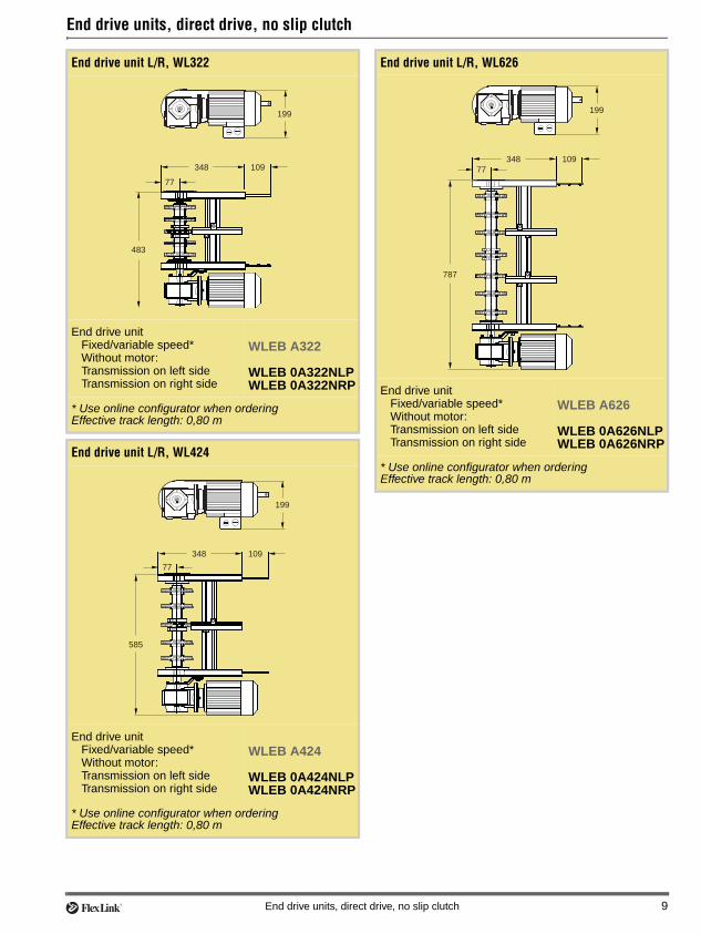
End drive units, direct drive with slip clutch
End drive unit L/R with slip clutch, WL322
End drive unitFixed/variable speed*Without motor:Transmission on left sideTransmission on right side
WLEB A322
WLEB 0A322LPWLEB 0A322RP
* Use online configurator when orderingEffective track length: 0,80 m
End drive unit L/R with slip clutch, WL424
End drive unitFixed/variable speed*Without motor:Transmission on left sideTransmission on right side
WLEB A424
WLEB 0A424LPWLEB 0A424RP
* Use online configurator when orderingEffective track length: 0,80 m
572
230
77
348 109
674
230
77
348 109
End drive unit L/R with slip clutch, WL626
End drive unitFixed/variable speed*Without motor:Transmission on left sideTransmission on right side
WLEB A626
WLEB 0A626LPWLEB 0A626RP
* Use online configurator when orderingEffective track length: 0,80 m
876
230
77
348 109
10 End drive units, direct drive with slip clutch

Idler end units – introductionChain guidance at end of conveyorThe idler end unit is used to guide the chain from the return side of the conveyor up to the top side with a min-imum of friction. The chain is guided by three or more idler wheels on a common, rotating shaft supported by ball bearings.
Number of idler wheels vs. conveyor width
Ordering information• Connecting strips are included with the idler end
units.
• Slide rail must be ordered separately.
Idler units
Idler end unit
Width 322 mm 424 mm 626 mm
Idler wheels 3 3 5
Idler end unit, WL322
Idler end unit
Effective track length: 0,80 m
WLEJ 300A322
Idler end unit, WL424
Idler end unit
Effective track length: 0,80 m
WLEJ 300A424
348 109
158
322
348 109
158
424
Idler end unit, WL626
Idler end unit
Effective track length: 0,80 m
WLEJ 300A626
348 109
158
626
Idler end units – introduction 11

Plain bends
Plain bend, 30°
Plain bend, 30°±1°R=820±10 mm, WL322R=1100±10 mm, WL424R=1650±10 mm, WL626
WLBP 30A322WLBP 30A424WLBP 30A626
Effective track lengths:R820: 1,80 m (top+bottom)R1100: 2,20 m (top+bottom)R1650: 2,90 m (top+bottom)
Plain bend, 45°
Plain bend, 45°±1°R=820±10 mm, WL322R=1100±10 mm, WL424R=1650±10 mm, WL626
WLBP 45A322WLBP 45A424WLBP 45A626
Effective track lengths:R820: 2,30 m (top+bottom)R1100: 2,90 m (top+bottom)R1650: 3,90 m (top+bottom)
(2x 200)
R ±10
30° ±1°
80
(2x 200)
R ±10
45° ±1°
80
Plain bend, 60°
Plain bend, 60°±1°R=820±10 mm, WL322R=1100±10 mm, WL424R=1650±10 mm, WL626
WLBP 60A322WLBP 60A424WLBP 60A626
Effective track lengths:R820: 2,80 m (top+bottom)R1100: 3,50 m (top+bottom)R1650: 4,90 m (top+bottom)
Plain bend, 90°
Plain bend, 90°±1°R=820±10 mm, WL322R=1100±10 mm, WL424R=1650±10 mm, WL626
WLBP 90A322WLBP 90A424WLBP 90A626
Effective track lengths:R820: 3,80 m (top+bottom)R1100: 4,90 m (top+bottom)R1650: 6,90 m (top+bottom)
(2x 200)
R ±10
60° ±1°
80
(2x 200)
R ±10
90° ±1°
80
12 Plain bends

Vertical bends
Vertical bend, 5°
Vertical bend, 5°, WL322Vertical bend, 5°, WL424Vertical bend, 5°, WL626
WLBV 5A322WLBV 5A424WLBV 5A626
Effective track length: 0,50 m (top+bottom)
80 5° 80
R750
225
10
80
Vertical bend, 15°
Vertical bend, 15° WL322Vertical bend, 15° WL424Vertical bend, 15° WL626
WLBV 15A322WLBV 15A424WLBV 15A626
Effective track length: 0,75 m (top+bottom)
80 15°
R750
351
46
8080
Vertical bends 13

Support designs
Support componentsThe illustrations on this page show recommended sup-ports for the conveyor. All supports are built using com-ponents from FlexLink structural system XC.
System WL626 requires some additional support, please see page 15 for details.
Height and witdth of supports Type 1, 2 and 3
Suggested support components
WL322 WL424 WL626
W1 (mm) 322 424 626
L1 (mm) ca. H1-100 ca. H1-100 ca. H1-100
W2 (mm) 173,6 275,6 477,6
L2 (mm) ca. H2-284 ca. H2-284 ca. H2-224
W3 (mm) 193,6 295,6 497,6
L3 (mm) ca. H3-280 ca. H3-280 ca. H3-224
L
TOC
1
H 1
W1
44
20Ø 10
44
2
3
4
5
6
7
Type 1
L
TOC
2
H 2
W2
1
2
3
4
5
6
7
L
TOC
3
H 3
W3
1
2
3
4
5
6
7
Type 2 Type 3
We recommend using a drill fixture for Type 1 supports.
Item no. 8050040
Pos Item DesignationType 1 Type 2 Type 3
1 Beam support bracket – XMCS 64 C XLCS 64
2 Leg support XCBL 3×44×88 XCBL 3×64 XCBL 3×64
3 Foot XCFS 12×68 XCFS 12×68 XCFS 12×68
4 End cap XCBE 44×88 XCBE 64 XCBE 64
5 Angle bracket XCFA 88 B XCFA 44 B XCFA 44 B
6 Cross beam XCBL 3×44×88 XCBL 3×64 XCBL 3×64
7 End plate for beam XCFE 44×88 M12A XCFE 64 M12A XCFE 64 M12A
14 Support designs

Support designs (continued)
Additional support for WL626System WL626 requires extra support due to the width of the conveyor.
Pos Item Designation
1 Cleat XWCP 20
2 Support profile, 668 mm XFBM L×30
3 Support bracket XLDB 21×100
4 Cross beam XCBL 3×44×88
32
4
1
668
Support designs 15

Product indexProduct designations in alphanumeric order5056130 ..................................58050032 ..................................68050033 ..................................68050034 ..................................6WLAF 30 .................................6WLBP 30A322.......................12WLBP 30A424.......................12WLBP 30A626.......................12WLBP 45A322.......................12WLBP 45A424.......................12WLBP 45A626.......................12WLBP 60A322.......................12WLBP 60A424.......................12WLBP 60A626.......................12WLBP 90A322.......................12WLBP 90A424.......................12WLBP 90A626.......................12WLBV 15A322.......................13WLBV 15A424.......................13WLBV 15A626.......................13WLBV 5A322.........................13WLBV 5A424.........................13WLBV 5A626.........................13WLCB 3A322...........................5WLCB 3A424...........................5WLCB 3A626...........................5WLCB LA322...........................5WLCB LA424...........................5WLCB LA626...........................5WLCC 322...............................6WLCC 424...............................6WLCC 626...............................6WLCF 3x113 ...........................5WLCF Lx113 ...........................5WLCN 3x20.............................5WLCN Lx20.............................5WLCS 25×5 H .........................6WLEB 0A322LP ....................10WLEB 0A322NLP....................9WLEB 0A322NRP ...................9WLEB 0A322RP....................10WLEB 0A424LP ....................10WLEB 0A424NLP....................9WLEB 0A424NRP ...................9WLEB 0A424RP....................10WLEB 0A626LP ....................10WLEB 0A626NLP....................9WLEB 0A626NRP ...................9WLEB 0A626RP....................10WLEB A322...........................10WLEB A322.............................9WLEB A424...........................10WLEB A424.............................9WLEB A626...........................10WLEB A626.............................9WLEJ 300A322 .....................11
WLEJ 300A424..................... 11WLEJ 300A626..................... 11WLMR 135.............................. 6WLTP 1A304 F ....................... 3WLTP 1A304 H....................... 3WLTP 1A406 F ....................... 3WLTP 1A406 H....................... 3WLTP 1A608 F ....................... 3WLTP 1A608 H....................... 3XBCR 25 H ............................. 6XBCR 25 HB........................... 6XFAN 6 ................................... 5XFBM 3×30............................. 6XFBM L×30............................. 6XSCJ 6×160............................ 5XWCP 20 ................................ 5
16 Support designs