Packaging Serializer On a Conveyor Belt With Pick & Place ...
86
Autonomous Pharmaceutical - Packaging Serializer On a Conveyor Belt With Pick & Place Aggregation System by Humphrey Takunda Muchapireyi (R143785X) Submitted in partial fulfillment for the degree of Bachelor of Science (Honours) Telecommunications Department of Appiled Physics in the Faculty of Science and Technology at the Midlands State University Gweru, Zimbabwe June, 2018 Supervisor: Mr Garikayi Manjengwa Co-supervisor: Dr Action Nechibvute HTEL 438 Dissertation
-
Upload
khangminh22 -
Category
Documents
-
view
2 -
download
0
Transcript of Packaging Serializer On a Conveyor Belt With Pick & Place ...

Autonomous Pharmaceutical - Packaging Serializer
On a Conveyor Belt
With Pick & Place Aggregation System
by
Humphrey Takunda Muchapireyi (R143785X)
Submitted in partial fulfillment for the degree of
Bachelor of Science (Honours) Telecommunications
Department of Appiled Physics in the Faculty of Science and Technology at the
Midlands State University
Gweru, Zimbabwe
June, 2018
Supervisor: Mr Garikayi Manjengwa
Co-supervisor: Dr Action Nechibvute
HTEL 438 Dissertation
i
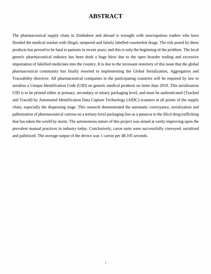
ABSTRACT
The pharmaceutical supply chain in Zimbabwe and abroad is wrought with unscrupulous traders who have
flooded the medical market with illegal, tampered and falsely labelled counterfeit drugs. The risk posed by these
products has proved to be fatal to patients in recent years; and this is only the beginning of the problem. The local
generic pharmaceutical industry has been dealt a huge blow due to the open boarder trading and excessive
importation of falsified medicines into the country. It is due to the incessant notoriety of this issue that the global
pharmaceutical community has finally resorted to implementing the Global Serialization, Aggregation and
Traceability directive. All pharmaceutical companies in the participating countries will be required by law to
serialize a Unique Identification Code (UID) on generic medical products no latter than 2019. This serialization
UID is to be printed either at primary, secondary or tetiary packaging level, and must be authenticated (Tracked
and Traced) by Automated Identification Data Capture Technology (AIDC) scanners at all points of the supply
chain, especially the dispensing stage. This research demonstrated the automatic conveyance, serialization and
palletization of pharmaceutical cartons on a tertiary level packaging line as a panacea to the illicit drug trafficking
that has taken the world by storm. The autonomous nature of this project was aimed at vastly improving upon the
prevalent manual practices in industry today. Conclusively, caron units were successifully conveyed, serialized
and palletized. The average output of the device was 1 carton per 48.105 seconds.

ii
DECLARATION
I, Humphrey Takunda Muchapireyi (R143785X), hereby declare that I am the sole author of this dissertation.
I authorize the Midlands State University to lend this dissertation to other institutions or individuals for the
purpose of scholarly research.
Signature _________________________________ Date _____________________________

iii
APPROVAL
This dissertation entitled “Autonomous Pharmaceutical Packaging Serializer On a Conveyor Belt With Pick
And Place Aggregation System” by Humphrey Takunnda Muchapireyi (R143785X) meets the regulations
governing the award of the degree of BSc (Honours) in Telecommunications of the Midlands State University,
and is approved for its contribution to knowledge and literal presentation.
Supervisor: Mr Garikayi Manjengwa Co-Supervisor: Dr Action Nechibvute
Signature: ______________________ Signature: ______________________
Date: ______________________ Date: ______________________

iv
DEDICATION
This manuscript is dedicated to Charles, Victoria, Gamuchirai and Huggins Muchapireyi.

v
ACKNOWLEDGEMENTS
I owe the successful compilation of this dissertation to the living God, for His unfathomable blessings upon my
life. I am forever indebted to my parents and siblings for their unconditional love and sacrifices. I also extend my
heartfelt gratitude towards my fellow students for their fruitful collaborations, financial support and uplifiting
morale. My deepest appreciation goes to my supervisors, Mr Manjengwa and Dr Nechibvute, for their priceless
mentorship and guidance throughout this endeavour.

vi
ABBREVIATIONS
EoAT – End of Arm Tool
UID – Unique Identification Code
AIDC - Automated Identification Data Capture Technology
DOF – Degrees of Freedom
NHRN - National Healthcare Reimbursement Number
vii
Contents
Introduction
1.1 Background of Study ...................................................................................................................................1
1.2 Problem Statement .......................................................................................................................................2
1.3 Generic Research on the Problem ................................................................................................................2
1.4 Scope and Objectives of Study ....................................................................................................................3
1.4.1 Aim of Study ....................................................................................................................................3
1.4.2 Objectives of Study ..........................................................................................................................3
1.5 Purpose of Study ..........................................................................................................................................3
1.6 Justification ..................................................................................................................................................3
1.7 Dissertation Outline .....................................................................................................................................4
1.8 References ....................................................................................................................................................5
Literature Review
2.1 Introduction ..................................................................................................................................................6
2.2 Theoretical Aspects ......................................................................................................................................6
2.2.1 Serialization, Aggregation, Track and Trace ...................................................................................6
2.2.2 Pharmaceutical Packaging and Labelling Technology. ...................................................................9
2.2.3 Ultrasonic Wave Theory ................................................................................................................12
2.2.4 Robotic Arm Theory ......................................................................................................................15
2.2.5 Gripper End of Arm Tool (EoAT) Technology .............................................................................16
2.3 Review of Empirical Research on Related Study and Findings ................................................................18
2.3.1 Bliss Bot for Pharmaceutical Inspection ........................................................................................18
2.3.2 Pharmaceutical Product Information Based on Android Platform. ...............................................19
2.3.3 Distance Sensing with Ultrasonic Sensor and Arduino .................................................................20
2.3.4 Automatic Sorting System ............................................................................................................21
2.3.5 Automatic Material Handling Pick & Place Robotic Arm & Image Processing ..........................22
2.3.6 SAP® Advanced Track and Trace for Pharmaceuticals ...............................................................23
viii
2.3.7 Bosch Track & Trace CPS ............................................................................................................24
2.3.8 Mettler Toledo PCE T2660 Manual Aggregation Station (MAS) .................................................25
2.3.9 Denmark Labelling Systems Scandinavia (LSS) ..........................................................................26
2.4 Software Requirements .............................................................................................................................27
2.4.1 Fritzing ..........................................................................................................................................27
2.4.2 Proteus PCB Design and Simulation ...........................................................................................27
2.4.3 Arduino Software IDE ..................................................................................................................27
2.5 System Hardware Requirements ................................................................................................................28
2.5.1 Arduino Uno Microcontroller .......................................................................................................29
2.5.2 Unipolar Stepper Motor 28 BYJ-48 ...............................................................................................30
2.5.3 Unipolar Stepper Driver ULN 2003A ...........................................................................................31
2.5.4 Bipolar Stepper Driver (L298N) ...................................................................................................32
2.5.5 Bipolar Stepper Motor (CD-ROM) ................................................................................................33
2.5.6 Servo Motor SG90 .........................................................................................................................34
2.5.7 Ultrasonic Sensor (HC-SR04)........................................................................................................35
2.5.8 Micro Servo (MG90S High Torque Metal Gear) ..........................................................................36
2.5 Conclusion .................................................................................................................................................36
2.5 References ..................................................................................................................................................36
Research Method
3.1 Introduction ................................................................................................................................................39
3.2 System Design and Assumptions .............................................................................................................39
3.2.1 Design Assumptions ...................................................................................................................39
3.2.2 System Block Diagram .................................................................................................................40
3.2.3 System Flow Chart .......................................................................................................................41
3.2.4 Overall System Overview ............................................................................................................42
3.2.5 Hardware Interfacing And Prototype Building ............................................................................44
3.3 Analysis of Ethical Issues .........................................................................................................................49
3.4 Conclusion ................................................................................................................................................49
ix
3.3.2 References ................................................................................................................................................50
Results and Analysis
4.1 Introduction ................................................................................................................................................51
4.2 Presentation of Prototype Results .............................................................................................................51
4.2.1 Final Prototype (Right Side View) ................................................................................................51
4.2.2 Final Prototype (Direct Top View) ...............................................................................................52
4.2.3 Final Prototype (Left Side View) ...................................................................................................52
4.2.4 Final Prototype (Back View) .........................................................................................................53
4.2.5 Final Prototype (Oblique Top View) .............................................................................................53
4.3 Presentation of Tabular Results ................................................................................................................54
4.3.1 Data for the Physical Dimensions .................................................................................................54
4.3.2 Data for the Physical Constants and EoAT Dimensions ..............................................................54
4.3.3 Data for the Gripping Force of the EoAT .....................................................................................55
4.3.4 Data for Autonomous Conveyance, Serialization, Pick and Place ...............................................56
4.3.5 Data for Manual Material Handling, Serialization, Pick and Place ..............................................57
4.4 Presentation of Serial Monitor Results ......................................................................................................58
4.4.1 Initialize Carton Detection .............................................................................................................58
4.4.2 Carton Detected, Begin Serialization ............................................................................................58
4.4.3 Serialization Completed ................................................................................................................59
4.4.4 Execution of Carton Pick ..............................................................................................................59
4.4.5 Execution of Carton Place ............................................................................................................60
4.4.6 Resume Carton Detection .............................................................................................................60
4.5 Analysis and Intepretation of Data ...........................................................................................................61
4.5.1 Variation of Production Speed per Carton with Time ..................................................................61
4.5.2 Variation of Packaging Efficiency With Inverse Completion Time .............................................62
4.5.3 Drive Cycle for an EoAT Industrial Robot ...................................................................................63
4.5.4 Motor Delay Factor .......................................................................................................................64
x
4.6 References .................................................................................................................................................65
Conclusion
5.1 Introduction ................................................................................................................................................66
5.2 Discussion .................................................................................................................................................66
5.3 Limitations of the Study ............................................................................................................................66
5.4 Recommendations .....................................................................................................................................67
5.4.1 Automated Identification Data Capture (AIDC) ...........................................................................67
5.4.2 Vision Sensing Technology ..........................................................................................................67
5.4.3 EoAT Degrees of Freedom ...........................................................................................................67
5.4.4 Laser/Printed Label Applicator .....................................................................................................67
Appendix ..............................................................................................................................................................68

xi
List of Figures
Introduction
2.1 Criminal Drug Incidents ..............................................................................................................................6
2.2 South African Serialization Plan .................................................................................................................7
2.3 Global Serialization and Traceability .........................................................................................................8
2.4 T3 - Transaction History, Information and Statement ................................................................................8
2.5 Pharmaceutical Packaging Line Devices .....................................................................................................9
2.6 Characteristic Curve of Conveyor Load Variation with Motor Velocity ..................................................11
2.7 HC-SR04 Sensor Module: Front and Back View .....................................................................................12
2.8 Ultrasonic Communication Protocol..........................................................................................................12
2.9 HC-SR04 Module Timing.........................................................................................................................13
2.10 Locus of the obstacle in ultrasonic detection ............................................................................................13
2.11 Ultrasonic Test Data Experiment ..............................................................................................................14
2.12 Da Vinci Robot 1945 .................................................................................................................................15
2.13 3D space depiction of roll, yaw, and pitch in a robotic arm .....................................................................15
2.14 Prototype: Bliss Bot ..................................................................................................................................18
2.15 Search query result – “drug not approved.” ...............................................................................................19
2.16 Prototype: Ultrasonic distance meter ........................................................................................................20
2.17 Robotic arm grabs objects from the conveyor belt ....................................................................................21
2.18 Prototype: Conveyor Belt and Four Axis Robot ........................................................................................22
2.19 SAP Advanced Track and Trace System ..................................................................................................23
2.20 The Mettler Toledo PCE T2660 MAS ......................................................................................................25
2.21 The Denmark Labelling Systems Scandinavia (LSS) ................................................................................26
2.22 Arduino Uno Microcontroller ...................................................................................................................29
2.23 Unipolar Stepper Motor 28 BYJ-48 ...........................................................................................................30
2.24 Unipolar Stepper Driver ULN 2003A .......................................................................................................31
xii
2.25 Bipolar Stepper Driver L298N...................................................................................................................32
2.26 Bipolar Stepper Motor (CD-ROM) ............................................................................................................33
2.27 Servo Motor SG90 .....................................................................................................................................34
2.28 SG90 Servo Control Signal Pulse Train ....................................................................................................34
2.29 The HC-SR04 Ultrasonic Module .............................................................................................................35
3.1 System Block Diagram ..............................................................................................................................40
3.2 System Flow Chart ....................................................................................................................................41
3.3 Arduino to ULN2003A Unipolar Stepper Motor Driver Connection ........................................................44
3.4 Arduino Uno to Ping Ultrasonic Sensor Connection ................................................................................45
3.5 Arduino Uno to L298N Bipolar Stepper Motor Driver Connection .........................................................46
3.6 Arduino Uno to Pick And Place EoAT Palletizer Connection .................................................................47
3.7 Overall System Schematic (Fritzing Simulation) ......................................................................................48
4.1 Final Prototype (Right Side View) ............................................................................................................51
4.2 Final Protoype (Direct Top View) .............................................................................................................52
4.3 Final Prototype (Side View) ......................................................................................................................52
4.4 Final Prototype (Back View) .....................................................................................................................53
4.5 Final Prototype (Oblique Top View) .........................................................................................................53
4.6 Image Capture: Initialization of Carton Detection ....................................................................................58
4.7 Image Capture: Carton Detected, Begin Serialization ..............................................................................58
4.8 Image Capture: Serialization Completed ..................................................................................................59
4.9 Image Capture: Execution of Carton Pick .................................................................................................59
4.10 Image Capture: Execution of Carton Place ................................................................................................60
4.11 Image Capture: Resume Carton Detection ................................................................................................60
4.12 Variation of Production Speed with Time ................................................................................................61
4.13 Variation of Efficiency With Inverse Completion Time ..........................................................................62
4.14 Cycle for an industrial robot servo motor .................................................................................................63
4.15 Derivation of Motor Delay Factor ............................................................................................................64

xiii
List of Tables
Introduction
2.1 Legend of variables: Conveyor Belt Kinematics .....................................................................................10
2.2 Legend of variables: Belt Tension ............................................................................................................11
2.3 Legend of variables: Gripper EoAT Kinematics ......................................................................................17
2.4 The Bosch Track & Trace CPS Modules ...................................................................................................24
2.5 Technical Specifications of the ATmega328 .............................................................................................29
2.6 Technical Specifications of the 28 BYJ-48 ...............................................................................................30
2.7 Technical Specifications of the L298N......................................................................................................32
2.8 Technical Specifications of the SG90 ........................................................................................................34
2.9 Technical Specifications of the HC-SR04 .................................................................................................35
2.10 Technical Specifications of the MG90S ....................................................................................................36
4.1 Physical Dimensions of Carton, Labeler and Belt of Conveyor ................................................................54
4.2 Physical Constants and EoAT Dimensions................................................................................................54
4.3 Data for the Gripping force of the EoAT ..................................................................................................55
4.4 Autonomous Times for Conveyance, Serialization, Pick and Place .........................................................56
4.5 Autonomous Speeds for Conveyance, Serialization, Pick and Place .......................................................56
4.6 Manual Times for Conveyance, Serialization, Pick and Place .................................................................57
4.7 Manual Speeds for Conveyance, Serialization, Pick and Place ..................................................................5
CHAPTER 1
Introduction
1.1 Background of Study
Western drug manufacturers have only until next year to implement counterfeit-proof drug packaging. In fact by
the 9th of February 2019, the Falsified Medicines Directive (FMD) dictates that a tamper – evident unique serial
identifier must be printed on all individual prescription (white) and high-risk OTC (black) drug cartons [1]. With
the exception of Lybia and South Africa, no African drug manufacturering nation has adopted this legislation yet,
and it is the purpose of this project to demonstrate the automatic serialization of pharmaceutical carton units on a
packaging line with a unique identifier (UID), as well as their pick and place palletization into a case on a pallet,
as a panacea to the illicit trafficking of fake pharmaceutical products such as ‘Tsunami’ which have flooded the
Zimbabwean medical market. Globally, an estimated $75 billion is lost every year by pharmaceutical companies
due to counterfeit medications [2]. Thus this low cost prototype serves to protect medical patients, as it will make
counterfeit products harder to circulate; and the automated conveyance approach will improve upon the manual
serialization and palletization practices which are prevalent in some pharma - packaging lines. The project will
be demonstrated on a stepper motor driven conveyer belt, wherein cartons will be ferried to an automatic label
applicator, whereafter they are picked and placed into a case on a pallet. Considering the endorsement of the
American Drug Quality and Security Act of 2013 (DQSA), especially Title II of the Drug Supply Chain Security
Act (DSCSA), the pharmaceutical sector will soon experience a paradigm shift in prescription drug labelling and
transacting [3]. According to Zimbabwean Statutory Instrument 150 of 1991, a “label” with respect to a medical
package denotes any written, pictorial or marking on the package; and “expiry date”, with respect to a medical
batch, denotes the date when its shelf life expires [4]. Serialization is defined as the printing of a unique verifiable
identifier (UID) to single units, which could be either a 1 or 2 dimensional bar code. Pharmaceutical
serialization is therefore the inscription of this UID onto each produced pharmaceutical unit. After serialization,
the cartons are then packed into a case,which itself has a UID which identifies the case and each individual carton
within it; then finally palletization is perfomed. The concept of tamper-resistant packaging was initially coined
by the Food and Drug Administration in 1983, though the phrase was unpopular in the packaging community;
thus the new term ‘temper – evident packaging’ [5]. Thus, a tamper-evident package, according to the Food and
Drug Administration (21 CFR § 211.132) has got identifiers at the opening which, if tampered with, give
visible proof to consumers that foul play has occured. Faced with these brutal facts, the student was motivated to
adapt this new global standard of pharma - packaging and implement it in Zimbabwe; thus was born the proposed
system.
2
1.2 Problem Statement
Zimbabwean pharmaceutical manufacturing and packaging companies are not yet in compliance with the new
serialization and traceability legislation which has taken the world by storm. To say the least, the country’s
pharmaceutical industry is in a shambles and in need of resuscitation. According to the latest Register of Licensed
Pharmaceutical Manufacturing Premises published by the Medicines Control Authority of Zimbabwe (MCAZ),
only 4 out of the total 9 manufacturers are able to manufacture generic medicines [6]. Also, Zimbabwe relies too
much on the importation of finished pharmaceutical products, which has crippled the local manufacturing of
generic medicines. As a consequence, the open boarder smuggling of pharmaceuticals has ushered in a range of
illegal counterfeit drugs such as Tsunami, Betasol, Diproson, Epiderm, Apetito Cyproheptadine tablets and
Broncleer; all of which may be lethal to public health [7]. According to the OECD, counterfeit medicines are
responsible for more than 700,000 deaths annually; in fact, up to 30% of all medicines are estimated to be fake
[8]. Developed nations have one percent of counterfeit pharmaceuticals on the market; developing countries have
10 and 50 percent. Historically, the spread of fake anti-malarial drugs is a tragedy that has cost thousands of lives
[9]. Though ,in some instances,legal action has been taken in the past, by failing to join the global serialization
and traceability campaign, Zimbabwe will continue to struggle to curb the prevalence of false, expired, tampered
and wrongly labelled drugs [10].
1.3 Generic Research On The Problem
Pharmaceutical counterfeiting has become an enormous problem in Zimbabwe and the world over. Various
corrective measures have been proposed in the past by individual countries to solve this problem, but with varying
amounts of success. These included arresting fraudulent traders of pharmaceutical black markets, confiscating
false drugs, urging manufacturers to print custom logos (which were often replicated). As a final resort, the global
pharmaceutical community has proposed the adoption of a new directive in order to secure the pharmaceutical
supply chain from falsified medicines. This is the first collective effort by pharmaceutical packaging institutions
to solve the issue of drug counterfeiting across all boarders simultaneously. The new joint solution is called the
Global Pharmaceutical Serialization, Track and Trace initiative. Its scope includes all pharmaceutical medicines
from prescription drugs, vaccines, beauty products and all health products. The requirements of this directive are
that all pharmaceutical manufacturers and packaging companies in every participating nation will now be required
by law to print a standardized label at primary(dispensed unit), secondary(regular marketing unit) or tertiary
(carton unit, case and pallet) packaging level. This label must contain the following data matrix elements: date of
expiry, national healthcare reimbursement number (NHRN), batch number, lot number, product code, serial
number and unique identification number (UID). The deadlines for this directive vary from continent to continent
but most seem to point towards 2018, 2019 up to 2022.

3
1.4 Scope and Objectives of the Research
1.4.1 Aim of Study
The aim of this project is to design a low cost tertiary level packaging line device comprising of a stepper - driven
conveyor belt which conveys pharmaceutical carton units towards a label applicator which automatically
serializes the cartons with a unique identifier (UID), as well as a gripper End of Arm Tool (EOAT) palletizer
which picks and places the serialized cartons into a case on a pallet; as a panacea to illicit drug counterfeiting.
1.4.2 Objectives of Study
1. To ferry carton units on a microcontroller based tertiary level packaging line conveyor belt.
2. To detect carton units on the packaging line using a ping ultrasonic range finder.
3. To automatically serialize each carton with a unique identification number (UID) using a label applicator.
4. To pick and place each serialized carton in succession from the conveyor into a case on the pallet, by use
of a EOAT gripper palletizer.
1.5 Purpose of Study
The purpose of this study is to secure the pharmaceutical supply chain from fake and counterfeit products.
Consequently, the lives of countless patients will be saved as prescription drugs will no longer be contaminated.
This study will also benefit both industrial practitioners, policy makers and researchers alike. Moreso this study
will fill the void in current literature on serialization, aggregation, track and trace in pharmaceutical packaging.
In addition, it will also pave way for Zimbabwean law makers and industrial practitioners to become conscious
of the global threat facing the pharma – industry; urging them to take appropriate measures to implement this
prototype on a larger scale in compliance with the global Falsified Medicines Directive.
1.6 Justification
A prototype of this caliber is justifiably necessary; considering that the integrity and viability of the entire
Zimbabwean pharmaceutical supply chain from the saleable unit carton to the pallet are at stake. Rough estimates
of the cost of serializing a cartoner line to item level is currently between US$47000 to US$268000, which is
ridiculously expensive. Thus the student has devised a cheaper electromechanical system that is affordable and
effective to curb fake pharma products and eradicate the health risk to patients. The automated nature of the
proposed system replaces human effort and thus reduces labour, time and errors. Moreover, the vast technological
gap between first world countries and third world nations will be bridged.
4
1.7 Dissertation Layout Chapter 2 - Literature Review:
In this chapter, a comprehensive coverage of the theoretical concepts related to the study is given. This is followed
by a review of the empirical research that has dealt with topics similar to the study; with particular interest to
literature most applicable to the study.
Chapter 3 - Research Method:
This chapter is divided into two sections:
1. The first section gives a critical discussion of the paradigm that the student used in the study. It also
discusses the design as well as the assumptions associated with that design and a rationale for its use.
2. The second sections discusses the ethical issues associated with the research.
Chapter 4 - Results and Analysis:
This chapter deals with data analysis for the project. It is primarily a narrative supported by table figures and
statistical information. Laslty, the interpretation of data is also provided in this chapter.
Chapter 5 – Conclusion:
This is the final chapter of the project. It comprises a discussion of the major findings of the research. Each
question is linked to the final findings. In addition, the student will suggest some recommendations to industrial
practioners and policy makers. Finally, the chapter will reflect on the research processes like the limitations of
the study as well as suggestions for future research.
5
1.8 References
[1] Europhartech Communication, "Pharmaceutical Serialisation and Tamper-evident at Europhartech,"
Europhartech, 19 September 2017. [Online]. Available: http://www.europhartech.com/pharmaceutical-
serialisation-tamper-evident/. [Accessed 18 March 2018].
[2] R. Sanchez, "New Trends & Technology: Pharmaceutical Serialization and Track & Trace. What is the
Difference Between Pharmaceutical Serialization and Track & Trace?," Masipack, 9 November 2016.
[Online]. Available: https://masipack.com/2016/11/09/new-trends-and-technology-pharmaceutical-
serialization-and-track-and-trace/. [Accessed 22 April 2018].
[3] Healthcare Packaging, "Pharmaceutical Track-And-Trace," Serialization Playbook, 2016.
[4] "Medicines and Allied Substances Control (General) Regulations, 1991.".Statutory Instrument 150 of 1991.
[5] A. U.S. Food and Drug, "CPG Sec. 450.500 Tamper-Resistant Packaging Requirements for Certain Over-
the-Counter Human Drug Products," US Department of Health and Human Services, 20 March 2015.
[Online]. Available:
https://www.fda.gov/ICECI/ComplianceManuals/CompliancePolicyGuidanceManual/ucm074391.htm.
[Accessed 4 February 2018].
[6] C. Chitemerere, "Pharmaceutical Sector Profile: Zimbabwe," in Global UNIDO Project: Strengthening the
local production of essential generic drugs in least developed and developing countries., Vienna, 2011.
[7] S. M. Reporter, "Hip-enlargement drugs on sale in Zim," The Sunday Mail, 17 August 2014.
[8] The Adents Team, "Serialization, aggregation, coding formats – global challenges for the Pharma industry,"
Adents, 29 July 2017. [Online]. Available: https://adents.com/article-serialization-aggregation-coding-
formats-global-challenges-pharma-industry-1474.html. [Accessed 15 April 2018].
[9] M. Davison, Pharmaceutical Anti-Counterfeiting Combating the Real Danger from Fake Drugs, Hoboken,
New Jersey.: John Wiley & Sons, Inc., 2011.
[10] S. Jakes, "Woman charged for illegal possession of drugs," Bulawayo 24 News, 27 August 2015.
6
CHAPTER 2
Literature Review
2.1 Introduction
This chapter discusses the theoretical aspects concerning the research. A thorough review of the empirical
research on studies and findings which are relevant to the project is given. In addition, the theoretical aspects of
the software and hardware requirements for this research are also presented.
2.2 Theoretical Aspects
2.2.1 Serialization, Aggregation, Track and Trace
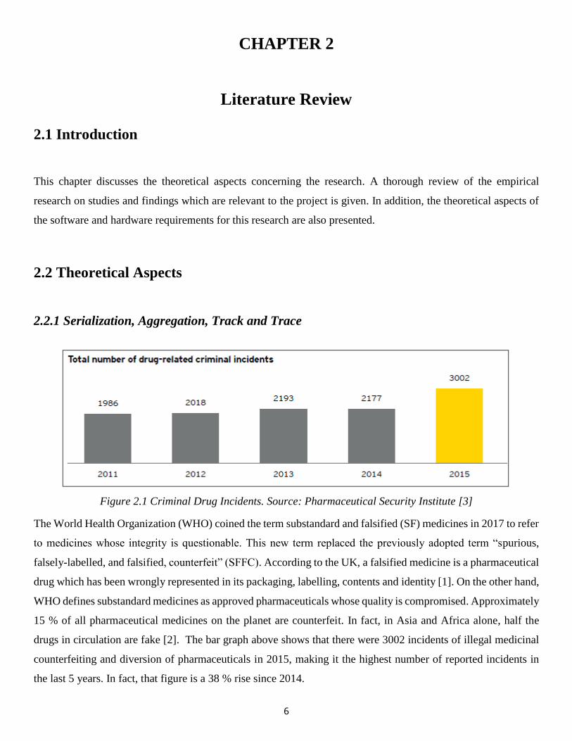
Figure 2.1 Criminal Drug Incidents. Source: Pharmaceutical Security Institute [3]
The World Health Organization (WHO) coined the term substandard and falsified (SF) medicines in 2017 to refer
to medicines whose integrity is questionable. This new term replaced the previously adopted term “spurious,
falsely-labelled, and falsified, counterfeit” (SFFC). According to the UK, a falsified medicine is a pharmaceutical
drug which has been wrongly represented in its packaging, labelling, contents and identity [1]. On the other hand,
WHO defines substandard medicines as approved pharmaceuticals whose quality is compromised. Approximately
15 % of all pharmaceutical medicines on the planet are counterfeit. In fact, in Asia and Africa alone, half the
drugs in circulation are fake [2]. The bar graph above shows that there were 3002 incidents of illegal medicinal
counterfeiting and diversion of pharmaceuticals in 2015, making it the highest number of reported incidents in
the last 5 years. In fact, that figure is a 38 % rise since 2014.
7
To resolve this conundrum, the EU FMD proposed the serialization of pharmaceutical products by manufacturers,
before their unique identifier (UID) is scanned at each stage in the supply chain. After scanning the product, if it
fails to meet the quality standards, it is removed from the supply chain [3]. In other words, regulatory bodies
around the world are or will impose the concept of serialization track-and trace systems in their pharmaceutical
supply chains. Serialization is thus defined as the labeling of a pharmaceutical product with a unique numerical
identifier for track and tracing purposes. Track and trace is defined as the recording of the serialized
pharmaceutical product at any stage in the supply chain [4]. Whilst most of the First World countries have already
begun to implement track and trace, most Third World pharmaceutical manufacturers still lag behind. The
Zimbabwean generic pharmaceutical industry has not been participative in international and regional activities,
and this has caused the industry to suffer. Some of these activities include the Pharmaceutical Manufacturing Plan
for Africa (PMPA), the Global Strategy and Plan of Action on Public Health, Intellectual Property and Innovation
(GSPA), and the SADC Pharmaceutical Business Plan. These initiatives would have vastly improved Zimbabwe’s
local pharmaceutical manufacturers, but the country has not participated much. To make it worse, The Zimbabwe
Pharmaceutical Manufacturers’ Association (PMA), which represents Zimbabwe’s generic manufacturers, does
not have a secretariat, and it only comprises of eight pharma companies namely: Plus Five Pharmaceuticals
(current Chair), Datlabs, Pharmanova, Varichem Pharmaceuticals, Graniteside Chemicals, Ecomed, CAPS and
ZimPharm. This has greatly hindered the pharmaceutical industry in Zimbabwe, thereby lessening the country’s
involvement in international activities such as the global serialization track and trace; which is the motivation for
this project [5].
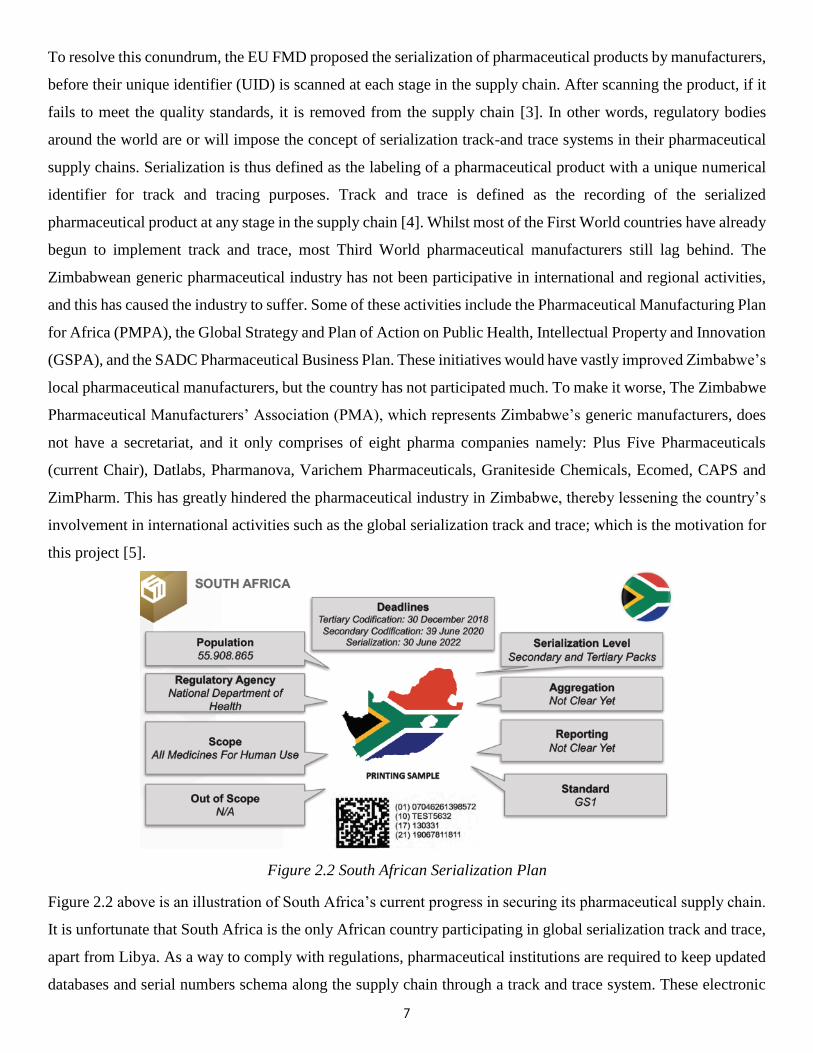
Figure 2.2 South African Serialization Plan
Figure 2.2 above is an illustration of South Africa’s current progress in securing its pharmaceutical supply chain.
It is unfortunate that South Africa is the only African country participating in global serialization track and trace,
apart from Libya. As a way to comply with regulations, pharmaceutical institutions are required to keep updated
databases and serial numbers schema along the supply chain through a track and trace system. These electronic
8
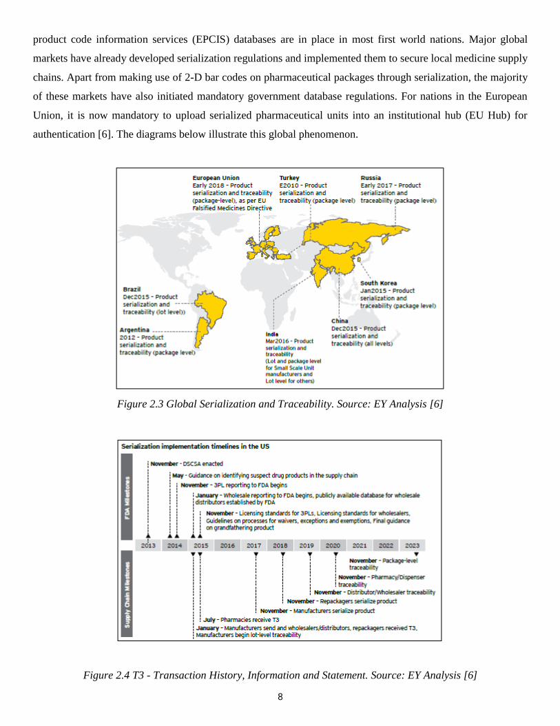
product code information services (EPCIS) databases are in place in most first world nations. Major global
markets have already developed serialization regulations and implemented them to secure local medicine supply
chains. Apart from making use of 2-D bar codes on pharmaceutical packages through serialization, the majority
of these markets have also initiated mandatory government database regulations. For nations in the European
Union, it is now mandatory to upload serialized pharmaceutical units into an institutional hub (EU Hub) for
authentication [6]. The diagrams below illustrate this global phenomenon.
Figure 2.3 Global Serialization and Traceability. Source: EY Analysis [6]
Figure 2.4 T3 - Transaction History, Information and Statement. Source: EY Analysis [6]

9
2.2.2 Pharmaceutical Packaging and Labelling Technology
A typical pharmaceutical packaging cartoner has many requirements, all of which must be met in the utmost
sanity conditions. Some of these include blister pack packaging, high speed pill - bottle filling, as well as regular
inspections. Various conveyors are available in industry, from steel to aluminum belt, chain and roller conveyors
engineered for the packaging of pharmaceutical products. Pharmaceutical cartoning equipment is used for sorting,
bundling, capping, counting, accumulating, batching and packaging medical drugs. As shown in Figure 2.5 below,
pharmaceutical conveyors handle medical equipment on the packaging line. These conveyors are designed to
ferry pharmaceutical capsules, tablets and powders. In essence, pharmaceutical conveyors carry medical related
objects, both raw materials and finished units throughout the production chain. Not only do these conveyors
improve packaging efficiency, but they also increase coordination of products on the packaging line. Human
labour is thus replaced by this automated process, thereby saving time and increasing profit margins [7].
Figure 2.5 Pharmaceutical Packaging Line Devices
Significance of Pharmaceutical Conveyors
1. Medical conveyors have better handling.
2. They exhibit better sanitation.
3. They increase productivity in pharmaceutical packaging.
4. They maintain the steady flow of production and coordination on the packaging line.
5. They replace human labour in transporting medical objects during packaging.
6. These increase production time, hence efficiency.
7. They improve profit margins of pharmaceutical companies.
10
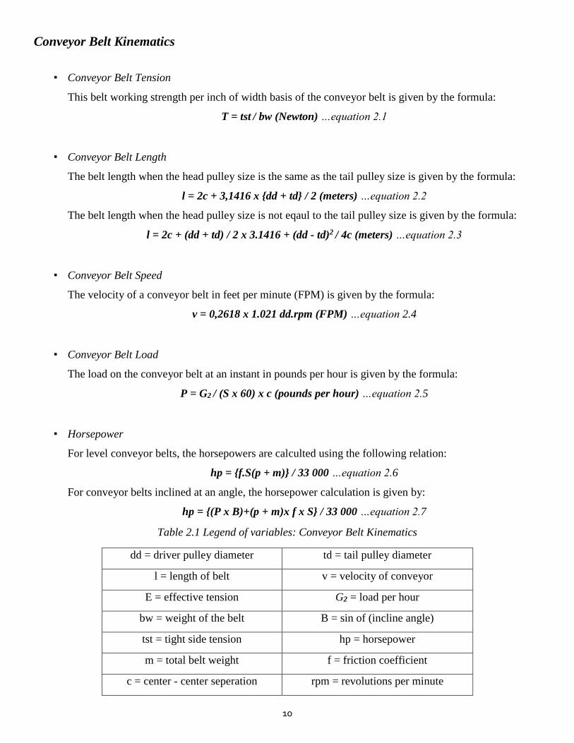
Conveyor Belt Kinematics
▪ Conveyor Belt Tension
This belt working strength per inch of width basis of the conveyor belt is given by the formula:
T = tst / bw (Newton) …equation 2.1
▪ Conveyor Belt Length
The belt length when the head pulley size is the same as the tail pulley size is given by the formula:
l = 2c + 3,1416 x {dd + td} / 2 (meters) …equation 2.2
The belt length when the head pulley size is not eqaul to the tail pulley size is given by the formula:
l = 2c + (dd + td) / 2 x 3.1416 + (dd - td)2 / 4c (meters) …equation 2.3
▪ Conveyor Belt Speed
The velocity of a conveyor belt in feet per minute (FPM) is given by the formula:
v = 0,2618 x 1.021 dd.rpm (FPM) …equation 2.4
▪ Conveyor Belt Load
The load on the conveyor belt at an instant in pounds per hour is given by the formula:
P = G2 / (S x 60) x c (pounds per hour) …equation 2.5
▪ Horsepower
For level conveyor belts, the horsepowers are calculted using the following relation:
hp = {f.S(p + m)} / 33 000 …equation 2.6
For conveyor belts inclined at an angle, the horsepower calculation is given by:
hp = {(P x B)+(p + m)x f x S} / 33 000 …equation 2.7
Table 2.1 Legend of variables: Conveyor Belt Kinematics
dd = driver pulley diameter td = tail pulley diameter
l = length of belt v = velocity of conveyor
E = effective tension G2 = load per hour
bw = weight of the belt B = sin of (incline angle)
tst = tight side tension hp = horsepower
m = total belt weight f = friction coefficient
c = center - center seperation rpm = revolutions per minute
11
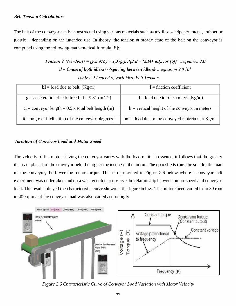
Belt Tension Calculations
The belt of the conveyor can be constructed using various materials such as textiles, sandpaper, metal, rubber or
plastic – depending on the intended use. In theory, the tension at steady state of the belt on the conveyor is
computed using the following mathematical formula [8]:
Tension T (Newtons) = {g.h.ML} + 1,37g.f.cl{2.il + (2.bl+ ml).cos (δ)} …equation 2.8
il = {mass of both idlers} / {spacing between idlers} …equation 2.9 [8]
Table 2.2 Legend of variables: Belt Tension
bl = load due to belt (Kg/m) f = friction coefficient
g = acceleration due to free fall = 9.81 (m/s/s) il = load due to idler rollers (Kg/m)
cl = conveyor length = 0.5 x total belt length (m) h = vertical height of the conveyor in meters
δ = angle of inclination of the conveyor (degrees) ml = load due to the conveyed materials in Kg/m
Variation of Conveyor Load and Motor Speed
The velocity of the motor driving the conveyor varies with the load on it. In essence, it follows that the greater
the load placed on the conveyor belt, the higher the torque of the motor. The opposite is true, the smaller the load
on the conveyor, the lower the motor torque. This is represented in Figure 2.6 below where a conveyor belt
experiment was undertaken and data was recorded to observe the relationship between motor speed and conveyor
load. The results obeyed the characteristic curve shown in the figure below. The motor speed varied from 80 rpm
to 400 rpm and the conveyor load was also varied accordingly.
Figure 2.6 Characteristic Curve of Conveyor Load Variation with Motor Velocity
12
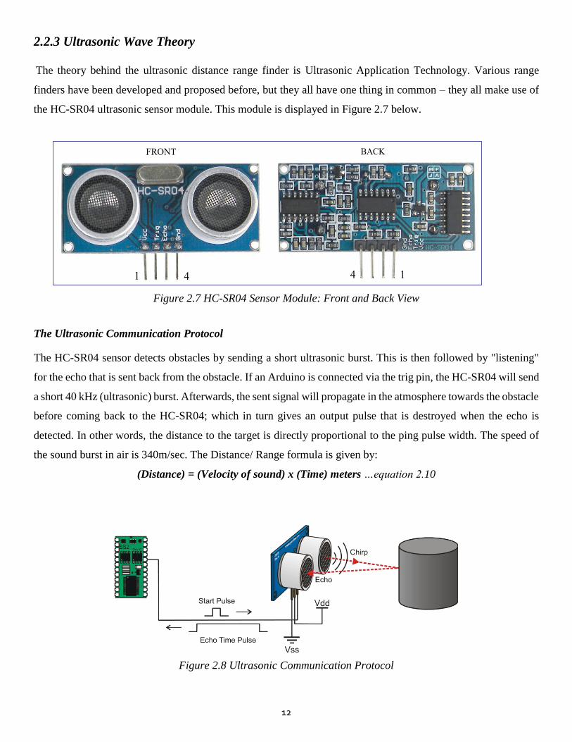
2.2.3 Ultrasonic Wave Theory
The theory behind the ultrasonic distance range finder is Ultrasonic Application Technology. Various range
finders have been developed and proposed before, but they all have one thing in common – they all make use of
the HC-SR04 ultrasonic sensor module. This module is displayed in Figure 2.7 below.
Figure 2.7 HC-SR04 Sensor Module: Front and Back View
The Ultrasonic Communication Protocol
The HC-SR04 sensor detects obstacles by sending a short ultrasonic burst. This is then followed by "listening"
for the echo that is sent back from the obstacle. If an Arduino is connected via the trig pin, the HC-SR04 will send
a short 40 kHz (ultrasonic) burst. Afterwards, the sent signal will propagate in the atmosphere towards the obstacle
before coming back to the HC-SR04; which in turn gives an output pulse that is destroyed when the echo is
detected. In other words, the distance to the target is directly proportional to the ping pulse width. The speed of
the sound burst in air is 340m/sec. The Distance/ Range formula is given by:
(Distance) = (Velocity of sound) x (Time) meters …equation 2.10
Figure 2.8 Ultrasonic Communication Protocol
13
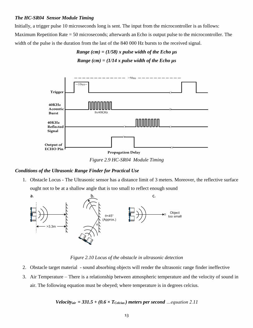
The HC-SR04 Sensor Module Timing
Initially, a trigger pulse 10 microseconds long is sent. The input from the microcontroller is as follows:
Maximum Repetition Rate = 50 microseconds; afterwards an Echo is output pulse to the microcontroller. The
width of the pulse is the duration from the last of the 840 000 Hz bursts to the received signal.
Range (cm) = (1/58) x pulse width of the Echo µs
Range (cm) = (1/14 x pulse width of the Echo µs
Figure 2.9 HC-SR04 Module Timing
Conditions of the Ultrasonic Range Finder for Practical Use
1. Obstacle Locus - The Ultrasonic sensor has a distance limit of 3 meters. Moreover, the reflective surface
ought not to be at a shallow angle that is too small to reflect enough sound
Figure 2.10 Locus of the obstacle in ultrasonic detection
2. Obstacle target material - sound absorbing objects will render the ultrasonic range finder ineffective
3. Air Temperature – There is a relationship between atmospheric temperature and the velocity of sound in
air. The following equation must be obeyed; where temperature is in degrees celcius.
Velocityair = 331.5 + (0.6 × TCelcius ) meters per second …equation 2.11
14
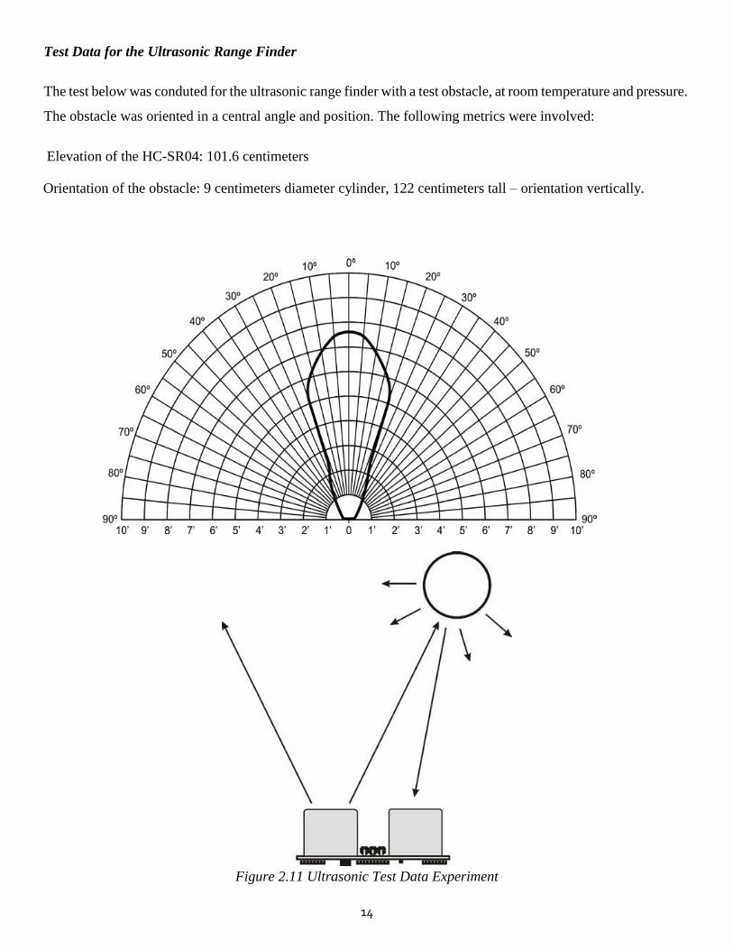
Test Data for the Ultrasonic Range Finder
The test below was conduted for the ultrasonic range finder with a test obstacle, at room temperature and pressure.
The obstacle was oriented in a central angle and position. The following metrics were involved:
Elevation of the HC-SR04: 101.6 centimeters
Orientation of the obstacle: 9 centimeters diameter cylinder, 122 centimeters tall – orientation vertically.
Figure 2.11 Ultrasonic Test Data Experiment

15
2.2.4 Robotic Arm Theory
A robotic arm is a mechanical device which changes its form by use of a couple of electric motors (servos motors,
DC motors, stepping motors) and whose movements resemble those of pneumatic or hydraulic actuators. The
main principle behind robotics is to mimic real actual human movements. It was the great polymath Leonardo Da
Vinci who first coined the term “robot” in 1495 without any reference to whether or not it would be
reprogrammable [9]. The prototype of Da Vinci’s robot is depicted in Figure 2.12 below.
Figure 2.12 Da Vinci Robot 1945. Source: Wikimedia Creative Commons Attribution License
In robotics, the term “degrees of freedom” DOF refers to its permissible statistical axes of movement. Three
variables describe the DOF of a robotic arm and these are: roll, yaw, and pitch. An outline of the 3D motion of a
robotic arm in space is shown in Figure 2.13 below. The human arm itself has 7 degrees of freedom.
Figure 2.13 3D space depiction of roll, yaw, and pitch in a robotic arm
16
2.2.5 Gripper End of Arm Tool (EoAT) Technology
End of Arm Tool is the tool region of a robot where the end effector is, and it is the one that has direct contact
with the environment. It is this end effector which interacts with the elements or objects being handled. End
effectors can be designed as a gripper, claw, drill, needle etc – depending on the application.
In robotic prehension, four main categories of robot grippers are listed below:
▪ Contigutive: they only work if there is surface contact; if adhesion is to happen effectively
▪ Impactive: jaws and claws - they grasp the object and have direct interaction with the object.
▪ Astrictive: these utilize the suction power applied to the surface of the object. The adhesion can either be
electric or magnetic depending on the instance.
▪ Ingressive: this type of EoAT penetrates onto the suface of the object, for example EoAT robotic arms
that have needles and drills as the end effector.
Applications of EoAT
▪ Vacuum EoAT
▪ Parallel EOAT
▪ Gripper EoAT
▪ Magnetic EoAT
▪ Pneumatic EoAT
Advantages of EoAT
▪ Precise positioning
▪ Very little maintanance required
▪ High speeds
▪ They are always consistent
▪ Long lifespan
▪ They conserve time
▪ Quick change devices
17
In this research, the student chose the gripper EoAT to perfom palletization from carton to pallet. The gripper is
an EOAT hand that that actually manipulates the object. In simple terms, the gripper is a robot’s controllable
“hand” which grasps and releases the objects on the assembly, packaging or production line. A lot of industrial
gripping tools achieve accurate pick and place due to precision mounting surfaces.
Types of Robotic Grippers:
▪ Needle Grippers
▪ Adaptive/ Multifinger Grippers
▪ Vacuum Cup Grippers
▪ Double and Tripple Jaw Gripper
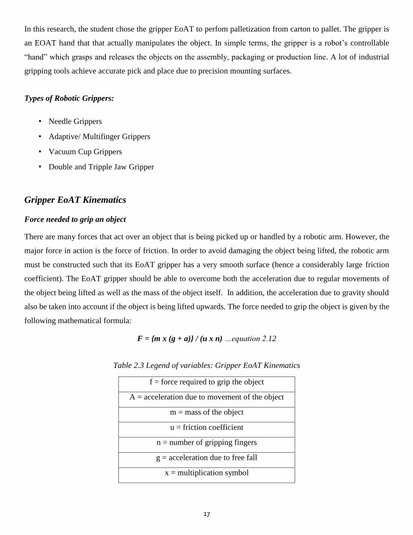
Gripper EoAT Kinematics
Force needed to grip an object
There are many forces that act over an object that is being picked up or handled by a robotic arm. However, the
major force in action is the force of friction. In order to avoid damaging the object being lifted, the robotic arm
must be constructed such that its EoAT gripper has a very smooth surface (hence a considerably large friction
coefficient). The EoAT gripper should be able to overcome both the acceleration due to regular movements of
the object being lifted as well as the mass of the object itself. In addition, the acceleration due to gravity should
also be taken into account if the object is being lifted upwards. The force needed to grip the object is given by the
following mathematical formula:
F = {m x (g + a)} / (u x n) …equation 2.12
Table 2.3 Legend of variables: Gripper EoAT Kinematics
f = force required to grip the object
A = acceleration due to movement of the object
m = mass of the object
u = friction coefficient
n = number of gripping fingers
g = acceleration due to free fall
x = multiplication symbol
18
2.3 Review of Empirical Research on Related Studies and Findings
The following is an outline of researches and technologies similar to the project. Their similarity and differences
from this project are given, along with their advantages and disadvantages.
Proposed Systems from Academic Research
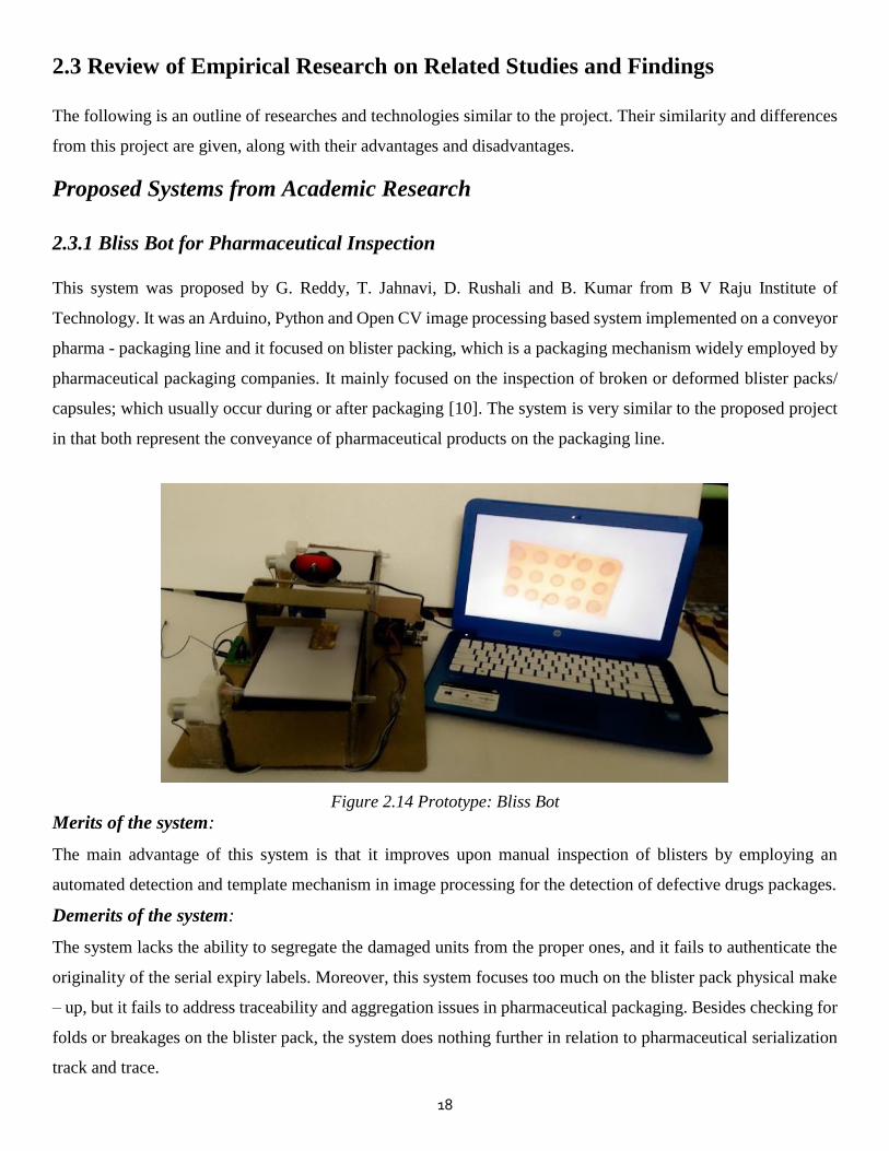
2.3.1 Bliss Bot for Pharmaceutical Inspection
This system was proposed by G. Reddy, T. Jahnavi, D. Rushali and B. Kumar from B V Raju Institute of
Technology. It was an Arduino, Python and Open CV image processing based system implemented on a conveyor
pharma - packaging line and it focused on blister packing, which is a packaging mechanism widely employed by
pharmaceutical packaging companies. It mainly focused on the inspection of broken or deformed blister packs/
capsules; which usually occur during or after packaging [10]. The system is very similar to the proposed project
in that both represent the conveyance of pharmaceutical products on the packaging line.
Figure 2.14 Prototype: Bliss Bot
Merits of the system:
The main advantage of this system is that it improves upon manual inspection of blisters by employing an
automated detection and template mechanism in image processing for the detection of defective drugs packages.
Demerits of the system:
The system lacks the ability to segregate the damaged units from the proper ones, and it fails to authenticate the
originality of the serial expiry labels. Moreover, this system focuses too much on the blister pack physical make
– up, but it fails to address traceability and aggregation issues in pharmaceutical packaging. Besides checking for
folds or breakages on the blister pack, the system does nothing further in relation to pharmaceutical serialization
track and trace.
19
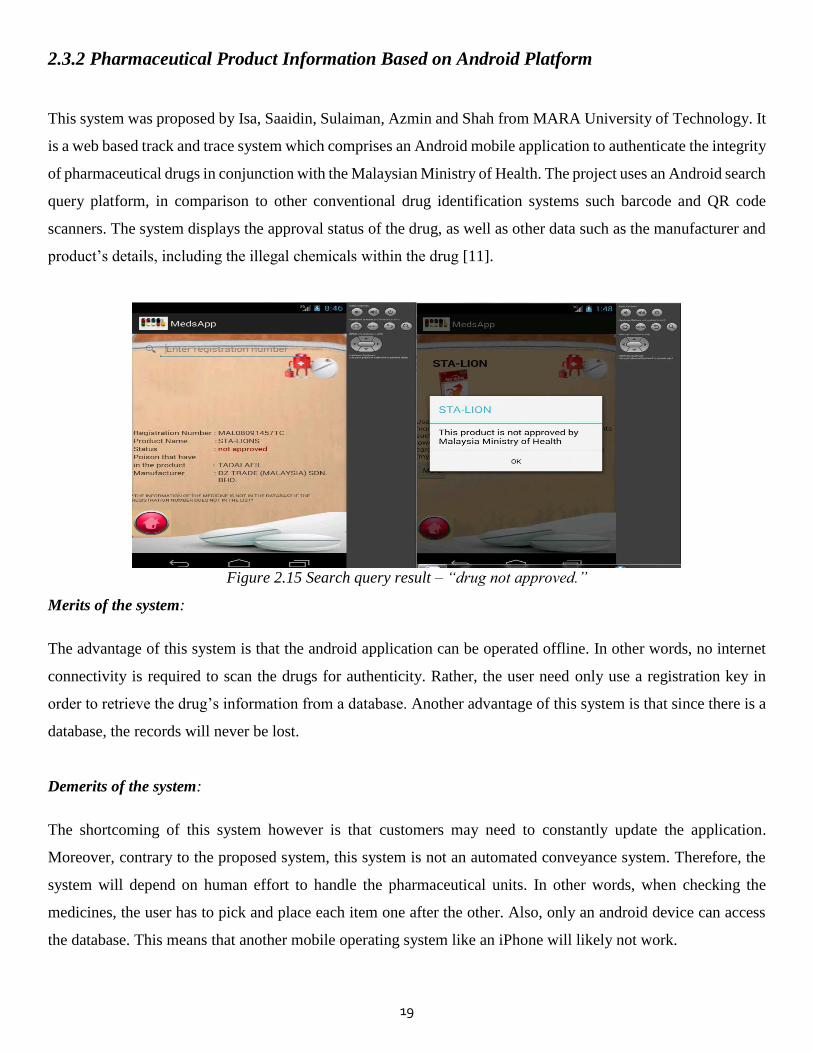
2.3.2 Pharmaceutical Product Information Based on Android Platform
This system was proposed by Isa, Saaidin, Sulaiman, Azmin and Shah from MARA University of Technology. It
is a web based track and trace system which comprises an Android mobile application to authenticate the integrity
of pharmaceutical drugs in conjunction with the Malaysian Ministry of Health. The project uses an Android search
query platform, in comparison to other conventional drug identification systems such barcode and QR code
scanners. The system displays the approval status of the drug, as well as other data such as the manufacturer and
product’s details, including the illegal chemicals within the drug [11].
Figure 2.15 Search query result – “drug not approved.”
Merits of the system:
The advantage of this system is that the android application can be operated offline. In other words, no internet
connectivity is required to scan the drugs for authenticity. Rather, the user need only use a registration key in
order to retrieve the drug’s information from a database. Another advantage of this system is that since there is a
database, the records will never be lost.
Demerits of the system:
The shortcoming of this system however is that customers may need to constantly update the application.
Moreover, contrary to the proposed system, this system is not an automated conveyance system. Therefore, the
system will depend on human effort to handle the pharmaceutical units. In other words, when checking the
medicines, the user has to pick and place each item one after the other. Also, only an android device can access
the database. This means that another mobile operating system like an iPhone will likely not work.

20
2.3.3 Distance Sensing with Ultrasonic Sensor and Arduino
This project was proposed by N. Anju Latha1, B. Rama Murthy and K. Bharat Kumar of Sri Krishnadevaraya
University, and it is an ultrasonic distance meter. It is similar to the proposed system in that it uses an Arduino
and ultrasonic sensor for non - contact range measurement. However that system is simply a distance measuring
device, whereas the proposed project employs the ultrasonic sensor to detect pharmaceutical cartons on the
conveyor packaging line, causing the motor to stop as instructed by the microcontroller. The device (shown in
Figure 2.1.6 below) can detect objects in the range of 2cm – 450cm, and displaying the measured distance on a
liquid screen display (LCD) [12].
Figure 2.16 Prototype: Ultrasonic distance meter
Merits of the system
The system is not really affected by dirt and wet environments. Also, it comes in very handy for non-contact
distance measurement. Also, it works best when detecting large objects. Another advantage of this system is that
its range of measurement is considerably extensive (from two centimeters up to four meters). Also, another
advantage of this system is its cost. The HC-SR04 Ultrasonic Sensor itself is very affordable. Hence the full
implementation of such a system is very feasible. Moreover, the device can be operated in dark places because it
does not depend on color or transparency of objects.
Demerits of the system
A drawback of the system is that the object, whose distance is to be measured from the ultrasonic distance meter,
should always be perpendicular to the plane of sound wave propagation. In other words, the accuracy of the
device can be compromised by wrong target - object orientation. Another demerit is that the accuracy of the
device is affected by soft materials. The ultrasonic distance meter is also affected by changes in temperature in
the environment, precisely about five to ten degrees; also it is not water-resistant.
21
2.3.4 Automatic Sorting System
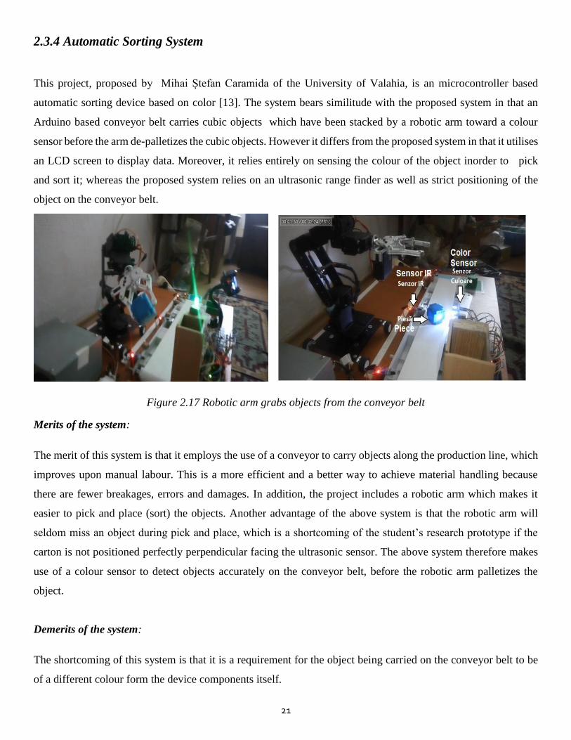
This project, proposed by Mihai Ștefan Caramida of the University of Valahia, is an microcontroller based
automatic sorting device based on color [13]. The system bears similitude with the proposed system in that an
Arduino based conveyor belt carries cubic objects which have been stacked by a robotic arm toward a colour
sensor before the arm de-palletizes the cubic objects. However it differs from the proposed system in that it utilises
an LCD screen to display data. Moreover, it relies entirely on sensing the colour of the object inorder to pick
and sort it; whereas the proposed system relies on an ultrasonic range finder as well as strict positioning of the
object on the conveyor belt.
Figure 2.17 Robotic arm grabs objects from the conveyor belt
Merits of the system:
The merit of this system is that it employs the use of a conveyor to carry objects along the production line, which
improves upon manual labour. This is a more efficient and a better way to achieve material handling because
there are fewer breakages, errors and damages. In addition, the project includes a robotic arm which makes it
easier to pick and place (sort) the objects. Another advantage of the above system is that the robotic arm will
seldom miss an object during pick and place, which is a shortcoming of the student’s research prototype if the
carton is not positioned perfectly perpendicular facing the ultrasonic sensor. The above system therefore makes
use of a colour sensor to detect objects accurately on the conveyor belt, before the robotic arm palletizes the
object.
Demerits of the system:
The shortcoming of this system is that it is a requirement for the object being carried on the conveyor belt to be
of a different colour form the device components itself.

22
2.3.5 Automatic Material Handling System, Pick & Place Robotic Arm & Image Processing
This project, designed by Rajnor and Proffesor A.S Bhide, is similar to the proposed system in that it constitutes
the use of an Arduino microcontroller to control a motor – driven conveyor belt to ferry objects, as well as a
robotic arm to pick and palce them to a specified location. Although the core function of this project was not to
specifically ferry pharmaceutical cartons, it does indeed bear resemblance to and compliments the proposed
system in that they both mimic a packaging line with a robotic palletizer. However, the system differs in that it
employs sensors and Matlab image processing to senses the colour and size of the objects; which is contrary to
the proposed system in that it does not treat colour and size of the cartons as variables. The movement of the
robotic arm is thus dependant on the input of the sensors, before gripping and releasing the objects to a particular
location [14]. The prototype is shown in Figure 2.18 below:
Figure 2.18 Prototype: Conveyor Belt and Four Axis Robot
Merits of the system:
The main advantage of the system is that it reduces human effort in both the conveyor belt system as well as the
EoAT robotic arm subsystems. The conveyor belt carries the objects in place of human labour all across the
production line. The four axis robotic arm performs pick and place based on the colour of the object. In both
instances, the device reduces human effort considerably and improves time and improves profit margins in an
organization due to increased productivity.
Demerits of the system:
The main disadvantage is that if the colour signature of the object being sensed matches that of the device itself,
then the device will malfunction. This is because the ability of the EoAT to accurately pick and place depends
sorely on colour. This differs from the student’s research on pharmaceutical packaging in that the EoAT’s
positional accuracy depends on the ultrasonic sensor which detects the cartons on the conveyor.
23
Industrial Systems and Technologies
2.3.6 SAP® Advanced Track and Trace for Pharmaceuticals
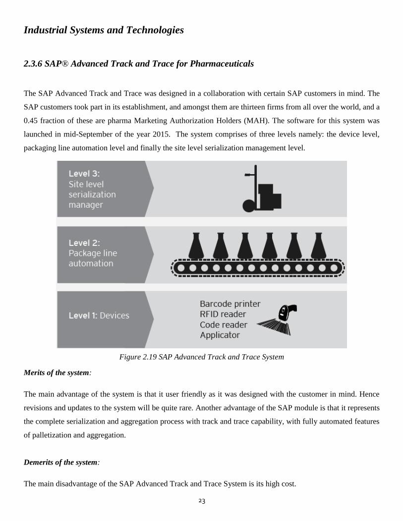
The SAP Advanced Track and Trace was designed in a collaboration with certain SAP customers in mind. The
SAP customers took part in its establishment, and amongst them are thirteen firms from all over the world, and a
0.45 fraction of these are pharma Marketing Authorization Holders (MAH). The software for this system was
launched in mid-September of the year 2015. The system comprises of three levels namely: the device level,
packaging line automation level and finally the site level serialization management level.
Figure 2.19 SAP Advanced Track and Trace System
Merits of the system:
The main advantage of the system is that it user friendly as it was designed with the customer in mind. Hence
revisions and updates to the system will be quite rare. Another advantage of the SAP module is that it represents
the complete serialization and aggregation process with track and trace capability, with fully automated features
of palletization and aggregation.
Demerits of the system:
The main disadvantage of the SAP Advanced Track and Trace System is its high cost.
24
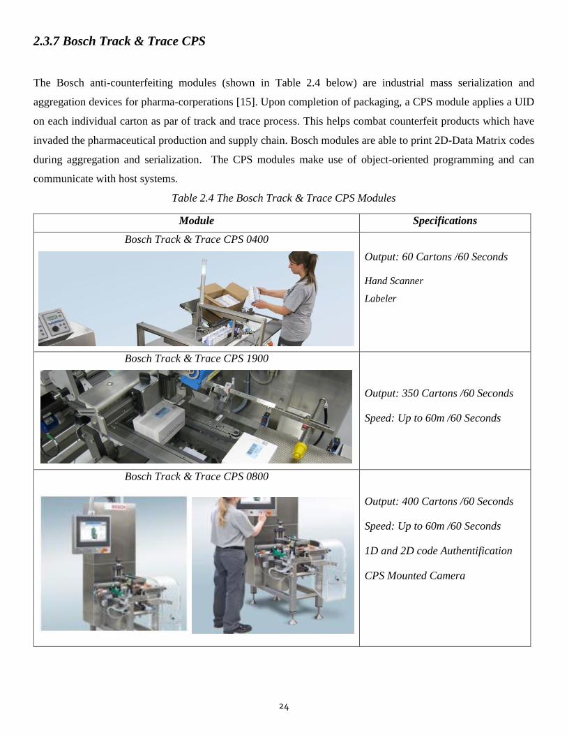
2.3.7 Bosch Track & Trace CPS
The Bosch anti-counterfeiting modules (shown in Table 2.4 below) are industrial mass serialization and
aggregation devices for pharma-corperations [15]. Upon completion of packaging, a CPS module applies a UID
on each individual carton as par of track and trace process. This helps combat counterfeit products which have
invaded the pharmaceutical production and supply chain. Bosch modules are able to print 2D-Data Matrix codes
during aggregation and serialization. The CPS modules make use of object-oriented programming and can
communicate with host systems.
Table 2.4 The Bosch Track & Trace CPS Modules
Module Specifications
Bosch Track & Trace CPS 0400
Output: 60 Cartons /60 Seconds
Hand Scanner
Labeler
Bosch Track & Trace CPS 1900
Output: 350 Cartons /60 Seconds
Speed: Up to 60m /60 Seconds
Bosch Track & Trace CPS 0800
Output: 400 Cartons /60 Seconds
Speed: Up to 60m /60 Seconds
1D and 2D code Authentification
CPS Mounted Camera
25
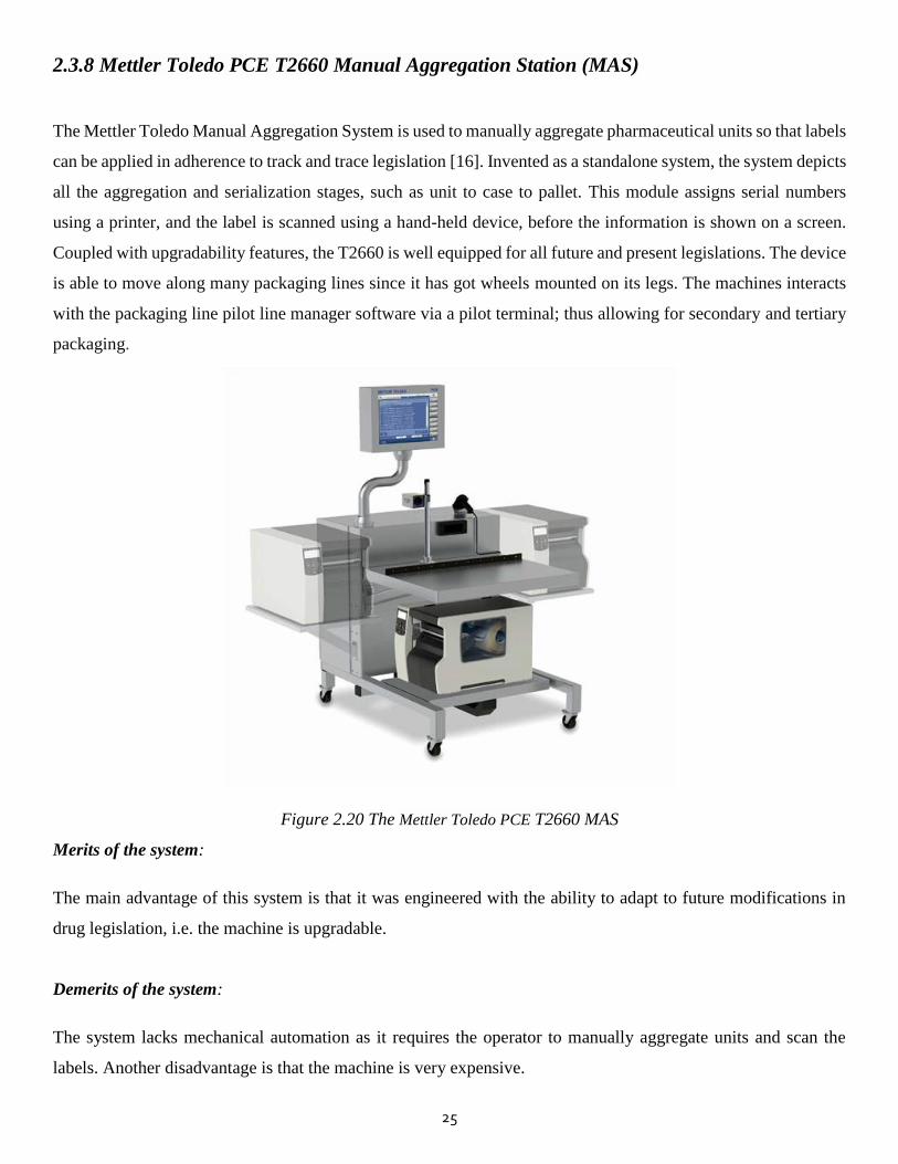
2.3.8 Mettler Toledo PCE T2660 Manual Aggregation Station (MAS)
The Mettler Toledo Manual Aggregation System is used to manually aggregate pharmaceutical units so that labels
can be applied in adherence to track and trace legislation [16]. Invented as a standalone system, the system depicts
all the aggregation and serialization stages, such as unit to case to pallet. This module assigns serial numbers
using a printer, and the label is scanned using a hand-held device, before the information is shown on a screen.
Coupled with upgradability features, the T2660 is well equipped for all future and present legislations. The device
is able to move along many packaging lines since it has got wheels mounted on its legs. The machines interacts
with the packaging line pilot line manager software via a pilot terminal; thus allowing for secondary and tertiary
packaging.
Figure 2.20 The Mettler Toledo PCE T2660 MAS
Merits of the system:
The main advantage of this system is that it was engineered with the ability to adapt to future modifications in
drug legislation, i.e. the machine is upgradable.
Demerits of the system:
The system lacks mechanical automation as it requires the operator to manually aggregate units and scan the
labels. Another disadvantage is that the machine is very expensive.

26
2.3.9 Denmark Labelling Systems Scandinavia (LSS)
This latest pharmaceutical device, released by Danish Labelling Systems Scandinavia (LSS), is totally in
accordance with the European Falsified Medicines Directive (FMD) 2011/62/EU legislation. It is a true feat of
pharma – packaging engineering; with the latest serialization track and trace technology embedded within it. The
main philosophy behind its implementation is the need for tamper evident labeling in pharmaceutical products.
This device can perfom serialization and aggregation, as well as allow track and trace at any stage in the supply
chain.
Figure 2.21 The Denmark Labelling Systems Scandinavia (LSS)
The device’s labels can be transparent or not; it is entirely a matter of choice. The label applicator will seal a
carton, then a serialization UID code for track and trace is printed onto the carton. Its output capacity is three
hundred cartons in sixty seconds. The sequence of operating the LSS label applicator is this: when a carton is
detected, its dimensions and location are recorded. At any instance, this procedure can be ceased at any moment
and the system rebooted, but the labeler will not lose the recorded data.
Merits of the system:
The advantage of the LSS is its high output capacity (300 cartons/ minute), which makes it highly efficient
compared to other labelling systems. Another merit is its ability to retain data after power loss.
Demerits of the system:
The main shortcoming of this system is its very high cost. This device is expensive and is hardly affordable to
many pharmaceutical manufacturers, especially generic medicine packagers in Zimbabwe.

27
2.4 Software Requirements
The following softwares were used in this research:
▪ Fritzing
▪ Proteus
▪ Arduino
A brief desription of the theoretical aspects of each software will be outlined below. In essence, Fritzing and
Proteus are simulation softwares; whilst the Arduino IDE is a coding platform for microcontrollers.
2.4.1 Fritzing
Fritzing is an open source software developed by Interaction Design Lab Potsdam for those hobbyists who lack
thourough knowledge of circuits and electronics. In other words, non proffesionals can use the software to design
cicuits in electronics, to shift from mere experimentation to more realistic designs. Fritzing was coded in C++
and it supports the following operating systems:Unix, Mac OS and Windows.
2.4.2 Proteus PCB Design and Simulation
Proteus PCB Design and simulation is a Virtual System Modelling (VSM) software suite that was developed by
Labcenter Electronics. It consists of simulation, PCB design and schematic sections. For PCB design, Ares is
used and it has the capability to view the resultant PCB in three dimensions (though two dimensional CAD
drawings can be achieved as well). Meanwhile, for circuit simulation and drawing schematics, ISIS software is
used. This simulation will be running in real time. In addition, Proteus bears aspects of microprocessor models,
SPICE circuit simulation, as well as animated tools. The core of Proteus VSM is ProSPICE which allows the user
to use many manufacturer – provided models (up to six thousand). ProSPICE also include a SPICE3f5 analogue
simulator which allows mixed-mode simulation.
2.4.3 Arduino Software IDE
Arduino software integrated development environment (IDE) is an open source software package used to code
the microcontroller. It has a green and white interface and comprises a text editor and console, a series of menus,
a toolbar as well as a message region. It is compatible withh the following operating systems: Linux, Windows
and Mac OS. It was written in Java and is based on Processing; thus making it easier to code and upload programs
to the Arduino board.

28
2.5 System Hardware Requirements
The hardware components used in this research to assemble the prototype are listed below. The theoretical aspects
and electrical specifications of each electronic component are also discussed.
▪ Bipolar Stepper Motor
▪ Conveyor Rollers
▪ Servo Tilt Bracket
▪ Bipolar Stepper Driver
▪ Conveyor Belt
▪ Unipolar Stepper Driver
▪ Unipolar Stepper Motor
▪ Wood Nails
▪ Hack Saw
▪ 9V 1A Power Adapter
▪ 5V 1A Power Adapter
▪ Ultrasonic Sensor
▪ Arduino Uno
▪ Servo Motors
▪ USB Cable (A-B)
▪ Cardboard Case
▪ Wooden Pallet
▪ Breadboard
▪ Prime Bond Glue
▪ Soldering Wire
▪ Soldering Gun
▪ Jumper Wires
▪ Super Glue
29
2.5.1 Arduino Uno Microcontroller
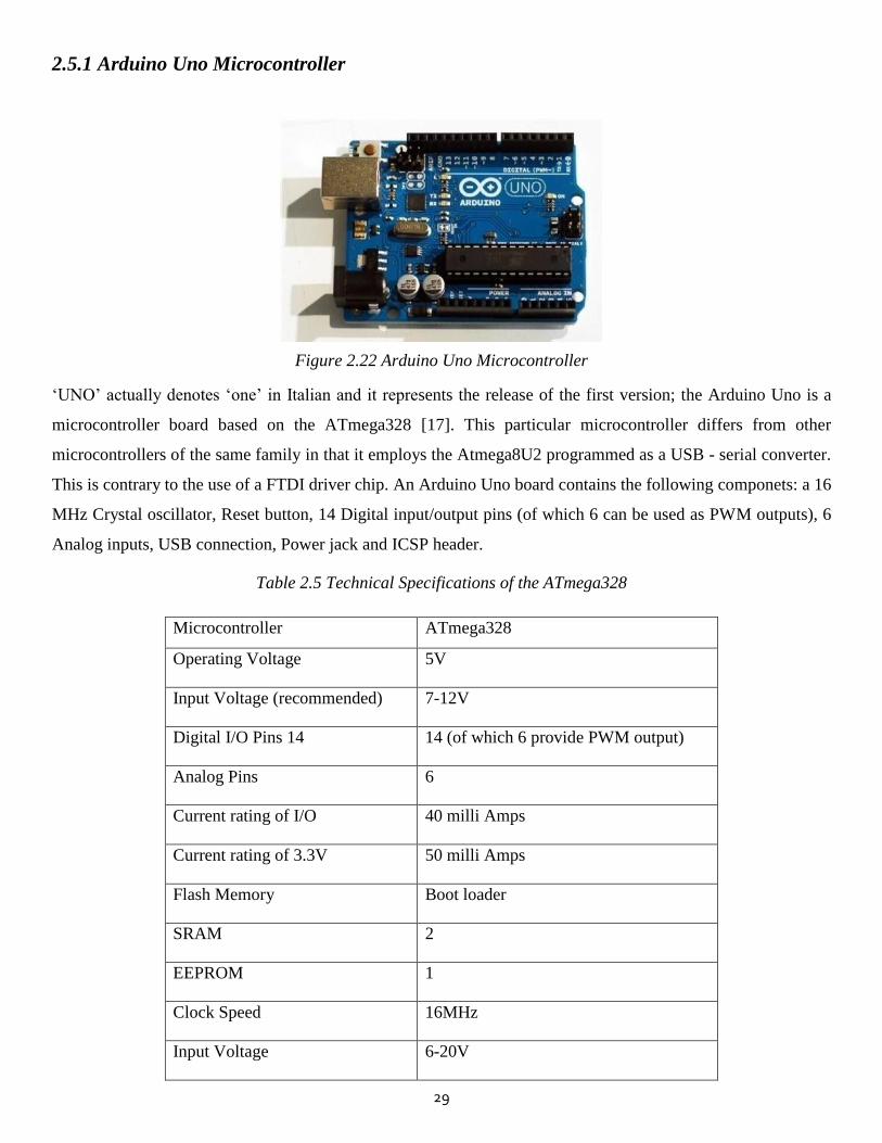
Figure 2.22 Arduino Uno Microcontroller
‘UNO’ actually denotes ‘one’ in Italian and it represents the release of the first version; the Arduino Uno is a
microcontroller board based on the ATmega328 [17]. This particular microcontroller differs from other
microcontrollers of the same family in that it employs the Atmega8U2 programmed as a USB - serial converter.
This is contrary to the use of a FTDI driver chip. An Arduino Uno board contains the following componets: a 16
MHz Crystal oscillator, Reset button, 14 Digital input/output pins (of which 6 can be used as PWM outputs), 6
Analog inputs, USB connection, Power jack and ICSP header.
Table 2.5 Technical Specifications of the ATmega328
Microcontroller ATmega328
Operating Voltage 5V
Input Voltage (recommended) 7-12V
Digital I/O Pins 14 14 (of which 6 provide PWM output)
Analog Pins 6
Current rating of I/O 40 milli Amps
Current rating of 3.3V 50 milli Amps
Flash Memory Boot loader
SRAM 2
EEPROM 1
Clock Speed 16MHz
Input Voltage 6-20V
30
2.5.2 Unipolar Stepper Motor (28 BYJ-48)
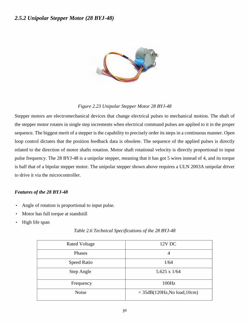
Figure 2.23 Unipolar Stepper Motor 28 BYJ-48
Stepper motors are electromechanical devices that change electrical pulses to mechanical motion. The shaft of
the stepper motor rotates in single step increments when electrical command pulses are applied to it in the proper
sequence. The biggest merit of a stepper is the capability to precisely order its steps in a continuous manner. Open
loop control dictates that the position feedback data is obsolete. The sequence of the applied pulses is directly
related to the direction of motor shafts rotation. Motor shaft rotational velocity is directly proportional to input
pulse frequency. The 28 BYJ-48 is a unipolar stepper, meaning that it has got 5 wires instead of 4, and its torque
is half that of a bipolar stepper motor. The unipolar stepper shown above requires a ULN 2003A unipolar driver
to drive it via the microcontroller.
Features of the 28 BYJ-48
▪ Angle of rotation is proportional to input pulse.
▪ Motor has full torque at standstill
▪ High life span
Table 2.6 Technical Specifications of the 28 BYJ-48
Rated Voltage 12V DC
Phases 4
Speed Ratio 1/64
Step Angle 5.625 x 1/64
Frequency 100Hz
Noise < 35dB(120Hz,No load,10cm)
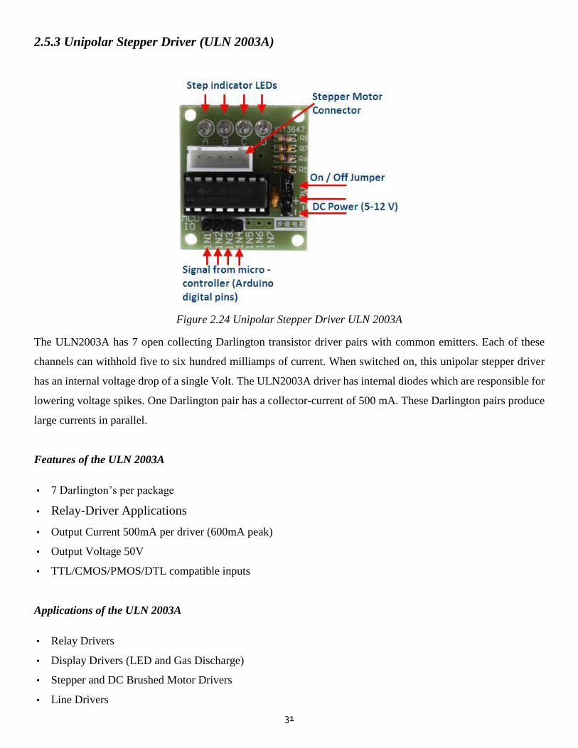
31
2.5.3 Unipolar Stepper Driver (ULN 2003A)
Figure 2.24 Unipolar Stepper Driver ULN 2003A
The ULN2003A has 7 open collecting Darlington transistor driver pairs with common emitters. Each of these
channels can withhold five to six hundred milliamps of current. When switched on, this unipolar stepper driver
has an internal voltage drop of a single Volt. The ULN2003A driver has internal diodes which are responsible for
lowering voltage spikes. One Darlington pair has a collector-current of 500 mA. These Darlington pairs produce
large currents in parallel.
Features of the ULN 2003A
▪ 7 Darlington’s per package
▪ Relay-Driver Applications
▪ Output Current 500mA per driver (600mA peak)
▪ Output Voltage 50V
▪ TTL/CMOS/PMOS/DTL compatible inputs
Applications of the ULN 2003A
▪ Relay Drivers
▪ Display Drivers (LED and Gas Discharge)
▪ Stepper and DC Brushed Motor Drivers
▪ Line Drivers
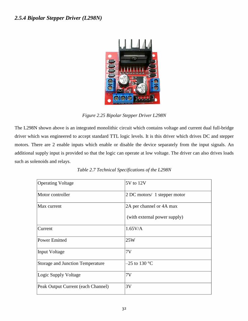
32
2.5.4 Bipolar Stepper Driver (L298N)
Figure 2.25 Bipolar Stepper Driver L298N
The L298N shown above is an integrated monolithic circuit which contains voltage and current dual full-bridge
driver which was engineered to accept standard TTL logic levels. It is this driver which drives DC and stepper
motors. There are 2 enable inputs which enable or disable the device separately from the input signals. An
additional supply input is provided so that the logic can operate at low voltage. The driver can also drives loads
such as solenoids and relays.
Table 2.7 Technical Specifications of the L298N
Operating Voltage 5V to 12V
Motor controller 2 DC motors/ 1 stepper motor
Max current 2A per channel or 4A max
(with external power supply)
Current 1.65V/A
Power Emitted 25W
Input Voltage 7V
Storage and Junction Temperature –25 to 130 °C
Logic Supply Voltage 7V
Peak Output Current (each Channel) 3V
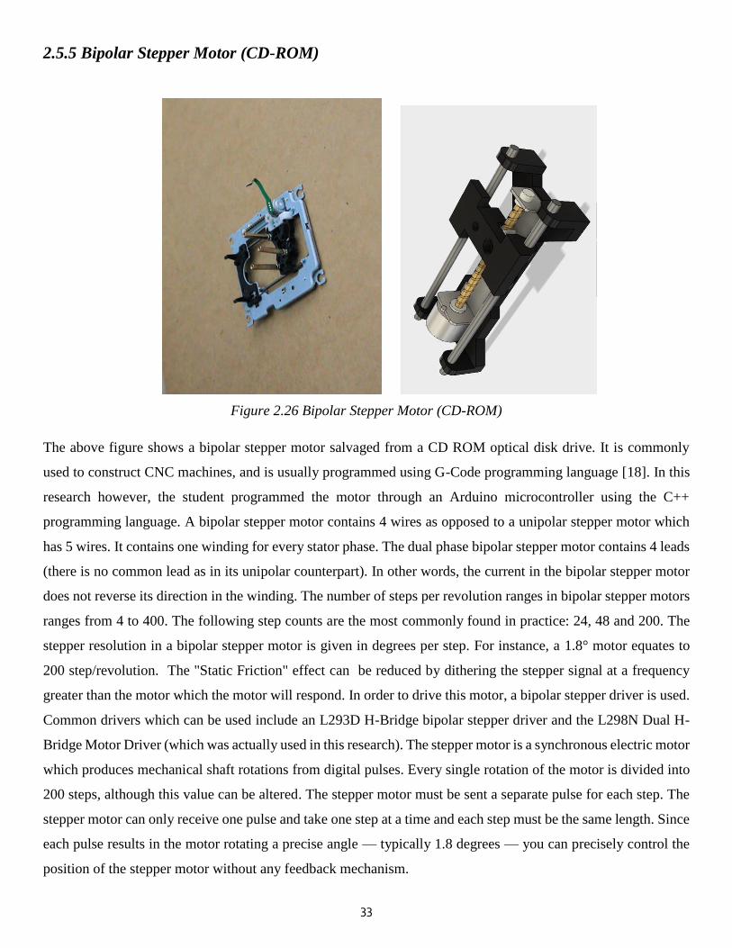
33
2.5.5 Bipolar Stepper Motor (CD-ROM)
Figure 2.26 Bipolar Stepper Motor (CD-ROM)
The above figure shows a bipolar stepper motor salvaged from a CD ROM optical disk drive. It is commonly
used to construct CNC machines, and is usually programmed using G-Code programming language [18]. In this
research however, the student programmed the motor through an Arduino microcontroller using the C++
programming language. A bipolar stepper motor contains 4 wires as opposed to a unipolar stepper motor which
has 5 wires. It contains one winding for every stator phase. The dual phase bipolar stepper motor contains 4 leads
(there is no common lead as in its unipolar counterpart). In other words, the current in the bipolar stepper motor
does not reverse its direction in the winding. The number of steps per revolution ranges in bipolar stepper motors
ranges from 4 to 400. The following step counts are the most commonly found in practice: 24, 48 and 200. The
stepper resolution in a bipolar stepper motor is given in degrees per step. For instance, a 1.8° motor equates to
200 step/revolution. The "Static Friction" effect can be reduced by dithering the stepper signal at a frequency
greater than the motor which the motor will respond. In order to drive this motor, a bipolar stepper driver is used.
Common drivers which can be used include an L293D H-Bridge bipolar stepper driver and the L298N Dual H-
Bridge Motor Driver (which was actually used in this research). The stepper motor is a synchronous electric motor
which produces mechanical shaft rotations from digital pulses. Every single rotation of the motor is divided into
200 steps, although this value can be altered. The stepper motor must be sent a separate pulse for each step. The
stepper motor can only receive one pulse and take one step at a time and each step must be the same length. Since
each pulse results in the motor rotating a precise angle — typically 1.8 degrees — you can precisely control the
position of the stepper motor without any feedback mechanism.

34
Figure 2.28 SG90 Servo Control Signal Pulse Train
2.5.6 Servo Motor (SG90)
Figure 2.27 Servo Motor SG90
A servo-motor is an actuator with a built-in feedback mechanism that responds to a control signal (from a
microcontroller). It is a small motor which rotates up to 180 degrees and has a high power output.There are 2
types of servos basically: continuous rotation servos and standard servos.
Table 2.8 Technical Specifications of the SG90
Voltage 4.8 - 5V
Temperature 0 ºC – 55 ºC
Speed 0.1s/ degree
Weight 9g
Stall Torque 1.8
1 ms
1.5 ms
2 ms
1 ms = pulse width

35
2.5.7 Ultrasonic Sensor (HC-SR04)
Figure 2.29 The HC-SR04 Ultrasonic Module
The HC-SR04 ultrasonic ranging sensor is a very cost efficient module comprising of a a transmitter, receiver
and control circuit. Its range of measurement is from 2cm to 400cm for non-contact applications. The ultrasonic
sensor’s accuracy is approximately 0.3cm.
Features of the HC-SR04
▪ Stable during operation
▪ Near precise range measurement
▪ High-density SMD Board
▪ Close Range (minimum of 2cm)
▪ High sensitivity (0.3cm ranging accuracy)
Table 2.9 Technical Specifications of the HC-SR04
Electrical Parameters HC-SR04 Ultrasonic Module
Voltage 5VDC
Current 15mA
Frequency of Use 40KHz
Maximum Distance 4m
Closest Distance 2cm
Measuring Angle 15 Degrees
Input Trigger Signal 10 microseconds
Output Echo Signal TTL level signal, proportional to
distance
Measurements 1-13/16" X 13/16" X 5/8"
Circuitry 4 X 0.1" Pitch Right Angle Header Pins
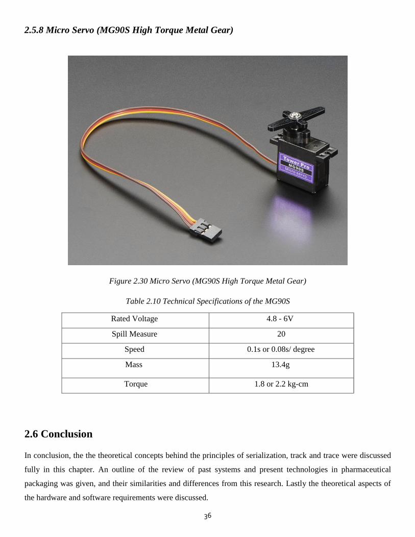
36
2.5.8 Micro Servo (MG90S High Torque Metal Gear)
Figure 2.30 Micro Servo (MG90S High Torque Metal Gear)
Table 2.10 Technical Specifications of the MG90S
Rated Voltage 4.8 - 6V
Spill Measure 20
Speed 0.1s or 0.08s/ degree
Mass 13.4g
Torque 1.8 or 2.2 kg-cm
2.6 Conclusion
In conclusion, the the theoretical concepts behind the principles of serialization, track and trace were discussed
fully in this chapter. An outline of the review of past systems and present technologies in pharmaceutical
packaging was given, and their similarities and differences from this research. Lastly the theoretical aspects of
the hardware and software requirements were discussed.
37
2.7 References
[1] B. N. et al., "EU Falsified Medicines Directive mandatory requirements for secondary care: A concise
review," Journal of Generic Medicines, vol. 12, no. 3-4, pp. 95-101, 2015.
[2] F. E.-J. F. A. H. A. Racha Fadlallah, "Strategies and Systems-Level Interventions to Combat or Prevent
Drug Counterfeiting: A Systematic Review of Evidence Beyond Drug Counterfeiting: A Systematic Review
of Evidence Beyond Drug Counterfeiting: A Systematic Review of Evidence Beyond Effectivene," Pharm
Med, vol. 30, p. 263–276, 19 August 2016.
[3] B. D. Naughton, "The EU Falsified Medicines Directive: key implications for dispensers," Medicine Access
@ Point of Care, 23 December 23 2017.
[4] M. A. Greenberg, "Serialization: Benefits Beyond Regulatory Compliance," Therapeutic Innovation &
Regulatory Science, vol. 48, no. 6, p. NP22, 2014.
[5] C. Chitemerere, "Pharmaceutical Sector Profile: Zimbabwe," in Global UNIDO Project: Strengthening the
local production of essential generic drugs in least developed and developing countries., Vienna, 2011.
[6] A. Malhotra, "Pharmaceutical serialization: compliance and beyond. A holistic analysis," Serialization in
Life Sciences supply chain Impact on Indian pharmaceutical sector, June 2016.
[7] Pharmaceutical Machinery , "Cartoning and Packaging," Pharmaceutical Machinery , [Online]. Available:
http:/www.pharmaceuticalmachinery.in/pharmaceutical_machinery_cartoning_and_%20packaging.htm.
[Accessed 27 April 2018].
[8] J. J. Muhammad, "Positioning of Conveyor and Loadcell Measurement," GRD Journals- Global Research
and Development Journal for Engineering, vol. 2, no. 4, March 2017.
[9] M. C. Ramon, "Assembling and Controlling a Robotic Arm," in Intel® Galileo and Intel® Galileo Gen 2,
2014, pp. 509-577.
[10] G. R. Reddy, D. Rushali, T. S. Jahnavi and B. A. Kumar, "BLISS BOT FOR PHARMACEUTICAL
INSPECTION," in International Conference on Trends in Electronics and Informatics ICEI, 2017.
[11] S. S. N. A. S. A. A. N. S. A. A. S. Naimah Mat Isa, "Pharmaceutical Product Information Based on Android
Platform," in 2nd International Conference on Electrical, Electronics and System Engineering (ICEESE),
2014.
38
[12] B. R. M. K. B. K. N. Anju Latha, "Distance Sensing with Ultrasonic Sensor and Arduino," International
Journal of Advance Research, Ideas and Innovations in Technology IJARIIT, vol. 2, no. 5, 2016.
[13] M. Ș. Caramida, "Automatic Sorting System," Journal of Electrical Engineering, Electronics, Control and
Computer Science JEEECCS, vol. 2, no. 5, pp. 5-10, 2016.
[14] .. D. L. Rajnor and P. A. Bhide, "Automatic Material Handling System Using Pick & Place Robotic Arm &
Image Processing," IJSRD - International Journal for Scientific Research & Development, vol. 2, no. 5,
2014.
[15] Bosch, "Track & Trace and Serialization Solutions," Bosch.
[16] Mettler Toledo Group, " Track & Trace Variable Use Complete Aggregation Rework Support T2660
Marking And Verifying," PCE Track and Trace, Jaunary 2018.
[17] R. S. M. K. A. P. S. R. D. P. Sathiya, "Arduino ATMEGA-328 Microcontroller," INTERNATIONAL
JOURNAL OF INNOVATIVE RESEARCH IN ELECTRICAL, ELECTRONICS, INSTRUMENTATION AND
CONTROL ENGINEERING, vol. 3, no. 4, April 2015.
[18] D. A. K. I. A. D. P. S. Pranav, "Development of Arduino Controlled CNC/3D Printer," International Journal
of Emerging Research in Management &Technology, vol. 5, no. 7, pp. 1-10, July 2016.

39
CHAPTER 3
Research Method
3.1 Introduction
This chapter discusses the approach used to carry out the research. It also discusses the design assumptions related
to the system design. An outline is given of the system block diagram, system flow chart, hardware connections,
overall system schematic and the ethical issues governing the research.
3.2 System Design and Assumptions
3.2.1 Design Assumptions
In assembling the system, the following assumptions were taken into account:
1. It is assumed that for demostration purposes, a few cubic pieces of expanded polystyrene (EPS) foam will be
used as a substitute for real pharmaceutical cartons, due to their rigidity (to withstand the stamping force of
the label applicator) and due to their light weight (for ease of pick and place).
2. It is assumed that prior to serialization, each pharmaceutical carton is alreadly sealed.
3. It is assumed that during pick and place, the EOAT palletizer’s gripping torque cannot be overcome by the
weight and physical dimensions of the cartons.
4. It is assumed that the UID will not contain a bar code or QR code, as these are very difficult to engrave into
a prototype an inked stamp/ label applicator. Rather, a human readable inked - mark (containing the serial
number, expiry date etc.) will be stamped onto the cartons for the sake of demonstation.
5. It is assumed that the concept of track and trace, which is the next step after serialization in securing the supply
chain, will not be demonstrated in this project. This is because it is impossible to scan a human readable code
without character recognition; but had it been a 2D matrix barcode or QR code, a barcode and QR scanner
would have sufficed. Therefore since image processing will not be demostrated in this study, the human
readable characters will simply be applied, not be scanned.
6. It is assumed that the ink which will be used to serialize the cartons will be manually applied onto the label
applicator by the user.
7. It is finally assumed that the outer material of the carton (cardboard) will be considered as wood for the
purpose of calculating the gripping force (F) between the wooden EoAT and the carton. Hence the static
coefficient of friction of wood-to-wood will be used in place of wood-to-cardboard.
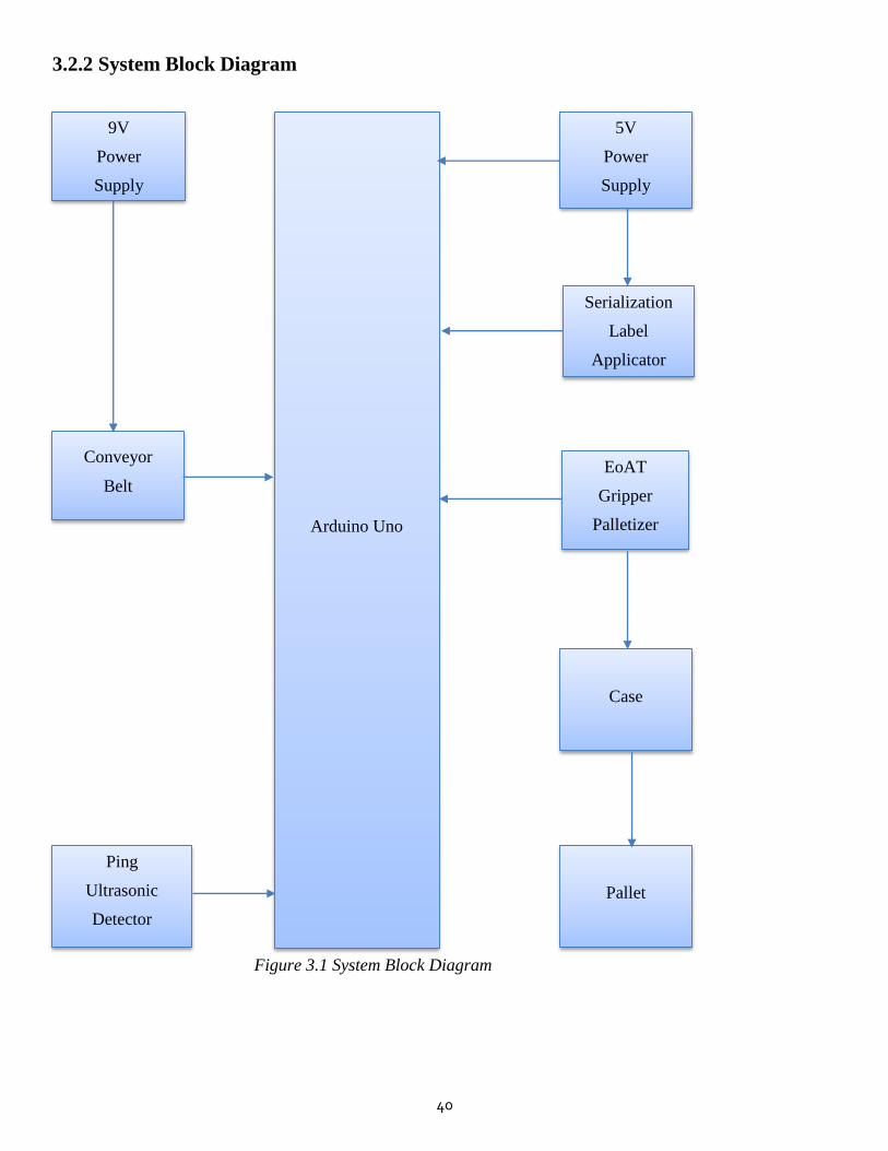
40
3.2.2 System Block Diagram
9V
Power
Supply
5V
Power
Supply
Arduino Uno
Serialization
Label
Applicator
Conveyor
Belt EoAT
Gripper
Palletizer
Ping
Ultrasonic
Detector
Case
Pallet
Figure 3.1 System Block Diagram
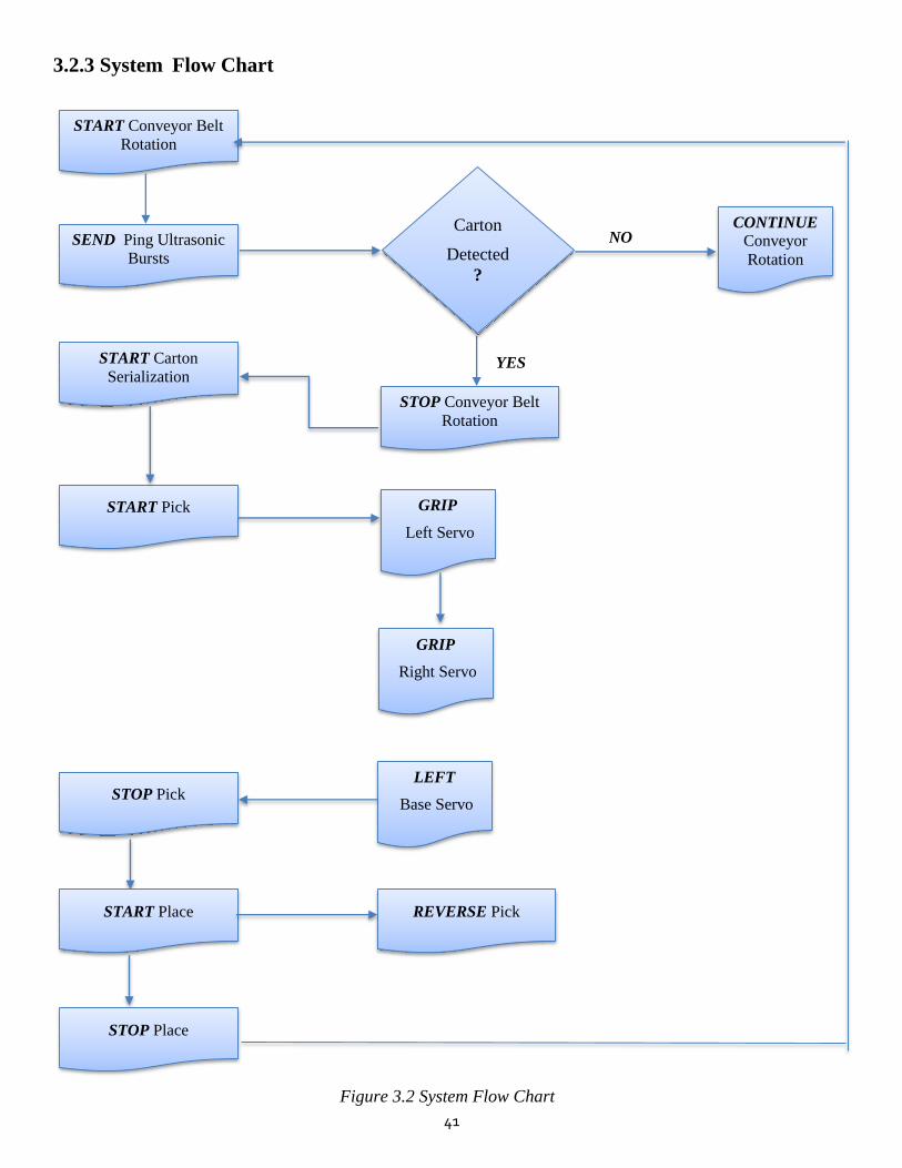
41
3.2.3 System Flow Chart
NO
YES
CONTINUE
Conveyor
Rotation
START Conveyor Belt
Rotation
SEND Ping Ultrasonic
Bursts
START Carton
Serialization
STOP Conveyor Belt
Rotation
START Pick GRIP
Left Servo
GRIP
Right Servo
LEFT
Base Servo
STOP Pick
START Place REVERSE Pick
STOP Place
Carton
Detected
?
Figure 3.2 System Flow Chart

42
3.2.4 Overall System Overview
The system comprises of 4 main subsystems namely:
▪ Conveyor Belt Subsystem
This comprises of a unipolar (28 BYJ-48) stepper motor connected to a unipolar (ULN 2003A) stepper driver.
This motor driver is in turn controlled by the Arduino Uno microcontroller. The conveyor belt comprises of a
textile belt and a wooded enclosure/ body. Utilizing friction, the belt is driven by two plastic rollers (one is
the driver roller, the other is the idle roller). Attached to the driver roller is the shaft of the unipolar stepper
motor, such that when the motor rotates, the driver roller also moves. The net result of this is that the idle
roller is also forced into motion and hence the conveyor belt is set into motion.
▪ Ping Ultrasonic Carton Detection Subsystem
This subsystem consists of a ping ultrasonic range finder that is placed facing the path of oncoming
pharmaceutical cartons on the conveyor belt. The ping ultrasonic range finder is simply an ultrasonic sensor
(HC-SR04 module) connected to the Arduino. The code from the Arduino causes the sensor to emmit short
bursts of ultrasonic waves (pings) torwards the path of oncoming cartons on the conveyor. A maximum range
is declared in the code to restrict the range of the sensor to the width of the belt only. Once a carton approaches
and cuts the line of sight of the ultrasonic sensor, an emitted ultrasonic wave will return to the sensor in a
shorter duration (hence shorter distsnce) from the sensor. This will cause Arduino to stop the unipolar stepper
motor throught its driver (thereby stopping the entire conveyor belt).
▪ Label Applicator Serialization Subsystem
This subsystem comprises of a label applicator that perfoms serialization on the pharmaceutical cartons on
the packaging line. The label applicator is simply a modified CD-ROM linear actuator slavaged from a disused
CD player (which itself is a biplolar stepper motor that is mounted in such a way that when its shaft rotates,
the rotational torque is converted to ‘up – down’ linear motion). This bipolar stepper motor is connected to a
bipolar stepper motor driver (L298N Dual Bridge), which itself is connected to the Arduino Uno. From the
previous subsystem, once the conveyor belt has stopped, the Arduino will cause the bipolar stepper driver to
move the bipolar motor stepper. The linear actuator moves down then up, directly facing the stationary carton
below the label applicator (which has an inked stamp strapped to the bottom of the actuator and the inked
marking that it leaves on the carton contains a human readable Unique Identifier code (UID), the expiry date
as well as the serial number of the pharmaceutical carton [1]. This typically demonstrates the serialization of
the cartons on the packaging line.

43
▪ EoAT Pick And Place Palletization Subsystem
This is the final subsystem of the entire project. The EoAT pick and place palletizer consists of a robotic arm
with few degrees of freedom situated at the end of the packaging line [2]. The robotic arm is made up of three
microservo motors (SG90) that move according to purpose: left gripper, right gripper and base rotation servo.
Continuing from the previous serialization subsystem, once the inked UID label has been applied on the carton
unit, the conveyor belt will still be stationary. The robotic arm will pick the serialized carton from the conveyor
and place it below into a case sitting on a pallet, before returning to its original position. Once that happens
the arduino causes the unipolar stepper motor (conveyor) to rotate again. The next carton in line goes through
the same sequence and the system repeats itself in a loop.

44
3.2.5 Hardware Interfacing And Prototype Buillding
Interfacing Arduino Uno to ULN2003A Unipolar Stepper Motor Driver
Figure 3.3 Arduino to ULN2003A Unipolar Stepper Motor Driver Connection (Fritzing Circuit)
This circuit represents the Conveyor Belt Subsystem. It indicates how the 28 BYJ -48 unipolar stepper motor
was interfaced to the ULN2003A unipolar stepper driver. It also illustrates how the ULN2003A unipolar stepper
driver was connected to the Arduino Uno microcontroller. The 28 BYJ -48 unipolar stepper motor’s female white
5 pin connector was connected directly into its male counterpart on the ULN2003A driver board [3].
The pin configuration for Figure 3.3
▪ Connected the ULN2003A Driver’s +12V pin to 9V Power Adapter’s positive terminal
▪ Connected the ULN2003A Driver’s GND pin to Arduino’s GND pin
▪ Connected the ULN2003A Driver’s IN1 pin to Arduino’s D8 pin
▪ Connected the ULN2003A Driver’s IN2 pin to Arduino’s D9 pin
▪ Connected the ULN2003A Driver’s IN3 pin to Arduino’s D10 pin
▪ Connected the ULN2003A Driver’s IN4 pin to Arduino’s D11 pin
▪ Connected the ULN2003A Driver’s 5 pin female connector to the 28 BYJ -48 stepper’s male connector.
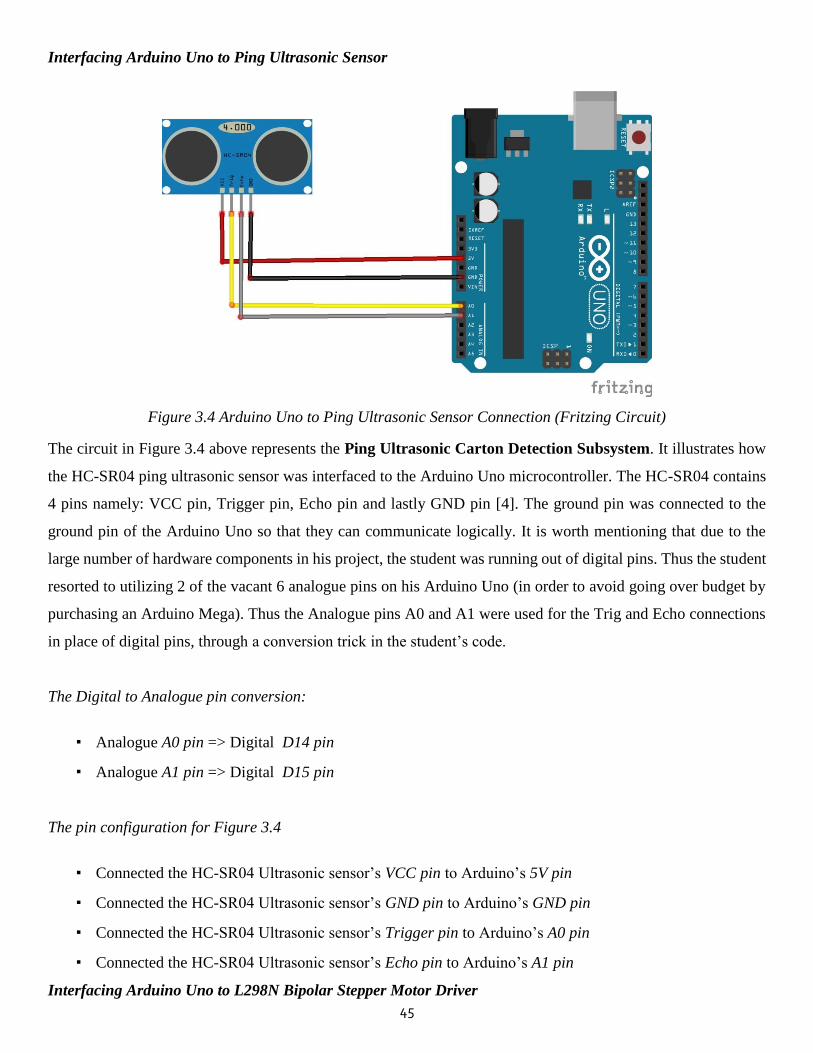
45
Interfacing Arduino Uno to Ping Ultrasonic Sensor
Figure 3.4 Arduino Uno to Ping Ultrasonic Sensor Connection (Fritzing Circuit)
The circuit in Figure 3.4 above represents the Ping Ultrasonic Carton Detection Subsystem. It illustrates how
the HC-SR04 ping ultrasonic sensor was interfaced to the Arduino Uno microcontroller. The HC-SR04 contains
4 pins namely: VCC pin, Trigger pin, Echo pin and lastly GND pin [4]. The ground pin was connected to the
ground pin of the Arduino Uno so that they can communicate logically. It is worth mentioning that due to the
large number of hardware components in his project, the student was running out of digital pins. Thus the student
resorted to utilizing 2 of the vacant 6 analogue pins on his Arduino Uno (in order to avoid going over budget by
purchasing an Arduino Mega). Thus the Analogue pins A0 and A1 were used for the Trig and Echo connections
in place of digital pins, through a conversion trick in the student’s code.
The Digital to Analogue pin conversion:
▪ Analogue A0 pin => Digital D14 pin
▪ Analogue A1 pin => Digital D15 pin
The pin configuration for Figure 3.4
▪ Connected the HC-SR04 Ultrasonic sensor’s VCC pin to Arduino’s 5V pin
▪ Connected the HC-SR04 Ultrasonic sensor’s GND pin to Arduino’s GND pin
▪ Connected the HC-SR04 Ultrasonic sensor’s Trigger pin to Arduino’s A0 pin
▪ Connected the HC-SR04 Ultrasonic sensor’s Echo pin to Arduino’s A1 pin
Interfacing Arduino Uno to L298N Bipolar Stepper Motor Driver
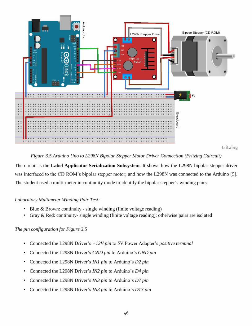
46
Figure 3.5 Arduino Uno to L298N Bipolar Stepper Motor Driver Connection (Fritzing Cuircuit)
The circuit is the Label Applicator Serialization Subsystem. It shows how the L298N bipolar stepper driver
was interfaced to the CD ROM’s bipolar stepper motor; and how the L298N was connected to the Arduino [5].
The student used a multi-meter in continuity mode to identify the bipolar stepper’s winding pairs.
Laboratory Multimeter Winding Pair Test:
▪ Blue & Brown: continuity - single winding (finite voltage reading)
▪ Gray & Red: continuity- single winding (finite voltage reading); otherwise pairs are isolated
The pin configuration for Figure 3.5
▪ Connected the L298N Driver’s +12V pin to 5V Power Adapter’s positive terminal
▪ Connected the L298N Driver’s GND pin to Arduino’s GND pin
▪ Connected the L298N Driver’s IN1 pin to Arduino’s D2 pin
▪ Connected the L298N Driver’s IN2 pin to Arduino’s D4 pin
▪ Connected the L298N Driver’s IN3 pin to Arduino’s D7 pin
▪ Connected the L298N Driver’s IN3 pin to Arduino’s D13 pin

47
Interfacing Arduino Uno to Pick And Place EoAT Palletizer
Figure 3.6 Arduino Uno to Pick And Place EoAT Palletizer Connection (Fritzing Circuit)
The circuit represents the EoAT Pick and Place Palletization Subsystem. It illustrates how each servo motor in
the robotic gripper palletizer was interfaced to the Arduino Uno microcontroller. A breadboard was used to bridge
the connections between the components. Because it was not safe to power 3 servo motors from the Arduino itself
(due to limited current drawn from the arduino), the student resorted to powering the servos using an external
power – the same 9V (AC-DC) power adapter powering the conveyor belt. In order to reduce the noise jitter
causing the servos to jerk around uncontrollably during power-on, the student resorted to twiching the code such
that the servos’ signal pin receives commands from the arduino before the power pin. The 3 servos were named
according to the movements they would perfom during pick and place, such that the first servo is the rotating
base, the second is the right gripper and the last is the left gripper.
The pin configuration for Figure 3.6
▪ Connected all the servo’s power pin to 9V Power Adapter’s positive terminal
▪ Connected all the servo’s GND pin to Arduino’s GND pin
▪ Connected the base - servo’s signal pin to Arduino’s D3 pin
▪ Connected the right - gripper - servo’s signal pin to Arduino’s D5 pin
▪ Connected the left - gripper - servo’s signal pin to Arduino’s D6 pin

48
Overall System Schematic
Figure 3.7 Overall System Schematic (Fritzing Simulation)
Figure 3.7 above represents the overal circuit for the whole system. Each subsystem was interfaced to the
microcontroller by connecting the grounds of each component to the same ground of the Arduino Uno. This
ensures logical communication between each and every component with the microcontroller. The circuit was first
modelled in Proteus and the C++ code was uploaded through a hex file to debug it. After that the circuit was
simulated in Fritzing to produce the schemaics shown above. Finally, the code was uploaded into the actual
Arduino Uno microcontroller through the Arduino IDE software. After physically connecting all the hardware
componets according to this circuit above, the overall system of the Autonomous Pharmaceutical Packaging on a
Conveyor Belt With Pick and Place Aggregation System was complete. The subsystems were linked to each other
through a series of events which are dictated by ‘if-else statements’ in the code. The first step in the sequence is
to place a pharmaceutical carton unit on the rotating unipolar stepper-driven conveyor belt, thereby carrying it
forwad along the packaging line. Once the ultrasonic sensor situated across the belt detects the presence of an
obstacle (carton), the Arduino Uno stops the conveyor belt. As soon as that happens, the bipolar stepper motor
will move the label applicator downwards and then upwards; thereby serializing the carton directly below it with
an inked UID. After this, the robotic EoAT’s left gripper servo moves, followed by the right gripper servo (thereby
gripping the carton), then the base servo moves sideways towards the pallet. The left and right servos ungrip the
carton and release it into the case sitting on the pallet. The robotic EoAT then returns to its original position,
allowing the conveyor to resume movement etc.
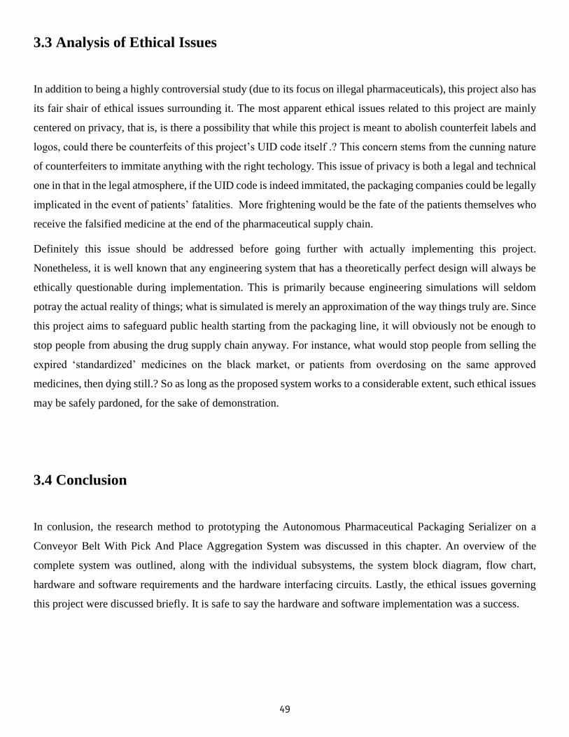
49
3.3 Analysis of Ethical Issues
In addition to being a highly controversial study (due to its focus on illegal pharmaceuticals), this project also has
its fair shair of ethical issues surrounding it. The most apparent ethical issues related to this project are mainly
centered on privacy, that is, is there a possibility that while this project is meant to abolish counterfeit labels and
logos, could there be counterfeits of this project’s UID code itself .? This concern stems from the cunning nature
of counterfeiters to immitate anything with the right techology. This issue of privacy is both a legal and technical
one in that in the legal atmosphere, if the UID code is indeed immitated, the packaging companies could be legally
implicated in the event of patients’ fatalities. More frightening would be the fate of the patients themselves who
receive the falsified medicine at the end of the pharmaceutical supply chain.
Definitely this issue should be addressed before going further with actually implementing this project.
Nonetheless, it is well known that any engineering system that has a theoretically perfect design will always be
ethically questionable during implementation. This is primarily because engineering simulations will seldom
potray the actual reality of things; what is simulated is merely an approximation of the way things truly are. Since
this project aims to safeguard public health starting from the packaging line, it will obviously not be enough to
stop people from abusing the drug supply chain anyway. For instance, what would stop people from selling the
expired ‘standardized’ medicines on the black market, or patients from overdosing on the same approved
medicines, then dying still.? So as long as the proposed system works to a considerable extent, such ethical issues
may be safely pardoned, for the sake of demonstration.
3.4 Conclusion
In conlusion, the research method to prototyping the Autonomous Pharmaceutical Packaging Serializer on a
Conveyor Belt With Pick And Place Aggregation System was discussed in this chapter. An overview of the
complete system was outlined, along with the individual subsystems, the system block diagram, flow chart,
hardware and software requirements and the hardware interfacing circuits. Lastly, the ethical issues governing
this project were discussed briefly. It is safe to say the hardware and software implementation was a success.
50
3.5 References
[1] C. Stobie, "The hidden challenges of pharmaceutical serialisation by Domino Printing Sciences," Journal of
Generic Medicines, vol. 12, no. 1, p. 6, 12 August 2015.
[2] D. V.A.Dheeraj, "Material and Cost Analysis of Five Fingered Robot Gripper," IOSR Journal of Mechanical
and Civil Engineering (IOSR-JMCE), vol. 14, no. 4, p. 1, July 2017.
[3] R. H. S. A. ,. I. R. R. Kingshuk Chowdhury, "RC Servo and Stepper Motor Control using Verilog HDL,"
SSRG International Journal of VLSI & Signal Processing (SSRG-IJVSP), vol. 2, no. 3, pp. 3-4, 2015.
[4] B. R. M. K. B. K. N. Anju Latha, "Distance Sensing with Ultrasonic Sensor and Arduino," International
Journal of Advance Research, Ideas and Innovations in Technology IJARIIT, vol. 2, no. 5, 2016.
[5] M.-A.-M. A. A. S. M. Mohammad Kamruzzaman Khan Prince, "Implementation of a Low-cost CNC Plotter
Using Spare Parts," International Journal of Engineering Trends and Technology (IJETT), vol. 43, no. 6, p.
3, January 2017.
[6] F. B. J. D. L. H. Chau V. Vo, "Advances in Thermal Insulation of Extruded Polystyrene Foams," Cellular
Polymers, vol. 30, no. 3, p. 3, 12 May 2011.
[7] S. Jakes, "Woman charged for illegal possession of drugs," Bulawayo 24 News, 27 August 2015.
[8] Medicines and Allied Substances Control (General) (Ammendment) Regulations, 2017 (No 29), "Statutory
Instrument 98 of 2017," vol. 15, no. 3, p. 1, 4 September 2017.
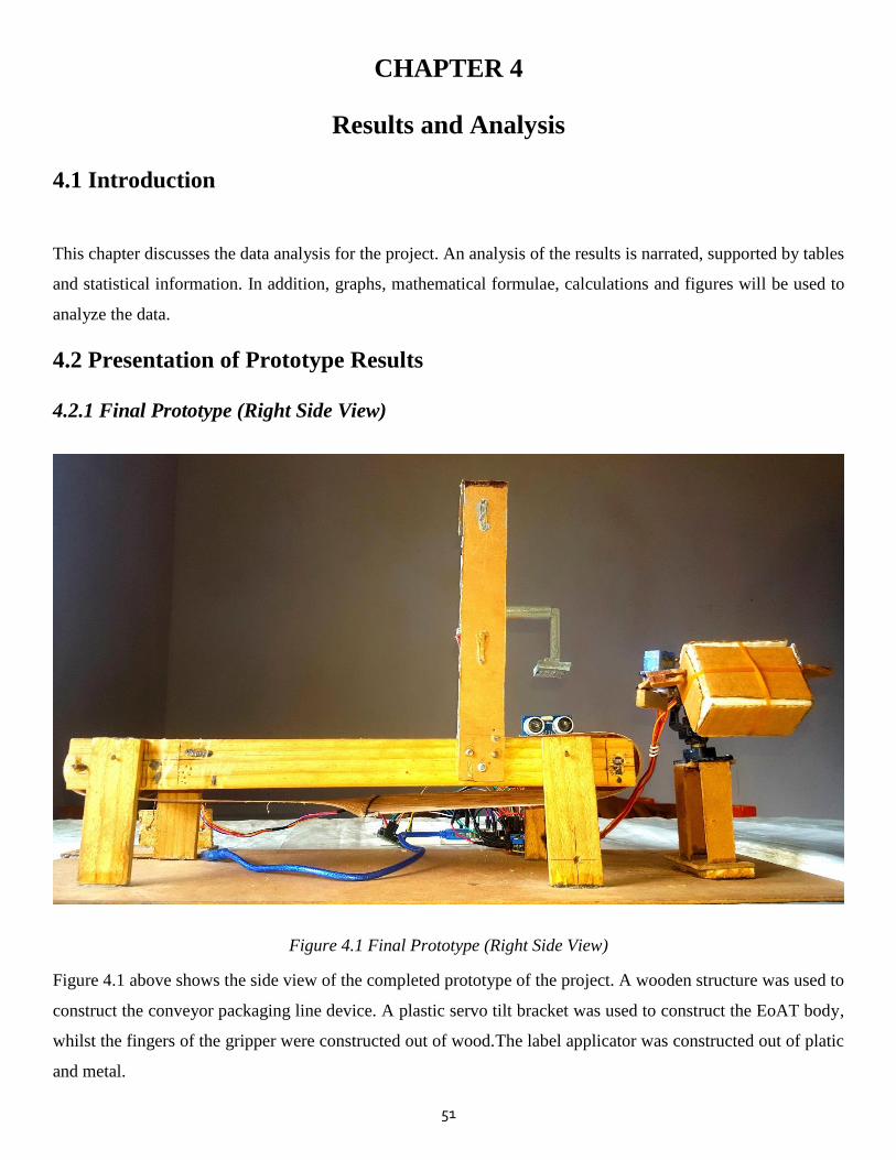
51
CHAPTER 4
Results and Analysis
4.1 Introduction
This chapter discusses the data analysis for the project. An analysis of the results is narrated, supported by tables
and statistical information. In addition, graphs, mathematical formulae, calculations and figures will be used to
analyze the data.
4.2 Presentation of Prototype Results
4.2.1 Final Prototype (Right Side View)
Figure 4.1 Final Prototype (Right Side View)
Figure 4.1 above shows the side view of the completed prototype of the project. A wooden structure was used to
construct the conveyor packaging line device. A plastic servo tilt bracket was used to construct the EoAT body,
whilst the fingers of the gripper were constructed out of wood.The label applicator was constructed out of platic
and metal.
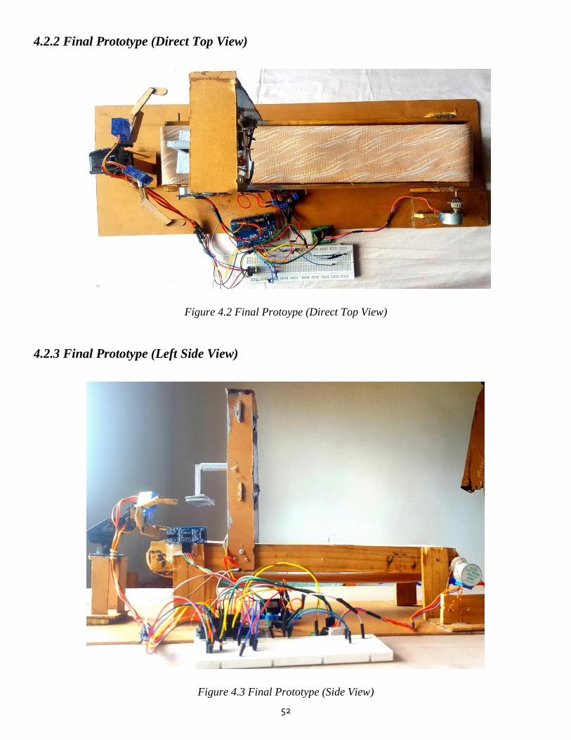
52
4.2.2 Final Prototype (Direct Top View)
Figure 4.2 Final Protoype (Direct Top View)
4.2.3 Final Prototype (Left Side View)
Figure 4.3 Final Prototype (Side View)

53
4.2.4 Final Prototype (Back View)
Figure 4.4 Final Prototype (Back View)
4.2.5 Final Prototype (Oblique Top View)
Figure 4.5 Final Prototype (Oblique Top View)
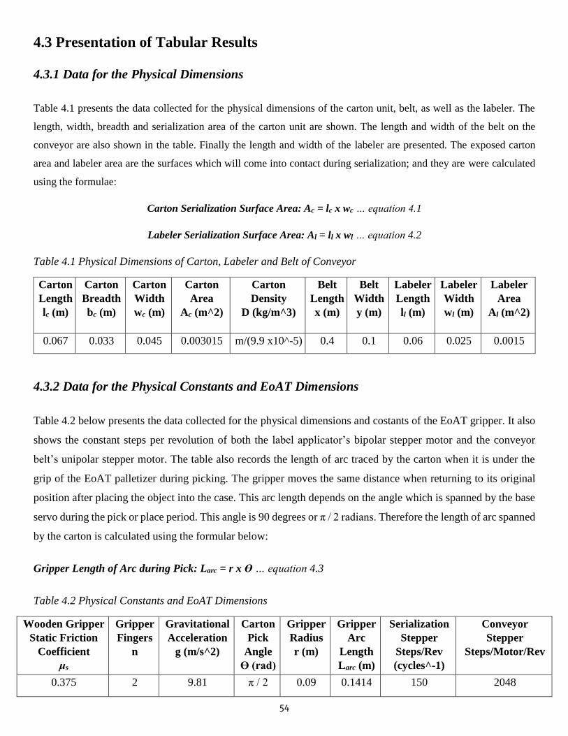
54
4.3 Presentation of Tabular Results
4.3.1 Data for the Physical Dimensions
Table 4.1 presents the data collected for the physical dimensions of the carton unit, belt, as well as the labeler. The
length, width, breadth and serialization area of the carton unit are shown. The length and width of the belt on the
conveyor are also shown in the table. Finally the length and width of the labeler are presented. The exposed carton
area and labeler area are the surfaces which will come into contact during serialization; and they are were calculated
using the formulae:
Carton Serialization Surface Area: Ac = lc x wc … equation 4.1
Labeler Serialization Surface Area: Al = ll x wl … equation 4.2
Table 4.1 Physical Dimensions of Carton, Labeler and Belt of Conveyor
Carton
Length
lc (m)
Carton
Breadth
bc (m)
Carton
Width
wc (m)
Carton
Area
Ac (m^2)
Carton
Density
D (kg/m^3)
Belt
Length
x (m)
Belt
Width
y (m)
Labeler
Length
ll (m)
Labeler
Width
wl (m)
Labeler
Area
Al (m^2)
0.067 0.033 0.045 0.003015 m/(9.9 x10^-5) 0.4 0.1 0.06 0.025 0.0015
4.3.2 Data for the Physical Constants and EoAT Dimensions
Table 4.2 below presents the data collected for the physical dimensions and costants of the EoAT gripper. It also
shows the constant steps per revolution of both the label applicator’s bipolar stepper motor and the conveyor
belt’s unipolar stepper motor. The table also records the length of arc traced by the carton when it is under the
grip of the EoAT palletizer during picking. The gripper moves the same distance when returning to its original
position after placing the object into the case. This arc length depends on the angle which is spanned by the base
servo during the pick or place period. This angle is 90 degrees or π / 2 radians. Therefore the length of arc spanned
by the carton is calculated using the formular below:
Gripper Length of Arc during Pick: Larc = r x Ɵ … equation 4.3
Table 4.2 Physical Constants and EoAT Dimensions
Wooden Gripper
Static Friction
Coefficient
μs
Gripper
Fingers
n
Gravitational
Acceleration
g (m/s^2)
Carton
Pick
Angle
Ɵ (rad)
Gripper
Radius
r (m)
Gripper
Arc
Length
Larc (m)
Serialization
Stepper
Steps/Rev
(cycles^-1)
Conveyor
Stepper
Steps/Motor/Rev
0.375 2 9.81 π / 2 0.09 0.1414 150 2048

55
4.3.3 Data for the Gripping Force of the EoAT
Table 4.3 below presents the data collected inorder to calculate the gripping force of the EoAT palletizer during
pick and place. The data was collected over a series of 4 experiments during prototype testing. The table shows
the recorded mass (in kilograms) of the cartons used in each test. The table also shows the acceleration of the
carton under the grip of the EoAT during picking. This acceleration is calculated using Galileo Galilei’s law of
motion:
Distance s = u x t + 0.5 x a x t ^ 2 …equation 4.4
Since initial velocity of the carton sitting on the conveyor is zero, the acceleration can be computed for each test
using the time it takes for the pick process to execute. As for the place acceleration, the value equals to the
acceleration due to free fall in all 4 tests. This is because during place, the gripper simply drops the carton into
the case in the pallet. This free fall takes place at an acceleration equal to 9.81 m/s^2. Finally, the frigging force
in each test is calculated using the equation:
Robotic Arm Gripping Force: Fpick = { m x ( g + apick ) } / n x μs … equation 4.5
The value of m represents the mass of the carton in each experiment. The value of g is 9.81 and the value of n
represents the number of fingers of the EoAT gripper – which is 2. The value of μs represents the coefficient of
friction between the gripper and the carton. Since the gripper fingers are wooden and the carton is made of EPS
but coated with cardboard, the student assumed the contact is approximately equal to that of wood – to – clean
wood. The static coefficient of friction between two wooden materials in contact ranges from 0.25 to 0.5. As a
consequence, the student resorted to taking the average, which is 0.375. Therefore the formula for the gripping
force on the carton during pick and place is becomes:
Robotic Arm Gripping Force: Fpick = { m x ( 9.81 + apick ) } / 0.75 … equation 4.6
Table 4.3 Data for the Gripping force of the EoAT
Test Carton
Mass
m (kg)
Pick
Acceleration
apick (m/s^2)
Place
Acceleration
aplace (m/s^2)
Pick
Gripping Force
Fpick (Newton)
1 0.015 0.000589 9.81 0.1962
2 0.025 0.000524 9.81 0.327
3 0.035 0.000585 9.81 0.458
4 0.045 0.000584 9.81 0.589
Average 0.03 0.000571 9.81 0.393
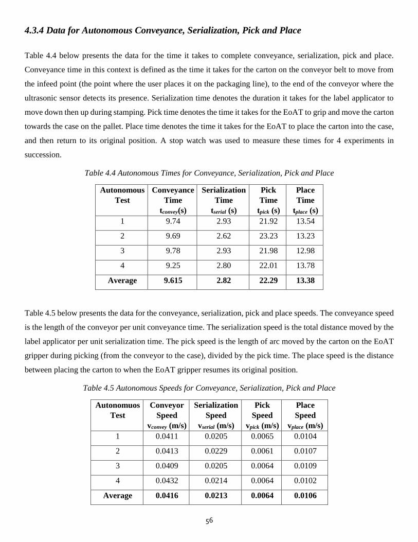
56
4.3.4 Data for Autonomous Conveyance, Serialization, Pick and Place
Table 4.4 below presents the data for the time it takes to complete conveyance, serialization, pick and place.
Conveyance time in this context is defined as the time it takes for the carton on the conveyor belt to move from
the infeed point (the point where the user places it on the packaging line), to the end of the conveyor where the
ultrasonic sensor detects its presence. Serialization time denotes the duration it takes for the label applicator to
move down then up during stamping. Pick time denotes the time it takes for the EoAT to grip and move the carton
towards the case on the pallet. Place time denotes the time it takes for the EoAT to place the carton into the case,
and then return to its original position. A stop watch was used to measure these times for 4 experiments in
succession.
Table 4.4 Autonomous Times for Conveyance, Serialization, Pick and Place
Autonomous
Test
Conveyance
Time
tconvey(s)
Serialization
Time
tserial (s)
Pick
Time
tpick (s)
Place
Time
tplace (s)
1 9.74 2.93 21.92 13.54
2 9.69 2.62 23.23 13.23
3 9.78 2.93 21.98 12.98
4 9.25 2.80 22.01 13.78
Average 9.615 2.82 22.29 13.38
Table 4.5 below presents the data for the conveyance, serialization, pick and place speeds. The conveyance speed
is the length of the conveyor per unit conveyance time. The serialization speed is the total distance moved by the
label applicator per unit serialization time. The pick speed is the length of arc moved by the carton on the EoAT
gripper during picking (from the conveyor to the case), divided by the pick time. The place speed is the distance
between placing the carton to when the EoAT gripper resumes its original position.
Table 4.5 Autonomous Speeds for Conveyance, Serialization, Pick and Place
Autonomuos
Test
Conveyor
Speed
vconvey (m/s)
Serialization
Speed
vserial (m/s)
Pick
Speed
vpick (m/s)
Place
Speed
vplace (m/s)
1 0.0411 0.0205 0.0065 0.0104
2 0.0413 0.0229 0.0061 0.0107
3 0.0409 0.0205 0.0064 0.0109
4 0.0432 0.0214 0.0064 0.0102
Average 0.0416 0.0213 0.0064 0.0106
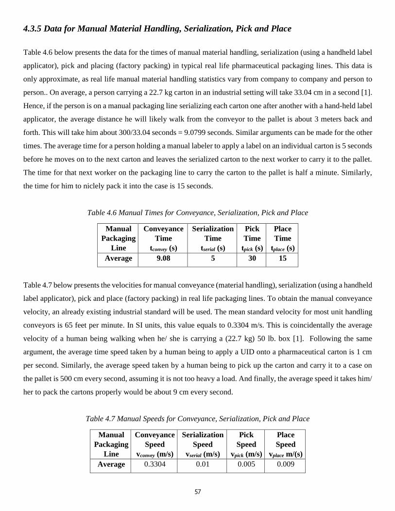
57
4.3.5 Data for Manual Material Handling, Serialization, Pick and Place
Table 4.6 below presents the data for the times of manual material handling, serialization (using a handheld label
applicator), pick and placing (factory packing) in typical real life pharmaceutical packaging lines. This data is
only approximate, as real life manual material handling statistics vary from company to company and person to
person.. On average, a person carrying a 22.7 kg carton in an industrial setting will take 33.04 cm in a second [1].
Hence, if the person is on a manual packaging line serializing each carton one after another with a hand-held label
applicator, the average distance he will likely walk from the conveyor to the pallet is about 3 meters back and
forth. This will take him about 300/33.04 seconds = 9.0799 seconds. Similar arguments can be made for the other
times. The average time for a person holding a manual labeler to apply a label on an individual carton is 5 seconds
before he moves on to the next carton and leaves the serialized carton to the next worker to carry it to the pallet.
The time for that next worker on the packaging line to carry the carton to the pallet is half a minute. Similarly,
the time for him to niclely pack it into the case is 15 seconds.
Table 4.6 Manual Times for Conveyance, Serialization, Pick and Place
Manual
Packaging
Line
Conveyance
Time
tconvey (s)
Serialization
Time
tserial (s)
Pick
Time
tpick (s)
Place
Time
tplace (s)
Average 9.08 5 30 15
Table 4.7 below presents the velocities for manual conveyance (material handling), serialization (using a handheld
label applicator), pick and place (factory packing) in real life packaging lines. To obtain the manual conveyance
velocity, an already existing industrial standard will be used. The mean standard velocity for most unit handling
conveyors is 65 feet per minute. In SI units, this value equals to 0.3304 m/s. This is coincidentally the average
velocity of a human being walking when he/ she is carrying a (22.7 kg) 50 lb. box [1]. Following the same
argument, the average time speed taken by a human being to apply a UID onto a pharmaceutical carton is 1 cm
per second. Similarly, the average speed taken by a human being to pick up the carton and carry it to a case on
the pallet is 500 cm every second, assuming it is not too heavy a load. And finally, the average speed it takes him/
her to pack the cartons properly would be about 9 cm every second.
Table 4.7 Manual Speeds for Conveyance, Serialization, Pick and Place
Manual
Packaging
Line
Conveyance
Speed
vconvey (m/s)
Serialization
Speed
vserial (m/s)
Pick
Speed
vpick (m/s)
Place
Speed
vplace m/(s)
Average 0.3304 0.01 0.005 0.009
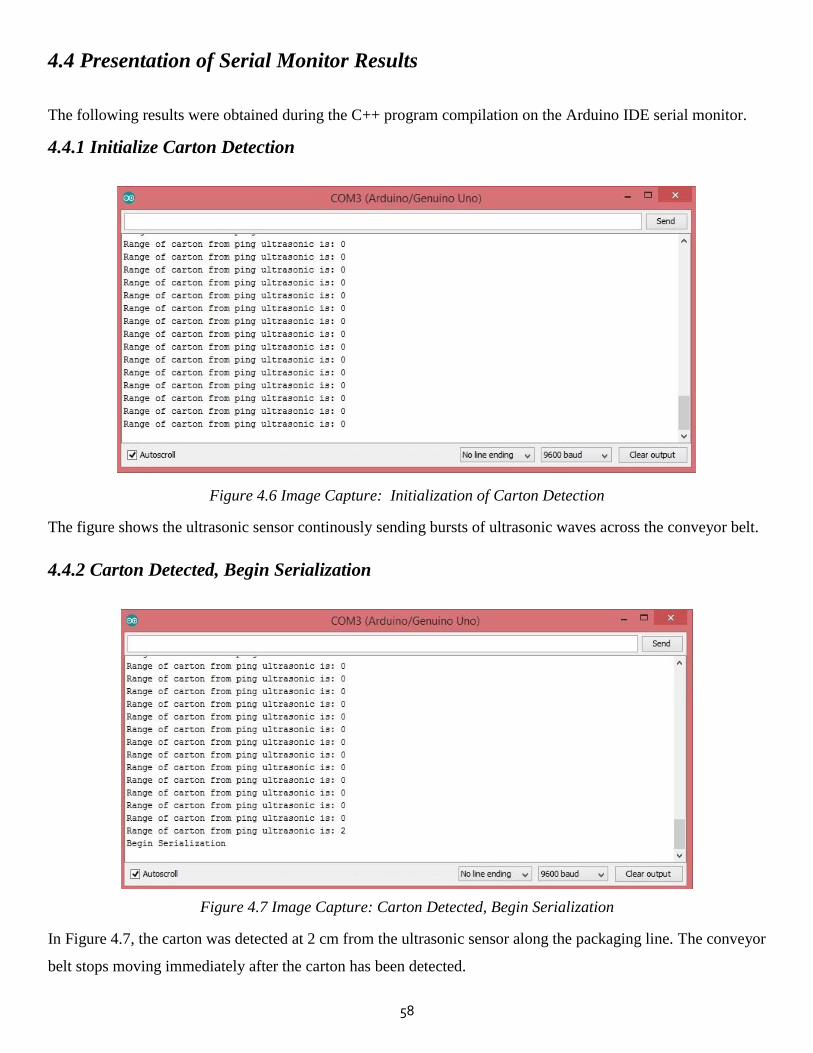
58
4.4 Presentation of Serial Monitor Results
The following results were obtained during the C++ program compilation on the Arduino IDE serial monitor.
4.4.1 Initialize Carton Detection
Figure 4.6 Image Capture: Initialization of Carton Detection
The figure shows the ultrasonic sensor continously sending bursts of ultrasonic waves across the conveyor belt.
4.4.2 Carton Detected, Begin Serialization
Figure 4.7 Image Capture: Carton Detected, Begin Serialization
In Figure 4.7, the carton was detected at 2 cm from the ultrasonic sensor along the packaging line. The conveyor
belt stops moving immediately after the carton has been detected.

59
4.4.3 Serialization Completed
Figure 4.8 Image Capture: Serialization Completed
Figure 4.8 above shows that the carton has been successifully serialized with the UID.
4.4.4 Execution of Carton Pick
Figure 4.9 Image Capture: Execution of Carton Pick
Figure 4.9 depicts the result of the succesiful execution of picking the carton from the conveyor belt and carrying
it to the case on the pallet. During this duration, both the conveyor belt and the label applicator will be dormant.
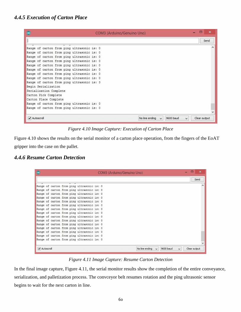
60
4.4.5 Execution of Carton Place
Figure 4.10 Image Capture: Execution of Carton Place
Figure 4.10 shows the results on the serial monitor of a carton place operation, from the fingers of the EoAT
gripper into the case on the pallet.
4.4.6 Resume Carton Detection
Figure 4.11 Image Capture: Resume Carton Detection
In the final image capture, Figure 4.11, the serial monitor results show the completion of the entire conveyance,
serialization, and palletization process. The convceyor belt resumes rotation and the ping ultrasonic sensor
begins to wait for the next carton in line.
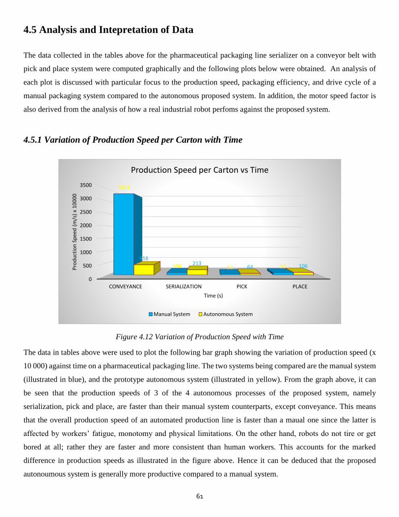
61
4.5 Analysis and Intepretation of Data
The data collected in the tables above for the pharmaceutical packaging line serializer on a conveyor belt with
pick and place system were computed graphically and the following plots below were obtained. An analysis of
each plot is discussed with particular focus to the production speed, packaging efficiency, and drive cycle of a
manual packaging system compared to the autonomous proposed system. In addition, the motor speed factor is
also derived from the analysis of how a real industrial robot perfoms against the proposed system.
4.5.1 Variation of Production Speed per Carton with Time
Figure 4.12 Variation of Production Speed with Time
The data in tables above were used to plot the following bar graph showing the variation of production speed (x
10 000) against time on a pharmaceutical packaging line. The two systems being compared are the manual system
(illustrated in blue), and the prototype autonomous system (illustrated in yellow). From the graph above, it can
be seen that the production speeds of 3 of the 4 autonomous processes of the proposed system, namely
serialization, pick and place, are faster than their manual system counterparts, except conveyance. This means
that the overall production speed of an automated production line is faster than a maual one since the latter is
affected by workers’ fatigue, monotomy and physical limitations. On the other hand, robots do not tire or get
bored at all; rather they are faster and more consistent than human workers. This accounts for the marked
difference in production speeds as illustrated in the figure above. Hence it can be deduced that the proposed
autonoumous system is generally more productive compared to a manual system.
0
500
1000
1500
2000
2500
3000
3500
CONVEYANCE SERIALIZATION PICK PLACE
3304
100 50 90
416213
64 106Pro
du
ctio
n S
pee
d (
m/s
) x
10
00
0
Time (s)
Production Speed per Carton vs Time
Manual System Autonomous System
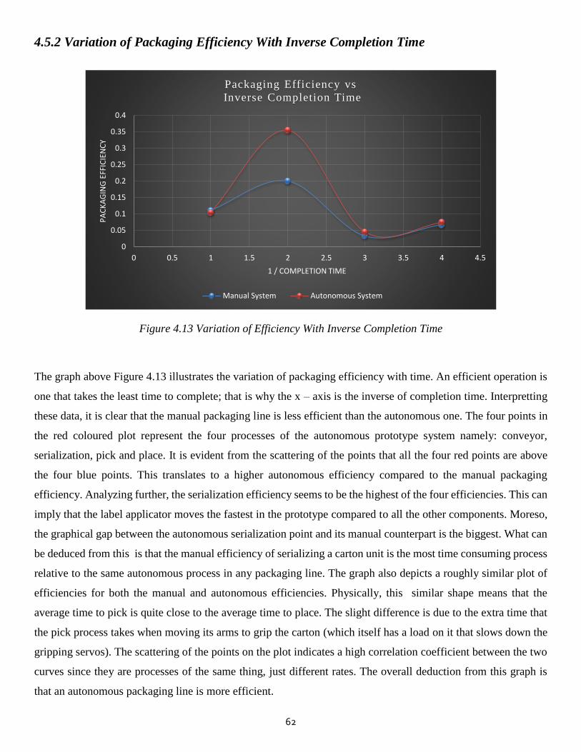
62
4.5.2 Variation of Packaging Efficiency With Inverse Completion Time
Figure 4.13 Variation of Efficiency With Inverse Completion Time
The graph above Figure 4.13 illustrates the variation of packaging efficiency with time. An efficient operation is
one that takes the least time to complete; that is why the x – axis is the inverse of completion time. Interpretting
these data, it is clear that the manual packaging line is less efficient than the autonomous one. The four points in
the red coloured plot represent the four processes of the autonomous prototype system namely: conveyor,
serialization, pick and place. It is evident from the scattering of the points that all the four red points are above
the four blue points. This translates to a higher autonomous efficiency compared to the manual packaging
efficiency. Analyzing further, the serialization efficiency seems to be the highest of the four efficiencies. This can
imply that the label applicator moves the fastest in the prototype compared to all the other components. Moreso,
the graphical gap between the autonomous serialization point and its manual counterpart is the biggest. What can
be deduced from this is that the manual efficiency of serializing a carton unit is the most time consuming process
relative to the same autonomous process in any packaging line. The graph also depicts a roughly similar plot of
efficiencies for both the manual and autonomous efficiencies. Physically, this similar shape means that the
average time to pick is quite close to the average time to place. The slight difference is due to the extra time that
the pick process takes when moving its arms to grip the carton (which itself has a load on it that slows down the
gripping servos). The scattering of the points on the plot indicates a high correlation coefficient between the two
curves since they are processes of the same thing, just different rates. The overall deduction from this graph is
that an autonomous packaging line is more efficient.
0
0.05
0.1
0.15
0.2
0.25
0.3
0.35
0.4
0 0.5 1 1.5 2 2.5 3 3.5 4 4.5
PA
CK
AG
ING
EFF
ICIE
NC
Y
1 / COMPLETION TIME
Packaging Efficiency vs
Inverse Completion Time
Manual System Autonomous System
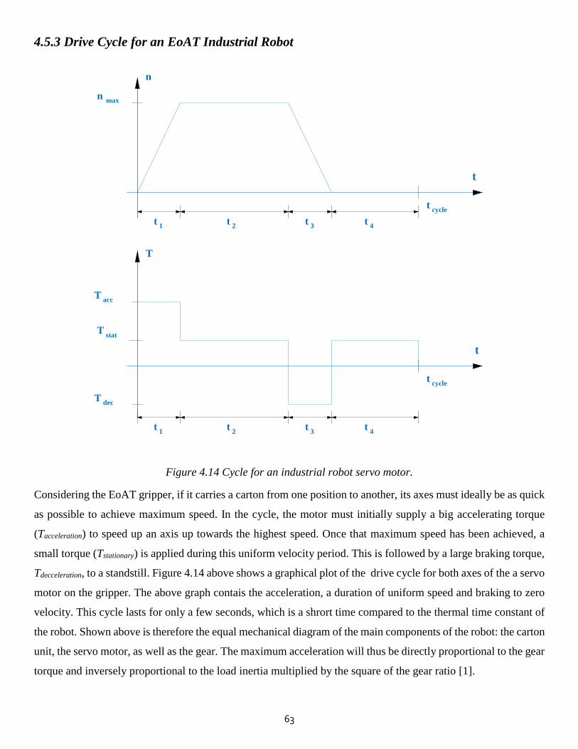
63
4.5.3 Drive Cycle for an EoAT Industrial Robot
Figure 4.14 Cycle for an industrial robot servo motor.
Considering the EoAT gripper, if it carries a carton from one position to another, its axes must ideally be as quick
as possible to achieve maximum speed. In the cycle, the motor must initially supply a big accelerating torque
(Tacceleration) to speed up an axis up towards the highest speed. Once that maximum speed has been achieved, a
small torque (Tstationary) is applied during this uniform velocity period. This is followed by a large braking torque,
Tdecceleration, to a standstill. Figure 4.14 above shows a graphical plot of the drive cycle for both axes of the a servo
motor on the gripper. The above graph contais the acceleration, a duration of uniform speed and braking to zero
velocity. This cycle lasts for only a few seconds, which is a shrort time compared to the thermal time constant of
the robot. Shown above is therefore the equal mechanical diagram of the main components of the robot: the carton
unit, the servo motor, as well as the gear. The maximum acceleration will thus be directly proportional to the gear
torque and inversely proportional to the load inertia multiplied by the square of the gear ratio [1].
t
t
t 1
t 1
t 2
t 2
t 3
t 3
t 4
t 4
t cycle
t cycle
T acc
T dec
T stat
T
n max
n
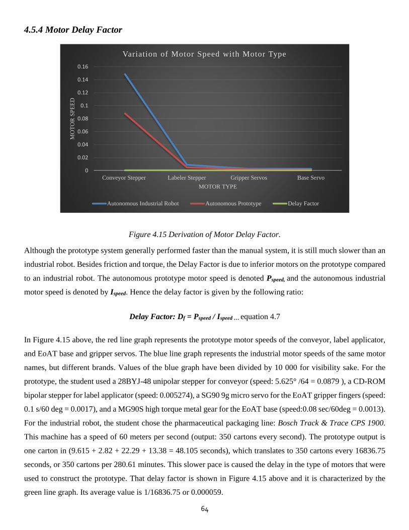
64
4.5.4 Motor Delay Factor
Figure 4.15 Derivation of Motor Delay Factor.
Although the prototype system generally performed faster than the manual system, it is still much slower than an
industrial robot. Besides friction and torque, the Delay Factor is due to inferior motors on the prototype compared
to an industrial robot. The autonomous prototype motor speed is denoted Pspeed, and the autonomous industrial
motor speed is denoted by Ispeed. Hence the delay factor is given by the following ratio:
Delay Factor: Df = Pspeed / Ispeed … equation 4.7
In Figure 4.15 above, the red line graph represents the prototype motor speeds of the conveyor, label applicator,
and EoAT base and gripper servos. The blue line graph represents the industrial motor speeds of the same motor
names, but different brands. Values of the blue graph have been divided by 10 000 for visibility sake. For the
prototype, the student used a 28BYJ-48 unipolar stepper for conveyor (speed: 5.625° /64 = 0.0879 ), a CD-ROM
bipolar stepper for label applicator (speed: 0.005274), a SG90 9g micro servo for the EoAT gripper fingers (speed:
0.1 s/60 deg = 0.0017), and a MG90S high torque metal gear for the EoAT base (speed:0.08 sec/60deg = 0.0013).
For the industrial robot, the student chose the pharmaceutical packaging line: Bosch Track & Trace CPS 1900.
This machine has a speed of 60 meters per second (output: 350 cartons every second). The prototype output is
one carton in (9.615 + 2.82 + 22.29 + 13.38 = 48.105 seconds), which translates to 350 cartons every 16836.75
seconds, or 350 cartons per 280.61 minutes. This slower pace is caused the delay in the type of motors that were
used to construct the prototype. That delay factor is shown in Figure 4.15 above and it is characterized by the
green line graph. Its average value is 1/16836.75 or 0.000059.
0
0.02
0.04
0.06
0.08
0.1
0.12
0.14
0.16
Conveyor Stepper Labeler Stepper Gripper Servos Base Servo
MO
TO
R S
PE
ED
MOTOR TYPE
Variation of Motor Speed with Motor Type
Autonomous Industrial Robot Autonomous Prototype Delay Factor

65
4.6 References
[1] J. J. Muhammad, "Positioning of Conveyor and Loadcell Measurement," GRD Journals- Global Research
and Development Journal for Engineering, vol. 2, no. 4, March 2017.

66
CHAPTER 5
Conclusion
5.1 Introduction
This chapter discusses the major findings of the research. It links each question to the final findings as well as the
literature in Chapter 2. In addition, the student will suggest some recommendations to industrial practioners and
policy makers. Finally, the chapter will reflect on the research processes like the limitations of the study as well
as suggestions for future research.
5.2 Discussion
The design and prototyping of the Autonomous Pharmaceutical Packaging Serializer with Pick and Place
Aggregation System was successfull. All the objectives of the research were met and the aim was achieved. The
project results were analyzed with the utmost scrutiny, and vital findings were deduced. The most important result
was that the production output of the proposed system is approximately 1 carton per 48.105 seconds. This is
actually faster than most manual pharmaceutical tertiary packaging lines, considering this is only a prototype.
Nontheless, the production output of most modern industrial robots of similitude is 350 cartons per second. This
implies that with better components and some improvements, the proposed system may reach even faster speeds
than most industrial robotic builds. A general conclusion is that an autonomous packaging line is indeed more
efficient than its manual counterpart. Based on such deductions, this research will add to exisitng literature and
systems in industrial practice. Applications of the system are mainly in pharmaceutical packaging, although the
ideas in the project may be extended to other disciplines in dire need of automation, where manual work is still
prevalent.
5.3 Limitations of the Study
The student encountered some challenges during the implementation of this research. The first challenge was
constructing a rigid yet lightweight conveyor belt, and reducing the friction therewith. Another limitation was
making use of very limited hardware components due to the student’s tight budget. The third challenge was that
the ultrasonic sensor worked best only when the carton to be detected was flat sided facing the sensor. As a
consequence, a rectangular carton had to be placed perfectly straight on the conveyor belt, otherwise the carton
would stop in the wrong position when it cut the line of sight ot the ultrasonic sensor; and this would in turn
render the execution of pick and place inacurrate.

67
5.4 Recommendations
The student suggests the following recommendations for the future improvement of this project. A brief
description of each suggestion is presented below.
5.4.1 Automated Identification Data Capture (AIDC)
This research mainly focused on the serialization and material handling of carton units on a tertiary level
pharmaceutical packaging line. In order to complete the entire global serialization, trace and trace process, the
student suggests the adoption of AIDC technology at the end of the supply chain. This means making use of QR
code, character recognition and bar code scanners at medicine dispensing points to scan the UID code on each
serialized pharmaceutical unit before it reaches the patient. This will not only secure the pharmaceutical supply
chain, but it will also secure the health and life of medical patients.
5.4.2 Vision Sensing Technology
The student recommends the addition of vision sensors to the project to assist the ultrasonic sensor in carton
detection. This implies that in addition to sensing the presence of the cartons on the conveyor belt using ultrasonic
waves, the project will work better with cameras, characer and colour recognition sensors mounted on the
packaging line. More so, the accuracy of the robotic gripper will be vastly improved since the execution of pick
and place depends on very precise timing and positioning – both of which can be achieved if vision sensors are
incoperated in the project.
5.4.3 EoAT Degrees of Freedom
The student proposes adding more degrees of freedom to the EoAT robotic palletizer. In addition to the gripper
servos, the robotic palletizer would better suit its purpose if elbow, shoulder and wrist servos were added to the
robotic arm. This would enable the palletizer to manourver pick and place with precise dexterity and flexibility.
5.4.4 Laser/Printed Label Applicator
The student also suggests the use of printed labels instead of inked stamps in the project. Inked markings can
easily come off due to scratching, wear and tear. By using printed stickers onto carton units, or directly engraving
a permanet laser or printed marking onto the carton surface, the project will yeild better results compared to the
current prototype. This is because such labels are more presentable and durable.
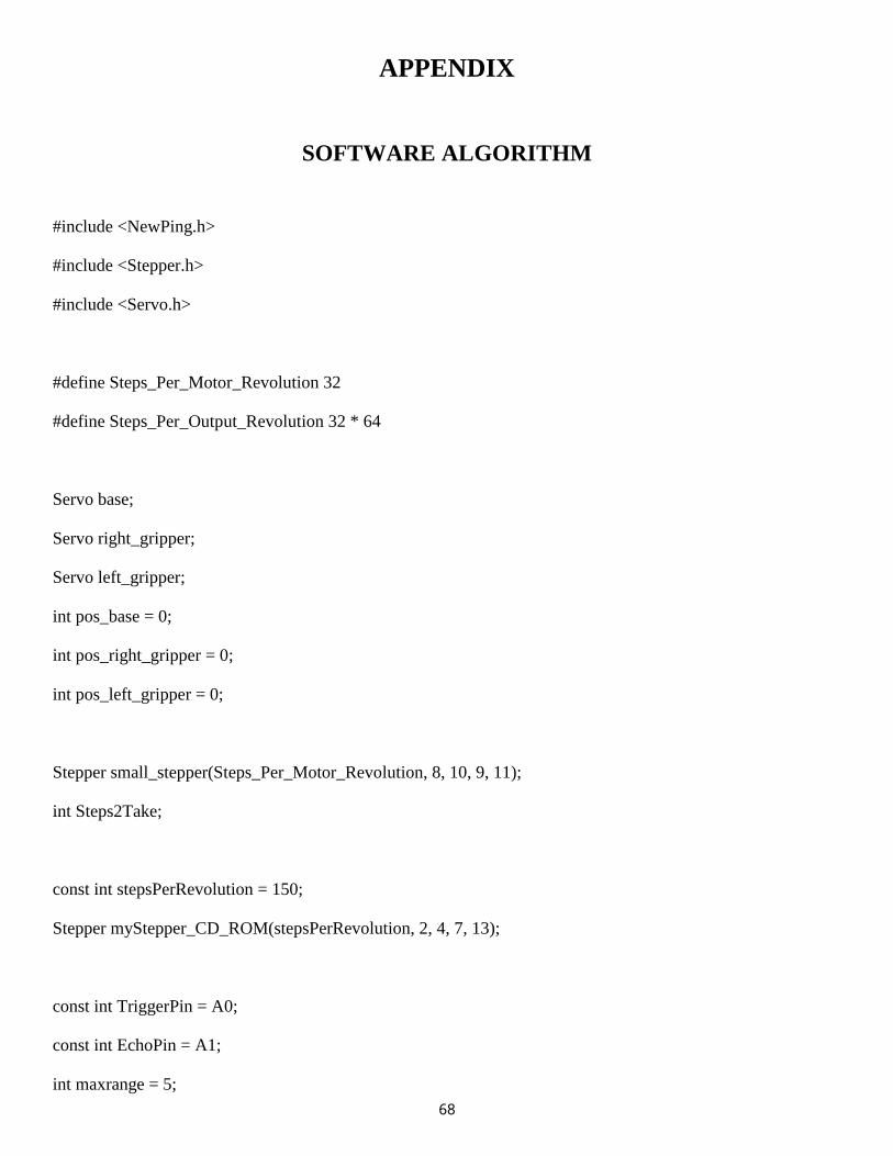
68
APPENDIX
SOFTWARE ALGORITHM
#include <NewPing.h>
#include <Stepper.h>
#include <Servo.h>
#define Steps_Per_Motor_Revolution 32
#define Steps_Per_Output_Revolution 32 * 64
Servo base;
Servo right_gripper;
Servo left_gripper;
int pos_base = 0;
int pos_right_gripper = 0;
int pos_left_gripper = 0;
Stepper small_stepper(Steps_Per_Motor_Revolution, 8, 10, 9, 11);
int Steps2Take;
const int stepsPerRevolution = 150;
Stepper myStepper_CD_ROM(stepsPerRevolution, 2, 4, 7, 13);
const int TriggerPin = A0;
const int EchoPin = A1;
int maxrange = 5;
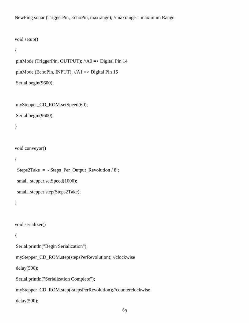
69
NewPing sonar (TriggerPin, EchoPin, maxrange); //maxrange = maximum Range
void setup()
{
pinMode (TriggerPin, OUTPUT); //A0 => Digital Pin 14
pinMode (EchoPin, INPUT); //A1 => Digital Pin 15
Serial.begin(9600);
myStepper_CD_ROM.setSpeed(60);
Serial.begin(9600);
}
void conveyor()
{
Steps2Take = - Steps_Per_Output_Revolution / 8 ;
small_stepper.setSpeed(1000);
small_stepper.step(Steps2Take);
}
void serializer()
{
Serial.println("Begin Serialization");
myStepper_CD_ROM.step(stepsPerRevolution); //clockwise
delay(500);
Serial.println("Serialization Complete");
myStepper_CD_ROM.step(-stepsPerRevolution);//counterclockwise
delay(500);
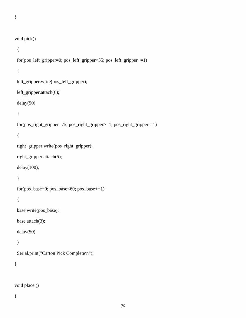
70
}
void pick()
{
for(pos_left_gripper=0; pos_left_gripper<55; pos_left_gripper+=1)
{
left_gripper.write(pos_left_gripper);
left_gripper.attach(6);
delay(90);
}
for(pos_right_gripper=75; pos_right_gripper>=1; pos_right_gripper-=1)
{
right_gripper.write(pos_right_gripper);
right_gripper.attach(5);
delay(100);
}
for(pos_base=0; pos_base<60; pos_base+=1)
{
base.write(pos_base);
base.attach(3);
delay(50);
}
Serial.print("Carton Pick Complete\n");
}
void place ()
{
71
for(pos_left_gripper=90; pos_left_gripper>=1; pos_left_gripper-=1)
{
left_gripper.write(pos_left_gripper);
left_gripper.attach(6);
delay(90);
}
for(pos_right_gripper=0; pos_right_gripper<60; pos_right_gripper+=1)
{
right_gripper.write(pos_right_gripper);
right_gripper.attach(5);
delay(100);
}
Serial.print("Carton Place Complete\n");
for(pos_base=90; pos_base>=1; pos_base-=1)
{
base.write(pos_base);
base.attach(3);
delay(50);
}
}
void aggregation()
{
delay(50);
serializer();
delay(100);
pick();
72
delay(50);
place();
}
void loop()
{
int x = sonar.ping_cm();
Serial.print("Range of carton from ping ultrasonic is: ");
Serial.println(x);
if(x==0)
{
conveyor();
}
else
{
delay(100);
aggregation();
}
}