track conveyor system in a flexible manufacturing cell - CORE
91
Lehigh University Lehigh Preserve eses and Dissertations 1986 Layout design analysis and installation of a cart-on- track conveyor system in a flexible manufacturing cell / Recep Erkan Ilhan Lehigh University Follow this and additional works at: hps://preserve.lehigh.edu/etd Part of the Industrial Engineering Commons is esis is brought to you for free and open access by Lehigh Preserve. It has been accepted for inclusion in eses and Dissertations by an authorized administrator of Lehigh Preserve. For more information, please contact [email protected]. Recommended Citation Ilhan, Recep Erkan, "Layout design analysis and installation of a cart-on-track conveyor system in a flexible manufacturing cell /" (1986). eses and Dissertations. 4685. hps://preserve.lehigh.edu/etd/4685
-
Upload
khangminh22 -
Category
Documents
-
view
0 -
download
0
Transcript of track conveyor system in a flexible manufacturing cell - CORE

Lehigh UniversityLehigh Preserve
Theses and Dissertations
1986
Layout design analysis and installation of a cart-on-track conveyor system in a flexible manufacturingcell /Recep Erkan IlhanLehigh University
Follow this and additional works at: https://preserve.lehigh.edu/etd
Part of the Industrial Engineering Commons
This Thesis is brought to you for free and open access by Lehigh Preserve. It has been accepted for inclusion in Theses and Dissertations by anauthorized administrator of Lehigh Preserve. For more information, please contact [email protected].
Recommended CitationIlhan, Recep Erkan, "Layout design analysis and installation of a cart-on-track conveyor system in a flexible manufacturing cell /"(1986). Theses and Dissertations. 4685.https://preserve.lehigh.edu/etd/4685

LAYOUT DESIGN ANALYSIS AND INSTALLATION OF A CART-ON-TRACK CONVEYOR SYSTEM IN A
FLEXIBLE MANUFACTURING CELL
by
Recep Erkan Ilhan
A Thesis
Presented to t.he Graduate Co111111ittce
of Lehigh U nivcrsity •
in Candidacy for the Degree of
Master of Science
• Ill
Lehigh University 1086

This thesis is accepted and approved • 1n partial fulfillment of the
requirements for the degree of Master of Science in Industrial Engineering.
It:/ /{~C --------~------------------
Professor in Charge Date
Chai:iman of Department
•• ll

Acknowledgments
My sincere thanks and appreciation to Dr. Mikell P. Groover, Di rector of
,; /.
the Manufacturing Technology Laboratory,\ tor his encouragement, guidance and
support in helping me complete this project. I would also like to thank Research
Engineer John Keefe., Jr. for his co-operation and the people at SI Handling,
Inc., for providing the materials handling equipment and information necessary
in the research.
I would like to dedicate this thesis to my parents for all of the support
given to me.
I .
• • • . ,_ J lll

Table of Contents
Abstract 1. Introduction
1.1 Determining Materials Handling Requirements 1.2 Automated Materials 11andling Objectives 1.3 Basic Elements of a Flexible Manufacturing Cell 1.4 Integrated Islands of Automation and Its Benefits 1.5 Types of Automated Materials Handling Systems
2. Conveyors and Cart-on-Track (Cartrac) Conveyor Characteristics
2.1 Introduction to Conveyors 2.2 Cart-on-Track Conveyor Systems
2.3 Capabilities I
2.4 System Operation 2.5 System Control 2.6 Applications
3. Cartrac Conveyor System Components
3.1 Main Assemblies 3.1.1 System Track 3.1.2 Tube Drive 3.1.3 System Carrier 3.1.4 Right Angle Turntable 3.1.5 Radius Turns 3.1.6 Transfer Assembly 3.1.7 Shuttle 3.1.8 Access Device 3.1. 9 Vertical Lift 3.1.10 Ramp
3.2 Su bassemblies 3.2.1 Queue Station 3.2.2 Trapping Queue Station 3.2.3 Limit Switch 3.2.4 Photocell
. f
Systems
1
2
2 3 5 6 9
12
12 13 14 16 18 19
22
22 22 23 24 26 27 28 29 30 30 31 32 32 33 3:l 34
3.2.5 Single and Double Actuator 34 3.2.6 Solenoid Valve Panel 35
4. Cartrac System Layout Design for the Ma11ufacturing 36
Tecl111ology Laboratory
4.1 The \t1an ufacturing Technology IJaboratory 36 4. 2 Desired Objectives in Layout Designing 36 4.3 Predetermined Layout Plans 37
4.3.1 Analysis of These Plans 38 4.3.2 Disadvantages of the Previous Plans 43
•
4.4 Factors Considered in Designing 43 4.5 Pr.oposed Layout Design 44
• IV
I)

(.
...
4.5.1 Analysis 4.5.2 Problems with the Proposed l.1ayout Design
5. Description of Installation for Cartrac Conveyor
5.1 System Track and Pe>ripheral Equipment 5.2 Transfer Assembly and Peripheral Equiprnent 5.3 Dual Shuttle and Peripheral Equipment
6. System Interfacing 6.1 Interfacing with other Materials Hand Ii ng Systems
6.1.1 AS/RS 6.1.2 AC VS Docking
6.2 Interfacing with H.obot or other Work Stations 6. 2.1 Robots 6.2.2 Workstations
7. Conclusion and Areas for Future Study
References
Vita
V
\ 44 \ 45
System 48
48 62 67
69
69 69 71 73 73 75
77
79
81
·I

Figure 2-1: Figure 2-2: Figure 2-3: Figure 3-1: Figure 3-2: Figure 3-3: Figure 3-4: Figure 3-5: Figure 3-6: Figure 3-7: Figure 3-8: Figure 3-9: Figure 3-10: Figure 3-11: Figure 3-12: Figure 4-1: Figure 4-2: Figure 4-3: Figure 4-4: Figure 4-5:
Figure 5-1: Figure 5-2: Figure 5-3: Figure 5-4: Figure 5-5: Figure 5-6: Figure 5-'1: Figure 5-8: Figure 5-9: Figure 5-10: Figure 5-11: Figure 5-12: Figure 5-13: Figure 5-14: Figure 5-15: Figure 5-16: Figure 5-17: Figure 5-18: Figure 5-19: Figure 5-20: Figure 5-21: Figure 5-22: Figure 5-23:
List of Figures
System operation [2]. Cartrac concept [ l 3j. Cartrac cars for all purposes [ 12J. The track module [2]. Mini-Cartrac system track [ 13]. Cartrac carrier [ 13]. Typical carrier subasserriblies [2]. Right angle turntable [13J. Radius turn [2]. Transfer assembly [ 13]. The shuttle [13]. Access device [ 13 J.
Mini-Cartrac lift [ 13]. Ramp [12J. Queue station and Limit switch [ 13].
Predetermined plan- I [ 1 OJ. Original cartrac system layout plan [ 11]. Predetermined plan-2. Proposed layout plan and the subassemblies.
..
Cartrac system in the 1'1anufacturing Technology
Laboratory. View A-A for track support [ 11]. Track support [ 11]. Track and track support [ 11]. Friction wheel housing and track support : 11 j. Track joint and track support 1111.
l •
Thrust block [ 11]. Drive assembly [II]. Ori ve and be)t tensioning [ 11]. Typical queue station and limit switch 11].
' 1 Carrier, queue station., and track join ts : l l 1.
Q1Ieue station and track joint ( 11]. rrrapping queue station · 11 j. Trapping queue station and track joints [ 11]. Solenoid valve panel '. 11:.
l J
Solenoid valve panel and track s11pport joint [ 11 ]. System device tubing and connect.ors [ I 11. P n e u rn at i c s u pp I y panel ( F . R .. L . ) [ I 1 ] . Penumatic supply panel joint [II]. Queue station pneun1atic control diagram [11]. Single actuator pneu n1atic con t.rol diagrarr1 [ 11]. Double actuator pneumatic control diagram [ 11]. Shuttle pnucmatic con to) diagram [ 11]. Tran sf er car [ 1 l].
. VI
. I.
"' '
16 17
I 21 22 24 25 25 27 27 28 29 30 31 31 32 40 41 42 46 47
51 51 52 52 53 53 54 54 55 ... -~,)
56 56 57 57 58 58 59 59 60 60 GI 61 63
,

Figure 5-24: Figure 5-25:
Figure 5-26: Figure 5-27: Figure 5-28: Figure 5-29: Figure 5-30: Figure 5-31: Figure 5-32: Figure 5-33: Figure 6-1: Figure 6-2: Figure 6-3: Figure 6-4: Figure 7-1:
•
Photocell, carrier, and track joint 111 J. Transfer car, limit switch, actuator, and track joints
[ 11]. Transfer tracks and base plate ! I I j. Transfer tracks and base plate joint ! 11 J. Drive tube, coupler, thrust block, and track joint [ 11}. Transfer asse m b I y drive [ 11 ] . Left hand side fixed control bar and track joint [II]. Right hand side fixed control bar and track joint [ 11]. Dual shuttle interfacing with track modules [ 11]. Dual shuttle and floor joints [ 11].
:\ G \'S- Docking. Interfacing with a robot station. Interfacing with a CNC Lathe. Solenoid activators [ 13]. FMS in the Manufacturing Technology Laboratory
. . Vll
63 64
64 65 65 66 66 67 68 68 72 73 75 76 78

Abstract
The Manufacturing Technology Laboratory is establishing a major research
and educational area in materials handling, in addition to its traditional areas
in manufacturing processes and automated production systems. An automated
guided vehicle system., a cart-on-track (Mini Cartrac) conveyor system, and an
automated storage/retrieval system are currently being installed. Major problems
being solved in the laboratory are the layout design analysis, installation of
these systems, and getting them to operate.
The thesis is concerned with the Cart-on-track conveyor system and the
problems encountered in planning, installing, and operating such a system. The
thesis consists of three major parts. First, Chapter 1 provides a literature review
on automated materials handling and flexible manufacturing systems (FMS).
Second, Chapters 2 and 3 describe the unique characteristics and components of
the ~1ini-Cartrac and its application in a F\1S. rfhcse chapters might be
thought of as a user's or operator's rnanual. Third, Chapters 4., 5., and 6 are
the research portions of the thesis which discuss alternative layout plans of the
handling system with relative advantages and disadvantages of each. Evaluation
of these alternatives resulted in the selection and final design of the Cart-on
track configuration that has been installed. rfhis third part also dPals with the
system installation and interfacing of the \·1i n i-Cartrac with other materials
handling systems, robots, and other work st.at.ions. This discussion serves as the
background and justification for the proposed FMS configuratioo . lfl the
Manufacturing Technology L-- boratory.
1
•

Chapter 1
Introduction
1.1 Determining Materi&ls Hanclling Requir~n1er1ts
Material handling is a critical consideration with respect to the automated
factory in which great amounts of in-proc~ss material are rr1oved from place to
place, stored for future use or fed into rnanufacturing operations. In its rr1odern
role~ material handling is becorning rnore and rnore autorr1ated. The older
systems of conveyors~ pallet trucks~ bridge cranes, etc .. are still in wide use but,
increasingly, installations are coming on line that incorporate such innovations
as automated guided vehicle systems and automated storage/retrieval systems
[ 9 J.
Material handling systems in automated factories typically cost rnore
initially than material handling systems in traditional factories. These higher
costs are due to the less forgiving environrnent of an automated factorv [15;. . ' '
The cost of materials handling is also a significant cost that is estimated as
high as two/thirds of the manufacturing cost, since rnaterials and components in
manufacturing spend between 75 and 90 % of their tirne in material handling
and storage [3]. This fraction varies according to the type and quantity of
production and the degree of autornation in the rnat<'rials handling function (5;.
As in all mat.erial handling operations, the prime objective is the same: get
the right materials and to0ls to the right place at the right tirr1e and at low
cost, without damage to the materials [5, 9].
2

1.2 Automated Materials Han<lling Objectives
Material handling is an important factor in the entire facility design as
well as the success of the enterprise. Too much emphasis cannot be placed on
the importance of determining the most efficient plan for the flow of materials, •
information and people. The importance of the material handling pattern in any
facility as it influences production can be analyzed in advance for cost, quality
and time using various means of rneasu rement. 1 n designing rr1aterial r.andli ng
systems for the automated factory, the following objectives should be considered
115 17]: l ,
I. Create an environment that results in the production of high quality
products.
2. Provide planned and orderly flows of material, equipment, people and
information.
3. It should be capable of operating at a variety of speeds and should be
able to handle a variety of loads.
4. Unit load sizes., configurations and capacities should be standardized.,
and all "special" equipment should be very closely reviewed.
5. 1\ccomrnodate higher or lower production volumes.
6. The material handling syst.ern shou Id br designed to bP easily expanded
or contracted~ i.e . ., modular.
7. Reduce work-in-process.
8. Provide controlled flow and storage of rnatPrials.
9. Integrate • proccss1 ng, inspection, hand)jng, storage and control of
material.
10. Eliminate manual material handling at work stations and between work
3
•
stations.
11. Deliver parts to work stations • 1n predetermined quantities and
physically positioned to allow automatic transfer and automatic parts feeding to
machines.
12. Deliver tooling to machines in a controlled position to allow automatic
unloading and automatic tool change.
13. Utilize space most effectively., consider~ ng overhead space and
impedirnents to cross traffic.
14. The optimization of material handling systems within each cell is not
nearly as important as the optimization of the total facility's material handling
system. Therefore, it is only after the total system is planned that handling
systems within the cells should be planned within the context of the overall
system.
15. All material handling systems should support autornation within the
factory. This is applicable to both rnanufacturing autornation and inforrnation
and control autornation.
16. The system must also provide the proper material orientation and
report to the control system all move transactions. There is no control in an
autornated factory if the material handling system does not s_upport the control
system.
17. It must be able to operate rnod ularly and should allow implementation
of one section at a time.
4

..
1.3 Basic Elements of a Flexible Man11facturing Cell
A flexible manufacturing system results from a combiuation of three basic
elements: work stations (fully manual to fully automatic), computer controls and
automated material handling the integrator of the system [ t8J.
Work Stations: A manufacturing cell consists of one or more work
stations that are grouped together to produce a family of parts. The stations
can be any combinations of manual.. semi-automatic or fully automatic
operations. They require fewer but rnore versatile machines, techniques and
processes. Semi-autornatic and fully automatic work stations n1ay utilize NC
machines, robots, automated inspection devices and hard auton1ation techniques
[18]. These can be set up to carry out many different functions. Some of these
functions are:
----.i\t:sembly: placement., fastening and welding.
----Machining: milling, drilling, t.apping, turning, boring., facing and
grinding.
----Inspection: din1ensions, locations, geometry and finish.
----Work piece loading/ unloading: placement., fixturing, re-orientation on
fixtures, clamping.
----Heat trPatrnent, painting and finishing.
Con1puter Control: "'The coordination and control of the parts handling
and processing activities is accomplished under cornrnand of the con1puter. One
or more computers can be used to control a single FMS"" [6;. 'fhe data files.,
such as; part program file, routing file, part production file, pallet reference file
and etc., are needed to carry out the various functions which the computer ..
performs. Among these functions are [6]:
5
' . i
•
1. CNC-compu.ter control of the individual machines.
2. DNC-direct computer control of all the machine tools in the FMS.
3. Both CNC and DNC functions can be incorporated into a single FMS.
4. Part program storage.
5. Distribution of part programs to machines and robots at work stations.
6. Sequencing and tracking different loads to selected work stations., based
on variable routing instructions.
7. Collecting real-time data regarding operation of the work station
equipment and production.
8. Communicating with a host computer system.
9. Performing other process monitoring functions as required.
Various types of computer-prepared reports are also required during
operation of the FMS. Some of these reports are utilization reports, production
reports~ and tool status reports.
Automated Materials Handling: \Vithin manufacturing cells and ~~\,1Ss,
work-in-process must be transported quickly and reliably from one workstation
to the next. Stored workpieces must be easily accessible and recovered rapidly
when required.
1.4 I11tegrated Islands of A11ton1atior1 1111,l Its Ile11efits
Today ~s manufacturing plants often have sophisticated \vorkstat ions located
throughout the factory. Even though automated rnachines rnay be 1n use_ the
total result is ~islands of automation', in which the 1narhinerv itself is verv ~ ~
' I
efficient, but its actual utilization time (and therefore its return on investment)
is low and large stores of work-in-process and parts are required to support it.
Robert A. Pierson, divisional general rr1anager, Webb Rack Storage Systems and
6

LJnibilt Divisions !t4J, notes that "Material handling used to deal with islands of
manufacturing, then came islands of automation. Now material handling provides
a mechanical and control network for implementing integrated manufacturing.!'
Typical islands of automation include numerically controlled machine tools,
robots, automated storage/retrieval systems and nexible machining systems. In
some cases, the islands are very small (e.g., an individual machine or work
station)~ in other case, they are departrr1ent-sized. In meeting with the prime
objective, modern material handling systems rnust also be able to integrate with
computer-controlled manufacturing and distribution systems of all kinds. In fact,
without integrated material handling, many of these modern manufacturing
systems would remain ,, islands of automation" unable to reach .
maximum
effectiveness because they are not tied into an overall computer-integrated
system !9].
Every system is, by definition, an integrated system. And svstem .,
integration is the process of bringing independent systems togt·ther . In a
condition of harmonious. orderly interaction. In many people's rninds. system
integration is equate<l with automation and computerized control. These are
important tools. 11owever, whi]e increased automation is certainly the trend~ it
is not nec<>ssarily the only path to int.egrated material handling. The real key is
coordination of both activity and inforrnation '.3]. Such a fully integrated system
can increase utilization of high-investn1ent rnachinery to 80-90 %, as opposed to
the 10-15 % rate of traditional rnethods [18] .
. .\fter the manufacturing processes and ~'islands of autorr1ation"' have been
integrated, the benefits will begin to accrue, including [ 18]:
7

Reduced Inventory: Automated material handling systems ensure
constant availability of products to the cell. Because parts and work-in-process
are delivered to work cells as needed, in-process inventory is minimized and less
floor space is required around the machines. Also, as the operation approaches
"just-in-time" production, the warehousing of raw materials and of finished
products will be greatly diminished., reducing the cost of goods produced.
Greater Manufacturing Flexibility:_ Manufacturing cells. with highly
versatile NC machines and tool changing capability, can easily produce different
products to meet the demands of the market place. Engineering design changes
can be accommodated with less changeover and set-up time. Also, required spare
part and "special job" production can be mixed . In without significantly
disrupting normal production activities.
Improved Product Quality: Production methods are important
influences on product quality. Ce1lular manufacturing often includes a high level
of automation, and the consistently precise interfacing of \\'orkpieces and
automatic equipment that is attainable through the application of modern
automated material handling systems wili lead to more consistent quality. The
reduced number of machine setups needed and fewer workstations utilized are
also important factors contributing to a better, product.
Reduced Direct Labor Cost: In unmanned flexible n1anufacturing, much
machinery is operated under computer control (either CNC or DNC), eliminating
the need for operators. Also, manual workstations are often staffed by multi
skilled personnel to carry out functions in which autornation cannot be justified.
8

1.5 Types of Automated Materials Har1dling Systems
Though material handling contributes to integrated manufacturing from
receipt of raw material to delivery of finished product., there are certain systems
that are the most viable options for handling and transportation in an FMS.
The following is a brief overview of some of the equipment that should be
considered in the automated factory.
Automated Guided Vehicle System (AGVS): The guided vehicle
usually carries the work piece on a machine pallet or fixture base~ from work
cell to work cell or it may transport trays of parts that are manuallv or
robotically chucked., fixtured or locked onto machine tables at workstations. The
AGVS control system allows for virtually unlimited computer controlled
operation of the AGVs. The ease of altering or expanding an AG\'S makes
these systems among the most flexible material handling equipment for the
automated factory.
Powered Conveyors: Powered conveyors can be used for basic
transportation between flexible machining cells or for positioning parts to
interact with robots or other positioning devices. As1nchronous conveyors based
on the principle of rotating tubes are used to posit.ion loads precisely for robots,
as well as to move loads at high speeds. In n1achining centers, sperialized
conveyors can be designed to handle any type of part from operation to
operation [ 14].
Overhead, Power-and-Free Conveyors: Overhead~ power-and-free
conveyors offer flexibility to a manufacturing operation. With the carrier's
identity being automatically scanned on the move. loads can be selectively
diverted to work stations.
9

f'
Self-Powered Monorails: These systems have independently driven
trolleys that can run on the level or uphill. A master controller directs the
trolleys in ,highly flexible travel configuration. They can be given the capabilities
of forward and reverse operation, multiple speed, shortest path routing, system
blocking, etc. Although monorails do not compete with power-and-free conveyors
in high volume applications, in low-to-medium volume areas, the flexibility of
the rnonorails makes the equipment a viable option for FMS [15].
Robots: These devices can perform either part or all of the transport
function. They are often used as workpiece/machine tool interfaces at work
stations. For example, to remove a workpiece from the transport system carrier,
place it in a machining center and then return the workpiece to the carrier [18].
Automated Storage and Retrieval Sytems (AS/RS): As flexible
manufacturing systems increase their output and the variety of parts that will
be produced in small lots, an AS/RS fills the need for buffer storage. Some new
FMSs are being designed with raw sto"~k being stored in an AS/RS and
delivered tu machines by automatic guided vehicles [ 14]. The AS/ RS can also
provide quick access to the jigs, fixtures and tooling required by the FMS.
Carousels: A carousel consists of horizontal revolving bins that bring the
bin requested to a forward pick station. They are not new. 1--lowever, the I
replacement of the order picker at the end of the picking aisle with a storage
and retrieval robot is new. The robot can retrieve and store tote pans in the
bins. When this robot is properly interfaced with a conveyor system, the
opportunity for truly automated storage and retrieval via a carousel is realized
[ 15].
Automatic Identification Systems: Integrated manufacturing cannot be
10 'I

accomplished without the ability to identify parts and products automatically for
the purpose of accounting and direct their movement by means of computers
and programmable logic controllers ! 15J. An automatic identification system
consists of· ,
1. An item to be identified.
2. A label to be read to identify the subject.
3. A device which is to read the code.
4. The memory control to which the code is to be sent and stored.
Bar code .
scanning • IS the lowest cost, most universal approach to
automatic identification. However, in the harsh environment of some
manufacturing applications, radio frequency (RF) systems are being used on
more and more occasions [14].
11

Chapter 2
Conveyors and Cart-on-Track ( Cartrac)
Conveyor Systems Charact·eristics
2.1 I11troduction to Co11veyors
Conveyors represent a basic clement of the automated factory. They are
used when material is to be rnoved f rcquently between specific points over a
fixed path. Conveyors ran transport loads at floor level or overhead, move them
vertically, carry them up inclines or down spiral chutes, around corners or along
straight runs. Some models transport loads • 1n sequence~ others have the
capability of allo·.ving one load to bypass another to change routings. or to
make it easy to shunt materials out of the main delivery path without impeding
the flow. Conveyors can handle items of practically any size or shape (individual
parts. products in cases or tote boxes, or any rnat.erial that ran be put in a
container or stacked on a pallet) [I].
Conveyors can be interfaced with production equipment or with other
types of handling equipment to automate materials handling through one section
of the factory or through an entire manufacturing operation. Conveyors are also
used to deliver parts within "islands of autornation"", or to link them together,
and to provide live storage, and sort products. \\'hile conveyors ran be classified
in several ways, the most useful is by the n1ethod of mounting: overhead, above
floor and in-floor. Each group has various advantages and limitations for
different applications in the auton1at~d factory [1 ].
Overhead Conveyors: ~)verhead conveyors do not create any
obstructions on the work floor. They are mounted along overhead pathways and
12
,,

..
can therefore transport materials over aisles or production equipment. Some
overhead conveyors provide live storage. Others are used simply for point-to
point deliveries, interfacing with workers on the plant floor through vertical lifts.,
drop sections or by the conveyor's ability to move goods up and down inclines.
Above-Floor Conveyors: Above-floor conveyors include a variety of
types - cart-on-track., roller., belt, and carrier chain are the most popular ones.
These conveyors are supported by a permanent frame which raises the conveying
bed above the plant floor. rfhis arrangerr1ent makes the load handling easier for
fork trucks while simplifing manual loading and unloading.
In-Floor Conveyors: In-floor conveyors have some of the advantages of
both overhead and above-floor conveyors. Because the conveying medium is
mounted beneath the surface of the floor, croSB-over J
traffic . lS at least
theoretically possible. At the same time, loads are accessible to fork trucks or
manual loading. Towlines are the typical type of in-floor conveyor in the
au to mated factory [I].
2.2 Cart-on-Track Conveyor Systems
Cart-on-track transport systems ( also called . .
sp1nn1ng tube conveyors)
provide a precise, efficient means of conveying products to aid in manufacturing
and distribution center processes. These systems have been proven effective in
increasing productivity, while at the same time reducing overall operating costs
and product damages. The modularity of the systems facilitates installation in
new or existing buildings and provides the flexibility necessary to adapt to
changing industrial requirements. One of the cart-on-track conveyor suppliers is ,•
SI Handling, Inc., Easton, PA, whose product is known as Cartrac.
This method of transporting materials is operating successfully in facilities
13

...
throughout the world. They benefit manufacturing plants by providing an
interface with manufacturing processes and assembly operations. The systems are
easily integrated with manual or newly developed automated manufacturing
processes. In the warehouse or distribution center, Cartrac systems safely convey
products integrating with order selection and automated storage and retrieval
functions. They are especially useful with products which are bulky, delicate. or
otherwise difficult to convey and require accurate positioning, and where
environmental conditions are detrimental to employee health. In all of these
applications, cartrac systems are used to improve productivity and to effectively
control flow in the workplace [2J.
2.3 Capabilities
The capabilities of this Cartrac system have solved manv difficult "'
production and distribution problems. Nonsynchronous, independent movement
permits carriers to be individually indexed throughout the system. Carriers move
from one station to another without affecting the rest of the system operation.
Controlled acceleration and deceleration is especially useful in applications
where delicate and stable loads must be transported. This smooth movement ,..,
prevents product damage often incurred by fork truck or manual transport.
Controlled acceleration/ deceleration also enables .
carriers t.o be precisely
positioned for interface with other production equipment. Position can be as
precise as + or - 0.005 in. in three p]anes. This precise positioning . IS a
necessity when the transport svstem .,
. IS integrated with precise automated
machining and assembly operations.
Different speeds may be used sirnultaneously in separate sections of a
system, according to the user's requirements. Speed can be varied from 0.5 to
14

600 or more feet per minute [2}. In addition, this capability permits individual
sections of a system to be shut down in order to conserve energy or perform
routine maintenance procedures.
Cartrac systems have been proven to be operationally , effective • 1n
environmentally harsh industrial and warehousing applications. These systems
can be used in freezers with temperatures as low as -40 degree F and in ovens
where temperatures reach 200 degree F. They function in the presence of dirt,
dust, and chemicals and in environments that would otherwise be unsafe for
employees. In addition to these capabilities, Cartrac systems increase efficiency
through better use of 111anpower and space, resulting . In greater system
throughputs. The system ,s modular design allows for easy installation . 1n new
and existing facilities and can be totally relocated if necessary. Vertical
movement is possible to connect multiple levels in a building. Right angle a11d
radius turns can be accomplished. The system can be mounted on or beneath
the floor, or hung from a wall or ceiling [2., 12, 13].
The basic objectives of using the system are as follows:
----More process time in work stations.
----Increased production.
----Decreased work-in-process.
----Stop-and-go assembly.
----Flexible routing.
----Insures load stability.
----Minimal maintenance.
----Low spare parts inventory.
----No special skills required for maintenance personnel.
15

V
I
----Cartrac's adaptability meets specific application's needs.
----Accommadates future expansion.
----Flexible, initial design.
----Ease of installation.
----Improved interfac,~ capabilities with peripheral devices.
----Improved product quality through tighter tolerances.
2.4 System Operation
. Operation of the Cartrac system is simple, with only one powered
subassembly. That subassembly is the drive tube which is mounted between the
rails of a two-rail section of track. Sections of track are connected together
according to the system layout. Carriers are mounted on and guided by this
track and propelled by the drive tube within (Figure 2-1).
Fig11re 2-1: System operation [2].
16

A spring-loaded drive wheel, mounted on the underside of the carrier, is
pressed against the drive tube. Contact between this drive wheel and drive tube
creates a forward motion of the carrier. When the drive wheel centerline is
parallel with the drive tube, there is no driving force and the wheel merely
rotates in place. As the angle between the drive tube and drive wheel centerline
increases, a thrust is generated which propels the • carrier forward~ Maximum
carrier speed is obtained when this angle reaches 45 degree. Carrier speed can
be decreased by decreasing the angle and therefore reducing the thrust (Figure
2-2).
Cartrac Concept
Note: Reversing tube rotation reverses carrier direction.
Figure 2-2:
~ -.-----
Cartrac concept [ 13].
A pivoting housing contains the drive wheel and limits its movernent
bet\veen O degree to 45 degrees. This pivoting housing also provides for
independent control of carrier and tube speeds. Specially designed queue st.ation
control bars are located on the track throughout the system ··layout to control
the position· of the pivoting housing. These control bars provide for the precise
positioning and controlled acceleration and deceleration of each carrier. For
accumuJ_?tion capabilities, a cam follower arm on the front of each • • carrier 1s
linked to the pivoting housing. A cam is also located at the rear of the carrier
17
-· r
(see Figure 2-1 ). Contact between the cam folJower arm of one carrier and the
cam of another provides controlled acceleration or deceleration • 1n the
accumulation of carriers.
2.5 Syste1n Co11trol
Controls for the Cartrac ,ystem can be simple or sophisticated, depending
on individual requirements and capital available to invest in the system. As
with the Cartrac system layout, control systems can be updated to meet future
needs and expanded to incorporate additional operating functions.
The most basic control system is one that functions only to regulate
carrier traffic flow. Once power is supplied to the system, the operator has no
individual control over the different sections of the layout. Carriers travel in a
predetermined path, with no remote identification capabilities. In advanced
control systems, operators monitor the movement of each carrier in relation to
the total system layout. ~\ddrcssing capabilities can determine where a carrier
must go, what path it should take and what it must do once it reaches that
destination. The operator has a means of identifying the location of each
carrier at any time .. t\dvanced c0I1tr0I systems are irnperative if the system is to
be interfaced with other warehousing or manufacturing operations. These systems
are easily intPgrated \vith advanced manufacturing processes such as industrial
robots and rorr1puter controlled rnachine tools. In the modern distribution center,
co1nputcrized order-select ion systems are interfaced with Cartrac systems to
guarantee the quick, efficient delivery of custorner orders.
Controls for the Cartrac system can also be linked to corporate
management functions such as inventory control, shipping and receiving and up
to-the-minute status reports. This unique data highway is possible through the
18
•
/

.. -.
use of programmable logic controllers., microprocessors, and large scale process
control computers.
2.6 Applications
Cart-on-track material trai1sport systems can easily be applied for use in
any manufacturing or distribution center. Its versatility and flexibility permits
its use with products as diverse as fruits and ve1getab)es to large 12-cy)inder
diesel truck engines. A rapidly growing function of Cartrac systems involves the
movement of parts within a manufacturing facility from one machine tool
operation to another. This application eliminates the need for batch handling of
parts between machines and )eaves the area uncluttered of in-process work.
Parts are delivered, as required, by the carriers which then move on to the next
operation after work has been completed. Mechanization of manufacturing
operations is easily accornplished. Because of its accurate positioning capabilities.,
the Cartrac system can be effectively integrated with robots or automatic
cycling devices. Preprogrammed routing indexes parts directly from one operation
to the next. Production rates can be predetermined by adjusting the transport
system's rate of travel.
They can also be applied to assernb]y operations. T\1any types of materials
and parts can be transported with ease by specially designed fixtures mounted
on the carriers (Figure 2-3). By maintaining a fixed, constant speed, the system
assures that predetermined production rates will be met. Systern layout can be
designed so that one main system is used for final assembly, while subsystems
are employed to carry parts to the main system. With advanced cornputer
capabilities, carriers can be randomly selected to move n1aterials from one
station to another in any desired sequence.
19

The Cartrac system is also used to link products to high-rise automated
storage and retrieval systems (AS/RS). Parts are carried to and from production
areas by the transport system and are manually or automatically placed in
storage or production vehicles. This transport method optimizes the available
space within a warehouse and provides a constant control of inventory. With
this system'I the cost of fork truck maintenance and fuel is significantly reduced.
A facility may employ one Cartrac system for in-process work and another for
AS/RS, or the functions can be combined to form one large system.
Order picking is a distribution center function which lends itself well to
the use of this type of transport system. The system can be employed in
conjunction with manual or automatic product selection to achieve higher
productivity rates and reduce product damage. The order-picking transport
system is designed as a closed loop circuit with designated stations established
for selection and replenishment operations. The in1proved product flow feature
maintains an uncongested traffic pattern and opt.imizes space utilization of the
f ac i Ii t y [ 2 ~ 1 2, 13 J .
p_
20

AS/RS INTERFACE Car specially designed
TILT DECK Special deck allows bundles
to slide off easily.
Tooling block on CARTRAC holds work pieces
through processing.
to interface with Automatic Storage and Retrieval Systems.
AUTOMOTIVE FIXTURE Car is provided with
precision fixtures to locate auto body precisely for
interfacing with robot welders.
..,.,-: .... i.... '
FLAT DECK Flat deck on car
accepts pallets or special fixtures. etc.
AUTOMATIC/MANUAL CARTRAC drive wheel assembly
is applied to a standard "push cart" to permit automatic transfer of
the cart over long distances and manual handling in corridors. etc.
Figure 2-3: Cartrac cars for all purposes [ 12).
• 21

Chapter 3
Ca'rtrac Conveyor System Components
3.1 Main Assc1nblies
3.1.1 System Track
A system track mainly consists of a track module and a track support.
The function of the track module is to support. guide, and propel the carriers
through the system. Tube drives, queue stations, and limit switches are all
mounted on the track module. Each track module is comprised of three basic
assemblies: the track rails, crossmembers, and the drive tube. These components
are illustrated in Figure 3-1.
Figure 3-1: The track module [ 2].
The track rails are formed from I-beams and are designed for the structural
strength and rigidity necessary to support bot}] the carriers and the maximurn
load c_~pacity of the system. The track frame is constructed by weld;ng these
rails to steel angle cross1nembers. Holes in the crossmembers are provided for
22 \

mounting the drive tube, track supports, queuing devices and tube drives.· The
drive tube is constructed of mechanical steel tubing with hex-shaft plugs capping
off each end. Hex-bore ball bearing pillow blocks, sealed and permanently
lubricated, are clamped rigidly at the tube ends. This hex-shaft/hex-bore bearing
combination assures positive bearing rotation, greater reliability, and longer life
[2]. When a tube drive is to be located at a track junction, the driven end
will require a sheaved tube end to cap off the drive tube and the track modules
used in that situation are called double interface track modules. If a tube drive
is not required at a track junction, the tubes are joined with a male/female
coupling. In that rase, the type of track module is a single interface track
module.
The track supports provide a rigid base for supporting the track modules
at a predetermined elevation above the floor level. A support consists of a top
pan and two feet bolted together and anchored to the floor. Track crossmembers
are bolted to the top pan [2]. Photocells, solenoid valve panels, single and
double actuators (push-pull buttons) are placed on the track support (Figure
3-2).
3.1.2 Tube Drive
The tube drive provides the power necPssary t.o propel the .
carriers
th rou ghou t the system. This is arcornplished by rotating the drive tu bes with in
the track modules. A tube drive is rapable of rot.ating one or rnore drive tubes,
depending on the horsepower req uirernents of the syst.crn.
The drive package consists of a rnotor, speed redurer, sheave and bushing,
V-belts, and rnounting frame. The horsepower and electrical characteristics of
the motor are dependent on the system and installation site requirements. A
23

Figure 3-2: \1ini-Cartrac system track [13}.
flexible coupling connects the motor shaft to the high-speed side of a speed
reducer. A grooved sheave is attached to the output shaft of the speed reducer.
V-belts transmit power from reducer to the sheaved-tube end of the track
module drive tube.
3.1.3 System Carrier
Carriers are the transport vehicles of the Cartrac system. rfhey are
propelled through the track layout in a smooth, quiet, and safe manner.,
stopping as required at the predeterrnined locations. The chasis is a rigidly
formed steel frame., cornprised of deck plate, end members, and a center channel
(Figure 3-3). A typical carrier is constructed of these assemblies: chasis, drive
wheel, guide wheels., travelJing wheels., limit S\vitch cam, accurnulation nose, and
accumulation tail (Figure 3-4). Specially designed fixtures for carrying products
or materials are rnounted on top of the chasis. The drive wheel is a vertically
spring-loaded urethane wheel which provides positive contact with the drive
tube. Sealed and permanently lubricated ball bearings on the drive wheel assure
smooth, dependable operation.
. 24
J

Figure 3-3: Cartrac carrier [ 13].
Figure 3-4: Typical carrier subassemblies [2].
25

..
The top plate of the drive wheel is bolt<"d to the center channel of the
chasis. Two guide-wheel suba<iserr1blies are bolted to the deck plate on one side
of the carrier while two travelling wheels support the carrier on the opposite
side of the guide wheels. Automatic accumulation is made possible through the
use of an accumulation nose cam follower (mounted on the fro~1t of the carrier)
and accumulation tail cam (mounted at the rear of the carrier). The
accumulation nose mechanism consists of a cam roller mounted to a pivoting
f
nose plate, which is linked to the drive ~eel by a connecting rod. The
accumulation tail is a plate with a cam surface. The carrier operates when the
spring-loaded drive wheel is compressed against the drive tube. Front and rear
guide wheels straddle one side of 'uhe track [ 2].
3.1.4 Right Angle Turntable
Turntables are used to change the carrier~s direction of travel by 90 degree
(Figure 3-5 ). In performing this function, the turn table also supports, guides,
and propels the carrier throughout the system. The two main components of the
turntable are the deck and the supporting frame. The deck is the rotational
portion of the turntable. It is supported by a large-diarneter ball bearing, and
includes a deck plate~ track rails, drive tube, queue station~ tube drive, and
limit switch. A rnore cornplex type of turntable is also available which., in
addition to changing the carrier direction by 90 degree, also serves as a rnerge
I
or divert location. In other \Vords., this '' T"" type turntable may accept carriers
from two locations and rr1erge these carriers inLo a third output location or
accept a carrier from one input location and divert it into two possible output
locations.
26

Figure 3-5: Right angle turntable [13].
3.1.5 Radius Turns
Radius turns are also used to change a carrier's direction of travel within
the Cartrac system. The turns utilize the basic concept of the track module,
incorporating track rails, drive tubes, universal joints., and tube drive units. A
radius turn also serves to support, guide, and propel a carrier through the
system (Figure 3-6).
Figure 3-6: Radius turn [2].
Turns are formed by rolling standard track rails to a desired radius. 'fhe
curved track rails are then welded to steel crossmernbers to form a rigid frame.
tloles in the crossmembers are provided for mounting and supporting the drive
tubes and for attaching the track supports. Two types of drive tubes are used:
' 27

fixed tu bes with pillow blocks and floating tu bes without pillow blocks. Fixed
and floating tubes are placed alternately throughout .the turn and joined by
universal joints. The same hex-shaft/hex-bore bearing combination found on
standard track modules is utilized here. The standard tube drive unit. powers
the drive tubes of the radius turn.
As in the straight track modules, carriers" are propelled through the turn
by the interaction of the .
carrier drive wheel against the drive tube. Guide
rollers on the swivel wheels of the carrier follow the path of the curved rails,
effecting a smooth, uninterrupted change of direction. Supports are bolted to the
turn structure in the same manner as on the straight track modules.
3.1.6 Transfer Assembly
Transfers are used to transport a carrier in a perpendicular direction from
one path to a parallel path. In doing so, the transfer is capable of discharging
the carrier in the original or reverse direction of travel (Figure 3-7).
Figure 3-7: Tran sf er assern bly [ 1 :1].
The two major components of a transfer are the i',ransfer car and transfer
track (transfer assembly base level). The transfer car is similar to a carrier, in
" that it utilizes a chasis with integral drive, guide, and load carrying wheels and
28
,

, I
a limit switch cam. The fixture mounted on the top of the transfer car is a
standard Cartrac track ,section. It incorporates a tube drive, queue station, drive
tube, and limit switch. The transfer track propels the transfer car from one end
of the transfer to the other. Its construction is similar to that of a standard
track module. It utilizes track rails, crossmembers, drive pan, and drive tube.
Tube drive, queue stations or left and right fixed control bars, and limit
switches are also included.
3.1. 7 Shuttle
A shuttle powered by air pressure works in conjunction with a main track
line for moving carriers off the track line in order to interface with a machine
or a work station (Figure 3-8). It normally has a standard track module section
·and utilizes a drive motor, queue station, and drive tube. In dual shuttle, the
movement of other carriers through the divided main line v.·hile the shuttle is
interfacing is made possible by having another access track module on the
shuttle.
Figure 3-8: The shuttle [13].
The shuttle base level includes two guidance rails and limit switches. As
long as the guidance rails permit, the carrier can be moved forward from the
29

main line. That distance depends on the type of application required. When
the carrier reaches the far point of the guidance rails, the second access track
module interfaces itself with the main track lines.
3.1.8 Access Device
This device provides an opening through the main track Jine by raising a
track module section. The configuration of track module and fixtures on it are
the same as in the standard track module. The mechanism also supports the
track module ( Figure 3-9).
Figure 3-9: Access device [13}.
3.1.9 Vertical Lift
A vertical lift is used to lift or lower a carrier smoothly and accurately
between two or more levels. It consists of a supporting frame and a track
module which is rnoved up and down° by a hoist mechanism and the supporting
frame. The track rails and the crossmembers are rnounted on the deck plate. It
also includes a drive tube, queue station, drive motor, and limit switch (Figure
3-10).
30

Figure 3-10: Mi ni-Cartrac lift ; 13 j.
3.1.10 Ramp
The ramp enables cars to change elevation without a vertical lift. The
elevation changes gradually between the t\vo levels as illustrated in Figure 3-12.
F1gure 3-11: Rarnp [12].
31
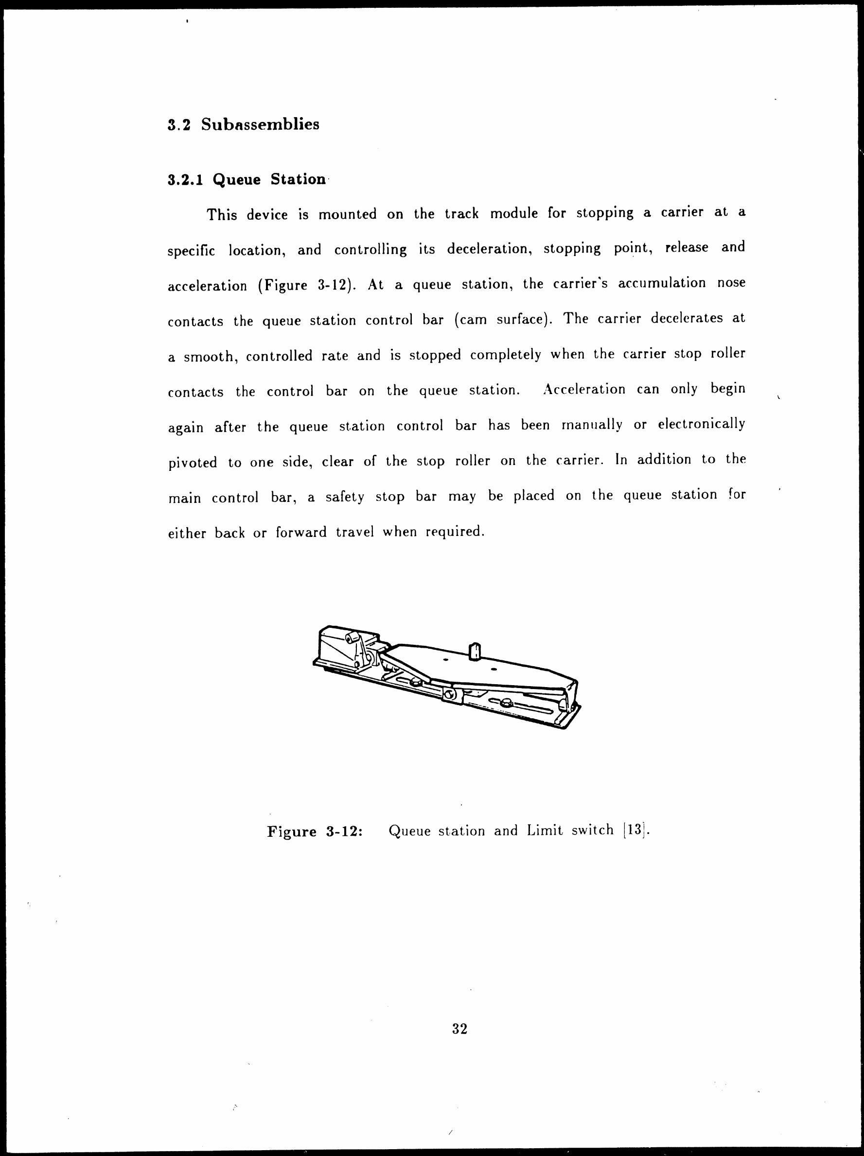
3. 2 Subnssemblies
3.2.1 Queue Station·
This device is mounted on the track module for stopping a carrier at a
specific location, and controlling its deceleration, stopping poi.nt, release and
acceleration (Figure 3-12). At a queue station, the carrier~s accumulation nose
contacts the queue station control bar { cam surface). The carrier decelerates at
a smooth, controlled rate and is stopped completely when the carrier stop roller
contacts the control bar on the queue station. i\cceleration can only begin
again after the queue station control bar has been rnanually or electronically
pivoted to one side, clear of the stop roller on the carrier. In addition to the
main control bar, a safety stop bar may be placed on the queue station for
either back or forward travel when required.
Figure 3-12: Queue station and Limit switch lI3].
32
;·'·
I
\

3.2.2 Trapping Queue Station
A trapping queue station is used for accumulation of carriers on a track
module. The track module section also has a tube drive which must be capable
of rotating in two directions. The carrier is not allowed to move further in its
current direction and accumulation is accornplished on line when a moving
carrier comes in contact with a carrier that has stopped. The roller on the front
of the approaching carrier contacts the cam plate at the rear of the stopped
carrier. The cam plate moves the roller and lever arm~ which in turn rr1oves the
drive wheel assembly to a neutral position. As a result, the approaching car
slows and stops. Any number of carriers may be acr.uniulated in this manner on
a straight section of track.
3.2.3 Limit Switch
As explained above, a queue station brings the carrier to a controlled stop
and activates the limit switch (see Figure 3-12). In generaL the limit switch
detects the stopped carrier's present location. The cam bolted to the .
carrier
chassis operates the roller lever on the limit switch thus relaying an electrical
signal. Then, the limit switch causes the carrier to be released from the queue
station by pivoting the control bar on the queue station. The same logic is also
valid for the rnovement of a transfer car in the transfer assembly. rotational
drive unit in turntables, and the shuttle on its guidance rails. flowever~ a
second limit switch is needed in these cases. Some exarr1ples for the operation of
limit switches ar,e as follows [ 2]:
Transfer assembly: The carrier presence activates the transfer car limit
switch which initiates transfer car travel. The transfer car travels to its
predetermined destination where it is stopped by a queue station or a fixed
33

control bar on the transfer track. The presence of the transfer car activates
another limit switch which in turn causes the carrier to be released from the
transfer car.
Right Angle Turntable: The limit switch detects the carrier's presence
and activates the rotational drive unit. This rotational drive unit, which is
mounted on the supporting frame., rotates the carrier 90 degr~es. A second limit
switch senses that the carrier has completed its rotation.. pivots the queue
station control bar, and the carrier accelerates forward.
Shuttle: As a . .
carrier is stopped by the queue station control bar, the
presence of the carrier activates the shuttle to move forward bv means of a .
limit switch. After the required shuttle position for interfacing is reached., the
second limit switch activates the interfacing equipment.
3.2.4 Photocell
A photocell is used to identify if a .
carrier . is on the transfer car.
Photocells are located at the loading or unloading points of the transfer
assembly in the Cartrac system. These devices can identify the carriers by
means of the reflector mounted under the carrier~s deck plate.
3.2.5 Single a11d Double Actuator
Basically. an actuator is a pull-push button. It is placed at certain points
where transfer cars interface with the .
rna1n track Ii ne. 'fhey operate
simultaneously as the limit switch initiates transfer car travel or causes the
carrier to be released from the transfer car or a queue station. The pull or push
movement of the transfer car is necessary for precise interfacing. If the transfer
car interfaces with the two track sections, the double actuator is needed.
34

3.2.6 Solenoid Valve Panel
The air pressure accommodates the power necessary to pivot a queuP
station or trapping queue station control bar to one side, to move a shuttle
forward or backward., and to pull or push a transfer car in interftlring with the
track module section(s) by means of a single or double actuator. A solenoid
valve panel is the distribution center of that power. There could be more than
one air distribution centers ~n a cartrac system. A typical system layout uses all
of these components to create an orderly flow of traffic throughout the facility.
Through the use of limit switches and advanced electronic sensing devices. the
system is able to interface with modern rnanufact.uring and warehousing
processes.
35

\ .....
Chapter 4
Cartrac System Layout Design for the
Manufacturing Technology Laboratory
4.1 The Manufacturing Tecl111ology Lnboratory
The Manufacturing Technology Laboratory is establishing a major research
and educational area in materials handling, in addition to its traditional areas
in manufacturing processes and automated production systems. A local cornpany,
SI Handling Systems Inc., Easton PA, has provided an automated guided vehicle
system (AGVS-Unit Load Carrier), Mini-Cartrac conveyor system, and an
automated storage/retrieval system (AS/RS) as part of a joint research project
performed at Lehigh. These systems are being ~nstalled in the laboratory where
major current problems being solved are the layout design analysis., the
installation of these systems, and getting them to operate.
4. 2 Desired Objectives in Layout Designing
Since the Cartrac system has been used for a while before being delivered
to Lehigh University. it had already had a layout configuration. According to
that plan, the system has a loop including the shuttle, and .
a carrier
accumulation track section which is located outside and interfaced with the loop
(see Figure 4-2).
In one part of the Manufacturing rferhnology I.Jaborat~ry, a CNC
horizontal machining center has been installed and its location will not be
modified. Since it is a bulky system and has some auxiliary equipment~ it would
be impractical to remove and replace it. Another decision ·had been rnade for
the exact loca,n oL the AS/R system which is being installed next to the
36
....

CNC horizontal machining center. Besides that a CNC turning center will be
located in front of the CNC horizontal machining center.
A mechanical interface design fixture was developed by Richard Davis
Jiranek as his masters thesis [8J, 1986. That fixture design might be used in
conjunction with the production equipment and Cartrac system.
Having the above situation., we can describe our objectives for the Mini
Cartrac system as follows: interfacing with CNC horizontal and turning
machining centers, AS/RS., 1\G VS, and robot or other work stations for
integrated materials handling and manufacturing. In order to meet these
objectives, there seemed to be two ways being followed: to use the layout
configuration which was previously determined or to design a new layout
configuration. In the second case., it should be pointed out that only the
delivered equipment must be considered in planning. Since the Cartrac system is
computerized and is very expensive, to get new equipment from the supplier is
not the optimum solution for this problem. Existing control software can be
adapted easily for a new layout plan, because Cartrac 's real time computer
communication capability enables the .
carriers to be efficiently sequenced for
rapid accommodation of changing production needs, and cornputer controls are
modular and up\\'ardly expandable to support future needs.
4. 3 Predetc>r111i11ed Larout. Plans
There were several predetermined layout plans, one of which was the same
original layout configuration that the Cartrac system had before being delivered
to Lehigh. '
37

\
4.3.1 Analysis of These Plans
A layout plan was submitted by Robert Sloand as a part of his masters
thesis j l 0), 1984. According to that plan, the system configuration has a loop
containing two parallel main track lines, two transfer assemblies, and two track
modules each of which interfaced with one of the CNC machining centers by
means of using the two shuttles ( Figure 4-1 ). Sloand explains the systfm
operation as follows I I Oi:
"'The AGV stops at the proper location.,. signals its presence to the local
cart control, and transfer is initiated. When the pallet transfer is completed. the
cart control directs the load to the proper machining station and signals its
position as ready. The pallet is shut tied off the cart onto either the pallet
shuttles on the machining center or the buffer area of the turning center.
At the machining center stations., the CNC is signalled by the cart control
that a load is in position for transfer into the machine's workspace. The CNC
will then initiate the pallet shuttle when it requests another workpiece for
processing. When part transfer is completed, the CNC will start the proper
program for that particular part. During· this time, the next part to be
processed at this station is brought into position by the cart control and
transferred to the ready position on the pallet shuttle. This procedure is
repeated for all workpieces scheduled for these situations.
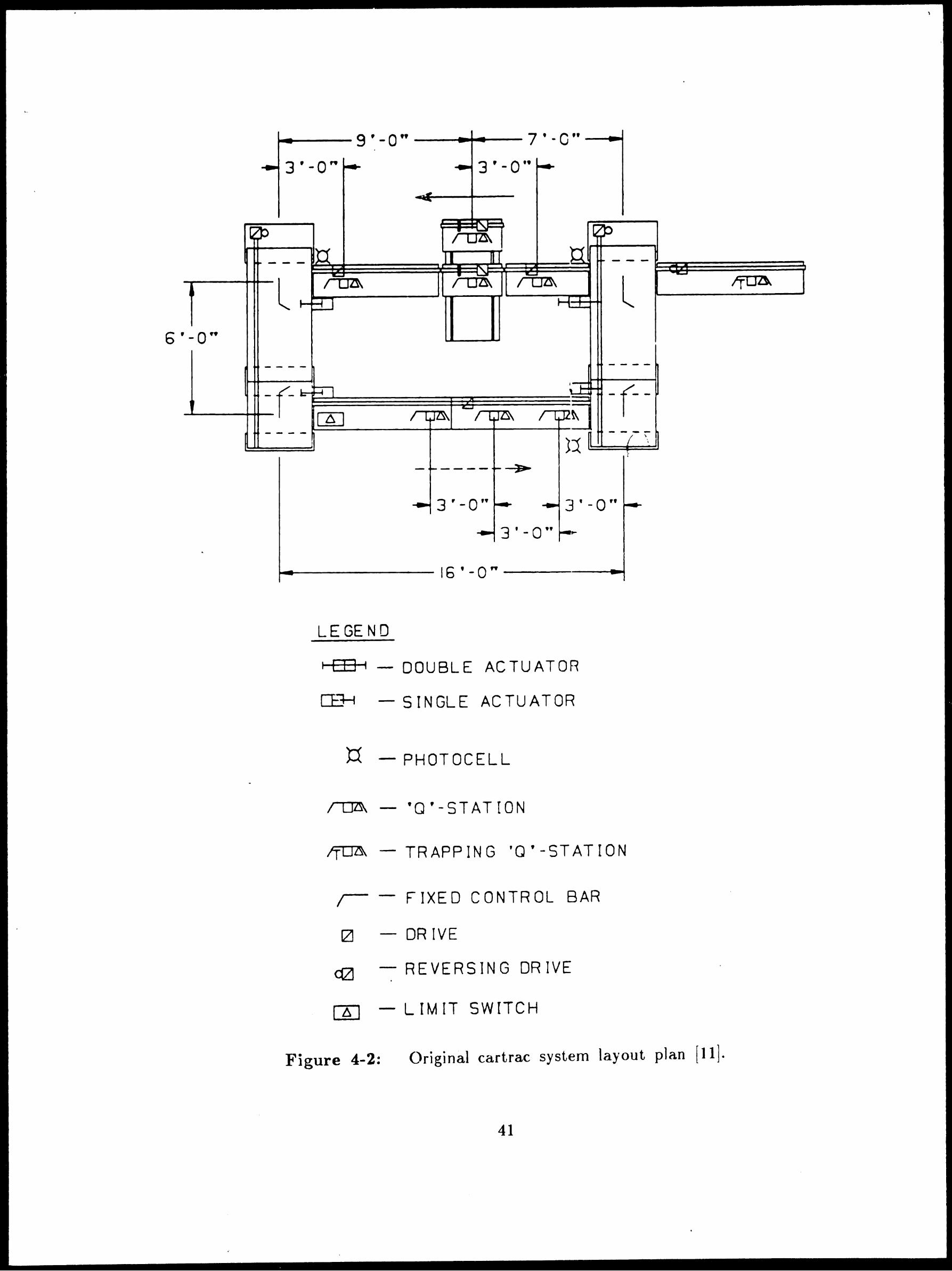
i\nother plan was developed by research engineer John Keefe Jr. using the
original system layout configuration mentioned in Section 4.2. That. layout
configuration is rnade up of a loop and carrier accumulation track section
(Figure 4-2). The vertical movement against parallel main track lines in the
loop is provided by two transfer assemblies. One of the parallel main track lines
38

has three major parts~ the dual shuttle, and two double interface track modules
placed on both sides of the shuttle. Each of the tracks includes the same
equipment; a photocell, drive motor, queue station, drive tube, and limit switch.
The other main track line, on which four limit switches, three queue stations.,
and a photocell are rnounted, involves two single interface track modules ha\ling
a tube drive supplying the power needed. The carrier accumulation track section
carries out a trapping queue station., limit switch., drive tube., and a reversing
drive motor. Each of the transfer assemblies contains a transfer car rr1oving on
the base levels, having a drive tube. and queue station. On the other hand~ a
transfer assembly ba~e level has a left and right hand side fixed con t.rol bars~
drive tube, and reversing drive motor. The system is supported by 9 track
supports, four of which are at the edges of the parallel main track lines holding
up a limit switch and actuator for the traffic control of transfer cars. Three
solenoid valve panels are installed on the track supports where they distribute
the air pressure needed for system.
39

I
-----------U---..-..J TO RQBOJIC LA80AATOAY
CONTROL ANO
NC PROGRAMMING
ROOM
STORAGE
ROOM
--.. S
~ ~i <
.J .J r I
I I
Figure 4-1:
.,_
CNC TURNIN CENTER
.. , kn I
CART-ON-
TRACK
CMM
SPECIAL PROJECTS
AREA
... LEBLOND I I
... f 6• LATHE ..
CNC HORIZONTAL
CHINING CENTER
D CNC VERTICA
MACHIN! G CENTER
HILLING M>.CHIN£·
MANUAL LOAD
... LEBLOND I I
- t 6• LATHE
Predetermined plan-I ( 1 OJ.
40
I
I . '
.......,.. __ 9 ' - O" ---t ....... -- 7 ' -C" -----41-.
3 '-0" 3 '-0 ..
l ff04. l / OZ\\ ~
6 ' - 0 ••
-r- -
3 '-0" 3'-0"
LE GEN D
't t It - DOUBLE ACTUATOR
Cl:..~ - SINGLE ACTUATOR
- PHOTOCELL
/0~ - 'Q'-STATION
~ - TRAPPING 'Q'-STATION
I - FIXED CONTROL BAR
- OR IVE
- REVERSING DRIVE
CX] - LIM IT SWITCH
Figure 4-2: Original cartrac system layout plan (11].
41
•
...
------U----ro ROBOTICS LAB Q\C
n.ANING CENTER
- I
OFFICE
~~ -I c~ I
-METROLOGY LAB
I vc I vc II DESK , ,
STAIRWAY
I
tz WW
.ll ~ (.!) a..<(
_.IHC! 0:)0 001-r- w (/)
I
< w Ct <(
~ ~ o= 0 3
w -' co < ~
~
l; 3
.........
I t-<(
Cl.
> (.!) <(
D
u z u
CNC VMC .,
w I t-< _J
oO
3-AXIS HILL
-
~ ::0 ---i ::0 > ("')
C/)
-< Cl)
-1 ,,, 3:
CNC MACH[NlNS CEN~
(
(/) a::
' (/) <(
I L'
,-------------, :NEW PROCESS : ,TECHNOLOGY AREA 1
L ____________ _j
-LODGE &c I
vc -SHIPLEY
ex:
18 I 0
HYORAU..IC POWER SlPPLY
R'EFRIG. OlL COOL£R
l~I LOADING
l~I ex:
1~1 DOCK 0
AREA
....._ ______________________ __._ - - -
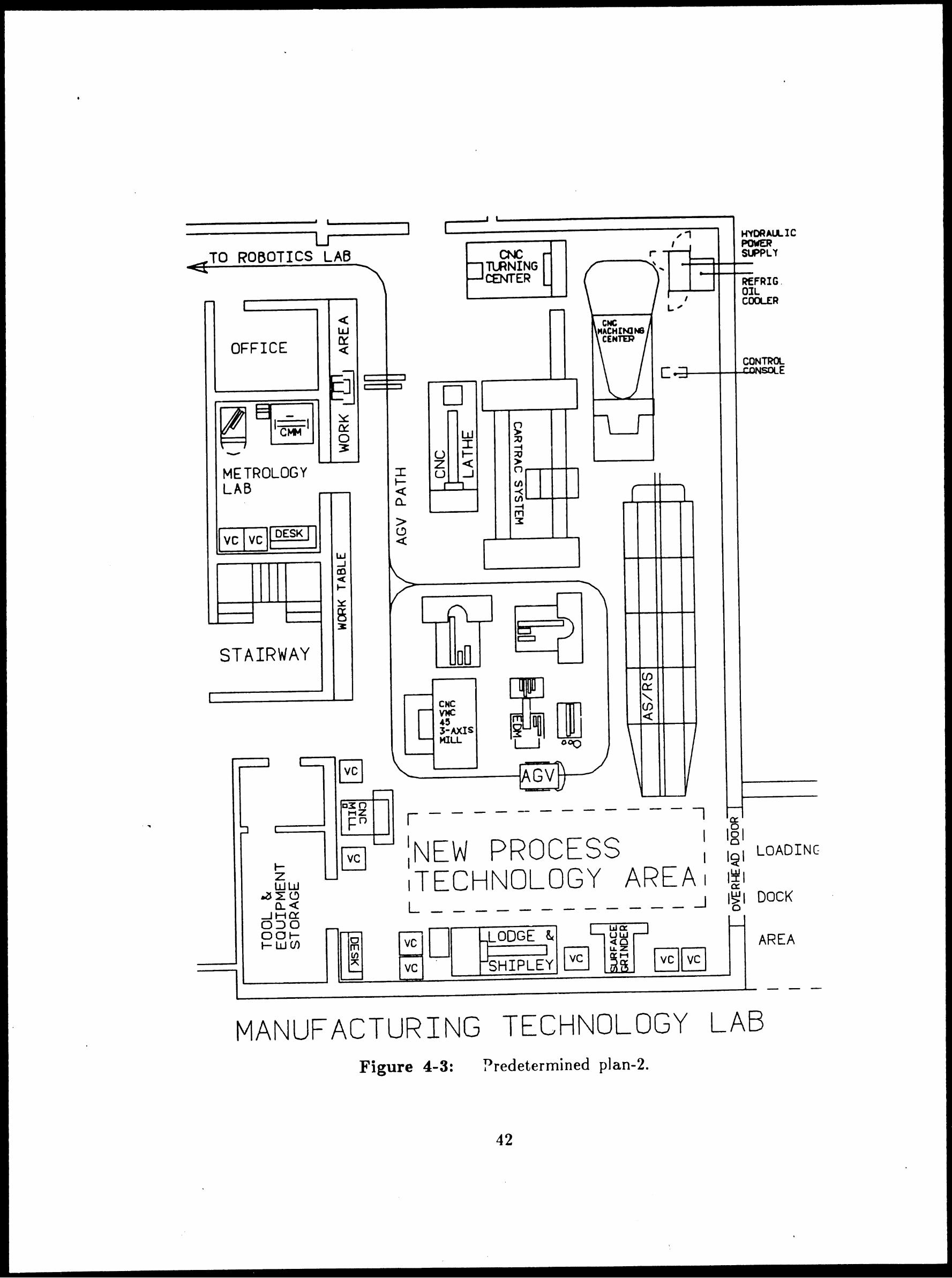
MANUFACTURING TECHNOLOGY LAB Figure 4-3: Predetermined plan-2.
42

'
4.3.2 Disadvantages of the Previous Plans
Sloand's layout plan is not feasible because of lack of required space and
equipment. The plan proposes that the Cartrac system interfaces with the CNC
horizontal and vertical machining centers in the same line which also includes
the AS/RS, a manual load station, and a surface grinder. However, the actual
dimensions of the laboratory do not allow us to have all of these systems and
equipment. There is only a space for loading dock area except the installed
CNC horizontal machining center and AS/RS. Another reason is that the
Cartrac system involves more eoliipment than we actually have. There is also
no consideration to have a CNC vertical machining center in establishing the
flexible manufacturing cell. The sum of these reasons shows that the first
predeterrnined layout plan is not valid for our case.
The second plan is feasible, but it does not meet all of our objectives in
planning. The system interfaces with the AG VS next to the transfer assembly,
and the CNC turning center connected by a robot. Interfacing with the CNC
horizontal machining center and AS/RS, however, still seems to be a problem
( Figure 4-3).
4.4 Factors Co11si(lere<l in D~signi11g
There are a number of factors being consid<}red in a system layout design.
some of the most important of which are as follows:
Co1nbini11g Ha11dling with Otl1~r Functio11s:
'fhe system layout should permit interfacing with other material handling
system" and workstations so that the system integration accommodates the
utilization of high investment machinery.
43
,,._'

•
Improved Flexibility:
The layout must be capable of providing future needs and handle any size
of load.
Optimum Space Requirement:
The available space should be engaged by utilizing as little space as
possible.
Being Compatible with Balance of Laboratory:
Since the Manufacturing Technology Laboratory will be connected to thP
Robotics Lab., the system must accurately work together with the speed of
other equipments, machines, and systems.
4.5 Proposed Layout Design
4.5.1 Analysis
A number of different layouts were developed and revised on the IBM
CADAiv1 system in the Computer-Integrated \1anufacturing (C;I!\A) laboratory.
Since the CNC llorizontal machining center has been running and the AS/RS
has been installed, these systems v-·ere considered as a st.arting point. The use of
a robot providing access bet\V()cn the CNC turning center and the Cartrac
system seerned logical. Therefore, that part of the systern might have b~en a
carrier accumulation track module or norrnal track rnodule without any .
carrier
accumulation on it. At the same time. it should interface with the C~ C
Horizontal machining center. In the original layout p]an, one of the parallel
main track lines including the dual shuttle in the loop appeared to be an ideal
section of the system. After that, the problem was how the system should be
expanded to connect with the AS/RS. In order to make the loop up again, the
44

other .
main track line consisting of two single interface track modules was
separated and these modules could have been the parallel track modules of the
loop. Of course, the two transfer assemblies are vertical at both sides of these
paralJel modules. The left part of the system was the carrier accumulation track
module which was long enough to extend the system up to the center section of
the AS/RS where the loading and unloading is possible (Figure 4-4).
At this point let's review our objectives. The system is working together
with the CNC horizontal machining center and turning center., and the AS/RS
in conjunction with the appropriate interfacing equipment for the systems ,, •,
encountered. The location for the AGVS interfacing is available in front of the
:\S /RS., next t.o the transfer assembly. As it can be understood., the system has
satisfied all of our required objectives. The location of the system also permits
efficient use of floor space in the laboratory and future expansion by the
addition of rnore workstations . Figure 4-5 i]]ustrates the final layout plan for
the !\1ini Ca~trac conveyor system. The conveyor system has been installed in
the :\1anufacturing Technology Laboratory according to this plan.
4.5.2 Problems with the Proposed Layout Design
Many of the hard\\1are cornponents of the new layout plan shown in Figure
4-4 are the same as in the original plan described in Subsection 4.3.1. In
comparing these two plans, the transfer asscrnblies and the dual shuttle have
the same subassemblies on their track modules. The parallel 1r1ain lines of the
loop must be double interface track rnodules with their appropriate drive tubes.
The current track modules and drive tubes., therefore, are not useful for that
plan.· Because of the new configuration, the system needs one more track
support, photocell, and double actuator to be used on the track module located
45
AS/RS
SYSTEM CNC
HORIZONTAL
MA CHINING CENTER I • I> _l . - rOI'\ , 111a,
' Q MINI CARlRAC
l"""tJI'. SYSTEM - - ..
·- f . ...-cl' ~ .ITCII' /"Dl'
01~ - -, n, ..
tta1 DOUBLE ACTUATOR HII SINGLE ACTUATOR l:1 PHOTOCELL
r'DI' 'a' STATION ~TRAPPING 'Q' STATION r- FIXED CONTROL BAR aa REVERSING DRIVE 0 DR I VE
r
D I - -
l /TtB\
ll
- -/
--' , ....... - -, I
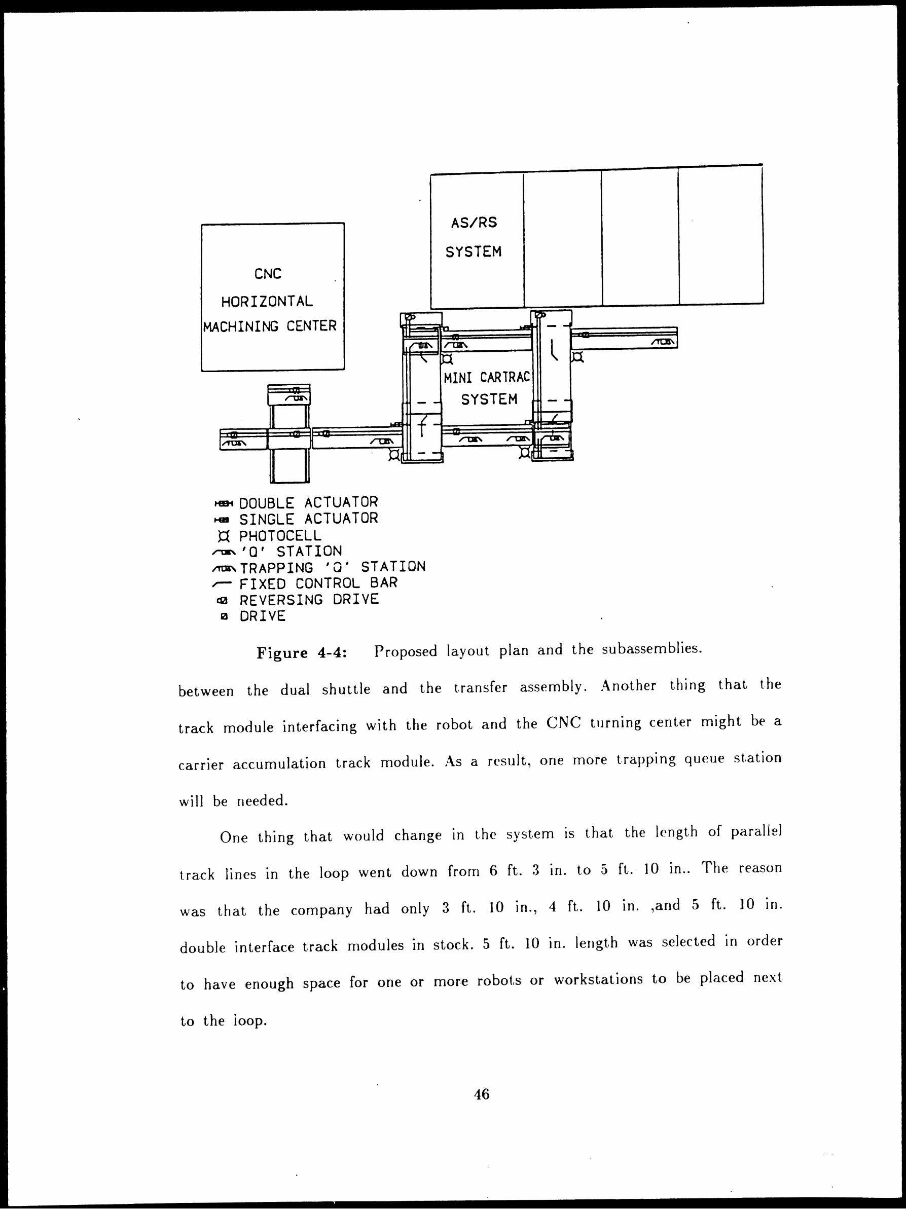
Figure 4-4: Proposed layout plan and the su bassemblies.
between the dual shuttle and the transfer assembly. :\.nother thing that the
track module interfacing with the robot and the CNC turning center might be a
carrier accumulation track module. ,i\s a result, one more trapping queue station
will be needed.
One thing that would change in the system is that the length of parallel
track lines in the loop went down from 6 ft. 3 in. to 5 ft. 10 in .. The reason
was that the company had only 3 ft. 10 in., 4 ft. 10 in. ,and 5 ft. 10 in.
double interface track modules in stock. 5 ft. 10 in. length was selected in order
to have enough space for one or more robots or workstations to be placed next
to the loop.
46

I
•
u
- I
OFFICE
--
STAIRWAY
I
r
I-z -WW .ZS ~ (.!)
Ci.<( _J HO:: 0::) 0 001-r- w (/)
CNC TURNlf'G CENTER
--
CNC HACH[NJ.S
CENTm
r
I
CARTRAC (
.._ CJ)
0::
' U) <(
\
I L.,
C:-~
l
';'
a:
181 0
l~I l~I a: l~I 0
HYOAM.t.lC POWER SUPPL 'f
~FRIG Oll COOL.ER
LOADING
DOCK
AREA
MANUF.ACTURING TECHNOLOGY LAB Figure 4-5: Cartrac system in the Manufacturing Technology Laboratory.
47

Chapter 5 ··
Description of Installation for Cartrac
Conveyor System
5.1 System Track and Peripl1~rRI E<111ipment
The systerr1 installation is rnade possible from the system layout plan and
the engineeriug drawings. Before anchoring, all system track supports., modules,
transfer assembly base levels and the shuttle n1ust be initially placed over the
installation area. Then all bolt points are marked down while the system pieces
are located in position according to the layout plan .
. ~fter that, the system pieces are rernoved from the installation area and
the floor level, which must be within -- or - 1/2 inches [I], is checked out.
During that operation~ we can establish the high and low points of the floor
where track supports are located. The next step is to drill the holes in which
the anchoring bolts are inserted. At that point~ we are r<1ady for installing the
system. We describe it in three procedures in which each step should be
followed.
Typical Track Support and Track Module Joints:
The system height according to the high point of the floor has to be
established. Then, the track supports are placed in posit.ion and rough level
surface -F- (Figure 5-1). If the floor is too far out, a shim n1ight be placed
under the track support base. Anchoring rnay begin at this time while keeping
the plane -G- and -H- at the san1e level (Figure 5-2).
By using a special fixture, surf ace -E-, -D-, -B-, -C- and -J- must be
checked out if they are in line (Figure 5-3). The drive shaft is also aligned by
I•
48

\
using the fixture and maintaining surface -D-. It must contact the fixture at
two surfaces as shown in Figure 5-3. The shim can be used under the friction
~
wheel housing as required (Figure 5-4). Surface -K- must also be maintained
straight ( Figure 5-5). .~fter aligning the drive shaft, the thrust block is installed
(Figure 5-6).
Drive Motors, Reducers and Belt Tensioning:
The sheave and bushing should be fastened together bv w
. using the
adjustment screws, before placing on the reducer shaft and the key coated with
anti-seize compound. If the drive motor is located at the other end of the track~
the motor disconnect switch, and the sheave and bushing locations n1ust be
reversed (Figure 5-7). After checking the oil level in the reducer which are
normally shipped prelu bricated~ they are connected to the motor shaft as in the
sheave-reducer f aste.n i ng.
Then the drive motor is assernbled to the track as shown in Figure 5-7
and adjusted by using the take up nuts. The reducer output shaft rnust be
parallel to the drive shaft and the belts must be perpendicular to the drive
shaft. The drive motor must also be parallel to the bottom of the track. The
Yent plug r11ust be installed before operating and the vent hole rnust face
i1p\\1ard (Figure 5-8). Finally the drive guard is assen1bled as shown in Figurfl
5-8.
Queue and Trapping Queue Stations, Li111it Switcl1es:
The queue station (or trapping queue station) is assembled to the track
using the fixture shown in Figure 5-9. If the queue station blade is not parallel
to the fixture after shimrning (Figure 5-10), the blade rnounting bolts and the
tilt blade is made looser until the guide rollers are kept parallel against the
49

rods as shown in Figure 5-11. Then~ the blade mounting belts are fastened and
checked. Figure 5-12 and Figure 5-13 indicates the trapping queue station and
track joints.
Solenoid Valve Panel:
After determining the solenoid valve location from the the system layout ..
the valve mounting plate is assembled as shown in Figure 5-14 and Figure 5-15.
rfhen the air lines are installed. rfhe use of seamless steel tubing and connectors.
or brass connectors, or stainless steel tubing and connectors from the F.R.L
(Filter, Regulator, Lubricator) panel to the syst.em device (Figure 5-16 and
Figure 5-17) is recornmended so that the contarnination of the air lines are
avoided from the foreign matter, such as~ thrrading, oil residue and metal chips.
Pneumatic installer must purge all .
air lines bef0re connecting to individual
devices (Figure 5-18).
Figure 5-19, Figure 5-20, t,igure 5-21. and Figure 5-22 illustrates the
su bassemblies pneumatic control diagrams.
50
..
' .. • -~- ...

• •
• •
•

.,._ ________ ,(D~ u.~--------1 '
---•
'· I 't [-F-] t ~--·=-1..:::1-- ·-
'
I I I I
i: \ !: .... _ ____. 1' c:::-::-:::::.~-;: .. · •,lr.,-L__ . --- .J 1 ;:.1 -• · ...,. ,1...,,1,_, I
--- -.,._ ____ -....J F~~ ~L=-,,,- - I.:: ......
~~] I ' I
I I I I
I I
w"a._0 w\-E-::!E F.....=<:~ ~
I
'-'=~-...EiliiiL..----L----_B.l---1~_::::::::_ '2' I..C (',(w.A'SH E < _L. _ex::.~ U .._:.
'5~c.E. \... is ~~, =e o />--~+-V+'2--.-5-"--• \
see -\.,: o,E." I
Sr-4 ,~ SE.E. ~o't"6. --i.
{S'-'O?'L\E:::> eY a.r.>~) I
I ,...--i w'l( ~1 · Al-J(hCR ecLi . I I I
Figure 5-1: View A-A for track support ; 11].
-H-
0
1-G-J __ ._;.__
0 Q ~
I
I I
. I
I
I I
lo I
I I lo I I 1-......,
Figure 5-2: Track support· [11].
51
o' i
I
c-;,
~·A·
-c:::::;,~· :;;:=1: =-r~ - ----I! ,I ,I
I, 'I 1• II I, ,. !I h 11
1:
:r I
' :,
•

. --.;..J..f r, •; £ '•"-'".:]
Fi.t1'1,l£
IVAC..Qi] 1.111&..1.-- r-1 ------...
I I
I 'L ... ,J f - -
~<~·
' ' I I
I i_.J
--:Tl I I I
r/").,cr,~ ,-/.r.r. -: nl":; ,\1v:r (.Ct:llf ~;r,,:~:;·,1 '4 wt.~./ ::X,d ~r - '1.: .:.:U(.,W, ~
o I
~
~'"' S"4t..FT 'ltU~i t:OHi~"t ~\' TWO tn ~u"-rt..e.t f:, ~~ .SHOWN.
u:-,,1, S.-, r IAv:r C.t:n ,..,. : T ""'", ~ .... :, J
/v,.,.!..:..-:...: A! ... :n::J,.. V
·I _J~t1~ --- o,··-....j:_...I --- • v(..I.PfPO,e r
r, 111=1·· j.~
Figure 5-3: Track and track support [ l l].
Figure 5-4:
' I
. I ) F«rlt.W J,/,...-L .bus,M;
I I
'
l
,
I
. ·-'-' Friction wheel housing and track support [ ll].
.52

..
j"LocKNtJT
1-z locXMJT--
Figure 5-5:
f-K-!_
I
i( W,C,t" I
~ .. -
Track joint and track support [ 11].
r--_ ' ; 3 • .5<,,.,,., .c·";' /(JO. ~1£1: r. 1 f !.(.Ill•
,_- .i:J.;a.' ORl'f E ~ t ~f'T !,UU "( l. "Ito~~ fl.> t 1\1~,l)V ( 1()P Or-11-11\U!,l 8\.0C..I\
iMIZu~ &U:X"- / ~lhM (lt-G,l,.-.JGt6) ~INGkJt~
I - 1 \o ll .. 0.0 --~ .. - ·-. -~'·".. ·-- ~. nPr --· 1
~"l,A/T - · ---.,:1r, I . ·--.------
Figure 5-6: Thrust block Tll].
53 , .
. r,·"
'
I

s, .• • II • ~,.~.- ~t l l .J _, ~., ... _ ..... ,c...
C·-. :.1. a.~.:,.._'
• •
...... c::s ....... --,,----------c o I ~
l .. ~,,c~ ..
I
~' ,,,1, ,. _,.,'T ; ..... ~.-..a ~,~.,.t ...... , :,,,,,,. •~ oJ .,,, • .,,~
,,. ,, • .,.,. .:;1111,~ -, =''''" _..,,., , .. "' .......... ,.,ct'\C..,_ t,a .,., .. ~<.L...
~l., :..;1.,:! • "~ :\,c.,, fJl1,,1
.... l) .):l,1(. ':,, ..... ~ .. ~ ~--~--
':m:::IIIICll.'/.""'11::111111:lllr'"
i d .. __ ..,; ..
,. -d I ~ ---_ ___. .. a ... 'I,', ':IL· - - - ·· r·
J
I
I I
_J v,t_, ·, .• : n:t
,J It, .J • '::, •
Figure 5-7: Drive assembly [ 11 ].
:11' l!i..i\1t1-4C.
"-~· ~ui.ol, oH.
·1~--"--. . I
.Ii r.:.~I -:..-:..-:..-:..-:. ,
! J : L .. -\- ...
';,~i-.lL bE1.'T ~ S ~ t ... Vf'. ~ c;o.,i ~.I ,Ju,
R f..Q 1,,111(..0 f°' '1· r!lf.., "T \
U.01.HU.D '.>~ =-1.A.l ~Ll."T)
Figure 5-8:
,,,. • ! f. • l/4" <;.t Ill.....,
~, \.!:>c.ic. .... ,'\.~t..~.
• ·•
• " ()
l,. ,. . .. · .a • ..- L !: \I \. , ... lo .a u 'T
" , " ~
,>
'4 I:)• ':.i. ' 1• ~:_:_~.J "'/ n..i'T •
.o,.,...., .. <,,;_"'IL~
Drive and belt tensioning [ll].
54
'

' . . I
I
/
h
. _ .. .
I
I
----- - ------ ------------------ -------
------------------------ -----~--------
--------------------.
I I
LsTOP BLOCK
. I
\ - ... c-~AFE.TY ST~~ BLOCK FOR F?.ONT TKAIIE.\...
'-SAFETY STOP BLOCK FOR BACK TRAVEL ONL'< (WHcN ~tQUl~=.D)
'
. . /
I
Figure 5-9: Typical queue station and limit switch [11 ].
I ••
I
s· 8-~~I
-.-- - 5~ -··· i LIMIT SWITCH ,- FIXTU~E.
ACTUATO~ ~OLLER / ---·· --.... ----- ;1~
/ " - - .• :-:-=:.::: .. -- :.=::;..:..:.· • -=t==-=-=· --=,=-=-· .:..:· -= . . , . J
·-.:;:.==:::-:-:-:==-·~~ ~ .. ~------·
! ' ' i
,,-·- ·----1
ii
!i ... Ll
' ! .... --------·-----
• I .
' ,,_. -
L SNAP BUSHING W/HOLE. QUEUE 4::>iP..1\0N (.t,...M SUf,f/1,.(.E
C. 01'-\\ ~ C.., t\ 't.1 \J~.E. J).. S SH OWN
- GUEL\( $Tl\ T\.JN ~HIM t,n ~ \(., G~)
~':J Y.EQJIREO.
Figure 5-10: Carrier, queue station, and track joints [ 11].
55
MUS"'i

/
;roP ROLL:R -
STOP BLOCK -
~~: .-;:, =.:.· :,.::j =. tf:1 ..:.:· -~:..:A:'-:""':'~-=::..:.:· ·:..:::~ •• :-:::.,.:..:::.
t f I
SHOWN IN A.CTUA1 EP P~tT•oH
~\.1'.tif MOUN l \NC. e.OL 1 ~-R ·_fJ GLJ\D(
( ,·
Figure 5~11:
I
CAR TRAVEL (~RONT)
Queue station and track joint [ 11).
C.~R \\'°.f\'Jr.. L ( ~ " [_ \.(_ ) ...
--,----- _ --~~O~\\/E_ S\-\~.~\ ---------
--. --j . I
'
------· _\ \ I
L <
-------
-----: :~ I I ~~------
: :::_;l I ~ L.t':: :':1-1 -~ . ·-;-.--,r- ~~-- ----
- I: It ~
_---~~--
..--~.;;;-~ - - - - - - - - - - - _;. - - .... - .,. - - - - - - - - - - - - - - - -·-.c-----.------·--11 I - - - - -...:.._"-::- -
I I / - - - ) ---·.:... I I 1; .. _,. -
Ii I I 'l 0
- ,1 -1-
1 I / \ 1, I , \ ·• I
I ~ - ---, -: ·-.-.- --- . - ------.1 .-,----- - ,.- -- -:' --·, .,._JI '
<, 1- -·~.., '. - - - -::::- • /--r:- - - - _,n : . rt ----·-·~ _; ,-::--: ----. ~-~-~ -~r. :~_::::! -~ - -:, , r , I ~- r . .. .- / i •. _., . . . - ·-:::- !.,· . r--= . . ... c: J ==------·. -_--. ~ : . _ .---_::: ;::::::::::--~ , · · r. 1 - _ 1 '.' r-:- - - •
j•:--.....__ -·---- I ~ . 1 I '
. _ _jj\~. _-::::-:: .. =-::=---~-=-. -.:-a--~-= ~-;7."-"-~:-J_~~~r=='-..:.---------. -~~~~~~v=:; __ : ! i . -·-•• ~ . . J, , .., ' I . !
..... .,.__ --- _.., •• - • ~ • ~ - - - j- - - -- - - - ~ . '
'-"' -- ...,-..- ---J "-"-=. ·=., ==-=--- - . . . - - - -· -- --J •
---·-·~-- -- ·- -.- ---·-- ·- --·- ··-' . I -I I I
~~~~-- -· --~~ I I
:_ ::l f'\~t.. ,'t' :::>10P ~LOU"' FOR (V~~\~N R£Q ·r:,)
------. - - ------ . - _ _.;..... __ _
Figure 5-12: Trapping queue station [ 11 J.
56
' ' I ---,.
--------· --?,'t.C:t' b)I
I
I

I .l., • J!;} ,
:-i I -··-
< I -·· .. . -
Figure 5-13: Trapping queue station and track joints [ 11 ].
r=:---..I~ ,. ,,
b il.c;'b : .. ~,v I__ - -----. -----
-;:::::-7==\:::~=iL:J ...__ ri£i. o C~E ..:new
J NPrT ·p·AJNr
I - ·-
r ---
- ~ -- -- - -- - -. - - - ·- - - - - -- ·- --· rh : : rl·: · d,: I I.).·.· 1
.1 ' I ~ .u ' . . -~.;. : !-, '-·-·---. - __ J _ - ..:. _..,_ Le· ~ ·- ·-~ -~ ~ _,JI> ''r' y.tv · A :~
Ll> I I .' J..: ,--;-=i~ _ w _ _ . . . _ _..i .... __ . _ ·--. ~n--- ~p-- -· - ·1n--
Figure 5-14: Solenoid valve panel [J l].
57

•
Figure ·5-15:
~-. --~
< _d.~ .-;+n. < ~t,}~..,...ete Ii ._.. • ._.-w-u,,..r,sr/'.~
"tr~':71: .. '• ~- ·: .-.:-==.:-: ·. d , .
11
I •,""\ Jivvr---' : I I I I
7 • ,· ·a· a . ·:--.. ~ I .. "'.'·: .- [[Jr .. · .·· h,,J.,J.:R r.'=·._-:1._ .-~.., r ···-' -- . - ......... - _::i t_ .• J I '--·• -~
~' ........ '·'-'..) I' JJl
--1...L--·· --"'-~ .•.• -·' L,_..... .• .. -·- .. .J
! j I 1
' I
I'.. I 'I [Jl
I
..
Solenoid valve panel and track support joint [ 11 J.
---- . . . ??J\
Figure 5-16: System device tubing and connectors [11].
58
I , 1

-- .... _.. • ._. _. .. ,._,. '• -w •_,.WW W ,a WU U WU"W --
Figure 5-17:
Figure 5-18:
~~,.,.,. ... a,_,,,r;,.
~N'll'CII --'
..),J '1.W l A·
Pneumatic supply panel (F .. R. L.) !tIJ.
, I I' I
' I
I ' I I
I I : : .-c
~~r. r
I I
r·enumatic s·upply panel joint [11(.
59

' ••
0..1t L.1£ . Sm, ·1c:Jl.!
2
Figure 5-19: Queue station pneumatic control diagram [ 11].
•
14'igure 5-20:
Tffi!JSFER CAR SHUTTLE MECHANISM
B
. .
E:8 €A
Single actuator pneumatic control diagram [ 11].
60

•
.S A
EB
Figure 5-21:
.. ..
.
"". ''1 ~ ()\L Th.~.
..L
TR'RtvSFE"R CA,'? S>-iUTTLE ~ECHANIS~
a
EB T
Double actuator pneumatic control diagram [ 11:.
I
H ' ·, -.i . T .
I . I
I
·, ..L.
C. · :>1~ 1 \L)l'-l ON
~Hun LE I I --T""---t--l.
o·· S;I\\\O~ 0 t'-\
ST'.:,f'"' 1?.P..,:Y... __ L.J. --L.
l I I -I I
--- .. - ---- ..... -""---- -------'
Figure 5-22: Shuttle pnuematic contol diagram [11).
61

5. 2 Trar1sfer Assernbly and Peripheral E<111ipment
Transfer Cars, Photocells, and Push-Pull Buttons:
The locations of transfer assembly and the interface track are est,1blished
from the system layout. The bottom of the track or surface -A- must be
adjusted to the system elevation (Figure 5-23}. Surfate -B- and the guidance
surface -C- must be maintained straight with all interface tracks. When the
carrier is in pos1 t1on on the transfer car~ the photocell shou Id he adjusted to
opt•rate off the renector on the carrier (Figure 5-24). Then, the tapping arrr1 is
adjusted to clear the stop on the carrier as the transfer car is pushed or pulled
against the interface track (Figure 5-25).
Transfer Assembly Base Levels, Transfer Tracks, Tube Drives
and Reducers, Fixed Control Bars:
The high and low points of the floor where base plates are located is
defined before installing. After that, the transfer base plates are placed. Surface
-A- (Figure 5-26) and surface -C- (Figure 5-27) must be in line and anchoring
may begin at this time.
The drive shaft is aligned by maintaining surface -B- and -D- (Figure
5-28). The reducer output shaft is also adjusted with the transfer drive shaft by
using the shims as shovvn in Figure 5-29. The lor at ions of the left. and right
hand side fixed control bars depend on the transfer car interfacing position with
the system tracks. 1\fter adjustrnent .. they are fastened by using two screws
(Figure 5-30 and Figure 5-31).
62
.1 .

·.·•·
•• ••
• • ••••••
•

-,--.i:- :WWW
( .
~------- -- .... ~
Figure 5-23: Tran sf er car [ 11].
\a 1YP fOR b.\..L 1R~C."" \N1£~f~C:..E TO TRAN'::>f[R C~R.
-r =t + +
,~~~~~~~~~--~, . . T.;=-~-~~~~-;----. ---~ ... -. _-r~. -- ---. _>_-_1_
----·-0-<t. ThA~Sf[~-~ l ' r-- ' .,
rj~-·.·· -~. ~:=)· .
___ :f· ··-•
I . .
RE fl'tC.10R
I
--@-·
IE-- __ -:.;1~-~~==l L i TIP f OR l>.LL lRl\(.1', It-Hi. RV/I.< .. :.: 10 lf'.P..NS ft 'R C. "R.
Figure 5-24: Photocell, carrier, and track joint [ 11].
63

-- -' ·-·· • 79L . • • :9' - r . ..&..., i : I
I_J , -J= '. ~ 1?\~'4:..flR - ,... =- ,_::I. --~ -,!2:. - I ==>- ' 1. ,~~l'.• °'.. ,~ 1:1' .... r;: ,._-.L_ I
- I\ I
__ -,..--...~~~--~~~~~------------.......: ~ I
r- ... f ' ! -'--~ - I - \.J~\'\ S'N\TC..H .... C!::c ~ -&. -...-, - • '._ ••-•:::=::J I
..... - . , ~ _ .. ~--- n..ooR L""lt t
I j
Figure 5-25:
ill ill _, ------- 2" ~"
I
Transfer car, limit switch, actuator., and track joints [11].
r \J~t. EP..'"::,E r\.f'.,£ r,ut--r,C· 'I'·. ,_r-.-~t·. ,~,,tr. 't.~~)'_~;r: E.~:..ti=L~\E ~::, U:.£0 f:t..1 rr~E 8'1':> CF l?r-,.~:\.-c.l-" \ f' I\ c... ¥-~ .
I
•
t
x . ;*
\Nlt:\\ M£'C\t,1c B~ERA1"E
y
' X
Figure 5-26: Transfer tracks and base plate [ 11].
64

Figure 5-27:
f='L00R ~ IN E hl {" ~ L'o~ ~C ~t W ' ~ LO( ~WA'..i1f R
Lt ,.o .. !: o.o. w~~£R
Transfer tracks and base plate joint i 11 j.
~ .Z, ,o • 100 IAt.~•l•-
-~
: ......
oc. ,·,• ... ")yf:
·i·~ . . ."
. / /,, ,
/
/
:-..:
/ /
,
//
,
'
, ....
'
. • I )It
.,
Figure 5-28: Drive tube, coupler, thrust block, and track joint [11].
65

'\
\.
-g· hl I I Rt. '"O\JC ( ?, :::,\-\, ti\ (,lD~ 20 GA\J.1: P.."_ ~\ E~\R tD. .
~t~\JCEF. OU1PJ1 ~\4~F\ ,o 'tJE \N \JN£
w,,'t\ l"?-J~.t\:_.rER DR'''E ~r,~t\ \/'J\1\1 \N T2.·
·- ~\<. \C. ,, ON Wl--\E. E \_ \-\ OU 1::-, NG 5'n \ T\/\
(_,r.o "" 2 D G~:: t) A:_ f.EQU \K ED.
Figure 5-29: Transfer assembly drive [ 11;.
--·----- . '
------ _______ J '~- ------
! I --- ----- ------·---------
* ---4--- -~~- -~-' ~-====-== ---=====-.=..;::.;:=:=--=-=-==-=-===-:-- I 1 · -
>
> ' . I . th --· r -t-I ·-- . .,J1* ·- --~' --·
. I•• t t f ••I
.. '-nr.r,J;h'..:-~-:.-::ll~-=--1.: ___ - --- ;r :=--~ ~-==:- ---I LJ- -. -- ------- -----, --------1 ,--- --------- ------ -- -- -- -- - - -- - ------
,· I I ' :1
- I I I
I -I I I
:
-- I -. -- -
I I - - I - - - - D I
-
-- -·1 -- -- -- --. -' I
~
-
·------·$· --
OUEUE
---
-- . -- - ---¢. "'------:,...,.. -,..
.. e
.
- -
WWW
- .
. . I
c;::.,"'t-. ,, ,; ,, 11 , . " c:·-~ . • 'i
I I
' I ,r:< ! t.
--
Figure 5-30: Left hand side fixed control bar and track joint [ 11 J.
66

-----' ---· -- ---1-;I~--· __
':it-I~~ ~USH\N{,, W/HOl.t <"<j'> Is.
' .L __ - - --- .• ·~:, _______ .) .. ..,
I . ------ ----- ----- - ----------! I
I - I I - - -I
r. .. . -
I
I - -- -- -- -.
C.t\~ -\ 1 _j Ti". ~ N ~ f t R '4
INTt?, t~CE ,R~C.K. g .
1_5 l -Figure 5-31:
-· u,
-
- -
. .
• ·------··-- --- ··----..L.---· -------·· --·,
l__=.:.:..:·. =-:-:. ~?-· I 1-·· ·---~t)-· j
-:-. ---=.:.:~=.:..=====-.:.:.:===-:.-=-=--~ I • I
I I
I I I
I I
·-· ~
' '
I L , r, -) J -
l'~ ~<S· ' ' . I I ..
[ i'I .. \-1. n~ I: D CD 1-11 ?. o l
t ·-.. .., J ·'.. •• • . - .. ·£ . - . . l · .. -.. ~·:~: .. . · · .. -... ,, ~ -- .. - . · . 'l..".·.·.·-·.11.r.r."t..:..::~ ·---·.-,.-.·.·.:: .·:: r.·.1r-.~·.-., ']-:.:. ,, L:.--. -.. --. --.. -. -. -. -... --... ~ -......... ! ' ....,..__ --------~ .. • I
! --· -· • - e
J.---~ \. UP)Y[ :,~1f\f i - . - I ' -
. . . - - . - . - .
I ' I
. - .. . . - - -. f;
,... I I
-~;
'
I > <, i
Right hand side fixed control bar and track joint [ 11 ].
5.3 Dual Sl111t.tl~ nr1d Peri1>l1cral E,111i1>1r1P11t.
After determining the shuttle and interface track )oration frorn the system
layout., the .shuttle stop bolt may be adjusted to align the shut.tie· track rnodule
sides with other track modules (Figure 5-32). The top surface bright of the
shuttle should be equal to the height of ·the fther track modules {Figure 5-33).
Then the leveling plates must .be .secured to the floor \Vith anchor bolts. The
air /oil tanks are filled· to proper levels at the factory. \Vith the shuttle at the I •
end of stroke, one t.ank should be full and the opposite t.ank shu-,_J]d be near
ernpty. 'fhe shuttle should not he rnoved rnanually with the flow- control valves
closed. This rr1ay cause a vacuum forcing oil to exhaust through the solenoid
valves.
67
..

•
I ·-•·~
--- . .-•.-r • ,- .• --· t I. _Jj -...i..::.l_ ·-i TY P J=OR ~LL 1~'1'.. ,..i1(RrA(( lO $HLIT1Lf ~-
/: r~~C. I(. LO(~, ,ow . HOL o i o wntHN ! Ji
. ...., rD 0 ~
r -z f'T1
I
-' . . ... . 41) l~·
. ..._.. I .~ I I I I I '
~-I -~- 1. I .
~/1 · 1
. ' ....... 1,0.
--' 510!' BOL~ ~ _£ . ... ..
• 1 I
'
'I
I . . l I I . I
l:r ~-: , I
-------~- t . ~ ~ ~ ~I
l L---------·
_; I
I I I
: I ..I ' I
i l ·
I ! 1'
·,: . -
Figure 5-32: Dual shuttle interfacing with track modules [ 11 ].
• I I
I I
I~\
' ' l~'. !
l f1== LF
/:I ,. I
---' ;
' I
,-· •• -r ~ .l .. - --~~,---,,----~=...-:..::,..:, --=-a=~=-===-=======--===--==:-L1i·L:-: .. · .I· F-y' '
: . I . JL. I
I . !-,1 . . . . . '" " Q::.-:--l ----;,:r :...=r--===---1---=-L=::'\'~-:-=-==
'e'
I I
.-- --. __. __ I I
' I NI- r I,. --4
, ~~N~- 0 ~ s;t ,.., ~~ r: :t: l,,N ~ ' :...i O ptu.i ~ t ~::z::
;o '? ~~ ii' ,i
,:: .
I '!::f
I
• I I . I == .&
' I·
·_s- ___ :;i ,., .,
I I
I --~-·- I L- - . - - - :::!::J
-·-----L
uil c.. l s· ··,~ -'I .~ r :;;. N --~------·~ r1'11-...-------- 11"1 .;>
:-:'I U" C:
. ________ ___:_ _________ ~~~___:_---------___:_---------~ ,, ;a
~ ;l ;iQ ;;.4
~
Figure 5-33: Dual shuttle and floor joints [11].
68

Chapter 6
System Interfacing
6.1 Interfacing with other Materials Handling Systems
Consideration was given . in this thesis project to the desirability of
interfacing the Mini Cartrar conveyor system with other material hand ling
systems in the \1an11farturing Technology Laboratory. The other handling
systems in the lab include an automated storagP and retrieval system (AS/RS).
an automated guided vehicle system. and one or more industrial robots. The
layout plan for the f\1ini Cartrac is designed to permit interfacing with these
other systems. Th is chapter describes the issues and plans relative to systern
i n t er f ac i n g.
6.1.1 AS/RS
:\n .-\S/RS ran be defined to be "'a combination of equipment and controls
which handles, stores, and retrieves materials with precision, accuracy, and speed
under a defined degree of automation"' [5]. Such systems range from relatively
simple manually controlled order picking machines operating in small storage
structures to relatively complex, con1puter-con trolled storage/ retrieve) ( S: R)
syst.erns that are totally intPgrated into the rnanufacturing and distribution
process.
,.\n autornated storage and retrieval system \Vas donated to the
\!lanufactllring Technology l..,aboratory by SI Handling Systerns as part of its
rnatching contribution to a Ben Franklin project at Lehigh. The :\S/RS is
approxirnately 32 ft. 6 in. long, 7 ft. 1/2 in. wide and 16 ft. 5 in. high. It
consists of a single aisle with storage racks on both sides of the aisle. The
69

length of the ,\S/RS is divided into eight sections (four sections on each side of
the aisle)" only four of which contain storage shelves (two sections on each
side). These storage sections are located at either end of the .i\S/RS, thus
leaving the rr1iddle sections empty of shelves. There are 15 storage shelves
vertically in each of the four sections., thus providing a total of 60 storage
compartments in the AS/RS. ~:ach storage compartment can accommadate one
tote pan or pallet fixture .. ~ double masted storage/retrieval (S/R) machine is
used to perforrn the stocage and retrieval transactions.
The operation of the system is tyµical of an AS/RS: the S/R machine is
controlled to move horizontallv and vertirally to position its extraction
mechanism at any of the storage compartments. When positioned, the extraction
mechanism pulls the tote pan (or pallet) fror11 the cornpartment in the case of a
retrieval transaction, or pushes the tote pan into the compartrr1ent in the case
of a storage transaction.
rfo interface with the ~1ini Cartrac conveyor~ the S/R machine positions
its extraction mechanism at a location near the rniddle of the storage racks (in .,
one of the ernpty sections of the AS/RS) corresponding to the position of the
loading and unloading station of the Mini Cartrac. A specially designed transfer
mechanism will be used to rnove the tote pan bet\veen the ,\S / RS and the
conveyor cart.
70

6.1.2 AGVS Docking •
,t\n AC\'S can be defined as follows 15]: "An automated guided vehicle
systen-1 is a materials handling systerr1 that uses independently operated, self
propelled vehicles that are guided along defined pathways in the floor. The
vehicles are powered by me.ans of on-board batteries that allow operation for
several hours (eight to 16 hours is typical) between recharging. The definition of
the pathways is generaJly accon1~lished using wires irnbedded in the noor or
renective paint on the noor surface. Guidance is achieved by sensors on the
vehic]es that can follow the guide wires or paint."
Since the AG V in the laboratory is a unit load .
carrier. it may be 1
equipped for automatic loading and unloading by rneans of powered rollers.,
rnoving be]ts, mechanized lift platforms or other devices. In our case. the unit
load carrier could be equipped with a Cartrac module section that contains a
trapping queue station, limit switch, drive tube, and drive motor. The location
for interfacing might be next to the transfer assembly. and in front of the
. .\.S/RS. It would work in conjunction with the transfer car that transports the
carrier from the Cartrac system to the AGVS (Figure 6-1). Basically, the
operation is as follows:
1\s soon as the 1\GV-unit lo<1d carrier gets the pre<lPtPrrnined destination
point, it tells an activation device that it is readv to be loa<led. \\'hen the "'
transfer car is in position with the (_~artrac track rnodule \vhich · is one of the
main track lines of the 1oop and the .t\G\'-unit load carrier, a doublfl actuator
pulls the transf <)r car toward the track rnodule and th<\ qu(lue station lets the
Cartrac carrier rnove forward. Then, the carrier approaches the transfer assembly
and its whLels move onto the adjacent track rails of the transfer car and a
71

queue station stops the carrier's motion. At this time. the transfer car waits to
be pushed toward the AGV via a double actuator which is activated by the
carrier presence. After being pushed, the queue station control bar is pivoted
and the carrier accelerates forward. As the carrier gets the AG V on which a
trapping queue station stops the carrier's motion precisely and a lirr1it s\\·itch
senses that the loading operation has been cornpleted and allows the :\G V to
move to its next prrdeterrnined destination point. The unloading operation is
the reverse of the prored u re described above.
CNC
HORIZONTAL MACHINING CENTER I :11
..
.. L.Oell ..
.......-cJIS\.
~ DOUBLE ACTUATOR ..-m SINGLE ACTUATOR :Q PHOTOCELL ~ '0' STATION
l:11-
_...._ , IU.-.,,
' - -f-- -
"'°" TRAPPING ,·a' STATION r- FIXED CONTROL BAR ~ REVERSING DRIVE 0 DRIVE
AS/RS
SYSTEM
I
rel'
0
- -
MINI CARTRAC SYSTEM
f"'l
,llll' /"'Cl!\.
..
U,-
- -
l n:
- -I
---1,.__
l"'1J'I' , ua-
- - AGVS ~ --
Figure 6-1: i\ (~ VS-Docking.
72
.
~
(
,

/ r
6.2 Interfacing with Robot or <>ther Work St11tions
6.2.1 Robots
As we mentioned in earlier sections, a Cincinnati Milacron TJ robot
coordinates bet ween the CNC turning center and the Cartrac • system 1n
transferring materials. ..\nother possible use of a robot is in front of the loop,
between transfer asser11blies (Figure 6-2). The opPrat.ion done by that robot
could be one of the following manufacturing operations.
CNC
HORIZONTAL
MACHINING CENTER
AS/RS
SYSTEM
I l>
' a.
HB-1 DOUBLE ACTUATOR KE SINGLE ACTUATOR :t:i PHOTOCELL
~ - -
:01 - -
~ 'O' STATION ~TRAPPING 'O' STATION ~ FIXED CONTROL BAR ~ REVERSING DRIVE 0 DRIVE
MINI CARTRAC
SYSTEM - - -
ROBOT STATION
Figure 6-2: Interfacing with a robot station.
Welding: \\' elding, processes are a very important application area for
industrial robots. The applications logically divide into two basic categories, spot.
73

\
welding and arc welding. There are several advant.agcs attributed to a robot
welding station cornpared with its manually operated counterpart. Arnong these
are the following i7l:
----Higher productivity.
----Improved safety.
----More consistent welds.
Processing Operations: 'fhe . .
processing operation is performed by a
specialized tool attached to the robot's \vrist as its end effector. 'fhe end
effector is typically a powered spindle which holds and rot.ates a tool such as a
drill. The robot. would be used to bring the tool into rontart with a stationary
workpart during processing.
Assembly: Since there are variations in products and the demand for
each product is significantly ]o\ver than in niass production, batch type assembly
operations seem to offer the most promise for using robots. The robot would
pick a part or subassernbly stored in the assembly area and place it in the base
unit, the fundamental building block which originates at the first assernbly
station.
Inspection: Robots (-'l}ll i pped with mechanical probes. optical .
sensing
capabilities~ or other rneasuring devices can bt-1 prograrn111Pd to pcrforrn
dirnensional checking and other forrns of inspPct..ion op('rations.
74
I I

. ; I
_.)
6.2.2 Workstations
The Cartrac system may be interfaced with another \\·orkstation in f rant
of the loop, between transfer assemblies (Figure 6-3). That workstation could
be a CNC lathe. The interfacing equipment which transfers the workparts
bet.ween the Cartrac system and the CNC lathe rnight be a roller or belt
conveyor system.
AS/RS
SYSTEM CNC
HORIZONTAL
MACHINING CENTER I ~P
~~t~·;;;;;;;~~1--L.------S: l=cel:s=====-= lu ~
' 0. MINI CARTRAC
~ - - SYSTEM -
p~ - -
~ DOUBLE AC TUA TOR HE SINGLE ACTUATOR CNC LATHE Q PHOTOCELL
/""Cl'. '0' STATION /'rm\ TRAPPING '0' ST AT ION ~ FIXED CONTROL BAR ~ REVERSING DRIVE izi DRIVE
- -
Figure 6-3: Interfacing with a CNC Lathe.
Interfacing with the CNC horizantal rnarhining center ran be rnade
possible by operating the dual shuttle in conjunction with a n1echanical interface
fixture designed by Richard .Jiranek who explains the ideal interfacing operation
as follows [8]: "The cart will perform normaUy during transport to the
workstation. However, the cart will arrive at its destination point; four solenoids
75
,.
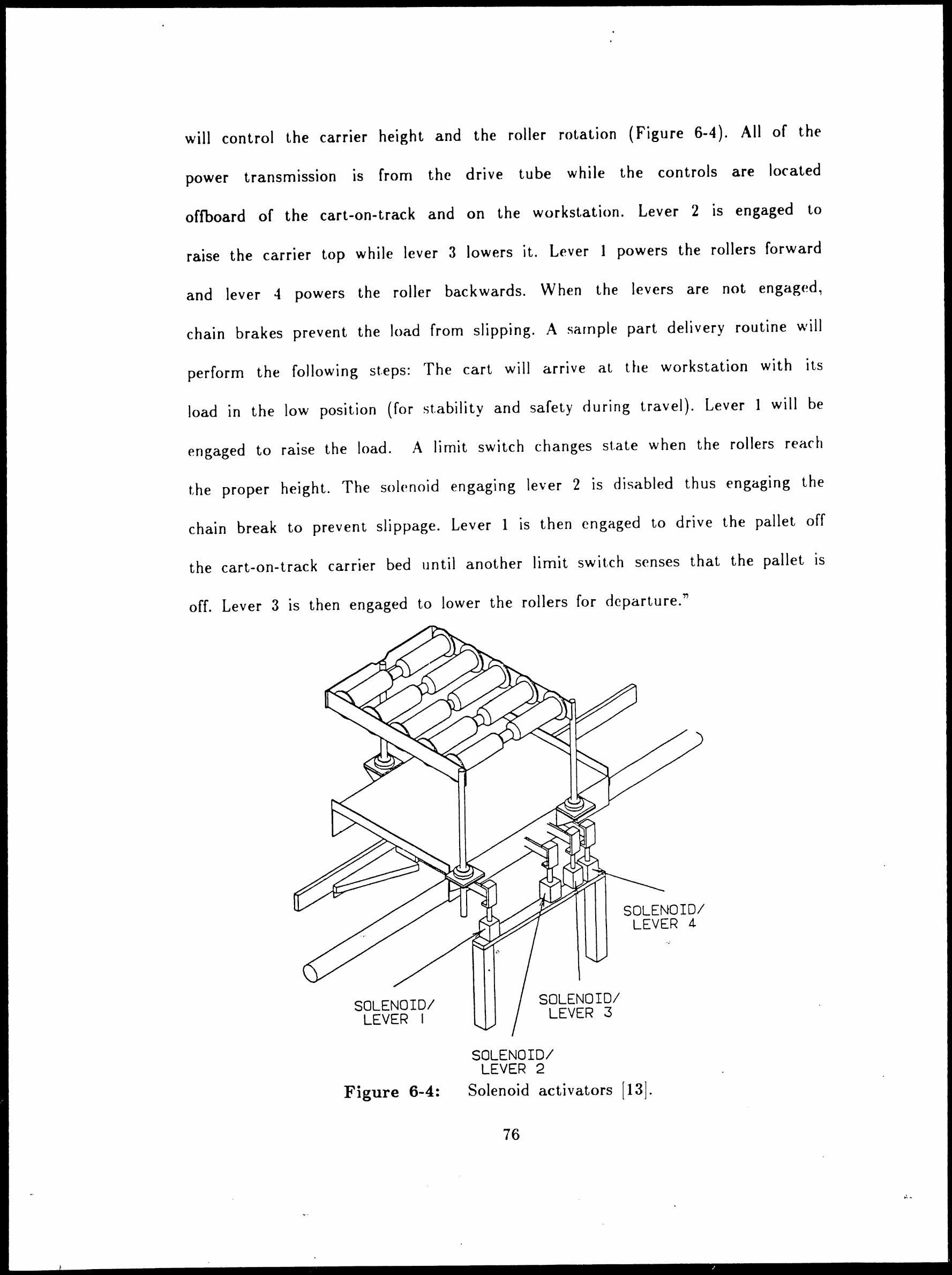
will control the carrier height and the roller rotation (Figure 6-4). All of the
power transmission is from the drive tube while the controls are located
offboard of the cart-on-track and on the workstation. Lever 2 is engaged to
raise the carrier top while lever 3 lowers it. Lever I powers the rollers forward
and lever 4 powers the roller backwards. When the levers are not engaged,
chain brakes prevent the load from slipping. A sarnple part delivery routine \viii
perform the following steps: The cart will arrive at the workstation with its
load in the low position (for stability and safety during travel). Lever I will be
engaged to raise the load. A limit switch changes st.ate when the rollers reach
the proper height. The solenoid engaging lever 2 is disabled thus engaging the
chain break to prevent slippage. Lever 1 is then engaged to drive the pallet off
the cart-on-track carrier bed until another limit switch senses that the pallet is
off. Lever 3 is then engaged to lower the rollers for departure."
SOLENOID/ LEVER I
Figure 6-4:
SOLENOID/ LEVER 3
SOLENOID/ LEVER 2
SOLENOID/ LEVER 4
Solenoid activators [13].
76
' ... -

Chapter 7
Conclusion and Areas for Future Study
. .\ layout plan has bPen develop(•d for a Mini (;arlrac conveyor system~
contributed by SI llandling Systern Inc .. that would permit it to serve as the
r.rntral rr1at.erial handling systPm for a nex:ble rnanufarturing systPn1 (FMS) in
the \1an,,facturing TPchnology Laborat.orv. 'rhis lavout plan is i)lustrat.ed in
FigurP 7-1. The handling syst<1 rn is designed to .
pc r nut parts t.o be rnoved
bet ween t. he t \Vo rn ac hi n e tools in tht· F \1S to acrornrnodate . . .
var1at1ons 1n
processing. These two machine tools are a C~C horizontal rnachining center and
a C~C turning renter. :\t the horizontal rnachining center, a pallet fixture
holding the work part will be transferred back and forth between the \1ini
Cartrac conveyor cart and the rnachine tool table. :\t the turning center, an
industrial robot will be used to pick parts from the conveyor rart to place t.hc·m
into the machine chuck.
In addition to its f u n ct ion as t he c en tr a I hand l i n g sys tern for t hr ~ ~ \1 S ~
the ~1ini Cartrac system has also bPen planned so that it ran be interfaced \\'1th
the automated guided vehicle system (AGVS) and the autornat.ed storage and
retrieval system (AS/RS) in the lab .. \ccordingly. it \viii be possible to transfer
pallets (on which the single \vorkparts are at t.ach()d) and t.ote pans (in \\·hirh
more than one part can be contained) bPt.WPfln the t hrPe syst.erns (~1ini Cartrac,
:\t~\'S, and AS/RS).
Further resParch and developrnent. is requirPd in the follo\ving areas related
to the i\1ini Cartrac system and other rnat.erial handling .
syst.err1s 1n the
"
Manufacturing Technology Laboratory:
----Design of the peripheral equipment for interfacing the Mini Cartrac '
,,
77

•
/
conveyor system with the CNC horizontal rnachining center, the robot, the CNC
turning center, the AS,1 RS and the AG VS.
----Development of the appropriate controls for coordinating the transfers of
I
parts and loads between the various systems.
----Design of a pallet fixture that can be used to hold parts t<> be
processed in the F\.1S and can also be moved by the various handling systems
in the laboratory and transferred between these systems.
/'
CNC
TURNING
CENTER
MANUFACTURING TECHNOLOGY LABORATORY
CNC
HORIZONTAL
MACHINlNG CENTER
ROBOT STATION
AS/RS
SYSTEM
: SJ
' u. MINl CARlRAC
~.. - SYSTEM ~.. -
.:a ... -
HIN DOUBLE ACTUATOR .m SINGLE ACTUATOR 0: PHOTOCELL
rt:11' 'Q' ST A TION ~ TRAPPING 'Q' STATION ~ FIXED CONTROL BAR dZ! REVERSING DRIVE 0 DRIVE
/
FLEX IBLE MANIJF ACTLIP T f\lG C~I __ I
Figure T-1: Frv1S in the N1anuf acturing Technology Laboratory
...
78
..
•
/

References
[Il- Announcernent, "(~onveyor Syst.erns'". \1odern Yiaterials llandling .
. i\ ugust 5, 1983, pp 50-5 7.
r21 I :- J. Dorrance. ., Spinn i ng-'fu be (., ¥J _..,onvcvors ,
"' \1atcrials I land ling
Handbook. 2nd edition (R. A. Kulwier .. editor). John \Viley & Sons. '.'Jew ''ork.
0 U n Tl • '!'I ~ )' St, f> rn S ) rt l CI gr at j O fl : rr h P (~ r rat j V r S j d ( 1 0 f ~ate r j a)
l1 an d Ii n g ~ • P I an t F: n g i nee r i n g , F e b r u a r y I 3 ., I 9 8 6 . p p · 14 -4 7 .
; 1 ,r ("'1 I "' M d I I d \1 · I 11 ..JI' ~ D · 1 · [4:- .~. .i enney, 1 o u ar ntegrate . aterta anu 1ng .. _ vstrrn r· ac1 1tates
.i\ utomation Process'", Industrial Engineering, '.\lo,·c·rnbc~r 1 g81. pp 118-124.
[51- M. P. Groover, .;\utomation, Production Syster11s and Computer
Integrated Manufacturing, Prentice-Hall. Inc .. Englewood Cliffs. \ ew .J ersev. "'
1987, Chapter 14.
[6]- M. P. Groover, :\ utomation. 1
Prod ll<'t ion Systems and (~orn pu tc~r
Integrated !\1anufacturing, Prentice-Hall, Inc .. F:nglewood (;liffs. \e\\' Jersey.
1980, Chapter 19.
[7]- M. P. Groover and E. W. Zimrr1ers., Jr., "Robot ,\pplications.,.
C .. \ D /CA i\1 Co rn p u t, er- : \ id Pd I) es i g n and .\1 an ll far t u r i n g ~ P re n t i c e-11 a 11, I n c ..
[nglewood (~liffs., \<'\\' Jersey. 1984., pp 257-27:~.
[8]- R. D. Jiranek. .., Design ))rinciµles For \1Prhanical Interfacing
Production Equiprnent ,.ro \1aterial llandling SystPrns·"., \1asters rrhesis.
\tanufacturing Systerr1s Engineering f>rograrn., LPhigh l:niversity. 8et hlPh<1 rn. r> . .\.
1986, pp 13-22.
[9]- ME Staff Report, "i\utornated !\1aterials l~andling~, \1Pchanical
Engineering, September 1983, pp 38-43. -,
79

I .
[ 10!- I{. ~loand, "I)<>sign and DPvf•loprnenl of the \1anufacturing
Technology Laboratory at Lehigh lJniversity"'. Masters Thesis. Industrial
Engineering Departrnent, Lehigh Cuiversity. IJ< .. thlc1 hern, f>:\, 1984 .. pp 86-89.
[ 111- SI I land ling Systerns lncq ,.. F:ngint·ering Drawings... ~ngineering
Service. f:aston. P.i\ .. 1986, I)rawing shc1 et 1-20 of 1)-K 34.t\15.
'. I 2 )- S I ~I an d I i n g S v st rm s . I nr.. .,. (~art rac ~vst t•rns-'I. . l~ tJ 11 e t i n '.'J o . I 17 8 .
13:- SI llandling Systerns, Inc .. '"SI (.:art rac-. l\1dlPtin \o. c~rr:iM. ~aston.
P:\, 1985.
; l-1i- Staff J~eport.. ., Integrated \i1anufacturing ... , JJro<111ction f~ngine<1ring.
February 1986. pp 1\11-32
r 1 ... 1 J \ ! ~~- • : •
Tompkins and J. D. Srnith, ,, Keys to Developing \1at~rial
}iandling Syst.er11 For :\utomated Factory :\re I.Jist.ed"', Industrial EnginePring,
Septernber I 983, pp 48-54.
; 16)- J. ..\. Ton1pkins c1nd J. 1\. White., "'.~utomated Storage/f{et.rieve] l •
Systems-", Facilities Planning, John Wiley & Sons. ~ew York, 1984, pp 167-181.
[17]- J. A. 'A'hite. P.E . ., ..,Fart.ory Of Future \Viii ;\eed Bridges Between
Its Is I ands Of !\. u t om at ion ,., , I n d u st r i a I En g i nee r i n g , .-\ p r i I I 9 8 2 ~ pp 6 1 -6 8 .
i]8'.- 8. I. Zisk, ~Flexibilit.y Is Key To :\11tornated \lat<~rial Transport
System For \1anufacturing (~ells"·. Industrial Engineering, \overnber 198:~. pp
58-62.
80
\,, .

Vita
Rc1 rep Erkan llhan, thP son of (~avidan and .i\ys<·l llhan, was born in
Istanbul, Turkey on January 1, 1961. H~ r(\ceiv~d his 13ache)or of Science de1free
. 1n 1983 f rorn ls tan bu I Technical lJ n iv c rs it y , with a
. rnaJor
. 1n Industrial
Engineering ,\fter having a scholarship f rorn the Turkish Government, he
attended to LPhigh l;niversity in .January, 1985. Ile) PXpt~cts to receive his
\1asters degree in Industrial ~:nginPering in 1986.
81