Learning to track colored objects
18
Learning to track colored objects with log-polar vision Giorgio Metta a , Antonios Gasteratos b, * , Gulio Sandini a a Laboratory for Integrated Advanced Robotics (LIRA-Lab), Department of Communications Computer and System Science, University of Genoa, Viale Causa 13, I-16145 Genoa, Italy b Laboratory of Robotics and Automation, Section of Production Systems, Department of Production and Management Engineering, Democritus University of Thrace, University Library Building, Kimmeria, GR-671 00 Xanthi, Greece Accepted 18 May 2004 Abstract An approach bringing together space-variant vision through a simple color segmentation technique and learning is presented. The proposed approach is employed to control the movement of a 5 degree of freedom (d.o.f.) robotic head. Color information is used to determine the position of the object of interest in the image plane and, consequently, to track it during its motion. The distance of the target from the center of the image is used to feed both a closed-loop and an open-loop controller. Most important, the parameters of the controllers are learnt on-line in a self-supervised fashion. Experiments are presented to demonstrate empirically the feasibility of the approach and its application to a real world control problem. Ó 2004 Elsevier Ltd. All rights reserved. Keywords: Log-polar images; Gaze control; Active vision; Learning 1. Introduction In human vision system color plays dominant role. It helps us to perform various complex tasks such as to discriminate between objects with similar characteristics but different color features, to track moving objects, as well as scene property analysis. In artificial vision color is equally important. It has been used in a large number of * Corresponding author. Tel.: +30-2541-079-359; fax: +30-2541-079-343. E-mail addresses: [email protected], [email protected] (A. Gasteratos). 0957-4158/$ - see front matter Ó 2004 Elsevier Ltd. All rights reserved. doi:10.1016/j.mechatronics.2004.05.003 Mechatronics 14 (2004) 989–1006
Transcript of Learning to track colored objects

Mechatronics 14 (2004) 989–1006
Learning to track colored objectswith log-polar vision
Giorgio Metta a, Antonios Gasteratos b,*, Gulio Sandini a
a Laboratory for Integrated Advanced Robotics (LIRA-Lab), Department of Communications
Computer and System Science, University of Genoa, Viale Causa 13, I-16145 Genoa, Italyb Laboratory of Robotics and Automation, Section of Production Systems, Department of Production
and Management Engineering, Democritus University of Thrace, University Library Building,
Kimmeria, GR-671 00 Xanthi, Greece
Accepted 18 May 2004
Abstract
An approach bringing together space-variant vision through a simple color segmentation
technique and learning is presented. The proposed approach is employed to control the
movement of a 5 degree of freedom (d.o.f.) robotic head. Color information is used to
determine the position of the object of interest in the image plane and, consequently, to track it
during its motion. The distance of the target from the center of the image is used to feed both a
closed-loop and an open-loop controller. Most important, the parameters of the controllers
are learnt on-line in a self-supervised fashion. Experiments are presented to demonstrate
empirically the feasibility of the approach and its application to a real world control problem.
� 2004 Elsevier Ltd. All rights reserved.
Keywords: Log-polar images; Gaze control; Active vision; Learning
1. Introduction
In human vision system color plays dominant role. It helps us to perform various
complex tasks such as to discriminate between objects with similar characteristics but
different color features, to track moving objects, as well as scene property analysis. Inartificial vision color is equally important. It has been used in a large number of
* Corresponding author. Tel.: +30-2541-079-359; fax: +30-2541-079-343.
E-mail addresses: [email protected], [email protected] (A. Gasteratos).
0957-4158/$ - see front matter � 2004 Elsevier Ltd. All rights reserved.
doi:10.1016/j.mechatronics.2004.05.003
990 G. Metta et al. / Mechatronics 14 (2004) 989–1006
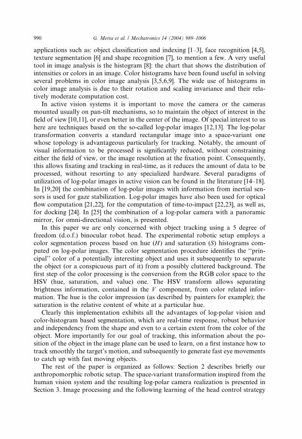
applications such as: object classification and indexing [1–3], face recognition [4,5],
texture segmentation [6] and shape recognition [7], to mention a few. A very useful
tool in image analysis is the histogram [8]: the chart that shows the distribution of
intensities or colors in an image. Color histograms have been found useful in solvingseveral problems in color image analysis [3,5,6,9]. The wide use of histograms in
color image analysis is due to their rotation and scaling invariance and their rela-
tively moderate computation cost.
In active vision systems it is important to move the camera or the cameras
mounted usually on pan-tilt mechanisms, so to maintain the object of interest in the
field of view [10,11], or even better in the center of the image. Of special interest to us
here are techniques based on the so-called log-polar images [12,13]. The log-polar
transformation converts a standard rectangular image into a space-variant onewhose topology is advantageous particularly for tracking. Notably, the amount of
visual information to be processed is significantly reduced, without constraining
either the field of view, or the image resolution at the fixation point. Consequently,
this allows fixating and tracking in real-time, as it reduces the amount of data to be
processed, without resorting to any specialized hardware. Several paradigms of
utilization of log-polar images in active vision can be found in the literature [14–18].
In [19,20] the combination of log-polar images with information from inertial sen-
sors is used for gaze stabilization. Log-polar images have also been used for opticalflow computation [21,22], for the computation of time-to-impact [22,23], as well as,
for docking [24]. In [25] the combination of a log-polar camera with a panoramic
mirror, for omni-directional vision, is presented.
In this paper we are only concerned with object tracking using a 5 degree of
freedom (d.o.f.) binocular robot head. The experimental robotic setup employs a
color segmentation process based on hue (H ) and saturation (S) histograms com-
puted on log-polar images. The color segmentation procedure identifies the ‘‘prin-
cipal’’ color of a potentially interesting object and uses it subsequently to separatethe object (or a conspicuous part of it) from a possibly cluttered background. The
first step of the color processing is the conversion from the RGB color space to the
HSV (hue, saturation, and value) one. The HSV transform allows separating
brightness information, contained in the V component, from color related infor-
mation. The hue is the color impression (as described by painters for example); the
saturation is the relative content of white at a particular hue.
Clearly this implementation exhibits all the advantages of log-polar vision and
color-histogram based segmentation, which are real-time response, robust behaviorand independency from the shape and even to a certain extent from the color of the
object. More importantly for our goal of tracking, this information about the po-
sition of the object in the image plane can be used to learn, on a first instance how to
track smoothly the target’s motion, and subsequently to generate fast eye movements
to catch up with fast moving objects.
The rest of the paper is organized as follows: Section 2 describes briefly our
anthropomorphic robotic setup. The space-variant transformation inspired from the
human vision system and the resulting log-polar camera realization is presented inSection 3. Image processing and the following learning of the head control strategy

G. Metta et al. / Mechatronics 14 (2004) 989–1006 991
are discussed in Section 4. In Section 5 experimental results are given and, finally,
concluding remarks are made in Section 6.
2. The experimental setup [26]
The color based processing and the robotic setup was developed in the context of
a wider project devoted to the investigation of biologically inspired principles withina robotic framework. The aim of the project was, and still it is, the realization of an
artificial agent with self-tuning and learning mechanisms similar to those of newborn
babies [27–30]. The whole design process of the hardware and the control archi-
tecture of the robot are biologically motivated. This justifies design choices, to be
explained later on this section, including the use inertial sensors (gyroscopes), sim-
ulating the vestibular apparatus and the use of space-variant vision (mimicking the
distribution of photoreceptors in the human retina). Following the general idea of
testing hypotheses about the acquisition of sensori-motor coordination, we devel-oped the robot architecture shown in Fig. 1. This consists of a five d.o.f. robot head,
and an off-the-shelf six d.o.f. robot manipulator, both mounted on a rotating base.
The kinematics resembles that of the upper part of the human body although with
less d.o.f. The 12 d.o.f. of our setup are shown in Fig. 1b. The dashed lines indicate
joint’s axes numbered from q1 to q12, respectively. Lately, a 6 d.o.f. robotic hand has
been added to the experimental setup to allow exploration into aspects of the
acquisition of manipulation behaviors.
The reference task in this paper is the generation of appropriate eye movementstoward visually identified objects in extra-personal space. Consequently, only five
d.o.f. belonging to the robot head are considered throughout the paper, (numbered
from q1 to q5). Actuators are DC motors with harmonic drive gearbox. They have
been chosen according to their mechanical characteristics, which due to the har-
monic drive gearing provide high reduction ratios in a single stage, zero backlash,
Fig. 1. The experimental setup: (a) physical representation and (b) an abstract representation showing the
axes of rotation on each degree of freedom (dashed lines).

992 G. Metta et al. / Mechatronics 14 (2004) 989–1006
and high precision. Furthermore, the head was designed in order to mimic the
human visual system in terms of speed and acceleration [31].
From the sensory point of view, the robot is equipped with a pair of color space-
variant cameras [32,33], whose sensor’s layout is analytically described in the nextsection, inertial sensors simulating the vestibular system [20,21], microphones for
acoustic localization and proprioceptive information through motor encoders. The
robot is controlled by a set of PCs––ranging from Pentium III to Pentium IV pro-
cessors––each running Windows and connected by a fast Ethernet link (100 Mbit/s).
In order to provide the necessary interface with the hardware (i.e. sensors and
motors) some machines are equipped with motion control boards, frame grabbers,
AD converters, etc. In particular one machine controls the robot arm and the torso,
another one the head, and a third computer carries on the visual processing. Datapassing and synchronization of the different processes dealing with sensory and
motor information is based on a software standard called DCOM (Distributed
Component Object Model) [34]. This is a binary standard, which allows working
with components in an object-oriented framework and, further, allows running these
software objects across a computer network. From the software point of view, the
use of components allows layering the code, and creating a separation from the
‘‘low-level handling of hardware resources’’, such as frame-grabbers, control boards,
etc. and the ‘‘high-level implementation’’, i.e. control loops, learning, etc. In thissense, once a component is designed, it may be reused throughout the system. We
designed a distributed system with a uniform programming environment.
3. The log-polar color camera
Studies on the primate visual pathways from the retina to the visual cortex have
shown that the geometrical layout follows an almost regular topographic arrange-
ment [35–38]. These results can be summarized as follows:
• The distribution of the cones, i.e. the photoreceptors of the retina involved in
diurnal vision, is not uniform. They lay more densely in the central region called
fovea (about 1/1000th of the total retinal area), while they are sparser in theperiphery. Consequently the resolution also decreases, moving away from the
fovea toward the periphery. The distribution has a radial symmetry, which can
be approximated by a polar distribution.
• The projection of the cones array to the primary visual cortex can be well approx-
imated by a logarithmic-polar (log-polar) distribution mapped onto a rect-
angular-like surface (the cortex). Here the representation of the fovea is
expanded several-fold, i.e. more neurons are devoted to the fovea while the
periphery is represented using a coarser resolution.
From the mathematical point of view the log-polar mapping can be expressed as a
transformation between the polar plane ðq; hÞ (retinal plane), the log–polar plane
ðn; gÞ (cortical plane) and the Cartesian plane ðx; yÞ (image plane), as follows [12,13]:

Fi
G. Metta et al. / Mechatronics 14 (2004) 989–1006 993
g ¼ q � hn ¼ loga
qq0
(ð1Þ
where q0 is the radius of the innermost circle, 1=q is the minimum angular resolution
of the log-polar layout and ðq; hÞ are the polar co-ordinates. These are related to theconventional Cartesian reference system by:
x ¼ q cos hy ¼ q sin h
�ð2Þ
Fig. 2 illustrates the log-polar layout as derived from Eqs. (1) and (2). In par-ticular, in Fig. 2a the grid on the left represents a standard Cartesian image mapped
according to Eq. (1). The plot on the right shows the corresponding log-polar
(cortical) image. Fig. 2b presents a Cartesian image and its log-polar counterpart. It
is worth noting that the flower petals, that have a polar structure, are mapped
horizontally in the log-polar image. Circles, on the other hand, are mapped verti-
cally. Furthermore, the stamens that lie in the center of the image of the flower,
occupy about half of the corresponding log-polar image.
g. 2. The log-polar transformation: (a) graphical illustration and (b) example of a real image.

Fig. 3. (a) The log-polar camera implementation and (b) Red, Green and Blue pixel arrangement.
994 G. Metta et al. / Mechatronics 14 (2004) 989–1006
The cameras that were used in our setup are based on the above-described
topology, so that they provide directly the equivalent log-polar image at their output.
A photograph of the camera implementation is shown in Fig. 3a. The sensor was
realized using the Tower TS35, 0.35 lm, CMOS process. It is approximately com-
posed of 33,000 pixels with logarithmic response. Its smallest photosites are
6.8 · 6.45 lm2 while the largest in the periphery are 84 · 86 lm2. The overall size of
the chip is 84 · 86 mm2 and, due to the CMOS technology, each pixel is directly
accessible allowing a pixel rate of up to 2 Mpixels/s. The same CMOS design is usedto realize a color version of the chip. The latter is obtained by depositing RGB color
filters on the surface of the gray-level version of the chip, shown in Fig. 3b. Thus, the
total number of the color pixels of the sensor is reduced at 1/3, i.e. about 11,000
pixels. Due to the polar structure of the sensor, specific patterns of red, green and
blue pixel placement are used in a hexagonal-like grid. The color reconstruction is
symmetrical both in the radial and the angular direction.

G. Metta et al. / Mechatronics 14 (2004) 989–1006 995
4. Color segmentation and head control
4.1. The segmentation procedure
Color segmentation allows extracting the position of the objects from visual
information. Though the technique might be considered simple, it offers several
advantages in terms of robustness. In general terms, a color segmentation procedure,
should identify the principal color of the object and separate it from the background.
An appropriate color representation provides a more efficient way of dealing with
color information. This is to say that the first step of the color processing is the
conversion from RGB information to HSV. The transformation of the crude RGBdata into the HSV space is performed according to the following equations:
HðR;G;BÞ ¼ a tan 2ðffiffiffi3
pðG� BÞ; ðR� GÞ þ ðR� BÞÞ ð3Þ
and
SðR;G;BÞ ¼ 1�minðR;G;BÞRþ Gþ B
ð4Þ
respectively. The V component is purposely not used for segmentation and, in fact,
our algorithm isolates the object almost irrespectively of its average intensity (within
certain limits).
A motion detection procedure is applied to initially locate the object of interest. In
practice, with the robot initially stationary, a temporal differencing processing de-
tects a potential target for tracking. The use of temporal differencing for motiondetection exhibits several drawbacks, with the most important one being the
dependency on the speed of the object, i.e. only ‘moving’ edges tend to be detected,
rather than the object itself. However, the goal of the procedure is that of identifying
‘something’ moving––even a small part of the object––in order to guess what the
color of the object is. The procedure performs well enough in practice. On sub-
sequent frames, if the color is guessed well, the color segmentation will succeed;
otherwise the object will be temporarily labeled as uninteresting. This might delay
the detection of the moving object but usually does not prevent tracking.After the temporal differencing, a histogram of moving pixels in HS space is
constructed in order to group the pixels belonging to the object. That is, the region of
the histogram representing the moving object is located in a neighborhood of the
histogram maximum, and isolated by means of a region growing procedure. The idea
is basically that of identifying the histogram bin with the largest number of pixels,
and assuming that it represents the object average color. The surrounding of this
particular bin is also examined in order to see whether the object contains also other
similar colors. These are considered only if their number of pixels is a significantfraction of the maximum. This procedure determines which part of the color space
represents the target, under the assumptions that the object has a dominant color,
with a sufficient number of pixels. All these conditions are checked at run time before
‘‘deciding’’ to actually start a tracking sequence. A second histogram representing
the background pixels is also built, and updated online. The histogram of the

996 G. Metta et al. / Mechatronics 14 (2004) 989–1006
background is updated whenever the robot is stationary and, thus, no object is being
tracked. If the object and background histograms differ enough [3] and, therefore,
the object can be reliably distinguished from the background, then the color seg-
mentation procedure is initiated. This last stage is simply performed by standardhistogram back-projection. An example of this procedure is depicted in Fig. 4. In
order to achieve real-time performance, sub-sampled log-polar images (32 · 64¼2048 pixel) are used. Fig. 4a presents the original image remapped into the Cartesian
space and Fig. 4b the segmented region. The corresponding HS histograms of the
background and of the object are shown in Fig. 4c and d, respectively. The histo-
gram intensity in Fig. 4c and d represents the number of pixels having certain hue
and saturation. As it can be seen in this Figure, both histograms have a fixed number
of bins (14 · 10), since there is no need to burden the procedure with dynamicallychanging histograms and, furthermore, the results of the proposed segmentation
algorithm are adequate for tracking purposes. Moreover, the number of bins was
kept small, in order to avoid the problem of grouping perceptually similar colors into
different bins, which occurs when the number of bin is too big, i.e. when the size of a
bin is comparable to the quantization step in the color space.
Once the segmentation procedure has been performed, the position of the object is
extracted by estimating the center of mass of the pixels belonging to the object, i.e.
Fig. 4. Segmentation procedure. A typical image from the robot’s point of view: (a) original image and (b)
color segmented image. All the processing is carried out in the log-polar domain; the images have been
mapped back to the Cartesian space for visualization purposes. HS histograms: (c) background and (d)
object. Note that, as the histograms do not overlap, segmentation can be performed reliably. Hue values
range from 0 to 360. Saturation ranges from 0 to 1.

G. Metta et al. / Mechatronics 14 (2004) 989–1006 997
those which result in a back-projection intensity higher than a threshold. The center
of mass ðxc; ycÞ of the segmented region is computed as:
1 Th
of the
xc ¼1
A
Xx
Xy
xIðx; yÞ and yc ¼1
A
Xy
Xx
yIðx; yÞ ð5Þ
where Iðx; yÞ is the binary image which results by setting the pixels of the segmented
region to ‘‘1’’ and ‘‘0’’ elsewhere and A is the image area, i.e. the sum of ‘‘1’’.
The centroid is estimated in both eyes and it is used to compute the retinal error
(position with respect to the image center), which is eventually used to learn a
suitable control policy and therefore to control the head motion.
4.2. The head control
The computed center of mass of the object is used as positional information to
drive a negative feedback loop. The fundamental problem in such a strategy is that
of converting the target position, which is expressed in retino-centric coordinates
into motor commands. The latter are expressed with respect to a motor coordinates
system. If this is the case the error is described by: 1
e ¼ C � sðtÞ ð6Þ
where e is the position error expressed in motor coordinates, sðtÞ the retinal error andC a coordinate conversion matrix. The matrix C must be designed in order to sta-bilize the closed-loop system. The generated motor command is:
_q ¼ �k � e ð7Þ
with _q being the speed of the joint, which is the control variable and k a positiveconstant gain. A possible choice of C, as proposed in the visual serving literature[39], is:
C ¼ os
oq
� ��1
ð8Þ
Learning of the matrix C is carried out by acquiring discrete samples of the
variation of the retinal error Ds due to a variation of the joint variable Dq. A least-
square approach is used to compute the components of C. Further, it is important to
define how to obtain the samples. Performing random movements according to thefollowing equation is a suitable strategy:
_q ¼ �kCsðtÞ þ gð0; rÞ ð9Þ
The first term is the closed-loop component described in Eq. (7); the second term grepresents a zero mean uniform noise with standard deviation r. It is worth noting
that at the beginning of learning the noise dominates (C ¼ 0, r 6¼ 0), whereas as
is description is actually a simplification, which does not take into account for instance the dynamic
robot head. More sophisticated techniques could be employed (see for example [16]).

998 G. Metta et al. / Mechatronics 14 (2004) 989–1006
learning proceeds the closed-loop term takes over the control of movements. In
order to guarantee convergence the standard deviation r has to be reduced to zero
over a reasonable period of time.
Although the closed-loop approach described above is effective, it does not meanit is also efficient. In fact, a closed-loop approach would always lag behind a moving
target. If the perceived target lies in the periphery of the visual field, the robot would
take several control steps to move the cameras toward it. In our artificial system, the
requirement for generating fast eye movements, emulating saccades, is to know as
precisely as possible the transformation between retinal error s and the corre-
sponding motor command Dq, that is:
Dq ¼ f̂ðsÞ ð10Þ
Under the hypothesis of a stationary target and the closed-loop control in place, thegathering of training pairs, each one having the form ðDq; sÞ, is much simplified. The
retinal error s is acquired at the beginning of the motion, while the required motor
command can be measured when the retinal error is zeroed. In other words the whole
joint movement is the most appropriate one to generate the saccade. In order to relaxthe stationary target hypothesis, it is possible to acquire a new training sample, as
soon as some control cycles have been performed. In this case, the motion of the
target would influence the measure of the motor command insignificantly and its
effect on average would be negligible. The output of the proposed mapping is then
used to generate saccades. Saccade initiation is controlled by another module, which
issues a saccade command each time either the retinal error is greater than a fixed
threshold (catch-up saccade) or a moving target is detected but a target is not cur-
rently being tracked. This fixed threshold is not learned, but it is estimated empiri-cally in order to generate a reasonable amount of saccades and to avoid trying
saccades under small retinal errors. The overall loop controlling the eye motion is
shown in Fig. 5a. In this figure the primary closed-loop and the feed forward sec-
ondary loop are clearly depicted. The loop using the inverse Jacobian is derived from
a classical visual servoing approach. The secondary loop consists of an inverse
model, indicated as ‘‘Map’’. This is activated whenever the retinal error exceeds a
fixed threshold and generates a saccadic motion of the eyes, in order to foveate the
target.Of course moving only the eyes is not enough in an articulated robotic head. The
robot could explore the whole visual space and, since our setup possesses more d.o.f.,
the neck pan and tilt are used. The head-eye system is kinematically redundant;
consequently, a further constraint has to be employed when programming coordi-
nated head-eye movements. In fact, the same fixation point in the 3D world can be
obtained using different configurations of the joint angles (infinite). It is important to
note that the various joints of the head/eye system have different physical charac-
teristics. In order not to overload the mechanics, it would be reasonable to respectsuch constraints, and consequently, the eyes can move faster than the neck. Fur-
thermore, it seems a natural behavior to require the robot to achieve a symmetrical
vergence configuration: that is, the neck should move, in order to be approximately
heading toward the target. This position could be advantageous if several move-

Fig. 5. The eye/head control schema: (a) eyes control loop and (b) head control loop.
G. Metta et al. / Mechatronics 14 (2004) 989–1006 999
ments have to be generated sequentially. Even by enforcing such constraints the
trajectory of eyes and neck during a movement would be undetermined. Usually this
problem is solved in robotics by imposing a further constraint, such as the mini-
mization of some cost functional over the whole trajectory [40]. As described in our
previous works [20] we chose a different approach, where both neck and eyes are
roughly driven toward the target, as if they were two independent physical systems.
These two subsystems are actually decoupled, because whenever the neck is moving,the eyes are counter-rotated at the same speed, by employing the information pro-
vided by the inertial sensor. The control system is greatly simplified, it is completely
reactive, and no optimization mechanism is involved, as it can be observed in Fig.
5b. It has already been shown that this strategy is an efficient image stabilization
mechanism. Concerning the actual neck motion controller, a two-loop system,
similar in principle to the one commanding the movement of the eyes, deals with the
situation. A PD controller governs the closed-loop module. Its goal is that of zeroing
the difference between the angles of the eyes:
_q1 ¼ PDðq4 � q5Þ ð11Þ
where _q1 is the neck pan velocity and q4, q5 the right and the left camera pan,
respectively.

1000 G. Metta et al. / Mechatronics 14 (2004) 989–1006
Also in this case an ‘‘inverse model’’ map can improve performances. It maps the
predicted eye positions to the proper neck motion. The control diagram is sketched
in Fig. 5b. Formally:
Dq1 ¼ f̂ ðpredq4; predq5Þ ð12Þ
where Dq1 is the neck motion command, predqð4;5Þ the predicted eye positions. Theseare the current eye positions updated by the saccadic eye motion. The eye movement
can be recovered using the eye maps, even before any actual motion has been started.In equation form:
predqð4;5Þ ¼ qð4;5Þ þ saccadeDqð4;5Þ ð13Þ
Eventually, both eye and neck commands are generated and fed into the low-level
controller at the same time.
The schema described above for the horizontal movement controls also the
common tilt of the eyes; two commands are computed independently (one for each
eye) and averaged. The control of the neck tilt movement is accomplished by using a
PD controller as in the case of joint 1, that is:
_q2 ¼ PDðq2 � q3Þ ð14Þ
The behavior is roughly the same as joint 1; in fact, the PD controller links thetwo redundant degrees of freedom (eye tilt and neck tilt) as before.
5. Experimental results
The goal of our experiments was to evaluate how reliable it is the proposed
control system. Various experiments were conducted to verify the automatic
acquisition of the controller. Our aim was mostly to show how a suitable sequence of
learning events might lead to the unsupervised acquisition of such controller. The
system switches through several phases. Each phase naturally exploits earlier stages
by relying on their correct behavior. The first phase consists in acquiring the closed-
loop control of the eyes, trying to maintain the neck stationary. The construction of
the inverse model (phase two) clearly relies on having already the closed-loopfunctional. Only at this point the proper control of the movement of the neck is
started. This third phase utilizes the eyes’ inverse model to predict the final position
of the eyes for better performance. Also in this last case, an additional inverse model
can eventually be acquired since a feedback loop is already functional. The following
set of experiments show this sequence and the performance of the overall system.
With regard of learning, parameters, as in the case of the Jacobian matrix, were
acquired by employing a very standard recursive least square procedure. Maps, on
the other hand, are obtained by training a suitable neural network. This is a neural-gas type as described in [41].
A first qualitative demonstration of the performance of the algorithm is shown in
Fig. 6a. A green toy gun was passing back and forth a still camera. During this
experiment the head control was off, whilst the color segmentation was on. The

Fig. 6. A sequence of images and the results of the segmentation procedure: (a) Selected images of
the sequence; from top to bottom are presented the reconstructed Cartesian image, the cortical image, the
segmented image and the frame number of the sequence; (b) the trajectory of the target recorded for the
above sequence.
G. Metta et al. / Mechatronics 14 (2004) 989–1006 1001

1002 G. Metta et al. / Mechatronics 14 (2004) 989–1006
complete sequence consists of 26 events acquired at frame rate (25 Hz). In Fig. 6a
only a sequence of eight representative images is presented together with the results
of the segmentation. As one may see in this figure many object pixels are not selected
as such. This is because the threshold, above which the pixels are consideredbelonging to the object, was set too high, without affecting the tracking performance
though. The target position as recorded during the sequence is presented in Fig. 6b.
A simple way to analyze the behavior of the whole system, both image processing
and control, is by displaying the motion of the target in the image plane when the
control is active. If this is done during different stages of learning we are also able to
assess, though qualitatively, the improvement through time of the controller effi-
ciency. In this respect Fig. 7a and b show some exemplar trajectories recorded during
the acquisition of the closed-loop controller and the open-loop one, respectively. Theresults from the first stage are plotted in Fig. 7a, where abscissa and ordinates
represent the image plane, and different graphical signs mark different trajectories
(the target position at each control step )40 ms period). As expected all the trajec-
tories are converging to the fovea. This plot was obtained after the closed-loop
control has been learned as described in Section 4. In this case the movements are
still quite slow, and the number of ‘‘points per trajectory’’ is high meaning that is
takes a long time to complete a foveation.
Conversely, Fig. 7b has been obtained after learning of the closed-loop controllerwas completed and the saccade maps almost converged to a stable configuration.
Note as the first few steps are enough to reduce the retinal error to less than five
pixels, the target afterwards remains in the fovea.
Target trajectories Target trajectories
(a) (b)
Fig. 7. Trajectories of the target in the image plane recorded in: (a) closed-loop only control. Abscissa and
ordinates are measured in pixels, (0,0) represents the image center. (b) Open-loop and closed-loop control
operating together after learning.

G. Metta et al. / Mechatronics 14 (2004) 989–1006 1003
Another experiment aimed at showing that the color segmentation process pro-
vides a reliable source of information, which allows the system to learn the con-
troller. As described in the previous section the learning process could be divided intwo parts. During the first stage only the closed-loop gain, i.e. the Jacobian matrix, is
tuned. This is obtained by measuring the displacement of the object as a function of
the displacement of the joint position. A recursive least square procedure is em-
ployed. An exemplar trace of this process is shown in Fig. 8. Note that stable values
are already available after about ten steps. Precise convergence is obtained after
about 200 steps. Each step lasts 40 ms.
In a second stage the open-loop controller is tuned. A map regarding the left eye is
shown in Fig. 9 where the cross marks (+) represent the most recent 300 samples ofthe training set, and the circles the position of the center of each unit. The plot has
been obtained after about 90,000 steps, using the most recent 300 samples from the
training set. The input space ðx; yÞ is the image plane in Cartesian coordinates. This is
done for presentation clarity only, as the actual data are acquired in the space-
variant log-polar plane, as described in Section 3. The output (the height of the
surface plot) is the angle required to foveate a target appearing in the corresponding
ðx; yÞ image position. Similar results were obtained for the other maps controlling the
other joints (eyes’ tilt and neck). It has also been shown [41] that the neural networkis actually improving the robot performance, during the training procedure, in terms
of the average positioning error.
Videos demonstrating the system and the proposed technique can be retrieved on-
line at the following URL: http://www.lira.dist.unige.it/babybotvideos.htm.
Fig. 8. The learning process: Acquisition of the closed-loop Jacobian matrix C. Note that stable values are
already available after about ten steps. Precise convergence is obtained after about 200 steps. Each step
lasts 40 ms.

Fig. 9. The learning process: The open-loop tuning map. Abscissa and ordinates represent the image plane
in Cartesian coordinates. The Z-axis stands for the control surface. The cross marks are the most recent
300 training samples.
1004 G. Metta et al. / Mechatronics 14 (2004) 989–1006
6. Discussion
This paper presented a complete system including vision, control, and learning
instantiated in a real robotic platform. Clearly, there is still much to be done since
pretty much every module could be further optimized. At this stage, what was
important in our view was the complete integration in an on-line behaving system. In
addition almost any module exploited learning to tune its performance to the physics
of the robot. The proposed approach brings together space-variant images, a colorsegmentation technique, and learning (or parameter automatic tuning) of the con-
troller. The long-term objective of the work presented in this paper is the realization
of a biologically inspired artificial agent via learning and adaptation mimicking the
early stages of biological development. It is fair to say, though, that in a few cases the
robot might fail. These include for example the change of apparent color due to a
change in illumination (unless the size of the histogram bins is very large in HS
space), and the confusion due to a colored illuminant, especially in artificial light
conditions. Of course a color-cluttered background can influence performances aswell. However, we are well aware of these limitations and consequently our efforts
are directed also toward the integration of many different visual cues.

G. Metta et al. / Mechatronics 14 (2004) 989–1006 1005
Acknowledgements
This work has been supported EU projects SVAVISCA (ESPRIT-31951) andAMOVITE (IST-1999-11156) and grants from the Italian Space Agency (ASI).
The authors would like to thank the anonymous referees for their constructive
criticism that allowed them to improve the presentation of the paper.
References
[1] Gevers T, Smeulders AWM. Color-based object recognition. Pattern Recogn 1999;32(3):453–64.
[2] Sandini G, Buemi F, Massa M, Costi G. The Agrobot project. Adv Space Res 1996;18(1/2):185–96.
[3] Swain MJ, Ballard DH. Color indexing. Int J Comput Vision 1991;7(1):11–32.
[4] Varchmin AC, Rae R, Ritter H. Image based recognition of gaze direction using adaptive methods.
In: International Gesture Workshop. (Bielefeld, Germany): 1997. p. 245–58.
[5] Yoo T-W, Oh I-S. A fast algorithm for tracking human faces based on chromatic histograms. Pattern
Recogn Lett 1999;20(10):967–78.
[6] Chang CC, Wang LL. Color texture segmentation for clothing in a computer-aided fashion design
system. Image Vision Comput 1996;14(9):685–702.
[7] Drew MS. Shape from color. Technical Report, CSS/LCCR TR 92-07, Simon Fraser University,
Vancouver BC, Canada, 1992.
[8] Gonzalez RC, Woods RE. Digital image processing. Reading, Massachusetts: Addison-Wesley; 1992.
[9] Impey SJ, Bangham JA. Image segmentation by area decomposition of HSV components. In:
EUSIPCO-96. (Trieste, Italy), 1996.
[10] Aloimonos J, Weiss I, Bandyopadhyay A. Active vision. Int J Comput Vision 1988;1(4):333–56.
[11] Ballard DH. Animate vision. Artif Intell 1991;48(1):57–86.
[12] Sandini G, Tagliasco V. An anthropomorphic retina-like structure for scene analysis. Comput Vision,
Graph Image Process 1980;14(3):365–72.
[13] Schwartz EL. Spatial mapping in the primate sensory projection: analytic structure and relevance to
perception. Biol Cybernet 1977;25:181–94.
[14] Capurro C, Panerai F, Sandini G. Dynamic Vergence using Log-polar Images. Int J Comput Vision
1997;24(1):79–94.
[15] Manzotti R, Gasteratos A, Metta G, Sandini G. Disparity estimation on log-polar images and
vergence control. Comput Vision Image Understand 2001;83(2):97–117.
[16] Bernardino A, Santos-Victor J. Binocular visual tracking: integration of perception and control.
IEEE Trans Robot Automat 1999;15(6):1080–94.
[17] Bernardino A, Santos-Victor J. A Binocular Stereo Algorithm for Log-Polar Foveated Systems,
Lecture Notes in Computer Science, Springer-Verlag, Berlin-Heidelberg, LNCS-2525. p. 127–36.
[18] Oshiro N, Maru N, Nishikawa A, Miyazaki F. Binocular tracking using log polar mapping. IROS’96,
vol. 2, 1996. p. 791–8.
[19] Panerai F, Sandini G. Oculo-motor stabilization reflexes:integration of inertial and visual informa-
tion. Neural Networks 1998;11:1191–204.
[20] Panerai F, Metta G, Sandini G. Visuo-inertial stabilization in space-variant binocular systems. Robot
Auton Syst 2000;30(1–2):195–214.
[21] Daniilidis K, Kruger V. Optical flow computation in the log-polar plane. In: Proceedings of the
International Conference on Computer Analysis of Images and Patterns CAIP, Prague, 1995. p. 65–
72.
[22] Tistarelli M, Sandini G. On the advantages of polar and log-polar mapping for direct estimation of
time-to-impact from optical flow. IEEE Trans PAMI 1993;15(4):401–10.
[23] Boluda JA, Pardo F. A reconfigurable architecture for autonomous visual-navigation. Mach Vision
Appl 2003;13:322–31.

1006 G. Metta et al. / Mechatronics 14 (2004) 989–1006
[24] Barnes NM, Sandini G. Direction control for an active docking behaviour based on the rotational
component of log-polar optic flow. In: ECCV2000––Proceedings of the European Conference on
Computer Vision, vol. 2, Dublin, Ireland, June 2000. p. 167–81.
[25] Gaechter S, Pajdla T, Micusik B. Mirror design for an omnidirectional camera with a space variant
imager. Omnidirectional Vision Applied to Robotic Orientation and Nondestructive Testing
Workshop. Budapest, August 2001.
[26] Metta G. Babyrobot: a study on sensori-motor development. PhD Thesis, University of Genoa,
Genoa, Italy, 1999.
[27] Cheng G, Kuniyoshi Y. Complex continuous meaningful humanoid interaction: a multi sensory-cue
based approach. In: IEEE International Conference on Robotics and Automation, ICRA 2000. (San
Francisco, USA), 2000. p. 2235–42.
[28] Pfeifer R, Scheier C. Representation in natural and artificial agents: an embodied cognitive science
perspective. In: Natural Organisms, Artificial Organisms, and Their Brains. Germany: Bielefeld; 1998.
p. 480–503.
[29] Metta G, Sandini G, Konczak J. A developmental approach to visually-guided reaching in artificial
systems. Neural Networks 1999;12(10):1413–27.
[30] Brooks R. Behavior-based humanoid robotics. In: IEEE/RSJ IROS’96, 1996. p. 1–8.
[31] Carpenter RHS. Movements of the eyes. London: Pion Limited; 1988.
[32] Sandini G, Alaerts A, Dierickx B, Ferrari F, Hermans L, Mannucci A, Parmentier B, Questa P,
Meynants G, Sheffer D. The project SVAVISCA: a space-variant color CMOS sensor. In:
AFPAEC’98. (Zurich, Swicherland), 1998.
[33] Sandini G, Questa P, Scheffer D, Mannucci A, A retina-like CMOS sensor and its applications. In:
SAM-2000. (Cambridge, USA), 2000.
[34] Microsoft Corporation, DCOM––The distributed component object model. 1996. Available from:
http://www.microsoft.com/TechNet/winnt/Winntas/technote/dcomwp.asp.
[35] Daniel M, Whitteridge D. The representation of the visual field on the cerebral cortex in monkeys. J
Physiol 1961;(159):203–21.
[36] Cowey A. Projection of the retina on to striate and prestriate cortex in the squirrel monkey (saimiri
sciureus). J Neurophysiol 1964;(27):266–93.
[37] Allman JM, Kaas JH. Representation of the visual field in striate and adjoining cortex of the owl
monkey (aotus trivirgatus). Brain Res 1971;35:89–106.
[38] Atchinson DA, Smith G. Optics of the human eyes. Oxford: Butterworth-Heinemann Ltd.; 2000.
[39] Espiau B, Chaumette F, Rives P. A new approach to visual servoing in robotics. IEEE Trans Robot
Automat 1992;8(3):313–26.
[40] Yoshikawa T. Foundations of robotics: analysis and control. Cambridge, Massachusetts: MIT Press;
1990.
[41] Metta G, Carlevarino A, Martinotti R, Sandini G. An incremental growing neural network and its
application to robot control. In: International Joint Conference on Neural Networks (Como, Italy),
2000.