
an approach based on colored Petri nets - Pure
468
Patterns for process-aware information systems : an approach based on colored Petri nets Citation for published version (APA): Mulyar, N. A. (2009). Patterns for process-aware information systems : an approach based on colored Petri nets. [Phd Thesis 1 (Research TU/e / Graduation TU/e), Industrial Engineering and Innovation Sciences]. Technische Universiteit Eindhoven. https://doi.org/10.6100/IR639997 DOI: 10.6100/IR639997 Document status and date: Published: 01/01/2009 Document Version: Publisher’s PDF, also known as Version of Record (includes final page, issue and volume numbers) Please check the document version of this publication: • A submitted manuscript is the version of the article upon submission and before peer-review. There can be important differences between the submitted version and the official published version of record. People interested in the research are advised to contact the author for the final version of the publication, or visit the DOI to the publisher's website. • The final author version and the galley proof are versions of the publication after peer review. • The final published version features the final layout of the paper including the volume, issue and page numbers. Link to publication General rights Copyright and moral rights for the publications made accessible in the public portal are retained by the authors and/or other copyright owners and it is a condition of accessing publications that users recognise and abide by the legal requirements associated with these rights. • Users may download and print one copy of any publication from the public portal for the purpose of private study or research. • You may not further distribute the material or use it for any profit-making activity or commercial gain • You may freely distribute the URL identifying the publication in the public portal. If the publication is distributed under the terms of Article 25fa of the Dutch Copyright Act, indicated by the “Taverne” license above, please follow below link for the End User Agreement: www.tue.nl/taverne Take down policy If you believe that this document breaches copyright please contact us at: [email protected] providing details and we will investigate your claim. Download date: 17. Sep. 2022
-
Upload
khangminh22 -
Category
Documents
-
view
6 -
download
0
Transcript of an approach based on colored Petri nets - Pure

Patterns for process-aware information systems : an approachbased on colored Petri netsCitation for published version (APA):Mulyar, N. A. (2009). Patterns for process-aware information systems : an approach based on colored Petri nets.[Phd Thesis 1 (Research TU/e / Graduation TU/e), Industrial Engineering and Innovation Sciences]. TechnischeUniversiteit Eindhoven. https://doi.org/10.6100/IR639997
DOI:10.6100/IR639997
Document status and date:Published: 01/01/2009
Document Version:Publisher’s PDF, also known as Version of Record (includes final page, issue and volume numbers)
Please check the document version of this publication:
• A submitted manuscript is the version of the article upon submission and before peer-review. There can beimportant differences between the submitted version and the official published version of record. Peopleinterested in the research are advised to contact the author for the final version of the publication, or visit theDOI to the publisher's website.• The final author version and the galley proof are versions of the publication after peer review.• The final published version features the final layout of the paper including the volume, issue and pagenumbers.Link to publication
General rightsCopyright and moral rights for the publications made accessible in the public portal are retained by the authors and/or other copyright ownersand it is a condition of accessing publications that users recognise and abide by the legal requirements associated with these rights.
• Users may download and print one copy of any publication from the public portal for the purpose of private study or research. • You may not further distribute the material or use it for any profit-making activity or commercial gain • You may freely distribute the URL identifying the publication in the public portal.
If the publication is distributed under the terms of Article 25fa of the Dutch Copyright Act, indicated by the “Taverne” license above, pleasefollow below link for the End User Agreement:www.tue.nl/taverne
Take down policyIf you believe that this document breaches copyright please contact us at:[email protected] details and we will investigate your claim.
Download date: 17. Sep. 2022

Patterns for
Process-Aware Information Systems:
An Approach Based on Colored Petri Nets

Copyright c© 2009 by Nataliya A. Mulyar. All Rights Reserved.
A catalogue record is available from the Eindhoven University of TechnologyLibrary
Mulyar, Nataliya Alexandrovna
Patterns for Process-Aware Information Systems: An Approach Based on Col-ored Petri Nets / by Nataliya A. Mulyar.- Eindhoven: Technische Universiteit Eindhoven, 2009. - Proefschrift. -
ISBN: 978-90-386-1504-2
NUR 982
Keywords: Process-Aware Information Systems /Patterns / Business Process Management /Colored Petri Nets / Workflow patterns / Service Oriented Architecture /Flexibility
The work in this thesis has been carried out under the auspices ofBeta Research School for Operations Management and Logistics.
This research was supported by the Dutch Organization for ScientificResearch (NWO) under project number 612.066.407
Beta Dissertation Series D111

Patterns for
Process-Aware Information Systems:
An Approach Based on Colored Petri Nets
PROEFSCHRIFT
ter verkrijging van de graad van doctor aan de
Technische Universiteit Eindhoven, op gezag van de
Rector Magnificus, prof.dr.ir. C.J. van Duijn, voor een
commissie aangewezen door het College voor
Promoties in het openbaar te verdedigen
op dinsdag 16 juni 2009 om 16.00 uur
door
Nataliya Alexandrovna Mulyar
geboren te Bratsk, Rusland

Dit proefschrift is goedgekeurd door de promotor:
prof.dr.ir. W.M.P. van der Aalst
Copromotor:dr. N.C. Russell

Contents
1 Introduction 1
1.1 Process-Aware Information Systems . . . . . . . . . . . . . 11.2 Historic developments and related trends . . . . . . . . . . . 51.3 Research . . . . . . . . . . . . . . . . . . . . . 8
1.3.1 Problem definition . . . . . . . . . . . . . . . . 8
1.3.2 Workflow Pattern Initiative . . . . . . . . . . . . . 111.3.3 Research approach . . . . . . . . . . . . . . . . 13
1.4 Thesis outline . . . . . . . . . . . . . . . . . . . 14
I Conceptual Foundations 17
2 Patterns 212.1 Types of patterns . . . . . . . . . . . . . . . . . . 212.2 Pattern format . . . . . . . . . . . . . . . . . . . 23
2.3 Pattern identification . . . . . . . . . . . . . . . . . 252.4 Related work . . . . . . . . . . . . . . . . . . . 272.5 Summary . . . . . . . . . . . . . . . . . . . . 28
3 Colored Petri Nets Patterns 293.1 Main concepts of CPN . . . . . . . . . . . . . . . . . 303.2 Catalog of CPN patterns . . . . . . . . . . . . . . . . 353.3 Classification of CPN patterns . . . . . . . . . . . . . . 102
3.3.1 Relationships between CPN patterns . . . . . . . . . . 1023.3.2 Clustering of CPN patterns . . . . . . . . . . . . . 105
3.4 Analysis of CPN patterns usability in practice . . . . . . . . . . 1063.5 Related work . . . . . . . . . . . . . . . . . . . 111
3.6 Summary . . . . . . . . . . . . . . . . . . . . 112
II Patterns for Process-Aware Information Systems 113
4 Workflow Control-Flow Patterns 117
4.1 Revisiting the control-flow patterns . . . . . . . . . . . . . 1174.1.1 Context assumptions . . . . . . . . . . . . . . . 1184.1.2 Classification of control-flow patterns . . . . . . . . . . 1204.1.3 Catalog of control-flow patterns . . . . . . . . . . . . 122
4.1.4 Relationships between control-flow patterns . . . . . . . . . 1904.2 Patterns operationalization . . . . . . . . . . . . . . . 191
4.2.1 Core Process Constructs Modeling Language . . . . . . . . 194

vi Contents
4.3 Tool evaluations . . . . . . . . . . . . . . . . . . 2144.3.1 Background . . . . . . . . . . . . . . . . . . 2154.3.2 Evaluation of Oracle BPEL PM . . . . . . . . . . . . 2204.3.3 Evaluation of CIG modeling languages . . . . . . . . . . 221
4.4 Related work . . . . . . . . . . . . . . . . . . . 2234.5 Summary . . . . . . . . . . . . . . . . . . . . 225
5 Service Interaction Patterns 2275.1 Introduction . . . . . . . . . . . . . . . . . . . 2275.2 Configurable framework for service interaction patterns . . . . . . . 231
5.2.1 Pattern family: Multi-party Multi-message Request-Reply Conversation 2335.2.2 Pattern family: Renewable Subscription . . . . . . . . . . 2455.2.3 Pattern family: Message Correlation . . . . . . . . . . . 2565.2.4 Pattern family: Message Mediation . . . . . . . . . . . 2645.2.5 Pattern family: Bipartite Conversation Correlation . . . . . . 2815.2.6 Pattern-based service interaction design method . . . . . . . 289
5.3 Tool evaluations . . . . . . . . . . . . . . . . . . 2945.3.1 Evaluation of Oracle BPEL PM . . . . . . . . . . . . 294
5.4 Related work . . . . . . . . . . . . . . . . . . . 3175.5 Summary . . . . . . . . . . . . . . . . . . . . 319
6 Process Flexibility Patterns 3236.1 Taxonomy of process flexibility . . . . . . . . . . . . . . 323
6.1.1 Flexibility by design . . . . . . . . . . . . . . . 3256.1.2 Flexibility by deviation . . . . . . . . . . . . . . 3266.1.3 Flexibility by underspecification . . . . . . . . . . . . 3266.1.4 Flexibility by momentary change . . . . . . . . . . . . 3276.1.5 Flexibility by permanent change . . . . . . . . . . . . 328
6.2 Catalog of process flexibility patterns . . . . . . . . . . . . 3296.2.1 Context assumptions . . . . . . . . . . . . . . . 3316.2.2 Flexible initiation . . . . . . . . . . . . . . . . 3346.2.3 Flexible termination . . . . . . . . . . . . . . . 3486.2.4 Flexible selection . . . . . . . . . . . . . . . . 3586.2.5 Flexible reordering . . . . . . . . . . . . . . . . 3696.2.6 Flexible elimination . . . . . . . . . . . . . . . 3776.2.7 Flexible extension . . . . . . . . . . . . . . . . 3836.2.8 Flexible concurrency . . . . . . . . . . . . . . . 3926.2.9 Flexible repetition . . . . . . . . . . . . . . . . 3996.2.10 Discussion . . . . . . . . . . . . . . . . . . 406
6.3 Tool evaluations . . . . . . . . . . . . . . . . . . 4086.4 Related work . . . . . . . . . . . . . . . . . . . 4136.5 Summary . . . . . . . . . . . . . . . . . . . . 417
7 Epilogue 4197.1 Contributions, limitations, and future work . . . . . . . . . . . 419
7.1.1 Colored Petri Nets . . . . . . . . . . . . . . . . 4197.1.2 Workflow control-flow . . . . . . . . . . . . . . . 4207.1.3 Service interaction . . . . . . . . . . . . . . . . 4227.1.4 Process flexibility . . . . . . . . . . . . . . . . 423
7.2 Reflection . . . . . . . . . . . . . . . . . . . . 4247.3 Summary . . . . . . . . . . . . . . . . . . . . 428
Appendices 429

vii
A Workflow Reference Model 429
B Web-services stack 431
C Glossary 433
Bibliography 437
Summary 453
Samenvatting 455
Acknowledgements 457
Curriculum Vitae 459

viii Contents

Chapter 1
Introduction
Process-Aware Information Systems (PAISs) have become increasingly popular as a tech-nology for facilitating the specification and enactment of business processes. Contemporaryorganizations tend to focus on the precise definitions of relevant business processes and theirautomation using some form of process technology as there exists a common understandingthat in order to improve operational effectiveness, business processes need to be managedin the same way as other more tangible corporate assets. The selection of a PAIS from abroad range of contemporary offerings is experienced by organizations as a complex andnon-trivial task. Due to a lack of understanding of process technologies, the large diver-sity between functionalities offered by distinct offerings, and lack of common standardswhich could be used for comparing PAISs, the process of selecting a PAIS is quite chaoticand not well-defined. This thesis offers a solution to this problem by providing a rigorousfoundation for PAISs in the form of a knowledge base that enhances the conceptual under-standing of the various perspectives of PAISs. In doing so, it provides a reference point forthe evaluation and improvement of contemporary offerings, and delivers insights into thedefinition of new languages and standards in the domain.
In this chapter, we introduce the research presented in this thesis. We start by introduc-ing various kinds of PAISs in Section 1.1 in order to illustrate the plethora of differentapproaches to business process automation. In Section 1.2, we present an historical viewon developments in the domain and relevant trends which determine the focus of investi-gations presented in this thesis. In Section 1.3, we define the problem addressed in thisresearch and describe the approach selected for solving the research problem. Finally, inSection 1.4 we give an outline of the contents of this thesis.
1.1 Process-Aware Information Systems
In this section, we will focus on PAISs as these are the main topic of research in this thesis.In a generic sense, we will consider the class of information systems whose main goal is tosupport business processes within an organization. First, we need to understand what abusiness process and an information system are, and how these can be combined in orderto help organizations function more effectively.
A business process is a special type of process, that can be defined as a set of tasks thatneed to be executed in a specific order by dedicated employees or other kinds of resources,

2 Chapter 1 Introduction
processing supplied input data and producing output data, with the aim of realizing one ormore business goals. Typically, a business process describes an internal behavior within anorganization, however it may interact with other organizations, for example, by using theresources of other organizations for accomplishing particular tasks or by providing infor-mation/products/services to them based on their requests. Business processes limited toone organization are called intra-organizational, whilst processes interacting with businessprocesses in other organizations are called inter-organizational (the latter are also knownas business processes forming process choreographies [223]).
In order to automate business processes, organizations require the support of some kindof information system. In [29], Alter defines an information system as “a particular typeof a work system ... that processes information by performing various combinations of sixtypes of operations: capturing, transmitting, storing, retrieving, manipulating, and dis-playing information”. In this definition, a work system is defined to be “a system in whichhuman participants and/or machines perform a business process using information, tech-nology, and other resources to produce products (and/or services) for internal or externalcustomers.”
In this thesis, we consider information systems that link information technology tobusiness processes, and which are termed as Process-Aware Information Systems. In [80],Dumas et al. define a PAIS as “a software system that manages and executes operationalprocesses involving people, applications, and/or information sources on the basis of processmodels”. The term process model is used in this definition to represent a business processusing some kind of (graphical) notation, which can be seen as “a blueprint for a set ofprocess instances with a similar structure” [223]. In a process model, process entitiesand the relationships between them are explicitly defined. Various kinds of notations andlanguages can be used to describe business processes, e.g., Petri nets [102], EPCs [4], UMLactivity diagrams [44], BPMN (Business Process Modeling Notation) [165], or dedicatednotations employed by specific information systems.
Unlike data-driven applications such as an e-mail client, which offers functionality forsending emails but which is unaware of the process to which email is sent, or a calculatorprogram, which performs mathematical calculations for particular tasks in a process butwhich is unaware of the process to which these calculations relate, PAISs shift the focusfrom task to process-driven execution. The process-driven approach helps managers tokeep a clear overview of the whole process in an organization, enabling them to monitorexecution progress at the level of the process, rather than as a series of individual taskexecutions, to track dependencies between execution statuses of different tasks, and tofacilitate process-awareness within the organization by using process models as a means ofcommunication and illustration.
PAISs allow processes to be enacted according to an underlying process definition. Au-tomated enactment is a way to improve organizational efficiency by means of automatictask scheduling, information routing and time/resource optimization. The fact that PAISsare driven by underlying process models, allows the execution of a particular process in-stance to be adjusted as well as the original model to be optimized or even redesigned,without requiring the functionality of the application supporting process enactment to bemodified [80].
The broad range of PAISs is illustrated in Figure 1. In this figure, PAISs are classifiedusing two dimensions: the degree of adherence by a given process to an underlying pro-cess definition and nature of participants (i.e. humans or software applications) involved ininteractions associated with PAISs [80]. The dimension characterizing the nature of par-

Section 1.1 Process-Aware Information Systems 3
tracking systems
groupware
process - aware collaboration
tools
project management
workflow
case handling / flexible workflow
ad hoc workflow scientific workflow
process - unaware application integration
A 2 A & B 2 B integration processes /
service composition
P 2 P P 2 A A 2 A
tightly framed
loosely framed
ad hoc framed
unframed
Figure 1: Types of PAISs (from [80])
ticipants can be used to classify a PAIS as human or system-oriented. The abbreviationsP2P, P2A and A2A denote Person-to-Person, Person-to-Application, and Application-to-Application processes respectively. Typical examples of P2P processes are tracking systemswhere a registered letter is being delivered by a postman to a person directly, project man-agement systems where a manager evaluates the progress made by an employee using aproject-tracking chart, and groupware tools which are used to enable real time collabora-tion between several people such as collective writing, shared database access or electronicmeetings. P2P processes consist of tasks which involve humans, i.e. they are not fullyautomated tasks.
The second group of PAISs are characterized by P2A processes, which involve bothpeople and applications. The support for people in such processes is necessary in order tohelp a system to make a decision. A typical example of PAIS supporting a P2A process is aworkflow system (i.e. a system which enacts a process based on a process model specifyingwho has to perform which activities and in what order). Work distribution mechanismsemployed by a workflow system ensure that tasks requiring human intervention are assignedto the right people. Note that because the execution of tasks in a workflow system can beperformed automatically, it may also serve as a platform for supporting A2A processes.
The third group, A2A processes, are characterized by coordinated inter-system in-teractions. Tasks in such processes are accomplished automatically, which is typical fortransaction processing systems and enterprise application integration platforms. Althoughthe majority of tasks in A2A processes are performed automatically, there may be somedegree of human intervention required. This indicates that there is not a strict separationbetween P2P, P2A and A2A processes, and they may need to coexist in the context of alarger and more complex process. Note that in the end a business process always aims toserve customers (i.e. humans), however parts of the process may be fully automated.
We now move on to the classification of PAISs from the perspective of adherence to anunderlying process definition. In Figure 1, the degree of adherence to an underlying processdefinition has four values: tightly-framed, loosely-framed, ad-hoc framed and unframed.A process is classified as unframed if there is no process model to which the execution ofthe process must conform. Systems where process models do not play any role (implicitor explicit) are not process-centric and thus are not considered. A tightly-framed systemexecutes a process strictly based on a predefined process model. A typical example of this

4 Chapter 1 Introduction
is a workflow system such as Staffware, or service-oriented process management systemsuch as Oracle BPEL PM. Loosely-framed systems execute processes based on a definedprocess model, however they allow for deviations from the prescribed flow of activitiesby ignoring or repeating specific tasks. Loosely-framed processes are often supported bycase-handling systems such as FLOWer. Finally, ad-hoc framed processes are supportedby systems which allow the execution prescribed by the process model to be changed foreach specific case by adjusting or refining the process model. Such processes are oftensupported by ad-hoc workflow systems such as TIBCO InConcert or scientific workflowswhere depending on the results of tests certain steps may need to be performed less ormore frequently.
The degree of adherence to an existing process definition is directly related to thedegree of process flexibility supported by a particular offering. A process, whose behavioris hard to predict, may require more flexibility in adapting to changes in the operatingenvironment than a process of the static nature. Processes of an unpredictable naturecan often be observed in the medical domain. For instance, it is difficult to predefineprocesses of an emergency-care department as patients conditions may differ significantlyand a common treatment strategy cannot be applied. Tightly-framed systems are notsuitable for supporting such processes because they force the execution to strictly adhereto a process model, whereas in an emergency situation decisions often have to be madeon-the-fly. In the medical domain, loosely-framed systems rely on a guidance approach,where based on encoded best practices, a guideline to prescribe one or another type of thetreatment can be given to a medical assistant. A medical assistant, who uses the guidancesystem, has the flexibility to select one, several or even none of the treatments suggested.
Unlike loosely-framed systems, ad-hoc framed systems provide flexibility in modifying aprocess model during its execution. These systems are effective in supporting legislative orother rule-based processes where as a consequence of changes in laws or policies a transitionfrom an old set of rules to a new set is required. Workflow systems and groupware arecompletely opposite to each other from the perspective of process flexibility. Workflowsystems dictate which task needs to be executed and which resource must be assigned toexecute the given task. In these systems, the decision-making related to the assignment ofresources is performed centrally, resulting in very rigid and inflexible behavior. Whereasin groupware systems the decision-making is made locally, which allows resources to beassigned in a more flexible manner.
Based on the PAIS life cycle, which is visualized in Figure 2, we will characterizePAISs in terms of their design and implementation-orientation [80]. A typical PAIS lifecycle consists of four phases: process design, process implementation, process enactmentand diagnosis. During the process design phase, based on earlier requirements analysis, thebusiness processes are identified, reviewed, validated and presented as process models [223].This phase is entered initially at design-time in order to define a blueprint for futureprocess instances. The design of process models is usually supported by business processmodeling tools. These could be stand-alone process-designers or designers incorporatedinto a Workflow Management System (WFMS).
In the process implementation phase, a process is refined into an operational processthat can be supported by a software system [80]. In this phase, the correctness of theprocess is verified and the process is deployed. Once the process has been deployed, it canbe enacted. In the process enactment phase, a process is executed in the way prescribedby the process model. These two steps are usually supported by WFMSs and service-oriented process management systems. In WFMSs, processes are enacted by means of a

Section 1.2 Historic developments and related trends 5
diagnosis
process design
process enactment
process implementation
Figure 2: The PAIS life cycle
workflow engine, while in service-oriented process management systems, deployed processesare placed in a repository from where they can be initiated using a web-based interface.
Once the execution of a process has completed, execution-relevant information can begathered and analyzed. In the diagnosis phase, any problems in the process are identifiedand decisions regarding possible solutions are made. For analysis purposes, the informationlogged by a WFMS or an audit trail produced by the web-process administrator can beused. Alternatively, dedicated project management tools can be used for this purpose. Theresults of analysis can be used to redesign a business process, and this step is characterizedby entering the process design phase again.
In this section, we have shown the wide range of PAISs, which differ in terms of theirfunctionality, goals, degree of rigidity/flexibility, and human/system involvement. In thenext section, we take an historical view on the development of PAISs in order to showrelevant trends and how these have impacted the evolution of PAISs.
1.2 Historic developments and related trends
An increasing understanding of the importance of managing business processes withinand across organizational boundaries, can be characterized by changes in the enablingtechnologies used for information system development [80]. In this section, we will discussthe trends relevant to the development of PAISs [80].
Figure 3 shows that contemporary information systems have evolved from small oper-ating systems with very limited functionality and tailor-made applications built on top ofthe operating systems, to multi-layered structures. The center of this structure is formedby the system infrastructure which makes the underlying hardware platform operational(e.g., operating systems). The second layer is formed by generic applications: these areapplications that are used throughout the whole organization for general purpose applica-tions (e.g., processing textual documentation, data management, calculations, etc.). Thethird layer is formed by domain specific applications: these are applications handling prob-lems of a particular nature and usually their usage is limited to a particular departmentin an organization (e.g., human resource management, accounting, etc.). The fourth layeris formed by tailor-made applications developed for specific purposes.
The four outbound arrows in this figure illustrate the trend of each of these layers toincrease in size by absorbing functionality from higher layers. This is a consequence of theexpanding functionality provided by applications residing at each of these levels. Nowadaysnot only operating systems offer more functionality, but contemporary domain-specific ap-plications also include functionality previously only found in tailor-made applications. Thismeans that an information system with specific functionality does not need to be created

6 Chapter 1 Introduction
tailor - made applications
domain - specific applications
generic applications
system infrastructure
Figure 3: Trends related to PAISs [80]
from scratch, but can be obtained simply by configuring currently available software sys-tems. The ongoing trend of making various pieces of functionality available as stand-aloneapplications that can easily be reused, allows an application with required functionality tobe obtained by assembling already existing components into a single system and orches-trating their behavior as required.
Figure 4 illustrates historical developments of PAISs. The development of first infor-mation systems, which appeared in the late 1960s, was driven by the need to store andretrieve data [80]. In the 1970s, office automation systems appeared in order to supporteveryday data processing tasks such as data calculations and document creation. Thesesystems were mainly intended to simplify tasks related to the processing of information,e.g., text and image processing systems, spreadsheet programs for performing calculations,presentation packages, and personal database systems such as a calendar and a note-pad.Although office automation systems simplified execution of information processing tasks,they often neglected the modeling of business processes [80, 239].
With appearance of the Internet in the late 1960s and 1970s, the development of in-formation systems focused on improving communication between people by interacting viaE-mail, tele and video-conferencing and sharing information in many different forms (e.g.,instant messaging or chat rooms). The scope of communication has evolved and extendedsince then in many ways. Groupware systems that appeared in the late 1980s help teamswork together by sharing information [30]. Groupware does not dictate or guide the groupwork, it is aimed only at supporting the functioning of a team by facilitating messaging,E-mail, document sharing and access [90].
As the use of automation technology proved to be helpful in task planning, organizationof data storage and access, processing of email and documents, organizations slowly startedshifting the focus from data to processes. This shift impacted the functionality of evolvingand new information systems, and triggered the development of a new discipline knownas Business Process Management (BPM). BPM attempts to continuously improve pro-cesses by defining, measuring and improving various process performance indicators [95].In order to support process definition and enactment, by mid 1980s commercial and aca-demic workflow systems were designed. Workflow allowed tasks, process participants, andthe assignment of resources to be described in a very precise way. Moreover, it offeredfunctionality for monitoring relevant process indicators during and after execution.
The process of gathering information for monitoring purposes has evolved from record-ing events occurring during process execution using paper log sheets [30], after which theinformation gathered is sent for analysis of performance-related ratings, to the immediate

Section 1.2 Historic developments and related trends 7
Office Automation Systems Scientific Workflow Systems
Commercial Workflow Systems
1970 1975 1980 1985 1990 1995 2000 2005
shift from
data to
processes data orientation
process orientation
service orientation
adaptability/ flexibility
Figure 4: History of PAISs and relevant trends (inspired by [239])
monitoring during process execution provided by workflow systems. Workflow systems of-fered the possibility to automatically gather data at each execution step and make the datagathered immediately available at other sources. One of the techniques related to analysisof data gathered during the process execution is process mining [174]. It allows a processmodel to be discovered based on the actual order of events recorded in a data log. Theprocess model obtained can be used to check the conformance of an original process modelwith the actual process execution. Furthermore, on the basis of the data logged, variousmetrics could be analyzed and used as a source for business process redesign.
Originally, WFMSs were designed for ‘heavy imaging production applications’ [90].Although initially the use of these systems was very restricted, by 1997 there were over200 research and commercial systems developed [239] with a typical lifespan of 5 to 10years. Some offerings were developed as pure workflow systems, whilst others evolved fromimage management systems, document management systems, relational or object databasesystems [62]. Each of these systems was developed independently, resulting in very diversesets of functionality and features. In order to support the execution of specialized tasks,workflow systems offered a link to document management applications (originated fromoffice automation systems) and other IT applications via external interfaces.
Due to the large disparity between the functionality offered by distinct workflow sys-tems and the manner in which process modeling entities and constructs were interpreted,in 1995 the Workflow Management Coalition (WfMC) attempted to standardize the termi-nology in the domain and defined the Workflow Reference Model (cf. Appendix A). Thismodel provides a functional description of necessary software components in a WFMS andthe interfaces between them. The definition of interfaces between various software compo-nents aims at standardizing information exchange, thus enabling interoperability betweendifferent products [126]. The reference model introduced interfaces for interacting with ex-ternal systems, however it did not provide a notation for describing the interaction betweendistributed processes. These gaps have been filled in by other standards (e.g., BusinessProcess Execution Language (BPEL) [164] and Web-Services Choreography DescriptionLanguage (WS-CDL) [217]). Although often criticized as ineffectual, the standardizationefforts of the WfMC have had an impact on the development of workflow systems by in-creasing the awareness of the basic requirements workflow offerings have to satisfy andfacilitating business process improvement [126].

8 Chapter 1 Introduction
In the early 1990s, e-commerce emerged as a way to provide and obtain services (e.g.,selling or fulfilling orders) through electronic links of the World Wide Web. Any businessapplication that has been defined using standard Web interfaces and deployed in order tocommunicate with other applications over a network represents a web-service [127]. Web-services are heavily based on information systems, as they require the extensive use ofcomputers, data, and communication technologies to make a particular process availableas a service and to acquire other kinds of services offered by external providers. With theappearance of web-services it has become possible to execute a business in a distributedmanner. As it is possible for services to be sold or obtained from elsewhere, it has be-come unnecessary to physically locate a business partner, i.e. the required service couldautomatically be accessed via a network.
In the last five years, service-orientation started playing an important role in manag-ing business processes. In addition to offering a basic support for process modeling andenactment, many workflow vendors nowadays promote service-orientation as a means ofsupporting distributed processes. Service Oriented Architecture (SOA) describes an in-formation technology architecture that enables distributed computing environments withmany different types of computing platforms and applications. It separates the function-ality associated with particular processes into distinct units, and allows these processesto be accessed via network [97]. This enables reusability of processes, provides the abil-ity to combine web-services in order to form a more complex process and support theirorchestration.
Aiming at support of business processes operating in the dynamic and quickly changingenvironment, in the last decade, numerous academic and commercial vendors focused on theadaptability of business processes. As the majority of workflow offerings support processesin a very rigid manner, the ability to deal with unpredicted behavior remains a challenge.
In this historical view of the development of PAISs, we showed the large diversity ofPAISs that have been evolving under the influence of various trends. Although PAISsprovide a means of supporting business process automation, they are distinct in terms offunctionality they offer for business process modeling and enactment. Because PAISs areinherently complex in nature, and different viewpoints on how they work can be taken, theinterpretation of the functionality offered by distinct PAISs is not uniform. This meritsfurther research into fundamentals of PAISs. We elaborate on the research topic in detailin the next section.
1.3 Research
We start describing the research presented in this thesis by outlining the problem definition(cf. Sub-section 1.3.1). Sub-section 1.3.2 describes the context in which the given problemis addressed. Finally, Sub-section 1.3.3 describes the research approach selected to tacklingthis research problem.
1.3.1 Problem definition
One of the fundamental objectives of any organization is to increase the effectiveness oftheir operations. In order to do so, companies need to manage their resources, controlinformation flow, coordinate the execution of tasks and orchestrate relevant processes.Production time, use of resources and generated waste have to be minimized, while theflexibility to select suitable partners and adapt to changes in the operating environment

Section 1.3 Research 9
have to be maximized. Products supplied have to be of a high standard, moreover theyneed to be delivered to customers within an agreed timeframe. In many cases, theseproblems can be addressed by identifying relevant business processes and streamliningtheir operation by using appropriate Information Technology (IT). Given the wide rangeof commercial and non-commercial offerings that support business process enactment, theselection of a suitable information system is difficult and the process for doing so is notwell-understood. Although some attempts to standardize the development of PAISs havebeen made (see the earlier discussion in Section 1.2), contemporary PAISs differ in termsof the functionality they provide for modeling business processes, interacting with externalservices and applications, and their ability to react to (unforeseen) events.
In order to reduce the complexity of PAISs analyzed, a separation of views is necessaryfor the analysis of relevant requirements. The separation of views has earlier been made inARIS (Architecture of Integrated Information Systems) [199], CIMOSA (Computer Inte-grated Manufacturing Open Systems Architecture) [213], Zachmann framework [234], andMOBILE framework [128], which aim at providing an integrated infrastructure for execu-tion of process models. In these frameworks, multiple perspectives have been distinguished.Although named differently, each of the frameworks identifies three common perspectiveswhich are inherent in any business process: control-flow (function/operation/behavior),data (information), and resource (organization/network) perspectives. The control-flowperspective describes the structure of a process in terms of process modeling entities, theirimplementation, and interconnections between them in terms of the flow of control. Thedata perspective describes the kinds of data elements used in a process and the manner inwhich they are utilized. The resource perspective describes the manner in which tasks areassigned to resources, and the overall organizational structure.
In addition to the three fundamental perspectives, i.e. control-flow, data, and resourceperspectives, in this thesis we also consider service interaction and process flexibility per-spectives. The importance of the service interaction perspective can be illustrated in lightof the current trend in the development of PAISs to offer a means of supporting distributedprocesses via service interaction (cf. Section 1.2). The availability of business processes inthe form of web-services, which can be accessed via uniform interfaces, allows the func-tionality of these services to be easily reused by many other applications. Moreover, theability of web-services to dynamically determine credentials of business partners allowsservice providers to be easily interchanged with another party at any suitable moment,if required. Whereas the control-flow, data and resource perspectives concentrate on theinternal aspects of a business process, the service interaction perspective concentrates onthe external behavior associated with business processes. Thus by focusing on the serviceinteraction perspective, we aim to gain a better understanding of the requirements forPAISs in supporting inter-process communication.
In this thesis, we also focus on the process flexibility perspective as it addresses oneof the biggest challenges that contemporary PAISs have to deal with, i.e. the ability tomodify existing processes in order to adapt to changes in the operating environment. Inorder to do so, it is important not only to understand why contemporary offerings are sorigid, but also what is required in order to make them more flexible. The analysis of theprocess flexibility perspective has been insufficiently addressed to date [184], and we aimto develop a better understanding of the requirements relevant to PAISs for supportingprocesses of a highly volatile nature.
According to [239], Jablonski and Bussler identified several other perspectives (e.g.,causality, integrity and failure recovery, quality, history, security and autonomy) which

10 Chapter 1 Introduction
could also be used for analysis. The causality perspective contains elements specifyingunder which conditions a process can be executed. The integrity and failure recoveryperspective contains elements specifying the correct execution of a process instance andhow exceptional situations need to be handled. The quality perspective is related to theestablishment of a control mechanism to determine whether a process instance has beenexecuted in an efficient manner or not. The history perspective contains elements usedfor monitoring the execution of a process instance on the basis of a history of executedevents (recorded in the form of an audit trail or a process log). The security perspectiveis associated with application-based control aspects through the specification of privilegesand authorizations associated with users and roles. The autonomy perspective specifieselements of remote access of work items by users and issues of continuous synchronizationof a user with a worklist. These perspectives are not considered in this thesis for severalreasons.
First of all, these perspectives are defined by Jablonski and Bussler as being an ‘op-tional enhancement’ of the mandatory perspectives addressing fundamental issues relatedto the control-flow, data and resources. Secondly, the majority of issues addressed by theseoptional perspectives are encompassed in the five perspectives considered in this thesis.As such, the context conditions associated with process execution, related to the causalityperspective, can be specified by control-flow relations and data conditions associated withthe control-flow and data perspectives. Issues relating to correct execution and the abil-ity to handle unforeseen events, inherent to the integrity and failure recovery perspective,are encompassed into the process flexibility perspective which specifies various approachesto handing an unpredicted behavior. The quality perspective, which relates to determin-ing whether a process instance is executed in an efficient manner, requires a particularcorrective action to be taken when given criteria are not met. The ability to deal withunexpected events by adjusting the execution of a business process is encompassed in theprocess flexibility perspective. We do not consider the history perspective as it is only rel-evant after the process execution has completed. Any modifications that may need to bemade after information gathered during process execution has been analyzed, can be seenas potential adjustments which can be encompassed by the process flexibility perspective.Issues relating to regulating task access, relevant to both the security and the autonomyperspectives, can be specified via users and roles, which are encompassed in the resourceperspective. Thus, the scope of this thesis (cf. Figure 5) comprises five perspectives: thecontrol-flow, data, resource, service interaction and process flexibility, an understanding ofwhich is essential in order to utilize PAISs to support business process operation.
The upper part of Figure 5 represents the perspectives relevant to PAISs, whereas thebottom part of the figure represents a conceptual foundation for formalizing requirementsfor each of these perspectives. As Figure 5 shows, each process encompasses elementsrelated to the control-flow, data and resource perspectives. These perspectives characterizethe internal behavior of a process. The control-flow perspective specifies the structure ofa process in terms of process entities, and the relationships between them describing theflow of control. The control-flow perspective essentially specifies the order of tasks in aprocess and can be seen as a backbone on which other perspectives reside. The dataperspective augments the control-flow perspective with information that is necessary forexecution of tasks. Furthermore, it provides input for data-based control-flow routing. Theresource perspective describes the organizational aspects of a process, i.e. the assignmentof resources to specific tasks in a process as well as their roles and responsibilities.
Although Figure 5 illustrates only two processes which interact with each other, the

Section 1.3 Research 11
scope of this thesis is not limited to bilateral interactions. The service interaction perspec-tive encompasses multiple processes which may interact with each other by exchangingprocess-related information. This perspective describes the nature of interactions betweenprocesses in terms of the number of parties are involved, how many messages are ex-changed, how the messages received are correlated with messages sent earlier, and otherfactors related to message processing.
Finally, the process flexibility perspective describes the ability of a given process toadapt to foreseen and unforeseen events in the external environment. It describes howflexibility in selecting a suitable execution sequence can be incorporated in a process modelat process design-time, and how the execution of a process can be adjusted if a desiredexecution path cannot be found during process execution.
Service interaction
Flexibility
p a t t e
r n s
process process
C o
n t r
o l - f
l o w
R e s
o u r
c e s
D a t
a
p a t
t e r n
s
patterns
Colored Petri Nets ( CPNs )
patterns
Figure 5: Scope of research: (1) the upper layer represents interacting processes, where each ofthe processes is characterized by control-flow, data, resources and flexibility perspectives; (2) thelower layer represents the formal foundation for describing requirements for PAISs
The main goal of this thesis is to provide a rigorous foundation for PAISs that facilitatesthe conceptual understanding of the various perspectives of PAISs, provides a referencepoint for the evaluation and improvement of contemporary offerings, and bring new insightsto the definition of languages and standards in the domain. This work should be consideredin the context of Workflow Pattern Initiative, which is described in the next section.
1.3.2 Workflow Pattern Initiative
The Workflow Patterns Initiative, which commenced in 1999, aims at establishing a con-ceptual foundation for process technology that can be used for assessing the strengths andweaknesses of various approaches to process specification [230]. It has taken an empiricalapproach to identifying requirements for PAISs and documenting them in form of patterns.

12 Chapter 1 Introduction
The concept of pattern was introduced by Christopher Alexander who identified a seriesof reusable structures in an architectural context [25]. According to Alexander, a pat-tern is a relationship between a problem and a solution applicable in a specific context.Patterns have proven to be very successful for sharing proven and sound solutions for fre-quently recurring problems in various domains. Therefore the patterns approach has alsobeen chosen by the Workflow Patterns Initiative to describe requirements for PAISs fromdifferent perspectives.
The investigation started from the control-flow perspective, which forms the basis of aprocess. As shown in Figure 6, in 2000 the first proposal summarizing requirements forPAISs from the control-flow perspective was published. Van der Aalst et al. empiricallyanalyzed a selection of workflow systems available at that time and identified 20 commoncontrol-flow structures termed “workflow control-flow patterns” [9, 12]. Soon thereafter,Russell et al. investigated the data and resource perspectives. In 2005, they published 40data patterns and 43 resource patterns, describing the various ways in which data andresources are represented and utilized in workflows respectively [191, 192]. This work wasfollowed by the definition of a general graphical exception language with 16 primitives [190].
Control - flow patterns
Resource patterns
Data patterns
time 1999 2000 2003 Sep 2004 Jun 2005 Oct 2005 Jun 2006
Exception patterns
Workflow Pattern Initiative
P 4 PAIS project
Figure 6: Workflow Pattern Initiative
The patterns identified have been used to evaluate the capabilities of various workflowmanagement systems and web-services standards. Several workflow offerings have beenevaluated using the patterns identified, however at the time vendors did not show muchinterest in these results. In 2001, the patterns became more visible and accessible when thewww.workflowpatterns.com web-site was released (this web-site is currently being visitedby at least 350 people a day). Since then the patterns have been applied in product de-velopment and product evaluations. They have inspired the development of several newsystems, e.g., Yet Another Workflow Language (YAWL)1, Ivolutia Orchestration, Open-WFE, Zebra, and Alphaflow. The patterns also triggered improvements and redesign ofexisting systems, e.g., FLOWer 3.0, Bizagi, Staffware Process Suite, etc. Furthermore,the patterns have been extensively used in teaching and facilitating the sharing of bestpractice in the domain. The paper on workflow patterns [12], although less than ten yearsold, is already the third most cited workflow paper according to Google Scholar. The totalnumber of references to this paper exceeds 900, which is a sign that patterns also have animpact in the academic world.
The ‘Patterns for Process-Aware Information Systems’ (P4PAIS) research project pre-sented in this thesis started in 2004 as a continuation of the work done in the context ofthe Workflow Patterns Initiative with the goal of refining the control-flow patterns and
1YAWL is a spin-off of the Workflow Patterns Initiative, whose original goal was to show how theworkflow patterns can be supported in practice.

Section 1.3 Research 13
investigating requirements for perspectives which have not yet been addressed. Whilst theanalysis of the data and resources perspectives was already underway, the need to revisethe control-flow patterns was identified. Extensive use of the control-flow patterns for as-sessing workflow offerings revealed that some of the pattern definitions were ambiguous(e.g., they could be potentially interpreted and implemented in several distinct ways) andsome patterns were missing. In addition to addressing these issues, the requirements forPAISs from other perspectives also merited further analysis.
The control-flow, data and resource perspectives can be used to describe business pro-cesses with a focus on the internal aspects of an organization. However this knowledge isnot sufficient for supporting organizations planning to extend their boundaries by interact-ing with other organizations or by merging several businesses and thus requiring businessprocess integration. In light of current trends in BPM, service-orientation is becomingincreasingly important, therefore we analyze the requirements for PAISs from the perspec-tive of service-interaction. Another very important dimension we will address in this thesisis process flexibility. Understanding what constitutes process flexibility and how it canbe achieved is crucial for selecting a PAIS capable of coping with unpredicted events in acontinually changing environment.
This thesis complements the earlier work on control-flow, data, resource, and exceptionpatterns. In particular, the following patterns are provided:
• revised control-flow patterns;• service interaction patterns;• process flexibility patterns.
Together with the thesis of Russell [194], these patterns provide a comprehensive cov-erage of PAIS functionality. Note that Figure 5 shows the combined sets of patterns whilehighlighting the patterns presented in this thesis.
1.3.3 Research approach
The selection of the research approach to the problems identified above is driven by thequestion: “How should the requirements for PAISs be described from various perspectives(i.e. control-flow, service-interaction and process flexibility) in a systematic and preciseway?”. There are several decisions that have to be taken in order to answer this question.First of all, a suitable presentation format needs to be selected that allows for describingrequirements for PAISs in a structured and unified manner. Secondly, a formalism capableof describing the semantics of the requirements identified in a precise and an unambiguousway needs to be chosen:
1) In order to describe requirements for PAISs systematically, we have chosen thepatterns approach previously used by the Workflow Pattern Initiative. This approach hasproven to be very appealing to workflow vendors, process designers, system developers,and BPM researchers, as it facilitates the sharing of best practices within a domain ina language-independent manner. Traditionally, patterns are described in a form whichmotivates their usage, by providing typical examples of the pattern in practice, discussinghow the pattern may be implemented, and (potential) issues that may arise as a result oftheir usage. We will elaborate on the topic of patterns in more detail in Chapter 2.
2) In order to describe requirements in a precise way, we specify their semantics usingthe Colored Petri Nets (CPNs) formalism. CPNs provide a graphical formally-definedlanguage that has been extensively used for design, specification and simulation of dynamicsystems with elements of concurrency [66]. Its application domain includes (but is not

14 Chapter 1 Introduction
limited to) automated production systems, workflow systems, distributed and embeddedsystems. CPNs are an extension of classical Petri nets with time, hierarchy and color. Theextension with time enables the modeling of temporal aspects and the evaluation of systemperformance. The extension with hierarchy allows a model to be compactly structured bydecomposing it into a series of smaller models (or pages) with well-defined interfaces. Theextension with color allows data to be modeled explicitly, thus overcoming the drawback ofthe classical Petri nets where all data manipulations must be included directly in the netstructure by means of places and transitions. Another important aspect is the tool support.CPN Tools [66] offers a good modeling and simulation environment, where CPN modelscan be designed, executed, and analyzed. The ability of CPN diagrams to capture dynamicbehavior is a significant advantage over other formalisms as this aspect is important fordescribing the flow of control within a process, interaction between processes and theadaptability of processes to changes. Thus the choice of CPNs is driven by the power ofthe language (which allows both control-flow and data associated with it to be expressed)and very good tool support that allows models to be operationalized.
Figure 5 illustrates that for each of the three perspectives: control-flow, service-interaction and process flexibility, the requirements are described by means of patterns,and their semantics are specified using CPNs.
To design CPN models efficiently, we were hoping to gain access to the accumulatedknowledge in the domain. As CPNs are heavily used in practice, similar problems can beexperienced by different designers and same solutions can be used by them to solve theproblems they have identified. To help developers to model efficiently without reinventingsolutions, a source of knowledge describing sound and proven solutions is needed. To thebest of our knowledge, a shared knowledge base satisfying the above described requirementsdoes not exist. Due to the absence of such a knowledge base and also as a consequence ofthe prominent role CPNs play in our research, we decided to gather solutions commonlyused for solving problems frequently occurring in CPN modeling and document them inthe form of patterns.
1.4 Thesis outline
The roadmap for the research presented in this thesis is visualized in Figure 7. Part Ipresents conceptual foundations for the thesis:
• Chapter 2 describes the fundamentals of the pattern-based approach to describinggeneric concepts in a given problem domain. The concepts of a pattern, a patternformat and a pattern language are introduced, and different types of patterns aredescribed. Furthermore, the methods that we have used for pattern identification aresummarized in this chapter.
• Chapter 3 presents CPN patterns. The relationships between the patterns areanalyzed and the patterns are divided into clusters in order to help users in selectingan appropriate pattern from the pattern catalog. Furthermore, the frequency ofpattern use in practice is examined through an empirical analysis of a selection ofCPN models.
The research presented in Part II of this thesis builds on the conceptual foundationspresented in Part I, and addresses three perspectives of PAISs:

Section 1.4 Thesis outline 15
Service interaction
Flexibility
p a t t e
r n s
process process
C o
n t r
o l -
f l o
w
R e s
o u r c
e s
D a t
a
p a t
t e r n
s
patterns
Colored Petri Nets ( CPNs )
patterns
Part I
Ch . 3
Part II
Ch . 4
Ch . 5
Ch . 6
Figure 7: Scope of research
• Chapter 4 presents workflow control-flow patterns. The definitions of the origi-nal patterns are revised, new patterns are added, and the semantics of all of thepatterns are precisely defined in terms of CPN diagrams. In order to differentiatebetween different approaches to operationalizing these patterns, the formal Core Pro-cess Construct Modeling Language is presented. The use of the patterns is examinedin a series of PAISs as a means of assessing the specific control-flow capabilities ofindividual offerings.
• Chapter 5 presents service interaction patterns. The patterns identified address theissues of request-reply interactions involving multiple parties and multiple messages inthe context of short and long-running conversations. In order to distinguish patternvariants an intuitive graphical notation is defined. Furthermore, the semantics ofeach of the service interaction patterns identified is described using CPN diagrams.In order to illustrate the extent of patterns support experienced in practice a selectionof PAISs is analyzed.
• Chapter 6 presents a taxonomy of process flexibility which classifies different ap-proaches to facilitating process flexibility. The operationalization of the differentprocess flexibility approached identified is defined by means of process flexibility pat-terns. The function of these patterns is illustrated by means of a process engineexpressed in terms of CPN diagrams.
Finally, this thesis concludes with Chapter 7, which describes limitations and proposesfuture work.


Part I
Conceptual Foundations


The scope of the research presented in this part of the thesis is presented in Figure 8. Inparticular, we concentrate on the bottom part of the figure, i.e. the conceptual foundationfor PAISs. There are two main topics addressed in this part: patterns (e.g., the genericmeaning of patterns, their different uses, relations, application domains, etc.) and CPNs(e.g., the formal foundation used to present the requirements for PAISs in part II of thisthesis).
Service interaction
Flexibility
p a t t e
r n s
process process
C o
n t r
o l -
f l o
w
R e s
o u r c
e s
D a t
a
p a t
t e r n
s
patterns
Colored Petri Nets ( CPNs )
patterns
Part I
Ch . 3
Part II
Ch . 4
Ch . 5
Ch . 6
Figure 8: Scope of the research: Part I
Due to the prominent role CPNs play in our research, we decided to gather solutionscommonly used for solving frequently occurring problems in CPN modeling and documentthem in the form of patterns. Before we proceed to CPN patterns, we first discuss thevarious characteristics and types of patterns, and their use as a means of capturing andsharing knowledge within a given domain. In Chapter 2, we concentrate on the notionof a pattern, a pattern language, a pattern format, and give a generic overview of otherpattern-related work. Then in Chapter 3 we present the CPN patterns identified.

.

Chapter 2
Patterns
In this chapter, we describe the fundamentals of the pattern-based approach to describinggeneric concepts in a given problem domain. First, in Section 2.1 we introduce the conceptof a pattern, a pattern language, and discuss different types of patterns. In Section 2.2,we elaborate on the pattern format used to describe different kinds of patterns. Then,in Section 2.3 we summarize the methods that we have used for pattern identification.Finally, in Section 2.4 we discuss related work.
2.1 Types of patterns
The concept of a pattern was introduced by the architect Christopher Alexander in his book“The Timeless Way of Building” [26] in 1977. Alexander defined a pattern as “a three-part rule, which expresses a relation between a certain context, a problem, and a solution”.Patterns characterize constructs, methods or techniques that have been encountered inpractice repeatedly. Each pattern is intended to address an individual problem. In orderfor more complex problems to be solved, a number of patterns may need to be combined. Byclassifying different kinds of patterns and the types of relations between them, patterns caneasily can be combined together. Moreover, with knowledge of the specific characteristicsof individual patterns, one may choose the pattern most appropriate for a given situation.A pattern language is “a structured method of describing design practices within a field ofexpertise by explicitly describing the key characteristics of effective solutions for meetingsome stated goal” [96]. A pattern language helps a user to move from problem to solutionin a logical way, thus allowing for many alternative paths through the design process.
A pattern language is not fixed, it is built up on collected experience in a field, and asthe techniques used in practice change, the pattern language may also evolve. Accordingto Alexander, patterns which are often used in practice are “alive”, while the ones usedrarely or not used any more are “dead”. In order for the pattern language to be alive,it has to consist of patterns that are actively used in practice. In order to know whethera pattern is alive, one has to observe different situations and confirm that this pattern isbeing repeatedly used.
Patterns are encountered by everyone in their everyday lives. Preparing meals accord-ing to their grandmother’s recipes, using proven materials for fixing electricity and waterpipes, resolving common problems with electronic appliances using the manual - these areexamples of the typical patterns encountered in domestic life. Patterns exist in various

22 Chapter 2 Patterns
fields. One can think of the health care domain where examinations and medicines areused to treat patients’ problems; the social sciences where patterns are related with select-ing a leader, collaborating in order to develop solutions, approaches for resolving conflicts,etc.; the chemical industry where compositions containing various elements are used forcleaning, deodorizing or painting purposes.
Patterns represent a piece of knowledge about how to solve a particular task. Whileproblems originate from the requirements which need to be satisfied, the actual pattern isabout solutions that can be used to solve the specified problem in a given context. Figure 9illustrates different phases of the pattern identification process.
requirements
Set of problems
P
ANALYSIS SYNTHESIS VERIFICATION
Solution domain s1...sn
s1+s2+...+sn
p1
p2
...
pn
s1
s2
...
sn
Figure 9: Different phases of pattern identification process
In the analysis phase, the requirements are examined, based on which a set of problemsare identified. Complex problems are decomposed into smaller parts. For each of thesub-problems in the pattern synthesis phase possible solutions are identified, which aregrouped together in order to solve the original problem. In the pattern verification phase,the combined solutions are checked and tested.
Apart from the fact that patterns address different problems, depending on the natureof the domain in which the problem has been encountered, patterns differ in terms of thedegree of abstraction that they demonstrate. Figure 10 illustrates the problem decomposi-tion process, where based on the given set of requirements, a set of problems are identified.The solution for each of these problems represents a pattern. When looking for solutionsto each of the problems identified, it may be necessary to decompose the problem into aseries of problems at a lower level of abstraction and to solve them first. The solution toa more specific problem also represents a pattern.
Pattern abstraction level
high
high
low
low
Requirements
Problems P1...Pn Patterns
Patterns
Extract solutions S1 S2 ... Sn
p1 p2 ... pn
Different levels of abstraction s1 s2 ... sn
Figure 10: Pattern abstraction levels

Section 2.2 Pattern format 23
A typical example of a problem that can be decomposed into smaller parts, is theintegration of two applications. First, an architecture needs to be defined. For this, thearchitecture patterns and enterprise integration patterns can be used. The componentsdefined in the architecture need to be worked out in further detail, which requires knowledgeand use of the design patterns. Finally, when a particular object needs to be implemented,typical implementation solutions are used. Problems solved at each of these levels arecharacterized by different degrees of problem granularity and belong to different levels ofabstractions.
The pattern initiative of Alexander [26] was widely supported and triggered a set ofparallel initiatives, i.e. pattern languages, in other application fields and domains. In sub-sequent years, the idea of patterns became popular in the object-oriented community. Asan evidence of this, we refer to the 23 design patterns by Gamma et al. [99], and numeroussuccessors such as the analysis patterns by Fowler [92], and the framework patterns byPree [176], etc. (a more extensive overview of related patterns work follows in Section 2.4).
Patterns at different levels of abstraction describe generic or detailed solutions. Thetype of information specified in different solutions may be less or more specific, whichneeds to be reflected in the manner the patterns are described. In order to uniformlydocument patterns, one needs to select an appropriate pattern format. In Section 2.2, wedescribe different pattern formats commonly applied to systematically document patterns.Furthermore, we indicate which pattern formats are utilized in this thesis.
2.2 Pattern format
In order to communicate proven solutions for frequently recurring problems, patterns needto be documented using a systematic approach. The precise description of patterns isone of the prerequisites for these patterns to be organized in a pattern language. In [26],Alexander introduced a pattern format, which included (1) a picture graphically illustratinga problem, (2) explanation of the context in which the pattern is to be used and relationto other patterns, (3) a statement of the problem and discussion of different variants of theproblem, (4) a solution to a problem described in the form of instructions, often supportedby a graphical illustration, and (5) a list of patterns that are used in the solution, orpatterns that need to be used in combination with the given pattern in order to solve amore complex problem.
From the moment the concept of a pattern was introduced, the pattern-based approachgained popularity and patterns have been documented in various domains. Because thenature of the problems addressed, the context conditions and methods used in differentdomains vary significantly, the original pattern format has been modified in order to meetthe needs of specific domains, thus resulting in a variety of pattern formats. One of themost representative examples is the format introduced by Gamma et al. [99] for describingdesign patterns in object-oriented software development. “Each pattern is divided intosections according to the following template...
• Pattern name and classification: The pattern’s conveys the essence of the pat-tern succinctly. A good name is vital, because it will become part of your designvocabulary...
• Intent: A short statement that answers the following questions: What does thedesign pattern do? What is its rationale and intent? What particular design issue orproblem does it address?
• Also known as: Other well-known names for the pattern, if any;

24 Chapter 2 Patterns
• Motivation: A scenario that illustrates a design problem and how the class andobject structures in the pattern solve the problem. The scenario will help you un-derstand the the more abstract description of the pattern that follows.
• Applicability: What are the situations in which the pattern can be applied? Whatare examples of poor designs that the pattern can address? How can you recognizethese situations?
• Structure: A graphical representation of the classes in the pattern using a notationbased on the Object Modeling Technique (OMT)...
• Participants: The classes and/or objects participating in the design and their re-sponsibilities.
• Collaborations: How the participants collaborate to carry out their responsibilities.• Consequences: How does the pattern support its objective? What are the trade-
offs and results of using the pattern? What aspect of system structure does it let youvary independently?
• Implementation: What pitfalls, hints, or techniques should you be aware of whenimplementing the pattern? Are these language-specific issues?
• Sample code: Code fragments that illustrate how you might implement the patternin C++ or Smalltalk.
• Known uses: Examples of the pattern found in real systems.• Related patterns: What design patterns are closely related to this one? What are
the important differences? With which other patterns should this one be used?” [99].
By comparing the pattern format of Alexander and that of Gamma, one can identifynumerous disparities. One can argue that the extended pattern format is needed in dif-ferent domains due to the different nature of problems being addressed and higher/lowerdegrees of pattern granularity. While the format of Alexander is rather generic, it lacksprecise semantics. The usage of this pattern format in other domains may lead to ambigu-ities in pattern interpretation, which is not desirable. This drawback has been addressedin Gamma’s format by using a standardized method for describing solutions and giving(programming) language-specific examples.
The approach selected for describing a pattern defines the range of readers to which thepattern will be accessible. Patterns described in a generic and language-independent waycan be used in various domains, while language-specific problems need to be expressed interms of the considered language and thus are mainly aimed at the audience acquaintedwith this language.
Despite numerous discussions regarding the optimal pattern format that could be usedfor describing patterns, no consensus has been achieved. Nevertheless, in order to begenerally useful a pattern format must contain at least the pattern name, the problemdescription, the solution, and the consequences of applying the pattern as illustrated inFigure 11.
Such a pattern format may be sufficient for describing patterns at a more abstract level,while language-specific patterns addressing more detailed problems may require additionalfields related to the pattern implementation to be added. Note that one of the ways todescribe pattern variants is by describing a generic pattern problem and providing context-specific solutions for it. An example of a pattern having such a structure is a “MessageFilter” defined by Hohpe en Woolf [125]:
Pattern Name: Message Filter.
Problem: How can a component avoid receiving uninteresting messages?
Solution: Use a special kind of Message Router, a Message Filter, to eliminate undesired

Section 2.3 Pattern identification 25
Pattern Name : short description of the problem, its solution, and consequences.
Problem : when to apply the pattern (problem, and context).
Solution : generalized (not-specific!) solution to the problem
Consequences : results and trade-offs of applying the pattern.
Problem
Solution
Main elements of a pattern
Figure 11: Generic pattern format
messages from a channel based on a set of criteria.Consequences: The Message Filter has only a single output channel. If the messagecontent matches the criteria specified by the Message Filter, the message is routed tothe output channel. If the message content does not match the criteria, the message isdiscarded.
Besides differences in pattern formats utilized to document patterns at distinct levels ofabstraction, there is the distinction between approaches used for pattern identification. InSection 2.3, we describe two approaches to pattern identification utilized in this researchproject.
2.3 Pattern identification
The process of pattern identification consists of several steps. A pattern cannot be invented,it can only be empirically identified. Identifying a new solution does not result in a newpattern being created. In order for the solution to become a pattern, it first needs tobe tested (i.e. observed) in practice. Only sound solutions, which have been proven tosolve particular problems effectively, can be considered. Sound solutions can be derivedfrom expert knowledge, tutorials where common solutions are communicated to users, orempirical evaluation of products where particular features, characteristics or functionalitiesare frequently observed and used.
For instance, if we analyze information systems or programming tools, they offer alarge set of functionality for supporting users in achieving particular results. Not onlymay particular features offered by the tools represent patterns, but also combinations ofthe steps performed by a user in order to achieve a particular goal can be considered aspatterns. In order to identify patterns in a particular domain, one has to define the scopeof problems to be analyzed and determine the degree of problem granularity in order todecide at which level of abstraction the patterns will operate. When the scope of theanalysis domain has been clearly defined, solutions can be gathered using a bottom-upempirical approach or derived using a top-down systematic analysis method.
Using the empirical approach various products can be observed and solutions addressinga particular aspect of the problems analyzed can be identified. Figure 12 illustrates thisprocess of pattern identification. For frequently used solutions, a corresponding problemis identified, and they both are recorded using the selected pattern format.
This approach does not guarantee the completeness of the patterns identified, because itis based on observation rather than on systematic derivation. Nevertheless, the collection

26 Chapter 2 Patterns
Figure 12: Pattern identification: bottom-up approach
of patterns obtained using this approach may be particularly useful for communicatingsolutions most commonly used in practice. The pattern collection can be extended whenmissing or new solutions have been identified.
An alternative to the empirical approach, is the top-down pattern derivative approachwhere, based on the problem domain to be analyzed, a set of dimensions central to all ofthe problems are identified.
Figure 13: Pattern identification: top-down approach
As illustrated in Figure 13, for each of the dimensions identified a possible set of values isdefined. Then possible combinations of different values associated with distinct dimensionsare analyzed, and meaningful combinations are filtered out for further analysis based onthe application of domain knowledge. The set of useful combinations achieved is analyzedin terms of similarity and combinations addressing similar kinds of problems are groupedtogether. The groups of related patterns identified correspond to pattern groups, while thecombinations within these groups represent individual patterns. To test the use of patternsderived using this method in practice, one has to analyze support for the dimensions earlieridentified. Supported values for each of these dimensions define possible combinations andthus the supported patterns. Although some in the pattern community may not considerthese to be patterns, it is important to underline that the main goal of this approach is tostructure the knowledge in the field, set the scope and identify relevant dimensions, ratherthan simply to identify recurring solutions.
In this thesis, we apply both approaches to pattern identification. The CPN patterns,presented in Chapter 3, are based on the empirical approach. The goal of this chapter is toshare commonly used solutions, rather than arriving at a complete collection of patterns. In

Section 2.4 Related work 27
Chapter 4, patterns related to the control-flow perspective of PAISs are identified using theempirical approach, however for a selection of patterns the systematic derivative approach isapplied. The patterns related to the service interaction perspective of PAISs also describedin Chapter 5 using the systematic approach. Finally, in Chapter 6 patterns related tothe process flexibility perspective are also systematically derived. Due to the differentapproaches used and the disparity in the degree of abstraction characterizing the patternsidentified, we will adopt different pattern formats for each of the pattern groups.
2.4 Related work
It is impossible to give a complete overview of the different types of patterns describedin the literature. As indicated before, the ideas of a “pattern” and a “pattern language”were introduced by the architect Christopher Alexander in [26] to assist people in designingown homes and communities. Since Alexander described his pattern language [25], pat-terns have become a popular means of capturing and sharing the co-existing knowledge invarious domains. The pattern approach has heavily influenced the software developmentcommunity.
The 23 design patterns by Gamma et al. [99] triggered the development of many morepatterns initiatives in the object-oriented software community. Some of its successors in-clude: the patterns for knowledge and software reuse by Sutcliffe [208], the design patternsin communication software by Rising [188], and the framework patterns by Pree [176]describing how to reuse the source code and architectural design to build software applica-tions. Aside from generic patterns, sets of language-specific pattern languages (UML [88],Smalltalk [28], XML [229], Python [198], etc.) have also been discovered and documented(cf. www.hillside.net).
In [148], MacDonald et al. explain that design patterns are not used as generativeconstructs that support code re-use because design patterns describe solutions to a familyof related problems and it is difficult to generate code for solving a particular problem.The authors present a parameterized approach helping users to adapt generic patterns totheir specific code requirements.
Furthermore, some work has been done on formalizing organizational, process, analysis,and business-related patterns. Among them are the analysis patterns by Fowler [92] whichshow examples of domain models, and the framework process patterns by Carey [53] whichconcentrate on the resource perspective and identify means of effective communicationduring different phases of the framework development process. In addition, the patternsfor e-business [18] which focus on business patterns, integration patterns, and applicationpatterns; the business patterns at work [87] which use UML to model a business system;Coplien’s organizational patterns [65] which describe successful approaches for organizingand managing people involved with the software process, and Ambler’s process patterns [31]describing various stages and phases in the development process.
Other interesting patterns collections are the enterprise integration patterns by Hohpeand Woolf [125] and the service interaction patterns by Barros et al. [37]. In their book[125], Hohpe and Woolf propose a visual notation framework to describe large-scale in-tegration solutions involving many technologies. It concentrates on the advantages andlimitations of asynchronous messaging architectures with a particular focus on messag-ing systems used for message routing. The service interaction patterns presented in [37]document common problems and approaches to the design and implementation of web ser-vices. The special emphasis of these patterns is on situations where services are engaged

28 Chapter 2 Patterns
in concurrent and interrelated interactions (both of a bilateral and multilateral nature).Strategies for integrating applications using Microsoft technology, and patterns for datareplication and synchronization are documented in [154].
Weber et al. [219] describe 18 change patterns and seven change support features thatcan be used for analysis of PAISs from the perspective of process change. The authors definethe change patterns in terms of operations that can be applied during process executionin order to adapt a process model to new requirements. Furthermore, they address issuesof version control and process instance migration, which are important means for keepingthe consistency across existing process models and instances.
In addition to the large set of pattern collections, the issue of documenting patterns ina way that makes them understandable to their intended audience has been addressed bymultiple authors. In [153], Meszaros and Doble present meta-patterns, i.e. best practicesabout pattern writing, which give insights into pattern-writing techniques. Furthermore,Jonson describes how software frameworks can be documented using patterns. In [132],Jonson considers a framework as a reusable design for a program expressed as a set ofclasses. To illustrate that patterns can be used not only as ways of communicating designinformation, in [41] Beck shows that they can also be used to derive an architecture froma problem statement (“an architecture is the way the parts work together to make thewhole” [41]).
In contrast to patterns, which document solutions that have been repeatedly used inpractice for solving particular problems, the concept of “anti-pattern” exists. Anti-patternsdescribe solutions that have been used in multiple projects which have been unsuccessful,thus providing knowledge of what does not work in practice [32]. Anti-patterns typicallydescribe how to transform refactored solutions into a more efficient ones. Although anti-patterns are less widely studied, some of them are utilized by the software community.Moreover, to come up with a proper, sound solution, one requires both knowledge of soundsolutions and typical counterexamples. This thesis mainly concentrates on patterns anddoes not consider anti-patterns.
The starting point for this work is the Workflow Patterns Initiative already mentionedin Section 1.3.2. To capture the functionality of PAISs in term of patterns, control-flowpatterns [12], data patterns [191], resource patterns [192] and exception patterns [190] havebeen documented. This thesis contributes to the Workflow Pattern Initiative by redefiningthe control-flow patterns, defining patterns in service interaction and process flexibility, aswell as CPN patterns in order to bring further understanding to problems where the control-flow and data perspectives interplay. This complements the work done by Russell [194]which focussed on the control-flow, data, resource, and exception patterns. This thesis andRussell’s thesis are intended to cover the broader domain of workflow patterns.
2.5 Summary
In this chapter, we introduced the concepts of a pattern and a pattern language, describeddifferences in pattern formats used for documenting patterns, and explained two methodsapplied in this thesis for patterns identification. Patterns presented in the next chapterdescribe solutions frequently reoccurring when designing CPN models. Together with thischapter, the CPN patterns form a conceptual foundation for describing requirements forPAISs, which are presented in Part II of this thesis.

Chapter 3
Colored Petri Nets Patterns
In this chapter, we present a pattern language for CPNs. Although the main features ofclassical Petri nets are incorporated in CPN patterns, we concentrate on their extensionwith color. By means of color, tokens in the Petri nets can have data values associated withthem, thus enabling data associated with control-flow in processes to be specified. First, inSection 3.1 we introduce the main concepts of CPNs that are necessary for understandingthe patterns presented in this chapter. Then, we present our collection of 33 patterns inthe form of a pattern catalog (Section 3.2). This catalog describes common solutions tomodeling problems recurring during design of CPN diagrams. In order to support devel-opers in selecting an appropriate pattern, we examine the clustering of CPN patterns intodifferent groups in Section 3.3. Furthermore, we identify the different types of relationshipsbetween the patterns in order to facilitate easy navigation through the pattern catalog. Toillustrate the use of patterns in practice, we present an empirical evaluation of a set of CPNmodels in Section 3.4. Finally, we discuss related work and draw conclusions in regard tothe use of CPN patterns in Section 3.5 and Section 3.6 respectively.
Patterns are usually described in a standard pattern format, which includes the patternintent, context conditions, problem description, possible solutions and relevant implemen-tation strategies (see the discussion on this topic in Section 2.2). In order to illustratethe implementation of solutions, a tool supporting modeling in CPNs had to be selected.For this purpose, we chose CPN Tools [66] (a successor of Design/CPN [67]), a tool thatoffers interactive and automatic simulation facilities, by means of which models designed inCPNs can be executed. The ability to use a CPN model as a system’s description and theability to analyze its behavior are the motivations for the extensive use and application ofCPN Tools in practice. CPNs have been actively used by 700 organizations and individualsin 70 countries as illustrated by [66].
Since there are multiple views on how to document patterns and no consensus on asingle pattern format has yet been achieved (as discussed in Section 2.2), we took thepattern format of Gamma [99] as a starting point, and adjusted it to fit our purposes:
• Pattern name This section identifies the pattern, and captures the main idea ofwhat the pattern does.
• Intent This section describes in several sentences the main goal of a pattern, i.e.identifying which problem(s) it offers a solution.
• Motivation This section describes the actual context of the problem addressed bythe pattern, and explains why the problem needs to be solved.

30 Chapter 3 Colored Petri Nets Patterns
• Problem description This section presents the problem addressed by the pattern.For the sake of clarity, the problem is explained using a specific example. Examplesfor the majority of patterns are also illustrated by means of CPN diagrams.
• Solution This section describes possible solutions to the problem. Note that a singleproblem addressed by the pattern can be solved in several ways, depending on therequirements and/or context conditions with which the pattern is to be applied. Sincemultiple solutions are possible, we consider each solution separately and for each ofthe solutions we include an implementation subsection.
• Implementation of Solution This section illustrates how the approach identifiedin the Solution can be implemented in CPN Tools. The implementation not onlygraphically represents the pattern with CPNs, but also describes how to integrate thissolution into the example considered in the Problem description section. A solutionmay have several implementations. The presented implementations may not be theonly way to implement a solution correctly. An implementation alternative must beselected based on the context conditions of the pattern. Note that the correctnessof an implementation is guaranteed only if CPN Tools is used for implementationpurposes. The implementation may deviate from the given one if a different tool toCPN Tools is applied. However, most of the high-level Petri net tools provide similarmechanisms and it is usually easy to adapt the implementation for other tools (e.g.,CPN-AMI, ExSpect, VisualPetri, SEA, Tina, etc.).
• Consequences This section outlines what the possible advantages/disadvantages ofusing the pattern are. For patterns with multiple solutions this section elaborates onthe differences between them.
• Examples This section lists several examples which demonstrate the use of thepattern in practice.
• Related Patterns This section specifies the relationship of this pattern to otherpatterns. Specific relationship types are explained in detail in Section 3.3.
We will use this format to describe the 33 CPN patterns that have been identified. However,before presenting the pattern catalog, we first introduce main concepts required in orderto understand the patterns.
3.1 Main concepts of CPN
A basic CPN model consists of a set of places and transitions connected by means of di-rected arcs. An example of a CPN model created in CPN Tools is shown in Figure 14.Places, depicted by ovals, represent intermediary states of the modeled process. Tran-sitions, depicted by rectangles in Figure 14, represent tasks or actions that have to beexecuted. Directed arcs connect places and transitions, and denote the flow of control anddata in the model. Tokens represent information objects, either conceptual or physical,that are stored in places. Places are typed, meaning that they may store tokens only of aspecific color (i.e. data type). In Figure 14 the o1 place stores pairs of integers, while therest of the places may store tokens of the integer (INT) type.
Transitions consume tokens from input places and produce tokens in output places.Tokens can be consumed by a transition only if the transition is enabled. The transitionis enabled if sufficient tokens are present in every input place and conditions specified inthe transition guard are satisfied. Figure 14 contains an example of the transition guarddefined for the A transition. This guard specifies that variable i must be less than 10 inorder for the transition to be enabled.

Section 3.1 Main concepts of CPN 31
Annotations on arcs specify how many tokens can be consumed by a transition fromits input places and how many tokens have to be produced to each of the output places.In Figure 14 transition A consumes a token from the i1 input place, and produces tokenswith the same value in both its output places p1 and p2. The D transition requires inputsfrom both places p3 and p4 in order for it to be enabled. When it fires, a pair of integers(i,j) is produced in the output place o1.
Annotations on arcs may include conditional statements and functions written usingthe CPN-ML-language. Conditional annotations are used in Figure 14 on the outgoing arcsfrom the C transition. Depending on the value of the variable i, one or the other outgoingbranch is taken (an empty value corresponds to no token being produced). An annotationassociated with one of the outgoing arcs contains the inc() function, which is declaredoutside of the net body. If the condition specified in the arc inscription is satisfied, thisfunction is called, resulting in the value i being incremented.
D
C
A
p3
INT
p4
INT
p2
INT
p1
o1
INTxINT
i1
INT
B
subprocsubproc
i
i
i
i
i
if i<=3 then inc(i)else empty
INT
j
j
iif i>3 then 1`ielse empty
(i,j)
[i<10]
Figure 14: Example of a CPN model
Sub-processes defined separately from the main process can be mapped onto a particulartransition (known as a substitution transition). When such a transition becomes enabled,it passes the flow of control to the sub-process associated with it. In this way, a hierarchicalnet structure can be created. In Figure 14 the B transition represents a substitutiontransition, whose behavior is unfolded to the net presented in Figure 15. The input andoutput places connected to the main process are marked as input and output ports.
jjjiB2B1 p5
INT
p3
OutINT
p1
InINT
In Out
[j=i+1]
Figure 15: Example of a sub-net
Although CPNs have the capability to represent time within a model, this feature hasbeen not extensively used in this research and therefore is not discussed here. Havingintroduced the relevant concepts we now move on to the description of the CPN patternsthat have been identified.

32 Chapter 3 Colored Petri Nets Patterns
Overview of CPN patterns presented in Section 3.2
Type of problem addressed Pattern group
Data-based control-flow routing 1 Deterministic XOR-Split (p.36)2 Non-Deterministic XOR-Split (p.38)3 OR-Split (p.40)
Filtering of data elements being 4 BSI Filter (p.42)transferred based on data properties 5 BSD Filter (p.43)
6 NBSI Filter (p.45)7 NBSD Filter (p.47)
Identity management 8 ID Matching (p.49)9 ID Manager (p.51)
Data exchange during 10 Asynchronous Transfer (p.54)bilatery interactions 11 Synchronous Transfer (p.56)
12 Rendezvous (p.58)
Data exchange during 13 Asynchronous Router (p.60)one-to-many and many-to-one 14 Broadcasting (p.63)interactions 15 Distributed Data Processing (p.65)
Referral to single and mulitple 16 Aggregate Objects (p.67)data elements and restrictions 17 Deaggregate Objects (p.69)associated with their storage 18 Capacity Bounding (p.71)
19 Containment Testing (p.73)
Coordinating the 20 Queue (p.75)order in which data elements 21 FIFO Queue (p.78)aggregated into a collection 22 LIFO Queue (p.79)are being utilized 23 Random Queue (p.80)
24 Priority Queue (p.81)25 Prioritized Execution (p.85)
Content management within 26 Region Flush (p.86)the specified region 27 Content Settting (p.89)
Referral to single and mulitple 28 Shared Database (p.90)data elements and restrictions 29 Database Management (p.92)associated with their storage 30 Concurrent Access (p.95)
31 Copy Manager (p.96)32 Lock Manager (p.98)33 Bi-Lock Manager (p.100)
This table gives only a brief overview of the CPN patterns presented in Section 3.2.For classification purposes, patterns addressing the same kind of problem have beencombined in a single pattern group. Pattern groups are presented in the patterncatalog in the same order as they are listed in this table. The description of prob-lems addressed by a particular pattern group as well as the main differences betweenthe patterns are provided in the form of a summary, preceding the actual patterndescriptions.

Section 3.1 Main concepts of CPN 33
CPN pattlets
ID Pattern name Intent
1 Deterministic XOR-Split p.36
To allow at most one transition outof several possible transitions to exe-cute, based on the fulfillment of con-ditions which mutually exclude eachother.
2 Non-Deterministic XOR-Split p.38
To allow the execution of preciselyone transition out of several possi-ble transitions that satisfy the sameconditional expression.
3 OR-Split p.40
To allow any number of transitionsto be selected for execution, basedon the fulfillment of a specific con-ditional expression.
4 BSI Filter p.42To prevent data, which does notconform to a specified property,from being processed.
5 BSD Filter p.43
To prevent data being passed whichdoes not conform to a property re-lated to the state of an external datastructure.
6 NBSI Filter p.45
To prevent data that does not con-form to a specified property from be-ing passed, while avoiding the accu-mulation of non-conforming data atthe filter’s input place.
7 NBSD Filter p.47
To filter-out data that does not con-form to a property involving thestate of an external data-structure,while avoiding accumulation of non-conforming data at the filter’s inputplace.
8 ID Matching p.49To make information objects distin-guishable.
9 ID Manager p.51To ensure the uniqueness of identi-fiers used for distinguishing of iden-tical objects.
10 Asynchronous Transfer p.54To allow the transfer of data fromone location to another, while avoid-ing blocking of the sender.
In order to provide an overview of the CPN patterns presented in the catalog, thistable describes a set of patlets consisting of the name and the intent associated witha pattern.

34 Chapter 3 Colored Petri Nets Patterns
CPN pattlets (cont.)
ID Pattern name Intent
11 Synchronous Transfer p.56
To allow the transfer of data fromone location to another, ensuringthat a party that posted a requestis blocked until the requested infor-mation becomes available.
12 Rendezvous p.58To allow multiple processes to syn-chronously exchange data in bothdirections.
13 Asynchronous Router p.60
To enable asynchronous transfer ofdata from a single source to a dedi-cated target, ensuring that old tar-gets can be easily removed and newtargets can be added without affect-ing the source.
14 Broadcasting p.63
To broadcast data from a singlesource to multiple targets, whileavoiding creating a direct depen-dency between them.
15 Distributed Data Processing p.65
To decompose a data element insmaller parts in order for them to beprocessed in parallel, subsequentlymerging the processed data later on.
16 Aggregate Objects p.67To allow a set of information objectsto be manipulated as a single entity.
17 Deaggregate Objects p.69
To allow the manipulation of an ob-ject aggregated into a collection asan independent entity.
18 Capacity Bounding p.71To prevent over-accumulation of ob-jects in a certain place.
19 Containment Testing p.73To allow the (non)-availability of ob-jects with particular properties in agiven location to be tested.
20 Queue p.75To allow the manipulation of queuedobjects in a strictly specified order.
21 FIFO Queue p.78
To allow manipulation of queued ob-jects in a strictly specified order,such that an object, which arrivesfirst, is consumed first.
22 LIFO Queue p.79
To allow manipulation of queued ob-jects in a strictly specified order,such that the most recently addedobject is retrieved first.
23 Random Queue p.80
To allow manipulation of queued ob-jects such that an object is added tothe collection in some specified orderand an arbitrary object is consumedfrom it.

Section 3.2 Catalog of CPN patterns 35
CPN pattlets (cont.)
ID Pattern name Intent
24 Priority Queue p.81To allow the selection of queued ob-jects in the order of object priority.
25 Prioritized Execution p.85
To coordinate the execution orderof two tasks, such that in situationswhen both of them are simultane-ously enabled, one of them alwaysexecutes before the other.
26 Region Flush p.86To clear the content of all places ina particular region.
27 Content Settting p.89To reset the content of a particularregion to another state.
28 Shared Database p.90
To enable the centralized storageof data shared by multiple taskswith support for different levels ofdata visibility (i.e. local, group, orglobal).
29 Database Management p.92
To specify an interface for accessingdata, stored in a shared database,for read-only and modification pur-poses.
30 Concurrent Access p.95
To provide concurrent access tocommon data elements by a seriesof individual tasks without implyingany changes to these data elements.
31 Copy Manager p.96
To make data, stored in a shareddatabase, available at other loca-tions for local use, whilst maintain-ing the consistency of data in allplaces.
32 Lock Manager p.98To synchronize access to shared databy means of exclusive locks.
33 Bi-Lock Manager p.100To synchronize access to shared datafor reading and writing purposes bymeans of shared and exclusive locks.
3.2 Catalog of CPN patterns
In this section, we describe 33 CPN patterns using the selected pattern format. Thepatterns presented have been gathered empirically. The majority of patterns originatefrom the knowledge of experts in the field (e.g., Kurt Jensen, Wil van der Aalst, Kees vanHee, Wolgang Reisig). Some of the patterns have been fragmantelly documented by themin literature [7,8,119,130,185], whereas others have been modeled based on the analysis ofmodels presented in the 1999-2004 CPN Workshop papers [66].

36 Chapter 3 Colored Petri Nets Patterns
The first pattern group consists of three patterns (Deterministic XOR-Split, Non-deterministic XOR-split and OR-split), which address issues related to data-basedcontrol-flow routing. Where specific properties of data elements supplied need to beanalyzed in order to decide which of the available tasks has to be executed, the natureof the decision associated with the evaluation of the data elements is either deter-ministic, non-deterministic or a combination thereof. The Deterministic XOR-Splitpattern describes a situation where exactly one of several tasks is selected based on theexplicitly defined mutually excluding conditions. The Non-Deterministic XOR-Splitpattern allows either of tasks satisfying the same set of data conditions to be selectednon-deterministically. Whereas the OR-split pattern considers situations where dataconditions associated with each of the available tasks may overlap. The evaluation ofthese conditions may potentially result in one or more tasks being selected for execu-tion.
Pattern 1 DETERMINISTIC XOR-SPLIT
Intent To allow at most one transition out of several possible transitions to execute,based on the fulfillment of conditions which mutually exclude each other.
Motivation In many systems, there are data structures which can be accessed byseveral tasks concurrently. However, it is not allowed that several tasks execute at thesame time, i.e. only one task out of several possible needs to be selected. In terms of safetyrequirements for event-driven systems, it is allowed that after a certain event only one oftwo possible events happen, but not both. Similar, in some situations there is the need toensure that at most one process can be engaged in a specified activity at a time.
Problem Description Consider the model in Figure 16 with a place Data and twotransitions Activity1 and Activity2, which have access to data elements stored in thisplace. Depending on the value of data element d supplied by the Data place it is necessaryto ensure that only one of the transitions Activity1 and Activity2 executes. In the net inFigure 16 both transitions are enabled, so the choice of an activity is not explicitly defined.
d
d
Activity1
Activity2
Data
Data
1`5
Figure 16: The problem of a non-deterministic choice
Solution 1 In order to define explicitly which transition out of several possible op-tions is selected for execution, all transitions have to be associated with guards containingconditional expressions which mutually exclude each other. The evaluation of mutuallyexcluding expressions results in the selection of at most one transition.
Implementation of Solution 1 The list of instructions below describes how toimplement Solution 1 for the Deterministic XOR-Split pattern (cf. Figure 17):
• Place Data, where data for the execution of activities is stored, is connected totransitions Activity1 and Activity2. The flow of data element d occurs in thedirection of the arcs connecting the place and the transitions.

Section 3.2 Catalog of CPN patterns 37
d
d
Activity1
[d<=N]
Activity2
[d>N]
Data
Data
Figure 17: Implementation of Solution 1 for the Deterministic XOR-split pattern
• Mutually excluding conditional expressions, which cover all possible values of dataelements that can be stored in the Data place, are added to the transition guards.In Figure 17, the guard for the Activity2 transition evaluates to True and enablesthe execution of this transition if the data element d is bigger than N. The guardassociated with the Activity1 transition evaluates to True in all other cases, i.e. ifthe value of data element d is less or equal to N. Note, that since the data elementincluded in the expression of the guard can be of composite form, several conditionalstatements may be specified in each guard respectively.
Solution 2 In order to define explicitly which transition out of several possible optionsis selected for execution, each transition must be associated with conditional expressionswhich mutually exclude each other. Evaluation of these expressions must be performed inadvance and must result in the selection of at most one transition.
Implementation of Solution 2 The list of instructions below describes how toimplement Solution 2 for the Deterministic XOR-Split pattern (cf. Figure 18):
d
d
if d<=N then 1`d else empty
if d>N then 1`d else empty
dDefine branch
Activity1
Activity2
Data Act 1
Data
DataAct 2
Data
Data
Data
Figure 18: Implementation of Solution 2 for the Deterministic XOR-split pattern
• The Data place, which provides data inputs to transitions Activity1 and Activity2,is decoupled from the transitions by introducing two intermediate places Data Act1
and Data Act2. Places Data Act1 and Data Act2 store only data elements that sat-isfy the enabling criteria for the Activity1 and Activity2 transitions respectively.
• The Define branch transition is introduced in order to move the responsibility forevaluation of conditional expressions and selection of an activity away from the ac-tivities Activity1 and Activity2.
• The Data place is connected to the Define branch transition in order to supply theinput data element d. This transition is connected to places Data Act1 and Data
Act 2. The inscriptions of arcs connecting the transition with these places includeconditional expressions for selecting the corresponding branch.
• In Figure 18, conditional expressions if d>N then 1’d else empty and if d<=N

38 Chapter 3 Colored Petri Nets Patterns
then 1’d else empty are used1. Note that considered expressions mutually excludeeach other. Based on the evaluation of these expressions, data element d is placedinto the Data Act2 place if the value of data d is bigger than N or to the Data Act1
place otherwise.
Consequences This pattern can be applied to make an explicit selection of at mostone activity, event or a task, that is modeled by means of a transition, based on thecharacteristics of data provided as an input.
The Deterministic XOR-split pattern provides two solutions. The moment at whichmutually excluding conditional expressions are being evaluated in order for exactly oneout of several possible transitions to be selected (i.e. as late as possible or in advance)is the main distinction between Solution 1 and Solution 2 of the Deterministic XOR-Splitpattern. In Solution 1, this decision is made at the latest possible moment, while in Solution2 as early as possible. Solution 2 can be applied when the selection of a transition has tobe performed based on conditional statements which are evaluated before the transitionactually becomes enabled. This solution allows the transitions to abstract from the booleanexpressions involved in the selection procedure, thus making these expressions transparentto them.
This pattern addresses the problem of data based control-flow routing, which is similarto the ones addressed in the Non-Deterministic XOR-Split pattern (cf. page 38) and theOR-Split pattern (cf. page 40).
Examples• Depending on the type of a file provided by a user (e.g., a text document or a picture),
either the Word editor or the Paint editor is launched.• In financial institutions, requests from private individuals and corporate representa-
tives follow different paths in a process.
Related Patterns This pattern is similar to the Non-Deterministic XOR-Split pattern(cf. page 38) and the OR-Split pattern (cf. page 40).
Pattern 2 NON-DETERMINISTIC XOR-SPLIT
Intent To allow the execution of precisely one transition out of several possible transitionsthat satisfy the same conditional expression.
Motivation Mutually excluding data conditions associated with a set of transitionsguarantee that only one of these transitions is selected based on the analysis of data el-ements supplied. In some situations, there is the need to make such mutually exclud-ing conditions less strict, thus allowing the choice of a transition to be performed non-deterministically. For example, two types of resources need to handle three types of tasks.Each group of resources specializes in carrying out only one specific task. However, tasksof a more generic type can be executed by any resource. The ability to relax mutuallyexclusive data conditions can result in more flexible work distribution.
Problem Description Figure 19 presents two transitions, only one of which can beenabled at a time. The Activity1 transition may execute if the value of data d providedby the Data place is bigger than a certain value N, and the Activity2 transition mayexecute if the data value does not exceed N. Now assume that we want to specify thatdata element, whose value is bigger than 5 but less than 10, can be handled by any of
1Note that in CPN Tools an expression “if b then 1’d else empty” can be replaced by a shortcut “b%d”.

Section 3.2 Catalog of CPN patterns 39
these activities, whilst still ensuring that only one activity may execute at a time. In thisnet, such a behavior cannot be obtained as there is a strict separation of the conditionalexpressions on the basis of mutual exclusion.
d
d
if d<=N then 1`d else empty
if d>N then 1`d else empty
dDefine branch
Activity1
Activity2
Data Act 1
Data
DataAct 2
Data
Data
Data
Figure 19: Implementation of Solution 2 of the Deterministic XOR-split pattern
Solution In order to allow the non-deterministic selection of precisely one transition outof several possible ones, every transition has to be associated with overlapping conditionalexpressions.
Implementation of Solution The list of instructions below describes how toimplement the Non-Deterministic XOR-Split pattern (cf. Figure 20):
• The Data place, where data elements determining the execution of activities is stored,is connected to transitions Activity1 and Activity2.
• Conditional expressions in transition guards are specified as being overlapping forvalues where both transitions could be enabled. Figure 20(a) illustrates that datavalues between N1 and N2 (N2>N1) can be processed by either of the activities, whileall other values outside of the specified range can be handled by only one activity.Note that the choice of activities, when the common condition is satisfied, is non-deterministic. It is not possible to predict which of the activities will handle valuesin this range.
• If only one of the two transitions should be selected non-deterministically for all pos-sible data values, the transition guards can be omitted as visualized in Figure 20(b).
d
d
Activity1
[d<=N2]
Activity2
[d>N1]
Data
Data
(a)
d
d
Activity1
Activity2
Data
Data
(b)
Figure 20: Implementation of the Non-deterministic XOR-split pattern
Consequences This pattern can be applied to realize the non-deterministic selectionof a task from a set of possible tasks, while ensuring that only one task may execute at atime. It addresses the problem of data based control-flow routing, in a similar way to theDeterministic XOR-Split pattern (cf. page 36) and the OR-split pattern (cf. page 40).
In comparison to the mutually excluding conditional expressions, the overlapping con-ditions in some way extend the options available for handling data. Note that in general,

40 Chapter 3 Colored Petri Nets Patterns
overlapping and mutually excluding conditions can be combined. In contrast to the over-lapping conditions, one can specify conditions that are too restrictive, i.e. where some dataelements do not result in any of the transitions being enabled. For instance, if one taskhandles data with a value smaller than 5, and another task handles data with a value biggerthan 10, then data in the range from 5 to 10 will not be handled at all. This may causeundesirable blocking or even deadlock. Conditions that are too strict can be applied if onecan ensure that only data in the specified range is likely to occur. However, the usage ofinsufficient conditional expressions is not desirable.
Examples• Any application suitable for processing of a textual documents (e.g., Wordpad,
Notepad, or Word) can be launched for processing of a text-file supplied by a user.• Two receptionists process requests of visitors to the city hall. When both receptionists
are free, either of them may be approached by a new visitor.
Related Patterns This pattern is similar to the Deterministic XOR-Split pattern(cf. page 36) and the OR-Split pattern (cf. page 40).
Pattern 3 OR-SPLIT
Intent To allow any number of transitions to be selected for execution, based on thefulfillment of a specific conditional expression.
Motivation The usage of mutually exclusive conditional expressions associated with agroup of transitions ensures that only one of these transitions is selected for execution. Insome situations, there is no need to pose strict restrictions on the number of transitionswhich may execute simultaneously. Thus, the number of transitions that may executeconcurrently may vary depending on the fulfillment of a specified condition. For instance,when distributing work items, an employee may receive a work item if she specializes inthe specific type of work being distributed, however some types of work may be executedby all employees.
Problem Description Figure 21 presents two transitions Activity 1 and Activity
2, at most one of which may execute when a condition common to both of them is satisfied.Although this diagram allows either of the tasks to be selected when N1<N2, it does notallow all of the tasks to execute concurrently.
d
d
Activity1
[d<=N2]
Activity2
[d>N1]
Data
Data
Figure 21: Implementation of Solution 1 of the Non-Deterministic XOR-split pattern
Solution In order to enable the execution of all, some or only one transition out of severalavailable options based on the fulfillment of common or mutually exclusive conditionalexpression, extend Solution 2 of the Deterministic XOR-Split pattern with overlappingdata conditions.

Section 3.2 Catalog of CPN patterns 41
Implementation of Solution The list of instructions below describes how toimplement the OR-Split pattern (cf. Figure 22):
• Solution 2 of the Deterministic XOR-Split pattern (cf. page 36) is extended by intro-ducing overlapping conditional expressions in inscriptions of the arcs from the Definebranch transition to places Data Act1 and Data Act2, which provide input data totransitions Activity1 and Activity2 respectively.
• When the Define branch transition fires, the specified data is added to the outgoingplace if a condition in the expression associated with the arc to the outgoing place issatisfied. As such, if the value of data element supplied by the Data place is in therange between N1 and N2 (N1 < N2), then this data element will be provided asan input to both transitions Activity1 and Activity2. However, if the data valueis less than N1, then only transition Activity1 will execute; and if the data value isbigger than N2, then it will only be provided as an input to transition Activity2.
d
d
if d<N2 then 1`d else empty
if d>N1 then 1`d else empty
dDefine branch
Activity1
Activity2
Data Act. 1
Data
DataAct. 2
Data
Data
Data
Figure 22: Implementation of the OR-split pattern
Consequences This pattern can be applied to allow one or more tasks to executeconcurrently depending on the fulfillment of the conditional expressions associated withthe each of these tasks. Similar to Solution 2 of the Deterministic XOR-Split pattern, inthis pattern, tasks processing data are not aware of conditions based on which they havebeen enabled. This allows tasks to concentrate on the actual processing of data, withoutbeing involved in the evaluation of the related conditions.
Note that this pattern is able to support the functionality of the Asynchronous Routerpattern (cf. page 60) for distributing data elements to a number of targets on the condi-tional basis. After having distributing data amongst the targets, the data may need tobe merged later on into a single data entity. In order to ensure the correct branching andsynchronization of the data elements, the Distributed Data Processing pattern may needto be applied (cf. page 65). To realize such a behavior, it may be necessary to keep trackof the selected branches by means of the Boolean variables.
Example
• Specialized data files can be processed only by a dedicated program, whereas forreading of a text file any of available programs can be launched.
• Doctors working at a hospital specialize in a particular kind of treatment, however apatient may count on one or more specialists able to offer the first-aid help.
Related Patterns This pattern extends Solution 2 of the Deterministic XOR-Splitpattern (cf. page 36).

42 Chapter 3 Colored Petri Nets Patterns
The second group of CPN patterns addresses problems related to filtering of non-complying data elements being transfered from one place to another based on theanalysis of data properties. Depending on whether the state of an external data struc-ture is involved in the evaluation of the data properties and whether the non-compliantobjects are being blocked in the filter’s input place, we distinguish the Blocking State-Independent Filter, Blocking State-Dependent Filter, Non-Blocking State-IndependentFiler, and Non-Blocking State-Dependent Filter patterns.
Pattern 4 BLOCKING STATE-INDEPENDENT (BSI) FILTER
Intent To prevent data, which does not conform to a specified property, from beingprocessed.
Motivation In many different application examples, data being transferred from onesource to another may be scrambled, modified or flawed. Because of this, a target datarecipient instead of receiving data in an expected format, can be faced with incorrect,invalid or unknown data. To avoid this problem, there is a need to filter incoming databased on data-specific qualities or characteristics.
Problem Description Consider a process where a number of requests (such asproduct enquiries, subscription offers or insurance applications) are provided to a particularresource for processing. Accepting all requests may either be not allowed or undesirable asonly requests satisfying a specific set of properties may be handled. For instance, in manyinsurance companies processing of claims may be performed only by authorized employees(thus it is necessary to check whether the request was delivered to the right person). Thehandling of requests in such situations has to be performed only if all conditions specifiedhave been fulfilled.
Solution In order to prevent data, non-conforming to a certain property, from passing,use a blocking state-independent (BSI) filter. The BSI filter consumes input data andcompares it against the set of specified conditions. The filter passes the data through onlyif it satisfies the specified set of properties, otherwise the data is blocked.
Implementation of Solution The list of instructions below describes how toimplement the BSI Filter pattern (cf. Figure 23):
• The In place, where non-filtered data is located, is connected to the Filter transition.• The guard of the Filter transition contains the f(x) function that specifies condi-
tions for data filtering. Note that incoming data may be of any format, e.g., lists,composite data structures, etc.
• In this implementation alternative, the Filter transition has knowledge of databounds within which the incoming data should fit. It passes data elements, whosevalue is within the boundaries indicated, from the input place to the output placeOut, while blocking the rest of the data in the input place.
xxFilter
[f(x)]
Out
T
In
T
Figure 23: Implementation of the Blocking State-Independent Filter pattern
Figure 24 illustrates an example of filtering out data exceeding a certain value (x>5), i.e.only data with values bigger than five may be passed to the output place Out. The Filter

Section 3.2 Catalog of CPN patterns 43
transition is enabled for the binding x=7, as this is the only value satisfying the filteringcondition.
xxFilter
[x>5]
out
INT
In
1`1++1`5++1`7
INT
3
x = 7
Figure 24: Example of applying the Blocking State-Independent Filter pattern (place In holdsthree tokens: one with value 1, one with value 5, and one with value 7)
Consequences This pattern should be applied in situations, where data properties areused as a means for filtering data. One of the characteristics of this pattern is its “blocking”property: the filter ensures that all non-complaint data is blocked and cannot pass throughthe filter. The drawback of this pattern is that it does not prevent the accumulation of non-complaining objects at the input place of the filter. To address this problem an extension ofthis pattern, i.e. Non-Blocking State-Independent Filter (cf. page 45), can be used instead.
In some situations, the filtering properties need to be based not only on the value ofincoming data but also on some context information, e.g., the state of some external datastructure. To handle such situations, an extension of this pattern, i.e. Blocking State-Dependent Filter (cf. page 43), can be applied.
Examples• Only trigger the credit-application task for incoming application objects where age
is greater or equal to 18.• For subsequent review and participation in the conference, only accept Emails whose
subject contains the ‘paper submission’ field.
Related Patterns This pattern is extended by the Blocking State-Dependent Filterpattern (cf. page 43) and the Non-Blocking State-Independent Filter pattern (cf. page 45).
Pattern 5 BLOCKING STATE-DEPENDENT (BSD) FILTER
Intent To prevent data being passed which does not conform to a property related tothe state of an external data structure.
Motivation The Blocking State-Independent Filter pattern (cf. page 42) provides ameans of filtering out data satisfying a specific data property and blocking non-compliantdata from being passed. In some situations, the analysis of data properties should be basednot only on the data value but also on the state of an external data structure. For instance,only passengers who are registered in the central database are allowed to board a flight, oronly passengers whose names do not appear in the ‘black list’ are able to complete passportcontrol. The state of such an external data structure may be static or may vary over time.
Problem Description Figure 25 illustrates the solution of the BSD Filter pattern,where before processing data element x supplied by the In place first the properties of thedata element are analyzed by means of the function f(). Although this solution helps infiltering out data based on the data properties, it does not allow the information stored insome external place to be used during the analysis.
Solution In order to prevent data, which does not conform to a property based onthe state of an externally located data structure (i.e. list or multi-set), from being passed,

44 Chapter 3 Colored Petri Nets Patterns
[f(x)]
?
Out
Figure 25: Problem of the state-dependent filtering
use a blocking state-dependent (BSD) filter. The BSD filter consumes data from an inputplace, checks the state of the external data collection, and where the filtering conditionsare fulfilled passes the data to the output place.
Implementation of Solution The list of instructions below describes how toimplement the BSD Filter pattern (cf. Figure 26).
• The implementation of the Blocking State-Independent Filter (cf. page 42) is extendedby connecting the Filter transition to an external data collection stored in theExternal place place. The state of this external place needs to be used in theconditions for data filtering. Note that the collection is always populated, i.e. thereis always one token of the collection type residing in it. Such a place may, for instance,represent a shared database.
• In Figure 26(a), a guard of the Filter transition contains the check(l,x) functionwhich examines an input data element x and an external collection l to identifywhether a specific data property is fulfilled. For instance, the filtering condition maybe used to check if no duplicates have been sent.
• In Figure 26(b), the External place stored a collection of all data values passed tothe Out place, and the check(l,x) function examines whether the input data elementx is contained in the list l. Similar filtering conditions may test non-containment ofelements in the collection or non-compliance with a certain criteria.
• Note that the state of the data collection can be static as in Figure 26(a), i.e. do notchange during the whole process execution, or be dynamic as in Figure 26(b) andvary during execution.
y y
xx
Filter
[check(x,y)]
Externalplace
INT
Out
INT
In
INT
1`5
(a) Static variant
l x::l
xxFilter
[check(l,x)]
Externalplace
list_int
Out
INT
In
INT
1`[5,7]
(b) Dynamic variant
Figure 26: Implementation of the Blocking State-Dependent Filter pattern
Consequences This pattern can be applied to test incoming data for fulfillment of aset of properties involving the state of an external data structure. As this pattern extendsthe Blocking State-Independent Filter pattern (cf. page 42), it also blocks data which doesnot satisfy a given set of properties in the filter’s input place. However, the problem of

Section 3.2 Catalog of CPN patterns 45
accumulating non-complying data in the input place of the filter is not resolved by thispattern. In order to address this issue, an extension of this pattern, i.e. the Non-BlockingState-Dependent Filter pattern (cf. page 47), needs to be used instead.
Objects stored in an external collection can be represented as stand-alone tokens or aselements aggregated into a single collection (obtained by applying the Aggregate Objectspattern (cf. page 67)).
Examples• To avoid unintended messages, only accept Emails from the senders whose addresses
are recorded in the contact list.• Before a candidate is invited to a job interview at a financial organization, the candi-
date’s credentials are checked against the historical database of employees who wereinvolved in illegal activities.
Related Patterns This pattern is an extension of the Blocking State-IndependentFilter pattern (cf. page 42). It is extended by the Non-Blocking State-Dependent Filterpattern (cf. page 47). Furthermore, it can be combined with the Aggregate Objects pattern(cf. page 67).
Pattern 6 NON-BLOCKING STATE-INDEPENDENT (NBSI) FILTER
Intent To prevent data that does not conform to a specified property from being passed,while avoiding the accumulation of non-conforming data at the filter’s input place.
Motivation The Blocking State-Independent Filter pattern (cf. page 42) offers a so-lution for preventing the data that does not meet a certain property from being passed.However, it does not resolve the problem of non-conforming data accumulating in the fil-ter’s input place. In some situations, instead of blocking or ignoring the non-conformingdata, it is necessary to reroute this data or to store it elsewhere.
Problem Description Figure 27 illustrates the solution of the Blocking State-Independent Filter. In this solution, any data elements which do not fulfill a specificproperty (as specified by the guard of the Filter transition) cannot be passed through,i.e. they accumulate in the In place. Assume that non-complying data elements need tobe used for processing elsewhere in the process. In this solution it is not possible due toblocking of the non-complying data in the filter’s input place.
[f(x)]
Passed
Not
passed?
Figure 27: Problem of data accumulation associated with the BSI filter
Solution In order to prevent data, that does not conform to a certain property, frombeing passed, while avoiding the accumulation of non-conforming data in the filter’s inputplace, use a non-blocking state-independent (NBSI) filter. The NBSI filter consumes alldata from the input place, analyzes it against a set of the specified conditions, and passesit to a specific output depending on whether it conforms or not with the filter property.
Implementation of Solution The list of instructions below describes how toimplement the NBSI Filter (cf. Figure 28):

46 Chapter 3 Colored Petri Nets Patterns
• The In place, where non-filtered data is located, is connected to the Filter transitionwhich tests incoming data.
• The Filter transition is connected to two output places Passed and Not passed,where data conforming and not conforming to the filter property is placed respec-tively. Note that the Not passed place is optional (cf. Figure 28(b)), i.e. it is requiredonly if data elements non complying with a certain property need to be accumulatedin order to be used elsewhere.
• Arcs connecting the Filter transition with output places are associated with mutu-ally exclusive filtering conditions: a filtering condition cond which must be fulfilledby data in order to pass through the filter and the negation of this condition whichfilters non-conforming data.
if not(cond(x) )then 1`x else empty
if cond(x) then 1`x else emptyx
Filter
Notpassed
T
Passed
T
In
INT
(a)
xFilter
TINT
In Passed
if cond(x) then 1`x else empty
(b)
Figure 28: Implementation of the Non-Blocking State-Independent Filter pattern
Figure 29 illustrates an example of filtering out data of Integer type, whose value isbelow the specified range (i.e. x<=5).
if x<=5 then 1`x else empty
if x>5 then 1`x else emptyx
Filter
Not passed
INT
Passed
INT
In
INT
Figure 29: Example of applying the Non-Blocking State-Independent Filter pattern
Consequences This pattern can be used to analyze a stream of incoming data elementsaccording to a set of specified rules. It is essential for this pattern to avoid blocking ofnon-conforming data at the filter’s input place, since all data elements need subsequentlyto be used somewhere else in the process.
In contrast to the Blocking State-Independent Filter pattern (cf. page 42), this patternhandles all incoming data routing data satisfying a filter property to one place, and non-conforming data to another place. This filter works deterministically, i.e. it has sufficientknowledge about all possible data values and in order to filter the data it uses mutuallyexclusive data conditions as suggested by Solution 2 of the Deterministic XOR-Split pattern(cf. page 36).
Example• Patients arriving at the emergency department of a hospital are examined against
a list of life-threatening symptoms. Patients that require emergency treatment are

Section 3.2 Catalog of CPN patterns 47
immediately directed to the emergency care unit, while the other patients are sentto appropriate specialists.
• For security reasons, before entering the museum, visitors and their belongings needto be checked. Women and children are separated from men, and both two groupsare analyzed concurrently.
Related Patterns This pattern is an extension of the Blocking State-IndependentFilter pattern (cf. page 42). It uses Solution 2 of the Deterministic XOR-Split pattern(cf. page 36).
Pattern 7 NON-BLOCKING STATE-DEPENDENT (NBSD) FILTER
Intent To filter-out data that does not conform to a property involving the state of anexternal data-structure, while avoiding accumulation of non-conforming data at the filter’sinput place.
Motivation The Blocking State-Dependent Filter pattern (cf. page 43) prevents dataelements that do not fulfill a property involving the state of external data structure from be-ing passed. However, it does not handle the problem of the accumulation of non-conformingdata elements at the filter’s input place. In some situations, data which does not satisfy thefilter property needs to be rerouted to another place instead of being blocked and ignoredby the filter.
Problem Description Figure 30 illustrates the solution of the Blocking State-Dependent Filter. In this solution, any data elements which do not fulfill a specific property(potentially involving the state of an external data structure) cannot be passed, i.e. they ac-cumulate in the In place. This solution does not allow to use non-complying data elsewherein the process by blocking it in the filter’s input place.
[f(x)]
Passed
Not
passed
T
?
Figure 30: Problem of data accumulation associated with the BSD filter
Solution In order to filter-out data elements that do not conform to a property thatinvolves the state of an externally located data structure (i.e. list or multi-set), whileavoiding the accumulation of non-conforming data elements in the filter’s input place, usea non-blocking state-dependent (NBSD) filter. The NBSD filter consumes data from theinput place, checks the state of the external data collection, and passes on data elementsthat fulfill the filtering condition to one output and non-compliant data to another output.
Implementation of Solution The list below describes how to implement a Non-Blocking State-Dependent Filter pattern (cf. Figure 31):
• The solution of the Blocking State-Independent Filter pattern is extended in thefollowing way. The Filter transition is connected to two output places: one placePassed will serve as the destination for the data elements conforming to the filter

48 Chapter 3 Colored Petri Nets Patterns
property and the other place Not passed will be the destination for non-conformingdata elements respectively. Note that the Not passed place is optional, i.e. it isrequired only when non-complying data elements need to be accumulated in order tobe used elsewhere.
• Arcs connecting the Filter transition with its outgoing places have to be associatedwith filtering conditions, i.e. a condition which must be fulfilled for data elementspassing through the filter, and the negation of this condition for filtering out non-conforming data elements.
if cond(l,x) then 1`x else empty
l l
if not(cond(l,x)) then 1`x else empty
xFilter Passed
T
State
1`[]
listT
Notpassed
T
In
T
(a)
l l
xFilter
T
State
1`[]
listT
T
Passed
if cond(l,x) then 1`x else empty
In
(b)
Figure 31: Implementation of the Non-Blocking State-Dependent Filter pattern
The net in Figure 32 illustrates that data elements supplied to the filter are passed throughonly if they are not contained in the external data collection, while redundant data, i.e. thedata which is already present in the external store, is filtered out. Note that other filteringconditions can be also used.
if not(contains(l,x)) then 1`x else empty
l l
if (contains(l,x)) then 1`x else empty
xFilter Passed
INT
State
1`[5]
list_int
Notpassed
INT
In
1`1++2`5++1`7
INT
Figure 32: Example of applying the Non-Blocking State-Dependent Filter pattern
Consequences This pattern can be applied in order to examine data against a spec-ified property based on the state of an external data structure in order to filter out non-conforming data elements. This pattern ensures that all incoming data is handled, thusavoiding the accumulation of non-conforming data at the filter’s input place.
This pattern can be considered as an extension of the Blocking State-Dependent Filterpattern (cf. page 43) with Solution 2 of the Deterministic XOR-Split pattern (cf. page 36).
Examples• Handling of insurance claims, where all incoming claims should be analyzed and
either reviewed in detail or rejected.

Section 3.2 Catalog of CPN patterns 49
• A family doctor, based on the records available about a patient, decides whether toprescribe a medicine or to direct the patient to hospital for further tests.
Related Patterns This pattern extends the Blocking State-Dependent Filter pattern(cf. page 43) by using Solution 2 of the Deterministic XOR-Split pattern (cf. page 36).
The third pattern group offers solutios to issues related to identity management. Thisgroup consists of two patterns: ID Matching and ID Manager. The ID Matchingpattern addresses the problem of matching data objects of the same data type aftertheir original value has been modified. In order to distinguish objects of the same type,this pattern proposes a solution based on associating an identifier with each data object.The ID Manager pattern addresses the problem of uniqueness of object identifiers byintroducing an id generator. Object identifiers are often used in this pattern catalog forreferencing a specific object in a database or another collection, as well as for referringto specific parties engaged in the message exchange.
Pattern 8 ID MATCHING
Intent To make information objects distinguishable.
Motivation In CPNs, a token can serve as a representation of an information object(e.g., a process instance, a case, an item, etc). A place may contain multiple objects of thesame type. In some cases, it is necessary to compare the original value of an object withthe value of the same object after it has been modified. As a consequence of modification,the value of the object changes, and the object may loose its identity. Consequently, itbecomes impossible to distinguish which of the modified values corresponds to which ofthe original values of the objects.
Problem Description Figure 33 illustrates the problem of object matching. Initially,two objects obj of the same type T are present in the Start place. These objects serveas an input for two functions f1 and f2, which replace the values of the processed objectswith a randomly generated integer number. After applying the functions, values producedby them need to be matched by the Match pair transition for each specific object.
y2
f2(x)x
y1
x
(y1,y2)
x
f1(x)x
x
Apply f2
Match pair
Apply f1
t1
Return f2(x)
FT
End
Result
T
Return f1(x)
FTT
Start
2`obj
T
p1
p2 21`24++1`65
21`17++1`95
y2 = ?
y1 = ?
Figure 33: Problem of losing identity by multiple identical objects
Tokens accumulate in the Return f1(x) and Return f2(x) places after the f1 and f2
functions are applied respectively. At the moment of modification, objects lost their iden-tity, i.e. it becomes impossible to distinguish which of the values present in place Return
f1(x) correspond to which of the values in place Return f2(x).

50 Chapter 3 Colored Petri Nets Patterns
Since tokens are consumed from places in a non-deterministic order, the value producedby the function f1 for one object can be matched with a value produced by the functionf2 for another object. Such behavior is undesirable and may lead to inconsistent resultsand incorrect matching operations.
Solution In order to solve the problem of distinguishing individual objects, couple eachobject with an identifier. The availability of identifiers makes it possible to distinguishobjects of the same type even when they have the same values.
Implementation of Solution The following list of instructions describes how toimplement the ID Matching pattern (cf. Figure 34).
• Type T, associated with the type of objects to be distinguished, is replaced by a multi-set type TxID. Type ID is an arbitrary type selected to serve as an identification for anobject (for example, INT, STRING, etc.). For instance, in case of integers, identifierscan be represented as 1, 2, 3, etc. One could also use a more complex/compositedata type to encode id’s.
• Each identical object is coupled with a unique identifier (the problem of the IDuniqueness is addressed in the ID Manager pattern on page 51). For this, inscrip-tions on the arcs, which contain a variable representing an object, are replaced witha corresponding pair (variable of object type, variable of ID type). For in-stance, a variable x of type T can be replaced by a pair (x,id), where id is of typeID.
• To refer to an object, the object identifier id is coupled with the value of the object. Inorder to match values corresponding to the same object, the Match pair transitionis introduced. This transition is enabled only for objects whose identifiers match.Different variables representing identifiers, for instance id1 and id2, can be matchedusing the guard of the transition performing the matching, i.e. [id1=id2].
(y2,id2)
(f2(x),id)(x,id)
(y1,id1)
(x,id)
(y1,y2)
(x,id)
(f1(x),id)(x,id)
(x,id)
Apply f2
Matchpair
[id1=id2]
Apply f1
t1
Return f2(x)
FTxID
End
Result
TxID
Return f1(x)
FTxIDTxID
Start
1`(obj,1) ++1`(obj,2)
TxID
p2
p1
Figure 34: Implementation of the ID Matching pattern
Figure 34 illustrates how to incorporate identifiers into the example presented in the Prob-lem description section. Note that in the initial marking, place Start contains two identicalobjects obj that are coupled with integer identifiers 1 and 2. When combined with iden-tifiers, objects form distinct pairs. Even if the value of an object now changes, it will bepossible to refer to the object by means of the identifier associated with it.
Consequences This pattern can be applied when it is necessary to refer explicitly toa specific object from a group of objects of the same type, distinguish between identicalobjects, or organize objects by referring to identifiers rather than actual values of theobjects.
The ID Matching pattern helps to solve the problem of referring to in-distinguishableobjects by means of object identifiers. However, this pattern does not guarantee that

Section 3.2 Catalog of CPN patterns 51
the identifiers used are unique. In order to ensure that identifiers used for referencingto specific objects are unique, the ID Matching pattern must be combined with the IDManager pattern (cf. page 51).
Examples• Every year the level of sugar in the blood of patients with high risk of diabetes is
analyzed. The results obtained are compared with those earlier stored under thepatient’s name in a database in order to estimate the effectiveness of the treatment.
• Prior to sending the evaluation result to the review-assessment task, it is assigned aunique identifier to ensure it is still identifiable should its original value be changedduring the review activity.
Related Patterns This pattern can be combined with the ID Manager pattern(cf. page 51) to ensure uniqueness of identifiers used for distinguishing identical objects.
Pattern 9 ID MANAGER
Intent To ensure the uniqueness of identifiers used for distinguishing of identical objects.
Motivation The ID Matching pattern (cf. page 49) solves the problem of distinguishingbetween identical objects by assigning an identifier to each of these objects. However, itdoes not guarantee that the identifiers used are unique. Since CPNs allow the use of multi-sets, where the same object can be created multiple times, identical objects may also havethe same identifier, and thus become in-distinguishable. This may lead to confusion anddiminish the value of the notion of object identity.
Problem Description Figure 35 illustrates the problem of ID uniqueness. The Startplace contains two objects a and b of the same type T, each coupled with an identifier. Interms of the correctness of the specified net, no problems can be detected. However, inthe current marking both objects are associated with the same identifier. These objectscannot be distinguished due to the non-uniqueness of their identifiers.
(y2,id)
(f2(x),id)(x,id)
(y1,id)
(x,id)
(y1,y2)
(x,id)
(f1(x),id)(x,id)
t3
t1
FTxID
End
Result
p2
TxID
Return f1(x)
FTxID
p1
TxID
Start
1`("a",1)++1`("b",1)
TxID
Applyf2
Apply f1
Return f2(x)
(x,id)
Figure 35: Problem of non-unique identifiers
Solution In order to guarantee the uniqueness of identifiers, used for distinguishingidentical objects, use an ID manager. The ID manager ensures that only unique identifiersare generated. Optionally, the ID manager may contain the functionality for verifying andcontrolling the consistency of allocated identifiers.
In general, it is sufficient to have the mechanism of ID generation implemented. The IDgeneration operation is responsible for generation of new id’s. The uniqueness of identifiersused for object identification in this case is guaranteed by the fact that once assigned to

52 Chapter 3 Colored Petri Nets Patterns
an object, the identifier will not be reassigned to another object in the future under anycircumstances. In some situations, the number of identifiers that can be coupled to objectsmay be limited. When old objects are outdated, they need to be replaced with new ones.For this, old objects have to be decoupled from their identifiers in order for these identifiersto be reassigned again. The ID deletion operation is responsible for removing unused ID’s.Finally, the ID approval operation is responsible for examining whether the returned IDor the ID supplied by the ID generator, is not in use.
Implementation of Solution The list of instructions below describes how toimplement the ID Manager pattern.
• ID generation Figure 36(a) illustrates a mechanism for generating ID’s. Uniqueidentifiers, produced by the Generate ID transition, are stored in the Fresh ID
place. The Last ID place keeps track of generated identifiers, by storing the lastproduced one. Alternatively, a list of all allocated ID’s can be maintained. The LastID place stores a token with an arbitrary integer value, that is incremented each timethe Generate ID transition fires. The incrementing operation applied to the mostrecently generated identifier ensures the uniqueness of identifiers used. Note that inFigure 36(a) identifiers of INT type are used, however any data type having a totalorder can be used instead.
id
Generate ID
ID
ID
Last ID
idid+1
Fresh ID
1`0
(a) IDgeneration
id
lid
del(id, lid)
id
id
id::lid
lid
Destroy ID
Approve ID
[not(elt(id,lid))]Returned ID's
ID
Approved ID's
ID
Exisiting ID's
[]
ListID
ID
Fresh ID's
(b) ID deletion/verification
Figure 36: Implementation of the ID Manager pattern
• ID deletion To maintain the consistency of identifiers it might be necessary toremove id’s returned, for instance, due to object destruction, from the list of allocatedidentifiers. After the returned identifier has been deleted, it may be reallocated again.Figure 36(b) illustrates the operation of deleting the returned identifier from the listof allocated identifiers. The Destroy ID Transition removes returned identifier id
from the list of allocated identifiers lid using the del() function2:
fun del(x,y::z) = if x=y then z else y::(del(x,z))|
del(x,[]) = [];
The consistency manager can be obtained by combining the operations of inserting,deleting, and verifying identifiers.
2Note that in CPN Tools there is a built-in function rm that can be used for this purpose.

Section 3.2 Catalog of CPN patterns 53
• ID verification Figure 36(b) illustrates the mechanism of verifying the uniqueness ofidentifiers before they are coupled to objects. Identifiers which are not yet allocatedare identified using Solution 2 of the Filter pattern and added to the Approved ID’s
place. Transition Approve ID takes as input a new id supplied for checking and a listof the allocated identifiers lid stored in place Existing ID’s, and applies the elt()function to check whether the id is an element of the list of the existing identifiers.
fun elt(x,y::z) = if x=y then true else elt(x,z)|
elt(x,[])=false;
Unique id’s are also added to the list of allocated identifiers lid in order to keep thelist up-to-date. Note that allocated identifiers are aggregated into a list, for whichthe Aggregate Objects pattern (cf. page 67) is used. In addition, one can apply theQueue pattern (cf. page 75) to keep identifiers in the list in a strictly specified order.
Figure 37 shows how to incorporate the ID Manager pattern into the example describedin the Problem description section. Note that only functionality of the ID Generation isused, because (re-)allocation of identifiers is not required in this example.
id
(y1,y2)
(y2,id)
(y1,id)
(f2(x),id)
(f1(x),id)
(x,id)
(x,id)
(x,id)
(x,id)
x
id
id
id+1
t3
Applyf2
Apply f1
t1
Generate ID
End
Result
FTxID
FTxID
p2
TxID
p1
TxID
Start
1`"a"++1`"b"
T
Fresh ID
ID
Last ID
1`0
ID
Return f2(x)
Return f1(x)
Figure 37: Example of applying the ID generator
Consequences This pattern can be combined with the ID Matching pattern in orderto guarantee the uniqueness of identifiers used for distinguishing identical objects, to keeptrack of allocated identifiers and to ensure the consistency of allocated identifiers. Inaddition, this pattern can be used to solve the problem of the data inconsistency occurringwhen identifiers of the outdated objects have to be reassigned. Note that in its solution,this pattern uses Blocking State-Dependent Filter pattern (cf. page 43) in combination withthe Aggregate Objects pattern (cf. page 67).
Examples
• The tax office handles requests from visitors. When visitors arrive at the tax office,they receive a ticket with a number which specifies their place in the queue. Theticket number must be unique in order to avoid several visitors approaching the sametax officer at the same time.
• Employees with identical names are issued different email aliases so that they can bedistinguished.
Related Patterns This pattern uses the Blocking State-Dependent Filter pattern(cf. page 43) and the Aggregate Objects pattern (cf. page 67) in its solution. It can becombined with the Queue pattern (cf. page 75).

54 Chapter 3 Colored Petri Nets Patterns
The fourth group consists of three CPN patterns (Asynchronous Transfer, SynchronousTransfer and Rendezvous patterns), which address problems related to data exchangebetween two processes. The Asynchronous Transfer pattern describes situations whereduring data exchange, the sending process may continue executing without waiting fora response to be received for a message sent by it. The Synchronous Transfer patterndescribes the situation where the sending process becomes blocked whilst it waits for aresponse to message that it has sent. Finally, the situation where the exchange of databetween the processes may happen synchrounously in both directions is described bythe Rendezvous pattern.
When considering request-reply interactions, it is important to be aware that thedelivery of messages is not always guaranteed. In Chapter 5 of this thesis, we examinevarious aspects of interactions involving two or more parties. Don’t miss the discussionof request-reply interactions on page 233.
Pattern 10 ASYNCHRONOUS TRANSFER
Intent To allow the transfer of data from one location to another, while avoiding blockingof the sender.
Motivation In a distributed environment, several processes may operate independentlyof each other until one process needs to interrupt another process in order to transfer datato it. Although the processes interact with each other through a data channel, they mustremain independent.
Problem Description Assume that there are two processes running independentlyas Figure 38 illustrates. One process produces data for transfer to another process. Aftersending the data element with identifier id1 and value val1, a new data element is gen-erated using the f() function. The other process analyzes the data received from the firstprocess. Waiting for the notification of the data acceptance by the second process maycause the first process to block, thus postponing the preparation of data for subsequentdata transfers.
Process 1
Process 2
?
Figure 38: Problem of tight coupling between processes
Solution In order to send data from one place to another, while avoiding blocking of thesender, use an asynchronous transfer. The asynchronous transfer is established through aplaceholder which stores data arriving from the sender until the receiver picks it up.

Section 3.2 Catalog of CPN patterns 55
Implementation of Solution The list of instructions below describes how toimplement the Asynchronous Transfer pattern (cf. Figure 39):
id
(id,vl)
vlid
(id, vl)
(id,vl)Send Out1
Value
ValueID
IDxVAL
IDxVAL
Request
ReceiveIn2 Out2
In1
Figure 39: Implementation of the Asynchronous Transfer pattern
• To achieve the asynchronous transfer of data from one process to another, placeRequest is introduced between the Send and Receive transitions of the correspondingprocesses. The format of data in this place must incorporate data identifiers knownboth to the sender and to the receiver. The receiver will use the data identifier as areference when consuming the data from the place.
• The Send transition puts data in the placeholder Request in the form of a tuple(id,vl). The Receive transition uses the ID Matching pattern (cf. page 49) toextract the value of the data element from the placeholder.
Figure 40 demonstrates how to incorporate the Asynchronous Transfer pattern intothe net presented in the problem description section. The first process sends data elementto the second process via the Request place. After sending the data, the first processcontinues preparation of data for the next transfer, and the second process analyzes thedata received.
vl
(id,vl)
(id,vl)(id,vl)id
(id,vl)(id,vl)(id,vl)
Receivedata
Process data
Analyzedata
Send data
Request
IDxVAL
o2
Value
o1
IDxVAL
p2
IDxVAL
in2
1`(1)++1`(2)
ID
p1
IDxVAL
in1
1`(1,5)++1`(2,4)
IDxVAL
(id,vl)
(id,vl)
Figure 40: Example of applying the Asynchronous Transfer pattern
Consequences This pattern can be applied to establish a communication channelbetween multiple parties, when the sender of data does not require an instant acknowl-edgement of the data being received. This promotes the independence of communicatingparties and avoids blocking by the sender.
The advantage of this pattern is that it allows the sender to function independentlyfrom the receiver. This pattern is similar to the Synchronous Transfer pattern (cf. page 56)and the Rendezvous pattern (cf. page 58), because they address similar kind of problemsin the context of the data transport in distributed environments.

56 Chapter 3 Colored Petri Nets Patterns
Examples• An employee, who needs to send a letter, does not wait until a mail carrier arrives
to pick it up, and puts the letter in a mailbox. The mail carrier will pick the letterup at a later time of their own choosing.
• Participants, who are online at different times, use Web message boards, newsgroups,or e-mail, to interact asynchronously.
Related Patterns This pattern uses the ID Matching pattern (cf. page 49). Thispattern is similar to the Synchronous Transfer pattern (cf. page 56) and the Rendezvouspattern (cf. page 58).
Pattern 11 SYNCHRONOUS TRANSFER
Intent To allow the transfer of data from one location to another, ensuring that a partythat posted a request is blocked until the requested information becomes available.
Motivation In a distributed environment, several processes may proceed independentlyof each other until one of them is interrupted during the transfer of data to another process.The data sender needs to get a rapid response on the data request sent, and may not proceeduntil this response is obtained. Such a request/respond communication strategy is used,for example, by people gathering at the same time for chatting or instant messaging.
Problem Description Assume that there are two processes running independently(Figure 41). Process 1 produces data for transferring to the process 2. Process 2 requiresdata produced by process 1 in its calculations. Process 1 will provide data only if therequest for data transmission has been received from the other process.
Process 1
Process 2
?
Figure 41: Problem of synchronous transfer
Solution In order to transfer data from one location to another, ensuring that the senderremains blocked until the response from the receiver arrives, use a synchronous transfer.A synchronous transfer is established through two placeholders which temporarily storerequests posted by one process and replies provided by another process as a response tothe posted requests.
Implementation of Solution The list of instructions below describes how toimplement the Synchronous Transfer pattern (cf. Figure 42):
• Two processes, one playing a role of an initiator of the synchronous transfer andanother playing the role of the responder, are defined. In the initiating process,transitions Send and Receive are responsible for sending data to and receiving datafrom the responder process respectively.

Section 3.2 Catalog of CPN patterns 57
val2id1
(id1,val2)
(id1,F(val1))(id1,val1)
val1id1
(id1, val1)
id1(id1,val1)Receive
Ackn.
Send
Value
Response
IDxVAL
Out2
Value
In2
ID
IDxVAL
Wait
IDIDxVAL
In1 Out1
Request
Figure 42: Implementation of the Synchronous Transfer pattern
• The Send transition has to be connected to the Receive transition through a waitingplace Wait, in which the initiator of the data exchange will pause until the requesteddata becomes available.
• Between the initiator and the responder processes two places Request and Response
are introduced. The former place stores requests posted by the initiator process untilthe request is consumed by the responder process. The latter place stores data sentby the responder process to the initiator process once the response to the request isreceived.
• The Ackn transition of the responder process is connected to the Send and Receive
transitions of the initiator process via the placeholders Request and Response, indi-cating the direction of flow of data (requests) by direction of the arrows. The samebehavior could also be obtained by fusing three transitions Send data, Send, andReceive into a single transition.
Note that since the initiating process may post multiple requests, the replies receivedhave to be correlated with the requests sent. In order to identify which response correspondsto which of the requests sent, the requests have to be coupled to unique identifiers. Theseidentifiers will be used by the initiator process to correlate requests stored in the Wait
place and responses in the Response place using the ID Matching pattern (cf. page 49).
Figure 43 demonstrates how to incorporate the synchronous data transfer into the netpresented in the problem description section. Note that in order to realize the desiredbehavior, Process 1 is extended with place Wait and transition Receive.
(id,vl)
vl
(id,vl2)
(id,vl)(id,vl)id
(id,vl)
Receivedata
Process data
IDxVAL
o2
Value
IDxVAL
p2
IDxVAL
in2
ID
1`(1,5)++1`(2,4)
IDxVAL
in1Send data
1`(1)++1`(2)
(id,vl)
IDxVAL
(id, F(vl))
IDxVAL
wait(id,vl)
IDxVAL
(id,vl2)Receiveresp.
(id,vl)p1
Analyzedata
(id,vl2)
Request Response
(id,vl2)o1
Figure 43: Example of applying the Synchronous Transfer pattern
Consequences This pattern can be used to provide data produced by one process toanother process, ensuring that the initiator of the data exchange is blocked until it receivesa response from the other process.

58 Chapter 3 Colored Petri Nets Patterns
This pattern is similar to the Asynchronous Transfer pattern (cf. page 54) and the Ren-dezvous pattern (cf. page 58), because they address similar kind of problems in the contextof data transportation in a distributed environment. In comparison to the AsynchronousTransfer pattern (cf. page 54), the disadvantage of the Synchronous Transfer pattern isthat the sender is blocked until the receiver finishes processing of the request received. Inthe same way as the Rendezvous pattern (cf. page 58), the Synchronous Transfer patternneeds to synchronize the sender and the receiver. However, in this pattern the synchro-nization is done sequentially, while in the Rendezvous pattern it is done concurrently.
Examples• Any kinds of interactions, where an instant response from participants is expected.• Subroutine calls from a program on one machine to the library routines on another
machine.
Related Patterns This pattern is similar to the Asynchronous Transfer pattern(cf. page 54) and the Rendezvous pattern (cf. page 58). It can be combined with the IDMatching pattern (cf. page 49).
Pattern 12 RENDEZVOUS
Intent To allow multiple processes to synchronously exchange data in both directions.
Motivation In some situations, it is necessary to model a channel, which only transfersdata messages but does not store them, allowing sending and receiving of the messages atthe same time and in both directions.
Problem Description Assume that there are two processes running independentlyas shown in Figure 44. Process 1 produces data for transferring to process 2 based on thedata it has provided. Process 2 correspondingly processes data received from process 1 andsends the results of the processing back to it. In order to avoid unnecessary waiting, bothprocesses need to be able to exchange, i.e. send and receive, data concurrently.
?
Figure 44: Problem of concurrent data exchange
Solution In order to allow for synchronous data exchange between multiple processesin both directions, use a rendezvous. A rendezvous enables concurrent exchange of databetween multiple processes by connecting senders and receivers to a single transition, whichreveals data available for sending and broadcasts it to the corresponding recipient(s).
Implementation of Solution The list of instructions below describes how toimplement the Rendezvous pattern (cf. Figure 45):
• For each of the processes, participating in a concurrent data exchange, an input placeand an output place are defined. The input places In1 and In2 provide data thatneeds to be transferred. The output places Out1 and Out2 store the data received.

Section 3.2 Catalog of CPN patterns 59
(id1,val1)(id2,val2)
(id2,val2)(id1,val1)
Exchange
IDxVAL
Out2
IDxVALIDxVAL
IDxVAL
In1 Out1
In2
Figure 45: Implementation of the Rendezvous pattern
• The input and output places have to be connected to the Exchange transition, whichwill consume data from the input places and put data in the output places simulta-neously. Note that amount of data swapped between the processes could vary.
Unlike the Synchronous Transfer pattern where the exchange of information can beperformed as a series of requests and replies, this pattern concentrates on the concurrentexchange of information at a particular place and time.
Figure 46 illustrates how to implement concurrent data exchange in the example de-scribed earlier. Note that transitions Send data and Process data are fused into onetransition Exchange, which synchronizes concurrent communication between process 1 andprocess 2.
vl
vl
(id,vl)
(id,vl)
Process from P1
Processfrom P2
o2
Value
o1
Value
p2
IDxVAL
in2
IDxVAL
p1
IDxVAL
in1
IDxVAL
Exchange
(id,vl)
(id,vl)
(id2,vl2)
(id2,vl2)
1`(1,3)++1`(2,4)
1`(1,5)++1`(2,4)
Figure 46: Example of applying the Rendezvous pattern
Consequences The Rendezvous pattern facilitates synchronous exchange of data be-tween two or more actors in both directions. This pattern is similar to the SynchronousTransfer pattern (cf. page 56) and the Asynchronous Transfer pattern (cf. page 54), be-cause they address similar kinds of problems in the context of data transportation in adistributed environment. In contrast to the Synchronous Transfer pattern, in this patternthe data producers and consumers are tightly coupled and must execute simultaneouslyfor data delivery to occur.
The Rendezvous pattern can be applied for broadcasting data to multiple recipients.The disadvantage of this pattern is in the tight coupling it requires between senders andreceivers. If the tight dependency between senders and receivers is not desirable duringdata exchange, then the Broadcasting pattern (cf. page 63) can be applied instead. Thedrawback of using the Broadcasting pattern is that it is based on the Asynchronous Transferpattern, which does not ensure that target recipients will obtain data simultaneously.

60 Chapter 3 Colored Petri Nets Patterns
Example• Two insurance companies agree to exchange data about the claims received from
clients involved in the other company on a daily basis.• A business event where various organizations meet to exchange their details for the
purpose of future collaboration.
Related Patterns This pattern is similar to the Synchronous Transfer pattern(cf. page 56), the Asynchronous Transfer pattern (cf. page 54) and the Broadcasting pat-tern (cf. page 63).
The fifth pattern group consists of three patterns (Asynchronous Router, Broadcast-ing, and Distributed Data Processing), which address problems related to data exchangeduring one-to-many and many-to-one interactions. The Asynchronous Router patterndescribes situations where a source sends data to a number of targets on an asyn-chronous basis. The data sent by a source is dedicated only to one target, and thesource is not blocked after performing the data transfer. The Broadcasting patterndescribes situations where the same data needs to be transferred to several targets si-multaneously. The Distributed Data Processing pattern describes situations where afterdecomposing a data element into smaller parts and distributing these amongst severaltargets for concurrent processing, there is a need to gather the results of processing thedistributed data parts and aggregate them into a single entity for use elsewhere.
Identity management plays an important role in the patterns considered. The Asyn-chronous Router pattern utilizes target identifiers in order to check whether a dataelement sent is delivered to the correct recipient. For the Broadcasting pattern targetidentifiers may need to be utilized to prevent the same data object being consumed bya recipient multiple times. The Distributed Data Processing pattern may utilize dataidentifiers in order to match up the results of processing objects which were distributedearlier for concurrent processing.
The matching of object and target identifiers in these patterns is closely related tothe issue of message correlation discussed in a detail in Chapter 5 on page 256.
Pattern 13 ASYNCHRONOUS ROUTER
Intent To enable asynchronous transfer of data from a single source to a dedicatedtarget, ensuring that old targets can be easily removed and new targets can be addedwithout affecting the source.
Motivation In some situations, there is a need to transfer data from a source toany of several available targets asynchronously. This can be achieved by applying theAsynchronous Transfer pattern (cf. page 54), which allows a source and target to workindependently, however it requires the parties involved in the interaction to know eachother’s identities. To deliver data directly to a target, the source requires knowledge aboutall of the target recipients. Due to the tight coupling between the source and target(s),changes in any of the target(s) may directly affect the source, thus providing minimalflexibility when manipulating any of the targets.

Section 3.2 Catalog of CPN patterns 61
Problem Description Figure 47 presents the problem of directly addressing datamessages between a data source and targets. A data element mes of type Message needsto be sent by transition Source to a specific target, e.g., target1, target2 or target3.In order to specify to which target a message is being sent, the source specifies a targetidentifier (of type TargetID). However, the targets have no knowledge about how the sourceselects a target and what information it uses for this purpose.
?
Figure 47: Problem of direct addressing
Changes on the target side such as the addition of a new target, no information aboutthe address of which is available, are not possible in this diagram. In addition, changes inany of the targets directly affect the source, and may even influence the connection betweenthe source and the rest of the targets.
Solution 1 In order to decouple a data source from a set of targets, which communicateasynchronously, while ensuring that data sent by the source is received by the target towhich it was directed, introduce an asynchronous router. An asynchronous router willdirect all data received from the source to a place, where it will be stored until the intendedtarget picks it up at a time of its choosing.
Implementation of Solution 1 The list of instructions below describes how toimplement Solution 1 of the Asynchronous Router pattern (cf. Figure 48(a)):
• The source place from which data is to be distributed to the targets must be of typeMesxTargetID, where Mes is a message to be sent and TargetID is an identifier ofthe target.
• The Route transition takes data from the source place and puts it in the temp placewhich serves as temporary storage for all data sent by the source.
• Targets represented by transitions target 1, target 2 and target 3 are connectedto the temp place, ensuring that only data whose identifier corresponds to the targetidentifier is consumed by the target. For this, the ID Matching pattern (cf. page 49)has to be applied (a guard comparing the target identifier with the identifier of thedata stored in place temp must be added for every target-transition).Note that data from source to temp is sent asynchronously, as the AsynchronousTransfer pattern (cf. page 54) describes. Since targets identifiers are all different, notwo targets can consume the same data (as the Deterministic XOR-Split pattern isused (cf. page 36)) at once.Note that data, which is routed from the source to temp, is consumed by a targettransition in a non-deterministic order. In order to ensure that targets consume data

62 Chapter 3 Colored Petri Nets Patterns
in the order of arrival, the data in place temp can be aggregated into a collection byapplying the Aggregate Objects pattern (cf. page 67), while data manipulation in someother ordering sequence can be enforced by applying the Queue pattern (cf. page 75).
(mes,t)
source
source
target 1
target 1
[t=t1]
target 2
target 2
[t=t2]
target 3
target 3
[t = t3]
Route
a
temp MessagexTargetID
target 3 target 2 target 1
source
MessagexTargetID
(mes,t)
(mes,t)
(mes,t)(mes,t)
(a) Implementation of Solution 1
if t=t3 then 1`mes else empty
if t=t1 then 1`mes else empty
if t=t2 then 1`mes else empty
target 1
target 1
target 2
target 2
target 3
target 3
source
source
Route
d
Message
b
Message
a
MessagexTargetID
c
Message
source
target 3 target 2 target 1
(mes,t)
(b) Implementation of Solution 2
Figure 48: Implementation of the Asynchronous Router pattern
Solution 2 In order to decouple a data source from a set of targets, with which itcommunicates asynchronously, while ensuring that data sent by the source is received bythe target to which it was directed, introduce an asynchronous router. The asynchronousrouter will direct data directly to a specific target.
Implementation of Solution 2 The list of instructions below describes how toimplement Solution 2 of the Asynchronous Router pattern (cf. Figure 48(b)).
• The Route transition is introduced, to which the source place is connected, providingthe composite data element (mes,t) which includes an information object to be sentto the target and the identifier of the target.
• For each of the targets an input place into which the router will place a dedicateddata element is introduced. As such, for targets 1, 2 and 3 places b, c, and d areintroduced respectively.
• Every outgoing arc of the Route transition is associated with a filtering conditionthat determines whether a data element should be routed down this arc. For this,the ID Matching pattern (cf. page 49) is used. For instance, to examine whether adata element supplied by the router is intended for the target1 transition, a filter-ing condition if t=t1 then 1’mes else empty is added. The resulting constructincorporates Solution 2 of the Deterministic XOR-Split pattern (cf. page 36).
Consequences This pattern can be applied to avoid a direct dependency between asource and targets which are communicating asynchronously. By adding a new target orremoving an existing one, the source will not be affected.
This pattern allows decoupling of source and targets in two different ways. Solution 1

Section 3.2 Catalog of CPN patterns 63
places all data routed from the source in temporary data storage. From the target’s point ofview, if the delivery of data was organized and initiated by the source, then after applyingthis solution, targets should become more active and take the initiative for obtaining thedata at a time of their choosing.
Solution 2 routes data from the source to an input place of a target, without involvingthe target in the procedure of selecting a dedicated data. The drawback of this solution isthat the router is impacted each time a new target is added.
This pattern includes the Asynchronous Transfer pattern (cf. page 54) to ensure thatdata is sent asynchronously, and the Deterministic XOR-Split pattern (cf. page 36), whichguarantees that every data element will be consumed by one-and-only-one intended target.
The major characteristic of this pattern is that a source, producing data for multipletargets, sends it asynchronously to a single dedicated target. When it is necessary tobroadcast data from a source to a set of targets, so that every target receives the samedata, the Broadcasting pattern (cf. page 63) should be applied.
Since this pattern is based on asynchronous communication, the data source does notknow whether a target received the data element that was sent to it. If for example theconnection was broken, but the target did receive the data element, the source may tryto retransmit the same data element again. Thus this pattern does not guarantee thatduplicated data is not transferred from the source to a target. In order to address thisproblem, this pattern can be combined with the BSD Filter pattern (cf. page 43).
Examples• The secretary of a department is responsible for distribution of holiday cards. Instead
of delivering a card directly to every employee of the department, the secretary putsthe cards in the employee’s post-boxes. Employees pick up their cards at a time oftheir choosing.
• The canteen provides organized meetings with coffee and tea assuming meeting par-ticipants will serve themselves.
Related Patterns This pattern includes the Deterministic XOR-Split pattern(cf. page 36), the Asynchronous Transfer pattern (cf. page 54) and the ID Matchingpattern (cf. page 49). This pattern is similar to the Broadcasting pattern (cf. page 63),and can be combined with the Blocking State-Dependent Filter pattern (cf. page 43).
Pattern 14 BROADCASTING
Intent To broadcast data from a single source to multiple targets, while avoiding creatinga direct dependency between them.
Motivation In some situations, there is a need to transfer data from a single sourceto a set of targets, so that all targets receive the same information. This can be doneusing the Asynchronous Router pattern (cf. 60), however the data exchange achieved thisway requires tight coupling between the source and the targets. Such data transfer isperformed asynchronously, whereas the concurrent distribution would be more efficient.Moreover, direct addressing from a source to targets can become cumbersome, when thenumber of targets and other target-related information is not known in advance or maychange over time.
Problem Description Figure 49 presents the problem of direct addressing of datamessages between a source and multiple targets. In order to broadcast the same data mes
to several targets, the source transition needs to be connected to each of the targets, thus

64 Chapter 3 Colored Petri Nets Patterns
providing data directly to each of them. If the number of target recipients varies, the sourcewill be directly affected. In terms of programming, this necessitates recompilation of thesource each time a new component is added or removed. Thus, tight coupling between asource and targets minimizes flexibility when broadcasting to a series of targets.
?
Figure 49: The problem of direct data addressing
Solution 1 In order to loosen the connection between a source and targets, ensuring thatthe same data is received by each of the targets, decouple the source from the targets byintroducing an intermediate placeholder. The source will provide data to the placeholder,and targets will take the data from this place at their own initiative.
Implementation of Solution 1 The list of instructions below describes how toimplement Solution 1 of the Broadcasting pattern (cf. Figure 50 (a)):
• Places directly connecting the source transition with targets are merged in oneplace Router. In this place objects are stored as separate tokens, but it is possibleto aggregate all data into a collection by applying the Aggregate Objects pattern(cf. page 67).
• The merged place Router is connected to the targets by means of bidirectional arcs.An arc from the Router place to a target provides data mes to a target, while thearc in the opposite direction returns the data back to the Router place in order toallow other targets to utilize this information.
Solution 2 In order to loosen the connection between a source and targets, ensuring thatthe same data is received by each of the targets, decouple the source from the targets bymeans of broadcasting. The data provided by the source for broadcasting will be distributedto all targets simultaneously.
Implementation of Solution 2 The list of instructions below describes how toimplement Solution 2 of the Broadcasting pattern (cf. Figure 50(b)):
• The output place a of the source transition, where the data which needs to bebroadcasted locates, and places b,c and d providing data to the targets are connectedto the Broadcast transition. The Broadcast transition consumes data from the a
place and distributes it simultaneously to all its outgoing places.• In order for targets to receive the data from the source, the type of places a, b, c
and d should be the same (i.e. Message type).
Consequences This pattern can be used to broadcast data from a single source tomultiple targets, ensuring that every target receives the same data. The Broadcasting

Section 3.2 Catalog of CPN patterns 65
target 2
target 2
target 3
target 3
Router Message
target 3 target 2
target 1
target 1target 1
mes
mes
mes
mes
source
sourcesource
(a) Implementation of Solution 1
mes
mes
target 1
target 1
target 2
target 2
target 3
target 3
source
source
d
Message
b
Message
a
Message
c
Message
source
target 3 target 2 target 1
mes mes
Broadcast
(b) Implementation of Solution 2
Figure 50: Implementation of the Broadcasting pattern
pattern decouples a source from the targets, ensuring that every target receives the samedata. The advantage of this pattern is that the source does not need to consider the deliveryof data to targets, but only to the router. Targets themselves take care of consuming datafrom the router.
In comparison to Solution 2, Solution 1 of this pattern shifts the responsibility forobtaining the broadcasted data to targets. It is however not guaranteed that every targetwill consume data elements only once because the broadcasted data accumulates in theintermediate placeholder. In order to solve this problem, this pattern needs to be combineswith the Region Flush and Blocking State-Dependent Filter patterns. The Region Flush(cf. page 86) will remove the content which has been broadcasted, and the BSD Filter(cf. page 43) will ensure that the content is removed only after each of the targets hasconsumed the data exactly once.
Examples• Broadcasting of TV programs to all receivers connected to the network.• After each update, a configuration manager puts a new version of the tool in the
shared directory, where it can be accessed by all employees.
Related Patterns This pattern can be combined with the Aggregate Objects pattern(cf. page 67), the Region Flush pattern (cf. page 86), and the BSD Filter (cf. page 43).
Pattern 15 DISTRIBUTED DATA PROCESSING
Intent To decompose a data element in smaller parts in order for them to be processedin parallel, subsequently merging the processed data later on.
Motivation In most business processes and information systems, where continuouslygrowing amounts of data require processing, there is a need to improve the processingefficiency by introducing parallelism, in relation to both flow and structure of information.Depending on the processing context, the nature and complexity of data, it might be

66 Chapter 3 Colored Petri Nets Patterns
necessary to involve several either identical or specialized entities that can process dataconcurrently, rather then letting a single entity doing all of the work sequentially.
Problem Description Consider a complex data structure such as a compound re-quest received from a client for registering a bank account and a set of insurance policies.Processing of such a request can be done more efficiently if several employees, each respon-sible for a constituent part of the request, are involved. To enable efficient processing ofthe request, it needs to be decomposed into independent parts and passed for processingto corresponding parties respectively. Figure 51 illustrates a problem of sequential dataprocessing. A composite data element (a,b,c) is processed in several stages, thus resultingin longer waiting time than when processed concurrently.
(a1,b1,f3(c))(a1,b1,c)(a,b,c)
TTTT
(f1(a),b,c)Process a
(a1,b,c) (a1,f2(b),c)In p1
Process b
In1Process
cOut
Figure 51: Problem of sequential data processing
Solution In order to scale the throughout of data processing, use distributed data pro-cessing. The compound data unit is divided in to smaller parts, which are distributedbetween several concurrent processing streams, either specializing or performing the sameset of operations. After each of the streams completed the processing of the data elements,the results of processing are merged back into a single entity.
Depending on the data structure, the complexity of data, and the context of dataprocessing, the data distributor either spreads the input data equally or divides it amongseveral different locations for independent processing.
Implementation of Solution The list of instructions below describes how toimplement the Distributed Data Processing pattern (cf. Figure 52):
. . .
. . .
. . .
inA
inB
inC
outA
outB
outC
partA(x)
partB(x)
partC(x)
p1
p2
p3
p4
p5
p6
Figure 52: Implementation of the Distributed Data Processing pattern
• A transition Distribute is introduced to distribute data received from the sourceplace In between a set of the output places p1, p2, and p3.
• The distribution rules, specifying what data element is to be provided to each ofthe output places of the Distribute transition, have to be defined and encoded infunctions partA(), partB() and partC() respectively.
• The results of processing by each of the parallel streams are provided to the p4, p5,and p6 places. The data elements from each of these places are merged by means ofthe Merge transition in to a single entity. Note that the types of places p4, p5 andp6 can be adjusted in order to allow multiple tokens to be consumed from each ofthe places. One could also consider using the Aggregate Objects pattern (cf. page 67)in order to address all data elements accumulated in each of these places as a singleentity.

Section 3.2 Catalog of CPN patterns 67
Consequences This pattern can be applied to support parallel processing of data.It can be used to decompose a single compound request into several simpler requests.Typically, after processing data, it is necessary to combine the results of processing backinto a single data unit. This pattern assumes that all threads processing the data elementswill also provide the results of processing for subsequent merge. Note that in order toensure that after distributing data the corresponding results of data processing are mergedcorrectly, each of the distributed parts may need to associated with an identifier (as theID Matching pattern suggests). The usage of a unique identifier may help to performmatching and subsequent merging of data elements correctly.
The distribution of data has the same structure as the Asynchronous Router pattern(cf. page 60) and the Broadcasting (cf. page 63) patterns. When distributed or broad-casted data need to be merged, these patterns can be combined with the Distributed DataProcessing pattern.
Examples• To distribute the load between several processors a complex process is divided into
several threads which are distributed over available processors.• Distribution of the papers within a group of researchers in order to speed up the
reviewing process.
Related Patterns This pattern is similar to the Broadcasting pattern (cf. page 63)and the Asynchronous Router pattern (cf. page 60). It can be combined with the IDMatching pattern (cf. page 49).
The sixth pattern group consists of four patterns: Aggregate Objects, Deaggregate Ob-jects, Capacity Bounding and Containment Testing. The Aggregate Objects and Deag-gregate Objects patterns allow objects to be organized into a collection or for theretrieval of a single object from a collection in order for it to be processed as a singleentity respectively. As a consequence of having multiple objects available at one place,it may be necessary to limit the capacity of the object collection. This problem isaddressed by the Capacity Bounding pattern. The Containment Testing pattern ad-dresses the problem of testing for the absence or presence of particular objects in thecollection.
Pattern 16 AGGREGATE OBJECTS
Intent To allow a set of information objects to be manipulated as a single entity.
Motivation In many cases, it is natural to represent an information object (e.g., anorder, a car, a message) as a single entity, i.e. there is a one-to-one correspondence betweenobjects in a “real system” and tokens in the model. Sometimes, it is necessary to aggregateobjects into one token to enable a collection of objects to be referenced as a single entity.
Problem Description Figure 53 illustrates the problem addressed by this pattern.In the original model, the objects place is of type T and transitions put and get add andremove tokens from this place. Note that each token corresponds to an object.
Suppose that it is necessary to perform an operation from the following list:• Count the number of objects in the objects place;• Select an object from the objects place with some property relative to the other
objects (e.g., the first, the last, the smallest, the largest, the cheapest, etc.);

68 Chapter 3 Colored Petri Nets Patterns
xxxxgetput out
T
objects
T
in
T
Figure 53: Problem of accessing multiple/specific objects
• Modify all objects in a single action (e.g., increase the price by 10 percent);• (Re-) move all objects in one batch (e.g., remove a set of outdated files, items, etc.
at once, rather than one by one).None of these operations can be directly applied in the diagram shown above. Note thatit is only possible to inspect one token at a time and this is a non-deterministic choice.Moreover, this choice can be limited by transition guards and arc inscriptions, but it ismemory-less and not relative to the other tokens in the place. This makes it very difficultor even impossible to realize operations mentioned above.
Solution In order to allow a set of information objects to be manipulated as a singleentity, aggregate objects into a single token of “collection type”.
Implementation of Solution The list of instructions below describes how toimplement the Aggregate Objects pattern (cf. Figure 54).
l
xin
inp
T
[]
LT
objectsadd(x,l)
put
Figure 54: Implementation of the Aggregate Objects pattern
• Type T of place objects, where multiple objects may reside, is replaced with thecollection type LT (e.g., list, set, bag). In this example, the collection type list ischosen: color LT = list T.
• Arcs between transition put and place objects are replaced by a bi-directional arcwith the following inscriptions. An inscription of the arc supplying an object to thecollection contains a function add(x,l), which adds an object x of type T to the list l.By referring to the list l, all objects contained in it can be addressed simultaneously.
Figure 55 illustrates application of the Aggregate Objects pattern to a model presented inthe problem description section. In this implementation, the add() function is representedas x::l in order to achieve the last-in-first-out behavior (cf. also the LIFO Queue patternon page 79).
ll
l
xx::l
getput out
LT
in
T
objects
LT
[]l
Figure 55: Model after applying the Aggregate Objects pattern
By introducing a collection type, it becomes possible to refer to the collection of objectsas a single entity and perform operations on multiple objects contained in the collectionat once. In order to check the number of objects in the collection or test the availability ofobjects satisfying a particular property, an extension of this pattern, i.e. the ContainmentTesting pattern (cf. page 73) can be used. An example in Figure 56 shows how to calculatethe number of objects in the collection. Note that there is always precisely one tokenin place objects representing all objects. The count transition takes the current list of

Section 3.2 Catalog of CPN patterns 69
objects and sends the size of the list to the Number of objects place. Note that thesize(l) function for determining the size of the collection is predefined in CPN Tools.
l size(l)
l
xcount
INTT
objects
[]
LT
putadd(x,l)
inNumber of
objects
Figure 56: Example of defining the size of the collection
In a similar way, it is possible to modify all objects in a single action (for instance,increase the price by ten percent) and to remove all tokens (simply by returning a tokenwith a value []).
Consequences This pattern can be applied to organize multiple objects into a collec-tion and/or perform an operation on a group of objects or the whole collection at once.
In principle, this pattern is not concerned with the order in which tokens are takenfrom the collection. The example used in the implementation section uses last-in-first-out ordering (cf. the LIFO Queue pattern on page 79). Nevertheless, if the problem ofordering is relevant, one should apply an extension of this pattern by adding the Queuepattern (cf. page 75), or one of its specializations.
This pattern can be combined with the Deaggregate Object pattern (cf. page 69), whoseintent is to extract an object from the collection in order to use it elsewhere. Furthermore,the Containment Testing pattern (cf. page 73), which extends this pattern, can be used totest the absence/presence of tokens satisfying a certain property in a place.
Examples• The salary administration of a university divides employees into different groups:
students, PhD students, and professors. All PhD students get a salary increase of10%. The salary administration does not need to adjust the salary slips for everyPhD student individually, but does it in one step by increasing the salaries of thewhole group.
• The documents are collected and organized in one file. This allows the whole file tobe taken and sent for processing elsewhere.
Related Patterns This pattern is extended by the Queue pattern (cf. page 75) andthe Containment Testing pattern (cf. page 73). It can be combined with the DeaggregateObject pattern (cf. page 69).
Pattern 17 DEAGGREGATE OBJECT
Intent To allow the manipulation of an object aggregated into a collection as an inde-pendent entity.
Motivation The Aggregate Objects pattern (cf. 67) describes how to aggregate objectsinto a collection in order to manipulate them as a single entity. In some situations, objectsstored in the collection need to be addressed separately. Such objects can be retrieved fromthe collection in order to be updated, destroyed or used elsewhere in the process withoutaffecting other objects in the collection.
Problem Description After individual objects have been placed in a collectionobjects (cf. Figure 57), they can not be referenced as a single entity. Suppose that itis necessary to perform an operation on a single object from a given collection l storedin place objects. Such an operation can not be performed without addressing the wholecollection.

70 Chapter 3 Colored Petri Nets Patterns
l?
lget out
T
objects
[t1,t2]
LT
Figure 57: Problem of addressing a single object aggregated into a collection
Solution In order to allow the manipulation of an object contained in a collection ofobjects as a single entity, the object has to be deaggregated. After a required object hasbeen retrieved from the collection, it can be manipulated as a single entity.
Implementation of Solution The list of instructions below describes how toimplement the Deaggregate Objects pattern (cf. Figure 58).
• In order to deaggregate objects from the collection of objects stored in the objects
place, the unpack transition is introduced which consumes the list of objects, extractsall objects from it and places them in the out place and returns an empty collectionto the objects place.In order for a object specifying a specific property to be retrieved from the collec-tion, this pattern can be combined with the Blocking State-Dependent Filter pattern(cf. page 43).
[]l
unpack out
T
objects
LT
l
Figure 58: Implementation of the Deaggregate Objects pattern
After the object has been deaggregated from the collection, it can be referenced as anindividual entity.
Consequences This pattern can be applied to retrieve specific objects from the col-lection in order to use them elsewhere in the process as a separate entity. This pattern issimilar the Containment Testing pattern (cf. 73) where the collection of objects is exam-ined in order to identify whether an object satisfying is (not) contained in the collection.However, the main purpose of that pattern is to test for presence in the collection ratherthan to deaggregate a single object from it. Finally, the Deaggregate Object and the Con-tainment Testing pattern (cf. page 73) can be combined in order for an object with acertain property to be extracted from the collection.
The Aggregate Objects pattern (cf. page 67) can be used in combination with the Deag-gregate Objects pattern in order to model a temporary storage of objects in a collectionthat is updated when old objects are retrieved and new objects are added. A collectionof objects achieved in this way is not ordered. To enforce objects in the collection retaina strictly specified order, objects have to be sorted by applying one of the variants of theQueue pattern (cf. page 75).
Examples• A collective holiday is organized for all employees of an organization at the same time.
All reservations are made in the name of the organization. Because the duration ofstay for many employees varies, the return ticket needs to be booked for each of theemployees separately.
• For each member of an alumni club, once a year the statement about membershippayment status needs to be sent. The secretary of the club has to send the paymentdetails provided by the board to each of the members.

Section 3.2 Catalog of CPN patterns 71
Related Patterns This pattern can be used in combination with the Aggregate Objectspattern (cf. page 67) and the Containment Testing pattern (cf. page 73).
Pattern 18 CAPACITY BOUNDING
Intent To prevent over-accumulation of objects in a certain place.
Motivation Places in CPNs are potentially unbounded and may accumulate an unlim-ited number of tokens. In some situations, for instance for modeling of a network buffer,it is necessary to limit the number of tokens which a certain place is allowed to contain.
Problem Description In the net presented in Figure 59 different resources storedin the Objects place are accessed by transitions Put and Get. Assume that it is necessaryto prevent over-accumulation of the resources due to the limited size of the storage (letthe storage size be N). In such a net it is not possible to limit the capacity of the Objects
place since by definition places in CPNs are unbounded.
xxxxGetPut Out
T
Objects
T
In
T
Figure 59: Problem of unbounded places
Solution 1 In order to prevent over-accumulation of information objects in a certainplace, use an anti-place. An anti-place is a place corresponding to the original place,which in combination with the original place and its incoming/outgoing transitions formsa feedback construct.
() ()
xx
GetPut
Anti-place
Unit
Place
T
Figure 60: The feedback construct
We talk about the feedback between two transitions Put and Get if they depend oneach other in such a way that Get both consumes an output token from Put and producesan input token for Put (cf. Figure 60). The Anti-place stores N tokens (), where thenumber N defines the maximal capacity of the Place. Tokens stored in the Anti-place
are of type Unit, a colorset with only one element ().
Implementation of Solution 1 The list of instructions below describes how toimplement Solution 1 of the Capacity Bounding pattern (cf. Figure 61).
• A new place (Anti-place) of type Unit is added to the net. Note that a multi-settype can be used instead, which allows for multiple instances of tokens of the sametype.
• The initial marking of the Anti-place is set to N‘(), where N is the capacity boundof the original place Objects.
• Outgoing and incoming transitions of the Objects place are connected to Anti-place,such that incoming transition of the Objects place corresponds to the outgoing tran-sition of the Anti-place and vice versa.

72 Chapter 3 Colored Petri Nets Patterns
() ()
xxxxGetPut
Antiplace
N`()
Unit
Out
T
Objects
T
In
T
Figure 61: Implementation of Solution 1 of the Capacity Bounding pattern
Solution 2 In order to prevent over-accumulation of objects in a given place, use acounter-place, which will count the number of objects present in the place. The BlockingState-Dependent Filter pattern can used to examine the state of the counter and preventnew objects from being added if the counter has reached the maximal place capacity.
Implementation of Solution 2 The list of instructions below describes how toimplement Solution 2 of the Capacity Bounding pattern (cf. Figure 62).
nn+1
n n-1
xxxxGetPut
[n<N]
Counter-place
1`0
INT
Out
T
Objects
T
In
T
Figure 62: Implementation of Solution 2 of the Capacity Bounding pattern
• A new place Counter of the type INT is added to count how many objects are accu-mulated in the Objects place.
• The counter is connected to transitions Put and Get, which add and remove objectsfrom the Objects place. When a new object is added to the Objects place, thecounter is incremented. When an object is removed from the Objects place, thecounter is decremented.
• A value N is declared to represent the maximal capacity of the Objects place.• A guard [n<N] is associated with a transition Put which compares the status of the
counter, i.e. how many objects are contained in place Objects, with the maximalcapacity of this place. If there is some free capacity available, then a new object canbe added. Otherwise, transition Put remains disabled until some of the objects havebeen removed.
Note that this solution incorporates the Blocking State-Dependent Filter pattern (cf.page 43), which examines the state of the counter, and based on the value of the counter,determines whether it is possible to add a new object.
Solution 3 In order to prevent over-accumulation of information objects in a given place,aggregate objects into a collection using the Aggregate Objects pattern. The current size ofthe collection is examined using the Blocking State-Dependent Filter pattern (cf. page 43)to prevent new objects from being added to the collection if the collection size has reachedthe maximal place capacity.
Implementation of Solution 3 The list of instructions below describes how toimplement Solution 3 of the Capacity Bounding pattern (cf. Figure 63).

Section 3.2 Catalog of CPN patterns 73
ll
xx::lx::l
xGetPut
[size(l)<N]
Out
T
Objects
1`[]
LT
In
T
Figure 63: Implementation of Solution 3 of the Capacity-Bounding pattern
• Type T of place Objects is changed to the collection type LT=list T.• One of the variants of the Queue pattern (cf. page 75) is applied to specify in which
order objects must be retrieved from the collection. In this example, the LIFO Queuepattern (cf. page 79) is applied.
• A value N is declared to represent the maximal capacity bound of the Objects place.In this particular example, N=2 which means that at most two tokens can be presentin the Objects place at once.
• Transition Put, which evaluates the size of the collection, i.e. how many objects itcontains, and compares it with the maximal capacity of this place, is associated witha guard [size(l)<N]. If some free capacity is available, then a new object can beadded. Otherwise, transition Put remains disabled until some of the objects havebeen removed.
Note that this solution incorporates the Blocking State-Dependent Filter pattern (cf.page 43), which examines the state of the counter and prevents from new objects beingadded if the capacity of the place has been reached. The Deaggregate Objects pattern (cf.page 69) is used in this solution for retrieving objects from the queue.
Consequences This pattern provides a means for bounding the capacity of places.However, it is not applicable for places where an upper bound cannot be defined or doesnot exist.
All three solutions presented in this pattern require knowledge about the maximumnumber of objects a place can hold. In contrast to solutions 1 and 2, where every object isrepresented by a separate token, Solution 3 aggregates all objects into one collection andprovides extra flexibility by allowing operations to be performed on a group of objects atonce. Although the second solution has a more complex realization than other solutions,it allows the exact value of the current place capacity to be monitored and used elsewherein the model.
Examples• The number of applications that can be processed concurrently in the city hall is
limited by the number of officers available.• Requests for residence permit extension are handled by a group of four immigration
officers. Whilst all officers are occupied no new requests can be registered.
Related Patterns This pattern uses the Blocking State-Dependent Filter pattern(cf. page 43); Solution 3 also uses the Aggregate Objects and Deaggregate Object pattern(cf. page 67 and page 69).
Pattern 19 CONTAINMENT TESTING
Intent To allow the (non)-availability of objects with particular properties in a givenlocation to be tested.
Motivation In CPNs it is easy to test the presence of a particular object in a place bylinking this place to a transition, which fires and consumes the object satisfying a certain

74 Chapter 3 Colored Petri Nets Patterns
property from the place. In some situations, it may be necessary to test the number oftokens or the color of tokens present in a place. Potentially, it might also be necessaryto have a transition which is enabled if a place does not contain a token satisfying acertain property. For instance, a corrective action has to be taken when incorrect datais encountered in a database or when a bottleneck in a process is identified. However, inCPN it is not possible to test for the absence of tokens in a certain place.
Problem Description Consider the situation presented in Figure 64. Objects oftype T are placed in and taken from the Object place. Now suppose that we want to checkwhether the Object place does not hold a token with a specific value. In such a net thisis not possible, because CPNs only allows testing for the presence of a token in a placeby linking it to a transition and subsequently firing it consuming a token from this placewhen doing so.
Figure 64: Example illustrating the problem of non-containment property of place
Solution In order to check whether objects satisfying a certain property are (not)contained in a place with unbounded capacity, aggregate the objects into a collection asthe Aggregate Objects pattern suggests, and connect this place to an external transitionwill test the status of the collection via the test arc. A test arc is a bidirectional arc thatconsumes the contents of a place and returns the contents unmodified back to the place.
Implementation of Solution The list of instructions below describes how toimplement the Containment Testing pattern (cf. Figure 65).
ll
xlx::l
out
LT
in
T
[]
T T
objects
l
getput
test tofrom
l
y y
[not(elt(y,l))]
LT
Figure 65: Implementation of the Containment Testing pattern
• Objects of type T are aggregated into a list LT=list T.• The current list of objects l has to be examined by the elt() function3 enclosed in
the guard of transition Test. This function identifies if y is an element of the listl. Note that any other function, performing the analysis of elements stored on thecollection could be used instead.
fun elt(y,[]) = false |
elt(y,x::l) = if x=y then true else elt(y,l);
3Note that CPN Tools has a built-in function mem that can be used for selecting an element from alist.

Section 3.2 Catalog of CPN patterns 75
Note that the capacity of the Objects place can be bounded if needed by applying theCapacity Bounding pattern (cf. page 71).
Consequences This pattern can be applied to test the absence of objects satisfyinga certain property in a place. If objects that do not satisfy the conditions specified havebeen identified in a place, it might be necessary to remove them. To do this, this patterncan be combined with variants of the NBSI Filter or NBSD Filter patterns (cf. pages 45and 47 respectively).
Examples• A medical assistant makes appointments with patients over the telephone. As long as
emergency-patients are on the phone, the assistant continues handling their requests.When no emergency-patients are left on the phone, the assistant switches to thepatient waiting in the queue at the reception counter.
• Families with children and disabled people are selected from the passenger’s queueas the first ones to board the plane.
Related Patterns This pattern uses the Aggregate Objects pattern (cf. page 67). Itcan be combined with the NBSI Filter or NBSD Filter patterns (cf. pages 45 and 47).
The seventh pattern group consists of six patterns. The Queue pattern, the FIFOQueue pattern, the LIFO Queue pattern, the Random Queue pattern and the PriorityQueue pattern address the problems of coordinating the order in which data elementsaggregated into a collection are utilized. The Queue pattern describes a generic ap-proach to enforcing that objects be added to a collection and removed from it in aparticular order. Different approaches to queue management, e.g., sorting based onthe order of arrival, priority associated with objects or random selection are discussedin the FIFO Queue, LIFO Queue, Random Queue and Priority Queue patterns. Thesituation where the availability of a particular data element defines the order in whichtasks are executed is described by the Prioritized Execution pattern.
Pattern 20 QUEUE
Intent To allow the manipulation of queued objects in a strictly specified order.
Motivation In many systems, there are buffers where a variable number of objects arerequired to queue in between two steps in a process. This pattern assumes an unboundedqueue. The objects need to be placed in a queue and retrieved according to a specificqueuing policy. By exchanging one policy for another, it is possible to obtain the desiredordering of the buffered objects.
Problem Description Assume that a collection of objects in the form of a queueis given, and that it is necessary either to add an object to the collection, or to select anobject and remove it from the queue. The order in which objects are being added to orremoved from the collection may depend on the properties of an individual object (e.g.,age, weight, etc.), the location in the queue (FIFO, LIFO), or a time-stamp (cf. Figure 53).
Solution 1 In order to enforce that elements of a queue move in a strictly specifiedorder, and enable that several queued elements to be moved in one go, use the AggregateObjects pattern in combination with the Deaggregate Objects pattern. The objects areadded to a list and removed from it based on a predefined ordering algorithm.

76 Chapter 3 Colored Petri Nets Patterns
Implementation of Solution 1 The list of instructions below describes how toimplement Solution 1 of the Queue pattern (cf. Figure 66).
rest(l)
xgetput
T
in
T
Queue
[]
LT
add(x,l) l
outl
[l<>[]]
select(l)
Figure 66: Implementation of Solution 1 of the Queue pattern
• Objects of type T to be queued have to be aggregated in a collection of a list type LT,such that color LT = list T. The add() function adds objects in a specified order.The select() function retrieves a required element from the queue, and the rest
function puts an updated queue back in the Queue place. Objects can be added tothe queue and removed from it based on a first-in-first-out, last-in-first-out or objectpriority basis as described in patterns FIFO Queue, LIFO Queue and Priority Queue(cf. pages 78, 79, and 81) respectively.
Solution 2 In order to enforce that elements of a queue move in a strictly specifiedorder, such that each of the queued objects is distinguishable as a separate entity, objectshave to be augmented with a number indicating their position in the queue. Furthermore,for each queue it is also necessary to keep track of the objects at the head and tail of thequeue in order to facilitate the addition and removal of objects.
Implementation of Solution 2 The list of instructions below describes how toimplement Solution 2 of the Queue pattern (cf. Figure 67).
(a+1,b)
(a,b)
(a,b+1)
(a,b)
x
x
(a,x)(b+1,x)
getput
bounds
(1,0)
INTxINT
out
T
in
T
FIFOqueue
NT
Figure 67: Implementation of Solution 2 of the Queue pattern
• Two variables identifying at the queue bounds (i.e. head and tail) are introduced.These variables need to be updated when the first element is inserted to the queueand the last element is retrieved from it respectively. The upper bound is incrementedwhen a new element is added to the queue. The lower bound is incremented when anelement is removed from the queue. By using a lower/upper bound one can directlyrefer to the first/last element in the queue respectively.
• In Figure 67 every object x is coupled to a number. Variables a and b keep track ofelements in the queue, i.e. variable a stores the position of the first element in thequeue, while variable b points to the last added element. When a new element isadded to the queue, the value of b is increased by 1, thus the pointer is moved to thelast element. When an element needs to be removed from the queue, the element with

Section 3.2 Catalog of CPN patterns 77
position a (the first element of the queue) is supplied to transition get. After theobject is retrieved, variable a is incremented in order to point to the (new) beginningof the queue. Note that although this applies to the FIFO queue (cf. page 78), forthe current pattern any ordering can be applied.
Solution 3 In order to enforce that elements of a queue move in a strictly specified order,such that every queued element, (which consists of an object and an object identifier), isdistinguished separately, a sorted collection of object identifiers needs to be introduced.The ID Matching pattern helps in defining the queue element to be retrieved next basedon the matching of object identifier with the identifiers stored in the introduced collection.
Implementation of Solution 3 The list of instructions below describes how toimplement Solution 3 of the Queue pattern (cf. Figure 68).
(x,id)(x,id)
ll
x
(x,id)
id::ll^^[id]
getput
Queueelements
TxID
out
T
in
TxID
Identifiersqueue
[]
Lid
Figure 68: Implementation of Solution 3 of the Queue pattern
• A place Identifiers queue is created in order to store the collection of objectidentifiers. To maintain the ordering of objects by means of identifiers, the identifiershave to be sorted according to a desired policy (i.e. FIFO, LIFO, random, etc.).
• When adding a new element to the queue Queued elements, the identifier of theobject is added to the list of identifiers. Note that in Figure 68, the identifiers areadded to the tail of the list in order to achieve a first-in-first-out behavior.
• To retrieve an element from the queue, the ID Matching pattern has to be applied.An element from the queue, whose identifier matches the identifier extracted fromthe head of the list of identifiers, will be retrieved.
Consequences The Queue pattern presents three solutions, each of which can beapplied for managing the order of objects as they are inserted in or removed from a certainplace. Although the first solution is more flexible, it hides the behavior inside each of thefunctions. The second solution provides less flexibility and has a more complex realization.However, it captures the required behavioral logic in the diagram structure itself anddoes not encapsulate the ordering functionality in functions. The third solution offersthe flexibility of the first solution and exposes the behavioral logic in the same way asthe second solution. In contrast to the second solution, referencing the first and the lastelements of the queued objects, the third solution provides more flexibility in definingthe order of removal of elements from the queue, and similar to the first solution canbe realized according to first-in-first-out, last-in-last-out, or other desired ordering policy.The selection of the solution depends on the context, within which the pattern needs to beapplied, and whether it is necessary to distinguish objects as separate entities (as in thesecond and third solution) or perform operations on several objects simultaneously (firstsolution).

78 Chapter 3 Colored Petri Nets Patterns
This pattern is a generic representation of queue management. The specializations ofthis pattern addressing specific ordering policies are described in the patterns FIFO Queue,LIFO Queue, and Random Queue (cf. pages 78, 79 and 80) respectively. In this pattern,the ordering algorithm is fixed either by functions or by the net structure, so that allelements of a queue are treated in a uniform way. In some situations, there is a need tomake the ordering of objects more flexible and responsive to certain object properties, e.g.,age, weight, time-stamp, etc. This problem is addressed by the Priority Queue pattern(cf. page 81), which is a special type of the Queue pattern.
To manage the order of elements queued in a buffer with a limited capacity, this patternshould be combined with the Capacity Bounding pattern (cf. page 71) whose main intentis to bound the capacity of unbounded places.
Examples• The city hall handles requests from citizens. In order to minimize waiting time for
each citizen, visitors that arrive first are served first.• In order to rent a house, people register at the housing agencies. Based on the date
of an application or urgency of the application an ordering is imposed on the waitingqueue. For allocation of apartments in new districts, a candidate is randomly selectedfrom the list of reactions received.
Related Patterns This pattern uses the Aggregate Objects pattern (cf. page 67) andthe Deaggregate Objects pattern (cf. page 69) in Solution 1, and uses the ID Matchingpattern (cf. page 49) in Solution 2. The Priority Queue, FIFO Queue, LIFO Queue, andRandom Queue patterns (cf. pages 81, 78, 79 and 80) are specializations of this pattern.This pattern can be combined with the Capacity Bounding pattern (cf. page 71).
Pattern 21 FIFO QUEUE
Intent To allow manipulation of queued objects in a strictly specified order, such thatan object, which arrives first, is consumed first.
Motivation The Queue pattern (cf. 75) allows a variable number of objects to queuein-between two steps in a process, providing a means for manipulating objects in a strictlyspecified order. As was mentioned for the Queue pattern, there are many scheduling poli-cies, according to which manipulation of queued objects can be done. In some situations,there is the need to retrieve objects from the queue in the order of arrival.
Problem Description Assume that a collection of objects takes the form of a queueand that it is necessary either to add an object to the collection or to select an object fromthe collection and remove it from the queue, whilst ensuring that an object, which arrivedfirst, is retrieved first.
Solution In order to enforce that elements of a queue move in the order of arrival, usea first-in-first-out queue. In the FIFO-queue new elements are added to the tail of the list,where the queued elements are stored, and old elements are removed from the head of thelist.
Implementation of Solution The list of instructions below describes how toimplement a FIFO Queue (cf. Figure 69).
• Objects of type T to be queued are aggregated into a collection of a list type LT, suchthat color LT = list T.

Section 3.2 Catalog of CPN patterns 79
ll x
xx::ll^^[x]
getput out
T
in
T
FIFOqueue
[]
LT
Figure 69: Implementation of the FIFO Queue pattern
• Transition put adds an object x to the end of the list l with help of the concatenationfunction l∧∧[x]. After the object x is added, the updated list is returned as an inputto transition put.
• Transition get removes the first element of the list x::l and puts an updated listback in the queue place. In this way, objects that arrive first are retrieved first.
Note that other solutions presented for the Queue pattern (cf. page 75) are also possible,e.g., figures 67 and 68 refer to a FIFO queue.
Consequences The FIFO Queue pattern is a specialization of Solution 1 of the Queuepattern, which is applied in the situation where multiple objects are aggregated into acollection with unbounded capacity that is sorted in the order of arrival.
Examples• A butcher shop handles requests from clients. In order to keep the waiting time fair,
customers who arrived first are served first.• In order to rent a house, people register at the housing agency. Based on the date of
application, the (FIFO) order in the waiting queue is defined.
Related Patterns This pattern is a specialization of the Queue pattern (cf. page 75).
Pattern 22 LIFO QUEUE
Intent To allow manipulation of queued objects in a strictly specified order, such thatthe most recently added object is retrieved first.
Motivation The Queue pattern (cf. 75) allows a variable number of objects to queuein-between two steps in a process, providing a means of manipulating objects in a strictlyspecified order. As was mentioned in the Queue pattern, there are many scheduling poli-cies, according to which the manipulation of queued objects can be undertaken. In somesituations, after placing objects in a queue there is a need to retrieve the most recentlyadded object first. Such queueing structure is known in the software community underterm “stack”.
Problem Description Assume that a collection of objects takes the form of a queue,and that it is necessary either to add an object to the collection or to select an object fromthe collection and remove it from the queue, ensuring that the last object added is the firstone to retrieved.
Solution In order to enforce that elements in a queue move in the order of arrival, use alast-in-first-out queue. In the LIFO-queue a new object is added to the head of the objectslist, where the queued elements are stored, and an object is also removed from the head ofthe list.
Implementation of Solution The list of instructions below describes how toimplement the LIFO Queue pattern (cf. Figure 70).
• Objects of type T that are to be queued are aggregated in a collection of the list typeLT, such that color LT = list T.

80 Chapter 3 Colored Petri Nets Patterns
ll x
xx::lx::l
getput out
T
in
T
LIFOqueue
[]
LT
Figure 70: Implementation of the LIFO Queue pattern
• Transition put adds an object x to the head of the list l via function x::l. Afterthe object x is added, the updated list is returned as an input to the transition put.
• Transition put removes the first element of the list x::l and puts an updated listback into the queue place. In this way, the most recently arrived object is retrievedfirst.
Consequences This pattern can be applied to ensure strict ordering of objects whichare inserted in or removed from from a collection, such that the most recently added objectis retrieved first. In computer society, this pattern is known as stack, which represents acontainer of nodes and two operations, e.g., pop and push. These operations add newnodes to the top of the stack and removing the node from the top of the stack respec-tively. The LIFO Queue pattern is a specialization of Solution 1 of the Queue pattern(cf. page 75) which addresses the issue of manipulating objects aggregated into a collectionwith unbounded capacity.
Examples• Inventory accounting in which the most recently acquired items are assumed to be
the first sold.• An example of a LIFO is a stack of plates in a cafeteria. In such a stack, only the top
plate is accessible to the user, whereas other plates remain hidden. As new platesare added, each new plate becomes the top of the stack, pushing the stack of platesdown.
Related Patterns This pattern is a specialization of the Queue pattern (cf. page 75).
Pattern 23 RANDOM QUEUE
Intent To allow manipulation of queued objects such that an object is added to thecollection in some specified order and an arbitrary object is consumed from it.
Motivation The Queue pattern (cf. 75) allows a variable number of objects to queuein-between two steps in a process, providing a means of manipulating objects in a strictlyspecified order. In some situations, the order in which objects are inserted into the queueis unimportant, since an arbitrary object from the queue needs to be consumed.
Problem Description Assume that a collection of objects takes the form of a queue,and that it is necessary either to add an object to the collection or select an arbitrary objectfrom the collection and remove it from the queue.
Solution In order to enforce that elements of a queue move in an arbitrary order, objectsare added either to the tail or to the head of the list in which the queued elements arestored, and randomly removed from it.
Implementation of Solution The list of instructions below describes how toimplement the Random Queue pattern (cf. Figure 71).
• Objects of type T to be queued are aggregated in the collection of list type LT, suchthat color LT = list T.

Section 3.2 Catalog of CPN patterns 81
rest(x,l)l x
x
lx::l
get
[x = rand(l)]
put out
T
in
T
LIFOqueue
[]
LT
Figure 71: Implementation of the Random Queue pattern
• Objects can be placed in the list in any order, i.e. either at the head of the list x::lor at the tail of the list l∧∧[x]. In Figure 71 objects are added to the head of thelist.
• Transition get picks a random element of the list using the function rand.
fun rand(l) = List.nth(l,discrete(0,size(l)-1));
• An updated list, i.e. the list without the withdrawn element, is supplied by thefunction rest().
fun rest(x, h::l)= if x=h then l else h::rest(x,l);
Note that Figure 53 is a possible solution for this pattern, provided that the non-deterministic selection of tokens is done in a “fair” way.
Consequences This pattern can be applied to add and remove elements from thequeue in any order. The Random Queue pattern is a specialization of Solution 1 of theQueue pattern (cf. page 75) addressing the issue of manipulating objects aggregated intoa collection with unbounded capacity.
Examples• In order to rent a house, a person must subscribe to a housing agency. After subscrib-
ing, registered members may react to the available houses. A notary of the housingagency randomly selects a person who will get the house.
• The selection of a candidate who reacted on the same accommodation advertisementand who have the same waiting time is performed by a notary on the random basis.
Related Patterns This pattern is a specialization of the Queue pattern (cf. page 75).
Pattern 24 PRIORITY QUEUE
Intent To allow the selection of queued objects in the order of object priority.
Motivation In many systems, as Solution 1 of the Queue pattern describes (cf. 75),there are buffers where a variable number of objects, aggregated into a collection, arequeued in-between two steps in a process. The order in which objects are being added toand removed from the collection may be based on the priority associated with an object.
Problem Description Assume that a collection of objects in form of a queue isgiven, and that it is necessary either to add an object to the queue or select an objectand remove it from the queue. The Queue pattern solves this problem by capturing apredefined ordering algorithm in the net structure and functions. Specializations of theQueue pattern which queue objects in the order of their arrival treat all objects in uniformway, i.e. no matter what the value of an object is, an object is retrieved only when its turncomes (first-in-first-out, last-in-first-out, etc). However, this approach does not allow theorder of objects in a queue to vary depending on certain object properties, i.e. the value ofan object or the priority associated with it.

82 Chapter 3 Colored Petri Nets Patterns
Solution In order to allow for the manipulation of objects in an order whose priorityis defined by object-specific properties, use a Priority Queue. When accessing objects in aqueue, the object with the highest priority is removed first.
There are several alternatives for implementing this solution. The selection of an ap-propriate implementation depends on one of the following context conditions:
• Sorting of a queue based on object priority is done at the moment of object insertion(cf. corresponding implementation alternatives 1 and 2).
• Sorting of a queue based on object priority is done at the moment of object retrieval(cf. corresponding implementation alternatives 3 and 4).
• Sorting of a queue based on object priority after object insertion but before the objectretrieval (cf. the implementation alternative 5).
Implementation 1 of Solution A collection of queued objects has to be sorted atthe object insertion in order of ascending priority (cf. Figure 72). The priority of an objectis based on the object’s value. The first element of the list, i.e. the object with the highestpriority, is retrieved first. The list of instructions below describes how to implement thePriority Queue pattern (cf. Figure 72).
x
ll
pinsert(x, l)
xGetPut Out
T
In
T
Objects
[]
LT
x::l
Figure 72: Implementation 1 of the Priority Queue pattern
Assumption: initially, the collection of objects stored in place Objects, is either emptyor sorted.
• Place Objects is of type LT. This is a list type which collects objects of type T,i.e. "color LT = list T". In this model, objects are sorted in order of descendingpriority, i.e. an object with the highest priority is withdrawn from the queue first. Oftwo objects of INT type, the object with the highest priority is the one, whose valueis greatest (cf. the higherPriority() function).
fun higherPriority (p1, p2) =(p1>p2);
(* p1 has higher priority than p2 if p1 is greater than p2 *)
• Objects in the Objects place are stored in ascending order, i.e. the first element hasthe largest value, while the last element has the smallest value. The Put transitiondetermines the priority of the new object and inserts it in the queue, ensuring thatthe queue remains properly sorted (cf. the pinsert() function).
fun pinsert(elm,[]) = [elm]
| pinsert (elm, q::queue) =
if higherPriority (elm,q)
then elm::q::queue
else q::(pinsert(elm, queue));
• The Get transition removes the object with the highest priority (and correspondinglythe largest value from the queue) by taking the first element of the collection x::l.
Implementation 2 of Solution A collection of queued objects has to be sortedat object insertion in order of ascending priority (as shown in Figure 73). In contrast toimplementation 1, the object’s priority is not based on the value associated with an object,but is passed as a separate value coupled to the corresponding object. Since the collection ofqueued elements is composed of pairs (obj value, priority value), the second element

Section 3.2 Catalog of CPN patterns 83
of a pair, i.e. priority, is a parameter for sorting. The first element that will be retrievedfrom the queue is the element with the highest priority.
l l
x
(x,prio)::lsort((x,prio),l)
(x,prio)GetPut Out
T
In
TxP
Objects
[]
PrQ
Figure 73: Implementation 2 of the Priority Queue pattern
Assumption: initially, the collection of objects stored in place Objects is either emptyor properly sorted.
• In Figure 73 transition Put takes a pair and sorts the queue using the sort() function:
fun sort((x,p), []) = [(x,p)] | sort((x,p), ((y,q)::queue)) =
if higherPriority(p,q) then (x,p)::(y,q)::queue
else (y,q)::(sort((x,p), queue));
• The collection of objects l is sorted. Transition Get takes the first pair from a list(x,prio), which is the pair with the highest priority prio, and returns back theupdated list l.
Implementation 3 of Solution Objects are inserted in a queue in any order(objects stored in the collection are not sorted). The collection needs to be sorted basedon priority of objects at the moment of object retrieval (cf. Figure 74). In Figure 74, amerge-sort algorithm is used for sorting the list in descending order, however without lossof generality any other sorting algorithm may be used.
x
templl
lx::l
xGet
[x::templ=sort(l)]
Put Out
T
In
T
Objects
[]
LT
Figure 74: Implementation 3 of the Priority Queue pattern: another alternative
• First, objects are inserted into the collection l in any order, i.e. either at the beginningx::l or at the end of the list l∧∧[x].
• Then, a transition guard [x::templ=sort(l)] added to the Get transition, assignsthe sorted list l to a new list templ.
• The first element x of this list is passed to the Out place, while the rest of the listtempl is put back in the Objects place.
Implementation 4 of Solution Pairs of objects and priorities associated with theobjects are inserted in a queue in any order. The collection needs to be sorted based onthe value of object priority at the moment of object retrieval (cf. Figure 75).
• Pairs of objects and the priorities associated with them are stored in pairs in the listl in any order. When an object needs to be retrieved from the collection, the list lis sorted based on the value of the priority element. This implementation, similar toimplementation 2, uses pairs of elements, where the priority of an object is specified.Similar to implementation 3, it uses sorting upon retrieval with help of the merge-sortalgorithm. Note that any other sorting algorithm can be used instead.
• A sorted list sl consists of pairs, from which only the first pair, i.e. hd(sl), is passedto place Out.

84 Chapter 3 Colored Petri Nets Patterns
l
l(x,prio)::l
(x,prio)GetPut Out
TxPrio
In
TxPrio
Objects
[]
List_TxPrio tl(sl)
[sl=sort(l)]
hd(sl)
Figure 75: Implementation 4 of the Priority Queue pattern
Implementation 5 of Solution Objects are handled in a FIFO (first-in-first-out) order. The sorting of objects is neither done at object insertion nor upon the objectretrieval. In contrast to all of the other implementations considered, sorting in this imple-mentation alternative is done externally, i.e. with help of the Sort transition (cf. Figure 76).This transition can fire when a new object is added to the collection.
sort(l) l
x
ll
x::ll^^[x]
x
Sort
[l <> sort(l)]
GetPut Out
T
In
T
Objects
[]
LT
Figure 76: Implementation 5 of the Priority Queue pattern
This implementation alternative is “non-safe”, given that there is not a strict ordering offiring transitions Sort and Get. In an ideal case, transition Sort must fire before transitionGet in order to ensure that all elements in the collection are sorted and the element withhighest priority is taken first. However, this may not occur. If a new element is addedto the top of the list, and its priority is lower than the preceding element, it should beplaced by transition Sort in the correct location. Assume, that transition Get fires first,before the list was sorted. In this case, a newly arrived element with a lower priority willbe consumed and the element with the highest priority will stay in the collection.
Consequences This pattern can be utilized to retrieve objects from a queue in theorder defined by priorities specified in terms of object properties like price, weight, age, etc.To apply this pattern, one should determine how the object priority is defined and whenthe sorting should be performed, i.e. upon object insertion or upon the object retrieval fromthe queue respectively. The Priority Queue pattern allows for manipulation of objects inthe order defined by object-specific properties. To make this possible, this pattern usesa sorting algorithm which is hidden inside one of the functions. Many sorting algorithmshave been developed, which differ in the efficiency and speed of sorting. We leave theselection of the sorting algorithm out of the scope of this pattern, since this informationcan be found elsewhere.
Implementations 1 to 4 are safe in the sense that they ensure that the retrieval of objectsin the order of specified priority. Implementation 5, in contrast to the other implementationalternatives, also performs the sorting of objects, however it is not safe since it cannotguarantee that sorting will be done at the right moment, i.e. preceding object retrieval. Tosolve this problem, one could apply the Prioritized Execution pattern (cf. page 85).
Example

Section 3.2 Catalog of CPN patterns 85
• The service desk of a company distributing coffee-machines handles complaints ofclients. Every day there is a list of urgent complaints received, which must be resolvedwithin the same day. However, if too many complaints are received on the same day,and the service desk is not able to handle them all in time, they are scheduled astasks with the highest priority for the next day.
• The human resources department schedules meetings based on the availability ofemployees and the urgency of the subjects to be discussed.
Related Patterns This pattern is a specialization of the Queue pattern (cf. page 75).It can be combined with the Prioritized Execution pattern (cf. page 85).
Pattern 25 PRIORITIZED EXECUTION
Intent To coordinate the execution order of two tasks, such that in situations when bothof them are simultaneously enabled, one of them always executes before the other.
Motivation In some situations, the execution order of two tasks has to be regulatedaccording to the priorities associated with these tasks. The high-priority task always needsto be executed before the low-priority task.
Problem Description Figure 77 presents an example of the prioritized enabling oftwo transitions A and B. Having both inputs in places p3 and p4 available, transition B mayfire before transition A has completed. In this situation, it is necessary to ensure that thelow-priority transition B fires only after transition A has completed.
?
Figure 77: Example of the prioritized execution problem
In such a net it is necessary to ensure that the B transition becomes enabled only afterall inputs have been consumed by transition A from the p1 and p2 places. In this diagram,if the absence of tokens in the p1 and p2 has not been tested, the B transition can fire assoon as the collection of objects in the p3 and p4 places becomes non-empty. In CPN, itis possible to check the presence of tokens in a place by linking the place to a transition,which fires and consumes tokens from the input place; however the absence of tokens inthe place cannot be checked.
Solution In order to coordinate the execution order of two tasks, where one task haspriority over the other, test the absence of tokens in the input place of the high-priority taskand only then execute the low-priority task. To do this, aggregate the tokens in the placethat needs to be tested into a collection as described by the Aggregate Objects pattern, andconnect an arc to this place for checking the number of objects in the collection.
Implementation of SolutionThe list of instructions below describes how to implement the Prioritized Execution
pattern (cf. Figure 78).

86 Chapter 3 Colored Petri Nets Patterns
Figure 78: Implementation of Solution of the Prioritized Execution
• The type T of the p1 and p2 places are replaced with a collection of type LT accordingto the Aggregate Objects pattern (cf. page 67). In this case a list type (color LT =
list T) is used. Note that the order of objects in the collection is unimportant.• The initial marking of the p1 and p2 places has been set to the empty list [] if
originally this place contained no elements. Otherwise, the list has to be filled withthe corresponding elements.
• The enabled high-priority task consumes the required number of tokens from the in1place, and returns the rest of the list to the place.
Consequences The Prioritized Execution pattern can be used for enforcing conditionalenablement of two tasks such that one of them always executes before the other. Theenabling of a low-priority task is based on testing for absence of objects in inputs of thehigh-priority task. This pattern can be combined with the Containment Testing pattern(cf. page 73) for testing of the “non-containment” property of places to check that an objectsatisfying a certain property is not present in a place.
Examples• A medical assistant makes appointments with patients via the telephone. As long as
patients continue to call, the assistant continues handling their requests. When nopatients remain to be answered, the assistant switches to serving the patient waitingin the queue at the reception counter.
• Of two patients who simultaneously arrive at the first-aid unit of a hospital, thepatient with the most life-treating ailment is treated first.
Related Patterns This pattern uses the Aggregate Objects pattern (cf. page 67). Itcan be combined with the Containment Testing pattern (cf. page 73).
So far, we have considered the management of objects residing in a particular place.The eighth pattern group considers two situations where there is a need to manageobjects residing in a region that may contain multiple places. The Region Flush patterndescribes how the content of a particular region can be emptied immediately. TheContent Setting pattern describes how the content of a particular region can be resetto another state.
Pattern 26 REGION FLUSH
Intent To clear the content of all places in a particular region.

Section 3.2 Catalog of CPN patterns 87
Motivation In some situations, where a particular region in a process needs to becanceled, all content within this region needs to be instantly removed. When clearing upsuch a region, all data is discarded and the process may be initiated again.
Problem Description Figure 79 illustrates a part of the journey booking processwhere both a plane and a hotel need to be booked. Each of the bookings is performedseparately, and may consist of several steps, thus being characterized by different states.The payment is performed only when both bookings have been successfully completed.However if a hotel or a plane booking is unsuccessful (i.e. there is a token in the nok
place), the other booking needs to be canceled.
Figure 79: Problem of the region cancelation
To cancel a booking process, one needs know which places in the booking region arepopulated and empty the content of these places. This could be done by connecting allplaces to the Cancel transition via a “reset” arc, which consumes all of the contents ofthe place (if any), however this construct is not available in CPNs. Therefore, in order toempty each of the places in the region, one needs to add a separate transition consumingboth a token from this place and the token from the nok-place. If a region contains manyplaces, this solution results in a very large and complex model, thus a more elegant way ofemptying the contents of the region is required.
Solution In order to clear the contents of all places in a particular region, aggregateobjects in each of the places as the Aggregate Objects pattern suggests, and connect eachof these places to the Cancel transition in order to empty the content of all places at once.
Implementation of Solution The list of instructions below describes how toimplement the Region Flush pattern (cf. Figure 80).
3
Figure 80: Implementation of the Region Flush pattern

88 Chapter 3 Colored Petri Nets Patterns
• To clear the content of the p1, p2, ok1 and ok2 places, where all objects are accu-mulated in a single collection, these places are connected to the Cancel transitionwhich consumes collections lt and lt1, and places an empty list [] back in them.
• Figure 81 illustrates how to clear the content of four places. If the region containsmore places, these steps have to be repeated for every place.
Implementation 2 of Solution Figure 81 demonstrates an alternative imple-mentation for emptying the contents of a region. This implementation is based on theassumption that objects cannot be aggregated in a collection and are stored as separateentities in a place. To calculate the number of objects in the place, the counter-place isintroduced.
Figure 81: Implementation 2 of the Region Flush pattern
• For each of the places in the region whose contents needs to be emptied, a counterplace is added whose value is incremented when an object is added to the place anddecremented when an object is removed from it. This counter is necessary in order toknow how many objects have to be removed from the place whose contents is beingflushed. If the capacity of the place needs to be bounded, Solution 2 of the CapacityBounding pattern (cf. the next pattern) should be applied.
• Both the counter place and the place whose contents need to be emptied are connectedto the Cancel transition. The current value of the counter i indicates the number ofobjects to be removed from the p2 place.
Note that although in this solution all tokens have the same value, it also applies tosituations where tokens are associated with different types and distinct values.
Consequences The Region Flush pattern can be combined with the Content Testing
pattern (cf. page 73) in order to enable objects satisfying a particular property to beremoved from a place (or all places in a region). In situations where after emptying aregion the process needs to be reset to its original state, one could use an extension of thispattern, i.e. the Content Setting pattern (cf. next pattern for details).
In its solution, this pattern uses the Aggregate Objects pattern (cf. page 67) in orderto remove all objects available in a place at once. Note that by aggregating objects into

Section 3.2 Catalog of CPN patterns 89
a collection, an empty collection can be tested, which would not be possible if the placestored objects as separate entities.
Examples• After patient’s death the relevant records in the patient database are destroyed.• For security reasons, upon transferral from one department to another an employee’s
data must be removed from the employee computer.
Related Patterns This pattern uses the Aggregate Objects pattern (cf. page 67) in itsimplementation 1. It can be combined with Solution 2 of the Capacity Bounding pattern(cf. page 71), and is extended by the Content Setting pattern (cf. page 89).
Pattern 27 CONTENT SETTING
Intent To reset the content of a particular region to another state.
Motivation The Region Flush pattern allows the content of places in a particular regionto be removed. In some situations, after the region has been emptied it may be necessaryto reset it to its original or another state. This may be necessary, for instance, when aprocess that failed needs to be restarted or when requirements for process execution haschanged and the state of the process needs to be adjusted.
Problem Description Figure 82 illustrates the process of trip booking where both ahotel and a plane need to be booked. In case, one of the bookings fails, the other bookingprocess needs to be stopped and the both procedures have to be restarted. This situationis different from that described in the Region Flush pattern where a region is canceled andall contents are inconsequentially removed from it.
Figure 82: Problem of region resetting
Solution In order to reset the content of a region, in each place within the regionaggregate objects into a collection as described by the Aggregate Objects pattern, andconnect the Reset transition to it such that it will remove all objects from the variouscollections simultaneously and add new objects into them.
Implementation of Solution The list of instructions below describes how toimplement the Content Setting pattern (cf. Figure 83).
• Objects in places p1 and p2 are aggregated in to a collection as described by theAggregate Objects pattern (cf. page 67).

90 Chapter 3 Colored Petri Nets Patterns
Figure 83: Implementation of the Content Setting pattern
• The the Reset transition is added, whose incoming arcs remove all the content of theplaces within the region by consuming lists lt and lt1, and put back a new valueinto each of them.
Consequences This pattern allows all of the contents in a particular region to be resetto another state. For this, the contents of all places in the region are emptied by applyingthe Region Flush pattern (cf. page 86) and then the selected places are reset to anothervalue.
Examples• After having modified the personal settings of their mobile phone, a user may choose
to delete all changes and reset them to default values.• When during an operation a patient develops high pressure, the operation needs to
be halted, and all associated resources have to be prepared for the next operation.
Related Patterns This pattern extends the Region Flush pattern (cf. page 86).
The last pattern group consists of seven patterns, which address problems of data or-ganization and access. The Shared Database pattern describes how to provide differentlevels of data visibility in a model and share access to data stored in one place be-tween multiple transitions. The Database Management pattern describes an interfacefor accessing a shared database. The Concurrent Access pattern addresses the problemwhere multiple tasks need to use data stored in a particular place simultaneously. TheCopy Manager pattern describes how to maintain the consistency of data distributedin multiple places. The Lock Manager and Bi-Lock Manager patterns describe differ-ent variants of accessing data stored in a shared database on the basis of shared andexclusive locks.
Pattern 28 SHARED DATABASE
Intent To enable the centralized storage of data shared by multiple tasks with supportfor different levels of data visibility (i.e. local, group, or global).
Motivation In Petri nets, a transition is only aware of data directly supplied to itsinput places. It has no knowledge of data related to other transitions. In other words, thevisibility of data relative to a transition is local. In some cases, it is necessary to make

Section 3.2 Catalog of CPN patterns 91
the local data visible to a group of transitions or to all transitions contained in a model,providing for group and global visibility respectively.
Problem Description Assume that within a given chain of transitions (cf. Figure 84),it is necessary to pass some data from the start of the chain A to the end D. Althoughintermediate steps do not change the data at all or do so only infrequently, the data ispassed through the whole sequence of transitions rather than made being available uponrequest, i.e. only at the moment when it is needed.
x(id,x)(id,x)(id,x)(id,f(x))T3
T
C
IDxTIDxTIDxT
A(id,x)
T1 B T2 D
Figure 84: Problem of data sharing
Data element x with an identifier id is sequentially passed from place A to place D viatransitions T1, T2 and T3. Although transition T2 does not use the data element x, itknows that it is passed. In terms of network transfers, this leads to overloading of traffic,increases the duration of the data transfer and slows down overall performance. From asecurity point of view, it might be desirable to limit a set of transitions to that sub-setwhich is authorized to access the data element, thus minimizing information outflow.
Solution In order to centralize the storage of data shared between multiple tasks, use ashared database. A shared database is a place that provides access to data for transitionsconnected to the database.
In order to enable global visibility of data in a model, all transitions in the net mustbe connected to the shared database. In order to limit the visibility of data to a certaingroup of transitions and thus establish group visibility, the shared database has to beconnected only to those transitions which are allowed to access the data. Local visibilitycan be obtained by connecting only one transition to the database. Thus, the number oftransitions connected to the shared database determines the visibility of data in a model.
Implementation of Solution The list of instructions below describes how toimplement the Shared Database pattern (cf. Figure 85).
xidididid(id,x)T3T2T1
INP
IDxT
D
T
C
ID
B
ID
A
IDxT
Shared data
(id,f(x)) (id,x)
(id,x)(id,x2)
Figure 85: Implementation of the Shared Database pattern
• A place Shared data, where data shared between transitions will be stored, is intro-duced. The format of data stored in the database must allow all data stored in thedatabase to be referenced by means of unique identifiers (as required by the DatabaseManagement pattern which defines the interface for accessing the shared databaseon page 92). Instead of passing data elements through a whole chain of transitionswhich have no access to the shared database, it is sufficient to pass only identifierscorresponding to the data elements. The desired level of data visibility is determinedby the number of transitions which are connected to the database.

92 Chapter 3 Colored Petri Nets Patterns
• The identified transitions are connected to the shared database by means of bidirec-tional arcs. An arc directed to a transition supplies the transition with the currentvalue of the data element requested by transition. For details of accessing data in adatabase see the Database Management pattern.
• Organize the data stored in the shared database into a data structure of the collectiontype, so that the whole database corresponds to a single token, using the AggregateObjects pattern (cf. page 67).
Consequences This pattern can be used to share data between a group of transitions,so that each transition can access the data in the database whenever it needs to. One of itspossible uses is to restrict access to data by unauthorized transitions by defining differentlevels of data visibility.
The definition of the level of data visibility is one of the most important decisions thedeveloper of a model needs to take during the early stages of the development. Carefullyselecting the degree of data visibility may help in preventing unauthorized data access,information outflow or making a model cumbersome by passing irrelevant or complex data.In almost every model there is the need for at least one global database, which storespersistent information (often non-variable or less-frequently variable), and several localdatabases, the visibility in which is limited to a specific group of transitions.
The drawback of implementing this pattern is that it can make a model look “spaghetti-alike” due to the multiple arcs connecting transitions and a shared place. Model complexitymay increase dramatically if multiple databases have to be introduced, thus creating foreach group an extra place with corresponding arcs. Therefore, one should make a trade-offbetween increased model complexity, introduced by the shared places, and the importanceof (non)limited access to data.
As it was mentioned in the implementation section, for structuring the database, thispattern can be combined with the Aggregate Objects pattern (cf. page 67). In some situa-tions, it is necessary to make data, which is available in one shared database, also availablein other locations. To make this possible, this pattern should be combined with the CopyManager pattern (cf. page 96).
Examples• A supervisory board is composed of ten people, three of whom are responsible for
the budget. Each of the three people has access to the bank account. The visibilityof the account data in this case is limited to these three people.
• Two companies, each of which has a number of internal projects, are involved in ajoined venture. The members of both companies have access to the joint venture(global visibility). However, the members of one company do not have access to theinternal projects of the other company, since the visibility of those projects is limitedto the particular company’s staff members.
Related Patterns This pattern is extended by the Database Management pattern(cf. page 92). It can be combined with the Aggregate Objects pattern (cf. page 67) and theCopy Manager pattern (cf. page 96).
Pattern 29 DATABASE MANAGEMENT
Intent To specify an interface for accessing data, stored in a shared database, for read-only and modification purposes.

Section 3.2 Catalog of CPN patterns 93
Motivation The Shared Database pattern (cf. 90) provides a solution for centralizingdata shared between several transitions, allowing support for different levels of data visi-bility. Usually, a shared database is used either as a static data provider, which containsdata for read only purposes and prohibits modifications, or as dynamic storage, where datais accessed for read/write purposes. To make the distinction between these two types ofdatabases, their access interfaces should be clearly differentiated.
Problem Description Assume that two independent threads need to retrieve datafrom the Shared Database for read-only and modification purposes respectively (cf. Fig-ure 86). According to the Shared Database pattern, it is necessary to connect transitionsRead-only and Modify to the Shared Database place, which makes the data stored in thedatabase visible and shared between these transitions. However, when connecting thesetransitions to the database, it is not clear what interface must be used for retrieving datafor read-only and modification purposes respectively.
Modify
Read-only
Out2
Value
In2
1`2
ID
Shared Database
IDxValue
Out1
Value
In1
1`1++1`3
ID
1`(1, 10)++1`(2,10)++1`(3,20)
Figure 86: Problem of accessing the shared database
Solution Assumption: all data stored in a shared database has a unique identifier forreferencing purposes.
In order to retrieve a data element from a shared database, use identifiers associatedwith data elements stored in the database as a reference. For read-only purposes, the valueof the data element is retrieved and put back unmodified. For modification purposes, thevalue of the data element is retrieved and the modified value is put back in the database.
Implementation of Solution The list of instructions below describes how toimplement read/write interfaces for shared database (cf. Figure 87). It is the generalizationof both read and modify operations, which allows a shared database of the dynamic type4
both to read and modify data stored in it. The specialization of this pattern, an interfaceof accessing a shared database of the static type, can be derived from the interface ofaccessing a dynamic database by removing features which allows for data modification.
• The Shared Database place is connected to the Modify transition, providing thevalue of a data element with the requested identifier in the form (id1, value).Note that the data identifier serves as a key for retrieving the value of a data elementfrom the database by using the ID Matching pattern (cf. page 49).
• A guard of transition Modify contains a function f() which defines the new (modified)value of the data element.
• After the guard has been evaluated, the new value val1 m is placed back in theShared Database.
4We use the terms dynamic database to refer to a database whose content can be changed, and staticdatabase to refer to a database whose content is fixed and used for only for reading purposes.

94 Chapter 3 Colored Petri Nets Patterns
(id1,value) (id1,val1_m)
val1_mid1Modify
[val1_m=f(value)]
Out2
Value
In2
ID
Shared Database
IDxValue
INP
Figure 87: Implementation of the read/write interface of the Shared Database
Figure 88 illustrates the interface for “read-only” access to the shared database.
val1idRetrieve Out1
Value
Shared Database
INP
IDxValue
In1
ID
(id,val1)
Figure 88: Implementation of read-only access to the shared database
The Retrieve transition provides an identifier id for accessing the value val1 of a dataelement stored in the shared database for the read-only purposes (this value is subsequentlyreturned back unmodified).
Figure 89 illustrates the access interfaces implemented in the example presented in theProblem Description section.
(id2,value)(id2,val1_m)
(id,val1)(id,val1)
val1_mid2
val1id
Modify
[val1_m=f(value)]
Read-only
Out2
Value
In2
ID
Shared Database
IDxValue
Out1
Value
In1
ID
INP
Figure 89: Example of access interfaces to the shared database
Consequences This pattern can be applied to realize an access interface to a staticshared database for read-only purposes and a dynamic database required for both readingand modification of data stored in the database.
The Database Management pattern clarifies the interfaces required for accessing shareddatabases on a read-only and read/write basis. However, this pattern does not deal withproblems which might appear during the simultaneous access of data for modification byseveral transitions. In order to synchronize concurrent access to the shared data, the SharedDatabase pattern should be combined with the Lock Manager pattern (cf. page 98) or with

Section 3.2 Catalog of CPN patterns 95
the Bi-Lock Manager pattern (cf. page 100). The Lock Manager pattern ensures exclusiveaccess to all data elements by means of exclusive locks. The Bi-Lock Manager patternprovides shared access for reading and exclusive access for writing by means of shared andexclusive locks respectively.
Examples• Databases with bibliographical information relating to books, articles, and other
published materials accessed by users on-line.• Centralized storage of the patient data in a hospital, which is available in all functional
departments of the hospital.
Related Patterns This pattern uses the ID Matching pattern (cf. page 49). It canbe combined with the Lock Manager pattern (cf. page 98) or the Bi-Lock Manager pattern(cf. page 100).
Pattern 30 CONCURRENT ACCESS
Intent To provide concurrent access to common data elements by a series of individualtasks without implying any changes to these data elements.
Motivation In situations, where the same object needs to be used by different entities,the entities need to queue and wait until the object is released by preceding users before itactually can be utilized. Having only one object available, the users may access it only onan interleaved basis (as described in the Shared Database pattern on page 90), and cannotutilize it concurrently. This may result in long waiting times and introduce undesireddependencies between previously independent parties.
Problem Description Figure 90 represents a place realized according to the SharedDatabase pattern. Transitions T1, T2 and TN read the value of the object stored in theObject place. In this diagram, when one transition consumes a token from the Object
place, others may not access it and thus must wait until it is available.
Figure 90: Problem of concurrent testing

96 Chapter 3 Colored Petri Nets Patterns
Solution In order to enable concurrent access to a data element stored in a particularplace by a series of individual tasks, replicate the value of the data element as many timesas there are tasks that require access to it.
Implementation of Solution Figure 91 demonstrates implementation of the Con-current Access pattern.
N`xN`x
tt
t
...
T1
T2
Object
T
TNt
Set
Get
Update
N`y
N`x
Figure 91: Implementation of the Concurrent Access pattern
• Assuming that less than N transitions need to use the content of the Object place,the value of this place is replicated by adding N’e tokens to it via the Set transition.When necessary, all objects can be removed from the Object place via the Get
transition. Furthermore, the content of the Object place can be updated by meansof the Update transition. Having as many objects in the Object place available asthere are transitions testing it allows for concurrent access by all parties.
Consequences The Concurrent Access pattern allows the contents of a place to beused by multiple transitions concurrently. Note that the access to the data element is readonly, thus no modifications resulting in data inconsistency can be made. This pattern issimilar to the Shared Database pattern (cf. page 90) where objects stored in the databasecan be accessed for reading or writing purposes. However, in this pattern the objects storedin the shared place may be accessed concurrently, while in the Shared Database the accessto the objects is performed on an interleaved basis. In case a particular property of objectsstored in the shared place needs to be analyzed, this pattern can be combined with theContainment Testing pattern (cf. page 73).
Examples• A library keeps several copies of each publication, to allow the same information
source to be accessed by several readers simultaneously.• A department has requested several license keys for a software tool to allow multiple
students to work with the tool during instructions.
Related Patterns This pattern is similar to the Shared Database pattern (cf. page 90)and can be combined with the Containment Testing pattern (cf. page 73).
Pattern 31 COPY MANAGER
Intent To make data, stored in a shared database, available at other locations for localuse, whilst maintaining the consistency of data in all places.
Motivation In many situations, data stored in a central database needs to be accessedconcurrently in different locations, which are often independent of each other. Such loca-tions need to be able to work with data even when the connection to the central database

Section 3.2 Catalog of CPN patterns 97
is not available. The data stored in the central database must be kept up-to-date andconsistent with the various copies of it that are in use.
Problem Description Assume that there is a central database in which data relatedto employees is stored. Different departments, e.g., finance department, housing service,education center, etc. need to access this data concurrently. As a consequence of anexclusive access restrictions to the database, one department can not access data until itis released by another department. Such dependencies result in long waiting times andinefficient work practices. In addition, there is the possibility that access to the datastored in the database will be limited for all departments if the network connecting thesedepartments to the database is temporarily unavailable. Thus, there is the need to makethe data stored in the central database locally available.
Solution In order to make data stored in the shared database available at other locations,use a copy manager. The copy manager replicates data from the central database to localstorage. The copy manager maintains data consistency by updating data in the maindatabase when the local copy has been modified and by synchronizing local copies withthe main databases when it has been modified.
Implementation of Solution The list of instructions below describes how toimplement the Copy Manager pattern (cf. Figure 92).
old_l
l
(id,y) (id,y)
(id,y)::l
(id,x)::l
l
l
l
[y=modify(x)]
Report change
[ml= update(l,id,y)]
Replicate
Modifiedvalue
IDxVal
Local copy
1`[]
List_IDxVal
SharedDatabase
List_IDxVal
ml
Modify
Figure 92: Implementation of the Copy Manager pattern
• In order to replicate data stored in a shared database in one go, data in the shareddatabase is aggregated into a collection (as the Aggregate Objects pattern on page 67describes). Copying elements one-by-one is inefficient and time-consuming, thereforeit is not considered as an implementation option.
• A new place Local copy is created, where a local copy of the data available in thecentral database will be stored. Note that the types of places Shared Database andLocal copy are the same.
• The Shared Database place, where the central database is stored, is connected tothe newly created local database by the Replicate transition which copies all datafrom one place to the other.
• After the data stored in the local database has been modified by the Modify tran-sition, the old value stored in the central database is updated with a new value viathe Report change transition. In order to update the original database according tochanges performed in the local database, only elements that were modified have tobe reported. The Report Change transition takes the whole data collection from theShared Database and replaces the value of the data element with the specified id.
fun update((id,a)::queue,id2,y) = if (id=id2) then
(id,y)::queue else (id,a)::update(queue,id2,y);

98 Chapter 3 Colored Petri Nets Patterns
• The Local copy place must be regularly synchronized (with the Shared Database
place) by executing the Replicate transition. This ensures that data in the localcopy coincides with data stored in the shared database.
Consequences This pattern can be applied to manage the consistency between datastored in one place and that stored at another place by means of data replication.
Since multiple local databases may modify data elements stored in their copies, thesechanges should be communicated to the central database to ensure data consistency. Be-cause multiple local databases may want to update the same data in the shared databaseconcurrently, there is the need to incorporate the Bi-Lock Manager pattern (cf. page 100),which solves synchronization problems resulting from concurrent database access by meansof shared and exclusive locks.
Note that even if no data is changed in the local copy, it is still necessary to periodicallyreplicate the data in order to incorporate recent changes introduced either by the centraldatabase itself or by other local databases for overall data consistency. When several partiestry to modify the same information at once, some updates may be lost. This problem canbe solved by enforcing the use of locks each time a data element needs to be modified. Thisproblem is addressed by the next pattern.
Examples• Mobile employees require a reliable software solution that allows them to access their
company data locally on a mobile device, modify this data, and synchronize thechanges with a database on a remote server in a timely fashion.
• Synchronization of databases between different departments.
Related Patterns This pattern can be combined with the Bi-Lock Manager pattern(cf. page 100).
Pattern 32 LOCK MANAGER
Intent To synchronize access to shared data by means of exclusive locks.
Motivation When several related processes execute concurrently, often they share someresources or data stored in a shared database. The Shared Database pattern (cf. 90) allowsmultiple entities to access data stored in the shared database concurrently, but it does notprotect them from overwriting each other’s changes accidentally or reading inconsistentdata due to changes that are in progress.
Problem Description Assume that two owners of the same (joint) bank accountwithdraw money from different cash-dispensers simultaneously. If both cash-dispensersaccess the account concurrently, it is not clear whether one or both amounts will be sub-tracted from the account and what the final balance would be. Thus, unsynchronizedaccess to information stored in the shared database can lead to data inconsistency.
Figure 93 illustrates two processes that retrieve data with an identifier id from theDatabase place, subsequently apply function f() to modify the value of the data elementretrieved and substitute the old data value with a newly calculated one. Such a netpotentially exhibits problems with the consistency of data in the database, when the valueof the data element utilized by one process gets updated by another process during thetime that the first process is using the data element.
Solution In order to synchronize access to a shared data, use a lock manager. The lockmanager allows only one user to use a shared data element at a time. In order to access

Section 3.2 Catalog of CPN patterns 99
(id,y)
(id,y)
(id,f(x))
(id,x)
(id,y)
(id,y)
(id,f(x))(id,x)(id,x)
update 2
retrieve 2
update1
retrieve 1
p2
IdxVal
p1
IdxVal
shareddatabase
ID
in1id
ID
in2id
IdxVal
(id,x)
Figure 93: Problem of inconsistent data updates
a shared data, an actor must acquire a lock. A user that owns a lock must release a lockbefore the shared data element can be used by another user.
Implementation of Solution The list of instructions below describe how to imple-ment the Lock Manager pattern (cf. Figure 94). The lock manager consists of two parts:lock acquisition and lock release.
• The Locks place contains a list of locks for objects that have already been acquired.This place is connected both to transitions that acquire access to an element storedin the database and transitions that release elements after they have been processed.In particular, the Locks place is connected to the retrieve1, retrieve2, update1and update2 transitions.
• When a request to retrieve an object with an identified id is supplied by thein1 or in2 places, the enabling condition associated with transitions retrieve1
and retrieve2 is checked respectively. Guards associated with these transitions,[not(mem lid id)] check if an object with identifier id is not contained in the listof acquired locks lid.
• If an identifier for the object that needs to be retrieved from the database has notbeen found in the list of locks lid, the permission to access the object with thegiven identifier in the Database place is given. After processing this object, thecorresponding transition (update1 or update2) returns (potentially modified) objectto the Database place. Furthermore, the lock for the given is released by means ofthe del(id,lid) function.
Note that Figure 94 illustrates two processes accessing elements of the database forprocessing. Since the mechanism of lock acquisition/release is the same for each of theparties, as emphasized in the diagram, it can be used to controlling access when otherprocesses are added.
Consequences This pattern can be applied to ensure the synchronization of concurrentaccess to the data shared between multiple users by means of exclusive locks, i.e. allowingonly one user access the data at a time. This pattern can be applied in combinationwith shared databases described by the Shared Database pattern (cf. page 90) in order tomaintain the consistency of data accessed by multiple users simultaneously.
Note that this pattern uses the ID Matching pattern (cf. page 49) in its solution foranalyzing requests for data access. In order to keep a track of locks, this pattern aggregatesthem into a list using the Aggregate Objects pattern (cf. page 67).
In situations where exclusive access to shared data needs to be combined with sharedaccess, instead of this pattern its extension the Bi-Lock Manager pattern (cf. page 100)can be used.
Examples

100 Chapter 3 Colored Petri Nets Patterns
(id,y)
(id,f(x))
(id,y)
(id,x)
(id,x)
(id,y)
id
update2
retrieve2
update1
retrieve1 in2
ID
p2
IDxValIDxVal
in1
ID
[]
Locks
id::lid
lid
[not(mem lid id)]
p1
idid::lid
lid
[not(mem lid id)]
Database
(id,x)
(id,x) (id,x)
(id,x)
del(id,lid)
lid del(id,lid)
lid(id,f(x))
(id,y)
LID
IDxVal
Figure 94: Implementation of the Lock Manager pattern
• Account access by banks, credit card companies and insurance companies.• Critical section of a program code, i.e. a section of code that should be executed by
only one processor at a time.
Related Patterns This pattern uses the Aggregate Objects pattern (cf. page 67) andthe ID Matching pattern (cf. page 49) in its solution. This pattern is extended by theBi-Lock Manager pattern (cf. page 100).
Pattern 33 BI-LOCK MANAGER
Intent To synchronize access to shared data for reading and writing purposes by meansof shared and exclusive locks.
Motivation When several related processes execute concurrently, they often shareresources or data. The Shared Database pattern (cf. 90) allows multiple users to accessdata stored in a shared database concurrently, however it does not protect them fromoverwriting each other’s changes accidentally or reading inconsistent data due to changesthat are in-progress. Often in practice, there is a need to provide shared and exclusiveaccess to data stored in a shared database so that multiple users can read data concurrently,however only one user should be able to modify the corresponding data element at a time.
Problem Description The Lock Manager pattern (cf. 98) solves the problem ofsynchronizing access to a shared resource by means of exclusive locks. No matter whatthe purpose of the access is, i.e. reading or modification, this pattern allows only one userto access the data element at a time. In some situations, it is necessary to differentiatebetween two types of data access, i.e. access for reading and access for writing, so thatmultiple users can access an object for reading purposes but for writing purposes only oneuser can access it at a time.
Figure 95 illustrates a shared database that may need to be accessed by two processesconcurrently. In this net, processes may both read data from and write new data to thedatabase. Due to the absence of the access control, a data element that has been retrievedby one process for reading purposes may be modified meanwhile by the other process,without being noticed by the first process and thus resulting in data inconsistency.
Solution In order to synchronize access to a shared data element, allowing for bothshared and exclusive access, use a bi-lock manager. The bi-lock manager provides sharedand exclusive locks which must be acquired by users in order to read and modify data

Section 3.2 Catalog of CPN patterns 101
(id,y)
(id,x)
id
id
(id,y)
(id,y)
(id,f(x))
(id,x)
(id,x)
(id,x)(id,x)
(id,x)
(id,x)
update 2retrieve 2
Finishreading
Read
Modifiedresult
IdxVal
Readresult
IdxVal
Modifyrequest
ID
Readrequest
ID
modifying
IdxVal
reading
IdxVal
shareddatabase
IdxVal
Figure 95: Problem of shared data access
respectively. Shared locks allow multiple users access the data at the time for readingpurposes, while exclusive locks ensure exclusive access for data that needs to be modified.
Implementation of Solution The list of instructions below describes how toimplement the Bi-Lock Manager pattern (cf. Figure 96).
id
id
IDxVal
ID IDxVal
IDxVal
Readrequest
ID
LID
[not(mem wlid id)]
id::wlid
[]
IDxVal
(id,x) (id,x) (id,x)
lid
readingReadresult
IDxVal(id,y) (id,y)
del(id,wlid)
(id,f(x))
Releasewritelock
Modifiedresult
Modify
(id,x)
Writelocks
modifying
Releasereadlock
Modify request
id::lid
lid
Read
Database
Readlocks
wlid
[]
lid
LID
wlid
[not(mem wlid id),not(mem lid id)]
(id,y)
wlid
del(id,lid)
(id,x)
Figure 96: Implementation of the Bi-Lock Manager pattern
• In order to differentiate between exclusive and shared locks, two places Read locks
and Write locks are introduced. These places store locks, acquired for reading ormodifying a data element in a database, in the form of a collection of data identifiers.When a request for reading/writing has been granted by Read or Modify transitions,an identifier of the data element that is being accessed is added to the list of locks.
• In order for an exclusive lock to be granted, the guard of the Modify transition needsto be fulfilled. This guard specifies that the data element requested for modificationshould not be locked for reading nor for writing:
[not(mem lid id), not(mem wlid id)]
• In order for transition Read to be enabled, an identifier id of the data element whichhas been requested for reading, should not be contained in the list wlid. In otherwords this data element should not be modified by any other process in order for is

102 Chapter 3 Colored Petri Nets Patterns
value to be retrieved from the database.• After reading a data element, transition Release read lock releases the read lock
by removing the corresponding identifier from the list of the read locks lid via thedel() function.
• After modifying the value of a data element, the Release write lock transitionreturns an updated value y to the Database place.
Consequences This pattern can be applied to ensure a synchronized access to datashared between multiple users. The Bi-Lock Manager is an extension of the Lock Man-ager pattern (cf. page 98). Similar to the Lock Manager pattern, this pattern should beused in combination with a shared database as described in the Shared Database pattern(cf. page 90)in order to manage access to data stored in the database.
This pattern can combined with the Copy Manager pattern (cf. page 96), whose intentis to replicate data stored in a central database into local copies providing for overalldata consistency. To prevent overwriting the same data in the shared database duringsynchronization with multiple local databases, the Copy Manager pattern requires exclusiveaccess to the shared database for modification purposes and shared access for readingpurposes.
Examples• Account access by banks, credit card companies and insurance companies, which
provide shared access for reading but exclusive access for writing.
Related Patterns This pattern extends the Lock Manager pattern (cf. page 98). Itcan be used in combination with the Shared Database pattern (cf. page 90) and the CopyManager pattern (cf. page 96).
When describing the CPN patterns we indicated the type of problems they address. Inorder to support users in selecting a suitable pattern from the pattern catalog, in Section 3.3we concentrate on the classification of CPN patterns. Furthermore, in order to simplify thenavigation through the pattern catalog we analyze the relationships between the patternsand graphically depicit them in the form of a relationship diagram.
3.3 Classification of CPN patterns
This section focuses on the classification of the CPN patterns. In Sub-section 3.3.1, weanalyze relationships between patterns and visualize them in the form of a relationshipdiagram. In order to support users in selecting a suitable pattern from the pattern catalog,in Sub-section 3.3.2 we group the patterns into clusters and explain how such a classificationcan be used in practice.
3.3.1 Relationships between CPN patterns
In this section, we analyze relationships between the CPN patterns, and organize them intoa relationship diagram, which allows navigation through the pattern catalog in order toidentify related patterns. The main purpose of this classification is to provide a holistic viewof the catalog of patterns, providing a means for a user to select a number of patterns andto determine how individual patterns can help in solving a given problem. The selectedtypes of relationships can help to trace other patterns related to a chosen pattern, and

Section 3.3 Classification of CPN patterns 103
D e t
e r m
i n i s
t i c
X O
R - s
p l i t
( s 1 ,
s 2 )
O R
N o n
- d e t
e r m
i n i s
t i c
X O
R - s
p l i t
B l o
c k i n
g S
t a t e
- D
e p e n
d e n t
F i l t
e r
e x t e
n d s
s 2
I D M
a n a g
e r
u s e s
I D M
a t c h
i n g
C o p
y M
a n a g
e r
S h a
r e d
D a t
a b a s
e
A g g
r e g a
t e O
b j e
c t s
D a t
a M
a n a g
e m e n
t
e x t e
n d s
L o c k
M a n
a g e r
Q u e
u e
( s 1 ,
s 2 , s
3 )
L I F
O Q
u e u e
C a p
a c i t y
B o u
n d i n
g
( s 1 ,
s 2 , s
3 )
A s y
n c h r
o n o u
s
R o u
t e r
( s 1 ,
s 2 )
A s y
n c h r
o n o u
s
T r a
n s f e
r
S y n
c h r o
n o u s
T
r a n s
f e r
R e n
d e z v
o u s
B r o
a d c a
s t i n
g
e x t e
n d s
D i s
t r i b
u t e d
D a t
a
P r o
c e s s
i n g
B i - L
o c k
M a n
a g e r
e x
t e n
d s
R a n
d o m
Q u e
u e
F I F
O Q
u e u e
i s a
s p
e c i a
l i z a
t i o n
o
f s 1
P r i o
r i t y
Q u e
u e
C o n
t a i n
m e n
t T
e s t i n
g
s 1 e
x t e
n d s
e x t e
n d s
u s e s
B l o
c k i n
g S
t a t e
- I n
d e p e
n d e n
t F i l t
e r
e x t e
n d s
u s e s
N o n
- b l o
c k i n
g S
t a t e
- I n
d e p e
n d e n
t F i l t
e r
e x t e
n d s
N o n
- b l o
c k i n
g S
t a t e
- D
e p e n
d e n t
F i l t
e r
e x t e
n d s
s 1
e x t e
n d s
u s e s
s 2
u s e s
s 2
s 1 u
s e s
s 1 ,
s 2 u
s e s
s 2
u s e s
s 3 u
s e s
s 1 , s
2 , s
3 u
s e
s 3 u
s e s
P r o
b l e
m s
i m i l a
r i t y
C o m
b i n
a b l e
s o
l u t i o
n s
A
u s e s
B
A u
s e s
B i n
i t s
s o
l u t i o
n
P r o
b l e
m s
p e c
i a l i z
a t i o
n
A
e x t e
n d s
B
A s
y n t a
c t i c
a l l y
e x t
e n d
s
i m p
l e m
e n t a
t i o n
o f B
A
i s a
s p
e c i a
l i z a
t i o n
o f B
C o n
c u r r
e n t A
c c e s
s
D e a
g g r e
g a t e
O
b j e
c t s
s 1 u
s e s
s 3 u
s e s
R e g
i o n
F l u
s h
u s e
s
C o n
t e n t
S e t
t i n g
e x t e
n d s
u s e s
P r i o
r i t i z
e d
E x e
c u t i o
n
u s e s
u s e s
u s e s
A
B
A
B
A
B
u s e s
u s e s
Figure 97: The CPN patterns relationship diagram

104 Chapter 3 Colored Petri Nets Patterns
compare the chosen pattern with similar patterns in order to select an optimal solution fora problem in the given context.
The 33 CPN patterns that have been identified, together with the relationships be-tween them, form a pattern language. In order to classify the CPN patterns we haveexamined the nature of the relationships between the patterns. We used three types ofprimary relationships: problem-oriented, solution-oriented, and implementation-oriented ;and two types of secondary relationships: problem similarity, and combinable solutions todescribe the relationships between patterns. Some of the relationship types are based onZimmer’s classification [238]. Figure 97 shows the relationships between various patterns.The graphical representation and the text depict the type of a relationship. To understandthe diagram, we first need to explain the different types of relationships.
Primary relationships We consider three types of primary relations:
• Problem-oriented relationship: Pattern A is a specialization of a more generalpattern B. More specifically, pattern A deals with a specialization of the problem thatpattern B addresses, and has a similar but more specialized solution than pattern B.Pattern A includes all the properties of pattern B, but adds further restrictions byincluding some specialized characteristics. Note that a specialization often adds morecontext to the problem thus making it less generic. An example of this relationship isthe FIFO Queue pattern (cf. page 78) which is a special variant of the Queue pattern(cf. page 75).
• Solution-oriented relationship: Pattern A uses pattern B in its solution. Whensearching for a solution to a problem addressed by pattern A, one of the sub-problemsis found to be similar to the problem addressed by pattern B. Thus, the solutionof pattern B is a composite part of the solution of pattern A. Whenever patternA is used, pattern B should also be considered, since it forms a part of A.5 Allinstantiations of pattern A use pattern B. Some examples of this relationship are: theLock Manager pattern (cf. page 98) which uses the ID Matching pattern (cf. page 49),and the Asynchronous Router pattern (cf. page 60) which uses the AsynchronousTransfer pattern (cf. page 54).
• Implementation-oriented relationship: Pattern A syntactically extends the im-plementation of pattern B. Pattern A addresses a set of requirements which haveadditional or slightly different functionality to those in pattern B. However, it is theimplementation of B, which is syntactically extended by A, rather than the problem ora solution. For example, the implementation of Content Setting pattern (cf. page 89)extends the implementation of the Region Flush pattern (cf. page 86).
Secondary relations In addition to the three kinds of primary relationships which di-rectly link patterns with each other, we also consider two types of secondary relationships:
• Problem similarity relationship: Pattern A is similar to pattern B. Pattern Aaddresses a problem similar to the one addressed by pattern B. Patterns A and Bcan be considered as alternatives of each other; therefore, one can compare them andselect the pattern which best fits. For example, the Deterministic XOR-Split pattern(cf. page 36) is similar to the Non-Deterministic XOR-Split pattern (cf. page 38).
5Since a pattern may have multiple solutions, the relationship may need to refer to a specific solution.For the sake of clarity we use the mnemonics “s1”, “s2” and “s3” as identifiers for referring to the first,second, and third solution and to make relations between pattern solutions explicit.

Section 3.3 Classification of CPN patterns 105
• Combinable solutions relationship: Pattern A can be combined with pattern B.Neither of the patterns is a part of the other. Combining the solution of pattern Bwith the solution of pattern A can help to solve a more complex problem than a singlepattern solves in isolation. This relationship can help in finding other patterns whichcan be used in addition to pattern A. For example, the Shared Database pattern(cf. page 90) can be combined with the Copy Manager pattern (cf. page 96); thePrioritized Execution pattern (cf. page 85) can be combined with the Priority Queuepattern (cf. page 81).
Figure 97 shows the five types of relationships which exist between CPN patterns. Notethat the secondary relationships depicted only represent some typical examples. The solidarrows represent primary relationships while the dashed lines represent secondary rela-tionships. The problem-oriented relation is labeled “is specialization of”. The solution-oriented relation is labeled “uses”. The implementation-oriented relation is labeled “ex-tends”. Problem similarity is denoted by dashed lines (without dots) while combinablesolutions are denoted by dashed lines with dots. Note that details regarding the combi-nation of one pattern with another one, or similarities between patterns are not indicatedin the relationship diagram, but can be found in the Consequences and Related patternssections of the individual patterns.
3.3.2 Clustering of CPN patterns
In this section, we classify the CPN patterns into categories in order to simplify the processof selecting a pattern from the CPN pattern catalog. Although the CPN pattern relation-ship diagram presented in Figure 97 allows for navigation through the catalog of the CPNpatterns, it is not sufficient to classify the patterns precisely and unambiguously.
Given the nature of CPNs, the CPN patterns aim to solve problems in the domainwhere data and control-flow perspectives interplay. In this domain, three pattern groupscan be distinguished:
• patterns where the data perspective dominates, but which must be considered in thecontext of the control-flow (for instance, the ID Matching pattern (cf. page 49) refersto the property of objects rather than to the control-flow);
• patterns where the control-flow perspective dominates, but which are data-based (forinstance, the data-based control-flow routing patterns such as Deterministic XOR-Split pattern (cf. page 36));
• patterns where both data perspectives and control-flow perspectives are equally im-portant (for instance, the Priority Queue pattern (cf. page 81) where both aspectsof data-based analysis and control-flow routing are important).
In the main, this classification is helpful only for the purpose of CPN patterns discovery.In this case, patterns where the control-flow perspective plays a prominent role can beselected, and based on their formal specification the relevant control-flow structures can beidentified in the model being analyzed. However, when a user needs to choose a particularpattern without having clearly defined the problem according to the role of the data andcontrol-flow perspectives, this classification appears to be less meaningful and somewhatsubjective.
In order to provide a more useful means for selecting an appropriate pattern, we adoptthe classification approach presented in [118] to categorize the CPN patterns. This classi-fication is based on the intent of each pattern. The rationale for each pattern has been an-alyzed according to a hierarchical three-level structure where common components contain

106 Chapter 3 Colored Petri Nets Patterns
diagnostic elements, and in turn diagnostic elements contain supplementary components.This structure will be used in describing different pattern clusters in Table 3.1.
Common components define the set of related meanings, on the basis of which differentpatterns can be grouped. For instance, patterns addressing the problem of creating newelements or entities, belong to the same group with the common component create. Thisindicates the intent of a pattern from the process (functionality) point of view. For example,patterns, whose main intent is to manage or control something, will be combined into agroup with a common component control.
Diagnostic elements define the contrastive features which distinguish the patterns be-longing to the same common component. For instance, patterns belonging to the samecommon component control, i.e. control patterns, may involve different participants ordiffer in terms of control parameters. Additionally, patterns, whose main purpose is tocontrol such features as order, throughput, and quantity, belong to the same group witha common control component and can be distinguished by the diagnostic elements Order,Throughput, Quantity respectively.
Supplementary components address additional features with extended definitions ofmeanings. This component addresses special circumstances when applying a pattern. Thisfeature could be applied to distinguish one pattern from other patterns belonging to thesame common component with the same diagnostic elements; however, multiple patternsmay have the same supplementary component.
Using the nested format described above (i.e. common components, diagnostic elements,supplementary components), we are able to classify the 33 CPN patterns as illustrated inTable 3.1.
Let’s consider how the given classification can be used in the example of one pattern.The Aggregate Objects pattern (cf. page 67) is classified under the common component“Assemble”, the diagnostic component “Data objects”, and supplementary component “byaggregating into a collection”. It is interesting to see how the Queue pattern (cf. page 75),although it extends Aggregate Objects pattern, is classified completely differently. This canbe explained by the clear difference in the pattern’s intent.
Although the CPN patterns presented in this chapter originate from the practice, it isinteresting to see how frequently they are actually applied during modeling. In Section 3.4,we analyze the selection of models in order to identify which CPN patterns they utilizeand how often. We illustrate the process of pattern identification using as an example oneof the models analyzed.
3.4 Analysis of CPN patterns usability in practice
In this section, we present the results of an analysis of the frequency of use of CPN patternsin practice. To draw conclusions regarding the actual use and applicability of patterns inpractice we analyzed 20 models provided by the participants of CPN workshops that tookplace in Aarhus, Denmark in 2005-2007. The models were created using CPN Tools andwere made by expert users from different organizations (cf. [155]).
To answer the following two research questions: “Which patterns are used in practice?”and “How often are patterns used in practice?” we defined several metrics. Each of themodels has been analyzed with respect to the model complexity, by calculating the totalnumber of places and transitions in the model, the number of distinct patterns used in amodel, and the total number of patterns including the repeating ones used in these models.These metrics are visualized in Figure 98.

Section 3.4 Analysis of CPN patterns usability in practice 107
Table 3.1: Classification of CPN patterns
Common Diagnostic component Supplementary component
component
Control Order of data objects (Queue) by predefined scheduling policy:Queue (page 75), FIFO Queue (page 81),LIFO Queue (page 79), Random Queue (page 80)by objects’ priority:Priority Queue (page 81)
Consistency of distributed data by regular data replication:Copy Manager (page 96)
Concurrent access to shared data by means of exclusive locks:Lock Manager (page 98)by means of shared and exclusive locks:Bi-Lock Manager (page 100)
Throughput of data by inspecting content:BSI Filter (page 42), NBSI Filter (page 45)by inspecting state:BSD Filter (page 43), NBSD Filter (page 47)
Number of objects in place by bounding the place capacity:Capacity Bounding (page 71)
Uniqueness of data objects by generating fresh identifiers:ID manager (page 51)
Discern Identity of data objects by using object identifier:ID Matching (page 49)
Visibility of data objects by sharing access to data objects:Shared Database (page 90)
Choose Single branch/ task by exclusive data conditions:Deterministic XOR-Split (page 36)by non-exclusive conditions:Non-Deterministic XOR-Split (page 38)
Several branches/tasks by overlapping data conditions:OR-Split (page 40)
Transfer Data from one process to another by blocking the sender:Synchronous Transfer (page 56)by non-blocking the sender:Asynchronous Transfer (page 54)by simultaneous exchange:Rendezvous (page 58)
Distribute Data to several places by decomposing/merging data objects:for concurrent processing Distributed Data Processing (page 65)Data to dedicated target indirectly by routing:
Asynchronous Router (page 60)Data to multiple targets indirectly by decoupling source from targets:
Broadcasting (page 63)Assemble Data objects by aggregating into a collection:
Aggregate Objects (page 67)Extract Data object by deaggregation:
Deaggregate Objects (page 69)Access Data objects in the shared database by read/write operations:
Database Management (page 92)by accessing individual copy:Concurrent Access (page 95)
Prioritize Execution of two tasks by testing comparative data availability:Prioritized Execution (page 85)
Inspect Collection of data objects by (non)containment testing:Containment Testing (page 73)
Clear Content of a region by emptying every place:Region Flush (page 86)
Reset A region to a particular state by content setting:Content Setting (page 89)

108 Chapter 3 Colored Petri Nets Patterns
Quantity of patterns in a model
0
10
20
30
40
50
60
70
80
1 2 3 4 5 6 7 8 9 10 11 12 13 14 15 16 17 18 19 20
Model ID
Mod
el c
ompl
exity
/ pat
tern
qua
ntity
Number of places Number of transitions Total patterns used Number of distinct patterns
Figure 98: Number of places, transitions, unique patterns and total patterns used in each of theanalyzed models
The complexity of models analyzed varied in terms of places from 8 to 73, and in termsof transitions from 7 to 40. Note that the number of distinct patterns used in the models isnot proportional to the parameters representing the model complexity, and varies between2 and 12. Each of the models contained at least 2 patterns, and none of the modelscontained all CPN patterns. In the majority of models, some of the patterns were usedmultiple times, which is evident from the Number of distinct patterns and Total patternsused metrics presented in Figure 98. The difference between these metrics is larger in thehierarchical models containing multiple pages of similar design structure.
The frequency of pattern use for each of the patterns is a relative metric, calculatedas the number of times a given pattern has been used in all considered models divided bythe total number of patterns used in these models. The sum of relative frequencies for allmodels equals 1. This metric is graphically depicted in Figure 99. In the considered set ofmodels, 19 out of the 33 CPN patterns were used. This is the consequence of the nature ofthe modeled processes, which are characterized by different constraints and requirements.Note that this analysis has been performed in order to get an idea about how often CPNpatterns are used in practice, and not to prove that each of the patterns is indeed used.It is natural to expect that not all patterns would occur in the models analyzed as theCPN patterns address different kinds of problems and the scope of the models selectedfor investigation is restricted. Moreover, all of the CPN patterns have been discoveredbased on existing solutions and experts knowledge, thus they do originate from practice.Nevertheless their application is context-specific.
As Figure 99 illustrates, from 19 patterns used, most often used is the Non-DeterministicXOR-Split pattern (ID2). The BSD Filter pattern (ID5) has often been used for data-based control-flow routing (its relative frequency is 0, 104). In the same frequency range,the Aggregate Objects pattern (ID16) was often applied in combination with the SharedDatabase pattern (ID28). Note that the Database Management pattern (ID29) was usedfor accessing each of the shared databases identified. Although the Shared Database pat-tern can be used to provide local, group and global visibility, no shared databases whichwould provide for global visibility have been identified in the models analyzed. Whereas

Section 3.4 Analysis of CPN patterns usability in practice 109
Pattern frequency
0
0,02
0,04
0,06
0,08
0,1
0,12
0,14
0,16
0,18
1 3 5 7 9 11 13 15 17 19 21 23 25 27 29 31 33
Pattern ID
Rel
ativ
e fr
eque
ncy
Figure 99: Relative frequency of use of patterns within the investigated study
the shared databases providing for local visibility were very often used. In multiple cases,the data elements stored in a shared database were organized in the collection, howeverstorages of data elements where each element is represented as a separate entity have alsobeen identified.
Although the Aggregate Objects pattern was often used for organizing data stored inshared databases, in several models this pattern was used for queuing purposes. Of allQueue patterns (ID20) identified, several occurrences of FIFO ordering (ID21) have beendetermined. In other cases, no particular queuing strategy was identified where the contentof a queue was replaced with new elements (the Content Setting pattern (ID27)) or wherethe content of the whole collection was completely reset (the Region Flush pattern (ID26)).The Containment Testing pattern (ID19) has been used in three of the analyzed modelsto check the (non) containment of a specific element in the collection.
The ID Matching pattern (ID8) and the ID Manager pattern (ID9) were often usedin order to distinguish between the resources stored in a shared database. Furthermore,identifiers were used in combination with the Distributed Data Processing pattern (ID15)applied to distribute data for parallel processing and subsequent merging of the obtainedresults. In a number of models, where the Broadcasting pattern (ID14) was used, alsothe Distributed Data Processing pattern was applied for synchronization purposes. As nodiagrams modeling data transfer protocols were analyzed, no patterns related to inter-process communication were identified.
To further explain why in Figure 99 such a scale is used, let’s consider how to calculatethe relative frequency for one of the patterns. The Aggregate Objects pattern (ID16) hasbeen used 26 times in all analyzed models. In total, 286 patterns were used in these models.Thus, the relative frequency of the Aggregate Objects pattern is: 26/286 = 0.09.
In contrast to the Aggregate Objects pattern (ID16) which belongs to a group of pat-terns where the data perspective dominates, the Distributed Data Processing pattern (ID15)belongs to a group of patterns where the control-flow perspectives dominates. Patterns De-terministic XOR-Split (ID1) and Non-Deterministic XOR-Split (ID2) belong to the samegroup, i.e. where the control-flow perspective dominates. These two patterns were used at

110 Chapter 3 Colored Petri Nets Patterns
least as frequently as patterns Blocking State-Independent Filter (ID4) and Blocking State-Dependent Filter (ID5) which belong to a group of patterns where data and control-flowperspectives are equally important. Note that the pattern Blocking State-Dependent Filter(ID5) was used more often than the Blocking State-Independent Filter pattern (ID4) sinceit is included in the solution/implementation of several other patterns (e.g., ID Manager(ID9) and Capacity-Bounding (ID18)).
**Queue**
wi
wi::wis
wis
wi
wis
wis
offer(wi,amaps,umaps)
amaps
umaps
offer(wi,amaps,umaps)
(u,wi)
amaps
(u,wi)
wi
umaps
wi
uwi
(u,wi)
completes
reject
selects
[elt(wi,wis)]
offers
assigned work items
WI
offered work items
WIs
WI
UWI
activitymap
iAMaps
AMaps
to be offeredOut
UWI
iWI
WI
selectedIn
UWI
user map
iUMaps
UMaps
completedIn
UWI
approvedOut
UWI
UWI
Out
In
In
Out
**Containment Testing**del(wi,wis)
completed work items
**Content Setting**
[]
** Aggregate Objects**
[not(elt(wi,wis))]
rejectedOutOut
withdrawn offerOutOut
(u,wi)
new work items
(a) Aggregate Objects, Queue,Containment Testing and Content
Setting patterns
**BSD Filter**
wi
wi::wis
del(wi,wis)
wis
wi
wis
wis
offer(wi,amaps,umaps)
amaps
umaps
offer(wi,amaps,umaps)
(u,wi)
amaps
(u,wi)
wi
umaps
wi
(u,wi)
uwi
(u,wi)
completes
reject
selects
[elt(wi,wis)]
offers
assigned work items
WI
offered work items
[]
WIs
completed work items
WI
UWI
activitymap
iAMaps
AMaps
to be offeredOut
UWI
iWI
WI
selectedIn
UWI
user map
iUMaps
UMaps
completedIn
UWI
approvedOut
UWI
UWI
Out
In
In
Out
new work items
rejectedOutOut
[not(elt(wi,wis))]
withdrawn offerOutOut
(b) BSD Filter pattern
**BSD Filter**
wi
wi::wis
del(wi,wis)
wis
wi
wis
wis
offer(wi,amaps,umaps)
amaps
umaps
offer(wi,amaps,umaps)
(u,wi)
(u,wi)
wi
umaps
wi
(u,wi)
uwi
(u,wi)
reject
selects
[elt(wi,wis)]
offers
WI
offered work items
[]
WIs
completed work items
WI
UWI
AMaps
to be offeredOut
UWI
iWI
WI
selectedIn
UWIUMaps
UWI
approvedOut
UWI
UWI
Out
In
Out
new work items
[not(elt(wi,wis))]**Containment Testing**
rejectedOutOut
withdrawn offerOutOut
user map
iUMaps
Shared Database
activitymap
amaps
iAMaps
Shared Database
assigned work items
completes completedInIn
(c) Shared Database, ContainmentTesting, BSD Filter and Data Merge
patterns
wi
wi::wis
wis
wi
wis
wis
offer(wi,amaps,umaps)
amaps
umaps
(u,wi)
amaps
(u,wi)
wi
umaps
wi
(u,wi)
uwi
(u,wi)
completes
reject
[not(elt(wi,wis))]
selects
[elt(wi,wis)]
offers
assigned work items
WI
offered work items
[]
WI
withdrawn offerOut
UWI
activitymap
iAMaps
AMaps
to be offeredOut
UWI
iWI
WI
selectedIn
UWI
user map
iUMaps
UMaps
completedIn
UWI
approvedOut
UWI
rejectedOut
UWIOut
Out
In
In
Out
Out
**Data Merge/Distribution**
WIs
del(wi,wis)
new work items
completed work items
offer(wi,amaps,umaps)
(d) Data Distribution and Data Mergepatterns
Figure 100: Examples of CPN patterns identified in a model
Figure 100(a)-(d) illustrates patterns identified in one of sub-pages of the model suppliedfor analysis by the authors of [169]. The pattern identifiers are added to the model next

Section 3.5 Related work 111
to the constructs distinguishing the corresponding patterns. Place offered work items
together with transitions offers and selects form the queue structure (pattern Queue),where objects are aggregated into a list (pattern Aggregate Objects) (Figure 100(a)). Whena collection is retrieved from the offered work items place, it is updated and thus setto another value (pattern Content Setting). The guard associated with transition selects
tests the presence of element wi in the collection wis (pattern Containment Testing).Transitions selects and reject are associated with guards involving the state of the
offered queue, which corresponds to the Blocking State-Dependent Filter pattern (cf. fig-ures 100(b) and (c)). In Figure 100(c), place selected and the two outgoing transitionsselects and reject, which are associated with two mutually-exclusive guard conditions,correspond to the Deterministic XOR-Split pattern. Testing the non-containment propertyof the offered work items place is realized by transition Reject, which corresponds tothe Containment Testing pattern. In this figure two shared databases are used, i.e. theactivity map and user map places. Transition completes merges the data supplied byplaces assigned work items and completed (the Data Merge pattern).
Finally in Figure 100(d) the data merge and data distribution constructs associatedwith the Distributed Data Processing pattern are visualized, which are associated with theselects transition. The data elements provided to this transition are combined and usedfor withdrawing an offer, and data element (u,wi) supplied to the transition is decomposedand distributed over the assigned work item and approved places.
Although we did not encounter all 33 patterns in the analyzed models, we discoveredthat more than a half of the patterns were applied in practice. Figure 100 shows thatnot all patterns are used equally frequently. Patterns with a low frequency can be seen asspecial-purpose patterns, while more frequently used ones can be seen as common patterns.
3.5 Related work
Nowadays, there is a broad understanding of what a pattern is, i.e. a relationship betweena problem, a solution and a certain context. Patterns have been identified and documentedin various fields and domains (as has been in detail discussed in Section 2.4).
In the context of Petri nets some initial attempts to capture patterns have been made.Earlier work by Jensen [130,144], van der Aalst [7], van Hee [119], and Reisig [185] identifysome patterns in an implicit and/or fragmented manner. In [175], Petri nets are used torepresent workflow and communication patterns in the context of web-services. In [89],Fabian et al. illustrate some elementary Petri net constructs for operation lists, howeverthese concentrate only on the control-flow aspect of manufacturing processes. In [123],Heuser and Richter provide a set of constructs for modeling information systems withPetri nets. They concentrate mostly on the problems related to the bounded capacity ofplaces, and identify several extensions to Petri nets by means of restoring and maintainingarcs required for realization of state-based problems. Note however that such extensionshave no practical value since they are not supported by contemporary CPN developmenttools.
In [129,159], Naedele and Janneck address the need for systematic description of Petri-net modeling knowledge. They provide a starting point in demonstrating four patternsfrom their experience and underline the need to define domain specific presentation styles.To describe the patterns, a variant of the pattern format introduced by Gamma et al. [99]is used. Furthermore, the authors indicate that the design of a pattern language, at leastfor a restricted set of patterns, is one of the most important research areas.

112 Chapter 3 Colored Petri Nets Patterns
One of the few papers, linking CPNs to patterns is [172]. However, here CPNs aremerely used as an underlying representation of the dynamic object-oriented architectureand the real focus is on patterns found in concurrent software designs. The paper thatis probably most closely related to our work is [109] by Griess et al. They define threepatterns in terms of classical Petri nets using a pattern language similar to ours. For agiven example they analyze the use of these patterns. Our work differs from these papersin at least two ways. First of all, we use CPNs (rather than classical nets) and focuson the interplay between control flow and data flow. Second, our set of patterns is morecomprehensive as is illustrated by the number of patterns, classification, and relationships.
3.6 Summary
In this chapter, we have presented a set of 33 CPN patterns. The patterns collected focuson the interplay between control flow and data flow. Although expressed in a specificlanguage, the patterns can be applied to other languages suitable for modeling dynamicsystems dealing with data and concurrency.
The language and the patterns have been developed in an explorative manner. Thismeans that we applied empirical methods to gather information, based on observation,content analysis, and simulation. In order to discover patterns we used application mod-els, publications, tutorials, workshop materials, opinions from experts, and feedback frommodel developers. We applied the content analysis technique for extracting the patternsfrom the literature sources, and verified the correctness of models, which represent solutionsfor certain problems by simulating them in CPN Tools.
We do not claim that the CPN patterns gathered are complete, since they are theresult of an explorative work and were not derived in a systematic manner. This meansthat new patterns are likely to be added to the pattern language. The implementations ofCPN patterns have been made available to the CPN community in the form of a patternlibrary [158]. We encourage members of the CPN community to extend the catalog ofpatterns by including additional ones not covered here. Moreover, these patterns can serveas a language enhancing interactions between developers, by allowing them to communicateproblems and solutions unambiguously.
Not only can the collection be extended, but it can also be used as a basis for automaticrecognition of patterns in models. The knowledge provided in this chapter can be usedfor improvement of user interfaces in the CPN development tools. In particular, variousimplementations can be embedded in the tool to allow user automatically select a suitablepattern rather than designing it from scratch on the basis of the information provided inthe CPN catalog. In order to assist users in selecting patterns from the pattern catalog weclassified the patterns in several clusters and visualized relations between the patterns bymeans of a relationship diagram.
As it has been mentioned earlier, we chose CPNs as a formal foundation for specify-ing the semantics of patterns related to different perspectives of PAISs for its ability toexplicitly model concurrent behavior, state, data, strict formal semantics and an intuitivegraphical notation. Whenever applicable, in the subsequent chapters we will indicate whichCPN patterns have been used when designing CPN diagrams.

Part II
Patterns for Process-Aware
Information Systems


Part II of this thesis refines the conceptual foundation for PAISs. It does this by under-taking a comprehensive revision of the patterns related to the control-flow perspective of abusiness process, identifying requirements relevant to the interaction of a business processwith the external environment, and identifying requirements for improved process flexibilitythat are necessary when dealing with changes imposed by the operational environment.
Service interaction
Flexibility
p a t t e
r n s
process process
C o
n t r
o l -
f l o
w
R e s
o u r c
e s
D a t
a
p a t
t e r n
s
patterns
Colored Petri Nets ( CPNs )
patterns
Part I
Ch . 3
Part II
Ch . 4
Ch . 5
Ch . 6
Figure 101: Scope of research: Part II
Figure 101 illustrates the scope of work presented in this part of the thesis. In particular,we address the following perspectives:
• Control-Flow: the structure of the process definition describing the order of tasksand relations between them;
• Service-Interaction: the order of message interactions between different processes,relations between them, and the manner in which the messages exchanged are pro-cessed and correlated;
• Process Flexibility: the ability to support foreseen and unforeseen changes in theenvironment that may impact the operation of a process by adapting the structureof the associated process definition.
In order to avoid the potential for misinterpretations we formally define the semanticsof the requirements identified for each of these perspectives in the form of CPNs. Whiledoing so, we indicate which of the CPN patterns presented in Chapter 3, have been used.
This part of the thesis is organized as follows: Chapters 4, 5, and 6 systematically de-scribe requirements for the control-flow, service-interaction, and process flexibility perspec-tives using the pattern-based approach. Note that although data and resource perspectivesare also relevant for understanding the requirements for PAISs, they are not addressed inthis thesis as they have been examined by Russell and presented in form of data patternsand resource patterns in [194].

The perspectives considered complement each other in the following way. The workflowcontrol-flow patterns described in Chapter 4 concentrate on tasks and ordering relationsbetween them forming a set of recurring constructs. The control-flow patterns on theirown are incapable of describing the behavior of interactive business processes. The inter-action of a process with an external environment, for consuming or providing a particularservice, has to be specified by means of the service interaction patterns described in Chap-ter 5. The description of the control-flow of a business process by means of the workflowcontrol-flow patterns is based on the assumption that all future process instances will bebased on a predefined process definition. Such a definition is constructed assuming thatall possible execution paths are known in advance and that no changes in an externalenvironment will occur or impact on original process definition. This makes the processdefinition relatively rigid and incapable of dealing with changing requirements imposed byan external environment of a highly-volatile nature. Effective business processes must beable to accommodate changes in the environment in which they operate. The ability toencompass such changes, termed process flexibility, is presented in Chapter 6 using a setof process flexibility patterns.

Chapter 4
Workflow Control-Flow
Patterns
In this chapter, we concentrate on the control-flow aspects of a business process, i.e. thetasks constituting a process and the control-flow dependencies between them. In particular,we present the fundamental constructs for describing the structure of a process model in theform of workflow control-flow patterns (Section 4.1). For each of the patterns, we providea formal semantics using CPNs, and establish a set of evaluation criteria that provide anobjective basis for assessing the support of a control-flow pattern by a particular offering.The control-flow patterns operate at a conceptual level, i.e. they specify recurring genericconstructs relevant to process structure and enactment in an abstract sense, consequentlythey do not provide much guidance in regard to their actual realization.
Individual workflow offerings provide various sets of constructs which can be used to realizeparticular patterns. However, in order to describe how these constructs work, we need todefine their operational semantics in a precise way. Additionally, it would be helpful if thiswere done in the context of a common framework. In the absence of a suitable framework,in Section 4.2 we concentrate on the core constructs used for modeling business processesthat are encountered in any PAIS, and propose a means for capturing and comparing thefunctionality of these constructs in a language-independent way. In Section 4.3, we assessthe operational support of control-flow patterns across a series of selected PAISs. Finally,we describe related work and conclusions in sections 4.4 and 4.5 respectively.
4.1 Revisiting the control-flow patterns
The work presented in this section was conducted as part of the Workflow Patterns Initia-tive (cf. Section 1.3.2) that was established with the aim of providing a conceptual basisfor process technology. In line with this initiative, a comprehensive survey of selectedworkflow offerings available at that time was undertaken, which resulted in 20 genericconstructs being identified and presented in the form of patterns. The patterns identifiedprovide a means of reasoning about the implementation of certain business requirementsin a particular PAIS, provide a tool for benchmarking distinct offerings, and offer a basisfor language and tool development [230].
Examination of the original 20 control-flow patterns in a variety of industrial offerings

118 Chapter 4 Workflow Control-Flow Patterns
has revealed that some of the pattern definitions were subject to ambiguous interpretationand that some of the patterns were missing. In order to determine whether the original20 control-flow patterns provide comprehensive coverage of the constructs encountered inthe control-flow perspective, we have revisited the original control-flow patterns in [193].Consequently, 23 new patterns, including new patterns and specializations of already ex-isting ones, were identified. To remove any potential ambiguities in pattern definitions, weformalized the semantics of the patterns in the form of CPN models. The formalizationis based on a set of the context assumptions explicitly listed in Section 4.1.1. The iden-tification of the new patterns and their formalization has been done in cooperation withRussell et al. [194]. This thesis adds to this work by reclassifying the collection of patternsobtained and by defining different approaches to their operationalization.
Aiming at consistent pattern classification, we examined the existing pattern groups inorder to identify how the new patterns could be positioned. The new patterns did not fitwell with the original classification, i.e. not all patterns were encompassed by the existinggroupings. This identified the need for a more intuitive approach to grouping patternsbased on their actual purpose rather than the manner in which they were realized. Withthis aim in mind, we propose a new pattern classification in Section 4.1.2, and reorder thepatterns respectively in the pattern catalog in Section 4.1.3.
In Section 2.2, we discussed different pattern formats that can be used for documentingpatterns. In this chapter, we will describe each of the control-flow patterns in terms of thefollowing format:
- description: a summary of its functionality;- examples : illustrative examples of its usage;- motivation: the rationale for the use of the pattern;- overview : an explanation of its operation including a detailed operational definition
where necessary;- context : other conditions that must hold in order for the pattern to be used in a
process context;- implementation: how the pattern is typically realized in practice;- issues : problems potentially encountered when using the pattern;- solutions : how these problems can be overcome; and- evaluation criteria: the conditions that an offering must satisfy in order to be con-
sidered to support the pattern.
The operation of each pattern is described in terms of a CPN model, which representsthe actual semantics for the pattern rather than its exact realization. Thus the direct repli-cation of the CPN model in a specific process language does not necessarily demonstratesupport for the pattern. In order for an offering to be considered to support a pattern,specific evaluation criteria associated with the pattern have to be satisfied. Before weproceed with reordering the control-flow patterns, first we describe the relevant contextassumptions.
4.1.1 Context assumptions
To describe the context in which the patterns can be used and operational semantics ofthe revised pattern definitions, as far as possible, each pattern is illustrated using theCPN formalism. This allows us to provide a precise description of each pattern that isboth deterministic and executable. Whenever applicable, we identify the CPN patterns(described in Chapter 3) we used when describing the semantics of each of the control-flow

Section 4.1 Revisiting the control-flow patterns 119
patterns.
Throughout this thesis, a description of a process at the type level is termed a processdefinition. A process definition is composed of a number of tasks together with constraintson their execution order. To put a process to work, its process description needs to beinstantiated. An executing instance of process definition is called a process instance. Mul-tiple process instances may run simultaneously. These process instances are independent ofeach other and may exhibit differing execution paths. Depending on the context conditionsassociated with each of the process instances, different decisions can be taken at variousdecision points for individual process instances. The information about the execution ofdifferent process instances, i.e. the tasks and the order in which they were executed, canbe compared using execution traces. Typically, the execution traces obtained for differentprocess instances created on the basis of a single process description differ.
The execution of a process instance begins with a start task and finishes with the endtask. A task corresponds to a single unit of work. We distinguish atomic, compositeand multiple-instance tasks. A task that cannot be decomposed into smaller parts anddescribed in terms of other tasks is called an atomic task. The execution of an atomic taskresults in only a single task instance being initiated. A composite task is a task which hasan implementation defined in terms of a sub-process. A sub-process is a process within aprocess that may be executed on its own right. As with any other process, a sub-processalso has a start task and an end task. When a composite task is started, the point ofcontrol is passed to the start task in the corresponding sub-process, and at its completion,the thread of control is passed back to the composite task. The use of sub-processes allowsfor hierarchical decomposition and reuse of the process definitions. A multiple-instance taskis a task, whose execution results in the initiation of one or more distinct task instancesthat run concurrently and independently of each other within the same process instance.The multiple-instance task is considered to be complete when a nominated number of thetask instances have completed or the relevant completion condition is satisfied. We use thegeneric term task to refer to an atomic task, and whenever a composite or multiple-instancetask needs to be used, we will refer to the task type explicitly. We use the term processfragment to refer to a collection of tasks and corresponding routing elements in a processdefinition.
All of the CPN models used in this chapter are based on a set of assumptions de-scribed below. For each of the models, we adopt a notation in which input places arelabeled i1...in, output places are labeled o1...on, internal places are labeled p1...pn
and transitions are labeled A...Z. In the case where either places or transitions serve amore significant role in the context of the pattern, they are given more meaningful names(e.g., buffer or anti-place). In general, transitions are intended to represent tasks or activ-ities in processes, and places are the preceding and subsequent states which describe whenthe activity can be enabled and what the consequences of its completion are.
Unless stated otherwise, we assume that the tokens flowing through a CPN modelthat signify control-flow are typed piID (short for “process instance ID”) and that eachexecuting process instance has a distinct identifer. For most patterns, the assumption isalso made that the model is safe, i.e. that each place in the model can only contain at mostone token (i.e. one thread of control for each case currently being executed). This providesclarity in regard to the way in which each of the CPN models describing pattern operationare intended to function.
Safe behavior is not a mandatory quality of workflow systems. Some of the systemsthat we examine during the course of this chapter, do implement safe process models whilst

120 Chapter 4 Workflow Control-Flow Patterns
others do not. Where a system does provide a safe execution environment, this is typicallyachieved in one of two ways: either (1) during execution, the state of a given case is neverallowed to transition into an unsafe state. This is the approach adopted by COSA, whichblocks an activity’s execution where it has a token in the place immediately after it andallowing it to execute could potentially result in an unsafe state (i.e. the following placehaving two tokens in it). The other alternative (2) is to detect any unsafe situations thatmay arise and migrate them to safe states. An example of this is the strategy employed byStaffware where any additional triggering received by an activity that is currently executingare coalesced into the same thread of control resulting in a single thread of control beingdelivered to outgoing branches when the activity completes.
These variations in the ways in which distinct offerings implement concurrency with aprocess instance lead to differences in the ranges of patterns that they are able to supportand the means by which they realize them. In the following sections, we will providea precise description of each pattern and examine the differences in the approaches tooperationalization of constructs used by workflow offerings for the pattern realization.
4.1.2 Classification of control-flow patterns
In this section, we classify the control-flow patterns based on the similarity of problems thatthey address. In total, the control-flow patterns can be divided into nine classes: branch-ing patterns, synchronization and merging patterns, repetition patterns, multiple instancespatterns, concurrency control patterns, triggering patterns, cancelation and completion pat-terns, and termination patterns. An overview of the control-flow patterns classification isgiven in Table 4.1. We describe each of the classes identified and related patterns in detailbelow.
The class of branching patterns describes situations where a single thread of controldiverges into one or more branches, on the basis of a preceding decision. In this context,the thread of control is either split into multiple threads of control on the same branch orinto distinct threads of control distributed over one or more branches. Depending on therequirements that have to be satisfied at the moment of branching, we can distinguish fivesub-classes No-Split, AND-Split, XOR-split, OR-split or Thread-split respectively. Each ofthese split types may exhibit different variants. The situation where a task is linked to asingle outgoing branch without the thread of control being diverged into multiple threads,is characterized by the absence of branching.
The class of synchronization and merging patterns describes situations where threadsof control obtained by diverging a single thread of control into one or more branches (cor-responding to the branching patterns) need to be coalesced into a single thread of control.Depending on the requirements that have to be satisfied at the moment of synchronization,we distinguish five types of join construct: AND-join, Partial join, XOR-join, OR-join andthread-join.
The class of repetition patterns describes situations where there is a need for repetitiveexecution of a task or a process fragment. Three different approaches to the realization ofrepetitive execution are described by the repetition patterns: a flexible loop with multipleentry and exit-points, more restrictive forms of iteration such as while and repeat loops,and repetitive task execution which is based on self-invocation.
The class of multiple instance patterns describes situations where one or more instancesof the same task need to be created and executed either sequentially or concurrently. De-pending on whether there is a need to synchronize created task instances on completion,

Section 4.1 Revisiting the control-flow patterns 121
Table 4.1: Classification of control-flow patterns
Pattern class/subclass ID Pattern name
Branching No-Split WCF-1 Sequence (p.123)AND-splits WCF-2 Parallel Split (p.124)XOR-splits WCF-3 Exclusive Choice (p.125)
WCF-4 Deferred Choice (p.127)OR-splits WCF-5 Multi-Choice (p.128)Thread-splits WCF-6 Thread Split (p.130)
Synchronization AND-joins WCF-7 Synchronization (p.131)and merging WCF-8 Generalized AND-join (p.133)
Partial joins WCF-9 Structured Discriminator (p.135)WCF-10 Blocking Discriminator (p.137)WCF-11 Canceling Discriminator (p.138)WCF-12 Structured Partial Join (p.141)WCF-13 Blocking Partial Join (p.143)WCF-14 Canceling Partial Join (p.144)
XOR-joins WCF-15 Simple Merge (p.145)WCF-16 Multi-Merge (p.146)
OR-joins WCF-17 Structured Synchr. Merge (p.148)WCF-18 Local Synchronizing Merge (p.150)WCF-19 General Synchronizing Merge (p.151)
Thread-joins WCF-20 Thread Merge (p.153)
Repetition WCF-21 Arbitrary Cycles (p.154)WCF-22 Structured Loop (p.155)WCF-23 Recursion (p.156)
Multiple WCF-24 MI without synchronization (p.158)Instances (MI) WCF-25 MI with a priori DTK (p.160)
WCF-26 MI with a priori RTK (p.161)WCF-27 MI without a priori RTK (p.163)WCF-28 Static part. join for MI (p.164)WCF-29 Canceling part. join for MI (p.166)WCF-30 Dynamic part. join for MI (p.167)
Concurrency WCF-31 Interleaved Routing (p.169)Control WCF-32 Interleaved Parallel Routing (p.170)
WCF-33 Critical Section (p.172)WCF-34 Milestone (p.173)
Triggering WCF-35 Transient Trigger (p.174)WCF-36 Persistent Trigger (p.176)
Cancelation and WCF-37 Cancel Task (p.178)completion WCF-38 Cancel Region (p.179)
WCF-39 Cancel Case (p.181)WCF-40 Cancel MI Task (p.182)WCF-41 Complete MI Task (p.184)
Termination WCF-42 Implicit Termination (p.187)WCF-43 Explicit Termination (p.188)

122 Chapter 4 Workflow Control-Flow Patterns
and the moment at which it is known how many instances need to be created, several sit-uations are distinguished. The thread of control can potentially be passed to a subsequenttask immediately after multiple instances have been initiated, or after all existing instanceshave completed. In some situations, the flow of control needs to be passed on, prior tocompletion of all instances for a given task. A partial join between instances of a such atask allows a subsequent task to be triggered once a threshold of concurrent task instanceshave completed or a specified completion condition has been met.
The class of concurrency control patterns describe situations where the restrictions areset on concurrent execution of branches, which otherwise would execute in parallel. In thiscontext, two types of restrictions may be considered: first, where none of the branches mayexecute simultaneously, and second, where one branch may not proceed if the other branchis not in a certain state.
The class of triggering patterns describe situations where the moment at which a workitem commences needs to be synchronized with a signal (or trigger) from external environ-ment. In this context, triggers of both a persistent and a transient nature are considered.
The class of cancelation and completion patterns describe situations where an individualtask, an arbitrary group of tasks in a process, or a complete process instance needs to becanceled during execution. Additionally, the multiple instances task is considered to be aspecial case, for which both the ability to cancel and to force completion during executionare recognized.
The class of termination patterns define two alternative approaches to recognizing pro-cess completion. Both implicit and explicit process completion are covered by this class.
4.1.3 Catalog of control-flow patterns
In this section, we present a catalog of the control-flow patterns using the classificationdescribed in the previous section as a guideline.
Class: Branching patterns
Branching patterns can be divided in five sub-classes. Patterns characterized by di-verging a thread of control into multiple threads of control over the same branch belongto the thread-split sub-class. Patterns where a thread of control is split over all, someor only one of the outgoing branches correspond to AND-split, OR-split and XOR-splitsub-classes respectively. The absence of branching (corresponding to No-split sub-class)represents the sequence of tasks, which is the basic control-flow construct that can beencountered in any workflow offering (known as the Sequence pattern). This and otherbranching patterns are described in detail below.
Sub-class: No-split The absence of split behavior is described by the Sequence pat-tern (note that it is not really a branching pattern). The Sequence pattern describessituations where two tasks are consecutively executed one after another in the specifiedorder. Although sequential execution (as described by the Sequence pattern) is sup-ported by all offerings, actual realizations of this pattern may have differing semantics.The manner in which a task reacts to triggers arriving during its execution determineswhether the input provided will be inconsequentially consumed or ignored until taskcompletion. In a similar vein, a task that provides input to a subsequent task mayblock until the latter completes or it may remain unblocked and able to send inputs.

Section 4.1 Revisiting the control-flow patterns 123
In Section 4.2, we introduce a graphical notation which provides a means of visual-izing the differences between various approaches to producing/consuming inputs duringa task execution. On page 208, we revisit the Sequence pattern to illustrate how theproposed graphical notation can be used to depict the differences in its implementationin two offerings (Oracle BPEL PM and Staffware).
Pattern WCF-1 (Sequence)
Description A task in a process is enabled after the completion of a preceding task in thesame process.
Examples
– The verify-account task executes after the credit card details have been captured.– A receipt is printed after the train ticket is issued.
Motivation The Sequence pattern serves as the fundamental building block for processes.It is used to construct a series of consecutive tasks which execute in turn one after theother. Two tasks form part of a Sequence if there is a control-flow edge from one of themto the next which has no guards or conditions associated with it.
Overview Figure 102 illustrates the Sequence pattern using CPN diagram.
i1
piID
p1
piID
o1
piID
A Bpi pi pi pi
Figure 102: Sequence pattern
Context There is one context condition associated with this pattern: an instance of theSequence pattern cannot be started again until it has completed execution of the precedingthread of control (i.e. all places such as p1 in the Sequence must be safe).
Implementation The Sequence pattern is widely supported and all of the offerings ex-amined1 directly implement it.
Issues Although all of the offerings examined implement the Sequence pattern, there arehowever subtle variations in the manner in which it is supported. In the main, these dif-ferences center on how individual offerings deal with concurrency within a given processinstance and also between distinct process instances. In essence these variations are char-acterized by whether the offering implements a safe process model or not. In CPN terms,this corresponds to whether each of the places in the process model such as that in Figure102 are 1-bounded (i.e. can only contain at most one token for a process instance) or not.
Solutions This issue is handled in a variety of differing ways. BPMN, XPDL and UML2.0 Activity Diagrams assume the use of a “token-based” approach to managing processinstances and distinguishing between them, although no details are given as to how thisactually occurs. Further, although individual tokens are assumed to be conserved duringexecution of a process instance, it is possible for a task, split or join construct to actu-ally add or remove tokens during execution beyond what would reasonably be expected.
1A detailed review of patterns support that has been conducted in fourteen distinct offerings includingworkflow systems (Staffware, WebSphere MQ, COSA, iPlanet, SAP Workflow and FileNet), case handlingsystems (FLOWer), business process modelling languages (BPMN, UML 2.0 Activity Diagrams and EPCs)and business process execution languages and tools (BPEL4WS, WebSphere BPEL, Oracle BPEL andXPDL) can be found in [193].

124 Chapter 4 Workflow Control-Flow Patterns
Staffware simply ignores the issue and where a step receives two threads (or more) of ex-ecution at the same time, they are simply coalesced into a single firing of the step (thusresulting in race conditions). COSA adopts a prevention strategy, both by implementinga safe process model and also by disabling the task(s) preceding a currently enabled taskand not allowing the preceding task(s) to fire until the subsequent task has completed.
Evaluation Criteria Full support for this pattern is demonstrated by any offering whichsupports an explicit representation of dependency (e.g., directed arc) between two taskswhich specifies the execution sequence.
Sub-class: AND-split The AND-split construct characterizes situations where a sin-gle thread of control diverges into multiple independent branches. This branching isunconditional, i.e. it results in the enablement of all subsequent branches concurrentlyas described by the Parallel Split pattern.
Pattern WCF-2 (Parallel Split)
Description The divergence of a branch into two or more parallel branches each of whichexecute concurrently.
Examples
– After completion of the capture enrolment task, run the create student profile and issueenrolment confirmation tasks simultaneously.
– Once the customer has paid for the goods, pack them and issue a receipt.
Motivation The Parallel Split pattern allows a single thread of execution to be split intotwo or more branches which can execute tasks concurrently. These branches may or maynot be re-synchronized at some future time.
Overview Figure 103 illustrates the implementation of the Parallel Split. After taskA has completed, two distinct threads of execution are initiated and tasks B and C canproceed concurrently. The CPN model of this pattern resembles the implementation ofthe Broadcasting CPN pattern (cf. page 63), where the main focus is on the concurrentdistribution of data between multiple targets. However, the purpose of this CPN diagramis not to distribute data over multiple branches, but to split the thread of control andenable them concurrently.
i1
piID
p1
piID
p2
piID
o1
piID
o2
piID
A
B
C
pi
pi
pi
pi
pi
pi
pi
Figure 103: Parallel Split pattern
Context There are no specific context conditions for this pattern.
Implementation The Parallel Split pattern is implemented by all of the offerings exam-ined. It may be depicted either explicitly or implicitly in process models. Where it is

Section 4.1 Revisiting the control-flow patterns 125
represented explicitly, a specific construct exists for the Parallel Split with one incomingedge and two or more outgoing edges. Where it is represented implicitly, this can be donein one of two ways: either (1) the edge representing control-flow can split into two (ormore) distinct branches or (2) the task after which the Parallel Split occurs has multipleoutgoing edges which do not have any conditions associated with them or where it doesthese conditions always evaluate to true.
Of the offerings examined, Staffware, WebSphere MQ, FLOWer, COSA and iPlanetrepresent the pattern implicitly. SAP Workflow, EPCs and BPEL2 do so with explicitbranching constructs. UML 2.0 ADs, BPMN and XPDL allow it to be represented in bothways.
Issues None identified.
Solutions N/A.
Evaluation Criteria Full support for this pattern is demonstrated by the provision of aconstruct (either implicit or explicit) that allows the thread of control at a given point ina process to be split into two or more concurrent branches.
Sub-class: XOR-Split The XOR-split construct characterizes situations where a sin-gle thread of control is passed to exactly one branch out of several available ones. Twopatterns Exclusive Choice and Deferred Choice belong to this split type. The majordifference between them relates to the moment at which the selection of a branch oc-curs. For the Exclusive Choice pattern, the selection of a branch is conditional andthe options associated with the choice are explicitly predefined, while the selection of abranch in the Deferred Choice pattern is postponed until the latest possible time whensufficient information from the operating environment becomes available and one ofthe alternative branches is started.
Pattern WCF-3 (Exclusive Choice)
Description The divergence of a branch into two or more branches such that when theincoming branch is enabled, the thread of control is immediately passed to precisely one ofthe outgoing branches based on a mechanism that can select one of the outgoing branches.
Examples
– Depending on the volume of earth to be moved, either the dispatch-backhoe, despatch-bobcat or despatch-D9-excavator task is initiated to complete the job.
– After the review election task is complete, either the declare results or the recount votestask is undertaken.
Motivation The Exclusive Choice pattern allows the thread of control to be directed toa specific (subsequent) task depending on the outcome of a preceding task, the values ofelements of specific data elements in the process, the results of an expression evaluation orsome other form of programmatic selection mechanism.
Overview The behavior of the Exclusive Choice pattern is illustrated by the CPN modelin Figure 104. Depending on the results of the cond expression, the thread of control is
2In general, the two BPEL implementations examined – WebSphere BPEL (which is part of WebSphereProcess Server) and Oracle BPEL – provide a relatively faithful implementation of the BPEL 1.1 specifi-cation hence the evaluation results are identical for all three offerings. For this reason they are not listedindividually in this chapter unless there is a variation between them.

126 Chapter 4 Workflow Control-Flow Patterns
either routed to task B or C3. The realization of this CPN model is similar to Solution 2of the Deterministic XOR-Split CPN pattern (cf. page 36) with the only difference beingthat conditions used for branch selection are not based on the actual data passed to the A
transition, but rather represent abstractions of it.
i1
piID
p1
piID
p2
piID
o1
piID
o2
piID
A
B
C
pi
if cond then 1‘pi else empty
pi
if cond then emptyelse 1‘pi
pi
pi
pi
Figure 104: Exclusive Choice pattern
Context There is one context condition associated with this pattern: the mechanismthat evaluates the Exclusive Choice is able to access any required data elements or othernecessary resources when determining which of the outgoing branches the thread of controlshould be routed to.
Implementation Similar to the Parallel Split pattern, the Exclusive Choice pattern caneither be represented explicitly via a specific construct or implicitly via disjoint conditionson the outgoing control-flow edges of a task. Staffware, SAP Workflow, XPDL, EPCs andBPMN provide explicit XOR-split constructs. In the case of Staffware, it is a binary con-struct whereas other offerings support multiple outgoing arcs. BPMN and XPDL providefor multiple outgoing edges as well as a default arc. Each edge (other than the default arc)has a condition associated with it and there is also the potential for defining the evaluationsequence but only one condition can evaluate to true at runtime. There is no provision formanaging the situation where no default is specified and none of the branch conditions eval-uate to true nor where more than one branch condition evaluates to true (simultaneously)and no evaluation sequence is specified. SAP Workflow provides three distinct means ofimplementing this pattern: (1) based on the evaluation of a Boolean expression one of twopossible branches is chosen, (2) one of multiple possible branches is chosen based on thevalue of a specific data element (each branch has a nominated set of values which allowit to be selected and each possible value is assigned to exactly one branch) and (3) basedon the outcome of a preceding task, a specific branch is chosen (a unique branch is associ-ated with each possible outcome). UML 2.0 ADs also provide a dedicated split constructalthough it is left to the auspices of the designer to ensure that the conditions on outgoingedges are disjoint (e.g., the same construct can be used for OR-splits as well). LikewiseEPCs support the pattern in a similar fashion. The other offerings examined – WebSphereMQ, FLOWer, COSA, iPlanet and BPEL – represent the pattern implicitly, typically viaconditions on the outgoing control-flow edges from a task which must be specified in sucha way that they are disjoint.
Issues One of the difficulties associated with this pattern is ensuring that precisely oneoutgoing branch is triggered when the Exclusive Choice is executed.
Solutions The inclusion of default outgoing arcs on XOR-split constructs is an increasinglycommon means of ensuring that an outgoing branch is triggered (and hence the thread of
3As a general comment, the notation x’c on an input arc to a CPN transition means that x instancesof token c are required for the input arc to be enabled.

Section 4.1 Revisiting the control-flow patterns 127
control continues in the process instance) when the XOR-split is enabled and none of theconditions on outgoing branches evaluate to true. An associated issue is ensuring that notmore than one branch is triggered. There are two possible approaches to dealing with thisissue where more than one of the arc conditions will potentially evaluate to true. The firstof these is to randomly select one of these arcs and allow it to proceed whilst ensuringthat none of the other outgoing arcs are enabled. The second option, which seems morepractical, is to assign an evaluation sequence to the outgoing arcs which defines the orderin which arc conditions will be evaluated. The means of determining which arc is triggeredthen becomes one of evaluating the arc conditions in sequential order until one evaluates totrue. This arc is then triggered and the evaluation stops (i.e. no further arcs are triggered).In the event that none evaluate to true, then the default arc is triggered.
Evaluation Criteria Full support for this pattern is demonstrated by any offering whichprovides a construct which satisfies the description when used in a context satisfying thecontext assumption.
The Exclusive Choice pattern describes the situation where one out of several (explicitly-predefined) options needs to be selected at the moment the choice construct is encountered.In some situations, the routing decision may not be taken immediately, because it requiressome input from the operating environment. The deferral of the choice until the momentwhen sufficient information becomes available is described by the Deferred Choice pattern.
Pattern WCF-4 (Deferred Choice)
Description A point in a process where one of several branches is chosen based on interac-tion with the operating environment. Prior to the decision, all branches represent possiblefuture courses of execution. The decision is made by initiating the first task in one of thebranches, i.e. there is no explicit choice but rather a race between different branches. Afterthe decision is made, execution alternatives in branches other than the one selected arewithdrawn.
Examples
– At the commencement of the Resolve complaint process, there is a choice between theInitial customer contact task and the Escalate to manager task. The Initial customercontact is initiated when it is started by a customer services team member. The Escalateto manager task commences 48 hours after the process instance commences. Once oneof these tasks is initiated, the other is withdrawn.
– Once a customer requests an airbag shipment, it is either picked up by the postman or acourier driver depending on who can visit the customer site first.
Motivation The Deferred Choice pattern provides the ability to defer the moment ofchoice in a process, i.e. the moment as to which one of several possible courses of actionshould be chosen is delayed to the last possible time and is based on factors external to theprocess instance (e.g., incoming messages, environment data, resource availability, timeoutsetc.). Up until the point at which the decision is made, any of the alternatives presentedrepresent viable courses of future action.
Overview The operation of this pattern is illustrated in Figure 105. The moment ofchoice is signified by place p1. Either task B or C represent valid courses of action but onlyone of them can be chosen. The realization of this CPN model is based on the unguardedimplementation variant of the Non-Deterministic XOR-Split CPN pattern (see page 38).Note however that we abstract from the role of data in the selection of an appropriatebranch.

128 Chapter 4 Workflow Control-Flow Patterns
i1
piID
p1
piID
o1
piID
o2
piID
A
B
C
pi pi
pi
pi
pi
pi
Figure 105: Deferred Choice pattern
Context There is one context condition associated with this pattern: only one instance ofthe Deferred Choice can operate at any time (i.e. place p1 is assumed to be safe).
Implementation This is a complex pattern and it is interesting to see that only thoseofferings that can claim a token-based underpinning (or something analogous to it4) are ableto successfully support it. COSA is based on a Petri net foundation and can implement thepattern in much the same way as it is presented in Figure 105. BPEL provides support for itvia the <pick> construct, BPMN through the event-based gateway construct, XPDL usingthe XOREVENT-split construct and UML 2.0 ADs using a ForkNode followed by a set ofAcceptSignal actions, one preceding each action in the choice. In the case of the latter threeofferings, the actual choice is made based on message-based event interactions. FLOWerdoes not directly provide a notion of state but it provides several ways of supporting thispattern through the use of user and system decisions on plan types and also by using arcguards that evaluate to NIL in conjunction with data elements to make the decision as towhich branch is selected. FileNet provides partial support for the pattern as it only allowsfor withdrawal of timer-based branches not of all branches other than the one selected forexecution.
Issue None identified.
Solution N/A.
Evaluation Criteria Full support for this pattern is demonstrated by any offering whichprovides a construct which satisfies the description when used in a context satisfying thecontext assumption. If there are any restrictions on which branches can be selected orwithdrawn, then the offering is rated as having partial support.
Sub-class: OR-split The OR-split construct characterizes situations where a branchdiverges into multiple outgoing branches and the thread of control is passed to at leastone of the outgoing branches. The selection of branches is conditional, and potentiallyresults in subsequent enabling of one, several or all available branches as described bythe Multi-Choice pattern.
Pattern WCF-5 (Multi-Choice)
Description The divergence of a branch into two or more branches such that when theincoming branch is enabled, the thread of control is immediately passed to one or more ofthe outgoing branches based on a mechanism that selects one or more outgoing branches.
4The use of dead path elimination when evaluating link enablement in BPEL is analogous to the use oftrue/false token as a means of propagating control-flow in a Petri net sense.

Section 4.1 Revisiting the control-flow patterns 129
Example
– Depending on the nature of the emergency call, one or more of the despatch-police,despatch-fire-engine and despatch-ambulance tasks is immediately initiated.
– Depending on the knowledge of a candidate, either a theory exam, a vehicle-driving examor both have to be undertaken.
Motivation The Multi-Choice pattern provides the ability for the thread of execution tobe diverged into several concurrent threads in distinct branches on a selective basis. Thedecision as to whether to pass the thread of execution to a specific branch is made atruntime. It can be based on a variety of factors including the outcome of a preceding task,the values of elements of specific data elements in the process, the results of evaluating anexpression associated with the outgoing branch or some other form of programmatic selec-tion mechanism. This pattern is essentially an analogue of the Exclusive Choice pattern(WCF-3) in which multiple outgoing branches can be enabled.
Overview The operation of the Multi-Choice pattern is illustrated in Figure 106. Aftertask A has been triggered, the thread of control can be passed to one or both of the followingbranches depending on the evaluation of the conditions associated with each of them. Therealization of this CPN model is based on the OR-Split CPN pattern (cf. page 40) withthe only difference being that the conditions used for branch selection are not based on theactual data passed to the A transition, but rather represent abstractions of it.
i1
piID
p1
piID
p2
piID
o1
piID
o2
piID
A
B
C
pi
if cond1then 1‘pi else empty
if cond2then 1‘pielse empty
pi
pi
pi
pi
Figure 106: Multi-Choice pattern
Context There is one context condition associated with this pattern: the mechanismthat evaluates the Multi-Choice is able to access any required data elements or necessaryresources when determining which of the outgoing branches the thread of control shouldbe routed.
Implementation As with other branching and merging constructs, the Multi-Choice pat-tern can either be represented implicitly or explicitly. WebSphere MQ captures it implicitlyvia (non-disjoint) conditions on outgoing arcs from a process or block construct, COSA andiPlanet do much the same via overlapping conditions on outgoing arcs from tasks and out-going routers respectively. Both COSA and iPlanet allow for relatively complex expressionsto be specified for these outgoing branches and iPlanet also allows for procedural elementsto form part of these conditions. The modelling and business process execution languagesexamined tend to favor the use of explicit constructs for representing the pattern: BPELvia conditional links within the <flow> construct, UML 2.0 ADs via the ForkNode withguards conditions on the outgoing arcs and EPCs via textual notations to the OR-splitconstruct. BPMN and XPDL provide three alternative representations including the useof an implicit split with conditions on the arcs, an OR-split or a complex gateway.
Issues Two issues have been identified with the use of this pattern. First, as with theExclusive Choice, an issue that also arises with the use of this pattern is ensuring that at

130 Chapter 4 Workflow Control-Flow Patterns
least one outgoing branch is selected from the various options available. If this is not thecase, then there is the potential for the process to stall. Second, where an offering doesnot support the Multi-Choice construct directly, the question arises as to whether thereare any indirect means of achieving the same behavior.
Solutions With respect to the first issue, the general solution to this issue is to enforcethe use of a default outgoing arc from a Multi-Choice construct which is enabled if none ofthe conditions on the other outgoing arcs evaluate to true at runtime. For the second issue,a work-around that can be used to support the pattern in most offerings is based on theuse of an AND-split immediately followed by an (binary) XOR-split in each subsequentbranch. Another is the use of an XOR-split with an outgoing branch for each possibletask combination, e.g., a Multi-Choice construct with outgoing branches to tasks A andB would be modeled using an XOR-split with three outgoing branches – one to task A,another to task B and a third to an AND-split which then triggered both tasks A and B.Further details on these transformations are presented by van der Aalst et al. [12].
Evaluation Criteria Full support for this pattern is demonstrated by any offering whichprovides a construct which satisfies the description when used in a context satisfying thecontext assumption. Note that the work-around based on XOR-splits and AND-splits isnot considered to constitute support for this pattern as the decision process associatedwith evaluation of the Multi-Choice is divided across multiple split constructs.
Sub-class: Thread-split The thread-split construct characterizes situations wherea single thread of control is not split into several branches, but rather into multiplethreads of control in the same branch as described by the Thread Split pattern.
Pattern WCF-6 (Thread Split)
Description At a given point in a process, a nominated number of execution threads canbe initiated in a single branch of the same process instance.
Example
– At the completion of the confirm paper receival task, initiate three instances of thesubsequent independent peer review task.
– At the birth of a child, prepare 10 post-cards for notifying close relatives.
Motivation This pattern provides a means of triggering multiple execution threads alonga branch within a given process instance. It can be seen as a counterpart of the ThreadMerge pattern (WCF-20) which merges multiple execution threads along the same branch.Unless used in conjunction with the Thread Merge pattern, the execution threads will runindependently to the end of the process.
Overview The operation of this pattern is illustrated in Figure 107. Note that numinstsindicates the number of threads to be created.
numinsts`pipiA o1
piID
i1
piID
Figure 107: Thread Split pattern
Context There is one context consideration for this pattern: the number of threads needingto be created (i.e. numinsts) must be known in advance.

Section 4.1 Revisiting the control-flow patterns 131
Implementation As with the Thread Merge pattern, implementation of this pattern im-plies that an offering is able to support the execution of processes in a non-safe context.This rules out the majority of the offerings examined from providing any tractable forms ofimplementation. BPMN and XPDL provide direct support for the pattern by allowing thequantity of tokens flowing down the outgoing sequence flow from a task at its conclusionto be specified. UML 2.0 ADs allow a similar behavior to be achieved through the useof multiple outgoing edges from a task to a MergeNode which then directs the variousinitiated threads of control down the same branch. BPEL indirectly allows the same effectto be achieved via the <invoke> action in conjunction with suitably specified correlationsets.
Issues None identified.
Solutions N/A.
Evaluation Criteria Full support for this pattern is demonstrated by any offering whichprovides a construct which satisfies the description when used in a context satisfying thecontext assumption. If any degree of programmatic extension is required to achieve thesame behavior, then the partial support rating applies.
Class: Synchronization and Merging patterns
Synchronization and merging patterns describe situations where threads of controlthat have been earlier diverged over one or several branches (corresponding to thebranching patterns described on page 122) need to be coalesced into a single thread ofcontrol. Patterns describing merging of several threads of control in the same branchinto a single thread of control correspond to the thread-join sub-class. The AND-join, OR-join and XOR-join sub-classes describe patterns addressing synchronizationof threads of control previously diverged over all, some or one of several availablebranches. The partial-join sub-class describes situations where a sub-set of previouslyenabled branches need to be merged together. Each of these synchronization types,including related patterns, are described in detail below.
Sub-class: AND-joins The AND-join construct characterizes situations where all ex-isting threads of control associated with branches produced by a preceding AND-splitpattern, have to be coalesced into a single thread of control. Two patterns Synchro-nization and Generalized AND-Join, correspond to this type of synchronization. Thedifference between these two patterns is in the operating context, i.e. the Synchro-nization pattern operates in a situation, where each of the incoming branches may beenabled only once, while the Generalized AND-Join pattern operates in the contextwhere one or more branches may be triggered multiple times for the same processinstance.
Pattern WCF-7 (Synchronization)
Description The convergence of two or more branches into a single subsequent branchsuch that the thread of control is passed to the subsequent branch when all input brancheshave been enabled.Examples
– The despatch-goods task runs immediately after both the check-invoice and produce-invoice tasks are completed.

132 Chapter 4 Workflow Control-Flow Patterns
– Cash-drawer reconciliation can only occur when the store has been closed and the creditcard summary has been printed.
Motivation Synchronization provides a means of reconverging the execution threads intwo or more parallel branches. In general, these branches are created using the ParallelSplit (AND-split) construct earlier in the process model. The thread of control is passedto the task immediately following the synchronizer once all of the incoming branches havecompleted.
Overview The behavior of the Synchronization pattern is illustrated by the CPN model inFigure 108. The pattern contains an implicit AND-join, known as the synchronizer, whichis considered to be activated once it receives input on one of the incoming branches (i.e. atplaces p1 or p2). Similarly it is considered to be reset (and hence can be re-enabled) onceinput has been received on each incoming branch and the synchronizer has fired, removingthese tokens. The realization of this CPN model corresponds to the synchronization part ofthe Distributed Data Processing CPN pattern (cf. page 65) with the only difference beingthat the focus is on merging of threads of control distributed across multiple branches,rather than on merging of data elements.
i1
piID
i2
piID
p1
piID
p2
piID
o1
piID
A
B
C
pi pi
pi
pi pi
pi
pi
Figure 108: Synchronization pattern
Context This pattern has the following context condition: once the synchronizer has beenactivated and has not yet been reset, it is not possible for another signal to be receivedon the activated branch or for multiple signals to be received on any incoming branch. Inother words, all input places to the synchronizer (e.g., p1 and p2 are safe).
Implementation Similar to the Parallel Split pattern, the synchronizer can either berepresented explicitly or implicitly in a process model. Staffware has an explicit AND-joinconstruct as do SAP Workflow, EPCs, BPMN and XPDL. Other offerings – WebSphereMQ, FLOWer, COSA, iPlanet and BPEL – represent this pattern implicitly through mul-tiple incoming (and unconditional) control edges to a task. Only when each of these arcshas received the thread of control can the task be enabled. UML 2.0 ADs allow it to berepresented in both ways.
Issues The use of the Synchronization pattern can potentially give rise to a deadlock inthe situation where one of the incoming branches fails to deliver a thread of control to thejoin construct. This could be a consequence of a design error or that one of the tasks inthe branch failing to complete successfully (e.g., as a consequence of it experiencing someform of exception) or because the thread of control is passed outside of the branch.
Solutions None of the offerings examined provide support for resolving this issue wherethe problem is caused by task failure in one of the incoming branches. Where this patternis used in a structured context, the second possible cause of deadlock generally does notarise.

Section 4.1 Revisiting the control-flow patterns 133
Evaluation Criteria Full support for this pattern is demonstrated by any offering pro-viding a construct which satisfies the description when used in a context satisfying thecontext assumption.
Pattern WCF-8 (Generalized AND-Join)
Description The convergence of two or more branches into a single subsequent branchsuch that the thread of control is passed to the subsequent branch when all input brancheshave been enabled. Additional triggers received on one or more branches between firingsof the join persist and are retained for future firings. Over time, each of the incomingbranches should deliver the same number of triggers to the AND-join construct (althoughobviously, the timing of these triggers may vary).
Examples
– When all Get Directors Signature tasks have completed, run the Complete Contract task.– Accumulate engine, chassis and body components from the various production lines.
When one of each has been received, use one of each component to assemble the basiccar.
Motivation The Generalized AND-Join corresponds to one of the generally accepted no-tions of an AND-join implementation (the other situation is described by the Synchroniza-tion pattern) in which several paths of execution are synchronized and merged together.Unlike the Synchronization pattern, it supports the situation where one or more incomingbranches may receive multiple triggers for the same process instance (i.e. a non-safe con-text) before the join resets. The classical Petri net uses semantics close to this pattern.This shows that this semantics can be formulated easily. However, the intended semanticsin practice tends to be unclear in situations involving non-safe behavior.
Overview The operation of the Generalized AND-Join is illustrated in Figure 109. Beforetransition C can be enabled, an input token (corresponding to the same process instances)is required in each of the incoming places (i.e. p1 and p2). When there are correspondingtokens in each place, transition C is enabled and consumes a token from each input placeand once it has completed, deposits a token in output place o1. If there is more than onetoken at an input place, they are left intact.
The process analogy to this sequence of events is that the AND-join only fires when atrigger has been received on each incoming branch for a given process instance however ad-ditional triggers are retained for future firings. This approach to AND-join implementationrelaxes the context condition associated with the Synchronization pattern that only allowsit to receive one trigger on each incoming branch after activation but before firing and asa result, it is able to be used in concurrent execution environments such as process modelswhich involve loops as well as offerings that do not assume a safe execution environment.In light of this realization the same CPN pattern has been used as for the Synchronizationpattern, which indicates a specialization relations between them.
Context There are no specific context conditions associated with the pattern.
Implementation This need to provide persistence of triggerings (potentially betweendistinct firings of the join) means that this construct is not widely supported by the offeringsexamined and only FileNet provides a construct for it. Token-based process models suchas BPMN and XPDL have an advantage in this regard and both modeling notations areable to support this pattern5. EPCs provide a degree of ambiguity in their support for this
5Although it is noted that these formalisms are modeling languages which do not need to implement agiven construct and may leave subtle semantical issues undefined.

134 Chapter 4 Workflow Control-Flow Patterns
i1
piID
i2
piID
p1
piID
p2
piID
o1
piID
A
B
C
pi pi
pi
pi pi
pi
pi
: Pointers to partial states of di�erent process instances
Figure 109: Generalized AND-join pattern
pattern – whilst most documentation indicates that they do not support it, in the ARISSimulator, they exhibit the required behavior – hence they are awarded a partial supportrating on account of this variance.
Issues None identified.
Solutions N/A.
Evaluation Criteria An offering achieves full support if it provides a construct thatsatisfies the description for the pattern. If there is any ambiguity associated with thespecification or use of the construct, an offering is considered to provide partial supportfor the pattern.
Sub-class: partial join The partial join construct characterizes situations wherethreads associated with a subset of branches, that were enabled by a preceding AND-split construct, have to be synchronized in order for the thread of control to be passedon. This sub-class contains six patterns which represent the revision of the originalDiscriminator pattern. The Discriminator requires only one incoming branch to com-plete in order for the thread of control to be passed to the subsequent task. Theoriginal pattern did not differentiate between distinct implementation approaches andthe degree to which they were able to deal with concurrency within a process instance.When defining the semantics of the pattern, the distinction has been made betweenstructured, canceling and blocking types of the Discriminator. Interesting to note thatthe partial (or N-out-of-M) join was considered only as a sub-case of the Discriminatorpattern, whereas now it is considered to be a pattern in its own right with three distinctforms: structured, canceling and blocking.
The structured partial join operates in the safe context, where each branch executesprecisely once before a reset takes place, and there is a single preceding AND-split.The blocking partial join can be applied in non-safe situations, i.e. where multipletriggers can be obtained on the same branch for the same process instance, but whichensure that additional execution threads within the same branch are blocked untilthe partial join construct has reset. The canceling partial join applies to situationswhere remaining branches, that are still executing after the partial join has reset, arecanceled. Six patterns, i.e. the structured, blocking, and canceling discriminator andthe structured, blocking, and canceling partial join are described in detail below.

Section 4.1 Revisiting the control-flow patterns 135
Pattern WCF-9 (Structured Discriminator)
Description The convergence of two or more branches into a single subsequent branchfollowing a corresponding divergence earlier in the process model such that the threadof control is passed to the subsequent branch when the first incoming branch has beenenabled. Subsequent enablements of incoming branches do not result in the thread ofcontrol being passed on. The Structured Discriminator construct resets when all incomingbranches have been enabled. The Structured Discriminator occurs in a structured context,i.e. there must be a single Parallel Split construct earlier in the process model with whichthe Structured Discriminator is associated and it must merge all of the branches emanatingfrom the Structured Discriminator. These branches must either flow from the Parallel Splitto the Structured Discriminator without any splits or joins or they must be structured inform (i.e. balanced splits and joins).
Example
– When handling a cardiac arrest, the check breathing and check pulse tasks run in parallel.Once the first of these has completed, the triage task is commenced. Completion of theother task is ignored and does not result in a second instance of the triage task.
Motivation The Structured Discriminator pattern provides a means of merging two ormore distinct branches in a process into a single subsequent branch such that the firstof them to complete results in the subsequent branch being triggered, but completions ofother incoming branches thereafter have no effect on (and do not trigger) the subsequentbranch. As such, the Structured Discriminator provides a mechanism for progressing theexecution of a process once the first of a series of concurrent tasks has completed.
Overview The operation of the Structured Discriminator pattern is illustrated in Figure110. Note that this realization assumes that inputs received from branches A1 to Am corre-spond to a single process instance, i.e. multiple process instances are not considered. Anuntyped token (), residing in place p2, indicates that the Discriminator is ready to beenabled. The first token received at any of the incoming places i1 to im results in theDiscriminator being enabled and an output token being produced in output place o1. Anuntyped token is also produced in place p3 indicating that the Structured Discriminator hasfired but not yet reset. Subsequent tokens received at each of the other input places haveno effect on the Structured Discriminator (and do not result in any output tokens in placeo1). Once one token has been received by each input place, the Structured Discriminatorresets and can be re-enabled once again. This occurs when m-1 tokens have accumulatedat place p1 allowing the reset transition to be enabled. Once again, the combination ofthe Structured Discriminator and the preceding Parallel Split can also be considered asa structured component that is compositional in form and can be incorporated in otherstructured processes whilst retaining the overall structural form. In this realization, a vari-ant of the Region Flush CPN pattern (cf. page 86) is used for resetting the discriminatorconstruct by removing outputs from the remaining branches (m-1)’pi from the p1 place.Although the Region Flush CPN pattern suggests aggregating objects in a place in orderfor it to be reset, in this realization there is no need to use a collection type because thecapacity of the p1 is limited by the number of branches that can be enabled concurrently.
There are two possible variants of this pattern that can be utilized in non-structuredcontexts. Both of which improve the applicability of the Structured Discriminator pat-tern whilst retaining its overall behavior. First, the Blocking Discriminator (WCF-10)removes the requirement that each incoming branch can only be enabled once betweenStructured Discriminator resets. It allows each incoming branch to be triggered multiple

136 Chapter 4 Workflow Control-Flow Patterns
Figure 110: Structured Discriminator pattern
times although the construct only resets when one triggering has been received on eachinput branch. It is discussed in further detail on page 137.
The second alternative, the Canceling Discriminator (WCF-11), improves the efficiencyof the pattern further by preventing any subsequent tasks in the remaining incomingbranches to the Canceling Discriminator from being enabled once the first branch hascompleted. Instead the remaining branches are effectively put into a “bypass mode” whereany remaining tasks are “skipped” hence expediting the reset of the construct. It is dis-cussed in further detail on page 138.
Context There are two context conditions associated with the use of this pattern: (1)once the Structured Discriminator has been activated and has not yet been reset, it is notpossible for another signal to be received on the activated branch or for multiple signalsto be received on any incoming branch. In other words, all input places to the StructuredDiscriminator (i.e. i1 to im) are safe and (2) there is a corresponding Parallel Split andonce this has been enabled none of the tasks in the branches leading to the StructuredDiscriminator can be canceled before it has been triggered, i.e. an input is expected fromall m input tasks. The only exception to this is that it is possible for all of the tasks leadingup to the Structured Discriminator to be canceled. It is interesting to note that a corollaryof these context criteria is that correct behavior of the pattern is assured and relies onlyon local information available to the Structured Discriminator at runtime.
Implementation The Structured Discriminator can be directly implemented in iPlanet byspecifying a custom trigger condition for a task with multiple incoming routers which onlyfires when the first router is enabled. BPMN and XPDL potentially support the patternwith a COMPLEX-Join construct however it is unclear how the IncomingCondition forthe join is specified. UML 2.0 ADs shares a similar problem with its JoinNode construct.SAP Workflow provides partial support for this pattern via the fork construct althoughany unfinished branches are canceled once the first completes.
Issues One issue that can arise with the Structured Discriminator is that failure to receiveinput on each of the incoming branches may result in the process instance (and possiblyother process instances) stalling.
Solutions The alternate versions of this pattern provide potential solutions to the issue.The Blocking Discriminator allows multiple execution threads in a given process instanceto be handled by a single Blocking Discriminator (although a subsequent thread can onlytrigger the construct when inputs have been received on all incoming branches and theBlocking Discriminator has reset). The Canceling Discriminator only requires the first

Section 4.1 Revisiting the control-flow patterns 137
thread of control to be received in an incoming branch. Once this has been received, theremaining branches are effectively put into “bypass” mode and any remaining tasks inthose branches that have not already been commenced are skipped (or canceled) allowingthe discriminator to be reset as soon as possible.
Evaluation Criteria Full support for this pattern is demonstrated by any offering whichprovides a construct which satisfies the description when used in a context satisfying thecontext assumptions. It rates as partial support if the Structured Discriminator can resetwithout all tasks in incoming branches having run to completion.
Pattern WCF-10 (Blocking Discriminator)
Description The convergence of two or more branches into a single subsequent branchfollowing one or more corresponding divergences earlier in the process model. The thread ofcontrol is passed to the subsequent branch when the first active incoming branch has beenenabled. The Blocking Discriminator construct resets when all active incoming brancheshave been enabled once for the same process instance. Subsequent enablements of incomingbranches are blocked until the Blocking Discriminator has reset.
Example
– The check credentials task can commence once the confirm delegation arrival or the secu-rity check task has been completed. Although these two tasks can execute concurrently,in practice, the confirm delegation arrival task always completes before security checktask. Another instance of the check credentials task cannot be initiated if a precedinginstance of the task has not yet completed. Similarly, subsequent instances of the con-firm delegation arrival and the security check tasks cannot be initiated if a precedinginstance of the check credentials task has not yet completed.
Motivation The Blocking Discriminator pattern is a variant of the Structured Discrim-inator pattern that is able to run in environments where there are potentially severalconcurrent execution threads within the same process instance. This quality allows it tobe used in loops and other process structures where more than one execution thread maybe received in a given branch in the time between the first branch being enabled and theBlocking Discriminator being reset.
Overview Figure 111 illustrates the operation of this pattern. It is more robust than theStructured Discriminator as it is not subject to the constraint that each incoming branchcan only be triggered once prior to reset. The Blocking Discriminator functions by keepingtrack of which inputs have been triggered (via the triggered input place) and preventingthem from being re-enabled until the construct has reset as a consequence of receiving atrigger on each incoming branch. An important feature of this pattern is that it is able tobe utilized in environments that do not support a safe process model or those that mayreceive multiple triggerings on the same input place, e.g., where the Blocking Discriminatoris used within a loop. In this realization, the Non-deterministic XOR-Split CPN pattern(cf. page 38) is used to select an arbitrary branch by the D transition from the p3 place,and Region Flush CPN pattern (cf. page 86) used for withdrawing non-consumed branchoutputs by the reset transition from the p3 and triggered input places. Additionally,the BSD Filter CPN pattern (cf. page 43) is used to block other process instances by meansof guard conditions associated with the t1...tm transitions. Furthermore, the AggregateObjects CPN pattern (cf. page 67) is used to keep track of the activated branches byrecording the identifiers of the activated branches to the triggered input place of thecollection type (i.e. list cs is used in this case).

138 Chapter 4 Workflow Control-Flow Patterns
Figure 111: Blocking Discriminator pattern
Context There is one context condition associated with the pattern: all m inputs shouldarrive.
Implementation In the event of concurrent process instances attempting to simultane-ously initiate the same Blocking Discriminator, it is necessary to keep track of both theprocess instance and the input branches that have triggered the Blocking Discriminatorand also the execution threads that are consequently blocked (including the number ofdistinct triggerings on each branch) until it completes. The Blocking Discriminator ispartially supported by BPMN, XPDL and UML 2.0 ADs.
Issues None identified.
Solutions N/A.
Evaluation Criteria An offering achieves full support if it provides a construct thatsatisfies the description for the pattern. If there is any ambiguity in how the join conditionis specified, an offering is considered to provide partial support for the pattern.
Pattern WCF-11 (Canceling Discriminator)
Description The convergence of two or more branches into a single subsequent branchfollowing one or more corresponding divergences earlier in the process model. The threadof control is passed to the subsequent branch when the first active incoming branch hasbeen enabled. Triggering the Canceling Discriminator also cancels the execution of all ofthe other incoming branches and resets the construct.
Example
– After the extract-sample task has completed, parts of the sample are sent to three dis-tinct laboratories for examination. Once the first of these laboratories completes thesample-analysis, the other two task instances are canceled and the review-drilling taskcommences.
Motivation This pattern provides a means of expediting a process instance where a seriesof incoming branches to a join need to be synchronized but it is not important that thetasks associated with each of the branches (other than the first of them) be completed.
Overview The operation of this pattern is shown in Figure 112. Inputs i1 to im to theCanceling Discriminator serve to identify the branches preceding the construct. Transi-tions A1 to Am signify tasks in these preceding branches. Transitions C1 to Cm indicatealternate “bypass” or “cancelation” tasks for each of these branches (these execution op-tions are not initially available to incoming execution threads). The first control-flow token

Section 4.1 Revisiting the control-flow patterns 139
for a given case received at any input will cause B to fire and put a token in o1. As soon asthis occurs, subsequent execution threads on other branches are put into “bypass mode”and instead of executing the normal tasks (A1..Am) on their specific branch, they can ex-ecute the “cancel” transitions (C1..Cm). (Note that the bypass transitions do not requireany interaction. Hence they are executed directly by the PAIS and it can be assumedthat the skip transitions are executed once they are enabled and complete almost instan-taneously hence expediting completion of the branch). Once all incoming branches for agiven case have been completed, the Canceling Discriminator construct can then reset andbe re-enabled again for the same case. In addition to the Non-deterministic XOR-Splitand Region Flush CPN patterns used in the Structured Discriminator pattern, this CPNmodel also uses the Non-Deterministic XOR-Split CPN pattern to realize cancelation ofbranches that have not yet completed (i.e. the choice between executing the A transitionand skipping/canceling it by executing the C transition is non-deterministic).
()
()
pi
pi
pipi
pi
pi
()
()pi
(m-1)`pi
pi
pi1`pi
pi
pi
pi
pi
Cm
C1
reset
B
Am
A1
o1
piID
p2
()
Unit
p3
piID
p1
piID
im
piID
i1
piID
Figure 112: Canceling Discriminator pattern
Context There is one context condition associated with the use of this pattern: once theCanceling Discriminator has been activated and has not yet been reset, it is not possible foranother signal to be received on the activated branch or for multiple signals to be receivedon any incoming branch. In other words, all input places to the Canceling Discriminator(i.e. i1 to im) are safe. Another assumption for this pattern is that all inputs associatedwith branches i1 to im will arrive.
Implementation In order to implement this pattern, it is necessary for the offering tosupport some means of denoting the extent of the incoming branches to be canceled. Thiscan be based on the Cancel Region pattern although support is only required for a restrictedform of the pattern as the region to be canceled will always be a connected subgraph of theoverall process model with the Canceling Discriminator construct being the connectionpoint for all of the incoming branches.
This pattern is supported by the fork construct in SAP Workflow with the number ofbranches required for completion set to one. In BPMN, it is achieved by incorporatingthe incoming branches and the Canceling Discriminator in a subprocess that has an errorevent associated with it. The error event is triggered, canceling the remaining branchesin the subprocess, when the Canceling Discriminator is triggered by the first incoming

140 Chapter 4 Workflow Control-Flow Patterns
branch. This configuration is illustrated in Figure 113(a). A similar solution is availablein XPDL. UML 2.0 ADs support the pattern in a similar way by enclosing all of theincoming branches in an InterruptibleActivityRegion which is canceled when the CancelingDiscriminator fires.
a) BPMN implementation
1st branch complete
1
n
A
A
B
1
n
A
A
B
b) UML 2.0 ADs implementation
1st branch complete
Figure 113: Canceling discriminator pattern in BPMN and UML 2.0 ADs
Issues The major difficulty with this pattern is in determining how much of the processmodel preceding the Canceling Discriminator is to be included in the cancelation region.
Solutions This issue is easily addressed in structured processes as all of the branches backto the preceding split construct which corresponds to the Canceling Discriminator shouldbe subject to cancelation. In Figure 114(a), it is easy to see that the area denoted by thedotted box should be the cancelation region. It is a more complex matter when the processis not structured, e.g., in Figure 114(b) a cancelation region can be conceived which reachesback to the first AND-split and the pattern can be implemented based on this. A formalapproach to determining the scope of the cancelation region can be found elsewhere [6].
b)
DISCA
C
ED
F
B
G
HAND
H
C
ED
F
B
G
ANDA
AND
DISC
a)
Figure 114: Process structure considerations for canceling discriminator
Evaluation Criteria Full support for this pattern is demonstrated by any offering whichprovides a construct which satisfies the description when used in a context satisfying the

Section 4.1 Revisiting the control-flow patterns 141
context assumption. An offering is considered to provide partial support for the pattern ifthere are side-effects associated with the execution of the pattern (e.g., tasks in incomingbranches which have not completed being recorded as complete).
Pattern WCF-12 (Structured Partial Join)
Description The convergence of two or more branches (say m) into a single subsequentbranch following a corresponding divergence earlier in the process model such that thethread of control is passed to the subsequent branch when n of the incoming branches havebeen enabled where n is less than m. Subsequent enablements of incoming branches do notresult in the thread of control being passed on. The join construct resets when all activeincoming branches have been enabled. The join occurs in a structured context, i.e. theremust be a single Parallel Split construct earlier in the process model with which the join isassociated and it must merge all of the branches emanating from the Parallel Split. Thesebranches must either flow from the Parallel Split to the join without any splits or joins orbe structured in form (i.e. balanced splits and joins).
Example
– Once two of the preceding three Expenditure Approval tasks have completed, start theIssue Cheque task. Wait until the remaining task has completed before allowing theIssue Cheque task to fire again.
Motivation The Structured Partial Join pattern provides a means of merging two or moredistinct branches resulting from a specific Parallel Split or AND-split construct earlier ina process into a single branch. The join construct does not require triggers on all incomingbranches before it can fire. Instead a given threshold can be defined which describes thecircumstances under which the join should fire – typically this is presented as the ratio ofincoming branches that need to be live for firing as against the total number of incomingbranches to the join, e.g., a 2-out-of-3 join signifies that the join construct should fire whentwo of three incoming arcs are live. Subsequent completions of other remaining incomingbranches have no effect on (and do not trigger) the subsequent branch. As such, theStructured Partial Join provides a mechanism for progressing the execution of a processonce a specified number of concurrent tasks have completed rather than waiting for all ofthem to complete.
Overview The Structured Partial Join pattern is one possible variant of the AND-Joinconstruct where the number of incoming arcs that will cause the join to fire (n) is between2 and m - 1 (i.e. the total number of incoming branches less one, i.e. 2≤n<m). There area number of possible specializations of the AND-join pattern and they form a hierarchybased on the value of n. Where only one incoming arc must be live for firing (i.e. n=1),this corresponds to one of the variants of the Discriminator pattern (cf. WCF-9, WCF-10and WCF-11).
The pattern provides a means of merging two or more branches in a process and pro-gressing execution of the process as rapidly as possible by enabling the subsequent (merged)branch as soon as a thread of control has been received on n of the incoming branches wheren is less than the total number of incoming branches. The semantics of the Structured Par-tial Join pattern are illustrated in Figure 115. Note that B requires n tokens in place p1
to progress. In this realization, the same set of CPN patterns is used as for the StructuredDiscriminator pattern, which indicates a specialization relationship between them.
Context There are two context conditions associated with the use of this pattern: (1)once the Structured Partial Join has been activated and has not yet been reset, it is not

142 Chapter 4 Workflow Control-Flow Patterns
Figure 115: Structured Partial Join pattern
possible for another signal to be received on the activated branch or for multiple signalsto be received on any incoming branch. In other words, all input places to the StructuredPartial Join (i.e. i1 to im) are safe and (2) once the associated Parallel Split has beenenabled none of the tasks in the branches leading to the Structured Partial Join can becanceled before it has been triggered. The only exception to this is that it is possible forall of the tasks leading up to the Structured Partial Join to be canceled.
There are two possible variants of this pattern that arise from relaxing some of thecontext conditions associated with it. Both of these improve on the efficiency of the joinwhilst retaining its overall behavior. The first alternative, the Blocking Partial Join (WCF-13) removes the requirement that each incoming branch can only be enabled once betweenjoin resets. It allows each incoming branch to be triggered multiple times although theconstruct only resets when one triggering has been received on each input branch. It isdiscussed in detail on page 143. Second, the Canceling Partial Join (WCF-14), improvesthe efficiency of the pattern further by canceling the other incoming branches to the joinconstruct once n incoming branches have completed. It is discussed in further detail onpage 144.
Implementation One of the difficulties in implementing the Structured Partial Join isthat it essentially requires a specific construct to represent the join if it is to be donein a tractable manner. iPlanet does so via the router construct which links precedingtasks to a target task. A router can have a custom trigger condition specified for itthat causes the target task to trigger when n incoming branches are live. SAP Workflowprovides partial support for this pattern via the fork construct although any unfinishedbranches are canceled once the first completes. None of the other offerings examinedoffers a dedicated construct. Staffware provides for a 1-out-of-2 join, but more complexjoins must be constructed from this resulting in an over-complex process model. Similardifficulties exist for COSA. Of the business process modelling languages, both BPMN andXPDL appear to provide support for the Structured Partial Join via the complex gatewayconstruct but the lack of detail on how the IncomingCondition is specified results in a partialrating. UML 2.0 ADs also suffers from a similar lack of detail on the JoinSpec configurationrequired to support this pattern. There is no ability to represent the construct in BPEL.
Issues None identified.
Solutions N/A.
Evaluation Criteria Full support for this pattern is demonstrated by any offering whichprovides a construct which satisfies the description when used in a context satisfying the

Section 4.1 Revisiting the control-flow patterns 143
context assumptions. If there is any ambiguity in how the join condition is specified, anoffering is considered to provide partial support for the pattern.
Pattern WCF-13 (Blocking Partial Join)
Description The convergence of two or more branches (say m) into a single subsequentbranch following one or more corresponding divergences earlier in the process model. Thethread of control is passed to the subsequent branch when n of the incoming brancheshave been enabled (where 2≤n<m). The join construct resets when all active incomingbranches have been enabled once for the same process instance. Subsequent enablementsof incoming branches are blocked until the join has reset.
Example
– When the first member of the visiting delegation arrives, the check credentials task cancommence. It concludes when either the ambassador or the president arrives. Owing tostaff constraints, only one instance of the check credentials task can be undertaken atany time. Should members of another delegation arrive, the checking of their credentialsis delayed until the first check credentials task has completed.
Motivation The Blocking Partial Join is a variant of the Structured Partial Join thatis able to run in environments where there are concurrent process instances, particularlyprocess instances that have multiple concurrent execution threads.
Overview Figure 116 illustrates the operation of this pattern. The Blocking Partial Joinfunctions by keeping track of which inputs have been enabled (via the triggered input
place) and preventing them from being re-enabled until the construct has reset as a conse-quence of receiving a trigger on each incoming place. After n incoming triggers have beenreceived for a given process instance (via tokens being received in n distinct input placesfrom i1 to im), the join fires and a token is placed in output o1. The completion of theremaining n-m branches has no impact on the join except that it is reset when the last ofthem is received.
The pattern shares the same advantages over the Structured Partial Join as the BlockingDiscriminator does over the Structured Discriminator, namely greater flexibility as it isable to deal with the situation where a branch is triggered more than once, e.g., wherethe construct exists within a loop. In this realization, the same set of CPN patterns isused as for the Blocking Discriminator pattern, which implies a specialization relationshipbetween these patterns.
Figure 116: Blocking Partial Join pattern

144 Chapter 4 Workflow Control-Flow Patterns
Context There is one context conditions associated with the pattern: all inputs associatedwith m branches are assumed to arrive.
Implementation The approach to implementing this pattern is essentially the same asthat for the Blocking Discriminator except that the join fires when n incoming brancheshave triggered rather than just the first. The Blocking Partial Join is partially supportedby BPMN, XPDL and UML 2.0 ADs as it is unclear how the join condition is specified.
Issues None identified.
Solutions N/A.
Evaluation Criteria An offering achieves full support if it provides a construct thatsatisfies the description for the pattern. If there is any ambiguity in how the join conditionis specified, an offering is considered to provide partial support for the pattern.
Pattern WCF-14 (Canceling Partial Join)
Description The convergence of two or more branches (say m) into a single subsequentbranch following one or more corresponding divergences earlier in the process model. Thethread of control is passed to the subsequent branch when n of the incoming branches havebeen enabled where n is less than m. Triggering the join also cancels the execution of all ofthe other incoming branches and resets the construct.
Example
– Once the picture is received, it is sent to three art dealers for the examination. Oncetwo of the prepare condition report tasks have been completed, the remaining preparecondition report task is canceled and the plan restoration task commences.
Motivation This pattern provides a means of expediting a process instance where a seriesof incoming branches to a join need to be synchronized but only a subset of those tasksassociated with each of the branches needs to be completed.
Overview The operation of this pattern is shown in Figure 117. It operates in the sameway as the Canceling Discriminator except that, for this pattern, the cancelation is onlytriggered when n distinct incoming branches have been enabled. In this realization, thesame set of CPN patterns is used as for the Canceling Discriminator pattern, which impliesthat a specialization relation exists between these patterns.
Context There is one context condition associated with the use of this pattern: once theCanceling Partial Join has been activated and has not yet been reset, it is not possible foranother signal to be received on the activated branch or for multiple signals to be receivedon any incoming branch. In other words, all input places to the Canceling Partial Join(i.e. i1 to im) are safe. Furthermore, all inputs are expected to arrive.
Implementation The approach to implementing this pattern is essentially the same asthat for the Canceling Discriminator except that the join fires when n incoming brancheshave triggered rather than just the first. The Canceling Partial Join is supported by SAPWorkflow and UML 2.0 ADs. BPMN and XPDL achieve a partial support rating as it isunclear exactly how the join condition is specified.
Issues As for the Canceling Discriminator pattern.
Solutions As for the Canceling Discriminator pattern.
Evaluation Criteria Full support for this pattern is demonstrated by any offering whichprovides a construct which satisfies the description when used in a context satisfying thecontext assumption. An offering is considered to provide partial support for the pattern if

Section 4.1 Revisiting the control-flow patterns 145
()
()
pi
pi
pipi
pi
pi
()pi
(m-n)`pi
pi
pin`pi
pi
pi
pi
pi
Sm
S1
reset
B
Am
A1
o1
piID
p2
()
Unit
p6
piID
p1
piID
im
piID
i1
piID
()
Figure 117: Canceling Partial Join pattern
there are undesirable side-effects associated with the construct firing (e.g., tasks in incom-ing branches which have not completed being recorded as complete) or if the semanticsassociated with the join condition are unclear.
Sub-class: XOR-joins The XOR-join characterizes situations where one or moredistinct branches need to be merged into a single branch. Two patterns Simple Mergeand Multi Merge belong to this join type. While the Simple Merge pattern operates ina safe context, where at most one incoming branch may be active simultaneously, theMulti Merge pattern allows multiple active branches to be merged into a single branchwithout synchronizing them.
Pattern WCF-15 (Simple Merge)
Description The convergence of two or more branches into a single subsequent branchsuch that each enablement of an incoming branch results in the thread of control beingpassed to the subsequent branch.
Examples
– At the conclusion of either the bobcat-excavation or the D9-excavation tasks, an estimateof the amount of earth moved is made for billing purposes.
– After the cash-payment or provide-credit tasks, initiate the produce-receipt task.
Motivation The Simple Merge pattern provides a means of merging two or more distinctbranches without synchronizing them. As such, this presents the opportunity to simplifya process model by removing the need to explicitly replicate a sequence of tasks that iscommon to two or more branches. Instead, these branches can be joined with a simplemerge construct and the common set of tasks need only to be depicted once in the processmodel.
Overview Figure 118 illustrates the behavior of this pattern. Immediately after either taskA or B is completed, task C will be enabled. There is no consideration of synchronization.
Context There is one context condition associated with the pattern: the place at whichthe merge occurs (i.e. place p1 in Figure 118) is safe and can never contain more than one

146 Chapter 4 Workflow Control-Flow Patterns
i1
piID
i2
piID
p1
piID
o1
piID
A
B
C
pi
pi
pi pi
pi
pi
Figure 118: Simple Merge pattern
token.
Implementation Similar to patterns WCF6–WCF9 described earlier, this pattern caneither be represented explicitly or implicitly. Staffware, SAP Workflow and UML 2.0 ADsprovide specific join constructs for this purpose whereas it is represented implicitly inWebSphere MQ, FLOWer, COSA and BPEL. BPMN and XPDL allow it to be representedin both ways.
Issues One issue that can arise with the use of this pattern occurs where it cannot beensured that the incoming place to the merge (p1) is safe.
Solutions In this situation, the context conditions for the pattern are not met and itcannot be used, however there is an alternative pattern – the Multi-Merge (WCF-16) –that is able to deal with the merging of branches in potentially unsafe process instances.
Evaluation Criteria Full support for this pattern is demonstrated by any offering whichprovides a construct which satisfies the description when used in a context satisfying thecontext assumption.
Pattern WCF-16 (Multi-Merge)
Description The convergence of two or more branches into a single subsequent branchsuch that each enablement of an incoming branch results in the thread of control beingpassed to the subsequent branch.
Example
– The lay foundations, order materials and book labourer tasks occur in parallel as separateprocess branches. As each of them completes the quality review task is run before thatbranch of the process finishes.
Motivation The Multi-Merge pattern provides a means of merging distinct branches ina process into a single branch. Although several execution paths are merged, there is nosynchronization of control-flow and each thread of control which is currently active in anyof the preceding branches will flow unimpeded into the merged branch.
Overview The operation of this pattern is illustrated in Figure 119. Note that this figureis identical to Figure 118, which indicates specialization relationship between them. Anythreads of control on incoming branches to p1 should be passed on to the outgoing branch.The analogy to this in CPN terms, is that each incoming token to place p1 should bepreserved. The distinction between this pattern and the Simple Merge is that it is possiblefor more than one incoming branch to be active simultaneously and there is no necessityfor place p1 to be safe.
Context There is one context condition associated with this pattern: the Multi-Mergepattern assumes that there is a corresponding Multi-Choice construct preceding it.

Section 4.1 Revisiting the control-flow patterns 147
i1
piID
p1
piID
i2
piID
o1
piID
A
B
C
pi
pi
pi
pi
pi pi
Figure 119: Multi-Merge pattern
Implementation iPlanet allows the Multi-Merge pattern to be implemented by specifyinga trigger condition for a task that allows it to be triggered when any of its incoming routersare triggered. BPMN and XPDL directly implement it via the XOR-join construct andUML 2.0 ADs have an analogue in the form of the MergeNode construct. EPCs also providethe XOR-join construct, however they only expect one incoming thread of control andignore subsequent simultaneous triggers, hence they do not support the pattern. FLOWeris able to support multiple concurrent threads through dynamic subplans however its highlystructured nature does not enable it to provide general support for the Multi-Merge pattern.Although COSA is based on a Petri net foundation, it only supports safe models and henceis unable to fully support the pattern. For example, both A and B in Figure 119 will blockif there is a token in place p1. Staffware attempts to maintain a safe process model bycoalescing subsequent triggerings of a step whilst it is active into the same thread of controlhence it is also unable to support this pattern. This behavior is quite problematic as itcreates a race condition in which all of the execution sequences ABC, BAC, ACBC and BCAC
are possible.
Issues None identified.
Solutions N/A.
Evaluation Criteria Full support for this pattern is demonstrated by any offering whichprovides a construct which satisfies the description when used in a context satisfying thecontext assumptions. Partial support is awarded to offerings that do not provide supportfor multiple branches to merge simultaneously or do not provide for preservation of allthreads of control where this does occur.
Sub-class: OR-joins The OR-join characterizes situations where one or morebranches that have been previously enabled by a corresponding OR-split, need to besynchronized into a single branch. The original Synchronizing Merge pattern did notadequately differentiate between possible context assumptions, each of which has adistinct semantics. Depending on whether there is a single corresponding OR-splitconstruct preceding the OR-join, and whether it is possible to foresee which of thebranches were enabled and when will they complete, we distinguish three variants ofthe Synchronizing Merge:
• Structured Synchronizing Merge: a join corresponding to a preceding split (i.e.Multi-Choice) which applies only to structured process models where there is aone-to-one correspondence between splits and joins;

148 Chapter 4 Workflow Control-Flow Patterns
• Local Synchronizing Merge: a join whose evaluation is based on directly availableinformation about the enablement of incoming branches that is signaled, forinstance, by passing true/false tokens (i.e. local semantics); and
• General Synchronizing Merge: a join, whose evaluation is based on the currentand potential future states of a process instance (i.e. non-local semantics).
In order to differentiate between specific OR-join implementations in distinct offer-ings, in Section 4.2.1 we introduce a graphical notation able to capture synchronizationbased on both local and non-local semantics. As the analysis of non-local semantics isthe research topic in its own right, we give a brief overview of approaches to handlingnon-local semantics on page 205.
Pattern WCF-17 (Structured Synchronizing Merge)
Description The convergence of two or more branches (which diverged earlier in the pro-cess at a uniquely identifiable point) into a single subsequent branch such that the thread ofcontrol is passed to the subsequent branch when each active incoming branch has been en-abled. The Structured Synchronizing Merge occurs in a structured context, i.e. there mustbe a single Multi-Choice construct earlier in the process model with which the StructuredSynchronizing Merge is associated and it must merge all of the branches emanating fromthe Multi-Choice. These branches must either flow from the Multi-Choice to the StructuredSynchronizing Merge without any splits or joins or they must be structured in form (i.e.balanced splits and joins).
Example
– Depending on the type of emergency, either or both of the despatch-police and despatch-ambulance tasks are initiated simultaneously. When all emergency vehicles arrive at theaccident, the transfer-patient task commences.
Motivation The Structured Synchronizing Merge pattern provides a means of merging thebranches resulting from a specific Multi-Choice (or OR-split) construct earlier in a processinto a single branch. Implicit in this merging is the synchronization of all of the threadsof execution resulting from the preceding Multi-Choice.
Overview It is not necessary that all of the incoming branches to the Structured Synchro-nizing Merge are active in order for the construct to be enabled, however all of the activethreads of control associated with the incoming branches must have reached the StructuredSynchronizing Merge before it can fire.
One of the difficulties associated with the use of this pattern is knowing when theStructured Synchronizing Merge can fire. The Structured Synchronizing Merge constructmust be able to resolve the decision based on local information available to it during thecourse of execution. Critical to this decision is knowledge of how many branches emanatingfrom the preceding Multi-Choice are active and require synchronization. This is crucialin order to remove any potential for the “vicious circle paradox” [140] to arise where thedetermination of exactly when the merge can fire is based on non-local semantics whichby necessity includes a self-referencing definition and makes the firing decision inherentlyambiguous.
Addressing this issue without introducing non-local semantics for the Structured Syn-chronizing Merge can be achieved by structuring of the process model following a Multi-Choice such that the subsequent Structured Synchronizing Merge will always receive pre-

Section 4.1 Revisiting the control-flow patterns 149
cisely one trigger on each of its incoming branches and no additional knowledge is requiredto make the decision as to when it should be enabled.
The implementation of this pattern is illustrated in Figure 120. The assumption associ-ated with this alternative is that the merge construct always occurs in a structured context,i.e. it is always paired with a distinct preceding Multi-Choice. It is interesting to note thatthe combination of the Structured Synchronizing Merge and the preceding Multi-Choice(together with the intervening tasks) forms a structured component that is compositionalin form and can be incorporated in other structured processes whilst retaining the overallstructural form. This approach involves adding an alternate “bypass” path around eachbranch from the multi-merge to the Structured Synchronizing Merge which is enabled inthe event that the normal path is not chosen. The “bypass” path is merged with the nor-mal path for each branch prior to the Structured Synchronizing Merge construct ensuringthat it always gets a trigger on all incoming branches and can hence be implemented asan AND-join construct. In this model, the BCI Filter CPN pattern (cf. page 42) is usedto block inputs that do not satisfy guard conditions associated with the A transition. Theselection of branches and their associated bypass paths is done according to the Deter-ministic XOR-split CPN pattern (cf. page 36). The split and merge of branches in thisdiagram is associated with the Distributed Data Processing CPN pattern (cf. page 65) withthe only difference that the focus is on the spliting/merging of threads of control ratherthan spliting/merging data elements.
pi
pi pi pi pi
pi
pi pi pi
pi
if cond1 then empty else 1`pi
if cond1 then 1`pielse empty
if cond2 then 1`pielse empty
if cond2 then empty else 1`pi
A
[cond1 orelse cond2]
B
C
D
Ei1
piID
p1
piID
p2
piID
p3
piID
p4
piID
p5
piID
o1
piID
Figure 120: Structured Synchronizing Merge pattern
Context There are two context conditions associated with the use of this pattern: (1) oncethe Structured Synchronizing Merge has been activated and has not yet been reset, it is notpossible for another signal to be received on the activated branch or for multiple signalsto be received on any incoming branch In other words, all input places to the StructuredSynchronizing Merge (i.e. p4 and p5) are safe and (2) once the Multi-Choice has beenenabled none of the tasks in the branches leading to the Structured Synchronizing Mergecan be canceled before the merge has been triggered. The only exception to this is thatit is possible for all of the tasks leading up to the Structured Synchronizing Merge to becanceled.
Implementation The Structured Synchronizing Merge can be implemented in any processlanguage which supports the Multi-Choice construct and can satisfy the context conditionsdiscussed above. It is directly supported in WebSphere MQ, FLOWer, FileNet, BPMN,BPEL, XPDL and EPCs.

150 Chapter 4 Workflow Control-Flow Patterns
Issues One consideration that arises with the implementation of the OR-join is providinga form that is able to be used in arbitrary loops and more complex process models whichare not structured in form. The Structured Synchronizing Merge cannot be used in thesecontexts.
Solutions Both the Local Synchronizing Merge (WCF-18) and the General SynchronizingMerge (WCF-19) are able to be used in unstructured process models. The latter is alsoable to be used in arbitrary loops. The Local Synchronizing Merge tends to be moreattractive from an implementation perspective as it is less computationally expensive thanthe General Synchronizing Merge.
Evaluation Criteria Full support for this pattern in an offering is evidenced by theavailability of a construct which when placed in the proper context will synchronize allactive threads emanating from the corresponding Multi-Choice.
Pattern WCF-18 (Local Synchronizing Merge)
Description The convergence of two or more branches which diverged earlier in the processinto a single subsequent branch such that the thread of control is passed to the subsequentbranch when each active incoming branch has been enabled. Determination of how manybranches require synchronization is made on the basis of information locally available tothe merge construct. This may be communicated directly to the merge by the precedingdiverging construct or alternatively it can be determined on the basis of local data such asthe threads of control arriving at the merge.
Example After advertising an Open Day at the school of modern art, visitors are expectedto arrive at the particular date and time. Show-lessons start at the indicated time for allvisitors that have arrived.Motivation The Local Synchronizing Merge provides a deterministic semantics for thesynchronizing merge which does not rely on the process model being structured (as isrequired for the Structured Synchronizing Merge) but also does not require the use ofnon-local semantics in evaluating when the merge can fire.
Overview Figure 121 illustrates one approach to implementing this pattern. It is based onthe use of “true” and “false” tokens which are used to indicate whether a branch is enabledor not. After the divergence at transition A, one or both of the outgoing branches maybe enabled. The determinant of whether the branch is enabled is that the token passedto the branch contains both the case id as well as a Boolean variable which is “true” ifthe tasks in the branch are to be executed, “false” otherwise. As the control-flow tokenis passed down a branch, if it is a “true” token, then each task that receives the threadof control is executed otherwise it is skipped (illustrated by the execution of the bypasstask S1..Sn associated with each task). The Local Synchronizing Merge, which in thisexample is illustrated by transition E, can be evaluated when every incoming branch hasdelivered a token to the input places for the same case. This realization uses the BSI FilterCPN pattern (cf. page 42) for enabling of the A transition based on the status of its guard,whose execution results in the selection of one or more branches. The ID Matching CPNpattern (cf. page 49) is applied multiple times when matching branch inputs using pi asa process instance identifier. The choice between execution or skipping of tasks in eachof the enabled branches is non-deterministic and is realized using the Non-deterministicXOR-split CPN pattern (cf. page 38).
Another possible solution is provided by Rittgen [189]. It involves the direct communi-cation of the number of active branches from the preceding OR-Join(s) divergence to theLocal Synchronizing Merge so that it is able to determine when to fire.

Section 4.1 Revisiting the control-flow patterns 151
(pi,false)(pi,false)
(pi,false)(pi,false)(pi,false)(pi,false)
(pi,st2)
(pi,st1)
pi
(pi,st2)(pi,true)(pi,true)
(pi,st1)
(pi,true)(pi,true)(pi,true)(pi,true)
pi
S2
S3
S1
E
D
C
B
A
[st1 orelse st2]
o1
piID
p5
piIDxBOOL
p4
piIDxBOOL
p3
piIDxBOOL
p2
piIDxBOOL
p1
piIDxBOOL
i1
piID
Figure 121: Local Synchronizing Merge pattern
Context There are two context conditions associated with the use of this pattern: (1)once the Local Synchronizing Merge has been activated and has not yet been reset, it is notpossible for another signal to be received on the activated branch or for multiple signalsto be received on any incoming branch, i.e. all input places to the Local SynchronizingMerge (places p4 and p5) are safe and (2) the Local Synchronizing Merge construct mustbe able to determine how many incoming branches require synchronization based on localknowledge available to it during execution.
Implementation WebSphere MQ, FLOWer, COSA, BPEL and EPCs provide supportfor this pattern. UML 2.0 ADs seems to provide support although there is some ambiguityover the actual JoinSpec configuration required.
Issues None identified.
Solutions N/A.
Evaluation Criteria Full support for this pattern is demonstrated by any offering whichprovides a construct which satisfies the description when used in a context satisfying thecontext assumptions. If there is any ambiguity as to the manner in which the synchroniza-tion condition is specified, then it rates as partial support.
Pattern WCF-19 (General Synchronizing Merge)
Description The convergence of two or more branches which diverged earlier in the processinto a single subsequent branch such that the thread of control is passed to the subsequentbranch when either (1) each active incoming branch has been enabled or (2) it is notpossible that any branch that has not yet been enabled will be enabled at any future time.
Example Figure 122 provides an example of the General Synchronizing Merge pattern.It shares a similar fundamental structure to the examples presented in Figures 120 and121 for the other forms of OR-join however the conditional feedback path from p4 to p1
involving F (which effectively embeds a “loop” within the process where cond3 evaluatesto true) means that it is not possible to model it either in a structured way or to uselocal information available to E to determine when the OR-join should be enabled. In this

152 Chapter 4 Workflow Control-Flow Patterns
realization, the same CPN patterns have been used as for the Local Synchronizing Mergepattern.
pi
if cond2 then 1`pielse empty
if cond1 then 1`pielse empty
pi
pi
pipi
pi
pipipipi
pi
F
E
D
C
B
A
[cond1 orelse cond2]
o1
piID
p5
piID
p4
piID
p3
piID
p2
piID
p1
piID
i1
piID
o2
piIDif cond3 then emptyelse 1`pi
if cond3 then 1`pielse empty
Figure 122: Problem addressed by General Synchronizing Merge pattern
Motivation This pattern provides a general approach to the evaluation of the GeneralSynchronizing Merge (or OR-join) in processes. It is able to be used in non-structuredand highly concurrent processes including process models that include arbitrary loopingstructures.
Overview This pattern provides general support for the OR-join construct that is widelyutilized in modeling languages but is often only partially implemented or severely restrictedin the form in which it can be used. The difficulty in implementing the General Synchro-nizing Merge stems from the fact that its evaluation relies on non-local semantics [11] inorder to determine when it can fire. In fact, it is easy to see that this construct can leadto the “vicious circle paradox” [140] where two OR-joins depend on one another.
The OR-join can only be enabled when the thread of control has been received from allincoming branches and it is certain that the remaining incoming branches which have notbeen enabled will never be enabled at any future time. Determination of this fact requiresa (computationally expensive) evaluation of possible future states for the current processinstance.
Context There are no specific context conditions associated with this pattern.
Implementation FileNet is the only offering examined to support this pattern. An algo-rithm describing an approach to implementing the General Synchronizing Merge based onReset-Nets is described in [232] and has been used as the basis for the OR-join constructin the YAWL reference implementation [15].
Issues There are three significant issues associated with this pattern: (1) when determiningwhether an OR-join should be enabled in a given process instance, how should compositetasks which precede the OR-join be handled, (2) how should preceding OR-joins be handledand (3) how can the performance implications of OR-join evaluation (which potentiallyinvolves a state space analysis for the case in which the OR-join appears) be addressed.
Solutions Solutions to all of these problems are described in [232]. It provides a determin-istic means of evaluating whether an OR-join should be enabled based on an evaluation

Section 4.1 Revisiting the control-flow patterns 153
of the current execution state of preceding tasks. It considers composite tasks to functionin the same way as atomic tasks – i.e. they are either enabled or not, – and there is nofurther consideration of the execution specifics of the underlying subprocess. Moreover it isassumed that they will continue executing and pass the thread of control onto subsequenttasks when complete. In terms of the second issue, any preceding OR-joins are all consid-ered to function either as XOR-joins or AND-joins when determining if the task with whichthey are associated can be enabled. By doing this, the “vicious circle” problem is avoided.It also offers some potential solutions to the third issue involving the use of reduction ruleswhich limit the size of the state space evaluation required in order to establish whether theOR-join should be enabled.
Evaluation Criteria An offering achieves full support if it provides a construct thatsatisfies the description for the pattern.
Sub-class: thread-joins The thread-join characterizes situations where distinctthreads of control along a single branch need to be coalesced into a single threadof control as described by the Thread Merge pattern. The Thread Merge is applied inthe context, where it is always preceded by a corresponding thread-split.
Pattern WCF-20 (Thread Merge)
Description At a given point in a process, a nominated number of execution threads in asingle branch of the same process instance should be merged together into a single threadof execution.
Example
– Instances of the register-vehicle task run independently of each other and of other tasksin the Process Enquiry process. They are created as needed. When ten of them havecompleted, the process-registration-batch task should execute once to finalize the vehicleregistration system records update.
Motivation This pattern provides a means of merging multiple threads within a givenprocess instance. It is a counterpart to the Thread Split pattern which creates multipleexecution threads along the same branch.
Overview The operation of this pattern is illustrated in Figure 123. Note that numinstsindicates the number of threads to be merged.
pinuminsts`piA o1
piID
i1
piID
Figure 123: Thread Merge pattern
Context There is one context consideration for this pattern: the number of threads needingto be merged (i.e. numinsts) must be known at design-time.
Implementation Implementation of this pattern implies that an offering is able to sup-port the execution of processes in a non-safe context. This rules out the majority of theofferings examined from providing any tractable forms of implementation. BPMN andXPDL provide direct support for the pattern by including a task after the spawned taskin which the StartQuantity attribute is set to the number of threads that need to be syn-chronized. The StartQuantity attribute specifies the number of incoming tokens required

154 Chapter 4 Workflow Control-Flow Patterns
to start a task. UML 2.0 ADs offer a similar behavior via weights on ActivityEdge objects.BPEL provides an indirect means of implementation based on the correlation facility forfeedback from the <invoke> action although some programmatic housekeeping is requiredto determine when synchronization should occur.
Issues None identified.
Solutions N/A.
Evaluation Criteria Full support for this pattern is demonstrated by any offering whichprovides a construct which satisfies the description when used in a context satisfying thecontext assumption. If any degree of programmatic extension is required to achieve thesame behavior, then the partial support rating applies.
Class: Repetition patterns
Repetition patterns describe situations where the execution of a task or a processfragment needs to be repeated on a conditional basis. The Arbitrary Cycles patterndid not adequately cover more restrictive forms of iteration such as while and repeatloops, hence the class of repetition patterns has been extended with the StructuredLoop pattern. Similarly, the Recursion pattern has been introduced in order to addressrepetitive task execution which is based on self-invocation. Three repetitions patterns(Arbitrary Cycles, Structured Loop, and Recursion), addressing different approaches tothe realization of repetitive execution, are described in a detail below.
Pattern WCF-21 (Arbitrary Cycles)
Description The ability to represent cycles in a process model that have more than oneentry or exit point. It must be possible for individual entry and exit points to be associatedwith distinct branches.
Example Figure 124 provides an illustration of the pattern with two entry points: p3 andp4.
pi
piif cond1 then 1`pi else empty
pi
pipipi
A
piID
i1
piID
piID
piIDpiID
p1
piID
B p3 D p4 E P5 F
piID
pi
pi
pi
o1
if cond1 then emptyelse 1`pi
Cpi
p2
if cond2 then emptyelse 1`pi
if cond2 then 1`pielse empty
Figure 124: Arbitrary Cycles pattern
Motivation The Arbitrary Cycles pattern provides a means of supporting repetition in aprocess model in an unstructured way without the need for specific looping operators orrestrictions on the overall format of the process model.
Overview The only further consideration for this pattern is that the process model is ableto support cycles (i.e. it is not block structured).
Context There are no specific context conditions associated with this pattern.

Section 4.1 Revisiting the control-flow patterns 155
Implementation Staffware, COSA, iPlanet, FileNet, BPMN, XPDL, UML 2.0 ADs andEPCs are all capable of capturing the Arbitrary Cycles pattern. Block structured offeringssuch as WebSphere MQ, FLOWer, SAP Workflow and BPEL are not able to representarbitrary process structures.
Issues The unstructured occurrences of the Arbitrary Cycles pattern are difficult to capturein some types of PAIS, particularly those that implement structured process models.
Solutions In some situations, it is possible to transform process models containing Ar-bitrary Cycles into structured processes, thus allowing them to be captured in offeringsbased on structured process models. Further details on the types of process models thatcan be transformed and the approaches to doing so can be found elsewhere [135,136].
Evaluation Criteria An offering achieves full support for the pattern if it is able tocapture unstructured cycles that have more than one entry and/or exit point.
Pattern WCF-22 (Structured Loop)
Description The ability to execute a task or subprocess repeatedly. The loop has eithera pre-test or post-test condition (or both) associated with it that is either evaluated atthe beginning or end of the loop to determine whether it should continue. The loopingstructure has a single entry and exit point.
Examples
– While the machine still has fuel remaining, continue with the production process.– Continue processing photographs from the film until all of them have been printed.
Motivation There are two general forms of this pattern – the while loop which equatesto the classic while...do pre-test loop construct used in programming languages and therepeat loop which equates to the repeat...until post-test loop construct.
The while loop allows for the repeated sequential execution of a specified task or asubprocess zero or more times providing a nominated condition evaluates to true. Thepre-test condition is evaluated before the first iteration of the loop and is re-evaluatedbefore each subsequent iteration. Once the pre-test condition evaluates to false, the threadof control passes to the task immediately following the loop.
The repeat loop allows for the execution of a task or subprocess one or more times,continuing with execution until a nominated condition evaluates to true. The post-testcondition is evaluated after the first iteration of the loop and is re-evaluated after eachsubsequent iteration. Once the post-test condition evaluates to true, the thread of controlpasses to the task immediately following the loop.
Overview As indicated above, there are two variants of this pattern: the while loopillustrated in Figure 125 and the repeat loop shown in Figure 126. In both cases, taskB is executed repeatedly. The conditional choice as to whether to continue with anotheriteration of the loop or exit it is realized using the Deterministic XOR-Split CPN pattern(cf. page 36).
Context There is one context condition associated with this pattern: only one instance ofa loop can be active at any time, i.e. places p1 and p2 (and any other places in the bodyof the loop) must be safe.
Implementation The main consideration in supporting the Structured Loop pattern is theavailability of a construct within a modelling language to denote the repeated executionof a task or subprocess based on a specified condition. The evaluation of the conditionto determine whether to continue (or cease) execution can occur either before or after thetask (or subprocess) has been initiated.

156 Chapter 4 Workflow Control-Flow Patterns
pi
pi pi pi
if cond then 1`pi else empty
if cond then emptyelse 1`pi
pi
pi
pi
C
A pre-test Bp2
piID
o1
piID
i1
piID
p1
piID
p3
piID
Figure 125: Structured Loop pattern (while variant)
pi pi pipi pi pi
if condthen emptyelse 1`pi
if cond then 1`pi else empty
piA B Cpost-testp1
piID
p3
piID
i1
piID
p2
piID
o1
piID
Figure 126: Structured Loop pattern (repeat variant)
WebSphere MQ provides support for post-tested loops through the use of exit conditionson block or process constructs. Similarly, FLOWer provides the sequential plan constructthat allows a sequence of tasks to be repeated sequentially until a nominated condition issatisfied. iPlanet also supports post-tested loops through conditions on outgoing routersfrom a task that loop back to the beginning of the same task. BPEL directly supportspre-tested loops via the <while> construct. BPMN and XPDL allow both pre-tested andpost-tested loops to be captured through the loop task construct. Similarly UML 2.0 ADsprovide the LoopNode construct which has similar capabilities. SAP provides two loopconstructs corresponding to the while loop and the repeat loop. (In fact, the SAP loopconstruct is more general merging both the while and repeat loop into a single construct).
Issues None identified.
Solutions N/A.
Evaluation Criteria Full support for this pattern is demonstrated by any offering whichprovides a construct which satisfies the description when used in a context satisfying thecontext assumption.
Pattern WCF-23 (Recursion)
Description The ability of a task to invoke itself during its execution or an ancestor interms of the overall decomposition structure with which it is associated.
Example
– An instance of the resolve-defect task is initiated for each mechanical problem that isidentified in the production plant. During the execution of the resolve-defect task, ifa mechanical fault is identified during investigations that is not related to the currentdefect, another instance of the resolve-defect is started. These subprocesses can alsoinitiate further resolve-defect tasks should they be necessary. The parent resolve-defect

Section 4.1 Revisiting the control-flow patterns 157
task cannot complete until all child resolve-defect tasks that it initiated have been sat-isfactorily completed.
Motivation For some types of task, simpler and more succinct solutions can be providedthrough the use of recursion rather than iteration. In order to harness recursive forms ofproblem solving within the context of a process, a means of describing a task execution interms of itself (i.e. the ability for a task to invoke another instance of itself whilst executing)is required.
Overview Figure 127 illustrates the format of the recursion pattern in Petri net terms.Task A can be decomposed into the process model with input i1 and output o1. It isimportant to note that this process also contains the task A hence the task is described interms of itself.
pi pi pi pi pi pi
pi pi
B A C
D
i1
piIDIn
p1
piID
p2
piID
o1
piIDOut
A
Figure 127: Recursion pattern
In order to implement the pattern, a process model requires the ability to denote thesynchronous invocation of a task or subprocess within the same model. In order to ensurethat use of recursion does not lead to infinite self-referencing decompositions, Figure 127contains one path (illustrated by task sequence BDC) which is not self-referencing andwill terminate normally. This corresponds to the terminating condition in mathematicaldescriptions of recursion and ensures that, where recursion is used in a process, the overallprocess will eventually complete normally when executed.
Context There are no specific context conditions associated with this pattern.
Implementation In order to implement recursion within the context of a process, somemeans of invoking a distinct instance of a task is required from within a given task imple-mentation. Staffware, WebSphere MQ, COSA, iPlanet and SAP Workflow all provide theability for a task to invoke an instance of itself whilst executing.
The actual mechanics of implementing recursion for a process such as that depictedin Figure 127 are shown in Figure 128. The execution of the recursive task A is denotedby the transitions startA and endA. When an instance of task A is initiated in a processinstance pi, any further execution of the process instance is suspended and the thread ofcontrol is passed to the decomposition that describes the recursive task (in this case, task B
is enabled). A new process instance id is created for the thread of control that is passed tothe decomposition and a mapping function (in this example denoted by child()) is usedto capture the relationship between the parent case-id and the decomposition case-id, thusensuring that once the child case has completed, the parent case can continue from thepoint at which it originally suspended execution and invoked the child instance of itself.
Issues None identified.
Solutions N/A.

158 Chapter 4 Workflow Control-Flow Patterns
pi
pi
pipi
pi
pi
child(pi)child(pi)
pi
pipi
pipi
pipipipipi
t2t1
EndA
D
CStartAB
o2
piID
p4
piID
i2
piID
p2 piID
o1
piID
p3
piID
p1
piID
i1
piID
Figure 128: Recursion implementation
Evaluation Criteria An offering achieves full support if it provides a construct thatsatisfies the description for the pattern.
Class: Multiple Instance (MI) patterns
Multiple Instance patterns describe situations where, for a given task, several instancesneed to be created and executed either sequentially or concurrently. The MI withoutSynchronization, MI with Design-Time Knowledge, MI with Run-Time Knowledge, andMI without Run-Time Knowledge patterns identify different ways to synchronize cre-ated task instances on completion. They differ in terms of the moment at which it isknown how many instances need to be created. Unlike the MI without Synchronizationpattern, which passes the thread of control to a subsequent task immediately after taskinstances have been initiated, the other three patterns acknowledge the ability to passcontrol to a subsequent task after all existing instances have completed.
Existing multiple instances patterns assume that all task instances must completebefore a subsequent task can be enabled. In recognition that the process can proceedbeyond the multiple instance task prior to the completion of all instances of a giventask, the notion of a partial join has been introduced for multiple instance patterns.A partial join between instances of a particular task allows a subsequent task to betriggered once a threshold of concurrent task instances have completed. Three variantsof partial join for MI task are described in the Static Partial Join for MI, CancelingPartial Join for MI, and Dynamic Partial Join for MI patterns.
Pattern WCF-24 (MI without Synchronization)
Description Within a given process instance, multiple instances of a task can be created.These instances are independent of each other and run concurrently. There is no require-ment to synchronize them upon completion. Each of the instances of the multiple instancetask that are created must execute within the context of the process instance from whichthey were started (i.e. they must share the same case identifier and have access to the samedata elements) and each of them must execute independently from and without referenceto the task that started them.
Example
– A list of traffic infringements is received by the Transport Department. For each in-fringement on the list an Issue-Infringement-Notice task is created. These tasks run to

Section 4.1 Revisiting the control-flow patterns 159
completion in parallel and do not trigger any subsequent tasks. They do not need to besynchronized at completion.
Motivation This pattern provides a means of creating multiple instances of a given task.It caters for situations where the number of individual tasks required is known before thespawning action commences, the tasks can execute independently of each other and nosubsequent synchronization is required.
Overview There are two possible variants in the way in which this pattern can operate.The first is illustrated by Figure 129 in which the create instance task runs within aloop and the new task instances are created sequentially. Place p2 indicates the numberof instances required and is decremented as each new instance is created. New instancescan only be created when the token in p2 has a value greater than zero – the guard onthe create instance task ensures this is the case. When all instances have been created,the next task (B) can be enabled – again the guard on task B ensures this is also the case.The selection between transitions B and create instance, each associated with a guard,corresponds to the Deterministic XOR-Split pattern (cf. page 36). The synchronization ofthe counter with transitions A and B corresponds to the Distributed Data Processing CPNpattern (cf. page 65). The conditional enabling of the B transition depends on the numberof instances created, thus represents the BSD Filter CPN pattern (cf. page 43).
Figure 129: Multiple Instances without Synchronization (Variant 1)
In Figure 130, the task instances are all created simultaneously. In both variants, it isa requirement that the number of new instances required is known before the creation taskcommences. It is also assumed that task instances can be created that run independently(and in addition to the thread of control which started them) and that they do not requiresynchronizing as part of this construct.
pi pi pi
numinst`pi pi
pi pi
pi
piA
createinstances
C
Bi1
piID
p1
piID
p3
piID
p2
piID
o2
piID
o1
piID
Figure 130: Multiple Instances without Synchronization (Variant 2)
Context There is one context condition associated with this pattern: the number of taskinstances (i.e. numinst) is known at design time and is a fixed value.

160 Chapter 4 Workflow Control-Flow Patterns
Implementation Most offerings – COSA, iPlanet, BPEL, BPMN, XPDL and UML 2.0ADs – support the sequential variant of this pattern (as illustrated in Figure 129) with thetask creation occurring within a loop. SAP Workflow also does so, but with the limitationthat a new process instance is started for each task instance invoked. BPMN also supportsthe second variant, as do Staffware and FLOWer, and they provide the ability to createthe required number of task instances simultaneously.
Issues None identified.
Solutions N/A.
Evaluation Criteria An offering achieves full support if it provides a construct thatsatisfies the description for the pattern. Where the newly created task instances run in adistinct process instance to the task that started them or it cannot access the same dataelements as the parent task, the offering achieves only partial support.
Pattern WCF-25 (MI with a priori Design-Time Knowledge)
Description Within a given process instance, multiple instances of a task can be created.The required number of instances is known at design time. These instances are independentof each other and run concurrently. It is necessary to synchronize the task instances atcompletion before any subsequent tasks can be triggered.
Example
– The Annual Report must be signed by all six Directors before it can be issued.
Motivation This pattern provides the basis for concurrent execution of a nominated taska predefined number of times. It also ensures that all task instances are complete beforesubsequent tasks are initiated.
Overview Similar to WCF-24, the Multiple Instances without Synchronization pattern,there are both sequential and simultaneous variants of this pattern illustrated in Figures131 and 132 respectively. In both figures, task C is the one that executes multiple times.The realization in Figure 131 uses the Deterministic XOR-Split CPN pattern (cf. page 36)to specify by means of transition guards which of the tasks create instance or completeMI task, i.e. B, needs has to be selected. To synchronize multiple branches, the DistributedData Processing CPN pattern (cf. page 65) is used in association with transitions A and B.
Figure 131: Multiple Instances with a priori Design-Time Knowledge (Variant 1)
Context There is one context condition associated with this pattern: the number of taskinstances (i.e. numinst) is known at design time and is a fixed value.
Implementation In order to implement this pattern, an offering must provide a specificconstruct in the process model that is able to denote the actual number of concurrent

Section 4.1 Revisiting the control-flow patterns 161
Figure 132: Multiple Instances with a priori Design-Time Knowledge (Variant 2)
task instances that are required. Staffware, FLOWer, SAP Workflow and UML 2.0 ADssupport the simultaneous variant of the pattern through the use of dynamic subprocedure,dynamic subplan, multi-line container element and ExpansionRegion constructs respec-tively. BPMN and XPDL support both options via the multi-instance loop task constructwith the MI Ordering attribute supporting both sequential and parallel values dependingon whether the tasks should be started one-by-one or all together. Unlike other BPELofferings which do not support this pattern, Oracle BPEL provides a <flowN> constructthat enables the creation of multiple concurrent instances of a task.
Issues Many offerings provide a work-around for this pattern by embedding some formof task invocation within a loop. These implementation approaches have two significantproblems associated with them: (1) the task invocations occur at discrete time intervalsand it is possible for the individual task instances to have distinct states (i.e. there is norequirement that they execute concurrently) and (2) there is no consideration of the meansby which the distinct task instances will be synchronized. These issues, together with thenecessity for the designer to effectively craft the pattern themselves (rather than having itprovided by the offering) rule out this form of implementation from being considered assatisfying the requirements for full support.
Solutions One possibility that exists where this functionality is not provided by an offeringbut an analogous form of operation is required is to simply replicate the task in the process-model. Alternatively a solution based on iteration can be utilized.
Evaluation Criteria Full support for this pattern is demonstrated by any offering whichprovides a construct which satisfies the description when used in a context satisfying thecontext assumption. Although work-arounds are possible which achieve the same behaviorthrough the use of various constructs within an offering such as task replication or loops,they have a number of shortcomings and are not considered to constitute support for thepattern.
Pattern WCF-26 (MI with a priori Run-Time Knowledge)
Description Within a given process instance, multiple instances of a task can be created.The required number of instances may depend on a number of runtime factors, includingstate data, resource availability and inter-process communications, but is known before thetask instances must be created. Once initiated, these instances are independent of eachother and run concurrently. It is necessary to synchronize the instances at completionbefore any subsequent tasks can be triggered.
Examples
– When diagnosing an engine fault, multiple instances of the check-sensor task can runconcurrently depending on the number of error messages received. Only when all mes-sages have been processed, can the identify-fault task be initiated;
– In the review process for a paper submitted to a journal, the review paper task is executedseveral times depending on the content of the paper, the availability of referees and thecredentials of the authors. The review process can only continue when all reviews havebeen returned;

162 Chapter 4 Workflow Control-Flow Patterns
– When dispensing a prescription, the weigh compound task must be completed for eachingredient before the preparation can be compounded and dispensed.
Motivation The Multiple Instances with a priori Run-Time Knowledge pattern providesa means of executing multiple instances of a given task in a synchronized manner with thedetermination of exactly how many instances will be created being deferred to the latestpossible time before the first of the tasks is started.
Overview As with other multiple instance patterns, there are two variants of this patterndepending on whether the instances are created sequentially or simultaneously as illustratedin Figures 133 and 134. In both cases, the number of instances of task C to be executed(indicated in these diagrams by the variable numinst6) is communicated at the same timethat the thread of control is passed for the process instance. In this realization, the sameCPN patterns are used as for the MI with Design-Time Knowledge pattern.
Figure 133: Multiple Instances with a priori Run-Time Knowledge (Variant 1)
Figure 134: Multiple Instances with a priori Run-Time Knowledge (Variant 2)
Context There is one context condition associated with this pattern: the number of taskinstances (i.e. numinst) is known at runtime prior to the creation of instances of the task.Once determined, the number of task instances is a fixed value.
Implementation Staffware, FLOWer and UML 2.0 ADs support the simultaneous vari-ant of the pattern through the use of dynamic subplan and ExpansionRegion constructsrespectively. BPMN and XPDL support both options via the multi-instance loop taskconstruct. In the case of FLOWer, BPMN and XPDL, the actual number of instancesrequired is indicated through a variable passed to the construct at runtime. For UML 2.0ADs, the ExpansionRegion construct supports multiple instantiations of a task based onthe number of instances of a defined data element(s) passed at runtime. Oracle BPELsupports the pattern via its (unique) <flowN> construct.
Issues None identified.
6Note that ‘numinst’ was first used as a constant and is now being used as a variable.

Section 4.1 Revisiting the control-flow patterns 163
Solutions N/A.
Evaluation Criteria Full support for this pattern is demonstrated by any offering whichprovides a construct which satisfies the description when used in a context satisfying thecontext assumption.
Pattern WCF-27 (MI without a priori Run-Time Knowledge)
Description Within a given process instance, multiple instances of a task can be created.The required number of instances may depend on a number of runtime factors, includingstate data, resource availability and inter-process communications and is not known untilthe final instance has completed. Once initiated, these instances are independent of eachother and run concurrently. At any time, whilst instances are running, it is possiblefor additional instances to be initiated. It is necessary to synchronize the instances atcompletion before any subsequent tasks can be triggered.
Example
– The despatch of an oil rig from factory to site involves numerous transport shipmenttasks. These occur concurrently and although sufficient tasks are started to cover initialestimates of the required transport volumes, it is always possible for additional tasks tobe initiated if there is a shortfall in transportation requirements. Once the whole oilrig has been transported, and all transport shipment tasks are complete, the next task(assemble rig) can commence.
Motivation This pattern is an extension to the Multiple Instances with a priori Run-TimeKnowledge pattern which defers the need to determine how many concurrent instances ofthe task are required until the last possible moment – either when the synchronization ofthe multiple instances occurs or the last of the executing instances completes. It offers moreflexibility in that additional instances can be created “on-the-fly” without any necessarychange to the process model or the synchronization conditions for the task.
Overview Similar to other multiple instance patterns, there are two variants to this pat-tern depending on whether the initial round of instances are started sequentially or simul-taneously. These scenarios are depicted in Figures 135 and 136. It should be noted that itis possible to add additional instances of task C in both of these implementations via theadd instance transition at any time up until all instances have completed and the joinassociated with them has fired triggering the subsequent task (B). In both realizations, theDistributed Data Processing pattern (cf. page 65) is used in association with transitions Aand B to create and synchronize multiple branches respectively. In both implementationvariants, the Non-Deterministic XOR-split CPN pattern (cf. page 38) is used to specifythat creation of new process instance and completion of the MI task can be executednon-deterministically.
Context There is one context condition associated with this pattern: the initial numberof task instances (i.e. numinst) is known at runtime prior to the completion of the multipleinstance task (note that the final number of instances does not need to be known wheninitializing the MI task).
Implementation Only one of the offerings examined – FLOWer – provides direct supportfor this pattern. It does this through the dynamic subplan construct.
Issues None identified.
Solutions N/A.

164 Chapter 4 Workflow Control-Flow Patterns
Figure 135: Multiple Instances without a priori Run-Time Knowledge (Variant 1)
Figure 136: Multiple Instances without a priori Run-Time Knowledge (Variant 2)
Evaluation Criteria Full support for this pattern is demonstrated by any offering whichprovides a construct which satisfies the description when used in a context satisfying thecontext assumption.
Pattern WCF-28 (Static Partial Join for Multiple Instances)
Description Within a given process instance, multiple concurrent instances of a task (saym) can be created. The required number of instances is known when the first task instancecommences. Once n of the task instances have completed (where n is less than m), the nexttask in the process is triggered. Subsequent completions of the remaining m-n instances areinconsequential, however all instances must have completed in order for the join constructto reset and be subsequently re-enabled.
Example
– Examine 10 samples from the production line for defects. Continue with the next taskwhen 7 of these examinations have been completed.
Motivation The Static Partial Join for Multiple Instances pattern is an extension tothe Multiple Instances with a priori Runtime Knowledge pattern which allows the processinstance to continue once a given number of the task instances have completed rather thanrequiring all of them to finish before the subsequent task can be triggered.

Section 4.1 Revisiting the control-flow patterns 165
Overview The general format of the Static Partial Join for Multiple Instances pattern isillustrated in Figure 137. This diagram focuses only on one process instance in isolation.Transition A corresponds to the multiple instance task. In terms of the operation of thispattern, once the input place i1 is triggered for a case, m instances of the multi-instancetask A are initiated concurrently and an “active” status is recorded for the pattern. Theseinstances proceed independently and once n of them have completed7, the join can betriggered and a token placed in output place o1 signalling that the thread of control can bepassed to subsequent tasks in the process model. Simultaneously with the join firing, thetoken is removed from the active place allowing the remaining n - m tasks to complete.Once all m instances of task A have finished, the status of the pattern changes to “ready”allowing it to be re-enabled. This realization uses the Distributed Data Processing CPNpattern (cf. page 65) to synchronize branches between transitions start and join. TheNBSD Filter CPN pattern (cf. page 47) is used to enable the join transition when sufficientnumber of instances have completed, and to complete all remaining instances in one go bytransition complete afterwards.
i1
piID
UNIT
active
A
piID
INT
joinstart
piID piID
p2
ready
UNIT
p3
piID
counter complete
pi
()
()
() ()
m`pip1
pi pi
[x=m orelse x=n]
pi
m
m
()
m
[min<=m,m<=max]
(m-x)`pi
x
x
x`pio1
Figure 137: Static Partial Join implementation for Multiple Instances
There are two variants of this pattern which relax some of the restrictions associatedwith the form of the pattern described above. First, the Canceling Partial Join for MultipleInstances pattern removes the need to wait for all of the task instances to complete bycanceling any remaining task instances as soon as the join fires. It is illustrated in Figure138 and discussed further on page 166.
The second, the Dynamic Partial Join for Multiple Instances pattern allows the value ofm (i.e. the number of instances) to be determined during the execution of the task instances.In particular, it allows additional task instances to be created “on the fly”. This patternis illustrated in Figure 139 and described in further detail on page 167.
Context There are two context conditions associated with this pattern: (1) the initialnumber of concurrent task instances (denoted by variable m in Figure 137) is known priorto task commencement and (2) the number of tasks that need to be completed beforesubsequent tasks in the process model can be triggered (denoted by variable n in Figure137) is also known prior to task commencement.
Implementation BPMN and XPDL both appear to offer support for this pattern via the
7Note that n is a constant in this case.

166 Chapter 4 Workflow Control-Flow Patterns
Multiple Instance Loop Activity construct where the MI Flow Condition attribute is setto complex and ComplexMI FlowCondition is an expression that evaluates to true whenexactly n instances have completed causing a single token to be passed on to the followingtask. However no detail is provided to explain how the ComplexMI FlowCondition isspecified hence this is considered to constitute partial support for the pattern.
Issues None identified.
Solutions N/A.
Evaluation Criteria An offering achieves full support if it provides a construct thatsatisfies the description and context criteria for the pattern. It achieves partial support ifthere is any ambiguity associated with the specification of the join condition.
Pattern WCF-29 (Canceling Partial Join for Multiple Instances)
Description Within a given process instance, multiple concurrent instances of a task (saym) can be created. The required number of instances is known when the first task instancecommences. Once n of the task instances have completed (where n is less than m), the nexttask in the process is triggered and the remaining m−n instances are canceled.
Example
– Run 500 instances of the Protein Test task with distinct samples. Once 400 have com-pleted, cancel the remaining instances and initiate the next task.
Motivation This pattern is a variant of the Multiple Instances with a priori RuntimeKnowledge pattern that expedites process throughput by both allowing the process tocontinue to the next task once a specified number (n) of the multiple instance tasks havecompleted and also cancels any remaining task instances negating the need to expend anyfurther effort executing them.
Overview Figure 138 illustrates the operation of this pattern. It is similar in form tothat for the Static Partial Join for Multiple Instances pattern (WCF-34) but functionsin a different way once the join has fired. At this point any remaining instances whichhave not already commenced are “bypassed” by allowing the skip task to execute in theirplace. The skip task executes almost instantaneously for those and the pattern is almostimmediately able to reset. In addition to the CPN patterns used in the Static PartialJoin for MI pattern, this realization uses the Non-Deterministic XOR-Split CPN pattern(cf. page 38) to effect cancelation of the task individual instances (i.e. either transition A
or skip is executed depending on the circumstances).
Figure 138: Canceling Partial Join implementation for Multiple Instances

Section 4.1 Revisiting the control-flow patterns 167
Context This pattern has the same context conditions as the Static Partial Join for Mul-tiple Instances pattern: (1) the number of concurrent task instances (denoted by variablem in Figure 137) is known prior to task commencement and (2) the number of tasks thatneed to complete before subsequent tasks in the process model can be triggered (denotedby variable n in Figure 137) is also known prior to task commencement.
Implementation This pattern relies on the availability of a Cancel Task or Cancel Regioncapability within an offering and at least one of these patterns needs to be supported forthis pattern to be facilitated. Both BPMN and XPDL appear to offer support for thispattern by associating an error type intermediate trigger with the multiple instance task.Immediately following this task is a task that issues a cancel event effectively terminatingany remaining task instances once the first n-of-them have completed. However it is unclearhow the ComplexMI FlowCondition should be specified to allow the cancelation to betriggered once n task instances have completed.
Issues None identified.
Solutions N/A.
Evaluation Criteria Full support for this pattern is demonstrated by any offering whichprovides a construct which satisfies the description when used in a context satisfying thecontext assumption. An offering achieves partial support if there is any ambiguity associ-ated with the implementation of the pattern (e.g., if it is unclear how the join condition isspecified).
Pattern WCP-30 (Dynamic Partial Join for Multiple Instances)
Description Within a given process instance, multiple concurrent instances of a task canbe created. The required number of instances may depend on a number of runtime factors,including state data, resource availability and inter-process communications and is notknown until the final instance has completed. At any time, whilst instances are running,it is possible for additional instances to be initiated providing the ability to do so hasnot been disabled. A completion condition is specified which is evaluated each time aninstance of the task completes. Once the completion condition evaluates to true, the nexttask in the process is triggered. Subsequent completions of the remaining task instancesare inconsequential and no new instances can be created.
Example
– The despatch of an oil rig from factory to site involves numerous transport shipmenttasks. These occur concurrently and although sufficient tasks are started to cover initialestimates of the required transport volumes, it is always possible for additional tasks to beinitiated if there is a shortfall in transportation requirements. Once 90% of the transportshipment tasks are complete, the next task (invoice transport costs) can commence. Theremaining transport shipment tasks continue until the whole rig has been transported.
Motivation This pattern is a variant of the Multiple Instances without a priori RuntimeKnowledge pattern that provides the ability to trigger the next task once a nominatedcompletion condition is satisfied.
Overview Figure 139 illustrates the operation of this pattern. The multiple instance taskis illustrated by transition A. At commencement, the number of instances initially requiredis indicated by variable m. Additional instances may be added to this at any time via thestart instance transition. At commencement, the pattern is in the active state. Onceenough instances of task A have completed and the join transition has fired, the next task

168 Chapter 4 Workflow Control-Flow Patterns
is enabled (illustrated via a token being placed in the output place o1) and the remaininginstances of task A run to completion before the complete transition is enabled. No newinstances can be created at this time. Finally when all instances of A have completed, thepattern resets and can be re-enabled. An important feature of the pattern is the abilityto disable further creation of task instances at any time after the first instances have beencreated. In this realization, the same set of CPN patterns is used as for the Static PartialJoin for MI pattern. In addition, the BSD Filter CPN pattern (cf. page 43) is used toallow the dynamic creation of new process instances by the start instance transitiononce the initial tasks have been initiated up to the time when the join transition fires.
Figure 139: Dynamic Partial Join implementation for Multiple Instances
Context This pattern has two context conditions: (1) the number of concurrent taskinstances to be started initially (denoted by variable m in Figure 137) is known prior totask commencement and (2) it must be possible to access any data elements or othernecessary resources required to evaluate the completion condition at the conclusion of eachtask instance.
Implementation Of the offerings identified, only FLOWer provides support for the dy-namic creation of multiple instance tasks (via dynamic subplans), however it requires all ofthem to be completed before any completion conditions associated with a dynamic subplan(e.g., partial joins) can be evaluated and subsequent tasks can be triggered. This is notconsidered to constitute support for this pattern.
Issues None identified.
Solutions N/A.
Evaluation Criteria Full support for this pattern is demonstrated by any offering whichprovides a construct which satisfies the description when used in a context satisfying thecontext assumptions. It achieves partial support if the creation of task instances cannotbe disabled once the first task instance has commenced.

Section 4.1 Revisiting the control-flow patterns 169
Class: Concurrency Control patterns
Concurrency Control patterns describe situations where a number of restrictions areimposed on the execution order of several available branches, i.e. none of the branchesmay execute simultaneously, and where one branch may not proceed if the other branchis not in a certain state. The original Interleaved Parallel Routing pattern is extendedto two new patterns: Critical Section and Interleaved Routing. These three patternshave been combined together with the Milestone pattern as each of them operate in thecontext where execution of one branch is dependent on the state of other branch(es).This group of patterns consists of four patterns:
- the Interleaved Routing pattern denotes situations where a group of tasks areexecuted sequentially in any order, providing that none of them execute concur-rently;
- the Interleaved Parallel Routing pattern imposes a partial ordering over the exe-cution of tasks described by the Interleaved Routing pattern;
- the Critical Section pattern extends a group of tasks, whose execution must beinterleaved as specified by the Interleaved Routing pattern, to a group of processfragments, thus providing the ability to prevent concurrent execution of specificparts of a process within a given process instance; and
- the Milestone pattern describes the synchronization of two distinct branches ofa process instance, such that one branch cannot proceed unless the other branchis in a specified state.
Pattern WCF-31 (Interleaved Routing)
Description Each member of a set of tasks must be executed once. They can be executedin any order but no two tasks can be executed at the same time (i.e. no two tasks canbe active for the same process instance at the same time). Once all of the tasks havecompleted, the next task in the process can be initiated.
Example
– The check-oil, test-feeder, examine-main-unit and review-warranty tasks all need to beundertaken as part of the machine-service process. Only one of them can be undertakenat a time, however they can be executed in any order.
Motivation The Interleaved Routing pattern allows a sequence of tasks to be executed inany order, but not simultaneously.
Overview Figure 140 illustrates the operation of this pattern. After A is completed, tasksB, C, and D can be completed in any order. The mutex place ensures that only one ofthem can be executed at any time. After all of them have been completed, task E can beundertaken. The realization of the mutex place corresponds to a simple variant of the LockManager CPN pattern (cf. page 98). Thread split and join associated with transitions A
and E correspond to the Distributed Data Processing (cf. page 65), where the role of thedata perspective is minimal and is used for the purpose of the process instance identification(as described by the ID Matching CPN pattern on page 49)).
Context There is one consideration associated with the use of this pattern: tasks mustbe initiated and completed on a sequential basis, in particular it is not possible to suspendone task during its execution to work on another.

170 Chapter 4 Workflow Control-Flow Patterns
Figure 140: Interleaved Routing pattern
Implementation In order to effectively implement this pattern, an offering must have anintegrated notion of state that is available during execution of the control-flow perspective.COSA has this from its Petri net foundation and is able to directly support the pattern.Other offerings lack this capability and hence are not able to directly support this pattern.BPEL (although not Oracle BPEL) can achieve similar effects using serializable scopeswithin the context of a <pick> construct. FLOWer has a distinct foundation to thatinherent in other workflow products in which all tasks in a case are always allocated to thesame resource for completion hence interleaving of task execution is guaranteed, howeverit is also possible for a resource to suspend a task during execution to work on anotherhence the context conditions for this pattern are not fully satisfied. BPMN and XPDLindirectly support the pattern through the use of ad-hoc processes however it is unclearhow it is possible to ensure that each task in the ad-hoc subprocess is executed preciselyonce.
Issues None identified.
Solutions N/A.
Evaluation Criteria Full support for this pattern is demonstrated by any offering whichprovides a construct which satisfies the description when used in a context satisfying thecontext assumption. An offering is rated as having partial support if it has limitations onthe range of tasks that can be coordinated (e.g., tasks must be in the same process block)or if it cannot enforce that tasks are executed precisely once or ensure tasks are not ableto be suspended once started whilst other tasks in the interleave set are commenced.
Pattern WCF-32 (Interleaved Parallel Routing)
Description A set of tasks has a partial ordering defining the requirements with respectto the order in which they must be executed. Each task in the set must be executed onceand they can be completed in any order that accords with the partial order. Moreover,any tasks in the set can be routed to resources for execution as soon as they are enabled,thus there is the provision within the partial ordering for parallel routing of tasks shouldmore than one of them be enabled simultaneously and there is no necessity that they berouted sequentially. However, there is an additional requirement, that no two tasks can beexecuted at the same time (i.e. no two tasks in the set can be active for the same processinstance at the same time), hence the execution of tasks is also interleaved.
Example

Section 4.1 Revisiting the control-flow patterns 171
– When despatching an order, the pick goods, pack goods and prepare invoice tasks mustbe completed. The pick goods task must be done before the pack goods task. The prepareinvoice task can occur at any time. Only one of these tasks can be done at any time fora given order.
Motivation The Interleaved Parallel Routing pattern offers the possibility of relaxing thestrict ordering that a process usually imposes over a set of tasks. Note that InterleavedParallel Routing is related to mutual exclusion, i.e. a semaphore makes sure that tasks arenot executed at the same time without enforcing a particular order.
Overview Figure 141 provides an example of Interleaved Parallel Routing. Place p3 en-forces that tasks B, C and D be executed in some order. In this example, the permissibletask orderings are: ABDCE, ABCDE and ACBDE. For the realization of this CPN model, thesame set of the CPN patterns as for the Interleaved Routing pattern has been used.
pi
pi pi
()
()()pi
pi pipi
pi pi
pi pi
pi()
()
()
A E
B
C
Dp1
piID
p3
piID
mutex
Unit
()
p2
piID
p4
piID
i1
piID
o1
piID
p5
piID
Figure 141: Interleaved Parallel Routing pattern
Context There is one context condition associated with this pattern: tasks must be initi-ated and completed on a sequential basis and it is not possible to suspend one task duringits execution to work on another.
Implementation In order to effectively implement this pattern, an offering must have anintegrated notion of state that is available during execution of the control-flow perspective.COSA has this from its Petri net foundation and is able to directly support the pattern.Other offerings lack this capability and hence are not able to directly support this pattern.BPEL (although surprisingly not Oracle BPEL) can indirectly achieve similar effects usingserializable scopes within the context of a <pick> construct although only tasks in thesame block can be included within it. It also has the shortcoming that every permissibleexecution sequence of interleaved tasks must be explicitly modeled. FLOWer has a distinctfoundation to that inherent in other workflow products in which all tasks in a case arealways allocated to the same resource for completion hence interleaving of task executionis guaranteed, however it is also possible for a resource to suspend a task during executionto work on another hence the context condition for this pattern is not fully satisfied.
Issues None identified.
Solutions N/A.
Evaluation Criteria Full support for this pattern is demonstrated by any offering whichprovides a construct which satisfies the description when used in a context satisfying thecontext assumption. It achieves a partial support rating if there are any limitations on theset of tasks that can be interleaved or if tasks can be suspended during execution.

172 Chapter 4 Workflow Control-Flow Patterns
Pattern WCF-33 (Critical Section)
Description Two or more connected subgraphs of a process model are identified as “criticalsections”. At runtime for a given process instance, only tasks in one of these “criticalsections” can be active at any given time. Once execution of the tasks in one “criticalsection” commences, it must complete before another “critical section” can commence.
Example
– Both the take-deposit and insurance-payment tasks in the holiday booking process requirethe exclusive use of the credit-card-processing machine. Consequently only one of themcan execute at any given time.
Motivation The Critical Section pattern provides a means of limiting two or more sectionsof a process from executing concurrently. Generally this is necessary if tasks within thissection require exclusive access to a common resource (either data or a physical resource)necessary for a task to be completed. However, there are also regulatory situations (e.g.,as part of due diligence or quality assurance processes) which necessitate that two tasksdo not occur simultaneously.
Overview The operation of this pattern is illustrated in Figure 142. The mutex placeserves to ensure that within a given process instance, only the sequence BD or CE can beactive at any given time. For the realization of this CPN model, the same set of the CPNpatterns as for the Interleaved Routing pattern has been used, with the only differencebeing that the scope of the process fragments interleaved via the mutex place is larger andconsists of multiple transitions.
critical section
critical section
pi
pi
pi() ()
()pi
pi pi
pi pi
pi pi pi
pi pi
pi
()
()
A F
B
C
D
E
p1
piID
p5
piID
Unit
p2
piID
p4
piID
i1
piID
o1
piID
p3
piID
p6
piID
mutex
Figure 142: Critical Section pattern
Context There is one consideration associated with the use of this pattern: tasks incritical sections must be initiated and completed on a sequential basis, in particular it isnot possible to suspend one task during its execution to work on another.
Implementation Although useful, this pattern is not widely supported amongst the of-ferings examined. BPEL allows it to be directly implemented through its serializable scopefunctionality. COSA supports this pattern by including a mutex place in the processmodel to prevent concurrent access to critical sections. FLOWer provides indirect supportthrough the use of data elements as semaphores.
Issues None identified.
Solutions N/A.

Section 4.1 Revisiting the control-flow patterns 173
Evaluation Criteria Full support for this pattern is demonstrated by any offering whichprovides a construct which satisfies the description when used in a context satisfying thecontext assumption. Where an offering is able to achieve similar functionality throughadditional configuration or programmatic extension of its existing constructs (but does nothave a specific construct for the pattern) this qualifies as partial support.
Pattern WCF-34 (Milestone)
Description A task is only enabled when the process instance (of which it is part) isin a specific state (typically in a parallel branch). The state is assumed to be a specificexecution point (also known as a milestone) in the process model. When this executionpoint is reached the nominated task can be enabled. If the process instance has progressedbeyond this state, then the task cannot be enabled now or at any future time (i.e. thedeadline has expired). Note that the execution does not influence the state itself, i.e.unlike normal control-flow dependencies it is a test rather than a trigger.
Example
– Most budget airlines allow the routing of a booking to be changed providing the tickethas not been issued;
– The enrol student task can only execute whilst new enrolments are being accepted. Thisis after the open enrolment task has completed and before the close off enrolment taskcommences.
Motivation The Milestone pattern provides a mechanism for supporting the conditionalexecution of a task or subprocess (possibly on a repeated basis) where the process instanceis in a given state. The notion of state is generally taken to mean that control-flow hasreached a nominated point in the execution of the process instance (i.e. a Milestone). Assuch, it provides a means of synchronizing two distinct branches of a process instance, suchthat one branch cannot proceed unless the other branch has reached a specified state.
Overview The nominal form of the Milestone pattern is illustrated by Figure 143. TaskA cannot be enabled when it receives the thread of control unless the other branch isin state p1 (i.e. there is a token in place p1). This situation presumes that the processinstance is either in state p1 or will be at some future time. It is important to note thatthe repeated execution of A does not influence the top parallel branch. Note that the A
transition performs synchronization of threads belonging to the same process instance (forthis purpose the ID Matching CPN pattern (cf. page 49) is used).
pi pi pi pi
pi pi
pipi
B C
A
i1
piID piID
o1
piID
on
piID
in
piID
p1
Figure 143: Milestone pattern
Note that A can only occur if there is a token in p1. Hence a Milestone may cause apotential deadlock. There are at least two ways of avoiding this. First of all, it is possibleto define an alternative task for A which takes a token from the input place(s) of A withouttaking a token from p1. One can think of this task as a time-out or a skip task. This waythe process does not get stuck if C occurs before A. Moreover, it is possible to delay the

174 Chapter 4 Workflow Control-Flow Patterns
execution of C until the lower branch finishes. Note that in both cases A may be optional(i.e. not execute at all) or can occur multiple times because the token in p1 is only testedand not removed.
Context There are no specific context conditions for this pattern.
Implementation The necessity for an inherent notion of state within the process modelmeans that the Milestone pattern is not widely supported. Of the offerings examined,only COSA is able to directly represent it. FLOWer offers indirect support for the patternthrough the introduction of a data element for each situation in which a Milestone isrequired. This data element can be updated with a value when the Milestone is reachedand the branch which must test for the Milestone achievement can do so using the FLOWermilestone construct. Note that this is only possible in a data-driven system like FLOWer.It is not possible to use variables this way in a classical control-flow driven system becausea “busy wait” would be needed to constantly inspect the value of this variable. (Note thatFLOWer only re-evaluates the state after each change with respect to data elements).
Issues None identified.
Solutions N/A.
Evaluation Criteria An offering achieves full support if it provides a construct thatsatisfies the description for the pattern. It receives a partial support rating if there is nota specific construct for the Milestone but it can be achieved indirectly.
Class: Triggering patterns
Triggering patterns describe situations where the moment at which a work item com-mences needs to be synchronized with a signal (or trigger) from external environment.The ability to respond to external signals within a process instance was not well cov-ered by the original patterns other than by the Deferred Choice (cf. page 127) whichallows a decision regarding possible execution paths to be based on environmental in-put. Therefore two new patterns are introduced to denote the ability of external signalsto affect process execution. Depending on the nature of the trigger, we distinguish theTransient Trigger and Persistent Trigger patterns.
Pattern WCF-35 (Transient Trigger)
Description The ability for a task instance to be triggered by a signal from another partof the process or from the external environment. These triggers are transient in nature andare lost if not acted on immediately by the receiving task. A trigger can only be utilizedif there is a task instance waiting for it at the time it is received.
Examples
– Start the Handle Overflow task immediately when the dam capacity full signal is re-ceived.
– If possible, initiate the Check Sensor task each time an alarm trigger signal is received.
Motivation Transient triggers are a common means of signalling that a pre-defined eventhas occurred and that an appropriate handling response should be undertaken – comprisingeither the initiation of a single task, a sequence of tasks or a new thread of execution in aprocess. Transient triggers are events which must be dealt with as soon as they are received.In other words, they must result in the immediate initiation of a task. The process provides

Section 4.1 Revisiting the control-flow patterns 175
no form of memory for transient triggers. If they are not acted on immediately, they areirrevocably lost.
Overview There are two main variants of this pattern depending on whether the processis executing in a safe execution environment or not. Figure 144 shows the safe variant, onlyone instance of task B can wait on a trigger at any given time. Note that place enabled
holds a token for each possible process instance. This place ensures that at most oneinstance of task B exists at any time. In both realization variants, the ID Matching CPNpattern (cf. page 49) is used for matching an external trigger with relevant process instance.Furthermore, the safe variant of the transient trigger realization uses the anti-place of theCapacity Bounding pattern (cf. page 71) to ensure that only one instance of task B canwait for a trigger.
enabled
( )
( )
( )
Figure 144: Transient Trigger pattern (safe variant)
The alternative option for unsafe processes is shown in Figure 145. Multiple instancesof task B can remain waiting for a trigger to be received. However only one of these canbe enabled for each trigger when it is received.
piID
Ai1pi
piID piID piID
p1pi
Bpi pi
p2 Cpi pi
o1
trigger
Trigger
t
Removetrigger
t
[match(t,pi)]
t
Producetrigger
Figure 145: Transient trigger pattern (unsafe variant)
Context There are no specific context conditions associated with the pattern.
Implementation Staffware provides support for transient triggers via the Event Stepconstruct. Similarly COSA provides a trigger construct which can operate in both syn-chronous and asynchronous mode supporting transient and persistent triggers respectively.

176 Chapter 4 Workflow Control-Flow Patterns
Both of these offerings implement the safe form of the pattern (as illustrated in Figure 144).SAP Workflow provides similar support via the “wait for event” step construct. UML 2.0ADs provide the ability for signals to be discarded where there are not immediately re-quired through the explicit enablement feature of the AcceptEventAction construct whichis responsible for handling incoming signals.
Issues One consideration that arises with the use of transient triggers is what happenswhen multiple triggers are received simultaneously or in a very short time interval. Are thelatter triggers inherently lost as a trigger instance is already pending or are all instancespreserved (albeit for a potentially short timeframe)?
Solutions In general, in the implementations examined (Staffware, COSA and SAP Work-flow) it seems that all transient triggers are lost if they are not immediately consumed.There is no provision for transient triggers to be duplicated.
Evaluation Criteria An offering achieves full support if it provides a construct thatsatisfies the description for the pattern.
Pattern WCF-36 (Persistent Trigger)
Description The ability for a task instance to be triggered by a signal from another partof the process or from the external environment. These triggers are persistent in form andare retained by the process until they can be acted on by the receiving task.
Examples
– Initiate the Staff Induction task each time a new staff member event occurs.– Start a new instance of the Inspect Vehicle task for each service overdue signal that is
received.
Motivation Persistent triggers are inherently durable in nature, ensuring that they arenot lost in transit and are buffered until they can be dealt with by the target task. Thismeans that the signalling task can be certain that the trigger will result in the task towhich they are directed being initiated either immediately (if it already has received thethread of control) or at some future time.
Overview There are two variants of the persistent triggers. Figure 146 illustrates thesituation where a trigger is buffered until control-flow passes to the task to which thetrigger is directed. Once this task has received a trigger, it can commence execution.Alternatively, the trigger can initiate a task (or the beginning of a thread of execution) thatis not contingent on the completion of any preceding tasks. This scenario is illustrated byFigure 147. The realization in Figure 146 uses the ID Matching CPN pattern (cf. page 49)to identify the correspondence between the process instance pi and an external trigger tthat has been received.
Context There are no specific context conditions associated with the pattern.
Implementation Of the offerings examined, COSA provide support for persistent triggersvia its integrated trigger construct, SAP Workflow has the “wait for event” step construct,FLOWer and FileNet provide the ability for tasks to wait on specific data conditions thatcan be updated from outside the process. The business process modelling formalismsBPMN, XPDL and BPEL all provide a mechanism for this form of triggering via messagesand in all cases the messages are assumed to be durable in nature and can either trigger astandalone task or can enable a blocked task waiting on receipt of a message to continue.UML 2.0 Activity Diagrams provide a similar facility using signals. Although EPCs providesupport for multiple input events which can be utilized as persistent triggers, it is not

Section 4.1 Revisiting the control-flow patterns 177
Figure 146: Persistent Trigger pattern
producetrigger
startthread
Trigger
B
o1
t
t
create_pi(t)
Figure 147: Persistent Trigger pattern (new execution thread variant)
possible to differentiate between them hence this is viewed as partial support. Note that ifthe pattern is not directly supported, it is often possible to implement persistent triggersindirectly by adding a dummy task which “catches” the trigger.
Issues None identified.
Solutions N/A
Evaluation Criteria An offering achieves full support if it has a construct that satisfiesthe description for the pattern. If triggers do not retain a discrete identity when receivedand/or stored, an offering is viewed as providing partial support.
Class: Cancelation and Completion patterns
Cancelation and Completion patterns describe situations where an individual task,an arbitrary group of tasks in a process, or a complete process instances need to becanceled during execution. Previous notions of cancelation only related to individualtasks and complete process instances (as specified in the Cancel Task and Cancel Casepatterns respectively). The Cancel Region pattern has been introduced in order todeal with cancelation in a more general sense where arbitrary groups of tasks in aprocess need to be canceled during execution. Additionally, the multiple instancestask is considered to be a special case, for which both the ability to cancel and toforce its completion during execution are recognized (as described by the Cancel MITask and Complete MI Task patterns respectively). Not all task instances may havecompleted when the decision regarding the cancelation or forced-completion of the MItask is taken. Therefore the Cancel MI Task and Complete MI Task patterns explicitlyspecify how the remaining instances and the flow of control are dealt with.

178 Chapter 4 Workflow Control-Flow Patterns
In Section 4.2.1 we propose a graphical notation to visually depict the cancelationset associated with a given task. Although this graphical notation is used to differenti-ate the operational semantics of process modeling entities encountered in any PAIS, onecan extend it with multiple instance tasks in order to differentiate between cancelationand force completion.
Pattern WCF-37 (Cancel Task)
Description An enabled task is withdrawn prior to or during to its execution. If the taskhas started, it is disabled and, where possible, the currently running instance is halted andremoved.
Examples
– The assess damage task is undertaken by two insurance assessors. Once the first assessorhas completed the task, the second is canceled;
– The purchaser can cancel their building inspection task at any time before it commences.
Motivation The Cancel Task pattern provides the ability to withdraw a task which hasbeen enabled or is already executing. This ensures that it will not commence or completeexecution.
Overview The general interpretation of the Cancel Task pattern is illustrated by Figure148. The thread of control which has enabled task B is removed, preventing the task fromproceeding. In this realization, we used the Non-deterministic XOR-Split CPN pattern(cf. page 38) to define the choice between executing task B and its cancelation on a non-deterministic basis.
pi pi pi pi
pi
pi piA B
cancel B
Ci1
piID
p1
piID
p2
piID
o1
piID
Figure 148: Cancel Task pattern (Variant 1)
There is also a second variant of the pattern where the task has already commencedexecution but has not yet completed. This scenario is shown in Figure 149, where a taskwhich has been enabled or is currently executing can be canceled. It is important to note forboth variants that cancelation is not guaranteed and it is possible that the task will continueexecuting to completion. In effect, the cancelation vs continuation decision operates as aDeferred Choice with a race condition being set up between the cancelation event and themuch slower task of resources responding to work assignment. For all practical purposes,it is much more likely that the cancelation will be effected rather than the task beingcontinued.
Where guaranteed cancelation is required, the implementation of tasks should take theform illustrated in Figure 150. The decision to cancel task B can only be made after ithas been enabled and prior to it completing. Once this decision is made, it is not possiblefor the task to progress any further. For obvious reasons, it is not possible to cancel atask which has not been enabled (i.e. there is no “memory” associated with the action of

Section 4.1 Revisiting the control-flow patterns 179
Figure 149: Cancel task pattern (Variant 2)
pi pi pi pi pi pipi
pipi
A CstartB endB
terminate
i1
piID
p2
piID
p1
piID
o1
piID
B-run.
piID
cancelB
enabled
activity B
( ) ( ) ( )
( )
( )
( )( )
Unit
Unit
pi
Figure 150: Cancel task pattern with guaranteed termination
canceling a task in the way that there is for triggers) nor is it possible to cancel a taskwhich has already completed execution.
Context There are no specific context conditions associated with the pattern.
Implementation The majority of the offerings examined provide support for this patternwithin their process models. Most support the first variant as illustrated in Figure 148:Staffware does so with the withdraw construct, COSA allows tokens to be withdrawnfrom the places before tasks, iPlanet provides the AbortActivity method, FileNet providesthe <Terminate Branch> construct and SAP Workflow provides the process control stepfor this purpose although it has limited usage. BPEL supports the second variant viafault compensation handlers attached to tasks, as do BPMN and XPDL using error typetriggers attached to the boundary of the task to be canceled. UML 2.0 ADs provide asimilar capability by placing the task to be canceled in an interruptible region triggeredby a signal or another task. FLOWer does not directly support the pattern although taskscan be skipped and redone.
Issues None identified.
Solutions N/A.
Evaluation Criteria An offering achieves full support if it provides a construct thatsatisfies the description for the pattern. If there are any side-effects associated with thecancelation (e.g., forced completion of other tasks, the canceled task being marked ascomplete), the offering is rated as having partial support.
Pattern WCF-38 (Cancel Region)
Description The ability to disable a set of tasks in a process instance. If any of the tasks

180 Chapter 4 Workflow Control-Flow Patterns
are already executing (or are currently enabled), then they are withdrawn. The tasks neednot be a connected subset of the overall process model.
Examples
– Stop any tasks in the Prosecution process which access the evidence database fromrunning.
– Withdraw all tasks in the Waybill Booking process after the freight-lodgement task.
Motivation The option of being able to cancel a series of (potentially unrelated) tasks isa useful capability, particularly for handling unexpected errors or for implementing formsof exception handling.
pi
active
pi
pi
pi
pi
pipi
regionstart
piID
start
t
tSKIP
pi
t
cancelregion
Trigger
cancel
t'SKIP
t'
piID
normalend
endbypass
end
pi
pi
[match(t,pi)]
Figure 151: Cancel Region implementation
Overview The general form of this pattern is illustrated in Figure 151. It is based onthe premise that every task in the required region has an alternate “bypass” task. Whenthe cancelation of the region is required, the process instance continues execution, but thebypass tasks are executed instead of the original tasks. As a consequence, no further workoccurs on the tasks in the cancelation region. However, as shown for the Cancel Case(WCF-39) pattern, there are several alternative mechanisms that can be used to cancelparts of a process.
Context There are no specific context conditions associated with the pattern.
Implementation The concept of cancelation regions is not widely supported. Staffwareoffers the opportunity to withdraw steps but only if they have not already commencedexecution. FLOWer allows individual tasks to be skipped but there is no means of cancelinga group of tasks. UML 2.0 Activity Diagrams are the only offering examined which providescomplete support for this pattern: the InterruptibleActivityRegion construct allows a setof tasks to be canceled. BPMN and XPDL offer partial support by enclosing the tasksthat will potentially be canceled in a subprocess and associating an error event with thesubprocess to trigger cancelation when it is required. In both cases, the shortcoming of thisapproach is that the tasks in the subprocess must be a connected subgraph of the overallprocess model. Similarly BPEL only supports cancelation of tasks in the same scope henceit also achieves a partial rating as it is not possible to cancel an arbitrary group of tasks.

Section 4.1 Revisiting the control-flow patterns 181
As COSA has an integrated notion of state, it is possible to implement cancelation regionsin a similar way to that presented in Figure 151 however the overall process model is likelyto become intractable for cancelation regions of any reasonable scale hence this is viewedas partial support.
Issues One issue that can arise with the implementation of the Cancel Region patternoccurs when the canceling task lies within the cancelation region. Although this task mustrun to completion and cause the cancelation of all of the tasks in the defined cancelationregion, once this has been completed, it too must be canceled.
Solutions The most effective solution to this problem is to ensure that the canceling taskis the last of those to be processed (i.e. the last to be terminated) of the tasks in thecancelation region. The actual cancelation occurs when the task to which the cancelationregion is attached completes execution.
Evaluation Criteria An offering achieves full support if it provides a construct thatsatisfies the description for the pattern. It rates as partial support if the process modelmust be changed in any way (e.g., use of subprocesses, inclusion of bypass tasks) in orderto accommodate cancelation regions.
Pattern WCF-39 (Cancel Case)
Description A complete process instance is removed. This includes currently executingtasks, those which may execute at some future time and all subprocesses. The processinstance is recorded as having completed unsuccessfully.
Examples
– During an insurance claim process, it is discovered that the policy has expired and, asa consequence, all tasks associated with the particular process instance are canceled;
– During a mortgage application, the purchaser decides not to continue with a house pur-chase and withdraws the application.
Motivation This pattern provides a means of halting a specified process instance andwithdrawing any tasks associated with it.
Overview Cancelation of an entire case involves the disabling of all currently enabledtasks. Figure 152 illustrates one scheme for achieving this. It is based on the identificationof all possible sets of states that the process may exhibit for a process instance. Eachcombination has a transition associated with it (illustrated by C1, C2,. . . etc) that disablesall enabled tasks. Where cancelation of a case is enabled, it is assumed that precisely oneof the canceling transitions (i.e. C1, C2, . . . ) will fire canceling all necessary enabled tasks.To achieve this, it is necessary that none of the canceling transitions represent a statethat is a superset of another possible state, otherwise tokens may be left behind after thecancelation.
An alternative scheme is presented in Figure 153, where every state has a set of cance-lation transitions associated with it (illustrated by C1, C2 . . . etc.). When the cancelationis initiated, these transitions are enabled for a very short time interval (in essence thedifference between time t and t + epsilon where epsilon is a time interval approachingzero), thus effecting an instantaneous cancelation for a given state that avoids the potentialdeadlocks that might arise with the approach shown in Figure 152. Note that time is usedas a priority mechanism as CPNs do not directly support this.
A more general approach to cancelation has been illustrated in Figure 151. This may beused to cancel individual tasks, regions or even whole cases. It is premised on the creationof an alternative “bypass” task for each task in a process that may need to be canceled.

182 Chapter 4 Workflow Control-Flow Patterns
piID
piID
piID
piID
end
piID
piID
start
C1 C2CN
Trigger
[match(t,pi)][match(t,pi)][match(t,pi)]
piID
Cancel
Figure 152: Cancel Case pattern (Variant 1)
When a cancelation is initiated, the case continues processing but the “bypass” tasks areexecuted rather than the normal tasks, so in effect no further work is actually achieved onthe case.
Context There is an important context condition associated with this pattern: cancelationof an executing case must be viewed as unsuccessful completion of the case. This meansthat even though the case was terminated in an orderly manner, perhaps even with tokensreaching its endpoint, this should not be interpreted in any way as a successful outcome.For example, where a log is kept of events occurring during process execution, the caseshould be recorded as incomplete or canceled.
Implementation There is reasonable support for this pattern amongst the offerings ex-amined. SAP Workflow provides the process control step for this purpose, FileNet providesthe <Terminate Process> construct, BPEL provides the <terminate> construct, BPMNand XPDL provide support by including the entire process in a transaction with an as-sociated end event that allows all executing tasks in a process instance to be terminated.Similarly UML 2.0 ADs achieve the same effect using the InterruptibleActivityRegion con-struct. FLOWer provides partial support for the pattern through its ability to skip or redoentire cases.
Issues None identified.
Solutions N/A.
Evaluation Criteria Full support for this pattern is demonstrated by any offering whichprovides a construct which satisfies the description when used in a context satisfying thecontext assumption. If there are any side-effects associated with the cancelation (e.g.,forced completion of other tasks, the process instance being marked as complete), then theoffering is rated as having partial support.
Pattern WCF-40 (Cancel Multiple Instance Task)
Description Within a given process instance, multiple instances of a task can be created.The required number of instances is known at design time. These instances are independentof each other and run concurrently. At any time, the multiple instance task can be canceled

Section 4.1 Revisiting the control-flow patterns 183
start
piID
piID
piID
piID
piID
piID
end
piID
t
t
t
tt
begincancel cancel
end
tt@+epsilon
t
Trigger
cancel
p1
p2
C1 C2 CN
[match(t,pi)] [match(t,pi)] [match(t,pi)]
pipi
pi
Figure 153: Cancel Case pattern (Variant 2)
and any instances which have not completed are withdrawn. Task instances that havealready completed are unaffected.
Example
– Run 500 instances of the Protein Test task with distinct samples. If it has not completedone hour after commencement, cancel it.
Motivation This pattern provides a means of canceling a multiple instance task at anytime during its execution such that any remaining instances are canceled. However anyinstances which have already completed are unaffected by the cancelation.
Overview There are two variants of this pattern depending on whether the task instancesare started sequentially or simultaneously. These scenarios are depicted in Figures 154 and155. In both cases, transition C corresponds to the multiple instance task, which is executednuminst times. When the cancel transition is enabled, any remaining instances of task C
that have not already executed are withdrawn, as is the ability to initiate any additionalinstances (via the create instance transition). No subsequent tasks are enabled as aconsequence of the cancelation. Note that in the sequential and concurrent initiationvariants of the Cancel MI Task pattern utilize the Distributed Data Processing CPN pattern(cf. page 65) to synchronize branches between transitions A and B. Additionally, we usedthe Deterministic XOR-Split CPN pattern (cf. page 36) to define conditions for creatingnew task instances, completing and canceling the MI task.
Context There is one context condition associated with this pattern: it is assumed thatonly one instance of each multiple instance task is executing for a given case at any time.
Implementation In order to implement this pattern, an offering also needs to support

184 Chapter 4 Workflow Control-Flow Patterns
Figure 154: Cancel Multiple Instance Task pattern (sequential initiation)
one of the Multiple Instance patterns that provide synchronization of the task instances atcompletion (i.e. WCF-29 – WCF-31). Staffware provides the ability to immediately termi-nate dynamic subprocedures albeit with loss of any associated data. SAP Workflow allowsmultiple instances created from a “multi-line container element” to be terminated when theparent task terminates. BPMN and XPDL support the pattern via a MI task which has anerror type intermediate event trigger at the boundary. When the MI task is to be canceled,a cancel event is triggered to terminate any remaining MI task instances. Similarly UML2.0 ADs provide support by including the multiple instance task in a cancelation region.Oracle BPEL is able to support the pattern by associating a fault or compensation handlerwith a <flowN> construct. As the <flowN> construct is specific to Oracle BPEL, thereis no support for this pattern by BPEL more generally.
Issues None identified.
Solutions N/A.
Evaluation Criteria Full support for this pattern is demonstrated by any offering whichprovides a construct which satisfies the description when used in a context satisfying thecontext assumption. If there are any limitations on the range of tasks that can appearwithin the cancelation region or the types of task instances that can be canceled then anoffering achieves a partial rating.
Pattern WCF-41 (Complete Multiple Instance Task)
Description Within a given process instance, multiple instances of a task can be created.The required number of instances is known at design time. These instances are indepen-dent of each other and run concurrently. It is necessary to synchronize the instances atcompletion before any subsequent tasks can be triggered. During the course of execution, itis possible that the task needs to be forcibly completed such that any remaining instancesare withdrawn and the thread of control is passed to subsequent tasks.
Example

Section 4.1 Revisiting the control-flow patterns 185
pipi
n
BCA
UNIT
p2
piID
counter
INT
o1
piID
p3
INT
piIDxN
pi
0
cancel
n
[not(canc)]
running
addpi
piID
(i-n)`pi
i+1[not(canc)]i
canccancelled
canc
true
p1
numinst
i1(pi,numinst)
i
(i-n)`pi
i`pi
()
()
pi
0
false
canc false
i
[n<i]
n+1 n
i
BOOL()
Figure 155: Cancel Multiple Instance Task pattern (concurrent initiation)
– Run 500 instances of the Protein Test task with distinct samples. One hour after com-mencement, withdraw all remaining instances and initiate the next task.
Motivation This pattern provides a means of finalizing a multiple instance task that hasnot yet completed at any time during its execution such that any remaining instancesare withdrawn and the thread of control is immediately passed to subsequent tasks. Anyinstances which have already completed are unaffected by the cancelation.
Overview There are two variants of this pattern depending on whether the task instancesare started sequentially or simultaneously. These scenarios are depicted in Figures 156and 157. In both cases, transition C corresponds to the multiple instance task, whichis executed numinst times. When the complete transition is enabled, any remaininginstances of task C that have not already executed are withdrawn, as is the ability toadd any additional instances (via the create instance transition). The subsequent task(illustrated by transition B) is enabled immediately. In this realization, we used the counter-place counters of the Capacity-Bounding CPN pattern (cf. page 71) in order to keep trackof the total number of task instances.
The counters place in Figure 156 keeps track of task instances in different states: thep1 place stores one token for a given process instance that enables task instance creation,instances that have been initiated are stored in the p2 place, and instances that havecompleted are stored in the p3 place. Process instances that have not yet completed andwhich are represented as tokens in the p2 place can be forced to complete by removingtokens both from the p1 and p2 places, and producing a corresponding token in place p3.
Figure 157 represents the semantics of completing the multiple instance task, instancesassociated with which execute concurrently. The variable numinst indicates the numberof instances of task C which need to be created. This number is both supplied to the p1
place and the count place. The count place keeps track of how many instances of task C

186 Chapter 4 Workflow Control-Flow Patterns
(numinst,i,j)(numinst,0,0)
(numinst,i,j)
pi
numinst`pi
pipipi pipipipi
C Bcreate
instance
[numinst>i+j]
A p3
piIDpiID
o1
piID
p1
piID
i1
piID
(numinst,i,j)(numinst,i+1,j)
(numinst-j)`pi
pi
(numinst,i,j)
[j<>numinst]
INTxINTxINT
counters
p2
complete
(i-j)`pi (numinst,0,numinst)
(numinst,i,j+1)
Figure 156: Complete Multiple Instance Task pattern (sequential initiation)
have been initiated (the value of the counter n is deducted with 1 each time a new taskinstance has been created). After execution of each of the task instances a token is placedto the p2 place. Prior to the initiation of task C there exists the possibility to force thecompletion of this task by firing the complete transition.
Figure 157: Complete Multiple Instance Task pattern (concurrent initiation)
Context There is one context condition associated with this pattern: only one instance ofa multiple instance task can execute at any time.
Implementation In order to implement this pattern, an offering also needs to supportone of the Multiple Instance patterns that provide synchronization of the task instances atcompletion (i.e. WCF-29 – WCF-31). FLOWer provides indirect support for this patternvia the auto-complete condition on dynamic plans which force-completes unfinished planswhen the condition evaluates to true however this can only occur when all subplans havecompleted. Similarly, it also provides deadline support for dynamic plans which ensuresthat all remaining instances are forced complete once the deadline is reached, however thisaction also causes all subsequent tasks to be force completed as well.
Issues None identified.
Solutions N/A.
Evaluation Criteria Full support for this pattern is demonstrated by any offering whichprovides a construct which satisfies the description when used in a context satisfying thecontext assumption. It demonstrates partial support if there are limitations on when the

Section 4.1 Revisiting the control-flow patterns 187
completion task can be initiated or if the force completion of the remaining instances doesnot result in subsequent tasks in the process instance being triggered normally.
Class: Termination patterns
Termination patterns define two alternative approaches to recognizing process comple-tion. An implicit termination of a process instance, which occurs when there are noremaining work items that can be executed, was previously described by the ImplicitTermination pattern. The Explicit Termination pattern is introduced as an alternativeapproach to process instance termination which occurs when a dedicated end-node isexecuted and a specific nominated state is reached.
Pattern WCF-42 (Implicit Termination)
Description A given process (or subprocess) instance should terminate when there are noremaining work items that are able to be done either now or at any time in the future andthe process instance is not in deadlock. There is an objective means of determining thatthe process instance has successfully completed.
Example The research project is considered to be completed when all students havecompleted courses, wrote reports, and no outstanding tasks have been remained.
Motivation The rationale for this pattern is that it represents the most realistic approachto determining when a process instance can be designated as complete. This is when thereis no remaining work to be completed as part of it and it is not possible that work itemswill arise at some future time.
Overview Figure 158 illustrates a process model where after executing task A multiplebranches can be enabled simultaneously. The given process instance does not terminatewhen the execution of tasks in one of the branches has completed, as there are (potentially)tasks left in other branches which still could be executed. An Implicit Termination patternpresumes that the execution of a process instance terminates when no tasks that still couldbe executed remain. In CPN terms this means that a process instance terminates when alltokens have reached the end of the process.
Workflow offerings that do not enforce all branches in a process model to be synchro-nized with a single end node, but which do support implicit termination, implement thebehavior which is illustrated in Figure 159. Note that this diagram represents only thesemantics of the pattern and does not specify how exactly such behavior needs to be im-plemented in the offerings.
Context There are no specific context conditions associated with this pattern.
Implementation Staffware, WebSphere MQ, FLOWer, FileNet, BPEL, BPMN, XPDL,UML 2.0 ADs and EPCs support this pattern. iPlanet requires processes to have a uniqueend node. COSA terminates a process instance when a specific type of end node is reached.
Issues Where an offering does not directly support this pattern, the question arises as towhether it can implement a process model which has been developed based on the notionof Implicit Termination.
Solutions For simple process models, it may be possible to indirectly achieve the sameeffect by replacing all of the end nodes for a process with links to an OR-join which thenlinks to a single final node. However, it is less clear for more complex process modelsinvolving multiple instance tasks whether they are always able to be converted to a model

188 Chapter 4 Workflow Control-Flow Patterns
?
Figure 158: Example of a process with multiple branches whose execution needs to be implicitlyterminated
Figure 159: Implicit Termination pattern: a process instance implicitly terminates when notasks left which still can be execute
with a single terminating node. Potential solutions to this are discussed at length byKiepuszewski et al. [137].
It is worthwhile noting that some languages do not offer this construct on purpose: theImplicit Termination pattern makes it difficult (or even impossible) to distinguish propertermination from deadlock. Often it is only through examination of the process log that itis possible to determine if a particular case has actually finished. Additionally, processeswithout explicit endpoints are more difficult to use in compositions.
Evaluation Criteria An offering achieves full support if it is possible to have multiplefinal nodes and the behavior of these nodes satisfies the description for the pattern.
Pattern WCF-43 (Explicit Termination)
Description A given process (or subprocess) instance should terminate when it reachesa nominated state. Typically this is denoted by a specific end node. When this end node

Section 4.1 Revisiting the control-flow patterns 189
is reached, any remaining work in the process instance is canceled and the overall processinstance is recorded as having completed successfully, regardless of whether there are anytasks in progress or remaining to be executed.
Example The recruitment process terminates when a suitable candidate has been foundfor a specific position. As a consequence of this, any pending interactions with remainingcandidates are stopped.
Motivation The rationale for this pattern is that it represents an alternative means ofdefining when a process instance can be designated as complete. This is when the threadof control reaches a defined state within the process model. Typically this is denoted by adesignated termination node at the end of the model. Where there is a single end node ina process, its inclusion in other compositions is simplified.
Overview Figures 160 and 161 illustrate the semantics of Explicit Termination patternin the context of a process model with a single and multiple end nodes respectively.
Figure 160: Explicit Termination pattern: after reaching a designated end-node, the processinstance terminates
For models with a single end node, as shown in Figure 160, after executing the End
transition, a token is produced to the o1 place indicating the termination of the givenprocess instance. This assumes that any remaining work is canceled.
In Figure 161 a process model with two end nodes is shown. When any of these nodes isreached, a process instance is considered to be successfully completed. In order to illustratethat any remaining work is canceled after an end node is reached, each of the transitionsEnd1 and End2 is associated with a cancelation region.

190 Chapter 4 Workflow Control-Flow Patterns
Figure 161: Explicit Termination pattern: after reaching any of the designated end-points theprocess instance terminates and any remaining tokens are withdrawn
Context There is one context condition associated with this pattern: every task in aprocess must be on a path from a designated start node to a designated end node.
Implementation COSA, iPlanet, SAP Workflow, BPMN, XPDL and UML 2.0 ADs sup-port this pattern although other than iPlanet, none of these offerings enforce that there isa single end node.
Issues One consideration that does arise where a process model has multiple end nodes iswhether it can be transformed to one with a single end node.
Solutions For simple process models, it may be possible to simply replace all of theend nodes for a process with links to an OR-join which then links to a single final node.However, it is less clear for more complex process models involving multiple instance taskswhether they are always able to be converted to a model with a single terminating node.Potential solutions to this are discussed at length elsewhere [137].
Evaluation Criteria An offering achieves full support for this pattern if it demonstratesthat it can meet the description and context criterion for the pattern.
4.1.4 Relationships between control-flow patterns
In order to facilitate an understanding the commonalities and differences between patternsin order to enable selection of the best pattern for a specific purpose, we have analyzedwhich patterns can be implemented through combination of other patterns and whichpatterns represent a more restricted form of another pattern. Figure 162 illustrates twotypes of relationships between patterns: a composition relationship and a specializationrelationship. A composition relationship is shown with a dashed line and specializationrelationship is shown with a solid line.
An example of a composition relationship is the Multi-Choice pattern (cf. page 128)which can be realized by combining the Parallel Split pattern (cf. page 124) with the Ex-clusive Choice pattern (cf. page 125). Another example is the Structured Loop pattern (cf.page 155) which can be realized by combining the Exclusive Choice pattern (cf. page 125)with the Multi-Merge pattern (cf. page 146).

Section 4.2 Patterns operationalization 191
Partial Join
DiscriminatorStructured
StructuredSynchronizing
Merge
SynchronizingMerge
General
LocalSynchronizing
Merge
BlockingDiscriminator
Cancel Case Cancel Region
Cancel Activity
Cancel MultipleInstance Activity
Instance ActivityComplete Multiple
Exclusive Choice Cancelling
Partial Join forMultiple Instances
Blocking
Partial Join
Dynamic
Multiple Instances
Static
Multiple Instances
Interleaved ParallelRouting
Multiple Instanceswithout Run Time
Knowledge
Multiple Instanceswith Run Time
Knowledge
Multiple Instanceswith Design Time
Knowledge
Structured Loop
Multiple Merge
Parallel Split
Multiple Choice
Simple Merge
Arbitrary Cycles GeneralizedAND−Join
Multiple Instanceswithout
Synchronization
Interleaved Routing
Synchronization
Structured
CancellingCancellingDiscriminator
Partial Join forPartial Join for
Partial Join
Composition relationshipSpecialization relationship
Figure 162: Specialization and composition relationships between control-flow patterns
An example of a specialization relationship is the Parallel Split pattern (cf. page 124)which represents a special case of the Multi-Choice pattern (cf. page 128). The Multi-Choicepattern can be configured to unconditionally enable all outgoing branches as required by theParallel Split pattern. A pattern can represent a generic variant for several specializations.For instance, the Synchronization pattern (cf. page 131) has four specializations, whilstthe Structured Discriminator (cf. page 135) has two specializations.
Having described the control-flow patterns, we now move on to an analysis of the constructsrequired for their implementation in PAISs.
4.2 Patterns operationalization
The control-flow patterns presented in Section 4.1.3 provide an insight into generic con-structs that are commonly used in workflow offerings for describing possible behavior in

192 Chapter 4 Workflow Control-Flow Patterns
the control-flow perspective. Since the control-flow patterns abstract from the details oftheir operationalization, distinct offerings may implement the same pattern in differentways8. To illustrate the variations in the modeling languages used by workflow systems,we briefly review a set of PAISs: YAWL, COSA, Staffware and Oracle BPEL PM. In doingso, we show that even basic constructs such as the XOR-join and AND-join (the Petri-netrepresentations of which are given in Figure 163), which are supported by the majorityof workflow systems, are not implemented in a uniform way. In order to differentiate be-tween different implementation approaches, in Section 4.2.1 we examine the core processconstructs that can be encountered in any offering and propose a formal language thatoffers an intuitive graphical notation to depict differences between distinct implementationapproaches in a uniform and language-independent way.
In Petri-nets, states, tasks and causal dependencies between them are modeled by places,transitions, and arcs respectively. The XOR-join specifies that several distinct paths cometogether without synchronization (cf. a place p1 with ingoing arcs from transitions A andB in Figure 163(a)). The AND-join specifies the synchronization of multiple paths (cf. atransition C with incoming arcs from places p1 and p2 in Figure 163(b)).
p1
A
B
C
A
B
C p2
p1
p2
p3
(a) (b)
Figure 163: XOR-join (a) and AND-join (b) in Petri Nets
The Petri-net based workflow system YAWL offers direct support for the XOR-joinand AND-join constructs (cf. Figure 164(a) and (b) respectively). Places in YAWL haveunbounded capacity, and in order to enable a task, each input place must contain at leastone token. YAWL also allows the modeling of an OR-join (Figure 164(c)), which is aconstruct that may behave like an XOR-join or an AND-join (or a mixture of the two)depending on the context in which it is used. The OR-join waits until no additional tokenscan arrive and only then does it fire.
Figure 164: Notation for (a) XOR-join, (b) AND-join, and (c) OR-join in YAWL
COSA is a Petri-net based workflow management system. The main building blocks ofCOSA are states, activities, and transitions, which are based directly on the concepts of
8Note that the CPN models were only added to provide semantics and not intended as an end-userlanguage implementation.

Section 4.2 Patterns operationalization 193
Petri-nets as places, transitions, and arcs respectively. Figures 165(a) and (b) depict theXOR-join and the AND-join constructs respectively. A COSA model can be considered asa safe Petri-net, i.e. at most one token can be stored in a place at any given time. Hence,activities block when the output states are not empty. For example, activity A blockswhen there is a token in place s1. As a result, COSA behaves differently from YAWL andordinary Petri nets.
(a) (b)
Figure 165: Notation for XOR-join (a) and AND-join (b) in COSA: activities block if not alloutput states are empty
The XOR-join and AND-join constructs in Staffware are denoted by means of Step
and Wait objects (cf. models (a) and (b) of Figure 166 respectively). Step C behaves as anXOR-join, i.e. it is triggered when Step A or Step B has completed. Only one instance ofC can be active at a time. For instance, if Step C is still active and a new trigger arrives,it will be ignored and all information associated with it will be lost. Note that this way aso-called “race condition” is created.
(a) (b)
Figure 166: Constructs for (a) an XOR-join and (b) an AND-join in Staffware. The defaultsemantics of a step (e.g., C) is an XOR-join. A wait step (sand-timer symbol) needs to be insertedto synchronize flows (AND-join))
Just like COSA, Staffware forces intermediate states to be “safe”. However, COSAenforces safeness by blocking activities, while Staffware simply removes excess triggers.The Wait object synchronizes left and top input arcs. This object may only have one leftand up to 16 top arcs. However, the Wait object can only be triggered by a signal arrivingat the left arc. When the object has been triggered, it starts evaluating the status of the

194 Chapter 4 Workflow Control-Flow Patterns
top arcs. When all input arcs provided input, the Wait object executes. Note that whenused in a loop, the Wait object behaves differently. For instance, if Step B is in the loop,but Step A is not, then for the repeated enabling of Step C, it is sufficient for Step B tocomplete. However, if both steps A and B are in the loop, they both must complete in orderto trigger Step C again.
Currently there are many systems supporting BPEL [94]. In this thesis, we selectedOracle BPEL as a representative of this class. Oracle BPEL PM implements the XOR-join and the AND-join by means of BPEL activities <switch> and <flow> as shown inFigures 167(a) and (b) respectively. In contrast to YAWL, Staffware and COSA, theseconstructs are applied within a structured workflow, i.e. every join is preceded by a corre-sponding split-construct. This way the corresponding processes are safe and the exceptionalsituations mentioned for COSA and Staffware cannot occur.
Figure 167: Constructs for an XOR-join and an AND-joins in Oracle BPEL PM. AlthoughBPEL is a textual language, a graphical interface is provided which directly reflects the BPELcode
We have shown that the implementation of XOR- and AND-joins in COSA, YAWL,Staffware and Oracle BPEL PM are based on different assumptions in regard to the mannerin which these constructs behave. Thus, even simple constructs such as the XOR-join andAND-join are not interpreted in a uniform way in different PAISs.
In order to describe how the control-flow patterns can be operationalized, we need todescribe the semantics of the constructs used for their realization. With this aim in mind,in Section 4.2.1 we concentrate on a subset of patterns and describe the constructs requiredfor their realization in a uniform, precise and language-independent way. To achieve this,we define a Core Process Constructs Modeling Language that provides a graphical notationto depict various core constructs available in every PAIS. Note that in doing so, we abstractfrom more complex process features as multiple-instance tasks, triggers and hierarchicaldecomposition.
4.2.1 Core Process Constructs Modeling Language
In this subsection, we describe the core process modeling constructs that are typicallyencountered in every PAIS in the form of the Core Process Constructs Modeling Language(CPC-ML). This language is formally defined, and offers a graphical notation to depict

Section 4.2 Patterns operationalization 195
individual variants of these process constructs. The goal of CPC-ML is to provide aninstrument for comparing different approaches to the implementation of the control-flowpatterns in distinct PAISs.
The scope of the language is limited to a single process instance, covering the details oftask routing, while leaving external relationships with other process instances, processes,and the external environment out of consideration. There are two fundamental premises inregard to the semantics of CPC-ML. First, all behavior in the modeled process is associatedwith active tasks, i.e. tasks whose execution changes the state of the modeled system.Second, the modeled process behaviors are message-driven and discrete. Discrete meansthat a modeled system is characterized by a certain state at each moment in time.
Figure 168 illustrates the control-flow patterns, the core process constructs inherent toCPC-ML, and the hierarchical relationship between them.
Task Message Channel
Intra- task
behavior Inter-task behavior
Process instance
Control-flow patterns Patterns
Behavior
Basic constructs
Figure 168: Relation between control-flow patterns and core modeling constructs
In order to describe this figure, first we need to introduce a new concept. A GenericWorkflow Net (GWF-net) is a language-independent representation of a workflow model,which can be created using process entities encountered in any PAIS, expressed in terms ofCPC-ML constructs. Three structural constructs the GWF-net is composed of, i.e. a task,a channel, and a message are represented on the bottom layer. In terms of Petri nets, a task,a channel, and a message correspond to a transition, a place, and a token respectively. Atask is an abstraction of an activity, characterized by a set of inputs and outputs, assignedto a certain resource. Note that we concentrate only on atomic tasks9. A message refers tothe task input/output expressed in terms of a basic or complex data structure. A messageis an abstraction of the control data, used for routing purposes, and/or the productiondata, i.e. any information (excluding control data) that can be manipulated as a discreteentity for the purpose of executing a certain activity. Note that by using messages weabstract from the actual data contained in the messages. A channel connects tasks and isused to convey messages.
The next layer is behavioral; it addresses the details of inter-task and intra-task be-haviors. The intra-task area defines the variants of the task behavior based on the taskproperties, while the inter-task area addresses different ways of combining the structuralentities together.
At the highest level of abstraction there is a set of extensible control-flow patterns,which are obtained as a result of the interplay between the inter- and intra-task behaviors.
9We abstract from multiple instances tasks and composite tasks since these are special cases and arenot as common as atomic tasks (note that these could be formally defined as has been done in [15]).

196 Chapter 4 Workflow Control-Flow Patterns
In this context, a control-flow pattern is defined as a three-part rule expressing a relationbetween a certain context (the lifecycle of a single process instance), a problem (addressingthe behavioral aspects of task routing), and a solution (expressed in terms of the struc-tural entities). When expressed using the semantics of CPC-ML, operationalization of thecontrol-flow patterns presented in Section 4.1 can be discussed at a more detailed level.
In Figure 168, we only introduced the main concepts related to the operationalizationof the control-flow patterns. Now we will present a detailed description of CPC-ML, allelements of which are graphically depicted in Figure 169.
o1
o2
Task Name
i4
i1c1
i2
Local input port
Local channel
(safe)
External input port
External channel
(safe)
Output port
jtypeblpmcmismISOSCS
Optional port
Mandatory port
i5External channel
(bounded)
Local channel
(bounded)
i6External channel(unbounded)
i3Local channel
(unbounded)
c4
c3
c2
c5
c6
Task attributes:
jtype: join type
blp: blocking mode of output ports
mcm: message consumption mode
ism: input selection modeIS: input sets
OS: output sets
CS: cancellation set
Figure 169: The various notations for tasks, channels, and ports
Tasks send and receive messages to/from channels via ports, which play the role of mes-sage gates. Ports producing messages are called output ports. Ports consuming messagesare called input ports. Every input port is mapped to a channel, which stores messages.We will refer to the combination of an input port and a channel to which this port ismapped as a task input, whilst we understand a task output to be the combination of anoutput port and a channel to which this port sends messages. We denote input and outputchannels as squares residing on the front and back edges of the task block respectively.
Every GWF-net may have multiple input channels and output channels, however ex-actly one input channel and one output channel are involved in the initiation and termi-nation of the process instance.
Every channel is characterized by a set of parameters, such as the maximal capacity,the minimal capacity, and the enabling status. The maximal capacity parameter defineshow many messages the channel may hold at once. A channel with unlimited maximalcapacity is called an unbounded channel, while a channel with limited maximal capacity iscalled a bounded channel. We will refer to bounded channels that are able to hold at mostone message at a time, as safe channels. We denote safe, bounded and unbounded channelsas a single, double and triple circles respectively. The direction of the arrows representsthe message flow.
The minimal capacity parameter of a channel defines at least how many messages thechannel must contain in order to make a port, consuming messages from this channel,

Section 4.2 Patterns operationalization 197
enabled. A channel is enabled if its minimal capacity has been reached, otherwise thechannel is said to be disabled.
Depending on the enabling status of a channel, an input port mapped to it can beeither enabled or disabled. An input port is enabled if the channel to which this port ismapped is also enabled, otherwise the port is considered to be disabled.
Depending on the level of visibility of the transferred messages and the accessibility ofthem, two types of channels can be distinguished. A local channel (relative to the taskinput) is used for dedicated message transfer, i.e. when messages sent by a task-producerare to be received by a single dedicated task-consumer, and no other tasks may accessthe messages stored in this channel. The external channel (relative to the task input) isused for non-dedicated message transfer, i.e. when the message sent by a task-producer tothe channel is to be consumed by one of several task-consumers which share access to themessages stored in this channel. To distinguish local and external channels graphically, wemerge local channels with input ports.
Input ports which are mapped to local channels are called local input ports, while inputports mapped to external channels are called external input ports. The availability ofmessages in input channels is a property associated with input ports. A mandatory inputport is a port, which must be enabled before the task may commence. An optional inputport is a port, the enabling of which is not compulsory for task commencement. Theoutput ports can also be mandatory or optional. An output port produces one messageupon task termination. A mandatory output port always produces a message upon tasktermination. An optional output port produces one message upon the task termination ifand only if a data-based condition associated with this port has been satisfied (we do notelaborate on the data conditions, since in the context of this work we abstract from thedata perspective). We denote optional and mandatory ports as white and dark squaresrespectively.
Every task has a set of properties that define the input and output logic of the taskand the behavior of the task in an active state. A task is in the active state after it hascommenced but before it has terminated. The input sets (IS) of a task define all possiblesets of input ports, which must be enabled for task commencement. The input selectionmode (ism) of a task defines which set of enabled input ports is to be selected from theinput sets.
The message consumption mode (mcm) of a task defines how many messages are to beconsumed from the channels attached to the ports selected for consumption. In minimalmessage consumption mode, the minimal channel capacity is consumed from each of thechannels, attached to the enabled ports selected for message consumption. Any non-consumed messages remain in the channels unless these channels are explicitly includedin the task cancelation set (CS), which specifies locations from which all messages are tobe removed upon task termination. In maximal message consumption mode, all messagesavailable in the channels attached to the enabled ports selected for message consumption,are consumed at once.
The output sets (OS) of a task defines a set of output ports each of which will produceone message at the moment of task termination.
The blocking mode (blp) of output ports is a property defined for each task. In blockedmode, output ports may send messages to output channels if and only if the maximalcapacity of the corresponding channels has not been reached. If the maximal capacity ofthe channel has been reached, the output ports are blocked and wait until the requiredchannel capacity becomes available. In open mode, output ports may send messages to

198 Chapter 4 Workflow Control-Flow Patterns
channels whose maximal capacity has been reached, however these messages will be lostand will not modify the state of the channels.
The cancelation set (CS) defines which parts of the net should be emptied at the timeof task termination. Emptying part of a GWF-net corresponds to removing messages fromspecified locations. Removing messages from a task corresponds to aborting execution ofthat task. We denote the cancelation set as a dashed-line attached to a task (cf. Figure 172).
Every task has a data-based guard, the status of which influences the enabling status ofthe task. Furthermore, the join logic of a given task is dependent on the jtype parameter,which specifies whether the processing of the task inputs is local, i.e. based on the messagescurrently available in the input channels, or future, i.e. postponed until no new messagescan arrive at the task inputs.
Definition of CPC-ML The following section formalizes the notions just introduced.First, we define a GWF-net.
Definition 4.2.1. (GFW-net)A generic workflow net (GWF-net) N is a tuple (C, LC , EC , i, o, T, P, IP, OP, ManP,OptP, ptoc, psend, mincap, maxcap, blp, IS , ism, OS, mcm, CS, guard, jtype, F) where:
• C is a set of channels.
• LC ⊆ C is a set of local channels.
• EC ⊆ C is a set of external channels, such that LC and EC partition C, i.e.LC
⋂EC = ∅ ∧ LC
⋃EC = C.
• i ⊂ C is a set of input channels.
• o ⊂ C is a set of output channels, such that i⋂
o = ∅.
• T is a set of tasks.
• P is a set of ports.
• IP : T → P(P ) defines a set of input ports for each task.
• OP : T → P(P ) defines a set of output ports of a task t ∈ T , such that ∀t1,t2∈T :(IP(t1)
⋃OP(t1))
⋂(IP(t2)
⋃OP(t2)) 6= ∅) ⇒ t1 = t2 and IP(t)
⋂OP(t) = ∅ for
any task t ∈ T .
• ManP : T → P(P ) defines a set of mandatory ports for each task, such that ∀t∈T :ManP(t) ⊆ (IP(t)
⋃OP(t))
• OptP : T → P(P ) defines a set of optional ports for each task, such that ∀t∈T :ManP(t)
⋂OptP(t) = ∅ ∧ (ManP(t)
⋃OptP(t) = IP(t)
⋃OP(t))
• ptoc : P → C maps every port to a channel, such that a single input/output port ismapped to a local channel, while multiple ports can be mapped to the same externalchannel.
∀p1,p2∈P∀c∈C : ptoc(p1) = ptoc(p2) = c ⇒ (p1 = p2 ∨ c ∈ EC )
As a shorthand we use p = ptoc(p) for any p ∈ P . This is generalized for sets:X = {ptoc(x )|x ∈ X } for X ⊆ P .
• mincap : C → N defines the minimal channel capacity. (Note that a channel withmincap(c)=0 behaves like a reset arc [79]).
• maxcap : C → (N\{0})⋃{∞} defines the maximal channel capacity.
Section 4.2 Patterns operationalization 199
if maxcap(c) = ∞, then the channel c is unbounded.
if maxcap(c) = k, where k ≥ 2, then the channel c is bounded.
if maxcap(c) = 1 then the channel c is safe.
• blp : P 9 {blocked, open} defines the blocking mode of all output ports. Note thatdom(blp) =
⋃t∈T OP (t).
• IS : T → P(P(P )) defines input sets for each task, specifying input ports the enablingof which is sufficient for task commencement, such that(∀t∈T∀Q∈IS(t) : (Q ⊆ IP(t) ∧ (ManP(t)
⋂IP(t) ⊆ Q)))
• ism : T → {max ,min, ran} defines the input selection mode of a task.
max : indicates a “maximal” set of IS(t), i.e. there is not a larger set Q of enabledinput ports in IS(t) with respect to set inclusion.
min: indicates a “minimal” set of IS (t), i.e. there is not a smaller set Q of enabledinput ports in IS(t) with respect to set inclusion.
ran: indicates any set of enabled input ports in IS (t).
• OS : T → P(P(P )) defines output sets of a task specifying what sets of output portsare to produce messages upon task termination, such that(∀t∈T∀Q∈OS(t) : (Q ⊆ OP(t) ∧ (ManP(t)
⋂OP(t) ⊆ Q)))
• mcm : T → {min, max} defines the message consumption mode, i.e. how manymessages are to be consumed from the enabled inputs selected according to ism(t)for the given task t ∈ T .
min: consume the number of messages specified by the minimal capacity parameterof the channel.
max : consume all messages available in the channel.
• CS : T → P((C⋃
T ) \ (i⋃
o)) specifies the task cancelation set, i.e. what additionalmessages are to be removed by emptying a part of the workflow.
• guard : T → Bool defines the status of the data-based task guard, which influencesthe enabling status of the task. (Note that the signature of this function might bemisleading, since the dependency on data elements is missing due to the abstractionfrom the data perspective. Given a task t, guard(t) may evaluate to true or falsedepending on the data values at the moment of evaluation.)
• jtype : T → {local, future} specifies whether the processing of task inputs is local,i.e. based on the messages currently available in the input channels, or future, i.e.postponed until no more new messages may arrive at the task inputs.
• F = {(c, t) ∈ C × T |c ∈ IP(t)}⋃{(t, c) ∈ T × C|c ∈ OP(t)} is the flow relation.
• every node in the graph (C⋃
T, F ) is on a directed path from some c1 ∈ i to somec2 ∈ o, i.e.
(∀x∈C∪T∃c1∈i∃c2∈o : (c1, x) ∈ F ∗ ∧ (x, c2) ∈ F ∗)
where F ∗ is the transitive closure of F .
In order to illustrate how the CPC-ML graphical notation can be used in practice, let’sconsider a travel agency example.

200 Chapter 4 Workflow Control-Flow Patterns
Example 4.2.2. (Travel Agency)The typical procedure for booking a business trip consists of several steps: registering aclient, booking a flight, a hotel, a car, or a combination thereof, and payment. In orderto demonstrate different values of the task and channel attributes, let’s consider threesituations, where: (1) payment is performed each time a booking of a car, a hotel, ora flight has been completed; (2) payment is performed only once, i.e. after all initiatedbookings have been completed; and (3) payment is performed only once, after the firstbooking has completed.
s 1 c 4 e 1
Register
jtype blp mcm ism IS OS CS
i 1
o 1
o 2
o 3
Hotel
jtype blp mcm ism IS OS CS
i 3 o 5
Flight
jtype blp mcm ism IS OS CS
i 2 o 4
Car
jtype blp mcm ism IS OS CS
i 4 o 6
Pay
jtype blp mcm ism IS OS CS
i 5 o 7
c 1
c 2
c 3
jtype ( Register )= local jtype ( Pay )= local mincap ( s 1 )= 1 mcm ( Register )= min mcm ( Pay )= min mincap ( c 1 )= 1 ism ( Register )= min ism ( Pay )= min mincap ( c 2 )= 1 IS ( Register )= {{ i 1 }} IS ( Pay )= {{ i 5 }} mincap ( c 3 )= 1 OS ( Register )= {{ o 1 },{ o 2 },{ o 3 },{ o 1 , o 2 },{ o 2 , o 3 },{ o 1 , o 3 },{ o 1 , o 2 , o 3 }} OS ( Pay )= {{ o 7 }} mincap ( c 4 )= 1 CS ( Register )= {} CS ( Pay )= {} mincap ( e 1 )= 1
jtype ( Flight )= local jtype ( Hotel )= local jtype ( Car )= local i = { s 1 } mcm ( Flight )= min mcm ( Hotel )= min mcm ( Car )= min o = { e 1 } ism ( Flight )= min ism ( Hotel )= min ism ( Car )= min IS ( Flight )= {{ i 2 }} IS ( Hotel )= {{ i 3 }} IS ( Car )= {{ i 4 }} OS ( Flight )= {{ o 4 }} OS ( Hotel )= {{ o 5 }} OS ( Car )= {{ o 6 }} CS ( Flight )= {} CS ( Hotel )= {} CS ( Car )= {}
for all output ports p : blp ( p )= open
Figure 170: Task Pay executes each time one of the three preceding tasks completes
The first CPC-ML specification for multiple payments presented in Figure 170 startswith the Register task which enables tasks for booking of Flight, Hotel and/or Car.Task Pay is executed each time one of the three tasks (Flight, Hotel or Car) completes.In this graphical notation, unbounded channels are used, i.e. channels which are able tostore an unlimited number of messages at any moment of time. The minimal capacitymincap of all channels is set to 1, specifying that exactly one message is required fromeach channel to enable a port attached to the given channel. Although channels are able tostore multiple messages, the message consumption mode mcm of all tasks is set to minimal,meaning that exactly one message (as specified by the minimal channel capacity) will beconsumed by the corresponding ports, while the rest of the messages will be ignored andthus kept in the channels for subsequent task enabling. In order to show that as the result

Section 4.2 Patterns operationalization 201
of the execution of task Register a message is sent to a single task (Flight, Hotel or Car)or their combination, the output set of task Register, i.e. OS(Register), lists all set ofchannels that may be enabled upon the termination of the considered task. The enablingof all tasks in Figure 170 is based on the messages currently available in the channels. Thisis reflected by the jtype parameter, which is set to local .
s 1 e 1
Register
jtype blp mcm ism IS OS CS
i 1
o 1
o 2
o 3
Hotel
jtype blp mcm ism IS OS CS
i 3 o 5
Flight
jtype blp mcm ism IS OS CS
i 2 o 4
Car
jtype blp mcm ism IS OS CS
i 4 o 6
Pay
jtype blp mcm ism IS OS CS
i 5
o 7
c 1
c 2
c 3 jtype ( Register )= local jtype ( Pay )= future mcm ( Register )= min mcm ( Pay )= min ism ( Register )= min ism ( Pay )= max IS ( Register )= {{ i 1 }} IS ( Pay )= {{ i 5 },{ i 6 },{ i 7 },{ i 5 , i 6 }, { i 5 , i 7 }, { i 6 , i 7 },{ i 5 , i 6 , i 7 }} OS ( Register )= {{ o 1 },{ o 2 },{ o 3 }, { o 1 , o 2 },{ o 2 , o 3 },{ o 1 , o 3 }, { o 1 , o 2 , o 3 }} OS ( Pay )= {{ o 7 }} i = { s 1 } CS ( Register )= {} CS ( Pay )= {} o = { e 1 }
jtype ( Flight )= local jtype ( Hotel )= local jtype ( Car )= local mincap ( s 1 )= 1 mcm ( Flight )= min mcm ( Hotel )= min mcm ( Car )= min mincap ( c 1 )= 1 ism ( Flight )= min ism ( Hotel )= min ism ( Car )= min mincap ( c 2 )= 1 IS ( Flight )= {{ i 2 }} IS ( Hotel )= {{ i 3 }} IS ( Car )= {{ i 4 }} mincap ( c 3 )= 1 OS ( Flight )= {{ o 4 }} OS ( Hotel )= {{ o 5 }} OS ( Car )= {{ o 6 }} mincap ( c 4 )= 1 CS ( Flight )= {} CS ( Hotel )= {} CS ( Car )= {} mincap ( c 5 )= 1
mincap ( c 6 )= 1 for all output ports p : blp ( p )= open mincap ( e 1 )= 1
c 4
i 6 c 5
i 7 c 6
Figure 171: Task Pay executes only once, i.e. after all started tasks have completed
The second CPC-ML specification shown in Figure 171 combines individual paymentsinto one payment. Task Pay waits until each of the tasks enabled by task Register
completes. Note that task Pay does not synchronize incoming channels if and only if aflight, a hotel or a car is booked. However, if the trip contains two or three elements, taskPay is delayed until all have completed. This mechanism is reflected by the parameterjtype of task Pay which is set to future. Moreover, to indicate that the maximal set ofinput ports from the ones specified in the input sets IS (Pay) is to be selected for themessage consumption, the input selection mode ism(Pay) is set to maximal. For instance,if tasks Hotel and Car were executed, i.e. the messages were placed in channels c5 and c6,then both ports i6 and i7 (attached to these channels respectively) will be enabled.
The third CPC-ML specification shown in Figure 172 enables all three tasks (Flight,Hotel and Car) but executes task Pay after the first task has completed. After the paymentall running tasks are canceled. In contrast to the two earlier specifications, this CPC-MLspecification associates a non-empty cancelation set with task Pay. The cancelation set

202 Chapter 4 Workflow Control-Flow Patterns
s 1 c 4 e 1
Register
jtype blp mcm ism IS OS CS
i 1
o 1
o 2
o 3
Hotel
jtype blp mcm ism IS OS CS
i 3 o 5
Flight
jtype blp mcm ism IS OS CS
i 2 o 4
Car
jtype blp mcm ism IS OS CS
i 4 o 6
Pay
jtype blp mcm ism IS OS CS
i 5 o 7
c 1
c 2
c 3
jtype ( Register )= local jtype ( Pay )= local mcm ( Register )= min mcm ( Pay )= min ism ( Register )= min ism ( Pay )= min IS ( Register )= {{ i 1 }} IS ( Pay )= {{ i 5 }} OS ( Register )= {{ o 1 },{ o 2 },{ o 3 },{ o 1 , o 2 },{ o 2 , o 3 },{ o 1 , o 3 }, { o 1 , o 2 , o 3 }} OS ( Pay )= {{ o 7 }} CS ( Register )= {} CS ( Pay )= { c 1 , c 2 , c 3 , c 4 , Flight , Hotel , Car }
jtype ( Flight )= local jtype ( Hotel )= local jtype ( Car )= local mincap ( s 1 )= 1 i = { s 1 } mcm ( Flight )= min mcm ( Hotel )= min mcm ( Car )= min mincap ( c 1 )= 1 o = { e 1 } ism ( Flight )= min ism ( Hotel )= min ism ( Car )= min mincap ( c 2 )= 1 IS ( Flight )= {{ i 2 }} IS ( Hotel )= {{ i 3 }} IS ( Car )= {{ i 4 }} mincap ( c 3 )= 1 OS ( Flight )= {{ o 4 }} OS ( Hotel )= {{ o 5 }} OS ( Car )= {{ o 6 }} mincap ( c 4 )= 1 CS ( Flight )= {} CS ( Hotel )= {} CS ( Car )= {} mincap ( e 1 )= 1
for all output ports p : blp ( p )= open
CS ( Pay )
Figure 172: Task Pay executes only once, i.e. after the first task has completed
of task Pay contains all channels and tasks which will be emptied the moment the taskcompletes. Graphically the cancelation set of a task is visualized as a dashed rectangleattached to the given task, the scope of which is also indicated by the attribute CS .
Semantics of CPC-ML Definition 4.2.1 on page 198 specifies the syntax of the GWF-net in mathematical terms, however it does not give any semantics. In order to do this,we need to define the state space and state transitions.
The state space of GWF-net consists of a collection of messages, which serve as wrappersfor data10. In order to deal with identical messages which may accumulate in channels weuse bags also known as multi-sets. The state of a channel is represented by a multi-set ofmessages. In order to define the state space, we first introduce some notations.
10Note that in this specification we do not consider the data perspective.

Section 4.2 Patterns operationalization 203
Notation
We denote input ports and output ports of a task t ∈ T as •t and t•, and input channelsand output channels of the task as •t and t• respectively, such that:
•t = IP(t)t• = OP(t)•t = •tt• = t•
A bag over alphabet A is a function from A to the natural numbers IN. For some bag X overalphabet A and a ∈ A, X(a) denotes the number of occurrences of a in X , and is referredto as the cardinality of a in X . [] denotes the empty bag, [a, a, b] and [a2, b] denote the bagcontaining two a’s and one b. Let B(A) denote the set of all bags over A. The sum of twobags X and Y , denoted X
⊎Y , is defined as [an|a ∈ A∧n = X(a)+ Y (a)]. The difference
of X and Y , denoted as X −Y , is defined as [an|a ∈ A∧n = max((X(a)−Y (a)), 0)]. Thesize of a bag is denoted as size(X) =
∑a∈A X(a). The restriction of X to some domain
D ⊆ A, denoted as X ↾ D, is defined as [aX(a)|a ∈ D]. Restriction binds more stronglythan sum and difference (note that the binding of sum and difference is left-associative).Bag X is a sub-bag of Y , denoted as X ⊆ Y , iff for all a ∈ A, X(a) ≤ Y (a). X ⊂ Yiff X ⊆ Y and for some a ∈ A, X(a) < Y (a). Note that any finite set of elements fromA also denotes a unique bag over A, namely the function yielding 1 for every element inthe set and 0 otherwise. Therefore, finite sets can also be used as bags. If X is a bagover A and Y is a finite subset of A, then X − Y, X
⊎Y, Y − X, Y
⊎X yield bags over
A. Let set(x) denote a function which transforms a bag x ∈ B(A) into a set, such thatset(x) = {a ∈ A|x(a) ≥ 1}.
Now we can formally define the state space. In this definition, we consider channelsand tasks as locations and the state space is a bag over all locations.
State space
Definition 4.2.3. (State space)Let N=(C, LC, EC, i, o, T, P, IP, OP, ManP, OptP, ptoc, psend, mincap, maxcap, blp,IS, ism, OS, mcm, CS, guard, jtype, F) be a GWF-net. A workflow state s is a multi-setover the channels and tasks, i.e. s ∈ S, where S = B(C
⋃T ) is the state space of N .
Whenever there is a need to refer to a set of locations (i.e. either channels or internal taskstates) marked in state s by messages, we will use the function set(s) = {x ∈ C
⋃T |x ∈ s}.
Let us consider the task lifecycle visualized in Figure 173. This figure shows the internalstructure of a task t. Note that in a state s ∈ S, there is a token in Activet if and onlyif t ∈ s. A task is considered to be active if its internal state is marked by a message, i.e.after the task has commenced but before it has terminated.
Definition 4.2.4. (Task enabling)Let N=(C, LC, EC, i, o, T, P, IP, OP, ManP, OptP, ptoc, psend, mincap, maxcap, blp,IS, ism, OS, mcm, CS, guard, jtype, F) be a GWF-net. The boolean function enable(t, s)evaluates to true if and only if for a task t ∈ T in state s ∈ S the following three conditionsare satisfied:
• The task guard evaluates to true:

204 Chapter 4 Workflow Control-Flow Patterns
Active
Task
Enter Exitt
t
t
t
Figure 173: The internal task states
guard(t) = true
• One of the input sets is enabled:
(∃Q∈IS(t) : Q ⊆ {p ∈ •t|s(p) ≥ mincap(p)})
• Let S′ be a set of states reachable from s (assuming some reachability relation withoutexecuting t). If jtype(t) = future, then 6 ∃s′∈S′ s↾ (•t) ⊂ s′↾ (•t).
Let us clarify the semantics of the message consumption/production using a task withmultiple input and output ports connected to a single external input and output channelrespectively. This situation is depicted in Figure 174.
Task 1
i1 jtype blp mcm ism IS OS
o1
i2 o2
c1 c2
Figure 174: Message consumption/production
To illustrate the semantics, we consider two cases:
• If IS (Task1) = {{i1}, {i2}} and OS(Task1) = {{o1}, {o2}}, then a single messageis consumed from the channel c1 and a single message is produced on channel c2.
• However, if IS(Task1) = {{i1, i2}} and OS(Task1) = {{o1, o2}}, then there is anasymmetry in message consumption/production, i.e. a single message is consumedfrom channel c1 and two messages are produced for channel c2. Note that such anasymmetry has to do with the rules for task enabling, message consumption andmessage production. If the minimal capacity of the channel c1 has been reached,both input ports i1 and i2 of Task 1 become enabled. At the time of task activation,the minimal capacity of the channel c1 is consumed once by the input ports (eitheri1 or i2), while at task termination both output ports produce a message to theoutgoing channel c2.
Enablement of a task t where jtype(t) = future and that has multiple inputs which need tobe synchronized (we will refer to such tasks as OR-joins) needs to be postponed until nomore messages can arrive, thus resulting in the enabling of a larger number of input portsfor the OR-join. Since enabling of the OR-join depends on the possible future states, itssemantics are non-local. Non-locality of the semantics of the OR-join has been a subject

Section 4.2 Patterns operationalization 205
for a debate, and as a consequence several approaches to handling non-local semanticshave been proposed. In [11], Kindler et al. address the problem of non-local semanticsin the context of EPCs demonstrating that there is no sound formal semantics for EPCsthat is fully compliant with the informal semantics of EPCs. In [138,139], Kindler definesa non-local semantics of EPCs using techniques from fixed point theory and a pair ofcorresponding transition relations. The proposed technique is claimed to be applicable tothe formalization of all kinds of non-local semantics. In [151], Mendling et al. present a newsemantics definition for EPCs which also covers the behavior of the OR-join. In contrast toother semantical proposals for process modeling languages with OR-joins, their definition isapplicable for any EPC without imposing a restriction on the syntax and yields into soundbehavior. In [231], Wynn et al. propose a general and formal approach to OR-joins inworkflow using Reset-nets. The authors examine the concept of the OR-join in the contextof the workflow language YAWL and propose an algorithmic approach towards determiningOR-join enablement. Because the issue of non-local semantics of OR-joins is a subject ofintense an investigation on its own, we consider this issue to be outside of the scope ofthis thesis. Thus, we simply assume that a suitable approach for dealing with non-localsemantics of OR-joins is known. Therefore, we assume some S′ in Definition 4.2.4, whereS′ is the set of reachable states and if jtype(t) = future, then the enabling of t depends onthis set S′.
State transitions
Let’s formalize the transitions possible in a given state by means of binding functionsbindingenter and bindingexit corresponding to task commencement, which brings a taskfrom the disabled state to the active state, and task termination, which brings a task froman active state back to the disabled state, respectively.
Definition 4.2.5. (Task commencement)Let N=(C, LC, EC, i, o, T, P, IP, OP, ManP, OptP, ptoc, psend, mincap, maxcap,blp, IS, ism, OS, mcm, CS, guard, jtype, F) be a GWF-net. The Boolean functionbindingenter(t, cons, prod, s) evaluates to true if and only if the transition enter can oc-cur for a task t ∈ T in the state s ∈ S, while consuming the bag of messages cons andproducing the bag of messages prod, such that the following conditions are satisfied:
• The task t is enabled in the given state s:
enable(t, s) = true
• Messages to be consumed are present in the state:
cons ⊆ s
• There exists a set Q ∈ IS(t) such that:
⋄ Messages are consumed from inputs of the task:
set(cons) = Q
⋄ If the input selection mode is set to maximal, then a maximal set of enabled inputports of IS (t) is selected, i.e. there is no a bigger set with respect to set inclusion:
if ism(t) = max, then ∀Q′∈IS(t)(Q ⊆ Q′) ⇒ ∃p∈Q′\Q s(p) < mincap(p)

206 Chapter 4 Workflow Control-Flow Patterns
⋄ If the input selection mode is set to minimal, then a minimal set of enabled taskinputs of IS(t) is selected for message consumption, i.e. there is not smaller setwith respect to set inclusion:
if ism(t) = min, then (∀Q′∈IS(t) : Q′ 6⊂ Q)
⋄ If the input selection mode is set to random, then any set of enabled task inputsof IS(t) can be selected for the message consumption.
• One message is created for the active task state:
prod = [t]
• The task is not active yet:
t /∈ s
• The number of messages consumed from the selected task inputs is determined bythe message consumption mode of the considered task. In the minimal messageconsumption mode, the number of messages required for enabling of the input isconsumed, while the rest of the messages remain in the input channels. In themaximal message consumption mode, all messages contained in the channels of theselected input ports are consumed. For all c ∈ set(cons):
(mcm(t) = min) ⇒ (cons(c) = mincap(c))
and
(mcm(t) = max ) ⇒ (cons(c) = s(c))
Next we define the function bindingexit which does not consider cancelations.
Definition 4.2.6. (Task termination)The boolean function bindingexit(t, cons, prod, s) evaluates to true if and only if the tran-sition exit can occur for a task t in state s, while consuming the bag of messages cons andproducing the bag of messages prod, and the following conditions are satisfied:
• Task t is active in state s:
t ∈ s
• One message is consumed from the internal task state:
cons = [t]
• There exists a set Q ∈ OS(t) such that potentially one message is produced foreach of the selected output ports and the maximal channel capacity is respected (cf.blocking mode):
prod′ = [p1|p ∈ Q]
if blp(t) = blocked, then prod = prod′ and ∀c∈t• (s⊎
prod)(c) ≤ maxcap(c)
if blp(t) = open, then ∀c∈t• prod(c) = min(prod′(c), (maxcap(c) − s(c)))
Using bindingexit function, we define bindingCSexit which takes cancelation into account.
Definition 4.2.7. (Task termination with cancelation)The boolean function bindingCS
exit(t, cons, prod, s) yields true if and only if there exists acons′ such that bindingexit(t, cons′, prod, s) yields true and for any x ∈ C
⋃T :

Section 4.2 Patterns operationalization 207
cons(x) = s(x) if x ∈ CS (t)
and
cons(x) = cons′(x) if x /∈ CS (t)
Messages are removed from all input channels of task t and from its cancelation set. Thisimplies cancelation of tasks in the cancelation set which have not yet completed.
Definition 4.2.8. (Task binding)Let N=(C, LC, EC, i, o, T, P, IP, OP, ManP, OptP, ptoc, psend, mincap, maxcap,blp, IS, ism, OS, mcm, CS, guard, jtype, F) be a GWF-net. The Boolean functionbinding(t, cons, prod, s) yields true if and only if one of the following conditions holds:
- The enter part of a task is enabled:
bindingenter(t, cons, prod, s)
- The exit part of a task is enabled:
bindingCSexit(t, cons, prod, s)
Definition 4.2.9. (State transition)Let N=(C, LC, EC, i, o, T, P, IP, OP, ManP, OptP, ptoc, psend, mincap, maxcap, blp,IS, ism, OS, mcm, CS, guard, jtype, F) be a GWF-net, S its state space and s1 and s2
two workflow states in S. s1 s2 if and only if there are t ∈ T , cons, prod ∈ S such thatbinding(t, cons, prod, s1) and s2 = (s1 − cons) ⊎ prod.
defines a transition relation on the states of the given workflow. The reflexivetransitive closure of is denoted ∗ and R(s) = {s′ ∈ S|s ∗ s′} is the set of statesreachable from state s.
The state space S and transition relation define a transition system (S, ) for agiven GWF-net.
This completes the formalization of GWF-nets. Using this formalization we can alsoreason about the correctness of GWF-nets. For example, we can generalize the well-knownsoundness property as shown in Definition 4.2.10.
Definition 4.2.10. (Soundness)Let N=(C, LC, EC, i, o, T, P, IP, OP, ManP, OptP, ptoc, psend, mincap, maxcap, blp,IS, ism, OS, mcm, CS, guard, jtype, F) be a GWF-net.
- N has the option to complete iff for any state s ∈⋃
c∈i R([c]) : ∃c∈o[c] ∈ R(s).
- N has no dead tasks iff for any t ∈ T there is a state s ∈⋃
c∈i R([c]) such thatt ∈ set(s).
- N has proper completion iff for any state s ∈⋃
c1∈i R([c1]) and any c2 ∈ o : (s ≥ [c2])⇒(s = [c2]).
N is sound iff N has the option to complete, has no dead tasks, and has proper completion.
Note that three GWF-nets used in the travel agency example 4.2.2 on page 200 havethe option to complete and have no dead tasks. In contrast to the GWF-nets depicted inFigures 171 and 172, the GWF-net in Figure 170 has no proper completion because of themultiple messages produced by task Pay directed to the end channel e1.

208 Chapter 4 Workflow Control-Flow Patterns
CPC-ML in action Having precisely described the core process modeling constructsusing CPC-ML, we now want to illustrate its use with respect to the operationalization ofthe control-flow patterns defined in Section 4.1.3.
As an example, we illustrate that even the simplest control-flow patterns such as Se-quence (WCF-1) can be operationalized using different approaches11. Thereafter, we showhow CPC-ML can be used to assess the functionality of distinct PAISs and we comparerealizations of specific behavioral constructs.
For the Sequence pattern, we describe a selected CPC-ML specification, its alternativerepresentations, and the mapping of the implementations in Staffware and Oracle BPELPM to the CPC-ML notation. Note that to describe different variants of the Sequencepattern, we use relevant task attributes as variation points. By setting each of the taskattributes to a specific value, a configuration of a pattern variant can be specified.
Pattern WCF1 - Sequence
Description A task in a process is enabled after the completion of a preceding task in thesame process.
Selected CPC-ML specification Figure 175 shows the CPC-ML notation of the Se-quence pattern. In terms of CPC-ML, task t2 is executed after the execution of task t1.Messages are transferred via a safe external channel c1. The blocking mode of an outputport o1 of task t1 is chosen to be open to allow task t1 to complete if the channel c1 isnon-empty. The enabling of task t2 is based on the messages currently available in thechannel, i.e. jtype is set to local. Messages are consumed in the minimal message con-sumption mode. The choice of the input selection mode for this net is irrelevant, sincethe number of the input ports is limited to one, thus no option for the input selection isavailable. However, to make the specification complete, ism for t2 is set to minimal. Forthe sake of convenience, the input sets of task t1 and output sets of task t2, which mayvary without influencing the behavior of a pattern, are omitted in this net. This is one ofmany possible interpretations of the pattern.
o1
Task 1
jtypeblpmcmismISOSCS
Task 2
jtypeblpmcmismISOSCS
blp(o1) = openOS(t1)={{o1}}CS(t1)={}
c1
Channel c1 is safe, i.e.maxcap(c1)=1mincap(c1)=1
jtype(t2)= localmcm(t2)= minism(t2)=minIS(t2)={{i1}}CS(t2)={}
i1
Figure 175: WP1 - Sequence. Selected CPC-ML specification
Alternative CPC-ML specifications The variation points, based on which alternativeconfigurations of the Sequence pattern can be obtained, are listed below:
• Channel characteristics. Channel capacity: the maximal channel capacity can beincreased from safe to bounded or unbounded, depending on the number of messages
11More complex patterns can be analyzed in a similar vein as has been done in [156].

Section 4.2 Patterns operationalization 209
the channel is able to store at once. If the minimal channel capacity mincap(c1) = 1does not change, this notation is equivalent to the main notation. Note however, thatby increasing the minimal channel capacity, the enabling of the input port connectedto this channel would be delayed until the specified minimal channel capacity isreached.Channel positioning: an external channel can be used (as in Figure 175) with theadditional requirement that no tasks other than those comprising the sequence areconnected to this channel. However, for direct message transfer, the local channeltype can be selected.
• Blocking of output ports. Output port o1 of task t1 can be set to open or blocked.If the safe channel c1 is not empty, then an open output port o1 for task t1 is allowedto produce a message, however this message will be lost. If the output port is in theblocked mode, the completion of task t1 will be postponed until the capacity of thechannel c1 is freed. Note that if the maximal capacity of the channel c1 is unbounded,the output port o1 of task t1 is always open and is never blocked since the maximalcapacity of the channel cannot be reached.
• Message consumption mode. In the minimal message consumption mode, thenumber of messages required to enable the channel (equivalent to the minimal channelcapacity) is consumed, the rest of the non-consumed messages are stored in thechannel for the subsequent task execution. To consume all messages available in thechannel, the message consumption mode should be set to maximal.
Note that in the initial definition of the Sequence pattern on page 123 such attributes asthe message consumption mode, the blocking of output ports, and the channel capacityare not specified, which makes the pattern definition subject to multiple interpretations.
Staffware implementation The Staffware model of the Sequence and its correspondingCPC-ML interpretation are presented in Figures 176 (a) and (b) respectively. The behaviorof this pattern can be described by means of the CPC-ML attributes as follows. Messages inStaffware are transferred via a safe channel (c1 is chosen to be safe, i.e. maxcap(c1) = 1).The enabling of task B is based on the messages available locally (jtype(B) = local).The consumption of messages is performed in the minimal message consumption mode(mcm(B) = min). In Staffware, messages can be sent to a channel even if the capacityof the channel has been reached. The second message will cancel the first one. AlthoughStaffware has no notion of ports, the described behavior corresponds to the open mode ofthe output port (blp(o1) = open) in the CPC-ML terms.
Oracle BPEL PM implementation The 〈sequence〉 construct presented in Figure 177,which also corresponds to the BPEL code listed below, allows the definition of the collectionof tasks to be performed in the lexical order.
<sequence name="Sequence_1">
<empty name="A"/>
<empty name="B"/>
</sequence>
The fact that BPEL is structured and acyclic, implies that it does not facilitate rea-soning about attributes such as the input selection mode and the blocking mode of theports. Activity B is enabled as soon as it is triggered by a message, therefore jtype ofthe corresponding CPC-ML task is set to local. It is sufficient to have a single trigger forenabling a task, therefore the message consumption mode of task B is set to minimal, i.e.min.

210 Chapter 4 Workflow Control-Flow Patterns
o1
A
jtype blp mcm ism IS OS CS
B
i1 jtype blp mcm ism IS OS CS
CS(A)={} jtype(B)= local mincap(c1)=1 OS(A)= {{o1}} mcm(B)= min maxcap(c1)=1 blp(o1) = open CS(B)= {}
IS(B)= {{i1}}
c1
a) b)
Figure 176: Staffware implementation of WP1
o1
A
jtype blp mcm ism IS OS CS
B
i1 jtype blp mcm ism IS OS CS
OS(A)= {{o1}} jtype(B)= local mincap(c1)=1 CS(A)={} IS(B)= {{i1}} maxcap(c1)=1
mcm(B)= min ism(B)=min CS(B)= {}
c1
a) b)
Figure 177: Oracle implementation of WP1
Variation points expressed in terms of CPC-ML for each of the control-flow patternsserve as classification criteria for distinguishing different variants of the same pattern. Asan example of this we have illustrated that even such a basic pattern as Sequence, which issupported by all workflow systems evaluated in [193], has several variants. To distinguishbetween different pattern variants, it is important to identify the characteristics of channelsused to model the pattern, specifying explicitly the maximal channel capacity that indicatesthe number of messages the channel is able to store at once; the minimal channel capacityand the message consumption mode specifying how many messages are required to enabletasks in the sequence; and the blocking mode of the output ports of tasks in a net definingwhether the tasks producing messages may complete when the maximal channel capacityhas been reached.
Although such a classification could potentially lead to an explosion of the numberof patterns, it offers the potential to increase the precision of pattern definitions from anoperational perspective significantly, thus avoiding possible misinterpretations. Moreover,the properties of the basic model entities that are captured in CPC-ML are orthogonal. Byexplicitly identifying the various dimensions and by distinguishing all combinations of val-ues in different dimensions we can obtain a large set of variants of the control-flow patterns.

Section 4.2 Patterns operationalization 211
CPC-ML is a powerful tool for the analysis of workflow systems. So far, we have used CPC-ML as a means of comparing the expressiveness of the implementations of the control-flowpatterns in Staffware and Oracle BPEL PM. Note that CPC-ML can easily be used forthe analysis of other workflow systems. To illustrate this, we will show the mapping ofthe XOR-join and the AND-join constructs implemented in COSA, GLIF and YAWL toCPC-ML. Some of these systems were also mentioned at the beginning of Section 4.2.1 onpage 192. The mapping of process modeling languages to CPC-ML allows us not only toreason about features of specific languages but also to compare them using CPC-ML as anevaluation tool. Figure 178 depicts the mapping of the XOR-join construct to CPC-ML(cf. models (a) and (b) respectively).
C
jtype blp mcm ism IS OS CS
A
i1
jtype blp mcm ism IS OS CS
B
jtype blp mcm ism IS OS CS
o2
o1
OS(A)={{o1}} OS(B)={{o2}} OS(C)={{o3}}
jtype(C)= local mcm(C)=min IS(C)={{i1}} CS(C)={} ism(C)=max for all output ports p: blp(p)=blocked
mincap(s1)=1 maxcap(s1)=1 mincap(s2)=1 maxcap(s2)=1
s1 o3 s2
a) b)
Figure 178: The XOR-join: mapping of COSA to CPC-ML
COSA activities A, B and C and states s1 and s2 correspond to CPC-ML tasks A, Band C and channels s1 and s2 respectively. The maximal capacity of channels in COSAis bounded to one, therefore the channels are safe. In COSA, tasks A and B can not beenabled if state s1 is not empty. This corresponds to the blocked mode set for all outputports in the GWF-net.
Figures 179(a) and (b) show the mapping of the AND-join construct implemented inCOSA to CPC-ML respectively. COSA activities A, B and C and states s1, s2 and s3correspond to CPC-ML tasks A, B and C and channels s1, s2 and s3 respectively. ActivityC requires both inputs from states s1 and s2, which corresponds to the synchronization ofincoming threads. Such AND-join behavior is denoted in CPC-ML by means of the inputsets of task C. Similar to the description of the XOR-join implementation in COSA, thismodel corresponds to a GWF-net with safe channels, blocked output ports, and maximalinput selection mode. The enabling of tasks is based on locally-available information.
In contrast to COSA, a language for modeling clinical guidelines GLIF has no notionof states that could be directly mapped to channels of CPC-ML. Figure 180 shows themapping of the XOR-join construct in GLIF to CPC-ML. The action steps A and B arefollowed by the patient state step C, which merges the outputs of A and B. Step C isexecuted as soon as an input from either of these branches has arrived, therefore themessage consumption mode for task C is set to min. The output ports of tasks A and B

212 Chapter 4 Workflow Control-Flow Patterns
C
jtype blp mcm ism IS OS CS
A
i1
s1
jtype blp mcm ism IS OS CS
B
i2 s2
jtype blp mcm ism IS OS CS
o2
o1
jtype(C)= local mcm(C)= min ism(C)= max
OS(A)={o1} OS(B)={o2} OS(C)={o3} IS(C)={{i1,i2}} CS(C)={} for all output ports p: blp(p)=blocked
mincap(s1)=1 maxcap(s1)=1 mincap(s2)=1 maxcap(s2)=1 mincap(s3)=1 maxcap(s3)=1
a) b)
s3 o3
Figure 179: The AND-join: mapping of COSA to CPC-ML
Figure 180: The XOR-join: mapping of GLIF to CPC-ML
are set to the open mode, which means that they may produce messages even if previousmessages have not yet been processed by task C.
Figure 181 depicts the mapping of the AND-join construct in GLIF to CPC-ML. Sincethe threshold of the synchronization step C can be set to a subset of incoming branches,the input consumption mode of step C is set to minimal. Note however that the messageconsumption mode for this step is set to maximal in order to ensure that all inputs providedare consumed. The merge of inputs is based on the locally available information, thereforejtype(C) is set to local.
Figure 182, Figure 183 and Figure 184 depict the mapping of the XOR-join, AND-join

Section 4.2 Patterns operationalization 213
Figure 181: The AND-join: mapping of GLIF to CPC-ML
C C
jtype blp mcm ism IS OS CS
A
i1
jtype blp mcm ism IS OS CS
B
jtype blp mcm ism IS OS CS
o2
o1
OS(A)={{o1}} OS(B)={{o2}} OS(C)={{o3}} for all output ports p: blp(p)=open
jtype(C)= local mcm(C)=min IS(C)={{i1}} CS(C)={} mincap(p1)=1
p1 o3
p2
a) b)
Figure 182: The XOR-join: mapping of YAWL to CPC-ML
and OR-join implemented in YAWL to CPC-ML respectively. In contrast to COSA, YAWLallows an unlimited number of messages to be stored in places, therefore channels in theGWF-net are chosen to be unbounded. Since the maximal capacity of the channels cannever be reached, all output ports produce messages in the open mode. The input selectionmode for all joins is set to maximal, meaning that the maximal set of enabled input portsfrom the perspective of set inclusion is selected by task C. The join logic is incorporatedinto the input sets of task C, the enabling of which is based on local and future states forXOR-join, AND-join, and OR-join respectively. The messages are consumed from channelsin minimal mode, i.e. one message is consumed from every channel selected for messageconsumption.

214 Chapter 4 Workflow Control-Flow Patterns
C
jtype blp mcm ism IS OS CS
A
i1
jtype blp mcm ism IS OS CS
B
i2
jtype blp mcm ism IS OS CS
o2
o1
jtype(C)= local mcm(C)= min ism(C)= max
OS(A)={o1} OS(B)={o2} IS(C)={{i1,i2}} CS(C)={}
for all output ports p: blp(p)=open mincap(p1)=1 mincap(p2)=1
o3
p2
p1
p3
a) b)
Figure 183: The AND-join. Mapping of YAWL to CPC-ML
C
jtype blp mcm ism IS OS CS
A
i1
jtype blp mcm ism IS OS CS
B
i1
jtype blp mcm ism IS OS CS
o2
o1
jtype(C)= future mcm(C)= min ism(C)=max
IS(C)={{i1},{i2},{i1,i2}} OS(A)={{o1}} OS(B)={{o2}} OS(C)={{o3}} CS(C)={}
for all output ports p: blp(p)=open
o3 p3 p2
p1
a) b)
Figure 184: The OR-join. Mapping of YAWL to CPC-ML
We have shown that CPC-ML can also be used for specifying the functionality of systemssuch as COSA and YAWL, and thus is generic enough to serve as a point of reference whenassessing and comparing modeling languages employed by PAISs. The examples presentedhighlight many subtle differences between systems and many possible interpretations ofthe control-flow patterns. This concludes the discussion of requirements for PAIS from thecontrol-flow perspective. We now move on to a comprehensive evaluation of control-flowpattern support in a selection of PAISs.
4.3 Tool evaluations
In this section, we show how the control-flow patterns can be used for assessing and com-paring process modeling languages employed by a wide range of PAISs. In particular, we

Section 4.3 Tool evaluations 215
concentrate on two extreme approaches utilizing process models: a BPEL-based processengine (Oracle BPEL PM) and clinical Computer-Interpretable Guideline (CIG) modelinglanguages. The medical community claims that CIG modeling languages are very differentfrom workflow management systems, as they require the support of processes of more flexi-ble and unpredictable nature, therefore it is interesting to investigate the actual differencesbetween workflow management systems and CIG modeling languages from the control-flowperspective. In Section 4.3.1, we give a brief overview of languages selected for the eval-uation. The evaluation of the BPEL-based process engine is presented in Section 4.3.2,whereas the evaluation of the CIG modeling languages is presented in Section 4.3.3.
We have selected Oracle BPEL Process Manager 10.1.3.1 as a candidate offering whichsupports processes based on the BPEL standard. Although this tool provides functionalityfor inter-process communication, in this evaluation we concentrate only on the control-flowperspective in the context of a single process instance. Oracle BPEL PM can be consideredto be a system employing an imperative approach, i.e. it explicitly specifies tasks and theorder in which they should be performed.
Clinical CIG modeling languages utilize an alternative approach in regard to address-ing particular modeling challenges. Instead of dictating what should be done and how,these languages guide users through the process and provide recommendations for decisionmaking. The main goal of CIG modeling languages is to assist users in making decisionsby providing computer-interpretable representations of the clinical knowledge containedin clinical guidelines. To analyze CIG modeling languages from the control-flow perspec-tive, we chose four standards, i.e. Asbru, PROforma, EON and GLIF, supported by theAsbruView, Tallis, and Protege-2000 tools respectively.
4.3.1 Background
Before we proceed with a more detailed analysis of the control-flow patterns support, wefirst give some background information about BPEL and CIG modeling languages.
Business Process Execution Language for Web-Services (WS-BPEL)
Oracle BPEL Process Manager 10.1.3.1 is a tool providing facilities for modeling, deployingand managing BPEL-processes [166] (v.1.1). It provides a graphical interface for visualizingBPEL process modeling activities, which are described below.
The Business Process Execution Language for Web-Services (WS-BPEL) is a businessprocess modeling language that is executable. We chose Oracle BPEL PM as an exampleof a system that provides operational support for WS-BPEL. WS-BPEL is an orchestrationlanguage, which allows multiple services to be linked together. It takes the viewpoint of asingle participant in the specification of such an interaction. Processes deployed as web-services can be linked together and communicate by means of messages. The messagingmechanism that WS-BPEL relies on is defined by the Web Services Description Language(v1.1) [60].
Apart from its ability to specify abstract processes, i.e. providing a high-level viewon the interaction between communicating processes, WS-BPEL also provides constructsfor specifying executable processes. While WS-BPEL supplies only a textual descriptionof processes expressed in the form of an XML-schema, Oracle BPEL PM provides also agraphical interface to visualize each of the process modeling activities.

216 Chapter 4 Workflow Control-Flow Patterns
A generic BPEL-document contains definitions of partner links, variables, fault han-dlers, and the description of a structure of a business process. Partner links define partiesthat are involved in an interaction; these are declared in the <partnerLinks> section. Eachpartner link is of type PartnerLinkTypeswhich represents dependencies between services,each playing one of the two specified roles (i.e. a service provider or a service consumer).The variables section defines data variables used in a process and messages exchanged bythe given process during its execution. Each message has a type whose definition is basedon an XML-schema and is defined in a corresponding WSDL-document. The fault handlerssection defines activities that must be performed in response to faults that may happenduring interaction. Finally, the <process> definition contains a description of the processbehavior. WS-BPEL offers a set of process activities that represent the actions associatedwith tasks which comprise a business process. We will briefly describe each of these processactivities below.
The <receive>, <reply>, <invoke> and <pick> are activities used in WS-BPEL tosend and receive messages between processes. The <invoke> activity allows a businessprocess to invoke an operation provided by another process. Depending on whether suchcall is one-way or request-response, the requestor process may specify how the expectedresponse needs to be processed. The <receive> activity is executed when a message whosemessage type matches the corresponding port type is received (ports are considered to begates for messages for a particular type). An alternative means of receiving a messageis provided by the <pick> construct. It includes multiple branches, each of which canbe associated with a particular action, e.g., on message receival <onMessage> or on thebasis of a particular event <onEvent>. A race condition exists between activities includedin these branches, i.e. only the first one can execute, while the rest are withdrawn. The<reply> activity allows a business process to send a message in response to a messagethat was previously received by any of Inbound Message Activities (IMA) (i.e. <receive>,<onMessage>, or <onEvent>).
The <assign> activity is used to update variables with new data. The <validate>
activity is used to validate the values of variable against the corresponding XML definition.Faults are generated inside a business process by means of the <throw> activity. Waitingfor a given period of time can be accomplished via the <wait> activity. It can also be usedas a timeout event in the pick construct. The <empty> activity represents an empty task,that is used primarily for synchronization purposes. The <exit> activity is used to endthe execution of the business process immediately.
The <scope> activity is used in WS-BPEL to define a nested activity. If execu-tion within the scope fails, the <compensateScope> activity can be performed. The<compensate> activity is used to compensate all inner scopes that have completed suc-cessfully. The <rethrow> activity is used to rethrow the fault which was originally caughtby the enclosing fault handler.
The following set of constructs defines the execution order of tasks in a process. The<sequence> activity defines a set of tasks to be performed sequentially in a defined order(i.e. in the order that activities are listed). The <flow> activity specifies multiple branchesthat run concurrently. By means of links associated with tasks in these branches, a partialorder can be enforced. The <forEach> activity iterates an enclosed activity a specifiednumber of times, either sequentially or in parallel. This construct corresponds to the<flowN> construct in Oracle BPEL PM. The <if> activity is used to describe conditionalchoice, where one activity is selected from a set of choices. The <while> activity definesconditions for repeating the execution of a child activity. Finally, the <repeatUntil>

Section 4.3 Tool evaluations 217
activity defines the repetitious execution of a child activity until a specified condition issatisfied.
Computer-Interpretable Guideline modeling languages
Clinical practice guidelines and protocols are being applied in diverse areas including policydevelopment, utilization management, education, clinical decision support, conduct of clin-ical trials, and workflow facilitation. The main intent of clinical guidelines is to improve thequality of patient care and reduce costs. Difficulties associated with accessing informationcontained in conventional guidelines and applying it in practice have motivated the develop-ment of decision-support systems whose main purpose is to create computer-interpretablerepresentations of the clinical knowledge contained in clinical guidelines.
We introduce the main concepts of four functioning Computer-Interpretable Guideline(CIG) modeling languages selected for evaluation, i.e. Asbru, EON, GLIF, and PROforma,by modeling the following patient diagnosis scenario in each of the corresponding tools. Apatient is registered at a hospital, after which he is consulted by a doctor. The doctorrequests the patient to give a blood test and a urine test. When the results of both testsbecome available, the doctor makes a diagnosis and confirms the treatment strategy.
Figure 185 presents the scenario modeled in AsbruView [34]. AsbruView is a markuptool among many others (e.g., Delt/A [75, 215], URUZ [142], and CareVis [22, 52]) thatwere developed to support the authoring of guidelines in Asbru [34]. A process model inAsbru [201] is represented by means of a time-oriented skeletal plan.
time
levels
sequential plans are specified from left to right
parallel sub-plans reside next to each other on the
top of a common plan
Parallel plans
Figure 185: The patient-diagnosis scenario modeled in AsbruView
The root plan (marked as Plan A in Figure 185) is composed of a set of other plans,which are depicted with different colors for the purpose of differentiation. The plans arerepresented as 3-dimensional objects, where the width represents the time axis, the depthrepresents plans at the same level of the decomposition (i.e. which are performed in paral-lel), and the height represents the decomposition of plans into sub-plans. Parent plans areconsidered to be completed when all mandatory sub-plans have been completed. Enabling,completion, resumption and abortion conditions can be specified for each plan where re-quired. As the time axis shows, plans Register patient, Consult doctor, Test phase

218 Chapter 4 Workflow Control-Flow Patterns
and Define treatment are executed sequentially. The Test phase plan is a parallel planconsisting of two activities Ask for urine test and Ask for blood test. In this model,we used only two types of plans: sequential (root plan) and parallel (Test phase plan).AsbruView also support the visualization of the Any-order Plan, Unordered Plan, CyclicalPlan, and If-then-else Plan, and two types of actions: Ask and Variable Assignment.
Branch step Synchronization step
Figure 186: The patient-diagnosis scenario modeled in EON/Protege
An EON model of the patient-diagnosis scenario created in the Protege-2000 environ-ment is illustrated in Figure 186. Protege-2000 is an ontology-editor and knowledge-baseframework [162]. The main modeling entities in EON [211] are scenarios, action steps,branching, decisions, and synchronization [210,212]. A scenario is used to characterize thestate of a patient. There are two types of decision steps in EON, i.e. a Case step and aChoice step, which allow exactly one path or more than one path to be selected respec-tively. An Action step is used to specify a set of action specifications or a sub-guidelinethat are to be carried out. Branch and Synchronization steps are used to specify parallelexecution.
GLIF 3.5 [46] is a specification method for the structured representation of guidelines.To create a model in GLIF, an ontology schema and a graph widget have to be loadedinto the Protege-2000 environment. Figure 187 illustrates the GLIF model of the patient-diagnosis scenario.
In GLIF3.5, five main modeling entities are used for process modeling, i.e. an ActionStep, a Branch Step, a Decision Step, a Patient Step, and a Synchronization Step. AnAction Step is a block used to specify a set of tasks to be performed, without constraintsset on the execution order. It allows the inclusion of sub-guidelines into the model. Decisionsteps, combining a Case Step and a Choice Step from GLIF 3.4, are used for conditionaland unconditional routing of the flow to one of multiple steps. Branch and Synchronizationsteps are used for modeling concurrent steps and synchronization of the parallel branchesrespectively. A Patient Step is a guideline step used for describing a patient state and forspecifying an entry point(s) to a guideline. A remarkable feature of GLIF3.5 is its abilityto specify several alternative entry-points to a process model, the execution of any of whichresults in the initiation of a new process instance. In Chapter 6 of this thesis, we focus

Section 4.3 Tool evaluations 219
Branch step Synchronization step
Figure 187: The patient-diagnosis scenario modeled in GLIF3.5/Protege
on different approaches to process flexibility and describe them in the form of patterns.The ability of GLIF3.5 to support multiple entry-points corresponds to the AlternativeEntry-Points process flexibility pattern described on page 335. Interesting to note, thatthis pattern is not supported by typical workflow systems and is the typical characteristicof CIG modeling languages.
Action Enquiry Plan Decision
Keystone
Figure 188: The patient-diagnosis scenario modeled in PROforma/Tallis

220 Chapter 4 Workflow Control-Flow Patterns
PROforma [93] is a formal knowledge representation language for authoring, publish-ing and executing clinical guidelines. It deliberately supports a minimal set of modelingconstructs: actions, compound plans, decisions, and enquiries that can be used as tasksin a task network. In addition, a keystone may be used to denote a generic task in atask network. All tasks share attributes describing goals, control flow, preconditions, andpostconditions. A model of the patient-diagnosis scenario created in Tallis is shown inFigure 188. Note that in PROforma control-flow behavior is captured by modeling con-structs in combination with scheduling constraints. Scheduling constraints are visualizedas arrows connecting two tasks, meaning that the task at the tail of the arrow may becomeenabled only after the task at the head of the arrow has completed.
Unlike other CIG modeling languages, PROforma combines two approaches to processspecification: an imperative approach and a declarative approach. As a consequence ofthis, it is capable of expressing the majority of process flexibility patterns (cf. page 323)that can be included in the process definition at design-time.
4.3.2 Evaluation of Oracle BPEL PM
In this section, we consider the evaluation results obtained from a detailed analysis of thecontrol-flow patterns in Oracle BPEL PM 10.1.3.1. In total, Oracle BPEL PM supports 20of the 43 patterns directly and 3 patterns indirectly. The evaluation results are summarizedin Table 4.2.
All branching patterns are well supported by Oracle BPEL PM, the only exceptionbeing that realization of the Thread Split pattern (WCF-6) is only indirectly achievablethrough the use of the <invoke> construct in conjunction with programmatic extensions.From the Synchronization patterns, Oracle BPEL PM supports a basic variant of theSynchronization pattern and all structured-type patterns. The native support for theStructured Discriminator pattern (WCF-9) and the Structured Synchronizing Merge pat-terns (WCF-17) is due to the block-structured nature of the process modeling language.Note however that more flexible variants of the Discriminator pattern, i.e. the BlockingDiscriminator and Canceling Discriminator, are not supported. Although a more genericvariant of the Structured Synchronizing Merge, i.e. the General Synchronizing Merge, thatrequires “future”-based semantics is not supported, Oracle BPEL PM allows the LocalSynchronizing Merge to be realized using links within the <flow> construct.
The Repetition pattern Structured Loop (WCF-21) is supported by Oracle BPEL PMin two ways, i.e. via the <repeatUntil> and the <while> constructs. No support forthe Arbitrary Cycles pattern (WCF-23) is provided due to the block-structured nature ofthe modeling language. Nor is there the support for self-invocation as required by theRecursion pattern (WCF-22).
Although Oracle BPEL PM has no notion of a multiple instance task, three of the Mul-tiple Instance patterns can be realized. The MI without Synchronization pattern (WCF-24)can be implemented using the <invoke> construct within the <while> loop. The MI witha priori Design-Time Knowledge pattern (WCF-25) and the MI with a priori Run-TimeKnowledge pattern (WCF-26) are supported through the use of the <flowN> construct,which allows multiple instances of a task to be created based on the dynamically set vari-able N indicating the desired number of instances.
Of the four concurrency control patterns, Oracle BPEL PM directly supports only oneof them: the Critical Section (WCF-33). Despite the fact that BPEL has a notion ofserializable scopes, providing concurrency control in governing access to a common set of

Section 4.3 Tool evaluations 221
shared variables, the realization of serializable scopes in Oracle BPEL PM does not behaveas expected. In Oracle BPEL, the serializable scopes they behave as if they executed insequence rather than concurrently. This means that the Interleaved Routing and InterleavedParallel Routing patterns are not supported.
Since events in Oracle BPEL PM are of a durable nature, there is a direct support forthe Persistent Trigger pattern (WCF-35), but no corresponding support for the TransientTrigger pattern (WCF-36).
Cancelation and Completion patterns are very well supported by Oracle BPEL PM asfollows. The Cancel Task pattern (WCF-37) is achieved by associating a fault or a com-pensation handler with a task. The Cancel Case pattern (WCF-39) is directly supportedvia the <terminate> construct. The Cancel MI Task pattern (WCF-40) is supported ina <flowN> construct by associating it with a fault or compensation handler. The CancelRegion pattern (WCF-38) is not directly supported, since there is no means of cancelingarbitrary groups of tasks, although tasks within the same scope can be canceled. OracleBPEL PM does not support the Complete MI Task pattern (WCF-41) since there is nonotion of a multiple instance task.
Only one means of denoting process instance termination, - Implicit Termination, - issupported by Oracle BPEL PM. The process instance terminates when there are no moretasks remaining.
4.3.3 Evaluation of CIG modeling languages
In this section, we provide a detailed examination of the CIG modeling languages. Table 4.2summarizes the comparison. As the results of the analysis show, PROforma offers directsupport for the largest number of patterns (22 out of 43) among the examined offerings.Asbru and GLIF offer support for 20 and 17 patterns respectively. Even less patterns aresupported by EON (it supports only 11 patterns).
More detailed analysis of the pattern support reveals that all offerings examined directlysupport the majority of the Branching and Synchronization patterns, which are relativelycommon in business processes used in practice. Note that the Structured SynchronizingMerge pattern (WCF-17) is not supported by any of the examined offerings. While PRO-forma supports this pattern directly, Asbru adds a time restriction to the synchronizationprocess to approximate the desired behavior. The semantics of the synchronization blocksin EON and GLIF are not precise enough, i.e. they do not specify what happens to theactive tasks after the Synchronization task has been executed. This is also the reason whysome of the variants of the Synchronizing Merge are not supported by EON and GLIF.
None of the examined modeling languages support the concept of a multiple instanceactivity and, therefore, patterns from the Multiple Instances pattern group are not sup-ported. In the business process domain, multiple threads of execution that relate to thesame activity are often supported (e.g., an insurance claim with a variable number of wit-ness statements or an order containing multiple order lines). Similar situations may arise,for example, when a clinical trial is executed for groups of patients. To identify whetherthere is a need for CIG modeling constructs supporting multiple instances, more researchneeds to be done addressing the nature of the clinical guidelines requirements (note thatthis falls outside of the scope of work presented in this thesis).
Although EON and GLIF have the notion of patient state, they lack the notion of pro-cess state, thus providing no support for the Concurrency Control patterns. The only lan-guage that employed these concepts is PROforma. PROforma is the only system/language

222 Chapter 4 Workflow Control-Flow Patterns
Table 4.2: Support for the Control–flow Patterns in (1) Asbru, (2) EON, (3) GLIF, (4)PROforma, and (5) Oracle BPEL PM
ID Pattern name 1 2 3 4 5
WCF-1 Sequence + + + + +WCF-2 Parallel Split + + + + +WCF-3 Exclusive Choice + + + + +WCF-4 Deferred Choice + - + + +WCF-5 Multi-Choice + + + + +WCF-6 Thread Split - - - - +/-
WCF-7 Synchronization + + + + +WCF-8 Generalized AND-join - - - - -WCF-9 Structured Discriminator + + + + +WCF-10 Blocking Discriminator - - - - -WCF-11 Canceling Discriminator + - - + -WCF-12 Structured Partial Join + - + + -WCF-13 Blocking Partial Join - - - - -WCF-14 Canceling Partial Join - - - + -WCF-15 Simple Merge + + + + +WCF-16 Multi-Merge - - - - -WCF-17 Structured Synch. Merge +/- - - + +WCF-18 Local Synch. Merge - - - + +WCF-19 General Synch. Merge - - - - -WCF-20 Thread Merge - - - - +/-
WCF-21 Structured Loop + + + + +WCF-22 Arbitrary Cycles - + + - -WCF-23 Recursion + - - - -
WCF-24 MI without synch. - - - - +WCF-25 MI with a priori DTK +/- +/- +/- +/- +WCF-26 MI with a priori RTK - - - - +WCF-27 MI without a priori RTK - - - - -WCF-28 Static partial join for MI - - - - -WCF-29 Canceling partial join for MI - - - - -WCF-30 Dynamic partial join for MI - - - - -
WCF-31 Interleaved Routing + - + - -WCF-32 Interleaved Parallel Routing + - - - -WCF-33 Critical Section + - + - +WCF-34 Milestone - - - + -
WCF-35 Transient Trigger - - - + -WCF-36 Persistent Trigger - - + + +
WCF-37 Cancel Task + + + + +WCF-38 Cancel Region - - - - +/-WCF-39 Cancel Case + - +/- + +WCF-40 Cancel MI Task + - + + +WCF-41 Complete MI Task + - - + -
WCF-42 Implicit Termination + + + + +WCF-43 Explicit Termination - - - - -

Section 4.4 Related work 223
supporting the Milestone pattern (WCF-34). In contrast, Asbru supports all variants ofthe Interleaved Routing pattern (i.e. WCF-31, WCF-32 and WCF-33) directly via its Any-order type plans.
All of the languages analyzed except EON support the Cancelation and Completionpatterns relatively well. Note that none of the systems has the functionality for cancelingan arbitrary group of tasks available. PROforma plays a leading role in supporting theTrigger patterns. In addition to the Transient Trigger and Persistent Trigger patterns,it also offers the notion of force triggers, i.e. triggers that force a certain task to executesuch that any non-satisfied pre-conditions for its execution are ignored. In terms of processinstance termination, all the languages examined provide support for implicit termination,i.e. the process instance terminates when no tasks are left to execute.
Based on the results of evaluating CIG modeling languages, we can conclude that fromthe control-flow perspective these languages are very similar to the process languages ofworkflow management systems. This is remarkable since one would have expected dedi-cated constructs allowing for more flexibility given the more dynamic nature of care pro-cesses.
4.4 Related work
There have been multiple attempts to define business process modeling languages, aimingto provide a single point of reference for business process specification. In [56], Casati et alpropose a WorkFlow Description Language (WFDL) where a workflow model is composedof workflow tasks and routing tasks are used to denote partial and iterative joins. In [182],Reichert and Dadam present the ADEPT Workflow Model that is based on the concept ofsymmetrical control structures (e.g., splits, joins and loops specified as symmetrical blockswith a single start and end points). In [143], Kradolfer and Geppert describe a TRAMsworkflow model, where control flow is specified through start and end conditions associatedwith workflow tasks.
Various formal techniques such as process algebra [42, 124], pi calculus [177], statecharts [224] and Petri nets [102] have been used as a basis for developing process modelinglanguages. Of these, Petri nets have established themselves as the most pervasive concep-tual basis for describing control-flow in a process language. In [2], van der Aalst advocatesthree main advantages that Petri nets offer: (1) availability of a formal semantics despitethe graphical nature, (2) state-based reasoning (instead of event-based), and (3) a largenumber of analysis techniques. In spite of these advantages, very few PAISs directly usePetri nets as a basis for describing control-flow. Nevertheless, many of the languages arevery similar to Petri Nets in many respects.
The varying interpretations of basic process modeling concepts employed in distinctPAISs have motivated the definition of a single standard providing a common vocabulary,a universal reference model, and operational semantics. One of the most widely citedattempts in this direction was the Workflow Reference Model [63] by the Workflow Man-agement Coalition (WfMC) which aimed to identify the range of constructs that shouldbe embodied in a workflow engine. Due to relatively limited set of control-flow constructsit described, and their incomplete and imprecise definition, it failed to provide a univer-sal source of reference. A more considered pattern-based approach aiming to cover theinsufficiencies identified has been introduced by the Workflow Patterns Initiative.
The first application of a pattern-based approach to identification of generic workflowconstructs in [9] resulted in a set of patterns relevant to the control-flow perspective. A

224 Chapter 4 Workflow Control-Flow Patterns
subsequent step towards gathering control-flow patterns has resulted in a collection oftwenty control-flow patterns that aimed to provide a formal basis for understanding therequirements of PAIS from the control-flow perspective. These patterns were applied forevaluation of capabilities a large set of commercial and research workflow systems and webservices standards.
In [135], the expressiveness of the systems was evaluated using control-flow patterns.In [81], the control-flow patterns were utilized to examine the capabilities of UML 1.4Activity Diagrams, with the aim of identifying their strengths, weaknesses and areas forpossible improvement. Similar investigations into the expressiveness of languages havebeen performed for BPEL4WS [225], BML [227], UML 2.0 Activity Diagrams [228], andBPMN [226].
In recognition that the original workflow patterns were limited to the control-flow per-spective, and a comprehensive description of a workflow process also requires an under-standing of the data and resource perspectives [128], in the context of the Workflow Pat-terns Initiative additional research was conducted aiming at the identification of require-ments in the data and resource perspectives. As a result, 40 data patterns [191] and 43resource patterns [192] have been identified and documented. In [190], subsequent researchhas also proposed a patterns-based approach to workflow exception handling.
Some of the control-flow patterns presented in this chapter are related to control-flowpatterns of Jablonski et al [128]. However, [128] aims at the development of a WFMSthat can be extended with new patterns rather than characterizing existing control-flowstructures and using them for evaluation. Note that the term of workflow patterns has beenalready used by other authors, however their focus was more on workflow architecture [152]or on data-flow related issues arising in the context of collaborative work on documentprocessing [147].
The workflow control-flow patterns formed the starting point for the development of YetAnother Workflow Language (YAWL) [15]. This language extends Petri nets, illustratingsupport for almost all control-flow patterns. It also aimed to support all data, resourceand exception handling patterns identified in [190–192] respectively.
In [107], Greco et al. investigate the problem of mining unconnected patterns in work-flows as the authors believe that detecting sequences of tasks which frequently occur to-gether are crucial for discovering meaningful execution patterns. For this purpose, theypropose a mechanism for graphical analysis of the frequencies of process instances. Businessprocess discovery has become an interesting topic in the research and has been addressedby many authors [98,100,233]. Following on from the topic of discovering workflow patternsin the form of workflow regions in a model, Truong et al. analyze performance metrics foruse in evaluating the performance of Grid workflows.
In [48], Braghetto et al. propose an alternative business process definition language, thesuitability and expressiveness of which is evaluated using the set of the workflow control-flow patterns. In [51], Cardoso proposes a metric for computing the complexity of BPEL-processes, and uses the control-flow patterns, data patterns, and resource patterns as a basisfor the evaluation. Philippi and Hill [173] propose the APRIL process modeling language,where they use control-flow patterns to illustrate the animation aspects of the language;furthermore, the authors identify future plans to implement all control-flow patterns. In[49], Brambilla et al. address the topic of process modeling in web application. The authorsanalyze various tools and use the workflow patterns as a means of benchmarking.
In their paper [133], Joncheere et al. aim at the definition of a new generation ofworkflow systems, tailored for grid service composition. In order to identify requirements

Section 4.5 Summary 225
for this workflow system, the authors extensively use workflow control-flow patterns. Thetopic of grid environments and grid optimizations has been also addressed in [58, 69, 112].
In [91], Fortino et al. propose an agent-based approach for modeling and enactmentof distributed workflows. In their model, the authors use a workflow schema based onthe workflow control-flow patterns. Zhao et al. also refer to workflow patterns in theirwork [237] related to agent-based flow control. In [197], Savarimuthu et al. apply theworkflow patterns also for monitoring and controlling of a multi-agent based workflowsystem.
In a series of related works [104–106], Gomes et al. present an approach for extendingtools for composition of application by with design patterns and operators, aiming atproviding a better way to manipulate and manage the execution of available components.
4.5 Summary
In this chapter, we have revisited the control-flow patterns. In order to specify the opera-tional semantics of the control-flow patterns precisely, we developed a set of CPN diagramsthat define the conceptual operation of each pattern. Where applicable, we identified spe-cific CPN patterns that were used during the CPN-modeling of control-flow patterns. Aninteresting observation is that many CPN diagrams designed to describe the semantics ofthe control-flow patterns resemble implementations of the CPN patterns, however they arenot the same thing. The CPN patterns describe generic structures that might be encoun-tered in CPN models of various kinds of systems, while the CPN models of the control-flowpatterns represent the semantics of the control-flow constructs in business process modelinglanguages. Despite the similarity in the CPN models structure, the context in which theyoperate and their actual realization differ significantly.
To provide an objective basis for pattern evaluations, we have established a set ofevaluation criteria for each of the control-flow patterns. Furthermore, we have classifiedpatterns into groups based on the similarities in problems addressed by each of the patterns.The control-flow patterns have a wide range of potential application areas, each of whichwe will expand on subsequently. These include:
• Reuse of accumulated knowledge;
• Benchmarking of offerings;
• Enhancement of existing tools;
• Development of new tools and standards;
• Education and training.
By systematically documenting common constructs used in process modeling, thecontrol-flow patterns facilitate the reuse of accumulated knowledge. Proven in practicesolutions communicated in form of patterns can be reused by practitioners without havingto reinvent them over and over again. The control-flow patterns also provide a basis forbenchmarking of offerings : the degree of pattern support can be checked across distinctPAISs and standards. The results of the evaluation can be used as a trigger for enhance-ment of existing tools by redesign or extension with missing patterns. The patterns havedirectly influenced the development of many academic and commercial tools as well asthe development of standards including BPMN and BPEL. In particular, FLOWer 3.0of Pallas Athena has extended the functionality with the synchronizing merge construct,Staffware Process Suite has been extended based on the patterns for multiple instances,

226 Chapter 4 Workflow Control-Flow Patterns
and BizAgi of Vision Software has been completely redesigned to support more patterns.Furthermore, open source workflow systems Ivolutia Orchestration, OpenWFE, Zebra, andAlphaflow were inspired by the workflow patterns. The Workflow Patterns Initiative hasalso influenced the development of a Yet Another Workflow Language (YAWL) [1], whichaims to provide both workflow language that is based on the workflow patterns and alsoan open-source reference implementation that demonstrates the manner in which theseconstructs can interoperate. In addition, the proved in the practice solutions can be usedfor education and training purposes.
Apart from describing the capabilities of PAISs to support control-flow patterns, wehave illustrated that realization of the same control-flow constructs can be based on distinctassumptions that impose syntactic restrictions on the process modeling languages employedby different PAISs. In this context, we showed that operationalization aspect of the control-flow patterns can be made more precise by setting the structural and behavioral propertiesof the basic process modelling constructs in more detail, as described in the CPC-ML.
Expressing the control-flow patterns in terms of CPC-ML forces us to think of thebehavior inherent to a pattern from the perspective of all entity attributes, thus allowingfor more precise definitions of the patterns from the operationalization point of view. De-pending on the value of the attributes set for the modeling entities, a single pattern mayhave different notations which correspond to the same behavioral pattern or be treatedas different behavioral pattern variants depending on the values chosen for the variationspoints. The practical value of CPC-ML is multilateral: it can be used as
• a means of precise specification of the control-flow patterns, and
• a deterministic basis for capturing the operationalization semantics of process mod-eling constructs in distinct PAISs.
Furthermore, CPC-ML can be used by workflow system developers to prevent themfrom imposing restrictive constraints on workflow specifications, and identifying patternvariants a system needs to support.
In this chapter, we have concentrated on the internal aspects of a process, focusing onissues related to control-flow within a process instance. However, this knowledge is in-sufficient to describe interactions between processes. Interactive processes provide and/oruse services to/from other processes. In order to understand requirements for such pro-cesses, interactions with the external environment have to be examined. The next chapteris devoted to the analysis of requirements from the service interaction perspective.

Chapter 5
Service Interaction Patterns
In Chapter 4, we concentrated on the internal aspects of a business process and presentedthe fundamental constructs for describing the structure of a process model in the formof control-flow patterns. In this chapter, we shift our focus from the internals of theprocess to the interaction of the process with the external environment. The insightsthat we provide in this chapter are crucial for understanding the requirements associatedwith service interaction. These are especially important for organizations which need tointegrate third party applications and external services into their business processes, andfor PAISs aiming to provide support for interactive business processes. A significant issue inthe field of service orientation is that the requirements associated with service interactionsare not very well understood. Some aspects of these interactions are ambiguous in theirinterpretation, and some relevant attributes are not considered at all. Furthermore, theserequirements are limited to simple interactions, i.e. they do not cover interaction scenariosof a more complex nature.
In this chapter, we consolidate the results of an in-depth analysis of the requirements inservice interaction and present them in the form of service interaction patterns. We startby introducing concepts relevant to service interaction in Section 5.1. Then in Section 5.2,we adapt an approach to compactly present service interaction patterns identified in theform of the configurable framework. In Section 5.3, we perform the tool evaluation usingthe patterns identified. We discuss the related work in Section 5.4 and draw the conclusionsin Section 5.5.
5.1 Introduction
In light of current trends in the development of PAISs (as described in Section 1.2), the SOAparadigm has gained widespread acceptance as an approach to supporting the integrationof software applications within and across organizational boundaries. In this context,distributed processes can be deployed as stand-alone services and interconnected usingWeb-based standards (cf. Appendix B). The functionality offered by a service can belinked to execution of a certain task in a process. Effectively, interaction between theprocess requesting a service and the process offering the service is performed via tasksdedicated to send and/or receive units of information in form of messages.
The interaction of one process with another process, can be characterized using one

228 Chapter 5 Service Interaction Patterns
of four basic interaction types presented in Figure 189. In unidirectional interactions,depicted in Figure 189(a) and (b), a dedicated task in one process either sends a messageto another process, or receives a message from it. From the orchestration perspective, i.e.the point of view of a single party, process A sends a message to process B via Task A1, andreceives a message from process B via Task A2. From the choreography perspective, i.e.the global view on the interaction between processes, in each of the interactions presentedin Figure 189(a) and (b) both parties execute a send task and a receive task.
Task A1 Task B1
Process A Process Instance 1
Process B Process Instance 1
(a) send interaction: A to B
Task A2 Task B2
(b) receive interaction: A from B
Task A3 Task B3
(c) asynchronous interaction
Task A4 Task B4
(d) synchronous interaction
Party Party
message
Figure 189: Basic types of inter-process interactions
Two types of bidirectional interactions, presented in Figure 189(c) and (d), are possible:an asynchronous interaction and a synchronous interaction. An asynchronous interactionis the interaction between two parties, where one party sends a request message to anotherparty, and expects a reply message to be received back in response to the first message.Assuming that the processing of the request may take a significant amount of time, in anasynchronous interaction the requestor party is not blocked and can continue processing.An asynchronous interaction can also be represented as a series of related interactions,where process A sends a request message to process B, which responds with a reply messageat a later time. In contrast, in a synchronous interaction, a task in the requestor party isblocked until a reply message is received from the responder party.
Since services offered by different organizations may potentially be developed using

Section 5.1 Introduction 229
distinct technologies, they must adopt a common set of standards in order to allow suchservices to be easily integrated. Although contemporary technologies for web-services de-velopment and integration have reached a reasonable level of maturity in realizing simplebilateral interactions, many issues remain unresolved when it comes to managing morecomplex long-running interactions involving multiple (and possibly loosely-coupled) ser-vices [64].
The requirements for service interactions between multiple processes can be describedusing the concepts of orchestration and choreography. The difference between them is inthe point of view from which an interaction is considered. Whilst orchestration definingthe rules for a business process from the point of view of a single participant, choreographyprovides a global view on the interaction between the processes. The latest and the mostsignificant standard, addressing issues of orchestration, is the Business Process ExecutionLanguage for Web-Services (WS-BPEL or BPEL) [164]. It provides a set of process ac-tivities for modeling of structured workflows combined with capabilities of incoming andoutgoing message interactions. The W3C’s Web Services Choreography Definition Lan-guage (WS-CDL) [217] adopts a global view in order to define common ordering conditionsand constraints under which messages are exchanged between participants in an interaction.While BPEL and WS-CDL aim to support a coordinated exchange between participants,the scope of the requirements they address is limited to bilateral interactions [40, 64].
To specify requirements in service interaction more extensively than had previously beendone in the context of BPEL4WS and WS-CDL, thirteen service interaction patterns [37]covering bilateral, multilateral, competing, atomic and causally related interactions wereidentified. We have systematically reviewed the thirteen service interaction patterns pre-sented in [37] and concluded that the scope of these patterns is limited to simple interactionscenarios, and that these patterns potentially suffer from ambiguous interpretation due totheir imprecise definition. We have taken up the challenge of reconciling the requirementsfor service interaction and describing them using the pattern approach. Understandingthese requirements in detail is crucial for improving existing standards in the field, mak-ing correct design choices when developing SOA-based PAISs, evaluating and selecting theright technology for realization and integration of business processes.
The scope of the work presented in this chapter goes beyond simple interactions: weconcentrate on various aspects of long-running interactions between multiple tightly andloosely-coupled processes. Due to the large number of patterns identified, instead of listingeach pattern separately, we present them in the form of a configurable framework. Theframework proposed consists of five pattern families. Each pattern family combines a largeset of pattern variants related to the same set of concepts. Pattern variants are generatedfrom a pattern configuration by assigning different values to each of the configuration pa-rameters defined for a particular pattern family. Figure 190 illustrates the main buildingblocks the framework consists of, and indicates how many meaningful pattern variants canbe generated for each of the pattern families identified. Note that the original thirteen ser-vice interaction patterns [37] correspond to pattern variants belonging to different patternfamilies presented in this chapter.
In order to exclude the possibility of ambiguous interpretation, for each of the patternconfigurations we provide a precise formal semantics in the form of CPNs. For every patternfamily, we have developed a set of CPN models and tested them using CPN Tools [66].Furthermore, for each pattern family we propose an intuitive notation that allows differentvalues of configuration parameters to be graphically depicted. Thus, the graphical notationserves as a means for both visualizing and distinguishing pattern variants.

230 Chapter 5 Service Interaction Patterns
Multi-party Multi-message Request-Reply Conversation
Renewable Subscription
Message Correlation
Message Mediation
Bipartite Conversation Correlation
1072
20
100
392
18
pattern families
pattern configuration
Figure 190: The configurable framework for service interaction
The five pattern families described in this chapter address the following problems:• The Multi-party Multi-message Request-Reply Conversation pattern family considers
conversations in which a single party interacts with multiple parties via multiplemessages. It addresses the problems of non-guaranteed response and different aspectsof message handling, e.g., sorting, consumption, and utilization of messages. Thispattern family combines 1072 pattern variants.
• The Renewable Subscription pattern family identifies requirements related to long-running conversations (often termed subscriptions) where either of the two partiesinvolved in the conversation can take the initiative when initializing and renewing asubscription. In total, 20 pattern variants can be derived from the pattern configu-ration for this family.
• The pattern families Message Correlation, Message Mediation and Bipartite Conver-sation Correlation address the problem of correlation, where the first pattern familyaddresses the problem at a low-level of abstraction, while the latter two do so at ahigher-level.
- In the context of interactions between two tightly-coupled parties, the MessageCorrelation pattern family addresses the issue of correlating incoming messageswith previously exchanged messages related to the same conversation. Thispattern family combines 100 pattern variants.
- The Message Mediation pattern family concentrates on message exchange be-tween two loosely coupled parties that interact via an intermediary. Two typesof messages mediation, named Mediated Introduction and Mediated Interaction,are distinguished where the role of the intermediary is to introduce one partyto another or to forward messages back-and-forth between these parties. Thispattern family combines 72 pattern variants for Mediated Introduction and 320pattern variants for Mediated Interaction.
- The Bipartite Conversation Correlation pattern family concentrates on messagecorrelation in the context of a long-running conversation between two parties,whose knowledge used for the message correlation may change during the course

Section 5.2 Configurable framework for service interaction patterns 231
of the conversation. This pattern family combines 18 meaningful pattern vari-ants.
In Section 5.2, we present the conceptual foundation for the framework in the form of ameta-model, which is later augmented with the concepts specific to a particular patternfamily. The five pattern families: Multi-party Multi-Message Request-Reply Conversation,Renewable Subscription, Message Correlation, Message Mediation, and Bipartite Conver-sation Correlation are described in sections 5.2.1, 5.2.2, 5.2.3, 5.2.4 and 5.2.5 respectively.The operational support for the pattern variants identified in selected PAISs is examinedin Section 5.3.
5.2 Configurable framework for service interaction pat-
terns
In this section, we present a framework for describing new service interaction patterns. Tosystematically describe the various patterns identified, pattern variants sharing the sameset of concepts are combined into a single pattern family. The differences between patternvariants belonging to the same pattern family are described by means of pattern attributes.For each of the pattern attributes a range of possible values is identified. The set of allpattern attributes identified for a given pattern family forms a pattern configuration. Byinstantiating all pattern attributes, a pattern configuration representing a specific patternvariant can be obtained.
The pattern families introduced in this section adopt a consistent presentation format.We depict each pattern configuration using an intuitive graphical notation, consisting ofa set of labels each of which corresponds to a specific pattern attribute. By configuringthese attributes, a graphical notation of a specific pattern variant is obtained.
The meta-model describing the key concepts shared by all pattern family is illustratedby the UML class diagram shown in Figure 191. Later, various parts of this core modelwill be extended with concepts specific to each of the pattern families.
Party
Conversation
Message
Request Reply
1
1 ..*
corresponds to
involves
2 ..*
0 ..*
1 0 ..*
Figure 191: UML meta-model of service interaction concepts shared by all pattern families

232 Chapter 5 Service Interaction Patterns
For the purpose of this thesis, a conversation is defined as the communication of a set ofcontextually related messages between two or more parties. A party is an entity involved incommunication with other parties by means of sending/receiving messages. A party mayrepresent a process, a service, a business unit, etc. A message is a unit of information thatmay be composed of one or more data fields.
The association involves in Figure 191 shows that two or more parties may be involvedin a conversation, represented as Party and Conversation classes respectively. The com-position relation between Conversation and Message classes indicates that at least onemessage is exchanged in a conversation. A message may represent a request or a reply asvisualized by specializations Request and Reply of the Message class. There is an asso-ciation between Request and Reply message types indicating that there may be zero ormore replies corresponding to a given request. In case of the one-way interaction, no replyis required, whereas in case of the two-way interaction a reply message may be either notsent at all, or one or more replies may be sent in response to the request message received.
To clarify the semantics of the pattern configuration we use a formalism based onCPNs. For each pattern family, we have designed a (set of) CPN model(s) which is exe-cutable in CPN Tools [66]. Declarations used within CPN models are consistent with theconcepts described in the meta-model and pattern attributes characterizing the patternconfiguration.
The pattern attributes that influence the detailed semantics of each pattern variantare described separately. Pattern attributes (also referred to as parameters) representorthogonal dimensions used for classifying different aspects of service interaction withinthe context of the given meta-pattern. All possible combinations of the attribute valuesresult in a large set of pattern variants, each of which can be easily derived from thepattern configuration and are depicted by a corresponding label. In total, for the fivepattern families identified, 1602 meaningful pattern variants can be generated.
The five pattern families, from which this framework is composed of, are describedusing the following format:
- Description: service interaction scenarios to which the given pattern family applies.- Examples : examples illustrating the application of the given pattern variant in prac-
tice.- UML meta-model : a model describing the concepts specific to a given pattern family.- Visualization: a graphical notation representing a pattern configuration and the
detailed description of configuration parameters.- Illustrative example: classification of one of the examples using the configuration
parameters and its representation using the graphical notation defined for the givenpattern family.
- CPN semantics : the semantics of a generic pattern illustrated in the form of CPNspresented by means of the screen-shots of the models and their corresponding de-scription.
- Issues : issues that can be encountered when applying a pattern variant from thegiven pattern family in practice and corresponding solutions.
In the remainder of this section, we describe each of the pattern families in more detail.

Section 5.2 Configurable framework for service interaction patterns 233
Various graphical notations exist for depicting service interactions (e.g., BPMN [165],WS-CDL [217], Let’s Dance [235]). They focus on different aspects of service interac-tion and adopt different approaches to its visualization. Even when describing basicinteractions, using these notations not all interaction parameters are taken into account.For example, there is the possibility of a deadlock situation in the following scenariowhere two parties, a customer and a provider, are engaged in a order/purchase pro-cess. Whilst the provider waits for the payment to arrive before delivering the orderedproduct, the customer may wait for the product to be delivered before paying for it.In order to prevent an endless waiting process, it is important to specify under whichconditions an interaction is completed/aborted. In BPMN and WS-CDL this problemis solved by identifying control-flow dependencies between the parties. Let’s Danceadopts the interaction modeling approach, where interactions are visualized as basicbuilding blocks in the choreography model. However, parameters such as the possibil-ity for missing requests and replies are not included in these notations. Furthermore,the interaction attributes such as conditions for (force)completion of an interaction orrules describing consumption and utilization of messages received are also not fullyaddressed.
On page 234, we introduce a graphical notation for depicting the dynamic nature ofrequest-reply interactions which can be configured according to the required interactioncharacteristics.
5.2.1 Pattern family: Multi-party Multi-message Request-Reply
Conversation
The first pattern family described using the format discussed in the previous section is theMulti-party Multi-message Request-Reply Conversation pattern family.
Description A requestor posts a compound request consisting of N sub-requests to a setof M parties and expects a reply message to be received for each sub-request. There existsthe possibility that some parties will not respond at all and also the possibility that aresponder will not reply to some sub-requests. The requestor queues all incoming messagesin a certain order. The enabling of the requestor for consumption of reply messages dependson the fulfillment of certain activation criteria. The requestor should be able to, optionally,consume a subset of the responses and even process a subset of the consumed set - henceallowing for use in cases where only the best or fastest responses are needed. The numberof times the requestor may consume messages from the queue can be specified explicitly.
Example
• Requests to submit an abstract or to submit a paper are issued by an editor to a listof 117 people registered for participation in a workshop. Only papers and abstractssubmitted before the deadline will be reviewed. If a large number of papers arrive,only the first 50 will be reviewed and only 10 best papers out of the reviewed oneswill be published.
UML meta-model An object diagram illustrating the Multi-party Multi-message Request-Reply Conversation pattern family at a conceptual level is presented in Figure 192. A con-versation consists of a set of messages (cf. the composition relation between Conversation
and Message). A conversation involves an initiating process (e.g., requestor), and atleast one following process (e.g., responder), depicted by the associations requestor and

234 Chapter 5 Service Interaction Patterns
responder. A process may be or may not be involved in multiple conversations (cf. themultiplicity of the association involves). The requestor generates at least one Request
message, while the responder returns one or more Reply messages or does not react atall. The relation between Request and Reply messages is depicted by the corresponds
to association, and the sending of request and reply messages by a party is illustrated bythe is sent by and is produced by dependency relations. Request messages issued by arequester can be composite. This means that the requestor may send several sub-requestsin a single message concurrently to a single or to multiple parties.
Party
Conversation
Message
Request Reply
1
1 ..*
corresponds to
involves
2 ..*
0 ..*
requestor responder
0 ..* 0 ..*
1 1 ..*
is sent by is produced by
1 0 ..* 0 ..* 0 ..*
Figure 192: UML meta-model of Multi-party Multi-message Request-Reply Conversation
Visualization The graphical notation of the configurable Multi-party Multi-messageRequest-Reply Conversation is shown in Figure 193. The parties are visualized as rectan-gles. Directed arrows represent the direction in which a party sends a message. A messagecontaining a single request is visualized as a black token, while a compound request isrepresented by multiple overlapping tokens. Parameters specific to a given party are vi-sualized as labels residing within the boundaries of a rectangle representing a party. Thisgraphical notation is used to specify the following set of configuration parameters :
C FIFO
U
M
?
?
List of Responders
Sorting algorithm of messages in the queue
Number of messages consumed from queue
Consumpt ion frequency
Enabling condition for message consumption
Number of used messages from the consumed ones
List of sub - requests
Possibility of missing replies
Possibility of non - responding parties
Requestor
Reply Message
E
F
Figure 193: Graphical notation: Multi-party Multi-message Request-Reply Conversation

Section 5.2 Configurable framework for service interaction patterns 235
M
?
? ?
?
(4a) (4b) (4c) (4d)
K B
(2a) (2b)
(1a) (1b)
FIFO LIFO PRIO NOQUEUE
(3a) (3b) (3c)
(5a) (5b) (5c) (5d)
Figure 194: Variants of graphical notation for Multi-party Multi-message Request-Reply Con-versation
• N - a parameter denoting a list of sub-requests sent by a requestor to a responder ina single message.Range of values : size(N)≥1.Default value: size(N)=1.Visualization: This parameter is depicted by the dots on the arc from the requesterto the responder(s). For size(N)>1 and size(N)=1 the graphical notations depictedin Figure 194 (1a) and (1b) are used respectively.
• M - a parameter denoting a list of responders involved in the conversation.Range of values : size(M)≥1.Default value: size(M)=1.Visualization: For size(M)>1 and size(M)=1 the graphical notations depicted inFigure 194 (2a) and (2b) are used respectively.
• Possibility of non-responding parties - a parameter specifying whether some of theresponders will ignore the request issued by the requestor.Range of values :
◦ No: all M responders will reply at least something (for example, a request toreport the level of income to the tax-office obliges all receivers to reply);
◦ Yes: some responders may not reply at all (for example, only interested partiesreact on the invitation to participate in a social event).
Default value: No.Visualization: Figure 194 depicts the graphical representation of four variations,where: in (4a) and (4b) all M responders will produce at least some replies; in (4c)and (4d) some responders may not reply to all requests received. (See also the nextconfiguration parameter).
• Possibility of missing replies - a parameter specifying whether the responder will notreply to some of the sub-requests (i.e. it is the choice of the responder to engage ina conversation or not, and to reply to all or only to some of the received requests).

236 Chapter 5 Service Interaction Patterns
Range of values :
◦ No: responders reply to all sub-requests (for example, the responder answers onall questions in the tax declaration);
◦ Yes: responders reply only to some sub-requests (for example, a client subscribesonly to two out of the five journal offers received).
Default value: No.Visualization: Figure 194 depicts the graphical representation of four variations,where: in (4a) and (4c) no replies are lost; in (4b) and (4d) some replies may notreach the requestor. Note that this notation is combined with the notation of theprevious parameter.
• Sorting of queued messages - a parameter specifying an ordering discipline accordingto which response messages queued by the sender are sorted.Range of values :
◦ FIFO: oldest message is the first one in the queue;◦ LIFO: newest message is the first one in the queue;◦ PRIO: sorting based on some criterion (for instance, on price);◦ NoQueue: messages are not queued and are consumed upon arrival if the sender
is ready to process them, otherwise they are lost.
Default value: NoQueue.Visualization: Figure 194 (5a)-(5d) depicts the graphical notation of different policiesthat cab be applied for sorting messages in the queue.
• Enabling condition - a parameter specifying the condition that has to be fulfilled toenable the requestor to consume replies.Range of values :
◦ a timeout (for example, requests for purchase on a discounted basis are acceptedonly until the expiration of the discount period);
◦ a specified minimal number of messages K (0<K≤N);◦ a Boolean condition, examining the properties of the queued messages (for ex-
ample, at least three low-cost offers are required in order to select the best ofthem).
Default value: K=1.Visualization: the E label residing at the requestor’s side in Figure 193 substitutedwith one of the graphical notations presented in Figure 194 (3a), (3b) and (3c) whichdenote activation conditions based on a timeout, availability of specific number ofmessages and a Boolean expression respectively.
• Consumption index - a parameter specifying the number of reply messages to beconsumed by the requestor from the queue.Range of values :
◦ 0: none of the messages are removed from the queue (for example, messagesenable the receival process, but it may be necessary to leave them on the queuefor another process to use);
◦ S: S messages are removed from the queue such that 0<S<K, where K is thenumber of replies sufficient for activation of the requester (as specified in theenabling condition);
◦ All: all messages contained in the queue are removed.
Default value: All.Visualization: the C label residing at the requestor’s side in Figure 193 substituted

Section 5.2 Configurable framework for service interaction patterns 237
with a suitable value, i.e. 0, S or All.
• Utilization index - a parameter specifying the number of messages from those con-sumed that are used by the requestor for the processing.Range of values :
◦ 0: no messages are used for processing (for example, if no messages were con-sumed, or if none of the consumed messages are required by the receiving pro-cess);
◦ 1: one message is used for processing (for instance, the best offer from theavailable ones is selected);
◦ UN: a specific number of messages is used for processing such that 1<UN<C,where C is the number of messages consumed;
◦ All: all consumed messages are used for processing.
Default value: All.Visualization: the U label residing at the requestor’s side in Figure 193 substitutedwith its value, i.e. 0, 1, UN or All.
• Consumption Frequency - a parameter specifying the number of times the requestorperforms the consumption of messages from the queue.Range of values :
◦ 1: the requestor is activated only once, after this all remaining and arrivingmessages are destroyed;
◦ FN: the requestor consumes messages FN number of times, 1<FN, after whichall remaining and subsequent messages are destroyed;
◦ ∞: the requestor consumes messages as long as they continue to arrive.
Default value: 1.Visualization: the F label residing at the requestor’s side in Figure 193 substitutedwith its value, i.e. 1, FN, or ∞.
The pattern variant representing a scenario in which every parameter is set to thedefault value is presented in Figure 195. A party A sends a single request to a party B, whosends a reply back. The party A does not queue messages, and consumes them as soon asthey arrive. Only one message is necessary for party A to become enabled and start theconsumption and processing of messages. All other messages that may arrive later will bediscarded.
NoQueue
All
1
A B
All
1
1
single request (N=1) single responder (M=1)
(No) possibility of non-responding parties; (No) possibility for missing replies
All messages available are
consumed (C=All)
All messages consumed are utilized
(U=All) Enabling upon a single
message (K=1) Consume only once (F=1)
No queueing, immediate consumption (NoQueue)
Figure 195: Notation for the default Multi-party Multi-message Request-Reply Conversationpattern variant

238 Chapter 5 Service Interaction Patterns
Meaningful configurations Various pattern variants can be obtained by setting con-figuration parameters to a specific value. The total number of possible configurationscan be calculated by multiplying the number of values defined for each of the configurationparameters. One could conceive that for the Multi-party Multi-message Request-Reply Con-versation pattern family in total 6912 configurations would be permissible. This numberis obtained by counting all possible combinations of parameter settings. However, few ofthem represent meaningful pattern variants. Therefore, we try to provide a more accuratenumber.
Meaningful configurations are illustrated in Figure 196 that represents an alternative tocommonly used tree structure. As the latter is used to determine the number of paths fromthe top parent node to bottom children nodes, this representation can be used to calcu-late the total number of meaningful pattern configurations. The configuration parameterscorrespond to nodes, and arcs directed downwards correspond to the leaves. Each arc isassociated with a set of values the configuration parameters may take, thus multiple val-ues associated with an arc compactly represent multiple arcs each associated with a singlevalue.
(1,>1)
(1,>1)
(YY,YN,NY,NN)
(NoQueue) (FIFO,LIFO,PRIO)
Enabling
Sorting
Possibility of nonresponding parties and missing replies
M
N
Consumption index
(K=1) (Timeout) (Bool)
(K messages)
(0) (All) (0) (All) (0) (All) (0) (All) (S)
Utilization index (0) (0,1,All) (0) (0) (0) (0,1,
UN, All)
(0,1, UN, All)
(0,1, UN, All)
(0,1, UN, All)
Consumption frequency
(1) (1) (1) (1) (1) (1) (1) (1, FN, )
(1)
Figure 196: Meaningful configurations of Multi-party Multi-message Request-Reply Conversa-tion (total 1072 configurations)
In order to arrive at an arithmetic expression for calculating the total number of mean-ingful configurations, we define a set of rules describing how to construct such an expression.We start with an empty expression and extend it gradually by moving from the top to thebottom of the tree structure in Figure 196. Where a parameter has a single outgoing arc,the expression is extended by multiplying it by the number of values associated with thearc. For example, starting with an empty expression and processing the parameter N (i.e.number of sub-requests in a message) with 2 values on its outgoing arc (representing asingle request in a message or multiple ones), will result in a total expression of “2 ∗ ...′′.Processing the next node M (i.e. number of responders) will result in the same extension tothe expression, i.e. “2 ∗ 2 ∗ ...′′. When dealing with a parameter with several arcs outgoingfrom the same point the following extension to the expression is made: “
∑A
i=1 ni ∗ (...)”,

Section 5.2 Configurable framework for service interaction patterns 239
where A is the number of arcs outgoing from the same point and ni is a number of valuesassociated with the arc i. Then each of the bracket-pairs needs to be filled in separately.Each bracket pair has to be initialized with an empty expression if the bottom of thestructure has not been reached, or be treated as 1. The described procedure has to berecursively applied to every bracket.
Using the rule described, a total number of 1072 meaningful configurations canbe calculated (e.g., 2*2*4*(1*(1*(1*1*1 + 1*3*1)) + 3*(1*(1*1*1+1*3*3+1*3*1) +1*(1*1*1+1*3*1) + 1*(1*1*1+1*3*1))) = 1072 ). It is interesting to see why not allpattern configurations are considered to be meaningful. The configuration parametersspecifying the number of sub-requests in a message, the number of responders involved inthe conversation, the possibility of non-responding parties and missing replies are orthogo-nal, i.e. any combination of their values is possible. Distinct approaches for calculating themeaningful configurations start from the sorting algorithm applied for messages queued. Ifno queuing mechanism is available (NoQueue), then incoming messages are consumed andprocessed upon arrival. This means that enabling conditions related to counting of mes-sages in a queue, analyzing their properties or postponed consumption are not applicable.In other cases, when messages are queued, they are sorted according to one of the sortingalgorithms, i.e. FIFO, LIFO or PRIO. To differentiate between rules for consumptionand processing for queued and non-queued messages, the latter are visualized separately.
If messages are not queued, then they are consumed immediately for processing, i.e. thenumber of messages required for starting the message consumption K = 1. The messagearrived may be either discarded, in which case the consumption index is C = 0, or it isconsumed C = All. If no messages are consumed, none of them can be utilized (i.e. U = 0).If all messages were consumed, then either none, one or all of them can be utilized. Notethat in this case, consuming one or all messages has the same semantics. Because thereis no queue available, no messages are left for future consumption, thus the only possiblevalue of consumption frequency is F = 1.
If messages are queued, the consumption of messages from the queue may be enabledbased on a timeout, the availability of messages satisfying a certain property and theavailability of a minimal number of messages. In the first two cases, if the consumption ofmessages is enabled, either none or all messages are consumed from the queue (C = 0 orC = All). If the enabling of message consumption is based on the availability of a minimalnumber of messages in the queue, then all, none or a subset of these messages (C = S) maybe consumed for processing. Only in the case when not all messages available in the queueare consumed, is there the possibility for multiple consumption (F = FN or F = ∞).
Illustrative example To illustrate how the pattern configuration of the Multi-party Multi-message Request-Reply Conversation can be applied in practice, we revisit the examplepresented earlier for which we describe the corresponding pattern variant by defining valuesfor the configuration parameters.
In this example, the editor plays the role of the requestor and people registered forparticipation in a workshop represent multiple responders (size(M)=117). The editor sendsa request to submit an abstract or to submit a paper, thus the request is of a compositenature and size(N)≥1. Since there is no guarantee that the responders will reply, thereis the possibility of non-responding parties. Since not all responders may respond bysending an abstract and a paper, there is also the possibility of missing replies. Replymessages are sorted according to a FIFO policy. The enabling condition for consumptionof replies for processing is set to the timeout corresponding to the nominated deadline.The consumption index is set to 50 papers, this means that all other messages will be

240 Chapter 5 Service Interaction Patterns
discarded. The utilization index is set to 10 (only the 10 best papers will be reviewed).The consumption frequency is set to 1, no messages are stored in the queue for subsequentprocessing. The graphical notation representing the pattern configuration for this exampleis shown in Figure 197.
FIFO
10
M=117
50
1
N=2
?
?
Figure 197: Notation for the paper submission example
CPN semantics To avoid an ambiguous interpretation of the pattern variants relatedto Multi-party Multi-message Request-Reply Conversation we formalize the semantics bymeans of CPNs. Figure 198 depicts the top view of the CPN diagram representing thepattern. Requestor and responder are represented as substitution transitions which canbe unfolded to the nets depicted in Figure 199 and Figure 200(c) respectively. In everyconversation, the parties exchange requests and replies of type Message. Since the requestorprocess does not expect a simultaneous reply, the interactions between the requestor andthe responder are realized using the Asynchronous Transfer CPN pattern, described onpage 54.
The requestor (whose behavior is shown in Figure 199) can send requests and receive
Table 5.1: Data types used in Figures 198 -201
colset Party = string;colset Request = string;colset Requests = list Request;colset Reply = string;colset Replies = list Reply;colset ConvId = int;colset Content = union Req:Requests + Repl:Replies; 1
colset Message = product ConvId * Party * Party * Content; 2
1 The content of a message is ei-ther a list of requests or a list of replies.The CPN union type is used to specifythis.
2 A message is a tuple(cid,P1,P2,c) where cid is a conversa-tion identifier, P1 is the requestor, P2is the responder, and c is the content.Such a message is of type Message.
Responder
Responder
Requestor
Requestor
reply
Message
request
Message
Requestor Responder
Figure 198: CPN diagram: The top view ofMulti-party Multi-response Request-Reply Con-versation

Section 5.2 Configurable framework for service interaction patterns 241
response messages using substitution transitions Send request and Receive response
whose decompositions are shown in Figure 200(b) and Figure 201. A requestor processmay have multiple process instances, whose lifecycle is shown in Figure 200(a). Processinstances available for participation in a conversation are stored in the enabled place.A process instance chosen for conversation is stored in the running place. Transitionsactivate, deactivate and complete control the status of a process instance during itslifecycle. When an enabled process instance is activated, it has the status active and mayparticipate in sending and receiving of messages. Meanwhile the active process instancecan become inactive through deactivation or can become completed. The lifecycle ofa process instances ends when it is complete and the process instance is added to thecompleted place. Note that in order to realize different statuses of a process instance weuse the Non-deterministic XOR-split CPN pattern, described on page 38.
Each process instance is represented by a list of requests crqs that need to be sent,a list of replies crps received from the responder parties, and the status of the processinstance. In order to refer to requests and replies associated with a given process instance
Table 5.2: Data types used in Figure 199
colset Count = int;colset MTime = int;colset Status = with active|inactive|enabled|completed; 3
colset ConvRequest = product Parties * Requests;colset ConvRequests = list ConvRequest;colset ConvReply = product Parties * Replies;colset ConvReplies = list ConvReply;colset Pr = product ConvRequests*ConvReplies*Status;colset Proc = product ConvId*Pr; 4
colset ConvInfo = record start time: MTime * last act:MTime* nof unique messages: Count * nof parties: Count *
total nof messages: Count;colset Conv = product ConvId * ConvInfo * Status;
3The lifecycle of a pro-cess instance starts with theactivation of an enabled in-stance. An active instance canbecome inactive through de-activation, or completed whenthe instance lifecycle ends.
4Process instances of typePr contain a list of requestssent, replies received and thestatus of the instance. Whena conversation starts, a processinstance is coupled with a con-versation identifier.
Receive response
Receive response
Send request
Send request
Process instances
process instances
Conversations
Conv
Requestor ID
"X"
Party
running
Proc
Message
Message
Send request
Receive response
Request
OutOut
Reply
InIn
process instances
Figure 199: CPN diagram: The Requestor page ofMulti-party Multi-message Request-Reply Conversation

242 Chapter 5 Service Interaction Patterns
(crqs,crps,completed)
proc
proc
end
start
running
I/OProc
enabled
InitProc
Pr
completed
Proc
I/O
(crqs,crps,completed)
complete
completecomplete
activate
activateactivate
deactivate
deactivatedeactivate
(a) The Process instances sub-page
(c) The Responder sub-page
************Variation point:messages with Nrequests are sentto M parties************
cid cid+1
(crqs,crps,active)
(tl(crqs),crps,active)
requestor
create_messages(cid,requestor,crqs)send
[crqs<>[]]
conversationcounter
1
ConvId
Proc
Conv
"X"
Party
request
OutMessage
Out
conversations
OutOut
RequestorID
I/OI/O
create_conversation(cid,requestor,crqs)
running
I/OI/O
(b) The Requestor’s Send Request sub-page
Figure 200: CPN diagrams of Multi-party Multi-message Request-Reply Conversation
as a single entity, we aggregate them in a collection using the Aggregate Objects CPNpattern, described on page 67.
The requestor’s Send Request sub-page in Figure 200(b) shows that the requestor,whose identifier is stored in place Requestor ID, at the moment of sending a requestmessage creates a new conversation. In order to distinguish conversations, for each ofthem a conversation identifier cid is generated. The uniqueness of identifiers is ensuredby incrementing a counter whose value is stored in the conversation counter place. Torealize this counter we applied the ID Manager CPN pattern, described on page 51. Note

Section 5.2 Configurable framework for service interaction patterns 243
that request messages are sent by the requestor only if the list of requests is not empty.This condition is included in the guard of the send transition, and acts as a filter based onthe BSD Filter CPN pattern, described on page 43.
Function create messages() takes a list of conversation requests crqs (which is of theConvRequests type), which contains a list of parties to whom a request should be sent,and a list of sub-requests that should be sent to each party, and creates as many messagesas there are parties in the list. This function directly corresponds to the configurationparameter specifying that messages with N sub-requests are sent to M parties.
When request messages are created, a new conversation is created by means of thefunction create conversation(). This function records information about the conver-sation identifier, conversation-specific parameters (the start time of the conversation, thetime of the last activation, a total number of messages sent, the number of parties towhom the requests have been sent, and the number of unique messages (i.e. a numberof sub-requests can be contained in the single message)), and the status of the processinstance. The recorded conversation information is used later on for the purpose of cor-relating response messages received with the requests sent and for identifying how manytimes the received messages can be consumed for processing. This behavior correspondsto the Shared Database CPN pattern, described on page 90.
The responder page shown in Figure 200(c) illustrates the behavior of responders in-volved in the conversation. The identities of the responders are stored in place self.They are used to relate incoming requests to the right party, based on the party iden-tifier. The operation of matching the party identifiers is realized according to the IDMatching CPN pattern, described on page 49. When a responder receives a request mes-sage, it unpacks the composite requests into separate messages each containing a distinctsub-request. The parameter prob all lost for party corresponds to a configuration pa-rameter specifying the probability that the responder will ignore a received compositerequest or will process it. If the responder decides to reply to the request, the param-eter prob individual message lost is used as a configuration parameter to define theprobability that a reply will be sent for every unpacked sub-request.
The requestor’s Receive response sub-page presented in Figure 201 illustrates themechanism for queueing and processing incoming responses by the requestor. The re-questor processes only messages addressed to it based on the requestor identity stored inthe Requestor ID place. For this purpose the ID Matching CPN pattern, describedon page 49, is used. The response messages received are queued according to theQueueingDiscipline() function, which corresponds to the configuration parameter thatcan be set to any of the supported queueing disciplines, i.e. LIFO, FIFO or PRIO, and re-alized using the Queue (cf. page 75), FIFO Queue (cf. page 78), LIFO Queue (cf. page 79),and Priority Queue (cf. page 81) CPN patterns respectively. If messages should not besorted (NoQueue), they are filtered out using the BSD Filter CPN pattern, described onpage 43, and consumed immediately.
Function Consume() corresponds to the configuration parameter specifying how manymessages from the queued ones have to be consumed. One, several, or all available messagesin the queue can be consumed. The consumption of messages occurs when the enablingcondition (encoded as a guard of transition Pull) is satisfied. The Activated functioncan be configured to enable the pull transition based on the availability of one or sev-eral messages in a queue, upon the satisfaction of a certain condition or upon a timeout.The guarded enabling of the Pull transition corresponds to the BSD Filter CPN pattern(cf. page 43).

244 Chapter 5 Service Interaction Patterns
************Variation point:a number of timesthe sender is activatedfor consumption************
************Variation point:immediate consumptionor not************
************Variation point:enabling conditionfor activating the consumption of messages************
************Variation point:sorting of the messages************
(cid,(crqs,crps,sp))
mss
filter(mss,cid,sc,sp,NoQueue)
(cid,ci,i,sc)
(cid,(crqs,crps,active))
responder(cid,requestor,responder,con)
(cid,ci,i,active)
(cid,upd(ci),i+1,if i<MaxAct then active else completed)
QueueingDiscipline((cid,requestor,responder,con),mss)
mss
mss
destroy messages
[mss<>filter(mss,cid,sc,sp,NoQueue)]
receivepull
[Activated(cid,ci,mss)]
Responder ID
I/O
"X"
Party
Reply
InMessage
running
I/OProc
Conversations
I/OConv
queue
[]
Messages
I/O
I/O
In
I/O
Consume(cid,ci,mss)
************Variation point:a number of consumedmessages ************
(cid,(crqs,crps^^Use(cid,ci,mss),active))
************Variation point:a number of messagesused from the consumed ones***********
Figure 201: CPN diagram: The Requestor’s Receive Response sub-page
From the messages consumed only the number of messages defined by the Use() func-tion are actually used by the requestor for the processing. This configuration parametercan be set to use either one, several or all consumed messages.
The MaxAct parameter corresponds to the configuration parameter specifying how manytimes the requestor may consume the messages from the queue for the given conversation.If the messages have been consumed the specified number of times, the process instancereceives the status completed and the messages left in the queue are removed from itby means of the filter() function. Transition destroy messages is used to retrievemessages from the queue place if the incoming response messages do not need to be sortedand have to be consumed immediately upon arrival.
When describing the behavior of the Multi-party Multi-message Request-Reply Conver-sation pattern family in the form of CPN, we used 12 distinct CPN patterns. Table 5.3indicates how frequently each of the patterns has been used and how many patterns intotal, i.e. including the repeating ones, were applied.
Issues When applying pattern variants belonging to the Multi-party Multi-messageRequest-Reply Conversation pattern family the issue of the message correlation mayarise while matching replies received with the requests sent. This issue can be addressedby applying a suitable pattern variant from the Message Correlation pattern family (de-scribed in Section 5.2.3). If the Multi-message Multi-Party Request-Reply Conversationpattern variant has to be applied in the context of a long-running conversation, wherea series of requests have to be sent one after another, the given pattern variant can becombined with a suitable pattern variant from the Bipartite Conversation Correlationpattern family (described in Section 5.2.5).

Section 5.2 Configurable framework for service interaction patterns 245
Table 5.3: CPN patterns used in the implementation of Multi-party Multi-message Request-Reply Conversation
CPN pattern FrequencyID Matching 2ID Manager 1Aggregate Objects 2Queue 1FIFO Queue 1LIFO Queue 1Priority Queue 1Shared Database 1Data Distributor 1BSD Filter 3Asynchronous Transfer 2Non-deterministic XOR-split 1Total 16
The publish-subscribe interaction is a special kind of interaction between two parties,a provider and a customer, whose main goal is to establish an agreement on deliveryof a particular product according the specific subscription terms. A publish-subscribeinteraction is usually performed in several phases: an initiation phase where an agree-ment to deliver a product is established between a customer and a provider, and arenewal phase where one of the parties takes the responsibility to renew or cancel thecurrent subscription. In software community, the publish-subscribe pattern is oftenused to describe a situation where an entity maintains a list of dependents and notifiesthem of any state change. Interesting to note that when considering publish-subscribescenarios the focus is usually set on the initiation of a particular conversation, whereasthe renewal phase is not considered at all. For example, the ‘Publish-Subscribe Chan-nel’ described in the Enterprise Integration Patterns by Hohpe [125] concentrates onbroadcasting of an event to interested receivers by splitting one input channel intoseveral output channels and delivering an event to each of these output channels. Themain focus of the Hohpe’s pattern is to announce an event to multiple receivers; henceit does not address possible variants of reacting to events by a subscriber and omitsstrategies for renewing an established subscription.
In Section 5.2.2, we focus on renewable subscriptions. On page 246, we describepossible variants of subscription renewal and provide a graphical notation to depict bothsubscription initiation and subscription renewal phases of the conversation establishedbetween a publisher and a subscriber.
5.2.2 Pattern family: Renewable Subscription
This sub-section describes the second pattern family named Renewable Subscription.
Description Two parties, a provider and a customer, are involved in a conversation witheach other. A provider offers a product under specific subscription terms and a customerconsumes the product. Both the provider and the customer may initiate the subscriptionprocess by sending a request message. There may be a confirmation/rejection response to

246 Chapter 5 Service Interaction Patterns
the subscription request or no response at all. Depending on the terms of subscription,the subscription can be renewed automatically, at the initiative of the customer or theprovider.
Examples
• To apply for travel insurance, a client contacts an insurance company. The insurancecompany informs the client about available types of insurance and duration terms.Once the client has taken out insurance, it is automatically renewed every year. Theinsurance can be canceled at the client’s request at any time.
• A short-term trial newspaper subscription can be extended at the request of a reader.
UML meta-model Concepts specific to the Renewable Subscription pattern family areillustrated by means of the class diagram in Figure 202. By subscription we understand aconversation between two parties, one party offering a product (cf. the provider associationbetween Party and Subscription) and another party consuming it (cf. the customer
association between Party and Subscription), to establish an agreement for delivery of acertain product according to pre-agreed subscription terms. A party may offer zero or moreproducts and define a set of subscription terms (cf. aggregation relations between Party,and Product and SubscrTerms). Subscription terms define a subscription period, a numberof products to be delivered during this subscription period, a response period within whichthe customer has to acknowledge the acceptance or rejection of the offered subscription,and how the acknowledgment should be notified. The established subscription relates toone product and a particular set of subscription terms, although these could be the samefor multiple subscriptions.
Each subscription has one initiation phase and may have multiple renewal phases ormay not have a Renewal phase at all (cf. the association relations between Subscription,Initiation and Renewal). Initiation and renewal are conversations (cf. specializationrelation between Conversation, Initiation and Renewal) held for the purpose of estab-lishing and renewing of a subscription respectively. Parties involved in the conversation,play the role of requestor or responder, where requestor initiates a phase by sending aRequest message and responder replies with zero or more Reply messages.
Visualization Figure 203 illustrates the graphical notation for the Subscription Renewalpattern configuration. Depending on who initiates the subscription and who takes theinitiative for its renewal, six subscription renewal types can be distinguished. For eachsubscription renewal type listed in Table 5.4 there is a separate graphical notation asshown in Figure 203.
Table 5.4: Renewable Subscriptions types
Subscription type Initiator Renewer
(a) Customer-initiated Automatically-renewed Customer none
(b) Provider-initiated Automatically-renewed Provider none
(c) Customer-initiated Customer-renewed Customer Customer
(d) Provider-initiated Customer-renewed Provider Customer
(e) Customer-initiated Provider-renewed Customer Provider
(f) Provider-initiated Provider-renewed Provider Provider
The parties are visualized as rectangles with a vertical line in the center of a rectan-gle representing internal message flow. Directed arrows between rectangles represent thedirection in which a party sends a message. A dashed arrow indicates that no reply may

Section 5.2 Configurable framework for service interaction patterns 247
Party
Conversation
Message
Request Reply
1
1 ..*
corresponds to
involves
2 ..*
0 ..* 0 ..*
0 ..*
1
is sent by is produced by
1 0 ..* 0 ..* 0 ..*
1
requestor
responder
1 1
Subscription
Product SubscrTerms
Initialization Renewal
1 *
1 *
* *
0 ..* 0 ..* 1 1
1 1 1 0 ..*
1 1
* *
customer
provider
Figure 202: UML meta-model of Renewable Subscriptions
be sent back, i.e. the reply is optional. Every message is represented as a black token.The message properties are embedded in the rectangles attached to the message. The timesequence of message exchange corresponds to the time axis. Request and reply messagesare denoted as REQ and RPL respectively. Message indexes c and p denote that message issent by the customer or the provider respectively. Message indexes init and renew denotethat the message is related to the initialization or renewal of a subscription, while indexcnlrenew identifies the message is related to the cancelation of an automatically renewedsubscription.
Besides selecting the subscription renewal type, there is a set of the following configu-ration parameters5 that have to be set to a specific value in order to differentiate patternvariants:
• Expected initiation confirmation: confirmation expected by the provider to the sub-scription initiation offer sent to the customer. This parameter applies only for theprovider-initiated subscription type.Range of values :
◦ Yes/No: the provider requests the customer to reply with “Yes” or “No” toaccept or reject an offer for initiation of a subscription. If no confirmation isreceived, no subscription is established.
5We omit the default values of the configuration parameters, since these may not apply to all subscriptionrenewal types.

248 Chapter 5 Service Interaction Patterns
◦ Yes: the provider requests the customer to reply with “Yes” in order to initiatea subscription. If the expected response is not received, no subscription isestablished.
◦ No: the provider requests the customer to reply “No” in order to terminate theinitiation of a subscription which is implicitly considered to be established. Ifexpected response is not received, the subscription is considered to be accepted.
Visualization: the Qi label in the message properties of an initiation request sent bythe provider to the customer, substituted with a suitable value (Figure 203)(d),(e) and(f)). An example illustrating the provider’s request with an expected confirmation“Yes” is presented in Figure 204.
• Expected renewal confirmation: confirmation expected by the provider to the sub-scription renewal offer sent to the customer. This parameter applies only to theprovider-renewed subscription type.Range of values :
◦ Yes/No: the provider requests the customer to reply with “Yes” or “No” toaccept or reject an offer for the renewal of a subscription. If no confirmation isreceived, no subscription is established.
◦ Yes: the provider requests the customer to reply with “Yes” in order to renewa subscription. If the expected response is not received, no subscription isestablished.
◦ No: the provider requests the customer to reply with “No” in order to terminatethe renewal of a subscription which is implicitly considered to be established. Ifexpected response is not received, the subscription is considered to be accepted.
Visualization: the Qr label in the message properties of a renewal request sent bythe provider to the customer, substituted with a suitable value (Figure 203(c) and(f)).
Besides the configuration parameters, the graphical notation in Figure 203 also containsa set of dynamic attributes. Values of dynamic attributes may vary for different examplesthat are characterized by the same pattern variant. The dynamic attributes describecharacteristics of a subscription such as the period of subscription (SP), the specific product(Prod), the number of products to be delivered (Nr) within the subscription period, and theresponse period (RP) during which a subscription offer has to be accepted. Furthermore,the customer’s response to the subscription initiation offer and to the subscription renewaloffer (denoted Ri and Rr respectively), and the provider’s response to the subscriptioninitiation request or the subscription renewal request received from the customer (denotedPRi and PRr respectively) belong to the behavioral variables that may have different valuesin different conversations. In particular, the customer may reply to the subscription offerreceived from the provider with Yes or No, or not reply at all. When the customer sendsa request to the provider to initiate or renew a subscription, the provider may accept orreject the request, or may not reply at all. The behavioral variables are visualized bysubstituting labels Prod, SP, RP, NR, Ri, Rr, PRi, and PRr, residing in the propertiesof messages in the corresponding subscription renewal type in Figure 203, with a suitablevalue.

Section 5.2 Configurable framework for service interaction patterns 249
REQ c,cnlrenew (Prod ) time
SP
Customer Provider
REQ c,init (Prod)
RPL p,init (Prod,Nr,SP, P R i )
Message properties Message
Product delivery
(a) Customer-initiatedAutomatically-renewed Subscription
REQ c,renew (Prod ) time
RPL p,renew (Prod,Nr,SP, P R r )
SP
Customer Provider
REQ c,init (Prod)
RPL p,init (Prod,Nr,SP, P R i )
(b) Customer-initiated Customer-renewedSubscription
time
REQ p,renew (Prod,Nr,SP,RP, Qr )
RPL c,init (Prod, R r )
Customer Provider
REQ c,init (Prod)
RPL p,init (Prod,Nr,SP, P R i )
SP
RP
(c) Customer-initiated Provider-renewedSubscription
REQ c,cnlrenew (Prod ) time
REQ p,init (Prod,Nr,SP,RP, Qi )
RPL c,init (Prod, R i )
RP
Customer Provider
SP
(d) Provider-initiated Automatically-renewedSubscription
time
REQ p,init (Prod,Nr,SP,RP, Q i )
REQ c,renew (Prod )
RPL c,ini t (Prod, R i )
RPL p,renew (Prod,Nr,SP, P R r )
RP
SP
Customer Provider
(e) Provider-initiated Customer-renewedSubscription
time
REQ p,init (Prod,Nr,SP,RP, Qi )
REQ p,renew (Prod,Nr,SP,RP, Q r )
RPL c,init (Prod, R i )
RPL c,init (Prod, R r )
RP
SP
Customer Provider
(f) Provider-initiated Provider-renewedSubscription
Figure 203: Graphical notation: Renewable Subscriptions

250 Chapter 5 Service Interaction Patterns
The example shown in Figure 204 presents a subscription offer for 4 issues of a journal“Cosmo” that will be delivered within 30 days. The customer is expected to reply on thisoffer with “Yes” to accept the offer within the response period of 14 days. The values of be-havioral variables Ri and PRr are not specified, because these are set dynamically and thusmay take different values for each conversation. In a particular instance of the subscriptionconversation, the customer could accept the offer from the provider and acknowledge theacceptance by sending “Yes”. When the subscription period is about to finish, the cus-tomer can request the renewal of the subscription by sending a request specifying the nameof the magazine. The provider may acknowledge the acceptance of the renewal request byissuing the “Accept” response, confirming the subscription period and the number of issuesto be delivered.
Customer is expected to reply with "Yes", otherwise "No" is assumed, i.e. Qi =Yes
REQ p,init ("Cosmo",4,30,14, Yes )
RPL c,ini t ("Cosmo", Ri)
time
REQ c,renew ("Cosmo")
RPL p,renew ("Cosmo",4,30,PRr )
Customer Provider
Customer replies with Ri= "Yes"/ "No"/none
If Customer accepted subscirption, the subscription is reniewed on its initiative
Provider notifies whether subscription is renewed:
PRr="Yes"/"No"/none
Figure 204: An example of the Provider-initiated Customer-renewed pattern variant
Meaningful configurations Figure 205 depicts the structure for calculating meaning-ful pattern configurations of Renewable Subscriptions. Applying the rules described onpage 238 for calculating the total number of possible configurations depicted in Figure 205,results in 20 pattern variants. In this structure, the expected initiation confirmation and ex-pected renewal confirmation configuration parameters are applied only in case the providerplays the role of the subscription initiator and subscription renewer respectively.
Illustrative example To describe the pattern variants used in one of the examples listedearlier, let’s define the values of the configuration parameters. In the travel insuranceexample, where a client contacts an insurance company to apply for travel insurance, theinsurance is renewed automatically every year. The client and the insurance companymap to the roles of the customer and the provider respectively. This corresponds to theCustomer-initiated Automatically-renewed subscription type. The graphical notation forthe pattern configuration for the given example is depicted in Figure 206. In a requestto the insurance provider, the client specifies the product requested “trvl insurance”. Theprovider indicates to the client in the reply message the number of products to be delivered,i.e. 1, the subscription period of 1 year, and its acceptance response PRi, which can be either“Accept” or “Reject”. Since the acceptance response is determined dynamically, it’s valueis not specified. Within the subscription period, the client may send a cancelation requestto the insurance provider to cancel the insurance.
CPN semantics In this section, we only describe in detail the semantics of Provider-

Section 5.2 Configurable framework for service interaction patterns 251
Initiator
Renewer
Expected initiation confirmation
Expected renewal confirmation
(Customer) (Provider)
(Customer)
(automatic) (Provider) (Customer)
(automatic)
(Provider)
(Yes/No,Yes,No)
(Yes/No,Yes,No) (Yes/No,Yes,No)
Figure 205: Meaningful configurations of Renewable Subscription (total 20 configurations)
REQ c,cnlrenew ("trvl ins" ) time
1 year
Customer Provider
REQ c,init ("trvl ins")
RPL p,init ("trvl ins",1,1year, P R i )
Figure 206: Notation for the travel insurance example
initiated Customer-renewed subscription type. The CPN models for the remaining sub-scription renewal types are listed in [157].
Figure 207 illustrates the top view of the Provider-initiated Customer-renewed sub-scription scenario. Customer and provider are represented by substitution transitions withcorresponding names that unfold to the sub-pages presented in Figure 208 and Figure 209respectively. The definition of data types is based on the concepts and notation introducedearlier. The subscription scenario is based on the assumption, that there is a one-to-onerelation between customer and provider. This means that from the customer perspective,conversations are performed with a single provider, and the same holds for the provider.This implies that customer and provider do not need to specify their identities in themessages exchanged (this could easily be added if desired). However, since multiple sub-scriptions can be established between customer and provider for the same product, thesubscriptions have to be differentiated. For this purpose, a subscription identifier of typeSID is introduced in the messages exchanged. Since interactions between the customerand the provider are of the asynchronous type, we realized them using the AsynchronousTransfer CPN pattern described on page 54.
The customer, whose behavior is presented in Figure 208, receives an initialization re-quest reqpinit and puts it in the Subscription offered place by means of the Receive

252 Chapter 5 Service Interaction Patterns
init request transition. If the customer decides to reply, the createcinitreply() func-tion generates an initialization reply message of type RPLcinit. A variable r of type R indi-cates whether the request is accepted, rejected or ignored. Its value is non-deterministicallydetermined. If the customer accepts the subscription, the subscription details are recordedin the Subscription established place by means of the recordsubscr() function. Tocreate an initiation reply and record accepted subscriptions, we used the OR-split CPNpattern (cf. page 40) which allows both or either of these operations to be performed.
Products sent by the provider are received by the customer via transition Receive
product, which examines whether the product delivered is the product expected by thecustomer by means of the productforme() function. For this, matching of the party
Table 5.5: Data types used in Fig. 207-210
colset Prod = string; 6
colset RP = int; 7
colset SP = int; 8
colset Nr = int; 9
colset Q = with YesNo|Yes|No; 10
colset R = with Yes|No|none; 11
colset PR = with Accept|Reject|Neglect; 12
colset SID = int; 13
colset REQpinit = product SID * Prod * Nr *RP * SP * Q; 14
colset REQprenew = product SID * Prod * Nr * RP * SP *Q; 15
colset REQcinit = Prod; 16
colset REQcrenew = product SID * Prod; 17
colset RPLpinit = product SID * Prod * Nr * SP * PR; 18
colset RPLprenew = product SID * Prod * Nr * SP * PR; 19
colset RPLcinit = product SID * Prod * R; 20
colset RPLcrenew = product SID * Prod * R; 21
6Product name7Response period8Subscription period9 Number of products to be deliv-
ered10Confirmation expected by
provider11Confirmation sent by customer12Confirmation sent by provider13An identifier for distinguishing
identical subscriptions14Init. request of provider15Renewal request of provider16Init. request of customer17Renewal request of customer18Init. reply of provider19Renewal reply of provider20Init. reply of customer21Renewal reply of customer
Provider
Provider
Customer
Customer
Renewreply
RPLprenew
Renewrequest
REQcrenew
Product
Prod
Initreply
RPLcinit
Initrequest
REQpinit
Customer Provider
Figure 207: CPN diagram: The top view ofProvider-initiated Customer-Renewed Subscrip-tion

Section 5.2 Configurable framework for service interaction patterns 253
identifiers is performed according to the ID Matching CPN pattern described on page 49.In order to block unintended messages, the BSD Filter CPN pattern (cf. page 43) isapplied. When the last product has been received by the customer, the customer generatesa renewal request via the createcrenewreq() function and sends it to the provider bythe Send renew request transition. In order to match future replies from the providerwith the request sent, the customer stores the subscription request in the Subscription
requested place. When a renewal reply rplprenew is received from the provider, thereplyforcustomer() function locates a corresponding request. If the provider acceptedthe renewal request, the function updatesubscr() records the details of the subscriptionrenewed in the place Subscription established. From this moment on, the customermay continue receiving products and may perform subscription renewal requests again.Note that in order to filter out replies that match with requests sent both the ID MatchingCPN pattern (cf. page 49) and the BSD Filter CPN pattern (cf. page 43) are used.
The provider, whose behavior is presented in Figure 209, initiates the conversation withthe potential customer by sending an initialization request for subscription reqpinit of typeREQpinit. Decomposition of a substitution transition Send init request is presented inFigure 210. The createpinitrequest() function generates an initialization request basedon the product offers available at the provider in Product offers place and a variable q
of type Q that represents the confirmation expected by the provider on the given request.This is a configuration parameter that is set dynamically to one of the values of the smallcolor-set Q. Subscription offers sent are stored in place Offered subscription. In orderto distinguish subscriptions between each other, they are assigned a conversation identifiergenerated by incrementing the value of a counter stored at the Conv Counter place. Theuse of the ID Manager CPN pattern (cf. page 51) ensures the uniqueness of the generatedidentifiers.
When a customer replies on the initialization request, the provider at first examinesthe reply message (rplcinit) received. The replyforprovider() function checks whetherthe reply received corresponds to any of the requests sent. The matching replies arepassed through, while the other replies are blocked. To accomplish this behavior, the IDMatching (cf. page 49) and BSD Filter (cf. page 43) CPN patterns are used. Then, forcorrelated requests the subscription details are recorded by the createsubscr() functionin the Established subscription place if the customer confirms the acceptance of thesubscription. For established subscriptions, the provider delivers a specified number ofproducts nr during the agreed subscription period sp.
Products are sent to the customer via transition Send product. When the provider re-ceives a renewal request reqcrenew from the customer, it examines by the reqforprovider()function whether there is a corresponding subscription that could be renewed. A subscrip-tion which can be renewed is stored in place Requested subscription. If the providerdecides not to neglect the reply, a reply message is created by the createrenewreply()
function, and if the provider accepts the request received, the subscription details arerecorded by the renewsubscr() function in the Established subscription place.
When describing the behavior of the Provider-initiated Customer-renewed Subscriptionin the form of a CPN, we used 7 distinct CPN patterns. The Table 5.7 indicates howfrequent each of the patterns has been used and how many patterns were used in total, i.e.including the repeating ones, were applied.
Issues The pattern variants belonging to the family of Renewable Subscription considerone-to-one relation between a customer and a provider. However, in many real life scenarios

254 Chapter 5 Service Interaction Patterns
Table 5.7: CPN patterns used in the implementation of Provider-initiated Customer-renewedSubscription
CPN pattern FrequencyID Matching 3ID Manager 1Shared Database 4Data Distributor 1BSD Filter 4Asynchronous Transfer 5OR-Split 2Total 20
Figure 208: The Customer page of Provider-initiated Customer-Renewed Subscription
Table 5.6: Data types used in Fig. 208-210
colset Offer = product Prod * Nr * RP * SP * Ren;colset Subscr = product SID * Prod * Nr * SP *Ren;colset OfferedSubscr = product SID * Prod * Nr * RP * SP * Q * Ren;colset RequestedSubscr = product SID * Prod;

Section 5.2 Configurable framework for service interaction patterns 255
(prod,nr,rp,sp)
os
req_pinit
if pr=Accept then renewsubscr(sbcr,pr) else empty
sbcr
sbcr
sbcr
createsubscr(rpl_cinit,os)
os
req_crenew
rpl_cinit
Send product
Send product
Sendinit request
Send init request
Sendrenew reply
Receiverenew request
[reqforprovider(req_crenew,sbcr)]
Receiveinit reply
[replyforprovider(rpl_cinit,os)]
Productoffers
Offer
Requested subscription
Subscr
Establishedsubscription
Subscr
Offeredsubscription
OfferedSubscr
Renewreply
OutRPLprenew
Renewrequest
InREQcrenew
Initreply
InRPLcinit
Initrequest
OutREQpinit
Product
OutProd
Out
Out
In
In
Out
Send init request
Send product
******************************Variable pr of type PR (small color-set) isset non-deterministically to define whetherthe provider will accept, reject, or neglect the request for subscription renewal*******************************
if pr=Neglect then empty elsecreaterenewreply(sbcr,pr)
1`("Cosmo",5,14,60)
Figure 209: CPN diagram: The Provider page of Provider-initiated Customer-Renewed Sub-scription
i+1 i (prod,nr,rp,sp)
recordofferedsubscr(i,prod,nr, rp,sp,q)
createpinitrequest(i,prod,nr,rp,sp,q)
Sendinit request
Convcounter
1`1
INT Productoffers
I/O
Offer
Offeredsubscription
Out
OfferedSubscr
Initrequest
OutREQpinit
Out
Out
I/O
**********************Variation point: variable q of type Q (small color-set)representing an expectedsubscription initiation confirmation is setdynamically************************
Figure 210: CPN diagram: The Send init request sub-page of Provider-initiated Customer-Renewed Subscription
a customer may have multiple subscriptions with the same or different providers and aprovider may have multiple subscriptions with the same or different customers. Suchcontext conditions obviously require a deep insight into the message correlation issue.The issues of correlation can be addressed by combining a Renewable Subscription patternvariant with a suitable pattern variant from the families of Message Correlation or BipartiteConversation Correlation. The involvement of multiple providers and customers as well asrequests for multiple subscriptions can be expressed by combining a renewable subscriptionpattern variant with the pattern variants of the Multi-party Multi-message Request-ReplyConversation pattern family.

256 Chapter 5 Service Interaction Patterns
The term message correlation is often used for matching a reply message that has beenreceived with an earlier request message that was sent, especially when multiple repliesmay be possible for a given request. In order to perform correlation, an entity needs tokeep track of events describing executions, and each such log must include identifiersthat associate a message with a specific context. Different sources of information areused as a key during correlation: a message id, a party id, a conversation id or acombination thereof. In some situations, this information is neglected, and the useof an artificial correlation identifier is enforced (the use of such correlation identifiershas been observed in Oracle BPEL PM (cf. Section 5.3.1)). In reality, informationprovided for correlation is rarely complete, therefore correlation is performed basedon the analysis of the message content. When correlation fails (i.e. no correspondingearlier messages can be found), a new conversation may be initiated or the receivedmessage is discarded. The main goal of message correlation is to find a conversationto which a message received relates, and because a conversation may involve multipleparties, also to identify the corresponding party.
In Section 5.2.3, we focus on the fundamentals of message correlation and describepossible variants of successful correlation. The situation where a response to a messagereceived needs to be sent to a third party is known as mediator-based interaction. Weclassify such scenarios on page 264. It is interesting to note that during a conversationthe information used for correlation purposes may change. On page 281, we provide agraphical notation that is able to capture the dynamic character of message correlationin a bilateral context.
5.2.3 Pattern family: Message Correlation
The third pattern family, named Message Correlation, addresses issues of correlation at alower-level of abstraction. This family is described in this sub-section.
Description A party communicating with other parties has to handle incoming messagesin accordance with a history of established conversations. Message Correlation is the actof identifying the relevant conversation for a message received by the party.
Example• An insurance company handles claims for refund of lost baggage, medical costs, etc.
When a claim is received, an insurance advisor determines whether the client has avalid insurance policy and whether there are any records related to the claim received.If the client has no valid insurance, the advisor may provide the client with a newpolicy or may refuse to handle the claim.
UML meta-model Concepts specific to the Message Correlation pattern family are illus-trated by means of the class diagram in Figure 211. A party may participate in multipleconversations with other parties (illustrated by the association relation between Party andConversation). The party may send messages to and receive messages from other parties(cf. relations send and receive between Party and Message). It is an assumption of thispattern that messages exchanged between parties contain information about the sender,the receiver as well as additional content in the format (From, To, Content). The partysending out a message determines what information relating to the sender’s and receiver’sidentity it wants to reveal in the message.
Visualization Figure 212 illustrates the graphical notation for the Message Correlation

Section 5.2 Configurable framework for service interaction patterns 257
Party
Conversation
Message
1
1 ..*
involves
2 ..*
0 ..*
sends
receives
0 ..*
0 ..*
1
0 .. 1
Figure 211: UML meta-model of Message Correlation
pattern configuration. A party is visualized as a rectangle. The direction of arrows linkedto the party node indicates the direction of message flow. Information about the messagesender contained in the message is enclosed in the From-field. The information aboutthe message receiver contained in the message is enclosed in the To-field. Informationthe receiving party has about its own credentials before correlating a message received isenclosed in the Me field. The information a party has about the credentials of the otherparty involved in a conversation is enclosed in the You field. Information a party hasabout its own identity and the identity of the other party from whom a message has beenreceived after message correlation is enclosed in fields Me and You’ respectively. We assumethat information associated with the Content field of a message is irrelevant for messagecorrelation, therefore we omit this field in the graphical notation.
This graphical notation contains a set of static attributes and configuration parameters.Both static attributes and configuration parameters have to be configured for each of thepattern variants. For all pattern variants, the value of static attributes is fixed and doesnot change, while configuration parameters can be configured in accordance with values inthe specified range.
Values of the static attribute representing the knowledge of the receiving party aboutown identity before and after message correlation are denoted by the Me label. Me is apair (Pr, Cr) where Pr denotes the id of the party-receiver and Cr denotes the id of theconversation used by the receiving party to correlate the message received. To illustrate apattern variant, the Me label is substituted with the value (Pr, Cr). Note that Me is not aconfiguration parameter.
The graphical notation shown in Figure 212 illustrates that this pattern family has thefollowing set of configuration parameters:
• Message Sender field : the extent of the information revealed by the sender of a mes-sage regarding its identity.Range of values : From is a tuple comprised of potential sender identifier and conver-sation identifier. The sender identifier is denoted Ps and the conversation identifierused by the sender for correlation purposes is denoted Cs. Either the id of the sender,the id of the conversation or both can be missing in the From-field. Missing informa-tion can be either intentionally or accidentally underspecified by the message sender

258 Chapter 5 Service Interaction Patterns
Me You
ToFrom
Credentials of thereceiving party after
message correlation
Information about sender
in a message
Credentials of the receivingparty before message
correlationInformation about receiver
in a message
Me You`
Credentials of thesending party before
message correlation
Credentials of the
sending party after
message correlation
Figure 212: Graphical notation: Message Correlation
(for instance, when a party wants to hide its id or when it forgets to include someinformation). Missing information is denoted as ⊥. So, possible values of the From-field are (Ps, Cs), (Ps,⊥), (⊥, Cs) and (⊥,⊥).Default value: (Ps, Cs) (i.e. both the party identifier and the conversation are sup-plied by the sender).Visualization: the From label shown in Figure 212 substituted with a suitable value.An example specifying the default value of the message sender field is shown in Fig-ure 213.
• Message Receiver field : the extent of information specified by the sender of a messageregarding the receiver’s identity.Range of values : To is a tuple comprised of the intended receiver identifier and itsconversation identifier. The receiver identifier is denoted Pr and the conversationidentifier used by the receiver for correlation purposes is denoted Cr. Either the idof the receiver, the id of the conversation or both can be omitted in the To-field. So,possible values of the To-field are (Pr, Cr), (Pr ,⊥), (⊥, Cr) and (⊥,⊥).
Information specified by the message sender about the identity of the receiving partyis required by the message receiver to uniquely identify a conversation related to themessage received.Default value: (Pr,⊥) (i.e. only the id of the intended party is specified).Visualization: the To label shown in Figure 212 substituted with a suitable value.An example specifying the default value for the message receiver field is shown inFigure 213.
• Credentials of the message sender before message correlation: receiver’s knowledgein regard to the credentials of the sending party involved in the conversation withthe receiving party.Range of values : You is a tuple including the potential message sender identifierand its conversation identifier. The same notation as introduced earlier is used todenote the id of the party-sender and its conversation identifier. Since the receiver’sinformation about the message sender may be incomplete, possible values of the You-field are (Ps, Cs), (Ps,⊥), (⊥, Cs) and (⊥,⊥).Default value: (Ps,⊥) (i.e. the receiving party has knowledge only about the identityof the sending party).

Section 5.2 Configurable framework for service interaction patterns 259
Visualization: the You label shown in Figure 212 substituted with a suitable value.An example specifying the default value of the message receiver field is shown inFigure 213.
• Credentials of the message sender after message correlation: information about thecredentials of the sending party involved in the conversation with the given receivingparty, updated after message correlation.Range of values : You’ is a pair comprised of the possible sender identifier and itsconversation identifier. Since information the party has about the sender id and itsconversation id available before the message correlation might be incomplete, someof the missing knowledge can be gained by the receiving party from the informationprovided in the message sender field. For instance, if You=(⊥,⊥) and From =(Ps, Cs), then You’= (Ps, Cs) if all missing information is recorded. Note that someof the missing information may be forgotten, and the resulting value of You’ may be(Ps,⊥), (⊥, Cs) or may even remain unchanged (⊥,⊥). Table 5.8 illustrates possiblevalues of the You’ field calculated based on the information available in the You field,the information provided in the From field and the possibility of not recording theprovided information.
Default value: (Pr, Cr).Visualization: the You’ label shown in Figure 212 substituted with a suitable value.An example specifying the default value for the message receiver field is shown inFigure 213.
Figure 213 illustrates the graphical notation used for the Message Correlation patternvariant where all configuration parameters are set to the default values.
( Pr , Cr )( Ps , )
( Pr , Cr )( Ps , Cs )
( Pr , ) ( Ps , Cs )
The message sender field FROM =( Ps , Cs )
indicates that both its party and conversation identifiers are provided .
The message receiver field TO =( Pr , | ) indicates that
the message is aimed for party Pr , and its
conversation id is unknown .
The credentials of the message sender available to the receiving party after message receival also contain the conversation id gained from the message received .
The credentials of the message sender available to the receiving party before message receival contain only the party identifier , the conversation id is unknown .
Figure 213: Default notation: Message Correlation
Meaningful configurations Figure 214 illustrates the structure describing meaningfulpattern configurations of Message Correlation. Applying the rules for traversing the struc-ture, described on page 238, a total number of 100 configurations can be obtained. Fig-ure 214 is constructed from the information presented in Table 5.8 describing 25 scenariosregarding possible information gained after message arrival. As entries in Table 5.8 do notconsider the values which the message receiver field (i.e. To) might take. If we do considerthese values (there are 4 of them), then the total number of meaningful combinations isachieved by multiplying 25 by 4.

260 Chapter 5 Service Interaction Patterns
Table 5.8: Enumeration of all scenarios regarding possible information gained
From You You’(Ps,Cs) (Ps,Cs) (Ps,Cs)
(Ps,⊥) (Ps,Cs)(Ps,⊥)
(⊥, Cs) (Ps,Cs)(⊥, Cs)
(⊥,⊥) (Ps,Cs)(Ps,⊥)(⊥, Cs)(⊥,⊥)
(Ps,⊥) (Ps,Cs) (Ps,Cs)(Ps,⊥) (Ps,⊥)(⊥, Cs) (Ps,Cs)
(⊥, Cs)(⊥,⊥) (Ps,⊥)
(⊥,⊥)(⊥, Cs) (Ps,Cs) (Ps,Cs)
(Ps,⊥) (Ps,Cs)(Ps,⊥)
(⊥, Cs) (⊥, Cs)(⊥,⊥) (⊥, Cs)
(⊥,⊥)(⊥,⊥) (Ps,Cs) (Ps,Cs)
(Ps,⊥) (Ps,⊥)(⊥, Cs) (⊥, Cs)(⊥,⊥) (⊥,⊥)
To
((Pr,Cr),(Pr,_),(_,Cr),(_,_))
From
(Ps,Cs) (Ps,_) (_,Cs)
(_,_)
You
(Ps,Cs)
(Ps,_) (_,Cs) (_,_) (Ps,Cs)
(Ps,_) (_,Cs) (_,_) (Ps,Cs)
(Ps,_) (_,Cs) (_,_) (Ps,Cs)
(Ps,_) (_,Cs) (_,_)
You'
(Ps,Cs) ((Ps,Cs), (Ps,_))
((Ps,Cs), (_,Cs))
((Ps,Cs), (Ps,_), (_,Cs), (_,_))
(Ps,Cs) (Ps,_) ((Ps,Cs), (_,Cs))
((_,Cs), (_,_))
(Ps,Cs) ((Ps,Cs), (Ps,_))
(_,Cs) ((_,Cs), (_,_))
(Ps,Cs) (Ps,_) (_,Cs) (_,_)
Figure 214: Meaningful configurations of Message Correlation (total 100 configurations)
Illustrative example To illustrate the example presented earlier, we identify values forthe configuration parameters of the Message Correlation pattern configuration, and showthe graphical notation for the given pattern configuration (cf. Figure 215). In the insuranceclaims handling example, when a claim is received, an insurance advisor determines whether

Section 5.2 Configurable framework for service interaction patterns 261
the client has a valid insurance policy and whether there are any records related to theclaim received. Let Ps be an identity of the client specified by the client, Cs be theinsurance number specified by the client for handling the claim, Pr be the identity of theinsurance advisor, and Cr be a client number associated with the client used within theinsurance company. It is assumed in this example that the client has a valid insurancepolicy. The client specifies both information about their identity, the insurance numberin their claim, and the identity of the insurance company. Since no correlation-relatedinformation is gained by the insurance advisor from the incoming message, the knowledgeabout the client after handling the claim does not change.
(Pr,Cr)(Ps,Cs)
(Pr,Cr)(Ps,Cs)
(Pr, ) (Ps,Cs)
Figure 215: Notation for the claim handling example
CPN semantics In this section, we formalize the semantics of Message Correlation bymeans of CPN. The CPN diagram presented in Figure 216 illustrates the act of correlatingan incoming message of type Message with the history of existing conversations Conv viatransition Correlate. Messages that have to be processed by the party are supplied in theform (from,to,cont), where from (of type From) represents the identity of the messagesender; to (of type To) represents the identity of the party to which the message is intended,and cont (of type Cont) represents the content of the message. The knowledge relating tothe history of existing conversations available to the party before a received message hasbeen correlated has the form (me,you,cont old). The element me (of type Me) representsthe knowledge of the receiving party itself. The element you (of type You) represents theknowledge about the message sender from previous interactions. The element cont old
(of type Content) represents the content of all messages previously exchanged in the givenconversation.
Values NoPartyId and NoConvId (which correspond to the symbol ⊥ introduced in thepattern visualization section above) denote the absence of information about the partyidentifer and conversation identifier respectively. Note that a union type is used to incor-porate such “missing values”.
The abletocorrelate() function matches information supplied in the incoming mes-sage with the history of previous and current conversations. In particular, matchesare performed between variables to and me, and from and you. In this example, theabletocorrelate() function performs correlation by matching the identities of the mes-sage sender and message receiver supplied in the message with the corresponding identitiesavailable to the party-receiver in the history of conversations.
Note that instead of correlating based on matching the information contained in theincoming message with local knowledge of the party, also some analysis of the messagecontent can be performed (this issue is discussed in more detail in the paragraph relatedto issues). If correlation is successful, i.e. the abletocorrelate() function has identified

262 Chapter 5 Service Interaction Patterns
a conversation to which the message received can be uniquely correlated, then the historyof existing conversations is updated. In particular, the merge() function adds the contentcont of the message received to the old content cont old of the identified conversation.The addmissing() function identifies if there is any missing information regarding thecredentials of the message sender, and where such information is identified, adds it to theexisting information. Note that since not all information provided necessarily has to berecorded, the some() function defines how much of the missing information will be actuallyrecorded.
In the net presented in Figure 216, messages which can not be correlated are blocked inthe Incoming messages place. This net could be extended with mechanisms for handlingcorrelation failure. In particular, constructs could be added for creating a new conversationor for discarding an incoming message for which no corresponding conversation has beenfound in the history of existing conversations.
In this implementation, we applied the ID Matching CPN pattern (cf. page 49) andBSD Filter CPN patterns (cf. page 43) in order to perform the message matching and filterout unintended messages respectively. The Table 5.10 indicates how frequently each of thepatterns has been used and how many patterns in total, i.e. including the repeating ones,were applied.
Issues The Message Correlation pattern family identifies the issues experienced by a partyreceiving a message that must be correlated. The given pattern family considers correlation
Table 5.9: Data types used in Fig. 216
colset PartyId = union smallstr + NoPartyId; 22
colset ConvId = union smallint + NoConvId; 23
colset PxC = product PartyId*ConvId;colset Content = string;colset From = PxC;colset To = PxC;colset Me = PxC;colset You = PxC;colset Conv = product PxC*PxC*Content;colset Message = product From*To*Content;
22The id of a partyis a small color-set of acertain type (STRINGin this case) or is de-noted by NoPartyId ifnot specified.
23The id of aconversation is a smallcolor-set of a certaintype (INT in thiscase) or is denotedby NoPartyId if notspecified.
***************Variation point:knowledge about themessage sender******************
**************Variation points:information provided about the message sender and the messagereceiver**************** *********************
Variation point: all, some or noinformation is gained after message correlation**********************
(me,you',cont_new)
(me,you,cont_old)
(from,to,cont)Correlate
[abletocorrelate((from,to,cont),(me,you,cont_old))]
input (you, from, cont, cont_old);output (you', cont_new);action (addmissing(you,some(from)), merge(cont, cont_old));
Historyafter
correlation
Conv
Historybefore
correlation
Conv
Incomingmessage
Message
Figure 216: CPN diagram: Message Correlation

Section 5.2 Configurable framework for service interaction patterns 263
Table 5.10: CPN patterns used in the implementation of Message Correlation
CPN pattern FrequencyID Matching 1BSD Filter 1Total 2
between two tightly-coupled parties. When fewer dependencies are desired between theparties, the tight binding between them may be relaxed. The issue of message mediationamong two loosely-coupled parties is addressed in the Message Mediation pattern family(cf. page 264). Furthermore, the Message Correlation pattern family concentrates ona single interaction between two parties in the context of already existing conversation.Thus, it does not provide any insight into how information used for correlation changesduring the course of the conversation. The issue of varying correlation information in thecontext of a bipartite conversation is addressed in the Bipartite Conversation Correlationpattern family (cf. page 281).
From a functional point of view, message correlation is performed by a party usingeither a key-matching or a property-analysis approach. A party may use key-matchingto uniquely identify a conversation related to the message received. For this, messagefields From and To are used as keys for correlation. The mapping of these keys to thevalues of You and Me should be unique, i.e. no two conversations can be identified as aresult of applying key-matching. In situations, where key-matching results in a non uniquemapping, some additional analysis of the message content might be needed. The property-analysis approach is used to identify a conversation related to the message received basedon examination of message content. For analysis purposes, other information available tothe party may also be used. Based on the content of the message (for instance, message id,conversation id, time-stamp, etc.) together with other information available to the partyit may be possible to determine the conversation to which the message received relates.Note that in this section we only considered key matching.
The perfect scenario leading to successful correlation would contain the maximal pos-sible information for all configuration parameters. However, in real-life situations not allinformation is guaranteed to be available. For instance, information specified by the mes-sage sender in the message may be incomplete or information available to the receiverabout the sender may be missing. If no identifier for the receiving party is specified inthe message, no guarantee can be given that the message will be delivered to the rightparty. If the message sender does not disclose its id in the message, there is no guaranteethat the follow-up response will be correctly delivered. If no conversation id, used by thereceiver for correlation purposes, is contained in the message, then there is the possibilityof it being correlated with the wrong conversation.
An exceptional situation may occur if, as a result of correlation, no conversation relatedto the message received can be identified (i.e. in case of the correlation failure). To dealwith such an exception, a party may create a new conversation or discard the messagereceived.
The majority of existing products rely on the key-matching approach, i.e. they performcorrelation based on matching of information supplied in the message with informationavailable to the party. These products discard messages which do not provide completeinformation about the credentials of the message receiver, while the identity of the partyor the conversation identifier could potentially be inferred based on analysis of availablemessage content.

264 Chapter 5 Service Interaction Patterns
There are a number of considerations when deciding if an interaction between two par-ties needs to be performed directly or can be facilitated via another intermediary party.Message mediation allows messages to be passed from one party to another withoutrequiring these parties to engage in interactions with each other directly. Mediation isoften used in situations where one party needs to be introduced to another party inorder to establish the basis for direct follow-up interaction or when one party wantsto utilize a service offered by another party without having their credentials revealed.Although in a tripartite conversation each of the parties performs message correla-tion as described on page 256, the message mediator is also responsible for correlatingmessages exchanged amongst the parties involved. In Section 5.2.4, we analyze theparticularities of message correlation in tripartite conversations.
One could argue that message mediation can be used for determining whether amessage can be delivered based on some conditional logic. In order to facilitate suchbehavior, one needs to apply the control-flow patterns (cf. Chapter 4) to describe theinternal behavior of the mediator and to specify the various interactions with the partiesinvolved using the graphical notation of tripartite interaction presented on page 266.
5.2.4 Pattern family: Message Mediation
In this sub-section, we describe the fourth pattern family called Message Mediation. Thispattern family concentrates on the mediation of messages related to a conversation betweentwo loosely-coupled parties.
Description A party requesting a service may not know the credentials of the partyproviding this service or may know the party credentials but not be willing to engage ina message exchange with them directly. To establish a conversation between two loosely-coupled parties, the customer and the provider, a third intermediary party named “themediator” is required. The customer posts a request to the mediator and expects a responseto be received back. The mediator forwards requests from the service customer to theservice provider and replies from the provider back to the customer. Alternatively, themediator may provide a party with details of the credentials of the other party involved inthe conversation to allow for future interactions to occur directly between them.
Examples• To order office equipment an employee contacts a secretary, who forwards the em-
ployee’s request to a supplier. After processing the request, the supplier delivers theequipment ordered directly to the employee.
• Air-miles card owners may exchange accrued air-miles for reservation of flights pro-vided by one of the airline partners. The miles-to-flight exchange is performed via theAir-miles web-site, which mediates data exchange between the client and the airlineoperator. The itinerary details provided to the client contains contact details for theairline operator for any future enquiries regarding the booking.
UML meta-model Concepts specific to the Message Mediation pattern family are illus-trated by means of the class diagram in Figure 217. A conversation between a customerand a provider involves a third party, i.e. a mediator (the three parties involved in a con-versation are illustrated by the association relations between Party and Conversation).Each party involved in the conversation may send and receive messages (cf. the associationrelations between Party and Message). Messages exchanged can be either of type Request

Section 5.2 Configurable framework for service interaction patterns 265
or Reply, where each reply corresponds to one request, and one request may have multiplereplies.
Party
Conversation
Message
Request Reply
1
1 ..*
corresponds to
involves
2 ..*
0 ..*
1 0 ..*
sends
receives
0 ..*
0 ..*
1
0 .. 1
0 ..* 0 ..*
0 ..*
1 1 1
provider customer
mediator
Figure 217: UML meta-model of Message Mediation
Visualization In tripartite conversations, the mediator may play two different roles: (1)forward both a request from the customer to the provider and the provider’s reply back tothe customer; (2) route a request from a customer to a provider and supply the providerwith a reference to the customer’s credentials (so that the provider can reply to the customerdirectly). The role of the mediator is one of the configuration parameters that must be setin order to distinguish between two types of message mediation: Mediated Interaction andMediated Introduction, which are denoted using the notation presented in figures 218 and221 respectively.
This notation is based on the graphical notation used for the Message Correlationpattern family. It is assumed that messages exchanged between parties involved in thetripartite conversation are of the format (From, To, Them, Expose, Content), whereFrom represents the credentials of the message sender, To represents the credentials of themessage receiver, Them identifies the third party involved in the given conversation, Exposeindicates permission to reveal the credentials of the message sender to the third party inthe conversation, and Content represents additional content of the message (i.e. payload).As the Content field carries no information related for message routing, we omit it infigures 218 and 221. Note that compared to the basic correlation scenario described in theprevious sub-section, there are two additional fields: Them and Expose.
Both graphical notations contain a set of configuration parameters (i.e. parametersthat have to be set to a specific value in order to configure a pattern variant), a set ofstatic attributes (i.e. pattern attributes whose value is fixed for all pattern variants derivedfrom the pattern configuration), and a set of dynamic attributes (i.e. pattern attributeswhose value is derived from other pattern attributes once all configuration parameterscharacterizing a specific pattern variant have been set to a specific value).

266 Chapter 5 Service Interaction Patterns
Let P1, P2, and P3 denote the party identifiers of the customer, the mediator, andthe provider respectively. Let C1, C2, and C3 denote the conversation identifiers used bythe customer, the mediator and the provider for correlation purposes respectively. Let ⊥denote the absence of either party or conversation identifier in the message.
From1 To1 Them1 Expose1
From2 To2 Them2
From3 To3 Them3 Expose3
From4 To4 Them4
Mediator
Me Cust Prov ExpC
Me Cust Prov' ExpC
Me Cust Prov'' ExpC ExpP
Credentials of Mediator
Credentials of Customer
Credentials of the Provider supplied by the Customer
Knowledge about the visibility of Customer's credentials
Credentials of Provider used in the forwarded request
Knowledge about the visibility of Provider's credentials
Credentials of Provider after receiving the Provider's reply
Customer's permission to expose its credentials
Visibility of the provider's credentials
Customer request for specific provider
Figure 218: Graphical notation: Mediated Interaction
For the sake of clarity, first we will describe the pattern configuration of the MediatedIntroduction, followed by the description of the Mediated Interaction pattern configura-tion. The graphical notation of the Mediated Interaction pattern configuration is shownin Figure 218. This notation contains the following configuration parameters:
• Customer request for specific provider : denotes information revealed by the customerabout the identity of provider, which the mediator has to forward at the customer’srequest.Range of values : Them1 is a pair comprising a party identifier and a conversationidentifier, potentially representing the credentials of the provider supplied by thecustomer to the mediator. The customer may know the identity of provider or maynot know who the potential provider will be. If the customer knows the identity of theprovider, it may indicate it in the Them1 field in the form of (P3,⊥). The mediatorwill forward the request to the specified party. If the customer does not know theprovider’s identity or does not want to specify it, the value (⊥,⊥) is assigned to theThem1 field.Default value: (⊥,⊥).Visualization: the Them1 label substituted with a suitable value in Figure 218. Anexample specifying a default value is given in Figure 219.
• Customer’s permission to expose its credentials: denotes permission granted to themediator by the customer to disclose its credentials to the provider.Range of values : Expose1 is a Boolean variable, whose value can be true or false
indicating that the customer allows the mediator to expose its identity to the provideror prohibits it to do so in order to remain anonymous respectively.

Section 5.2 Configurable framework for service interaction patterns 267
Default value: false (i.e. the customer does not give permission for its credentialsto be revealed).Visualization: the Expose1 label substituted with a suitable value in Figure 218. Anexample specifying a default value is given in Figure 219.
• Visibility of the provider’s credentials: denotes whether permission is granted to themediator by the provider to disclose its credentials to the customer.Range of values : Expose3 is a Boolean variable, indicating whether the providerallows the mediator to expose its identity to the customer or prohibits it to do soin order to remain anonymous. The provider may expose its identity in order toallow the customer to interact directly with them in the future independently of themediator.Default value: false (i.e. the permission to expose the credentials is not granted).Visualization: the Expose3 label substituted with a suitable value in Figure 218. Anexample specifying a default value is given in Figure 219.
• Provider’s knowledge about credentials of customer : denotes information revealed bythe provider in the response message to the mediator about the credentials of thecustomer. This information may be used by the mediator to correlate response mes-sages received from the provider.Range of values : Them3 is a pair comprising the customer identifier and the con-versation identifier. The provider may specify none, some or all information receivedfrom the mediator about the identity of the customer retrieved from the Them2 field.So, possible values of Them3 are (P1, C1), (P1,⊥), (⊥, C1) or (⊥,⊥).Default value: (⊥,⊥).Visualization: the Them3 label substituted with a suitable value in Figure 218. Anexample specifying a default value is given in Figure 219.
• Information about the message sender in the response from provider to mediator :denotes credentials of the provider revealed by the provider in the response messagesent to the mediator.Range of values : From3 is a pair comprising the provider identity and the conversationidentifier. The provider may underspecify some information about its identity in themessage sent to the mediator . If an underspecified identity is passed by the mediatorto the customer, the customer may fail to start a direct interaction with the providerin the future. Thus, possible values of the From3 field are (P3, C3), (P3,⊥), (⊥, P3)or (⊥,⊥).Default value: (P3, C3).Visualization: the From3 label substituted with a suitable value in Figure 218. Anexample specifying a default value is given in Figure 219.
• Information about the message sender in the response from mediator to customer :denotes the identity of mediator revealed in the response message sent by the mediatorto the customer.Range of values : From4 is a pair comprising a party identifier and a conversationidentifier. The mediator may underspecify some information about its credentials,therefore possible values of the From4 field are (P2, C2), (P2,⊥), (⊥, C2) and (⊥,⊥).Default value: (P2, C2).Visualization: the From4 label substituted with a suitable value in Figure 218. Anexample of specifying a default value is given in Figure 219.
The static attributes of the Mediated Interaction pattern configuration are listed below:

268 Chapter 5 Service Interaction Patterns
- From1: information specified by the customer about its credentials in the requestmessage to the mediator. It is assumed that the customer reveals all informationabout its credentials, therefore From1 = (P1, C1).
- To1: information about the mediator’s credentials specified by the customer in themessage receiver field of the request message sent to the mediator. Initially, thecustomer has no knowledge about the conversation identifier used by the mediatorfor correlation, therefore To1 = (P2,⊥).
- Me: knowledge of the mediator about its party identifier and the associated conver-sation identifier: Me = (P2, C2).
- From2: information specified by the mediator about its credentials in the requestmessage to the provider. It is assumed that the mediator reveals all informationabout its credentials in order for the response message to be delivered to the correctaddress, therefore From2 = (P2, C2).
The dynamic attributes of the Mediated Interaction pattern configuration are listedbelow. These can be derived given the relevant configuration parameters.
- Cust: information supplied by the customer about its credentials in the requestto the mediator. This information is retained knowledge held by the mediator forcorrelation purposes. The knowledge about the identity of the customer is gained bythe mediator from the From1 field: Cust=From1.
- Prov: information supplied by the customer in the request sent to the mediatorabout the identity of the provider. This information is retained knowledge held bythe mediator in order to forward the request received from the customer to the partywith the indicated identity (if it has been provided). This knowledge is gained fromthe Them1 field: Prov=Them1.
- To2: information about the provider’s credentials specified by the mediator in themessage receiver field of the request message forwarded to the provider. The identityof the provider is set to Prov if it has been provided by the customer, or is definedby the mediator based on its implicit knowledge and set to (P3,⊥).
- Prov’: credentials of the provider to whom the mediator has sent the request,recorded for the purpose of the future correlations. This information is derived fromthe To2 field: Prov’=To2.
- Prov’’: knowledge about the credentials of the provider available to the mediatorafter receiving the response message from the provider. The mediator extends infor-mation about the provider’s identity stored in the Prov’ field with missing knowledgegained from the From3 field of the response message received from the provider. Sincethe provider could underspecify some knowledge about its identity, possible values ofProv’’ are (P3, C3) or (P3,⊥).
- ExpC: knowledge of the mediator about permission granted by the customer to discloseits credentials to the provider. It is assumed that the mediator hides the identitiesof parties involved in the conversation and discloses them only if the correspondingparty has given permission to do so, i.e. ExpC=Expose1.
- Them2: information specified by the mediator in the request message to the providerabout the credentials of the customer. The knowledge retained in the Cust field isused to set the value of the Them2 field only if the customer has granted permission todisclose its credentials, i.e. Them2=Cust=(P1, C1) if and only if ExpC=true, otherwiseThem2=(⊥,⊥).

Section 5.2 Configurable framework for service interaction patterns 269
- ExpP: knowledge of the mediator about permission granted by the provider to discloseits credentials to the customer. This knowledge is gained from the Expose3 field:ExpP=Expose3.
- Them4: information specified by the mediator in the response message to the customerabout the credentials of the provider. The knowledge retained in the Prov field isused to set the value of the Them4 field only if the provider has granted the permis-sion to disclose its credentials, i.e. Them4=Prov if and only if ExpP=true, otherwiseThem4=(⊥,⊥).
- To4: information about the customer’s credentials specified by the mediator in themessage receiver field of the reply message sent to the customer. The mediatorretrieves the credentials of the customer from the Cust field: To4=Cust.
Figure 219 illustrates the graphical notation of the Message Interaction pattern variantwhere all pattern attributes are set to their default value.
(P2,C2)(P3, )( , )
(P3,C3)(P2,C2)( , )(false)
Mediator
(P2,C2) (P1,C1)( , )(false)
(P2,C2) (P1,C1)(P3,C3)(false)(false)
(P2,C2)(P1,C1)( , )
(P1,C1) (P2, ) ( , ) (false)
(P2,C2) (P1,C1)(P3, )(false)
From1 To1 Them1 Expose1
From4 To4 Them4
From2 To2 Them2
From3 To3 Them3 Expose3
Me Cust Prov ExpC
Me Cust Prov' ExpC
Me Cust Prov'' ExpC ExpP
Customer does not
provide the
credentials of the
Provider
Customer does not givepermission to expose
its credentials
Provider reveals its party
identifier P3 and the
conversation id C3
Provider supplies no
reference to the
customer credentials,
since these are unknown
Mediator reveals its identity,
including the party identifier
P2 and the conversationidentifier C2
Figure 219: Default notation: Message Interaction
Meaningful configurations Figure 220 illustrates the structure for calculating the totalnumber of meaningful configurations of Mediated Interaction. Applying the rules describedon page 238, 320 distinct pattern configurations can be deduced from the structure pre-sented in Figure 220.
Depending on the customer’s permission to expose its credentials, different values of thecustomer’s credentials can be exposed by the provider to the mediator. If no permissionhas been granted by the customer to expose its credentials, the provider has no knowledgeabout the customer’s credentials and thus may not reveal them in the response to themediator. Otherwise, the provider may reveal complete, partial or no information about

270 Chapter 5 Service Interaction Patterns
the customer’s credentials. The rest of the configuration parameters are independent fromeach other, and their values may be combined without restriction.
Customer request for specific provider
Customer's persmission to expose its credentials
((P3,_),(_,_))
Visibility of the provider's credentials
(true)
Provider's knowledge about credentials of customer
(true,false)
Information about the message sender in the response from provider to mediator
((P1,C1),(P1,_),(_,C1),(_,_))
Information about the message sender in the response from mediator to customer
((P3,C3),(P3,_),(_,C3),(_,_))
((P2,C2),(P2,_),(_,C2),(_,_))
(false)
(true,false)
((_,_))
((P3,C3),(P3,_),(_,C3),(_,_))
((P2,C2),(P2,_),(_,C2),(_,_))
Figure 220: Meaningful configurations of Mediated Interaction (total 320 configurations)
Now we move to the second type of message mediation, i.e. Message Introduction. Theconfiguration parameters of the Mediated Introduction pattern configuration are describedbelow:
From1 To1 Them1
From2 To2 Them2
Mediator
Me Cust Prov Credentials of the third party involved in the conversation
Credentials of the message receiver
Credentials of the message sender
From5 To5 Them5
Figure 221: Graphical notation: Mediated Introduction
• Customer request for specific provider : denotes information revealed by the cus-tomer about the identity of the provider, which the mediator has to forward at thecustomer’s request.Range of values : Them1 is a pair comprising a party identifier and a conversationidentifier, representing the credentials of the provider supplied by the customer to themediator. The customer may know the identity of provider or may not know who thepotential provider will be. If the customer knows the identity of the provider, it mayindicate it in the Them1 field in the form (P3,⊥). The mediator will forward therequest to the specified party. If the customer does not know the provider’s identityor does not want to specify it, the value (⊥,⊥) is assigned to the Them1 field.

Section 5.2 Configurable framework for service interaction patterns 271
It is assumed that the customer has no knowledge about the conversation identifierused by the provider, since there was no direct interaction between them in thecontext of the previous conversation. Therefore, the values (P3, C3) and (⊥, C3) areexcluded.Default value: (⊥,⊥).Visualization: the Them1 label substituted with a suitable value in Figures 221. Anexample specifying a default value is given in Figure 222.
• Information about the message sender in the request from mediator to provider : de-notes information revealed by the mediator about its credentials in the request mes-sage forwarded to the provider.Range of values : information provided by the mediator about its credentials in therequest to the provider may be underspecified. The mediator may reveal all, some ornone of its identity to the provider, providing that the mediator passes a completereference to the credentials of the customer (the latter is required for sending a re-sponse message directly back to the customer).So, possible values for the From2 field are (P2, C2), (P2,⊥), (⊥, C2) and (⊥,⊥).Default value: (P2, C2).Visualization: the From2 label substituted with its value in Figure 221. An examplespecifying a default value is given in Figure 222.
• Information about the message sender in the response from provider to customer : de-notes the credentials of the provider revealed by the provider in the response messagesent to the customer.Range of values : From5 is a pair comprising the provider identity and the conver-sation identifier. The provider may underspecify some information about its iden-tity in the message sent to the mediator. However, if an underspecified identityis passed to the customer, the customer may be unable to start a direct interac-tion with the provider in the future. Thus, possible values of the From5 field are(P3, C3), (P3,⊥), (⊥, P3) or (⊥,⊥).Default value: (P3, C3).Visualization: the From5 label substituted with a suitable value in Figure 221. Anexample of specifying a default value is given in Figure 222.
• Information about mediator exposed by provider to customer : denotes the credentialsof the mediator revealed by the provider in the response message sent to the customer.Range of values : Them5 is a pair comprising the party identifier and the conversationidentifier, whose value is based on the From2 field. Table 5.11 illustrates possiblevalues of the Them5 field, containing all or part of the information from the From2
field.Default value: (⊥,⊥).Visualization: the Them5 label substituted with a suitable value in Figure 221. Anexample specifying a default value is given in Figure 222.
The static attributes of the Mediated Introduction pattern configuration are listedbelow:
- From1: information specified by the customer about its credentials in the requestmessage to the mediator. It is assumed that the customer reveals all informationabout its credentials, therefore From1 = (P1, C1).
- To1: information about the mediator’s credentials specified by the customer in themessage receiver field of the request message sent to the mediator. Initially, the

272 Chapter 5 Service Interaction Patterns
Table 5.11: Enumeration of all scenarios regarding revealed credentials of the mediator
From2 Them5(Ps, Cs) (Ps, Cs)
(Ps,⊥)(⊥, Cs)(⊥,⊥)
(Ps,⊥) (Ps,⊥)(⊥,⊥)
(⊥, Cs) (⊥, Cs)(⊥,⊥)
(⊥,⊥) (⊥,⊥)
customer has no knowledge about the conversation identifier used by the mediatorfor correlation, therefore To1 = (P2,⊥).
- Me: knowledge of the mediator about its party identifier and the associated conver-sation identifier: Me = (P2, C2).
The dynamic attributes of the Mediated Introduction pattern configuration are listedbelow. Their values are derived from other pattern attributes.
- Cust: information supplied by the customer about its credentials in the requestto the mediator. This information is retained knowledge held by the mediator forcorrelation purposes. The knowledge about the identity of the customer is gained bythe mediator from the From1 field: Cust=From1.
- Prov: information supplied by the customer in the request sent to the mediatorabout the identity of the provider. This information is retained knowledge held bythe mediator in order to to forward the request received from the customer to theparty with the indicated identity (if it has been provided). This knowledge is gainedfrom the Them1 field: Prov=Them1.
- To2: information about the provider’s credentials specified by the mediator in themessage receiver field of the request message forwarded to the provider. The identityof the provider is set to Prov if it has been provided by the customer, or is definedby the mediator based on its implicit knowledge and set to (P3,⊥).
- Them2: information specified by the mediator in the request message to the providerabout the credentials of the customer. This information will be used by the providerwhen sending the response to the customer. The knowledge retained in the Cust fieldis used to set the value of the Them2 field, i.e. Them2=Cust.
- To5: information about the customer’s credentials specified by the provider in themessage receiver field of the reply message sent to the customer. The provider re-trieves the credentials of the customer from the Them2 field: To5=Them2.
Figure 222 illustrates the graphical notation of the Message Introduction pattern variantwhere all pattern attributes are set to their default value.
Meaningful configurationsFigure 223 illustrates the structure for calculating the total number of meaningful config-urations of Mediated Introduction. Applying the rules described on page 238, 72 distinctpattern configurations can be deduced from the structure presented in Figure 223.

Section 5.2 Configurable framework for service interaction patterns 273
(P1,C1)(P2, )( , )
(P2,C2)(P3, )(P1,C1)
(P3,C3)(P1,C1)(P2,C2)
(P2,C2) (P1,C1) ( , ) From1 To1 Them1
Me Cust Prov
From2 To2 Them2
From5 To5 Them5
Customer does not provide the
credentials of the Provider
Mediator reveals its identity: the party identifier P2 and the conversation id C2
Provider reveals the credentials of mediator
including both the party id P2 and the conversation id C2
Provider reveals its own identity, including the
party id P3 and the conversation id C3
Figure 222: Default notation: Message Introduction
Depending on the information exposed by the mediator to the provider about themediator’s credentials, different values of the mediator’s credentials can be exposed bythe provider to the customer. If the mediator specified both the party identifier and theconversation identifier, the provider may reveal both, some or none of them. Otherwise,the provider reveals no information about the mediator’s credentials at all. The rest of theconfiguration parameters are independent of each other, and their values may be combinedwithout restriction.
Customer request for specific provider
Information about the message sender in the request from mediator to provider
((P3,_),(_,_))
Information about the message sender in the response from provider to customer
Information about mediator exposed by provider to customer
(P2,C2) (P2,_) (_,C2) (_,_)
((P3,C3),(P3,_),(_,C3),(_,_))
((P2,C2),(P2,_),(_,C2),(_,_))
((P3,C3),(P3,_),(_,C3),(_,_)) ((P3,C3),(P3,_),(_,C3),(_,_)) ((P3,C3),(P3,_),(_,C3),(_,_))
((P2,_),(_,_)) ((_,C2),(_,_)) (_,_)
Figure 223: Meaningful configurations of Mediated Introduction (total 72 configurations)
Illustrative example To show how the pattern configuration can be used in practice, weanalyze one of the examples presented earlier and define the corresponding pattern variant.In the air-miles exchange example, the air-miles card owner sends a request to the Air-milesweb-site to exchange accrued air-miles for the reservation of a specific flight. The air-milesweb-site serves as a mediator between the client and the airline operator (cf. Figure 224).When forwarding the request from the client to the selected airline operator, the mediatorreveals the client’s credentials (these are needed to book a flight). The airline operatorsends the details of the reservation back to the mediator, who in its turn forwards themto the client. Together with the details of the reservation made, the mediator specifiesthe contact address of the airline operator in order to allow the customer to contact theairline company directly in the future for any outstanding issues. In this example, the

274 Chapter 5 Service Interaction Patterns
Mediated Interaction is performed by the Air-miles web-site. The label Expose1 is set totrue, since the clients details have to be communicated to the airline operator. The Them1
label contains the identity of the airline operator selected by the client. The Expose3 labelis set to true, since the airline operator discloses its credentials to the client in order toallow for the future interactions. The From3 label contains complete information about thecredentials of the airline operator and the From4 label also contains complete informationabout the Air-miles organization.
(P2,C2)(P3, )(P1,C1)
(P3,C3)(P2,C2)( , )(true)
Mediator
(P2,C2) (P1,C1)(P3, )(true)
(P2,C2) (P1,C1)(P3,C3)(true)(true)
(P2,C2)(P1,C1)(P3,C3)
(P1,C1) (P2, )(P3, ) (true)
(P2,C2) (P1,C1)(P3, )(true)
From1 To1 Them1 Expose1
From4 To4 Them4
From2 To2 Them2
From3 To3 Them3 Expose3
Me Cust Prov ExpC
Me Cust Prov' ExpC
Me Cust Prov'' ExpC ExpP
Figure 224: Notation for the air-miles exchange example
CPN semantics In this section, we describe the semantics of both Message Mediationtypes in the form of CPN models. The Mediated Interaction scenario is represented in Fig-ure 225. The three parties involved in a conversation, i.e. customer, mediator, and provider,are represented as substitution transitions that are decomposed in Figures 226, 227 and 228respectively. The interactions between these parties are realized using the AsynchronousTransfer CPN pattern (described on page 54).
The behavior of the customer is shown in Figure 226. The customer communicates di-rectly with the mediator by sending a request message of type CustRequest to and receivinga response message of type MedReply from the mediator via transitions Send request andReceive response respectively. The place Mediator identity stores information aboutthe identity of mediators to one of which a request message will be sent by the customer.Initially, the customer has no knowledge of the conversation identifier used by the medi-ator for correlation purposes. The customer may know the identity of the provider withwhom it wishes to communicate directly. The customer may either provide the mediatorwith the identity of the provider or may leave it out. The knowledge about the identityof the provider is enclosed in the them1 field of the request message. The value of thisconfiguration parameter is set by the non-deterministic defthem1() function that eitherspecifies the credentials of the provider or leaves this field empty. In the request messagethe customer explicitly specifies whether it allows the mediator to disclose its credentialsto the provider or not by setting the expose1 variable of Boolean type to true or false
respectively.

Section 5.2 Configurable framework for service interaction patterns 275
Provider
Provider
Mediator
Mediator
Customer
Customer
Forwardresponse
ProvReply
Forwardrequest
MedRequest
InitResponse
MedReply
InitRequest
CustRequest
Customer Mediator Provider
Figure 225: CPN diagram: The top view of Mediated Interaction
Table 5.12: Data types used in the Mediated Interaction diagrams
colset PartyId = union smallstr + NoPartyId;colset ConvId = union smallint + NoConvId;colset PxC = product PartyId * ConvId;colset Content = STRING;colset From = PxC;colset To = PxC;colset Them = PxC;colset Expose = BOOL;colset ExpC = Expose;colset ExpP = Expose;colset Me = PxC;colset You = PxC;colset Cust = PxC;colset Prov = PxC;colset Conv = product Me * PxC * PxC * Content;colset ConvM = product Me * Cust * Prov * ExpC * ExpP * Content; 24
colset CustRequest = product From * To * Them * Expose * Content;colset MedRequest = product From * To * Them * Content;colset MedReply = product From * To * Them * Content;colset ProvReply = product From * To* Them * Expose * Content;
24ConvM denotes information recorded by mediator about conversations with customerand provider. While customer and provider communicate directly only with one party andstore conversations of type Conv, the mediator has to keep track of interaction with bothparties at once.

276 Chapter 5 Service Interaction Patterns
Figure 226: CPN diagram: The Customer page of Mediated Interaction
The History place keeps track of all messages sent by the customer to the mediator,including the credentials of all parties involved in the conversation. In order to distinguishconversations, each of them is assigned an identifier, generated by incrementing the valueof a counter stored in the New Conv place. To realize the id generator we used the IDManager CPN pattern describe on page 51. Response messages sent by the mediator toplace Response are received by the customer via the Receive response transition. Afunction abletocorrelate() in the transition guard checks whether the response messagereceived can be correlated with any of the requests sent. In this example, correlation isperformed based on matching the message receiver field with the identity of the customer. Ifthe result of the correlation is successful, the missing information gained from the responsemessage is recorded in the Updated history place by means of the addmissing() function,otherwise the message is ignored. The matching operation corresponds to the ID MatchingCPN pattern (cf. page 49), and blocking of unintended messages corresponds to the BSDFilter CPN patterns (cf. page 43). Information contained in the them4 field of the responsemessage can be used by the customer to send a follow-up request directly to provider.
The behavior of the mediator is shown in Figure 227. Requests sent by the customer tothe Init request place are received by the mediator via the Receive request transition.For each of the requests received, the mediator creates a new conversation, whose identifieris provided by the New Conv counter place (realized using the ID Manager CPN patterndescribed on page 51). After receiving the request, the mediator adds a record about therequest received to the History of received requests place. This record contains infor-mation about the credentials of the customer from1, information provided by the customerabout the identity of the provider them1, and information about the visibility of the cus-tomer’s credentials to the provider expose1. When forwarding a request received from thecustomer, the mediator specifies the address of the message receiver, its own credentialsand shows the credentials of the customer if the customer has granted the permission todisclose its identity. The latter is done by means of the defthem() function. The defto2()function determines the identity of the provider. If the customer has specified the identity

Section 5.2 Configurable framework for service interaction patterns 277
P3
(me,cust,prov, expC, expP,c)
(me,cust,addmissing(prov,from3), expC, expose3,c3)
(from3,to3,them3,expose3,c3)
(me,cust,prov, expC, c)
(me,cust,to2,expC,c)
(from2,to2,them2,c)
(me,cust,prov, expC,c)
(from4,to4, them4,c)
new(P2,C2)(P2,C2)
(from1,(P2,NoConv),them1,expose1,c1)
Receivefw response
[abletocorrelate((from3,to3,c3),(me,prov,c))]
Forwardrequest
input (P3,prov,cust,expC,me);output (from2,to2,them2);action(me,defto2(P3,prov),defthem(cust,expC));
Sendreply
input (me,cust,prov,expP);output (from4,to4,them4);action(some(me),cust,defthem(prov,expP));
Receiverequest
Provider
1`P("C")
PartyId
History ofresponses
ConvM2
History of forwardedrequests
ConvM
Forwardresponse
InProvReply
Forwardrequest
OutMedRequest
History ofreceived requests
ConvM
NewConv
1`(P("B"), C(1))
PxC
Initresponse
OutMedReply
Initrequest
In
CustRequest
In
Out
Out
In
((P2,C2),from1,them1,expose1,c1)
***********************Variation point:the Customer has either specifiedthe identity of the Provider or not************************Variation point: the Customer has allowed itscredentials to be revealed tothe Provider or not****************************
*******************Variation point:the Mediator specifieseither all information about its identity or only part of it**********************
*******************Variation point: the Mediator has either specified all information aboutits credentials or only part of it************************
*******************Variation point: the Mediator has either allowed its credentialsto be exposed or not********************
Figure 227: CPN diagram: The Mediator page of Mediated Interaction
of the provider to which the mediator should forward the request, then this identity is usedin the to2 field, otherwise the mediator determines to which of the parties, whose identitiesare stored in place Provider, the message can be forwarded. Note that we applied theData Distributor CPN pattern (cf. page 65) to replicate the message sent to the provider bytransition Forward request. This information is recorded in the History of forwarded
requests place and used for correlating future replies.
When response messages of type ProvReply, stored in place Forward response, arereceived from the provider, the mediator tries to correlate them with previous requestsusing the abletocorrelate() function. If the related conversation has been identified,the mediator records the missing information gained from the response message in theHistory of responses place using the addmissing() function. The mediator forwardsthe response message to the customer via the Send Reply transition. In this message, the

278 Chapter 5 Service Interaction Patterns
mediator may underspecify its credentials in the from4 field using the function some().Function defthem() is used to define the value of the them4 field. In particular, if theprovider has granted permission for its credentials to be revealed to the customer (i.e.variable expP has been set to true), the credentials of the provider stored in variable provare assigned to the them4 field.
(from3,to3,them3,expose3,c3)
(me,you, them, c)
((P3,C3), from2, them2, c2)
(from2,to2,them2,c2)
(P3,C3)new(P3,C3)
Send response
input (me,you,them);output (from3,to3,them3);action(some(me),you, them);
Receiverequest
History
Conv
NewConv
1`(P("C"), C(1))
PxC
Forwardrequest
InMedRequest
Forwardresponse
OutProvReply
Out
In
*******************Variation point: the Mediator either specifies all information aboutits credentials or only part of it************************
*******************Variation point: the Mediator either allows its credentialsto be exposed or not********************
Figure 228: CPN diagram: The Provider page of Mediated Interaction
The behavior of the provider is shown in Figure 228. For each of the requests forwardedby the mediator, the provider creates a new conversation and records information relatedto the conversation in the History place. The provider sends a response message to theaddress specified by the mediator in the From2 field. When sending a response message,the provider may decide to reveal all, some or none of its identity to the mediator. Thisinformation is defined by the function some and enclosed in the from3 field of the responsemessage. Moreover, the provider may decide to expose its credentials to the customer, andfor this, the Boolean variable expose3 must be set to true.
The main page of the Mediated Introduction pattern configuration is shown in Fig-ure 229. The behavior of the customer is identical to the one presented in Figure 226. Thebehavior of both the mediator and provider differs slightly from the nets described in theMediated Interaction scenario and is presented in figures 230 and 231 respectively.
In the Mediated Introduction scenario, messages of different types are used (cf. Ta-ble 5.13). None of the messages exchanged between parties in this scenario contains theExpose field, because it is assumed that the credentials of the parties can be freely revealedto other parties.
The substantial difference between the behavior of the mediator presented in Figure 230and that of the mediator in the Mediated Interaction scenario, is that credentials of thecustomer recorded by the mediator in the cust variable are assigned to the them2 fieldin the response message sent to the provider without examining the permission of thecustomer to expose its credentials. As has been mentioned already, this is done based on

Section 5.2 Configurable framework for service interaction patterns 279
Table 5.13: Data types used in Mediated Introduction diagrams
colset CustRequest = product From * To * Them * Content;colset MedRequest = product From * To * Them * Content;colset MedReply = product From * To * Them * Content;colset ProvReply = product From * To* Them * Content;
Provider
Provider
Mediator
Mediator
Customer
Customer
Forwardrequest
MedRequest
Response
ProvReply
InitRequest
CustRequest
Customer
Mediator
Provider
Figure 229: CPN diagram: The top view of Mediated Introduction
the assumption that no permission is required for the mediator to expose the credentialsof the customer to the provider.
P3
(me,cust,to2,c)
(from2,to2,them2,c)
(me,cust,prov,c)
((P2,C2),from1,them1,c1)
new(P2,C2)(P2,C2)
(from1,(P2,NoConv),them1,c1)
Forwardrequest
input (P3,prov,cust,me);output (from2,to2,them2);action(me,defto2(P3,prov),cust);
Receiverequest
Provider
1`P("C")
PartyId
History of forwardedrequests
Conv
Forwardrequest
OutMedRequest
History ofreceived requests
Conv
NewConv
1`(P("B"), C(1))
PxC
Initrequest
In
CustRequest
In
Out
*********************Variation point: the Mediatorspecifies all information aboutits credentials or only part of it************************
***********************Variation point: the Customer has either specifiedthe identity of the Provideror lets the Mediator to do it************************
Figure 230: CPN diagram: The Mediator page of Mediated Introduction
The behavior of the provider is shown in Figure 231. After receiving a response messagefrom the customer, the provider sends the response message directly to the customer. As

280 Chapter 5 Service Interaction Patterns
there was no interaction between the customer and the provider in the past, and thecustomer does not know the provider, the provider uses the reference to the customer’scredentials provided by the mediator in the them2 field to specify the address of the messagereceiver to5 in its response message.
(from5,to5,them5,c)
(me,you, them, c)
((P3,C3), from2, them2, c2)
(from2,to2,them2,c2)
(P3,C3)new(P3,C3)
Send response
input (me,you,them);output (from5,to5,them5);action(some(me),them, some(you));
Receiverequest
History
Conv
NewConv
1`(P("C"), C(1))
PxC
Forwardrequest
InMedRequest
Response
OutProvReply
Out
In
*************************Variation point: the Providerspecifies either all informationabout its identity or only part of it*************************
******************Variation point: the Provider either givesall information about the Mediator or only part of it**********************
Figure 231: CPN diagram: The Provider page of Mediated Introduction
When describing the behavior of the Mediated Introduction and Mediated Interactionin the form of CPN, we used 5 distinct CPN patterns. Table 5.14 indicates how frequentlyeach of the patterns has been used and how many patterns in total, i.e. including therepeating ones, were applied in both models.
Table 5.14: CPN patterns used in the implementation of Message Mediation
CPN pattern FrequencyID Matching 3ID Manager 6Data Distributor 4BSD Filter 3Asynchronous Transfer 7Total 23
Issues Pattern variants belonging to the Message Mediation family address scenarios wherea single message is exchanged between involved parties. If multiple sub-requests have tobe sent to a set of mediators at once, or if a customer has to send requests to a set ofmediators, who in turn might want to forward the request to a set of providers, then thegiven pattern variant can be combined with another suitable pattern variant belongingthe Multi-Party Multi-message Request-Reply Conversation family. One of the roles of themediator in the tripartite conversation is to pass a reference to the identify of one partyto another in order to enable their direct interaction in the future. In the course of long-

Section 5.2 Configurable framework for service interaction patterns 281
running bipartite conversations, information used for correlation may change. This issueis addressed by the Bipartite Conversation Correlation pattern family.
In Section 5.2.3, we focused on the fundamentals of message correlation and describedpossible variants of successful correlation. When considering a series of related inter-actions, it is interesting to note that during a conversation the information used forcorrelation purposes may change. On page 283, we provide a graphical notation that isable to capture the dynamic character of message correlation in the bilateral context.
5.2.5 Pattern family: Bipartite Conversation Correlation
In this sub-section, we describe the fifth and final pattern family, named Bipartite Con-versation Correlation, which addresses the issue of varying correlation information in thecontext of a long-running conversation between two parties, i.e. the pattern family is con-cerned about how earlier interactions can be exploited to set up a correlation agreement.
Description Each of the two parties involved in a long-running conversation may indicateduring the initiation of the conversation what correlation token it expects to receive infollow-up messages in order to unambiguously relate them to the existing conversation.Independently from the correlation information provided by one party during conversationinitiation, the other party may forget or choose to ignore it in the follow-up interactions.
Example• A client requests a telephone subscription from the telephone company. The com-
pany registers the customer and confirms the registration by sending a letter with atelephone number and the client’s name to the address specified by the client. Thecompany expects a client to indicate the telephone number in any future enquiries.However, it is likely that when making future enquiries, the client will forget to doso or will send incomplete information.
UML meta-model Concepts specific to the Bilateral Conversation Correlation patternconfiguration are illustrated by means of the class diagram in Figure 232. Two parties,a requestor and a responder, are involved in a bipartite conversation (cf. the responder
and requestor association relations between Party and Conversation). Each of theparties involved in a conversation may send and receive messages (cf. associations sends
and receives between Party and Message). Messages can either be of type Request
or Reply, where every reply corresponds to precisely one request and multiple repliescan be sent for the same request. A conversation consists of two phases: initiation andfollow-up interactions (represented as specializations Initiation and Follow-up). Therequestor initiates a conversation by sending a message to the other party. The requestorspecifies its correlation credentials (i.e. a party identifier and a conversation identifier) inthe initial message sent to the other party and expects the responding party to use thesame credentials in any response messages, however the responder may choose to ignorethis information in the follow-up interactions.
Visualization Figure 233 illustrates the graphical notation used for illustrating BipartiteConversation Correlation. Parties are visualized as rectangles. Arrows between rectanglesindicate interactions between parties, where direction of arrows corresponds to the messageflow. Interactions marked as initial request and initial response correspond tothe initiation of conversation, where parties notify each other about the credentials theywant to use as tokens for correlation in the follow-up interactions. It is an assumption

282 Chapter 5 Service Interaction Patterns
Party
Conversation
Message
Request Reply
1
1 ..*
corresponds to
involves
2 ..*
0 ..*
1 0 ..*
sends
receives
0 ..*
0 ..*
1
0 .. 1
requestor
responder
0 ..* 0 ..*
1
1
Initiation
Follow - up
follows 1
1 ..*
1
1 ..*
Figure 232: UML meta-model of Bipartite Conversation Correlation
of this pattern, that messages exchanged have the form (From, To, Content), specifyinginformation about the message sender, message receiver, and the content of the message.Labels, marked as From and To, denote information about the message sender and themessage receiver respectively.
Let P1 and P2 denote the party identifiers of the requestor and responder respectively.Let C1 and C2 denote conversation identifiers used by the requestor and the responder forcorrelation purposes respectively. Let ⊥ denote the absence of either party or conversationidentifier in a message.
This graphical notation in Figure 233 contains a set of static attributes, dynamic at-tributes and configuration parameters. The static attributes refer to information that isfixed in every pattern variant. The dynamic attributes derive their value from other patternattributes. The configuration parameters refers to information that varies in all patternvariants, i.e. the configuration parameters have to be set to a value from the defined rangein order for a specific pattern variant to be configured. The list of the static attributes isshown below:
• Requestor credentials in the initial request : information specified by the requestorabout its identity in the initial conversation request. The requestor expects theresponder to use the specified credentials when sending a response message back.From1 is a pair comprising the requestor identifier and the conversation identifierused by the requestor for correlation purposes. It is an assumption, that the requestoralways specifies the maximal possible information about its identity when initiatinga conversation with another party: From1=(P1, C1).
• Responder credentials in the initial request : information specified by the requestorabout the credentials of the responder in the initial conversation request. To1 is apair comprising the responder identifier and the conversation identifier used by theresponder for correlation purposes. It is assumed, that initially the requestor does

Section 5.2 Configurable framework for service interaction patterns 283
P1 P2
To1 From1
To3 From3
From2 To2
Requestor Responder
Party identifier
Message sender field
Message receiver field
initial request
initial response
follow-up request
Figure 233: Graphical notation:Bipartite Conversation Correlation
not have any knowledge about the conversation identifier the responder will use forcorrelation: To1= (P2,⊥).
The graphical notation in Figure 233 contains only one dynamic pattern attributedescribed below:
• Requestor credentials in the initial response: information specified by the responderabout the identity of the requestor in the response to the initiation request. To2 isa pair comprising the requestor identifier and the conversation identifier used by therequestor for correlation purposes, such that To2=From1.Fixed value: (P1, C1).Visualization: label To2 in Figure 233 substituted with its value.
The list of configuration parameters is given below.
• Responder credentials in the initial response: information specified by the responderabout its identity in the response to the initial request received from the requestor.Range of values : From2 is a pair containing the responder identifier and the con-versation identifier used by the responder for correlation purposes. The requestoridentifier is denoted as P2 and its conversation identifier is denoted as C2. It isassumed, that the requestor may forget to specify or choose not to disclose some ofthe information about its credentials. The absence of this information is denoted by⊥. So, possible values of the From2 field are (P2, C2), (P2,⊥), (⊥, C2) and (⊥,⊥).Default value: (P2, C2).Visualization: the From2 label in Figure 233 substituted with a suitable value. Anexample specifying a default value is shown in Figure 234.
• Responder credentials in the follow-up request : information specified by the requestorabout the identity of the responder in follow-up requests.Range of values : To3 is a pair containing the possible responder identifier and theconversation identifier used by the responder for correlation purposes. Although therequestor has received information about the responder credentials in the initiationresponse, it may decide to use all of the information provided, some of it or noinformation at all. Where the requestor decides to use the credentials specified by

284 Chapter 5 Service Interaction Patterns
the responder in the FROM2 field, To3 = From2. If the requestor decides to specify onlypart of the information retrieved from the FROM2 field, the responder’s party identifier,the conversation identifier or both may be omitted. Thus, if From2=(P2, C2), thenpossible values of the To3 field are (P2, C2), (P2,⊥), (⊥, C2) and (⊥,⊥).Default value: From2.Visualization: the To3 label in Figure 233 substituted with a suitable value. Anexample specifying a default value is shown in Figure 234.
• Requestor credentials in the follow-up request : information specified by the requestorabout its identity in the follow-up requests sent to the requestor.Range of values : From3 is a pair containing the responder identifier and the conver-sation identifier used by the responder for correlation purposes. Depending on whatinformation the requestor specifies about the identity of the responder in the follow-up request, i.e. whether it used all credentials specified by the responder or only partof them, the requestor may specify either complete information about its identity asindicated in the From1 field, or only part of it. So, possible values of the From3-fieldare: (P1, C1), (P1,⊥), (⊥, C1) and (⊥,⊥). Note that the latter three values have themeaning only if the complete responder’s credentials have been specified, otherwisecorrelation performed by the responder may lead to ambiguous results.Default value: (P1, C1).Visualization: the From3 label in Figure 233 substituted with a suitable value. Anexample specifying a default value is shown in Figure 234.
Figure 234 presents the graphical notation for one of the bipartite conversation patternvariants where all configuration parameters are set to their default values. The requestorand the responder retrieve all information from the messages received, and specify completeinformation about the identity of the message sender and the message receiver.
P1 P2
(P2, ) (P1,C1)
Requestor Responder
(P1,C1)
(P2,C2)
(P2,C2)
(P1,C1)
Responder provides information about its party
identifier and conversation id, i.e. FROM2 = (P2,C2)
Requestor specifies all available information about the responder credentials,
i.e. TO3=(P2,C2)
Requestor specifies all information about
its credentials, i.e. FROm3=(P1,C1)
To1 From1
To3 From3
From2 To2
Figure 234: Default notation: Bipartite Conversation Correlation
Meaningful configurations Figure 235 illustrates the structure for calculating the totalnumber of meaningful configurations of Bipartite Conversation Correlation. Applying therules described on page 238, 18 distinct pattern configurations can be deduced from thestructure presented in Figure 235.

Section 5.2 Configurable framework for service interaction patterns 285
Depending on what information the responder has provided in the initiation responseto the requestor, the requestor may specify the same information about the responder’scredentials in the follow-up request to realize the scenario where the responder defines thecorrelation information for future interactions. Alternatively, the requestor may underspec-ify part of the responders credentials and reveal as much information about own identityas desired. The only requirement for specifying information in the follow-up request isthat the responder’s identity has to be explicitly specified. If in addition to the responder’sidentifier also its conversation identifier is also available to the requestor, and these areexplicitly specified in the follow-up request, the requestor may omit or underspecify theinformation about its identity.
Responder credentials in the intial response
Responder credentials in the follow-up request
Requestor credentials in the follow-up request
(P2,C2) (P2,_) (_,C2) (_,_)
((P1,C1), (P1,_), (_,C1), (_,_))
(P2,C2) (P2,_) (P2,_) (P2,C2) (P2,_) ((P2,_)
((P1,C1), (P1,_), (_,C1), (_,_))
((P1,C1), (P1,_), (_,C1), (_,_))
((P1,C1), (P1,_), (_,C1), (_,_))
(P1,C1) (P1,C1)
Figure 235: Meaningful configurations of Bipartite Conversation Correlation (total 18 configu-rations)
Illustrative example For the telephone subscription example described earlier we definethe pattern configuration depicted in Figure 236. In this example, a client requests atelephone subscription from the telephone company. The company registers the customerand confirms the registration by sending a letter with a telephone number and the client’sname to the address specified by the client. The company expects a client to indicate thetelephone number in any future enquiries. However, when making the next enquiry, theclient forgets to specify their telephone number. In the graphical notation, the client andthe telephone company map directly to the roles of the responder and the provider. Therequestor omits the conversation id specified by the responder (i.e. the telephone number)in the follow-up request. Note that the requestor assumes the responder to have used C1
as an identifier.
P1 P2
(P2, ) (P1,C1)
Requestor Responder
(P1,C1)
(P2, )
(P2,C2)
(P1,C1)
Figure 236: Notation for the telephone subscription example
CPN semantics A CPN diagram illustrating the semantics of the Bipartite ConversationCorrelation is shown in Figure 237. Two parties, a requestor and a responder, representedas substitution transitions Requestor and Responder, are involved in a conversation. In-teractions between the parties are realized using the Asynchronous Transfer CPN pattern

286 Chapter 5 Service Interaction Patterns
(cf. page 54). The responder initiates a conversation by sending an initiation request Initrequest of type Message. In this initiation request, the requestor specifies the credentialsit wants the responder to use when responding to this request. The responder sends aninitiation response Init response of type Message, where it specifies its own credentialsthat must be used by the requestor in the follow-up requests. Messages exchanged betweenthe parties take the form (From,To,Content), where From is credentials of the messagesender, To is credentials of the message receiver and Content is the content of the message.
The decomposition of transitions Requestor and Responder is shown in Figure 238 andFigure 239 respectively. The CPN models for bipartite conversation correlation are basedon the correlation mechanisms and data types introduced for the Message Correlationpattern family (cf. Section 5.2.3).
The behavior of the requestor is depicted in Figure 238. Transitions Send init
request, Receive init request and Send follow-up request correspond to the sendconversation initiation request, receive initiation reply, and send follow-up request respec-tively. To initiate a new conversation, a new unique conversation id is created by thenew() function, which increments the identifier of the last conversation. When sendingout an initialization request, the requestor specifies its identity (P1,C1), where P1 is aparty identifier of type PartyId and C1 is a conversation identifier of type ConvId. In thecredentials of the message receiver in the initiation request, the requestor only specifiesthe id of the responder P2. The absence of the conversation identifier is denoted by meansof the value NoConvId. After the message has been sent, it is recorded in the History
Table 5.15: Data types used in Figs. 237-239
colset PartyId = union smallstring + NoPartyId; 25
colset ConvId = union smallint + NoConvId; 26
colset PxC = product PartyId * ConvId;colset Content = string;colset From = PxC;colset To = PxC;colset Me = PxC;colset You = PxC;colset Conv = product Me*You*Content;colset Message = product From*To*Content;
25The id of a party is a small color-set oftype STRING or is denoted by NoPartyId ifnot specified.
26The id of a conversation is a small color-set of type INT or is denoted by NoPartyId ifnot specified.
Follow-uprequest
Message
Initresponse
Message
Initrequest
Message
Responder
Responder
Requestor
RequestorRequestor Responder
Figure 237: CPN diagram: The top view of Bi-partite Conversation Correlation

Section 5.2 Configurable framework for service interaction patterns 287
function of type Conv. This place stores the history of all current conversations for use incorrelating response messages from the responder.
Figure 238: CPN diagram: The Requestor sub-page of Bipartite Conversation Correlation
When an initialization response arrives, the Receive init response transition checksby means of the abletocorrelate() function whether the message received can be cor-related with one of the conversations recorded in the place History. The correlationmechanism is based on the model presented for the Message Correlation pattern family.If the message received can be correlated, the history of conversations is updated. Theaddmissing() function records information supplied by the responder about its identitywhich was not known to the requestor. Since the requestor may forget to retrieve someinformation, the some() function defines how much information will be included in eachcase. By means of this function, it is possible to specify that either the party identifier,the conversation identifier or both are forgotten.
In the follow-up request, the requestor may use all or just part of the informationstored in the Updated history place to specify the credentials of the message senderand the message receiver. The some function determines how much information will beunderspecified in the From and To fields of the follow-up response.
The behavior of the responder is depicted in Figure 239. A conversation initiationrequest sent by the requestor in place Init request is consumed by transition Receive
init request, which creates a new conversation identifier via the function new(). The

288 Chapter 5 Service Interaction Patterns
*******************Variation point: information specifiedby the Responder about its identity *******************
(from3,to3,cont3)
(me,you,cont)
((P1,C1),(P2,C2),merge(cont1,cont2))
(from2,(P1,C1),cont2)
((P1,C1),(P2,C2),cont1)
((P1,C1),(P2,C2),cont1)
new(P2,C2)(P2,C2)
((P1,C1),(P2,NoConv),cont1)
Receivefollow-uprequest
[abletocorrelate((from3,to3,cont3),(me,you,cont))]
Sendinit reply
[from2=some((P2,C2))]
Receiveinit request
UpdatedHistory
Conv
History
Conv
NewConv
1`(P("B"), C(1))
PxC
Initresponse
Out
Message
Follow-uprequest
InMessage
Initrequest
In
Message
In
In
Out
Figure 239: CPN diagram: The Responder sub-page of Bipartite Conversation Correlation
created conversation identifier will be used by the responder in the future interactionswith the requestor for correlation purposes. Information contained in the initializationrequest received is associated with the newly created conversation identifier, and all of thisinformation is recorded in the History place. When sending the initialization response, theresponder may underspecify its identity in the from2-field by applying the some() function.After the response message has been sent, the conversation history is updated and recordedin the Updated History place. The responder expects the requestor to use the informationpreviously provided by the responder about its identity in follow-up requests. Follow-uprequests sent by the requestor to place Follow-up request are checked by transitionReceive follow-up request and consumed only if the function abletocorrelate() hasidentified a conversation with which the message received can be correlated. In this net,all messages for which no matching conversation can be found are ignored. Note thata mechanism for handling correlation failure could be added to this model, in order tospecify whether such messages have to be discarded, or whether a new conversation has tobe created to process them.
Note that in this implementation we used the ID Manager CPN pattern (cf. page 51) toensure the uniqueness of identifiers associated with conversations; the ID Matching CPNpattern (cf. page 49) and the BSD Filter CPN pattern (cf. page 43) for message matchingduring message correlation, and the Data Distributor CPN pattern (cf. page 65) to recordthe information about messages sent that is required for future correlations. Table 5.16indicates how frequently each of the patterns has been used and how many patterns intotal, i.e. including the repeating ones, were applied.
Issues In long-running conversations, the information used for correlation purposes may

Section 5.2 Configurable framework for service interaction patterns 289
Table 5.16: CPN patterns used in the implementation of Bipartite Conversation Correlation
CPN pattern FrequencyID Matching 3ID Manager 2Data Distributor 2BSD Filter 4Asynchronous Transfer 3Total 14
change. If the parties involved in the conversation underspecify information about theidentity of a requestor or a responder, the correlation might fail. In this pattern family, theparties involved in the conversation are assumed to already know each other. However, insome situations the identity of a responding party is not known to the requestor directly.The conversation in such a setting involves an intermediary, who either forwards requestsand replies between the involved parties and hides the identity of the parties involved fromeach other, or brings the parties in contact by providing a reference to their identity. Thesescenarios are described in the Message Mediation pattern family.
5.2.6 Pattern-based service interaction design method
In this section, we present a pattern-based design method which describes how the con-figurable framework presented in Section 5.2 can be used for classifying service-interactionscenarios. This method identifies which pattern families need to be applied, the order inwhich they should to be applied, and what the rationale is for using a specific patternfamily. We illustrate this design method in action using a travel agency example.
In order to classify a particular service interaction scenario, one has to perform thesteps listed below in the order specified:
1 Use the Multi-party Multi-message Request-Reply Conversation pattern family, asdetailed on page 233, to describe the overall situation, i.e. model all parties involvedand their high-level interactions. The parameters defined for this pattern family haveto be configured in the order they are listed, and for each of them a specific valuefrom the defined range has to be determined.
2 Decide whether information related to individual conversations needs to be corre-lated. This is especially important if interacting parties expect to receive messagesrelated to different conversations, or originating from different parties. Conversationscan be classified as short-running or long-running, depending on whether they con-sist of a single request-response interaction or multiple interactions respectively, andas bilateral or mediated, depending on whether the interaction between the partiesinvolved is performed directly or via a third party-mediator respectively.
The following types of interactions are possible27:
• Short-running bilateral conversation: to support this style of interaction use theMessage Correlation pattern family, as detailed on page 256, to specify whatinformation in regard to both party’s credentials is revealed in a message, and
27Note that this only applies to conversations involving correlation, i.e. in the same application scenariomultiple types may be identified.

290 Chapter 5 Service Interaction Patterns
how the message is correlated by (each of) the message receivers. The correla-tion information obtained helps to differentiate between messages belonging todifferent conversations, (and potentially involving multiple parties,) thus helpingto relate replies received with previously sent requests.
• Long-running bilateral conversation: to support this style of interaction use theBilateral Conversation Correlation pattern family, as detailed on page 281, tospecify what information must be specified in messages and used by the partiesto ensure that each message is delivered to the right destination. This givesfurther insight into how information used for correlation purposes may changeduring the course of the conversation.
Parties may be engaged in multiple conversations, therefore, it is importantto specify how messages are being correlated for each conversation. In orderto describe precisely how each party performs message correlation, and whatinformation they gain from the messages received, use the Message Correlationpattern family, as detailed on page 256.
• Short-running mediated conversation: to support this style of interaction use theMessage Mediation pattern family, as detailed on page 264, to describe whatinformation about each party’s credentials is revealed in the messages exchanged.The role of the mediator in the conversation is determined as follows:
a) introduction: the message mediator brings several parties in touch by re-vealing the credentials of one party to another and thereafter lets the partiesinteract directly: in this situation use the Message Introduction type of theMessage Mediation pattern family to describe the interaction between theseparties.
b) interaction: the message mediator forwards both requests and replies be-tween two parties, without revealing their identities: in this situation, usethe Message Interaction type of the Message Mediation pattern family todescribe the interaction between these parties.
• Long-running mediated conversation: this conversation represents either a seriesof short-running mediated conversations, or the combination of a short-runningmediated conversation with a short-running or long-running bilateral conversa-tion. To describe the long-running mediated conversation, each of its compositeparts have to be described separately as indicated earlier.
3 For each of the conversations, determine whether the conversation is associated withthe distribution of goods or services by one party to another under specific subscrip-tion terms. If the concept of subscription is relevant, use the Renewable Subscrip-tion pattern family, as detailed on page 245, to describe who is the initiator of thesubscription, what the terms of subscription are, and how the subscription will berenewed.
4 The complete description of an interactive process is obtained when both the internalbehavior of a party and the interactions this party is involved in are fully defined.For modeling of the control-flow in each party use the control-flow patterns describedin Chapter 4.
To illustrate how this design method can be used in practice, let’s analyze a travel-agency example. Imagine that one travel agency has bought another travel agency, and it

Section 5.2 Configurable framework for service interaction patterns 291
needs to integrate the systems of both agencies in an expeditious manner. To make such anintegration possible, it is necessary to identify requirements the systems to be integratedhave to support and what they are actually supporting. By applying the pattern-basedservice-interaction design method, the agency would be able to define what aspects need tobe modeled and which pattern family needs to be selected for describing the characteristicsidentified.
As an example, let’s consider a scenario where a client sends a request to the travelagency. The request triggers the booking of a car, a hotel, and an airplane journey. Theclient expects at least two offers, of which only the best and most affordable one will beselected. The travel agent seeks to provide offers within a limited period of time. Toachieve this, it sends requests for booking a hotel, a car, and an airline journey to multipleservice partners. Responses are expected from two car-lease agencies, three hotels and fiveairline operators, who are official partners the travel agency is constantly dealing with.
In order to classify this scenario, we start with applying the Multi-party Multi-messageRequest-reply Conversation pattern family (Step 1). In this step, we define the high-level interaction between the parties involved. In doing so, we use the graphical notationpresented in Figure 240 to describe the conversation between the client and the travelagency from the perspective of the client, and the conversations between the travel agencyand car lease, hotel rental and airline partners from the perspective of the travel agency.
FIFO 1 All
1
B
FIFO UN All
1
FIFO All
1
FIFO
UN All
1
?
?
?
?
?
?
Client Travel Agency
Car Lease
M=1
M=3
M=5
M=2
Hotel
Airline Operator
UN
N=3
Figure 240: Travel agency: multi-party view (Step 1)
We define the number of parties involved in the conversation, i.e. more than two. Sincethe client places multiple sub-requests to the travel agency, these are represented withmultiple circles (N=3). There is no possibility of non-responding parties and missing repliessince the conversation takes place at the travel agency directly. The client accepts offers

292 Chapter 5 Service Interaction Patterns
in order of their arrival, however only starts processing them when two offers have beenreceived. This condition is represented as a Boolean expression (B) that must be satisfiedto enable the client to start processing the information. When the enabling condition issatisfied, the client processes all offers supplied (the consumption index C is set to All),and only one of the offers is selected (the utilization index U is set to 1). The offers areprocessed directly and only once, therefore the consumption frequency F is set to 1.
In order to delineate conversations between the travel agency and the car lease, hotelbooking and airline partners, these are depicted separately. Although the order in whichconversations with each of these partner groups may be started may be different, in thisexample we assume it to be fixed as represented in Figure 240. A single request for bookinga car, a hotel, and an airplane is sent to a group of car lease partners, a group of hotelpartners, and a group of airline operators respectively. The number of partners in each ofthe groups is represented via parameter M . This is the only parameter that distinguishesthese conversations. For the rest, all configuration parameters are set to the same value.In particular, there is the possibility that some partners will not reply and that somereplies will be missing. Replies from the partners are accepted by the travel agency inorder of arrival. Since the waiting period is limited, the enabling condition is representedby the timeout. Upon expiration all replies received by the travel agency are consumed(C = All). The number of offers utilized by the travel agency, visualized as UN , representsa subset of offers received. After offers from all partner groups have been received, theseare communicated to the client.
Having described the high-level interactions between the parties identified, we definethe details relating to the correlation of messages that are exchanged during each of theconversations (Step 2). The interaction we consider consists of two parts: first, mediatedinteraction between the client and the booking partners via the travel agency, and second,direct interaction between the client and a booking partner. Thus, the conversation weare considering can be classified as a long-running mediated conversation that consists ofa short-running mediated interaction followed by a short-running bilateral interaction.
Lets describe the interaction step-by-step, starting with the short-running mediatedinteraction. The travel agency plays the role of the message mediator through which themessage interaction between the client and the booking partners is performed. We depict aspecific interaction between the client, the travel agency and a booking partner, and definethe configuration of the Message Mediation pattern family as depicted in Figure 241.
The client provides the travel agency with its credentials, which are openly communi-cated to the booking partner (i.e. parameter Expose1 is set to true). The booking partneris selected by the travel agency, since the client did not request a particular partner (i.e.the Them1 field is empty). The travel agency forwards the credentials of the client to thebooking partner, who in response sends a reply to the travel agency. The booking partnerspecifies its credentials in the From3 field, which are revealed to the client by the travelagency.
Having described the short-running mediated interaction, we proceed with bilateralinteraction between the client and a booking partner. Since in the follow-up interactionthe credentials provided by the booking partners during mediated interaction are used,the conversation is classified as long-running, therefore we apply the Bipartite Conversa-tion Correlation pattern family. We depict this information by augmenting Figure 241appropriately.
The reference to the credentials of the booking partner are used by the client in thefollow-up conversation, where the client directly contacts the booking partner without re-

Section 5.2 Configurable framework for service interaction patterns 293
(P2,C2)(P3, )(P1,C1)
(P3,C3)(P2,C2)(P1,C1)(true)
Travel Agency
(P2,C2) (P1,C1)( , )(true)
(P2,C2) (P1,C1)(P3,C3)(true)(true)
(P2,C2)(P1,C1)(P3,C3)
(P1,C1) (P2, ) ( , ) (true)
(P2,C2) (P1,C1)(P3, )(true)
From1 To1 Them1 Expose1
From4 To4 Them4
From2 To2 Them2
From3 To3 Them3 Expose3
Me Cust Prov ExpC
Me Cust Prov' ExpC
Me Cust Prov'' ExpC ExpP
(P1,C1) (P3,C3)
From5 To5
Client Hotel/ Airline operator/ Car lease
Figure 241: Travel agency: message mediation and message correlation in the context of along-running conversation (Step 2)
quiring mediation by the travel agency. In order to facilitate correlation, the client specifiesthe credentials of the booking partner in the To5 field, and also includes information abouttheir own identity in the From5 field.
To obtain the complete picture regarding correlation, for each of the parties it is im-portant to specify exactly how incoming messages are correlated with outgoing ones, i.e.either based on a certain property of the message (known as property-based analysis) orbased on matching of party and conversation identifiers (known as key-matching). In thisexample, the key-matching approach is used for correlating replies with previously sentrequests. Furthermore, the mechanism for handling exceptional situations arising when anincoming message cannot be correlated has to be defined, i.e. either the message has to bediscarded or a new conversation needs to be created. In this example, all messages thatarrive from booking partners after the timeout expiration or any unintended messages thatare received are ignored.
Step 3 does not apply, since the conversation considered is not related to subscriptionsfor a particular product.
The classification obtained provides insights into the external interactions of the travelagency with clients and booking partners. In order to complete the description, one hasto describe the control-flow of each of the parties (Step 4). For this, the Workflow ControlFlow patterns described in Chapter 4 can be used. Note that in Section 4.2.2 we alreadyused the Travel Agency example and illustrated its operational semantics using the CPCmodeling language.
Having illustrated how the design method presented can assist in selecting the patternconfigurations for classifying complex service-interaction scenarios, we now move on to adetailed analysis of a selected PAIS from the perspective of service interaction.

294 Chapter 5 Service Interaction Patterns
5.3 Tool evaluations
This section presents the evaluation results obtained from a detailed analysis of the service-interaction patterns across selected PAISs. In particular, we consider Oracle BPEL PM asan example of a system which next to basic capabilities for modeling of business processes,also provides BPEL-based support for inter-process communication. Note that we do notconsider CIG modeling languages, since their main goal is to automate support for decision-making based on medical guidelines, rather than to describe high-level interactions betweenbusiness processes.
5.3.1 Evaluation of Oracle BPEL PM
Oracle BPEL PM is based on BPEL (whose concepts have been introduced in Section 4.3.1on page 215), therefore it enables interactions across multiple organizations whose processesare deployed as Web services. BPEL is based on XML Schema [50], Simple Object AccessProtocol (SOAP) [45], and Web Services Description Language (WSDL) [60]. In order tobe accessible by other processes, a process that has been defined in the Oracle ProcessDesigner, must be deployed to Oracle BPEL Server. Once deployed, a BPEL process ispublished as a Web service, and can be accessed through a client that uses WSDL interfacedefinition of the given process and SOAP as a communication protocol. The role of theclient may be performed by a user initiating the deployed process via the BPEL console,or by another process.
In order to send a message to a process, the client needs to know the custom data typesdefined in the XML schema of the target process, the message types and the port typesdeclared in the WSDL definition of the process. Types of messages, sent and received bya process, are defined in terms of the data types declared in the associated XML schema.The portType element includes a supported set of operations, each describing the inputand output messages for each operation. Thus, in order to send a message to a process, infact an operation on the specific port type has to be called, and the type of the messagesent must coincide with the type of the input message defined for the given port type.
BPEL defines the concept of a partner link, which represents a dependency betweentwo services. A partner link specifies roles played by the services, and the port typessupported by each of the roles. In order to represent an interaction of a process withanother service, a valid partner link needs to be defined. In Oracle BPEL PM, in order todefine the partner link, one has to look up the required service in a Universal Description,Discovery, and Integration (UDDI) browser. UDDI is a specification for maintaining astandardized Web-based distributed directory containing information about Web services,i.e. their capabilities, location and requirements, in a universally recognized format [163].
In Oracle BPEL PM, a web service can be invoked as a synchronous or asynchronousoperation. A synchronous service provides an immediate response, and blocks the BPELprocess for the duration of the operation. An asynchronous service does not block andcontinues with the BPEL process, and is used when a service may take a long time toprocess a client request.
Having introduced the main technologies and concepts, knowledge of which is necessaryfor understanding the details of implementing services in Oracle BPEL PM, we proceedwith the pattern evaluations. For each of the pattern families, first, we illustrate how aselected pattern variant can be implemented in Oracle BPEL PM. For this, we describethe mapping between the configuration parameters and corresponding settings in the im-

Section 5.3 Tool evaluations 295
plementation presented. Thereafter, we discuss the support for other pattern variants byanalyzing each of the configuration parameters in detail.
Multi-party Multi-message Request-Reply Conversation
Figure 242 shows the notation for the pattern variant where all configuration parametersare set to the default values. In this pattern variant, a Requestor sends one message to aResponder, who responds with a reply message. Messages received by the Requestor arenot queued and are consumed immediately (one message is required for the requestor tostart the consumption and utilization of the messages received). The Requestor consumesa message from the queue only once, and the rest of the messages are discarded.
NoQueue
All
1
All
1
1
Requestor Responder
Figure 242: Notation for the default pattern variant of the Multi-party Multi-message Request-Reply Conversation pattern family
We implement this example as an asynchronous interaction, because there is the possi-bility that the responder service will not reply. Each of the processes we consider, i.e. therequestor and the responder, needs to define the other process as a partnerLink. Sincethe requestor process needs to send a message to one responder process, only one part-ner link needs to be defined. In order to send a message, the requestor process needs an<invoke> activity, and in order to receive a message, one of the Inbound Message Activities(IMA), i.e. <receive>, <pick>, and <onEvent> is required. The responder process needs a<receive> activity to accept the incoming request, and a <reply> activity to return eitherthe requested information or an error message (i.e. a fault).
The requestor and responder processes, implemented in Oracle BPEL PM, are illus-trated in Figures 243(a) and (b) respectively. Figure 243(a) shows an asynchronous pro-cess which, upon an initiation by a client, performs an invocation of a synchronous ser-vice ResponseProcess presented in Figure 243(b) using the SendRequestToResponder
invoke activity . The request message sent by the requestor process is specified in theRequestorInputVariable input variable of the invoke activity as shown in the code frag-ment in Table 5.17. Note that the type of the message sent by one process to another hasto be the same both in the input variable of the invoke activity and in the output variableof the reply activity. The message types are defined in the WSDL definition for each of theinteracting processes. In this case, the input and output variables are of the String type(the source code of the XML, WSDL and BPEL files can be found in [157]).
In order to specify the content of the message, prior to the invoke activity the valueof its input variable has to be set. For this, the <assign> activity AssignInputData inFigure 243(a) is used.
The ResponseProcess process is initiated by a message received from the requestor pro-cess. The message received via the <receive> activity is processed by an <assign> activityProcessRequest in Figure 243(b), and a response is sent back to the requestor process

296 Chapter 5 Service Interaction Patterns
Figure 243: Implementation in Oracle BPEL PM: the default pattern variant of the Multi-partyMulti-message Request-Reply Conversation
Table 5.17: Code fragment of the <invoke> activity
<invoke name="SendRequestToResponder" partnerLink="ResponseProcess"
portType="ns2:ResponseProcess" operation="process"
inputVariable="RequestorInputVariable"
outputVariable="ObtainedOutputVariable"/>
using a replyOutput reply activity. The response message sent by the responder process isassigned to an output variable ObtainedOutputVariable of the SendRequestToResponderinvoke activity. Note that the <invoke> activity has no attribute for message queueing,therefore response messages are not queued and are consumed and processed as soon asthey arrive. This maps to consumption and utilization indexes whose value is set to one,and a sorting of messages configuration parameter whose value is set to NoQueue. Onlymessages of a specific type can be consumed by the <invoke> activity, other messages areignored. In this implementation, as soon as the corresponding message is received by the<receive> activity of the requestor process, the flow of control proceeds. This maps to aconsumption frequency configuration parameter whose value is set to one.
We have shown how the default pattern variant can be realized in Oracle BPEL PM. Inorder to see which other pattern variants can be realized in Oracle BPEL PM, we analyzethe configuration parameters in detail below.
• Number of sub-requests in a message: to include multiple sub-requests in a message,a RequestorInputVariable has to be a complex data type (whose definition needsto be performed in a xsd-file (XML Schema definition) and has to be included inboth the Requestor and Responder process definitions). Since the message provided

Section 5.3 Tool evaluations 297
by the requestor may be of composite type, the responder has to send a separatereply corresponding to each of the elements contained in the request message.
• Number of Responders involved in a conversation: an invocation activity may calloperations only on a single service represented as a partner link. In order to send thesame message to a set of responding parties, each party must be defined as a separatePartnerLink, and a distinct <invoke> activity targeting each partner link has to beadded on a separate branch of the <flow> construct.
• Possibility of non-responding parties: when a request-response invocation is per-formed by the Requester process, the <invoke> activity stays open until the responseis received. This however does not guarantee that the invoked service will respond.The time interval within which a response should be received by the <invoke> ac-tivity is fixed in Oracle BPEL PM. If within this time period a response has notbeen received, a fault is thrown. To handle the fault, the <invoke> activity can beincluded in a scope, and a corresponding event handler can be associated with thisscope.
• Possibility of missing replies: the Responder process after receiving a message fromthe Requestor process via an <invoke>,<pick> or <onMessage> construct may senda reply to all sub-requests in a single message, or to each of them separately. Theselection of sub-requests for which a reply message will be generated can be includedin the process logic (for instance, a <switch> construct could be used).
• Sorting of queued messages : receiving activities in Oracle BPEL PM need at mostone message to proceed. A message is processed as soon as it has been received bya matching target activity. This corresponds to the pattern variant, where NoQueue
is specified. In order to support scenarios where multiple messages are required inorder to make a decision, the receiving activity has to be included in a loop. Duringeach iteration, an array can be used to aggregate data from the messages received.When a sufficient number of messages have been received, the array data can beexamined and the required data can be extracted from it. For realization of FIFO,LIFO and PRIO ordering of messages, custom functions need to be written for theuse in the copy rules of the <assign> activity. Still, even with such a workaround, notall scenarios can be realized. For instance, scenarios where non-consumed messageshave to be kept in the queue for future use are not possible.
• Enabling condition: receiving activities in Oracle BPEL PM are triggered immedi-ately when a matching message is received by a process instance (i.e. a message ofa specific type). This corresponds to an enabling condition where the number ofmessages required is set to one, i.e. K=1. If queuing of the messages is realized bya receiving activity inserted in a loop, the enabling condition examining propertiesof the messages received can be specified as part of the loop termination condition.To realize the enablement of message consumption based on a timeout, a <wait>
construct can be used.• Consumption index : receiving activities are triggered by a matching message, and
this message is used for processing.• Utilization index : since receiving activities can only consume one message at a time,
the message consumed is also the one used for processing, i.e. U=1.• Consumption Frequency: since all messages received are consumed by receiving activ-
ities, eventually no messages are left in the queue. For this reason, no other patternvariants except the one where the consumption frequency is set to 1 can be realized.
To conclude, the majority of pattern variants belonging to the Multi-party Multi-message

298 Chapter 5 Service Interaction Patterns
Request-Reply Conversation pattern family can be realized in Oracle BPEL PM throughthe BPEL process activities and some programmatic extensions. However, since nativesupport for queues on inbound message activities is missing, pattern variants based onqueueing and consumption of multiple messages are difficult or even impossible to realize.
Renewable Subscription
Figure 244 shows the graphical notation for the Provider-initiated Customer-renewed sub-scription. We will use this subscription type as an example for realizing the RenewableSubscription pattern family in Oracle BPEL PM.
time
REQ p,init (Prod,Nr,SP,RP, Q i )
REQ c,renew (Prod )
RPL c,ini t (Prod, R i )
RPL p,renew (Prod,Nr,SP, P R r )
RP
SP
Customer Provider
Figure 244: Implementation in Oracle BPEL PM: Provider-initiated Customer-renewed sub-scription
In this example, two communicating parties, i.e. a customer and a provider, are involvedin a conversation that consists of two phases: subscription initiation and subscription re-newal. The customer and the provider have to be implemented as two processes, eachdeclaring the other process as a PartnerLink. Figures 245 and 246 show the implemen-tation of the provider process, and figures 247 and 248 show the implementation of thecustomer process respectively.
The processes presented describe the logic of the subscription renewal, where theprovider sends to the customer an offer for a subscription initiation via an <invoke> activ-ity. This offer specifies the product being distributed, the subscription period, the periodwithin which the customer has to respond, and the expected initiation confirmation. Themessages exchanged in this example are based on composite data types, whose definitionmust be shared between both the provider and customer processes. The code fragmentin Table 5.18 declares four message types that map directly to the graphical notation inFigure 244. These are Request, Response, RenewRequest and RenewResponse definedfor the RespondingCustomerProcess customer process to represent an initiation requestissued by the provider, an initiation response issued by the customer, a renewal requestissued by the customer, and a renewal response issued by the provider respectively. Thesemessage types are used in invocation and inbound message activities of both processes.
In general, in a renewable subscription process, both the customer and the providerof a service can play the role of the subscription initiator. For this, an initiating partyhas to execute an <invoke> activity, while the invoked party has to react to the message

Section 5.3 Tool evaluations 299
Table 5.18: Data types used in Provider-initiated Customer-renewed subscription
<schema attributeFormDefault="unqualified" elementFormDefault="qualified"
targetNamespace="http://xmlns.oracle.com/RespondingCustomer"
xmlns="http://www.w3.org/2001/XMLSchema">
<element name="REQpinit">
<complexType>
<sequence>
<element name="Prod">
<simpleType>
<restriction base="string"/>
</simpleType>
</element>
<element name="Nr" type="int"/>
<element name="SP" type="int"/>
<element name="RP" type="int"/>
<element name="Qi">
<simpleType>
<restriction base="string">
<enumeration value="Yes"/>
<enumeration value="No"/>
<enumeration value="YesNo"/>
</restriction>
</simpleType>
</element>
</sequence>
</complexType>
</element>
<element name="RPLcinit">
<complexType>
<sequence>
<element name="Prod" type="string"/>
<element name="R">
<simpleType>
<restriction base="string">
<enumeration value="Yes"/>
<enumeration value="No"/>
</restriction>
</simpleType>
</element>
</sequence>
</complexType>
</element>
<element name="REQcrenew">
<complexType>
received via a <receive> or <pick> activity, where the createInstance attribute is set to“yes” (the latter is needed to create a new process instance which can be correlated with agiven subscription). In this example, the provider process plays the role of the subscriptioninitiator.
The top view of the provider process is shown in Figure 245. After a process has been

300 Chapter 5 Service Interaction Patterns
Table 5.19: Data types in Provider-initiated Customer-renewed subscription (Cont.)
<sequence>
<element name="Prod" type="string"/>
</sequence>
</complexType>
</element>
<element name="RPLprenew">
<complexType>
<sequence>
<element name="Prod" type="string"/>
<element name="Nr" type="int"/>
<element name="SP" type="int"/>
<element name="PR">
<simpleType>
<restriction base="string">
<enumeration value="Accept"/>
<enumeration value="Reject"/>
</restriction>
</simpleType>
</element>
</sequence>
</complexType>
</element>
</schema>
initiated, the AssignVariationPoints activity is executed setting each of the configura-tion parameters in the initiation request to an allowable value. The product identifier,subscription period, response period, and expected response period are the values specifiedby the InvokeInitCustomerInputVariable input variable for the InvokeInitCustomer
invocation activity. This activity is of the synchronous type, which means that the flowof control in the provider process is blocked until a response from the customer processarrives.
Figure 246 shows the details of processing a renewal request sent by the customer whenthe accepted subscription is about to expire. The <switch> construct is used to modelthat either no response is sent by the provider or a response approving or rejecting thesubscription renewal request is sent to the customer. Figure 247 illustrates the top viewof the customer process, that is initialized upon arrival of a subscription offer from theprovider process via the <receiveInput> activity. The assignment activity is used to setstatic attributes and configuration parameters of the customer response, i.e. whether thesubscription offer will be accepted, rejected or ignored.
The details of processing the offer received by the customer are shown in Figure 248.Several switch cases are used to define the content of the initiation response messagedepending on the type of the request posted by the Provider. As such, for instance, forthe subscription offer whose confirmation attribute Qi=“No”, no response is required toaccept the subscription, while for Qi=“Yes/No” an explicit response needs to be sent.
Figure 247(b) shows the logic for renewing a subscription at the instigation of the cus-tomer. The decision of the customer process to renew or not to renew the subscriptionis implemented via the <switch> construct with two branches. If the subscription does

Section 5.3 Tool evaluations 301
Figure 245: Provider process: top level
not need to be renewed, an <empty> activity is executed, after which the customer pro-cess is terminated, otherwise the invocation activity is executed to send a message of theRenewRequest type to the provider process.
In this example, only one configuration parameter (Qi) needs to be set in order for thespecific pattern variant to be realized. The expected initiation confirmation parameter isset in the <assign> activity before the subscription initiation offer is sent to the customerprocess.
We have shown how different pattern variants for the Provider-initiated Customer-renewed subscription type can be realized in Oracle BPEL PM. To illustrate what otherpattern configurations can be realized, we discuss each of the configuration parametersbelow.
• Subscription renewal type: the other five subscription renewal types can be realizedin the same manner as has been done for the Provider-initiated Customer-renewedsubscription earlier. In these subscription renewal types, one of the processes, either

302 Chapter 5 Service Interaction Patterns
Figure 246: Provider process: processing of the renewal request
a customer or a provider, has to initiate the subscription. For this, an initiatingparty has to execute an <invoke> activity, while the invoked party has to react onthe message received via a <receive> or <pick> activity, where the createInstanceattribute is set to “yes” (the latter is needed to create a new process instance whichcan be correlated with a given subscription).The subscription renewal can be done at the initiative of the customer, the provider orautomatically. For automatically renewed subscriptions, in the customer process therenewal phase must be realized using a <while> construct that contains an activityfor receiving the product subscriptions from the provider process. The terminationcondition for this <while> construct determines whether the subscription should becanceled or not. If a decision to terminate the subscription is taken, a message of thecancelation type has to be sent to the provider process.Different message types, i.e. initiation, renewal, and cancelation requests and repliesissued by the customer and the provider, must be defined for each of the subscriptionrenewal types. As has been discussed, the XML-based data type declarations mustbe included in both the provider and the customer processes. The data type has toconsist of the configuration parameters and static attributes, which when instantiatedrepresent the pattern configuration for the specific pattern variant.
• Expected initiation confirmation: this configuration parameter constitutes a part ofthe initiation request issued by the provider process. It is defined as an element withthree possible values: Yes, No, YesNo. For a specific pattern variant, this parameterneeds to be set to one of these values depending on what confirmation approach the

Section 5.3 Tool evaluations 303
(a) top level
(b) renewing the subscription
Figure 247: Customer process
provider process requires. In order to accept a subscription offer whose Qi field is setto Yes or YesNo the customer process has to send Yes in the response message, ornot to send any response if the Qi field is set to No.
• Expected renewal confirmation: this confirmation parameter (Qr) constitutes a partof the subscription renewal request issued by the provider process, thus it appliesonly to provider-renewed subscriptions. The value of this configuration parametercan be set to Yes, No, or YesNo in the provider-renewal request. A message of theprovider renewal request type can be defined in the same way as described for theexpected initiation confirmation parameter.The decision of the customer to accept, reject or ignore the offer can be encoded usinga <switch> construct with three branches. Depending on the type of the confirmationexpected by the provider, either a message accepting or rejecting the offer is returnedor no message is sent at all.
Oracle BPEL PM provides basic primitives in the form of BPEL activities to describethe behavior of a business process based on interactions with other processes through web

304 Chapter 5 Service Interaction Patterns
Figure 248: Customer process: processing the subscription initiation request by Customer
service interfaces. Since BPEL concentrates on message exchange between processes, itdoes not define mechanisms for conversation-oriented scenarios like renewable subscriptionsbecause they are considered to occur at a higher level of abstraction and they are typicallymanaged at application level. Nevertheless, in Oracle BPEL PM renewable subscriptionscan be realized by specifying custom message types and defining supporting business logic.
Message Correlation
An example of the Message Correlation pattern variant where all configuration parametersare set to the default value is presented in Figure 249. In this example, a customer sendsan order request to the provider, where it specifies its address (Ps), the order id (Cs) andthe address of the customer Pr. The provider receives the order request and records the idof the order request received for use in future correlations. We will use this example for asample implementation in Oracle BPEL PM.
(Pr,Cr)(Ps, )
(Pr,Cr)(Ps,Cs)
(Pr, ) (Ps,Cs)
Figure 249: Default notation: Message Correlation

Section 5.3 Tool evaluations 305
Table 5.20: Endpoint reference definition format
<wsa:EndpointReference>
<wsa:Address>xs:anyURI</wsa:Address>
<wsa:ReferenceProperties>... </wsa:ReferenceProperties> ?
<wsa:ReferenceParameters>... </wsa:ReferenceParameters> ?
<wsa:PortType>xs:QName</wsa:PortType> ?
<wsa:ServiceName PortName="xs:NCName"?>xs:QName</wsa:ServiceName> ?
<wsp:Policy> ... </wsp:Policy>*
</wsa:EndpointReference>
Table 5.21: Message header definition format
<wsa:MessageID> xs:anyURI </wsa:MessageID>
<wsa:RelatesTo RelationshipType="..."?>xs:anyURI</wsa:RelatesTo>
<wsa:To>xs:anyURI</wsa:To>
<wsa:Action>xs:anyURI</wsa:Action>
<wsa:From>endpoint-reference</wsa:From>
<wsa:ReplyTo>endpoint-reference</wsa:ReplyTo>
<wsa:FaultTo>endpoint-reference</wsa:FaultTo>
There are two approaches for realizing message correlation in Oracle BPEL PM. Eitherthe facilities of WS-Addressing [216], BPEL correlation sets or their combination can beused for this purpose. Oracle BPEL PM uses WS-Addressing to automatically set locationand correlation information associated with a client role. WS-Addressing defines two con-cepts: endpoint references and message information headers. Endpoint references conveyinformation providing addresses for individual messages sent to and from Web services.The endpoint reference format shown in Table 5.20 includes the <Address> for specify-ing the address of the message sender or the message receiver. Furthermore, it includes<ReferenceProperties> or <ReferenceParameters> fields suitable for including the con-versation identifier used by the party for correlation.
The message information headers convey message attributes including the addressesof source and destination endpoints, and the message identity. The message informationheader format shown in Table 5.3.1 specifies the source address via the From field and thedestination address via the To field. The address of the message destination must be ex-plicitly specified, while the source address may be omitted (by doing so the message sendermay stay anonymous). These requirements directly map to the From and To configurationparameters of the Message Correlation pattern family.
Endpoint references must contain an address identifying an endpoint (i.e. this informa-tion may not be left out). Reference properties and reference parameters specify individualproperties and parameters required to effectively interact with the endpoint. This informa-tion is optional and may be omitted. When address and reference properties supplied ina message are compared with the actual address and reference properties of the endpoint,they are checked for equivalence. Not only the addresses of endpoints must be equivalent,but also the endpoints must contain the same number of individual properties, and for eachreference property there must exist an equivalent reference property in the other endpoint.If the sender address appears to be anonymous, other information specified in the messageinformation header about the message id or about the relation of this message to another

306 Chapter 5 Service Interaction Patterns
Table 5.22: Order type
<element name="order" type="tns:orderType"/>
<complexType name="orderType">
<sequence>
<element name="orderId" type="string"/>
</sequence>
</complexType>
Table 5.23: Correlation set “Order”
<correlationSets>
<correlationSet name="Order" properties="tns:orderId"/>
</correlationSets>
message can be used to identify the destination where reply messages can be sent to. Thiscombines both key-matching and property-based analysis correlation methods.
In addition to the use of WS-Addressing, Oracle BPEL PM allows the specification ofcorrelation sets, i.e. a set of properties, that are used amongst web-services to uniquelyidentify a conversation. To use correlation sets, custom data types must be defined in theXML Schema definition files of the communicating processes. Table 5.22 shows an exampledeclaration of the order type that will be used to uniquely identify orders by their orderIDidentifiers.
The actual definition of correlation sets is done in the BPEL-source of both sender andreceiver processes as shown in Table 5.23:
A receiving activity of the receiver processes a message, whose property orderID
matches with the property specified in the correlation set (as shown in Figure 250).
(a) General settings (b) Correlation settings
Figure 250: Correlation settings of the <Receive> activity
When a message with a particular correlation set is sent to a process for the first time,the correlation set has to be initialized. For this, its initiate attribute is set to yes asshown in Table 5.24.

Section 5.3 Tool evaluations 307
Table 5.24: Usage of correlation sets in the <receive> activity
<receive name="receiveInput"
partnerLink="client"
portType="tns:Customer"
operation="initiate"
variable="input"
createInstance="yes">
<correlations>
<correlation set="Order" initiate="yes"/>
</correlations>
</receive>
We have shown how a Message Correlation pattern variant can be implemented inOracle BPEL PM. In this implementation, both the facilities of WS-Addressing and BPELcorrelation have been used. For each of the configuration parameters listed below wedescribe how other pattern variants can be realized in Oracle BPEL PM.
• Message Sender field : if BPEL correlation sets are used for correlation, then insteadof the party identifier and the conversation identifier representing the credentials ofthe message sender, a set of properties shared by all messages in the correlated groupof operations within a process instance, known as a correlation set, has to be specified.
<correlationSets>?
<correlationSet name="NCName" properties="QName-list">+
</correlationSets>
Uniquely named correlation sets together with a partner link represent the credentialsof the message sender.
If WS-Addressing is used for correlation purposes, then information about the mes-sage sender is specified in the From field of the endpoint reference.
• Message Receiver field : in Oracle BPEL PM, the credentials of the message receiverare not included in the message explicitly, i.e. they are transparently added via WS-Addressing to the To field of the endpoint reference. To specify the message senderbased on BPEL-capabilities, a PartnerLink representing the party is defined. Thusthe destination address can be specified in the process definition or it may be setdynamically, however it is not possible to send a message to an arbitrary party. Inorder to specify the conversation identifier used by the message receiver, a correla-tion set initiated by the message receiver must have been included in the previousinteraction.
• Credentials of the message sender before message correlation: in BPEL terms, partieswith whom the message receiver has been or will be involved in a conversation, haveto be defined as partner links. Since a single dynamic partner link can be used bydifferent parties, messages sent by these parties have to be accompanied by uniquelynamed correlation sets in order for these parties to be distinguished. Note that it ispossible that initially the message receiver does not have any knowledge about thecorrelation set used by the message sender.
• Credentials of the message sender after message correlation: From the BPEL-perspective, if a message received by a party contains a correlation set that has not

308 Chapter 5 Service Interaction Patterns
been initialized yet, the message receiver has to initiate it. After this, the initiatedcorrelation set can be used in the follow-up interactions. If at the moment of messagereceival, the correlation set has been already initiated, no information is gained.
From the WS-Addressing perspective, the information about the message sender maybe retrieved from the Address, ReferenceProperties and ReferenceParameters
field of the From endpoint reference.
The combination of WS-Addressing and correlation sets allows for specification of themajority of message correlation pattern variants except the ones where the identity of thetarget process is underspecified by the sender process.
Message Mediation
In this subsection, we illustrate how a Mediated Introduction pattern variant can be im-plemented in Oracle BPEL PM. We omit the implementation of the Mediated Interactionpattern variant, since the realization of the default pattern variant is very similar to theexample of the Bipartite Conversation Correlation presented in the next section with theonly difference being that instead of two, three parties are involved in the conversation,and for correlation of messages two kinds of correlation sets are used: one shared betweenthe customer, mediator, and provider, and the other shared only between the mediator andthe provider. The concept of correlation sets has been described in the previous section.
Figure 251 illustrates the graphical notation of the Message Introduction pattern variantwhere all pattern attributes are set to their default values. In this pattern variant, thecustomer sends a request to the mediator which in turn has to delegate it to the provider.The customer does not specify credentials for the required provider (the Them1 field isempty), therefore the mediator is responsible for its selection. The customer expects aresponse to be returned. In order for the provider to contact the customer directly, themediator passes a reference to the credentials of the customer in the Them2 field. Whensending the response message to the customer, the provider specifies all information aboutits credentials in the From5 field, and also a reference to the mediator in the Them5 field.
(P1,C1)(P2, )( , )
(P2,C2)(P3, )(P1,C1)
(P3,C3)(P1,C1)(P2,C2)
(P2,C2) (P1,C1) ( , ) From1 To1 Them1
Me Cust Prov
From2 To2 Them2
From5 To5 Them5
Figure 251: Default notation: Message Introduction
In the default Mediated Introduction pattern variant, a customer process named FlowA
sends a request to the mediator process FlowB. The mediator process forwards the requestto the provider process FlowC, who based on the information provided by the mediatordynamically, binds with the customer process and sends the response message directlyto it (note that the customer process does not know the identity of the provider process

Section 5.3 Tool evaluations 309
initially). The customer, mediator and provider processes are shown in figures 252, 253and 254 respectively.
Figure 252: Customer process: FlowA
To correlate message exchange between these three processes, message invocation andreceival activities have to be associated with a shared correlation set. In this example, theorder identifier is used as a property for correlation set Order described in tables 5.25 and5.26.
Table 5.25: Order identifier in a correlation set
<correlationSets>
<correlationSet name="Order" properties="tns:orderId"/>
</correlationSets>
After the customer process has sent a request, it awaits an asynchronous callback.In this example, the callback location and correlation id is transparently handled usingWS-Addressing. In particular, the WSDL-file of the deployed FlowA process containsa field specifying that the ReplyTo field of the message information header is used toidentify the address to which the response message should be sent. This corresponds to

310 Chapter 5 Service Interaction Patterns
Figure 253: Mediator process: FlowB
Figure 254: Provider process: FlowC
the configuration parameter Them2. Furthermore, the address location is set dynamicallyby the caller (cf. Table 5.27).
To support all Message Mediation pattern variants, it should be possible to specify ina message the credentials of a third-party process, the message receiver should be able todispatch information about the credentials of the third party and dynamically bind to it.These requirements are met by WS-Addressing via the concepts of endpoints and message

Section 5.3 Tool evaluations 311
Table 5.26: Definition of order identifier
<complexType name="orderType">
<sequence>
<element name="orderId" type="string"/>
</sequence>
</complexType>
<bpws:property name="orderId" type="xsd:string"/>
<bpws:propertyAlias propertyName="tns:orderId"
messageType="tns:ABCARoutingFlowRequestMessage" part="payload"
query="/tns:order/tns:orderId"/>
Table 5.27: Dynamic address definition via WS-Addressing
<mesage name = "WSAReplyToHeader">
<part name = "ReplyTo" element = "wsa:ReplyTo"/>
</message>
<service name = "FlowACallbackService">
<port name = "FlowACallbackPort" binding="tns:FlowACallbackBinding">
<soap:address location = "http://set.by.caller" />
</port>
</service>
information headers, whose format is described in tables 5.20 and 5.27 respectively.
Message information headers convey information about the source and destination end-points of a given message in the From and To fields, and a ReplyTo address that can beused as a destination address for follow-up responses. The only mandatory field in themessage information header is the address of the message destination To. This means thatthe message sender can stay anonymous by omitting detailed specification of the From field,while at the same time it can provide additional information in the ReplyTo field, whichwill be used as an address for sending response messages. The RelatesTo field may containinformation specifying how the given message relates to other messages. Besides that, theMessageID field may contain a unique message identifier that can be used for correlationpurposes. In the example presented, the ReplyTo field of the request sent by the mediatorto the provider contains the credentials of the customer process (the Them2 field in Fig-ure 251). The provider uses this information to specify in the To5 field the address of theparty to whom the response message will be sent, i.e. the address of the customer.
We have shown how the Mediated Introduction pattern variant can be implemented inOracle BPEL PM. Since this implementation uses both the facilities of WS-Addressing andBPEL, it is interesting to see what other pattern variants can be implemented in OracleBPEL PM. For this, we analyze each of the configuration parameters below:
• Customer request for specific provider : in order to implement pattern variants, wherethe customer specifies the credentials of the provider, the partner link of the providerhas to be set dynamically.
In order to send a request to the provider after the mediator has been triggered by

312 Chapter 5 Service Interaction Patterns
a request received from the customer, the mediator should be able to dynamicallybind to the reference provided. In WS-BPEL, this can be done via assignment ofend-point references using the <Assign> activity. The reference provided is copiedfrom the <from> field to the <to> field:
<from partnerLink="NCName" endpointReference="myRole|partnerRole"/>
<to partnerLink="NCName"/>
Note that the type for values specified in the from/to-assignment clause is:
<sref:service-ref>.One could underspecify the PartnerLink by setting it to a generic service, and assignits value during run-time using the endpoint reference of WS-Addressing. For this,a variable of the EndpointReference type needs to be declared:
<variable name = "partyReference" element="wsa:EndpointReference">
The value of this variable has to be assigned to the dynamically-configured partnerlink.
• Information about the message sender in the request from mediator to provider : toreceive a response message back, the mediator has to specify a correlation set thatis shared with the provider, otherwise the correlation set initiated by the customerservice has to be passed.
• Information about the message sender in the response from provider to customer :the identity of the provider may be enclosed in the new correlation set (note thatcorrelation sets have to be shared) or via end-point references as has been describedearlier. An endpoint reference represents the data required to describe a partnerservice endpoint as a service reference container <sref:service-ref>. This referencecan be used to dynamically determine a partner service that is not known at themoment of process instantiation.
• Information about mediator exposed by provider to customer : in contrast to WS-Addressing where the RelatesTo field is used to pass the reference to the relatedprocess, in WS-BPEL this can only be done in the content of the message. Themessage in this case has to be based on the data type defined in the XML-schema ofthe corresponding process.
To realize all Message Introduction and Message Interaction pattern variants, processesinvolved in a bilateral interaction should be able to provide references to other parties aswell as to use the references provided for dynamic binding. Through the use of WS-Addressing and BPEL, Oracle BPEL PM is able to realize the majority of pattern variants(note that the pattern variants where some of the information related to the messagereceiver credentials is underspecified cannot be realized due to the limitations discussed inthe Section 5.3.1).
Bipartite Conversation Correlation
Figure 255 presents the graphical notation of Bipartite Conversation Correlation patternvariant where all configuration parameters are set to their default values. In this patternvariant, the requestor and the responder retrieve all information from the message received,and specify complete information about the identity of the message sender and the messagereceiver in messages exchanged. In the follow-up interaction, the requestor uses information

Section 5.3 Tool evaluations 313
provided by the responder as a token for correlation. We use this example as a basis forillustrating its implementation in Oracle BPEL PM.
P1 P2
(P2, ) (P1,C1)
Requestor Responder
(P1,C1)
(P2,C2)
(P2,C2)
(P1,C1)
Figure 255: Default notation: Bipartite Conversation Correlation
Two processes, Buyer and Seller, one requesting a service and another offering it,are directly related and thus must be declared as partner links. To illustrate correlationinformation changing in the course of a conversation between these processes let us considertheir implementations shown in Figures 256 and 257 respectively.
The Buyer sends a request to the Seller and specifies the correlation set that has tobe used in the response message. Note that the correlation set has been initialized beforethe invocation of the Seller process, therefore its initiate attribute is set to no. Further-more, the pattern attribute is set to out indicating that the correlation set applies to theoutbound message as shown in Table 5.28.
Table 5.28: Correlation set specified by the Buyer process in the initial request
<invoke partnerLink="Seller" portType="seller:Seller"
inputVariable="input"
name="SendRequest" operation="AsyncPurchase">
<correlations>
<correlation set="PurchaseOrder" initiate="no" pattern="out"/>
</correlations>
</invoke>
In order to be used in the process, this correlation set must be declared in the BPEL-specification for the process. The correlation sets shown in tables 5.28-5.30 are the onesused by the Buyer and Seller processes during the conversation. Each correlation setcontains two properties, representing the identity of the party and the order identifier.
Table 5.29: Correlation set specified by the Buyer process in the initial request
<correlationSets>
<correlationSet name="PurchaseOrder"
properties="cor:customerID cor:orderNumber"/>
<correlationSet name="Invoice" properties="cor:vendorID
cor:invoiceNumber"/>
</correlationSets>

314 Chapter 5 Service Interaction Patterns
Figure 256: Requestor process: Buyer
The Seller process, receives an initiation request from the Buyer process, and usesthe same correlation set PurchaseOrder for correlation. Note that this message not onlycreates a new process instance, but also initiates the correlation set within this processinstance as shown in Table 5.30:
After processing an initiation request, the Seller process invokes the Buyer processand, in addition to the PurchaseOrder correlation set required by the Buyer, also specifiesits own correlation set Invoice that must be used in the follow-up responses (cf. the codefragment in Table 5.31).
The Buyer process receives the initiation response from the Seller, and initializes theInvoice correlation set. Since the Invoice correlation set has not been used by the Buyer
process in the previous interaction, it must be initiated as shown in Table 5.32.
The follow-up request sent by the Buyer process to the Seller process specifies both

Section 5.3 Tool evaluations 315
Figure 257: Responder process: Seller
Table 5.30: Correlation set used by the Seller process for processing the initiation request
<receive partnerLink="Buyer" portType="seller:Seller"
operation="AsyncPurchase" variable="input" createInstance="yes"
name="ReceiveInitRequest">
<correlations>
<correlation set="PurchaseOrder" initiate="yes"/>
</correlations>
</receive>

316 Chapter 5 Service Interaction Patterns
Table 5.31: Correlation sets specified by the Seller process in the initiation response
<invoke partnerLink="Buyer" portType="seller:Buyer"
operation="AsyncPurchaseResponse" inputVariable="output"
name="SendInitResponse">
<correlations>
<correlation set="PurchaseOrder" initiate="no" pattern="out"/>
<correlation set="Invoice" initiate="yes" pattern="out"/>
</correlations>
</invoke>
Table 5.32: Correlation sets used by the Buyer process for processing of the initiation response
<receive partnerLink="Seller" portType="seller:Buyer"
operation="AsyncPurchaseResponse" variable="output"
createInstance="no" name="ReceiveInitResponse">
<correlations>
<correlation set="PurchaseOrder" initiate="no"/>
<correlation set="Invoice" initiate="yes"/>
</correlations>
</receive>
correlation sets as shown in Table 5.33.
Table 5.33: Correlation sets used by the Buyer process in the follow-up request
<invoke name="FollowUpRequest" partnerLink="Seller"
portType="seller:Seller"
operation="AsyncNextPurchase" inputVariable="nextinput">
<correlations>
<correlation initiate="no" set="PurchaseOrder"/>
<correlation initiate="no" set="Invoice"/>
</correlations>
</invoke>
Realizing pattern variants, where only part of the correlation information requiredby the message receiver is specified by the message sender is possible by excluding thecorresponding correlation set from the correlation sets included for the invocation activity.To deal with such a situation, the receiver must have a separate inbound message activitywhose correlation sets matches with the one specified by the message sender. In general,such messages would not be processed, thus the corresponding conversation would not beidentified.
Using the support for message correlation via WS-Addressing, where message infor-mation headers contain information both about the message sender in the From field andthe message receiver in the To field, it should be possible to realize pattern variants wherethe message sender underspecifies its credentials. If in general, the absence of the messagesender credentials makes it impossible to deliver the response message to the right destina-tion, in WS-Addressing message information headers may contain additional informationabout a message id or relationship of this message to another message. By analyzing this

Section 5.4 Related work 317
information, the corresponding process instance to which the response message has to besent can be identified.
In order to define which other pattern variants can be realized in Oracle BPEL PM, weanalyze each of the configuration parameters in more detail below:
• Responder credentials in the initial response: All correlation sets specified by therequestor process in a message initiating a conversation with the responder processmust be initiated, i.e. the initiate attribute of every correlation set must be set to“yes”. Once initiated by the requestor, this correlation set should be used by theresponder process in the follow-up responses. However, in addition to the correlationset provided by the requestor, the responder may initiate another correlation set thatshould be used in follow-up messages issued by the requestor. This new correlationset represents the provider credentials. However in order to correlate a message inwhich this correlation set is specified, the receiver process must have a correspondinginbound message activity sharing the same correlation set.
• Responder credentials in the follow-up request : Depending on the context of the con-versation, the requestor may choose to use its own correlation set or the one providedby the responder. In order for the follow-up request issued by the requestor to be suc-cessfully processed, the responder process must have a pending activity whose correla-tion sets match, otherwise such a message will raise the bpel:correlationViolationfault. In general, the correlation set specified by the responder may be combined witha new or already existing correlation set initiated by the requestor.
• Requestor credentials in the follow-up request : The correlation set specified bythe responder process in the initiation response must be used by the requestorin the follow-up request. It may be omitted only if the responder has a pend-ing activity whose correlation sets match, otherwise such a message will raise thebpel:correlationViolation fault.
The combination of WS-Addressing and correlation sets of BPEL allow all pattern vari-ants of the Bipartite Conversation Correlation pattern family to be implemented in OracleBPEL PM. However, if one is restricted to native BPEL support, then the pattern variantswhere a party uses only a subset of credentials provided by another party as correlationinformation specified in the follow-up messages or where a party specifies additional infor-mation in addition to that requested by the other party would not be possible to realizein Oracle BPEL PM due to the limitations imposed by correlation sets (as described inSection 5.3.1).
5.4 Related work
The service interaction patterns documented by Barros et al. [37,38] describe a collection ofscenarios, where a number of parties, each with its own internal processes, need to interactwith one another according to a set of pre-agreed rules. These scenarios are consolidatedinto 13 patterns and classified based on the maximal number of parties involved in an ex-change, the maximum number of exchanges between two parties involved in an interactionand whether the receiver of a response was necessarily the same as the sender of a request.Based on this classification, four groups were identified: (1) single transmission bilateralinteractions (i.e. one-way and round-trip bilateral interactions where a party sends and/orreceives a message to/from another party); (2) single transmission multilateral non-routedinteractions (i.e. a party sends/receives multiple messages to/from different parties); (3)

318 Chapter 5 Service Interaction Patterns
multi transmission bilateral interaction (i.e. a party sends/receives more than one messageto/from the same party); and (4) routed interactions.
Since the service interaction patterns [37] lacked formal semantics, their formalizationby means of the π-calculus has been proposed in [73]. The majority of these patternscan be interpreted in various ways. Decker and Puhlmann formalize the patterns basedon the pattern descriptions and make some additional assumptions about the value ofvarious variable pattern attributes, however they do not specify the whole range of valuesthe selected pattern attributes may take. Thus, they show the possibility of formalizingcertain aspects of service interaction, but in fact do not make the definition of patterns lessambiguous. For example, the Racing Incoming Messages pattern specifies: A party expectsto receive one among a set of messages. These messages may be structurally different (i.e.different types) and may come from different categories of partners. The way a messageis processed depends on its type and/or the category of partner from which it comes. Thispattern does not specify what happens if the party receives multiple messages at once, i.e.it is not clear how many of the received messages will be consumed and whether the restof the messages will be discarded.
In [235], Zaha et al. formulated requirements for a service interaction modeling language,in addition to the requirements covered by Barros et al. in [38]. The authors used theserequirements for modeling behavioral dependencies between service interactions.
In [36], Barros et al. introduced five correlation mechanisms, five conversation patterns,and eight process instance to conversation relationships that were subsequently used forevaluation of the WS-addressing and BPEL standards. However, the framework presentedby the authors does not cover relationships between different process instances. In thischapter, we addressed this issue by analyzing correlation at both a higher and a lower levelof abstraction.
Aldred et al. [24] performed a detailed analysis of the notion of coupling/decouplingin communication middleware using three dimensions of decoupling, i.e. synchronization,time and space, and documented coupling integration patterns .
In [64], Cooney et al. proposed a programming language for service interaction, whichhas been used to describe the implementations of two service interaction patterns, i.e.One-to-Many Send-Receive and Contingent Requests [37].
This work is also related to contracting workflows and the protocol patterns of vanDijk [76], who proposed a number of protocol patterns for the negotiation phase of atransaction.
Barros et al. [39] have proposed a compositional framework for service interaction pat-terns and interaction flows. They provided high-level models for eight service interactionscenarios using ASM, illustrating the need to distinguish between different interpretationsof the patterns.
The work of Hohpe and Woolf on Enterprise Application Integration [125] covers variousmessaging aspects that may be encountered during application integration. Some of theenterprise application integration patterns relate to the problems addressed in this chapter,however they do not address all aspects of these problems explicitly and lack a formalsemantics. Based on implicit assumptions, the related enterprise integration patterns canbe mapped to pattern variants from one or more pattern families we have presented. Anexample of entreprise integration patterns, Scatter-Gather, concerning the overall messageflow when a message must be sent to multiple recipients, each of whom may send a reply,is presented in Figure 258(a).
This notation specifies, that a message (e.g., a quote request) is broadcast to multiple

Section 5.5 Summary 319
All FIFO
1
3
?
?
1
a) b)
Figure 258: Mapping of Scatter-Gather pattern to the notation of the Multi-party Multi-messageRequest-Reply Conversation pattern family
recipients and the responses are aggregated into a single message. Although many issuesrelated to in-time consumption of messages, selection of the “best quote” from of them, etc.are raised in the description of the Scatter-Gather pattern, not all of them are explicitlyaddressed. This pattern with a set of implicit assumptions, can be mapped to one ofthe pattern variants of the Multi-party Multi-message Request-Reply Conversation patternfamily, whose configuration is presented in Figure 258(b). This configuration reflects thebroadcast of a single message to a list of three parties, responses from whom are notguaranteed. Furthermore, it specifies how messages received are to be sorted (based onorder of their arrival), what is the enabling condition (in this case, the timeout is usedto avoid deadlock if no responses are received) for consumption, how many messages areconsumed (i.e. C = All), and how many of them are utilized (U = 1).
5.5 Summary
This chapter has identified a series of the requirements encountered in service interactionand described them in the form of service interaction patterns. It provides more compre-hensive coverage of various aspects of interactions of bilateral and multilateral nature thanprevious work [37, 38] where 13 basic imprecisely-specified patterns were identified.
Due to the large number of patterns identified (i.e. in total 1602 new patterns), anapproach to describing the patterns in the form of a configurable framework has beenadopted. For this, two new concepts have been introduced: a pattern variant and a patternfamily. Although these concepts have not been explicitly employed in Chapters 3 and 4, wecan define the following correspondence. Patterns which represent specializations of a moregeneric pattern in terms of the manner in which they address a certain problem, can beconsidered as pattern variants. For instance, the FIFO Queue (cf. page 78), LIFO Queue(cf. page 79) and Priority Queue (cf. page 81) CPN patterns can be considered as patternvariants of a more generic pattern Queue (cf. page 75). The Blocking Discriminator WCF-pattern and the Canceling Discriminator WCF-pattern can be considered as variants ofthe more generic discriminator type. In both catalogs of CPN patterns and control-flowpatterns, patterns addressing (structurally) similar problems and solutions are combinedinto groups which can be associated with pattern families. Although the pattern groupsconsist of similar patterns, they do not have a single pattern core from which the differentpattern configurations can be derived.

320 Chapter 5 Service Interaction Patterns
The focus of this chapter is on service interaction. To remove any potential ambiguityand possibility for misinterpretation, a precise definition of pattern operation using theformalism of CPNs has been provided. To visualize different pattern variants, an intuitivegraphical notation corresponding to a pattern configuration has been introduced. A patternconfiguration is a set of pattern attributes that are set to specific values in order for aspecific pattern variant to be obtained. Since the number of configuration parameters isquite large and varies for each pattern family, the graphical notation provides a convenientway to depict and distinguish distinct pattern variants.
For each of the pattern families we analyzed the meaningful pattern configurations, andcalculated the total number of pattern variants per family. As such, 1072 pattern variantswere identified as belonging to the Multi-party Multi-message Request-Reply Conversationpattern family, 20 pattern variants belong to the Renewable Subscription pattern family,100 pattern variants belong to the Message Correlation pattern family, 392 pattern variantsbelong to the Message Mediation pattern family, and 18 pattern variants belong to theBipartite Conversation Correlation pattern family.
The large number of pattern variants identified demonstrates the heterogenous nature ofrequirements in service interaction. The service interaction patterns identified are beneficialfor:
• Reusing accumulated knowledge;
• Precise, light-weight description of SOA scenarios;
• Benchmarking SOA offerings; and
• Common SOA vocabulary.
We describe each of these facets in detail below.
Given the popularity of SOA and lack of understanding requirements associated withservice interaction, the service interaction patterns facilitate the understanding of theserequirements by explicitly delineating problems that need to be solved, and describingpossible solutions to them. As a consequence of investigating various approaches in theservice-oriented domain, we identified a comprehensive set of patterns, and systematicallydocumented them in the form of a configurable framework in order to facilitate the reuseof accumulated knowledge in the field.
Different aspects of complex service-interaction scenarios can be characterized by meansof applying corresponding pattern families. Given a set of pattern families, it is unclearhow to perform classification of a service-interaction under consideration, which patternfamilies are relevant and in which order they should be applied. Therefore, in order toassist users in classifying service-interaction scenarios, we have defined a pattern-basedservice interaction design method. Depending on the goal of the classification and thedegree of details required, this method defines what pattern families have to be used forclassification, how they can be configured, and which pattern families can be combined.As a consequence, a precise, light-weight description of SOA scenarios is achieved.
In addition, benchmarking of SOA offerings can be performed in order to identify thesupport for different aspects of service interaction. For this, configuration parameters canbe mapped to features offered by the systems, and support for realizing different values foreach of the configuration parameters can be identified. Note that original patterns havebeen successfully used in pattern-based evaluations [38] and influenced the development oflanguages and standards such as Let’s Dance [235], [236], [74] and GPSL [64].
Considering that standardization in the web-services domain is a central topic at themoment, the insight into the requirements of services interaction provided in this chapter

Section 5.5 Summary 321
can be used as a source of suggestions for improving already existing standards in the field.For instance, the BPEL standard does not have concepts able to capture the meaning ofall configuration parameters or these concepts are not explicitly defined. By definition,in BPEL all inbound message activities are executed as soon as a suitable message ar-rives. Selection of such a behavior results in quite limited capabilities to support differentvariants of message handling. Since BPEL intentionally does not specify a mechanism forhandling of the race conditions, systems supporting BPEL-processes may employ differentimplementations and thus support distinct pattern variants. In this case, the configurationparameters can be used as an instrument for selection of an appropriate system. When se-lecting an appropriate middleware technology, in addition to identifying the required serviceinteraction scenarios, an analysis of the (de-)coupling requirements can also be performedbased on the framework identified in [23]. This framework describes three dimensions ofdecoupling, i.e. space, time, and synchronization, which characterize interaction by defin-ing whether the sender uses a direct address to send the message to, whether the endpointis concurrently operational, and whether the sender’s thread of control is blocked after amessage has been sent respectively.
The pattern language also serves as a source of reference for design and development ofSOA-based tools. The pattern configurations of each pattern family can be included in theuser interface of a particular tool to simplify the specification of all relevant attributes ofservice interactions. Besides, the concepts in the configurable framework precisely definecommonly used SOA terms and approaches, thus providing the basis for a common SOAvocabulary. Usage of this vocabulary helps to improve communication of problems andsolutions in the domain. This becomes evident from earlier experiences in the control-flowdomain, where pattern names are increasingly being used for referring to common processmodeling constructs.
The ability to interact with external services is only one of many important aspectscontemporary PAISs are required to address. Organizations seeking for success requiretheir processes to be flexible, i.e. it should be possible to include foreseen and unforeseenbehavior in the process definition, thus allowing the process to adapt to requirementsimposed by quickly changing environment. The next chapter is devoted to investigation ofrequirements of PAISs from the process flexibility perspective.

322 Chapter 5 Service Interaction Patterns

Chapter 6
Process Flexibility Patterns
In Chapter 4, we described fundamental constructs for describing the structure of a processmodel in the form of control-flow patterns. The manner in which desired and/or possiblebehavior is captured in the process definition, greatly influences the flexibility given to auser in selecting a suitable execution path during process execution. As a consequence ofchanges in the operating environment, the execution of a process may need to be steered inthe right direction in order to achieve the desired execution order of tasks. This becomespossible when multiple alternative paths have been foreseen during design-time. In situ-ations, where the required execution path cannot be found, the need to deviate from theprescribed execution path may arise, necessitating changes to be made to process definitionon the spot. In this chapter, we focus on the aspect of process flexibility. We distinguishdifferent types of process flexibility and present them in the form of a taxonomy. Foreach of the flexibility types identified, we systematically analyze the requirements for pro-cess flexibility and describe them in a language-independent and precise manner using apattern-based approach. We then utilize the process flexibility patterns identified in orderto evaluate the functionality of selected PAISs.
This chapter is organized as follows. Section 6.1 presents a taxonomy for process flexibility.In Section 6.2, we describe 34 process flexibility patterns that have been identified. InSection 6.3, we use these patterns to evaluate the support for process flexibility in a selectionof contemporary PAISs. In Section 6.4, we discuss related work. Finally, Section 6.5concludes this chapter.
6.1 Taxonomy of process flexibility
In this section, we present a comprehensive description of five distinct approaches that canbe taken to facilitate flexibility within a process. This is a variant of our earlier taxonomypresented in [200]. Figure 259 shows five types of flexibility: flexibility by design, flexibilityby deviation, flexibility by underspecification, and two types of flexibility by change, i.e.flexibility by momentary change and flexibility by permanent change. The flexibility typesidentified represent orthogonal dimensions and are intended to operate independently ofeach other. Note however that it mainly concentrates on the control-flow perspective, anddoes not address issues related to other perspectives such as data handling and resourceassignment.

324 Chapter 6 Process Flexibility Patterns
The taxonomy is applicable to both classical (imperative) and constraint-based (declar-ative) process specifications1. An imperative approach focuses on the precise definition ofhow a given set of tasks has to be performed (i.e. the task order is explicitly defined). Inimperative languages, constraints on the execution order are typically described either vialinks (or connectors) between tasks and/or data conditions associated with them. Thusfor imperative languages, the process description generally takes the form of a directedgraph. Although there are notable exceptions such as BPEL [164]. A declarative approachfocuses on what should be done instead of how it should be done. It uses constraints torestrict possible task execution options. By default, all execution paths are allowed exceptexecutions that violate the constraints. In declarative languages, constraints are definedas relationships between tasks. Mandatory constraints have to be strictly enforced, whileoptional constraints can be violated, if needed. Thus for declarative languages, the processdescription consists of a set of tasks and the set of relationships between them.
Figure 259: Flexibility types
Each of the five flexibility types aim at improving the ability of business processes to re-spond to changes in their operating environment without necessitating a complete redesignof the underlying process definition, however they differ in the timing and manner in whichthey are applied. Figure 260 shows how the flexibility types identified can be classifiedin terms of the moment at which the need for a specific flexibility type is recognized, themoment at which steps for facilitating the anticipated flexibility needs are taken, and theirrelationship to actual process execution. The scope of impact associated with each of theflexibility types is defined as follows. When a decision related to the realization of a specificflexibility type affects only a particular process instance, we map it at the process instancelevel; when all existing process instances are affected, we map the flexibility type at thetype level.
Figure 260: Recognition and realization of flexibility types: moment and scope
1We concentrated on workflow offerings employing the imperative approach when evaluating the supportfor WCF and service interaction patterns in chapters 4 and 5. In this chapter, we also concentrate onsystems employing the declarative approach as they provide alternative means for process flexibility.

Section 6.1 Taxonomy of process flexibility 325
As Figure 260 shows, the need for flexibility by design is recognized at the type levelat design-time. All decisions related to the incorporation of this type of flexibility intoa process definition are both taken and realized before process initiation. Thus thereis a direct relationship between the flexibility incorporated into a process definition atdesign-time and the way it influences process execution. Flexibility by underspecificationis recognized at design-time when a process definition is being created, however its completerealization is postponed until run-time. For this flexibility type, the desired behavior isset for a specific process instance, during the course of its execution. Note that differentinstances of the same process may have distinct realizations. Flexibility by deviation isrecognized at run-time at the moment of (or shortly after) process initiation (for a specificprocess instance). The same classification applies to the flexibility by momentary change.The main difference between these two flexibility types is that flexibility by momentarychange results in the modification of the process definition associated with a given processinstance during execution, whilst realization of flexibility by deviation leaves the processdefinition unaffected. Finally, flexibility by permanent change can be seen as redesign ofthe process definition at the type level at run-time. This flexibility type is facilitated byperforming changes to the process definition, potentially impacting all existing processinstances.
Each of the individual flexibility types introduced above are now described in detailusing a standard format including: a motivation, definition, scope and realization options.We start with flexibility by design.
6.1.1 Flexibility by design
Motivation When a process operates in a changing operational environment it is desir-able to incorporate support for the various execution alternatives that may arise duringexecution within the process definition. At runtime, the most appropriate execution pathcan then be selected from those encoded in the design time process definition.
Definition Flexibility by Design is the ability to incorporate alternative execution pathswithin a process definition at design time allowing for selection of the most appropriateexecution path to be made at runtime for each process instance depending on the circum-stances encountered.
Scope Flexibility by design applies to any process which has multiple predefined executiontrace and the choice of these traces can be influenced at run-time.
Realization options The most common options for realization of flexibility by design,such as parallelism, choice, iteration, etc. are thoroughly described by the control-flowpatterns in Chapter 4 and have been widely observed in a variety of imperative languages.We argue that these concepts are equally applicable in a declarative setting which has amuch broader repertoire of constraints that allow for flexibility by design. Note that bothapproaches really differ with respect to flexibility. To increase flexibility in an imperativeprocess, more execution paths have to be modeled explicitly, whereas increasing flexibilityin declarative processes is accomplished by reducing the number of constraints, or weak-ening existing constraints. A declarative model is most flexible when it does not have anyconstraints [171]. In this case, all of its constituent tasks can be executed in any order,any number of times.
Describing all possible execution paths in a process definition completely at design-timemay be either undesirable from the standpoint of model complexity or impossible due to an

326 Chapter 6 Process Flexibility Patterns
unknown or unlimited number of possible execution paths. The following flexibility typesprovide alternative mechanisms for process flexibility.
6.1.2 Flexibility by deviation
Motivation Some process instances need to temporarily deviate from the execution se-quence prescribed by their associated process definition in order to accommodate changesin the operating environment encountered at runtime. The overall process definition andits constituent tasks remain unchanged.
Definition Flexibility by Deviation is the ability for a process instance to deviate at runtimefrom the execution path prescribed by the original process without altering its associatedprocess definition. The deviation can only encompass changes to the execution sequenceof tasks in the process for a specific process instance, it does not allow for changes in theprocess definition or the tasks that it comprises.
Scope The concept of deviation is particularly suited to the specification of process def-initions which are intended to guide possible sequences of execution rather than restrictthe options that are available (i.e. they are descriptive rather than prescriptive). Thesespecifications contain the preferred execution of the process, but other scenarios are alsopossible.
Realization options The manner in which deviation is achieved depends on the spec-ification approach utilized. Deviation can be seen as varying the actual tasks that willbe executed next, from those that are implied by the current set of enabled tasks in theprocess instance. In imperative languages, this can be achieved by applying deviation op-erations such as redo, task skip, etc. For declarative approaches, deviation occurs throughthe violation of (optional) constraints.
6.1.3 Flexibility by underspecification
Motivation When specifying a process definition it might be foreseen that during run-timeexecution more execution paths are needed which must be incorporated within an existingprocess definition. Furthermore, often only during the execution of a process instance doesit become clear what needs to be done at a specific point in a process. When all executionpaths cannot easily be defined in advance in the standard way, it is useful to be able toexecute an incomplete process definition and dynamically add process fragments expressingmissing scenarios to it.
Definition Flexibility by Underspecification is the ability to execute an incomplete processdefinition at run-time, i.e. one which does not contain sufficient information to allow it tobe executed to completion. Note that this type of flexibility does not require the definitionto be changed at run-time, instead the definition is completed by providing a concreterealization for the undefined parts as they are encountered at run-time.
Scope The concept of underspecification is mostly suited to processes where it is clearlyknown in advance that the process definition will have to be adjusted or has high variabilityat specific points, although the exact content at these points is not yet known (and maynot be known until the time that an instance of the process is executed). This approachto process design and enactment is particularly useful where distinct parts of an overallprocess are designed and controlled by different work groups, but the overall structure ofthe process is fixed. In this situation, it allows each of the individual groups to retain some

Section 6.1 Taxonomy of process flexibility 327
degree of autonomy in regard to the tasks that are actually executed at runtime in theirrespective parts of the process, whilst still complying with the overall process definition.
Realization options An underspecified process definition is deemed to be one which iswell-formed but does not have a detailed definition of the ultimate realization of every task.An incomplete process definition contains one or more so-called placeholders. Placeholdersare nodes which are marked as underspecified (i.e. their content is unknown or is specifiedoutside of the process model) and whose content is specified when they are encountered atrun-time. We distinguish two types of placeholder enactment :
• Late binding: where the realization of a placeholder is selected from a set of availableprocess fragments. Note that to realize a placeholder one process fragment has to beselected from an existing set of predefined process fragments or defined via ripple-down rules (RDR)2. This approach is limited to selection, and does not allow a newprocess fragment to be constructed.
• Late modeling: where a new process fragment is constructed in order to realize a givenplaceholder. Not only can a process fragment be constructed from a set of currentlyavailable process fragments, but also a new process fragment can be developed fromscratch. Therefore late binding is complemented by late modeling. Some approaches[196] limit the construction of new definitions by (declarative) constraints.
For both approaches, the realization of a placeholder can occur at a number of distincttimes during process execution. Here, two distinct moments of realization are recognized:
• before placeholder execution: the placeholder is realized at the commencement of aprocess instance or during execution before the placeholder has been executed for thefirst time.
• at placeholder execution: the placeholder is realized when it is executed.
Placeholders can be either realized once, or for every execution of the placeholder. Wedistinguish two distinct realization types :
• static realization, where the process fragment chosen to realize the placeholder duringthe first execution is used to realize the placeholder for every subsequent execution.
• dynamic realization, where the realization of a placeholder can be chosen for eachexecution of the placeholder.
The following two types of flexibility facilitate the incorporation of execution behaviors atrun-time that have not been anticipated at design-time. Depending on the extent to whichthe realization of flexibility by change applies, we can distinguish flexibility by momentarychange and flexibility by permanent change. These two types of flexibility by change aredescribed in detail below.
6.1.4 Flexibility by momentary change
Motivation In some situations, when executing a given process instance, the need toachieve specific behavior that has not been foreseen at design-time may arise. Sometimes
2If late binding is used based on rules (cf. RDR in Worklets [19]), then one could argue that this is justan XOR-split. In principle, this is correct, however we still consider this flexibility by underspecification.

328 Chapter 6 Process Flexibility Patterns
such behavior cannot be facilitated by temporary deviations from the existing process def-inition, but requires the process definition for a particular process instance to be modified.
Definition Flexibility by Momentary Change is the ability to modify a process definitionat run-time such that the process definition associated with a given process instance isamended in order to realize previously not foreseen behavior.
Scope Flexibility by change allows processes to adapt to transient changes that are iden-tified in the operating environment. Changes are introduced at the level of the processinstance and do not affect other process instances.
Realization optionsMoment of allowed change specifies the moment at which changes can be introduced in agiven process instance.
• Entry time: changes can be performed at only the moment the process instance iscreated. After the process instance has been created, no further changes can beintroduced to the given process instance. Momentary changes performed at entrytime affect only a single process instance.
• On-the-fly: changes can be performed at any time during process execution. Mo-mentary changes performed on-the-fly correspond to customization of a given processinstance during its execution.
6.1.5 Flexibility by permanent change
Motivation In some cases, events may occur during process execution that were notforeseen during process design. Sometimes these events cannot be addressed by temporarydeviations from the existing process definition, but require the addition or removal of tasksor links in the process definition on a permanent basis. This necessitates changing theprocess definition for all currently executing instances.
Definition Flexibility by Permanent Change is the ability to modify a process definition atrun-time such that all currently executing process instances are migrated to a new processdefinition and all new process instances utilize the new process definition. The processdefinition constructed at design time is modified and all executing process instances needto be transferred from the old to the new process definition.
Scope Flexibility by change allows processes to adapt to changes that are identified in theoperating environment. Changes are introduced at type level resulting in the modificationof the process definition.
Realization optionsMoment of allowed change specifies the moment at which changes can be introduced in agiven process instance or a process definition.
• Entry time: changes can be performed only at the moment the process instance iscreated. After the process instance has been created, no further changes can be madeto the given process instance. The result of permanent change performed at entrytime is that all new process instances have to be started after the change to theprocess definition has been performed, and no existing process instances are affected(they continue execution according to the process definition with which they areassociated).
• On-the-fly: changes can be performed at any time during process execution. Perma-nent changes performed on-the-fly impact both existing and new process instances.

Section 6.2 Catalog of process flexibility patterns 329
The new process instances are created according to the new process definition, whilethe existing process instances may need to be migrated from the existing processdefinition to the new process definition.
Migration strategy defines what to do with running process instances that are impacted bya permanent change.
• Forward recovery: affected process instances are aborted.• Backward recovery: affected process instances are aborted (compensated if necessary)
and restarted.• Proceed : changes introduced are ignored by the existing process instances. Existing
process instances are handled the old way, and new process instances are handled thenew way.
• Transfer : the existing process instances are transferred to a corresponding state inthe new process definition.
We have described the five flexibility types by illustrating the motivation for each of them,giving their definition and defining the scope that each of them impact in a process. How-ever, when it comes to the realization of these flexibility types in practice, it is unclearwhat the typical constructs required for realizing particular types of flexibility are, whatthe semantics of these constructs are and in which situations and domains they are ap-plicable. In the next section, we address this issue by defining a set of process flexibilitypatterns.
6.2 Catalog of process flexibility patterns
In this section, we present the set of flexibility patterns that have been identified. Thepatterns are divided into eight groups (cf. Table 6.1). Each group addresses a commonproblem and is intended to describe a specific aspect of process flexibility such as flexibleinitiation, flexible termination, flexible reordering, flexible selection, flexible elimination,flexible extension, flexible concurrency and flexible repetition. For instance, flexible elimi-nation patterns aim to facilitate flexibility by avoiding the execution of a particular task.This can be done already during design-time by incorporating a bypass path, at run-timeby skipping the execution of a currently enabled task, or by removing this task from theprocess definition.
Each of the pattern groups consist of at most five patterns, and each pattern correspondsto one of the five flexibility types: flexibility by design, flexibility by deviation, flexibilityby underspecification, flexibility by momentary change or flexibility by permanent change.This provides an overall structure of 8 ∗ 5 possible patterns. However, not all desiredaspects of flexibility can be mapped to the notions associated with the five flexibilitytypes, therefore some pattern groups contain less than five patterns. When describingeach of the pattern groups, we will indicate which configurations are meaningful and whichare not. Note that the goal of the process flexibility patterns is not to fill in the processflexibility matrix, but rather to use it as a guide to meaningful types of flexible executionmechanisms.

330 Chapter 6 Process Flexibility Patterns
Overview of process flexibility groups
Group name Description Page
Flexible initiationThe ability to initiate a process instance froma point other than the nominated entry-pointto the process definition
page 334
Flexible terminationThe ability to terminate a business processon a premature basis
page 348
Flexible selectionThe ability to select an execution path ap-propriate to the operational circumstances
page 358
Flexible reorderingThe ability to establish alternative executionordering for the tasks in a process at run-time
page 369
Flexible eliminationThe ability to avoid the execution of a par-ticular task
page 377
Flexible extension
The ability to enable an execution path al-ternative to the one prescribed by the pro-cess definition by incorporating a task thathas not previously been foreseen
page 383
Flexible concurrencyThe ability to avoid unnecessary dependen-cies between several independent tasks by ex-ecuting them concurrently
page 392
Flexible repetitionThe ability to repeat the execution of a par-ticular task variable number of times
page 399
Flexibility by
Design Deviation Underspecification Momentary
Change
Permanent
Change
Flexible initiation Alternative
entry points
Entrance
skip
Undefined entry Momentary
entry change
Permanent
entry change
Flexible termination Alternative
exit points
Termination
skip
Undefined exit Momentary
exit change
Permanent
exit change
Flexible selection Choice Task
substitution
Late selection Momentary
choice
insertion
Permanent
choice
insertion
Flexible reordering Interleaving Swap Momentary
reordering
Permanent
reordering
Flexible elimination Foreseen
bypass path
Task skip Momentary
task
elimination
Permanent
task
elimination
Flexible extension Task
invocation
Late creation Momentary
task insertion
Permanent
task insertion
Flexible
concurrency
Parallelism Momentary
task
parallelization
Permanent
task
parallelization
Flexible repetition Iteration Redo Momentary
loop insertion
Permanent
loop insertion
Table 6.1: The Process Flexibility Matrix used to position all patterns in this chapter

Section 6.2 Catalog of process flexibility patterns 331
6.2.1 Context assumptions
A process definition consists of a set of tasks and a set of constraints specifying the order inwhich these tasks have to be executed. Figure 261 shows the graphical notation we will useto visualize a process definition. Typically, a process definition contains a single start task,i.e. a task from which process execution begins, and a single end task, i.e. a task whosecompletion results in the termination of the process instance. Process elements that areleft underspecified at design-time are marked as placeholders. We will use a square with asolid and dashed line to denote placeholders (cf. Figure 261). For some patterns we alsoneed to differentiate individual execution instances. We will use a symbol in the form of ashaded triangle, circle or square to denote (partial) states associated with different processinstances (i.e. tokens referring to particular instances). Such a symbol preceding a task inthe process definition indicates that this task is enabled for execution.
To show the effect of applying a flexibility pattern to a particular process instance atrun-time, both the process definition before and after applying this pattern are visualized.We depict process definitions associated with different process instances separately to showthe effect of momentary changes, i.e. changes resulting in modification of the process defini-tion associated with a particular process instance. To denote that changes of a permanentnature, performed at the type level, impact all existing process instances, we show a singleprocess definition common to all process instances before and after the permanent changehas been performed. To illustrate different execution paths within a process definition,each task may have associated split and join connectors of XOR or AND type or may haveno split/join behavior at all.
B A C D
Exit point
Start task End task
Entry point
Placeholder
XOR - split
XOR - join
AND - split
AND - join
Pointers to partial states of different process instances
process definition
Figure 261: Process entities
To describe the context in which the flexibility patterns can be used and to explainthe operational semantics of our basic notations, we present a basic engine for executingprocess instances based on the process definitions using the CPN formalism that has beenextensively described in Chapter 3. Figure 262(a) illustrates the top-level view of thebasic engine able to handle both concrete and placeholder tasks. Two substitution transi-tions Engine and Placeholder definition interface correspond to the nets depictedin Figure 262(c) and (b) respectively.
Process definitions for which process instances will be created are stored in the Processdefinition place. In order to differentiate between distinct models, they are associated

332 Chapter 6 Process Flexibility Patterns
with identifiers of type ModelID to refer to a particular process model. The process defini-tions are of type ProcModel, and contain information about the model id (of type ModelID),the id of the start task, the id of the end task, a list of the tasks in the process definitionsand a list of arcs between the tasks. The execution of a process starts with the start taskspecified in the process definition, and completes when no tasks are left which can still beexecuted.
Each task is defined as a tuple of the Task type, specifying the id of the task, the typeof the task (i.e. whether it is concrete or underspecified), the type of the join connectorand the type of the split connector. The join connector and the split connector are of typeConnectorType, which specify for a given task whether it needs to synchronize multipleincoming branches and produce output to multiple outgoing branches. Where both connec-tors have value none, the task can be characterized as sequential. The connector values XORand AND represent XOR/AND-splits and XOR/AND-joins explained earlier on page 122and page 131 respectively. The definition of the main data types used in Figure 262 isvisualized in Table 6.2.
To create a process instance, a user places a token of type ProcInst in the Begin
place, specifying the id for the process definition that needs to be populated (i.e. mid ofthe ModelID type), and the id that has to be assigned to the process instance being created
Placeholder definition interface
PlaceholderEngine
Engine
Engine
Runninginstance
I/OProcInstState
Processdefinition
I/OProcModel
End
OutProcInstProcInst
Out
I/O
I/O
Engine
PlaceholderEngine
Begin
InIn
(a) Top view
(pid,m,st)
(pid,m,st)
CreateCreate
SelectSelect
ComposeCompose
completeplaceholder
[isPlaceholder(pid,m,st)]
selectedinstance
ProcInstState
Repository
Repos
Runninginstance
I/OProcInstState
I/O
Create ComposeSelect
(b) Placeholder engine
(mid,pid)
m
createinst(m,pid) (mID(m),pid)(pid,m,st)
(pid,m,st)
[match(mid,m)] [not(existsEnabledTask(pid,m,st))]
ProcInst
ProcModel
Runninginstance
I/OProcInstState ProcInst
I/O
Createprocessinstance
Begin
InIn
Completeprocess instance
End
OutOut
Executetask
(pid,m,ns(pid,m,st))
[existsEnabledTask(pid,m,st), isConcrete(pid,m,st)]
Processdefinition
I/OI/O
(c) Execution engine
Figure 262: Basic engine

Section 6.2 Catalog of process flexibility patterns 333
(i.e. pid of the piID type).
A process instance is created by the engine based on the input (mid,pid) provided bythe user and the matching model m. The Create process instance transition matchesmid, (the id of the model provided by the user), with the id associated with the processdefinition m available in the Process definition place using the match(mid,m) function.Where these match, the createinst(pid,m) function creates a process instance of typeProcInstState. The process instance contains the id for the specific process instance pid,a replica of the process definition m, and the current state st indicating which task iscurrently enabled. Note that this does not imply that we assume an implementation wherethe process model is replicated for every instance, i.e. the model could also be passed byreference.
A task in an activated process instance, information about which is stored in theRunning instance place, can be executed only if the task is concrete (i.e. the contentof the task has explicitly been defined at design-time). If the task has been left underspec-ified (i.e. it has the placeholder type), first the definition of this task has to be completedby the placeholder engine illustrated in Figure 262(b). The placeholder may be completedby creating a new process fragment, by selecting an element from the repository of pre-defined process fragments or by composing a new process fragment. By executing one ofthe transitions Create, Select or Compose, the task that previously had the placeholdertype is replaced with the desired content and its task type is set to concrete. From thismoment on, the Execute task transition in the basic engine (cf. Figure 262(c)) may firewhen the Boolean function existsEnabledTask(pid,m,st) evaluates to True, indicatingthat there exist enabled tasks which can be executed.
The task to be executed next is selected non-deterministically from the set of enabledtasks (note that we abstract from work distribution, etc. and hence can consider thischoice to be non-deterministic). The set of enabled tasks is formed by tasks whose enablingconditions are satisfied. A task without a join connector is enabled if the task preceding ithas been executed and the arc connecting these two tasks is present in the state associated
Table 6.2: Data types used in Figure 262
colset ModelID = string;colset piID = int;colset ProcInst = product ModelID * piID;colset TaskID = smallstr;colset TaskType = with concrete|placeholder;colset ConnectorType = with XOR|AND|none;colset Task = product TaskID * TaskType * ConnectorType3 * ConnectorType4 ;colset Tasks = list Task;colset Link = product TaskID * TaskID;colset Arcs = list Link;colset ProcModel = product ModelID*TaskID5 *TaskID6 *Tasks*Arcs;colset State = Arcs;colset ProcInstState = product piID * ProcModel * State;
3Task split4Task join5Start task6End task

334 Chapter 6 Process Flexibility Patterns
with the given process instance (as indicated by attribute st of type State). If a taskhas a join connector of XOR type, the process instance state must contain at least oneenabled arc; otherwise, if the task has a join connector of AND type, all incoming arcsmust be enabled and thus be present in the state st. After the task has been executed,the ns(pid,m,st) function determines the new state for the process instance. If the splitconnector associated with the executed task is of type XOR, one of its output arcs isselected non-deterministically and added to the state. If the split connector is of typeAND, then all outgoing arcs are added to the state. The execution of the process instancecompletes when no enabled tasks are left, i.e. the existsEnabledTask(pid,m,st) functionevaluates to False.
We will use the graphical notation described in Figure 261 to depict the flexibilityoptions that are characterized by the flexibility patterns. To describe the operationalsemantics of the patterns, we illustrate the basic engine depicted in Figure 262 that isenhanced with flexibility extensions specific to the pattern being considered, thus focusingonly on the differences between the basic and the enhanced engines in each case.
We will describe each of the process flexibility patterns using the same pattern formatthat was used in Chapter 4 for describing the control-flow patterns (cf. page 118):
- description: a summary of its functionality;- examples : illustrative examples of its usage;- motivation: the rationale for the use of the pattern;- overview : a graphical notation illustrating the pattern and an explanation of its
operation;- context : a detailed operational definition of the pattern in terms of CPNs, illustrated
as an enhancement of the basic process engine;- implementation: how the pattern is typically realized in practice 7;- issues : problems potentially encountered when using the pattern;- solutions : how these problems can be overcome; and- evaluation criteria: the conditions that an offering must satisfy in order to be con-
sidered to support the pattern.We start with a description of patterns related to flexible process initiation.
6.2.2 Flexible initiation
This group of patterns aims to describe flexibility options related to the initiation of abusiness process, i.e. flexibility considerations that influence the manner in which processinstances are created. Figure 263 illustrates the scope of patterns presented in this subsec-tion and their relationship to the different types of flexibility outlined in Section 6.1. Wewill traverse cells in the highlighted row from left to right and analyze the mapping of theconcept of flexible process initiation to each of these flexibility types.
Usually a process definition has a single entry point which triggers the initiation of anew process instance. An example of such a process is shown in Figure 264. The executionof this process starts with task A each time an instance of this process is initiated. Suchan approach to process definition forces the execution of all associated process instancesto start with the same task. In some situations, the execution of the process may need tostart from a task other than the nominated start task prescribed by the process definition.
7We describe the implementation options for Oracle BPEL PM, CIG modeling languages and foursystems illustrating different kinds of support for process flexibility (ADEPT1, FLOWer, YAWL, andDeclare.)

Section 6.2 Catalog of process flexibility patterns 335
Flexibility by
Design Deviation Underspecification Momentary Change
Permanent Change
Flexible initiation Alternative entry points
Entrance skip
Undefined entry Momentary entry change
Permanent entry change
Flexible termination Flexible selection Flexible reordering Flexible elimination Flexible extension Flexible concurrency Flexible repetition
Figure 263: Process Flexibility Matrix: flexible initiation
For rigid process definitions with a single start task this is impossible, thus the start taskmust be executed even if it is not required.
B A C D
Figure 264: Example of a process definition
Depending on the moment at which the need for an alternative entry-point to a processdefinition is recognized and the manner in which it is facilitated, we distinguish the followingfive patterns: Alternative Entry-Points, Entrance Skip, Undefined Entry, Momentary EntryChange and Permanent Entry Change.
Although the goal of all of these five patterns is to allow a user to start execution of aprocess instance from a task different to the nominated start task, these patterns differ inthe moment at which the need for flexibility is anticipated. The Alternative Entry-Pointspattern is associated with a process at design-time (i.e. all decisions allowing for flexibleprocess initiation are defined before a process instance has been created), while the otherfour patterns are associated with its run-time execution. In the Entrance Skip pattern, theneed to deviate from the nominated start task is only anticipated at the moment a processinstance is created. In the Undefined Entry pattern, the need for flexible process initiationis anticipated at design-time, however its realization is accomplished at run-time. In theMomentary Entry Change and Permanent Entry Change patterns, the need for flexibleprocess initiation is anticipated and realized at run-time by changing the process definitionat the instance or type level.
Pattern PF-1 ALTERNATIVE ENTRY-POINTS
Description A process definition contains more than one start task, each of whichrepresents an alternative entry point for the process definition. Any of the start taskscan be selected by a knowledgable user at run-time when creating a new process instancecausing the process instance to commence from that task. This pattern characterizes aneed for flexible process initiation that is anticipated at design-time, thus it correspondsto the flexibility by design type.

336 Chapter 6 Process Flexibility Patterns
Examples– The medical processes for handling patients in a hospital are defined in such a way that
a patient may commence at any stage of the treatment process depending on their needsand their current state of health.
– In order to be admitted to the driving exam, candidates first have to pass a verbaltheory exam. However, a candidate who already possesses a certificate for the theoreticalexamination may advance to the practical examination directly.
Motivation The majority of structured-workflow systems prescribe a single start task asthe entry point to a process definition. Despite differences in the context in which distinctprocess instances have to operate, the process definition created in such workflow systemsenforces that the same start task has to be executed by each of the process instances.In some situations, it is necessary to skip the beginning of the process and commenceexecution from another task contained in the process definition. The Alternative Entry-Points pattern applies to situations when different execution paths, each having a distinctstart task, are foreseen during the design of a process definition.
Overview Figure 265 illustrates two process notations: the top one corresponds to arigid process with a single entry point, and the bottom one corresponds to a process withtwo alternative entry points, either of which can be selected to initiate the process fromthe associated start task.
B A C D
B A C D
Figure 265: Alternative Entry-Points pattern
Context Figure 266 illustrates the process engine expressed using the CPN formalismextended to support the Alternative Entry-Points pattern.
(mid,pid,tid)
m
createinst'(m,pid,tid) (mID(m),pid)(pid,m,st)Createprocessinstance
[match(mid,m) andalsoisStartTask(tid,m)]
Completeprocess instance
[not(existsEnabledTask(pid,m,st))]
Begin
InProcInst'
Processdefinition
I/OProcModel'
Runninginstances
I/OProcInstState
End
OutProcInst
OutI/O
I/O
In
(pid,m,st)
Executetask
(pid,m,ns(pid,m,st))
[existsEnabledTask(pid,m,st), isConcrete(pid,m,st)]
******************************ProcModel' contains a list of start tasksrather than a single start task. Any of thestart tasks can be selected for processinstance creation*******************************
************************A process instance is createdfor a process model whose identifier mid matches with theid of existing process definitions,providing that the id of the start task (tid) supplied by a user is in thelist of the alternative start tasksdefined in the process definition m**************************
Figure 266: Engine enhanced with the Alternative Entry-Points pattern
To allow for process initiation from different start tasks, multiple start tasks have to

Section 6.2 Catalog of process flexibility patterns 337
be included in the process definition and are stored in the Process definition place.For this, the ProcModel type is modified to ProcModel’ as shown below (note that this isdifferent from the original process definition which contains only a single start task).
colset TaskIDs = list TaskID;
colset ProcModel’ = product ModelID * TaskIDs * TaskID * Tasks * Arcs;
In order to create a process instance, a knowledgable user supplies information in theform (mid,pid,tid), where mid identifies the process definition based on which a processinstance needs to be created, pid identifies the process instance to be created, and tid
identifies the desired start task from which the given process needs to be initiated. Forthis, the ProcInst type is modified to ProcInst’ in order to include the identifier of thestart task:
colset ProcInst’ = product ModelID * piID * TaskID;
The information provided by the user is used in the guard for the Create process
instance transition, which, based on the input provided, identifies the process definitionwith the corresponding identifier and creates a process instance with the indicated starttask tid. The isStartTask(tid,m) function is used to check whether the task identifiertid provided by the user corresponds to one of the start tasks defined for the indicatedprocess definition. If the guard conditions are satisfied, the createinst’(m,pid,tid)
function creates a process instance which can be executed until the nominated completionconditions are met. Note that the createinst’(m,pid,tid) function is different from theoriginal createinst(m,pid) function in terms of the parameters it requires, and in orderto create a process instance, a start task must be provided by the user.
Implementation Imperative systems intended for modeling structured workflows typ-ically do not support this pattern directly, since they require a single entry point to theprocess definition that must be executed for all populated process instances. This appliesto YAWL, FLOWer and ADEPT1. To realize multiple entry points in such systems, onehas to introduce a dummy choice construct that allows one of the tasks associated withthe choice branches to be selected.
In contrast, declarative systems such as Declare allow any task, independent of thecompletion status of other tasks in the process definition, to be selected as a start task.CIG modeling languages such as EON and GLIF also allow multiple tasks to be marked asstart tasks and depending on the patient’s state an appropriate task can be selected fromwhich a new process instance can commence. PROforma combines both imperative anddeclarative approaches and allows any unconstrained task to be selected as a start task. InOracle BPEL PM, different <receive> activities can initiate a process instance by settingthe createInstance attribute to yes.
Issues If, during run-time, a required start task cannot be found because the correspond-ing execution path has not been foreseen at design-time, a user may need to choose themost suitable of the foreseen execution paths, and execute a set of tasks, which normallywould not need to be executed, in order to reach the required starting point in the process.By “jumping” into the process semantic problems, e.g., deadlocks and missing data, mayoccur.
Solutions One could solve this issue by applying the Entrance Skip pattern (cf. page 338)in order to deviate from the executing tasks prescribed by the selected execution path.Alternatively, the Undefined Entry pattern (cf. page 340) could be applied in order todetermine the beginning of the process at run-time. Finally, the Momentary Entry-Point

338 Chapter 6 Process Flexibility Patterns
Change pattern (cf. page 343) or the Permanent Entry-Point Change pattern (cf. page 345)could be applied to change the entry-point prescribed by the process definition.
Evaluation Criteria Full support for this pattern is demonstrated by any offeringthat allows several alternative tasks to be nominated for a process definition each of whichmay play the role of the start task when a process instance is initiated.
Pattern PF-2 ENTRANCE SKIP
Description At process initiation, there is the possibility of deviating from the execu-tion path prescribed by the process definition by ignoring the nominated start task. Theexecution of a process instance may start from any subsequent task specified in the processdefinition. The pattern assumes that the act of skipping the beginning of the process is adeviation that has no effect on the process definition. This pattern characterizes a need forflexible process initiation that is anticipated at the moment of process instance creation,thus it corresponds to the flexibility by deviation type.
Examples– Treatment of patients at a hospital starts with the registration of a patient. Patients
who have been registered or are already being treated may immediately proceed to therequired health unit.
– A housing agency identifies tenants to whom available accommodation will be allocatedbased on the length of time that they have waited. The normal selection process isskipped if a new client has requested accommodation under urgent conditions.
Motivation In the Alternative Entry-Points pattern (described on page 335), flexi-bility in process initiation is achieved by specifying alternative entry-points for a processdefinition at design-time. In some situations, where no alternative entry-points have beennominated at design-time or where no suitable entry-point can be found at run-time, thedesired start task can only be reached by actually executing all tasks preceding it. Thisnecessitates the execution of a number of tasks, which normally would be omitted. TheEntrance Skip pattern allows the execution of a given process instance to start with thecommencement of a desired task, by skipping all tasks on the path leading to it.
Overview Figure 267 illustrates the graphical notation for the Entrance Skip pattern.The top view illustrates an initiated process instance before applying the pattern. In thisprocess instance, the thread of control, which is visualized by the filled triangle, indicatesthe task that is currently enabled (in this case, the start task A is enabled).
The bottom view, illustrates the process instance after the Entrance Skip pattern hasbeen applied. The process definition associated with the created process instance remainsthe same, however instead of enabling the start task A, the thread of control is moved to asubsequent task C. Thus the tasks A and B are skipped in order to commence the processinstance at task C.
B A C D
B A C D
Figure 267: Entrance Skip pattern

Section 6.2 Catalog of process flexibility patterns 339
Context Figure 268 illustrates the process engine expressed using the CPN formalismand shows how the Entrance Skip pattern should be realized.
In order to allow for process initiation from a task different to the nominated starttask, a user needs to supply the identifier of the desired start task tid. For this, theinformation provided by a user at process initiation (which is of type ProcInst) is modifiedto ProcInst’ type as follows:
colset ProcInst’ = product ModelID * piID * TaskID;
When the identifier for the desired start task tid together with the correspondingmodel identifier and the identifier for the process instance to be created are made availableby a user in the Begin place, this data is used by the Create process instance transi-tion to create a process instance with the nominated start task or by the Entrance Skip
transition to create a process instance without a nominated start task. As described forthe Alternative Entry-Point pattern, in this engine the isStartTask(tid,m) functionis introduced to check whether the identifier tid provided by the user corresponds to anominated start task in the model m. Furthermore, the createinst(m,pid,tid) functionis used to create a process instance, where the start task identifier is tid.
createinst(m,pid,tid)
m
(mid,pid,tid)
(mid,pid,null)
m
createinst(m,pid,tid) (mID(m),pid)(pid,m,st)
(pid,m,ns(pid,m,st))(pid,m,st)
Entrance Skip
[match(mid,m),not(isStartTask(tid,m))]
Createprocessinstance
[match(mid,m)]
Completeprocess instance
[not(existsEnabledTask(pid,m,st))]
Executetask
[existsEnabledTask(pid,m,st), isConcrete(pid,m,st)]
Begin
InProcInst'
Processdefinition
I/OProcModel
Runninginstances
I/OProcInstState
End
OutProcInst
OutI/O
I/O
In
*********************************************An arbitrary task with the specified identifier tid could be specified as a start task. Eventually, all taskspreceding it are skipped, and a new process instance is created with tid playing the role of the start task.If instead of a task identified, null value is provided,then a process instance is initiated from the default start task.*********************************************
Figure 268: Engine enhanced with the Entrance Skip pattern
Implementation Of the wide range of contemporary offerings investigated, onlyFLOWer and Declare provide support for the Entrance Skip pattern. In Declare, a set oftasks including the start task can be skipped by ignoring optional constraints. Although inFLOWer it is not possible to advance to a desired start task directly, the same effect can beachieved by executing a series of skip operations. In ADEPT1 and YAWL, it is not possibleto skip start tasks at process initiation, neither is this possible in Oracle BPEL PM. How-ever, in Declare if none of the tasks has been marked as a start task, the process executionmay start from any of the tasks defined for a process model. The decision-support systemsused for enactment of clinical guidelines such as PROforma provide recommendations inthe form of decisions where zero, one or more options can be selected. These can be usedto encode decisions related to the execution of a certain task in the process, thus they arealso applicable for describing optional start tasks. In Asbru, EON and GLIF, configurationwith respect to a desired start task cannot be done at process initiation.
Issues When the execution of a specific task needs to be skipped, and a subsequent taskneeds to be enabled, problems related to data dependencies between these tasks may arise.

340 Chapter 6 Process Flexibility Patterns
Often in order to be enabled, a task requires input data which is provided by the previoustask. When a task is skipped, the required data may not be available to the subsequenttask.
Solutions In order to avoid the problem of required data elements from preceding tasksnot being available at task enablement, it is possible to define a default value for dataelements and use this instead.
Evaluation Criteria Full support for this pattern is demonstrated by any offeringthat provides an explicit operation to skip one or more tasks, including the start task, atprocess initiation.
Pattern PF-3 UNDEFINED ENTRY
Description A process definition contains a placeholder, associated with the beginningof the process, that is intentionally left underspecified. During process initiation thereis the possibility of completing the specification of this placeholder with an appropriatestart task. This pattern characterizes the need for flexible process initiation recognized atdesign-time, but whose actual realization is performed at run-time, thus it corresponds tothe flexibility by underspecification type.
Examples– The accounting program developed to calculate financial metrics which track the per-
formance of a business can be supplied to and used in any organization. Depending onthe context in which the program is to be used, the initial information which needs tobe provided when initiating the accounting program may vary, thus allowing it to betailored to a specific customer.
– An IDEAL-application, providing on-request access to bank accounts via Internet, canbe used at various corporate web-sites in order to complete the process of purchasing aproduct ordered by clients via Internet. An interface for launching this application needsto be configured by organizations depending on their needs.
Motivation Often in situations where the need for flexible process initiation is rec-ognized at design-time, a set of possible start tasks is defined, each corresponding to analternative execution path. The Alternative Entry-Points pattern (described on page 335)allows different entry-points to a process to be specified by explicitly defining distinct starttasks at design-time. In some situations, it is not always clear at design-time which of thetasks may need to play the role of the start task or it may be impractical to specify allpossible start tasks explicitly. The Undefined Entry-Point pattern allows the specificationof the beginning of the process, including the start task, to be postponed until processinitiation when more information related to the operational context becomes available.
Overview Figure 269 illustrates the graphical notation for the Undefined Entry pat-tern. The top view illustrates a process instance that has been populated from the processdefinition where the beginning of the process is left underspecified and marked as a place-holder. The static part of the process which consists of tasks C and D has been predefinedat design time, and thus cannot be executed until the beginning of the process is defined.
The bottom view visualizes the completion of the placeholder performed at runtime afterapplying the pattern. After process instance creation, the placeholder becomes enabled asillustrated by the execution thread preceding it. Once the placeholder is enabled, it needsto be completed. Once the content of the placeholder has been defined, the thread ofcontrol is moved to the specified start task. In this case, task B is chosen as a start task,

Section 6.2 Catalog of process flexibility patterns 341
however a process fragment consisting of tasks A and B could have been used instead. Notethat the mechanism for completing the placeholder associated with the beginning of theprocess is the same as that for any other placeholder in the process definition.
C D
C D
B
Figure 269: Undefined Entry pattern
Context In this section, we illustrate how flexibility in process initiation as promotedby the Undefined Entry pattern can be incorporated in the process engine. In order forthe definition of a start task to be completed at run-time, the start task needs to be leftunderspecified in the design-time process definition and the type of this start task has tobe set to placeholder.
(pid,m,st)
(pid,m,st)
CreateCreate
SelectSelect
ComposeCompose
completeplaceholder
[isPlaceholder(pid,m,st)]
selectedinstance
ProcInstState
Repository
Repos
Runninginstance
I/OProcInstState
I/O
Create ComposeSelect
Figure 270: Placeholder engine: top view
After a process has been initiated by the basic process engine presented in Figure 262(c)no tasks may be executed until the definition of the underspecified start task is completedby the placeholder engine whose main view is presented in Figure 270. In the placeholderengine, a placeholder for a given process instance can be completed either by creating anew task (e.g., the Create substitution transition), selecting a process fragment from a setof process fragments defined at design-time (e.g., the Select substitution transition), orby composing a new process fragment from existing and/or new tasks (e.g., the Compose
substitution transition).In order for a new task to be created, the substitution transition Create, whose func-
tionality is presented in Figure 271(a), needs to be executed. The new task created bythe createnewtask() function is added to the repository of process fragments by theaddtasktorepos() function. The content of the selected placeholder selp is replaced by

342 Chapter 6 Process Flexibility Patterns
the newly created task. In particular, the update create() function modifies both theprocess definition, and also updates the state of the process instance so that the createdtask can be executed.
(pid,m,st)
lrep
Create
[t = createnewtask(), selp = selectp(pid,m,st)]
selectedinstance
InProcInstState
Runninginstances
OutProcInstState
Repository
I/ORepos
I/O
OutIn
addtasktorepos(tID(t),lrep)
update_create(pid,m,st,t,selp)
(a) Create
(pid,m,st)
lrep
Select
[lrep<>[],tp = pick(lrep) ,selp = selectp(pid,m,st)]
selectedinstance
InProcInstState
Repository
I/ORepos
Runninginstances
OutProcInstStateOut
I/O
In
update_select(pid,m,st,selp,tp)
(b) Select
([],[])
(tasks,arcs)
addtask(t,tasks,arcs)
(tasks,arcs)
updatedfragm(lrep,tasks,arcs,slp)
lrep
(pid,m,st)(pid,m,st)
update_compose(pid,newtasks, newarcs, m,st)
(pid,m,st)
CreateSelect
[slp= pick(lrep) ]
Endcomposition
Start composition
processfragment
ProcFragment
ready
ProcInstState
ProcInstState
Repository
I/ORepos
ProcInstState
I/O
[t = createnewtask() ]
(newtasks,newarcs)
Runninginstances
OutOut
selectedinstance
InIn
(c) Compose
Figure 271: Placeholder engine
When the placeholder needs to be completed with one of the previously defined processfragments, the Select substitution transition needs to be executed. The behavior corre-sponding to this transition is presented in Figure 271(b). A process element tp can beselected from the repository of process fragments lrep available in the Repository placeon the assumption that the repository is non-empty. A process fragment, that has beenrandomly selected from the repository, is used to substitute the given placeholder in theprocess definition and in the process instance state. The update of the process definitionand process instance state is performed via the update select() function.
Finally, the content of a placeholder can be defined by composing a process fragmentfrom new tasks and process fragments available in the Repository place. In order to com-pose a process fragment, the Compose transition, whose behavior is shown in Figure 271(c),needs to be executed. A process fragment that will be used for completion of the selectedplaceholder is formed by the Select and Create transitions, and stored in the process
fragment place. The functionality of these transitions corresponds to the ones describedearlier for task creation and process fragment selection. The created and selected ele-ments are coupled to each other in sequential order. The content of the placeholder isthen replaced by the process fragment obtained and the process state is updated by the

Section 6.2 Catalog of process flexibility patterns 343
update compose() function in such a way that the first task in this fragment becomesenabled.
Implementation From the set of workflow offerings analyzed, only YAWL supportsthis pattern through its worklets extension [19]. A worklet is a reusable process fragmentconsisting of one or more tasks that can be included in the process at run-time. Noneof the other systems investigated, i.e. ADEPT1, Declare, FLOWer or Oracle BPEL PM,provide any means of realizing of the Underfined Entry pattern. Among CIG modelinglanguages, only PROforma provides a similar concept, where at design-time a keystoneconstruct representing a generic task can be used. However, before deploying the processdefinition the keystone has to be specified explicitly. Thus the moment of specification ispostponed not until run-time but until the latest possible moment at design-time.
Issues The repository of fragments used to determine the start task for a given processinstance at run-time should not be empty, i.e. it must contain at least one process fragmentif the placeholder is to be completed by selecting a fragment from the repository ratherthan by creating a new process fragment. An empty repository may potentially lead toprocess instances blocking.
Solutions When the definition of a placeholder at runtime cannot be completed becausethe repository of process fragments is empty, it should be possible to select a processfragment with empty content. The execution of a placeholder with empty content can betreated as if this placeholder would not exist or its completion would be skipped.
Evaluation Criteria Full support for this pattern is demonstrated by any offeringthat allows an incomplete process definition to be enacted. An underspecified process-entry fragment must be explicitly marked as a placeholder at design-time, and it shouldbe possible to complete its definition at run-time either before or when the placeholder isenabled.
Pattern PF-4 MOMENTARY ENTRY-POINT CHANGE
Description At process initiation, i.e. before the start task prescribed by the processdefinition has commenced, there is the possibility to change the entry-point for the processby modifying the process definition associated with the particular process instance beingcreated. This pattern characterizes a change to the given process instance and has noeffect on other (current or future) process instances, thus it corresponds to the flexibilityby momentary change type.
Examples– A patient transported from one hospital to another is accompanied by his/her X-ray
photos. For this patient the X-ray examination should not be performed, and he/sheshould immediately proceed to surgery.
– A typical boarding procedure for clients at an airport is modified for premium clientsaccording to their personal requirements (e.g., the issuing of the boarding pass and visaarrangement can be omitted to allow the client to proceed to the gate immediately).
Motivation In situations, where at process initiation no suitable start task can befound in the set of foreseen start tasks and it is not possible to deviate from the prescribedexecution path by ignoring the nominated start task, the prescribed start task and anysubsequent tasks have to be executed until the desired task is reached. The MomentaryEntry-Point Change pattern allows the process definition associated with the given process

344 Chapter 6 Process Flexibility Patterns
instance to be modified in such a way that its execution may start with any task in theprescribed execution path.
Overview Figure 272 illustrates the graphical notation for the Momentary Entry-PointChange pattern. The top view depicts two distinct process instances populated from thesame process definition. Each instance has a process definition associated with it that isused to determine the next task to be executed. The thread of control in each of the processdefinitions is illustrated by the shaded triangle and circle respectively. The pattern is to beapplied to a process instance whose execution thread is depicted by the shaded triangle.
B A C D
C D
B A C D
B A C D
Figure 272: Momentary Entry-Point Change pattern
The momentary entry-point change that is performed for one of the process instances,does not affect the process definition associated with other process instances. The bottomview illustrates that after task A and task B have been removed from one process instance,the thread of control associated with this instance is moved to the subsequent task, whilstother process instances are unaffected.
Context Figure 273 illustrates how the process engine expressed using the CPN for-malism needs to be extended in order for flexibility for process initiation as demonstratedby the Momentary Entry-Point Change.
In order to incorporate the functionality for supporting flexibility by momentary change,we will extend the basic process engine as shown in the Figure 273. For context purposes, wewill modify the name of transition performing the modification of the particular processinstance, however the names of functions used will remain unchanged. Note that thestructure of the engine allowing for momentary changes is uniform for all patterns enhancingthe flexibility by momentary change. The main difference between the realization of thesepatterns is the functionality associated with the change possible() and update pi()
functions. In order for the process definition associated with the given process instance tobe changed, a set of conditions incorporated into the change possible() function haveto be satisfied. The update pi() function makes the actual modifications in the processdefinition, and whenever necessary also updates the state of the process instance.
In the Momentary Entry-Point Change pattern, the process definition associated withthe process instance stored in the Running instance place which has not commenced yetcan be modified in order to start execution from a task other than the nominated starttask. The change possible() function checks whether there are enabled tasks that can beexecuted and whether the task enabled is the nominated start task. This function wouldevaluate to False if the execution of the process instance has commenced and the starttask has already been executed.
When the guard associated with the Momentary entry change transition is satisfied, itcan be executed. The update pi() function updates the process instance in the following

Section 6.2 Catalog of process flexibility patterns 345
********************************For a given process instancea start task that has not yet been executedcan be changed to any subsequent task. ********************************
(mid,pid)
m
createinst(m,pid) (mID(m),pid)(pid,m,st)
(pid,m,ns(pid,m,st)) (pid,m,st)
[change_possible(pid,m,st)]
Createprocessinstance
[match(mid,m)]
Completeprocess instance
[not(existsEnabledTask(pid,m,st))]
Executetask
[existsEnabledTask(pid,m,st), isConcrete(pid,m,st)]
Begin
InProcInst
ProcModel
Runninginstance
I/OProcInstState
End
OutProcInst
OutI/OIn
(pid,m,st)update_pi(pid,m,st)
Momentaryentry change
Processdefinition
I/OI/O
Figure 273: Engine enhanced with the Momentary Entry-Point Change pattern
way. First, an arbitrary task from the set of tasks associated with the given processdefinition m is selected. This task will be set as the new start task in the original processdefinition. All tasks preceding the newly selected start task will not be executed anymore, therefore these tasks and all branches associated with them are removed from theprocess model. Then the process instance state is updated, i.e. the newly selected starttask becomes enabled.
Note that this engine is realized based on the assumption that momentary changes areperformed on-the-fly, i.e. after the process instance has been created.
Implementation ADEPT1 and Declare allow the Momentary Entry-Point Changepattern to be applied after a process instance have been created and before the starttask prescribed by the process definition has been enacted. In ADEPT1, a desired taskcannot be initiated directly and requires a number of delete operations to be performed.In Declare, a start task can be deleted and execution may start from another task. Noneof FLOWer, Oracle BPEL PM, YAWL or the clinical guideline languages allow for changesto be performed at run-time at the process instance level.
Issues When the beginning of a process is being removed from the process definitionin order for process execution to commence from another task, the problem may arisethat data elements are missing that were previously provided by the tasks that have beenremoved.
Solutions In order to allow the beginning of a process to be inconsequentially removed,each of the tasks in a process definition that may play the role of a start task must beassociated with a default value which could be used for enabling the execution of the giventask if no other input has been or can be provided.
Evaluation Criteria Full support for this pattern is demonstrated by an offering thatallows any task (including the start task) to be deleted from the process model associatedwith a given process instance at run-time. It should be possible to mark a task other thanthe dedicated start task as the entry point to the process definition.
Pattern PF-5 PERMANENT ENTRY-POINT CHANGE
Description At run-time, the possibility exists to permanently change the entry pointfor a process by modifying the process definition. This pattern characterizes a change

346 Chapter 6 Process Flexibility Patterns
that affects all future process instances directly and requires existing process instances tomigrate from the old to the new process definition, thus it corresponds to the flexibility bypermanent change type.
Examples– Visitors traveling to Eastern Europe are expected to acquire a visa before making ticket
reservations. For countries that joined the European Union, the visa requirement isabolished. Visitors already possessing a visa continue traveling as usual. For new visitorshowever, the travel organization may start directly with ticket reservation.
– The masters program for international students used to start with a half-year quali-fication period. Due to financial reasons, the reorganization of a school is performedrequiring canceling the half-year qualification program for new generations of students.This change aims at increasing the level of accepted applicants, and does not affect thestudents who already follow the homologation program.
Motivation When the start task identifying the entry point to a process definitionneeds to be removed for all future process executions, there may arise the need to per-manently modify the process definition by removing the nominated start task. Such anadjustment may be more efficient than applying the Momentary Entry-Point Change pat-tern (described on page 343) to each newly created process instance. The PermanentEntry-Point Change pattern allows the process definition to be modified at a type leveland the execution of process instances to start from a task subsequent to the nominatedstart task.
Overview Figure 274 illustrates the graphical notation for the Permanent Entry-PointChange pattern. The top view depicts the execution state of several process instances(based on the same process definition) before applying the pattern.
B A C D
C D
Figure 274: Permanent Entry-Point Change pattern
The bottom view illustrates that for all process instances the process definition hasbeen modified by removing task A and task B. The thread of control associated with theprocess instances where these tasks have not been executed yet is moved to the subsequenttask C. The process instance visualized by the square that has already passed this point isnot affected by the change.
Context Figure 275 illustrates how the process engine expressed using the CPN for-malism needs to be extended in order to cater for the Permanent Entry-Point Changepattern.
In order to incorporate the functionality for supporting flexibility by permanent change,we will extend the basic process engine as shown in the Figure 275. For context purposes,we will modify the name of transition performing the modification of the particular processinstance, however the names of the functions used will remain unchanged. Note that thestructure of the engine allowing for changes at the type level is uniform for all patterns

Section 6.2 Catalog of process flexibility patterns 347
enhancing the flexibility by permanent change. The main difference between the realizationof these patterns is the functionality associated with the change possible(), modify m(),transferposisble() and migrate() functions. In order for the process definition to bechanged on the type level, a set of conditions incorporated into the change possible()
function have to be satisfied. The modify m() function makes the actual modifications inthe process definition. After the process definition has been modified, the migration ofexisting process instances may need to be performed. The transfer possible functionchecks whether the migration can be performed, and if it can, then the migrate() functionupdates the process definition and process state associated with a given process instance.
In the Permanent Entry-Point Change pattern, the possibility to modify the starttask associated with the process definition at run-time. The Permanent entry change
transition associated with this functionality can be executed only if there exist a task thatcan be selected as a new start task. This realization assumes that the process definitionmust contain at least two tasks, including the start task and the end task. The modify m()
function changes the original start task to the new start task that has been selected on arandom basis from the set of available tasks. The original start task, all tasks precedingthe newly selected start task as well as any related branches are removed from the processdefinition.
The migration of existing process instances in the Running instance place to the newprocess definition can be performed only if there are enabled tasks in the process instance.For the process instances that have been initiated already, this change is inconsequential,however for process instances that have not yet commenced the change performed mayimpact the process execution. The actual migration strategy defining the mapping of ex-isting process instances to the new process definition is encoded in the migrate() function.Process instances whose original process definition m differs from the new process definitionnewm may either proceed with execution, be aborted, restarted or transferred to the newdefinition.
*************************An entry change is performed on the type level. ************************
newm
modify_m(m)
m
(mid,pid)
m
createinst(m,pid) (mID(m),pid)(pid,m,st)
(pid,m,ns(pid,m,st)) (pid,m,st)
[change_possible(m)]
Createprocessinstance
[match(mid,m)]
Completeprocess instance
[not(existsEnabledTask(pid,m,st))]
Executetask
[existsEnabledTask(pid,m,st), isConcrete(pid,m,st)]
Begin
InProcInst
Processdefinition
I/OProcModel
Runninginstance
I/O
End
OutProcInst
OutI/O
I/O
In
newm
(pid,m,st) migrate(pid,m,newm,st)
Migrate
[transfer_possible(m,newm)]
Permanententry change
ProcInstState
*************************All non-complying to the new process definitionprocess instances are migrated.*************************
Figure 275: Engine enhanced with the Permanent Entry-Point Change pattern
Implementation ADEPT1 and Declare allow the Permanent Entry-Point Change

348 Chapter 6 Process Flexibility Patterns
pattern to be applied at run-time in order to adjust a process description. Such a changeimplies the need for process instance migration, which applies both to existing processinstances that have not yet commenced and to all future process instances. Existing processinstances ignore the change introduced and continue to execute. In ADEPT1, it is notpossible to change the entry point for a process in one step, but tasks must be removedone-by-one until the desired start task is reached. Definition of a new process in YAWL viaworklets means that this worklet is available to all existing and future process instances viaa shared repository. FLOWer, Oracle BPEL PM, and the CIG modeling languages offerno support for permanent changes to process during execution.
Issues When existing process instances need to be migrated to a new process definition,a problem known as the ‘dynamic change bug’ may occur [6]. The dynamic change bugis characterized by errors that may occur when transferring an old process definition to anew one (e.g., tasks may be duplicated, omitted, or even deadlock situations may arise).
Solutions In order to address the dynamic change bug problem, an approach proposedin [6,10,86,187] can be used. For a given process definition the change region, i.e. the partof the process definition that is affected by the change, is calculated. Each process instanceis analyzed in regard to the identified change region. If the thread of control in a processinstance is outside of this region, the transfer to the new process definition can be safelyperformed, otherwise the transfer is postponed until the thread of control in the processinstance leaves this region.
Evaluation Criteria Full support for this pattern is demonstrated by any offeringthat allows a task (including the start task) to be deleted from the process definition atrun-time, and provides migration facilities for mapping existing process instances from theold to the new process definition. It should be possible to mark a task other than thenominated start task as the new entry point to the process definition.
6.2.3 Flexible termination
This group of patterns aims to describe flexibility options when terminating a businessprocess on a premature basis. Figure 276 illustrates the scope of patterns presented in thissubsection and their relationship to different types of flexibility. We will traverse cells inthe emphasized row from left to right and analyze the mapping of the concept of flexibleprocess termination for each of the flexibility types.
Flexibility by
Design Deviation Underspecification Momentary
Change
Permanent
Change
Flexible initiation Alternative
entry points
Entrance
skip
Undefined entry Momentary
entry change
Permanent
entry change
Flexible termination Alternative
exit points
Termination
skip
Undefined exit Momentary
exit change
Permanent
exit change
Flexible selection
Flexible reordering
Flexible elimination
Flexible extension
Flexible
concurrency
Flexible repetition
Figure 276: Process Flexibility Matrix: flexible termination

Section 6.2 Catalog of process flexibility patterns 349
Usually a process definition has an explicit end task, which needs to be executed for aprocess instance to complete. Such single-exit processes force the execution of all processinstances to follow all of the steps prescribed by the process definition until the end taskis reached. In some situations, the execution of the end task may no longer be needed atrun-time or the execution of the process may need to complete before the specified end taskhas been reached. Depending on the moment at which the need for an alternative processtermination point is recognized and the manner in which it is achieved, we distinguishthe following five patterns: Alternative Exit Points, Termination Skip, Undefined Exit,Momentary Exit Change and Permanent Exit Change.
Although these patterns all describe means of achieving premature process termination,they differ in terms of the moment at which the need for such flexibility is anticipated. Ofthese five patterns, the Alternative Exit Points pattern is relevant at design-time. In thispattern, the need for premature process termination is recognized during process design andall possible options for its realization are incorporated in the process definition. The otherfour patterns are characterized by the fact that the actual decision in regard to the selectionof the process termination point is taken at run-time. In the Termination Skip pattern,the need to deviate from the nominated end-task is identified after process initiation.In the Undefined Exit pattern, the need for flexible process termination is recognized atdesign-time, however the actual realization of this decision is postponed until the latestpossible moment at run-time. In the Momentary Exit Change and Permanent Exit Changepatterns, the need for flexible process termination is anticipated and realized at run-timeby modifying the process definition at the instance and type levels respectively.
Pattern PF-6 ALTERNATIVE EXIT-POINTS
Description A process definition specified contains more than one end task, executionof any of which at run-time results in the termination of a given process instance. Theavailability of alternative exit points in a process definition gives flexibility in terminatingthe process execution on the premature basis. This pattern characterizes a need for flexibleprocess termination that is anticipated at design-time, thus it corresponds to the flexibilityby design type.
Examples– The 6-year education program can be terminated after four, five or six years of study
corresponding to attainment of the bachelor, engineer and masters levels respectively.– The treatment of the cancer consists of several steps: where a patient has to undergo a set
of chemotherapies, followed by ablation. A patient may undergo as many chemotherapiesas he/she chooses and may stop the treatment at any point if the side-effects become un-bearable. For patients who have recovered from the disease after several chemotherapiesthe treatment process stops immediately.
Motivation Typical process definitions contain a single end task. Once initiated suchprocesses may complete only after the nominated end task has been completed. Underconditions which are different from the normal flow of tasks, it might be necessary to pre-maturely terminate process execution. The Alternative Exit-Points pattern allows severalend-tasks to be incorporated in the process definition at design-time, thus providing alter-native exit points for process instances. The completion of an end task from the specifiedset of nominated end-tasks results in the process instance terminating.
Overview Figure 277 illustrates the graphical notation for the Alternative Exit-Pointspattern. The top view corresponds to a rigid process with a single exit point, before

350 Chapter 6 Process Flexibility Patterns
applying the pattern. The bottom view illustrates the process definition after applying thepattern. Several alternative exit points are now defined, any of which can be selected toterminate the process via the related end task. The process definition in the bottom viewcontains a static part (i.e. task A), which is fixed and must be executed for any processinstance, while a dynamic part consisting of tasks B and B, C, D defines an alternative wayof terminating the process instance.
B A C D
B A C D
Figure 277: Alternative Exit-Points pattern
Context Figure 278 illustrates the process engine expressed using the CPN formal-ism and how the Alternative Exit-Points pattern can be realized in order to provide forflexibility in process termination. To incorporate alternative end tasks into the processdefinition, the original ProcModel type needs to be changed to the ProcModel’ type inorder to include a set of end-tasks rather than a single end-task, as shown below:
colset ProcModel’ = product ModelID * TaskID * TaskIDs * Tasks * Arcs;
In the basic process engine, a process instance stored at the Running instance place canbe terminated when no enabled tasks remain. When one of the alternative end taskshas been selected for execution, no tasks can be executed afterwards, and the executionof the process instance can be completed by executing the Complete process instance
transition.
*****************************If during process executionone of the alternative end-taskshas been executed, no tasks may execute any more and the process instance can be considered completed. ******************************
***************************To incorporate multiple end-pointsthe ProcModel' includes a set ofend-tasks rather than a single end-task:colset ProcModel' = product ModelID * TaskID * TaskIDs * Tasks * Arcs;***************************
(mid,pid)
m
createinst(m,pid) (mID(m),pid)(pid,m,st)
(pid,m,ns(pid,m,st))(pid,m,st)
Createprocessinstance
[match(mid,m)]
Completeprocess instance
[not(existsEnabledTask(pid,m,st))]
Executetask
[existsEnabledTask(pid,m,st), isConcrete(pid,m,st)]
Begin
InProcInst
Processdefinition
I/O
ProcModel'
Runninginstance
I/O
ProcInstState
End
OutProcInst
OutI/O
I/O
In
Figure 278: Engine enhanced with the Alternative Exit-Points pattern
Implementation None of the systems analyzed except for Declare allow multipletasks in a model to be marked as end tasks. YAWL explicitly forces all end tasks to besynchronized into a single exit point. Oracle BPEL PM, ADEPT1 and FLOWer operatewith structured models, which are characterized by a single start task and a single endtask, however in Oracle BPEL PM it is also possible to introduce a <terminate> activity

Section 6.2 Catalog of process flexibility patterns 351
in order to terminate process execution earlier. In Declare, different tasks can be associatedwith a process termination condition. After executing a task whose process terminationcondition is satisfied, no further tasks in the process definition can be executed. Amongstthe considered CIG modeling languages, only PROforma allows process termination condi-tions to be associated with several tasks in a process. After executing a task whose processtermination condition has been satisfied, the process terminates.
Issues When a decision to terminate a process instance by selecting one of the nominatedend tasks is taken, there may exist tasks that are currently executing or which are enabledand may execute later. Early termination of tasks that have commenced but not yetcompleted may result in loss of data.
Solutions Depending on whether the data is produced by tasks executed at the momentof process instance termination, the decision may be taken either to allow these tasks tocomplete or to abort their execution and loose the data.
Evaluation Criteria Full support for this pattern is demonstrated by any offeringthat allows several tasks to play the role of an end task, the execution of any of whichcauses a corresponding process instance to terminate.
Pattern PF-7 TERMINATION SKIP
Description During execution, i.e. after a process instance has been created, there isthe possibility of deviating from the execution path prescribed by the process definition byignoring all subsequent tasks. The act of skipping the execution of the currently enabledand in future to-be-enabled tasks results in the premature termination of a process instance.This has no effect on the process definition, thus this pattern corresponds to the flexibilityby deviation type.
Examples– In the middle of the investigation, the patient’s complaint disappeared, therefore the
patient decided to stop the treatment process. All prescribed tests have been skipped.– The recruitment process for a candidate, who did not pass the capability test, is termi-
nated without affecting the established procedure for recruitment.
Motivation A typical process definition contains a set of tasks that have to be exe-cuted until the end of the process is reached. In some situations, the process needs to beterminated before the end task prescribed by the process definition has been reached. Thissituation may even occur if at design-time the possibility for premature process termina-tion has been foreseen and multiple alternative exit tasks have been defined (as describedin the Alternative Exit Points pattern on page 349), however the desired end-task has notyet been reached. The Termination Skip pattern allows the execution of a given processinstance to end at a particular task by skipping all currently enabled and in future to beexecuted tasks.
Overview Figure 279 illustrates the graphical notation for the Termination Skip pat-tern. The top view shows the process instance before applying the pattern. The executionthread in this process instances indicates that task C is enabled. The bottom view showsthat after applying the pattern the thread of control has been moved beyond the taskD, which corresponds to process termination. Note that the process definition remainsunchanged.

352 Chapter 6 Process Flexibility Patterns
B A C D
B A C D
Figure 279: Termination Skip pattern
Context Figure 280 illustrates the process engine expressed using the CPN formalismand shows how the Termination Skip pattern needs to be realized in order to supportflexible process termination.
********************************At any point in time during run-timethe termination skip canbe performed, resulting in the state in which no tasks may be executed any more(termination of the process instance)**********************************
tid::tids
tids
tids
tids
update_dev(pid,m,st)
(pid,m,st)
(mid,pid)
m
createinst(m,pid) (mID(m),pid)(pid,m,st)
update_exec(tid,pid,m,st) (pid,m,st)
Terminationskip
[deviation_possible(pid,m,st)]
Createprocessinstance
[match(mid,m)]
Completeprocess instance
[not(existsEnabledTask(pid,m,st))]
Executetask
[existsEnabledTask(pid,m,st), isConcrete(pid,m,st),tid=exectask(pid,m,st)]
Log
[]
TaskIDs
Begin
InProcInst
Processdefinition
I/O
ProcModel
Runninginstance
I/O
ProcInstState
End
OutProcInst
OutI/O
I/O
In
Figure 280: Engine enhanced with the Termination Skip pattern
In order to realize the functionality associated with flexibility by deviation, the modelof the process engine is extended with a transition performing the deviation operation andthe Log place which illustrates which tasks have been executed (thus providing a means fortracking the deviations from the prescribed execution order). When describing the behaviorof patterns facilitating flexibility by deviation, we will use a set of functions with uniformnames, and will adjust the content of these functions in order to incorporate the desiredbehavior. As such, the deviation possible() function incorporates a set of conditionsthat have to be satisfied in order to allow for deviation operations. The update dev()
function updates the process instance state but has no impact on the process definitionassociated with the given process instance.
Due to the introduction of the Log place, the structure of the functions associated withenabling and execution of the Execute task transition have been slightly modified. A newfunction exectask() has been introduced, which non-deterministically selects a task fromthe set of currently enabled tasks for the execution. The update exec() function updatesthe process instance state after the selected enabled task has been executed.
Unlike other extensions to the process engine to support momentary and permanentchanges, the extension of the process model presented in Figure 280 represents a mix ofthe engine functionality and the environmental/user choice causing the deviation from thenormal execution sequence. Depending on the engine realization, these extensions can be

Section 6.2 Catalog of process flexibility patterns 353
incorporated as explicit functionality options or supported implicitly.In the Termination Skip pattern, for running process instances whose process defini-
tions and current states are stored in the Running instance place, there is the possibilityeither to execute a currently enabled task or to skip all current and future tasks by exe-cuting the Termination Skip transition. The execution of this transition is equivalent tocompletion of the process instance on a premature basis. The guard for the Termination
Skip transition specifies that it can only be enabled if there are tasks enabled in the cur-rent state. By executing this transition, it is possible to jump from any execution stateto the process instance termination state in which no further tasks can be executed. Thetermination state is calculated using the update dev() function. In particular, the state ofa given process instance is set to empty (i.e. no tasks can be executed any more), thereforetransition Complete process instance becomes enabled.
Implementation Support for the Termination Skip pattern is provided by OracleBPEL PM, FLOWer, and Declare. In FLOWer, a process instance can be terminatedby executing a skip operation at the level of the root plan. In Oracle BPEL PM, anevent handler can be defined at the outer scope of the process to perform the Terminate
activity once a particular event occurs. In Declare, the process can be terminated after allmandatory constraints have been satisfied. The CIG modeling languages offer no supportfor this pattern.
Issues None identified.
Solutions N/A.
Evaluation Criteria Full support for this pattern is demonstrated by any offeringthat provides an explicit operation to skip several tasks at once, resulting in the thread ofcontrol being moved to the end of the process.
Pattern PF-8 UNDEFINED EXIT
Description A process definition contains a placeholder, associated with the end ofthe process, that is intentionally left underspecified. During process initiation there is thepossibility to complete the specification of this placeholder with an appropriate end task.This pattern characterizes the need for flexible process termination recognized at design-time, but whose actual realization occurs at run-time, thus it corresponds to the flexibilityby underspecification type.
Examples– Students starting a high-school education are obliged to follow a basic set of courses.
They may select additional elective subjects when their individual academic goals becomeclear.
– For patients arriving at the emergency center only the admittance procedure is defined:the patient’s insurance is checked and a questionnaire is filled in. The subsequent inves-tigative or treatment steps depend on the state of the patient and are defined next.
Motivation In many situations, it is not practical to explicitly specify how the processexecution must end. This may either be because the actual end of the process is unknown orbecause it may vary for individual process instances. The Undefined Exit pattern allows thespecification of the end of a process to be postponed until run-time, when more informationrelated to the operational context becomes available.
Overview Figure 281 illustrates the graphical notation for the Undefined Exit pattern.The top view shows a process instance where the end of the process represented by a

354 Chapter 6 Process Flexibility Patterns
placeholder is enabled. In order to complete the process, the placeholder needs to bedefined. The bottom view shows that after applying the pattern, task C defining thecontent of the placeholder becomes enabled. Note that tasks A and B represent the staticpart of the process, which are to be executed for each process instance. The content ofthe placeholder may however vary for different process instances, e.g., instead of task C aprocess fragment consisting of tasks C and D could be used.
B A
B A
C
Figure 281: Undefined Exit pattern
Context The semantics of completing the placeholder representing the end of the processis the same as for any other placeholder. Once the placeholder is enabled, its definitionneeds to be completed by the placeholder engine depicted on Figure 262(b) in a similarmanner to how it has been described in the Undefined Entry pattern (cf. page 340). Inorder to allow the process end to be defined at run-time, the end-task associated with theprocess definition has to be underspecified at design-time (its task type must be set to theplaceholder value).
Implementation Of the set of workflow offerings analyzed only YAWL supports thispattern by means of worklets [19]. None of other systems investigated, i.e. ADEPT1,Declare, FLOWer or Oracle BPEL PM provide means for realization of the Undefined Exitpattern. Among CIG modeling languages, only PROforma provides a similar concept,where at design-time a keystone construct representing a generic task can be used. However,before deploying the process definition the keystone has to be specified explicitly. Thusthe moment of specification is postponed not until run-time but until the latest possiblemoment at design-time.
Issues The same issues as identified for the Undefined Entry pattern (cf. page 340)apply here also.
Solutions See solutions identified for the Undefined Entry pattern.
Evaluation Criteria Full support for this pattern is demonstrated by any offeringthat allows incomplete process definitions to be enacted. An underspecified process-endfragment must be explicitly marked by a placeholder at design-time, and it should bepossible to complete its definition at run-time either before or at the time that the threadof control reaches once the placeholder.
Pattern PF-9 MOMENTARY EXIT-POINT CHANGE
Description During execution, i.e. after process initiation, there is the possibilityof changing the exit-point for a process by temporarily modifying the process definitionassociated with the given process instance. In this pattern, the change applies only to aspecific process instance and has no effect on other (existing and future) process instances,thus it corresponds to the flexibility by momentary change type.
Examples

Section 6.2 Catalog of process flexibility patterns 355
– For a patient who developed signs of high blood-pressure an appointment made for anoperation has to be canceled and the medication previously prescribed by the doctor hasto be terminated immediately.
– The employment of a PhD student who has been ill for more than two years is termi-nated. As a consequence of this all subscriptions for new courses has to be stopped andinvolvement of all ongoing courses for the given student is terminated.
Motivation A typical process definition contains a single exit task, which needs to beexecuted in order for the process to terminate. Although it is possible to include severalalternative exit-points in a process definition at design-time (as the Alternative Exit-Pointspattern on page 349 describes), there exists the possibility that the desired exit-point willnot be found in the set of exit tasks defined. When no suitable exit task for a terminatingprocess instance can be found at run-time, and it is not possible to deviate from theexecution path prescribed by applying the Termination Skip pattern (cf. page 351), itmay be necessary to temporarily modify the process definition in order to allow the givenprocess instance to terminate prematurely. The Momentary Exit-Point Change patternallows the execution of a process instance to be instantly completed at any point duringprocess execution by modifying the nominated end task.
Overview Figure 272 illustrates the graphical notation for the Momentary Entry-PointChange pattern. The top view depicts two distinct process instances populated from thesame process definition before applying the pattern. The pattern is applied to the processinstance whose execution thread is depicted by the shaded triangle. The bottom viewshows that for the given process instance tasks C and D have been removed from theprocess definition, and the thread of control has been to moved to the end of the process.This change does not affect the other process instance.
B A C D
B A C D
B A
B A C D
Figure 282: Momentary Exit-Point Change pattern
Context Figure 283 expresses the process engine using the CPN formalism and showshow the Momentary Exit-Point Change pattern is realized.
In order to incorporate the flexibility facilitated by the Momentary Exit-Point Changepattern, the basic engine is extended as has been described earlier for the MomentaryEntry-Point Change pattern on page 343. The Momentary exit change transition can beexecuted for an initiated process instance that is stored in the Running instance placeand which has not yet reached the end task yet.
Any currently enabled task that is different to the nominated end task can be selected asa new end-task. By executing the Momentary exit change transition, the original processdefinition associated with the given process instance is modified. The update pi() functionsets the currently enabled task to be a new end-task, ensuring that all follow-up tasks and

356 Chapter 6 Process Flexibility Patterns
********************************Any task that has not yet been executedand which preceeds the nominated exit task can be marked as the new end task. ********************************
update_pi(pid,m,st) (pid,m,st)
(mid,pid)
m
createinst(m,pid) (mID(m),pid)(pid,m,st)
(pid,m,ns(pid,m,st)) (pid,m,st)
Momentary exit change
[change_possible(pid,m,st)]
Createprocessinstance
[match(mid,m)]
Completeprocess instance
[not(existsEnabledTask(pid,m,st))]
Executetask
[existsEnabledTask(pid,m,st), isConcrete(pid,m,st)]
Begin
InProcInst
Processdefinition
I/OProcModel
Runninginstance
I/OProcInstState
End
OutProcInst
OutI/O
I/O
In
Figure 283: Engine enhanced with the Momentary Exit-Point Change pattern
arcs are removed from the process definition associated with the given process instance.The process instance state does not change in this case and therefore is not modified.
Implementation ADEPT1 and Declare allow the Momentary Exit-Point Changepattern to be applied after process initiation. In ADEPT1, all tasks subsequent to aparticular point in the process definition have to be removed one-by-one. The removalin ADEPT1 corresponds to disabling of tasks, i.e. after deleting a task a user still seeswhere the deleted task resided but cannot execute it. In Declare, either all unnecessarytasks have to be removed or a condition associated with the desired end task needs to bemodified such that it becomes the process instance termination condition. In YAWL, whena desired point in the process has been reached, an exlet [21] can be called which will resultin the termination of the given process instance. In FLOWer, Oracle BPEL PM and CIGmodeling languages, no changes to the process definition can be performed at run-time ona temporary basis.
Issues None identified.
Solutions N/A.
Evaluation Criteria Full support for this pattern is demonstrated by any offeringthat allows any group of tasks (including the end task) to be deleted from the processdefinition associated with a given process instance at run-time in a single step. It shouldbe possible to mark any task other than the nominated end task as an exit point from theprocess definition.
Pattern PF-10 PERMANENT EXIT-POINT CHANGE
Description At run-time, there is the possibility to permanently change the exit pointfor a process by modifying the process definition. In this pattern, the change performeddirectly affects all future process instances, while existing process instances may requiremigration from the old to the new process definition, thus it corresponds to the flexibilityby permanent change type.
Examples– The procedure of obtaining a visa has been modified for all applicants. Since the intro-
duction of electronic applications, all documents are handled by an external organization,and no interviews at the embassy are required. All appointments made for interviewsare canceled and no new appointments will be made from this point.

Section 6.2 Catalog of process flexibility patterns 357
– In order to save costs, a company producing products on demand decided to eliminatethe number of final tests of the product functionality. This change affects all ongoingand future product production lines.
Motivation Due to changes in the operational environment, there may arise the need tomodify the end of a process when completing the execution of current and future processinstances earlier than originally defined. Although the Momentary Exit-Point Changepattern can be used for modifying an exit-point for a specific process instance, it requiresthe changes to be made for each process instance separately. The Permanent Exit-PointChange pattern offers a more efficient way of modifying the exit-point associated with theprocess definition by changing it at the type level.
Overview Figure 284 illustrates the graphical notation for the Permanent Exit-PointChange pattern. The top view depicts the execution state of several process instancespopulated based on the same process definition before applying the pattern. The perma-nent entry change performed at the type level (eliminating tasks C and D) affects processdefinition associated with all existing process instances, as shown on the bottom view.
B A C D
B A
Figure 284: Permanent Exit-Point Change pattern
Context Figure 285 illustrates an engine extended with the Permanent Exit Changepattern, which enhances flexibility in process termination, using the CPN formalism. Theprocess engine has been extended using the structure described earlier for the PermanentEntry-Point Change pattern on page 345.
The content of the change possible() function defines that the Permanent exit
change transition is enabled only when the process model contains more than two tasks(including the start and end tasks). The modify m() function picks an arbitrary task fromthe set of the tasks associated with the process definition being modified, sets it as the newend task, and removes all succeeding tasks and related branches.
The process definition m associated with a process instance stored in the Running
instance place can be replaced by the migrate() function with the new process defi-nition newm if the change performed does not course enabling problems afterwards. If atask that has not been yet executed has been selected as the new start task, then themigration can be performed directly. However, if this task has been executed already, thechange either will be inconsequential or will require the process instance to be restarted.This highly depends on the migration strategy chosen for the realization of the migrate()
function.
Implementation ADEPT1 and Declare are the only systems of those analyzed whichallow the Permanent Exit-Point Change pattern to be applied at run-time in order tomodify the end task in the process description. This change implies the need for processinstance migration. Process instances which have not yet commenced or which have notreached the new exit task are migrated directly to the new process definition, while theprocess instances that have passed this execution point are terminated. In YAWL, an exlet

358 Chapter 6 Process Flexibility Patterns
(mid,pid)
m
createinst(m,pid) (mID(m),pid)(pid,m,st)
(pid,m,ns(pid,m,st)) (pid,m,st)
Permanent exit change
Createprocessinstance
[match(mid,m)]
Completeprocess instance
[not(existsEnabledTask(pid,m,st))]
Executetask
[existsEnabledTask(pid,m,st), isConcrete(pid,m,st)]
Begin
InProcInst
Processdefinition
I/OProcModel
Runninginstance
I/OProcInstState
End
OutProcInst
OutI/O
I/O
In
[transfer_possible(m,newm)]
Migrate
[change_possible(m)]newm
migrate(pid,m,newm,st)(pid,m,st)
modify_m(m)
m
newm
********************************Any task preceding the exit task whichhas not yet been executed can be markedas the end task. The change made is reflected in the process definition, and all existing process instances are migrated according to the migrating strategy utilized.********************************
Figure 285: Engine enhanced with the Permanent Exit Change pattern
can be called that allows all existing process instances to be terminated. In FLOWer,Oracle BPEL PM and the CIG modeling languages there is no possibility of changing theend task in a process definition on a permanent basis at run-time.
Issues Identical to the issues identified for the Permanent Entry-Point Change pattern(cf. page 345).
Solutions See the solutions identified for the Permanent Entry-Point Change pattern.
Evaluation Criteria Full support for this pattern is demonstrated by any offeringthat allows several tasks in a process (including the nominated end task) to be deletedfrom the process definition in a single step, and which provides support for process instancemigration.
6.2.4 Flexible selection
This group of patterns aims to provide flexibility when selecting an execution path ap-propriate to the operational circumstances. Figure 286 illustrates the scope of patternspresented in this subsection and their relationship to different types of flexibility.
In sequential processes, all tasks have to be executed in a predefined order. Suchprocesses are very rigid and offer no possibility for deviating from the default execution pathand selecting an appropriate alternative to it. In some situations, different execution pathsmay need to be incorporated in the process definition in order to allow a knowledgable userto select a suitable execution alternative during process execution. The flexible selectionpatterns address different ways of realizing choices between several alternative tasks, eachof which corresponds to an alternative execution path. The main purpose of these patternsis to promote the availability of multiple alternatives and the ability to make a choicebetween them, rather than to specify the exact semantics of such a choice. In order tospecify the type of choice explicitly, one has to consider different variants of branchingcontrol-flow patterns described in Chapter 4.
Depending on the moment at which the need for realizing the choice between alterna-tive tasks is recognized and the manner in which it is achieved, we distinguish the following

Section 6.2 Catalog of process flexibility patterns 359
Flexibility by
Design Deviation Underspecification Momentary
Change
Permanent
Change
Flexible initiation Alternative
entry points
Entrance
skip
Undefined entry Momentary
entry change
Permanent
entry change
Flexible termination Alternative
exit points
Termination
skip
Undefined exit Momentary
exit change
Permanent
exit change
Flexible selection Choice Task
substitution
Late selection Momentary
choice
insertion
Permanent
choice
insertion
Flexible reordering
Flexible elimination
Flexible extension
Flexible
concurrency
Flexible repetition
Figure 286: Process Flexibility Matrix: flexible selection
five patterns: Choice, Task Substitution, Late Selection, Momentary Choice Insertion, andPermanent Choice Insertion. Of these five patterns, the Choice pattern corresponds tothe design-time choice. In this pattern, the need for several alternative execution pathsis recognized and incorporated into the process definition at design-time. The Task Sub-stitution pattern relates to situations when the need for an alternative execution path isrecognized at run-time, i.e. after the process instance creation, and is realized by deviatingfrom the prescribed execution path rather than by modifying the corresponding processdefinition. In the Late Selection pattern, the need for alternative execution paths is recog-nized at design-time, however the actual realization of the chosen execution alternative ispostponed until the latest possible moment at run-time. The Momentary Choice Insertionand Permanent Choice Insertion patterns correspond to the realization of future decisionsrelated to the selection of an appropriate execution path by introducing a choice constructinto the process definition at run-time at the instance and type levels respectively.
Pattern PF-11 CHOICE
Description A process definition specified at design-time contains a choice constructwhose execution at run-time results in the selection of one out of several possible tasks.Such a decision may depend, for example, on the evaluation of a particular data expressionor the availability of an external trigger. This pattern characterizes the need for flexibleselection of an execution path which is anticipated at design-time, thus it corresponds tothe flexibility by design type.
Examples– When enrolling in a driving course a student has to decide what course of education
he/she wants to follow: in-class lectures or self-study.– A patient visiting a doctor may choose their preferred method of treatment: conventional
medical treatment or homeopathic.
Motivation In order to allow for the flexible selection of an execution path from aset of possible alternatives, the decision points associated with the selection of the taskto be executed next can be incorporated in the process definition at design-time. Byselecting electing a task from the set of available options at run-time, a correspondingexecution path becomes enabled. Such choices are common in practice as has already been

360 Chapter 6 Process Flexibility Patterns
illustrated earlier by the branching class of the control-flow patterns (cf. page 122) and the(Deterministic XOR-Split and Non-deterministic XOR-split CPN patterns (cf. page 35).The decision-making may be either non-deterministic or based on the status of a datacondition associated with a particular branch. Although multiple options may potentiallybe selected by a user, in this pattern we assume that a user makes an exclusive choice (cf. theExclusive Choice WCF-pattern on page 125). The Choice pattern facilitates flexibilityin selecting an appropriate execution path by defining a decision point in the process,associating a corresponding XOR-split construct with it and defining a set of alternativetasks which may be selected from.
Overview Figure 287 illustrates the graphical notation for the Choice pattern. The topview illustrates the original process definition. Before applying the pattern, in this processdefinition after task B has completed task C always needs to be executed. The bottomview shows the process definition after applying the pattern. In this process definition, analternative to task C, i.e. task E, is incorporated. After completing task B, a user has todecide which task to execute next, thus selecting either task C or task E.
B A C D
B A C D
E
Figure 287: Choice pattern
Context Figure 288 illustrates the basic process engine which incorporates the function-ality for supporting the Choice pattern. In order realize this pattern, the process definitionused as the basis for process initiation has to include a task after whose execution of whicha choice of one out several alternative branches needs to be performed. For instance, in aprocess where after task B either task C or task E needs to be executed, the process modelneeds to be defined as follows: the type of the split-connector associated with task B has tobe set to “XOR” (i.e. the task definition should be defined as (‘B’,generic,none,XOR)),and two arcs representing alternative branches have to be added to the list of arcs asso-ciated with the process definition (i.e.(B,C),(B,E)). The Execute task transition afterexecuting the currently enabled task (B) calculates the new process instance state by meansof the ns() function. For this, the type of the split-connector of the currently executedtask is evaluated, and if it corresponds to the XOR-split, one of the subsequent tasks ischosen. Since we abstract from the data perspective, in this realization a task is selectedon a random basis.
Implementation All of the systems analyzed allow the Choice pattern to be realized.In YAWL, the type of the split is associated with a task, and evaluated after it has com-pleted. For an exclusive choice it has to be set to ‘XOR’ in order for an exclusive choice tobe realized. In ADEPT1, in order for such choice to be defined, a dedicated construct needsto be inserted and in each of the branches a task from a predefined set of templates needsto be selected. The number of alternatives can be increased by adding extra branches. InOracle BPEL PM, a task cannot be associated with a connector type, therefore in order torepresent the XOR-split, a task must be followed by the <switch> construct with multiplecases, each representing an alternative branch (cf. Section 4.3.2). In FLOWer, a choice can

Section 6.2 Catalog of process flexibility patterns 361
(mid,pid)
m
createinst(m,pid) (mID(m),pid)(pid,m,st)
(pid,m,st)
[match(mid,m)] [not(existsEnabledTask(pid,m,st))]
ProcInst
ProcModel
Runninginstance
I/OProcInstState ProcInst
I/O
Createprocessinstance
Begin
InIn
Completeprocess instance
End
OutOut
Executetask
(pid,m,ns(pid,m,st))
[existsEnabledTask(pid,m,st), isConcrete(pid,m,st)]
Processdefinition
I/OI/O
Figure 288: Basic process engine: support for Choice
be specified either by means of a plan of the user-decision type or the system-decision type.In Declare, both deterministic and non-deterministic choices can be realized by means ofconstraints. Having multiple unconstrained tasks enables a non-deterministic choice, whileby defining constraints for each of the tasks, a choice between them becomes enabled. InCIG modeling languages (cf. Section 4.3.3) GLIF and EON, there are dedicated constructsthat can be used to denote an exclusive choice in the process definition. Asbru achievessuch behavior by means of the If-then-else plan. In PROforma, there is a dedicateddecision construct that allows one or more options to be selected at run-time.
Issues Depending on the number of options available and the conditions for defining thenumber of options which will execute at the same time, different types of choice constructsare possible. Having only one, several or all options selected, may require the completionof the selected options to be synchronized.
Solutions In order to know when to synchronize execution options offered by the choiceconstruct, one has to keep track of the branches selected by means of Boolean variables asdescribed in the Structured Synchronizing Merge and Local Synchronizing Merge control-flow patterns (cf. page 148 and page 150 respectively).
Evaluation Criteria Full support for this pattern is demonstrated by any offeringthat provides a decision construct which allows the selection of one of several alternativetasks to be included in the process definition at design-time.
Pattern PF-12 TASK SUBSTITUTION
Description During execution, i.e. after a process instance has been created, thereis the possibility to deviate from the execution path prescribed by the process definitionby substituting the currently enabled task with another task contained in the processdefinition. Consequently, the enabled task is ignored and another task is executed instead.This has no effect on the process definition and other process instances, thus this patterncorresponds to the flexibility by deviation type.
Examples– A student following a course at the driving school is unable to attend a lecture. Instead,
he/she studies the lecture material at home using the material provided for self-educationor for e-distance learning.
– For a patient who develops an allergy to penicillin, an alternative antibiotic treatmentcan be made available.

362 Chapter 6 Process Flexibility Patterns
Motivation The Choice pattern allows execution alternatives that have been foreseento be included in the process definition at design-time. However, it is possible that not allexecution options have been foreseen. Therefore, at run-time there may arise the need toexecute a task that is not currently enabled but which is included in the process definition.The Task Substitution pattern promotes flexibility by deviation by allowing a currentlyenabled task to be substituted with another task in the process definition. Note that sucha deviation only affects the execution order of tasks and does not result in the processdefinition being modified.
Overview Figure 289 illustrates the graphical notation for the Task Substitution pat-tern. The top view shows that a process instance, in which task C is enabled, beforeapplying the pattern. The bottom view shows that instead of executing task C, a decisionto execute another task E has been taken by moving the thread of control from task C totask E. Task E is a generic representation of any task contained in the process definition.After executing this task the thread of control progresses to the task D.
B A C D
B A C D
E
Figure 289: Task Substitution pattern
Context Figure 290 illustrates the basic engine, which is enhanced with the Task Substi-tution pattern, using the CPN formalism. In this diagram, the Substitute task transitionis added in order to execute a different task to the currently enabled task. The tid variablerepresents the task to be executed, which is selected non-deterministically by means of thedev action() function. After executing this task, the new state of the process instance iscalculated by means of the update dev() function. In this state, task(s) subsequent to theoriginally enabled task are enabled. Note that since task substitution does not affect theprocess definition, the only way to track the effect of its operation is to record tasks thathave been executed. For this purpose, the Log place is added. Whenever a task has beencompleted, a record containing the id of the task is added to the log.
Implementation Of all of the systems analyzed only FLOWer and Oracle BPEL PMoffer some support for this pattern. In FLOWer, this pattern is not supported directly,but a similar result can be achieved by invoking a required task and performing a skipoperation for moving the thread of control to a subsequent task. In Oracle BPEL PM,when a task becomes enabled, an exception needs to be raised, which can be handled byexecuting an alternative task.
Issues When substituting the currently enabled task with another task contained in theprocess definition, a problem may arise where the substitute task blocks as a consequence ofspecific input data elements that it requires which should have been provided by precedingtasks but being as a consequence of the fact that these tasks have not yet run.
Solutions In order to avoid blocking of a task caused by the absence of required inputdata, a default data value needs to be defined allowing this task to be enabled and executedwhen necessary.

Section 6.2 Catalog of process flexibility patterns 363
tids
tid::tidstids
tid::tids
update_dev(tid,pid,m,st)
(pid,m,st)
(mid,pid)
m
createinst(m,pid) (mID(m),pid)(pid,m,st)
update_exec(tid,pid,m,st)
(pid,m,st)
Substitutetask
[deviation_possible(pid,m,st),tid=dev_action(pid,m,st)]
Createprocessinstance
[match(mid,m)]
Completeprocess instance
[not(existsEnabledTask(pid,m,st))]
Executetask
[existsEnabledTask(pid,m,st), isConcrete(pid,m,st),tid= exectask(pid,m,st)]
Log
[]
TaskIDs
Begin
InProcInst
Runninginstance
I/O ProcInstState
End
OutProcInst
OutI/OIn
********************************************************************A task which has not yet been executed is selected from the process definitionnon-deterministacally. The execution of the Substitute task transition corresponds toexecution of the selected task, which can be tracked only based on the log.******************************************************************
ProcModel
Processdefinition
I/OI/O
Figure 290: Engine enhanced with the Task Substitution pattern
Evaluation Criteria Full support for this pattern is demonstrated by any offeringthat offers a means of substituting a currently enabled task with another task contained inthe process definition, such that the process definition remains unchanged, and after thecompletion of the invoked task the thread of control can move forward as if no substitutionhas taken place.
Pattern PF-13 LATE SELECTION
Description A process definition created at design-time contains a placeholder whichmay be completed at run-time in order to allow an alternative execution path that has notbeen foreseen at design-time to be taken. The completion of the placeholder is optionaland is performed only if an execution path different from the default one needs to be takenat run-time. The need for flexible execution path selection in this pattern is recognized atdesign-time, although its actual realization is performed at run-time. It corresponds to theflexibility by underspecification type.
Examples– The procedure of acquiring travel insurance via the Internet assumes that by default
only one product is requested by a client. However, the client may decide to take thisinsurance as one part of a substitute part for a bigger package of products offered by theinsurance company.
– When requesting a new credit card the client may choose a standard design, or createtheir own design before submitting their request.
Motivation When different execution paths are foreseen at design-time, they can beincluded explicitly into the process definition by applying the Choice pattern (cf. page 359).However, in some situations not all execution options can be foreseen or it may be imprac-tical to specify them all explicitly in the process definition. The Late Selection patternoffers the possibility of selecting between a particular task in the process definition or analternative for it that has intentionally been left underspecified at design-time.
Overview Figure 291 illustrates the graphical notation for the Late Selection pattern.The top view shows the process instance where after executing task B a decision to take

364 Chapter 6 Process Flexibility Patterns
an alternative path has been taken. This is visualized by the enabled placeholder. Thebottom view illustrates that at run-time the content of the placeholder has been completedwith task E, to which the thread of control has been moved.
B A C D
B A C D
E
Figure 291: Late Selection pattern
Context Figure 292 illustrates the basic process engine enhanced with the flexibility fa-cilitated by the Late Selection pattern. The realization of this pattern is similar to thatdescribed for the Choice pattern with the only difference being that when including an al-ternative task E in the model, the type of this alternative task has to be set to placeholder.Because in the basic process engine no tasks can be executed when an underspecified task isencountered in the set of enabled tasks, in the extended process engine the enabling condi-tion associated with the Execute task transition has to be weakened. For this purpose, theisConcrete(pid,m,st) function is replaced with the existsConcrete(pid,m,st) func-tion which evaluates to True if a task of the concrete type is available in the set of enabledtasks. Thus, when both a concrete and an underspecified task are enabled, a user maydecide whether to execute the concrete task or take an alternative path and define thecontent of the underspecified task.
(mid,pid)
m
createinst(m,pid) (mID(m),pid)(pid,m,st)
(pid,m,st)
Createprocessinstance
[match(mid,m)]
Completeprocess instance
[not(existsEnabledTask(pid,m,st))]
[existsEnabledTask(pid,m,st), existsConcrete(pid,m,st)]
Begin
InProcInst
ProcModel
Runninginstance
I/OProcInstState
End
OutProcInst
OutI/OIn
Processdefinition
I/OI/O
********************************When both a concrete task and a placeholder taskare enabled, one of which needs tobe selected, the decision to choose theplaceholder task and define its content can be made, otherwise the concrete taskis executed without having the definiton of theplaceholder task completed. ********************************
Executetask
(pid,m,ns(pid,m,st))
Figure 292: Engine enhanced with the Late Selection pattern (note the guard of the Execute
task transition)
Implementation To realize this pattern, a system must support both the Choicepattern and also allow a task to be left underspecified at design-time. Of all of the systemsexamined, only YAWL supports this pattern via the worklet service and its ability toassociate the XOR-type (i.e. exclusive choice) behavior with a task split construct.

Section 6.2 Catalog of process flexibility patterns 365
Issues The issues discussed for the Undefined Entry pattern (cf. page 340) and theChoice pattern (cf. page 359) apply here also.
Solutions See the corresponding solutions identified for the Undefined Entry and theChoice pattern.
Evaluation Criteria Full support for this pattern is demonstrated by any offeringthat allows a decision in regard to selecting a task or an underspecified alternative to beincluded in the process definition at design-time, such that the content of the task whichhas been left underspecified, can be completed when required at run-time.
Pattern PF-14 MOMENTARY CHOICE INSERTION
Description During execution, the process definition associated with a particular pro-cess instance can be modified to include a choice between a task predefined in the design-time process definition and an alternative task that previously has not been foreseen. Thechange applies only to the given process instance and has no effect on other (current orfuture) process instances. It corresponds to the flexibility by momentary change type.
Examples– A standard education trajectory for students assumes attendance at lectures for all
courses. For a handicapped student a modification to the education program can bemade. Attendance at lectures can be replaced with study of the lecture material athome.
– For a passenger who did not confirm their departure date, no place on the flight could befound. The passenger has been offered the option of waiting until all passengers completethe check-in in order to find out whether any free places remain or to be booked on thenext connecting flight.
Motivation In situations, where no alternative execution paths have been foreseenand/or incorporated in to the process definition at design-time, there may arise the needto introduce an additional execution path for a given process instance. The MomentaryChoice Insertion pattern anticipates the need to allow for the selection of an appropriateexecution path at a later point in time. The need for flexible execution path selection inthis pattern is facilitated by identifying a task for which an alternative task needs to beinserted and associating a choice construct (as described in the Choice pattern on page 359)with it.
Overview Figure 293 illustrates the graphical notation for the Momentary ChoiceInsertion pattern. The top view illustrates two distinct process instances populated fromthe same process definition. The execution threads indicate that task B is enabled in eachof the process instances. For one of the process instances at this point of time an optionalpath has been foreseen where instead of task C another task E may be selected.
The bottom view illustrates the process instances after the pattern has been applied tothe given process instance. As the result of change, the modified process instance includesa choice construct with two alternative tasks C and E, while the other process instanceremains unaffected.
Context Figure 294 illustrates the basic engine enhanced with the Momentary ChoiceInsertion pattern using the CPN formalism. The engine extension is of the same formas for all of the patterns facilitating flexibility by momentary change, the first of whichwas described earlier on page 343. The change possible() function specified that achoice construct can be inserted into the given process instance only if it is associated

366 Chapter 6 Process Flexibility Patterns
B A C D
B A C D
E
B A C D
B A C D
E
Figure 293: Momentary Choice Insertion pattern
with a sequential task with no split and joins which has not yet been executed. If there areseveral tasks that meet this condition, then one task is randomly selected. The update pi()
function creates a bypass path for the selected task, modifies the type of the split-connectorof the task at which the choice needs to made to an XOR-split, modifies the join-connectorof a subsequent synchronization task to an XOR-join, and inserts a new task into the createdbypass path. When during subsequent execution of the process instance the task associatedwith the choice is executed, either the default path or the newly created alternative pathis taken.
**************************************For a task that has not yet been executed an alternative task can be inserted. For the given task a by-pass path is created and a new task is inserted in this path.**************************************
update_pi(pid,m,st) (pid,m,st)
(mid,pid)
m
createinst(m,pid) (mID(m),pid)(pid,m,st)
(pid,m,ns(pid,m,st))(pid,m,st)
Momentarychoice insertion
[change_possible(pid,m,st)]
Createprocessinstance
[match(mid,m)]
Completeprocess instance
[not(existsEnabledTask(pid,m,st))]
Executetask
[existsEnabledTask(pid,m,st), isConcrete(pid,m,st)]
Begin
InProcInst
Processdefinition
I/OProcModel
Runninginstances
I/O ProcInstState
End
OutProcInst
OutI/O
I/O
In
Figure 294: Engine enhanced with the Momentary Choice Insertion pattern
Implementation Of all of the systems analyzed, only Declare allows a choice to beinserted in a process definition at run-time. By inserting a task and associating a particularconstraint with it, an alternative execution path can be inserted. In ADEPT1, althoughit is possible to add and remove tasks at run-time, there is no functionality for insertinga choice (in one of the versions of ADEPT1, it is possible to associate a code region withoutgoing arcs in order to obtain the data-based routing). It is also not possible to add analternative branch and to modify the type of a task split construct.
Issues This pattern is similar to the Foreseen Bypass Path pattern (cf. page 378), wherethe ability to omit the execution of a particular task by taking a bypass is foreseen at

Section 6.2 Catalog of process flexibility patterns 367
design-time. To implement an optional bypass path for a given task, either no task or anempty task need to be inserted into the alternative path created by the Momentary ChoiceInsertion pattern.
Solutions N/A.
Evaluation Criteria Full support for this pattern is demonstrated by any offeringthat allows an alternative execution path, containing a task that has not previously beenforeseen, to be inserted in the process definition associated with a given process instanceat run-time.
Pattern PF-15 PERMANENT CHOICE INSERTION
Description During execution, there is the possibility to permanently add a choice con-struct between a task defined in the design-time process definition and an alternative taskthat previously has not been foreseen. This adds flexibility when selecting an appropriateexecution path. The change performed affects all future process instances, while existingprocess instances may require migration from the old to the new process definition, thus itcorresponds to the flexibility by permanent change type.
Examples– The product offerings of a software house are extended with a new product. All ongoing
product development is unaffected, however for future orders a client can be offered abroader selection of product offerings to address their requirements.
– Due to an increased number of patients, not all patients can undergo blood tests onthe same day. To distribute the load, the medical center has signed an agreement witha laboratory, to which the tests can be delivered for the required analysis. Since thiscontract has been signed, patients are free to choose where their blood will be analyzed.
Motivation As a result of extensions to services/products within a particular process,there may arise the need to include a variety of choices (and thus alternative executionpaths) in the original process definition. Although this change can be incorporated in eachof the process instances by applying the Momentary Choice Insertion pattern (cf. page 365),this approach is less efficient than performing the same change at the type level. ThePermanent Choice Insertion pattern allows a process definition to be extended with analternative execution path at run-time by identifying a decision point in the process andassociating a new task with it.
Overview Figure 295 illustrates the graphical notation for the Permanent Choice In-sertion pattern. The top view depicts the execution state of several process instancespopulated on the basis of the same process definition before applying the pattern. Forthis process definition, a decision has been taken to include task E which represents analternative to task C.
The bottom view shows that the process definition associated with all process instanceshas been affected by inserting the choice construct preceding with these two tasks. Forthe process instance that has passed task C, this change is inconsequential, while for theother two process instances the ability to choose from several execution paths has becomepossible.
Context Figure 296 illustrates the basic engine enhanced with the Permanent ChoiceInsertion pattern using the CPN formalism. This model adopts the structure describedearlier for the Permanent Entry-Point Change pattern. The execution of the Permanent

368 Chapter 6 Process Flexibility Patterns
B A C D
B A C D
E
E
Figure 295: Permanent Choice Insertion pattern
choice insertion transition allows for the inclusion of an alternative path with a taskthat has not been foreseen during design-time into the process definition at the type level.The change possible() function specifies that the choice can be inserted only if a taskwith no splits and joins (other than the start and end tasks) is available in the model. Themodify m() function picks an arbitrary task of the sequential type, adds a bypass path,creates a new task and inserts it in the bypass path introduced, and modifies the splitsand joins of related synchronization tasks to the XOR-type. The Migrate transition can beenabled only if process instances associated with the process model with the same identifieras the model recently changed is available at the Running instance place. Furthermore,the transfer possible() function checks whether the migration is possible, e.g., theremust be no changes impacting the enabling of the currently enabled tasks. The migrate()function defines the strategy for migrating the existing process instances to the new processdefinitions.
newm
migrate(pid,m,newm,st)(pid,m,st)
newm
m
modify_m(m)
(mid,pid)
m
createinst(m,pid) (mID(m),pid)(pid,m,st)
(pid,m,ns(pid,m,st))(pid,m,st)
Migrate
[transfer_possible(m,newm,st)]
Permanentchoice insertion
[change_possible(m)]
Createprocessinstance
[match(mid,m)]
Completeprocess instance
[not(existsEnabledTask(pid,m,st))]
Executetask
[existsEnabledTask(pid,m,st), isConcrete(pid,m,st)]
Begin
InProcInst
Processdefinition
I/O
ProcModel
Runninginstances
I/O ProcInstState
End
OutProcInst
OutI/O
I/O
In
********************************For a task that has not yet been executed an alternative task can be inserted. A new branch is added in which the newtask is inserted.********************************
Figure 296: Engine enhanced with the Permanent Choice Insertion pattern
Implementation Of the systems examined, only Declare and YAWL allow an alterna-tive execution path to be inserted by adding a new task and defining scheduling constraintsfor it. Declare also ensures that all instances are migrated (if possible). In YAWL, an exletcan be called allowing a new worklet to be defined which is associated with a choice be-

Section 6.2 Catalog of process flexibility patterns 369
tween several alternatives tasks. The worklet defined becomes available for other processinstances and can be used for the same purpose.
Issues Similar issues apply to those identified for the Permanent Entry-Point Changepattern (cf. page 345).
Solutions See solutions identified for the Permanent Entry-Point Change pattern.
Evaluation Criteria Full support for this pattern is demonstrated by any offeringthat allows a new task representing an execution alternative to an existing task to be addedto the process definition, such that only one of these tasks can be selected at run-time. Inaddition to this, there must be support for process instance migration.
6.2.5 Flexible reordering
This group of patterns aims at achieving flexibility by establishing alternative executionordering for the tasks in a process at run-time. Figure 297 illustrates the scope of patternspresented in this subsection and their relationship to different types of flexibility.
Flexibility by
Design Deviation Underspecification Momentary
Change
Permanent
Change
Flexible initiation Alternative
entry points
Entrance
skip
Undefined entry Momentary
entry change
Permanent
entry change
Flexible termination Alternative
exit points
Termination
skip
Undefined exit Momentary
exit change
Permanent
exit change
Flexible selection Choice Task
substitution
Late selection Momentary
choice
insertion
Permanent
choice
insertion
Flexible reordering Interleaving Swap Momentary
reordering
Permanent
reordering
Flexible elimination
Flexible extension
Flexible
concurrency
Flexible repetition
Figure 297: Process Flexibility Matrix: flexible reordering
In situations, where a set of predefined tasks need to be executed is available, but whoseeventual execution order may vary for different process instances, it may be desirable toallow for flexible reordering of the tasks in the process in order for a suitable executionpath to be selected. This group consists of four patterns: Interleaving, Swap, MomentaryReordering and Permanent Reordering. The Interleaving pattern allows different taskorders to be included in the process definition at design-time such that, i.e. only one ofthem will be selected at run-time. The other three patterns are characterized by thefact that the need for an alternate execution order is identified only at run-time. In theSwap pattern, the possibility of deviating from the prescribed execution order can beaccomplished by swapping the execution order of two tasks. The Momentary Reorderingand Permanent Reordering patterns allow the desired execution order to be achieved bymoving a particular task to a desired location in the process definition, thus modifying theprocess definition both at the instance and type level respectively.
Note that this pattern group has no pattern related to flexibility by underspecification.The reason for this is that if at design-time the need for alternative execution paths isforeseen, they can be either explicitly incorporated into the process definition at that

370 Chapter 6 Process Flexibility Patterns
time (which corresponds to the Interleaving pattern), or the (re-)definition of the orderingrelations between the tasks can be postponed until run-time as described by the LateSelection pattern. Effectively, any placeholder associated with a set of predefined taskscan be replaced by an ordered sequence of the tasks from the given set.
Pattern PF-16 INTERLEAVING
Description A process definition specified at design-time contains two execution paths,each representing alternate execution sequences for two tasks allowing them to be executedin either order but not concurrently. The need for flexible tasks ordering in this pattern isrecognized at design-time, and corresponds to the flexibility by design type.
Examples– When diagnosing patients both a blood test and an MRI scan have to be performed.
The order in which the tests are undertaken is not important, however they cannot beconducted concurrently.
– When interacting with another party, a receiver may both send and receive messages,however these operations cannot be done concurrently.
Motivation In situations, where a specific execution ordering of two tasks needs to berelaxed in order to allow their execution sequence to vary for different process instances,it may be necessary to incorporate alternate execution sequences for these two tasks inthe process definition at design-time. The Interleaving pattern allows two execution pathsrepresenting alternate sequences for the given tasks to be included in the process definitionat design-time such that only of these sequences can be selected at runtime for a givenprocess instance.
Overview Figure 298 illustrates the graphical notation for the Interleaving pattern.The top view illustrates the process definition before applying the pattern. In this processdefinition, tasks B and C have been identified, as tasks which may execute in either order.
B A C D
B
A
C
D
C B
Figure 298: Interleaving pattern
The bottom view illustrates the process definition after applying the pattern. To allowfor alternate orderings of these two tasks, a choice construct has been associated with taskA. After executing this task a decision needs to be taken in regard to selecting the desiredexecution order of tasks B and C.
Context The basic process engine incorporates functionality for handling the Interleav-ing pattern. In fact, the same functions which are used to support the Choice pattern alsoprovide support for the Interleaving pattern. The alternate order of tasks that need tobe interleaved must be specified in the process definition. For instance, the process modelwith id m1, the start task A and the end task D, and two alternate sequences of tasks, B, C
and C, B, have to be defined as follows:

Section 6.2 Catalog of process flexibility patterns 371
("m1", A, D, {("A",concrete,XOR,none),("B",concrete,none,none),
("C",concrete,none,none),("D",concrete,none,XOR)},
{(A,B),(A,D),(B,C),(C,B),(C,D),(B,D)}
In this definition, the types of split and join connectors associated with tasks A andD are set to the XOR-type, indicating that only one of the branches B,C or C,B would betaken.
Implementation Oracle BPEL PM supports this pattern by means of serializablescopes or by defining alternative branches for the <switch> construct. In YAWL, ADEPT1and FLOWer, this pattern can be realized by explicitly defining branches with alternativeexecution sequences, one of which needs to be selected using the means of the Choice
pattern (cf. page 359). In Declare, this pattern is also supported by associating exclusivechoice constraints with the tasks whose execution order needs to be interleaved. In Asbru,this pattern is supported by means of the Any-Order plan. PROforma, GLIF and EONrequire the alternative execution sequences to be explicitly defined as branches associatedwith a choice construct.
Issues None identified.
Solutions N/A.
Evaluation Criteria Full support for this pattern is demonstrated by any offeringthat allows a decision in regard to the selection of an execution order for two or moresequential tasks (each of which has to be executed) to be explicitly included in the processdefinition at design-time.
Pattern PF-17 SWAP
Description During execution, at any time after a process instance has been created,there is the possibility to deviate from the execution path prescribed by the process defini-tion by swapping the execution order of the currently enabled task and its successor. Thishas no effect on the process definition and corresponds to the flexibility by deviation type.
Examples– In an emergency situation, it may necessary to swap the order of the register patient and
perform triage tasks.– Before preparing a patient for medical treatment at a private hospital, an examination
by a doctor and preparation of a patient file have to be performed. Depending on theavailability of the doctor, the execution order of these tasks may be swapped.
Motivation Where the execution order of two sequential tasks needs to be reversed atrun-time and it is not possible to include an alternate path in the process definition, thereis a need to deviate from the prescribed execution order by swapping the currently enabledtask with its successor task. The Swap pattern allows the the execution of the currentlyenabled task to be postponed until the moment when the execution of the subsequent taskcompletes.
Overview Figure 299 illustrates the graphical notation for the Swap pattern. The topview shows a process instance in which task B is enabled. For the given process instancetask C needs to be executed first. The bottom view shows that after applying the pattern,instead of task B task C is enabled. Note that by executing task C it is not guaranteedthat task B will be the task selected for execution. Deviation allows to make local decisionrelated to execution of a currently enabled task, e.g. after executing task C any other

372 Chapter 6 Process Flexibility Patterns
deviation operation could be applied. Hence, Figure 299 illustrates an example of possibleexecution sequence.
B A C D
B A C D
C B
Figure 299: Swap pattern
Context Figure 300 illustrates the basic engine enhanced with the Swap pattern usingthe CPN formalism. To support flexibility in task reordering this engine is extended usinga generic structure for deviations described earlier for the Termination Skip pattern onpage 351. In addition to modifying the content of the functions, in this model the infor-mation about the initiated process instances stored in the Running instances place hasbeen extended with further state information:
colset ProcInstStSt = product piID * ProcModel * State *State;
tid::tids
tids
tid::tids
tids
update_dev(tid, pid,m,st,negst)
(pid,m,st,negst)update_exec(tid, pid,m,st,negst)
(mid,pid)
m
createinst(m,pid) (mID(m),pid)(pid,m,st,negst)
(pid,m,st,negst)
Deviate
[deviation_possible(pid,m,st),tid= dev_action(pid,m,st)]
Createprocessinstance
[match(mid,m)]
Completeprocess instance
[not(existsEnabledTask(pid,m,st))]
Executetask
[existsEnabledTask(pid,m,st),isConcrete(pid,m,st),tid = exectask(pid,m,st,negst)]
Log
[]
TaskIDs
Begin
InProcInst
Processdefinition
I/O
ProcModel
Runninginstance
I/O ProcInstStSt
End
OutProcInst
OutI/O
I/O
In
Figure 300: Engine enhanced with the Swap pattern
This information is required in order to keep track of tasks that had to be executed butthe execution of which has been postponed because another task has been executed instead(as a consequence of a task swap). The Deviate transition allows a task that has not yetbeen executed and which is not currently enabled to be executed, thus deviating from thenormal flow of control. The deviation possible() function specifies that the Deviate
transition can be only executed if there is an enabled task that needs to be executed, theprocess end task has not yet been reached and there is a task other than currently enabledtask which can be executed instead. The dev action() function selects an arbitrary taskfrom the set of tasks that have not yet been executed and which are not enabled. Afterexecuting the selected task tid, the record about its execution is added to the Log place.

Section 6.2 Catalog of process flexibility patterns 373
The update dev() function does not modify the model, but updates both states asso-ciated with the process instance. The normal state contains information about subsequenttasks that become enabled after the task execution, and the negative state keeps therecord of the task which had to be executed but whose execution has been postponed.This information is used by the exectask() function for determining what task needs tobe executed next. If there are tasks in the negative state, one of these tasks is selectednon-deterministically. If no tasks whose execution has been postponed can be found, e.g.,the negative state is empty, a task from the normal state is selected. The update exec()
function updates both states after the task has been executed. If the task from the nega-tive state has been selected, this task is removed, otherwise a new state according to theprocess model is calculated.
Implementation Only FLOWer and Declare offer direct support for this pattern.In FLOWer, a task that is not currently enabled can be immediately initiated. Aftercompletion of this task the thread of control returns back to the originally enabled taskwhich then can be executed.
Issues Swapping the execution order of tasks may result in data dependencies betweenthem being invalidated. The absence of data required for enabling the subsequent taskmay result in its blocking when the decision to execute it before the preceding task is madeand the data dependencies have not been satisfied.
Solutions To loosen the dependency between tasks and allow their execution order tobe switched, input variables for each of the tasks should be set to a default value.
Evaluation Criteria Full support for this pattern is demonstrated by any offeringthat allows the execution order of a task and its successor in a given process instance tobe reversed without modifying the process definition.
Pattern PF-18 MOMENTARY REORDERING
Description During execution, at any time after process initiation, the process defini-tion associated with a particular process instance can be modified by changing the executionorder associated with a particular task. Having a task moved to another place in the pro-cess definition allows the execution of the task to be postponed until a desired moment,thus enabling an execution outcome that might not have been foreseen at design-time tobe effected. The need for task reordering in this pattern is recognized at run-time. Thechange applies only to the given process instance and has no effect on other (current orfuture) process instances, thus it corresponds to the flexibility by momentary change type.
Examples– Based on a request from a client, the travel advisor changed the order of events planned
for the booked trip. Because of their late arrival, the client cannot attend the firstplanned social event. The ticket for this activity has been re-booked for a later date.
– A typical procedure for car-hire starts with the recording of payment details. For repeatclients, an exception can be made, where they can pick-up the car on an express basisand arrange the payment afterwards.
Motivation In situations, where the execution order of two sequential tasks needs to bereversed for a particular process instance at run-time and it is not possible to deviate fromthe order prescribed by swapping these tasks (as described in the Swap pattern), there isthe need to temporarily change the order of these tasks in the process definition in orderto achieve the desired behavior. The Momentary Reordering pattern allows the currently

374 Chapter 6 Process Flexibility Patterns
enabled task to be moved later in the process definition in order to allow a subsequent taskto be executed first.
Overview Figure 321 illustrates the graphical notation for the Momentary Reorderingpattern. The top view shows two distinct process instances based on the same processdefinition. For the process instance, whose execution thread is depicted by the triangle,the need to interchange the order of the currently enabled task B with its successor task C
is recognized.
B A C D
B A C D
C A B D
B A C D
Figure 301: Momentary Reordering pattern
The bottom view illustrates that after applying the pattern the process definition as-sociated with the given process instance has been modified by reordering these tasks. Thethread of control in this process instance has been moved to task C, whilst the other processinstance remains unaffected.
Context Figure 302 illustrates the basic process engine enhanced with the Momen-tary Reordering pattern using the CPN formalism. To allow for momentary reordering,the functions update pi() and change possible() have been modified as follows. TheMomentary task move transition can be only executed if there is an enabled task and ifthe enabled task is not the end task. The update pi() function selects a task withoutsplits or joins that has not yet been executed and an arc between two other tasks whichalso have not been executed, where the selected task will be moved to. The selected taskis deleted, tasks from the preset and postset of the removed task are reconnected, and theremoved task is inserted into the selected arc.
Implementation Declare supports this pattern by modifying constraints defining theexecution order of tasks. In ADEPT1, it is not possible to move tasks from one place toanother, however two tasks can be swapped by deleting these tasks first and inserting themin the reverse order. None of the other tools investigated support this pattern.
Issues Similar issues as identified for the Swap pattern apply here too.
Solutions See solutions identified for the Swap pattern.
Evaluation Criteria Full support for this pattern is demonstrated by any offeringthat allows the process definition associated with a given process instance to be modifiedin order to reverse the execution order of two subsequent sequential tasks which have notyet been executed.

Section 6.2 Catalog of process flexibility patterns 375
**************************************A task which has no splits and joins is selectedfor moving into another arc. The selected task isremoved from the model, tasks from preset and postset of the removed task are connected, and the task is inserted intothe selected arc.**************************************
update_pi(pid,m,st) (pid,m,st)
(mid,pid)
m
createinst(m,pid) (mID(m),pid)(pid,m,st)
(pid,m,ns(pid,m,st)) (pid,m,st)
Momentarytask move
[change_possible(pid,m,st)]
Createprocessinstance
[match(mid,m)]
Completeprocess instance
[not(existsEnabledTask(pid,m,st))]
Executetask
[existsEnabledTask(pid,m,st), isConcrete(pid,m,st)]
Begin
InProcInst
Processdefinition
I/O
ProcModel
Runninginstance
I/O ProcInstState
End
OutProcInstOutI/O
I/O
In
Figure 302: Engine enhanced with the Momentary Reordering pattern
Pattern PF-19 PERMANENT REORDERING
Description During execution, there is the possibility to permanently modify theexecution order associated with a particular task in the execution sequence. The task canbe moved before or after its current position in order to hasten or postpone its executionrespectively. The change performed affects all future process instances directly, whileexisting process instances may require migration from the old to the new process definition,thus it corresponds to the flexibility by permanent change type.
Examples– In order to improve communication between students working together in projects, the
presentation and communication skills course has been moved to the beginning of theeducation program. The current generation of students continues with the old program,while new students participate in the updated program.
– The procedure for issuing residence permits to foreign visitors has been changed inthe following way: before the application for a residence permit can be accepted, theapplicant must personally visit the office and pay the fee. In the past, applicants couldsubmit applications at any time, which required the payment to be performed only whenthe application has been accepted.
Motivation In situations, where at run-time the need to rearrange the order of tasksin a process is anticipated, a set of actions may need to be taken in order to redesignthe original process definition and to adapt the execution sequence of current and futureprocess instances. The Permanent Reordering pattern allows the order of two sequentialtasks in a process to be changed by permanently moving the currently enabled task inorder to postpone its execution and let its successor task execute instead.
Overview Figure 303 illustrates the graphical notation for the Permanent Reorderingpattern. The top view shows the execution state of three distinct process instances, sharingthe same process definition. At run-time execution the need to change the order of tasksB and C at the type level is recognized.
The bottom view illustrates the process definition after applying the pattern. The orderof tasks B and C has been swapped. For process instances where task B was enabled, thethread of control has been moved to task C. For process instances that have passed task B,this change is inconsequential.

376 Chapter 6 Process Flexibility Patterns
B A C D
C A B D
Figure 303: Permanent Reordering pattern
Context Figure 304 illustrates the basic process engine enhanced with the PermanentReordering pattern using the CPN formalism. In order to permanently change the exe-cution order of two sequential and independent tasks, the process definition stored in theProcess definition place needs to be adjusted and all existing process instances have tobe migrated. For this, the model of the basic process engine is extended with the Permanenttask move transition, which modifies the process definition both for a given process in-stance and the original process definition stored in the Process definition place, andthe Migrate transition which transfers the old process definition oldm associated witheach process instances stored in the Running instance place to the new process definitionnewm. The mechanism for reordering tasks in a process definition is implemented usingthe moveTask(tID,inarc,m) function in the same way as described for the MomentaryReordering pattern.
newm
migrate(pid,m,newm,st)(pid,m,st)
newm
m
modify_m(m)
(mid,pid)
m
createinst(m,pid) (mID(m),pid)(pid,m,st)
(pid,m,ns(pid,m,st))(pid,m,st)
Migrate
[transfer_possible(m,newm,st)]
Permanenttask move
[change_possible(m)]
Createprocessinstance
[match(mid,m)]
Completeprocess instance
[not(existsEnabledTask(pid,m,st))]
Executetask
[existsEnabledTask(pid,m,st), isConcrete(pid,m,st)]
Begin
InProcInst
Processdefinition
I/O
ProcModel
Runninginstances
I/O ProcInstState
End
OutProcInst
OutI/O
I/O
In
********************************A task that has no splits or joins is selectedfor moving into another arc. First, the task is removed from the model and its preset and postset are reconnected, then the removedtask is inserted into the selected branch.********************************
Figure 304: Engine enhanced with the Permanent Reordering pattern
Implementation Of all of the systems analyzed ADEPT1, Declare and YAWL supportthis pattern. ADEPT1 allows the tasks to be removed and to be inserted in the reverseorder, providing that all existing process instances migrate to the new process definition.In Declare, the execution order between tasks can be changed by modifying the constraintsassociated with these tasks, and migrating all existing process instance to the updatedprocess definition. In YAWL, it is possible to invoke an exlet to execute tasks in analternate order and to skip the execution of these tasks in the original order when the

Section 6.2 Catalog of process flexibility patterns 377
execution of the exlet completes. The alternate ordering of tasks in this case is defined viaa worklet, which becomes available for other process instances to use.
Issues The same issues apply as identified for the Permanent Entry-Point Change pat-tern (cf. page 345) and the Swap pattern (cf. page 371) apply.
Solutions See solutions identified for the above mentioned patterns.
Evaluation Criteria Full support for this pattern is demonstrated by any offeringthat allows the process definition to be permanently modified at run-time execution inorder to reverse the execution order of two tasks which have not yet been executed. Inaddition, there must be support for process instance migration.
6.2.6 Flexible elimination
This group of patterns aims to facilitate flexibility by avoiding the execution of a particulartask. Figure 305 illustrates the scope of patterns presented in this subsection and theirrelationship to different types of flexibility.
Flexibility by
Design Deviation Underspecification Momentary
Change
Permanent
Change
Flexible initiation Alternative
entry points
Entrance
skip
Undefined entry Momentary
entry change
Permanent
entry change
Flexible
termination
Alternative
exit points
Termination
skip
Undefined exit Momentary
exit change
Permanent
exit change
Flexible selection Choice Task
substitution
Late selection Momentary
choice
insertion
Permanent
choice
insertion
Flexible reordering Interleaving Swap Momentary
reordering
Permanent
reordering
Flexible
elimination
Foreseen
bypass path
Task skip Momentary
task
elimination
Permanent
task
elimination
Flexible extension
Flexible
concurrency
Flexible repetition
Figure 305: Process Flexibility Matrix: flexible elimination
In situations, where the execution of a particular task needs to be avoided, there mayarise the need to omit the execution of a task. Depending on the moment at which theneed for eliminating the execution of a particular task is realized, we distinguish fourpatterns: Foreseen Bypass Path, Task Skip, Momentary Task Extraction and PermanentTask Extraction. Of these four patterns, the Foreseen Bypass Path pattern is characterizedby anticipating and realizing an optional bypass for a task, whose execution may need tobe avoided, at design-time. In the other three patterns the need to eliminate the executionof a given task is anticipated and realized at run-time. The Task Skip pattern allows acurrently enabled task to be skipped, which corresponds to deviation from the executionpath prescribed by the process definition. The Momentary Task Extraction and PermanentTask Extraction patterns allow the execution of a given task to be avoided by removing itfrom the process definition on a temporary or permanent basis.
Note that the idea of flexible task elimination has no straightforward mapping to flexi-bility by underspecification. The context conditions of this pattern group assume that theexecution order and the content of the task which may need to be eliminated is knownand fixed at design-time, whilst flexibility by underspecification assumes that the content

378 Chapter 6 Process Flexibility Patterns
of particular process fragment that is marked as placeholder cannot be precisely defineduntil runtime.
Pattern PF-20 FORESEEN BYPASS PATH
Description A process definition specified at design-time contains a bypass path as-sociated with a particular task, which if taken at run-time results in the task not beingexecuted. This pattern recognizes the need for flexible task elimination which is anticipatedat design-time, and corresponds to the flexibility by design type.
Examples– The composition of the education program for postgraduate students allows some of the
obligatory courses to be skipped if they have been completed during previous study.– At the end of a course all students are offered a questionnaire to fill in investigating
possible areas for improvement. Completion of the questionnaire is optional.
Motivation A typical process definition specifies the order in which tasks need to beexecuted. In some situations, it may be necessary to allow the execution of a particulartask to be executed on an optional basis. This requires flexibility in choosing whetheror not to execute a given task. The Foreseen Bypass Path pattern allows the possibilityfor optionally excluding a particular task which is included into the process definition atdesign-time.
Overview Figure 306 illustrates the graphical notation for the Foreseen Bypass Pathpattern. The top view shows the process definition before applying the pattern. Accordingto this process definition, after executing task A always task B has to be executed. In thisprocess, the optional execution of task B recognized at design-time.
B A C D
B A C D
Figure 306: Foreseen Bypass Path pattern
The bottom view shows the process definition after applying the pattern. In order tooffer a choice between executing task B and bypassing it, task A is associated with a choiceconstruct and an alternate direct path to task C is inserted.
Context The Foreseen Bypass Path pattern is supported by the basic process enginein the similar manner as by the Choice pattern described on page 359. The realizationof a bypass is equivalent to realization of a choice construct where one of the brancheshas no tasks. In order to incorporate the bypass path in the process definition, two tasksperforming the selection and synchronization of branches need to be identified and theirconnectors have to be set to the XOR-type.
Implementation In Declare, it is possible to bypass a task by violating an optionalconstraint. In AsbruView, the If-Then-Else plan can be used where either a desiredtask or an empty task can be selected. In all other systems investigated, a bypass pathassociated with a particular task can be realized the same way as for the Choice pattern,providing that one of the branches contains no tasks.

Section 6.2 Catalog of process flexibility patterns 379
Issues Selection of a bypass path associated with a specific task may result in a subse-quent task blocking due to missing data that should have been provided by the bypassedtask.
Solutions In order to avoid blocking of the subsequent task, mandatory input dataelements for this task should be set to have a default value.
Evaluation Criteria Full support for this pattern is demonstrated by any offeringthat allows support for optional task execution to be included in the process definition atdesign-time.
Pattern PF-21 TASK SKIP
Description During execution, at any time after a process instance has been created,there is the possibility of deviating from the execution path prescribed by the processdefinition by skipping the execution of a currently enabled task. This has no effect onthe process definition and is only reflected in the execution trace associated with a givenprocess instance. The need for flexible task elimination in this pattern is anticipated atrun-time. It corresponds to the flexibility by deviation type.
Examples– The registration for an email account requires a set of questions to be answered. Some
of the questions can be skipped and filled in later after the registration of the accounthas completed.
– The planning of a travel route in the navigation system offers a demo of the route thatcan be viewed before the route is initialized. A user may skip this step and proceedimmediately to entering route instructions.
Motivation In some situations, after a process has been initiated, it may be necessaryto postpone the execution of a given task because the mandatory input data elementsrequired for processing are not available or because this task does not need to be executedat all. When the process definition does not contain a bypass for the task (as describedin the Foreseen Bypass Path pattern) that can be taken in order to obviate the need toexecute it, other means of eliminating the currently enabled task are required. The Skippattern allows the execution of a given process instance to deviate from the execution pathprescribed by the process definition by skipping the currently enabled task.
Overview Figure 307 illustrates the graphical notation for the Task Skip pattern. Thetop view shows a process instance before applying the pattern. For this process instancethe need to avoid the execution of the currently enabled task B is recognized.
B A C D
B A C D
Figure 307: Task Skip pattern
The bottom view shows that after applying the pattern the currently enabled task B
is skipped (without modifying the process definition), and the thread of control has beenmoved to task C.
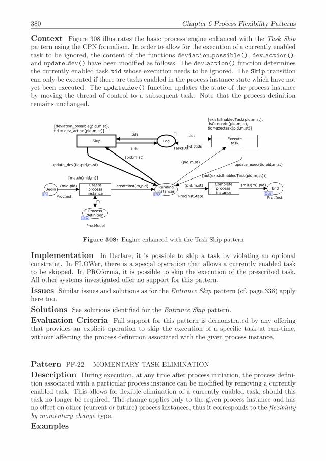
380 Chapter 6 Process Flexibility Patterns
Context Figure 308 illustrates the basic process engine enhanced with the Task Skippattern using the CPN formalism. In order to allow for the execution of a currently enabledtask to be ignored, the content of the functions deviation possible(), dev action(),and update dev() have been modified as follows. The dev action() function determinesthe currently enabled task tid whose execution needs to be ignored. The Skip transitioncan only be executed if there are tasks enabled in the process instance state which have notyet been executed. The update dev() function updates the state of the process instanceby moving the thread of control to a subsequent task. Note that the process definitionremains unchanged.
tid::tids
tidstids
tids
update_dev(tid,pid,m,st)
(pid,m,st)
(mid,pid)
m
createinst(m,pid) (mID(m),pid)(pid,m,st)
update_exec(tid,pid,m,st)(pid,m,st)
Skip
[deviation_possible(pid,m,st),tid = dev_action(pid,m,st)]
Createprocessinstance
[match(mid,m)]
Completeprocess instance
[not(existsEnabledTask(pid,m,st))]
Executetask
[existsEnabledTask(pid,m,st), isConcrete(pid,m,st),tid=exectask(pid,m,st)]
Log
[]
TaskIDs
Begin
InProcInst
Processdefinition
I/O
ProcModel
Runninginstances
I/O ProcInstState
End
OutProcInst
OutI/O
I/O
In
Figure 308: Engine enhanced with the Task Skip pattern
Implementation In Declare, it is possible to skip a task by violating an optionalconstraint. In FLOWer, there is a special operation that allows a currently enabled taskto be skipped. In PROforma, it is possible to skip the execution of the prescribed task.All other systems investigated offer no support for this pattern.
Issues Similar issues and solutions as for the Entrance Skip pattern (cf. page 338) applyhere too.
Solutions See solutions identified for the Entrance Skip pattern.
Evaluation Criteria Full support for this pattern is demonstrated by any offeringthat provides an explicit operation to skip the execution of a specific task at run-time,without affecting the process definition associated with the given process instance.
Pattern PF-22 MOMENTARY TASK ELIMINATION
Description During execution, at any time after process initiation, the process defini-tion associated with a particular process instance can be modified by removing a currentlyenabled task. This allows for flexible elimination of a currently enabled task, should thistask no longer be required. The change applies only to the given process instance and hasno effect on other (current or future) process instances, thus it corresponds to the flexibilityby momentary change type.
Examples

Section 6.2 Catalog of process flexibility patterns 381
– For visitors to a football match who hold a European passport, no visa requirementsapply. This modification in the customs procedure is performed on a person-by-personbasis for the period of the championship competition.
– A time registration program provides a timesheet with predefined fields. A task which isincluded in the timesheet (for instance, planned sick leave for a doctor’s appointment),but which has not be been undertaken during the reporting period, can be removed fromthe timesheet.
Motivation When at run-time a particular task needs to be ignored, and there isno a bypass path defined in the process definition for skipping the given task, and it isnot possible to deviate from the prescribed execution order, there may arise the needto temporarily modify the process definition to exclude the task. The Momentary TaskElimination pattern allows a particular task to be removed from the process definition inorder to avoid executing the task for a given process instance.
Overview Figure 309 illustrates the graphical notation for the Momentary Task Elim-ination pattern. The top view shows two distinct process instances based on the sameprocess definition before applying the pattern. For one of these process instances the needto eliminate the currently enabled task B is recognized.
B A C D
A C D
B A C D
B A C D
v
Figure 309: Momentary Task Elimination pattern
The bottom view shows that after applying the pattern the process definition associatedwith one of the process instances has been modified. In particular, task B has been removedfrom the process definition, and the thread of control associated with the given processinstance has been moved forward to task C.
Context Figure 310 illustrates the basic process engine enhanced with the MomentaryTask Elimination pattern using the CPN formalism. The model adopts the structurepresented earlier in the Momentary Entry-Point Change pattern (cf. page 343), howeverthe content of functions change possible() and update pi() has been modified. TheMomentary task extract transition can only be executed if there are enabled tasks in theprocess instance state which have not been executed and if the end of the process has notbeen reached. The update pi() function selects a currently enabled task, deletes it fromthe process definition, and connects the task preceding it to a subsequent task by means ofan arc. Once that task has been removed, the process instance state is also recalculated.
Implementation In Declare, it is possible to remove a specific task from the model.ADEPT1 also allows a task to be deleted from the model, however the deleted task isvisualized as disabled rather than extracted from the process definition associated withthe given process instance. In YAWL, there is the possibility to invoke an exlet to removea workitem, however when the workitem has been removed, no subsequent tasks can be

382 Chapter 6 Process Flexibility Patterns
(pid,m,st)
(mid,pid)
m
createinst(m,pid) (mID(m),pid)(pid,m,st)
(pid,m,ns(pid,m,st)) (pid,m,st)
[change_possible(pid,m,st)]
Createprocessinstance
[match(mid,m)]
Completeprocess instance
[not(existsEnabledTask(pid,m,st))]
Executetask
[existsEnabledTask(pid,m,st), isConcrete(pid,m,st)]
Begin
InProcInst
Processdefinition
I/OProcModel
Runninginstances
I/O ProcInstState
End
OutProcInst
OutI/O
I/O
In
update_pi(pid,m,st)****************************************Aspecified task (which has not yet been executed)is removed from the process definition associated with a given process instance. Tasks from a presetand a postset of the extracted task are connectedto each other.***************************************
Momentarytask extract
Figure 310: Engine enhanced with the Momentary Task Elimination pattern
executed. Instead, it is possible to force failure or completion of the given task in orderto proceed with execution of the next task. No other systems that have been investigatedoffer support for this pattern.
Issues Removing a task from the process definition may trigger blocking of subsequenttasks requiring output data provided by the task removed.
Solutions After removing a task, either all data dependencies have also to be removedor a default value assigned to the input data elements of subsequent tasks.
Evaluation Criteria Full support for this pattern is demonstrated by any offeringthat allows a task to be deleted from the process definition associated with a particularprocess instance.
Pattern PF-23 PERMANENT TASK ELIMINATION
Description During execution, there is a possibility to permanently eliminate theexecution of a particular task in the process by removing it from the process definition atthe type level. This allows the selected task to be ignored in all future process instancesand existing process instances whose execution has not passed this point yet. The changeperformed affects all future process instances directly, while existing process instances mayrequire migration from the old to the new process definition, thus the pattern is of theflexibility by permanent change type.
Examples– A template for project schedule can be updated by removing tasks which do not need to
be executed any more.– Due to centralization of data by the city hall, tax office and insurance companies, changes
in family living arrangements do not need to be reported to the insurance companydirectly. This step is removed from the predefined procedures of the insurance company.The data is instead reported to the insurance company by the tax office.
Motivation In situations where after process initiation the need to eliminate the ex-ecution of a particular task for current and future process instances is recognized, theremay arise a need to modify the process definition at the type level. The Permanent Task

Section 6.2 Catalog of process flexibility patterns 383
Elimination pattern allows a particular task to be permanently removed from the processdefinition such that this task will never be executed again.
Overview Figure 311 illustrates the graphical notation for the Permanent Task Elim-ination pattern. The top view shows the execution state of several process instancespopulated based on the same process definition. At run-time the need to eliminate task B
at the type level is recognized.
B A C D
A C D
Figure 311: Permanent Task Elimination pattern
The bottom view shows that the process definition after applying the pattern. TaskB has been removed from the process definition. For process instances where task B wasenabled, the thread of control has been moved forward to its successor task C.
Context Figure 312 illustrates the basic process engine enhanced with the PermanentTask Elimination pattern using the CPN formalism. The model of the engine is extendedaccording to the structure described earlier for the Permanent Entry-Point Change pattern(cf. page 345). The functions used have been changed as follows. The Permanent task
extract can only be executed if the process definition contains more than two tasks (e.g.,start and end tasks). This condition is incorporated in the change possible() function.The modify m() function removes the selected task from the process definition m, andreconnects the tasks preceding and following it. The Migrate transition performs migrationof existing process instances stored in the Running instance place only if the processinstance has not reached the end. For the process instance whose process model id matcheswith the id of the process definition earlier modified, the migrate() function transfersthe old process definition oldm to the new process definition newm according to a desiredmigration policy.
Implementation Of all systems analyzed, only Declare and ADEPT1 support thispattern. In addition to the functionality for removing a task from the model, they alsoprovide a means of process instance migration.
Issues The same issues as identified for the Permanent Entry-Point Change pattern(cf. page 345) and the Momentary Task Elimination pattern apply here too.
Solutions See solutions identified for the above mentioned patterns.
Evaluation Criteria Full support for this pattern is demonstrated by any offeringthat allows a task to be permanently removed from the process definition, and providesfacilities for the process instance migration.
6.2.7 Flexible extension
This group of patterns aims to provide flexibility in enabling an execution path alternativeto the one prescribed by the process definition by incorporating a task that has not pre-viously been foreseen (i.e. no reordering or selection). Figure 313 illustrates the scope of

384 Chapter 6 Process Flexibility Patterns
newm
migrate(pid,m,newm,st)(pid,m,st)
newm
m
modify_m(m)
(mid,pid)
m
createinst(m,pid) (mID(m),pid)(pid,m,st)
(pid,m,ns(pid,m,st))(pid,m,st)
Migrate
[transfer_possible(m,newm,st)]
Permanenttask extract
[change_possible(m)]
Createprocessinstance
[match(mid,m)]
Completeprocess instance
[not(existsEnabledTask(pid,m,st))]
Executetask
[existsEnabledTask(pid,m,st), isConcrete(pid,m,st)]
Begin
InProcInst
Processdefinition
I/O
ProcModel
Runninginstances
I/O ProcInstState
End
OutProcInst
OutI/O
I/O
In
********************************A task (with no splits or joins) is selectedfor extraction from the process model. After the task has been removed, its preset and postset are reconnected.********************************
Figure 312: Engine enhanced with the Permanent Task Elimination pattern
patterns presented in this subsection and their relationship to different types of flexibility.
Flexibility by
Design Deviation Underspecification Momentary
Change
Permanent
Change
Flexible initiation Alternative
entry points
Entrance
skip
Undefined entry Momentary
entry change
Permanent
entry change
Flexible termination Alternative
exit points
Termination
skip
Undefined exit Momentary
exit change
Permanent
exit change
Flexible selection Choice Task
substitution
Late selection Momentary
choice
insertion
Permanent
choice
insertion
Flexible reordering Interleaving Swap Momentary
reordering
Permanent
reordering
Flexible elimination Foreseen
bypass path
Task skip Momentary
task
elimination
Permanent
task
elimination
Flexible extension Task
invocation
Late creation Momentary
task insertion
Permanent
task insertion
Flexible
concurrency
Flexible repetition
Figure 313: Process Flexibility Matrix: flexible extension
In situations, where at run-time a task needs to be executed which has not been foreseenin the process definition, it should be possible to easily incorporate the desired task in orderfor desired behavior to be achieved. The need for flexible extension in this group of patternsis recognized at run-time. The concept of flexible extension cannot be facilitated at design-time, because all execution alternatives that are foreseen at design-time can explicitlybe included into the process definition by applying the Choice pattern (cf. page 359) asillustrated in Figure 314.
There are four flexible extension patterns: Task Invocation, Late Creation, MomentaryTask Insertion and Permanent Task Insertion which describe four approaches to incorpo-rating unforeseen tasks in order for a desired execution option to be obtained at run-time.

Section 6.2 Catalog of process flexibility patterns 385
B A C D
E
F
Z
...
Figure 314: Flexible extension by design
The Task Invocation pattern allows for deviation from the execution path prescribed byinvoking a task different to the one that is currently enabled without replacing any existingtask. The Late Creation pattern offers the possibility to create an alternative executionpath at a particular point in the process at the last possible moment based on the needto introduce optional behavior that could not be foreseen at design-time. The MomentaryTask Insertion and Permanent Task Insertion patterns allow for inclusion of a task thathas not been foreseen at design-time in the process definition on a temporary or permanentbasis respectively.
Pattern PF-24 TASK INVOCATION
Description During execution, at any time after a process instance has been created,there is the possibility to deviate from the execution path prescribed by the process def-inition by invoking a task which has not yet been executed and completing it before thecurrently enabled task is executed. This allows for flexible extension of the execution op-tions associated with a given process instance with one of the tasks contained in the processdefinition. Such a deviation does not affect the process definition, and corresponds to theflexibility by deviation type.
Examples– Students possessing diploma’s from European institutions do not have to pass a language
test in order to enroll into the masters program. In some cases however, the level ofEnglish ability may need to be assessed. For this an appointment is made with anadvisor handling English tests for foreign students.
– A patient treated in the department of internal diseases has developed a skin rush. Tohandle this problem a doctor from the dermatological department has been called.
Motivation In some situations, after a process has been initiated, it may be necessary topostpone the execution of a certain task because another task that has not been previouslyforeseen at design-time needs to be executed first. The Task Invocation pattern allowsfor suspension of the execution of tasks prescribed by the process definition in order foranother task to be invoked and executed first. The possibility of extending the set of tasksprescribed by the process definition in this pattern corresponds to flexibility by deviation,which has an impact only on the manner in which the given process instance is executed,and does not affect the original process definition.
Overview Figure 315 illustrates the graphical notation for the Task Invocation pattern.The top view illustrates a process instance where after executing task B the need to executea task different to the one prescribed by the process definition is recognized.

386 Chapter 6 Process Flexibility Patterns
B A C D
B A C D
E
Figure 315: Task Invocation pattern
The bottom view shows that after applying the pattern task E has been invoked andthe thread of control from task C has been temporarily moved to task E. Note that task E
is a generic representation of a task that is contained in the process definition but whichhas not been executed yet. The invocation of this task is performed without modifying theprocess definition.
Context Figure 316 illustrates the basic process engine enhanced with the Task Invoca-tion pattern using the CPN formalism. The model adopts the structure for deviation op-erations described earlier for the Termination Skip pattern on page 351. The Invoke Task
transition can only be executed for a process instance whose execution has not completedyet. The dev action() function selects a task that has not yet been executed and whichwill be invoked before executing the currently enabled task. The invoked task is recordedin the Log place, and the state of the process instance is updated by the update dev()
function so that the originally enabled task becomes enabled again
tid::tids
tids
tids
tid::tids
update_dev(tid,pid,m,st)
(pid,m,st)
(mid,pid)
m
createinst(m,pid) (mID(m),pid)(pid,m,st)
update_exec(tid,pid,m,st)
(pid,m,st)
InvokeTask
[deviation_possible(pid,m,st,tids),tid=dev_action(m,tids)]
Createprocessinstance
[match(mid,m)]
Completeprocess instance
[not(existsEnabledTask(pid,m,st))]
Executetask
[existsEnabledTask(pid,m,st),isConcrete(pid,m,st),tid=exectask(pid,m,st)]
Log
[]
TaskIDs
Begin
InProcInst
Processdefinition
I/O
ProcModel
Runninginstance
I/O ProcInstState
End
OutProcInst
OutI/O
I/O
In
********************************Any task in a model which has not yet beenexecuted can be invoked by executing the Invoke Task transition. ********************************
Figure 316: Engine enhanced with the functionality of the Task Invocation pattern
Implementation Of all of the systems analyzed, only FLOWer, Declare, and OracleBPEL provide support for this pattern. In FLOWer, another task can be invoked at anypoint in the process. In Oracle BPEL PM, an exception needs to be raised and in thecorresponding exception handler an invocation activity needs to be included.
Issues None identified.

Section 6.2 Catalog of process flexibility patterns 387
Solutions N/A.
Evaluation Criteria Full support for this pattern is demonstrated by any offeringthat allows a task contained in the process definition which has not yet been executed tobe invoked. Execution of the main process must be suspended until the execution of theinvoked task completes.
Pattern PF-25 LATE CREATION
Description A process definition created at design-time contains a placeholder whichmay be completed at run-time in order to allow for an extension of the process definitionwith a task whose content cannot be foreseen in advance. The completion of the placeholderis optional and is performed only if an additional task needs to be added at run-time.The need for flexible execution path selection in this pattern is recognized at design-time,whose actual realization is performed at run-time, thus this pattern is of the flexibility byunderspecification type.
Examples– The process of submitting electronic photos for printing starts with the uploading of
photos into a photo application, selection of the print format and submission of the order.The client may submit the order immediately, or order additional products offered bythe company, and only then proceed to order submission.
– The software program supplied with the navigation system offers a default voice forroute directions. When defining a route, a user may also choose to record their owninstructions and then move on to planning the route.
Motivation At design-time when creating a process definition it may be foreseen thatan additional task may need to be added at run-time, whose content is either unknownor may vary for different process instances. The Late Creation pattern allows for thepossibility of creating an additional task at the latest possible moment to be included inthe process definition in the form of a placeholder. The definition of this placeholder maybe completed at run-time if for a given process instance a new task needs to be added.Otherwise it can be ignored.
Overview Figure 317 illustrates the graphical notation for the Late Creation pattern.The top view shows a process definition where after executing task B there is the possibilityof executing task C or creating another task and executing it before proceeding to task C.The possibility for late creation of a task is incorporated into the process definition bymeans of a placeholder.
The bottom view shows that after applying the pattern, a new task E is created whencompleting the definition of the enabled placeholder, and the thread of control is passedto this task.
Context The CPN semantics of the Late Creation pattern can be described in termsof the Choice pattern (cf. page 359) and the Late Selection pattern (cf. page 363). In orderfor flexibility in process extension facilitated by the Late Creation pattern to be obtained,the process definition created at design-time has to include a choice construct with twoalternative branches: one representing the normal flow of tasks and another containinga placeholder task whose content can be created when needed at run-time. Figure 318pattern shows the basic process engine modified in a similar way as has been done forthe Late Selection pattern. The enabling condition for the Execute task transition hasbeen weakened in order to allow the user to choose whether to execute a concrete task

388 Chapter 6 Process Flexibility Patterns
B A C D
E
B A C D
Figure 317: Late Creation pattern
or to define the content of an underspecified task. This condition is incorporated in theexistsConcrete(pid,m,st) function.
(mid,pid)
m
createinst(m,pid) (mID(m),pid)(pid,m,st)
(pid,m,st)
Createprocessinstance
[match(mid,m)]
Completeprocess instance
[not(existsEnabledTask(pid,m,st))]
[existsEnabledTask(pid,m,st), existsConcrete(pid,m,st)]
Begin
InProcInst
ProcModel
Runninginstance
I/OProcInstState
End
OutProcInst
OutI/OIn
Processdefinition
I/OI/O
********************************When both a concrete task and a placeholder taskare enabled, one of which needs tobe selected, the decision to choose theplaceholder task and define its content can be made, otherwise the concrete taskis executed without having the definiton of theplaceholder task completed. ********************************
Executetask
(pid,m,ns(pid,m,st))
Figure 318: The engine enhanced with the Late Creation pattern
Implementation Of all systems analyzed, only YAWL and Oracle BPEL PM supportthis pattern. By incorporating a worklet into one of the alternative branches associatedwith an exclusive choice construct (cf. the Choice pattern on page 359) it is possible topostpone the decision for late task creation until run-time. In Oracle BPEL PM, a taskresponsible for invoking a process whose implementation details are not yet known canbe defined at design-time. The implementation details can be set dynamically during theprocess execution.
Issues The same issues as for the Late Selection pattern (cf. page 363) apply here also.
Solutions See solutions identified for the Late Selection pattern.
Evaluation Criteria Full support for this pattern is demonstrated by any offeringthat allows a decision in regard to executing a task prescribed by the process definition orcreating and executing a previously unforeseen task, to be included in the process definitionat design-time.

Section 6.2 Catalog of process flexibility patterns 389
Pattern PF-26 MOMENTARY TASK INSERTION
Description During execution, at any time after process initiation, the process defini-tion associated with a particular process instance can be modified by extending the processdefinition with a task that has not been foreseen. The execution of the currently enabledtask is postponed until the newly identified task has been completed. The change appliesonly to a given process instance and has no effect on other (current or future) processinstances, thus it corresponds to the flexibility by momentary change type.
Examples– A timesheet used for recording activities performed by an employee during the day
contains a list of predefined tasks. If a non-standard task that is not included in thelist needs to be performed, the timesheet for the corresponding day can be adjusted byinserting the new task.
– Due to the unexpected illness of an employee, the tasks of this employee are dividedamongst other members of the group. Each employee to whom an extra task has beenassigned adjust their personal planning accordingly.
Motivation When at run-time a desired task cannot be found in a process definition,it should be possible to introduce this task on a temporary basis. The Momentary TaskInsertion pattern allows the set of tasks executed by a particular process instance to beextended by temporarily inserting a task into the corresponding process definition.
Overview Figure 319 illustrates the graphical notation for the Momentary Task In-sertion pattern. The top view shows two process instances populated based on the sameprocess definition before applying the pattern. Both process instances are in a state wheretask C is enabled and needs to be executed. For one of the process instances, the need toexecute a task not contained in the process definition is recognized.
B A C D
B A C D E
E
B A C D
B A C D
Figure 319: Momentary Task Insertion pattern
The bottom view shows the process definitions associated with given process instancesafter applying the pattern. The process instance where the new task was introduced hasbeen extended with task E, and the execution thread has been moved backward from thepreviously enabled task C to task E. The other process instance remains unaffected.
Context Figure 320 illustrates the basic process engine enhanced with the MomentaryTask Insertion pattern using the CPN formalism. The process engine is extended accord-ing to the structure adopted by all patterns facilitating flexibility by momentary change(cf. page 343). To realize the functionality for extending the set of tasks associated with aparticular process instance the change possible() and update pi() functions have been

390 Chapter 6 Process Flexibility Patterns
updated as follows. The change possible() function specifies that a new task that pre-viously has not been foreseen be inserted into the process definition by the Momentary
task insertion transition only if for a given process instance there are enabled tasks thathave not yet been executed. The update pi() function creates a new task, selects an arcconnecting two tasks between which the created task will be inserted, and replaces this arcwith two arcs connecting the preceding and subsequent tasks to the created task.
update_pi(pid,m,st)
(pid,m,st)
(mid,pid)
m
createinst(m,pid) (mID(m),pid)(pid,m,st)
(pid,m,ns(pid,m,st)) (pid,m,st)
Createprocessinstance
[match(mid,m)]
Completeprocess instance
[not(existsEnabledTask(pid,m,st))]
Executetask
[existsEnabledTask(pid,m,st), isConcrete(pid,m,st)]
Begin
InProcInst
ProcModel
Runninginstance
I/O ProcInstState
End
OutProcInst
OutI/OIn
[change_possible(pid,m,st)]
Momentarytask insertion
Processdefinition
I/OI/O
********************************A newly created task is insertedin the arc between two indicated tasks.********************************
Figure 320: Engine enhanced with the Momentary Task Insertion pattern
Implementation Of the systems analyzed, only Declare, ADEPT1 and YAWL supportthis pattern. In Declare and ADEPT1, there is an explicit operation defined allowing anew task to be inserted in a model. In YAWL, at run-time execution it is possible to invokean exlet in order for a process fragment (which was not earlier foreseen) to be executedwhile the main process is suspended.
Issues By inserting a task between two tasks in the process, any data assumptions thatexist between these two tasks can potentially be disrupted and may cause the last task toblock.
Solutions In order to solve this problem, the visibility of data used in the process has tobe set to the process instance level, so that data produced at each step during the processbecomes visible to other tasks.
Evaluation Criteria Full support for this pattern is demonstrated by any offeringthat allows a task to be inserted into a process definition associated with a given processinstance at run-time.
Pattern PF-27 PERMANENT TASK INSERTION
Description During execution, there is the possibility to permanently modify theprocess definition by adding a new task. This allows for functionality that has not beenforeseen earlier to be incorporated in all existing and future process instances. The changeperformed affects future process instances directly, whilst existing process instances requiretheir old process definition to be migrated to the new process definition, thus this patterncorresponds to the flexibility by permanent change type.
Examples

Section 6.2 Catalog of process flexibility patterns 391
– The introduction of electronic identity cards requires all traveling passengers to hold apassport with an electronic id. Passengers whose passport has not expired yet, continueto use it during the transition period, however when this passport expires a new onemust be requested. The issuing of an electronic id is an additional step performed afterthe new passport has been acquired.
– The takeover of one company by another requires product certification, which previouslyhas not been done. This implies that all ongoing requests have to be terminated andredone according to the new steps dictated by the certification standard.
Motivation In situations, where at run-time the need to extend the set of tasks con-tained in a process is anticipated, a set of actions may need to be taken in order to redesignthe original process definition and to adapt the execution of current and future process in-stances. The Permanent Task Insertion pattern allows a task that has not previously beenforeseen to be included in the process definition on a permanent basis.
Overview Figure 321 illustrates the graphical notation for the Permanent Task In-sertion pattern. The top view shows several process instances sharing the same processdefinition. At run-time execution the need to execute task E which has not previously beenforeseen is recognized at the type level.
B A C D
B A C D E
E
Figure 321: Permanent Task Insertion pattern
The bottom view shows that after applying the pattern, the process definition has beenextended with task E. The process instance that has passed this point remains unaffected,while for other process instances the thread of control has been migrated from previouslyenabled task C to the newly inserted task E.
Context Figure 322 illustrates the process engine enhanced with the Permanent TaskInsertion pattern using the CPN formalism. The model of the process engine is extendedwith the Permanent task insertion and Migrate transition according to the structureadopted by all patterns facilitating flexibility by permanent change and described earlieron page 345. In order to insert a task that previously has not been foreseen into theprocess definition at the type level by means of the Permanent task insertion transition,functions change possible() and modify m() have been modified as follows. A newlycreated task is inserted into a selected arc by means of the modify m() function by splittingthe selected arc into two parts. Process instances corresponding to the process model whichhas been recently modified, which are stored in the Running instance place, may needto be migrated to the new process definition. The transfer possible() function checkswhether transfer is possible for the given process instance (i.e. there are enable tasks whichhave not yet been executed and transfer is possible). If migration needs to be performed,the migrate() function transfers the corresponding process instances from the old to newprocess definition.

392 Chapter 6 Process Flexibility Patterns
newm
migrate(pid,m,newm,st)(pid,m,st)
newm
m
modify_m(m)
(mid,pid)
m
createinst(m,pid) (mID(m),pid)(pid,m,st)
(pid,m,ns(pid,m,st))(pid,m,st)
Migrate
[transfer_possible(m,newm,st)]
Permanenttask insertion
[change_possible(m)]
Createprocessinstance
[match(mid,m)]
Completeprocess instance
[not(existsEnabledTask(pid,m,st))]
Executetask
[existsEnabledTask(pid,m,st), isConcrete(pid,m,st)]
Begin
InProcInst
Processdefinition
I/O
ProcModel
Runninginstances
I/O ProcInstState
End
OutProcInst
OutI/O
I/O
In
********************************A new task is inserted between two sequential tasks.********************************
Figure 322: Engine enhanced with the Permanent Task Insertion pattern
Implementation Of all of the systems analyzed, only Declare and ADEPT1 supportthis pattern. They offer an operation for inserting a task into a process model and allowexisting process instances to be migrated to the new process definition.
Issues The same issues as identified for the Permanent Entry-Point Change pattern(cf. page 345) and the Momentary Task Reordering pattern apply here also.
Solutions See solutions identified for the Permanent Entry-Point Change pattern .
Evaluation Criteria Full support for this pattern is demonstrated by any offeringthat allows a task to be permanently inserted into a process definition at run-time, andprovides facilities for migrating existing process instances from the old process definitionto the new one.
6.2.8 Flexible concurrency
This group of patterns aims at achieving flexibility when executing several independenttasks concurrently, thus avoiding unnecessary dependencies between them. Although asimilar outcome can be achieved by applying patterns facilitating flexible reordering, thefocus of this group of patterns is not to change the order of tasks, but to achieve the desiredconcurrency. Figure 323 illustrates the scope of patterns presented in this subsection andtheir relationship to the other types of flexibility.
Often sequential processes which require that tasks be executed one after another con-tain a set of tasks whose execution does not depend on each other. To decrease theduration of the process and make its execution more efficient, whereas possible indepen-dent tasks should be undertaken concurrently. The flexible concurrency patterns describedifferent ways in which dependencies between independent tasks can be decreased by let-ting them run in parallel. This group contains three patterns: Parallelism, MomentaryTask Parallelization and Permanent Task Parallelization corresponding to flexibility bydesign, momentary change and permanent change respectively. Note that no mapping offlexible concurrency to the concepts of flexibility by underspecification can be made. Flex-

Section 6.2 Catalog of process flexibility patterns 393
Flexibility by
Design Deviation Underspecification Momentary
Change
Permanent
Change
Flexible initiation Alternative
entry points
Entrance
skip
Undefined entry Momentary
entry change
Permanent
entry change
Flexible termination Alternative
exit points
Termination
skip
Undefined exit Momentary
exit change
Permanent
exit change
Flexible selection Choice Task
substitution
Late selection Momentary
choice
insertion
Permanent
choice
insertion
Flexible reordering Interleaving Swap Momentary
reordering
Permanent
reordering
Flexible elimination Foreseen
bypass path
Task skip Momentary
task
elimination
Permanent
task
elimination
Flexible extension Task
invocation
Late creation Momentary
task insertion
Permanent
task insertion
Flexible
concurrency
Parallelism Momentary
task
parallelization
Permanent
task
parallelization
Flexible repetition
Figure 323: Process Flexibility Matrix: flexible concurrency
ibility by underspecification assumes that the content of a particular process fragment isnot foreseen at design-time and any necessary control-flow dependencies are not known,whilst the tasks whose execution needs to be parallelized in this case are well-defined andno dependencies between these tasks are required. The mapping to flexibility by deviationcorresponds to the Swap pattern described on page 371, which enables the deviation fromexecuting the currently enabled task to invoking another task to occur. In light of theinterleaving semantics of CPN Tools the same realization mechanism as used for the Swappattern also applies for supporting flexible concurrency. In the Parallelism pattern, theneed for concurrent task execution is recognized at design-time and is realized by meansof parallel branching. The Momentary Task Parallelization and Permanent Task Paral-lelization allow the introduction of concurrent behavior based on parallel branching at theinstance and type levels respectively.
Pattern PF-28 PARALLELISM
Description A process definition specified at design-time contains a construct thatallows two independent tasks to execute simultaneously or in any order. This allows formore concurrency during the execution of tasks and avoids unnecessary waiting and de-pendencies. The need for flexible process concurrency in this pattern is anticipated atdesign-time, and corresponds to the flexibility by design type.
Examples– In high-performance computing large problems are often divided into small units which
are then processed concurrently.– Where the production of parts for car assembly involves production activities for parts
which are not dependent on each other, their individual production processes can beundertaken in parallel.
Motivation When a set of tasks is identified at design-time which can be executedindependently, it may be necessary to specify that they can be executed concurrently or inany order. The Parallelism pattern allows two independent tasks to execute concurrently

394 Chapter 6 Process Flexibility Patterns
by introducing two branches which can be undertaken in parallel. At run-time executionthese tasks may be executed in either order or concurrently.
Overview Figure 321 illustrates the graphical notation for the Parallelism pattern. Thetop view shows the process definition where task C is executed after task B has completed.At design-time it is recognized that tasks B and C are independent of each other, and thereis no need to enforce the execution ordering between them.
B A C D
B
A
C
D
Figure 324: Parallelism pattern
The bottom view shows the process definition after applying the pattern. In this processdefinition, tasks B and C have been put in parallel, i.e. they can be executed in either orderor concurrently after the completion of task A.
Context The basic process engine (cf. Figure 325) supports the Parallelism patternas follows. In order to specify the parallelism between two tasks B and C, which havebeen identified as independent tasks at design-time, and which need to be become enabledconcurrently after task A has completed, the split and join connectors of associated diver-gence and synchronization tasks have to be set to AND. After executing task A by means ofthe Execute task transition, the ns() function analyzes the type of split of the executedtask, and if it corresponds to the AND-split enables all outgoing subsequent arcs. Notethat although theoretically these tasks can be executed concurrently, CPN Tools assumesan interleaving semantics which allows these tasks to be executed in any order but notsimultaneously.
(mid,pid)
m
createinst(m,pid) (mID(m),pid)(pid,m,st)
(pid,m,st)
[match(mid,m)] [not(existsEnabledTask(pid,m,st))]
ProcInst
ProcModel
Runninginstance
I/OProcInstState ProcInst
I/O
Createprocessinstance
Begin
InIn
Completeprocess instance
End
OutOut
Executetask
(pid,m,ns(pid,m,st))
[existsEnabledTask(pid,m,st), isConcrete(pid,m,st)]
Processdefinition
I/OI/O
Figure 325: Basic process engine: support for Parallelism
Implementation This pattern is supported by all of the systems analyzed. In Ora-cle BPEL PM, this pattern is supported by means of the <flow> construct with severalconcurrent branches. In GLIF and EON, a special branching block needs to be insertedwith which parallel branches have to be associated. In AsbruView, the Parallel plan canbe used for this purpose. YAWL enables parallel execution by associating the AND-split

Section 6.2 Catalog of process flexibility patterns 395
connector with a task. In PROforma, parallel execution can be enabled by incorporatingthe Decision construct.
Issues None identified.
Solutions N/A.
Evaluation Criteria Full support for this pattern is demonstrated by any offeringthat allows two or more tasks to be executed concurrently at run-time, based on the parallelexecution paths specified for them in the process definition at design-time.
Pattern PF-29 MOMENTARY TASK PARALLELIZATION
Description During execution, at any time after process initiation, a process definitionassociated with a particular process instance can be modified by parallelizing the executionof two subsequent independent tasks. This gives flexibility in initiating these tasks allowingthem to execute in any order as well as concurrently. The change applies only to a givenprocess instance and has no effect on other (current or future) process instances, thus itcorresponds to the flexibility by momentary change type.
Examples– Due to change in planning, all activities are required to be completed earlier than usual,
therefore in addition to the currently executing task an employee initiates another ac-tivity that has been planned for a later time.
– The workshop program consists of a set of presentations, followed by a feedback sessionwhere students complete evaluation forms. To shorten the workshop program, studentshave been asked to fill in the evaluation form while attending one of the presentations.
Motivation When at run-time several independent tasks have been identified, whichare prescribed by the process definition to execute sequentially, it should be possible tolet them run concurrently or in any order. The Momentary Task Parallelization patternallows for concurrent execution of two independent tasks by temporarily parallelizing themfor a given process instance.
Overview Figure 321 illustrates the graphical notation for the Momentary Task Par-allelization pattern. The top view shows two process instances populated from the sameprocess definition. For one of the process instances the need to execute enabled task B
concurrently with its successor task C is recognized.
B A C D
B A C D
B
A
C
D
B A C D
Figure 326: Momentary Task Parallelization pattern

396 Chapter 6 Process Flexibility Patterns
The bottom view shows that after applying the pattern for a given process instancethe process definition has been changed: tasks B and C have been parallelized, and anadditional execution thread has been spawned off in order to enable task C.
Context Figure 327 illustrates the basic process engine enhanced with the MomentaryTask Parallelization pattern using the CPN formalism. The model of the engine is extendedusing the structure adopted by all patterns facilitating flexibility by momentary change(cf. page 343). The Momentary parallelization transition can be executed in order toparallelize a currently enabled (sequential) task with a subsequent task that is yet to beexecuted. The change possible() function checks whether for the given process instancestored in the Running instance place there exist an enabled task that still has to beexecuted, and whether there exist two adjacent tasks with no join and split connectors(these tasks should different from the start and end tasks). The update pi() functionselects an arbitrary arc between two sequential tasks (other than those being parallelized),deletes the sequential dependency between them, modifies the join and split connectors ofthe corresponding divergence and synchronization tasks and adds missing arcs from thedivergence and synchronization tasks to the parallelized tasks. After the change the processinstance state is updated. If the currently enabled task has been involved in the change,then the updated state would contain two enabled tasks.
*******************************Two subsequent sequential tasks, whichare not in the beginning and not in the end of theprocess, are selected for parallelization.The split and join connectors of the corresponding synchronizationtasks are modified. After the change, both tasks are enabled.**********************************
update_pi(pid,m,st) (pid,m,st)
(mid,pid)
m
createinst(m,pid) (mID(m),pid)(pid,m,st)
(pid,m,ns(pid,m,st))(pid,m,st)
Momentary parallelization
[change_possible(pid,m,st)]
Createprocessinstance
[match(mid,m)]
Completeprocess instance
[not(existsEnabledTask(pid,m,st))]
Executetask
[existsEnabledTask(pid,m,st),isConcrete(pid,m,st)]
Begin
InProcInst
Processdefinition
I/OProcModel
Runninginstances
I/O ProcInstState
End
OutProcInst
OutI/O
I/O
In
Figure 327: Engine enhanced with the Momentary Task Parallelization pattern
Implementation Of all of the systems analyzed, only Declare supports this pattern.To allow another task to be executed concurrently with currently enabled task, the con-strains associated with the task to be invoked have to be removed. Although ADEPT1provides flexibility by change, it does not allow for the parallelization of sequential tasks.
Issues None identified.
Solutions N/A.
Evaluation Criteria Full support for this pattern is demonstrated by any offeringthat allows the order of tasks in the process definition associated with a given processinstance to be modified in such a way that two independent sequential tasks are parallelized,and may be executed concurrently.

Section 6.2 Catalog of process flexibility patterns 397
Pattern PF-30 PERMANENT TASK PARALLELIZATION
Description During execution, there is the possibility to permanently modify theprocess definition by transforming the sequential ordering of previously independent tasksinto a concurrent structure, which allows these tasks to execute simultaneously or in anyorder. The parallelization of tasks is performed in the process definition at the type levelon a permanent basis. The change performed affects future process instances directly,and existing process instance require migration from the old process definition to the newprocess definition, thus it corresponds to the flexibility by permanent change type.
Examples– The education program at a school has been revised allowing students to follow in-
dependent courses in parallel. The previous version of the program allowed only forparticipation in a new course only after the previous course has been completed.
– It is common practice in hospitals to solve the health problem of one patient at a time.In order to decrease waiting times, patients in the same family are accepted togetherand treated concurrently.
Motivation When at run-time the possibility for concurrent execution of independenttasks is recognized there may arise the need to restructure the original process definitionby parallelizing the execution order of these tasks. The Permanent Task Parallelizationpattern allows two independent tasks to be parallelized on a permanent basis in order toprovide flexibility in defining the execution order for these tasks.
Overview Figure 321 illustrates the graphical notation for the Permanent Task Paral-lelization pattern. The top view shows three distinct process instances populated from thesame process definition. At run-time execution for the given process definition the need torelax the dependency between tasks B and C at the type level is recognized.
B A C D
B A
C
D
c
Figure 328: Permanent Task Parallelization pattern
The bottom view shows that after applying the pattern tasks B and C have been paral-lelized. For the process instance that has passed these tasks this change is inconsequential.For the other two process instances, where task B has been enabled, an additional threadof control has been spawned off in order to execute task C independently of task B. Bothtasks have to complete in order for task D to become enabled.
Context Figure 329 illustrates the basic process engine enhanced with the PermanentTask Parallelization pattern using the CPN formalism. The model of the process engineis extended using the structure described earlier in the Permanent Entry-Point Changepattern on page 345.
Two sequential tasks can be put in parallel by the Permanent parallelization tran-sition in the process definition only if conditions specified by the change possible() func-tion are satisfied. In particular, there must be an arc between two sequential tasks (with

398 Chapter 6 Process Flexibility Patterns
no splits or joins), and these tasks must be different from the start and end tasks. Themodify m() function selects an arbitrary arc between sequential tasks (other than thosebeing parallelized), identifies their synchronization tasks, sets the join and split connectorsof the divergence and synchronization tasks to AND, deletes the selected arc, and adds twoother arcs connecting the synchronization tasks with the tasks recently parallelized instead.After the change has been performed, it may be necessary to migrate existing process in-stances stored in the Running instance place. The transfer possible() function checkswhether there mismatches between the old and new versions of the process definitions andwhether the transfer is possible. The migrate() function performs the transfer of a pro-cess instance from the old to new process definition according to the specified migrationstrategy.
********************************Two tasks in a sequence are selectedfor parallelization. The connectors of thecorresponding synchronization tasks are modified to AND-type.********************************
newm
migrate(pid,m,newm,st)(pid,m,st)
newm
m
modify_m(m)
(mid,pid)
m
createinst(m,pid) (mID(m),pid)(pid,m,st)
(pid,m,ns(pid,m,st))(pid,m,st)
Migrate
[transfer_possible(m,newm,st)]
Permanentparallelization
[change_possible(m)]
Createprocessinstance
[match(mid,m)]
Completeprocess instance
[not(existsEnabledTask(pid,m,st))]
Executetask
[existsEnabledTask(pid,m,st), isConcrete(pid,m,st)]
Begin
InProcInst
Processdefinition
I/O
ProcModel
Runninginstances
I/O ProcInstState
End
OutProcInst
OutI/O
I/O
In
Figure 329: Engine enhanced with the Permanent Task Parallelization pattern
Implementation Of all of the systems analyzed, only ADEPT1, Declare and YAWLoffer some support for this pattern. Declare allows previously sequential tasks to be con-currently enabled by removing the dependency constraints between them. Furthermore,it offers the possibility to transfer existing process instances to the new process definition.In order for two tasks to be put in parallel in ADEPT1, one of them have to be removedand inserted back in parallel with the other task. In YAWL, an exlet needs to be called inwhich given two tasks will be removed from the process model and inserted in the desiredorder by defining a new worklet.
Issues The same issues as identified for the Permanent Entry-Point Change pattern(cf. page 345) also apply here.
Solutions See solutions identified for the Permanent Entry-Point Change pattern.
Evaluation Criteria Full support for this pattern is demonstrated by any offeringthat allows the execution order of two sequential tasks to be parallelized, providing thatexisting process instances can be migrated from the old process definition to the new one.

Section 6.2 Catalog of process flexibility patterns 399
6.2.9 Flexible repetition
The last group of patterns aims at flexibility in repeating the execution of a particular taskvariable number of times. Figure 330 illustrates the scope of patterns presented in thissubsection and their relationship with the other types of flexibility.
Flexibility by
Design Deviation Underspecification Momentary
Change
Permanent
Change
Flexible initiation Alternative
entry points
Entrance
skip
Undefined entry Momentary
entry change
Permanent
entry change
Flexible termination Alternative
exit points
Termination
skip
Undefined exit Momentary
exit change
Permanent
exit change
Flexible selection Choice Task
substitution
Late selection Momentary
choice
insertion
Permanent
choice
insertion
Flexible reordering Interleaving Swap Momentary
reordering
Permanent
reordering
Flexible elimination Foreseen
bypass path
Task skip Momentary
task
elimination
Permanent
task
elimination
Flexible extension Task
invocation
Late creation Momentary
task insertion
Permanent
task insertion
Flexible
concurrency
Parallelism Momentary
task
parallelization
Permanent
task
parallelization
Flexible repetition Iteration Redo Momentary
loop insertion
Permanent
loop insertion
Figure 330: Process Flexibility Matrix: flexible repetition
In some situations, when creating a process definition it may be foreseen that a partic-ular task may need to be executed multiple times, but the number of times it will need toexecute may vary or be unknown. The flexible repetition patterns describe different waysof achieving the behavior allowing a certain task to be executed multiple times. Of the fourpatterns identified, the Iteration pattern represents a generic form of loop introduced inthe process definition at design-time, which allows tasks residing in the body of the loop tobe executed repeatedly until the loop termination condition is satisfied. There are differentforms of iterations possible, such as those described by the control-flow repetition patternsdescribed on page 154. However, in the context of this research we abstract from differentforms of the loops and consider its generic form. The Redo pattern applies to situationswhere after executing a particular task the decision to repeat it at some later point in timeis taken. The Momentary Loop Insertion and Permanent Loop Insertion patterns representvariants of the Iteration pattern realized at run-time by modifying the process definitionat the instance and type levels respectively. Note that this group contains no patternscorresponding to flexibility by underspecification. This has to do with the fact that thecontent of the task and its position are known and thus do not need to be represented asplaceholders.
Pattern PF-31 ITERATION
Description A process definition specified at design-time contains a loop which allowsthe execution of a given task to be repeated. Typically, the decision to enable the taskin the loop or continue with the subsequent task depends on the evaluation of a datacondition associated with this task. This gives flexibility in realizing execution sequenceswhere the task embedded in the loop may need to be executed multiple times. The need

400 Chapter 6 Process Flexibility Patterns
for flexible task concurrency in this pattern is anticipated at design-time and correspondsto the flexibility by design type.
Examples– For a driving license a candidate is required to take a theory exam. If the first attempt
is unsuccessful, a candidate may repeat the test until they finally pass it.– The blood examination in a laboratory is repeated for a sample until all required elements
have been identified.
Motivation In situations where it is recognized (at design-time) that a certain taskmay need to be executed a variable number of times, it should be possible to specify thatthe execution of this task should can be repeated. The Iteration pattern provides flexibilityin repeating the execution of a certain task by embedding it in the body of a loop, whichcan be iterated as many times as required.
Overview Figure 331 illustrates the graphical notation for the Iteration pattern. Thetop view shows the process definition in which each tasks executes only once. At design-timefor this process definition the possibility of executing task C multiple times is recognized.
B A C D
B A C D
Figure 331: Iteration pattern
The bottom view shows that after applying the pattern task C has been modified insuch a way that it can be executed multiple times. The number of times a given task isexecuted in distinct process instances may vary.
Context The Iteration pattern is supported by the basic process engine in a similarway as for the Choice pattern (cf. page 359). The possibility of repeating the execution ofa specific task can be incorporated into the process definition at design-time by inserting achoice construct forming a self-loop. For instance, in order to specify that after executingtask C either another instance of task C needs to be executed or task D, both the joinand split connectors of task C have to be set to XOR, and an additional arc (C,C) needsto be added to the set of arcs associated with the process model. In Figure 332, afterexecuting task C by means of the Execute task transition, the ns() function calculatesa new process instance state. When the value of the split connector associated with atask has been evaluated, for the XOR-type only one task out of several possible options isselected non-deterministically. This means that the number of times the task will iterateis not predefined, but is determined on a random basis.
Implementation In each of the systems analyzed, it is possible to achieve task itera-tion by embedding a task in a loop (for this, the same support as for the Choice patternis required). In PROforma, there exists an option to set an iteration attribute associatedwith a specific task to a value or to an expression, thus allowing the number of task itera-tions to vary. In Oracle BPEL PM, a task needs to be inserted into a <while> loop, whoseenabling condition defines whether a task residing in the loop will be iterated again. InFLOWer, iteration of a specific task can be achieved by inserting this task in the body ofa sequential plan.

Section 6.2 Catalog of process flexibility patterns 401
(mid,pid)
m
createinst(m,pid) (mID(m),pid)(pid,m,st)
(pid,m,st)
[match(mid,m)] [not(existsEnabledTask(pid,m,st))]
ProcInst
ProcModel
Runninginstance
I/OProcInstState ProcInst
I/O
Createprocessinstance
Begin
InIn
Completeprocess instance
End
OutOut
Executetask
(pid,m,ns(pid,m,st))
[existsEnabledTask(pid,m,st), isConcrete(pid,m,st)]
Processdefinition
I/OI/O
Figure 332: Basic CPN engine: support for Iteration
Issues In order to define whether a given task can be repeated, a data-based conditionidentifying whether to repeat the task has to be defined. The number of times the executionof the given task will be repeated depends on the moment of the data condition is evaluated.
Solutions There exist two variants of task iteration: a ’while’ loop and a ’repeat-until’loop. In case of the ’while’ loop the condition is evaluated before executing the task, whilstin case of the ’repeat-until’ loop the data condition is evaluated after the task has beencompleted. For implementation details see the Structured Loop control-flow pattern onpage 155.
Evaluation Criteria Full support for this pattern is demonstrated by any offeringthat allows the execution of a specific task to be repeated multiple times based on a datacondition included in the process definition at design-time.
Pattern PF-32 REDO
Description During execution, after process instance initiation, there is the possibilityof deviating from the execution path prescribed by the process definition by repeating theexecution of a task that has recently been completed. The need to execute a particulartask more often than prescribed by the process definition is anticipated at run-time. Thishas no effect on the process definition, and corresponds to the flexibility by deviation type.
Examples– Due to unexpected changes in travel plans, one of the reservations had to repeated in
order to change the flight to another date.– The results of software testing showed some inconsistencies in the software design. This
triggered revision of the design.
Motivation When at run-time it is recognized that the execution of a particular taskdid not go as well as expected, it should be possible to perform the given task again.The Redo pattern offers flexibility in deviating from the execution path prescribed by theprocess definition by allowing the execution of the currently enabled tasks to be deferreduntil the execution of previous task has been repeated.
Overview Figure 333 illustrates the graphical notation for the Redo pattern. The topview shows the process instance for which the need to repeat the previously executed taskC is recognized.
The bottom view shows that after applying the pattern the thread of control has beenmoved in the given process instance from task D to task C, thus allowing its execution tobe repeated.

402 Chapter 6 Process Flexibility Patterns
B A C D
B A C D
Figure 333: Redo pattern
Context Figure 334 illustrates the basic process engine enhanced with the Redo patternusing the CPN formalism. The Redo transition allows for deviation from the normalprescribed execution order by executing a task that has already been completed (anda record of which is available in the Log place). The deviation possible() functionspecifies that in order to redo a task, the list of executed tasks stored in the Log placeshould not be empty. The task whose execution needs to be redone is randomly selectedby the dev action() function. Note that the execution state of the given process instanceand the process definition remain unchanged.
tid::tids
tids
tids
tid::tids
(mid,pid)
m
createinst(m,pid) (mID(m),pid)(pid,m,st)
update_exec(tid,pid,m,st)(pid,m,st)
Redotask
Createprocessinstance
[match(mid,m)]
Completeprocess instance
[not(existsEnabledTask(pid,m,st))]
Executetask
Log
[]
TaskIDs
Begin
InProcInst
Processdefinition
I/OProcModel
Runninginstance
I/O ProcInstState
End
OutProcInst
OutI/O
I/O
In
[existsEnabledTask(pid,m,st),isConcrete(pid,m,st),tid=exectask(pid,m,st)]
(pid,m,st)
[deviation_possible(pid,m,st,tids),tid=dev_action(pid,m,st,tids)]
********************************During process instance executiona task that has beenexecuted can be redone. Trackingof executed tasks performed based on a log.**********************************
Figure 334: Engine enhanced with the Redo pattern
Implementation Of all systems analyzed only FLOWer and Oracle BPEL PM supportthis pattern. FLOWer offers a special operation to redo the execution of a previouslyexecuted task. In Oracle BPEL PM the only possible way to redo a task is to raise anexception or trigger an event upon which a previously executed task will become enabledagain.
Issues When the execution of a specific task needs to be redone, the problem of over-writing data obtained during the first execution can occur.
Solutions Depending on whether there are data dependencies between the task thatneeds to be repeated and its subsequent task(s), it may be necessary to roll back the exe-cution of these (subsequent) tasks. In order to avoid overwriting data, the values providedfor data elements when executing the task to be redone can be marked as ‘unconfirmed’rather than being discarded [114].
Evaluation Criteria Full support for this pattern is demonstrated by any offering

Section 6.2 Catalog of process flexibility patterns 403
that allows the execution of a previously executed task to be redone.
Pattern PF-33 MOMENTARY LOOP INSERTION
Description During execution, at any time after process initiation, a process definitionassociated with a particular process instance can be temporarily modified by inserting aparticular task in a loop. This allows the selected task to be executed more often thanoriginally prescribed by the process definition. The need for momentary task repetitionis recognized at run-time. This change applies only to the given process instance andhas no effect on other (current or future) process instances, thus it is of the flexibility bymomentary change type.
Examples– A patient who arrived at the emergency care center has been given an injection in the
stomach for a dog bite. The injection is required to be repeated daily for 10 days.– During process execution there arose a need to repeat a particular task over a specific
period of time. The task planning section of the configuration window has no option torepeat a particular task. To make this possible the advanced settings of the configurationwindow have been changed by marking the “task repetition” field.
Motivation When at run-time a task has been identified which needs to be executedmore often than prescribed by the process definition, it should be possible to adjust theprocess definition in order to allow the execution of the given task to be repeated multipletimes. The Momentary Loop Insertion pattern allows a sequential task to be incorporatedinto a loop in a given process instance in order for multiple subsequent executions of thegiven task to be achieved.
Overview Figure 335 illustrates the graphical notation for the Momentary Loop Inser-tion pattern. The top view shows two distinct process instances based on the same processdefinition. At run-time execution, the need for iteration of the currently enabled task C isrecognized in one of these process instances.
B A C D
B A C D
B A C D
B A C D
Figure 335: Momentary Loop Insertion pattern
The bottom view shows that after applying the pattern the process definition associatedwith the given process instance has been modified by transforming task C into a repetitivetask. Note that the other process instance remains unaffected.
Context Figure 336 illustrates the basic process engine enhanced with the MomentaryLoop Insertion pattern using the CPN formalism. The model of the engine adopts thestructure for momentary changes described earlier in the Momentary Entry-Point Change

404 Chapter 6 Process Flexibility Patterns
pattern on page 343. In order to allow the execution of the currently enabled task to berepeated, it needs to be inserted in the loop by executing the Momentary loop insertion
transition. The change possible() function specifies that a loop can only be inserted ina given process instance if there exists an enabled task that still needs to be executed, andif the currently enabled task has no split or join connectors of AND type. The update pi()
function modifies the split and join connectors of the selected task to XOR, and adds an arcrepresenting a self-loop to the set of arcs associated with the given process instance. Notethat the update pi() function can be changed in such a way that not only the currentlyenabled task but any other task that still needs to be executed can be inserted in the loop.
(mid,pid)
m
createinst(m,pid) (mID(m),pid)(pid,m,st)
(pid,m,ns(pid,m,st)) (pid,m,st)
Createprocessinstance
[match(mid,m)]
Completeprocess instance
[not(existsEnabledTask(pid,m,st))]
Executetask
[existsEnabledTask(pid,m,st),isConcrete(pid,m,st)]
Begin
InProcInst
ProcModel
Runninginstance
I/O ProcInstState
End
OutProcInst
OutI/OIn
update_pi(pid,m,st) (pid,m,st)
[change_possible(pid,m,st)]
*******************************A currently enabled task of sequentialtype can be inserted in the loop. *******************************
Momentaryloop insertion
Processdefinition
I/OI/O
Figure 336: Engine enhanced with the Momentary Loop Insertion pattern
Implementation Of all of the systems analyzed, only Declare supports this pattern.Declare allows the execution of a task to be repeated by changing its cardinality constraint.In YAWL, an exlet needs to be called, which requires a new worklet containing a loop to bedefined. Once the defined worklet has been defined, it becomes available to other processinstances (this considered to be a change of permanent nature rather than momentary).
Issues Depending on the moment when the decision to repeat the execution of a partic-ular task is made (i.e. before or immediately after it has been executed), different forms ofa loop may need to be used.
Solutions Having completed a specific task, the only possibility to repeat its executionis to insert it in a loop of the ‘repeat-until’ type. The condition associated with this loopwill be evaluated at its conclusion, allowing the execution of this task to be repeated if theloop termination condition has not been satisfied. When the need to repeat the executionof a particular task is recognized prior to task execution, both the ‘repeat-until’ and ‘while’forms of a loop are possible. In the ‘while-do’ loop, the decision about executing the task istaken before entering the loop (cf. the Structured Loop control-flow pattern on page 155).
Evaluation Criteria Full support for this pattern is demonstrated by any offeringthat allows a specific task in a process definition associated with a given process instanceto be inserted into a loop in order to allow this task to be executed multiple times.
Pattern PF-34 PERMANENT LOOP INSERTION
Description At run-time, a process definition can be permanently modified by insertinga particular task in a loop. This allows the number of times the selected task will be

Section 6.2 Catalog of process flexibility patterns 405
executed may vary for different process instances. The need for task repetition is recognizedat run-time. The change performed affects future process instances directly, and existingprocess instances may require migration from the old process definition to the new processdefinition, thus this pattern is of the flexibility by permanent change type.
Examples– According to changes in the medicine prescription policy, patients do not need to visit
a doctor each time a repeat prescription is required, but can pick up their medicine attheir preferred pharmacy. The repeat prescription request is processed automatically bya new system installed at the drugstore.
– As a result of a reorganization an electronic time-registration system has been introduced.Employees of this company involved in reorganization have to register their time workinghours weekly using the system installed.
Motivation In situations, where at run-time execution the need to execute a certaintask multiple times is identified, it should be possible to modify the number of timesthe given task is required to execute. The Permanent Loop Insertion pattern allows theexecution of a sequential task to be repeated multiple times by embedding this task into aloop.
Overview Figure 337 illustrates the graphical notation for the Permanent Loop Inser-tion pattern. The top view shows three distinct process instances populated from the sameprocess definition. At run-time execution, the need to iterate task C is recognized at thetype level.
B A C D
B A C D
c
c
Figure 337: Permanent Loop Insertion pattern
The bottom view shows that after applying the pattern, the process definition has beenmodified by transforming task C into an iterative task and all existing process instanceshave been affected.
Context Figure 338 illustrates the basic process engine enhanced with the PermanentLoop Insertion pattern using the CPN formalism. The model of the engine has been ex-tended using the structure adopted by all patterns facilitating the flexibility by permanentchange (as described in the Permanent Entry-Point Change pattern on page 345). Theexecution of the Permanent loop insertion transition inserts a selected task in a loop.This transition can only be executed if the process description m, stored in the Process
definition place, contains more than two tasks and if there is a task that has no splitand join connectors of AND-type. The modify m() function selects an arbitrary task of thesequential type and modifies its split and join connectors to XOR value. The migration ofexisting process instances from the old process definition m to the new process definitionnewm is performed using the migrate() function.
Implementation Of all of the systems analyzed, only Declare offers support for thispattern by allowing the cardinality constraints associated with a specific task to be modifiedand migration of existing process instances to the new process definition to be performed.In YAWL, an exlet needs to be called, which requires a new worklet containing a loop to be

406 Chapter 6 Process Flexibility Patterns
********************************A task that has no splits or joins is selected for insertion in the loop. ********************************newm
migrate(pid,m,newm,st)(pid,m,st)
newm
m
modify_m(m)
(mid,pid)
m
createinst(m,pid) (mID(m),pid)(pid,m,st)
(pid,m,ns(pid,m,st))(pid,m,st)
Migrate
[transfer_possible(m,newm,st)]
Permanentloop insertion
[change_possible(m)]
Createprocessinstance
[match(mid,m)]
Completeprocess instance
[not(existsEnabledTask(pid,m,st))]
Executetask
[existsEnabledTask(pid,m,st), isConcrete(pid,m,st)]
Begin
InProcInst
Processdefinition
I/O
ProcModel
Runninginstances
I/O ProcInstState
End
OutProcInst
OutI/O
I/O
In
Figure 338: Permanent Loop Insertion pattern
defined. Once the defined worklet has been defined, it becomes available to other processinstances.
Issues The same issues as identified for the Permanent Entry-Point Change pattern(cf. page 345) also apply here.
Solutions See solutions identified for the Permanent Entry-Point Change pattern.
Evaluation Criteria Full support for this pattern is demonstrated by any offeringthat allows a process definition to be modified by permanently inserting a specific task intoa loop. In addition, there must be support for process instance migration.
6.2.10 Discussion
In this subsection, we give an overview of the flexibility patterns identified and examinethe relationships between them. Figure 339 depicts the process flexibility matrix with 34patterns that have been identified. Some of the cells in this matrix are empty, indicatingthat the mapping of the process flexibility aspect to the specific flexibility type cannot bemade or is not meaningful. In particular, there is no pattern providing flexibility by exten-sion that can be mapped to flexibility by design. The reason for this is that all alternativeexecution paths that have been foreseen at design-time, can be included into the processdefinition using the Choice pattern. In the column for flexibility by underspecification,there are no patterns providing flexibility in task reordering, bypassing a task, task con-currency and task repetition. This has to do with the fact that these operations apply totasks which are known at design-time (i.e. there is no need to underspecify their content).
Amongst the seven patterns characterizing flexibility by design, only the Alternativeentry points and Choice patterns require direct support in order for flexibility in processinitiation and flexibility in execution path selection to be achieved. The other five patternsif not directly supported can be expressed in terms of the Choice pattern. For instance, to

Section 6.2 Catalog of process flexibility patterns 407
realize the Parallelism pattern the condition for selecting one of several available branchesdefined for the Choice pattern needs to be relaxed, allowing all branches to be selected.The Foreseen Bypass Path pattern represents a choice between executing a specific task ornot executing it at all, thus this can be implemented using the Choice pattern also. TheInterleaving pattern can be expressed using the Choice pattern by explicitly defining allpossible ordering sequences, and selecting only one of them. The Iteration pattern canbe seen as a special kind of choice where a decision to iterate a loop or to continue withsubsequent activities needs to be taken.
Flexibility by
Design Deviation Underspecification Momentary
Change
Permanent
Change
Flexible initiation Alternative
entry points
Entrance
skip
Undefined entry Momentary
entry change
Permanent
entry change
Flexible termination Alternative
exit points
Termination
skip
Undefined exit Momentary
exit change
Permanent
exit change
Flexible selection Choice Task
substitution
Late selection Momentary
choice
insertion
Permanent
choice
insertion
Flexible reordering Interleaving Swap Momentary
reordering
Permanent
reordering
Flexible elimination Foreseen
bypass path
Task skip Momentary
task
elimination
Permanent
task
elimination
Flexible extension Task
invocation
Late creation Momentary
task insertion
Permanent
task insertion
Flexible
concurrency
Parallelism Momentary
task
parallelization
Permanent
task
parallelization
Flexible repetition Iteration Redo Momentary
loop insertion
Permanent
loop insertion
Figure 339: Process Flexibility Matrix: patterns identified
Patterns related to flexibility by deviation have a corresponding mapping to each of theeight aspects of process flexibility identified. In this group of patterns, direct support forthe Task Skip pattern and the Task Invocation pattern is required in order for the flexibilityfeatures offered by the other six patterns to be realized. In particular, the Entrance Skippattern can be considered as a special variant of the Task Skip pattern. In order to start theexecution of a process from a task other than the nominated one, the Task Skip patterncan be iteratively applied until the desired point in the process has been reached. TheTermination Skip pattern can be also seen as a variant of the Task Skip pattern. Thedifference between them is that the effect of the Termination Skip pattern can be achievedby iteratively applying the Task Skip pattern, which moves the execution thread to asubsequent task rather than to the end of the process immediately. Having support forthe Task Invocation pattern available, a task that is not currently enabled can be invokedin order to substitute the currently enabled task (i.e. the Task Substitution pattern), or torepeat a previously executed task (i.e. the Redo pattern). Combinations of the Task Skipand Task Invocation pattern are required in order for the Swap pattern to be realized.
The group of patterns supporting flexibility by underspecification consists of four pat-terns. To realize these patterns, support for placeholders is required. The completion ofplaceholders in each of these patterns can be done according to the late modeling and latebinding strategies, introduced earlier on page 326.
Patterns characterized by flexibility by momentary change and flexibility by perma-nent change can be mapped to each of the eight process flexibility aspects. Support for theMomentary Entry Change can be accomplished by applying the Momentary Task Elim-ination pattern until the desired entry-point is reached. The support for this pattern is

408 Chapter 6 Process Flexibility Patterns
also required in order for flexibility in process termination offered by the Momentary ExitChange pattern to be achieved. The Momentary Loop Insertion pattern requires supportfor the Momentary Choice Insertion pattern, whereas the Momentary Reordering can beachieved via the Momentary Task Insertion and the Momentary Task Elimination pat-terns. The same relationships apply to the group of patterns supporting flexibility bypermanent change.
This concludes the discussion of requirements for PAISs from the process flexibility per-spective. We now move on to a comprehensive evaluation of flexibility pattern support inthe selected PAISs.
6.3 Tool evaluations
In this section, we show how the process flexibility patterns can be used for assessing andcomparing process modeling languages and enactment mechanisms employed by a widerange of PAISs. We concentrate on ADEPT1, FLOWer, YAWL and Declare because theyprovide support for different types of flexibility. Furthermore, we analyze the capabilitiesof Oracle BPEL PM that is often used for the realization of interactive processes. Changesin one of the interacting processes may impact other processes involved in the interaction,thus it is interesting to see up to which extent this tool is capable to adapt to changesin the operating environment. In the health-care environment, unpredictable situationsoften occur, which require a very sensitive mechanism for adapting to changes. In suchdynamic and unpredictable environment flexibility is an important issue. To check thedegree of flexibility offered by CIG modeling languages used in the health-care domain forencoding medical guidelines we evaluate PROforma, EON, GLIF, and Asbru8. We willdefine the degree of support offered by these languages by analyzing them against subsetsof the flexibility patterns identified.
Table 6.3 summarizes the results of evaluating the selected PAISs. The full support(marked in Table 6.3 as “+”) for each of the patterns is defined on the basis of the evaluationcriteria associated with them. Typically, there must be an explicit operation available thatallows the effect of the flexibility approach identified by a pattern to be easily achieved.Partial support (marked in Table 6.3 as “+/-”) indicates that there is no direct way ofrealizing the desired behavior, however it can be achieved by executing a number of othersteps. The absence of support (marked in Table 6.3 as “-”) indicates that either the desiredbehavior cannot be achieved or that a workaround solution requires significant effort andis hard to realize. In addition to the overview of supported patterns, Table 6.4 illustratesthe support of patterns related to each of the five flexibility types.
Oracle BPEL PM offers good support for flexibility by design. By setting thecreateInstance attribute to “yes” different <receive> activities in a process modelcan serve as alternative start tasks. The ability to put the <Terminate> activity in dif-ferent places in a process model allows the process to be terminated once any of theseactivities has been executed. Support for flexible selection, flexible reordering and flexible
8Of these four modeling languages only PROforma can be evaluated from the perspective of five flexibil-ity types identified: the Tallis tool is based on PROforma semantics and provides functionality for processexecution. The other three languages are analyzed only from the perspective of flexibility by design. Therun-time behavior associated with flexibility by deviation, flexibility by underspecification, flexibility bymomentary and permanent change cannot be assessed due to non-availability of enactment engines forthese languages.

Section 6.3 Tool evaluations 409
Table 6.3: Support for the process flexibility patterns in (1) Oracle BPEL PM,(2) ADEPT1, (3)FLOWer, (4) Declare, (5) YAWL, (6) PROforma, (7) EON, (8) GLIF, and (9) Asbru
ID Pattern name 1 2 3 4 5 6 7 8 9
Flexible Initiation
FP-1 Alt. Entry-Points + - - + - + - + -FP-2 Entrance Skip - - +/- + - -FP-3 Undefined Entry - - - - + -FP-4 Mom. Entry Change - +/- - + - -FP-5 Perm. Entry Change - +/- - + - -
Flexible Termination
FP-6 Alt. Exit-Points + - - + - + - - -FP-7 Termination Skip + - + + - -FP-8 Undefined Exit - - - - + -FP-9 Mom. Exit Change - +/- - + + -FP-10 Perm. Exit Change - +/- - + + -
Flexible Selection
FP-11 Choice + + + + + + + + +FP-12 Task Substitution + - +/- - - -FP-13 Late Selection - - - - + -FP-14 Mom. Choice Insertion - +/- - + - -FP-15 Perm. Choice Insertion - +/- - + + -
Flexible Reordering
FP-16 Interleaving + + + + + + + + +FP-17 Swap - - + + - -FP-18 Mom. Reordering - +/- - + - -FP-19 Perm. Reordering - +/- - + + -
Flexible Elimination
FP-20 Foreseen Bypass Path + + + + + + + + +FP-21 Task Skip - - + + - +FP-22 Mom. Task Elimination - + - + + -FP-23 Perm. Task Elimination - + - + - -
Flexible Extension
FP-24 Task Invocation + - + - - -FP-25 Late Creation + - - - + -
FP-26 Mom. Task Insertion - + - + - -FP-27 Perm. Task Insertion - + - + + -
Flexible Concurrency
FP-28 Parallelism + + + + + + + + +FP-29 Mom. Task Parallelization - +/- - + - -FP-30 Perm. Task Parallelization - +/- - + + -
Flexible Repetition
FP-31 Iteration + + + + + + + + +
FP-32 Redo + - + - - -
FP-33 Mom. Loop Insertion - - - + - -
FP-34 Perm. Loop Insertion - - - + + -

410 Chapter 6 Process Flexibility Patterns
Table 6.4: Support for the process flexibility patterns in (1) Oracle BPEL PM, (2) ADEPT1,(3) FLOWer, (4) Declare, (5) YAWL, (6) PROforma, (7) EON, (8) GLIF, and (9) Asbru
ID Pattern name 1 2 3 4 5 6 7 8 9
Flexibility by Design
FP-1 Alt. Entry-Points + - - + - + - + -FP-6 Alt. Exit-Points + - - + - + - - -FP-11 Choice + + + + + + + + +FP-16 Interleaving + + + + + + + + +FP-20 Foreseen Bypass Path + + + + + + + + +FP-28 Parallelism + + + + + + + + +FP-31 Iteration + + + + + + + + +
Flexibility by Deviation
FP-2 Entrance Skip - - +/- + - -FP-7 Termination Skip + - + + - -FP-12 Task Substitution + - +/- - - -FP-17 Swap - - + + - -FP-21 Task Skip - - + + - +FP-24 Task Invocation + - + - - -FP-32 Redo + - + - - -
Flexibility by Underspecification
FP-3 Undefined Entry - - - - + -FP-8 Undefined Exit - - - - + -FP-13 Late Selection - - - - + -FP-25 Late Creation + - - - + -
Flexibility by Mom.Change
FP-4 Mom. Entry Change - +/- - + - -FP-9 Mom. Exit Change - +/- - + + -FP-14 Mom. Choice Insertion - +/- - + - -FP-18 Mom. Reordering - +/- - + - -FP-22 Mom. Task Elimination - + - + + -FP-26 Mom. Task Insertion - + - + - -FP-29 Mom. Task Parallelization - +/- - + - -FP-33 Mom. Loop Insertion - - - + - -
Flexibility by Perm.Change
FP-5 Perm. Entry Change - +/- - + - -
FP-10 Perm. Exit Change - +/- - + + -FP-15 Perm. Choice Insertion - +/- - + + -FP-19 Perm. Reordering - +/- - + + -FP-23 Perm. Task Elimination - + - + - -FP-27 Perm. Task Insertion - + - + + -FP-30 Perm. Task Parallelization - +/- - + + -FP-34 Perm. Loop Insertion - - - + + -

Section 6.3 Tool evaluations 411
elimination can be accomplished in Oracle BPEL PM using the <switch> construct, wherealternative tasks, sequences of tasks or empty tasks can be defined in each of the branches.Support for flexible concurrency is provided by the <flow> activity, whilst flexible rep-etition can be obtained by using the <while>-loop construct. The ability to throw anexception in the scope of a specific task, allows a compensation action to be performed. Inthis way, the execution of one task can be substituted with another, a previously executedtask can be redone, a process instance can be terminated or another task or process canbe invoked, thus providing support for four deviation patterns. Although Oracle BPELPM does not support the concept of a placeholder, it allows the definition of credentialsof a process that needs to be invoked to be postponed until run-time. These can beset dynamically based on the input provided, thus corresponding to the Late Creation
pattern. This system provides no means of support for flexibility by momentary change orflexibility by permanent change, because the process definition cannot be modified at aninstance nor at a type level.
ADEPT1 is characterized by its support for structured workflows with a single entryand a single exit point. This feature is used for checking soundness when defining processmodels and migrating process instances from an old process definition to a new process def-inition, obtained as the result of change. This systems scores well in supporting flexibilityby design, flexibility by momentary change and flexibility by permanent change. ADEPT1allows the process definition to be modified at run-time in order to facilitate adaptationto changes in the operating environment. The basic operations that are directly supportedare adding and deleting a task, these correspond to direct support for flexibility in processextension and flexibility in task elimination. Patterns such as Momentary Entry Change,Momentary Exit Change, Momentary Choice Insertion, Momentary Reordering and Mo-mentary Parallelization cannot be realized directly, however the effect of the flexibilitymechanisms they facilitate can be achieved by applying the insert and delete task opera-tions. The desired start task in a process can be achieved by deleting tasks in the beginningof the process one-by-one. Similar steps can be performed in order for a process to be ter-minated earlier. To reorder two tasks, they need to be removed and re-inserted in thecorrect order. The same holds for task parallelization. It is however not possible to inserta task in a loop, therefore the only patterns not supported in the group of momentaryand permanent change patterns are the Momentary Loop Insertion and Permanent LoopInsertion. A notable feature supported by ADEPT1 is the migration of process instancesto a new process definition. This explains why patterns in the group of permanent changeare supported as well as those in the group of momentary change.
FLOWer is a case-handling system offering a lot of support for deviating from theexecution order prescribed by the process definition. Similar to ADEPT1, FLOWer allowsonly a single entry to and single exit from the process model. This explains, why theAlternative Entry Points and the Alternative Exit Points patterns are not supported. Theavailability of various types of plans (i.e. sequential, dynamic) provide good support for theother six patterns in the flexibility by design group. The majority of patterns facilitatingflexibility by deviation are supported by FLOWer directly. It is possible to start theexecution of a non-enabled task directly, skip a task, invoke a non-enabled task concurrentlywith a currently enabled task or rollback and repeat a previously executed task. There isthe possibility to perform a termination skip by executing a skip operation at the level of aroot plan. The only two deviation patterns that are supported indirectly are the EntranceSkip pattern and the Task Substitution pattern. In order to skip all tasks preceding adesired start task, a skip operation has to be applied for each of the tasks individually. In

412 Chapter 6 Process Flexibility Patterns
order to execute a task different to the currently enabled one, the task needs to be invokedand the skip operation needs to be applied to the originally enabled task. FLOWer offers nosupport for flexibility by underspecification, flexibility by momentary change and flexibilityby permanent change.
Declare is a system based on the declarative approach to process specification. It offersfull support for flexibility by design-time, flexibility by momentary change and flexibility bypermanent change. Furthermore, it supports the majority of patterns facilitating flexibilityby deviation. From this group, the Task Substitution pattern and the Redo pattern arenot supported. Such a broad range of patterns are supported by means of inserting anddeleting tasks and/or constraints defining the execution order of these tasks. Support forprocess instance migration allows process instances to be transferred from an old processdefinition to a newly defined one, thus facilitating flexibility by momentary and permanentchange.
The CIG modeling languages analyzed offer support for almost all patterns related toflexibility by design. Of all these languages, only PROforma allows a process to be startedfrom and ended with alternative tasks (this is possible because of its combined imperativeand declarative approaches). In GLIF, various start tasks can be defined allowing a patientto enter a process at any suitable stage. The rest of the patterns facilitating flexibility bydesign can be directly expressed in each of the languages examined.
Based on the results of the analysis, we can conclude that the intent of the sys-tem/language analyzed influences the types of flexibility supported. Systems based ondeclarative approaches (i.e. Declare) score well from the perspective of flexibility by de-viation, because various types of behaviors may be achieved by simply adding, removingor modifying constraints associated with tasks. Case-handling systems such as FLOWeroffer an explicit set of deviation operations in order for the desired behavior to be easilyachieved at run-time, without requiring an underlying process definition to be modified.Support for flexibility by momentary and permanent change is facilitated in systems wherethe possibility of reacting to unforeseen events has been incorporated in the system de-sign (i.e. migration mechanisms of ADEPT1, YAWL and Declare). The ability to leavea process definition underspecified, such that it can be completed at run-time is clearlyan aspect of process flexibility that is less widely supported. The fact that Oracle BPELPM and YAWL’s worklets extension accommodate service-based approaches illustrates theapplicability of concepts related to flexibility by underspecification in the service-orienteddomain. From the perspective of the health-care domain, where more flexibility is requireddue to unpredictable nature of events, CIG modeling languages score slightly better thantraditional workflow systems. In particular, their the ability to initiate a process at anarbitrary point and terminate it “on spot” are typical operations in this domain.
Tables 6.5 and 6.6 summarize the results of evaluating the offerings against the processflexibility groups and process flexibility types respectively. In these tables, the rating(+++) is given to an offering that support more than half of the patterns per a given groupor flexibility type; the rating (++) is given to an offering supporting at least half of thepatterns; the rating (+) is given to an offering if it supports one pattern; the rating (+/-)
is given to an offering that offers no direct support for patterns; finally, the rating (-)
indicates that no patterns are supported by the offering.

Section 6.4 Related work 413
Table 6.5: Support for the Process Flexibility groups in (1) Oracle BPEL PM, (2) ADEPT1, (3)FLOWer, (4) Declare, (5) YAWL, (6) PROforma, (7) EON, (8) GLIF, and (9) Asbru
Pattern group 1 2 3 4 5 6 7 8 9
Flexible Initiation + +/- +/- +++ + + - + -
Flexible Termination ++ +/- + +++ +++ + - - -
Flexible Selection ++ + + +++ +++ + + + +
Flexible Reordering + + ++ +++ ++ + + + +
Flexible Elimination + +++ ++ +++ ++ + + + +
Flexible Extension ++ ++ + ++ ++ +
Flexible Concurrency + + ++ +++ ++ + + + +
Flexible Repetition ++ + ++ +++ ++ + + +
Table 6.6: Support for the Process Flexibility types in (1) Oracle BPEL PM, (2) ADEPT1, (3)FLOWer, (4) Declare, (5) YAWL, (6) PROforma, (7) EON, (8) GLIF, and (9) Asbru
Flexibility by 1 2 3 4 5 6 7 8 9
Design +++ +++ +++ +++ +++ +++ +++ +++ +++
Deviation ++ - +++ +++ - + - - -
Underspecification + - - - +++ - - - -
Mom.Change - ++ - +++ + - - - -
Perm.Change - ++ - +++ +++ - - - -
6.4 Related work
The need for process flexibility has been acknowledged in the workflow and process tech-nology communities as a critical quality of effective business processes in order for organi-zations to adapt to changing business circumstances [121,180,184]. The notion of flexibilityis often viewed in terms of the ability of an organization’s processes and supporting tech-nologies to adapt to these changes [70, 203]. An alternate view advanced by Regev andWegmann [178] is that flexibility should be considered from the opposite perspective, i.e. interms of what stays the same not what changes. Indeed, a process can only be consideredto be flexible if it is possible to change it without needing to replace it completely [179].Hence flexibility is effectively a balance between change and stability that ensures that theidentity of the process is retained [178,181].
A series of proposals have been made to classify process flexibility based on factorswhich motivate it and the ways in which it can be achieved within business processes.Snowdon et al. [203] identify three causal factors: type flexibility (arising from the diversityof information being handled), volume flexibility (arising from the amount of informationtypes) and structural flexibility (arising from the need to operate in different ways. Soffer[204] differentiates between short-term flexibility, which involves a temporary deviationfrom the standard way of working, and long-term flexibility, which involves changes to theusual way of working. Kumar and Narasipuram [145] distinguish pre-designed flexibilitywhich is anticipated by the designer and forms part of the process definition and just-in-time responsive flexibility which requires an “intelligent process manager” to deal with thevariation as it arises at runtime. Carlsen et al. [54] identify a series of desirable flexibilityfeatures for workflow systems based on an examination of five workflow offerings using aquality evaluation framework.
Heinl et al. [121] propose a classification scheme with distinct approaches – flexibility

414 Chapter 6 Process Flexibility Patterns
by selection, where a variety of alternative execution paths are designed into a process,and flexibility by adaption, where a workflow is “adapted” (i.e. modified) to meet withthe new requirements. Two distinct approaches to achieving each of these approaches arerecognized: flexibility by selection can be implemented either by advanced modeling (beforeexecution time) or late modeling (during execution time) whereas flexibility by adaption canbe handled either by type adaption (where the process definition is changed but individualprocess instances currently running are unaffected) or instance adaption where selected (orall) process instances are changed to meet with new operational requirements. Van derAalst and Jablonski [13] adopt a similar strategy for supporting flexibility. Moreover theypropose a scheme for classifying workflow changes in detail based on six criteria: (1) reasonfor change, (2) effect of change, (3) perspectives affected, (4) kind of change, (5) when arechanges allowed and (6) what to do with existing process instances. In [200], Schonenberget al. presented a preliminary version of the taxonomy of process flexibility, covering fourtypes of flexibility: design, deviation, underspecification and change. This work has beenelaborated in a more detail in this chapter, and for each flexibility type a set of processflexibility patterns have been defined that allow evaluation of offerings in a more preciseway.
Regev et al. [179] made an initial attempt to define a taxonomy of concepts that arerelevant to business process flexibility. This taxonomy has three orthogonal dimensions:the abstraction level of the change, the subject of the change and the properties of thechange. Whilst it incorporates elements of the research initiatives described above, it isnot comprehensive in form and does not describes the relationships that exist betweenthese concepts or link them to possible realization approaches.
There are a variety of approaches to incorporating flexibility within a design-time pro-cess definition. Traditional process design methods [43,146,184] have centered on the sepa-ration of business logic from the actual application processing and utilizing constructs suchas hierarchy, conditional elements and business rules within the process definition to explic-itly cater for various execution scenarios that might be encountered. Whilst effective, thesestrategies require that all possible situations be captured a priori at design-time, an assump-tion that proves to be unrealistic in practice [121]. The use of exceptions [84,195,207] pro-vides one means of handling expected but infrequently occurring processing errors withoutrequiring their explicit inclusion in the process definition. Various techniques to implement-ing exception handling strategies in workflow systems have been demonstrated by offeringsincluding WAMO [83], ConTracts [186], Exotica [27], OPERA [115,116], TREX [206] andWIDE [55].
Another approach that has been investigated for embedding flexible constructs in busi-ness processes involve the augmentation of control-flow routing constructs operators basedon fuzzy logic [17]. Indeed one area that offers significant opportunity for increasing thepotential flexibility of a business process is the replacement of the strict graph-based struc-tures that are generally used to describe control-flow dependencies between the tasks in aprocess with other means of describing these dependencies. ConDec [14, 168, 170, 171] isa declarative language that specifies control-flow dependencies using linear temporal logicexpressions. Other research initiatives in this area have investigated a variety of othermeans of defining control-flow including the use of process grammars to specify dependen-cies between tasks and documents (i.e. data elements) in a process [103], the introduction ofthe notion of “anticipation” [110] which allows the execution of sequential tasks to overlapat the discretion of workflow users where there are not specific data dependencies betweenthem, the inclusion of flexible elements in process definitions that describe alternate execu-

Section 6.4 Related work 415
tion options, alternate task orderings and optional tasks [141] and basing control-flow onrule-based invariants that must hold during process execution [178] or constraints basedon task pre and postconditions [218] that determine when individual tasks can start andcomplete.
The potential for increasing process flexibility by allowing deviations from the specifiedprocess definition at runtime is supported in PROSYT [68] which allows a deviation policyto be specified for a process, identifying which forms of deviation are tolerated, togetherwith a consistency handling policy, which ensures any allowed deviations do not impactthe overall correctness of the system. In the context of the WASA system, Weske [68]nominates three user-initiated operations – SkipActivity, StopActivity and RepeatActivity– that allow for deviations from normal workflow execution.
Several approaches have been proposed that support the underspecification of processesthus allowing for greater flexibility in the actual tasks initiated at runtime. Noll [160]advocates the use of low fidelity models which specify the major tasks and main sequencein a process, but leave the actual sequence of execution at the discretion of the user. Thisessentially corresponds to a more general notion of the case handling paradigm [16] as itallows distinct tasks in a given process instance to be undertaken by differing users. Ina similar vein, Herrmann and Loser [122] advocate the inclusion of “vagueness” in socio-technical process definitions allowing concepts such as arc conditions and task ordering tobe deliberately omitted from models and also supporting the inclusion of specific modelingconstructs to identify aspects of the model that are incomplete or unspecified. Van der Aalstadvances the notion of generic process definitions [3, 5] which allow placeholders elements(termed generic processes) to be specified in models which correspond to fragments of theoverall process whose actual composition is determined at runtime. Mangan and Sadiq [149]propose an analogous scheme where a process is partially specified as a set of fragments andthe actual format of the process definition undertaken for a given instance of the processis deferred to runtime at the discretion of individual users. In a subsequent paper [196],Sadiq et al. describe a flexible workflow modeling language which incorporates “pocketsof flexibility” which denote regions of the process whose actual content is determined atruntime based on workflow fragments (tasks or subprocesses) and composition rules thatare associated with them. The OPENflow system [117] is an example of an actual systemthat supports this approach to process flexibility. The issue of managing dynamic changeto executing processes has been widely researched in the fields of adaptive and evolutionaryworkflow [57, 61, 85, 131, 134, 202, 222]. A number of significant research prototypes havebeen developed in this area including ADEPTflex [182], ADOME [59], CBRFlow [221],DYNAMITE [120], WASA2 [222], Declare [200] and YAWL worklets [20].
When during process execution, the process needs to be changed on an ad-hoc basis,such that all existing process instances are migrated, various kind of errors can occur,e.g., introduction of duplicate tasks, deadlocks or livelocks. This problem is known as the‘dynamic change bug’. One of the first steps towards resolving this problem was madeby Ellis et al. [86], who introduced a mathematical formalism for modeling and analyzingdynamic changes in workflow. This work was not complete, and was addressed by a numberof subsequent investigations. In [10], van der Aalst et al. propose the use of inheritance-preserving transformation rules in order to prevent the occurrence of the dynamic changebug. The authors define a set of transformation rules that can be used to restrict changesin process definitions such that new process model inherits desirable properties of the oldworkflow process. In [6], van der Aalst describes an approach for calculating a safe changeregion. If a process instance is in such a change region, the transfer of the process instance

416 Chapter 6 Process Flexibility Patterns
from the old process definition to the new one is postponed. A comprehensive evaluationof various approaches (both conceptual and implementation-based) to managing dynamicchanges to workflow processes is presented by Rinderle et al. in [187].
As a means of comparing various approaches to process change, Weber et al. [219,220]have proposed a set of 18 change patterns and 7 change support features, which have beengathered by empirically analyzing a selection of process models. The authors divide the 18change patterns into adaptation patterns and patterns for changes in predefined regions.They indicate that process flexibility can be achieved either through structural processadaptations or by allowing for loosely specified models (which may be refined during processexecution). Process adaptations defined at the type and instance level correspond to twotypes of flexibility defined in this chapter, i.e. flexibility by permanent change and flexibilityby momentary change. The other approach, identified by Weber et al. is termed ‘built-inflexibility’. This approach assumes that some part of a process model are left unspecifiedduring design-time, however they are refined at run-time when more information becomesavailable. This approach corresponds to the flexibility by underspecification type identifiedin this chapter. Weber et al. focus on changes to the control-flow perspective, whereas inthis chapter we systematically define five flexibility types, two of which (i.e. flexibility bydesign and flexibility by deviation) are not covered in [219]. Furthermore, there is a largedistinction in the approaches used for pattern identification between the work of Weberet al. and the work presented in this chapter. The change patterns of Weber et al. wereidentified based on an empirical analysis of models from the healthcare and automotivedomains, and are limited to flexibility by underspecification and flexibility by momentaryand permanent changes types. Not only were process flexibility patterns presented in thischapter derived in a more structured way, they also cover the broader scope. In fact, themajority of the change patterns by Weber et al. can be mapped onto the process flexibilitypatterns presented in this chapter.
Reijers et al [183] present yet another view on flexibility. The authors categorize ex-ceptions as expected and unexpected. Expected exceptions are addressable if they aretechnologically solvable. They authors describe how each type of addressable exceptionshould be handled, i.e. either by executing the main workflow in a specific way; or byexecuting a separate workflow. To increase the flexibility of WFMSs the authors proposeextending the functionality of WFMS with case variables and preconditions, providing di-rect access to the workflow execution status and jump facilities (this suggestion has beenimplemented by Staffware).
De Moor and Jeusfeld [72] propose the ‘legitimate user-driven approach’ which enhancesthe acceptability of workflow changes in the context of virtual communities. Chun andAtluri in [205] propose an approach for workflows in the context of eGovernment to adapt torun-time changes. The authors classify different types of run-time changes and propose anontology-based framework for dynamic workflow change management system which adoptsthe changes based on profile change, exceptions and rule change using migration rules. Vander Aalst [6] discusses the problem of case migration caused by workflow change leadingto task duplication, skipping of tasks, deadlocks, and livelocks. To address this problem,the author proposes an approach for calculating a safe change region. Several approachesfor adaptive process management have been proposed in [187]. Adaptive processes enableusers to evolve process definitions, so that they meet new requirements [113].
In several contemporary offerings, process flexibility has played a significant role indefining the manner in which each of these offerings were developed. Staffware ProcessOrchestrator [101] has been developed with an approach to assign process components

Section 6.5 Summary 417
(that are not known at design-time) dynamically at run-time, when sufficient amount ofinformation becomes available. This feature is especially useful in service-oriented environ-ment, where the selection of a service needs to be based on an event or a response from anexternal system. InConcert [77] allows the task structure of a process instance to be modi-fied dynamically by a user with appropriate authorization using operations such as addingand deleting tasks, adding and deleting dependencies, and specifying task properties suchas durations and conditional execution.
6.5 Summary
In this chapter, we have focused on the issue of process flexibility and defined a taxonomyconsisting of five flexibility types: flexibility by design, flexibility by deviation, flexibilityby underspecification, flexibility by momentary change and flexibility by permanent change.This classification shows that there are different approaches to facilitating flexibility for auser when selecting a desired execution outcome. The need for flexibility may be recog-nized during design-time when creating a process definition or at run-time. However, theactual decision regarding which execution path will be taken is made at run-time executiondepending on the constraints posed by the operating environment. Since it is very hardto foresee all possible behaviors in advance, contemporary PAISs must be able to adapt tocontinuously-changing requirements. In terms of the functionality offered by PAISs, it isimportant to clearly identify which type of flexibility the system supports:
• Does a system allow for enactment of incomplete process definitions?
• Is it possible to deviate from the steps prescribed by the process definition?
• Is it possible to change the behavior of a specific process instance?
• Is it possible to redesign the process definition in such a way that the changes madedirectly become available in current and future process instances?
Since the taxonomy of process flexibility does not give sufficient details about how eachof the flexibility types can be operationalized, we have defined a set of process flexibilitypatterns, each addressing a specific aspect of flexibility and corresponding to one of the fiveflexibility types. The 34 patterns reason about flexibility in process initiation, flexibilityin process termination, flexibility in execution path selection, flexibility in task reordering,flexibility in task elimination, flexibility in process extension, flexibility in task concurrencyand flexibility in task repetition.
The process flexibility patterns identified have a wide range of potential applicationareas including:
• Facilitating a better understanding of process flexibility requirements;
• Providing a precise, systematic description of flexibility aspects;
• Benchmarking of PAISs; and
• Establishing a common process flexibility vocabulary.
Process flexibility is a topic that has been attracting a lot of attention both fromresearch and commercial observers. A clear understanding of the requirements for processflexibility is important for process designers who need to deal with non-typical behaviorwhilst designing process definitions; for architects and developers of information systems todefine the degree of flexibility a system needs to offer and how these needs will be realized;and for users who need to have sufficient knowledge of the system and its capabilities

418 Chapter 6 Process Flexibility Patterns
from the process flexibility perspective in order to make correct decisions when adaptinga process to changes in the operating environment.
Process flexibility patterns provide a precise and systematic description of wide varietyof flexibility aspects. We defined a map of process flexibility requirements, where for eachof eight process flexibility aspects a set of patterns corresponding to a specific flexibilitytype are defined. In order to distinguish between patterns, for each of them we defineda graphical notation. The purpose of this notation is to show the effect of a pattern byvisualizing the process definition on the type/instance level before and after applying thepattern. In order to avoid ambiguous interpretation, for each of the patterns identified wedesigned a CPN diagram illustrating the behavior of a pattern in the context of a basicprocess engine.
As we showed in Section 6.3, the patterns identified can be used as a means of bench-marking the degree of process flexibility support in PAISs. It is interesting to note thatnone of the offerings analyzed provide support for all flexibility types. Patterns can beused as a tool for selecting a system supporting desired types of flexibility.
Finally, the systematic approach used for identifying process flexibility patterns helpsto structure knowledge accumulated in the domain. Concepts defined in the taxonomy ofprocess flexibility, i.e. flexibility types, flexibility groups and pattern names can enrich thedomain vocabulary, and be used for improving communication between process designers,system developers, and end users.
The scope of the topic addressed in this chapter is limited to process control-flow flexibil-ity. In order to achieve a holistic understanding of requirement for process flexibility, otherrelevant perspectives (such as data and resources) have to be investigated. Nevertheless,the information presented in this chapter can be seen as a first step towards a universal flex-ibility model (for example, this could be done using a meta- or ontological-format). Thereare many other possible applications of flexibility patterns. For example, issues related toprocess mining of patterns applied during run-time execution can be investigated.

Chapter 7
Epilogue
The goal of this thesis was to facilitate the understanding of the requirements for PAISsby describing the control-flow, service-interaction and process flexibility perspectives in aprecise and systematic manner. The workflow control-flow patterns, service-interactionpatterns and process flexibility patterns address the requirements for each of these per-spectives. The patterns defined provide a reference point for evaluation and improvementof contemporary offerings, bring new insights to the definition of new languages and stan-dards in the domain, and provide a language-independent manner for sharing knowledgeaccumulated in the domain. In addition to contributing to the conceptual foundations ofPAISs, this thesis also provides a knowledge-base of proven solutions used in CPN model-ing. In this chapter we describe contributions, limitations and future work (cf. Section 7.1).Furthermore, we present generic insights and observations related to the pattern researchpresented in this thesis (cf. Section 7.2).
7.1 Contributions, limitations, and future work
This section summarizes the contributions. Moreover, limitations and directions for futurework are given.
7.1.1 Colored Petri Nets
Contributions In Chapter 3 of this thesis, we presented 33 CPN patterns which addressproblems that are commonly encountered when modeling dynamic systems which requirethe flow of control and data to be specified explicitly. There are a number of importantcharacteristics of this work:
• Classification: in order to assist users in selecting an appropriate pattern, the CPNpatterns identified were divided into several clusters. By mapping a problem thatneeds to be solved to a suitable cluster, a desired pattern can be selected.
• Catalog-navigation: the relationships identified between patterns are presentedin the form of a relationship diagram which can be used as a means of navigationthrough the pattern catalog. If a chosen pattern does not fit the problem needingto be solved, based on problem similarity or problem specialization relationships tomore suitable patterns may be identified.

420 Chapter 7 Epilogue
• Complex problems: given that each of the patterns addresses a specific problemand in practice such isolated problems are very rare, problems of a more complexnature are decomposed into smaller parts. In order to solve the original problem, asolution of the core problem may need to be combined with other relevant solutions.The ‘can be combined with’ relationship identified between the CPN patterns specifiespatterns that can be combined in order to solve a complex problem.
• Shared knowledge-base: in order to facilitate sharing of accumulated knowledge,the implementations of the CPN patterns have been made publicly available at http://is.tm.tue.nl/staff/nmulyar/Repository/index.html.
Limitations
• Catalog-completeness: the CPN patterns have been gathered using an empiricalapproach based on an analysis of literature, models and expert knowledge in the field.The limited range of the source material, and the nature of the empirical approachadopted do not guarantee the completeness of the catalog. On the contrary, thiscollection should be considered as starting point for a broader initiative to motivatedesigners to share solutions that are proven in practice. As part of such a scheme,the pattern catalog would be extended with new patterns when new solutions areencountered.
• Language-dependence: although CPN patterns describe problems where control-flow and data interplay and the solutions can be applied when modeling a diverserange of systems, the applicability of CPN patterns is limited to the CPN communitybecause the implementation of the patterns is CPN-language dependent. Further-more, for the purpose of illustrating the realization of these patterns, we selected aspecific tool: CPN Tools. Although as far as possible we abstract from the function-ality offered by CPN Tools, the implementation of patterns in alternative CPN toolsmay necessitate that some adjustments are made.
Future directions
• Automatic pattern discovery: to date the identification of the patterns used in aCPN model has been performed manually. This requires a deep understanding of thecore assumptions and details of implementing the CPN patterns and is consequently adifficult and errorprone process. In order to define pattern usability in a more preciseway, tool support providing automatic pattern identification is required. Althougheach CPN pattern is supplied with a corresponding implementation diagram createdin CPN Tools, for automated pattern identification the pattern definitions have tobe formally defined (for example, using an ontological approach as in [214]) bothsyntactically and semantically.
• User-interface support One of the promising applications for the CPN patternsis to extend user-interfaces of CPN modeling tools with templates allowing a desiredCPN pattern to be inserted into a model automatically.
7.1.2 Workflow control-flow
Contributions In Chapter 4, we analyzed the requirements for PAISs from the control-flow perspective and identified the fundamental constructs for describing the structure of

Section 7.1 Contributions, limitations, and future work 421
a process model, presenting them in the form of control-flow patterns. There are a numberof important characteristics of this work:
• Pattern collection: the fundamental requirements for the control-flow perspectivein PAISs have been described by 43 control-flow patterns. The definition of theoriginal 20 patterns has been revisited: some of the definitions has been revised,some of the patterns have been decomposed into several pattern variants, and severalnew patterns have been added.
• Precise definition: the problem of ambiguity in the pattern definitions has beenresolved by revising the definitions and by specifying their formal semantics usingCPNs.
• Evaluation criteria: in order to provide an objective means of evaluating workflowofferings, for each of the patterns a set of evaluation criteria has been defined, onthe basis of which a full, partial or no support rating can be determined for a givenoffering.
• Reclassification: revision of the original 20 patterns and introduction of new pat-terns triggered the need to reclassify the 43 patterns. Because some new patterns didnot fit very well into the previous classification, the patterns have been reclassifiedbased on their purpose rather than the manner in which they are realized. Sucha classification identifies groups of similar patterns and assists users in selecting apattern based on their intended usage.
• Operationalization: the control-flow patterns operate at a conceptual level, i.e.they specify recurring generic constructs relevant to process structure and enactmentin an abstract sense, consequently they do not provide much guidance in regard totheir actual realization. In order to describe how the control-flow constructs work, weproposed the CPC-ML modeling language which defines the operational semantics ofselected patterns in a precise way.
• Graphical notation: CPC-ML offers a graphical notation in order to visualize anddistinguish different approaches to the operationalization of the control-flow patterns.This notation can be used not only for expressing the operational semantics of thepatterns, but also for illustrating the capabilities of workflow offerings at the level ofindividual process constructs.
Limitations
• Completeness: the majority of the control-flow patterns have been gathered usingan empirical approach. In contrast to CPC-ML, which systematically describes vari-ous process constructs and possible behavioral variants, the pattern identification wasnot a structured process. Although the set of patterns identified may be incomplete,by configuring attributes of CPC-ML various pattern variants can be obtained.
• Restricted scope of CPC-ML: due to the fact that CPC-ML concentrates only onthe basic functionality that can be encountered in the majority of workflow systems,it captures only a limited set of patterns variants. In order to allow for all possiblepattern variants, this language would need to be extended with elements related toexternal triggers, multiple instances and task compositionality.

422 Chapter 7 Epilogue
Future directions
• User-interface support: in order to simplify the process of creating a process def-inition, the user interfaces of process modeling tools can be extended with templatescorresponding to the control-flow patterns.
• Assessment tool: the wide range of process constructs identified by the control-flow patterns can be used as an objective means of assessing current standards andsystems, leading to revision or extension of the functionality associated with thecontrol-flow perspective in these offerings. The control-flow patterns can also beused as a reference for designing an architecture for new PAISs.
• Meaningful combinations: of the wide range of pattern variants identified it maybe helpful to identify which pattern variants can be combined in order for problemsof more complex nature to be addressed than those which a specific pattern can solve.
• Pattern discovery: by means of process mining [78], an event log describing theexecution of a specific process can be analyzed in order to identify which control-flowpatterns have actually been used during execution, and how often they have beenused [35]. This information could be used in order to define whether original processdefinition contains all patterns identified and whether it needs to be adjusted. Fur-thermore, the quantitative characteristics such as frequency of use can be identified.
• Minimal set: one of the challenging tasks related to the control-flow patterns is toidentify the minimal set of patterns that have to be supported by a tool. This issuerequires a balance to be found between suitability and expressiveness of the processmodeling facilities offered by a given tool.
7.1.3 Service interaction
Contributions In Chapter 5, we analyzed the requirements for PAISs from the service-interaction perspective and presented them in the form of a configurable framework. Thisincluded service-interaction scenarios of a bilateral and multilateral nature, involving oneor more messages and characterized by short and long-running conversations. There areseveral aspects characterizing this work:
• Configurable framework: a systematic and compact form of presenting service-interaction requirements in the form of five pattern families, each describing possiblepattern configurations, allows the broad range of requirements in service interactionto be distinguished. The five pattern families identified contain 1602 pattern variants.
• Meaningful combinations: since each pattern configuration is characterized bya set of parameters that may take different values, many pattern variants can beobtained by setting the parameters to different values. Of these combinations, onlymeaningful pattern variants have been identified by analyzing possible combinationsof values assigned to different parameters and the meaning of such combinations.
• Graphical notation: for each pattern family a graphical notation has been definedthat can be configured in order to depict a specific pattern variant. Considering thelarge number of pattern variants contained in a pattern family, this graphical notationoffers an intuitive means of distinguishing different pattern variants graphically.
• Precise definition: in order to avoid ambiguous interpretation of pattern defini-tions, their semantics are defined in terms of CPN diagrams.

Section 7.1 Contributions, limitations, and future work 423
• Pattern-based service interaction design method: in order to assist users inclassifying service-interaction scenarios by means of pattern families, we have defineda pattern-based service interaction design method. Depending on the goal of theclassification and the degree of detail required, this method defines which patternfamilies have to be used for the classification, how they should be configured, andwhich pattern families can be combined.
Limitations
• Restricted scope: the service interaction patterns concentrate mainly on the behav-ioral aspects of interactions between several parties from the control-flow perspective.The data used in interaction scenarios is necessary in order to describe the routingaspects rather than to define types of messages, possible content and other message-handling issues. In order to understand requirements in service interaction in moredetail, the data and resource perspectives have to be considered.
• Limited empirical validation: unlike the control-flow, data, and resource patterns,it is less clear what systems should be evaluated.
Future directions
• Benchmarking tool: the patterns identified can be used to identify the supportfor different aspects of service interaction in SOA offerings. For this, configurationparameters defined in each of the pattern families can be mapped to features offeredby specific systems, and the support for realizing different values for each of theconfiguration parameters can be identified. The requirements for service interactiondescribed in the configurable framework can be used to assess and improve web-basedstandards.
• Configurable templates: in order to support users in modeling interactive pro-cesses, the user interfaces of the process modeling tools could be extended with tem-plates that can be configured to allow desired pattern variants to be included in theprocess definition.
• Process change impact: the service interaction patterns concentrate only on inter-process communication, however the need for interacting with external processes isusually triggered on the basis of an internal process definition. Changes performedin the process definition such as modification of control-flow or data parametersmay have an impact on interactions with external parties. Therefore it is importantto investigate relationships between these perspectives and analyze how changes inprocesses involved in the interaction influence the overall interaction.
7.1.4 Process flexibility
Contributions In Chapter 6, we analyzed requirements for PAISs from a process flexibil-ity perspective and systematically described them in the form of process flexibility patterns.There are several aspects characterizing this work:
• Taxonomy of process flexibility: five approaches to achieving process flexibilityhave been identified and presented in the form of a taxonomy. Such a classificationcan be used as a reference for describing the support for process flexibility by PAISsat a generic level.

424 Chapter 7 Epilogue
• Pattern catalog: in order to determine patterns with similar intents across five flex-ibility types, we identified eight flexibility aspects (such as flexible process initiation,termination, etc.). Of the 34 patterns identified, a desired pattern can be selected byidentifying a desired approach to process flexibility and the behavior that needs tobe achieved.
• Graphical notation: for each pattern identified, a graphical notation illustratingthe behavioral aspect of process flexibility has been defined. This notation illustratesthe type and the scope of flexibility operation facilitated by the pattern.
• Flexible process engine: in order to illustrate the dynamic nature of the patterns,we defined a generic process engine using the CPN formalism, and for each of thepatterns we showed how the given process engine needs to be extended or modifiedin order to allow for the desired flexibility behavior. The combination of realizationsof all flexibility patterns ultimately represents a maximally flexible process engine.The use of the CPN formalism ensures precise interpretation of each of the patterndefinitions.
• Assessment tool: the patterns identified can be used as an assessment tool forevaluating the degree of support for process flexibility aspects, and in general forclassifying approaches to process flexibility adopted by specific PAISs.
Limitations
• Restricted scope: the process flexibility patterns identified concentrate only onthe control-flow perspective. In order to get a complete understanding of flexibilityissues, the data and resource perspectives must also be considered.
Future directions
• Tool development: the operations allowing for flexible behavior which are describedin the process flexibility patterns could be used as a reference for extending thefunctionality of existing tools and, development of new tools.
• Data and resource flexibility: as the current set of process flexibility patternsconcentrates only on the control-flow perspective, flexibility in data manipulationand resource assignment also needs to be investigated.
• Universal model of flexibility: having investigated flexibility issues in all perspec-tives relevant to PAISs and clearly described them, a universal model of flexibilitycould be obtained. One possible means to specify such a model is by applying anontological approach.
7.2 Reflection
In this thesis, we have described requirements for PAISs from the control-flow, serviceinteraction and process flexibility perspectives in the form of patterns. The patternsidentified have one thing in common: they are associated with the dynamic behavior. Incase of the control-flow perspective, it is the flow of control from one task to another;in case of service-interaction, it is the flow of control between processes; and in case ofprocess flexibility, it is the ability to react to changes in external environment by choosingan appropriate execution path. Additional research may need to be performed in order

Section 7.2 Reflection 425
to understand the interrelation between these perspectives and to identify how changes ofprocess definition on the inter- and intra-process level influence other perspectives relevantto PAISs.
There are a number of generic insights and observations related to the pattern researchpresented in this thesis:
• Pattern format : the selection of a pattern format is an important step in system-atization of knowledge in the field and describing it systematically in the form ofpatterns. In this thesis, we used different formats to document the various patternsidentified. The major differences between formats used for describing the CPN pat-terns and patterns related to PAISs are caused by the intent of the patterns and theaudience the patterns are aimed at. Unlike the patterns related to PAISs, which aimto provide a generic and language-independent manner of describing requirements forPAISs, the CPN patterns are intended to support users experiencing problems whileusing a specific modeling language (e.g., CPNs). In order to describe problems thatare experienced by CPN modelers and how these can be solved, language-specificconcepts and terms have been utilized. Moreover, the CPN patterns require a moreextensive pattern format which allows various solution alternatives and implementa-tion variants to be systematically described. The control-flow patterns and processflexibility patterns adopt almost identical pattern formats, with the only exceptionbeing that the service interaction patterns are presented in form of a configurableframework in order to describe numerous pattern variants identified in a compactmanner.
• Relation ‘context’-‘pattern’-‘pattern variant’ : since a pattern expresses a relation be-tween a problem and a solution applied in a particular context, the context conditionsplay an important role in identifying a correct solution for a given problem. Whencomparing the series of patterns identified, one can notice that multiple CPN pat-terns offer several solutions corresponding to a particular problem. The selection ofa solution or even the selection of an implementation alternative is determined bythe context conditions that have to be fulfilled. For example, the Capacity Boundingpattern (cf. page 71) offers means for bounding the capacity of a particular place.When objects stored in this place need to be represented as a single collection, Solu-tion 3 needs to applied, whereas for objects distinguished as separate entities eitherSolution 1 or Solution 2 is applicable.In Section 2.2, we mentioned that no agreement on the use of a common patternformat for describing patterns has been reached. Some practitioners represent aproblem that is encountered in different contexts as being separate patterns, whereasothers consider them as being variants of a single pattern. The standpoint relatedto the role of context conditions in a pattern influences the pattern format used fordocumenting patterns. Unlike the service interaction patterns, where we defined anumber of attributes that can be configured in order for a pattern variant related toa particular pattern family to be obtained, the control-flow patterns separately listpattern variants (such as the Blocking Discriminator and Canceling Discriminatorpatterns, described on pages 137 and 138). Although the process flexibility patternsidentified have been presented as separate patterns, it is also possible to considerpatterns belonging to a common group (e.g., flexible repetition, flexible selection,etc.) as variants of one pattern, whose context conditions depend on the moment atwhich the need for flexibility has been anticipated and the manner in which needs to

426 Chapter 7 Epilogue
be realized.• Degree of problem granularity: patterns described in this thesis differ in terms of
problem granularity. For example, when we consider the service interaction patterns,the scope of problems addressed by them is much broader than the scope of theproblems associated with the control-flow patterns. In case of the service interac-tion patterns, we concentrate on interaction between several processes, whereas thecontrol-flow patterns concentrate on internal behavior of a single process. The CPNpatterns are even more specialized as they concentrate on particular aspects of CPNconcepts. Differences between levels of problem granularity are directly related withdifferences in pattern evaluations. In particular, when analyzing the extent to whichthe control-flow patterns are supported, we mainly evaluated a modeling languageprovided by an examined offering; in case of the process flexibility patterns, we ana-lyzed the whole system (i.e. both the process modeling languages and capabilities ofenactment engines); whereas in case of the service interaction patterns, we evaluatedfunctionality available for expressing interactions between several systems.
• Role of classification in a pattern language: when describing patterns, we identifiedcorresponding relationships between patterns. Together with relationships identified,patterns form a part of a pattern language. Patterns in isolation only documentrecurring solutions to a particular problem, whilst a pattern language can be usedin order to solve problems of a more complex nature than the ones addressed byindividual patterns. Patterns classification helps in selecting solutions that may needto be combined in order for a particular problem to be solved. As patterns languagesare not fixed, they can be extended with new practices, providing that correspondingrelationships to other patterns are clearly identified.
• Preciseness of pattern definitions : in order to avoid ambiguous interpretations, thesemantics of all patterns is described by means of CPNs. The CPNs formalismsignificantly reduces the ambiguity in pattern interpretations. In case of the control-flow patterns, service interaction patterns and process flexibility patterns, the CPNdiagrams are aimed at describing the semantics of patterns without dictating theparticular way (e.g., language) in which these patterns need to be realized. Further-more, as has been mentioned in Chapter 4, the control-flow patterns describe variouscontrol-flow constructs, however they do not provide sufficient details regarding theiroperationalization. For this purpose, we defined a formal language CPC-ML whichresolves the ambiguities related to the realization of the control-flow patterns byprecisely describing their behavior in a language independent manner.
• Subjectivity of empirical evaluations: the process of pattern identification is at somedegree subjective because there is no a uniform way to define whether a particular so-lution corresponds to a pattern or not. Subjective elements are present in the processof empirically evaluating the support of a pattern by a particular offering. Althoughfor the majority of patterns a set of evaluation criteria have been identified, the useof these criteria as a reference for evaluating a particular system may still result indifferent interpretations. This may become problematic when the semantics of theevaluated constructs have not been completely defined and implicit assumptions havebeen made during the system design.In case of CPN patterns, we performed an empirical analysis of CPN models in orderto identify how often these patterns are used in practice. In order to perform suchanalysis, both the knowledge of patterns and context conditions associated with themodel analyzed are required. The process of pattern identification can be made

Section 7.2 Reflection 427
more precise by performing it automatically using a pattern discovery tool. Suchautomatic pattern identification requires explicit differentiation between fixed andvariable elements of a pattern. Every pattern has a set of fixed attributes, definingthe core of a pattern and a set of attributes with variable values, which are context-dependent.
• Technological support : in order to increase the applicability of patterns in practice,patterns could be stored in a pattern repository. There has been an attempt to designa pattern repository by Norta et al. [161], however this repository had a very limitedusability. The main limitations of this repository is inability to incorporate differentpattern formats, i.e. the pattern repository should provide a means for selectingan appropriate format for describing patterns of descriptive nature, and also thepossibility to describe the configurable patterns of more generative nature (such asthe service interaction patterns presented in Chapter 5).Furthermore, patterns can be supported by tools of two different types: pattern dis-covery tools allow a (process) model to be analyzed in order to identify what patternsit comprises, and process modeling tools can include solutions or their implementa-tions in form of templates directly accessible via a user interface for assisting usersin modeling. Note that a selection of the most frequently occurring control-flowpatterns has been used to extend the commercial modeling tool IBM WebSphereBusiness Modeler [111]. In this tool, in addition to the ability to drag-and-drop apattern template from the editor panel, the soundness of a model is checked and toolfeedback is provided to prevent users from modeling errors.
• Approach for pattern generation: the pattern-based approach can be successfullyused to describe requirements in a particular domain. In this thesis, we used twoapproaches for pattern identification. The ‘bottom-up’ approach is based on empiri-cal analysis of various sources of information. It results in identification of recurringsolutions, however it does not guarantee that all possible patterns within a partic-ular scope have been discovered. We applied this approach for identification of theCPN patterns and for revision of the control-flow patterns that have previously beengathered using the empirical approach.In order to describe requirements for PAISs in a more systematic manner, we adoptedanother ‘top-down’ approach that allows various pattern variants to be derived froma generic core pattern. In particular, we analyzed the problem domain and identifieda set of important (orthogonal) dimensions. For each of the dimensions identified, wedetermined a set of fixed and variable parameters, each associated with a set of possi-ble values. By assigning each of the parameters to a particular value a large numberof combinations can be generated. We applied this approach for specifying variousoptions to realization of the control-flow patterns by means of CPC-ML. Further-more, this approach was used in the configurable framework for service interactionpatterns and during identification of the process flexibility patterns. Because not allpattern variants generated using this approach may appear to be meaningful, it isimportant to identify only meaningful combinations. Where it not possible to ana-lytically define which of combinations are meaningful, one has to test the occurrenceof each combination in practice in order to claim that they are applicable.
• Strengths and weaknesses of the pattern-based approach: overall, the pattern-basedapproach proved to be a good design choice as it allows the requirements for PAISsto be described in a language-independent way, thus making patterns accessible tothe large audience without requiring any domain-specific knowledge. The problem-

428 Chapter 7 Epilogue
solution-context structure works well for positioning a specific problem that can beencountered in a certain context and a corresponding solution. The possibility toadjust a pattern format helps in including (domain or purpose-specific) information,whereas maintaining a uniform structure throughout a pattern language.While we formalized the behavior associated with a pattern using CPNs, the patterndescriptions appear to be not precise enough when it comes to translating themdirectly in a language supported by a tool offering the functionality for discoveringpatterns in existing models. This deficiency could be solved by describing the patterndefinitions using a specific language, i.e. applying an ontological approach [214].The static and dynamic aspects of behavior associated with each of the conceptsidentified in a pattern language is unambiguously described using the syntax of achosen language [71, 108]. The language-dependent description can be used directlyin tools supporting this language, whereas a big drawback of this approach is that itnarrows the domain of users to whom these descriptions are easy understandable.
7.3 Summary
In this thesis, we presented requirements for PAISs from the control-flow, service inter-action and process flexibility perspectives by means of patterns. As mentioned earlier,this research complements the set of patterns identified by N. Russell [194] in order toget a generic understanding of requirements for PAISs, however it leaves room for futureresearch. In particular, process flexibility needs to be further investigated in relation todata and resource perspectives. Furthermore, adaptability of processes is closely relatedto the concept of configurability of process models. On a more generic level, one couldincorporate details of all perspectives addressed so far and define workflow architecturepatterns, incorporating both service interaction and process flexibility dimensions. Wehope that this thesis will facilitate the understanding of various perspectives of PAISs aswell as bring new insights in the development of new systems and standards in the domain.

Appendix A
Workflow Reference Model
In this appendix, we describe the Workflow Reference Model defined by the WfMC. Thismodel identifies five categories of interoperability and communication standards allowingworkflow products to coexist and interoperate within a user’s environment [62], is illus-trated in Figure 340. The model consists of workflow enactment service and five types ofinterfaces with external tools and applications. The workflow enactment service representsthe core of the workflow management system and may consist of one or more workflowengines. It communicates with external tools and applications through various workflowapplication programming interfaces (APIs). In this model, each interface is described interms of an abstract specification. The functionality provided by each of interfaces is asfollows:
Figure 340: WfMC Workflow Reference Model (from [62])
• Interface 1 (Process definition tools) provides a generic process definition formatwhich describes common process elements and the relationships between them. Var-

Appendix A Workflow Reference Model
ious process definition tools can be used in order to create a process definition whichcan be interpreted at runtime by the workflow engine(s) within the workflow enact-ment service.
• Interface 2 (Workflow client applications) describes communication between a work-flow engine and client applications (e.g., a worklist handler through which usersinteract with workflow management system).
• Interface 3 (Invoked applications) describes an interface for invoking external appli-cations. These could be standardized or special-purpose software tools (e.g., editors,spreadsheet programs, etc.).
• Interface 4 (Other workflow enactment services) provides an interface for specify-ing process-to-process interaction with another workflow engine. This enables bothenvironments to share a single view of the process definition objects and their at-tributes [62]. However, there may be compatibility issues as a consequence of differ-ences in encoding and data formats utilized by individual applications, which must beresolved outside of the facilities provided by the interface (for instance, by exportingdata from one format to another or by using a suitable mapping between processdefinition formats).
• Interface 5 (Administration and monitoring tools) specifies an interface allowingadministration and monitoring tools utilized by different applications to share func-tions for analyzing certain process parameters characterizing the run-time execution.Audit trails recording the process-relevant information can be used as performanceindicators for workflow executions.
Note that not all of the interfaces specified have been utilized in practice. Althoughinterface 1 provides a good overview of process elements common in workflow managementsystems, it is perceived to be without practical relevance [239]. XPDL (XML-based ProcessDefinition Language) is a language proposed by the WfMC for exchanging process defi-nitions, is used by over 80 products nowadays, however the practical demand for reusingworkflow models is rather small [239] and different vendors tend to interpret XPDL indifferent ways. Interfaces 2 and 3 have been implemented by a number of vendors [239]for interacting with client and invoked applications. Interface 4, offering a description ofinteroperability functions, has been implemented by a number of workflow vendors. How-ever, the majority of aspects introduced by the WfMC to support this interface are alsocovered by competing standards such as BPML [47], WS-BPEL [164] and WS-CDL [217].

Appendix B
Web-services stack
In this appendix, we illustrate a Web-services stack which specifies standards for estab-lishing, managing and processing messages exchanged between services. The Web-servicesstack, presented in Figure 341, consists of three layers: Messaging, Service, and SOA [150].The Messaging layer serves as a backbone on which the other two layers reside. It spec-ifies how messages are being defined and transported. The Service layer defines the coreof a service and how it can be accessed. Finally, the SOA layer addresses both serviceorchestration and choreography. Many important issues such as reliability, security andquality of service are also addressed in this Web-services stack, however we focus only onthe key Web services standards (e.g., XML, WSDL, and SOAP) that are necessary forunderstanding the research presented in this thesis.
Business agreement languages ( ebXML )
Choreography & Coordination Languages ( WS - CDL )
User Interaction ( WS - RP )
Orchestration & Composition Languages ( WS - BPEL 2 . 0 )
Discovery ( UDDI )
Description WSDL
Context
Transaction
Reliable messaging ( WS - RM )
Routing , Addressing ( WS - Addressing )
Protocol ( SOAP 1 . 2 )
Packaging Syntax ( XML , XSD , URI etc .)
Runtime Design time
Transport ( HTTP , SMTP , etc .)
M a n
a g e m
e n t
S e c
u r i t y
( W
S - T
r u s t
, W S
- F e d
e r a t
i o n
, e t c
. ) Integration
Application
S O
A
S e r
v i c e
s
i n S
O A
S
e r v i
c e
f a b
r i c
S e r
v i c e
M
e s s a
g i n g
S e m
a n t i c
W e b
( R
D F
, O W
L )
A c c
e s s i
b i l i
t y
Figure 341: Web-services stack (from [82])

Appendix B Web-services stack
XML (eXtensible Markup Language) is a standard introduced by the World WideWeb Consortium (W3C) for exchanging structured documents and data [50]. By meansof this standard the content of messages to be exchanged can be easily defined. WSDL(Web-Services Description Language) is a standard based on XML used to create an XMLdocument which describes a Web service and how to access it [60]. WSDL has been designedin order to separate the abstract definition of an interface from the invocation details. Itmainly describes operations which need to be called in order for a message sent to beprocessed, defines types of messages that can be sent and received, and if necessary can beused to describe the message body using the XML Schema specification. SOAP (SimpleObject Access Protocol) is a standard used to enable the exchange of XML informationbetween interacting parties [45]. SOAP is a transport-independent protocol which can bebound to an existing transport (for instance, HTTP (HyperText Transfer Protocol used totransfer web pages on the World Wide Web)).
The discovery layer residing between the Service and the SOA layers focuses on thedefinition of a service directory which can be used as a search engine in order to find a suit-able service amongst those that have already been published. Universal Data DescriptionInterface (UDDI) used for this purpose provides all necessary information for accessing adesired service. Such registries can be defined for private or public use.
Two more layers that merit further discussion are Orchestration& Composition layer re-lated to application of services in the SOA, and Choreography& Coordination layer relatedto business integration. The main difference between these layers is in their view on ser-vices in an SOA: Business Process Execution Language for Web Services (WS-BPEL) [164]describes an interaction from the perspective of a single participant, whilst Web-ServicesChoreography Definition Language (WS-CDL) [217] defines information formats being ex-changed by all participants in an interaction.
In the service-oriented domain, it has been recognized that in order to help organizationsfunction effectively their processes may need to be reused in the form of business serviceswhich can be freely acquired and used by other business partners. In order to enableinteraction between services, their interfaces should be defined according to a commonlyrecognized standard. In the last decade, multiple standards proposals have been proposed,some of which have been discontinued ((XLANG, BPML and WSCI) [33, 47, 167, 209])and some of which have gained broader acceptance (BPEL4WS, WS-BPEL, BPMN) andcurrently serve as the basis for ongoing standardization initiatives.

Appendix C
Glossary
Active task A task whose execution changes the state of the modeled system.
Asynchronous interaction An interaction between two parties, where one party sends a requestmessage to another party, and expects a reply message to be received back in response tothe first message (note that the requestor party is not blocked and can continue processing).
Atomic task A task that cannot de decomposed into smaller parts and described in terms ofother tasks.
Blocking mode A parameter associated with output ports of a task, specifying whether outputports are allowed to send messages to the corresponding output channels when their maximalcapacity has been reached.
Bounded channel A channel with limited maximal capacity.
Business process A special type of process that can be defined as a set of tasks that need to beexecuted in a specific order by dedicated employees or other kinds of resources, processingsupplied input data and producing output data, with the aim of realizing one or morebusiness goals.
Business Process Management (BPM) A methodology that aims at continuous improve-ment of processes by defining, measuring and improving various process performance indi-cators.
Cancelation set A set of locations from which all messages are to be removed upon the tasktermination.
Channel A path connecting two or more tasks, used to convey messages.
Choreography A sequence of dependencies between interactions of multiple parties defined inorder to implement a business process comprising multiple services.
Composite task A task execution of which results in an initiation of a sub-process.
Conversation Communication of a set of contextually related messages between two or moreparties.
Configuration parameters Parameters that have to be set to a specific value from the definedrange in order to for a specific pattern variant to be configured.
Control-flow pattern A three-part rule expressing a relation between a certain context (thelifecycle of a single process instance), a problem (addressing the behavioral aspects of taskrouting), and a solution (expressed in terms of structural entities).
Core Process Constructs Modeling Language (CPC-ML) A formally defined languagewhich offers a graphical notation to depict individual variants of process constructs encoun-tered in every PAIS.

Appendix C Glossary
Correlation A mechanism used by a party to identify a process instance for processing of areceived message in the context of a particular conversation.
Customer A party, the recipient of a service or a product, which may be represented by variouspeople and processes in different roles (e.g., user, buyer, payer, etc.).
Discrete system A system that is characterized by a certain state at each moment in time.
Dynamic attribute A pattern attribute, whose value is derived from other pattern attributes.
External channel A channel providing messages for shared access between several tasks.
External input port An input port mapped to an external channel.
Information System A particular type of a work system that processes information by per-forming various combinations of six types of operations: capturing, transmitting, storing,retrieving, manipulating, and displaying information.
Input port A port consuming messages from a corresponding channel.
Input selection mode A parameter defining which set of enabled input ports associated witha given task is to be selected from the input sets for message consumption.
Input sets All possible sets of input ports associated with a given task, which must be enabledfor task commencement.
Interaction An act of interacting between two or more parties by means of sending/receiving ofmessages.
Flexibility The ability of a process to deal changes in operating environment, by varying oradapting those parts of the business process that are affected by them, whilst retaining theessential format of those parts that are not impacted by the variations.
Flexibility by design The ability to incorporate alternative execution paths within a processdefinition at design time allowing for selection of the most appropriate execution path to bemade at runtime for each process instance depending on the circumstances encountered.
Flexibility by deviation The ability for a process instance to deviate at runtime from theexecution path prescribed by the original process without altering its associated processdefinition. The deviation can only encompass changes to the execution sequence of tasksin the process for a specific process instance, it does not allow for changes in the processdefinition or the tasks that it comprises.
Flexibility by underspecification The ability to execute an incomplete process definition atrun-time, i.e. one which does not contain sufficient information to allow it to be executed tocompletion. Note that this type of flexibility does not require the definition to be changedat run-time, instead the definition is completed by providing a concrete realization for theundefined parts as they are encountered at run-time.
Flexibility by momentary change The ability to modify a process definition at run-time suchthat the process definition associated with a given process instance is amended in order torealize previously not foreseen behavior.
Flexibility by permanent change The ability to modify a process definition at run-time suchthat all currently executing process instances are migrated to a new process definition andall new process instances utilize the new process definition.
Generic Workflow Net (GWF-net) A language-independent representation of a workflowmodel, which can be created using process entities encountered in any PAIS, expressed interms of CPC-ML constructs.
Local channel A channel conveying messages between two specific tasks.
Local input port An input port mapped on a local channel associated with a given task.

435
Mandatory input port A port which must be enabled before the task associated with it maycommence.
Mandatory output port A port which always produces a message to an output port once thecorresponding task has terminated.
Mediator A party who acts as a link between two parties involved in a conversation.
Maximal capacity of a channel A parameter that defines how many messages the channelmay hold at once.
Message A unit of information associated with the task input/output, which is expressed interms of basic or complex data structure.
Message consumption mode A parameter that defines how many messages are to be consumedfrom the channels attached to the input ports selected for message consumption.
Migration The systematic movement of process instances from to the old process definition tothe new process definition.
Minimal capacity of a channel A parameter that defines at least how many messages a chan-nel must contain in order to make a port, consuming messages from this channel, enabled.
Momentary change An action of modifying a process definition associated with a particularprocess instance.
Multiple-instance task A task, execution of which results in initiation of one or more distincttask instances that run concurrently and independently of each other within the same processinstance.
Optional output port A port that produces a message to an output channel if and only if adata-based condition associated with this port has been satisfied.
Orchestration The control and data flow between business services that are necessary to achievea business process, from the viewpoint of one participant.
Output port A port producing messages to the corresponding output channel.
Output sets A set of output ports associated with a given task, each of which will produce onemessage at the moment of task termination.
Party An entity involved in communication with other entities by means of sending/receivingmessages (e.g., a process, a service, a business unit, etc.).
Permanent change An action of modifying a process definition at a type level, potentiallyimpacting all existing and future process instances.
Pattern A solution for a recurring problem encountered in a certain context. Conceptuallysimilar patterns that share a set of common pattern attributes and differ only by valuesthese pattern attributes take are also termed as pattern variants.
Pattern catalog A set of patterns addressing problems in a particular domain, listed in the formof a catalog.
Pattern configuration A set of pattern attributes defined for a given pattern family to differ-entiate between different pattern variants. By setting pattern attributes to different valuesfrom the defined range various different pattern variants can be generated.
Pattern variant An instance of a pattern configuration for a particular pattern family whoseconfiguration parameters are set to a specific value from the defined range.
Pattern family A set of pattern variants, sharing the same concepts, grouped together.
Pattern format A format selected for documenting of patterns, typically including the patternname, problem description, solution, and consequences sections.
Port A gate through which messages are sent and received by a task.

Appendix C Glossary
Process Cf. Business Process.
Process-Aware Information System (PAIS) A software system that manages and executesoperational processes involving people, applications, and/or information sources on the basisof process models.
Process definition The representation of a business process in a form which supports modelingand/or enactment by a process execution engine.
Process instance An executing instance of the process definition.
Process fragment A set of one or more tasks contained in a process definition.
Process mining A technique that allows to mine a process model representing the actual orderof events on the basis of a data log.
Process model A representation of a business process (i.e. process entities and relationshipsbetween them) using some kind of (graphical) notation.
Provider A party that provides services/products to a customer.
Product A good or a service that is produced.
Reply A reply, answer, or additional message that is returned to a requestor.
Renew policy A policy specifying who from the involved two parties in a subscription is respon-sible for renewing the subscription.
Request A message sent by a requestor party to another party.
Requestor A party issuing request messages to a (set of) other parties involved in the conversa-tion.
Responder A party producing a reply message to respond on the request message received.
Response period A period of time within which a reply on the request sent is expected.
Safe channel A channel that is able to hold at most one message at a time.
Static attribute A pattern attribute whose value is fixed for all pattern variants derived fromthe pattern configuration.
Subscription A special kind of a conversation between two parties, a provider and a customer,who are both capable of initiating and renewing the process of subscription aiming at thedelivery of a certain product under accepted subscription terms.
Subprocess A process within another process that may be executed on its own right.
Subscription initiation A conversation held for the purpose of establishing a subscription.
Subscription renewal A conversation held for the purpose of renewing of the established sub-scription.
Subscription terms A set of rules or constraints characterizing a given subscription, whichincludes a subscription period, a renew policy and a product of subscription.
Synchronous interaction An interaction between two parties, where one party sends a requestmessage to another party, and expects a reply message to be received back in response tothe first message, providing that the requestor party is blocked until the response messageis received.
Task An abstraction of an activity, characterized by a set of inputs and outputs, assigned to acertain resource.
Unbounded channel A channel with unlimited maximal capacity.
Web-service Any business application that has been defined using standard Web interfaces anddeployed in order to communicate with other applications over a network.
Workflow A set of interdependent tasks that occur in a specific sequence.
Work System A system in which human participants and/or machines perform a business pro-cess using information, technology, and other resources to produce products (and/or ser-vices) for internal or external customers.

Bibliography
[1] W.M.P. an der Aalst, L. Aldred, M. Dumas, and A.H.M. ter Hofstede. Design and Imple-mentation of the YAWL System. In A. Persson and J. Stirna, editors, Proceedings of the16th International Conference on Advanced Information Systems Engineering (CAiSE’04),pages 142–159, Riga, Latvia, 2004. Springer-Verlag.
[2] W.M.P. van der Aalst. Three Good Reasons for Using a Petri-net-based Workflow Manage-ment System. In S. Navathe and T. Wakayama, editors, Proceedings of the InternationalWorking Confrence on Information and Process Integration in Enterprises (IPIC’96), pages179–201, Cambridge, MA, USA, 1996. Kluwer Academic Publishers.
[3] W.M.P. van der Aalst. Flexible Workflow Management Systems: An Approach Based onGeneric Process Models. In T. Bench-Capon, G. Soda, and A.M. Tjoa, editors, Proceedings ofthe 10th International Conference on Database and Expert Systems Applications (DEXA’99),volume 1677 of Lecture Notes in Computer Science, pages 186–195, London, UK, 1999.Springer-Verlag.
[4] W.M.P. van der Aalst. Formalization and Verification of Event-driven Process Chains.Information & Software Technology, 41(10):639–650, 1999.
[5] W.M.P. van der Aalst. Generic Workflow Models: How to Handle Dynamic Change andCapture Management Information? In Proceedings of the Fourth IECIS International Con-ference on Cooperative Information Systems (CoopIS’99), pages 115–126, Washington, DC,USA, 1999. IEEE Computer Society.
[6] W.M.P. van der Aalst. Exterminating the Dynamic Change Bug: A Concrete Approach toSupport Workflow Change. Information Systems Frontiers, 3(3):297–317, 2001.
[7] W.M.P. van der Aalst. Process Modeling, Lecture Notes. Eindhoven University of Technology,Eindhoven, The Netherlands, 2003.
[8] W.M.P. van der Aalst. Business Process Management Demystified: A Tutorial on Models,Systems and Standards for Workflow Management. In J. Desel, W. Reisig, and G. Rozenberg,editors, Lectures on Concurrency and Petri Nets, volume 3098, pages 1–65. Springer-Verlag,2004.
[9] W.M.P. van der Aalst, A.P. Barros, A.H.M. ter Hofstede, and B. Kiepuszewski. AdvancedWorkflow Patterns. In O. Etzion and P. Scheuermann, editors, Proceedings of the FifthIFCIS International Conference on Cooperative Information Systems (CoopIS’00), volume1901 of Lecture Notes in Computer Science, pages 18–29, Eilat, Israel, 2000. Springer-Verlag.
[10] W.M.P. van der Aalst and T. Basten. Inheritance of Workflows: An Approach to TacklingProblems Related to Change. Theoretical Computer Science, 270(1-2):125–203, 2002.
[11] W.M.P. van der Aalst, J. Desel, and E. Kindler. On the Semantics of EPCs: A Vicious Circle.In M. Nuttgens and F.J. Rump, editors, Proceedings of Business Process Management usingEPCs (EPK’02), pages 71–80, Trier, Germany, 2002. Gesellschaft fur Informatik, Bonn.

438 Bibliography
[12] W.M.P. van der Aalst, A.H.M. ter Hofstede, B. Kiepuszewski, and A.P. Barros. WorkflowPatterns. Distributed and Parallel Databases, 14(1):5–51, 2003.
[13] W.M.P. van der Aalst and S. Jablonski. Dealing with Workflow Change: Identification ofIssues and Solutions. International Journal of Computer Systems, Science, and Engineering,15(5):267–276, 2000.
[14] W.M.P. van der Aalst and M. Pesic. DecSerFlow: Towards a Truly Declarative Service FlowLanguage. In M. Bravetti, M. Nunez, and G. Zavattaro, editors, International Conferenceon Web Services and Formal Methods (WS-FM’2006), volume 4184 of Lecture Notes inComputer Science, pages 1–23. Springer-Verlag, 2006.
[15] W.M.P. van der Aalst and A.H.M. ter Hofstede. YAWL: Yet Another Workflow Language.Information Systems, 30(4):245–275, 2005.
[16] W.M.P. van der Aalst, M. Weske, and D. Grunbauer. Case Handling: A New Paradigm forBusiness Process Support. Data and Knowledge Engineering, 53(2):129–162, 2005.
[17] O. Adam and O. Thomas. A Fuzzy Based Approach to the Improvement of Business Pro-cesses. In C. Bussler and A. Haller, editors, Proceedings of the 1st International Workshopon Business Process Intelligence (BPI’2005), volume 3812 of Lecture Notes in ComputerScience, pages 183–189, Nancy, France, 2005. Springer-Verlag.
[18] J. Adams, S. Koushik, G. Vasudeva, and G. Galambos. Patterns for e-Business. A Strategyfor Reuse. IBM Press, 2001.
[19] M. Adams, A.H.M. ter Hofstede, D. Edmond, and W.M.P. van der Aalst. Worklets: AService-Oriented Implementation of Dynamic Flexibility in Workflows. In R. Meersmanand Z. Tari, editors, On the Move to Meaningful Internet Systems 2006 (Proceedings of theOTM Confederated International Conferences), volume 4275 of Lecture Notes in ComputerScience, pages 291–308, Montpellier, France, 2006. Springer-Verlag.
[20] M. Adams, A.H.M. ter Hofstede, D. Edmond, and W.M.P. van der Aalst. FacilitatingFlexibility and Dynamic Exception Handling in Workflows through Worklets. In O. Belo,J. Eder, O. Pastor, and J. Falcao e Cunha, editors, Proceedings of the 17th Conference onAdvanced Information Systems Engineering (CAiSE’05), volume 161 of CEUR WorkshopProceedings, pages 45–50, Porto, Portugal, 2005. CEUR-WS.org.
[21] M. Adams, A.H.M. ter Hofstede, W.M.P. van der Aalst, and D. Edmond. Dynamic, Ex-tensible and Context-Aware Exception Handling for Workflows. In R. Meersman and Z.Tari, editor, On the Move to Meaningful Internet Systems 2007 (Proceedings of the OTMConfederated International Conferences: CoopIS’07). Part I, volume 4803 of Lecture Notesin Computer Science, pages 95–112, Vilamoura, Portugal, 2007. Springer-Verlag.
[22] W. Aigner and S. Miksch. CareVis: Integrated Visualization of Computerized Protocols andTemproal Patient Data. Artificial Intelligence in Medicine, 37(3):203–218, 2006.
[23] L. Aldred, W.M.P. van der Aalst, M. Dumas, and A.H.M. ter Hofstede. On the Notion ofCoupling in Communication Middleware. In R. Meersman and Z. Tari, editor, On the Moveto Meaningful Internet Systems 2005 (Proceedings of the OTM Confederated InternationalConferences), volume 3761 of Lecture Notes in Computer Science, pages 1015–1033, AgiaNapa, Cyprus, 2005. Springer-Verlag.
[24] L. Aldred, W.M.P. van der Aalst, M. Dumas, and A.H.M. ter Hofstede. Understanding theChallenges in Getting Together: The Semantics of Decoupling in Middleware. TechnicalReport BPM Center Report BPM-06-19, BPMcenter.org, 2006.
[25] C. Alexander. A Pattern Language: Towns, Building and Construction. Oxford UniversityPress, 1977.
[26] C. Alexander. Timeless Way of Building. Oxford University Press, 1979.

439
[27] G. Alonso, D. Agrawal, A.El. Abbadi, M. Kamath, G. Gunthor, and C. Mohan. AdvancedTransaction Models in Workflow Contexts. In S.Y.W. Su, editor, Proceedings of the 12thInternational Conference on Data Engineering, pages 574–581, New Orleans, USA, 1996.IEEE Computer Society.
[28] S.R. Alpert, K. Brown, and B. Woolf. The Design Patterns Smalltalk Companion. Addison-Wesley Longman Publishing Co., Inc., Boston, MA, USA, 1998.
[29] S. Alter. A General, Yet Useful Theory of Information Systems. Communications of theAIS, 1:3, 1999.
[30] S. Alter. Information Systems: Foundation of E-Business. Prentice Hall PTR, 2002.
[31] S.W. Ambler. Process Patterns: Building Large-Scale Systems Using Object Technology.Cambridge University Press, 1998.
[32] AP. Antipatterns Home Page. http://www.antipatterns.com.
[33] A. Arkin, S. Askary, S. Fordin, and W. Jekel. Web Service Choreography Interface (WSCI)1.0. Standards proposal by BEA Systems, Intalio, SAP, and Sun Microsystems, 2002.
[34] AsbruView. The ASGAARD Project. http://www.asgaard.tuwien.ac.at/asbruview.
[35] K. Baına, W. Gaaloul, R.E. Khattabi, and A. Mouhou. WorkflowMiner: a New WorkflowPatterns and Performance Analysis tool. In Forum Proceedings of the 18th Conference onAdvanced Information Systems Engineering (CAiSE’06), , volume 231 of CEUR WorkshopProceedings, Luxembourg, 2006. CEUR-WS.org.
[36] A. Barros, G. Decker, M. Dumas, and F. Weber. Correlation Patterns in Service-Oriented Ar-chitectures. In Proceedings of the 9th International Conference on Fundamental Approachesto Software Engineering (FASE), volume 4422 of Lecture Notes in Computer Science, pages245–259, Braga, Portugal, 2007. Springer-Verlag.
[37] A. Barros, M. Dumas, and A.H.M. ter Hofstede. Service Interaction Patterns: Towards aReference Framework for Service-based Business Process Interconnection. QUT Technicalreport, FIT-TR-2005-02, Queensland University of Technology, Brisbane, Australia, 2005.
[38] A. Barros, M. Dumas, and A.H.M. ter Hofstede. Service Interaction Patterns. In W.M P.van der Aalst, B. Benatallah, F. Casati, and F. Curbera, editors, Proceedings of the 3rdInternational Conference on Business Process Management (BPM’05), volume 3649, pages302–318, Nancy, France, 2005. Springer-Verlag.
[39] A.P. Barros and E. Borger. A Compositional Framework for Service Interaction Patternsand Interaction Flows. In K. Lau and R. Banach, editors, Proceedings of the Formal Methodsand Software Engineering (ICFEM’05), volume 3785 of Lecture Notes in Computer Science,pages 5–35, Manchester, UK, 2005. Springer-Verlag.
[40] A.P. Barros, M. Dumas, and P. Oaks. Standards for Web Service Choreography and Or-chestration: Status and Perspectives. In C. Bussler and A. Haller, editor, Proceedings ofthe Business Process Management Workshops, BPM 2005 International Workshops, volume3812, pages 61–74, Nancy, France, 2005.
[41] K. Beck and R. Johnson. Patterns Generate Architectures. In Proceedings of the 8th Eu-ropean Conference on Object-Oriented Programming (ECOOP’94), volume 821 of LectureNotes In Computer Science, pages 139–149, London, UK, 1994. Springer-Verlag.
[42] J.A. Bergstra. Handbook of Process Algebra. Elsevier Science Inc., New York, NY, USA,2001.
[43] J.M. Bhat and N. Deshmukh. Methods for Modeling Flexibility in Business Processes. In O.Pastor and J. Falcao e Cunha, editor, Workshop on Business Process Modeling, Design andSupport (BPMDS’05), Proceedings of CAiSE’05 Workshops, volume 3520 of Lecture Notesin Computer Science, Porto, Portugal, 2005. Springer-Verlag.

440 Bibliography
[44] G. Booch, J. Rumbaugh, and I. Jacobson. The Unified Modeling Language User Guide.Addison Wesley, Reading, MA, USA, 1998.
[45] D. Box, D. Ehnebuske, G. Kakivaya, A. Layman, N. Mendelsohn, H. Nielsen, S. Thatte,and D. Winer. Simple Object Access Protocol (SOAP) 1.1. World Wide Web Consortium(W3C). Availbale via http://www.w3.org/TR/soap, 2000.
[46] A.A. Boxwala, M. Peleg, S. Tu, O. Oqunyemi, Q. Zeng, and D. Wang. GLIF3: a Representa-tion Format for Sharable Computer-Interpretable Clinical Practive Guidelines. BiomedicalInformatics, 37(3):147–161, 2004.
[47] BPML. Business Process Modeling Language, Version 1.0. BPMI.org, 2002.
[48] K. Braghetto, J.E. Ferreira, and C. Pu. Using Control-Flow Patterns for Specifying BusinessProcesses in Cooperative Environments. In Proceedings of the 2007 ACM symposium onApplied computing (SAC’07), pages 1234–1241, New York, NY, USA, 2007. ACM.
[49] M. Brambilla, S. Ceri, P. Fraternali, and I. Manolescu. Process Modeling in Web applica-tions. ACM Transactions on Software Engineering and Methodology (TOSEM), 15(4):360–409, 2006.
[50] T. Bray, J. Paoli, C.M. Sperberg-McQueen, and E. Maler. eXtensible Markup Language(XML) 1.0 (Second Edition). World Wide Web Consortium (W3C). Available via http:
//www.w3.org/TR/REC-xml, 2000.
[51] J. Cardoso. Complexity Analysis of BPEL Web Processes. Software Process: Improvementand Practice, 12:35–49, 2007.
[52] CareVis. Interactive Visualization Methods to Support Protocol-Based Care. http://ieg.
ifs.tuwien.ac.at/projects/carevis.
[53] J. Carey and B. Carlson. Framework Process Patterns. Addison Wesley Longman, 2002.
[54] S. Carlsen, J. Krogstie, A. Slvberg, and O.I. Lindland. Evaluating Flexible Workflow Sys-tems. In Proceedings of the Thirtieth Hawaii International Conference on System Sciences(HICSS-30), Washington, DC, USA, 1997. IEEE Computer Society Press.
[55] F. Casati, S. Ceri, S. Paraboschi, and G. Pozzi. Specification and Implementation ofExceptions in Workflow Management Systems. ACM Transactions on Database Systems,24(3):405–451, 1999.
[56] F. Casati, S. Ceri, B. Pernici, and G. Pozzi. Conceptual Modeling of Workflows. InM.P. Papazoglou, editor, Proceedings of the 14th International Object-Oriented and Entity-Relationship Modelling Conference (OOER’95), volume 1021, pages 341–354, London, UK,1995. Springer-Verlag.
[57] F. Casati, S. Ceri, B. Pernici, and G. Pozzi. Workflow Evolution. In B. Thalheim, editor,Proceedings of 15th International Conference on Conceptual Modeling (ER’96), volume 1157of Lecture Notes in Computer Science, pages 438–455. Springer-Verlag, Cottbus, Germany,1996.
[58] J. Chen and Y. Yang. Key Research Issues in Grid Workflow Verification and Validation. InProceedings of the 2006 Australasian workshops on Grid computing and e-research (ACSWFrontiers’06), pages 97–104, Darlinghurst, Australia, 2006. Australian Computer Society,Inc.
[59] D.K.W. Chiu, Q. Li, and K. Karlapalem. ADOME-WFMS: Towards Cooperative Handlingof Workflow Exceptions. In Advances in Exception Handling Techniques, pages 271–288.Springer-Verlag, New York, NY, USA, 2001.
[60] E. Christensen, F. Curbera, G. Meredith, and S. Weerawarana. Web Services DescriptionLanguage (WSDL) 1.1. World Wide Web Consortium (W3C). Available via http://www.
w3.org/TR/wsdl, 2001.

441
[61] V. Christophides, R. Hull, A. Kumar, and J. Simeon. Workflow Mediation using VorteXML.IEEE Data Engineering Bulletin, 24(1):40–45, 2001.
[62] Workflow Management Coalition. WFMC Home Page. http://www.wfmc.org.
[63] Workflow Management Coalition. Reference Model - The Workflow Reference Model. http://www.wfmc.org/standards/docs/tc003v11.pdf, 1995.
[64] D. Cooney, M. Dumas, and P. Roe. GPSL: A Programming Language for Service Implemen-tation. In Fundamental Approaches to Software Engineering, 9th International Conference,FASE 2006, Held as Part of the Joint European Conferences on Theory and Practice ofSoftware, volume 3922 of Lecture Notes in Computer Science, pages 3–17, Vienna, Austria,2006. Springer-Verlag.
[65] J. Coplien. Organizational Patterns: Beyond Technology to People. In Databases andInformation Systems Integration (ICEIS(1)), volume 1, pages IS–15, Porto, Portugal, 2004.
[66] Denmark CPN Group, University of Aarhus. CPN Tools Home Page. http://wiki.daimi.au.dk/cpntools.
[67] Denmark CPN Group, University of Aarhus. Design/CPN Tool Home Page. Computer Toolfor Coloured Petri Nets. http://www.daimi.au.dk/designCPN.
[68] G. Cugola. Tolerating Deviations in Process Support Systems via Flexible Enactment ofProcess Models. IEEE Transactions of Software Engineering, 24(11):982–1001, 1998.
[69] D. Cybok. A Grid Workflow Infrastructure: Research Articles. Concurrency and Computa-tion: Practice and Experience Archive, 18(10):1243–1254, 2006.
[70] F. Daoudi and S. Nurcan. A Benchmarking Framework for Methods to Design FlexibleBusiness Processes. Software Process Improvement and Practice, 12:51–63, 2007.
[71] I. Davies, P. Green, S. Milton, and M. Rosemann. Analyzing and Comparing Ontologieswith Meta-Models. In J. Krogs, T. Halpin, and K. Siau, editors, Information ModelingMethods and Methodologies, pages 1–16. Idea Group, 2005.
[72] A. de Moor and M.A. Jeusfeld. Making Workflow Change Acceptable. Requirements Engi-neering, 6(2):75–96, 2001.
[73] G. Decker, F. Puhlmann, and M. Weske. Formalizing Service Interactions. In S. Dustdar, J.L.Fiadeiro, and A. Sheth, editors, Proceedings of the 4th International Conference on BusinessProcess Management (BPM’06), volume 4102 of Lecture Notes in Computer Science, pages414–419, Vienna, Austria, 2006. Springer-Verlag.
[74] G. Decker, J.M. Zaha, and M. Dumas. Execution Semantics for Service Choreographies. InWeb Services and Formal Methods, Third International Workshop, WS-FM’2006, volume4184 of Lecture Notes in Computer Science, pages 163–177, Vienna, Austria, 2006. Springer-Verlag.
[75] DELTA. The DELT/A Project: Document Exploration and Linking Tool/ Addons. http:
//ieg.ifs.tuwien.ac.at/projects/delta.
[76] A. van Dijk. Contracting Workflows and Protocol Patterns. In Business Process Manage-ment, International Conference, BPM 2003, volume 2678 of Lecture Notes in ComputerScience, pages 152–167, Eindhoven, the Netherlands, 2003. Springer-Verlag.
[77] K.R. Dittrich and A. Geppert. Object-Oriented DBMS and Beyond. In Proceedings ofthe 24th Seminar on Current Trends in Theory and Practice of Informatics (SOFSEM’97),pages 275–294, London, UK, 1997. Springer-Verlag.
[78] B. van Dongen, A.K. Alves de Medeiros, H.M.W. Verbeek, A.J.M.M. Weijters, and W.M.P.van der Aalst. The ProM framework: A New Era in Process Mining Tool Support. InG. Ciardo and P. Darondeau, editors, Application and Theory of Petri Nets 2005, volume3536 of Lecture Notes in Computer Science, pages 444–454. Springer-Verlag, 2005.

442 Bibliography
[79] C. Dufourd, A. Finkel, and P. Schnoebelen. Reset Nets Between Decidability and Unde-cidability. In K.G. Larsen, S. Skyum, and G. Winskel, editors, Proceedings of the 25thInternational Colloquium on Automata, Languages and Programming (ICALP’98), volume1443 of Lecture Notes in Computer Science, pages 103–115, London, UK, 1998. Springer-Verlag.
[80] M. Dumas, W.M.P. van der Aalst, and A.H.M. ter Hofstede. Process-Aware InformationSystems. Wiley, 2005.
[81] M. Dumas and A.H.M. ter Hofstede. UML Activity Diagrams as a Workflow SpecificationLanguage. In M. Gogolla and C. Kobryn, editors, Proceedings of the Fourth InternationalConference on the Unified Modeling Language (UML’2001), volume 2185 of Lecture Notesin Computer Science, pages 76–90, Toronto, Canada, 2001. Springer-Verlag.
[82] ebPML. Web-services stack. Available via http://www.ebpml.org/webservices.htm.
[83] J. Eder and W. Liebhart. The Workflow Activity Model (WAMO). In S. Laufmann, S. Spac-capietra, and T. Yokoi, editors, Proceedings of the Third International Conference on Co-operative Information Systems (CoopIS’95), pages 87–98, Vienna, Austria, 1995. Universityof Toronto Press.
[84] J. Eder and W. Liebhart. Workflow Recovery. In Proceedings of the First IFCIS InternationalConference on Cooperative Information Systems (CoopIS’96), pages 124–134, Brussels, Bel-gium, 1996. IEEE Computer Society.
[85] C. Ellis, K. Keddara, and G. Rozenberg. Dynamic change within workflow systems. InProceedings of conference on Organizational computing systems (COCS’95), pages 10–21,New York, USA, 1995. ACM.
[86] C.A. Ellis, K. Keddara, and G. Rozenberg. Dynamic Change within Workflow Systems. InN. Comstock and C. Ellis and R. Kling and J. Mylopoulos and S. Kaplan, editor, Proceedingsof the Conference on Organizational Computing Systems, pages 10 – 21, Milpitas, CA, USA,1995. ACM SIGOIS, ACM Press, New York.
[87] H. Eriksson and M. Penker. Business Modeling with UML. Business Patterns at Work.Wiley, John and Sons, 2000.
[88] P. Evitts. A UML Pattern Language. New Riders Publishing, Thousand Oaks, CA, USA,2000.
[89] M. Fabian and B. Lennartson. Petri Net Constructs for High Level Operations Lists. InINCOM’95: IFAC Symposium on Information Control Problems in Manufacturings, Beijing,China, 1995.
[90] L. Fischer, editor. Workflow Handbook 2003. Future Strategies Inc., 2003.
[91] G. Fortino, A. Garro, and W. Russo. From Modeling to Enactment of Distributed Work-flows: an Agent-Based Approach. In Proceedings of the 2006 ACM symposium on Appliedcomputing (SAC’06), pages 128–129, New York, NY, USA, 2006. ACM.
[92] M. Fowler. Analysis Patterns: Reusable Object Models. Addison-Wesley, 1997.
[93] J. Fox, N. Johns, and A. Rahmanzadeh. Disseminating Medical Knowledge: The PROformaApproach. Artificial Intelligence in Medicine, 14(1):157–182, 1998.
[94] Wikipedia. The free encyclopedia. BPEL. http://en.wikipedia.org/wiki/BPEL.
[95] Wikipedia. The free encyclopedia. Business Process Management. http://en.wikipedia.
org/wiki/Business_Process_Management.
[96] Wikipedia. The free encyclopedia. Pattern Language. http://en.wikipedia.org/wiki/
Pattern_language.
[97] Wikipedia. The free encyclopedia. Service Oriented Architecure. http://en.wikipedia.
org/wiki/Service-oriented_architecture.

443
[98] W. Gaaloul, S. Alaoui, K. Baa, and C. Godart. Mining Workflow Patterns through Event-Data Analysis. The 2005 Symposium on Applications and the Internet Workshops, 2005.Saint Workshops 2005, 0:226–229, 2005.
[99] E. Gamma, R. Helm, R. Johnson, and J. Vlissides. Design Patterns: Elements of ReusableObject-Oriented Software. Professional Computing Series. Addison Wesley, Reading, MA,USA, 1995.
[100] A. Gao, D. Yang, S. Tang, and M. Zhang. Mining Models of Composite Web Services forPerformance Analysis. In M.L. Lee, K.L. Tan, and V. Wuwongse, editors, Database Systemsfor Advanced Applications, 11th International Conference (DASFAA’2006), volume 3882 ofLecture Notes in Computer Science, pages 828–837, Singapore, 2006. Springer-Verlag.
[101] M. Georgeff and J. Pyke. Dynamic Process Orchestration: Leading the Way in BusinessAgility. http://about.reuters.com/partnerships/tibco/material/Staffware.pdf.
[102] G. Girault and R. Valk. Petri Nets for Systems Engineering: A Guide to Modeling, Verifi-cation, and Applications. Springer-Verlag, 2003.
[103] N.S. Glance, D.S. Pagani, and R. Pareschi. Generalized Process Structure Grammars GPSGfor Flexible Representations of Work. In Proceedings of the 1996 ACM conference on Com-puter supported cooperative work (CSCW’96), pages 180–189, New York, NY, USA, 1996.ACM.
[104] M.C. Gomes. Pattern Operators for Grid Environments. PhD Thesis. PhD thesis, Univer-sidade Nova de Lisboa, 11 2007.
[105] M.C. Gomes, O. Rana, and J.C. Cunha. Pattern Operators for Grid Environments. ScientificProgramming, 11(3):237–261, 2003.
[106] M.C. Gomes, O. Rana, and J.C. Cunha. Extending Grid-Based Workflow Tools with Pat-terns/Operators. The International Journal of High Performance Computing Applications,22(3):301–318, 2008.
[107] G. Greco, A. Guzzo, G. Manco, and D. Sacci. Mining Unconnected Patterns in Workflows.Information Systems, 32(5):685–712, 2007.
[108] P. Green and M. Rosemann. Applying Ontologies to Business and Systems Modeling Tech-niques and Perspectives: Lessons Learned. Journal of Database Management, 15(2):105–117,2004.
[109] M. Gries, J.W. Janneck, and M. Naedele. Reusing Design Experience for Petri Nets ThroughPatterns. In Proceedings of High Performance Computing (HPC’99), pages 453–458, SanDiego, CA, USA, 1999.
[110] D. Grigori, F. Charoy, and C. Godart. Anticipation to Enhance Flexibility of WorkflowExecution. In C.M. Heinrich, J. Lazansky, G. Quirchmayr, and P. Vogel, editors, Proceedingsof the Database and Expert Systems Applications, 12th International Conference DEXA ’01,volume 2113 of Lecture Notes in Computer Science, pages 264–273, Munich, Germany, 2001.Springer-Verlag.
[111] T. Gschwind, J. Koehler, and J. Wong. Applying Patterns during Business Process Model-ing. In M. Dumas, M. Reichert, and M. Shan, editors, Business Process Management, 6thInternational Conference, (BPM 2008), volume 5240 of Lecture Notes in Computer Science,pages 4–19, Milan, Italy, 2008. Springer-Verlag.
[112] T. Gubala, M. Bubak, M. Malawski, and K. Rycerz. Semantic-Based Grid Workflow Com-position. In Roman Wyrzykowski, Jack Dongarra, Norbert Meyer, and Jerzy Wasniewski,editors, Parallel Processing and Applied Mathematics, 6th International Conference (PPAM2005), volume 3911 of Lecture Notes in Computer Science, pages 651–658, Poznan, Poland,2005. Springer-Verlag.

444 Bibliography
[113] C.W. Gunther, S. Rinderle, M. Reichert, and W.M.P. van der Aalst. Change Mining inAdaptive Process Management Systems. In On the Move to Meaningful Internet Systems2006 (Proceedings of the OTM Confederated International Conferences), pages 309–326,Berlin, 2006. Springer-Verlag.
[114] C.W. Gunther and W.M.P. van der Aalst. Modeling the Case Handling Principles withColored Petri Nets. In Proceedings of the CPN Workshop’2005, Aarhus, Denmark, 2005.
[115] C. Hagen and G. Alonso. Flexible Exception Handling in the OPERA Process SupportSystem. In Proceedings of the 18th International Conference on Distributed ComputingSystems (ICDCS’98), pages 526–533, Amsterdam, The Netherlands, 1998. IEEE ComputerSociety.
[116] C. Hagen and G. Alonso. Exception Handling in Workflow Management Systems. IEEETransactions on Software Engineering, 26(10):943–958, 2000.
[117] J.J. Halliday, S.K. Shrivastava, and S.M. Wheater. Flexible Workflow Management in theOPENflow System. In Proceedings of the 5th IEEE International Conference on EnterpriseDistributed Object Computing (EDOC ’01), pages 82–98, Washington, DC, USA, 2001. IEEEComputer Society.
[118] S. Hasso and C.R. Carlson. Linguistics-based Software Design Patterns Classification. InProceedings of the Thirty-Seventh Annual Hawaii International Conference on System Sci-ence (HICSS-37), Honolulu, HI, 2004. IEEE Computer Society Press.
[119] K.M. van Hee. Information System Engineering: a Formal Approach. Cambridge UniversityPress, 1994.
[120] P. Heimann, G. Joeris, C. Krapp, and B. Westfechtel. DYNAMITE: Dynamic Task Netsfor Software Process Management. In Proceedings of the 18th International Conference onSoftware Engineering (ICSE 18), pages 331–341, Berlin, Germany, 1996. IEEE Press.
[121] P. Heinl, S. Horn, S. Jablonski, J. Neeb, K. Stein, and M. Teschke. A Comprehensive Ap-proach to Flexibility in Workflow Management Systems. In Proceedings of the internationaljoint conference on Work activities coordination and collaboration: WACC’99, pages 79–88,New York, NY, USA, 1999. ACM.
[122] T. Herrmann and K.U. Loser. Vagueness in models of socio-technical systems. Behaviour& Information Technology, 18(5):313–323, 1999.
[123] C.A. Heuser and G. Richter. Constructs for Modeling Information Systems with PetriNets. In Book Application and Theory of Petri Nets, volume 616/1992 of Lecture Notes inComputer Science, pages 224–243, Sheffield, UK, 2006. Springer-Verlag.
[124] A.H.M. ter Hofstede and E.R. Nieuwland. Task structure semantics through process algebra.Software Engineering Journal, 8(1):14–20, 1993.
[125] G. Hohpe and B. Woolf. Enterprise Integration Patterns. Addison-Wesley Professional,Reading, MA, 2003.
[126] D. Hollingsworth. The Workflow Reference Model: 10 Years On. Technical Committee,WfMC, 2005.
[127] J. Hurwitz, R. Bloor, C. Baroudi, and M. Kaufman. Service Oriented Architecture ForDummies. For Dummies, 2006.
[128] S. Jablonski and C. Bussler. Workflow Management: Modeling Concepts, Architecture andImplementation. Thomson Computer Press, 1996.
[129] J. Janneck and M. Naedele. Introducing Design Patterns for Petri Nets. Technical report,Computer Engineering and Networks Lab. TIK-Report Nr.39, Swiss Federal Institute ofTechnology Zurich, 1998.

445
[130] K. Jensen. Coloured Petri Nets. Basic Concepts, Analysis Methods and Practical Use, vol-ume 1 of EATCS monographs on Theoretical Computer Science. Springer-Verlag, 1997.
[131] G. Joeris. Defining Flexible Workflow Execution Behaviors. In P. Dadam and M. Reichert,editors, Workshop Informatik ’99: Enterprise-wide and Cross-enterprise Workflow Manage-ment: Concepts, Systems, Applications, volume 24 of CEUR Workshop Proceedings, pages49–55, Paderborn, Germany, 1999. CEUR-WS.org.
[132] R.E. Johnson. Documenting frameworks using patterns. In A. Paepcke, editor, Proceedingsof the Conference on Object-Oriented Programming Systems, Languages, and Applications(OOPSLA), volume 27, pages 63–72, New York, NY, 1992. ACM Press.
[133] N. Joncheere, W. Vanderperren, and R. van der Straeten. Requirements for a WorkflowSystem for Grid Service Composition. In J. Eder and S. Dustdar, editors, Business ProcessManagement Workshops, volume 4103 of Lecture Notes in Computer Science, pages 365–374.Springer-Verlag, 2006.
[134] P.J. Kammer, G.A. Bolcer, R.N. Taylor, A.S. Hitomi, and M. Bergman. Techniques forSupporting Dynamic and Adaptive Workflow. Computer Supported Cooperative Work,9(3/4):269–292, 2000.
[135] B. Kiepuszewski. Expressiveness and Suitability of Languages for Control Flow Modellingin Workflows. PhD thesis, Queensland University of Technology, Brisbane, Australia, 2003.Available via http://www.workflowpatterns.com.
[136] B. Kiepuszewski, A.H.M. ter Hofstede, and C. Bussler. On Structured Workflow Modelling.In B. Wangler and L. Bergman, editors, Proceedings of the 12th International Conferenceon Advanced Information Systems Engineering CAiSE’00, volume 1789 of Lecture Notes inComputer Science, Stockholm, Sweden, 2000. Springer-Verlag.
[137] B. Kiepuszewski, A.H.M. ter Hofstede, and W.M.P. van der Aalst. Fundamentals of ControlFlow in Workflows. Acta Informatica, 39(3):143–209, 2003.
[138] E. Kindler. On the Semantics of EPCs: A Framework for Resolving the Vicious Circle (Ex-tended Abstract). In M. Nuttgens and F.J. Rump, editors, Proceedings of the GI-WorkshopEPK’03: Business Process Management using EPCs, pages 7–18, Bamberg, Germany, 2003.Gesellschaft fur Informatik, Bonn.
[139] E. Kindler. On the Semantics of EPCs: A Framework for Resolving the Vicious Circle. InJ. Desel, B. Pernici, and M. Weske, editors, International Conference on Business ProcessManagement (BPM’04), volume 3080 of Lecture Notes in Computer Science, pages 82–97.Springer-Verlag, 2004.
[140] E. Kindler. On the Semantics of EPCs: Resolving the Vicious Circle. Data and KnowledgeEngineering, 56(1):23–40, 2006.
[141] J. Klingemann. Controlled Flexibility in Workflow Management. In B. Wangler andL. Bergman, editors, Proceedings of the 12th International Conference on Advanced Informa-tion Systems Engineering (CAiSE’00), volume 1789 of Lecture Notes in Computer Science,Stockholm, Sweden, 2000. Springer-Verlag.
[142] R. Kosara and S. Miksch. Metaphors of Movement: A Visualization and User Interface forTime-Oriented Skeletal plans. Artificial Intelligence in Medicine, 22(2):111–131, 2001.
[143] M. Kradolfer and A. Geppert. Dynamic Workflow Schema Evolution Based on WorkflowType Versioning and Workflow Migration. In Proceedings of the Fourth IECIS InternationalConference on Cooperative Information Systems (CoopIS’99), page 104, Washington, DC,USA, 1999. IEEE Computer Society.
[144] L.M. Kristensen, S. Christensen, and K. Jensen. The Practitioner’s Guide to Coloured PetriNets. International Journal on Software Tools for Technology Transfer, 2(2):98–132, 1998.

446 Bibliography
[145] K. Kumar and M.M. Narasipuram. Defining Requirements for Business Process Flexibility.In G. Regev, P. Soffer, and R. Schmidt, editors, Workshop on Business Process Model-ing, Design and Support (BPMDS’06), Proceedings of CAiSE’06 Workshops, volume 236 ofCEUR Workshop Proceedings, pages 137–148. CEUR-WS.org, 2006.
[146] F. Leymann and D. Roller. Workflow-based Applications. IBM Systems Journal, 36(1):102–123, 1997.
[147] J. Lonchamp. Process Model Patterns for Collaborative Work. In Proceedings of the 15thIFIP World Computer Congress, Telecooperation Conference, Telecoop’98, Vienna, Austria,1998.
[148] S. MacDonald, D. Szafron, J. Schaeffer, J. Anvik, S. Bromling, and K. Tan. GenerativeDesign Patterns. In Generative Design Patterns, 17th IEEE International Conference onAutomated Software Engineering (ASE), pages 23–34, Edinburgh, Scotland, UK, 2002. IEEEComputer Society.
[149] P. Mangan and S. Sadiq. On Building Workflow Models for Flexible Processes. In Proceedingsof the 13th Australasian database conference (ADC’02), pages 103–109, Darlinghurst, NSW,Australia, 2002. Australian Computer Society, Inc.
[150] M.Champion, C.Ferris, E.Newcomer, and D.Orchard. Web Services Architecture WorkingDraft 14 November 2002. World Wide Web Consortium (W3C). Available via http://www.
w3.org/TR/2002/WD-ws-arch-20021114, 2002.
[151] J. Mendling, B.F. van Dongen, and W.M.P. van der Aalst. Getting Rid of the OR-Join inBusiness Process Models. In Proceedings of the 11th IEEE International Enterprise Dis-tributed Object Computing Conference (EDOC’07), page 3, Washington, DC, USA, 2007.IEEE Computer Society.
[152] G. Meszaros and K. Brown. A Pattern Language for Workflow Systems. In Proceedings ofthe 4th Pattern Languages of Programming Conference (PLoP’97), Washington UniversityTechnical Report 97-34 (WUCS-97-34), 1997.
[153] G. Meszaros and J. Doble. Metapatterns: A pattern language for pattern writing. In 3rdPattern Languages of Programming conference, Monticello, Illinois, 1996.
[154] Microsoft. Patterns and practices. http://msdn.microsoft.com/en-us/practices/
default.aspx.
[155] N. Mulyar. Empirical Evaluation of Colored Petri Nets Patterns. BETA Working PaperSeries, WP 258, Eindhoven University of Technology, Eindhoven, The Netherlands, 2008.
[156] N. Mulyar, W.M.P. van der Aalst, A.H.M. ter Hofstede, and N. Russell. Towards a WPSL:A Critical Analysis of the 20 Classical Workflow Control-flow Patterns. Technical ReportBPM Center Report BPM-06-18, BPMcenter.org, 2006.
[157] N. Mulyar, L. Aldred, W.M.P. van der Aalst, and N. Russell. Service Interaction Patterns:A Configurable Framework. BPM Center Report BPM-07-07, BPMcenter.org, 2007.
[158] N. Mulyar. CPN Patterns Home Page. http://is.tm.tue.nl/staff/nmulyar/research.
html.
[159] M. Naedele and J. Janneck. Design Patterns in Petri Net System Modeling. In Proceedings of4th International Conference on Engineering of Complex Computer Systems (ICECCS’98),pages 47–54, Monterey, CA, USA, 1998. IEEE Computer Society.
[160] J. Noll. Flexible Process Enactment Using Low-Fidelity Models. In Proceedings of theInternational Conference on Software Engineering and Applications (SEA03), Marina DelRey, CA, USA, 2003.
[161] A. Norta and P. Greffen. A Pattern Repository for Establishing Inter-Organizational Busi-ness Processes. Technical Report BETA Working Paper Series, WP 163, Eindhoven Univer-sity of Technology, Eindhoven, 2006.

447
[162] N.F. Noy, R. Fergerson, and M. Musen. The Knowledge Model of Protege-2000: CombiningInteroperability and Flexibility. In R. Dieng and O. Corby, editors, Proceedings of the 12thEuropean Workshop on Knowledge Acquisition, Modeling and Management (EKAW ’00),volume 1937 of Lecture Notes in Computer Science, pages 17–32, Juan-les-Pins, France,2000. Springer-Verlag.
[163] OASIS. UDDI Version 3.0. Available via http://www.uddi.org, 2000.
[164] OASIS. Web Services Business Process Execution Language, Version 2.0. Available viahttp://www.oasis-open.org, 2007.
[165] OMG. Business Process Modeling Notation (BPMN), Version 1.1. BPMI.org, 2004.
[166] Oracle. BPEL Process Manager Developers Guide 10g Release 2 (10.1.2). http://download.oracle.com/otndocs/products/bpel/bpeldev.pdf, 2005.
[167] C. Peltz. Web Services Orchestration: a Review of Emerging Technologies, Tools and Stan-dards. Hewlett Packard, Co., 2003.
[168] M. Pesic. Constraint-Based Workflow Management Systems. PhD thesis, Technical Univer-sity of Eindhoven, 2008.
[169] M. Pesic and W.M.P. van der Aalst. Modeling Work Distribution Mechanisms using ColoredPetri Nets. BETA Working Paper Series, Eindhoven University of Technology, Eindhoven,2005.
[170] M. Pesic and W.M.P. van der Aalst. A Declarative Approach for Flexible Business ProcessesManagement. In J. Eder and S. Dustdar, editor, Business Process Management Workshops,volume 4103 of Lecture Notes in Computer Science, pages 169–180, Vienna, Austria, 2006.Springer-Verlag.
[171] M. Pesic, H. Schonenberg, and W.M.P. van der Aalst. DECLARE: Full Support for Loosely-Structured Processes. In Proceedings of the 11th IEEE International Enterprise DistributedObject Computing Conference (EDOC’07), page 287, Washington, DC, USA, 2007. IEEEComputer Society.
[172] R.G. Pettit and H. Gomaa. Modeling Behavioral Patterns of Concurrent Software Archi-tectures Using Petri Nets. In Proceedings of the Fourth Working IEEE/IFIP Conferenceon Software Architecture (WICSA’04), pages 57–66, Washington, DC, USA, 2004. IEEEComputer Society.
[173] S. Philippi and H.J. Hill. Communication support for systems engineering - process modellingand animation with APRIL. Journal of Systems and Software, 80(8):1305–1316, 2007.
[174] PM. Process Mining Home Page. http://www.processmining.org.
[175] S.K. Prasad and J. Balasooriya. Fundamental Capabilities of Web Coordination Bonds:Modeling Petri Nets and Expressing Workflow and Communication Patterns over Web Ser-vices. In Proceedings of the Proceedings of the 38th Annual Hawaii International Conferenceon System Sciences (HICSS’05) - Track 7, pages 165–167, Big Island, HI, USA, 2005. IEEEComputer Society.
[176] W. Pree. Framework patterns. SIGS Books, 1996.
[177] F. Puhlmann and M. Weske. Using the pi-calculus for Formalizing Workflow Patterns.In W.M.P. van der Aalst, B. Benatallah, F. Casati, and volume = F. Curbera, editors,Proceedings of the 3rd International Conference Business Process Management (BPM’05),pages 153–168, 2005.
[178] G. Regev, I. Bider, and A. Wegmann. Defining Business Process Flexibility with the Helpof Invariants. Software Process Improvement and Practice, 12:65–79, 2007.

448 Bibliography
[179] G. Regev, P. Soffer, and R. Schmidt. Taxonomy of Flexibility in Business Processes. InG. Regev, P. Soffer, and R. Schmidt, editors, Proceedings of the 7th Workshop on BusinessProcess Modelling, Development and Support (BPMDS’06), volume 236 of CEUR WorkshopProceedings, Luxemburg, 2006. CEUR-WS.org.
[180] G. Regev and A. Wegmann. A Regulation-Based View on Business Process and SupportingSystem Flexibility. In O. Pastor and J. Falcao e Cunha, editor, Workshop on BusinessProcess Modeling, Design and Support (BPMDS ’05) Proceedings of CAiSE ’05 Workshops,volume 3520 of Lecture Notes in Computer Science, pages 35–42. Springer-Verlag, 2005.
[181] G. Regev and A. Wegmann. Business Process Flexibility: Weick’s Organizational Theory tothe Rescue. In Proceedings of the 7th Workshop on Business Process Modelling, Developmentand Support(BPMDS ’06), volume 236 of CEUR Workshop Proceedings. CEUR-WS.org,2006.
[182] M. Reichert and P. Dadam. ADEPTflex: Supporting Dynamic Changes of Workflow withoutLoosing Control. Journal of Intelligent Information Systems, 10(2):93–129, 1998.
[183] H. Reijers, J. Rigter, and W.M.P. van der Aalst. The Case Handling Case. InternationalJournal of Cooperative Information Systems, 12(3):365–391, 2003.
[184] H.A. Reijers. Workflow Flexibility: The Forlorn Promise. Enabling Technologies, IEEEInternational Workshops on, 0:271–272, 2006.
[185] W. Reisig. Elements Of Distributed Algorithms: Modeling and Analysis with Petri Nets.Springer-Verlag, 1998.
[186] A. Reuter and F. Schwenkreis. ConTracts – A Low-Level Mechanism for Building General-Purpose Workflow Management-Systems. Data Engineering Bulletin, 18(1):4–10, 1995.
[187] S. Rinderle, M. Reichert, and P. Dadam. Correctness Criteria For Dynamic Changes inWorkflow Systems: A Survey. Data and Knowledge Engineering, 50(1):9–34, 2004.
[188] L. Rising. Design Patterns in Communication Software. Cambridge University Press, 2000.
[189] P. Rittgen. From Process Model to Electronic Business Process. In D. Avison, E. Christi-aanse, and C. Ciborra, editors, Proceedings of the 7th European Conference on InformationSystems (ECIS). Copenhagen Business School, Denmark, 1999.
[190] N. Russell, W.M.P van der Aalst, and A.H.M. ter Hofstede. Workflow Exception Patterns.In E. Dubois and K. Pohl, editors, Proceedings of the 18th International Conference onAdvanced Information Systems Engineering (CAiSE’06), volume 4001 of Lecture Notes inComputer Science, pages 288–302, Luxembourg, Luxembourg, 2006. Springer-Verlag.
[191] N. Russell, W.M.P. van der Aalst, A.H.M. ter Hofstede, and D. Edmond. Workflow DataPatterns: Identification, Representation and Tool Support. In publisher = L.M.L. Delcambreand C. Kop and H.C. Mayr and J. Mylopoulos and O. Pastor, editor, Proceedings of the24th International Conference on Conceptual Modeling (ER’05), volume 3716/2005, pages353–368, 2005.
[192] N. Russell, W.M.P. van der Aalst, A.H.M. ter Hofstede, and D. Edmond. Workflow ResourcePatterns: Identification, Representation and Tool Support. In O. Pastor and J. Falcao eCunha, editor, Proceedings of the 17th Conference on Advanced Information Systems En-gineering (CAiSE’05), volume 3520 of Lecture Notes in Computer Science, pages 216–232,Porto, Portugal, 2005. Springer-Verlag.
[193] N. Russell, A.H.M. ter Hofstede, W.M.P. van der Aalst, and N. Mulyar. Workflow Control-Flow Patterns: A Revised View. Technical Report BPM Center Report BPM-06-22, BPM-center.org, 2006.
[194] N.C. Russell. Foundations of Process-Aware Information Systems. PhD Thesis, Queens-land University of Technology, 2007. Available at http://www.yawl-system.com/theory/
publications.php.

449
[195] H. Saastamoinen and G.M. White. On Handling Exceptions. In N. Comstock and C. Ellis, ed-itors, Proceedings of the ACM Conference on Organizational Computing Systems (COCS’95),pages 302–310, Milpitas, CA, USA, 1995. ACM Press.
[196] S.W. Sadiq and M.E. Orlowska. Pockets of Flexibility in Workflow Specification. In series =H.S. Kunii and S. Jajodia and A. Solvberg, editor, Proceedings of the 20th InternationalConference on Conceptual Modeling (ER’01), pages 513–526, London, UK, 2001. Springer-Verlag.
[197] B.T.R. Savarimuthu, M. Purvis, and M. Fleurke. Monitoring and controlling of a multi-agent based workflow system. In Proceedings of the second workshop on Australasian in-formation security, Data Mining and Web Intelligence, and Software Internationalisation(ACSW Frontiers ’04), pages 127–132, Darlinghurst, Australia, 2004. Australian ComputerSociety, Inc.
[198] V. Savikko. Design Patterns in Python. In The Sixth International Python Conference, SanJose, CA, USA, 1997.
[199] A.-W. Scheer. ARIS - Business Process Modelling. Springer-Verlag, 2000.
[200] H. Schonenberg, R. Mans, N. Russell, N. Mulyar, and W.M.P. van der Aalst. Towards aTaxonomy of Process Flexibility. In Z. Bellahsene and C. Woo and E. Hunt and X. Franchand R. Coletta, editor, Proceedings of the Forum at the CAiSE’08 Conference, volume 344of CEUR Workshop Proceedings, pages 81–84, Montpellier, France, 2008. CEUR-WS.org.
[201] A. Seyfang, R. Kosara, and S. Miksch. Asbrus Reference Manual, Version 7.3. Technical Re-port Asgaard-TR-2002-1, Vienna University of Technology, Institute of Software Technology,Vienna, 2002.
[202] A. Sheth. From Contemporary Workflow Process Automation to Adaptive and DynamicWork Activity Coordination and Collaboration. In Proceedings of the 8th InternationalWorkshop on Database and Expert Systems Applications (DEXA’97), page 24, Washington,DC, USA, 1997. IEEE Computer Society.
[203] R.A. Snowdon, B.C. Warboys, R.M. Greenwood, C.P. Holland, P.J. Kawalek, and D.R.Shaw. On the Architecture and Form of Flexible Process Support. Software Process Im-provement and Practice, 12:21–34, 2007.
[204] P. Soffer. On the Notion of Flexibility in Business Processes. In O. Pastor and J. Fal-cao e Cunha, editors, Workshop on Business Process Modeling, Design and Support (BP-MDS’05), Proceedings of CAiSE05 Workshops, volume 12 of Lecture Notes in ComputerScience, pages 35–42, Porto, Portugal, 2005. Springer-Verlag.
[205] A.C. Soon and A. Vijayalakshmi. Ontology-based Workflow Change Management for Flexi-ble eGovernment Service Delivery. In Proceedings of the Fourth National Conference on Dig-ital Government, pages 131–134, Boston, MA, 2001. Digital Government Society of NorthAmerica.
[206] R. van Stiphout, T.D. Meijler, A. Aerts, D. Hammer, and R.Le. Comte. TREX: WorkflowTransaction by Means of Exceptions. In H.-J. Schek, F. Saltor, I. Ramos, and G. Alonso,editors, Proceedings of the Sixth International Conference on Extending Database Technology(EDBT’98), pages 21–26, Valencia, Spain, 1998.
[207] D.M. Strong and S.M. Miller. Exceptions and Exception Handling in Computerized Infor-mation Processes. ACM Transactions on Information Systems, 13(2):206–233, 1995.
[208] A. Sutcliffe. Patterns for Knowledge and Software Reuse. Lawrence Erlbaum AssociatesInc., 2002.
[209] S. Thatte. XLANG Web Services for Business Process Design. Available via http://www.
ebpml.org/xlang.htm, 2001.

450 Bibliography
[210] S.W. Tu. The EON Guideline Model. Available via http://smi.stanford.edu/projects/
eon, 2006.
[211] S.W. Tu and M.A. Musen. A Flexible Approach to Guideline Modeling. In Proceesdings ofthe AMIA Annual Symposium, pages 420–424. Hanley & Belfus, 1999.
[212] S.W. Tu and M.A. Musen. From Guideline Modeling to Guideline Execution: DefiningGuideline-Based Decision-Support Services. In Proceedings of the AMIA Annual Symposium,pages 863–867. Hanley & Belfus, 2000.
[213] F.B. Vernadat. Enterprise Modeling and Integration. Chapman and Hall, 1996.
[214] J.C. Vidal, M. Lama, and A. Bugarin. A High-Level Petri Net Ontology Compatible withPNML. Petri Net Newsletter, 71:14, 2006.
[215] P. Votruba, S. Miksch, and R. Kosara. Facilitating Knowledge Maintenance of ClinicalGuidelines and Protocols. Studies in Health Technology and Informatics, 107:57–61, 2004.
[216] W3C. Web Services Addressing. Available via http://www.w3.org/Submission/
ws-addressing, 2004.
[217] W3C. Web Services Choreography Description Language, Version 1.0. Available via http:
//www.w3.org/TR/2004/WD-ws-cdl-10-20041217, 2007.
[218] J. Wainer and F. de Lima Bezerra. Constraint-Based Flexible Workflows. In J. Favela andD. Decouchant, editor, Groupware: Design, Implementation, and Use, 9th InternationalWorkshop, CRIWG 2003, volume 2806 of Lecture Notes in Computer Science, pages 151–158, Autrans, France, 2003. Springer-Verlag.
[219] B. Weber, M. Reichert, and S. Rinderle-Ma. Change Patterns and Change Support Fea-tures - Enhancing Flexibility in Process-Aware Information Systems. Data and KnowledgeEngineering, 66(3):438–466, 2008.
[220] B. Weber, S. Rinderle, and M. Reichert. Change Patterns and Change Support Features inProcess-Aware Information Systems. In J. Krogstie, A.L. Opdahl, and G. Sindre, editors,Advanced Information Systems Engineering, 19th International Conference (CAiSE’07), vol-ume 4495 of Lecture Notes in Computer Science, pages 574–588, Trondheim, Norway, 2007.Springer-Verlag.
[221] B. Weber, W. Wild, and R. Breu. CBRFlow: Enabling Adaptive Workflow ManagementThrough Conversational Case-Based Reasoning. In P. Funk and P.A. Gonzalez-Calero,editors, ECCBR: Advances in Case-Based Reasoning, 7th European Conference, volume3155 of Lecture Notes in Computer Science, pages 434–448, Madrid, Spain, 2004. Springer-Verlag.
[222] M. Weske. Formal Foundation and Conceptual Design of Dynamic Adaptations in a Work-flow Management System. In R. Sprague, editor, Proceedings of the Thirty-Fourth AnnualHawaii International Conference on System Science (HICSS-34), Los Alamitos, CA, USA,2001. IEEE Computer Society Press.
[223] M. Weske. Business Process Management: Concepts, Languages, Architectures. Springer-Verlag, 2007.
[224] D. Wodtke and G. Weikum. A Formal Foundation for Distributed Workflow Execution Basedon State Charts. In F.N. Afrati and P.G. Kolaitis, editors, Database Theory - ICDT’97, 6thInternational Conference, Delphi, volume 1186 of Lecture Notes in Computer Science, pages230–246, London, UK, 1997. Springer-Verlag.
[225] P. Wohed, W.M.P. van der Aalst, M. Dumas, and A.H.M. ter Hofstede. Analysis of WebServices Composition Languages: The Case of BPEL4WS. In I.Y. Song, S.W. Liddle, T.W.Ling, and P. Scheuermann, editors, Proceedings of the 22nd International Conference onConceptual Modeling (ER’2003), volume 2813 of Lecture Notes in Computer Science, pages200–215, Chicago, IL, USA, 2003. Springer-Verlag.

451
[226] P. Wohed, W.M.P. van der Aalst, M. Dumas, A.H.M. ter Hofstede, and N. Russell. Onthe Suitability of BPMN for Business Process Modelling. In S. Dustdar and J.L. Fiadeiroand A.P. Sheth, editor, Business Process Management, volume 4102 of Lecture Notes inComputer Science, pages 161–176, Vienna, Austria, 2006. Springer-Verlag.
[227] P. Wohed, E. Perjons, M. Dumas, and A.H.M. ter Hofstede. Pattern Based Analysis of EAILanguages - The Case of the Business Modeling Language. In O. Camp and M. Piattini,editors, Proceedings of the 5th International Conference on Enterprise Information Systems(ICEIS’2003), volume 3, pages 174–184, Angers, France, 2003. Escola Superior de Tecnologiado Instituto Politecnico de Setubal.
[228] P. Wohed, W.M.P. van der Aalst, M. Dumas, A.H.M. ter Hofstede, and N. Russell. Pattern-Based Analysis of UML Activity Diagrams. In L. Delcambre, C. Kop, H.C. Mayr, J. My-lopoulos, and O. Pastor, editors, Proceedings of the 25th International Conference on Con-ceptual Modeling (ER’05), volume 3716 of Lecture Notes in Computer Science, pages 63–78,Klagenfurt, Austria, 2005. Springer-Verlag.
[229] P.T. Wood. On the Equivalence of XML Patterns. In Proceedings of the First InternationalConference on Computational Logic (CL’00), volume 1861 of Lecture Notes in ComputerScience, pages 1152–1166, London, UK, 2000. Springer-Verlag.
[230] WP. Workflow Patterns Home Page. http://www.workflowpatterns.com.
[231] M.T. Wynn, D. Edmond, W.M.P. van der Aalst, and A.H.M. ter Hofstede. Achieving aGeneral, Formal and Decidable Approach to the OR-join in Workflow using Reset nets.QUT Technical report, FIT-TR-2004-02, Queensland University of Technology, Brisbane,Australia, 2004.
[232] M.T. Wynn, D. Edmond, W.M.P. van der Aalst, and A.H.M. ter Hofstede. Achieving aGeneral, Formal and Decidable Approach to the OR-join in Workflow using Reset nets. InG. Ciardo and P. Darondeau, editors, Proceedings of the 26th International Conference onApplication and Theory of Petri nets and Other Models of Concurrency (Petri Nets’05),volume 3536 of Lecture Notes in Computer Science, pages 423–443, Miami, USA, 2005.Springer-Verlag.
[233] K. Xu, L. Liu, and C. Wu. A Three-layered Method for Business Processes Discovery and ItsApplication in Manufacturing industry. Computers & Industrial Engineering, 58(3):265–278,2007.
[234] J.A. Zachman. A Framework for Information Systems Architecture. IBM Systems Journal,26(3):276–292, 1987.
[235] J.M. Zaha, A.P. Barros, M. Dumas, and A.H.M. ter Hofstede. Let’s Dance: A Language forService Behavior Modeling. In On the Move to Meaningful Internet Systems 2006 (Proceed-ings of the OTM Confederated International Conferences), Montpellier, France.
[236] J.M. Zaha, M. Dumas, A.H.M. ter Hofstede, A.P. Barros, and G. Decker. Service InteractionModeling: Bridging Global and Local Views. In Proceedings of the 10th IEEE InternationalEnterprise Distributed Object Computing Conference (EDOC’06), pages 45–55, Hong Kong,China, 2006. IEEE Computer Society.
[237] Z. Zhao, D. Van Albada, and P. Sloot. Agent-Based Flow Control for HLA Components.Simulation, 81(7):487–501, 2005.
[238] W. Zimmer. Relationships Between Design Patterns. In J.O. Coplien and D.C. Schmidt,editor, Pattern Languages of Program Design, pages 345–364, New York, NY, USA, 1995.ACM Press/Addison-Wesley Publishing Co.
[239] M. zur Muehlen. Workflow-based Process Controlling - Or: What You Can Measure YouCan Control. In L. Fischer, editor, Workflow Handbook 2001, pages 61–77. Future Strategies,2001.

452 Bibliography

Summary
Patterns for Process-Aware Information Systems:An Approach Based on Colored Petri Nets
Organizations are continuously seeking ways to improve the efficiency and effectiveness of theiroperations. To assist in meeting these objectives, it is increasingly recognized that they require arange of techniques and technologies for managing their organizational business processes. Withthis need in mind, the Business Process Management (BPM) discipline has been established withthe aim of developing approaches to the operationalization of business processes based on softwaretechnology. Systems which manage business processes in conjunction with a process model (eitherexplicitly or implicitly) are typically termed Process-Aware Information Systems (or PAISs). Theincreasing demands of the modern business environment mean that PAISs need to be capableof supporting dynamic organizations in deploying flexible business processes that are subject toongoing change and evolution and involve the integration of external parties, organizations andsoftware applications.
Numerous PAIS offerings have been developed over the past decade resulting in an increasinglydiverse range of approaches to modeling and enacting business process concepts. This diversity oftechniques has triggered a number of initiatives aimed at establishing common standards in theBPM field. However none of the resultant standards proposals has met with widespread adoptance.In an effort to develop a rigorous conceptual foundation for the domain, the Workflow PatternsInitiative adopted a pattern-based approach to identifying and describing the fundamental require-ments for PAISs. The work presented in this thesis contributes to this initiative by refining theconceptual foundation for PAIS, specifically concentrating on the control-flow, service-interaction,and process flexibility perspectives. This thesis addresses these perspectives as follows.
The requirements for PAISs from the control-flow perspective are described by (1) a com-prehensive set of 43 workflow control-flow patterns, which identify recurring generic constructsrelevant to process structure and enactment, and (2) the Core Process Constructs SpecificationLanguage that allows different approaches to the operationalization of process constructs to beexplicitly described in a language-independent way.
The requirements in service interaction are described in the form of a configurable framework,consisting of five pattern families, in total combining 1602 Service Interaction pattern variants. Agraphical notation has been developed that encompasses each of the pattern families. It visualizesconfiguration parameters and their settings, thus providing a means to illustrate and distinguishdistinct pattern variants.
The requirements for process flexibility are described by means of 34 process flexibility patternsbased on five distinct flexibility types. These flexibility types distinguish the moment and themanner in which both foreseen and unforeseen behavior can be introduced into a process.
In order to avoid potential ambiguities in regard to pattern interpretation, the semantics ofall patterns are formally described in the terms of Colored Petri Nets (CPNs). This modeling

454 Summary
technique is widely used throughout the thesis. In doing so, a set of commonly-used and recurrentconstructs have been identified during the modeling of CPN diagrams. These constructs form thebasis for a comprehensive CPN pattern language.

Samenvatting
Patterns for Process-Aware Information Systems:An Approach Based on Colored Petri Nets
Bedrijven zijn continue op zoek naar manieren om de efficientie en de effectiviteit van hunorganisatiestructuur te verbeteren. Om deze doelen te halen, is het gebruikelijk om verschillendetechnieken en technologieen voor beheersing van bedrijfsprocessen toe te passen. Business ProcesManagement (BPM) is een discipline die verschillende aanpakken voor ondersteuning van bedri-jfsprocessen met behulp van informatiesystemen biedt. De systemen die de bedrijfsprocessen metbehulp van een procesmodel ondersteunen worden ook wel Procesgerichte Informatiesystemen (ofPAISs) genoemd. Door de toenemende vraag naar de beheersing van bedrijfsprocessen met be-hulp van IT worden in de moderne zakelijke omgeving veel eisen gesteld aan de PAISs. Omdatde bedrijfsprocessen vaak door de veranderingen in een operationele omgeving worden beınvloed,wordt er van PAISs verwacht dat ze in staat zijn om dynamische organisaties te ondersteunen metde middelen die het mogelijk maken om de bedrijfsprocessen te wijzigen en verbeteren.
In het afgelopen decennium zijn er veel informatiesystemen beschikbaar gekomen die bedrijf-sprocessen ondersteunen. Deze systemen gebruiken verschillende technieken voor de specificatie ende uitvoering van bedrijfsprocessen. Daarnaast interpreteren ze de basisconcepten op verschillendemanieren, waardoor er vaak misverstanden ontstaan. Dit brede scala van technieken bracht ver-schillende initiatieven voor de standaardisatie van het BPM gebied teweeg. Helaas is er tot hedengeen enkel standaardvoorstel gedaan dat wereldwijd geaccepteerd is. Om een sterke conceptuelegrondslag in dit gebied te bouwen, heeft het Workflow Patronen Initiatief een patroongerichteaanpak geadopteerd als een manier om de fundamentele eisen voor PAISs te identificeren en tebeschrijven. Het werk dat in dit proefschrift gepresenteerd wordt, voegt aan dit initiatief een aan-tal aspecten toe. In dit proefschrift zijn de volgende belangrijke perspectieven van PAISs verfijnd:besturing van de werkstroom, interactie tussen services, en procesflexibiliteit.
De eisen voor PAISs vanuit het besturingsperspectief worden beschreven door: (1) een uitge-breide set van 43 werkstroompatronen. Deze patronen identificeren generieke vaak terugkomendeconstructies die gerelateerd zijn aan de processtructuur; (2) de Core Process Constructs Specifica-tion Language die in staat is om de verschillende aanpakken voor uitvoering van procesconstructiesop een taalonafhankelijke manier te beschrijven.
De eisen gerelateerd aan de service interactie zijn in de vorm van een raamwerk beschreven.Het raamwerk bestaat uit vijf patroonfamilies. Deze patroonfamilies kunnen vervolgens wordengeconfigureerd om 1602 verschillende patroonvarianten te verkrijgen. Om de patronenvarianten teonderscheiden wordt er een grafische notatie toegepast. Met behulp van deze notatie kunnen deverschillende configuratieparameters duidelijk gevisualiseerd worden.
De eisen voor PAISs die aan procesflexibiliteit opgelegd zijn, worden met behulp van procesflexibiliteit patronen beschreven. Elk van deze patronen behoort tot een van de vijf groepen, diedoor het moment en de wijze van voorspeld gedrag onderscheiden kunnen worden.

456 Samenvatting
Om de ambiguiteit die tijdens de interpretatie van patronen kan ontstaan te vermijden, wordtde semantiek van alle patronen op een formele manier beschreven met behulp van GekleurdePetri-netten. Deze modelleringtechniek wordt regelmatig in dit proefschrift toegepast en vormteen grondslag voor de beschrijving van patronen. Bovendien hebben we patronen in GekleurdePetri-netten zelf gedefineerd. Deze patronen beschrijven vaak terugkomende constructies die doorontwerpers tijdens het modelleren gebruikt kunnen worden.

Acknowledgements
The work presented in this thesis has been influenced by many people. First of all, I would like tothank prof.dr.ir. Wil van der Aalst, my first supervisor, for his outstanding guidance, expertise andknowledge he has kindly been sharing with me during the whole project. Secondly, I would liketo express my gratitude to dr. Nick Russell, who has become my daily supervisor during the lastyear of the research project. Furthermore, I would like to thank each member of the InformationSystems capacity group as they made it a very pleasant environment to work. Kind memories goback to the colleagues of the Queensland University of Technology, Australia, who welcomed meduring the one-month stay at their group. After Wil van der Aalst has moved to the ComputerScience department, his new group became almost integrated with the group of the TechnologyManagement department. I would like to thank the colleagues of this group for their contributionin joint projects and cheerful attitude during social events.
My special thanks go to Harold Weffers, the project-manager of the post-master programmOOTI, who helped me to estimate the job market needs, resulted in the correct career choice.Business Process Management has become one of the subjects I am passionate about.
In addition, I would like to thank all members of the defense committee, i.e. prof.dr. Arthurter Hofstede, prof.dr. Kees van Hee, prof.dr. Marlon Dumas, prof.dr. Jan Dietz and dr. SørenChristensen, who have been kind to accept the invitation to read and assess my doctoral thesisand to participate in the defence ceremony.
During my research, I have closely cooperated with dr. Mor Peleg and prof.dr. John Fox on asubject of computer-interpretable guidelines, prof.dr. Wolfgang Reisig on a subject of distributedalgorithms, and prof.dr. Kurt Jensen on a subject of Colored Petri Nets, to whom I grateful. Thework on service interaction patterns has been done with involvement of Lachlan Aldred, MarlonDumas, Eric Verbeek, David Shaffer, Christian Stahl and Jan Martijn van der Werf. I thank themall for fruitful discussions. In the research on process flexibility, Ronny Mans, Helen Schonenberg,Maja Pesic and Michael Adams were involved. This cooperation has shown that team efforts canresult in novel and promising ideas. Furthermore, I would like to thank Florian Gottschalk, AnkeHutzschenreuter, Minseok Song and Boudewijn van Dongen for helping me out with Latex-hints,and Olivia Oanea for providing a template for the cover design. Next, I would like to thank MajaPesic, Ana Karla Alves de Medeiros, Mariska Netjes, Christian Gunter, Irene Vanderfeesten, andMonique Jansen-Vullers for providing their CPN models for evaluation. Additionally, I would liketo thank Dutch-speaking friends and colleagues who helped me to check the translation of thethesis summary.
Last but not least, I thank to my current and former friends and family members spread all overthe world (Ukraine, Russia, Netherlands and USA) for their continuous support, understandingand believe in me. This book is the reward for your love and care.
Nataliya MulyarEindhoven, March 2009

458 Acknowledgements

Curriculum Vitae
Nataliya Alexandrovna Mulyar was born on November 11, 1978 in Bratsk, Russian Federation.After moving to Ukraine, she studied at Vinnitsa secondary school N33. Having graduated fromthe high-school with honors, Nataliya chose Vinnitsa State Technical University as the next step inher education path. In 1995, Nataliya enrolled in the education at the Automatics and ComputerControl Systems faculty. There she obtained the Bachelor’s degree (1999), soon followed by theMaster’s degree (2000). Her thesis was dedicated to the research and development of means forinformation protection. This project Nataliya carried out under the supervision of prof. I.Ya.Haimzon. Nataliya continued the post-graduate study in this direction under the supervision ofprof. A.S. Vasyura, however it had to be discontinued due to moving to the Netherlands in July2001.
Soon after arriving to the Netherlands, Nataliya decided to deepen the knowledge of softwaretechnology, and therefore she enrolled in the 2-year postmaster programm Ontwerpers OpleidingTechnische Informatica (OOTI) at Stan Ackermans Institute (Technical University of Eindhoven).There she has gained practical experience in design, development, and testing of software in varioussoftware development projects. After following a set of courses and practical assignments, Nataliyadid a traineeship at the Embedded Systems Institute. During her final project, she investigatedwhether systems used by Oce for modeling of software and hardware components can be linkedtogether in order to obtain a single simulation environment.
In September 2004, Nataliya switched her focus from embedded systems to Business ProcessManagement. She became a PhD candidate in the department of Technology Management ofTechnical University of Eindhoven, under the supervision of prof.dr.ir. Wil van der Aalst. Thefocus of her doctoral thesis was on improving standards in the BPM domain. In particular,she analyzed requirements for Process-Aware Information Systems from the control-flow, serviceinteraction and process flexibility perspectives, and described them in the form of patterns.
After finishing her research at Eindhoven University of Technology, Nataliya got a position ofIntegral Process Advisor at Rijkswaterstaat, the implementation organization of the Ministry ofTransport, Public Works and Water Management.