CPN/Tools: A Post-WIMP Interface for Editing and Simulating Coloured Petri Nets
10
CPN/Tools: A Post-WIMP Interface for Editing and Simulating Coloured Petri Nets Michel Beaudouin-Lafon, Wendy E. Mackay, Peter Andersen, Paul Janecek, Mads Jensen, Michael Lassen, Kasper Lund, Kjeld Mortensen, Stephanie Munck, Anne Ratzer, Katrine Ravn, Søren Christensen and Kurt Jensen Department of Computer Science University of Aarhus IT-Parken, Aabogade 34 8200 Aarhus N - Denmark E-mail: [email protected] ABSTRACT CPN/Tools is a major redesign of the popular Design/CPN tool from the University of Aarhus CPN group. The new interface is based on advanced, post-WIMP interaction techniques, including bi-manual interaction, toolglasses and marking menus and a new metaphor for managing the workspace. It challenges traditional ideas about user interfaces, getting rid of pull-down menus, scrollbars, and even selection, while providing the same or greater functionality. It also uses the new and much faster CPN simulator. The first internal release of CPN/Tools was made in April 2000 and the first public release is expected in October 2000. CPN/Tools requires an OpenGL graphics accelerator and will run on all major platforms (Windows, Unix/Linux, MacOS). KEYWORDS : Coloured Petri Nets, graphical editor, Design/CPN, instrumental interaction, OpenGL. INTRODUCTION Interaction techniques for desktop workstations have changed little since the creation of the Xerox Star in the early eighties. The vast majority of today's interfaces are still based on a single mouse and keyboard to manipulate windows, icons, menus, dialog boxes, and to drag and drop objects on the screen. While these WIMP interfaces (Windows, Icons, Menus, Pointing) are now ubiquitous, they are also reaching their limits: as new applications become more powerful, the corresponding interfaces become more complex. Some users are at a breaking point and are less and less able to cope with new software releases [14]. Others have begun to actively reject software upgrades and cling to older versions of products (survey of Microsoft users, Business Week, 5 July, 1999). New interaction techniques, such as toolglasses [4] and marking menus [11], have been proposed to reduce this trade-off between power and ease-of-use. Yet such post- WIMP interaction techniques tend to be developed in isolation, as the focus of a particular research project. As a result, they have not made it into commercial tools even though they have been shown to be significantly more efficient than traditional techniques. CPN/Tools is the first real-size application to combine such advanced interaction techniques into a consistent interface. The goal of this project is two-fold: first, it will provide the CPN community with a new, cutting-edge interface to edit and simulate Coloured Petri Nets; second, it paves the way to a new generation of post-WIMP applications that will take advantage of recent advances in graphical interfaces. The CPN2000 project CPN/Tools is a complete redesign of Design/CPN [10], a graphical editor and simulator of Coloured Petri Nets (CPNs) developed at Meta Software (USA) and the University of Aarhus (Denmark) over the past 10 years. Design/CPN has a standard WIMP interface, based on direct manipulation, menus and dialog boxes (Figure 1). It is in use by over 600 organizations around the world, in both academia and industry. Production CPNs can have over a thousand places, transitions and arcs, structured into a hundred modules or more. The CPN2000 project started in February 1999. We used a highly participatory design process, involving the users throughout the design process [15, 9]. Version 1 of CPN/Tools was released in April 2000 and is in use by a small group of CPN designers for production work. Version 2 is planned for October 2000 and will be released to a selected set of users outside the project. The CPN/Tools interface uses a combination of traditional, recent and new interaction techniques, e.g. tool palettes, toolglasses, and magnetic guidelines. Integrating these interaction techniques together in a consistent way in a single tool proved quite challenging. To our knowledge, this had never been done before. We wanted to design a system that would strike a better balance between power and simplicity than current WIMP interfaces. This led us to define three design principles: reification, polymorphism
Transcript of CPN/Tools: A Post-WIMP Interface for Editing and Simulating Coloured Petri Nets

CPN/Tools: A Post-WIMP Interface forEditing and Simulating Coloured Petri Nets
Michel Beaudouin-Lafon, Wendy E. Mackay, Peter Andersen, Paul Janecek,Mads Jensen, Michael Lassen, Kasper Lund, Kjeld Mortensen, Stephanie Munck,
Anne Ratzer, Katrine Ravn, Søren Christensen and Kurt Jensen
Department of Computer ScienceUniversity of Aarhus
IT-Parken, Aabogade 348200 Aarhus N - Denmark
E-mail: [email protected]
ABSTRACTCPN/Tools is a major redesign of the popular Design/CPNtool from the University of Aarhus CPN group. The newinterface is based on advanced, post-WIMP interactiontechniques, including bi-manual interaction, toolglasses andmarking menus and a new metaphor for managing theworkspace. It challenges traditional ideas about userinterfaces, getting rid of pull-down menus, scrollbars, andeven selection, while providing the same or greaterfunctionality. It also uses the new and much faster CPNsimulator. The first internal release of CPN/Tools wasmade in April 2000 and the first public release is expectedin October 2000. CPN/Tools requires an OpenGL graphicsaccelerator and will run on all major platforms (Windows,Unix/Linux, MacOS).
KEYWORDS: Coloured Petri Nets, graphical editor,Design/CPN, instrumental interaction, OpenGL.
INTRODUCTIONInteraction techniques for desktop workstations havechanged little since the creation of the Xerox Star in theearly eighties. The vast majority of today's interfaces arestill based on a single mouse and keyboard to manipulatewindows, icons, menus, dialog boxes, and to drag and dropobjects on the screen. While these WIMP interfaces(Windows, Icons, Menus, Pointing) are now ubiquitous,they are also reaching their limits: as new applicationsbecome more powerful, the corresponding interfaces becomemore complex. Some users are at a breaking point and areless and less able to cope with new software releases [14].Others have begun to actively reject software upgrades andcling to older versions of products (survey of Microsoftusers, Business Week, 5 July, 1999).
New interaction techniques, such as toolglasses [4] andmarking menus [11], have been proposed to reduce this
trade-off between power and ease-of-use. Yet such post-WIMP interaction techniques tend to be developed inisolation, as the focus of a particular research project. As aresult, they have not made it into commercial tools eventhough they have been shown to be significantly moreefficient than traditional techniques. CPN/Tools is the firstreal-size application to combine such advanced interactiontechniques into a consistent interface. The goal of thisproject is two-fold: first, it will provide the CPNcommunity with a new, cutting-edge interface to edit andsimulate Coloured Petri Nets; second, it paves the way to anew generation of post-WIMP applications that will takeadvantage of recent advances in graphical interfaces.
The CPN2000 projectCPN/Tools is a complete redesign of Design/CPN [10], agraphical editor and simulator of Coloured Petri Nets(CPNs) developed at Meta Software (USA) and theUniversity of Aarhus (Denmark) over the past 10 years.Design/CPN has a standard WIMP interface, based on directmanipulation, menus and dialog boxes (Figure 1). It is inuse by over 600 organizations around the world, in bothacademia and industry. Production CPNs can have over athousand places, transitions and arcs, structured into ahundred modules or more.
The CPN2000 project started in February 1999. We used ahighly participatory design process, involving the usersthroughout the design process [15, 9]. Version 1 ofCPN/Tools was released in April 2000 and is in use by asmall group of CPN designers for production work. Version2 is planned for October 2000 and will be released to aselected set of users outside the project.
The CPN/Tools interface uses a combination of traditional,recent and new interaction techniques, e.g. tool palettes,toolglasses, and magnetic guidelines. Integrating theseinteraction techniques together in a consistent way in asingle tool proved quite challenging. To our knowledge,this had never been done before. We wanted to design asystem that would strike a better balance between power andsimplicity than current WIMP interfaces. This led us todefine three design principles: reification, polymorphism

- 2 -
Figure 1: Design/CPN, the predecessor to CPN/Tools
and reuse [1]. Reification states that any entity in theinterface should be accessible as a first-class object.Polymorphism states that commands should apply to asmany different object types as possible. Reuse states thatany output generated by the system and any input to thesystem should be reusable later, e.g. in the form of macros.
The resulting interface has no menu bars, no pull-downmenus, no scrollbars, no dialog boxes and no notion ofselection. Instead, it uses a unique combination of floatingpalettes, toolglasses and hierarchical marking menus, anovel windowing model based on pages and binders, andseveral new interaction techniques such as magneticguidelines to align objects and bi-manual interaction tomanipulate objects. This interface supports the same orhigher level of functionality as the previous Design/CPNapplication, yet we have empirical evidence [15, 9, 1] thatit is both simpler to use and more powerful.
The rest of this article presents the CPN/Tools interface andits design principles, outlines the implementation and givespreliminary performance evaluation data.
THE CPN/Tools INTERFACEThe CPN/Tools interface requires a traditional mouse andkeyboard, plus a trackball (or other locator) for the non-dominant hand. For simplicity, we assume a right-handeduser, but the mouse and trackball can be swapped for left-handed users. The keyboard is used only to input text and tonavigate within and across text objects. The design of thebi-manual interaction follows Guiard's Kinematic Chaintheory [7] in which the left hand manipulates the context(container objects such as windows and toolglasses) whilethe right hand manipulates objects within that context. Theexception is direct interaction for zooming and resizing,which, according to Casalta et al. [5], should give bothhands symmetrical roles. CPN/Tools incorporates sixprimary interaction techniques: direct and bi-manualinteraction, marking menus [11], keyboard input, floatingpalettes, and toolglasses [4].
Direct manipulation (i.e. clicking or dragging objects) isused for frequent operations such as moving objects,panning the content of a view and editing text. When a toolis held in the right hand, e.g. after having selected it in afloating palette, direct manipulation actions are stillavailable via a long click, i.e. pressing the mouse button,waiting for a short delay (200ms) until the cursor changes,and then either dragging or releasing the mouse button.Because of the visual feedback, this multiplexing of toolsin the right hand is easily understood by users.
Bi-manual manipulation is a variant of direct manipulationthat involves using both hands for a single task. It is usedto resize objects (windows, places, transitions, etc.) and tozoom the content of a page. The interaction is similar toholding an object with two hands and stretching orshrinking it. Bi-manual interaction could also be used tocontrol the orientation and position of an object. Thismight be used in the future to control the orientation of ourmagnetic guidelines (see below).
Marking menus are radial, contextual menus that appearwhen clicking the right button of the mouse. Markingmenus offer faster selection than traditional linear menus fortwo reasons. First, it is easier for the human hand to movethe cursor in a given direction than to reach a target at agiven distance. Second, the menu does not appear when theselection gesture is executed quickly, which supports asmooth transition between novice and expert use.Kurtenbach and Buxton [11] have shown that selectiontimes can be more than three times faster than withtraditional menus. Hierarchical marking menus involvemore complex gestures but are still much more efficientthan their linear counterparts.
Keyboard input is used only to edit text. Some navigationcommands are available at the keyboard to make it easier toedit several inscriptions in a row without having to movethe hands to the mouse and trackball. Keyboard modifiersand shortcuts are not necessary since most of the interactionis carried out with the two hands on the locator devices.
Floating palettes contain tools represented by buttons.Clicking a tool with the mouse activates this tool, i.e. theuser conceptually holds the tool in his or her hand.Clicking on an object with the tool in hand applies the toolto that object. In many current interfaces, after a tool isused (especially a creation tool), the system automaticallyactivates a "select" tool. This supports a frequent pattern ofuse in which the user wants to move or resize an objectimmediately after it has been created but causes problemswhen the user wants to create additional objects of the sametype. CPN/Tools avoids this automatic changing of thecurrent tool by getting rid of the notion of selection (seebelow) while ensuring that the user can always move anobject, even when a tool is active, with a long click(200ms) of the mouse. This mimics the situation in whichone continues holding a physical pen while moving anobject out of the way in order to write.

- 3 -
Figure 2: The CPN/Tools interface. The index appears in the left column. The upper-right binder contains a page withthe simulation layer active. The upper-left binder contains a view of the same page, at a different scale. The lowerbinder contains six pages: the top page shows several magnetic guideline (dashed lines). The VCR-like controls to theleft belong to the simulation floating palette. The toolglass at the bottom is positioned over objects on the page and isready to apply any of the attributes shown. To the right, a hierarchical marking menu has been popped up on the pageand is ready to accept a gesture to invoke one of the commands displayed.
Toolglasses, like floating palettes, contain a set of toolsrepresented by buttons. Unlike floating palettes, they aresemi-transparent and are moved with the left hand. A tool isapplied to an object with a click-through action: The tool ispositioned over the object of interest and the user clicksthrough the tool onto the object. The toolglass disappearswhen the tool requires a drag interaction, e.g., whencreating an arc. This prevents the toolglass from getting inthe way and makes it easier to pan the document with theleft hand when the target position is not visible. This is acase where the two hands operate simultaneously butindependently.
Since floating palettes and toolglasses both contain tools, itis possible to turn a floating palette into a toolglass andvice versa, using the right button of the trackball. Clickingthis button when a toolglass is active drops it, turning it
into a floating palette. Clicking this same button on afloating palette picks it up, turning it into a toolglass.
None of the above interaction techniques requires theconcept of selection. All are contextual, i.e. the object ofinterest is specified as part of the interaction. This causes aproblem, though, since it is not possible to apply acommand to a group of objects as with traditionalinterfaces. Some features of the interfaces such as magneticguidelines, described below, reduce the need to work withgroups. Nevertheless, Version 2 of CPN/Tools willincorporate additional facilities to create groups, includingdynamic groups resulting from a search.
Preliminary results from our user studies [15, 9] make itclear that none of the above techniques is always better orworse. Rather, each emphasizes a different, but common,pattern of use by using a different syntax:
- 4 -
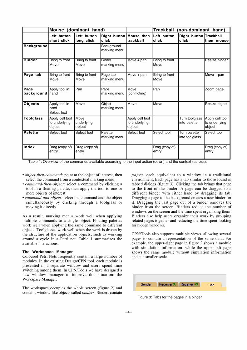
Figure 3: Tabs for the pages in a binder
Mouse (dominant hand) Trackball (non-dominant hand)Left button short click
Left button long click
Right button click
Mouse then trackball
Left button click
Right button click
Trackball then mouse
Background Background marking menu
Binder Bring to front Move
Bring to front Move
Binder marking menu
Move + pan Bring to front Move
Resize binder
Page tab Bring to front Move
Bring to front Move
Page tab marking menu
Move + pan Bring to front Move
Move + pan
Page background
Apply tool in hand
Pan Page marking menu
Move (conflicting)
Pan Zoom page
Objects Apply tool in hand Select text
Move Object marking menu
Move Move Resize object
Toolglass Apply cell tool to underlying object
Move underlying object
Apply cell tool to underlying object
Turn toolglass into palette
Apply cell tool to underlying object
Palette Select tool Select tool Palette marking menu
Select tool Select tool Turn palette into toolglass
Select tool
Index Drag (copy of) entry
Drag (copy of) entry
Drag (copy of) entry
Drag (copy of) entry
Table 1: Overview of the commands available according to the input action (down) and the context (across).
• object-then-command: point at the object of interest, thenselect the command from a contextual marking menu;
• command-then-object: select a command by clicking atool in a floating palette, then apply the tool to one ormore objects of interest;
• command-and-object: select the command and the objectsimultaneously by clicking through a toolglass ormoving it directly.
As a result, marking menus work well when applyingmultiple commands to a single object. Floating paletteswork well when applying the same command to differentobjects. Toolglasses work well when the work is driven bythe structure of the application objects, such as workingaround a cycle in a Petri net. Table 1 summarizes theavailable interactions.
The Workspace ManagerColoured Petri Nets frequently contain a large number ofmodules. In the existing Design/CPN tool, each module ispresented in a separate window and users spend timeswitching among them. In CPN/Tools we have designed anew window manager to improve this situation: theWorkspace Manager.
The workspace occupies the whole screen (figure 2) andcontains window-like objects called binders. Binders contain
pages , each equivalent to a window in a traditionalenvironment. Each page has a tab similar to those found intabbed dialogs (figure 3). Clicking the tab brings that pageto the front of the binder. A page can be dragged to adifferent binder with either hand by dragging its tab.Dragging a page to the background creates a new binder forit. Dragging the last page out of a binder removes thebinder from the screen. Binders reduce the number ofwindows on the screen and the time spent organizing them.Binders also help users organize their work by groupingrelated pages together and reducing the time spent lookingfor hidden windows.
CPN/Tools also supports multiple views, allowing severalpages to contain a representation of the same data. Forexample, the upper-right page in figure 2 shows a modulewith simulation information, while the upper-left pageshows the same module without simulation informationand at a smaller scale.

- 5 -
Figure 4: IndexFigure 5: Toolglass for editing attributes
The left part of the workspace iscalled the index (figure 4) andcontains a hierarchical list of objectsthat can be dragged into theworkspace with either hand. Objectsin the index include toolglasses,floating palettes and Petri netmodules. Dragging an entry out ofthe index creates a view on itscontents, i.e. a toolglass, a floatingpalette or a page holding a CPNmodule.
Pages and binders do not havescrollbars. If the contents of a pageis larger than its size, it can bepanned with the left button of thetrackball, even while the right handis using the mouse to, for example,
move an object or invoke a command from a markingmenu. Getting rid of scrollbars saves valuable space butmakes it harder to tell how much of the whole document isbeing displayed. A future version will use the borders of thepage to show what portion of the document is viewed in anon-intrusive, space-saving way.
Resizing a binder and zooming the contents of a pageinvolves direct bi-manual interaction (as described above).Unlike traditional window management techniques, usingtwo hands makes it possible to simultaneously resize andmove a binder, or pan and zoom the contents of a page atthe same time. Clicking the right button of the mouse onthe page tab or on the binder pops up a contextual markingmenu with additional commands to close, collapse, expandthe page or create a new page with the same content.
Creating and Laying out ObjectsCreation tools are accessible via any of the three interactiontechniques. The user may select the appropriate object fromthe floating palette, move to the desired position and click,or use the left hand to move the toolglass to the desiredposition and click-through with the right hand, or move tothe desired location and make the appropriate gesture fromthe marking menu.
Users of Design/CPN spend a great deal of time creatingand maintaining the layout of their Petri net diagrams. Theprimary technique is a set of align commands, similar tothose found in other drawing tools. The limitation is thatthey align the objects at the time the command is invoked,but do not remember that those objects have been aligned.We observed that most users use the same pattern to movean object: They manually select all objects aligned to theobject of interest and move them as a group. Thisdramatically slows down the interaction.
In order to facilitate the alignment of objects, we haveintroduced horizontal and vertical magnetic guidelines.Guidelines are first-class objects that are created in the sameway as the elements of the Petri net model, i.e. with toolsfound in a palette/toolglass or in a marking menu.
Guidelines are displayed as dashed lines (figure 2) and aremagnetic. Moving an object near a guideline causes theobject to snap to the guideline. Objects can be removedfrom a guideline by clicking and dragging them away fromthe guideline. Moving the guideline moves all the objectsthat are snapped to it, thus maintaining the alignment. Anobject can be snapped simultaneously to a horizontal and avertical guideline.
We have designed, and will implement, additional types ofguidelines. For example, rectangular or elliptical guidelineswould make it easier to layout the cycles commonly foundin Petri nets. We also plan to support spreading ordistributing objects over an interval within a line segment,since this is a common layout technique. Adding these newtypes of guidelines may create conflicts when an object issnapped to several guidelines. One solution is to assignweights to the guidelines and satisfy the alignmentconstraints of the guidelines with heaviest weight first.Such conflicts do not exist in the current system becauseonly horizontal and vertical guidelines are available.
Editing AttributesThe tools to edit the graphical attributes of the CPNelements are grouped in a palette/toolglass that containsfive rows (figure 5): two rows of color swatches, a row oflines with different thicknesses, a row of lines with differentdash patterns and a row for user-defined styles. The first fourrows are fairly standard and are not described further here.
Tools in the last row correspond to the reification of groupsof graphical attributes into styles. Initially, each tool inthis row is a style picker. Applying this tool to an objectcopies the object's color and thickness into the tool andtransforms the tool into a style dropper. Applying a styledropper to an object assigns the tool's color and thicknessto that object. Applying a style dropper to the backgroundof the page empties it and turns it into a style picker. If thisis done by mistake, the undo command restores its previousstate. In practice, style pickers and style droppers make itvery easy and efficient for users to define the styles they usemost often and apply them to objects in the diagram.

- 6 -
Figure 6: Simulation information
Figure 7: Simulation control panel
In Version 2 objects will remember which style theybelong to (like in, e.g., Microsoft Word) and it will bepossible to edit the attributes of a style in the toolglassitself. This will affect all the objects that use this style,saving repetitive editing.
Simulation toolsOnce a CPN model has been created, the developer runssimulations to validate it. CPN/Tools uses the newsimulator developed by the University of Aarhus CPNgroup [8], which is up to 1000 times faster than theprevious one used by Design/CPN. The simulator runs as aseparate process and communicates with the tool over aTCP/IP network connection.
CPN/Tools displays simulation information in asimulation layer that can be added to any page via any ofthe three interaction techniques. When the simulation layeris active (figure 6), the background color of the pagechanges, the number of tokens are displayed as small greendisks, the token colors are displayed as yellow textannotations, and enabled transitions are displayed with agreen halo. Each of these types of feedback can be toggledon or off using the tools in the simulation palette ortoolglass (figure 7, top row).
Running the simulation involves compiling the net intoML code based on the structure of the net and the textinscriptions. This may result in syntax errors (duringcompilation) and run-time errors (during the simulationitself). In both cases, error messages are displayed as red"bubbles" next to the location of the error. The object thatcaused the error has a red halo. Since the error may occur ina page that is not on top, the red halo also appears in thetab of any page that has an error.
CPN/Tools uses a video tape player metaphor to control thesimulation (figure 7, bottom row). Next frame lets the userselect a transition to fire. Play randomly fires enabledtransitions until a deadlock is reached or the user hits thestop button. Fast-forward runs the simulation at full speedfor a maximum number of steps set by the user, displayingonly the final state. Rewind resets the net to its initial
state. The Next frame command is polymorphic: If appliedto an enabled transition, it fires that transition. If applied toa page, it fires a randomly-selected transition within thepage. If applied to a binder or to the workspace, it fires arandomly-selected transition within the pages of the binderor the whole model, respectively.
Our user studies showed that users are either interested inthe results of the simulation, and thus do not want tochange the underlying diagram, or they are interested inediting the diagram and usually do not need the results ofthe simulation. Therefore, in our design, a diagram cannotbe edited in a page while the simulation layer is active,which makes it easier to adjust the location of thesimulation feedback. The user can always edit theunderlying diagram in a different page with the simulationlayer turned off (figure 2).
DESIGN PRINCIPLESGraphical user interfaces can be broadly defined asconsisting of graphical objects and commands. Graphicalobjects are represented on the screen and commands can beapplied to create, edit and delete them. The perceived "ease-of-use" of an interface depends upon many factors, includingthe effectiveness of the visual representation, thecompleteness of the command set and the support forefficient patterns of use.
We have developed three principles that address the issuessurrounding objects, commands and patterns of use:
• Reification extends the notion of what is an object;• Polymorphism extends the power of commands with
respect to these objects; and• Reuse provides a way to capture and reuse patterns of use.
ReificationReification is the process by which concepts are turned intoobjects. For example, in a graphical editing tool, theconcept of a circle is represented as an image of a circle in atool palette: it is reified into a tool. Reification thereforecreates new objects that can be manipulated by the user.
Instrumental Interaction [2] extends the principles of DirectManipulation [16] by reifying commands into interactioninstruments. An interaction instrument is a mediatorbetween the user and objects of interest: the user acts on theinstrument, which in turn acts on the objects. This reflectsthe fact that, in the physical world, our interaction witheveryday objects is mediated by tools and instruments suchas pens, hammers or handles. The menu items, toolbuttons, manipulation handles and scrollbars seen in today'suser interfaces are examples of interaction instruments. A

- 7 -
scrollbar, for example, is both a visible object on the screenthat can be manipulated by the user and also a command theuser manipulates to scroll the document.
Another example of reification is the notion of style: In atext editor such as Microsoft Word, a style is a collection ofattributes describing the look of a text in a paragraph, e.g.,the font and margins. The user can create and edit styles andapply them to paragraphs. Styles thus become first-classobjects for the user. Instruments may also operate on otherinstruments. For example, in some user interfaces, menusand toolbar buttons can be reconfigured to tailor theinterface: they become objects that can be manipulated by(meta-)instruments.
CPN/Tools uses reification in various ways. Allcommands, whether in a marking menu, palette ortoolglass, are instruments. As described below, this is alsoreflected in the implementation. Version 2 will supportextensive customization by including additional instrumentsto operate on the instruments in the palettes andtoolglasses. Also, the notion of group is reified in variousways. Magnetic guidelines represent a group of alignedobjects, reifying the notion of alignment. Styles reifygroups of graphical attributes to be applied to other objects.Binders reify groups of pages to be manipulated together.
PolymorphismPolymorphism is the property that enables a singlecommand to be applicable to objects of different types.Polymorphism allows us to maintain a small number ofcommands, even as reification increases the number ofobject types. This property is essential if we want to keepthe interface simple while increasing its power.
Most interfaces include the polymorphic commands cut,copy and delete, which can be applied to a wide variety ofobject types, such as text, graphics, files or spreadsheetcells. Undo and redo can also be considered polymorphic tothe extent that they can be applied to different commands.
Applying a command to a group of objects involvespolymorphism at two levels. First, most commands thatapply to an object can also be applied to a group of objectsof the same type by applying them to each object in thegroup. Second, such commands can also be applied to aheterogeneous group of objects, i.e. objects of differenttypes, as long as they have meaning for each of theindividual object types.
CPN/Tools uses polymorphism in two ways. First, manyinstruments are polymorphic, i.e., they work with differenttypes of objects. The best example is the "move"instrument used to move objects by direct manipulation: itworks with index entries, binders, pages, places,transitions, arc bendpoints, text items, etc. Second, manyinstruments apply to groups of objects as well as individualobjects. In some cases, the effect is to operate on all objectsin the group. For example, applying a style or graphicalattribute to a guideline affects all the objects attached to theguideline rather than the guideline itself. In other cases, the
effect is to select one object in the group and apply thecommand to it. For example, the "next-frame" simulationtool fires a single transition. When applied to a page orbinder, it randomly selects a single transition in the page orset of pages in the binder and fires it.
ReuseReuse can involve previous input, previous output or both.Input reuse makes previously-provided user input availablefor reuse in the current context. For example, the redocommand lets users repeat complex input strings withouthaving to retype them. Output reuse makes the results ofprevious user commands available for reuse. For example,duplicate and copy-paste let users avoid re-creating complexobjects they have just created.
Polymorphism facilitates input reuse because a sequence ofactions can be applied in a wider range of contexts if itinvolves polymorphic commands. Reification facilitatesoutput reuse by creating more first-class objects in theinterface which are then available for reuse. Thus, forexample a Microsoft Word user can create a new styleobject by reifying the style of an existing paragraph or byduplicating an existing style object, modifying the copy andreapplying it. A more elaborate form of reuse obtains whennew styles are created through inheritance from an existingstyle, which allows changes made in the reused object to bepropagated to the edited copies.
Macros, such as those found in Microsoft Excel, illustratethe power of combining these three design principles. Theuser begins by telling the system to "watch" as a sequenceof commands is performed. Reification enables the user tocapture the particular pattern of use as a sequence ofcommands that can be applied as a single new command toa new set of objects.
The current version of CPN/Tools has limited support forreuse. Some commands can be undone/redone, and the stylepicker/dropper makes it possible to reuse the set ofattributes of an object for other objects. Version 2 willincorporate more advanced facilities, including macros thatwill be available as regular tools in palettes and toolglasses.
IMPLEMENTATIONImplementing CPN/Tools required that we started fromscratch: most user interface toolkits do not support ourgraphical model (e.g. transparency and non-rectangularwindows) nor our input model (bi-manual input). Wedecided to use OpenGL [18] for output and to design and toimplement our own input management. Note that the extrahardware for bi-manual input is very inexpensive: anymouse or trackball can be used.
The choice of OpenGL was motivated by several factors.First, the performance of 3D accelerated graphics isincreasing faster than Moore's law, thanks to applicationssuch as video games driving the market, and more and moreof the rendering costs are off-loaded to the graphicshardware, saving CPU cycles. We anticipate that suchhardware, which is already inexpensive, will be standard on

- 8 -
Input
Structure
Document
Structure
Display
Structure
Abstract
Petri Net
hit detection
edit
show
notify
Figure 8: Main components of the architecture
PCs within a few years. Second, OpenGL is a standard API,implemented by many vendors on the three main platformsin use today : Windows, MacOS and Unix. This will makeit easier to support Design/CPN on these platforms. Third,OpenGL has a sophisticated graphics model that supportstransparency, lighting and texturing. This opens the door toadvanced visual effects, which we have only started to usein CPN/Tools.
The system architecture is depicted in figure 8. TheDocument Structure holds a set of Abstract Documents thatrepresent all persistent data in the system. The AbstractPetri Net is the part that represents the CPN diagrams andinterfaces with the CPN simulator. The simulator runs as aseparate process and is not covered in this description. TheDisplay Structure is used for rendering the documentstructure and for hit detection. The Input Structure managesthe interaction instruments that edit the documents.
The Document StructureAbstract documents represent the persistent data of thesystem, including the diagrams being loaded, the tools andtool palettes, and the configuration of the workspace. Thisstructure must be both extensible and efficient. The fileformat for storing the data in abstract documents is XML.
An abstract document is a collection of typed nodes. Thedocument maintains a classification tree so that accessingall the nodes of a given type is efficient. The nodes can alsobe organized in a graph by creating typed associationsamong them. Any other structure could be superimposed ona document. For example, a spatial index such as in Pad++[3] could be used to optimize access by the displaystructure.
Abstract documents generate notifications when nodes areadded, removed or changed. The observers of thesenotifications are the items of the display structure describedbelow as well as other nodes in the document structure. Forexample, an arc needs to know when its place or transitionis moved or destroyed.
The Display StructureThe role of the display structure is to represent what is onthe screen. It is used both by the rendering algorithm toupdate the screen and by the input structure for hitdetection. The display structure is a special scene graph,similar to those found in 3D graphics toolkits such as
Inventor [17]. Our display structure is slightly moreabstract than traditional scene graphs because we separatethe document structure from the display structure. Thereforethe document structure can be organized to suit the needs ofthe application while the display structure can be optimizedfor rendering and hit detection.
The root of the structure is a Canvas, representing thewhole screen. The Canvas contains an ordered set of Views,stacked from back to front. Views correspond roughly towindows in traditional window systems. Each view maycontain other views, for grouping. Views can be semi-transparent, i.e. the views underneath them may showthrough, and they can have any shape. This is used toimplement toolglasses.
The contents of a View is one or more Scenes, which arestacked like overlapping layers as in the multi-layer model[6]. We use different scenes to represent a single documentin order to control which parts of the document structure isvisible in a page:
• main layer: places, transitions and arcs, no textualinscriptions except the names of places and transitions;
• text layer: all text except names of places and transitions;• guidelines: magnetic guidelines for aligning objects;• simulation: tokens and messages related to the simulation• annotations: error messages, help tips, etc.
A Scene can be shared among multiple Views. Forexample, two pages may display the same diagram bysharing the main layer and the text layer. One page mayshow the guidelines layer while the other displays thesimulation layer, and each page may have its own scale.
Finally, the contents of a Scene is a set of Items. Items aremeant to be lightweight objects: they typically contain areference to the node of the document structure that theyrepresent, and some information used solely by the displayand hit detection algorithms.
The Input StructureThe input structure is based on the Instrumental Interactionmodel [2]. An interaction instrument is the association of aphysical part (the input device) and a logical part (therepresentation on the screen). An instrument operates on anode of the document structure called the target. Whenreceiving input events, an instrument provides feedback byupdating its on-screen representation and sends commandsto its target. The target responds to these commands byupdating its own state.
Instruments are easy to implement in this framework. Forexample, it took less than two hours to create a helpinstrument that works with any object in the interface(including other instruments) and that is available fromcontextual menus as well as in a tool palette.
Polymorphic instruments such as the move instrumentdescribed before are implemented as collections of"concrete" instruments that represent implementations of

- 9 -
instr.prepare(target)
Idle
Empty Tool
Waiting
Active
startTool/
chooseInstr()
devEvent/
instr.handleEvent()
timeout/
setInstr(move)
pick(tool)
drop(tool)finish
startMenu/
activateMenu(target)
devEvent/
instr.activate()
Figure 9: State machine for each hand
Empty workspace 50 - 60 fpsOne empty page 32 - 36 fps
After loading a 5 modules net:One binder with 5 pages 20-23 fpsTwo binders with 5 pages each 14-15 fpsFive binders with one page each 11-12 fpsFive binders without text layer 15-16 fps
Table 2: Frame rates measured on our referenceplatform, in frames per second (fps)
the instrument for different target types. When apolymorphic instrument is activated, it looks at the targetobject type, and activates the concrete instrument thatcorresponds to that type. For example the move instrumenthas many concrete instruments for moving places ortransitions, bend points of an arc, inscriptions, magneticguidelines, pages, binders, entries in the index, etc.
Several instruments may be ready for use at any one time.In our design, the user has instant access to up to fiveinstruments at a time:
• the tool selected in a palette and held in the right hand;• the move/pan tool accessible with a long click with the
right hand, or with a short click when no tool is selected;• the marking menu accessible with the right mouse button• the toolglass that can be moved with the left hand and
clicked-through with the right hand;• the resize/zoom tool accessible by bi-manual interaction
(left button press on the trackball and then click and dragwith the mouse).
The input manager uses two identical state machines tomanage the activation of instruments, one for each hand(figure 9). The transitions of the state machine are abstractevents generated by the input devices or the instrument. TheIdle state has two sub-states, Empty and Tool, describingwhether a tool has been selected (right hand) or a toolglasshas been picked up (left hand). The Waiting state is used todistinguish between a long click and a short click: when the200ms timeout occurs, the current instrument becomes themove instrument. The Active state corresponds to thecurrent instrument being used during a click or draginteraction. The instrument interacts with its target bysending it commands. Executing a command normallyresults in some edit of the document structure, which willbe reflected on the screen at the next redisplay. At somepoint the instrument generates a finish event and the statemachine is reset.
Since there are two state machines, one for each hand, it ispossible to execute parallel actions, e.g., moving an objectwith the right hand while panning the contents of a pagewith the left hand. For interactions that involve both hands,such as resizing and zooming, one state machine sets thestate of the other to Active (if it is Idle) and passes it itsinstrument and target. The two state machines thereforesend their respective events to the same instrument.
PERFORMANCE EVALUATIONThe data reported in this section corresponds to version 1 ofCPN/Tools, which is fully functional and has been in useby a small group of members of the CPN group for realwork for two months. Our reference platform is aHP/Kayak XW with a 500 MHz Pentium II and a VisualizeFX6 graphics card running Windows NT4. We also use asimilar PC with a Diamond FireGL 1 graphics card and aSGI Visual PC 320 for testing. CPN/Tools can also run onUnix (SGI O2) and Macintosh, but we need to improve themanagement of the secondary input device (the trackball) onthese platforms.
The system is implemented in Beta [12], a high-level,compiled, strongly-typed object-oriented language based ona single construct, the pattern, that unifies classes, objectsand methods. The implementation consists of 40000 linesof Beta code.
We have conducted a preliminary evaluation of the memoryfootprint and display rates of the system. However, wemust stress that virtually no optimization has been carriedout on this version. The memory footprint is typicallybetween 10 and 12Mb when a medium-size CPN model isloaded, compared to 7.5Mb for the former Design/CPNtool. A break-down of memory usage shows that theDocument, Display and Input structures use only 3Mb ofthe total, plus 1Mb for the texture cache. 2Mb are used bythe Beta runtime for garbage collection, and the remaining4Mb are used by OpenGL and the rest of the Beta run-time.While loading fonts, the Freetype engine may use up to anadditional 10Mb.
Table 2 summarizes the frame rates (number of screenredisplays per second) for typical situations on the referenceplatform. The size of the display window is 1280x1024,and all measurements are done with a semi-transparenttoolglass on the screen. As expected, the frame rates arevery stable, irrespective of what the user is doing: movingpages, panning, zooming, etc.
The Visual PC 320 gives similar frame rates, while theFireGL 1 is 30% faster. Visually, frame rates of 15 framesper second or more look smooth enough for the interactiontechniques we use. A close analysis of the profilinginformation shows that up to 50% of redisplay time couldbe optimized by using the hardware more efficiently. Also,profiling data shows that displaying text is time-consuming, as shown by the last two lines in the tableabove. But our choice of using OpenGL is clearly
- 10 -
successful and the increase in performance of graphics cardswill only make things better: the FireGL1 came out lessthan one year after the Visualize FX6, costs a fraction of itsprice and is 30% faster!
CONCLUSION AND FUTURE WORKWe have described the interface, design principles andimplementation of CPN/Tools and shown how it supportsa combination of advanced interaction techniques in a post-WIMP interface. Version 1 is functional and already in useby a small group of users. We are currently working on thenext version that will incorporate new features andimprovements, based on the same design principles andoverall approach.
Version 2 will feature various methods for creating andmanaging groups of objects. Groups will be specified eitherexplicitly by designating the objects in the group orindirectly through a query, e.g. to find all places that belongto a given color set. The interface will also becustomizable: users will be able to compose their ownpalettes and toolglasses and exchange them with otherusers. Styles and guidelines will be improved, and context-sensitive help will be available throughout the interface.
We are looking forward to the public release of Version 2 ofCPN/Tools to a wider group of users in the Petri Netscommunity to collect valuable feedback for the nextiteration of the design.
ACKNOWLEDGMENTSWe thank the members of the CPN group at the Universityof Aarhus for their participation in the design andevaluation activities.
This work is supported by the University of Aarhus, theDanish Centre for IT Research (CIT), Hewlett-Packard andMicrosoft Research.
REFERENCES1. Beaudouin-Lafon, M. & Mackay, W. Reification,
Polymorphism and Reuse: Three Principles forDesigning Visual Interfaces . In Proc. Conference onAdvanced Visual Interfaces, AVI 2000, Palermo, Italy,May 2000, in press.http://www.daimi.au.dk/~mbl/AVI2000
2. Beaudouin-Lafon, M. Instrumental Interaction: AnInteraction Model for Designing Post-WIMP UserInterfaces. In Proc. Human Factors in ComputingSystems, CHI'2000, ACM Press, 2000.
3. Bederson, B. & Meyer, J. Implementing a ZoomingInterface: Experience Building Pad++. SoftwarePractice and Experience, 28(10):1101-1135, August1998.
4. Bier, E., Stone, M., Pier, K., Buxton, W., De Rose,T. Toolglass and Magic Lenses : the See-ThroughInterface. In Proc. ACM SIGGRAPH, ACM Press,1993, p.73-80.
5. Casalta, D., Guiard, Y. and Beaudouin-Lafon, M.Evaluating Two-Handed Input Techniques: RectangleEditing and Navigation. ACM Human Factors InComputing Systems, CHI'99, Extended Abstracts,1999, p. 236-237.
6. Fekete, J-D. & Beaudouin-Lafon, M. Using the Multi-layer Model for Building Interactive GraphicalApplications. In Proc. ACM Symposium on UserInterface Software and Technology, UIST'96, ACMPress, p. 79-86.
7. Guiard, Y. Asymmetric division of labor in humanskilled bimanual action: The kinematic chain as amodel. Journal of Motor Behavior, 19:486-517, 1987.
8. Haag, T.B. and Hansen, T.R. Optimising a ColouredPetri Net Simulator. Master's Thesis, University ofAarhus (Denmark), December 1994.
9. Janecek, P., Ratzer, A., and Mackay, W. Petri-Nets-In-Use. In Proc. International Workshop on ColouredPetri Nets, Aarhus, Denmark, 1999.
10. Jensen, K. Coloured Petri Nets: Basic Concepts (Vol.1, 1992), Analysis Methods (Vol. 2, 1994), PracticalUse (Vol. 3, 1997). Monographs in TheoreticalComputer Science. Springer-Verlag, 1992-97.
11. Kurtenbach, G. & Buxton, W. User Learning andPerformance with Marking Menus. In Proc. HumanFactors in Computing Systems, CHI'94, ACM, 1994,p.258-264.
12. Lehrmann Madsen, O., Møller-Pedersen, B. &Nygaard, K. Object-Oriented Programming in the BetaProgramming Language, Addison-Wesley, 1993.
13. Mackay, W.E. Users and Customizable Software: ACo-Adaptive Phenomenon. Ph.D. Dissertation,Massachusetts Instititute of Technology, 1990.
14. Mackay, W.E. Triggers and barriers to customizingsoftware. In Proc. ACM Human Factors in ComputingSystems, CHI'91, ACM Press, 1991, p. 153-160.
15. Mackay, W., Ratzer, A. & Janecek, P. Video Artifactsfor Design: Bridging the Gap between Abstraction andDetail. In Proc. ACM Conference on DesigningInteractive Systems, DIS 2000, New York, August2000, in press.http://www.daimi.au.dk/~mackay/DIS2000
16. Shneiderman, B. Direct Manipulation : a Step BeyondProgramming Languages. IEEE Computer 16(8):57-69, 1983.
17. Strass, P. IRIS Inventor, a 3D Graphics Toolkit. InProc. ACM Conference on Object-OrientedProgramming, Systems, Languages and Applications,OOPSLA '93, ACM Press, 1993, p.192-200.
18. Woo, M., Neider, J. & Davis, T. O p e n G LProgramming Guide, Addison-Wesley, 1997.