Frequency-Based Controls for Terrain Editing
10
Frequency-Based Controls for Terrain Editing Gwyneth A. Bradbury * University College London Il Choi University College London Cristina Amati † University College London Kenny Mitchell ‡ Disney Research Tim Weyrich § University College London ABSTRACT Authoring virtual terrains can be a challenging task. Proce- dural and stochastic methods for automated terrain genera- tion produce plausible results but lack intuitive control of the terrain features, while data driven methods offer more cre- ative control at the cost of a limited feature set, higher stor- age requirements and blending artefacts. Moreover, artists often prefer a workflow involving varied reference material such as photographs, concept art, elevation maps and satel- lite images, for the incorporation of which there is little sup- port from commercial content-creation tools. We present a sketch-based toolset for asset-guided creation and intuitive editing of virtual terrains, allowing the manipulation of both elevation maps and 3D meshes, and exploiting a layer-based interface. We employ a frequency-band subdivision of eleva- tion maps to allow using the appropriate editing tool for each level of detail. Using our system, we show that a user can start from various input types: storyboard sketches, pho- tographs or height maps to easily develop and customise a virtual terrain. Categories and Subject Descriptors I.3.7 [Computer Graphics]: Three-Dimensional Graphics and Realism; I.3.8 [Computer Graphics]: Applications. General Terms Computer Graphics Keywords Terrain, modelling, first-person, silhouette, reference-based * [email protected] † [email protected] ‡ [email protected] § [email protected] Permission to make digital or hard copies of all or part of this work for personal or classroom use is granted without fee provided that copies are not made or distributed for profit or commercial advantage and that copies bear this notice and the full citation on the first page. To copy otherwise, to republish, to post on servers or to redistribute to lists, requires prior specific permission and/or a fee. CVMP ’14, November 13 - 14 2014, London, United Kingdom Copyright 2014 ACM 10.1145/2668904.2668944 ...$15.00. Figure 1: A user adds separate scales of fractal detail to two sketched ridges using our toolset. From top: high frequency noise applied to the left ridge, low frequency to the right; low frequency noise applied to the left ridge, high frequency to the right; lower levels of medium frequency noise applied to both features. Red marker indicates camera position. 1. INTRODUCTION Applications requiring virtual terrain include films, an- imation, games, landscape visualisation and flight simula- tions. Modelling terrain is a challenging task due to the char- acteristics of natural landscapes. At a macro level, terrains present distinctive geological features such as height, shape, and distribution of roughness, but at micro level they can become increasingly stochastic. This makes manual mod- elling by simply extruding elevation meshes a difficult task. Existing solutions for terrain generation and editing can be condensed into 2D methods and 3D methods. 2D meth- ods rely on the representation of terrain as a height map, essentially an image. Thus, common image processing oper- ations such as texture synthesis, blending and compositing can be applied to create a height map that corresponds to user specifications. The shortcomings of these methods con- sist of: the limitation of terrain features to the ones present
Transcript of Frequency-Based Controls for Terrain Editing

Frequency-Based Controls for Terrain Editing
Gwyneth A. Bradbury∗
University College LondonIl Choi
University College LondonCristina Amati
†
University College London
Kenny Mitchell‡
Disney ResearchTim Weyrich
§
University College London
ABSTRACTAuthoring virtual terrains can be a challenging task. Proce-dural and stochastic methods for automated terrain genera-tion produce plausible results but lack intuitive control of theterrain features, while data driven methods offer more cre-ative control at the cost of a limited feature set, higher stor-age requirements and blending artefacts. Moreover, artistsoften prefer a workflow involving varied reference materialsuch as photographs, concept art, elevation maps and satel-lite images, for the incorporation of which there is little sup-port from commercial content-creation tools. We present asketch-based toolset for asset-guided creation and intuitiveediting of virtual terrains, allowing the manipulation of bothelevation maps and 3D meshes, and exploiting a layer-basedinterface. We employ a frequency-band subdivision of eleva-tion maps to allow using the appropriate editing tool for eachlevel of detail. Using our system, we show that a user canstart from various input types: storyboard sketches, pho-tographs or height maps to easily develop and customise avirtual terrain.
Categories and Subject DescriptorsI.3.7 [Computer Graphics]: Three-Dimensional Graphicsand Realism; I.3.8 [Computer Graphics]: Applications.
General TermsComputer Graphics
KeywordsTerrain, modelling, first-person, silhouette, reference-based
∗[email protected]†[email protected]‡[email protected]§[email protected]
Permission to make digital or hard copies of all or part of this work forpersonal or classroom use is granted without fee provided that copies arenot made or distributed for profit or commercial advantage and that copiesbear this notice and the full citation on the first page. To copy otherwise, torepublish, to post on servers or to redistribute to lists, requires prior specificpermission and/or a fee.CVMP ’14, November 13 - 14 2014, London, United KingdomCopyright 2014 ACM 10.1145/2668904.2668944 ...$15.00.
Figure 1: A user adds separate scales of fractal detail to twosketched ridges using our toolset. From top: high frequencynoise applied to the left ridge, low frequency to the right;low frequency noise applied to the left ridge, high frequencyto the right; lower levels of medium frequency noise appliedto both features. Red marker indicates camera position.
1. INTRODUCTIONApplications requiring virtual terrain include films, an-
imation, games, landscape visualisation and flight simula-tions. Modelling terrain is a challenging task due to the char-acteristics of natural landscapes. At a macro level, terrainspresent distinctive geological features such as height, shape,and distribution of roughness, but at micro level they canbecome increasingly stochastic. This makes manual mod-elling by simply extruding elevation meshes a difficult task.
Existing solutions for terrain generation and editing canbe condensed into 2D methods and 3D methods. 2D meth-ods rely on the representation of terrain as a height map,essentially an image. Thus, common image processing oper-ations such as texture synthesis, blending and compositingcan be applied to create a height map that corresponds touser specifications. The shortcomings of these methods con-sist of: the limitation of terrain features to the ones present

Figure 2: Example reference collection for constructing adesert terrain, including photographs and digital elevationmap. (Moodboard drawn from Pure, courtesy of Disney.)
in the input height maps (if the method is data-driven);speed and computation time; high storage requirements, anddifficulty in editing once the new terrain map has been gen-erated.
3D methods can be procedurally-based or manual. Pro-cedural methods rely on different types of noise to createrich and plausible results, but are difficult to control at afeature level, and any modification requires the whole ter-rain to be re-generated from scratch. Interactive methodscan be found in software packages such as Mudbox [Aut14b],ZBrush [Pix14] or Maya [Aut14a] which offer the user com-plete freedom to sculpt a mesh to their desire. However,this is a lengthy and daunting process and can often resultin implausible terrains due to lack of high frequency detail.
In practice, artists resort to a manual, example-based ap-proach where inspiration and references are collected fromthe real world in various formats. These can include photog-raphy, elevation maps, satellite images or concept sketches- both digital or hand drawn. Figure 2 shows a moodboardused for video game production which gathers all these re-sources. It is important to note that the majority of re-sources are in fact 2D as the acquisition of 3D material fromnature is non-trivial. Maclean [Mac11] describes traditionalartistic workflows for collaborative scene and animation de-velopment which depend heavily on sketched scenes. With-out mixed-media methods such as ours, which allow 2D ref-erence materials and sketches to be converted into 3D assets,these esteemed artistic workflows are at risk of being lost.
To meet the need of artists to work with multiple inputtypes and also to offer great editing flexibility, we have cre-ated a terrain generation and editing framework that seam-lessly combines 2D and 3D workflows. Users can start eitherfrom 2D artwork, elevation maps or randomly generatedfractal terrain. The elevation map and the corresponding3D mesh are both editable using various sets of operationsdetailed in Section 4 and offer immediate visual feedback.
Different tools are best applied at different scales: creationof large-scale features can be fully artist-directed using in-teractive 3D methods, whereas creation of small-scale detailis a tedious task when carried out by hand and is best dealtwith by noise generation. We provide the separation into
high-, mid- and low-frequency bands of the terrain and al-low individual editing of each frequency band.
We borrow from image editing paradigms the concept oflayers and apply each new heightfield editing operation ina distinct layer. We extend this layer view to include threesub-layers which show, respectively, the high-, medium- andlow-frequency bands of the image This offers additional flex-ibility in handling content.
Our contributions to terrain generation and editing in-clude: extending the concept of layered image editing byincorporating frequency-controlled sub-layers; support formultiple input types to assist in initial terrain creation andcreative guidance, and a flexible workflow with multiple toolsapplicable both to elevation maps and terrain meshes.
Our prototype system offers a set of representative op-erators that combine state-of-the-art techniques in virtualterrain manipulation.
2. RELATED WORKVirtual terrain creation has recently received more atten-
tion in the literature. Until lately, procedural techniques hadbecome the default method for terrain generation, allowinga designer to generate vast, or even infinite, landscapes withjust a few parameters. These approaches, however, com-monly suffer a lack of intuitive control over the output aswell as low level of support for editing post-generation.
Whilst procedural and noise-based approaches still havesignificant application in adding high-frequency (small scale)detail to terrain, new techniques tend towards sketch-basedor data-driven methods as well as hybrid approaches. Cloneand stamp tools are also gaining in popularity, allowingthe designer to intuitively move or stamp certain featuresonto a terrain. Sketching, similarly, is a highly intuitivemeans of content creation either in the image domain (the2D heightfield, in our case) or directly in 3D, as in many 3Dmodelling software packages such as ZBrush [Pix14], Mud-box [Aut14b], or Maya [Aut14a].
Creating plausible landscapes with sketch and sculpt toolsalone can be a demanding task, especially at small scales.This is overcome using data-driven methods which provideaccurate replication of features from real-world examples.
Procedural Terrain GenerationMethods exploiting deterministic functions such as fractalnoise, Brownian Motion [EVB10] or Perlin noise [Per85], arecapable of generating complex, highly detailed terrain on thefly. An alternative to these random methods are mid-pointdisplacement and the diamond square fractal generation al-gorithms [FFC82], which are seed-based. Other rule-basedsystems, driven by hydrology [GGG13] and erosion [PM13]models, make significant progress in imitating systems in thenatural world but are computationally complex.
Genevaux et. al. [GGG13] present an intuitive sketch-based interface for modelling terrain via hydrology concepts.The user starts with a simple sketch but thereafter must tuneparameters for final terrain generation according to prefer-ence. Whilst the algorithm is efficient, allowing for real-timeuse, and produces plausible terrain, parameter control is stillhigh level and the user lacks fine control over the result.
Although many procedural algorithms suffer from unin-tuitive, parametric control, with little visual correlation be-tween the input values and the output terrain, these meth-ods remain a good starting point for terrain modelling and

are exploited in commercial tools such as Terragen [Pla14]and Vue [E-o14]. Smelik et al. [SDKT∗09] give a thoroughoverview of procedural terrain modelling approaches.
Example-Based Terrain GenerationParberry [Par13] presents an approach to iteratively adaptprocedurally generated heightfields to resemble a real-worlddigital elevation map using histogram matching. This is fastand efficient but does account for the variety of localisedterrain features. One further data-driven method is texturesynthesis [EL99, EF01, LH05], which is appropriate for con-tent creation and editing of 2D elevation maps.
Example-based texture synthesis solutions exploiting asketch-based user interface for guidance are also becomingmore prominent [ZTR07, TGM12, dPI13]. Texture synthe-sis is commonly guided by a user sketch depicting wherecertain features should occur and patches are merged us-ing blending in the gradient domain [PGB03]. This allowsthe user to focus on low frequency (large scale) features ofterrain with finer details obtained from the input patches.
Patch-based methods rely on having the required outputsufficiently well represented by the input data. If a featuredoes not exist in the source data, it cannot be reproducedin the target terrain. High complexity and storage require-ments (see [TGM12, BMV∗11]) can also be problematic, aswell as the need to perform a correspondence search in ahigh dimensional space.
Sketch-based Landscape ManipulationAn intuitive way to add new landscape features is by sketch-ing. This can be done either in the image domain on the ele-vation maps or directly in 3D, as in many 3D modelling soft-ware packages such as ZBrush [Pix14], Mudbox [Aut14b], orMaya [Aut14a].
Belhadj and Audibert [BA05] model elevation maps basedon sketched ridge and river networks. There, ridges arecreated by modelling a Gaussian cross-section over a user-sketched baseline. The base of the ridge is considered tobe flat on the ground plane. Gain et al. [GMS09] showa more detailed user interaction for ridge sketching, basedon parametrised curves drawn onto a base plane. The userdraws the ridge profile while the system approximates thebase with an editable ellipse and then generates geologicalfeatures to fit the silhouette and boundary.
Other sketch-based methods have also been developed (see[BKST10, Sme11]), allowing sketching of the overall terrainconstraints which is then filled with procedural geometry.While these approaches yield impressive results, once the ge-ometry is generated there are no more possibilities of furtherediting the output. Furthermore, these are constraint-basedapproaches and do not support fine-grain user interaction.
Many sketch-based solutions are limited by the unintu-itiveness of the user interface. Passos and Igarashi [dPI13]draw attention to this, stating that an artist (either naive orexperienced) will have a natural tendency to draw the sil-houettes of the landscape, as if painting it from a first-personperspective point of view, rather than the typical birds-eyeview many algorithms require. Their algorithm is limitedby the quality and scope of input data but gives the usera much more intuitive control over the final terrain. Tasseet. al. [TEC∗14] also present a first-person, sketch-based in-terface which allows easy personalisation of a landscape bydeforming the terrain to match the user’s sketch exactly.
Our ridge creation tool, described in Section 4.2, is stronglyinspired by these sketch-based interfaces, and incorporatesfurther flexibility by allowing the user to set the perspectivemapping of the sketch canvas. This allows better supportfor input references which may use different, and potentiallyunrealistic, perspectives.
We see this introduced capability as an important bridgeto recovering traditional artistic workflows which employ di-rect transfer of ‘flats’ or ‘plates’ to layered scene depictionwith studied depth and composition [Mac11], from which weprovide a path to fully generated 3D terrain relief edits.
Compositing and EditingTypical texture synthesis approaches are designed to workwell in image applications but require special treatment forterrain generation as they tend to leave seams along patchboundaries. This problem of seamless blending is most poi-gnant in the gradient domain. Dos Passos and Igarashi[dPI13], for example, apply a weighted sum of heights acrosspatch boundaries. This type of method produces artefacts inthe gradient domain which are only noticeable as the viewermoves through the scene [TGM12, PGB03, ZTR07].
Common solutions for seamless blending are Poisson im-age editing [PGB03] and Shepard Interpolation [She68], butthey have proven to be too slow for real-time applications[TGM12, ZTR07]. Our work employs Laplacian blending[BEA83] which is faster and ensures continuity across seams.
Gradient blending is also useful when features overlap,which is likely to happen when the user sketches edits ontoan existing terrain map. Vemuri et al. [VML97] blend newfeatures into the original terrain by treating them as splinesurfaces and applying a fractal to the surface to add terrain-like noise.
Jenny et. al. [BHL11] present a means of attenuating andamplifying certain spatial frequencies of a terrain using aLaplacian pyramid. Their slider-based interface is used toclean cartographic data for visualisation and generalises ter-rain whilst maintaining its characteristics. The tool targetsonly accentuation of geographical features and noise reduc-tion rather than creative control.
3. FRAMEWORK AND INTERFACEOur proposed system consists of sketch-based terrain cre-
ation and editing tools with various degrees of automationand manual control which, in combination, facilitate a work-flow for custom terrain creation.
The interface to our system provides the user with aerialand perspective views of the developing terrain. Concur-rent views update in real time during each edit. The aerialview consists of the 2D elevation map of the terrain and theperspective view shows the corresponding 3D mesh.
Using a 2D elevation map representation for terrain allowsour tools to exploit common image processing operations(e.g. cut, copy and paste), as well as layer-based editing.
The layers panel shows the original heightfield as the baselayer and each new modification as a sub-layer (see Fig-ure 3). Layers can then be merged or deleted, allowing for anon-destructive editing pipeline as seen commonly in imageediting software such as Adobe’s Photoshop [Ado14] and theGNU Image Manipulation Program [The14]. This is furtherdescribed in Section 3.2.
Rather than combining layers using alpha-blending, oursystem features gradient-domain blending, applied in real-
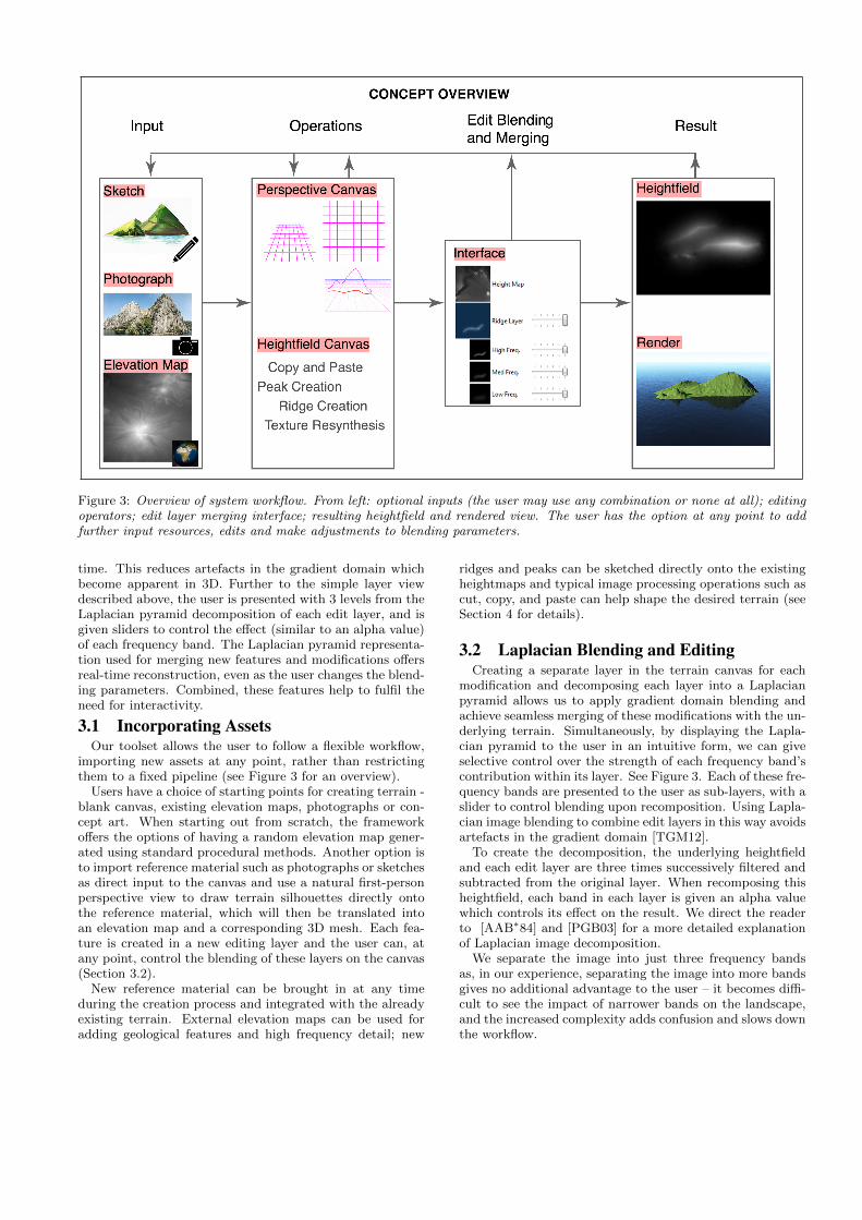
Figure 3: Overview of system workflow. From left: optional inputs (the user may use any combination or none at all); editingoperators; edit layer merging interface; resulting heightfield and rendered view. The user has the option at any point to addfurther input resources, edits and make adjustments to blending parameters.
time. This reduces artefacts in the gradient domain whichbecome apparent in 3D. Further to the simple layer viewdescribed above, the user is presented with 3 levels from theLaplacian pyramid decomposition of each edit layer, and isgiven sliders to control the effect (similar to an alpha value)of each frequency band. The Laplacian pyramid representa-tion used for merging new features and modifications offersreal-time reconstruction, even as the user changes the blend-ing parameters. Combined, these features help to fulfil theneed for interactivity.
3.1 Incorporating AssetsOur toolset allows the user to follow a flexible workflow,
importing new assets at any point, rather than restrictingthem to a fixed pipeline (see Figure 3 for an overview).
Users have a choice of starting points for creating terrain -blank canvas, existing elevation maps, photographs or con-cept art. When starting out from scratch, the frameworkoffers the options of having a random elevation map gener-ated using standard procedural methods. Another option isto import reference material such as photographs or sketchesas direct input to the canvas and use a natural first-personperspective view to draw terrain silhouettes directly ontothe reference material, which will then be translated intoan elevation map and a corresponding 3D mesh. Each fea-ture is created in a new editing layer and the user can, atany point, control the blending of these layers on the canvas(Section 3.2).
New reference material can be brought in at any timeduring the creation process and integrated with the alreadyexisting terrain. External elevation maps can be used foradding geological features and high frequency detail; new
ridges and peaks can be sketched directly onto the existingheightmaps and typical image processing operations such ascut, copy, and paste can help shape the desired terrain (seeSection 4 for details).
3.2 Laplacian Blending and EditingCreating a separate layer in the terrain canvas for each
modification and decomposing each layer into a Laplacianpyramid allows us to apply gradient domain blending andachieve seamless merging of these modifications with the un-derlying terrain. Simultaneously, by displaying the Lapla-cian pyramid to the user in an intuitive form, we can giveselective control over the strength of each frequency band’scontribution within its layer. See Figure 3. Each of these fre-quency bands are presented to the user as sub-layers, with aslider to control blending upon recomposition. Using Lapla-cian image blending to combine edit layers in this way avoidsartefacts in the gradient domain [TGM12].
To create the decomposition, the underlying heightfieldand each edit layer are three times successively filtered andsubtracted from the original layer. When recomposing thisheightfield, each band in each layer is given an alpha valuewhich controls its effect on the result. We direct the readerto [AAB∗84] and [PGB03] for a more detailed explanationof Laplacian image decomposition.
We separate the image into just three frequency bandsas, in our experience, separating the image into more bandsgives no additional advantage to the user – it becomes diffi-cult to see the impact of narrower bands on the landscape,and the increased complexity adds confusion and slows downthe workflow.

4. REPRESENTATIVE TOOLBOXOur system also includes typical image processing tools
such as cut, copy and paste as well as more complex tools:a first-person sketching canvas for tracing features from arange of reference types; texture synthesis for adding detail,and peak and ridge creation. Some of these are based onexisting techniques and outlined below. Figure 3 puts thesetools in the context of our system workflow.
- 255
- 128
- 0
Figure 4: Ridge creation interface: bottom left, user sketchesthe base of the new ridge onto the heightfield; top, user setsthe profile of the new ridge; bottom centre, before the newridge base profile is created; bottom right, the new ridgeblended into the canvas.
4.1 Silhouette Sketching from Concept ArtIn practice, reference material can come from a host of
different sources. Scouts bring back photographic referencesusing different camera set-ups whilst other artists createsketches and virtual mock-ups with a loose (and sometimesunrealistic) interpretation of perspective. Merging the dif-ferent perspective transformations captured by these sourcesthen becomes non-trivial using a sketch-based interface suchas [dPI13].
A further contribution of our system is a means of mit-igating the effect of these different perspective settings byallowing the user control over them in the sketching canvas.We provide a first-person perspective canvas, allowing theuser to sketch ridge features and see them appear in 3D onthe terrain.
In order to deal with a wealth of reference material, wegive the user intuitive control over the perspective mappingbetween first-person canvas and terrain. To aid in setting upthe perspective canvas, a grid is overlaid onto both the per-spective canvas and the corresponding 2D heightfield canvas,indicating the perspective mapping of the virtual groundplain. The user then adjusts this mapping by dragging thehorizon line and outer grid lines until the grid’s perspectivecorresponds with their interpretation of the image (Figure 3:‘Perspective Canvas’).
When terrain is sketched in the 3D perspective environ-ment, the new feature’s position is immediately transformedonto the heightfield simply by solving the homography be-tween the adjusted base plane and the 2D heightfield. Itselevation is inversely proportional to the depth of its corre-sponding position on the ground plane.
4.2 Peak and Ridge Creation
We allow the user to add peaks on top of the existingterrain. Once the base has been outlined, the height of adesired peak is set and a Gaussian-shaped peak of respectiveheight and standard deviation is added to the terrain. Thispeak can then be further modified, by interactively changingskewness and kurtosis, and by tracing its profile in a cross-sectional view. Finally, it is blended with the surroundingenvironment using a Laplacian pyramid
As an alternative means of ridge creation, we allow theuser to first sketch a ridge line directly onto the heightfieldand then sketch the height profile (Figure 4). The new ridgefeature is dynamically placed onto the terrain as it is created.The resulting features create a new layer and, by default,affect only the low-frequency content of the terrain. Higherfrequencies are taken from the original terrain.
4.3 Texture TransferTexture transfer is a broad term encompassing the way
our system deals with copy and paste operations. Whencopying and pasting terrain (either from the current can-vas or from an external source), we use gradient blendingto merge the two areas, taking the highest gradient pixelfrom either region. As a result, the output terrain preservescharacteristics from both the source and destination and ismerged seamlessly. By using the frequency decompositionin the layer view, the user can adjust the effect the pastedregion has on the existing terrain, choosing to discard detailsat high, medium or low frequency as desired.
This feature is important for adding detail to terrain fea-tures created by sketching. The sketched feature corre-sponds to low frequency features in the terrain but in orderfor the terrain to appear plausible (and not smooth), highfrequency detail must somehow be added. Our tool allowsthe user to choose detail they like from other sources andincorporate this into the scene. Figure 5 shows an exam-ple of pasting detail onto a new feature. Figure 6 showswhat happens when low frequencies in the pasted region arediscarded.
4.4 Texture SynthesisWe use a modified texture synthesis algorithm for hole
filling when a region is cut from the terrain which is basedon image quilting. For this purpose, we must not only con-sider constraints on neighbouring pixels but also enforce ini-tial boundary constraints. Traditional scan-line approachesleave artefacts at the boundaries where residual error frompatch matching accumulates. Ideally, this error should beevenly distributed across the synthesised region and, there-fore we employ a spiralling technique to achieve this goal.
In informal requirements discussion with artists, we re-ceived the request that the system should offer multiple ver-sions of auto-generated terrain, so the artist can pick a suit-able instance. This is in line with the need for more variationfor enforcing naturalness and plausibility of the terrain. Ac-cordingly, we synthesise the new region three times, and letthe user choose their preferred result (see Figure 7). Wethen allow the user to again resynthesise the region again,using the previously preferred result as a starting point, pre-serving its structure but providing further variations. Theprocess can be repeated or restarted as desired and the re-sult is then blended into the original heightmap. Figure 7shows an example result.

Figure 5: Adding texture to a new, initially smooth, sketchedfeature: before (left) and after (right).
Figure 6: Changing the frequency of detail transferred. Left,only high frequency detail is transferred; right, all detailtransferred.
Figure 7: Using texture synthesis for hole filling. Left, theoriginal terrain, a patch is selected for resynthesis basedon the rest of the terrain, center, the user chooses one ofthree possible results, which is again resynthesised. The fi-nal choice is merged into the terrain.
5. RESULTSOur results demonstrate how the user may successfully
turn concept artwork including photographs and digital sketchesinto virtual terrain. The resulting terrain geometry was cre-ated using our system and rendered using Planetside’s Ter-ragen 3 [Pla14].
Frequency band decomposition in the layer view of thescene proves useful for the user for transfer of high frequencydetail from an external source onto the terrain. Results us-ing this tool can be seen in Figures 11 and 10, demonstratingthe change in terrain as the user adjusts the effect of eachof two of our three frequency bands.
Figure 9 (a,b) uses a photograph as input to the system.The user gradually builds up terrain features by setting theperceived perspective of the input and sketching onto theperspective canvas. Figures 9 (c,d,e) demonstrate a similarresults, using a digital sketch as input. Figure ?? demon-strates how different viewpoints can be combined using theperspective sketching interface. The user sketches the first
ridge (top left in the figure), rotates the aerial canvas, anddraws a second (top, centre), intersecting ridge. High fre-quency detail is added to the resulting terrain (top right).Figure 8 further demonstrates the use of our supportingtools. Features are created on the aerial canvas as well asbeing copied from external terrain - elevation maps of boththe Grand Canyon and Mount Everest are used to providefeatures. Blending is seamless for all editing operations.
6. CONCLUSIONResults show that our system allows virtual terrain to be
designed from concept art using a non-rigid work-flow whichincorporates reversible, unordered, and non-destructive edit-ing phases. The resulting heightfields can be edited using asketch-based interface. We demonstrate a layering systemwhich allows tuning of coarse to fine levels of detail with-out inhibiting creative direction. Frequency-selective controlover the merging of terrain edits allows to tune individualoperators after their application.
Using our system, access to these levels of detail is straight-forward and displayed to the user in three frequency bands.The user can mix these bands and apply different edits toeach, as desired. To carry out a similar edits in commercialediting tools is a non-trivial process. There is no direct ac-cess to frequency bands of an image and so the user wouldneed to manually convolve and subtract image layers.
Our tools support additional reference material which canbe incorporated at any point. We handle perspective refer-ence material (e.g. photographs or concept artwork) by al-lowing the user to set a perspective mapping using a simpleguide mesh that maps new edits on the perspective can-vas directly onto the terrain’s heightfield. This is an im-portant feature, particularly for transforming concept art,which may use unrealistic perspective mapping, into usableterrain.
Our system addresses the need to guide terrain editingwith digital assets (terrain maps, photographs, and sketchesand concept art), linking conceptual art to terrain genera-tion.
There are several directions in which our work can beextended. Colours could be adapted from the input artworkand projected onto the new terrain. Whilst this would betrivial for a single image, the user may use different conceptart at different points in the scene which would need to beblended or merged in an intelligent way. Automatic, or semi-automatic, extraction of the base layer elevation would makethe system more usable - currently the system assumes thesame base layer elevation for all input but this could varydepending on the scene. Finally, whilst our system is baseddirectly on artist requirements, it would benefit significantlyfrom wider user testing.
User feedback has been encouraging, and showed that sucha tool could be useful in the creative pipeline. However,testing has been limited and would benefit from deeper in-vestigation in future work.
AcknowledgementsThis work was supported by the UCL EngD VEIV Centrefor Doctoral Training.
7. REFERENCES

(a)
(b)
(c)
(d)
(e)
Figure 9: Example output from our system. The user starts with (a, b) a photograph, or 2D concept art (c, d) and adds noiseusing our frequency sub-layer interface. From left to right: input image, adding perspective to the canvas and sketching ridges,the generated terrain, and the corresponding heightfield. In example (d), virtual trees are added to the generated terrain forrendering. (Pure in game screenshots (c,d), courtesy of Disney).

αhigh = 0, αlow = 0 αhigh = 0, αlow = 0.5 αhigh = 0, αlow = 1
αhigh = 0.5, αlow = 0 αhigh = 0.5, αlow = 0.5 αhigh = 0.5, αlow = 1
αhigh = 1, αlow = 0 αhigh = 1, αlow = 0.5 αhigh = 1, αlow = 1
Figure 11: Adding fractal detail to a heightfield output from our perspective sketching tool (Figure 9a). Horizontally, effect asthe ‘low frequency’ slider is incremented. Vertically, effect as the ‘high frequency’ slider is incremented. for each, we show theelevation map (left) and 3D interface view (right).For each, we show the resulting elevation map, 3D view from out interfaceand the same view rendered using Terragen 3 [Pla14].

(a) (b) (c) (d) (e)
Figure 8: Workflow as the user loads a procedurally gener-ated (fractal) heightfield (a), sketches ridges and peaks (b),and adds valley and peak features from the real world dig-ital elevation maps (c, d, e). All edit operations use oursupporting tools.
[AAB∗84] Adelson E. H., Anderson C. H., BergenJ. R., Burt P. J., Ogden J. M.: Pyramidmethods in image processing. RCA Engineer29, 6 (1984), 33–41.
[Ado14] Adobe: Photoshop. www.photoshop.com/,July 2014.
[Aut14a] Autodesk: Maya. www.autodesk.co.uk/products/autodesk-maya/overview, July2014.
[Aut14b] Autodesk: Mudbox. www.autodesk.com/products/mudbox/overview, July 2014.
[BA05] Belhadj F., Audibert P.: Modelinglandscapes with ridges and rivers. In VRST(2005), Singh G., Lau R. W. H., ChrysanthouY., Darken R. P., (Eds.), ACM, pp. 151–154.
[BEA83] Burt P. J., Edward, Adelson E. H.: Thelaplacian pyramid as a compact image code.IEEE Transactions on Communications 31(1983), 532–540.
[BHL11] Bernhard J., Helen J., Lorenz H.: Terraingeneralization with multi-scale pyramidsconstrained by curvature. Cartography andGeographic Information Science 38, 1 (2011),110–116.
[BKST10] Bidarra R., Kraker K. J. d., SmelikR. M., Tutenel T.: Integrating semanticsand procedural generation: key enablingfactors for declarative modeling of virtualworlds. In Proceedings of FOCUS K3DConference on Semantic 3D Media and
Initial heightfield (left) and added ridge feature (right)
αhigh = 0, αlow = 0
αhigh = 0, αlow = 0.5
αhigh = 0, αlow = 1Figure 10: Adding a new ridge (top right) to an existingheightfield (top left). Results show the effect as the ‘low fre-quency’ slider is incremented (there is no high frequency de-tail in the new, sketched ridge feature).
Content (Sophia Antipolis, France, feb 2010),pp. 51–55.
[BMV∗11] Bernhardt A., Maximo A., Velho L.,Hnaidi H., Cani M.-P.: Real-Time TerrainModeling Using CPU-GPU CoupledComputation. In SIBGRAPI (2011), LewinerT., da Silva Torres R., (Eds.), IEEE,pp. 64–71.
[dPI13] dos Passos V. A., Igarashi T.: Landsketch:a first person point-of-view example-basedterrain modeling approach. In Proceedings ofthe International Symposium on Sketch-BasedInterfaces and Modeling (2013), ACM,pp. 61–68.
[E-o14] E-on Software: Vue.www.e-onsoftware.com/products/vue/, July2014.
[EF01] Efros A. A., Freeman W. T.: Imagequilting for texture synthesis and transfer. InProceedings of the 28th annual conference onComputer graphics and interactive techniques(New York, NY, USA, 2001), SIGGRAPH ’01,ACM, pp. 341–346.
[EL99] Efros A., Leung T.: Texture synthesis by

non-parametric sampling. In In InternationalConference on Computer Vision (1999),pp. 1033–1038.
[EVB10] Echelard A., Vehel J., Barriere O.:Terrain modeling with multifractionalbrownian motion and self-regulating processes.Computer Vision and Graphics (2010),342–351.
[FFC82] Fournier A., Fussell D., Carpenter L.:Computer rendering of stochastic models.Commun. ACM 25, 6 (June 1982), 371–384.
[GGG13] Genevaux J., Galin E., Guerin E.: Terraingeneration using procedural models based onhydrology. ACM Transactions on Graphics 32,July (2013).
[GMS09] Gain J. E., Marais P., Strasser W.:Terrain sketching. In SI3D (2009), Haines E.,McGuire M., Aliaga D. G., Oliveira M. M.,Spencer S. N., (Eds.), ACM, pp. 31–38.
[LH05] Lefebvre S., Hoppe H.: Parallel controllabletexture synthesis. In ACM SIGGRAPH 2005Papers (New York, NY, USA, 2005),SIGGRAPH ’05, ACM, pp. 777–786.
[Mac11] Maclean F.: Setting the Scene. ChronicleBooks LLC, 2011.
[Par13] Parberry I.: Designer Worlds : ProceduralGeneration of Infinite Terrain from USGSElevation Data Designer Worlds : ProceduralGeneration of Infinite Terrain from USGSElevation Data. Tech. rep., University ofNorthern Texas, 2013.
[Per85] Perlin K.: An image synthesizer. SIGGRAPHComput. Graph. 19, 3 (July 1985), 287–296.
[PGB03] Perez P., Gangnet M., Blake A.: Poissonimage editing. In ACM SIGGRAPH 2003Papers (New York, NY, USA, 2003),SIGGRAPH ’03, ACM, pp. 313–318.
[Pix14] Pixlogic: ZBrush. www.autodesk.com/products/mudbox/overview, July 2014.
[Pla14] PlanetSide: Terragen 3.www.planetside.co.uk/products/terragen3,July 2014.
[PM13] Pytel A., Mann S.: Self-organized approachto modeling hydraulic erosion features.Computers & Graphics 37, 4 (June 2013),280–292.
[SDKT∗09] Smelik R. M., De Kraker K. J., TutenelT., Bidarra R., Groenewegen S. A.: Asurvey of procedural methods for terrainmodelling. In Proceedings of the CASAWorkshop on 3D Advanced Media In GamingAnd Simulation (3AMIGAS) (2009),pp. 25–34.
[She68] Shepard D.: A two-dimensional interpolationfunction for irregularly-spaced data. InProceedings of the 1968 23rd ACM NationalConference (New York, NY, USA, 1968), ACM’68, ACM, pp. 517–524.
[Sme11] Smelik R. M.: A Declarative Approach toProcedural Generation of Virtual Worlds. PhDthesis, TU Delft, 2011.
[TEC∗14] Tasse F. P., Emilien A., Cani M.-P.,Hahmann S., Bernhardt A.: First personsketch-based terrain editing. In Proceedings ofthe 2014 Graphics Interface Conference(2014), Canadian Information ProcessingSociety, pp. 217–224.
[TGM12] Tasse F., Gain J., Marais P.: Enhancedtexture-based terrain synthesis on graphicshardware. Comp. Graph. Forum 31, 6 (sep2012), 1959–1972.
[The14] The GIMP Team: The GNU ImageManipulation Program. www.gimp.org/, July2014.
[VML97] Vemuri B. C., Mandal C., Lai S.-H.: A fastgibbs sampler for synthesizing constrainedfractals. IEEE Trans. Vis. Comput. Graph. 3,4 (1997), 337–351.
[ZTR07] Zhou H., 0004 J. S., Turk G., Rehg J. M.:Terrain synthesis from digital elevationmodels. IEEE Trans. Vis. Comput. Graph. 13,4 (2007), 834–848.