DFL: A dataflow language based on Petri nets and nested relational calculus
25
This article was published in an Elsevier journal. The attached copy is furnished to the author for non-commercial research and education use, including for instruction at the author’s institution, sharing with colleagues and providing to institution administration. Other uses, including reproduction and distribution, or selling or licensing copies, or posting to personal, institutional or third party websites are prohibited. In most cases authors are permitted to post their version of the article (e.g. in Word or Tex form) to their personal website or institutional repository. Authors requiring further information regarding Elsevier’s archiving and manuscript policies are encouraged to visit: http://www.elsevier.com/copyright
Transcript of DFL: A dataflow language based on Petri nets and nested relational calculus

This article was published in an Elsevier journal. The attached copyis furnished to the author for non-commercial research and
education use, including for instruction at the author’s institution,sharing with colleagues and providing to institution administration.
Other uses, including reproduction and distribution, or selling orlicensing copies, or posting to personal, institutional or third party
websites are prohibited.
In most cases authors are permitted to post their version of thearticle (e.g. in Word or Tex form) to their personal website orinstitutional repository. Authors requiring further information
regarding Elsevier’s archiving and manuscript policies areencouraged to visit:
http://www.elsevier.com/copyright

Author's personal copy
Information Systems 33 (2008) 261–284
DFL: A dataflow language based on Petri netsand nested relational calculus$
Jan Hiddersa, Natalia Kwasnikowskac,d, Jacek Srokab,�,1,Jerzy Tyszkiewiczb,1, Jan Van den Busschec,d
aDepartment of Mathematics and Computer Science, University of Antwerp, Antwerp, BelgiumbInstitute of Informatics, Warsaw University, ul. Banacha 2, 02-097 Warsaw, Poland
cTheoretical Computer Science Group, Hasselt University, BelgiumdTransnational University of Limburg, Belgium
Received 16 November 2006; received in revised form 13 April 2007; accepted 27 September 2007
Recommended by B. Kemme
Abstract
In this paper we propose DFL—a formal, graphical workflow language for dataflows, i.e., workflows where large
amounts of complex data are manipulated, and the structure of the manipulated data is reflected in the structure of the
workflow. It is a common extension of (1) Petri nets, which are responsible for the organization of the processing tasks,
and (2) nested relational calculus, which is a database query language over complex objects, and is responsible for handling
collections of data items (in particular, for iteration) and for the typing system. We demonstrate that dataflows constructed
in a hierarchical manner, according to a set of refinement rules we propose, are semi-sound, i.e., initiated with a single token
(which may represent a complex scientific data collection) in the input node, terminate with a single token in the output
node (which represents the output data collection). In particular they never leave any ‘‘debris data’’ behind and an output
is always eventually computed regardless of how the computation proceeds.
r 2007 Elsevier B.V. All rights reserved.
Keywords: DFL; Petri net; Workflow system; Dataflow; Scientific workflow; Nested relational calculus
1. Introduction
In this paper we are concerned with the creationof a formal language to define dataflows—DFL(a dataflow language). Dataflows are often met inpractice, e.g., in silico experiments in bioinformaticsand systems processing data collected in physics,astronomy or other sciences. Their common featureis that large amounts of structured data areanalyzed by a software system organized into akind of network, through which the data flows and
ARTICLE IN PRESS
www.elsevier.com/locate/infosys
0306-4379/$ - see front matter r 2007 Elsevier B.V. All rights reserved.
doi:10.1016/j.is.2007.09.002
$A preliminary version of this paper was presented at the 2005
International Conference on Cooperative Information Systems.�Corresponding author. Tel.: +4822 55 44 430;
fax: +4822 55 44 400.
E-mail addresses: [email protected] (J. Hidders),
[email protected] (N. Kwasnikowska),
[email protected] (J. Sroka), [email protected]
(J. Tyszkiewicz), [email protected]
(J. Van den Bussche).1Supported by KBN Grant 4 T11C 042 25.
Author's personal copy
is processed. Nodes in the network representexternal computations like web-service or localprogram calls.
There are well-developed formalisms for workflows
that are based on Petri nets [1]. However, we claimthat for dataflows these should be extended with datamanipulation aspects to describe workflows thatmanipulate structured complex values and where thestructure of this data is reflected in the structure ofthe workflow. For this purpose we adopt the datamodel from the nested relational calculus (NRC),which is a well-known and well-understood formal-ism in the domain of database theory.
Consequently, in a dataflow, tokens (which aregenerally assumed to be atomic in workflows) aretyped and transport complex data values. There-fore, apart from classical places and transitions, weneed transitions which perform operations on suchdata values. Of course, the operations are those ofthe NRC.
The resulting language can be given a graphicalsyntax, thus allowing one to draw rather than towrite programs. This seems very important for alanguage designed for users that are not profes-sional computer scientists.
Next, we can give a formal semantics fordataflows. This is crucial, since we believe thatformal, and yet executable, descriptions of allcomputational processes in the sciences should bepublished along with their domain-specific conclu-sions. Used for that purpose, dataflows can beprecisely analyzed and understood, which isimportant for: (i) debugging by the authors,(ii) effective and objective assessment of their meritby the reviewers, and (iii) clear understanding by thereaders, once published.
Moreover, the formal semantics makes it possibleto perform formal analysis of the behavior ofprograms, including (automated) optimization andverification.
We demonstrate the potential of the formalmethods by proving the following theorem, pre-sented here in an informal manner.
Theorem. Dataflow constructed hierarchically, i.e.,according to a certain set of refinement rules we
propose, is semi-sound, i.e., initiated in the input node
with a single token representing a scientific data
collection, terminate with a single token in the output
node. In particular it never leaves any ‘‘debris data’’behind and the output is always eventually computed,regardless of how the computation proceeds.
We would like to emphasize that the abovetheorem is quite general—it applies uniformlyto a very wide class of dataflows. Yet, not everymeaningful dataflow can be constructed hierarchi-cally. However, we believe that the prevailingmajority of those met in practice are indeedhierarchical.
Our idea of extending classical Petri nets is notnew in general. Colored Petri nets [2] permit tokensto be colored (with finitely many colors), and thustokens carry some information. In the nets-within-nets paradigm [3] individual tokens have Petri netstructure themselves. This way they can representobjects with their own, proper dynamics. Finally,self-modifying nets [4] assume standard tokens, butpermit the transitions to consume and produce themin quantities functionally dependent on the occu-pancies of the places.
To compare, our approach assumes tokens torepresent complex data values, which are, however,static. The transitions are allowed to performoperations on the tokens’ contents. Edges can beannotated with conditions and pass only tokenswhich values satisfy those conditions. There is also aspecial unnest/nest annotation. When unnest isapplied to an output edge of a transition, the outputtoken with a set value is transformed into a set oftokens, one for each element of the set. When nest isapplied to an input edge of a transition, the set oftokens is grouped back into a single ‘‘composite’’token.
Also the introduction of complex value manip-ulation into Petri nets was already proposed byothers. Oberweis and Sander [5] proposed aformalism called NR/T-nets where places representnested relations in a database schema and transi-tions represent operations that can be applied to thedatabase. Although somewhat similar, the purposeof that formalism, i.e., representing the databaseschema and possible operations on it, is verydifferent from the one presented here. For example,the structure of the Petri net in NR/T-nets does notreflect the workflow, but only which relations areinvolved in which operations. In our DFL formal-ism, we can easily integrate external functions andtools as special transitions and use them at arbitrarylevels of the data structures. The latter is animportant feature for describing and managingdataflows as found in scientific settings. Thereforewe claim that, together with other differences, thismakes DFL a better formalism for representingdataflows.
ARTICLE IN PRESSJ. Hidders et al. / Information Systems 33 (2008) 261–284262
Author's personal copy
An initial version of DFL and the set ofrefinement rules was presented in [6]. This paperextends that work by giving more elaborate proofsand explaining the semantics of the language inmore detail.
1.1. Nested relational calculus
The NRC [7] is a query language allowing one todescribe functional programs using collection types,e.g., lists, bags, sets, etc. The most important featureof the language is the possibility to iterate over acollection. NRC assumes a set of base types whichcan be combined to form nested record andcollection types. The only collection type we willuse are sets.
Besides standard language constructs enablingmanipulation of records and sets, NRC contains thethree constructs sng, map and flatten. For a value v
of a certain type, sngðvÞ yields the singleton setcontaining v. Operation map, applied to a functionof type t! s, yields a function on sets of typeftg ! fsg. Finally, the operation flatten, given a setof sets of type t, yields a flattened set of type t, bytaking the union. These three basic operations arepowerful enough for specifying functions by struc-tural recursion over collections [7].
Under its usual semantics the NRC can alreadybe seen as a dataflow description language, but itonly describes which computations have to beperformed and not in what order, i.e., it is ratherweak in expressing control flow. For some dataflowsthis order can be important because a dataflow caninclude calls to external functions, such as Webservices, which may have side-effects or are re-stricted by a certain protocol.
1.2. Petri nets
A classical Petri net [8,9] is a bipartite graph withtwo types of nodes called places and transitions. Thenodes are connected by directed edges. Only nodesof different types can be connected. Places arerepresented by circles and transitions by rectangles.
Definition 1 (Petri net). A Petri net is a triplehP;T ;Ei where:
� P is a finite set of places,� T is a finite set of transitions ðP \ T ¼ ;Þ,� E � ðP� TÞ [ ðT � PÞ is a set of edges.
A place p is called an input place of a transition t,if there exists an edge from p to t. A place p is calledan output place of a transition t, if there exists anedge from t to p. Given a Petri net hP;T ;Ei we willuse the following notations:
� p ¼ ftjht; pi 2 Eg; p� ¼ ftjhp; ti 2 Eg,
� t ¼ fpjhp; ti 2 Eg; t� ¼ fpjht; pi 2 Eg,
� p ¼ fht; pijht; pi 2 Eg; p� ¼ fhp; tijhp; ti 2 Eg,
� t ¼ fhp; tijhp; ti 2 Eg; t� ¼ fht; pijht; pi 2 Eg
and their generalizations for sets:
� A ¼[x2A
�x; A� ¼[x2A
x � ,
� A ¼[x2A
�x; A� ¼[x2A
x � ,
where A � P [ T . Places are stores for tokens,which are depicted as black dots inside places whendescribing the run of a Petri net. Edges define thepossible token flow. The semantics of a Petri net isdefined as a transition system. A state is adistribution of tokens over places. It is oftenreferred to as a marking M 2 P! ðN [ f0gÞ. Thestate of a net changes when a transitions fires. For atransition t to fire it has to be enabled, that is, eachof its input places has to contain at least one token.If transition t fires, it consumes one token from eachof the places in �t and produces one token on eachof the places in t�.
Petri nets are a well-founded process modelingtechnique. The interest in them is constantlygrowing for the last 15 years. Many theoreticalresults are available. One of the better studiedclasses are workflow nets, which are used in work-flow management [1].
Definition 2 (Strongly connected). A Petri net isstrongly connected if and only if for every twonodes n1 and n2 there exists a directed path leadingfrom n1 to n2.
Definition 3 (Workflow net). A Petri net PN ¼
hP;T ;Ei is a workflow net if and only if:
(i) PN has two special places: a source and a sink.The source has no input edges, i.e., �source ¼ ;,and the sink has no output edges, i.e., sink� ¼ ;.
(ii) If we add to PN a transition t� and two edgeshsink; t�i, ht�; sourcei, then the resulting Petri netis strongly connected.
ARTICLE IN PRESSJ. Hidders et al. / Information Systems 33 (2008) 261–284 263

Author's personal copy
1.3. How we combine NRC and Petri nets
In this paper we propose a formal, graphicalworkflow language for dataflows—data-centric,scientific workflows. We call the proposed languageDFL. From NRC we inherit the set of basicoperators and the type system. This should makereusing of existing database theory results easy.Dataflows could for example undergo an optimiza-tion process as database queries do. To deal withthe synchronization issues arising from processingof the data by distributed services we will use aPetri-net based formalism which is a clear andsimple graphical notation and has an abundance ofcorrectness analysis results. We believe that thesetechniques can be reused and combined with knownresults from database theory for verifying thecorrectness of dataflows which can be described inDFL.
The fundamental operation in NRC is the mapoperation map. In order to allow a similar kind ofiteration in Petri nets we introduce special unnestand nest edges. Unnest edges are outgoing edges oftransitions and nest edges are incoming edges.Unnest edges can be used if the function associatedwith the transition produces a set value. If anoutgoing edge is marked as an unnest edge then, ifthe transition fires, instead of producing in theassociated place a single token with the set that isthe result of the transition, it will produce a set oftokens, one for each element of the set. Nest edgescan be used if the function associated with thetransition requires a set value as a parameter. If an
incoming edge is marked as a nest edge then, if thetransition fires, instead of consuming from theassociated place a single token with a set value, itwill consume a set of tokens and combine them intoa single set that is used as the parameter of thefunction.
A simple example with a nested iteration is givenin Fig. 1. If the dataflow is initiated in the left mostplace with a token representing a set of sets, it willbe processed by the identity transition id andunnested. Next, the resulting tokens representingsets that were elements of the input set are unnestedthemselves by the second pair of identity transitionand unnest edge. Finally, function f ð Þ is applied toeach of the elements of the unnested subsets and theresult is twice nested by two subsequent identitytransitions with nest edges. To assure that tokensoriginating from different sets are not intermixedwhile nesting and that nesting appears only when allthe necessary tokens have arrived, each tokencarries its unnesting history, which is described inSection 4.1.
The unnest and nest edges allow a straightfor-ward representation of the NRC map operation in aPetri net formalism and make it possible to reflectthe structure of the iteration in the structure of thenet, which is desired for data-centric workflows.
2. The DFL language
We define DFL by starting with Petri nets andadding labels to transitions to define the computa-tion done by them. Then we associate NRC values
ARTICLE IN PRESS
Fig. 1. Nested iteration example.
J. Hidders et al. / Information Systems 33 (2008) 261–284264
Author's personal copy
with the tokens to represent the manipulated data.As it is usual with workflows that are described byPetri nets we mandate one special input place andone special output place. If there is externalcommunication, this is modeled by transitions thatcorrespond to calls to external functions. We useedge labeling to define how values of the consumedtokens map onto the parameters of operationsrepresented by transitions. To express conditionalbehavior we propose edge annotations indicatingconditions that the value associated with a tokenmust satisfy, so it can be transferred through theannotated edge. We also introduce a special unnest/nest annotation, to enable explicit iteration overvalues of a collection.
A dataflow will be defined by an acyclic workflownet, transition labeling, edge labeling, and edgeannotation. The underlying Petri net will be called adataflow net.
Definition 4 (Dataflow net). A DFN ¼ hP;T ;E;source; sinki is a dataflow net if and only if:
(i) hP;T ;Ei is a workflow net and is acyclic,(ii) source 2 P is the source place,(iii) sink 2 P is the sink place.
The restriction to acyclic nets is introduced tokeep the presentation of the main ideas simple. Theformalism can be easily extended such that cyclesare allowed. Usually they are used to expressiteration over all elements of a list, but for this typeof iteration we will introduce alternatives in theform of constructs for unnesting and nesting values.Obviously this does not cover all types of iteration,but we conjecture that it is sufficient for the purposeof scientific dataflows. In addition, an advantages ofthe restriction is that the termination is alwaysguaranteed, but note that termination does notensure correct termination, i.e., termination withonly one token left which is in the sink and containsthe output value.
2.1. The type system
Dataflows are strongly typed, which here meansthat each transition consumes and produces tokenswith values of a well-determined type. The type ofthe value of a token is called the token type. We willidentify a type and the set of objects of that type.The type system is similar to that of NRC. Weassume a finite but user-extensible set of basic types
which might for example be given by
bH ¼ booleanjintegerjstringjXML,
where the type boolean contains the boolean valuestrue and false, integer contains all integer numbers,string contains all strings and XML contains allwell-formed XML documents. Although this set canbe arbitrarily chosen we will require that it at leastcontains the boolean type. Assuming that the non-terminal l denotes the set of field labels, from thesebasic types we can build complex types as defined by
tH ¼ bjhl: t; . . . ; l: tijftg.
The type hl1: t1; . . . ; ln: tni, where li are distinctlabels, is the type of all records having exactly fieldsl1; . . . ; ln of types t1; . . . ; tn, respectively (recordswith no fields are also included). Finally ftg is thetype of all finite sets of elements of type t. For lateruse we define CT to be the set of all complex typesand CV the set of all possible complex values.
NRC can be also defined on other collection typessuch as lists or bags. Moreover they are included inexisting scientific workflow systems, for exampleTaverna [10] supports lists. However, after a carefulanalysis of various use cases in bioinformatics andexamples distributed with existing scientific work-flow systems we have concluded that sets aresufficient.
2.2. Edge naming function
Dataflows are not only models used to reasonabout data-processing experiments but are meant tobe executed and produce computation results. Inparticular, when a transition has several inputedges, we need a way to distinguish those, so as toknow how the tokens map onto the operationarguments. This is solved by edge labeling. Onlyedges leading from places to transitions are labeled.This labeling is determined by an edge namingfunction EN: �T ! EL (note that �T ¼ P�), whereEL is some countably infinite set of edge labelnames, e.g., all strings over a certain non-emptyalphabet. The function EN is injective whenrestricted to incoming edges of a certain transition,i.e., there cannot be two distinct incoming edgeswith the same edge label for the same transition.
2.3. Transition naming function
To specify the desired operations and functionswe also label the transitions. The transition labeling
ARTICLE IN PRESSJ. Hidders et al. / Information Systems 33 (2008) 261–284 265

Author's personal copy
is defined by a transition naming functionTN:T ! TL, where TL is a set of transition labels.Each transition label determines the number andpossible labeling of input edges as well as the typesof tokens that the transition consumes and produceswhen it fires. For this purpose the input typing andoutput typing functions are used: IT :TL! CT
maps each transition label to the input type whichmust be a tuple type, and OT :TL! CT maps eachtransition label to the output type. Note that thesetwo functions are at the global level in the sense thatthey are the same for every dataflow and thereforenot part of the dataflow itself. This is similar to thesignatures of system functions which are not part ofa specific program. For detailed specification oftransition labels see Section 3.
2.4. Edge annotation function
To introduce conditional behavior we annotateedges with conditions. If an edge is annotatedwith a condition, then it can only transporttokens that satisfy the condition. Conditions arevisualized on diagrams in UML [11] fashion, i.e.,in square brackets. Only edges leading from placesto transitions are annotated with conditions.There are four possible condition annotations:‘‘¼ true’’, ‘‘¼ false’’, ‘‘¼ ;’’, ‘‘a;’’. Their meaningis self-explanatory. For detailed specification seeSection 4.
There is another annotation ‘‘�’’ used to indicatea special unnest/nest branch. On diagrams it isvisualized by addition of the symbol ‘‘�’’ in themiddle of the edge. This annotation can occur onedges leading from transitions to places as well as onedges from places to transitions. When an edgeleading from a transition to a place is annotated insuch manner, it means that a set value produced bythis transition is unnested. That is, instead ofinserting a token with a set value into the destina-tion place, a set of tokens representing each elementin the set value gets inserted. Such edges will becalled unnest edges. When an edge leading from aplace to a transition is annotated in such manner, itmeans that in order to fire the destination transitiona set of tokens that originated from unnesting ofsome set value will be used. That is, a set of tokensthat originated from unnesting of some set valuewill be consumed and a set of their values will be aninput data for the destination transition. Such edgeswill be called nest edges. The precise semantics andexplanation of the mechanism that is used to make
sure that all the tokens that originated fromunnesting of some set value are already there isdescribed in Section 4.
The annotations are defined by an edge annota-tion function:
EA: ð�T ! f‘‘ ¼ true’’; ‘‘ ¼ false’’,
‘‘ ¼ ;’’; ‘‘a;’’; ‘‘ � ’’; egÞ
[ ð�P! f‘‘ � ’’; egÞ,
where e indicates the absence of an annotation.
2.5. Place type function
With each place in a dataflow net we associate aspecific type that restricts the allowed values fortokens in that place. This is represented by a placetype function PT :P! CT .
2.6. Dataflow
The dataflow net with edge naming, transitionnaming, edge annotation and place typing functionsspecifies a dataflow.
Definition 5 (Dataflow). A dataflow is a five-tuplehDFN ;EN;TN;EA;PTi where:
� DFN ¼ hP;T ;E; source; sinki is a dataflow net,� EN: �T ! EL is an edge naming function such
that for each transition t the partial functionENj�t is injective,� TN:T ! TL is a transition naming function,� EA: ð�T ! f‘‘ ¼ true’’; ‘‘ ¼ false’’; ‘‘ ¼ ;’’; ‘‘a;’’;
‘‘ � ’’; egÞ [ ð�P! f‘‘ � ’’; egÞ is an edge annotationfunction,� PT :P! CT is a place type function.
In order to ensure that the different labelings andannotations in a dataflow are consistent, weintroduce the notion of legality. Informally, adataflow is legal, if for each transition t: (1) theinput edge labels and the types of their correspond-ing places, with the nest edges taken into account,define the input type of t; (2) if any of the inputedges of t are annotated with conditions, then theannotations are consistent with the types of theassociated input places; (3) if an output edge of t isnot an unnest edge, then the type of the connectedplace is equal the output type of t, but if an outputedge of t is an unnest edge, then the output type of t
is a set type and the type of the connected place isequal to the element type of this set type.
ARTICLE IN PRESSJ. Hidders et al. / Information Systems 33 (2008) 261–284266
Author's personal copy
Definition 6 (Legal). A dataflow hDFN ;EN;TN;EA;PTi is legal if and only if each transition t 2 T
satisfies the following:
(1) if fhp1; ti; . . . ; hpn; tig ¼ �t and for 1pipn wehave
li ¼ ENðhpi; tiÞ and
ti ¼PTðpiÞ if EAðhpi; tiÞa‘‘ � ’’;
fPTðpiÞg if EAðhpi; tiÞ ¼ ‘‘ � ’’
(
then ITðTNðtÞÞ ¼ hl1: t1; . . . ; ln: tni,(2) for each hp; ti 2 �t:� if EAðhp; tiÞ 2 f‘‘ ¼ true’’; ‘‘ ¼ false’’g, then
PTðpÞ ¼ boolean, and� if EAðhp; tiÞ 2 f‘‘ ¼ ;’’; ‘‘a;’’g, then PTðpÞ isa set type,
(3) for each ht; pi 2 t�:� if EAðht; piÞa‘‘ � ’’, then OTðTNðtÞÞ ¼ PTðpÞ,and� if EAðht; piÞ ¼ ‘‘ � ’’, then OT ðTNðtÞÞ ¼
fPTðpÞg.
Henceforth, dataflows will always be assumed tobe legal. Legality is an easy syntactic check.
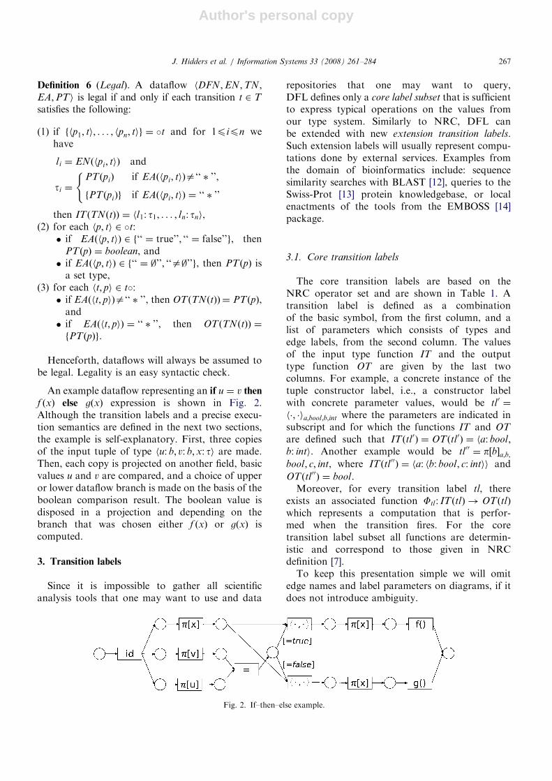
An example dataflow representing an if u ¼ v then
f ðxÞ else gðxÞ expression is shown in Fig. 2.Although the transition labels and a precise execu-tion semantics are defined in the next two sections,the example is self-explanatory. First, three copiesof the input tuple of type hu: b; v: b;x: ti are made.Then, each copy is projected on another field, basicvalues u and v are compared, and a choice of upperor lower dataflow branch is made on the basis of theboolean comparison result. The boolean value isdisposed in a projection and depending on thebranch that was chosen either f ðxÞ or gðxÞ iscomputed.
3. Transition labels
Since it is impossible to gather all scientificanalysis tools that one may want to use and data
repositories that one may want to query,DFL defines only a core label subset that is sufficientto express typical operations on the values fromour type system. Similarly to NRC, DFL canbe extended with new extension transition labels.Such extension labels will usually represent compu-tations done by external services. Examples fromthe domain of bioinformatics include: sequencesimilarity searches with BLAST [12], queries to theSwiss-Prot [13] protein knowledgebase, or localenactments of the tools from the EMBOSS [14]package.
3.1. Core transition labels
The core transition labels are based on theNRC operator set and are shown in Table 1. Atransition label is defined as a combinationof the basic symbol, from the first column, and alist of parameters which consists of types andedge labels, from the second column. The valuesof the input type function IT and the outputtype function OT are given by the last twocolumns. For example, a concrete instance of thetuple constructor label, i.e., a constructor labelwith concrete parameter values, would be tl 0 ¼
h�; �ia;bool;b;int where the parameters are indicated insubscript and for which the functions IT and OT
are defined such that ITðtl 0Þ ¼ OTðtl0Þ ¼ ha: bool;b: inti. Another example would be tl00 ¼ p½b�a;b;bool; c; int, where ITðtl 00Þ ¼ ha: hb: bool; c: intii and
OTðtl00Þ ¼ bool.Moreover, for every transition label tl, there
exists an associated function Ftl : ITðtlÞ ! OTðtlÞ
which represents a computation that is perfor-med when the transition fires. For the coretransition label subset all functions are determin-istic and correspond to those given in NRCdefinition [7].
To keep this presentation simple we will omitedge names and label parameters on diagrams, if itdoes not introduce ambiguity.
ARTICLE IN PRESS
Fig. 2. If–then–else example.
J. Hidders et al. / Information Systems 33 (2008) 261–284 267

Author's personal copy
3.2. Extension transition labels
Next to the set of core transition labels, the set oftransition labels TL also contains user-definedtransition labels. As for core transition labels thefunctions IT and OT must be defined for each ofthem, as well as an associated function Ftl : ITðtlÞ !
OTðtlÞ which can represent a possibly non-determi-nistic computation that is performed when thetransition fires.
To give a concrete example, a bioinformaticianmay define a getSWPrByAC extension transitionlabel, for which ITðgetSWPrByACÞ ¼ hac: stringi
and OTðgetSWPrByACÞ ¼ XML. The FgetSWPrByAC
function would represent a call to a Swiss-Protknowledgebase and return an XML formatted entryfor a given primary accession number.
4. Transition system semantics
The semantics of a dataflow hDFN ;EN ;TN ;EA;PTi is defined as a transition system (seeSection 4.2). Each place contains zero or moretokens, which represent data values. Formally atoken is a pair k ¼ hv; hi, where v 2 CV is thetransported value and h 2 H is this value’s unnesting
history. This unnesting history is defined in Section4.1. The set of all possible tokens is thenK ¼ CV �H. By the type of a token we mean thetype of its value, i.e., hv; hi : t if and only if v : t.
The state of a dataflow, also called marking, is thedistribution M : ðP� KÞ ! ðN [ f0gÞ of tokensover places, where Mðp; kÞ ¼ n means that place p
contains n copies of the token k. Distributions arelegal as markings only if the token types match thetypes of places their are in, i.e., for all places p 2 P
and tokens k 2 K such that Mðp; kÞ40 we musthave k : PTðpÞ.
Transitions are the active components in adataflow. They can change the state by firing, i.e.,consuming tokens from their input places andproducing tokens in their output places. In distinc-tion to classical workflow nets, transitions mayproduce/consume an arbitrary number of tokens in/from a place. This is the case when an edgeconnecting such a place with the transition isannotated with ‘‘�’’, i.e., is an unnest/nest edge. Atransition that can fire in a given state will be calledenabled. Firing of a transition t represents acomputation step determined by the functionFTNðtÞ associated with its transition label. Tokensconsumed from input places determine the compu-tation’s input value with respect to the definitions inTable 1.
4.1. Token unnesting history
Every time a transition with an unnest edge fires,a set of tokens is produced. Each token correspondsto an element of the set value that was produced as aresult of a computation carried out by thattransition. The history of each of the tokens isextended with a pair that contains the unnested setand an element of that set to which the given tokencorresponds. The full history is taken into accountwhen it is being determined whether a transitionwith nest edge can fire, that is if tokens representingall of the elements of the set that is being nested arealready there to be consumed. If it is the case, then aset of tokens will be consumed and the set of theirvalues will be used to compute the result.
This is illustrated in Fig. 3. In (a) in the top placewe see a single token with value f1; 2; 3g and an
ARTICLE IN PRESS
Table 1
Core transition labels
Sym. Parameters Operation name Input type Output type
; l; t1; t2 empty-set constr. hl: t1i ft2gf�g l; t singleton-set constr. hl: ti ftg[ l1; l2; t set union hl1: ftg; l2: ftgi ftgj l; t flatten hl: fftggi ftg� l1; t1; l2; t2 Cartesian product hl1: ft1g; l2: ft2gi fhl1: t1; l2: t2ig¼ l1; l2; b atomic-value equal. hl1: b; l2: bi boolean
h i l; t empty tuple constr. hl: ti h i
h�; �i l1; t1; . . . ; ln; tn tuple constr. hl1: t1; . . . ; ln: tni hl1: t1; . . . ; ln: tni
p½li � l; l1; t1; . . . ; ln; tn field projection hl: hl1: t1; . . . ; ln: tnii ti
id l; t identity hl: ti t
J. Hidders et al. / Information Systems 33 (2008) 261–284268

Author's personal copy
empty history. When the upper id transition fires, atoken for each element of the output value f1; 2; 3g isproduced as shown in (b). The history is extended atthe end with a pair that contains, first, the set thatwas unnested and, second, the element for whichthis particular token was produced. As is shown in(b)–(d) transitions without any unnest or nest edgewill produce tokens with histories identical to thatof the consumed input tokens. Once all the tokensthat belong to the same unnesting group havearrived in the input place of the bottom id
transition, as is shown in (d), it can fire and combinethem into a single set-valued token as is shown in(e). A transition can verify if all the tokens thatbelong to the same unnesting group have arrived bylooking at their histories. Note that where the firingof a transition with an unnest edge adds a pair to thehistory, firing a transition with a nest edge removesa pair from the history.
The second example (see Fig. 4) presents whathappens when one transition has unnest/nest edgesas well as normal edges. The initial state is presentedin (a). As shown in (b), after firing transition id, thetoken representing an empty set has been consumed.Since id has an unnest edge, the result of itscomputation—an empty set—has been unnestedand zero tokens have been inserted into the rightoutput place. Yet the left output place is connectedby a normal edge and a token has been producedthere. Because unnesting has been performed on the‘‘�’’ annotated edges, its history has been extended
with a pair consisting of twice the unnested set.After some additional processing this token trans-ports a set of three numbers f1; 2; 3g as can beobserved in (c). Now the set union transition canfire. Although one of its input places is empty, it isenabled because it is connected by a nest edge andthe examination of the history of the token from theother input place that was connected by a normaledge shows that tokens representing elements of anempty set are to be expected there (so no tokensneed to be consumed). When the set uniontransition fires, a set of f1; 2; 3g will be producedas a result of the union of f1; 2; 3g with an empty set.As is shown in (d) another unnest can be performedand this time tokens are inserted to both outputplaces.
In the case of transitions with many input edgestokens consumed from distinct input places musteither have the same history or must represent thesame set. This way the history of the tokensproduced by such a transition can be unambigu-ously determined, tokens representing elements ofdifferent sets do not interfere with each other in thebody of the iteration and at the same time the orderof execution is free of any unnecessary restrictions.This is illustrated on the third example (see Fig. 5).The transition in (a) can fire only if h1 ¼ h3 orh2 ¼ h3. Otherwise it is not enabled even thoughsome tokens are in both of its input places. Thetransition in (b) can fire consuming tokens withvalues x1 and x2 from the left input place and x3
ARTICLE IN PRESS
Fig. 3. An illustration of the unnest/nest edges and the unnesting history.
J. Hidders et al. / Information Systems 33 (2008) 261–284 269

Author's personal copy
from the right input place since they represent thesame sets. A token with value x4 cannot beconsumed in this state, because there is no tokenrepresenting the element of set fv1g in the left inputplace.
Since sets can be unnested and nested severaltimes, the history is a sequence of pairs, where eachpair contains the unnesting information of oneunnesting step. Therefore we formally define the set
of all histories H as the set of all sequences of pairshs;xi, where s 2 CV is a set and x 2 s or x ¼ s. Tomanipulate histories we will use the followingnotation for extending a sequence with an elementða1; a2; . . . ; anÞ anþ1:¼ða1; a2; . . . ; an; anþ1Þ.
The fourth and final example presents why thewhole history and not only its last element is takeninto account while nesting. The dataflow in Fig. 6unnest the input set of type fhv : fintegerg; b :booleanig and processes each of its pair valuesbased on the boolean element. For pairs with a truevalue, every element of the associated set of integersis increased by one, while for pairs with a falsevalue, the elements are decreased by one. In (a) the
initial state with the input value is presented. In (b)the input value has been already unnested and,similarly as with the If–then–else example fromSection 2.6, the paired elements have been separatedto make the trueness based test. The h�; �i � p½v�transitions are used to dispose of the boolean valueby creating a pair and projecting the boolean valueout. Although in this example it is not important,since both pairs contained the same set f1; 2g, thetransitions labeled h�; �i � p½v� would not consumevalues with different histories thus retaining theoriginal pairing. In (c) the integer sets have beenunnested and their values have been increased in theupper branch and decreased in the lower branch.The processed values are gathered in one place andare ready to be nested back. Observe that inspectingthe last element of the history during nesting is notenough and the whole history has to be taken intoaccount to prevent intermixing of the valuesprocessed by the lower and the upper branch.
It should be noted that our approach does notenforce iterating over elements of a set in anyparticular order and the transition semantics islocal, yet it is always possible to determine if a giventransition can fire and even in the case of a nestediteration over nested sets, tokens representingelements of different sets will not become inter-mixed.
4.2. Semantics of transitions
We define the semantics as a transition system,where the states are the distributions of tokens over
ARTICLE IN PRESS
Fig. 4. An illustration of the unnesting history and iteration over empty sets.
Fig. 5. An illustration of how history affects transitions with
many input places.
J. Hidders et al. / Information Systems 33 (2008) 261–284270

Author's personal copy
places and state changes are caused by firing enabledtransitions. A transition is enabled in a given state, iffrom each of its input places it can consume tokenswith matching histories—an arbitrary number fromplaces connected by nest edges or one if it is not thecase. Those tokens/sets of tokens represent valuesthat will become arguments for the function repre-sented by the enabled transition. The choice of suchtokens and the function arguments determined by itare called an enabling configuration.
The following shortcut will be used, since tokenscan only flow along a condition-annotated edge, ifthe value of the token satisfies the condition:
hv; hiye ¼ ðEAðeÞ ¼ eÞ _ ðEAðeÞ ¼ ‘‘ � ’’Þ
_ ðEAðeÞ ¼ ‘‘ ¼ true’’ ^ v ¼ trueÞ
_ ðEAðeÞ ¼ ‘‘ ¼ false’’ ^ v ¼ falseÞ
_ ðEAðeÞ ¼ ‘‘ ¼ ;’’ ^ v ¼ ;Þ
_ ðEAðeÞ ¼ ‘‘a;’’ ^ va;Þ.
Definition 7 (Enabling configuration). Given a tran-sition t in marking M, an enabling configuration is afunction EC : �t! 2K such that:
(i) for all places p 2 �t and for all tokens k 2
ECðpÞ it holds that Mðp; kÞX1 and kyhp; ti,(ii) at least one token is in the range of EC, i.e.,S
p2�tECðpÞa;, and(iii) there is a history h such that:
� if t has at least one nest edge, then thereexists a set S ¼ fx1; . . . ; xmg 2 CV suchthat for all places p 2 �t it holds that
ECð pÞ
¼
fhvp;1; h hS;x1ii; . . . ; hvp;m; h hS; xmiig
if EAðhp; tiÞ ¼ ‘‘ � ’’;
fhvp; h hS;Siig
if EAðhp; tiÞa‘‘ � ’’
8>>>>><>>>>>:
ARTICLE IN PRESS
Fig. 6. An illustration of a nested iteration.
J. Hidders et al. / Information Systems 33 (2008) 261–284 271

Author's personal copy
for some complex values vp;1; . . . ; vp;m
and vp,� if t has no nest edge, then for all places
p 2 �t it holds that ECðpÞ ¼ fhvp; hig forsome complex value vp.
Note that since the range of the enabling config-uration contains at least one token, it holds that ifsuch an EC exists, then h is uniquely determined, sowe denote it as hEC .
Moreover, given such an EC we define theenabling configuration value function ECVEC : �t! CV , which with a place p associates the valuerepresented by the tokens pointed by ECðpÞ, i.e., forall places p 2 �t it holds that
ECVECðpÞ ¼fvp;1; . . . ; vp;mg if EAðhp; tiÞ ¼ ‘‘ � ’’;
vp if EAðhp; tiÞa‘‘ � ’’:
(
A transition for which an enabling configurationexists can fire and it is called enabled. In a givenstate many enabling configurations can exist forone transition. For example, if t has two inputplaces connected by normal edges, one of its inputplace contains two tokens, the other contains threetokens and all the tokens have the same history,then there exist six enabling configurations for t inthis state.
Definition 8 (Enabled transition). Transition t isenabled in a given marking M if and only if thereexists an enabling configuration for t in M.
When a transition fires, it consumes tokensaccording to some enabling configuration EC andthe transition’s associated function is being com-puted with the arguments pointed by ECVEC .
4.2.1. State transition (firing a transition)
For each t 2 T it holds that M1!t
M2 if and onlyif there exists an enabling configuration EC for t inmarking M1 such that:
(1) for all places p 2 �t it holds that:(a) M2ðp; kÞ ¼M1ðp; kÞ 1 if k 2 ECðpÞ, and(b) M2ðp; kÞ ¼M1ðp; kÞ if keECðpÞ;
(2) if t has no unnest edges, then for all places p 2 t�
it holds that, if vres is the result ofFTNðtÞðhl1 : v1; . . . ; ln : vniÞ, in case when FTNðtÞ
is a deterministic function, or one of its possibleresults, when it is non-deterministic, wherefhl1; v1i; . . . ; hln; vnig ¼ fhENðhp0; tiÞ;ECV ECðp
0Þi
jp0 2 �tg then:(a) M2ðp; hvres; hECiÞ ¼M1ðp; hvres; hECiÞ þ 1,
and(b) M2ðp; hv0; h
0iÞ ¼M1ðp; hv0; h
0iÞ if hv0; h0ia
hvres; hECi;(3) if t has at least one unnest edge, then for all
places p 2 t� it holds that, if vres is the result ofFTNðtÞðhl1 : v1; . . . ; ln : vniÞ, in case when FTNðtÞ isa deterministic function, or one of its possibleresults, when it is non-deterministic, wherefhl1; v1i; . . . ; hln; vnig ¼ fhENðhp0; tiÞ;ECV ECðp
0Þi
jp0 2 �tg then:(a) M2ðp; hvres; hEC hvres; vresiiÞ ¼M1ðp; hvres;
hEC hvres; vresiÞ þ 1 if EAðht; piÞa‘‘ � ’’,and
(b) M2ðp; hv0; h0iÞ ¼M1ðp; hv0; h
0iÞ if EAðht; piÞa
‘‘ � ’’ and hv0; h0iahvres; hEC hvres; vresii
(c) M2ðp; hv; hEC hvres; viiÞ ¼M1ðp; hv; hEC
hvres; viÞ þ 1 if EAðht; piÞ ¼ ‘‘ � ’’ and v 2 vres,and
(d) M2ðp; hv0; h0iÞ ¼M1ðp; hv0; h
0iÞ if EAðht; piÞ ¼
‘‘ � ’’ and hv0; h0iahv; hEC hvres; vii for allv 2 vres;
(4) for all places pe � t [ t� it holds that M2ðp; kÞ ¼M1ðp; kÞ for all tokens k 2 K .
It should be noted that for a given state M1, atransition t and two not equal states M2 and M3 itcan hold that M1!
tM2 and M1!
tM3. This is
because in M1 there can be more than one enablingconfiguration for t. It can also be the case that thefunction represented by t is not a deterministic oneand transitions to M2 and M3 are possible for thesame enabling configuration, because two differentoutput values can be produced.
We adopt the following Petri net notations:
� M1 !M2: there is a transition t such that
M1!t
M2;
� M1!y
Mn: the firing sequence y ¼ t1t2 . . . tn1
leads from state M1 to state Mn, i.e.,
9M2;M3;...;Mn1M1!
t1M2!
t2M3!
t3. . .!
tn1Mn;
� M1!�
Mn: M1 ¼Mn or there is a firing sequence
y ¼ t1t2 . . . tn1 such that M1!y
Mn.
A state Mn is called reachable from M1 if andonly if M1!
�Mn.
Although the semantics of a dataflow is presentedas a transition system, as in classical Petri nets, two
ARTICLE IN PRESSJ. Hidders et al. / Information Systems 33 (2008) 261–284272

Author's personal copy
or more enabled transitions may fire concurrently, ifthere are enough input tokens for both of them.
5. A bioinformatics dataflow example
In this section we present a dataflow based on apart of a real bioinformatics example [15]. Thedataflow is shown in Fig. 7. The goal of thisdataflow is to find differences in peptide content oftwo samples of cerebrospinal fluid (a peptide is anamino acid polymer). One sample belongs to adiseased person and the other to a healthy one. A
mass spectrometry wet-lab experiment has provideddata about observed polymers in each sample. Apeptide-identification algorithm was invoked toidentify the sequences of those polymers, providingan amino-acid sequence and a confidence score foreach identified polymer.
The dataflow starts with a tuple containing twosets of data from the identification algorithm, oneobtained from the ‘‘healthy’’ sample and the otherfrom the ‘‘diseased’’ sample: complex input typeh healthy: PepList, diseased :PepList i withcomplex type PepList ¼ {hpeptide: String,score: Numberi}. Each data set contains tuplesconsisting of an identified peptide, represented bythe basic type String, and the associated confidencescore, represented by the basic type Number. Thedataflow transforms this input into a set of tuplescontaining the identified peptide, a singleton contain-ing the confidence score from the ‘‘healthy’’ data setor an empty set if the identified peptide was absent inthe ‘‘healthy’’ data set, and similarly, the confidencescore from the ‘‘diseased’’ data set. The complexoutput type is the following: {hpeptide: String,healthy: {Number}, diseased: {Number}i}.
The global structure of the dataflow can bedescribed as follows. In the first part up to andincluding the first transition labeled � it computesthe Cartesian product of two sets. The first set iscomputed in the left branch, which consists again oftwo sub-branches, and is the union of all mentionedpeptides in the initial tuple. The second set iscomputed in the right branch and is the singleton setcontaining the initial tuple. In the second part of theworkflow, between the first Cartesian product andthe final place, the workflow iterates over the resultof the first part and processes the tuples in theCartesian product in parallel in three branches,where the rightmost two branches themselvesconsist of two sub-branches, and combines theirresults into a single tuple with a tuple constructor.The first branch simply projects on the peptide intuple. The second and third branch compute thescores of this peptide in the ‘‘healthy’’ peptide listand the ‘‘diseased’’ peptide list, respectively. Theydo so by computing the Cartesian product of thepeptide and the relevant peptide list, iterating overthe result and applying to each tuple the functionscore_h (or score_d) which compares the firstpeptide with the peptide in the nested tuple and ifthey are equal returns a singleton set with the scoreor an empty set otherwise. Note that the transitionslabeled score_h and score_d could have been
ARTICLE IN PRESS
Fig. 7. Finding differences in peptide content of two samples.
J. Hidders et al. / Information Systems 33 (2008) 261–284 273
Author's personal copy
decomposed further and replaced with dataflows,but are represented here by single transitions forbrevity. Finally the dataflow collects all the tuplesconsisting of the peptide and its scores in the‘‘healthy’’ and the ‘‘diseased’’ peptide list, into asingle set.
6. Hierarchical dataflows
Our extension of workflow nets allows the reuseof various technical and theoretical results that areknown about them. This is what we intend todemonstrate here by discussing a way of construct-ing workflows that guarantees that they alwayssatisfy certain correctness criteria. A well-knowntechnique for this is the use of refinement rules thatallow the step-wise generation of Petri nets byreplacing a transition or place with a slightly biggernet. Such refinement rules were studied by Berthelotin [16] and Murata in [8] as reduction rules thatpreserve liveness and boundedness properties ofPetri nets. They are used by van der Aalst in [17], byReijers in [18] and by Chrzastowski-Wachtel et al. in[19] to generate workflow nets. We show that thesame principles can be applied to our extendednotion of workflow net, and can be adapted to dealwith the new problem of data-dependent controlflow.
DFL is developed to model data-centric work-flows and in particular scientific data-processingexperiments. The data to be processed should beplaced in the dataflow’s source and after theprocessing, the result should appear in its sink. Aspecial notation is introduced to distinguish be-tween two state families.
Definition 9 (Input state). Given dataflow D¼hDFN;EN;TN;EA;PTi with DFN¼hP;T ;E; source; sinki
and value v : PTðsourceÞ we define the input state
inputDv as a marking such that:
� inputDv ðsource; hv; ðÞiÞ ¼ 1, and
� for all places p 2 P and tokens k 2 K such thathp; kiahsource; hv; ðÞii it holds that inputD
v ðp; kÞ¼0.
Definition 10 (Output state). Given dataflow D ¼
hDFN ;EN;TN;EA;PTi with DFN ¼ hP;T ;E;source; sinki and value v : PTðsinkÞ we define theoutput state outputD
v as a marking such that:
� outputDv ðsink; hv; ðÞiÞ ¼ 1, and
� for all places p 2 P and tokens k 2 K such thathp; kiahsink; hv; ðÞii it holds that outputD
v ðp; kÞ¼ 0.
Starting with one token in the source andexecuting the dataflow need not always produce aresult in the form of a single token in the sink place.For some dataflows the computation may halt in astate in which none of the transitions is enabled, yetthe sink is empty. For other dataflows the resulttoken may be produced, but there still may betokens left in other places. Furthermore, for somedataflows reaching a state in which there are notokens at all is possible.
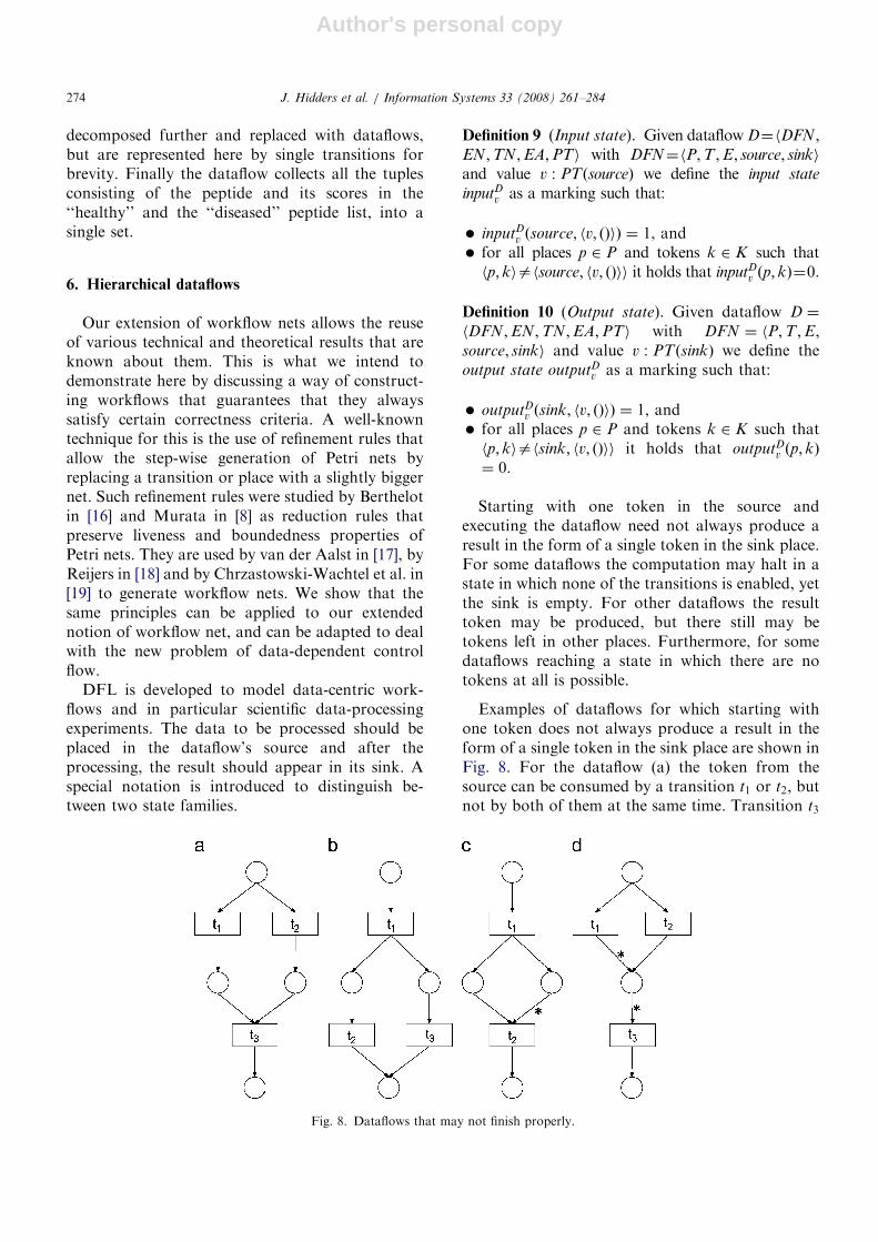
Examples of dataflows for which starting withone token does not always produce a result in theform of a single token in the sink place are shown inFig. 8. For the dataflow (a) the token from thesource can be consumed by a transition t1 or t2, butnot by both of them at the same time. Transition t3
ARTICLE IN PRESS
Fig. 8. Dataflows that may not finish properly.
J. Hidders et al. / Information Systems 33 (2008) 261–284274
Author's personal copy
will not become enabled then, because one of itsinput places will stay empty. The (b) case presentsan opposite scenario. Transition t1 produces twooutput tokens and after either t2 or t3 consumes oneof them and produces a computation result, thesecond token is still there and another computationresult can be produced. In the (c) case t2 will neverbecome enabled, since the tokens with historyappropriate for nesting will never be produced byt1. Similarly in case (d) if t2 gets the source token, t3will not become enabled, because only t1 canproduce a token with the required history. But for(d) it may even be not enough, when the t1consumes the source token. If the source tokencarried an empty set, then in the resulting state allplaces would be empty.
Similar problems were also studied in the contextof procedures modeled by classical workflow nets.The procedures without such problems are calledsound [1]. A workflow net is considered to be soundif an only if:
(1) if a token is inserted into the sink, then there areno other tokens left,
(2) the computation can always be completed, thatis, if one starts with a single token in the sourceand regardless of how the computation proceedsat start, it is always possible to reach a state withthe only token in the sink place, and
(3) every transition can be fired, if one starts with asingle token in the source.
This classical notion of soundness can be directlyapplied to dataflows such as (a) and (b) in Fig. 8 wherethe control flow does not depend upon the data, but indataflows such as (c) and (d) where the control flowmay depend upon the values and the unnestinghistories associated with a token the notion needs tobe adapted. Here tokens carry values, so there aremany possible input states from which a computationcan be started—one for each possible value for the firsttoken. It is natural to require that each transitionbecomes enabled in some input state, but not in all.
Definition 11 (Soundness). A dataflow D ¼
hDFN ;EN;TN;EA;PTi with DFN ¼ hP;T ;E;source; sinki is sound if and only if:
(i) for each value v0 : PTðsourceÞ and every mark-ing M such that inputD
v0 !�
M, if for some valuev00 : PTðsinkÞ and history h00 2 H it holds thatMðsink; hv00; h00iÞ40, then M ¼ outputD
v00 ,
(ii) for each value v0 : PTðsourceÞ and every mark-ing M such that inputD
v0 !�
M there exists a valuev00 : PTðsinkÞ such that M!
�outputD
v00 , and(iii) for each transition t 2 T there exists a value
v0 : PTðsourceÞ and two markings M and M 0
such that inputDv0 !�
M!t
M 0.
Although it seems desirable to require soundnessof dataflows, many of the systems with conditionalbehavior will not satisfy (iii). The problem isoften not caused by the structure of the net, butby operations associated with transition labels thatare being used. An appearance of a value thatactivates some part of the net may be dependent onthe value with which the dataflow is initiated.Checking if the right value can appear would beundecidable as is determining if an NRC expressionreturns an empty set. Indeed, it is well knownthat NRC can simulate the relational algebra [7].That is why we introduce a weaker semi-soundness
notion:
Definition 12 (Semi-soundness). A dataflow D ¼
hDFN ;EN;TN;EA;PTi with DFN ¼ hP;T ;E;source; sinki is semi-sound if and only if:
(i) for each value v0 : PTðsourceÞ and every markingM such that inputD
v0 !�
M, if for some value v00 :PTðsinkÞ and history h00 2 H it holds thatMðsink; hv00; h00iÞ40, then M ¼ outputD
v00 , and(ii) for each value v0 : PTðsourceÞ and every marking
M such that inputDv0 !�
M there exists a value v00 :PTðsinkÞ such that M!
�outputD
v00 .
6.1. Refinement rules
In this section we introduce refinement rulesfor generating what may be considered a well-structured dataflow. As we will show later, alldataflows generated in this way are semi-sound. Bystarting from a single place and applying the rules ina top-down manner we generate blank dataflows—dataflows without edge and transition naming. Wecall such generated blank dataflows hierarchical
blank dataflows. From these we then obtain data-flows by adding edge and transition namingfunctions. These will be called hierarchical data-
flows.
Definition 13 (Blank dataflow). A blank dataflow isa tuple hDFN ;EAi where:� DFN ¼ hP;T ;E; source; sinki is a dataflow net,
ARTICLE IN PRESSJ. Hidders et al. / Information Systems 33 (2008) 261–284 275
Author's personal copy
� EA : ð�T ! f‘‘¼ true’’; ‘‘¼ false’’; ‘‘¼;’’; ‘‘a;’’;‘‘ � ’’; egÞ [ ð�P! f‘‘ � ’’; egÞ is an edge annota-tion function.
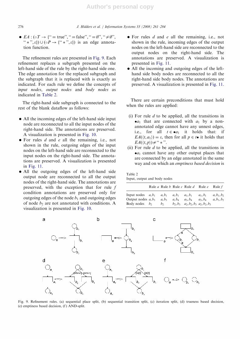
The refinement rules are presented in Fig. 9. Eachrefinement replaces a subgraph presented on theleft-hand side of the rule by the right-hand side one.The edge annotation for the replaced subgraph andthe subgraph that it is replaced with is exactly asindicated. For each rule we define the concepts ofinput nodes, output nodes and body nodes asindicated in Table 2.
The right-hand side subgraph is connected to therest of the blank dataflow as follows:
� All the incoming edges of the left-hand side inputnode are reconnected to all the input nodes of theright-hand side. The annotations are preserved.A visualization is presented in Fig. 10.� For rules d and e all the remaining, i.e., not
shown in the rule, outgoing edges of the inputnodes on the left-hand side are reconnected to theinput nodes on the right-hand side. The annota-tions are preserved. A visualization is presentedin Fig. 11.� All the outgoing edges of the left-hand side
output node are reconnected to all the outputnodes of the right-hand side. The annotations arepreserved, with the exception that for rule f
condition annotations are preserved only foroutgoing edges of the node b1 and outgoing edgesof node b2 are not annotated with conditions. Avisualization is presented in Fig. 10.
� For rules d and e all the remaining, i.e., notshown in the rule, incoming edges of the outputnodes on the left-hand side are reconnected to theoutput nodes on the right-hand side. Theannotations are preserved. A visualization ispresented in Fig. 11.� All the incoming and outgoing edges of the left-
hand side body nodes are reconnected to all theright-hand side body nodes. The annotations arepreserved. A visualization is presented in Fig. 11.
There are certain preconditions that must holdwhen the rules are applied:
(i) For rule d to be applied, all the transitions in�a1 that are connected with a1 by a non-annotated edge cannot have any unnest edges,i.e., for all t 2 �a1 it holds that: ifEAðht; a1iÞ ¼ �, then for all p 2 t� it holds thatEAðht; piÞa‘‘ � ’’.
(ii) For rule d to be applied, all the transitions in�a1 cannot have any other output places thatare connected by an edge annotated in the sameway and on which an emptiness based decision is
ARTICLE IN PRESS
Fig. 9. Refinement rules. (a) sequential place split, (b) sequential transition split, (c) iteration split, (d) trueness based decision,
(e) emptiness based decision, (f ) AND-split.
Table 2
Input, output and body nodes
Rule a Rule b Rule c Rule d Rule e Rule f
Input nodes a; b1 a; b1 a; b1 a1; b1 a1; b1 a; b1; b2Output nodes a; b3 a; b3 a; b4 a3; b4 a3; b4 a; b1; b2Body nodes b2 b2 b2; b3 a2; b2; b3 a2; b2; b3
J. Hidders et al. / Information Systems 33 (2008) 261–284276

Author's personal copy
performed, i.e., for all t 2 �a1 and for all p 2 t�
it holds that: if paa1 and EAðht; a1iÞ ¼
EAðht; piÞ, then for all t0 2 p� it holds thatEAðhp; t0iÞef‘‘ ¼ ;’’; ‘‘a;’’g.
(iii) For rule e to be applied, all the transitionsin �a1 cannot have any other output placesthat are connected by an edge annotatedin the same way and on which a trueness
based decision is performed, i.e., for all t 2 �a1
and for all p 2 t� it holds that: if paa1
and EAðht; a1iÞ ¼ EAðht; piÞ, then it holds thatfor all t0 2 p� it holds that EAðhp; t0iÞef‘‘ ¼ true’’; ‘‘ ¼ false’’g.
(iv) For rule f to be applied, a hasto have at leastone incoming and one outgoing edge.
The first three preconditions are necessary so thatit is always possible to label the generated blankdataflow such that it becomes a legal dataflow. (i)deals with a requirement that a token representingset values cannot be used to make a trueness based
decision (see Fig. 12(i)), while (ii) and (iii) preventusing tokens with the same values in different kindsof tests (see Fig. 12(ii) and (iii)). Precondition (iv)guarantees that there is exactly one input andoutput place.
ARTICLE IN PRESS
Fig. 10. Reconnecting of subgraphs. (a) sequential place split, (b) sequential transition split, (c) iteration split, (d) trueness based decision,
(e) emptiness based decision, (f) AND-split.
Fig. 11. Reconnecting of subgraphs—additional edges for rules d and e. (d) trueness based decision, (e) emptiness based decision.
J. Hidders et al. / Information Systems 33 (2008) 261–284 277

Author's personal copy
Definition 14 (Hierarchical blank dataflow). Ablank dataflow which is obtained by starting witha blank dataflow that consists of a single place withno transitions and performing the transformationspresented in Fig. 9 is called a hierarchical blankdataflow.
Definition 15 (Hierarchical dataflow). A hierarchi-cal dataflow is a legal dataflow D ¼ hDFN ;EN;TN;EA;PTi obtained by labeling transitionsand edges in a hierarchical blank dataflowBDF ¼ hDFN ;EAi.
The rules and the aim to make dataflowsstructured as in structured programming languageswere inspired by the work done on workflow nets byChrzastowski-Wachtel et al. [19].
An instance of a computation of a particulardataflow, which starts in some input state, will becalled a run. We will represent it as a pair of twosequences. The first one will contain successivetransitions that were fired and the second onesubsequent states including the input state.
Definition 16 (Run). Let D ¼ hDFN ;EN ;TN ;EA;PTi be a dataflow with a dataflow netDFN ¼ hP;T ;E; source; sinki. A sequence of transi-tions t1; . . . ; tn 2 T with a sequence of markingsM0; . . . ;Mn of D, where M0 is an input state,forms a run if and only if it holds thatM0!
t1M1!
t2� � �!
tnMn.
The run will be denoted as M0!t1
M1!t2� � �
!tn
Mn. If Mn is an output state of D, then we willcall such a run complete.
For a run M0!t1
M1!t2� � �!
tnMn, a place p and
history h we define a delta of tokens in p after firinga given transition tiþ1 in a state Mi:
Diðp; hÞ ¼X
v2CV
Miþ1ðp; hv; hiÞ X
v2CV
Miðp; hv; hiÞ.
We will also want to count tokens inserted to aplace (since there are no cycles, during onetransition tokens are never inserted to and con-sumed from a place at the same time):
Dþi ðp; hÞ ¼Diðp; hÞ if Diðp; hÞ40;
0 otherwise:
�
The number of tokens with a given history h
inserted into a place p during a run M0!t1
M1!t2� � �!
tnMn will be called a trace of p and
defined as Trðp; hÞ ¼Pn1
i¼0 Dþi ðp; hÞ.
Lemma 17. For each hierarchical dataflow D ¼
hDFN ;EN;TN;EA;PTi with a dataflow net DFN ¼
hP;T ;E; source; sinki and for each run M0!t1
M1!t2� � �!
tnMn of dataflow D, the trace of each
place is bounded by 1, i.e., it holds that
8h2H8p2PTrðp; hÞp1.
Theorem 18. Every hierarchical dataflow is semi-sound.
Proof of Lemma 17 and Theorem 18. We will proveLemma 17 and Theorem 18 together, by inductionon the number of refinements applied in thegeneration of the blank dataflow. During this proofwe will assume that in TL there are labelsrepresenting all the NRC expressions on theavailable external functions.
ARTICLE IN PRESS
Fig. 12. Preconditions.
J. Hidders et al. / Information Systems 33 (2008) 261–284278

Author's personal copy
For a hierarchical dataflow consisting of only oneplace, all runs have empty transition sequence andthe state sequence consists of only one state, whichis an input and an output state at the same time.Therefore such dataflow is semi-sound and the sumin Lemma 17 contains no elements, thus is equal 0.
Let us assume by mathematical induction that foreach hierarchical dataflow Dn ¼ hDFNn;ENn;TNn;EAn;PTni with a dataflow net DFNn ¼ hPn;Tn;En;sourcen; sinkni whose hierarchical blank dataflowwas generated in nX0 refinements it holds that:
(1) for each run M 00!
t1M 0
1!t2� � �!
tdM 0
d of Dn everytrace of every place is bounded by 1,
(2) for each value v0 : PTnðsourcenÞ and marking M 0
such that inputDn
v0 !�
M 0, if for some value v00 :PTnðsinknÞ and history h00 2 H it holds thatM 0ðsinkn; hv00; h
00iÞ40, then M 0 ¼ outputDn
v00 , and(3) for each value v0 : PTnðsourcenÞ and marking M 0
such that inputDn
v0 !�
M 0 there exists a value v00 :PTnðsinknÞ such that M 0 !
�outputDn
v00 .
We will show that if Dnþ1 ¼ hDFNnþ1;ENnþ1;TNnþ1;EAnþ1;PTnþ1i with a dataflow netDFNnþ1 ¼ hPnþ1;Tnþ1;Enþ1; sourcenþ1; sinknþ1i isan arbitrary hierarchical dataflow whose hierarch-ical blank dataflow was generated in nþ 1 refine-ments, then:
(i) for each run M0!t1
M1!t2� � �!
tmMm of Dnþ1
every trace of every place is bounded by 1,(ii) for each value v0 : PTnþ1ðsourcenþ1Þ and each
marking M such that inputDnþ1
v0 !�
M, if forsome value v00 : PTnþ1ðsinknþ1Þ and history h00 2
H it holds that Mðsinknþ1; hv00; h00iÞ40, then
M ¼ outputDnþ1
v00 , and(iii) for each value v0 : PTnþ1ðsourcenþ1Þ and each
marking M such that inputDnþ1
v0 !�
M there existsa value v00 : PTnþ1ðsinknþ1Þ such thatM!
�output
Dnþ1
v00 .
Let us consider each possible case for the last,(nþ 1)th, refinement applied.
(a) The last applied refinement was a sequential
place split (see Fig. 9a). Let BDF n ¼ hDFNn;EAni
with a dataflow net DFNn ¼ hPn;Tn;En; sourcen;sinkni be a blank hierarchical dataflow generated bythe first n refinements that generated the blankdataflow of Dnþ1. Let Dn ¼ hDFNn;ENn;TNn;EAn;PTni be a hierarchical dataflow labeledaccordingly to the labeling of Dnþ1. Since there is nob2 transition in Dn, to keep Dn legal, the function
that it computes is incorporated into the transitionsthat follow it directly, if there are any, or is omittedotherwise. That is PTnðaÞ ¼ PTnþ1ðb1Þ and for eacht 2 a� it holds that
TNnðtÞ ¼TNnþ1ðtÞj
FTNnþ1 ðb2 Þ
ENnþ1ðhb3 ;tiÞif EAðha; tiÞa‘‘ � ’’;
TNnþ1ðtÞjmapðFTNnþ1 ðb2 Þ
Þ
ENnþ1ðhb3 ;tiÞif EAðha; tiÞ ¼ ‘‘ � ’’:
8<:
Here tljflimeans the transition label obtained from the
transition label tl, by letting the input from edge li
through f first. Namely, if ITðtlÞ ¼ hl1 : t1; . . . ; lk : tki
and f : t0i ! ti, then ITðtljfliÞ ¼ hl1 : t1; . . . ; li : t0i; . . . ;
lk : tki, OTðtljfliÞ ¼ OTðtlÞ and for all values v1; . . . ; vk
of the appropriate types Ftlj
f
li
ðhl1 : v1; . . . ; lk : vkiÞ¼
Ftlðhl1 : v1; . . . ; li : f ðviÞ; . . . ; lk : vkiÞ.
For each run M0!t1
M1!t2� � �!
tmMm of Dnþ1 we
define a corresponding run M 00!
t01
M 01!
t02� � �!
t0d
M 0d
of Dn. The transitions are fired in the same order,they consume the same tokens and functionsproduce the same results, but all occurrencesof b2 are omitted. It is easy to see that
M 00!
t01
M 01!
t02� � �!
t0d
M 0d is indeed a run of Dn and
that it is unambiguously defined. Let us assume thatthe subsequence of not omitted transitions haveindices i1; . . . ; id . The markings of Dn are equal totheir counterparts in Dnþ1 on all the places thatappear in both of the dataflows (i.e., for every p 2
Pn \ Pnþ1 and k 2 K it holds that M0ðp; kÞ ¼M 0
0ðp; kÞ and Mi1 ðp; kÞ ¼M 01ðp; kÞ,y, Mid
ðp; kÞ ¼M 0
dðp; kÞ). Whereas place a contains all the tokens
that in the counterpart marking are stored in b1 aswell as all the tokens that were consumed from b1 inorder to produce the tokens that in the counterpartare stored in b3. This correspondence in not aninjection, though. For each run of Dn there can bemany corresponding runs of Dnþ1. This is becausethere is a choice when to fire b2, if tokens insertedinto a are not immediately consumed.
As for (i), the content of places inM0;Mi1 ; . . . ;Mid is bounded by the content ofplaces in M 0
0;M01; . . . ;M
0d , respectively. In the
remaining markings the only difference is that sometokens are consumed from b1, processed by b2 andthe result is placed in b3. Thus the traces of places inmarkings of Dnþ1 are limited by the traces of placesin markings of Dn, for which the inductionassumption holds.
As for (ii), we can assume without loss ofgenerality that Mm is the first marking inM0; . . . ;Mm in which sinknþ1 is not empty. We will
ARTICLE IN PRESSJ. Hidders et al. / Information Systems 33 (2008) 261–284 279

Author's personal copy
first consider the case when sinknþ1ab3 and tmab2.In the M 0
d of the corresponding run sinkn is also notempty (sinkn ¼ sinknþ1). From the induction as-sumption in M 0
d there is only one token—the one insinkn. Since in Mm there is the same number oftokens, then also in Md there is only one token—theone in the sinknþ1. In the case where sinknþ1 ¼ b3, itis only possible for a token to be inserted intosinknþ1 ¼ b3, when there was a token to beconsumed from b1. Yet, when the first token isinserted into b1, there are no other tokens since inthe corresponding run a token is inserted into a,which is a sink there. Since M0; . . . ;Mm wasarbitrarily chosen, (ii) holds.
As for (iii), let v0 : PTnþ1ðsourcenþ1Þ and let M be
a marking of Dnþ1 such that inputDnþ1
v0 !�
M. By the
definition of marking reachability there exists a run
M0!t1
M1!t2� � �!
tmMm, where M0 ¼ input
Dnþ1
v0 and
Mm ¼M. We know that for this run in Dn there
exists a corresponding run M 00!
t01
M 01!
t02� � �!
t0d
M 0d ,
where M 00 ¼ inputDn
v0 . From the semi-soundness of
Dn it follows that for some v00 : PTnðsinknÞ thiscorresponding run can be extended into a com-
plete run M 00!
t01
M 01!
t02� � �!
t0d
M 0d !
t0dþ1
M 0dþ1!
t0dþ2
� � �
!t0dþq
M 0dþq, where M 0
dþq ¼ outputDn
v00 . For it in turn
there exists a corresponding complete run
M0!t1
M1!t2� � �!
tmMm !
tmþ1
Mmþ1!tmþ2
� � � !tmþr
Mmþr
in Dnþ1, which at the beginning is identical to therun of Dnþ1 we started from and in Mmþr place b1 isempty (if b3 ¼ sinknþ1, b1 can be emptied by firingb2). This completes the proof, since we have shown
that Mm!�
outputDnþ1
v000 , for
v000 ¼FTNnþ1ðb2Þðv
00Þ if a ¼ sinkn;
v00 otherwise:
�
(b) The last refinement was a sequential transition
split (see Fig. 9b). As previously, with the first n
refinements, we can construct a blank hierarchicaldataflow and label it accordingly to the labeling ofDnþ1. In the resulting dataflow Dn, the label of a
represents the composition of functions FðTNnþ1ðb3ÞÞ
and FðTNnþ1ðb1ÞÞ. That is ITnðTNnðaÞÞ ¼ ITnþ1
ðTNnþ1ðb1ÞÞ, OTnðTNnðaÞÞ ¼ OTnþ1ðTNnþ1ðb3ÞÞ
and FTNnðaÞ ¼ FTNnþ1ðb3Þ� FTNnþ1ðb1Þ.
For each run M0!t1
M1!t2� � �!
tmMm of Dnþ1 we
define a corresponding run M 00!
t01
M 01!
t02� � �!
t0d
M 0d
of Dn. The transitions are fired in the same order,
they consume the same tokens and functionsproduce the same results, but all occurrences of b1
are omitted and all occurrences of b3 are replaced
with a. It is easy to see that M 00!
t01
M 01!
t02� � �!
t0d
M 0d
is indeed a run of Dn and that it is unambiguouslydefined. Let us assume that the subsequence of notomitted (other that b1) transitions have indicesi1; . . . ; id . The markings of Dn are equal to theircounterparts in Dnþ1 on all the places that appear inboth of the dataflows except the ones in �a ¼ �b1
(i.e., for every p 2 ððPn \ Pnþ1Þn � aÞ and k 2 K itholds that M0ðp; kÞ ¼M 0
0ðp; kÞ and Mi1 ðp; kÞ ¼M 0
1ðp; kÞ,y, Midðp; kÞ ¼M 0
dðp; kÞ)). Whereas each
place in �a contains all the tokens that in thecounterpart marking are stored in the correspond-ing place in �b1 as well all the tokens that wereconsumed from that place in order to produce thetokens that are in the counterpart stored in b2. Thiscorrespondence in not an injection, though. Foreach run of Dn there can be many correspondingruns of Dnþ1. This is because there is a choice whento fire b3, if tokens produced by a into a� are notimmediately consumed.
The rest of the proof follows the one given for (a).(c) The last refinement was an iteration split (see
Fig. 9c). As previously, with the first n refinements,we can construct a blank hierarchical dataflow andlabel it accordingly to the labeling of Dnþ1. In theresulting dataflow Dn, the label of transition a
represents a composition of three functions:FTNnþ1ðb4Þ, a pair function of appropriate type thatconstructs a pair of twice its argument, and a functionFTNnþ1ðb1Þ. That is ITnðTNnðaÞÞ ¼ ITnþ1ðTNnþ1ðb1ÞÞ,OTnðTNnðaÞÞ ¼ OTnþ1ðTNnþ1ðb4ÞÞ and FTNnðaÞ ¼
FTNnþ1ðb4Þ� pair � FTNnþ1ðb1Þ. The correspondence ofruns is analogous as in (b). The rest of the prooffollows.
(d) The last refinement was a trueness based
decision (see Fig. 9d). As previously, with the first n
refinements, we can construct a blank hierarchicaldataflow and label it accordingly to the labeling ofDnþ1. That is ITnðTNnða2ÞÞ ¼ ITnþ1ðTNnþ1ðb2ÞÞ ¼
ITnþ1ðTNnþ1ðb3ÞÞ and OTnðTNnða2ÞÞ ¼ OTnþ1
ðTNnþ1ðb2ÞÞ ¼ OTnþ1ðTNnþ1ðb3ÞÞ, and for the edgenames ENnðha1; a2iÞ ¼ ENnþ1ðhb1; b2iÞ ¼ ENnþ1
ðhb1; b3iÞ. Assume ITnþ1ðTNnþ1ðb2ÞÞ ¼ hl1 : t1; . . . ;lk : tk; ENnðha1; a2iÞ : PTða1Þi. TNnða2Þ representsa function computing if–then–else expression thatresults in evaluating of either of FTNnþ1ðb2Þ orFTNnþ1ðb3Þ. Which means that for every valuesv1; . . . ; vk of appropriate types and every v : PTða1Þ
ARTICLE IN PRESSJ. Hidders et al. / Information Systems 33 (2008) 261–284280

Author's personal copy
the result of function FTNnða2Þðhl1 : v1; . . . ; lk : vk;ENnðha1; a2iÞ : viÞ equals FTNðb2Þðhl1 : v1; . . . ; lk :vk;ENnðha1; a2iÞ : viÞ, if v ¼ false, or FTNðb3Þðhl1 :v1; . . . ; lk : vk;ENnðha1; a2iÞ : viÞ, otherwise.
The correspondence of runs in this case is abijection. Transitions are fired in the same order,but all occurrences of b2 and b3 are replaced with a2
or depending on the consumed token value a2 isreplaced by b2 or b3. The markings are equal to theircounterparts in all the place that appear in both ofthe dataflows. Whereas a1 contains the same tokensas b1 and a3 the same tokens as b4.
The rest of the proof follows.(e) The last refinement was an emptiness based
decision (see Fig. 9e). The proof follows the onegiven for (d).
(f) The last refinement was an AND-split (see Fig.9f). As previously, with the first n refinements, wecan construct a blank hierarchical dataflow andlabel it accordingly to the labeling of Dnþ1. SinceAND-split was the last refinement applied ingeneration of blank dataflow of Dnþ1, we knowthat b1� ¼ b2�, �b1 ¼ �b2 and thus PTnþ1ðb1Þ ¼
PTnþ1ðb2Þ. For every transition tnþ1 2 b1�,where ITðTNnþ1ðtnþ1ÞÞ ¼ hl1 : t1; . . . ; lk : tk;ENnþ1
ðhb1; tnþ1iÞ : PTnþ1ðb1Þ;ENnþ1ðhb2; tnþ1iÞ : PTnþ1
ðb2Þi, its corresponding transition tn 2 a� is definedas follows:
� ITðTNnðtnÞÞ ¼ hl1 : t1; . . . ; lk : tk;ENnþ1ðhb1;tnþ1iÞ : PTnþ1ðb1Þi, that is ENnðha; tniÞ ¼
ENnþ1hb1; tnþ1i,� OTðTNnðtnÞÞ ¼ OT ðTNnþ1ðtnþ1ÞÞ,� for all values v1; . . . ; vk of appropriate types and
all v : PTn the function computed by thistransition is defined as follows FTNnðtnÞðhl1 :v1; . . . ; lk : vk;ENnþ1ðhb1; tnþ1iÞ : viÞ ¼ FTNnþ1ðtnþ1Þ
ðhl1 : v1; . . . ; lk : vk;ENnþ1ðhb1; tnþ1iÞ : v;ENnþ1
ðhb2; tnþ1iÞ : viÞ.
The observation that in Dnþ1 places b1 and b2 getthe same tokens as a gets in Dn completes the proofof Lemma 17.
The correspondence of runs in this case is abijection. Transitions are fired in the same order.The markings are equal to their counterparts in allthe place that appear in both of the dataflows.Whereas a contains the same tokens as b1 and b2,which have to have identical content because, eachof the transitions consuming token from one ofthose places consumes a token with identical historyfrom the other one (b1� ¼ b2�) and from Lemma 17
we know that there is no choice of such tokens, so itmust be exactly the one consumed from the firstplace. The rest of the proof follows. &
7. The bioinformatics dataflow example revisited
We conjecture that in terms of expressiblefunctions hierarchical dataflows are equivalent toNRC and thus, by following our claim in [20], aresufficient to describe most data-centric experimentsin life sciences such as bioinformatics. To illustratethis we consider again the dataflow in Fig. 7. Closerinspection of this dataflow shows that it is nothierarchical. This is because the iterations in thedataflow start with a transition that only hasunnesting edges as outgoing edges. This is in conflictwith the iteration split rule in Fig. 9 which requiresthat next to the unnest-nest branch there is anotherbranch that does not unnest and nest. Recall thatthe reason for this requirement is that if the functionassociated with the initial transition produces theempty set then the transition produces no tokensand the workflow will probably not terminateproperly. Observe that this is indeed what happensif the workflow is presented with an empty‘‘healthy’’ or ‘‘diseased’’ peptide list since the [transition will never be enabled. The dataflow istherefore strictly speaking not semi-sound andcannot deal correctly with all possible input values.This soundness problem can be easily solved byintroducing extra branches for the synchronizationof the iterations as is shown in Fig. 13.
The corrected version of the dataflow can beshown to be hierarchical, which is demonstrated inFig. 14 where the corresponding blank dataflow,called BDF 8 here, is generated from the blankdataflow with only one place, called BDF 1. The grayboxes indicate groups of nodes that were generatedby expanding a single node in the preceding blankdataflow. For example, all nodes in BDF 2 wheregenerated from the place in BDF 1 by applying thesequential place split and sequential transition split.For BDF 3 a place is split by using the AND-split
and a transition is split by applying iteration split. Inthe following step BDF4 is generated by applyingthe sequential place split to two places. Then BDF 5
is generated by using the AND-split for two places.Then for constructing BDF 6 some of the places thatwere just introduced are expanded with the sequen-
tial place split. In the next step BDF 7 is constructedby applying the iteration split to four transitions andthe AND-split to two places. Finally, to construct
ARTICLE IN PRESSJ. Hidders et al. / Information Systems 33 (2008) 261–284 281

Author's personal copy
BDF 7 the sequential place split and sequential
transition split are applied several times.As the preceding example shows, the hierarchical
analysis of a dataflow can sometimes reveal subtlesoundness problems. We intend to create a tool inwhich it would not only be possible to constructdataflows by refinement, but also arbitrarily con-structed dataflows could be tested if they arehierarchical. For the rules proposed by Chrzastows-
ki-Wachtel et al. for plain Petri nets a similar test ispossible in polynomial time [21].
8. Conclusions and further research
In this paper we have presented DFL—a graphi-cal language for describing dataflows, i.e., work-flows where large amounts of complex data aremanipulated and the structure of the manipulateddata is reflected in the structure of the workflow. Inorder to be able to describe both the control flowand the data flow the language is based on Petri netsand the nested relational calculus and has a formalsemantics that is based upon these two formalisms.This ensures that from the large body of existingresearch on these we can reuse or adapt certainresults. This is illustrated by taking a well-knowntechnique for generating sound workflow nets andusing it to generate semi-sound dataflows.
In future research we intend to compare, inves-tigate and extend this formalism in several ways.Since the dataflow nets tend to become quite largefor relatively simple dataflows, we intend tointroduce syntactic sugar. We also want to investi-gate whether a similar control-flow semantics can begiven for the textual NRC and see how the twoformalisms compare under these semantics. Sinceexisting systems for data-intensive workflows oftenlack formal semantics, we will investigate if ourformalism can be used to provide these. It is alsoour intention to add the notions of provenance andrun of a dataflow to the semantics such that thesecan be queried with a suitable query language suchas the NRC. This can be achieved in a straightfor-ward and intuitive way by remembering all tokensthat passed through a certain place and defining theprovenance as a special binary relation over thesetokens. Storing all these tokens makes it not onlypossible to query the run of a dataflow but also toreuse intermediate results of previous versions of adataflow. Another subject is querying dataflows,where a special language is defined to querydataflow repositories, to find for example similardataflows or dataflows that can be reused for thecurrent research problem. Since dataflows in ourlanguage are essentially labeled graphs it seemslikely that a suitable existing graph-based queryformalism could be employed for this. Finally wewill investigate the possibilities of workflow optimi-zation by applying known techniques from NRCresearch. Since optimization often depends on thechanging of the order of certain operations it will
ARTICLE IN PRESS
Fig. 13. Finding differences in peptide content of two samples
(hierarchical).
J. Hidders et al. / Information Systems 33 (2008) 261–284282

Author's personal copy
then be important to extend the formalism with anotion of ‘‘color’’ for extension transitions thatindicates whether their relative order may bechanged by the optimizer.
References
[1] W.M.P. van der Aalst, The application of petri nets to
workflow management, J. Circuits Syst. Comput. 8 (1)
(1998) 21–66.
[2] K. Jensen, Coloured Petri Nets Basic Concepts Analysis
Methods and Practical Use. vols. 1 and 2, second ed.,
Springer, London, UK, 1996.
[3] R. Valk, Object Petri nets: using the nets-within-nets
paradigm, in: Lectures on Concurrency and Petri Nets,
2003, pp. 819–848.
[4] R. Valk, Self-modifying nets a natural extension of Petri
nets, in: ICALP, 1978, pp. 464–476.
[5] A. Oberweis, P. Sander, Information system behavior
specification by high level petri nets, ACM Trans. Inf. Syst.
14 (4) (1996) 380–420.
[6] J. Hidders, N. Kwasnikowska, J. Sroka, J. Tyszkiewicz, J.
Van den Bussche, Petri netþnested relational calculus¼data-
flow, in: OTM Conferences (1), 2005, pp. 220–237.
[7] P. Buneman, S. Naqvi, V. Tannen, L. Wong, Principles of
programming with complex objects and collection types,
Theor. Comput. Sci. 149 (1) (1995) 3–48.
[8] T. Murata, Petri nets: properties analysis and applications,
Proc. IEEE 77 (4) (1989) 541–580.
[9] W. Reisig, Petri Nets: An Introduction, Springer, New
York, Inc., NY, USA, 1985.
[10] T. Oinn, M. Addis, J. Ferris, D. Marvin, M. Greenwood,
T. Carver, A. Wipat, P. Li, Taverna: a tool for the
composition and enactment of bioinformatics workflows,
Bioinformatics 20 (17) (2004) 3045–3054.
[11] Object Management Group, Unified modeling language
resource page, hhttp://www.uml.org/i.
ARTICLE IN PRESS
Fig. 14. The generation of the blank dataflow from Fig. 7.
J. Hidders et al. / Information Systems 33 (2008) 261–284 283

Author's personal copy
[12] S. Altschul, W. Gish, W. Miller, E. Myers, D. Lipman, Basic
local alignment search tool, J. Mol. Biol. 215 (3) (1990)
403–410.
[13] B. Boeckmann, A. Bairoch, R. Apweiler, MC. Blatter, A.
Estreicher, et al., The swiss-prot protein knowledgebase and
its supplement trembl in 2003, Nucleic Acids Res. 31 (2003)
365–370.
[14] P. Rice, I. Longden, A. Bleasby, Emboss: the European
molecular biology open software suite (2000), Trends Genet.
16 (6) (2000) 276–277.
[15] D. Dumont, J.P. Noben, J. Raus, P. Stinissen, J. Robben,
Proteomic analysis of cerebrospinal fluid from multiple
sclerosis patients, Proteomics 4 (7) (2004).
[16] G. Berthelot, Checking properties of nets using transforma-
tion, in: Advances in Petri Nets 1985, Covers the
6th European Workshop on Applications and Theory in
Petri Nets-selected Papers, Lecture Notes in Computer
Science, vol. 222. London, UK, Springer, Berlin, 1986,
pp. 19–40.
[17] W.M.P. van der Aalst, Verification of workflow nets, in:
ICATPN ’97: Proceedings of the 18th International Con-
ference on Application and Theory of Petri Nets, London,
UK, Springer, Berlin, 1997, pp. 407–426
[18] H.A. Reijers, Design and Control of Workflow Processes:
Business Process Management for the Service Industry,
Lecture Notes in Computer Science, vol. 2617, Springer,
New York, Inc., Secaucus, NJ, USA, 2003.
[19] P. Chrzastowski-Wachtel, B. Benatallah, R. Hamadi, M.
O’Dell, A. Susanto, A top-down petri net-based approach
for dynamic workflow modeling, in: W.M.P. van der Aalst,
A.H.M. ter Hofstede, M. Weske (Eds.), Business Process
Management, Lecture Notes in Computer Science, vol. 2678,
Springer, Berlin, 2003 pp. 336–353.
[20] A. Gambin, J. Hidders, N. Kwasnikowska, S. Lasota, J.
Sroka, J. Tyszkiewicz, J. Van den Bussche, NRC as a formal
model for expressing bioinformatics workflows, Poster at
ISMB, 2005.
[21] P. Chrzastowski-Wachtel, private communication, 2007.
ARTICLE IN PRESSJ. Hidders et al. / Information Systems 33 (2008) 261–284284