DATAFLOW IN MODERN INDUSTRIAL AUTOMATION SYSTEMS. THEORY AND PRACTICE
11
International Journal of Applied Control, Electrical and Electronics Engineering (IJACEEE) Vol 2, No.4, November 2014 1 DATAFLOW IN MODERN INDUSTRIAL AUTOMATION SYSTEMS. THEORY AND PRACTICE Marcin Bajer 1 1 ABB Corporate Research Kraków, Poland ABSTRACT The goal of this publication is to provide brief description of industrial communication protocols. This paper shows how data flow can be realized in modern manufacturing facilities and how to integrate multiple data sources (sensors, actuators and controllers) into one heterogonous system. In order to illustrate the problem a model of multi tank water control system has been developed. In addition the paper presents approach to access production data by Android based devices. KEYWORDS Fieldbus, OPC, Profibus, Profinet, Android, XML RPC 1. INTRODUCTION Large industrial facilities often contains thousands of automation devices. Sensors, actuators and controllers can be distributed over large area. They differ in amount of information they produce, refresh rate and required reliability. Specific requirements imposed by industrial environment, possibly harsh conditions and cost saving factor must be also taken into consideration. Such diverse demands led to development of various industrial communication buses. Traditionally, dataflow in a factory has been described in a form of so-called automation pyramid (Figure 1). As it can be seen, together with narrowing of the pyramid the amount of information to be transmitted is growing. Sensors and actuators installed directly at the factory floor are not so complex, but their number is significantly higher than other devices. Generally, the following statement applies: the higher level is, the greater is the amount of information, but the speed of transmission is smaller and real-time requirements are weaker [1]. Figure 1. An Automation Pyramid
-
Upload
independent -
Category
Documents
-
view
1 -
download
0
Transcript of DATAFLOW IN MODERN INDUSTRIAL AUTOMATION SYSTEMS. THEORY AND PRACTICE

International Journal of Applied Control, Electrical and Electronics Engineering (IJACEEE) Vol 2, No.4, November 2014
1
DATAFLOW IN MODERN INDUSTRIAL AUTOMATION
SYSTEMS. THEORY AND PRACTICE
Marcin Bajer1
1ABB Corporate Research Kraków, Poland
ABSTRACT
The goal of this publication is to provide brief description of industrial communication protocols. This
paper shows how data flow can be realized in modern manufacturing facilities and how to integrate
multiple data sources (sensors, actuators and controllers) into one heterogonous system. In order to
illustrate the problem a model of multi tank water control system has been developed. In addition the
paper presents approach to access production data by Android based devices.
KEYWORDS
Fieldbus, OPC, Profibus, Profinet, Android, XML RPC
1. INTRODUCTION
Large industrial facilities often contains thousands of automation devices. Sensors, actuators
and controllers can be distributed over large area. They differ in amount of information they
produce, refresh rate and required reliability. Specific requirements imposed by industrial
environment, possibly harsh conditions and cost saving factor must be also taken into
consideration. Such diverse demands led to development of various industrial communication
buses.
Traditionally, dataflow in a factory has been described in a form of so-called automation
pyramid (Figure 1). As it can be seen, together with narrowing of the pyramid the amount of
information to be transmitted is growing. Sensors and actuators installed directly at the factory
floor are not so complex, but their number is significantly higher than other devices. Generally,
the following statement applies: the higher level is, the greater is the amount of information, but
the speed of transmission is smaller and real-time requirements are weaker [1].
Figure 1. An Automation Pyramid
International Journal of Applied Control, Electrical and Electronics Engineering (IJACEEE) Vol 2, No.4, November 2014
2
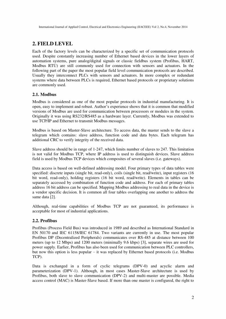
2. FIELD LEVEL
Each of the factory levels can be characterized by a specific set of communication protocols
used. Despite constantly increasing number of Ethernet based devices in the lower layers of
automation systems, pure analog/digital signals or classic fieldbus system (Profibus, HART,
Modbus RTU) are still commonly used for connection with sensors and actuators. In the
following part of the paper the most popular field level communication protocols are described.
Usually they interconnect PLCs with sensors and actuators. In more complex or redundant
systems where data between PLCs is required, Ethernet based protocols or proprietary solutions
are commonly used.
2.1. Modbus
Modbus is considered as one of the most popular protocols in industrial manufacturing. It is
open, easy to implement and robust. Author’s experience shows that it is common that modified versions of Modbus are used for communication between processors or modules in the system.
Originally it was using RS232/RS485 as a hardware layer. Currently, Modbus was extended to
use TCP/IP and Ethernet to transmit Modbus messages.
Modbus is based on Master-Slave architecture. To access data, the master sends to the slave a
telegram which contains: slave address, function code and data bytes. Each telegram has
additional CRC to verify integrity of the received data.
Slave address should be in range of 1-247, which limits number of slaves to 247. This limitation
is not valid for Modbus TCP, where IP address is used to distinguish devices. Slave address
field is used by Modbus TCP devices which composites of several slaves (i.e. gateways).
Data access is based on well-defined addressing model. Four primary types of data tables were
specified: discrete inputs (single bit, read-only), coils (single bit, read/write), input registers (16
bit word, read-only), holding registers (16 bit word, read/write). Elements in tables can be
separately accessed by combination of function code and address. For each of primary tables
address 16 bit address can be specified. Mapping Modbus addressing to real data in the device is
a vendor specific decision. It is common all four tables overlapping one another to address the
same data [2].
Although, real-time capabilities of Modbus TCP are not guaranteed, its performance is
acceptable for most of industrial applications.
2.2. Profibus
Profibus (Process Field Bus) was introduced in 1989 and described as International Standard in
EN 50170 and IEC 61158/IEC 61784. Two variants are currently in use. The most popular
Profibus DP (Decentralized Peripherals) communicates over RS-485 at distance between 100
meters (up to 12 Mbps) and 1200 meters (minimally 9.6 kbps) [3], separate wires are used for
power supply. Earlier, Profibus has also been used for communication between PLC controllers,
but now this option is less popular – it was replaced by Ethernet based protocols (i.e. Modbus
TCP).
Data is exchanged in a form of cyclic telegrams (DPV-0) and acyclic alarm and
parameterization (DPV-1). Although, in most cases Master-Slave architecture is used by
Profibus, both slave to slave communication (DPV-2) and multi-master are possible. Media
access control (MAC) is Master-Slave based. If more than one master is configured, the right to

International Journal of Applied Control, Electrical and Electronics Engineering (IJACEEE) Vol 2, No.4, November 2014
3
control the bus has a Master which currently possess a symbolic token. When the token holding
time for that master exceeds or the master has no more pending requests, the token is passed to
the subsequent master [4]. Communication real-time capabilities are guaranteed.
The main disadvantage of Profibus is its cabling. Wiring and terminators are the most expensive
and very sensitive part of the system. Potential problems are difficult to troubleshoot. In some
applications fibre optics can be also used instead.
Profibus PA (Process Automation) is much less popular. Profibus PA uses two-wire connection
which carry both power and data. It offers smaller throughput (31.25 kbit/s), but can be used in
explosive environments. Profibus PA and DP uses the same communication protocol and can be
linked together with a special gateway device.
2.3. Profinet
Profinet was designed as a successor of Profibus and was introduced to market in 2002. It
combines well proven concepts of the previous standard with powerful features of Ethernet.
Two specifications were described: Profinet CBA – for communication between components of
automation system and Profinet IO – for integration of distributed IOs. Currently, only Profinet
IO is a living standard. Profinet IO Real Time (RT) protocol is capable to use standard Ethernet
cabling and network equipment, but it is recommended to use dedicated switches which can
prioritize Profinet traffic. Minimal cycle time of 1 ms is available. In order to satisfy higher
performance requirement (i.e. for motion control) Profinet IO Isochronous Real Time (IRT) was
introduced. It requires special network components to reserve part of bandwidth for Profinet
traffic. Cycle time of 250 µs are available with high degree of determinism (1 µs).
In Profinet IO new communication profiles (i.e. ProfiSafe, ProfiEnergy, Sequence of Events)
and features (Shared Device, Shared Input, Configuration in a Run) are constantly developed
and implemented by the device vendors. Profinet become powerful but rather complex protocol.
2.4. HART
HART is hybrid protocol which uses both analog 4-20 mA current loop and digital frequency
shift keying signal. Analog signal is used to transfer measured process value, digital
transmission contains additional process parameters and sensor configuration. Data bytes are
transferred at the rate of 1200 bps, and can operate over long distance. Traditional sensors can
be directly integrated with HART enabled controller, in this way factory modification can be
divided into a few steps.
2.5. CAN
CAN was originally developed for automotive industry, but it has also been adopted for use at
the factory floor. Several automation fieldbuses use CAN as the backbone technology (i.e.
DeviceNet, CANOpen or SafetyBus). CAN is multi-master, when the bus is free any unit may
start sending data to other network nodes. A message consists of an identifier and up to eight
data bytes. Transmitter observes the bus, in case two devices start transmitting at the same time
a message with higher ID has lower priority. Transmitter which is sending this message should
stop.
Multiple µP has hardware support for CAN. Speed of communication depends on length of the
cable. It has maximal bit rate of 1 Mbit/s with the maximal bus length of 40 meters. Long bus,
up to 270 meters, can work with the maximal speed of 250 kbit/s [5].

International Journal of Applied Control, Electrical and Electronics Engineering (IJACEEE) Vol 2, No.4, November 2014
4
2.6. Wireless protocols
We are observing explosive growth in popularity of wireless communication in consumer
electronics. This trend can be find also in a field of industrial applications. Nowadays, wireless
technology has matured to the point it can be safety applied for manufacturing. Its reliability
and durability allow to use it not only for monitoring and asset management, but also for control
purpose. Wireless solutions offer far more benefits than just reduction of cabling cost and easy
integration with existing systems. It also enables new potential applications (i.e. rotating
machines, mobile robots, pipeline camera diagnostic.. etc.).
The wireless communication protocols can be divided into two types: those which transfer
power together with information and those transferring only data. Although, wireless power
transfer is niche solution, a few such protocols will be described further in this paper.
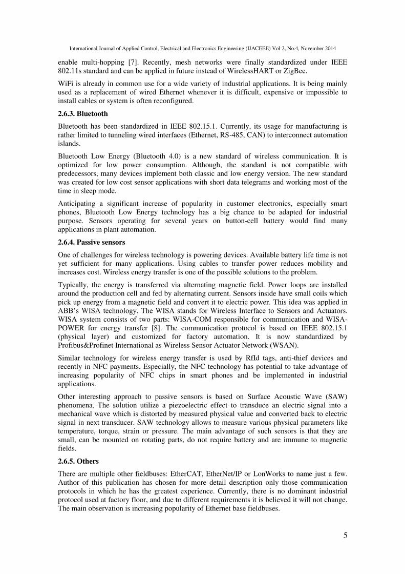
2.6.1. WirelessHART
WirelessHART is based on the proven and well established HART specification which has been
extended to ensure reliable and secure wireless data transfer. Wireless mesh technology was
applied to provide robust, self-healing network. Figure 2 shows an idea of mesh network.
Gateway is connected both to a host network and to a mesh. Multiple paths can occur between
the gateway and the mesh elements. If one pathway is blocked, network manager automatically
switches to redundant one. If new instrument joins the mesh, topology is automatically
reconfigured.
Each of network nodes has its own time slot for data transition. Time stamps are attached to
each telegram. WirelessHART offers several features to increase battery lifetime (transmission
only on data change, threshold for detection of value change, modification of refresh rate base
on process value, collecting and sending data in packs).
WirelessHART uses the same frequency as WiFi and Bluetooth. The bandwidth is divided into
15 channels. Before transmitting, device checks whether channel is currently being used. In
such case transmitter waits until next time slot and use a new channel.
Redundant path
Active path
Secure joint procedure
Host network
Figure 2. WirelessHART mesh topology [11]
2.6.2. WiFi
WiFi is a term to describe all Wireless Local Area Networks that conform to any of IEEE
802.11 standards. There are two basic modes of operation: infrastructure-based and ad-hoc. In
infrastructure mode each wireless client is connected to an Access Point (AP). Every two
devices need to communicate through an AP, which limits localization of them within range of
an AP. In ad-hoc mode devices can communicate directly between each other. The basic WiFi
configuration had no provision of multi-hop - network nodes cannot be used as an intermediary
devices. Several mechanisms have been proposed how to add routing capabilities to WiFi and
International Journal of Applied Control, Electrical and Electronics Engineering (IJACEEE) Vol 2, No.4, November 2014
5
enable multi-hopping [7]. Recently, mesh networks were finally standardized under IEEE
802.11s standard and can be applied in future instead of WirelessHART or ZigBee.
WiFi is already in common use for a wide variety of industrial applications. It is being mainly
used as a replacement of wired Ethernet whenever it is difficult, expensive or impossible to
install cables or system is often reconfigured.
2.6.3. Bluetooth
Bluetooth has been standardized in IEEE 802.15.1. Currently, its usage for manufacturing is
rather limited to tunneling wired interfaces (Ethernet, RS-485, CAN) to interconnect automation
islands.
Bluetooth Low Energy (Bluetooth 4.0) is a new standard of wireless communication. It is
optimized for low power consumption. Although, the standard is not compatible with
predecessors, many devices implement both classic and low energy version. The new standard
was created for low cost sensor applications with short data telegrams and working most of the
time in sleep mode.
Anticipating a significant increase of popularity in customer electronics, especially smart
phones, Bluetooth Low Energy technology has a big chance to be adapted for industrial
purpose. Sensors operating for several years on button-cell battery would find many
applications in plant automation.
2.6.4. Passive sensors
One of challenges for wireless technology is powering devices. Available battery life time is not
yet sufficient for many applications. Using cables to transfer power reduces mobility and
increases cost. Wireless energy transfer is one of the possible solutions to the problem.
Typically, the energy is transferred via alternating magnetic field. Power loops are installed
around the production cell and fed by alternating current. Sensors inside have small coils which
pick up energy from a magnetic field and convert it to electric power. This idea was applied in
ABB’s WISA technology. The WISA stands for Wireless Interface to Sensors and Actuators.
WISA system consists of two parts: WISA-COM responsible for communication and WISA-
POWER for energy transfer [8]. The communication protocol is based on IEEE 802.15.1
(physical layer) and customized for factory automation. It is now standardized by
Profibus&Profinet International as Wireless Sensor Actuator Network (WSAN).
Similar technology for wireless energy transfer is used by RfId tags, anti-thief devices and
recently in NFC payments. Especially, the NFC technology has potential to take advantage of
increasing popularity of NFC chips in smart phones and be implemented in industrial
applications.
Other interesting approach to passive sensors is based on Surface Acoustic Wave (SAW)
phenomena. The solution utilize a piezoelectric effect to transduce an electric signal into a
mechanical wave which is distorted by measured physical value and converted back to electric
signal in next transducer. SAW technology allows to measure various physical parameters like
temperature, torque, strain or pressure. The main advantage of such sensors is that they are
small, can be mounted on rotating parts, do not require battery and are immune to magnetic
fields.
2.6.5. Others
There are multiple other fieldbuses: EtherCAT, EtherNet/IP or LonWorks to name just a few.
Author of this publication has chosen for more detail description only those communication
protocols in which he has the greatest experience. Currently, there is no dominant industrial
protocol used at factory floor, and due to different requirements it is believed it will not change.
The main observation is increasing popularity of Ethernet base fieldbuses.
International Journal of Applied Control, Electrical and Electronics Engineering (IJACEEE) Vol 2, No.4, November 2014
6
3. SCADA LEVEL
The SCADA term stands for Supervisory Control And Data Acquisition. It generally refers to a
set of applications to control and monitor an industrial process. The OPC (OLE for Process
Control) was mostly created to enable interoperability at the SCADA level. Currently, OPC
technology is a widely accepted industrial communication standard that enables exchange of
data between multi-vendor field level devices and software for advance control and
visualization. Multiple OPC specifications were defined, currently the most widely spread is
OPC Data Access. OPC DA deals only with real-time process data. For historical data and
alarms separate specifications were created.
In OPC DA with each process value time stamp and signal quality value is associated. The OPC
technology has a Client – Server architecture. Usually OPC Server is an application running on
PC, communicating with industrial equipment via proprietary interface. Manufacturing Message
Specification (MMS) was proposed to standardize exchanging data between networked devices
and computers [9], but it had little success.
An OPC Client can subscribe in Server chosen data with a minimal refresh rate. The main
disadvantage of OPC DA technology is its dependency to Microsoft’s DCOM/COM. It limits usage of OPC DA in non-Windows base systems. As a solution for this problem OPC XML has
been proposed, but till now there are not many implementations of it. In practice, OPC United
Architecture (OPC UA), which include features of all previous OPC standards, has a chance to
become a true replacement of OPC DA. OPC UA is based on Web Services and Service
Oriented Architecture (SOA). SOA bases on the idea of service as an independent piece of
software with specified interface and is capable to provide described functionality. It is a cross
platform solution. It offers two protocols for communication between Server and Clients. One is
a binary TCP protocol, optimized for high performance and the second is XML based web
service. OPC Foundation provides exemplary implementations of OPC UA for ANSI C/C++,
Java and C#. Server can be implemented directly in a device which reduce need of installing
this software on the PC.
To provide vertical integration most of SCADA systems can be configured to be the OPC
Server for higher levels of the factory. In this case OPC UA is a step towards interoperability,
while using XML, generic SOAP clients can access data.
4. ENTERPRISE LEVEL
Enterprise network is used mainly by high level production management applications
(Enterprise Manufacturing Intelligence). The network traffic does not contain real-time data, but
trend is to increase that amount of production data processed and stored. Company executives
more often relay on those information to make critical decisions in near real-time.
To exchange data between multiple Enterprise Resource Planning software modules (i.e.
Material Resource Planning (MRP), Customer Relationship Manager (CRM), Supply Chain
Management (SCM) and more) common vendor independent architecture is needed. Service
Oriented Architecture (SOA) is well established solution in this area. It is frequent that both
service interface and communication protocol are defined with XML. Other solution for data
sharing between modules of ERP is common database.
5. CONCLUSIONS AND FUTURE TRENDS
In approach described in Figure 1 usually there is defined number (or even single) gateways
between tiers of the pyramid. Data exchange is taking place between different levels, but rarely
between devices within the same level. Recently, due to increase of popularity of Ethernet,
those both statements are not always valid. Growing number of sensors equipped with Ethernet
port allows accessing process data directly by the devices located in highest layers of an
International Journal of Applied Control, Electrical and Electronics Engineering (IJACEEE) Vol 2, No.4, November 2014
7
automation pyramid. Multiple clients can access the same data provider. Information can be
read from sensors at the same time both by the process controllers and SCADA/MRP systems.
It is more common that industrial devices provide embedded web page for configuration. It
reduce need of installing and managing proper version of configuration software. This solution
is also more platform independent - sensor configuration can be performed both on the
Windows, Linux or smartphone. Advances in real-time web design techniques allows to
smoothly show not only the static device configuration, but also process variables.
Another aspect of Ethernet popularity at the factory floor are changes in the way how
maintenance is performed. Many companies operate their production facilities spread all over
the world. It is often the case, that to solve not standard problem or perform non-routine
diagnostic, expertise not available locally at the plant is needed. Providing remote access to
factory devices enables possibility to involve several experts placed in distant locations to solve
the problem [10].
We can also observe emergence of new forms of service offered by automation devices vendors.
To ensure uninterrupted operation of their equipment they offer extended service contracts
which involves early diagnostic, preventive maintenance and emergency help base on remote
access. Term Intelligent Devices Management (IDM) was created to describe software which
allows manufacturers to monitor and manage remote equipment, systems and products via
the Internet [11]. Providing adequate level of security is a demanding task, but it is a win-win
scenario for both customer and device vendors. Customers will receive help in better and cost
effective assets management. Manufactures can use this data to improve their devices.
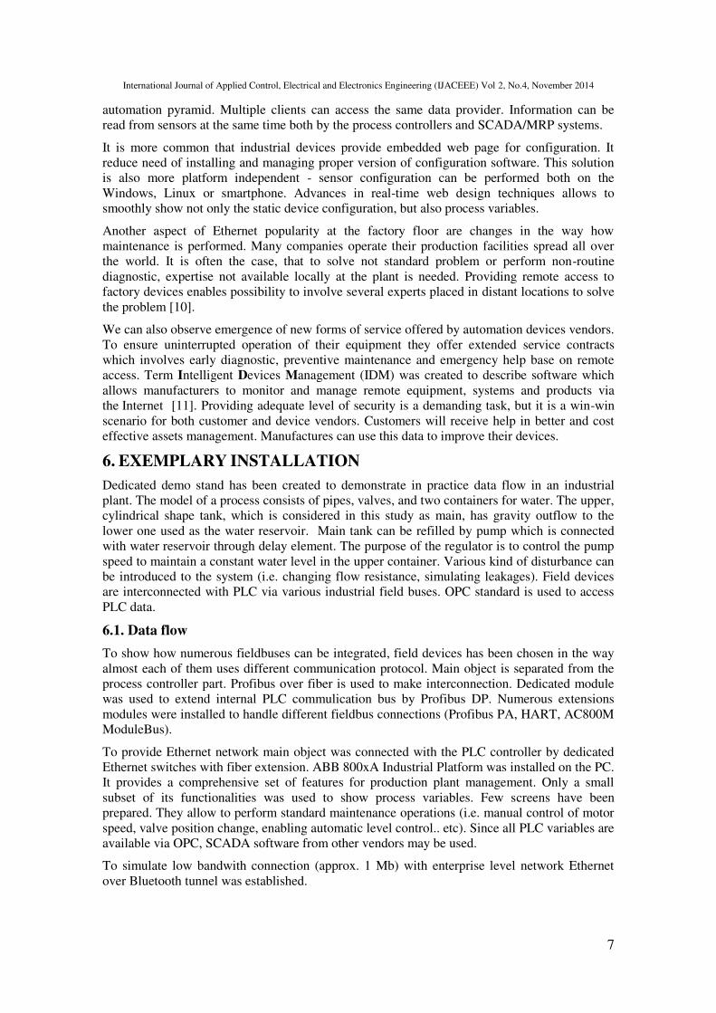
6. EXEMPLARY INSTALLATION
Dedicated demo stand has been created to demonstrate in practice data flow in an industrial
plant. The model of a process consists of pipes, valves, and two containers for water. The upper,
cylindrical shape tank, which is considered in this study as main, has gravity outflow to the
lower one used as the water reservoir. Main tank can be refilled by pump which is connected
with water reservoir through delay element. The purpose of the regulator is to control the pump
speed to maintain a constant water level in the upper container. Various kind of disturbance can
be introduced to the system (i.e. changing flow resistance, simulating leakages). Field devices
are interconnected with PLC via various industrial field buses. OPC standard is used to access
PLC data.
6.1. Data flow
To show how numerous fieldbuses can be integrated, field devices has been chosen in the way
almost each of them uses different communication protocol. Main object is separated from the
process controller part. Profibus over fiber is used to make interconnection. Dedicated module
was used to extend internal PLC commulication bus by Profibus DP. Numerous extensions
modules were installed to handle different fieldbus connections (Profibus PA, HART, AC800M
ModuleBus).
To provide Ethernet network main object was connected with the PLC controller by dedicated
Ethernet switches with fiber extension. ABB 800xA Industrial Platform was installed on the PC.
It provides a comprehensive set of features for production plant management. Only a small
subset of its functionalities was used to show process variables. Few screens have been
prepared. They allow to perform standard maintenance operations (i.e. manual control of motor
speed, valve position change, enabling automatic level control.. etc). Since all PLC variables are
available via OPC, SCADA software from other vendors may be used.
To simulate low bandwith connection (approx. 1 Mb) with enterprise level network Ethernet
over Bluetooth tunnel was established.
International Journal of Applied Control, Electrical and Electronics Engineering (IJACEEE) Vol 2, No.4, November 2014
8
6.2. Control algorithm
Preparation of the control algorithm was a subject of separate paper [12]. Model of the object
has been prepared and identified. The system has been divided into a few elements: pump, main
tank and reservoir. Each of them has been described with separate differential equation. Pump
speed is estimated by the drive (SZ-1) base on internal model of motor.
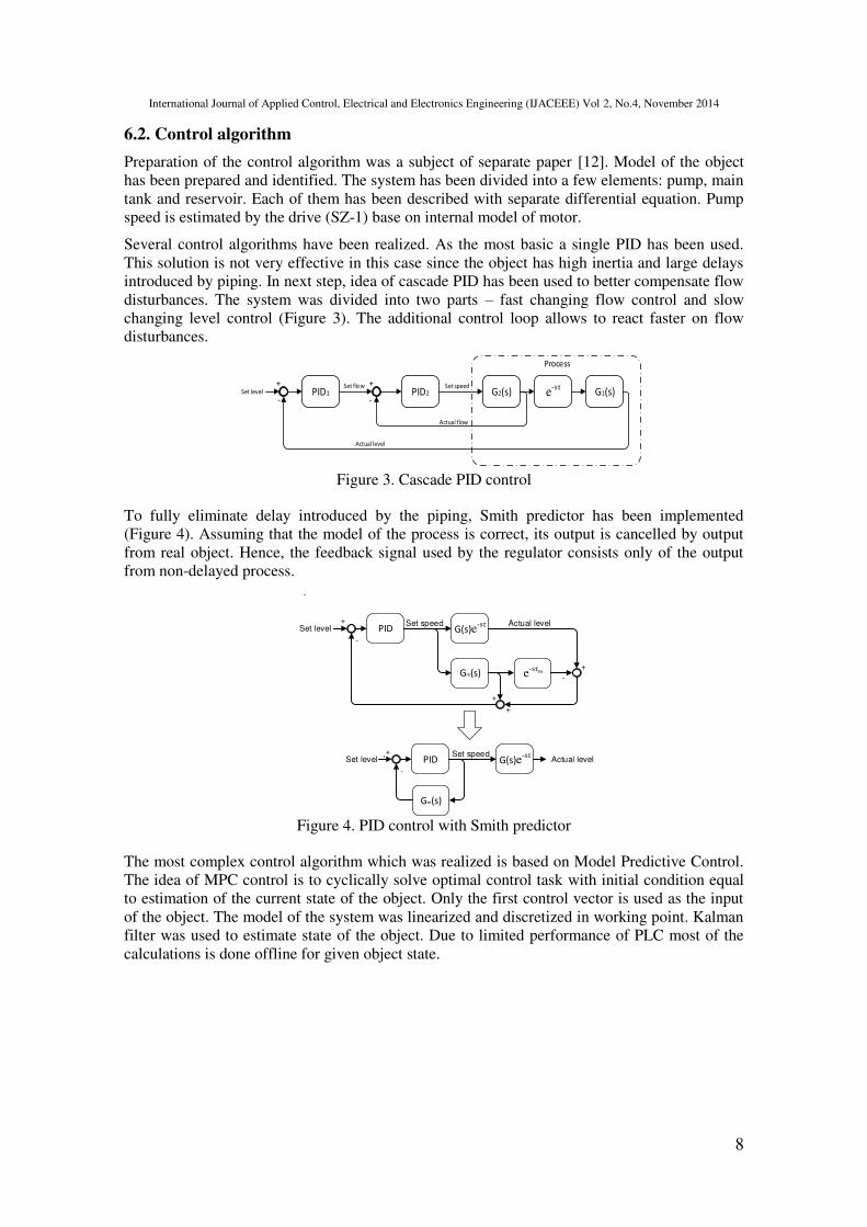
Several control algorithms have been realized. As the most basic a single PID has been used.
This solution is not very effective in this case since the object has high inertia and large delays
introduced by piping. In next step, idea of cascade PID has been used to better compensate flow
disturbances. The system was divided into two parts – fast changing flow control and slow
changing level control (Figure 3). The additional control loop allows to react faster on flow
disturbances.
Process
PID2Set speed
Actual flow
PID1Set flow
Actual level
Set level++
--G2(s) e-sτ
G1(s)
Figure 3. Cascade PID control
To fully eliminate delay introduced by the piping, Smith predictor has been implemented
(Figure 4). Assuming that the model of the process is correct, its output is cancelled by output
from real object. Hence, the feedback signal used by the regulator consists only of the output
from non-delayed process.
PIDSet speed
Set level+
-
G(s)e-sτ
Gm(s)
-
e-sτm
+
+
-
+
Actual level
PIDSet speed
Set level+
G(s)e-sτ
Gm(s)
-
Actual level
Figure 4. PID control with Smith predictor
The most complex control algorithm which was realized is based on Model Predictive Control.
The idea of MPC control is to cyclically solve optimal control task with initial condition equal
to estimation of the current state of the object. Only the first control vector is used as the input
of the object. The model of the system was linearized and discretized in working point. Kalman
filter was used to estimate state of the object. Due to limited performance of PLC most of the
calculations is done offline for given object state.

International Journal of Applied Control, Electrical and Electronics Engineering (IJACEEE) Vol 2, No.4, November 2014
9
LT1
LT2
Profibus PA HART
FT1
PDT-1
Profibus DP
ModuleBus over fiber
Profibus DP
SZ-1
KY1,KY2,
KY3,KY4
Digital IO
Profibus
over fiber
Profibus
DP
OPC
OPC
Ethernet
over
Bluetooth
Corporate
network
Ethernet
over fiber
OPC
800xA IT
Platform
XML-RPC
OPC DA
Protection
Relay
RS232
RS232 over Ethernet
Figure 5. Communication flow in prepared demo stand
Figure 5. Picture of demo stand
6.3. Protection relay
REF543R feeder terminal is designed to be used for protection, control, measurement and
supervision of medium voltage networks. Based on measurements of currents, voltage,
frequency, etc., the protection device is programmed to disconnect parts or equipment of the
system. In the described automation object the protection relay is measuring motor feed current
and voltage. It provides various measurements (i.e. THD, power, frequency, power factor.. etc.).
With such approach it is also possible to observe how ACS800 drive is controlling motor speed.
REF543R provides transient disturbance recorder which is able to record up to 16 currents or
voltages signals with high frequency.

International Journal of Applied Control, Electrical and Electronics Engineering (IJACEEE) Vol 2, No.4, November 2014
10
Information is read from protection relay by RS-232 and Ethernet tunnel. Virtual COM port is
available on the PC. Dedicated OPC server is running on the PC to allow accessing this data by
OPC clients.
6.4. Vendor independent to OPC DA
There are a few implementations of DCOM in Linux, but in fact they are almost never used for
creating OPC in non-Windows based systems (Android, QNX, iOS) [13]. Tunneling approach is
popular to enable vendor independent access to data provided by OPC DA. One solution is to
use OPC DA to OPC UA tunnel, second is to prepare custom software which translates OPC to
chosen protocol.
In the presented system, dedicated software was prepared to translate OPC to XML-RPC. There
are several reasons for using XML based protocol. XML-RPC uses HTTP as a transport
mechanism to exchange XML data between client and server. It provides less functionalities
than SOAP and number of transferred data is larger than while using JSON. The main
advantage of XML-RPC is that it can be easy debug with Wireshark. There are a few open
implementations of XML-RPC for various operating systems. Android application was prepared
to check feasibility of the idea (Figure 6). Additionally, PC gateway was prepared to run on the
PC where OPC server is installed. Since security was not a concern in this situation, it is
possible to access process anywhere within corporate network.
Figure 6. Main view of prepared Android application
7. SUMMARY
To sum up, this paper describes data flow in the typical industrial object. It was shown that with
dedicated equipment it is easy to integrate multiple industrial communication fieldbuses into
one system. Growing popularity of Ethernet is a game changer in area of field level
communication. It is expected that popularity of Ethernet based protocols will increase.
Currently, OPC DA is most popular standard for accessing process data by SCADA level
applications. Its usage is limited to Windows and it is expected that OPC UA will replace it.
Service Oriented Architecture is used for communication between elements at the enterprise
level software. Growing popularity of SOA increases interoperability and allows to create
vendor independent solutions.

International Journal of Applied Control, Electrical and Electronics Engineering (IJACEEE) Vol 2, No.4, November 2014
11
REFERENCES
[1] Dietrich R., Industrial Ethernet. from the Office to the Machine, Harting, 2005.
[2] Modbus Application Protocol Specification V1.1b3, Modbus Organization, 2012.04.
[3] Profibus Installation Guideline for Commisioning, Version 1.0.2, PI International, 2006.
[4] Tovar E., Vasques F., Cycle Time Properties of the PROFIBUS Timed Token Protocol, IEE
Proceedings - Software, 1998.
[5] Zhu Yu, CAN and FPGA Communication Engineering, Diplomica Verlag, 2010.
[6] HART Communication protocol, ABB Information Bulletin, IB/INST–016 Issue 1.
[7] Wei H.Y., Rykowski J., Dixit S., WiFi, WiMAX and LTE Multi-hop Mesh Networks : Basic
Communication Protocols and Application Areas, Wiley, 2013.
[8] Steigmann R., Endresen J., Introduction to WISA, ABB White Paper, July 2006
[9] Overview and Introduction to the Manufacturing Message Specification (MMS), Rev 2, SISCO,
1995
[10] Hollender M., Collaborative Process Automation Systems, ISA, 2010.
[11] Dong J., Network Dictionary, Javvin Technologies Inc., 2007.
[12] Bubak M., Sterowanie i diagnostyka obiektów nieliniowych na przykładzie układu dwóch zbiorników, Praca magisterska, Kraków 2010
[13] What is DCOM? DCOM implementations. http://linuxopc.info, (access 2013.10.30)
Authors
Marcin Bajer graduated from University of Science and Technology in
Kraków, Poland, in field of Computer Control Systems. Since 2008 he has
been working at ABB Corporate Research in Kraków, where he is
responsible for programming and testing embedded devices. His research
interests also cover industrial communication protocols, Linux kernel and
mobile technology