Automation - Lenze
77
Automation 417 037 Lenze Lenze GmbH & Co KG, Postfach 10 13 52, D-31763 Hameln, Site: Groß Berkel, Hans-Lenze-Straße 1, D-31855 Aerzen, Phone ++49 (0) 5154 82-0, Telefax ++49 (0) 5154 82-21 11 E-Mail: [email protected] · Internet: http://www.Lenze.com Technical alterations reserved · Printed in Germany 01.01 by ME / LHM · 00/09 en Lenze 2 Automation en 09/00 Systematic automation The automation pyramid symbolises the philosophy of the Lenze inverter generation 9300 and 8200 vector and motec up to the Drive PLC. At Lenze, the power range of the drives is not restricted to the lower level of the pyramid, the rotating motor shaft. The system commissioning engineer is supported by the technology functions and can therefore fully concentrate on his application. The second level of the automation pyramid thus ensures easy commissioning of complex drive functions. Thanks to the Servo PLC and the Drive PLC with the 8200 vector, the top of the pyramid is also covered. PLC functions are now implemented directly in the drive. In this way, the modular decentralised machine concept is also transferred to the control level.
-
Upload
khangminh22 -
Category
Documents
-
view
1 -
download
0
Transcript of Automation - Lenze
Automation
417 037 Lenze
Lenze GmbH & Co KG, Postfach 1013 52, D-31763 Hameln, Site: Groß Berkel,Hans-Lenze-Straße 1, D-31855 Aerzen, Phone ++49 (0) 5154 82-0, Telefax ++49 (0) 5154 82-21 11E-Mail: [email protected] · Internet: http://www.Lenze.comTechnical alterations reserved · Printed in Germany 01.01 by ME / LHM · 00/09 en Lenze2 Automation en 09/00
Systematic automation
The automation pyramid symbolises the philosophy of theLenze inverter generation 9300 and 8200 vector andmotec up to the Drive PLC. At Lenze, the power range of the drives is not restricted tothe lower level of the pyramid, the rotating motor shaft.The system commissioning engineer is supported by thetechnology functions and can therefore fully concentrateon his application.
The second level of the automation pyramid thus ensureseasy commissioning of complex drive functions.Thanks to the Servo PLC and the Drive PLC with the 8200 vector, the top of the pyramid is also covered. PLC functions are now implemented directly in the drive.In this way, the modular decentralised machine concept isalso transferred to the control level.
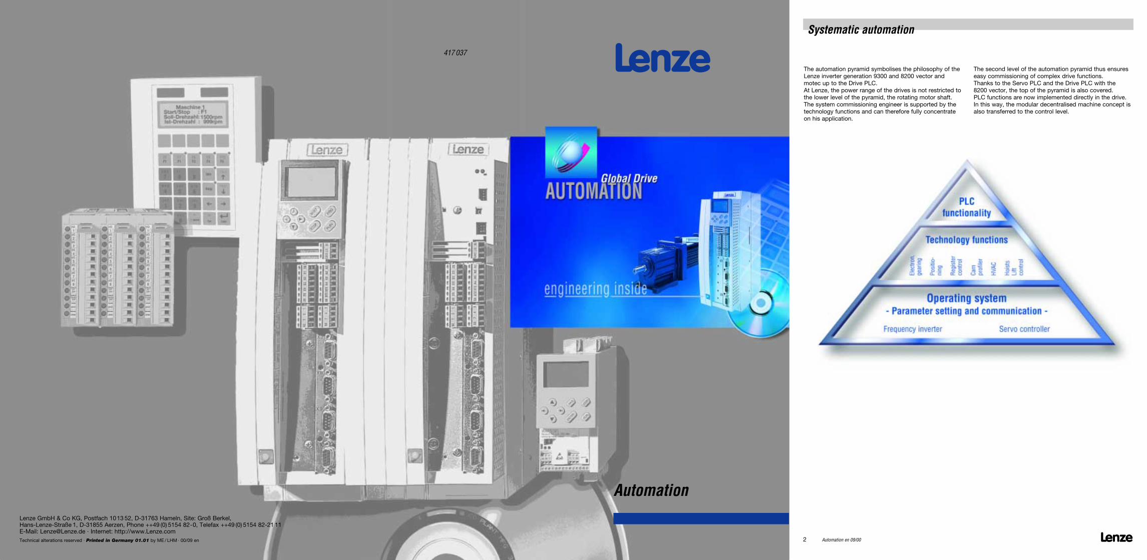
Keypad / display units Software tools
IEC 1131 inside
Drive
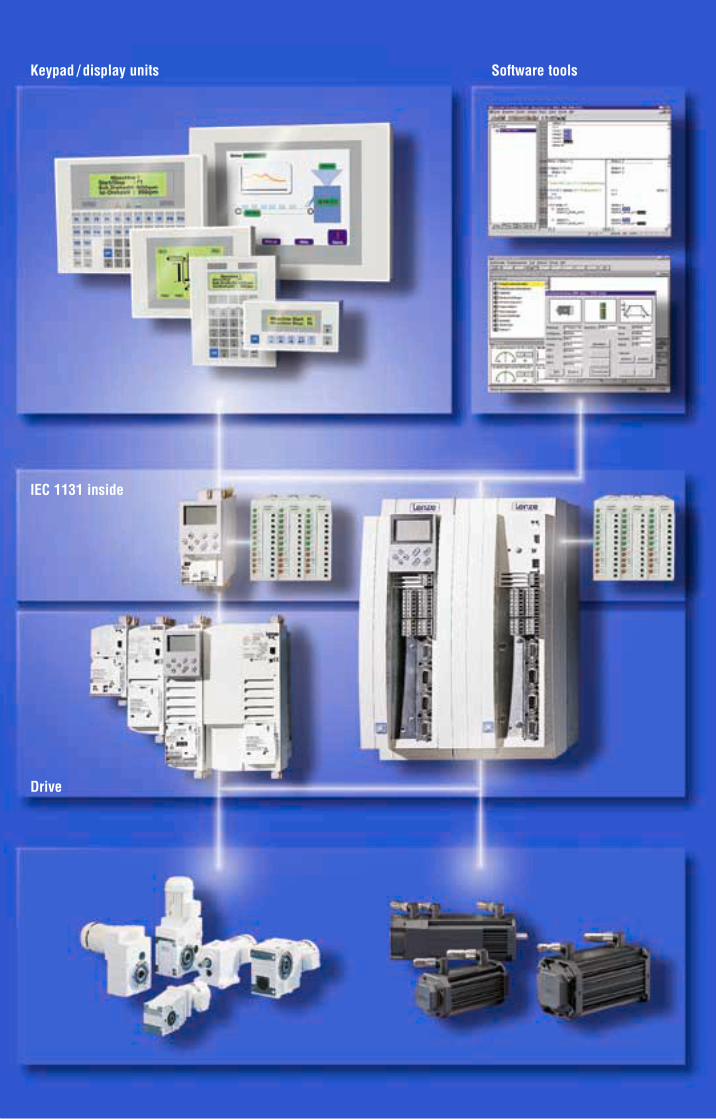
System structureLenze offers you a completesystem for your automation whichconsists of the most diverse hardware components and theappropriate software. This has thefollowing advantages:
One stop shopping• Compatible system components –
from the drive to the user interface
Tested, well-thought out softwaresolutions thanks to technologyfunctions• Reliability• Time advantage (⇒ cost
advantage) due to faster commissioning
• Know how protection since programming is made by thecustomer in IEC1131.
All included in the intelligent drive!
Cost savings throughout the entireproduct life-cycle• No additional programming skills
required and, as a result, reducedtraining costs
• Shorter project planning phase at the customer’s thanks to previously tested systems
• Competent contact partners areall over the world available toprovide aftersales servicesfor all system components.
Global Drive
Info
Ihre Maschine Ihr Firmenname
shiftEnter
Help
+ -
space
.
7V W X
8Y Z –
9+ / -
4M N O
5P Q R
6S T U
1D E F
0A B C
2G H I
3J K L
PgUp
PgDn
Clr
Esc
F6F1
F7F1
F8F3
F9F4
F10F5
Actual speet
Machine Start/StopSetpoint speed
Drive PLC
Human Machine Interface
9300 Servo PLC
distributed I/O
Software tools

Lenze Automation en 01/01 5
Contents
Software tools ___________________________________
Drive Server __________________________________50Drive PLC Developer Studio ____________________52Global Drive Control ___________________________54CamDesigner _________________________________58HMI Designer _________________________________59
Accessories
Bus systems for automation tasks_______________62Overview bus systems _________________________63System bus (CAN) _____________________________64PROFIBUS-DP ________________________________65INTERBUS ___________________________________66INTERBUS Loop ______________________________67DeviceNet ____________________________________68LECOM B (RS485)_____________________________69LECOM-LI ____________________________________70Keypad ______________________________________71Hand-held terminal 9372BB ____________________72PLC system bus inverter _______________________72Terminal extension ____________________________73
Order forms
_____________________________________________74
Lenze worldwide ________________________________
_____________________________________________78
Automation solutions
ApplicationsInverter technology_____________________________ 6Servo technology ______________________________ 7Servo cam profiler _____________________________ 8Servo positioning controller_____________________10Servo register controller ________________________12
Servo PLC and Drive PLC ______________________
Overview _____________________________________16
Drive PLC
Description ___________________________________18System overview ______________________________19Ratings ______________________________________20Standards and operating conditions _____________21Extension board_______________________________22Mechanical installation _________________________23Electrical installation ___________________________25
Servo PLC
Description ___________________________________28System overview ______________________________29Drive characteristics ___________________________31Characteristics of the servo motors______________32Ratings ______________________________________34Standards and operating conditions _____________35Mechanical installation _________________________39
Keypad / display units
Description ___________________________________43Ratings H310 _________________________________44Ratings H315 _________________________________45Ratings H410 _________________________________46Ratings H510 _________________________________47Ratings H520 _________________________________48
Lenze6 Automation en 01/01
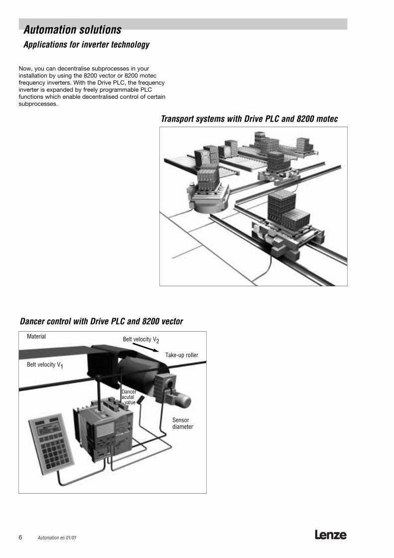
Automation solutions Applications for inverter technology
Dancer control with Drive PLC and 8200 vector
Transport systems with Drive PLC and 8200 motec
Now, you can decentralise subprocesses in your installation by using the 8200 vector or 8200 motec frequency inverters. With the Drive PLC, the frequencyinverter is expanded by freely programmable PLC functions which enable decentralised control of certainsubprocesses.
Belt velocity V2
Belt velocity V1
Material
Danceracutal
value
Take-up roller
Sensor diameter
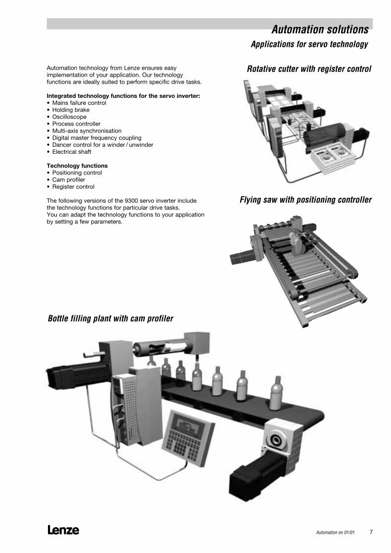
Automation solutions Applications for servo technology
Lenze Automation en 01/01 7
Rotative cutter with register control
Bottle filling plant with cam profiler
Flying saw with positioning controller
Automation technology from Lenze ensures easy implementation of your application. Our technology functions are ideally suited to perform specific drive tasks.
Integrated technology functions for the servo inverter:• Mains failure control• Holding brake• Oscilloscope• Process controller• Multi-axis synchronisation• Digital master frequency coupling• Dancer control for a winder / unwinder• Electrical shaft
Technology functions• Positioning control• Cam profiler• Register control
The following versions of the 9300 servo inverter includethe technology functions for particular drive tasks. You can adapt the technology functions to your applicationby setting a few parameters.
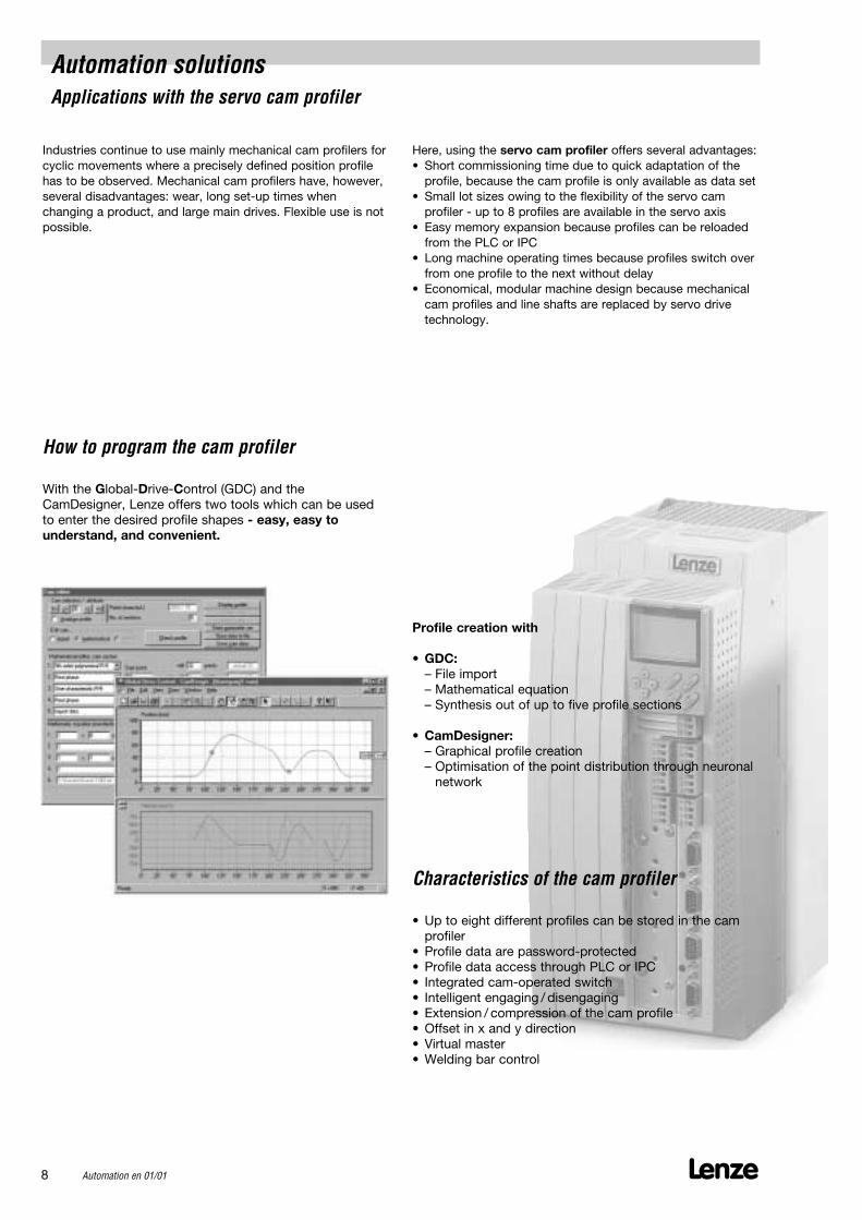
Automation solutions Applications with the servo cam profiler
Industries continue to use mainly mechanical cam profilers forcyclic movements where a precisely defined position profilehas to be observed. Mechanical cam profilers have, however,several disadvantages: wear, long set-up times when changing a product, and large main drives. Flexible use is notpossible.
Here, using the servo cam profiler offers several advantages: • Short commissioning time due to quick adaptation of the
profile, because the cam profile is only available as data set• Small lot sizes owing to the flexibility of the servo cam
profiler - up to 8 profiles are available in the servo axis• Easy memory expansion because profiles can be reloaded
from the PLC or IPC• Long machine operating times because profiles switch over
from one profile to the next without delay• Economical, modular machine design because mechanical
cam profiles and line shafts are replaced by servo drivetechnology.
Lenze8 Automation en 01/01
With the Global-Drive-Control (GDC) and theCamDesigner, Lenze offers two tools which can be usedto enter the desired profile shapes - easy, easy to understand, and convenient.
Characteristics of the cam profiler
How to program the cam profiler
• Up to eight different profiles can be stored in the camprofiler
• Profile data are password-protected• Profile data access through PLC or IPC• Integrated cam-operated switch• Intelligent engaging / disengaging• Extension / compression of the cam profile• Offset in x and y direction• Virtual master• Welding bar control
Profile creation with
• GDC: – File import– Mathematical equation – Synthesis out of up to five profile sections
• CamDesigner: – Graphical profile creation – Optimisation of the point distribution through neuronal
network
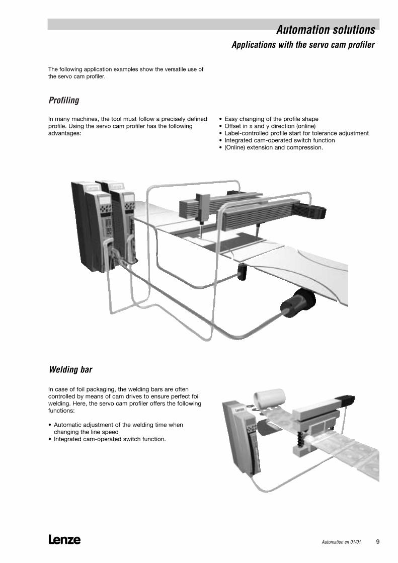
Profiling
• Easy changing of the profile shape• Offset in x and y direction (online)• Label-controlled profile start for tolerance adjustment• Integrated cam-operated switch function• (Online) extension and compression.
In many machines, the tool must follow a precisely definedprofile. Using the servo cam profiler has the followingadvantages:
In case of foil packaging, the welding bars are often controlled by means of cam drives to ensure perfect foilwelding. Here, the servo cam profiler offers the followingfunctions:
• Automatic adjustment of the welding time when changing the line speed
• Integrated cam-operated switch function.
Welding bar
Automation solutionsApplications with the servo cam profiler
Lenze Automation en 01/01 9
The following application examples show the versatile use ofthe servo cam profiler.

Lenze10 Automation en 01/01
Positioning tasks can be implemented in a very economical way with the help of electronic drives, because compared to mechanical solutions, such asclutch-brake-units, wear and energy consumption aremuch lower. And, the 9300 positioning controller at thesame time executes the decentralised PLC functions.
The servo positioning controller is distinguished by variousadvantages:
• Short training time required thanks to menu-controlledprogramming
• Touch probe function allows easy correction of mechanical inaccuracies
• Flexible control of peripherals means reduced requirement of hardware components
• Open system as positions are set by the PLC
Below, individual applications are demonstrated taking the9300 servo positioning controller as example.
Automation solutionsApplications with the servo positioning controller
The Global-Drive-Control (GDC), helps you to enter your positioning programs - application-oriented and easy-to-understand.
Characteristics of the positioning controller
How to program the positioning controller
• Up to 32 programming sets all including position target,acceleration, speed, positioning type, switching functions, branching, etc.
• Homing for the use of incremental encoders• 16 slow-down points, 8 out of which have a dead
time compensation to compensate dead times in thecontrolled aggregates
• Touch probe for easy synchronisation• S-ramp for soft accelerating• Override for online speed adjustment• Manual homing mode for set-up operations• Stand-by operation.
The positioning program:• Relative or absolute positioning• Branching• Loops• Waiting for events
Lenze Automation en 01/01 11
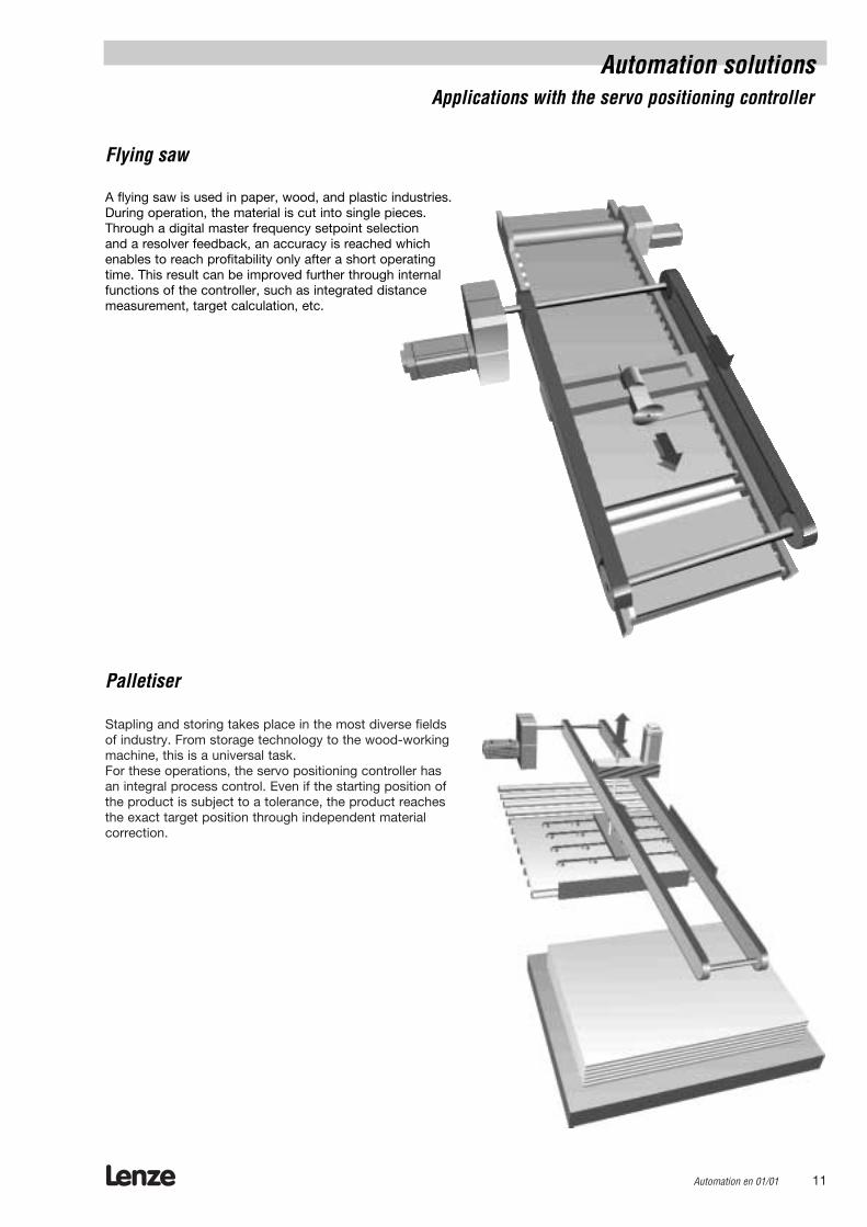
Stapling and storing takes place in the most diverse fieldsof industry. From storage technology to the wood-workingmachine, this is a universal task. For these operations, the servo positioning controller hasan integral process control. Even if the starting position ofthe product is subject to a tolerance, the product reachesthe exact target position through independent materialcorrection.
A flying saw is used in paper, wood, and plastic industries.During operation, the material is cut into single pieces.Through a digital master frequency setpoint selection and a resolver feedback, an accuracy is reached whichenables to reach profitability only after a short operatingtime. This result can be improved further through internalfunctions of the controller, such as integrated distancemeasurement, target calculation, etc.
Flying saw
Palletiser
Automation solutionsApplications with the servo positioning controller
Lenze12 Automation en 01/01
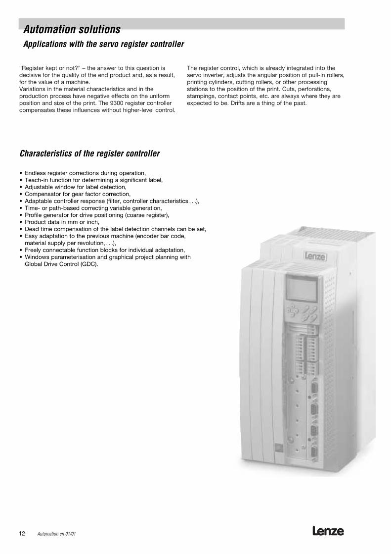
“Register kept or not?” – the answer to this question isdecisive for the quality of the end product and, as a result,for the value of a machine. Variations in the material characteristics and in the production process have negative effects on the uniformposition and size of the print. The 9300 register controllercompensates these influences without higher-level control.
The register control, which is already integrated into theservo inverter, adjusts the angular position of pull-in rollers,printing cylinders, cutting rollers, or other processing stations to the position of the print. Cuts, perforations,stampings, contact points, etc. are always where they areexpected to be. Drifts are a thing of the past.
Automation solutionsApplications with the servo register controller
Characteristics of the register controller
• Endless register corrections during operation,• Teach-in function for determining a significant label,• Adjustable window for label detection,• Compensator for gear factor correction,• Adaptable controller response (filter, controller characteristics . . .),• Time- or path-based correcting variable generation,• Profile generator for drive positioning (coarse register),• Product data in mm or inch,• Dead time compensation of the label detection channels can be set,• Easy adaptation to the previous machine (encoder bar code,
material supply per revolution, . . .),• Freely connectable function blocks for individual adaptation,• Windows parameterisation and graphical project planning with
Global Drive Control (GDC).
Lenze Automation en 01/01 13
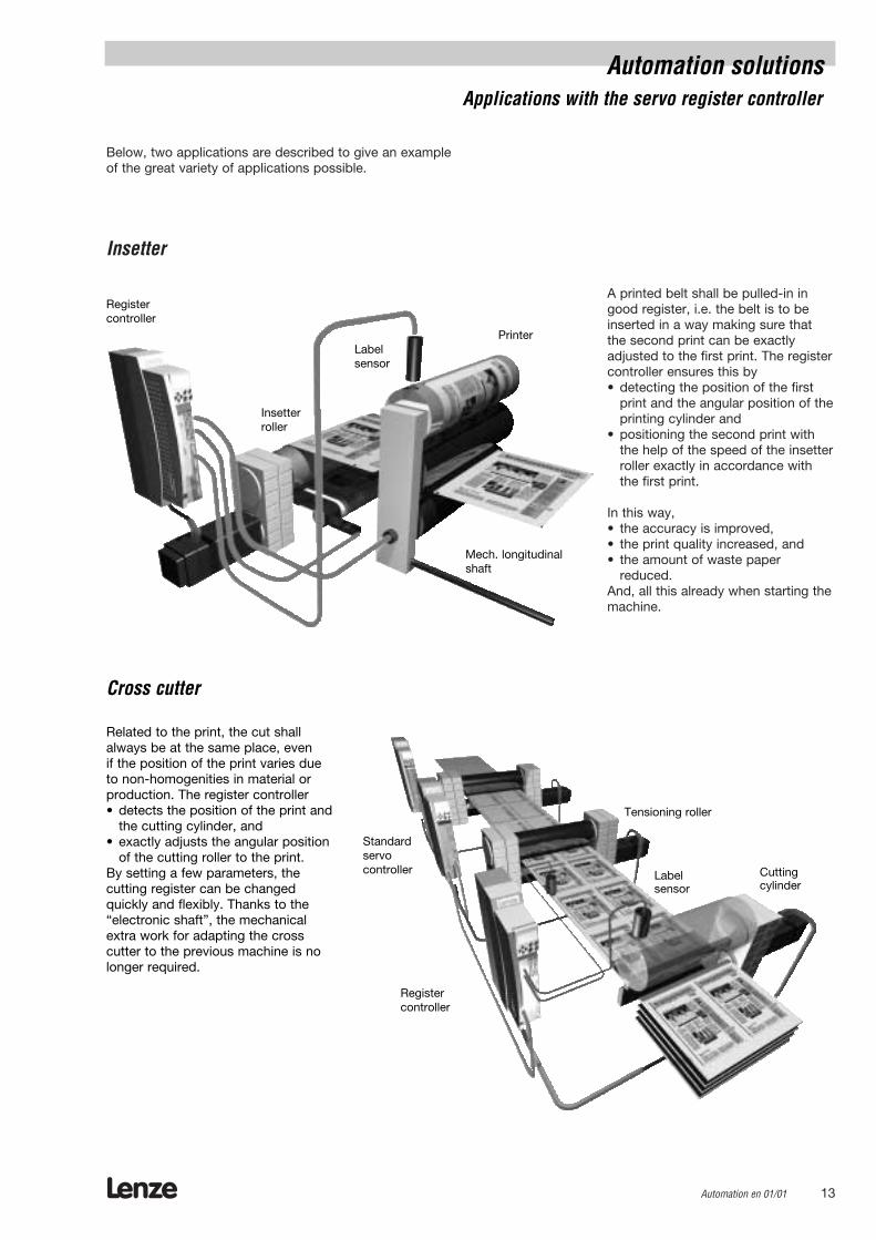
A printed belt shall be pulled-in ingood register, i.e. the belt is to beinserted in a way making sure thatthe second print can be exactly adjusted to the first print. The registercontroller ensures this by• detecting the position of the first
print and the angular position of theprinting cylinder and
• positioning the second print withthe help of the speed of the insetterroller exactly in accordance withthe first print.
In this way,• the accuracy is improved,• the print quality increased, and• the amount of waste paper
reduced.And, all this already when starting themachine.
Below, two applications are described to give an exampleof the great variety of applications possible.
Insetter
Insetterroller
PrinterLabelsensor
Registercontroller
Mech. longitudinalshaft
Related to the print, the cut shallalways be at the same place, even if the position of the print varies dueto non-homogenities in material orproduction. The register controller• detects the position of the print and
the cutting cylinder, and• exactly adjusts the angular position
of the cutting roller to the print.By setting a few parameters, the cutting register can be changedquickly and flexibly. Thanks to the“electronic shaft”, the mechanicalextra work for adapting the cross cutter to the previous machine is nolonger required.
Cross cutter
Tensioning roller
Cuttingcylinder
Label sensor
Standardservocontroller
Register controller
Automation solutionsApplications with the servo register controller

Lenze14 Automation en 01/01
Lenze Automation en 01/01 15
Servo PLC and Drive PLC
Lenze16 Automation en 01/01
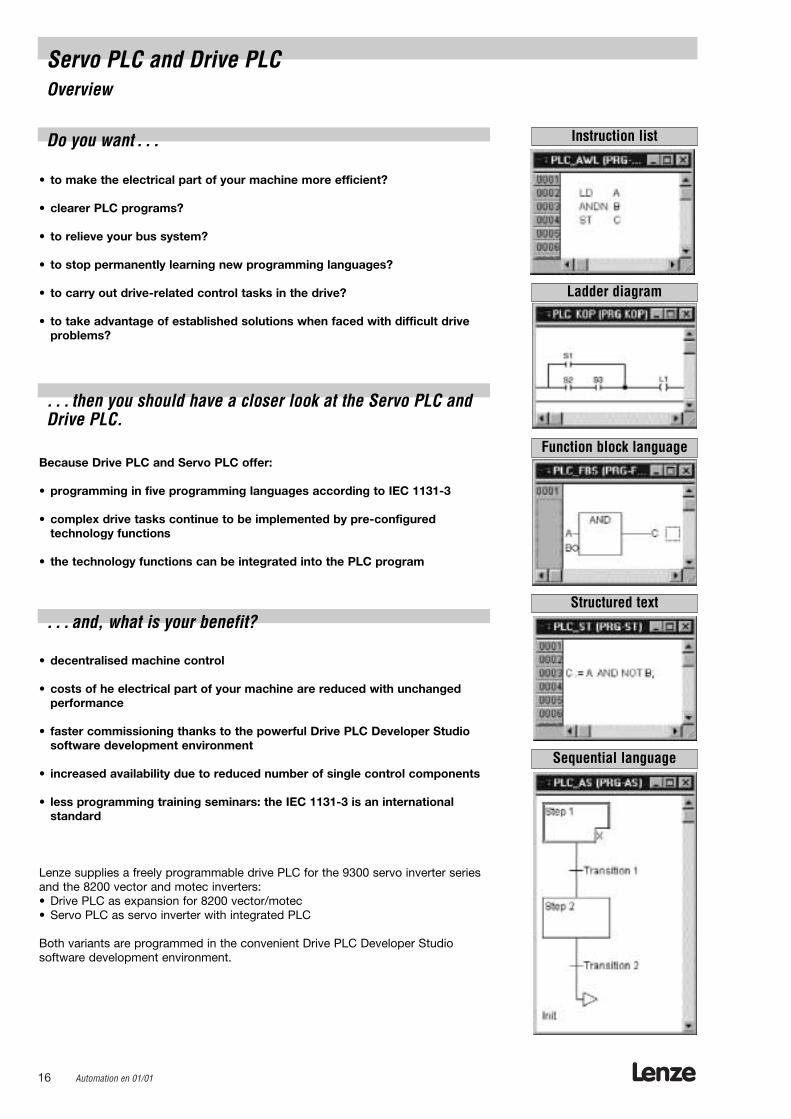
Servo PLC and Drive PLCOverview
Ladder diagram
Function block language
Structured text
Sequential language
Instruction list
• to make the electrical part of your machine more efficient?
• clearer PLC programs?
• to relieve your bus system?
• to stop permanently learning new programming languages?
• to carry out drive-related control tasks in the drive?
• to take advantage of established solutions when faced with difficult driveproblems?
Because Drive PLC and Servo PLC offer:
• programming in five programming languages according to IEC 1131-3
• complex drive tasks continue to be implemented by pre-configured technology functions
• the technology functions can be integrated into the PLC program
• decentralised machine control
• costs of he electrical part of your machine are reduced with unchanged performance
• faster commissioning thanks to the powerful Drive PLC Developer Studiosoftware development environment
• increased availability due to reduced number of single control components
• less programming training seminars: the IEC 1131-3 is an international standard
Lenze supplies a freely programmable drive PLC for the 9300 servo inverter seriesand the 8200 vector and motec inverters:• Drive PLC as expansion for 8200 vector/motec• Servo PLC as servo inverter with integrated PLC
Both variants are programmed in the convenient Drive PLC Developer Studio software development environment.
Do you want . . .
. . . then you should have a closer look at the Servo PLC andDrive PLC.
. . . and, what is your benefit?
Lenze Automation en 01/01 17
Servo PLC and Drive PLC
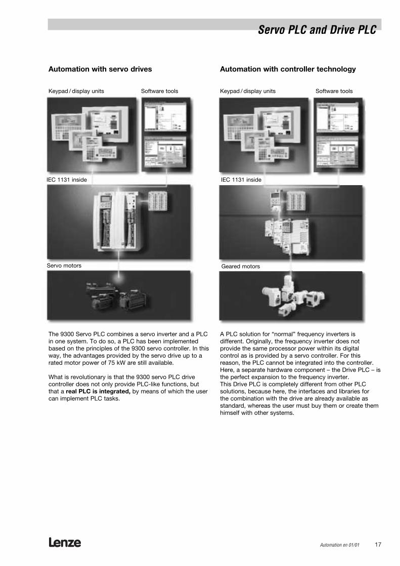
Automation with controller technology
A PLC solution for “normal” frequency inverters is different. Originally, the frequency inverter does not provide the same processor power within its digital control as is provided by a servo controller. For this reason, the PLC cannot be integrated into the controller.Here, a separate hardware component – the Drive PLC – isthe perfect expansion to the frequency inverter.This Drive PLC is completely different from other PLCsolutions, because here, the interfaces and libraries for the combination with the drive are already available asstandard, whereas the user must buy them or create themhimself with other systems.
The 9300 Servo PLC combines a servo inverter and a PLCin one system. To do so, a PLC has been implementedbased on the principles of the 9300 servo controller. In thisway, the advantages provided by the servo drive up to arated motor power of 75 kW are still available.
What is revolutionary is that the 9300 servo PLC drivecontroller does not only provide PLC-like functions, butthat a real PLC is integrated, by means of which the usercan implement PLC tasks.
Automation with servo drives
Keypad / display units Software tools
IEC 1131 inside
Geared motors
Keypad / display units Software tools
IEC 1131 inside
Servo motors

Lenze18 Automation en 01/01
Drive PLCDescription
With the Drive PLC, the 8200 vector frequency inverter isextended by a freely programmable drive PLC.This duo does not only control movements in yourmachine, but now also takes over the decentralised control tasks. System programming is made in the PLClanguages of the IEC 1131-3 international standard.
Why a Drive PLC?
Which additional advantages does the Drive PLC offerover a standard PLC?
• Parallel wiring and superfluous terminals are not necessary due to an integrated system bus interface withthe 8200 vector frequency inverter
• Easy engineering through special software library foreasy integration of the 8200 vector into the PLC program
• Plug-on modules enable easy integration of the mostdiverse fieldbuses
• Economical system with high basic functionality• No additional costs for gateway function to higher-level
bus systems such as INTERBUS, PROFIBUS, DeviceNet.In the system bus (CAN), the gateway function is automatically implemented by the operating system ofthe Drive PLC.
Lenze offers you a complete automation system for yourapplication from the keypad/display unit to the gearedmotor.And, now, even the software, which brings your machineto life, is quickly compiled by Lenze from the basic configurations and technology functions, and, all that inthe languages you are already familiar with of IEC 1131-3.
Lenze Automation en 01/01 19
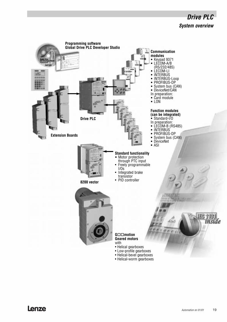
Function modules(can be integrated)• Standard-I/OIn preparation:• LECOM-B (RS485)• INTERBUS• PROFIBUS-DP• System bus (CAN)• DeviceNet • ASI
Standard functionality• Motor protection
through PTC input• Freely programmable
I/Os• Integrated brake
transistor• PID controller
Communicationmodules• Keypad 9371• LECOM-A/B
(RS/232/485)• LECOM-LI• INTERBUS• INTERBUS-Loop• PROFIBUS-DP• System bus (CAN)• DeviceNet/CANIn preparation:• Card module• LON
Drive PLC
8200 vector
G""motionGeared motors with• Helical gearboxes• Low-profile gearboxes• Helical-bevel gearboxes• Helical-worm gearboxes
Extension Boards
Programming softwareGlobal Drive PLC Developer Studio
Drive PLCSystem overview

Program memory 191 kB
Data memory 8.3 kB (1.3 kB Markers + 7 kB variables)
EEprom buffered memory 800-byte
Remanent memory 200-byte
Task types 1 cyclical task8 tasks (time- or event-controlled)
Processing time of abit operation 1.0 µs
No. of counters/timers freely selectable according to IEC 1131
Digital inputs 8 (3 out of which can be interrupted)
Expandable by extension board and decentralised terminals
Digital outputs 4 (1 A each)
Expandable by extension board and decentralised terminals
Analog inputs 3 (± 10 V, 11-bit)
Analog outputs 1 (± 10 V or ± 20 mA, 11-bit)
Communication interfaces system bus (CANopen)
RS232/485**
or PROFIBUS**
or INTERBUS/INTERBUS Loop**
or DeviceNet**
Dimensions (H x W x D) / [mm] 120 x 60 x 140
Operations available according to IEC 11131
Programming software Drive PLC Developer Studio with the programming languages: instruction list, ladder diagramand function block language structured text, SFC with simulation, debugging and monitoring,
visualisation
Power supply + 18 . . . 30 V DC
Current (at 24 V DC) 200 mA (without load on the outputs)
** plug-on fieldbus modules
Drive PLCRatings
Lenze20 Automation en 01/01
Type Order No.:
Drive PLC EPL 10200
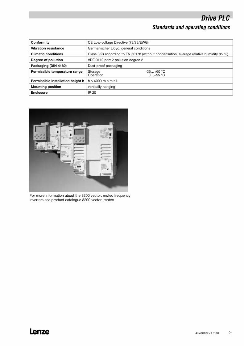
Drive PLCStandards and operating conditions
Lenze Automation en 01/01 21
Conformity CE Low-voltage Directive (73/23/EWG)
Vibration resistance Germanischer Lloyd, general conditions
Climatic conditions Class 3K3 according to EN 50178 (without condensation, average relative humidity 85 %)
Degree of pollution VDE 0110 part 2 pollution degree 2
Packaging (DIN 4180) Dust-proof packaging
Permissible temperature range Storage -25…+60 °COperation 0…+55 °C
Permissible installation height h h ≤ 4000 m a.m.s.l.
Mounting position vertically hanging
Enclosure IP 20
For more information about the 8200 vector, motec frequency inverters see product catalogue 8200 vector, motec
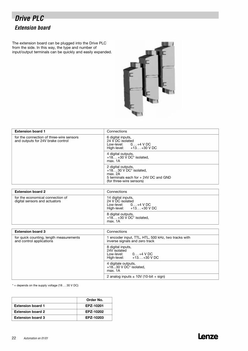
Drive PLCExtension board
The extension board can be plugged into the Drive PLCfrom the side. In this way, the type and number ofinput/output terminals can be quickly and easily expanded.
Lenze22 Automation en 01/01
Extension board 1 Connections
for the connection of three-wire sensors 6 digital inputs,and outputs for 24V brake control 24 V DC isolated
Low-level: 0. . . +4 V DCHigh-level: +13. . . +30 V DC
4 digital outputs,+18. . . +30 V DC* isolated,max. 1A
2 digital outputs,+18. . . 30 V DC* isolated,max. 2A5 terminals each for + 24V DC and GND (for three-wire sensors)
Extension board 2 Connections
for the economical connection of 14 digital inputs,digital sensors and actuators 24 V DC isolated
Low-level: 0. . . +4 V DCHigh-level: +13. . . +30 V DC
8 digital outputs,+18. . . +30 V DC* isolated,max. 1A
Extension board 3 Connections
for quick counting, length measurements 1 encoder input, TTL, HTL, 500 kHz, two tracks with and control applications inverse signals and zero track
8 digital inputs, 24V isolated Low-level: 0. . . +4 V DCHigh-level: +13. . . +30 V DC
4 digitale outputs, +18...30 V DC* isolated,max. 1A
2 analog inputs ± 10V (10-bit + sign)
* = depends on the supply voltage (18 . . . 30 V DC)
Order No.
Extension board 1 EPZ-10201
Extension board 2 EPZ-10202
Extension board 3 EPZ-10203

Lenze Automation en 01/01 23
Drive PLCMechanical installation
General notes
• Use Drive PLC as built-in unit only• Take adequate steps in case of contaminated exhaust
air (dust, fluff, grease, aggressive gases) (e.g. installationof filters, regular cleaning, etc.)
• Observe free spaces– Several units can be fixed next to each other without
spacing.– Ensure free access of cooling air and free outlet of
exhaust air.– Respect a free space of 100 mm at the top and
bottom of the unit.• In case of continuous vibrations or shocks:
Check use of shock absorbers.
The Drive PLC can be built into the control cabinet as follows:
• With attached standard rail(order quantity)
• With DIN rail• With swivel rail
a [mm] a1 [mm] b [mm] b1 [mm] b2 [mm] c [mm] d [mm] e [mm] f [mm]
60 30 167 147-167 120 140 6.5 27.5 146
Mounting with enclosedstandard rail

Lenze24 Automation en 01/01
Mounting on swivel railFor housings with a low assembly depth, the Drive PLCcan be mounted on a swivel rail.
For installation, setting, and diagnostics, the Drive PLCcan be turned to the side by 90°.
Drive PLCMechanical installation
Order No. a [mm] b [mm] b1 [mm] b2 [mm] c [mm] d [mm] e [mm]
E82ZJ001 60 223 193-212 120 175 6.5 11.5
Screw down here Ball point Screw down here to keep drive controller in 0º position
Swivel-rail mounting
a [mm] b [mm] c [mm] c1 [mm]
Order No.
E82ZJ002 60 120 158 151 18 11
DIN rail 35 x 15 or DIN rail 35 x 7,5 DIN rail fixing
DIN rail mounting
Drive PLCElectrical installation
Lenze Automation en 01/01 25
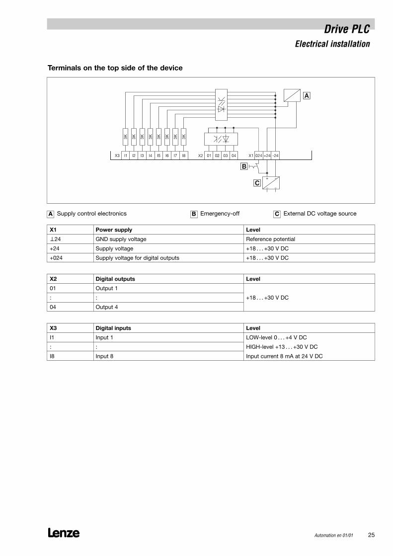
Terminals on the top side of the device
X1 Power supply Level
⊥24 GND supply voltage Reference potential
+24 Supply voltage +18 . . . +30 V DC
+024 Supply voltage for digital outputs +18 . . . +30 V DC
A Supply control electronics B Emergency-off C External DC voltage source
X2 Digital outputs Level
01 Output 1
: : +18 . . . +30 V DC
04 Output 4
X3 Digital inputs Level
I1 Input 1 LOW-level 0 . . . +4 V DC
: : HIGH-level +13 . . . +30 V DC
I8 Input 8 Input current 8 mA at 24 V DC

Lenze26 Automation en 01/01
Drive PLCElectrical installation
X4 Analog I/O Level
AI1 Analog input 1
AI2 Analog input 2 ± 10 V (10-bit + sign)
AI3 Analog input 3
A⊥ Analog GND Reference potential
A0V Analog output voltage ± 10 V (10-bit + sign)
A0i Analog output current ± 20 mA (10-bit + sign)
X5 System bus (CAN) Level
GND Reference potential
LOW CAN-LOW System bus LOW (data line)
HI CAN-HIGH System bus HIGH (data line)

Lenze Automation en 01/01 27
Lenze28 Automation en 01/01
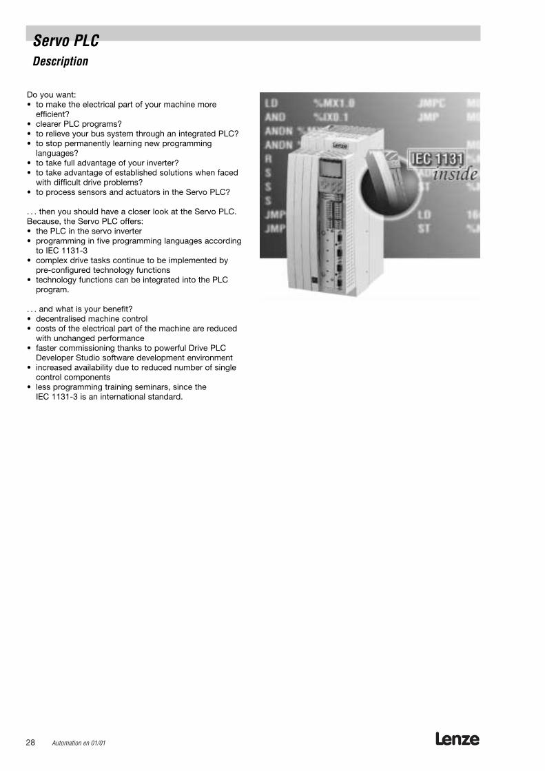
Servo PLCDescription
Do you want:• to make the electrical part of your machine more
efficient?• clearer PLC programs?• to relieve your bus system through an integrated PLC?• to stop permanently learning new programming
languages?• to take full advantage of your inverter?• to take advantage of established solutions when faced
with difficult drive problems?• to process sensors and actuators in the Servo PLC?
. . . then you should have a closer look at the Servo PLC.Because, the Servo PLC offers:• the PLC in the servo inverter• programming in five programming languages according
to IEC 1131-3• complex drive tasks continue to be implemented by
pre-configured technology functions• technology functions can be integrated into the PLC
program.
. . . and what is your benefit?• decentralised machine control• costs of the electrical part of the machine are reduced
with unchanged performance• faster commissioning thanks to powerful Drive PLC
Developer Studio software development environment • increased availability due to reduced number of single
control components• less programming training seminars, since the
IEC 1131-3 is an international standard.

Lenze Automation en 01/01 29
Communicationmodules• Keypad 9371• LECOM-A/B
(RS232/485)• LECOM-LI• INTERBUS• INTERBUS Loop• PROFIBUS DP• System bus (CAN)• DeviceNet/CANIn preparation:• Card module• LON
Servo PLC
Servo motor
Programming softwareGlobal Drive PLC Developer Studio
Engineering inside makes possible what modern drive andautomation tasks require:
• Well-thought out software solutions as function blocksand templates for different tasks directly in the drive.
• Easy to program in the familiar IEC 1131 languages.
Global Drive Automation - the matched system from theintelligent drive to the human-machine interface.
Terminalextension
Servo PLCSystem overview
CAN
AIF(Automation interface)
CAN

Lenze30 Automation en 01/01
Lenze Automation en 01/01 31
FlexibilityThe inverters are equipped for all the different requirements of servo technology, i.e. you canchoose the suitable technique according to yourapplication.
Integrated mains input For single drive operations only one element instead of two separate elements is required.
Matched system– Servo inverters with matched servo
motors (asynchronous, synchronous)– Regenerative and supply modules– Accessories for braking– Cold plate variant for special applications.
Regenerative power supply modulesThey ensure energy-saving group applications and multi-axis applications.
Feedback systemsThey ensure a perfect adaptation to the machinerequirements. You can select among resolver, TTL encoder or SinCos encoder.
Considerably reduced controller requirementsthrough high functionality:– Digital frequency for synchronous running by
means of simple plug connectors– Integrated position controller for exact positioning– Modular design of freely configurable control and
function blocks for easy connection– Comprehensive function block libraries, for
instance, with process controller, arithmetical function blocks and close-to-the-drive functionblocks for regulating and control tasks
– Integrated system bus (CAN open) for the interconnection of several controllers
The right setpoint source for every application:– Via setpoint potentiometer to the control
terminals– Via master voltage or master current to the
control terminals– Via the operation module at the frequency inverter– Via system bus (CAN open)
Intelligent drive controller Ability to execute complete processes or subprocesses through free programming according toIEC 1131-3.
Consistency The controllers are throughout the entire rangeconsistent in power, operation, and networking.
Energy-savingThe power supply is adapted to the load so that onlyas much energy as required for the momentarytorque/current is consumed.
Space-savingThanks to their book-shelf design, the frequencyinverters can be installed in a particularly space-saving way in the control cabinet, withouthaving to provide free space. Comprehensive mounting accessories allow diversemounting positions.
Motors can be adapted The modular design of the motors and plannedvariants facilitate the right selection for the individualapplications:Servo motor flanges with through-holes in B5 mounting or with threaded holes in B14 mounting.Different encoders that can be integrated allow the adaptation to the required precision:– Resolvers as standard solution– Optimum behaviour thanks to internal
improvement of the resolver accuracy – Incremental encoders or SinCos absolute value
encoders can also be used for special applications.
CE conformityOf course, the servo inverters of the 9300 series meet the EC Directives:– CE conformity according to the Low-Voltage
Directive– CE conformity according to the Directive of
Electromagnetic Compatibility for a typical drive configuration with servo inverter.
UL approved The global application of these controllers is ensuredby UL approval. UL 508 and UL 508c ensure the application in theUS.
CommunicatingConnection to the most common fieldbus systems ispossible:
– LECOM-A/B: Networking via RS232/485interface
– LECOM LI: Networking via fibre optics– INTERBUS: Connection to the remote bus
using DRIVECOM profile 21– INTERBUS Loop: Bus and power supply via
the same supply line.– System bus Connection to I/O terminals
(CAN): and of several inverters to eachother
– PROFIBUS-DP: Communication via PROFIBUS-DP
– DeviceNet: Communication between control system and simpleindustrial systems
Servo PLCDrive characteristics
Lenze32 Automation en 01/01
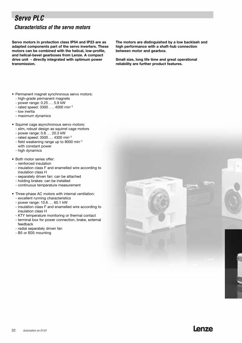
Servo motors in protection class IP54 and IP23 are asadapted components part of the servo inverters. Thesemotors can be combined with the helical, low-profile,and helical-bevel gearboxes from Lenze. A compactdrive unit - directly integrated with optimum powertransmission.
• Permanent magnet synchronous servo motors:- high-grade permanent magnets- power range: 0.25 . . . 5.9 kW- rated speed: 3300 . . . . 4000 min-1
- low inertia- maximum dynamics
• Squirrel cage asynchronous servo motors:- slim, robust design as squirrel cage motors- power range: 0.8 . . . 20.3 kW- rated speed: 3500 . . . 4300 min-1
- field weakening range up to 8000 min-1
with constant power- high dynamics
• Both motor series offer:- reinforced insulation- insulation class F and enamelled wire according to
insulation class H- separately driven fan: can be attached- holding brakes: can be installed- continuous temperature measurement
• Three-phase AC motors with internal ventilation:- excellent running characteristics- power range: 10.6 . . . 60.1 kW- insulation class F and enamelled wire according to
insulation class H- KTY temperature monitoring or thermal contact- terminal box for power connection, brake, external
feedback- radial separately driven fan- B5 or B35 mounting
The motors are distinguished by a low backlash andhigh performance with a shaft-hub connectionbetween motor and gearbox.
Small size, long life time and great operational reliability are further product features.
Servo PLCCharacteristics of the servo motors
Lenze Automation en 01/01 33
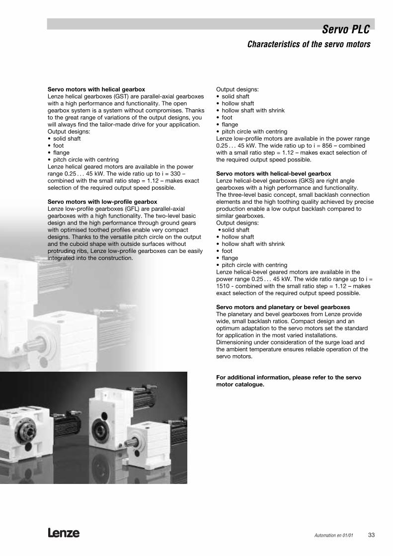
Servo motors with helical gearboxLenze helical gearboxes (GST) are parallel-axial gearboxeswith a high performance and functionality. The open gearbox system is a system without compromises. Thanksto the great range of variations of the output designs, youwill always find the tailor-made drive for your application.Output designs: • solid shaft • foot• flange• pitch circle with centringLenze helical geared motors are available in the powerrange 0.25 . . . 45 kW. The wide ratio up to i = 330 – combined with the small ratio step = 1.12 – makes exactselection of the required output speed possible.
Servo motors with low-profile gearboxLenze low-profile gearboxes (GFL) are parallel-axial gearboxes with a high functionality. The two-level basicdesign and the high performance through ground gearswith optimised toothed profiles enable very compactdesigns. Thanks to the versatile pitch circle on the outputand the cuboid shape with outside surfaces without protruding ribs, Lenze low-profile gearboxes can be easilyintegrated into the construction.
Output designs: • solid shaft • hollow shaft • hollow shaft with shrink • foot• flange• pitch circle with centringLenze low-profile motors are available in the power range0.25 . . . 45 kW. The wide ratio up to i = 856 – combinedwith a small ratio step = 1.12 – makes exact selection ofthe required output speed possible.
Servo motors with helical-bevel gearboxLenze helical-bevel gearboxes (GKS) are right angle gearboxes with a high performance and functionality. The three-level basic concept, small backlash connectionelements and the high toothing quality achieved by preciseproduction enable a low output backlash compared tosimilar gearboxes.Output designs:• solid shaft
• hollow shaft• hollow shaft with shrink• foot • flange • pitch circle with centring Lenze helical-bevel geared motors are available in thepower range 0.25 . . . 45 kW. The wide ratio range up to i =1510 - combined with the small ratio step = 1.12 – makesexact selection of the required output speed possible.
Servo motors and planetary or bevel gearboxesThe planetary and bevel gearboxes from Lenze providewide, small backlash ratios. Compact design and an optimum adaptation to the servo motors set the standardfor application in the most varied installations.Dimensioning under consideration of the surge load andthe ambient temperature ensures reliable operation of theservo motors.
For additional information, please refer to the servomotor catalogue.
Servo PLCCharacteristics of the servo motors
Lenze34 Automation en 01/01
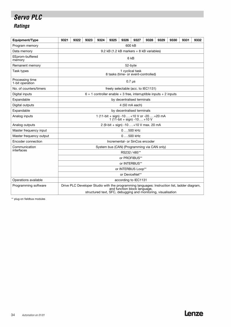
Equipment/Type 9321 9322 9323 9324 9325 9326 9327 9328 9329 9330 9331 9332
Program memory 600 kB
Data memory 9.2 kB (1.2 kB markers + 8 kB variables)
EEprom-buffered 6 kBmemory
Remanent memory 52-byte
Task types 1 cyclical task8 tasks (time- or event-controlled)
Processing time 0.7 µs1-bit operation
No. of counters/timers freely selectable (acc. to IEC1131)
Digital inputs 6 = 1 controller enable + 3 free, interruptible inputs + 2 inputs
Expandable by decentralised terminals
Digital outputs 4 (50 mA each)
Expandable by decentralised terminals
Analog inputs 1 (11-bit + sign) -10 . . . +10 V or -20 . . . +20 mA1 (11-bit + sign) -10 . . . +10 V
Analog outputs 2 (9-bit + sign) -10 . . . +10 V max. 20 mA
Master frequency input 0 . . . 500 kHz
Master frequency output 0 . . . 500 kHz
Encoder connection Incremental- or SinCos encoder
Communication System bus (CAN) (Programming via CAN only)interfaces
RS232 / 485**
or PROFIBUS**
or INTERBUS**
or INTERBUS Loop**
or DeviceNet**
Operations available according to IEC1131
Programming software Drive PLC Developer Studio with the programming languages: Instruction list, ladder diagram,and function block language,
structured text, SFC, debugging and monitoring, visualisation
** plug-on fieldbus modules
Servo PLCRatings
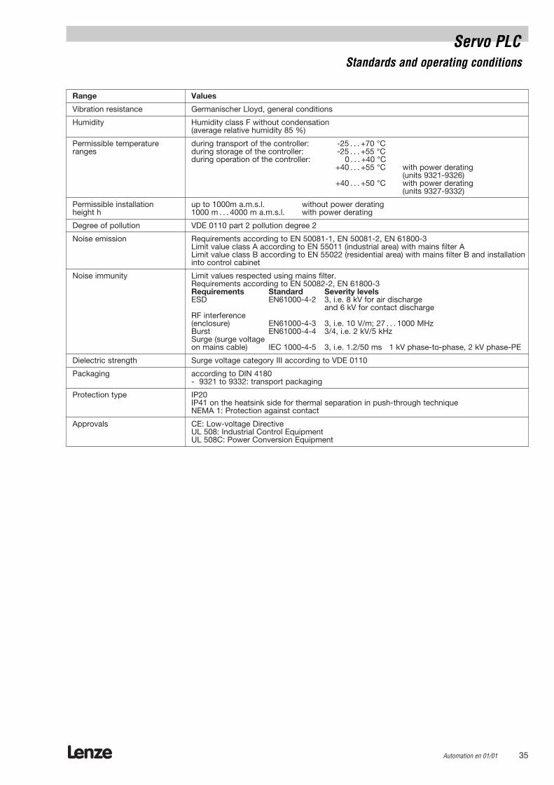
Range Values
Vibration resistance Germanischer Lloyd, general conditions
Humidity Humidity class F without condensation(average relative humidity 85 %)
Permissible temperature during transport of the controller: -25 . . . +70 °C ranges during storage of the controller: -25 . . . +55 °C
during operation of the controller: 0 . . . +40 °C +40 . . . +55 °C with power derating
(units 9321-9326)+40 . . . +50 °C with power derating
(units 9327-9332)
Permissible installation up to 1000m a.m.s.l. without power deratingheight h 1000 m . . . 4000 m a.m.s.l. with power derating
Degree of pollution VDE 0110 part 2 pollution degree 2
Noise emission Requirements according to EN 50081-1, EN 50081-2, EN 61800-3Limit value class A according to EN 55011 (industrial area) with mains filter ALimit value class B according to EN 55022 (residential area) with mains filter B and installationinto control cabinet
Noise immunity Limit values respected using mains filter. Requirements according to EN 50082-2, EN 61800-3Requirements Standard Severity levelsESD EN61000-4-2 3, i.e. 8 kV for air discharge
and 6 kV for contact dischargeRF interference(enclosure) EN61000-4-3 3, i.e. 10 V/m; 27 . . . 1000 MHz Burst EN61000-4-4 3/4, i.e. 2 kV/5 kHzSurge (surge voltageon mains cable) IEC 1000-4-5 3, i.e. 1.2/50 ms 1 kV phase-to-phase, 2 kV phase-PE
Dielectric strength Surge voltage category III according to VDE 0110
Packaging according to DIN 4180- 9321 to 9332: transport packaging
Protection type IP20IP41 on the heatsink side for thermal separation in push-through techniqueNEMA 1: Protection against contact
Approvals CE: Low-voltage Directive UL 508: Industrial Control Equipment UL 508C: Power Conversion Equipment
Lenze Automation en 01/01 35
Servo PLCStandards and operating conditions

Lenze36 Automation en 01/01
Type 9321 9322 9323 9324 9325
Servo PLC order No. EVS9321-EI EVS9322-EI EVS9323-EI EVS9324-EI EVS9325-EI
Mains voltage Vr [V] 320 . . . 528 V ± 0 % ; 45 . . . 65 Hz ± 0%
Alternative DC supply VG [V] 460 . . . 740 V +/-0%
Ratings for operation at a mains: 3 AC / 400 V / 50 Hz / 60 Hz
Motor power (4-pole ASM) Pr [kW] 0.37 0.75 1.5 3.0 5.5
Output current (8 kHz) * Ir8 [A] 1.5 2.5 3.9 7.0 13.0
Output current (16 kHz) * Ir16 [A] 1.1 1.8 2.9 5.2 9.7
Output power Sr8 [kVA] 1.0 1.7 2.7 4.8 9.0
Ratings for operation at a mains: 3 AC / 480 V / 50 Hz / 60 Hz
Motor power (4-pole ASM) Pr [kW] 0.37 0.75 1.5 3.0 5.5
Output current (8 kHz) * Ir8 [A] 1.5 2.5 3.9 7.0 13.0
Output current (16 kHz) * Ir16 [A] 1.1 1.8 2.9 5.2 9.7
Output power Sr8 [kVA] 1.2 2.1 3.2 5.8 10.8
max. output current at 8 kHz * 1) Imax 2.3 3.8 5.9 10.5 19.5
max. output current at 16 kHz * 1) Imax 1.7 2.7 4.4 7.8 14.6
Mains current at Vmains 400 V Ir [A] 1.5 2.5 3.9 7.0 12.0
Motor voltage VM [V] 3 ~ 0 ... Vmains
Power loss at Vmains 400 V Pv [W] 100 110 140 200 260
Power derating [%/K] 40 °C < Tamb < 50 °C: 2%/K (not UL-approved)[%/m] 1000 m . . . 4000 m a.m.s.l.: 5 % / 1000m
Dimensions [mm]a 78 x 78 x 97 x 97 x 135 xb 350 x 350 x 350 x 350 x 350 xe 250 x 250 x 250 x 250 x 250 x
Weight m [kg] 3.5 3.5 5.0 5.0 7.5
1) The current values apply to a periodic change of load cycle with a 1-minute overcurrent with the above current and a 2-minute basic load of 75 % Irx.
* Chopper frequency of the inverter (C0018)
Servo PLCRatings
a e
b
Technology functions are not based on IEC 1131:
– Servo positioning controller EVS93xx-EP
– Servo cam profiler EVS93xx-EK
– Servo register controller EVS93xx-ER
Lenze Automation en 01/01 37
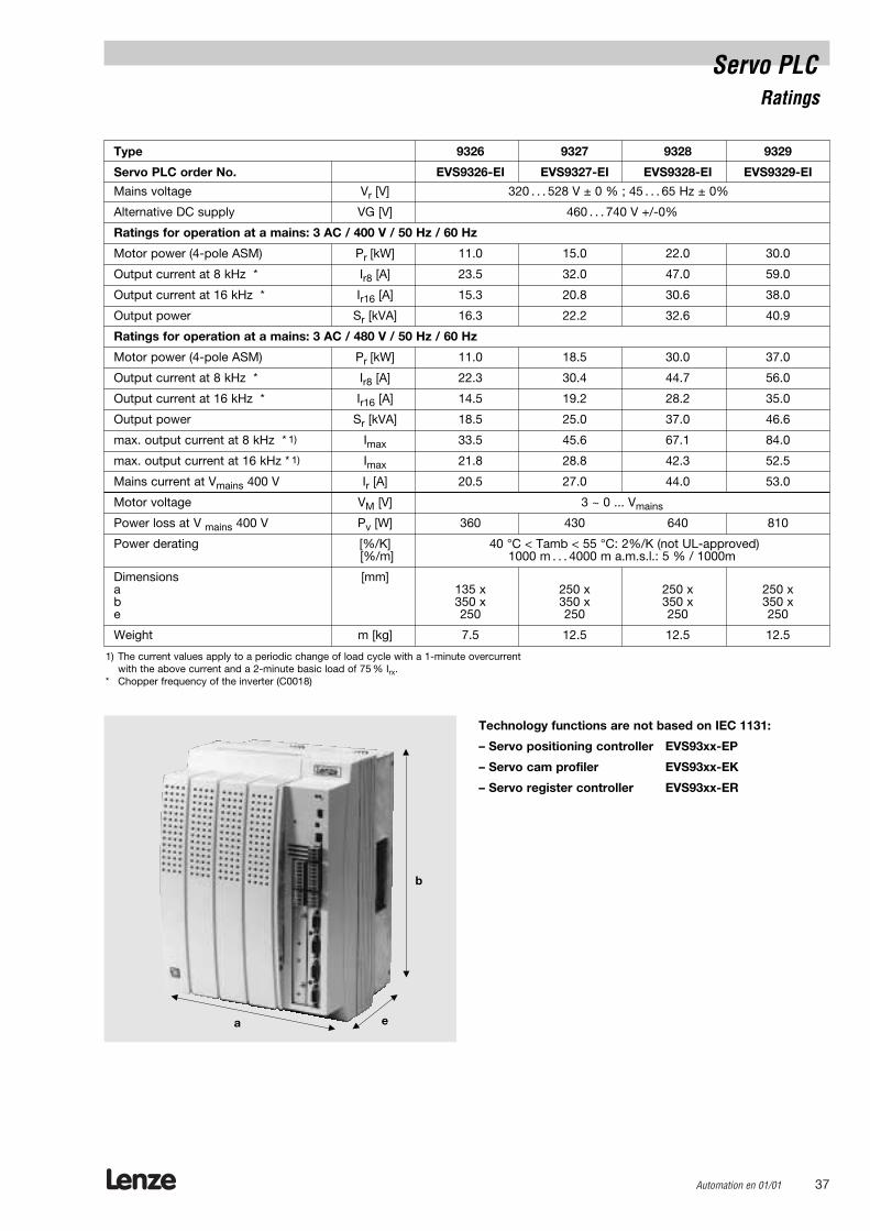
Type 9326 9327 9328 9329
Servo PLC order No. EVS9326-EI EVS9327-EI EVS9328-EI EVS9329-EI
Mains voltage Vr [V] 320 . . . 528 V ± 0 % ; 45 . . . 65 Hz ± 0%
Alternative DC supply VG [V] 460 . . . 740 V +/-0%
Ratings for operation at a mains: 3 AC / 400 V / 50 Hz / 60 Hz
Motor power (4-pole ASM) Pr [kW] 11.0 15.0 22.0 30.0
Output current at 8 kHz * Ir8 [A] 23.5 32.0 47.0 59.0
Output current at 16 kHz * Ir16 [A] 15.3 20.8 30.6 38.0
Output power Sr [kVA] 16.3 22.2 32.6 40.9
Ratings for operation at a mains: 3 AC / 480 V / 50 Hz / 60 Hz
Motor power (4-pole ASM) Pr [kW] 11.0 18.5 30.0 37.0
Output current at 8 kHz * Ir8 [A] 22.3 30.4 44.7 56.0
Output current at 16 kHz * Ir16 [A] 14.5 19.2 28.2 35.0
Output power Sr [kVA] 18.5 25.0 37.0 46.6
max. output current at 8 kHz * 1) Imax 33.5 45.6 67.1 84.0
max. output current at 16 kHz * 1) Imax 21.8 28.8 42.3 52.5
Mains current at Vmains 400 V Ir [A] 20.5 27.0 44.0 53.0
Motor voltage VM [V] 3 ~ 0 ... Vmains
Power loss at V mains 400 V Pv [W] 360 430 640 810
Power derating [%/K] 40 °C < Tamb < 55 °C: 2%/K (not UL-approved)[%/m] 1000 m . . . 4000 m a.m.s.l.: 5 % / 1000m
Dimensions [mm]a 135 x 250 x 250 x 250 xb 350 x 350 x 350 x 350 xe 250 250 250 250
Weight m [kg] 7.5 12.5 12.5 12.5
1) The current values apply to a periodic change of load cycle with a 1-minute overcurrent with the above current and a 2-minute basic load of 75 % Irx.
* Chopper frequency of the inverter (C0018)
Servo PLCRatings
a e
b
Technology functions are not based on IEC 1131:
– Servo positioning controller EVS93xx-EP
– Servo cam profiler EVS93xx-EK
– Servo register controller EVS93xx-ER
Lenze38 Automation en 01/01
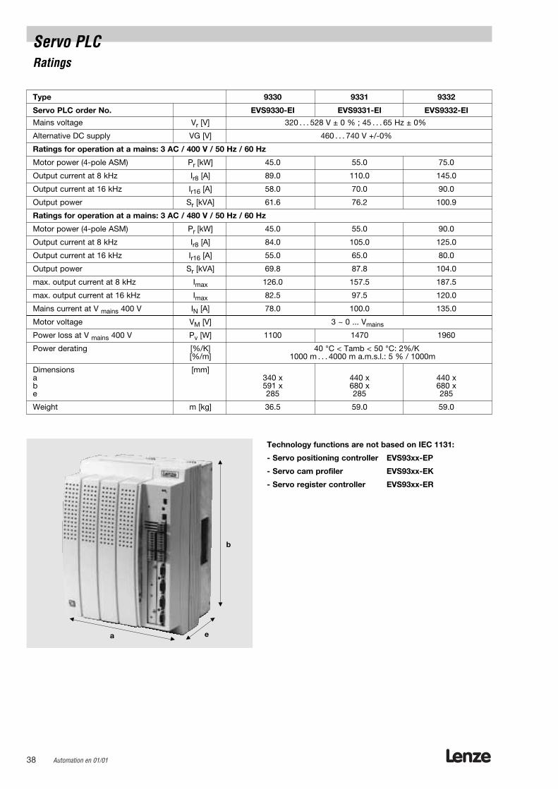
Type 9330 9331 9332
Servo PLC order No. EVS9330-EI EVS9331-EI EVS9332-EI
Mains voltage Vr [V] 320 . . . 528 V ± 0 % ; 45 . . . 65 Hz ± 0%
Alternative DC supply VG [V] 460 . . . 740 V +/-0%
Ratings for operation at a mains: 3 AC / 400 V / 50 Hz / 60 Hz
Motor power (4-pole ASM) Pr [kW] 45.0 55.0 75.0
Output current at 8 kHz Ir8 [A] 89.0 110.0 145.0
Output current at 16 kHz Ir16 [A] 58.0 70.0 90.0
Output power Sr [kVA] 61.6 76.2 100.9
Ratings for operation at a mains: 3 AC / 480 V / 50 Hz / 60 Hz
Motor power (4-pole ASM) Pr [kW] 45.0 55.0 90.0
Output current at 8 kHz Ir8 [A] 84.0 105.0 125.0
Output current at 16 kHz Ir16 [A] 55.0 65.0 80.0
Output power Sr [kVA] 69.8 87.8 104.0
max. output current at 8 kHz Imax 126.0 157.5 187.5
max. output current at 16 kHz Imax 82.5 97.5 120.0
Mains current at V mains 400 V IN [A] 78.0 100.0 135.0
Motor voltage VM [V] 3 ~ 0 ... Vmains
Power loss at V mains 400 V Pv [W] 1100 1470 1960
Power derating [%/K] 40 °C < Tamb < 50 °C: 2%/K[%/m] 1000 m . . . 4000 m a.m.s.l.: 5 % / 1000m
Dimensions [mm]a 340 x 440 x 440 xb 591 x 680 x 680 xe 285 285 285
Weight m [kg] 36.5 59.0 59.0
Servo PLCRatings
a e
b
Technology functions are not based on IEC 1131:
- Servo positioning controller EVS93xx-EP
- Servo cam profiler EVS93xx-EK
- Servo register controller EVS93xx-ER
Lenze Automation en 01/01 39
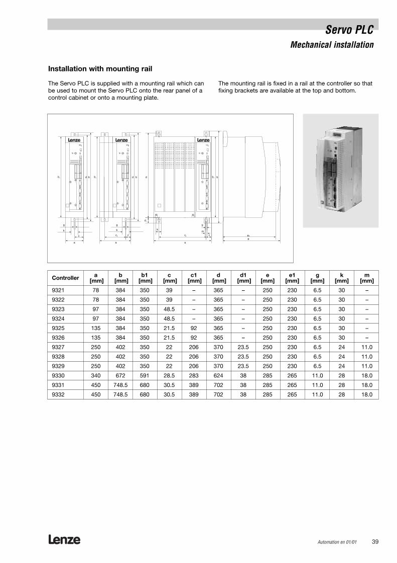
Servo PLCMechanical installation
Installation with mounting rail
The Servo PLC is supplied with a mounting rail which canbe used to mount the Servo PLC onto the rear panel of acontrol cabinet or onto a mounting plate.
The mounting rail is fixed in a rail at the controller so thatfixing brackets are available at the top and bottom.
Controller a b b1 c c1 d d1 e e1 g k m[mm] [mm] [mm] [mm] [mm] [mm] [mm] [mm] [mm] [mm] [mm] [mm]
9321 78 384 350 39 – 365 – 250 230 6.5 30 –
9322 78 384 350 39 – 365 – 250 230 6.5 30 –
9323 97 384 350 48.5 – 365 – 250 230 6.5 30 –
9324 97 384 350 48.5 – 365 – 250 230 6.5 30 –
9325 135 384 350 21.5 92 365 – 250 230 6.5 30 –
9326 135 384 350 21.5 92 365 – 250 230 6.5 30 –
9327 250 402 350 22 206 370 23.5 250 230 6.5 24 11.0
9328 250 402 350 22 206 370 23.5 250 230 6.5 24 11.0
9329 250 402 350 22 206 370 23.5 250 230 6.5 24 11.0
9330 340 672 591 28.5 283 624 38 285 265 11.0 28 18.0
9331 450 748.5 680 30.5 389 702 38 285 265 11.0 28 18.0
9332 450 748.5 680 30.5 389 702 38 285 265 11.0 28 18.0
ee
1

Lenze40 Automation en 01/01
Servo PLCMechanical installation
In some applications thermal separation is required.Heat generation inside the control cabinet is thus clearlyreduced. The 9300 servo controllers can be designed in a way thatthe heatsink remains outside the control cabinet. You needa mounting frame and a seal.
• The power loss is distributed as follows:– approx. 65% via separate coolers (heatsink and fan)– approx. 35% inside the controller
• The enclosure type of the separate cooler is IP41• The ratings of the controller are still effective.
Alternatively, the controller can be installed with the attached mounting rail.
Type a b c1 c2 c3 d1 d2 d3 e f g h[mm] [mm] [mm] [mm] [mm] [mm] [mm] [mm] [mm] [mm] [mm] [mm]
9321 112.5 385.5 26 86 – 10 115.5 164.5 250 92 6.5 9.0
9322 112.5 385.5 26 86 – 10 115.5 164.5 250 92 6.5 9.0
9323 131.5 385.5 26 105 – 10 115.5 164.5 250 92 6.5 9.0
9324 131.5 385.5 26 105 – 10 115.5 164.5 250 92 6.5 9.0
9325 169.5 385.5 26 137 – 10 115.5 164.5 250 92 6.5 9.0
9326 169.5 385.5 26 137 – 10 115.5 164.5 250 92 6.5 9.0
9327 280 379 28 140 252 41 141 1238 238 90 6.0 9.0
9328 280 379 28 140 252 41 141 1238 238 90 6.0 9.0
9329 280 379 28 140 252 41 141 1238 238 90 6.0 9.0
Heigth Width k l m n[mm] [mm] [mm] [mm] [mm] [mm]
9321, 9322 350 ± 3 82 ± 3 20 ± 2 198 ± 2 20 ± 2 359 ± 2
9323, 9324 350 ± 3 101 ± 3 20 ± 2 117 ± 2 20 ± 2 359 ± 2
9325, 9326 350 ± 3 139 ± 3 20 ± 2 155 ± 2 20 ± 2 359 ± 2
9327-9329 338 ± 3 238 ± 1 20 ± 2 259 ± 2 20 ± 2 359 ± 2
* preliminary dimensions
Cut-out
Installation with thermal separation (push-through technique)

Lenze Automation en 01/01 41
Keypad / display units

Lenze42 Automation en 01/01
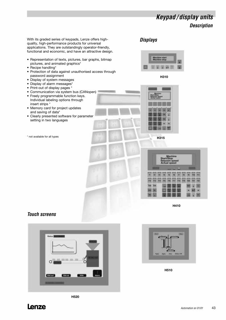
Keypad / display unitsDescription
With its graded series of keypads, Lenze offers high-quality, high-performance products for universal applications. They are outstandingly operator-friendly,functional and economic, and have an attractive design.
• Representation of texts, pictures, bar graphs, bitmap pictures, and animated graphics*
• Recipe handling*• Protection of data against unauthorised access through
password assignment• Display of system messages• Display of alarm messages*• Print-out of display pages *• Communication via system bus (CANopen)• Freely programmable function keys.
Individual labeling options through insert strips *
• Memory card for project updates and saving of data*
• Clearly presented software for parametersetting in two languages
* not available for all types
Displays
Touch screens
Lenze Automation en 01/01 43
H315
H310
H410
H510
H520
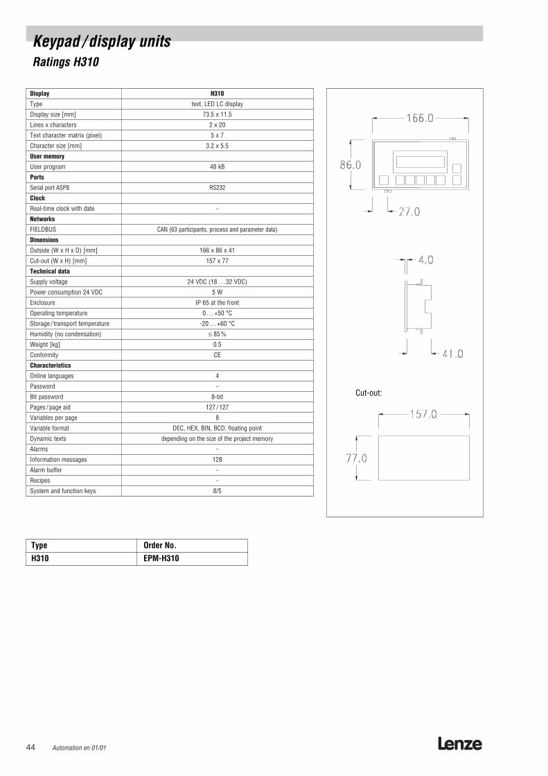
Display H310
Type text, LED LC display
Display size [mm] 73.5 x 11.5
Lines x characters 2 x 20
Text character matrix (pixel) 5 x 7
Character size [mm] 3.2 x 5.5
User memory
User program 48 kB
Ports
Serial port ASP8 RS232
Clock
Real-time clock with date -
Networks
FIELDBUS CAN (63 participants, process and parameter data)
Dimensions
Outside (W x H x D) [mm] 166 x 86 x 41
Cut-out (W x H) [mm] 157 x 77
Technical data
Supply voltage 24 VDC (18 . . . 32 VDC)
Power consumption 24 VDC 5 W
Enclosure IP 65 at the front
Operating temperature 0 . . . +50 °C
Storage / transport temperature -20 . . . +60 °C
Humidity (no condensation) ≤ 85 %
Weight [kg] 0.5
Conformity CE
Characteristics
Online languages 4
Password -
Bit password 8-bit
Pages / page aid 127 / 127
Variables per page 8
Variable format DEC, HEX, BIN, BCD, floating point
Dynamic texts depending on the size of the project memory
Alarms -
Information messages 128
Alarm buffer -
Recipes -
System and function keys 8/5
Lenze44 Automation en 01/01
Keypad / display unitsRatings H310
Cut-out:
Type Order No.
H310 EPM-H310
Automation en 01/01 45
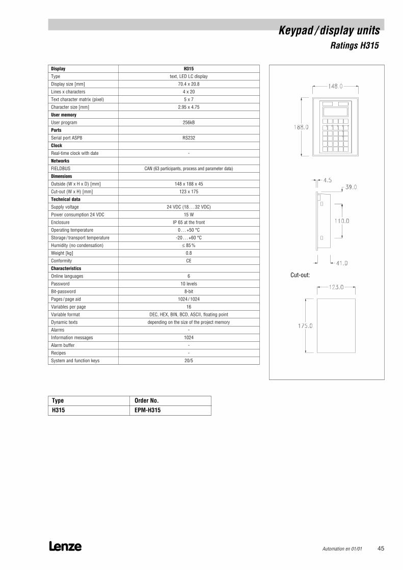
Display H315
Type text, LED LC display
Display size [mm] 70.4 x 20.8
Lines x characters 4 x 20
Text character matrix (pixel) 5 x 7
Character size [mm] 2.95 x 4.75
User memory
User program 256kB
Ports
Serial port ASP8 RS232
Clock
Real-time clock with date -
Networks
FIELDBUS CAN (63 participants, process and parameter data)
Dimensions
Outside (W x H x D) [mm] 148 x 188 x 45
Cut-out (W x H) [mm] 123 x 175
Technical data
Supply voltage 24 VDC (18 . . . 32 VDC)
Power consumption 24 VDC 15 W
Enclosure IP 65 at the front
Operating temperature 0 . . . +50 °C
Storage / transport temperature -20 . . . +60 °C
Humidity (no condensation) ≤ 85 %
Weight [kg] 0.8
Conformity CE
Characteristics
Online languages 6
Password 10 levels
Bit-password 8-bit
Pages / page aid 1024 / 1024
Variables per page 16
Variable format DEC, HEX, BIN, BCD, ASCII, floating point
Dynamic texts depending on the size of the project memory
Alarms -
Information messages 1024
Alarm buffer -
Recipes -
System and function keys 20/5
Lenze
Keypad / display unitsRatings H315
Cut-out:
Type Order No.
H315 EPM-H315
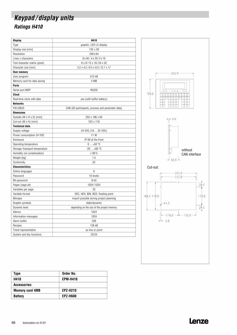
Display H410
Type graphic, LED LC display
Display size [mm] 132 x 39
Resolution 240 x 64
Lines x characters 8 x 40 / 4 x 20 / 2 x 10
Text character matrix (pixel) 6 x 8 / 12 x 16 / 24 x 32
Character size [mm] 3.2 x 4.2 / 6.5 x 8.5 / 12.7 x 17
User memory
User program 512 kB
Memory card for data saving 4 MB
Ports
Serial port MSP RS232
Clock
Real-time clock with date yes (with buffer battery)
Networks
FIELDBUS CAN (63 participants, process and parameter data)
Dimensions
Outside (W x H x D) [mm] 252 x 196 x 65
Cut-out (W x H) [mm] 232 x 178
Technical data
Supply voltage 24 VDC (18 . . . 32 VDC)
Power consumption 24 VDC 11 W
Enclosure IP 65 at the front
Operating temperature 0 . . . +50 °C
Storage / transport temperature -20 . . . +60 °C
Humidity (no condensation) ≤ 90 %
Weight [kg] 1.5
Conformity CE
Characteristics
Online languages 8
Password 10 levels
Bit-password 8-bit
Pages / page aid 1024 / 1024
Variables per page 32
Variable format DEC, HEX, BIN, BCD, floating point
Bitmaps import possible during project planning
Graphic symbols static/dynamic
Dynamic texts depending on the size of the project memory
Alarms 1024
Information messages 1024
Alarm buffer 256
Recipes 128 kB
Trend representation as line or point
System and key functions 25/24
Lenze46 Automation en 01/01
Cut-out:
Keypad / display unitsRatings H410
Type Order No.
H410 EPM-H410
Accessories:
Memory card 4MB EPZ-H210
Battery EPZ-H600
without CAN interface

Display H510
Type LCD monochrome STN 5.5´
Display size[mm] 123 x 68
Touch screen matrix 20 x 8 (each 12 x 16 pixel)
Resolution (pixel) 240 x 128
Lines x characters 16 x 40 / 8 x 20 / 4 x 10
Text character matrix (pixel) 6 x 8 / 12 x 16 / 24 x 32
Character size [mm] 3 x 4 / 6 x 8 / 12 x 16
Background lighting
Life time at 25 °C 10.000 h
User memory
User program 512 kB
Ports
Serial port MSP RS232
Clock
Real-time clock with date yes (with buffer battery)
Networks
FIELDBUS CAN (63 participants, process and parameter data)
Dimensions
Outside (W x H x D) [mm] 210 x 185 x 60
Cut-out (W x H) [mm] 198 x 148
Technical data
Supply voltage 24 VDC (18 . . . 32 VDC)
Power consumption 24 VDC 15 W
Enclosure IP 65 at the front
Operating temperature 0 . . . +50 °C
Storage / transport temperature -20 . . . +60 °C
Humidity (no condensation) ≤ 85 %
Weight [kg] 1.3
Conformity CE
Characteristics
Online languages 8
Password 10 levels
Bit-password 8-bit
Pages / page aid 1024 / 1024
Variables per page 48
Variable format DEC, HEX, BIN, BCD, floating point
Bitmaps import possible during project planning
Graphic symbols static/dynamic
Keys per page 160
Dynamic texts depending on the size of the project memory
Alarms 1024
Information messages 1024
Alarm buffer 256
Recipes 128 kB
Trend representation as line or point
Automation en 01/01 47Lenze
Cut-out:
Keypad / display unitsRatings H510
Type Order No.
H510 EPM-H510
Accessories:
Battery EPZ-H600
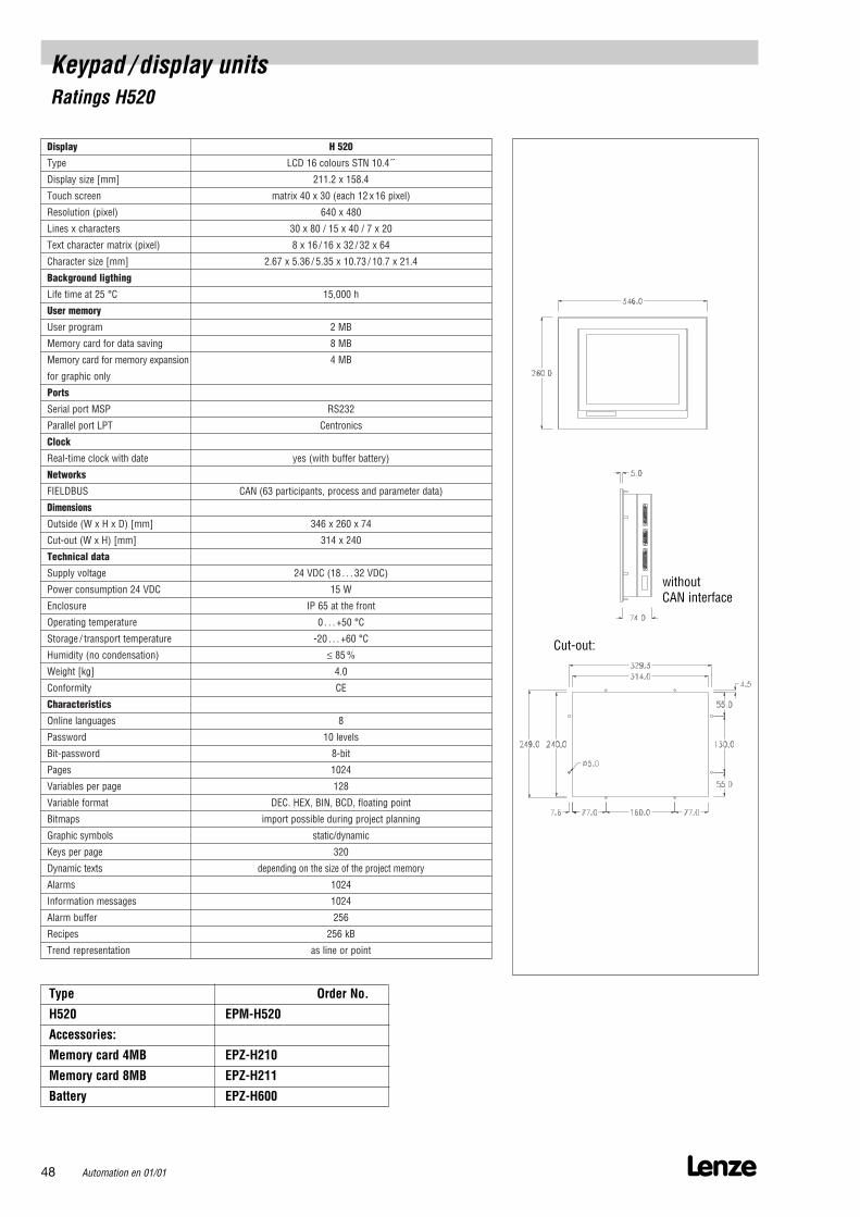
Display H 520
Type LCD 16 colours STN 10.4´
Display size [mm] 211.2 x 158.4
Touch screen matrix 40 x 30 (each 12 x 16 pixel)
Resolution (pixel) 640 x 480
Lines x characters 30 x 80 / 15 x 40 / 7 x 20
Text character matrix (pixel) 8 x 16 / 16 x 32 / 32 x 64
Character size [mm] 2.67 x 5.36 / 5.35 x 10.73 / 10.7 x 21.4
Background ligthing
Life time at 25 °C 15,000 h
User memory
User program 2 MB
Memory card for data saving 8 MB
Memory card for memory expansion 4 MB
for graphic only
Ports
Serial port MSP RS232
Parallel port LPT Centronics
Clock
Real-time clock with date yes (with buffer battery)
Networks
FIELDBUS CAN (63 participants, process and parameter data)
Dimensions
Outside (W x H x D) [mm] 346 x 260 x 74
Cut-out (W x H) [mm] 314 x 240
Technical data
Supply voltage 24 VDC (18 . . . 32 VDC)
Power consumption 24 VDC 15 W
Enclosure IP 65 at the front
Operating temperature 0 . . . +50 °C
Storage / transport temperature -20 . . . +60 °C
Humidity (no condensation) ≤ 85 %
Weight [kg] 4.0
Conformity CE
Characteristics
Online languages 8
Password 10 levels
Bit-password 8-bit
Pages 1024
Variables per page 128
Variable format DEC. HEX, BIN, BCD, floating point
Bitmaps import possible during project planning
Graphic symbols static/dynamic
Keys per page 320
Dynamic texts depending on the size of the project memory
Alarms 1024
Information messages 1024
Alarm buffer 256
Recipes 256 kB
Trend representation as line or point
Lenze48 Automation en 01/01
Cut-out:
Keypad / display unitsRatings H520
Type Order No.
H520 EPM-H520
Accessories:
Memory card 4MB EPZ-H210
Memory card 8MB EPZ-H211
Battery EPZ-H600
without CAN interface
Lenze Automation en 01/01 49
Software tools
Lenze50 Automation en 01/01
Software toolsDrive Server
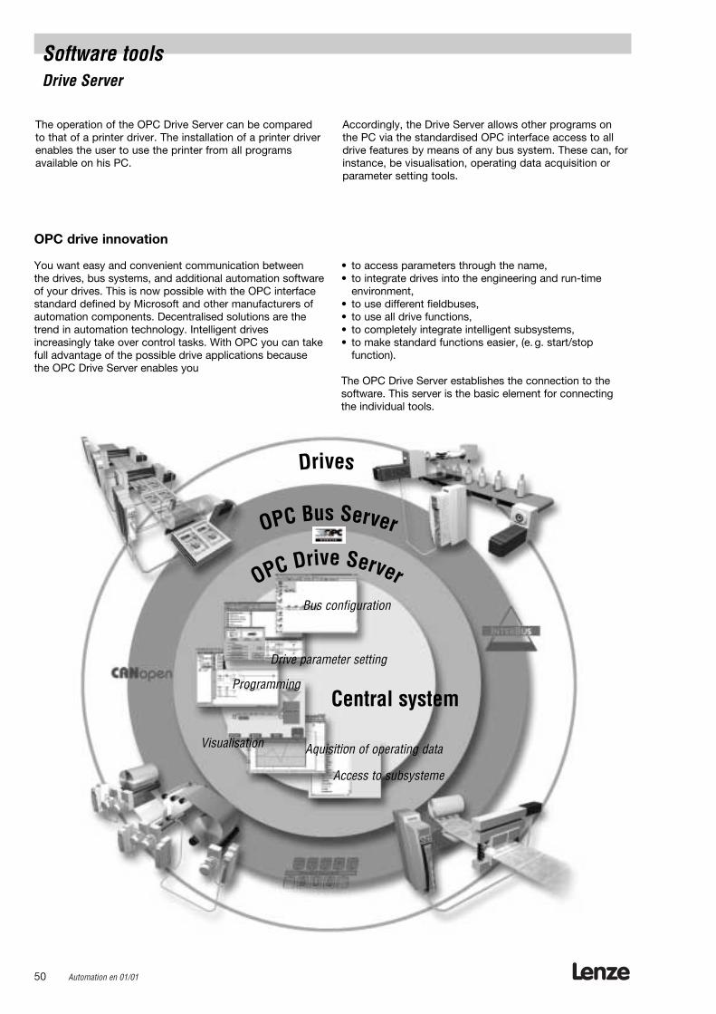
The operation of the OPC Drive Server can be comparedto that of a printer driver. The installation of a printer driverenables the user to use the printer from all programs available on his PC.
Accordingly, the Drive Server allows other programs onthe PC via the standardised OPC interface access to alldrive features by means of any bus system. These can, forinstance, be visualisation, operating data acquisition orparameter setting tools.
OPC drive innovation
You want easy and convenient communication between the drives, bus systems, and additional automation softwareof your drives. This is now possible with the OPC interfacestandard defined by Microsoft and other manufacturers ofautomation components. Decentralised solutions are thetrend in automation technology. Intelligent drives increasingly take over control tasks. With OPC you can takefull advantage of the possible drive applications becausethe OPC Drive Server enables you
• to access parameters through the name,• to integrate drives into the engineering and run-time
environment,• to use different fieldbuses,• to use all drive functions,• to completely integrate intelligent subsystems, • to make standard functions easier, (e. g. start/stop
function).
The OPC Drive Server establishes the connection to thesoftware. This server is the basic element for connectingthe individual tools.

Lenze Automation en 01/01 51
Software toolsDrive Server
The electronic drive systems are key components for therealisation of modular machine concepts. In conjunctionwith the Microsoft standard OPC and the drive propertiesas Drive Server, intelligent drives offer the user efficientand economical concepts for his application. Using theOPC interface as basis for the entire automation of theinstallation considerably reduces engineering costs. In thiscase, a central OPC Drive Server is used as core element.
The OPC driver for the intelligent drive allows the user touse all features of the drive via the bus. Whether with thevisualisation, the operating data acquisition, or the parameter setting tool.
As you know it from the PC: Plug & drive!
Material supply
Fans
Profiling
System requirements
Hardware:• IBM-compatible PC (Pentium 90-processor or higher)• 32 MB main memory (RAM)• 30 MB free hard disk space• VGA graphic card• CD ROM drive• free slots / interfaces according to the requirements of the
fieldbus cards / adapters to be used• Microsoft-compatible mouse
Software:• Windows 98/NT/2000
Lenze52 Automation en 01/01
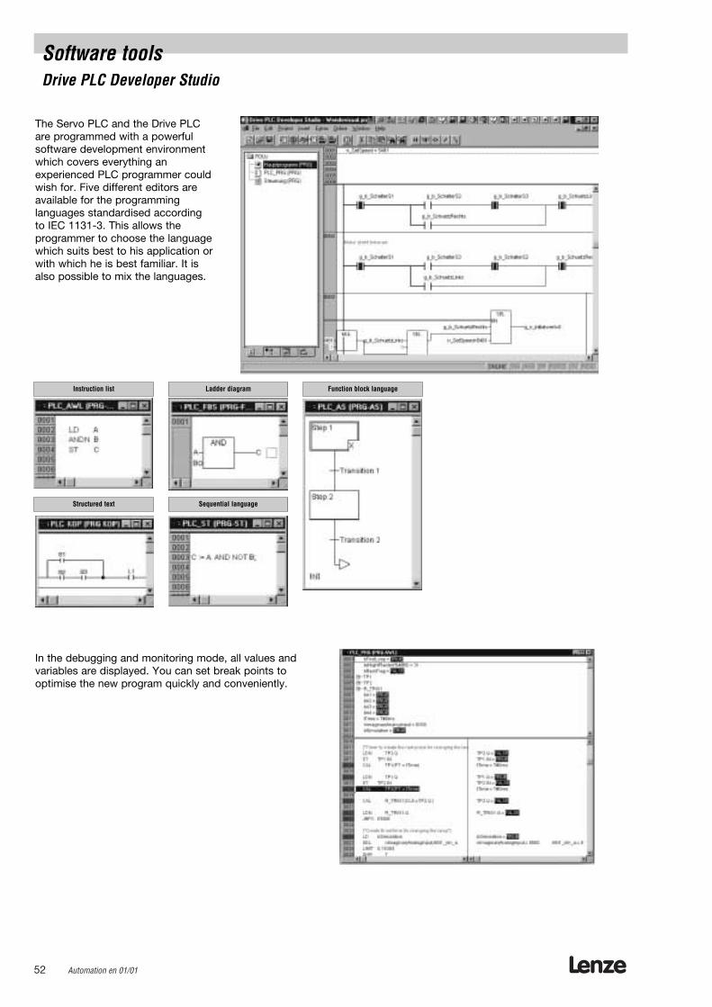
The Servo PLC and the Drive PLC are programmed with a powerful software development environmentwhich covers everything an experienced PLC programmer couldwish for. Five different editors areavailable for the programming languages standardised according to IEC 1131-3. This allows the programmer to choose the languagewhich suits best to his application orwith which he is best familiar. It isalso possible to mix the languages.
In the debugging and monitoring mode, all values and variables are displayed. You can set break points to optimise the new program quickly and conveniently.
Structured text
Ladder diagram
Sequential language
Function block languageInstruction list
Software toolsDrive PLC Developer Studio
Lenze Automation en 01/01 53
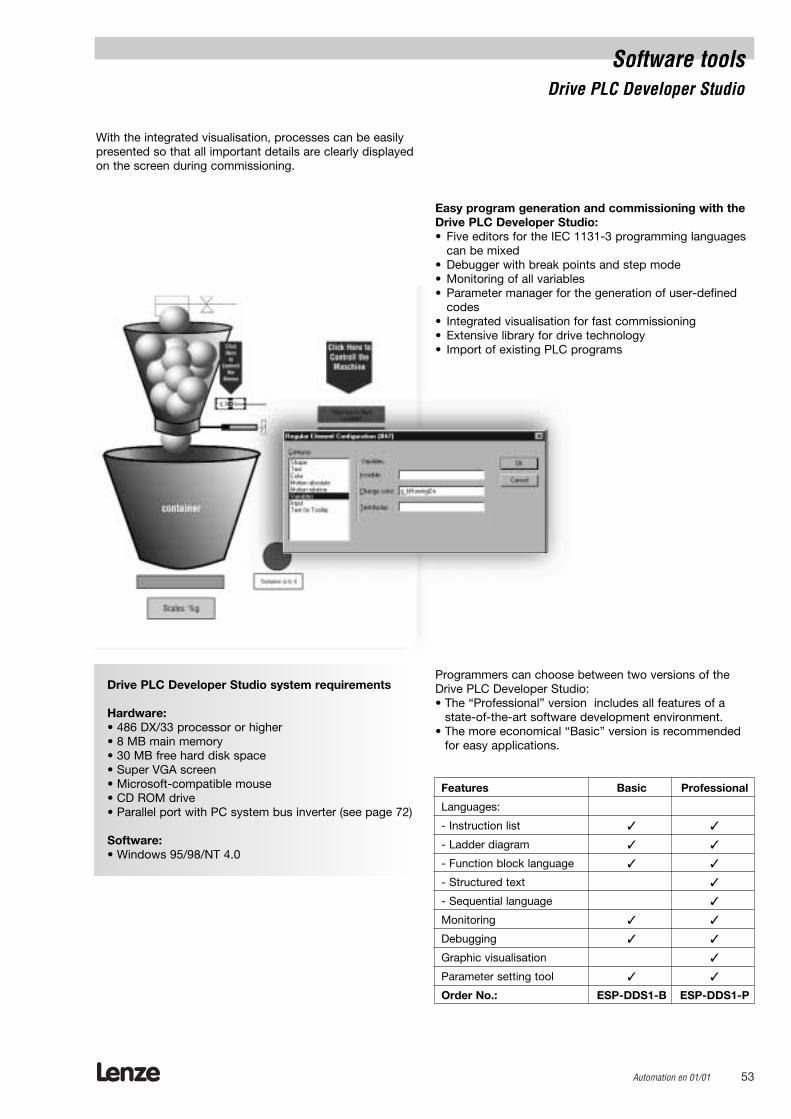
With the integrated visualisation, processes can be easilypresented so that all important details are clearly displayedon the screen during commissioning.
Easy program generation and commissioning with theDrive PLC Developer Studio:• Five editors for the IEC 1131-3 programming languages
can be mixed• Debugger with break points and step mode• Monitoring of all variables• Parameter manager for the generation of user-defined
codes• Integrated visualisation for fast commissioning• Extensive library for drive technology• Import of existing PLC programs
Programmers can choose between two versions of theDrive PLC Developer Studio:• The “Professional” version includes all features of a
state-of-the-art software development environment.• The more economical “Basic” version is recommended
for easy applications.
Drive PLC Developer Studio system requirements
Hardware:• 486 DX/33 processor or higher • 8 MB main memory• 30 MB free hard disk space• Super VGA screen• Microsoft-compatible mouse• CD ROM drive• Parallel port with PC system bus inverter (see page 72)
Software:• Windows 95/98/NT 4.0
Software toolsDrive PLC Developer Studio
Features Basic Professional
Languages:
- Instruction list
- Ladder diagram
- Function block language
- Structured text
- Sequential language
Monitoring
Debugging
Graphic visualisation
Parameter setting tool
Order No.: ESP-DDS1-B ESP-DDS1-P

Software toolsGlobal Drive Control
An increasing number of intelligent drive systems areinstalled in modern production plants which, in addition to their normal drive tasks, also implement technologyfunctions for the production process.
Global Drive Control (GDC) provides a tool for operation, parameter setting and diagnostics of drivetasks that is clearly laid out and easy to understand.
GDC has the following features• Quick and easy commissioning of the drive through
“short” commissioning • Numerous help functions enable easy operation,
even for inexperienced users • Convenient diagnostics options through various
monitoring windows and oscilloscope functions• Easy connection to the drive via RS232/485, optical
fibres or via the system bus
Short commissioning allows quick and easy commissioning of the complete drive through self-explanatory dialogs. All the parameters required for the drive train are entered in a menu that appears automatically on the screen. Extensive help functions thatmatch the inverter are always available, with detaileddescriptions of the individual parameters.
Short commissioning
Lenze54 Automation en 01/01
Lenze Automation en 01/01 55
Software toolsGlobal Drive Control
Mathematical functions: Arithmetical
operationsDrive functions: Brake logic
Positioning controllerMotor controlElectronic gearbox
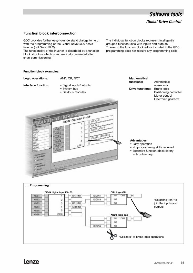
. . . Programming:
Advantages:• Easy operation• No programming skills required• Extensive function block library
with online help
“Scissors” to break logic operations
“Soldering iron” tojoin the inputs andoutputs
DIGIN digital input E1 - E5 OR1 logic OR
AND1 logic and
Function block examples:
Logic operations: AND, OR, NOT
Interface function: • Digital inputs/outputs,• System bus • Fieldbus modules
Function block interconnection
GDC provides further easy-to-understand dialogs to helpwith the programming of the Global Drive 9300 servoinverter (not Servo PLC). The functionality of the inverter is described by a functionblock structure which is automatically generated aftershort commissioning.
The individual function blocks represent intelligently grouped function units with inputs and outputs. Thanks to the function block editor included in the GDC,programming does not require any programming skills.
Lenze56 Automation en 01/01
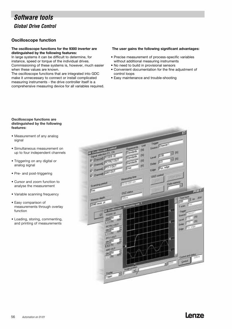
Oscilloscope functions are distinguished by the followingfeatures:
• Measurement of any analog signal
• Simultaneous measurement onup to four independent channels
• Triggering on any digital or analog signal
• Pre- and post-triggering
• Cursor and zoom function toanalyse the measurement
• Variable scanning frequency
• Easy comparison of measurements through overlayfunction
• Loading, storing, commenting,and printing of measurements
Software toolsGlobal Drive Control
Oscilloscope function
The oscilloscope functions for the 9300 inverter are distinguished by the following features:In large systems it can be difficult to determine, forinstance, speed or torque of the individual drives.Commissioning of these systems is, however, much easierwhen these values are known.The oscilloscope functions that are integrated into GDCmake it unnecessary to connect or install complicatedmeasuring instruments - the drive controller itself is a comprehensive measuring device for all variables required.
The user gains the following significant advantages:
• Precise measurement of process-specific variables without additional measuring instruments
• No need to build in provisional sensors • Convenient documentation for the fine adjustment of
control loops• Easy maintenance and trouble-shooting
Lenze Automation en 01/01 57
Software toolsGlobal Drive Control
9300 inverters
A number of technology functions are available for theGlobal Drive servo inverters to solve special drive problems.
Programming skills are not required for easy commissioning and adaptation.
The Global Drive Control includes the below-mentionedfunctions. If you only want to set the drive parameters, youcan also use the variant Global Drive Control easy: Global Drive Control system requirements
Hardware:• IBM-AT or compatible PC• CPU: 80486 or higher / Pentium• 16 MB RAM• 30 MB free hard disk space• Super VGA screen• CD ROM drive• A free serial port for RS232/optical fibre or• A free parallel port for system bus adapter (CAN)
Software:For Global Drive Control• Windows 3.1 x or Windows 95 / 98 / NT 4.0For Global Drive Control easy• Windows 95 / 98 / NT 4.0
Feature GDC easy GDCShort commissioning:
- 8200
- 8200 vector/motec
- 9300 vector
- 9300 Servo
- Technology functions
Code lists
Monitoring window
Function block window
Oscilloscope functions
Order No.: ESP-GDC2-E ESP-GDC2
Lenze58 Automation en 01/01
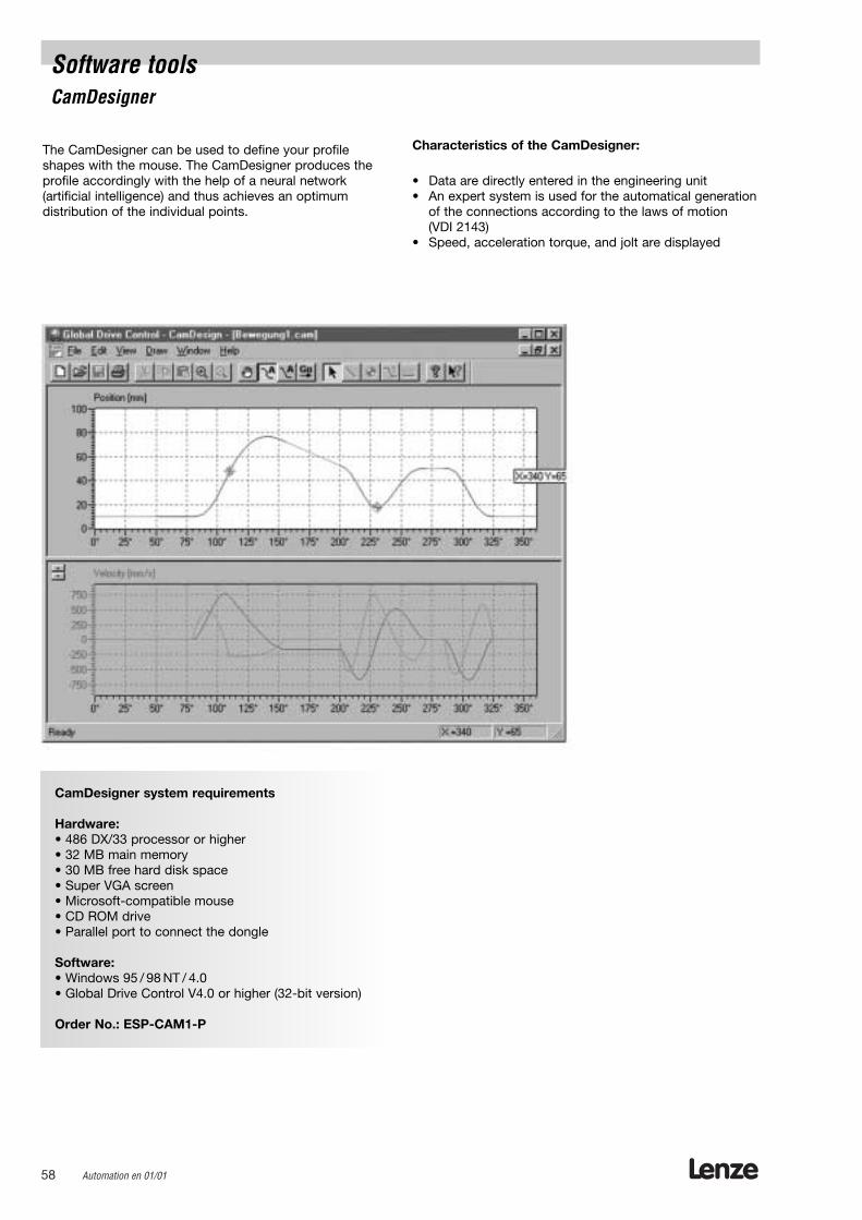
Software toolsCamDesigner
The CamDesigner can be used to define your profileshapes with the mouse. The CamDesigner produces theprofile accordingly with the help of a neural network (artificial intelligence) and thus achieves an optimum distribution of the individual points.
Characteristics of the CamDesigner:
• Data are directly entered in the engineering unit• An expert system is used for the automatical generation
of the connections according to the laws of motion (VDI 2143)
• Speed, acceleration torque, and jolt are displayed
CamDesigner system requirements
Hardware:• 486 DX/33 processor or higher• 32 MB main memory• 30 MB free hard disk space• Super VGA screen• Microsoft-compatible mouse• CD ROM drive• Parallel port to connect the dongle
Software:• Windows 95 / 98 NT / 4.0• Global Drive Control V4.0 or higher (32-bit version)
Order No.: ESP-CAM1-P
Lenze Automation en 01/01 59
Software toolsHMI Designer
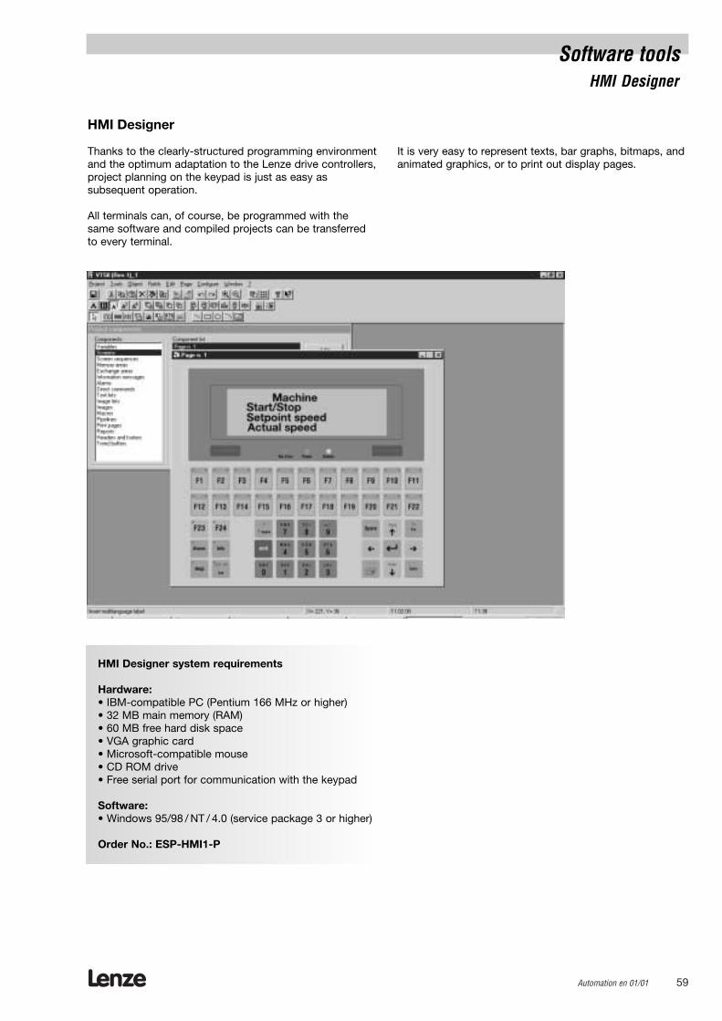
HMI Designer
Thanks to the clearly-structured programming environmentand the optimum adaptation to the Lenze drive controllers,project planning on the keypad is just as easy as subsequent operation.
All terminals can, of course, be programmed with thesame software and compiled projects can be transferredto every terminal.
It is very easy to represent texts, bar graphs, bitmaps, andanimated graphics, or to print out display pages.
HMI Designer system requirements
Hardware:• IBM-compatible PC (Pentium 166 MHz or higher)• 32 MB main memory (RAM)• 60 MB free hard disk space• VGA graphic card• Microsoft-compatible mouse• CD ROM drive• Free serial port for communication with the keypad
Software:• Windows 95/98 / NT / 4.0 (service package 3 or higher)
Order No.: ESP-HMI1-P

Lenze60 Automation en 01/01

Lenze Automation en 01/01 61
Accessories
Lenze62 Automation en 01/01
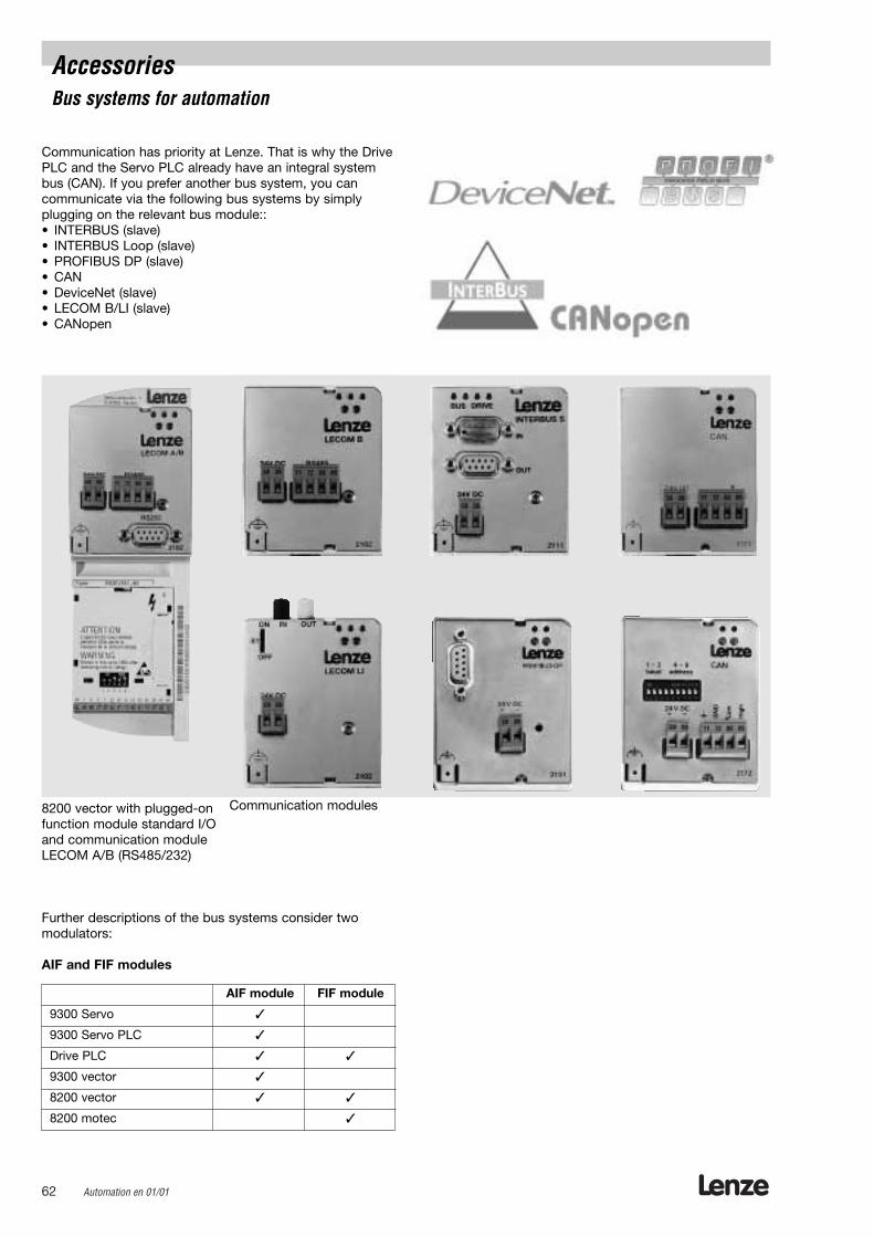
AccessoriesBus systems for automation
Communication has priority at Lenze. That is why the DrivePLC and the Servo PLC already have an integral systembus (CAN). If you prefer another bus system, you can communicate via the following bus systems by simplyplugging on the relevant bus module::• INTERBUS (slave)• INTERBUS Loop (slave)• PROFIBUS DP (slave)• CAN• DeviceNet (slave)• LECOM B/LI (slave)• CANopen
8200 vector with plugged-onfunction module standard I/Oand communication moduleLECOM A/B (RS485/232)
Communication modules
Further descriptions of the bus systems consider two modulators:
AIF and FIF modules
AIF module FIF module
9300 Servo
9300 Servo PLC
Drive PLC
9300 vector
8200 vector
8200 motec
Lenze Automation en 01/01 63
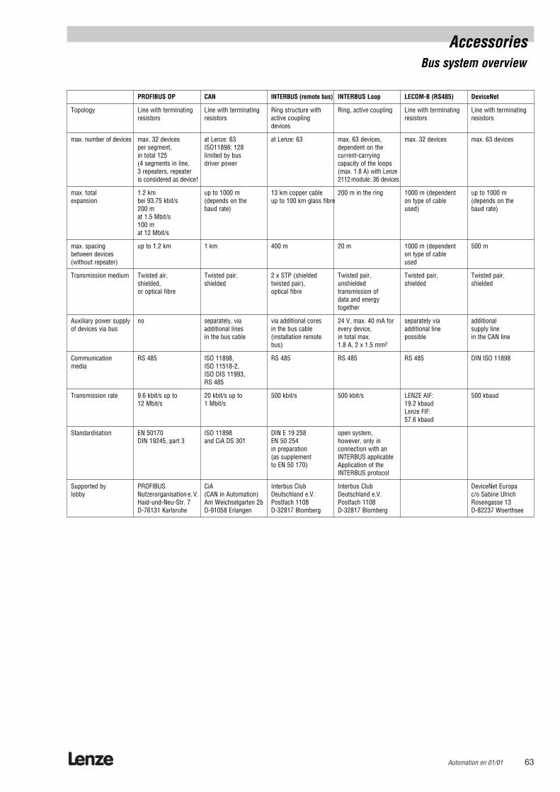
PROFIBUS DP CAN INTERBUS (remote bus) INTERBUS Loop LECOM-B (RS485) DeviceNet
Topology Line with terminating Line with terminating Ring structure with Ring, active coupling Line with terminating Line with terminatingresistors resistors active coupling resistors resistors
devices
max. number of devices max. 32 devices at Lenze: 63 at Lenze: 63 max. 63 devices, max. 32 devices max. 63 devicesper segment, ISO11898: 128 dependent on thein total 125 limited by bus current-carrying(4 segments in line, driver power capacity of the loops3 repeaters, repeater (max. 1.8 A) with Lenzeis considered as device! 2112module: 36 devices
max. total 1.2 km up to 1000 m 13 km copper cable 200 m in the ring 1000 m (dependent up to 1000 mexpansion bei 93.75 kbit/s (depends on the up to 100 km glass fibre on type of cable (depends on the
200 m baud rate) used) baud rate)at 1.5 Mbit/s100 m at 12 Mbit/s
max. spacing up to 1.2 km 1 km 400 m 20 m 1000 m (dependent 500 mbetween devices on type of cable(without repeater) used
Transmission medium Twisted air, Twisted pair, 2 x STP (shielded Twisted pair, Twisted pair, Twisted pair,shielded, shielded twisted pair), unshielded shielded shieldedor optical fibre optical fibre transmission of
data and energytogether
Auxiliary power supply no separately, via via additional cores 24 V, max. 40 mA for separately via additionalof devices via bus additional lines in the bus cable every device, additional line supply line
in the bus cable (installation remote in total max. possible in the CAN linebus) 1.8 A, 2 x 1.5 mm2
Communication RS 485 ISO 11898, RS 485 RS 485 RS 485 DIN ISO 11898media ISO 11518-2,
ISO DIS 11993, RS 485
Transmission rate 9.6 kbit/s up to 20 kbit/s up to 500 kbit/s 500 kbit/s LENZE AIF: 500 kbaud12 Mbit/s 1 Mbit/s 19.2 kbaud
Lenze FIF:57.6 kbaud
Standardisation EN 50170 ISO 11898 DIN E 19 258 open system, DIN 19245, part 3 and CiA DS 301 EN 50 254 however, only in
in preparation connection with an(as supplement INTERBUS applicableto EN 50 170) Application of the
INTERBUS protocol
Supported by PROFIBUS CiA Interbus Club Interbus Club DeviceNet Europalobby Nutzerorganisation e. V. (CAN in Automation) Deutschland e.V. Deutschland e.V. c/o Sabine Ulrich
Haid-und-Neu-Str. 7 Am Weichselgarten 2b Postfach 1108 Postfach 1108 Rosengasse 13D-76131 Karlsruhe D-91058 Erlangen D-32817 Blomberg D-32817 Blomberg D-82237 Woerthsee
AccessoriesBus system overview

AccessoriesBus modules
System bus (CAN)
The system bus (CAN) is used for communication amongthe individual Lenze devices. It enables easy and quickinterconnection of several inverters as well as connectionwith other external components, such as keypads.
DescriptionThe system bus module (CAN) is used to couple theinverter with the serial communication system CAN(Controller Area Network). It can be retrofit into the 8200vector/motec.
The function module expands the functionality of the drivecontroller, e. g. by:
parameter entries / remote parameter setting data exchange from inverter to inverter interfaces with external controls and control systems possible connection to
- decentralised terminal expansions- keypads
General data and operating conditions
Protocol based on CANopen (CAL-based communication profile DS301)
Communication medium DIN ISO 11898
Network topology line (terminated on both sides with 120 Ω)
Number of logic process data channels AIF: 2171/2172:1 / 2175:3 FIF: 2
Number of logic parameter data channels 2
System bus devices master or slave
max. number of devices 63
max. spacing between 2 devices not restricted, max. bus length is decisive
Baud rate [k Bit/s] 20 50 125 250 500 1000 (only AIF)
max. bus length [m] 2500 1000 500 250 AIF: 120 / FIF: 80 25
Electrical connection FIF: Screw terminals AIF: Pluggable screw terminalsFIF: Terminal for controller inhibit (CINH) available
DC supply voltage internal and external possible(when vector fails, bus system continues operation)
Insulation voltage to PE 50 V AC
Ambient temperature FIF: AIF:During operation: -20 ... +60 ºC -20 ... +40 ºCTransport: -25 ... +70 ºC -25 ... +70 ºCStorage: -25 ... +60 ºC -25 ... +55 ºC
Climatic conditions Class 3K3 according to EN 50178(without condensation, average relative humidity 85 %)
Order No. for AIF EMF2171IB, EMF 2172*, EMF 2175*
Order No. for FIF E82ZAFC
* Address and baud rate via DIP switch
Lenze64 Automation en 01/01
AccessoriesBus modules
Lenze Automation en 01/01 65
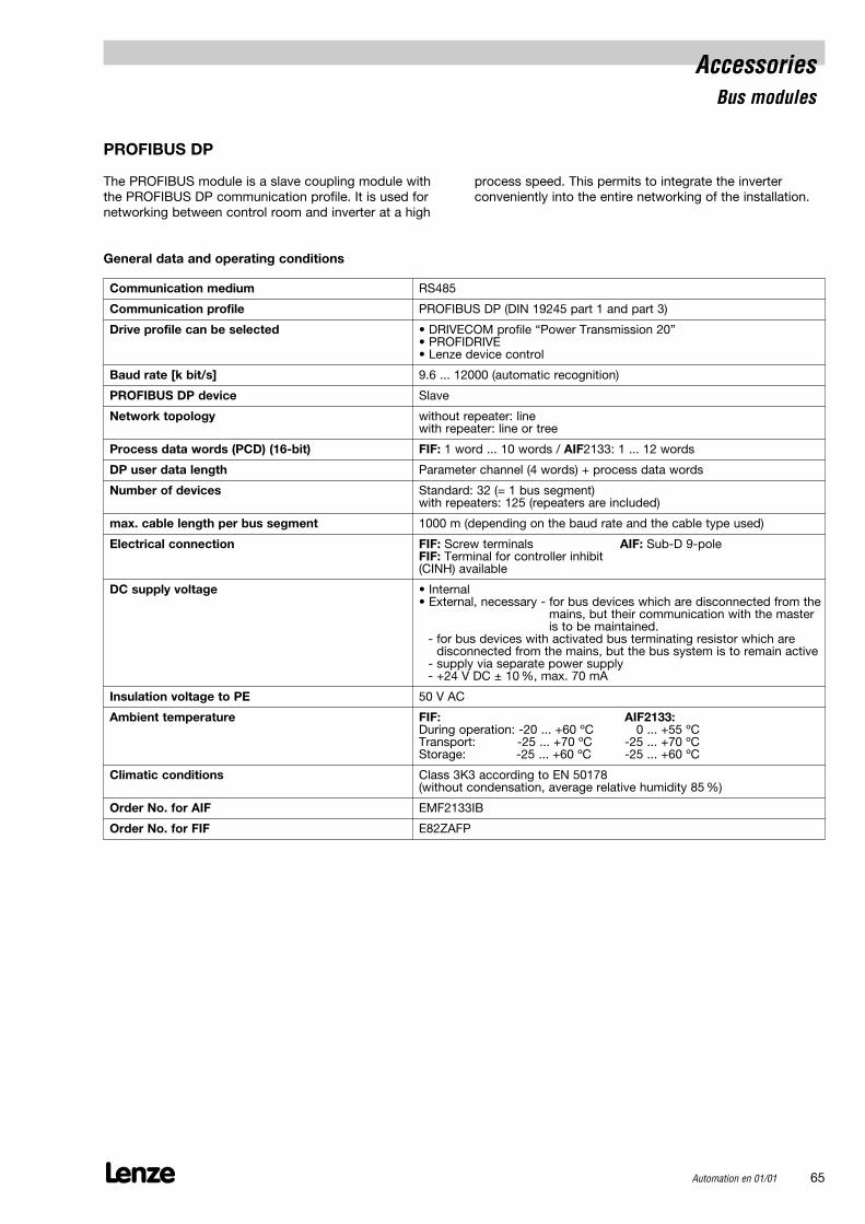
PROFIBUS DP
The PROFIBUS module is a slave coupling module with the PROFIBUS DP communication profile. It is used fornetworking between control room and inverter at a high
process speed. This permits to integrate the inverter conveniently into the entire networking of the installation.
General data and operating conditions
Communication medium RS485
Communication profile PROFIBUS DP (DIN 19245 part 1 and part 3)
Drive profile can be selected • DRIVECOM profile “Power Transmission 20”• PROFIDRIVE• Lenze device control
Baud rate [k bit/s] 9.6 ... 12000 (automatic recognition)
PROFIBUS DP device Slave
Network topology without repeater: linewith repeater: line or tree
Process data words (PCD) (16-bit) FIF: 1 word ... 10 words / AIF2133: 1 ... 12 words
DP user data length Parameter channel (4 words) + process data words
Number of devices Standard: 32 (= 1 bus segment)with repeaters: 125 (repeaters are included)
max. cable length per bus segment 1000 m (depending on the baud rate and the cable type used)
Electrical connection FIF: Screw terminals AIF: Sub-D 9-poleFIF: Terminal for controller inhibit (CINH) available
DC supply voltage • Internal• External, necessary - for bus devices which are disconnected from the
mains, but their communication with the masteris to be maintained.
- for bus devices with activated bus terminating resistor which are disconnected from the mains, but the bus system is to remain active
- supply via separate power supply- +24 V DC ± 10 %, max. 70 mA
Insulation voltage to PE 50 V AC
Ambient temperature FIF: AIF2133:During operation: -20 ... +60 ºC - 20 ... +55 ºCTransport: -25 ... +70 ºC -25 ... +70 ºCStorage: -25 ... +60 ºC -25 ... +60 ºC
Climatic conditions Class 3K3 according to EN 50178(without condensation, average relative humidity 85 %)
Order No. for AIF EMF2133IB
Order No. for FIF E82ZAFP
Lenze66 Automation en 01/01
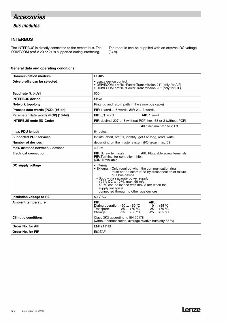
INTERBUS
The INTERBUS is directly connected to the remote bus. TheDRIVECOM profile 20 or 21 is supported during interfacing.
The module can be supplied with an external DC voltage(24 V).
AccessoriesBus modules
General data and operating conditions
Communication medium RS485
Drive profile can be selected • Lenze device control• DRIVECOM profile “Power Transmission 21” (only for AIF)• DRIVECOM profile “Power Transmission 20” (only for FIF)
Baud rate [k bit/s] 500
INTERBUS device Slave
Network topology Ring (go and return path in the same bus cable)
Process data words (PCD) (16-bit) FIF: 1 word ... 6 words AIF: 2 ... 3 words
Parameter data words (PCP) (16-bit) FIF: 0/1 word AIF: 1 word
INTERBUS code (ID-Code) FIF: decimal 227 or 3 (without PCP) hex: E3 or 3 (without PCP)
AIF: decimal 227 hex: E3
max. PDU length 64 bytes
Supported PCP services Initiate, abort, status, identify, get-OV-long, read, write
Number of devices depending on the master system (I/O area), max. 63
max. distance between 2 devices 400 m
Electrical connection FIF: Screw terminals AIF: Pluggable screw terminalsFIF: Terminal for controller inhibit (CINH) available
DC supply voltage • Internal• External - Only required when the communication ring
must not be interrupted by disconnection or failure of a bus device.
- Supply via separate power supply- +24 V DC ± 10 %, max. 90 mA- X3/59 can be loaded with max 3 mA when the
supply voltage is connected through to other bus devices
Insulation voltage to PE 50 V AC
Ambient temperature FIF: AIF:During operation: -20 ... +60 ºC -20 ... +55 ºCTransport: -25 ... +70 ºC -25 ... +70 ºCStorage: -25 ... +60 ºC -25 ... +55 ºC
Climatic conditions Class 3K3 according to EN 50178(without condensation, average relative humidity 85 %)
Order No. for AIF EMF2111IB
Order No. for FIF E82ZAFI

Lenze Automation en 01/01 67
INTERBUS Loop
The INTERBUS Loop is used in conjunction with the INTERBUS. The protocol used is identical to the INTERBUS,energy is, however, supplied directly via the bus.
General data and operating conditions
Communication medium RS485
Drive profile can be selected • Lenze device control• DRIVECOM profile “Power Transmission 20”
Baud rate [k bit/s] 500
INTERBUS device Slave
Network topology Ring
Process data words (PCD) (16-bit) AIF: 2 words
Parameter data words (PCP) (16-bit) not supported
INTERBUS code (ID-Code) decimal: 179; hex: B3
max. PDU length 4 bytes
Supported PCP services none
Number of devices depending on the current consumption (max. 36 Lenze drives)
max. distance between 2 devices 20 m
Electrical connection AIF: Pluggable screw terminals
DC supply voltage via the bus
Insulation voltage to PE 50 V AC
Ambient temperature AIF:-20 ... +55 ºC-25 ... +70 ºC-25 ... +55 ºC
Climatic conditions Class 3K3 according to EN 50178(without condensation, average relative humidity 85 %)
Order No. for AIF EMF2112IB
AccessoriesBus modules
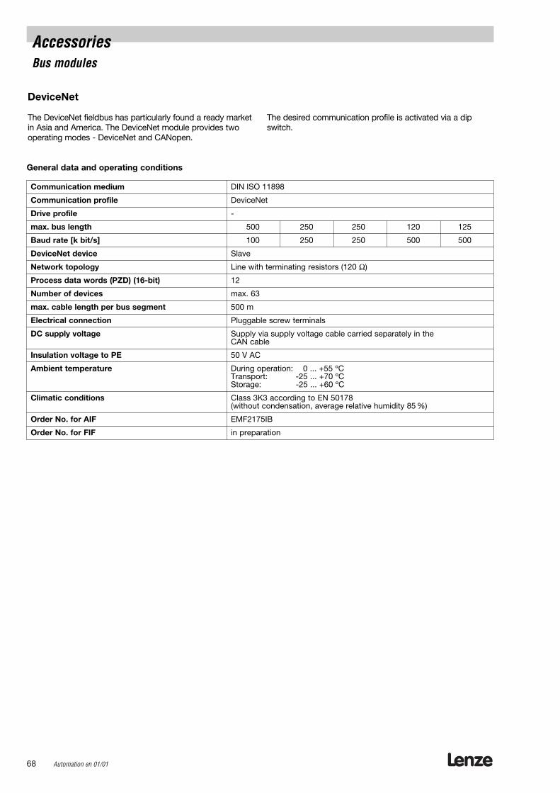
Lenze68 Automation en 01/01
DeviceNet
The DeviceNet fieldbus has particularly found a ready marketin Asia and America. The DeviceNet module provides twooperating modes - DeviceNet and CANopen.
The desired communication profile is activated via a dipswitch.
AccessoriesBus modules
General data and operating conditions
Communication medium DIN ISO 11898
Communication profile DeviceNet
Drive profile -
max. bus length 500 250 250 120 125
Baud rate [k bit/s] 100 250 250 500 500
DeviceNet device Slave
Network topology Line with terminating resistors (120 Ω)
Process data words (PZD) (16-bit) 12
Number of devices max. 63
max. cable length per bus segment 500 m
Electrical connection Pluggable screw terminals
DC supply voltage Supply via supply voltage cable carried separately in the CAN cable
Insulation voltage to PE 50 V AC
Ambient temperature During operation: -20 ... +55 ºCTransport: -25 ... +70 ºCStorage: -25 ... +60 ºC
Climatic conditions Class 3K3 according to EN 50178(without condensation, average relative humidity 85 %)
Order No. for AIF EMF2175IB
Order No. for FIF in preparation
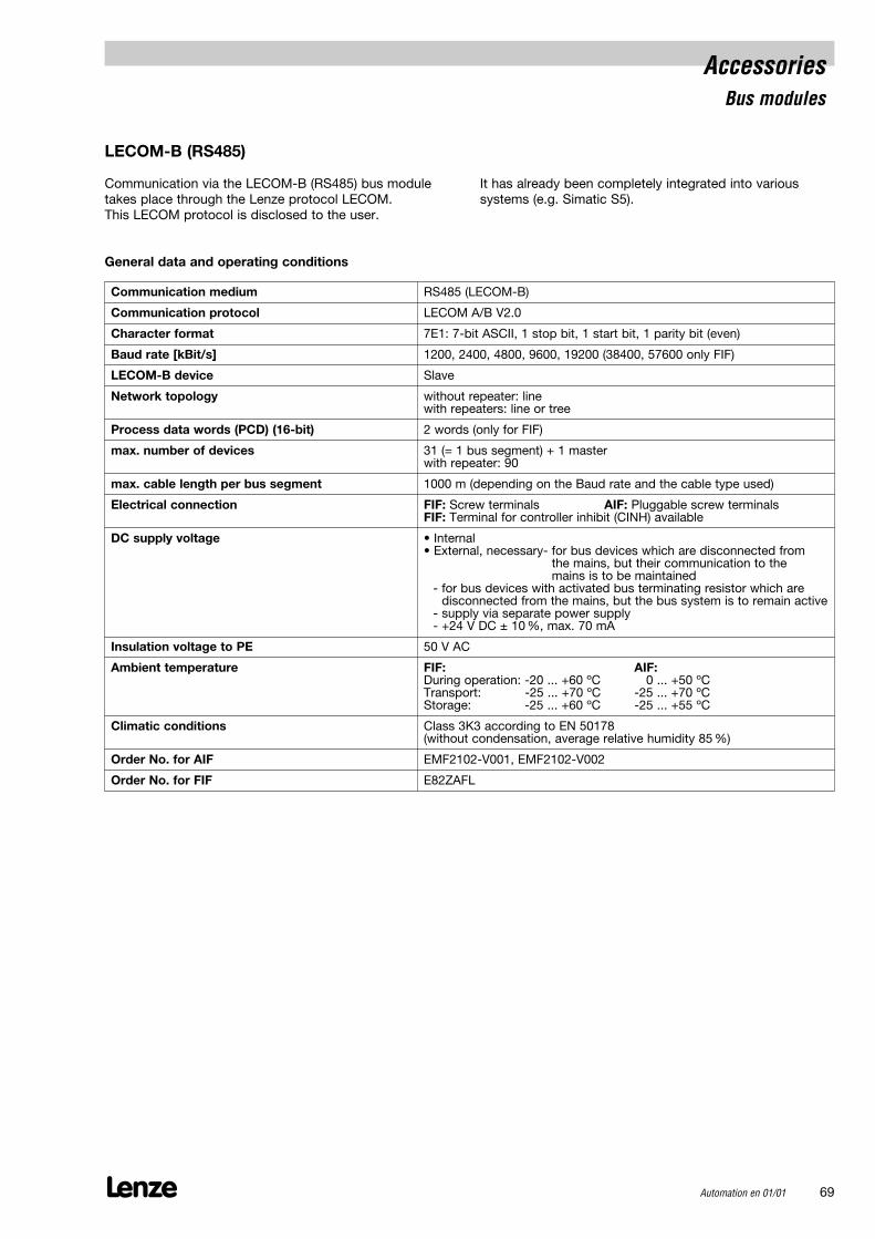
AccessoriesBus modules
Lenze Automation en 01/01 69
LECOM-B (RS485)
Communication via the LECOM-B (RS485) bus moduletakes place through the Lenze protocol LECOM. This LECOM protocol is disclosed to the user.
It has already been completely integrated into varioussystems (e.g. Simatic S5).
General data and operating conditions
Communication medium RS485 (LECOM-B)
Communication protocol LECOM A/B V2.0
Character format 7E1: 7-bit ASCII, 1 stop bit, 1 start bit, 1 parity bit (even)
Baud rate [kBit/s] 1200, 2400, 4800, 9600, 19200 (38400, 57600 only FIF)
LECOM-B device Slave
Network topology without repeater: linewith repeaters: line or tree
Process data words (PCD) (16-bit) 2 words (only for FIF)
max. number of devices 31 (= 1 bus segment) + 1 masterwith repeater: 90
max. cable length per bus segment 1000 m (depending on the Baud rate and the cable type used)
Electrical connection FIF: Screw terminals AIF: Pluggable screw terminalsFIF: Terminal for controller inhibit (CINH) available
DC supply voltage • Internal• External, necessary- for bus devices which are disconnected from
the mains, but their communication to the mains is to be maintained
- for bus devices with activated bus terminating resistor which are disconnected from the mains, but the bus system is to remain active
- supply via separate power supply- +24 V DC ± 10 %, max. 70 mA
Insulation voltage to PE 50 V AC
Ambient temperature FIF: AIF:During operation: -20 ... +60 ºC -20 ... +50 ºCTransport: -25 ... +70 ºC -25 ... +70 ºCStorage: -25 ... +60 ºC -25 ... +55 ºC
Climatic conditions Class 3K3 according to EN 50178(without condensation, average relative humidity 85 %)
Order No. for AIF EMF2102-V001, EMF2102-V002
Order No. for FIF E82ZAFL
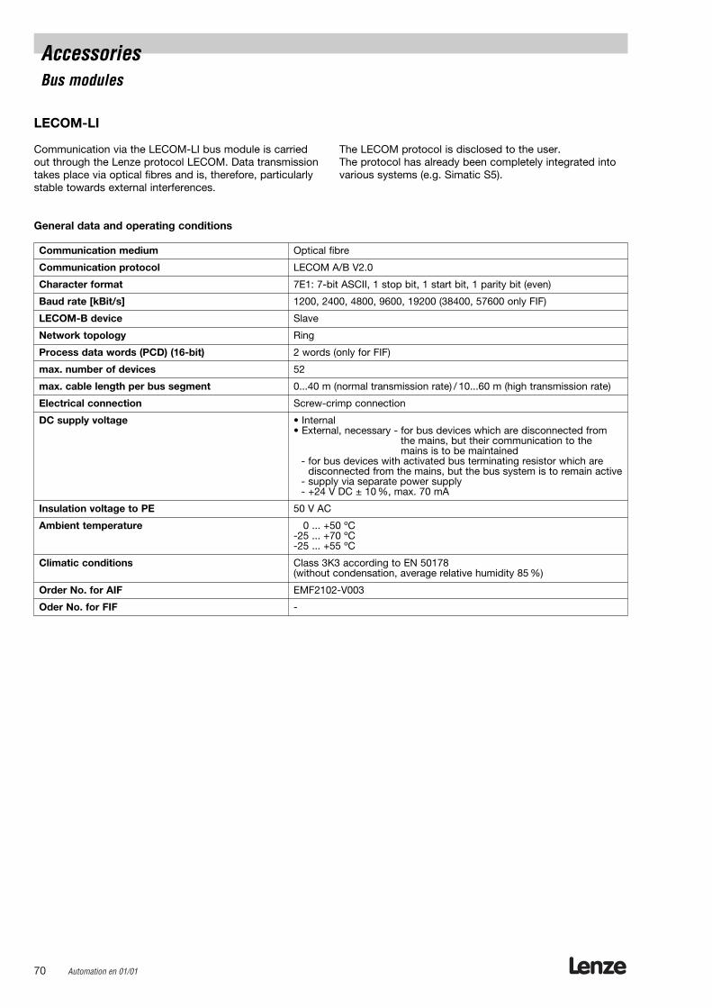
Lenze70 Automation en 01/01
AccessoriesBus modules
LECOM-LI
Communication via the LECOM-LI bus module is carriedout through the Lenze protocol LECOM. Data transmissiontakes place via optical fibres and is, therefore, particularlystable towards external interferences.
The LECOM protocol is disclosed to the user. The protocol has already been completely integrated intovarious systems (e.g. Simatic S5).
General data and operating conditions
Communication medium Optical fibre
Communication protocol LECOM A/B V2.0
Character format 7E1: 7-bit ASCII, 1 stop bit, 1 start bit, 1 parity bit (even)
Baud rate [kBit/s] 1200, 2400, 4800, 9600, 19200 (38400, 57600 only FIF)
LECOM-B device Slave
Network topology Ring
Process data words (PCD) (16-bit) 2 words (only for FIF)
max. number of devices 52
max. cable length per bus segment 0...40 m (normal transmission rate) / 10...60 m (high transmission rate)
Electrical connection Screw-crimp connection
DC supply voltage • Internal• External, necessary - for bus devices which are disconnected from
the mains, but their communication to the mains is to be maintained
- for bus devices with activated bus terminating resistor which are disconnected from the mains, but the bus system is to remain active
- supply via separate power supply- +24 V DC ± 10 %, max. 70 mA
Insulation voltage to PE 50 V AC
Ambient temperature -20 ... +50 ºC-25 ... +70 ºC-25 ... +55 ºC
Climatic conditions Class 3K3 according to EN 50178(without condensation, average relative humidity 85 %)
Order No. for AIF EMF2102-V003
Oder No. for FIF -
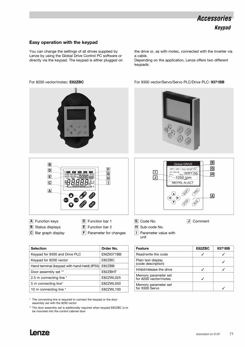
Lenze Automation en 01/01 71
Easy operation with the keypad
You can change the settings of all drives supplied byLenze by using the Global Drive Control PC software ordirectly via the keypad. The keypad is either plugged on
the drive or, as with motec, connected with the inverter viaa cable.Depending on the application, Lenze offers two differentkeypads:
For 8200 vector/motec: E82ZBC For 9300 vector/Servo/Servo PLC/Drive PLC: 9371BB
AccessoriesKeypad
SHIFT
RUN
STOP
Global DRIVE
PRG
Par 2SH PRG
Para
1250 rpm0051
MCTRL-N-ACT
RDY IMP Imax Mmax Fail
00
Selection Order No.
Keypad for 9300 and Drive PLC EMZ9371BB
Keypad for 8200 vector E82ZBC
Hand terminal (keypad with hand-held) (IP55) E82ZBB
Door assembly set ** E82ZBHT
2.5 m connecting line * E82ZWL025
5 m connecting line* E82ZWL050
10 m connecting line * E82ZWL100
* The connecting line is required to connect the keypad or the door assembly set with the 8200 vector
** The door assembly set is additionally required when keypad E82ZBC is tobe mounted into the control cabinet door
Function keys
Status displays
Bar graph display
Function bar 1
Function bar 2
Parameter for changes
Code No.
Sub-code No.
Parameter value withunit
CommentA
B
C
D G J
E H
F I
Feature E82ZBC 9371BB
Read/write the code
Plain text display (code description)
Inhibit/release the drive
Memory parameter setfor 8200 vector/motec
Memory parameter setfor 9300 Servo
B
HI
A
G
J

Lenze72 Automation en 01/01
AccessoriesSystem bus components
The hand terminal EMZ 9372BB can be used for displayand diagnostics. This hand terminal can be connected tothe system bus of the servo inverter. All parameters areaccessible. In a networked system, up to 63 servo inverters can be addressed via one hand terminal.
Hand terminal
The PC system bus inverter is used to connect the PCquickly and easily to the Lenze system bus (CAN). Theadapter is simply plugged on the printer interface of thePC. The relevant drivers are automatically installed withthe Lenze software. Supply voltage is provided via thekeypad
PC system bus inverter
Order No.:
Supply voltage via EMF2173IBkeypad with DIN connection
Supply voltage via EMF2173IB-V002keypad with PS2 connection
Order No.: EMZ9372BB
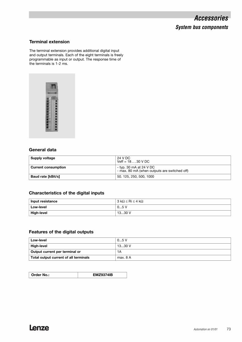
Lenze Automation en 01/01 73
AccessoriesSystem bus components
The terminal extension provides additional digital input and output terminals. Each of the eight terminals is freelyprogrammable as input or output. The response time ofthe terminals is 1-2 ms.
Terminal extension
General data
Supply voltage 24 V DCVeff = 18 . . . 30 V DC
Current consumption - typ. 30 mA at 24 V DC- max. 80 mA (when outputs are switched off)
Baud rate [kBit/s] 50. 125, 250, 500, 1000
Characteristics of the digital inputs
Input resistance 3 kΩ ≤ Ri ≤ 4 kΩ
Low-level 0...5 V
High-level 13...30 V
Features of the digital outputs
Low-level 0...5 V
High-level 13...30 V
Output current per terminal or 1A
Total output current of all terminals max. 8 A
Order No.: EMZ9374IB

Lenze74 Automation en 01/01
Recipient: LenzeBranch office/representation
Postal code/city:
Fax number:
Order form
Sender
Company Customer No.
Street / P.O. box Order No.
Postal code / city Issued by:
Delivery address* Phone
Fax
Invoice addressee* Delivery date
* Please fill in, when not sender. Date Signature
Order designations
Drive PLC and accessories:
Order No. Pcs.
Drive PLC EPL-10200
Extension board 1 (6 dig. inputs / 4/2 dig. outputs) EPZ-10201
Extension board 2 (14 dig. inputs / 8 dig. outputs) EPZ-10202
Extension board 3 (1 enc. / 8 dig. inputs / 4 dig. outputs / 2 anal. inputs) EPZ-10203
Swivel-rail assembly set E82ZJ001
DIN rail assembly set E82ZJ002
9300 servo and variants as built-in devices
Servo Inverter Servo PLC Positioning Cam Profiler Registercontroller controller
Order No. Pcs. Order No. Pcs. Order No. Pcs. Order No. Pcs. Order No. Pcs.
0.37 EVS9321-ES EVS9321-EI EVS9321-EP EVS9321-EK EVS9321-ER
0.75 EVS9322-ES EVS9322-EI EVS9322-EP EVS9322-EK EVS9322-ER
1.5 EVS9323-ES EVS9323-EI EVS9323-EP EVS9323-EK EVS9323-ER
3.0 EVS9324-ES EVS9324-EI EVS9324-EP EVS9324-EK EVS9324-ER
5.5 EVS9325-ES EVS9325-EI EVS9325-EP EVS9325-EK EVS9325-ER
11.0 EVS9326-ES EVS9326-EI EVS9326-EP EVS9326-EK EVS9326-ER
15.0 EVS9327-ES EVS9327-EI EVS9327-EP EVS9327-EK EVS9327-ER
22.0 EVS9328-ES EVS9328-EI EVS9328-EP EVS9328-EK EVS9328-ER
30.0 EVS9329-ES EVS9329-EI EVS9329-EP EVS9329-EK EVS9329-ER
45.0 EVS9330-ES EVS9330-EI EVS9330-EP EVS9330-EK EVS9330-ER
55.0 EVS9331-ES EVS9331-EI EVS9331-EP EVS9331-EK EVS9331-ER
75..0 EVS9332-ES EVS9332-EI EVS9332-EP EVS9332-EK EVS9332-ER
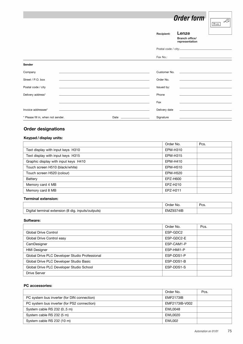
Automation en 01/01 75
Recipient: LenzeBranch office/representation
Postal code / city:
Fax No.:
Order form
Sender
Company Customer No.
Street / P.O. box Order No.
Postal code / city Issued by:
Delivery address* Phone
Fax
Invoice addressee* Delivery date
* Please fill in, when not sender. Date Signature
Order designations
Keypad / display units:
Order No. Pcs.
Text display with input keys H310 EPM-H310
Text display with input keys H315 EPM-H315
Graphic display with input keys H410 EPM-H410
Touch screen H510 (black/white) EPM-H510
Touch screen H520 (colour) EPM-H520
Battery EPZ-H600
Memory card 4 MB EPZ-H210
Memory card 8 MB EPZ-H211
Terminal extension:
Order No. Pcs.
Digital terminal extension (8 dig. inputs/outputs) EMZ9374IB
Software:
Order No. Pcs.
Global Drive Control ESP-GDC2
Global Drive Control easy ESP-GDC2-E
CamDesigner ESP-CAM1-P
HMI Designer ESP-HMI1-P
Global Drive PLC Developer Studio Professional ESP-DDS1-P
Global Drive PLC Developer Studio Basic ESP-DDS1-B
Global Drive PLC Developer Studio School ESP-DDS1-S
Drive Server
PC accessories:
Order No. Pcs.
PC system bus inverter (for DIN connection) EMF2173IB
PC system bus inverter (for PS2 connection) EMF2173IB-V002
System cable RS 232 (0..5 m) EWL0048
System cable RS 232 (5 m) EWL0020
System cable RS 232 (10 m) EWL002

Lenze76 Automation en 01/01
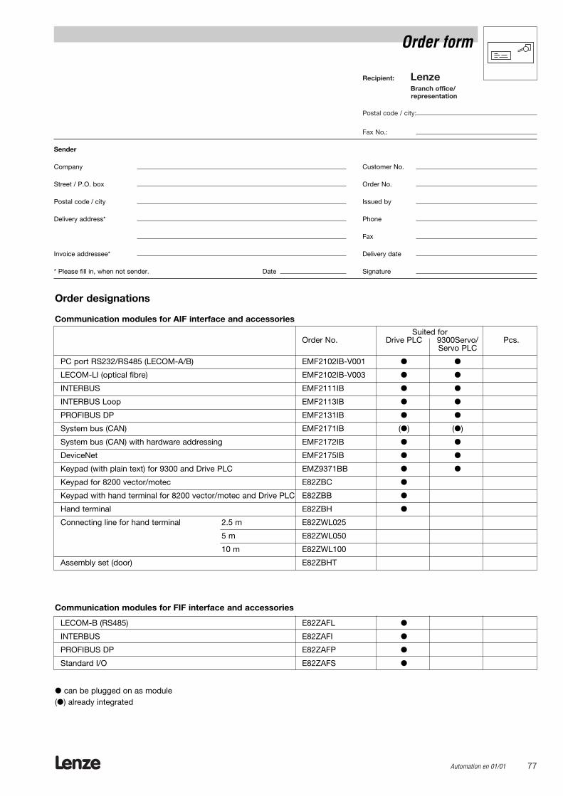
Lenze Automation en 01/01 77
Recipient: LenzeBranch office/representation
Postal code / city:
Fax No.:
Order form
Sender
Company Customer No.
Street / P.O. box Order No.
Postal code / city Issued by
Delivery address* Phone
Fax
Invoice addressee* Delivery date
* Please fill in, when not sender. Date Signature
Order designations
Communication modules for AIF interface and accessories
Suited forOrder No. Drive PLC 9300Servo/ Pcs.
Servo PLC
PC port RS232/RS485 (LECOM-A/B) EMF2102IB-V001
LECOM-LI (optical fibre) EMF2102IB-V003
INTERBUS EMF2111IB
INTERBUS Loop EMF2113IB
PROFIBUS DP EMF2131IB
System bus (CAN) EMF2171IB () ()
System bus (CAN) with hardware addressing EMF2172IB
DeviceNet EMF2175IB
Keypad (with plain text) for 9300 and Drive PLC EMZ9371BB
Keypad for 8200 vector/motec E82ZBC
Keypad with hand terminal for 8200 vector/motec and Drive PLC E82ZBB
Hand terminal E82ZBH
Connecting line for hand terminal 2.5 m E82ZWL025
5 m E82ZWL050
10 m E82ZWL100
Assembly set (door) E82ZBHT
Communication modules for FIF interface and accessories
LECOM-B (RS485) E82ZAFL
INTERBUS E82ZAFI
PROFIBUS DP E82ZAFP
Standard I/O E82ZAFS
can be plugged on as module() already integrated