
Automation PC 820 - ADEGIS
235
1 Automation PC 820 User's manual Version: 1.35 (April 2015) Model no.: MAAPC820-ENG All information contained in this manual is current as of its creation/publication. B&R reserves the right to change the contents of this manual without notice. The information contained herein is believed to be accurate as of the date of publication; however, Bernecker + Rainer Industrie-Elektronik Ges.m.b.H. makes no warranty, ex- pressed or implied, with regard to the products or documentation contained within this manual. In addition, Bernecker + Rainer Industrie-Elektronik Ges.m.b.H. shall not be liable for any incidental or consequential damages in connection with or arising from the furnishing, performance or use of the product(s) in this documentation. Soft- ware names, hardware names and trademarks are registered by their respective companies.
-
Upload
khangminh22 -
Category
Documents
-
view
1 -
download
0
Transcript of Automation PC 820 - ADEGIS
1
Automation PC 820User's manual
Version: 1.35 (April 2015)Model no.: MAAPC820-ENG
All information contained in this manual is current as of its creation/publication. B&R reserves the right to changethe contents of this manual without notice. The information contained herein is believed to be accurate as ofthe date of publication; however, Bernecker + Rainer Industrie-Elektronik Ges.m.b.H. makes no warranty, ex-pressed or implied, with regard to the products or documentation contained within this manual. In addition,Bernecker + Rainer Industrie-Elektronik Ges.m.b.H. shall not be liable for any incidental or consequential damagesin connection with or arising from the furnishing, performance or use of the product(s) in this documentation. Soft-ware names, hardware names and trademarks are registered by their respective companies.

2
Chapter 1: General information
Chapter 2: Technical data
Chapter 3: Installation
Chapter 4: Software
Chapter 5: Standards and certifications
Chapter 6: Accessories
Chapter 7: Maintenance and service
Appendix A
Table of contents
Tabl
e of
con
tent
s
Automation PC 820 user's manual V1.35 3
Chapter 1 General information................................................................................... 91 Manual history....................................................................................................................................................92 Safety guidelines..............................................................................................................................................11
2.1 Intended use...............................................................................................................................................112.2 Protection against electrostatic discharge..................................................................................................11
2.2.1 Packaging..............................................................................................................................................112.2.2 Guidelines for proper ESD handling.....................................................................................................11
2.3 Policies and procedures.............................................................................................................................112.4 Transport and storage................................................................................................................................122.5 Installation...................................................................................................................................................122.6 Operation.................................................................................................................................................... 12
2.6.1 Protection against touching electrical parts..........................................................................................122.6.2 Environmental conditions - Dust, moisture, corrosive gases................................................................122.6.3 Viruses and dangerous programs........................................................................................................ 12
2.7 Environmentally friendly disposal............................................................................................................... 132.7.1 Separation of materials.........................................................................................................................13
3 Organization of safety notices......................................................................................................................... 144 Guidelines.........................................................................................................................................................145 Overview...........................................................................................................................................................15
Chapter 2 Technical data.......................................................................................... 181 Introduction.......................................................................................................................................................18
1.1 Features......................................................................................................................................................181.2 System components................................................................................................................................... 19
1.2.1 Configuration - Base system................................................................................................................ 191.2.2 Configuration - Optional components................................................................................................... 20
2 Complete system............................................................................................................................................. 212.1 Temperature specifications.........................................................................................................................21
2.1.1 Maximum ambient temperature with a fan kit...................................................................................... 212.1.2 Temperature monitoring........................................................................................................................222.1.3 Temperature sensor locations.............................................................................................................. 22
2.2 Humidity specifications............................................................................................................................... 232.3 Power management................................................................................................................................... 24
2.3.1 Voltage supply block diagramVoltage supply....................................................................................... 242.3.2 Power calculation.................................................................................................................................. 24
2.4 Block diagram.............................................................................................................................................262.5 Device interfaces and slots........................................................................................................................ 27
2.5.1 +24 VDC power supply.........................................................................................................................272.5.2 Grounding..............................................................................................................................................272.5.3 Monitor / Panel connection................................................................................................................... 272.5.4 USB interfaces...................................................................................................................................... 292.5.5 CompactFlash slot 1............................................................................................................................. 302.5.6 CompactFlash slot 2............................................................................................................................. 302.5.7 COM1 serial interface........................................................................................................................... 312.5.8 COM2 serial interface........................................................................................................................... 322.5.9 CAN.......................................................................................................................................................352.5.10 POWERLINK....................................................................................................................................... 362.5.11 Ethernet 1 (ETH1)...............................................................................................................................392.5.12 Ethernet 2 (ETH2)...............................................................................................................................392.5.13 Battery................................................................................................................................................. 402.5.14 Hardware security key (dongle)..........................................................................................................412.5.15 LED status indicators..........................................................................................................................422.5.16 CMOS Profile switch...........................................................................................................................422.5.17 Power button.......................................................................................................................................432.5.18 Reset button........................................................................................................................................43
3 Individual components..................................................................................................................................... 443.1 System units............................................................................................................................................... 44

Table of contents
4 Automation PC 820 user's manual V1.35
3.1.1 Interfaces...............................................................................................................................................443.1.2 5PC820.SX01-00...................................................................................................................................493.1.3 5PC820.SX01-01...................................................................................................................................53
3.2 CPU boards 945GME.................................................................................................................................573.2.1 General information...............................................................................................................................573.2.2 Order data.............................................................................................................................................573.2.3 Technical data - 5PC800.B945-0x........................................................................................................583.2.4 Technical data - 5PC800.B945-1x........................................................................................................58
3.3 Main memory..............................................................................................................................................603.3.1 General information...............................................................................................................................603.3.2 Order data.............................................................................................................................................603.3.3 Technical data.......................................................................................................................................60
3.4 Heat sink with power supply...................................................................................................................... 613.4.1 General information...............................................................................................................................613.4.2 Order data.............................................................................................................................................613.4.3 Technical data.......................................................................................................................................61
3.5 Replacement fan 8BXF001.0000-00.......................................................................................................... 623.5.1 Order data.............................................................................................................................................623.5.2 Technical data.......................................................................................................................................62
3.6 PCIec plug-in cards....................................................................................................................................633.6.1 General information...............................................................................................................................633.6.2 Dimensions............................................................................................................................................633.6.3 5ACPCC.ETH0-00.................................................................................................................................643.6.4 5ACPCC.MPL0-00................................................................................................................................ 66
Chapter 3 Installation.................................................................................................701 Installation........................................................................................................................................................ 70
1.1 Important installation information............................................................................................................... 701.2 Mounting plates.......................................................................................................................................... 71
1.2.1 Feed-through mounting.........................................................................................................................711.2.2 Cold-plate mounting.............................................................................................................................. 711.2.3 Wall mounting....................................................................................................................................... 71
1.3 Mounting orientation................................................................................................................................... 721.4 Spacing for air circulation...........................................................................................................................731.5 Swivel range of the front cover..................................................................................................................741.6 Installation guidelines................................................................................................................................. 75
2 Cable connections............................................................................................................................................763 Connection examples.......................................................................................................................................77
3.1 Selecting display units................................................................................................................................773.2 One Automation Panel 900 via DVI...........................................................................................................78
3.2.1 Basic system requirements...................................................................................................................783.2.2 Link modules.........................................................................................................................................783.2.3 Cables................................................................................................................................................... 783.2.4 Possible Automation Panel devices, resolutions and segment lengths................................................793.2.5 BIOS settings........................................................................................................................................ 79
3.3 One Automation Panel 900 via SDL..........................................................................................................803.3.1 Basic system requirements...................................................................................................................803.3.2 Link modules.........................................................................................................................................803.3.3 Cables................................................................................................................................................... 803.3.4 Settings in BIOS................................................................................................................................... 81
3.4 One Automation Panel 800 via SDL..........................................................................................................823.4.1 Basic system requirements...................................................................................................................823.4.2 Cables................................................................................................................................................... 823.4.3 Settings in BIOS................................................................................................................................... 83
3.5 One AP900 and one AP800 via SDL........................................................................................................ 843.5.1 Basic system requirements...................................................................................................................843.5.2 Link modules.........................................................................................................................................84

Table of contents
Tabl
e of
con
tent
s
Automation PC 820 user's manual V1.35 5
3.5.3 Cables................................................................................................................................................... 843.5.4 Settings in BIOS................................................................................................................................... 84
3.6 Four Automation Panel 900 units via SDL................................................................................................ 863.6.1 Basic system requirements...................................................................................................................863.6.2 Link modules.........................................................................................................................................863.6.3 Cables................................................................................................................................................... 863.6.4 Settings in BIOS................................................................................................................................... 87
4 Connecting peripheral USB devices................................................................................................................884.1 Locally on the APC820.............................................................................................................................. 884.2 Remote connection to Automation Panel 900 via DVI...............................................................................894.3 Remote connection to Automation Panel 800 / 900 via SDL.................................................................... 89
5 Known problems / issues.................................................................................................................................90
Chapter 4 Software.................................................................................................... 911 BIOS options.................................................................................................................................................... 91
1.1 General information.................................................................................................................................... 911.2 BIOS setup and boot procedure................................................................................................................ 911.3 BIOS Setup keys........................................................................................................................................931.4 Main............................................................................................................................................................ 941.5 Advanced.................................................................................................................................................... 95
1.5.1 ACPI Configuration............................................................................................................................... 961.5.2 PCI Configuration..................................................................................................................................971.5.3 PCI Express Configuration................................................................................................................. 1001.5.4 Graphics Configuration....................................................................................................................... 1021.5.5 CPU Configuration.............................................................................................................................. 1041.5.6 Chipset Configuration..........................................................................................................................1051.5.7 I/O Interface Configuration..................................................................................................................1061.5.8 Clock Configuration.............................................................................................................................1071.5.9 IDE Configuration................................................................................................................................1071.5.10 USB Configuration............................................................................................................................ 1121.5.11 Keyboard/Mouse Configuration.........................................................................................................1141.5.12 Remote access configuration............................................................................................................1141.5.13 CPU Board Monitor...........................................................................................................................1161.5.14 Baseboard/Panel Features............................................................................................................... 117
1.6 Boot...........................................................................................................................................................1211.7 Security..................................................................................................................................................... 122
1.7.1 Hard Disk Security User Password.................................................................................................... 1231.7.2 Hard Disk Security Master Password.................................................................................................124
1.8 Power........................................................................................................................................................1241.9 Exit............................................................................................................................................................ 1261.10 BIOS default settings..............................................................................................................................127
1.10.1 Main...................................................................................................................................................1271.10.2 Advanced...........................................................................................................................................1271.10.3 Boot................................................................................................................................................... 1311.10.4 Security..............................................................................................................................................1311.10.5 Power................................................................................................................................................ 131
1.11 BIOS error signals (beep codes)............................................................................................................1331.12 Allocation of resources........................................................................................................................... 134
1.12.1 RAM address assignment.................................................................................................................1341.12.2 I/O address assignments.................................................................................................................. 1341.12.3 Interrupt assignments in PIC mode.................................................................................................. 1341.12.4 Interrupt assignments in APIC mode................................................................................................1351.12.5 Interrupt routing for BIOS up to V1.12............................................................................................. 1361.12.6 Interrupt routing for BIOS starting with V1.14.................................................................................. 136
2 Upgrade information.......................................................................................................................................1372.1 BIOS upgrade...........................................................................................................................................137
2.1.1 Important information.......................................................................................................................... 137
Table of contents
6 Automation PC 820 user's manual V1.35
2.1.2 Procedure with MS-DOS.................................................................................................................... 1382.1.3 Using the Control Center....................................................................................................................139
2.2 Firmware upgrade.................................................................................................................................... 1402.2.1 Procedure............................................................................................................................................1402.2.2 Possible upgrade problems and software dependencies (for V1.04)................................................. 141
2.3 Creating an MS-DOS boot diskette in Windows XP................................................................................1422.4 Creating a bootable USB flash drive for B&R upgrade files.................................................................... 144
2.4.1 Requirements...................................................................................................................................... 1442.4.2 Procedure............................................................................................................................................1442.4.3 How to access MS-DOS.....................................................................................................................144
2.5 Creating a bootable CompactFlash card for B&R upgrade files..............................................................1452.5.1 Requirements...................................................................................................................................... 1452.5.2 Procedure............................................................................................................................................1452.5.3 How to access MS-DOS.....................................................................................................................145
3 Microsoft DOS................................................................................................................................................1463.1 Order data................................................................................................................................................ 1463.2 Known problems.......................................................................................................................................1463.3 Resolutions and color depths...................................................................................................................146
4 Windows XP Professional..............................................................................................................................1474.1 General information.................................................................................................................................. 1474.2 Order data................................................................................................................................................ 1474.3 Overview................................................................................................................................................... 1484.4 Installation.................................................................................................................................................1484.5 Drivers.......................................................................................................................................................1484.6 Supported display resolutions.................................................................................................................. 148
5 Windows XP Embedded................................................................................................................................ 1495.1 General information.................................................................................................................................. 1495.2 Order data................................................................................................................................................ 1495.3 Overview................................................................................................................................................... 1495.4 Features with FP2007 (Feature Pack 2007)............................................................................................1495.5 Installation.................................................................................................................................................1505.6 Drivers.......................................................................................................................................................150
5.6.1 Touch screen driver............................................................................................................................ 1506 Windows Embedded Standard 2009............................................................................................................. 151
6.1 General information.................................................................................................................................. 1516.2 Order data................................................................................................................................................ 1516.3 Overview................................................................................................................................................... 1516.4 Features with WES2009 (Windows Embedded Standard 2009)............................................................. 1516.5 Installation.................................................................................................................................................1526.6 Drivers.......................................................................................................................................................152
6.6.1 Touch screen driver............................................................................................................................ 1526.7 Supported display resolutions.................................................................................................................. 152
7 Windows Embedded Standard 7................................................................................................................... 1537.1 General information.................................................................................................................................. 1537.2 Order data................................................................................................................................................ 1537.3 Overview................................................................................................................................................... 1547.4 Features with WES7 (Windows Embedded Standard 7)......................................................................... 1547.5 Installation.................................................................................................................................................1547.6 Drivers.......................................................................................................................................................155
7.6.1 Touch screen driver............................................................................................................................ 1557.7 Supported display resolutions.................................................................................................................. 155
8 Automation Runtime.......................................................................................................................................1568.1 General information.................................................................................................................................. 1568.2 Order data................................................................................................................................................ 1568.3 Automation Runtime Windows (ARwin)................................................................................................... 1568.4 Automation Runtime Embedded (ARemb)...............................................................................................1568.5 Technology Guarding............................................................................................................................... 157
Table of contents
Tabl
e of
con
tent
s
Automation PC 820 user's manual V1.35 7
9 B&R Automation Device Interface (ADI) - Control Center.............................................................................1589.1 Functions.................................................................................................................................................. 1589.2 Installation.................................................................................................................................................159
10 B&R Automation Device Interface (ADI) Development Kit.......................................................................... 16011 B&R Automation Device Interface (ADI) .NET SDK....................................................................................16212 B&R Key Editor............................................................................................................................................164
Chapter 5 Standards and certifications................................................................. 1661 Standards and guidelines.............................................................................................................................. 166
1.1 CE mark....................................................................................................................................................1661.2 EMC directive........................................................................................................................................... 1661.3 Low voltage directive................................................................................................................................166
2 Certifications...................................................................................................................................................1672.1 UL certification..........................................................................................................................................1672.2 GOST-R.................................................................................................................................................... 167
Chapter 6 Accessories............................................................................................ 1681 Male CAN connector (4-pin).......................................................................................................................... 168
1.1 General information.................................................................................................................................. 1681.2 Order data................................................................................................................................................ 1681.3 Technical data.......................................................................................................................................... 168
2 Replacement CMOS batteries....................................................................................................................... 1692.1 0AC201.91 / 4A0006.00-000....................................................................................................................169
2.1.1 General information.............................................................................................................................1692.1.2 Order data...........................................................................................................................................1692.1.3 Technical data.....................................................................................................................................169
3 DVI/Monitor adapter....................................................................................................................................... 1703.1 5AC900.1000-00.......................................................................................................................................1703.2 General information.................................................................................................................................. 1703.3 Order data................................................................................................................................................ 170
4 CompactFlash cards...................................................................................................................................... 1714.1 General information.................................................................................................................................. 1714.2 General information.................................................................................................................................. 171
4.2.1 Flash technology................................................................................................................................. 1714.2.2 Wear leveling...................................................................................................................................... 1714.2.3 ECC error correction...........................................................................................................................1714.2.4 S.M.A.R.T. support.............................................................................................................................. 1714.2.5 Maximum reliability..............................................................................................................................172
4.3 5CFCRD.xxxx-06...................................................................................................................................... 1734.3.1 General information.............................................................................................................................1734.3.2 Order data...........................................................................................................................................1734.3.3 Technical data.....................................................................................................................................1744.3.4 Temperature/Humidity diagram...........................................................................................................1774.3.5 Dimensions..........................................................................................................................................1774.3.6 Benchmark.......................................................................................................................................... 178
4.4 5CFCRD.xxxx-04...................................................................................................................................... 1794.4.1 General information.............................................................................................................................1794.4.2 Order data...........................................................................................................................................1794.4.3 Technical data.....................................................................................................................................1794.4.4 Temperature/Humidity diagram...........................................................................................................1814.4.5 Dimensions..........................................................................................................................................1814.4.6 Benchmark.......................................................................................................................................... 182
4.5 5CFCRD.xxxx-03...................................................................................................................................... 1834.5.1 General information.............................................................................................................................1834.5.2 Order data...........................................................................................................................................1834.5.3 Technical data.....................................................................................................................................1834.5.4 Temperature/Humidity diagram...........................................................................................................185
Table of contents
8 Automation PC 820 user's manual V1.35
4.5.5 Dimensions..........................................................................................................................................1854.6 Known problems/issues............................................................................................................................186
5 USB flash drives............................................................................................................................................ 1875.1 5MMUSB.2048-00.................................................................................................................................... 187
5.1.1 General information.............................................................................................................................1875.1.2 Order data...........................................................................................................................................1875.1.3 Technical data.....................................................................................................................................1875.1.4 Temperature/Humidity diagram...........................................................................................................188
5.2 5MMUSB.xxxx-01..................................................................................................................................... 1895.2.1 General information.............................................................................................................................1895.2.2 Order data...........................................................................................................................................1895.2.3 Technical data.....................................................................................................................................1895.2.4 Temperature/Humidity diagram...........................................................................................................190
6 Cables............................................................................................................................................................ 1916.1 DVI cables................................................................................................................................................ 191
6.1.1 5CADVI.0xxx-00..................................................................................................................................1916.2 SDL cables............................................................................................................................................... 194
6.2.1 5CASDL.0xxx-00.................................................................................................................................1946.3 SDL flex cables........................................................................................................................................ 197
6.3.1 5CASDL.0xxx-03.................................................................................................................................1976.4 SDL flex cables with extender................................................................................................................. 200
6.4.1 5CASDL.0xx0-13.................................................................................................................................2006.5 SDL cables with 45° male connector.......................................................................................................204
6.5.1 5CASDL.0xxx-01.................................................................................................................................2046.6 USB cables...............................................................................................................................................207
6.6.1 5CAUSB.00xx-00................................................................................................................................ 2076.7 RS232 cables........................................................................................................................................... 208
6.7.1 9A0014.xx.......................................................................................................................................... 2087 HMI Drivers & Utilities DVD...........................................................................................................................210
7.1 5SWHMI.0000-00..................................................................................................................................... 2107.1.1 General information.............................................................................................................................2107.1.2 Order data...........................................................................................................................................2107.1.3 Contents (V2.20)................................................................................................................................. 210
Chapter 7 Maintenance and service.......................................................................2131 Replacing the battery.....................................................................................................................................213
1.1 Evaluating the battery status....................................................................................................................2131.2 Procedure................................................................................................................................................. 213
2 Replacing a CompactFlash card................................................................................................................... 2153 Changing the fan........................................................................................................................................... 216
3.1 Procedure................................................................................................................................................. 216
Appendix A .............................................................................................................. 2171 Maintenance Controller Extended (MTCX)....................................................................................................217
1.1 Temperature monitoring Fan control........................................................................................................2182 Abbreviations..................................................................................................................................................2193 Glossary......................................................................................................................................................... 220
General information • Manual history
Cha
pter
1G
ener
al in
form
atio
n
Automation PC 820 user's manual V1.35 9
Chapter 1 • General information
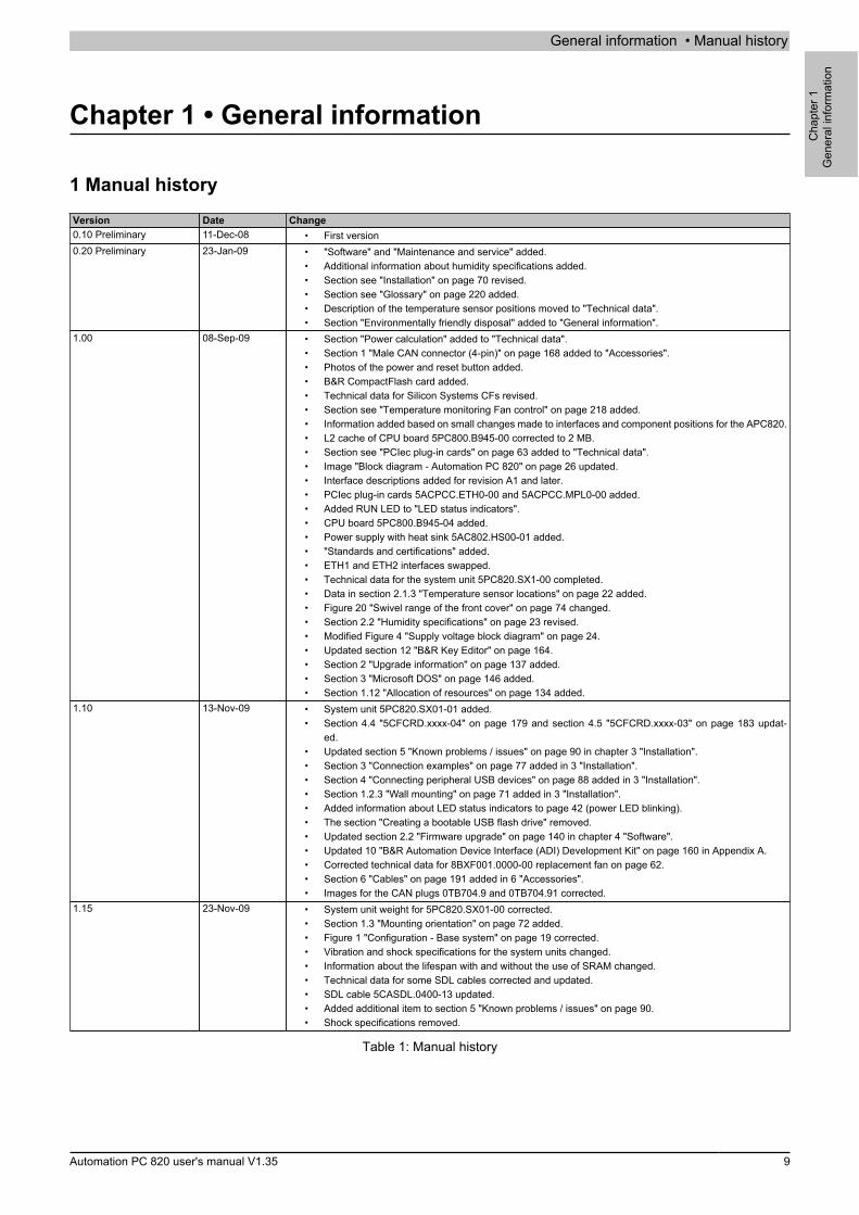
1 Manual historyVersion Date Change0.10 Preliminary 11-Dec-08 • First version0.20 Preliminary 23-Jan-09 • "Software" and "Maintenance and service" added.
• Additional information about humidity specifications added.• Section see "Installation" on page 70 revised.• Section see "Glossary" on page 220 added.• Description of the temperature sensor positions moved to "Technical data".• Section "Environmentally friendly disposal" added to "General information".
1.00 08-Sep-09 • Section "Power calculation" added to "Technical data".• Section 1 "Male CAN connector (4-pin)" on page 168 added to "Accessories".• Photos of the power and reset button added.• B&R CompactFlash card added.• Technical data for Silicon Systems CFs revised.• Section see "Temperature monitoring Fan control" on page 218 added.• Information added based on small changes made to interfaces and component positions for the APC820.• L2 cache of CPU board 5PC800.B945-00 corrected to 2 MB.• Section see "PCIec plug-in cards" on page 63 added to "Technical data".• Image "Block diagram - Automation PC 820" on page 26 updated.• Interface descriptions added for revision A1 and later.• PCIec plug-in cards 5ACPCC.ETH0-00 and 5ACPCC.MPL0-00 added.• Added RUN LED to "LED status indicators".• CPU board 5PC800.B945-04 added.• Power supply with heat sink 5AC802.HS00-01 added.• "Standards and certifications" added.• ETH1 and ETH2 interfaces swapped.• Technical data for the system unit 5PC820.SX1-00 completed.• Data in section 2.1.3 "Temperature sensor locations" on page 22 added.• Figure 20 "Swivel range of the front cover" on page 74 changed.• Section 2.2 "Humidity specifications" on page 23 revised.• Modified Figure 4 "Supply voltage block diagram" on page 24.• Updated section 12 "B&R Key Editor" on page 164.• Section 2 "Upgrade information" on page 137 added.• Section 3 "Microsoft DOS" on page 146 added.• Section 1.12 "Allocation of resources" on page 134 added.
1.10 13-Nov-09 • System unit 5PC820.SX01-01 added.• Section 4.4 "5CFCRD.xxxx-04" on page 179 and section 4.5 "5CFCRD.xxxx-03" on page 183 updat-
ed.• Updated section 5 "Known problems / issues" on page 90 in chapter 3 "Installation".• Section 3 "Connection examples" on page 77 added in 3 "Installation".• Section 4 "Connecting peripheral USB devices" on page 88 added in 3 "Installation".• Section 1.2.3 "Wall mounting" on page 71 added in 3 "Installation".• Added information about LED status indicators to page 42 (power LED blinking).• The section "Creating a bootable USB flash drive" removed.• Updated section 2.2 "Firmware upgrade" on page 140 in chapter 4 "Software".• Updated 10 "B&R Automation Device Interface (ADI) Development Kit" on page 160 in Appendix A.• Corrected technical data for 8BXF001.0000-00 replacement fan on page 62.• Section 6 "Cables" on page 191 added in 6 "Accessories".• Images for the CAN plugs 0TB704.9 and 0TB704.91 corrected.
1.15 23-Nov-09 • System unit weight for 5PC820.SX01-00 corrected.• Section 1.3 "Mounting orientation" on page 72 added.• Figure 1 "Configuration - Base system" on page 19 corrected.• Vibration and shock specifications for the system units changed.• Information about the lifespan with and without the use of SRAM changed.• Technical data for some SDL cables corrected and updated.• SDL cable 5CASDL.0400-13 updated.• Added additional item to section 5 "Known problems / issues" on page 90.• Shock specifications removed.
Table 1: Manual history

General information • Manual history
10 Automation PC 820 user's manual V1.35
Version Date Change1.20 07-Jul-10 • 5 "Standards and certifications" on page 166 revised.
• Section 6 "Windows Embedded Standard 2009" on page 151 added.• B&R ID codes for system units added.• B&R USB flash drive added to 6 "Accessories" on page 5MMUSB.2048-01.• CPU boards 5PC800.B945-10, 5PC800.B945-11, 5PC800.B945-12, 5PC800.B945-13, 5PC800.B945-14
added.• Technical data "Remanent variables for AR (Automation Runtime) in Power Fail Mode" added for the
APC820 system units.• Section 6 "Cables" on page 191 updated.
1.21 25-May-11 • BIOS version updated (1.14 -> 1.17).• SRAM information for "5ACPCC.MPL0-00" on page 66 updated.• Updated "Windows Embedded Standard 7" on page 153, "Automation Runtime" on page 156, "B&R
Automation Device Interface (ADI) .NET SDK" on page 162, "HMI Drivers & Utilities DVD" on page210 and "B&R Automation Runtime dongle".
• Revised sections "B&R Automation Device Interface (ADI) - Control Center" on page 158, "B&R KeyEditor" on page 164 and "B&R Automation Device Interface (ADI) Development Kit" on page 160.
• Information about battery lifespan corrected.• Chipset information for "CPU boards 945GME" on page 57 corrected.• Revised "Configuration - Optional components" on page 20.
1.30 10-Dec-12 • Section "Organization of safety notices" on page 14 revised - description text for "Caution" and "Warn-ing" rewritten.
• Revised section "CompactFlash cards".• Moved section 10 "B&R Automation Device Interface (ADI) Development Kit" on page 160 to 4 "Soft-
ware".• Section "Replacing a CompactFlash card" on page 215 added to "Maintenance and service" .• New CompactFlash cards 5CFCRD.xxxx-06 updated in 6 "Accessories". CompactFlash cards
5CFCRD.xxxx-04 discontinued.• Updated section "Cable lengths and resolutions for SDL transmission" on page 28.• Windows Embedded Standard 7 Service Pack 1 updated (see "Windows Embedded Standard 7" on page
153).• "B&R Automation Device Interface (ADI) - Control Center" on page 158 updated.• Updated "B&R Automation Device Interface (ADI) Development Kit" on page 160 to version 3.40.• Updated "B&R Automation Device Interface (ADI) .NET SDK" on page 162 to version 1.80.• Updated "B&R Key Editor" on page 164 to version 3.30.• CompactFlash card 5CFCRD.032G-06 added, see "5CFCRD.xxxx-06" on page 173.• BIOS version updated (1.17 -> 1.18).• Entire manual revised according to current formatting standards.
1.35 2015-04-02 • Updated B&R USB flash drive 5MMUSB.4096-01, see "USB flash drives" on page 187.• Updated GOST-R certification information in the technical data.• Revised pinout of "Monitor / Panel connection" on page 27.• Updated chapter 5 "Standards and certifications" on page 166.• Updated "B&R Automation Device Interface (ADI) - Control Center" on page 158.• Updated "B&R Automation Device Interface (ADI) Development Kit" on page 160 to version 3.70.• Updated "B&R Automation Device Interface (ADI) .NET SDK" on page 162 to version 2.10.• Updated "B&R Key Editor" on page 164 to version 3.50.• The new revisions of the CompactFlash cards 5CFCRD.xxxx-06 were updated, see "5CFCRD.xxxx-06"
on page 173.• Updated section "Automation Runtime" on page 156.
Table 1: Manual history
General information • Safety guidelines
Cha
pter
1G
ener
al in
form
atio
n
Automation PC 820 user's manual V1.35 11
2 Safety guidelines
2.1 Intended use
Programmable logic controllers (PLCs), operating/monitoring devices (industrial PCs, Power Panels, Mobile Pan-els, etc.) and B&R uninterruptible power supplies have been designed, developed and manufactured for conven-tional use in industrial environments. They were not designed, developed and manufactured for any use involvingserious risks or hazards that could lead to death, injury, serious physical damage or loss of any kind without theimplementation of exceptionally stringent safety precautions. In particular, such risks and hazards include the useof these devices to monitor nuclear reactions in nuclear power plants, their use in flight control or flight safety sys-tems as well as in the control of mass transportation systems, medical life support systems or weapons systems.
2.2 Protection against electrostatic discharge
Electrical components that can be damaged by electrostatic discharge (ESD) must be handled accordingly.
2.2.1 Packaging
• Electrical components with a housing...do not require special ESD packaging but must be handled properly (see "Electrical components witha housing").
• Electrical components without a housing…are protected by ESD-suitable packaging.
2.2.2 Guidelines for proper ESD handling
Electrical components with a housing
• Do not touch the connector contacts on connected cables.• Do not touch the contact tips on circuit boards.
Electrical components without a housing
The following applies in addition to the points listed under "Electrical components with a housing":
• Any persons handling electrical components or devices with installed electrical components must begrounded.
• Components are only permitted to be touched on their narrow sides or front plate.• Components should always be stored in a suitable medium (ESD packaging, conductive foam, etc.). Metal-
lic surfaces are not suitable storage surfaces!• Components should not be subjected to electrostatic discharge (e.g. through the use of charged plastics).• Ensure a minimum distance of 10 cm from monitors and TV sets.• Measuring instruments and equipment must be grounded.• Probes on potential-free measuring instruments must be discharged on sufficiently grounded surfaces be-
fore taking measurements.
Individual components
• ESD protective measures for individual components are thoroughly integrated at B&R (conductive floors,footwear, arm bands, etc.).
• These increased ESD protective measures for individual components are not necessary for customershandling B&R products.
2.3 Policies and procedures
Electronic devices are never completely failsafe. If the programmable control system, operating/monitoring deviceor uninterruptible power supply fails, the user is responsible for ensuring that other connected devices, e.g. motors,are brought to a secure state.
General information • Safety guidelines
12 Automation PC 820 user's manual V1.35
When using programmable logic controllers or operating/monitoring devices as control systems together with a softPLC (e.g. B&R Automation Runtime or comparable product) or slot PLC (e.g. B&R LS251 or comparable product),safety precautions relevant to industrial control systems (e.g. the provision of safety devices such as emergencystop circuits, etc.) must be observed in accordance with applicable national and international regulations. The sameapplies for all other devices connected to the system, such as drives.All tasks such as the installation, commissioning and servicing of devices are only permitted to be carried out byqualified personnel. Qualified personnel are those familiar with the transport, mounting, installation, commissioningand operation of devices who also have the appropriate qualifications (e.g. IEC 60364). National accident preven-tion regulations must be observed.The safety notices, connection descriptions (type plate and documentation) and limit values listed in the technicaldata are to be read carefully before installation and commissioning and must be observed.
2.4 Transport and storage
During transport and storage, devices must be protected against undue stress (mechanical loads, temperature,moisture, corrosive atmospheres, etc.).
2.5 Installation
• These devices are not ready for use upon delivery and must be installed and wired according to the spec-ifications in this documentation in order for the EMC limit values to apply.
• Installation must be performed according to this documentation using suitable equipment and tools.• Devices are only permitted to be installed by qualified personnel without voltage applied. Before installation,
voltage to the control cabinet must be switched off and prevented from being switched on again.• General safety guidelines and national accident prevention regulations must be observed.• Electrical installation must be carried out in accordance with applicable guidelines (e.g. line cross sections,
fuses, protective ground connections).
2.6 Operation
2.6.1 Protection against touching electrical parts
To operate programmable logic controllers, operating and monitoring devices, and uninterruptible power supplies,certain components must carry dangerous voltage levels. Touching one of these parts can result in a life-threateningelectric shock. This could lead to death, severe injury or damage to equipment.Before turning on the programmable logic controller, operating/monitoring devices or uninterruptible power supply,the housing must be properly grounded (PE rail). Ground connections must be established even when testing oroperating operating/monitoring devices or the uninterruptible power supply for a short time!Before turning the device on, all parts that carry voltage must be securely covered. During operation, all coversmust remain closed.
2.6.2 Environmental conditions - Dust, moisture, corrosive gases
The use of operating/monitoring devices (e.g. industrial PCs, Power Panels, Mobile Panels, etc.) and uninterruptiblepower supplies in very dusty environments should be avoided. Dust collection on the devices can affect functionalityand may prevent sufficient cooling, especially in systems with active cooling systems (fans).The presence of corrosive gases can also lead to malfunctions. When combined with high temperature and hu-midity, corrosive gases – e.g. with sulfur, nitrogen and chlorine components – can induce chemical reactions thatcan damage electronic components very quickly. Signs of the presence of corrosive gases are blackened coppersurfaces and cable ends on existing equipment.For operation in dusty or moist conditions, correctly installed (e.g. cutout installations) operating/monitoring deviceslike the Automation Panel or Power Panel are protected on the front. The back of all devices must be protectedfrom dust and moisture and cleaned at suitable intervals.
2.6.3 Viruses and dangerous programs
This system is subject to potential risk each time data is exchanged or software is installed from a data medium(e.g. diskette, CD-ROM, USB flash drive, etc.), a network connection or the Internet. The user is responsible forassessing these dangers, implementing preventive measures such as virus protection programs, firewalls, etc. andmaking sure that software is only obtained from trusted sources.

General information • Safety guidelines
Cha
pter
1G
ener
al in
form
atio
n
Automation PC 820 user's manual V1.35 13
2.7 Environmentally friendly disposal
All B&R programmable controllers, operating/monitoring devices and uninterruptible power supplies are designedto inflict as little harm as possible on the environment.
2.7.1 Separation of materials
It is necessary to separate different materials so the device can undergo an environmentally friendly recyclingprocess.Component DisposalProgrammable logic controllersOperating/Monitoring devicesUninterruptible power supplyBatteries and rechargeable batteriesCables
Electronics recycling
Cardboard box / Paper packaging Cardboard box / Paper recyclingPlastic packaging Plastic recycling
Table 2: Environmentally friendly separation of materials
Disposal must comply with applicable legal regulations.
General information • Guidelines
14 Automation PC 820 user's manual V1.35
3 Organization of safety notices
Safety notices in this manual are organized as follows:Safety notice DescriptionDanger! Disregarding these safety guidelines and notices can be life-threatening.Warning! Disregarding these safety guidelines and notices can result in severe injury or substantial damage to equipment.Caution! Disregarding these safety guidelines and notices can result in injury or damage to equipment.Information: This information is important for preventing errors.
Table 3: Description of the safety notices used in this documentation
4 Guidelines
EEuropean dimension standards apply to all dimension diagrams in this document.
All dimensions are specified in mm.Range of nominal sizes General tolerance according to
DIN ISO 2768 (medium)Up to 6 mm ±0.1 mmFor 6 to 30 mm ±0.2 mmFor 30 to 120 mm ±0.3 mmFor 120 to 400 mm ±0.5 mmFor 400 to 1000 mm ±0.8 mm
Table 4: Range of nominal sizes
General information • Overview
Cha
pter
1G
ener
al in
form
atio
n
Automation PC 820 user's manual V1.35 15
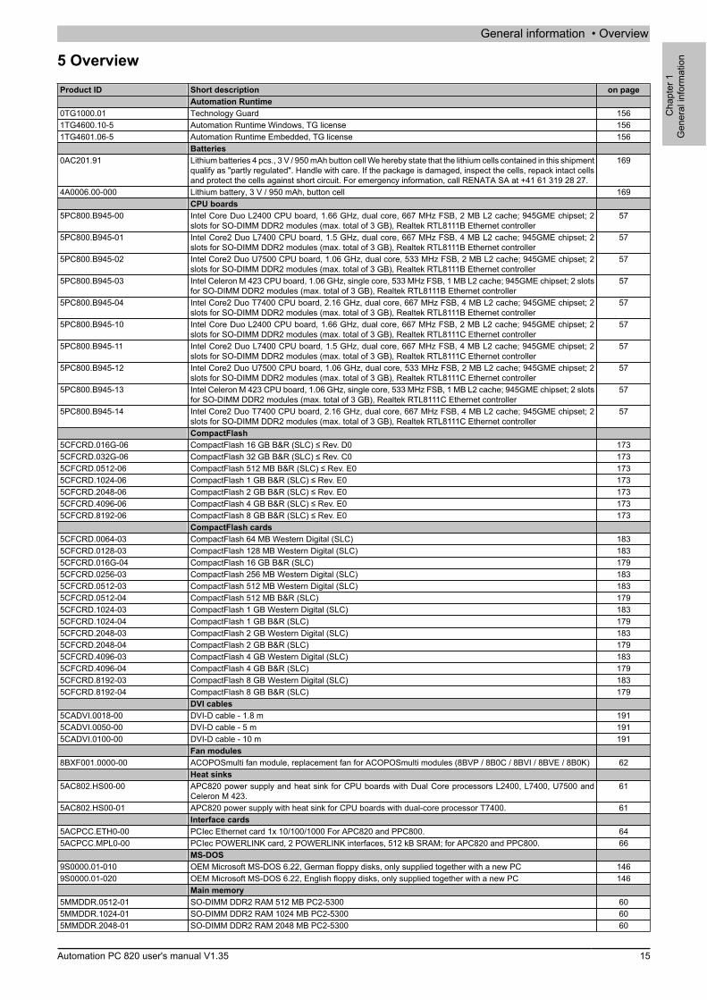
5 OverviewProduct ID Short description on page
Automation Runtime0TG1000.01 Technology Guard 1561TG4600.10-5 Automation Runtime Windows, TG license 1561TG4601.06-5 Automation Runtime Embedded, TG license 156
Batteries0AC201.91 Lithium batteries 4 pcs., 3 V / 950 mAh button cell We hereby state that the lithium cells contained in this shipment
qualify as "partly regulated". Handle with care. If the package is damaged, inspect the cells, repack intact cellsand protect the cells against short circuit. For emergency information, call RENATA SA at +41 61 319 28 27.
169
4A0006.00-000 Lithium battery, 3 V / 950 mAh, button cell 169CPU boards
5PC800.B945-00 Intel Core Duo L2400 CPU board, 1.66 GHz, dual core, 667 MHz FSB, 2 MB L2 cache; 945GME chipset; 2slots for SO-DIMM DDR2 modules (max. total of 3 GB), Realtek RTL8111B Ethernet controller
57
5PC800.B945-01 Intel Core2 Duo L7400 CPU board, 1.5 GHz, dual core, 667 MHz FSB, 4 MB L2 cache; 945GME chipset; 2slots for SO-DIMM DDR2 modules (max. total of 3 GB), Realtek RTL8111B Ethernet controller
57
5PC800.B945-02 Intel Core2 Duo U7500 CPU board, 1.06 GHz, dual core, 533 MHz FSB, 2 MB L2 cache; 945GME chipset; 2slots for SO-DIMM DDR2 modules (max. total of 3 GB), Realtek RTL8111B Ethernet controller
57
5PC800.B945-03 Intel Celeron M 423 CPU board, 1.06 GHz, single core, 533 MHz FSB, 1 MB L2 cache; 945GME chipset; 2 slotsfor SO-DIMM DDR2 modules (max. total of 3 GB), Realtek RTL8111B Ethernet controller
57
5PC800.B945-04 Intel Core2 Duo T7400 CPU board, 2.16 GHz, dual core, 667 MHz FSB, 4 MB L2 cache; 945GME chipset; 2slots for SO-DIMM DDR2 modules (max. total of 3 GB), Realtek RTL8111B Ethernet controller
57
5PC800.B945-10 Intel Core Duo L2400 CPU board, 1.66 GHz, dual core, 667 MHz FSB, 2 MB L2 cache; 945GME chipset; 2slots for SO-DIMM DDR2 modules (max. total of 3 GB), Realtek RTL8111C Ethernet controller
57
5PC800.B945-11 Intel Core2 Duo L7400 CPU board, 1.5 GHz, dual core, 667 MHz FSB, 4 MB L2 cache; 945GME chipset; 2slots for SO-DIMM DDR2 modules (max. total of 3 GB), Realtek RTL8111C Ethernet controller
57
5PC800.B945-12 Intel Core2 Duo U7500 CPU board, 1.06 GHz, dual core, 533 MHz FSB, 2 MB L2 cache; 945GME chipset; 2slots for SO-DIMM DDR2 modules (max. total of 3 GB), Realtek RTL8111C Ethernet controller
57
5PC800.B945-13 Intel Celeron M 423 CPU board, 1.06 GHz, single core, 533 MHz FSB, 1 MB L2 cache; 945GME chipset; 2 slotsfor SO-DIMM DDR2 modules (max. total of 3 GB), Realtek RTL8111C Ethernet controller
57
5PC800.B945-14 Intel Core2 Duo T7400 CPU board, 2.16 GHz, dual core, 667 MHz FSB, 4 MB L2 cache; 945GME chipset; 2slots for SO-DIMM DDR2 modules (max. total of 3 GB), Realtek RTL8111C Ethernet controller
57
CompactFlash5CFCRD.016G-06 CompactFlash 16 GB B&R (SLC) ≤ Rev. D0 1735CFCRD.032G-06 CompactFlash 32 GB B&R (SLC) ≤ Rev. C0 1735CFCRD.0512-06 CompactFlash 512 MB B&R (SLC) ≤ Rev. E0 1735CFCRD.1024-06 CompactFlash 1 GB B&R (SLC) ≤ Rev. E0 1735CFCRD.2048-06 CompactFlash 2 GB B&R (SLC) ≤ Rev. E0 1735CFCRD.4096-06 CompactFlash 4 GB B&R (SLC) ≤ Rev. E0 1735CFCRD.8192-06 CompactFlash 8 GB B&R (SLC) ≤ Rev. E0 173
CompactFlash cards5CFCRD.0064-03 CompactFlash 64 MB Western Digital (SLC) 1835CFCRD.0128-03 CompactFlash 128 MB Western Digital (SLC) 1835CFCRD.016G-04 CompactFlash 16 GB B&R (SLC) 1795CFCRD.0256-03 CompactFlash 256 MB Western Digital (SLC) 1835CFCRD.0512-03 CompactFlash 512 MB Western Digital (SLC) 1835CFCRD.0512-04 CompactFlash 512 MB B&R (SLC) 1795CFCRD.1024-03 CompactFlash 1 GB Western Digital (SLC) 1835CFCRD.1024-04 CompactFlash 1 GB B&R (SLC) 1795CFCRD.2048-03 CompactFlash 2 GB Western Digital (SLC) 1835CFCRD.2048-04 CompactFlash 2 GB B&R (SLC) 1795CFCRD.4096-03 CompactFlash 4 GB Western Digital (SLC) 1835CFCRD.4096-04 CompactFlash 4 GB B&R (SLC) 1795CFCRD.8192-03 CompactFlash 8 GB Western Digital (SLC) 1835CFCRD.8192-04 CompactFlash 8 GB B&R (SLC) 179
DVI cables5CADVI.0018-00 DVI-D cable - 1.8 m 1915CADVI.0050-00 DVI-D cable - 5 m 1915CADVI.0100-00 DVI-D cable - 10 m 191
Fan modules8BXF001.0000-00 ACOPOSmulti fan module, replacement fan for ACOPOSmulti modules (8BVP / 8B0C / 8BVI / 8BVE / 8B0K) 62
Heat sinks5AC802.HS00-00 APC820 power supply and heat sink for CPU boards with Dual Core processors L2400, L7400, U7500 and
Celeron M 423.61
5AC802.HS00-01 APC820 power supply with heat sink for CPU boards with dual-core processor T7400. 61Interface cards
5ACPCC.ETH0-00 PCIec Ethernet card 1x 10/100/1000 For APC820 and PPC800. 645ACPCC.MPL0-00 PCIec POWERLINK card, 2 POWERLINK interfaces, 512 kB SRAM; for APC820 and PPC800. 66
MS-DOS9S0000.01-010 OEM Microsoft MS-DOS 6.22, German floppy disks, only supplied together with a new PC 1469S0000.01-020 OEM Microsoft MS-DOS 6.22, English floppy disks, only supplied together with a new PC 146
Main memory5MMDDR.0512-01 SO-DIMM DDR2 RAM 512 MB PC2-5300 605MMDDR.1024-01 SO-DIMM DDR2 RAM 1024 MB PC2-5300 605MMDDR.2048-01 SO-DIMM DDR2 RAM 2048 MB PC2-5300 60
General information • Overview
16 Automation PC 820 user's manual V1.35
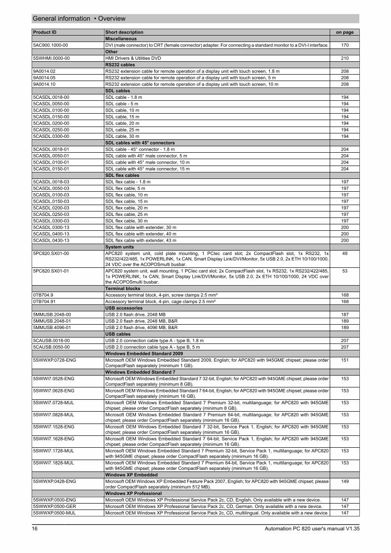
Product ID Short description on pageMiscellaneous
5AC900.1000-00 DVI (male connector) to CRT (female connector) adapter. For connecting a standard monitor to a DVI-I interface. 170Other
5SWHMI.0000-00 HMI Drivers & Utilities DVD 210RS232 cables
9A0014.02 RS232 extension cable for remote operation of a display unit with touch screen, 1.8 m 2089A0014.05 RS232 extension cable for remote operation of a display unit with touch screen, 5 m 2089A0014.10 RS232 extension cable for remote operation of a display unit with touch screen, 10 m 208
SDL cables5CASDL.0018-00 SDL cable - 1.8 m 1945CASDL.0050-00 SDL cable - 5 m 1945CASDL.0100-00 SDL cable, 10 m 1945CASDL.0150-00 SDL cable, 15 m 1945CASDL.0200-00 SDL cable, 20 m 1945CASDL.0250-00 SDL cable, 25 m 1945CASDL.0300-00 SDL cable, 30 m 194
SDL cables with 45° connectors5CASDL.0018-01 SDL cable - 45° connector - 1.8 m 2045CASDL.0050-01 SDL cable with 45° male connector, 5 m 2045CASDL.0100-01 SDL cable with 45° male connector, 10 m 2045CASDL.0150-01 SDL cable with 45° male connector, 15 m 204
SDL flex cables5CASDL.0018-03 SDL flex cable - 1.8 m 1975CASDL.0050-03 SDL flex cable, 5 m 1975CASDL.0100-03 SDL flex cable, 10 m 1975CASDL.0150-03 SDL flex cable, 15 m 1975CASDL.0200-03 SDL flex cable, 20 m 1975CASDL.0250-03 SDL flex cable, 25 m 1975CASDL.0300-03 SDL flex cable, 30 m 1975CASDL.0300-13 SDL flex cable with extender, 30 m 2005CASDL.0400-13 SDL flex cable with extender, 40 m 2005CASDL.0430-13 SDL flex cable with extender, 43 m 200
System units5PC820.SX01-00 APC820 system unit, cold plate mounting, 1 PCIec card slot; 2x CompactFlash slot, 1x RS232, 1x
RS232/422/485, 1x POWERLINK, 1x CAN, Smart Display Link/DVI/Monitor, 5x USB 2.0, 2x ETH 10/100/1000,24 VDC over the ACOPOSmulti busbar.
49
5PC820.SX01-01 APC820 system unit, wall mounting, 1 PCIec card slot; 2x CompactFlash slot, 1x RS232, 1x RS232/422/485,1x POWERLINK, 1x CAN, Smart Display Link/DVI/Monitor, 5x USB 2.0, 2x ETH 10/100/1000, 24 VDC overthe ACOPOSmulti busbar.
53
Terminal blocks0TB704.9 Accessory terminal block, 4-pin, screw clamps 2.5 mm² 1680TB704.91 Accessory terminal block, 4-pin, cage clamps 2.5 mm² 168
USB accessories5MMUSB.2048-00 USB 2.0 flash drive, 2048 MB 1875MMUSB.2048-01 USB 2.0 flash drive, 2048 MB, B&R 1895MMUSB.4096-01 USB 2.0 flash drive, 4096 MB, B&R 189
USB cables5CAUSB.0018-00 USB 2.0 connection cable type A - type B, 1.8 m 2075CAUSB.0050-00 USB 2.0 connection cable type A - type B, 5 m 207
Windows Embedded Standard 20095SWWXP.0728-ENG Microsoft OEM Windows Embedded Standard 2009, English; for APC820 with 945GME chipset; please order
CompactFlash separately (minimum 1 GB).151
Windows Embedded Standard 75SWWI7.0528-ENG Microsoft OEM Windows Embedded Standard 7 32-bit, English; for APC820 with 945GME chipset; please order
CompactFlash separately (minimum 8 GB).153
5SWWI7.0628-ENG Microsoft OEM Windows Embedded Standard 7 64-bit, English; for APC820 with 945GME chipset; please orderCompactFlash separately (minimum 16 GB).
153
5SWWI7.0728-MUL Microsoft OEM Windows Embedded Standard 7 Premium 32-bit, multilanguage; for APC820 with 945GMEchipset; please order CompactFlash separately (minimum 8 GB).
153
5SWWI7.0828-MUL Microsoft OEM Windows Embedded Standard 7 Premium 64-bit, multilanguage; for APC820 with 945GMEchipset; please order CompactFlash separately (minimum 16 GB).
153
5SWWI7.1528-ENG Microsoft OEM Windows Embedded Standard 7 32-bit, Service Pack 1, English; for APC820 with 945GMEchipset; please order CompactFlash separately (minimum 16 GB).
153
5SWWI7.1628-ENG Microsoft OEM Windows Embedded Standard 7 64-bit, Service Pack 1, English; for APC820 with 945GMEchipset; please order CompactFlash separately (minimum 16 GB).
153
5SWWI7.1728-MUL Microsoft OEM Windows Embedded Standard 7 Premium 32-bit, Service Pack 1, multilanguage; for APC820with 945GME chipset; please order CompactFlash separately (minimum 16 GB).
153
5SWWI7.1828-MUL Microsoft OEM Windows Embedded Standard 7 Premium 64-bit, Service Pack 1, multilanguage; for APC820with 945GME chipset; please order CompactFlash separately (minimum 16 GB).
153
Windows XP Embedded5SWWXP.0428-ENG Microsoft OEM Windows XP Embedded Feature Pack 2007, English; for APC820 with 945GME chipset; please
order CompactFlash separately (minimum 512 MB).149
Windows XP Professional5SWWXP.0500-ENG Microsoft OEM Windows XP Professional Service Pack 2c, CD, English. Only available with a new device. 1475SWWXP.0500-GER Microsoft OEM Windows XP Professional Service Pack 2c, CD, German. Only available with a new device. 1475SWWXP.0500-MUL Microsoft OEM Windows XP Professional Service Pack 2c, CD, multilingual. Only available with a new device. 147
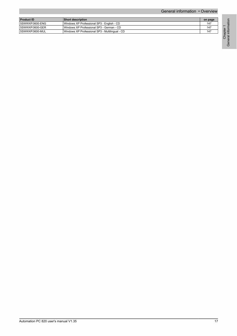
General information • Overview
Cha
pter
1G
ener
al in
form
atio
n
Automation PC 820 user's manual V1.35 17
Product ID Short description on page5SWWXP.0600-ENG Windows XP Professional SP3 - English - CD 1475SWWXP.0600-GER Windows XP Professional SP3 - German - CD 1475SWWXP.0600-MUL Windows XP Professional SP3 - Multilingual - CD 147

Technical data • Introduction
18 Automation PC 820 user's manual V1.35
Chapter 2 • Technical data
1 Introduction
The ultra-compact, integrated ACOPOSmulti offers the most cost-effective solution possible for machines withmultiple axes. What makes the ACOPOSmulti so easy to use? Maybe it's the modular cooling concept that can beflexibly adapted to any installation, the user-friendly cabling or its scalable performance.The Automation PC 820 was developed for the ACOPOSmulti system and is equipped on the machine for roughenvironmental conditions. Because the APC820 can be completely integrated into the ACOPOSmulti system, thespace otherwise needed for the PC is no longer occupied in the control cabinet. The APC820 was designed forthe toughest environments. Not a single internal cable connection was used during construction. This has made itpossible to achieve maximum vibration resistance and operational safety. Free of any rotating parts, CompactFlashcards are the optimum storage media for use in the machine.
1.1 Features
• Latest processor technologies - Core Duo, Core 2 Duo and Celeron M• Up to 3 GB main memory (dual-channel memory support)• 2 CompactFlash slots (type I)• 1 PCI Express compact Slot (for PCIec cards)• 5x USB 2.0• 2x Ethernet 10/100/1000 Mbit interfaces• 1x POWERLINK (with node switch)• 1x CAN interface (with node switch)• 1x RS232 interface• 1x RS232/422/485 interface• SRAM 1MB (battery backed)• Connection of various display devices to the "Monitor/Panel" video output (supports SDL, DVI, and monitor
signals)• Fan• BIOS (AMI)
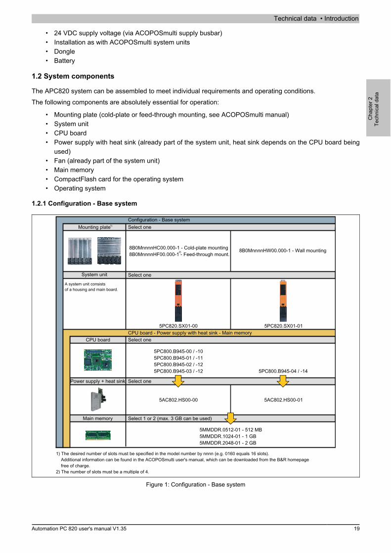
Technical data • Introduction
Cha
pter
2Te
chni
cal d
ata
Automation PC 820 user's manual V1.35 19
• 24 VDC supply voltage (via ACOPOSmulti supply busbar)• Installation as with ACOPOSmulti system units• Dongle• Battery
1.2 System components
The APC820 system can be assembled to meet individual requirements and operating conditions.The following components are absolutely essential for operation:
• Mounting plate (cold-plate or feed-through mounting, see ACOPOSmulti manual)• System unit• CPU board• Power supply with heat sink (already part of the system unit, heat sink depends on the CPU board being
used)• Fan (already part of the system unit)• Main memory• CompactFlash card for the operating system• Operating system
1.2.1 Configuration - Base system
CPU board
Select 1 or 2 (max. 3 GB can be used)
Select one
5PC820.SX01-00
5PC800.B945-00 / -105PC800.B945-01 / -115PC800.B945-02 / -125PC800.B945-03 / -12
System unit
Configuration - Base system
5MMDDR.0512-01 - 512 MB5MMDDR.1024-01 - 1 GB5MMDDR.2048-01 - 2 GB
5AC802.HS00-00
CPU board - Power supply with heat sink - Main memory
Main memory
A system unit consistsof a housing and main board.
Select oneMounting plate
1) The desired number of slots must be specified in the model number by nnnn (e.g. 0160 equals 16 slots). Additional information can be found in the ACOPOSmulti user's manual, which can be downloaded from the B&R homepage free of charge.2) The number of slots must be a multiple of 4.
8B0MnnnnHC00.000-1 - Cold-plate mounting8B0MnnnnHF00.000-1 - Feed-through mount.
Select onePower supply + heat sink
5PC800.B945-04 / -14
5AC802.HS00-01
8B0MnnnnHW00.000-1 - Wall mounting
5PC820.SX01-01
Select one
Figure 1: Configuration - Base system

Technical data • Introduction
20 Automation PC 820 user's manual V1.35
1.2.2 Configuration - Optional components
System unitConfiguration - Software and accessories
Replacement fan
8BXF001.0000-00
Software
CompactFlash
5CFCRD.0512-06, 5CFCRD.1024-06, 5CFCRD.2048-06, 5CFCRD.4096-06, 5CFCRD.8192-06, 5CFCRD.016G-06
5CFCRD.0064-03, 5CFCRD.0128-03, 5CFCRD.0256-03, 5CFCRD.0512-03,5CFCRD.1024-03, 5CFCRD.2048-03, 5CFCRD.4096-03, 5CFCRD.8192-03
PCIec plug-in cards
5ACPCC.ETH0-00 (PCIec Ethernet card 10/100/1000) 5ACPCC.MPL0-00 (PCIec POWERLINK MN 2-port)
5PC820.SX01-00 5PC820.SX01-01
Windows XP5SWWXP.0 00-ENG55SWWXP.0 00-GER55SWWXP.0 00-MUL55SWWXP.0600-ENG5SWWXP.0600-GER5SWWXP.0600-MUL
Windows Embedded Standard 75SWWI7. 52 -ENG1 85SWWI7. 62 -ENG1 85SWWI7. 72 -MUL1 85SWWI7. 82 -MUL1 8
Windows Embedded Standard 20095SWWXP.072 -ENG8
Automation Runtime1TG4600.10-51TG4601.06-50TG1000.01
Microsoft DOS9S0000.01-0109S0000.01-020
Windows XP Embedded5SWWXP.042 -ENG8
Select 1
Select 1
Select 1
Select 1 or 2
A system unit consists ofa housing and a main board.
Figure 2: Configuration - Optional components
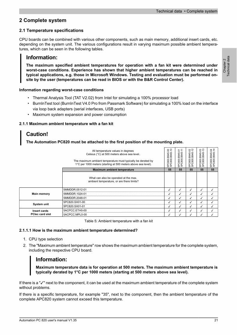
Technical data • Complete system
Cha
pter
2Te
chni
cal d
ata
Automation PC 820 user's manual V1.35 21
2 Complete system
2.1 Temperature specifications
CPU boards can be combined with various other components, such as main memory, additional insert cards, etc.depending on the system unit. The various configurations result in varying maximum possible ambient tempera-tures, which can be seen in the following tables.
Information:The maximum specified ambient temperatures for operation with a fan kit were determined underworst-case conditions. Experience has shown that higher ambient temperatures can be reached intypical applications, e.g. those in Microsoft Windows. Testing and evaluation must be performed on-site by the user (temperatures can be read in BIOS or with the B&R Control Center).
Information regarding worst-case conditions
• Thermal Analysis Tool (TAT V2.02) from Intel for simulating a 100% processor load• BurnInTest tool (BurnInTest V4.0 Pro from Passmark Software) for simulating a 100% load on the interface
via loop back adapters (serial interfaces, USB ports)• Maximum system expansion and power consumption
2.1.1 Maximum ambient temperature with a fan kit
Caution!The Automation PC820 must be attached to the first position of the mounting plate.
All temperature values in degrees Celsius (°C) at 500 meters above sea level.
The maximum ambient temperature must typically be derated by1°C per 1000 meters (starting at 500 meters above sea level).
5PC
800.
B945
-00
5PC
800.
B945
-10
5PC
800.
B945
-01
5PC
800.
B945
-11
5PC
800.
B945
-02
5PC
800.
B945
-12
5PC
800.
B945
-03
5PC
800.
B945
-13
5PC
800.
B945
-04
5PC
800.
B945
-14
Maximum ambient temperature 55 55 55 55 55
What can also be operated at the max. ambient temperature, or are there limits?
5MMDDR.0512-01 ✓ ✓ ✓ ✓ ✓ 5MMDDR.1024-01 ✓ ✓ ✓ ✓ ✓ Main memory5MMDDR.2048-01 ✓ ✓ ✓ ✓ ✓ 5PC820.SX01-00 ✓ ✓ ✓ ✓ ✓ System unit5PC820.SX01-01 ✓ ✓ ✓ ✓ ✓ 5ACPCC.ETH0-00 ✓ ✓ ✓ ✓ ✓ Insert cards
PCIec card slot 5ACPCC.MPL0-00 ✓ ✓ ✓ ✓ ✓
Table 5: Ambient temperature with a fan kit
2.1.1.1 How is the maximum ambient temperature determined?
1. CPU type selection2. The "Maximum ambient temperature" row shows the maximum ambient temperature for the complete system,
including the respective CPU board.
Information:Maximum temperature data is for operation at 500 meters. The maximum ambient temperature istypically derated by 1°C per 1000 meters (starting at 500 meters above sea level).
If there is a "✓" next to the component, it can be used at the maximum ambient temperature of the complete systemwithout problems.If there is a specific temperature, for example "35", next to the component, then the ambient temperature of thecomplete APC820 system cannot exceed this temperature.
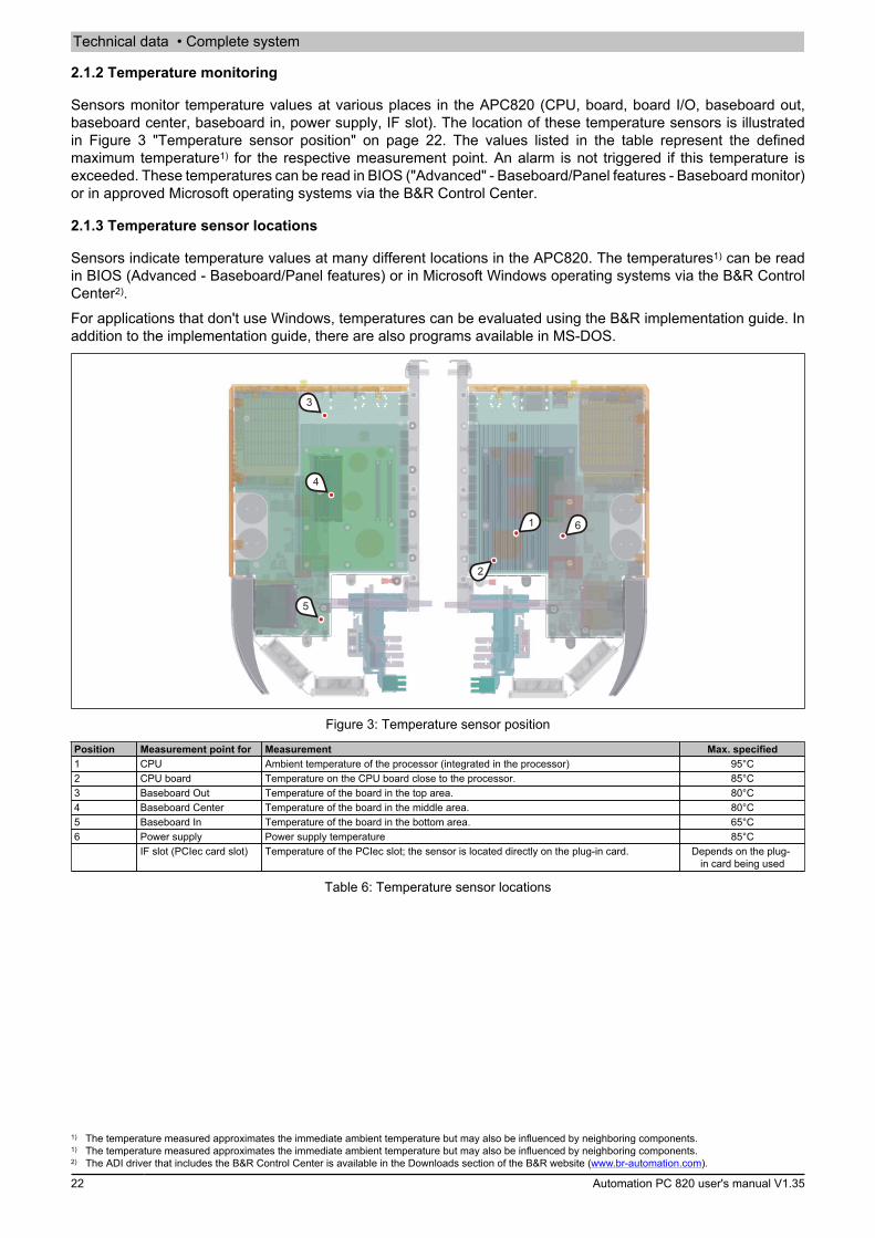
Technical data • Complete system
22 Automation PC 820 user's manual V1.35
2.1.2 Temperature monitoring
Sensors monitor temperature values at various places in the APC820 (CPU, board, board I/O, baseboard out,baseboard center, baseboard in, power supply, IF slot). The location of these temperature sensors is illustratedin Figure 3 "Temperature sensor position" on page 22. The values listed in the table represent the definedmaximum temperature1) for the respective measurement point. An alarm is not triggered if this temperature isexceeded. These temperatures can be read in BIOS ("Advanced" - Baseboard/Panel features - Baseboard monitor)or in approved Microsoft operating systems via the B&R Control Center.
2.1.3 Temperature sensor locations
Sensors indicate temperature values at many different locations in the APC820. The temperatures1) can be readin BIOS (Advanced - Baseboard/Panel features) or in Microsoft Windows operating systems via the B&R ControlCenter2).For applications that don't use Windows, temperatures can be evaluated using the B&R implementation guide. Inaddition to the implementation guide, there are also programs available in MS-DOS.
3
4
5
1
2
6
Figure 3: Temperature sensor position
Position Measurement point for Measurement Max. specified1 CPU Ambient temperature of the processor (integrated in the processor) 95°C2 CPU board Temperature on the CPU board close to the processor. 85°C3 Baseboard Out Temperature of the board in the top area. 80°C4 Baseboard Center Temperature of the board in the middle area. 80°C5 Baseboard In Temperature of the board in the bottom area. 65°C6 Power supply Power supply temperature 85°C
IF slot (PCIec card slot) Temperature of the PCIec slot; the sensor is located directly on the plug-in card. Depends on the plug-in card being used
Table 6: Temperature sensor locations
1) The temperature measured approximates the immediate ambient temperature but may also be influenced by neighboring components.1) The temperature measured approximates the immediate ambient temperature but may also be influenced by neighboring components.2) The ADI driver that includes the B&R Control Center is available in the Downloads section of the B&R website (www.br-automation.com).
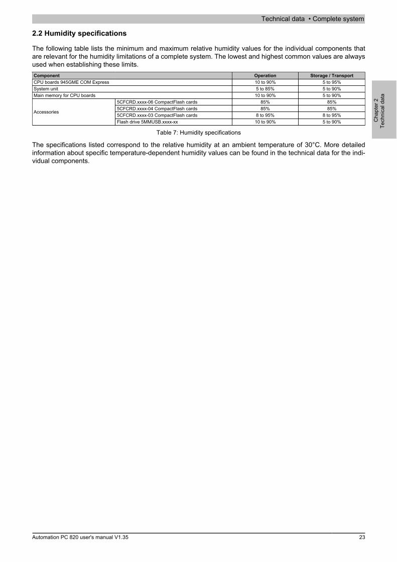
Technical data • Complete system
Cha
pter
2Te
chni
cal d
ata
Automation PC 820 user's manual V1.35 23
2.2 Humidity specifications
The following table lists the minimum and maximum relative humidity values for the individual components thatare relevant for the humidity limitations of a complete system. The lowest and highest common values are alwaysused when establishing these limits.Component Operation Storage / TransportCPU boards 945GME COM Express 10 to 90% 5 to 95%System unit 5 to 85% 5 to 90%Main memory for CPU boards 10 to 90% 5 to 90%
5CFCRD.xxxx-06 CompactFlash cards 85% 85%5CFCRD.xxxx-04 CompactFlash cards 85% 85%5CFCRD.xxxx-03 CompactFlash cards 8 to 95% 8 to 95%
Accessories
Flash drive 5MMUSB.xxxx-xx 10 to 90% 5 to 90%
Table 7: Humidity specifications
The specifications listed correspond to the relative humidity at an ambient temperature of 30°C. More detailedinformation about specific temperature-dependent humidity values can be found in the technical data for the indi-vidual components.
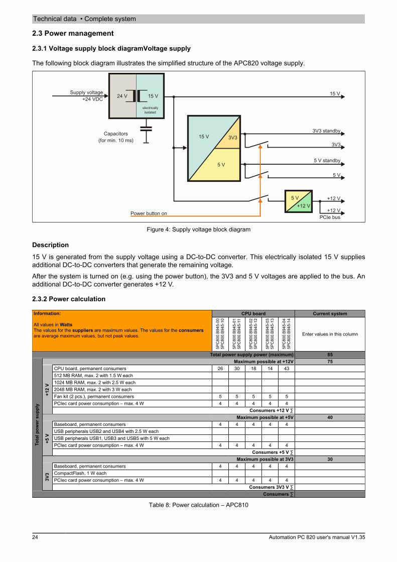
Technical data • Complete system
24 Automation PC 820 user's manual V1.35
2.3 Power management
2.3.1 Voltage supply block diagramVoltage supply
The following block diagram illustrates the simplified structure of the APC820 voltage supply.
24 V 15 VSupply voltage
+24 VDC
Capacitors(for min. 10 ms)
3V3 standby
3V3 3V3
5 V
15 V
+12 V
5 V
15 V
Power button on
5 V standby
electricallyisolated
+12 VPCIe bus
5 V+12 V
Figure 4: Supply voltage block diagram
Description
15 V is generated from the supply voltage using a DC-to-DC converter. This electrically isolated 15 V suppliesadditional DC-to-DC converters that generate the remaining voltage.After the system is turned on (e.g. using the power button), the 3V3 and 5 V voltages are applied to the bus. Anadditional DC-to-DC converter generates +12 V.
2.3.2 Power calculation
CPU board Current systemInformation:
All values in WattsThe values for the suppliers are maximum values. The values for the consumersare average maximum values, but not peak values.
5PC
800.
B945
-00
5PC
800.
B945
-10
5PC
800.
B945
-01
5PC
800.
B945
-11
5PC
800.
B945
-02
5PC
800.
B945
-12
5PC
800.
B945
-03
5PC
800.
B945
-13
5PC
800.
B945
-04
5PC
800.
B945
-14
Enter values in this column
Total power supply power (maximum) 85Maximum possible at +12V 75
CPU board, permanent consumers 26 30 18 14 43512 MB RAM, max. 2 with 1.5 W each1024 MB RAM, max. 2 with 2.5 W each2048 MB RAM, max. 2 with 3 W eachFan kit (2 pcs.), permanent consumers 5 5 5 5 5PCIec card power consumption – max. 4 W 4 4 4 4 4
+12
V
Consumers +12 V ∑Maximum possible at +5V 40
Baseboard, permanent consumers 4 4 4 4 4USB peripherals USB2 and USB4 with 2.5 W eachUSB peripherals USB1, USB3 and USB5 with 5 W eachPCIec card power consumption – max. 4 W 4 4 4 4 4
+5 V
Consumers +5 V ∑Maximum possible at 3V3 30
Baseboard, permanent consumers 4 4 4 4 4CompactFlash, 1 W eachPCIec card power consumption – max. 4 W 4 4 4 4 4
Tota
l pow
er s
uppl
y
3V3
Consumers 3V3 V ∑Consumers ∑
Table 8: Power calculation – APC810

Technical data • Complete system
Cha
pter
2Te
chni
cal d
ata
Automation PC 820 user's manual V1.35 25
Information:The PCIec card must not consume more than a total of 4 W (12V/5V/3V3)!
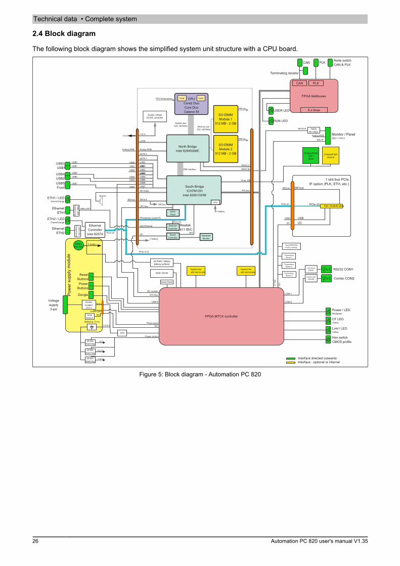
Technical data • Complete system
26 Automation PC 820 user's manual V1.35
2.4 Block diagram
The following block diagram shows the simplified system unit structure with a CPU board.
Monitor / PanelSDL1 / DVI-I
Voltagesupply3-pin
TemperatureSensor 1
RAM 128 kB
AS RAM 1 MByteBattery-buffered
Serial Flash
Serial EEPROMFactory settings
EthernetController
Intel 82574
Power / LEDRed/green
CF LEDYellow
Link1 LEDYellow
USER LED
EthernetETH1
EthernetETH2
USB3USB1
USB4USB2USB5Front
RS232 COM1
Combo COM2
Hex switchCMOS profile
CompactFlashSlot 1Slave
Combo 232/422/485
Line driverRS232
DC/DCSwitching
ADC
DC/DCSwitching
DC/DCSwitching
+5 V
+3.3 V
+12 V
USB0
USB4
USB7
GBit LAN1
PCIe (4)
PCIe (0-3)
I2C module
LPC Bus
USB 6
I2C
Power control
Power good
USB7
SM bus
SM bus
USB5
USB2
PCIe (2)
I2C
COM 1
COM 2
SDL IF
I2C
+12 V
USB5
USB1
FPGA MTCX controller
Analog RGB
Analog RGB
SDL IF
Interface directed outwardsInterface - optional or internal
Gbit LA
NT
ransformer
Gbit LA
NT
ransformer
SDVO B TMDSSil 1362A
System fanwith tachometer
Terminating resistor
CompactFlashInternal
Supply voltageDC/DC controller
North BridgeIntel 82945GME
Core Core
South BridgeICH7M-DH
Intel 82801GHM
CPU temperature
SO-DIMMModule 1
512 MB - 2 GB
SO-DIMMModule 2
512 MB - 2 GB
EthernetController
SM bus
LPC bus
PCI bus
PCIexpress (Lane0-5)
Gbit Ethernet
I2C
V battery
V battery
SPI
PCIe (5)
SM busRTC
LVDS
+12 V
System bus533 / 667MHz Memory bus
533 / 667MHz
DMI interface
Analog RGB
SATA 0
SATA 1
USB0
USB1
USB2USB3USB4USB5USB6
USB7
BIOSFlash
BoardController
HardwareMonitor
SM bus
SM bus
CPUCore2 DuoCore DuoCeleron M
SDVO C
SDVO B
Prim. IDE
Realtek8111B/C
Buzzer
HD Audio
ETH2 / LEDGreen/Orange
ETH1 / LEDGreen/Orange
FPGA fieldbuses
PLKCAN Node switchCAN & PLK
RUN LED
1 slot bus PCIeIF option (PLK, ETH, etc.)
Opt. module plug
USBI2C
PCIe (2)
SM bus
System fanwith tachometer
CAN PLK
8 x timer
Pow
er s
uppl
y m
odul
e
PowerButtons
Battery950 mAh
V battery
ResetButtons
+15.6 V
DC/DCIsolated15.6 V
Temp.Sensor
15.6 V
I2CPower good
Buffering 10 ms
TemperatureSensor 2
TemperatureSensor 3
USB4USB3
USB2
USB1USB0
USB1
Dongle
Figure 5: Block diagram - Automation PC 820
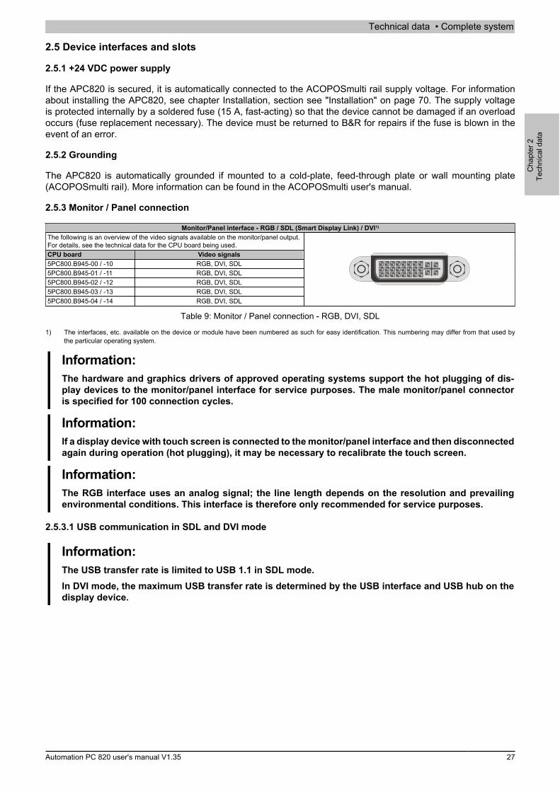
Technical data • Complete system
Cha
pter
2Te
chni
cal d
ata
Automation PC 820 user's manual V1.35 27
2.5 Device interfaces and slots
2.5.1 +24 VDC power supply
If the APC820 is secured, it is automatically connected to the ACOPOSmulti rail supply voltage. For informationabout installing the APC820, see chapter Installation, section see "Installation" on page 70. The supply voltageis protected internally by a soldered fuse (15 A, fast-acting) so that the device cannot be damaged if an overloadoccurs (fuse replacement necessary). The device must be returned to B&R for repairs if the fuse is blown in theevent of an error.
2.5.2 Grounding
The APC820 is automatically grounded if mounted to a cold-plate, feed-through plate or wall mounting plate(ACOPOSmulti rail). More information can be found in the ACOPOSmulti user's manual.
2.5.3 Monitor / Panel connection
Monitor/Panel interface - RGB / SDL (Smart Display Link) / DVI1)
The following is an overview of the video signals available on the monitor/panel output.For details, see the technical data for the CPU board being used.CPU board Video signals5PC800.B945-00 / -10 RGB, DVI, SDL5PC800.B945-01 / -11 RGB, DVI, SDL5PC800.B945-02 / -12 RGB, DVI, SDL5PC800.B945-03 / -13 RGB, DVI, SDL5PC800.B945-04 / -14 RGB, DVI, SDL
Table 9: Monitor / Panel connection - RGB, DVI, SDL
1) The interfaces, etc. available on the device or module have been numbered as such for easy identification. This numbering may differ from that used bythe particular operating system.
Information:The hardware and graphics drivers of approved operating systems support the hot plugging of dis-play devices to the monitor/panel interface for service purposes. The male monitor/panel connectoris specified for 100 connection cycles.
Information:If a display device with touch screen is connected to the monitor/panel interface and then disconnectedagain during operation (hot plugging), it may be necessary to recalibrate the touch screen.
Information:The RGB interface uses an analog signal; the line length depends on the resolution and prevailingenvironmental conditions. This interface is therefore only recommended for service purposes.
2.5.3.1 USB communication in SDL and DVI mode
Information:The USB transfer rate is limited to USB 1.1 in SDL mode.In DVI mode, the maximum USB transfer rate is determined by the USB interface and USB hub on thedisplay device.
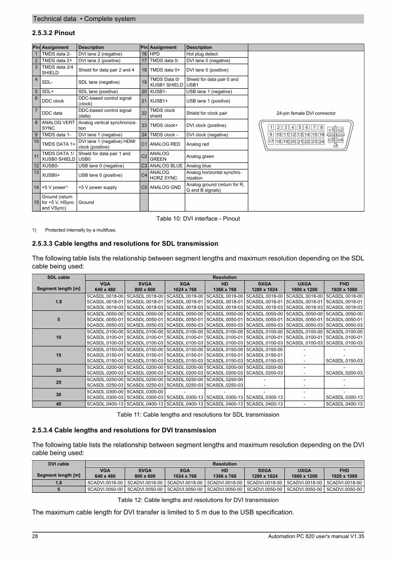
Technical data • Complete system
28 Automation PC 820 user's manual V1.35
2.5.3.2 Pinout
Pin Assignment Description Pin Assignment Description1 TMDS data 2- DVI lane 2 (negative) 16 HPD Hot plug detect2 TMDS data 2+ DVI lane 2 (positive) 17 TMDS data 0- DVI lane 0 (negative)3 TMDS data 2/4
SHIELD Shield for data pair 2 and 4 18 TMDS data 0+ DVI lane 0 (positive)
4 SDL- SDL lane (negative) 19 TMDS Data 0/XUSB1 SHIELD
Shield for data pair 0 andUSB1
5 SDL+ SDL lane (positive) 20 XUSB1- USB lane 1 (negative)6 DDC clock DDC-based control signal
(clock) 21 XUSB1+ USB lane 1 (positive)
7 DDC data DDC-based control signal(data) 22 TMDS clock
shield Shield for clock pair
8 ANALOG VERTSYNC
Analog vertical synchroniza-tion 23 TMDS clock+ DVI clock (positive)
9 TMDS data 1- DVI lane 1 (negative) 24 TMDS clock - DVI clock (negative)10 TMDS DATA 1+ DVI lane 1 (negative) HDMI
clock (positive) C1 ANALOG RED Analog red
11 TMDS DATA 1/XUSB0 SHIELD
Shield for data pair 1 andUSB0 C2 ANALOG
GREEN Analog green
12 XUSB0- USB lane 0 (negative) C3 ANALOG BLUE Analog blue13 XUSB0+ USB lane 0 (positive) C4 ANALOG
HORZ SYNCAnalog horizontal synchro-nization
14 +5 V power1) +5 V power supply C5 ANALOG GND Analog ground (return for R,G and B signals)
15Ground (returnfor +5 V, HSyncand VSync)
Ground
24-pin female DVI connector
6 7 851 2 3 414 15 16139 10 11 1222 23 242117 18 19 20
c1
c4
c2
c3c5
Table 10: DVI interface - Pinout
1) Protected internally by a multifuse.
2.5.3.3 Cable lengths and resolutions for SDL transmission
The following table lists the relationship between segment lengths and maximum resolution depending on the SDLcable being used:
ResolutionSDL cable
Segment length [m]VGA
640 x 480SVGA
800 x 600XGA
1024 x 768HD
1366 x 768SXGA
1280 x 1024UXGA
1600 x 1200FHD
1920 x 1080
1.85CASDL.0018-005CASDL.0018-015CASDL.0018-03
5CASDL.0018-005CASDL.0018-015CASDL.0018-03
5CASDL.0018-005CASDL.0018-015CASDL.0018-03
5CASDL.0018-005CASDL.0018-015CASDL.0018-03
5CASDL.0018-005CASDL.0018-015CASDL.0018-03
5CASDL.0018-005CASDL.0018-015CASDL.0018-03
5CASDL.0018-005CASDL.0018-015CASDL.0018-03
55CASDL.0050-005CASDL.0050-015CASDL.0050-03
5CASDL.0050-005CASDL.0050-015CASDL.0050-03
5CASDL.0050-005CASDL.0050-015CASDL.0050-03
5CASDL.0050-005CASDL.0050-015CASDL.0050-03
5CASDL.0050-005CASDL.0050-015CASDL.0050-03
5CASDL.0050-005CASDL.0050-015CASDL.0050-03
5CASDL.0050-005CASDL.0050-015CASDL.0050-03
105CASDL.0100-005CASDL.0100-015CASDL.0100-03
5CASDL.0100-005CASDL.0100-015CASDL.0100-03
5CASDL.0100-005CASDL.0100-015CASDL.0100-03
5CASDL.0100-005CASDL.0100-015CASDL.0100-03
5CASDL.0100-005CASDL.0100-015CASDL.0100-03
5CASDL.0100-005CASDL.0100-015CASDL.0100-03
5CASDL.0100-005CASDL.0100-015CASDL.0100-03
155CASDL.0150-005CASDL.0150-015CASDL.0150-03
5CASDL.0150-005CASDL.0150-015CASDL.0150-03
5CASDL.0150-005CASDL.0150-015CASDL.0150-03
5CASDL.0150-005CASDL.0150-015CASDL.0150-03
5CASDL.0150-005CASDL.0150-015CASDL.0150-03
---
--
5CASDL.0150-03
20 5CASDL.0200-005CASDL.0200-03
5CASDL.0200-005CASDL.0200-03
5CASDL.0200-005CASDL.0200-03
5CASDL.0200-005CASDL.0200-03
5CASDL.0200-005CASDL.0200-03
--
-5CASDL.0200-03
25 5CASDL.0250-005CASDL.0250-03
5CASDL.0250-005CASDL.0250-03
5CASDL.0250-005CASDL.0250-03
5CASDL.0250-005CASDL.0250-03
--
--
--
30 5CASDL.0300-005CASDL.0300-03
5CASDL.0300-005CASDL.0300-03
-5CASDL.0300-13
-5CASDL.0300-13
-5CASDL.0300-13
--
-5CASDL.0300-13
40 5CASDL.0400-13 5CASDL.0400-13 5CASDL.0400-13 5CASDL.0400-13 5CASDL.0400-13 - 5CASDL.0400-13
Table 11: Cable lengths and resolutions for SDL transmission
2.5.3.4 Cable lengths and resolutions for DVI transmission
The following table lists the relationship between segment lengths and maximum resolution depending on the DVIcable being used:
ResolutionDVI cable
Segment length [m]VGA
640 x 480SVGA
800 x 600XGA
1024 x 768HD
1366 x 768SXGA
1280 x 1024UXGA
1600 x 1200FHD
1920 x 10801.8 5CADVI.0018-00 5CADVI.0018-00 5CADVI.0018-00 5CADVI.0018-00 5CADVI.0018-00 5CADVI.0018-00 5CADVI.0018-005 5CADVI.0050-00 5CADVI.0050-00 5CADVI.0050-00 5CADVI.0050-00 5CADVI.0050-00 5CADVI.0050-00 5CADVI.0050-00
Table 12: Cable lengths and resolutions for DVI transmission
The maximum cable length for DVI transfer is limited to 5 m due to the USB specification.
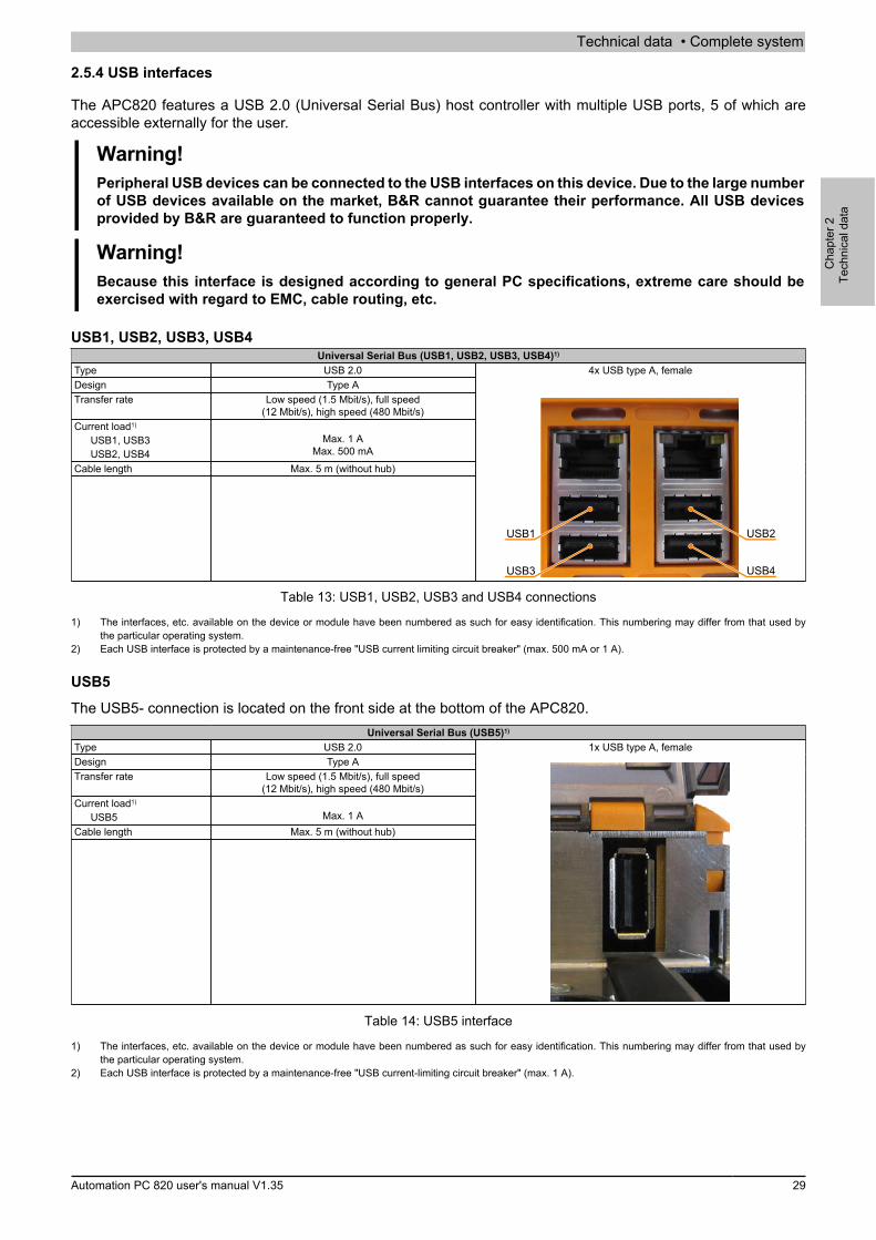
Technical data • Complete system
Cha
pter
2Te
chni
cal d
ata
Automation PC 820 user's manual V1.35 29
2.5.4 USB interfaces
The APC820 features a USB 2.0 (Universal Serial Bus) host controller with multiple USB ports, 5 of which areaccessible externally for the user.
Warning!Peripheral USB devices can be connected to the USB interfaces on this device. Due to the large numberof USB devices available on the market, B&R cannot guarantee their performance. All USB devicesprovided by B&R are guaranteed to function properly.
Warning!Because this interface is designed according to general PC specifications, extreme care should beexercised with regard to EMC, cable routing, etc.
USB1, USB2, USB3, USB4Universal Serial Bus (USB1, USB2, USB3, USB4)1)
Type USB 2.0Design Type ATransfer rate Low speed (1.5 Mbit/s), full speed
(12 Mbit/s), high speed (480 Mbit/s)Current load1)
USB1, USB3USB2, USB4
Max. 1 AMax. 500 mA
Cable length Max. 5 m (without hub)
4x USB type A, female
USB1
USB3
USB2
USB4
Table 13: USB1, USB2, USB3 and USB4 connections
1) The interfaces, etc. available on the device or module have been numbered as such for easy identification. This numbering may differ from that used bythe particular operating system.
2) Each USB interface is protected by a maintenance-free "USB current limiting circuit breaker" (max. 500 mA or 1 A).
USB5
The USB5- connection is located on the front side at the bottom of the APC820.Universal Serial Bus (USB5)1)
Type USB 2.0Design Type ATransfer rate Low speed (1.5 Mbit/s), full speed
(12 Mbit/s), high speed (480 Mbit/s)Current load1)
USB5 Max. 1 ACable length Max. 5 m (without hub)
1x USB type A, female
Table 14: USB5 interface
1) The interfaces, etc. available on the device or module have been numbered as such for easy identification. This numbering may differ from that used bythe particular operating system.
2) Each USB interface is protected by a maintenance-free "USB current-limiting circuit breaker" (max. 1 A).

Technical data • Complete system
30 Automation PC 820 user's manual V1.35
2.5.5 CompactFlash slot 1
This CompactFlash slot is a fixed part of an APC820 system and is internally connected with the chipset via IDEPATA. Type I CompactFlash cards are supported. The CompactFlash slots are located behind the cable cover.
CompactFlash slot (CF1)Connection PATA MasterCompactFlash
Type Type IModel number Short description
CompactFlash5CFCRD.0512-06 B&R CompactFlash 512 MB5CFCRD.1024-06 B&R CompactFlash 1024 MB5CFCRD.2048-06 B&R CompactFlash 2048 MB5CFCRD.4096-06 B&R CompactFlash 4096 MB5CFCRD.8192-06 B&R CompactFlash 8192 MB5CFCRD.016G-06 B&R CompactFlash 16 GB5CFCRD.0064-03 CompactFlash 64 MB WD5CFCRD.0128-03 CompactFlash 128 MB WD5CFCRD.0256-03 CompactFlash 256 MB WD5CFCRD.0512-03 CompactFlash 512 MB WD5CFCRD.1024-03 CompactFlash 1024 MB WD5CFCRD.2048-03 CompactFlash 2048 MB WD5CFCRD.4096-03 CompactFlash 4096 MB WD5CFCRD.8192-03 CompactFlash 8192 MB WD
CompactFlashSlot 2
CompactFlashSlot 1
Table 15: CompactFlash slot (CF1)
Warning!Power must be turned off before inserting or removing CompactFlash cards!
2.5.6 CompactFlash slot 2
This CompactFlash slot is a fixed part of an APC820 system and is internally connected with the chipset via IDEPATA. Type I CompactFlash cards are supported. The CompactFlash slots are located behind the cable cover.
CompactFlash slot (CF2)Connection PATA slaveCompactFlash
Type Type IModel number Short description
CompactFlash5CFCRD.0512-06 B&R CompactFlash 512 MB5CFCRD.1024-06 B&R CompactFlash 1024 MB5CFCRD.2048-06 B&R CompactFlash 2048 MB5CFCRD.4096-06 B&R CompactFlash 4096 MB5CFCRD.8192-06 B&R CompactFlash 8192 MB5CFCRD.016G-06 B&R CompactFlash 16 GB5CFCRD.0064-03 CompactFlash 64 MB WD5CFCRD.0128-03 CompactFlash 128 MB WD5CFCRD.0256-03 CompactFlash 256 MB WD5CFCRD.0512-03 CompactFlash 512 MB WD5CFCRD.1024-03 CompactFlash 1024 MB WD5CFCRD.2048-03 CompactFlash 2048 MB WD5CFCRD.4096-03 CompactFlash 4096 MB WD5CFCRD.8192-03 CompactFlash 8192 MB WD
CompactFlashSlot 2
CompactFlashSlot 1
Table 16: CompactFlash slot (CF2)
Warning!Power must be turned off before inserting or removing CompactFlash cards!
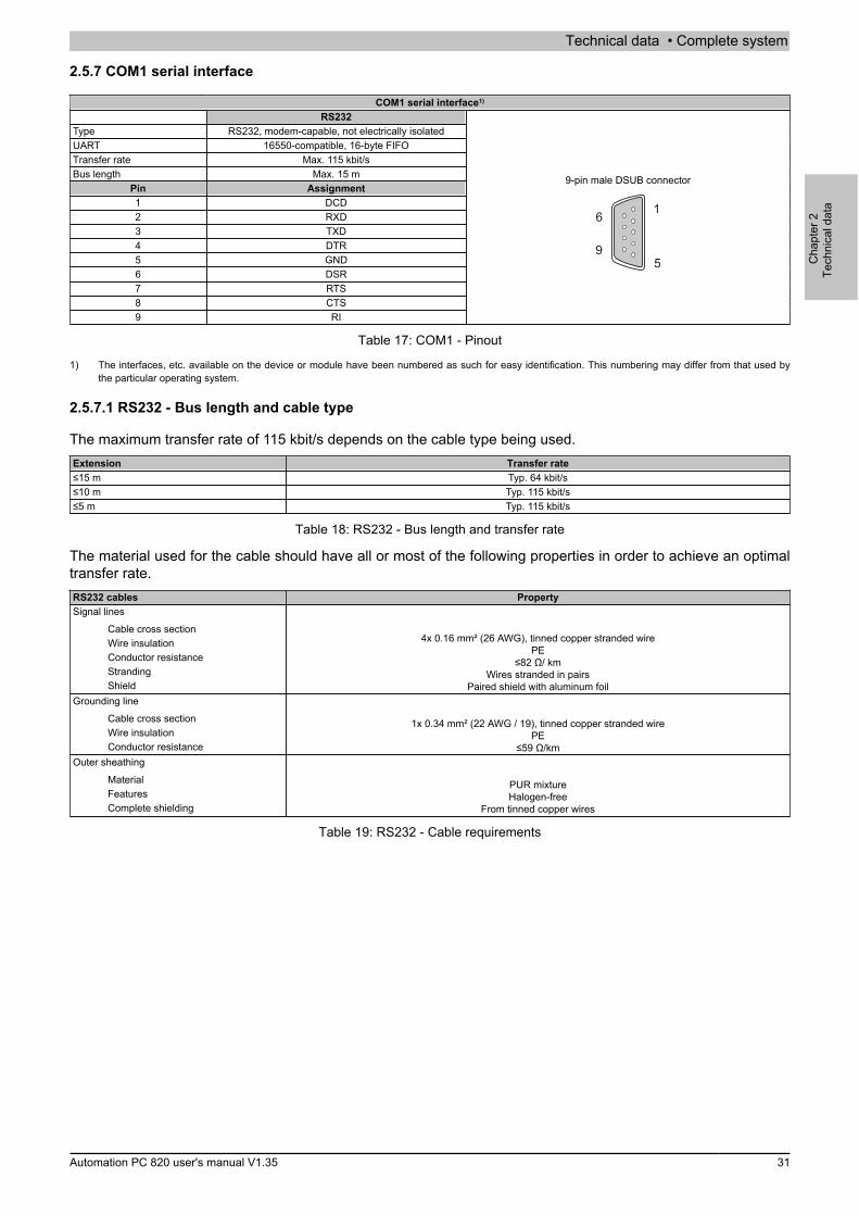
Technical data • Complete system
Cha
pter
2Te
chni
cal d
ata
Automation PC 820 user's manual V1.35 31
2.5.7 COM1 serial interface
COM1 serial interface1)
RS232Type RS232, modem-capable, not electrically isolatedUART 16550-compatible, 16-byte FIFOTransfer rate Max. 115 kbit/sBus length Max. 15 m
Pin Assignment1 DCD2 RXD3 TXD4 DTR5 GND6 DSR7 RTS8 CTS9 RI
9-pin male DSUB connector
5
1
9
6
Table 17: COM1 - Pinout
1) The interfaces, etc. available on the device or module have been numbered as such for easy identification. This numbering may differ from that used bythe particular operating system.
2.5.7.1 RS232 - Bus length and cable type
The maximum transfer rate of 115 kbit/s depends on the cable type being used.Extension Transfer rate≤15 m Typ. 64 kbit/s≤10 m Typ. 115 kbit/s≤5 m Typ. 115 kbit/s
Table 18: RS232 - Bus length and transfer rate
The material used for the cable should have all or most of the following properties in order to achieve an optimaltransfer rate.RS232 cables PropertySignal lines
Cable cross sectionWire insulationConductor resistanceStrandingShield
4x 0.16 mm² (26 AWG), tinned copper stranded wirePE
≤82 Ω/ kmWires stranded in pairs
Paired shield with aluminum foilGrounding line
Cable cross sectionWire insulationConductor resistance
1x 0.34 mm² (22 AWG / 19), tinned copper stranded wirePE
≤59 Ω/kmOuter sheathing
MaterialFeaturesComplete shielding
PUR mixtureHalogen-free
From tinned copper wires
Table 19: RS232 - Cable requirements
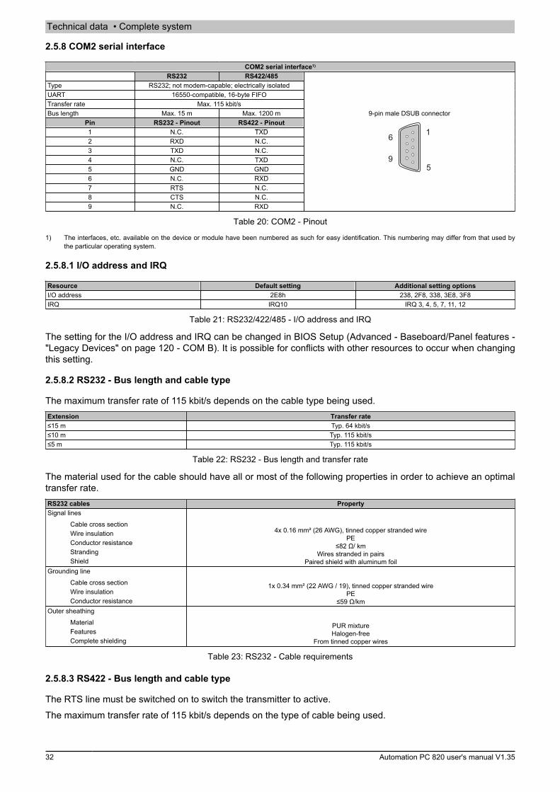
Technical data • Complete system
32 Automation PC 820 user's manual V1.35
2.5.8 COM2 serial interface
COM2 serial interface1)
RS232 RS422/485Type RS232; not modem-capable; electrically isolatedUART 16550-compatible, 16-byte FIFOTransfer rate Max. 115 kbit/sBus length Max. 15 m Max. 1200 m
Pin RS232 - Pinout RS422 - Pinout1 N.C. TXD2 RXD N.C.3 TXD N.C.4 N.C. TXD5 GND GND6 N.C. RXD7 RTS N.C.8 CTS N.C.9 N.C. RXD
9-pin male DSUB connector
5
1
9
6
Table 20: COM2 - Pinout
1) The interfaces, etc. available on the device or module have been numbered as such for easy identification. This numbering may differ from that used bythe particular operating system.
2.5.8.1 I/O address and IRQ
Resource Default setting Additional setting optionsI/O address 2E8h 238, 2F8, 338, 3E8, 3F8IRQ IRQ10 IRQ 3, 4, 5, 7, 11, 12
Table 21: RS232/422/485 - I/O address and IRQ
The setting for the I/O address and IRQ can be changed in BIOS Setup (Advanced - Baseboard/Panel features -"Legacy Devices" on page 120 - COM B). It is possible for conflicts with other resources to occur when changingthis setting.
2.5.8.2 RS232 - Bus length and cable type
The maximum transfer rate of 115 kbit/s depends on the cable type being used.Extension Transfer rate≤15 m Typ. 64 kbit/s≤10 m Typ. 115 kbit/s≤5 m Typ. 115 kbit/s
Table 22: RS232 - Bus length and transfer rate
The material used for the cable should have all or most of the following properties in order to achieve an optimaltransfer rate.RS232 cables PropertySignal lines
Cable cross sectionWire insulationConductor resistanceStrandingShield
4x 0.16 mm² (26 AWG), tinned copper stranded wirePE
≤82 Ω/ kmWires stranded in pairs
Paired shield with aluminum foilGrounding line
Cable cross sectionWire insulationConductor resistance
1x 0.34 mm² (22 AWG / 19), tinned copper stranded wirePE
≤59 Ω/kmOuter sheathing
MaterialFeaturesComplete shielding
PUR mixtureHalogen-free
From tinned copper wires
Table 23: RS232 - Cable requirements
2.5.8.3 RS422 - Bus length and cable type
The RTS line must be switched on to switch the transmitter to active.The maximum transfer rate of 115 kbit/s depends on the type of cable being used.

Technical data • Complete system
Cha
pter
2Te
chni
cal d
ata
Automation PC 820 user's manual V1.35 33
Extension Transfer rate1200 m Typ. 115 kbit/s
Table 24: RS422 - Bus length and transfer rate
The material used for the cable should have all or most of the following properties in order to achieve an optimaltransfer rate.RS422 cable PropertySignal lines
Cable cross sectionWire insulationConductor resistanceStrandingShield
4x 0.25 mm² (24 AWG / 19), tinned copper stranded wirePE
≤82 Ω/kmWires stranded in pairs
Paired shield with aluminum foilGrounding line
Cable cross sectionWire insulationConductor resistance
1x 0.34 mm² (22 AWG / 19), tinned copper stranded wirePE
≤59 Ω/kmOuter sheathing
MaterialFeaturesComplete shielding
PUR mixtureHalogen-free
From tinned copper wires
Table 25: RS422 - Cable requirements
2.5.8.4 When operated as an RS485 interface
When operated in this mode, the pins of the RS422 default interface (1, 4, 6 and 9) must be used. Pins shouldbe connected as shown.
RXD
RXD
TXD
TXD
9
6
4
1
DATA
DATA
Figure 6: RS232/RS422/RS485 interface - Operation in RS485 mode
The RTS line must be switched by the driver for each transmission or reception; there is no automatic switch-backmechanism. This cannot be configured in Windows.The voltage drop resulting from long cable lengths can lead to greater potential differences between bus stations,which can hinder communication. This can be improved by running ground wire with the others.The line ends of the RS485 interface should (at least for longer line lengths or larger transfer rates) be closed.Normally, a passive terminator can be used on the bus ends by connecting each of the signal lines with a 120Ω resistor.
2.5.8.5 RS485 - Bus length and cable type
The maximum transfer rate of 115 kbit/s depends on the type of cable being used.Extension Transfer rate1200 m Typ. 115 kbit/s
Table 26: RS485 - Bus length and transfer rate
The material used for the cable should have all or most of the following properties in order to achieve an optimaltransfer rate.

Technical data • Complete system
34 Automation PC 820 user's manual V1.35
RS485 cables PropertySignal lines
Cable cross sectionWire insulationConductor resistanceStrandingShield
4x 0.25 mm² (24 AWG / 19), tinned copper stranded wirePE
≤82 Ω/kmWires stranded in pairs
Paired shield with aluminum foilGrounding line
Cable cross sectionWire insulationConductor cross section
1x 0.34 mm² (22 AWG / 19), tinned copper stranded wirePE
≤59 Ω/kmOuter sheathing
MaterialFeaturesComplete shielding
PUR mixtureHalogen-free
From tinned copper wires
Table 27: RS485 - Cable requirements
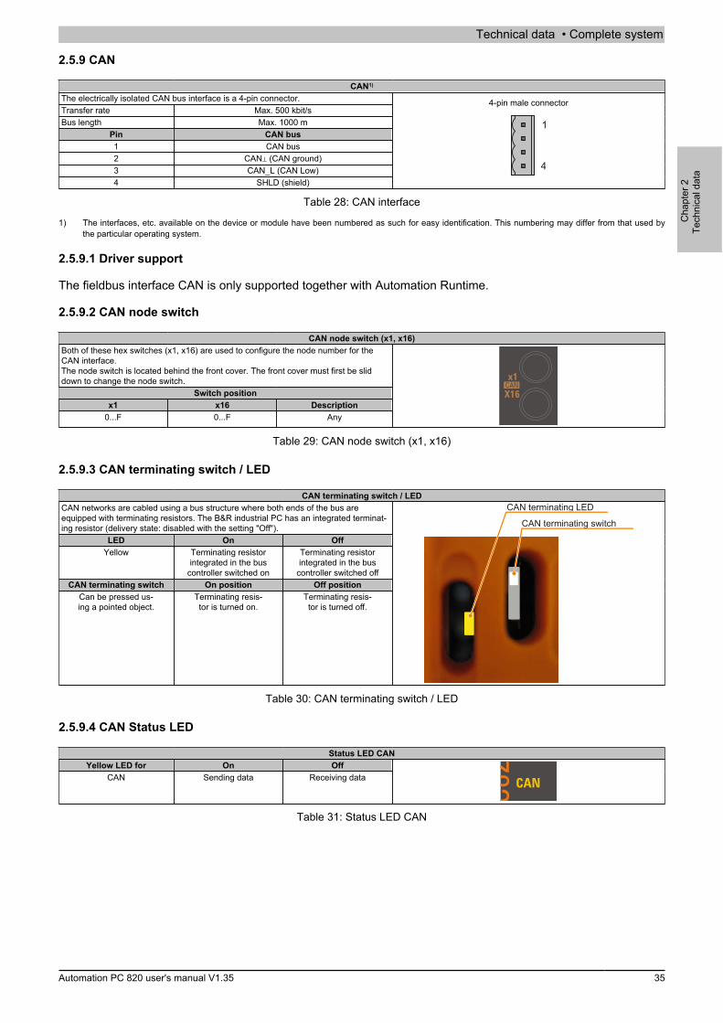
Technical data • Complete system
Cha
pter
2Te
chni
cal d
ata
Automation PC 820 user's manual V1.35 35
2.5.9 CAN
CAN1)
The electrically isolated CAN bus interface is a 4-pin connector.Transfer rate Max. 500 kbit/sBus length Max. 1000 m
Pin CAN bus1 CAN bus2 CAN⊥ (CAN ground)3 CAN_L (CAN Low)4 SHLD (shield)
4-pin male connector
1
4
Table 28: CAN interface
1) The interfaces, etc. available on the device or module have been numbered as such for easy identification. This numbering may differ from that used bythe particular operating system.
2.5.9.1 Driver support
The fieldbus interface CAN is only supported together with Automation Runtime.
2.5.9.2 CAN node switch
CAN node switch (x1, x16)Both of these hex switches (x1, x16) are used to configure the node number for theCAN interface.The node switch is located behind the front cover. The front cover must first be sliddown to change the node switch.
Switch positionx1 x16 Description
0...F 0...F Any
Table 29: CAN node switch (x1, x16)
2.5.9.3 CAN terminating switch / LED
CAN terminating switch / LEDCAN networks are cabled using a bus structure where both ends of the bus areequipped with terminating resistors. The B&R industrial PC has an integrated terminat-ing resistor (delivery state: disabled with the setting "Off").
LED On OffYellow Terminating resistor
integrated in the buscontroller switched on
Terminating resistorintegrated in the bus
controller switched offCAN terminating switch On position Off position
Can be pressed us-ing a pointed object.
Terminating resis-tor is turned on.
Terminating resis-tor is turned off.
CAN terminating LED
CAN terminating switch
Table 30: CAN terminating switch / LED
2.5.9.4 CAN Status LED
Status LED CANYellow LED for On Off
CAN Sending data Receiving data
Table 31: Status LED CAN
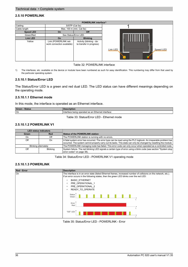
Technical data • Complete system
36 Automation PC 820 user's manual V1.35
2.5.10 POWERLINK
POWERLINK interface1)
Cabling S/STP (Cat 5e)Cable length Max. 100 m (min. Cat 5e)
Speed LED On OffGreen/Red See Status/Error LED.Link LED On Blinking
Yellow Link (POWERLINK net-work connection available)
Activity (blinking - da-ta transfer in progress)
1
Speed LEDLink LED
Table 32: POWERLINK interface
1) The interfaces, etc. available on the device or module have been numbered as such for easy identification. This numbering may differ from that used bythe particular operating system.
2.5.10.1 Status/Error LED
The Status/Error LED is a green and red dual LED. The LED status can have different meanings depending onthe operating mode.
2.5.10.1.1 Ethernet mode
In this mode, the interface is operated as an Ethernet interface.Green - Status DescriptionOn Interface being operated as an Ethernet interface
Table 33: Status/Error LED - Ethernet mode
2.5.10.1.2 POWERLINK V1
LED status indicatorsGreen Red Status of the POWERLINK station
On Off The POWERLINK station is running with no errors.Off On A fatal system error has occurred. The error type can be read using the PLC logbook. An irreparable problem has
occurred. The system cannot properly carry out its tasks. This state can only be changed by resetting the module.Blinking alternately The POWERLINK managing node has failed. This error code can only occur when operated as a controlled node.
Off Blinking System failure. The red blinking LED signals a certain type of error using a blink code (see section "System stoperror codes" on page 38).
Table 34: Status/Error LED - POWERLINK V1 operating mode
2.5.10.1.3 POWERLINK
Red - Error DescriptionOn The interface is in an error state (failed Ethernet frames, increased number of collisions on the network, etc.).
If an error occurs in the following states, then the green LED blinks over the red LED:• BASIC_ETHERNET• PRE_OPERATIONAL_1• PRE_OPERATIONAL_2• READY_TO_OPERATE
t
t
t
"S/E" LED
StatusGreen
ErrorRed
Table 35: Status/Error LED - POWERLINK - Error
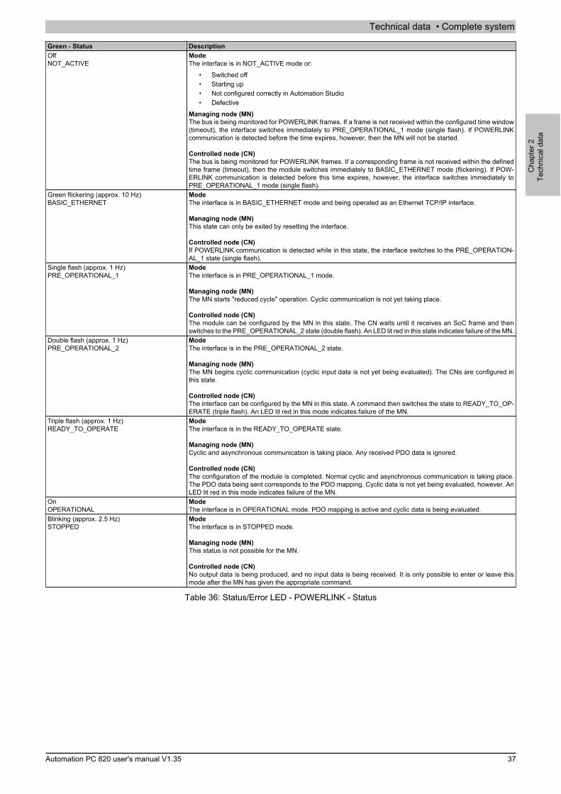
Technical data • Complete system
Cha
pter
2Te
chni
cal d
ata
Automation PC 820 user's manual V1.35 37
Green - Status DescriptionOffNOT_ACTIVE
ModeThe interface is in NOT_ACTIVE mode or:
• Switched off• Starting up• Not configured correctly in Automation Studio• Defective
Managing node (MN)The bus is being monitored for POWERLINK frames. If a frame is not received within the configured time window(timeout), the interface switches immediately to PRE_OPERATIONAL_1 mode (single flash). If POWERLINKcommunication is detected before the time expires, however, then the MN will not be started.
Controlled node (CN)The bus is being monitored for POWERLINK frames. If a corresponding frame is not received within the definedtime frame (timeout), then the module switches immediately to BASIC_ETHERNET mode (flickering). If POW-ERLINK communication is detected before this time expires, however, the interface switches immediately toPRE_OPERATIONAL_1 mode (single flash).
Green flickering (approx. 10 Hz)BASIC_ETHERNET
ModeThe interface is in BASIC_ETHERNET mode and being operated as an Ethernet TCP/IP interface.
Managing node (MN)This state can only be exited by resetting the interface.
Controlled node (CN)If POWERLINK communication is detected while in this state, the interface switches to the PRE_OPERATION-AL_1 state (single flash).
Single flash (approx. 1 Hz)PRE_OPERATIONAL_1
ModeThe interface is in PRE_OPERATIONAL_1 mode.
Managing node (MN)The MN starts "reduced cycle" operation. Cyclic communication is not yet taking place.
Controlled node (CN)The module can be configured by the MN in this state. The CN waits until it receives an SoC frame and thenswitches to the PRE_OPERATIONAL_2 state (double flash). An LED lit red in this state indicates failure of the MN.
Double flash (approx. 1 Hz)PRE_OPERATIONAL_2
ModeThe interface is in the PRE_OPERATIONAL_2 state.
Managing node (MN)The MN begins cyclic communication (cyclic input data is not yet being evaluated). The CNs are configured inthis state.
Controlled node (CN)The interface can be configured by the MN in this state. A command then switches the state to READY_TO_OP-ERATE (triple flash). An LED lit red in this mode indicates failure of the MN.
Triple flash (approx. 1 Hz)READY_TO_OPERATE
ModeThe interface is in the READY_TO_OPERATE state.
Managing node (MN)Cyclic and asynchronous communication is taking place. Any received PDO data is ignored.
Controlled node (CN)The configuration of the module is completed. Normal cyclic and asynchronous communication is taking place.The PDO data being sent corresponds to the PDO mapping. Cyclic data is not yet being evaluated, however. AnLED lit red in this mode indicates failure of the MN.
OnOPERATIONAL
ModeThe interface is in OPERATIONAL mode. PDO mapping is active and cyclic data is being evaluated.
Blinking (approx. 2.5 Hz)STOPPED
ModeThe interface is in STOPPED mode.
Managing node (MN)This status is not possible for the MN.
Controlled node (CN)No output data is being produced, and no input data is being received. It is only possible to enter or leave thismode after the MN has given the appropriate command.
Table 36: Status/Error LED - POWERLINK - Status
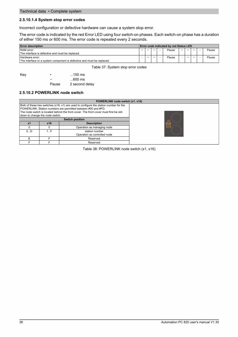
Technical data • Complete system
38 Automation PC 820 user's manual V1.35
2.5.10.1.4 System stop error codes
Incorrect configuration or defective hardware can cause a system stop error.The error code is indicated by the red Error LED using four switch-on phases. Each switch-on phase has a durationof either 150 ms or 600 ms. The error code is repeated every 2 seconds.Error description Error code indicated by red Status LEDRAM error:The interface is defective and must be replaced.
• • • - Pause • • • - Pause
Hardware error:The interface or a system component is defective and must be replaced.
- • • - Pause - • • - Pause
Table 37: System stop error codes
Key • ...150 ms− ...600 msPause 2 second delay
2.5.10.2 POWERLINK node switch
POWERLINK node switch (x1, x16)Both of these hex switches (x16, x1) are used to configure the station number for thePOWERLINK. Station numbers are permitted between #00 and #FD.The node switch is located behind the front cover. The front cover must first be sliddown to change the node switch.
Switch positionx1 x16 Description0 0 Operation as managing node
0...D 1...F station numberOperation as controlled node
E F ReservedF F Reserved
Table 38: POWERLINK node switch (x1, x16)
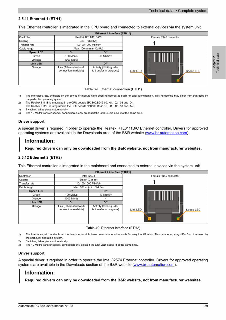
Technical data • Complete system
Cha
pter
2Te
chni
cal d
ata
Automation PC 820 user's manual V1.35 39
2.5.11 Ethernet 1 (ETH1)
This Ethernet controller is integrated in the CPU board and connected to external devices via the system unit.Ethernet 1 interface (ETH11))
Controller Realtek RTL8111B/C1)
Cabling S/STP (Cat5e)Transfer rate 10/100/1000 Mbit/s2)
Cable length Max. 100 m (min. Cat5e)Speed LED On Off
Green 100 Mbit/s 10 Mbit/s3)
Orange 1000 Mbit/s -Link LED On OffOrange Link (Ethernet network
connection available)Activity (blinking - da-
ta transfer in progress)
Female RJ45 connector
1
Speed LEDLink LED
Table 39: Ethernet connection (ETH1)
1) The interfaces, etc. available on the device or module have been numbered as such for easy identification. This numbering may differ from that used bythe particular operating system.
2) The Realtek 8111B is integrated in the CPU boards 5PC800.B945-00, -01, -02, -03 and -04.The Realtek 8111C is integrated in the CPU boards 5PC800.B945-10, -11, -12, -13 and -14.
3) Switching takes place automatically.4) The 10 Mbit/s transfer speed / connection is only present if the Link LED is also lit at the same time.
Driver support
A special driver is required in order to operate the Realtek RTL8111B/C Ethernet controller. Drivers for approvedoperating systems are available in the Downloads area of the B&R website (www.br-automation.com).
Information:Required drivers can only be downloaded from the B&R website, not from manufacturer websites.
2.5.12 Ethernet 2 (ETH2)
This Ethernet controller is integrated in the mainboard and connected to external devices via the system unit.Ethernet 2 interface (ETH21))
Controller Intel 82574Cabling S/STP (Cat 5e)Transfer rate 10/100/1000 Mbit/s2)
Cable length Max. 100 m (min. Cat 5e)Speed LED On Off
Green 100 Mbit/s 10 Mbit/s3)
Orange 1000 Mbit/s -Link LED On OffOrange Link (Ethernet network
connection available)Activity (blinking - da-
ta transfer in progress)
Female RJ45 connector
1
Speed LEDLink LED
Table 40: Ethernet interface (ETH2)
1) The interfaces, etc. available on the device or module have been numbered as such for easy identification. This numbering may differ from that used bythe particular operating system.
2) Switching takes place automatically.3) The 10 Mbit/s transfer speed / connection only exists if the Link LED is also lit at the same time.
Driver support
A special driver is required in order to operate the Intel 82574 Ethernet controller. Drivers for approved operatingsystems are available in the Downloads section of the B&R website (www.br-automation.com).
Information:Required drivers can only be downloaded from the B&R website, not from manufacturer websites.
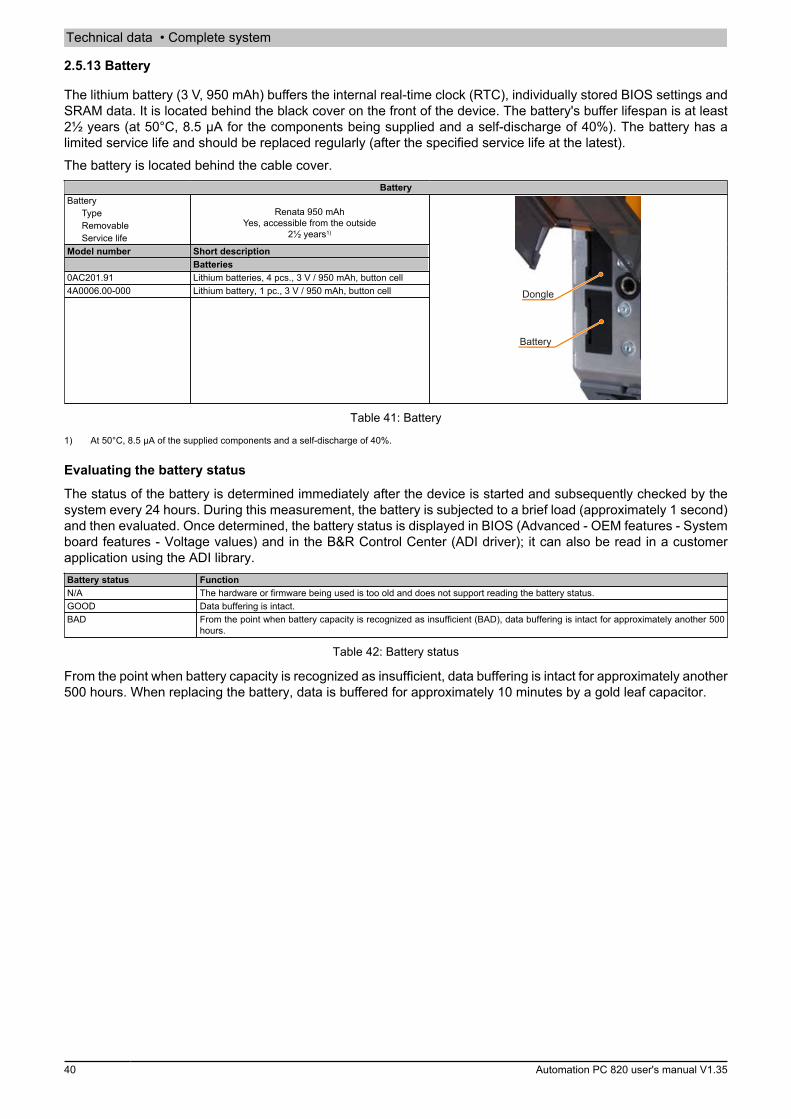
Technical data • Complete system
40 Automation PC 820 user's manual V1.35
2.5.13 Battery
The lithium battery (3 V, 950 mAh) buffers the internal real-time clock (RTC), individually stored BIOS settings andSRAM data. It is located behind the black cover on the front of the device. The battery's buffer lifespan is at least2½ years (at 50°C, 8.5 μA for the components being supplied and a self-discharge of 40%). The battery has alimited service life and should be replaced regularly (after the specified service life at the latest).The battery is located behind the cable cover.
BatteryBattery
TypeRemovableService life
Renata 950 mAhYes, accessible from the outside
2½ years1)
Model number Short descriptionBatteries
0AC201.91 Lithium batteries, 4 pcs., 3 V / 950 mAh, button cell4A0006.00-000 Lithium battery, 1 pc., 3 V / 950 mAh, button cell
Battery
Dongle
Table 41: Battery
1) At 50°C, 8.5 µA of the supplied components and a self-discharge of 40%.
Evaluating the battery status
The status of the battery is determined immediately after the device is started and subsequently checked by thesystem every 24 hours. During this measurement, the battery is subjected to a brief load (approximately 1 second)and then evaluated. Once determined, the battery status is displayed in BIOS (Advanced - OEM features - Systemboard features - Voltage values) and in the B&R Control Center (ADI driver); it can also be read in a customerapplication using the ADI library.Battery status FunctionN/A The hardware or firmware being used is too old and does not support reading the battery status.GOOD Data buffering is intact.BAD From the point when battery capacity is recognized as insufficient (BAD), data buffering is intact for approximately another 500
hours.
Table 42: Battery status
From the point when battery capacity is recognized as insufficient, data buffering is intact for approximately another500 hours. When replacing the battery, data is buffered for approximately 10 minutes by a gold leaf capacitor.
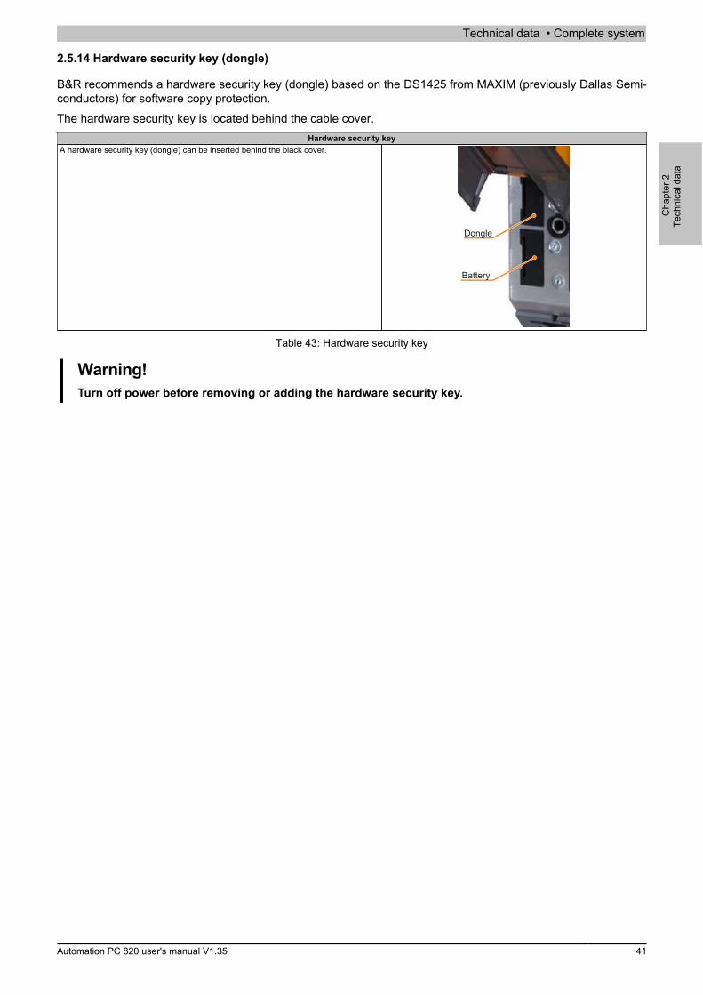
Technical data • Complete system
Cha
pter
2Te
chni
cal d
ata
Automation PC 820 user's manual V1.35 41
2.5.14 Hardware security key (dongle)
B&R recommends a hardware security key (dongle) based on the DS1425 from MAXIM (previously Dallas Semi-conductors) for software copy protection.The hardware security key is located behind the cable cover.
Hardware security keyA hardware security key (dongle) can be inserted behind the black cover.
Battery
Dongle
Table 43: Hardware security key
Warning!Turn off power before removing or adding the hardware security key.
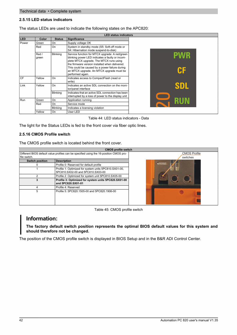
Technical data • Complete system
42 Automation PC 820 user's manual V1.35
2.5.15 LED status indicators
The status LEDs are used to indicate the following states on the APC820:LED status indicators
LED Color Status SignificanceGreen On Supply voltage OKRed On System in standby mode (S5: Soft-off mode or
S4: Hibernation mode suspend-to-disk)
Power
Red /green
Blinking Service function for MTCX upgrade: A red/greenblinking power LED indicates a faulty or incom-plete MTCX upgrade. The MTCX runs usingthe firmware version installed when delivered.This could be caused by a power failure duringan MTCX upgrade. An MTCX upgrade must beperformed again.
CF Yellow On Indicates access to CompactFlash (read orwrite)
On Indicates an active SDL connection on the moni-tor/panel interface
Link Yellow
Blinking Indicates that an active SDL connection has beeninterrupted by a loss of power to the display unit
Green On Application runningOn Service modeRedBlinking Indicates a licensing violation
Run
Yellow On User LED
PWR
RUN
CF
SDL
Table 44: LED status indicators - Data
The light for the Status LEDs is fed to the front cover via fiber optic lines.
2.5.16 CMOS Profile switch
The CMOS profile switch is located behind the front cover.CMOS profile switch
Different BIOS default value profiles can be specified using the 16-position CMOS pro-file switch.
Switch position Description0 Profile 0: Reserved for default profile1 Profile 1: Optimized for system units 5PC810.SX01-00,
5PC810.SX02-00 and 5PC810.SX03-002 Profile 2: Optimized for system unit 5PC810.SX05-003 Profile 3: Optimized for system units 5PC820.SX01-00
and 5PC820.SX01-014 Profile 4: Reserved5 Profile 5: 5PC820.1505-00 and 5PC820.1906-00
CMOS Profileswitches
Table 45: CMOS profile switch
Information:The factory default switch position represents the optimal BIOS default values for this system andshould therefore not be changed.
The position of the CMOS profile switch is displayed in BIOS Setup and in the B&R ADI Control Center.
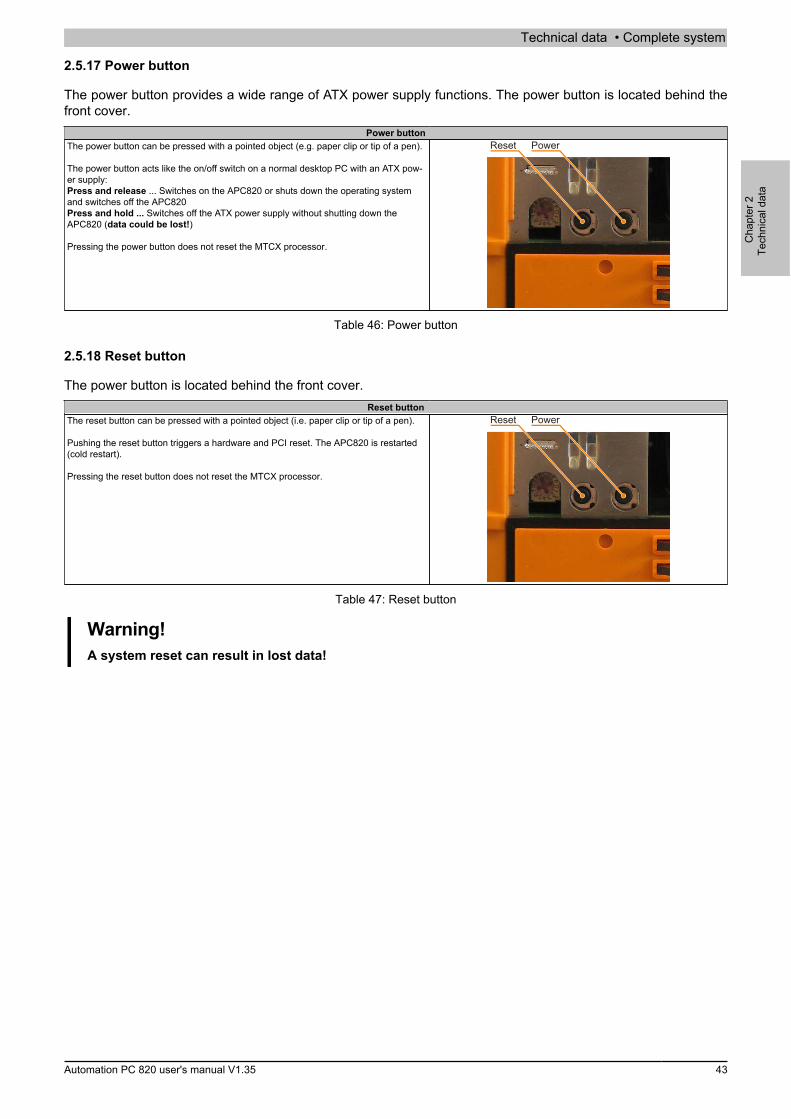
Technical data • Complete system
Cha
pter
2Te
chni
cal d
ata
Automation PC 820 user's manual V1.35 43
2.5.17 Power button
The power button provides a wide range of ATX power supply functions. The power button is located behind thefront cover.
Power buttonThe power button can be pressed with a pointed object (e.g. paper clip or tip of a pen).
The power button acts like the on/off switch on a normal desktop PC with an ATX pow-er supply:Press and release ... Switches on the APC820 or shuts down the operating systemand switches off the APC820Press and hold ... Switches off the ATX power supply without shutting down theAPC820 (data could be lost!)
Pressing the power button does not reset the MTCX processor.
PowerReset
Table 46: Power button
2.5.18 Reset button
The power button is located behind the front cover.Reset button
The reset button can be pressed with a pointed object (i.e. paper clip or tip of a pen).
Pushing the reset button triggers a hardware and PCI reset. The APC820 is restarted(cold restart).
Pressing the reset button does not reset the MTCX processor.
PowerReset
Table 47: Reset button
Warning!A system reset can result in lost data!

Technical data • Individual components
44 Automation PC 820 user's manual V1.35
3 Individual components
3.1 System units
3.1.1 Interfaces
Power LED
Node switchPOWERLINK
CAN node switch
CompactFlash LEDLink LEDRun LEDCAN LEDPOWERLINK LED
Ethernet ETH1 LED
Ethernet ETH2 LED
CompactFlash slot 2
CompactFlash slot 1Battery
Reset button
Power button
Dongle
FanCable covercan be tilted up
USB5 (max. 1 A)
Figure 7: APC820 interface overview - Front side ≤ A0
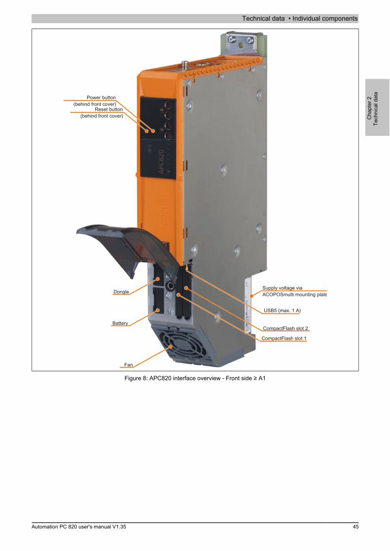
Technical data • Individual components
Cha
pter
2Te
chni
cal d
ata
Automation PC 820 user's manual V1.35 45
Supply voltage viaACOPOSmulti mounting plate
Battery
Dongle
Fan
CompactFlash slot 2
CompactFlash slot 1
USB5 (max. 1 A)
Reset button(behind front cover)
Power button(behind front cover)
Figure 8: APC820 interface overview - Front side ≥ A1

Technical data • Individual components
46 Automation PC 820 user's manual V1.35
CompactFlash LEDPower LED
Link LEDRun LEDCAN LED
POWERLINK LED
POWERLINK node switch
CAN node switch
IF slot LEDs
Figure 9: APC820 LED description - Front side ≥ A1

Technical data • Individual components
Cha
pter
2Te
chni
cal d
ata
Automation PC 820 user's manual V1.35 47
USB2, USB4 (max. 500 mA)
USB1, USB3 (max. 1 A)
POWERLINK
ETH1Ethernet 10/100/1000
ETH2Ethernet 10/100/1000
COM2RS232/422/485
COM1RS232
CAN Interface
Monitor / PanelSDL (Smart Display Link) / DVI
CAN Terminating switchCAN LED
PCIec card slot
Supply voltage viaACOPOSmulti mounting plate
Figure 10: APC820 interface overview - Top side ≤ A0

Technical data • Individual components
48 Automation PC 820 user's manual V1.35
POWERLINK
ETH2Ethernet 10/100/1000
ETH1Ethernet 10/100/1000
COM2RS232/422/485
COM1RS232
Monitor/PanelSDL (Smart Display Link) / DVI
CAN LED
PCIec card slot
USB2 (max. 500 mA)USB4 (max. 500 mA)
USB1 (max. 1 A)
USB3 (max. 1 A)
CAN Interface
CAN Terminating switch
Figure 11: APC820 interface overview - Top side ≥ A1
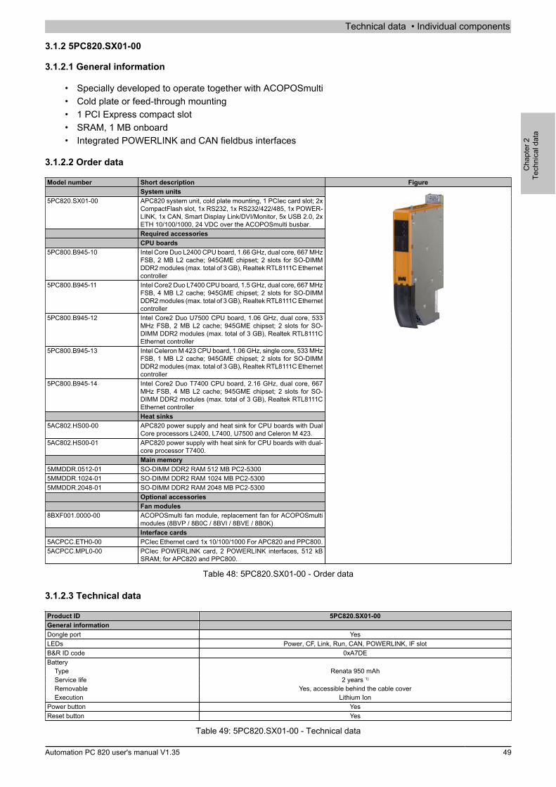
Technical data • Individual components
Cha
pter
2Te
chni
cal d
ata
Automation PC 820 user's manual V1.35 49
3.1.2 5PC820.SX01-00
3.1.2.1 General information
• Specially developed to operate together with ACOPOSmulti• Cold plate or feed-through mounting• 1 PCI Express compact slot• SRAM, 1 MB onboard• Integrated POWERLINK and CAN fieldbus interfaces
3.1.2.2 Order data
Model number Short description FigureSystem units
5PC820.SX01-00 APC820 system unit, cold plate mounting, 1 PCIec card slot; 2xCompactFlash slot, 1x RS232, 1x RS232/422/485, 1x POWER-LINK, 1x CAN, Smart Display Link/DVI/Monitor, 5x USB 2.0, 2xETH 10/100/1000, 24 VDC over the ACOPOSmulti busbar.Required accessoriesCPU boards
5PC800.B945-10 Intel Core Duo L2400 CPU board, 1.66 GHz, dual core, 667 MHzFSB, 2 MB L2 cache; 945GME chipset; 2 slots for SO-DIMMDDR2 modules (max. total of 3 GB), Realtek RTL8111C Ethernetcontroller
5PC800.B945-11 Intel Core2 Duo L7400 CPU board, 1.5 GHz, dual core, 667 MHzFSB, 4 MB L2 cache; 945GME chipset; 2 slots for SO-DIMMDDR2 modules (max. total of 3 GB), Realtek RTL8111C Ethernetcontroller
5PC800.B945-12 Intel Core2 Duo U7500 CPU board, 1.06 GHz, dual core, 533MHz FSB, 2 MB L2 cache; 945GME chipset; 2 slots for SO-DIMM DDR2 modules (max. total of 3 GB), Realtek RTL8111CEthernet controller
5PC800.B945-13 Intel Celeron M 423 CPU board, 1.06 GHz, single core, 533 MHzFSB, 1 MB L2 cache; 945GME chipset; 2 slots for SO-DIMMDDR2 modules (max. total of 3 GB), Realtek RTL8111C Ethernetcontroller
5PC800.B945-14 Intel Core2 Duo T7400 CPU board, 2.16 GHz, dual core, 667MHz FSB, 4 MB L2 cache; 945GME chipset; 2 slots for SO-DIMM DDR2 modules (max. total of 3 GB), Realtek RTL8111CEthernet controllerHeat sinks
5AC802.HS00-00 APC820 power supply and heat sink for CPU boards with DualCore processors L2400, L7400, U7500 and Celeron M 423.
5AC802.HS00-01 APC820 power supply with heat sink for CPU boards with dual-core processor T7400.Main memory
5MMDDR.0512-01 SO-DIMM DDR2 RAM 512 MB PC2-53005MMDDR.1024-01 SO-DIMM DDR2 RAM 1024 MB PC2-53005MMDDR.2048-01 SO-DIMM DDR2 RAM 2048 MB PC2-5300
Optional accessoriesFan modules
8BXF001.0000-00 ACOPOSmulti fan module, replacement fan for ACOPOSmultimodules (8BVP / 8B0C / 8BVI / 8BVE / 8B0K)Interface cards
5ACPCC.ETH0-00 PCIec Ethernet card 1x 10/100/1000 For APC820 and PPC800.5ACPCC.MPL0-00 PCIec POWERLINK card, 2 POWERLINK interfaces, 512 kB
SRAM; for APC820 and PPC800.
Table 48: 5PC820.SX01-00 - Order data
3.1.2.3 Technical data
Product ID 5PC820.SX01-00General informationDongle port YesLEDs Power, CF, Link, Run, CAN, POWERLINK, IF slotB&R ID code 0xA7DEBattery
Type Renata 950 mAhService life 2 years 1)
Removable Yes, accessible behind the cable coverExecution Lithium Ion
Power button YesReset button Yes
Table 49: 5PC820.SX01-00 - Technical data
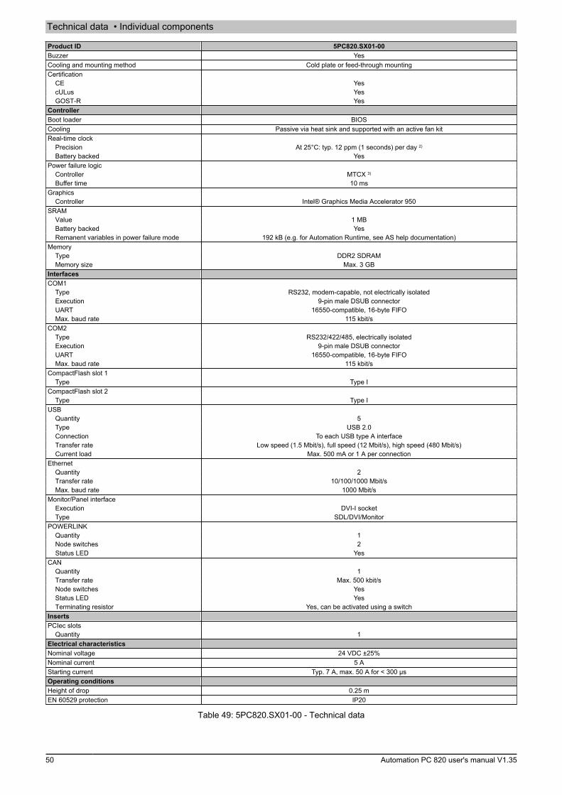
Technical data • Individual components
50 Automation PC 820 user's manual V1.35
Product ID 5PC820.SX01-00Buzzer YesCooling and mounting method Cold plate or feed-through mountingCertification
CE YescULus YesGOST-R Yes
ControllerBoot loader BIOSCooling Passive via heat sink and supported with an active fan kitReal-time clock
Precision At 25°C: typ. 12 ppm (1 seconds) per day 2)
Battery backed YesPower failure logic
Controller MTCX 3)
Buffer time 10 msGraphics
Controller Intel® Graphics Media Accelerator 950SRAM
Value 1 MBBattery backed YesRemanent variables in power failure mode 192 kB (e.g. for Automation Runtime, see AS help documentation)
MemoryType DDR2 SDRAMMemory size Max. 3 GB
InterfacesCOM1
Type RS232, modem-capable, not electrically isolatedExecution 9-pin male DSUB connectorUART 16550-compatible, 16-byte FIFOMax. baud rate 115 kbit/s
COM2Type RS232/422/485, electrically isolatedExecution 9-pin male DSUB connectorUART 16550-compatible, 16-byte FIFOMax. baud rate 115 kbit/s
CompactFlash slot 1Type Type I
CompactFlash slot 2Type Type I
USBQuantity 5Type USB 2.0Connection To each USB type A interfaceTransfer rate Low speed (1.5 Mbit/s), full speed (12 Mbit/s), high speed (480 Mbit/s)Current load Max. 500 mA or 1 A per connection
EthernetQuantity 2Transfer rate 10/100/1000 Mbit/sMax. baud rate 1000 Mbit/s
Monitor/Panel interfaceExecution DVI-I socketType SDL/DVI/Monitor
POWERLINKQuantity 1Node switches 2Status LED Yes
CANQuantity 1Transfer rate Max. 500 kbit/sNode switches YesStatus LED YesTerminating resistor Yes, can be activated using a switch
InsertsPCIec slots
Quantity 1Electrical characteristicsNominal voltage 24 VDC ±25%Nominal current 5 AStarting current Typ. 7 A, max. 50 A for < 300 µsOperating conditionsHeight of drop 0.25 mEN 60529 protection IP20
Table 49: 5PC820.SX01-00 - Technical data
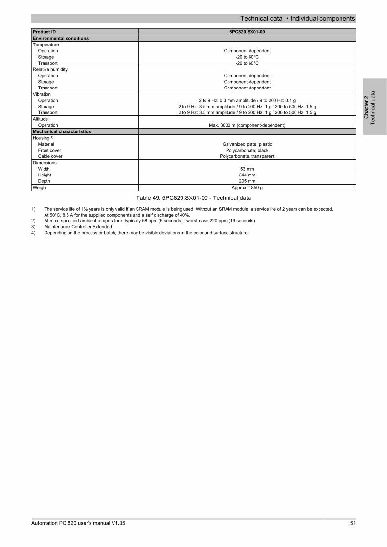
Technical data • Individual components
Cha
pter
2Te
chni
cal d
ata
Automation PC 820 user's manual V1.35 51
Product ID 5PC820.SX01-00Environmental conditionsTemperature
Operation Component-dependentStorage -20 to 60°CTransport -20 to 60°C
Relative humidityOperation Component-dependentStorage Component-dependentTransport Component-dependent
VibrationOperation 2 to 9 Hz: 0.3 mm amplitude / 9 to 200 Hz: 0.1 gStorage 2 to 9 Hz: 3.5 mm amplitude / 9 to 200 Hz: 1 g / 200 to 500 Hz: 1.5 gTransport 2 to 9 Hz: 3.5 mm amplitude / 9 to 200 Hz: 1 g / 200 to 500 Hz: 1.5 g
AltitudeOperation Max. 3000 m (component-dependent)
Mechanical characteristicsHousing 4)
Material Galvanized plate, plasticFront cover Polycarbonate, blackCable cover Polycarbonate, transparent
DimensionsWidth 53 mmHeight 344 mmDepth 205 mm
Weight Approx. 1850 g
Table 49: 5PC820.SX01-00 - Technical data
1) The service life of 1½ years is only valid if an SRAM module is being used. Without an SRAM module, a service life of 2 years can be expected.At 50°C, 8.5 A for the supplied components and a self discharge of 40%.
2) At max. specified ambient temperature: typically 58 ppm (5 seconds) - worst-case 220 ppm (19 seconds).3) Maintenance Controller Extended4) Depending on the process or batch, there may be visible deviations in the color and surface structure.
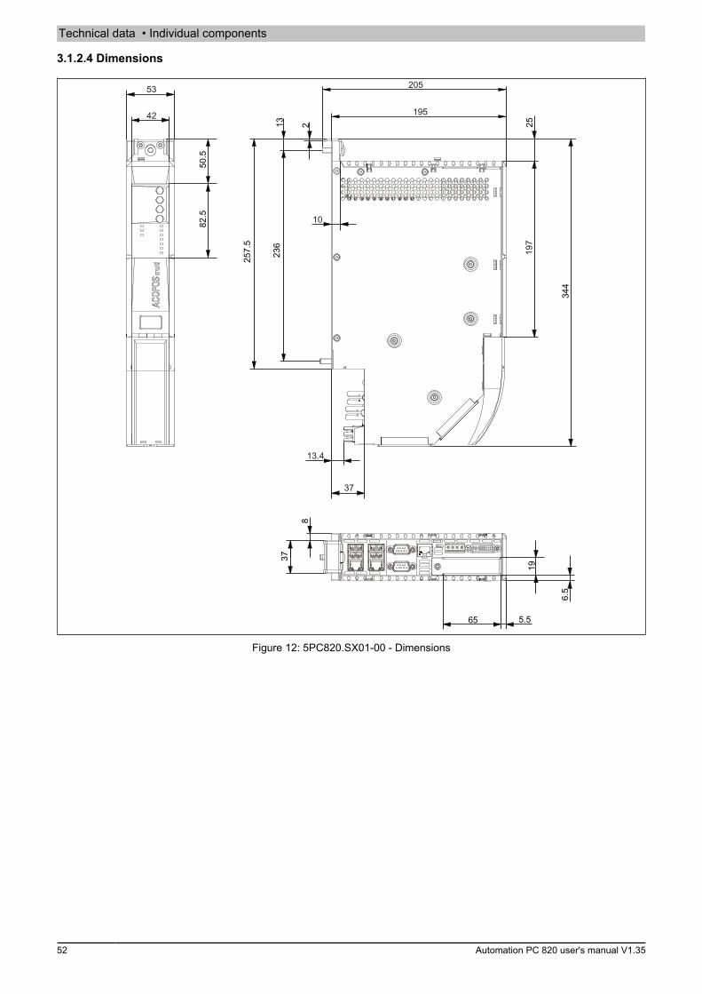
Technical data • Individual components
52 Automation PC 820 user's manual V1.35
3.1.2.4 Dimensions
344
2513236
257.5
2
37
65
19
5.5
6.5
82.5
8
50.5
10
37
13.4
53
42
205
195
197
Figure 12: 5PC820.SX01-00 - Dimensions

Technical data • Individual components
Cha
pter
2Te
chni
cal d
ata
Automation PC 820 user's manual V1.35 53
3.1.3 5PC820.SX01-01
3.1.3.1 General information
• Specially developed to operate together with ACOPOSmulti• Wall mounting• 1 PCI Express compact slot• SRAM, 1 MB onboard• Integrated POWERLINK and CAN fieldbus interfaces
3.1.3.2 Order data
Model number Short description FigureSystem units
5PC820.SX01-01 APC820 system unit, wall mounting, 1 PCIec card slot; 2x Com-pactFlash slot, 1x RS232, 1x RS232/422/485, 1x POWERLINK,1x CAN, Smart Display Link/DVI/Monitor, 5x USB 2.0, 2x ETH10/100/1000, 24 VDC over the ACOPOSmulti busbar.Required accessoriesCPU boards
5PC800.B945-10 Intel Core Duo L2400 CPU board, 1.66 GHz, dual core, 667 MHzFSB, 2 MB L2 cache; 945GME chipset; 2 slots for SO-DIMMDDR2 modules (max. total of 3 GB), Realtek RTL8111C Ethernetcontroller
5PC800.B945-11 Intel Core2 Duo L7400 CPU board, 1.5 GHz, dual core, 667 MHzFSB, 4 MB L2 cache; 945GME chipset; 2 slots for SO-DIMMDDR2 modules (max. total of 3 GB), Realtek RTL8111C Ethernetcontroller
5PC800.B945-12 Intel Core2 Duo U7500 CPU board, 1.06 GHz, dual core, 533MHz FSB, 2 MB L2 cache; 945GME chipset; 2 slots for SO-DIMM DDR2 modules (max. total of 3 GB), Realtek RTL8111CEthernet controller
5PC800.B945-13 Intel Celeron M 423 CPU board, 1.06 GHz, single core, 533 MHzFSB, 1 MB L2 cache; 945GME chipset; 2 slots for SO-DIMMDDR2 modules (max. total of 3 GB), Realtek RTL8111C Ethernetcontroller
5PC800.B945-14 Intel Core2 Duo T7400 CPU board, 2.16 GHz, dual core, 667MHz FSB, 4 MB L2 cache; 945GME chipset; 2 slots for SO-DIMM DDR2 modules (max. total of 3 GB), Realtek RTL8111CEthernet controllerHeat sinks
5AC802.HS00-00 APC820 power supply and heat sink for CPU boards with DualCore processors L2400, L7400, U7500 and Celeron M 423.
5AC802.HS00-01 APC820 power supply with heat sink for CPU boards with dual-core processor T7400.Main memory
5MMDDR.0512-01 SO-DIMM DDR2 RAM 512 MB PC2-53005MMDDR.1024-01 SO-DIMM DDR2 RAM 1024 MB PC2-53005MMDDR.2048-01 SO-DIMM DDR2 RAM 2048 MB PC2-5300
Optional accessoriesFan modules
8BXF001.0000-00 ACOPOSmulti fan module, replacement fan for ACOPOSmultimodules (8BVP / 8B0C / 8BVI / 8BVE / 8B0K)Interface cards
5ACPCC.ETH0-00 PCIec Ethernet card 1x 10/100/1000 For APC820 and PPC800.5ACPCC.MPL0-00 PCIec POWERLINK card, 2 POWERLINK interfaces, 512 kB
SRAM; for APC820 and PPC800.
Table 50: 5PC820.SX01-01 - Order data
3.1.3.3 Technical data
Product ID 5PC820.SX01-01General informationDongle port YesLEDs Power, CF, Link, Run, CAN, POWERLINK, IF slotB&R ID code 0xAD8ABattery
Type Renata 950 mAhService life 2 years 1)
Removable Yes, accessible behind the cable coverExecution Lithium Ion
Power button YesReset button Yes
Table 51: 5PC820.SX01-01 - Technical data

Technical data • Individual components
54 Automation PC 820 user's manual V1.35
Product ID 5PC820.SX01-01Buzzer YesCooling and mounting method Wall mountingCertification
CE YescULus YesGOST-R Yes
ControllerBoot loader BIOSCooling Passive via heat sink and supported with an active fan kitReal-time clock
Precision At 25°C: typ. 12 ppm (1 seconds) per day 2)
Battery backed YesPower failure logic
Controller MTCX 3)
Buffer time 10 msGraphics
Controller Intel® Graphics Media Accelerator 950SRAM
Value 1 MBBattery backed YesRemanent variables in power failure mode 192 kB (e.g. for Automation Runtime, see AS help documentation)
MemoryType DDR2 SDRAMMemory size Max. 3 GB
InterfacesCOM1
Type RS232, modem-capable, not electrically isolatedExecution 9-pin male DSUB connectorUART 16550-compatible, 16-byte FIFOMax. baud rate 115 kbit/s
COM2Type RS232/422/485, electrically isolatedExecution 9-pin male DSUB connectorUART 16550-compatible, 16-byte FIFOMax. baud rate 115 kbit/s
CompactFlash slot 1Type Type I
CompactFlash slot 2Type Type I
USBQuantity 5Type USB 2.0Connection To each USB type A interfaceTransfer rate Low speed (1.5 Mbit/s), full speed (12 Mbit/s), high speed (480 Mbit/s)Current load Max. 500 mA or 1 A per connection
EthernetQuantity 2Transfer rate 10/100/1000 Mbit/sMax. baud rate 1000 Mbit/s
Monitor/Panel interfaceExecution DVI-I socketType SDL/DVI/Monitor
POWERLINKQuantity 1Node switches 2Status LED Yes
CANQuantity 1Transfer rate Max. 500 kbit/sNode switches YesStatus LED YesTerminating resistor Yes, can be activated using a switch
InsertsPCIec slots
Quantity 1Electrical characteristicsNominal voltage 24 VDC ±25%Nominal current 5 AStarting current Typ. 7 A, max. 50 A for < 300 µsOperating conditionsHeight of drop 0.25 mEN 60529 protection IP20
Table 51: 5PC820.SX01-01 - Technical data

Technical data • Individual components
Cha
pter
2Te
chni
cal d
ata
Automation PC 820 user's manual V1.35 55
Product ID 5PC820.SX01-01Environmental conditionsTemperature
Operation Component-dependentStorage -20 to 60°CTransport -20 to 60°C
Relative humidityOperation Component-dependentStorage Component-dependentTransport Component-dependent
VibrationOperation 2 to 9 Hz: 0.3 mm amplitude / 9 to 200 Hz: 0.1 gStorage 2 to 9 Hz: 3.5 mm amplitude / 9 to 200 Hz: 1 g / 200 to 500 Hz: 1.5 gTransport 2 to 9 Hz: 3.5 mm amplitude / 9 to 200 Hz: 1 g / 200 to 500 Hz: 1.5 g
AltitudeOperation Max. 3000 m (component-dependent)
Mechanical characteristicsHousing 4)
Material Galvanized plate, plasticFront cover Polycarbonate, blackCable cover Polycarbonate, transparent
DimensionsWidth 53 mmHeight 344 mmDepth 253 mm
Weight Approx. 2550 g
Table 51: 5PC820.SX01-01 - Technical data
1) The service life of 1½ years is only valid if an SRAM module is being used. Without an SRAM module, a service life of 2 years can be expected.At 50°C, 8.5 A for the supplied components and a self discharge of 40%.
2) At max. specified ambient temperature: typically 58 ppm (5 seconds) - worst-case 220 ppm (19 seconds).3) Maintenance Controller Extended4) Depending on the process or batch, there may be visible deviations in the color and surface structure.

Technical data • Individual components
56 Automation PC 820 user's manual V1.35
3.1.3.4 Dimensions
53
42
50.5
82.5
3.5
13
...
236
257.5
67.9
91.5
197
25
344
19
6.5
5.566.5
8
37
249.5
Figure 13: 5PC820.SX01-01 - Dimensions
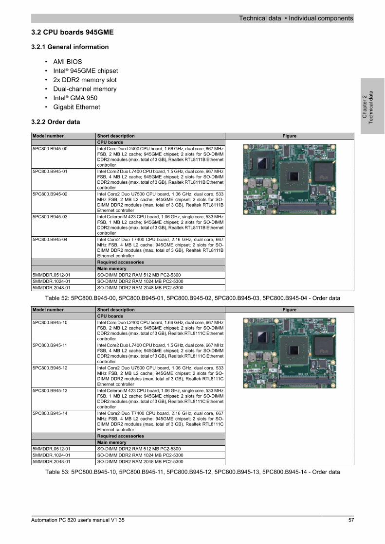
Technical data • Individual components
Cha
pter
2Te
chni
cal d
ata
Automation PC 820 user's manual V1.35 57
3.2 CPU boards 945GME
3.2.1 General information
• AMI BIOS• Intel® 945GME chipset• 2x DDR2 memory slot• Dual-channel memory• Intel® GMA 950• Gigabit Ethernet
3.2.2 Order data
Model number Short description FigureCPU boards
5PC800.B945-00 Intel Core Duo L2400 CPU board, 1.66 GHz, dual core, 667 MHzFSB, 2 MB L2 cache; 945GME chipset; 2 slots for SO-DIMMDDR2 modules (max. total of 3 GB), Realtek RTL8111B Ethernetcontroller
5PC800.B945-01 Intel Core2 Duo L7400 CPU board, 1.5 GHz, dual core, 667 MHzFSB, 4 MB L2 cache; 945GME chipset; 2 slots for SO-DIMMDDR2 modules (max. total of 3 GB), Realtek RTL8111B Ethernetcontroller
5PC800.B945-02 Intel Core2 Duo U7500 CPU board, 1.06 GHz, dual core, 533MHz FSB, 2 MB L2 cache; 945GME chipset; 2 slots for SO-DIMM DDR2 modules (max. total of 3 GB), Realtek RTL8111BEthernet controller
5PC800.B945-03 Intel Celeron M 423 CPU board, 1.06 GHz, single core, 533 MHzFSB, 1 MB L2 cache; 945GME chipset; 2 slots for SO-DIMMDDR2 modules (max. total of 3 GB), Realtek RTL8111B Ethernetcontroller
5PC800.B945-04 Intel Core2 Duo T7400 CPU board, 2.16 GHz, dual core, 667MHz FSB, 4 MB L2 cache; 945GME chipset; 2 slots for SO-DIMM DDR2 modules (max. total of 3 GB), Realtek RTL8111BEthernet controllerRequired accessoriesMain memory
5MMDDR.0512-01 SO-DIMM DDR2 RAM 512 MB PC2-53005MMDDR.1024-01 SO-DIMM DDR2 RAM 1024 MB PC2-53005MMDDR.2048-01 SO-DIMM DDR2 RAM 2048 MB PC2-5300
Table 52: 5PC800.B945-00, 5PC800.B945-01, 5PC800.B945-02, 5PC800.B945-03, 5PC800.B945-04 - Order data
Model number Short description FigureCPU boards
5PC800.B945-10 Intel Core Duo L2400 CPU board, 1.66 GHz, dual core, 667 MHzFSB, 2 MB L2 cache; 945GME chipset; 2 slots for SO-DIMMDDR2 modules (max. total of 3 GB), Realtek RTL8111C Ethernetcontroller
5PC800.B945-11 Intel Core2 Duo L7400 CPU board, 1.5 GHz, dual core, 667 MHzFSB, 4 MB L2 cache; 945GME chipset; 2 slots for SO-DIMMDDR2 modules (max. total of 3 GB), Realtek RTL8111C Ethernetcontroller
5PC800.B945-12 Intel Core2 Duo U7500 CPU board, 1.06 GHz, dual core, 533MHz FSB, 2 MB L2 cache; 945GME chipset; 2 slots for SO-DIMM DDR2 modules (max. total of 3 GB), Realtek RTL8111CEthernet controller
5PC800.B945-13 Intel Celeron M 423 CPU board, 1.06 GHz, single core, 533 MHzFSB, 1 MB L2 cache; 945GME chipset; 2 slots for SO-DIMMDDR2 modules (max. total of 3 GB), Realtek RTL8111C Ethernetcontroller
5PC800.B945-14 Intel Core2 Duo T7400 CPU board, 2.16 GHz, dual core, 667MHz FSB, 4 MB L2 cache; 945GME chipset; 2 slots for SO-DIMM DDR2 modules (max. total of 3 GB), Realtek RTL8111CEthernet controllerRequired accessoriesMain memory
5MMDDR.0512-01 SO-DIMM DDR2 RAM 512 MB PC2-53005MMDDR.1024-01 SO-DIMM DDR2 RAM 1024 MB PC2-53005MMDDR.2048-01 SO-DIMM DDR2 RAM 2048 MB PC2-5300
Table 53: 5PC800.B945-10, 5PC800.B945-11, 5PC800.B945-12, 5PC800.B945-13, 5PC800.B945-14 - Order data

Technical data • Individual components
58 Automation PC 820 user's manual V1.35
3.2.3 Technical data - 5PC800.B945-0x
Product ID 5PC800.B945-00 5PC800.B945-01 5PC800.B945-02 5PC800.B945-03 5PC800.B945-04General informationCertification
CE YesGOST-R - Yes -
ControllerBoot loader Embedded AMI BIOSProcessor
Type Intel® Core™Duo L2400
Intel® Core™2Duo L7400
Intel® Core™2Duo U7500
Intel® Celeron®M 423,
Intel® Core™2Duo T7400
Clock frequency 1660 MHz 1500 MHz 1060 MHz 2160 MHzNumber of cores 2 1 2Architectures 65 nmL1 cache 32 kBL2 cache 2 MB 4 MB 2 MB 1 MB 4 MBExternal bus 667 MHz 533 MHz 667 MHzIntel® 64 Architecture No Yes No YesIntel® Virtualization Technology(VT-x)
Yes No Yes
Enhanced Intel SpeedStep® Tech-nology
Yes No Yes
Chipset Intel® 945GMEIntel® 82801 GHM (ICH7M-DH)
Real-time clockPrecision At 25°C: typ. 12 ppm (1 seconds) per dayBattery backed Yes
Memory slotType DDR2Memory size Max. 3 GB
GraphicsController Intel® Graphics Media Accelerator 950Memory Up to 224 MB 1)
Color depth Max. 32-bitResolution
DVI 2x Intel-compliant SDVO ports, 1920 x 1080RGB 400 MHz RAMDAC, resolutions up to 2048 x 1536 @ 75 Hz (QXGA) and 1920 x 1080 @ 85 Hz (HDTV)
Mass memory management 2x SATA, 1x IDEPower management ACPI 2.0, S3 Support (suspend to RAM)
Table 54: 5PC800.B945-00, 5PC800.B945-01, 5PC800.B945-02, 5PC800.B945-03, 5PC800.B945-04 - Technical data
1) Allocated in main memory.
3.2.4 Technical data - 5PC800.B945-1x
Product ID 5PC800.B945-10 5PC800.B945-11 5PC800.B945-12 5PC800.B945-13 5PC800.B945-14General informationCertification
CE YescULus YesGOST-R Yes
ControllerBoot loader Embedded AMI BIOSProcessor
Type Intel® Core™Duo L2400
Intel® Core™2Duo L7400
Intel® Core™2Duo U7500
Intel® Celeron®M 423,
Intel® Core™2Duo T7400
Clock frequency 1660 MHz 1500 MHz 1060 MHz 2160 MHzNumber of cores 2 1 2Architectures 65 nmL1 cache 32 kBL2 cache 2 MB 4 MB 2 MB 1 MB 4 MBExternal bus 667 MHz 533 MHz 667 MHzIntel® 64 Architecture No Yes No YesIntel® Virtualization Technology(VT-x)
Yes No Yes
Enhanced Intel SpeedStep® Tech-nology
Yes No Yes
Chipset Intel® 945GMEIntel® 82801 GHM (ICH7M-DH)
Real-time clockPrecision At 25°C: typ. 12 ppm (1 seconds) per dayBattery backed Yes
Memory slotType DDR2Memory size Max. 3 GB
Table 55: 5PC800.B945-10, 5PC800.B945-11, 5PC800.B945-12, 5PC800.B945-13, 5PC800.B945-14 - Technical data

Technical data • Individual components
Cha
pter
2Te
chni
cal d
ata
Automation PC 820 user's manual V1.35 59
Product ID 5PC800.B945-10 5PC800.B945-11 5PC800.B945-12 5PC800.B945-13 5PC800.B945-14Graphics
Controller Intel® Graphics Media Accelerator 950Memory Up to 224 MB 1)
Color depth Max. 32-bitResolution
DVI 2x Intel-compliant SDVO ports, 1920 x 1080RGB 400 MHz RAMDAC, resolutions up to 2048 x 1536 @ 75 Hz (QXGA) and 1920 x 1080 @ 85 Hz (HDTV)
Mass memory management 2x SATA, 1x IDEPower management ACPI 2.0, S3 Support (suspend to RAM)
Table 55: 5PC800.B945-10, 5PC800.B945-11, 5PC800.B945-12, 5PC800.B945-13, 5PC800.B945-14 - Technical data
1) Allocated in main memory.
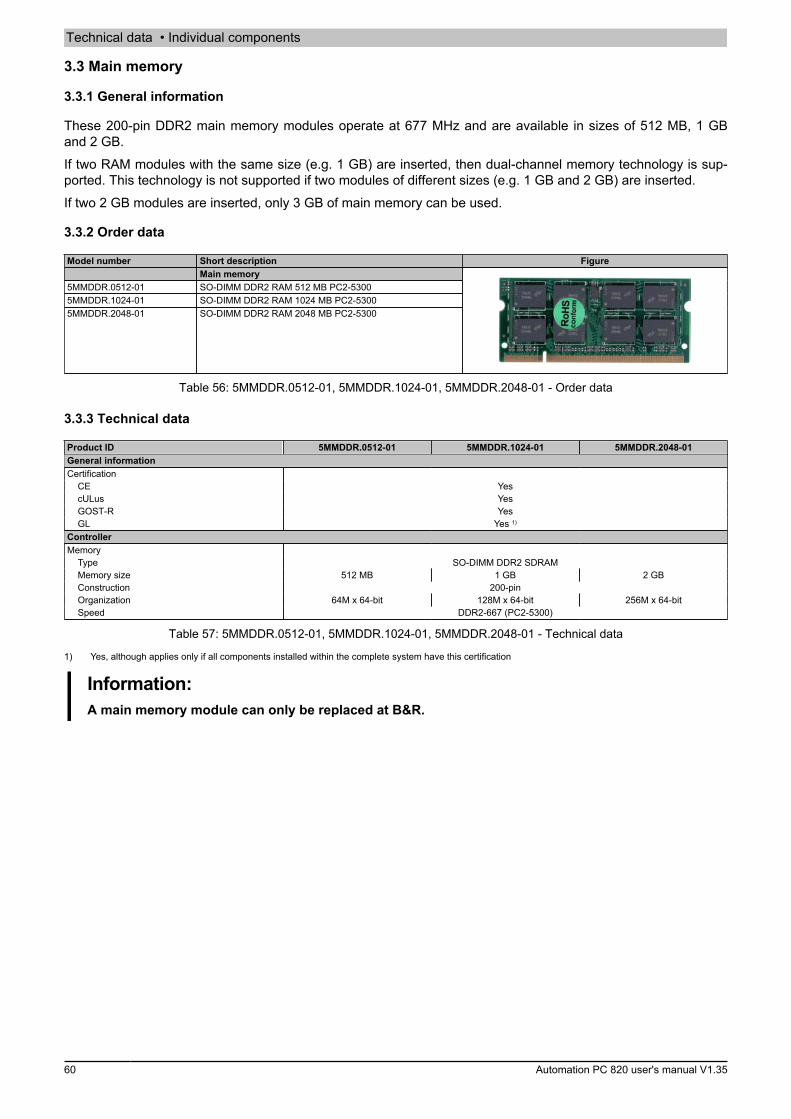
Technical data • Individual components
60 Automation PC 820 user's manual V1.35
3.3 Main memory
3.3.1 General information
These 200-pin DDR2 main memory modules operate at 677 MHz and are available in sizes of 512 MB, 1 GBand 2 GB.If two RAM modules with the same size (e.g. 1 GB) are inserted, then dual-channel memory technology is sup-ported. This technology is not supported if two modules of different sizes (e.g. 1 GB and 2 GB) are inserted.If two 2 GB modules are inserted, only 3 GB of main memory can be used.
3.3.2 Order data
Model number Short description FigureMain memory
5MMDDR.0512-01 SO-DIMM DDR2 RAM 512 MB PC2-53005MMDDR.1024-01 SO-DIMM DDR2 RAM 1024 MB PC2-53005MMDDR.2048-01 SO-DIMM DDR2 RAM 2048 MB PC2-5300
Table 56: 5MMDDR.0512-01, 5MMDDR.1024-01, 5MMDDR.2048-01 - Order data
3.3.3 Technical data
Product ID 5MMDDR.0512-01 5MMDDR.1024-01 5MMDDR.2048-01General informationCertification
CE YescULus YesGOST-R YesGL Yes 1)
ControllerMemory
Type SO-DIMM DDR2 SDRAMMemory size 512 MB 1 GB 2 GBConstruction 200-pinOrganization 64M x 64-bit 128M x 64-bit 256M x 64-bitSpeed DDR2-667 (PC2-5300)
Table 57: 5MMDDR.0512-01, 5MMDDR.1024-01, 5MMDDR.2048-01 - Technical data
1) Yes, although applies only if all components installed within the complete system have this certification
Information:A main memory module can only be replaced at B&R.
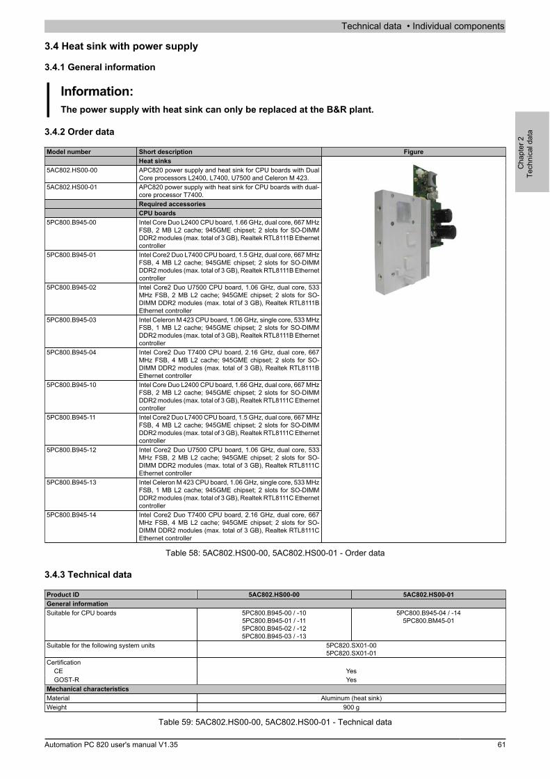
Technical data • Individual components
Cha
pter
2Te
chni
cal d
ata
Automation PC 820 user's manual V1.35 61
3.4 Heat sink with power supply
3.4.1 General information
Information:The power supply with heat sink can only be replaced at the B&R plant.
3.4.2 Order data
Model number Short description FigureHeat sinks
5AC802.HS00-00 APC820 power supply and heat sink for CPU boards with DualCore processors L2400, L7400, U7500 and Celeron M 423.
5AC802.HS00-01 APC820 power supply with heat sink for CPU boards with dual-core processor T7400.Required accessoriesCPU boards
5PC800.B945-00 Intel Core Duo L2400 CPU board, 1.66 GHz, dual core, 667 MHzFSB, 2 MB L2 cache; 945GME chipset; 2 slots for SO-DIMMDDR2 modules (max. total of 3 GB), Realtek RTL8111B Ethernetcontroller
5PC800.B945-01 Intel Core2 Duo L7400 CPU board, 1.5 GHz, dual core, 667 MHzFSB, 4 MB L2 cache; 945GME chipset; 2 slots for SO-DIMMDDR2 modules (max. total of 3 GB), Realtek RTL8111B Ethernetcontroller
5PC800.B945-02 Intel Core2 Duo U7500 CPU board, 1.06 GHz, dual core, 533MHz FSB, 2 MB L2 cache; 945GME chipset; 2 slots for SO-DIMM DDR2 modules (max. total of 3 GB), Realtek RTL8111BEthernet controller
5PC800.B945-03 Intel Celeron M 423 CPU board, 1.06 GHz, single core, 533 MHzFSB, 1 MB L2 cache; 945GME chipset; 2 slots for SO-DIMMDDR2 modules (max. total of 3 GB), Realtek RTL8111B Ethernetcontroller
5PC800.B945-04 Intel Core2 Duo T7400 CPU board, 2.16 GHz, dual core, 667MHz FSB, 4 MB L2 cache; 945GME chipset; 2 slots for SO-DIMM DDR2 modules (max. total of 3 GB), Realtek RTL8111BEthernet controller
5PC800.B945-10 Intel Core Duo L2400 CPU board, 1.66 GHz, dual core, 667 MHzFSB, 2 MB L2 cache; 945GME chipset; 2 slots for SO-DIMMDDR2 modules (max. total of 3 GB), Realtek RTL8111C Ethernetcontroller
5PC800.B945-11 Intel Core2 Duo L7400 CPU board, 1.5 GHz, dual core, 667 MHzFSB, 4 MB L2 cache; 945GME chipset; 2 slots for SO-DIMMDDR2 modules (max. total of 3 GB), Realtek RTL8111C Ethernetcontroller
5PC800.B945-12 Intel Core2 Duo U7500 CPU board, 1.06 GHz, dual core, 533MHz FSB, 2 MB L2 cache; 945GME chipset; 2 slots for SO-DIMM DDR2 modules (max. total of 3 GB), Realtek RTL8111CEthernet controller
5PC800.B945-13 Intel Celeron M 423 CPU board, 1.06 GHz, single core, 533 MHzFSB, 1 MB L2 cache; 945GME chipset; 2 slots for SO-DIMMDDR2 modules (max. total of 3 GB), Realtek RTL8111C Ethernetcontroller
5PC800.B945-14 Intel Core2 Duo T7400 CPU board, 2.16 GHz, dual core, 667MHz FSB, 4 MB L2 cache; 945GME chipset; 2 slots for SO-DIMM DDR2 modules (max. total of 3 GB), Realtek RTL8111CEthernet controller
Table 58: 5AC802.HS00-00, 5AC802.HS00-01 - Order data
3.4.3 Technical data
Product ID 5AC802.HS00-00 5AC802.HS00-01General informationSuitable for CPU boards 5PC800.B945-00 / -10
5PC800.B945-01 / -115PC800.B945-02 / -125PC800.B945-03 / -13
5PC800.B945-04 / -145PC800.BM45-01
Suitable for the following system units 5PC820.SX01-005PC820.SX01-01
CertificationCE YesGOST-R Yes
Mechanical characteristicsMaterial Aluminum (heat sink)Weight 900 g
Table 59: 5AC802.HS00-00, 5AC802.HS00-01 - Technical data
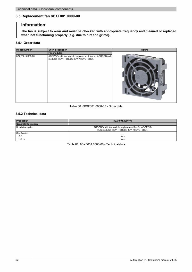
Technical data • Individual components
62 Automation PC 820 user's manual V1.35
3.5 Replacement fan 8BXF001.0000-00
Information:The fan is subject to wear and must be checked with appropriate frequency and cleaned or replacedwhen not functioning properly (e.g. due to dirt and grime).
3.5.1 Order data
Model number Short description FigureFan modules
8BXF001.0000-00 ACOPOSmulti fan module, replacement fan for ACOPOSmultimodules (8BVP / 8B0C / 8BVI / 8BVE / 8B0K)
Table 60: 8BXF001.0000-00 - Order data
3.5.2 Technical data
Product ID 8BXF001.0000-00General informationShort description ACOPOSmulti fan module, replacement fan for ACOPOS-
multi modules (8BVP / 8B0C / 8BVI / 8BVE / 8B0K)Certification
CE YescULus Yes
Table 61: 8BXF001.0000-00 - Technical data
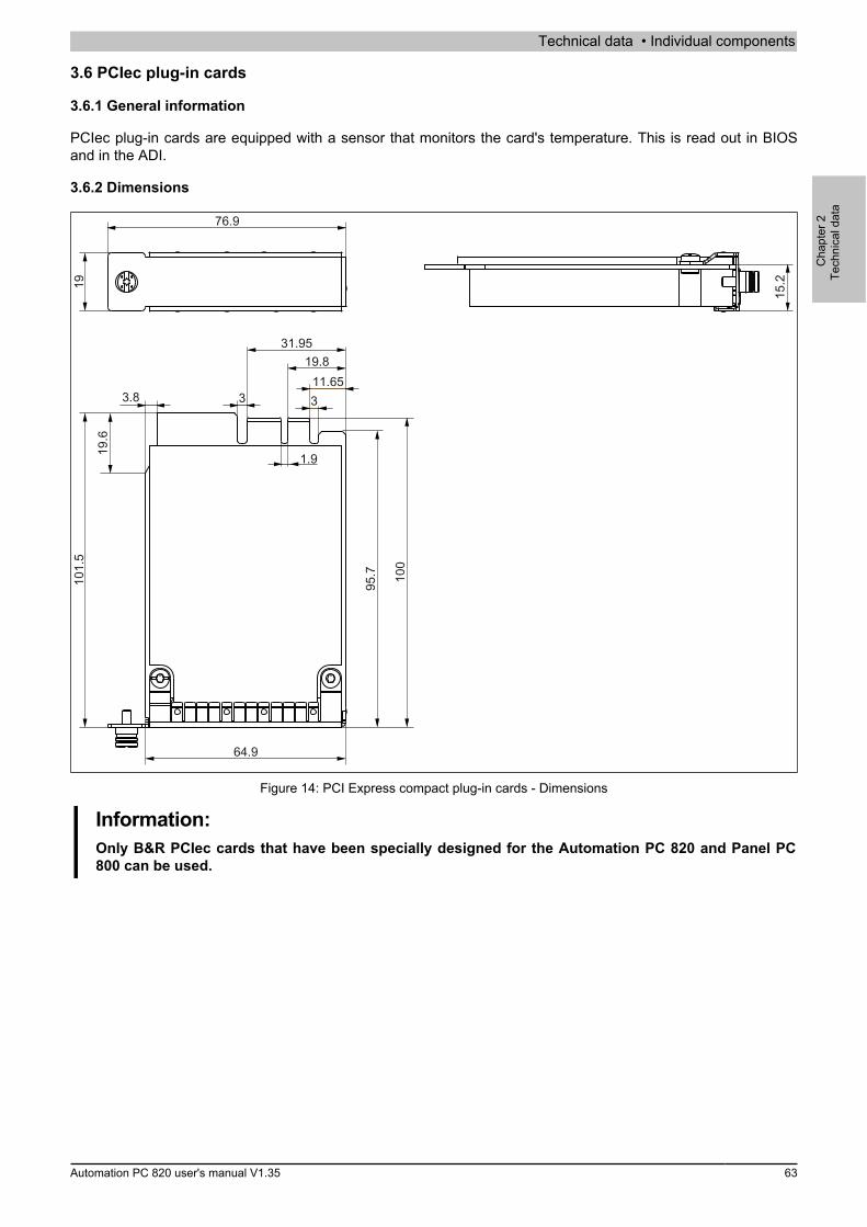
Technical data • Individual components
Cha
pter
2Te
chni
cal d
ata
Automation PC 820 user's manual V1.35 63
3.6 PCIec plug-in cards
3.6.1 General information
PCIec plug-in cards are equipped with a sensor that monitors the card's temperature. This is read out in BIOSand in the ADI.
3.6.2 Dimensions
100
95.7101.5
19
11.65
15.2
64.9
76.9
19.8
3
31.95
3
1.9
3.8
19.6
Figure 14: PCI Express compact plug-in cards - Dimensions
Information:Only B&R PCIec cards that have been specially designed for the Automation PC 820 and Panel PC800 can be used.

Technical data • Individual components
64 Automation PC 820 user's manual V1.35
3.6.3 5ACPCC.ETH0-00
3.6.3.1 General information
This PCI Express compact Ethernet card has a 10/100/1000 Mbit/s network connection and can be used as anadditional network interface in a PCI Express compact slot.
• PCIec Ethernet card• 1 network connection (10/100/1000 Mbit/s)
3.6.3.2 Order data
Model number Short description FigureInterface cards
5ACPCC.ETH0-00 PCIec Ethernet card 1x 10/100/1000 For APC820 and PPC800.
Table 62: 5ACPCC.ETH0-00 - Order data
3.6.3.3 Technical data
Product ID 5ACPCC.ETH0-00General informationB&R ID code 0xAB25Diagnostics
Data transfer Yes, using status LEDCertification
CE YesGOST-R Yes
InterfacesEthernet
Quantity 1Controller Intel 82574Design Shielded RJ45 portTransfer rate 10/100/1000 Mbit/sCable length Max. 100 m between two stations (segment length)
Mechanical characteristicsSlot PCIec module
Table 63: 5ACPCC.ETH0-00 - Technical data
3.6.3.3.1 Ethernet interface
Information:The following characteristics, features and limit values only apply to this individual component and candeviate from those specified for the complete system. For the complete system in which this individualcomponent is used, refer to the data given specifically for that device.
Ethernet interface (ETH1))Controller Intel 82574Cabling S/STP (Cat 5e)Transfer rate 10/100/1000 Mbit/s2)
Cable length Max. 100 m (min. Cat 5e)Speed LED On Off
Green 100 Mbit/s 10 Mbit/s3)
Orange 1000 Mbit/s -Link LED On OffOrange Link (Ethernet network
connection available)Activity (blinking - da-
ta transfer in progress)
Female RJ45 connector
1
Speed LEDLink LED
Table 64: 5ACPCC.ETH0-00 - Ethernet interface
1) The interfaces, etc. available on the device or module have been numbered as such for easy identification. This numbering may differ from that used bythe particular operating system.
2) Switching takes place automatically.3) The 10 Mbit/s transfer speed / connection is only present if the IF slot Link LED is also lit at the same time.

Technical data • Individual components
Cha
pter
2Te
chni
cal d
ata
Automation PC 820 user's manual V1.35 65
Driver support
A special driver is required in order to operate the Intel 82574 Ethernet controller. Drivers for approved operatingsystems are available in the Downloads section of the B&R website (www.br-automation.com).
Information:Required drivers can only be downloaded from the B&R website, not from manufacturer websites.
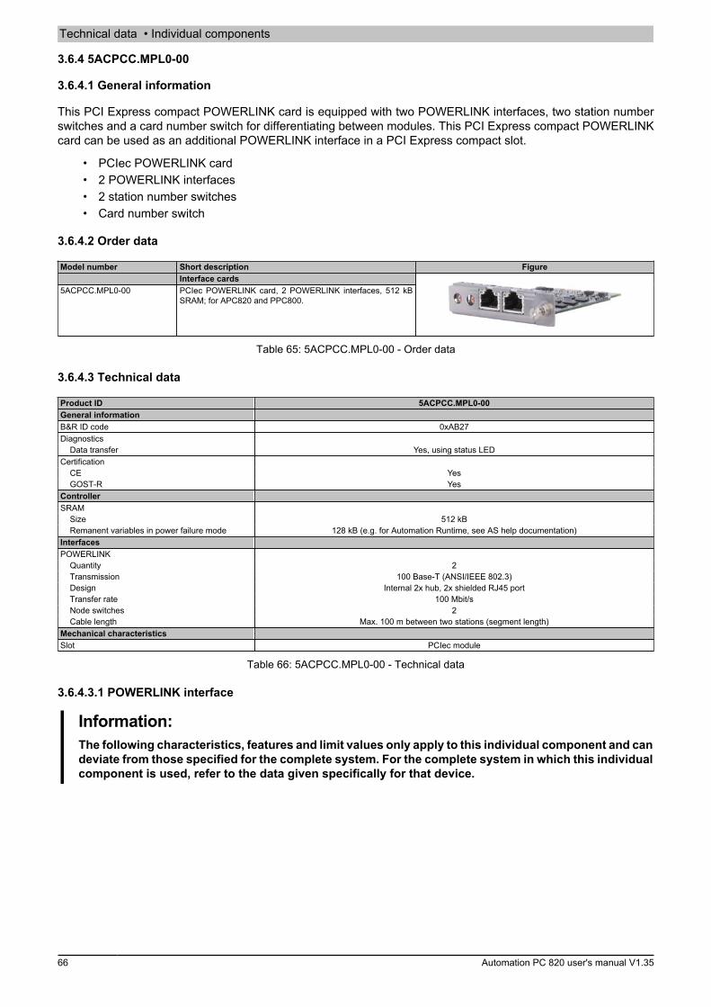
Technical data • Individual components
66 Automation PC 820 user's manual V1.35
3.6.4 5ACPCC.MPL0-00
3.6.4.1 General information
This PCI Express compact POWERLINK card is equipped with two POWERLINK interfaces, two station numberswitches and a card number switch for differentiating between modules. This PCI Express compact POWERLINKcard can be used as an additional POWERLINK interface in a PCI Express compact slot.
• PCIec POWERLINK card• 2 POWERLINK interfaces• 2 station number switches• Card number switch
3.6.4.2 Order data
Model number Short description FigureInterface cards
5ACPCC.MPL0-00 PCIec POWERLINK card, 2 POWERLINK interfaces, 512 kBSRAM; for APC820 and PPC800.
Table 65: 5ACPCC.MPL0-00 - Order data
3.6.4.3 Technical data
Product ID 5ACPCC.MPL0-00General informationB&R ID code 0xAB27Diagnostics
Data transfer Yes, using status LEDCertification
CE YesGOST-R Yes
ControllerSRAM
Size 512 kBRemanent variables in power failure mode 128 kB (e.g. for Automation Runtime, see AS help documentation)
InterfacesPOWERLINK
Quantity 2Transmission 100 Base-T (ANSI/IEEE 802.3)Design Internal 2x hub, 2x shielded RJ45 portTransfer rate 100 Mbit/sNode switches 2Cable length Max. 100 m between two stations (segment length)
Mechanical characteristicsSlot PCIec module
Table 66: 5ACPCC.MPL0-00 - Technical data
3.6.4.3.1 POWERLINK interface
Information:The following characteristics, features and limit values only apply to this individual component and candeviate from those specified for the complete system. For the complete system in which this individualcomponent is used, refer to the data given specifically for that device.
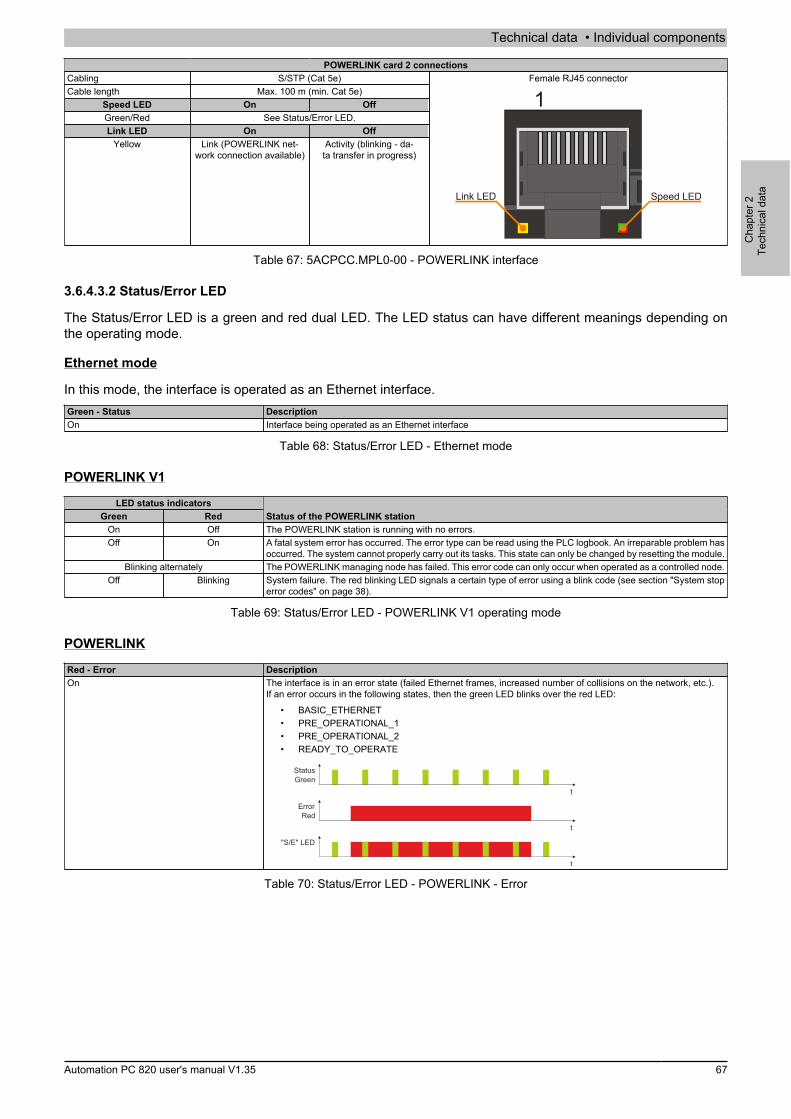
Technical data • Individual components
Cha
pter
2Te
chni
cal d
ata
Automation PC 820 user's manual V1.35 67
POWERLINK card 2 connectionsCabling S/STP (Cat 5e)Cable length Max. 100 m (min. Cat 5e)
Speed LED On OffGreen/Red See Status/Error LED.Link LED On Off
Yellow Link (POWERLINK net-work connection available)
Activity (blinking - da-ta transfer in progress)
Female RJ45 connector
1
Speed LEDLink LED
Table 67: 5ACPCC.MPL0-00 - POWERLINK interface
3.6.4.3.2 Status/Error LED
The Status/Error LED is a green and red dual LED. The LED status can have different meanings depending onthe operating mode.
Ethernet mode
In this mode, the interface is operated as an Ethernet interface.Green - Status DescriptionOn Interface being operated as an Ethernet interface
Table 68: Status/Error LED - Ethernet mode
POWERLINK V1
LED status indicatorsGreen Red Status of the POWERLINK station
On Off The POWERLINK station is running with no errors.Off On A fatal system error has occurred. The error type can be read using the PLC logbook. An irreparable problem has
occurred. The system cannot properly carry out its tasks. This state can only be changed by resetting the module.Blinking alternately The POWERLINK managing node has failed. This error code can only occur when operated as a controlled node.
Off Blinking System failure. The red blinking LED signals a certain type of error using a blink code (see section "System stoperror codes" on page 38).
Table 69: Status/Error LED - POWERLINK V1 operating mode
POWERLINK
Red - Error DescriptionOn The interface is in an error state (failed Ethernet frames, increased number of collisions on the network, etc.).
If an error occurs in the following states, then the green LED blinks over the red LED:• BASIC_ETHERNET• PRE_OPERATIONAL_1• PRE_OPERATIONAL_2• READY_TO_OPERATE
t
t
t
"S/E" LED
StatusGreen
ErrorRed
Table 70: Status/Error LED - POWERLINK - Error

Technical data • Individual components
68 Automation PC 820 user's manual V1.35
Green - Status DescriptionOffNOT_ACTIVE
ModeThe interface is in NOT_ACTIVE mode or:
• Switched off• Starting up• Not configured correctly in Automation Studio• Defective
Managing node (MN)The bus is being monitored for POWERLINK frames. If a frame is not received within the configured time window(timeout), the interface switches immediately to PRE_OPERATIONAL_1 mode (single flash). If POWERLINKcommunication is detected before the time expires, however, then the MN will not be started.
Controlled node (CN)The bus is being monitored for POWERLINK frames. If a corresponding frame is not received within the definedtime frame (timeout), then the module switches immediately to BASIC_ETHERNET mode (flickering). If POW-ERLINK communication is detected before this time expires, however, the interface switches immediately toPRE_OPERATIONAL_1 mode (single flash).
Green flickering (approx. 10 Hz)BASIC_ETHERNET
ModeThe interface is in BASIC_ETHERNET mode and being operated as an Ethernet TCP/IP interface.
Managing node (MN)This state can only be exited by resetting the interface.
Controlled node (CN)If POWERLINK communication is detected while in this state, the interface switches to the PRE_OPERATION-AL_1 state (single flash).
Single flash (approx. 1 Hz)PRE_OPERATIONAL_1
ModeThe interface is in PRE_OPERATIONAL_1 mode.
Managing node (MN)The MN starts "reduced cycle" operation. Cyclic communication is not yet taking place.
Controlled node (CN)The module can be configured by the MN in this state. The CN waits until it receives an SoC frame and thenswitches to the PRE_OPERATIONAL_2 state (double flash). An LED lit red in this state indicates failure of the MN.
Double flash (approx. 1 Hz)PRE_OPERATIONAL_2
ModeThe interface is in the PRE_OPERATIONAL_2 state.
Managing node (MN)The MN begins cyclic communication (cyclic input data is not yet being evaluated). The CNs are configured inthis state.
Controlled node (CN)The interface can be configured by the MN in this state. A command then switches the state to READY_TO_OP-ERATE (triple flash). An LED lit red in this mode indicates failure of the MN.
Triple flash (approx. 1 Hz)READY_TO_OPERATE
ModeThe interface is in the READY_TO_OPERATE state.
Managing node (MN)Cyclic and asynchronous communication is taking place. Any received PDO data is ignored.
Controlled node (CN)The configuration of the module is completed. Normal cyclic and asynchronous communication is taking place.The PDO data being sent corresponds to the PDO mapping. Cyclic data is not yet being evaluated, however. AnLED lit red in this mode indicates failure of the MN.
OnOPERATIONAL
ModeThe interface is in OPERATIONAL mode. PDO mapping is active and cyclic data is being evaluated.
Blinking (approx. 2.5 Hz)STOPPED
ModeThe interface is in STOPPED mode.
Managing node (MN)This status is not possible for the MN.
Controlled node (CN)No output data is being produced, and no input data is being received. It is only possible to enter or leave thismode after the MN has given the appropriate command.
Table 71: Status/Error LED - POWERLINK - Status
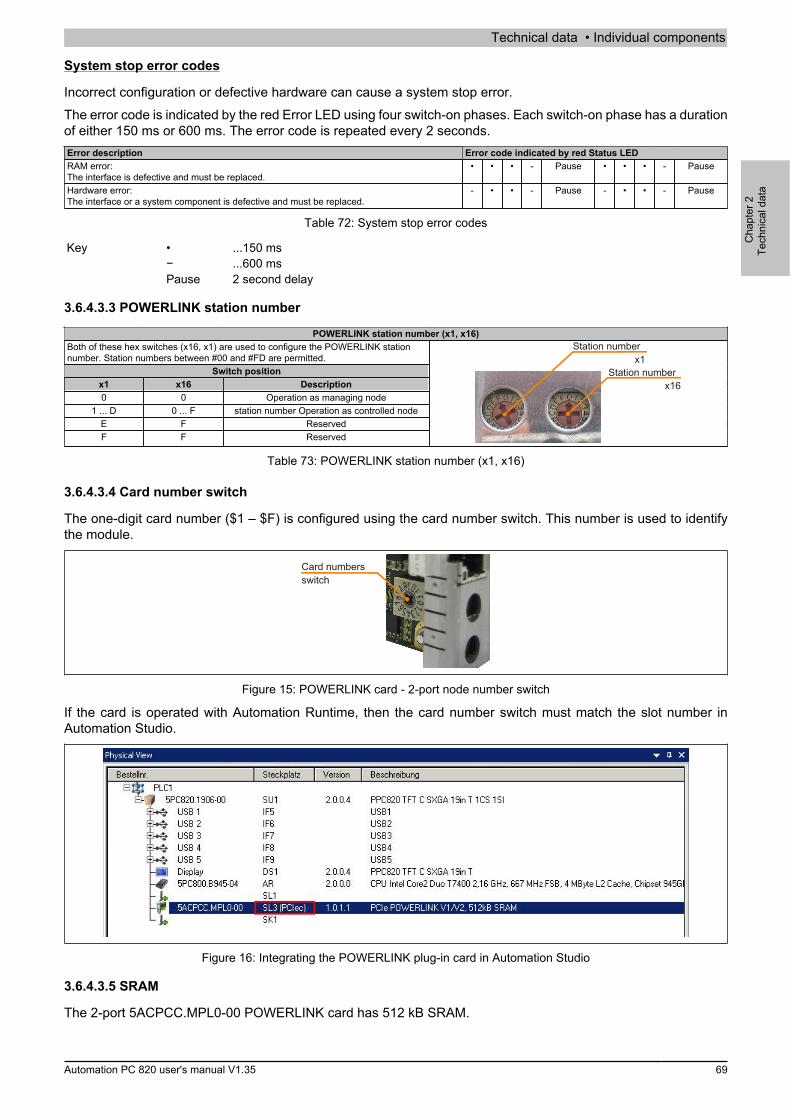
Technical data • Individual components
Cha
pter
2Te
chni
cal d
ata
Automation PC 820 user's manual V1.35 69
System stop error codes
Incorrect configuration or defective hardware can cause a system stop error.The error code is indicated by the red Error LED using four switch-on phases. Each switch-on phase has a durationof either 150 ms or 600 ms. The error code is repeated every 2 seconds.Error description Error code indicated by red Status LEDRAM error:The interface is defective and must be replaced.
• • • - Pause • • • - Pause
Hardware error:The interface or a system component is defective and must be replaced.
- • • - Pause - • • - Pause
Table 72: System stop error codes
Key • ...150 ms− ...600 msPause 2 second delay
3.6.4.3.3 POWERLINK station number
POWERLINK station number (x1, x16)Both of these hex switches (x16, x1) are used to configure the POWERLINK stationnumber. Station numbers between #00 and #FD are permitted.
Switch positionx1 x16 Description0 0 Operation as managing node
1 ... D 0 ... F station number Operation as controlled nodeE F ReservedF F Reserved
Station number x1
Station number x16
Table 73: POWERLINK station number (x1, x16)
3.6.4.3.4 Card number switch
The one-digit card number ($1 – $F) is configured using the card number switch. This number is used to identifythe module.
Card numbersswitch
Figure 15: POWERLINK card - 2-port node number switch
If the card is operated with Automation Runtime, then the card number switch must match the slot number inAutomation Studio.
Figure 16: Integrating the POWERLINK plug-in card in Automation Studio
3.6.4.3.5 SRAM
The 2-port 5ACPCC.MPL0-00 POWERLINK card has 512 kB SRAM.

Installation • Installation
70 Automation PC 820 user's manual V1.35
Chapter 3 • Installation
1 Installation
Generally, the APC820 must be mounted to the first position regardless of mounting method. It is important tomake sure that it is correctly fastened to the guide rail.
Feed-through mountingCold-plate mounting Wall mounting
Figure 17: Installation
1.1 Important installation information
• The APC820 must be secured to the first position of the ACOPOSmulti mounting plate.• Environmental conditions must be taken into consideration.• The APC820 is only certified for operation in closed rooms.• The APC820 cannot be situated in direct sunlight.• Ventilation holes must not be covered.• The flex radius of connected cables (DVI, SDL, USB, etc.) must not be exceeded (see "Cable connections"
on page 76).• Make sure that sufficient space is provided for air circulation.
Installation • Installation
Cha
pter
3In
stal
latio
n
Automation PC 820 user's manual V1.35 71
1.2 Mounting plates
The model numbers, the exact description as well as the dimension diagrams and installation dimensions for themounting plates can be found in the ACOPOSmulti manual in chapter 3, "Installation". This can be downloadedfrom the B&R website (www.br-automation.com).
Caution!Only feed-through and cold-plate mounting are allowed for the system unit 5PC820.SX01-00!Only wall mounting is allowed for the system unit 5PC820.SX01-01!
1.2.1 Feed-through mounting
With feed-through installation, excessive heat is output directly to the ambient air outside of the control cabinet.Suitable for a large number of axes with any range of power rating.The mounting surface for feed-through installation must provide sufficient stability for the mounting plate and alsobe non-flammable, level and free of contaminants.
Caution!The area of the mounting surface where the seal for the mounting plate sits must be free of scratchesand residue because otherwise it cannot be guaranteed that protection guidelines in accordance withEN 60529 are being met!
The cutout for the feed-through heat sink and the mounting holes (type and amount) are to be prepared according tothe dimension diagrams and installation dimensions in the ACOPOSmulti user's manual, which can be downloadedfor free from the B&R website (www.br-automation.com).The distances that must be used for mounting and ventilation of the Automation PC 820 and ACOPOSmulti modulescan be found in the dimension diagrams for the individual modules.
1.2.2 Cold-plate mounting
The excessive heat that is generated by the devices is output directly to the cooling medium via a plate cooledwith oil or water. Suitable for a large number of axes with any range of power rating and a machine's own coolingcirculation system.The mounting surface for the mounting plate must provide sufficient stability for the mounting plate and also benon-flammable, level and free of contaminants.
Connection of supply and return lines
The position of the connections for supply and return lines can be found in the installation diagram. This can foundin the ACOPOSmulti manual, which can be downloaded for free from the B&R website (www.br-automation.com).
Caution!The feed must be connected to the bottom connector of the mounting plate.The return line must be connected to the top connector of the mounting plate.
1.2.3 Wall mounting
The mounting surface for the mounting plate 8B0MxxxxHW00.000-1 must provide sufficient stability for the mount-ing plate and also be non-flammable, level and free of contaminants.The distances that must be used for mounting and ventilation of the Automation PC 820 and ACOPOSmulti modulescan be found in the dimension diagrams for the individual modules.

Installation • Installation
72 Automation PC 820 user's manual V1.35
1.3 Mounting orientation
The following diagrams illustrate the mounting orientations permitted by B&R. These are valid for cold-plate, feed-through and wall mounting.
Hanging vertically Lying horizontally
Figure 18: Permitted mounting orientations

Installation • Installation
Cha
pter
3In
stal
latio
n
Automation PC 820 user's manual V1.35 73
1.4 Spacing for air circulation
In order to guarantee sufficient air circulation, allow the specified amount of space above, below, to the side andbehind the . The minimum specified spacing is indicated in the following diagram. This applies to all variants.
mindestens60 mm spacing Air inlet
mindestens100 mm spacing
Air outlet
mindestens50 mm spacing
Figure 19: Spacing for air circulation
Information:The minimal spacing intervals indicated above must be adhered to in order to ensure sufficient aircirculation.To ensure that the fan modules in the mounting plate can be replaced easily, at least 250 mm clearancemust be available below the module.
Information:The spacing specifications for air circulation are based on the worst-case scenario for operation at themaximum specified ambient temperature (see "Temperature specifications" in the chapter "Technicaldata").If the spacing specifications for air circulation cannot be adhered to, then the maximum specified tem-peratures for the temperature sensors (see "Temperature sensor locations" in the chapter "Technicaldata") must be monitored by the user and appropriate measures taken if they are exceeded.
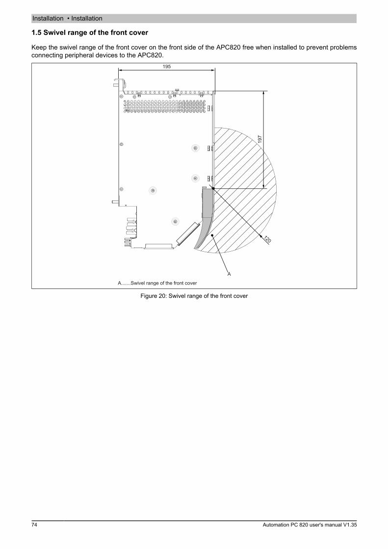
Installation • Installation
74 Automation PC 820 user's manual V1.35
1.5 Swivel range of the front cover
Keep the swivel range of the front cover on the front side of the APC820 free when installed to prevent problemsconnecting peripheral devices to the APC820.
195
197
A
A.......Swivel range of the front cover
120
Figure 20: Swivel range of the front cover

Installation • Installation
Cha
pter
3In
stal
latio
n
Automation PC 820 user's manual V1.35 75
1.6 Installation guidelines
The following must be taken into consideration when attaching to mounting plates:
• Attach the APC820 to the mounting plate using the mounting clip(s) on the top.
Information:The Automation PC820 must always be secured to the first position of the mounting plate.
Figure 21: Attaching modules
• Clip the APC820 into the backplane module. The APC820 must be thoroughly attached, so that it restsstraight in the backplane module in order for the module contacts to function properly.
• Tighten all M6 mounting screws (2 screws per module width) on the APC820 to a torque of max. 5 Nm.
Figure 22: Tightening the fastening screws

Installation • Cable connections
76 Automation PC 820 user's manual V1.35
2 Cable connections
Flex radius specifications must be taken into account when installing or connecting cables.
Information:The maximum torque for the locating screws is 0.5 Nm.
Flex radius
Locating screws
Locating screws
Figure 23: Flex radius - Cable connection
Information:The specified flex radius is listed in the technical data for the respective cable.

Installation • Connection examples
Cha
pter
3In
stal
latio
n
Automation PC 820 user's manual V1.35 77
3 Connection examples
The following examples provide an overview of the configuration options for connecting Automation Panel 800and Automation Panel 900 and/or Automation Panel 800 devices with the APC820. The following questions willbe answered:
• How are Automation Panel 900 devices connected to the monitor / panel output of the APC820, and whatneeds to be considered?
• How are Automation Panel 800 devices connected to the monitor / panel output of the APC820, and whatneeds to be considered?
• What are "Display Clone" and "Extended Desktop" modes?• How many Automation Panel 900 devices can be connected per line?• How many Automation Panel 900 devices can be connected to an Automation Panel 800 device per line?• How are the connected devices internally numbered?• Are there limitations to the segment length and if so, what are they?• What cables and link modules are needed?• Do BIOS settings have to be changed for a specific configuration?
3.1 Selecting display units
In order to connect an Automation Panel 800 and an Automation Panel 900 on the same line, the devices musthave the same display type. The following table lists the AP900 devices that can be connected on the same linewith an AP800 device.
Automation Panel 800 Automation Panel 9005AP820.1505-00 5AP920.1505-01
5AP951.1505-015AP980.1505-015AP981.1505-01
5AP880.1505-00 5AP920.1505-015AP951.1505-015AP980.1505-015AP981.1505-01
Table 74: Selecting display units

Installation • Connection examples
78 Automation PC 820 user's manual V1.35
3.2 One Automation Panel 900 via DVI
An Automation Panel 900 with max. SXGA resolution is connected to the integrated DVI interface (onboard). Asan alternative, an office TFT with a DVI interface or analog monitor (using adapter 5AC900.1000-00) can also beused. A separate cable is used for both the touch screen and USB data. If USB devices are to be operated onthe Automation Panel 900, the maximum distance is 5 meters. USB devices can only be connected directly to theAutomation Panel (i.e. without a hub).
Automation PC 820
DVI cables
RS232 cables
USB cables
Segementlänge 5 m (mit USB)max. 10 m (ohne USB)
Link: 5DLDVI.1000-01
USB up to 5 m OK
Monitor/PanelConnection
Figure 24: One Automation Panel 900 via DVI
3.2.1 Basic system requirements
The following table shows the possible combinations of APC820 system unit and CPU board to implement theconfiguration shown in the figure above. If a combination results in a limitation of the maximum resolution, this isalso indicated (e.g. when connecting a non-B&R Automation Panel 900 device).
with system unitCPU board 5PC820.SX01-00 5PC820.SX01-01LimitationResolution
5PC800.B945-005PC800.B945-10 ✓ ✓ Max. SXGA
5PC800.B945-015PC800.B945-11 ✓ ✓ Max. SXGA
5PC800.B945-025PC800.B945-12 ✓ ✓ Max. SXGA
5PC800.B945-035PC800.B945-13 ✓ ✓ Max. SXGA
5PC800.B945-045PC800.B945-14 ✓ ✓ Max. SXGA
Table 75: Possible combinations of system unit and CPU board
3.2.2 Link modules
Information:A corresponding Link module must be selected for each device used.
Model number Description Note5DLDVI.1000-01 Automation Panel Link DVI receiver
Connections for DVI-D, RS232 and USB 2.0 (Type B); 24 VDC (order screw clamp 0TB103.9 or cageclamp 0TB103.91 separately)
For Automation Panel 900
Table 76: Link modules
3.2.3 Cables
Select one Automation Panel 900 cable each from the 3 required types.Model number Description Length5CADVI.0018-00 DVI-D cable, 1.8 m 1.8 m ±50 mm5CADVI.0050-00 DVI-D cable, 5 m 5 m ±80 mm5CADVI.0100-00 DVI-D cable, 10 m 10 m ±100 mm9A0014.02 RS232 extension cable for remote operation of a display unit with touch screen, 1.8 m 1.8 m ±50 mm
Table 77: Cables for DVI configurations

Installation • Connection examples
Cha
pter
3In
stal
latio
n
Automation PC 820 user's manual V1.35 79
Model number Description Length9A0014.05 RS232 extension cable for remote operation of a display unit with touch screen, 5 m 5 m ±80 mm9A0014.10 RS232 extension cable for remote operation of a display unit with touch screen, 10 m 10 m ±100 mm5CAUSB.0018-00 USB 2.0 connection cable Type A - Type B, 1.8 m 1.8 m ±30 mm5CAUSB.0050-00 USB 2.0 connection cable Type A - Type B, 5 m 5 m ±50 mm
Table 77: Cables for DVI configurations
Information:Detailed technical data about cables can be found in the Automation Panel 900 user's manual. Thiscan be downloaded as a PDF file from the B&R website at www.br-automation.com.
3.2.4 Possible Automation Panel devices, resolutions and segment lengths
The following Automation Panel 900 devices can be used. In rare cases, segment length is limited by the resolution.Model number Display size Resolution Touch screen Keys Max. segment length5AP920.1043-01 10.4" VGA ✓ - 5 m / 10 m1)
5AP920.1214-01 12.1" SVGA ✓ - 5 m / 10 m1)
5AP920.1505-01 15.0" XGA ✓ - 5 m / 10 m1)
5AP920.1706-01 17.0" SXGA ✓ - 5 m / 10 m1)
5AP920.1906-01 19.0" SXGA ✓ - 5 m / 10 m1)
Table 78: Possible Automation Panel devices, resolutions and segment lengths
1) USB support is not possible on the Automation Panel 900 in these cases since USB is limited to 5 m.
Information:When transferring data via DVI, it is not possible to read statistical values from Automation Panel 900devices.
3.2.5 BIOS settings
No special BIOS settings are necessary for operation.
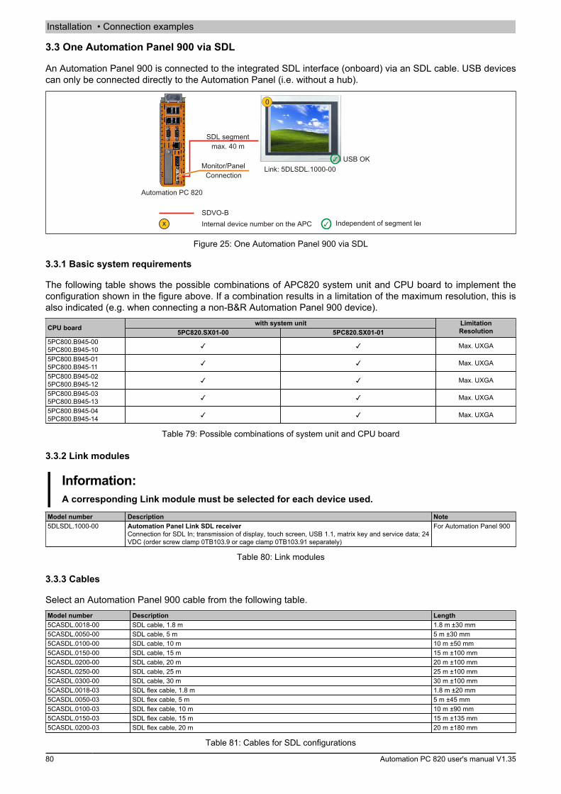
Installation • Connection examples
80 Automation PC 820 user's manual V1.35
3.3 One Automation Panel 900 via SDL
An Automation Panel 900 is connected to the integrated SDL interface (onboard) via an SDL cable. USB devicescan only be connected directly to the Automation Panel (i.e. without a hub).
Automation PC 820
SDL segmentmax. 40 m
Link: 5DLSDL.1000-00USB OK
SDVO-BInternal device number on the APC Independent of segment length
Monitor/PanelConnection
Figure 25: One Automation Panel 900 via SDL
3.3.1 Basic system requirements
The following table shows the possible combinations of APC820 system unit and CPU board to implement theconfiguration shown in the figure above. If a combination results in a limitation of the maximum resolution, this isalso indicated (e.g. when connecting a non-B&R Automation Panel 900 device).
with system unitCPU board 5PC820.SX01-00 5PC820.SX01-01LimitationResolution
5PC800.B945-005PC800.B945-10 ✓ ✓ Max. UXGA
5PC800.B945-015PC800.B945-11 ✓ ✓ Max. UXGA
5PC800.B945-025PC800.B945-12 ✓ ✓ Max. UXGA
5PC800.B945-035PC800.B945-13 ✓ ✓ Max. UXGA
5PC800.B945-045PC800.B945-14 ✓ ✓ Max. UXGA
Table 79: Possible combinations of system unit and CPU board
3.3.2 Link modules
Information:A corresponding Link module must be selected for each device used.
Model number Description Note5DLSDL.1000-00 Automation Panel Link SDL receiver
Connection for SDL In; transmission of display, touch screen, USB 1.1, matrix key and service data; 24VDC (order screw clamp 0TB103.9 or cage clamp 0TB103.91 separately)
For Automation Panel 900
Table 80: Link modules
3.3.3 Cables
Select an Automation Panel 900 cable from the following table.Model number Description Length5CASDL.0018-00 SDL cable, 1.8 m 1.8 m ±30 mm5CASDL.0050-00 SDL cable, 5 m 5 m ±30 mm5CASDL.0100-00 SDL cable, 10 m 10 m ±50 mm5CASDL.0150-00 SDL cable, 15 m 15 m ±100 mm5CASDL.0200-00 SDL cable, 20 m 20 m ±100 mm5CASDL.0250-00 SDL cable, 25 m 25 m ±100 mm5CASDL.0300-00 SDL cable, 30 m 30 m ±100 mm5CASDL.0018-03 SDL flex cable, 1.8 m 1.8 m ±20 mm5CASDL.0050-03 SDL flex cable, 5 m 5 m ±45 mm5CASDL.0100-03 SDL flex cable, 10 m 10 m ±90 mm5CASDL.0150-03 SDL flex cable, 15 m 15 m ±135 mm5CASDL.0200-03 SDL flex cable, 20 m 20 m ±180 mm
Table 81: Cables for SDL configurations
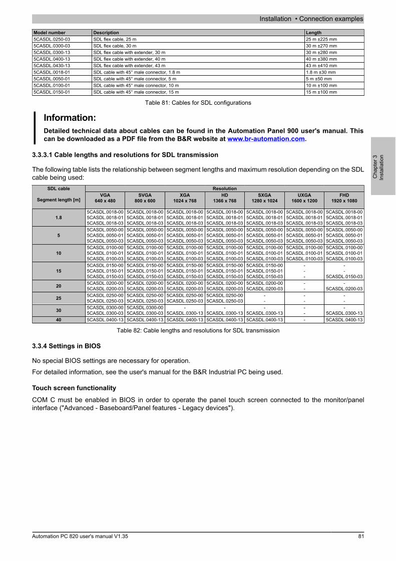
Installation • Connection examples
Cha
pter
3In
stal
latio
n
Automation PC 820 user's manual V1.35 81
Model number Description Length5CASDL.0250-03 SDL flex cable, 25 m 25 m ±225 mm5CASDL.0300-03 SDL flex cable, 30 m 30 m ±270 mm5CASDL.0300-13 SDL flex cable with extender, 30 m 30 m ±280 mm5CASDL.0400-13 SDL flex cable with extender, 40 m 40 m ±380 mm5CASDL.0430-13 SDL flex cable with extender, 43 m 43 m ±410 mm5CASDL.0018-01 SDL cable with 45° male connector, 1.8 m 1.8 m ±30 mm5CASDL.0050-01 SDL cable with 45° male connector, 5 m 5 m ±50 mm5CASDL.0100-01 SDL cable with 45° male connector, 10 m 10 m ±100 mm5CASDL.0150-01 SDL cable with 45° male connector, 15 m 15 m ±100 mm
Table 81: Cables for SDL configurations
Information:Detailed technical data about cables can be found in the Automation Panel 900 user's manual. Thiscan be downloaded as a PDF file from the B&R website at www.br-automation.com.
3.3.3.1 Cable lengths and resolutions for SDL transmission
The following table lists the relationship between segment lengths and maximum resolution depending on the SDLcable being used:
ResolutionSDL cable
Segment length [m]VGA
640 x 480SVGA
800 x 600XGA
1024 x 768HD
1366 x 768SXGA
1280 x 1024UXGA
1600 x 1200FHD
1920 x 1080
1.85CASDL.0018-005CASDL.0018-015CASDL.0018-03
5CASDL.0018-005CASDL.0018-015CASDL.0018-03
5CASDL.0018-005CASDL.0018-015CASDL.0018-03
5CASDL.0018-005CASDL.0018-015CASDL.0018-03
5CASDL.0018-005CASDL.0018-015CASDL.0018-03
5CASDL.0018-005CASDL.0018-015CASDL.0018-03
5CASDL.0018-005CASDL.0018-015CASDL.0018-03
55CASDL.0050-005CASDL.0050-015CASDL.0050-03
5CASDL.0050-005CASDL.0050-015CASDL.0050-03
5CASDL.0050-005CASDL.0050-015CASDL.0050-03
5CASDL.0050-005CASDL.0050-015CASDL.0050-03
5CASDL.0050-005CASDL.0050-015CASDL.0050-03
5CASDL.0050-005CASDL.0050-015CASDL.0050-03
5CASDL.0050-005CASDL.0050-015CASDL.0050-03
105CASDL.0100-005CASDL.0100-015CASDL.0100-03
5CASDL.0100-005CASDL.0100-015CASDL.0100-03
5CASDL.0100-005CASDL.0100-015CASDL.0100-03
5CASDL.0100-005CASDL.0100-015CASDL.0100-03
5CASDL.0100-005CASDL.0100-015CASDL.0100-03
5CASDL.0100-005CASDL.0100-015CASDL.0100-03
5CASDL.0100-005CASDL.0100-015CASDL.0100-03
155CASDL.0150-005CASDL.0150-015CASDL.0150-03
5CASDL.0150-005CASDL.0150-015CASDL.0150-03
5CASDL.0150-005CASDL.0150-015CASDL.0150-03
5CASDL.0150-005CASDL.0150-015CASDL.0150-03
5CASDL.0150-005CASDL.0150-015CASDL.0150-03
---
--
5CASDL.0150-03
20 5CASDL.0200-005CASDL.0200-03
5CASDL.0200-005CASDL.0200-03
5CASDL.0200-005CASDL.0200-03
5CASDL.0200-005CASDL.0200-03
5CASDL.0200-005CASDL.0200-03
--
-5CASDL.0200-03
25 5CASDL.0250-005CASDL.0250-03
5CASDL.0250-005CASDL.0250-03
5CASDL.0250-005CASDL.0250-03
5CASDL.0250-005CASDL.0250-03
--
--
--
30 5CASDL.0300-005CASDL.0300-03
5CASDL.0300-005CASDL.0300-03
-5CASDL.0300-13
-5CASDL.0300-13
-5CASDL.0300-13
--
-5CASDL.0300-13
40 5CASDL.0400-13 5CASDL.0400-13 5CASDL.0400-13 5CASDL.0400-13 5CASDL.0400-13 - 5CASDL.0400-13
Table 82: Cable lengths and resolutions for SDL transmission
3.3.4 Settings in BIOS
No special BIOS settings are necessary for operation.For detailed information, see the user's manual for the B&R Industrial PC being used.
Touch screen functionality
COM C must be enabled in BIOS in order to operate the panel touch screen connected to the monitor/panelinterface ("Advanced - Baseboard/Panel features - Legacy devices").
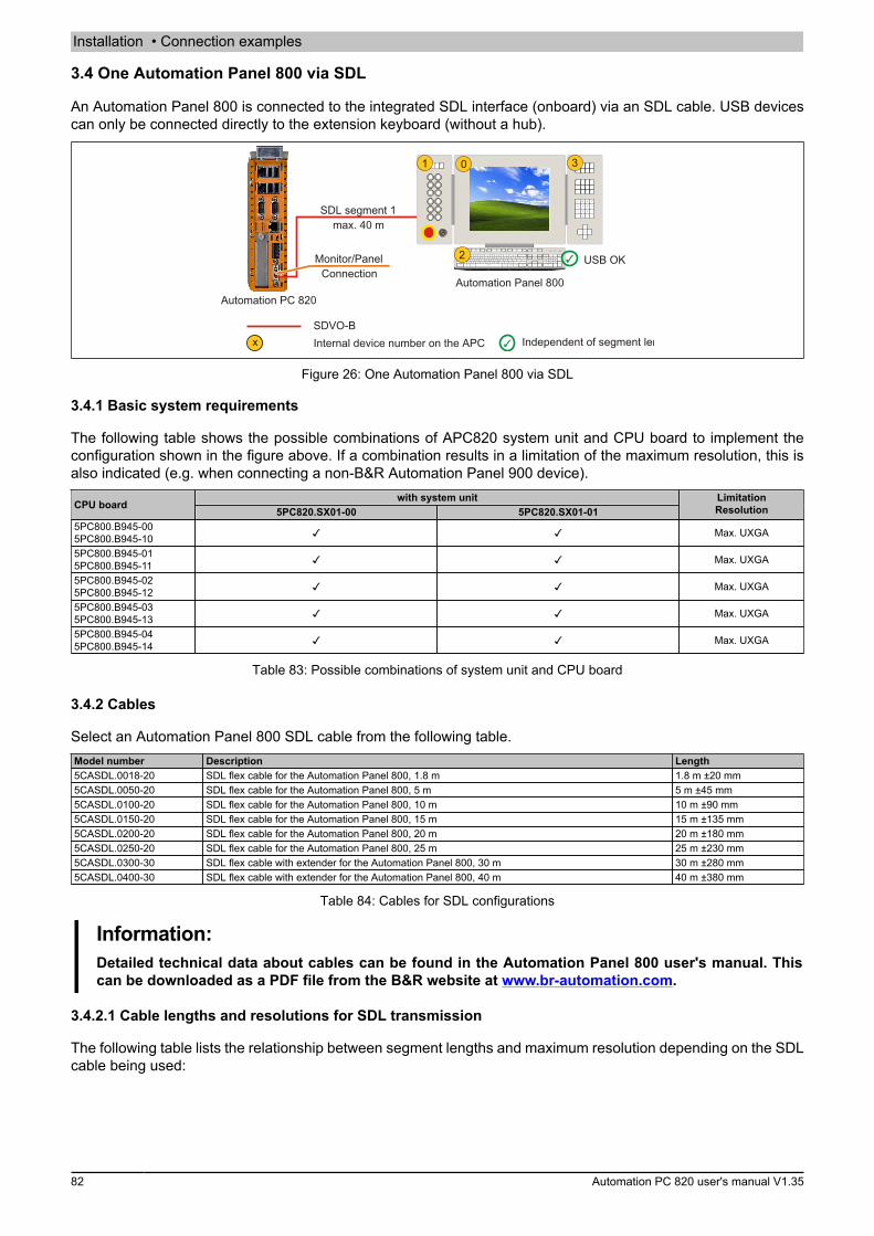
Installation • Connection examples
82 Automation PC 820 user's manual V1.35
3.4 One Automation Panel 800 via SDL
An Automation Panel 800 is connected to the integrated SDL interface (onboard) via an SDL cable. USB devicescan only be connected directly to the extension keyboard (without a hub).
Automation PC 820
SDL segment 1max. 40 m
Automation Panel 800
USB OK
SDVO-BInternal device number on the APC Independent of segment length
Monitor/PanelConnection
Figure 26: One Automation Panel 800 via SDL
3.4.1 Basic system requirements
The following table shows the possible combinations of APC820 system unit and CPU board to implement theconfiguration shown in the figure above. If a combination results in a limitation of the maximum resolution, this isalso indicated (e.g. when connecting a non-B&R Automation Panel 900 device).
with system unitCPU board 5PC820.SX01-00 5PC820.SX01-01LimitationResolution
5PC800.B945-005PC800.B945-10 ✓ ✓ Max. UXGA
5PC800.B945-015PC800.B945-11 ✓ ✓ Max. UXGA
5PC800.B945-025PC800.B945-12 ✓ ✓ Max. UXGA
5PC800.B945-035PC800.B945-13 ✓ ✓ Max. UXGA
5PC800.B945-045PC800.B945-14 ✓ ✓ Max. UXGA
Table 83: Possible combinations of system unit and CPU board
3.4.2 Cables
Select an Automation Panel 800 SDL cable from the following table.Model number Description Length5CASDL.0018-20 SDL flex cable for the Automation Panel 800, 1.8 m 1.8 m ±20 mm5CASDL.0050-20 SDL flex cable for the Automation Panel 800, 5 m 5 m ±45 mm5CASDL.0100-20 SDL flex cable for the Automation Panel 800, 10 m 10 m ±90 mm5CASDL.0150-20 SDL flex cable for the Automation Panel 800, 15 m 15 m ±135 mm5CASDL.0200-20 SDL flex cable for the Automation Panel 800, 20 m 20 m ±180 mm5CASDL.0250-20 SDL flex cable for the Automation Panel 800, 25 m 25 m ±230 mm5CASDL.0300-30 SDL flex cable with extender for the Automation Panel 800, 30 m 30 m ±280 mm5CASDL.0400-30 SDL flex cable with extender for the Automation Panel 800, 40 m 40 m ±380 mm
Table 84: Cables for SDL configurations
Information:Detailed technical data about cables can be found in the Automation Panel 800 user's manual. Thiscan be downloaded as a PDF file from the B&R website at www.br-automation.com.
3.4.2.1 Cable lengths and resolutions for SDL transmission
The following table lists the relationship between segment lengths and maximum resolution depending on the SDLcable being used:

Installation • Connection examples
Cha
pter
3In
stal
latio
n
Automation PC 820 user's manual V1.35 83
ResolutionCables
Segment length [m]XGA
1024 x 7681.8 5CASDL.0018-205 5CASDL.0050-20
10 5CASDL.0100-2015 5CASDL.0150-2020 5CASDL.0200-2025 5CASDL.0250-2030 5CASDL.0300-3040 5CASDL.0400-30
Table 85: Cable lengths and resolutions for SDL transmission
3.4.3 Settings in BIOS
No special BIOS settings are necessary for operation.For detailed information, see the user's manual for the B&R Industrial PC being used.
Touch screen functionality
COM C must be enabled in BIOS in order to operate the panel touch screen connected to the monitor/panelinterface ("Advanced - Baseboard/Panel features - Legacy devices").
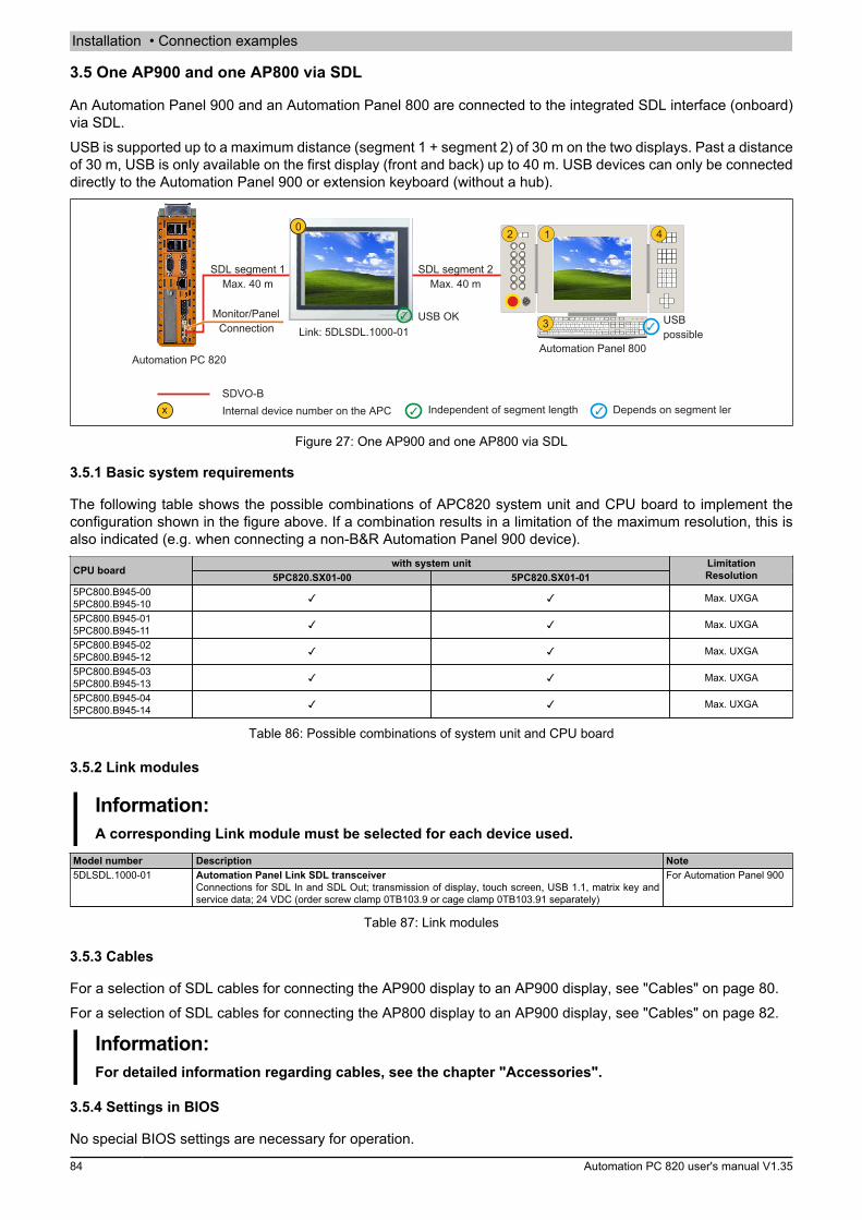
Installation • Connection examples
84 Automation PC 820 user's manual V1.35
3.5 One AP900 and one AP800 via SDL
An Automation Panel 900 and an Automation Panel 800 are connected to the integrated SDL interface (onboard)via SDL.USB is supported up to a maximum distance (segment 1 + segment 2) of 30 m on the two displays. Past a distanceof 30 m, USB is only available on the first display (front and back) up to 40 m. USB devices can only be connecteddirectly to the Automation Panel 900 or extension keyboard (without a hub).
USB OK
Automation PC 820
SDL segment 1Max. 40 m
Link: 5DLSDL.1000-01
SDL segment 2Max. 40 m
Automation Panel 800
USBpossible
SDVO-BInternal device number on the APC Independent of segment length Depends on segment length
Monitor/PanelConnection
Figure 27: One AP900 and one AP800 via SDL
3.5.1 Basic system requirements
The following table shows the possible combinations of APC820 system unit and CPU board to implement theconfiguration shown in the figure above. If a combination results in a limitation of the maximum resolution, this isalso indicated (e.g. when connecting a non-B&R Automation Panel 900 device).
with system unitCPU board 5PC820.SX01-00 5PC820.SX01-01LimitationResolution
5PC800.B945-005PC800.B945-10 ✓ ✓ Max. UXGA
5PC800.B945-015PC800.B945-11 ✓ ✓ Max. UXGA
5PC800.B945-025PC800.B945-12 ✓ ✓ Max. UXGA
5PC800.B945-035PC800.B945-13 ✓ ✓ Max. UXGA
5PC800.B945-045PC800.B945-14 ✓ ✓ Max. UXGA
Table 86: Possible combinations of system unit and CPU board
3.5.2 Link modules
Information:A corresponding Link module must be selected for each device used.
Model number Description Note5DLSDL.1000-01 Automation Panel Link SDL transceiver
Connections for SDL In and SDL Out; transmission of display, touch screen, USB 1.1, matrix key andservice data; 24 VDC (order screw clamp 0TB103.9 or cage clamp 0TB103.91 separately)
For Automation Panel 900
Table 87: Link modules
3.5.3 Cables
For a selection of SDL cables for connecting the AP900 display to an AP900 display, see "Cables" on page 80.For a selection of SDL cables for connecting the AP800 display to an AP900 display, see "Cables" on page 82.
Information:For detailed information regarding cables, see the chapter "Accessories".
3.5.4 Settings in BIOS
No special BIOS settings are necessary for operation.

Installation • Connection examples
Cha
pter
3In
stal
latio
n
Automation PC 820 user's manual V1.35 85
For detailed information, see the user's manual for the B&R Industrial PC being used.
Touch screen functionality
COM C must be enabled in BIOS in order to operate the panel touch screen connected to the monitor/panelinterface ("Advanced - Baseboard/Panel features - Legacy devices").
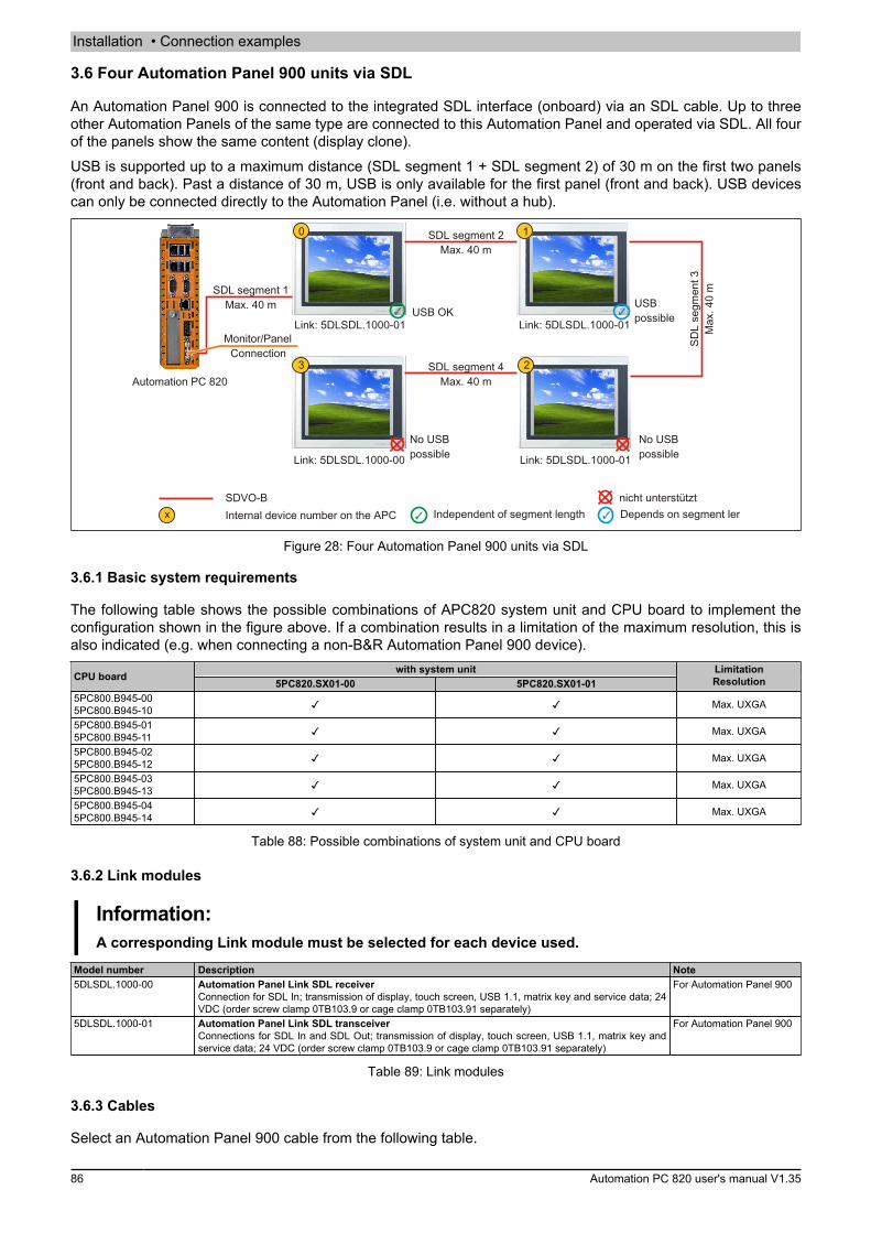
Installation • Connection examples
86 Automation PC 820 user's manual V1.35
3.6 Four Automation Panel 900 units via SDL
An Automation Panel 900 is connected to the integrated SDL interface (onboard) via an SDL cable. Up to threeother Automation Panels of the same type are connected to this Automation Panel and operated via SDL. All fourof the panels show the same content (display clone).USB is supported up to a maximum distance (SDL segment 1 + SDL segment 2) of 30 m on the first two panels(front and back). Past a distance of 30 m, USB is only available for the first panel (front and back). USB devicescan only be connected directly to the Automation Panel (i.e. without a hub).
Monitor/PanelConnection
Automation PC 820
SDL segment 1Max. 40 m
Link: 5DLSDL.1000-01
No USBpossible
Link: 5DLSDL.1000-01USB OK
Link: 5DLSDL.1000-01
Link: 5DLSDL.1000-00
SDL segment 2Max. 40 m
SDL
segm
ent 3
Max
. 40
m
SDL segment 4Max. 40 m
No USBpossible
USBpossible
SDVO-BInternal device number on the APC Independent of segment length Depends on segment length
nicht unterstützt
Figure 28: Four Automation Panel 900 units via SDL
3.6.1 Basic system requirements
The following table shows the possible combinations of APC820 system unit and CPU board to implement theconfiguration shown in the figure above. If a combination results in a limitation of the maximum resolution, this isalso indicated (e.g. when connecting a non-B&R Automation Panel 900 device).
with system unitCPU board 5PC820.SX01-00 5PC820.SX01-01LimitationResolution
5PC800.B945-005PC800.B945-10 ✓ ✓ Max. UXGA
5PC800.B945-015PC800.B945-11 ✓ ✓ Max. UXGA
5PC800.B945-025PC800.B945-12 ✓ ✓ Max. UXGA
5PC800.B945-035PC800.B945-13 ✓ ✓ Max. UXGA
5PC800.B945-045PC800.B945-14 ✓ ✓ Max. UXGA
Table 88: Possible combinations of system unit and CPU board
3.6.2 Link modules
Information:A corresponding Link module must be selected for each device used.
Model number Description Note5DLSDL.1000-00 Automation Panel Link SDL receiver
Connection for SDL In; transmission of display, touch screen, USB 1.1, matrix key and service data; 24VDC (order screw clamp 0TB103.9 or cage clamp 0TB103.91 separately)
For Automation Panel 900
5DLSDL.1000-01 Automation Panel Link SDL transceiverConnections for SDL In and SDL Out; transmission of display, touch screen, USB 1.1, matrix key andservice data; 24 VDC (order screw clamp 0TB103.9 or cage clamp 0TB103.91 separately)
For Automation Panel 900
Table 89: Link modules
3.6.3 Cables
Select an Automation Panel 900 cable from the following table.

Installation • Connection examples
Cha
pter
3In
stal
latio
n
Automation PC 820 user's manual V1.35 87
Model number Description Length5CASDL.0018-00 SDL cable, 1.8 m 1.8 m ±30 mm5CASDL.0050-00 SDL cable, 5 m 5 m ±30 mm5CASDL.0100-00 SDL cable, 10 m 10 m ±50 mm5CASDL.0150-00 SDL cable, 15 m 15 m ±100 mm5CASDL.0200-00 SDL cable, 20 m 20 m ±100 mm5CASDL.0250-00 SDL cable, 25 m 25 m ±100 mm5CASDL.0300-00 SDL cable, 30 m 30 m ±100 mm5CASDL.0018-03 SDL flex cable, 1.8 m 1.8 m ±20 mm5CASDL.0050-03 SDL flex cable, 5 m 5 m ±45 mm5CASDL.0100-03 SDL flex cable, 10 m 10 m ±90 mm5CASDL.0150-03 SDL flex cable, 15 m 15 m ±135 mm5CASDL.0200-03 SDL flex cable, 20 m 20 m ±180 mm5CASDL.0250-03 SDL flex cable, 25 m 25 m ±225 mm5CASDL.0300-03 SDL flex cable, 30 m 30 m ±270 mm5CASDL.0300-13 SDL flex cable with extender, 30 m 30 m ±280 mm5CASDL.0400-13 SDL flex cable with extender, 40 m 40 m ±380 mm5CASDL.0430-13 SDL flex cable with extender, 43 m 43 m ±410 mm5CASDL.0018-01 SDL cable with 45° male connector, 1.8 m 1.8 m ±30 mm5CASDL.0050-01 SDL cable with 45° male connector, 5 m 5 m ±50 mm5CASDL.0100-01 SDL cable with 45° male connector, 10 m 10 m ±100 mm5CASDL.0150-01 SDL cable with 45° male connector, 15 m 15 m ±100 mm
Table 90: Cables for SDL configurations
Information:Detailed technical data about cables can be found in the Automation Panel 900 user's manual. Thiscan be downloaded as a PDF file from the B&R website at www.br-automation.com.
3.6.3.1 Cable lengths and resolutions for SDL transmission
The following table lists the relationship between segment lengths and maximum resolution depending on the SDLcable being used:
ResolutionSDL cable
Segment length [m]VGA
640 x 480SVGA
800 x 600XGA
1024 x 768HD
1366 x 768SXGA
1280 x 1024UXGA
1600 x 1200FHD
1920 x 1080
1.85CASDL.0018-005CASDL.0018-015CASDL.0018-03
5CASDL.0018-005CASDL.0018-015CASDL.0018-03
5CASDL.0018-005CASDL.0018-015CASDL.0018-03
5CASDL.0018-005CASDL.0018-015CASDL.0018-03
5CASDL.0018-005CASDL.0018-015CASDL.0018-03
5CASDL.0018-005CASDL.0018-015CASDL.0018-03
5CASDL.0018-005CASDL.0018-015CASDL.0018-03
55CASDL.0050-005CASDL.0050-015CASDL.0050-03
5CASDL.0050-005CASDL.0050-015CASDL.0050-03
5CASDL.0050-005CASDL.0050-015CASDL.0050-03
5CASDL.0050-005CASDL.0050-015CASDL.0050-03
5CASDL.0050-005CASDL.0050-015CASDL.0050-03
5CASDL.0050-005CASDL.0050-015CASDL.0050-03
5CASDL.0050-005CASDL.0050-015CASDL.0050-03
105CASDL.0100-005CASDL.0100-015CASDL.0100-03
5CASDL.0100-005CASDL.0100-015CASDL.0100-03
5CASDL.0100-005CASDL.0100-015CASDL.0100-03
5CASDL.0100-005CASDL.0100-015CASDL.0100-03
5CASDL.0100-005CASDL.0100-015CASDL.0100-03
5CASDL.0100-005CASDL.0100-015CASDL.0100-03
5CASDL.0100-005CASDL.0100-015CASDL.0100-03
155CASDL.0150-005CASDL.0150-015CASDL.0150-03
5CASDL.0150-005CASDL.0150-015CASDL.0150-03
5CASDL.0150-005CASDL.0150-015CASDL.0150-03
5CASDL.0150-005CASDL.0150-015CASDL.0150-03
5CASDL.0150-005CASDL.0150-015CASDL.0150-03
---
--
5CASDL.0150-03
20 5CASDL.0200-005CASDL.0200-03
5CASDL.0200-005CASDL.0200-03
5CASDL.0200-005CASDL.0200-03
5CASDL.0200-005CASDL.0200-03
5CASDL.0200-005CASDL.0200-03
--
-5CASDL.0200-03
25 5CASDL.0250-005CASDL.0250-03
5CASDL.0250-005CASDL.0250-03
5CASDL.0250-005CASDL.0250-03
5CASDL.0250-005CASDL.0250-03
--
--
--
30 5CASDL.0300-005CASDL.0300-03
5CASDL.0300-005CASDL.0300-03
-5CASDL.0300-13
-5CASDL.0300-13
-5CASDL.0300-13
--
-5CASDL.0300-13
40 5CASDL.0400-13 5CASDL.0400-13 5CASDL.0400-13 5CASDL.0400-13 5CASDL.0400-13 - 5CASDL.0400-13
Table 91: Cable lengths and resolutions for SDL transmission
3.6.4 Settings in BIOS
No special BIOS settings are necessary for operation.For detailed information, see the user's manual for the B&R Industrial PC being used.
Touch screen functionality
COM C must be enabled in BIOS in order to operate the panel touch screen connected to the monitor/panelinterface ("Advanced - Baseboard/Panel features - Legacy devices").
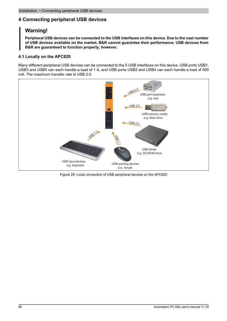
Installation • Connecting peripheral USB devices
88 Automation PC 820 user's manual V1.35
4 Connecting peripheral USB devices
Warning!Peripheral USB devices can be connected to the USB interfaces on this device. Due to the vast numberof USB devices available on the market, B&R cannot guarantee their performance. USB devices fromB&R are guaranteed to function properly, however.
4.1 Locally on the APC820
Many different peripheral USB devices can be connected to the 5 USB interfaces on this device. USB ports USB1,USB3 and USB5 can each handle a load of 1 A, and USB ports USB2 and USB4 can each handle a load of 500mA. The maximum transfer rate is USB 2.0.
USB 2.0
USB 2.0
USB memory mediae.g. flash drive
USB drivese.g. CD-ROM drive
USB pointing devicese.g. mouse
USB input devicese.g. keyboard
USB 1.1
USB 1.1
USB 2.0USB port expansion
e.g. hub
Figure 29: Local connection of USB peripheral devices on the APC820

Installation • Connecting peripheral USB devices
Cha
pter
3In
stal
latio
n
Automation PC 820 user's manual V1.35 89
4.2 Remote connection to Automation Panel 900 via DVI
Many different peripheral USB devices can be connected to the 2 or 3 USB interfaces on the Automation Panel900. These can each handle a load of 500 mA. The maximum transfer rate is USB 2.0.
Information:Only end devices (not hubs) can be connected to the Automation Panel 900.
USB 2.0
USB memory mediae.g. flash drive
USB drivese.g. CD-ROM drive
USB pointing devicese.g. mouse
USB input devicese.g. keyboard
USB 1.1
USB 1.1
DVI
USB 2.0
RS232
USB 2.0
Figure 30: Remote connection of USB peripheral devices on the APC900 via DVI
4.3 Remote connection to Automation Panel 800 / 900 via SDL
Many different peripheral USB devices can be connected to the 2 or 3 USB interfaces on Automation Panel 900or the USB interfaces on Automation Panel 800 devices. These can each handle a load of 500 mA. The maximumtransfer rate is USB 1.1.
Information:Only end devices (no hubs) can be connected to the Automation Panel 800 / 900.
SDL (USB 1.1)
USB 1.1
USB memory mediae.g. flash drive
USB drivese.g. CD-ROM drive
USB pointing devicese.g. mouse
USB input devicese.g. keyboard
USB 1.1
USB 1.1 USB 1.1
Figure 31: Remote connection of USB peripheral devices on the APC800/900 via SDL
Installation • Known problems / issues
90 Automation PC 820 user's manual V1.35
5 Known problems / issues
The following issues for the APC820 devices are known:
• Using two different types of CompactFlash cards can cause problems in Automation PCs and Panel PCs.This can result in one of the two cards not being detected during system startup. This is caused by varyingstartup speeds. CompactFlash cards with older technology require significantly more time during systemstartup than CompactFlash cards with newer technology. This behavior occurs near the limits of the timeframe provided for startup. This can occur because the startup time for the CompactFlash cards fluctuatesdue to the variance of the components being used. Depending on the CompactFlash cards being used,this error may occur never, sometimes or always.
• During daisy chain operation of multiple AP800/AP900 devices via SDL, it's possible that the touch con-troller status shows a red "X" in the Control Center applet for the touch screen driver when the touch con-troller is detected. The functionality of the touch system is not affected by this. This can be avoided bysetting a panel locking time of 50 ms. The panel locking time can be configured with the B&R Key Editor.
• HD resolution (1366x768) is not completely supported by VBIOS, which causes display errors after POST.The image flickers and is shifted down a line. BIOS POST and BIOS Setup are still displayed correctly,however. This effect occurs when using operating systems for which no driver is available (e.g. MS-DOS)or before the operating system's graphics driver is started (e.g. Windows XP boot logo). HD resolution isdisplayed corrected again when Windows XP or Windows 7 is booted properly with an installed graphicsdriver.

Software • BIOS options
Cha
pter
4So
ftwar
e
Automation PC 820 user's manual V1.35 91
Chapter 4 • Software
1 BIOS options
Information:The following diagrams, BIOS menu items and their descriptions refer to BIOS version 1.18. It is there-fore possible that these diagrams and BIOS descriptions do not correspond with the installed BIOSversion.
1.1 General information
BIOS is an acronym for "Basic Input/Output System". It is the most basic standardized interface between theuser and the system (hardware). The BIOS system used in this B&R Industrial PC was developed by AmericanMegatrends, Inc.The BIOS Setup utility can be used to modify basic system configuration settings. These settings are stored inCMOS and EEPROM memory (as a backup).CMOS data is buffered by a battery (if present) and remains stored on the B&R Industrial PC even when the poweris turned off (no 24 VDC supply).
1.2 BIOS setup and boot procedure
BIOS is activated immediately when switching on the power supply or pressing the power button on the B&RIndustrial PC. The system checks if the setup data from EEPROM memory is "OK". If the data is "OK", then it istransferred to CMOS. If the data is "Not OK", then the CMOS data is checked to see whether it is valid. An errormessage is output if the CMOS data contains errors, and the boot procedure can be continued by pressing <F1>.To prevent an error message from appearing on each restart, launch the BIOS Setup utility by pressing <F2> andresave the settings.BIOS reads the system configuration information, checks and configures the system with the Power-On Self-Test(POST).When these "preliminaries" are finished, BIOS looks for an operating system on the available data storage devices(hard drive, floppy drive, etc.). BIOS then launches the operating system and hands over to it the control of systemoperations.To enter BIOS Setup, press the <Del> key after the USB controller has been initialized as soon as the followingmessage appears on the screen (during POST): "Press DEL to run SETUP".
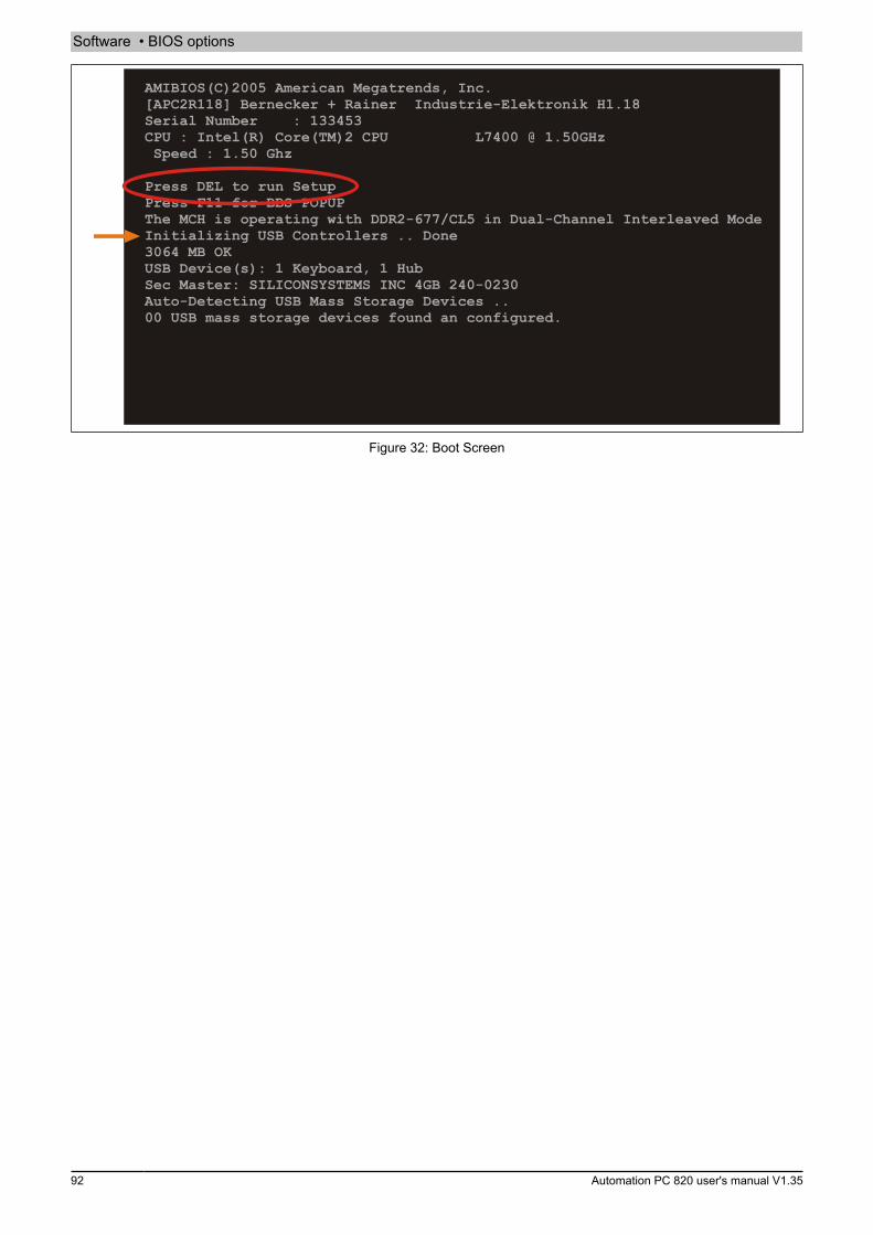
Software • BIOS options
92 Automation PC 820 user's manual V1.35
AMIBIOS(C)2005 American Megatrends, Inc.[APC2R118] Bernecker + Rainer Industrie-Elektronik H1.18Serial Number : 133453CPU : Intel(R) Core(TM)2 CPU L7400 @ 1.50GHz Speed : 1.50 Ghz
Press DEL to run SetupPress F11 for BBS POPUPThe MCH is operating with DDR2-677/CL5 in Dual-Channel Interleaved ModeInitializing USB Controllers .. Done3064 MB OKUSB Device(s): 1 Keyboard, 1 HubSec Master: SILICONSYSTEMS INC 4GB 240-0230Auto-Detecting USB Mass Storage Devices ..00 USB mass storage devices found an configured.
Figure 32: Boot Screen
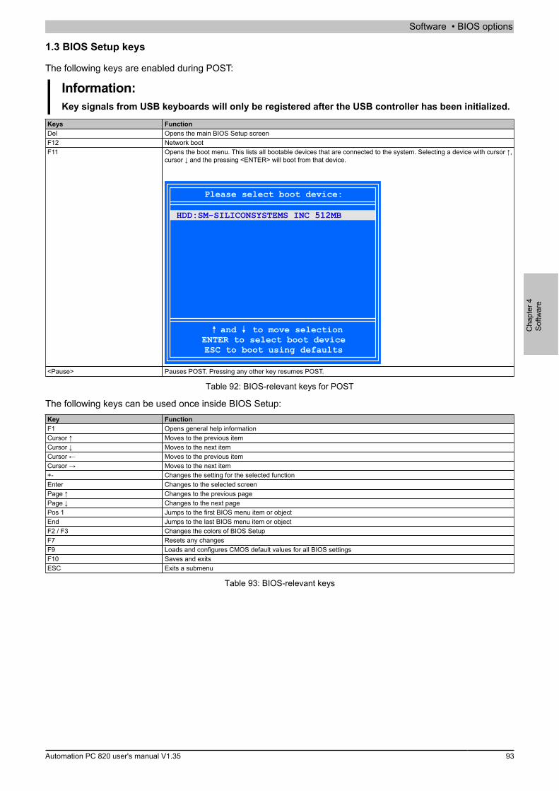
Software • BIOS options
Cha
pter
4So
ftwar
e
Automation PC 820 user's manual V1.35 93
1.3 BIOS Setup keys
The following keys are enabled during POST:
Information:Key signals from USB keyboards will only be registered after the USB controller has been initialized.
Keys FunctionDel Opens the main BIOS Setup screenF12 Network bootF11 Opens the boot menu. This lists all bootable devices that are connected to the system. Selecting a device with cursor ↑,
cursor ↓ and the pressing <ENTER> will boot from that device.
Please select boot device:
HDD:SM-SILICONSYSTEMS INC 512MB
and to move selectionENTER to select boot deviceESC to boot using defaults
<Pause> Pauses POST. Pressing any other key resumes POST.
Table 92: BIOS-relevant keys for POST
The following keys can be used once inside BIOS Setup:Key FunctionF1 Opens general help informationCursor ↑ Moves to the previous itemCursor ↓ Moves to the next itemCursor ← Moves to the previous itemCursor → Moves to the next item+- Changes the setting for the selected functionEnter Changes to the selected screenPage ↑ Changes to the previous pagePage ↓ Changes to the next pagePos 1 Jumps to the first BIOS menu item or objectEnd Jumps to the last BIOS menu item or objectF2 / F3 Changes the colors of BIOS SetupF7 Resets any changesF9 Loads and configures CMOS default values for all BIOS settingsF10 Saves and exitsESC Exits a submenu
Table 93: BIOS-relevant keys
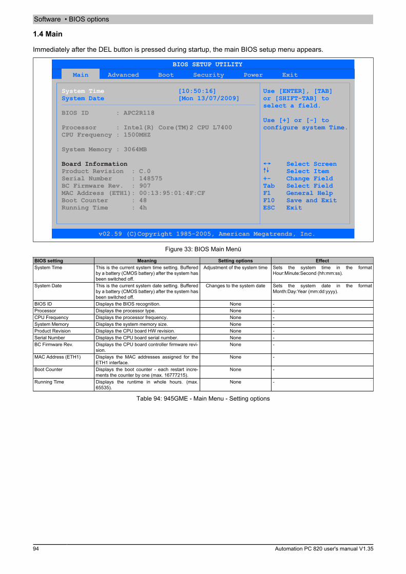
Software • BIOS options
94 Automation PC 820 user's manual V1.35
1.4 Main
Immediately after the DEL button is pressed during startup, the main BIOS setup menu appears.
Main Advanced Boot Security Power Exit
System Time
Board Information
[10:50:16] Use [ENTER], [TAB]System Date [Mon 13/07/2009] or [SHIFT-TAB] to select a field.
Use [+] or [-] toconfigure system Time.
Select Screen Select Item
+- Change FieldTab Select FieldF1 General Help
F10 Save and ExitESC Exit
BIOS ID : APC2R118
CPU Frequency : 1500MHZ
System Memory : 3064MB
Product Revision : C.0Serial Number : 148575BC Firmware Rev. : 907 MAC Address (ETH1): 00:13:95:01:4F:CFBoot Counter : 48 Running Time : 4h
Processor : Intel(R) Core(TM)2 CPU L7400
BIOS SETUP UTILITY
v02.59 (C)Copyright 1985-2005, American Megatrends, Inc.
Figure 33: BIOS Main Menü
BIOS setting Meaning Setting options EffectSystem Time This is the current system time setting. Buffered
by a battery (CMOS battery) after the system hasbeen switched off.
Adjustment of the system time Sets the system time in the formatHour:Minute:Second (hh:mm:ss).
System Date This is the current system date setting. Bufferedby a battery (CMOS battery) after the system hasbeen switched off.
Changes to the system date Sets the system date in the formatMonth:Day:Year (mm:dd:yyyy).
BIOS ID Displays the BIOS recognition. None -Processor Displays the processor type. None -CPU Frequency Displays the processor frequency. None -System Memory Displays the system memory size. None -Product Revision Displays the CPU board HW revision. None -Serial Number Displays the CPU board serial number. None -BC Firmware Rev. Displays the CPU board controller firmware revi-
sion.None -
MAC Address (ETH1) Displays the MAC addresses assigned for theETH1 interface.
None -
Boot Counter Displays the boot counter - each restart incre-ments the counter by one (max. 16777215).
None -
Running Time Displays the runtime in whole hours. (max.65535).
None -
Table 94: 945GME - Main Menu - Setting options
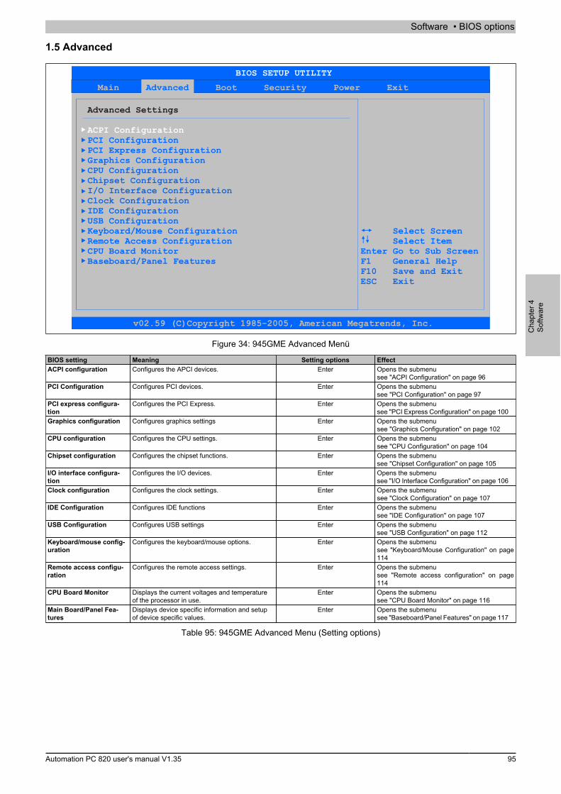
Software • BIOS options
Cha
pter
4So
ftwar
e
Automation PC 820 user's manual V1.35 95
1.5 Advanced
Main Boot Security Power ExitAdvanced
Advanced Settings
ACPI ConfigurationPCI ConfigurationPCI Express ConfigurationGraphics ConfigurationCPU ConfigurationChipset ConfigurationI/O Interface ConfigurationClock ConfigurationIDE ConfigurationUSB ConfigurationKeyboard/Mouse Configuration Remote Access Configuration CPU Board Monitor Baseboard/Panel Features
Select ScreenSelect Item
Enter Go to Sub ScreenF1 General HelpF10 Save and ExitESC Exit
BIOS SETUP UTILITY
v02.59 (C)Copyright 1985-2005, American Megatrends, Inc.
Figure 34: 945GME Advanced Menü
BIOS setting Meaning Setting options EffectACPI configuration Configures the APCI devices. Enter Opens the submenu
see "ACPI Configuration" on page 96PCI Configuration Configures PCI devices. Enter Opens the submenu
see "PCI Configuration" on page 97PCI express configura-tion
Configures the PCI Express. Enter Opens the submenusee "PCI Express Configuration" on page 100
Graphics configuration Configures graphics settings Enter Opens the submenusee "Graphics Configuration" on page 102
CPU configuration Configures the CPU settings. Enter Opens the submenusee "CPU Configuration" on page 104
Chipset configuration Configures the chipset functions. Enter Opens the submenusee "Chipset Configuration" on page 105
I/O interface configura-tion
Configures the I/O devices. Enter Opens the submenusee "I/O Interface Configuration" on page 106
Clock configuration Configures the clock settings. Enter Opens the submenusee "Clock Configuration" on page 107
IDE Configuration Configures IDE functions Enter Opens the submenusee "IDE Configuration" on page 107
USB Configuration Configures USB settings Enter Opens the submenusee "USB Configuration" on page 112
Keyboard/mouse config-uration
Configures the keyboard/mouse options. Enter Opens the submenusee "Keyboard/Mouse Configuration" on page114
Remote access configu-ration
Configures the remote access settings. Enter Opens the submenusee "Remote access configuration" on page114
CPU Board Monitor Displays the current voltages and temperatureof the processor in use.
Enter Opens the submenusee "CPU Board Monitor" on page 116
Main Board/Panel Fea-tures
Displays device specific information and setupof device specific values.
Enter Opens the submenusee "Baseboard/Panel Features" on page 117
Table 95: 945GME Advanced Menu (Setting options)

Software • BIOS options
96 Automation PC 820 user's manual V1.35
1.5.1 ACPI Configuration
Advanced
ACPI Settings Enable / Disable
Cooling Trip Point [Disabled]
ACPI support forOperating System.
ACPI Version Features [ACPI v2.0] ENABLE: If OSACPI APIC support [Enabled] supports ACPI.Suspend mode [S1 (POS)]USB Device Wakeup from S3/S4 [Disabled] DISABLE: If OS does not supportActive Cooling Trip Point [Disabled] ACPI.PassiveCritical Trip Point [105°C]
Select Screen Select Item +- Change Option F1 General Help F10 Save and Exit ESC Exit
ACPI Aware O/S [Yes]
BIOS SETUP UTILITY
v02.59 (C)Copyright 1985-2005, American Megatrends, Inc.
Figure 35: 945GME Advanced ACPI Configuration
BIOS setting Meaning Setting options EffectYes The operating system supports ACPI.ACPI Aware O/S This function determines if the operating system
supports the ACPI function (Advanced Configu-ration and Power Interface).
No The operating system does not support ACPI.
ACPI v1.0 ACPI functions in accordance with v1.0.ACPI v2.0 ACPI functions in accordance with v2.0.
ACPI Version Features Option for setting the power option specificationsto be supported. The ACPI functions must be sup-ported by the drivers and operating systems be-ing used.
ACPI v3.0 ACPI functions in accordance with v3.0.
Enabled Enables this function.ACPI APIC support This option controls the support of the advancedprogrammable interrupt controller in the proces-sor.
Disabled Disables this function.
S1 (POS) Sets S1 as Suspend mode. Only a few func-tions are disabled and are available again at thetouch of a button
Suspend mode Selects the ACPI status to be used when Sus-pend Mode is enabled.
S3 (STR) Sets S3 as Suspend Mode. The current stateof the operating system is written to the RAM,which is then supplied solely with power.
Enabled Enables this function.USB Device Wakeup fromS3/S4
This options makes it possible for activity on aconnected USB device to wake the system upfrom the S3/S4 standby mode.
Disabled Disables this function.
Disabled Disables this function.Active Cooling Trip Point With this function, an optional CPU fan above theoperating system can be set to turn on when theCPU reaches the set temperature.
50°C, 60°C, 70°C, 80°C, 90°C Temperature setting for the active cooling trippoint. Can be set in 10 degree increments.
Disabled Disables this function.Passive Cooling Trip Point With this function, a temperature can be set atwhich the CPU automatically reduces its speed. 50°C, 60°C, 70°C, 80°C, 90°C Temperature setting for the passive cooling trip
point. Can be set in 10 degree increments.Critical Trip Point With this function, a temperature can be set at
which the operating system automatically shutsitself down.
80°C, 85°C, 90°C, 95°C,100°C, 105°C, 110°C
Temperature setting for the critical trip point.Can be set in 5 degree increments.
Table 96: 945GME - Advanced ACPI configuration - Setting options
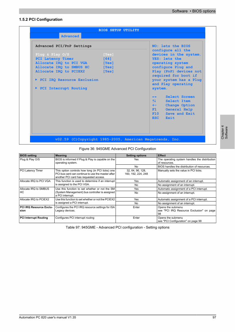
Software • BIOS options
Cha
pter
4So
ftwar
e
Automation PC 820 user's manual V1.35 97
1.5.2 PCI Configuration
Advanced
Advanced PCI/PnP Settings NO: lets the BIOS configure all the
devices in the system.PCI Latency Timer [64] YES: lets theAllocate IRQ to PCI VGA [Yes] operating systemAllocate IRQ to SMBUS HC [Yes] configure Plug andAllocate IRQ to PCIEX2 [Yes] Play (PnP) devices not
required for boot ifPCI IRQ Resource Exclusion your system has a Plug
and Play operatingPCI Interrupt Routing system.
Select Screen Select Item +- Change Option F1 General Help
F10 Save and Exit ESC Exit
Plug & Play O/S [Yes]
BIOS SETUP UTILITY
v02.59 (C)Copyright 1985-2005, American Megatrends, Inc.
Figure 36: 945GME Advanced PCI Configuration
BIOS setting Meaning Setting options EffectYes The operating system handles the distribution
of resources.Plug & Play O/S BIOS is informed if Plug & Play is capable on the
operating system.No BIOS handles the distribution of resources.
PCI Latency Timer This option controls how long (in PCI ticks) onePCI bus card can continue to use the master afteranother PCI card has requested access.
32, 64, 96, 128,160, 192, 224, 248
Manually sets the value in PCI ticks.
Yes Automatic assignment of an interrupt.Allocate IRQ to PCI VGA This function is used to determine if an interruptis assigned to the PCI VGA. No No assignment of an interrupt.
Yes Automatic assignment of a PCI interrupt.Allocate IRQ to SMBUSHC
Use this function to set whether or not the SM(System Management) bus controller is assigneda PCI interrupt.
No No assignment of an interrupt.
Yes Automatic assignment of a PCI interrupt.Allocate IRQ to PCIEX2 Use this function to set whether or not the PCIEX2is assigned a PCI interrupt. No No assignment of an interrupt.
PCI IRQ Resource Exclu-sion
Configures the PCI IRQ resource settings for ISALegacy devices.
Enter Opens the submenusee "PCI IRQ Resource Exclusion" on page98
PCI Interrupt Routing Configures PCI interrupt routing Enter Opens the submenusee "PCI Configuration" on page 99
Table 97: 945GME - Advanced PCI configuration - Setting options
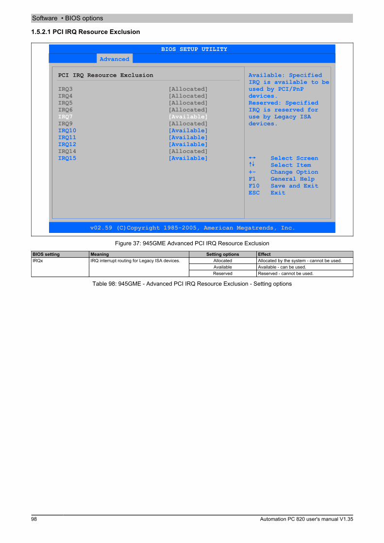
Software • BIOS options
98 Automation PC 820 user's manual V1.35
1.5.2.1 PCI IRQ Resource Exclusion
Advanced
PCI IRQ Resource Exclusion Available: Specified IRQ is available to be
used by PCI/PnPdevices.Reserved: Specified
devices.
IRQ is reserved for use by Legacy ISA
IRQ10 [Available]IRQ11 [Available]IRQ12 [Available]
IRQ15 [Available] Select Screen Select Item +- Change Option F1 General Help
F10 Save and Exit ESC Exit
IRQ3 [Allocated] IRQ4 [Allocated] IRQ5 [Allocated]IRQ6 [Allocated]
IRQ9 [Allocated]
IRQ14 [Allocated]
IRQ7 [Available]
BIOS SETUP UTILITY
v02.59 (C)Copyright 1985-2005, American Megatrends, Inc.
Figure 37: 945GME Advanced PCI IRQ Resource Exclusion
BIOS setting Meaning Setting options EffectAllocated Allocated by the system - cannot be used.Available Available - can be used.
IRQx IRQ interrupt routing for Legacy ISA devices.
Reserved Reserved - cannot be used.
Table 98: 945GME - Advanced PCI IRQ Resource Exclusion - Setting options

Software • BIOS options
Cha
pter
4So
ftwar
e
Automation PC 820 user's manual V1.35 99
1.5.2.2 PCI Configuration
Advanced
PCI Interrupt Routing
PCIEXn : PCI Express Root Port n INTn : External PCI Bus INTn LinePATA : Parallel ATA in Enhanced/Native ModeSATA : Serial ATA in Enhanced/Native ModeSMB : System Management Bus Controller
Select fixed IRQ for set AUTO to let the
BIOS and OS route anPIRQ B (PCIEX1,ETH1) [Auto] IRQ to this line.PIRQ C (PCIEX2,IF-Slot) [7]PIRQ D (SATA,UHCI1,SMB,PCIEX3) [Auto] Make sure that thePIRQ E (INTD,PATA,UHCI3) [Auto] selected IRQ is notPIRQ F (INTA,Powerlink) [5] assigned to legacy IO.PIRQ G (INTB,CAN,Timer) [6] PIRQ H (INTC,UHCI0,EHCI) [Auto]
1st Exclusive PCI [5]2nd Exclusive PCI [6]3rd Exclusive PCI [7]
Select Screen Select Item
+- Change Option F1 General Help F10 Save and Exit
ESC Exit
PIRQ A (VGA,PCIEX0,ETH2,UHCI2) [Auto]
BIOS SETUP UTILITY
v02.59 (C)Copyright 1985-2005, American Megatrends, Inc.
Figure 38: 945GME Advanced PCI Interrupt Routing
BIOS setting Meaning Setting options EffectAuto Automatic assignment by the BIOS and operat-
ing system.PIRQ A(VGA, PCIEX0, ETH2,UHCI2)
Option for setting the PIRQ A.
5,6,7,9,10.12 Manual assignmentAuto Automatic assignment by the BIOS and operat-
ing system.PIRQ B(PCIEX1, ETH1)
Option for setting the PIRQ B.
5,6,7,9,10.12 Manual assignmentAuto Automatic assignment by the BIOS and operat-
ing system.PIRQ C(PCIEX2, IF slot)
Option for setting the PIRQ C.
5,6,7,9,10.12 Manual assignmentAuto Automatic assignment by the BIOS and operat-
ing system.PIRQ D(SATA, UHCI1, SMB,PCIEX3)
Option for setting the PIRQ D.
5,6,7,9,10.12 Manual assignmentAuto Automatic assignment by the BIOS and oper-
ating system.PIRQ E(INTD, PATA, UHCI3)
Option for setting the PIRQ E.
5,6,7,9,10.12 Manual assignmentAuto Automatic assignment by the BIOS and operat-
ing system.PIRQ F(INTA, POWERLINK)
Option for setting the PIRQ F.
5,6,7,9,10.12 Manual assignmentAuto Automatic assignment by the BIOS and operat-
ing system.PIRQ G(INTB, CAN, Timer)
Option for setting the PIRQ G.
5,6,7,9,10.12 Manual assignmentAuto Automatic assignment by the BIOS and operat-
ing system.PIRQ H(INTC, UHCI0, EHCI)
Option for setting the PIRQ H.
5,6,7,9,10.12 Manual assignmentNone No interrupt is assigned.1st Exclusive PCI With this option you can determine if the IRQ as-
signed to the PIRQ x is handled exclusively (noIRQ sharing).
Information:Is only displayed if a PIRQ is manuallyset (e.g. 5).
x Assigns the PIRQ as 1st exclusive PCI IRQ.
Table 99: 945GME - Advanced PCI Interrupt Routing - Setting options
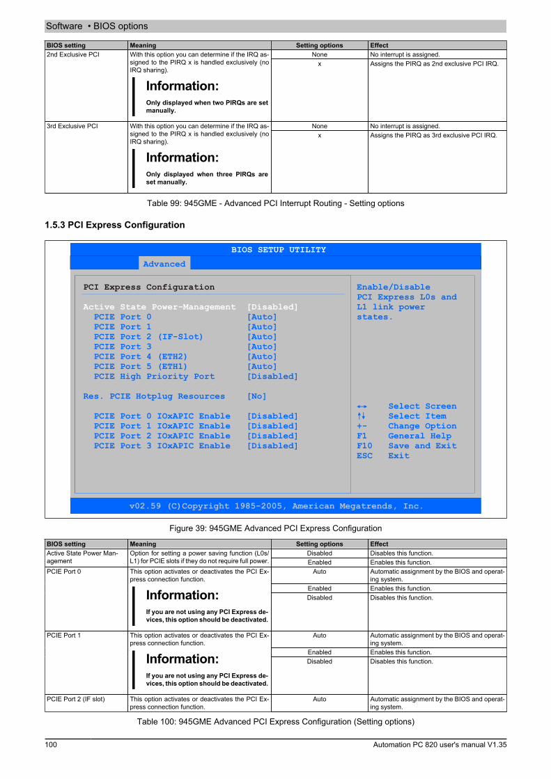
Software • BIOS options
100 Automation PC 820 user's manual V1.35
BIOS setting Meaning Setting options EffectNone No interrupt is assigned.2nd Exclusive PCI With this option you can determine if the IRQ as-
signed to the PIRQ x is handled exclusively (noIRQ sharing).
Information:Only displayed when two PIRQs are setmanually.
x Assigns the PIRQ as 2nd exclusive PCI IRQ.
None No interrupt is assigned.3rd Exclusive PCI With this option you can determine if the IRQ as-signed to the PIRQ x is handled exclusively (noIRQ sharing).
Information:Only displayed when three PIRQs areset manually.
x Assigns the PIRQ as 3rd exclusive PCI IRQ.
Table 99: 945GME - Advanced PCI Interrupt Routing - Setting options
1.5.3 PCI Express Configuration
Advanced
PCI Express Configuration Enable/Disable PCI Express L0s and
L1 link power PCIE Port 0 [Auto] states.
[No]
PCIE Port 1 [Auto] PCIE Port 2 (IF-Slot) [Auto] PCIE Port 3 [Auto] PCIE Port 4 (ETH2) [Auto] PCIE Port 5 (ETH1) [Auto] PCIE High Priority Port [Disabled]
Res. PCIE Hotplug Resources Select Screen
PCIE Port 0 IOxAPIC Enable [Disabled] Select ItemPCIE Port 1 IOxAPIC Enable [Disabled] +- Change Option
PCIE Port 2 IOxAPIC Enable [Disabled] F1 General Help PCIE Port 3 IOxAPIC Enable [Disabled] F10 Save and Exit ESC Exit
Active State Power-Management [Disabled]
BIOS SETUP UTILITY
v02.59 (C)Copyright 1985-2005, American Megatrends, Inc.
Figure 39: 945GME Advanced PCI Express Configuration
BIOS setting Meaning Setting options EffectDisabled Disables this function.Active State Power Man-
agementOption for setting a power saving function (L0s/L1) for PCIE slots if they do not require full power. Enabled Enables this function.
Auto Automatic assignment by the BIOS and operat-ing system.
Enabled Enables this function.
PCIE Port 0 This option activates or deactivates the PCI Ex-press connection function.
Information:If you are not using any PCI Express de-vices, this option should be deactivated.
Disabled Disables this function.
Auto Automatic assignment by the BIOS and operat-ing system.
Enabled Enables this function.
PCIE Port 1 This option activates or deactivates the PCI Ex-press connection function.
Information:If you are not using any PCI Express de-vices, this option should be deactivated.
Disabled Disables this function.
PCIE Port 2 (IF slot) This option activates or deactivates the PCI Ex-press connection function.
Auto Automatic assignment by the BIOS and operat-ing system.
Table 100: 945GME Advanced PCI Express Configuration (Setting options)

Software • BIOS options
Cha
pter
4So
ftwar
e
Automation PC 820 user's manual V1.35 101
BIOS setting Meaning Setting options EffectEnabled Enables this function.
Information:If you are not using any PCI Express de-vices, this option should be deactivated.
Disabled Disables this function.
Auto Automatic assignment by the BIOS and oper-ating system.
Enabled Enables this function.
PCIE Port 3 This option activates or deactivates the PCI Ex-press connection function.
Information:If you are not using any PCI Express de-vices, this option should be deactivated.
Disabled Disables this function.
Auto Automatic assignment by the BIOS and operat-ing system.
Enabled Enables this function.
PCIE Port 4 (ETH2) This option activates or deactivates the PCI Ex-press connection function.
Information:If you are not using any PCI Express de-vices, this option should be deactivated.
Disabled Enables this function.
Auto Automatic assignment by the BIOS and operat-ing system.
Enabled Enables this function.
PCIE Port 5 (ETH1) This option activates or deactivates the PCI Ex-press connection function.
Information:If you are not using any PCI Expressdevices, this option should be deacti-vated.
Disabled Disables this function.
Disabled Disables this function.Port 0 Activates Port 0 as priority port.Port 1 Activates Port 1 as priority port.Port 2 Activates Port 2 as priority port.Port 3 Activates Port 3 as priority port.ETH2 Activates ETH2 as priority port.
PCIE High Priority Port This option activates or deactivates the priorityport for PCIE.
ETH1 Activates ETH1 as priority port.No Resource is not reserved.Res. PCIE Hot Plugging
ResourceThis option can be used to reserve an I/O andmemory resource for a free PCIE port. A PCIEport must be set to enabled and resources mustbe reserved to support ExpressCard hot-plug-ging on a port.
Yes Resource is reserved.
Disabled Disables this function.PCIE Port 0 IOxAPIC En-able
This option is used to enable or disable theAPIC (Advanced Programmable Interrupt Con-troller) on the PCIE port 0. The IRQ resourcesavailable to the system are expanded when theAPIC mode is enabled.
Enabled Disables this function.
Disabled Disables this function.PCIE Port 1IOxAPIC enable
This option is used to enable or disable theAPIC (Advanced Programmable Interrupt Con-troller) on the PCIE port 1. The IRQ resourcesavailable to the system are expanded when theAPIC mode is enabled.
Enabled Disables this function.
Disabled Disables this function.PCIE Port 2IOxAPIC enable
This option is used to enable or disable theAPIC (Advanced Programmable Interrupt Con-troller) on the PCIE port 2. The IRQ resourcesavailable to the system are expanded when theAPIC mode is enabled.
Enabled Disables this function.
Disabled Disables this function.PCIE Port 3IOxAPIC enable
This option is used to enable or disable theAPIC (Advanced Programmable Interrupt Con-troller) on the PCIE port 3. The IRQ resourcesavailable to the system are expanded when theAPIC mode is enabled.
Enabled Disables this function.
Table 100: 945GME Advanced PCI Express Configuration (Setting options)
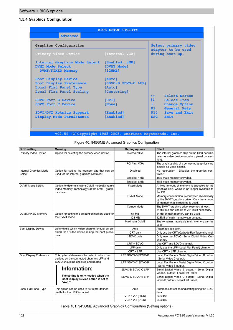
Software • BIOS options
102 Automation PC 820 user's manual V1.35
1.5.4 Graphics Configuration
Advanced
Graphics Configuration Select primary video adapter to be used
during boot up.
Internal Graphics Mode Select [Enabled, 8MB]DVMT Mode Select DVMT/FIXED Memory [128MB]
Boot Display Device
Local Flat Panel Type
SDVO Port B Device [DVI]
[DVMT Mode]
[Auto]Boot Display Preference [SDVO-B SDVO-C LFP]
[Auto]Local Flat Panel Scaling [Centering]
Select ScreenSelect Item
SDVO Port C Device [None] +- Change Option F1 General HelpSDVO/DVI Hotplug Support [Enabled] F10 Save and ExitDisplay Mode Persistence [Enabled] ESC Exit
Primary Video Device [Internal VGA]
BIOS SETUP UTILITY
v02.59 (C)Copyright 1985-2005, American Megatrends, Inc.
Figure 40: 945GME Advanced Graphics Configuration
BIOS setting Meaning Setting options EffectInternal VGA The internal graphics chip on the CPU board is
used as video device (monitor / panel connec-tion).
Primary Video Device Option for selecting the primary video device.
PCI / Int. VGA The graphics chip of a connected graphics cardis used as video device.
Disabled No reservation - Disables the graphics con-troller.
Enabled, 1MB 1MB main memory provided.
Internal Graphics ModeSelect
Option for setting the memory size that can beused for the internal graphics controller.
Enabled, 8MB 8MB main memory provided.Fixed Mode A fixed amount of memory is allocated to the
graphics chip, which is no longer available tothe PC.
DVMT Mode Memory consumption is controlled dynamicallyby the DVMT graphics driver. Only the amountof memory that is required is used.
DVMT Mode Select Option for determining the DVMT mode (DynamicVideo Memory Technology) of the DVMT graph-ics driver.
Combo Mode The DVMT graphics driver reserves at least64MB, but can use up to 224MB if necessary.
64 MB 64MB of main memory can be used.128 MB 128MB of main memory can be used.
DVMT/FIXED Memory Option for setting the amount of memory used forthe DVMT mode.
Maximum DVMT The remaining available main memory can beused.
Auto Automatic selection.CRT only Only use the CRT (Cathode Ray Tube) channel.
SDVO only Only use the SDVO (Serial Digital Video Out)channel.
CRT + SDVO Use CRT and SDVO channel.LFP only Only use the LFP (Local Flat Panel) channel.
Boot Display Device Determines which video channel should be en-abled for a video device during the boot proce-dure.
CRT + LFP Use CRT + LFP channel.LFP SDVO-B SDVO-C Local Flat Panel - Serial Digital Video B output
- Serial Video C output.LFP SDVO-C SDVO-B Local Flat Panel - Serial Digital Video C output
- Serial Video B output.SDVO-B SDVO-C LFP Serial Digital Video B output - Serial Digital
Video C output - Local Flat Panel.
Boot Display Preference This option determines the order in which thedevices on the connected channels LFP andSDVO should be checked and booted.
Information:The setting is only needed when theBoot Display Device option is set to"Auto".
SDVO-C SDVO-B LFP Serial Digital Video C output - Serial DigitalVideo B output - Local Flat Panel.
Auto Automatic detection and setting using the EDIDdata.
VGA 1x18 (002h) 640x480
Local Flat Panel Type This option can be used to set a pre-definedprofile for the LVDS channel.
VGA 1x18 (013h) 640x480
Table 101: 945GME Advanced Graphics Configuration (Setting options)
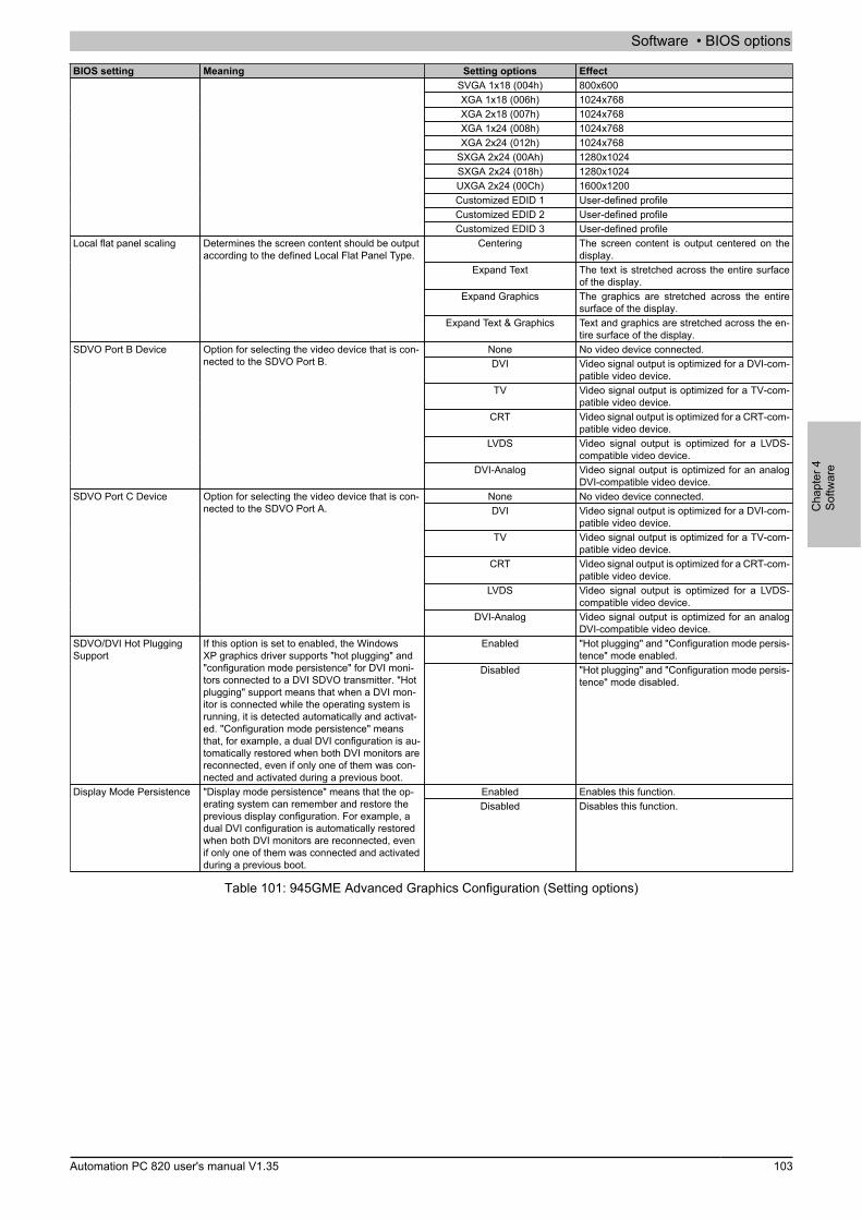
Software • BIOS options
Cha
pter
4So
ftwar
e
Automation PC 820 user's manual V1.35 103
BIOS setting Meaning Setting options EffectSVGA 1x18 (004h) 800x600XGA 1x18 (006h) 1024x768XGA 2x18 (007h) 1024x768XGA 1x24 (008h) 1024x768XGA 2x24 (012h) 1024x768
SXGA 2x24 (00Ah) 1280x1024SXGA 2x24 (018h) 1280x1024UXGA 2x24 (00Ch) 1600x1200Customized EDID 1 User-defined profileCustomized EDID 2 User-defined profileCustomized EDID 3 User-defined profile
Centering The screen content is output centered on thedisplay.
Expand Text The text is stretched across the entire surfaceof the display.
Expand Graphics The graphics are stretched across the entiresurface of the display.
Local flat panel scaling Determines the screen content should be outputaccording to the defined Local Flat Panel Type.
Expand Text & Graphics Text and graphics are stretched across the en-tire surface of the display.
None No video device connected.DVI Video signal output is optimized for a DVI-com-
patible video device.TV Video signal output is optimized for a TV-com-
patible video device.CRT Video signal output is optimized for a CRT-com-
patible video device.LVDS Video signal output is optimized for a LVDS-
compatible video device.
SDVO Port B Device Option for selecting the video device that is con-nected to the SDVO Port B.
DVI-Analog Video signal output is optimized for an analogDVI-compatible video device.
None No video device connected.DVI Video signal output is optimized for a DVI-com-
patible video device.TV Video signal output is optimized for a TV-com-
patible video device.CRT Video signal output is optimized for a CRT-com-
patible video device.LVDS Video signal output is optimized for a LVDS-
compatible video device.
SDVO Port C Device Option for selecting the video device that is con-nected to the SDVO Port A.
DVI-Analog Video signal output is optimized for an analogDVI-compatible video device.
Enabled "Hot plugging" and "Configuration mode persis-tence" mode enabled.
SDVO/DVI Hot PluggingSupport
If this option is set to enabled, the WindowsXP graphics driver supports "hot plugging" and"configuration mode persistence" for DVI moni-tors connected to a DVI SDVO transmitter. "Hotplugging" support means that when a DVI mon-itor is connected while the operating system isrunning, it is detected automatically and activat-ed. "Configuration mode persistence" meansthat, for example, a dual DVI configuration is au-tomatically restored when both DVI monitors arereconnected, even if only one of them was con-nected and activated during a previous boot.
Disabled "Hot plugging" and "Configuration mode persis-tence" mode disabled.
Enabled Enables this function.Display Mode Persistence "Display mode persistence" means that the op-erating system can remember and restore theprevious display configuration. For example, adual DVI configuration is automatically restoredwhen both DVI monitors are reconnected, evenif only one of them was connected and activatedduring a previous boot.
Disabled Disables this function.
Table 101: 945GME Advanced Graphics Configuration (Setting options)

Software • BIOS options
104 Automation PC 820 user's manual V1.35
1.5.5 CPU Configuration
Advanced
Configure advanced CPU settings Select the revsion
should be offered bythe BIOS.
Execute Disable Bit
Intel(R) SpeedStep(tm) tech.
of the multi processor support interface that
Select ScreenMax CPUID Value Limit [Disabled] Select Item
[Enabled] +- Change OptionCore Multi-Processing [Enabled] F1 General Help
[Automatic] F10 Save and ExitMax. CPU Frequency [1500 MHz] ESC Exit
C1 Config. [Standard]C2 Config. [Disabled]C3 Config. [Disabled]C4 Config. [Disabled]
Module Version -13.04
Manufacturer:IntelBrand String:Intel(R) Core(TM)2 CPU L7400 Frequency :1.50GHzFSB Speed :667MHz
Cache L1 :64 KBCache L2 :4096 KB
MPS Revision [1.4]
BIOS SETUP UTILITY
v02.59 (C)Copyright 1985-2005, American Megatrends, Inc.
Figure 41: 945GME Advanced CPU Configuration
BIOS setting Meaning Setting options Effect1.1 Sets MPS support Revision 1.1MPS Revision This option supports the use of multiple CPUs
(MPS=multi-processor system). 1.4 Sets MPS support Revision 1.4Enabled The processor limits the maximum CPUID input
value to 03h if necessary when the the proces-sor supports a higher value.
Max CPUID value limit Option for limiting the CPUID input value. Thiscould be necessary for older operating systems.
Disabled The processor returns the current maximumvalue upon request of the CPUID input value.
Enabled Enables this function.Execute Disable Bit Option for enabling or disabling hardware supportfor prevention of data execution. Disabled Disables this function.
Enabled Both cores are used in a Dual Core processor.Core Multi-Processing When using a Dual Core processor, this optioncan be used to disable a core. Disabled Only one core is used in a Dual Core processor.
Automatic The processor speed is regulated by the oper-ating system.
Maximum speed The processor speed is set to a maximum.Minimum speed The processor speed is set to a minimum.
Intel(R) Speedster(TM)tech.
Option for controlling the Intel(R) SpeedStep(TM)technology. The processor clock speed is in-creased or decreased according to the amountof calculations that must be made. As a result,the power consumption depends largely on theprocessor load.
Information:This option is not available for CeleronM processors.
Disabled Disables SpeedStep technology.
Max. CPU frequency Option for setting the maximum proces-sor speed if the value "Automatic" or "Max-imum Speed" is set for the option "Intel(R)SpeedStep(TM) tech.".
Information:This option is not available for CeleronM processors.
xxxx MHz The processor speed is limited to the set value.
Standard Standard C1 support.C1 Config Power Management in the Intel Core Duoprocessors. Enhanced Enhanced C1 support.
Standard Standard C2 support.Enhanced Enhanced C2 support.
C2 Config Power Management in the Intel Core Duoprocessors.
Disabled Disabled C2 support.Standard Standard C3 support.C3 Config Power Management in the Intel Core Duo
processors. Enhanced Enhanced C3 support.
Table 102: 945GME Advanced CPU Configuration (Setting options)

Software • BIOS options
Cha
pter
4So
ftwar
e
Automation PC 820 user's manual V1.35 105
BIOS setting Meaning Setting options EffectDisabled Disabled C3 support.Standard Standard C4 support.Enhanced Enhanced C4 support.
C4 Config Power Management in the Intel Core Duoprocessors.
Disabled Disabled C4 support.
Table 102: 945GME Advanced CPU Configuration (Setting options)
1.5.6 Chipset Configuration
Advanced
Advanced Chipset Settings Options
DRAM Frequency [Auto] AutoDRAM Refresh Rate [Auto] Auto
400 MHzMemory Hole [Disabled]DIMM Thermal Control [Disabled] 533 MHzDT in SPD [Disabled] 667 MHzTS on DIMM [Disabled]
High Precision Event Timer [Disabled]IOAPIC [Enabled]APIC ACPI SCI IRQ [Disabled]C4 On C3 [Disabled] Select Screen
Select Item +- Change Option
F1 General Help F10 Save and Exit ESC Exit
BIOS SETUP UTILITY
v02.59 (C)Copyright 1985-2005, American Megatrends, Inc.
Figure 42: 945GME Advanced Chipset Configuration
BIOS setting Meaning Setting options EffectAuto Frequency set automatically by the BIOS.DRAM Frequency Option for setting the RAM frequency.
400, 533, 667 MHz Desired clock frequency set manually.Auto DRAM Refresh is read from the SPD data of the
DRAM module.7.8 μs Manual setting for the DRAM refresh rate.
DRAM Refresh Rate Option for setting the DRAM refresh rate.
3.9 μs Manual setting for the DRAM refresh rate.Disabled Disables this function.Memory Hole Option for ISA cards with frame buffer. Not impor-
tant for an APC820. 15MB-16MB This address area is reserved.Disabled Surface temperature not limited.DIMM Thermal Control Option for setting the maximum surface temper-
ature of the DIMM module. The module is cooledby limiting the memory bandwidth if the definedsurface temperature is reached.
40°C, 50°C, 60°C,70°C, 80°C, 85°C, 90°C
Temperature limit value for the limitation.
Disabled Disables this function.DT in SPD Option to determine whether the GMCH (Graph-ics and Memory Controller Hub) supports DT(Delta Temperature) in the SPD (Serial Pres-ence Detect) Management Algorithm of the DIMMmodule.
Enabled Enables this function.
Disabled Disables this function.TS on DIMM Option to determine whether the GMCH (Graph-ics and Memory Controller Hub) supports TS(Thermal Sensor) in the Thermal ManagementAlgorithm of the DIMM module.
Enabled Enables this function.
Disabled Disables this function.High Precision Event Timer The HPET is a timer inside the PC. It is able totrigger an interrupt with a high degree of accu-racy, which allows other programs to better syn-chronize a variety of applications.
Enabled Enables this function.
Table 103: 945GME Advanced Chipset (Setting options)
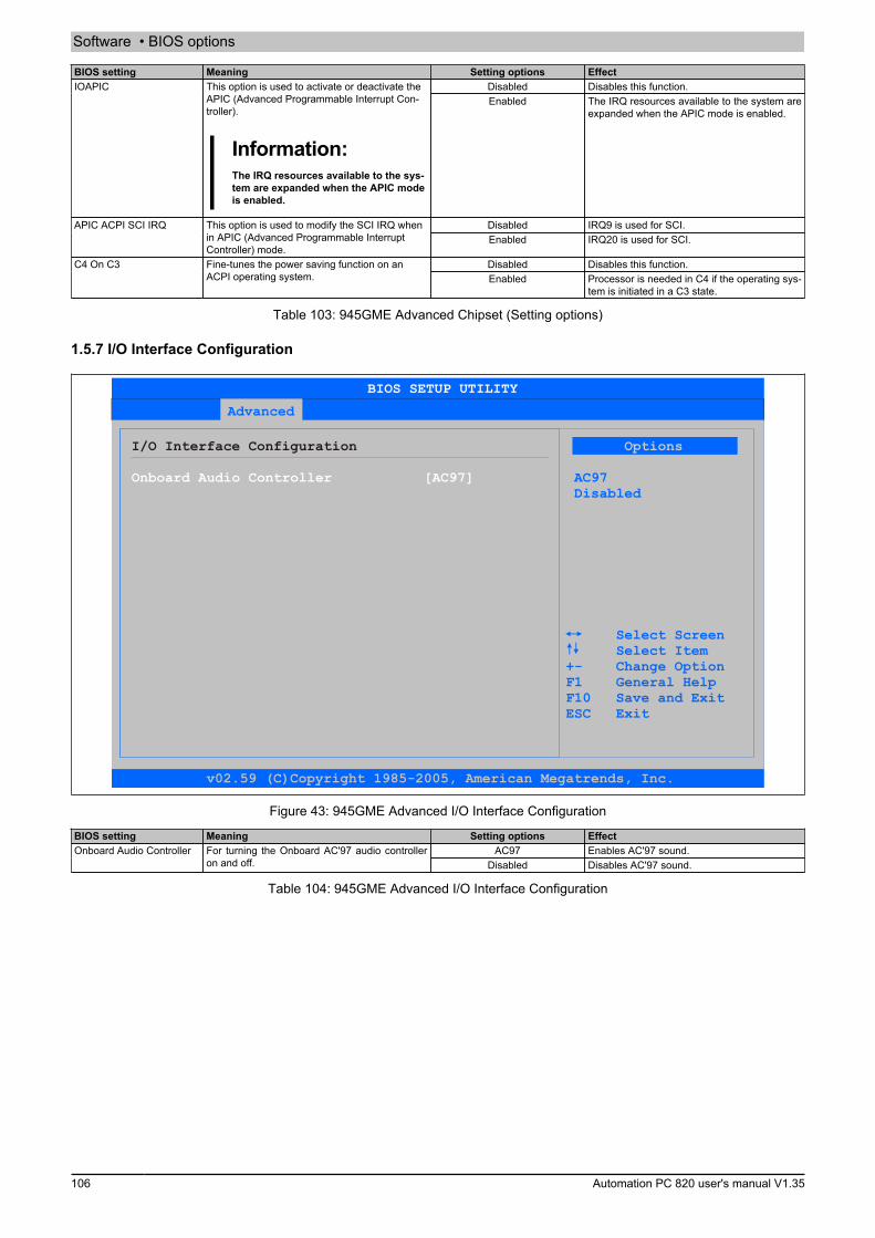
Software • BIOS options
106 Automation PC 820 user's manual V1.35
BIOS setting Meaning Setting options EffectDisabled Disables this function.IOAPIC This option is used to activate or deactivate the
APIC (Advanced Programmable Interrupt Con-troller).
Information:The IRQ resources available to the sys-tem are expanded when the APIC modeis enabled.
Enabled The IRQ resources available to the system areexpanded when the APIC mode is enabled.
Disabled IRQ9 is used for SCI.APIC ACPI SCI IRQ This option is used to modify the SCI IRQ whenin APIC (Advanced Programmable InterruptController) mode.
Enabled IRQ20 is used for SCI.
Disabled Disables this function.C4 On C3 Fine-tunes the power saving function on anACPI operating system. Enabled Processor is needed in C4 if the operating sys-
tem is initiated in a C3 state.
Table 103: 945GME Advanced Chipset (Setting options)
1.5.7 I/O Interface Configuration
Advanced
I/O Interface Configuration Options
AC97Disabled
Select ScreenSelect Item
+- Change Option F1 General Help F10 Save and Exit ESC Exit
Onboard Audio Controller [AC97]
BIOS SETUP UTILITY
v02.59 (C)Copyright 1985-2005, American Megatrends, Inc.
Figure 43: 945GME Advanced I/O Interface Configuration
BIOS setting Meaning Setting options EffectAC97 Enables AC'97 sound.Onboard Audio Controller For turning the Onboard AC'97 audio controller
on and off. Disabled Disables AC'97 sound.
Table 104: 945GME Advanced I/O Interface Configuration
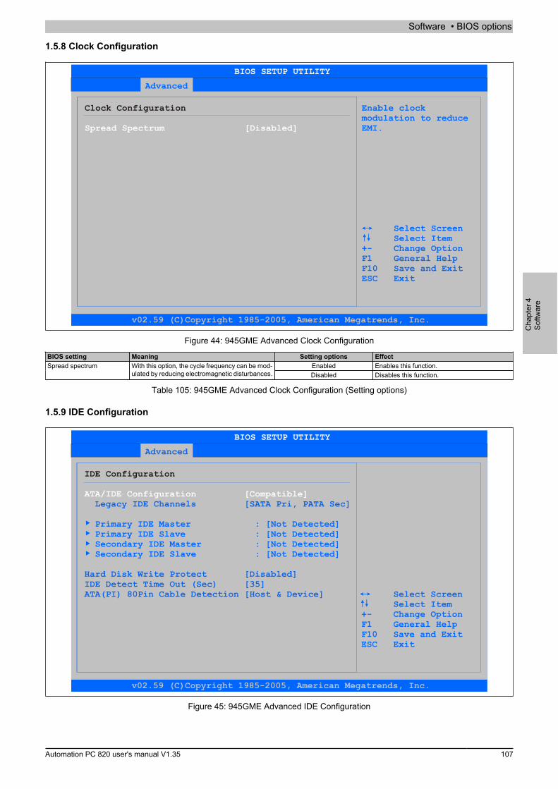
Software • BIOS options
Cha
pter
4So
ftwar
e
Automation PC 820 user's manual V1.35 107
1.5.8 Clock Configuration
Advanced
Clock Configuration Enable clockmodulation to reduceEMI.
Select ScreenSelect Item
+- Change Option F1 General Help F10 Save and Exit ESC Exit
Spread Spectrum [Disabled]
BIOS SETUP UTILITY
v02.59 (C)Copyright 1985-2005, American Megatrends, Inc.
Figure 44: 945GME Advanced Clock Configuration
BIOS setting Meaning Setting options EffectEnabled Enables this function.Spread spectrum With this option, the cycle frequency can be mod-
ulated by reducing electromagnetic disturbances. Disabled Disables this function.
Table 105: 945GME Advanced Clock Configuration (Setting options)
1.5.9 IDE Configuration
Advanced
IDE Configuration
Legacy IDE Channels [SATA Pri, PATA Sec]
Primary IDE Master : [ ] Primary IDE Slave : [Not Detected] Secondary IDE Master : [
Not Detected
Not Detected] Secondary IDE Slave : [Not Detected]
Hard Disk Write Protect [Disabled]IDE Detect Time Out (Sec) [35]ATA(PI) 80Pin Cable Detection [Host & Device] Select Screen Select Item +- Change Option F1 General Help F10 Save and Exit ESC Exit
ATA/IDE Configuration [Compatible]
BIOS SETUP UTILITY
v02.59 (C)Copyright 1985-2005, American Megatrends, Inc.
Figure 45: 945GME Advanced IDE Configuration

Software • BIOS options
108 Automation PC 820 user's manual V1.35
BIOS setting Meaning Setting options EffectCompatible Both controllers run in Legacy or Compatible
modeDisabled Both controllers disabled.
ATA/IDE Configuration Option for configuring the integrated PATA andSATA controller.
Enhanced Both controllers run in Enhanced or NativeMode.
SATA Pri, PATA Sec SATA drives are address primarily and PATAdrive secondarily.
SATA only Only use SATA drives.
Legacy IDE Channels Option for configuring the Legacy IDE channelsin Compatible mode.
PATA only Only use PATA drives.Primary IDE Master The drive in the system that is connected to the
IDE primary master port is configured here.Enter Opens the submenu
see "Primary IDE Master" on page 108Primary IDE slave The drive in the system that is connected to the
IDE primary slave port is configured here.Enter Opens the submenu
see "Primary IDE slave" on page 109Secondary IDE Master The drive in the system that is connected to the
IDE secondary master port is configured here.Enter Opens the submenu
see "Secondary IDE Master" on page 110Secondary IDE slave The drive in the system that is connected to the
IDE secondary slave port is configured here.Enter Opens the submenu
see "Secondary IDE slave" on page 111Disabled Disables this function.Hard disk write protect Write protection for the hard drive can be en-
abled/disabled here. Enabled Enables this function.IDE Detect TIme Out (Sec) Configuring the time overrun limit value for the
ATA/ATAPI device identification.0, 5, 10, 15, 20, 25, 30, 35 Time setting in seconds.
Host & device Using both IDE controllers (motherboard, diskdrive).
Host IDE controller motherboard used.
ATA(PI) 80-Pin Cable De-tection
Detects whether an 80 pin cable is connected tothe drive, the controller or to both.
Information:This option is not available on theAPC820 CPU board. Therefore this set-ting is not relevant.
Device IDE disk drive controller used.
Table 106: 945GME Advanced IDE Configuration (Setting options)
1.5.9.1 Primary IDE Master
Advanced
Primary IDE Master Select the type of device connected
to the system.
LBA/Large Mode [Auto]Block (Multi-Sector Transfer) [Auto]PIO Mode [Auto]DMA Mode [Auto]S.M.A.R.T. [Auto]32Bit Data Transfer [Enabled]
Select ScreenSelect Item
+- Change Option F1 General Help F10 Save and Exit ESC Exit
Device :Not Detected
Type [Auto]
BIOS SETUP UTILITY
v02.59 (C)Copyright 1985-2005, American Megatrends, Inc.
Figure 46: 945GME Primary IDE Master
BIOS setting Meaning Setting options EffectNot installed No drive installed.
Auto Automatic recognition of the drive and setup ofappropriate values.
CD/DVD CD -/ DVD drive.
Type The type of drive connected to the primary masteris configured here.
ARMD ARMD - drive (zip drive)Disabled Disables this function.LBA/Large Mode This option activates the logical block address-
ing / large mode for IDE. Auto Automatic enabling of this function when sup-ported by the system.
Table 107: 945GME - Primary IDE Master - Setting options

Software • BIOS options
Cha
pter
4So
ftwar
e
Automation PC 820 user's manual V1.35 109
BIOS setting Meaning Setting options EffectDisabled Disables this function.Block (Multi-Sector Trans-
fer)This option enables the block mode for IDE harddrives. When this option is enabled, the numberof blocks per request from the configuration sec-tor of the hard drive is read.
Auto Automatic enabling of this function when sup-ported by the system.
Auto Automatic configuration of PIO mode.PIO Mode The PIO mode determines the data rate of thehard drive.
Information:This option is not available on theAPC820. Therefore this setting is not rel-evant.
0, 1, 2, 3, 4 Manual configuration of PIO mode.
Auto Automatic definition of the transfer rate.DMA Mode The data transfer rate to and from the prima-ry master drive is defined here. The DMA modemust be activated in the Windows device manag-er in order to guarantee maximum performance.Only possible when manually setting up the drive.
Disabled Manual definition of the transfer rate.
Auto Automatic detection and enabling.Disabled Disables this function.
S.M.A.R.T. Monitoring function of modern hard drives (self-monitoring, analysis and reporting technology).
Enabled Enables this function.Disabled Disables this function.32 Bit Data Transfer This function enables 32-bit data transfer.Enabled Enables this function.
Table 107: 945GME - Primary IDE Master - Setting options
1.5.9.2 Primary IDE slave
Advanced
Primary IDE Slave Select the type of device connected
to the system.
LBA/Large Mode [Auto]Block (Multi-Sector Transfer) [Auto]PIO Mode [Auto]DMA Mode [Auto]S.M.A.R.T. [Auto]32Bit Data Transfer [Enabled]
Select ScreenSelect Item
+- Change Option F1 General Help F10 Save and Exit ESC Exit
Device :Not Detected
Type [Auto]
BIOS SETUP UTILITY
v02.59 (C)Copyright 1985-2005, American Megatrends, Inc.
Figure 47: 945GME Primary IDE Slave
BIOS setting Meaning Setting options EffectNot installed No drive installed.
Auto Automatic recognition of the drive and setup ofappropriate values.
CD/DVD CD -/ DVD drive.
Type The type of drive connected to the primary slaveis configured here.
ARMD ARMD - drive (zip drive)Disabled Disables this function.LBA/Large Mode This option activates the logical block address-
ing / large mode for IDE. Auto Automatic enabling of this function when sup-ported by the system.
Disabled Disables this function.Block (Multi-Sector Trans-fer)
This option enables the block mode for IDE harddrives. When this option is enabled, the numberof blocks per request from the configuration sec-tor of the hard drive is read.
Auto Automatic enabling of this function when sup-ported by the system.
Table 108: 945GME - Primary IDE Slave - Setting options
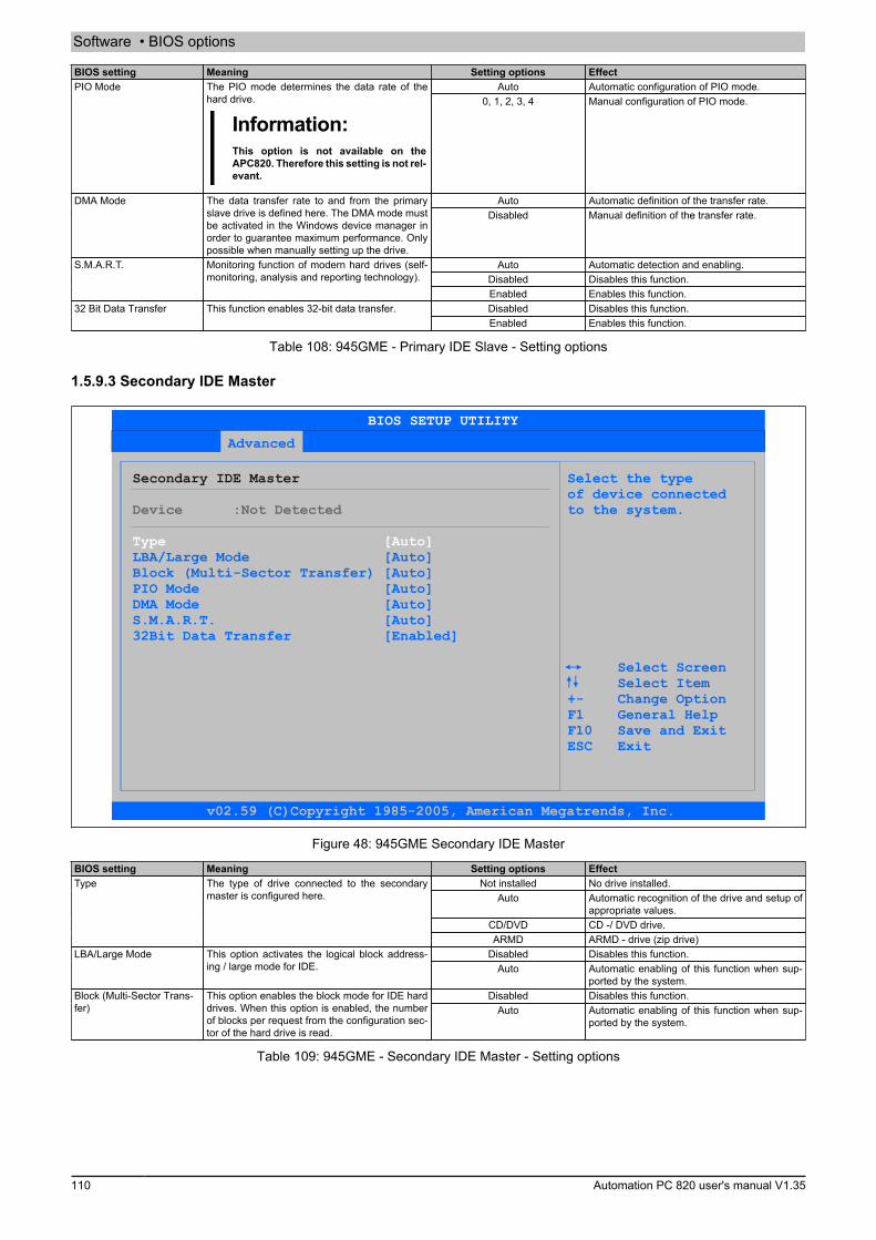
Software • BIOS options
110 Automation PC 820 user's manual V1.35
BIOS setting Meaning Setting options EffectAuto Automatic configuration of PIO mode.PIO Mode The PIO mode determines the data rate of the
hard drive.
Information:This option is not available on theAPC820. Therefore this setting is not rel-evant.
0, 1, 2, 3, 4 Manual configuration of PIO mode.
Auto Automatic definition of the transfer rate.DMA Mode The data transfer rate to and from the primaryslave drive is defined here. The DMA mode mustbe activated in the Windows device manager inorder to guarantee maximum performance. Onlypossible when manually setting up the drive.
Disabled Manual definition of the transfer rate.
Auto Automatic detection and enabling.Disabled Disables this function.
S.M.A.R.T. Monitoring function of modern hard drives (self-monitoring, analysis and reporting technology).
Enabled Enables this function.Disabled Disables this function.32 Bit Data Transfer This function enables 32-bit data transfer.Enabled Enables this function.
Table 108: 945GME - Primary IDE Slave - Setting options
1.5.9.3 Secondary IDE Master
Advanced
Secondary IDE Master Select the type of device connected
to the system.
LBA/Large Mode [Auto]Block (Multi-Sector Transfer) [Auto]PIO Mode [Auto]DMA Mode [Auto]S.M.A.R.T. [Auto]32Bit Data Transfer [Enabled]
Select ScreenSelect Item
+- Change Option F1 General Help F10 Save and Exit ESC Exit
Device :Not Detected
Type [Auto]
BIOS SETUP UTILITY
v02.59 (C)Copyright 1985-2005, American Megatrends, Inc.
Figure 48: 945GME Secondary IDE Master
BIOS setting Meaning Setting options EffectNot installed No drive installed.
Auto Automatic recognition of the drive and setup ofappropriate values.
CD/DVD CD -/ DVD drive.
Type The type of drive connected to the secondarymaster is configured here.
ARMD ARMD - drive (zip drive)Disabled Disables this function.LBA/Large Mode This option activates the logical block address-
ing / large mode for IDE. Auto Automatic enabling of this function when sup-ported by the system.
Disabled Disables this function.Block (Multi-Sector Trans-fer)
This option enables the block mode for IDE harddrives. When this option is enabled, the numberof blocks per request from the configuration sec-tor of the hard drive is read.
Auto Automatic enabling of this function when sup-ported by the system.
Table 109: 945GME - Secondary IDE Master - Setting options

Software • BIOS options
Cha
pter
4So
ftwar
e
Automation PC 820 user's manual V1.35 111
BIOS setting Meaning Setting options EffectAuto Automatic configuration of PIO mode.PIO Mode The PIO mode determines the data rate of the
hard drive.
Information:This option is not available on theAPC820. Therefore this setting is not rel-evant.
0, 1, 2, 3, 4 Manual configuration of PIO mode.
Auto Automatic definition of the transfer rate.DMA Mode The data transfer rate to and from the secondarymaster drive is defined here. The DMA modemust be activated in the Windows device manag-er in order to guarantee maximum performance.Only possible when manually setting up the drive.
Disabled Manual definition of the transfer rate.
Auto Automatic detection and enabling.Disabled Disables this function.
S.M.A.R.T. Monitoring function of modern hard drives (self-monitoring, analysis and reporting technology).
Enabled Enables this function.Disabled Disables this function.32 Bit Data Transfer This function enables 32-bit data transfer.Enabled Enables this function.
Table 109: 945GME - Secondary IDE Master - Setting options
1.5.9.4 Secondary IDE slave
Advanced
Secondary IDE Slave Select the type of device connected
to the system.
LBA/Large Mode [Auto]Block (Multi-Sector Transfer) [Auto]PIO Mode [Auto]DMA Mode [Auto]S.M.A.R.T. [Auto]32Bit Data Transfer [Enabled]
Select ScreenSelect Item
+- Change Option F1 General Help F10 Save and Exit ESC Exit
Device :Not Detected
Type [Auto]
BIOS SETUP UTILITY
v02.59 (C)Copyright 1985-2005, American Megatrends, Inc.
Figure 49: 945GME Secondary IDE Slave
BIOS setting Meaning Setting options EffectNot installed No drive installed.
Auto Automatic recognition of the drive and setup ofappropriate values.
CD/DVD CD -/ DVD drive.
Type The type of drive connected to the secondaryslave is configured here.
ARMD ARMD - drive (zip drive)Disabled Disables this function.LBA/Large Mode This option activates the logical block address-
ing / large mode for IDE. Auto Automatic enabling of this function when sup-ported by the system.
Disabled Disables this function.Block (Multi-Sector Trans-fer)
This option enables the block mode for IDE harddrives. When this option is enabled, the numberof blocks per request from the configuration sec-tor of the hard drive is read.
Auto Automatic enabling of this function when sup-ported by the system.
Table 110: 945GME - Secondary IDE Slave - Setting options

Software • BIOS options
112 Automation PC 820 user's manual V1.35
BIOS setting Meaning Setting options EffectAuto Automatic configuration of PIO mode.PIO Mode The PIO mode determines the data rate of the
hard drive.
Information:This option is not available on theAPC820. Therefore this setting is not rel-evant.
0, 1, 2, 3, 4 Manual configuration of PIO mode.
Auto Automatic definition of the transfer rate.DMA Mode The data transfer rate to and from the secondaryslave is defined here. The DMA mode must be ac-tivated in the Windows device manager in orderto guarantee maximum performance. Only possi-ble when manually setting up the drive.
Disabled Manual definition of the transfer rate.
Auto Automatic detection and enabling.Disabled Disables this function.
S.M.A.R.T. Monitoring function of modern hard drives (self-monitoring, analysis and reporting technology).
Enabled Enables this function.Disabled Disables this function.32 Bit Data Transfer This function enables 32-bit data transfer.Enabled Enables this function.
Table 110: 945GME - Secondary IDE Slave - Setting options
1.5.10 USB Configuration
Advanced
USB Configuration
USB Devices Enabled :
Options
USB 2.0 Controller [Enabled]
Legacy USB Support [Enabled]USB Legacy POST-Always [Enabled]USB Keyboard Legacy Support
Disabled 2 USB Ports
4 USB Ports 6 USB Ports
8 USB Ports
[Enabled]USB Mouse Legacy Support [Disabled]USB Storage Device Support [Enabled] Select Screen Port 64/60 Emulation [Disabled] Select ItemUSB 2.0 Controller Mode [HiSpeed] +- Change OptionBIOS EHCI Hand-Off [Disabled] F1 General HelpUSB Beep Message [Enabled] F10 Save and ExitUSB Stick Default Emulation [Hard Disk] ESC ExitUSB Mass Storage Reset Delay [20 Sec]Special Delay for USB HDDs [Disabled]
1 Keyboard, 1 Hub
USB Functions [8 USB Ports]
BIOS SETUP UTILITY
v02.59 (C)Copyright 1985-2005, American Megatrends, Inc.
Figure 50: 945GME Advanced USB Configuration
BIOS setting Meaning Setting options EffectDisabled Disables the USB port.
2 USB Ports USB1, USB3 are enabled.4 USB Ports USB1, USB2, USB3, USB4 are enabled.6 USB Ports USB1, USB2, USB3, USB4, USB5 are enabled.
USB Functions USB ports can be enabled/disabled here.
8 USB Ports USB1, USB2, USB3, USB4, USB5, USB are en-abled on an AP via SDL.
Enabled All USB ports run in USB 2.0 mode.USB 2.0 Controller Option for enabling or disabling USB 2.0 mode.Disabled All USB ports run in USB 1.1 mode.Disabled Disables this function.Enabled Enables this function.
Legacy USB Support Legacy USB support can be enabled/disabledhere.USB ports do not function during startup. USB issupported again after the operating system hasstarted. A USB keyboard is still recognized duringthe POST.
Auto Automatic enabling.
USB Legacy POST-Always Option to enable Legacy USB Support duringthe POST (Power On Self Test).
Enabled The BIOS Setup can be called up during thePOST using a USB keyboard.
Table 111: 945GME - Advanced USB Configuration - Setting options
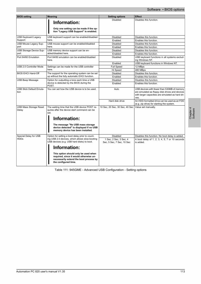
Software • BIOS options
Cha
pter
4So
ftwar
e
Automation PC 820 user's manual V1.35 113
BIOS setting Meaning Setting options Effect
Information:Only one setting can be made if the op-tion "Legacy USB Support" is enabled.
Disabled Disables this function.
Disabled Disables this function.USB Keyboard LegacySupport
USB keyboard support can be enabled/disabledhere. Enabled Enables this function.
Disabled Disables this function.USB Mouse Legacy Sup-port
USB mouse support can be enabled/disabledhere. Enabled Enables this function.
Disabled Disables this function.USB Storage Device Sup-port
USB memory device support can be en-abled/disabled here. Enabled Enables this function.
Disabled USB keyboard functions in all systems exclud-ing Windows NT.
Port 64/60 Emulation Port 64/60 emulation can be enabled/disabledhere.
Enabled USB keyboard functions in Windows NT.Full Speed 12 MBpsUSB 2.0 Controller Mode Settings can be made for the USB controller
here. Hi Speed 480 MBpsDisabled Disables this function.BIOS EHCI Hand-Off The support for the operating system can be set
up without the fully automatic EHCI function. Enabled Enables this function.Disabled Disables this function.USB Beep Message Option for outputting a tone each time a USB
device is detected by the BIOS during thePOST.
Enabled Enables this function.
Auto USB devices with fewer than 530MB of memoryare simulated as floppy disk drives and deviceswith larger capacities are simulated as hard dri-ves.
USB Stick Default Emula-tion
You can set how the USB device is to be used.
Hard disk drive An HDD-formatted drive can be used as an FDD(e.g. zip drive) for starting the system.
USB Mass Storage ResetDelay
The waiting time that the USB device POST re-quires after the device start command can beset.
Information:The message "No USB mass storagedevice detected" is displayed if no USBmemory device has been installed.
10 Sec, 20 Sec, 30 Sec, 40 Sec Value set manually.
Disabled Disables this function. No boot delay is added.Special Delay for USBHDDs
Option for setting a boot delay prior to count-ing USB 2.0 devices, which allows slow-bootingUSB devices (e.g. USB hard disks) to boot.
Information:This option should only be used whenrequired, since it would otherwise un-necessarily extend the boot process bythe configured time.
1 Sec, 2 Sec, 3 Sec, 4Sec, 5 Sec, 7 Sec, 10 Sec
A boot delay of 1, 2, 3, 4, 5, 7 or 10 secondsis added.
Table 111: 945GME - Advanced USB Configuration - Setting options
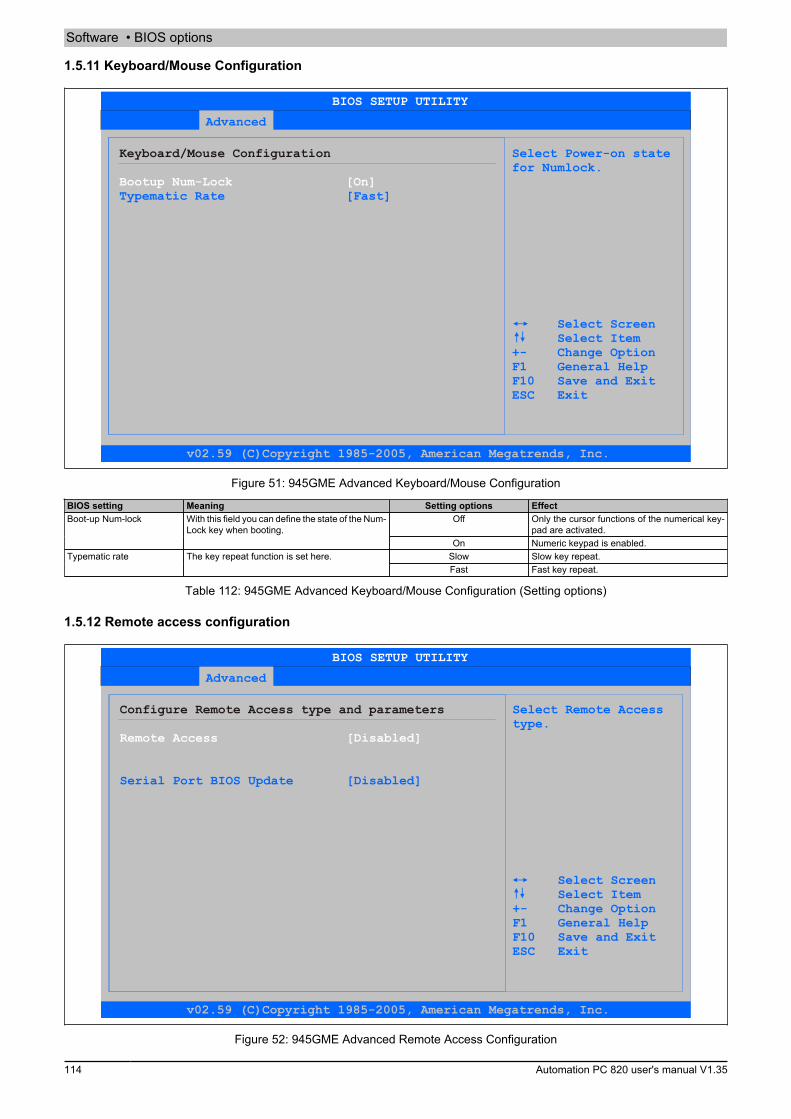
Software • BIOS options
114 Automation PC 820 user's manual V1.35
1.5.11 Keyboard/Mouse Configuration
Advanced
Keyboard/Mouse Configuration Select Power-on state for Numlock.
Typematic Rate [Fast]
Select ScreenSelect Item
+- Change Option F1 General Help F10 Save and Exit ESC Exit
Bootup Num-Lock [On]
BIOS SETUP UTILITY
v02.59 (C)Copyright 1985-2005, American Megatrends, Inc.
Figure 51: 945GME Advanced Keyboard/Mouse Configuration
BIOS setting Meaning Setting options EffectOff Only the cursor functions of the numerical key-
pad are activated.Boot-up Num-lock With this field you can define the state of the Num-
Lock key when booting.On Numeric keypad is enabled.
Slow Slow key repeat.Typematic rate The key repeat function is set here.Fast Fast key repeat.
Table 112: 945GME Advanced Keyboard/Mouse Configuration (Setting options)
1.5.12 Remote access configuration
Advanced
Configure Remote Access type and parameters Select Remote Access type.
Serial Port BIOS Update [Disabled]
Select ScreenSelect Item
+- Change Option F1 General Help F10 Save and Exit ESC Exit
Remote Access [Disabled]
BIOS SETUP UTILITY
v02.59 (C)Copyright 1985-2005, American Megatrends, Inc.
Figure 52: 945GME Advanced Remote Access Configuration

Software • BIOS options
Cha
pter
4So
ftwar
e
Automation PC 820 user's manual V1.35 115
BIOS setting Meaning Setting options EffectDisabled Disables this function.Remote access The remote access function can be enabled/dis-
abled here. Enabled Enables this function.COM1 Enables the COM1 interface as remote access
interface.COM2 Enables the COM2 interface as remote access
interface.
Serial port number The serial interface can be set using this optionas long as disabled is not entered in the Remoteaccess field.
COM3 Enables the COM3 interface as remote accessinterface.
Base address, IRQ Displays the logical address and interrupt for theserial port as long as disabled is not entered inthe Remote access field.
None -
Serial port mode The serial port transfer rate is defined here aslong as disabled is not entered in the Remote ac-cess field.
115200 8,n,157600 8,n,138400 8,n,119200 8,n,109600 8,n,1
Value set manually.
None The interface is operated without transfer con-trol.
Hardware The interface transfer control is carried outthrough hardware. This mode must be sup-ported by a cable.
Flow control This setting determines how the transfer is con-trolled via the interface.
Information:The setting must be the same on the ter-minal and the server.
Software The interface transfer control is carried outthrough software.
Disabled The redirection is switched off after start up.Boot loader Redirection is enabled during system start up
and charging.
Redirection after BIOSPOST
The redirection after start up can be set here aslong as disabled is not entered in the Remoteaccess field.
Always Redirection is always enabled.Terminal type The type of connection can be chosen here, as
long as disabled is not entered in the Remoteaccess field.
ANSI, VT100, VT-UTF8 Manual configuration of the connection type.
Disabled Disables this function.VT-UTF8 Combo Key Sup-port
With this option, the VT-UTF8 Combo Key Sup-port for the ANSI and VT100 connections canbe enabled as long as disabled is not entered inthe Remote access field.
Enabled Enables this function.
No delay No delay.Sredir Memory Display De-lay
The memory output delay can be set using thisoption as long as disabled is not entered in theRemote access field (Sredir -> serial redirec-tion).
Delay 1 sec, Delay2 sec, Delay 4 sec
Value set manually.
Disabled Disables this function.Serial port BIOS update During system start up, the update is loaded viathe serial interface in the processor.
Information:If this option is disabled, the boot timeis reduced.
Enabled Enables this function.
Table 113: 945GME Advanced Remote Access Configuration (Setting options)
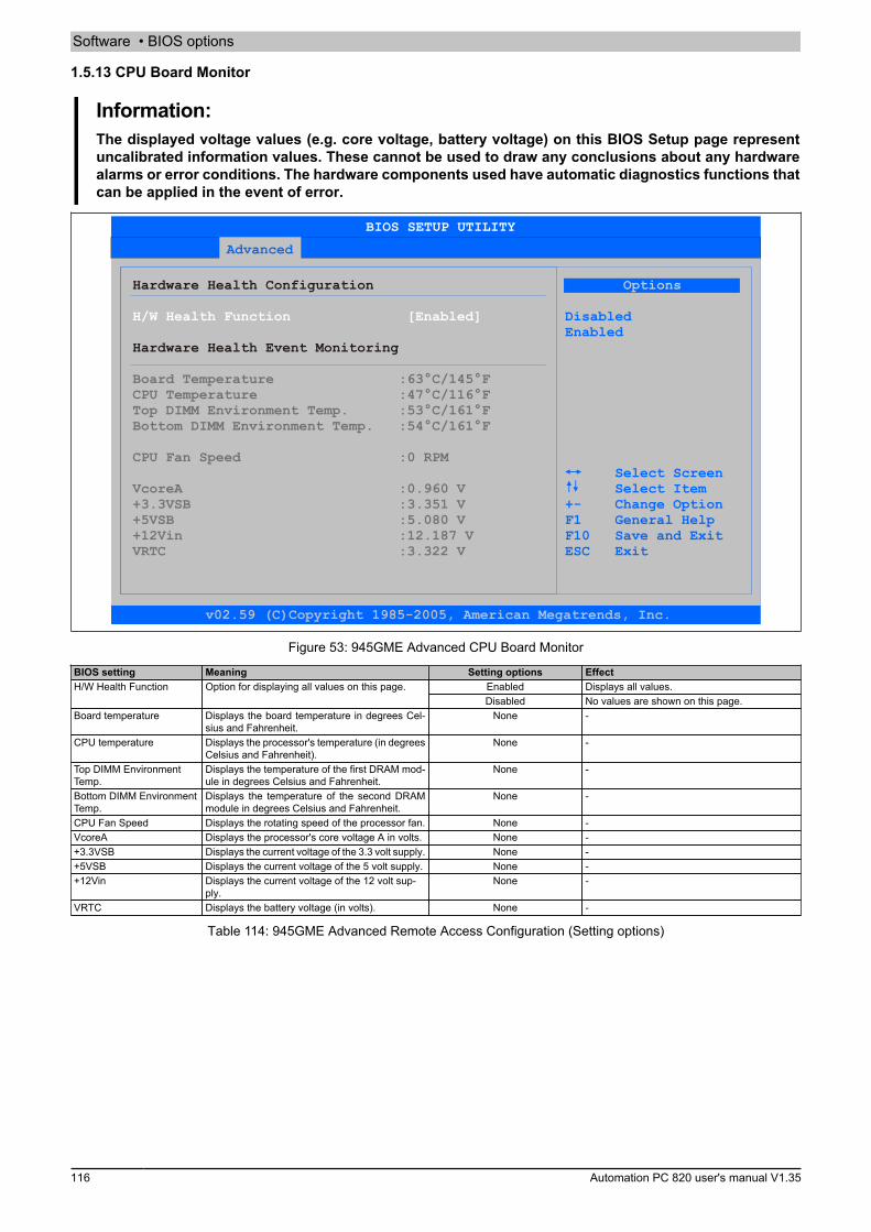
Software • BIOS options
116 Automation PC 820 user's manual V1.35
1.5.13 CPU Board Monitor
Information:The displayed voltage values (e.g. core voltage, battery voltage) on this BIOS Setup page representuncalibrated information values. These cannot be used to draw any conclusions about any hardwarealarms or error conditions. The hardware components used have automatic diagnostics functions thatcan be applied in the event of error.
Advanced
Hardware Health Configuration
Hardware Health Event Monitoring
Options
H/W Health Function [Enabled] DisabledEnabled
+- Change Option
Select Screen Select Item
F1 General Help F10 Save and Exit
ESC Exit
Board Temperature :63°C/145°FCPU Temperature :47°C/116°FTop DIMM Environment Temp. :53
VcoreA :0.960 V+3.3VSB :3.351 V+5VSB :5.080 V+12Vin :12.187 VVRTC :3.322 V
°C/161°FBottom DIMM Environment Temp. :54°C/161°F
CPU Fan Speed :0 RPM
BIOS SETUP UTILITY
v02.59 (C)Copyright 1985-2005, American Megatrends, Inc.
Figure 53: 945GME Advanced CPU Board Monitor
BIOS setting Meaning Setting options EffectEnabled Displays all values.H/W Health Function Option for displaying all values on this page.Disabled No values are shown on this page.
Board temperature Displays the board temperature in degrees Cel-sius and Fahrenheit.
None -
CPU temperature Displays the processor's temperature (in degreesCelsius and Fahrenheit).
None -
Top DIMM EnvironmentTemp.
Displays the temperature of the first DRAM mod-ule in degrees Celsius and Fahrenheit.
None -
Bottom DIMM EnvironmentTemp.
Displays the temperature of the second DRAMmodule in degrees Celsius and Fahrenheit.
None -
CPU Fan Speed Displays the rotating speed of the processor fan. None -VcoreA Displays the processor's core voltage A in volts. None -+3.3VSB Displays the current voltage of the 3.3 volt supply. None -+5VSB Displays the current voltage of the 5 volt supply. None -+12Vin Displays the current voltage of the 12 volt sup-
ply.None -
VRTC Displays the battery voltage (in volts). None -
Table 114: 945GME Advanced Remote Access Configuration (Setting options)
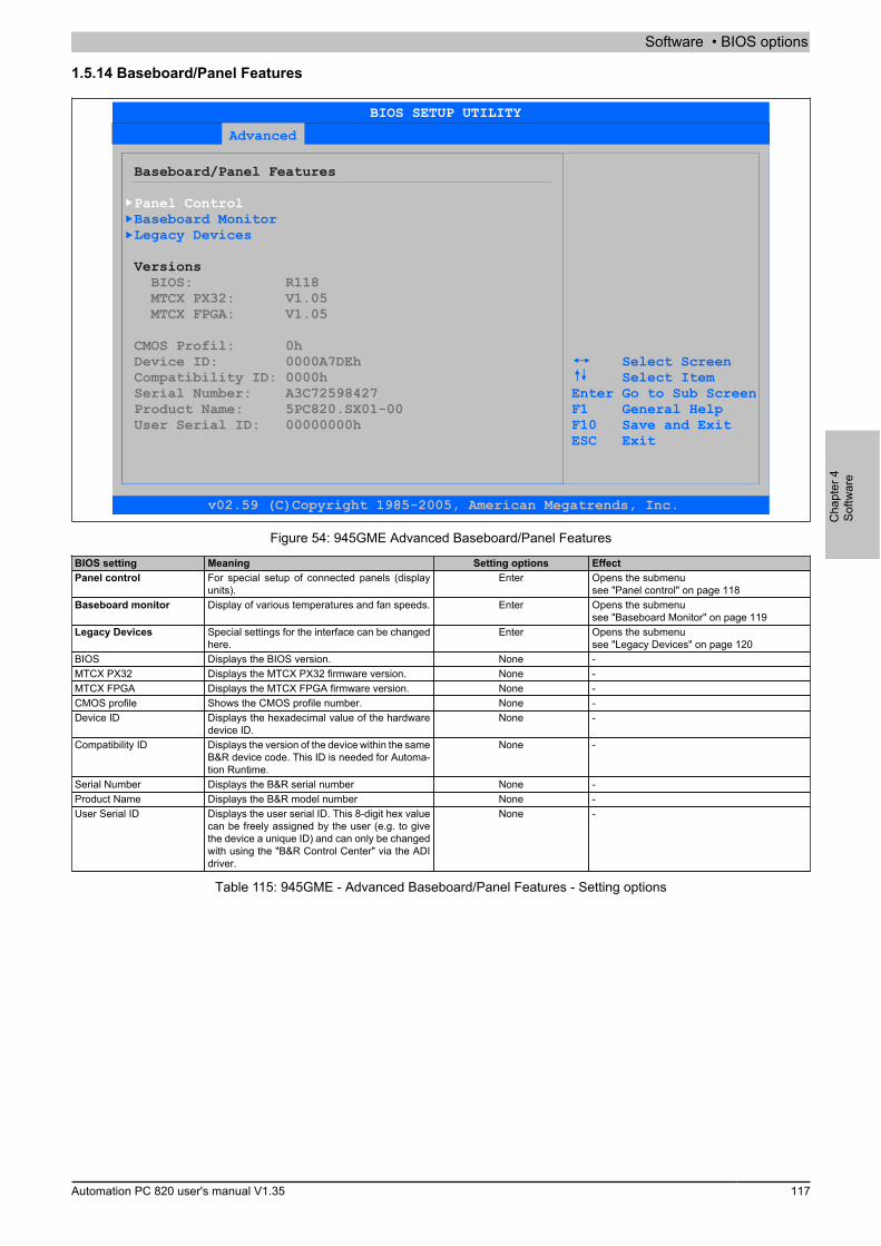
Software • BIOS options
Cha
pter
4So
ftwar
e
Automation PC 820 user's manual V1.35 117
1.5.14 Baseboard/Panel Features
Advanced
Baseboard/Panel Features
Versions
Panel Control
BIOS: R118 MTCX PX32: V1.05 MTCX FPGA: V1.05
CMOS Profil: 0hDevice ID: 0000A7DEh Compatibility ID: 0000hSerial Number: A3C72598427
User Serial ID: 00000000hProduct Name: 5PC820.SX01-00
Baseboard MonitorLegacy Devices
Select ScreenSelect Item
Enter Go to Sub ScreenF1 General HelpF10 Save and Exit
ESC Exit
BIOS SETUP UTILITY
v02.59 (C)Copyright 1985-2005, American Megatrends, Inc.
Figure 54: 945GME Advanced Baseboard/Panel Features
BIOS setting Meaning Setting options EffectPanel control For special setup of connected panels (display
units).Enter Opens the submenu
see "Panel control" on page 118Baseboard monitor Display of various temperatures and fan speeds. Enter Opens the submenu
see "Baseboard Monitor" on page 119Legacy Devices Special settings for the interface can be changed
here.Enter Opens the submenu
see "Legacy Devices" on page 120BIOS Displays the BIOS version. None -MTCX PX32 Displays the MTCX PX32 firmware version. None -MTCX FPGA Displays the MTCX FPGA firmware version. None -CMOS profile Shows the CMOS profile number. None -Device ID Displays the hexadecimal value of the hardware
device ID.None -
Compatibility ID Displays the version of the device within the sameB&R device code. This ID is needed for Automa-tion Runtime.
None -
Serial Number Displays the B&R serial number None -Product Name Displays the B&R model number None -User Serial ID Displays the user serial ID. This 8-digit hex value
can be freely assigned by the user (e.g. to givethe device a unique ID) and can only be changedwith using the "B&R Control Center" via the ADIdriver.
None -
Table 115: 945GME - Advanced Baseboard/Panel Features - Setting options
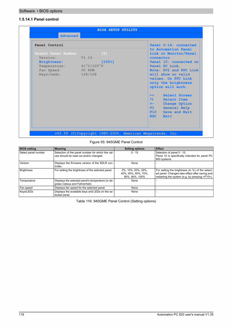
Software • BIOS options
118 Automation PC 820 user's manual V1.35
1.5.14.1 Panel control
Advanced
Panel Control Panel 0-14: connectedto Automation PanelLink or Monitor/Panelconnector.
Brightness: [100%] Panel 15: connected onPanel PC Link.Note: DVI and PPC Linkwill show no valid
values. On PPC Link only the brightness
option will work.
Select ScreenSelect Item
+- Change Option F1 General Help
F10 Save and Exit ESC Exit
Select Panel Number [0] Version: V1.14
Temperature: 41°C/105°F Fan Speed: 00 RPM Keys/Leds: 128/128
BIOS SETUP UTILITY
v02.59 (C)Copyright 1985-2005, American Megatrends, Inc.
Figure 55: 945GME Panel Control
BIOS setting Meaning Setting options EffectSelect panel number Selection of the panel number for which the val-
ues should be read out and/or changed.0 - 15 Selection of panel 0 - 15.
Panel 15 is specifically intended for panel PC800 systems.
Version Displays the firmware version of the SDLR con-troller.
None -
Brightness For setting the brightness of the selected panel. 0%, 10%, 20%, 30%,40%, 50%, 60%, 70%,
80%, 90%, 100%
For setting the brightness (in %) of the select-ed panel. Changes take effect after saving andrestarting the system (e.g. by pressing <F10>).
Temperature Displays the selected panel's temperature (in de-grees Celsius and Fahrenheit).
None -
Fan speed Displays fan speed for the selected panel. None -Keys/LEDs Displays the available keys and LEDs on the se-
lected panel.None -
Table 116: 945GME Panel Control (Setting options)
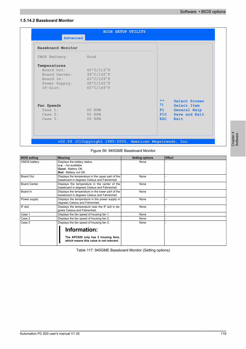
Software • BIOS options
Cha
pter
4So
ftwar
e
Automation PC 820 user's manual V1.35 119
1.5.14.2 Baseboard Monitor
Advanced
Baseboard Monitor
CMOS Battery: Good
Temperatures Board Out: 45°C/113°F Board Center: 39°C/102°F Board In: 43°C/109°F Power Supply: 39°C/102°F IF-Slot: 65°C/149°F
Select ScreenFan Speeds Select Item
Case 1: 00 RPM F1 General HelpCase 2: 00 RPM F10 Save and ExitCase 3: 00 RPM ESC Exit
BIOS SETUP UTILITY
v02.59 (C)Copyright 1985-2005, American Megatrends, Inc.
Figure 56: 945GME Baseboard Monitor
BIOS setting Meaning Setting options EffectCMOS battery Displays the battery status.
n.a. - not availableGood - Battery OK.Bad - Battery not OK.
None -
Board Out Displays the temperature in the upper part of thebaseboard in degrees Celsius and Fahrenheit.
None -
Board Center Displays the temperature in the center of thebaseboard in degrees Celsius and Fahrenheit.
None -
Board In Displays the temperature in the lower part of thebaseboard in degrees Celsius and Fahrenheit.
None -
Power supply Displays the temperature in the power supply indegrees Celsius and Fahrenheit.
None --
IF slot Displays the temperature near the IF slot in de-grees Celsius and Fahrenheit.
None -
Case 1 Displays the fan speed of housing fan 1. None -Case 2 Displays the fan speed of housing fan 2. None -Case 3 Displays the fan speed of housing fan 3.
Information:The APC820 only has 2 housing fans,which means this value is not relevant.
None -
Table 117: 945GME Baseboard Monitor (Setting options)

Software • BIOS options
120 Automation PC 820 user's manual V1.35
1.5.14.3 Legacy Devices
Advanced
Legacy Devices Enable/Disable theCOM 1 port.
Base I/O address: [3F8] Interrupt: [IRQ 4]COM B: [Enabled] Base I/O address: [2F8]
COM C: [ ]
Hardware Security Key
Interrupt: [IRQ 3]Disabled
Select Item Select Screen
: [Enabled] +- Change Option Base I/O address [378] F1 General Help F10 Save and ExitETH2 LAN controller: [Enabled] ESC Exit
COM A: [Enabled]
ETH2 MAC Address: 00:60:65:07:90:BC
BIOS SETUP UTILITY
v02.59 (C)Copyright 1985-2005, American Megatrends, Inc.
Figure 57: 945GME Legacy Devices
BIOS setting Meaning Setting options EffectDisabled Disables the interface.COM A Settings for the COM1 serial interface in the sys-
tem. Enabled Enables the interface.Base I/O address Selects the base I/O address for the COM port 238, 2E8, 2F8,
328, 338, 3E8, 3F8Selected base I/O address is assigned.
Interrupt Selection of the interrupt for the COM port. IRQ 3, IRQ 4, IRQ 5, IRQ 6,IRQ 7, IRQ 10, IRQ 11, IRQ 12
Selected interrupt is assigned.
Disabled Disables the interface.COM B Settings for the COM2 serial interface in the sys-tem. Enabled Enables the interface.
Base I/O address Selects the base I/O address for the COM port 238, 2E8, 2F8,328, 338, 3E8, 3F8
Selected base I/O address is assigned.
Interrupt Selection of the interrupt for the COM 2 port. IRQ 3, IRQ 4, IRQ 5, IRQ 6,IRQ 7, IRQ 10, IRQ 11, IRQ 12
Selected interrupt is assigned.
Disabled Disables the interface.COM C Setting the COM port for the touch screen onthe monitor/panel connector. Enabled Enables the interface.
Base I/O address Selects the base I/O address for the COM port 238, 2E8, 2F8,328, 338, 3E8, 3F8
Selected base I/O address is assigned.
Interrupt Selection of the interrupt for the COM port. IRQ 3, IRQ 4, IRQ 5, IRQ 6,IRQ 7, IRQ 10, IRQ 11, IRQ 12
Selected interrupt is assigned.
Disabled Disables the interface.Hardware security key Settings for the hardware security key (Dongle)are made here. Enabled Enables the interface.
Base I/O address Selection of the base I/O address for the hard-ware security interface.
278, 378, 3BC Selection of the base I/O address for the parallelport.
Disabled Disables the controller.ETH2 LAN controller For turning the onboard LAN controller (ETH2) onand off. Enabled Enables the controller.
ETH2 MAC Address Displays the Ethernet 2 controller MAC address. None -
Table 118: 945GME Legacy Devices (Setting options)
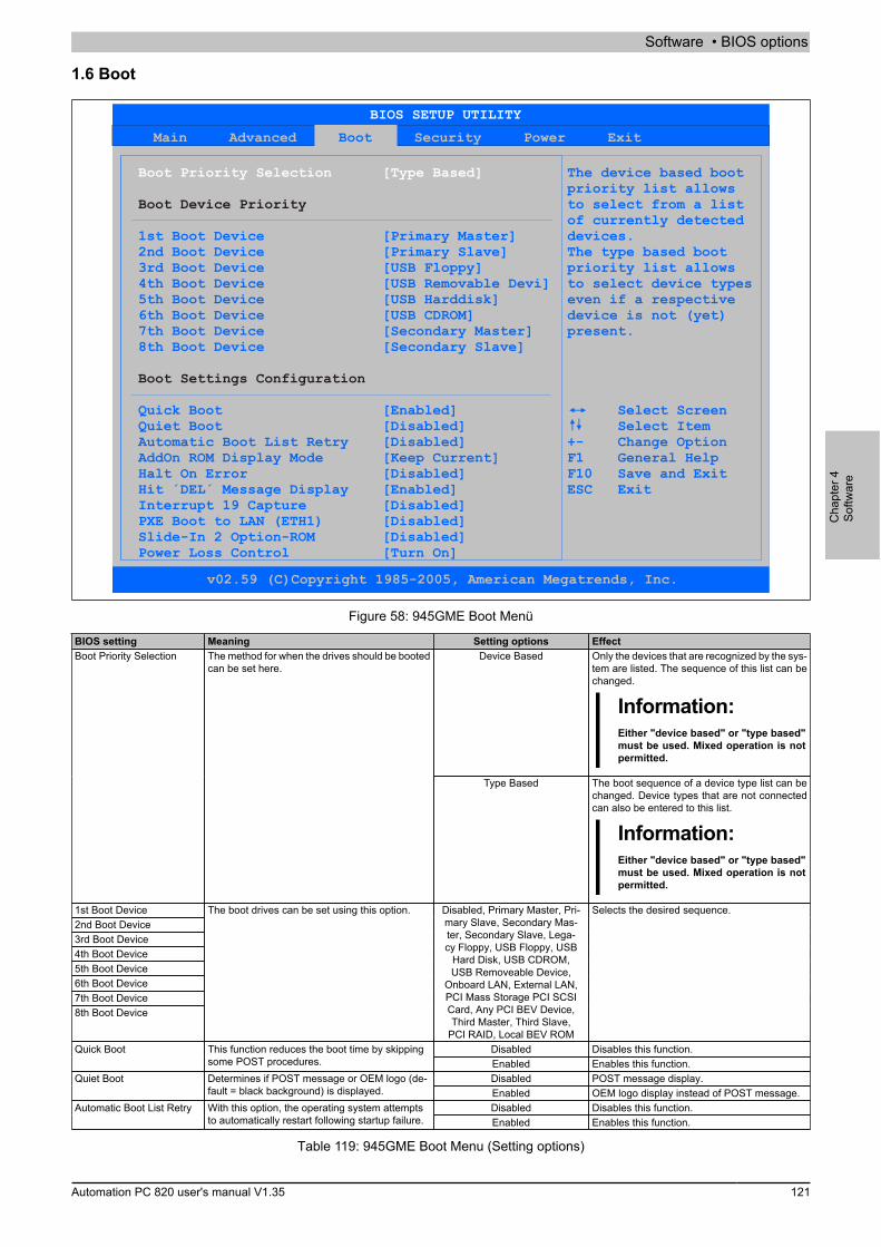
Software • BIOS options
Cha
pter
4So
ftwar
e
Automation PC 820 user's manual V1.35 121
1.6 Boot
Main Advanced Security Power ExitBoot
Boot Priority Selection [Type Based]
Boot Device Priority
Boot Settings Configuration
The device based boot priority list allows
to select from a list of currently detected1st Boot Device [ ] devices.2nd
Quick Boot [Enabled] Quiet Boot [Disabled] Automatic Boot List Retry [Disabled] AddOn ROM Display Mode [Keep Current] Halt On Error [Disabled] Hit ´DEL´ Message Display [Enabled] Interrupt 19 Capture [Disabled]PXE Boot to LAN (ETH1) [ ]Slide-In 2 Option-ROM [Disabled]Power Loss Control [Turn On]
Primary Master Boot Device [Primary Slave] The type based boot
3rd Boot Device [USB Floppy] priority list allows4th Boot Device [USB Removable Devi] to select device types5th Boot Device [USB Harddisk] even if a respective6th Boot Device [USB CDROM] device is not (yet)7th Boot Device [Secondary Master] present.8th Boot Device [Secondary Slave]
Select Screen Select Item+- Change OptionF1 General HelpF10 Save and ExitESC Exit
Disabled
BIOS SETUP UTILITY
v02.59 (C)Copyright 1985-2005, American Megatrends, Inc.
Figure 58: 945GME Boot Menü
BIOS setting Meaning Setting options EffectDevice Based Only the devices that are recognized by the sys-
tem are listed. The sequence of this list can bechanged.
Information:Either "device based" or "type based"must be used. Mixed operation is notpermitted.
Boot Priority Selection The method for when the drives should be bootedcan be set here.
Type Based The boot sequence of a device type list can bechanged. Device types that are not connectedcan also be entered to this list.
Information:Either "device based" or "type based"must be used. Mixed operation is notpermitted.
1st Boot Device2nd Boot Device3rd Boot Device4th Boot Device5th Boot Device6th Boot Device7th Boot Device8th Boot Device
The boot drives can be set using this option. Disabled, Primary Master, Pri-mary Slave, Secondary Mas-ter, Secondary Slave, Lega-cy Floppy, USB Floppy, USB
Hard Disk, USB CDROM,USB Removeable Device,
Onboard LAN, External LAN,PCI Mass Storage PCI SCSICard, Any PCI BEV Device,Third Master, Third Slave,
PCI RAID, Local BEV ROM
Selects the desired sequence.
Disabled Disables this function.Quick Boot This function reduces the boot time by skippingsome POST procedures. Enabled Enables this function.
Disabled POST message display.Quiet Boot Determines if POST message or OEM logo (de-fault = black background) is displayed. Enabled OEM logo display instead of POST message.
Disabled Disables this function.Automatic Boot List Retry With this option, the operating system attemptsto automatically restart following startup failure. Enabled Enables this function.
Table 119: 945GME Boot Menu (Setting options)

Software • BIOS options
122 Automation PC 820 user's manual V1.35
BIOS setting Meaning Setting options EffectForce BIOS An additional BIOS part can be displayed.Add-On ROM Display
ModeSets the display mode for the ROM (during thebooting procedure). Keep Current BIOS information is displayed.
Disabled The system does not pause. All errors are ig-nored.
Halt On Error This option sets whether the system shouldpause the Power On Self Test (POST) when itencounters an error. Enabled The system pauses. The system pauses every
time an error is encountered.Disabled The message is not displayed.Hit 'DEL' Message Display Settings can be made here for the "Hit 'DEL'
Message" display.
Information:When quiet boot is activated the mes-sage is not displayed.
Enabled The message is displayed.
Disabled Disables this function.Interrupt 19 Capture This function can be used to incorporate theBIOS interrupt. Enabled Enables this function.
Disabled Disables this function.PXE boot to LAN (ETH1) Enables/disables the function to boot from LAN(ETH1). Enabled Enables this function.
Disabled Disables this function.Slide-in 2 Optional ROM Activation/deactivation of an optional ROM for aslide-in 2 drive. Enabled Enables this function.
Remain Off Remains off.Turn On Powers on.
Power Loss Control Determines if the system is on/off following pow-er loss.
Last State Enables the previous state.
Table 119: 945GME Boot Menu (Setting options)
1.7 Security
Main Advanced Boot Power ExitSecurity
Security Settings
Hard Disk Security
Install or Change the password.
Change User Password
Boot Sector Virus Protection [Disabled]
Hard Disk Security User Passwords Select Screen Hard Disk Security Master Passwords Select Item
Enter Change F1 General Help F10 Save and Exit ESC Exit
Supervisor Password :Not InstalledUser Password :Not Installed
Change Supervisor Password
BIOS SETUP UTILITY
v02.59 (C)Copyright 1985-2005, American Megatrends, Inc.
Figure 59: 945GME Security Menü
BIOS setting Meaning Setting options EffectSupervisor Password Displays whether or not a supervisor password
has been set.None -
User Password Displays whether or not a user password hasbeen set.
None -
Change Supervisor Pass-word
To enter/change a supervisor password. A super-visor password is necessary to edit all BIOS set-tings.
Enter Enter password.
Change User Password To enter/change a user password. A user pass-word allows the user to edit only certain BIOS set-tings.
Enter Enter password.
Table 120: 945GME - Advanced PCI configuration - Setting options
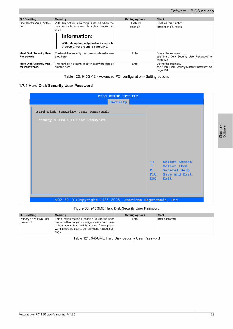
Software • BIOS options
Cha
pter
4So
ftwar
e
Automation PC 820 user's manual V1.35 123
BIOS setting Meaning Setting options EffectDisabled Disables this function.Boot Sector Virus Protec-
tionWith this option, a warning is issued when theboot sector is accessed through a program orvirus.
Information:With this option, only the boot sector isprotected, not the entire hard drive.
Enabled Enables this function.
Hard Disk Security UserPasswords
The hard disk security user password can be cre-ated here.
Enter Opens the submenusee "Hard Disk Security User Password" onpage 123
Hard Disk Security Mas-ter Passwords
The hard disk security master password can becreated here.
Enter Opens the submenusee "Hard Disk Security Master Password" onpage 124
Table 120: 945GME - Advanced PCI configuration - Setting options
1.7.1 Hard Disk Security User Password
Security
Hard Disk Security User Passwords
Primary Slave HDD User Password
Select Screen Select Item F1 General Help F10 Save and Exit ESC Exit
BIOS SETUP UTILITY
v02.59 (C)Copyright 1985-2005, American Megatrends, Inc.
Figure 60: 945GME Hard Disk Security User Password
BIOS setting Meaning Setting options EffectPrimary slave HDD userpassword
This function makes it possible to use the userpassword to change or configure each hard drivewithout having to reboot the device. A user pass-word allows the user to edit only certain BIOS set-tings.
Enter Enter password.
Table 121: 945GME Hard Disk Security User Password
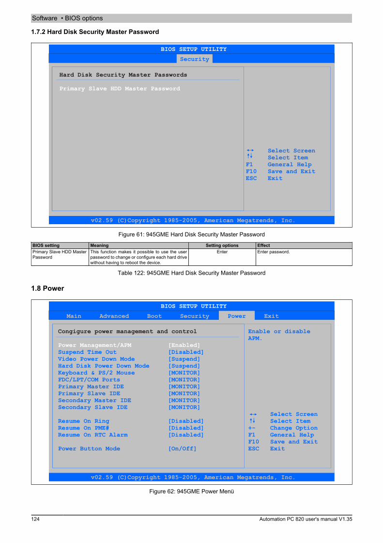
Software • BIOS options
124 Automation PC 820 user's manual V1.35
1.7.2 Hard Disk Security Master Password
Security
Hard Disk Security Master Passwords
Primary Slave HDD Master Password
Select Screen Select Item F1 General Help F10 Save and Exit ESC Exit
BIOS SETUP UTILITY
v02.59 (C)Copyright 1985-2005, American Megatrends, Inc.
Figure 61: 945GME Hard Disk Security Master Password
BIOS setting Meaning Setting options EffectPrimary Slave HDD MasterPassword
This function makes it possible to use the userpassword to change or configure each hard drivewithout having to reboot the device.
Enter Enter password.
Table 122: 945GME Hard Disk Security Master Password
1.8 Power
Main Advanced Boot Security ExitPower
Congigure power management and control Enable or disable APM.
Suspend Time Out [Disabled]Video Power Down Mode [Suspend]Hard Disk Power Down Mode [Suspend]Keyboard & PS/2 Mouse [MONITOR]FDC/LPT/COM Ports [MONITOR]Primary Master IDE [MONITOR]Primary Slave IDE [MONITOR]Secondary Master IDE [MONITOR]Secondary Slave IDE [MONITOR]
+-
F10 Exit
Select ScreenResume On Ring [Disabled] Select ItemResume On PME# [Disabled] Change OptionResume On RTC Alarm [Disabled] F1 General Help
Save and ExitPower Button Mode [On/Off] ESC
Power Management/APM [Enabled]
BIOS SETUP UTILITY
v02.59 (C)Copyright 1985-2005, American Megatrends, Inc.
Figure 62: 945GME Power Menü
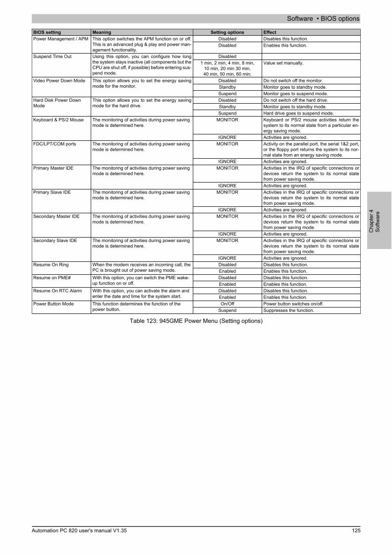
Software • BIOS options
Cha
pter
4So
ftwar
e
Automation PC 820 user's manual V1.35 125
BIOS setting Meaning Setting options EffectDisabled Disables this function.Power Management / APM This option switches the APM function on or off.
This is an advanced plug & play and power man-agement functionality.
Disabled Enables this function.
DisabledSuspend Time Out Using this option, you can configure how longthe system stays inactive (all components but theCPU are shut off, if possible) before entering sus-pend mode.
1 min, 2 min, 4 min, 8 min,10 min, 20 min 30 min,40 min, 50 min, 60 min;
Value set manually.
Disabled Do not switch off the monitor.Standby Monitor goes to standby mode.
Video Power Down Mode This option allows you to set the energy savingmode for the monitor.
Suspend Monitor goes to suspend mode.Disabled Do not switch off the hard drive.Standby Monitor goes to standby mode.
Hard Disk Power DownMode
This option allows you to set the energy savingmode for the hard drive.
Suspend Hard drive goes to suspend mode.MONITOR Keyboard or PS/2 mouse activities return the
system to its normal state from a particular en-ergy saving mode.
Keyboard & PS/2 Mouse The monitoring of activities during power savingmode is determined here.
IGNORE Activities are ignored.MONITOR Activity on the parallel port, the serial 1&2 port,
or the floppy port returns the system to its nor-mal state from an energy saving mode.
FDC/LPT/COM ports The monitoring of activities during power savingmode is determined here.
IGNORE Activities are ignored.MONITOR Activities in the IRQ of specific connections or
devices return the system to its normal statefrom power saving mode.
Primary Master IDE The monitoring of activities during power savingmode is determined here.
IGNORE Activities are ignored.MONITOR Activities in the IRQ of specific connections or
devices return the system to its normal statefrom power saving mode.
Primary Slave IDE The monitoring of activities during power savingmode is determined here.
IGNORE Activities are ignored.MONITOR Activities in the IRQ of specific connections or
devices return the system to its normal statefrom power saving mode.
Secondary Master IDE The monitoring of activities during power savingmode is determined here.
IGNORE Activities are ignored.MONITOR Activities in the IRQ of specific connections or
devices return the system to its normal statefrom power saving mode.
Secondary Slave IDE The monitoring of activities during power savingmode is determined here.
IGNORE Activities are ignored.Disabled Disables this function.Resume On Ring When the modem receives an incoming call, the
PC is brought out of power saving mode. Enabled Enables this function.Disabled Disables this function.Resume on PME# With this option, you can switch the PME wake-
up function on or off. Enabled Enables this function.Disabled Disables this function.Resume On RTC Alarm With this option, you can activate the alarm and
enter the date and time for the system start. Enabled Enables this function.On/Off Power button switches on/off.Power Button Mode This function determines the function of the
power button. Suspend Suppresses the function.
Table 123: 945GME Power Menu (Setting options)

Software • BIOS options
126 Automation PC 820 user's manual V1.35
1.9 Exit
Main Advanced Boot Security Power Exit
Exit Options Exit system setupafter saving thechanges.
Discard Changes and ExitDiscard Changes F10 key can be used for this operation.Load CMOS Defaults
Select Screen Select Item Enter Go to Sub Screen F1 General Help F10 Save and Exit ESC Exit
Save Changes and Exit
BIOS SETUP UTILITY
v02.59 (C)Copyright 1985-2005, American Megatrends, Inc.
Figure 63: 945GME Exit Menü
BIOS setting Meaning Setting options EffectSave Changes and Exit BIOS setup is closed with this item. Changes
made are saved in CMOS after confirmation, andthe system is rebooted.
OK / Cancel
Discard Changes and Exit With this item you can close BIOS setup withoutsaving the changes made.
OK / Cancel
Discard Changes In the event that settings were made that the usercan no longer remember, they can be reset aslong as they haven't been saved.
OK / Cancel
Load CMOS Defaults This item loads the CMOS default values, whichare defined by the DIP switch settings. These set-tings are loaded for all BIOS configurations.
OK / Cancel
Table 124: 945GME - Advanced PCI configuration - Setting options
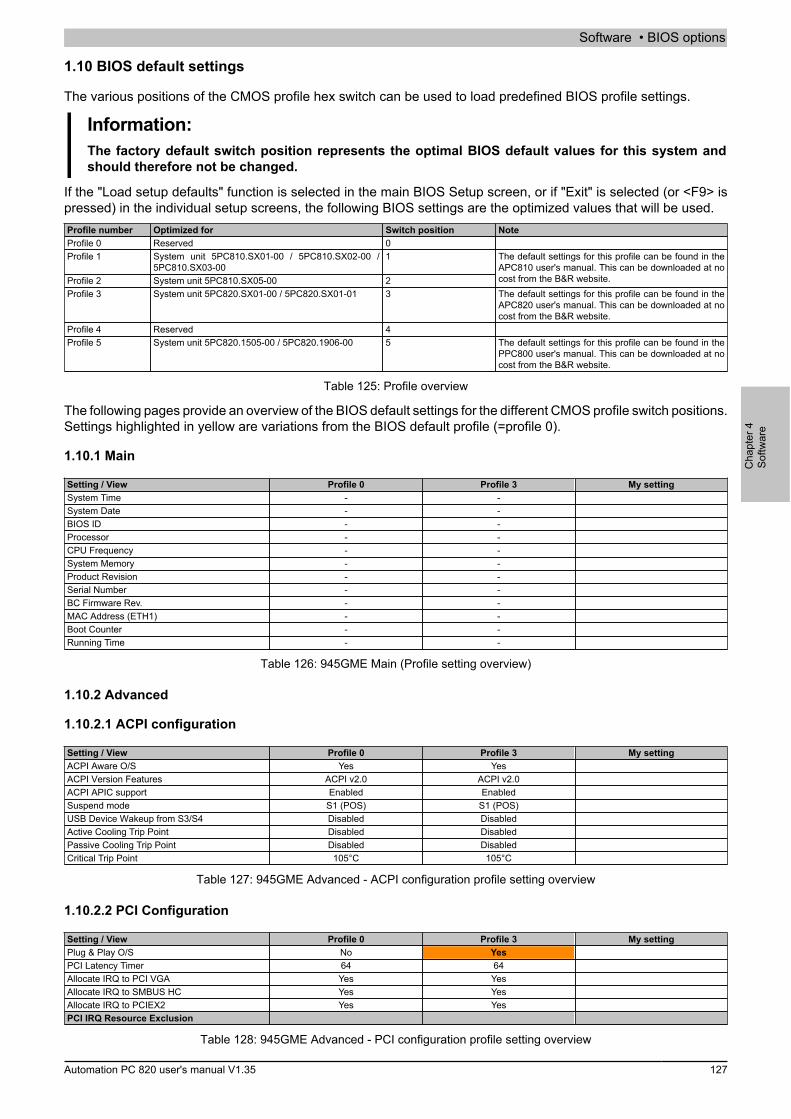
Software • BIOS options
Cha
pter
4So
ftwar
e
Automation PC 820 user's manual V1.35 127
1.10 BIOS default settings
The various positions of the CMOS profile hex switch can be used to load predefined BIOS profile settings.
Information:The factory default switch position represents the optimal BIOS default values for this system andshould therefore not be changed.
If the "Load setup defaults" function is selected in the main BIOS Setup screen, or if "Exit" is selected (or <F9> ispressed) in the individual setup screens, the following BIOS settings are the optimized values that will be used.Profile number Optimized for Switch position NoteProfile 0 Reserved 0Profile 1 System unit 5PC810.SX01-00 / 5PC810.SX02-00 /
5PC810.SX03-001
Profile 2 System unit 5PC810.SX05-00 2
The default settings for this profile can be found in theAPC810 user's manual. This can be downloaded at nocost from the B&R website.
Profile 3 System unit 5PC820.SX01-00 / 5PC820.SX01-01 3 The default settings for this profile can be found in theAPC820 user's manual. This can be downloaded at nocost from the B&R website.
Profile 4 Reserved 4Profile 5 System unit 5PC820.1505-00 / 5PC820.1906-00 5 The default settings for this profile can be found in the
PPC800 user's manual. This can be downloaded at nocost from the B&R website.
Table 125: Profile overview
The following pages provide an overview of the BIOS default settings for the different CMOS profile switch positions.Settings highlighted in yellow are variations from the BIOS default profile (=profile 0).
1.10.1 Main
Setting / View Profile 0 Profile 3 My settingSystem Time - -System Date - -BIOS ID - -Processor - -CPU Frequency - -System Memory - -Product Revision - -Serial Number - -BC Firmware Rev. - -MAC Address (ETH1) - -Boot Counter - -Running Time - -
Table 126: 945GME Main (Profile setting overview)
1.10.2 Advanced
1.10.2.1 ACPI configuration
Setting / View Profile 0 Profile 3 My settingACPI Aware O/S Yes YesACPI Version Features ACPI v2.0 ACPI v2.0ACPI APIC support Enabled EnabledSuspend mode S1 (POS) S1 (POS)USB Device Wakeup from S3/S4 Disabled DisabledActive Cooling Trip Point Disabled DisabledPassive Cooling Trip Point Disabled DisabledCritical Trip Point 105°C 105°C
Table 127: 945GME Advanced - ACPI configuration profile setting overview
1.10.2.2 PCI Configuration
Setting / View Profile 0 Profile 3 My settingPlug & Play O/S No YesPCI Latency Timer 64 64Allocate IRQ to PCI VGA Yes YesAllocate IRQ to SMBUS HC Yes YesAllocate IRQ to PCIEX2 Yes YesPCI IRQ Resource Exclusion
Table 128: 945GME Advanced - PCI configuration profile setting overview
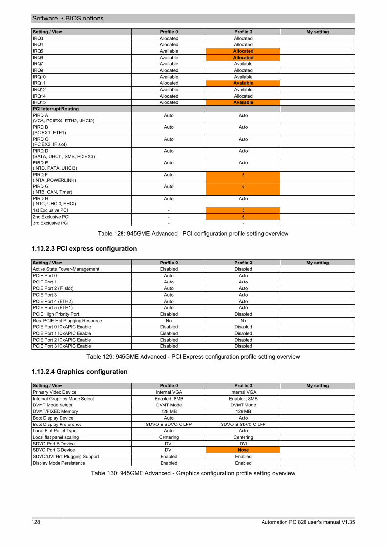
Software • BIOS options
128 Automation PC 820 user's manual V1.35
Setting / View Profile 0 Profile 3 My settingIRQ3 Allocated AllocatedIRQ4 Allocated AllocatedIRQ5 Available AllocatedIRQ6 Available AllocatedIRQ7 Available AvailableIRQ9 Allocated AllocatedIRQ10 Available AvailableIRQ11 Allocated AvailableIRQ12 Available AvailableIRQ14 Allocated AllocatedIRQ15 Allocated AvailablePCI Interrupt RoutingPIRQ A(VGA, PCIEX0, ETH2, UHCI2)
Auto Auto
PIRQ B(PCIEX1, ETH1)
Auto Auto
PIRQ C(PCIEX2, IF slot)
Auto Auto
PIRQ D(SATA, UHCI1, SMB, PCIEX3)
Auto Auto
PIRQ E(INTD, PATA, UHCI3)
Auto Auto
PIRQ F(INTA ,POWERLINK)
Auto 5
PIRQ G(INTB, CAN, Timer)
Auto 6
PIRQ H(INTC, UHCI0, EHCI)
Auto Auto
1st Exclusive PCI - 52nd Exclusive PCI - 63rd Exclusive PCI - -
Table 128: 945GME Advanced - PCI configuration profile setting overview
1.10.2.3 PCI express configuration
Setting / View Profile 0 Profile 3 My settingActive State Power-Management Disabled DisabledPCIE Port 0 Auto AutoPCIE Port 1 Auto AutoPCIE Port 2 (IF slot) Auto AutoPCIE Port 3 Auto AutoPCIE Port 4 (ETH2) Auto AutoPCIE Port 5 (ETH1) Auto AutoPCIE High Priority Port Disabled DisabledRes. PCIE Hot Plugging Resource No NoPCIE Port 0 IOxAPIC Enable Disabled DisabledPCIE Port 1 IOxAPIC Enable Disabled DisabledPCIE Port 2 IOxAPIC Enable Disabled DisabledPCIE Port 3 IOxAPIC Enable Disabled Disabled
Table 129: 945GME Advanced - PCI Express configuration profile setting overview
1.10.2.4 Graphics configuration
Setting / View Profile 0 Profile 3 My settingPrimary Video Device Internal VGA Internal VGAInternal Graphics Mode Select Enabled, 8MB Enabled, 8MBDVMT Mode Select DVMT Mode DVMT ModeDVMT/FIXED Memory 128 MB 128 MBBoot Display Device Auto AutoBoot Display Preference SDVO-B SDVO-C LFP SDVO-B SDV0-C LFPLocal Flat Panel Type Auto AutoLocal flat panel scaling Centering CenteringSDVO Port B Device DVI DVISDVO Port C Device DVI NoneSDVO/DVI Hot Plugging Support Enabled EnabledDisplay Mode Persistence Enabled Enabled
Table 130: 945GME Advanced - Graphics configuration profile setting overview
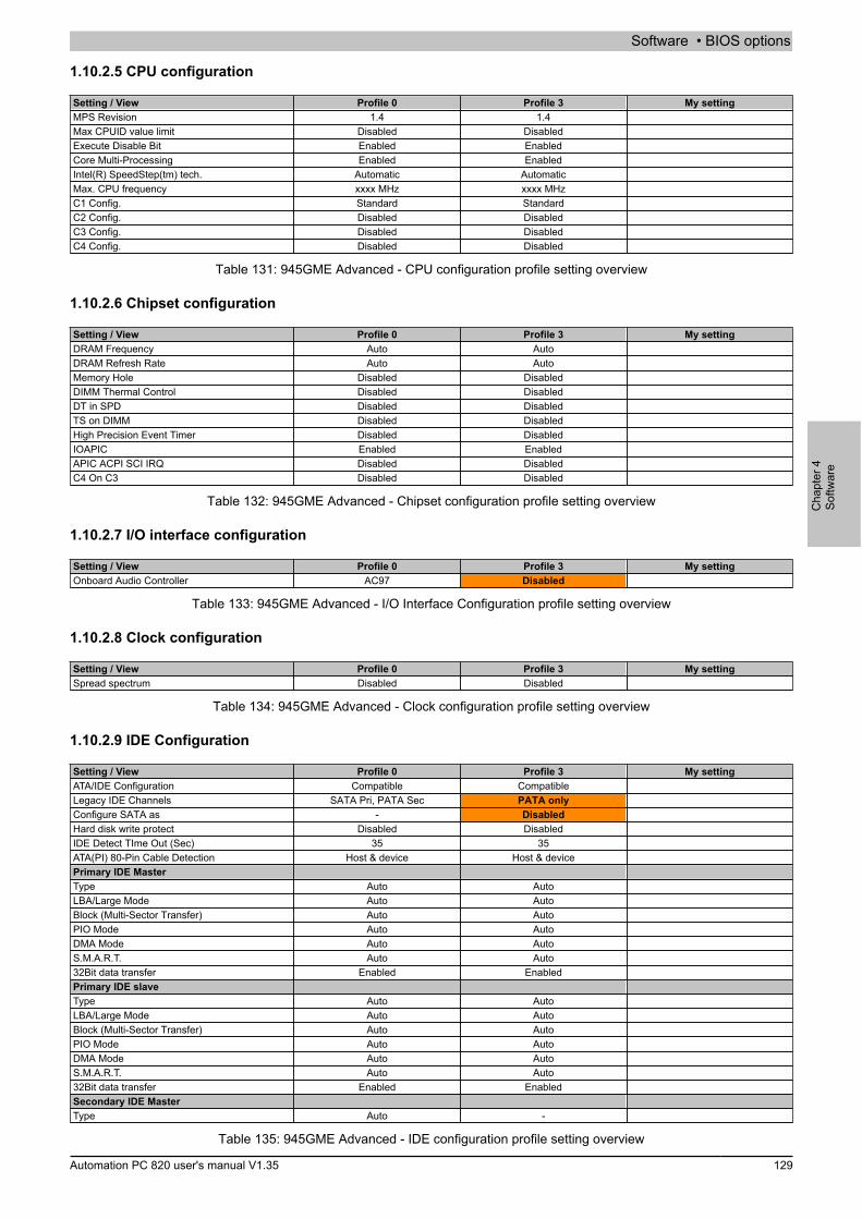
Software • BIOS options
Cha
pter
4So
ftwar
e
Automation PC 820 user's manual V1.35 129
1.10.2.5 CPU configuration
Setting / View Profile 0 Profile 3 My settingMPS Revision 1.4 1.4Max CPUID value limit Disabled DisabledExecute Disable Bit Enabled EnabledCore Multi-Processing Enabled EnabledIntel(R) SpeedStep(tm) tech. Automatic AutomaticMax. CPU frequency xxxx MHz xxxx MHzC1 Config. Standard StandardC2 Config. Disabled DisabledC3 Config. Disabled DisabledC4 Config. Disabled Disabled
Table 131: 945GME Advanced - CPU configuration profile setting overview
1.10.2.6 Chipset configuration
Setting / View Profile 0 Profile 3 My settingDRAM Frequency Auto AutoDRAM Refresh Rate Auto AutoMemory Hole Disabled DisabledDIMM Thermal Control Disabled DisabledDT in SPD Disabled DisabledTS on DIMM Disabled DisabledHigh Precision Event Timer Disabled DisabledIOAPIC Enabled EnabledAPIC ACPI SCI IRQ Disabled DisabledC4 On C3 Disabled Disabled
Table 132: 945GME Advanced - Chipset configuration profile setting overview
1.10.2.7 I/O interface configuration
Setting / View Profile 0 Profile 3 My settingOnboard Audio Controller AC97 Disabled
Table 133: 945GME Advanced - I/O Interface Configuration profile setting overview
1.10.2.8 Clock configuration
Setting / View Profile 0 Profile 3 My settingSpread spectrum Disabled Disabled
Table 134: 945GME Advanced - Clock configuration profile setting overview
1.10.2.9 IDE Configuration
Setting / View Profile 0 Profile 3 My settingATA/IDE Configuration Compatible CompatibleLegacy IDE Channels SATA Pri, PATA Sec PATA onlyConfigure SATA as - DisabledHard disk write protect Disabled DisabledIDE Detect TIme Out (Sec) 35 35ATA(PI) 80-Pin Cable Detection Host & device Host & devicePrimary IDE MasterType Auto AutoLBA/Large Mode Auto AutoBlock (Multi-Sector Transfer) Auto AutoPIO Mode Auto AutoDMA Mode Auto AutoS.M.A.R.T. Auto Auto32Bit data transfer Enabled EnabledPrimary IDE slaveType Auto AutoLBA/Large Mode Auto AutoBlock (Multi-Sector Transfer) Auto AutoPIO Mode Auto AutoDMA Mode Auto AutoS.M.A.R.T. Auto Auto32Bit data transfer Enabled EnabledSecondary IDE MasterType Auto -
Table 135: 945GME Advanced - IDE configuration profile setting overview
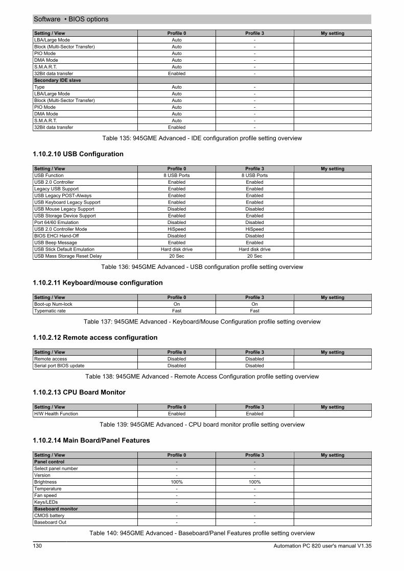
Software • BIOS options
130 Automation PC 820 user's manual V1.35
Setting / View Profile 0 Profile 3 My settingLBA/Large Mode Auto -Block (Multi-Sector Transfer) Auto -PIO Mode Auto -DMA Mode Auto -S.M.A.R.T. Auto -32Bit data transfer Enabled -Secondary IDE slaveType Auto -LBA/Large Mode Auto -Block (Multi-Sector Transfer) Auto -PIO Mode Auto -DMA Mode Auto -S.M.A.R.T. Auto -32Bit data transfer Enabled -
Table 135: 945GME Advanced - IDE configuration profile setting overview
1.10.2.10 USB Configuration
Setting / View Profile 0 Profile 3 My settingUSB Function 8 USB Ports 8 USB PortsUSB 2.0 Controller Enabled EnabledLegacy USB Support Enabled EnabledUSB Legacy POST-Always Enabled EnabledUSB Keyboard Legacy Support Enabled EnabledUSB Mouse Legacy Support Disabled DisabledUSB Storage Device Support Enabled EnabledPort 64/60 Emulation Disabled DisabledUSB 2.0 Controller Mode HiSpeed HiSpeedBIOS EHCI Hand-Off Disabled DisabledUSB Beep Message Enabled EnabledUSB Stick Default Emulation Hard disk drive Hard disk driveUSB Mass Storage Reset Delay 20 Sec 20 Sec
Table 136: 945GME Advanced - USB configuration profile setting overview
1.10.2.11 Keyboard/mouse configuration
Setting / View Profile 0 Profile 3 My settingBoot-up Num-lock On OnTypematic rate Fast Fast
Table 137: 945GME Advanced - Keyboard/Mouse Configuration profile setting overview
1.10.2.12 Remote access configuration
Setting / View Profile 0 Profile 3 My settingRemote access Disabled DisabledSerial port BIOS update Disabled Disabled
Table 138: 945GME Advanced - Remote Access Configuration profile setting overview
1.10.2.13 CPU Board Monitor
Setting / View Profile 0 Profile 3 My settingH/W Health Function Enabled Enabled
Table 139: 945GME Advanced - CPU board monitor profile setting overview
1.10.2.14 Main Board/Panel Features
Setting / View Profile 0 Profile 3 My settingPanel control - -Select panel number - -Version - -Brightness 100% 100%Temperature - -Fan speed - -Keys/LEDs - -Baseboard monitorCMOS battery - -Baseboard Out - -
Table 140: 945GME Advanced - Baseboard/Panel Features profile setting overview

Software • BIOS options
Cha
pter
4So
ftwar
e
Automation PC 820 user's manual V1.35 131
Setting / View Profile 0 Profile 3 My settingBaseboard Center - -Baseboard In - -Power supply - -IF slot - -Case 1 - -Case 2 - -Case 3 - -Case 4 - -Legacy DevicesCOM A Enabled EnabledBase I/O address 3F8 3F8Interrupt IRQ4 IRQ4COM B Enabled EnabledBase I/O address 2F8 2F8Interrupt IRQ3 IRQ3COM C Enabled DisabledBase I/O address 3E8 -Interrupt IRQ11 -CAN Disabled DisabledHardware security key Enabled EnabledBase I/O address 378 378ETH2 LAN Controller Enabled EnabledETH2 MAC Address - -
Table 140: 945GME Advanced - Baseboard/Panel Features profile setting overview
1.10.3 Boot
Setting / View Profile 0 Profile 3 My settingBoot Priority Selection Type Based Type Based1st Boot Device Onboard LAN Primary Master2nd Boot Device Primary Master Primary Slave3rd Boot Device Primary Slave USB Floppy4th Boot Device USB Floppy USB Removable Device5th Boot Device USB Removable Device USB Hard Disk6th Boot Device USB CDROM USB CDROM7th Boot Device Secondary Master Disabled8th Boot Device Secondary Slave DisabledQuick Boot Enabled EnabledQuiet Boot Disabled DisabledAutomatic Boot List Retry Disabled DisabledAdd-On ROM Display Mode Keep Current Keep CurrentHalt On Error Disabled DisabledHit "DEL" Message Display Enabled EnabledInterrupt 19 Capture Disabled DisabledPXE boot to LAN (ETH1) Enabled DisabledSlide-in 2 optional ROM Enabled DisabledPower Loss Control Turn On Turn On
Table 141: 945GME Main (Profile setting overview)
1.10.4 Security
Setting / View Profile 0 Profile 3 My settingSupervisor Password - -User Password - -Boot Sector Virus Protection Disabled DisabledHard disk security user password - -Hard disk security master password - -
Table 142: 945GME Security profile setting overview
1.10.5 Power
Setting / View Profile 0 Profile 3 My settingPower Management/APM Enabled EnabledSuspend Time Out Disabled DisabledVideo Power Down Mode Suspend SuspendHard Disk Power Down Mode Suspend SuspendKeyboard & PS/2 Mouse MONITOR MONITORFDC/LPT/COM ports MONITOR MONITORPrimary Master IDE MONITOR MONITOR
Table 143: 945GME Power profile setting overview

Software • BIOS options
132 Automation PC 820 user's manual V1.35
Setting / View Profile 0 Profile 3 My settingPrimary Slave IDE MONITOR MONITORSecondary Master IDE MONITOR MONITORSecondary Slave IDE MONITOR MONITORResume On Ring Disabled DisabledResume on PME# Disabled DisabledResume On RTC Alarm Disabled DisabledPower Button Mode On/Off On/Off
Table 143: 945GME Power profile setting overview

Software • BIOS options
Cha
pter
4So
ftwar
e
Automation PC 820 user's manual V1.35 133
1.11 BIOS error signals (beep codes)
While the B&R Industrial PC is booting, the following messages and errors can occur with BIOS. These errors aresignaled by different beep codes.Beep code Description Necessary user action1x short Memory refresh failed Load BIOS defaults. If the error persists, send the industrial PC to
B&R for testing.2x short Parity error: POST error (error in one of the hardware testing proce-
dures)Check that the card has been inserted properly. If the error persists,send the industrial PC to B&R for testing.
3x short Base 64 kB memory failure: Basic memory error, RAM error withinthe initial 64 kB
Send the industrial PC to B&R for testing.
4x short Timer not operational: System timer Send the industrial PC to B&R for testing.5x short Processor error: Defective processor Send the industrial PC to B&R for testing.6x short 8042 gate A20 failure: Defective keyboard controller (block 8042/
gate A20). The processor cannot switch to protected mode.Send the industrial PC to B&R for testing.
7x short Processor exception interrupt error: Virtual mode exception error(CPU generated an interrupt error)
Send the industrial PC to B&R for testing.
8x short Display memory read/write error: Video memory not accessible, de-fective graphics card or not installed (not a fatal error)
Check that the graphics card has been inserted correctly, replaceif necessary. If the error persists, send the industrial PC to B&R fortesting.
9x short ROM checksum error: ROM BIOS checksum incorrect; defectiveEPROM, EEPROM or flash ROM component; defective BIOS or in-correctly updated
Send the industrial PC to B&R for testing.
10x short CMOS shutdown register read/write error: Unable to read/write from/to CMOS
Send the industrial PC to B&R for testing.
11x short Cache error / external cache bad: Defective L2 cache on the main-board
Send the industrial PC to B&R for testing.
Table 144: 945GME BIOS - POST messages
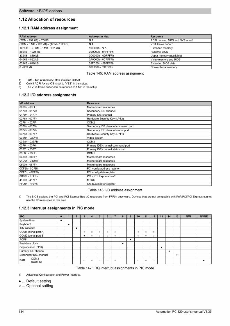
Software • BIOS options
134 Automation PC 820 user's manual V1.35
1.12 Allocation of resources
1.12.1 RAM address assignment
RAM address Address in Hex Resource(TOM - 192 kB) – TOM1) N.A. ACPI reclaim, MPS and NVS area2)
(TOM - 8 MB - 192 kB) – (TOM - 192 kB) N.A. VGA frame buffer3)
1024 kB – (TOM - 8 MB - 192 kB) 100000h - N.A. Extended memory869kB – 1024 kB 0E0000h - 0FFFFFh Runtime BIOS832kB – 869 kB 0D0000h - 0DFFFFh Upper memory (available)640kB – 832 kB 0A0000h - 0CFFFFh Video memory and BIOS639kB – 640 kB 09FC00h - 09FFFFh Extended BIOS data0 - 639 kB 000000h - 09FC00h Conventional memory
Table 145: RAM address assignment
1) TOM - Top of memory: Max. installed DRAM2) Only if ACPI Aware OS is set to "YES" in the setup.3) The VGA frame buffer can be reduced to 1 MB in the setup.
1.12.2 I/O address assignments
I/O address Resource0000h - 00FFh Motherboard resources0170h - 0177h Secondary IDE channel01F0h - 01F7h Primary IDE channel0278h - 027Fh Hardware Security Key (LPT2)02F8h - 02FFh COM20376h - 0376h Secondary IDE channel command port0377h - 0377h Secondary IDE channel status port0378h - 037Fh Hardware Security Key (LPT1)03B0h - 03DFh Video system03E8h - 03EFh COM303F6h - 03F6h Primary IDE channel command port03F7h - 03F7h Primary IDE channel status port03F8h - 03FFh COM10480h - 04BFh Motherboard resources04D0h - 04D1h Motherboard resources0800h - 087Fh Motherboard resources0CF8h - 0CFBh PCI config address register0CFCh - 0CFFh PCI config data register0D00h - FFFFh PCI / PCI Express bus1)
4100h - 417Fh MTCXFF00h - FF07h IDE bus master register
Table 146: I/O address assignment
1) The BIOS assigns the PCI and PCI Express Bus I/O resources from FFF0h downward. Devices that are not compatible with PnP/PCI/PCI Express cannotuse the I/O resources in this area.
1.12.3 Interrupt assignments in PIC mode
IRQ 0 1 2 3 4 5 6 7 8 9 10 11 12 13 14 15 NMI NONESystem timer ●Keyboard ●IRQ cascade ●COM1 (serial port A) ○ ● ○ ○ ○ ○ ○ ○COM2 (serial port B) ● ○ ○ ○ ○ ○ ○ ○ACPI1) ●Real-time clock ●Coprocessor (FPU) ●Primary IDE channel ●Secondary IDE channel ○
B&R COM3(COM C) ○ ○ ○ ○ ○ ○ ○ ○ ●
Table 147: IRQ interrupt assignments in PIC mode
1) Advanced Configuration and Power Interface.
● ... Default setting○ ... Optional setting
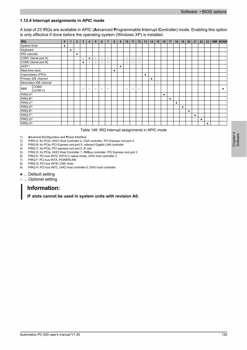
Software • BIOS options
Cha
pter
4So
ftwar
e
Automation PC 820 user's manual V1.35 135
1.12.4 Interrupt assignments in APIC mode
A total of 23 IRQs are available in APIC (Advanced Programmable Interrupt Controller) mode. Enabling this optionis only effective if done before the operating system (Windows XP) is installed.IRQ 0 1 2 3 4 5 6 7 8 9 10 11 12 13 14 15 16 17 18 19 20 21 22 23 NMI NONESystem timer ●Keyboard ●IRQ cascade ●COM1 (Serial port A) ○ ● ○ ○ ○ ○ ○ ○COM2 (Serial port B) ● ○ ○ ○ ○ ○ ○ ○ACPI1) ●Real-time clock ●Coprocessor (FPU) ●Primary IDE channel ●Secondary IDE channel ○
B&R COM3(COM C) ○ ○ ○ ○ ○ ○ ○ ○ ●
PIRQ A2) ●PIRQ B3) ●PIRQ C4) ●PIRQ D5) ●PIRQ E6) ●PIRQ F7) ●PIRQ G8) ●PIRQ H9) ●
Table 148: IRQ interrupt assignments in APIC mode
1) Advanced Configuration and Power Interface.2) PIRQ A: for PCIe; UHCI Host Controller 2, VGA controller, PCI Express root port 43) PIRQ B: for PCIe; PCI Express root port 5, onboard Gigabit LAN controller4) PIRQ C: for PCIe; PCI express root port 2, IF slot5) PIRQ D: for PCIe; UHCI Host Controller 1, SMBus controller, PCI Express root port 36) PIRQ E: PCI bus INTD, PATA in native mode, UHCI host controller 37) PIRQ F: PCI bus INTA, POWERLINK8) PIRQ G: PCI bus INTB, CAN, timer9) PIRQ H: PCI bus INTC, UHCI host controller 0, EHCI host controller
● ... Default setting○ ... Optional setting
Information:IF slots cannot be used in system units with revision A0.
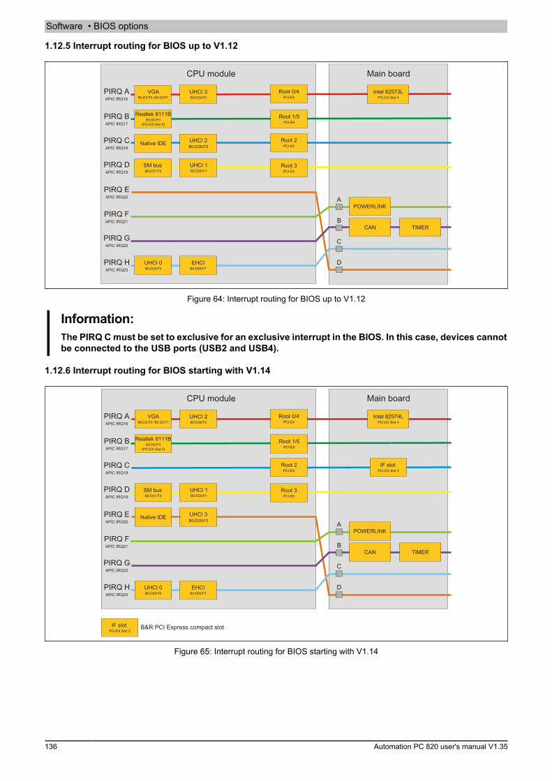
Software • BIOS options
136 Automation PC 820 user's manual V1.35
1.12.5 Interrupt routing for BIOS up to V1.12
PIRQ AAPIC IRQ16
CPU module
UHCI 3B0:D29:F3
VGAB0:D2:F0, B0:D2:F1
PIRQ BAPIC IRQ17
PIRQ CAPIC IRQ18
PIRQ DAPIC IRQ19
PIRQ EAPIC IRQ20
Root 0/4PCI-EX
Root 1/5PCI-EX
Root 2PCI-EX
UHCI 1B0:D29:F1
PIRQ FAPIC IRQ21
PIRQ GAPIC IRQ22
UHCI 0B0:D29:F0
PIRQ HAPIC IRQ23
EHCIB0:D29:F7
Main board
Intel 82573LPCI-EX Slot 4
Realtek 8111BB3:D0:F0
(PCI-EX Slot 5)
Native IDE
SM busB0:D31:F3
UHCI 2B0:D29:F2
D
C
B
APOWERLINK
CAN TIMER
Root 3PCI-EX
Figure 64: Interrupt routing for BIOS up to V1.12
Information:The PIRQ C must be set to exclusive for an exclusive interrupt in the BIOS. In this case, devices cannotbe connected to the USB ports (USB2 and USB4).
1.12.6 Interrupt routing for BIOS starting with V1.14
PIRQ AAPIC IRQ16
CPU module
UHCI 2B0:D29:F2
VGAB0:D2:F0, B0:D2:F1
PIRQ BAPIC IRQ17
PIRQ CAPIC IRQ18
PIRQ DAPIC IRQ19
PIRQ EAPIC IRQ20
Root 0/4PCI-EX
Root 1/5PCI-EX
Root 2PCI-EX
UHCI 1B0:D29:F1
PIRQ FAPIC IRQ21
PIRQ GAPIC IRQ22
UHCI 0B0:D29:F0
PIRQ HAPIC IRQ23
EHCIB0:D29:F7
Main board
Intel 82574LPCI-EX Slot 4
Realtek 8111BB3:D0:F0
(PCI-EX Slot 5)
Native IDE
SM busB0:D31:F3
UHCI 3B0:D29:F3
D
C
B
APOWERLINK
CAN TIMER
Root 3PCI-EX
IF slotPCI-EX Slot 2
IF slotPCI-EX Slot 2
B&R PCI Express compact slot
Figure 65: Interrupt routing for BIOS starting with V1.14
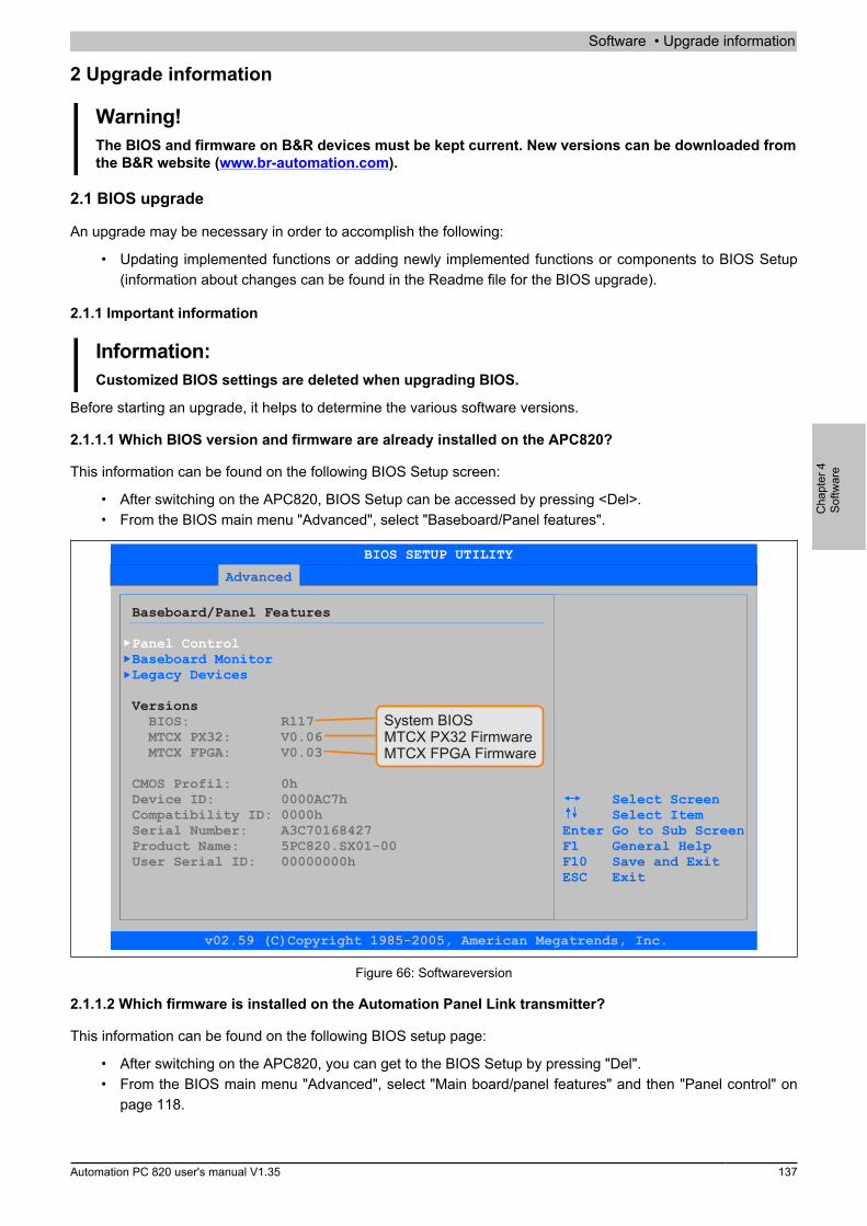
Software • Upgrade information
Cha
pter
4So
ftwar
e
Automation PC 820 user's manual V1.35 137
2 Upgrade information
Warning!The BIOS and firmware on B&R devices must be kept current. New versions can be downloaded fromthe B&R website (www.br-automation.com).
2.1 BIOS upgrade
An upgrade may be necessary in order to accomplish the following:
• Updating implemented functions or adding newly implemented functions or components to BIOS Setup(information about changes can be found in the Readme file for the BIOS upgrade).
2.1.1 Important information
Information:Customized BIOS settings are deleted when upgrading BIOS.
Before starting an upgrade, it helps to determine the various software versions.
2.1.1.1 Which BIOS version and firmware are already installed on the APC820?
This information can be found on the following BIOS Setup screen:
• After switching on the APC820, BIOS Setup can be accessed by pressing <Del>.• From the BIOS main menu "Advanced", select "Baseboard/Panel features".
Advanced
Baseboard/Panel Features
Versions
Panel Control
BIOS: R117 MTCX PX32: V0.06 MTCX FPGA: V0.03
CMOS Profil: 0hDevice ID: 0000AC7h Compatibility ID: 0000hSerial Number: A3C70168427
User Serial ID: 00000000hProduct Name: 5PC820.SX01-00
Baseboard MonitorLegacy Devices
Select ScreenSelect Item
Enter Go to Sub ScreenF1 General HelpF10 Save and Exit
ESC Exit
BIOS SETUP UTILITY
v02.59 (C)Copyright 1985-2005, American Megatrends, Inc.
System BIOSMTCX PX32 FirmwareMTCX FPGA Firmware
Figure 66: Softwareversion
2.1.1.2 Which firmware is installed on the Automation Panel Link transmitter?
This information can be found on the following BIOS setup page:
• After switching on the APC820, you can get to the BIOS Setup by pressing "Del".• From the BIOS main menu "Advanced", select "Main board/panel features" and then "Panel control" on
page 118.
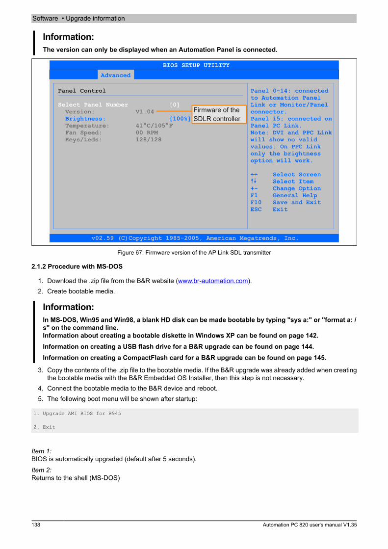
Software • Upgrade information
138 Automation PC 820 user's manual V1.35
Information:The version can only be displayed when an Automation Panel is connected.
Advanced
Panel Control Panel 0-14: connectedto Automation PanelLink or Monitor/Panelconnector.
Brightness: [100%] Panel 15: connected onPanel PC Link.Note: DVI and PPC Linkwill show no valid
values. On PPC Link only the brightness
option will work.
Select ScreenSelect Item
+- Change Option F1 General Help
F10 Save and Exit ESC Exit
Select Panel Number [0] Version: V1.04
Temperature: 41°C/105°F Fan Speed: 00 RPM Keys/Leds: 128/128
BIOS SETUP UTILITY
v02.59 (C)Copyright 1985-2005, American Megatrends, Inc.
Firmware of theSDLR controller
Figure 67: Firmware version of the AP Link SDL transmitter
2.1.2 Procedure with MS-DOS
1. Download the .zip file from the B&R website (www.br-automation.com).2. Create bootable media.
Information:In MS-DOS, Win95 and Win98, a blank HD disk can be made bootable by typing "sys a:" or "format a: /s" on the command line.Information about creating a bootable diskette in Windows XP can be found on page 142.Information on creating a USB flash drive for a B&R upgrade can be found on page 144.Information on creating a CompactFlash card for a B&R upgrade can be found on page 145.
3. Copy the contents of the .zip file to the bootable media. If the B&R upgrade was already added when creatingthe bootable media with the B&R Embedded OS Installer, then this step is not necessary.
4. Connect the bootable media to the B&R device and reboot.5. The following boot menu will be shown after startup:
1. Upgrade AMI BIOS for B945
2. Exit
Item 1:BIOS is automatically upgraded (default after 5 seconds).Item 2:Returns to the shell (MS-DOS)
Software • Upgrade information
Cha
pter
4So
ftwar
e
Automation PC 820 user's manual V1.35 139
Information:If a button is not pressed within 5 seconds, then item 1 "Upgrade AMI BIOS for B945" is automaticallycarried out to update the industrial PC.
6. The system must be rebooted after a successful upgrade.7. Reboot and press <Del> to enter BIOS Setup and load the setup defaults, then select "Save changes and
exit".
2.1.3 Using the Control Center
1. Download the .zip file from the B&R website (www.br-automation.com).2. Open the Control Center in the Control Panel.3. Select the Versions tab.4. Under CPU board, click on Update for BIOS. This brings up the "Open" dialog box.5. Enter the name of the BIOS file or select the file under Filename.6. Click on Open. This brings up the "Open" dialog box.
The transfer can be canceled by clicking on Cancel. "Cancel" is disabled when writing to flash memory.Deleting the data in flash memory can take several seconds depending on the memory block being used. Theprogress indicator is not updated during this time.
Information:The system must be restarted for the BIOS settings to take effect and for the updated version to bedisplayed. The user is prompted to restart the system when closing the Control Center.
Information:For more information about saving and updating BIOS, please refer to the help documentation for theControl Center.
Software • Upgrade information
140 Automation PC 820 user's manual V1.35
2.2 Firmware upgrade
The "Firmware upgrade (MTCX, SDLR)" software makes it possible to update the firmware for multiple controllers(MTCX, SDLR) depending on the APC820 system variant.Current "Firmware upgrade (MTCX, SDLR)" software can be downloaded directly from the Download section ofthe B&R website (www.br-automation.com).
2.2.1 Procedure
Proceed as follows to carry out a firmware upgrade:1. Download the .zip file from the B&R website (www.br-automation.com).2. Create bootable media.
Information:In MS-DOS, Win95 and Win98, a blank HD disk can be made bootable by typing "sys a:" or "format a: /s" on the command line.Information about creating a bootable diskette in Windows XP can be found on page 142.Information on creating a USB flash drive for a B&R upgrade can be found on page 144.Information on creating a CompactFlash card for a B&R upgrade can be found on page 145.
3. Copy the contents of the .zip file to the bootable media. If the B&R upgrade was already added when creatingthe bootable media with the B&R Embedded OS Installer, then this step is not necessary.
4. Connect the bootable media to the B&R device and reboot.5. The following boot menu will be shown after startup:
Information:The following boot menu options including descriptions are based on Version 1.04 of the APC820upgrade (MTCX, SDLR) disk. In some cases, these descriptions might not match the version you arecurrently using.
1. Upgrade MTCX (APC820) PX32 and FPGA2. Upgrade SDLR (AP800/AP900) on Monitor/Panel2.1. Upgrade SDLR on AP 0 (AP800/AP900)2.2. Upgrade SDLR on AP 1 (AP800/AP900)2.3. Upgrade SDLR on AP 2 (AP800/AP900)2.4. Upgrade SDLR on AP 3 (AP800/AP900)2.5. Upgrade all SDLR (AP800/AP900)2.6. Return to Main Menu3. Exit
Item 1:Automatically upgrades the PX32 and FPGA of the MTCX (default after 5 seconds)Item 2:Opens Submenu 1 for upgrading the SDLR controller on the monitor/panel interface2.1 Upgrade SDLR on AP 0 (AP800/AP900)Automatically updates the SDLR controller on the Automation Panel 0 interface2.2 Upgrade SDLR on AP 1 (AP800/AP900)Automatically updates the SDLR controller on the Automation Panel 1 interface2.3 Upgrade SDLR on AP 2 (AP800/AP900)Automatically updates the SDLR controller on the Automation Panel 2 interface2.4 Upgrade SDLR on AP 3 (AP800/AP900)Automatically updates the SDLR controller on the Automation Panel 3 interface2.5 Upgrade all SDLR (AP800/AP900)Automatically updates all SDLR controllers on all Automation Panels on the monitor/panel interface (default selec-tion after 5 sec)2.6 Return to main menuReturns to the main menu

Software • Upgrade information
Cha
pter
4So
ftwar
e
Automation PC 820 user's manual V1.35 141
Item 3:Returns to the shell (MS-DOS)
Information:The system must be powered off and back on again after a successful upgrade.
2.2.2 Possible upgrade problems and software dependencies (for V1.04)
• The SDLR firmware can only be updated if an Automation Panel with Automation Panel Link transceiver(5DLSDL.1000-01) and Automation Panel Link receiver (5DLSDL.1000-00) is connected.
• Automation Panel Link transceivers (5DLSDL.1000-01) or Automation Panel Link receivers(5DLSDL.1000-00) with a firmware version less than or equal to V00.10 can no longer be com-bined with Automation Panel Link transceivers (5DLSDL.1000-01) or Automation Panel Link receivers(5DLSDL.1000-00) with a firmware version greater than or equal to V01.04. Daisy chain mode is not pos-sible with this type of a combination.
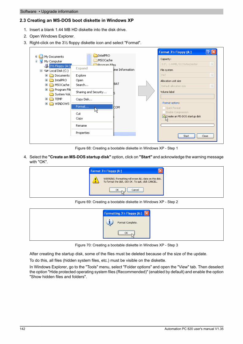
Software • Upgrade information
142 Automation PC 820 user's manual V1.35
2.3 Creating an MS-DOS boot diskette in Windows XP
1. Insert a blank 1.44 MB HD diskette into the disk drive.2. Open Windows Explorer.3. Right-click on the 3½ floppy diskette icon and select "Format".
Figure 68: Creating a bootable diskette in Windows XP - Step 1
4. Select the "Create an MS-DOS startup disk" option, click on "Start" and acknowledge the warning messagewith "OK".
Figure 69: Creating a bootable diskette in Windows XP - Step 2
Figure 70: Creating a bootable diskette in Windows XP - Step 3
After creating the startup disk, some of the files must be deleted because of the size of the update.To do this, all files (hidden system files, etc.) must be visible on the diskette.In Windows Explorer, go to the "Tools" menu, select "Folder options" and open the "View" tab. Then deselectthe option "Hide protected operating system files (Recommended)" (enabled by default) and enable the option"Show hidden files and folders".

Software • Upgrade information
Cha
pter
4So
ftwar
e
Automation PC 820 user's manual V1.35 143
before after
Figure 71: Creating a bootable diskette in Windows XP - Step 4
Figure 72: Creating a bootable diskette in Windows XP - Step 5
Now all files (selected) except Command.com, IO.sys and MSDOS.sys can be deleted.
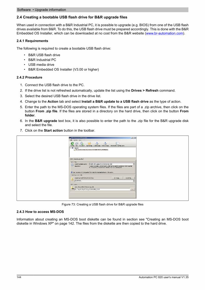
Software • Upgrade information
144 Automation PC 820 user's manual V1.35
2.4 Creating a bootable USB flash drive for B&R upgrade files
When used in connection with a B&R Industrial PC, it is possible to upgrade (e.g. BIOS) from one of the USB flashdrives available from B&R. To do this, the USB flash drive must be prepared accordingly. This is done with the B&REmbedded OS Installer, which can be downloaded at no cost from the B&R website (www.br-automation.com).
2.4.1 Requirements
The following is required to create a bootable USB flash drive:
• B&R USB flash drive• B&R Industrial PC• USB media drive• B&R Embedded OS Installer (V3.00 or higher)
2.4.2 Procedure
1. Connect the USB flash drive to the PC.2. If the drive list is not refreshed automatically, update the list using the Drives > Refresh command.3. Select the desired USB flash drive in the drive list.4. Change to the Action tab and select Install a B&R update to a USB flash drive as the type of action.5. Enter the path to the MS-DOS operating system files. If the files are part of a .zip archive, then click on the
button From .zip file. If the files are stored in a directory on the hard drive, then click on the button Fromfolder.
6. In the B&R upgrade text box, it is also possible to enter the path to the .zip file for the B&R upgrade diskand select the file.
7. Click on the Start action button in the toolbar.
Figure 73: Creating a USB flash drive for B&R upgrade files
2.4.3 How to access MS-DOS
Information about creating an MS-DOS boot diskette can be found in section see "Creating an MS-DOS bootdiskette in Windows XP" on page 142. The files from the diskette are then copied to the hard drive.
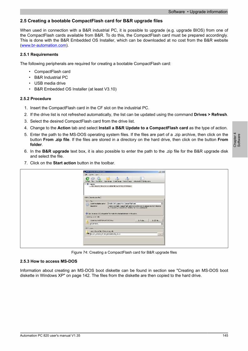
Software • Upgrade information
Cha
pter
4So
ftwar
e
Automation PC 820 user's manual V1.35 145
2.5 Creating a bootable CompactFlash card for B&R upgrade files
When used in connection with a B&R industrial PC, it is possible to upgrade (e.g. upgrade BIOS) from one ofthe CompactFlash cards available from B&R. To do this, the CompactFlash card must be prepared accordingly.This is done with the B&R Embedded OS Installer, which can be downloaded at no cost from the B&R website(www.br-automation.com).
2.5.1 Requirements
The following peripherals are required for creating a bootable CompactFlash card:
• CompactFlash card• B&R Industrial PC• USB media drive• B&R Embedded OS Installer (at least V3.10)
2.5.2 Procedure
1. Insert the CompactFlash card in the CF slot on the industrial PC.2. If the drive list is not refreshed automatically, the list can be updated using the command Drives > Refresh.3. Select the desired CompactFlash card from the drive list.4. Change to the Action tab and select Install a B&R Update to a CompactFlash card as the type of action.5. Enter the path to the MS-DOS operating system files. If the files are part of a .zip archive, then click on the
button From .zip file. If the files are stored in a directory on the hard drive, then click on the button Fromfolder.
6. In the B&R upgrade text box, it is also possible to enter the path to the .zip file for the B&R upgrade diskand select the file.
7. Click on the Start action button in the toolbar.
Figure 74: Creating a CompactFlash card for B&R upgrade files
2.5.3 How to access MS-DOS
Information about creating an MS-DOS boot diskette can be found in section see "Creating an MS-DOS bootdiskette in Windows XP" on page 142. The files from the diskette are then copied to the hard drive.
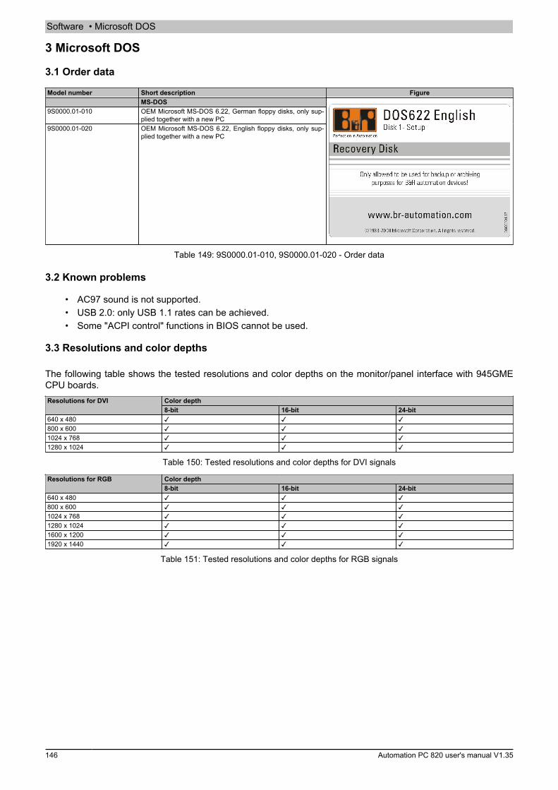
Software • Microsoft DOS
146 Automation PC 820 user's manual V1.35
3 Microsoft DOS
3.1 Order data
Model number Short description FigureMS-DOS
9S0000.01-010 OEM Microsoft MS-DOS 6.22, German floppy disks, only sup-plied together with a new PC
9S0000.01-020 OEM Microsoft MS-DOS 6.22, English floppy disks, only sup-plied together with a new PC
Table 149: 9S0000.01-010, 9S0000.01-020 - Order data
3.2 Known problems
• AC97 sound is not supported.• USB 2.0: only USB 1.1 rates can be achieved.• Some "ACPI control" functions in BIOS cannot be used.
3.3 Resolutions and color depths
The following table shows the tested resolutions and color depths on the monitor/panel interface with 945GMECPU boards.
Color depthResolutions for DVI8-bit 16-bit 24-bit
640 x 480 ✓ ✓ ✓800 x 600 ✓ ✓ ✓1024 x 768 ✓ ✓ ✓1280 x 1024 ✓ ✓ ✓
Table 150: Tested resolutions and color depths for DVI signals
Color depthResolutions for RGB8-bit 16-bit 24-bit
640 x 480 ✓ ✓ ✓800 x 600 ✓ ✓ ✓1024 x 768 ✓ ✓ ✓1280 x 1024 ✓ ✓ ✓1600 x 1200 ✓ ✓ ✓1920 x 1440 ✓ ✓ ✓
Table 151: Tested resolutions and color depths for RGB signals
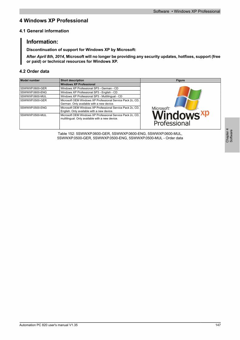
Software • Windows XP Professional
Cha
pter
4So
ftwar
e
Automation PC 820 user's manual V1.35 147
4 Windows XP Professional
4.1 General information
Information:Discontinuation of support for Windows XP by Microsoft:After April 8th, 2014, Microsoft will no longer be providing any security updates, hotfixes, support (freeor paid) or technical resources for Windows XP.
4.2 Order data
Model number Short description FigureWindows XP Professional
5SWWXP.0600-GER Windows XP Professional SP3 - German - CD5SWWXP.0600-ENG Windows XP Professional SP3 - English - CD5SWWXP.0600-MUL Windows XP Professional SP3 - Multilingual - CD5SWWXP.0500-GER Microsoft OEM Windows XP Professional Service Pack 2c, CD,
German. Only available with a new device.5SWWXP.0500-ENG Microsoft OEM Windows XP Professional Service Pack 2c, CD,
English. Only available with a new device.5SWWXP.0500-MUL Microsoft OEM Windows XP Professional Service Pack 2c, CD,
multilingual. Only available with a new device.
Table 152: 5SWWXP.0600-GER, 5SWWXP.0600-ENG, 5SWWXP.0600-MUL,5SWWXP.0500-GER, 5SWWXP.0500-ENG, 5SWWXP.0500-MUL - Order data

Software • Windows XP Professional
148 Automation PC 820 user's manual V1.35
4.3 Overview
Model number Edition Target sys-tem
Chipset Service pack Language Minimum hard diskspace required
Minimum RAM required
5SWWXP.0600-GER Professional APC510APC511APC620APC810APC820APC910PPC700PPC725PPC800PPC900PP500
945GMEGM45QM77/HM76NM10US15W
SP3 German ≤2.1 GB 128 MB
5SWWXP.0600-ENG Professional APC510APC511APC620APC810APC820APC910PPC700PPC725PPC800PPC900PP500
945GMEGM45QM77/HM76NM10US15W
SP3 English ≤2.1 GB 128 MB
5SWWXP.0600-MUL Professional APC510APC511APC620APC810APC820APC910PPC700PPC725PPC800PPC900PP500
945GMEGM45QM77/HM76NM10US15W
SP3 Multilingual ≤2.1 GB 128 MB
5SWWXP.0500-GER Professional APC620APC810APC820PPC700PPC725PPC800
945GMEGM45
SP2c German ≤2.1 GB 128 MB
5SWWXP.0500-ENG Professional APC620APC810APC820PPC700PPC725PPC800
945GMEGM45
SP2c English ≤2.1 GB 128 MB
5SWWXP.0500-MUL Professional APC620APC810APC820PPC700PPC725PPC800
945GMEGM45
SP2c Multilingual ≤2.1 GB 128 MB
4.4 Installation
B&R preinstalls the required Windows XP Professional version on the desired storage device (e.g. CompactFlashcard, etc.). All of the drivers required for operation (graphics, network, etc.) are also installed in this process.
4.5 Drivers
Current drivers for all approved operating systems are available in the Downloads section of the B&R website(www.br-automation.com).
Information:Required drivers can only be downloaded from the B&R website, not from manufacturer websites.
4.6 Supported display resolutions
In accordance with Microsoft requirements, Windows XP Professional requires SVGA resolution (800 x 600) orhigher in order to allow unimpeded operation of the Windows user interface (including system dialog boxes andapps, etc.). A lower resolution can be selected for applications.
Software • Windows XP Embedded
Cha
pter
4So
ftwar
e
Automation PC 820 user's manual V1.35 149
5 Windows XP Embedded
5.1 General information
Windows XP Embedded is the modular version of the desktop operating system Windows XP Professional. Win-dows XP Embedded is based on the same binary files as Windows XP Professional and is optimally tailored tothe hardware being used. In other words, only the functions and modules required by the respective device areincluded. Windows XP Embedded is also based on the same reliable code as Windows XP Professional. It pro-vides industry with leading reliability, improvements in security and performance and the latest technology for Webbrowsing and extensive device support.
5.2 Order data
Model number Short description FigureWindows XP Embedded
5SWWXP.0428-ENG Microsoft OEM Windows XP Embedded Feature Pack 2007,English; for APC820 with 945GME chipset; please order Com-pactFlash separately (minimum 512 MB).Required accessoriesCompactFlash cards
5CFCRD.016G-06 CompactFlash 16 GB B&R (SLC)5CFCRD.032G-06 CompactFlash 32 GB B&R (SLC)5CFCRD.0512-03 CompactFlash 512 MB Western Digital (SLC)5CFCRD.0512-06 CompactFlash 512 MB B&R (SLC)5CFCRD.1024-03 CompactFlash 1 GB Western Digital (SLC)5CFCRD.1024-06 CompactFlash 1 GB B&R (SLC)5CFCRD.2048-03 CompactFlash 2 GB Western Digital (SLC)5CFCRD.2048-06 CompactFlash 2 GB B&R (SLC)5CFCRD.4096-03 CompactFlash 4 GB Western Digital (SLC)5CFCRD.4096-06 CompactFlash 4 GB B&R (SLC)5CFCRD.8192-03 CompactFlash 8 GB Western Digital (SLC)5CFCRD.8192-06 CompactFlash 8 GB B&R (SLC)
Table 153: 5SWWXP.0428-ENG - Order data
5.3 Overview
Product ID 5SWWXP.0428-ENGOperating systemTarget systems
Industrial PC 1) APC820Chipset 945GME
Language EnglishMinimum RAM required 128 MBMinimum hard disk space required 2) 250 MBMinimum disk size 512 MB
Table 154: 5SWWXP.0428-ENG - Technical data
1) Can only be ordered together with a suitable B&R device.2) Data medium sold separately. The minimum size of the system partition is 488 MB.
5.4 Features with FP2007 (Feature Pack 2007)
The feature list shows the most important device functions in Windows XP Embedded with Feature Pack 2007(FP2007).Function PresentEnhanced Write Filter (EWF) ✓File Based Write Filter ✓Administrator accounts ✓User accounts ConfigurableExplorer shell ✓Registry filter ✓Internet Explorer 6.0 + SP2 ✓Internet information service (IIS) -Terminal service ✓Windows Firewall ✓MSN Explorer -Outlook Express -Administrative Tools ✓
Table 155: Device functions in Windows XP Embedded with FP2007
Software • Windows XP Embedded
150 Automation PC 820 user's manual V1.35
Function PresentRemote Desktop ✓Remote Assistance -.NET Framework -ASP.NET -Codepages / User locales / Keyboards ✓Disk Management Service ✓Windows Installer Service ✓Class Installer ✓CoDevice Installer ✓Media Player -DirectX -Accessories ✓Number of fonts 89
Table 155: Device functions in Windows XP Embedded with FP2007
5.5 Installation
B&R preinstalls Windows XP Embedded on a suitable CompactFlash card (minimum 512 MB). The system is thenautomatically configured when it is switched on for the first time. This procedure takes approximately 30 minutes,with the device being rebooted a number of times.
5.6 Drivers
All drivers required for operation are preinstalled along with the operating system. If an older version of the dri-ver is still being used, the latest version can be downloaded and installed from the B&R website (www.br-automa-tion.com). It is important that Enhanced Write Filter (EWF) is disabled for this.
5.6.1 Touch screen driver
The touch screen driver must be manually installed in order to operate Automation Panel 800 or Automation Panel900 touch screen devices. The driver is available in the Downloads section of the B&R website (www.br-automa-tion.com). Be sure to check that the "Enhanced Write Filter (EWF)" is enabled.
Information:Required drivers can only be downloaded from the B&R website, not from manufacturer websites.
Software • Windows Embedded Standard 2009
Cha
pter
4So
ftwar
e
Automation PC 820 user's manual V1.35 151
6 Windows Embedded Standard 2009
6.1 General information
Windows® Embedded Standard 2009 is the modular version of Windows® XP Professional. It is used if XP ap-plications should be executed with a minimal operating system size. Together with CompactFlash memory, Win-dows® Embedded Standard 2009 makes it possible to use the Microsoft desktop operating system in harsh envi-ronmental conditions. In addition to the familiar features included in Windows® XP Professional, Windows® Em-bedded Standard 2009 has been improved with regard to dependability by adding a write filter for individual mem-ory partitions. By protecting individual partitions such as the boot partition, the PC system can be started withoutproblems even after an unexpected power failure. B&R offers complete images for industrial PCs, Power Paneland Mobile Panel devices to make the transition to Windows® Embedded Standard 2009 as easy as possible. Inaddition to Windows® Embedded Standard 2009, the standard Windows® XP Professional operating system isalso available in English, German and a multilingual version.Windows® Embedded Standard 2009 is based on the same binary files as Windows® XP Professional with ServicePack 3 and is optimally tailored to the hardware being used. In other words, only the functions and modules requiredby the respective device are included. Windows® Embedded Standard 2009 is also based on the same reliablecode as Windows® XP Professional with SP3. It provides industry with leading reliability, security and performanceimprovements as well as the latest technology for web browsing and extensive device support.
6.2 Order data
Model number Short description FigureWindows Embedded Standard 2009
5SWWXP.0728-ENG Microsoft OEM Windows Embedded Standard 2009, English; forAPC820 with 945GME chipset; please order CompactFlash sep-arately (minimum 1 GB).Required accessoriesCompactFlash cards
5CFCRD.016G-06 CompactFlash 16 GB B&R (SLC)5CFCRD.032G-06 CompactFlash 32 GB B&R (SLC)5CFCRD.1024-06 CompactFlash 1 GB B&R (SLC)5CFCRD.2048-06 CompactFlash 2 GB B&R (SLC)5CFCRD.4096-06 CompactFlash 4 GB B&R (SLC)5CFCRD.8192-06 CompactFlash 8 GB B&R (SLC)
Table 156: 5SWWXP.0728-ENG - Order data
6.3 Overview
Product ID 5SWWXP.0728-ENGOperating systemTarget systems
Industrial PC 1) APC820Chipset 945GME
Language EnglishMinimum RAM required 256 MBMinimum disk size 2) 1 GB
Table 157: 5SWWXP.0728-ENG - Technical data
1) Can only be ordered together with a suitable B&R device.2) Data medium sold separately.
6.4 Features with WES2009 (Windows Embedded Standard 2009)
The following list of features shows the most important device functions included in Windows Embedded Standard2009.Function PresentEnhanced Write Filter (EWF) ✓File-Based Write Filter (FBWF) ✓Page file ConfigurableAdministrator accounts ✓User accounts ConfigurableExplorer shell ✓Registry filter ✓Internet Explorer 7.0 ✓Internet information service (IIS) -
Table 158: Device functions in Windows Embedded Standard 2009
Software • Windows Embedded Standard 2009
152 Automation PC 820 user's manual V1.35
Function PresentTerminal service ✓Windows Firewall ✓MSN Explorer -Outlook Express -Administrative Tools ✓Remote Desktop ✓Remote Assistance -.NET Framework -ASP.NET -Local network bridge ✓Codepages / User locales / Keyboards ✓Disk Management Service ✓Windows Installer Service ✓Class Installer ✓CoDevice Installer ✓Media Player 6.4 ✓DirectX 9.0c ✓Accessories ✓Number of fonts 89
Table 158: Device functions in Windows Embedded Standard 2009
6.5 Installation
Windows Embedded Standard 2009 is already preinstalled on a suitable CompactFlash card by B&R (minimum1 GB). The system is then automatically configured when it is switched on for the first time. This procedure takesapproximately 10 minutes, with the device being rebooted a number of times.
6.6 Drivers
All drivers required for operation are preinstalled along with the operating system. If an older version of a driver isstill being used, its latest version can be downloaded and installed from the B&R website (www.br-automation.com).It is important that Enhanced Write Filter (EWF) is disabled for this.
6.6.1 Touch screen driver
In order to operate Automation Panel 800 or Automation Panel 900 touch screen devices, the touch screen drivermust be installed manually or the touch screen interface updated in the device manager. The driver is availablein the Downloads section of the B&R website (www.br-automation.com). It is important that Enhanced Write Filter(EWF) is enabled for this.
Information:Required drivers can only be downloaded from the B&R website, not from manufacturer websites.
6.7 Supported display resolutions
In accordance with Microsoft requirements, Windows Embedded Standard 2009 requires SVGA resolution (800 x600) or higher in order to allow unimpeded operation of the Windows user interface (including system dialog boxes,etc.). A lower resolution can be selected for applications.

Software • Windows Embedded Standard 7
Cha
pter
4So
ftwar
e
Automation PC 820 user's manual V1.35 153
7 Windows Embedded Standard 7
7.1 General information
The successor to Windows® XP Embedded is Windows® Embedded Standard 7. As with previous versions, thisembedded operating system offers full system support for B&R Industrial PCs. In addition to brand new featuresthat are also included in Windows® 7 Professional, Windows® Embedded Standard 7 includes embedded compo-nents such as Enhanced Write Filter, File-Based Write Filter, Registry Filter and USB Boot. Windows® EmbeddedStandard 7 is available in two different versions. The main difference between them has to do with multilingualsupport. Windows® Embedded Standard 7 is only available in a single language, whereas Windows® EmbeddedStandard 7 Premium supports the installation of several languages simultaneously.With Windows® Embedded Standard 7, Microsoft has made substantial improvements in the area of security.The AppLocker program, available in the premium version, can prevent the execution of unknown or potentiallyundesired applications that are being installed over a network or from drives that are directly connected. A tieredapproach allows the differentiation between scripts (.ps1, .bat, .cmd, .vbs and .js), installation files (.msi, .msp)and libraries (.dll, .ocx). AppLocker can also be configured to record undesired activity and display it in the EventViewer. Windows® Embedded Standard 7 is available as both a 32-bit and 64-bit version2), which ensures thateven the most demanding applications have the level of support they need.
7.2 Order data
Model number Short description FigureWindows Embedded Standard 7
5SWWI7.0528-ENG Microsoft OEM Windows Embedded Standard 7 32-bit, English;for APC820 with 945GME chipset; please order CompactFlashseparately (minimum 8 GB).
5SWWI7.0628-ENG Microsoft OEM Windows Embedded Standard 7 64-bit, English;for APC820 with 945GME chipset; please order CompactFlashseparately (minimum 16 GB).
5SWWI7.0728-MUL Microsoft OEM Windows Embedded Standard 7 Premium 32-bit, multilanguage; for APC820 with 945GME chipset; please or-der CompactFlash separately (minimum 8 GB).
5SWWI7.0828-MUL Microsoft OEM Windows Embedded Standard 7 Premium 64-bit, multilanguage; for APC820 with 945GME chipset; please or-der CompactFlash separately (minimum 16 GB).
5SWWI7.1528-ENG Microsoft OEM Windows Embedded Standard 7 32-bit, ServicePack 1, English; for APC820 with 945GME chipset; please orderCompactFlash separately (minimum 16 GB).
5SWWI7.1628-ENG Microsoft OEM Windows Embedded Standard 7 64-bit, ServicePack 1, English; for APC820 with 945GME chipset; please orderCompactFlash separately (minimum 16 GB).
5SWWI7.1728-MUL Microsoft OEM Windows Embedded Standard 7 Premium 32-bit, Service Pack 1, multilanguage; for APC820 with 945GMEchipset; please order CompactFlash separately (minimum 16GB).
5SWWI7.1828-MUL Microsoft OEM Windows Embedded Standard 7 Premium 64-bit, Service Pack 1, multilanguage; for APC820 with 945GMEchipset; please order CompactFlash separately (minimum 16GB).Required accessoriesCompactFlash cards
5CFCRD.016G-06 CompactFlash 16 GB B&R (SLC)5CFCRD.032G-06 CompactFlash 32 GB B&R (SLC)5CFCRD.8192-06 CompactFlash 8 GB B&R (SLC)
Optional accessoriesWindows Embedded Standard 7
5SWWI7.0900-MUL Windows Embedded Standard 7 - 32-bit - Language Pack - DVD5SWWI7.1000-MUL Windows Embedded Standard 7 - 64-bit - Language Pack - DVD5SWWI7.1900-MUL Windows Embedded Standard 7 SP1 - 32-bit - Language Pack
DVD5SWWI7.2000-MUL Windows Embedded Standard 7 SP1 - 64-bit - Language Pack
DVD
Table 159: 5SWWI7.0528-ENG, 5SWWI7.0628-ENG, 5SWWI7.0728-MUL, 5SWWI7.0828-MUL,5SWWI7.1528-ENG, 5SWWI7.1628-ENG, 5SWWI7.1728-MUL, 5SWWI7.1828-MUL - Order data
2) 64-bit versions are not supported by all systems.
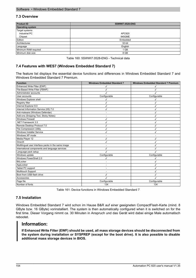
Software • Windows Embedded Standard 7
154 Automation PC 820 user's manual V1.35
7.3 Overview
Product ID 5SWWI7.0528-ENGOperating systemTarget systems
Industrial PC APC820Chipset 945GME
Edition EmbeddedArchitectures 32-bitLanguage EnglishMinimum RAM required 1 GBMinimum disk size 8 GB
Table 160: 5SWWI7.0528-ENG - Technical data
7.4 Features with WES7 (Windows Embedded Standard 7)
The feature list displays the essential device functions and differences in Windows Embedded Standard 7 andWindows Embedded Standard 7 Premium.Function Windows Embedded Standard 7 Windows Embedded Standard 7 PremiumEnhanced Write Filter (EWF) ✓ ✓File-Based Write Filter (FBWF) ✓ ✓Administrator accounts ✓ ✓User accounts Configurable ConfigurableWindows Explorer shell ✓ ✓Registry filter ✓ ✓Internet Explorer 8.0 ✓ ✓Internet Information Service (IIS) 7.0 ✓ ✓Anti-malware (Windows Defender) - ✓Add-ons (Snipping Tool, Sticky Notes) - ✓Windows Firewall ✓ ✓.NET Framework 3.5 ✓ ✓Remote Desktop Protocol 7.0 ✓ ✓File Compression Utility ✓ ✓Windows Installer Service ✓ ✓Windows XP mode - -Media Player 12 ✓ ✓DirectX ✓ ✓Multilingual user interface packs in the same image - ✓International components and language services ✓ ✓Language pack setup ✓ ✓Windows update Configurable ConfigurableWindows PowerShell 2.0 ✓ ✓BitLocker - ✓AppLocker - ✓Tablet PC support - ✓Multitouch Support - ✓Boot from USB flash drive ✓ ✓Accessories ✓ ✓Page file Configurable ConfigurableNumber of fonts 134 134
Table 161: Device functions in Windows Embedded Standard 7
7.5 Installation
Windows Embedded Standard 7 wird schon im Hause B&R auf einer geeigneten CompactFlash-Karte (mind. 8GByte bzw. 16 GByte) vorinstalliert. The system is then automatically configured when it is switched on for thefirst time. Dieser Vorgang nimmt ca. 30 Minuten in Anspruch und das Gerät wird dabei einige Male automatischrebootet.
Information:If Enhanced Write Filter (EWF) should be used, all mass storage devices should be disconnected fromthe system during installation or SYSPREP (except for the boot drive). It is also possible to disableadditional mass storage devices in BIOS.
Software • Windows Embedded Standard 7
Cha
pter
4So
ftwar
e
Automation PC 820 user's manual V1.35 155
7.6 Drivers
All drivers required for operation are preinstalled along with the operating system. If an older version of a driver isstill being used, its latest version can be downloaded and installed from the B&R website (www.br-automation.com).It is important that Enhanced Write Filter (EWF) is disabled for this.
7.6.1 Touch screen driver
A touch screen driver will be installed automatically if a touch controller is detected during the Windows EmbeddedStandard 7 installation. If a touch controller is not detected during Windows Embedded Standard 7 installation or aB&R Automation Panel is connected at a later time, then the touch screen driver needs to be installed manually orthe additional touch screen interface must be selected in the touch screen settings in the Windows Control Panel.The driver is available in the Downloads section of the B&R website (www.br-automation.com). It is important thatboth Enhanced Write Filter (EWF) and File Based Write Filter (FBWF) are disabled for this.
Information:Required drivers can only be downloaded from the B&R website, not from manufacturer websites.
7.7 Supported display resolutions
In accordance with Microsoft requirements, Windows Embedded Standard 7 requires XGA resolution (1024 x 768)or higher in order to allow unimpeded operation of the Windows user interface (including system dialog boxes andapps, etc.). A lower resolution can be selected for applications.
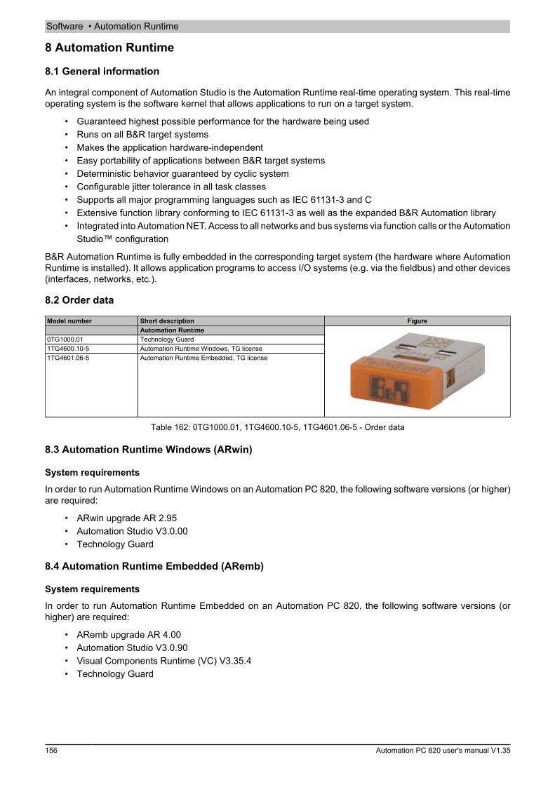
Software • Automation Runtime
156 Automation PC 820 user's manual V1.35
8 Automation Runtime
8.1 General information
An integral component of Automation Studio is the Automation Runtime real-time operating system. This real-timeoperating system is the software kernel that allows applications to run on a target system.
• Guaranteed highest possible performance for the hardware being used• Runs on all B&R target systems• Makes the application hardware-independent• Easy portability of applications between B&R target systems• Deterministic behavior guaranteed by cyclic system• Configurable jitter tolerance in all task classes• Supports all major programming languages such as IEC 61131-3 and C• Extensive function library conforming to IEC 61131-3 as well as the expanded B&R Automation library• Integrated into Automation NET. Access to all networks and bus systems via function calls or the Automation
Studio™ configuration
B&R Automation Runtime is fully embedded in the corresponding target system (the hardware where AutomationRuntime is installed). It allows application programs to access I/O systems (e.g. via the fieldbus) and other devices(interfaces, networks, etc.).
8.2 Order data
Model number Short description FigureAutomation Runtime
0TG1000.01 Technology Guard1TG4600.10-5 Automation Runtime Windows, TG license1TG4601.06-5 Automation Runtime Embedded, TG license
Table 162: 0TG1000.01, 1TG4600.10-5, 1TG4601.06-5 - Order data
8.3 Automation Runtime Windows (ARwin)
System requirements
In order to run Automation Runtime Windows on an Automation PC 820, the following software versions (or higher)are required:
• ARwin upgrade AR 2.95• Automation Studio V3.0.00• Technology Guard
8.4 Automation Runtime Embedded (ARemb)
System requirements
In order to run Automation Runtime Embedded on an Automation PC 820, the following software versions (orhigher) are required:
• ARemb upgrade AR 4.00• Automation Studio V3.0.90• Visual Components Runtime (VC) V3.35.4• Technology Guard

Software • Automation Runtime
Cha
pter
4So
ftwar
e
Automation PC 820 user's manual V1.35 157
8.5 Technology Guarding
Technology Guarding is a licensing approach used to safeguard individual software components. Licenses arestored on a "Technology Guard" (also referred to simply as a dongle), which is connected to an available USBinterface on the target system.The B&R software components Automation Runtime Embedded (ARemb), Automation Runtime Windows (ARwin)and Automation Runtime Embedded Terminal require a license, so a Technology Guard must always be used.
Information:Licensing with the Technology Guarding wizard is available in Automation Studio 4.1 and AutomationRuntime 4.08 and higher. Earlier versions of Automation Runtime do not require a Technology Guard.
Additional information about Technology Guarding can be found in the Automation Studio help system.
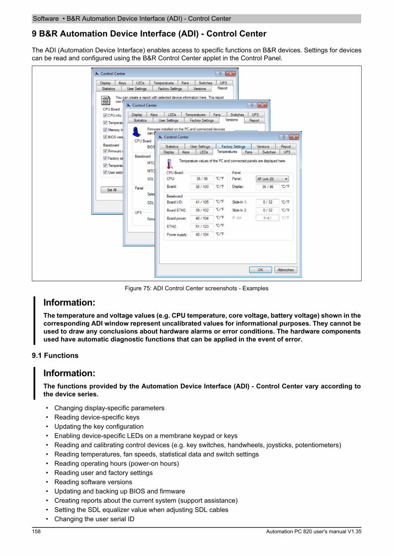
Software • B&R Automation Device Interface (ADI) - Control Center
158 Automation PC 820 user's manual V1.35
9 B&R Automation Device Interface (ADI) - Control Center
The ADI (Automation Device Interface) enables access to specific functions on B&R devices. Settings for devicescan be read and configured using the B&R Control Center applet in the Control Panel.
Figure 75: ADI Control Center screenshots - Examples
Information:The temperature and voltage values (e.g. CPU temperature, core voltage, battery voltage) shown in thecorresponding ADI window represent uncalibrated values for informational purposes. They cannot beused to draw any conclusions about hardware alarms or error conditions. The hardware componentsused have automatic diagnostic functions that can be applied in the event of error.
9.1 Functions
Information:The functions provided by the Automation Device Interface (ADI) - Control Center vary according tothe device series.
• Changing display-specific parameters• Reading device-specific keys• Updating the key configuration• Enabling device-specific LEDs on a membrane keypad or keys• Reading and calibrating control devices (e.g. key switches, handwheels, joysticks, potentiometers)• Reading temperatures, fan speeds, statistical data and switch settings• Reading operating hours (power-on hours)• Reading user and factory settings• Reading software versions• Updating and backing up BIOS and firmware• Creating reports about the current system (support assistance)• Setting the SDL equalizer value when adjusting SDL cables• Changing the user serial ID
Software • B&R Automation Device Interface (ADI) - Control Center
Cha
pter
4So
ftwar
e
Automation PC 820 user's manual V1.35 159
Supports the following systems:
• Automation PC 510• Automation PC 511• Automation PC 620• Automation PC 810• Automation PC 820• Automation PC 910• Automation PC 2100• Panel PC 300• Panel PC 700• Panel PC 725• Panel PC 800• Panel PC 900• Panel PC 2100• Power Panel 100/200• Power Panel 300/400• Power Panel 500• Mobile Panel 40/50• Mobile Panel 100/200• Connected Automation Panel 800• Connected Automation Panel 900
9.2 Installation
A detailed description of the Control Center can be found in the integrated help system. The B&R AutomationDevice Interface (ADI) driver (also includes the Control Center) is available at no charge in the Downloads sectionof the B&R website (www.br-automation.com).
1. Download and unzip the .zip archive.2. Close all applications.3. Run the Setup.exe file (e.g. double-click on it in Explorer).
Information:The ADI driver is already included in B&R images of embedded operating systems.If a more current ADI driver version exists (see the Downloads section of the B&R website), it can beinstalled later. It is important that Enhanced Write Filter (EWF) is disabled for this.

Software • B&R Automation Device Interface (ADI) Development Kit
160 Automation PC 820 user's manual V1.35
10 B&R Automation Device Interface (ADI) Development Kit
This software can be used to access B&R Automation Device Interface (ADI) functions directly from Windowsapplications created in one of the following development environments:
• Microsoft Visual C++ 6.0• Microsoft Visual Basic 6.0• Microsoft Embedded Visual C++ 4.0• Microsoft Visual Studio 2008 (or newer)
Figure 76: ADI Development Kit Screenshots (Version 3.70)
Features:
• One Microsoft Visual Basic module with ADI function declarations• Header files and import libraries for Microsoft Visual C++• Help files for Visual Basic and Visual C++• Sample projects for Visual Basic and Visual C++• ADI DLL (for application testing if no ADI driver is installed)
The following systems are supported (version 3.70 and higher):
• Automation PC 510• Automation PC 511• Automation PC 620• Automation PC 810• Automation PC 820• Automation PC 910• Automation PC 2100• Panel PC 300• Panel PC 700• Panel PC 800• Panel PC 900• Panel PC 2100

Software • B&R Automation Device Interface (ADI) Development Kit
Cha
pter
4So
ftwar
e
Automation PC 820 user's manual V1.35 161
• Power Panel 100/200• Power Panel 300/400• Power Panel 500• Mobile Panel 40/50• Mobile Panel 100/200
The ADI driver installed on the stated product series must be suitable for that device. The ADI driver is alreadyincluded in B&R images of embedded operating systems.A detailed description of how to use ADI functions can be found in the help system.The B&R Automation Device Interface (ADI) development kit is available at no cost in the Downloads section ofthe B&R website (www.br-automation.com).

Software • B&R Automation Device Interface (ADI) .NET SDK
162 Automation PC 820 user's manual V1.35
11 B&R Automation Device Interface (ADI) .NET SDK
This software can be used to access B&R Automation Device Interface (ADI) functions directly from .NET applica-tions created using Microsoft Visual Studio 2005 or later.Supported programming languages:
• Visual Basic• Visual C++• Visual C#
System requirements
• Development system: PC with Windows XP or Windows 7 and
° Microsoft Visual Studio 2005 (or newer)° Microsoft .NET Framework 2.0 and/or Microsoft .NET Compact Framework 2.0 (or newer)
Figure 77: ADI .NET SDK screenshots (version 2.10)
Features (version 2.10 and higher)
• ADI .NET class library• Help files in HTML Help 1.0 format (.chm), MS Help 2.0 format (.HxS) and MS Help Viewer format (.MSHC)
(help documentation is in English only)• Sample projects and code snippets for Visual Basic, Visual C++ and Visual C#• ADI DLL (for application testing if no ADI driver is installed)
The following systems are supported (version 2.10 and higher):
• Automation PC 510• Automation PC 511• Automation PC 620• Automation PC 810• Automation PC 820• Automation PC 910• Automation PC 2100• Panel PC 300• Panel PC 700• Panel PC 800• Panel PC 900• Panel PC 2100• Power Panel 100/200• Power Panel 300/400

Software • B&R Automation Device Interface (ADI) .NET SDK
Cha
pter
4So
ftwar
e
Automation PC 820 user's manual V1.35 163
• Power Panel 500• Mobile Panel 40/50• Mobile Panel 100/200
The ADI driver installed on the stated product series must be suitable for that device. The ADI driver is alreadyincluded in B&R images of embedded operating systems.A detailed description of how to use ADI functions can be found in the help system.The ADI .NET SDK is available in the Downloads section of the B&R website (www.br-automation.com).

Software • B&R Key Editor
164 Automation PC 820 user's manual V1.35
12 B&R Key Editor
On display devices, it is often necessary to adapt the function keys and LEDs directly to the application softwarebeing used. The B&R Key Editor makes it quick and easy to implement a unique configuration for the application.
Figure 78: B&R Key Editor screenshots (version 3.50)
Features:
• Configuration of normal keyboard keys (A, B, C, etc.)• Keyboard shortcuts (CTRL+C, SHIFT+DEL, etc.) using only one key• Special key functions (change brightness, etc.)• Assignment of functions to LEDs (HDD access, power, etc.)• 4 assignments possible per key (using layers)• Configuration of the panel locking time when multiple Automation Panel 900 devices are connected to
Automation PC and Panel PC devices.
The following systems are supported (version 3.50):
• Automation PC 510• Automation PC 511• Automation PC 620• Automation PC 810• Automation PC 820• Automation PC 910• Automation PC 2100• Automation Panel 800• Automation Panel 830
Software • B&R Key Editor
Cha
pter
4So
ftwar
e
Automation PC 820 user's manual V1.35 165
• Automation Panel 900• Automation Panel 9x3 / 9xD• IPC2000, IPC2001, IPC2002• IPC5000, IPC5600• IPC5000C, IPC5600C• Mobile Panel 40/50• Mobile Panel 100/200• Panel PC 300• Panel PC 700• Panel PC 800• Panel PC 900• Panel PC 2100• Power Panel 100/200• Power Panel 300/400• Power Panel 500
A detailed guide for configuring keys and LEDs can be found in the B&R Key Editor's help system. The B&R KeyEditor is available at no cost in the Downloads section of the B&R website (www.br-automation.com). It can alsobe found on the B&R HMI Drivers & Utilities DVD (model number 5SWHMI.0000-00).

Standards and certifications • Standards and guidelines
166 Automation PC 820 user's manual V1.35
Chapter 5 • Standards and certifications
1 Standards and guidelines
1.1 CE mark
Product complies with all applicable directives and their harmonized EN standards.
1.2 EMC directive
These devices meet the requirements of EC directive "2004/108/EC Electromagnetic compatibility" and are de-signed for the following areas:
EN 61131-2:2007 Programmable logic controllers - Part 2: Equipment requirements and testsEN 61000-6 -2:2005 Electromagnetic compatibility (EMC) - Part 6-2: Generic standards - Immunity for
industrial environmentsEN 61000-6 -4:2007 Electromagnetic compatibility (EMC) - Part 6-4: Generic standards - Emission stan-
dard for industrial environments
1.3 Low voltage directive
These devices satisfy the requirements of EC directive "2006/95/EC Low voltage directive" and are designed forthe following areas:
EN 61131-2:2007 Programmable logic controllers - Part 2: Equipment requirements and testsEN 60204-1:2006 +A1:2009
Safety of machinery - Electrical equipment of machines - Part 1: General require-ments

Standards and certifications • Certifications
Cha
pter
5St
anda
rds
and
certi
ficat
ions
Automation PC 820 user's manual V1.35 167
2 Certifications
Danger!A complete system can only receive certification if ALL of the individual components it includes havethe applicable certifications. If an individual component is being used that DOES NOT have an applic-able certification, then the complete system WILL NOT receive certification.
B&R products and services comply with applicable standards. This includes international standards from organi-zations such as ISO, IEC and CENELEC, as well as national standards from organizations such as UL, CSA, FCC,VDE, ÖVE, etc. We are committed to ensuring the reliability of our products in an industrial environment.Unless otherwise specified, the following certifications apply:
2.1 UL certification
Products with this mark have been tested by Underwriters Laboratories and are listedas "Industrial Control Equipment". This mark is valid for the USA and Canada andsimplifies the certification of your machines and systems in these areas.
Underwriters Laboratories (UL) in accordance with the UL508 standard - 17th EditionCanadian (CSA) standard in accordance with C22.2 No. 142-M1987
2.2 GOST-R
Products with this mark have been certified by an accredited testing laboratory andhave been approved for import to the Russian Federation (based on CE compliance).

Accessories • Male CAN connector (4-pin)
168 Automation PC 820 user's manual V1.35
Chapter 6 • Accessories
The following accessories have successfully completed functional testing at B&R and are approved for use withthis device. Nevertheless, it is important to observe any limitations that may apply to the complete system whenoperated with other individual components. When operating the complete system, the specifications for the indi-vidual components must be observed.All components listed in this manual have been subjected to extensive system and compatibility testing and areapproved for use. B&R can make no guarantee regarding the functionality of non-approved accessories.
1 Male CAN connector (4-pin)
1.1 General information
The single-row 4-pin terminal block TB704 is used as the supply voltage terminal block and the connection terminalfor fieldbuses.
1.2 Order data
Model number Short description FigureTerminal blocks
0TB704.9 Accessory terminal block, 4-pin, screw clamps 2.5 mm²0TB704.91 Accessory terminal block, 4-pin, cage clamps 2.5 mm²
Table 163: 0TB704.9, 0TB704.91 - Order data
1.3 Technical data
Information:The following characteristics, features and limit values only apply to this accessory and can deviatefrom those specified for the complete system. The data specifications for the complete system takeprecedence over those of individual components.
Product ID 0TB704.9 0TB704.91Terminal blockNote Nominal values according to ULNumber of pins 4Type of terminal clamp Screw clamps Cage clamps 1)
Cable type Only copper wires (no aluminum wires!)Distance between contacts 5.08 mmConnection cross section
AWG wire 26 to 12 AWGWire end sleeves with plastic covering 0.20 to 1.50 mm²Solid wires 0.20 to 2.50 mm²Fine strand wires 0.20 to 1.50 mm² 0.20 to 2.50 mm²With wire end sleeves 0.20 to 1.50 mm²
Electrical characteristicsNominal voltage 300 VNominal current 2) 10 A / contactContact resistance ≤5 mΩ
Table 164: 0TB704.9, 0TB704.91 - Technical data
1) Cage clamp terminal blocks cannot be used side-by-side.2) The limit data for each I/O module must be taken into consideration.

Accessories • Replacement CMOS batteries
Cha
pter
6Ac
cess
orie
s
Automation PC 820 user's manual V1.35 169
2 Replacement CMOS batteries
2.1 0AC201.91 / 4A0006.00-000
2.1.1 General information
This lithium battery is needed to back BIOS CMOS data and the real-time clock (RTC).The battery is subject to wear and must be replaced when the battery power is insufficient ("Bad" status).
2.1.2 Order data
Model number Short description FigureBatteries
0AC201.91 Lithium batteries 4 pcs., 3 V / 950 mAh button cell We herebystate that the lithium cells contained in this shipment qualify as"partly regulated". Handle with care. If the package is damaged,inspect the cells, repack intact cells and protect the cells againstshort circuit. For emergency information, call RENATA SA at +4161 319 28 27.
4A0006.00-000 Lithium battery, 3 V / 950 mAh, button cell
Table 165: 0AC201.91, 4A0006.00-000 - Order data
2.1.3 Technical data
Warning!The battery is only permitted to be replaced by a Renata CR2477N battery. The use of another batterymay present a risk of fire or explosion.The battery may explode if handled improperly. Do not recharge, disassemble or dispose of in fire.
Information:The following characteristics, features and limit values only apply to this accessory and can deviatefrom those specified for the complete system. The data specifications for the complete system takeprecedence over those of individual components.
Product ID 0AC201.91 4A0006.00-000General informationStorage time Max. 3 years at 30°CCertification
CE YescULus Yes
Electrical characteristicsCapacity 950 mAhSelf-discharging <1% per year (at 23°C)Voltage range 3 VEnvironmental conditionsTemperature
Storage -20 to 60°CRelative humidity
Operation 0 to 95%Storage 0 to 95%Transport 0 to 95%
Table 166: 0AC201.91, 4A0006.00-000 - Technical data
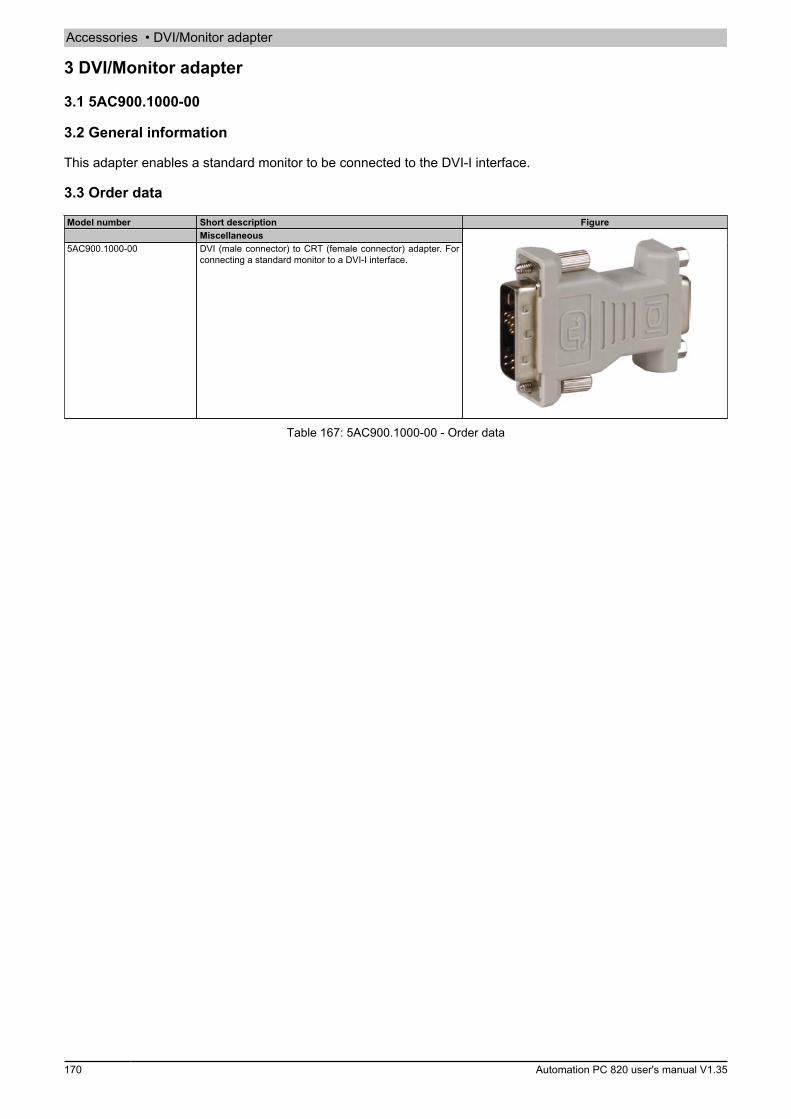
Accessories • DVI/Monitor adapter
170 Automation PC 820 user's manual V1.35
3 DVI/Monitor adapter
3.1 5AC900.1000-00
3.2 General information
This adapter enables a standard monitor to be connected to the DVI-I interface.
3.3 Order data
Model number Short description FigureMiscellaneous
5AC900.1000-00 DVI (male connector) to CRT (female connector) adapter. Forconnecting a standard monitor to a DVI-I interface.
Table 167: 5AC900.1000-00 - Order data
Accessories • CompactFlash cards
Cha
pter
6Ac
cess
orie
s
Automation PC 820 user's manual V1.35 171
4 CompactFlash cards
4.1 General information
CompactFlash cards are storage media that are easy to replace. Due to their robustness against environmentalinfluences (e.g. temperature, shock, vibration, etc.), CompactFlash cards are ideal for use as storage media inindustrial environments.
4.2 General information
In order to be suited for use in industrial automation, CompactFlash cards must be highly reliable. The followingitems are very important to achieving the necessary level of reliability:
• The flash technology used• An efficient algorithm for maximizing service life• Good mechanisms for detecting and fixing errors in the flash memory
4.2.1 Flash technology
Currently, CompactFlash cards are available with MLC (multi-level cell) and SLC (single-level cell) flash blocks.SLC flash memory has a service life 10 times longer than MLC, which is why only CompactFlash cards with SLCflash blocks are suited for industrial applications.
4.2.2 Wear leveling
Wear leveling is an algorithm that can be used to maximize the service life of a CompactFlash card. There arethree different algorithms:
• No wear leveling• Dynamic wear leveling• Static wear leveling
The basic idea behind wear leveling is to distribute data over a broad area of blocks or cells on the disk so that thesame areas don't have to be cleared and reprogrammed over and over again.
4.2.2.1 No wear leveling
The earliest CompactFlash cards didn't have an algorithm for maximizing service life. The service life of a Com-pactFlash card was determined only by the guaranteed lifespan of the flash blocks.
4.2.2.2 Dynamic wear leveling
Dynamic wear leveling makes it possible to utilize unused flash blocks when writing to a file.If the disk is 80% full with files, then only 20% can be used for wear leveling.The service life of the CompactFlash card is therefore dependent on the amount of unused flash blocks.
4.2.2.3 Static wear leveling
Static wear leveling monitors which data is rarely modified. From time to time, the controller then moves this datato blocks that have already been used frequently in order to prevent further wear on those cells.
4.2.3 ECC error correction
Bit errors can be caused by inactivity or when a certain cell is being operated. Error correction coding (ECC)implemented via hardware or software can detect and correct many errors of this type.
4.2.4 S.M.A.R.T. support
Self-Monitoring, Analysis and Reporting Technology (S.M.A.R.T.) is an industry standard for mass storage devicesthat has been introduced to monitor important parameters and quickly detect imminent failures. Critical performanceand calibration data is monitored and stored in order to help predict the probability of errors.

Accessories • CompactFlash cards
172 Automation PC 820 user's manual V1.35
4.2.5 Maximum reliability
CompactFlash cards used by B&R use SLC flash blocks and static wear leveling together with a powerful ECCalgorithm to provide maximum reliability.
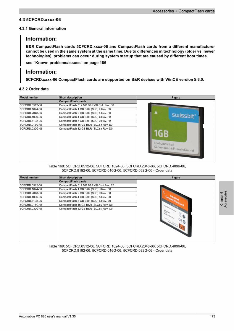
Accessories • CompactFlash cards
Cha
pter
6Ac
cess
orie
s
Automation PC 820 user's manual V1.35 173
4.3 5CFCRD.xxxx-06
4.3.1 General information
Information:B&R CompactFlash cards 5CFCRD.xxxx-06 and CompactFlash cards from a different manufacturercannot be used in the same system at the same time. Due to differences in technology (older vs. newertechnologies), problems can occur during system startup that are caused by different boot times.see "Known problems/issues" on page 186
Information:5CFCRD.xxxx-06 CompactFlash cards are supported on B&R devices with WinCE version ≥ 6.0.
4.3.2 Order data
Model number Short description FigureCompactFlash cards
5CFCRD.0512-06 CompactFlash 512 MB B&R (SLC) ≥ Rev. F05CFCRD.1024-06 CompactFlash 1 GB B&R (SLC) ≥ Rev. F05CFCRD.2048-06 CompactFlash 2 GB B&R (SLC) ≥ Rev. F05CFCRD.4096-06 CompactFlash 4 GB B&R (SLC) ≥ Rev. F05CFCRD.8192-06 CompactFlash 8 GB B&R (SLC) ≥ Rev. F05CFCRD.016G-06 CompactFlash 16 GB B&R (SLC) ≥ Rev. E05CFCRD.032G-06 CompactFlash 32 GB B&R (SLC) ≥ Rev. D0
Table 168: 5CFCRD.0512-06, 5CFCRD.1024-06, 5CFCRD.2048-06, 5CFCRD.4096-06,5CFCRD.8192-06, 5CFCRD.016G-06, 5CFCRD.032G-06 - Order data
Model number Short description FigureCompactFlash cards
5CFCRD.0512-06 CompactFlash 512 MB B&R (SLC) ≤ Rev. E05CFCRD.1024-06 CompactFlash 1 GB B&R (SLC) ≤ Rev. E05CFCRD.2048-06 CompactFlash 2 GB B&R (SLC) ≤ Rev. E05CFCRD.4096-06 CompactFlash 4 GB B&R (SLC) ≤ Rev. E05CFCRD.8192-06 CompactFlash 8 GB B&R (SLC) ≤ Rev. E05CFCRD.016G-06 CompactFlash 16 GB B&R (SLC) ≤ Rev. D05CFCRD.032G-06 CompactFlash 32 GB B&R (SLC) ≤ Rev. C0
Table 169: 5CFCRD.0512-06, 5CFCRD.1024-06, 5CFCRD.2048-06, 5CFCRD.4096-06,5CFCRD.8192-06, 5CFCRD.016G-06, 5CFCRD.032G-06 - Order data

Accessories • CompactFlash cards
174 Automation PC 820 user's manual V1.35
4.3.3 Technical data
Caution!A sudden loss of power may result in data loss! In very rare cases, the mass storage device may alsobecome damaged.To prevent damage and loss of data, the use of a UPS device is recommended.
Information:The following characteristics, features and limit values only apply to this accessory and can deviatefrom those specified for the complete system. The data specifications for the complete system takeprecedence over those of individual components.
Product ID 5CFCRD.0512-06
≥ Rev. F0
5CFCRD.1024-06
≥ Rev. F0
5CFCRD.2048-06
≥ Rev. F0
5CFCRD.4096-06
≥ Rev. F0
5CFCRD.8192-06
≥ Rev. F0
5CFCRD.016G-06≥ Rev. E0
5CFCRD.032G-06≥ Rev. D0
General informationCapacity 512 MB 1 GB 2 GB 4 GB 8 GB 16 GB 32 GBData retention 10 yearsData reliability <1 unrecoverable error in 1014 bit read accessesLifetime monitoring YesMTBF >3,000,000 hours (at 25°C)Maintenance NoneSupported operating modes PIO Mode 0-6, Multiword DMA Mode 0-4, Ultra DMA Mode 0-4Continuous reading
Typical 50 MB/s 50 MB/s 59 MB/s 59 MB/s 59 MB/s 59 MB/s 58 MB/sMaximum 53 MB/s 53 MB/s 65 MB/s 65 MB/s 65 MB/s 65 MB/s 65 MB/s
Continuous writingTypical 25 MB/s 25 MB/s 31 MB/s 31 MB/s 31 MB/s 31 MB/s 31 MB/sMaximum 27 MB/s 27 MB/s 35 MB/s 35 MB/s 35 MB/s 35 MB/s 35 MB/s
CertificationCE YescULus YescULus HazLoc Class 1 Division 2 - - - - - Yes1) -ATEX Zone 22 - - - - - Yes1) -GOST-R YesGL Yes1)
EnduranceSLC flash YesGuaranteed data volume
Guaranteed 2) 50 TB 100 TB 200 TB 400 TB 800 TB 1600 TB 3200 TBOver 5 years, equates to 2) 27.40 GB/day 54.79 GB/day 109.9 GB/day 219.8 GB/day 438.6 GB/day 876.72 GB/day 1753.44
GB/dayClear/Write cycles
Guaranteed 100,000Wear leveling StaticError correction coding (ECC) YesS.M.A.R.T. support YesSupportHardware PP300/400, PP500, PPC300, PPC700, PPC725, PPC800, APC620, APC810, APC820Operating systems
Windows 7 32-bit No No No No No Yes YesWindows 7 64-bit No No No No No No YesWindows Embedded Standard 732-bit
No No No No Yes Yes Yes
Windows Embedded Standard 764-bit
No No No No No Yes Yes
Windows XP Professional No No No Yes Yes Yes YesWindows XP Embedded YesWindows Embedded Standard 2009 No Yes Yes Yes Yes Yes YesWindows CE 6.0 Yes Yes Yes Yes Yes Yes 3) Yes 3)
Windows CE 5.0 NoSoftware
PVI Transfer ≥ V3.2.3.8(part of PVIDevelop-
ment Setup ≥V2.06.00.3011)
≥ V3.2.3.8(part of PVIDevelop-
ment Setup ≥V2.06.00.3011)
≥ V3.2.3.8(part of PVIDevelop-
ment Setup ≥V2.06.00.3011)
≥ V3.2.3.8(part of PVIDevelop-
ment Setup ≥V2.06.00.3011)
≥ V3.2.3.8(part of PVIDevelop-
ment Setup ≥V2.06.00.3011)
≥ V3.6.8.40(part of PVIDevelop-
ment Setup ≥V3.0.0.3020)
≥ V4.0.0.8 (partof PVI Devel-opment Setup≥ V3.0.2.3014)
B&R Embedded OS Installer ≥V3.10 ≥V3.10 ≥V3.10 ≥V3.10 ≥V3.10 ≥V3.20 ≥V3.21
Table 170: 5CFCRD.0512-06, 5CFCRD.1024-06, 5CFCRD.2048-06, 5CFCRD.4096-06,5CFCRD.8192-06, 5CFCRD.016G-06, 5CFCRD.032G-06 - Technical data
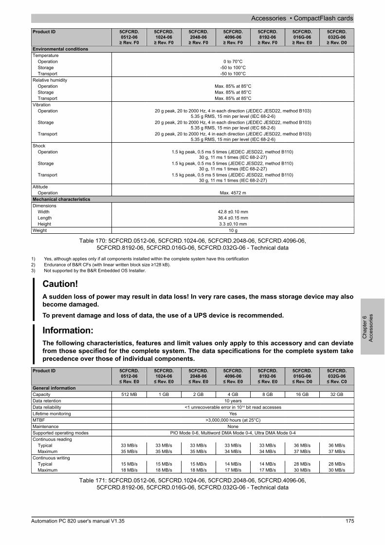
Accessories • CompactFlash cards
Cha
pter
6Ac
cess
orie
s
Automation PC 820 user's manual V1.35 175
Product ID 5CFCRD.0512-06
≥ Rev. F0
5CFCRD.1024-06
≥ Rev. F0
5CFCRD.2048-06
≥ Rev. F0
5CFCRD.4096-06
≥ Rev. F0
5CFCRD.8192-06
≥ Rev. F0
5CFCRD.016G-06≥ Rev. E0
5CFCRD.032G-06≥ Rev. D0
Environmental conditionsTemperature
Operation 0 to 70°CStorage -50 to 100°CTransport -50 to 100°C
Relative humidityOperation Max. 85% at 85°CStorage Max. 85% at 85°CTransport Max. 85% at 85°C
VibrationOperation 20 g peak, 20 to 2000 Hz, 4 in each direction (JEDEC JESD22, method B103)
5.35 g RMS, 15 min per level (IEC 68-2-6)Storage 20 g peak, 20 to 2000 Hz, 4 in each direction (JEDEC JESD22, method B103)
5.35 g RMS, 15 min per level (IEC 68-2-6)Transport 20 g peak, 20 to 2000 Hz, 4 in each direction (JEDEC JESD22, method B103)
5.35 g RMS, 15 min per level (IEC 68-2-6)Shock
Operation 1.5 kg peak, 0.5 ms 5 times (JEDEC JESD22, method B110) 30 g, 11 ms 1 times (IEC 68-2-27)
Storage 1.5 kg peak, 0.5 ms 5 times (JEDEC JESD22, method B110) 30 g, 11 ms 1 times (IEC 68-2-27)
Transport 1.5 kg peak, 0.5 ms 5 times (JEDEC JESD22, method B110) 30 g, 11 ms 1 times (IEC 68-2-27)
AltitudeOperation Max. 4572 m
Mechanical characteristicsDimensions
Width 42.8 ±0.10 mmLength 36.4 ±0.15 mmHeight 3.3 ±0.10 mm
Weight 10 g
Table 170: 5CFCRD.0512-06, 5CFCRD.1024-06, 5CFCRD.2048-06, 5CFCRD.4096-06,5CFCRD.8192-06, 5CFCRD.016G-06, 5CFCRD.032G-06 - Technical data
1) Yes, although applies only if all components installed within the complete system have this certification2) Endurance of B&R CFs (with linear written block size ≥128 kB).3) Not supported by the B&R Embedded OS Installer.
Caution!A sudden loss of power may result in data loss! In very rare cases, the mass storage device may alsobecome damaged.To prevent damage and loss of data, the use of a UPS device is recommended.
Information:The following characteristics, features and limit values only apply to this accessory and can deviatefrom those specified for the complete system. The data specifications for the complete system takeprecedence over those of individual components.
Product ID 5CFCRD.0512-06
≤ Rev. E0
5CFCRD.1024-06
≤ Rev. E0
5CFCRD.2048-06
≤ Rev. E0
5CFCRD.4096-06
≤ Rev. E0
5CFCRD.8192-06
≤ Rev. E0
5CFCRD.016G-06≤ Rev. D0
5CFCRD.032G-06≤ Rev. C0
General informationCapacity 512 MB 1 GB 2 GB 4 GB 8 GB 16 GB 32 GBData retention 10 yearsData reliability <1 unrecoverable error in 1014 bit read accessesLifetime monitoring YesMTBF >3,000,000 hours (at 25°C)Maintenance NoneSupported operating modes PIO Mode 0-6, Multiword DMA Mode 0-4, Ultra DMA Mode 0-4Continuous reading
Typical 33 MB/s 33 MB/s 33 MB/s 33 MB/s 33 MB/s 36 MB/s 36 MB/sMaximum 35 MB/s 35 MB/s 35 MB/s 34 MB/s 34 MB/s 37 MB/s 37 MB/s
Continuous writingTypical 15 MB/s 15 MB/s 15 MB/s 14 MB/s 14 MB/s 28 MB/s 28 MB/sMaximum 18 MB/s 18 MB/s 18 MB/s 17 MB/s 17 MB/s 30 MB/s 30 MB/s
Table 171: 5CFCRD.0512-06, 5CFCRD.1024-06, 5CFCRD.2048-06, 5CFCRD.4096-06,5CFCRD.8192-06, 5CFCRD.016G-06, 5CFCRD.032G-06 - Technical data
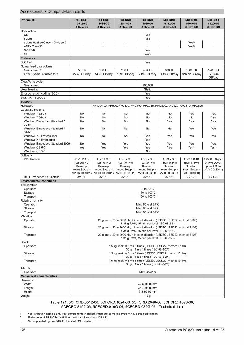
Accessories • CompactFlash cards
176 Automation PC 820 user's manual V1.35
Product ID 5CFCRD.0512-06
≤ Rev. E0
5CFCRD.1024-06
≤ Rev. E0
5CFCRD.2048-06
≤ Rev. E0
5CFCRD.4096-06
≤ Rev. E0
5CFCRD.8192-06
≤ Rev. E0
5CFCRD.016G-06≤ Rev. D0
5CFCRD.032G-06≤ Rev. C0
CertificationCE YescULus YescULus HazLoc Class 1 Division 2 - - - - - Yes1) -ATEX Zone 22 - - - - - Yes1) -GOST-R YesGL Yes1)
EnduranceSLC flash YesGuaranteed data volume
Guaranteed 2) 50 TB 100 TB 200 TB 400 TB 800 TB 1600 TB 3200 TBOver 5 years, equates to 2) 27.40 GB/day 54.79 GB/day 109.9 GB/day 219.8 GB/day 438.6 GB/day 876.72 GB/day 1753.44
GB/dayClear/Write cycles
Guaranteed 100,000Wear leveling StaticError correction coding (ECC) YesS.M.A.R.T. support YesSupportHardware PP300/400, PP500, PPC300, PPC700, PPC725, PPC800, APC620, APC810, APC820Operating systems
Windows 7 32-bit No No No No No Yes YesWindows 7 64-bit No No No No No No YesWindows Embedded Standard 732-bit
No No No No Yes Yes Yes
Windows Embedded Standard 764-bit
No No No No No Yes Yes
Windows XP Professional No No No Yes Yes Yes YesWindows XP Embedded YesWindows Embedded Standard 2009 No Yes Yes Yes Yes Yes YesWindows CE 6.0 Yes Yes Yes Yes Yes Yes 3) Yes 3)
Windows CE 5.0 NoSoftware
PVI Transfer ≥ V3.2.3.8(part of PVIDevelop-
ment Setup ≥V2.06.00.3011)
≥ V3.2.3.8(part of PVIDevelop-
ment Setup ≥V2.06.00.3011)
≥ V3.2.3.8(part of PVIDevelop-
ment Setup ≥V2.06.00.3011)
≥ V3.2.3.8(part of PVIDevelop-
ment Setup ≥V2.06.00.3011)
≥ V3.2.3.8(part of PVIDevelop-
ment Setup ≥V2.06.00.3011)
≥ V3.6.8.40(part of PVIDevelop-
ment Setup ≥V3.0.0.3020)
≥ V4.0.0.8 (partof PVI Devel-opment Setup≥ V3.0.2.3014)
B&R Embedded OS Installer ≥V3.10 ≥V3.10 ≥V3.10 ≥V3.10 ≥V3.10 ≥V3.20 ≥V3.21Environmental conditionsTemperature
Operation 0 to 70°CStorage -50 to 100°CTransport -50 to 100°C
Relative humidityOperation Max. 85% at 85°CStorage Max. 85% at 85°CTransport Max. 85% at 85°C
VibrationOperation 20 g peak, 20 to 2000 Hz, 4 in each direction (JEDEC JESD22, method B103)
5.35 g RMS, 15 min per level (IEC 68-2-6)Storage 20 g peak, 20 to 2000 Hz, 4 in each direction (JEDEC JESD22, method B103)
5.35 g RMS, 15 min per level (IEC 68-2-6)Transport 20 g peak, 20 to 2000 Hz, 4 in each direction (JEDEC JESD22, method B103)
5.35 g RMS, 15 min per level (IEC 68-2-6)Shock
Operation 1.5 kg peak, 0.5 ms 5 times (JEDEC JESD22, method B110) 30 g, 11 ms 1 times (IEC 68-2-27)
Storage 1.5 kg peak, 0.5 ms 5 times (JEDEC JESD22, method B110) 30 g, 11 ms 1 times (IEC 68-2-27)
Transport 1.5 kg peak, 0.5 ms 5 times (JEDEC JESD22, method B110) 30 g, 11 ms 1 times (IEC 68-2-27)
AltitudeOperation Max. 4572 m
Mechanical characteristicsDimensions
Width 42.8 ±0.10 mmLength 36.4 ±0.15 mmHeight 3.3 ±0.10 mm
Weight 10 g
Table 171: 5CFCRD.0512-06, 5CFCRD.1024-06, 5CFCRD.2048-06, 5CFCRD.4096-06,5CFCRD.8192-06, 5CFCRD.016G-06, 5CFCRD.032G-06 - Technical data
1) Yes, although applies only if all components installed within the complete system have this certification2) Endurance of B&R CFs (with linear written block size ≥128 kB).3) Not supported by the B&R Embedded OS Installer.

Accessories • CompactFlash cards
Cha
pter
6Ac
cess
orie
s
Automation PC 820 user's manual V1.35 177
4.3.4 Temperature/Humidity diagram
Temperature [°C]
Rel
ativ
e hu
mid
ity [%
RH
] (no
n-co
nden
sing
)
StorageTransport Operation
Figure 79: 5CFCRD.xxxx-06 - Temperature/Humidity diagram for CompactFlash cards
4.3.5 Dimensions
Above
26 50
1 251.01 ±0.07 1.01 ±0.07
1.60
±0.
05
0.99
±0.
05
4x R0.5 ±0.1
3.30 ±0.1
2x 1
2 ±0
.10
2x 2
5.78
±0.
07
1.65
42.8 ±0.1
41.66 ±0.13
36.4
±0.
15
2x 3
±0.
07
2.44 ±0.07
0.76
±0.
07
0.63 ±0.07
CompactFlash Type I
Figure 80: Type I CompactFlash card - Dimensions
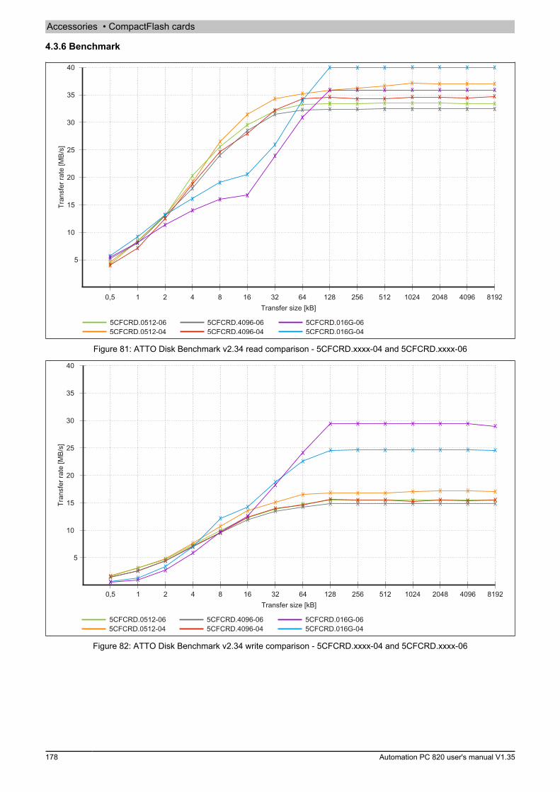
Accessories • CompactFlash cards
178 Automation PC 820 user's manual V1.35
4.3.6 BenchmarkTr
ansf
er ra
te [M
B/s]
Transfer size [kB]
Figure 81: ATTO Disk Benchmark v2.34 read comparison - 5CFCRD.xxxx-04 and 5CFCRD.xxxx-06
Tran
sfer
rate
[MB/
s]
Transfer size [kB]
Figure 82: ATTO Disk Benchmark v2.34 write comparison - 5CFCRD.xxxx-04 and 5CFCRD.xxxx-06
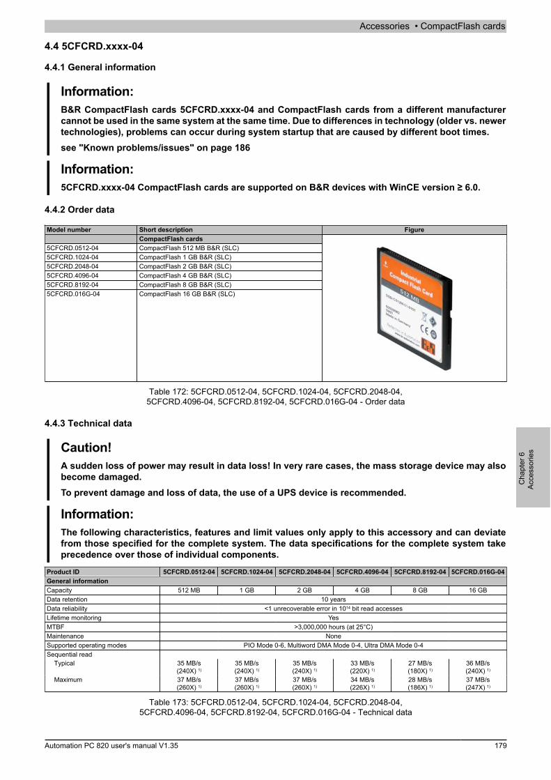
Accessories • CompactFlash cards
Cha
pter
6Ac
cess
orie
s
Automation PC 820 user's manual V1.35 179
4.4 5CFCRD.xxxx-04
4.4.1 General information
Information:B&R CompactFlash cards 5CFCRD.xxxx-04 and CompactFlash cards from a different manufacturercannot be used in the same system at the same time. Due to differences in technology (older vs. newertechnologies), problems can occur during system startup that are caused by different boot times.see "Known problems/issues" on page 186
Information:5CFCRD.xxxx-04 CompactFlash cards are supported on B&R devices with WinCE version ≥ 6.0.
4.4.2 Order data
Model number Short description FigureCompactFlash cards
5CFCRD.0512-04 CompactFlash 512 MB B&R (SLC)5CFCRD.1024-04 CompactFlash 1 GB B&R (SLC)5CFCRD.2048-04 CompactFlash 2 GB B&R (SLC)5CFCRD.4096-04 CompactFlash 4 GB B&R (SLC)5CFCRD.8192-04 CompactFlash 8 GB B&R (SLC)5CFCRD.016G-04 CompactFlash 16 GB B&R (SLC)
Table 172: 5CFCRD.0512-04, 5CFCRD.1024-04, 5CFCRD.2048-04,5CFCRD.4096-04, 5CFCRD.8192-04, 5CFCRD.016G-04 - Order data
4.4.3 Technical data
Caution!A sudden loss of power may result in data loss! In very rare cases, the mass storage device may alsobecome damaged.To prevent damage and loss of data, the use of a UPS device is recommended.
Information:The following characteristics, features and limit values only apply to this accessory and can deviatefrom those specified for the complete system. The data specifications for the complete system takeprecedence over those of individual components.
Product ID 5CFCRD.0512-04 5CFCRD.1024-04 5CFCRD.2048-04 5CFCRD.4096-04 5CFCRD.8192-04 5CFCRD.016G-04General informationCapacity 512 MB 1 GB 2 GB 4 GB 8 GB 16 GBData retention 10 yearsData reliability <1 unrecoverable error in 1014 bit read accessesLifetime monitoring YesMTBF >3,000,000 hours (at 25°C)Maintenance NoneSupported operating modes PIO Mode 0-6, Multiword DMA Mode 0-4, Ultra DMA Mode 0-4Sequential read
Typical 35 MB/s(240X) 1)
35 MB/s(240X) 1)
35 MB/s(240X) 1)
33 MB/s(220X) 1)
27 MB/s(180X) 1)
36 MB/s(240X) 1)
Maximum 37 MB/s(260X) 1)
37 MB/s(260X) 1)
37 MB/s(260X) 1)
34 MB/s(226X) 1)
28 MB/s(186X) 1)
37 MB/s(247X) 1)
Table 173: 5CFCRD.0512-04, 5CFCRD.1024-04, 5CFCRD.2048-04,5CFCRD.4096-04, 5CFCRD.8192-04, 5CFCRD.016G-04 - Technical data

Accessories • CompactFlash cards
180 Automation PC 820 user's manual V1.35
Product ID 5CFCRD.0512-04 5CFCRD.1024-04 5CFCRD.2048-04 5CFCRD.4096-04 5CFCRD.8192-04 5CFCRD.016G-04Sequential write
Typical 17 MB/s(110X)
17 MB/s(110X)
17 MB/s(110X)
16 MB/s(106X)
15 MB/s(100X)
18 MB/s(120X)
Maximum 20 MB/s(133X)
20 MB/s(133X)
20 MB/s(133X)
18 MB/s(120X)
17 MB/s(110X)
19 MB/s(126X)
CertificationCE YescULus YesGOST-R - Yes Yes Yes Yes YesGL Yes 2)
EnduranceSLC flash YesGuaranteed data volume
Guaranteed 3) 50 TB 100 TB 200 TB 400 TB 800 TB 1600 TBResults for 5 years 3) 27.40 GB/day 54.79 GB/day 109.9 GB/day 219.8 GB/day 438.6 GB/day 876.72 GB/day
Clear/Write cyclesTypical 4) 2,000,000Guaranteed 100,000
Wear leveling StaticError correction coding (ECC) YesS.M.A.R.T. support NoSupportHardware PP300/400, PP500, PPC300, PPC700, PPC725, PPC800, APC620, APC810, APC820Operating systems
Windows 7 32-bit No No No No No YesWindows 7 64-bit NoWindows Embedded Standard 7,32-bit
No No No No Yes Yes
Windows Embedded Standard 7,64-bit
No No No No No Yes
Windows XP Professional No No No Yes Yes YesWindows XP Embedded YesWindows Embedded Standard 2009 No Yes Yes Yes Yes YesWindows CE 6.0 Yes Yes Yes Yes Yes Yes 5)
Windows CE 5.0 NoSoftware
PVI Transfer ≥ V3.2.3.8 (partof PVI Develop-ment Setup ≥
V2.06.00.3011)
≥ V3.2.3.8 (partof PVI Develop-ment Setup ≥
V2.06.00.3011)
≥ V3.2.3.8 (partof PVI Develop-ment Setup ≥
V2.06.00.3011)
≥ V3.2.3.8 (partof PVI Develop-ment Setup ≥
V2.06.00.3011)
≥ V3.2.3.8 (partof PVI Develop-ment Setup ≥
V2.06.00.3011)
≥ V3.6.8.40 (partof PVI Develop-ment Setup ≥V3.0.0.3020)
B&R Embedded OS Installer ≥V3.10 ≥V3.10 ≥V3.10 ≥V3.10 ≥V3.10 ≥V3.20Environmental conditionsTemperature
Operation 0 to 70°CStorage -65 to 150°CTransport -65 to 150°C
Relative humidityOperation Max. 85% at 85°CStorage Max. 85% at 85°CTransport Max. 85% at 85°C
VibrationOperation 20 g peak, 20 to 2000 Hz, 4 in each direction (JEDEC JESD22, method B103)
5.35 g RMS, 15 min per level (IEC 68-2-6)Storage 20 g peak, 20 to 2000 Hz, 4 in each direction (JEDEC JESD22, method B103)
5.35 g RMS, 15 min per level (IEC 68-2-6)Transport 20 g peak, 20 to 2000 Hz, 4 in each direction (JEDEC JESD22, method B103)
5.35 g RMS, 15 min per level (IEC 68-2-6)Shock
Operation 1.5 kg peak, 0.5 ms 5 times (JEDEC JESD22, method B110) 30 g, 11 ms 1 times (IEC 68-2-27)
Storage 1.5 kg peak, 0.5 ms 5 times (JEDEC JESD22, method B110) 30 g, 11 ms 1 times (IEC 68-2-27)
Transport 1.5 kg peak, 0.5 ms 5 times (JEDEC JESD22, method B110) 30 g, 11 ms 1 times (IEC 68-2-27)
AltitudeOperation Max. 4572 m
Mechanical characteristicsDimensions
Width 42.8 ±0.10 mmLength 36.4 ±0.15 mmHeight 3.3 ±0.10 mm
Weight 10 g
Table 173: 5CFCRD.0512-04, 5CFCRD.1024-04, 5CFCRD.2048-04,5CFCRD.4096-04, 5CFCRD.8192-04, 5CFCRD.016G-04 - Technical data
1) Speed specification with 1X = 150 Kb/s. All specifications refer to Samsung flash chips, CompactFlash cards in UDMA mode 4 and 30 ns cycle time in TrueIDE mode with sequential write/read test.
2) Yes, although applies only if all components installed within the complete system have this certification
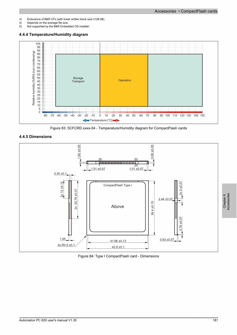
Accessories • CompactFlash cards
Cha
pter
6Ac
cess
orie
s
Automation PC 820 user's manual V1.35 181
3) Endurance of B&R CFs (with linear written block size ≥128 kB).4) Depends on the average file size.5) Not supported by the B&R Embedded OS Installer.
4.4.4 Temperature/Humidity diagram
Temperature [°C]
Rel
ativ
e hu
mid
ity [%
RH
] (no
n-co
nden
sing
)
StorageTransport Operation
Figure 83: 5CFCRD.xxxx-04 - Temperature/Humidity diagram for CompactFlash cards
4.4.5 Dimensions
Above
26 50
1 251.01 ±0.07 1.01 ±0.07
1.60
±0.
05
0.99
±0.
05
4x R0.5 ±0.1
3.30 ±0.1
2x 1
2 ±0
.10
2x 2
5.78
±0.
07
1.65
42.8 ±0.1
41.66 ±0.13
36.4
±0.
15
2x 3
±0.
07
2.44 ±0.07
0.76
±0.
07
0.63 ±0.07
CompactFlash Type I
Figure 84: Type I CompactFlash card - Dimensions

Accessories • CompactFlash cards
182 Automation PC 820 user's manual V1.35
4.4.6 BenchmarkTr
ansf
er ra
te [M
B/s]
Transfer size [kB]
Figure 85: ATTO Disk Benchmark v2.34 read comparison - 5CFCRD.xxxx-03 and 5CFCRD.xxxx-04
Tran
sfer
rate
[MB/
s]
Transfer size [kB]
Figure 86: ATTO Disk Benchmark v2.34 write comparison - 5CFCRD.xxxx-03 and 5CFCRD.xxxx-04
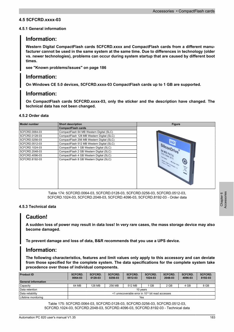
Accessories • CompactFlash cards
Cha
pter
6Ac
cess
orie
s
Automation PC 820 user's manual V1.35 183
4.5 5CFCRD.xxxx-03
4.5.1 General information
Information:Western Digital CompactFlash cards 5CFCRD.xxxx and CompactFlash cards from a different manu-facturer cannot be used in the same system at the same time. Due to differences in technology (oldervs. newer technologies), problems can occur during system startup that are caused by different boottimes.see "Known problems/issues" on page 186
Information:On Windows CE 5.0 devices, 5CFCRD.xxxx-03 CompactFlash cards up to 1 GB are supported.
Information:On CompactFlash cards 5CFCRD.xxxx-03, only the sticker and the description have changed. Thetechnical data has not been changed.
4.5.2 Order data
Model number Short description FigureCompactFlash cards
5CFCRD.0064-03 CompactFlash 64 MB Western Digital (SLC)5CFCRD.0128-03 CompactFlash 128 MB Western Digital (SLC)5CFCRD.0256-03 CompactFlash 256 MB Western Digital (SLC)5CFCRD.0512-03 CompactFlash 512 MB Western Digital (SLC)5CFCRD.1024-03 CompactFlash 1 GB Western Digital (SLC)5CFCRD.2048-03 CompactFlash 2 GB Western Digital (SLC)5CFCRD.4096-03 CompactFlash 4 GB Western Digital (SLC)5CFCRD.8192-03 CompactFlash 8 GB Western Digital (SLC)
Table 174: 5CFCRD.0064-03, 5CFCRD.0128-03, 5CFCRD.0256-03, 5CFCRD.0512-03,5CFCRD.1024-03, 5CFCRD.2048-03, 5CFCRD.4096-03, 5CFCRD.8192-03 - Order data
4.5.3 Technical data
Caution!A sudden loss of power may result in data loss! In very rare cases, the mass storage device may alsobecome damaged.
To prevent damage and loss of data, B&R recommends that you use a UPS device.
Information:The following characteristics, features and limit values only apply to this accessory and can deviatefrom those specified for the complete system. The data specifications for the complete system takeprecedence over those of individual components.
Product ID 5CFCRD.0064-03
5CFCRD.0128-03
5CFCRD.0256-03
5CFCRD.0512-03
5CFCRD.1024-03
5CFCRD.2048-03
5CFCRD.4096-03
5CFCRD.8192-03
General informationCapacity 64 MB 128 MB 256 MB 512 MB 1 GB 2 GB 4 GB 8 GBData retention 10 yearsData reliability <1 unrecoverable error in 1014 bit read accessesLifetime monitoring Yes
Table 175: 5CFCRD.0064-03, 5CFCRD.0128-03, 5CFCRD.0256-03, 5CFCRD.0512-03,5CFCRD.1024-03, 5CFCRD.2048-03, 5CFCRD.4096-03, 5CFCRD.8192-03 - Technical data

Accessories • CompactFlash cards
184 Automation PC 820 user's manual V1.35
Product ID 5CFCRD.0064-03
5CFCRD.0128-03
5CFCRD.0256-03
5CFCRD.0512-03
5CFCRD.1024-03
5CFCRD.2048-03
5CFCRD.4096-03
5CFCRD.8192-03
MTBF >4,000,000 hours (at 25°C)Maintenance NoneSupported operating modes PIO Mode 0-4, Multiword DMA Mode 0-2Sequential read
Typical 8 MB/sSequential write
Typical 6 MB/sCertification
CE YescULus YesGOST-R YesGL Yes 1)
EnduranceSLC flash YesClear/Write cycles
Typical >2,000,000Wear leveling StaticError correction coding (ECC) YesS.M.A.R.T. support NoSupportHardware MP100/200, PP100/200, PP300/400, PP500, PPC300, PPC700, PPC725,
PPC800, Provit 2000, Provit 5000, APC620, APC680, APC810, APC820Operating systems
Windows 7 32-bit NoWindows 7 64-bit NoWindows Embedded Standard 7,32-bit
No No No No No No No Yes
Windows Embedded Standard 7,64-bit
No
Windows XP Professional No No No No No No Yes YesWindows XP Embedded No No No Yes Yes Yes Yes YesWindows Embedded Standard 2009 No No No No Yes Yes Yes YesWindows CE 6.0 Yes Yes Yes Yes Yes Yes Yes Yes 2)
Windows CE 5.0 Yes Yes Yes Yes Yes No No NoSoftware
PVI Transfer ≥V2.57 (part of PVI Development Setup ≥ V2.5.3.3005)B&R Embedded OS Installer ≥V2.21
Environmental conditionsTemperature
Operation 0 to 70°CStorage -50 to 100°CTransport -50 to 100°C
Relative humidityOperation 8 to 95%, non-condensingStorage 8 to 95%, non-condensingTransport 8 to 95%, non-condensing
VibrationOperation Max. 16.3 g (159 m/s² 0-peak)Storage Max. 30 g (294 m/s² 0-peak)Transport Max. 30 g (294 m/s² 0-peak)
ShockOperation Max. 1000 g (9810 m/s² 0-peak)Storage Max. 3000 g (29430 m/s² 0-peak)Transport Max. 3000 g (29430 m/s² 0-peak)
AltitudeOperation Max. 24383 m
Mechanical characteristicsDimensions
Width 42.8 ±0.10 mmLength 36.4 ±0.15 mmHeight 3.3 ±0.10 mm
Weight 11.4 g
Table 175: 5CFCRD.0064-03, 5CFCRD.0128-03, 5CFCRD.0256-03, 5CFCRD.0512-03,5CFCRD.1024-03, 5CFCRD.2048-03, 5CFCRD.4096-03, 5CFCRD.8192-03 - Technical data
1) Yes, although applies only if all components installed within the complete system have this certification2) Not supported by the B&R Embedded OS Installer.
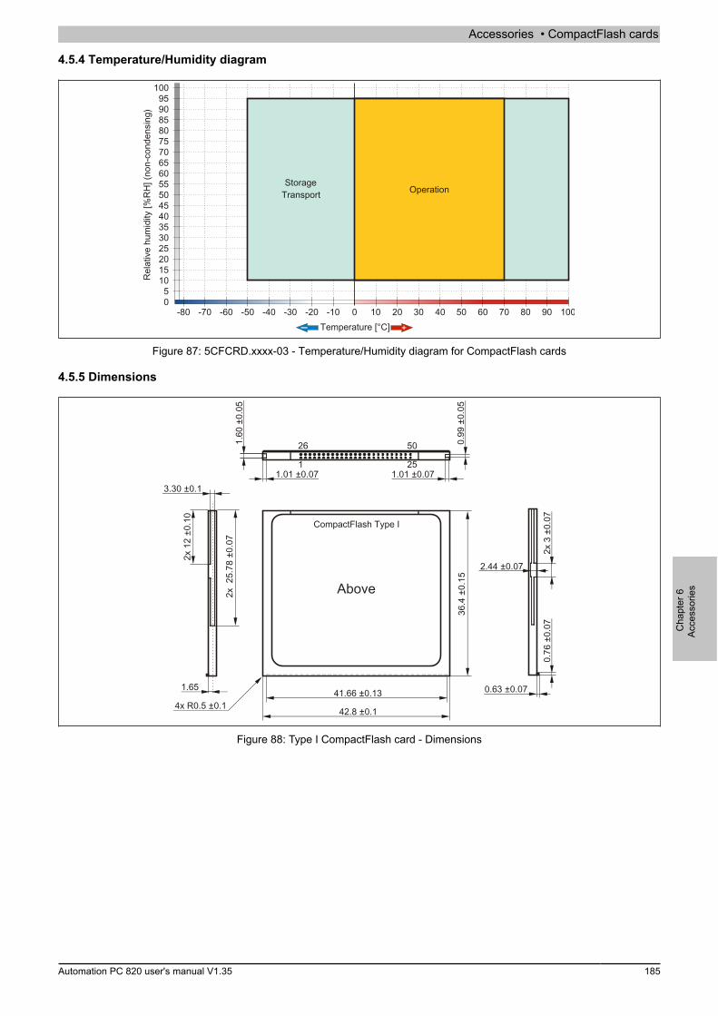
Accessories • CompactFlash cards
Cha
pter
6Ac
cess
orie
s
Automation PC 820 user's manual V1.35 185
4.5.4 Temperature/Humidity diagram
Temperature [°C]
Rel
ativ
e hu
mid
ity [%
RH
] (no
n-co
nden
sing
)
StorageTransport Operation
Figure 87: 5CFCRD.xxxx-03 - Temperature/Humidity diagram for CompactFlash cards
4.5.5 Dimensions
Above
26 50
1 251.01 ±0.07 1.01 ±0.07
1.60
±0.
05
0.99
±0.
05
4x R0.5 ±0.1
3.30 ±0.1
2x 1
2 ±0
.10
2x 2
5.78
±0.
07
1.65
42.8 ±0.1
41.66 ±0.13
36.4
±0.
15
2x 3
±0.
07
2.44 ±0.07
0.76
±0.
07
0.63 ±0.07
CompactFlash Type I
Figure 88: Type I CompactFlash card - Dimensions

Accessories • CompactFlash cards
186 Automation PC 820 user's manual V1.35
4.6 Known problems/issues
The following is a known issue for devices with two CompactFlash slots:
• Using two different types of CompactFlash cards can cause problems with Automation PCs and PanelPCs. For example, it is possible that one of the two cards is not detected during system startup. This iscaused by different startup speeds. CompactFlash cards with older technology require significantly moretime during system startup than CompactFlash cards with newer technology. This behavior occurs nearthe end of the time frame provided for startup. The problem described can occur because the startup timefor the CompactFlash cards fluctuates due to the different components being used. Depending on theCompactFlash card being used, this error might never, sometimes or always occur.
Accessories • USB flash drives
Cha
pter
6Ac
cess
orie
s
Automation PC 820 user's manual V1.35 187
5 USB flash drives
5.1 5MMUSB.2048-00
5.1.1 General information
USB flash drives are storage media that are easy to exchange. Because of their high-speed data transfer (USB2.0), USB flash drives are ideal for use as portable data storage. Without requiring additional drivers ("hot plugging",except in the case of Windows 98SE), the USB flash drive can immediately act as an additional drive for readingor writing data.
Information:Due to the large number of USB flash drives available on the market as well as their short product lifecycle, we reserve the right to supply alternative products at any time. The following measures maytherefore be necessary in order to boot from these flash drives as well:
• The flash drive must be reformatted or in some cases even repartitioned (set active partition).• The flash drive must be the first bootable device in the BIOS boot order; alternatively, the IDE
controllers can be disabled in BIOS. This can be avoided in most cases if the "fdisk /mbr"command is additionally executed on the USB flash drive.
5.1.2 Order data
Model number Short description FigureUSB accessories
5MMUSB.2048-00 USB 2.0 flash drive, 2048 MB
Table 176: 5MMUSB.2048-00 - Order data
5.1.3 Technical data
Information:The following characteristics, features and limit values only apply to this accessory and can deviatefrom those specified for the complete system. The data specifications for the complete system takeprecedence over those of individual components.
Product ID 5MMUSB.2048-00General informationData retention 10 yearsLEDs 1 LED (green) 1)
MTBF 100,000 hours (at 25°C)Type USB 1.1, USB 2.0Maintenance NoneCertification
CE YesInterfacesUSB
Type USB 1.1, USB 2.0Connection To any USB type A interfaceTransfer rate Low speed (1.5 Mbit/s), full speed (12 Mbit/s), high speed (480 Mbit/s)Sequential reading Max. 8.7 MB/sSequential writing Max. 1.7 MB/s
SupportOperating systems
Windows XP Professional YesWindows XP Embedded YesWindows ME YesWindows 2000 YesWindows CE 5.0 YesWindows CE 4.2 Yes
Electrical characteristicsPower consumption 650 µA sleep mode, 150 mA read/write
Table 177: 5MMUSB.2048-00 - Technical data
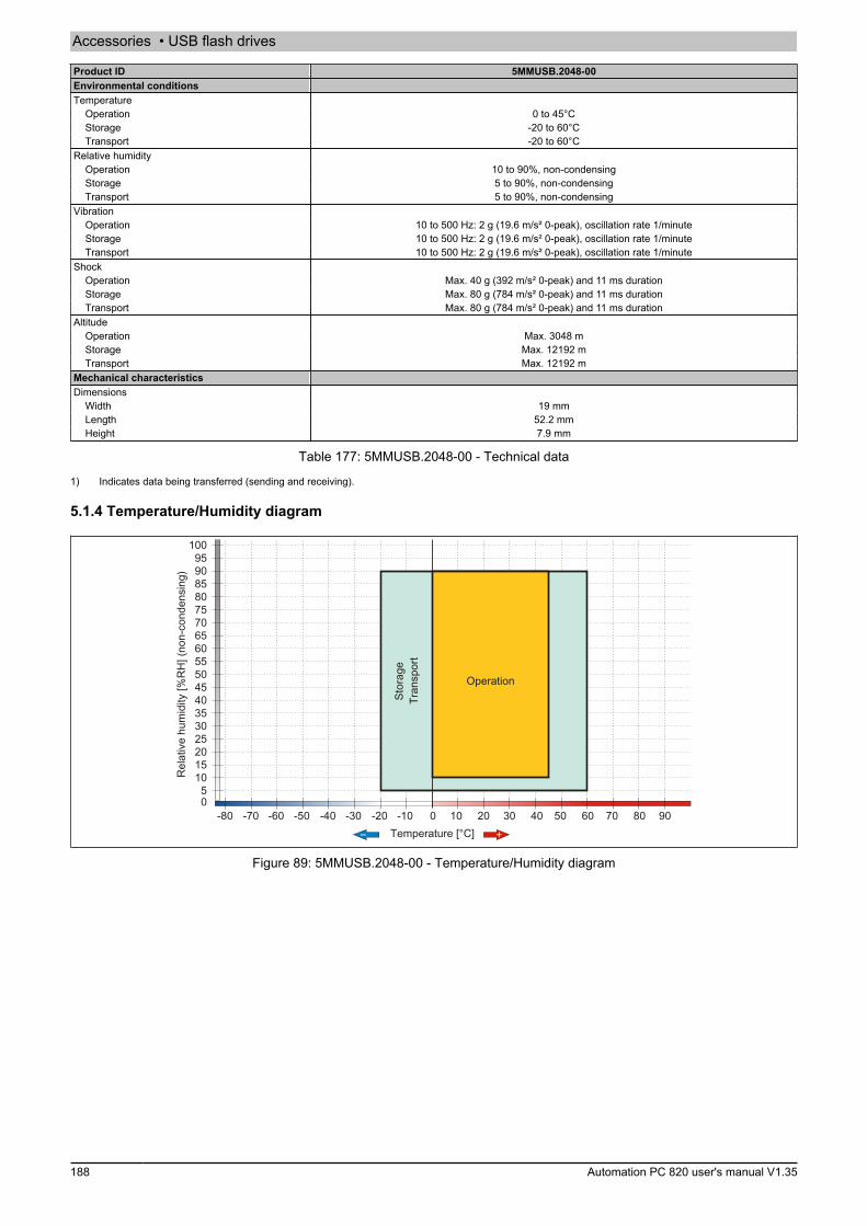
Accessories • USB flash drives
188 Automation PC 820 user's manual V1.35
Product ID 5MMUSB.2048-00Environmental conditionsTemperature
Operation 0 to 45°CStorage -20 to 60°CTransport -20 to 60°C
Relative humidityOperation 10 to 90%, non-condensingStorage 5 to 90%, non-condensingTransport 5 to 90%, non-condensing
VibrationOperation 10 to 500 Hz: 2 g (19.6 m/s² 0-peak), oscillation rate 1/minuteStorage 10 to 500 Hz: 2 g (19.6 m/s² 0-peak), oscillation rate 1/minuteTransport 10 to 500 Hz: 2 g (19.6 m/s² 0-peak), oscillation rate 1/minute
ShockOperation Max. 40 g (392 m/s² 0-peak) and 11 ms durationStorage Max. 80 g (784 m/s² 0-peak) and 11 ms durationTransport Max. 80 g (784 m/s² 0-peak) and 11 ms duration
AltitudeOperation Max. 3048 mStorage Max. 12192 mTransport Max. 12192 m
Mechanical characteristicsDimensions
Width 19 mmLength 52.2 mmHeight 7.9 mm
Table 177: 5MMUSB.2048-00 - Technical data
1) Indicates data being transferred (sending and receiving).
5.1.4 Temperature/Humidity diagram
Temperature [°C]
Rel
ativ
e hu
mid
ity [%
RH
] (no
n-co
nden
sing
)
Operation
Stor
age
Tran
spor
t
Figure 89: 5MMUSB.2048-00 - Temperature/Humidity diagram
Accessories • USB flash drives
Cha
pter
6Ac
cess
orie
s
Automation PC 820 user's manual V1.35 189
5.2 5MMUSB.xxxx-01
5.2.1 General information
USB flash drives are storage media that are easy to exchange. Because of their high-speed data transfer (USB2.0), USB flash drives are ideal for use as portable data storage. Without requiring additional drivers ("hot plugging",except in the case of Windows 98SE), the USB flash drive can immediately act as an additional drive for readingor writing data.
Information:Due to the large number of USB flash drives available on the market as well as their short product lifecycle, we reserve the right to supply alternative products at any time. The following measures maytherefore be necessary in order to boot from these flash drives as well:
• The flash drive must be reformatted or in some cases even repartitioned (set active partition).• The flash drive must be the first bootable device in the BIOS boot order; alternatively, the IDE
controllers can be disabled in BIOS. This can be avoided in most cases if the "fdisk /mbr"command is additionally executed on the USB flash drive.
5.2.2 Order data
Model number Short description FigureUSB accessories
5MMUSB.2048-01 USB 2.0 flash drive, 2048 MB, B&R5MMUSB.4096-01 USB 2.0 flash drive, 4096 MB, B&R
Table 178: 5MMUSB.2048-01, 5MMUSB.4096-01 - Order data
5.2.3 Technical data
Product ID 5MMUSB.2048-01 5MMUSB.4096-01General informationCapacity 2 GB 4 GBLEDs 1 LED (green) 1)
MTBF >3,000,000 hoursType USB 1.1, USB 2.0Maintenance NoneDefault file system FAT16 FAT32Certification
CE YesGOST-R Yes
InterfacesUSB
Type USB 1.1, USB 2.0Connection To any USB type A interfaceTransfer rate Low speed (1.5 Mbit/s), full speed (12 Mbit/s), high speed (480 Mbit/s)Sequential reading Full speed max. 1 MB/s,
high speed max. 32 MB/sSequential writing Full speed max. 0.9 MB/s,
high speed max. 23 MB/sEnduranceSLC flash YesData retention >10 yearsData reliability <1 unrecoverable error in 1014 bit read accessesConnection cycles >1,500SupportOperating systems
Windows 7 YesWindows XP Professional YesWindows XP Embedded YesWindows ME YesWindows 2000 YesWindows CE 5.0 YesWindows CE 4.2 Yes
Electrical characteristicsCurrent consumption Max. 500 μA sleep mode, max. 120 mA read/write
Table 179: 5MMUSB.2048-01, 5MMUSB.4096-01 - Technical data
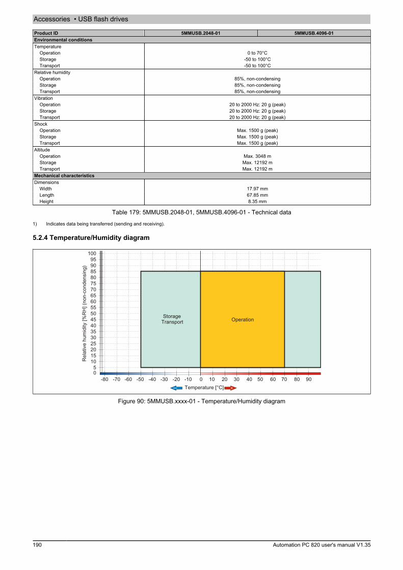
Accessories • USB flash drives
190 Automation PC 820 user's manual V1.35
Product ID 5MMUSB.2048-01 5MMUSB.4096-01Environmental conditionsTemperature
Operation 0 to 70°CStorage -50 to 100°CTransport -50 to 100°C
Relative humidityOperation 85%, non-condensingStorage 85%, non-condensingTransport 85%, non-condensing
VibrationOperation 20 to 2000 Hz: 20 g (peak)Storage 20 to 2000 Hz: 20 g (peak)Transport 20 to 2000 Hz: 20 g (peak)
ShockOperation Max. 1500 g (peak)Storage Max. 1500 g (peak)Transport Max. 1500 g (peak)
AltitudeOperation Max. 3048 mStorage Max. 12192 mTransport Max. 12192 m
Mechanical characteristicsDimensions
Width 17.97 mmLength 67.85 mmHeight 8.35 mm
Table 179: 5MMUSB.2048-01, 5MMUSB.4096-01 - Technical data
1) Indicates data being transferred (sending and receiving).
5.2.4 Temperature/Humidity diagram
Temperature [°C]
Rel
ativ
e hu
mid
ity [%
RH
] (no
n-co
nden
sing
)
OperationStorageTransport
Figure 90: 5MMUSB.xxxx-01 - Temperature/Humidity diagram
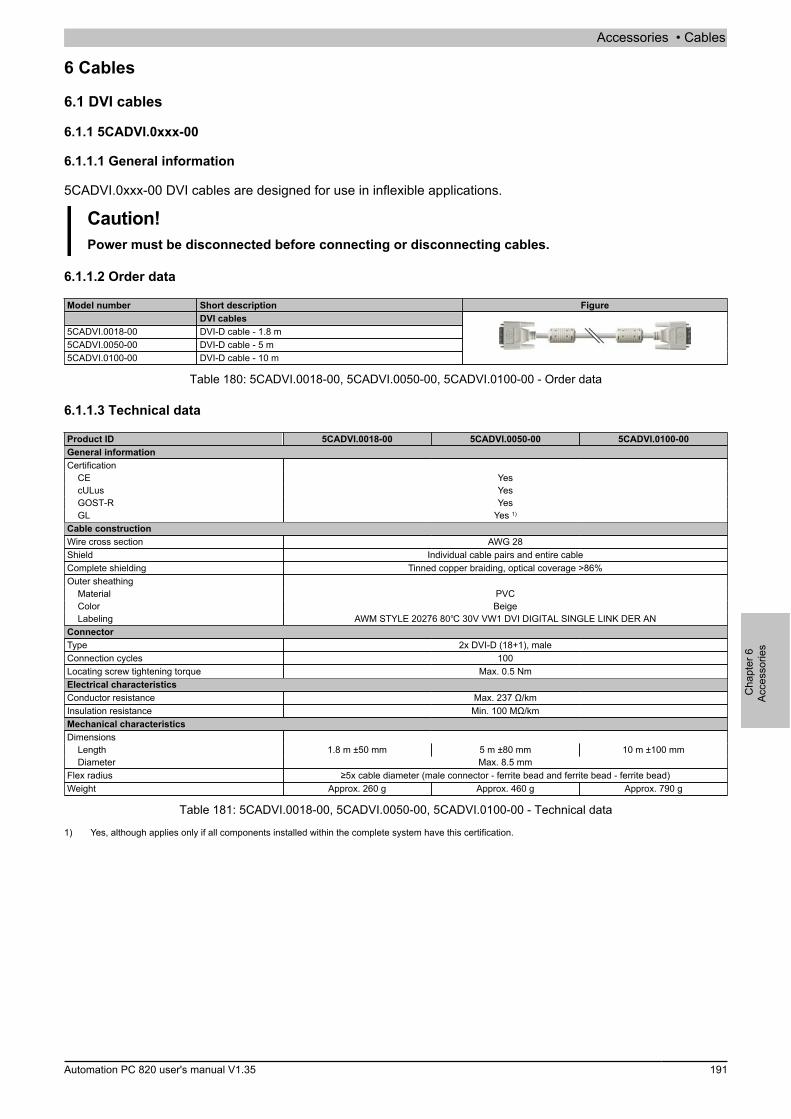
Accessories • Cables
Cha
pter
6Ac
cess
orie
s
Automation PC 820 user's manual V1.35 191
6 Cables
6.1 DVI cables
6.1.1 5CADVI.0xxx-00
6.1.1.1 General information
5CADVI.0xxx-00 DVI cables are designed for use in inflexible applications.
Caution!Power must be disconnected before connecting or disconnecting cables.
6.1.1.2 Order data
Model number Short description FigureDVI cables
5CADVI.0018-00 DVI-D cable - 1.8 m5CADVI.0050-00 DVI-D cable - 5 m5CADVI.0100-00 DVI-D cable - 10 m
Table 180: 5CADVI.0018-00, 5CADVI.0050-00, 5CADVI.0100-00 - Order data
6.1.1.3 Technical data
Product ID 5CADVI.0018-00 5CADVI.0050-00 5CADVI.0100-00General informationCertification
CE YescULus YesGOST-R YesGL Yes 1)
Cable constructionWire cross section AWG 28Shield Individual cable pairs and entire cableComplete shielding Tinned copper braiding, optical coverage >86%Outer sheathing
Material PVCColor BeigeLabeling AWM STYLE 20276 80℃ 30V VW1 DVI DIGITAL SINGLE LINK DER AN
ConnectorType 2x DVI-D (18+1), maleConnection cycles 100Locating screw tightening torque Max. 0.5 NmElectrical characteristicsConductor resistance Max. 237 Ω/kmInsulation resistance Min. 100 MΩ/kmMechanical characteristicsDimensions
Length 1.8 m ±50 mm 5 m ±80 mm 10 m ±100 mmDiameter Max. 8.5 mm
Flex radius ≥5x cable diameter (male connector - ferrite bead and ferrite bead - ferrite bead)Weight Approx. 260 g Approx. 460 g Approx. 790 g
Table 181: 5CADVI.0018-00, 5CADVI.0050-00, 5CADVI.0100-00 - Technical data
1) Yes, although applies only if all components installed within the complete system have this certification.

Accessories • Cables
192 Automation PC 820 user's manual V1.35
6.1.1.4 Flex radius specifications
Male connector
Ferrite bead
Ferrite bead
Ferrite bead
Flex radiusMale connector - Ferrite bead
Flex radiusFerrite bead - Ferrite bead
Figure 91: Flex radius specifications
6.1.1.5 Dimensions
28.5
Ø 1
7.5
25±5
Ø 8
.5
Length
Figure 92: 5CADVI.0xxx-00 - Dimensions

Accessories • Cables
Cha
pter
6Ac
cess
orie
s
Automation PC 820 user's manual V1.35 193
6.1.1.6 Cable pinout
Warning!Field-assembled cables must be wired according to these specifications.If a field-assembled cable is used, B&R cannot guarantee that it will function properly. All cables pro-vided by B&R are guaranteed to function properly, however.
DVI-D (24+1), male DVI-D (24+1), male
Pinout
DVI-D (24+1), male DVI-D (24+1), male
Cable shield Cable shield
Figure 93: 5CADVI.0xxx-00 - Pinout
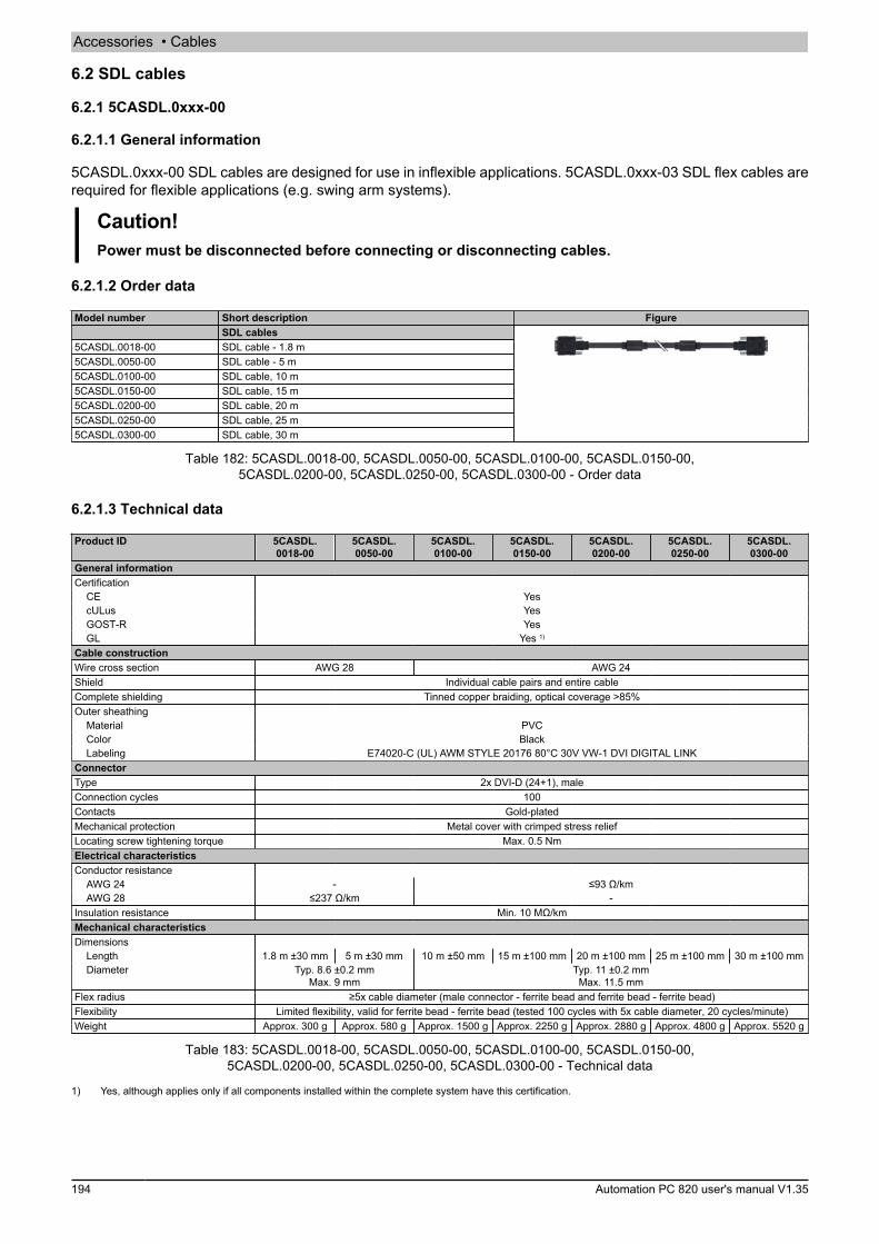
Accessories • Cables
194 Automation PC 820 user's manual V1.35
6.2 SDL cables
6.2.1 5CASDL.0xxx-00
6.2.1.1 General information
5CASDL.0xxx-00 SDL cables are designed for use in inflexible applications. 5CASDL.0xxx-03 SDL flex cables arerequired for flexible applications (e.g. swing arm systems).
Caution!Power must be disconnected before connecting or disconnecting cables.
6.2.1.2 Order data
Model number Short description FigureSDL cables
5CASDL.0018-00 SDL cable - 1.8 m5CASDL.0050-00 SDL cable - 5 m5CASDL.0100-00 SDL cable, 10 m5CASDL.0150-00 SDL cable, 15 m5CASDL.0200-00 SDL cable, 20 m5CASDL.0250-00 SDL cable, 25 m5CASDL.0300-00 SDL cable, 30 m
Table 182: 5CASDL.0018-00, 5CASDL.0050-00, 5CASDL.0100-00, 5CASDL.0150-00,5CASDL.0200-00, 5CASDL.0250-00, 5CASDL.0300-00 - Order data
6.2.1.3 Technical data
Product ID 5CASDL.0018-00
5CASDL.0050-00
5CASDL.0100-00
5CASDL.0150-00
5CASDL.0200-00
5CASDL.0250-00
5CASDL.0300-00
General informationCertification
CE YescULus YesGOST-R YesGL Yes 1)
Cable constructionWire cross section AWG 28 AWG 24Shield Individual cable pairs and entire cableComplete shielding Tinned copper braiding, optical coverage >85%Outer sheathing
Material PVCColor BlackLabeling E74020-C (UL) AWM STYLE 20176 80°C 30V VW-1 DVI DIGITAL LINK
ConnectorType 2x DVI-D (24+1), maleConnection cycles 100Contacts Gold-platedMechanical protection Metal cover with crimped stress reliefLocating screw tightening torque Max. 0.5 NmElectrical characteristicsConductor resistance
AWG 24 - ≤93 Ω/kmAWG 28 ≤237 Ω/km -
Insulation resistance Min. 10 MΩ/kmMechanical characteristicsDimensions
Length 1.8 m ±30 mm 5 m ±30 mm 10 m ±50 mm 15 m ±100 mm 20 m ±100 mm 25 m ±100 mm 30 m ±100 mmDiameter Typ. 8.6 ±0.2 mm
Max. 9 mmTyp. 11 ±0.2 mmMax. 11.5 mm
Flex radius ≥5x cable diameter (male connector - ferrite bead and ferrite bead - ferrite bead)Flexibility Limited flexibility, valid for ferrite bead - ferrite bead (tested 100 cycles with 5x cable diameter, 20 cycles/minute)Weight Approx. 300 g Approx. 580 g Approx. 1500 g Approx. 2250 g Approx. 2880 g Approx. 4800 g Approx. 5520 g
Table 183: 5CASDL.0018-00, 5CASDL.0050-00, 5CASDL.0100-00, 5CASDL.0150-00,5CASDL.0200-00, 5CASDL.0250-00, 5CASDL.0300-00 - Technical data
1) Yes, although applies only if all components installed within the complete system have this certification.
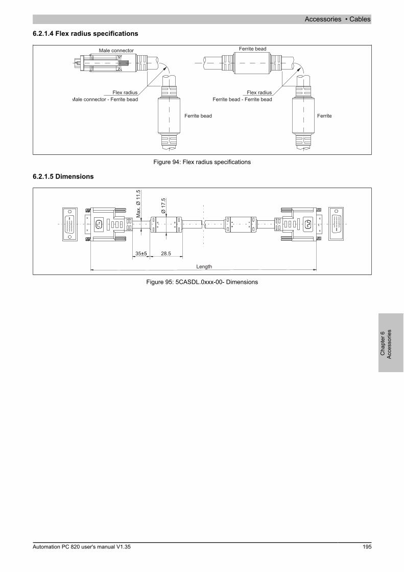
Accessories • Cables
Cha
pter
6Ac
cess
orie
s
Automation PC 820 user's manual V1.35 195
6.2.1.4 Flex radius specifications
Male connector
Ferrite bead
Ferrite bead
Ferrite bead
Flex radiusMale connector - Ferrite bead
Flex radiusFerrite bead - Ferrite bead
Figure 94: Flex radius specifications
6.2.1.5 Dimensions
Max
. Ø 1
1.5
28.5
Ø 1
7.5
35±5
Length
Figure 95: 5CASDL.0xxx-00- Dimensions

Accessories • Cables
196 Automation PC 820 user's manual V1.35
6.2.1.6 Cable pinout
Warning!Field-assembled cables must be wired according to these specifications.If a field-assembled cable is used, B&R cannot guarantee that it will function properly. All cables pro-vided by B&R are guaranteed to function properly, however.
DVI (24+1), male DVI (24+1), male
Pinout
DVI (24+1), male DVI (24+1), male
Cable shield Cable shield
Figure 96: 5CASDL.0xxx-00 - Pinout

Accessories • Cables
Cha
pter
6Ac
cess
orie
s
Automation PC 820 user's manual V1.35 197
6.3 SDL flex cables
6.3.1 5CASDL.0xxx-03
6.3.1.1 General information
5CASDL.0xxx-03 SDL flex cables are designed for use in both inflexible and flexible applications (e.g. swing armsystems).
Caution!Power must be disconnected before connecting or disconnecting cables.
6.3.1.2 Order data
Model number Short description FigureSDL flex cables
5CASDL.0018-03 SDL flex cable - 1.8 m5CASDL.0050-03 SDL flex cable, 5 m5CASDL.0100-03 SDL flex cable, 10 m5CASDL.0150-03 SDL flex cable, 15 m5CASDL.0200-03 SDL flex cable, 20 m5CASDL.0250-03 SDL flex cable, 25 m5CASDL.0300-03 SDL flex cable, 30 m
Table 184: 5CASDL.0018-03, 5CASDL.0050-03, 5CASDL.0100-03, 5CASDL.0150-03,5CASDL.0200-03, 5CASDL.0250-03, 5CASDL.0300-03 - Order data
6.3.1.3 Technical data
Product ID 5CASDL.0018-03
5CASDL.0050-03
5CASDL.0100-03
5CASDL.0150-03
5CASDL.0200-03
5CASDL.0250-03
5CASDL.0300-03
General informationCertification
CE YescULus YesGOST-R YesGL Yes 1)
Cable constructionWire cross section AWG 24 (control wires)
AWG 26 (DVI, USB, data)Features Silicone- and halogen-freeShield Individual cable pairs and entire cableComplete shielding Aluminum-clad foil + tinned copper braidingOuter sheathing
Material Special semi-glossy TMPUColor BlackLabeling (B&R) SDL Cable (UL) AWM 20236 80°C 30V E 63216
ConnectorType 2x DVI-D (24+1), maleConnection cycles Min. 200Contacts Gold-platedMechanical protection Metal cover with crimped stress reliefLocating screw tightening torque Max. 0.5 NmElectrical characteristicsOperating voltage ≤30 VTest voltage
Wire/Wire 1 kVWire/Shield 0.5 kV
Wave impedance 100 ±10 ΩConductor resistance
AWG 24 ≤95 Ω/kmAWG 26 ≤145 Ω/km
Insulation resistance >200 MΩ/kmOperating conditionsApprobation UL AWM 20236 80°C 30 VFlame-retardant In accordance with UL758 (cable vertical flame test)Oil and hydrolysis resistance In accordance with VDE 0282-10
Table 185: 5CASDL.0018-03, 5CASDL.0050-03, 5CASDL.0100-03, 5CASDL.0150-03,5CASDL.0200-03, 5CASDL.0250-03, 5CASDL.0300-03 - Technical data
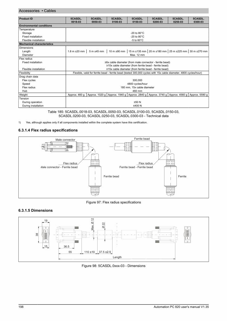
Accessories • Cables
198 Automation PC 820 user's manual V1.35
Product ID 5CASDL.0018-03
5CASDL.0050-03
5CASDL.0100-03
5CASDL.0150-03
5CASDL.0200-03
5CASDL.0250-03
5CASDL.0300-03
Environmental conditionsTemperature
Storage -20 to 80°CFixed installation -20 to 80°CFlexible installation -5 to 60°C
Mechanical characteristicsDimensions
Length 1.8 m ±20 mm 5 m ±45 mm 10 m ±90 mm 15 m ±135 mm 20 m ±180 mm 25 m ±225 mm 30 m ±270 mmDiameter Max. 12 mm
Flex radiusFixed installation ≥6x cable diameter (from male connector - ferrite bead)
≥10x cable diameter (from ferrite bead - ferrite bead)Flexible installation ≥15x cable diameter (from ferrite bead - ferrite bead)
Flexibility Flexible, valid for ferrite bead - ferrite bead (tested 300,000 cycles with 15x cable diameter, 4800 cycles/hour)Drag chain data
Flex cycles 300,000Speed 4800 cycles/hourFlex radius 180 mm, 15x cable diameterHub 460 mm
Weight Approx. 460 g Approx. 1020 g Approx. 1940 g Approx. 2840 g Approx. 3740 g Approx. 4560 g Approx. 5590 gTension
During operation ≤50 NDuring installation ≤400 N
Table 185: 5CASDL.0018-03, 5CASDL.0050-03, 5CASDL.0100-03, 5CASDL.0150-03,5CASDL.0200-03, 5CASDL.0250-03, 5CASDL.0300-03 - Technical data
1) Yes, although applies only if all components installed within the complete system have this certification.
6.3.1.4 Flex radius specifications
Male connector
Ferrite bead
Ferrite bead
Ferrite bead
Flex radiusMale connector - Ferrite bead
Flex radiusFerrite bead - Ferrite bead
Figure 97: Flex radius specifications
6.3.1.5 Dimensions
37.5 ±2.5
Ø 2
2
110 ±1055
36.5
19
15
38
Max
. Ø 1
2
Length
Figure 98: 5CASDL.0xxx-03 - Dimensions
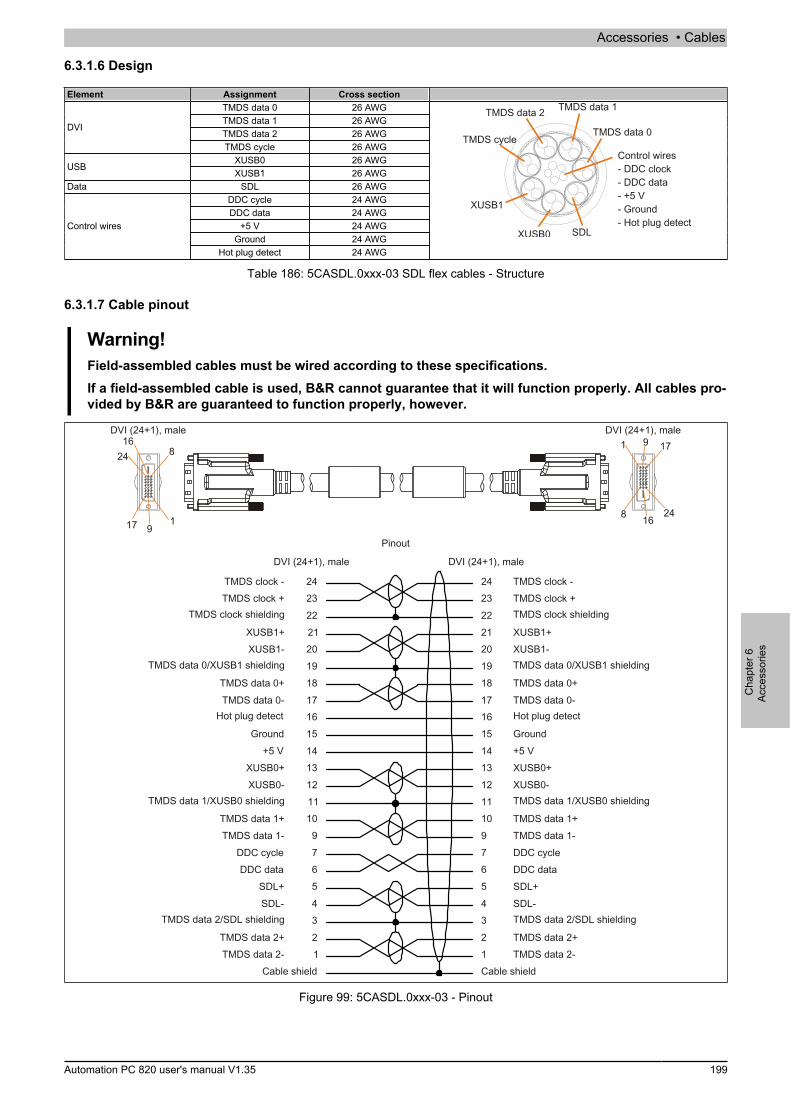
Accessories • Cables
Cha
pter
6Ac
cess
orie
s
Automation PC 820 user's manual V1.35 199
6.3.1.6 Design
Element Assignment Cross sectionTMDS data 0 26 AWGTMDS data 1 26 AWGTMDS data 2 26 AWG
DVI
TMDS cycle 26 AWGXUSB0 26 AWG
USBXUSB1 26 AWG
Data SDL 26 AWGDDC cycle 24 AWGDDC data 24 AWG
+5 V 24 AWGGround 24 AWG
Control wires
Hot plug detect 24 AWG
TMDS data 2
TMDS data 0
XUSB0
XUSB1
TMDS cycle
TMDS data 1
Control wires- DDC clock
+5 V- Ground- Hot plug detect
- DDC data-
SDL
Table 186: 5CASDL.0xxx-03 SDL flex cables - Structure
6.3.1.7 Cable pinout
Warning!Field-assembled cables must be wired according to these specifications.If a field-assembled cable is used, B&R cannot guarantee that it will function properly. All cables pro-vided by B&R are guaranteed to function properly, however.
Pinout
DVI (24+1), male DVI (24+1), male
Cable shield Cable shield
DVI (24+1), male DVI (24+1), male1 17
2416
9
8
TMDS clock -TMDS clock +TMDS clock shielding
XUSB1+XUSB1-TMDS data 0/XUSB1 shielding
TMDS data 0+TMDS data 0-Hot plug detect
Ground+5 VXUSB0+XUSB0-TMDS data 1/XUSB0 shielding
TMDS data 1+TMDS data 1-DDC cycleDDC dataSDL+SDL-TMDS data 2/SDL shielding
TMDS data 2+TMDS data 2-
TMDS clock -TMDS clock +
TMDS clock shielding
XUSB1+XUSB1-
TMDS data 0/XUSB1 shielding
TMDS data 0+TMDS data 0-
Hot plug detect
Ground+5 V
XUSB0+XUSB0-
TMDS data 1/XUSB0 shielding
TMDS data 1+TMDS data 1-
DDC cycleDDC data
SDL+SDL-
TMDS data 2/SDL shielding
TMDS data 2+TMDS data 2-
Figure 99: 5CASDL.0xxx-03 - Pinout

Accessories • Cables
200 Automation PC 820 user's manual V1.35
6.4 SDL flex cables with extender
6.4.1 5CASDL.0xx0-13
6.4.1.1 General information
5CASDL.0xx0-13 SDL flex cables with an extender are designed for use in both inflexible and flexible applications(e.g. swing arm systems).
Caution!Power must be disconnected before connecting or disconnecting cables.
6.4.1.2 Order data
Model number Short description FigureSDL flex cables
5CASDL.0300-13 SDL flex cable with extender, 30 m5CASDL.0400-13 SDL flex cable with extender, 40 m5CASDL.0430-13 SDL flex cable with extender, 43 m
Table 187: 5CASDL.0300-13, 5CASDL.0400-13, 5CASDL.0430-13 - Order data
6.4.1.3 Technical data
Product ID 5CASDL.0300-13 5CASDL.0400-13 5CASDL.0430-13General informationCertification
CE YescULus YesGOST-R YesGL Yes 1)
Cable constructionWire cross section AWG 24 (control wires)
AWG 26 (DVI, USB, data)Features Silicone- and halogen-freeShield Individual cable pairs and entire cableComplete shielding Aluminum-clad foil + tinned copper braidingOuter sheathing
Material Special semi-glossy TMPUColor BlackLabeling (B&R) SDL cable (UL) AWM 20236 80°C 30V E63216
ConnectorType 2x DVI-D (24+1), maleConnection cycles Min. 200Contacts Gold-platedMechanical protection Metal cover with crimped stress reliefLocating screw tightening torque Max. 0.5 NmElectrical characteristicsOperating voltage ≤30 VTest voltage
Wire/Wire 1 kVWire/Shield 0.5 kV
Wave impedance 100 ±10 ΩConductor resistance
AWG 24 ≤95 Ω/kmAWG 26 ≤145 Ω/km
Insulation resistance >200 MΩ/kmOperating conditionsApprobation UL AWM 20236 80°C 30 VFlame-retardant In accordance with UL758 (cable vertical flame test)Oil and hydrolysis resistance In accordance with VDE 0282-10Environmental conditionsTemperature
Storage -20 to 60°CFixed installation -20 to 60°CFlexible installation -5 to 60°C
Table 188: 5CASDL.0300-13, 5CASDL.0400-13, 5CASDL.0430-13 - Technical data
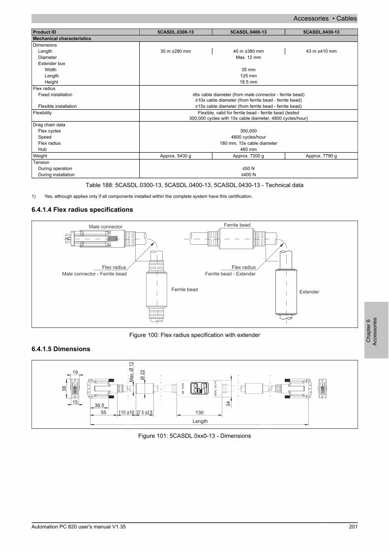
Accessories • Cables
Cha
pter
6Ac
cess
orie
s
Automation PC 820 user's manual V1.35 201
Product ID 5CASDL.0300-13 5CASDL.0400-13 5CASDL.0430-13Mechanical characteristicsDimensions
Length 30 m ±280 mm 40 m ±380 mm 43 m ±410 mmDiameter Max. 12 mmExtender box
Width 35 mmLength 125 mmHeight 18.5 mm
Flex radiusFixed installation ≥6x cable diameter (from male connector - ferrite bead)
≥10x cable diameter (from ferrite bead - ferrite bead)Flexible installation ≥15x cable diameter (from ferrite bead - ferrite bead)
Flexibility Flexible, valid for ferrite bead - ferrite bead (tested300,000 cycles with 15x cable diameter, 4800 cycles/hour)
Drag chain dataFlex cycles 300,000Speed 4800 cycles/hourFlex radius 180 mm, 15x cable diameterHub 460 mm
Weight Approx. 5430 g Approx. 7200 g Approx. 7790 gTension
During operation ≤50 NDuring installation ≤400 N
Table 188: 5CASDL.0300-13, 5CASDL.0400-13, 5CASDL.0430-13 - Technical data
1) Yes, although applies only if all components installed within the complete system have this certification.
6.4.1.4 Flex radius specifications
Extender
Flex radiusFerrite bead - Extender
Male connector
Ferrite bead
Ferrite bead
Flex radiusMale connector - Ferrite bead
Figure 100: Flex radius specification with extender
6.4.1.5 Dimensions
37.5 ±2.5
Ø 2
2
110 ±105536.5
19
15
38
Max
. Ø 1
2
Length
130
34
SD
L O
UTS
DL
IN
Figure 101: 5CASDL.0xx0-13 - Dimensions
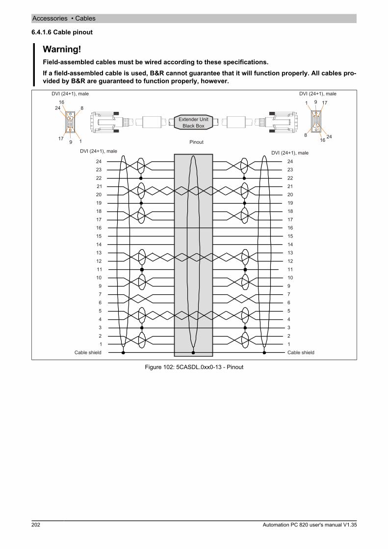
Accessories • Cables
202 Automation PC 820 user's manual V1.35
6.4.1.6 Cable pinout
Warning!Field-assembled cables must be wired according to these specifications.If a field-assembled cable is used, B&R cannot guarantee that it will function properly. All cables pro-vided by B&R are guaranteed to function properly, however.
Pinout
DVI (24+1), male DVI (24+1), male
DVI (24+1), male
Cable shield Cable shield
DVI (24+1), male
Figure 102: 5CASDL.0xx0-13 - Pinout
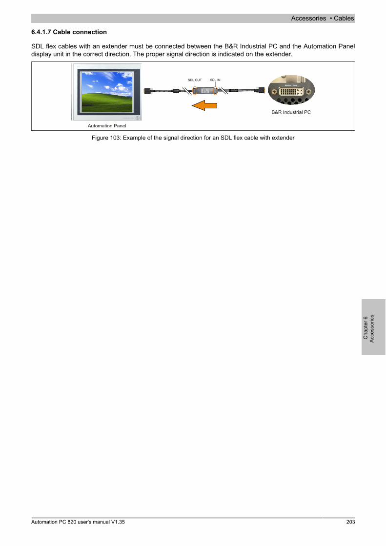
Accessories • Cables
Cha
pter
6Ac
cess
orie
s
Automation PC 820 user's manual V1.35 203
6.4.1.7 Cable connection
SDL flex cables with an extender must be connected between the B&R Industrial PC and the Automation Paneldisplay unit in the correct direction. The proper signal direction is indicated on the extender.
B&R Industrial PC
Figure 103: Example of the signal direction for an SDL flex cable with extender
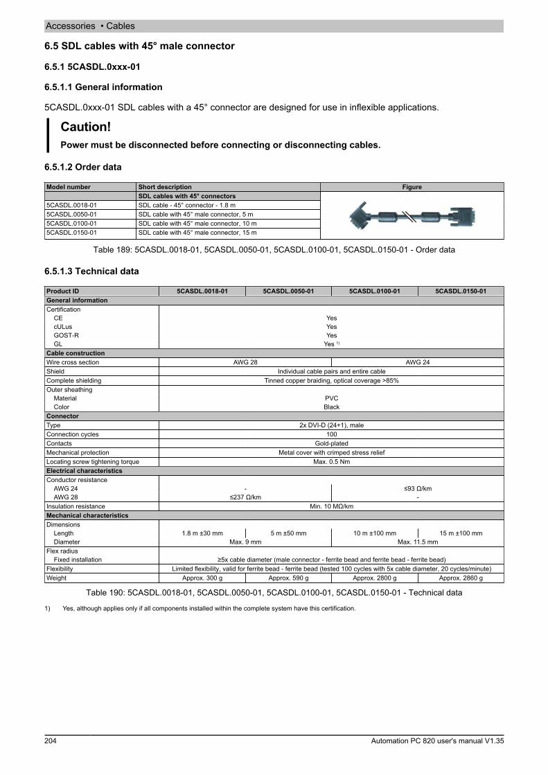
Accessories • Cables
204 Automation PC 820 user's manual V1.35
6.5 SDL cables with 45° male connector
6.5.1 5CASDL.0xxx-01
6.5.1.1 General information
5CASDL.0xxx-01 SDL cables with a 45° connector are designed for use in inflexible applications.
Caution!Power must be disconnected before connecting or disconnecting cables.
6.5.1.2 Order data
Model number Short description FigureSDL cables with 45° connectors
5CASDL.0018-01 SDL cable - 45° connector - 1.8 m5CASDL.0050-01 SDL cable with 45° male connector, 5 m5CASDL.0100-01 SDL cable with 45° male connector, 10 m5CASDL.0150-01 SDL cable with 45° male connector, 15 m
Table 189: 5CASDL.0018-01, 5CASDL.0050-01, 5CASDL.0100-01, 5CASDL.0150-01 - Order data
6.5.1.3 Technical data
Product ID 5CASDL.0018-01 5CASDL.0050-01 5CASDL.0100-01 5CASDL.0150-01General informationCertification
CE YescULus YesGOST-R YesGL Yes 1)
Cable constructionWire cross section AWG 28 AWG 24Shield Individual cable pairs and entire cableComplete shielding Tinned copper braiding, optical coverage >85%Outer sheathing
Material PVCColor Black
ConnectorType 2x DVI-D (24+1), maleConnection cycles 100Contacts Gold-platedMechanical protection Metal cover with crimped stress reliefLocating screw tightening torque Max. 0.5 NmElectrical characteristicsConductor resistance
AWG 24 - ≤93 Ω/kmAWG 28 ≤237 Ω/km -
Insulation resistance Min. 10 MΩ/kmMechanical characteristicsDimensions
Length 1.8 m ±30 mm 5 m ±50 mm 10 m ±100 mm 15 m ±100 mmDiameter Max. 9 mm Max. 11.5 mm
Flex radiusFixed installation ≥5x cable diameter (male connector - ferrite bead and ferrite bead - ferrite bead)
Flexibility Limited flexibility, valid for ferrite bead - ferrite bead (tested 100 cycles with 5x cable diameter, 20 cycles/minute)Weight Approx. 300 g Approx. 590 g Approx. 2800 g Approx. 2860 g
Table 190: 5CASDL.0018-01, 5CASDL.0050-01, 5CASDL.0100-01, 5CASDL.0150-01 - Technical data
1) Yes, although applies only if all components installed within the complete system have this certification.
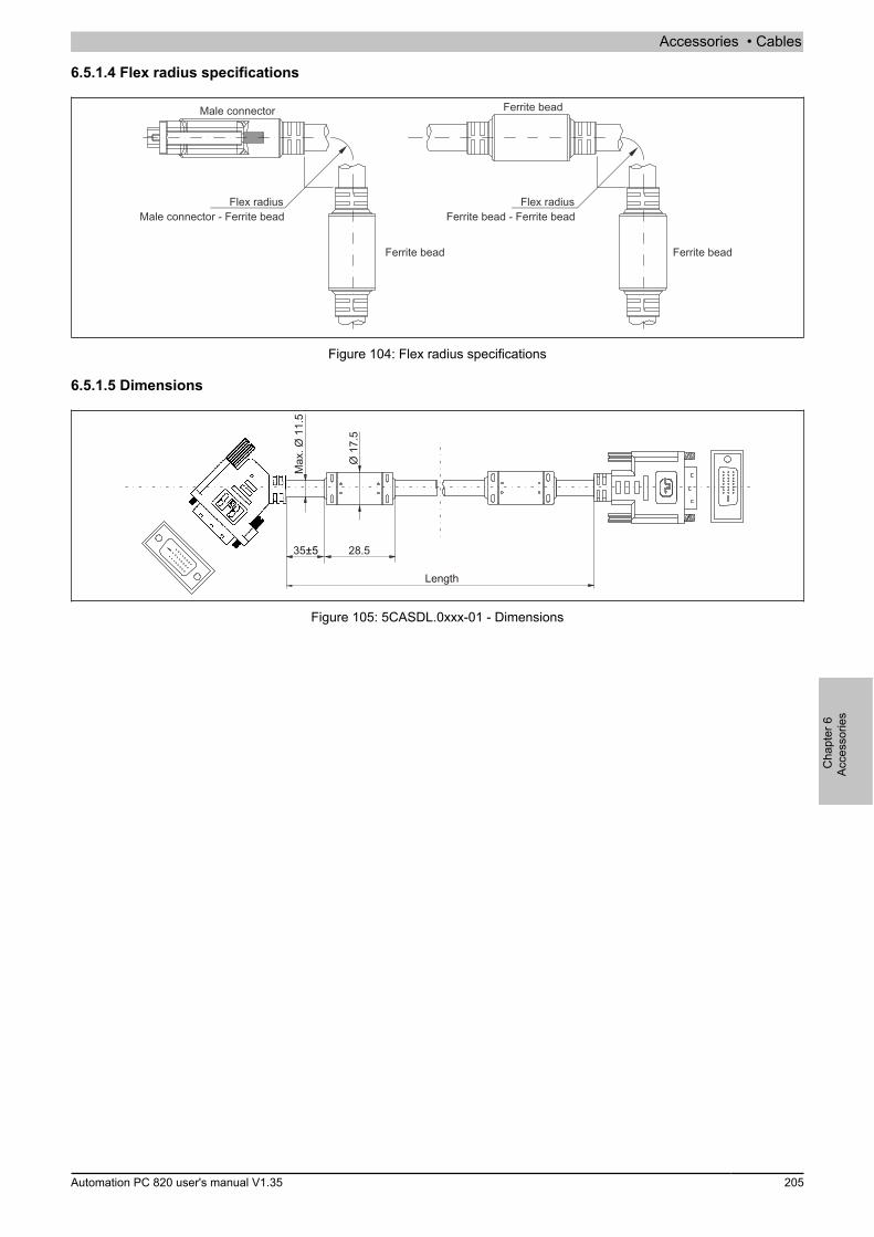
Accessories • Cables
Cha
pter
6Ac
cess
orie
s
Automation PC 820 user's manual V1.35 205
6.5.1.4 Flex radius specifications
Male connector
Ferrite bead
Ferrite bead
Ferrite bead
Flex radiusMale connector - Ferrite bead
Flex radiusFerrite bead - Ferrite bead
Figure 104: Flex radius specifications
6.5.1.5 Dimensions
Max
. Ø 1
1.5
35±5 28.5
Ø 1
7.5
Length
Figure 105: 5CASDL.0xxx-01 - Dimensions
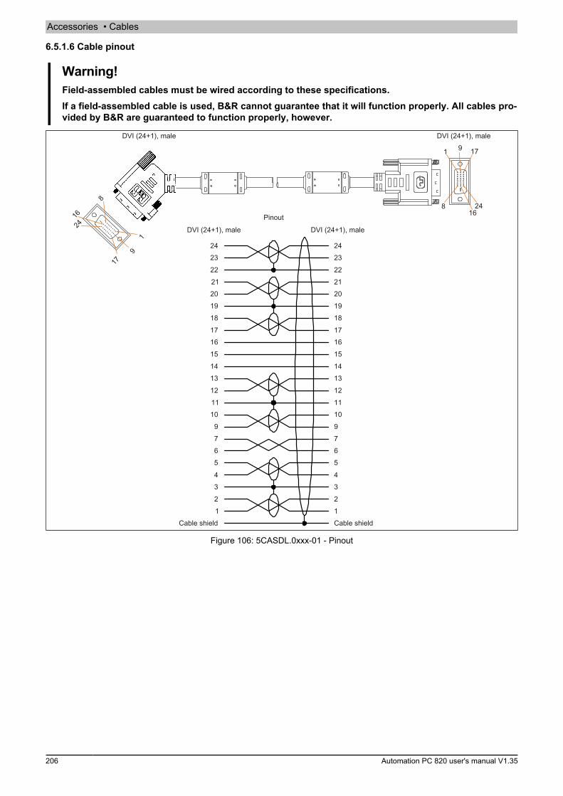
Accessories • Cables
206 Automation PC 820 user's manual V1.35
6.5.1.6 Cable pinout
Warning!Field-assembled cables must be wired according to these specifications.If a field-assembled cable is used, B&R cannot guarantee that it will function properly. All cables pro-vided by B&R are guaranteed to function properly, however.
DVI (24+1), male DVI (24+1), male
PinoutDVI (24+1), male DVI (24+1), male
Cable shield Cable shield
Figure 106: 5CASDL.0xxx-01 - Pinout
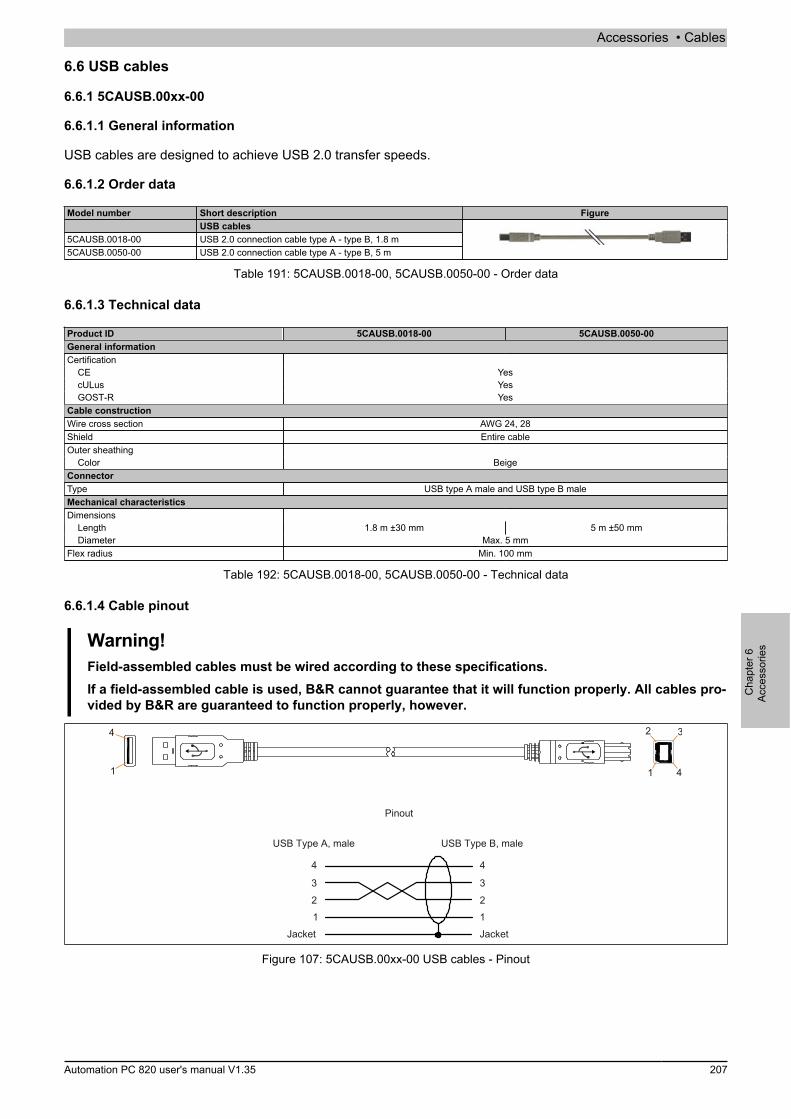
Accessories • Cables
Cha
pter
6Ac
cess
orie
s
Automation PC 820 user's manual V1.35 207
6.6 USB cables
6.6.1 5CAUSB.00xx-00
6.6.1.1 General information
USB cables are designed to achieve USB 2.0 transfer speeds.
6.6.1.2 Order data
Model number Short description FigureUSB cables
5CAUSB.0018-00 USB 2.0 connection cable type A - type B, 1.8 m5CAUSB.0050-00 USB 2.0 connection cable type A - type B, 5 m
Table 191: 5CAUSB.0018-00, 5CAUSB.0050-00 - Order data
6.6.1.3 Technical data
Product ID 5CAUSB.0018-00 5CAUSB.0050-00General informationCertification
CE YescULus YesGOST-R Yes
Cable constructionWire cross section AWG 24, 28Shield Entire cableOuter sheathing
Color BeigeConnectorType USB type A male and USB type B maleMechanical characteristicsDimensions
Length 1.8 m ±30 mm 5 m ±50 mmDiameter Max. 5 mm
Flex radius Min. 100 mm
Table 192: 5CAUSB.0018-00, 5CAUSB.0050-00 - Technical data
6.6.1.4 Cable pinout
Warning!Field-assembled cables must be wired according to these specifications.If a field-assembled cable is used, B&R cannot guarantee that it will function properly. All cables pro-vided by B&R are guaranteed to function properly, however.
Pinout
USB Type A, male USB Type B, male
Jacket Jacket
Figure 107: 5CAUSB.00xx-00 USB cables - Pinout

Accessories • Cables
208 Automation PC 820 user's manual V1.35
6.7 RS232 cables
6.7.1 9A0014.xx
6.7.1.1 General information
RS232 cables are used as extension cables between two RS232 interfaces.
6.7.1.2 Order data
Model number Short description FigureRS232 cables
9A0014.02 RS232 extension cable for remote operation of a display unitwith touch screen, 1.8 m
9A0014.05 RS232 extension cable for remote operation of a display unitwith touch screen, 5 m
9A0014.10 RS232 extension cable for remote operation of a display unitwith touch screen, 10 m
Table 193: 9A0014.02, 9A0014.05, 9A0014.10 - Order data
6.7.1.3 Technical data
Product ID 9A0014.02 9A0014.05 9A0014.10General informationCertification
CE YesGOST-R - Yes
Cable constructionWire cross section AWG 26Shield Entire cableOuter sheathing
Color BeigeConnectorType 9-pin male/female DSUB connectorLocating screw tightening torque Max. 0.5 NmMechanical characteristicsDimensions
Length 1.8 m ±50 mm 5 m ±80 mm 10 m ±100 mmDiameter Max. 5 mm
Flex radius Min. 70 mm
Table 194: 9A0014.02, 9A0014.05, 9A0014.10 - Technical data
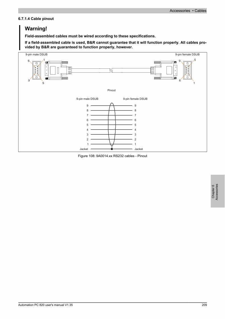
Accessories • Cables
Cha
pter
6Ac
cess
orie
s
Automation PC 820 user's manual V1.35 209
6.7.1.4 Cable pinout
Warning!Field-assembled cables must be wired according to these specifications.If a field-assembled cable is used, B&R cannot guarantee that it will function properly. All cables pro-vided by B&R are guaranteed to function properly, however.
9-pin male DSUB 9-pin female DSUB
Pinout
Jacket Jacket
9-pin male DSUB 9-pin female DSUB
Figure 108: 9A0014.xx RS232 cables - Pinout
Accessories • HMI Drivers & Utilities DVD
210 Automation PC 820 user's manual V1.35
7 HMI Drivers & Utilities DVD
7.1 5SWHMI.0000-00
7.1.1 General information
This DVD contains drivers, utilities, software upgrades and user's manuals for B&R panel system products (seethe "Industrial PCs" or "Visualization and operation" section of the B&R website at www.br-automation.com).When the DVD is created, its contents are identical to the files found in the Downloads section of the B&R website(Service / Material-related downloads).
7.1.2 Order data
Model number Short description FigureOther
5SWHMI.0000-00 HMI Drivers & Utilities DVD
Table 195: 5SWHMI.0000-00 - Order data
7.1.3 Contents (V2.20)
BIOS product upgrades
• Automation PC 620 / Panel PC 700 CPU board 815E and 855GME BIOS• Automation PC 620 / Panel PC 700 CPU board X855GME BIOS• Automation PC 620 / Panel PC 700 CPU board 945GME BIOS• Automation PC 620 / Panel PC 700 CPU board 945GME N270 BIOS• Automation PC 680• Automation PC 810 / Automation PC 820 / Panel PC 800 B945GME BIOS• Automation PC 810 / Panel PC 800 945GME N270 CPU board BIOS• Automation PC 810 / Panel PC 800 GM45 CPU board BIOS• Provit 2000 product family - IPC2000/2001/2002• Provit 5000 product family - IPC5000/5600/5000C/5600C• Power Panel 100 BIOS devices• Mobile Panel 100 BIOS devices• Power Panel 100 / Mobile Panel 100 user boot logo• Power Panel 100 / Mobile Panel 100 REMHOST utility• Power Panel 300/400 BIOS devices• Power Panel 300/400 BIOS user boot logo• Power Panel 500 / Automation PC 510 / Automation PC 511 BIOS• Panel PC 310
Device drivers
• Automation Device Interface (ADI)• Audio• Chipset• CD-ROM• LS120
Accessories • HMI Drivers & Utilities DVD
Cha
pter
6Ac
cess
orie
s
Automation PC 820 user's manual V1.35 211
• Graphics• Network• PCI / SATA RAID controller• Touch screen• Touchpad• Interface board
Firmware upgrades
• Automation PC 620 / Panel PC 700 (MTCX, SDLR, SDLT)• Automation PC 810 (MTCX, SDLR, SDLT)• Automation PC 820 (MTCX, SDLR, SDLT)• Mobile Panel 100 (SMCX)• Panel PC 300 (MTCX)• Power Panel 100 (aPCI)• Power Panel 300/400 (aPCI)• Power Panel 300/400 (MTCX)• Power Panel 500 / Automation PC 510 / Automation PC 511 (MTCX, SDLR, I/O board)• Panel PC 800 (MTCX, SDLR, SDLT)• UPS firmware
Utilities/Tools
• B&R Embedded OS Installer• Windows CE Tools• User boot logo conversion program• SATA RAID Installation Utility• Automation Device Interface (ADI)• CompactFlash service life calculator (Silicon Systems)• Miscellaneous• MTC utilities• B&R Key Editor• MTC & Mkey utilities• Mkey utilities• UPS configuration software• ICU ISA configuration• Intel PCI NIC boot ROM• Diagnostic programs
Windows
• Windows CE 6.0• Windows CE 5.0• Windows CE 4.2• Windows CE 4.1• Windows CE Tools• Windows Embedded Standard 2009• Windows Embedded Standard 7• Thin client• Windows NT Embedded• Windows XP Embedded• VNC viewer
Accessories • HMI Drivers & Utilities DVD
212 Automation PC 820 user's manual V1.35
MCAD templates for
• Industrial PCs• Visualization and operating devices• Slide-in label templates• Custom designs
ECAD templates for
• Industrial PCs• Automation PCs• Automation Panel 900• Panels (Power Panel)
Documentation for
• Automation PC 511• Automation PC 620• Automation PC 680• Automation PC 810• Automation PC 820• Automation Panel 800• Automation Panel 900• Panel PC 310• Panel PC 700• Panel PC 725• Panel PC 800• Power Panel 15/21/35/41• Power Panel 100/200• Power Panel 300/400• Power Panel 500• Mobile Panel 40/50• Mobile Panel 100/200• Mobile Panel connection box• Provit 2000• Provit 3030• Provit 4000• Provit 5000• Provit Benchmark• Provit Mkey• Windows CE 5.0 help documentation• Windows CE 6.0 help documentation• Windows NT Embedded application guide• Windows XP Embedded application guide• Uninterruptible power supply• Implementation guides• B&R Hilscher fieldbus cards (CANopen, DeviceNet, PROFIBUS, PROFINET)
Service tools
• Acrobat Reader 5.0.5 (freeware in German, English and French)• Power Archiver 6.0 (freeware in German, English and French)• Internet Explorer 5.0 (German and English)• Internet Explorer 6.0 (German and English)

Maintenance and service • Replacing the battery
Cha
pter
7M
aint
enan
cean
d se
rvic
e
Automation PC 820 user's manual V1.35 213
Chapter 7 • Maintenance and service
This chapter describes service/maintenance work that can be carried out by a qualified end user.
1 Replacing the battery
The lithium battery buffers the internal real-time clock (RTC) and CMOS data.
Information:• The product design allows the battery to be changed with the B&R device switched either on or
off. In some countries, safety regulations do not allow batteries to be changed while the moduleis switched on.
• Any BIOS settings that have been made will remain when the battery is changed with the powerturned off (stored in nonvolatile EEPROM). The date and time must be reset later since this datais lost when the battery is changed.
• The battery should only be replaced by qualified personnel.
Warning!The battery is only permitted to be replaced by a Renata CR2477N battery. The use of another batterymay present a risk of fire or explosion.The battery may explode if handled improperly. Do not recharge, disassemble or dispose of in fire.
The following replacement lithium batteries are available: 4A0006.00-000 (1 pc.) and 0AC201.91 (4 pcs.).
1.1 Evaluating the battery status
The status of the battery is determined immediately after the device is started and subsequently checked by thesystem every 24 hours. During this measurement, the battery is subjected to a brief load (approximately 1 second)and then evaluated. Once determined, the battery status is displayed in BIOS (Advanced - OEM features - Systemboard features - Voltage values) and in the B&R Control Center (ADI driver); it can also be read in a customerapplication using the ADI library.Battery status FunctionN/A The hardware or firmware being used is too old and does not support reading the battery status.GOOD Data buffering is intact.BAD From the point when battery capacity is recognized as insufficient (BAD), data buffering is intact for approximately another 500
hours.
Table 196: Battery status
From the point when battery capacity is recognized as insufficient, data buffering is intact for approximately another500 hours. When replacing the battery, data is buffered for approximately 10 minutes by a gold leaf capacitor.
1.2 Procedure
• Disconnect the power supply to the B&R Industrial PC.• Touch the housing or ground connection in order to discharge any electrostatic charge from your body.• Remove the cover from the battery compartment and carefully pull out the battery using the removal strip.
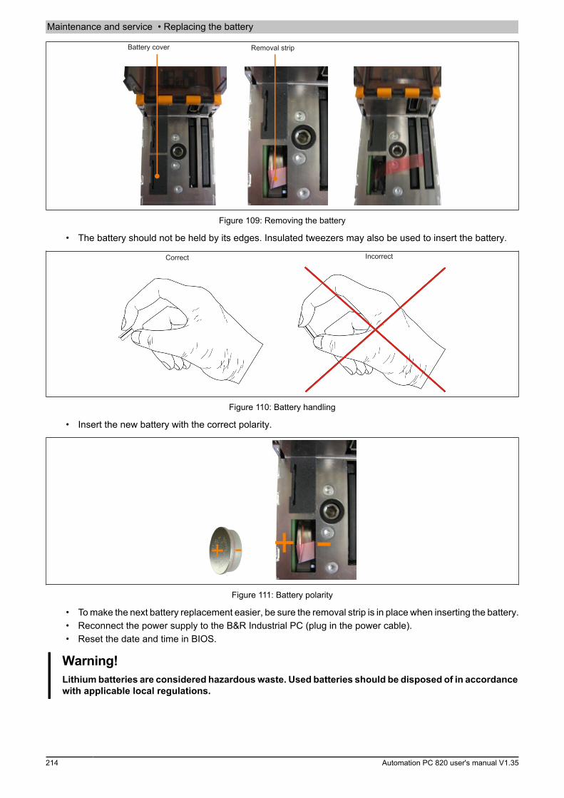
Maintenance and service • Replacing the battery
214 Automation PC 820 user's manual V1.35
Battery cover Removal strip
Figure 109: Removing the battery
• The battery should not be held by its edges. Insulated tweezers may also be used to insert the battery.
Correct Incorrect
Figure 110: Battery handling
• Insert the new battery with the correct polarity.
Figure 111: Battery polarity
• To make the next battery replacement easier, be sure the removal strip is in place when inserting the battery.• Reconnect the power supply to the B&R Industrial PC (plug in the power cable).• Reset the date and time in BIOS.
Warning!Lithium batteries are considered hazardous waste. Used batteries should be disposed of in accordancewith applicable local regulations.
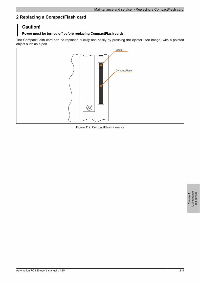
Maintenance and service • Replacing a CompactFlash card
Cha
pter
7M
aint
enan
cean
d se
rvic
e
Automation PC 820 user's manual V1.35 215
2 Replacing a CompactFlash card
Caution!Power must be turned off before replacing CompactFlash cards.
The CompactFlash card can be replaced quickly and easily by pressing the ejector (see image) with a pointedobject such as a pen.
Ejector
CompactFlash
Figure 112: CompactFlash + ejector
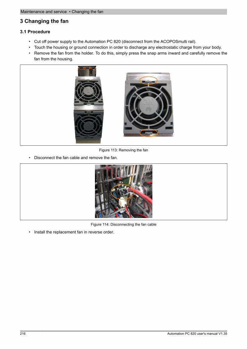
Maintenance and service • Changing the fan
216 Automation PC 820 user's manual V1.35
3 Changing the fan
3.1 Procedure
• Cut off power supply to the Automation PC 820 (disconnect from the ACOPOSmulti rail).• Touch the housing or ground connection in order to discharge any electrostatic charge from your body.• Remove the fan from the holder. To do this, simply press the snap arms inward and carefully remove the
fan from the housing.
Figure 113: Removing the fan
• Disconnect the fan cable and remove the fan.
Figure 114: Disconnecting the fan cable
• Install the replacement fan in reverse order.
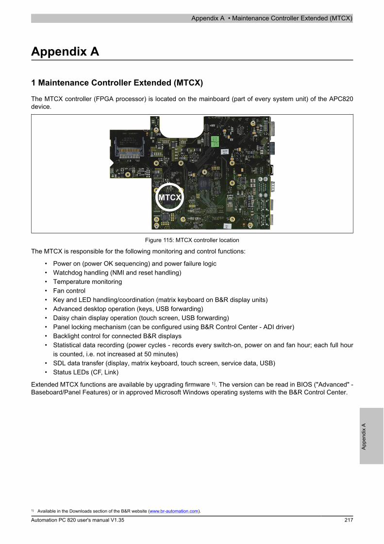
Appendix A • Maintenance Controller Extended (MTCX)
Appe
ndix
A
Automation PC 820 user's manual V1.35 217
Appendix A
1 Maintenance Controller Extended (MTCX)
The MTCX controller (FPGA processor) is located on the mainboard (part of every system unit) of the APC820device.
MTCX
Figure 115: MTCX controller location
The MTCX is responsible for the following monitoring and control functions:
• Power on (power OK sequencing) and power failure logic• Watchdog handling (NMI and reset handling)• Temperature monitoring• Fan control• Key and LED handling/coordination (matrix keyboard on B&R display units)• Advanced desktop operation (keys, USB forwarding)• Daisy chain display operation (touch screen, USB forwarding)• Panel locking mechanism (can be configured using B&R Control Center - ADI driver)• Backlight control for connected B&R displays• Statistical data recording (power cycles - records every switch-on, power on and fan hour; each full hour
is counted, i.e. not increased at 50 minutes)• SDL data transfer (display, matrix keyboard, touch screen, service data, USB)• Status LEDs (CF, Link)
Extended MTCX functions are available by upgrading firmware 1). The version can be read in BIOS ("Advanced" -Baseboard/Panel Features) or in approved Microsoft Windows operating systems with the B&R Control Center.
1) Available in the Downloads section of the B&R website (www.br-automation.com).

Appendix A • Maintenance Controller Extended (MTCX)
218 Automation PC 820 user's manual V1.35
1.1 Temperature monitoring Fan control
The MTCX constantly monitors the temperature using temperature sensors (see "Temperature sensor locations" onpage 22), which directly determines how the fans are controlled. The speed depends on the measured temperature.Sensor range Startup temperature Max. fan speed at:CPU 70°C 86°CBaseboard Out 65°C 81°CBaseboard Center 65°C 81°CBaseboard In 54°C 70°CPower supply 65°C 81°CIF slot (PCIec card slot) 65°C 81°C
Table 197: Temperature limits of the fan (MTCX PX32 V0.05).
The fans are only switched off again when the evaluated temperature remains 6°C below the start-up temperaturefor a time span of 30 minutes (=lag-time).
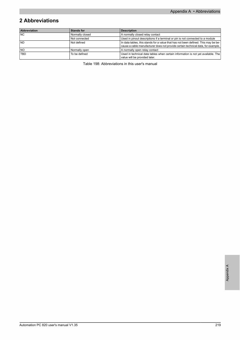
Appendix A • Abbreviations
Appe
ndix
A
Automation PC 820 user's manual V1.35 219
2 AbbreviationsAbbreviation Stands for Description
Normally closed A normally closed relay contactNCNot connected Used in pinout descriptions if a terminal or pin is not connected to a module
ND Not defined In data tables, this stands for a value that has not been defined. This may be be-cause a cable manufacturer does not provide certain technical data, for example.
NO Normally open A normally open relay contactTBD To be defined Used in technical data tables when certain information is not yet available. The
value will be provided later.
Table 198: Abbreviations in this user's manual
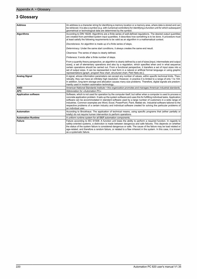
Appendix A • Glossary
220 Automation PC 820 user's manual V1.35
3 GlossaryAddress An address is a character string for identifying a memory location or a memory area, where data is stored and can
be retrieved. It is also a symbol (e.g. with numerical controllers) for identifying a function unit for which subsequentgeometrical or technological data are determined by the symbol.
Algorithms According to DIN 19226: Algorithms are a finite series of well-defined regulations. The desired output quantitiesare created from permitted system input quantities. It describes how something is to be done. A procedure mustat least satisfy the following requirements to be valid as an algorithm in a mathematical context.
Discreteness: An algorithm is made up of a finite series of steps.
Determinacy: Under the same start conditions, it always creates the same end result.
Clearness: The series of steps is clearly defined.
Finiteness: It ends after a finite number of steps.
From a quantity theory perspective, an algorithm is clearly defined by a set of sizes [input, intermediate and outputsizes], a set of elementary operations and also by a regulation, which specifies when and in what sequencecertain operations should be carried out. From a functional perspective, it transfers a set of input sizes into aset of output sizes. It can be represented in text form in a natural or artificial formal language or using graphicrepresentations [graph, program flow chart, structured chart, Petri Nets etc.].
Analog Signal A signal, whose information parameters can accept any number of values, within specific technical limits. Theo-retically, they can have an infinitely high resolution. However, in practice it is limited to a range of only 1 to 104.In addition, long-term storage and allocation causes many size problems. Therefore, digital signals are predom-inantly used in modern automation technology.
ANSI American National Standards Institute > this organization promotes and manages American industrial standards.APC Abbreviation for »Automation PC«Application software Software, which is not used for operation by the computer itself, but rather when a computer is used to process a
concrete application problem. It sets up the system software and uses this for fulfilling individual tasks. Applicationsoftware can be accommodated in standard software used by a large number of customers in a wide range ofindustries. Common examples are Word, Excel, PowerPoint, Paint, Matlab etc. Industrial software tailored to therespective problems of a certain industry and individual software created for solving the particular problems ofan individual user.
Automation According to Brockhaus: The application of technical means, using specific programs that (either partially ortotally) do not require human intervention to perform operations.
Automation Runtime A uniform runtime system for all B&R automation components.Failure Failure according to IEC 61508: A function unit loses the ability to perform a required function. In regards to
safety-oriented systems, a distinction is made between dangerous and safe failures. This depends on whetherthe status of the system failure is considered dangerous or safe. The cause of the failure may be load related orage-related, and therefore a random failure, or related to a flaw inherent in the system. In this case, it is knownas a systematic failure.
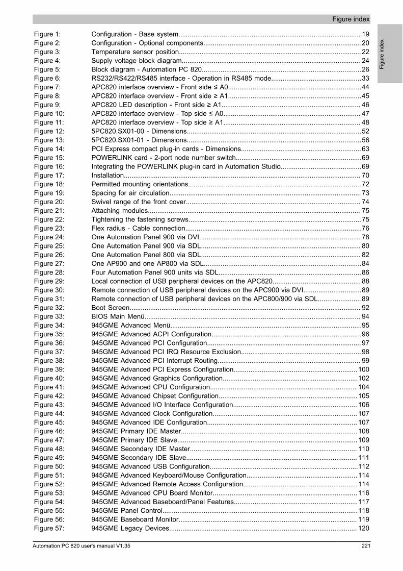
Figure index
Figu
re in
dex
Automation PC 820 user's manual V1.35 221
Figure 1: Configuration - Base system................................................................................................. 19Figure 2: Configuration - Optional components....................................................................................20Figure 3: Temperature sensor position................................................................................................. 22Figure 4: Supply voltage block diagram............................................................................................... 24Figure 5: Block diagram - Automation PC 820.....................................................................................26Figure 6: RS232/RS422/RS485 interface - Operation in RS485 mode................................................33Figure 7: APC820 interface overview - Front side ≤ A0.......................................................................44Figure 8: APC820 interface overview - Front side ≥ A1.......................................................................45Figure 9: APC820 LED description - Front side ≥ A1.......................................................................... 46Figure 10: APC820 interface overview - Top side ≤ A0......................................................................... 47Figure 11: APC820 interface overview - Top side ≥ A1......................................................................... 48Figure 12: 5PC820.SX01-00 - Dimensions.............................................................................................52Figure 13: 5PC820.SX01-01 - Dimensions.............................................................................................56Figure 14: PCI Express compact plug-in cards - Dimensions................................................................63Figure 15: POWERLINK card - 2-port node number switch...................................................................69Figure 16: Integrating the POWERLINK plug-in card in Automation Studio...........................................69Figure 17: Installation.............................................................................................................................. 70Figure 18: Permitted mounting orientations............................................................................................ 72Figure 19: Spacing for air circulation...................................................................................................... 73Figure 20: Swivel range of the front cover............................................................................................. 74Figure 21: Attaching modules................................................................................................................. 75Figure 22: Tightening the fastening screws............................................................................................75Figure 23: Flex radius - Cable connection..............................................................................................76Figure 24: One Automation Panel 900 via DVI...................................................................................... 78Figure 25: One Automation Panel 900 via SDL..................................................................................... 80Figure 26: One Automation Panel 800 via SDL..................................................................................... 82Figure 27: One AP900 and one AP800 via SDL....................................................................................84Figure 28: Four Automation Panel 900 units via SDL............................................................................86Figure 29: Local connection of USB peripheral devices on the APC820............................................... 88Figure 30: Remote connection of USB peripheral devices on the APC900 via DVI...............................89Figure 31: Remote connection of USB peripheral devices on the APC800/900 via SDL.......................89Figure 32: Boot Screen........................................................................................................................... 92Figure 33: BIOS Main Menü................................................................................................................... 94Figure 34: 945GME Advanced Menü......................................................................................................95Figure 35: 945GME Advanced ACPI Configuration................................................................................96Figure 36: 945GME Advanced PCI Configuration.................................................................................. 97Figure 37: 945GME Advanced PCI IRQ Resource Exclusion................................................................98Figure 38: 945GME Advanced PCI Interrupt Routing............................................................................ 99Figure 39: 945GME Advanced PCI Express Configuration..................................................................100Figure 40: 945GME Advanced Graphics Configuration........................................................................102Figure 41: 945GME Advanced CPU Configuration.............................................................................. 104Figure 42: 945GME Advanced Chipset Configuration..........................................................................105Figure 43: 945GME Advanced I/O Interface Configuration.................................................................. 106Figure 44: 945GME Advanced Clock Configuration............................................................................. 107Figure 45: 945GME Advanced IDE Configuration................................................................................ 107Figure 46: 945GME Primary IDE Master..............................................................................................108Figure 47: 945GME Primary IDE Slave................................................................................................109Figure 48: 945GME Secondary IDE Master......................................................................................... 110Figure 49: 945GME Secondary IDE Slave........................................................................................... 111Figure 50: 945GME Advanced USB Configuration...............................................................................112Figure 51: 945GME Advanced Keyboard/Mouse Configuration...........................................................114Figure 52: 945GME Advanced Remote Access Configuration.............................................................114Figure 53: 945GME Advanced CPU Board Monitor.............................................................................116Figure 54: 945GME Advanced Baseboard/Panel Features..................................................................117Figure 55: 945GME Panel Control........................................................................................................118Figure 56: 945GME Baseboard Monitor............................................................................................... 119Figure 57: 945GME Legacy Devices.................................................................................................... 120
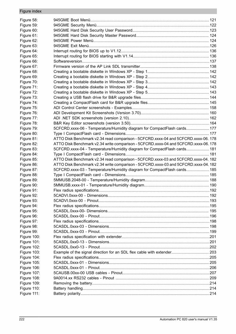
Figure index
222 Automation PC 820 user's manual V1.35
Figure 58: 945GME Boot Menü............................................................................................................ 121Figure 59: 945GME Security Menü.......................................................................................................122Figure 60: 945GME Hard Disk Security User Password......................................................................123Figure 61: 945GME Hard Disk Security Master Password.................................................................. 124Figure 62: 945GME Power Menü......................................................................................................... 124Figure 63: 945GME Exit Menü..............................................................................................................126Figure 64: Interrupt routing for BIOS up to V1.12................................................................................ 136Figure 65: Interrupt routing for BIOS starting with V1.14..................................................................... 136Figure 66: Softwareversion....................................................................................................................137Figure 67: Firmware version of the AP Link SDL transmitter...............................................................138Figure 68: Creating a bootable diskette in Windows XP - Step 1........................................................ 142Figure 69: Creating a bootable diskette in Windows XP - Step 2........................................................ 142Figure 70: Creating a bootable diskette in Windows XP - Step 3........................................................ 142Figure 71: Creating a bootable diskette in Windows XP - Step 4........................................................ 143Figure 72: Creating a bootable diskette in Windows XP - Step 5........................................................ 143Figure 73: Creating a USB flash drive for B&R upgrade files.............................................................. 144Figure 74: Creating a CompactFlash card for B&R upgrade files........................................................ 145Figure 75: ADI Control Center screenshots - Examples...................................................................... 158Figure 76: ADI Development Kit Screenshots (Version 3.70).............................................................. 160Figure 77: ADI .NET SDK screenshots (version 2.10)......................................................................... 162Figure 78: B&R Key Editor screenshots (version 3.50)........................................................................164Figure 79: 5CFCRD.xxxx-06 - Temperature/Humidity diagram for CompactFlash cards.....................177Figure 80: Type I CompactFlash card - Dimensions............................................................................ 177Figure 81: ATTO Disk Benchmark v2.34 read comparison - 5CFCRD.xxxx-04 and 5CFCRD.xxxx-06. 178Figure 82: ATTO Disk Benchmark v2.34 write comparison - 5CFCRD.xxxx-04 and 5CFCRD.xxxx-06. 178Figure 83: 5CFCRD.xxxx-04 - Temperature/Humidity diagram for CompactFlash cards.....................181Figure 84: Type I CompactFlash card - Dimensions............................................................................ 181Figure 85: ATTO Disk Benchmark v2.34 read comparison - 5CFCRD.xxxx-03 and 5CFCRD.xxxx-04. 182Figure 86: ATTO Disk Benchmark v2.34 write comparison - 5CFCRD.xxxx-03 and 5CFCRD.xxxx-04. 182Figure 87: 5CFCRD.xxxx-03 - Temperature/Humidity diagram for CompactFlash cards.....................185Figure 88: Type I CompactFlash card - Dimensions............................................................................ 185Figure 89: 5MMUSB.2048-00 - Temperature/Humidity diagram.......................................................... 188Figure 90: 5MMUSB.xxxx-01 - Temperature/Humidity diagram........................................................... 190Figure 91: Flex radius specifications.....................................................................................................192Figure 92: 5CADVI.0xxx-00 - Dimensions............................................................................................ 192Figure 93: 5CADVI.0xxx-00 - Pinout.....................................................................................................193Figure 94: Flex radius specifications.....................................................................................................195Figure 95: 5CASDL.0xxx-00- Dimensions............................................................................................ 195Figure 96: 5CASDL.0xxx-00 - Pinout....................................................................................................196Figure 97: Flex radius specifications.....................................................................................................198Figure 98: 5CASDL.0xxx-03 - Dimensions........................................................................................... 198Figure 99: 5CASDL.0xxx-03 - Pinout....................................................................................................199Figure 100: Flex radius specification with extender................................................................................201Figure 101: 5CASDL.0xx0-13 - Dimensions........................................................................................... 201Figure 102: 5CASDL.0xx0-13 - Pinout....................................................................................................202Figure 103: Example of the signal direction for an SDL flex cable with extender.................................. 203Figure 104: Flex radius specifications.....................................................................................................205Figure 105: 5CASDL.0xxx-01 - Dimensions........................................................................................... 205Figure 106: 5CASDL.0xxx-01 - Pinout....................................................................................................206Figure 107: 5CAUSB.00xx-00 USB cables - Pinout...............................................................................207Figure 108: 9A0014.xx RS232 cables - Pinout ..................................................................................... 209Figure 109: Removing the battery...........................................................................................................214Figure 110: Battery handling................................................................................................................... 214Figure 111: Battery polarity..................................................................................................................... 214
Figure index
Figu
re in
dex
Automation PC 820 user's manual V1.35 223
Figure 112: CompactFlash + ejector.......................................................................................................215Figure 113: Removing the fan................................................................................................................ 216Figure 114: Disconnecting the fan cable................................................................................................ 216Figure 115: MTCX controller location..................................................................................................... 217
Table index
224 Automation PC 820 user's manual V1.35
Table 1: Manual history............................................................................................................................... 9Table 2: Environmentally friendly separation of materials........................................................................ 13Table 3: Description of the safety notices used in this documentation.....................................................14Table 4: Range of nominal sizes.............................................................................................................. 14Table 5: Ambient temperature with a fan kit.............................................................................................21Table 6: Temperature sensor locations.....................................................................................................22Table 7: Humidity specifications................................................................................................................23Table 8: Power calculation – APC810...................................................................................................... 24Table 9: Monitor / Panel connection - RGB, DVI, SDL............................................................................ 27Table 10: DVI interface - Pinout..................................................................................................................28Table 11: Cable lengths and resolutions for SDL transmission..................................................................28Table 12: Cable lengths and resolutions for DVI transmission...................................................................28Table 13: USB1, USB2, USB3 and USB4 connections..............................................................................29Table 14: USB5 interface............................................................................................................................ 29Table 15: CompactFlash slot (CF1)............................................................................................................ 30Table 16: CompactFlash slot (CF2)............................................................................................................ 30Table 17: COM1 - Pinout............................................................................................................................ 31Table 18: RS232 - Bus length and transfer rate........................................................................................ 31Table 19: RS232 - Cable requirements...................................................................................................... 31Table 20: COM2 - Pinout............................................................................................................................ 32Table 21: RS232/422/485 - I/O address and IRQ...................................................................................... 32Table 22: RS232 - Bus length and transfer rate........................................................................................ 32Table 23: RS232 - Cable requirements...................................................................................................... 32Table 24: RS422 - Bus length and transfer rate........................................................................................ 33Table 25: RS422 - Cable requirements...................................................................................................... 33Table 26: RS485 - Bus length and transfer rate........................................................................................ 33Table 27: RS485 - Cable requirements...................................................................................................... 34Table 28: CAN interface.............................................................................................................................. 35Table 29: CAN node switch (x1, x16).........................................................................................................35Table 30: CAN terminating switch / LED.................................................................................................... 35Table 31: Status LED CAN......................................................................................................................... 35Table 32: POWERLINK interface................................................................................................................ 36Table 33: Status/Error LED - Ethernet mode..............................................................................................36Table 34: Status/Error LED - POWERLINK V1 operating mode................................................................ 36Table 35: Status/Error LED - POWERLINK - Error.................................................................................... 36Table 36: Status/Error LED - POWERLINK - Status.................................................................................. 37Table 37: System stop error codes.............................................................................................................38Table 38: POWERLINK node switch (x1, x16)........................................................................................... 38Table 39: Ethernet connection (ETH1)........................................................................................................39Table 40: Ethernet interface (ETH2)........................................................................................................... 39Table 41: Battery..........................................................................................................................................40Table 42: Battery status.............................................................................................................................. 40Table 43: Hardware security key.................................................................................................................41Table 44: LED status indicators - Data.......................................................................................................42Table 45: CMOS profile switch....................................................................................................................42Table 46: Power button............................................................................................................................... 43Table 47: Reset button................................................................................................................................ 43Table 48: 5PC820.SX01-00 - Order data................................................................................................... 49Table 49: 5PC820.SX01-00 - Technical data............................................................................................. 49Table 50: 5PC820.SX01-01 - Order data................................................................................................... 53Table 51: 5PC820.SX01-01 - Technical data............................................................................................. 53Table 52: 5PC800.B945-00, 5PC800.B945-01, 5PC800.B945-02, 5PC800.B945-03, 5PC800.B945-04 - Or-
der data....................................................................................................................................... 57Table 53: 5PC800.B945-10, 5PC800.B945-11, 5PC800.B945-12, 5PC800.B945-13, 5PC800.B945-14 - Or-
der data....................................................................................................................................... 57Table 54: 5PC800.B945-00, 5PC800.B945-01, 5PC800.B945-02, 5PC800.B945-03, 5PC800.B945-04 -
Technical data............................................................................................................................. 58
Table index
Tabl
e in
dex
Automation PC 820 user's manual V1.35 225
Table 55: 5PC800.B945-10, 5PC800.B945-11, 5PC800.B945-12, 5PC800.B945-13, 5PC800.B945-14 -Technical data............................................................................................................................. 58
Table 56: 5MMDDR.0512-01, 5MMDDR.1024-01, 5MMDDR.2048-01 - Order data..................................60Table 57: 5MMDDR.0512-01, 5MMDDR.1024-01, 5MMDDR.2048-01 - Technical data............................60Table 58: 5AC802.HS00-00, 5AC802.HS00-01 - Order data..................................................................... 61Table 59: 5AC802.HS00-00, 5AC802.HS00-01 - Technical data...............................................................61Table 60: 8BXF001.0000-00 - Order data.................................................................................................. 62Table 61: 8BXF001.0000-00 - Technical data............................................................................................ 62Table 62: 5ACPCC.ETH0-00 - Order data................................................................................................. 64Table 63: 5ACPCC.ETH0-00 - Technical data........................................................................................... 64Table 64: 5ACPCC.ETH0-00 - Ethernet interface...................................................................................... 64Table 65: 5ACPCC.MPL0-00 - Order data................................................................................................. 66Table 66: 5ACPCC.MPL0-00 - Technical data........................................................................................... 66Table 67: 5ACPCC.MPL0-00 - POWERLINK interface.............................................................................. 67Table 68: Status/Error LED - Ethernet mode..............................................................................................67Table 69: Status/Error LED - POWERLINK V1 operating mode................................................................ 67Table 70: Status/Error LED - POWERLINK - Error.................................................................................... 67Table 71: Status/Error LED - POWERLINK - Status.................................................................................. 68Table 72: System stop error codes.............................................................................................................69Table 73: POWERLINK station number (x1, x16)...................................................................................... 69Table 74: Selecting display units.................................................................................................................77Table 75: Possible combinations of system unit and CPU board...............................................................78Table 76: Link modules............................................................................................................................... 78Table 77: Cables for DVI configurations..................................................................................................... 78Table 78: Possible Automation Panel devices, resolutions and segment lengths......................................79Table 79: Possible combinations of system unit and CPU board...............................................................80Table 80: Link modules............................................................................................................................... 80Table 81: Cables for SDL configurations.................................................................................................... 80Table 82: Cable lengths and resolutions for SDL transmission..................................................................81Table 83: Possible combinations of system unit and CPU board...............................................................82Table 84: Cables for SDL configurations.................................................................................................... 82Table 85: Cable lengths and resolutions for SDL transmission..................................................................83Table 86: Possible combinations of system unit and CPU board...............................................................84Table 87: Link modules............................................................................................................................... 84Table 88: Possible combinations of system unit and CPU board...............................................................86Table 89: Link modules............................................................................................................................... 86Table 90: Cables for SDL configurations.................................................................................................... 87Table 91: Cable lengths and resolutions for SDL transmission..................................................................87Table 92: BIOS-relevant keys for POST.....................................................................................................93Table 93: BIOS-relevant keys..................................................................................................................... 93Table 94: 945GME - Main Menu - Setting options.....................................................................................94Table 95: 945GME Advanced Menu (Setting options)............................................................................... 95Table 96: 945GME - Advanced ACPI configuration - Setting options........................................................ 96Table 97: 945GME - Advanced PCI configuration - Setting options.......................................................... 97Table 98: 945GME - Advanced PCI IRQ Resource Exclusion - Setting options........................................ 98Table 99: 945GME - Advanced PCI Interrupt Routing - Setting options.................................................... 99Table 100: 945GME Advanced PCI Express Configuration (Setting options)............................................ 100Table 101: 945GME Advanced Graphics Configuration (Setting options)..................................................102Table 102: 945GME Advanced CPU Configuration (Setting options)........................................................ 104Table 103: 945GME Advanced Chipset (Setting options).......................................................................... 105Table 104: 945GME Advanced I/O Interface Configuration....................................................................... 106Table 105: 945GME Advanced Clock Configuration (Setting options)....................................................... 107Table 106: 945GME Advanced IDE Configuration (Setting options).......................................................... 108Table 107: 945GME - Primary IDE Master - Setting options..................................................................... 108Table 108: 945GME - Primary IDE Slave - Setting options....................................................................... 109Table 109: 945GME - Secondary IDE Master - Setting options.................................................................110Table 110: 945GME - Secondary IDE Slave - Setting options...................................................................111
Table index
226 Automation PC 820 user's manual V1.35
Table 111: 945GME - Advanced USB Configuration - Setting options...................................................... 112Table 112: 945GME Advanced Keyboard/Mouse Configuration (Setting options)..................................... 114Table 113: 945GME Advanced Remote Access Configuration (Setting options).......................................115Table 114: 945GME Advanced Remote Access Configuration (Setting options).......................................116Table 115: 945GME - Advanced Baseboard/Panel Features - Setting options..........................................117Table 116: 945GME Panel Control (Setting options)..................................................................................118Table 117: 945GME Baseboard Monitor (Setting options)......................................................................... 119Table 118: 945GME Legacy Devices (Setting options).............................................................................. 120Table 119: 945GME Boot Menu (Setting options)......................................................................................121Table 120: 945GME - Advanced PCI configuration - Setting options........................................................ 122Table 121: 945GME Hard Disk Security User Password........................................................................... 123Table 122: 945GME Hard Disk Security Master Password........................................................................124Table 123: 945GME Power Menu (Setting options)................................................................................... 125Table 124: 945GME - Advanced PCI configuration - Setting options........................................................ 126Table 125: Profile overview......................................................................................................................... 127Table 126: 945GME Main (Profile setting overview).................................................................................. 127Table 127: 945GME Advanced - ACPI configuration profile setting overview............................................127Table 128: 945GME Advanced - PCI configuration profile setting overview.............................................. 127Table 129: 945GME Advanced - PCI Express configuration profile setting overview................................ 128Table 130: 945GME Advanced - Graphics configuration profile setting overview......................................128Table 131: 945GME Advanced - CPU configuration profile setting overview.............................................129Table 132: 945GME Advanced - Chipset configuration profile setting overview........................................ 129Table 133: 945GME Advanced - I/O Interface Configuration profile setting overview................................129Table 134: 945GME Advanced - Clock configuration profile setting overview........................................... 129Table 135: 945GME Advanced - IDE configuration profile setting overview.............................................. 129Table 136: 945GME Advanced - USB configuration profile setting overview.............................................130Table 137: 945GME Advanced - Keyboard/Mouse Configuration profile setting overview.........................130Table 138: 945GME Advanced - Remote Access Configuration profile setting overview.......................... 130Table 139: 945GME Advanced - CPU board monitor profile setting overview...........................................130Table 140: 945GME Advanced - Baseboard/Panel Features profile setting overview............................... 130Table 141: 945GME Main (Profile setting overview).................................................................................. 131Table 142: 945GME Security profile setting overview................................................................................131Table 143: 945GME Power profile setting overview...................................................................................131Table 144: 945GME BIOS - POST messages........................................................................................... 133Table 145: RAM address assignment.........................................................................................................134Table 146: I/O address assignment............................................................................................................ 134Table 147: IRQ interrupt assignments in PIC mode...................................................................................134Table 148: IRQ interrupt assignments in APIC mode................................................................................ 135Table 149: 9S0000.01-010, 9S0000.01-020 - Order data.......................................................................... 146Table 150: Tested resolutions and color depths for DVI signals................................................................146Table 151: Tested resolutions and color depths for RGB signals.............................................................. 146Table 152: 5SWWXP.0600-GER, 5SWWXP.0600-ENG, 5SWWXP.0600-MUL, 5SWWXP.0500-GER,
5SWWXP.0500-ENG, 5SWWXP.0500-MUL - Order data.........................................................147Table 153: 5SWWXP.0428-ENG - Order data............................................................................................ 149Table 154: 5SWWXP.0428-ENG - Technical data......................................................................................149Table 155: Device functions in Windows XP Embedded with FP2007.......................................................149Table 156: 5SWWXP.0728-ENG - Order data............................................................................................ 151Table 157: 5SWWXP.0728-ENG - Technical data......................................................................................151Table 158: Device functions in Windows Embedded Standard 2009.........................................................151Table 159: 5SWWI7.0528-ENG, 5SWWI7.0628-ENG, 5SWWI7.0728-MUL, 5SWWI7.0828-MUL,
5SWWI7.1528-ENG, 5SWWI7.1628-ENG, 5SWWI7.1728-MUL, 5SWWI7.1828-MUL - Order da-ta................................................................................................................................................153
Table 160: 5SWWI7.0528-ENG - Technical data....................................................................................... 154Table 161: Device functions in Windows Embedded Standard 7...............................................................154Table 162: 0TG1000.01, 1TG4600.10-5, 1TG4601.06-5 - Order data....................................................... 156Table 163: 0TB704.9, 0TB704.91 - Order data.......................................................................................... 168Table 164: 0TB704.9, 0TB704.91 - Technical data....................................................................................168Table 165: 0AC201.91, 4A0006.00-000 - Order data.................................................................................169
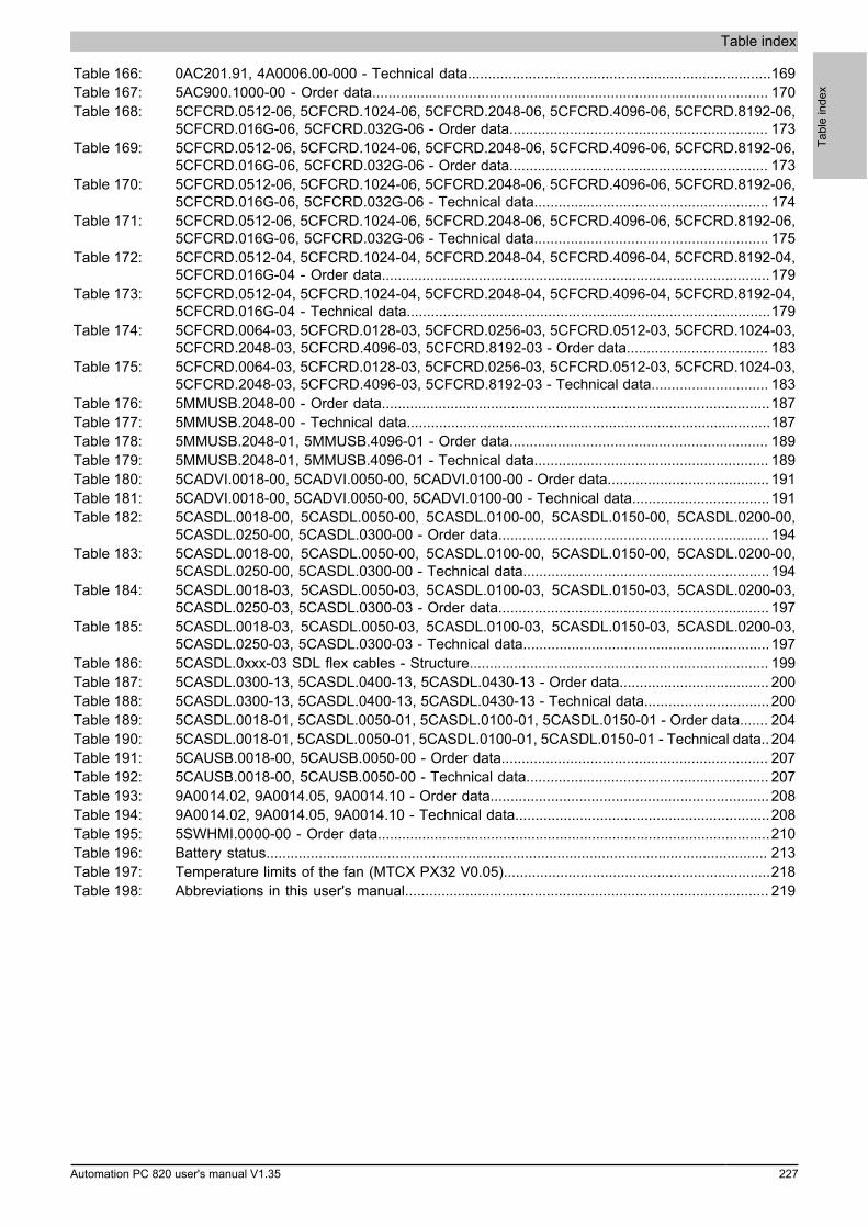
Table index
Tabl
e in
dex
Automation PC 820 user's manual V1.35 227
Table 166: 0AC201.91, 4A0006.00-000 - Technical data...........................................................................169Table 167: 5AC900.1000-00 - Order data.................................................................................................. 170Table 168: 5CFCRD.0512-06, 5CFCRD.1024-06, 5CFCRD.2048-06, 5CFCRD.4096-06, 5CFCRD.8192-06,
5CFCRD.016G-06, 5CFCRD.032G-06 - Order data................................................................ 173Table 169: 5CFCRD.0512-06, 5CFCRD.1024-06, 5CFCRD.2048-06, 5CFCRD.4096-06, 5CFCRD.8192-06,
5CFCRD.016G-06, 5CFCRD.032G-06 - Order data................................................................ 173Table 170: 5CFCRD.0512-06, 5CFCRD.1024-06, 5CFCRD.2048-06, 5CFCRD.4096-06, 5CFCRD.8192-06,
5CFCRD.016G-06, 5CFCRD.032G-06 - Technical data.......................................................... 174Table 171: 5CFCRD.0512-06, 5CFCRD.1024-06, 5CFCRD.2048-06, 5CFCRD.4096-06, 5CFCRD.8192-06,
5CFCRD.016G-06, 5CFCRD.032G-06 - Technical data.......................................................... 175Table 172: 5CFCRD.0512-04, 5CFCRD.1024-04, 5CFCRD.2048-04, 5CFCRD.4096-04, 5CFCRD.8192-04,
5CFCRD.016G-04 - Order data................................................................................................179Table 173: 5CFCRD.0512-04, 5CFCRD.1024-04, 5CFCRD.2048-04, 5CFCRD.4096-04, 5CFCRD.8192-04,
5CFCRD.016G-04 - Technical data..........................................................................................179Table 174: 5CFCRD.0064-03, 5CFCRD.0128-03, 5CFCRD.0256-03, 5CFCRD.0512-03, 5CFCRD.1024-03,
5CFCRD.2048-03, 5CFCRD.4096-03, 5CFCRD.8192-03 - Order data................................... 183Table 175: 5CFCRD.0064-03, 5CFCRD.0128-03, 5CFCRD.0256-03, 5CFCRD.0512-03, 5CFCRD.1024-03,
5CFCRD.2048-03, 5CFCRD.4096-03, 5CFCRD.8192-03 - Technical data............................. 183Table 176: 5MMUSB.2048-00 - Order data................................................................................................187Table 177: 5MMUSB.2048-00 - Technical data..........................................................................................187Table 178: 5MMUSB.2048-01, 5MMUSB.4096-01 - Order data................................................................ 189Table 179: 5MMUSB.2048-01, 5MMUSB.4096-01 - Technical data.......................................................... 189Table 180: 5CADVI.0018-00, 5CADVI.0050-00, 5CADVI.0100-00 - Order data........................................ 191Table 181: 5CADVI.0018-00, 5CADVI.0050-00, 5CADVI.0100-00 - Technical data..................................191Table 182: 5CASDL.0018-00, 5CASDL.0050-00, 5CASDL.0100-00, 5CASDL.0150-00, 5CASDL.0200-00,
5CASDL.0250-00, 5CASDL.0300-00 - Order data................................................................... 194Table 183: 5CASDL.0018-00, 5CASDL.0050-00, 5CASDL.0100-00, 5CASDL.0150-00, 5CASDL.0200-00,
5CASDL.0250-00, 5CASDL.0300-00 - Technical data.............................................................194Table 184: 5CASDL.0018-03, 5CASDL.0050-03, 5CASDL.0100-03, 5CASDL.0150-03, 5CASDL.0200-03,
5CASDL.0250-03, 5CASDL.0300-03 - Order data................................................................... 197Table 185: 5CASDL.0018-03, 5CASDL.0050-03, 5CASDL.0100-03, 5CASDL.0150-03, 5CASDL.0200-03,
5CASDL.0250-03, 5CASDL.0300-03 - Technical data.............................................................197Table 186: 5CASDL.0xxx-03 SDL flex cables - Structure.......................................................................... 199Table 187: 5CASDL.0300-13, 5CASDL.0400-13, 5CASDL.0430-13 - Order data..................................... 200Table 188: 5CASDL.0300-13, 5CASDL.0400-13, 5CASDL.0430-13 - Technical data............................... 200Table 189: 5CASDL.0018-01, 5CASDL.0050-01, 5CASDL.0100-01, 5CASDL.0150-01 - Order data....... 204Table 190: 5CASDL.0018-01, 5CASDL.0050-01, 5CASDL.0100-01, 5CASDL.0150-01 - Technical data.. 204Table 191: 5CAUSB.0018-00, 5CAUSB.0050-00 - Order data.................................................................. 207Table 192: 5CAUSB.0018-00, 5CAUSB.0050-00 - Technical data............................................................ 207Table 193: 9A0014.02, 9A0014.05, 9A0014.10 - Order data..................................................................... 208Table 194: 9A0014.02, 9A0014.05, 9A0014.10 - Technical data...............................................................208Table 195: 5SWHMI.0000-00 - Order data.................................................................................................210Table 196: Battery status............................................................................................................................ 213Table 197: Temperature limits of the fan (MTCX PX32 V0.05)..................................................................218Table 198: Abbreviations in this user's manual.......................................................................................... 219
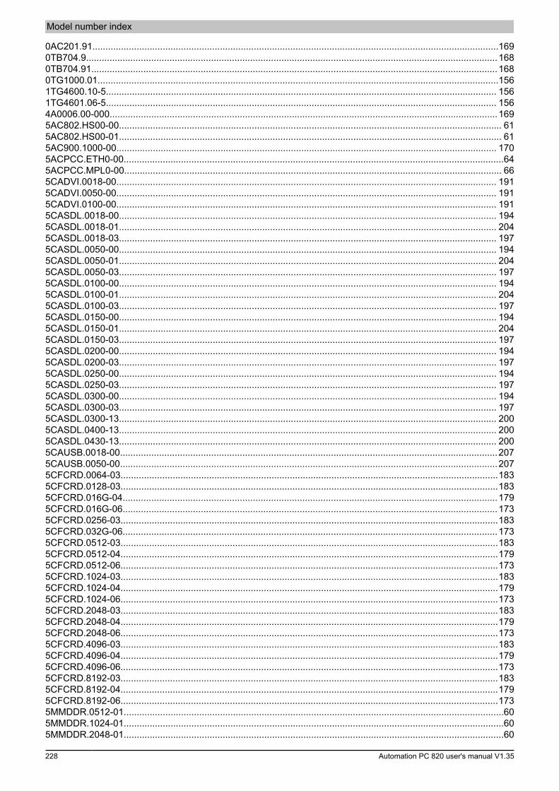
Model number index
228 Automation PC 820 user's manual V1.35
0AC201.91............................................................................................................................................................1690TB704.9..............................................................................................................................................................1680TB704.91............................................................................................................................................................1680TG1000.01..........................................................................................................................................................1561TG4600.10-5...................................................................................................................................................... 1561TG4601.06-5...................................................................................................................................................... 1564A0006.00-000.....................................................................................................................................................1695AC802.HS00-00................................................................................................................................................... 615AC802.HS00-01................................................................................................................................................... 615AC900.1000-00.................................................................................................................................................. 1705ACPCC.ETH0-00..................................................................................................................................................645ACPCC.MPL0-00................................................................................................................................................. 665CADVI.0018-00.................................................................................................................................................. 1915CADVI.0050-00.................................................................................................................................................. 1915CADVI.0100-00.................................................................................................................................................. 1915CASDL.0018-00................................................................................................................................................. 1945CASDL.0018-01................................................................................................................................................. 2045CASDL.0018-03................................................................................................................................................. 1975CASDL.0050-00................................................................................................................................................. 1945CASDL.0050-01................................................................................................................................................. 2045CASDL.0050-03................................................................................................................................................. 1975CASDL.0100-00................................................................................................................................................. 1945CASDL.0100-01................................................................................................................................................. 2045CASDL.0100-03................................................................................................................................................. 1975CASDL.0150-00................................................................................................................................................. 1945CASDL.0150-01................................................................................................................................................. 2045CASDL.0150-03................................................................................................................................................. 1975CASDL.0200-00................................................................................................................................................. 1945CASDL.0200-03................................................................................................................................................. 1975CASDL.0250-00................................................................................................................................................. 1945CASDL.0250-03................................................................................................................................................. 1975CASDL.0300-00................................................................................................................................................. 1945CASDL.0300-03................................................................................................................................................. 1975CASDL.0300-13................................................................................................................................................. 2005CASDL.0400-13................................................................................................................................................. 2005CASDL.0430-13................................................................................................................................................. 2005CAUSB.0018-00.................................................................................................................................................2075CAUSB.0050-00.................................................................................................................................................2075CFCRD.0064-03.................................................................................................................................................1835CFCRD.0128-03.................................................................................................................................................1835CFCRD.016G-04................................................................................................................................................1795CFCRD.016G-06................................................................................................................................................1735CFCRD.0256-03.................................................................................................................................................1835CFCRD.032G-06................................................................................................................................................1735CFCRD.0512-03.................................................................................................................................................1835CFCRD.0512-04.................................................................................................................................................1795CFCRD.0512-06.................................................................................................................................................1735CFCRD.1024-03.................................................................................................................................................1835CFCRD.1024-04.................................................................................................................................................1795CFCRD.1024-06.................................................................................................................................................1735CFCRD.2048-03.................................................................................................................................................1835CFCRD.2048-04.................................................................................................................................................1795CFCRD.2048-06.................................................................................................................................................1735CFCRD.4096-03.................................................................................................................................................1835CFCRD.4096-04.................................................................................................................................................1795CFCRD.4096-06.................................................................................................................................................1735CFCRD.8192-03.................................................................................................................................................1835CFCRD.8192-04.................................................................................................................................................1795CFCRD.8192-06.................................................................................................................................................1735MMDDR.0512-01..................................................................................................................................................605MMDDR.1024-01..................................................................................................................................................605MMDDR.2048-01..................................................................................................................................................60
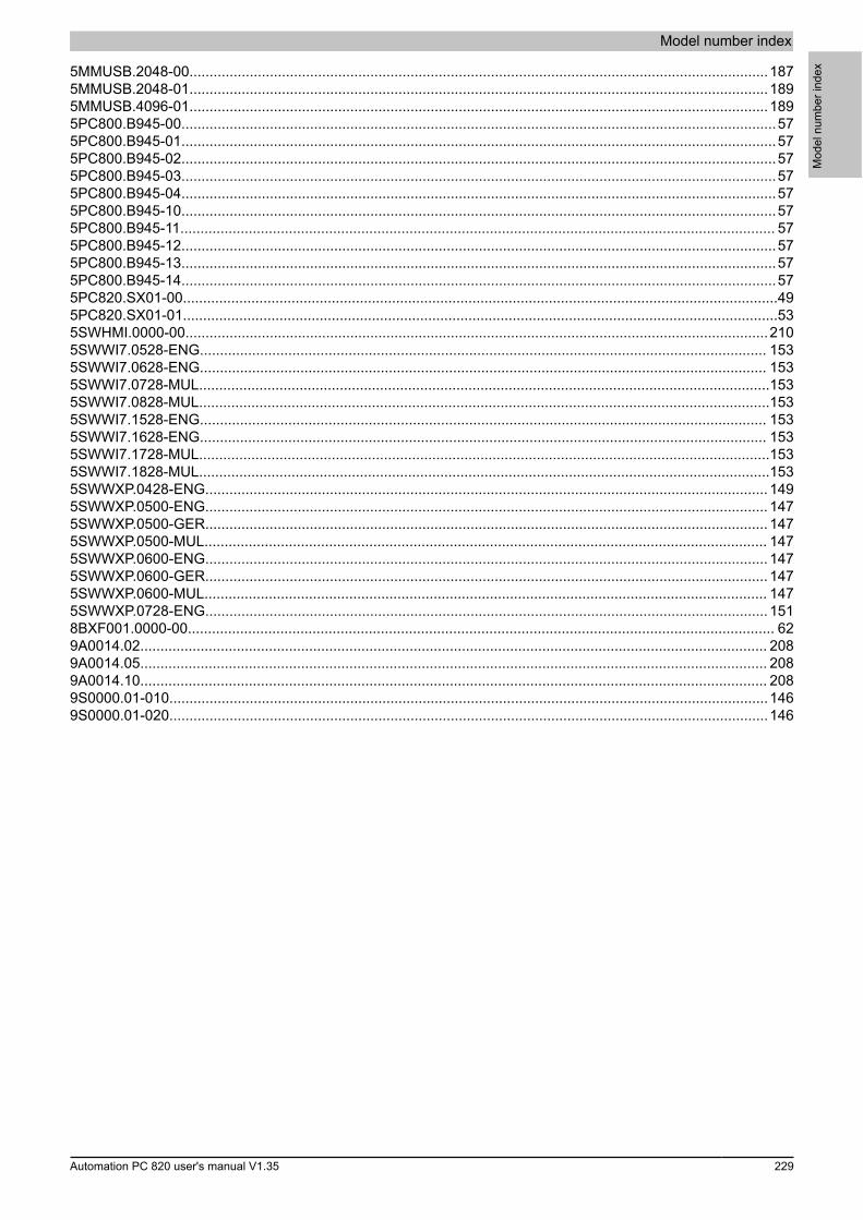
Model number index
Mod
el n
umbe
r ind
ex
Automation PC 820 user's manual V1.35 229
5MMUSB.2048-00................................................................................................................................................1875MMUSB.2048-01................................................................................................................................................1895MMUSB.4096-01................................................................................................................................................1895PC800.B945-00....................................................................................................................................................575PC800.B945-01....................................................................................................................................................575PC800.B945-02....................................................................................................................................................575PC800.B945-03....................................................................................................................................................575PC800.B945-04....................................................................................................................................................575PC800.B945-10....................................................................................................................................................575PC800.B945-11.................................................................................................................................................... 575PC800.B945-12....................................................................................................................................................575PC800.B945-13....................................................................................................................................................575PC800.B945-14....................................................................................................................................................575PC820.SX01-00....................................................................................................................................................495PC820.SX01-01....................................................................................................................................................535SWHMI.0000-00.................................................................................................................................................2105SWWI7.0528-ENG............................................................................................................................................. 1535SWWI7.0628-ENG............................................................................................................................................. 1535SWWI7.0728-MUL..............................................................................................................................................1535SWWI7.0828-MUL..............................................................................................................................................1535SWWI7.1528-ENG............................................................................................................................................. 1535SWWI7.1628-ENG............................................................................................................................................. 1535SWWI7.1728-MUL..............................................................................................................................................1535SWWI7.1828-MUL..............................................................................................................................................1535SWWXP.0428-ENG............................................................................................................................................ 1495SWWXP.0500-ENG............................................................................................................................................ 1475SWWXP.0500-GER............................................................................................................................................ 1475SWWXP.0500-MUL............................................................................................................................................ 1475SWWXP.0600-ENG............................................................................................................................................ 1475SWWXP.0600-GER............................................................................................................................................ 1475SWWXP.0600-MUL............................................................................................................................................ 1475SWWXP.0728-ENG............................................................................................................................................ 1518BXF001.0000-00.................................................................................................................................................. 629A0014.02............................................................................................................................................................ 2089A0014.05............................................................................................................................................................ 2089A0014.10............................................................................................................................................................ 2089S0000.01-010.....................................................................................................................................................1469S0000.01-020.....................................................................................................................................................146
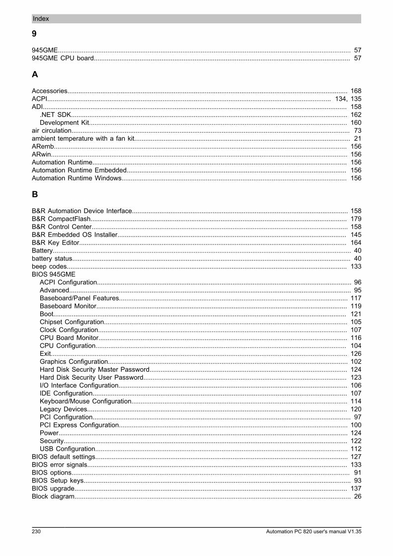
Index
230 Automation PC 820 user's manual V1.35
9
945GME................................................................................................................................................................ 57945GME CPU board............................................................................................................................................ 57
A
Accessories......................................................................................................................................................... 168ACPI........................................................................................................................................................... 134, 135ADI...................................................................................................................................................................... 158
.NET SDK....................................................................................................................................................... 162Development Kit............................................................................................................................................. 160
air circulation........................................................................................................................................................ 73ambient temperature with a fan kit...................................................................................................................... 21ARemb................................................................................................................................................................ 156ARwin.................................................................................................................................................................. 156Automation Runtime........................................................................................................................................... 156Automation Runtime Embedded........................................................................................................................ 156Automation Runtime Windows........................................................................................................................... 156
B
B&R Automation Device Interface...................................................................................................................... 158B&R CompactFlash............................................................................................................................................ 179B&R Control Center............................................................................................................................................ 158B&R Embedded OS Installer............................................................................................................................. 145B&R Key Editor.................................................................................................................................................. 164Battery................................................................................................................................................................... 40battery status........................................................................................................................................................ 40beep codes......................................................................................................................................................... 133BIOS 945GME
ACPI Configuration........................................................................................................................................... 96Advanced.......................................................................................................................................................... 95Baseboard/Panel Features............................................................................................................................. 117Baseboard Monitor......................................................................................................................................... 119Boot................................................................................................................................................................ 121Chipset Configuration..................................................................................................................................... 105Clock Configuration........................................................................................................................................ 107CPU Board Monitor........................................................................................................................................ 116CPU Configuration......................................................................................................................................... 104Exit.................................................................................................................................................................. 126Graphics Configuration................................................................................................................................... 102Hard Disk Security Master Password............................................................................................................ 124Hard Disk Security User Password............................................................................................................... 123I/O Interface Configuration............................................................................................................................. 106IDE Configuration........................................................................................................................................... 107Keyboard/Mouse Configuration...................................................................................................................... 114Legacy Devices.............................................................................................................................................. 120PCI Configuration............................................................................................................................................. 97PCI Express Configuration............................................................................................................................. 100Power.............................................................................................................................................................. 124Security........................................................................................................................................................... 122USB Configuration.......................................................................................................................................... 112
BIOS default settings.......................................................................................................................................... 127BIOS error signals.............................................................................................................................................. 133BIOS options........................................................................................................................................................ 91BIOS Setup keys.................................................................................................................................................. 93BIOS upgrade..................................................................................................................................................... 137Block diagram....................................................................................................................................................... 26
Index
Inde
x
Automation PC 820 user's manual V1.35 231
C
Cable connections................................................................................................................................................ 76Cable lengths................................................................................................................................................. 28, 28Cables................................................................................................................................................................. 191
DVI.................................................................................................................................................................. 191RS232............................................................................................................................................................. 208SDL................................................................................................................................................................. 194SDL flex.......................................................................................................................................................... 197SDL flex cables with extender....................................................................................................................... 200SDL with 45° male connector........................................................................................................................ 204USB................................................................................................................................................................ 207
CANnode switch...................................................................................................................................................... 35Status LED....................................................................................................................................................... 35terminating switch............................................................................................................................................. 35
CE mark.............................................................................................................................................................. 166Certifications....................................................................................................................................................... 167certifications
GOST-R.......................................................................................................................................................... 167Certifications
UL................................................................................................................................................................... 167Changing the fan................................................................................................................................................ 216CMOS................................................................................................................................................................... 42Cold-plate mounting.............................................................................................................................................. 71COM1.................................................................................................................................................................... 31COM2.................................................................................................................................................................... 32CompactFlash
Benchmark...................................................................................................................................................... 182CompactFlash cards........................................................................................................................................... 171CompactFlash slot.......................................................................................................................................... 30, 30Complete system.................................................................................................................................................. 21Configuration
Base system..................................................................................................................................................... 19Optional components....................................................................................................................................... 20
Configuration – APC820....................................................................................................................................... 19Connection examples........................................................................................................................................... 77Control Center.................................................................................................................................................... 158cooling circulation system.................................................................................................................................... 71CPU board............................................................................................................................................................ 57Creating reports.................................................................................................................................................. 158
D
Device interfaces and slots.................................................................................................................................. 27Dimensions
Cold-plate mounting......................................................................................................................................... 52Wall mounting................................................................................................................................................... 56
Dimension standards............................................................................................................................................ 14Disposal.......................................................................................................................................................... 13, 13Distribution of resources
I/O address assignments............................................................................................................................... 134RAM address assignment.............................................................................................................................. 134
dongle........................................................................................................................................................... 41, 157dual-channel memory........................................................................................................................................... 60DVI........................................................................................................................................................................ 27DVI cables.......................................................................................................................................................... 191DVI resolution....................................................................................................................................................... 28DVI transmission............................................................................................................................................ 28, 28Dynamic wear leveling....................................................................................................................................... 171
Index
232 Automation PC 820 user's manual V1.35
E
Electromagnetic compatibility............................................................................................................................. 166Embedded OS Installer...................................................................................................................................... 145EMC directive..................................................................................................................................................... 166ESD....................................................................................................................................................................... 11
Electrical components with a housing............................................................................................................. 11Electrical components without a housing........................................................................................................ 11Individual components...................................................................................................................................... 11Packaging......................................................................................................................................................... 11
ETH1..................................................................................................................................................................... 39ETH2..................................................................................................................................................................... 39Ethernet.......................................................................................................................................................... 39, 39Evaluating the battery status.............................................................................................................................. 213
F
Fan control.......................................................................................................................................................... 217fan speed............................................................................................................................................................ 218Feed-through mounting........................................................................................................................................ 71Firmware upgrade............................................................................................................................................... 140Flex radius............................................................................................................................................................ 76Flex radius specifications..................................................................................................................................... 76
G
General tolerance................................................................................................................................................. 14GOST-R.............................................................................................................................................................. 167Gosudarstwenny standard.................................................................................................................................. 167Grounding............................................................................................................................................................. 27Guidelines............................................................................................................................................................. 14
H
Hardware security key.......................................................................................................................................... 41Heat sink with power supply................................................................................................................................ 61Hibernation............................................................................................................................................................ 42HMI Drivers & Utilities DVD............................................................................................................................... 210Humidity specifications......................................................................................................................................... 23
I
I/O address assignment..................................................................................................................................... 134Installation............................................................................................................................................................. 70Installation guidelines........................................................................................................................................... 75Interfaces.............................................................................................................................................................. 27Interrupt assignment........................................................................................................................................... 134
K
Key Editor........................................................................................................................................................... 164Known problems / issues..................................................................................................................................... 90
L
LED status indicators........................................................................................................................................... 42Low voltage directive.......................................................................................................................................... 166
M
Main memory........................................................................................................................................................ 60
Index
Inde
x
Automation PC 820 user's manual V1.35 233
Maintenance Controller Extended...................................................................................................................... 217Manual history........................................................................................................................................................ 9Monitor / Panel connection.................................................................................................................................. 27Mounting
Cold-plate mounting......................................................................................................................................... 71Feed-through mounting.................................................................................................................................... 71Mounting plates................................................................................................................................................ 71Wall mounting................................................................................................................................................... 71
Mounting orientation............................................................................................................................................. 72MS-DOS.............................................................................................................................................................. 146MTCX.................................................................................................................................................................. 217
O
Operating systemWindows Embedded Standard 2009............................................................................................................. 151Windows Embedded Standard 7................................................................................................................... 153Windows XP Embedded................................................................................................................................ 149Windows XP Professional.............................................................................................................................. 147
P
Parity error.......................................................................................................................................................... 133PCIec.................................................................................................................................................................... 63Peripheral USB devices....................................................................................................................................... 88plug-in card........................................................................................................................................................... 63Power button........................................................................................................................................................ 43Power calculation.................................................................................................................................................. 24power failure......................................................................................................................................................... 42POWERLINK......................................................................................................................................................... 36
Card number switch......................................................................................................................................... 69Link LED.................................................................................................................................................... 36, 67node switch...................................................................................................................................................... 38Speed LED................................................................................................................................................. 36, 67station number.................................................................................................................................................. 69Status/Error LED........................................................................................................................................ 36, 67System stop error codes........................................................................................................................... 38, 69
Power management.............................................................................................................................................. 24power supply........................................................................................................................................................ 27Profile switch........................................................................................................................................................ 42Proper ESD
handling............................................................................................................................................................ 11
R
RAM address assignment.................................................................................................................................. 134Relative humidity.................................................................................................................................................. 23Replacement fan................................................................................................................................................... 62Replacing a CompactFlash card........................................................................................................................ 215Replacing the battery......................................................................................................................................... 213Reset button......................................................................................................................................................... 43Resolution............................................................................................................................................................. 57RGB...................................................................................................................................................................... 27RS232
Bus length.................................................................................................................................................. 31, 32Cable type.................................................................................................................................................. 31, 32
RS232 cables..................................................................................................................................................... 208RS422
Bus length........................................................................................................................................................ 32Cable type........................................................................................................................................................ 33
RS485Bus length........................................................................................................................................................ 33
Index
234 Automation PC 820 user's manual V1.35
Cable type........................................................................................................................................................ 33RS485 interface.................................................................................................................................................... 33
S
Safety guidelines.................................................................................................................................................. 11Environmental conditions................................................................................................................................. 12Environmentally friendly disposal..................................................................................................................... 13Installation......................................................................................................................................................... 12Intended use..................................................................................................................................................... 11Operation.......................................................................................................................................................... 12Policies and procedures................................................................................................................................... 11Protection against electrostatic discharge....................................................................................................... 11Separation of materials.................................................................................................................................... 13Transport and storage...................................................................................................................................... 12
SDL....................................................................................................................................................................... 27SDL cables......................................................................................................................................................... 194SDL cables with 45° male connector................................................................................................................. 204SDL flex cables.................................................................................................................................................. 197SDL flex cables with extender........................................................................................................................... 200SDL resolution...................................................................................................................................................... 28SDL transmission........................................................................................................................................... 28, 28Security key.......................................................................................................................................................... 41serial interface................................................................................................................................................ 31, 32Service function for MTCX upgrade..................................................................................................................... 42Service mode........................................................................................................................................................ 42Slots...................................................................................................................................................................... 27Smart Display Link............................................................................................................................................... 27software versions................................................................................................................................................ 158spacing.................................................................................................................................................................. 73Standards and guidelines................................................................................................................................... 166states..................................................................................................................................................................... 42Static wear leveling............................................................................................................................................ 171
T
Technology Guarding......................................................................................................................................... 157Temperature monitoring............................................................................................................................. 217, 218Temperature sensor locations........................................................................................................................... 3, 3Temperature specifications................................................................................................................................ 3, 3Terminating resistors............................................................................................................................................ 35
U
UL certification.................................................................................................................................................... 167Upgrade
BIOS............................................................................................................................................................... 137Firmware......................................................................................................................................................... 140
Upgrade failed...................................................................................................................................................... 42Upgrade information........................................................................................................................................... 137USB cables......................................................................................................................................................... 207USB flash drive................................................................................................................................................... 187USB interfaces...................................................................................................................................................... 29user serial ID...................................................................................................................................................... 158
V
Voltage supply...................................................................................................................................................... 24Voltage supply block diagram.............................................................................................................................. 24
Index
Inde
x
Automation PC 820 user's manual V1.35 235
W
Wall mounting....................................................................................................................................................... 71WES2009............................................................................................................................................................ 151WES7.................................................................................................................................................................. 154Windows Embedded Standard 2009.................................................................................................................. 151Windows Embedded Standard 7........................................................................................................................ 153Windows XP Embedded..................................................................................................................................... 149Windows XP Professional.................................................................................................................................. 147