
AM8000 + AM8500 Synchronous-servomotor - ADEGIS
80
AM8000 + AM8500 Synchronous-servomotor 10/07/2019 | Version 4.1 Operation instructions | EN
-
Upload
khangminh22 -
Category
Documents
-
view
6 -
download
0
Transcript of AM8000 + AM8500 Synchronous-servomotor - ADEGIS

AM8000 + AM8500Synchronous-servomotor
10/07/2019 | Version 4.1
Operation instructions | EN

Table of content
2 Version: 4.1AM8000 & AM8500
Table of content
Documentation notes .......................................................................................................................................... 4Disclaimer ......................................................................................................................................................... 4Version numbers............................................................................................................................................... 6Scope of the documentation ............................................................................................................................. 6Staff qualification............................................................................................................................................... 7Safety and instruction ....................................................................................................................................... 8Explanation of symbols ..................................................................................................................................... 8Beckhoff Services ............................................................................................................................................. 9
For your safety................................................................................................................................................... 10Safety pictograms ........................................................................................................................................... 10General safety instructions ............................................................................................................................. 11
Product overview............................................................................................................................................... 13Name plate...................................................................................................................................................... 13Type key ......................................................................................................................................................... 14Product characteristics.................................................................................................................................... 15Ordering options ............................................................................................................................................. 16Intended use ................................................................................................................................................... 17
Technical data.................................................................................................................................................... 18Definitions ....................................................................................................................................................... 18Data for operation and environment ............................................................................................................... 19AM801x........................................................................................................................................................... 20AM802x........................................................................................................................................................... 22AM803x & AM853x ......................................................................................................................................... 25AM804x & AM854x ......................................................................................................................................... 28AM805x & AM855x ......................................................................................................................................... 31AM806x & AM856x ......................................................................................................................................... 38AM807x........................................................................................................................................................... 45
Scope of supply ................................................................................................................................................. 54Packaging ....................................................................................................................................................... 54
Transport and storage....................................................................................................................................... 55Conditions ....................................................................................................................................................... 55Transport......................................................................................................................................................... 56Long-term storage........................................................................................................................................... 57
Technical description........................................................................................................................................ 58Mounting position............................................................................................................................................ 58Feedback ........................................................................................................................................................ 58Protection equipment ...................................................................................................................................... 59Shaft end A ..................................................................................................................................................... 59Power derating................................................................................................................................................ 59
Mechanical installation ..................................................................................................................................... 61Flange mounting ............................................................................................................................................. 61Output elements.............................................................................................................................................. 61Fan cover [+] ................................................................................................................................................... 63
Electrical installation......................................................................................................................................... 65Connection technology ................................................................................................................................... 65Connector assignment .................................................................................................................................... 68
Commissioning.................................................................................................................................................. 69Before commissioning..................................................................................................................................... 69During commissioning..................................................................................................................................... 69

Table of content
Version: 4.1 3AM8000 & AM8500
Prerequisites during operation ........................................................................................................................ 70After operation ................................................................................................................................................ 70
Maintenance and cleaning ................................................................................................................................ 71Cleaning materials .......................................................................................................................................... 71Intervals .......................................................................................................................................................... 72
Accessories........................................................................................................................................................ 73Connecting cables .......................................................................................................................................... 73iTec extension................................................................................................................................................. 73speedtec extension ......................................................................................................................................... 73Shaft seal ........................................................................................................................................................ 73Gear unit ......................................................................................................................................................... 74
Fault correction.................................................................................................................................................. 75
Decommissioning.............................................................................................................................................. 77Disassembly.................................................................................................................................................... 77Disposal .......................................................................................................................................................... 77
Guidelines and Standards ................................................................................................................................ 78Standards........................................................................................................................................................ 78Guidelines ....................................................................................................................................................... 78Test centers .................................................................................................................................................... 78EU conformity ................................................................................................................................................. 78CCC conformity............................................................................................................................................... 78UL conformity.................................................................................................................................................. 78
Index ................................................................................................................................................................... 79

Documentation notes
4 Version: 4.1AM8000 & AM8500
Documentation notes
Disclaimer The documentation has been prepared with care. Beckhoff productsare subject to continuous further development.We reserve the right to revise the documentation at any time andwithout notice. No claims for the modification of products that have already beensupplied may be made on the basis of the data, diagrams and de-scriptions in this documentation.
Trademarks Beckhoff®, TwinCAT®, EtherCAT®, EtherCAT P®, Safety over Ether-CAT®, TwinSAFE®, XFC® and XTS® are registered and licensedbrands of Beckhoff Automation GmbH & Co. KG.The use of other brand names or designations by third parties maylead to an infringement of the rights of the owners of the corre-sponding designations.
Patents The EtherCAT technology is protected by patent rights through thefollowing registrations and patents with corresponding applicationsand registrations in various other countries:• EP1590927• EP1789857• DE102004044764• DE102007017835
The TwinCAT technology is protected by patent rights through thefollowing registrations and patents with corresponding applicationsand registrations in various other countries:• EP0851348• US6167425
EtherCAT® is a registered trademark and patented technology, li-censed by Beckhoff Automation GmbH & Co. KG, Germany.

Documentation notes
Version: 4.1 5AM8000 & AM8500
Limitation of liability All components of this product described in the original operating in-structions are delivered in a hardware and software configuration,depending on the application requirements. Modifications andchanges to the hardware and/or software configuration that go be-yond the documented options are prohibited and nullify the liabilityof Beckhoff Automation GmbH & Co. KG.
In addition, the following are excluded from the liability:• Failure to comply with this documentation• Improper use• Use of untrained personnel• Use of unauthorized spare parts
Copyright © Beckhoff Automation GmbH & Co. KG, GermanyThe copying, distribution and utilization of this document as well asthe communication of its contents to others without express autho-rization is prohibited.Offenders will be held liable for the payment of damages. We re-serve all rights in the event of registration of patents, utility modelsand designs.

Documentation notes
6 Version: 4.1AM8000 & AM8500
Version numbers Origin of the documentThese operating instructions were originally written in German. Allother languages are derived from the German original.
Product featuresThe product features specified in the latest version of the originaloperating instructions are always applicable. Further informationgiven on the product pages of the Beckhoff homepage, in emails orin other publications is not authoritative.
Issue Comment4.1 Chapter update:
Scope of the documentation, For your safety, Product characteristics,Ordering options, Improper use, Technical data, Scope of supply, Long-term storage, Technical description, Mechanical installation, Electricalinstallation, Fault correction, Disposal by the manufactor
4.0 Complete revision, new version3.5 Chapter revision:
EC Declaration of Conformity 2.1; Feedback system 6.4.10; Connectiondiagrams 8.4, 8.5, 8.6; 8.9 and 8.10; Dimensional drawing AM806x andAM856x 10.6.1
3.4 Chapter revision:EC Declaration of Conformity 2.1; Dimensional drawing AM806x andAM856x 10.6.1
3.3 Chapter revision:1.0; 2.1; 3.0; 4.5; 5.3; 6.4.11; 8.3 to 8.14; 10.1 to 10.7; 10.7.1
New chapter:8.5; 8.10; 10.7.3.1
Removed chapter:Documented motors
3.2 Chapter revision:5.2; 5.3
3.1 Chapter revision:5.3; 6.4.10
3.0 Chapter revision:10.1 to 10.7, 10.1.1 to 10.7.1
Scope of the documen-tation
The complete documentation consists of the following documents:
AM8000 & AM8500 DefinitionTranslation of the original instructions;this documentation
Description of the mechanical and electri-cal characteristics as well as all the infor-mation required for operating the motors
Motor instruction leaflet Accompanying document with general in-structions for handling the motors. It is in-cluded with each product.
Fan cover instruction leaflet [+] Fan cover installation description [+]

Documentation notes
Version: 4.1 7AM8000 & AM8500
Staff qualification These operating instructions are intended for trained control and au-tomation specialists with knowledge of the applicable and requiredstandards and directives.Qualified personnel must have knowledge of drive technology andelectrical equipment as well as knowledge of safe working on electri-cal systems and machines. This includes knowledge of proper setupand preparation of the workplace as well as securing the workingenvironment for other persons.The documentation published at the time must be used for each in-stallation and commissioning. The products must be used in compli-ance with all safety requirements, including all applicable laws, regu-lations, provisions and standards.
Target group ExplanationInstructed person This target group has been informed about the possible dangers of improper use.
The assigned scope of duties is clearly defined. Training will be provided for anytasks outside this scope. Instructions on the required protective measures and de-vices were provided.
Trained user This target group meets all the requirements of an instructed person. In addition,machine- or plant-specific training was provided at the machine manufacturer's facil-ity.
Trained specialists Users who, based on their training, knowledge and experience, are able to assessthe tasks assigned to them and recognize potential hazards, are regarded astrained specialists. Work experience over several years in a relevant field can alsobe considered as part of the technical training.
Qualified electricians Qualified electricians are able to work on electrical machines or systems based ontheir specialist training (university degree, apprenticeship, specialist training). Possi-ble sources of danger are automatically identified and avoided.
Qualified electricians are specially trained for the working environment and are fa-miliar with the relevant standards and guidelines. Knowledge of control engineeringand automation is required. The provisions of the accident prevention regulationsmust be complied with.
Customer service Customer service is provided by technicians who have been demonstrably trainedand authorized by Beckhoff or the machine manufacturer to work on the respectivemachine or plant.

Documentation notes
8 Version: 4.1AM8000 & AM8500
Safety and instruction Read the contents that refer to the activities you have to performwith the product. Always read the chapter "For your safety", [Page 10] in the operating instructions. Observe the warnings in thechapters, so that you handle the product properly and safely.
Explanation of symbols Various symbols are used in the interest of clarity:
The triangle indicates instructions that you should execute• The bullet point indicates an enumeration[…] The square parentheses indicate cross-references to other
text passages in the document[+] The plus sign in square brackets indicates ordering options
and accessories
Pictograms Pictograms are used to indicate different text categories:
The warning triangle indicates warning notes. The possible consequences of failure to observe these include:• Damage and/or serious injuries• Fatal injuries
The warnings are shown at the points in the documentation whereit is important to observe them in order to prevent accidents andinjuries.
Notes are used for important information on the product! The possible consequences of failure to observe these include:• Malfunctions of the product• Damage to the product• Damage to the environment
InformationThis sign indicates information, tips and notes for dealing with theproduct or the software.
ExampleThis symbol shows examples of how to use the product or soft-ware.

Documentation notes
Version: 4.1 9AM8000 & AM8500
Beckhoff Services Beckhoff and its international partner companies offer comprehen-sive support and service.
Support Beckhoff Support offers technical advice on the use of individualBeckhoff products and system planning. Staff provide assistance forprogramming and commissioning complex automation systems andoffer a comprehensive training program.
Hotline: +49(0)5246/963-157Fax: +49(0)5246/963-199E-mail: [email protected]: www.beckhoff.de/support
Training Training in Germany takes place in our training center at the Beck-hoff headquarters in Verl, at branch offices or, by arrangement, atthe customer's premises.
Hotline: +49(0)5246/963-5000Fax: +49(0)5246/963-95000E-mail: [email protected]: www.beckhoff.de/training
Service The Beckhoff Service Centre supports you in all aspects of after-sales service (on-site service, repair service, spare parts service).
Hotline: +49(0)5246/963-460Fax: +49(0)5246/963-479E-mail: [email protected]: www.beckhoff.de/service
Download area In the download area you will find product information, software up-dates, the TwinCAT automation suite, documentation and muchmore.
Web: www.beckhoff.de/download
Headquarters Beckhoff Automation GmbH & Co. KGHülshorstweg 2033415 VerlGermany
Phone: +49(0)5246/963-0Fax: +49(0)5246/963-198E-mail: [email protected]: www.beckhoff.de
The addresses of the international Beckhoff branch offices can befound on the Beckhoff website: http://www.beckhoff.de

For your safety
10 Version: 4.1AM8000 & AM8500
For your safety
Read this chapter containing general safety information. The chap-ters in these operating instructions also contain warning notices. Al-ways observe the safety instructions for your own safety, the safetyof other persons and the safety of the product.When working with control and automation products, many dangerscan result from careless or incorrect use. Work particularly thor-oughly, not under time pressure and responsibly towards other peo-ple.
Safety pictograms On Beckhoff products you will find attached or lasered safety pic-tograms, which vary depending on the product. They serve to pro-tect people and to prevent damage to the products. Safety pic-tograms must not be removed and must be legible for the user.
Warning of hot surfaceDuring and after operation there is a risk of burns at the motor hous-ing from hot surfaces above 60 °C. Allow the motor housing to cooldown for the specified time, at least 15 minutes.
Avoid shocks to the shaftImpacts on the shaft may cause the maximum permissible axial andradial values to be exceeded. Optical encoder systems can thus bedestroyed.

For your safety
Version: 4.1 11AM8000 & AM8500
General safety instruc-tions
In this chapter you will find notes on safety when handling the mo-tors. They cannot run independently. The motors are therefore re-garded as incomplete machines. They must be installed in a ma-chine / plant by the machine manufacturer. The documentation cre-ated by the machine manufacturer must be read.
Before operation Keep the surroundings cleanKeep your workplace and the surrounding area clean. Ensure safeworking. Prevent dirt from penetrating into the components.
Secure the control cabinetWhen working on machines, secure the control cabinet against inad-vertent power-up.
Do not use defective motorsObserve the specifications in the technical data during storage,transport and operation. Do not use damaged motors.
Check safety pictogramsCheck whether the designated pictograms are on the product. Re-place missing or illegible stickers.
Observe the tightening torquesInstall connections and components in compliance with the specifiedtightening torques and check them regularly.
Ground electrical components or assemblies correctlyDo not touch electrical components or assemblies unless you arewearing protective ESD clothing. Only walk on conductive floors.
Only use original packaging for further processingWhen shipping, transporting, storing and packing, use the originalpackaging or conductive materials. Conductive materials are foamor aluminum, for example.

For your safety
12 Version: 4.1AM8000 & AM8500
During operation Avoid contact with DC link capacitors DC+ and DC-Measure the voltage at the DC link capacitors! Observe the follow-ing delay times after disconnecting from the mains supply:
• AX5101 to AX5125 and AX520x 5 minutes• AX5140 / AX5160 / AX5172 15 minutes• AX5190 / AX5191 30 minutes• AX81x8, AX8206 and AX8810 30 minutes• AX8620 to AX8640 30 minutes• AX5192 / AX5193 45 minutes
Do not work on live electrical partsDo not open the motor while it is live. Ensure that the protective con-ductor is properly connected. Never disconnect electrical connec-tions while they are live. Do not work on the motor until the voltagehas dropped below 50 V. Disconnect all components from the mainsand secure against reconnection.
Do not touch hot surfacesCheck cooling of the surfaces with a thermometer! Do not touch thehousing during and after operation. Allow the motor to cool down forat least 15 minutes after switching off.
Avoid overheatingOperate the motor according to the technical specifications. Pleaserefer to chapter: "Technical data", [Page 18]. Activate and monitorthe temperature contact of the motor. Ensure sufficient cooling andswitch off the motor immediately if the temperature is too high.
Do not touch rotating componentsDo not touch rotating parts while the motor is in operation. Ensurethat all parts / components on the machine / plant are firmly seated.
After operation Before working on components, make sure that they are de-en-ergizedCarry out a voltage test and check all safety-relevant devices forfunctionality. Secure the working environment and the control cabi-net against inadvertent power-up. See chapter: "Decommissioning",[Page 77].

Product overview
Version: 4.1 13AM8000 & AM8500
3Product overview
1 2 3
4
56
7
Number Explanation1 Power / feedback connection2 Sealing air connection [+]3 Eyebolt mounting lugs; only for AM807x4 Motor shaft5 Radial shaft-sealing ring [+]6 Name plate7 Motor housing
3.1
Name plate
Item number Explanation1 Motor type2 Protection class3 Thermal contact type4 Brake type5 Country of manufacture6 cURus approval7 CE conformity8 Serial number9 UL approval for USA / CAN10 Insulation class11 Power rating12 Nominal speed13 Nominal voltage14 Standstill current15 Standstill torque

Product overview
14 Version: 4.1AM8000 & AM8500
3.2
Type keyAM8 t u v – w x y z – 0 00 0 ExplanationAM8 Product range
Synchronous servo motorst Motor series
0 = Standard 5 = Increased mass moment of inertia
u Flange size 1 = 40 mm 2 = 58 mm 3 = 72 mm 4 = 87 mm 5 = 104 mm 6 = 142 mm 7 = 194 mm
v Construction length 1 2 3 4
w Shaft design 0 = Smooth shaft 1 = Shaft with groove and feather key to DIN 6885 2 = Shaft with radial shaft seal IP 65 and smooth shaft 3 = Shaft with radial shaft seal IP 65, groove, feather key 4 = Shaft with radial shaft seal IP 65, smooth shaft and sealing air connection 5 = Shaft with radial shaft seal IP 65, groove, feather key and sealing air connection
x Winding type A … Z S = Special winding
y Feedback system 0 = Resolver, two pole 1 = OCT Singleturn 2 = OCT Multiturn 3 = Hiperface Singleturn 128 SinCos from F6 4 = Hiperface Multiturn 128 SinCos from F6 A = OCT Singleturn 23-Bit B = OCT Multiturn 23-Bit G = OCT Singleturn 24-Bit, SIL 2 H = OCT Multiturn 24-Bit, SIL 2 N = without Feedback, “sensorless”
z Holding brake 0 = without holding brake 1 = 24 V holding brake A = Fan from F5; without holding brake B = Fan from F6; 24 V holding brake
0 Variants 0 = Standard 1 = Special variant 9 = At AM805x, AM855x and AM802x, flange compatible with AM3x5x and AM312x
00 Undefined0 Connection
0 = Rotatable angled plug or terminal box3.2.1
Flange sizes Motor sizes matching the adapter for gear unit mounting
Beckhoff flange size AM3000 AM3100 AM3500 AM8000 AM8100 AM8500F1 AM301x AM311x - AM801x AM811x -F2 AM302x - - AM802x AM812x -Exception - AM312x - AM802x-xxxx-9 - -F3 AM303x - - AM803x AM813x AM853xF4 AM304x - AM354x AM804x AM814x AM854xF5 - - - AM805x - AM855xException AM305x - AM355x AM805x-xxxx-9 - -F6 AM306x - AM356x AM806x - AM856xF7 AM307x - - AM807x - -Exception AM308x - - - - -

Product overview
Version: 4.1 15AM8000 & AM8500
Product characteristics Brushless three-phase synchronous motorsBrushless three-phase synchronous motors have no electrical con-tact between rotor and stator. This means that the motor has no sliprings or commutators, which facilitates longer service life of the mo-tor.
Neodymium permanent magnetsThe magnets installed in the motor are permanent magnets.Neodymium is a hard magnetic material that enables the preciseand highly dynamic positioning of the motors.
Three-phase stator windingThe three-phase winding in the stator reduces the amount of mate-rial required while maintaining the same electrical output. All phaseangles are 120°.
Electronic commutation in the servo driveThe commutation of the motor is done electronically. The three coilturns are supplied from a bridge circuit.
Holding brake [+]The motors can optionally be equipped with a permanent magnetholding brake [+]. These operate according to the quiescent currentprinciple and open at a voltage of 24 VDC +6 / -10%.The holding brake has > 10,000,000 switching cycles.The built-in holding brake [+] is not suitable for service braking, asthere is no monitoring for wear and functionality by the servo driveand the configuration. This applies in particular to vertical axes!
Safety measures for vertical axes must be appliedWhen operating vertical axes, additional redundancy brake units,mechanical safety devices and interlocks as well as weight com-pensation must be installed!Permanent magnet holding brakes [+] are not approved for per-sonal protection! Taking into account EN 954, ISO 13489-1 and13849-2, additional precautions must be taken for personal protec-tion.
If the voltage is interrupted through emergency stop or power failure,the holding brake [+] is conditionally permissible as a service brake.You can perform a maximum of 2000 emergency stops from a maxi-mum of 3000 rpm with an external inertia/intrinsic inertia of the mo-tor.These maximum values may vary due to increased load inertia.The function of the holding brake [+] can be checked using a torquewrench and TwinCAT Scope.
Thermal contactsA thermal contact "LPTC-600", [Page 59] is installed to monitorand measure the winding temperature and to protect the motoragainst overheating. This can be read out by the user.
Temperature warning and switch-off:• Motor warning temperature at 120 °C• Motor switch-off temperature at 140 °C

Product overview
16 Version: 4.1AM8000 & AM8500
Ordering options Order options are defined by the type key and must be ordered sep-arately. The listed components cannot be retrofitted.3.4.1
Feather keyA feather key serves to transmit torques to an output element.The motors are available with feather key groove and fitted featherkey according to DIN6885. The rotor is balanced with half a featherkey according to DIN ISO 21940-32:2012-08.3.4.2
Holding brakeA holding brake blocks the rotor in the de-energized state. The hold-ing brake increases the motor length and the rotor moment of iner-tia.3.4.3
Sealing air connectionIngress of liquids or dust at different temperature ranges can be pre-vented by a separate sealing air connection. It is installed togetherwith an axial shaft seal ring. A defined overpressure is created dur-ing assembly.A sealing air connection is recommended for:• Critical installation locations with extreme dust exposure• Motors with permanent and direct fluid contact
ImportantIn the horizontal mounting position IM V3, liquid can accumulatepermanently on the motor flange and penetrate into the motor. Evena sealing air connection cannot completely prevent the liquid fromentering.An air hose provided by the customer must be connected to a suit-able regulated pressure reducer. The compressed air must be freeof oil and dust.
Minimum requirements and technical data:Compressed air require-ment
according to DIN ISO 8573-1 Class 3:2010 [A:B:C]
Operating pressure 0.1 ± 0.05 barMaximum pressure 0.3 barAir connection Quick-release couplingRequired air line e.g. PA hose 6 mm x 4 mm

Product overview
Version: 4.1 17AM8000 & AM8500
3.4.4
Fan coverThe fan cover is used for external cooling of the motors. It thereforeincreases the performance data of the motor.This ordering option is available for motors of the following series:• AM8x5x and AM8x5x-9000; flange compatible with AM3x5x• AM8x6x and• AM807x
Intended use The synchronous servomotors of the AM8000 & AM8500 series mayonly be used for the intended activities as defined in this documen-tation under consideration of the specified environmental conditions. The components are to be installed in electrical systems or ma-chines and only put into operation as integrated components of thesystem or machine.The thermal protection contact incorporated in the motor windingsmust be analyzed and monitored on a regular basis.
Read the entire drive system documentation:• Original instructions• Original instructions for the AX5000 servo drives and/or the AX8000 multi-axis servo system• Complete machine documentation provided by the machine manufacturer
Improper use Any use exceeding the permissible values specified in the "Techni-cal data", [Page 18] is considered improper and therefore prohib-ited.Beckhoff servomotors of the AM8000 & AM8500 series Beckhoff arenot suitable for use in the following areas:• ATEX zones without suitable housing• Areas with aggressive environments, e.g. aggressive gases or
chemicalsThe relevant standards and directives for EMC interference emis-sions must be complied with in residential areas. The servomotorsshould only be installed in housings with appropriate attenuation ofshielding.

Technical data
18 Version: 4.1AM8000 & AM8500
Technical data
Definitions of terms, ambient conditions and operating data as wellas technical data for the motors are provided below.4.1
DefinitionsCharacteristic torque and speed curvesDetailed information on characteristic curves can be found under:www.beckhoff.de -> Beckhoff motor curves
External fan performance dataDetailed information on the performance data of the external fancan be found in chapter:Mechanical installation: "Performance data of the external fan",[Page 64]
All data, with the exception of the voltage constant, are based on40 °C ambient temperature and 100 K overtemperature of the wind-ing. The data can have a tolerance of +/- 10%.If a gear unit is attached the power may be reduced by up to 20 %.The flange of the motor used for heat dissipation is fitted with a gearunit that generates heat during operation. The loss in performancetherefore has thermal reasons.
Technical term Symbol [Unit]
Definition
Standstill torque M0 [Nm] Torque, also referred to as starting torque, that the motor can generate at standstill. Itcan be maintained indefinitely at a speed n < 100 min-1 and rated ambient conditions.
Nominal torque Mn [Nm] The torque that the motor delivers when it is operated at nominal speed and nominalcurrent. Can be output in continuous operation S1 for an unlimited period of time.
Standstill current I0rms [A] Sinusoidal current RMS value. This is consumed at a speed of n < 100 min-1 in orderto generate the standstill torque.
Peak current,pulse current
I0max [A] Sinusoidal peak current RMS value. Corresponds to approx. five times the standstillcurrent and three times for AM806x, AM856x and AM807x. The configured peak cur-rent of the servo drive used must be less or equal.
Torque constant KTrms [Nm/A] Indication of the torque in Nm generated by the motor per ampere of standstill cur-rent. M0 = I0 x KT applies
Voltage constant KErms [mVmin] Indication of the induced motor EMF at 20 °C, based on 1000 rpm. This is specifiedas the sine RMS value between two terminals.
Rotor moment of inertia J [kgcm²] Measure of the acceleration capacity of the motor. For example, at J0 the accelera-tion time tb from 0 to 3000 min-1 can be calculated based on the following formula:
40
3000 2 ²[ ]60 10 ²b
mt S JM s cm
p*= * *
*with M0 in Nm and J in kgcm2
Thermal time constant tTH [min] Specification of the heating time of the cold motor under load with I0 until an overtem-perature of 0.63 x 100 Kelvin is reached. This temperature rise happens in a muchshorter time when the motor is loaded with the peak current.
Release delay time / ap-plication delay time of thebrake
tBRH [ms] / tBRL [ms] Specification of the response times of the holding brake [+] when operated with thenominal voltage
Winding inductance L [mH] Indication of the motor inductance. It is the average value for one motor revolution,with two energized phases, at 1 kHz. Saturation of the motor must be taken into ac-count.

Technical data
Version: 4.1 19AM8000 & AM8500
Data for operation andenvironment
Beckhoff products are designed for operation under certain environ-mental conditions, which vary depending on the product. The follow-ing specifications must be observed for operation and environmentin order to achieve the optimum service life of the products.
Operate the motor only under the specified conditionsOperate motors only under the operating and environmental con-ditions specified in this chapter. This ensures a long service lifeand proper operation.Temperatures above 40 °C and encapsulated installation canshorten the service life of the servomotor.
Environmental requirements Climate category 2K3 according to EN 60721 Ambient temperature at operation For installation altitudes up to 1000 m above sea level:
+5 to +40 °C, extended temperature range Ambient temperature at transport and storage Maximum fluctuation 20 K/hour:
-25 °C to +70 °C Permissible air humidity at operation 95% relative humidity, no condensation Permissible air humidity at transport and storage 5% to 95% relative humidity, no condensation
Specifications for intended use Power reduction, "derating“ currents and torques
For installation altitudes of 1000 m above sea level and 40 °C:6% at 2000 m above sea level17% at 3000 m above sea level30% at 4000 m above sea level55% at 5000 m above sea level
No derating for site altitudes of 1000 m above sea level with temperature reductionof 10K / 1000m.
Insulation material class F according to IEC 60085, UL1446 class F Protection class Listed in the technical data of the motors Mounting position See chapter: "Technical description", [Page 58] Maintenance intervals See chapter: "Maintenance and cleaning", [Page 71] Vibration class <= 1800 [rpm] Maximum relative vibration displacement 90 µm Maximum run-out 23 µm Vibration class > 1800 [rpm] Maximum relative vibration displacement 65 µm Maximum run-out 16 µm Feedback system See chapter: "Technical description", [Page 58] Vibration resistance 50 g, 10...2000 Hz according to EN 60068-2-6 Shock resistance 100 g, 6 ms according to EN 60068-2-27 EMC requirements conforms to EN 61800-3:2004 + A1:2012 Approvals CE,
cURusEACSee chapter: "Guidelines and Standards", [Page 78]
Technical data
20 Version: 4.1AM8000 & AM8500
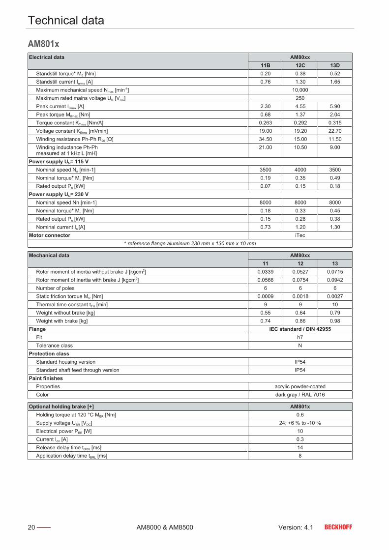
4.3
AM801xElectrical data AM80xx
11B 12C 13D Standstill torque* M0 [Nm] 0.20 0.38 0.52 Standstill current Iorms [A] 0.76 1.30 1.65 Maximum mechanical speed Nmax [min-1] 10,000 Maximum rated mains voltage UN [VAC] 250 Peak current I0max [A] 2.30 4.55 5.90 Peak torque M0max [Nm] 0.68 1.37 2.04 Torque constant KTrms [Nm/A] 0.263 0.292 0.315 Voltage constant KErms [mVmin] 19.00 19.20 22.70 Winding resistance Ph-Ph R20 [Ω] 34.50 15.00 11.50 Winding inductance Ph-Ph measured at 1 kHz L [mH]
21.00 10.50 9.00
Power supply UN= 115 V Nominal speed Nn [min-1] 3500 4000 3500 Nominal torque* Mn [Nm] 0.19 0.35 0.49 Rated output Pn [kW] 0.07 0.15 0.18Power supply UN= 230 V Nominal speed Nn [min-1] 8000 8000 8000 Nominal torque* Mn [Nm] 0.18 0.33 0.45 Rated output Pn [kW] 0.15 0.28 0.38 Nominal current In [A] 0.73 1.20 1.30Motor connector iTec
* reference flange aluminum 230 mm x 130 mm x 10 mm
Mechanical data AM80xx11 12 13
Rotor moment of inertia without brake J [kgcm2] 0.0339 0.0527 0.0715 Rotor moment of inertia with brake J [kgcm2] 0.0566 0.0754 0.0942 Number of poles 6 6 6 Static friction torque MR [Nm] 0.0009 0.0018 0.0027 Thermal time constant tTH [min] 9 9 10 Weight without brake [kg] 0.55 0.64 0.79 Weight with brake [kg] 0.74 0.86 0.98Flange IEC standard / DIN 42955 Fit h7 Tolerance class NProtection class Standard housing version IP54 Standard shaft feed through version IP54Paint finishes Properties acrylic powder-coated Color dark gray / RAL 7016
Optional holding brake [+] AM801x Holding torque at 120 °C MBR [Nm] 0.6 Supply voltage UBR [VDC] 24; +6 % to -10 % Electrical power PBR [W] 10 Current Ion [A] 0.3 Release delay time tBRH [ms] 14 Application delay time tBRL [ms] 8

Technical data
Version: 4.1 21AM8000 & AM8500
Dimensional drawing • All figures in millimeters
Motor Y Z - BrakeAM8011 97 129AM8012 117 149AM8013 137 169
Feather key [+] • Centring hole according to DIN 332-D
x
Force diagram Beckhoff load / force calculatorThe software is used to display axial and radial forces on the mo-tor shaft. These are shown in the following example for anAM8011 without holding brake.• Download load / force calculator

Technical data
22 Version: 4.1AM8000 & AM8500
4.4
AM802xElectrical data AM80xx
21B 21D 22D 22E 23E 23F Standstill torque* M0 [Nm] 0.50 0.50 0.80 0.80 1.20 1.20 Standstill current Iorms [A] 0.85 1.60 1.50 2.44 2.20 3.40 Maximum mechanical speed Nmax [min-1] 12000 Maximum rated mains voltage UN [VAC] 480 Peak current I0max [A] 4.90 8.60 7.70 12.60 11.40 17.70 Peak torque M0max [Nm] 2.68 2.67 4.18 4.18 6.36 6.37 Torque constant KTrms [Nm/A] 0.588 0.313 0.533 0.328 0.545 0.353 Voltage constant KErms [mVmin] 42 23 41 25 43 25 Winding resistance Ph-Ph R20 [Ω] 39.40 12.80 13.20 5.10 8.50 3.60 Winding inductance Ph-Ph measured at 1 kHz L [mH]
67.00 21.60 30.10 11.20 20.80 8.70
Power supply UN= 115 V Nominal speed Nn [min-1] 1500 3500 2000 4000 2000 3500 Nominal torque* Mn [Nm] 0.50 0.50 0.78 0.76 1.15 1.16 Rated output Pn [kW] 0.08 0.18 0.16 0.32 0.24 0.43Power supply UN= 230 V Nominal speed Nn [min-1] 4000 8000 4500 8000 4500 8000 Nominal torque* Mn [Nm] 0.50 0.50 0.75 0.70 1.10 1.00 Rated output Pn [kW] 0.21 0.42 0.35 0.59 0.52 0.84Power supply UN= 400 V Nominal speed Nn [min-1] 8000 9000 8000 9000 8000 9000 Nominal torque* Mn [Nm] 0.50 0.50 0.70 0.65 1.00 0.90 Rated output Pn [kW] 0.42 0.47 0.59 0.61 0.84 0.85 Nominal current In [A] 0.85 1.60 1.30 1.95 1.85 2.85Power supply UN= 480 V Nominal speed Nn [min-1] 9000 9000 9000 9000 9000 9000 Nominal torque* Mn [Nm] 0.50 0.50 0.65 0.65 0.90 0.90 Rated output Pn [kW] 0.47 0.47 0.61 0.61 0.85 0.85Motor connector iTec
* reference flange aluminum 230 mm x 130 mm x 10 mm
Mechanical data AM80xx21 22 23
Rotor moment of inertia without brake J [kgcm2] 0.139 0.258 0.378 Rotor moment of inertia with brake J [kgcm2] 0.208 0.328 0.448 Number of poles 6 6 6 Static friction torque MR [Nm] 0.002 0.004 0.006 Thermal time constant tTH [min] 10 13 16 Weight without brake [kg] 1.00 1.30 1.70 Weight with brake [kg] 1.16 1.66 1.96Flange IEC standard / DIN 42955 Fit J6 Tolerance class NProtection class Standard housing version IP65 Standard shaft feed through version IP54 Shaft bushing with shaft sealing ring IP65Paint finishes Properties acrylic powder-coated Color dark gray / RAL 7016

Technical data
Version: 4.1 23AM8000 & AM8500
Optional holding brake [+] AM802x Holding torque at 120 °C MBR [Nm] 2.0 Supply voltage UBR [VDC] 24; +6 % to -10 % Electrical power PBR [W] 10 Current Ion [A] 0.3 Release delay time tBRH [ms] 25 Application delay time tBRL [ms] 8
Dimensional drawing • All figures in millimeters
Motor Y Z - BrakeAM8021 111,5 146AM8022 133,5 168AM8023 155,5 190
Feather key [+] • Centring hole according to DIN 332-D
x

Technical data
24 Version: 4.1AM8000 & AM8500
Force diagram Beckhoff load / force calculatorThe software is used to display axial and radial forces on the mo-tor shaft. These are shown in the following example for anAM8022 without holding brake.• Download load / force calculator

Technical data
Version: 4.1 25AM8000 & AM8500
4.5
AM803x & AM853xElectrical data AM80xx / AM85xx
31C 31D 31F 32D 32E 32H 33E 33F 33J Standstill torque* M0 [Nm] 1.37 1.38 1.40 2.38 2.37 2.37 3.20 3.22 3.22 Standstill current Iorms [A] 1.00 1.95 3.20 1.70 2.95 5.10 2.10 4.10 6.80 Maximum mechanical speed Nmax [min-1] 10000 Maximum rated mains voltage UN [VAC] 480 Peak current I0max [A] 5.5 10.7 17.6 9.6 17.2 29.5 12.9 24.6 39.8 Peak torque M0max [Nm] 6.1 6.07 6.07 11.66 11.66 11.65 17.19 17.71 17.22 Torque constant KTrms [Nm/A] 1.37 0.71 0.44 1.4 0.8 0.46 1.52 0.78 0.47 Voltage constant KErms [mVmin] 99 50 30 100 56 32 106 57 34 Winding resistance Ph-Ph R20 [Ω] 51.0 12.6 5.0 21.0 6.5 2.2 13.2 3.9 1.35 Winding inductance Ph-Ph measured at 1 kHz L [mH]
134 36 13.3 71.9 22.6 7.7 46.3 14 4.9
Power supply UN= 115 V Nominal speed Nn [min-1] 400 1400 2700 600 1400 2700 600 1400 2700 Nominal torque* Mn [Nm] 1.36 1.38 1.37 2.37 2.34 2.29 3.15 3.10 3.05 Rated output Pn [kW] 0.06 0.20 0.39 0.15 0.34 0.65 0.20 0.45 0.86Power supply UN= 230 V Nominal speed Nn [min-1] 1400 3300 6000 1500 3000 6000 1500 3000 5900 Nominal torque* Mn [Nm] 1.35 1.36 1.34 2.34 2.30 2.10 3.10 3.00 2.70 Rated output Pn [kW] 0.20 0.47 0.84 0.37 0.76 1.32 0.49 1.00 1.67Power supply UN= 400 V Nominal speed Nn [min-1] 3000 6000 9000 3000 6000 9000 3000 6000 9000 Nominal torque* Mn [Nm] 1.34 1.33 1.30 2.30 2.20 1.85 2.98 2.70 2.30 Rated output Pn [kW] 0.42 0.84 1.23 0.72 1.38 1.74 0.94 1.70 2.17 Nominal current In [A] 0.95 1.90 3.00 1.60 2.75 4.10 2.00 3.60 5.10Power supply UN= 480 V Nominal speed Nn [min-1] 3400 6800 9000 3400 6800 9000 3400 6800 9000 Nominal torque* Mn [Nm] 1.33 1.32 1.3 2.26 2.1 1.85 2.95 2.6 2.3 Rated output Pn [kW] 0.47 0.94 1.23 0.8 1.5 1.74 1.05 1.85 2.17Motor connector iTec
* reference flange aluminum 230 mm x 130 mm x 10 mm
Mechanical data AM80xx / AM85xxAM8031 AM8531 AM8032 AM8532 AM8033 AM8533
Rotor moment of inertia without brake J [kgcm2] 0.467 1.67 0.847 2.05 1.23 2.440 Rotor moment of inertia with brake J [kgcm2] 0.546 1.76 0.926 2.15 1.46 --- Number of poles 8 8 8 8 8 8 Static friction torque MR [Nm] 0.009 0.009 0.015 0.015 0.020 0.020 Thermal time constant tTH [min] 24 24 26 26 28 28 Weight without brake [kg] 1.80 2.40 2.40 3.00 3.00 3.60 Weight with brake [kg] 2.20 2.60 2.80 3.30 3.60 ---Flange IEC standard / DIN 42955 Fit J6 Tolerance class NProtection class Standard housing version IP65 Standard shaft feed through version IP54 Shaft bushing with shaft sealing ring IP65Paint finishes Properties acrylic powder-coated Color dark gray / RAL 7016

Technical data
26 Version: 4.1AM8000 & AM8500
Optional holding brake [+] AM8031 AM8531 AM8032 AM8532 AM8033 Holding torque at 120 °C MBR [Nm] 2.0 2.0 2.0 2.0 3.5 Supply voltage UBR [VDC] 24; +6 % to -10 % Electrical power PBR [W] 11 11 11 11 12 Current Ion [A] 0.33 0.33 0.33 0.33 0.36 Release delay time tBRH [ms] 25 25 25 25 35 Application delay time tBRL [ms] 8 8 8 8 15
Dimensional drawing • All figures in millimeters
Motor Y Z – BrakeAM8031 129 168AM8032 154 194AM8033 180 229AM8531 168 194AM8532 194 229AM8533 229 --
Feather key [+] • Centring hole according to DIN 332-D
M5 x 12,5

Technical data
Version: 4.1 27AM8000 & AM8500
Force diagram Beckhoff load / force calculatorThe software is used to display axial and radial forces on the mo-tor shaft. These are shown in the following example for anAM8032 without holding brake.• Download load / force calculator

Technical data
28 Version: 4.1AM8000 & AM8500
4.6
AM804x & AM854xElectrical data AM80xx / AM85xx
41D 41E 41H 42E 42F 42J 43E 43H 43K Standstill torque* M0 [Nm] 2.37 2.45 2.40 4.10 4.10 4.10 5.65 5.65 5.60 Standstill current Iorms [A] 1.65 3.00 5.25 2.15 4.10 6.90 2.90 5.40 9.30 Maximum mechanical speed Nmax [min-1] 9000 Maximum rated mains voltage UN [VAC] 480 Peak current I0max [A] 8.30 13.6 23.30 11.80 22.70 37.60 16.60 31.00 53.90 Peak torque M0max [Nm] 9.67 9.14 9.14 18.94 18.90 18.89 29.33 29.25 29.25 Torque constant KTrms [Nm/A] 1.43 0.81 0.45 1.90 1.00 0.59 1.94 1.04 0.60 Voltage constant KErms [mVmin] 101.0 56.00 33.00 128.0 68.00 41.00 131.0 73.00 42.00 Winding resistance Ph-Ph R20 [Ω] 22.50 6.10 2.21 14.20 3.70 1.40 8.90 2.40 0.83 Winding inductance Ph-Ph measured at 1 kHz L [mH]
83.1 25.0 8.5 64.9 17.4 6.3 42.0 11.7 3.9
Power supply UN= 115 V Nominal speed Nn [min-1] 600 1300 2600 500 1200 2200 500 1200 2200 Nominal torque* Mn [Nm] 2.35 2.43 2.34 4.05 3.97 3.90 5.58 5.50 5.27 Rated output Pn [kW] 0.15 0.33 0.64 0.21 0.50 0.90 0.29 0.69 1.21Power supply UN= 230 V Nominal speed Nn [min-1] 1500 3000 6000 1200 2800 5000 1200 2700 5000 Nominal torque* Mn [Nm] 2.33 2.39 2.27 3.97 3.90 3.70 5.50 5.30 4.90 Rated output Pn [kW] 0.37 0.75 1.43 0.50 1.14 1.94 0.70 1.50 2.57Power supply UN= 400 V Nominal speed Nn [min-1] 3000 6000 8000 2500 5000 8000 2500 5000 8000 Nominal torque* Mn [Nm] 2.30 2.31 2.10 3.90 3.70 3.10 5.30 4.90 4.10 Rated output Pn [kW] 0.72 1.45 1.76 1.02 1.94 2.60 1.39 2.57 3.43 Nominal current In [A] 1.60 2.90 4.60 2.05 3.80 5.20 2.70 4.75 6.90Power supply UN= 480 V Nominal speed Nn [min-1] 3400 6800 8000 2800 5700 8000 2800 5700 8000 Nominal torque* Mn [Nm] 2.29 2.27 2.10 3.87 3.64 3.10 5.30 4.88 4.10 Rated output Pn [kW] 0.82 1.62 1.76 1.13 2.17 2.60 1.55 2.91 3.43Motor connector M23-speedtec
* reference flange aluminum 230 mm x 130 mm x 10 mm
Mechanical data AM80xx / AM85xxAM8041 AM8541 AM8042 AM8542 AM8043 AM8543
Rotor moment of inertia without brake J [kgcm2] 1.09 4.62 1.98 5.51 2.87 6.41 Rotor moment of inertia with brake J [kgcm2] 1.73 5.27 2.63 6.17 3.52 --- Number of poles 8 8 8 8 8 8 Static friction torque MR [Nm] 0.020 0.020 0.027 0.027 0.035 0.035 Thermal time constant tTH [min] 30 30 33 33 36 36 Weight without brake [kg] 2.80 3.80 3.80 4.90 4.90 6.00 Weight with brake [kg] 3.60 4.50 4.70 5.70 5.80 ---Flange IEC standard / DIN 42955 Fit J6 Tolerance class NProtection class Standard housing version IP65 Standard shaft feed through version IP54 Shaft bushing with shaft sealing ring IP65Paint finishes Properties acrylic powder-coated Color dark gray / RAL 7016

Technical data
Version: 4.1 29AM8000 & AM8500
Optional holding brake [+] AM804x AM854x Holding torque at 120 °C MBR [Nm] 9 Supply voltage UBR [VDC] 24; +6 % to -10 % Electrical power PBR [W] 18 Current Ion [A] 0.54 Release delay time tBRH [ms] 40 Application delay time tBRL [ms] 20
Dimensional drawing • All figures in millimeters
Motor Y Z - BrakeAM8041 132 179,5AM8042 162 209,5AM8043 192 239,5AM8541 179,5 209,5AM8542 209,5 239,5AM8543 239,5 --
Feather key [+] • Centring hole according to DIN 332-D
M6 x 16

Technical data
30 Version: 4.1AM8000 & AM8500
Force diagram Beckhoff load / force calculatorThe software is used to display axial and radial forces on the mo-tor shaft. These are shown in the following example for anAM8042 without holding brake.• Download load / force calculator

Technical data
Version: 4.1 31AM8000 & AM8500
4.7
AM805x & AM855xElectrical data AM80xx / AM85xx
51E 51G 51K 52F 52J 52L 53G 53K 53N Standstill torque* M0 [Nm] 4.80 4.90 4.90 8.20 8.20 8.20 11.40 11.40 11.40 Standstill current Iorms [A] 2.70 4.75 8.50 3.30 6.30 11.30 4.70 8.80 15.60 Maximum mechanical speed Nmax [min-1] 9000 Maximum rated mains voltage UN [VAC] 480 Peak current I0max [A] 12.10 20.90 37.70 17.90 33.60 60.70 26.90 50.90 89.70 Peak torque M0max [Nm] 17.74 17.76 17.78 35.32 35.34 35.34 53.13 53.13 53.14 Torque constant KTrms [Nm/A] 1.77 1.03 0.57 2.48 1.30 0.72 2.42 1.29 0.73 Voltage constant KErms [mVmin] 125.0 73.00 40.00 167.0 89.00 49.00 168.0 89.00 51.00 Winding resistance Ph-Ph R20 [Ω] 11.40 3.60 1.14 8.50 2.30 0.70 5.10 1.40 0.45 Winding inductance Ph-Ph measured at 1 kHz L [mH]
42.7 14.4 4.6 36.9 10.5 3.2 23.7 6.6 2.1
Power supply UN= 115 V Nominal speed Nn [min-1] 500 1200 2300 400 1000 1900 400 1000 1900 Nominal torque* Mn [Nm] 4.80 4.80 4.65 8.00 7.90 7.55 11.10 10.80 10.00 Rated output Pn [kW] 0.25 0.60 1.12 0.34 0.83 1.50 0.46 1.13 2.00Power supply UN= 230 V Nominal speed Nn [min-1] 1400 2700 5000 1100 2200 4000 1100 2200 4000 Nominal torque* Mn [Nm] 4.70 4.65 4.40 7.80 7.50 6.90 10.70 9.90 8.35 Rated output Pn [kW] 0.69 1.31 2.30 0.90 1.73 2.89 1.23 2.28 3.50Power supply UN= 400 V Nominal speed Nn [min-1] 2500 5000 8000 2000 4000 7300 2000 4000 7000 Nominal torque* Mn [Nm] 4.60 4.40 3.90 7.50 6.90 5.40 10.00 8.35 4.50 Rated output Pn [kW] 1.20 2.30 3.27 1.57 2.89 4.13 2.09 3.50 3.30 Nominal current In [A] 2.55 4.20 6.70 3.10 5.20 7.50 4.10 6.30 4.50Power supply UN= 480 V Nominal speed Nn [min-1] 3000 5700 8000 2300 4500 7500 2400 4500 7000 Nominal torque* Mn [Nm] 4.50 4.30 3.90 7.40 6.70 5.40 9.70 7.85 4.50 Rated output Pn [kW] 1.41 2.57 3.27 1.78 3.16 4.24 2.44 3.70 3.30Motor connector M23-speedtec
* reference flange aluminum 305 mm x 305 mm x 10 mm
Mechanical data AM80xx / AM85xxAM8051 AM8551 AM8052 AM8552 AM8053 AM8553
Rotor moment of inertia without brake J [kgcm2] 2.25 8.75 4.09 10.6 5.93 12.4 Rotor moment of inertia with brake J [kgcm2] 2.91 9.41 4.75 11.3 7.04 --- Number of poles 8 8 8 8 8 8 Static friction torque MR [Nm] 0.021 0.021 0.036 0.036 0.050 0.050 Thermal time constant tTH [min] 31 31 38 38 40 40 Weight without brake [kg] 4.10 5.50 5.70 7.00 7.40 8.80 Weight with brake [kg] 4.90 6.30 6.60 7.90 8.40 ---Flange IEC standard / DIN 42955 Fit J6 Tolerance class NProtection class Standard housing version IP65 Standard shaft feed through version IP54 Shaft bushing with shaft sealing ring IP65Paint finishes Properties acrylic powder-coated Color dark gray / RAL 7016

Technical data
32 Version: 4.1AM8000 & AM8500
Optional holding brake [+] AM8051 AM8551 AM8052 AM8552 AM8053 Holding torque at 120 °C MBR [Nm] 9 9 9 9 13 Supply voltage UBR [VDC] 24; +6 % to -10 % Electrical power PBR [W] 18 18 18 18 17 Current Ion [A] 0.54 0.54 0.54 0.54 0.51 Release delay time tBRH [ms] 40 40 40 40 45 Application delay time tBRL [ms] 20 20 20 20 20
Dimensional drawing • All figures in millimeters
Motor Y Z – BrakeAM8051 136,5 183,5AM8052 169,5 216,5AM8053 202,5 251,5AM8551 183,5 216,5AM8552 216,5 251,5AM8553 251,5 284,5
Feather key [+] • Centring hole according to DIN 332-D
M8 x 19

Technical data
Version: 4.1 33AM8000 & AM8500
Dimensional drawing • The flange of version AM8x5x-xxxx-9000 is compatible withAM3x5x
• All figures in millimeters
Motor Y Z – BrakeAM8051-xxxx-9000 136,5 183,5AM8052-xxxx-9000 169,5 216,5AM8053-xxxx-9000 202,5 251,5AM8551-xxxx-9000 183,5 216,5AM8552-xxxx-9000 216,5 251,5AM8553-xxxx-9000 251,5 284,5
Feather key [+] • Centring hole according to DIN 332-D
M8 x 19

Technical data
34 Version: 4.1AM8000 & AM8500
Force diagram Beckhoff load / force calculatorThe software is used to display axial and radial forces on the mo-tor shaft. These are shown in the following example for anAM8052 without holding brake.• Download load / force calculator

Technical data
Version: 4.1 35AM8000 & AM8500
4.7.4
AM805x & AM855x withfan cover [+]Electrical data AM80xx / AM85xx
51F 51J 51L 52G 52K 52N 53J 53L 53P Standstill torque* M0 [Nm] 6.20 6.30 6.30 10.70 10.70 9.60 15.40 15.40 13.30 Standstill current Iorms [A] 3.50 5.80 11.10 4.30 8.50 13.60 6.40 11.90 18.60 Maximum mechanical speed Nmax [min-1] 9000 Maximum rated mains voltage UN [VAC] 480 Peak current I0max [A] 12.10 20.90 37.70 17.90 33.60 60.70 26.90 50.90 89.70 Peak torque M0max [Nm] 17.74 17.76 17.78 35.32 35.34 35.34 53.13 53.13 53.14 Torque constant KTrms [Nm/A] 1.77 1.09 0.57 2.48 1.30 0.72 2.42 1.29 0.73 Voltage constant KErms [mVmin] 125.0 73.00 40.00 167.0 89.00 49.00 168.0 89.00 51.00 Winding resistance Ph-Ph R20 [Ω] 11.40 3.60 1.14 8.50 2.30 0.70 5.10 1.40 0.45 Winding inductance Ph-Ph measured at 1 kHz L [mH]
42.7 14.4 4.6 36.9 10.5 3.2 23.7 6.6 2.1
Power supply UN= 115 V Nominal speed Nn [min-1] 500 1100 2300 400 900 1900 400 1000 1900 Nominal torque* Mn [Nm] 6.10 6.20 5.90 10.50 10.30 9.50 15.30 15.10 12.30 Rated output Pn [kW] 0.32 0.71 1.42 0.44 0.97 1.90 0.65 1.58 2.45Power supply UN= 230 V Nominal speed Nn [min-1] 1400 2600 4900 1000 2100 4000 1000 2200 4000 Nominal torque* Mn [Nm] 6.00 5.80 5.30 10.30 9.60 8.10 15.10 14.80 8.40 Rated output Pn [kW] 0.88 1.58 2.72 1.08 2.11 3.40 1.58 3.40 3.52Power supply UN= 400 V Nominal speed Nn [min-1] 2500 4750 8000 2000 4000 6000 2000 4000 5000 Nominal torque* Mn [Nm] 5.80 5.50 3.60 9.70 9.10 5.40 14.90 12.90 7.10 Rated output Pn [kW] 1.52 2.74 3.02 2.03 3.77 4.08 3.12 5.41 3.72 Nominal current In [A] 3.20 5.20 6.30 4.00 7.10 9.00 6.10 10.00 6.00Power supply UN= 480 V Nominal speed Nn [min-1] 3000 5000 8000 2300 4500 7000 2300 4500 7000 Nominal torque* Mn [Nm] 5.70 5.40 3.60 9.20 8.80 4.50 14.70 12.10 4.10 Rated output Pn [kW] 1.79 3.22 3.01 2.21 4.14 4.24 3.54 5.84 3.00Motor connector M23-speedtec
* reference flange aluminum 305 mm x 305 mm x 10 mm
Mechanical data AM80xx / AM85xxAM8051 AM8551 AM8052 AM8552 AM8053 AM8553
Rotor moment of inertia without brake J [kgcm2] 2.24 8.75 4.080 10.600 5.920 12.500 Rotor moment of inertia with brake J [kgcm2] 2.90 9.41 4.74 11.20 7.04 --- Number of poles 8 8 8 8 8 8 Static friction torque MR [Nm] 0.021 0.021 0.036 0.036 0.050 0.050 Thermal time constant tTH [min] 31 31 38 38 40 40 Weight without brake [kg] 5.20 6.60 6.80 8.10 8.50 9.90 Weight with brake [kg] 6.00 7.40 7.70 9.00 9.50 ---Flange IEC standard / DIN 42955 Fit J6 Tolerance class NProtection class Standard housing version IP20 Standard shaft feed through version IP54 Shaft bushing with shaft sealing ring IP65Paint finishes Properties acrylic powder-coated Color dark gray / RAL 7016

Technical data
36 Version: 4.1AM8000 & AM8500
Optional holding brake [+] AM8051 AM8551 AM8052 AM8552 AM8053 AM8553 Holding torque at 120 °C MBR [Nm] 9 9 9 9 13 13 Supply voltage UBR [VDC] 24; +6 % to -10 % Electrical power PBR [W] 18 18 18 18 17 17 Current Ion [A] 0.54 0.54 0.54 0.54 0.51 0.51 Release delay time tBRH [ms] 40 40 40 40 45 45 Application delay time tBRL [ms] 20 20 20 20 20 20
Dimensional drawing • Illustration with fan cover [+]• All figures in millimeters
Motor Y / ZAM8051-xxxA-xxx0 205,5AM8051-xxxB-xxx0 252,5AM8052-xxxA-xxx0 238,5AM8052-xxxB-xxx0 285,5AM8053-xxxA-xxx0 271,5AM8053-xxxB-xxx0 320,5AM8551-xxxA-xxx0 252,5AM8551-xxxB-xxx0 285,5AM8552-xxxA-xxx0 285,5AM8552-xxxB-xxx0 320,5AM8553-xxxA-xxx0 320,5AM8553-xxxB-xxx0 353,5
Feather key [+] • Centring hole according to DIN 332-D
M8 x 19

Technical data
Version: 4.1 37AM8000 & AM8500
Dimensional drawing • The flange of version AM8x5x-9000 is compatible with AM3x5x• Illustration with fan cover [+]• All figures in millimeters
Motor Y / ZAM8051-xxxA-9000 205,5AM8051-xxxB-9000 252,5AM8052-xxxA-9000 238,5AM8052-xxxB-9000 285,5AM8053-xxxA-9000 271,5AM8053-xxxB-9000 320,5AM8551-xxxA-9000 252,5AM8551-xxxB-9000 285,5AM8552-xxxA-9000 285,5AM8552-xxxB-9000 320,5AM8553-xxxA-9000 320,5AM8553-xxxB-9000 353,5
Feather key [+] • Centring hole according to DIN 332-D
M8 x 19

Technical data
38 Version: 4.1AM8000 & AM8500
4.8
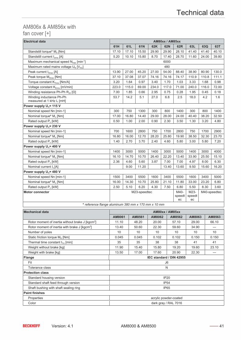
AM806x & AM856xElectrical data AM80xx / AM85xx
61G 61J 61M 62J 62L 62P 63K 63N 63R Standstill torque* M0 [Nm] 12.80 12.80 12.80 21.10 21.10 21.10 29.00 29.00 29.00 Standstill current Iorms [A] 4.00 7.80 13.10 6.20 12.40 20.30 8.70 17.20 29.50 Maximum mechanical speed Nmax [min-1] 6000 Maximum rated mains voltage UN [VAC] 480 Peak current I0max [A] 13.90 27.00 45.20 27.00 54.00 88.40 38.90 80.90 130.0 Peak torque M0max [Nm] 37.10 37.08 37.07 74.16 74.16 74.17 110.9 110.8 111.1 Torque constant KTrms [Nm/A] 3.20 1.64 0.97 3.40 1.70 1.03 3.33 1.68 0.98 Voltage constant KErms [mVmin] 223.0 115.0 69.00 234.0 117.0 71.00 240.0 116.0 72.00 Winding resistance Ph-Ph R20 [Ω] 7.00 1.85 0.66 2.95 0.75 0.28 1.95 0.45 0.18 Winding inductance Ph-Ph measured at 1 kHz L [mH]
53.7 14.2 5.1 27.0 6.8 2.5 18.0 4.2 1.6
Power supply UN= 115 V Nominal speed Nn [min-1] 300 750 1300 300 800 1400 300 800 1400 Nominal torque* Mn [Nm] 12.60 12.40 12.20 20.70 20.10 18.60 28.20 25.90 22.80 Rated output Pn [kW] 0.40 0.97 1.66 0.65 1.68 2.73 0.89 2.17 3.34Power supply UN= 230 V Nominal speed Nn [min-1] 800 1600 2800 800 1700 2800 800 1700 3000 Nominal torque* Mn [Nm] 12.40 12.00 11.10 20.10 18.20 15.30 25.90 21.10 13.20 Rated output Pn [kW] 1.04 2.01 3.25 1.68 3.24 4.49 2.17 3.76 4.15Power supply UN= 400 V Nominal speed Nn [min-1] 1500 3000 5000 1500 3000 5000 1500 3000 4000 Nominal torque* Mn [Nm] 12.10 11.00 9.00 18.50 15.20 6.50 22.30 13.20 6.10 Rated output Pn [kW] 1.90 3.46 4.71 2.91 4.78 3.40 3.50 4.15 2.56 Nominal current In [A] 3.90 6.80 9.10 5.60 9.40 6.60 6.70 8.10 6.00Power supply UN= 480 V Nominal speed Nn [min-1] 1700 3400 5000 1700 3400 5000 1700 3400 4000 Nominal torque* Mn [Nm] 12.00 10.40 9.00 18.20 13.90 6.50 21.10 11.00 6.10 Rated output Pn [kW] 2.14 3.70 4.71 3.24 4.95 3.40 3.76 3.92 2.56Motor connector M23-speedtec M40-
speedtec
* reference flange aluminum 380 mm x 170 mm x 10 mm
Mechanical data AM80xx / AM85xxAM8061 AM8561 AM8062 AM8562 AM8063 AM8563
Rotor moment of inertia without brake J [kgcm2] 11.10 48.20 20.00 57.10 29.00 66.10 Rotor moment of inertia with brake J [kgcm2] 13.40 50.60 22.30 59.60 34.90 --- Number of poles 10 10 10 10 10 10 Static friction torque MR [Nm] 0.045 0.045 0.102 0.102 0.150 0.150 Thermal time constant tTH [min] 35 35 38 38 41 41 Weight without brake [kg] 9.80 13.20 13.60 17.00 17.40 20.90 Weight with brake [kg] 11.60 14.80 15.40 18.70 20.10 ---Flange IEC standard / DIN 42955 Fit J6 Tolerance class NProtection class Standard housing version IP65 Standard shaft feed through version IP54 Shaft bushing with shaft sealing ring IP65Paint finishes Properties acrylic powder-coated Color dark gray / RAL 7016
Technical data
Version: 4.1 39AM8000 & AM8500
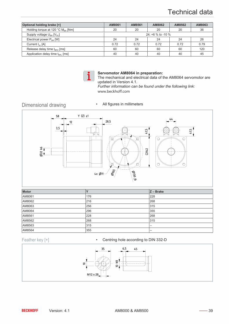
Optional holding brake [+] AM8061 AM8561 AM8062 AM8562 AM8063 Holding torque at 120 °C MBR [Nm] 20 20 20 20 36 Supply voltage UBR [VDC] 24; +6 % to -10 % Electrical power PBR [W] 24 24 24 24 26 Current Ion [A] 0.72 0.72 0.72 0.72 0.79 Release delay time tBRH [ms] 60 60 60 60 120 Application delay time tBRL [ms] 40 40 40 40 45
Servomotor AM8064 in preparation:The mechanical and electrical data of the AM8064 servomotor areupdated in Version 4.1.Further information can be found under the following link:www.beckhoff.com
Dimensional drawing • All figures in millimeters
Motor Y Z – BrakeAM8061 176 228AM8062 216 268AM8063 256 315AM8064 296 355AM8561 228 268AM8562 268 315AM8563 315 --AM8564 355 --
Feather key [+] • Centring hole according to DIN 332-D
M12 x 28

Technical data
40 Version: 4.1AM8000 & AM8500
Dimensional drawing • Illustration with R and T winding• All figures in millimeters
Motor Y Z – BrakeAM8063-xRxx 256 315AM8563-xRxx 315 --AM8064-xTxx 296 355AM8564-xTxx 355 --
Feather key [+] • Centring hole according to DIN 332-D
M12 x 28
Force diagram Beckhoff load / force calculatorThe software is used to display axial and radial forces on the mo-tor shaft. These are shown in the following example for anAM8062 without holding brake.• Download load / force calculator
Technical data
Version: 4.1 41AM8000 & AM8500
4.8.4
AM806x & AM856x withfan cover [+]Electrical data AM80xx / AM85xx
61H 61L 61N 62K 62N 62R 63L 63Q 63T Standstill torque* M0 [Nm] 17.10 17.10 15.50 29.90 29.90 28.10 41.40 41.40 40.10 Standstill current Iorms [A] 5.20 10.10 15.80 8.70 17.40 28.70 11.60 24.00 39.80 Maximum mechanical speed Nmax [min-1] 6000 Maximum rated mains voltage UN [VAC] 480 Peak current I0max [A] 13.90 27.00 45.20 27.00 54.00 88.40 38.90 80.90 130.0 Peak torque M0max [Nm] 37.10 37.08 37.07 74.16 74.16 74.17 110.9 110.8 111.1 Torque constant KTrms [Nm/A] 3.20 1.64 0.97 3.40 1.70 1.03 3.33 1.68 0.98 Voltage constant KErms [mVmin] 223.0 115.0 69.00 234.0 117.0 71.00 240.0 116.0 72.00 Winding resistance Ph-Ph R20 [Ω] 7.00 1.85 0.66 2.95 0.75 0.28 1.95 0.45 0.18 Winding inductance Ph-Ph measured at 1 kHz L [mH]
53.7 14.2 5.1 27.0 6.8 2.5 18.0 4.2 1.6
Power supply UN= 115 V Nominal speed Nn [min-1] 300 750 1300 300 800 1400 300 800 1400 Nominal torque* Mn [Nm] 17.00 16.80 14.40 29.00 28.00 24.00 40.40 38.20 32.50 Rated output Pn [kW] 0.50 1.00 2.00 0.90 2.30 3.50 1.30 3.20 4.80Power supply UN= 230 V Nominal speed Nn [min-1] 700 1600 2800 750 1700 2800 750 1700 2900 Nominal torque* Mn [Nm] 16.80 16.00 12.70 28.20 25.80 19.90 38.50 32.30 23.70 Rated output Pn [kW] 1.40 2.70 3.70 2.40 4.60 5.80 3.00 5.80 7.20Power supply UN= 400 V Nominal speed Nn [min-1] 1400 3000 5000 1400 3000 5000 1400 3000 4000 Nominal torque* Mn [Nm] 16.10 14.70 10.70 26.40 22.20 13.40 33.90 25.50 15.10 Rated output Pn [kW] 2.36 4.60 5.60 3.87 7.00 7.00 4.97 8.00 6.30 Nominal current In [A] 9.00 11.20 13.40 13.60 9.50 15.60 16.20Power supply UN= 480 V Nominal speed Nn [min-1] 1500 3400 5500 1600 3400 5500 1600 3400 5000 Nominal torque* Mn [Nm] 16.00 14.30 10.70 25.80 21.10 11.80 33.00 23.20 6.80 Rated output Pn [kW] 2.50 5.10 6.20 4.30 7.50 6.80 5.50 8.30 3.60Motor connector M23-speedtec M40-
speedtec
M23-speedt
ec
M40-speedtec
* reference flange aluminum 380 mm x 170 mm x 10 mm
Mechanical data AM80xx / AM85xxAM8061 AM8561 AM8062 AM8562 AM8063 AM8563
Rotor moment of inertia without brake J [kgcm2] 11.10 48.20 20.00 57.10 29.00 66.10 Rotor moment of inertia with brake J [kgcm2] 13.40 50.60 22.30 59.60 34.90 --- Number of poles 10 10 10 10 10 10 Static friction torque MR [Nm] 0.045 0.045 0.102 0.102 0.150 0.150 Thermal time constant tTH [min] 35 35 38 38 41 41 Weight without brake [kg] 11.90 15.40 15.80 19.20 19.60 23.10 Weight with brake [kg] 13.50 17.00 17.60 20.90 22.30 ---Flange IEC standard / DIN 42955 Fit J6 Tolerance class NProtection class Standard housing version IP20 Standard shaft feed through version IP54 Shaft bushing with shaft sealing ring IP65Paint finishes Properties acrylic powder-coated Color dark gray / RAL 7016
Technical data
42 Version: 4.1AM8000 & AM8500
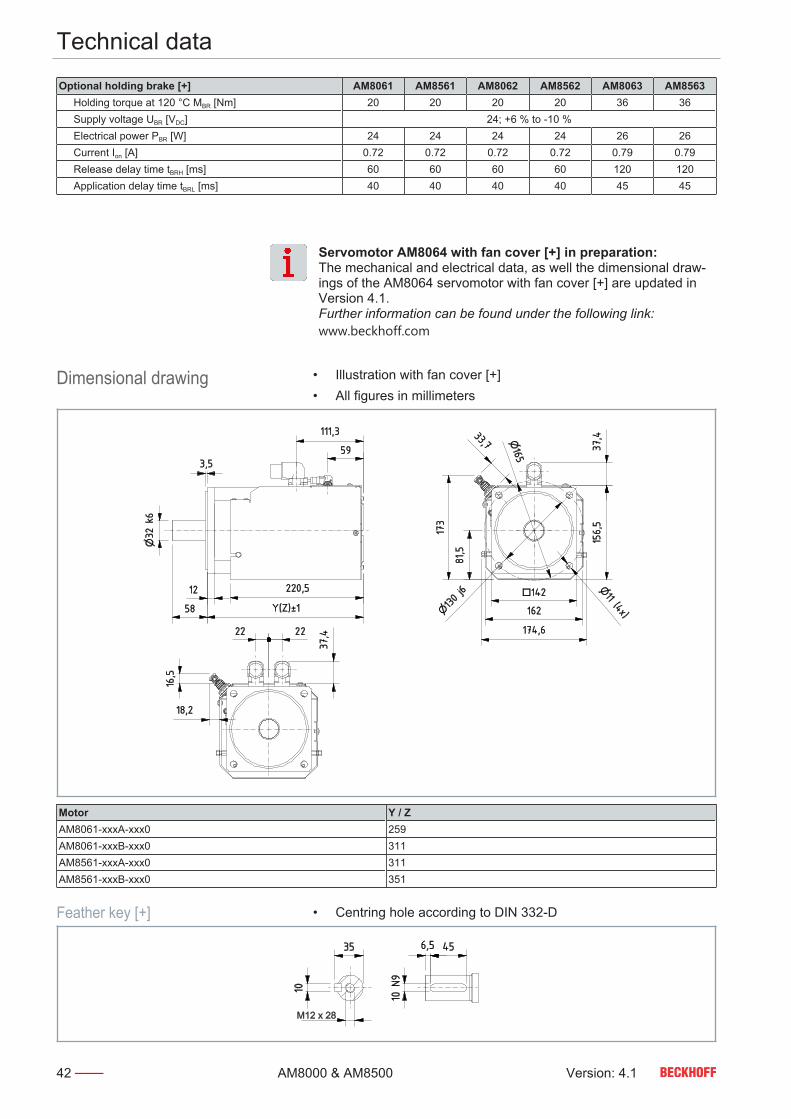
Optional holding brake [+] AM8061 AM8561 AM8062 AM8562 AM8063 AM8563 Holding torque at 120 °C MBR [Nm] 20 20 20 20 36 36 Supply voltage UBR [VDC] 24; +6 % to -10 % Electrical power PBR [W] 24 24 24 24 26 26 Current Ion [A] 0.72 0.72 0.72 0.72 0.79 0.79 Release delay time tBRH [ms] 60 60 60 60 120 120 Application delay time tBRL [ms] 40 40 40 40 45 45
Servomotor AM8064 with fan cover [+] in preparation:The mechanical and electrical data, as well the dimensional draw-ings of the AM8064 servomotor with fan cover [+] are updated inVersion 4.1.Further information can be found under the following link:www.beckhoff.com
Dimensional drawing • Illustration with fan cover [+]• All figures in millimeters
Motor Y / ZAM8061-xxxA-xxx0 259AM8061-xxxB-xxx0 311AM8561-xxxA-xxx0 311AM8561-xxxB-xxx0 351
Feather key [+] • Centring hole according to DIN 332-D
M12 x 28

Technical data
Version: 4.1 43AM8000 & AM8500
Dimensional drawing • Illustration with fan cover [+] and K-N-L winding• All figures in millimeters
Motor Y / ZAM8062-xKxA-xxx0 299AM8062-xKxB-xxx0 351AM8062-xNxA-xxx0 299AM8062-xNxB-xxx0 351AM8063-xLxA-xxx0 339AM8063-xLxB-xxx0 398AM8562-xKxA-xxx0 351AM8562-xNxA-xxx0 351AM8562-xKxB-xxx0 398AM8562-xNxB-xxx0 398AM8563-xLxA-xxx0 398
Feather key [+] • Centring hole according to DIN 332-D
M12 x 28

Technical data
44 Version: 4.1AM8000 & AM8500
Dimensional drawing • Illustration with fan cover [+] and R-Q-T winding• All figures in millimeters
Motor Y / ZAM8062-xRxA-xxx0 299AM8062-xRxB-xxx0 351AM8063-xQxA-xxx0 339AM8063-xQxB-xxx0 398AM8063-xTxA-xxx0 339AM8063-xTxB-xxx0 398AM8562-xRxA-xxx0 351AM8562-xRxB-xxx0 398AM8563-xQxA-xxx0 398AM8563-xTxA-xxx0 398
Feather key [+] • Centring hole according to DIN 332-D
M12 x 28
Technical data
Version: 4.1 45AM8000 & AM8500
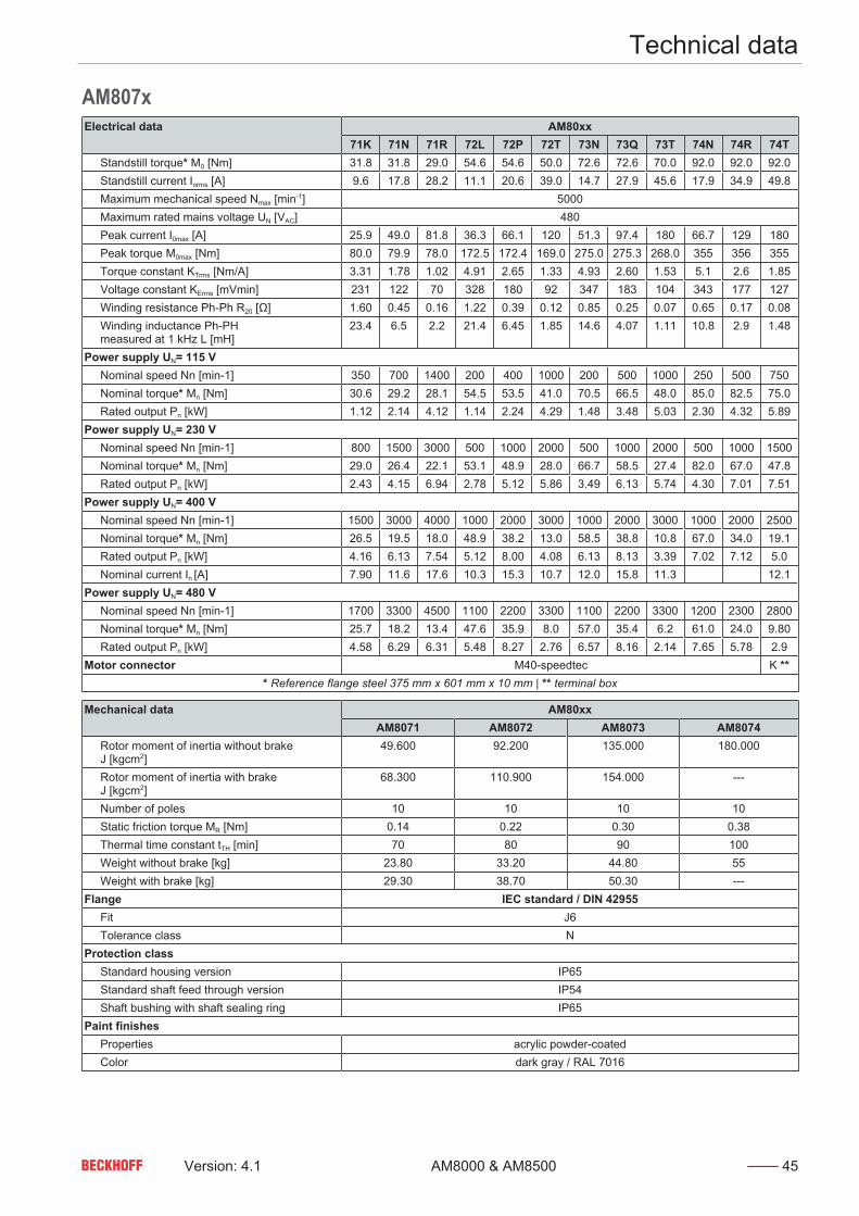
4.9
AM807xElectrical data AM80xx
71K 71N 71R 72L 72P 72T 73N 73Q 73T 74N 74R 74T Standstill torque* M0 [Nm] 31.8 31.8 29.0 54.6 54.6 50.0 72.6 72.6 70.0 92.0 92.0 92.0 Standstill current Iorms [A] 9.6 17.8 28.2 11.1 20.6 39.0 14.7 27.9 45.6 17.9 34.9 49.8 Maximum mechanical speed Nmax [min-1] 5000 Maximum rated mains voltage UN [VAC] 480 Peak current I0max [A] 25.9 49.0 81.8 36.3 66.1 120 51.3 97.4 180 66.7 129 180 Peak torque M0max [Nm] 80.0 79.9 78.0 172.5 172.4 169.0 275.0 275.3 268.0 355 356 355 Torque constant KTrms [Nm/A] 3.31 1.78 1.02 4.91 2.65 1.33 4.93 2.60 1.53 5.1 2.6 1.85 Voltage constant KErms [mVmin] 231 122 70 328 180 92 347 183 104 343 177 127 Winding resistance Ph-Ph R20 [Ω] 1.60 0.45 0.16 1.22 0.39 0.12 0.85 0.25 0.07 0.65 0.17 0.08 Winding inductance Ph-PH measured at 1 kHz L [mH]
23.4 6.5 2.2 21.4 6.45 1.85 14.6 4.07 1.11 10.8 2.9 1.48
Power supply UN= 115 V Nominal speed Nn [min-1] 350 700 1400 200 400 1000 200 500 1000 250 500 750 Nominal torque* Mn [Nm] 30.6 29.2 28.1 54.5 53.5 41.0 70.5 66.5 48.0 85.0 82.5 75.0 Rated output Pn [kW] 1.12 2.14 4.12 1.14 2.24 4.29 1.48 3.48 5.03 2.30 4.32 5.89Power supply UN= 230 V Nominal speed Nn [min-1] 800 1500 3000 500 1000 2000 500 1000 2000 500 1000 1500 Nominal torque* Mn [Nm] 29.0 26.4 22.1 53.1 48.9 28.0 66.7 58.5 27.4 82.0 67.0 47.8 Rated output Pn [kW] 2.43 4.15 6.94 2.78 5.12 5.86 3.49 6.13 5.74 4.30 7.01 7.51Power supply UN= 400 V Nominal speed Nn [min-1] 1500 3000 4000 1000 2000 3000 1000 2000 3000 1000 2000 2500 Nominal torque* Mn [Nm] 26.5 19.5 18.0 48.9 38.2 13.0 58.5 38.8 10.8 67.0 34.0 19.1 Rated output Pn [kW] 4.16 6.13 7.54 5.12 8.00 4.08 6.13 8.13 3.39 7.02 7.12 5.0 Nominal current In [A] 7.90 11.6 17.6 10.3 15.3 10.7 12.0 15.8 11.3 12.1Power supply UN= 480 V Nominal speed Nn [min-1] 1700 3300 4500 1100 2200 3300 1100 2200 3300 1200 2300 2800 Nominal torque* Mn [Nm] 25.7 18.2 13.4 47.6 35.9 8.0 57.0 35.4 6.2 61.0 24.0 9.80 Rated output Pn [kW] 4.58 6.29 6.31 5.48 8.27 2.76 6.57 8.16 2.14 7.65 5.78 2.9Motor connector M40-speedtec K **
* Reference flange steel 375 mm x 601 mm x 10 mm | ** terminal box
Mechanical data AM80xxAM8071 AM8072 AM8073 AM8074
Rotor moment of inertia without brake J [kgcm2]
49.600 92.200 135.000 180.000
Rotor moment of inertia with brake J [kgcm2]
68.300 110.900 154.000 ---
Number of poles 10 10 10 10 Static friction torque MR [Nm] 0.14 0.22 0.30 0.38 Thermal time constant tTH [min] 70 80 90 100 Weight without brake [kg] 23.80 33.20 44.80 55 Weight with brake [kg] 29.30 38.70 50.30 ---Flange IEC standard / DIN 42955 Fit J6 Tolerance class NProtection class Standard housing version IP65 Standard shaft feed through version IP54 Shaft bushing with shaft sealing ring IP65Paint finishes Properties acrylic powder-coated Color dark gray / RAL 7016

Technical data
46 Version: 4.1AM8000 & AM8500
Optional holding brake [+] AM807x Holding torque at 120 °C MBR [Nm] 70 Supply voltage UBR [VDC] 24; +6 % to -10 % Electrical power PBR [W] 40 Current Ion [A] 1.21 Release delay time tBRH [ms] 200 Application delay time tBRL [ms] 50
Dimensional drawing • All figures in millimeters
Motor Y Z - BrakeAM8071 212 284,5AM8072 269 341,5AM8073 326 398,5AM8074 398,5 --
Feather key [+] • Centring hole according to DIN 332-D
M12 x 28

Technical data
Version: 4.1 47AM8000 & AM8500
Dimensional drawing • Illustration with OCT feedback• All figures in millimeters
Motor Y Z - BrakeAM8071 212 284,5AM8072 269 341,5AM8073 326 398,5AM8074 398,5 --
Feather key [+] • Centring hole according to DIN 332-D
M12 x 28

Technical data
48 Version: 4.1AM8000 & AM8500
Force diagram Beckhoff load / force calculatorThe software is used to display axial and radial forces on the mo-tor shaft. These are shown in the following example for anAM8072 without holding brake.• Download load / force calculator

Technical data
Version: 4.1 49AM8000 & AM8500
Dimensional drawing • Illustration with terminal box and T winding• All figures in millimeters
Motor Y Z – BrakeAM8071 212 284,5
Feather key [+] • Centring hole according to DIN 332-D
M12 x 28

Technical data
50 Version: 4.1AM8000 & AM8500
4.9.5
Terminal box assignment
Power and feedback Temperature and brakeWire Slot Wire Slot1 U 5 B+2 V 6 B-3 W 7 T-4 PE 8 T+

Technical data
Version: 4.1 51AM8000 & AM8500
4.9.6
AM807x with fan cover [+]Electrical data AM80xx
71M 71P 71T 72N 72R 72U 73P 73R 73U 74R 74T 74U Standstill torque* M0 [Nm] 42.8 42.8 41.2 80.7 80.7 74.0 104 104 95.0 129 129 129 Standstill current Iorms [A] 12.6 23.8 41.1 16.1 29.2 53.0 19.8 37.4 66.5 25.8 49.4 69.2 Maximum mechanical speed Nmax [min-1] 5000 Maximum rated mains voltage UN [VAC] 480 Peak current I0max [A] 25.9 49.0 81.8 36.3 66.1 120 51.3 97.4 180 66.7 129 180 Peak torque M0max [Nm] 80.00 79.91 78 172.5 172.4 168.7 274.7 275.3 267.9 355 356 355 Torque constant KTrms [Nm/A] 3.4 1.8 1.0 5.0 2.76 1.4 5.25 2.78 1.43 4.99 2.61 1.86 Voltage constant KErms [mVmin] 231 122 70 328 180 92 347 183 104 343 177 127 Winding resistance Ph-Ph R20 [Ω] 1.60 0.45 0.16 1.22 0.39 0.12 0.85 0.25 0.07 0.65 0.17 0.08 Winding inductance Ph-PH measured at 1 kHz L [mH]
23.4 6.5 2.2 21.4 6.45 1.85 14.6 4.1 1.1 10.8 2.9 1.48
Power supply UN= 115 V Nominal speed Nn [min-1] 350 700 1400 200 400 1000 200 400 1000 250 500 750 Nominal torque* Mn [Nm] 41.1 39.2 36.6 79.9 78.3 62.3 98.2 96.8 76.5 122 115 106 Rated output Pn [kW] 1.50 2.90 5.40 1.70 3.30 6.50 2.10 5.00 8.00 3.20 6.02 8.32Power supply UN= 230 V Nominal speed Nn [min-1] 800 1500 2900 500 1000 2000 500 1000 2000 500 1000 1500 Nominal torque* Mn [Nm] 39.1 36.2 27.5 77.7 72.6 47.9 93.9 83.7 57.5 115 93.3 73.0 Rated output Pn [kW] 3.30 5.70 8.00 4.10 7.60 10.0 5.00 8.80 12.0 6.02 9.77 11.46Power supply UN= 400 V Nominal speed Nn [min-1] 1500 2900 4000 1000 2000 3000 1000 2000 3000 1000 2000 3000 Nominal torque* Mn [Nm] 36.2 29.2 18.1 72.6 60.1 33.8 83.7 63.3 17.8 93.3 51.7 24.5 Rated output Pn [kW] 5.70 8.90 7.60 7.60 12.6 10.6 8.80 13.3 5.60 9.77 10.83 7.70 Nominal current In [A] 10.8 17.1 17.6 14.7 23.3 26.4 12.0 25.4 12.7 18.8 22.9 15.0Power supply UN= 480 V Nominal speed Nn [min-1] 1700 3300 4500 1100 2200 3300 1100 2200 3000 1200 2200 3200 Nominal torque* Mn [Nm] 35.4 27.2 13.6 71.3 57.8 29.2 80.1 58.5 17.8 84.6 41.9 17.6 Rated output Pn [kW] 6.35 9.33 6.40 8.20 13.3 10.1 9.30 13.6 4.50 10.63 9.65 5.90Motor connector M40-speedtec T **
* Reference flange steel 375 mm x 601 mm x 10 mm | ** terminal box
Mechanical data AM80xxAM8071 AM8072 AM8073 AM8074
Rotor moment of inertia without brake J [kgcm2]
49.600 92.200 135.000 180.000
Rotor moment of inertia with brake J [kgcm2]
68.300 110.900 154.000 ---
Number of poles 10 10 10 10 Static friction torque MR [Nm] 0.14 0.22 0.30 0.38 Thermal time constant tTH [min] 70 80 90 100 Weight without brake [kg] 27.20 36.60 48.20 Weight with brake [kg] 32.70 42.10 53.70Flange IEC standard / DIN 42955 Fit J6 Tolerance class NProtection class Standard housing version IP20 Standard shaft feed through version IP54 Shaft bushing with shaft sealing ring IP65Paint finishes Properties acrylic powder-coated Color dark gray / RAL 7016

Technical data
52 Version: 4.1AM8000 & AM8500
Optional holding brake [+] AM807x Holding torque at 120 °C MBR [Nm] 70 Supply voltage UBR [VDC] 24; +6 % to -10 % Electrical power PBR [W] 40 Current Ion [A] 1.21 Release delay time tBRH [ms] 200 Application delay time tBRL [ms] 50
Dimensional drawing • Illustration with fan cover [+]• All figures in millimeters
Motor Y / ZAM8071-xxxA-xxx0 321AM8071-xxxB-xxx0 393,5AM8072-xxxA-xxx0 378AM8072-xxxB-xxx0 450,5AM8073-xxxA-xxx0 435AM8073-xxxB-xxx0 507,5AM8074-xR0A-xxx0 507,5
Feather key [+] • Centring hole according to DIN 332-D
M12 x 28

Technical data
Version: 4.1 53AM8000 & AM8500
Dimensional drawing • Illustration with fan cover [+], terminal box and T-U winding• All figures in millimeters
Motor Y / ZAM8074-xT0A-xxxx 507,5AM8074-xU0A-xxxx 507,5
Feather key [+] • Centring hole according to DIN 332-D
M12 x 28

Scope of supply
54 Version: 4.1AM8000 & AM8500
Scope of supply
Check missing or damaged partsCheck your delivery for completeness. If any parts are missing orbecame damaged during transport, contact the carrier, manufac-turer or our service department immediately.
Please check that the delivery includes the following items:• AM8000 or AM8500 series motor with yellow protective cap• Instruction leaflet, short info
When ordering a motor with external fan:• Fan cover [+] with fittings
Packaging Instructions for handling are printed on the packaging:
Symbol Explanation+65°C
-25°C
These are the permitted maximum and minimum temperaturesat which the device may be stored and transported.
This is the correct position for the packaging.
The packaging must be protected from moisture.
The contents are fragile.
Transport and storage
Version: 4.1 55AM8000 & AM8500
Transport and storage
Avoid damage to the motors and resulting loss of warrantyObserve the conditions specified in the following chapters forTransport and Storage. Failure to observe the conditions may result in damage to the mo-tors and void the warranty.
Do not remove the yellow protective capDo not remove the yellow protective cap on the drive shaft. The protective cap protects against mechanical damage and envi-ronmental influences. If you remove the protective cap, the shaftmay be damaged.
Conditions During transport and storage ensure that the motors and individualcomponents are not damaged. Observe the specifications in the fol-lowing chapters and comply with the following conditions:• Climate category: 2K3 according to EN 60721• Temperature: -25 °C to +70 °C, maximum fluctuation 20 K/hour• Air humidity: 5% to 95% relative humidity, no condensation• Use of suitable means of transport• The device should be transported and stored in a horizontal po-
sition• Use of the manufacturer's original packaging
The table shows the maximum stacking height at which you maystore and transport the motors on a pallet in the original packaging:
Motor type Stacking height of original packaging[items]
AM801x 10AM802x 10AM803x / AM853x 6AM804x / AM854x 6AM805x / AM855x 5AM806x / AM856x 2AM807x 1
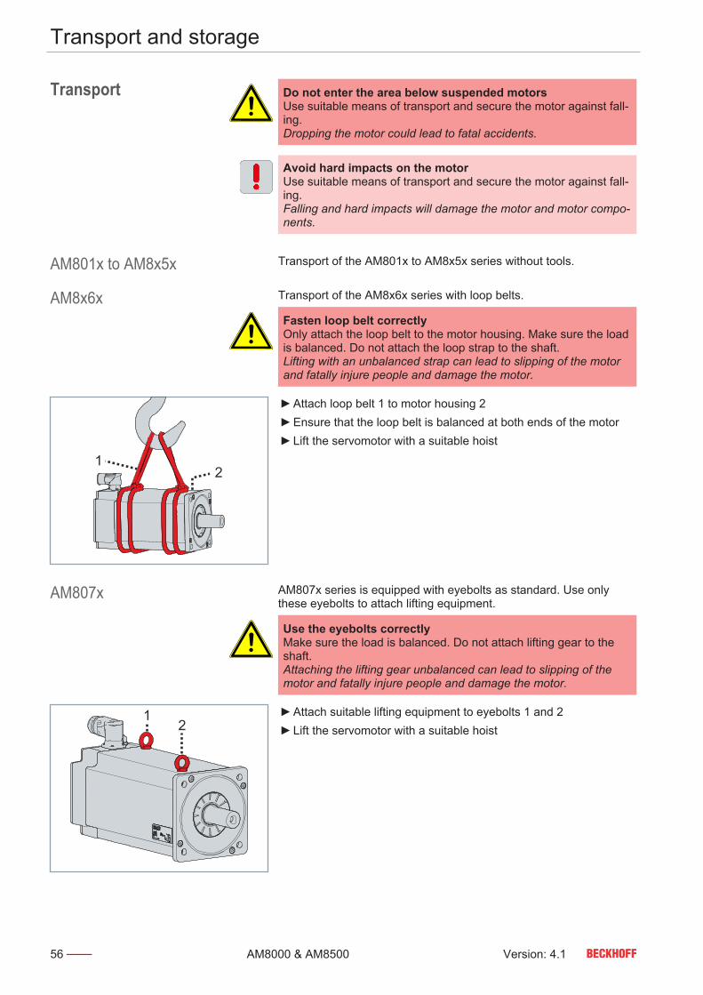
Transport and storage
56 Version: 4.1AM8000 & AM8500
Transport Do not enter the area below suspended motorsUse suitable means of transport and secure the motor against fall-ing.Dropping the motor could lead to fatal accidents.
Avoid hard impacts on the motorUse suitable means of transport and secure the motor against fall-ing.Falling and hard impacts will damage the motor and motor compo-nents.
AM801x to AM8x5x Transport of the AM801x to AM8x5x series without tools.
AM8x6x Transport of the AM8x6x series with loop belts.
Fasten loop belt correctlyOnly attach the loop belt to the motor housing. Make sure the loadis balanced. Do not attach the loop strap to the shaft.Lifting with an unbalanced strap can lead to slipping of the motorand fatally injure people and damage the motor.
12
Attach loop belt 1 to motor housing 2 Ensure that the loop belt is balanced at both ends of the motor Lift the servomotor with a suitable hoist
AM807x AM807x series is equipped with eyebolts as standard. Use onlythese eyebolts to attach lifting equipment.
Use the eyebolts correctlyMake sure the load is balanced. Do not attach lifting gear to theshaft.Attaching the lifting gear unbalanced can lead to slipping of themotor and fatally injure people and damage the motor.
12
Attach suitable lifting equipment to eyebolts 1 and 2 Lift the servomotor with a suitable hoist

Transport and storage
Version: 4.1 57AM8000 & AM8500
Long-term storage Observe the maximum storage timeDo not exceed the maximum storage time of two years.Exceeding the specified maximum storage time can lead tochanges in the properties of the lubricant used and damage themotor during subsequent operation.
Perform recurring inspectionsCheck the motor for proper condition every six months.Damage to the motor or maintenance work not carried out will af-fect the service life of the installed components and parts.
Prevent the formation of condensationKeep the ambient temperature constant. Avoid solar radiation andhigh humidity.Condensation water can lead to damage during subsequent oper-ation or to rust formation.
The motors can be stored for shorter or longer periods. For storagewe always recommend the original packaging. Observe the condi-tions specified in chapter: "Transport and storage", [Page 55].The motors are protected against chemical and aggressive sub-stances, class 1C2 chemical substances and 1B2 biological condi-tions.Ensure the storage space is vibration-free.

Technical description
58 Version: 4.1AM8000 & AM8500
Technical description
Mounting positionObserve the maintenance intervals and mounting positionsCarry out maintenance at regular intervals.In the horizontal IM V3 mounting position, liquid which has beenleft on the flange for a longer period can penetrate the motorthrough capillary action. In mounting position IM V1 liquid can es-cape. If you do not observe the maintenance intervals, the motor mayoverheat depending on the mounting position. Ingress and leak-age of liquids may damage the motor.
The standard mounting position of the motors is IM B5 according toDIN EN 60034-7.
IM V1 (V1) IM V3 (V3) IM B5 (B5)
7.2
Feedback The following table provides information about system accuraciesand resolutions of the motor feedback systems:
Feedback Resolution System accuracy CommentOCT, single-
turnOCT, multi-turn
18-bit ± 120 angular seconds ~ 0.03° Standard:AM801x – AM8x6x
Standard fan:AM805x – AM8x6x
Hiperface, sin-gle-turn
Hiperface,Multi-turn
18-bit ± 120 angular seconds ~ 0.03° Standard:AM807x
OCT, single-turn
OCT, multi-turn
23-bit ± 45 angular seconds ~ 0.0125° From firmwarev2.10
Resolver 14-bit ± 600 angular seconds ~ 0.17° Option
Feedback exchangeThe feedback system installed can only be replaced with an identi-cal system. It is not possible to change the feedback system retro-spectively.

Technical description
Version: 4.1 59AM8000 & AM8500
Protection equipment With the exception of the AM801x series, temperature sensorLPTC-600 is installed in the standard version of all motors.The LPTC-600 is integrated into the monitoring system of the servodrive when using the pre-assembled motor cable. Configure theservo drive taking note of the motor temperature warning of 120 °Cand the switch-off temperature of 140 °C.The LPTC-600 is identical to the KTY 84.130 used previously.
LPTC-600 sensor The following table shows the resistance values of the temperaturesensor:
Temperature [°C] T/°C [%/K] LPTC-600Resistance [Ω]
Temperature error[K]
minimum Nominal value maximum-40 0.84 340 359 379 ± 6.48-30 0.83 370 391 411 ± 6.36-20 0.82 403 424 446 ± 6.26-10 0.80 437 460 483 ± 6.160 0.79 474 498 522 ± 6.07
10 0.77 514 538 563 ± 5.9820 0.75 555 581 607 ± 5.8925 0.74 577 603 629 ± 5.8430 0.73 599 626 652 ± 5.7940 0.71 645 672 700 ± 5.6950 0.70 694 722 750 ± 5.5960 0.68 744 773 801 ± 5.4770 0.66 797 826 855 ± 5.3480 0.64 852 882 912 ± 5.2190 0.63 910 940 970 ± 5.06
100 0.61 970 1000 1030 ± 4.90110 0.60 1029 1062 1096 ± 5.31120 0.58 1089 1127 1164 ± 5.73130 0.57 1152 1194 1235 ± 6.17140 0.55 1216 1262 1309 ± 6.63150 0.54 1282 1334 1385 ± 7.10160 0.53 1350 1407 1463 ± 7.59170 0.52 1420 1482 1544 ± 8.10180 0.51 1492 1560 1628 ± 8.62
Shaft end A The A-side is used for force transmission via a backlash-free andfrictional connection. This is achieved by means of a coupling and acylindrical shaft end according to DIN 748-3 with a centering bore atthe front according to DIN 332-2. Alternatively, forces can be trans-mitted via a frictional connection and a feather key groove accordingto DIN 6885 / ISO 2491.
Radial forces Axial forces• Motors driven via pinion / toothed belt • Pinion or pulley mounted on the shaft• Permissible values depend on thespeed
• For example, when operating angulargear units
Calculation of the exact radial and axial forcesThe calculation toolBeckhoff AM8000 motors radial forces / axial forces, service lifeis available via www.beckhoff.de.
Preferred backlash-fress coupling elements:• Double-coned collets and metal bellows couplings
7.5

Technical description
60 Version: 4.1AM8000 & AM8500
Power derating Power reduction may be required at high ambient temperatures orfor operation at high altitudes. In addition, some motors may experi-ence power reductions depending on the feedback system installedor the holding brake [+]. The reduction affects the standstill currentand the standstill torque.
Ambient temperaturefT = Temperature utilization factor
tA = Ambient temperature in °C
Calculation of the performance data if thespecified temperature limit > 40 °C to55 °C is exceeded:
M0_red = M0 x fT
Installation altitudefH = Altitude utilization factor
h = Altitude in meters
Calculation of the performance data if thespecified installation altitude is exceeded> 1000 m to 3000 m:
M0_red = M0 x fH
Ambient temperature and installation altitudeCalculation of the power data when exceeding the specified limits:
Ambient temperature > 40 °C, altitude > 1000 m and < 3000 m:
M0_red = M0 x fT x fH

Mechanical installation
Version: 4.1 61AM8000 & AM8500
Mechanical installation
Carry out all work with great care and without time pressure.
Flange mounting The following table provides information on components for mount-ing the motor on the machine / system:
Motor Bore dia. [mm] Cheese-headscrew DIN ENISO 4762; 8.8
Tighteningtorque [Nm]
Washer DINEN ISO 7089
AM801x 4.3 M4 x 16 3 4.3AM802x 5.5 M5 x 16 5.5 5.3; DIN 7980AM8x3x 6.0 M5 x 16 5.5 5.3; DIN 7980AM8x4x 7.0 M6 x 20 10.0 6.4AM8x5x 9.0 M8 x 25 25.0 8.3AM8x6x 11.0 M10 x 30 50.0 10.5AM807x 13.5 M12 x 40 85.0 13.0; DIN 7980
Output elements Secure moving parts against ejectionMake sure there are no moving parts on or in the machine duringoperation. Feather keys [+] are only secured during transport.Unsecured parts can be ejected from the machine during opera-tion and cause serious or fatal injuries.
Protect the motor from inadmissible loadAvoid bending components during transport or handling and donot change any insulation distances. Avoid hard shocks to theshaft end, the ball bearings or the feedback system. Furthermore,note vibration qualities and vibration resistance. If necessary, pro-vide additional support for the motor.An impermissible load on the components can have a negative ef-fect on the performance of the motor! Impacts on the motor shaftimpair the concentricity of the motor.
Ensure adequate grounding via the protective conductorThe thermal connection of the motor flange determines the powerdissipation.Ensure adequate grounding via the protective conductor or themotor flange.
Bearing load during instal-lation
Avoid mechanically overdetermined support of the motor shaftthrough rigid coupling and additional external support.
1
2
FA
FR
x
When mounting output elements, ensure that the load on the shaftsand bearings due to transverse forces by radial force FR and axialforce FA is low. Axial loads shorten the service life and can lead tomalfunctions of the holding brake [+].
Special features when using toothed belt drives:When using a toothed belt drive, the radial and axial loads on theshaft must not be exceeded. Excessive load can lead to fatigue frac-ture of the motor shaft. Please pay attention to chapter: "Technicaldata", [Page 18].

Mechanical installation
62 Version: 4.1AM8000 & AM8500
Mounting Do not touch hot output elements without personal protectiveequipmentOnly handle hot output elements, such as couplings or pulleys,with special thermal gloves. Avoid prolonged contact with hot com-ponents.Hot components can cause severe burns to body parts and limbs.
Do not mount the drive element offsetPlace the drive element centered and straight on the motor shaft.An offset will cause unacceptable vibration and the destruction ofthe ball bearings and the coupling.
Warm up the output elements according to manufacturer's in-structions
Remove the protective cap Degrease and clean the motor shaft Remove the output element from the oven and transport it to the
workstation
1
2
1
2
Place output element 1 centered and straight on the motor shaft2
1
2
1
2
3 4
6 5
Insert washer 3 with screw 4 of strength class 8.8 and nut 5 intothe locking thread 6 of the motor shaft
Tighten nut 5The output element is pulled onto the motor shaft by the nut.

Mechanical installation
Version: 4.1 63AM8000 & AM8500
Dismantling Only use backlash-free, friction-locked collets, pullers or suitablecouplings for dismantling the output elements. Degrease the motor shaft
12
3
Screw puller 3 and intermediate disc 2 into the locking thread ofthe motor shaft
Place the puller fully on the drive element 1 Pull the output element 1 with the puller 3 from the motor shaft
Fan cover [+] A motor is cooled by an external device using forced ventilation.This facilitates higher performance. The air flow passes through thefan cover [+] over the motor housing.
Mounting Clean the working environmentWorkplaces and their immediate surroundings must be tidy anddust-free. Avoid dirt in tapped holes.Dirt in the tapped holes can damage screws and threads duringmounting. Dirty and foreign objects in the working environmentcan damage the motor and the fan cover [+]. Furthermore, theperformance characteristics and performance of the motor can beimpaired.
Attach the motor to the machine For AM807x series: release and remove the eyebolts on the mo-
tor housing
1
23
Slide fan cover [+] 1 up to the mechanical stop Make sure that on both sides of the motor the elongated holes 3
are aligned with the screw connection devices 2
4+5 6+7
8 11
9 10
Fit screws 4 to 7 Fit nuts 8 and 11 with washers 9 and 10 Observe the tightening torques:
Screws Nuts3 Nm; size 2.5 2.5 Nm; size 7
Use Beckhoff control cable!Use the pre-assembled control cable ZK4054-6400-0xxx to connectthe fan cover [+]

Mechanical installation
64 Version: 4.1AM8000 & AM8500
12
13
Plug the power connector 12 into the power box 13 of the motor Hand-tighten power connector 12 and check for tight fit
8.3.2
Performance data of theexternal fan
The following table shows electrical and mechanical data for the ex-ternal fan:
Technical data Symbol [Unit] AM8x5x AM8x6x AM8x7xSupply voltage ULA [VDC] 24Electrical power PLA [W] 4.6 9.8 31.2Current I [A] 0.19 0.41 1.3Protection class IP20
Assignment plan of the powerconnector
The following table shows the assignment of the power connector ofthe external fan:
Socket configuration Contact in the connector Assignment on the cable1 PE: green / yellow2 +24 VDC: brown3 not used4 GND: blue5 not used
Additional documentation for control cable ZK4054-6400-0xxxThe data sheet of the control cable can be found under:www.beckhoff.com → Download → Data sheets → Cables andwires

Electrical installation
Version: 4.1 65AM8000 & AM8500
Electrical installation
Connection technology Beckhoff supplies pre-assembled power cables and feedback ca-bles. Mating connectors are not included in the scope of supply. Toselect the necessary cables, refer to the Beckhoff documentation forconnecting cables [+]. In the documentation you will find a completeoverview of the available cables and information on the technicaldata.
For interference-free data transmission, please note:• Maximum number of mating cycles for the connectors: 500 cy-cles• Maximum number of rotations of the power box: 10If the maximum number of mating cycles or rotations is exceeded,clean data transmission can no longer be guaranteed. This resultsin signs of wear.
Power box The motors are equipped with angled, rotatable power boxes forpower supply and feedback signals. Only for resolver and Hiperface.The power box can be rotated by 330°.
330°
330°
330°
Cables Avoid soiling and damageWhen connecting the socket and connector, make sure that thepoles and the inside of the component are not soiled or damaged.Failure to do so may adversely affect the function of the connec-tions.
For proper application and assembly we recommend:• Wiring in accordance with applicable regulations and standards• Pre-assembled and shielded Beckhoff cables
Beckhoff offers pre-assembled cables for faster and flawless instal-lation of the motors. These cables are tested with regard to the ma-terial used, shielding and connection type. Perfect functioning andcompliance with legal regulations, such as EMC and UL, are guar-anteed. The use of other cables can cause unexpected malfunctionsand result in exclusion of warranty.
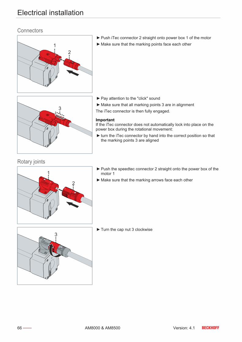
Electrical installation
66 Version: 4.1AM8000 & AM8500
9.1.3
Connectors
12
Push iTec connector 2 straight onto power box 1 of the motor Make sure that the marking points face each other
3
Pay attention to the "click" sound Make sure that all marking points 3 are in alignmentThe iTec connector is then fully engaged.
ImportantIf the iTec connector does not automatically lock into place on thepower box during the rotational movement: turn the iTec connector by hand into the correct position so that
the marking points 3 are aligned9.1.4
Rotary joints
1
2
Push the speedtec connector 2 straight onto the power box of themotor 1
Make sure that the marking arrows face each other
3 Turn the cap nut 3 clockwise

Electrical installation
Version: 4.1 67AM8000 & AM8500
4 Make sure that all markings and the lettering "open" 4 are alignedThe speedtec connector is then fixed properly.
Terminal box Avoid soiling and damageWhen dismantling the cover and connecting the terminal box andcables, make sure that no foreign objects or dirt particles enter theterminal box, the clamping ring or the M40 thread on the terminalbox.Failure to do so may adversely affect the function of the connec-tions.
Assembly of the power cable and feedback cableWhen assembling the cables, note that the size of the three blindplug thread in the terminal box is M40.
1+23+4
5 6
1+23+4
5 6
1+23+4
5 6
1+23+4
5 6
Make sure that the rubber seal 6 in the cover 5 is not lost or dam-aged
Loosen and remove screws 1 to 4 Remove cover 5
7 8
9
7 8
97 8
9
Loosen clamping ring 8 Insert motor cable 7 through clamping ring 8 into terminal box 9
Motor cable Order details10 mm² for motors with terminal box ZK4506-8027-xxxx16 mm² for motors with terminal box ZK4506-8018-xxxx

Electrical installation
68 Version: 4.1AM8000 & AM8500
8
8
8
Fasten clamping ring 8 to the terminal box Connect the cable ends to the terminal according to the assign-
ment diagram
ImportantThe assignment diagram of the terminal box can be found below:"Technical data AM807x", [Page 50]. Make sure that the seal is correctly placed on the terminal box Re-install the cover 5
Connector assignment Beckhoff offers various power connectors and feedback connectors.All connectors are IP65 rated. A protective conductor connection ac-cording to VDE 0627 is provided on the housing.
OneCableTechnology The following tables show the connector assignment on the motorside:
Pin assignment iTec connectoriTec connector Contact Function Core identification
A U black / 1B W black / 3C V black / 21 Brake + 52 Brake - 63 Temperature + / OCT
+white
4 Temperature - / OCT - blue5 --- ---
PE PE green / yellow
Pin assignment M23 connectorM23 connector Contact Function Core identification
A U black / 1B V black / 2C W black / 3D PE green / yellowE Temperature - / OCT - blueF Shield ShieldG Brake + black / 5H Temperature + / OCT
+white
L Brake - black / 6
Pin assignment M40 connectorM40 connector Contact Function Core identification
U U black / 1V V black / 2W W black / 3PE PE green / yellowN --- ---+ Brake + black / 5- Brake - black / 61 --- ---2 --- ---H Temperature + / OCT
+white
L Temperature - / OCT - blue

Commissioning
Version: 4.1 69AM8000 & AM8500
Commissioning
Observe the operating instructions for the servo drivesFor commissioning, read the operating instructions for the servodrives and carry out the steps according to the commissioning in-structions. With multi-axis systems, each drive unit is commis-sioned individually.
Exemplary commissioningThe procedure for commissioning is described as an example. Adifferent method may be appropriate or necessary, depending onthe application of the components.
Before commissioning • Check drive for damage• Check installation and alignment• Tighten screw connections correctly• Installing mechanical, thermal and electrical protective devices• Check the wiring, connection and proper grounding of
the drive and servo drive
For motors with holding brake [+]• Check the function of the holding brake [+]• In case of malfunction: Apply 24 VDC, the brake must release• Check emergency stop functions
For motors with fan cover [+]• Check connection and function• Fan must rotate freely, pay attention to grinding noises• Check the direction of rotation of the fan
During commissioning • Make sure that all fittings were checked for function and adjust-ment
• Observe information for environment and operation• Check protective measures against moving and live parts
ConfigurationBeckhoff recommends the use of servo drives and motors fromBeckhoff in combinations, and configuration in the Beckhoff TwinCAT DriveManager.Carry out the instructions in the operating manual for servo drives:• Build Project and Choose Target System• Implement devices by scanning or manually• Configure devices, determine and set motor type• Create axis configuration• Set scaling factor and speeds• Check status and activate control system

Commissioning
70 Version: 4.1AM8000 & AM8500
Prerequisites during op-eration
• Pay attention to atypical noise development• Pay attention to smoke development• Always check drive surfaces and cables for
dirt, leaks, moisture or dust
• Check temperature development• Check for lubricant leakage• Observe recommended maintenance intervals• Check function of safety devices
For motors with fan cover [+]:• Check air intakes for contamination• Check that the motor and fan cover [+] are firmly seated• Observe tightening torques
After operation Ensure safe condition of the machine / systemMake sure that the rotor comes to a complete stop.When the holding brake [+] is released, the rotor moves withoutremanent torque. Rotating components can lead to serious in-juries.

Maintenance and cleaning
Version: 4.1 71AM8000 & AM8500
Maintenance and cleaning
Ensure safe condition for cleaning workBasically, electronic devices are not fail-safe. The condition is al-ways safe when the unit is switched off and not energized. Forcleaning work, bring the connected motors and the machine into asafe condition.Carrying cleaning work during operation can lead to serious or fa-tal injuries.
Do not submerge or spray the motorOnly wipe the motor with a cleaner and a cloth.Cleaning by immersion may result in surface and motor damageand leakage problems as a result of impermissible solutions.
Contamination, dust or chips can have a negative effect on the func-tion of the components. In the worst case, contamination can lead tofailure. The components should therefore be cleaned and servicedat regular intervals.
Cleaning materials Carefully clean the components with a damp cloth or brush.For cleaning, we provide an overview of cleaning agents to whichthe motors may be exposed up to a maximum concentration of 3%.You will also receive information about non-approved cleaningagents.11.1.1
Non-approved cleaningagents
Non-approved cleaning agents Chemical formulaAniline hydrochloride C6H5NH2HCIBromine Br2
Sodium hypochlorite; bleaching solution NaCIOMercury II chloride HgCl2Hydrochloric acid HCI
11.1.2
Approved cleaning agents Approved cleaning agents Chemical formulaAcetyl chloride CH3COCIAluminum chloride AICI3-6H2OAmmonium chloride NH4CIAntimony trichloride SbCl3Barium chloride BaCl2-2H2OChlorine; also chlorine water, chlorinatedlime and chlorobenzene
Cl2
Chlorosulfuric acid HSO3ClHydrogen chloride gas HCIChromic acid CrO3
Iron III chloride FeCl3Hydrogen fluoride HFCarnallite KCIMgCl2-6H2OAqua regia HCL + HNO3
Magnesium chloride MgCl2-6H2OMonochloroacetic acid CH2CICOOHSodium chloride; common salt NaClSodium hydroxide NaOHSodium peroxide Na2O2
Sulfuric acid H2SO4
Tartaric acid COOH; CHOH2 COOHTin II IV chloride SnCl2-2H2O SnCl4

Maintenance and cleaning
72 Version: 4.1AM8000 & AM8500
Intervals Under nominal conditions, the motor components have different op-erating hours. The following table provides a list of maintenancework and intervals for various components:
Component Interval MaintenanceBall bearing 30,000 operating hours Replace bearingMotor 2,500 operating hours /
annuallyCheck motor for bearing noises
If noises are detected:do not continue to operate motor; replace bearing
Shaft seal 5000 operating hours Perform visual inspection
Lubricate the shaft seal
Recommended lubricants:“MobilgreaseTM FM22" from Mobil
In case of damage and pressure drop:Replace shaft seal
Cables regular intervals Perform visual inspection and check for damage
As required:Replace cables
5 million bending cycles Replace cablesFan cover [+] half-yearly Perform visual inspection and check for damage
In the event of unbalance:Clean fanContact Beckhoff Service
In case of damage:Contact Beckhoff Service
Power box 500 mating cycles In case of damage:Contact Beckhoff Service
Connector 10 turning cycles In case of damage:Contact Beckhoff Service

Accessories
Version: 4.1 73AM8000 & AM8500
Accessories
12.1
Connecting cablesOrange power cables and green feedback cables are used for theconnection between motor and servo drive. Information on connecting a motor with a servo drive or the multi-axis servo system can be found in chapter: "Electrical installation",[Page 65].12.2
iTec extensionMotor cables can be extended using an iTec extension cable.12.3
speedtec extensionMotor cables can be extended using an speedtec extension cable.12.4
Shaft sealThe radial shaft-sealing ring FKM is used for sealing against splashwater and protects the motor shaft against dust or dirt. This in-creases the protection class of the shaft feed through to IP65.The radial shaft-sealing ring can be replaced at any time. Pleasenote, however, that the exchange may lead to a reduction in thenominal values.

Accessories
74 Version: 4.1AM8000 & AM8500
Gear unit Axial load due to thermal expansion of the motor shaftTo avoid displacement of the motor shaft at high temperatures,use couplings as length compensation.Directly mounted bevel gears or helical gear wheels can exceedthe axial load of the floating bearing on the shaft end A.
A gear unit serves to transmit a force moment or torque and is usedon the motor as an output element. Information on flange sizes formotor and gear unit combinations can be found in section: Type key.

Fault correction
Version: 4.1 75AM8000 & AM8500
Fault correction
The following table describes selected malfunctions. Depending onthe application, other causes may be responsible for the malfunc-tion.Conspicuous control behavior is the result of incorrect parameteriza-tion of the servo drive.With multi-axis systems such as the AX8000, malfunctions mayhave different causes.
Error CauseMotor standstill (nostarting)
1 2 5
Motor runs slug-gishly
1 3 5 6
Start-up noises 3 5 6 11
Noises during oper-ation
1 3 5 6 11
High temperature atidling speed
4 7 8 9
High temperatureunder load
1 3 7 8 9
Untrue running be-havior
10 11
Grinding noises 12
Brake fault 13 14
Output stage fault 5 15 16
Feedback error 17 18
Lack of braking ef-fect
5 6
Leakages 19
Cause Error Solution1 Servo drive not enabled Set ENABLE signal and enable servo drive
Motor overload Check load and reduce if necessary, then restart and en-able the servo drive and set the ENABLE signal
Mechanical blockage of the motor Check mechanics and release blockageHolding brake [+] not released Check the control configuration of the holding brakes [+]
and reconfigure if necessary
2 Phase interruption in the power supply or reversed motorphases
Check servo drive and supply lines, power and feedbackand replace defective cables
3 Phase interruption after switching on the power supply Check servo drive and supply lines, power and feedbackand replace defective cables
Power cable or feedback cable with defective shield Check ground connection and shielding
4 Short-circuit in the voltage supply cable for the holding brake [+] Replace defective cable, measure and check cable afterreplacement
Output voltage of the servo drive too low Check the settings in the configuration and read out theelectronic type plate of the motor again
Defective holding brake [+] Replace motor, then measure and check
5 Short circuit or earth leakage in the motor cable Replace defective motor cable, then measure and check
6 Power connector not fitted correctly Check the connectors on the power connector and on themotor
Interruption in the feedback or motor cable Check cables for broken wire or crushing. Replace defec-tive cables, then measure and check.
7 Required holding torque too high Check design configuration and adjust if necessary

Fault correction
76 Version: 4.1AM8000 & AM8500
Cause Error SolutionDefective holding brake [+] Replace holding brake [+], then measure and check
8 Inlet temperature too high Lower and adjust the inlet temperatureNo more cooling water available Replenish cooling water and check regularly
9 Motor heat dissipation system not functioning Clean the surface of the motors and the servo drive as wellas the heat sinks and exhaust air slots. Check the installa-tion depths of the servo drives and motors.
10 Power cable or feedback cable with defective or insufficientshielding
Check ground connection and shielding
11 Servo drive gain set too high. Reconfigure the parameters of the servo drive and adjustthem if necessary
12 Contamination or foreign bodies inside the motor Send in motor. The repair is carried out by the manufac-turer.
Rotating parts chafing on the housing or motor components Inspect chafing parts and readjust if necessaryDefective bearings by irreparable bearing damage Send in motor. The repair is carried out by the manufac-
turer.
13 Short-circuit in the supply voltage cable to the motor holdingbrake [+]
Replace defective cable, then measure and check
14 Inadequate power supply of the holding brake [+] Check the settings in the configuration and read out theelectronic type plate of the motor again
15 Short circuit or earth leakage in the motor Replace defective motor, then measure and check
16 Insufficient power supply Check the settings in the configuration and read out theelectronic type plate of the motor again
17 Interruption or crushing in the feedback cable Check cables for broken wire or crushing. Replace defec-tive cables, then measure and check.
18 Feedback connector not fitted correctly Check the position of the feedback connectorLoose fit of the feedback connector or no contact of the plugcontacts with the power socket of the motor.
Check the connector assembly. Contact Beckhoff Serviceif necessary.
19 Cooling water pipes and / or water connections leaky / defective Determine leakage and seal if necessary

Decommissioning
Version: 4.1 77AM8000 & AM8500
Decommissioning
Disassembly may only be carried out by qualified and trained per-sonnel. For more information please refer to Chapter: "Documenta-tion notes", [Page 4]. When disposing of electronic waste, make sure that you dispose ofit in accordance with the regulations applicable in your country.Read and follow the instructions for proper disposal.
Disassembly Risk of injury from leaking oilPrevent oil from leaking. Let it cool down before starting work.Soak up any leaked oil with approved binding agents. Mark thedanger spot.Leaking oil can cause slips and falls, resulting in serious or fatalinjury. Hot oil can cause severe burns.
Unauthorized removal of servomotor componentsThe motors have permanent magnets in the rotor. These motorsmay only be dismantled by Beckhoff Automation GmbH & Co. KG.Contact Beckhoff Service for further information.
Removing the motor from the machine• Remove cables and electrical connections• Cool and drain liquids, then remove• Remove supply lines and water hoses• Loosen and remove the fixing screws of the motor• Transport the motor to the work area or store it
Disposal If you dispose of your motor, observe the following instructions forproper disposal of the components:
Cast iron and metalCast and metal parts can be handed over to scrap metal recycling.
Plastics and hard plasticsPlastic and hard plastic parts can be recycled via the waste man-agement center or reused in accordance with the component regula-tions and labels.
Oils and lubricantsAll oils and lubricants used in the motor and the machine / systemmust be collected in separate containers and disposed of at a wasteoil collection point.
Disposal by the manufac-turer
In accordance with the WEEE 2012/19/EU Directives we take olddevices and accessories back for professional disposal, providedthe transport costs are taken over by the sender.Send the devices with the note “For disposal” to:Beckhoff Automation GmbH & Co. KGHuelshorstweg 20D-33415 VerlAlternatively, you can contact a certified specialist disposal companyfor waste electrical and electronic equipment in your area. Disposeof the old components in accordance with the regulations applicablein your country.
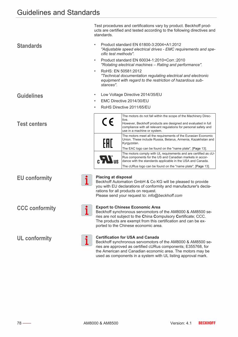
Guidelines and Standards
78 Version: 4.1AM8000 & AM8500
Guidelines and Standards
Test procedures and certifications vary by product. Beckhoff prod-ucts are certified and tested according to the following directives andstandards.
Standards • Product standard EN 61800-3:2004+A1:2012"Adjustable speed electrical drives - EMC requirements and spe-cific test methods".
• Product standard EN 60034-1:2010+Corr.:2010"Rotating electrical machines – Rating and performance".
• RoHS: EN 50581:2012"Technical documentation regulating electrical and electronicequipment with regard to the restriction of hazardous sub-stances".
Guidelines • Low Voltage Directive 2014/35/EU• EMC Directive 2014/30/EU• RoHS Directive 2011/65/EU15.3
Test centersThe motors do not fall within the scope of the Machinery Direc-tive. However, Beckhoff products are designed and evaluated in fullcompliance with all relevant regulations for personal safety anduse in a machine or system.The motors meet all the requirements of the Eurasian EconomicUnion. These include Russia, Belarus, Armenia, Kazakhstan andKyrgyzstan.
The EAC logo can be found on the "name plate", [Page 13].The motors comply with UL requirements and are certified as cU-Rus components for the US and Canadian markets in accor-dance with the standards applicable in the USA and Canada.
The cURus logo can be found on the "name plate", [Page 13].
EU conformity Placing at disposalBeckhoff Automation GmbH & Co KG will be pleased to provideyou with EU declarations of conformity and manufacturer's decla-rations for all products on request. Please send your request to: [email protected]
CCC conformity Export to Chinese Economic AreaBeckhoff synchronous servomotors of the AM8000 & AM8500 se-ries are not subject to the China Compulsory Certificate; CCC.The products are exempt from this certification and can be ex-ported to the Chinese economic area.
UL conformity Certification for USA and CanadaBeckhoff synchronous servomotors of the AM8000 & AM8500 se-ries are approved as certified cURus components; E355768, forthe American and Canadian economic area. The motors may beused as components in a system with UL listing approval mark.

Index
Version: 4.1 79AM8000 & AM8500
Index
AAccessories
Connecting cables 73Gear unit 74iTec extension 73Shaft seal 73speedtec extension 73
CCharacteristics 15Cleaning 71
Cleaning materials 71Connect
Electric 65Mechanic 61
DDeclaration of conformity 78Dimensional drawing 18
EEnvironmental conditions 19
FFan cover 63
Mounting 63Performance data 64
Fault correction 75Feedback 58
HHolding brake 15
IInstruction 8iTec connector
Connect 66
LLabel, see Safety pictograms 10
MMaintenance 71
Intervals 72Motor
Bring into operation 69Dismantling 77Disposal 77Electrical installation 65Mechanical installation 61Store 55Transport 55
Mounting position 58
NName plate 13
OOperating conditions 19Ordering options 16
Fan cover 17Feather key 16Holding brake 16Sealing air connection 16
Output elementsDismantling 63Mounting 61
PPictograms 8Power box 65
Rotation 65Power reduction (Derating) 60Protection equipment 59
Temperature sensor 59
SSafety 10
DC link capacitors 12General safety instructions 11Grounding 11Hot surfaces 12Intended use 17Overheating 12Powerless and de-energized state 12Rotating components 12Safety pictograms 11Secure the control cabinet 11Tightening torques 11
Safety pictograms 10Scope of supply 54Shaft end A 59speedtec Connector
Connect 66Storage 55Support 9Symbols 8
TTarget group 7Technical data 18Terminal box
Connect 67Tightening torque
Flange 61Tightening torques
Fan cover 63Transport 55

Beckhoff Automation GmbH & Co. KGHülshorstweg 20D-33415 [email protected]
More Information: www.beckhoff.com/am8000