Synchronous motors - EU Automation
140
Siemens NC 61 · 2007/2008 6/2 Introduction 6/4 1FT6 motors 6/6 Core type, natural cooling 6/8 Standard type, natural cooling 6/18 Standard type, forced ventilation 6/22 Standard type, water cooling 6/26 1FT7 Compact motors 6/28 Core type, natural cooling 6/30 Standard type, natural cooling 6/40 1FK7 Compact/ 1FK7 High Dynamic motors 6/42 Compact, natural cooling 6/46 High Dynamic, natural cooling 6/48 Compact/High Dynamic, natural cooling for Power Modules 6/50 Gearboxes 6/50 Series SP+ planetary gearbox for 1FT6 motors 6/55 Series SP+ planetary gearbox for 1FK7 motors 6/61 Series LP+ planetary gearbox for 1FK7 motors 6/63 Geared motors 6/63 1FK7-DYA compact geared motors 6/66 1FN3 linear motors Standard type, water cooling 6/76 Hall-effect sensor box 6/76 Connector box 6/77 Measuring systems 6/77 Liquid cooling 6/78 1FW6 built-in torque motors Standard type, water cooling 6/86 1FE1 built-in motors Standard type, water cooling 6/97 VPM Voltage Protection Module 6/98 2SP1 ECS motor spindles Standard type, water cooling 6/104 Selection guides Type/mounting position Degree of protection 6/105 Dimension drawings 6/105 1FT6 motors 6/117 1FT7 Compact motors 6/119 1FK7 Compact/ 1FK7 High Dynamic motors 6/122 1FT6 motors with SP+ planetary gearbox 6/127 1FK7 motors with SP+ planetary gearbox 6/132 1FK7 motors with LP+ planetary gearbox 6/135 1FK7-DYA compact geared motors 6/136 1FN3 linear motors 6/138 1FW6 built-in torque motors 6/96 1FE1 built-in motors 6/139 2SP1 ECS motor spindles 6/140 CAD CREATOR Dimension drawing and 2D/3D CAD generator Dimension drawings and 2D/3D CAD data are also provided by the CAD CREATOR. http://www.siemens.com/cad-creator For products approved for Canada and the U.S.A., see Appendix. Synchronous motors © Siemens AG 2007
-
Upload
khangminh22 -
Category
Documents
-
view
0 -
download
0
Transcript of Synchronous motors - EU Automation

Siemens NC 61 · 2007/2008
6/2 Introduction
6/4 1FT6 motors 6/6 Core type, natural cooling6/8 Standard type, natural cooling6/18 Standard type, forced ventilation6/22 Standard type, water cooling
6/26 1FT7 Compact motors6/28 Core type, natural cooling6/30 Standard type, natural cooling
6/40 1FK7 Compact/1FK7 High Dynamic motors
6/42 Compact, natural cooling6/46 High Dynamic, natural cooling6/48 Compact/High Dynamic,
natural coolingfor Power Modules
6/50 Gearboxes6/50 Series SP+ planetary gearbox
for 1FT6 motors6/55 Series SP+ planetary gearbox
for 1FK7 motors6/61 Series LP+ planetary gearbox
for 1FK7 motors
6/63 Geared motors6/63 1FK7-DYA compact geared
motors
6/66 1FN3 linear motorsStandard type, water cooling
6/76 Hall-effect sensor box6/76 Connector box6/77 Measuring systems6/77 Liquid cooling
6/78 1FW6 built-in torque motorsStandard type, water cooling
6/86 1FE1 built-in motorsStandard type, water cooling
6/97 VPM Voltage Protection Module
6/98 2SP1 ECS motor spindlesStandard type, water cooling
6/104 Selection guidesType/mounting positionDegree of protection
6/105 Dimension drawings6/105 1FT6 motors6/117 1FT7 Compact motors6/119 1FK7 Compact/
1FK7 High Dynamic motors6/122 1FT6 motors with SP+
planetary gearbox6/127 1FK7 motors with SP+
planetary gearbox6/132 1FK7 motors with LP+
planetary gearbox6/135 1FK7-DYA compact geared
motors6/136 1FN3 linear motors6/138 1FW6 built-in torque motors6/96 1FE1 built-in motors6/139 2SP1 ECS motor spindles
6/140 CAD CREATORDimension drawing and 2D/3D CAD generator
Dimension drawings and 2D/3D CAD data are also provided by the CAD CREATOR.http://www.siemens.com/cad-creator
For products approved for Canada and the U.S.A., see Appendix.
Synchronous motors
© Siemens AG 2007

Synchronous motorsfor SINAMICS S120
Introduction
6/2 Siemens NC 61 · 2007/2008
6
■ Overview
■ Application
There are many fields of application for the 1FT6/1FT7/1FK7/1FN3/1FW6 synchronous motors.
On machine tools, they are designated and used as feed motors.
On production machines such as printing, packaging and textile machines they are designated as synchronous servo motors.
The motors are referred to generally in this documentation as synchronous motors, due to their principle of operation.
The 1FE1 built-in motors are used as motor spindles in machine tools for turning, milling, or grinding. The 2SP1 ECS motor spindles are a motorized spindle series used in machine tools for milling.
1FT6 1FT7 Compact 1FK7 Compact1FK7 High Dynamic
Cooling Natural coolingForced ventilationWater cooling
Natural cooling Natural cooling
Rated speed 1500 ... 6000 rpm 1500 ... 6000 rpm 2000 ... 6000 rpm
Static torque M0 0.4 ... 300 Nm (3.54 ... 2655 lbƒ-in) 2 ... 70 Nm (17.7 ...620 lbƒ-in) 0.85 ... 48 Nm (7.52 .... 425 lbƒ-in) (1FK7 Compact)1.3 ... 28 Nm (11.5 ... 248 lbƒin) (1FK7 High Dynamic)
Overload capability up to max. 4 × M0 4 × M0 3 × M0
Encoder system, built-in, for motors with/without DRIVE-CLiQ interface
• Incremental encoder• Absolute encoder• ResolverSee the technical specifications and the selection and ordering data for the required motor for information about a compatible encoder system.
Sound pressure level in accordance with EN ISO 1680
55 ... 74 dB (A) 65 ... 74 dB (A) 55 ... 74 dB (A)
Degree of protection EN 60034-5(IEC 60034-5)
IP64 ... IP68 IP64 ... IP67 IP64IP65, additional IP67 drive end flange
Insulation of the stator windingEN 60034-1 (IEC 60034-1)
Temperature class 155 (F) for a winding temperature rise of ΔT = 100 K at an ambient temperature of 40 °C (104 °F)
With water cooling, inlet temperature max. 30 °C (86 °F)
– –
Type of motor Permanent-magnet-excited synchronous motor, 3-phase
Paint finish Anthracite RAL 7016 Pearl dark grey RAL 9023 Unpainted, anthracite RAL 7016 (option)
Holding brake Built-in (option)
Mounted gearing • Planetary gearbox series SP+i = 4 to 10 (single-stage)i = 16 to 50 (2-stage)
– • Planetary gearbox series LP+i = 5, i = 10 (single-stage)
• Planetary gearbox series SP+i = 4 to 10 (single-stage)i = 16 to 50 (2-stage)
Core types can be supplied for certain motor types. These core types can be express delivered as replacement motors in the event of plant outages and offer the advantage of a quicker spare parts supply. For this reason, core types should be used for configuration wherever possible.
© Siemens AG 2007

Synchronous motorsfor SINAMICS S120
Introduction
6/3Siemens NC 61 · 2007/2008
6
■ Overview (continued)
1) Observe maximum speed of measuring system.2) Sound pressure level of stock removal and tool changing are not taken into account.
Linear motors
1FN3Peak load
1FN3Continuous load
Cooling Water cooling Water cooling
Velocity at Frated 105 ... 836 m/min (344 ... 2743 ft/min)1) 129 ... 435 m/min (423 ... 1427 ft/min)1)
Feedrate force Frated 200 ... 8100 N (45.0 ... 1821 lbƒ) 150 ... 10375 N (33.7 ... 2332 lbƒ)
Overload capability up to max. 2.75 x Frated 1.7 x Frated
Encoder system(not included in scope of supply)
Linear scale (enclosed or open)• Incremental encoder sin/cos 1 Vpp• Absolute encoder with EnDat interface
Degree of protection EN 60034-5(IEC 60034-5)
IP65
Insulation of the stator windingEN 60034-1 (IEC 60034-1)
Temperature class H for a winding temperature of 120 °C (248 °F)
Inlet temperature of coolant max. 35 °C (95 °F)
Type of motor Permanent-magnet-excited synchronous linear motor, 3-phase
Paint finish Unpainted
1FW6built-in torque motors
1FE1built-in motors
2SP1ECS motor spindles
Cooling Water cooling
Speed at Mrated 40 ... 430 rpm Up to 40000 rpm Up to 18000 rpm
Static torque M0 85 ... 3380 Nm (62.7 ... 2493 lbƒ-ft) – –
Rated torque Mrated 109 ... 4590 Nm (80.4 ... 3386 lbƒ-ft) 5 ... 820 Nm (3.69 ... 605 lbƒ-ft) 42 ... 170 Nm (31.0 ... 125 lbƒ-ft)
Overload capability up to max. 2 x M0 – –
Encoder system Rotary encoder• Incremental encoder sin/cos 1 Vpp• Absolute encoder with EnDat
interface
Hollow-shaft measuring system• SIMAG H2• L&B GEL 244
Hollow-shaft measuring systemIncremental encoder sin/cos 1 Vpp 256 S/R (built-in)
Sound pressure level in accordance with EN ISO 1680
– Depending on spindle design 70 dB (A)2)
Degree of protection EN 60034-5(IEC 60034-5)
IP23 IP00 or as specified by spindle manufacturer
IP64 (in working area)IP53 (behind the spindle flange)
Insulation of the stator windingEN 60034-1 (IEC 60034-1)
Temperature class 155 (F) for a winding temperature rise of ΔT = 100 K for an ambient temperatureof 40 °C (104 °F)
Temperature class 155 (F)
Inlet temperature of coolant max. 35 °C (95 °F)
with an inlet temperature of coolant of 25 °C (77 °F)
Type of motor Permanent-magnet-excited synchronous torque motor, 3-phase
AC main spindle motor in synchronous system with permanent magnets
AC main spindle motor in asynchronous/synchronous system
Paint finish Unpainted
Holding brake – Using spindle design –
© Siemens AG 2007

Synchronous motorsFeed motors for SINAMICS S120
1FT6 motors
6/4 Siemens NC 61 · 2007/2008
6
■ Overview
1FT6 motors are permanent-magnet excited synchronous motors with compact dimensions.
1FT6 motors with built-in encoders are suitable for use with the SINAMICS S120 drive system.
The fully digital control system of the SINAMICS S120 drive system and the encoder technology of the 1FT6 motors fulfill the highest demands in terms of dynamic performance, speed setting range, and shaft and flange accuracy.
1FT6 motors are available with natural cooling, forced ventilation, or water cooling. With the natural cooling method, heat is dissi-pated through the surface of the motor, whereas with the forced ventilation method, heat is forced out by means of built-on fans. Maximum power ratings, as well as a high degree of protection, can be achieved using water cooling.
■ Benefits
7 Optimum surface quality of the workpiece thanks to high rotational accuracy (sinusoidal current injection)
7 Short non-productive times thanks to high dynamic performance
7 Power and signal connections for use in severely contaminated areas
7 Easy installation thanks to reduced cabling overhead7 Can absorb high cantilever forces7 High thermal reserves for continuous and overload conditions7 High momentary overload capability (250 ms)7 Extremely high efficiency7 Extremely good dynamic response of the drive due to the
lower rotor moments of inertia7 Low torque ripple (average value 1%)7 High degree of protection
■ Application
• High-performance machine tools• Machines with stringent requirements in terms of dynamic
response, precision and flexibility, e.g. packaging machines, high-bay racking vehicles, conveyor systems, handling equipment, and printing machines
© Siemens AG 2007© Siemens AG 2007

Synchronous motorsFeed motors for SINAMICS S120
1FT6 motors
6/5Siemens NC 61 · 2007/2008
6
■ Technical specifications
S/R = signals/revolution
1) Shaft extension run-out, concentricity of spigot and shaft and perpen-dicularity of mounting face of flange to shaft.
Product name 1FT6 motor
Type of motor Permanent-magnet-excited synchronous motor
Magnet material Rare-earth magnet material
Cooling Natural cooling, forced ventilation, water coolingFor water cooling max. inlet temperature 30 °C (86 °F)Avoid condensation
Temperature monitoring KTY 84 temperature sensor in the stator winding
Insulation of the stator winding in accordance with
EN 60034-1 (IEC 60034-1)
Temperature class 155 (F) for a winding temperature of ∆T = 100 K at an ambient temperature of 40 °C (104 °F)
Type in accordance withEN 60034-7 (IEC 60034-7)
IM B5 (IM V1, IM V3)IM B14 (IM V18, IM V19)IM B35 with 1FT613
Degree of protection in accordance with EN 60034-5 (IEC 60034-5)
IP64 standard type, IP65 core type
Shaft extension on the drive end in accordance with DIN 748-3 (IEC 60072-1)
Plain shaft
Shaft and flange accuracy1) in accordance with DIN 42955 (IEC 60072-1)
Tolerance N
Vibration magnitude in accordance with EN 60034-14 (IEC 60034-14)
Grade Ais observed up to rated speed
Sound pressure level in accordance with EN ISO 1680, max.
• Motors with natural/water cooling- 1FT602 ... 1FT604- 1FT606 ... 1FT613
55 dB (A)70 dB (A)
• Motors with forced ventilation- 1FT608/1FT610- 1FT613
70 dB (A)74 dB (A)
Product name 1FT6 motor
Encoder systems, built-in,for motors withoutDRIVE-CLiQ interface
• Incremental encoder sin/cos 1 Vpp 2048 S/R
• Absolute encodermulti-turn (traversing range 4096 revolutions) with EnDat interface1FT603 ... 1FT613: 2048 S/R1FT602: 512 S/R
• Multi-pole resolver(number of poles corresponds to number of pole pairs of the motor)
• 2-pole resolver
Encoder systems, built-in,for motors with DRIVE-CLiQ interface
• 22 bit incremental encoder (2048 S/R internal)
• Absolute encodersingle-turn + 12 bit multi-turn (traversing range 4096 revolutions)1FT603 ... 1FT613: 22 bit single-turn (2048 S/R internal)1FT602: 20 bit single-turn (512 S/R internal)
• 15 bit resolver• 14 bit resolver
Connection Connectors for signals and powerTerminal box possible on 1FT61
Paint finish Anthracite RAL 7016
2nd rating plate Enclosed separately
Options • Shaft extension on the drive end with fitted key and keyway (half-key balancing)
• Vibration magnitude Grade R• Built-in holding brake• Degree of protection IP67, IP68
M5 sealing air connection present (except with forced ventilation)
• Terminal box for power terminal• Planetary gearbox, built-on
(requirement: Plain shaft exten-sion, shaft and flange accuracy tolerance N, vibration magni-tude grade A, and IP65 degree of protection)
© Siemens AG 2007© Siemens AG 2007

Synchronous motorsFeed motors for SINAMICS S1201FT6 core type motorsNatural cooling
6/6 Siemens NC 61 · 2007/2008
6
■ Selection and Ordering Data
Ratedspeed
Shaft height
Rated power
Static torque
Ratedtorque1)
Rated current
1FT6 synchronous motorsNatural cooling
Num-ber ofpole pairs
Rotor moment of inertia (without brake)
Weight (without brake)
nrated SH Prated at ∆T=100 K
M0 at ∆T=100 K
Mrated at ∆T=100 K
Irated at ∆T=100 K
Order No.Core type
J m
rpm kW (HP)
Nm (lbƒ-in)
Nm (lbƒ-in)
A 10-4 kgm2 (10-3 x lbƒ-in-s2)
kg (lb)
2000 100 4.8 (6.44)8.0 (10.7)
27 (239)50 (443)
23 (204)38 (336)
1117.6
1FT6102 - 1AC71 - 7 7 7 11FT6105 - 1AC71 - 7 7 7 1
44
99 (87.6)168 (149)
27.5 (60.6)39.5 (87.1)
3000 48 1.4 (1.88) 5 (44.3) 4.3 (38.1) 2.9 1FT6044 - 1AF71 - 7 7 7 1 2 5.1 (4.51) 8.3 (18.3)
63 1.5 (2.01)2.2 (2.95)
6 (53.1)9.5 (84.1)
4.7 (41.6)7 (62.0)
3.44.9
1FT6062 - 1AF71 - 7 7 7 11FT6064 - 1AF71 - 7 7 7 1
33
8.5 (7.52)13 (11.5)
9.5 (20.9)12.5 (27.6)
80 3.2 (4.29)4.6 (6.17)5.8 (7.78)
13 (115)20 (177)27 (239)
10.3 (91.2)14.7 (130)18.5 (164)
8.71113
1FT6082 - 1AF71 - 7 7 7 11FT6084 - 1AF71 - 7 7 7 11FT6086 - 1AF71 - 7 7 7 1
444
30 (26.6)48 (42.5)66.5 (58.9)
15 (33.1)20.5 (45.2)25.5 (56.2)
4500 63 1.7 (2.28)2.3 (3.08)
6 (53.1)9.5 (84.1)
3.6 (31.9)4.8 (42.5)
3.95.5
1FT6062 - 1AH71 - 7 7 7 11FT6064 - 1AH71 - 7 7 7 1
33
8.5 (7.52)13 (11.5)
9.5 (20.9)12.5 (27.6)
80 4.9 (6.57)5.7 (7.64)
20 (177)27 (239)
10.5 (92.9)12 (106)
12.512.6
1FT6084 - 1AH71 - 7 7 7 11FT6086 - 1AH71 - 7 7 7 1
44
48 (42.5)66.5 (58.9)
20.5 (45.2)25.5 (56.2)
6000 36 0.88 (1.18) 2 (17.7) 1.4 (12.4) 2.1 1FT6034 - 1AK71 - 7 7 7 1 2 1.1 (0.97) 4.4 (9.70)
80 4.1 (5.50) 20 (177) 6.5 (57.5) 9.2 1FT6084 - 1AK71 - 7 7 7 1 4 48 (42.5) 20.5 (45.2)
Type: IM B5 1
Connector outlet direction: Transverse right (not for 1FT603/1FT604/1FT606)Transverse left (not for 1FT603/1FT604/1FT606)Axial NDEAxial DE
1234
Encoder systems for motors without DRIVE-CLiQ interface:
Incremental encoder sin/cos 1 Vpp 2048 S/RAbsolute encoder EnDat 2048 S/R1)
AE
Encoder systems for motors with DRIVE-CLiQ interface:
Incremental encoder 22 bit Absolute encoder, 22 bit single-turn + 12 bit multi-turn1)
DF
Shaft extension:Plain shaftPlain shaft
Shaft and flange accuracy:Tolerance NTolerance N
Holding brake:withwithout
GH
Vibration magnitude:Grade A
Degree of protection:IP65 1
© Siemens AG 2007© Siemens AG 2007

Synchronous motorsFeed motors for SINAMICS S120
1FT6 core type motorsNatural cooling
6/7Siemens NC 61 · 2007/2008
6
■ Selection and Ordering Data
1) If the absolute encoder is used, Mrated is reduced by 10%.2) The current carrying capacity of the power cables complies with IEC 60204-1 for installation type C under continuous operating conditions at an
ambient air temperature of 40 °C (104 °F), designed for I0 (100 K), PVC/PUR-insulated cable.3) With default setting of the pulse frequency.4)
Motor type(continued)
Static current
Calculated powerPcalc
4)
SINAMICS S120 Motor Module Power cable with complete shieldMotor connection (and brake connection) via power connectorRated
output current3)
Booksize format
I0 at M0 ∆T=100 K
Pcalcfor M0 ∆T=100 K
Irated Order No. Power connector
Motor cable cross-section2)
Order No.Pre-assembled cable
A kW (HP)
A Size mm2
1FT6102-1AC7...1FT6105-1AC7...
12.121.4
5.7 (7.64)10.5 (14.1)
1830
6SL3127 - 7TE21 - 8AA36SL3127 - 1 TE23 - 0AA3
1.51.5
4 x 1.54 x 4
6FX7 002 - 57S21 - ....6FX7 002 - 57S41 - ....
1FT6044-1AF7... 3 1.6 (2.15) 3 6SL3127 - 7TE13 - 0AA3 1 4 x 1.5 6FX7 002 - 57S01 - ....
1FT6062-1AF7...1FT6064-1AF7...
4.16.1
1.9 (2.55)3.0 (4.02)
59
6SL3127 - 7TE15 - 0AA36SL3127 - 7TE21 - 0AA3
11
4 x 1.54 x 1.5
6FX7 002 - 57S01 - ....6FX7 002 - 57S01 - ....
1FT6082-1AF7...1FT6084-1AF7...1FT6086-1AF7...
9.613.216.4
4.1 (5.50)6.3 (8.45)8.5 (11.4)
181818
6SL3127 - 7TE21 - 8AA36SL3127 - 7TE21 - 8AA36SL3127 - 7TE21 - 8AA3
1.51.51.5
4 x 1.54 x 1.54 x 2.5
6FX7 002 - 57S21 - ....6FX7 002 - 57S21 - ....6FX7 002 - 57S31 - ....
1FT6062-1AH7...1FT6064-1AH7...
5.79.0
2.8 (3.75)4.5 (6.03)
9 9
6SL3127 - 7TE21 - 0AA36SL3127 - 7TE21 - 0AA3
11
4 x 1.54 x 1.5
6FX7 002 - 57S01 - ....6FX7 002 - 57S01 - ....
1FT6084-1AH7...1FT6086-1AH7...
19.823.3
9.4 (12.6)12.7 (17.0)
1830
6SL3127 - 7TE21 - 8AA36SL3127 - 1 TE23 - 0AA3
1.51.5
4 x 44 x 4
6FX7 002 - 57S41 - ....6FX7 002 - 57S41 - ....
1FT6034-1AK7... 2.6 1.3 (1.74) 3 6SL3127 - 7TE13 - 0AA3 1 4 x 1.5 6FX7 002 - 57S01 - ....
1FT6084-1AK7... 24.1 12.6 (16.9) 30 6SL3127 - 1 TE23 - 0AA3 1.5 4 x 4 6FX7 002 - 57S41 - ....
Cooling:Internal air coolingExternal air cooling
01
Motor Module:Single Motor ModuleDouble Motor Module
12
Type of power cable:MOTION-CONNECT 800MOTION-CONNECT 500
85
Without brake coresWith brake cores
CD
For length code as well as power and signal cables, see Connection system MOTION-CONNECT. ....
Pcalc [kW] =M0 [Nm] x nrated
9550 Pcalc [HP] =M0 [lbƒ-in] x nrated
63000
© Siemens AG 2007© Siemens AG 2007

Synchronous motorsFeed motors for SINAMICS S1201FT6 standard type motorsNatural cooling
6/8 Siemens NC 61 · 2007/2008
6
■ Selection and Ordering Data
To select the degree of protection and type, see Selection guides.
Rated speed
Shaft height
Ratedpower
Static torque
Ratedtorque1)
Ratedcurrent
1FT6 synchronous motorsNatural cooling
Num-ber ofpole pairs
Rotor moment of inertia (without brake)
Weight (without brake)
nrated SH Prated at∆T=100 K
M0 at ∆T=100 K
Mratedat ∆T=100 K
Iratedat ∆T=100 K
Order No.Standard type
J m
rpm kW (HP)
Nm (lbƒ-in)
Nm (lbƒ-in)
A 10-4 kgm2 (10-3 x lbƒ-in-s2)
kg (lb)
1500 100 3.8 (5.10)6.4 (8.58)9.6 (12.9)
27 (239)50 (443)70 (620)
24.5 (217)41 (363)61 (540)
8.414.520.5
1FT6102 - 8AB77 - 7 7 7 71FT6105 - 8AB77 - 7 7 7 71FT6108 - 8AB77 - 7 7 7 7
444
99 (87.6)168 (149)260 (230)
27.5 (60.6)39.5 (87.1)55.5 (122)
132 9.7 (13.0)11.8 (15.8)13.8 (18.5)
75 (664)95 (841)
115 (1018)
62 (549)75 (664)88 (779)
192427
1FT6132 - 6AB7 1 - 7 7 7 71FT6134 - 6AB7 1 - 7 7 7 71FT6136 - 6AB7 1 - 7 7 7 7
333
430 (381)547 (484)664 (588)
85 (187)100 (221)117 (258)
Type: IM B5IM B142) (not for 1FT613)
12
Connector outlet direction: Transverse rightTransverse leftAxial NDE (not for 1FT613)Axial DE
Terminal box/cable entry:
Transverse/from rightTransverse/from leftAxial/from NDEAxial/from DE
5678
Encoder systems for motors without DRIVE-CLiQ interface:
Incremental encoder sin/cos 1 Vpp 2048 S/RAbsolute encoder EnDat 2048 S/R1) Multi-pole resolver2-pole resolver
Encoder systems for motors with DRIVE-CLiQ interface:
Incremental encoder 22 bit Absolute encoder, 22 bit single-turn + 12 bit multi-turn1) 15 bit resolver14 bit resolver
DFUP
Shaft extension:Fitted key and keywayFitted key and keywayFitted key and keywayFitted key and keywayPlain shaftPlain shaftPlain shaftPlain shaft
Shaft and flange accuracy:Tolerance NTolerance NTolerance RTolerance RTolerance NTolerance NTolerance RTolerance R
Holding brake:withoutwithwithoutwithwithoutwithwithoutwith
Vibration magnitude:Grade AGrade AGrade AGrade AGrade RGrade RGrade RGrade R
Degree of protection:IP64IP65IP67IP68IP64IP65IP67IP68
1234
AEST
ABDEGHKL
01263457
© Siemens AG 2007© Siemens AG 2007

Synchronous motorsFeed motors for SINAMICS S120
1FT6 standard type motorsNatural cooling
6/9Siemens NC 61 · 2007/2008
6
■ Selection and Ordering Data
1) If the absolute encoder is used, Mrated is reduced by 10%.2) Same flange as for IM B5 type, but with metric threaded insert in the four fixing holes.3) The current carrying capacity of the power cables complies with IEC 60204-1 for installation type C under continuous operating conditions at an
ambient air temperature of 40 °C (104 °F), designed for I0 (100 K), PVC/PUR-insulated cable.4) With default setting of the pulse frequency.5)
Motor type(continued)
Static current
Calculated powerPcalc
5)
SINAMICS S120 Motor Module Power cable with complete shieldMotor connection (and brake connection) via power connectorRated
output current4)
Booksize format
I0 at M0 ∆T=100 K
Pcalcfor M0 ∆T=100 K
Irated Order No. Power connector
Motor cable cross-section3)
Order No.Pre-assembled cable
A kW (HP)
A Size mm2
1FT6102-8AB7...1FT6105-8AB7...1FT6108-8AB7...
8.716.022.3
4.2 (5.63)7.9 (10.6)
11.0 (14.8)
91830
6SL3127 - 7TE21 - 0AA36SL3127 - 7TE21 - 8AA36SL3127 - 11111TE23 - 0AA3
1.51.51.5
4 x 1.54 x 2.54 x 4
6FX7 002 - 57S21 - ....6FX7 002 - 57S31 - ....6FX7 002 - 57S41 - ....
1FT6132-6AB7 ...1FT6134-6AB7 ...1FT6136-6AB7...
21.627.034
11.8 (15.8)14.9 (20.0)18.1 (24.3)
303045
6SL3127 - 11111TE23 - 0AA36SL3127 - 11111TE23 - 0AA36SL3127 - 11111TE24 - 5AA3
1.51.51.5
4 x 44 x 44 x 10
6FX7 002 - 57S41 - ....6FX7 002 - 57S41 - ....6FX7 002 - 57S64 - ....
Cooling:Internal air coolingExternal air cooling
01
Motor Module:Single Motor ModuleDouble Motor Module
12
Type of power cable:MOTION-CONNECT 800MOTION-CONNECT 500
85
Without brake coresWith brake cores
CD
For length code as well as power and signal cables, see Connection system MOTION-CONNECT. ....
Pcalc [kW] =M0 [Nm] x nrated
9550 Pcalc [HP] =M0 [lbƒ-in] x nrated
63000
© Siemens AG 2007© Siemens AG 2007

Synchronous motorsFeed motors for SINAMICS S1201FT6 standard type motorsNatural cooling
6/10 Siemens NC 61 · 2007/2008
6
■ Selection and Ordering Data
To select the degree of protection and type, see Selection guides.
Ratedspeed
Shaft height
Rated power
Static torque
Ratedtorque1)
Ratedcurrent
1FT6 synchronous motorsNatural cooling
Num-ber ofpole pairs
Rotor moment of inertia (without brake)
Weight (without brake)
nrated SH Prated at ∆T=100 K
M0 at ∆T=100 K
Mrated at ∆T=100 K
Irated at ∆T=100 K
Order No.Standard type
J m
rpm kW (HP)
Nm (lbƒ-in)
Nm (lbƒ-in)
A 10-4 kgm2 (10-3 x lbƒ-in-s2)
kg (lb)
2000 63 0.8 (1.07)1.1 (1.48)1.7 (2.28)
4 (35.4)6 (53.1)9.5 (84.1)
3.7 (32.7)5.2 (46.0)8 (70.8)
1.92.63.8
1FT6061 - 6AC77 - 7 7 7 71FT6062 - 6AC77 - 7 7 7 71FT6064 - 6AC77 - 7 7 7 7
333
6 (5.31)8.5 (7.52)
13 (11.5)
8 (17.6)9.5 (20.9)
12.5 (27.6)
80 1.6 (2.15)2.4 (3.22)3.5 (4.69)4.7 (6.30)
8 (70.8)13 (115)20 (177)27 (239)
7.5 (66.4)11.4 (101)16.9 (150)22.5 (199)
4.16.68.3
10.9
1FT6081 - 8AC77 - 7 7 7 71FT6082 - 8AC77 - 7 7 7 71FT6084 - 8AC77 - 7 7 7 71FT6086 - 8AC77 - 7 7 7 7
4444
21 (18.6)30 (26.6)48 (42.5)66.5 (58.9)
12.5 (27.6)15 (33.1)20.5 (45.2)25.5 (56.2)
100 4.8 (6.44)8.0 (10.7)
11.5 (15.4)
27 (239)50 (443)70 (620)
23 (204)38 (336)55 (487)
1117.624.5
1FT6102 - 8AC77 - 7 7 7 71FT6105 - 8AC77 - 7 7 7 71FT6108 - 8AC77 - 7 7 7 7
444
99 (87.6)168 (149)260 (230)
27.5 (60.6)39.5 (87.1)55.5 (122)
132 11.5 (15.4)13.6 (18.2)15.5 (20.8)
75 (664)95 (841)
115 (1018)
55 (487)65 (575)74 (655)
232730
1FT6132 - 6AC7 1 - 7 7 7 71FT6134 - 6AC7 1 - 7 7 7 71FT6136 - 6AC7 1 - 7 7 7 7
333
430 (381)547 (484)664 (588)
85 (187)100 (221)117 (258)
Type: IM B5IM B142) (not for 1FT613)
12
Connector outlet direction: Transverse right (not for 1FT606)Transverse left (not for 1FT606)Axial NDE (not for 1FT613)Axial DE
1234
Terminal box/cable entry:(only for 1FT61)
Transverse/from rightTransverse/from leftAxial/from NDEAxial/from DE
5678
Encoder systems for motors without DRIVE-CLiQ interface:
Incremental encoder sin/cos 1 Vpp 2048 S/RAbsolute encoder EnDat 2048 S/R1) Multi-pole resolver 2-pole resolver
AEST
Encoder systems for motors with DRIVE-CLiQ interface:
Incremental encoder 22 bit Absolute encoder, 22 bit single-turn + 12 bit multi-turn1) 15 bit resolver14 bit resolver
DFUP
Shaft extension:Fitted key and keywayFitted key and keywayFitted key and keywayFitted key and keywayPlain shaftPlain shaftPlain shaftPlain shaft
Shaft and flange accuracy:Tolerance NTolerance NTolerance RTolerance RTolerance NTolerance NTolerance RTolerance R
Holding brake:withoutwithwithoutwithwithoutwithwithoutwith
ABDEGHKL
Vibration magnitude:Grade AGrade AGrade AGrade AGrade RGrade RGrade RGrade R
Degree of protection:IP64IP65IP67IP68IP64IP65IP67IP68
01263457
© Siemens AG 2007© Siemens AG 2007

Synchronous motorsFeed motors for SINAMICS S120
1FT6 standard type motorsNatural cooling
6/11Siemens NC 61 · 2007/2008
6
■ Selection and Ordering Data
1) If the absolute encoder is used, Mrated is reduced by 10%.2) Same flange as for IM B5 type, but with metric threaded insert in the four fixing holes.3) The current carrying capacity of the power cables complies with IEC 60204-1 for installation type C under continuous operating conditions at an
ambient air temperature of 40 °C (104 °F), designed for I0 (100 K), PVC/PUR-insulated cable.4) With default setting of the pulse frequency.5)
Motor type(continued)
Static current
Calculated powerPcalc
5)
SINAMICS S120 Motor Module Power cable with complete shieldMotor connection (and brake connection) via power connectorRated
output current4)
Booksize format
I0 at M0 ∆T=100 K
Pcalcfor M0 ∆T=100 K
Irated Order No. Power connector
Motor cable cross-section3)
Order No.Pre-assembled cable
A kW (HP)
A Size mm2
1FT6061-6AC7...1FT6062-6AC7...1FT6064-6AC7...
1.92.74.2
0.84 (1.13)1.3 (1.74)2.0 (2.68)
335
6SL3127 - 7TE13 - 0AA36SL3127 - 7TE13 - 0AA36SL3127 - 7TE15 - 0AA3
111
4 x 1.54 x 1.54 x 1.5
6FX7 002 - 57S01 - ....6FX7 002 - 57S01 - ....6FX7 002 - 57S01 - ....
1FT6081-8AC7...1FT6082-8AC7...1FT6084-8AC7...1FT6086-8AC7...
3.96.68.8
11.3
1.7 (2.28)2.7 (3.62)4.2 (5.63)5.7 (7.64)
59
918
6SL3127 - 7TE15 - 0AA36SL3127 - 7TE21 - 0AA36SL3127 - 7TE21 - 0AA36SL3127 - 7TE21 - 8AA3
1.51.51.51.5
4 x 1.54 x 1.54 x 1.54 x 1.5
6FX7 002 - 57S21 - ....6FX7 002 - 57S21 - ....6FX7 002 - 57S21 - ....6FX7 002 - 57S21 - ....
1FT6102-8AC7...1FT6105-8AC7...1FT6108-8AC7...
12.121.429
5.7 (7.64)10.5 (14.1)14.7 (19.7)
183030
6SL3127 - 7TE21 - 8AA36SL3127 - 1 TE23 - 0AA36SL3127 - 1 TE23 - 0AA3
1.51.51.5
4 x 1.54 x 44 x 6
6FX7 002 - 57S21 - ....6FX7 002 - 57S41 - ....6FX7 002 - 57S51 - ....
1FT6132-6AC7 ...1FT6134-6AC7 ...1FT6136-6AC7...
293642
15.7 (21.1)19.9 (26.7)24.1 (32.3)
30 4545
6SL3127 - 1 TE23 - 0AA36SL3127 - 1 TE24 - 5AA36SL3127 - 1 TE24 - 5AA3
1.51.53
4 x 64 x 104 x 10
6FX7 002 - 57S51 - ....6FX7 002 - 57S64 - ....6FX7 002 - 57S14 - ....
Cooling:Internal air coolingExternal air cooling
01
Motor Module:Single Motor ModuleDouble Motor Module
12
Type of power cable:MOTION-CONNECT 800MOTION-CONNECT 500
85
Without brake coresWith brake cores
CD
For length code as well as power and signal cables, see Connection system MOTION-CONNECT. ....
Pcalc [kW] =M0 [Nm] x nrated
9550 Pcalc [HP] =M0 [lbƒ-in] x nrated
63000
© Siemens AG 2007© Siemens AG 2007

Synchronous motorsFeed motors for SINAMICS S1201FT6 standard type motorsNatural cooling
6/12 Siemens NC 61 · 2007/2008
6
■ Selection and Ordering Data
To select the degree of protection and type, see Selection guides.
Rated speed
Shaft height
Rated power
Static torque
Ratedtorque1)
Rated current
1FT6 synchronous motorsNatural cooling
Num-ber ofpole pairs
Rotor moment of inertia (without brake)
Weight (without brake)
nrated SH Prated at∆T=100 K
M0 at ∆T=100 K
Mratedat ∆T=100 K
Irated at ∆T=100 K
Order No.Standard type
J m
rpm kW (HP)
Nm (lbƒ-in)
Nm (lbƒ-in)
A 10-4 kgm2 (10-3 x lbƒ-in-s2)
kg (lb)
3000 48 0.7 (0.94)1.4 (1.88)
2.6 (23.0)5 (44.3)
2.15 (19.0)4.3 (38.1)
1.72.9
1FT6041 - 4AF71 - 7 7 7 71FT6044 - 4AF71 - 7 7 7 7
22
2.9 (2.57)5.1 (4.51)
6.6 (14.6)8.3 (18.3)
63 1.1 (1.48)1.5 (2.01)2.2 (2.95)
4 (35.4)6 (53.1)9.5 (84.1)
3.5 (31.0)4.7 (41.6)7 (62.0)
2.63.44.9
1FT6061 - 6AF77 - 7 7 7 71FT6062 - 6AF77 - 7 7 7 71FT6064 - 6AF77 - 7 7 7 7
333
6 (5.31)8.5 (7.52)
13 (11.5)
8 (17.6)9.5 (20.9)
12.5 (27.6)
80 2.2 (2.95)3.2 (4.29)4.6 (6.17)5.8 (7.78)
8 (70.8)13 (115)20 (177)27 (239)
6.9 (61.1)10.3 (91.2)14.7 (130)18.5 (164)
5.68.7
1113
1FT6081 - 8AF77 - 7 7 7 71FT6082 - 8AF77 - 7 7 7 71FT6084 - 8AF77 - 7 7 7 71FT6086 - 8AF77 - 7 7 7 7
4444
21 (18.6)30 (26.6)48 (42.5)66.5 (58.9)
12.5 (27.6)15 (33.1)20.5 (45.2)25.5 (56.2)
100 6.1 (8.18)9.7 (13.0)
11.6 (15.6)
27 (239)50 (443)70 (620)
19.5 (173)31 (274)37 (327)
13.222.525
1FT6102 - 8AF77 - 7 7 7 71FT6105 - 8AF77 - 7 7 7 71FT6108 - 8AF77 - 7 7 7 7
444
99 (87.6)168 (149)260 (230)
27.5 (60.6)39.5 (87.1)55.5 (122)
132 11.3 (15.2) 75 (664) 36 (319) 23 1FT6132 - 6AF71 - 7 7 7 7 3 430 (381) 85 (187)
Type: IM B5IM B142) (not for 1FT604/1FT613)
12
Connector outlet direction: Transverse right (not for 1FT604/1FT606)Transverse left (not for 1FT604/1FT606)Axial NDE (not for 1FT613 and 1FT6 with DRIVE-CLiQ and power connector size 3)Axial DE
123
4
Terminal box/cable entry:(only for 1FT61)
Transverse/from rightTransverse/from leftAxial/from NDEAxial/from DE
5678
Encoder systems for motors without DRIVE-CLiQ interface:
Incremental encoder sin/cos 1 Vpp 2048 S/RAbsolute encoder EnDat 2048 S/R1) Multi-pole resolver 2-pole resolver
AEST
Encoder systems for motors with DRIVE-CLiQ interface:
Incremental encoder 22 bit Absolute encoder, 22 bit single-turn + 12 bit multi-turn1) 15 bit resolver14 bit resolver
DFUP
Shaft extension:Fitted key and keywayFitted key and keywayFitted key and keywayFitted key and keywayPlain shaftPlain shaftPlain shaftPlain shaft
Shaft and flange accuracy:Tolerance NTolerance NTolerance RTolerance RTolerance NTolerance NTolerance RTolerance R
Holding brake:withoutwithwithoutwithwithoutwithwithoutwith
ABDEGHKL
Vibration magnitude:Grade AGrade AGrade AGrade AGrade RGrade RGrade RGrade R
Degree of protection:IP64IP65IP67IP68IP64IP65IP67IP68
01263457
© Siemens AG 2007© Siemens AG 2007

Synchronous motorsFeed motors for SINAMICS S120
1FT6 standard type motorsNatural cooling
6/13Siemens NC 61 · 2007/2008
6
■ Selection and Ordering Data
1) If the absolute encoder is used, Mrated is reduced by 10%.2) Same flange as for IM B5 type, but with metric threaded insert in the four fixing holes.3) With the specified Motor Module, the motor cannot be fully utilized with M0 at ∆T = 100 K winding temperature rise. If a Motor Module with a higher
rating is used, you must check whether the specified power cable can be connected to it.4) The current carrying capacity of the power cables complies with IEC 60204-1 for installation type C under continuous operating conditions at an
ambient air temperature of 40 °C (104 °F), designed for I0 (100 K), PVC/PUR-insulated cable.5) With default setting of the pulse frequency.6)
Motor type(continued)
Static current
Calculated powerPcalc
6)
SINAMICS S120 Motor Module Power cable with complete shieldMotor connection (and brake connection) via power connectorRated
output current5)
Booksize format
I0 at M0 ∆T=100 K
Pcalcfor M0 ∆T=100 K
Irated Order No. Power connector
Motor cable cross-section4)
Order No.Pre-assembled cable
A kW (HP)
A Size mm2
1FT6041-4AF7...1FT6044-4AF7...
1.93
0.8 (1.07)1.6 (2.15)
33
6SL3127 - 7TE13 - 0AA36SL3127 - 7TE13 - 0AA3
11
4 x 1.54 x 1.5
6FX7 002 - 57S01 - ....6FX7 002 - 57S01 - ....
1FT6061-6AF7...1FT6062-6AF7...1FT6064-6AF7...
2.74.16.1
1.3 (1.74)1.9 (2.55)3.0 (4.02)
359
6SL3127 - 7TE13 - 0AA36SL3127 - 7TE15 - 0AA36SL3127 - 7TE21 - 0AA3
111
4 x 1.54 x 1.54 x 1.5
6FX7 002 - 57S01 - ....6FX7 002 - 57S01 - ....6FX7 002 - 57S01 - ....
1FT6081-8AF7...1FT6082-8AF7...1FT6084-8AF7...1FT6086-8AF7...
5.89.6
13.216.4
2.5 (3.35)4.1 (5.50)6.3 (8.45)8.5 (11.4)
9181818
6SL3127 - 7TE21 - 0AA36SL3127 - 7TE21 - 8AA36SL3127 - 7TE21 - 8AA36SL3127 - 7TE21 - 8AA3
1.51.51.51.5
4 x 1.54 x 1.54 x 1.54 x 2.5
6FX7 002 - 57S21 - ....6FX7 002 - 57S21 - ....6FX7 002 - 57S21 - ....6FX7 002 - 57S31 - ....
1FT6102-8AF7...1FT6105-8AF7...1FT6108-8AF7...
16.93241
8.5 (11.4)15.7 (21.1)22.0 (29.5)
18303)
45
6SL3127 - 7TE21 - 8AA36SL3127 - 1 TE23 - 0AA36SL3127 - 1 TE24 - 5AA3
1.51.53
4 x 2.54 x 104 x 10
6FX7 002 - 57S31 - ....6FX7 002 - 57S61 - ....6FX7 002 - 57S14 - ....
1FT6132-6AF7... 43 23.6 (31.6) 45 6SL3127 - 1 TE24 - 5AA3 3 4 x 10 6FX7 002 - 57S14 - ....
Cooling:Internal air coolingExternal air cooling
01
Motor Module:Single Motor ModuleDouble Motor Module
12
Type of power cable:MOTION-CONNECT 800MOTION-CONNECT 500
85
Without brake coresWith brake cores
CD
For length code as well as power and signal cables, see Connection system MOTION-CONNECT. ....
Pcalc [kW] =M0 [Nm] x nrated
9550 Pcalc [HP] =M0 [lbƒ-in] x nrated
63000
© Siemens AG 2007© Siemens AG 2007

Synchronous motorsFeed motors for SINAMICS S1201FT6 standard type motorsNatural cooling
6/14 Siemens NC 61 · 2007/2008
6
■ Selection and Ordering Data
To select the degree of protection and type, see Selection guides.
Rated speed
Shaftheight
Rated power
Static torque
Ratedtorque1)
Rated current
1FT6 synchronous motorsNatural cooling
Num-ber ofpole pairs
Rotor moment of inertia (without brake)
Weight (without brake)
nrated SH Prated at∆T=100 K
M0 at ∆T=100 K
Mrated at ∆T=100 K
Irated at ∆T=100 K
Order No.Standard type
J m
rpm kW (HP)
Nm (lbƒ-in)
Nm (lbƒ-in)
A 10-4 kgm2 (10-3 x lbƒ-in-s2)
kg (lb)
4500 63 1.4 (1.88)1.7 (2.28)2.3 (3.08)
4 (35.4)6 (53.1)9.5 (84.1)
2.9 (25.7)3.6 (31.9)4.8 (42.5)
3.43.95.5
1FT6061 - 6AH77 - 7 7 7 71FT6062 - 6AH77 - 7 7 7 71FT6064 - 6AH77 - 7 7 7 7
333
6 (5.31)8.5 (7.52)
13 (11.5)
8 (17.6)9.5 (20.9)
12.5 (27.6)
80 2.7 (3.62)4 (5.36)4.9 (6.57)5.7 (7.64)
8 (70.8)13 (115)20 (177)27 (239)
5.8 (51.3)8.5 (75.2)
10.5 (92.9)12 (106)
7.31112.512.6
1FT6081 - 8AH77 - 7 7 7 71FT6082 - 8AH77 - 7 7 7 71FT6084 - 8AH77 - 7 7 7 71FT6086 - 8AH77 - 7 7 7 7
4444
21 (18.6)30 (26.6)48 (42.5)66.5 (58.9)
12.5 (27.6)15 (33.1)20.5 (45.2)25.5 (56.2)
100 5.7 (7.64) 27 (239) 12 (106) 12 1FT6102 - 8AH77 - 7 7 7 7 4 99 (87.6) 27.5 (60.6)
Type: IM B5IM B142)
12
Connector outlet direction: Transverse right (not for 1FT606)Transverse left (not for 1FT606)Axial NDEAxial DE
1234
Terminal box/cable entry:(only for 1FT61)
Transverse/from rightTransverse/from leftAxial/from NDEAxial/from DE
5678
Encoder systems for motors without DRIVE-CLiQ interface:
Incremental encoder sin/cos 1 Vpp 2048 S/RAbsolute encoder EnDat 2048 S/R1) Multi-pole resolver2-pole resolver
AEST
Encoder systems for motors with DRIVE-CLiQ interface:
Incremental encoder 22 bitAbsolute encoder, 22 bit single-turn + 12 bit multi-turn1) 15 bit resolver14 bit resolver
DFUP
Shaft extension:Fitted key and keywayFitted key and keywayFitted key and keywayFitted key and keywayPlain shaftPlain shaftPlain shaftPlain shaft
Shaft and flange accuracy:Tolerance NTolerance NTolerance RTolerance RTolerance NTolerance NTolerance RTolerance R
Holding brake:withoutwithwithoutwithwithoutwithwithoutwith
ABDEGHKL
Vibration magnitude:Grade AGrade AGrade AGrade AGrade RGrade RGrade RGrade R
Degree of protection:IP64IP65IP67IP68IP64IP65IP67IP68
01263457
© Siemens AG 2007© Siemens AG 2007

Synchronous motorsFeed motors for SINAMICS S120
1FT6 standard type motorsNatural cooling
6/15Siemens NC 61 · 2007/2008
6
■ Selection and Ordering Data
1) If the absolute encoder is used, Mrated is reduced by 10%.2) Same flange as for IM B5 type, but with metric threaded insert in the four fixing holes.3) With the specified Motor Module, the motor cannot be fully utilized with M0 at ∆T = 100 K winding temperature rise. If a Motor Module with a higher
rating is used, you must check whether the specified power cable can be connected to it.4) The current carrying capacity of the power cables complies with IEC 60204-1 for installation type C under continuous operating conditions at an
ambient air temperature of 40 °C (104 °F), designed for I0 (100 K), PVC/PUR-insulated cable.5) With default setting of the pulse frequency.6)
Motor type(continued)
Static current
Calculated powerPcalc
6)
SINAMICS S120 Motor Module Power cable with complete shieldMotor connection (and brake connection) via power connectorRated
output current5)
Booksize format
I0 at M0 ∆T=100 K
Pcalcfor M0 ∆T=100 K
Irated Order No. Power connector
Motor cable cross-section4)
Order No.Pre-assembled cable
A kW (HP)
A Size mm2
1FT6061-6AH7...1FT6062-6AH7...1FT6064-6AH7...
45.79.0
1.9 (2.55)2.8 (3.75)4.5 (6.03)
59
9
6SL3127 - 7TE15 - 0AA36SL3127 - 7TE21 - 0AA36SL3127 - 7TE21 - 0AA3
111
4 x 1.54 x 1.54 x 1.5
6FX7 002 - 57S01 - ....6FX7 002 - 57S01 - ....6FX7 002 - 57S01 - ....
1FT6081-8AH7...1FT6082-8AH7...1FT6084-8AH7...1FT6086-8AH7...
8.614.819.823.3
3.8 (5.10)6.1 (8.18)9.4 (12.6)
12.7 (17.0)
918183)
30
6SL3127 - 7TE21 - 0AA36SL3127 - 7TE21 - 8AA36SL3127 - 7TE21 - 8AA36SL3127 - 1TE23 - 0AA3
1.51.51.51.5
4 x 1.54 x 1.54 x 44 x 4
6FX7 002 - 57S21 - ....6FX7 002 - 57S21 - ....6FX7 002 - 57S41 - ....6FX7 002 - 57S41 - ....
1FT6102-8AH7... 24.1 12.7 (17.0) 30 6SL3127 - 1TE23 - 0AA3 1.5 4 x 4 6FX7 002 - 57S41 - ....
Cooling:Internal air coolingExternal air cooling
01
Motor Module:Single Motor ModuleDouble Motor Module
12
Type of power cable:MOTION-CONNECT 800MOTION-CONNECT 500
85
Without brake coresWith brake cores
CD
For length code as well as power and signal cables, see Connection system MOTION-CONNECT. ....
Pcalc [kW] =M0 [Nm] x nrated
9550 Pcalc [HP] =M0 [lbƒ-in] x nrated
63000
© Siemens AG 2007© Siemens AG 2007

Synchronous motorsFeed motors for SINAMICS S1201FT6 standard type motorsNatural cooling
6/16 Siemens NC 61 · 2007/2008
6
■ Selection and Ordering Data
To select the degree of protection and type, see Selection guides.
Rated speed
Shaft height
Rated power
Static torque Ratedtorque1)
Rated current
1FT6 synchronous motorsNatural cooling
Num-ber ofpole pairs
Rotor moment of inertia (without brake)
Weight (without brake)
nrated SH Prated at ∆T=100 K
M0 at ∆T=100 K
Mrated at ∆T=100 K
Irated at ∆T=100 K
Order No.Standard type
J m
rpm kW (HP)
Nm (lbƒ-in)
Nm (lbƒ-in)
A 10-4 kgm2 (10-3 x lbƒ-in-s2)
kg (lb)
6000 28 0.19 (0.25)0.31 (0.42)
0.4 (3.54)0.8 (7.08)
0.3 (2.66)0.5 (4.43)
1.10.9
1FT6021 - 6AK71 - 7 7 7 71FT6024 - 6AK71 - 7 7 7 7
33
0.21 (0.19)0.34 (0.30)
1.2 (2.65)2.1 (4.63)
36 0.47 (0.63)0.88 (1.18)
1 (8.85)2 (17.7)
0.75 (6.64)1.4 (12.4)
1.22.1
1FT6031 - 4AK71 - 7 7 7 71FT6034 - 4AK71 - 7 7 7 7
22
0.65 (0.58)1.1 (0.97)
3.1 (6.84)4.4 (9.70)
48 1.1 (1.48)1.9 (2.55)
2.6 (23.0)5 (44.3)
1.7 (15.0)3 (26.6)
2.44.1
1FT6041 - 4AK71 - 7 7 7 71FT6044 - 4AK71 - 7 7 7 7
22
2.9 (2.57)5.1 (4.51)
6.6 (14.6)8.3 (18.3)
63 1.3 (1.74)1.3 (1.74)1.3 (1.74)
4 (35.4)6 (53.1)9.5 (84.1)
2.1 (18.6)2.1 (18.6)2.1 (18.6)
3.13.23.5
1FT6061 - 6AK77 - 7 7 7 71FT6062 - 6AK77 - 7 7 7 71FT6064 - 6AK77 - 7 7 7 7
333
6 (5.31)8.5 (7.52)
13 (11.5)
8 (17.6)9.5 (20.9)
12.5 (27.6)
80 2.9 (3.89)3.5 (4.69)4.1 (5.50)
8 (70.8)13 (115)20 (177)
4.6 (40.7)5.5 (48.7)6.5 (57.5)
7.79.19.2
1FT6081 - 8AK77 - 7 7 7 71FT6082 - 8AK77 - 7 7 7 71FT6084 - 8AK77 - 7 7 7 7
444
21 (18.6)30 (26.6)48 (42.5)
12.5 (27.6)15 (33.1)20.5 (45.2)
Type: IM B5IM B142) (not for 1FT602/1FT603/1FT604)
12
Connector outlet direction: Transverse right (not for 1FT603/1FT604/1FT606)Transverse left (not for 1FT603/1FT604/1FT606)Axial NDEAxial DE
1234
Encoder systems for motors without DRIVE-CLiQ interface:
Incremental encoder sin/cos 1 Vpp 2048 S/RAbsolute encoder EnDat 2048 S/R (not for 1FT602)1)
Absolute encoder EnDat 512 S/R (only for 1FT602)1)
Multi-pole resolver 2-pole resolver
AEHST
Encoder systems for motors with DRIVE-CLiQ interface:
Incremental encoder 22 bitAbsolute encoder, 22 bit single-turn + 12 bit multi-turn1) (not for 1FT602)Absolute encoder, 20 bit single-turn + 12 bit multi-turn1) (only for 1FT602)15 bit resolver14 bit resolver
DF
L
UP
Shaft extension:Fitted key and keywayFitted key and keywayFitted key and keywayFitted key and keywayPlain shaftPlain shaftPlain shaftPlain shaft
Shaft and flange accuracy:Tolerance NTolerance NTolerance RTolerance RTolerance NTolerance NTolerance RTolerance R
Holding brake:withoutwithwithoutwithwithoutwithwithoutwith
ABDEGHKL
Vibration magnitude:Grade AGrade AGrade AGrade AGrade RGrade RGrade RGrade R
Degree of protection:IP64IP65 (not for 1FT602)IP67IP68 (not for 1FT602)IP64IP65 (not for 1FT602)IP67IP68 (not for 1FT602)
01263457
© Siemens AG 2007© Siemens AG 2007

Synchronous motorsFeed motors for SINAMICS S120
1FT6 standard type motorsNatural cooling
6/17Siemens NC 61 · 2007/2008
6
■ Selection and Ordering Data
1) If the absolute encoder is used, Mrated is reduced by 10%.2) Same flange as for IM B5 type, but with metric threaded insert in the four fixing holes.3) The current carrying capacity of the power cables complies with IEC 60204-1 for installation type C under continuous operating conditions at an
ambient air temperature of 40 °C (104 °F), designed for I0 (100 K), PVC/PUR-insulated cable.4) With default setting of the pulse frequency.5)
Motor type(continued)
Static current
Calculated powerPcalc
5)
SINAMICS S120 Motor Module Power cable with complete shieldMotor connection (and brake connection) via power connectorRated
output current4)
Booksize format
I0 at M0 ∆T=100 K
Pcalcfor M0 ∆T=100 K
Irated Order No. Power connector
Motor cable cross-section3)
Order No.Pre-assembled cable
A kW (HP)
A Size mm2
1FT6021-6AK7 ...1FT6024-6AK7...
1.251.25
0.3 (0.40)0.5 (0.67)
33
6SL3127 - 7TE13 - 0AA36SL3127 - 7TE13 - 0AA3
11
4 x 1.54 x 1.5
6FX7 002 - 57S01 - ....6FX7 002 - 57S01 - ....
1FT6031-4AK7 ...1FT6034-4AK7...
1.42.6
0.6 (0.80)1.3 (1.74)
33
6SL3127 - 7TE13 - 0AA36SL3127 - 7TE13 - 0AA3
11
4 x 1.54 x 1.5
6FX7 002 - 57S01 - ....6FX7 002 - 57S01 - ....
1FT6041-4AK7 ...1FT6044-4AK7 ...
35.9
1.6 (2.15)3.1 (4.16)
39
6SL3127 - 7TE13 - 0AA36SL3127 - 7TE21 - 0AA3
11
4 x 1.54 x 1.5
6FX7 002 - 57S01 - ....6FX7 002 - 57S01 - ....
1FT6061-6AK7...1FT6062-6AK7...1FT6064-6AK7...
57.6
12
2.5 (3.35)3.8 (5.10)4.0 (5.36)
59
18
6SL3127 - 7TE15 - 0AA36SL3127 - 7TE21 - 0AA36SL3127 - 7TE21 - 8AA3
111
4 x 1.54 x 1.54 x 1.5
6FX7 002 - 57S01 - ....6FX7 002 - 57S01 - ....6FX7 002 - 57S01 - ....
1FT6081-8AK7...1FT6082-8AK7...1FT6084-8AK7...
11.117.324.1
5.0 (6.71)8.2 (11.0)
12.6 (16.9)
181830
6SL3127 - 7TE21 - 8AA36SL3127 - 7TE21 - 8AA36SL3127 - 1 TE23 - 0AA3
1.51.51.5
4 x 1.54 x 2.54 x 4
6FX7 002 - 57S21 - ....6FX7 002 - 57S31 - ....6FX7 002 - 57S41 - ....
Cooling:Internal air coolingExternal air cooling
01
Motor Module:Single Motor ModuleDouble Motor Module
12
Type of power cable:MOTION-CONNECT 800MOTION-CONNECT 500
85
Without brake coresWith brake cores
CD
For length code as well as power and signal cables, see Connection system MOTION-CONNECT. ....
Pcalc [kW] =M0 [Nm] x nrated
9550 Pcalc [HP] =M0 [lbƒ-in] x nrated
63000
© Siemens AG 2007© Siemens AG 2007

Synchronous motorsFeed motors for SINAMICS S1201FT6 standard type motorsForced ventilation
6/18 Siemens NC 61 · 2007/2008
6
■ Selection and Ordering Data
To select the degree of protection and type, see Selection guides.
Rated speed
Shaft height
Rated power
Static torque Ratedtorque1)
Rated current
1FT6 synchronous motorsForced ventilation2)
Num-ber ofpole pairs
Rotor moment of inertia (without brake)
Weight (without brake)
nrated SH Prated at ∆T=100 K
M0 at ∆T=100 K
Mrated at ∆T=100 K
Irated at ∆T=100 K
Order No.Standard type
J m
rpm kW (HP)
Nm (lbƒ-in)
Nm (lbƒ-in)
A 10-4 kgm2 (10-3 x lbƒ-in-s2)
kg (lb)
1500 100 9.3 (12.5)13 (17.4)
65 (575)90 (797)
59 (522)83 (735)
21.731
1FT6105 - 8SB77 - 7 7 7 71FT6108 - 8SB77 - 7 7 7 7
44
168 (149)260 (230)
45.5 (100)61.5 (136)
132 16 (21.5)20.4 (27.4)25.1 (33.7)
110 (974)140 (1239)175 (1549)
102 (903)130 (1151)160 (1416)
364555
1FT6132 - 6SB71 - 7 7 7 71FT6134 - 6SB71 - 7 7 7 71FT6136 - 6SB71 - 7 7 7 7
333
430 (381)547 (484)664 (588)
91 (201)106 (234)123 (271)
2000 100 11.7 (15.7)16.8 (22.5)
65 (575)90 (797)
56 (496)80 (708)
2840
1FT6105 - 8SC77 - 7 7 7 71FT6108 - 8SC77 - 7 7 7 7
44
168 (149)260 (230)
45.5 (100)61.5 (136)
132 20.5 (27.5)26.2 (35.1)32.5 (43.6)
110 (974)140 (1239)175 (1549)
98 (867)125 (1106)155 (1372)
465772
1FT6132 - 6SC71 - 7 7 7 71FT6134 - 6SC71 - 7 7 7 71FT6136 - 6SC71 - 7 7 7 7
333
430 (381)547 (484)664 (588)
91 (201)106 (234)123 (271)
Type: IM B5IM B143) (not for 1FT613)
12
Connector outlet direction: Transverse rightTransverse leftAxial NDE (not for 1FT613 and not for 1FT6 with DRIVE-CLiQ and power connector size 3)Axial DE
123
4
Terminal box/cable entry:
Transverse/from rightTransverse/from leftAxial/from NDEAxial/from DE
5678
Encoder systems for motors without DRIVE-CLiQ interface:
Incremental encoder sin/cos 1 Vpp 2048 S/RAbsolute encoder EnDat 2048 S/R1) Multi-pole resolver 2-pole resolver
AEST
Encoder systems for motors with DRIVE-CLiQ interface:
Incremental encoder 22 bitAbsolute encoder, 22 bit single-turn + 12 bit multi-turn1) 15 bit resolver14 bit resolver
DFUP
Shaft extension:Fitted key and keywayFitted key and keywayFitted key and keywayFitted key and keywayPlain shaftPlain shaftPlain shaftPlain shaft
Shaft and flange accuracy:Tolerance NTolerance NTolerance RTolerance RTolerance NTolerance NTolerance RTolerance R
Holding brake:withoutwithwithoutwithwithoutwithwithoutwith
ABDEGHKL
Vibration magnitude:Grade AGrade AGrade RGrade R
Degree of protection:4)
IP64IP65IP64IP65
0134
© Siemens AG 2007© Siemens AG 2007

Synchronous motorsFeed motors for SINAMICS S120
1FT6 standard type motorsForced ventilation
6/19Siemens NC 61 · 2007/2008
6
■ Selection and Ordering Data
Notes on forced ventilation
1) If the absolute encoder is used, Mrated is reduced by 10%.2) Not for use in environments containing electrically conductive dust. Forced ventilation cannot be used if flammable, chemically aggressive,
electrically-conductive or explosive dust is present.3) Same flange as for IM B5 type, but with metric threaded insert in the four fixing holes.4) The degree of protection refers to the motor. The built-on fan meets the requirements of degree of protection IP54.5) The current carrying capacity of the power cables complies with IEC 60204-1 for installation type C under continuous operating conditions at an
ambient air temperature of 40 °C (104 °F), designed for I0 (100 K), PVC/PUR-insulated cable.6) With default setting of the pulse frequency.7)
Motor type(continued)
Static current
Calculated powerPcalc
7)
SINAMICS S120 Motor Module Power cable with complete shieldMotor connection (and brake connection) via power connectorRated
output current6)
Booksize format
I0 at M0 ∆T=100 K
Pcalcfor M0 ∆T=100 K
Irated Order No. Power connector
Motor cable cross-section5)
Order No.Pre-assembled cable
A kW (HP)
A Size mm2
1FT6105-8SB7...1FT6108-8SB7...
21.930
10.2 (13.7)14.1 (18.9)
3030
6SL3127 - 1TE23 - 0AA36SL3127 - 1TE23 - 0AA3
1.51.5
4 x 44 x 6
6FX7 002 - 57S41 - ....6FX7 002 - 57S51 - ....
1FT6132-6SB7...1FT6134-6SB7...1FT6136-6SB7...
364455
17.3 (23.2)22.0 (29.5)27.5 (36.9)
456060
6SL3127 - 1TE24 - 5AA36SL3127 - 1TE26 - 0AA36SL3127 - 1TE26 - 0AA3
333
4 x 104 x 104 x 16
6FX7 002 - 57S14 - ....6FX7 002 - 57S14 - ....6FX7 002 - 57S23 - ....
1FT6105-8SC7...1FT6108-8SC7...
3041
13.6 (18.2)18.8 (25.2)
3045
6SL3127 - 1TE23 - 0AA36SL3127 - 1TE24 - 5AA3
1.53
4 x 64 x 10
6FX7 002 - 57S51 - ....6FX7 002 - 57S14 - ....
1FT6132-6SC7...1FT6134-6SC7...1FT6136-6SC7...
475877
23.0 (30.8)29.3 (39.3)36.6 (49.1)
606085
6SL3127 - 1TE26 - 0AA36SL3127 - 1TE26 - 0AA36SL3127 - 1TE28 - 5AA3
333
4 x 104 x 164 x 25
6FX7 002 - 57S14 - ....6FX7 002 - 57S23 - ....6FX7 002 - 5DS33 - ....
Cooling:Internal air coolingExternal air cooling
01
Motor Module:Single Motor Module 1
Type of power cable:MOTION-CONNECT 800MOTION-CONNECT 500
85
Without brake coresWith brake cores
CD
For length code as well as power and signal cables, see Connection system MOTION-CONNECT. ....
Shaft heights SH 80 and SH 100 Shaft height SH 132
Direction of air flow From NDE to DE From DE to NDE
Connection system Connector size 1 Terminal box
Type of connecting cable 6FX.002-5CA01-.... 6FX.008-1BB11-....
Pin and terminal assignment Pin 1: L1, Pin 2: N U1/L1: V2/L2: W3/L3
Supply voltage 220/260 V 1 AC, 50/60 Hz 400/460 V 3 AC, 50/60 Hz
Max. fan current 0.3 A 0.4 A
Weight of the fan module, approx. 4.8 kg (10.6 lb) 5.6 kg (12.3 lb)
Sound pressure level 70 dB (A) 74 dB (A)
Pcalc [kW] =M0 [Nm] x nrated
9550 Pcalc [HP] =M0 [lbƒ-in] x nrated
63000
© Siemens AG 2007© Siemens AG 2007

Synchronous motorsFeed motors for SINAMICS S1201FT6 standard type motorsForced ventilation
6/20 Siemens NC 61 · 2007/2008
6
■ Selection and Ordering Data
To select the degree of protection and type, see Selection guides.
Ratedspeed
Shaft height
Rated power
Static torque
Ratedtorque1)
Rated current
1FT6 synchronous motorsForced ventilation2)
Num-ber ofpole pairs
Rotor moment of inertia (without brake)
Weight (without brake)
nrated SH Prated at ∆T=100 K
M0 at ∆T=100 K
Mrated at ∆T=100 K
Irated at ∆T=100 K
Order No.Standard type
J m
rpm kW (HP)
Nm (lbƒ-in)
Nm (lbƒ-in)
A 10-4 kgm2 (10-3 x lbƒ-in-s2)
kg (lb)
3000 80 6.9 (9.25)9.7 (13.0)
26 (230)35 (310)
22 (195)31 (274)
1724.5
1FT6084 - 8SF77 - 7 7 7 71FT6086 - 8SF77 - 7 7 7 7
44
48 (42.5)66.5 (58.9)
25 (55.1)30 (66.2)
100 15.7 (21.1)22 (29.5)
65 (575)90 (797)
50 (443)70 (620)
3553
1FT6105 - 8SF77 - 7 7 7 71FT6108 - 8SF77 - 7 7 7 7
44
168 (149)260 (230)
45.5 (100)61.5 (136)
132 28.3 (38.0)34.6 (46.4)45.5 (61.0)
110 (974)140 (1239)175 (1549)
90 (797)110 (974)145 (1283)
6272
104
1FT6132 - 6SF71 111- 7 7 7 71FT6134 - 6SF71 - 7 7 7 71FT6136 - 6SF71 - 7 7 7 7
333
430 (381)547 (484)664 (588)
91 (201)106 (234)123 (271)
4500 80 9.4 (12.6)12.7 (17.0)
26 (230)35 (310)
20 (177)27 (239)
24.531.5
1FT6084 - 8SH77 - 7 7 7 71FT6086 - 8SH77 - 7 7 7 7
44
48 (42.5)66.5 (58.9)
25 (55.1)30 (66.2)
100 18.8 (25.2) 65 (575) 40 (354) 41 1FT6105 - 8SH77 - 7 7 7 7 4 168 (149) 45.5 (100)
6000 80 10.7 (14.3)13.8 (18.5)
26 (230)35 (310)
17 (150)22 (195)
25.529
1FT6084 - 8SK77 - 7 7 7 71FT6086 - 8SK77 - 7 7 7 7
44
48 (42.5)66.5 (58.9)
25 (55.1)30 (66.2)
Type: IM B5IM B143) (not for 1FT613)
12
Connector outlet direction(not for 1FT6136-6SF71):
Transverse rightTransverse leftAxial NDE (not for 1FT613 and not for 1FT6 with DRIVE-CLiQ and power connector size 3)Axial DE
123
4
Terminal box/cable entry:(only for 1FT61)
Transverse/from rightTransverse/from leftAxial/from NDEAxial/from DE
5678
Encoder systems for motors without DRIVE-CLiQ interface:
Incremental encoder sin/cos 1 Vpp 2048 S/RAbsolute encoder EnDat 2048 S/R1) Multi-pole resolver 2-pole resolver
AEST
Encoder systems for motors with DRIVE-CLiQ interface:
Incremental encoder 22 bitAbsolute encoder, 22 bit single-turn + 12 bit multi-turn1) 15 bit resolver14 bit resolver
DFUP
Shaft extension:Fitted key and keywayFitted key and keywayFitted key and keywayFitted key and keywayPlain shaftPlain shaftPlain shaftPlain shaft
Shaft and flange accuracy:Tolerance NTolerance NTolerance RTolerance RTolerance NTolerance NTolerance RTolerance R
Holding brake:withoutwithwithoutwithwithoutwithwithoutwith
ABDEGHKL
Vibration magnitude:Grade AGrade AGrade RGrade R
Degree of protection:4)
IP64IP65IP64IP65
0134
© Siemens AG 2007© Siemens AG 2007

Synchronous motorsFeed motors for SINAMICS S120
1FT6 standard type motorsForced ventilation
6/21Siemens NC 61 · 2007/2008
6
■ Selection and Ordering Data
Notes on forced ventilation
1) If the absolute encoder is used, Mrated is reduced by 10%.2) Not for use in environments containing electrically conductive dust. Forced ventilation cannot be used if flammable, chemically aggressive,
electrically-conductive or explosive dust is present.3) Same flange as for IM B5 type, but with metric threaded insert in the four fixing holes.4) The degree of protection refers to the motor. The built-on fan meets the requirements of degree of protection IP54.5) With the specified Motor Module, the motor cannot be fully utilized with M0 at ∆T = 100 K winding temperature rise. If a Motor Module with a higher
rating is used, you must check whether the specified power cable can be connected to it.6) The current carrying capacity of the power cables complies with IEC 60204-1 for installation type C under continuous operating conditions at an
ambient air temperature of 40 °C (104 °F), designed for I0 (100 K), PVC/PUR-insulated cable.7) With default setting of the pulse frequency.8)
Motor type(continued)
Static current
Calculated powerPcalc
8)
SINAMICS S120 Motor Module Power cable with complete shieldMotor connection (and brake connection) via power connectorRated
output current7)
Booksize format
I0 at M0 ∆T=100 K
Pcalcfor M0 ∆T=100 K
Irated Order No. Power connector
Motor cable cross-section6)
Order No.Pre-assembled cable
kW (HP)
A Size mm2
1FT6084-8SF7...1FT6086-8SF7...
18.225
8.2 (11.0)11.0 (14.8)
185)
306SL3127 - 7TE21 - 8AA36SL3127 - 1TE23 - 0AA3
1.51.5
4 x 2.54 x 4
6FX7 002 - 57S31 - ....6FX7 002 - 57S41 - ....
1FT6105-8SF7...1FT6108-8SF7...
4262
20.4 (27.4)28.3 (38.0)
45 605)
6SL3127 - 1TE24 - 5AA36SL3127 - 1TE26 - 0AA3
33
4 x 104 x 16
6FX7 002 - 57S14 - ....6FX7 002 - 57S23 - ....
1FT6132-6SF7...1FT6134-6SF7...1FT6136-6SF7...
6983
110
34.6 (46.4)44.0 (59.0)55 (73.8)
8585
132
6SL3127 - 1TE28 - 5AA36SL3127 - 1TE28 - 5AA36SL3127 - 1TE31 - 3AA3
33
4 x 254 x 25
6FX7 002 - 5DS33 - ....6FX7 002 - 5DS33 - ....
1FT6084-8SH7...1FT6086-8SH7...
2638
12.3 (16.5)16.5 (22.1)
3045
6SL3127 - 1TE23 - 0AA36SL3127 - 1TE24 - 5AA3
1.53
4 x 44 x 10
6FX7 002 - 57S41 - ....6FX7 002 - 57S14 - ....
1FT6105-8SH7... 59 30.6 (41.0) 85 6SL3127 - 1TE28 - 5AA3 3 4 x 16 6FX7 002 - 57S23 - ....
1FT6084-8SK7...1FT6086-8SK7...
3544
16.3 (21.9)22.0 (29.5)
4545
6SL3127 - 1TE24 - 5AA36SL3127 - 1TE24 - 5AA3
1.53
4 x 104 x 10
6FX7 002 - 57S64 - ....6FX7 002 - 57S14 - ....
Cooling:Internal air coolingExternal air cooling
01
Terminal box (max. 4 x 3.5)
Motor Module:Single Motor ModuleDouble Motor Module
12
Type of power cable:MOTION-CONNECT 800MOTION-CONNECT 500
85
Without brake coresWith brake cores
CD
For length code as well as power and signal cables, see Connection system MOTION-CONNECT. ....
Shaft heights SH 80 and SH 100 Shaft height SH 132
Direction of air flow From NDE to DE From DE to NDE
Connection system Connector size 1 Terminal box
Type of connecting cable 6FX.002-5CA01-.... 6FX.008-1BB11-....
Pin and terminal assignment Pin 1: L1, Pin 2: N U1/L1: V2/L2: W3/L3
Supply voltage 220/260 V 1 AC, 50/60 Hz 400/460 V 3 AC, 50/60 Hz
Max. fan current 0.3 A 0.4 A
Weight of the fan module, approx. 4.8 kg (10.6 lb) 5.6 kg (12.3 lb)
Sound pressure level 70 dB (A) 74 dB (A)
Pcalc [kW] =M0 [Nm] x nrated
9550 Pcalc [HP] =M0 [lbƒ-in] x nrated
63000
© Siemens AG 2007© Siemens AG 2007

Synchronous motorsFeed motors for SINAMICS S1201FT6 standard type motorsWater cooling
6/22 Siemens NC 61 · 2007/2008
6
■ Selection and Ordering Data
To select the degree of protection and type, see Selection guides.
Rated speed
Shaft height
Rated power
Static torque
Ratedtorque
Rated current
1FT6 synchronous motorsWater cooling1)2)
Num-ber ofpole pairs
Rotor moment of inertia (with-out brake)
Weight (without brake)
nrated SH Prated at ∆T=100 K
M0 at ∆T=100 K
Mratedat ∆T=100 K
Irated at ∆T=100 K
Order No.Standard type
J
10-4 kgm2 (10-3 x lbƒ-in-s2)
m
rpm kW (HP)
Nm (lbƒ-in)
Nm(lbƒ-in)
A kg(lb)
1500 100 18.2 (24.4) 119 (1053) 116 (1027) 43 1FT6108 - 8WB77 - 7 7 7 7 4 260 (230) 61.5 (136)
2000 100 17.2 (23.1)24.1 (32.3)
85 (752)119 (1053)
82 (726)115 (1018)
6057
1FT6105 - 8WC77 - 7 7 7 71FT6108 - 8WC77 - 7 7 7 7
44
168 (149)260 (230)
45.5 (100)61.5 (136)
3000 63 3.2 (4.29)5.1 (6.84)
10.2 (90.3)16.2 (143)
10 (88.5)16 (142)
6.910.3
1FT6062 - 6WF77 - 7 7 7 71FT6064 - 6WF77 - 7 7 7 7
33
8.5 (7.52)13 (11.5)
9.5 (20.9)12.5 (27.6)
80 11.0 (14.8)14.5 (19.4)
35 (310)47 (416)
35 (310)46 (407)
2737
1FT6084 - 8WF77 - 7 7 7 71FT6086 - 8WF77 - 7 7 7 7
44
48 (42.5)66.5 (58.9)
21 (46.3)26 (57.3)
100 24.5 (32.9)34.2 (45.9)
85 (752)119 (1053)
78 (690)109 (965)
8281
1FT6105 - 8WF77 - 7 7 7 71FT6108 - 8WF77 - 7 7 7 7
44
168 (149)260 (230)
45.5 (100)61.5 (136)
4500 63 4.7 (6.30)7.5 (10.1)
10.2 (90.3)16.2 (143)
10 (88.5)16 (142)
9.615.2
1FT6062 - 6WH77 - 7 7 7 71FT6064 - 6WH77 - 7 7 7 7
33
8.5 (7.52)13 (11.5)
9.5 (20.9)12.5 (27.6)
80 16.5 (22.1)21.2 (28.4)
35 (310)47 (416)
35 (310)45 (398)
3953
1FT6084 - 8WH77 - 7 7 7 71FT6086 - 8WH77 - 7 7 7 7
44
48 (42.5)66.5 (58.9)
21 (46.3)26 (57.3)
6000 63 6.2 (8.31)9.9 (13.3)
10.2 (90.3)16.2 (143)
9.8 (86.7)15.8 (140)
12.720
1FT6062 - 6WK77 - 7 7 7 71FT6064 - 6WK77 - 7 7 7 7
33
8.5 (7.52)13 (11.5)
9.5 (20.9)12.5 (27.6)
80 21.4 (28.7)27.7 (37.1)
35 (310)47 (416)
34 (301)44 (389)
5158
1FT6084 - 8WK77 - 7 7 7 71FT6086 - 8WK77 - 7 7 7 7
44
48 (42.5)66.5 (58.9)
21 (46.3)26 (57.3)
Type: IM B5IM B143)
12
Connector outlet direction: Transverse right (not for 1FT606)Transverse left (not for 1FT606)Axial NDE (not for 1FT6 with DRIVE-CLiQ and power connector size 3)Axial DE (1FT6062 only with water connection on side or below)2)
123
4
Terminal box/cable entry:(only for 1FT61)
Transverse/from rightTransverse/from leftAxial/from NDEAxial/from DE
5678
Encoder systems for motors without DRIVE-CLiQ interface:
Incremental encoder sin/cos 1 Vpp 2048 S/RAbsolute encoder EnDat 2048 S/RMulti-pole resolver2-pole resolver
AEST
Encoder systems for motors with DRIVE-CLiQ interface:
Incremental encoder 22 bitAbsolute encoder, 22 bit single-turn + 12 bit multi-turn 15 bit resolver14 bit resolver
DFUP
Shaft extension:Fitted key and keywayFitted key and keywayFitted key and keywayFitted key and keywayPlain shaftPlain shaftPlain shaftPlain shaft
Shaft and flange accuracy:Tolerance NTolerance NTolerance RTolerance RTolerance NTolerance NTolerance RTolerance R
Holding brake:withoutwithwithoutwithwithoutwithwithoutwith
ABDEGHKL
Vibration magnitude:Grade AGrade AGrade AGrade AGrade RGrade RGrade RGrade R
Degree of protection:IP64IP65IP67IP68IP64IP65IP67IP68
01263457
© Siemens AG 2007© Siemens AG 2007

Synchronous motorsFeed motors for SINAMICS S120
1FT6 standard type motorsWater cooling
6/23Siemens NC 61 · 2007/2008
6
■ Selection and Ordering Data
Notes on water cooling:• Inlet temperature of cooling water: 30 °C (86 °F) max.• Cooling water throughput: At least 5 l/min
(5 l = 1.1 British gallons/1.32 US gallons)• Pressure at motor inlet: pmax = 3 bar
• Cooling water connection: G 3/8"• Coolant: Water with up to 25% corrosion protection
(recommendation: Tyfocor)• Loss of pressure between inlet and outlet < 0.1 bar
1) Delivered as standard with water connection on top.2) Water connection on right side: Add -Z + order code Q20 to order number
Water connection on left side: Add -Z + order code Q21 to order numberWater connection at bottom: Add -Z + order code Q22 to order number.
3) Same flange as for IM B5 type, but with metric threaded insert in the four fixing holes.4) With the specified Motor Module, the motor cannot be fully utilized with M0 at ∆T = 100 K winding temperature rise. If a Motor Module with a higher
rating is used, you must check whether the specified power cable can be connected to it.5) The current carrying capacity of the power cables complies with IEC 60204-1 for installation type C under continuous operating conditions at an
ambient air temperature of 40 °C (104 °F), designed for I0 (100 K), PVC/PUR-insulated cable.6) With default setting of the pulse frequency.7)
Motor type(continued)
Static current
Calculated powerPcalc
7)
SINAMICS S120 Motor Module Power cable with complete shieldMotor connection (and brake connection) via power connectorRated
output current6)
Booksize format
I0 at M0 ∆T=100 K
Pcalcfor M0 ∆T=100 K
Irated Order No. Power connector
Motor cable cross-section5)
Order No.Pre-assembled cable
A kW (HP)
A Size mm2
1FT6108-8WB7... 43 18.7 (25.1) 45 6SL3127 - 1TE24 - 5AA3 3 4 x 10 6FX7 002 - 57S14 - ....
1FT6105-8WC7...1FT6108-8WC7...
5857
17.8 (23.9)24.9 (33.4)
6060
6SL3127 - 1TE26 - 0AA36SL3127 - 1TE26 - 0AA3
33
4 x 164 x 16
6FX7 002 - 57S23 - ....6FX7 002 - 57S23 - ....
1FT6062-6WF7...1FT6064-6WF7...
6.910.3
3.2 (4.29)5.1 (6.84)
918
6SL3127 - 7TE21- 0AA36SL3127 - 7TE21- 8AA3
11
4 x 1.54 x 1.5
6FX7 002 - 57S01 - ....6FX7 002 - 57S01 - ....
1FT6084-8WF7...1FT6086-8WF7...
24.534
11.0 (14.8)14.8 (19.8)
3045
6SL3127 - 1TE23 - 0AA36SL3127 - 1TE24 - 5AA3
1.51.5
4 x 44 x 10
6FX7 002 - 57S41 - ....6FX7 002 - 57S64 - ....
1FT6105-8WF7...1FT6108-8WF7...
8386
26.7 (35.8)37.4 (50.2)
85854)
6SL3127 - 1TE28 - 5AA36SL3127 - 1TE28 - 5AA3
33
4 x 254 x 35
6FX5 002 - 5DS33 - ....6FX5 002 - 5DS43 - ....
1FT6062-6WH7...1FT6064-6WH7...
9.715.4
4.8 (6.44)7.6 (10.2)
1818
6SL3127 - 7TE21- 8AA36SL3127 - 7TE21- 8AA3
11
4 x 1.54 x 2.5
6FX7 002 - 57S01 - ....6FX7 002 - 57S11 - ....
1FT6084-8WH7...1FT6086-8WH7...
3752
16.5 (22.1)22.1 (29.6)
4560
6SL3127 - 1TE24 - 5AA36SL3127 - 1TE26 - 0AA3
1.53
4 x 104 x 16
6FX7 002 - 57S64 - ....6FX7 002 - 57S23 - ....
1FT6062-6WK7...1FT6064-6WK7...
12.920.5
6.4 (8.58)10.2 (13.7)
1830
6SL3127 - 7TE21- 8AA36SL3127 - 1TE23 - 0AA3
11
4 x 1.54 x 2.5
6FX7 002 - 57S01 - ....6FX7 002 - 57S11 - ....
1FT6084-8WK7...1FT6086-8WK7...
4759
22.0 (29.5)29.5 (39.6)
6060
6SL3127 - 1TE26 - 0AA36SL3127 - 1TE26 - 0AA3
33
4 x 104 x 16
6FX7 002 - 57S14 - ....6FX7 002 - 57S23 - ....
Cooling:Internal air coolingExternal air cooling
01
Motor Module:Single Motor ModuleDouble Motor Module
12
Type of power cable:MOTION-CONNECT 800MOTION-CONNECT 500
85
Without brake coresWith brake cores
CD
For length code as well as power and signal cables, see Connection system MOTION-CONNECT. ....
Pcalc [kW] =M0 [Nm] x nrated
9550 Pcalc [HP] =M0 [lbƒ-in] x nrated
63000
© Siemens AG 2007© Siemens AG 2007

Synchronous motorsFeed motors for SINAMICS S1201FT6 standard type motorsWater cooling
6/24 Siemens NC 61 · 2007/2008
6
■ Selection and Ordering Data
To select the degree of protection and type, see Selection guides.
Rated speed
Shaft height
Rated power
Static torque
Rated torque
Rated current
1FT6 synchronous motorsWater cooling
Num-ber ofpole pairs
Rotor moment of inertia (without brake)
Weight (without brake)
nrated SH Prated at ∆T=100 K
M0 at ∆T=100 K
Mratedat ∆T=100 K
Irated at ∆T=100 K
Order No.Standard type
J m
rpm kW (HP)
Nm (lbƒ-in)
Nm (lbƒ-in)
A 10-4 kgm2 (10-3 x lbƒ-in-s2)
kg (lb)
1500 132 23.6 (31.6)29.1 (39.0)36.1 (48.4)
155 (1372)200 (1770)240 (2124)
150 (1328)185 (1637)230 (2036)
586790
1FT6132 - 6WB76 - 7 7 7 71FT6134 - 6WB76 - 7 7 7 71FT6136 - 6WB76 - 7 7 7 7
333
430 (381)547 (484)665 (589)
90 (198)103 (227)120 (265)
45.5 (61.0) 300 (2655) 290 (2567) 112 1FT6138 - 6WB76 - 7 7 7 7 3 845 (748) 137 (302)
2500 132 35.3 (47.3)48.4 (64.9)57.6 (77.2)
155 (1372)200 (1770)240 (2124)
135 (1195)185 (1637)220 (2036)
82115149
1FT6132 - 6WD76 - 7 7 7 71FT6134 - 6WD76 - 7 7 7 71FT6136 - 6WD76 - 7 7 7 7
333
430 (381)547 (484)665 (589)
90 (198)103 (227)120 (265)
72.0 (96.6) 300 (2655) 275 (2434) 162 1FT6138 - 6WD76 - 7 7 7 7 3 845 (748) 137 (302)
Type: IM B35 6
Terminal box/Cable entry:
Transverse/from rightTransverse/from leftAxial/from NDEAxial/from DE
5678
Encoder systems for motors without DRIVE-CLiQ interface:
Incremental encoder sin/cos 1 Vpp 2048 S/RAbsolute encoder EnDat 2048 S/RMulti-pole resolver 2-pole resolver
AEST
Encoder systems for motors with DRIVE-CLiQ interface:
Incremental encoder 22 bitAbsolute encoder, 22 bit single-turn + 12 bit multi-turn 15 bit resolver14 bit resolver
DFUP
Shaft extension:Fitted key and keywayFitted key and keywayPlain shaftPlain shaft
Shaft and flange accuracy:Tolerance NTolerance RTolerance NTolerance R
Holding brake:withoutwithoutwithoutwithout
ADGK
Vibration magnitude:Grade AGrade AGrade RGrade R
Degree of protection:IP64IP65 IP64IP65
1234
© Siemens AG 2007© Siemens AG 2007

Synchronous motorsFeed motors for SINAMICS S120
1FT6 standard type motorsWater cooling
6/25Siemens NC 61 · 2007/2008
6
■ Selection and Ordering Data
Notes on water cooling• Inlet temperature of cooling water: 30 °C (86 °F) max.• Cooling water throughput: At least 8 l/min
(8 l = 1.76 British gallons/2.11 US gallons)• Pressure at motor inlet: pmax = 6 bar• Cooling water connection: G 3/8"• Coolant: Water with up to 25% corrosion protection
(recommendation: Tyfocor)• Loss of pressure between inlet and outlet < 0.1 bar
1) With the specified Motor Module, the motor can only be utilized for a short time after M0.2) Terminal box type: gk 6303) With default setting of the pulse frequency.4)
Motor type(continued)
Static current
Calculated powerPcalc
4)
SINAMICS S120 Motor Module Power cable with complete shieldMotor connection (and brake connection) via power connectorRated
output current3)
Booksize format
I0 at M0 ∆T=100 K
Pcalcfor M0 ∆T=100 K
Irated Order No. Cable entryTerminal box2)
Connect-able cable cross-section, max.
Order No.Power cableBy the meter
A kW (HP)
A mm2
1FT6132-6WB7 ...1FT6134-6WB7 ...1FT6136-6WB7 ...
587392
24.3 (32.6)31.4 (42.1)37.7 (50.6)
601)
85132
6SL3127 - 1TE 26 - 0AA36SL3127 - 1TE 28 - 5AA36SL3127 - 1TE 31 - 3AA3
2 x M32 x 1.52 x M40 x 1.52 x M50 x 1.5
2 x 4 x 162 x 4 x 352 x 4 x 50
6FX7 008 - 1BB61 - ....6FX7 008 - 1BB35 - ....6FX7 008 - 1BB50 - ....
1FT6138-6WB7 ... 112 47.1 (63.2) 132 6SL3127 - 1TE 31 - 3AA3 2 x M50 x 1.5 2 x 4 x 50 6FX7 008 - 1BB50 - ....
1FT6132-6WD7 ...1FT6134-6WD7 ...1FT6136-6WD7 ...
92122158
40.6 (54.4)52.4 (70.3)62.8 (84.2)
851)
132200
6SL3127 - 1TE 28 - 5AA36SL3127 - 1TE 31 - 3AA36SL3127 - 1TE 32 - 0AA3
2 x M40 x 1.52 x M50 x 1.52 x M50 x 1.5
2 x 4 x 352 x 4 x 502 x 4 x 50
6FX7 008 - 1BB35 - ....6FX7 008 - 1BB50 - ....6FX7 008 - 1BB50 - ....
1FT6138-6WD7 ... 167 78.5 (105) 200 6SL3127 - 1TE 32 - 0AA3 2 x M50 x 1.5 2 x 4 x 50 6FX7 008 - 1BB50 - ....
Cooling:Internal air coolingExternal air cooling
01
Motor Module:Single Motor Module 1
Type of power cable:MOTION-CONNECT 800MOTION-CONNECT 500
85
For length code as well as power and signal cables, see Connection system MOTION-CONNECT. ....
Pcalc [kW] =M0 [Nm] x nrated
9550 Pcalc [HP] =M0 [lbƒ-in] x nrated
63000
© Siemens AG 2007© Siemens AG 2007

Synchronous motorsFeed motors for SINAMICS S120
1FT7 Compact motors
6/26 Siemens NC 61 · 2007/2008
6
■ Overview
The new 1FT7 Compact motors are permanent-magnet-excited synchronous motors with very compact dimensions and an opti-cally attractive design. Due to the well proven cross-profile, quick and easy mounting of the motors is possible.
The 1FT7 Compact motors fulfill the highest demands on dynamic performance, speed setting range including field weakening, shaft and flange accuracy. They are equipped with state-of-the-art encoder technology and optimized for operation on our fully digital drive and control systems.
■ Benefits
7 High shaft and flange accuracy7 Low torque ripple (average value <1%)7 High dynamic performance7 High overload capability (up to 4 x M0)7 Compact design7 High degree of protection7 Rugged, vibration-isolated encoder mounting7 Easy encoder replacement on site without alignment7 Quick and easy mounting due to cross-profile7 Rotatable connectors7 New flange type with recessed flange surface, especially suit-
able for toothed-belt output and vertical assembly (IM V1). The previous flange design, compatible with the 1FT6 motors, can be ordered as an option.
■ Application
• High-performance machine tools• Machines with stringent requirements in terms of dynamic
response and precision, such as packaging machines, foil extractor machines, printing machines and handling equip-ment
© Siemens AG 2007© Siemens AG 2007

Synchronous motorsFeed motors for SINAMICS S120
1FT7 Compact motors
6/27Siemens NC 61 · 2007/2008
6
■ Technical specifications
S/R = signals/revolution
1) Shaft extension run-out, concentricity of spigot and shaft and perpendicularity of mounting face of flange to shaft.
Product name 1FT7 Compact motor
Type of motor Permanent-magnet-excited synchronous motor
Magnet material Rare-earth magnet material
Cooling Natural cooling
Temperature monitoring KTY 84 temperature sensor in the stator winding
Insulation of the stator winding
in accordance with EN 60034-1(IEC 60034-1)
Temperature class 155 (F) for a winding temperature of ∆T = 100 K at an ambient temperature of 40 °C (104 °F)
Type in accordance withEN 60034-7 (IEC 60034-7)
IM B5 (IM V1, IM V3)with flange 0
Degree of protection in accordance with EN 60034-5 (IEC 60034-5)
IP65
Shaft extension on the drive end in accordance with DIN 748-3 (IEC 60072-1)
Plain shaft
Shaft and flange accuracy in accordance with DIN 42955 (IEC 60072-1)1)
Tolerance N
Vibration magnitude in accordance with EN 60034-14 (IEC 60034-14)
Grade A is observed up to rated speed
Sound pressure level in accordance with EN ISO 1680, max.• 1FK703:• 1FT704 ... 1FT706:• 1FT708 ... 1FT710:
60 dB (A)65 dB (A)70 dB (A)
Encoder systems, built-in, for motors without DRIVE-CLiQ interface
• Incremental encoder sin/cos 1 Vpp 2048 S/R
• Absolute encoder, multi-turn, 2048 S/R (traversing range 4096 revolutions) with EnDat interface
Encoder systems, built-in, for motors with DRIVE-CLiQ interface
• Incremental encoder 22 bit (2048 S/R internal)
• Absolute encoder 22 bit single-turn (2048 S/R internal) +12 bit multi-turn (traversing range 4096 revolutions)
Connection Connectors for signals and power can be rotated up to 270°
Paint finish Pearl dark grey (RAL 9023)
2nd rating plate Enclosed separately
Options • Type IM B5 (IM V1, IM V3) with flange 1 (compatible with 1FT6)
• Shaft extension on the drive end with fitted key and keyway (half-key balancing)
• Built-in holding brake• Degree of protection IP64, IP67 • Shaft and flange accuracy
Tolerance R
© Siemens AG 2007© Siemens AG 2007

Synchronous motorsFeed motors for SINAMICS S1201FT7 Compact core type motorsNatural cooling
6/28 Siemens NC 61 · 2007/2008
6
■ Selection and Ordering Data
To select the degree of protection and type, see Selection guides.
Ratedspeed
Shaft height
Rated power
Static torque
Rated torque
Rated current
1FT7 Compactsynchronous motorsNatural cooling
Num-ber ofpole pairs
Rotor moment of inertia (without brake)
Weight (without brake)
nrated SH Prated at ∆T=100 K
M0 at ∆T=100 K
Mrated at ∆T=100 K
Irated at ∆T=100 K
Order No.Core type
J m
rpm kW (HP)
Nm (lbƒ-in)
Nm (lbƒ-in)
A 10-4 kgm2 (10-3 x lbƒ-in-s2)
kg (lb)
2000 100 5.03 (6.75)7.96 (10.7)
30 (266)50 (443)
24 (212)38 (336)
1015
1FT7102 - 1AC77 - 17 7 11FT7105 - 1AC77 - 17 7 1
55
91.4 (80.9)178 (158)
26.1 (57.6)44.2 (97.5)
3000 48 1.35 (1.81) 5 (44.3) 4.3 (38.1) 2.6 1FT7044 - 1AF77 - 17 7 1 3 5.43 (4.81) 7.2 (15.9)
63 1.7 (2.28)2.39 (3.20)
6 (53.1)9 (79.7)
5.4 (47.8)7.6 (67.3)
3.95.1
1FT7062 - 1AF77 - 17 7 11FT7064 - 1AF77 - 17 7 1
55
7.36 (6.51)11.9 (10.5)
7.1 (15.7)9.7 (21.4)
80 3.24 (4.34)4.55 (6.10)5.65 (7.58)
13 (115)20 (177)28 (248)
10.5 (92.9)14.5 (128)18 (159)
6.68.5
11
1FT7082 - 1AF77 - 17 7 11FT7084 - 1AF77 - 17 7 11FT7086 - 1AF77 - 17 7 1
555
26.5 (23.5)45.1 (39.9)63.6 (56.3)
14 (30.9)20.8 (45.9)31.6 (69.7)
4500 80 4.82 (6.46)3) 20 (177) 11.5 (102)3) 10.13) 1FT7084 - 1AH77 - 17 7 1 5 45.1 (39.9) 20.8 (45.9)
6000 36 0.88 (1.18) 2 (17.7) 1.4 (12.4) 2.5 1FT7034 - 1AK77 - 17 7 1 3 0.85 (0.75) 3.8 (8.38)
63 2.13 (2.86)1)
2.59 (3.47)2)6 (53.1)9 (79.7)
3.7 (32.7)1)
5.5 (48.7)2)5.91)
6.12)1FT7062 - 1AK77 - 17 7 11FT7064 - 1AK77 - 17 7 1
55
7.36 (6.51)11.9 (10.5)
7.1 (15.7)9.7 (21.4)
Type IM B5: Flange 0Flange 1 (compatible with 1FT6)
01
Encoder systems for motors without DRIVE-CLiQ interface:
Incremental encoder sin/cos 1 Vpp 2048 S/RAbsolute encoder EnDat 2048 S/R
NM
Encoder systems for motors with DRIVE-CLiQ interface:
Absolute encoder 22 bitAbsolute encoder, 22 bit single-turn + 12 bit multi-turn
DF
Shaft extension:Plain shaftPlain shaft
Shaft and flange accuracy:Tolerance NTolerance N
Holding brake:withoutwith
GH
Vibration magnitude:Grade A
Degree of protection:IP65 1
© Siemens AG 2007© Siemens AG 2007

Synchronous motorsFeed motors for SINAMICS S120
1FT7 Compact core type motorsNatural cooling
6/29Siemens NC 61 · 2007/2008
6
■ Selection and Ordering Data
1) These values refer to n = 5500 rpm.2) These values refer to n = 4500 rpm. 3) These values refer to n = 4000 rpm. 4) The current carrying capacity of the power cables complies with IEC 60204-1 for installation type C under continuous operating conditions at an
ambient air temperature of 40 °C (104 °F), designed for I0 (100 K), PVC/PUR-insulated cable.5) With default setting of the pulse frequency.6)
Motor type(continued)
Static current
Calculated powerPcalc
6)
SINAMICS S120 Motor Module Power cable with complete shieldMotor connection (and brake connection) via power connectorRated
output current5)
Booksize format
I0 at M0 ∆T=100 K
Pcalcfor M0 ∆T=100 K
Irated Order No. Power connector
Motor cable cross-section4)
Order No.Pre-assembled cable
A kW (HP)
A Size mm2
1FT7102-1AC7...1FT7105-1AC7...
1218
6.28 (8.42)10.47 (14.0)
1818
6SL3127 - 7TE21 - 8AA36SL3127 - 7TE21 - 8AA3
1.51.5
4 x 1.54 x 2.5
6FX7 002 - 57S21 - ....6FX7 002 - 57S31 - ....
1FT7044-1AF7... 2.8 1.57 (2.11) 3 6SL3127 - 7TE13 - 0AA3 1 4 x 1.5 6FX7 002 - 57S01 - ....
1FT7062-1AF7...1FT7064-1AF7...
3.95.6
1.88 (2.52)2.83 (3.80)
59
6SL3127 - 7TE15 - 0AA36SL3127 - 7TE21 - 0AA3
11
4 x 1.54 x 1.5
6FX7 002 - 57S01 - ....6FX7 002 - 57S01 - ....
1FT7082-1AF7...1FT7084-1AF7...1FT7086-1AF7...
7.61115.5
4.08 (5.47)6.28 (8.42)8.8 (11.8)
91818
6SL3127 - 7TE21 - 0AA36SL3127 - 7TE21 - 8AA36SL3127 - 7TE21 - 8AA3
111.5
4 x 1.54 x 1.54 x 2.5
6FX7 002 - 57S01 - ....6FX7 002 - 57S01 - ....6FX7 002 - 57S31 - ....
1FT7084-1AH7... 15.6 9.42 (12.6) 18 6SL3127 - 7TE21 - 8AA3 1.5 4 x 2.5 6FX7 002 - 57S31 - ....
1FT7034-1AK7... 2.9 1.26 (1.69) 3 6SL3127 - 7TE13 - 0AA3 1 4 x 1.5 6FX7 002 - 57S01 - ....
1FT7062-1AK7...1FT7064-1AK7...
8.49
3.77 (5.06)5.65 (7.58)
99
6SL3127 - 7TE21 - 0AA36SL3127 - 7TE21 - 0AA3
11
4 x 1.54 x 1.5
6FX7 002 - 57S01 - ....6FX7 002 - 57S01 - ....
Cooling:Internal air coolingExternal air cooling
01
Motor Module:Single Motor ModuleDouble Motor Module
Type of power cable:MOTION-CONNECT 800MOTION-CONNECT 500
Without brake coresWith brake cores
For length code as well as power and signal cables, see Connection system MOTION-CONNECT.
12
85
CD
....
Pcalc [kW] =M0 [Nm] x nrated
9550 Pcalc [HP] =M0 [lbƒ-in] x nrated
63000
© Siemens AG 2007© Siemens AG 2007
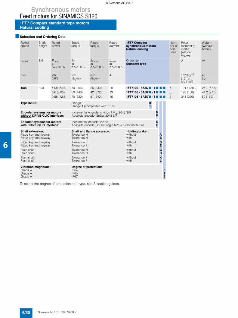
Synchronous motorsFeed motors for SINAMICS S1201FT7 Compact standard type motorsNatural cooling
6/30 Siemens NC 61 · 2007/2008
6
■ Selection and Ordering Data
To select the degree of protection and type, see Selection guides.
Rated speed
Shaft height
Ratedpower
Static torque
Ratedtorque
Ratedcurrent
1FT7 Compactsynchronous motorsNatural cooling
Num-ber ofpole pairs
Rotor moment of inertia (without brake)
Weight (without brake)
nrated SH Prated at∆T=100 K
M0 at ∆T=100 K
Mratedat ∆T=100 K
Iratedat ∆T=100 K
Order No.Standard type
J m
rpm kW (HP)
Nm (lbƒ-in)
Nm (lbƒ-in)
A 10-4 kgm2 (10-3 x lbƒ-in-s2)
kg (lb)
1500 100 4.08 (5.47)6.6 (8.85)9.58 (12.8)
30 (266)50 (443)70 (620)
26 (230)42 (372)61 (540)
81316
1FT7102 - 5AB77 - 1 7 7 71FT7105 - 5AB77 - 1 7 7 71FT7108 - 5AB77 - 1 7 7 7
555
91.4 (80.9)178 (158)248 (220)
26.1 (57.6)44.2 (97.5)59 (130)
Type IM B5: Flange 0Flange 1 (compatible with 1FT6)
01
Encoder systems for motors without DRIVE-CLiQ interface:
Incremental encoder sin/cos 1 Vpp 2048 S/RAbsolute encoder EnDat 2048 S/R
Encoder systems for motors with DRIVE-CLiQ interface:
Incremental encoder 22 bitAbsolute encoder, 22 bit single-turn + 12 bit multi-turn
DF
Shaft extension:Fitted key and keywayFitted key and keywayFitted key and keywayFitted key and keywayPlain shaftPlain shaftPlain shaftPlain shaft
Shaft and flange accuracy:Tolerance NTolerance NTolerance RTolerance RTolerance NTolerance NTolerance RTolerance R
Holding brake:withoutwithwithoutwithwithoutwithwithoutwith
Vibration magnitude:Grade AGrade AGrade A
Degree of protection:IP64IP65IP67
NM
ABDEGHKL
012
© Siemens AG 2007© Siemens AG 2007

Synchronous motorsFeed motors for SINAMICS S120
1FT7 Compact standard type motorsNatural cooling
6/31Siemens NC 61 · 2007/2008
6
■ Selection and Ordering Data
1) The current carrying capacity of the power cables complies with IEC 60204-1 for installation type C under continuous operating conditions at an ambient air temperature of 40 °C (104 °F), designed for I0 (100 K), PVC/PUR-insulated cable.
2) With default setting of the pulse frequency.3)
Motor type(continued)
Static current
Calculated powerPcalc
3)
SINAMICS S120 Motor Module Power cable with complete shieldMotor connection (and brake connection) via power connectorRated
output current2)
Booksize format
I0 at T0 ∆T=100 K
Pcalcfor M0 ∆T=100 K
Irated Order No. Power connector
Motor cable cross-section1)
Order No.Pre-assembled cable
A kW (HP)
A Size mm2
1FT7102-5AB7...1FT7105-5AB7...1FT7108-5AB7...
91518
4.71 (6.32)7.85 (10.5)
10.99 (14.7)
91818
6SL3127 - 7TE21 - 0AA36SL3127 - 7TE21 - 8AA36SL3127 - 7TE21 - 8AA3
1.51.51.5
4 x 1.54 x 1.54 x 2.5
6FX7 002 - 57S21 - ....6FX7 002 - 57S21 - ....6FX7 002 - 57S31 - ....
Cooling:Internal air coolingExternal air cooling
01
Motor Module:Single Motor ModuleDouble Motor Module
Type of power cable:MOTION-CONNECT 800MOTION-CONNECT 500
Without brake coresWith brake cores
For length code as well as power and signal cables, see Connection system MOTION-CONNECT.
12
85
CD
....
Pcalc [kW] =M0 [Nm] x nrated
9550 Pcalc [HP] =M0 [lbƒ-in] x nrated
63000
© Siemens AG 2007© Siemens AG 2007

Synchronous motorsFeed motors for SINAMICS S1201FT7 Compact standard type motorsNatural cooling
6/32 Siemens NC 61 · 2007/2008
6
■ Selection and Ordering Data
To select the degree of protection and type, see Selection guides.
Rated speed
Shaftheight
Ratedpower
Static torque
Ratedtorque
Ratedcurrent
1FT7 Compactsynchronous motorsNatural cooling
Num-ber ofpole pairs
Rotor moment of inertia (without brake)
Weight (without brake)
nrated SH Prated at∆T=100 K
M0 at ∆T=100 K
Mratedat ∆T=100 K
Iratedat ∆T=100 K
Order No.Standard type
J m
rpm kW (HP)
Nm (lbƒ-in)
Nm (lbƒ-in)
A 10-4 kgm2 (10-3 x lbƒ-in-s2)
kg (lb)
2000 80 2.39 (3.20)3.54 (4.75)4.71 (6.32)
13 (115)20 (177)28 (248)
11.4 (101)16.9 (150)22.5 (199)
4.77.89.2
1FT7082 - 5AC77 - 1 7 7 71FT7084 - 5AC77 - 1 7 7 71FT7086 - 5AC77 - 1 7 7 7
555
26.5 (23.5)45.1 (39.9)63.6 (56.3)
14 (30.9)20.8 (45.9)31.8 (70.1)
100 5.03 (6.75)7.96 (10.7)
10.5 (14.1)
30 (266)50 (443)70 (620)
24 (212)38 (336)50 (443)
101518
1FT7102 - 5AC77 - 1 7 7 71FT7105 - 5AC77 - 1 7 7 71FT7108 - 5AC77 - 1 7 7 7
555
91.4 (80.9)178 (158)248 (220)
26.1 (57.6)44.1 (97.2)59 (130)
Type IM B5: Flange 0Flange 1 (compatible with 1FT6)
01
Encoder systems for motors without DRIVE-CLiQ interface:
Incremental encoder sin/cos 1 Vpp 2048 S/RAbsolute encoder EnDat 2048 S/R
Encoder systems for motors with DRIVE-CLiQ interface:
Incremental encoder 22 bitAbsolute encoder, 22 bit single-turn + 12 bit multi-turn
DF
Shaft extension:Fitted key and keywayFitted key and keywayFitted key and keywayFitted key and keywayPlain shaftPlain shaftPlain shaftPlain shaft
Shaft and flange accuracy:Tolerance NTolerance NTolerance RTolerance RTolerance NTolerance NTolerance RTolerance R
Holding brake:withoutwithwithoutwithwithoutwithwithoutwith
Vibration magnitude:Grade AGrade AGrade A
Degree of protection:IP64IP65IP67
NM
ABDEGHKL
012
© Siemens AG 2007© Siemens AG 2007

Synchronous motorsFeed motors for SINAMICS S120
1FT7 Compact standard type motorsNatural cooling
6/33Siemens NC 61 · 2007/2008
6
■ Selection and Ordering Data
1) The current carrying capacity of the power cables complies with IEC 60204-1 for installation type C under continuous operating conditions at an ambient air temperature of 40 °C (104 °F), designed for I0 (100 K), PVC/PUR-insulated cable.
2) With default setting of the pulse frequency.3)
Motor type(continued)
Static current
Calculated powerPcalc
3)
SINAMICS S120 Motor Module Power cable with complete shieldMotor connection (and brake connection) via power connectorRated
output current2)
Booksize format
I0 at M0 ∆T=100 K
Pcalcfor M0 ∆T=100 K
Irated Order No. Power connector
Motor cable cross-section1)
Order No.Pre-assembled cable
A kW (HP)
A Size mm2
1FT7082-5AC7...1FT7084-5AC7...1FT7086-5AC7...
4.98.5
10.6
2.72 (3.65)4.19 (5.62)5.86 (7.86)
59
18
6SL3127 - 7TE15 - 0AA36SL3127 - 7TE21 - 0AA36SL3127 - 7TE21 - 8AA3
111
4 x 1.54 x 1.54 x 1.5
6FX7 002 - 57S01 - ....6FX7 002 - 57S01 - ....6FX7 002 - 57S01 - ....
1FT7102-5AC7...1FT7105-5AC7...1FT7108-5AC7...
121825
6.28 (8.42)10.47 (14.0)14.66 (19.7)
181830
6SL3127 - 7TE21 - 8AA36SL3127 - 7TE21 - 8AA36SL3127 - 7TE23 - 1AA3
1.51.51.5
4 x 1.54 x 2.54 x 4
6FX7 002 - 57S21 - ....6FX7 002 - 57S31 - ....6FX7 002 - 57S41 - ....
Cooling:Internal air coolingExternal air cooling
01
Motor Module:Single Motor ModuleDouble Motor Module
Type of power cable:MOTION-CONNECT 800MOTION-CONNECT 500
Without brake coresWith brake cores
For length code as well as power and signal cables, see Connection system MOTION-CONNECT.
12
85
CD
....
Pcalc [kW] =M0 [Nm] x nrated
9550 Pcalc [HP] =M0 [lbƒ-in] x nrated
63000
© Siemens AG 2007© Siemens AG 2007

Synchronous motorsFeed motors for SINAMICS S1201FT7 Compact standard type motorsNatural cooling
6/34 Siemens NC 61 · 2007/2008
6
■ Selection and Ordering Data
To select the degree of protection and type, see Selection guides.
Rated speed
Shaftheight
Ratedpower
Static torque
Ratedtorque
Ratedcurrent
1FT7 Compactsynchronous motorsNatural cooling
Num-ber ofpole pairs
Rotor moment of inertia (without brake)
Weight (without brake)
nrated SH Prated at∆T=100 K
M0 at ∆T=100 K
Mratedat ∆T=100 K
Iratedat ∆T=100 K
Order No.Standard type
J m
rpm kW (HP)
Nm (lbƒ-in)
Nm (lbƒ-in)
A 10-4 kgm2 (10-3 x lbƒ-in-s2)
kg (lb)
3000 48 0.85 (1.14)1.35 (1.81)1.76 (2.36)
3 (26.6)5 (44.3)7 (62.0)
2.7 (23.9)4.3 (38.1)5.6 (49.6)
2.12.63.5
1FT7042 - 5AF 77 - 1 7 7 71FT7044 - 5AF 77 - 1 7 7 71FT7046 - 5AF 77 - 1 7 7 7
333
2.81 (2.49)5.43 (4.81)7.52 (6.66)
4.6 (10.1)7.2 (15.9)9.3 (20.5)
63 1.7 (2.28)2.39 (3.20)2.92 (3.92)3.42 (4.59)
6 (53.1)9 (79.7)
12 (106)15 (133)
5.4 (47.8)7.6 (67.3)9.3 (82.3)
10.9 (96.5)
3.95.17.26.7
1FT7062 - 5AF 77 - 1 7 7 71FT7064 - 5AF 77 - 1 7 7 71FT7066 - 5AF 77 - 1 7 7 71FT7068 - 5AF 77 - 1 7 7 7
5555
7.36 (6.51)11.9 (10.5)16.4 (14.5)23.2 (20.5)
7.1 (15.7)9.7 (21.4)
12.3 (27.1)16.3 (35.9)
80 3.24 (4.34)4.55 (6.10)5.62 (7.54)
13 (115)20 (177)28 (248)
10.5 (92.9)14.5 (128)18 (159)
6.68.5
11
1FT7082 - 5AF 77 - 1 7 7 71FT7084 - 5AF 77 - 1 7 7 71FT7086 - 5AF 77 - 1 7 7 7
555
26.5 (23.5)45.1 (39.1)63.6 (56.3)
14 (30.9)20.8 (45.9)31.8 (70.1)
100 6.28 (8.42)8.8 (11.8)
30 (266)50 (443)
20 (177)28 (248)
1215
1FT7102 - 5AF 77 - 1 7 7 71FT7105 - 5AF 77 - 1 7 7 7
55
91.4 (80.9)178 (158)
26.1 (57.6)44.2 (97.5)
Type IM B5: Flange 0Flange 1 (compatible with 1FT6)
01
Encoder systems for motors without DRIVE-CLiQ interface:
Incremental encoder sin/cos 1 Vpp 2048 S/RAbsolute encoder EnDat 2048 S/R
Encoder systems for motors with DRIVE-CLiQ interface:
Incremental encoder 22 bit Absolute encoder, 22 bit single-turn + 12 bit multi-turn
DF
Shaft extension:Fitted key and keywayFitted key and keywayFitted key and keywayFitted key and keywayPlain shaftPlain shaftPlain shaftPlain shaft
Shaft and flange accuracy:Tolerance NTolerance NTolerance RTolerance RTolerance NTolerance NTolerance RTolerance R
Holding brake:withoutwithwithoutwithwithoutwithwithoutwith
Vibration magnitude:Grade AGrade AGrade A
Degree of protection:IP64IP65IP67
NM
ABDEGHKL
012
© Siemens AG 2007© Siemens AG 2007

Synchronous motorsFeed motors for SINAMICS S120
1FT7 Compact standard type motorsNatural cooling
6/35Siemens NC 61 · 2007/2008
6
■ Selection and Ordering Data
1) The current carrying capacity of the power cables complies with IEC 60204-1 for installation type C under continuous operating conditions at an ambient air temperature of 40 °C (104 °F), designed for I0 (100 K), PVC/PUR-insulated cable.
2) With default setting of the pulse frequency.3)
Motor type(continued)
Static current
Calculated powerPcalc
3)
SINAMICS S120 Motor Module Power cable with complete shieldMotor connection (and brake connection) via power connectorRated
output current2)
Booksize format
I0 at M0 ∆T=100 K
Pcalcfor M0 ∆T=100 K
Irated Order No. Power connector
Motor cable cross-section1)
Order No.Pre-assembled cable
A kW(HP)
A Size mm2
1FT7042-5AF7...1FT7044-5AF7...1FT7046-5AF7...
2.12.84
0.94 (1.26)1.57 (2.11)2.2 (2.95)
335
6SL3127 - 7TE13 - 0AA36SL3127 - 7TE13 - 0AA36SL3127 - 7TE15 - 0AA3
111
4 x 1.54 x 1.54 x 1.5
6FX7 002 - 57S01 - ....6FX7 002 - 57S01 - ....6FX7 002 - 57S01 - ....
1FT7062-5AF7...1FT7064-5AF7...1FT7066-5AF7...1FT7068-5AF7...
3.95.68.48.3
1.88 (2.52)2.83 (3.80)3.77 (5.06)4.71 (6.32)
5999
6SL3127 - 7TE15 - 0AA36SL3127 - 7TE21 - 0AA36SL3127 - 7TE21 - 0AA36SL3127 - 7TE21 - 0AA3
1111
4 x 1.54 x 1.54 x 1.54 x 1.5
6FX7 002 - 57S01 - ....6FX7 002 - 57S01 - ....6FX7 002 - 57S01 - ....6FX7 002 - 57S01 - ....
1FT7082-5AF7...1FT7084-5AF7...1FT7086-5AF7...
7.61115.5
4.08 (5.47)6.28 (8.42)8.8 (11.8)
91818
6SL3127 - 7TE21 - 0AA36SL3127 - 7TE21 - 8AA36SL3127 - 7TE21 - 8AA3
111.5
4 x 1.54 x 1.54 x 2.5
6FX7 002 - 57S01 - ....6FX7 002 - 57S01 - ....6FX7 002 - 57S31 - ....
1FT7102-5AF7...1FT7105-5AF7...
1826
9.42 (12.6)15.71 (21.1)
1830
6SL3127 - 7TE21 - 8AA36SL3127 - 7TE23 - 1AA3
1.51.5
4 x 2.54 x 4
6FX7 002 - 57S31 - ....6FX7 002 - 57S41 - ....
Cooling:Internal air coolingExternal air cooling
01
Motor Module:Single Motor ModuleDouble Motor Module
Type of power cable:MOTION-CONNECT 800MOTION-CONNECT 500
Without brake coresWith brake cores
For length code as well as power and signal cables, see Connection system MOTION-CONNECT.
12
85
CD
....
Pcalc [kW] =M0 [Nm] x nrated
9550 Pcalc [HP] =M0 [lbƒ-in] x nrated
63000
© Siemens AG 2007© Siemens AG 2007

Synchronous motorsFeed motors for SINAMICS S1201FT7 Compact standard type motorsNatural cooling
6/36 Siemens NC 61 · 2007/2008
6
■ Selection and Ordering Data
To select the degree of protection and type, see Selection guides.
Rated speed
Shaftheight
Ratedpower
Static torque
Ratedtorque
Ratedcurrent
1FT7 Compactsynchronous motorsNatural cooling
Num-ber ofpole pairs
Rotor moment of inertia (without brake)
Weight (without brake)
nrated SH Prated at∆T=100 K
M0 at ∆T=100 K
Mratedat ∆T=100 K
Iratedat ∆T=100 K
Order No.Standard type
J m
rpm kW (HP)
Nm (lbƒ-in)
Nm (lbƒ-in)
A 10-4 kgm2 (10-3 x lbƒ-in-s2)
kg (lb)
4500 48 1.32 (1.77)1) 7 (62.0) 3.6 (31.9)1) 4.71) 1FT7046 - 5AH77 - 1 7 7 7 3 7.52 (6.66) 9.3 (20.5)
63 2.55 (3.42)2) 12 (106) 6.1 (54.0)2) 7.52) 1FT7066 - 5AH77 - 1 7 7 7 5 16.4 (14.5) 12.3 (27.1)
80 3.77 (5.06)4.82 (6.46)2)
13 (115)20 (177)
8 (70.8)11.5 (102)2)
8.410.12)
1FT7082 - 5AH77 - 1 7 7 71FT7084 - 5AH77 - 1 7 7 7
55
26.5 (23.5)45.1 (39.9)
14 (30.9)20.8 (45.9)
Type IM B5: Flange 0Flange 1 (compatible with 1FT6)
01
Encoder systems for motors without DRIVE-CLiQ interface:
Incremental encoder sin/cos 1 Vpp 2048 S/RAbsolute encoder EnDat 2048 S/R
Encoder systems for motors with DRIVE-CLiQ interface:
Incremental encoder 22 bitAbsolute encoder, 22 bit single-turn + 12 bit multi-turn
DF
Shaft extension:Fitted key and keywayFitted key and keywayFitted key and keywayFitted key and keywayPlain shaftPlain shaftPlain shaftPlain shaft
Shaft and flange accuracy:Tolerance NTolerance NTolerance RTolerance RTolerance NTolerance NTolerance RTolerance R
Holding brake:withoutwithwithoutwithwithoutwithwithoutwith
Vibration magnitude:Grade AGrade AGrade A
Degree of protection:IP64IP65IP67
NM
ABDEGHKL
012
© Siemens AG 2007© Siemens AG 2007

Synchronous motorsFeed motors for SINAMICS S120
1FT7 Compact standard type motorsNatural cooling
6/37Siemens NC 61 · 2007/2008
6
■ Selection and Ordering Data
1) These values refer to n = 3500 rpm.2) These values refer to n = 4000 rpm. 3) The current carrying capacity of the power cables complies with IEC 60204-1 for installation type C under continuous operating conditions at an
ambient air temperature of 40 °C (104 °F), designed for I0 (100 K), PVC/PUR-insulated cable.4) With default setting of the pulse frequency.5)
Motor type(continued)
Static current
Calculated powerPcalc
5)
SINAMICS S120 Motor Module Power cable with complete shieldMotor connection (and brake connection) via power connectorRated
outputcurrent4)
Booksize format
I0 at M0 ∆T=100 K
Pcalcfor M0 ∆T=100 K
Irated Order No. Power connector
Motor cable cross-section3)
Order No.Pre-assembled cable
A kW (HP)
A Size mm2
1FT7046-5AH7... 8.1 3.3 (4.43) 9 6SL3127 - 7TE21 - 0AA3 1 4 x 1.5 6FX7 002 - 57S01 - ....
1FT7066-5AH7... 13.6 5.65 (7.58) 18 6SL3127 - 7TE21 - 8AA3 1 4 x 1.5 6FX7 002 - 57S01 - ....
1FT7082-5AH7...1FT7084-5AH7...
12.315.6
6.13 (8.22)9.42 (12.6)
1818
6SL3127 - 7TE21 - 8AA36SL3127 - 7TE21 - 8AA3
11.5
4 x 1.54 x 2.5
6FX7 002 - 57S01 - ....6FX7 002 - 57S31 - ....
Cooling:Internal air coolingExternal air cooling
01
Motor Module:Single Motor ModuleDouble Motor Module
Type of power cable:MOTION-CONNECT 800MOTION-CONNECT 500
Without brake coresWith brake cores
For length code as well as power and signal cables, see Connection system MOTION-CONNECT.
12
85
CD
....
Pcalc [kW] =M0 [Nm] x nrated
9550 Pcalc [HP] =M0 [lbƒ-in] x nrated
63000
© Siemens AG 2007© Siemens AG 2007

Synchronous motorsFeed motors for SINAMICS S1201FT7 Compact standard type motorsNatural cooling
6/38 Siemens NC 61 · 2007/2008
6
■ Selection and Ordering Data
To select the degree of protection and type, see Selection guides.
Rated speed
Shaftheight
Ratedpower
Static torque
Ratedtorque
Ratedcurrent
1FT7 Compactsynchronous motorsNatural cooling
Num-ber ofpole pairs
Rotor moment of inertia (without brake)
Weight (without brake)
nrated SH Prated at∆T=100 K
M0 at ∆T=100 K
Mratedat ∆T=100 K
Iratedat ∆T=100 K
Order No.Standard type
J m
rpm kW (HP)
Nm (lbƒ-in)
Nm (lbƒ-in)
A 10-4 kgm2 (10-3 x lbƒ-in-s2)
kg (lb)
6000 36 0.88 (1.18)1.07 (1.43)
2 (17.7)3 (26.6)
1.4 (12.4)1.7 (15.0)
2.52.6
1FT7034 - 5AK77 - 1 7 7 71FT7036 - 5AK77 - 1 7 7 7
33
0.85 (0.75)1.33 (1.18)
3.8 (8.38)5 (11.0)
48 1.26 (1.69)1.41 (1.89)1)
3 (26.6)5 (44.3)
2 (17.7)3 (26.6)1)
33.61)
1FT7042 - 5AK77 - 1 7 7 71FT7044 - 5AK77 - 1 7 7 7
33
2.81 (2.49)5.43 (4.81)
4.6 (10.1)7.2 (15.9)
60 2.13 (2.86)2)
2.59 (2.59)1)6 (53.1)9 (79.7)
3.7 (32.7)2)
5.5 (48.7)1)5.92)
6.11)1FT7062 - 5AK77 - 1 7 7 71FT7064 - 5AK77 - 1 7 7 7
55
7.36 (6.51)11.9 (10.5)
7.1 (15.7)9.7 (21.4)
Type IM B5: Flange 0Flange 1 (compatible with 1FT6)
01
Encoder systems for motors without DRIVE-CLiQ interface:
Incremental encoder sin/cos 1 Vpp 2048 S/RAbsolute encoder EnDat 2048 S/R
Encoder systems for motors with DRIVE-CLiQ interface:
Incremental encoder 22 bitAbsolute encoder, 22 bit single-turn + 12 bit multi-turn
DF
Shaft extension:Fitted key and keywayFitted key and keywayFitted key and keywayFitted key and keywayPlain shaftPlain shaftPlain shaftPlain shaft
Shaft and flange accuracy:Tolerance NTolerance NTolerance RTolerance RTolerance NTolerance NTolerance RTolerance R
Holding brake:withoutwithwithoutwithwithoutwithwithoutwith
Vibration magnitude:Grade AGrade AGrade A
Degree of protection:IP64IP65IP67
NM
ABDEGHKL
012
© Siemens AG 2007© Siemens AG 2007

Synchronous motorsFeed motors for SINAMICS S120
1FT7 Compact standard type motorsNatural cooling
6/39Siemens NC 61 · 2007/2008
6
■ Selection and Ordering Data
1) These values refer to n = 4500 rpm.2) These values refer to n = 5500 rpm. 3) The current carrying capacity of the power cables complies with IEC 60204-1 for installation type C under continuous operating conditions at an
ambient air temperature of 40 °C (104 °F), designed for I0 (100 K), PVC/PUR-insulated cable.4) With default setting of the pulse frequency.5)
Motor type(continued)
Static current
Calculated powerPcalc
5)
SINAMICS S120 Motor Module Power cable with complete shieldMotor connection (and brake connection) via power connectorRated
output current4)
Booksize format
I0 at M0 ∆T=100 K
Pcalcfor M0 ∆T=100 K
Irated Order No. Power connector
Motor cable cross-section3)
Order No.Pre-assembled cable
A kW (HP)
A Size mm2
1FT7034-5AK7...1FT7036-5AK7...
2.94.3
1.26 (1.69)1.88 (2.52)
35
6SL3127 - 7TE13 - 0AA36SL3127 - 7TE15 - 0AA3
11
4 x 1.54 x 1.5
6FX7 002 - 57S01 - ....6FX7 002 - 57S01 - ....
1FT7042-5AK7...1FT7044-5AK7...
3.95.7
1.89 (2.53)3.15 (4.22)
59
6SL3127 - 7TE15 - 0AA36SL3127 - 7TE21 - 0AA3
11
4 x 1.54 x 1.5
6FX7 002 - 57S01 - ....6FX7 002 - 57S01 - ....
1FT7062-5AK7...1FT7064-5AK7...
8.49
3.78 (5.07)5.67 (7.60)
99
6SL3127 - 7TE21 - 0AA36SL3127 - 7TE21 - 0AA3
11
4 x 1.54 x 1.5
6FX7 002 - 57S01 - ....6FX7 002 - 57S01 - ....
Cooling:Internal air coolingExternal air cooling
01
Motor Module:Single Motor ModuleDouble Motor Module
Type of power cable:MOTION-CONNECT 800MOTION-CONNECT 500
Without brake coresWith brake cores
For length code as well as power and signal cables, see Connection system MOTION-CONNECT.
12
85
CD
....
Pcalc [kW] =M0 [Nm] x nrated
9550 Pcalc [HP] =M0 [lbƒ-in] x nrated
63000
© Siemens AG 2007© Siemens AG 2007

Synchronous motorsFeed motors for SINAMICS S120
1FK7 motors
6/40 Siemens NC 61 · 2007/2008
6
■ Overview
1FK7 motors are extremely compact, permanent-magnet-excited synchronous motors. The available options, gearboxes and encoders, together with the expanded product range, mean that 1FK7 motors can be optimally adapted to any application. They therefore also satisfy the permanently increasing demands of state-of-the-art machine generations.
1FK7 motors can be combined with the SINAMICS S120 drive system to create a powerful system with high functionality. The integrated encoder systems for speed and position control can be selected depending on the application.
The motors are designed for operation without external cooling and the heat is dissipated through the motor surface. 1FK7 motors have a high overload capability.
■ Benefits
1FK7 Compact motors offer:7 Space-saving installation thanks to extremely high power
density 7 Can be used universally for many applications7 Wide range of motors
1FK7 High Dynamic motors offer:7 Extremely high dynamic response due to low rotor moment of
inertia
■ Application
• Machine tools• Robots and handling systems• Wood, glass, ceramics and stone working• Packaging, plastics and textile machines• Auxiliary axes
© Siemens AG 2007© Siemens AG 2007

Synchronous motorsFeed motors for SINAMICS S120
1FK7 motors
6/41Siemens NC 61 · 2007/2008
6
■ Technical specifications
1) Shaft extension run-out, concentricity of spigot and shaft and perpen-dicularity of mounting face of flange to shaft.
2) 1FK701 only available in degree of protection IP54 and anthracite paint finish, separately packed rating plate, planetary gearbox not available.
S/R = signals/revolution
Product name 1FK7 Compact motor1FK7 High Dynamic motor
Type of motor Permanent-magnet-excited synchronous motor
Magnet material Rare-earth magnet material
Cooling Natural cooling
Temperature monitoring KTY 84 temperature sensor in stator winding
Insulation of the stator winding in accordance with EN 60034-1 (IEC 60034-1)
Temperature class 155 (F) for a winding temperature riseof ∆T = 100 K at an ambient temperature of 40 °C(104 °F)
Type in accordance withEN 60034-7 (IEC 60034-7)
IM B5 (IM V1, IM V3)
Degree of protection in accordance with EN 60034-5 (IEC 60034-5)
IP64
Shaft extension on the drive end in accordance with DIN 748-3 (IEC 60072-1)
Plain shaft
Shaft and flange accuracy in accordance with DIN 42955(IEC 60072-1)1)
Tolerance N
Vibration magnitudein accordance withEN 60034-14 (IEC 60034-14)
Grade A is observed up to rated speed
Sound pressure levelin accordance with EN ISO 1680, max.
• 1FK701 ... 1FK704:• 1FK706:• 1FK708 ... 1FK710:
55 dB (A)65 dB (A)70 dB (A)
Encoder systems, built-infor motors without DRIVE-CLiQ interface
• Incremental encoder sin/cos 1 Vpp 2048 S/R
• Absolute encoder, multi-turn (traversingrange 4096 revolutions) with EnDat interface1FK704 ... 1FK710: 2048 S/R1FK701 ... 1FK703: 512 S/R1FK704 ... 1FK710: 32 S/R1FK701 ... 1FK703: 16 S/R
• Multi-pole resolver(number of poles corresponds to number of pole pairs of the motor)
• 2-pole resolver
Encoder systems, built-in for motors with DRIVE-CLiQ interface
• Incremental encoder 22 bit (2048 S/R internal)
• Absolute encodersingle-turn + 12 bit multi-turn (traversing range 4096 revolutions)1FK704 ... 1FK710:22 bit single-turn (2048 S/R internal)1FK701 ... 1FK703:20 bit single-turn (512 S/R internal)1FK704 ... 1FK710:16 bit single-turn (32 S/R internal)1FK701 ... 1FK703:15 bit single-turn (16 S/R internal)
• 15 bit resolver• 14 bit resolver
Connection Connectors for signals and power can be rotated (270°)
Paint finish Unpainted
2nd rating plate3rd rating plate
Attached in the NDE coverEnclosed separately
Options2) • Shaft extension on the drive end with fitted key and keyway (half-key balancing)
• Built-in holding brake• Degree of protection IP65,
plus DE flange IP67• Planetary gearbox, built-on
(requires: plain shaft extension, degree of protection IP64 for LP+ and IP65 for SP+)
• Anthracite paint finish
© Siemens AG 2007© Siemens AG 2007

Synchronous motorsFeed motors for SINAMICS S1201FK7 Compact motorsNatural cooling
6/42 Siemens NC 61 · 2007/2008
6
■ Selection and Ordering Data
To select the degree of protection and type, see Selection guides.
Rated speed
Shaftheight
Rated power
Static torque
Ratedtorque1)
Rated current
1FK7 Compactsynchronous motorNatural cooling
Num-ber ofpole pairs
Rotor moment of inertia (without brake)
Weight (without brake)
nrated SH Prated at ∆T=100 K
M0 at ∆T=100 K
Mrated at ∆T=100 K
Irated at ∆T=100 K
Order No. J m
rpm kW (HP)
Nm (lbƒ-in)
Nm (lbƒ-in)
A 10-4 kgm2 (10-3 x lbƒ-in-s2)
kg (lb)
2000 100 7.75 (10.4) 48 (425) 37 (327) 16 1FK7105 - 5AC71- 17 7 7 4 156 (138) 39 (86.0)
3000 48 0.82 (1.10) 3 (26.6) 2.6 (23.0) 1.95 1FK7042 - 5AF71- 17 7 7 4 3.01 (2.66) 4.9 (10.8)
63 1.48 (1.98)2.29 (3.07)
6 (53.1)11 (97.4)
4.7 (41.6)7.3 (64.6)
3.75.6
1FK7060 - 5AF71- 17 7 71FK7063 - 5AF71- 17 7 7
44
7.95 (7.04)15.1 (13.4)
7 (15.4)11.5 (25.4)
80 2.14 (2.87)3.3 (4.43)
8 (70.8)16 (142)
6.8 (60.2)10.5 (92.9)
4.47.4
1FK7080 - 5AF71- 17 7 71FK7083 - 5AF71- 17 7 7
44
15 (13.3)27.3 (24.2)
10 (22.1)14 (30.9)
100 3.77 (5.06)4.87 (6.53)5.37 (7.20)2)
8.17 (11.0)
18 (159)27 (239)36 (319)48 (425)
12 (106)15.5 (137)20.5 (181)2)
26 (230)
811.816.52)
18
1FK7100 - 5AF71- 17 7 71FK7101 - 5AF71- 17 7 71FK7103 - 5AF71- 17 7 71FK7105 - 5AF71- 17 7 7
4444
55.3 (48.9)79.9 (70.7)
105 (92.9)156 (138)
19 (41.9)21 (46.3)29 (63.9)39 (86.0)
Encoder systems for motors without DRIVE-CLiQ interface:
Incremental encoder sin/cos 1 Vpp 2048 S/RAbsolute encoder EnDat 2048 S/R1) Absolute encoder EnDat 32 S/R1) Multi-pole resolver2-pole resolver
AEGST
Encoder systems for motors with DRIVE-CLiQ interface:
Incremental encoder 22 bit Absolute encoder 22 bit single-turn + 12 bit multi-turn1)
Absolute encoder 16 bit single-turn + 12 bit multi-turn1) 15 bit resolver14 bit resolver
DFKUP
Shaft extension:Fitted key and keywayFitted key and keywayPlain shaftPlain shaft
Shaft and flange accuracy: Tolerance NTolerance NTolerance NTolerance N
Holding brake:withoutwithwithoutwith
ABGH
Degree of protection: IP64 (not for 1FK701)IP65 and DE flange IP67 (not for 1FK701)IP64 (IP54 with 1FK701) and anthracite paint finishIP65 and DE flange IP67, anthracite paint finish
(not for 1FK701)IP65 and DE flange IP67, anthracite paint finish
and metal rating plate on motor (not for 1FK701)
0235
8
© Siemens AG 2007© Siemens AG 2007

Synchronous motorsFeed motors for SINAMICS S120
1FK7 Compact motorsNatural cooling
6/43Siemens NC 61 · 2007/2008
6
■ Selection and Ordering Data
1) If the absolute encoder is used, Mrated is reduced by 10%.2) These values refer to n = 2500 rpm.3) The current carrying capacity of the power cables complies with IEC 60204-1 for installation type C under continuous operating conditions at an
ambient air temperature of 40 °C (104 °F), designed for I0 (100 K), PVC/PUR-insulated cable.4) With default setting of the pulse frequency.5)
Motor type(continued)
Static current
Calculated powerPcalc
5)
SINAMICS S120 Motor Module Power cable with complete shieldMotor connection (and brake connection) via power connectorRated
output current4)
Booksize format
I0 at M0 ∆T=100 K
Pcalcfor M0 ∆T=100 K
Irated Order No. Power connector
Motor cable cross-section3)
Order No.Pre-assembled cable
A kW (HP)
A Size mm2
1FK7105-5AC71... 20 10 (13.4) 30 6SL3127 - 7TE23 - 0AA3 1.5 4 x 2.5 6FX7 002 - 57S31 - ....
1FK7042-5AF71... 2.2 0.9 (1.21) 3 6SL3127 - 7TE13 - 0AA3 1 4 x 1.5 6FX7 002 - 57S01 - ....
1FK7060-5AF71...1FK7063-5AF71...
4.58
1.9 (2.55)3.5 (4.69)
59
6SL3127 - 7TE15 - 0AA36SL3127 - 7TE21 - 0AA3
11
4 x 1.54 x 1.5
6FX7 002 - 57S01 - ....6FX7 002 - 57S01 - ....
1FK7080-5AF71...1FK7083-5AF71...
4.810.4
2.5 (3.35)5.0 (6.71)
593)
6SL3127 - 7TE15 - 0AA36SL3127 - 7TE21 - 0AA3
11
4 x 1.54 x 1.5
6FX7 002 - 57S01 - ....6FX7 002 - 57S01 - ....
1FK7100-5AF71...1FK7101-5AF71...1FK7103-5AF71...1FK7105-5AF71...
11.21927.531
5.7 (7.64)8.5 (11.4)
11.3 (15.2)15 (20.1)
18183)
30303)
6SL3127 - 7TE21 - 8AA36SL3127 - 7TE21 - 8AA36SL3127 - 1TE23 - 0AA36SL3127 - 1TE23 - 0AA3
11.51.51.5
4 x 1.54 x 2.54 x 44 x 10
6FX7 002 - 57S01 - ....6FX7 002 - 57S31 - ....6FX7 002 - 57S41 - ....6FX7 002 - 57S61 - ....
Cooling:Internal air coolingExternal air cooling
01
Motor Module:Single Motor ModuleDouble Motor Module
12
Type of power cable:MOTION-CONNECT 800MOTION-CONNECT 500
85
Without brake coresWith brake cores
CD
For length code as well as power and signal cables, see Connection system MOTION-CONNECT. ....
Pcalc [kW] =M0 [Nm] x nrated
9550 Pcalc [HP] =M0 [lbƒ-in] x nrated
63000
© Siemens AG 2007© Siemens AG 2007

Synchronous motorsFeed motors for SINAMICS S1201FK7 Compact motorsNatural cooling
6/44 Siemens NC 61 · 2007/2008
6
■ Selection and Ordering Data
To select the degree of protection and type, see Selection guides.
Rated speed
Shaftheight
Rated power
Static torque
Ratedtorque1)
Rated current
1FK7 Compact synchronous motorNatural cooling
Num-ber ofpole pairs
Rotor moment of inertia (without brake)
Weight (without brake)
nrated SH Prated at ∆T=100 K
M0 at ∆T=100 K
Mrated at ∆T=100 K
Irated at ∆T=100 K
Order No. J m
rpm kW (HP)
Nm (lbƒ-in)
Nm(lbƒ-in)
A 10-4 kgm2 (10-3 x lbƒ-in-s2)
kg (lb)
4500 63 1.74 (2.33)2.09 (2.80)2)
6 (53.1)11 (97.4)
3.7 (32.7)5 (44.3)2)
4.16.12)
1FK7060 - 5AH71- 17 7 71FK7063 - 5AH71- 17 7 7
44
7.95 (7.04)15.1 (13.4)
7 (15.4)11.5 (25.4)
80 2.39 (3.20)2)
3.04 (4.08)3)8 (70.8)
16 (142)5.7 (50.5)2)
8.3 (73.5)3)5.62)
93)1FK7080 - 5AH71- 17 7 71FK7083 - 5AH71- 17 7 7
44
15 (13.3)27.3 (24.2)
10 (22.1)14 (30.9)
6000 20 0.05 (0.07)0.10 (0.13)
0.18 (1.59)0.35 (3.10)
0.08 (0.71)0.16 (1.42)
0.850.85
1FK7011 - 5AK71- 17 7 31FK7015 - 5AK71- 17 7 3
44
0.064 (0.06)0.083 (0.07)
0.9 (1.98)1.1 (2.43)
28 0.43 (0.58) 0.85 (7.52) 0.6 (5.31) 1.4 1FK7022 - 5AK71- 17 7 7 3 0.28 (0.25) 1.8 (3.97)
36 0.50 (0.67)0.63 (0.84)
1.1 (9.74)1.6 (14.2)
0.8 (7.08)1 (8.85)
1.31.3
1FK7032 - 5AK71- 17 7 71FK7034 - 5AK71- 17 7 7
33
0.61 (0.54)0.9 (0.80)
2.7 (5.95)3.7 (8.16)
48 0.69 (0.93) 1.6 (14.2) 1.1 (9.74) 1.7 1FK7040 - 5AK71- 17 7 7 4 1.69 (1.50) 3.5 (7.72)
1.02 (1.37)4) 3 (26.6) 1.95 (17.3)4) 3.14) 1FK7042 - 5AK71- 17 7 7 4 3.01 (2.66) 4.9 (10.8)
Encoder systems for motors without DRIVE-CLiQ interface:
Incremental encoder sin/cos 1Vpp 2048 S/RAbsolute encoder EnDat 2048 S/R (not for 1FK701...1FK703)1)
Absolute encoder EnDat 512 S/R (only for 1FK701...1FK703)1)
Absolute encoder EnDat 32 S/R (not for 1FK701...1FK703)1)
Absolute encoder EnDat 16 S/R (only for 1FK701...1FK703)1) Multi-pole resolver2-pole resolver
AEHG
JST
Encoder systems for motors with DRIVE-CLiQ interface:5)
Incremental encoder 22 bit (not for 1FK701)Absolute encoder 22 bit single-turn + 12 bit multi-turn1) (not for 1FK701 ... 1FK703)Absolute encoder 20 bit single-turn + 12 bit multi-turn1) (only for 1FK701 ... 1FK703)Absolute encoder 16 bit single-turn + 12 bit multi-turn1) (not for 1FK701 ... 1FK703)Absolute encoder 15 bit single-turn + 12 bit multi-turn1) (only for 1FK701 ... 1FK703)15 bit resolver (not for 1FK701)14 bit resolver (not for 1FK701)
D
F
L
K
V
UP
Shaft extension:Fitted key and keywayFitted key and keywayPlain shaftPlain shaft
Shaft and flange accuracy: Tolerance NTolerance NTolerance NTolerance N
Holding brake:withoutwithwithoutwith
ABGH
Degree of protection: IP64 (not for 1FK701)IP65 and DE flange IP67 (not for 1FK701)IP64 (IP54 with 1FK701) and anthracite paint finishIP65 and DE flange IP67, anthracite paint finish
(not for 1FK701)IP65 and DE flange IP67, anthracite paint finish
and metal rating plate on motor (not for 1FK701)
0235
8
© Siemens AG 2007© Siemens AG 2007

Synchronous motorsFeed motors for SINAMICS S120
1FK7 Compact motorsNatural cooling
6/45Siemens NC 61 · 2007/2008
6
■ Selection and Ordering Data
1) If the absolute encoder is used, Mrated is reduced by 10%.2) These values refer to n = 4000 rpm.3) These values refer to n = 3500 rpm.4) These values refer to n = 5000 rpm.5) Motors with shaft height 20 are not available with a DRIVE-CLiQ interface. The encoder systems are connected via the SMC
(Sensor Module Cabinet-Mounted).6) The current carrying capacity of the power cables complies with IEC 60204-1 for installation type C under continuous operating conditions at an
ambient air temperature of 40 °C (104 °F), designed for I0 (100 K), PVC/PUR-insulated cable.7) With default setting of the pulse frequency.8)
Motor type(continued)
Static current
Calculated powerPcalc
8)
SINAMICS S120 Motor Module Power cable with complete shieldMotor connection (and brake connection) via power connectorRated
output current7)
Booksize format
I0 at M0 ∆T=100 K
Pcalcfor M0 ∆T=100 K
Irated Order No. Power connector
Motor cable cross-section6)
Order No.Pre-assembled cable
A kW (HP)
A Size mm2
1FK7060-5AH71...1FK7063-5AH71...
6.212
2.8 (3.75)5.2 (6.97)
918
6SL3127 - 7TE21 - 0AA36SL3127 - 7TE21 - 8AA3
11
4 x 1.54 x 1.5
6FX7 002 - 57S01 - ....6FX7 002 - 57S01 - ....
1FK7080-5AH71...1FK7083-5AH71...
7.415
3.8 (5.10)7.5 (10.1)
918
6SL3127 - 7TE21 - 0AA36SL3127 - 7TE21 - 8AA3
11
4 x 1.54 x 1.5
6FX7 002 - 57S01 - ....6FX7 002 - 57S01 - ....
1FK7011-5AK71...1FK7015-5AK71...
1.51.5
0.11 (0.15)0.22 (0.30)
33
6SL3127 - 7TE13 - 0AA36SL3127 - 7TE13 - 0AA3
0.50.5
4 x 1.54 x 1.5
6FX5 002 - 5DA20 - ....6FX5 002 - 5DA20 - ....
1FK7022-5AK71... 1.8 0.5 (0.67) 3 6SL3127 - 7TE13 - 0AA3 1 4 x 1.5 6FX7 002 - 57S01 - ....
1FK7032-5AK71...1FK7034-5AK71...
1.71.9
0.7 (0.94)1 (1.34)
33
6SL3127 - 7TE13 - 0AA36SL3127 - 7TE13 - 0AA3
11
4 x 1.54 x 1.5
6FX7 002 - 57S01 - ....6FX7 002 - 57S01 - ....
1FK7040-5AK71... 2.25 1.0 (1.34) 3 6SL3127 - 7TE13 - 0AA3 1 4 x 1.5 6FX7 002 - 57S01 - ....
1FK7042-5AK71... 4.4 1.9 (2.55) 5 6SL3127 - 7TE15 - 0AA3 1 4 x 1.5 6FX7 002 - 57S01 - ....
Cooling:Internal air coolingExternal air cooling
01
Motor Module:Single Motor ModuleDouble Motor Module
12
Type of power cable:MOTION-CONNECT 800MOTION-CONNECT 500
85
Without brake coresWith brake cores
CD
For length code as well as power and signal cables, see Connection system MOTION-CONNECT. ....
Pcalc [kW] =M0 [Nm] x nrated
9550 Pcalc [HP] =M0 [lbƒ-in] x nrated
63000
© Siemens AG 2007© Siemens AG 2007
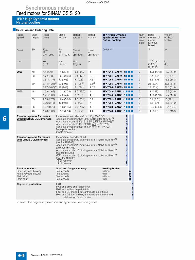
Synchronous motorsFeed motors for SINAMICS S1201FK7 High Dynamic motorsNatural cooling
6/46 Siemens NC 61 · 2007/2008
6
■ Selection and Ordering Data
To select the degree of protection and type, see Selection guides.
Rated speed
Shaftheight
Rated power
Static torque
Ratedtorque1)
Rated current
1FK7 High Dynamic synchronous motorNatural cooling
Num-ber ofpole pairs
Rotor moment of inertia (without brake)
Weight (without brake)
nrated SH Prated at ∆T=100 K
M0 at ∆T=100 K
Mratedat ∆T=100 K
Irated at ∆T=100 K
Order No. J m
rpm kW (HP)
Nm (lbƒ-in)
Nm (lbƒ-in)
A 10-4 kgm2 (10-3 x lbƒ-in-s2)
kg (lb)
3000 48 1.1 (1.48) 4 (35.4) 3.5 (31.0) 4 1FK7044 - 7AF71- 17 7 7 3 1.28 (1.13) 7.7 (17.0)
63 1.7 (2.28)2.51 (3.37)
6.4 (56.6)12 (106)
5.4 (47.8)8 (70.8)
5.37.5
1FK7061 - 7AF71- 17 7 71FK7064 - 7AF71- 17 7 7
33
3.4 (3.01)6.5 (5.75)
10 (22.1)15.5 (34.2)
80 3.14 (4.21)2)
3.77 (5.06)3)22 (195)28 (248)
12 (106)2)
18 (159)3)12.52)
14.53)1FK7085 - 7AF71- 17 7 71FK7086 - 7AF71- 17 7 7
44
23 (20.4)23 (20.4)
23.5 (51.8)23.5 (51.8)
4500 48 1.23 (1.65)1.41 (1.89)
3.1 (27.4)4 (35.4)
2.6 (23.0)3 (26.6)
44.9
1FK7043 - 7AH71- 17 7 71FK7044 - 7AH71- 17 7 7
33
1 (0.89)1.28 (1.13)
6.3 (13.9)7.7 (17.0)
63 2.03 (2.72)2.36 (3.16)
6.4 (56.6)12 (106)
4.3 (38.1)5 (44.3)
5.97
1FK7061 - 7AH71- 17 7 71FK7064 - 7AH71- 17 7 7
33
3.4 (3.01)6.5 (5.75)
10 (22.1)15.5 (34.2)
6000 36 0.57 (0.76) 1.3 (11.5) 0.9 (7.97) 1.5 1FK7033 - 7AK71- 17 7 7 3 0.27 (0.24) 3.1 (6.84)
48 1.26 (1.69) 3.1 (27.4) 2 (17.7) 4.4 1FK7043 - 7AK71- 17 7 7 3 1 (0.89) 6.3 (13.9)
Encoder systems for motors without DRIVE-CLiQ interface:
Incremental encoder sin/cos 1 Vpp 2048 S/RAbsolute encoder EnDat 2048 S/R (not for 1FK703)1)
Absolute encoder EnDat 512 S/R (only for 1FK703)1)
Absolute encoder EnDat 32 S/R (not for 1FK703)1)
Absolute encoder EnDat 16 S/R (only for 1FK703)1)
Multi-pole resolver2-pole resolver
AEHGJST
Encoder systems for motors with DRIVE-CLiQ interface:
Incremental encoder 22 bit Absolute encoder 22 bit single-turn + 12 bit multi-turn1) (not for 1FK703)Absolute encoder 20 bit single-turn + 12 bit multi-turn1) (only for 1FK703)Absolute encoder 16 bit single-turn + 12 bit multi-turn1) (not for 1FK703)Absolute encoder 15 bit single-turn + 12 bit multi-turn1) (only for 1FK703)15 bit resolver14 bit resolver
DF
L
K
V
UP
Shaft extension:Fitted key and keywayFitted key and keywayPlain shaftPlain shaft
Shaft and flange accuracy: Tolerance NTolerance NTolerance NTolerance N
Holding brake:withoutwithwithoutwith
ABGH
Degree of protection: IP64IP65 and drive end flange IP67IP64 and anthracite paint finishIP65 and DE flange IP67, anthracite paint finishIP65 and DE flange IP67, anthracite paint finish and
metal rating plate on motor
02358
© Siemens AG 2007© Siemens AG 2007

Synchronous motorsFeed motors for SINAMICS S120
1FK7 High Dynamic motorsNatural cooling
6/47Siemens NC 61 · 2007/2008
6
■ Selection and Ordering Data
1) If the absolute encoder is used, Mrated is reduced by 10%.2) These values refer to n = 2500 rpm.3) These values refer to n = 2000 rpm.4) The current carrying capacity of the power cables complies with IEC 60204-1 for installation type C under continuous operating conditions at an
ambient air temperature of 40 °C (104 °F), designed for I0 (100 K), PVC/PUR-insulated cable.5) With default setting of the pulse frequency.6)
Motor type(continued)
Static current
Calculated powerPcalc
6)
SINAMICS S120 Motor Module Power cable with complete shieldMotor connection (and brake connection) via power connectorRated
output current5)
Booksize format
I0 at M0 ∆T=100 K
Pcalcfor M0 ∆T=100 K
Irated Order No. Power connector
Motor cable cross-section4)
Order No.Pre-assembled cable
A kW (HP)
A Size mm2
1FK7044-7AF71... 4.5 1.3 (1.74) 5 6SL3127 - 7TE15 - 0AA3 1 4 x 1.5 6FX7 002 - 57S01 - ....
1FK7061-7AF71...1FK7064-7AF71...
6.111
2.0 (2.68)3.8 (5.10)
918
6SL3127 - 7TE21 - 0AA36SL3127 - 7TE21 - 8AA3
11
4 x 1.54 x 1.5
6FX7 002 - 57S01 - ....6FX7 002 - 57S01 - ....
1FK7085-7AF71...1FK7086-7AF71...
22.521
6.9 (9.25)8.8 (11.8)
3030
6SL3127 - 1TE23 - 0AA36SL3127 - 1TE23 - 0AA3
1.51.5
4 x 44 x 4
6FX7 002 - 57S41 - ....6FX7 002 - 57S41 - ....
1FK7043-7AH71...1FK7044-7AH71...
4.56.3
1.5 (2.01)1.9 (2.55)
59
6SL3127 - 7TE15 - 0AA36SL3127 - 7TE21 - 0AA3
11
4 x 1.54 x 1.5
6FX7 002 - 57S01 - ....6FX7 002 - 57S01 - ....
1FK7061-7AH71...1FK7064-7AH71...
815
3.0 (4.02)5.7 (7.64)
918
6SL3127 - 7TE21 - 0AA36SL3127 - 7TE21 - 8AA3
11
4 x 1.54 x 1.5
6FX7 002 - 57S01 - ....6FX7 002 - 57S01 - ....
1FK7033-7AK71... 2.2 0.8 (1.07) 3 6SL3127 - 7TE13 - 0AA3 1 4 x 1.5 6FX7 002 - 57S01 - ....
1FK7043-7AK71... 6.4 1.9 (2.55) 9 6SL3127 - 7TE21 - 0AA3 1 4 x 1.5 6FX7 002 - 57S01 - ....
Cooling:Internal air coolingExternal air cooling
01
Motor Module:Single Motor ModuleDouble Motor Module
12
Type of power cable:MOTION-CONNECT 800MOTION-CONNECT 500
85
Without brake coresWith brake cores
CD
For length code as well as power and signal cables, see Connection system MOTION-CONNECT. ....
Pcalc [kW] =M0 [Nm] x nrated
9550 Pcalc [HP] =M0 [lbƒ-in] x nrated
63000
© Siemens AG 2007© Siemens AG 2007

Synchronous motorsFeed motors for SINAMICS S1201FK7 Compact/High Dynamic motorsNatural cooling for Power Modules
6/48 Siemens NC 61 · 2007/2008
6
■ Selection and Ordering Data
To select the degree of protection and type, see Selection guides.
Rated speed
Shaftheight
Rated power
Static torque
Ratedtorque1)
Rated current
1FK7 Compact/1FK7 High Dynamicsynchronous motorNatural coolingConnection to SINAMICS230 V 1 AC
Num-ber ofpole pairs
Rotor moment of inertia (without brake)
Weight (without brake)
nrated SH Prated at ∆T=100 K
M0 at ∆T=100 K
Mratedat ∆T=100 K
Irated at ∆T=100 K
Order No. J m
rpm kW (HP)
Nm (lbƒ-in)
Nm (lbƒ-in)
A 10-4 kgm2 (10-3 x lbƒ-in-s2)
kg (lb)
3000 36 0.31 (0.42)0.38 (0.51)0.46 (0.62)
1.15 (10.2)1.3 (11.5)1.6 (14.2)
1.0 (8.85)1.2 (10.6)1.45 (12.8)
1.621.8
1FK7032 - 5AF21- 17 7 71FK7033 - 7AF21- 17 7 71FK7034 - 5AF21- 17 7 7
333
0.61 (0.54)0.27 (0.24)0.9 (0.80)
2.7 (5.95)3.1 (6.84)3.7 (8.16)
48 0.82 (1.10)0.79 (1.06)
3 (26.6)2.7 (23.9)
2.6 (23.0)2.5 (22.1)
3.53.8
1FK7042 - 5AF21- 17 7 71FK7043 - 7AF21- 17 7 7
43
3.01 (2.66)1 (0.89)
4.9 (10.8)6.3 (13.9)
6000 20 0.05 (0.07)0.10 (0.13)
0.18 (1.59)0.35 (3.10)
0.08 (0.71)0.16 (0.42)
0.50.5
1FK7011 - 5AK21-17 7 31FK7015 - 5AK21-17 7 3
44
0.064 (0.06)0.083 (0.07)
0.9 (1.98)1.1 (2.43)
28 0.38 (0.51) 0.85 (7.52) 0.6 (5.31) 1.4 1FK7022 - 5AK21-17 7 7 3 0.28 (0.25) 1.8 (3.97)
Synchronous motor: 1FK7 Compact1FK7 High Dynamic
57
Encoder systems for motors without DRIVE-CLiQ interface:
Incremental encoder sin/cos 1 Vpp 2048 S/RAbsolute encoder EnDat 2048 S/R (only for 1FK704)1)
Absolute encoder EnDat 512 S/R (not for 1FK704)1)
Absolute encoder EnDat 32 S/R (only for 1FK704)1)
Absolute encoder EnDat 16 S/R (not for 1FK704)1)
Multi-pole resolver2-pole resolver
AEHGJST
Encoder systems for motors with DRIVE-CLiQ interface:4)
Incremental encoder 22 bit (not for 1FK701)Absolute encoder 22 bit single-turn + 12 bit multi-turn1) (only for 1FK704)Absolute encoder 20 bit single-turn + 12 bit multi-turn1) (only for 1FK702/1FK703)Absolute encoder 16 bit single-turn + 12 bit multi-turn1) (only for 1FK704)Absolute encoder 15 bit single-turn + 12 bit multi-turn1) (not for 1FK704)15 bit resolver (not for 1FK701)14 bit resolver (not for 1FK701)
D
F
L
K
V
UP
Shaft extension:Fitted key and keywayFitted key and keywayPlain shaftPlain shaft
Shaft and flange accuracy: Tolerance NTolerance NTolerance NTolerance N
Holding brake:withoutwithwithoutwith
ABGH
Degree of protection: IP64 (not for 1FK701)IP65 and DE flange IP67 (not for 1FK701)IP64 (IP54 with 1FK701) and anthracite paint finishIP65 and DE flange IP67, anthracite paint finish
(not for 1FK701)IP65 and DE flange IP67, anthracite paint finish and
metal rating plate on motor (not for 1FK701)
0235
8
© Siemens AG 2007© Siemens AG 2007

Synchronous motorsFeed motors for SINAMICS S120
1FK7 Compact/High Dynamic motorsNatural cooling for Power Modules
6/49Siemens NC 61 · 2007/2008
6
■ Selection and Ordering Data
1) If the absolute encoder is used, Mrated is reduced by 10%.2) This power cable is fitted with a connector with M17 thread at the motor end and brake cores as standard (4 x 1.5 mm2 + 2 x 1.5 mm2).3) The current carrying capacity of the power cables complies with IEC 60204-1 for installation type C under continuous operating conditions at an
ambient air temperature of 40 °C (104 °F), designed for I0 (100 K), PVC/PUR-insulated cable.4) Motors with shaft height 20 are not available with a DRIVE-CLiQ interface. The encoder systems are connected via the SMC
(Sensor Module Cabinet-Mounted).5) With default setting of the pulse frequency.6)
Motor type(continued)
Static current
Calculated powerPcalc
6)
SINAMICS S120 Power Module Power cable with complete shieldMotor connection (and brake connection) via power connectorRated
output current5)
Blocksize formatwithout line filter
I0 at M0 ∆T=100 K
Pcalcfor M0 ∆T=100 K
Irated Order No. Power connector
Motor cable cross-section3)
Order No.Pre-assembled cable
A kW(HP)
A Size mm2
1FK7032-5AF21...1FK7033-7AF21...1FK7034-5AF21...
1.72.11.9
0.36 (0.48)0.41 (0.55)0.5 (0.67)
2.32.32.3
6SL3210-1SB12-3UA06SL3210-1SB12-3UA06SL3210-1SB12-3UA0
111
4 x 1.54 x 1.54 x 1.5
6FX7 002 - 57G01 - ....6FX7 002 - 57G01 - ....6FX7 002 - 57G01 - ....
1FK7042-5AH21...1FK7043-7AH21...
3.93.9
0.94 (1.26)0.85 (1.14)
3.93.9
6SL3210-1SB14-0UA06SL3210-1SB14-0UA0
11
4 x 1.54 x 1.5
6FX7 002 - 57G01 - ....6FX7 002 - 57G01 - ....
1FK7011-5AK21...1FK7015-5AK21...
0.850.85
0.11 (0.15)0.22 (0.30)
0.90.9
6SL3210-1SB11-0UA06SL3210-1SB11-0UA0
0.50.5
4 x 1.54 x 1.5
6FX5 002 - 5DA30 - ....2)
6FX5 002 - 5DA30 - ....2)
1FK7022-5AK21... 1.8 0.53 (0.71) 2.3 6SL3210-1SB12-3UA0 1 4 x 1.5 6FX7 002 - 57G01 - ....
Type of power cable:MOTION-CONNECT 800MOTION-CONNECT 500
85
Without brake coresWith brake cores
CD
For length code as well as power and signal cables, see Connection system MOTION-CONNECT. ....
Pcalc [kW] =M0 [Nm] x nrated
9550 Pcalc [HP] =M0 [lbƒ-in] x nrated
63000
© Siemens AG 2007© Siemens AG 2007

Synchronous motorsGearboxesSeries SP+ planetary gearbox for 1FT6 motors
6/50 Siemens NC 61 · 2007/2008
6
■ Overview
1FT6 motors can be combined with planetary gearboxes to form compact coaxial drive units. The gearboxes are flanged directly to the drive end of the motors.
When selecting the gearboxes, ensure that the permissible speed of the gearbox is not exceeded by the maximum speed of the motor. In the case of high operating frequencies, allow-ance must be made for the factor f2 (see Configuration Manual for synchronous motors). The frictional losses of the gearbox must always be taken into account in planning.
The gearboxes are only available in non-balanced design.
■ Benefits
7 High efficiencySingle-stage: > 97%Two-stage: > 94%
7 Minimum torsional backlashSingle-stage: ≤ 4 arcminTwo-stage: ≤ 6 arcmin
7 Power transmission from the central sun wheel via planet wheels
7 No shaft deflections in the planet wheel set due to symmetrical force distribution
7 Very low moment of inertia and hence short acceleration times of the motors
7 Output shaft bearings dimensioned for high lateral and axial loads with preloaded tapered-roller bearings
7 The gearboxes are connected to the motor shaft via an integrated clamping hub. A plain motor shaft extension is necessary for this purpose. Shaft and flange accuracy toler-ance N in accordance with DIN 42955 and vibration magni-tude grade A in accordance with EN 60034-14 are sufficient. The motor flange is adapted by means of adapter plates.
7 Output shaft of gearbox exactly coaxial with the motor7 The gearboxes are enclosed (seal between gearbox and
motor) and filled with oil at the factory. They are lubricated and sealed for their service life. Gearboxes of frame sizes SP 060S to SP 180S are suitable for all mounting positions. The oil filling quantity for gearboxes of frame sizes SP 210 and SP 240 depends on the mounting position. The mounting position has to be specified when ordering.
7 Degree of protection of gearbox: IP65 (IP64 for frame sizes SP 210/SP 240)
7 Small dimensions7 Low weight
Synchronous motor with mounted planetary gearbox series SP+
■ Integration
1FT602 and 1FT613 motors can be supplied ex works (Siemens AG) complete with flange-mounted planetary gearbox.
The gearboxes assigned to the individual motors and gear ratios i available for these motor/gearbox combinations are listed in the selection table. When making a selection, account must be taken of the maximum permissible input speed of the gear-box (this is the same as the maximum motor speed).
The motor/gearbox combinations listed in the selection tables are mainly intended for cycle operation S3-60% (ON time ≤ 60% and ≤ 20 min). Reduced maximum motor speeds and output torques apply for use in S1 continuous duty (ON time > 60% or > 20 min). The gearbox temperature must not exceed 90 °C (194 °F).
Follow the instructions contained in the Configuration Manual for synchronous motors when assigning gearboxes to the motor.
1FT6 motors must be designed with plain motor shaft extension, shaft and flange accuracy tolerance N and vibration magnitude grade A/degree of protection IP65 (for 1FT602: IP64) for mounting onto the gearbox.
© Siemens AG 2007© Siemens AG 2007

Synchronous motorsGearboxes
Series SP+ planetary gearboxes, single-stagefor 1FT6 motors
6/51Siemens NC 61 · 2007/2008
6
■ Selection and Ordering Data
✔ Possible – Not possible1) In reference to the output shaft center.2) For these versions, the quantity of oil in the gearbox depends on the mounting position. In the case of a vertical mounting position, the 12th position
in the Order No. should be "9" and a further order code also has to be specified: 1FT6...-...79-.. 7 1-Z J.. + M1 7
3) IP64 degree of protection with 1FT602.: 1FT602.-6AK71-.. 7 0-Z J..
Motor Planetary gearbox Single-stage
Available gear ratios i =
Motor speed, max.S3-60%
Output torque, max. S3-60%
Radial load onoutput shaft, max.1)
Axial load onoutput shaft, max.1)
Type Type Tor-sional back-lash
Weight of gearbox, approx.
4 5 7 10 nG1
(n1)
MG2
(T2B)
Fr
(F2Rmax)
Fa
(F2Amax)
arcmin kg (lb) rpm Nm (lbƒ-ft) N (lbƒ) N (lbƒ)
1FT60211FT6024
SP 060S-MF1 ≤ 4 1.9 (4.19)
–✔
–✔
–✔
✔
✔
6000 40 (29.5)(32 (23.6) for i = 10)
2700 (607)
2400 (540)
1FT60311FT6034
✔
✔
✔
✔
✔
✔
✔
–
1FT6034 SP 075S-MF1 ≤ 4 3.9 (8.6)
– – – ✔ 6000 110 (81.1)(90 (66.4) for i = 10)
4000 (899)
3350 (753)1FT6041
1FT6044✔
✔
✔
✔
✔
✔
✔
✔
1FT60611FT60621FT6064
SP 100S-MF1 ≤ 3 7.7 (17)
✔
✔
✔
✔
✔
✔
✔
✔
✔
✔
✔
✔
4500 300 (221)(225 (167) for i = 10)
6300 (1416)
5650 (1270)
1FT60811FT60821FT60841FT6086
SP 140S-MF1 ≤ 3 17.2 (37.9)
✔
✔
✔
✔
✔
✔
✔
✔
✔
✔
✔
✔
✔
✔
✔
–
4000 600 (442)(480 (354) for i = 10)
9450 (2124)
9870 (2219)
1FT6086 SP 180S-MF1 ≤ 3 34 (75)
– – – ✔ 3500 1100 (811)(880 (649) for i = 10)
14700 (3305)
14150 (3181)
1FT6102 1FT61051FT6108
✔
✔
✔
✔
✔
✔
✔
✔
✔
✔
––
1FT61051FT6108
SP 210-MF12) ≤ 4 53 (117)
––
––
––
✔
✔
2500 1900 (1400)(1520 (1120) for i = 10)
18000 (4047)
22500 (5058)
1FT61321FT61341FT6136
✔
✔
✔
✔
✔
✔
✔
✔
✔
✔
––
1FT61341FT6136
SP 240-MF12) ≤ 4 80 (176)
––
––
––
✔
✔
2200 2720 (2005) 27000 (6070)
27800 (6250)
Order codes• Gearbox shaft with fitted key J02 J03 J05 J09• Gearbox shaft without fitted key J22 J23 J25 J29
Ordering data: 1FT6 ... -... 71-..7 1-Z
without holding brakewith holding brake
Order No. of the motor with identifier "-Z" andorder code for mounting the planetary gearbox assigned to the motorPreconditions for mounting planetary gearboxes:Plain motor shaft extension/shaft and flange accuracy tolerance N and vibration magnitude grade A/IP65 degree of protection3)
J7 7 GH
GH
H Mounting position IM V1G Mounting position IM V3
GH
© Siemens AG 2007© Siemens AG 2007

Synchronous motorsGearboxesSeries SP+ planetary gearboxes, single-stagefor 1FT6 motors
6/52 Siemens NC 61 · 2007/2008
6
■ Technical specifications
1) The limit values in the table apply for S1 continuous duty (ON time > 60% or > 20 min) for a maximum gearbox temperature of 90 °C (194 °F).
Planetary gearbox with 1FT6 motor
Single-stageType
Gear ratio Motor speed
Output torque
Moments of inertia of gearbox (referred to the drive)
Continuous duty S11) 1FT602. 1FT603. 1FT604. 1FT606. 1FT608. 1FT610. 1FT613.
nrated 1 Mrated 2 (T2 rated)
J1 J1 J1 J1 J1 J1 J1
rpm Nm(lbƒ-in)
kgcm2
(lbƒ-in2)kgcm2
(lbƒ-in2)kgcm2
(lbƒ-in2)kgcm2
(lbƒ-in2)kgcm2
(lbƒ-in2)kgcm2
(lbƒ-in2)kgcm2
(lbƒ-in2)
SP 060S-MF1 4 3300 26 (230) 0.16 (0.05) 0.24 (0.08) – – – – –
5 3300 26 (230) 0.13 (0.04) 0.22 (0.08) – – – – –
7 4000 26 (230) 0.11 (0.04) 0.19 (0.06) – – – – –
10 4000 17 (151) 0.10 (0.03) 0.18 (0.06) – – – – –
SP 075S-MF1 4 2900 75 (664) – 0.69 (0.24) 0.94 (0.32) – – – –
5 2900 75 (664) – 0.58 (0.20) 0.83 (0.28) – – – –
7 3100 75 (664) – 0.48 (0.16) 0.73 (0.25) – – – –
10 3100 52 (460) – 0.42 (0.14) 0.67 (0.23) – – – –
SP 100S-MF1 4 2500 180 (1593) – – – 3.65 (1.25) – – –
5 2500 175 (1549) – – – 2.99 (1.02) – – –
7 2800 170 (1505) – – – 2.81 (0.96) – – –
10 2800 120 (1062) – – – 2.58 (0.88) – – –
SP 140S-MF1 4 2100 360 (3186) – – – – 14.3 (4.89) – –
5 2100 360 (3186) – – – – 13.1 (4.48) – –
7 2600 360 (3186) – – – – 12 (4.1) – –
10 2600 220 (1947) – – – – 11.4 (3.90) – –
SP 180S-MF1 4 1500 750 (6638) – – – – 45.1 (15.4) 45.1 (15.4) –
5 1500 750 (6638) – – – – 36.4 (12.4) 36.4 (12.4) –
7 2300 750 (6638) – – – – 28.6 (9.77) 28.6 (9.77) –
10 2300 750 (6638) – – – – 24.4 (8.34) 24.4 (8.34) –
SP 210-MF1 4 1200 1000 (8851) – – – – – 75.8 (25.9) 75.8 (25.9)
5 1200 1000 (8851) – – – – – 63.5 (21.7) 63.5 (21.7)
7 1700 1000 (8851) – – – – – 52.9 (18.1) 52.9 (18.1)
10 1700 1000 (8851) – – – – – 47.1 (16.1) 47.1 (16.1)
SP 240-MF1 4 1000 1700 (15046) – – – – – – 146 (49.9)
5 1000 1700 (15046) – – – – – – 120 (41.0)
7 1500 1700 (15046) – – – – – – 96.4 (32.9)
10 1500 1700 (15046) – – – – – – 83.1 (28.4)
© Siemens AG 2007© Siemens AG 2007

Synchronous motorsGearboxes
Series SP+ planetary gearbox, two-stagefor 1FT6 motors
6/53Siemens NC 61 · 2007/2008
6
■ Selection and Ordering Data
1) In reference to the output shaft center.2) For these versions, the quantity of oil in the gearbox depends on the mounting position. In the case of a vertical mounting position, the 12th position
in the Order No. should be "9" and a further order code also has to be specified: 1FT6...-.A.79-.. 7 1-Z J.. + M1 7
3) IP64 degree of protection with 1FT602.: 1FT602.-6AK71-.. 7 0-Z J..
Motor Planetary gearboxTwo-stage
Available gear ratios i =
Motor speed,max.S3-60%
Output torque, max. S3-60%
Radial load onoutput shaft,max.1)
Axial load onoutput shaft,max.1)
Type Type Tor-sional back-lash
Weight of gearbox, approx.
16 20 28 40 50 nG1
(n1)
MG2
(T2B)
Fr
(F2Rmax)
Fa
(F2Amax)
arcmin kg (lb) rpm Nm (lbƒ-ft) N (lbƒ) N (lbƒ)
1FT60211FT6024
SP 060S-MF2 ≤ 6 2 (4.41)
✔
✔
✔
✔
✔
✔
✔
✔
✔
–6000 40 (29.5) 2700
(607)2400 (540)
1FT6031 ✔ ✔ ✔ – –1FT6024 SP 075S-MF2 ≤ 6 3.6
(7.94)– – – – ✔ 6000 110 (81.1) 4000
(899)3350 (753)1FT6031
1FT6034–✔
–✔
–✔
✔
–✔
–1FT6041 ✔ ✔ – – –1FT6034 SP 100S-MF2 ≤ 5 7.9
(17.4)– – – ✔ ✔ 4500 300 (221) 6300
(1416)5650 (1270)1FT6041
1FT6044–✔
–✔
✔
✔
✔
–✔
–1FT60611FT60621FT6064
✔
✔
✔
✔
✔
–
✔
✔
–
✔
––
–––
1FT6044 SP 140S-MF2 ≤ 5 17 (37.5)
– – – ✔ ✔ 4000 600 (443) 9450 (2124)
9870 (2219)1FT6061
1FT60621FT6064
–––
––✔
––✔
–✔
–
✔
✔
–1FT60811FT60821FT6084
✔
✔
✔
✔
✔
–
✔
––
✔
––
–––
1FT6064 SP 180S-MF2 ≤ 5 36.4 (80.3)
– – – ✔ ✔ 4000 1100 (811) 14700 (3305)
14150 (3181)1FT6081
1FT60821FT60841FT6086
–––✔
––✔
✔
–✔
✔
–
–✔
––
✔
–––
1FT6102 ✔ ✔ – – –1FT6082 SP 210-MF2 2) ≤ 6 50
(110)– – – – ✔ 3500 1900 (1401) 18000
(4047)22500 (5058)1FT6105 ✔ – – – –
1FT60841FT6086
SP 240-MF2 2) ≤ 6 70 (154)
––
––
–✔
✔
✔
✔
✔
3500 3400 (2508) 27000 (6070)
27800 (6250)
1FT61021FT61051FT6108
––✔
–✔
✔
✔
✔
–
✔
––
✔
––
1FT61321FT61341FT6136
✔
✔
✔
✔
––
–––
–––
–––
Order codes• Gearbox shaft with fitted key J12 J13 J15 J16 J17• Gearbox shaft without fitted key J32 J33 J35 J36 J37
Ordering data: 1FT6...-...71-..71-Z
without holding brakewith holding brake
Order No. of the motor with identifier "-Z" andorder code for mounting the planetary gearbox assigned to the motorPreconditions for mounting planetary gearboxes:Plain motor shaft extension/shaft and flange accuracy tolerance N and vibration magnitude grade A/IP65 degree of protection3)
J7 7 GH
GH
H Mounting position IM V1G Mounting position IM V3
GH
© Siemens AG 2007© Siemens AG 2007

Synchronous motorsGearboxesSeries SP+ planetary gearbox, two-stagefor 1FT6 motors
6/54 Siemens NC 61 · 2007/2008
6
■ Technical specifications
1) The limit values in the table apply for S1 continuous duty (ON time > 60% or > 20 min) for a maximum gearbox temperature of 90 °C (194 °F).
Planetary gearbox with 1FT6 motor
Two-stageType
Gear ratio Motor speed
Output torque
Moments of inertia of gearbox (referred to the drive)
Continuous duty S11) 1FT602. 1FT603. 1FT604. 1FT606. 1FT608. 1FT610. 1FT613.
nrated 1 Mrated 2 (T2 rated)
J1 J1 J1 J1 J1 J1 J1
rpm Nm(lbƒ-in)
kgcm2
(lbƒ-in2)kgcm2
(lbƒ-in2)kgcm2
(lbƒ-in2)kgcm2
(lbƒ-in2)kgcm2
(lbƒ-in2)kgcm2
(lbƒ-in2)kgcm2
(lbƒ-in2)
SP 060S-MF2 16 4400 26 (230) 0.08 (0.03) 0.18 (0.06) – – – – –
20 4400 26 (230) 0.07 (0.03) 0.17 (0.06) – – – – –
28 4400 26 (230) 0.06 (0.02) 0.16 (0.05) – – – – –
40 4400 26 (230) 0.06 (0.02) 0.16 (0.05) – – – – –
50 4800 26 (230) 0.06 (0.02) 0.16 (0.05) – – – – –
SP 075S-MF2 16 3500 75 (664) 0.17 (0.06) 0.25 (0.08) 0.68 (0.23) – – – –
20 3500 75 (664) 0.14 (0.05) 0.22 (0.08) 0.65 (0.22) – – – –
28 3500 75 (664) 0.11 (0.04) 0.19 (0.06) 0.62 (0.21) – – – –
40 3500 75 (664) 0.10 (0.03) 0.18 (0.06) 0.61 (0.21) – – – –
50 3800 75 (664) 0.10 (0.03) 0.18 (0.06) 0.61 (0.21) – – – –
SP 100S-MF2 16 3100 180 (1593) – 0.72 (0.25) 0.96 (0.33) 2.60 (0.89) – – –
20 3100 180 (1593) – 0.60 (0.20) 0.84 (0.29) 2.48 (0.85) – – –
28 3100 180 (1593) – 0.49 (0.17) 0.73 (0.25) 2.36 (0.81) – – –
40 3100 180 (1593) – 0.43 (0.15) 0.67 (0.23) 2.31 (0.79) – – –
50 3500 175 (1549) – 0.43 (0.15) 0.66 (0.23) 2.30 (0.79) – – –
SP 140S-MF2 16 2900 360 (3186) – – 2.79 (0.96) 3.61 (1.23) 9.60 (3.28) – –
20 2900 360 (3186) – – 2.26 (0.77) 3.08 (1.05) 9.07 (3.1) – –
28 2900 360 (3186) – – 1.84 (0.63) 2.66 (0.91) 8.65 (2.96) – –
40 2900 360 (3186) – – 1.58 (0.54) 2.39 (0.82) 8.39 (2.87) – –
50 3200 360 (3186) – – 1.57 (0.54) 2.38 (0.81) 8.37 (2.86) – –
SP 180S-MF2 16 2700 750 (6638) – – – 10.2 (3.48) 15.8 (5.41) 14.4 (4.91) –
20 2700 750 (6638) – – – 8.48 (2.9) 14.1 (4.82) 12.1 (4.12) –
28 2700 750 (6638) – – – 6.90 (2.36) 12.5 (4.27) 11 (3.76) –
40 2700 750 (6638) – – – 6.06 (0.91) 11.6 (3.96) 10.2 (3.48) –
50 2900 750 (6638) – – – 5.98 (2.04) 11.6 (3.96) 10.1 (3.45) –
SP 210-MF2 16 2100 1000 (8851) – – – – 36.3 (12.4) 37.4 (12.8) –
20 2100 1000 (8851) – – – – 34.5 (11.8) 35.6 (12.2) –
28 2100 1000 (8851) – – – – 32.3 (11.0) 33.4 (11.4) –
40 2300 1000 (8851) – – – – 23.1 (7.89) 24.3 (8.3) –
50 2300 1000 (8851) – – – – 21.9 (7.48) 23 (7.86) –
SP 240-MF2 16 1900 1700 (15046) – – – – 47.3 (16.2) 48.4 (16.5) 53 (18.1)
20 1900 1700 (15046) – – – – 43.1 (14.7) 44.2 (15.1) 48.8 (16.7)
28 1900 1700 (15046) – – – – 37.5 (12.8) 38.6 (13.2) 43.2 (14.8)
40 2100 1700 (15046) – – – – 32.4 (11.1) 33.6 (11.5) 38.1 (13)
50 2100 1700 (15046) – – – – 29.5 (10.1) 30.6 (10.5) 35.1 (12)
© Siemens AG 2007© Siemens AG 2007

Synchronous motorsGearboxes
Series SP+ planetary gearboxfor 1FK7 motors
6/55Siemens NC 61 · 2007/2008
6
■ Overview
1FK7 motors can be combined with planetary gearboxes to form compact coaxial drive units. The gearboxes are flanged directly to the drive end of the motors.
When selecting the gearboxes, ensure that the permissible speed of the gearbox is not exceeded by the maximum speed of the motor. In the case of high operating frequencies, allow-ance must be made for the factor f2 (see Configuration Manual for synchronous motors). The frictional losses of the gearbox must always be taken into account in planning.
The gearboxes are only available in non-balanced design.
■ Benefits
7 High efficiencySingle-stage: > 97%Two-stage: > 94%
7 Minimum torsional backlashSingle-stage: ≤ 4 arcmin,two-stage: ≤ 6 arcmin
7 Power transmission from the central sun wheel via planet wheels
7 No shaft deflections in the planet wheel set due to symmetrical force distribution
7 Very low moment of inertia and hence short acceleration times of the motors
7 Output shaft bearings dimensioned for high lateral and axial loads with preloaded tapered-roller bearings
7 The gearboxes are connected to the motor shaft via an integrated clamping hub. A plain motor shaft extension is necessary for this purpose. Shaft and flange accuracy tolerance N in accordance with DIN 42955 and vibration magnitude grade A in accordance with EN 60034-14 are sufficient. The motor flange is adapted by means of adapter plates.
7 Output shaft of gearbox exactly coaxial with the motor7 The gearboxes are enclosed (seal between gearbox and
motor) and filled with oil at the factory. They are lubricated and sealed for their service life. Gearboxes of frame sizes SP 060S to SP 180S are suitable for all mounting positions. The oil filling quantity for gearboxes of frame sizes SP 210 and SP 240 de-pends on the mounting position. The mounting position has to be specified when ordering.
7 Degree of protection of gearbox: IP65 (IP64 for frame sizes SP 210/SP 240)
7 Small dimensions7 Low weight
Synchronous motor with mounted planetary gearbox series SP+
■ Integration
1FK702 to 1FK710 motors can be supplied ex works (Siemens AG) complete with flange-mounted planetary gearbox.
The gearboxes assigned to the individual motors and gear ratios i available for these motor/gearbox combinations are listed in the selection table. When making a selection, account must be taken of the maximum permissible input speed of the gear-box (this is the same as the maximum motor speed).
The motor/gearbox combinations listed in the selection tables are mainly intended for cycle operation S3-60% (ON time ≤ 60% and ≤ 20 min). Reduced maximum motor speeds and output torques apply for use in S1 continuous duty (ON time > 60% or > 20 min). The gearbox temperature must not exceed 90 °C (194 °F).
Follow the instructions contained in the Configuration Manual for synchronous motors when assigning gearboxes to the motor.
1FK7 motors must be designed with plain motor shaft extension/ shaft and flange accuracy tolerance N, degree of protection IP65 and anthracite paint finish for mounting onto the gearbox.
© Siemens AG 2007© Siemens AG 2007

Synchronous motorsGearboxesSeries SP+ planetary gearbox, single-stagefor 1FK7 motors
6/56 Siemens NC 61 · 2007/2008
6
■ Selection and Ordering Data
✔ Possible– Not possible1) In reference to the output shaft center.2) For these versions, the quantity of oil in the gearbox depends on the mounting position. In the case of a vertical mounting position, the 12th position
in the Order No. should be "9" and a further order code also has to be specified: 1FK7...-.A.79-.. 7 5-Z J.. + M1 7
MotorNaturalcooling
Planetary gearbox Single-stage
Available gear ratios i =
Motor speed,max.S3-60%
Output torque, max. S3-60%
Radial load onoutput shaft,max.1)
Axial load onoutput shaft,max.1)
Type Type Tor-sional back-lash
Weight of gearbox, approx.
4 5 7 10 nG1
(n1)
MG2
(T2B)
Fr
(F2Rmax)
Fa
(F2Amax)
arcmin kg (lb) rpm Nm (lbƒ-ft) N (lbƒ) N (lbƒ)
1FK7022 SP 060S-MF1 ≤ 4 1.9 (4.19)
✔ ✔ ✔ ✔ 6000 40 (29.5)(32 (23.6) for i = 10)
2700 (607)
2400 (540)
1FK70321FK70331FK7034
✔
✔
✔
✔
✔
✔
✔
✔
✔
✔
✔
✔
1FK70401FK70421FK70431FK7044
SP 075S-MF1 ≤ 4 3.9 (8.60)
✔
✔
✔
✔
✔
✔
✔
✔
✔
✔
✔
✔
✔
✔
✔
✔
6000 110 (81.1)(90 (66.4) for i = 10)
4000 (899)
3350 (753)
1FK70601FK70611FK70631FK7064
SP 100S-MF1 ≤ 3 7.7 (17.0)
✔
✔
✔
✔
✔
✔
✔
✔
✔
✔
✔
✔
✔
✔
✔
✔
4500 300 (221)(225 (166) for i = 10)
6300 (1416)
5650 (1270)
1FK70801FK70821FK70831FK70851FK7086
SP 140S-MF1 ≤ 3 17.2 (37.9)
✔
✔
✔
✔
✔
✔
✔
✔
✔
✔
✔
✔
✔
✔
✔
✔
✔
✔
✔
✔
4000 600 (443)(480 (354) for i = 10)
9450 (2124)
9870 (2219)
1FK71001FK71011FK71031FK7105
SP 180S-MF1 ≤ 3 34 (75)
✔
✔
✔
✔
✔
✔
✔
✔
✔
✔
✔
✔
✔
✔
✔
–
3500 1100 (811) 14700 (3305)
14150 (3181)
1FK7105 SP 210-MF12) ≤ 4 53 (117)
– – – ✔ 2200 2720 (2006) 18000 (4047)
22500 (5058)
Order codes• Gearbox shaft with fitted key J02 J03 J05 J09• Gearbox shaft without fitted key J22 J23 J25 J29
Ordering data: 1FK7...-.A.71-..75-Z
without holding brakewith holding brake
Order No. of the motor with identifier "-Z" andorder code for mounting the planetary gearbox assigned to the motorPreconditions for mounting planetary gearboxes:Plain motor shaft extension and IP65 degree of protection, anthracite paint finish
J7 7 GH
GH
H Mounting position IM V1G Mounting position IM V3
© Siemens AG 2007© Siemens AG 2007

Synchronous motorsGearboxes
Series SP+ planetary gearbox, single-stagefor 1FK7 motors
6/57Siemens NC 61 · 2007/2008
6
■ Technical specifications
1) The limit values in the table apply for S1 continuous duty (ON time > 60% or > 20 min) for a maximum gearbox temperature of 90 °C (194 °F).
Planetary gearbox with 1FK7 motor, natural cooling
Single-stageType
Gear ratio Motor speed
Output torque
Moments of inertia of gearbox (referred to the drive)
Continuous duty S11) 1FK702. 1FK703. 1FK704. 1FK706. 1FK708. 1FK710.
nrated1 Mrated 2 (T2 rated)
J1 J1 J1 J1 J1 J1
rpm Nm(lbƒ-in)
kgcm2
(lbƒ-in2)kgcm2
(lbƒ-in2)kgcm2
(lbƒ-in2)kgcm2
(lbƒ-in2)kgcm2
(lbƒ-in2)kgcm2
(lbƒ-in2)
SP 060S-MF1 4 3300 26 (230) 0.16 (0.05) 0.24 (0.08) – – – –
5 3300 26 (230) 0.13 (0.04) 0.22 (0.08) – – – –
7 4000 26 (230) 0.11 (0.04) 0.19 (0.06) – – – –
10 4000 17 (151) 0.10 (0.03) 0.18 (0.06) – – – –
SP 075S-MF1 4 2900 75 (664) – – 0.94 (0.32) – – –
5 2900 75 (664) – – 0.83 (0.28) – – –
7 3100 75 (664) – – 0.73 (0.25) – – –
10 3100 52 (460) – – 0.67 (0.23) – – –
SP 100S-MF1 4 2500 180 (1593) – – – 3.65 (1.25) – –
5 2500 175 (1549) – – – 2.99 (1.02) – –
7 2800 170 (1505) – – – 2.81 (0.96) – –
10 2800 120 (1062) – – – 2.58 (0.88) – –
SP 140S-MF1 4 2100 360 (3186) – – – – 14.3 (4.89) –
5 2100 360 (3186) – – – – 13.1 (4.48) –
7 2600 360 (3186) – – – – 12 (4.1) –
10 2600 220 (1947) – – – – 11.4 (3.90) –
SP 180S-MF1 4 1500 750 (6638) – – – – – 45.1 (15.4)
5 1500 750 (6638) – – – – – 36.4 (12.4)
7 2300 750 (6638) – – – – – 28.6 (9.77)
10 2300 750 (6638) – – – – – 24.4 (8.34)
SP 210-MF1 4 1200 1000 (8851) – – – – – 75.8 (25.9)
5 1200 1000 (8851) – – – – – 63.5 (21.7)
7 1700 1000 (8851) – – – – – 52.9 (18.1)
10 1700 1000 (8851) – – – – – 47.1 (16.1)
© Siemens AG 2007© Siemens AG 2007

Synchronous motorsGearboxesSeries SP+ planetary gearbox, two-stagefor 1FK7 motors
6/58 Siemens NC 61 · 2007/2008
6
■ Selection and Ordering Data
✔ Possible– Not possible1) In reference to the output shaft center.
MotorNaturalcooling
Planetary gearboxTwo-stage
Available gear ratios i =
Motor speed,max.S3-60%
Output torque, max. S3-60%
Radial load onoutput shaft,max.1)
Axial load onoutput shaft,max.1)
Type Type Tor-sional back-lash
Weight of gearbox, approx.
16 20 28 40 50 nG1
(n1)
MG2
(T2B)
Fr
(F2Rmax)
Fa
(F2Amax)
arcmin kg (lb) rpm Nm (lbƒ-ft) N (lbƒ) N (lbƒ)
1FK7022 SP 060S-MF2 ≤ 6 2 (4.4)
✔ ✔ ✔ – – 6000 40 (29)
2700 (607)
2400 (540)1FK7032
1FK7033✔
✔
✔
✔
––
––
––
1FK7022 SP 075S-MF2 ≤ 6 3.6 (7.9)
– – – ✔ ✔ 6000 110 (81)
4000 (899)
3350 (753)1FK7032
1FK70331FK7034
––✔
––✔
✔
✔
✔
✔
✔
–
✔
✔
–1FK70401FK70421FK7043
✔
✔
✔
✔
✔
–
✔
––
–––
–––
1FK70341FK70401FK70421FK70431FK7044
SP 100S-MF2 ≤ 5 7.9 (17.4)
––––✔
–––✔
✔
––✔
✔
✔
✔
✔
✔
✔
✔
✔
✔
✔
✔
–
4500 300 (221)
6300 (1416)
5650 (1270)
1FK70601FK7061
✔
✔
✔
✔
✔
–––
––
1FK7044 SP 140S-MF2 ≤ 5 17 (17.4)
– – – – ✔ 4000 600 (442)
9450 (2124)
9870 (2219)1FK7060
1FK70611FK70631FK7064
––✔
✔
––✔
✔
–✔
✔
✔
✔
✔
––
✔
✔
––
1FK70801FK70821FK7083
✔
✔
✔
✔
✔
✔
✔
––
✔
––
–––
Order codes• Gearbox shaft with fitted key J12 J13 J15 J16 J17• Gearbox shaft without fitted key J32 J33 J35 J36 J37
Ordering data: 1FK7...-.A.71-..75-Z
without holding brakewith holding brake
Order No. of the motor with identifier "-Z" and order code for mounting the planetary gearbox assigned to the motorPreconditions for mounting planetary gearboxes: Plain motor shaft extension and IP65 degree of protection, anthracite paint finish
J7 7 GH
© Siemens AG 2007© Siemens AG 2007

Synchronous motorsGearboxes
Series SP+ planetary gearbox, two-stagefor 1FK7 motors
6/59Siemens NC 61 · 2007/2008
6
■ Selection and Ordering Data
1) In reference to the output shaft center.2) For these versions, the quantity of oil in the gearbox depends on the mounting position. In the case of a vertical mounting position, the 12th position
in the Order No. should be "9" and a further order code also has to be specified: 1FK7...-.A.79-.. 7 5-Z J.. + M1 7
MotorNaturalcooling
Planetary gearboxTwo-stage
Available gear ratios i =
Motor speed,max.S3-60%
Output torque, max. S3-60%
Radial load onoutput shaft,max.1)
Axial load onoutput shaft,max.1)
Type Type Tor-sional back-lash
Weight of gearbox, approx.
16 20 28 40 50 nG1
(n1)
MG2
(T2B)
Fr
(F2Rmax)
Fa
(F2Amax)
arcmin kg (lb) rpm Nm (lbƒ-ft) N (lbƒ) N (lbƒ)
1FK70631FK7064
SP 180S-MF2 ≤ 5 36.4 (80.3)
––
––
––
✔
✔
✔
✔
4000 1100 (811)
14700 (3305)
14150 (3181)
1FK70801FK70831FK70851FK7086
––✔
✔
––✔
✔
–✔
––
––––
✔
–––
1FK71001FK71011FK7103
✔
✔
✔
✔
✔
–
✔
––
–––
–––
1FK70831FK70851FK7086
SP 210-MF2 2) ≤ 6 50 (110)
–––
–––
–✔
✔
✔
✔
–
✔
––
3500 1900 (1401)
18000 (4047)
22500 (5058)
1FK71001FK71011FK71031FK7105
–––✔
––✔
✔
–✔
––
✔
–––
✔
–––
1FK71011FK71031FK7105
SP 240-MF2 2) ≤ 6 70 (154)
–––
–––
–✔
✔
✔
✔
–
✔
––
3500 3400 (2508)
27000 (6070)
27800(6250)
Order codes• Gearbox shaft with fitted key J12 J13 J15 J16 J17• Gearbox shaft without fitted key J32 J33 J35 J36 J37
Ordering data: 1FK7...-.A.71-..75-Z
without holding brakewith holding brake
Order No. of the motor with identifier "-Z" and order code for mounting the planetary gearbox assigned to the motorPreconditions for mounting planetary gearboxes: Plain motor shaft extension and IP65 degree of protection, anthracite paint finish
J7 7 GH
GH
H Mounting position IM V1G Mounting position IM V3
© Siemens AG 2007© Siemens AG 2007

Synchronous motorsGearboxesSeries SP+ planetary gearbox, two-stagefor 1FK7 motors
6/60 Siemens NC 61 · 2007/2008
6
■ Technical specifications
1) The limit values in the table apply for S1 continuous duty (ON time > 60% or > 20 min) for a maximum gearbox temperature of 90 °C (194 °F).
Planetary gearbox with 1FK7 motor
Two-stageType
Gear ratio Motor speed
Output torque
Moments of inertia of gearbox (referred to the drive)
Continuous duty S11) 1FK702. 1FK703. 1FK704. 1FK706. 1FK708. 1FK710.
nrated 1 Mrated 2 (T2 rated)
J1 J1 J1 J1 J1 J1
rpm Nm(lbƒ-in)
kgcm2
(lbƒ-in2)kgcm2
(lbƒ-in2)kgcm2
(lbƒ-in2)kgcm2
(lbƒ-in2)kgcm2
(lbƒ-in2)kgcm2
(lbƒ-in2)
SP 060S-MF2 16 4400 26 (230) 0.08 (0.03) 0.18 (0.06) – – – –
20 4400 26 (230) 0.07 (0.03) 0.17 (0.06) – – – –
28 4400 26 (230) 0.06 (0.02) 0.16 (0.05) – – – –
40 4400 26 (230) 0.06 (0.02) 0.16 (0.05) – – – –
50 4800 26 (230) 0.06 (0.02) 0.16 (0.05) – – – –
SP 075S-MF2 16 3500 75 (664) 0.17 (0.06) 0.25 (0.08) 0.68 (0.23) – – –
20 3500 75 (664) 0.14 (0.05) 0.22 (0.08) 0.65 (0.22) – – –
28 3500 75 (664) 0.11 (0.04) 0.19 (0.06) 0.62 (0.21) – – –
40 3500 75 (664) 0.10 (0.03) 0.18 (0.06) 0.61 (0.21) – – –
50 3800 75 (664) 0.10 (0.03) 0.18 (0.06) 0.61 (0.21) – – –
SP 100S-MF2 16 3100 180 (1593) – – 0.96 (0.33) 2.60 (0.89) – –
20 3100 180 (1593) – – 0.84 (0.29) 2.48 (0.85) – –
28 3100 180 (1593) – – 0.73 (0.25) 2.36 (0.81) – –
40 3100 180 (1593) – – 0.67 (0.23) 2.31 (0.79) – –
50 3500 175 (1549) – – 0.66 (0.23) 2.30 (0.79) – –
SP 140S-MF2 16 2900 360 (3186) – – 2.79 (0.96) 3.61 (1.23) 9.60 (3.28) –
20 2900 360 (3186) – – 2.26 (0.77) 3.08 (1.05) 9.07 (3.1) –
28 2900 360 (3186) – – 1.84 (0.63) 2.66 (0.91) 8.65 (2.96) –
40 2900 360 (3186) – – 1.58 (0.54) 2.39 (0.82) 8.39 (2.87) –
50 3200 360 (3186) – – 1.57 (0.54) 2.38 (0.81) 8.37 (2.86) –
SP 180S-MF2 16 2700 750 (6638) – – – 10.2 (3.48) 15.8 (5.41) 14.4 (4.91)
20 2700 750 (6638) – – – 8.48 (2.9) 14.1 (4.82) 12.1 (4.12)
28 2700 750 (6638) – – – 6.90 (2.36) 12.5 (4.27) 11 (3.76)
40 2700 750 (6638) – – – 6.06 (0.91) 11.6 (3.96) 10.2 (3.48)
50 2900 750 (6638) – – – 5.98 (2.04) 11.6 (3.96) 10.1 (3.45)
SP 210-MF2 16 2100 1000 (8851) – – – – 36.3 (12.4) 37.4 (12.8)
20 2100 1000 (8851) – – – – 34.5 (11.8) 35.6 (12.2)
28 2100 1000 (8851) – – – – 32.3 (11.0) 33.4 (11.4)
40 2300 1000 (8851) – – – – 23.1 (7.89) 24.3 (8.3)
50 2300 1000 (8851) – – – – 21.9 (7.48) 23 (7.86)
SP 240-MF2 16 1900 1700 (15046) – – – – – 48.4 (16.5)
20 1900 1700 (15046) – – – – – 44.2 (15.1)
28 1900 1700 (15046) – – – – – 38.6 (13.2)
40 2100 1700 (15046) – – – – – 33.6 (11.5)
50 2100 1700 (15046) – – – – – 30.6 (10.5)
© Siemens AG 2007© Siemens AG 2007

Synchronous motorsGearboxes
Series LP+ planetary gearboxfor 1FK7 motors
6/61Siemens NC 61 · 2007/2008
6
■ Overview
1FK7 motors can easily be combined with planetary gearboxes to form compact coaxial drive units. The gearboxes are flanged directly to the drive end of the motors.
When selecting the gearboxes, ensure that the permissible speed of the gearbox is not exceeded by the maximum speed of the motor. In the case of high operating frequencies, allow-ance must be made for the factor f2 (see Configuration Manual for synchronous motors). The frictional losses of the gearbox must always be taken into account in planning.
The gearboxes are only available in non-balanced design and with fitted key.
■ Benefits
7 High efficiency, single-stage: > 97%7 Torsional backlash, single-stage: ≤ 12 arcmin7 Power transmission from the central sun wheel via
planet wheels7 No shaft deflections in the planet wheel set due to
symmetrical force distribution7 The gearboxes are connected to the motor shaft via an
integrated clamping hub. A plain motor shaft extension is necessary for this purpose. Shaft and flange accuracy tolerance N in accordance with DIN 42955 and vibration magnitude grade A in accordance with EN 60034-14 are sufficient. The motor flange is adapted by means of adapter plates.
7 Output shaft of gearbox exactly coaxial with the motor7 The gearboxes are enclosed (seal between gearbox and
motor) and filled with grease at the factory.They are lubricated and sealed for their service life
7 Degree of protection of gearbox: IP647 Small dimensions7 Low weight
Synchronous motor with mounted planetary gearbox series LP+
■ Integration
1FK702 to 1FK710 motors can be supplied ex works (Siemens AG) complete with flange-mounted planetary gearbox.
The gearboxes assigned to the individual motors and gear ratios i available for these motor/gearbox combinations are listed in the selection table. When making a selection, account must be taken of the maximum permissible input speed of the gearbox (this is the same as the maximum motor speed).
The motor/gearbox combinations listed in the selection table are mainly intended for cycle operation S3-60% (ON time ≤ 60% and ≤ 20 min). Reduced maximum motor speeds and output torques apply for use in S1 continuous duty (ON time > 60% or > 20 min). The gearbox temperature must not exceed 90 °C (194 °F).
Follow the instructions contained in the Configuration Manual for synchronous motors when assigning gearboxes to the motor.
1FK7 motors must be designed with plain motor shaft extension/ shaft and flange accuracy tolerance N, degree of protection IP64 and anthracite paint finish for mounting onto the gearbox.
© Siemens AG 2007© Siemens AG 2007

Synchronous motorsGearboxesSeries LP+ planetary gearbox, single-stagefor 1FK7 motors
6/62 Siemens NC 61 · 2007/2008
6
■ Selection and Ordering Data
Continuous duty S1
Continuous duty is permissible at the rated speed and rated torque. The gearbox temperature may not exceed 90 °C (194 °F).
✔ Possible– Not possible1) In reference to the output shaft center at 100 rpm.
Motor Naturalcooling
Planetary gearbox Single-stageTorsional backlash ≤ 12 arcmin
Available gear ratios i =
Input speed,max.S3-60%
Output torque,max.S3-60%
Output shaftradial force,max.1)
Moment of inertia Gearbox
Type Type Weight of gearbox, approx.
5 10 nG1 MG2at i = 5
MG2at i = 10
Fr JGat i = 5/10
kg (lb)
rpm Nm(lbƒft)
Nm(lbƒ ft)
N (lbƒ)
10-4 kgm2
(10-3 x lbƒ -in-s2)
1FK7022 LP 050-M01 0.75 (1.7) ✔ – 8000 12 (9) 11 (8) 650 (146) 0.055 (0.05)
1FK70221FK70321FK70331FK7034
LP 070-M01 2 (4.4) –✔
✔
✔
✔
✔
✔
✔
6000 35 (26) 32 (24) 1450 (326) 0.28 (0.25)
1FK70401FK70421FK70431FK7044
LP 090-M01 4 (8.8) ✔
✔
✔
✔
✔
✔
✔
✔
6000 90 (66) 80 (59) 2400 (540) 1.77 (1.57)
1FK70601FK70611FK70631FK7064
LP 120-M01 8.6 (19) ✔
✔
✔
✔
✔
✔
✔
–
4800 220 (162) 200 (148) 4600 (1034) 5.42 (4.80)
1FK70801FK70831FK70851FK7086
LP 155-M01 17 (38) ✔
✔
✔
✔
✔
✔
––
3600 450 (332) 350 (258) 7500 (1686) 25.7 (22.8)
1FK71001FK71011FK71031FK7105
✔
✔
✔
✔
✔
–––
Order code• Gearbox shaft with fitted key V40 V42
Ordering data: 1FK7...-.A.71-..73-Z
without holding brakewith holding brake
Order No. of the motor with identifier "-Z" andorder code for mounting the planetary gearbox assigned to the motorPreconditions for mounting planetary gearboxes:Plain motor shaft extension and IP64 degree of protection, anthracite paint finish
V7 7 GH
Planetary gearbox Single-stageTorsional backlash ≤ 12 arcmin
Rated input speed
Ratedoutputtorque
Type nrated1 Mrated2at i = 5
Mrated2at i = 10
rpm Nm(lbƒ-ft)
Nm(lbƒ-ft)
LP 050-M01 4000 5.7 (4.2) –
LP 070-M01 3700 18 (13) 16.5 (12.2)
LP 090-M01 3400 45 (33) 40 (30)
LP 120-M01 2600 110 (81) 100 (74)
LP 155-M01 2000 320 (236) 190 (140)
© Siemens AG 2007© Siemens AG 2007

Synchronous motorsGeared motors
1FK7-DYA compact geared motors
6/63Siemens NC 61 · 2007/2008
6
■ Overview
The 1FK7-DYA compact geared motor combines electrical and mechanical components in the smallest space possible. This mechatronic unit consists of a permanent-magnet-excited syn-chronous motor and a directly mounted single-stage planetary gearbox.
The 1FK7-DYA compact geared motors with degree of protec-tion IP64 are designed for operation without external cooling as the heat is dissipated over the motor surface. The integrated planetary gearboxes have high maximum torques and permit high radial and axial forces at the shaft extension.1FK7-DYA compact geared motors can be combined with the SINAMICS S120 drive system to create a powerful system with high functionality. The integrated encoder system for speed and position control can be selected depending on the application.
■ Benefits
7 Space-saving installation due to the high power density of the motor and integration of the planetary gearbox directly into the motor end shield. This greatly simplifies gear mounting on the machine and reduces logistics to a minimum.
7 Highly dynamic due to lower motor moment of inertia; this means shorter cycle times.
7 Maintenance-free7 Suitable for S1 continuous duty7 High positioning accuracy thanks to low mechanical torsional
backlash of <8 arcmin7 Mechanical compatibility with regard to IM B14 flange and
shaft extension for the LP+ planetary gearbox
■ Application
In general mechanical engineering, wherever coaxial drive units are used, such as in• Packaging machinery• Wood, glass and ceramic working machines• Plastic injection molding and foil stretching machines• Handling systems• Machine tools• All kinds of auxiliary axes
■ Technical specifications
S/R = signals/revolution1) Shaft extension run-out, concentricity of spigot and shaft and perpen-
dicularity of mounting face of flange to shaft.
Type of motor Permanent-magnet-excited synchronous motor
Magnet material Rare-earth magnet material
Insulation of the stator winding in accordance with EN 60034-1 (IEC 60034-1)
Temperature class 155 (F) for a winding temperature rise of ∆T = 100 K at an ambient temperature of 40 °C (104 °F)
Cooling Natural cooling
Temperature monitoring KTY 84 temperature sensor in stator winding
Type in accordance with EN 60034-7 (IEC 60034-7)
IM B5 (IM V1, IM V3)IM B14
Degree of protection in accordance with EN 60034-5 (IEC 60034-5)
IP64
Shaft extension on the drive end in accordance with DIN 748-3 (IEC 60072-1)
With fitted key
Shaft and flange accuracy1) in accordance with DIN 42955 (IEC 60072-1)
Tolerance N
Vibration magnitude in accordance with EN 60034-14 (IEC 60034-14)
Grade A is observed up to rated speed
Sound pressure levelin accordance with EN ISO 1680, max.• 1FK703• 1FK704• 1FK706• 1FK708
72 dB (A)75 dB (A)80 dB (A)82 dB (A)
Encoder systems, built-infor motors without DRIVE-CLiQ interface
• Incremental encoder sin/cos 1 Vpp 2048 S/R
• Absolute encoder multi-turn (traversing range 4096 revolu-tions) with EnDat interface 1FK704 ... 1FK708: 2048 S/R1FK703: 512 S/R1FK704 ... 1FK708: 32 S/R1FK703: 16 S/R
• Multi-pole resolver(number of poles corresponds to number of pole pairs of the motor)
• 2-pole resolver
Encoder systems, built-infor motors with DRIVE-CLiQ interface
• 22 bit incremental encoder (2048 S/R internal)
• Absolute encoder single-turn +12 bit multi-turn (traversing range 4096 revolutions)1FK704 ... 1FK708:22 bit single-turn (2048 S/R internal) 1FK703: 20 bit single-turn (512 S/R internal) 1FK704 ... 1FK708: 16 bit single-turn (32 S/R internal) 1FK703:15 bit single-turn(16 S/R internal)
• 15 bit resolver• 14 bit resolver
Connection Connectors for signals and power can be rotated (270°)
Paint finish Anthracite RAL 7016
2nd rating plate3rd rating plate
Attached in the NDE coverEnclosed separately
Options Built-in holding brake
© Siemens AG 2007© Siemens AG 2007

Synchronous motorsGeared motors
1FK7-DYA compact geared motors
6/64 Siemens NC 61 · 2007/2008
6
■ Selection and Ordering Data
Rated speed
Rated power
Maximum speed
Maximum torque
Static torque
Rated torque
Available gear ratio
Compact geared motor1FK7-DYANatural cooling
Num-ber of pole pairs
Rotor moment of inertia2)
(without brake)
(with brake)
n2 rated P2 n2max M2max M20 M2 rated1) i Order No. Order
codeJ J
rpm kW (HP)
rpm Nm(lbƒ-in)
Nm(lbƒ-in)
Nm(lbƒ-in)
10-4 kgm2
(10-3 x lbƒ-in-s2)
10-4 kgm2
(10-3 x lbƒ-in-s2)
370 0.37 (0.50)
600 32 (283) 11 (97) 9.5 (84.1) 10 1FK7032-5AK71-111111 7 7 3-Z A03 3 0.75 (0.66) 0.83 (0.73)
740 0.5 (0.67)
1200 32 (283) 7.5 (66) 6.5 (57.5) 5 1FK7034-5AK71-1 7 7 3-Z A00 3 1.04 (0.92) 1.12 (0.99)
340 0.45 (0.60)
600 49 (434) 15 (133) 12.5 (111) 10 1FK7040-5AK71-1 7 7 3-Z A13 4 2.3 (2.04) 3 (2.66)
680 0.71 (0.95)
1200 51 (451) 13 (115) 10 (88.5) 5 1FK7042-5AK71-1 7 7 3-Z A10 4 3.6 (3.19) 4.3 (3.81)
260 1.25 (1.68)
480 175 (1549) 57 (505) 46 (407) 10 1FK7060-5AH71-1 7 7 3-Z A73 4 10.3 (9.12) 12.5 (11.1)
520 1.74 (2.33)
960 170 (1505) 51 (451) 32 (283) 5 1FK7063-5AH71-1 7 7 3-Z A70 4 17.4 (15.4) 19.6 (17.3)
200 1.47 (1.97)
360 242 (2142) 76 (673) 70 (620) 10 1FK7080-5AH71-1 7 7 3-Z A83 4 28.7 (25.4) 31.8 (28.1)
400 1.88 (2.52)
720 233 (2062) 68 (602) 45 (398) 5 1FK7083-5AH71-1 7 7 3-Z A80 4 41 (36.3) 49.6 (43.9)
Encoder systems for motors without DRIVE-CLiQ interface:
Incremental encoder sin/cos 1 Vpp 2048 S/RAbsolute encoder EnDat 2048 S/R1) (not for 1FK703)Absolute encoder EnDat 512 S/R1) (only for 1FK703)Absolute encoder EnDat 32 S/R1) (not for 1FK703)Absolute encoder EnDat 16 S/R1) (only for 1FK703)Multi-pole resolver2-pole resolver
AEHGJST
Encoder systems for motors with DRIVE-CLiQ interface:
Incremental encoder 22 bit Absolute encoder, 22 bit single-turn +12 bit multi-turn1) (not for 1FK703)Absolute encoder, 20 bit single-turn +12 bit multi-turn1)
(only for 1FK703)Absolute encoder, 16 bit single-turn +12 bit multi-turn1)
(not for 1FK703)Absolute encoder, 15 bit single-turn +12 bit multi-turn1)
(only for 1FK703)14 bit resolver15 bit resolver
DF
L
K
V
UP
Shaft extension:Fitted key and keywayFitted key and keyway
Shaft and flange accuracy:Tolerance NTolerance N
Holding brake:WithoutWith
UV
Degree of protection: IP64, anthracite finish RAL 7016 3
© Siemens AG 2007© Siemens AG 2007

Synchronous motorsGeared motors
1FK7-DYA compact geared motors
6/65Siemens NC 61 · 2007/2008
6
■ Selection and Ordering Data
1) If the absolute encoder is used, M2 rated is reduced by 10%.2) In reference to the motor shaft.3) The current carrying capacity of the power cables complies with IEC 60204-1 for installation type C under continuous operating conditions at an
ambient air temperature of 40 °C (104 °F), designed for I0 (100 K), PVC/PUR-insulated cable.4) With default setting of the pulse frequency.
Motor type (continued)
Weight Static current
Maxi-mum current
SINAMICS S120 Motor Module Power cable with complete shieldMotor terminal (and brake terminal) via power connector(without
brake)(with brake)
Rated output current4)
Booksize format
m m I0at M0∆T=100 K
Imax Irated Order No. Power con-nector
Motor cable cross-section3)
Order No.Pre-assembled cable
kg (lb) kg (lb) A A A Size mm2
1FK7032-5AK71-11111... 4.11 (9.1)
4.47 (9.9)
1.7 5 3 6SL3127 - 7TE13 - 0AA3 1 4 x 1.5 6FX7 002-57S01-....
1FK7034-5AK71-... 5.01 (11.0)
5.37 (11.8)
1.9 7.9 3 6SL3127 - 7TE13 - 0AA3 1 4 x 1.5 6FX7 002-57S01-....
1FK7040-5AK71-... 6.6 (14.6)
7.61 (16.8)
2.3 7.4 3 6SL3127 - 7TE13 - 0AA3 1 4 x 1.5 6FX7 002-57S01-....
1FK7042-5AK71-... 7.91 (17.4)
8.62 (19.0)
4.4 14.9 5 6SL3127 - 7TE15 - 0AA3 1 4 x 1.5 6FX7 002-57S01-....
1FK7060-5AH71-... 13.9 (30.7)
15 (33.1)
6.2 19 9 6SL3127 - 7TE21 - 0AA3 1 4 x 1.5 6FX7 002-57S01-....
1FK7063-5AH71-... 17.6 (38.8)
19 (41.9)
12 41 18 6SL3127 - 7TE21-8AA3 1 4 x 1.5 6FX7 002-57S01-....
1FK7080-5AH71-... 23.4 (51.6)
24.6 (54.2)
7.4 24 9 6SL3127 - 7TE21 - 0AA3 1 4 x 1.5 6FX7 002-57S01-....
1FK7083-5AH71-... 28.6 (63.1)
31.2 (68.8)
15 48 18 6SL3127 - 7TE21-8AA3 1 4 x 1.5 6FX7 002-57S01-....
Cooling:Internal air coolingExternal air cooling
01
Motor Module:Single Motor ModuleDouble Motor Module
12
Type of ower cable:MOTION-CONNECT 800MOTION-CONNECT 500
85
Without brake coresWith brake cores
CD
For length code as well as power and signal cables, see Connection system MOTION-CONNECT. ....
© Siemens AG 2007© Siemens AG 2007

Synchronous motorsLinear motors for SINAMICS S1201FN3 linear motorsWater cooling
6/66 Siemens NC 61 · 2007/2008
6
■ Overview
In combination with the SINAMICS S120 drive system, 1FN3 linear motors provide an optimally tuned linear direct drive system for the requirements of modern mechanical engineering.
The motors comprise a primary section and a secondary section with magnets made of rare-earth material. The primary section has fixed dimensions, while the secondary section is made up of individual elements (segments) to suit the required traversing range. Through parallel operation of the motors, feedrate force and length can be scaled beyond the available spectrum.
■ Benefits
7 Outstanding dynamic response and very high traversing velocity
7 Excellent precision7 Easy installation7 Drive components are free of wear thanks to contactless drive
force transmission
The main advantage of linear direct drive technology is the ex-tensive avoidance of the effects of elasticity, play, and friction, as well as natural oscillation in the drive train. This results in a higher dynamic response and increased precision. If suitable measur-ing systems are used and the temperature conditions are appro-priate, the motors can be positioned in the nanometer range.
■ Design
The simple mechanical construction without transmission elements, such as ballscrew, coupling or belt, enhances the reliability of the drive components.
Heat loss occurs almost exclusively in the primary section and is dissipated via an integrated liquid cooling system. The optional Thermo-Sandwich dual-circuit cooling system permits both a thermal decoupling of the motor from the machine, and also a low-priced cooling design.
The stainless metal encapsulation of the primary section ensures the high mechanical ruggedness and resistance to soiling re-quired for use in machine tools, as well as high resistance to cor-rosive liquids. In addition, the motor places minimal demands on the preparation of mounting surfaces thanks to the large air gap. The mounting tolerances for the air gap are ± 0.3 mm (0.012 in).
Design variants
1FN linear motors are available as single-sided or double-sided motors. • Single-sided motors
The single-sided version consists of a primary section that is mounted parallel to the associated secondary section.
• Double-sided motorsThe special secondary section of the double-sided version lies between two primary sections (one primary section with standard winding and one with complementary winding). The design as a double-sided motor is particularly suitable for applications with movable secondary section and small traversing paths with fast acceleration (e.g. non-circular machining).
■ Application
Version for peak load
Used in machine axes that are temporarily accelerated (e.g. S3 duty) or when large forces are required for a short time.
Typical applications:• High-dynamic and flexible machine tool construction• Laser machining• Handling
Version for continuous load
Used in machine axes with constant acceleration changes (e.g. S1 duty), with high process/weight forces or for operation without water cooling.
Typical applications:• Grinding• Non-circular machining (e.g. oscillating applications)• Z-axes without weight compensation, quills• Handling, Cartesian robots
© Siemens AG 2007© Siemens AG 2007

Synchronous motorsLinear motors for SINAMICS S120
1FN3 linear motorsWater cooling
6/67Siemens NC 61 · 2007/2008
6
■ Technical specifications
The 1FN3 linear motors have an overload range available for acceleration processes. The maximum force FMAX can only be utilized up to a maximum velocity vMAX(FMAX); up to velocity vMAX(Frated), only the feedrate force Frated is available.
1) For SME120/SME125, see SINAMICS S120 drive system.
Product name 1FN3 linear motors
Peak load Continuous load
Type of motor Permanent-magnet-excited synchronous linear motor
Magnet material Rare-earth magnet material
Insulation of stator winding in accordance with EN (IEC) 60034-1
Temperature class 155 (F) for a winding temperature of 120 °C (248 °F)
Overload ratio (FMAX:Frated) up to max.
2.75 1.7
Degree of protection in accordance with EN 60034-5(IEC 60034-5)
IP65
Type of cooling Water cooling
Water cooler connections G 1/8 internal thread on all primary and secondary section coolers
Temperature influence on surrounding construction with precision cooling, max.
+4 K
Coolant inlet temperature, permissible
35 °C (95 °F) (avoid condensation)> 35 °C (95 °F) on reduction of rated motor power
Temperature monitoring integrated in the primary section winding
2 monitoring circuits (Temp-S with PTC thermistor) and Temp-F with KTY 84 temperature sensor (for 1FN3050, Temp-S only) Evaluation via Sensor Module External SME120/SME1251)
Available configurations Different gradations due to modular construction
Secondary section cover Exchangeable through all segments or segment by segment
2nd rating plate Enclosed separately
Recommended measuring systems
See Overview of measuring systems
Type of connection Prepared for separate connection of the power and signal cable
0 0
F
F
v
F
v F v F
© Siemens AG 2007© Siemens AG 2007

Synchronous motorsLinear motors for SINAMICS S1201FN3 standard type linear motorsVersion for peak load – water cooling
6/68 Siemens NC 61 · 2007/2008
6
■ Selection and Ordering Data
Feedrate force Maximumvelocity3)
1FN3 linear motors – Version for peak loadWater cooling
Weight, approx.
Frated1)2) FMAX vMAX at
FMAX
vMAX atFrated
Primary section
Order No.
Secondary section
Order No.
Primary section without/with precision cooling
Secondary section without/with heatsink profiles
N (lbƒ)
N(lbƒ)
m/min (ft/min)
m/min (ft/min)
kg (lb)
kg (lb)
200 (45) 550 (124) 146 (479) 373 (1224) 1FN3050-2WC00-0EA1 1FN3050-4SA00-0AA0 2.4/2.9 (5.3/6.4) 0.4/0.5 (0.9/1.1)
200 (45) 550 (124) 146 (479) 373 (1224) 1FN3050-2WC00-0FA1 2.4/2.9 (5.3/6.4) 0.4/0.5 (0.9/1.1)
200 (45) 490 (110) 138 (453) 322 (1056) 1FN3100-1WC00-0BA1 1FN3100-4SA00-0AA0 2.2/– (4.9/–)4) 0.7/0.8 (1.5/1.8)
450 (101) 1100 (247) 131 (430) 297 (974) 1FN3100-2WC00-0BA1 3.8/4.4 (8.4/9.7)
450 (101) 1100 (247) 237 (778) 497 (1631) 1FN3100-2WE00-0BA1 3.8/4.4 (8.4/9.7)
675 (152) 1650 (371) 120 (394) 277 (909) 1FN3100-3WC00-0BA1 5.4/6.2 (11.9/13.7)
675 (152) 1650 (371) 237 (778) 497 (1631) 1FN3100-3WE00-0BA1 5.4/6.2 (11.9/13.7)
900 (202) 2200 (495) 131 (430) 297 (974) 1FN3100-4WC00-0BA1 7.4/8.5 (16.3/18.7)
900 (202) 2200 (495) 237 (778) 497 (1631) 1FN3100-4WE00-0BA1 7.4/8.5 (16.3/18.7)
1125 (253) 2750 (618) 109 (358) 255 (837) 1FN3100-5WC00-0BA1 9.1/10.4 (20.1/22.9)
340 (76) 820 (184) 126 (413) 282 (925) 1FN3150-1WC00-0BA1 1FN3150-4SA00-0AA0 3.0/– (6.6/–)4) 1.2/1.3 (2.7/2.9)
675 (152) 1650 (371) 126 (413) 282 (925) 1FN3150-2WC00-0BA1 5.3/6 (11.7/13.2)
1015 (228) 2470 (555) 126 (413) 282 (925) 1FN3150-3WC00-0BA1 7.8/8.7 (17.2/19.2)
1350 (304) 3300 (742) 126 (413) 282 (925) 1FN3150-4WC00-0BA1 10.2/11.4 (22.5/25.1)
1690 (380) 4120 (926) 126 (413) 282 (925) 1FN3150-5WC00-0BA1 12.8/14.2 (28.2/31.3)
615 (138) 1720 (387) 128 (420) 309 (1014) 1FN3300-1WC00-0BA1 1FN3300-4SA00-0AA0 6.2/ – (13.7/–)4) 2.4/2.6 (5.3/5.7)
1225 (275) 3450 (776) 63 (207) 176 (577) 1FN3300-2WB00-0BA1 11.4/12.4 (25.1/27.3)
1225 (275) 3450 (776) 125 (410) 297 (974) 1FN3300-2WC00-0BA1 11.4/12.4 (25.1/27.3)
1225 (275) 3450 (776) 369 (1211) 805 (2641) 1FN3300-2WG00-0BA1 11.4/12.4 (25.1/27.3)
1840 (414) 5170 (1162) 125 (410) 297 (974) 1FN3300-3WC00-0BA1 17.0/18.4 (37.5/40.6)
1840 (414) 5170 (1162) 383 (1257) 836 (2743) 1FN3300-3WG00-0BA1 17.0/18.4 (37.5/40.6)
2450 (551) 6900 (1551) 63 (207) 176 (577) 1FN3300-4WB00-0BA1 22.2/24 (48.9/52.9)
2450 (551) 6900 (1551) 125 (410) 297 (974) 1FN3300-4WC00-0BA1 22.2/24 (48.9/52.9)
Type of connection:Frame sizes 1FN3100 to 1FN3900Connection cover prepared for separate power and signal cables
B
Frame size 1FN3050Permanently connected power and signal cables with open core endsLength: 2 m (6.56 ft)
E
Frame size 1FN3050Permanently connected power and signal cables pre-assembled, with connectorsLength: 0.5 m (1.64 ft)
F
© Siemens AG 2007© Siemens AG 2007

Synchronous motorsLinear motors for SINAMICS S120
1FN3 standard type linear motorsVersion for peak load – water cooling
6/69Siemens NC 61 · 2007/2008
6
■ Selection and Ordering Data
1) For water cooling with inlet temperature 35 °C (95 °F).2) A reduction of up to 30% must be expected in case of motor standstill, at very low speeds, or with very short traverse paths.3) Velocity values refer to a converter DC link voltage of 600 V DC.4) No precision cooler available.5) The current carrying capacity of the power cables complies with IEC 60204-1 for installation type C, Table 5, under continuous operating conditions
at an ambient air temperature of 40 °C (104 °F).6) Permanently connected power and signal cables, length 2 m (6.56 ft), with open core ends:7) Permanently connected power and signal cables, length 0.5 m (1.64 ft), with power connector size 1 or M17 connector.
Motor typePrimary section(continued)
Rated current
Maxi-mum cur-rent
Calcu-lated power
SINAMICS S120 Motor Module Power cable with complete shieldMotor connection via adapter cable with power connector for increased velocity/accelerationRequired
rated current
Booksize format
Order No. Order No.
Cable-cross-section5) Order No.
Irated1) IMAX Pcalc Irated /
IMAX
Pre-assembled adapter cablefor motor
Power con-nector
Motor Pre-assembled basic cable to converter
A A kW (HP)
A Size mm2
1FN3050-2WC00-... 2.7 8.2 4.1 (5.5) 5/10 6SL312 7 - 7 TE15-0AA3 –6) 1 4 x 2.5 6FX8002-5CS11- ....
1FN3050-2WC00-... 2.7 8.2 4.1 (5.5) 5/10 6SL312 7 - 7 TE15-0AA3 –7) 1 4 x 2.5 6FX8002-5CS11- ....
1FN3100-1WC00-... 2.4 6.5 3.1 (4.2) 5/10 6SL312 7 - 7 TE15-0AA3 6FX7002-5LM42- .... 1 4 x 2.5 6FX8002-5CS11- ....
1FN3100-2WC00-... 5.1 13.5 6.3 (8.5) 9/18 6SL312 7 - 7 TE21-0AA3 6FX7002-5LM42- .... 1 4 x 2.5 6FX8002-5CS11- ....
1FN3100-2WE00-... 8.1 21.5 8.3 (11.1) 18/36 6SL312 7 - 7 TE21-8AA3 6FX7002-5LM42- .... 1 4 x 2.5 6FX8002-5CS11- ....
1FN3100-3WC00-... 7.2 19.1 9.2 (12.3) 18/36 6SL312 7 - 7 TE21-8AA3 6FX7002-5LM42- .... 1 4 x 2.5 6FX8002-5CS11- ....
1FN3100-3WE00-... 12.1 32.2 12.4 (16.6) 18/36 6SL312 7 - 7 TE21-8AA3 6FX7002-5LM42- .... 1 4 x 2.5 6FX8002-5CS11- ....
1FN3100-4WC00-... 10.1 27.0 12.6 (16.9) 18/36 6SL312 7 - 7 TE21-8AA3 6FX7002-5LM42- .... 1 4 x 2.5 6FX8002-5CS11- ....
1FN3100-4WE00-... 16.1 43.0 16.5 (22.1) 30/56 6SL312 7 - 1 TE23-0AA3 6FX7002-5LM42- .... 1 4 x 2.5 6FX8002-5CS11- ....
1FN3100-5WC00-... 11.0 29.5 14.4 (19.3) 18/36 6SL312 7 - 7 TE21-8AA3 6FX7002-5LM42- .... 1 4 x 2.5 6FX8002-5CS11- ....
1FN3150-1WC00-... 3.6 9.5 4.3 (5.8) 5/10 6SL312 7 - 7 TE15-0AA3 6FX7002-5LM42- .... 1 4 x 2.5 6FX8002-5CS11- ....
1FN3150-2WC00-... 7.2 19.1 8.7 (11.7) 18/36 6SL312 7 - 7 TE21-8AA3 6FX7002-5LM42- .... 1 4 x 2.5 6FX8002-5CS11- ....
1FN3150-3WC00-... 10.7 28.6 13.0 (17.4) 18/36 6SL312 7 - 7 TE21-8AA3 6FX7002-5LM42- .... 1 4 x 2.5 6FX8002-5CS11- ....
1FN3150-4WC00-... 14.3 38.2 17.4 (23.3) 30/56 6SL312 7 - 1 TE23-0AA3 6FX7002-5LM42- .... 1 4 x 2.5 6FX8002-5CS11- ....
1FN3150-5WC00-... 17.9 47.7 21.7 (29.1) 30/56 6SL312 7 - 1 TE23-0AA3 6FX7002-5LM42- .... 1 4 x 2.5 6FX8002-5CS11- ....
1FN3300-1WC00-... 6.5 20.0 8.7 (11.7) 18/36 6SL312 7 - 7 TE21-8AA3 6FX7002-5LM62- .... 1 4 x 2.5 6FX8002-5CS11- ....
1FN3300-2WB00-... 8.0 24.7 13.2 (17.7) 18/36 6SL312 7 - 7 TE21-8AA3 6FX7002-5LM62- .... 1 4 x 2.5 6FX8002-5CS11- ....
1FN3300-2WC00-... 12.6 39.2 16.8 (22.5) 30/56 6SL312 7 - 1 TE23-0AA3 6FX7002-5LM62- .... 1 4 x 2.5 6FX8002-5CS11- ....
1FN3300-2WG00-... 32.2 99.7 30.1 (40.4) 60/113 6SL312 7 - 1 TE26-0AA3 6FX7002-5LM82- .... 1.5 4 x 6 6FX8002-5CS54- ....
1FN3300-3WC00-... 19.0 58.7 25.1 (33.7) 30/56 6SL312 7 - 1 TE23-0AA3 6FX7002-5LM62- .... 1 4 x 2.5 6FX8002-5CS11- ....
1FN3300-3WG00-... 50.0 154.9 46.2 (61.9) 132/210 6SL312 7 - 1 TE31-3AA3 6FX7002-5LM02- .... 1.5 4 x 16 6FX8002-5CS24- ....
1FN3300-4WB00-... 16.0 49.4 26.3 (35.3) 30/56 6SL312 7 - 1 TE23-0AA3 6FX7002-5LM62- .... 1 4 x 2.5 6FX8002-5CS11- ....
1FN3300-4WC00-... 25.3 78.3 33.5 (44.9) 45/85 6SL312 7 - 1 TE24-5AA3 6FX7002-5LM72- .... 1.5 4 x 4 6FX8002-5CS54- ....
Cooling:Internal air coolingExternal air cooling
01
Motor Module:Single Motor ModuleDouble Motor Module
12
For length code as well as power and signal cables, see Connection system MOTION-CONNECT. .... ....
Designation Order No.
Pre-assembled signal cable with M17 connector
• 1FN3100/1FN3150 motors 6FX7002-2SL01-....
• 1FN3300 to 1FN3900 motors 6FX7002-2SL02-....
© Siemens AG 2007© Siemens AG 2007

Synchronous motorsLinear motors for SINAMICS S1201FN3 standard type linear motorsVersion for peak load – water cooling
6/70 Siemens NC 61 · 2007/2008
6
■ Selection and Ordering Data
1) For water cooling with inlet temperature 35 °C (95 °F).2) A reduction of up to 30% must be expected in case of motor standstill, at very low speeds, or with very short traverse paths.3) Velocity values refer to a converter DC link voltage of 600 V DC.
Feedrate force Maximumvelocity3)
1FN3 linear motors – Version for peak loadWater cooling
Weight, approx.
Frated1)2) FMAX vMAX at
FMAX
vMAX atFrated
Primary section
Order No.
Secondary section
Order No.
Primary section without/with precision cooling
Secondary section without/with heatsink profiles
N(lbƒ)
N(lbƒ)
m/min (ft/min)
m/min (ft/min)
kg (lb)
kg (lb)
1930 (434) 5180 (1165) 30 (98) 112 (368) 1FN3450-2WA50-0BA1 1FN3450-4SA00-0AA0 15.9/17.1 (35.1/37.7) 3.8/4 (8.4/8.8)
1930 (434) 5180 (1165) 120 (394) 275 (902) 1FN3450-2WC00-0BA1 15.9/17.1 (35.1/37.7)
1930 (434) 5180 (1165) 240 (787) 519 (1703) 1FN3450-2WE00-0BA1 15.9/17.1 (35.1/37.7)
2895 (651) 7760 (1745) 62 (203) 164 (538) 1FN3450-3WB00-0BA1 22.6/24.3 (49.8/53.6)
2895 (651) 7760 (1745) 90 (295) 217 (712) 1FN3450-3WB50-0BA1 22.6/24.3 (49.8/53.6)
2895 (651) 7760 (1745) 120 (394) 275 (902) 1FN3450-3WC00-0BA1 22.6/24.3 (49.8/53.6)
2895 (651) 7760 (1745) 240 (787) 519 (1703) 1FN3450-3WE00-0BA1 22.6/24.3 (49.8/53.6)
3860 (868) 10350 (2327) 62 (203) 164 (538) 1FN3450-4WB00-0BA1 30.9/33.1 (68.1/73)
3860 (868) 10350 (2327) 90 (295) 217 (712) 1FN3450-4WB50-0BA1 30.9/33.1 (68.1/73)
3860 (868) 10350 (2327) 120 (394) 275 (902) 1FN3450-4WC00-0BA1 30.9/33.1 (68.1/73)
3860 (868) 10350 (2327) 240 (787) 519 (1703) 1FN3450-4WE00-0BA1 30.9/33.1 (68.1/73)
2610 (587) 6900 (1551) 36 (118) 120 (394) 1FN3600-2WA50-0BA1 1FN3600-4SA00-0AA0 22.2/24.7 (49/54.5) 4.6/5 (10.1/11)
3915 (880) 10350 (2327) 58 (190) 155 (509) 1FN3600-3WB00-0BA1 31.5/33.4 (69.5/73.7)
3915 (880) 10350 (2327) 112 (368) 254 (833) 1FN3600-3WC00-0BA1 31.5/33.4 (69.5/73.7)
5220 (1174) 13800 (3102) 26 (85) 105 (345) 1FN3600-4WA30-0BA1 40.8/43.3 (90/95.5)
5220 (1174) 13800 (3102) 58 (190) 155 (509) 1FN3600-4WB00-0BA1 40.8/43.3 (90/95.5)
5220 (1174) 13800 (3102) 91 (299) 215 (705) 1FN3600-4WB50-0BA1 40.8/43.3 (90/95.5)
5220 (1174) 13800 (3102) 112 (368) 254 (833) 1FN3600-4WC00-0BA1 40.8/43.3 (90/95.5)
4050 (910) 10350 (2327) 65 (213) 160 (525) 1FN3900-2WB00-0BA1 1FN3900-4SA00-0AA0 28.2/29.7 (62.2/65.4) 7.5/7.9 (16.5/17.4)
4050 (910) 10350 (2327) 115 (377) 253 (830) 1FN3900-2WC00-0BA1 28.2/29.7 (62.2/65.4)
6075 (1366) 15530 (3491) 75 (246) 181 (594) 1FN3900-3WB00-0BA1 42.2/44.3 (93.1/97.6)
8100 (1821) 20700 (4653) 65 (213) 160 (525) 1FN3900-4WB00-0BA1 56.2/58.9 (124/130)
8100 (1821) 20700 (4653) 88 (290) 203 (666) 1FN3900-4WB50-0BA1 56.2/58.9 (124/130)
8100 (1821) 20700 (4653) 115 (377) 253 (830) 1FN3900-4WC00-0BA1 56.2/58.9 (124/130)
Type of connection:Frame sizes 1FN3100 to 1FN3900Connection cover prepared for separate power and signal cables
B
© Siemens AG 2007© Siemens AG 2007

Synchronous motorsLinear motors for SINAMICS S120
1FN3 standard type linear motorsVersion for peak load – water cooling
6/71Siemens NC 61 · 2007/2008
6
■ Selection and Ordering Data
4) The current carrying capacity of the power cables complies with IEC 60204-1 for installation type C, Table 5, under continuous operating conditions at an ambient air temperature of 40 °C (104 °F).
5) Sold by the meter only (4 x 16 mm2). Connected to primary section with 16 mm2 (< 1.5 m (4.92 ft)) then routed onwards through terminal box with 25 mm2.
6) Sold by the meter only (4 x 25 mm2).
Motor typePrimary section(continued)
Rated cur-rent
Maxi-mum cur-rent
Calcu-lated power
SINAMICS S120 Motor Module Power cable with complete shieldMotor connection via adapter cable with power connectorfor increased velocity/accelerationRequired
rated current
Booksize format
Order No. Order No.
Cable-cross-section4) Order No.
Irated1) IMAX Pcalc Irated /
IMAX
Pre-assembled adapter cablefor motor
Power con-nector
Motor Pre-assembled basic cable to converter
A A kW (HP)
A Size mm2
1FN3450-2WA50-... 8.6 25.3 15.9 (21.3) 18/36 6SL312 7 - 7 TE21-8AA3 6FX7002-5LM62- .... 1 4 x 2.5 6FX8002-5CS11- ....
1FN3450-2WC00-... 18.8 55.3 23.1 (31) 30/56 6SL312 7 - 1 TE23-0AA3 6FX7002-5LM62- .... 1 4 x 2.5 6FX8002-5CS11- ....
1FN3450-2WE00-... 33.8 99.7 32.6 (43.7) 60/113 6SL312 7 - 1 TE26-0AA3 6FX7002-5LM82- .... 1.5 4 x 6 6FX8002-5CS54- ....
1FN3450-3WB00-... 17.9 52.7 27.5 (36.9) 30/56 6SL312 7 - 1 TE23-0AA3 6FX7002-5LM62- .... 1 4 x 2.5 6FX8002-5CS11- ....
1FN3450-3WB50-... 22.8 67.3 31.1 (41.7) 45/85 6SL312 7 - 1 TE24-5AA3 6FX7002-5LM72- .... 1.5 4 x 4 6FX8002-5CS54- ....
1FN3450-3WC00-... 28.1 83.0 34.6 (46.4) 45/85 6SL312 7 - 1 TE24-5AA3 6FX7002-5LM72- .... 1.5 4 x 4 6FX8002-5CS54- ....
1FN3450-3WE00-... 50.7 149.6 48.9 (65.6) 132/210 6SL312 7 - 1 TE31-3AA3 6FX7002-5LM02- .... 1.5 4 x 16 6FX8002-5CS24- ....
1FN3450-4WB00-... 23.8 70.3 36.7 (49.2) 45/85 6SL312 7 - 1 TE24-5AA3 6FX7002-5LM72- .... 1.5 4 x 4 6FX8002-5CS54- ....
1FN3450-4WB50-... 30.4 89.8 41.4 (55.5) 60/113 6SL312 7 - 1 TE26-0AA3 6FX7002-5LM82- .... 1.5 4 x 6 6FX8002-5CS54- ....
1FN3450-4WC00-... 37.5 110.6 46.2 (61.9) 60/113 6SL312 7 - 1 TE26-0AA3 6FX7002-5LM32- .... 1.5 4 x 10 6FX8002-5CS64- ....
1FN3450-4WE00-... 67.6 199.5 65.3 (87.5) 132/210 6SL312 7 - 1 TE31-3AA3 6FX7008-1BB61- ....5) – 4 x 25 6FX7008-1BB25- ....6)
1FN3600-2WA50-... 12.4 36.0 21.9 (29.4) 18/36 6SL312 7 - 7 TE21-8AA3 6FX7002-5LM62- .... 1 4 x 2.5 6FX8002-5CS11- ....
1FN3600-3WB00-... 23.2 67.3 35.4 (47.5) 45/85 6SL312 7 - 1 TE24-5AA3 6FX7002-5LM72- .... 1.5 4 x 4 6FX8002-5CS54- ....
1FN3600-3WC00-... 35.2 102.4 41.6 (55.8) 60/113 6SL312 7 - 1 TE26-0AA3 6FX7002-5LM82- .... 1.5 4 x 6 6FX8002-5CS54- ....
1FN3600-4WA30-... 22.3 64.9 41.8 (56.1) 45/85 6SL312 7 - 1 TE24-5AA3 6FX7002-5LM72- .... 1.5 4 x 4 6FX8002-5CS54- ....
1FN3600-4WB00-... 30.9 89.8 47.2 (63.3) 60/113 6SL312 7 - 1 TE26-0AA3 6FX7002-5LM82- .... 1.5 4 x 6 6FX8002-5CS54- ....
1FN3600-4WB50-... 40.8 118.5 52.2 (70) 85/141 6SL312 7 - 1 TE28-5AA3 6FX7002-5LM32- .... 1.5 4 x 10 6FX8002-5CS64- ....
1FN3600-4WC00-... 46.9 136.5 55.5 (74.4) 85/141 6SL312 7 - 1 TE28-5AA3 6FX7002-5LM32- .... 1.5 4 x 10 6FX8002-5CS64- ....
1FN3900-2WB00-... 24.7 69.5 34.5 (46.3) 45/85 6SL312 7 - 1 TE24-5AA3 6FX7002-5LM72- .... 1.5 4 x 4 6FX8002-5CS54- ....
1FN3900-2WC00-... 36.7 103.3 41.0 (55) 60/113 6SL312 7 - 1 TE26-0AA3 6FX7002-5LM32- .... 1.5 4 x 10 6FX8002-5CS64- ....
1FN3900-3WB00-... 40.6 114.0 54.5 (73.1) 85/141 6SL312 7 - 1 TE28-5AA3 6FX7002-5LM32- .... 1.5 4 x 10 6FX8002-5CS64- ....
1FN3900-4WB00-... 49.4 138.9 68.9 (92.4) 132/210 6SL312 7 - 1 TE31-3AA3 6FX7002-5LM32- .... 1.5 4 x 10 6FX8002-5CS64- ....
1FN3900-4WB50-... 60.6 170.3 76.3 (102.3) 132/210 6SL312 7 - 1 TE31-3AA3 6FX7002-5LM02- .... 1.5 4 x 16 6FX8002-5CS24- ....
1FN3900-4WC00-... 73.5 206.5 81.9 (109.8) 132/210 6SL312 7 - 1 TE31-3AA3 6FX7008-1BB61- ....5) – 4 x 25 6FX7008-1BB25- ....6)
Cooling:Internal air coolingExternal air cooling
01
Motor Module:Single Motor ModuleDouble Motor Module
12
For length code as well as power and signal cables, seeConnection system MOTION-CONNECT. .... ....
Designation Order No.
Pre-assembled signal cable with M17 connector
• 1FN3100/1FN3150 motors 6FX7002-2SL01-....
• 1FN3300 to 1FN3900 motors 6FX7002-2SL02-....
© Siemens AG 2007© Siemens AG 2007

Synchronous motorsLinear motors for SINAMICS S1201FN3 standard type linear motorsVersion for continuous load – water cooling
6/72 Siemens NC 61 · 2007/2008
6
■ Selection and Ordering Data
1) For water cooling with inlet temperature 35 °C (95 °F).2) A reduction of up to 30% must be expected in case of motor standstill, at very low speeds, or with very short traverse paths.3) Velocity values refer to a converter DC link voltage of 600 V DC.
Feedrate force Maximumvelocity3)
1FN3 linear motors – Version for continuous loadWater cooling
Weight, approx.
Frated1)2) FMAX vMAX at
FMAX
vMAX atFrated
Primary section
Order No.
Secondary section
Order No.
Primary section without/with precision cooling
Secondary section without/with heatsink profiles
N(lbƒ)
N(lbƒ)
m/min (ft/min)
m/min (ft/min)
kg (lb)
kg (lb)
150 (34) 260 (58) 242 (794) 435 (1427) 1FN3050-1ND00-0EA1 1FN3050-4SA00-0AA0 1.9/2.3 (4.2/5.1) 0.4/0.5 (0.9/1.1)
150 (34) 260 (58) 242 (794) 435 (1427 1FN3050-1ND00-0FA1 1.9/2.3 (4.2/5.1)
300 (67) 510 (115) 108 (354) 202 (663) 1FN3050-2NB80-0EA1 3.2/3.9 (7.1/8.6)
300 (67) 510 (115) 108 (354) 202 (663) 1FN3050-2NB80-0FA1 3.2/3.9 (7.1/8.6)
300 (67) 510 (115) 117 (384) 214 (702) 1FN3100-1NC00-0BA1 1FN3100-4SA00-0AA0 3/3.5 (6.6/7.7) 0.7/0.8 (1.5/1.8)
605 (136) 1020 (229) 170 (558) 307 (1007) 1FN3100-2NC80-0BA1 5.1/5.9 (11.3/13.1)
905 (203) 1530 (344) 115 (337) 211 (692) 1FN3100-3NC00-0BA1 7.3/8.3 (16.1/18.03)
1205 (271) 2040 (459) 169 (555) 305 (1001) 1FN3100-4NC80-0BA1 10/11.9 (22.1/26.2)
455 (102) 770 (173) 129 (423) 234 (768) 1FN3150-1NC20-0BA1 1FN3150-4SA00-0AA0 4.1/4.6 (9.0/10.1) 1.2/1.3 (2.7/2.9)
905 (203) 1530 (344) 110 (361) 201 (660) 1FN3150-2NB80-0BA1 7.2/8.1 (15.9/17.9)
1360 (306) 2300 (517) 163 (535) 292 (958) 1FN3150-3NC70-0BA1 10.5/11.6 (23.2/25.6)
1810 (407) 3060 (688) 109 (358) 200 (656) 1FN3150-4NB80-0BA1 13.8/15.2 (30.4/33.5)
865 (195) 1470 (331) 129 (423) 230 (755) 1FN3300-1NC10-0BA1 1FN3300-4SA00-0AA0 8.8/9.5 (19.4/20.9) 2.4/2.6 (5.3/5.7)
1730 (389) 2940 (661) 127 (417) 228 (748) 1FN3300-2NC10-0BA1 16.1/17.2 (35.5/37.9)
2595 (583) 4400 (989) 144 (473) 257 (843) 1FN3300-3NC40-0BA1 22.8/24.3 (50.3/53.6)
3460 (778) 5870 (1320) 109 (358) 196 (643) 1FN3300-4NB80-0BA1 30.4/32.3 (67.0/71.2)
2595 (583) 4400 (989) 153 (502) 271 (889) 1FN3450-2NC50-0BA1 1FN3450-4SA00-0AA0 22/23.2 (48.5/51.2) 3.8/4 (8.4/8.8)
3890 (875) 6600 (1484) 152 (499) 270 (886) 1FN3450-3NC50-0BA1 32/32.7 (70.6/72.1)
5185 (1166) 8810 (1981) 106 (348) 190 (623) 1FN3450-4NB80-0BA1 42.3/44.4 (93.3/97.9)
3460 (778) 5870 (1320) 112 (368) 200 (656) 1FN3600-2NB80-0BA1 1FN3600-4SA00-0AA0 28.9/30.4 (63.7/67.0) 4.6/5 (10.1/11)
5185 (1166) 8810 (1981) 111 (364) 199 (653) 1FN3600-3NB80-0BA1 42.9/45.0 (94.6/99.2)
6915 (1555) 11740 (2639) 111 (364) 199 (653) 1FN3600-4NB80-0BA1 56.6/59.2 (124.8/130.54)
5185 (1166) 8810 (1981) 71 (233) 130 (427) 1FN3900-2NB20-0BA1 1FN3900-4SA00-0AA0 42.4/44.2 (93.5/97.5) 7.5/7.9 (16.5/17.4)
7780 (1749) 13210 (2970) 71 (233) 129 (423) 1FN3900-3NB20-0BA1 62/64.5 (136.7/142.2)
10375 (2332) 17610 (3959) 70 (230) 129 (423) 1FN3900-4NB20-0BA1 82.2/85.4 (181.3/188.3)
Type of connection:Frame sizes 1FN3100 to 1FN3900Connection cover prepared for separate power and signal cables
B
Frame size 1FN3050Permanently connected power and signal cables with open core endsLength: 2 m (6.56 ft)
E
Frame size 1FN3050Permanently connected power and signal cables pre-assembled, with connectorsLength: 0.5 m (1.64 ft)
F
© Siemens AG 2007© Siemens AG 2007

Synchronous motorsLinear motors for SINAMICS S120
1FN3 standard type linear motorsVersion for continuous load – water cooling
6/73Siemens NC 61 · 2007/2008
6
■ Selection and Ordering Data
4) Power modules are designed for feedrate force Frated. If feedrate force FMAX is utilized, the next largest power module must be used. If a power module with a higher rating is used, you must check whether the specified power cable can be connected to it.
5) The current carrying capacity of the power cables complies with IEC 60204-1 for installation type C, Table 5, under continuous operating conditions at an ambient air temperature of 40 °C (104 °F).
6) Permanently connected power and signal cables.
Motor typePrimary section(continued)
Rated cur-rent
Maxi-mum current
Calcu-lated power
SINAMICS S120 Motor Module Power cable with complete shieldMotor connection via adapter cable with power connector for increased velocity/accelerationRequired
rated current
Booksize format
Order No. Order No.
Cable cross-section5) Order No.
Irated1) IMAX Pcalc Irated /
IMAX
Pre-assembled adapter cablefor motor
Power con-nector
Motor Pre-assembled basic cable to converter
A A kW (HP)
A Size mm2
1FN3050-1ND... 2.8 5.9 1.8 (2.4) 3/6 6SL312 7 - 7 TE13-0AA3 6) 1 4 x 2.5 6FX8002-5CS11- ....
1FN3050-1ND... 2.8 5.9 1.8 (2.4) 3/6 6SL312 7 - 7 TE13-0AA3 6) 1 4 x 2.5 6FX8002-5CS11- ....
1FN3050-2NB... 2.8 5.9 2.4 (3.2) 3/6 6SL312 7 - 7 TE13-0AA3 6) 1 4 x 2.5 6FX8002-5CS11- ....
1FN3050-2NB... 2.8 5.9 2.4 (3.2) 3/6 6SL312 7 - 7 TE13-0AA3 6) 1 4 x 2.5 6FX8002-5CS11- ....
1FN3100-1NC... 2.8 5.9 2.1 (2.8) 3/6 6SL312 7 - 7 TE13-0AA3 6FX7002-5LM42- .... 1 4 x 2.5 6FX8002-5CS11- ....
1FN3100-2NC... 8 16.5 5.2 (7) 9/18 6SL312 7 - 7 TE21-0AA3 6FX7002-5LM42- .... 1 4 x 2.5 6FX8002-5CS11- ....
1FN3100-3NC... 8.5 17.6 6.3 (8.5) 9/18 6SL312 7 - 7 TE21-0AA3 6FX7002-5LM42- .... 1 4 x 2.5 6FX8002-5CS11- ....
1FN3100-4NC... 15.9 33.1 10.3 (13.8) 18/36 6SL312 7 - 7 TE21-8AA3 6FX7002-5LM42- .... 1 4 x 2.5 6FX8002-5CS11- ....
1FN3150-1NC... 4.5 9.4 3.2 (4.3) 5/10 6SL312 7 - 7 TE15-0AA3 6FX7002-5LM42- .... 1 4 x 2.5 6FX8002-5CS11- ....
1FN3150-2NB... 8 16.5 5.9 (7.9) 9/18 6SL312 7 - 7 TE21-0AA3 6FX7002-5LM42- .... 1 4 x 2.5 6FX8002-5CS11- ....
1FN3150-3NC... 16.9 35.2 10.8 (14.5) 18/36 6SL312 7 - 7 TE21-8AA3 6FX7002-5LM42- .... 1 4 x 2.5 6FX8002-5CS11- ....
1FN3150-4NB... 15.9 33.1 11.7 (15.7) 18/36 6SL312 7 - 7 TE21-8AA3 6FX7002-5LM42- .... 1 4 x 2.5 6FX8002-5CS11- ....
1FN3300-1NC... 8.1 17.1 5.4 (7.2) 9/18 6SL312 7 - 7 TE21-0AA3 6FX7002-5LM62- .... 1 4 x 2.5 6FX8002-5CS11- ....
1FN3300-2NC... 16.2 34.1 10.8 (14.5) 18/36 6SL312 7 - 7 TE21-8AA3 6FX7002-5LM62- .... 1 4 x 2.5 6FX8002-5CS11- ....
1FN3300-3NC... 27.3 57.4 17.4 (23.3) 30/564) 6SL312 7 - 1 TE23-0AA3 6FX7002-5LM72- .... 1.5 4 x 4 6FX8002-5CS41- ....
1FN3300-4NB... 28.4 59.6 19.8 (26.6) 30/564) 6SL312 7 - 1 TE23-0AA3 6FX7002-5LM72- .... 1.5 4 x 4 6FX8002-5CS41- ....
1FN3450-2NC... 28.4 59.6 17.5 (23.5) 30/564) 6SL312 7 - 1 TE23-0AA3 6FX7002-5LM72- .... 1.5 4 x 4 6FX8002-5CS41- ....
1FN3450-3NC... 42.5 89.5 26.2 (35.1) 45/854) 6SL312 7 - 1 TE24-5AA3 6FX7002-5LM32- .... 1.5 4 x 10 6FX8002-5CS64- ....
1FN3450-4NB... 40.8 85.8 28.1 (37.7) 45/854) 6SL312 7 - 1 TE24-5AA3 6FX7002-5LM32- .... 1.5 4 x 10 6FX8002-5CS64- ....
1FN3600-2NB... 28.4 59.6 19.1 (25.6) 30/564) 6SL312 7 - 1 TE23-0AA3 6FX7002-5LM72- .... 1.5 4 x 4 6FX8002-5CS41- ....
1FN3600-3NB... 42.5 89.5 28.5 (38.2) 45/854) 6SL312 7 - 1 TE24-5AA3 6FX7002-5LM32- .... 1.5 4 x 10 6FX8002-5CS64- ....
1FN3600-4NB... 56.7 119.3 38 (51) 60/1134) 6SL312 7 - 1 TE26-0AA3 6FX7002-5LM02- .... 1.5 4 x 16 6FX8002-5CS24- ....
1FN3900-2NB... 28.4 59.6 22 (29.5) 30/564) 6SL312 7 - 1 TE23-0AA3 6FX7002-5LM72- .... 1.5 4 x 4 6FX8002-5CS41- ....
1FN3900-3NB... 42.5 89.5 32.9 (44.1) 45/854) 6SL312 7 - 1 TE24-5AA3 6FX7002-5LM32- .... 1.5 4 x 10 6FX8002-5CS64- ....
1FN3900-4NB... 56.7 119.3 43.8 (58.7) 60/1134) 6SL312 7 - 1 TE26-0AA3 6FX7002-5LM02- .... 1.5 4 x 16 6FX8002-5CS24- ....
Cooling:Internal air coolingExternal air cooling
01
Motor Module:Single Motor ModuleDouble Motor Module
12
For length code as well as power and signal cables, seeConnection system MOTION-CONNECT. .... ....
Designation Order No.
Pre-assembled signal cable with M17 connector
• 1FN3100/1FN3150 motors 6FX7002-2SL01-....
• 1FN3300 to 1FN3900 motors 6FX7002-2SL02-....
© Siemens AG 2007© Siemens AG 2007

Synchronous motorsLinear motors for SINAMICS S1201FN3 standard type linear motorsWater cooling
6/74 Siemens NC 61 · 2007/2008
6
■ Selection and Ordering Data
1) Integrated cover for several secondary sections. The maximum length of the secondary section cover is 6 m (19.7 ft). For the following frame sizes, this corresponds to: 1FN3050 to 1FN3150, a maximum number of 50 secondary sections (AB to FA). 1FN3300 to 1FN3900, a maximum number of 32 secondary sections (AB to DC).
2) The secondary section end pieces are designed to allow clamping of the integrated secondary section cover.
1FN3 linear motors Optional components
Secondary section cover Cover end pieces for secondary section cover2)
Type Integrated1)Segmented Retaining of the integrated cover
without heat sink profiles
Order No. Order No. Order No.
1FN3050-... 1FN3050-0TB00-1 7 7 0 1FN3050-4TP00-1A 7 7 1FN3050-0TC00-0AA0
1FN3100-... 1FN3100-0TB00-1 7 7 0 1FN3100-4TP00-1A 7 7 1FN3100-0TC00-0AA0
1FN3150-... 1FN3150-0TB00-1 7 7 0 1FN3150-4TP00-1A 7 7 1FN3150-0TC00-0AA0
1FN3300-... 1FN3300-0TB00-1 7 7 0 1FN3300-4TP00-1A 7 7 1FN3300-0TC00-0AA0
1FN3450-... 1FN3450-0TB00-1 7 7 0 1FN3450-4TP00-1A 7 7 1FN3450-0TC00-0AA0
1FN3600-... 1FN3600-0TB00-1 7 7 0 1FN3600-4TP00-1A 7 7 –
1FN3900-... 1FN3900-0TB00-1 7 7 0 1FN3900-4TP00-1A 7 7 –
Number of secondary sections
01020304050
ABCDEF
Number of secondary sections for all frame sizes
2.53
3.545
CDDEF
50500
0123456789
ABCDEFGHJK
Number of secondary sections for frame sizes1FN3600/1FN3900
5.56.5
FG
55
1FN3 linear motorsVersion for peak load
Optional componentsPrecision cooler
Type Order No.
1FN3050-2W... 1FN3050-2PK00-0AA0
1FN3100-2W...1FN3100-3W...1FN3100-4W...1FN3100-5W...
1FN3100-2PK00-0AA01FN3100-3PK00-0AA01FN3100-4PK00-0AA01FN3100-5PK00-0AA0
1FN3150-2W...1FN3150-3W...1FN3150-4W...1FN3150-5W...
1FN3150-2PK00-0AA01FN3150-3PK00-0AA01FN3150-4PK00-0AA01FN3150-5PK00-0AA0
1FN3300-2W...1FN3300-3W...1FN3300-4W...
1FN3300-2PK00-0AA01FN3300-3PK00-0AA01FN3300-4PK00-0AA0
1FN3450-2W...1FN3450-3W...1FN3450-4W...
1FN3450-2PK00-0AA01FN3450-3PK00-0AA01FN3450-4PK00-0AA0
1FN3600-2W...1FN3600-3W...1FN3600-4W...
1FN3600-2PK00-0AA01FN3600-3PK00-0AA01FN3600-4PK00-0AA0
1FN3900-2W...1FN3900-3W...1FN3900-4W...
1FN3900-2PK00-0AA01FN3900-3PK00-0AA01FN3900-4PK00-0AA0
1FN3 linear motorsVersion for continuous load
Optional componentsPrecision cooler
Type Order No.
1FN3050-1N...1FN3050-2N...
1FN3050-1PK10-0AA01FN3050-2PK10-0AA0
1FN3100-1N...1FN3100-2N...1FN3100-3N...1FN3100-4N...
1FN3100-1PK10-0AA01FN3100-2PK10-0AA01FN3100-3PK10-0AA01FN3100-4PK10-0AA0
1FN3150-1N...1FN3150-2N...1FN3150-3N...1FN3150-4N...
1FN3150-1PK10-0AA01FN3150-2PK10-0AA01FN3150-3PK10-0AA01FN3150-4PK10-0AA0
1FN3300-1N...1FN3300-2N...1FN3300-3N...1FN3300-4N...
1FN3300-1PK10-0AA01FN3300-2PK10-0AA01FN3300-3PK10-0AA01FN3300-4PK10-0AA0
1FN3450-2N...1FN3450-3N...1FN3450-4N...
1FN3450-2PK10-0AA01FN3450-3PK10-0AA01FN3450-4PK10-0AA0
1FN3600-2N...1FN3600-3N...1FN3600-4N...
1FN3600-2PK10-0AA01FN3600-3PK10-0AA01FN3600-4PK10-0AA0
1FN3900-2N...1FN3900-3N...1FN3900-4N...
1FN3900-2PK10-0AA01FN3900-3PK10-0AA01FN3900-4PK10-0AA0
© Siemens AG 2007© Siemens AG 2007

Synchronous motorsLinear motors for SINAMICS S120
1FN3 standard type linear motorsWater cooling
6/75Siemens NC 61 · 2007/2008
6
■ Selection and Ordering Data
Precision cooler
Secondary section cover
Power cooler
Connection cover
Combi distributor
Heatsink profiles
Secondary section
Primary section
G_N
C01
_XX_
0029
9a
Linear motors Optional components
Type Heatsink profile3) Secondary section end pieces2)
Combi distributor Combi adapter Combi end piece
Parallel water connection for all heatsink profiles
Combi adapter and end piece can only be implemented together.
Single-sided water connection
Water diversion
Order No. Order No. Order No. Order No.
1FN3050-... 1FN3002-0TK0 7 -1 7 7 0 1FN3050-0TJ01-0AA0 1FN3050-0TG01-0AA0 1FN3050-0TF01-0AA0
1FN3100-... 1FN3002-0TK0 7 -1 7 7 0 1FN3100-0TJ01-0AA0 1FN3100-0TG01-0AA0 1FN3100-0TF01-0AA0
1FN3150-... 1FN3002-0TK0 7 -1 7 7 0 1FN3150-0TJ01-0AA0 1FN3150-0TG01-0AA0 1FN3150-0TF01-0AA0
1FN3300-... 1FN3003-0TK0 7 -1 7 7 0 1FN3300-0TJ01-0AA0 1FN3300-0TG01-0AA0 1FN3300-0TF01-0AA0
1FN3450-... 1FN3003-0TK0 7 -1 7 7 0 1FN3450-0TJ01-0AA0 1FN3450-0TG01-0AA0 1FN3450-0TF01-0AA0
1FN3600-... 1FN3004-0TK0 7 -1 7 7 0 1FN3600-0TJ01-0AA0 – –
1FN3900-... 1FN3005-0TK0 7 -1 7 7 0 1FN3900-0TJ01-0AA0 – –
With plug-in coupling prepared for connection to combi distributor with plug-in coupling, combi adapter with plug-in coupling, combi end piece with plug-in coupling or as intermediate unit for heat-sink profile with cable grommet nippleFrame sizes 1FN3050 to 1FN34504):Grommet nipple only on right end of secondary section trackFrame sizes 1FN3600/1FN3900:Grommet nipple on both ends of secondary section trackFrame sizes 1FN3050 to 1FN34504):Grommet nipple only on left end of secondary section track
4
6
6
7
ABC
Number of secondary sections
01020
3) Frame sizes 1FN3050 to 1FN3450: 2 units per secondary section track. 1FN3600 to 1FN3900: 3 units per secondary section track.The maximal available length of a single-part heat-sink profile is 3 m (9.84 ft).For the following frame sizes, this corresponds to:1FN3050 to 1FN3150, a maximum of 24 secondary sections (AB to CE)1FN3300 to 1FN3900, a maximum of 16 secondary sections (AB to BG).
4) Available only in length AC (equals 2 secondary sections). The difference in the secondary section track length must be compensated through assembly with the heatsink profile 1FN300.-0TK04-1..0.
ABCDEFGHJK
0123456789
© Siemens AG 2007© Siemens AG 2007

Synchronous motorsLinear motors for SINAMICS S1201FN3 linear motorsHall-effect sensor box
6/76 Siemens NC 61 · 2007/2008
6
■ Overview
The motor position can be identified with an incremental linear measuring system using an additional hall-effect sensor box, or also motion-based if certain supplementary conditions are taken into account.
■ Selection and Ordering Data
■ Overview
A connector box is required to connect a hall-effect sensor box (option).
■ Technical specifications
■ Selection and Ordering Data
Linear motor Hall-effect sensor box
1FN3 Straight cable outlet Cable outlet at side
Type Order No. Order No.
Mounted opposite primary section terminal end
1FN3050-2...1FN3100-2...1FN3100-4...1FN3150-2...1FN3150-4...
1FN3002-0PH00-0AA0 1FN3002-0PH01-0AA0
1FN3100-1...1FN3100-3...1FN3100-5...1FN3150-1...1FN3150-3...1FN3150-5...
1FN3005-0PH00-0AA0 1FN3005-0PH01-0AA0
1FN3300-2...1FN3300-4...1FN3450-2...1FN3450-4...1FN3600-2...1FN3600-4...1FN3900-2...1FN3900-4...
1FN3003-0PH00-0AA0 1FN3003-0PH01-0AA0
1FN3300-1...1FN3300-3...1FN3450-3...1FN3600-3...1FN3900-3...
1FN3006-0PH00-0AA0 1FN3006-0PH01-0AA0
Mounted on primary section terminal end
1FN3050-...1FN3100-...1FN3150-...
1FN3002-0PH00-0AA0 1FN3002-0PH01-0AA0
1FN3300-...1FN3450-...1FN3600-...1FN3900-...
1FN3003-0PH00-0AA0 1FN3003-0PH01-0AA0
Product name Connector box
Degree of protection in accordance with EN 60529-5 (IEC 60529)
IP65
Permissible air humidity in accordance with DIN 40040
95% (without condensation)
Dimensions(without sockets or cable glands)
• Width 69.6 mm (2.74 in)
• Height 54 mm (2.13 in)
• Depth 25 mm (0.98 in)
Weight, approx. 0.26 kg (0.57 lb)
Designation Order No.
Connector box 1FN1910-0AA00-0AA0
For connecting an incremental encoder
1FN3 linear motorsConnector box
© Siemens AG 2007© Siemens AG 2007

Synchronous motorsLinear motors for SINAMICS S120
1FN3 linear motorsLiquid cooling
6/77Siemens NC 61 · 2007/2008
6
■ Overview
Recommended linear measuring systems for 1FN3 linear motors
1) Refers to the measuring head.
■ Overview
Non-Siemens products whose fundamental suitability is familiar to us. It goes without saying that equivalent products from other manufacturers may be used. Our recommendations are to be seen as helpful information, not as requirements or dictates. We do not warrant the composition, nature, state or quality of non-Siemens products.
Please get in touch with the contact persons of the cooler man-ufacturers listed below for technical information.
For design of the coolers, see Configuration Manual (see documentation for Order No.).
Absolute encoder EnDat enclosed
Type LC 183 LC 483
Signal cycle 20 µm 20 µm
Acceleration in measuring direction, max.
100 m/s2 (328 ft/s2) 100 m/s2 (328 ft/s2)
Traversing velocity, max. 180 m/min (591 ft/min)
180 m/min (591 ft/min)
Measuring length, max. 3040 mm (120 in) 2040 mm (80.3 in)
Output signal 1 Vpp 1 Vpp
Incremental encoder sin/cos 1 Vppenclosed
Type LS 187 (C) LS 487 (C)
Signal cycle 20 µm 20 µm
Acceleration in measuring direction, max.
100 m/s2 (328 ft/s2) 100 m/s2 (328 ft/s2)
Traversing velocity, max. 120 m/min (394 ft/min)
120 m/min(394 ft/min)
Measuring length, max. 3040 mm (120 in) 2040 mm (80.3 in)
Output signal 1 Vpp 1 Vpp
Incremental encoder sin/cos 1 Vppopen
Type LIDA 185 LIDA 485 RenishawRG2
Signal cycle 40 µm 20 µm 20 µm
Acceleration in measuring direction, max.
200 m/s2) (656 ft/s2)1)
200 m/s2
(656 ft/s2)1)300 m/s2
(984 ft/s2)1)
Traversing velocity, max. 480 m/min (1575 ft/min)
480 m/min (1575 ft/min)
300 m/min (984 ft/min)
Measuring length, max. 30040 mm (1183 in)
30040 mm (1183 in)
50000 mm (1968 in)
Output signal 1 Vpp 1 Vpp 1 Vpp
BKW Kälte-Wärme-Versorgungstechnik GmbH
Benzstraße 2 72649 WOLFSCHLUGEN, GermanyPhone:+49 (0) 70 22 - 50 03 - 0Fax: +49 (0) 70 22 - 50 03 - 30E-mail: [email protected]
Helmut Schimpke und Team Industriekühlanlagen GmbH + Co. KG
Contact person: Mr. Gerkens
Ginsterweg 25-2742781 HAAN, GermanyPhone: +49 (0) 21 29 - 94 38 - 0Fax: +49 (0) 21 29 - 94 38 - 99E-mail: [email protected]
Hydac System GmbH
Contact person: Mr. Klein
Postfach 12 5166273 SULZBACH/SAAR, GermanyPhone: +49 (0) 68 97 - 5 09 - 7 08Fax: +49 (0) 68 97 - 5 09 - 4 54E-mail: [email protected]
Pfannenberg GmbH
Contact person: Mr. Hille
Werner-Witt-Straße 121035 HAMBURG, GermanyPhone: +49 (0) 40 - 7 34 12 - 1 27Fax: +49 (0) 40 - 7 34 12 - 1 01E-mail: [email protected]
Rittal GmbH & Co. KG
Contact person: Mr. Cieslar
Postfach 16 6235726 HERBORN, GermanyPhone: +49 (0) 27 72 - 5 05 - 20 63Fax: +49 (0) 27 72 - 5 05 - 29 66E-mail: [email protected]
1FN3 linear motorsMeasuring systems
© Siemens AG 2007© Siemens AG 2007

Synchronous motorsTorque motors for SINAMICS S1201FW6 standard type built-in torque motorsWater cooling
6/78 Siemens NC 61 · 2007/2008
6
■ Overview
1FW6 built-in torque motors are liquid-cooled, multi-pole perma-nent-magnet-excited AC synchronous motors with hollow-shaft rotor. The 1FW6 motors are supplied as built-in components that are held together in the delivered state by transport locks. For a complete drive unit, an additional bearing and shaft encoder are required.
Each frame size is available in different axis lengths. The stator and rotor are equipped with flanges at each end with centering surfaces and threaded holes for installation in the machine.
Please note that when 1FW6 direct motors (torque motors) are used in fork heads for machine tools or robots, a license for US patent US5584621 and the associated international patent protection may be required.
■ Benefits
7 No elasticity in the drive train 7 High availability, since there are no gear components subject
to wear in the drive train7 High torque, compact design and low construction volume 7 Low moment of inertia 7 Direct coupling to the machine using flanges
■ Application
In conjunction with the SINAMICS S120 drive system, the built-in torque motors can be used as direct drive for the following machine applications: • Rotary indexing machines, rotary tables, swivel axes • Rotary axes (A, B, C axis in 5-axis machine tools) • Turret indexing and cylinder indexing for single-spindle and
multi-spindle machines • Dynamic tool magazines • Rotating spindles in milling machines • Roller and cylinder drives• Infeed and handling axes
■ Design
The 1FW6 built-in torque motor comprises the following compo-nents:
Stator
Iron core with a 3-phase AC winding. To improve dissipation of the heat loss, the motor can be force-cooled by means of a liquid cooler (main cooler).
Rotor
Cylindrical hollow shaft made of steel with permanent magnets fixed to the circumference.
If the main cooler and precision cooler are used together in a heat exchanger, a cooling connection adapter (accessory) can be ordered separately for simpler connection.
Cooler types
The design of the cooler system is dependent on the size (exter-nal diameter) of the motor.
1FW6 motorType
Type of cooling
1FW6090/1FW6130 Jacket cooling
1FW6160 to 1FW6290 Integrated cooling
© Siemens AG 2007© Siemens AG 2007

Synchronous motorsTorque motors for SINAMICS S1201FW6 standard type built-in torque motors
Water cooling
6/79Siemens NC 61 · 2007/2008
6
■ Design (continued)
Motors with jacket cooling
The coolant inlet and outlet must be provided by the machine manufacturer in the surrounding construction.
Motor components of sizes 1FW6090/1FW6130 with jacket cooling (rotor, stator)
Motors with integrated cooling
These motors feature a ready-to-connect, integrated dual-circuit cooling system and are therefore thermally insulated against the mechanical axis construction to a considerable extent.
Motor components of sizes 1FW6160 to 1FW6290 with integrated cooling (rotor, stator)
1) For SME120/SME125, see SINAMICS S120 drive system.
■ Integration
The 1FW6 motors which must be fed from the SINAMICS S120 drive system are designed for operation on a 600 V DC-link volt-age level and require a sinusoidal current.
The cable connection is brought out of the front face of the stator and the free cable end must be connected to a terminal box pro-vided by the machine manufacturer. The length of the power and signal cables from the motor to the drive system must not ex-ceed 50 m (164 ft).
■ Technical specifications
Product name 1FW6 built-in torque motorsType of motor Synchronous motor with
permanent magnet rotor, multi-pole (number of rotor poles 44 ... 98)
Torque ripple ≤ 1.5% M0Insulation of the stator windingin accordance with EN 60034-1 (IEC 60034-1)
Temperature class 155 (F)
Type Individual components: Stator, rotor
Degree of protection in accordance with IEC 60034-5
IP23 The final degree of protection (minimum degree of protection is IP54) for the installed motor is determined by the machine manufacturer. Protection against touch, foreign bodies and water for electrical equipment is specified in accordance with IEC 60034-5.
Coolant inlet temperature, max.
35 °C (95 °F)
Pressure in cooling circuit, max. 10 bar (static) Temperature monitoring 2 x PTC thermistor drilled hole
with response threshold 130/150 °C (266/302 °F) (in accordance with DIN 44081/44082) and1 x KTY84 thermistor(in accordance with IEC 60034-11) in the stator. Evaluation via Sensor Module External SME120/SME125.1)
Paint finish UnpaintedEncoder system(not included in scope of supply)
The encoder must be selected according to the mechanical and converter-specific boundary conditions.
Connection, electrical Permanently connected power and signal cables
© Siemens AG 2007© Siemens AG 2007

Synchronous motorsTorque motors for SINAMICS S1201FW6 standard type built-in torque motorsWater cooling
6/80 Siemens NC 61 · 2007/2008
6
■ Selection and Ordering Data
Maximum torque
Static torque1)3)
Rated torque2)3)
Max. speed at maximum torque2)
Max. speed at rated torque2)
1FW6 built-in torque motorsWater cooled
Moment of inertia of rotor
Weight, approx.stator + rotor
Mmax M0 Mrated nmax at Mmax nmax at Mrated Order No.Standard type
J m
Nm(lbƒ -in)
Nm(lbƒ -in)
Nm(lbƒ -in)
rpm rpm 10-2 kgm2
(lbƒ -in-s2)kg (lb)
179 (1584) 119 (1053) 113 (1000) 46 140 1FW6090-07 B05-0F 7 2 1.52 (0.13) 9.2 (20.3)
109 (965) 140 250 1FW6090-07 B05-0K 7 2 1.52 (0.13) 9.2 (20.3)
251 (2221) 166 (1469) 154 (1363) 120 220 1FW6090-07 B07-0K 7 2 2.2 (0.19) 12.2 (27)
142 (1257) 270 430 1FW6090-07 B07-1J 7 2 2.2 (0.19) 12.2 (27)
358 (3168) 238 (2106) 231 (2044) 8.7 82 1FW6090-07 B10-0K 7 2 3.09 (0.27) 17.2 (37.9)
216 (1912) 170 270 1FW6090-07 B10-1J 7 2 3.09 (0.27) 17.2 (37.9)
537 (4752) 357 (3159) 338 (2991) 78 150 1FW6090-07 B15-1J 7 2 4.65 (0.41) 27.2 (60)
319 (2823) 200 310 1FW6090-07 B15-2J 7 2 4.65 (0.41) 27.2 (60)
439 (3885) 258 (2283) 241 (2133) 47 130 1FW6130-07 B05-0K 7 2 6.37 (0.56) 13.2 (29.1)
217 (1920) 180 310 1FW6130-07 B05-1J 7 2 6.37 (0.56) 13.2 (29.1)
614 (5434) 361 (3195) 344 (3044) 21 96 1FW6130-07 B07-0K 7 2 8.92 (0.79) 18.2 (40.1)
324 (2867) 110 200 1FW6130-07 B07-1J 7 2 8.92 (0.79) 18.2 (40.1)
878 (7770) 516 (4567) 484 (4283) 50 120 1FW6130-07 B10-1J 7 2 12.7 (1.12) 25.2 (55.6)
450 (3983) 150 250 1FW6130-07 B10-2J 7 2 12.7 (1.12) 25.2 (55.6)
1320 (11682) 775 (6859) 744 (6584) 14 78 1FW6130-07 B15-1J 7 2 19.1 (1.69) 38.2 (84.2)
714 (6319) 77 150 1FW6130-07 B15-2J 7 2 19.1 (1.69) 38.2 (84.2)
Cable outlet for 1FW6090/1FW6130 only:AxialRadially outwardsTangential
PQN
Type of connection:Permanently connected power and signal cables with open core endsLength: 2 m (6.56 ft)Permanently connected power and signal cables pre-assembled with connectorsLength: 0.5 m (1.64 ft)
C
D
© Siemens AG 2007© Siemens AG 2007

Synchronous motorsTorque motors for SINAMICS S1201FW6 standard type built-in torque motors
Water cooling
6/81Siemens NC 61 · 2007/2008
6
■ Selection and Ordering Data
1) Torque and current at low speeds.2) The values refer to a supply voltage of 400 V 3 AC ±10% (converter DC link voltage 600 V DC).3) In case of water cooling with inlet temperature of 35 °C (95 °F) and maximum rotor flange temperature of 60 °C (140 °F).4) Selection optimized to size of power module. The next higher power module offers 100% torque utilization.5) Permanently connected power and signal cables.6) The current carrying capacity of the power cables complies with IEC 60204-1 for installation type C, Table 5, under continuous operating conditions
at an ambient air temperature of 40 °C (104 °F).
Motor type(continued)
Static cur-rent1)3)
Rated cur-rent2)3)
Maxi-mum cur-rent2)
Calculated power
SINAMICS S120 Motor Module Power cable with complete shieldMotor connection via power connector5)
Required rated current
Booksize format
I0 Irated Imax Pel, max Irated/Imax
Order No. Power con-nector
Cable cross-section6)
Order No.Pre-assembled basic cable to converter
Motor
A A A kW (HP)
A Size mm2
1FW6090-0.B05-0F.. 5.9 5.6 9.5 6.55 (8.78) 5/104) 6SL312 7 - 7 TE15-0AA3 1 4 x 2.5 6FX8002-5CS11-....
1FW6090-0.B05-0K.. 8.2 7.4 13 8.12 (10.88) 9/18 6SL312 7 - 7 TE21-0AA3 1 4 x 2.5 6FX8002-5CS11-....
1FW6090-0.B07-0K.. 10 9.5 16 10.3 (13.8) 9/184) 6SL312 7 - 7 TE21-0AA3 1 4 x 2.5 6FX8002-5CS11-....
1FW6090-0.B07-1J.. 16 13 26 14.1 (18.9) 18/36 6SL312 7 - 7 TE21-8AA3 1 4 x 2.5 6FX8002-5CS11-....
1FW6090-0.B10-0K.. 8.2 7.9 13 9.43 (12.6) 9/18 6SL312 7 - 7 TE21-0AA3 1 4 x 2.5 6FX8002-5CS11-....
1FW6090-0.B10-1J.. 16 14 26 15.3 (20.5) 18/36 6SL312 7 - 7 TE21-8AA3 1 4 x 2.5 6FX8002-5CS11-....
1FW6090-0.B15-1J.. 16 15 26 17.1 (22.9) 18/36 6SL312 7 - 7 TE21-8AA3 1 4 x 2.5 6FX8002-5CS11-....
1FW6090-0.B15-2J.. 26 23 43 24.1 (32.3) 30/56 6SL312 7 -1 TE23-0AA3 1.5 4 x 4 6FX8002-5CS41-....
1FW6130-0.B05-0K.. 9.7 9 18 12.2 (16.4) 9/184) 6SL312 7 - 7 TE21-0AA3 1 4 x 2.5 6FX8002-5CS11-....
1FW6130-0.B05-1J.. 17 14 32 18.3 (24.5) 18/36 6SL312 7 - 7 TE21-8AA3 1 4 x 2.5 6FX8002-5CS11-....
1FW6130-0.B07-0K.. 10 10 20 14.2 (19) 9/184) 6SL312 7 - 7 TE21-0AA3 1 4 x 2.5 6FX8002-5CS11-....
1FW6130-0.B07-1J.. 17 15 32 19.7 (26.4) 18/36 6SL312 7 - 7 TE21-8AA3 1 4 x 2.5 6FX8002-5CS11-....
1FW6130-0.B10-1J.. 17 16 32 21.4 (28.7) 18/36 6SL312 7 - 7 TE21-8AA3 1 4 x 2.5 6FX8002-5CS11-....
1FW6130-0.B10-2J.. 28 24 53 30.6 (41) 30/56 6SL312 7 -1 TE23-0AA3 1.5 4 x 4 6FX8002-5CS41-....
1FW6130-0.B15-1J.. 19 18 36 25.4 (34.1) 18/364) 6SL312 7 - 7 TE21-8AA3 1 4 x 2.5 6FX8002-5CS11-....
1FW6130-0.B15-2J.. 28 26 54 34.1 (45.7) 30/56 6SL312 7 -1 TE23-0AA3 1.5 4 x 4 6FX8002-5CS41-....
Cooling:Internal air coolingExternal air cooling
01
Motor Module:Internal air coolingExternal air cooling
12
For length code as well as power and signal cables, see Connection system MOTION-CONNECT. ....
© Siemens AG 2007© Siemens AG 2007

Synchronous motorsTorque motors for SINAMICS S1201FW6 standard type built-in torque motorsWater cooling
6/82 Siemens NC 61 · 2007/2008
6
■ Selection and Ordering Data
Maximum torque
Static torque1)3)
Rated torque2)3)
Max. speed at maximum torque2)
Max. speed at rated torque2)
1FW6 built-in torque motorsWater cooled
Moment of inertia of rotor
Weight, approx.stator + rotor
Mmax M0 Mrated nmax at Mmax nmax at Mrated Order No. J mStandard type
Nm(lbƒ-in)
Nm(lbƒ-in)
Nm(lbƒ-in)
rpm rpm kgm2 (lbƒ-in-s2)
kg (lb)
716 (6337) 467 (4133) 431 (3814) 84 140 1FW6160-0 7 B05-1J 7 2 0.19 (1.682) 36.3 (80.0)
404 (3575) 150 250 1FW6160-0 7 B05-2J 7 2 0.19 (1.682) 36.3 (80.0)
1000 (8850) 653 (5779) 620 (5487) 53 96 1FW6160-0 7 B07-1J 7 2 0.258 (2.283) 48.3 (107)
594 (5257) 100 170 1FW6160-0 7 B07-2J 7 2 0.258 (2.283) 48.3 (107)
1430 (12656) 933 (8257) 903 (7992) 29 60 1FW6160-0 7 B10-1J 7 2 0.36 (3.186) 66.3 (146)
878 (7770) 65 110 1FW6160-0 7 B10-2J 7 2 0.36 (3.186) 66.3 (146)
2150 (19028) 1400 (12390) 1350 (11948) 34 66 1FW6160-0 7 B15-2J 7 2 0.531 (4.699) 95.3 (210)
1280 (11328) 97 160 1FW6160-0 7 B15-5G 7 2 0.531 (4.699) 95.3 (210)
990 (8762) 672 (5947) 633 (5602) 54 97 1FW6190-0 7 B05-1J 7 2 0.358 (3.168) 42.8 (94.4)
605 (5354) 96 160 1FW6190-0 7 B05-2J 7 2 0.358 (3.168) 42.8 (94.4)
1390 (12302) 941 (8328) 905 (8009) 33 63 1FW6190-0 7 B07-1J 7 2 0.486 (4.142) 55.8 (123)
879 (7779) 64 110 1FW6190-0 7 B07-2J 7 2 0.486 (4.142) 55.8 (123)
1980 (17523) 1340 (11859) 1310 (11594) 14 38 1FW6190-0 7 B10-1J 7 2 0.678 (6.0) 75.8 (167)
1290 (11417) 39 70 1FW6190-0 7 B10-2J 7 2 0.678 (6.0) 75.8 (167)
2970 (26285) 2020 (17877) 1970 (17435) 17 40 1FW6190-0 7 B15-2J 7 2 0.998 (8.832) 107.8 (238)
1890 (16727) 62 100 1FW6190-0 7 B15-5G 7 2 0.998 (8.832) 107.8 (238)
Cable outlet for 1FW6160 to 1FW6290 only:AxialRadially outwardsTangential
WVT
Type of connection:Permanently connected power and signal cables with open core endsLength: 2 m (6.56 ft)Permanently connected power and signal cables pre-assembled with connectorsLength: 0.5 m (1.64 ft)
C
D
© Siemens AG 2007© Siemens AG 2007

Synchronous motorsTorque motors for SINAMICS S1201FW6 standard type built-in torque motors
Water cooling
6/83Siemens NC 61 · 2007/2008
6
■ Selection and Ordering Data
1) Torque and current at low speeds.2) The values refer to a supply voltage of 400 V 3 AC ±10% (converter DC link voltage 600 V DC).3) In case of water cooling with inlet temperature of 35 °C (95 °F) and maximum rotor flange temperature of 60 °C (140 °F).4) Permanently connected power and signal cables.5) The current carrying capacity of the power cables complies with IEC 60204-1 for installation type C, Table 5, under continuous operating conditions
at an ambient air temperature of 40 °C (104 °F)
Motor type(continued)
Static cur-rent1)3)
Rated cur-rent2)3)
Maxi-mum current2)
Calculated power
SINAMICS S120 Motor Module Power cable with complete shieldMotor connection via power connector4)
Required rated current
Booksize format
I0 Irated Imax Pel, max Irated/Imax
Order No. Power connector
Cable cross-section5)
Order No.Pre-assembled basic cable to converter
Motor
A A A kW (HP)
A Size mm2
1FW6 160-0.B05-1J.. 17 16 31 15.1 (20.2) 18/36 6SL312 7 - 7 TE21-8AA3 1 4 x 2.5 6FX8002-5CS11-....
1FW6 160-0.B05-2J.. 28 24 49 20 (26.8) 30/56 6SL312 7 - 1 TE23-0AA3 1.5 4 x 4 6FX8002-5CS41-....
1FW6 160-0.B07-1J.. 17 16 31 16.7 (22.4) 18/36 6SL312 7 - 7 TE21-8AA3 1 4 x 2.5 6FX8002-5CS11-....
1FW6 160-0.B07-2J.. 28 25 49 21.8 (29.2) 30/56 6SL312 7 - 1 TE23-0AA3 1.5 4 x 4 6FX8002-5CS41-....
1FW6 160-0.B10-1J.. 17 17 31 19 (25.5) 18/36 6SL312 7 - 7 TE21-8AA3 1 4 x 2.5 6FX8002-5CS11-....
1FW6 160-0.B10-2J.. 28 26 49 24.4 (32.7) 30/56 6SL312 7 - 1 TE23-0AA3 1.5 4 x 4 6FX8002-5CS41-....
1FW6 160-0.B15-2J.. 28 26 49 28.2 (37.8) 30/56 6SL312 7 - 1 TE23-0AA3 1.5 4 x 4 6FX8002-5CS41-....
1FW6 160-0.B15-5G.. 56 50 98 42.6 (57.1) 60/113 6SL312 7 - 1 TE26-0AA3 1.5 4 x 16 6FX8002-5CS24-....
1FW6 190-0.B05-1J.. 18 17 31 16.3 (21.9) 18/36 6SL312 7 - 7 TE21-8AA3 1 4 x 2.5 6FX8002-5CS11-....
1FW6 190-0.B05-2J.. 27 24 47 20.6 (27.6) 30/56 6SL312 7 - 1 TE23-0AA3 1.5 4 x 4 6FX8002-5CS41-....
1FW6 190-0.B07-1J.. 18 17 31 18.2 (24.4) 18/36 6SL312 7 - 7 TE21-8AA3 1 4 x 2.5 6FX8002-5CS11-....
1FW6 190-0.B07-2J.. 27 25 47 22.7 (30.4) 30/56 6SL312 7 - 1 TE23-0AA3 1.5 4 x 4 6FX8002-5CS41-....
1FW6 190-0.B10-1J.. 18 17 31 20.7 (27.8) 18/36 6SL312 7 - 7 TE21-8AA3 1 4 x 2.5 6FX8002-5CS11-....
1FW6 190-0.B10-2J.. 27 26 47 25.7 (34.5) 30/56 6SL312 7 - 1 TE23-0AA3 1.5 4 x 4 6FX8002-5CS41-....
1FW6 190-0.B15-2J.. 27 26 47 30.1 (40.4) 30/56 6SL312 7 - 1 TE23-0AA3 1.5 4 x 4 6FX8002-5CS41-....
1FW6 190-0.B15-5G.. 54 50 95 44.1 (59.1) 60/113 6SL312 7 - 1 TE26-0AA3 1.5 4 x 16 6FX8002-5CS24-....
Cooling:Internal air coolingExternal air cooling
01
Motor Module:Internal air coolingExternal air cooling
12
For length code as well as power and signal cables, see Connection system MOTION-CONNECT. ....
© Siemens AG 2007© Siemens AG 2007

Synchronous motorsTorque motors for SINAMICS S1201FW6 standard type built-in torque motorsWater cooling
6/84 Siemens NC 61 · 2007/2008
6
■ Selection and Ordering Data
Maximum torque
Static torque1)3)
Rated torque2)3)
Max. speed at maximum torque2)
Max. speed at rated torque2)
1FW6built-in torque motorsWater cooled
Moment of inertia of rotor
Weight, approx.stator + rotor
Mmax M0 Mrated nmax at Mmax nmax at Mrated Order No. J mStandard type
Nm(lbƒ -in)
Nm(lbƒ -in)
Nm(lbƒ -in)
rpm rpm kgm2 (lbƒ -in-s2)
kg (lb)
1320 (11682) 841 (7443) 799 (7071) 34 69 1FW6230-0 7 B05-1J 7 2 0.622 (5.505) 44.8 (98.8)
774 (6850) 59 110 1FW6230-0 7 B05-2J 7 2 0.622 (5.505) 44.8 (98.8)
1840 (16284) 1180 (10443) 1140 (10089) 19 45 1FW6230-0 7 B07-1J 7 2 0.843 (7.460) 58.8 (130)
1120 (9912) 38 73 1FW6230-0 7 B07-2J 7 2 0.843 (7.460) 58.8 (130)
2630 (23276) 1680 (14868) 1630 (14426) 21 46 1FW6230-0 7 B10-2J 7 2 1.18 (10.443) 81.8 (180)
1520 (13452) 74 130 1FW6230-0 7 B10-5G 7 2 1.18 (10.443) 81.8 (180)
3950 (34958) 2520 (22302) 2440 (21594) 19 43 1FW6230-0 7 B15-4C 7 2 1.73 (15.310) 117.8 (260)
2380 (21063) 44 80 1FW6230-0 7 B15-5G 7 2 1.73 (15.310) 117.8 (260)
8570 (75854) 4760 (42126) 4590 (40622) 28 53 1FW6290-0 7 B15-7A 7 2 4.40 (38.939) 214.6 (473)
Cable outlet for 1FW6160 to 1FW6290 only:AxialRadially outwardsTangential
WVT
Type of connection:Permanently connected power and signal cables with open core endsLength: 2 m (6.56 ft)Permanently connected power and signal cables pre-assembled with connectorsLength: 0.5 M (1.64 ft)
C
D
© Siemens AG 2007© Siemens AG 2007

Synchronous motorsTorque motors for SINAMICS S1201FW6 standard type built-in torque motors
Water cooling
6/85Siemens NC 61 · 2007/2008
6
■ Selection and Ordering Data
■ Accessories
1) Torque and current at low speeds.2) The values refer to a supply voltage of 400 V 3 AC ±10% (converter DC link voltage 600 V DC).3) In case of water cooling with inlet temperature of 35 °C (95 °F) and maximum rotor flange temperature of 60 °C (140 °F).4) Permanently connected power and signal cables.5) The current carrying capacity of the power cables complies with IEC 60204-1 for installation type C, Table 5, under continuous operating
conditions at an ambient air temperature of 40 °C (104 °F).
Motor type(continued)
Static current1) 3)
Rated current 2) 3)
Maxi-mum current2)
Calculated power
SINAMICS S120 Motor Module Power cable with complete shieldMotor connection via power connector4)
Required rated current
Booksize format
I0 Irated Imax Pel, max Irated/Imax Order No. Power connector
Cable cross-section5)
Order No.Pre-assembled basic cable to converter
Motor
A A A kW (HP)
A Size mm2
1FW6 230-0.B05-1J.. 16 15 31 17.3 (23.2) 18/36 6SL312 7 - 7 TE21-8AA3 1 4 x 2.5 6FX8002-5CS11-....
1FW6 230-0.B05-2J.. 24 22 45 21 (28.2) 30/56 6SL312 7 - 1 TE23-0AA3 1.5 4 x 4 6FX8002-5CS41-....
1FW6 230-0.B07-1J.. 16 16 31 19.4 (26.0) 18/36 6SL312 7 - 7 TE21-8AA3 1 4 x 2.5 6FX8002-5CS11-....
1FW6 230-0.B07-2J.. 24 22 45 23.6 (31.6) 30/56 6SL312 7 - 1 TE23-0AA3 1.5 4 x 4 6FX8002-5CS41-....
1FW6 230-0.B10-2J.. 24 23 45 27.1 (36.3) 30/56 6SL312 7 - 1 TE23-0AA3 1.5 4 x 4 6FX8002-5CS41-....
1FW6 230-0.B10-5G.. 54 48 100 42 (56.3) 60/113 6SL312 7 - 1 TE26-0AA3 1.5 4 x 16 6FX8002-5CS24-....
1FW6 230-0.B15-4C.. 33 32 63 38 (50.9) 45/85 6SL312 7 - 1 TE24-5AA3 1.5 4 x 6 6FX8002-5CS54-....
1FW6 230-0.B15-5G.. 53 49 100 47.4 (63.5) 60/113 6SL312 7 - 1 TE26-0AA3 1.5 4 x 16 6FX8002-5CS24-....
1FW6 290-0.B15-7A.. 64 61 130 65.2 (87.4) 85/141 6SL312 7 - 1 TE28-5AA3 1.5 4 x 16 6FX8002-5CS24-....
Cooling:Internal air coolingExternal air cooling
01
Motor Module:Internal air coolingExternal air cooling
12
For length code as well as power and signal cables, see Connection system MOTION-CONNECT. ....
Designation Order No.
Cooling connection adapter for • Torque motors
1FW6160 to 1FW6230• Torque motors
1FW6290
1FW6160-1BA00-0AA0
1FW6290-1BA00-0AA0
Designation Order No.
Power connector • Size 1
for 4 x 2.5 mm2
• Size 1.5for 4 x 4/4 x 10/4 x 16 mm2
6FX2003-1CG10
6FX2003-1CG20
Signal connector • M17 (socket)
for 6 x 0.5 + 1 x 1.0 mm26FX2003-0SU07
© Siemens AG 2007© Siemens AG 2007

Synchronous motorsMain spindle motors for SINAMICS S1201FE1 standard type built-in motorsWater cooling
6/86 Siemens NC 61 · 2007/2008
6
■ Overview
The 1FE1 built-in motors are water-cooled, synchronous motors that are supplied as stator and rotor components. When the rotor has been mounted to the spindle in the spindle box, a complete spindle unit is created.
■ Benefits
7 Compact design (e. g. for turning machines and vertical milling machines) by dispensing with mechanical compo-nents, such as motor switch armature, belt drive, gearbox and spindle encoder
7 High power density thanks to water cooling7 Maximum speed up to 40000 rpm, torque up to 820 Nm
for S1 duty7 Higher torque - up to 60% - with the same active component
volume, consequently more compact machine design com-pared to 1PH2
7 Extremely short ramp-up and braking times (50%) thanks to higher torque compared to 1PH2
7 Cold rotor due to excitation using permanent magnets, this means significantly less power loss in the rotor in the lower speed range and therefore less bearing heating and spindle expansion
7 The stator and rotor are ready to install, no finishing is necessary.
7 The absence of drive transverse forces permits extremely high accuracy on the workpiece thanks to smooth, accurate spindle motion even at very low speeds.
7 Larger rotor inner bore than squirrel-cage rotor of asynchro-nous motors, but with the same outer diameter, which is an advantage with regard to the bar capacity of automatic turning machines and results in higher spindle stiffness due to larger shaft diameters for milling spindles.
7 Increased rigidity of the spindle drive achieved by mounting the motor components between the spindle main bearings
7 Less cooling capacity required for the same power compared to 1PH2, i. e. greater efficiency
7 Only one encoder (hollow-shaft measuring system) for sensing motor speed and spindle position
7 Simple servicing by replacing complete motor spindles
■ Benefits (continued)7 Compatible system of SINUMERIK, SINAMICS and motor,
therefore fast commissioning is ensured7 Higher machine productivity:
The permanent-magnet-excited motor spindles (PE spindles) increase the power density and economic efficiency of CNC machines. The optimized combination of 1FE1 built-in motor, drive control and CNC offers further opportunities for rationa-lization, such as lower workpiece machining times and fewer clamping faces.
■ Application
The 1FE1 built-in water-cooled synchronous motors are used in combination with the SINAMICS drive system where there is a requirement for• excellent machining quality, accuracy and running smooth-
ness, and• very short ramp-up times.
The 1FE1 built-in motors are offered in two main versions:• High-Torque series
6-pole/8-pole synchronous motors are available that have been developed for turning and grinding machines with moderate maximum speeds.These motors are characterized by an extremely high torque utilization. In this case, the speed range is approximately 1:2.
• High-Speed series In this series, 4-pole synchronous motors are available for milling. These motors are optimized for high maximum speeds and a speed range of over 1:4. A voltage limitation module is required for these motors when they are operated up to the maximum speed.
■ Design
The 1FE1 built-in motor comprises:• A laminated, permanently excited rotor, which, as an option,
can be designed with a sleeve for simple mounting and removal.
• A wound stator core with cooling jacket and encapsulated winding overhang.- Free cable ends of 0.5 m/1.5 m (1.64 ft/4.92 ft)- Two integral PTC thermistors (incl. 1 spare), optionally with full
or universal protection- A cooling jacket into which the stator has been inserted
Rotor with sleeve
Torque is transmitted to the spindle mechanically without play by means of a cylindrical stepped press fit. The rotor is mounted on the spindle by thermal shrinking.The rotor with sleeve is pre-balanced and can be removed and subsequently remounted. The bond can be released by pres-sure-oil injection without affecting the joint surfaces.
Rotor without sleeve
Torque is transmitted to the spindle mechanically without play by means of a cylindrical stepped press fit. The rotor is mounted on the spindle by thermal shrinking.Removal of the rotor is not possible with this type of mounting. Rotors without sleeves are not pre-balanced.
© Siemens AG 2007© Siemens AG 2007

Synchronous motorsMain spindle motors for SINAMICS S120
1FE1 standard type built-in motorsWater cooling
6/87Siemens NC 61 · 2007/2008
6
■ Characteristics
Comparison of synchronous/asynchronous spindle
Advantages of 1FE1 synchronous spindle over asynchronous spindle
Comparison of power/speed characteristics
Comparison of torque/speed characteristics
Power/speed and torque/speed characteristics of PE spindles compared to the asynchronous version under the following sup-plementary conditions: identical active part volume and identical rated current (60 A) of the power section.
■ Technical specifications
For a list of heat exchanger manufacturers, please refer to Asynchronous motors – Liquid cooling.
100
50
150
200 %
Motor spindle as induction motor
Permanently excited motor spindle (PE spindle) as synchronous motor
Torque (same active component volume)
Ramp-up time (same moment of inertia)
Rotor power dissipation (same rated current)
Product name 1FE1 built-in motors
Type of motor Synchronous spindle with permanent-magnet-excited rotor
Constant power range 1:2 (6-/8-pole) / 1:4 (4-pole)
Insulation of the stator windingin accordance with EN 60034-1 (IEC 60034-1)
Temperature class 155 (F) for a coolant inlet temperature of 25 °C (77 °F)
Type (cf. ISO) Individual components: Stator, rotor, motor encoder
Degree of protection in accordance with IEC 60034-5
IP00
Recommended coolant inlet temperature, approx.
25 °C (77 °F)
Standard protection – temperature monitoring
2 KTY thermistors in the stator winding, 1 as spare
Full protection optionalApplication example:processing at motor standstill
In addition to standard protection3 x PTC thermistor drillingEvaluation possibility e. g. using thermal motor protection:Order No.: 3RN1013-1GW10
Universal protection optional - Full protection +- NTC PT3-51F- NTC K227
Balance quality of rotorin accordance with ISO 1940-1
• Rotor with sleeve Pre-balanced depending on the design, balance quality G 2.5 Reference speed 3600 rpm,or unbalanced for complete balancing after mounting
• Rotor without sleeve Not pre-balanced
Recommended motor encoder (not included in scope of supply)
Hollow-shaft measuring system SIMAG H2 or L&B GEL 244 for speeds greater than 33,000 rpm
Motor connection Free cable ends with I = 0.5/1.5 m (1.64 ft/4.92 ft) length
© Siemens AG 2007© Siemens AG 2007

Synchronous motorsMain spindle motors for SINAMICS S1201FE1 standard type built-in motorsWater cooling
6/88 Siemens NC 61 · 2007/2008
6
■ Selection and Ordering Data
Rated power for duty type in accordance with IEC 60034-11)
Rated torque1)
Rated speed
Speed,max
1FE1 built-in motorsWater cooling
Moment of inertiaRotorwithout sleeve8)
Weight (rotor and stator),approx.
Prated Mrated nrated nmax Order No. J m
S1 S6-40% S1 S6-40%
kW (HP)
kW (HP)
Nm(lbƒ -in)
Nm(lbƒ -in)
rpm rpm kgm2 (lbƒ -in-s2)
kg (lb)
High-Torque series, 6-pole
7.4 (9.9) 10 (13.4) 4.5 (39.8) 6 (53.1) 15800 20000 1FE1041-6WM 7 0- 1 B A 7 0.00019 (0.0017) 2.8 (6.2)
14.4 (19.3) 18 (24.1) 11 (97) 14 (124) 12500 18000 1FE1042-6WN 7 0- 1 B A 7 0.00033 (0.0029) 6..5 (14.3)
11.5 (15.4) 14.6 (19.6) 11 (97) 14 (124) 10000 15000 1FE1042-6WR 7 0- 1 B A 7 0.00033 (0.0029) 6.5 (14.3)
6.3 (8.5) 7.9 (10.6) 10 (89) 12.6 (112) 6000 12000 1FE1051-6WN 7 0- 1 B 7 7 0.00106 (0.0094) 5.5 (12.1)
8.3 (11.1) 10.4 (13.9) 10 (89) 12.6 (112) 8000 15000 1FE1051-6WK 7 0- 1 B 7 7 0.00106 (0.0094) 5.5 (12.1)
11.5 (15.4) 14.5 (19.4) 20 (177) 25.2 (223) 5500 12000 1FE1052-6WN 7 0- 1 B 7 7 0.00195 (0.0173) 8.2 (18.1)
14 (18.8) 18 (24.1) 18 (159) 23 (204) 7500 15000 1FE1052-6WK 7 0- 1 B 7 7 0.00195 (0.0173) 8.2(18.1)
23 (30.8) 29 (38.9) 37 (328) 46 (407) 6000 12000 1FE1054-6WN 7 0- 1 B A 7 0.0038 (0.0336) 14.3 (31.5)
11.6 (15.6) 15 (20.1) 13 (115) 17 (151) 8500 12000 1FE1061-6WH 7 0- 1 B 7 7 0.00141 (0.0125) 5.5 (12.1)
4 (5.4) 5.3 (7.1) 13 (115) 17 (151) 3000 5000 1FE1061-6WY 7 0- 1 B 7 7 0.00141 (0.0125) 5.5 (12.1)
25 (33.5) 36.5 (48.9) 56 (496) 81 (717) 4300 12000 1FE1064-6WN 7 1- 1 B A 7 0.00553 (0.0489) 14.5 (32)
20 (26.8) 29 (38.9) 56 (496) 81 (717) 3400 10000 1FE1064-6WQ 7 1- 1 B A 7 0.00553 (0.0489) 14.5 (32)
34 (45.6) 42 (56.3) 65 (575) 81 (717) 5000 8500 1FE1082-6WP 7 0- 1 B 7 7 0.01048 (0.0927) 14 (30.9)
24.5 (32.8) 30.5 (40.9) 65 (575) 81 (717) 3600 6000 1FE1082-6WS 7 0- 1 B 7 7 0.01048 (0.0927) 14 (30.9)
29.3 (39.3) 36.5 (48.9) 65 (575) 81 (717) 4300 9000 1FE1082-6WQ 7 1- 1 B 7 7 0.01048 (0.0927) 14 (30.9)
15 (20.1) 18.7 (25.1) 65 (575) 81 (717) 2200 9000 1FE1082-6WW 7 1- 1 B 7 7 0.01048 (0.0927) 14 (30.9)
23.1 (31) 31.1 (41.7) 130 (1151) 175 (1549) 1700 7000 1FE1084-6WU 7 1- 1 B 7 7 0.02067 (0.1829) 30 (66.2)
31 (41.6) 42 (56.3) 130 (1151) 175 (1549) 2300 9000 1FE1084-6WR 7 1- 1 B 7 7 0.02067 (0.1829) 30 (66.2)
15 (20.1) 19 (25.5) 130 (1151) 175 (1549) 1100 4500 1FE1084-6WX 7 1- 1 B 7 7 0.02067 (0.1829) 30 (66.2)
10 (13.4) 13.2 (17.7) 28 (248) 36 (319) 3500 7000 1FE1091-6WN 7 0- 1 B 7 7 0.00814 (0.0720) 20 (44.1)
6.3 (8.5) 7.5 (10.1) 30 (266) 36 (319) 2000 4000 1FE1091-6WS 7 0- 1 B 7 7 0.00814 (0.0720) 20 (44.1)
24.2 (32.4) 31 (41.6) 66 (584) 85 (752) 3500 7000 1FE1092-6WN 7 0- 1 B 7 7 0.01566 (0.1386) 30.5 (67.3)
22 (29.5) 28 (37.5) 66 6 (584) 85 (752) 3200 7000 1FE1092-6WR 7 1- 1 B 7 7 0.0240 (0.2124) 30.5 (67.3)
36.6 (49.1) 47 (63) 100 (885) 128 (1133) 3500 7000 1FE1093-6WN 7 0- 1 B 7 7 0.02317 (0.2051) 41 (90.4)
21 (28.2) 27 (36.2) 100 (885) 128 (1133) 2000 4000 1FE1093-6WS 7 0- 1 B 7 7 0.02317 (0.2051) 41 (90.4)
16.8 (22.5) 21.5 (28.8) 100 (885) 128 (1133) 1600 7000 1FE1093-6WV 7 1- 1 B 7 7 0.02317 (0.2051) 41 (90.4)
• Standard protection: 2xKTY2)
• Full protection: 2xKTY + 3xPTC thermistor drilling6)
• Universal protection7)
135
•• Delivery of stator + rotor2)4)5) 1
•• Stator with cooling jacket 2)3) B
•• Without rotor sleeve• With rotor sleeve, for d* see dimensions table• With rotor sleeve, for d** see dimensions table• With rotor sleeve "-..D." for 1FE1082.../1FE1113-6W... only, see dimensions table• With rotor sleeve "-..E." for 1FE1113-6W... only, see dimensions table
ABCDE
•• Free cable ends, 1.5 m (4.92 ft) in length9)
Cable outlet at larger outer diameter of cooling jacketCable outlet at smaller outer diameter of cooling jacket (on request)
• Free cable ends, flexible, 0.5 m (1.64 ft) in length (preferred variant)Cable outlet at larger outer diameter of cooling jacketCable outlet at smaller outer diameter of cooling jacket (on request)
01
23
S1 = continuous dutyS6 = intermittent duty:
Sizes 40, 50, 60: duty cycle time 1 minSizes 80 to 140: duty cycle time 2 min
© Siemens AG 2007© Siemens AG 2007

Synchronous motorsMain spindle motors for SINAMICS S120
1FE1 standard type built-in motorsWater cooling
6/89Siemens NC 61 · 2007/2008
6
■ Selection and Ordering Data
1) Data for ∆T = 105 K, special windings on request.2) Standard scope of supply: Encapsulated winding with 2xKTY (1 spare).3) Stator without cooling jacket, with impregnated winding on request.4) Ordering spare parts: Stator: 1FE1...-.....-2.W.5) Ordering spare parts: Rotor: 1FE1...-.....-3W..6) Full protection option, application example: Load at motor standstill, external tripping unit required: Order No. 3RN1013-1GW10.7) Universal protection option: Full protection + NTC PT3-51F + NTC K227.8) For moment of inertia with sleeve, see Configuration Manual.9) For cable design, see Configuration Manual10) Power section with integrated VPM available soon.
Motor type(continued)
Rated current for duty type in accordance with IEC 60034-11)
Voltage Protection Module10)
SINAMICS S120 Motor Module
Required rated current
Booksize format
Irated Irated Order No.
S1 S6-40% S1 to nmax
A A A
High-Torque series, 6-pole
1FE1041-6WM... 13 17.5 – 18 6SL312 7 - 7 TE21-8AA3
1FE1042-6WN... 24 32 – 45 6SL312 7 - 1 TE24-5AA3
1FE1042-6WR... 19 26 – 30 6SL312 7 - 1 TE23-0AA3
1FE1051-6WN... 15 22 – 18 6SL312 7 - 7 TE21-8AA3
1FE1051-6WK... 20 29 – 30 6SL312 7 - 1 TE23-0AA3
1FE1052-6WN... 30 44 – 45 6SL312 7 - 1 TE24-5AA3
1FE1052-6WK... 37 54 – 45 6SL312 7 - 1 TE24-5AA3
1FE1054-6WN... 60 88 – 85 6SL312 7 - 1 TE28-5AA3
1FE1061-6WH... 21 30 – 30 6SL312 7 - 1 TE23-0AA3
1FE1061-6WY... 8 11.5 – 9 6SL312 7 - 7 TE21-0AA3
1FE1064-6WN... 56 80 VPM 120 60 6SL312 7 - 1 TE26-0AA3
1FE1064-6WQ... 43 61 VPM 120 45 6SL312 7 - 1 TE24-5AA3
1FE1082-6WP... 65 91 – 85 6SL312 7 - 1 TE28-5AA3
1FE1082-6WS... 45 62 – 45 6SL312 7 - 1 TE24-5AA3
1FE1082-6WQ... 60 84 VPM 120 60 6SL312 7 - 1 TE26-0AA3
1FE1082-6WW... 30 42 VPM 120 30 6SL312 7 - 1 TE23-0AA3
1FE1084-6WU... 45 64 VPM 120 45 6SL312 7 - 1 TE24-5AA3
1FE1084-6WR... 60 84 VPM 120 60 6SL312 7 - 1 TE26-0AA3
1FE1084-6WX... 30 42 VPM 120 30 6SL312 7 - 1 TE23-0AA3
1FE1091-6WN... 24 35 – 30 6SL312 7 - 1 TE23-0AA3
1FE1091-6WS... 15 19 – 30 6SL312 7 - 1 TE23-0AA3
1FE1092-6WN... 58 84 – 60 6SL312 7 - 1 TE26-0AA3
1FE1092-6WR... 41 58 VPM 120 45 6SL312 7 - 1 TE24-5AA3
1FE1093-6WN... 83 120 – 85 6SL312 7 - 1 TE28-5AA3
1FE1093-6WS... 53 76 – 60 6SL312 7 - 1 TE26-0AA3
1FE1093-6WV... 43 60 VPM 120 45 6SL312 7 - 1 TE24-5AA3
Cooling:Internal air coolingExternal air cooling
01
Motor Module:Single Motor ModuleDouble Motor Module
12
© Siemens AG 2007© Siemens AG 2007

Synchronous motorsMain spindle motors for SINAMICS S1201FE1 standard type built-in motorsWater cooling
6/90 Siemens NC 61 · 2007/2008
6
■ Selection and Ordering Data
Rated power for duty type in accordance withIEC 60034-11)
Rated torque1)
Rated speed
Speed, max.
1FE1 built-in motorsWater cooling
Moment of inertiaRotorwithout sleeve9)
Weight (rotor and stator),approx.
Prated Mrated nrated nmax Order No. J m
S1 S6-40% S1 S6-40%
kW (HP)
kW (HP)
Nm(lbƒ -in)
Nm(lbƒ -in)
rpm rpm kgm2 (lbƒ -in-s2)
kg (lb)
High-Torque series, 6-pole
33 (44.2) 35 (46.9) 150 (1328) 190 (1682) 2100 6500 1FE1113-6WU 7 1- 1 B 7 7 0.0650 (0.5752) 57 (126)
22 (29.5) 24 (32.2) 150 (1328) 190 (1682) 1400 5700 1FE1113-6WX 7 1- 1 B 7 7 0.0650 (0.5752) 57 (126)
41.9 (56.2) 53.6 (71.9) 200 (1770) 256 (2266) 2000 6500 1FE1114-6WR 7 1- 1 B 7 7 0.06239 (0.5521) 80 (176)
29.3 (39.3) 37.5 (50.3) 200 (1770) 256 (2266) 1400 6500 1FE1114-6WT 7 1- 1 B 7 7 0.06239 (0.5521) 80 (176)
20.9 (28.0) 26.8 (35.9) 200 (1770) 256 (2266) 1000 6000 1FE1114-6WW 7 1- 1 B 7 7 0.06239 (0.5521) 80 (176)
41.6 (55.8) 45.0 (60.4) 265 (2345) 340 (3009) 1500 6500 1FE1115-6WT 7 1- 1 B C 7 0.0780 (0.690) 90 (198)
37.7 (50.5) 48.3 (64.8) 300 (2655) 384 (3399) 1200 6500 1FE1116-6WR 7 1- 1 B 7 7 0.09285 (0.8217) 103 (227)
28.3 (37.9) 36.2 (48.5) 300 (2655) 384 (3399) 900 5500 1FE1116-6WT 7 1- 1 B 7 7 0.09285 (0.8217) 103 (227)
22 (29.5) 28 (37.5) 300 (2655) 384 (3399) 700 4000 1FE1116-6WW 7 1- 1 B 7 7 0.09285 (0.8217) 103 (227)
High-Torque series, 8-pole
63 (84.5) 80 (107) 430 (3806) 620 (5487) 1400 6500 1FE1144-8WL 7 1- 1 B C 7 0.11440 (1.013) 84.5 (186)
104 (139.4) 124 (166)2) 585 (5188) 795 (7036)2) 1700 8000 1FE1145-8WN 7 1- 1 B C 7 0.21636 (1.9148) 117 (258)
79.6 (106.7) 96 (129) 585 (5188) 795 (7036) 1300 6000 1FE1145-8WQ 7 1- 1 B C 7 0.21636 (1.9148) 117 (258)
67.4 (90.4) 80 (107) 585 (5188) 795 (7036) 1100 5000 1FE1145-8WS 7 1- 1 B C 7 0.21636 (1.9148) 117 (258)
103 (138.1) 124 (166)2) 820 (7258) 1110 (9824)2) 1200 5500 1FE1147-8WN 7 1- 1 B C 7 0.28823 (2.5508) 155 (342)
81.6 (109.4) 96 (129) 820 (7258) 1110 (9824) 950 4200 1FE1147-8WQ 7 1- 1 B C 7 0.28823 (2.5508) 155 (342)
64.4 (86.3) 80 (107) 820 (7258) 1110 (9824) 750 3500 1FE1147-8WS 7 1- 1 B C 7 0.28823 (2.5508) 155 (342)
• Standard protection: 2xKTY3)
• Full protection: 2xKTY + 3xPTC thermistor drilling7)
• Universal protection8)
135
•• Delivery of stator + rotor3)5)6) 1
•• Stator with cooling jacket 3)4) B
•• Without rotor sleeve• With rotor sleeve, for d* see dimensions table• With rotor sleeve, for d** see dimensions table• With rotor sleeve "-..D." for 1FE1082.../1FE1113-6W... only, see dimensions table• With rotor sleeve "-..E." for 1FE1113-6W... only, see dimensions table
ABCDE
•• Free cable ends, 1.5 m (4.92 ft) in length10)
Cable outlet at larger outer diameter of cooling jacketCable outlet at smaller outer diameter of cooling jacket (on request)
• Free cable ends, flexible, 0.5 m (1.64 ft) in length (preferred variant)Cable outlet at larger outer diameter of cooling jacketCable outlet at smaller outer diameter of cooling jacket (on request)
01
23
S1 = continuous dutyS6 = intermittent duty:
Sizes 40, 50, 60: duty cycle time 1 minSizes 80 to 140: duty cycle time 2 min
© Siemens AG 2007© Siemens AG 2007

Synchronous motorsMain spindle motors for SINAMICS S120
1FE1 standard type built-in motorsWater cooling
6/91Siemens NC 61 · 2007/2008
6
■ Selection and Ordering Data
1) Data for ∆T = 105 K, special windings on request.2) Observe limit for power section.3) Standard scope of supply: Encapsulated winding with 2xKTY (1 spare).4) Stator without cooling jacket, with impregnated winding on request.5) Ordering spare parts: Stator: 1FE1...-.....-2.W.6) Ordering spare parts: Rotor: 1FE1...-.....-3W..7) Full protection option, application example: Load at motor standstill, external tripping unit required: Order No. 3RN1013-1GW10.8) Universal protection option: Full protection + NTC PT3-51F + NTC K227.9) For moment of inertia with sleeve, see Configuration Manual.10) For cable design, see Configuration Manual11) Power section with integrated VPM available soon.
Motor type(continued)
Rated current for duty type in accordance with IEC 60034-11)
Voltage Protection Module11)
SINAMICS S120 Motor Module
Required rated current
Booksize format
Irated Irated Order No.
S1 S6-40% S1
A A A
High-Torque series, 6-pole
1FE1113-6WU... 60 91 VPM 120 60 6SL312 7 - 1 TE26-0AA3
1FE1113-6WX... 43 62 VPM 120 45 6SL312 7 - 1 TE24-5AA3
1FE1114-6WR... 108 160 VPM 120 132 6SL312 7 - 1 TE31-3AA3
1FE1114-6WT... 84 123 VPM 120 85 6SL312 7 - 1 TE28-5AA3
1FE1114-6WW... 58 85 VPM 120 60 6SL312 7 - 1 TE26-0AA3
1FE1115-6WT... 85 123 VPM 120 85 6SL312 7 - 1 TE28-5AA3
1FE1116-6WR... 109 160 VPM 120 132 6SL312 7 - 1 TE31-3AA3
1FE1116-6WT... 84 123 VPM 120 85 6SL312 7 - 1 TE28-5AA3
1FE1116-6WW... 60 87 VPM 120 60 6SL312 7 - 1 TE26-0AA3
High-Torque series, 8-pole
1FE1144-8WL... 133 193 VPM 200 200 6SL312 7 - 1 TE32-0AA3
1FE1145-8WN... 200 2902) VPM 200 200 6SL312 7 - 1 TE32-0AA3
1FE1145-8WQ... 158 230 VPM 200 200 6SL312 7 - 1 TE32-0AA3
1FE1145-8WS... 130 188 VPM 200 200 6SL312 7 - 1 TE32-0AA3
1FE1147-8WN... 200 2902) VPM 200 200 6SL312 7 - 1 TE32-0AA3
1FE1147-8WS... 158 230 VPM 200 200 6SL312 7 - 1 TE32-0AA3
1FE1147-8WS... 130 190 VPM 200 200 6SL312 7 - 1 TE32-0AA3
Cooling:Internal air coolingExternal air cooling
01
Motor Module:Single Motor Module 1
© Siemens AG 2007© Siemens AG 2007

Synchronous motorsMain spindle motors for SINAMICS S1201FE1 standard type built-in motorsWater cooling
6/92 Siemens NC 61 · 2007/2008
6
■ Selection and Ordering Data
Rated power for duty type in accordance with IEC 60034-11)
Rated torque1)
Rated speed
Speed, max.
1FE1 built-in motorsWater cooling
Moment of inertia of rotor
Weight (rotor and stator),approx.
Prated Mrated nrated nmax Order No. J m
S1 S6-40% S1 S6-40%
kW (HP)
kW (HP)
Nm(lbƒ -in)
Nm(lbƒ -in)
rpm rpm kgm2 (lbƒ -in-s2)
kg (lb)
High-Speed series, 4-pole
12.6 (16.9) 17.6 (23.6) 5 (44.3) 7 (62) 24000 40000 1FE1051-4HC 7 0- 1 B A 7 0.00045 (0.004) 4.1 (9.0)
6.5 (8.7) 8.0 (10.7) 6.5 (57.5) 9.0 (79.7) 9500 30000 1FE1051-4WN 7 1- 1 B A 7 0.00057 (0.005) 4.2 (9.3)
31.4 (42.1) 35 (47) 12 (106) 15.5 (137.2) 25000 400008) 1FE1052-4HD 7 0- 1 B A 7 0.00087 (0.007) 7.15 (15.77)
23.9 (32.0) 30 (40) 12 (106) 15.5 (137.2) 19000 400008) 1FE1052-4HG 7 1- 1 B A 7 0.00087 (0.007) 7.15 (15.77)
11 (15) 12 (16) 13 (115) 18 (159) 8000 30000 1FE1052-4WN 7 1- 1 B A 7 0.00110 (0.0097) 7.35 (16.21)
17.5 (23.1) 19 (26) 13 (115) 17 (151) 12500 30000 1FE1052-4WK 7 1- 1 B A 7 0.00110 (0.0097) 7.35 (16.21)
25.5 (34.2) 32.5 (43.6) 18 (159) 23 (204) 13500 400008) 1FE1053-4HH 7 1- 1 B A 7 0.00128 (0.0113) 10.2 (22.5)
23 (31) 25 (34) 20 (177) 27 (239) 11000 30000 1FE1053-4WJ 7 1- 1 B A 7 0.00163 (0.0144) 10.5 (23.2)
16.5 (22.1) 18 (24) 20 (177) 27 (239) 7900 30000 1FE1053-4WN 7 1- 1 B A 7 0.00163 (0.0144) 10.5 (23.2)
16 (21) 16 (21) 28 (248) 40 (354) 5500 24000 1FE1072-4WN 7 1- 1 B A 7 0.00287 (0.0254) 11.2 (24.7)
20 (27) 20 (27) 28 (248) 40 (354) 6800 24000 1FE1072-4WL 7 1- 1 B A 7 0.00287 (0.0254) 11.2 (24.7)
28.5 (38.2) 28.5 (38.2) 28 (248) 40 (354) 9700 20000 1FE1072-4WH 7 1- 1 B A 7 0.00287 (0.0254) 11.2 (24.7)
30 (40) 30 (40) 42 (372) 59 (522) 6800 24000 1FE1073-4WN 7 1- 1 B A 7 0.00430 (0.0381) 16 (35.3)
15 (20) 15 (20) 45 (398) 64 (566) 3200 14000 1FE1073-4WT 7 1- 1 B A 7 0.00430 (0.0381) 16 (35.3)
41 (55) 41 (55) 56 (496) 79 (699) 7000 20000 1FE1074-4WN 7 1- 1 B A 7 0.00573 (0.0507) 21 (46.3)
48 (64) 51 (68) 60 (531) 86 (761) 7700 20000 1FE1074-4WM 7 1- 1 B A 7 0.00573 (0.0507) 21 (46.3)
25.8 (34.6) 28 (38) 60 (531) 85 (752) 4100 18000 1FE1074-4WT 7 1- 1 B A 7 0.00573 (0.0507) 21 (46.3)
15.5 (20.8) 15.5 (20.8) 42 (372) 55 (487) 3500 20000 1FE1082-4WN 7 1- 1 B A 7 0.00559 (0.0495) 15.1 (33.3)
8.8 (11.8) 8.8 (11.8) 42 (372) 55 (487) 2000 11000 1FE1082-4WR 7 1- 1 B A 7 0.00559 (0.0495) 15.1 (33.3)
28 (38) 28 (38) 63 (558) 83 (735) 4200 20000 1FE1083-4WN 7 1- 1 B A 7 0.00847 (0.0750) 22 (48.5)
38 (51) 38 (51) 84 (744) 110 (974) 4300 20000 1FE1084-4WN 7 1- 1 B A 7 0.01118 (0.0989) 28.5 (62.9)
35 (47) 35 (47) 78 (690) 110 (974) 4300 20000 1FE1084-4WP 7 1- 1 B A 7 0.01118 (0.0989) 28.5 (62.9)
30 (40) 30 (40) 84 (743) 110 (974) 3400 18000 1FE1084-4WQ 7 1- 1 B A 7 0.01118 (0.0989) 28.5 (62.9)
26.4 (35.4) 26.4 (35.4) 84 (743) 110 (974) 3000 15000 1FE1084-4WT 7 1- 1 B A 7 0.01118 (0.0989) 28.5 (62.9)
38 (51) 38 (51) 105 (929) 138 (1221) 3500 18000 1FE1085-4WN 7 1- 1 B A 7 0.01388 (0.1228) 35 (77.2)
24 (32) 24 (32) 105 (929) 140 (1239) 2200 12000 1FE1085-4WT 7 1- 1 B A 7 0.01388 (0.1228) 35 (77.2)
33 (44) 33 (44) 105 (929) 140 (1239) 3000 16000 1FE1085-4WQ 7 1- 1 B A 7 0.01388 (0.1228) 35 (77.2)
• Standard protection: 2xKTY2)
• Full protection: 2xKTY + 3xPTC thermistor drilling 6)
• Universal protection7)
135
•• Delivery of stator + rotor2)4)5) 1
•• Stator with cooling jacket2)3) B
•• Without rotor sleeve A
•• Free cable ends, 1.5 m (4.92 ft) in length9)
Cable outlet at larger outer diameter of cooling jacketCable outlet at smaller outer diameter of cooling jacket (on request)
• Free cable ends, flexible, 0.5 m (1.64 ft) in length (preferred variant)Cable outlet at larger outer diameter of cooling jacketCable outlet at smaller outer diameter of cooling jacket (on request)
01
23
S1 = continuous dutyS6 = intermittent duty:
Sizes 40, 50, 60: duty cycle time 1 minSizes 80 to 140: duty cycle time 2 min
© Siemens AG 2007© Siemens AG 2007

Synchronous motorsMain spindle motors for SINAMICS S120
1FE1 standard type built-in motorsWater cooling
6/93Siemens NC 61 · 2007/2008
6
■ Selection and Ordering Data
1) Data for ∆T = 105 K, special windings on request.2) Standard scope of supply: Encapsulated winding with 2xKTY (1 spare).3) Stator without cooling jacket, with impregnated winding on request.4) Ordering spare parts: Stator: 1FE1...-.....-2.W.5) Ordering spare parts: Rotor: 1FE1...-.....-3W..6) Full protection option, application example: Load at motor standstill, external tripping unit required: Order No. 3RN1013-1GW10.7) Universal protection option: Full protection + NTC PT3-51F + NTC K227.8) Series reactor required, see Configuration Manual.9) For cable design, see Configuration Manual10) Power section with integrated VPM available soon.
Motor type(continued)
Rated current for duty type in accordance with IEC 60034-11)
Voltage Protection Module10)
SINAMICS S120 Motor Module
Required rated current
Booksize format
Irated Irated Order No.
S1 S6-40% S1 to nmax
A A A
High-Speed series, 4-pole
1FE1051-4HC... 25 34.5 – 45 6SL312 7 - 1 TE24-5AA3
1FE1051-4WN... 12 17 VPM 120 18 6SL312 7 - 7TE21-8AA3
1FE1052-4HD... 57 75 – 132 6SL312 7 - 1 TE31-3AA3
1FE1052-4HG... 44 59 VPM 120 85 6SL312 7 - 1 TE28-5AA3
1FE1052-4WN... 20 26 VPM 120 30 6SL312 7 - 1 TE23-0AA3
1FE1052-4WK... 30 39 VPM 120 45 6SL312 7 - 1 TE24-5AA3
1FE1053-4HH... 46 63 VPM 120 85 6SL312 7 - 1 TE28-5AA3
1FE1053-4WJ... 36 49 VPM 120 60 6SL312 7 - 1 TE26-0AA3
1FE1053-4WN... 29 38 VPM 120 45 6SL312 7 - 1 TE24-5AA3
1FE1072-4WN... 36 54 VPM 120 45 6SL312 7 - 1 TE24-5AA3
1FE1072-4WL... 45 68 VPM 120 60 6SL312 7 - 1 TE26-0AA3
1FE1072-4WH... 64 96 VPM 120 85 6SL312 7 - 1 TE28-5AA3
1FE1073-4WN... 65 97 VPM 120 85 6SL312 7 - 1 TE28-5AA3
1FE1073-4WT... 30 44 VPM 120 45 6SL312 7 - 1 TE24-5AA3
1FE1074-4WN... 91 136 VPM 120 132 6SL312 7 - 1 TE31-3AA3
1FE1074-4WM... 97 144 VPM 120 132 6SL312 7 - 1 TE31-3AA3
1FE1074-4WT... 53 77 VPM 120 60 6SL312 7 - 1 TE26-0AA3
1FE1082-4WN... 42 60 VPM 120 45 6SL312 7 - 1 TE24-5AA3
1FE1082-4WR... 24 34 VPM 120 30 6SL312 7 - 1 TE23-0AA3
1FE1083-4WN... 77 110 VPM 120 85 6SL312 7 - 1 TE28-5AA3
1FE1084-4WN... 105 150 VPM 120 132 6SL312 7 - 1 TE31-3AA3
1FE1084-4WP... 79 120 VPM 120 132 6SL312 7 - 1 TE31-3AA3
1FE1084-4WQ... 83 119 VPM 120 85 6SL312 7 - 1 TE28-5AA3
1FE1084-4WT... 84 110 VPM 120 85 6SL312 7 - 1 TE28-5AA3
1FE1085-4WN... 105 150 VPM 120 132 6SL312 7 - 1 TE31-3AA3
1FE1085-4WT... 60 85 VPM 120 60 6SL312 7 - 1 TE26-0AA3
1FE1085-4WQ... 85 120 VPM 120 85 6SL312 7 - 1 TE28-5AA3
Cooling:Internal air coolingExternal air cooling
01
Motor Module:Single Motor ModuleDouble Motor Module
12
© Siemens AG 2007© Siemens AG 2007

Synchronous motorsMain spindle motors for SINAMICS S1201FE1 standard type built-in motorsWater cooling
6/94 Siemens NC 61 · 2007/2008
6
■ Selection and Ordering Data
Rated power for duty type in accordance withIEC 60034-11)
Rated torque1)
Rated speed
Speed, max.
1FE1 built-in motorsWater cooling
Moment of inertia of rotor
Weight (rotor and stator),approx.
Prated Mrated nrated nmax Order No. J
S1 S6-40% S1 S6-40%
kW (HP)
kW (HP)
Nm(lbƒ -in)
Nm(lbƒ -in)
rpm rpm kgm2 (lbƒ -in-s2)
kg (lb)
High-Speed series, 4-pole
16 (21) 16 (21) 45 (398) 60 (531) 3400 18000 1FE1092-4WP 7 1- 1 B 7 7 0.00916 (0.0811) 30 (66.2)
10.5 (14.1) 10.5 (14.1) 24 (443) 35 (310) 2000 10000 1FE1092-4WV 7 1- 1 B 7 7 0.00916 (0.0811) 30 (66.2)
27.5 (36.9) 27.5 (36.9) 64 (310) 92 (814) 3500 18000 1FE1093-4WM 7 1- 1 B 7 7 0.01694 (0.1499) 43.5 (95.9)
26 (35) 26 (35) 75 (664) 103 (912) 3300 16000 1FE1093-4WN 7 1- 1 B 7 7 0.01694 (0.1499)9) 43.5 (95.9)
35 (47) 35 (47) 75 (664) 103 (912) 4500 18000 1FE1093-4WH 7 1- 1 B 7 7 0.01694 (0.1499)9) 43.5 (95.9)
40 (54) 40 (54) 100 (885) 137 (1213) 3800 18000 1FE1094-4WL 7 1- 1 B 7 7 0.02168 (0.1919)9) 50.5 (111)
46 (62) 46 (62) 100 (885) 137 (1213) 4400 18000 1FE1094-4WK 7 1- 1 B 7 7 0.02168 (0.1919)9) 50.5 (111)
26 (35) 26 (35) 100 (885) 125 (1106) 2500 13000 1FE1094-4WS 7 1- 1 B 7 7 0.02168 (0.1919)9) 50.5 (111)
18 (24) 18 (24) 95 (841) 118 (1044) 1800 10000 1FE1094-4WU 7 1- 1 B 7 7 0.02168 (0.1919) 50.5 (111)
46 (62) 46 (62) 125 (1106) 170 (1505) 3500 18000 1FE1095-4WN 7 1- 1 B 7 7 0.02642 (0.2338)9) 59 (130)
52 (70) 52 (70) 150 (1328) 206 (1823) 3300 16000 1FE1096-4WN 7 1- 1 B 7 7 0.03140 (0.2779)9) 67 (148)
38.5 (51.6) 45 (60) 102 (903) 142 (1257) 3600 16000 1FE1103-4WN 7 1- 1 B A 7 0.01589 (0.1406) 34 (75)
54 (72) 64 (86) 136 (1204) 190 (1682) 3800 16000 1FE1104-4WN 7 1- 1 B A 7 0.02098 (0.1857) 42.5 (93.7)
53.4 (71.6) 64 (86) 170 (1505) 236 (2089) 3000 16000 1FE1105-4WN 7 1- 1 B A 7 0.02609 (0.2309) 52 (115)
72.6 (97.3) 85 (114) 204 (1806) 283 (2505) 3400 16000 1FE1106-4WN 7 1- 1 B A 7 0.03147 (0.2785) 61.5 (136)
62 (83) 66 (89) 204 (1806) 270 (2390) 2900 14000 1FE1106-4WR 7 1- 1 B A 7 0.03147 (0.2785) 61.5 (136)
56.5 (75.7) 60 (80) 200 (1770) 270 (2390) 2700 12500 1FE1106-4WS 7 1- 1 B A 7 0.03147 (0.2785) 61.5 (136)
25 (34) 30 (40) 200 (1770) 270 (2390) 1200 6000 1FE1106-4WY 7 1- 1 B A 7 0.03147 (0.2785) 61.5 (136)
63 (85) 75 (101) 200 (1770) 275 (2434) 3000 14000 1FE1124-4WN 7 1- 1 B A 7 0.05112 (0.4524) 62.6 (138)
78.5 (105.2) 90 (121) 250 (2213) 345 (3054) 3000 14000 1FE1125-4WN 7 1- 1 B A 7 0.06337 (0.5608) 76 (168)
65.5 (87.8) 82 (110) 250 (2213) 345 (3054) 2500 12500 1FE1125-4WP 7 1- 1 B A 7 0.06337 (0.5608) 76 (168)
94 (126) 112 (150) 300 (2655) 410 (3629)2) 3000 14000 1FE1126-4WN 7 1- 1 B A 7 0.07604 (0.6729) 90 (198)
78.5 (105.2) 100 (134) 300 (2655) 410 (3629)2) 2500 12500 1FE1126-4WP 7 1- 1 B A 7 0.07604 (0.6729) 90 (198)
63 (85) 82 (110) 300 (2655) 410 (3629) 2000 10000 1FE1126-4WQ 7 1- 1 B A 7 0.07604 (0.6729) 90 (198)
• Standard protection: 2xKTY3)
• Full protection: 2xKTY + 3xPTC thermistor drilling7)
• Universal protection8)
135
•• Delivery of stator + rotor3)5)6) 1
•• Stator with cooling jacket3)4) B
•• Without rotor sleeve• Without rotor sleeve, di = 80 mm (3.15 in) for 1FE109.-4W... only
AR
•• Free cable ends, 1.5 m (4.92 ft) in length10)
Cable outlet at larger outer diameter of cooling jacketCable outlet at smaller outer diameter of cooling jacket (on request)
• Free cable ends, flexible, 0.5 m (1.64 ft) in length (preferred variant)Cable outlet at larger outer diameter of cooling jacketCable outlet at smaller outer diameter of cooling jacket (on request)
01
23
S1 = continuous dutyS6 = intermittent duty:
Sizes 50 and 70: Duty cycle time 1 minSizes 80 to 120: duty cycle time 2 min
© Siemens AG 2007© Siemens AG 2007

Synchronous motorsMain spindle motors for SINAMICS S120
1FE1 standard type built-in motorsWater cooling
6/95Siemens NC 61 · 2007/2008
6
■ Selection and Ordering Data
1) Data for ∆T = 105 K, special windings on request.2) Observe limit for power section.3) Standard scope of supply: Encapsulated winding with 2xKTY (1 spare).4) Stator without cooling jacket, with impregnated winding on request.5) Ordering spare parts: Stator: 1FE1...-.....-2.W.6) Ordering spare parts: Rotor: 1FE1...-.....-3W..7) Full protection option, application example: Load at motor standstill, external tripping unit required: Order No. 3RN1013-1GW10.8) Universal protection option: Full protection + NTC PT3-51F + NTC K227.9) For moment of inertia for version "R" without rotor jacket di = 80 mm (3.15 in), see Configuration Manual.10) For cable design, see Configuration Manual.11) Power section with integrated VPM available soon.
Motor type(continued)
Rated current for duty type in accordance with IEC 60034-11)
Voltage Protection Module11)
SINAMICS S120 Motor Module
Required rated current
Booksize format
Irated Irated Order No.
S1 S6-40% S1
A A A
High-Speed series, 4-pole
1FE1092-4WP... 41 58 VPM 120 45 6SL312 7 - 1 TE24-5AA3
1FE1092-4WV... 24 25 VPM 120 30 6SL312 7 - 1 TE23-0AA3
1FE1093-4WM... 64 92 VPM 120 85 6SL312 7 - 1 TE28-5AA3
1FE1093-4WN... 60 86.4 VPM 120 60 6SL312 7 - 1 TE26-0AA3
1FE1093-4WH... 83 120 VPM 120 132 6SL312 7 - 1 TE31-3AA3
1FE1094-4WL... 90 130 VPM 120 132 6SL312 7 - 1 TE31-3AA3
1FE1094-4WK... 108 156 VPM 120 132 6SL312 7 - 1 TE31-3AA3
1FE1094-4WS... 60 85 VPM 120 60 6SL312 7 - 1 TE26-0AA3
1FE1094-4WU... 45 64 VPM 120 45 6SL312 7 - 1 TE24-5AA3
1FE1095-4WN... 108 156 VPM 120 132 6SL312 7 - 1 TE31-3AA3
1FE1096-4WN... 120 173 VPM 120 132 6SL312 7 - 1 TE31-3AA3
1FE1103-4WN... 84 127 VPM 120 85 6SL312 7 - 1 TE28-5AA3
1FE1104-4WN... 120 181 VPM 200 132 6SL312 7 - 1 TE31-3AA3
1FE1105-4WN... 120 180 VPM 200 132 6SL312 7 - 1 TE31-3AA3
1FE1106-4WN... 159 240 VPM 200 200 6SL312 7 - 1 TE32-0AA3
1FE1106-4WR... 128 184 VPM 200 200 6SL312 7 - 1 TE32-0AA3
1FE1106-4WS... 120 170 VPM 200 132 6SL312 7 - 1 TE31-3AA3
1FE1106-4WY... 60 85 VPM 120 60 6SL312 7 - 1 TE26-0AA3
1FE1124-4WN... 135 198 VPM 200 200 6SL312 7 - 1 TE32-0AA3
1FE1125-4WN... 162 240 VPM 200 200 6SL312 7 - 1 TE32-0AA3
1FE1125-4WP... 147 215 VPM 200 200 6SL312 7 - 1 TE32-0AA3
1FE1126-4WN... 200 2952) VPM 200 200 6SL312 7 - 1 TE32-0AA3
1FE1126-4WP... 180 2652) VPM 200 200 6SL312 7 - 1 TE32-0AA3
1FE1126-4WQ... 147 215 VPM 200 200 6SL312 7 - 1 TE32-0AA3
Cooling:Internal air coolingExternal air cooling
01
Motor Module:Single Motor Module 1
© Siemens AG 2007© Siemens AG 2007

Synchronous motorsMain spindle motors for SINAMICS S120
1FE1 built-in motors
6/96 Siemens NC 61 · 2007/2008
6
■ Dimension drawing
Rotors of the High-Speed series are supplied without rotor sleeve and unbalanced.
Note:Rotors without rotor sleeve "-..A." are supplied without pre-balancing. Rotors with rotor sleeve "-..B./-..C./-..D./-..E." are supplied pre-balanced.
L
D DA
di
d*/d
**
Rotor Air gap Stator Hollow shaft Sleeve Cooling jacket
G_N
C01
_EN
_001
48
1FE1 motorType
Lmm (in)
Dmm (in)
DAmm (in)
dimm (in)
High-Speed series
1FE1051-4....-1BA. 130 (5.12) 120 (4.72) 106 (4.17) 46 (1.81)1FE1052-4....-1BA. 180 (7.09) 120 (4.72) 106 (4.17) 46 (1.81)1FE1053-4....-1BA. 230 (9.06) 120 (4.72) 106 (4.17) 46 (1.81)
1FE1072-4W...-1BA. 185 (7.28) 155 (6.10) 135 (5.31) 58 (2.28)1FE1073-4W...-1BA. 235 (9.25) 155 (6.10) 135 (5.31) 58 (2.28)1FE1074-4W...-1BA. 285 (11.2) 155 (6.10) 135 (5.31) 58 (2.28)
1FE1082-4W...-1BA. 190 (7.48) 180 (7.09) 160 (6.30) 68 (2.68)1FE1083-4W...-1BA. 240 (9.45) 180 (7.09) 160 (6.30) 68 (2.68)1FE1084-4W...-1BA. 290 (11.4) 180 (7.09) 160 (6.30) 68 (2.68)1FE1085-4W...-1BA. 340 (13.4) 180 (7.09) 160 (6.30) 68 (2.68)
1FE1092-4W...-1BR. 200 (7.87) 205 (8.07) 180 (7.09) 80 (3.15)1FE1093-4W...-1BA. 250 (9.84) 205 (8.07) 180 (7.09) 72 (2.83)1FE1093-4W...-1BR. 250 (9.84) 205 (8.07) 180 (7.09) 80 (3.15)1FE1094-4W...-1BA. 300 (11.8) 205 (8.07) 180 (7.09) 72 (2.83)1FE1094-4W...-1BR. 300 (11.8) 205 (8.07) 180 (7.09) 80 (3.15)1FE1095-4W...-1BA. 350 (13.8) 205 (8.07) 180 (7.09) 72 (2.83)1FE1095-4W...-1BR. 350 (13.8) 205 (8.07) 180 (7.09) 80 (3.15)1FE1096-4W...-1BA. 400 (15.7) 205 (8.07) 180 (7.09) 72 (2.83)1FE1096-4W...-1BR. 400 (15.7) 205 (8.07) 180 (7.09) 80 (3.15)
1FE1103-4W...-1BA. 265 (10.4) 230 (9.06) 200 (7.87) 96 (3.78)1FE1104-4W...-1BA. 315 (12.4) 230 (9.06) 200 (7.87) 96 (3.78)1FE1105-4W...-1BA. 365 (14.4) 230 (9.06) 200 (7.87) 96 (3.78)1FE1106-4W...-1BA. 415 (16.3) 230 (9.06) 200 (7.87) 96 (3.78)
1FE1124-4W...-1BA. 315 (12.4) 270 (10.6) 240 (9.45) 110 (4.33)1FE1125-4W...-1BA. 365 (14.4) 270 (10.6) 240 (9.45) 110 (4.33)1FE1126-4W...-1BA. 415 (16.3) 270 (10.6) 240 (9.45) 110 (4.33)
1FE1 motor Internal rotor diameter with sleeve
Type
L
mm (in)
D
mm (in)
DA
mm (in)
di-..A.mm (in)
d*-..B.mm (in)
d**-..C.mm (in)
d**-..D.mm (in)
d**-..E.mm (in)
High-Torque series
1FE1041-6W...-1BA. 107 (4.21) 95 (3.74) 85 (3.35) 44 (1.73) – – – –
1FE1042-6W...-1BA. 157 (6.20) 95 (3.74) 85 (3.35) 44 (1.73) – – – –
1FE1051-6W...-1B.. 170 (6.69) 115 (4.53) 103.5 (4.07) 42 (1.65) – 33 (1.30) – –1FE1052-6W...-1B.. 220 (8.66) 115 (4.53) 103.5 (4.07) 42 (1.65) – 33 (1.30) – –1FE1054-6W...-1BA. 320 (12.6) 115 (4.53) 103.5 (4.07) 42 (1.65) – – – –
1FE1061-6W...-1B.. 130 (5.12) 130 (5.12) 118 (4.65) 58 (2.28) 48 (1.89) – – –1FE1064-6W...-1BA. 280 (11.0) 130 (5.12) 118 (4.65) 58 (2.28) – – – –
1FE1082-6W...-1B.. 195 (7.68) 190 (7.48) 170 (6.69) 93 (3.66) 67 (2.64) 74 (2.91) 80 (3.15) –1FE1084-6W...-1B.. 295 (11.6) 190 (7.48) 170 (6.69) 93 (3.66) – 74 (2.91) – –
1FE1091-6W...-1B.. 150 (5.91) 205 (8.07) 180 (7.09) 92 (3.62) 67 (2.64) 80 (3.15) – –1FE1092-6W...-1B.. 200 (7.87) 205 (8.07) 180 (7.09) 92 (3.62) 67 (2.64) 80 (3.15) – –1FE1093-6W...-1B.. 250 (9.84) 205 (8.07) 180 (7.09) 92 (3.62) 67 (2.64) 80 (3.15) – –
1FE1113-6W...-1B.. 260 (10.2) 250 (9.84) 220 (8.66) 120 (4.72) – – 80 (3.15) 105.2 (4.14)1FE1114-6W...-1B.. 310 (12.2) 250 (9.84) 220 (8.66) 120 (4.72) 82 (3.23) 102 (4.02) – –1FE1115-6W...-1B.. 360 (14.2) 250 (9.84) 220 (8.66) 120 (4.72) – 102 (4.02) – –1FE1116-6W...-1B.. 410 (16.1) 250 (9.84) 220 (8.66) 120 (4.72) 82 (3.23) 102 (4.02) – –
1FE1144-8W...-1BA. 340 (13.4) 310 (12.2) 280 (11.0) 166.7 (6.56) – – – –1FE1145-8W...-1BC. 390 (15.3) 310 (12.2) 280 (11.0) – – 150.3 (5.92) – –1FE1147-8W...-1BC. 490 (19.3) 310 (12.2) 280 (11.0) – – 150.3 (5.92) – –
© Siemens AG 2007© Siemens AG 2007

Synchronous motorsMain spindle motors for SINAMICS S120
VPM Voltage Protection Module
6/97Siemens NC 61 · 2007/2008
6
■ Overview
The VPM is used with motors 1FE1...-_...1-.... and 2SP1 with EMF of Û > 800 V to 2000 V (Ueff 570 V to 1400 V) to limit the DC link voltage at the converter in the event of a fault. If the line voltage fails at maximum motor speed or if the drive converter pulses are canceled as a result of the power failure, the synchronous motor regenerates at high voltage back into the DC link.
The VPM detects a DC link voltage that is too high ( > 800 V DC) and short-circuits the three motor supply cables. The power remaining in the motor is converted to heat via the short circuit in the VPM and motor.
The VPM can withstand short-circuit braking a number of times.
■ Integration
The VPM is only operational in conjunction with SINAMICS S120 and 1FE1/2SP1 motors.
The VPM must be installed between motor and drive system (at a maximum distance from the drive system of 1.5 m (4.92 ft)). 6FX8 shielded motor supply cables must be used in combina-tion with the VPM.
System requirements for operating1FE1/2SP1 motors: • SINAMICS S120• SINUMERIK 840D sl SW version 1.3 and higher
■ Technical specifications
■ Selection and Ordering Data
Product name Voltage Protection Module
VPM 120 VPM 200 VPM 200 DYNAMIK
Degree of protection in accordance with EN 60529 (IEC 60529)
IP20
Humidity rating based on EN 60721-3-3
Class 3K5, condensation and icing excluded. Low air temperature 0 °C (32 °F)
Ambient temperature
• Storage -25 ... +55 °C (-13 ... +131 °F)
• Transport -25 ... +55 °C (-13 ... +131 °F)
• Operation 0 ... 55 °C (32 ... 131 °F)
Dimensions
• Height 300 mm (11.8 in) 300 mm (11.8 in) 300 mm (11.8 in)
• Width 150 mm (5.91 in) 250 mm (9.84 in) 250 mm (9.84 in)
• Depth 180 mm (7.09 in) 190 mm (7.48 in) 260 mm (10.2 in)
Weight, approx. 6 kg (13.2 lb) 11 kg (24.3 lb) 12 kg (26.5 lb)
Designation Order No.
Voltage Protection Module
• VPM 120 (120 A) 6SN1113-1AA00-1JA1
• VPM 200 (200 A) 6SN1113-1AA00-1KA1
• VPM 200 DYNAMIK (200 A)for large conductor cross-sections (up to 50 mm2) and for non-Siemens synchronous motors
6SN1113-1AA00-1KC1
© Siemens AG 2007© Siemens AG 2007

Synchronous motorsMotor spindles for SINAMICS S1202SP1 ECS standard type motor spindlesWater cooling
6/98 Siemens NC 61 · 2007/2008
6
■ Overview
The 2SP1 ECS motor spindle product range comprises compact standard motor spindles for milling machines that can be used as an alternative to belt-driven spindles and can be used both for rough cutting and for precise fine machining.
The 2SP1 motor spindle contains all the classical elements of a motor spindle, such as a tool interface, tool clamping and re-lease mechanism, spindle bearings suitable for absorbing the machining forces, water-cooled drive motor, spindle casing for fixing and sensors for indexing and monitoring tool changeover.
The motorized spindles are available in 2 diameters of 200 mm (7.87 in) (2SP120) and 250 mm (9.84 in) (2SP125) and are of-fered with different torque and speed graduations to match the respective milling machine family. The motor spindles are ideally matched to the performance levels of SINAMICS S120.
The complete product range of 2SP1 motor spindles was developed in cooperation with and is manufactured at Weiss Spindeltechnologie GmbH.
■ Benefits
The 2SP1 ECS motor spindles offer the user the following impor-tant advantages over conventional belt-driven solutions:7 Compact spindle solution and "everything included" in the
spindle box 7 Fewer components and easy installation 7 Economical standard solution as compared with today's belt-
driven solutions 7 Drive train with high degree of rigidity 7 High torque and speed and therefore high productivity thanks
to high cutting efficiency and reduction of non-productive time 7 Higher speed and shorter start-up times as compared with
conventional belt-driven or gear solutions 7 Economical pneumatic tool release mechanism or optional
fast hydraulic tool release mechanism 7 Worldwide system delivery including spindle mechanics from
a single source – from Siemens 7 Extremely short tool change times with 2SP210 thanks to
2-channel technology and clamping set with optional latching capability
■ Application
The main application area for 2SP1 ECS motor spindles are main spindles for simple milling machines and machining centers in the job shop area of the machine tools sector.
The 2SP120 motor spindles are particularly suitable for the area of light metal machining at low torque and high speeds.
The 2SP125 motor spindles are characterized by a high torque. The main area of application is in the machining of steel and castings.
■ Design
The 2SP1 ECS motor spindles are characterized by a rugged design.
Depending on the version, the following options are available for 2SP1 ECS motor spindles: • Various tool interfaces• Internal tool cooling• External tool cooling
© Siemens AG 2007© Siemens AG 2007

Synchronous motorsMotor spindles for SINAMICS S120
2SP1 ECS standard type motor spindlesWater cooling
6/99Siemens NC 61 · 2007/2008
6
■ Integration
The 2SP1 ECS motor spindle can generally be used with:• SINAMICS S120• SINUMERIK 802D sl• SINUMERIK 840Di sl• SINUMERIK 840D sl
A VPM 120 Voltage Protection Module must be used with ECS motor spindles in synchronous design, see 1FE1 built-in motors.
■ Characteristics
2SP1 ECS motor spindles in asynchronous design with star-delta changeover
2SP1 ECS motor spindles in synchronous design
n n ∆
P
© Siemens AG 2007© Siemens AG 2007

Synchronous motorsMotor spindles for SINAMICS S1202SP1 ECS standard type motor spindlesWater cooling
6/100 Siemens NC 61 · 2007/2008
6
■ Technical specifications
1) For manual tool changing; additional sensors are required for automatic tool changing (see Options).
Product name 2SP120 ECS motor spindles
2SP125 ECS motor spindles
Standard functions
Enclosure Cartridge with flange mounting Cartridge with flange mounting
Working position Horizontal/vertical Horizontal/vertical
Tool holder HSK A63 SK 40 for tools with asymmetrical T sliding blocks
Tool clamping device Release using pneumatic cylinder, 6 bar Clamping using cup-spring assembly
Release using pneumatic cylinder, 6 bar Clamping using cup-spring assembly
Speed, max. 15000 rpm 10000 rpm
Bearing lubrication Grease, permanent lubrication Grease, permanent lubrication
Seal, bearing front Sealing air 1 to 1.5 m3/h, filter grade 8 µm Sealing air 1 to 1.5 m3/h, filter grade 8 µm
Tool taper cleaning Compressed air through draw-bar 5 to 6 bar Compressed air through draw-bar 5 to 6 bar
Insulation of the stator winding in accordance with EN 60034-1 (IEC 60034-1)
Temperature class 155 (F) for a coolant inlet temperature of 25 °C (77 °F)
Temperature class 155 (F) for a coolant inlet temperature of 25 °C (77 °F)
Degree of protection in accordance with IEC 60034-5
IP64 (in working area)IP53 (behind the spindle flange)
IP64 (in working area)IP53 (behind the spindle flange)
Recommended coolant inlet temperature, approx.
25 °C (77 °F) (depending on the ambient temperature)
25 °C (77 °F) (depending on the ambient temperature)
Measuring system Hollow-shaft measuring system, incremental, sin/cos 1 Vpp 256 S/R with zero mark
Hollow-shaft measuring system, incremental, sin/cos 1 Vpp 256 S/R with zero mark
Standard protection – temperature monitoring
• Motor thermal sensor KTY84-130• PTC for full thermal protection• NTC PT3-51F• NTC K227
• Motor thermal sensor KTY84-130• PTC for full thermal protection• NTC PT3-51F• NTC K227
Clamping status monitoring Sensors (analog)• Tool clamped• Draw-bar in the release position• Clamped without toolSensors (digital)• Position of release piston
Sensors (digital)• Tool clamped1)
• Draw-bar in the release position• Clamped without tool
Cooling with water • max. 5 bar, 10 l/min• max. 25% corrosion protection agent
Clariant Antifrogen N or Tyfocor• Filter grade 100 µm
• max. 5 bar, 10 l/min• max. 25% corrosion protection agent
Clariant Antifrogen N or Tyfocor• Filter grade 100 µm
Connections for the media• Cooling• Sealing air• Air purge• Release tool• Clamp tool
2 x hose plug-in connector, Ø 12/10 mm (0.47/0.39 in)1 x G 1/8 radial/Ø 5 mm (0.20 in) axial1 x G 1/41 x G 1/41 x G 1/8
2 x G 1/2 (Ø 9 mm (0.35 in))1 x G 1/8 (Ø 8 mm (0.31 in))1 x G 1/41 x M16x1.51 x G 1/8
Electrical connections • Power through cable 1.5 m (4.92 ft)• Sensors through signal plug
• Power through cable 1.5 m (4.92 ft)• Sensors through signal plug
© Siemens AG 2007© Siemens AG 2007

Synchronous motorsMotor spindles for SINAMICS S120
2SP1 ECS standard type motor spindlesWater cooling
6/101Siemens NC 61 · 2007/2008
6
■ Technical specifications
Product name 2SP120 ECS motor spindles
2SP125 ECS motor spindles
Options
Internal tool cooling • 50 bar, up to 54 l/min• Filter grade 50 µm according to -/16/13 ISO 4406• 1 x G1/4 coolant• 1 x G1/8 leakage
• 50 bar, up to 54 l/min• Filter grade 50 µm according to -/16/13 ISO 4406• 1 x G1/4 coolant• 1 x G1/8 leakage
External tool cooling • Ring with 6 adjustable nozzles• 5 bar• Filter grade 50 µm according to -/16/13 ISO 4406
–
Increased max. speed 18000 rpm 15000 rpm (with HSK A63)
Tool clamping device • Release using hydraulic cylinder, 80 bar • Clamping using cup-spring assembly• 1 x G 1/4, release tool• 1 x G 1/4, clamp tool
–
Tool interface – BT 40, CAT 40, HSK A63
© Siemens AG 2007© Siemens AG 2007

Synchronous motorsMotor spindles for SINAMICS S1202SP1 ECS standard type motor spindlesWater cooling
6/102 Siemens NC 61 · 2007/2008
6
■ Selection and Ordering Data
Spindle diameter
Rated powerStar/delta
Rated torqueStar/delta
Rated speedStar/delta
Maximum speed
2SP1 ECS motor spindlesWater cooling
Prated Mrated nrated nmax Order No.Standard type
S1 S6-40% S1 S6-40%
mm (in)
kW (HP)
kW (HP)
Nm (lbƒ-in)
Nm (lbƒ-in)
rpm rpm
Synchronous
200 12.0/– (16.1/–) 12.0/– (16.1/–) 42/– (372/–) 55/– (487/–) 2700/– 15000 2SP1202-1HA 7 7 -1 D 7 7
15.5/– (20.8/–) 15.5/– (20.8/–) 42/– (372/–) 55/– (487/–) 3500/– 18000 2SP1202-1HB 7 7 -2 D 7 7
26.4/– (35.4/–) 26.4/– (35.4/–) 84/– (744/–) 110/– (974/–) 3000/– 15000 2SP1204-1HA 7 7 -1 D 7 7
35.0/– (46.9/–) 35.0/– (46.9/–) 78/– (690/–) 110/– (974/–) 4300/– 18000 2SP1204-1HB 7 7 -2 D 7 7
Asynchronous
250 13.2/13.2 (17.7/17.7)
18.9/18.9 (25.3/25.3)
70/32 (620/283)
100/45 (885/398)
1800/4000 10000 2SP1253-8HA 0 7 -0 7 7 2
13.2/13.2 (17.7/17.7)
18.9/18.9 (25.3/25.3)
70/32 (620/283)
100/45 (885/398)
1800/4000 15000 2SP1253-8HA 0 7 -1 D 7 2
11.7/11.7 (15.7/15.7)
16.7/16.7 (22.4/22.4)
140/62 (1239/549)
200/89 (1170/788)
800/1800 10000 2SP1255-8HA 0 7 -0 7 7 2
11.7/11.7 (15.7/15.7)
16.7/16.7 (22.4/22.4)
140/62 (1239/549)
200/89 (1170/788)
800/1800 15000 2SP1255-8HA 0 7 -1 D 7 2
Synchronous
250 26.0/– (34.9/–) 29.0/– (38.9/–) 100/– (885/–) 130/– (1151/–) 2500/– 10000 2SP1253-1HA 0 7 -0 7 7 2
35.0/– (46.9/–) 38.0/– (50.9/–) 100/– (885/–) 130/– (1151/–) 3300/– 15000 2SP1253-1HB 0 7 -1 D 7 2
46.3/– (62.1/–) 55.0/– (73.7/–) 170/– (1505/–) 236/– (2089/–) 2600/– 10000 2SP1255-1HA 0 7 -0 7 7 2
53.4/– (71.6/–) 64.0/– (85.8/–) 170/– (1505/–) 236/– (2089/–) 3000/– 15000 2SP1255-1HB 0 7 -1 D 7 2
Tool clamping and release mechanism:Pneumatic (only for 2SP125)Pneumatic (only for 2SP120)Hydraulic (only for 2SP120)
023
Cooling:Closed cooling jacketClosed cooling jacket and internal tool coolingClosed cooling jacket and ring for external tool cooling (only for 2SP120)Closed cooling jacket, internal tool cooling and ring for external tool cooling (only for 2SP120)
1345
Tool interfaces:Tool interface SK 40Tool interface BT 40 45°Tool interface CAT 40Tool interface HSK A63Tool interface BT 40 30°Tool interface HSK A63, latching (only for 2SP120)
ABCDER
Sensors:"Tool clamped" sensor, "draw-bar in the release position" sensor and "clamped without tool" sensorD + "position of release piston" sensor (only for 2SP120)
DF
Type of connection:Permanently connected cable, sensor cable with signal connector, length: 1.5 m (4.92 ft)Power cable with open core endsPower cable with connector (2SP1202: Connector size 1.5/2SP1204: Connector size 3)
26
© Siemens AG 2007© Siemens AG 2007

Synchronous motorsMotor spindles for SINAMICS S120
2SP1 ECS standard type motor spindlesWater cooling
6/103Siemens NC 61 · 2007/2008
6
■ Selection and Ordering Data
■ More information
Please refer to Asynchronous motors – Liquid cooling for a list of heat exchanger manufacturers.
In addition to the standard motor spindles in the 2SP1 product range, it is also possible to use individually customized motor spindle designs.
For information about other motor spindles for turning, grinding, milling and drilling, please contact:
Weiss Spindeltechnologie GmbH – a Siemens Company –Rudolf-Diesel-Str. 3597424 SCHWEINFURT, Germany
Phone: +49 (0)97 21 - 77 01 - 10Fax: +49 (0)97 21 - 77 01 - 13 3
More information is available on the Internet at
http://www.weissgmbh.de
1) No options included.Internal tool cooling: + 1 kg (2.21 lb)External tool cooling: + 8 kg (17.6 lb).
Motor type(continued)
Moment of inertia Weight,1)
approx.Rated currentStar/delta
Voltage Protection Module
SINAMICS S120 Motor Module
Required rated current
Booksize format
J m Irated Irated Order No.
S1 S6-40% S1
kgm2 (lbƒ-in-s2)
kg (lb) A A A
Synchronous
2SP1202-1HA... 0.015 (0.1327) 83 (183) 30/– 43/– VPM 120 30 6SL312 7 - 1 TE23-0AA3
2SP1202-1HB... 0.015 (0.1327) 83 (183) 42/– 60/– VPM 120 45 6SL312 7 - 1 TE24-5AA3
2SP1204-1HA... 0.023 (0.2035) 101 (223) 60/– 85/– VPM 120 60 6SL312 7 - 1 TE26-0AA3
2SP1204-1HB... 0.023 (0.2035) 101 (223) 79/– 120/– VPM 120 85 6SL312 7 - 1 TE28-5AA3
Asynchronous
2SP1253-8HA0.-0... 0.037 (0.3274)
130 (287)
28/29 39/39 – 30 6SL312 7 - 1 TE23-0AA3
2SP1253-8HA0.-1... 0.037 (0.3274)
130 (287)
28/29 39/39 – 30 6SL312 7 - 1 TE23-0AA3
2SP1255-8HA0.-0... 0.055 (0.4867)
165 (364)
30/29 40/37 – 30 6SL312 7 - 1 TE23-0AA3
2SP1255-8HA0.-1... 0.055 (0.4867)
165 (364)
30/29 40/37 – 30 6SL312 7 - 1 TE23-0AA3
Synchronous
2SP1253-1HA... 0.037 (0.3274) 130 (287) 53/– 75/– VPM 120 60 6SL312 7 - 1 TE26-0AA3
2SP1253-1HB... 0.037 (0.3274) 130 (287) 68/– 98/– VPM 120 85 6SL312 7 - 1 TE28-5AA3
2SP1255-1HA... 0.055 (0.4867) 165 (364) 95/– 135/– VPM 120 132 6SL312 7 - 1 TE31-3AA3
2SP1255-1HB... 0.055 (0.4867) 165 (364) 120/– 180/– VPM 120 132 6SL312 7 - 1 TE31-3AA3
Cooling:Internal air coolingExternal air cooling
01
Motor Module:Single Motor Module 1
© Siemens AG 2007© Siemens AG 2007

Synchronous motorsSelection guides
Type/mounting position
6/104 Siemens NC 61 · 2007/2008
6
The degree of protection designation in accordance with EN 60034-5 (IEC 60034-5) is made using the letters "IP" and two dig-its (e.g., IP64). The second digit in the degree of protection des-ignation represents the protection against water, the first digit the protection against penetration of foreign matter.
Since coolants used for machine tools and transfer machines usually contain oil, are able to creep, and may also be corrosive, protection against water alone is insufficient. The indicated de-gree of protection should only be considered here as a guide-line. The motors must be protected by suitable covers. Attention must be paid to providing suitable sealing of the motor shaft for the selected degree of protection for the motor.
The table can serve as a decision aid for selecting the proper degree of protection for motors. For a mounting position with ver-tical shaft end IM V3/IM V19, static fluid on the flange is only per-mitted with degree of protection IP67/IP68 and recessed DE flange in some cases.
1) IP64 with dry run at shaft exit.
Type/mounting position
Designa-tion
Type/mounting position
Designa-tion
Type/mounting position
Designa-tion
IM B3 IM B5IM B14
IM B35
IM V5 IM V1IM V18
IM V15
IM V6 IM V3IM V19
IM V35
Liquids
Effect
General work-shop environ-ment
Water;gen. coolant (95% water,5% oil);oil
Creep oil;petroleum;aggressivecoolants
Dry IP64 – –
Water-enriched environment
– IP64 IP671)
Mist – IP65 IP67
Spray – IP65 IP68
Jet – IP67 IP68
Surge, brief immersion; constant inundation
– IP67 IP68
Degree of protection
© Siemens AG 2007© Siemens AG 2007

Synchronous motorsDimension drawings
1FT6 motors without/with DRIVE-CLiQNatural cooling
6/105Siemens NC 61 · 2007/2008
6
For motor Dimensions in mm (in)With-outDRIVE-CLiQ
WithDRIVE-CLiQ
Encoder system:ResolverWithout brake With brake
Shaft height
Type DINIEC
a1P
b1N
c1LA
e1M
fAB
f1T
g2–
g2–
hH
i2–
s2S
o1 kLB
o–
kLB
o–
1FT6, type IM B5, natural cooling, with connector, without/with brake28 1FT6021 – 40
(1.57)9.8(0.39)
63(2.48)
55(2.17)
2.5(0.10)
64(2.52)
73.5(2.89)
28(1.10)
20(0.79)
5.8(0.23)
34.5(1.36)
193(7.60)
122(4.80)
218(8.58)
147(5.79)
1FT6024 233(9.17)
162(6.38)
258(10.16)
187(7.36)
36 1FT6031 92(3.62)
60(2.36)
8(0.31)
75(2.95)
72(2.83)
3(0.12)
76(2.99)
86(3.39)
36(1.42)
30(1.18)
5.5(0.22)
– 180(7.09)
151(5.94)
200(7.87)
171(6.73)
1FT6034 220(8.66)
191(7.52)
240(9.45)
211(8.31)
Encoder system:Incremental encoder Absolute encoder
DE shaft extension
Without brake With brakeShaft height
Type DINIEC
kLB
o–
kLB
o–
dD
d6–
IE
tGA
uF
28 1FT6021 193(7.60)
122(4.80)
218(8.58)
147(5.79)
9(0.35)
M8 20(0.79)
10.2(0.40)
3(0.12)
1FT6024 233(9.17)
162(6.38)
258(10.16)
187(7.36)
36 1FT6031 220(8.66)
151(5.94)
240(9.45)
171(6.73)
14(0.55)
M5 30(1.18)
16(0.63)
5(0.20)
1FT6034 260(10.24)
191(7.52)
280(11.02)
211(8.31)
1FT602
1FT603
k
o
i
b
f
g
h
s
e
d
l
d
o
c
f G_DA65_EN_00126a
5
9
(2.3
2)
56.2
(2.21)
Shaft versionwith fitted key
G_DA65_XX_00127f1
d6
u
t l
d6
l
c1i2
ko
hg 2
f
s2
e1
a1
b1
dd
© Siemens AG 2007© Siemens AG 2007

Synchronous motorsDimension drawings1FT6 motors without/with DRIVE-CLiQNatural cooling
6/106 Siemens NC 61 · 2007/2008
6
For motor Dimensions in mm (in)With-outDRIVE-CLiQ
WithDRIVE-CLiQ
Encoder system:ResolverWithout brake With brake
Shaft height
Type DINIEC
a1P
b1N
c1LA
e1M
fAB
f1T
g2–
g2–
hH
i2–
s21)
Ss2
2)
SkLB
o–
kLB
o–
1FT6, type IM B5, natural cooling, with connector, without/with brake48 1FT6041 120
(4.72)80(3.15)
10(0.39)
100(3.94)
96(3.78)
3(0.12)
80(3.15)
90(3.54)
48(1.89)
40(1.57)
7(0.28)
M6 185(7.28)
159(6.26)
220(8.66)
194(7.64)
1FT6044 235(9.25)
209(8.23)
270(10.63)
244(9.61)
63 1FT6061 146(5.75)
110(4.33)
10(0.39)
130(5.12)
116(4.57)
3.5(0.14)
90(3.54)
100(3.94)
58(2.28)
50(1.97)
9(0.35)
M8 198(7.80)
172(6.77)
228(8.98)
202(7.95)
1FT6062 223(8.78)
197(7.76)
253(9.96)
227(8.94)
1FT6064 273(10.75)
247(9.72)
303(11.93)
277(10.91)
Encoder system:Incremental encoder Absolute encoder
DE shaft extension
Without brake With brakeShaft height
Type DINIEC
kLB
o–
kLB
o–
dD
d6–
IE
tGA
uF
48 1FT6041 228(8.98)
157(6.18)
263(10.35)
192(7.56)
19(0.75)
M6 40(1.57)
21.5(0.85)
6(0.24)
1FT6044 278(10.94)
207(8.15)
313(12.32)
242(9.53)
63 1FT6061 228(8.98)
172(6.77)
258(10.16)
202(7.95)
24(0.94)
M8 50(1.97)
27(1.06)
8(0.31)
1FT6062 253(9.96)
197(7.76)
283(11.14)
227(8.94)
1FT6064 303(11.93)
247(9.72)
333(13.11)
277(10.91)
1FT6041FT606
G_DA65_XX_00128d6
ko
f
s2
a1
e1l
c1i2
hg 2
f1
u
t l
d6
b1
dd
Shaft versionwith fitted key
1) IM B52) IM B14
© Siemens AG 2007© Siemens AG 2007

Synchronous motorsDimension drawings
1FT6 motors without/with DRIVE-CLiQNatural cooling
6/107Siemens NC 61 · 2007/2008
6
For motor Dimensions in mm (in)Encoder system:ResolverWithout brake With brake
Shaft height
Type DINIEC
a1P
b1N
c1LA
e1M
fAB
f1T
g2–
hH
i2–
s21)
Ss2
2)
So1–
kLB
o–
kLB
o–
1FT6, type IM B5, natural cooling, with connector, without/with brake80 1FT6081 194
(7.64)130(5.12)
12(0.47)
165(6.50)
155(6.10)
3.5(0.14)
127.5(5.02)
77.5(3.05)
58(2.28)
11(0.43)
M10 76(2.99)
221(8.70)
113(4.45)
248(9.76)
140(5.51)
1FT6082 246(9.69)
138(5.43)
273(10.75)
165(6.50)
1FT6084 296(11.65)
188(7.40)
342(13.46)
234(9.21)
1FT6086 346(13.62)
238(9.37)
392(15.43)
284(11.18)
Encoder system:Incremental encoder Absolute encoder
DE shaft extension
Without brake With brakeShaft height
Type DINIEC
kLB
o–
kLB
o–
dD
d6–
IE
tGA
uF
80 1FT6081 221(8.70)
113(4.45)
248(9.76)
140(5.51)
32(1.26)
M12 58(2.28)
35(1.38)
10(0.39)
1FT6082 246(9.69)
138(5.43)
273(10.75)
165(6.50)
1FT6084 296(11.65)
188(7.40)
342(13.46)
234(9.21)
1FT6086 346(13.62)
238(9.37)
392(15.43)
284(11.18)
1FT608
G_DA65_XX_00129f
u
t l
d6
l e1
s2
f1
hg 2
a1d6
k
c1i2
o o1
b1
dd
Shaft versionwith fitted key
1) IM B52) IM B14
© Siemens AG 2007© Siemens AG 2007

Synchronous motorsDimension drawings1FT6 motors without/with DRIVE-CLiQNatural cooling
6/108 Siemens NC 61 · 2007/2008
6
For motor Dimensions in mm (in)ConnectorSize1.5 3
Shaft height
Type DINIEC
a1P
b1N
c1LA
e1M
fAB
f1T
g2–
g2–
hH
i2–
pHD
s21)
Ss2
2)
So1–
1FT6, type IM B5, natural cooling, with connector, without/with brake100 1FT6102
1FT61051FT6108
240(9.45)
180(7.09)
13(0.51)
215(8.46)
192(7.56)
4(0.16)
146(5.75)
172(6.77)
96(3.78)
80(3.15)
155(6.10)
14(0.55)
M12 76(2.99)
132 1FT61321FT61341FT6136
– 250(9.84)
18(0.71)
300(11.81)
260(10.24)
5(0.20)
172.5(6.79)
198.5(7.81)
132(5.20)
82(3.23)
245(9.65)
18(0.71)
– 66(2.60)
Encoder system:Resolver Incremental encoder
Absolute encoder
DE shaft extension
Without brake With brake Without brake With brakeShaft height
Type DINIEC
kLB
o–
kLB
o–
kLB
o–
kLB
o–
dD
d6–
IE
tGA
uF
100 1FT6102 295(11.61)
186(7.32)
341(13.43)
232(9.13)
295(11.61)
186(7.32)
341(13.43)
232(9.13)
38(1.50)
M12 80(3.15)
41(1.61)
10(0.39)
1FT6105 370(14.57)
261(10.28)
416(16.38)
307(12.09)
370(14.57)
261(10.28)
416(16.38)
307(12.09)
1FT6108 470(18.50)
361(14.21)
516(20.31)
407(16.02)
470(18.50)
361(14.21)
516(20.31)
407(16.02)
132 1FT6132 423(16.65)
288(11.34)
473(18.62)
338(13.31)
423(16.65)
288(11.34)
473(18.62)
338(13.31)
48(1.89)
M16 82(3.23)
52.5(2.07)
14(0.55)
1FT6134 473(18.62)
338(13.31)
523(20.59)
388(15.28)
473(18.62)
338(13.31)
523(20.59)
388(15.28)
1FT6136 523(20.59)
388(15.28)
573(22.56)
438(17.24)
523(20.59)
388(15.28)
573(22.56)
438(17.24)
1FT610
1FT613
G_DA65_XX_00130
u
t l
d6 f1d6
s2
e1
fa1
l
hg 2
k
c1i2o o1
pb1 dd
Shaft versionwith fitted key
u
t l
d6 d6
e1
f
s2
f1
l
k
c1i2
o o1
hg 2
pb1 dd
350 (13.78)
G_DA65_EN_00131b
1) IM B52) IM B14
© Siemens AG 2007© Siemens AG 2007

Synchronous motorsDimension drawings
1FT6 motors without/with DRIVE-CLiQNatural cooling
6/109Siemens NC 61 · 2007/2008
6
For motor Dimensions in mm (in)Terminal boxgk 130 gk 230
Shaft height
Type DINIEC
a1P
b1N
c1LA
e1M
fAB
f1T
g2–
g2–
hH
i2–
pHD
s21)
Ss2
2)
Ss3–
o1–
1FT6, type IM B5, natural cooling, with terminal box, without/with brake100 1FT6102
1FT61051FT6108
240(9.45)
180(7.09)
13(0.51)
215(8.46)
192(7.56)
4(0.16)
155(6.10)
160(6.30)
96(3.78)
80(3.15)
155(6.10)
14(0.55)
M12 PG29 76(2.99)
132 1FT61321FT61341FT6136
– 250(9.84)
18(0.71)
300(11.81)
260(10.24)
5(0.20)
– 194(7.64)
132(5.20)
82(3.23)
245(9.65)
18(0.71)
– PG29/PG36
–
Encoder system:Resolver Incremental encoder
Absolute encoder
DE shaft extension
Without brake With brake Without brake With brakeShaft height
Type DINIEC
kLB
o–
kLB
o–
kLB
o–
kLB
o–
dD
d6–
IE
tGA
uF
100 1FT6102
1FT6105
1FT6108
295(11.61)370(14.57)470(18.50)
186(7.32)261(10.28)361(14.21)
341(13.43)416(16.38)516(20.31)
232(9.13)307(12.09)407(16.02)
295(11.61)370(14.57)470(18.50)
186(7.32)261(10.28)361(14.21)
341(13.43)416(16.38)516(20.31)
232(9.13)307(12.09)407(16.02)
38(1.50)
M12 80(3.15)
41(1.61)
10(0.39)
132 1FT6132
1FT6134
1FT6136
423(16.65)473(18.62)523(20.59)
288(11.34)338(13.31)388(15.28)
473(18.62)523(20.59)573(22.56)
338(13.31)388(15.28)438(17.24)
423(16.65)473(18.62)523(20.59)
288(11.34)338(13.31)388(15.28)
473(18.62)523(20.59)573(22.56)
338(13.31)388(15.28)438(17.24)
48(1.89)
M16 82(3.23)
51.5(2.03)
14(0.55)
1FT610
1FT613
G_DA65_XX_00132a
ko
f1
c1i2
s2
s3
a1 f
e1l
u
t l
d6
d6
hg
2
p
o1
Øb
1
Ød
Ød
Shaft versionwith fitted key
d 6
e
1
f
s
2
u
t
l
d 6 f
1
k
o
h
g
2
c
1
i
2
l
p
Øb
1 Ø
d
Ød
s 3
350 (13.78)
G_DA65_EN_00133b
1) IM B52) IM B14
© Siemens AG 2007© Siemens AG 2007

Synchronous motorsDimension drawings1FT6 motors without/with DRIVE-CLiQForced ventilation
6/110 Siemens NC 61 · 2007/2008
6
For motor Dimensions in mm (in)ConnectorSize1.5 3
Shaft height
Type DINIEC
a1P
b1N
c1LA
e1M
fAB
f1T
g2–
g2–
hH
i2–
pHD
s21)
Ss2
2)
So1–
o2–
1FT6, type IM B5, forced ventilation, with connector, without/with brake80 1FT6084
1FT6086194(7.64)
130(5.12)
12(0.47)
165(6.50)
185(7.28)
3.5(0.14)
140(5.51)
154(6.06)
93(3.66)
58(2.28)
175(6.89)
11(0.43)
M10 76(2.99)
169(6.65)
100 1FT61051FT6108
240(9.45)
180(7.09)
13(0.51)
215(8.46)
221(8.70)
4(0.16)
158(6.22)
172(6.77)
111(4.37)
80(3.15)
212(8.35)
14(0.55)
M12 76(2.99)
170(6.69)
Encoder system:ResolverIncremental encoderAbsolute encoder
DE shaft extension
Without brake With brakeShaft height
Type DINIEC
kLB
o–
kLB
o–
dD
d6–
IE
tGA
uF
80 1FT6084
1FT6086
399(15.71)449(17.68)
188(7.40)238(9.37)
445(17.52)495(19.49)
234(9.21)284(11.18)
32(1.26)
M12 58(2.28)
35(1.38)
10(0.39)
100 1FT6105
1FT6108
473(18.62)573(22.56)
261(10.28)361(14.21)
519(20.43)619(24.37)
307(12.09)407(16.02)
38(1.50)
M12 80(3.15)
41(1.61)
10(0.39)
1FT608
1FT610
G_DA65_XX_00134f
g 2
f1
c1i2
l
s2
a1
e1
ko
o1
o2
d6
u
t l
d6
u
hp
g 2
b1
dd
Shaft versionwith fitted key
G_DA65_XX_00135f1
l
d6
u
t l
d6
u
g 2h
p
g 2
a1 f
e1
s2
ko o2
c1i2 o1
b1
dd
1) IM B52) IM B14
© Siemens AG 2007© Siemens AG 2007

Synchronous motorsDimension drawings
1FT6 motors without/with DRIVE-CLiQForced ventilation
6/111Siemens NC 61 · 2007/2008
6
For motor Dimensions in mm (in)Con-nectorSize3
Shaft height
Type DINIEC
a1P
b1N
c1LA
e1M
fAB
f1T
g2–
hH
i2–
pHD
s21)
Ss2
2)
So1–
o2–
1FT6, type IM B5, forced ventilation, with connector, without/with brake132 1FT6132
1FT61341FT6136
– 250(9.84)
18(0.71)
300(11.81)
260(10.24)
5(0.20)
198.5(7.81)
132(5.20)
82(3.23)
245(9.65)
18(0.71)
– 66(2.60)
–
Encoder system:ResolverIncremental encoderAbsolute encoder
DE shaft extension
Without brake With brakeShaft height
Type DINIEC
kLB
o–
kLB
o–
dD
d6–
IE
tGA
uF
132 1FT6132
1FT6134
1FT6136
541(21.30)591(23.27)641(25.24)
288(11.34)338(13.31)388(15.28)
591(23.27)641(25.24)691(27.20)
338(13.31)388(15.28)438(17.24)
48(1.89)
M16 82(3.23)
51.5(2.03)
14(0.55)
1FT613
d
6
u
t
l
d
6
p
f 1
f
e
1
s
2
h g 2
k o
o
1 c
1
i 2
l
b 1 d d
350 (13.78)
G_DA65_EN_00136c
Shaft versionwith fitted key
1) IM B52) IM B14
© Siemens AG 2007© Siemens AG 2007

Synchronous motorsDimension drawings1FT6 motors without/with DRIVE-CLiQForced ventilation
6/112 Siemens NC 61 · 2007/2008
6
For motor Dimensions in mm (in)Terminal boxgk 130 gk 230 gk 420
Shaft height
Type DINIEC
a1P
b1N
c1LA
e1M
fAB
f1T
g2–
g2–
g2–
hH
i2–
pHD
s21)
Ss2
2)
Ss3–
1FT6, type IM B5, forced ventilation, with terminal box, without/with brake100 1FT6105
1FT6108240(9.45)
180(7.09)
13(0.51)
215(8.46)
221(8.70)
4(0.16)
167(6.57)
172(6.77)
– 111(4.37)
80(3.15)
212(8.35)
14(0.55)
M12 PG29
132 1FT61321FT61341FT6136
– 250(9.84)
18(0.71)
300(11.81)
260(10.24)
5(0.20)
– 186.5(7.34)
202(7.95)
132(5.20)
82(3.23)
245(9.65)
18(0.71)
– PG29/PG36
Encoder system:ResolverIncremental encoderAbsolute encoder
DE shaft extension
Without brake With brakeShaft height
Type DINIEC
o1–
o2–
kLB
o–
kLB
o–
dD
d6–
IE
tGA
uF
100 1FT6105
1FT6108
76(2.99)
170(6.69)
473(18.62)573(22.56)
261(10.28)361(14.21)
519(20.43)619(24.37)
307(12.09)407(16.02)
38(1.50)
M12 80(3.15)
41(1.61)
10(0.39)
132 1FT6132
1FT6134
1FT6136
– – 541(21.30)591(23.27)641(25.24)
288(11.34)338(13.31)388(15.28)
591(23.27)641(25.24)691(27.20)
338(13.31)388(15.28)438(17.24)
48(1.89)
M16 82(3.23)
51.5(2.03)
14(0.55)
1FT610
1FT613
G_DA65_XX_00137a
e1
s2
ff1
hp
o1
o2
ko
c1
i2
l
a1
g2
d6
u
t l
d6
Øb
1
Ød
Ød
s3
Shaft versionwith fitted key
d
6
u
t
l
d
6
f
1
f
p
k
o
c
1
i
2
l
h
g
2
s
2
s
3
e
1
Øb
1
Ød
Ød
350 (13.78)
G_DA65_EN_000138d
1) IM B52) IM B14
© Siemens AG 2007© Siemens AG 2007

Synchronous motorsDimension drawings
1FT6 motors without/with DRIVE-CLiQWater cooling
6/113Siemens NC 61 · 2007/2008
6
For motor Dimensions in mm (in)ConnectorSizeWith DRIVE-CLiQ
With-out DRIVE-CLiQ
1 1 1.5 3Shaft height
Type DINIEC
a1P
b1N
c1LA
e1M
fAB
f1T
g2–
g2–
g2–
g2–
hH
i2–
pHD
s21)
Ss2
2)
S
1FT6, type IM B5, water cooling, with connector, without/with brake63 1FT6062
1FT6064146(5.75)
110(4.33)
10(0.39)
130(5.12)
116(4.57)
3.5(0.14)
100(3.94)
99(3.90)
– – 58(2.28)
50(1.97)
– 9(0.35)
M8
80 1FT60841FT6086
194(7.64)
130(5.12)
12(0.47)
165(6.50)
155(6.10)
3.5(0.14)
– – 139.5(5.49)
153.5(6.04)
77.5(3.05)
58(2.28)
– 11(0.43)
M10
Encoder system:ResolverIncremental encoder Absolute encoder
Resolver Incremental encoder Absolute encoder
DE shaft extension
Without brake With brake Without/with brake Without/with brakeShaft height
Type DINIEC
o–
kLB
o1–
kLB
o1–
kLB
o1–
kLB
o1–
dD
d6–
IE
tGA
uF
63 1FT6062
1FT6064
– – – – – 253(9.96)303(11.93)
227(8.94)277(10.91)
283(11.14)333(13.11)
227(8.94)277(10.91)
24(0.94)
M8 50(1.97)
27(1.06)
8(0.31)
80 1FT6084
1FT6086
76(2.99)
296(11.65)346(13.62)
188(7.40)238(9.37)
342(13.46)392(15.43)
234(9.21)284(11.18)
–
–
–
–
–
–
–
–
32(1.26)
M12 58(2.28)
35(1.38)
10(0.39)
1FT606
1FT608
u
t l
d
d6 d6
b 1
c1
i2
f1
k
o1
g 2h
e1
f
a1
G3/8 G3/8
s2
l
d
Water connection Water connection Water connection
G_DA65_EN_00140a
(3.46)88
(2.68)68
(1.57)40
(3.5
4)90
(5.35)136
(1.57)40
(0.39)10
(0.3
9)10
(2.52)64
(3.54)90
Shaft versionwith fitted key
u
t l
d6
l e1
s2
f1
hg 2
a1d6
c1
i2
oo1
g 2
k
G3/8 G3/8
b 1
dd
f
Water connection
Water connection Water connection
G_DA65_EN_00141a
(4.3
3)11
0
(3.31)84
(4.33)110
(0.39)10
(0.3
9)10
(3.31)84
(2.52)64
(1.57)40
1) IM B52) IM B14
© Siemens AG 2007© Siemens AG 2007
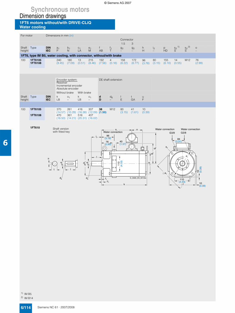
Synchronous motorsDimension drawings1FT6 motors without/with DRIVE-CLiQWater cooling
6/114 Siemens NC 61 · 2007/2008
6
For motor Dimensions in mm (in)Connector 1.5 3
Shaft height
Type DINIEC
a1P
b1N
c1LA
e1M
fAB
f1T
g2–
g2–
hH
i2–
pHD
s21)
Ss2
2)
So–
1FT6, type IM B5, water cooling, with connector, without/with brake100 1FT6105
1FT6108240(9.45)
180(7.09)
13(0.51)
215(8.46)
192(7.56)
4(0.16)
158(6.22)
172(6.77)
96(3.78)
80(3.15)
155(6.10)
14(0.55)
M12 76(2.99)
Encoder system:ResolverIncremental encoder Absolute encoder
DE shaft extension
Without brake With brakeShaft height
Type DINIEC
kLB
o1–
kLB
o1–
dD
d6–
IE
tGA
uF
100 1FT6105
1FT6108
370(14.57)470(18.50)
261(10.28)361(14.21)
416(16.38)516(20.31)
307(12.09)407(16.02)
38(1.50)
M12 80(3.15)
41(1.61)
10(0.39)
1FT610
u
t
l
d
6
f 1
d
6
e
1
f
a
1
l
g 2
k
c
1
i 2
o
o
1
p g 2
G3/8
G3/8
d d b 1
s
2
Water connection
Water connection
Water connection
G_DA65_EN_00142a
(3.78)96
(2.99)76 (1.57)
40
(4.3
3)11
0
(3.31)84
(4.33)110
(0.39)10
(0.3
9)10
Shaft versionwith fitted key
1) IM B52) IM B14
© Siemens AG 2007© Siemens AG 2007

Synchronous motorsDimension drawings
1FT6 motors without/with DRIVE-CLiQWater cooling
6/115Siemens NC 61 · 2007/2008
6
For motor Dimensions in mm (in)Encoder system:ResolverIncremental encoder Absolute encoderWithout brake With brake
Shaft height
Type DINIEC
a1P
b1N
c1LA
e1M
fAB
f1T
g2–
hH
i2–
kLB
o–
kLB
o–
o1–
pHD
s2S
s3-
1FT6, type IM B5, water cooling, with terminal box gk 230 for nrated ≤ 2000 rpm, without/with brake
100 1FT6105
1FT6108
240(9.45)
180(7.09)
13(0.51)
215(8.46)
192(7.56)
4(0.16)
161(6.34)
96(3.78)
80(3.15)
370(14.57)470(18.50)
261(10.28)361(14.21)
416(16.38)516(20.31)
307(12.09)407(16.02)
76(2.99)
155(6.10)
14(0.55)
PG29
1FT6, type IM B5, water cooling, with terminal box gk 420 for nrated = 3000 rpm, without/with brake
1FT6105
1FT6108
240(9.45)
180(7.09)
13(0.51)
215(8.46)
192(7.56)
4(0.16)
176(6.93)
96(3.78)
80(3.15)
370(14.57)470(18.50)
261(10.28)361(14.21)
416(16.38)516(20.31)
307(12.09)407(16.02)
– 155(6.10)
14(0.55)
PG36
DE shaft extension
Shaft height
Type DINIEC
dD
d6–
IE
tGA
uF
100 1FT61051FT6108
38(1.50)
M12 80(3.15)
41(1.61)
10(0.39)
1FT61051FT6108
38(1.50)
M12 80(3.15)
41(1.61)
10(0.39)
1FT610with terminal boxgk 320
1FT610with terminal boxgk 420
k
o
f
1
c
1
i
2
s
2
s
3
a
1
f
e
1
l
u
t
l
d
6
d
6
h
g
2
p
o
1
Øb
1
Ød
Ød
G3/8
G3/8
Water connection
(3.31)
(4.3
3)
(1.57)(3.78)
110
40
96
Water connection
Water connection
84
G_DA65_EN_00176c
(0.39)
10 (0
.39
)
10
k
o
f
1
c
1
i
2
s
2
a
1
f
e
1
l
u
t
l
d
6
d
6
h
g
2
p
Øb
1
Ød
Ød
G3/8
G3/8
s
3
Water connection
(3.31)
(4.3
3)
(1.57)(3.78)
110
40
96
Water connection
Water connection
84
G_DA65_EN_00177c
(0.39)
10
(0.3
9)
10
© Siemens AG 2007© Siemens AG 2007

Synchronous motorsDimension drawings1FT6 motors without/with DRIVE-CLiQWater cooling
6/116 Siemens NC 61 · 2007/2008
6
For motor Dimensions in mm (in)
Shaft height
Type DIN a b b1 c c1 e e1 f f1 f2 h i2 k m m1 m2IEC B A N LA – BB M AB T – H – LB BA – –
1FT6, type IM B35, water cooling, with terminal box132 1FT6132
1FT6134
1FT6136
1FT6138
342(13.46)392(15.43)442(17.40)517(20.35)
216(8.50)
250(9.84)
14(0.55)
16(0.63)
366(14.41)416(16.38)466(18.35)541(21.30)
300(11.81)
260(10.24)
5(0.20)
245(9.65)
132(5.20)
82(3.23)
423(16.65)473(18.62)523(20.59)598(23.54)
36(1.42)
53(2.09)
23(0.91)
nrated=1500 rpm
nrated=2500 rpm
DE shaft extension
Shaft height
Type DIN n o p p1 s s2 s3 s3 w1 d d6 I t uIEC AA – HD AC K K – – C D – E GA F
132 1FT6132
1FT6134
1FT6136
1FT6138
14(0.55)
255.5(10.06)305.5(12.03)355.5(14.00)430.5(16.95)
350.5(13.80)
245(9.65)
12(0.47)
18(0.71)
M32 x 1.5
M40 x 1.5
M50 x 1.5
M50 x 1.5
M40 x 1.5
M50 x 1.5
M50 x 1.5
M50 x 1.5
53(2.09)
48(1.89)
M16 82(3.23)
51.5(2.03)
14(0.55)
a
d
d6
b 1
ko
ci2
l
s
m2
m1m
f1
h
s2
e1
nbf
p
c
w1
A
u
t ld6
d
e
p 1
s
1
s3
2f
G 3/8 G 3/8
A
Water connection Water connection
G_DA65_EN_00179
1FT613
© Siemens AG 2007© Siemens AG 2007

Synchronous motorsDimension drawings
1FT7 Compact motors without/with DRIVE-CLiQNatural cooling
6/117Siemens NC 61 · 2007/2008
6
For motor Dimensions in mm (in)Flange 1 (1FT6-compatible)
Without brake With brakeShaft height
Type DINIEC
a1P
b1N
c1LA
e1M
fAB
f1T
g2–
o1–
s2S
i2–
kLB
o–
kLB
o–
1FT7 Compact, type IM B5, natural cooling, with connector, without/with brake36 1FT7034 90
(3.54)60(2.36)
8(0.31)
75(2.95)
72(2.83)
3(0.12)
80(3.15)
52(2.05)
5.5(0.22)
30(1.18)
195(7.68)
134(5.28)
222(8.74)
161(6.34)
1FT7036 243(9.57)
182(7.17)
270(10.63)
209(8.23)
48 1FT7042 120(4.72)
80(3.15)
10(0.39)
100(3.94)
96(3.78)
3(0.12)
93(3.66)
52(2.05)
6.5(0.26)
40(1.57)
169(6.65)
102(4.02)
201(7.91)
134(5.28)
1FT7044 219(8.62)
152(5.98)
251(9.88)
184(7.24)
1FT7046 259(10.20)
192(7.56)
291(11.46)
224(8.82)
63 1FT7062 155(6.10)
110(4.33)
10(0.39)
130(5.12)
126(4.96)
3.5(0.14)
105(4.13)
52(2.05)
9(0.35)
50(1.97)
173(6.81)
106(4.17)
208(8.19)
141(5.55)
1FT7064 205(8.07)
137(5.39)
240(9.45)
172(6.77)
1FT7066 236(9.29)
169(6.65)
272(10.71)
204(8.03)
1FT7068 284(11.18)
216(8.50)
319(12.56)
251(9.88)
Flange 0 DE shaft extensionWithout brake With brake
Shaft height
Type DINIEC
b2–
i2–
f2–
kLB
o–
kLB
o–
dD
d6–
IE
tGA
uF
36 1FT7034 36(1.42)
36.5(1.44)
5.5(0.22)
189(7.44)
127(5.00)
216(8.50)
154(6.06)
14(0.55)
M5 30(1.18)
16(0.63)
5(0.20)
1FT7036 237(9.33)
175(6.89)
264(10.39)
202(7.95)
48 1FT7042 46(1.81)
46(1.81)
5.5(0.22)
163(6.42)
96(3.78)
195(7.68)
128(5.04)
19(0.75)
M6 40(1.57)
21.5(0.85)
6(0.24)
1FT7044 213(8.39)
146(5.75)
245(9.65)
178(7.01)
1FT7046 253(9.96)
186(7.32)
285(11.22)
218(8.58)
63 1FT7062 51(2.01)
56.5(2.22)
6(0.24)
166(6.54)
100(3.94)
202(7.95)
135(5.31)
24(0.94)
M8 50(1.97)
27(1.06)
8(0.31)
1FT7064 198(7.80)
131(5.16)
233(9.17)
166(6.54)
1FT7066 230(9.06)
163(6.42)
265(10.43)
198(7.80)
1FT7068 277(10.91)
210(8.27)
312(12.28)
245(9.65)
Flange 01FT7031FT7041FT706
Flange 1 (1FT6-compatible)1FT7031FT7041FT706
e 1
k
f2
1f
Ød
Øb
2
Øb
1
G_DA65_XX_00258
o o1
f
s2
a1
c
l
1
i 2
g2
u
t
Ød
d6l
Shaft versionwith fitted key
e 1
k
1f
Ød
Øb
1
G_DA65_XX_00259
o o1
f
s2
a1
c1
i 2
g2
l
Ød
ld6
u
t
© Siemens AG 2007© Siemens AG 2007

Synchronous motorsDimension drawings1FT7 Compact motors without/with DRIVE-CLiQNatural cooling
6/118 Siemens NC 61 · 2007/2008
6
For motor Dimensions in mm (in)Flange 1 (1FT6-compatible)
Without brake With brakeShaft height
Type DINIEC
a1P
b1N
c1LA
e1M
fAB
f1T
g2–
o1–
s2S
i2–
kLB
o–
kLB
o–
1FT7 Compact, type IM B5, natural cooling, with connector, without/with brake80 1FT7082 195
(7.68)130(5.12)
11.5(0.45)
165(6.50)
155(6.10)
3.5(0.14)
141(5.55)
50(1.97)
11(0.43)
58(2.28)
196(7.72)
130(5.12)
248(9.76)
183(7.20)
1FT7084 247(9.72)
165(6.50)
299(11.77)
234(9.21)
1FT7086 299(11.77)
234(9.21)
351(13.82)
286(11.26)
100 1FT7102 245(9.65)
180(7.09)
13(0.51)
215(8.46)
196(7.72)
4(0.16)
161(6.34)
55(2.17)
14(0.55)
80(3.15)
221(8.70)
151(5.94)
273(10.75)
203(7.99)
1FT7105 307(12.09)
238(9.37)
360(14.17)
290(11.42)
1FT7108 377(14.84)
307(12.09)
429(16.89)
359(14.13)
Flange 0 DE shaft extensionWithout brake With brake
Shaft height
Type DINIEC
b2–
i2–
f2–
kLB
o–
kLB
o–
dD
d6–
IE
tGA
uF
80 1FT7082 66(2.60)
64.5(2.54)
6(0.24)
189(7.44)
124(4.88)
241(9.49)
177(6.97)
32(1.26)
M12 58(2.28)
35(1.38)
10(0.39)
1FT7084 241(9.49)
159(6.26)
293(11.54)
228(8.98)
1FT7086 292(11.50)
228(8.98)
345(13.58)
280(11.02)
100 1FT7102 81(3.19)
87(3.43)
6.5(0.26)
214(8.43)
144(5.67)
266(10.47)
196(7.72)
38(1.50)
M12 80(3.15)
41(1.61)
10(0.39)
1FT7105 301(11.85)
231(9.09)
353(13.90)
283(11.14)
1FT7108 370(14.57)
300(11.81)
422(16.61)
352(13.86)
Flange 01FT7081FT710
Flange 1 (1FT6-compatible)1FT7081FT710
k
G_DA65_XX_00260
i 2
g2Ød
Øb
2
Øb
1
e 1
f
s2
a1
1o1c
l
o
1f
2f
u
t
Ød
d6l
Shaft versionwith fitted key
k
G_DA65_XX_00261
i 2
g2Ød
Ød
Øb
1
u
t ld6 e 1
f
s2
a1
1o
1co
1f
l
© Siemens AG 2007© Siemens AG 2007

Synchronous motorsDimension drawings
1FK7 Compact motors without/with DRIVE-CLiQNatural cooling
6/119Siemens NC 61 · 2007/2008
6
For motor Dimensions in mm (in)Encoder system:ResolverAbsolute encoder EnDat 16 S/RAbsolute encoder 15 bit (16 S/R)Without brake With brake
Shaft height
Type DIN a1 b1 c1 e1 f f1 g2 h i2 s2 k o1 o2 k o1 o2IEC P N LA M AB T – H – S LB – – LB – –
1FK7 Compact, type IM B5, natural cooling, with connector, without/with brake20 1FK7011-5 – 30
(1.18)7(0.28)
46(1.81)
40(1.57)
2.5(0.10)
65.5(2.58)
20(0.79)
18(0.71)
4.5(0.18)
140(5.51)
89(3.50)
118(4.65)
140(5.51)
89(3.50)
118(4.65)
1FK7015-5 165(6.50)
114(4.49)
143(5.63)
165(6.50)
114(4.49)
143(5.63)
28 1FK7022-5 – 40(1.57)
10(0.39)
63(2.48)
55(2.17)
2.5(0.10)
75(2.95)
27.5(1.08)
20(0.79)
5.4(0.21)
153(6.02)
95(3.74)
128(5.04)
175(6.89)
95(3.74)
150(5.91)
36 1FK7032-5 92(3.62)
60(2.36)
8(0.31)
75(2.95)
72(2.83)
3(0.12)
81(3.19)
36(1.42)
30(1.18)
6.5(0.26)
150(5.91)
90(3.54)
125(4.92)
175(6.89)
90(3.54)
149(5.87)
1FK7034-5 175(6.89)
115(4.53)
150(5.91)
200(7.87)
115(4.53)
174(6.85)
48 1FK7040-5 120(4.72)
80(3.15)
10(0.39)
100(3.94)
96(3.78)
3(0.12)
90(3.54)
48(1.89)
40(1.57)
7(0.28)
134(5.28)
73(2.87)
106(4.17)
163(6.42)
73(2.87)
135(5.31)
1FK7042-5 162(6.38)
101(3.98)
134(5.28)
191(7.52)
101(3.98)
163(6.42)
63 1FK7060-5 155(6.10)
110(4.33)
10(0.39)
130(5.12)
126(4.96)
3.5(0.14)
105(4.13)
63(2.48)
50(1.97)
9(0.35)
157(6.18)
94(3.70)
126(4.96)
200(7.87)
94(3.70)
169(6.65)
1FK7063-5 202(7.95)
139(5.47)
171(6.73)
245(9.65)
139(5.47)
214(8.43)
Encoder system:Incremental encoder sin/cos1 VppIncremental encoder 22 bit (2048 S/R)Absolute encoder EnDat 32 S/RAbsolute encoder 16 bit (32 S/R)
Absolute encoder EnDat 2048 S/RAbsolute encoder 22 bit (2048 S/R)Absolute encoder EnDat 512 S/RAbsolute encoder 20 bit (512 S/R)
DE shaft extension
Without brake With brake Without brake With brakeShaft height
Type k o1 o2 k o1 o2 k o1 o2 k o1 o2 d d6 l t uLB – – LB – – LB – – LB – – D – E GA F
20 1FK7011-5 155(6.10)
89(3.50)
118(4.65)
155(6.10)
89(3.50)
118(4.65)
155(6.10)
89(3.50)
118(4.65)
155(6.10)
89(3.50)
118(4.65)
8(0.31)
– 18(0.71)
8.8(0.35)
2(0.08)
1FK7015-5 180(7.09)
114(4.49)
143(5.63)
180(7.09)
114(4.49)
143(5.63)
180(7.09)
114(4.49)
143(5.63)
180(7.09)
114(4.49)
143(5.63)
28 1FK7022-5 178(7.01)
95(3.74)
128(5.04)
200(7.87)
95(3.74)
150(5.91)
178(7.01)
95(3.74)
128(5.04)
200(7.87)
95(3.74)
150(5.91)
9(0.35)
M3 20(0.79)
10.2(0.40)
3(0.12)
36 1FK7032-5 175(6.89)
90(3.54)
125(4.92)
200(7.87)
90(3.54)
149(5.87)
175(6.89)
90(3.54)
125(4.92)
200(7.87)
90(3.54)
149(5.87)
14(0.55)
M5 30(1.18)
16(0.63)
5(0.20)
1FK7034-5 200(7.87)
115(4.53)
150(5.91)
225(8.86)
115(4.53)
174(6.85)
200(7.87)
115(4.53)
150(5.91)
225(8.86)
115(4.53)
174(6.85)
48 1FK7040-5 155(6.10)
73(2.87)
106(4.17)
184(7.24)
73(2.87)
135(5.31)
163(6.42)
73(2.87)
106(4.17)
192(7.56)
73(2.87)
135(5.31)
19(0.75)
M6 40(1.57)
21.5(0.85)
6(0.24)
1FK7042-5 182(7.17)
101(3.98)
134(5.28)
211(8.31)
101(3.98)
163(6.42)
191(7.52)
101(3.98)
134(5.28)
220(8.66)
101(3.98)
163(6.42)
63 1FK7060-5 180(7.09)
94(3.70)
126(4.96)
223(8.78)
94(3.70)
169(6.65)
188(7.40)
94(3.70)
126(4.96)
231(9.09)
94(3.70)
169(6.65)
24(0.94)
M8 50(1.97)
27(1.06)
8(0.31)
1FK7063-5 225(8.86)
139(5.47)
171(6.73)
268(10.55)
139(5.47)
214(8.43)
233(9.17)
139(5.47)
171(6.73)
276(10.87)
139(5.47)
214(8.43)
1FK701.-51FK702.-51FK703.-51FK704.-51FK706.-5
d
u
t l
e1
a1 f
s2
d 6 f1
l
i2 c1
o1
2o
k G_D
A65
_XX
_001
22
hg
2
6
b1
d d
Shaft versionwith fitted key
© Siemens AG 2007© Siemens AG 2007

Synchronous motorsDimension drawings1FK7 Compact motors without/with DRIVE-CLiQNatural cooling
6/120 Siemens NC 61 · 2007/2008
6
For motor Dimensions in mm (in)Encoder system:ResolverWithout brake With brake
Shaft height
Type DIN a1 b1 c1 e1 f f1 g2 h i2 s2 k o1 o2 k o1 o2IEC P N LA M AB T – H – S LB – – LB – –
1FK7 Compact, type IM B5, natural cooling, with connector, without/with brake80 1FK7080-5 186
(7.32)130(5.12)
13(0.51)
165(6.50)
155(6.10)
3.5(0.14)
119.5(4.70)
77.5(3.05)
58(2.28)
11(0.43)
156(6.14)
91(3.58)
124(4.88)
184(7.24)
91(3.58)
151(5.94)
1FK7083-5 194(7.64)
129(5.08)
162(6.38)
245(9.65)
129(5.08)
207(8.15)
100 1FK7100-5 240(9.45)
180(7.09)
13(0.51)
215(8.46)
192(7.56)
4(0.16)
138(5.43)
96(3.78)
80(3.15)
14(0.55)
185(7.28)
113(4.45)
153(6.02)
204(8.03)
113(4.45)
172(6.77)
1FK7101-5 211(8.31)
139(5.47)
179(7.05)
240(9.45)
139(5.47)
208(8.19)
1FK7103-5 237(9.33)
165(6.50)
205(8.07)
266(10.47)
165(6.50)
234(9.21)
1FK7105-5 289(11.38)
217(8.54)
257(10.12)
318(12.52)
217(8.54)
286(11.26)
Encoder system:Incremental encoder sin/cos1 VppIncremental encoder 22 bit (2048 S/R)Absolute encoder EnDat 32 S/RAbsolute encoder 16 bit (32 S/R)
Absolute encoder EnDat 2048 S/RAbsolute encoder 22 bit (2048 S/R)
DE shaft extension
Without brake With brake Without brake With brakeShaft height
Type k o1 o2 k o1 o2 k o1 o2 k o1 o2 d d6 l t uLB – – LB – – LB – – LB – – D – E GA F
80 1FK7080-5 179(7.05)
91(3.58)
124(4.88)
206(8.11)
91(3.58)
151(5.94)
187(7.36)
91(3.58)
124(4.88)
215(8.46)
91(3.58)
151(5.94)
32(1.26)
M12 58(2.28)
35(1.38)
10(0.39)
1FK7083-5 217(8.54)
129(5.08)
162(6.38)
268(10.55)
153(6.02)
213(8.39)
225(8.86)
129(5.08)
162(6.38)
276(10.87)
129(5.08)
207(8.15)
100 1FK7100-5 208(8.19)
113(4.45)
153(6.02)
227(8.94)
113(4.45)
172(6.77)
216(8.50)
113(4.45)
153(6.02)
235(9.25)
113(4.45)
172(6.77)
38(1.50)
M12 80(3.15)
41(1.61)
10(0.39)
1FK7101-5 234(9.21)
139(5.47)
179(7.05)
263(10.35)
139(5.47)
208(8.19)
242(9.53)
139(5.47)
179(7.05)
271(10.67)
139(5.47)
208(8.19)
1FK7103-5 260(10.24)
165(6.50)
205(8.07)
289(11.38)
165(6.50)
234(9.21)
268(10.55)
165(6.50)
205(8.07)
297(11.69)
165(6.50)
234(9.21)
1FK7105-5 312(12.28)
217(8.54)
257(10.12)
341(13.43)
217(8.54)
286(11.26)
320(12.60)
217(8.54)
257(10.12)
349(13.74)
217(8.54)
286(11.26)
1FK708.-5
1FK7100-51FK7101-51FK7103-51FK7105-5
d
u
t l
e1
a1 f
s2
d 6 f1
l
i2 c1
o1
2o
k G_D
A65
_XX
_001
22
hg
2
6
b1
d d
Shaft versionwith fitted key
e1
a1f
s2
d6 f1
l
i2 c1
o1
2o
k G_D
A65
_XX
_001
23
hg
2
d
u
t l
6
b1d d
© Siemens AG 2007© Siemens AG 2007

Synchronous motorsDimension drawings
1FK7 High Dynamic motors without/with DRIVE-CLiQ
6/121Siemens NC 61 · 2007/2008
6
For motor Dimensions in mm (in)Encoder system:ResolverAbsolute encoder EnDat 16 S/RAbsolute encoder 15 bit (16 S/R)Without/with brake
Shaft height
Type DINIEC
a1P
b1N
c1LA
e1M
fAB
f1T
g2–
hH
i2–
s2S
kLB
o1–
o2–
1FK7 High Dynamic, type IM B5, natural cooling, with connector, without/with brake36 1FK7033-7 92
(3.62)60(2.36)
8(0.31)
75(2.95)
72(2.83)
3(0.12)
78(3.07)
36(1.42)
30(1.18)
6.5(0.26)
170/195(6.69/7.68)
108/108(4.25/4.25)
145/170(5.71/6.69)
48 1FK7043-7 120(4.72)
80(3.15)
10(0.39)
100(3.94)
96(3.78)
3(0.12)
90(3.54)
48(1.89)
40(1.57)
7(0.28)
191/220(7.52/8.66)
130/130(5.12/5.12)
163/192(6.42/7.56)
1FK7044-7 216/245(8.51/9.65)
155/155(6.10/6.10)
188/217(7.40/8.54)
63 1FK7061-7 155(6.10)
110(4.33)
10(0.39)
130(5.12)
126(4.96)
3.5(0.14)
105(4.13)
63(2.48)
50(1.97)
9(0.35)
185/228(7.28/8.98)
121/121(4.76/4.76)
153/196(6.02/7.72)
1FK7064-7 249/292(9.80/11.50)
185/185(7.28/7.28)
217/260(8.54/10.24)
80 1FK7085-7 186(7.32)
130(5.12)
13(0.51)
165(6.50)
155(6.10)
3.5(0.14)
141.5(5.57)
77.5(3.05)
60(2.36)
11(0.43)
261/304(10.28/11.97)
190/191(7.48/7.52)
229/272(9.02/10.71)
1FK7086-7 140.5(5.53)
261/303(10.28/11.93)
192/192(7.56/7.56)
Encoder system:Incremental encoder sin/cos1 VppIncremental encoder 22 bit (2048 S/R)Absolute encoder EnDat 32 S/RAbsolute encoder 16 bit (32 S/R)
Absolute encoder EnDat 2048 S/RAbsolute encoder 22 bit (2048 S/R)Absolute encoder EnDat 512 S/RAbsolute encoder 20 bit (512 S/R)
DE shaft extension
Without/with brake Without/with brakeShaft height
Type DINIEC
kLB
o1–
o2–
kLB
o1–
o2–
dD
d6–
IE
tGA
uF
36 1FK7033-7 194/219(7.64/8.62)
109/109(4.29/4.29)
144/168(5.67/6.61)
194/219(7.64/8.62)
109/109(4.29/4.29)
144/168(5.67/6.61)
14(0.55)
M5 30(1.18)
16(0.63)
5(0.20)
48 1FK7043-7 212/241(8.35/9.49)
130/130(5.12/5.12)
163/192(6.42/7.56)
220/249(8.66/9.80)
130/130(5.12/5.12)
163/192(6.42/7.56)
19(0.75)
M6 40(1.57)
21.5(0.85)
6(0.24)
1FK7044-7 237/266(9.33/10.47)
155/155(6.10/6.10)
188/217(7.40/8.54)
245/274(9.65/10.79)
155/155(6.10/6.10)
188/217(7.40/8.54)
63 1FK7061-7 208/251(8.19/9.88)
121/121(4.76/4.76)
154/197(6.06/7.76)
217/260(8.54/10.24)
121/121(4.76/4.76)
154/197(6.06/7.76)
24(0.94)
M6 50(1.97)
27(1.06)
8(0.31)
1FK7064-7 272/315(10.71/12.40)
185/185(7.28/7.28)
218/261(8.58/10.28)
281/324(11.06/12.76)
185/185(7.28/7.28)
218/261(8.58/10.28)
80 1FK7085-7 283/326(11.14/12.83)
192/192(7.56/7.56)
229/272(9.02/10.71)
292/334(11.50/13.15)
192/192(7.56/7.56)
229/272(9.02/10.71)
32(1.26)
M12 58(2.28)
35(1.38)
10(0.39)
1FK7086-7
1FK703.-71FK704.-71FK706.-71FK708.-7
G_DA65_XX_00119ff1
d6 d6
e1
s2
hg 2
ko2
o1
u
t l
l
c1i2
a1
b1
dd
Shaft versionwith fitted key
1FK7 High Dynamic motors without/with DRIVE-CLiQNatural cooling
© Siemens AG 2007© Siemens AG 2007

Synchronous motorsDimension drawings1FT6 motors without/with DRIVE-CLiQwith SP+ planetary gearbox, single-stage
6/122 Siemens NC 61 · 2007/2008
6
For motor Dmensions in mm (in)Encoder system:Resolver Incremental
encoderAbsolute encoder
Planetarygearbox
Without brake
With brake
Without brake
With brake
Shaft height
Type F4 Type D1 D2 D3 D4 L5 L6 L7 L8 K K K K
1FT6 with SP+ planetary gearbox, single-stage, type IM B5, natural cooling, with connector, without/with brake28 1FT6021 62 SP060S-MF1 60 16 5.5 68 138 28 20 6 283 308 283 308
(2.44) (2.36) (0.63) (0.22) (2.68) (5.44) (1.10) (0.79) (0.24) (11.15) (12.14) (11.15) (12.14)1FT6024 323 348 323 348
(12.73) (13.71) (12.73) (13.71)36 1FT6031 62 SP060S-MF1 60 16 5.5 68 142 28 20 6 274 294 314 334
(2.44) (2.36) (0.63) (0.22) (2.68) (5.59) (1.10) (0.79) (0.24) (10.80) (11.58) (12.37) (13.16)1FT6034 314 334 354 374
(12.37) (13.16) (13.95) (14.74)1FT6034 76 SP075S-MF1 70 22 6.6 85 164 36 20 7 328 348 368 388
(2.99) (2.76) (0.87) (0.26) (3.35) (6.46) (1.42) (0.79) (0.28) (12.92) (13.71) (14.50) (15.29)48 1FT6041 76 SP075S-MF1 70 22 6.6 85 168 36 20 7 297 332 340 375
(2.99) (2.76) (0.87) (0.26) (3.35) (6.62) (1.42) (0.79) (0.28) (11.70) (13.08) (13.40) (14.78)1FT6044 347 382 390 425
(13.67) (15.05) (15.37) (16.75)63 1FT6061 101 SP100S-MF1 90 32 9 120 217 58 30 10 327 357 357 387
(3.98) (3.55) (1.26) (0.35) (4.73) (8.55) (2.29) (1.18) (0.39) (12.88) (14.07) (14.07) (15.25)1FT6062 352 382 382 412
(13.87) (15.05) (15.05) (16.23)1FT6064 402 432 432 462
(15.84) (17.02) (17.02) (18.20)80 1FT6081 141 SP140S-MF1 130 40 11 165 283 82 30 12 392 419 392 419
(5.56) (5.12) (1.58) (0.43) (6.50) (11.15) (3.23) (1.18) (0.47) (15.44) (16.51) (15.44) (16.51)1FT6082 417 444 417 444
(16.43) (17.49) (16.43) (17.49)1FT6084 467 513 467 513
(18.40) (20.21) (18.40) (20.21)1FT6086 517 563 517 563
(20.37) (22.18) (20.37) (22.18)1FT6086 182 SP180S-MF1 160 55 13.5 215 310 82 30 15 544 590 544 590
(7.17) (6.30) (2.17) (0.53) (8.47) (12.21) (3.23) (1.18) (0.59) (21.43) (23.25) (21.43) (23.25)
1FT6021FT6031FT6041FT6061FT608
L6
D2
D1
Ø Ø
F4
L5L7
K G_
DA
65
_X
X_
00
24
2
D3
D4
L8
© Siemens AG 2007© Siemens AG 2007

Synchronous motorsDimension drawings
1FT6 motors without/with DRIVE-CLiQwith SP+ planetary gearbox, single-stage
6/123Siemens NC 61 · 2007/2008
6
For motor Dmensions in mm (in)Encoder system:Resolver Incremental
encoderAbsolute encoder
Planetarygearbox
Without brake
With brake
Without brake
With brake
Shaft height
Type F4 Type D1 D2 D3 D4 L5 L6 L7 L8 K K K K
1FT6 with SP+ planetary gearbox, single-stage, type IM B5, natural cooling, with connector, without/with brake100 1FT6102 182 SP180S-MF1 160 55 13.5 215 310 82 30 15 493 539 493 539
(7.17) (6.30) (2.17) (0.53) (8.47) (12.21) (3.23) (1.18) (0.59) (19.42) (21.24) (19.42) (21.24)1FT6105 568 614 568 614
(22.38) (24.19) (22.38) (24.19)1FT6105 212 SP210-MF1 180 75 17 250 350 105 38 17 577 623 577 623
(8.35) (7.09) (2.96) (0.67) (9.85) (13.79) (4.14) (1.50) (0.67) (22.73) (24.55) (22.73) (24.55)1FT6108 182 SP180S-MF1 160 55 13.5 215 310 82 30 15 668 714 668 714
(7.17) (6.30) (2.17) (0.53) (8.47) (12.21) (3.23) (1.18) (0.59) (26.32) (28.13) (26.32) (28.13)1FT6108 212 SP210-MF1 180 75 17 250 350 105 38 17 677 723 677 723
(8.35) (7.09) (2.96) (0.67) (9.85) (13.79) (4.14) (1.50) (0.67) (26.67) (28.49) (26.67) (28.49)132 1FT6132 212 SP210-MF1 180 75 17 250 350 105 38 17 630 680 630 680
(8.35) (7.09) (2.96) (0.67) (9.85) (13.79) (4.14) (1.50) (0.67) (24.82) (26.79) (24.82) (26.79)1FT6134 680 730 680 730
(26.79) (28.76) (26.79) (28.76)1FT6134 242 SP240-MF1 200 85 17 290 436 130 40 20 739 789 739 789
(9.53) (7.88) (3.35) (0.67) (11.43) (17.18) (5.12) (1.58) (0.79) (29.12) (31.09) (29.12) (31.09)1FT6136 212 SP210-MF1 180 75 17 250 350 105 38 17 730 780 730 780
(8.35) (7.09) (2.96) (0.67) (9.85) (13.79) (4.14) (1.50) (0.67) (28.76) (30.73) (28.76) (30.73)1FT6136 242 SP240-MF1 200 85 17 290 436 130 40 20 789 839 789 839
(9.53) (7.88) (3.35) (0.67) (11.43) (17.18) (5.12) (1.58) (0.79) (31.09) (33.06) (31.09) (33.06)
1FT6101FT613
L6
D2
D1
Ø Ø
F4
L5L7
K G_
DA
65
_X
X_
00
24
2
D3
D4
L8
© Siemens AG 2007© Siemens AG 2007

Synchronous motorsDimension drawings1FT6 motors without/with DRIVE-CLiQwith SP+ planetary gearbox, two-stage
6/124 Siemens NC 61 · 2007/2008
6
For motor Dmensions in mm (in)Encoder system:Resolver Incremental
encoderAbsolute encoder
Planetarygearbox
Without brake
With brake
Without brake
With brake
Shaft height
Type F4 Type D1 D2 D3 D4 L5 L6 L7 L8 K K K K
1FT6 with SP+ planetary gearbox, two-stage, type IM B5, natural cooling, with connector, without/with brake28 1FT6021 62 SP060S-MF2 60 16 5.5 68 156 28 20 6 301 326 301 326
(2.44) (2.36) (0.63) (0.22) (2.68) (6.15) (1.10) (0.79) (0.24) (11.86) (12.84) (11.86) (12.84)1FT6021 76 SP075S-MF2 70 22 6.6 85 175 36 20 7 312 337 312 337
(2.99) (2.76) (0.87) (0.26) (3.35) (6.90) (1.42) (0.79) (0.28) (12.29) (13.28) (12.29) (13.28)1FT6024 62 SP060S-MF2 60 16 5.5 68 156 28 20 6 341 366 341 366
(2.44) (2.36) (0.63) (0.22) (2.68) (6.15) (1.10) (0.79) (0.24) (13.44) (14.42) (13.44) (14.42)1FT6024 76 SP075S-MF2 70 22 6.6 85 175 36 20 7 352 377 352 377
(2.99) (2.76) (0.87) (0.26) (3.35) (6.90) (1.42) (0.79) (0.28) (13.87) (14.85) (13.87) (14.85)1FT6024 101 SP100S-MF2 90 32 9 120 230 58 30 10 375 400 375 400
(3.98) (3.55) (1.26) (0.35) (4.73) (9.06) (2.29) (1.18) (0.39) (14.78) (15.76) (14.78) (15.76) 36 1FT6031 62 SP060S-MF2 60 16 5.5 68 164 28 20 6 296 316 336 356
(2.44) (2.36) (0.63) (0.22) (2.68) (6.46) (1.10) (0.79) (0.24) (11.66) (12.45) (13.24) (14.03)1FT6031 76 SP075S-MF2 70 22 6.6 85 179 36 20 7 303 323 343 363
(2.99) (2.76) (0.87) (0.26) (3.35) (7.05) (1.42) (0.79) (0.28) (11.94) (12.73) (13.51) (14.30)1FT6031 101 SP100S-MF2 90 32 9 120 230 58 30 10 322 342 362 382
(3.98) (3.55) (1.26) (0.35) (4.73) (9.06) (2.29) (1.18) (0.39) (12.69) (13.47) (14.26) (15.05)1FT6034 76 SP075S-MF2 70 22 6.6 85 179 36 20 7 343 363 383 403
(2.99) (2.76) (0.87) (0.26) (3.35) (7.05) (1.42) (0.79) (0.28) (13.51) (14.30) (15.09) (15.88)1FT6034 101 SP100S-MF2 90 32 9 120 230 58 30 10 362 382 402 422
(3.98) (3.55) (1.26) (0.35) (4.73) (9.06) (2.29) (1.18) (0.39) (14.26) (15.05) (15.84) (16.63)1FT6034 141 SP140S-MF2 130 40 11 165 298 82 30 12 406 426 446 466
(5.56) (5.12) (1.58) (0.43) (6.50) (11.74) (3.23) (1.18) (0.47) (16.00) (16.78) (17.57) (18.36) 48 1FT6041 76 SP075S-MF2 70 22 6.6 85 192 36 20 7 321 356 364 399
(2.99) (2.76) (0.87) (0.26) (3.35) (7.56) (1.42) (0.79) (0.28) (12.65) (14.03) (14.34) (15.72)1FT6041 101 SP100S-MF2 90 32 9 120 234 58 30 10 331 366 374 409
(3.98) (3.55) (1.26) (0.35) (4.73) (9.22) (2.29) (1.18) (0.39) (13.04) (14.42) (14.74) (16.11)1FT6041 141 SP140S-MF2 130 40 11 165 298 82 30 12 371 406 414 449
(5.56) (5.12) (1.58) (0.43) (6.50) (11.74) (3.23) (1.18) (0.47) (14.62) (16.00) (16.31) (17.69)1FT6044 101 SP100S-MF2 90 32 9 120 234 58 30 10 381 416 424 459
(3.98) (3.55) (1.26) (0.35) (4.73) (9.22) (2.29) (1.18) (0.39) (15.01) (16.39) (16.71) (18.08)1FT6044 141 SP140S-MF2 130 40 11 165 298 82 30 12 421 456 464 499
(5.56) (5.12) (1.58) (0.43) (6.50) (11.74) (3.23) (1.18) (0.47) (16.59) (17.97) (18.28) (19.66)1FT6044 182 SP180S-MF2 160 55 13.5 215 346 82 30 15 469 504 512 547
(7.17) (6.30) (2.17) (0.53) (8.47) (13.63) (3.23) (1.18) (0.59) (18.48) (19.86) (20.17) (21.55)
1FT6021FT6031FT604 L6
D2
D1
Ø Ø
F4
L5L7
K G_
DA
65
_X
X_
00
24
2
D3
D4
L8
© Siemens AG 2007© Siemens AG 2007

Synchronous motorsDimension drawings
1FT6 motors without/with DRIVE-CLiQwith SP+ planetary gearbox, two-stage
6/125Siemens NC 61 · 2007/2008
6
For motor Dmensions in mm (in)Encoder system:Resolver Incremental
encoderAbsolute encoder
Planetarygearbox
Without brake
With brake
Without brake
With brake
Shaft height
Type F4 Type D1 D2 D3 D4 L5 L6 L7 L8 K K K K
1FT6 with SP+ planetary gearbox, two-stage, type IM B5, natural cooling, with connector, without/with brake 63 1FT6061 101 SP100S-MF2 90 32 9 120 252 58 30 10 362 392 392 422
(3.98) (3.55) (1.26) (0.35) (4.73) (9.93) (2.29) (1.18) (0.39) (14.26) (15.44) (15.44) (16.63)1FT6061 141 SP140S-MF2 130 40 11 165 305 82 30 12 391 421 421 451
(5.56) (5.12) (1.58) (0.43) (6.50) (12.02) (3.23) (1.18) (0.47) (15.41) (16.59) (16.59) (17.77)1FT6061 182 SP180S-MF2 160 55 13.5 215 346 82 30 15 432 462 462 492
(7.17) (6.30) (2.17) (0.53) (8.47) (13.63) (3.23) (1.18) (0.59) (17.02) (18.20) (18.20) (19.38)1FT6062 101 SP100S-MF2 90 32 9 120 252 58 30 10 387 417 417 447
(3.98) (3.55) (1.26) (0.35) (4.73) (9.93) (2.29) (1.18) (0.39) (15.25) (16.43) (16.43) (17.61)1FT6062 141 SP140S-MF2 130 40 11 165 305 82 30 12 416 446 446 476
(5.56) (5.12) (1.58) (0.43) (6.50) (12.02) (3.23) (1.18) (0.47) (16.39) (17.57) (17.57) (18.75)1FT6064 101 SP100S-MF2 90 32 9 120 252 58 30 10 437 467 467 497
(3.98) (3.55) (1.26) (0.35) (4.73) (9.93) (2.29) (1.18) (0.39) (17.22) (18.40) (18.40) (19.58)1FT6064 141 SP140S-MF2 130 40 11 165 305 82 30 12 466 496 496 526
(5.56) (5.12) (1.58) (0.43) (6.50) (12.02) (3.23) (1.18) (0.47) (18.36) (19.54) (19.54) (20.72)1FT6064 182 SP180S-MF2 160 55 13.5 215 346 82 30 15 507 537 537 567
(7.17) (6.30) (2.17) (0.53) (8.47) (13.63) (3.23) (1.18) (0.59) (19.98) (21.16) (21.16) (22.34) 80 1FT6081 141 SP140S-MF2 130 40 11 165 332 82 30 12 441 468 441 468
(5.56) (5.12) (1.58) (0.43) (6.50) (13.08) (3.23) (1.18) (0.47) (17.38) (18.44) (17.38) (18.44)1FT6081 182 SP180S-MF2 160 55 13.5 215 355 82 30 15 464 491 464 491
(7.17) (6.30) (2.17) (0.53) (8.47) (13.99) (3.23) (1.18) (0.59) (18.28) (19.35) (18.28) (19.35)1FT6081 212 SP210-MF2 180 75 17 250 397 105 38 17 475 502 475 502
(8.35) (7.09) (2.96) (0.67) (9.85) (15.64) (4.14) (1.50) (0.67) (18.72) (19.78) (18.72) (19.78)1FT6082 141 SP140S-MF2 130 40 11 165 332 82 30 12 466 493 466 493
(5.56) (5.12) (1.58) (0.43) (6.50) (13.08) (3.23) (1.18) (0.47) (18.36) (19.42) (18.36) (19.42)1FT6082 182 SP180S-MF2 160 55 13.5 215 355 82 30 15 489 516 489 516
(7.17) (6.30) (2.17) (0.53) (8.47) (13.99) (3.23) (1.18) (0.59) (19.27) (20.33) (19.27) (20.33)1FT6082 212 SP210-MF2 180 75 17 250 397 105 38 17 500 527 500 527
(8.35) (7.09) (2.96) (0.67) (9.85) (15.64) (4.14) (1.50) (0.67) (19.70) (20.76) (19.70) (20.76)1FT6084 141 SP140S-MF2 130 40 11 165 332 82 30 12 516 562 516 562
(5.56) (5.12) (1.58) (0.43) (6.50) (13.08) (3.23) (1.18) (0.47) (20.33) (22.14) (20.33) (22.14)1FT6084 182 SP180S-MF2 160 55 13.5 215 355 82 30 15 539 585 539 585
(7.17) (6.30) (2.17) (0.53) (8.47) (13.99) (3.23) (1.18) (0.59) (21.24) (23.05) (21.24) (23.05)1FT6084 242 SP240-MF2 200 85 17 290 454 130 40 20 580 626 580 626
(9.53) (7.88) (3.35) (0.67) (11.43) (17.89) (5.12) (1.58) (0.79) (22.85) (24.66) (22.85) (24.66)1FT6086 141 SP140S-MF2 130 40 11 165 332 82 30 12 566 612 566 612
(5.56) (5.12) (1.58) (0.43) (6.50) (13.08) (3.23) (1.18) (0.47) (22.30) (24.11) (22.30) (24.11)1FT6086 182 SP180S-MF2 160 55 13.5 215 355 82 30 15 589 635 589 635
(7.17) (6.30) (2.17) (0.53) (8.47) (13.99) (3.23) (1.18) (0.59) (23.21) (25.02) (23.21) (25.02)
1FT6061FT608
L6
D2
D1
Ø Ø
F4
L5L7
K G_
DA
65
_X
X_
00
24
2
D3
D4
L8
© Siemens AG 2007© Siemens AG 2007

Synchronous motorsDimension drawings1FT6 motors without/with DRIVE-CLiQwith SP+ planetary gearbox, two-stage
6/126 Siemens NC 61 · 2007/2008
6
For motor Dmensions in mm (in)Encoder system:Resolver Incremental
encoder Absolute encoder
Planetarygearbox
Without brake
With brake
Without brake
With brake
Shaft height
Type F4 Type D1 D2 D3 D4 L5 L6 L7 L8 K K K K
1FT6 with SP+ planetary gearbox, two-stage, type IM B5, natural cooling, with connector, without/with brake 100 1FT6102 182 SP180S-MF2 160 55 13.5 215 355 82 30 15 538 584 538 584
(7.17) (6.30) (2.17) (0.53) (8.47) (13.99) (3.23) (1.18) (0.59) (21.20) (23.01) (21.20) (23.01)1FT6102 242 SP240-MF2 200 85 17 290 454 130 40 20 579 625 579 625
(9.53) (7.88) (3.35) (0.67) (11.43) (17.89) (5.12) (1.58) (0.79) (22.81) (24.63) (22.81) (24.63)1FT6105 212 SP210-MF2 180 75 17 250 397 105 38 17 624 670 624 670
(8.35) (7.09) (2.96) (0.67) (9.85) (15.64) (4.14) (1.50) (0.67) (24.59) (26.40) (24.59) (26.40)1FT6105 242 SP240-MF2 200 85 17 290 454 130 40 20 654 700 654 700
(9.53) (7.88) (3.35) (0.67) (11.43) (17.89) (5.12) (1.58) (0.79) (25.77) (27.58) (25.77) (27.58)1FT6108 242 SP240-MF2 200 85 17 290 454 130 40 20 754 800 754 800
(9.53) (7.88) (3.35) (0.67) (11.43) (17.89) (5.12) (1.58) (0.79) (29.71) (31.52) (29.71) (31.52) 132 1FT6132 212 SP210-MF2 180 75 17 250 397 105 38 170 677 727 677 727
(8.35) (7.09) (2.96) (0.67) (9.85) (15.64) (4.14) (1.50) (6.70) (26.67) (28.64) (26.67) (28.64)1FT6134 242 SP240-MF2 200 85 17 290 454 130 40 20 757 807 757 807
(9.53) (7.88) (3.35) (0.67) (11.43) (17.89) (5.12) (1.58) (0.79) (29.83) (31.80) (29.83) (31.80)1FT6136 807 857 807 857
(31.80) (33.77) (31.80) (33.77)
1FT6101FT613
L6
D2
D1
Ø Ø
F4
L5L7
K G_
DA
65
_X
X_
00
24
2
D3
D4
L8
© Siemens AG 2007© Siemens AG 2007

Synchronous motorsDimension drawings
1FK7 Compact motors without/with DRIVE-CLiQwith SP+ planetary gearbox, single-stage
6/127Siemens NC 61 · 2007/2008
6
For motor Dimensions in mm (in)Encoder system:ResolverAbsolute encoder EnDat 16 S/RAbsolute encoder 15 bit (16 S/R)
Incremental encoder sin/cos 1 VppIncremental encoder 22 bit (2048 S/R)Absolute encoder EnDat 32 S/RAbsolute encoder 16 bit (32 S/R)
Absolute encoder EnDat 2048 S/RAbsolute encoder 22 bit (2048 S/R)Absolute encoder EnDat 512 S/RAbsolute encoder 20 bit (512 S/R)
Planetarygearbox
Without brake
With brake
Without brake
With brake
Without brake
With brake
Shaft height
Type F4 Type D1 D2 D3 D4 L5 L6 L7 L8 K K K K K K
1FK7 Compact with SP+ planetary gearbox, single-stage, type IM B5, natural cooling, with connector, without/with brake28 1FK7022-5 62 SP060S-MF1 60 16 6 68 137 28 20 6 242 264 267 289 267 289
(2.44) (2.36) (0.63) (0.24) (2.68) (5.40) (1.10) (0.79) (0.24) (9.53) (10.40) (10.52) (11.39) (10.52) (11.39) 36 1FK7032-5 62 SP060S-MF1 60 16 6 68 142 28 20 6 244 269 269 294 269 294
(2.44) (2.36) (0.63) (0.24) (2.68) (5.59) (1.10) (0.79) (0.24) (9.61) (10.60) (10.60) (11.58) (10.60) (11.58) 48 1FK7040-5 76 SP075S-MF1 70 22 7 85 168 36 20 7 246 275 267 296 275 304
(2.99) (2.76) (0.87) (0.28) (3.35) (6.62) (1.42) (0.79) (0.28) (9.69) (10.84) (10.52) (11.66) (10.84) (11.98)1FK7042-5 274 303 294 323 303 332
(10.80) (11.94) (11.58) (12.73) (11.94) (13.08) 63 1FK7060-5 101 SP100S-MF1 90 32 9 120 217 58 30 10 286 329 309 352 317 360
(3.98) (3.55) (1.26) (0.35) (4.73) (8.55) (2.29) (1.18) (0.39) (11.27) (12.96) (12.17) (13.87) (12.49) (14.18)1FK7063-5 331 374 354 397 362 405
(13.04) (14.74) (13.98) (15.64) (14.26) (15.96) 80 1FK7080-5 141 SP140S-MF1 130 40 11 165 283 82 30 12 327 355 350 377 358 386
(5.56) (5.12) (1.58) (0.43) (6.50) (11.15) (3.23) (1.18) (0.47) (12.88) (13.95) (13.79) (14.85) (14.11) (15.21)1FK7083-5 365 416 388 439 396 447
(14.38) (16.39) (15.29) (17.30) (15.60) (17.61) 100 1FK7100-5 182 SP180S-MF1 160 55 14 215 310 82 30 15 383 402 406 425 414 433
(7.17) (6.30) (2.17) (0.55) (8.47) (12.21) (3.23) (1.18) (0.59) (15.09) (15.84) (16.00) (16.75) (16.31) (17.06)1FK7101-5 409 438 432 461 440 469
(16.11) (17.26) (17.02) (18.16) (17.34) (18.48)1FK7103-5 435 464 458 487 466 495
(17.14) (18.28) (18.05) (19.19) (18.36) (19.50)1FK7105-5 182 SP180S-MF1 160 55 14 215 310 82 30 15 487 516 510 539 518 547
(7.17) (6.30) (2.17) (0.55) (8.47) (12.21) (3.23) (1.18) (0.59) (19.19) (20.33) (20.09) (21.24) (20.41) (21.55)1FK7105-5 212 SP210-MF1 180 75 17 250 350 105 38 17 496 525 519 548 527 556
(8.35) (7.09) (2.96) (0.67) (9.85) (13.79) (4.14) (1.50) (0.67) (19.54) (20.68) (20.45) (21.59) (20.76) (21.91)
1FK702.-51FK703.-51FK704.-51FK706.-51FK708.-51FK710.-5
L6
L5L7
G_
DA
65
_X
X_
00
24
3
D3
D4
KL8
D2
D1
Ø Ø
F4
© Siemens AG 2007© Siemens AG 2007

Synchronous motorsDimension drawings1FK7 High Dynamic motors without/with DRIVE-CLiQ with SP+ planetary gearbox, single-stage
6/128 Siemens NC 61 · 2007/2008
6
For motor Dimensions in mm (in)Encoder system:ResolverAbsolute encoder EnDat 16 S/RAbsolute encoder15 bit (16 S/R)
Incremental encoder sin/cos 1 VppIncremental encoder 22 bit (2048 S/R)Absolute encoder EnDat 32 S/RAbsolute encoder 16 bit (32 S/R)
Absolute encoder EnDat 2048 S/RAbsolute encoder 22 bit (2048 S/R)Absolute encoder EnDat 512 S/RAbsolute encoder 20 bit (512 S/R)
Planetarygearbox
Without brake
With brake
Without brake
With brake
Without brake
With brake
Shaft height
Type F4 Type D1 D2 D3 D4 L5 L6 L7 L8 K K K K K K
1FK7 High Dynamic with SP+ planetary gearbox, single-stage, type IM B5, natural cooling, with connector, without/with brake36 1FK7033-7 62 SP060S-MF1 60 16 6 68 142 28 20 6 263 288 288 313 288 313
(2.44) (2.36) (0.63) (0.24) (2.68) (5.59) (1.10) (0.79) (0.24) (10.36) (11.35) (11.35) (12.33) (11.35) (12.33) 48 1FK7043-7 76 SP075S-MF1 70 22 7 85 168 36 20 7 303 332 324 353 332 361
(2.99) (2.76) (0.87) (0.28) (3.35) (6.62) (1.42) (0.79) (0.28) (11.94) (13.08) (12.77) (13.91) (13.08) (14.22)1FK7044-7 328 357 349 378 357 386
(12.92) (14.07) (13.75) (14.89) (14.07) (15.21) 63 1FK7061-7 101 SP100S-MF1 90 32 9 120 217 58 30 10 314 357 337 380 346 389
(3.98) (3.55) (1.26) (0.35) (4.73) (8.55) (2.29) (1.18) (0.39) (12.37) (14.07) (13.28) (14.97) (13.63) (15.33)1FK7064-7 378 421 401 444 410 453
(14.89) (16.59) (15.80) (17.49) (16.15) (17.85) 80 1FK7085-7 141 SP140S-MF1 130 40 11 165 283 82 30 12 432 474 454 497 463 505
(5.56) (5.12) (1.58) (0.43) (6.50) (11.15) (3.23) (1.18) (0.47) (17.02) (18.68) (17.89) (19.58) (18.24) (19.90)1FK7086-7 432 474 454 497 463 505
(17.02) (18.68) (17.89) (19.58) (18.24) (19.90)
1FK703.-71FK704.-71FK706.-71FK708.-7 L6
L5L7
G_
DA
65
_X
X_
00
24
3
D3
D4
KL8
D2
D1
Ø Ø
F4
1FK7 High Dynamic motors without/with DRIVE-CLiQ with SP+ planetary gearbox, single-stage
© Siemens AG 2007© Siemens AG 2007

Synchronous motorsDimension drawings
1FK7 Compact motors without/with DRIVE-CLiQwith SP+ planetary gearbox, two-stage
6/129Siemens NC 61 · 2007/2008
6
For motor Dimensions in mm (in)Encoder system:ResolverAbsolute encoder EnDat 16 S/RAbsolute encoder15 bit (16 S/R)
Incremental encoder sin/cos 1 VppIncremental encoder 22 bit (2048 S/R)Absolute encoder EnDat 32 S/RAbsolute encoder 16 bit (32 S/R)
Absolute encoder EnDat 2048 S/RAbsolute encoder 22 bit (2048 S/R)Absolute encoder EnDat 512 S/RAbsolute encoder 20 bit (512 S/R)
Planetarygearbox
Without brake
With brake
Without brake
With brake
Without brake
With brake
Shaft height
Type F4 Type D1 D2 D3 D4 L5 L6 L7 L8 K K K K K K
1FK7 Compact with SP+ planetary gearbox, two-stage, type IM B5, natural cooling, with connector, without/with brake28 1FK7022-5 62 SP060S-MF2 60 16 5.5 68 156 28 20 6 261 283 286 308 286 308
(2.44) (2.36) (0.63) (0.22) (2.68) (6.15) (1.10) (0.79) (0.24) (10.28) (11.15) (11.27) (12.14) (11.27) (12.14)1FK7022-5 76 SP075S-MF2 70 22 6.6 85 175 36 20 7 272 294 297 319 297 319
(2.99) (2.76) (0.87) (0.26) (3.35) (6.90) (1.42) (0.79) (0.28) (10.72) (11.58) (11.70) (12.57) (11.70) (12.57)1FK7022-5 101 SP100S-MF2 90 32 9 120 230 58 30 10 295 317 320 342 320 342
(3.98) (3.55) (1.26) (0.35) (4.73) (9.06) (2.29) (1.18) (0.39) (11.62) (12.49) (12.61) (13.47) (12.61) (13.47) 36 1FK7032-5 62 SP060S-MF2 60 16 5.5 68 164 28 20 6 266 291 291 316 291 316
(2.44) (2.36) (0.63) (0.22) (2.68) (6.46) (1.10) (0.79) (0.24) (10.48) (11.47) (11.47) (12.45) (11.47) (12.45)1FK7032-5 76 SP075S-MF2 70 22 6.6 85 179 36 20 7 273 298 298 323 298 323
(2.99) (2.76) (0.87) (0.26) (3.35) (7.05) (1.42) (0.79) (0.28) (10.76) (11.74) (11.74) (12.73) (11.74) (12.73)1FK7032-5 101 SP100S-MF2 90 32 9 120 230 58 30 10 292 317 317 342 317 342
(3.98) (3.55) (1.26) (0.35) (4.73) (9.06) (2.29) (1.18) (0.39) (11.50) (12.49) (12.49) (13.47) (12.49) (13.47) 48 1FK7040-5 76 SP075S-MF2 70 22 6.6 85 192 36 20 7 270 299 291 320 299 328
(2.99) (2.76) (0.87) (0.26) (3.35) (7.56) (1.42) (0.79) (0.28) (10.64) (11.78) (11.47) (12.61) (11.78) (12.92)1FK7040-5 101 SP100S-MF2 90 32 9 120 234 58 30 10 280 309 301 330 309 338
(3.98) (3.55) (1.26) (0.35) (4.73) (9.22) (2.29) (1.18) (0.39) (11.03) (12.17) (11.86) (13.00) (12.17) (13.32)1FK7040-5 141 SP140S-MF2 130 40 11 165 298 82 30 12 320 349 341 370 349 378
(5.56) (5.12) (1.58) (0.43) (6.50) (11.74) (3.23) (1.18) (0.47) (12.61) (13.75) (13.44) (14.58) (13.75) (14.89)1FK7042-5 76 SP075S-MF2 70 22 6.6 85 192 36 20 7 298 327 298 347 327 356
(2.99) (2.76) (0.87) (0.26) (3.35) (7.56) (1.42) (0.79) (0.28) (11.74) (12.88) (11.74) (13.67) (12.88) (14.03)1FK7042-5 101 SP100S-MF2 90 32 9 120 234 58 30 10 308 337 308 357 337 366
(3.98) (3.55) (1.26) (0.35) (4.73) (9.22) (2.29) (1.18) (0.39) (12.14) (13.28) (12.14) (14.07) (13.28) (14.42)1FK7042-5 141 SP140S-MF2 130 40 11 165 298 82 30 12 348 377 368 397 377 406
(5.56) (5.12) (1.58) (0.43) (6.50) (11.74) (3.23) (1.18) (0.47) (13.71) (14.85) (14.50) (15.64) (14.85) (16.00) 63 1FK7060-5 101 SP100S-MF2 90 32 9 120 252 58 30 10 321 364 344 387 352 395
(3.98) (3.55) (1.26) (0.35) (4.73) (9.93) (2.29) (1.18) (0.39) (12.65) (14.34) (13.55) (15.25) (13.87) (15.56)1FK7060-5 141 SP140S-MF2 130 40 11 165 305 82 30 12 350 393 373 416 381 424
(5.56) (5.12) (1.58) (0.43) (6.50) (12.02) (3.23) (1.18) (0.47) (13.79) (15.48) (14.70) (16.39) (15.01) (16.71)1FK7063-5 141 SP140S-MF2 130 40 11 165 305 82 30 12 395 438 418 461 426 469
(5.56) (5.12) (1.58) (0.43) (6.50) (12.02) (3.23) (1.18) (0.47) (15.56) (17.26) (16.47) (18.16) (16.78) (18.48)1FK7063-5 182 SP180S-MF2 160 55 13.5 215 346 82 30 15 436 479 459 502 467 510
(7.17) (6.30) (2.17) (0.53) (8.47) (13.63) (3.23) (1.18) (0.59) (17.18) (18.87) (18.08) (19.78) (18.40) (20.09)
1FK702.-51FK703.-51FK704.-51FK706.-5 L6
L5L7
G_
DA
65
_X
X_
00
24
3
D3
D4
KL8
D2
D1
Ø Ø
F4
© Siemens AG 2007© Siemens AG 2007

Synchronous motorsDimension drawings1FK7 Compact motors without/with DRIVE-CLiQ with SP+ planetary gearbox, two-stage
6/130 Siemens NC 61 · 2007/2008
6
For motor Dimensions in mm (in)Encoder system:Resolver Incremental
encoder sin/cos 1 VppIncremental encoder 22 bit (2048 S/R)Absolute encoder EnDat 32 S/RAbsolute encoder 16 bit (32 S/R)
Absolute encoder EnDat 2048 S/RAbsolute encoder 22 bit (2048 S/R)
Planetarygearbox
Without brake
With brake
Without brake
With brake
Without brake
With brake
Shaft height
Type F4 Type D1 D2 D3 D4 L5 L6 L7 L8 K K K K K K
1FK7 Compact with SP+ planetary gearbox, two-stage, type IM B5, natural cooling, with connector, without/with brake 80 1FK7080-5 141 SP140S-MF2 130 40 11 165 332 82 30 12 376 404 399 426 407 435
(5.56) (5.12) (1.58) (0.43) (6.50) (13.08) (3.23) (1.18) (0.47) (14.81) (15.92) (15.72) (16.78) (16.04) (17.14)1FK7080-5 182 SP180S-MF2 160 55 13.5 215 355 82 30 15 399 427 422 449 430 458
(7.17) (6.30) (2.17) (0.53) (8.47) (13.99) (3.23) (1.18) (0.59) (15.72) (16.82) (16.63) (17.69) (16.94) (18.05)1FK7080-5 212 SP210-MF2 180 75 17 250 397 105 38 17 410 438 433 460 441 469
(8.35) (7.09) (2.96) (0.67) (9.85) (15.64) (4.14) (1.50) (0.67) (16.15) (17.26) (17.06) (18.12) (17.38) (18.48)1FK7083-5 141 SP140S-MF2 130 40 11 165 332 82 30 12 414 465 437 488 445 496
(5.56) (5.12) (1.58) (0.43) (6.50) (13.08) (3.23) (1.18) (0.47) (16.31) (18.32) (17.22) (19.23) (17.53) (19.54)1FK7083-5 182 SP180S-MF2 160 55 13.5 215 355 82 30 15 437 488 460 511 468 519
(7.17) (6.30) (2.17) (0.53) (8.47) (13.99) (3.23) (1.18) (0.59) (17.22) (19.23) (18.12) (20.13) (18.44) (20.45)1FK7083-5 212 SP210-MF2 180 75 17 250 397 105 38 17 448 499 471 522 479 530
(8.35) (7.09) (2.96) (0.67) (9.85) (15.64) (4.14) (1.50) (0.67) (17.65) (19.66) (18.56) (20.57) (18.87) (20.88) 100 1FK7100-5 182 SP180S-MF2 160 55 13.5 215 310 82 30 15 383 402 406 425 414 433
(7.17) (6.30) (2.17) (0.53) (8.47) (12.21) (3.23) (1.18) (0.59) (15.09) (15.84) (16.00) (16.75) (16.31) (17.06)1FK7100-5 212 SP210-MF2 180 75 17 250 397 105 38 17 439 458 462 481 470 489
(8.35) (7.09) (2.96) (0.67) (9.85) (15.64) (4.14) (1.50) (0.67) (17.30) (18.05) (18.20) (18.95) (18.52) (19.27)1FK7101-5 182 SP180S-MF2 160 55 13.5 215 310 82 30 15 409 438 432 461 440 469
(7.17) (6.30) (2.17) (0.53) (8.47) (12.21) (3.23) (1.18) (0.59) (16.11) (17.26) (17.02) (18.16) (17.34) (18.48)1FK7101-5 212 SP210-MF2 180 75 17 250 397 105 38 17 465 494 488 517 496 525
(8.35) (7.09) (2.96) (0.67) (9.85) (15.64) (4.14) (1.50) (0.67) (18.32) (19.46) (19.23) (20.37) (19.54) (20.69)1FK7101-5 242 SP240-MF2 200 85 17 290 454 130 40 20 495 524 518 547 526 555
(9.53) (7.88) (3.35) (0.67) (11.43) (17.89) (5.12) (1.58) (0.79) (19.50) (20.65) (20.41) (21.55) (20.72) (21.87)1FK7103-5 182 SP180S-MF2 160 55 13.5 215 310 82 30 15 435 464 458 487 466 495
(7.17) (6.30) (2.17) (0.53) (8.47) (12.21) (3.23) (1.18) (0.59) (17.14) (18.28) (18.05) (19.19) (18.36) (19.50)1FK7103-5 212 SP210-MF2 180 75 17 250 397 105 38 17 491 520 514 543 522 551
(8.35) (7.09) (2.96) (0.67) (9.85) (15.64) (4.14) (1.50) (0.67) (19.35) (20.49) (20.25) (21.39) (20.57) (21.71)1FK7103-5 242 SP240-MF2 200 85 17 290 454 130 40 20 521 550 544 573 552 581
(9.53) (7.88) (3.35) (0.67) (11.43) (17.89) (5.12) (1.58) (0.79) (20.53) (21.67) (21.43) (22.58) (21.75) (22.89)1FK7105-5 212 SP210-MF2 180 75 17 250 397 105 38 17 543 572 566 595 574 603
(8.35) (7.09) (2.96) (0.67) (9.85) (15.64) (4.14) (1.50) (0.67) (21.39) (22.54) (22.30) (23.44) (22.62) (23.76)1FK7105-5 242 SP240-MF2 200 85 17 290 454 130 40 20 573 602 596 625 604 633
(9.53) (7.88) (3.35) (0.67) (11.43) (17.89) (5.12) (1.58) (0.79) (22.58) (23.72) (23.48) (24.63) (23.80) (24.94)
1FK708.-51FK710.-5
L6
L5L7
G_
DA
65
_X
X_
00
24
3
D3
D4
KL8
D2
D1
Ø Ø
F4
© Siemens AG 2007© Siemens AG 2007

Synchronous motorsDimension drawings
1FK7 High Dynamic motors without/withDRIVE-CLiQ with SP+ planetary gearbox, two-
6/131Siemens NC 61 · 2007/2008
6
For motor Dimensions in mm (in)Encoder system:ResolverAbsolute encoder EnDat 16 S/RAbsolute encoder 15 bit (16 S/R)
Incremental encoder sin/cos 1 VppIncremental encoder 22 bit (2048 S/R)Absolute encoder EnDat 32 S/RAbsolute encoder 16 bit (32 S/R)
Absolute encoder EnDat 2048 S/RAbsolute encoder 22 bit (2048 S/R)Absolute encoder EnDat 512 S/RAbsolute encoder 20 bit (512 S/R)
Planetarygearbox
Without brake
With brake
Without brake
With brake
Without brake
With brake
Shaft height
Type F4 Type D1 D2 D3 D4 L5 L6 L7 L8 K K K K K K
1FK7 High Dynamic with SP+ planetary gearbox, two-stage, type IM B5, natural cooling, with connector, without/with brake36 1FK7033-7 62 SP060S-MF2 60 16 5.5 68 164 28 20 6 285 310 310 335 310 335
(2.44) (2.36) (0.63) (0.22) (2.68) (6.46) (1.10) (0.79) (0.24) (11.23) (12.21) (12.21) (13.20) (12.21) (13.20)1FK7033-7 76 SP075S-MF2 70 22 6.6 85 179 36 20 7 292 317 317 342 317 342
(2.99) (2.76) (0.87) (0.26) (3.35) (7.05) (1.42) (0.79) (0.28) (11.50) (12.49) (12.49) (13.47) (12.49) (13.47)1FK7033-7 101 SP100S-MF2 90 32 9 120 230 58 30 10 311 336 336 361 336 361
(3.98) (3.55) (1.26) (0.35) (4.73) (9.06) (2.29) (1.18) (0.39) (12.25) (13.24) (13.24) (14.22) (13.24) (14.22) 48 1FK7043-7 76 SP075S-MF2 70 22 6.6 85 192 36 20 7 327 356 348 377 356 385
(2.99) (2.76) (0.87) (0.26) (3.35) (7.56) (1.42) (0.79) (0.28) (12.88) (14.03) (13.71) (14.85) (14.03) (15.17)1FK7043-7 101 SP100S-MF2 90 32 9 120 234 58 30 10 337 366 358 387 366 395
(3.98) (3.55) (1.26) (0.35) (4.73) (9.22) (2.29) (1.18) (0.39) (13.28) (14.42) (14.11) (15.25) (14.42) (15.56)1FK7043-7 141 SP140S-MF2 130 40 11 165 298 82 30 12 377 406 398 427 406 435
(5.56) (5.12) (1.58) (0.43) (6.50) (11.74) (3.23) (1.18) (0.47) (14.85) (16.00) (15.68) (16.82) (16.00) (17.14)1FK7044-7 101 SP100S-MF2 90 32 9 120 234 58 30 10 362 391 383 412 391 420
(3.98) (3.55) (1.26) (0.35) (4.73) (9.22) (2.29) (1.18) (0.39) (14.26) (15.41) (15.09) (16.23) (15.41) (16.55)1FK7044-7 141 SP140S-MF2 130 40 11 165 298 82 30 12 402 431 432 452 431 460
(5.56) (5.12) (1.58) (0.43) (6.50) (11.74) (3.23) (1.18) (0.47) (15.84) (16.98) (17.02) (17.81) (16.98) (18.12) 63 1FK7061-7 101 SP100S-MF2 90 32 9 120 252 58 30 10 349 392 372 415 381 424
(3.98) (3.55) (1.26) (0.35) (4.73) (9.93) (2.29) (1.18) (0.39) (13.75) (15.44) (14.66) (16.35) (15.01) (16.71)1FK7061-7 141 SP140S-MF2 130 40 11 165 305 82 30 12 378 421 401 444 410 453
(5.56) (5.12) (1.58) (0.43) (6.50) (12.02) (3.23) (1.18) (0.47) (14.89) (16.59) (15.80) (17.49) (16.15) (17.85)1FK7064-7 442 485 465 508 474 517
(17.41) (19.11) (18.32) (20.02) (18.68) (20.37) 80 1FK7085-7 182 SP180S-MF2 160 55 13.5 215 355 82 30 15 504 547 526 569 535 577
(7.17) (6.30) (2.17) (0.53) (8.47) (13.99) (3.23) (1.18) (0.59) (19.84) (21.54) (20.71) (22.40) (21.06) (22.72)1FK7085-7 212 SP210-MF2 180 75 17 250 397 105 38 17 515 557 537 580 546 588
(8.35) (7.09) (2.96) (0.67) (9.85) (15.64) (4.14) (1.50) (0.67) (20.29) (21.95) (21.16) (22.85) (21.51) (23.17)1FK7086-7 182 SP180S-MF2 160 55 13.5 215 355 82 30 15 504 547 526 569 535 577
(7.17) (6.30) (2.17) (0.53) (8.47) (13.99) (3.23) (1.18) (0.59) (19.84) (21.54) (20.71) (22.40) (21.06) (22.72)1FK7086-7 212 SP210-MF2 180 75 17 250 397 105 38 17 515 557 537 580 546 588
(8.35) (7.09) (2.96) (0.67) (9.85) (15.64) (4.14) (1.50) (0.67) (20.29) (21.95) (21.16) (22.85) (21.51) (23.17)
1FK703.-71FK704.-71FK706.-71FK708.-7 L6
L5L7
G_
DA
65
_X
X_
00
24
3
D3
D4
KL8
D2
D1
Ø Ø
F4
1FK7 High Dynamic motors without/with DRIVE-CLiQwith SP+ planetary gearbox, two-stage
© Siemens AG 2007© Siemens AG 2007

Synchronous motorsDimension drawings1FK7 Compact motors without/with DRIVE-CLiQwith LP+ planetary gearbox, single-stage
6/132 Siemens NC 61 · 2007/2008
6
For motor Dimensions in mm (in)Encoder system:ResolverAbsolute encoder EnDat 16 S/RAbsolute encoder 15 bit (16 S/R)
Incremental encoder sin/cos 1 VppIncremental encoder 22 bit (2048 S/R)Absolute encoder EnDat 32 S/RAbsolute encoder 16 bit (32 S/R)
Absolute encoder EnDat 2048 S/RAbsolute encoder 22 bit (2048 S/R)Absolute encoder EnDat 512 S/RAbsolute encoder 20 bit (512 S/R)
Without brake With brake Without brake With brake Without brake With brakeShaft height
Type DIN k K k K k K k K k K k K l d a1IEC LB – LB – LB – LB – LB – LB – E D P
1FK7 Compact with LP+ planetary gearbox, single-stage, type IM B5, natural cooling, with connector, without/with brake28 1FK7022-5 153
(6.02)216(8.50)
175(6.89)
238(9.37)
178(7.01)
241(9.49)
200(7.87)
263(10.35)
178(7.01)
241(9.49)
200(7.87)
263(10.35)
20(0.79)
9(0.35)
-
1FK7022-5 236(9.29)
258(10.16)
261(10.28)
283(11.14)
261(10.28)
283(11.14)
36 1FK7032-5 150(5.91)
240(9.45)
175(6.89)
265(10.43)
175(6.89)
265(10.43)
200(7.87)
290(11.42)
175(6.89)
265(10.43)
200(7.87)
290(11.42)
30(1.18)
14(0.55)
92(3.62)
1FK7034-5 175(6.89)
265(10.43)
200(7.87)
290(11.42)
200(7.87)
290(11.42)
225(8.86)
315(12.40)
200(7.87)
290(11.42)
225(8.86)
315(12.40)
48 1FK7040-5 135(5.31)
247(9.72)
164(6.46)
276(10.87)
155(6.10)
267(10.51)
184(7.24)
296(11.65)
164(6.46)
276(10.87)
193(7.60)
305(12.01)
40(1.57)
19(0.75)
120(4.72)
1FK7042-5 162(6.38)
274(10.79)
191(7.52)
303(11.93)
183(7.20)
295(11.61)
212(8.35)
324(12.76)
191(7.52)
303(11.93)
220(8.66)
332(13.07)
63 1FK7060-5 157(6.18)
297(11.69)
200(7.87)
340(13.39)
180(7.09)
320(12.60)
223(8.78)
363(14.29)
188(7.40)
328(12.91)
231(9.09)
371(14.61)
50(1.97)
24(0.94)
155(6.10)
1FK7063-5 202(7.95)
342(13.46)
245(9.65)
385(15.16)
225(8.86)
365(14.37)
268(10.55)
408(16.06)
233(9.17)
373(14.69)
276(10.87)
416(16.38)
80 1FK7080-5 156(6.14)
325(12.80)
184(7.24)
353(13.90)
179(7.05)
347(13.66)
206(8.11)
375(14.76)
187(7.36)
355(13.98)
215(8.46)
384(15.12)
58(2.28)
32(1.26)
186(7.32)
1FK7083-5 194(7.64)
363(14.29)
245(9.65)
414(16.30)
217(8.54)
385(15.16)
268(10.55)
436(17.17)
225(8.86)
393(15.47)
276(10.87)
444(17.48)
Planetarygearbox
Shaft height
Type Type D1 D2 D3 D4 D5 L2 L3 L4 L5 L8 L9 L10 L16– – – – – – – – – – – – –
28 1FK7022-5 LP050-M01 50(1.97)
35(1.38)
12(0.47)
44(1.73)
M4 18(0.71)
4(0.16)
7(0.28)
8(0.31)
14(0.55)
4(0.16)
50(1.97)
88(3.46)
1FK7022-5 LP070-M01 70(2.76)
52(2.05)
16(0.63)
62(2.44)
M5 28(1.10)
5(0.20)
8(0.31)
10(0.39)
18(0.71)
5(0.20)
70(2.76)
119(4.69)
36 1FK7032-5 LP070-M01 70(2.76)
52(2.05)
16(0.63)
62(2.44)
M5 28(1.10)
5(0.20)
8(0.31)
10(0.39)
18(0.71)
5(0.20)
70(2.76)
126(4.96)
1FK7034-548 1FK7040-5 LP090-M01 90
(3.54)68(2.68)
22(0.87)
80(3.15)
M6 36(1.42)
5(0.20)
10(0.39)
12(0.47)
25(0.98)
6(0.24)
90(3.54)
158(6.22)
1FK7042-563 1FK7060-5 LP120-M01 120
(4.72)90(3.54)
32(1.26)
108(4.25)
M8 58(2.28)
6(0.24)
12(0.47)
16(0.63)
35(1.38)
10(0.39)
120(4.72)
210(8.27)
1FK7063-580 1FK7080-5 LP155-M01 155
(6.10)120(4.72)
40(1.57)
140(5.51)
M10 82(3.23)
8(0.31)
15(0.59)
20(0.79)
43(1.69)
12(0.47)
150(5.91)
266(10.47)
1FK7083-5
1FK702.-51FK703.-51FK704.-51FK706.-51FK708.-5
D
L
a
d
L
D
klK
LLL
L
D
L
8
9
1
3
16
4
3
2
110
4D2
deepD / L5 5
G_DA65_EN_00124
© Siemens AG 2007© Siemens AG 2007

Synchronous motorsDimension drawings
1FK7 Compact motors without/with DRIVE-CLiQwith LP+ planetary gearbox, single-stage
6/133Siemens NC 61 · 2007/2008
6
For motor Dimensions in mm (in)Encoder system:Resolver Incremental encoder sin/cos 1 Vpp
Incremental encoder 22 bit (2048 S/R)Absolute encoder EnDat 32 S/RAbsolute encoder 16 bit (32 S/R)
Absolute encoder EnDat 2048 S/RAbsolute encoder 22 bit (2048 S/R)
Without brake With brake Without brake With brake Without brake With brakeShaft height
Type DIN k K k K k K k K k K k K l d a1IEC LB – LB – LB – LB – LB – LB – E D P
1FK7 Compact with LP+ planetary gearbox, single-stage, type IM B5, natural cooling, with connector, without/with brake100 1FK7100-5 185
(7.28)374(14.72)
204(8.03)
393(15.47)
208(8.19)
396(15.59)
227(8.94)
415(16.34)
216(8.50)
404(15.91)
235(9.25)
423(16.65)
80(3.15)
38(1.50)
240(9.45)
1FK7101-5 211(8.31)
400(15.75)
240(9.45)
429(16.89)
234(9.21)
422(16.61)
263(10.35)
452(17.80)
242(9.53)
430(16.93)
271(10.67)
460(18.11)
1FK7103-5 237(9.33)
426(16.77)
266(10.47)
455(17.91)
260(10.24)
448(17.64)
289(11.38)
478(18.82)
268(10.55)
456(17.95)
297(11.69)
486(19.13)
1FK7105-5 289(11.38)
478(18.82)
318(12.52)
507(19.96)
312(12.28)
500(19.69)
341(13.43)
530(20.87)
320(12.60)
508(20.00)
349(13.74)
538(21.18)
Planetarygearbox
Shaft height
Type Type D1 D2 D3 D4 D5 L2 L3 L4 L5 L8 L9 L10 L16– – – – – – – – – – – – –
100 1FK710.-5 LP155-M01 155(6.10)
120(4.72)
40(1.57)
140(5.51)
M10 82(3.23)
8(0.31)
15(0.59)
20(0.79)
43(1.69)
12(0.47)
150(5.91)
286(11.26)
1FK710.-5
D
L
d
L
DD
klK
LLLL
8
9
1 2
3
16
4
3
2
L10
a
1
D4
D / L deep5 5
G_DA65_EN_00125
© Siemens AG 2007© Siemens AG 2007

Synchronous motorsDimension drawings1FK7 High Dynamic motors without/with DRIVE-CLiQ with LP+ planetary gearbox, sinlge-stage
6/134 Siemens NC 61 · 2007/2008
6
For motor Dimensions in mm (in)Encoder system:ResolverAbsolute encoder EnDat 16 S/RAbsolute encoder 15 bit (16 S/R)
Incremental encoder sin/cos 1 VppIncremental encoder 22 bit (2048 S/R)Absolute encoder EnDat 32 S/RAbsolute encoder 16 bit (32 S/R)
Absolute encoder EnDat 2048 S/RAbsolute encoder 22 bit (2048 S/R)Absolute encoder EnDat 512 S/RAbsolute encoder 20 bit (512 S/R)
Without brake With brake Without brake With brake Without brake With brakeShaft height
Type DIN k K k K k K k K k K k K l d a1IEC LB – LB – LB – LB – LB – LB – E D P
1FK7 High Dynamic with LP+ planetary gearbox, single-stage, type IM B5, natural cooling, with connector, without/with brake36 1FK7033-7 170
(6.69)260(10.24)
195(7.68)
285(11.22)
195(7.68)
285(11.22)
220(8.66)
310(12.20)
195(7.68)
285(11.22)
220(8.66)
310(12.20)
30(1.18)
14(0.55)
92(3.62)
48 1FK7043-7 191(7.52)
303(11.93)
220(8.66)
332(13.07)
212(8.35)
324(12.76)
240(9.45)
352(13.86)
220(8.66)
332(13.07)
249(9.80)
361(14.21)
40(1.57)
19(0.75)
120(4.72)
1FK7044-7 216(8.50)
328(12.91)
245(9.65)
357(14.06)
237(9.33)
349(13.74)
265(10.43)
377(14.84)
245(9.65)
357(14.06)
274(10.79)
386(15.20)
63 1FK7061-7 185(7.28)
325(12.80)
228(8.98)
368(14.49)
208(8.19)
348(13.70)
251(9.88)
391(15.39)
217(8.54)
357(14.06)
260(10.24)
400(15.75)
50(1.97)
24(0.94)
155(6.10)
1FK7064-7 249(9.80)
389(15.31)
292(11.50)
432(17.01)
272(10.71)
412(16.22)
315(12.40)
455(17.91)
281(11.06)
421(16.57)
324(12.76)
464(18.27)
80 1FK7085-71FK7086-7
261(10.28)
430(16.93)
304(11.97)
473(18.62)
284(11.18)
453(17.83)
326(12.83)
495(19.49)
292(11.50)
461(18.15)
335(13.19)
504(19.84)
58(2.28)
32(1.26)
186(7.32)
Planetarygearbox
Shaft height
Type Type D1 D2 D3 D4 D5 L2 L3 L4 L5 L8 L9 L10 L16– – – – – – – – – – – – –
36 1FK7033-7 LP070-M01 70(2.76)
52(2.05)
16(0.63)
62(2.44)
M5 28(1.10)
5(0.20)
8(0.31)
10(0.39)
18(0.71)
5(0.20)
70(2.76)
126(4.96)
48 1FK7043-71FK7044-7
LP090-M01 90(3.54)
68(2.68)
22(0.87)
80(3.15)
M6 36(1.42)
5(0.20)
10(0.39)
12(0.47)
25(0.98)
6(0.24)
90(3.54)
158(6.22)
63 1FK7061-71FK7064-7
LP120-M01 120(4.72)
90(3.54)
32(1.26)
108(4.25)
M8 58(2.28)
6(0.24)
12(0.47)
16(0.63)
35(1.38)
10(0.39)
120(4.72)
210(8.27)
80 1FK7085-71FK7086-7
LP155-M01 155(6.10)
120(4.72)
40(1.57)
140(5.51)
M10 82(3.23)
8(0.31)
15(0.59)
20(0.79)
43(1.69)
12(0.47)
150(5.91)
266(10.47)
1FK7033-71FK704.-71FK706.-71FK708.-7 D
L
a
d
L
D
klK
LLL
L
D
L
8
9
1
3
16
4
3
2
110
4D2
deepD / L5 5
G_DA65_EN_00124
1FK7 High Dynamic motors without/with DRIVE-CLiQ with LP+ planetary gearbox, sinlge-stage
© Siemens AG 2007© Siemens AG 2007

Synchronous motorsDimension drawings
1FK7-DYA motors without/with DRIVE-CLiQwith planetary gearbox, single-stage
6/135Siemens NC 61 · 2007/2008
6
For motor Dimensions in mm (in)Encoder system:ResolverAbsolute encoder EnDat 16 S/RAbsolute encoder 15 bit (16 S/R)
Incremental encoder sin/cos 1 VppIncremental encoder 22 bit (2048 S/R)Absolute encoder EnDat 32 S/RAbsolute encoder 16 bit (32 S/R)
Absolute encoder EnDat 2048 S/RAbsolute encoder 22 bit (2048 S/R)Absolute encoder EnDat 512 S/RAbsolute encoder 20 bit (512 S/R)
Without brake With brake Without brake With brake Without brake With brakeShaft height
Type K K1 K K1 K K1 K K1 K K1 K K1
1FK7-DYA with planetary gearbox, single-stage, type IM B5, natural cooling, with connector, without/with brake36 1FK7032-5 197
(7.76)177(6.97)
222(8.74)
202(7.95)
222(8.74)
202(7.95)
247(9.72)
227(8.94)
222(8.74)
202(7.95)
247(9.72)
227(8.94)
1FK7034-5 222(8.74)
202(7.95)
247(9.72)
227(8.94)
247(9.72)
227(8.94)
272(10.71)
252(9.92)
247(9.72)
227(8.94)
272(10.71)
252(9.92)
48 1FK7040-5 194(7.64)
174(6.85)
223(8.78)
203(7.99)
214(8.43)
194(7.64)
243(9.57)
223(8.78)
223(8.78)
203(7.99)
252(9.92)
232(9.13)
1FK7042-5 221(8.70)
201(7.91)
250(9.84)
230(9.06)
242(9.53)
222(8.74)
271(10.67)
251(9.88)
250(9.84)
230(9.06)
279(10.98)
259(10.20)
63 1FK7060-5 233(9.17)
208(8.19)
261(10.28)
236(9.29)
256(10.08)
231(9.09)
284(11.18)
259(10.20)
264(10.39)
239(9.41)
292(11.50)
267(10.51)
1FK7063-5 278(10.94)
253(9.96)
306(12.05)
281(11.06)
301(11.85)
276(10.87)
329(12.95)
304(11.97)
309(12.17)
284(11.18)
337(13.27)
312(12.28)
80 1FK7080-5 250(9.84)
220(8.66)
278(10.94)
248(9.76)
273(10.75)
243(9.57)
300(11.81)
270(10.63)
281(11.06)
251(9.88)
309(12.17)
279(10.98)
1FK7083-5 288(11.34)
258(10.16)
339(13.35)
309(12.17)
311(12.24)
281(11.06)
362(14.25)
332(13.07)
319(12.56)
289(11.38)
370(14.57)
340(13.39)
Planetarygearbox
Shaft height
Type Type D1 D2 D3 D4 D5 D7 D8 L1 L2 L3 L4 L5 L8 L9 L10 L12
36 1FK7032-5 DYA70-10 70(2.76)
52(2.05)
16(0.63)
62(2.44)
M5 82(3.23)
5.5(0.22)
56(2.20)
28(1.10)
5(0.20)
8(0.31)
10(0.39)
18(0.71)
5(0.20)
20(0.79)
76(2.99)
1FK7034-5 DYA70-5
48 1FK7040-5 DYA90-10 90(3.54)
68(2.68)
22(0.87)
80(3.15)
M6 105(4.13)
7(0.28)
66(2.60)
36(1.42)
5(0.20)
10(0.39)
12(0.47)
24.5(0.96)
6(0.24)
20(0.79)
101(3.98)
1FK7042-5 DYA90-5
63 1FK7060-5 DYA120-10 120(4.72)
90(3.54)
32(1.26)
108(4.25)
M8 140(5.51)
9(0.35)
95(3.74)
58(2.28)
6(0.24)
12(0.47)
16(0.63)
35(1.38)
10(0.39)
25(0.98)
128(5.04)
1FK7063-5 DYA120-5
80 1FK7080-5 DYA155-10 155(6.10)
120(4.72)
40(1.57)
140(5.51)
M10 170(6.69)
11(0.43)
127(5.00)
82(3.23)
8(0.31)
15(0.59)
20(0.79)
43(1.69)
12(0.47)
30(1.18)
161(6.34)
1FK7083-5 DYA155-5
1FK703.-51FK704.-51FK706.-51FK708.-5
L2 L4
L3
G_
DA
65
_X
X_
00
25
0
D8
D5 x L5
L8
L9
D4
D7
K1
L10L1
K
D3
D2
Ø
D1
Ø Ø
L12
© Siemens AG 2007© Siemens AG 2007
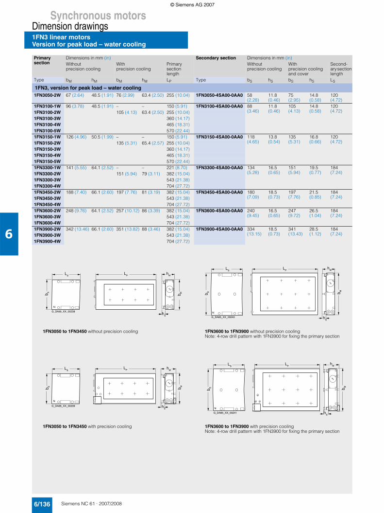
Synchronous motorsDimension drawings1FN3 linear motorsVersion for peak load – water cooling
6/136 Siemens NC 61 · 2007/2008
6
Primary section
Dimensions in mm (in) Secondary section Dimensions in mm (in)Without precision cooling
With precision cooling
Primary section length
Without precision cooling
With precision cooling and cover
Second-ary section length
Type bM hM bM hM LP Type bS hS bS hS LS
1FN3, version for peak load – water cooling1FN3050-2W 67 (2.64) 48.5 (1.91) 76 (2.99) 63.4 (2.50) 255 (10.04) 1FN3050-4SA00-0AA0 58
(2.28)11.8(0.46)
75(2.95)
14.8(0.58)
120(4.72)
1FN3100-1W 96 (3.78) 48.5 (1.91) – – 150 (5.91) 1FN3100-4SA00-0AA0 88(3.46)
11.8(0.46)
105(4.13)
14.8(0.58)
120(4.72)1FN3100-2W 105 (4.13) 63.4 (2.50) 255 (10.04)
1FN3100-3W 360 (14.17)1FN3100-4W 465 (18.31)1FN3100-5W 570 (22.44)1FN3150-1W 126 (4.96) 50.5 (1.99) – – 150 (5.91) 1FN3150-4SA00-0AA0 118
(4.65)13.8(0.54)
135(5.31)
16.8(0.66)
120(4.72)1FN3150-2W 135 (5.31) 65.4 (2.57) 255 (10.04)
1FN3150-3W 360 (14.17)1FN3150-4W 465 (18.31)1FN3150-5W 570 (22.44)1FN3300-1W 141 (5.55) 64.1 (2.52) – – 221 (8.70) 1FN3300-4SA00-0AA0 134
(5.28)16.5(0.65)
151(5.94)
19.5(0.77)
184(7.24)1FN3300-2W 151 (5.94) 79 (3.11) 382 (15.04)
1FN3300-3W 543 (21.38)1FN3300-4W 704 (27.72)1FN3450-2W 188 (7.40) 66.1 (2.60) 197 (7.76) 81 (3.19) 382 (15.04) 1FN3450-4SA00-0AA0 180
(7.09)18.5(0.73)
197(7.76)
21.5(0.85)
184(7.24)1FN3450-3W 543 (21.38)
1FN3450-4W 704 (27.72)1FN3600-2W 248 (9.76) 64.1 (2.52) 257 (10.12) 86 (3.39) 382 (15.04) 1FN3600-4SA00-0AA0 240
(9.45)16.5(0.65)
247(9.72)
26.5(1.04)
184(7.24)1FN3600-3W 543 (21.38)
1FN3600-4W 704 (27.72)1FN3900-2W 342 (13.46) 66.1 (2.60) 351 (13.82) 88 (3.46) 382 (15.04) 1FN3900-4SA00-0AA0 334
(13.15)18.5(0.73)
341(13.43)
28.5(1.12)
184(7.24)1FN3900-3W 543 (21.38)
1FN3900-4W 704 (27.72)
hM
b M
hS
LP
LS
G_DA65_XX_00238
b S
N
hM
b M
hS
LPL
S
G_DA65_XX_00239
b S
N
hS
LPL
S
G_DA65_XX_00240
b S
N
hM
b M
hS
LPL
S
G_DA65_XX_00241
b S
N
hM
b M
1FN3050 to 1FN3450 with precision cooling 1FN3600 to 1FN3900 with precision coolingNote: 4-row drill pattern with 1FN3900 for fixing the primary section
1FN3050 to 1FN3450 without precision cooling 1FN3600 to 1FN3900 without precision coolingNote: 4-row drill pattern with 1FN3900 for fixing the primary section
© Siemens AG 2007© Siemens AG 2007

Synchronous motorsDimension drawings
1FN3 linear motorsVersion for continuous load – water cooling
6/137Siemens NC 61 · 2007/2008
6
Primary section
Dimensions in mm (in) Secondary section Dimensions in mm (in)Without precision cooling
With precision cooling
Primary section length
Without precision cooling
With precision cooling
Second-ary section length
Type bM hM bM hM LP Type bS hS bM hM LS
1FN3, version for continuous load – water cooling1FN3050-1ND 67 (2.64) 59.4 (2.34) 76 (2.99) 74.3 (2.93) 162 (6.38) 1FN3050-4SA00-0AA0 58
(2.28)11.8(0.46)
75(2.95)
14.8(0.58)
120(4.72)1FN3050-2NB 267 (10.51)
1FN3100-1NC 96 (3.78) 59.4 (2.34) 105 (4.13) 74.3 (2.93) 162 (6.38) 1FN3100-4SA00-0AA0 88(3.46)
11.8(0.46)
105(4.13)
14.8(0.58)
120(4.72)1FN3100-2NC 267 (10.51)
1FN3100-3NC 372 (14.65)1FN3100-4NC 477 (18.78)1FN3150-1NC 126 (4.96) 61.4 (2.42) 135 (5.31) 76.3 (3.00) 162 (6.38) 1FN3150-4SA00-0AA0 118
(4.65)13.8(0.54)
135(5.31)
16.8(0.66)
120(4.72)1FN3150-2NB 267 (10.51)
1FN3150-3NC 372 (14.65)1FN3150-4NB 477 (18.78)1FN3300-1NC 141 (5.55) 78 (3.07) 150 (5.91) 92.9 (3.66) 238 (9.37) 1FN3300-4SA00-0AA0 134
(5.28)16.5(0.65)
151(5.94)
19.5(0.77)
184(7.24)1FN3300-2NC 399 (15.71)
1FN3300-3NC 560 (22.05)1FN3300-4NB 721 (28.39)1FN3450-2NC 188 (7.40) 80 (3.15) 197 (7.76) 94.9 (3.74) 399 (15.71) 1FN3450-4SA00-0AA0 180
(7.09)18.5(0.73)
197(7.76)
21.5(0.85)
184(7.24)1FN3450-3NC 560 (22.05)
1FN3450-4NB 721 (28.39)1FN3600-2NB 248 (9.76) 78 (3.07) 257 (10.12) 99.9 (3.93) 399 (15.71) 1FN3600-4SA00-0AA0 240
(9.45)16.5(0.65)
247(9.72)
26.5(1.04)
184(7.24)1FN3600-3NB 560 (22.05)
1FN3600-4NB 721 (28.39)1FN3900-2NB 342 (13.46) 80 (3.15) 351 (13.82) 101.9 (4.01) 399 (15.71) 1FN3900-4SA00-0AA0 334
(13.15)18.5(0.73)
341(13.43)
28.5(1.12)
184(7.24)1FN3900-3NB 560 (22.05)
1FN3900-4NB 721 (28.39)
hM
b M
hS
LP
LS
G_DA65_XX_00238
b S
N
hM
b M
hS
LPL
S
G_DA65_XX_00239
b S
N
hS
LPL
S
G_DA65_XX_00240
b S
N
hM
b M
hS
LPL
S
G_DA65_XX_00241
b S
N
hM
b M
1FN3050 to 1FN3450 with precision cooling 1FN3600 to 1FN3900 with precision coolingNote: 4-row drill pattern with 1FN3900 for fixing the primary section
1FN3050 to 1FN3450 without precision cooling 1FN3600 to 1FN3900 without precision coolingNote: 4-row drill pattern with 1FN3900 for fixing the primary section
© Siemens AG 2007© Siemens AG 2007

Synchronous motorsDimension drawings1FW6 built-in torque motorsWater cooling
6/138 Siemens NC 61 · 2007/2008
6
For motor Dimensions in mm (in)
Type D1 D2 D3 L1 L2
1FW6, type IM B5, water cooling1FW6090-0.B05 230 (9.06) 140 (5.51) 170 (6.69) 90 (3.54) 51 (2.01)1FW6090-0.B07 110 (4.33) 71 (2.80)1FW6090-0.B10 140 (5.51) 101 (3.98)1FW6090-0.B15 190 (7.48) 151 (5.94)1FW6130-0.B05 310 (12.20) 220 (8.66) 254 (10.00) 90 (3.54) 51 (2.01)1FW6130-0.B07 110 (4.33) 71 (2.80)1FW6130-0.B10 140 (5.51) 101 (3.98)1FW6130-0.B15 190 (7.48) 151 (5.94)1FW6160-0.B05 440 (17.32) 280 (11.02) 328 (12.91) 110 (4.33) 60 (2.36)1FW6160-0.B07 130 (5.12) 80 (3.15)1FW6160-0.B10 160 (6.30) 110 (4.33)1FW6160-0.B15 210 (8.27) 160 (6.30)1FW6190-0.B05 502 (19.76) 342 (13.46) 389 (15.31) 110 (4.33) 60 (2.36)1FW6190-0.B07 130 (5.12) 80 (3.15)1FW6190-0.B10 160 (6.30) 110 (4.33)1FW6190-0.B15 210 (8.27) 160 (6.30)1FW6230-0.B05 576 (22.68) 416 (16.38) 463 (18.23) 110 (4.33) 60 (2.36)1FW6230-0.B07 130 (5.12) 80 (3.15)1FW6230-0.B10 160 (6.30) 110 (4.33)1FW6230-0.B15 210 (8.27) 160 (6.30)1FW6290-0.B15 730 (28.74) 522 (20.55) 580 (22.83) 220 (8.66) 170 (6.69)
1FW60901FW6130
G_DA65_XX_00244
D2
Ø Ø Ø
D3
D1
L2
L1
1FW61601FW61901FW62301FW6290
L2
L1
G_DA65_XX_00245
D2
Ø Ø Ø
D3
D1
© Siemens AG 2007© Siemens AG 2007

Synchronous motorsDimension drawings
2SP1 ECS motor spindlesWater cooling
6/139Siemens NC 61 · 2007/2008
6
For motor Dimensions in mm (in)
Type D1 D2 D3 D4 D5 L11) L2 L3 L4
2SP1, type IM B5, water cooling2SP1202 200
(7.88)199(7.84)
250(9.85)
225(8.87)
150(5.91)
7354)
(28.94)115.5(4.55)
3094)
(12.17)584)
(2.28)2SP1204 8354)
(32.87)
2SP12532) 250(9.85)
237(9.34)
310(12.21)
275(10.84)
150(5.91)
813(32.03)
124.4(4.90)
310(12.21)
43(1.69)
2SP12552) 913(35.97)
2SP12533) 819(32.27)
2SP12553) 919(36.21)
2SP120
D5
L2 L3 L4L1
D4
D3
Ø Ø Ø
Ø Ø
D1
h7
D2
h6
G_DA65_XX_00246
2SP125
D5
L2
L3 L4
L1
D4
D1
Øh
7
D2
Øh
6
D3
Ø Ø Ø
G_DA65_XX_00247
1)The spindle is approx. 43 mm (1.69 in) shorter without turning bushing.2)HSK A63 tool interface.3)SK40, CAT40, BT40 tool interfaces.4)Spindle length L1 is approx. 118 mm (4.65 in) shorter, L3 approx. 147 mm (5.79 in) shorter and L4 approx. 30 mm (1.18 in) longer with a hydraulic tool
clamping device.
© Siemens AG 2007© Siemens AG 2007

Synchronous motorsCAD CREATOR
Dimension drawing and 2D/3D CAD generator
6/140 Siemens NC 61 · 2007/2008
6
■ Overview
The CAD CREATOR provides a user-friendly interface which helps you to create product-specific data quickly and supports you in generating plant documentation containing project-specific information.
■ Benefits
7 Multilingual operator interface in English, French, German, Italian and Spanish
7 Dimension drawings with measurements in mm or inches7 Dimension drawings and 2D/3D CAD data for
• 1FT6/1FT7/1FK7 synchronous motors• 1PH7/1PH4/1PM4/1PM6 asynchronous motors• 1FT6/1FK7/1FK7-DYA geared motors• 1FW3 torque motors• 1FE1 built-in motors
The CAD CREATOR provides you with various options to begin with product configuration:7 Order number7 Order number search7 Geometric data
■ Benefits (continued)
Once a product is successfully configured, the product-specific information, such as dimension drawings and 2D/3D CAD data are displayed and made available for storing in various formats, e.g.: *.pdf, *.dxf, *.stp or *.igs.
The CAD CREATOR is available on CD-ROM and as an Internet application.
Additional information is available on the Internet at:
http://www.siemens.com/cad-creator
© Siemens AG 2007© Siemens AG 2007