Converter with the CU250S-2 Control Units - ADEGIS
534
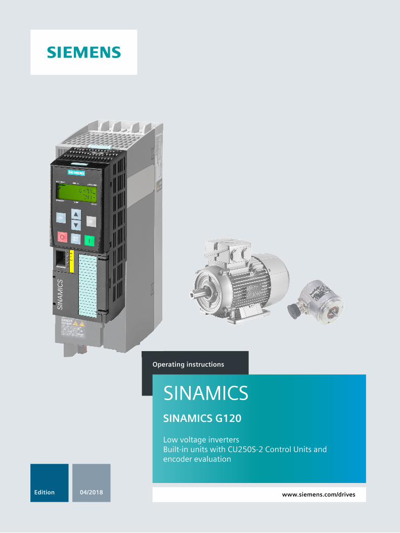
Operating instructions Low voltage inverters Built-in units with CU250S-2 Control Units and encoder evaluation SINAMICS G120 04/2018 Edition SINAMICS www.siemens.com/drives
-
Upload
khangminh22 -
Category
Documents
-
view
1 -
download
0
Transcript of Converter with the CU250S-2 Control Units - ADEGIS
Operating instructions
Low voltage invertersBuilt-in units with CU250S-2 Control Units and encoder evaluation
SINAMICS G120
04/2018Edition
SINAMICS
www.siemens.com/drives

SINAMICS
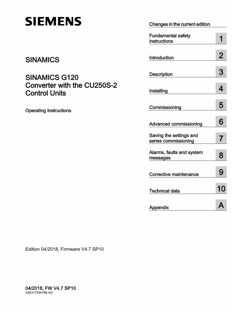
SINAMICS G120Converter with the CU250S-2 Control Units
Operating Instructions
Edition 04/2018, Firmware V4.7 SP10
04/2018, FW V4.7 SP10A5E31759476B AG
Changes in the current edition
Fundamental safety instructions 1
Introduction 2
Description 3
Installing 4
Commissioning 5
Advanced commissioning 6Saving the settings and series commissioning 7Alarms, faults and system messages 8
Corrective maintenance 9
Technical data 10
Appendix A
Legal informationWarning notice system
This manual contains notices you have to observe in order to ensure your personal safety, as well as to prevent damage to property. The notices referring to your personal safety are highlighted in the manual by a safety alert symbol, notices referring only to property damage have no safety alert symbol. These notices shown below are graded according to the degree of danger.
DANGERindicates that death or severe personal injury will result if proper precautions are not taken.
WARNINGindicates that death or severe personal injury may result if proper precautions are not taken.
CAUTIONindicates that minor personal injury can result if proper precautions are not taken.
NOTICEindicates that property damage can result if proper precautions are not taken.If more than one degree of danger is present, the warning notice representing the highest degree of danger will be used. A notice warning of injury to persons with a safety alert symbol may also include a warning relating to property damage.
Qualified PersonnelThe product/system described in this documentation may be operated only by personnel qualified for the specific task in accordance with the relevant documentation, in particular its warning notices and safety instructions. Qualified personnel are those who, based on their training and experience, are capable of identifying risks and avoiding potential hazards when working with these products/systems.
Proper use of Siemens productsNote the following:
WARNINGSiemens products may only be used for the applications described in the catalog and in the relevant technical documentation. If products and components from other manufacturers are used, these must be recommended or approved by Siemens. Proper transport, storage, installation, assembly, commissioning, operation and maintenance are required to ensure that the products operate safely and without any problems. The permissible ambient conditions must be complied with. The information in the relevant documentation must be observed.
TrademarksAll names identified by ® are registered trademarks of Siemens AG. The remaining trademarks in this publication may be trademarks whose use by third parties for their own purposes could violate the rights of the owner.
Disclaimer of LiabilityWe have reviewed the contents of this publication to ensure consistency with the hardware and software described. Since variance cannot be precluded entirely, we cannot guarantee full consistency. However, the information in this publication is reviewed regularly and any necessary corrections are included in subsequent editions.
Siemens AGDivision Digital FactoryPostfach 48 4890026 NÜRNBERGGERMANY
A5E31759476B AG 04/2018 Subject to change
Copyright © Siemens AG 2013 - 2018.All rights reserved
Changes in the current edition
Essential changes with respect to Edition 09/2017
New hardware PM240-2 Power Module, FSG
Power Module with IP20 degree of protection (Page 35)Dimensioned drawings, drilling dimensions for the PM240-2 Power Module, IP20
(Page 62)Specific technical data, 400 V inverters (Page 457)Specific technical data, 690 V inverters (Page 467)
New functionsFirmware version 4.7 SP10 (Page 481)
Corrections Article number of the PM240-2 PT Power Module, 132 kW, corrected.
Technical data, PM240-2 Power Modules (Page 445)
Dimensions of the PM240-2 Power Module corrected.Dimensioned drawings, drilling dimensions for the PM240-2 Power Module, IP20
(Page 62)
Setting the feedback signal for the line contactor control corrected.Line contactor control (Page 355)
SSI encoder and Endat 2.1 encoder are permissible for speed control.Installing encoders (Page 121)
PROFIdrive control word 2, bit 8 correctedPROFIdrive status word 2, bit 7 corrected
Telegrams (Page 184)
Revised descriptions Only commissioning using the Startdrive PC-based tool is described. Commissioning with
STARTER has been removed.Exceptions: Write and know-how protection.You can find information on commissioning with STARTER on the Internet:
Operating Instructions, 09/2017 Edition (https://support.industry.siemens.com/cs/ww/en/view/109751322)
Converter with the CU250S-2 Control UnitsOperating Instructions, 04/2018, FW V4.7 SP10, A5E31759476B AG 3

Changes in the current edition
Converter with the CU250S-2 Control Units4 Operating Instructions, 04/2018, FW V4.7 SP10, A5E31759476B AG
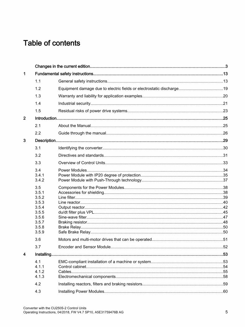
Table of contents
Changes in the current edition......................................................................................................................3
1 Fundamental safety instructions.................................................................................................................13
1.1 General safety instructions.....................................................................................................13
1.2 Equipment damage due to electric fields or electrostatic discharge......................................19
1.3 Warranty and liability for application examples......................................................................20
1.4 Industrial security...................................................................................................................21
1.5 Residual risks of power drive systems...................................................................................23
2 Introduction.................................................................................................................................................25
2.1 About the Manual...................................................................................................................25
2.2 Guide through the manual......................................................................................................26
3 Description..................................................................................................................................................29
3.1 Identifying the converter.........................................................................................................30
3.2 Directives and standards........................................................................................................31
3.3 Overview of Control Units......................................................................................................33
3.4 Power Modules......................................................................................................................343.4.1 Power Module with IP20 degree of protection.......................................................................353.4.2 Power Module with Push-Through technology.......................................................................37
3.5 Components for the Power Modules......................................................................................383.5.1 Accessories for shielding.......................................................................................................383.5.2 Line filter.................................................................................................................................393.5.3 Line reactor............................................................................................................................403.5.4 Output reactor........................................................................................................................423.5.5 du/dt filter plus VPL................................................................................................................453.5.6 Sine-wave filter.......................................................................................................................473.5.7 Braking resistor......................................................................................................................483.5.8 Brake Relay............................................................................................................................503.5.9 Safe Brake Relay...................................................................................................................50
3.6 Motors and multi-motor drives that can be operated..............................................................51
3.7 Encoder and Sensor Module..................................................................................................52
4 Installing.....................................................................................................................................................53
4.1 EMC-compliant installation of a machine or system..............................................................534.1.1 Control cabinet.......................................................................................................................544.1.2 Cables....................................................................................................................................554.1.3 Electromechanical components.............................................................................................58
4.2 Installing reactors, filters and braking resistors......................................................................59
4.3 Installing Power Modules.......................................................................................................60
Converter with the CU250S-2 Control UnitsOperating Instructions, 04/2018, FW V4.7 SP10, A5E31759476B AG 5

4.3.1 Basic installation rules for built-in units..................................................................................604.3.2 Dimensioned drawings, drilling dimensions for the PM240-2 Power Module, IP20...............624.3.3 Dimension drawings, drilling dimensions for PM240-2 Power Modules in push-through
technology..............................................................................................................................654.3.4 Dimensioned drawings, drilling dimensions for the PM250 Power Module............................69
4.4 Connecting the line supply and motor....................................................................................724.4.1 Permissible line supplies........................................................................................................724.4.1.1 TN line system.......................................................................................................................734.4.1.2 TT line system........................................................................................................................754.4.1.3 IT system................................................................................................................................764.4.2 Protective conductor..............................................................................................................774.4.3 Connecting an inverter with the PM240-2 Power Module......................................................794.4.4 Connecting the inverter with the PM250 Power Module........................................................844.4.5 Connecting the motor to the inverter in a star or delta connection.........................................864.4.6 Connecting a motor holding brake.........................................................................................874.4.6.1 Installing a Brake Relay - PM250 Power Module...................................................................894.4.6.2 Installing a Brake Relay - PM240-2 Power Module................................................................90
4.5 Connecting the interfaces for the inverter control..................................................................914.5.1 Overview of the interfaces on the front and upper side..........................................................924.5.2 Terminal strips behind the upper front door...........................................................................934.5.3 Terminal strips behind the lower front door............................................................................944.5.4 Fieldbus and encoder interfaces on the lower side................................................................954.5.5 Factory interface settings.......................................................................................................964.5.6 Default setting of the interfaces..............................................................................................984.5.7 Fail-safe digital input............................................................................................................1094.5.8 Wire up the terminal strip and connect the shield................................................................1104.5.9 Connecting the temperature contact of the braking resistor................................................1134.5.10 Fieldbus interfaces...............................................................................................................1134.5.11 Connecting the inverter to PROFINET.................................................................................1144.5.11.1 Communication via PROFINET IO and Ethernet.................................................................1144.5.11.2 Connecting the PROFINET cable to the inverter.................................................................1154.5.11.3 What do you have to set for communication via PROFINET?.............................................1164.5.11.4 Installing GSDML.................................................................................................................1174.5.12 Connecting the inverter to PROFIBUS.................................................................................1174.5.12.1 Connecting the PROFIBUS cable to the inverter.................................................................1184.5.12.2 What do you have to set for communication via PROFIBUS?.............................................1184.5.12.3 Installing the GSD................................................................................................................1194.5.12.4 Setting the address..............................................................................................................119
4.6 Installing encoders...............................................................................................................121
5 Commissioning.........................................................................................................................................125
5.1 Commissioning guidelines...................................................................................................125
5.2 Tools to commission the inverter.........................................................................................126
5.3 Preparing for commissioning................................................................................................1275.3.1 Collecting motor data...........................................................................................................1275.3.2 Forming DC link capacitors..................................................................................................1285.3.3 Inverter factory setting..........................................................................................................1305.3.4 Inverter function modules.....................................................................................................132
5.4 Quick commissioning with a PC...........................................................................................134
Table of contents
Converter with the CU250S-2 Control Units6 Operating Instructions, 04/2018, FW V4.7 SP10, A5E31759476B AG
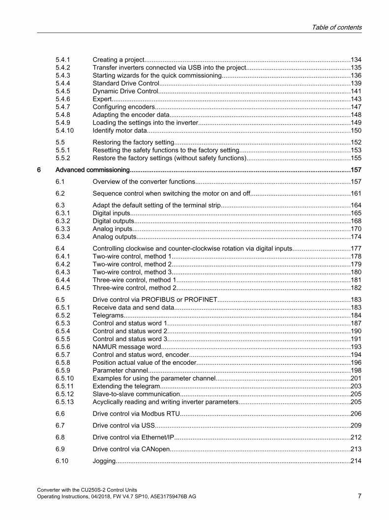
5.4.1 Creating a project.................................................................................................................1345.4.2 Transfer inverters connected via USB into the project.........................................................1355.4.3 Starting wizards for the quick commissioning......................................................................1365.4.4 Standard Drive Control.........................................................................................................1395.4.5 Dynamic Drive Control.........................................................................................................1415.4.6 Expert...................................................................................................................................1435.4.7 Configuring encoders...........................................................................................................1475.4.8 Adapting the encoder data...................................................................................................1485.4.9 Loading the settings into the inverter...................................................................................1495.4.10 Identify motor data...............................................................................................................150
5.5 Restoring the factory setting................................................................................................1525.5.1 Resetting the safety functions to the factory setting.............................................................1535.5.2 Restore the factory settings (without safety functions).........................................................155
6 Advanced commissioning.........................................................................................................................157
6.1 Overview of the converter functions.....................................................................................157
6.2 Sequence control when switching the motor on and off.......................................................161
6.3 Adapt the default setting of the terminal strip.......................................................................1646.3.1 Digital inputs.........................................................................................................................1656.3.2 Digital outputs......................................................................................................................1686.3.3 Analog inputs.......................................................................................................................1706.3.4 Analog outputs.....................................................................................................................174
6.4 Controlling clockwise and counter-clockwise rotation via digital inputs...............................1776.4.1 Two-wire control, method 1..................................................................................................1786.4.2 Two-wire control, method 2..................................................................................................1796.4.3 Two-wire control, method 3..................................................................................................1806.4.4 Three-wire control, method 1...............................................................................................1816.4.5 Three-wire control, method 2...............................................................................................182
6.5 Drive control via PROFIBUS or PROFINET.........................................................................1836.5.1 Receive data and send data................................................................................................1836.5.2 Telegrams............................................................................................................................1846.5.3 Control and status word 1....................................................................................................1876.5.4 Control and status word 2....................................................................................................1906.5.5 Control and status word 3....................................................................................................1916.5.6 NAMUR message word........................................................................................................1936.5.7 Control and status word, encoder........................................................................................1946.5.8 Position actual value of the encoder....................................................................................1966.5.9 Parameter channel...............................................................................................................1986.5.10 Examples for using the parameter channel..........................................................................2016.5.11 Extending the telegram........................................................................................................2036.5.12 Slave-to-slave communication.............................................................................................2056.5.13 Acyclically reading and writing inverter parameters.............................................................205
6.6 Drive control via Modbus RTU.............................................................................................206
6.7 Drive control via USS...........................................................................................................209
6.8 Drive control via Ethernet/IP................................................................................................212
6.9 Drive control via CANopen...................................................................................................213
6.10 Jogging.................................................................................................................................214
Table of contents
Converter with the CU250S-2 Control UnitsOperating Instructions, 04/2018, FW V4.7 SP10, A5E31759476B AG 7
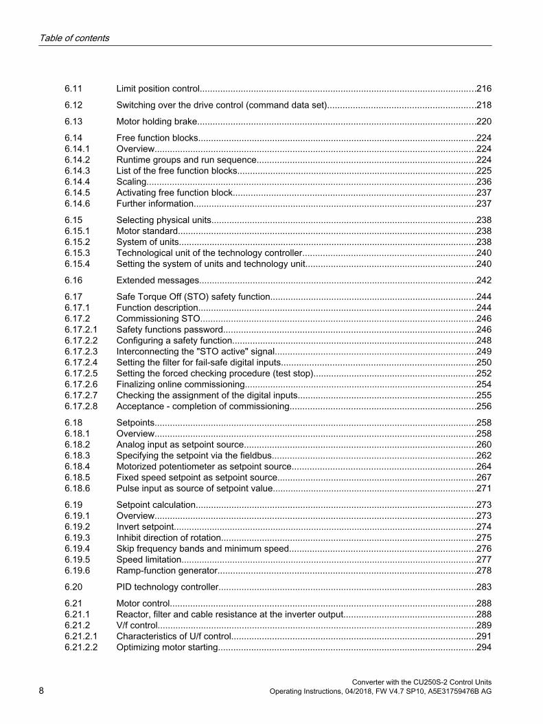
6.11 Limit position control............................................................................................................216
6.12 Switching over the drive control (command data set)..........................................................218
6.13 Motor holding brake.............................................................................................................220
6.14 Free function blocks.............................................................................................................2246.14.1 Overview..............................................................................................................................2246.14.2 Runtime groups and run sequence......................................................................................2246.14.3 List of the free function blocks..............................................................................................2256.14.4 Scaling.................................................................................................................................2366.14.5 Activating free function block...............................................................................................2376.14.6 Further information...............................................................................................................237
6.15 Selecting physical units........................................................................................................2386.15.1 Motor standard.....................................................................................................................2386.15.2 System of units.....................................................................................................................2386.15.3 Technological unit of the technology controller....................................................................2406.15.4 Setting the system of units and technology unit...................................................................240
6.16 Extended messages.............................................................................................................242
6.17 Safe Torque Off (STO) safety function.................................................................................2446.17.1 Function description.............................................................................................................2446.17.2 Commissioning STO............................................................................................................2466.17.2.1 Safety functions password...................................................................................................2466.17.2.2 Configuring a safety function................................................................................................2486.17.2.3 Interconnecting the "STO active" signal...............................................................................2496.17.2.4 Setting the filter for fail-safe digital inputs............................................................................2506.17.2.5 Setting the forced checking procedure (test stop)................................................................2526.17.2.6 Finalizing online commissioning...........................................................................................2546.17.2.7 Checking the assignment of the digital inputs......................................................................2556.17.2.8 Acceptance - completion of commissioning.........................................................................256
6.18 Setpoints..............................................................................................................................2586.18.1 Overview..............................................................................................................................2586.18.2 Analog input as setpoint source...........................................................................................2606.18.3 Specifying the setpoint via the fieldbus................................................................................2626.18.4 Motorized potentiometer as setpoint source........................................................................2646.18.5 Fixed speed setpoint as setpoint source..............................................................................2676.18.6 Pulse input as source of setpoint value................................................................................271
6.19 Setpoint calculation..............................................................................................................2736.19.1 Overview..............................................................................................................................2736.19.2 Invert setpoint.......................................................................................................................2746.19.3 Inhibit direction of rotation....................................................................................................2756.19.4 Skip frequency bands and minimum speed.........................................................................2766.19.5 Speed limitation....................................................................................................................2776.19.6 Ramp-function generator.....................................................................................................278
6.20 PID technology controller.....................................................................................................283
6.21 Motor control........................................................................................................................2886.21.1 Reactor, filter and cable resistance at the inverter output....................................................2886.21.2 V/f control.............................................................................................................................2896.21.2.1 Characteristics of U/f control................................................................................................2916.21.2.2 Optimizing motor starting.....................................................................................................294
Table of contents
Converter with the CU250S-2 Control Units8 Operating Instructions, 04/2018, FW V4.7 SP10, A5E31759476B AG
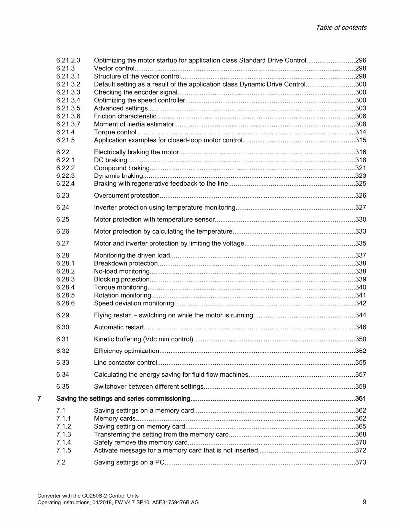
6.21.2.3 Optimizing the motor startup for application class Standard Drive Control..........................2966.21.3 Vector control.......................................................................................................................2986.21.3.1 Structure of the vector control..............................................................................................2986.21.3.2 Default setting as a result of the application class Dynamic Drive Control..........................3006.21.3.3 Checking the encoder signal................................................................................................3006.21.3.4 Optimizing the speed controller............................................................................................3006.21.3.5 Advanced settings................................................................................................................3036.21.3.6 Friction characteristic...........................................................................................................3066.21.3.7 Moment of inertia estimator..................................................................................................3086.21.4 Torque control......................................................................................................................3146.21.5 Application examples for closed-loop motor control.............................................................315
6.22 Electrically braking the motor...............................................................................................3166.22.1 DC braking...........................................................................................................................3186.22.2 Compound braking...............................................................................................................3216.22.3 Dynamic braking..................................................................................................................3236.22.4 Braking with regenerative feedback to the line....................................................................325
6.23 Overcurrent protection.........................................................................................................326
6.24 Inverter protection using temperature monitoring................................................................327
6.25 Motor protection with temperature sensor............................................................................330
6.26 Motor protection by calculating the temperature..................................................................333
6.27 Motor and inverter protection by limiting the voltage............................................................335
6.28 Monitoring the driven load....................................................................................................3376.28.1 Breakdown protection..........................................................................................................3386.28.2 No-load monitoring...............................................................................................................3386.28.3 Blocking protection...............................................................................................................3396.28.4 Torque monitoring................................................................................................................3406.28.5 Rotation monitoring..............................................................................................................3416.28.6 Speed deviation monitoring..................................................................................................342
6.29 Flying restart – switching on while the motor is running.......................................................344
6.30 Automatic restart..................................................................................................................346
6.31 Kinetic buffering (Vdc min control).......................................................................................350
6.32 Efficiency optimization..........................................................................................................352
6.33 Line contactor control...........................................................................................................355
6.34 Calculating the energy saving for fluid flow machines.........................................................357
6.35 Switchover between different settings..................................................................................359
7 Saving the settings and series commissioning.........................................................................................361
7.1 Saving settings on a memory card.......................................................................................3627.1.1 Memory cards......................................................................................................................3627.1.2 Saving setting on memory card............................................................................................3657.1.3 Transferring the setting from the memory card....................................................................3687.1.4 Safely remove the memory card..........................................................................................3707.1.5 Activate message for a memory card that is not inserted....................................................372
7.2 Saving settings on a PC.......................................................................................................373
Table of contents
Converter with the CU250S-2 Control UnitsOperating Instructions, 04/2018, FW V4.7 SP10, A5E31759476B AG 9

7.3 Saving settings to an operator panel....................................................................................375
7.4 Other ways to back up settings............................................................................................377
7.5 Write protection....................................................................................................................378
7.6 Know-how protection............................................................................................................3807.6.1 Extending the exception list for know-how protection..........................................................3827.6.2 Activating and deactivating know-how protection................................................................383
8 Alarms, faults and system messages.......................................................................................................387
8.1 Operating states indicated on LEDs.....................................................................................388
8.2 System runtime....................................................................................................................392
8.3 Identification & maintenance data (I&M)..............................................................................393
8.4 Alarms, alarm buffer, and alarm history...............................................................................394
8.5 Faults, alarm buffer and alarm history..................................................................................397
8.6 List of alarms and faults.......................................................................................................401
9 Corrective maintenance............................................................................................................................411
9.1 Spare parts compatibility......................................................................................................411
9.2 Replacing inverter components............................................................................................4129.2.1 Overview of replacing converter components......................................................................4139.2.2 Replacing a Control Unit with enabled safety function.........................................................4159.2.3 Replacing the Control Unit without the safety functions enabled.........................................4189.2.4 Replacing the Control Unit without data backup..................................................................4219.2.5 Replacing a Control Unit with active know-how protection..................................................4219.2.6 Replacing a Power Module with enabled safety function.....................................................4249.2.7 Replacing a Power Module without the safety function being enabled................................425
9.3 Replacing an encoder..........................................................................................................4269.3.1 Replacing the encoder - same encoder type.......................................................................4269.3.2 Replacing the encoder - different encoder type...................................................................427
9.4 Firmware upgrade and downgrade......................................................................................4299.4.1 Upgrading the firmware........................................................................................................4319.4.2 Firmware downgrade...........................................................................................................4339.4.3 Correcting an unsuccessful firmware upgrade or downgrade..............................................435
9.5 Reduced acceptance after a component has been replaced and a firmware change.........436
9.6 If the converter no longer responds.....................................................................................437
10 Technical data..........................................................................................................................................439
10.1 Technical data, CU250S-2 Control Unit...............................................................................439
10.2 Overload capability of the inverter........................................................................................444
10.3 Technical data, PM240-2 Power Modules...........................................................................44510.3.1 High overload - low overload PM240-2................................................................................44510.3.2 Ambient conditions...............................................................................................................44510.3.3 General technical data, 200 V inverters...............................................................................44710.3.4 Specific technical data, 200 V inverters...............................................................................44810.3.5 Current derating depending on the pulse frequency, 200 V inverters..................................455
Table of contents
Converter with the CU250S-2 Control Units10 Operating Instructions, 04/2018, FW V4.7 SP10, A5E31759476B AG
10.3.6 General technical data, 400 V inverters...............................................................................45610.3.7 Specific technical data, 400 V inverters...............................................................................45710.3.8 Current derating depending on the pulse frequency, 400 V inverters..................................46510.3.9 General technical data, 690 V inverters...............................................................................46610.3.10 Specific technical data, 690 V inverters...............................................................................46710.3.11 Current derating depending on the pulse frequency, 690 V inverters..................................470
10.4 Technical data, PM250 Power Module................................................................................47110.4.1 Ambient conditions...............................................................................................................47210.4.2 General technical data, PM250............................................................................................47310.4.3 Specific technical data, PM250............................................................................................47410.4.4 Current reduction depending upon pulse frequency............................................................476
10.5 Data regarding the power loss in partial load operation.......................................................477
10.6 Restrictions for special ambient conditions..........................................................................478
A Appendix...................................................................................................................................................481
A.1 New and extended functions................................................................................................481A.1.1 Firmware version 4.7 SP10..................................................................................................481A.1.2 Firmware version 4.7 SP9....................................................................................................483A.1.3 Firmware version 4.7 SP6....................................................................................................485A.1.4 Firmware version 4.7 SP3....................................................................................................486A.1.5 Firmware version 4.7............................................................................................................489A.1.6 Firmware version 4.6 SP6....................................................................................................490A.1.7 Firmware version 4.6............................................................................................................491
A.2 Activating licensed functions................................................................................................492A.2.1 Licensing..............................................................................................................................492A.2.2 Creating or displaying the license key..................................................................................493A.2.3 Writing the license key to the card.......................................................................................496
A.3 Handling the BOP 2 operator panel.....................................................................................498A.3.1 Changing settings using BOP-2...........................................................................................499A.3.2 Changing indexed parameters.............................................................................................500A.3.3 Directly entering the parameter number and value..............................................................501A.3.4 A parameter cannot be changed..........................................................................................502
A.4 Interconnecting signals in the inverter..................................................................................503A.4.1 Fundamentals......................................................................................................................503A.4.2 Application example.............................................................................................................505
A.5 Application Examples...........................................................................................................507A.5.1 Setting an absolute encoder................................................................................................507A.5.2 Connecting a fail-safe digital input.......................................................................................511
A.6 Acceptance tests for the safety functions.............................................................................513A.6.1 Recommended acceptance test...........................................................................................513A.6.2 Acceptance test STO (basic functions)................................................................................514A.6.3 Machine documentation.......................................................................................................516A.6.4 Documenting the settings for the basic functions, firmware V4.4 ... V4.7 SP6....................518
A.7 Manuals and technical support............................................................................................519A.7.1 Overview of the manuals......................................................................................................519A.7.2 Configuring support..............................................................................................................521A.7.3 Product Support...................................................................................................................522
Table of contents
Converter with the CU250S-2 Control UnitsOperating Instructions, 04/2018, FW V4.7 SP10, A5E31759476B AG 11

Index.........................................................................................................................................................523
Table of contents
Converter with the CU250S-2 Control Units12 Operating Instructions, 04/2018, FW V4.7 SP10, A5E31759476B AG
Fundamental safety instructions 11.1 General safety instructions
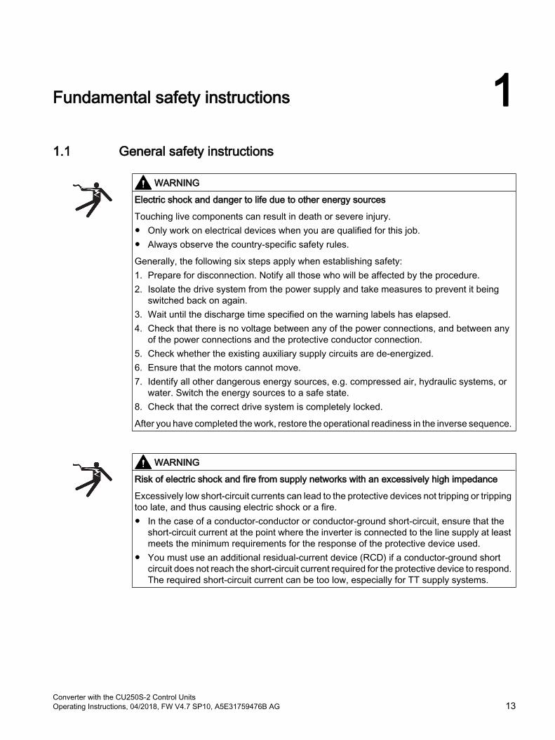
WARNING
Electric shock and danger to life due to other energy sources
Touching live components can result in death or severe injury. Only work on electrical devices when you are qualified for this job. Always observe the country-specific safety rules.
Generally, the following six steps apply when establishing safety: 1. Prepare for disconnection. Notify all those who will be affected by the procedure.2. Isolate the drive system from the power supply and take measures to prevent it being
switched back on again.3. Wait until the discharge time specified on the warning labels has elapsed. 4. Check that there is no voltage between any of the power connections, and between any
of the power connections and the protective conductor connection.5. Check whether the existing auxiliary supply circuits are de-energized.6. Ensure that the motors cannot move.7. Identify all other dangerous energy sources, e.g. compressed air, hydraulic systems, or
water. Switch the energy sources to a safe state.8. Check that the correct drive system is completely locked.
After you have completed the work, restore the operational readiness in the inverse sequence.
WARNING
Risk of electric shock and fire from supply networks with an excessively high impedance
Excessively low short-circuit currents can lead to the protective devices not tripping or tripping too late, and thus causing electric shock or a fire. In the case of a conductor-conductor or conductor-ground short-circuit, ensure that the
short-circuit current at the point where the inverter is connected to the line supply at least meets the minimum requirements for the response of the protective device used.
You must use an additional residual-current device (RCD) if a conductor-ground short circuit does not reach the short-circuit current required for the protective device to respond. The required short-circuit current can be too low, especially for TT supply systems.
Converter with the CU250S-2 Control UnitsOperating Instructions, 04/2018, FW V4.7 SP10, A5E31759476B AG 13
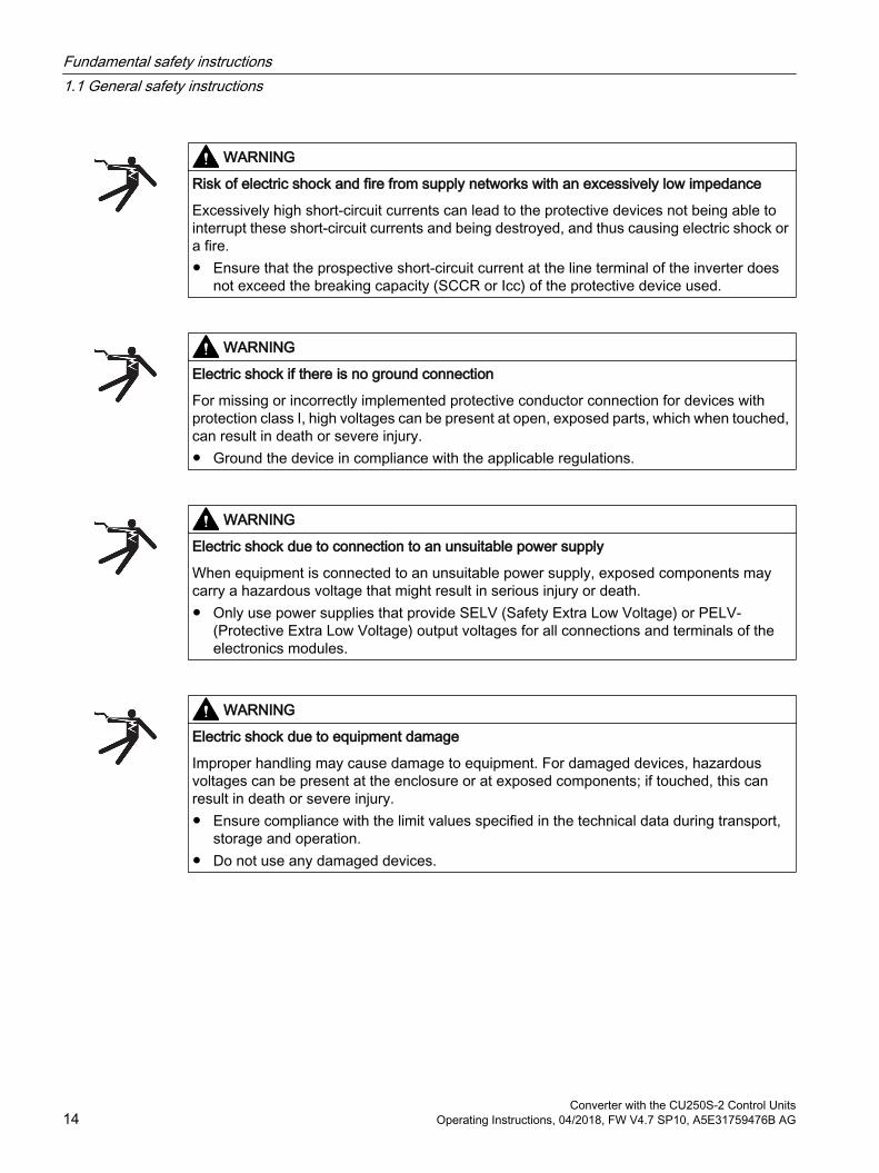
WARNING
Risk of electric shock and fire from supply networks with an excessively low impedance
Excessively high short-circuit currents can lead to the protective devices not being able to interrupt these short-circuit currents and being destroyed, and thus causing electric shock or a fire. Ensure that the prospective short-circuit current at the line terminal of the inverter does
not exceed the breaking capacity (SCCR or Icc) of the protective device used.
WARNING
Electric shock if there is no ground connection
For missing or incorrectly implemented protective conductor connection for devices with protection class I, high voltages can be present at open, exposed parts, which when touched, can result in death or severe injury. Ground the device in compliance with the applicable regulations.
WARNING
Electric shock due to connection to an unsuitable power supply
When equipment is connected to an unsuitable power supply, exposed components may carry a hazardous voltage that might result in serious injury or death. Only use power supplies that provide SELV (Safety Extra Low Voltage) or PELV-
(Protective Extra Low Voltage) output voltages for all connections and terminals of the electronics modules.
WARNING
Electric shock due to equipment damage
Improper handling may cause damage to equipment. For damaged devices, hazardous voltages can be present at the enclosure or at exposed components; if touched, this can result in death or severe injury. Ensure compliance with the limit values specified in the technical data during transport,
storage and operation. Do not use any damaged devices.
Fundamental safety instructions1.1 General safety instructions
Converter with the CU250S-2 Control Units14 Operating Instructions, 04/2018, FW V4.7 SP10, A5E31759476B AG
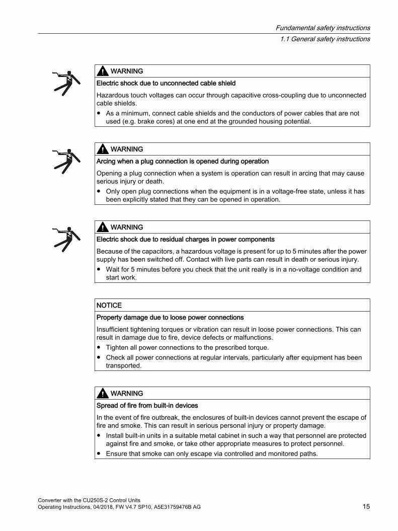
WARNING
Electric shock due to unconnected cable shield
Hazardous touch voltages can occur through capacitive cross-coupling due to unconnected cable shields. As a minimum, connect cable shields and the conductors of power cables that are not
used (e.g. brake cores) at one end at the grounded housing potential.
WARNING
Arcing when a plug connection is opened during operation
Opening a plug connection when a system is operation can result in arcing that may cause serious injury or death. Only open plug connections when the equipment is in a voltage-free state, unless it has
been explicitly stated that they can be opened in operation.
WARNING
Electric shock due to residual charges in power components
Because of the capacitors, a hazardous voltage is present for up to 5 minutes after the power supply has been switched off. Contact with live parts can result in death or serious injury. Wait for 5 minutes before you check that the unit really is in a no-voltage condition and
start work.
NOTICE
Property damage due to loose power connections
Insufficient tightening torques or vibration can result in loose power connections. This can result in damage due to fire, device defects or malfunctions. Tighten all power connections to the prescribed torque. Check all power connections at regular intervals, particularly after equipment has been
transported.
WARNING
Spread of fire from built-in devices
In the event of fire outbreak, the enclosures of built-in devices cannot prevent the escape of fire and smoke. This can result in serious personal injury or property damage. Install built-in units in a suitable metal cabinet in such a way that personnel are protected
against fire and smoke, or take other appropriate measures to protect personnel. Ensure that smoke can only escape via controlled and monitored paths.
Fundamental safety instructions1.1 General safety instructions
Converter with the CU250S-2 Control UnitsOperating Instructions, 04/2018, FW V4.7 SP10, A5E31759476B AG 15
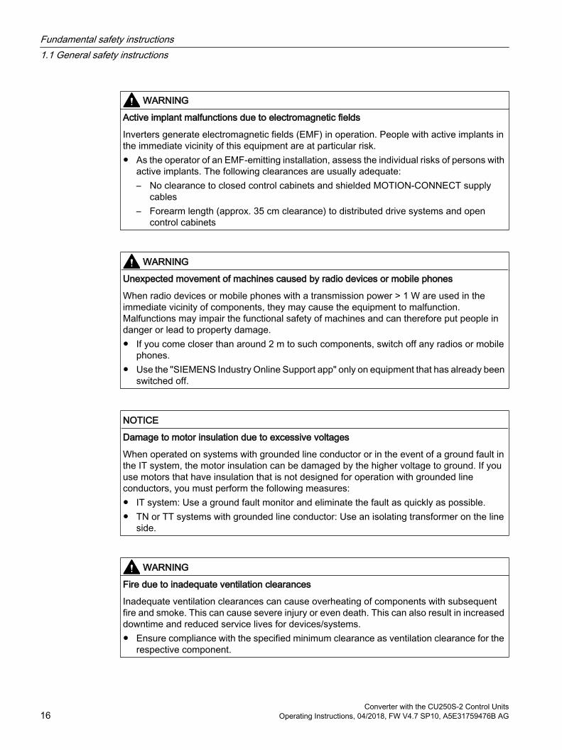
WARNING
Active implant malfunctions due to electromagnetic fields
Inverters generate electromagnetic fields (EMF) in operation. People with active implants in the immediate vicinity of this equipment are at particular risk. As the operator of an EMF-emitting installation, assess the individual risks of persons with
active implants. The following clearances are usually adequate:– No clearance to closed control cabinets and shielded MOTION-CONNECT supply
cables– Forearm length (approx. 35 cm clearance) to distributed drive systems and open
control cabinets
WARNING
Unexpected movement of machines caused by radio devices or mobile phones
When radio devices or mobile phones with a transmission power > 1 W are used in the immediate vicinity of components, they may cause the equipment to malfunction. Malfunctions may impair the functional safety of machines and can therefore put people in danger or lead to property damage. If you come closer than around 2 m to such components, switch off any radios or mobile
phones. Use the "SIEMENS Industry Online Support app" only on equipment that has already been
switched off.
NOTICE
Damage to motor insulation due to excessive voltages
When operated on systems with grounded line conductor or in the event of a ground fault in the IT system, the motor insulation can be damaged by the higher voltage to ground. If you use motors that have insulation that is not designed for operation with grounded line conductors, you must perform the following measures: IT system: Use a ground fault monitor and eliminate the fault as quickly as possible. TN or TT systems with grounded line conductor: Use an isolating transformer on the line
side.
WARNING
Fire due to inadequate ventilation clearances
Inadequate ventilation clearances can cause overheating of components with subsequent fire and smoke. This can cause severe injury or even death. This can also result in increased downtime and reduced service lives for devices/systems. Ensure compliance with the specified minimum clearance as ventilation clearance for the
respective component.
Fundamental safety instructions1.1 General safety instructions
Converter with the CU250S-2 Control Units16 Operating Instructions, 04/2018, FW V4.7 SP10, A5E31759476B AG
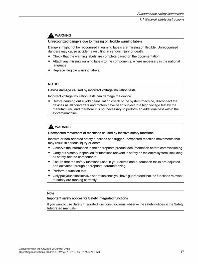
WARNING
Unrecognized dangers due to missing or illegible warning labels
Dangers might not be recognized if warning labels are missing or illegible. Unrecognized dangers may cause accidents resulting in serious injury or death. Check that the warning labels are complete based on the documentation. Attach any missing warning labels to the components, where necessary in the national
language. Replace illegible warning labels.
NOTICE
Device damage caused by incorrect voltage/insulation tests
Incorrect voltage/insulation tests can damage the device. Before carrying out a voltage/insulation check of the system/machine, disconnect the
devices as all converters and motors have been subject to a high voltage test by the manufacturer, and therefore it is not necessary to perform an additional test within the system/machine.
WARNING
Unexpected movement of machines caused by inactive safety functions
Inactive or non-adapted safety functions can trigger unexpected machine movements that may result in serious injury or death. Observe the information in the appropriate product documentation before commissioning. Carry out a safety inspection for functions relevant to safety on the entire system, including
all safety-related components. Ensure that the safety functions used in your drives and automation tasks are adjusted
and activated through appropriate parameterizing. Perform a function test. Only put your plant into live operation once you have guaranteed that the functions relevant
to safety are running correctly.
NoteImportant safety notices for Safety Integrated functions
If you want to use Safety Integrated functions, you must observe the safety notices in the Safety Integrated manuals.
Fundamental safety instructions1.1 General safety instructions
Converter with the CU250S-2 Control UnitsOperating Instructions, 04/2018, FW V4.7 SP10, A5E31759476B AG 17

WARNING
Malfunctions of the machine as a result of incorrect or changed parameter settings
As a result of incorrect or changed parameterization, machines can malfunction, which in turn can lead to injuries or death. Protect the parameterization (parameter assignments) against unauthorized access. Handle possible malfunctions by taking suitable measures, e.g. emergency stop or
emergency off.
Fundamental safety instructions1.1 General safety instructions
Converter with the CU250S-2 Control Units18 Operating Instructions, 04/2018, FW V4.7 SP10, A5E31759476B AG
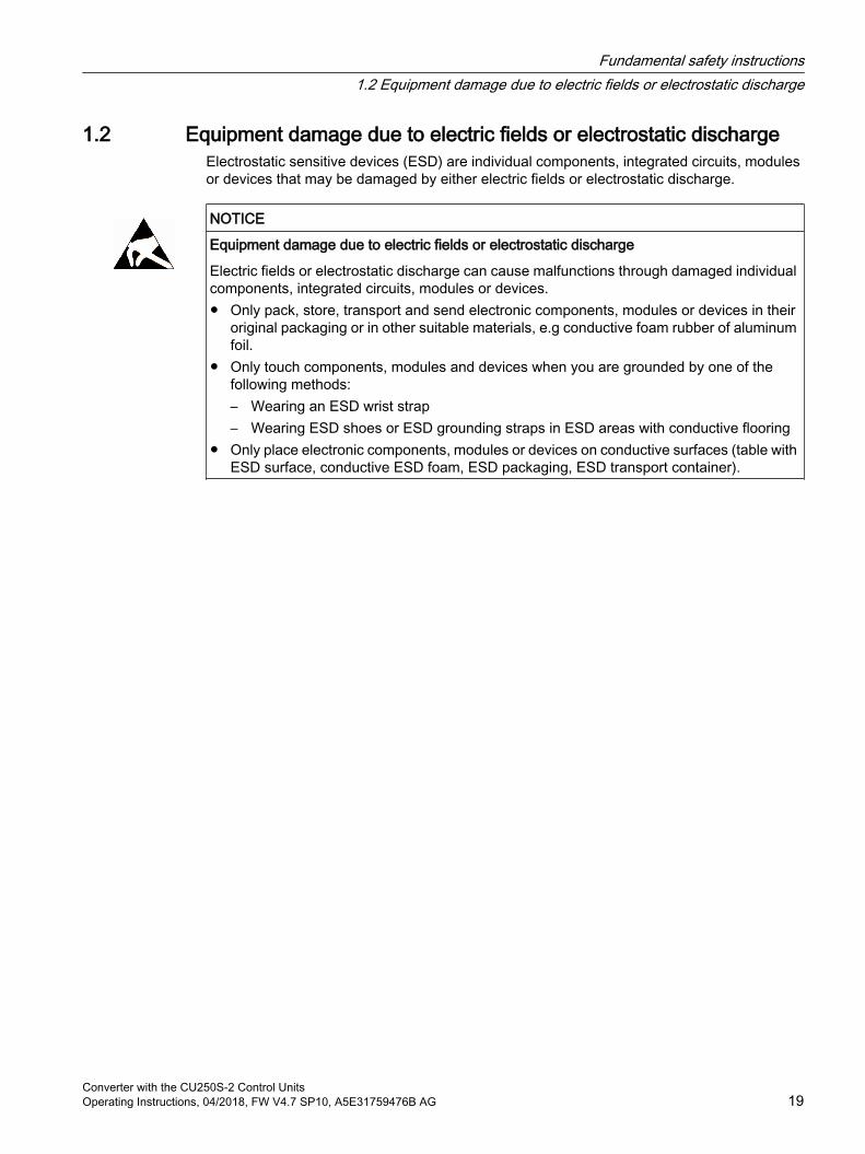
1.2 Equipment damage due to electric fields or electrostatic dischargeElectrostatic sensitive devices (ESD) are individual components, integrated circuits, modules or devices that may be damaged by either electric fields or electrostatic discharge.
NOTICE
Equipment damage due to electric fields or electrostatic discharge
Electric fields or electrostatic discharge can cause malfunctions through damaged individual components, integrated circuits, modules or devices. Only pack, store, transport and send electronic components, modules or devices in their
original packaging or in other suitable materials, e.g conductive foam rubber of aluminum foil.
Only touch components, modules and devices when you are grounded by one of the following methods:– Wearing an ESD wrist strap– Wearing ESD shoes or ESD grounding straps in ESD areas with conductive flooring
Only place electronic components, modules or devices on conductive surfaces (table with ESD surface, conductive ESD foam, ESD packaging, ESD transport container).
Fundamental safety instructions1.2 Equipment damage due to electric fields or electrostatic discharge
Converter with the CU250S-2 Control UnitsOperating Instructions, 04/2018, FW V4.7 SP10, A5E31759476B AG 19

1.3 Warranty and liability for application examplesApplication examples are not binding and do not claim to be complete regarding configuration, equipment or any eventuality which may arise. Application examples do not represent specific customer solutions, but are only intended to provide support for typical tasks.
As the user you yourself are responsible for ensuring that the products described are operated correctly. Application examples do not relieve you of your responsibility for safe handling when using, installing, operating and maintaining the equipment.
Fundamental safety instructions1.3 Warranty and liability for application examples
Converter with the CU250S-2 Control Units20 Operating Instructions, 04/2018, FW V4.7 SP10, A5E31759476B AG

1.4 Industrial security
NoteIndustrial security
Siemens provides products and solutions with industrial security functions that support the secure operation of plants, systems, machines and networks.
In order to protect plants, systems, machines and networks against cyber threats, it is necessary to implement – and continuously maintain – a holistic, state-of-the-art industrial security concept. Siemens’ products and solutions constitute one element of such a concept.
Customers are responsible for preventing unauthorized access to their plants, systems, machines and networks. Such systems, machines and components should only be connected to an enterprise network or the Internet if and to the extent such a connection is necessary and only when appropriate security measures (e.g. firewalls and/or network segmentation) are in place.
For additional information on industrial security measures that may be implemented, please visit:
Industrial security (http://www.siemens.com/industrialsecurity)
Siemens’ products and solutions undergo continuous development to make them more secure. Siemens strongly recommends that product updates are applied as soon as they are available and that the latest product versions are used. Use of product versions that are no longer supported, and failure to apply the latest updates may increase customer’s exposure to cyber threats.
To stay informed about product updates, subscribe to the Siemens Industrial Security RSS Feed at:
Industrial security (http://www.siemens.com/industrialsecurity)
Further information is provided on the Internet:
Industrial Security Configuration Manual (https://support.industry.siemens.com/cs/ww/en/view/108862708)
Fundamental safety instructions1.4 Industrial security
Converter with the CU250S-2 Control UnitsOperating Instructions, 04/2018, FW V4.7 SP10, A5E31759476B AG 21

WARNING
Unsafe operating states resulting from software manipulation
Software manipulations (e.g. viruses, trojans, malware or worms) can cause unsafe operating states in your system that may lead to death, serious injury, and property damage. Keep the software up to date. Incorporate the automation and drive components into a holistic, state-of-the-art industrial
security concept for the installation or machine. Make sure that you include all installed products into the holistic industrial security concept. Protect files stored on exchangeable storage media from malicious software by with
suitable protection measures, e.g. virus scanners. Protect the drive against unauthorized changes by activating the "know-how protection"
drive function.
Fundamental safety instructions1.4 Industrial security
Converter with the CU250S-2 Control Units22 Operating Instructions, 04/2018, FW V4.7 SP10, A5E31759476B AG
1.5 Residual risks of power drive systemsWhen assessing the machine- or system-related risk in accordance with the respective local regulations (e.g., EC Machinery Directive), the machine manufacturer or system installer must take into account the following residual risks emanating from the control and drive components of a drive system:
1. Unintentional movements of driven machine or system components during commissioning, operation, maintenance, and repairs caused by, for example,
– Hardware and/or software errors in the sensors, control system, actuators, and cables and connections
– Response times of the control system and of the drive
– Operation and/or environmental conditions outside the specification
– Condensation/conductive contamination
– Parameterization, programming, cabling, and installation errors
– Use of wireless devices/mobile phones in the immediate vicinity of electronic components
– External influences/damage
– X-ray, ionizing radiation and cosmic radiation
2. Unusually high temperatures, including open flames, as well as emissions of light, noise, particles, gases, etc., can occur inside and outside the components under fault conditions caused by, for example:
– Component failure
– Software errors
– Operation and/or environmental conditions outside the specification
– External influences/damage
3. Hazardous shock voltages caused by, for example:
– Component failure
– Influence during electrostatic charging
– Induction of voltages in moving motors
– Operation and/or environmental conditions outside the specification
– Condensation/conductive contamination
– External influences/damage
4. Electrical, magnetic and electromagnetic fields generated in operation that can pose a risk to people with a pacemaker, implants or metal replacement joints, etc., if they are too close
5. Release of environmental pollutants or emissions as a result of improper operation of the system and/or failure to dispose of components safely and correctly
6. Influence of network-connected communication systems, e.g. ripple-control transmitters or data communication via the network
For more information about the residual risks of the drive system components, see the relevant sections in the technical user documentation.
Fundamental safety instructions1.5 Residual risks of power drive systems
Converter with the CU250S-2 Control UnitsOperating Instructions, 04/2018, FW V4.7 SP10, A5E31759476B AG 23

Fundamental safety instructions1.5 Residual risks of power drive systems
Converter with the CU250S-2 Control Units24 Operating Instructions, 04/2018, FW V4.7 SP10, A5E31759476B AG
Introduction 22.1 About the Manual
Who requires the operating instructions and what for?These operating instructions primarily address fitters, commissioning engineers and machine operators. The operating instructions describe the devices and device components and enable the target groups being addressed to install, connect-up, set, and commission the converters safely and in the correct manner.
What is described in the operating instructions?These operating instructions provide a summary of all of the information required to operate the converter under normal, safe conditions.
The information provided in the operating instructions has been compiled in such a way that it is sufficient for all standard applications and enables drives to be commissioned as efficiently as possible. Where it appears useful, additional information for entry level personnel has been added.
The operating instructions also contain information about special applications. Since it is assumed that readers already have a sound technical knowledge of how to configure and parameterize these applications, the relevant information is summarized accordingly. This relates, e.g. to operation with fieldbus systems and safety-related applications.
What is the meaning of the symbols in the manual? Reference to further information in the manual
Download from the Internet
DVD that can be ordered
End of a handling instruction.
Examples of inverter function symbols
Converter with the CU250S-2 Control UnitsOperating Instructions, 04/2018, FW V4.7 SP10, A5E31759476B AG 25

2.2 Guide through the manual
Section In this section you will find answers to the following questions: Description (Page 29) How is the inverter marked?
Which components make up the inverter? Which optional components are available for the inverter? What is the purpose of the optional components? Which motors can be fed from the inverter? Which commissioning tools are there?
Installing (Page 53) Which sequence is recommended when installing the inverter? What does EMC-compliant installation actually mean? Which options are available to install optional components below the inverter? What are the inverter dimensions? Which mounting and installation materials are required when installing the inverter? To which line supplies can the inverter be connected? How is the inverter connected to the line supply? How is the braking resistor connected to the inverter? Which terminals and fieldbus interfaces does the inverter have? What are the interface functions?
Commissioning (Page 125) Which motor data is required for commissioning How is the inverter set in the factory? What is the commissioning procedure? How do you restore the inverter factory settings?
Advanced commissioning (Page 157)
Which functions are included in the inverter firmware? How do the functions interoperate with one another? How are the functions set?
Saving the settings and ser‐ies commissioning (Page 361)
Why is it necessary to back up the inverter settings? Which options are available to back up the settings? How does the data backup function? How do you prevent the inverter settings from being changed? How do you prevent the inverter settings from being read out?
Corrective maintenance (Page 411)
How are inverter components replaced? How do you change the firmware version of the inverter?
Alarms, faults and system messages (Page 387)
What is the meaning of the LEDs provided on the inverter? How does the system runtime respond? How does the inverter save alarms and faults? What do the inverter alarms and faults mean? How are inverter faults resolved? Which I&M data is saved in the inverter?
Introduction2.2 Guide through the manual
Converter with the CU250S-2 Control Units26 Operating Instructions, 04/2018, FW V4.7 SP10, A5E31759476B AG

Section In this section you will find answers to the following questions: Technical data (Page 439) What is the inverter technical data?
What do "High Overload" and "Low Overload" mean? Appendix (Page 481) What are the new functions of the current firmware?
What are the most important inverter parameters? How is the inverter operated using the BOP-2 Operator Panel? How does the device trace function in STARTER? How can signal interconnections be changed in the inverter firmware? What does "BiCo technology" mean? Where can you find additional manuals and information about the inverter?
Introduction2.2 Guide through the manual
Converter with the CU250S-2 Control UnitsOperating Instructions, 04/2018, FW V4.7 SP10, A5E31759476B AG 27

Introduction2.2 Guide through the manual
Converter with the CU250S-2 Control Units28 Operating Instructions, 04/2018, FW V4.7 SP10, A5E31759476B AG

Description 3Use for the intended purpose
The inverter described in this manual is a device to control a three-phase motor. The inverter is designed for installation in electrical installations or machines.
It has been approved for industrial and commercial use on industrial networks. Additional measures have to be taken when connected to public grids.
The technical specifications and information about connection conditions are indicated on the rating plate and in the operating instructions.
Use of third-party productsThis document contains recommendations relating to third-party products. Siemens accepts the fundamental suitability of these third-party products.
You can use equivalent products from other manufacturers.
Siemens does not accept any warranty for the properties of third-party products.
Use of OpenSSLThis product contains software developed in the OpenSSL project for use within the OpenSSL toolkit.
This product contains cryptographic software created by Eric Young.
This product contains software developed by Eric Young.
Further information is provided on the Internet:
OpenSSL (https://www.openssl.org/)
Cryptsoft (mailto:[email protected])
Converter with the CU250S-2 Control UnitsOperating Instructions, 04/2018, FW V4.7 SP10, A5E31759476B AG 29
3.1 Identifying the converter
Main components of the inverter
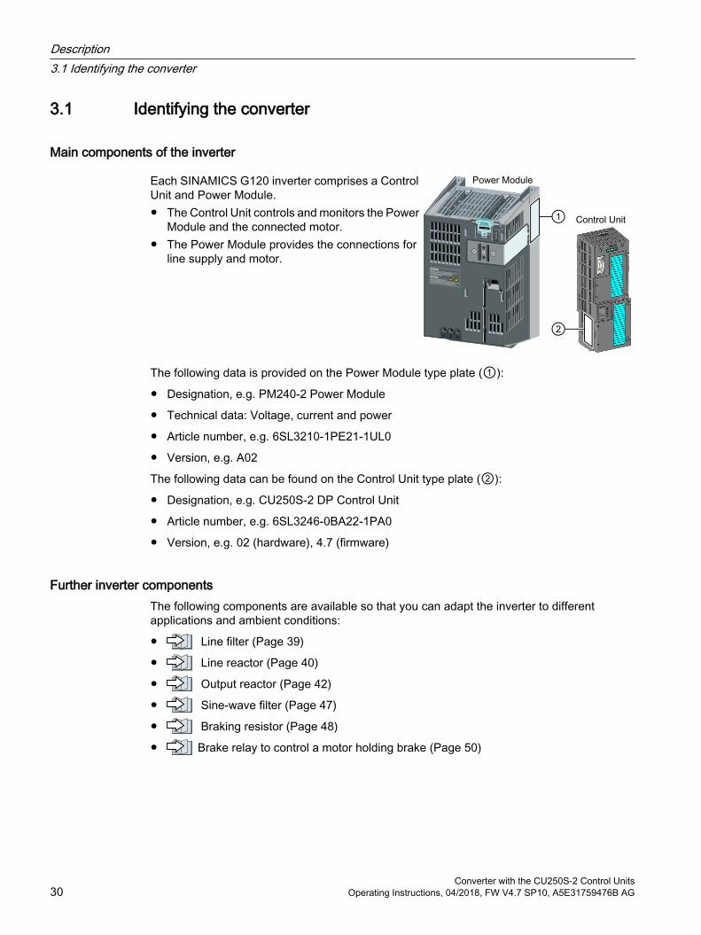
Each SINAMICS G120 inverter comprises a Control Unit and Power Module. The Control Unit controls and monitors the Power
Module and the connected motor. The Power Module provides the connections for
line supply and motor.
The following data is provided on the Power Module type plate (①):
Designation, e.g. PM240-2 Power Module
Technical data: Voltage, current and power
Article number, e.g. 6SL3210-1PE21-1UL0
Version, e.g. A02
The following data can be found on the Control Unit type plate (②):
Designation, e.g. CU250S-2 DP Control Unit
Article number, e.g. 6SL3246-0BA22-1PA0
Version, e.g. 02 (hardware), 4.7 (firmware)
Further inverter componentsThe following components are available so that you can adapt the inverter to different applications and ambient conditions:
Line filter (Page 39)
Line reactor (Page 40)
Output reactor (Page 42)
Sine-wave filter (Page 47)
Braking resistor (Page 48)
Brake relay to control a motor holding brake (Page 50)
Description3.1 Identifying the converter
Converter with the CU250S-2 Control Units30 Operating Instructions, 04/2018, FW V4.7 SP10, A5E31759476B AG
3.2 Directives and standards
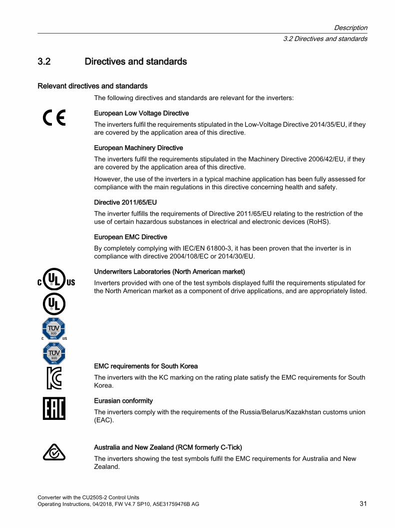
Relevant directives and standardsThe following directives and standards are relevant for the inverters:
European Low Voltage DirectiveThe inverters fulfil the requirements stipulated in the Low-Voltage Directive 2014/35/EU, if they are covered by the application area of this directive.
European Machinery DirectiveThe inverters fulfil the requirements stipulated in the Machinery Directive 2006/42/EU, if they are covered by the application area of this directive.
However, the use of the inverters in a typical machine application has been fully assessed for compliance with the main regulations in this directive concerning health and safety.
Directive 2011/65/EUThe inverter fulfills the requirements of Directive 2011/65/EU relating to the restriction of the use of certain hazardous substances in electrical and electronic devices (RoHS).
European EMC DirectiveBy completely complying with IEC/EN 61800-3, it has been proven that the inverter is in compliance with directive 2004/108/EC or 2014/30/EU.
Underwriters Laboratories (North American market)Inverters provided with one of the test symbols displayed fulfil the requirements stipulated for the North American market as a component of drive applications, and are appropriately listed.
EMC requirements for South KoreaThe inverters with the KC marking on the rating plate satisfy the EMC requirements for South Korea.
Eurasian conformityThe inverters comply with the requirements of the Russia/Belarus/Kazakhstan customs union (EAC).
Australia and New Zealand (RCM formerly C-Tick)The inverters showing the test symbols fulfil the EMC requirements for Australia and New Zealand.
Description3.2 Directives and standards
Converter with the CU250S-2 Control UnitsOperating Instructions, 04/2018, FW V4.7 SP10, A5E31759476B AG 31
Immunity to voltage drop of semiconductor process equipment.The inverters comply with the requirements of standard SEMI F47-0706.
Quality systemsSiemens AG employs a quality management system that meets the requirements of ISO 9001 and ISO 14001.
Certificates for download EC Declaration of Conformity: (https://support.industry.siemens.com/cs/ww/de/view/
58275445)
Certificates for the relevant directives, prototype test certificates, manufacturers declarations and test certificates for functions relating to functional safety ("Safety Integrated"): (http://support.automation.siemens.com/WW/view/en/22339653/134200)
Certificates for products that were certified by UL: (http://database.ul.com/cgi-bin/XYV/template/LISEXT/1FRAME/index.html)
Certificates for products that were certified by TÜV SÜD: (https://www.tuev-sued.de/industrie_konsumprodukte/zertifikatsdatenbank)
Standards that are not relevant
China Compulsory CertificationThe inverters do not fall in the area of validity of the China Compulsory Certification (CCC).
Description3.2 Directives and standards
Converter with the CU250S-2 Control Units32 Operating Instructions, 04/2018, FW V4.7 SP10, A5E31759476B AG
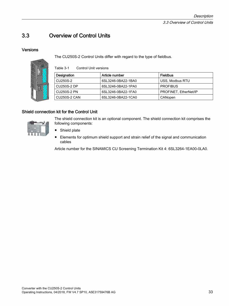
3.3 Overview of Control Units
VersionsThe CU250S-2 Control Units differ with regard to the type of fieldbus.
Table 3-1 Control Unit versions
Designation Article number FieldbusCU250S-2 6SL3246-0BA22-1BA0 USS, Modbus RTUCU250S-2 DP 6SL3246-0BA22-1PA0 PROFIBUSCU250S-2 PN 6SL3246-0BA22-1FA0 PROFINET, EtherNet/IPCU250S-2 CAN 6SL3246-0BA22-1CA0 CANopen
Shield connection kit for the Control UnitThe shield connection kit is an optional component. The shield connection kit comprises the following components:
Shield plate
Elements for optimum shield support and strain relief of the signal and communication cables
Article number for the SINAMICS CU Screening Termination Kit 4: 6SL3264-1EA00-0LA0.
Description3.3 Overview of Control Units
Converter with the CU250S-2 Control UnitsOperating Instructions, 04/2018, FW V4.7 SP10, A5E31759476B AG 33

3.4 Power ModulesImportant data on the Power Modules is provided in this section. Further information is contained in the Hardware Installation Manual of the Power Module.
Overview of the manuals (Page 519)
All power data refers to rated values or to power for operation with low overload (LO).
You can operate the CU250S-2 Control Unit with the following Power Modules:
PM240-2, in IP20 degree of protection and push-through technology
PM240P-2
PM250
Description3.4 Power Modules
Converter with the CU250S-2 Control Units34 Operating Instructions, 04/2018, FW V4.7 SP10, A5E31759476B AG
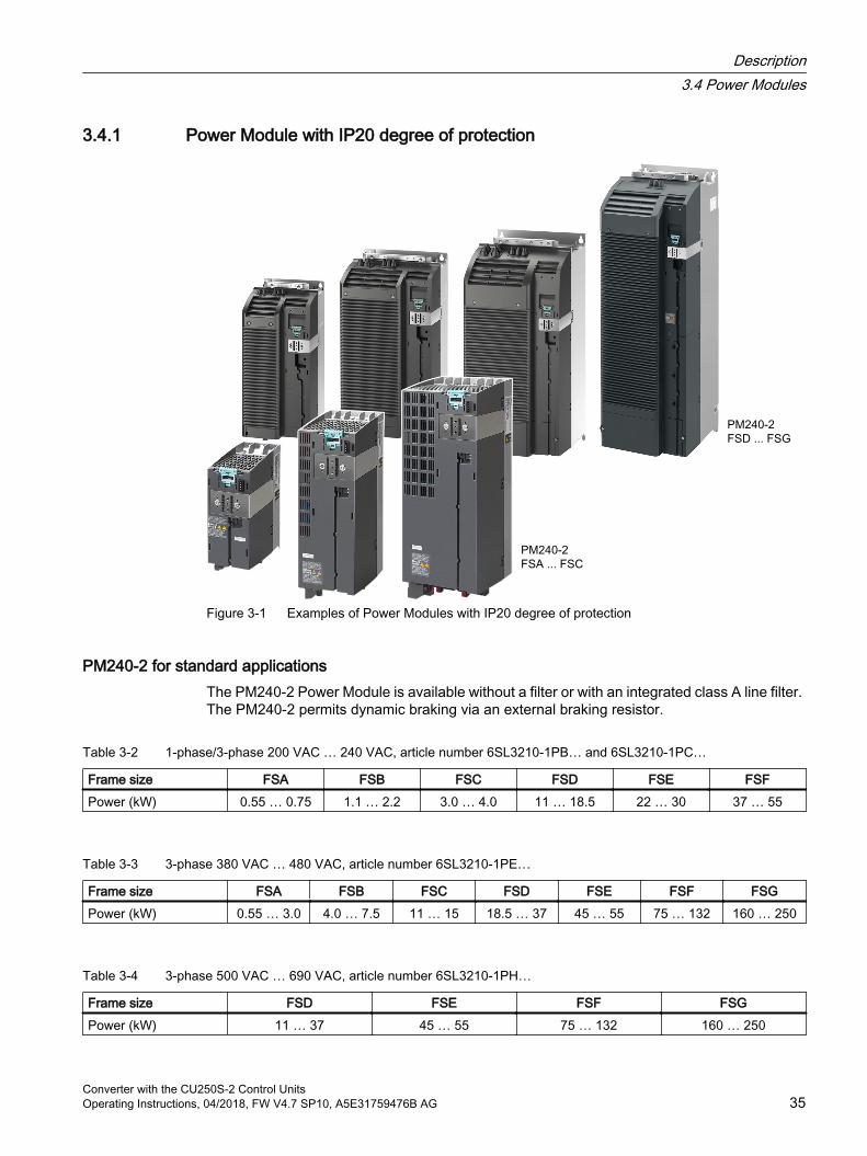
3.4.1 Power Module with IP20 degree of protection
Figure 3-1 Examples of Power Modules with IP20 degree of protection
PM240-2 for standard applicationsThe PM240-2 Power Module is available without a filter or with an integrated class A line filter. The PM240-2 permits dynamic braking via an external braking resistor.
Table 3-2 1-phase/3-phase 200 VAC … 240 VAC, article number 6SL3210-1PB… and 6SL3210-1PC…
Frame size FSA FSB FSC FSD FSE FSFPower (kW) 0.55 … 0.75 1.1 … 2.2 3.0 … 4.0 11 … 18.5 22 … 30 37 … 55
Table 3-3 3-phase 380 VAC … 480 VAC, article number 6SL3210-1PE…
Frame size FSA FSB FSC FSD FSE FSF FSGPower (kW) 0.55 … 3.0 4.0 … 7.5 11 … 15 18.5 … 37 45 … 55 75 … 132 160 … 250
Table 3-4 3-phase 500 VAC … 690 VAC, article number 6SL3210-1PH…
Frame size FSD FSE FSF FSGPower (kW) 11 … 37 45 … 55 75 … 132 160 … 250
Description3.4 Power Modules
Converter with the CU250S-2 Control UnitsOperating Instructions, 04/2018, FW V4.7 SP10, A5E31759476B AG 35

PM250 for standard applications with energy recoveryThe PM250 Power Module is available without a filter or with integrated class A line filter. The PM250 permits dynamic braking with energy recovery into the line supply.
Table 3-5 3-phase 380 VAC … 480 VAC, article number 6SL3225-0BE…
Frame size FSC FSD FSE FSFPower (kW) 7.5 … 15 18.5 … 30 37 … 45 55 … 90
Description3.4 Power Modules
Converter with the CU250S-2 Control Units36 Operating Instructions, 04/2018, FW V4.7 SP10, A5E31759476B AG
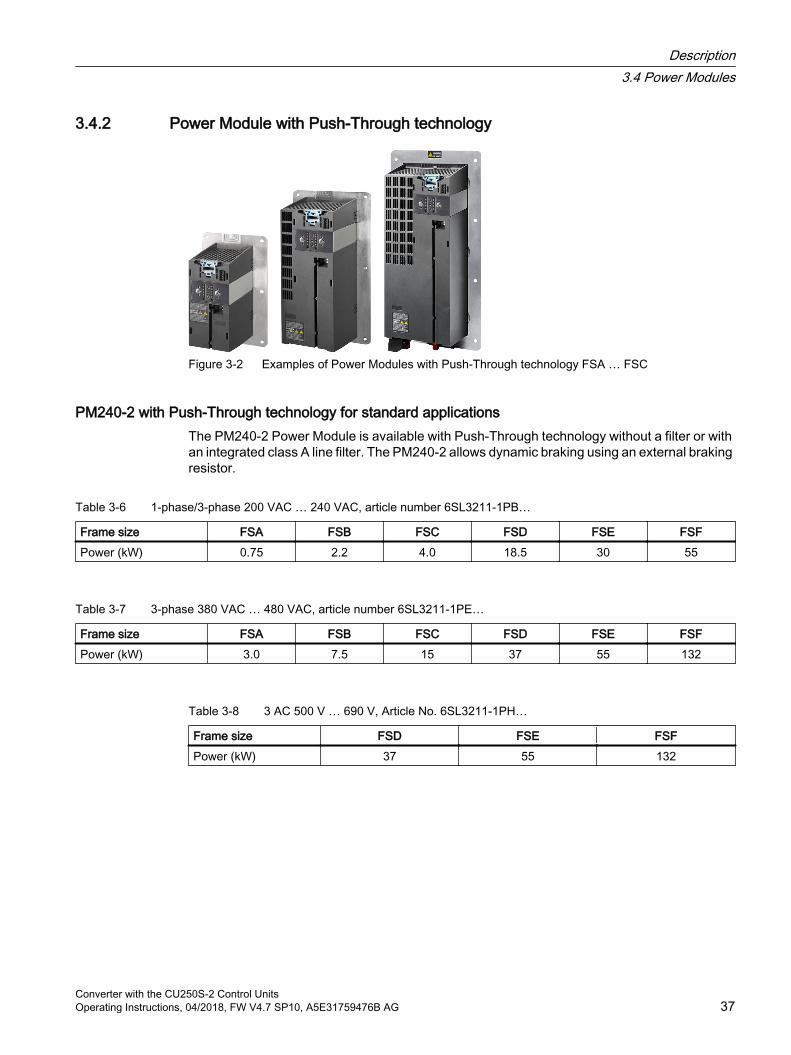
3.4.2 Power Module with Push-Through technology
Figure 3-2 Examples of Power Modules with Push-Through technology FSA … FSC
PM240-2 with Push-Through technology for standard applicationsThe PM240-2 Power Module is available with Push-Through technology without a filter or with an integrated class A line filter. The PM240-2 allows dynamic braking using an external braking resistor.
Table 3-6 1-phase/3-phase 200 VAC … 240 VAC, article number 6SL3211-1PB…
Frame size FSA FSB FSC FSD FSE FSFPower (kW) 0.75 2.2 4.0 18.5 30 55
Table 3-7 3-phase 380 VAC … 480 VAC, article number 6SL3211-1PE…
Frame size FSA FSB FSC FSD FSE FSFPower (kW) 3.0 7.5 15 37 55 132
Table 3-8 3 AC 500 V … 690 V, Article No. 6SL3211-1PH…
Frame size FSD FSE FSFPower (kW) 37 55 132
Description3.4 Power Modules
Converter with the CU250S-2 Control UnitsOperating Instructions, 04/2018, FW V4.7 SP10, A5E31759476B AG 37
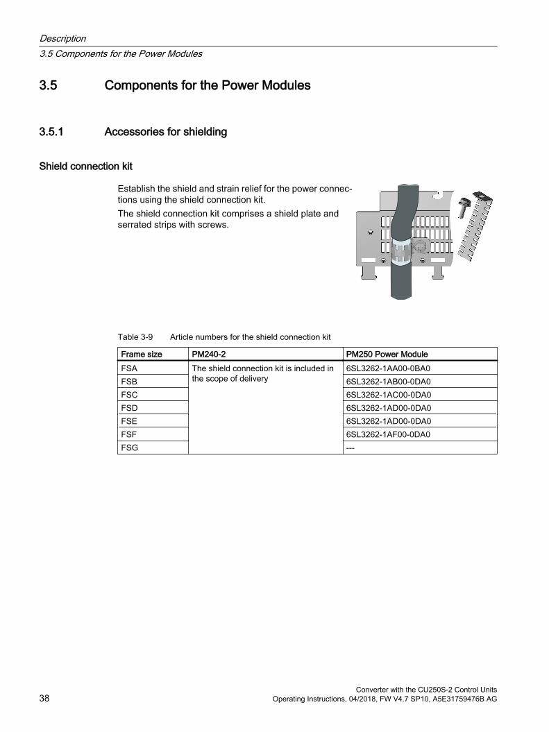
3.5 Components for the Power Modules
3.5.1 Accessories for shielding
Shield connection kit
Establish the shield and strain relief for the power connec‐tions using the shield connection kit.The shield connection kit comprises a shield plate and serrated strips with screws.
Table 3-9 Article numbers for the shield connection kit
Frame size PM240-2 PM250 Power ModuleFSA The shield connection kit is included in
the scope of delivery6SL3262-1AA00-0BA0
FSB 6SL3262-1AB00-0DA0FSC 6SL3262-1AC00-0DA0FSD 6SL3262-1AD00-0DA0FSE 6SL3262-1AD00-0DA0FSF 6SL3262-1AF00-0DA0FSG ---
Description3.5 Components for the Power Modules
Converter with the CU250S-2 Control Units38 Operating Instructions, 04/2018, FW V4.7 SP10, A5E31759476B AG
3.5.2 Line filterWith a line filter, the inverter can achieve a higher radio interference class.
NOTICE
Overloading the line filter when connected to line supplies that are not permissible
The line filter is only suitable for operation on TN or TT line supplies with a grounded neutral point. If operated on other line supplies, the line filter will be thermally overloaded and will be damaged. For inverters equipped with line filter, only connect to TN or TT line supplies with a
grounded neutral point.
External line filters for PM250
Power Module Power Class B line filter according to EN55011: 2009
FSC 6SL3225-0BE25‑5AA0, 6SL3225-0BE27‑5AA0, 6SL3225-0BE31‑1AA0
7.5 kW … 15.0 kW 6SL3203-0BD23-8SA0
Description3.5 Components for the Power Modules
Converter with the CU250S-2 Control UnitsOperating Instructions, 04/2018, FW V4.7 SP10, A5E31759476B AG 39
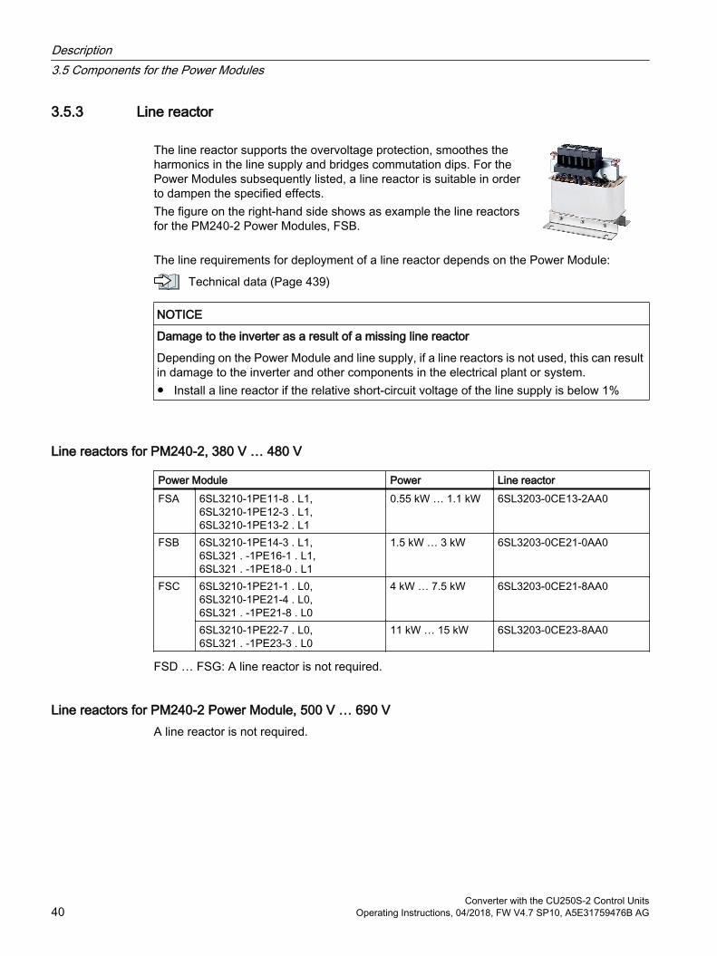
3.5.3 Line reactor
The line reactor supports the overvoltage protection, smoothes the harmonics in the line supply and bridges commutation dips. For the Power Modules subsequently listed, a line reactor is suitable in order to dampen the specified effects.The figure on the right-hand side shows as example the line reactors for the PM240-2 Power Modules, FSB.
The line requirements for deployment of a line reactor depends on the Power Module:
Technical data (Page 439)
NOTICE
Damage to the inverter as a result of a missing line reactor
Depending on the Power Module and line supply, if a line reactors is not used, this can result in damage to the inverter and other components in the electrical plant or system. Install a line reactor if the relative short-circuit voltage of the line supply is below 1%
Line reactors for PM240-2, 380 V … 480 V
Power Module Power Line reactorFSA 6SL3210-1PE11-8 . L1,
6SL3210-1PE12-3 . L1, 6SL3210-1PE13-2 . L1
0.55 kW … 1.1 kW 6SL3203-0CE13-2AA0
FSB 6SL3210-1PE14-3 . L1, 6SL321 . -1PE16-1 . L1, 6SL321 . -1PE18-0 . L1
1.5 kW … 3 kW 6SL3203-0CE21-0AA0
FSC 6SL3210-1PE21-1 . L0, 6SL3210-1PE21-4 . L0, 6SL321 . -1PE21-8 . L0
4 kW … 7.5 kW 6SL3203-0CE21-8AA0
6SL3210-1PE22-7 . L0, 6SL321 . -1PE23-3 . L0
11 kW … 15 kW 6SL3203-0CE23-8AA0
FSD … FSG: A line reactor is not required.
Line reactors for PM240-2 Power Module, 500 V … 690 VA line reactor is not required.
Description3.5 Components for the Power Modules
Converter with the CU250S-2 Control Units40 Operating Instructions, 04/2018, FW V4.7 SP10, A5E31759476B AG
Line reactors for PM240-2, 200 V … 240 V
Power Module Power Line reactorFSA 6SL3210-1PB13-0 . L0,
6SL3210-1PB13-8 . L00.55 kW … 0.75 kW 6SL3203-0CE13-2AA0
FSB 6SL3210-1PB15-5 . L0, 6SL3210-1PB17-4 . L0, 6SL321 . -1PB21-0 . L0
1.1 kW … 2.2 kW 6SL3203-0CE21-0AA0
FSC 6SL3210-1PB21-4 . L0, 6SL321 . -1PB21-8 . L0
3 kW … 4 kW 6SL3203-0CE21-8AA0
6SL321 . -1PC22-2 . L0, 6SL3210-1PC22-8 . L0
5.5 kW … 7.5 kW 6SL3203-0CE23-8AA0
FSD … FSF: A line reactor is not required.
Description3.5 Components for the Power Modules
Converter with the CU250S-2 Control UnitsOperating Instructions, 04/2018, FW V4.7 SP10, A5E31759476B AG 41

3.5.4 Output reactor
Output reactors reduce the voltage stress on the motor windings and the load placed on the inverter as a result of capacitive recharging currents in the cables. One or two output reactors are required for longer motor cables.You will find more information about permissible motor cable lengths in the Hardware Installation Manual for the Power Module.
Overview of the manuals (Page 519)The figure on the right-hand side shows as example the output reactors for PM240-2 Power Modules, FSB and FSC.
NOTICE
Overheating of the output reactor if the pulse frequency is too high
The output reactor is dimensioned for the inverter pulse frequency set in the factory. Inverter operation with pulse frequencies higher than the factory setting can result in thermal overload of the output reactor. Excessively high temperatures damage the output reactor. Operate the inverter with an output reactor with a maximum pulse frequency ≤ factory
setting.
Output reactors for PM240-2 Power Modules, 380 V … 480 V
Power Module Power Output reactorFSA 6SL3210‑1PE11‑8 . L1,
6SL3210‑1PE12‑3 . L1, 6SL3210‑1PE13‑2 . L1, 6SL3210‑1PE14‑3 . L1, 6SL3210‑1PE16‑1 . L1
0.55 kW … 2.2 kW 6SL3202‑0AE16‑1CA0
6SL321 . ‑1PE18‑0 . L1 3 kW 6SL3202‑0AE18‑8CA0FSB 6SL3210‑1PE21‑1 . L0,
6SL3210‑1PE21‑4 . L0, 6SL321 . ‑1PE21‑8 . L0
4 kW … 7.5 kW 6SL3202‑0AE21‑8CA0
FSC 6SL3210‑1PE22‑7 . L0, 6SL321 . ‑1PE23‑3 . L0
11 kW … 15 kW 6SL3202‑0AE23‑8CA0
FSD 6SL3210‑1PE23‑8 . L06SL3210‑1PE24‑5 . L06SL3210‑1PE26‑0 . L06SL3210‑1PE27‑5 . L0
18.5 kW … 37 kW 6SE6400‑3TC07‑5ED0
FSE 6SL3210‑1PE28‑8 . L0, 6SL3210‑1PE31‑1 . L0, 6SL3210‑1PE31‑5 . L0, 6SL3210‑1PE31‑8 . L0
45 kW … 90 kW 6SE6400‑3TC14‑5FD0
FSF 6SL3210‑1PE32‑1 . L0 110 kW 6SL3000‑2BE32‑1AA06SL3210‑1PE32‑5 . L0 132 kW 6SL3000‑2BE32‑6AA0
Description3.5 Components for the Power Modules
Converter with the CU250S-2 Control Units42 Operating Instructions, 04/2018, FW V4.7 SP10, A5E31759476B AG
Power Module Power Output reactorFSG 6SL3210‑1PE33‑0 . L0 160 kW 6SL3000‑2BE33‑2AA0
6SL3210‑1PE33‑7 . L0 200 kW 6SL3000‑2BE33‑8AA06SL3210‑1PE34‑8 . L0 250 kW 6SL3000‑2BE35‑0AA0
Output reactors for PM240-2 Power Modules, 500 V … 690 V
Power Module Power Output reactorFSF 6SL3210‑1PH28‑0 . L0,
6SL3210‑1PH31‑0 . L075 kW … 90 kW 6SL3000‑2AH31‑0AA0
6SL3210‑1PH31‑2 . L0, 6SL3210‑1PH31‑4 . L0
110 kW … 132 kW 6SL3000‑2AH31‑5AA0
FSG 6SL3210‑1PH31‑7CL0 160 kW 6SL3000‑2AH31‑8AA06SL3210‑1PH32‑1CL0 200 kW 6SL3000‑2AH32‑4AA06SL3210‑1PH32‑5CL0 250 kW 6SL3000‑2AH32‑6AA0
Output reactors for PM240-2 Power Modules, 200 V … 240 V
Power Module Power Output reactorFSA 6SL3210‑1PB13‑0 . L0,
6SL321 . ‑1PB13‑8 . L00.55 kW … 0.75 kW 6SL3202‑0AE16‑1CA0
FSB 6SL3210‑1PB15‑5 . L0 1.1 kW6SL3210‑1PB17‑4 . L0 1.5 kW 6SL3202‑0AE18‑8CA0
FSB 6SL321 . ‑1PB21‑0 . L0 2.2 kW 6SL3202‑0AE21‑8CA0FSC 6SL3210‑1PB21‑4 . L0,
6SL321 . ‑1PB21‑8 . L03 kW … 4 kW
6SL321 . ‑1PC22‑2 . L0, 6SL3210‑1PC22‑8 . L0
5.5 kw … 7.5 kW 6SL3202‑0AE23‑8CA0
FSD 6SL3210‑1PC24‑2UL0, 6SL3210‑1PC25‑4UL0, 6SL3210‑1PC26‑8UL0
11 kW … 18.5 kW 6SE6400‑3TC07‑5ED0
FSE 6SL3210‑1PC28‑0UL0, 6SL3210‑1PC31‑1UL0
22 kW … 55 kW 6SE6400‑3TC14‑5FD0
FSF 6SL3210‑1PC31‑3UL0, 6SL3210‑1PC31‑6UL0, 6SL3210‑1PC31‑8UL0
Description3.5 Components for the Power Modules
Converter with the CU250S-2 Control UnitsOperating Instructions, 04/2018, FW V4.7 SP10, A5E31759476B AG 43
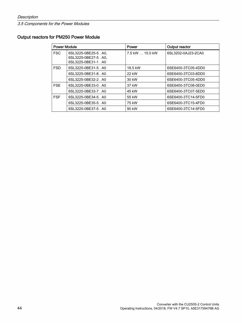
Output reactors for PM250 Power Module
Power Module Power Output reactorFSC 6SL3225-0BE25‑5 . A0,
6SL3225-0BE27‑5 . A0, 6SL3225-0BE31‑1 . A0
7.5 kW … 15.0 kW 6SL3202-0AJ23-2CA0
FSD 6SL3225-0BE31-5 . A0 18.5 kW 6SE6400-3TC05-4DD06SL3225-0BE31-8 . A0 22 kW 6SE6400-3TC03-8DD06SL3225-0BE32-2 . A0 30 kW 6SE6400-3TC05-4DD0
FSE 6SL3225-0BE33-0 . A0 37 kW 6SE6400-3TC08-0ED06SL3225-0BE33-7 . A0 45 kW 6SE6400-3TC07-5ED0
FSF 6SL3225-0BE34-5 . A0 55 kW 6SE6400-3TC14-5FD06SL3225-0BE35-5 . A0 75 kW 6SE6400-3TC15-4FD06SL3225-0BE37-5 . A0 90 kW 6SE6400-3TC14-5FD0
Description3.5 Components for the Power Modules
Converter with the CU250S-2 Control Units44 Operating Instructions, 04/2018, FW V4.7 SP10, A5E31759476B AG

3.5.5 du/dt filter plus VPL
A combination of du/dt filter and a voltage peak limiter (VPL) – du/dt filter plus VPL – are available to suppress voltage peaks. When using the du/dt filter plus VPL, the output frequency must not exceed 150 Hz. The pulse frequency may not exceed 4 kHz.
Further information is provided on the Internet:
Sales Release and Operating Instructions (https://support.industry.siemens.com/cs/ww/en/view/109756054)
du/dt filters plus VPL for PM240‑2 Power Modules, 380 V … 480 V
Power Module Power du/dt filter plus VPL FSA 6SL3210‑1PE11‑8 . L1,
6SL3210‑1PE12‑3 . L1, 6SL3210‑1PE13‑2 . L1, 6SL3210‑1PE14‑3 . L1, 6SL3210‑1PE16‑1 . L1, 6SL321 . ‑1PE18‑0 . UL1
0.55 kW … 3.0 kW JTA:TEF1203-0GB
FSB 6SL3210‑1PE21‑1 . L0, 6SL3210‑1PE21‑4 . L0, 6SL321 . ‑1PE21‑8 . L0
4.0 kW … 7.5 kW JTA:TEF1203-0GB
FSC 6SL3210‑1PE22‑7 . L0, 6SL321 . ‑1PE23‑3 . L0
11 kW … 15 kW JTA:TEF1203-0HB
FSD 6SL3210-1PE23-8 . L0 18.5 kW JTA:TEF1203-0HB6SL3210-1PE24-5 . L0,6SL3210-1PE26-0 . L0
22 kW, 30 kW JTA:TEF1203-0JB
FSDFSE
6SL321 . -1PE27-5 . L0,6SL3210-1PE28-8 . L0
37 kW, 45 kW JTA:TEF1203-0KB
FSEFSF
6SL321 . -1PE31-1 . L0,6SL3210-1PE31-5 . L0
55 kW, 75 kW JTA:TEF1203-0LB
FSF 6SL3210-1PE31-8 . L0,6SL3210-1PE32-1 . L0,6SL321 . -1PE32-5 . L0
90 kW … 132 kW JTA:TEF1203-0MB
du/dt filters plus VPL for PM240‑2 Power Modules, 500 V … 690 V
Power Module Power du/dt filter plus VPL FSD 6SL3210-1PH21-4 . L0
6SL3210-1PH22-0 . L06SL3210-1PH22-3 . L0
11 kW … 18.5 kW JTA:TEF1203-0GB
6SL3210-1PH22-7 . L06SL3210-1PH23-5 . L06SL3210-1PH24-2 . L0
22 kW … 37 kW JTA:TEF1203-0HB
Description3.5 Components for the Power Modules
Converter with the CU250S-2 Control UnitsOperating Instructions, 04/2018, FW V4.7 SP10, A5E31759476B AG 45

Power Module Power du/dt filter plus VPL FSE 6SL3210-1PH25-2 . L0
6SL3210-1PH26-2 . L045 kW, 55 kW JTA:TEF1203-0JB
FSF 6SL3210-1PH28-0 . L06SL3210-1PH31-0 . L0
75 kW, 90 kW JTA:TEF1203-0KB
6SL3210-1PH31-2 . L06SL3210-1PH31-4 . L0
110 kW, 132 kW JTA:TEF1203-0LB
FSG 6SL3210-1PH31-7CL0 6SL3210-1PH32-1CL0 6SL3210-1PH32-5CL0
160 kW … 250 kW JTA:TEF1203-0MB
Description3.5 Components for the Power Modules
Converter with the CU250S-2 Control Units46 Operating Instructions, 04/2018, FW V4.7 SP10, A5E31759476B AG

3.5.6 Sine-wave filter
The sine-wave filter at the inverter output limits the voltage rate-of-rise and the peak voltages at the motor winding. The maximum per‐missible length of motor feeder cables is increased to 300 m. The following applies when using a sine-wave filter: Operation is only permissible with pulse frequencies from 4 kHz
to 8 kHz. From 110 kW power rating of the Power Modules (according to the type plate) only 4 kHz is permissible.
The inverter power is reduced by 5%. The maximum output frequency of the inverter is 150 Hz at 380 V to 480 V. Operation and commissioning may only be performed with the motor connected, as the
sine-wave filter is not no-load proof. An output reactor is superfluous.
Sine-wave filter for PM250 Power Module
Power Module Power Sine-wave filterFSC 6SL3225-0BE25‑5 . A0 7.5 kW 6SL3202-0AE22-0SA0
6SL3225-0BE27‑5 . A0, 6SL3225-0BE31‑1 . A0
11.0 kW … 15.0 kW 6SL3202-0AE23-3SA0
FSD 6SL3225-0BE31-5 . A0, 6SL3225-0BE31-8 . A0
18.5 kW … 22 kW 6SL3202-0AE24-6SA0
6SL3225-0BE32-2 . A0 30 kW 6SL3202-0AE26-2SA0FSE 6SL3225-0BE33-0 . A0,
6SL3225-0BE33-7 . A037 kW … 45 kW 6SL3202-0AE28-8SA0
FSF 6SL3225-0BE34-5 . A0, 6SL3225-0BE35-5 . A0
55 kW … 75 kW 6SL3202-0AE31-5SA0
6SL3225-0BE37-5 . A0 90 kW 6SL3202-0AE31-8SA0
Description3.5 Components for the Power Modules
Converter with the CU250S-2 Control UnitsOperating Instructions, 04/2018, FW V4.7 SP10, A5E31759476B AG 47
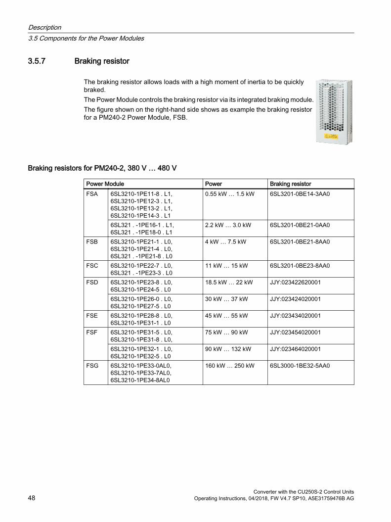
3.5.7 Braking resistor
The braking resistor allows loads with a high moment of inertia to be quickly braked.The Power Module controls the braking resistor via its integrated braking module.The figure shown on the right-hand side shows as example the braking resistor for a PM240-2 Power Module, FSB.
Braking resistors for PM240-2, 380 V … 480 V
Power Module Power Braking resistorFSA 6SL3210‑1PE11‑8 . L1,
6SL3210‑1PE12‑3 . L1, 6SL3210‑1PE13‑2 . L1, 6SL3210‑1PE14‑3 . L1
0.55 kW … 1.5 kW 6SL3201‑0BE14‑3AA0
6SL321 . ‑1PE16‑1 . L1, 6SL321 . ‑1PE18‑0 . L1
2.2 kW … 3.0 kW 6SL3201‑0BE21‑0AA0
FSB 6SL3210‑1PE21‑1 . L0, 6SL3210‑1PE21‑4 . L0, 6SL321 . ‑1PE21‑8 . L0
4 kW … 7.5 kW 6SL3201‑0BE21‑8AA0
FSC 6SL3210‑1PE22‑7 . L0, 6SL321 . ‑1PE23‑3 . L0
11 kW … 15 kW 6SL3201‑0BE23‑8AA0
FSD 6SL3210‑1PE23‑8 . L0, 6SL3210‑1PE24‑5 . L0
18.5 kW … 22 kW JJY:023422620001
6SL3210‑1PE26‑0 . L0, 6SL3210‑1PE27‑5 . L0
30 kW … 37 kW JJY:023424020001
FSE 6SL3210‑1PE28‑8 . L0, 6SL3210‑1PE31‑1 . L0
45 kW … 55 kW JJY:023434020001
FSF 6SL3210‑1PE31‑5 . L0,6SL3210‑1PE31‑8 . L0,
75 kW … 90 kW JJY:023454020001
6SL3210‑1PE32‑1 . L0,6SL3210‑1PE32‑5 . L0
90 kW … 132 kW JJY:023464020001
FSG 6SL3210‑1PE33‑0AL0, 6SL3210‑1PE33‑7AL0, 6SL3210‑1PE34‑8AL0
160 kW … 250 kW 6SL3000‑1BE32‑5AA0
Description3.5 Components for the Power Modules
Converter with the CU250S-2 Control Units48 Operating Instructions, 04/2018, FW V4.7 SP10, A5E31759476B AG
Braking resistors for PM240-2, 500 V … 690 V
Power Module Power Braking resistorFSD 6SL3210‑1PH21‑4 . L0,
6SL3210‑1PH22‑0 . L0, 6SL3210‑1PH22‑3 . L0, 6SL3210‑1PH22‑7 . L0, 6SL3210‑1PH23‑5 . L0, 6SL3210‑1PH24‑2 . L0
11 kW … 37 kW JJY:023424020002
FSE 6SL3210‑1PH25‑2 . L0, 6SL3210‑1PH26‑2 . L0
45 kW … 55 kW JJY:023434020002
FSF 6SL3210‑1PH28‑0 . L0,6SL3210‑1PH31‑0 . L0,
75 kW … 90 kW JJY:023464020002
6SL3210‑1PH31‑2 . L0,6SL3210‑1PH31‑4 . L0
110 kW … 132 kW JJY:023464020002
FSG 6SL3210‑1PH31‑7CL0, 6SL3210‑1PH32‑1CL0, 6SL3210‑1PH32‑5CL0
160 kW … 250 kW 6SL3000‑1BH32‑5AA0
Braking resistors for PM240-2, 200 V … 240 V
Power Module Power Braking resistorFSA 6SL3210‑1PB13‑0 . L0,
6SL321 . ‑1PB13‑8 . L00.55 kW … 0.75 kW JJY:023146720008
FSB 6SL3210‑1PB15‑5 . L0, 6SL3210‑1PB17‑4 . L0, 6SL321 . ‑1PB21‑0 . L0
1.1 kW … 2.2 kW JJY:023151720007
FSC 6SL3210‑1PB21‑4 . L0, 6SL321 . ‑1PB21‑8 . L0
3 kW … 4 kW JJY:02 3163720018
6SL3210‑1PC22‑2 . L0, 6SL3210‑1PC22‑8 . L0
5.5 kW … 7.5 kW JJY:023433720001
FSD 6SL3210‑1PC24‑2UL0,6SL3210‑1PC25‑4UL0,6SL3210‑1PC26‑8UL0
11 kW … 18.5 kW JJY:023422620002
FSE
6SL3210‑1PC28‑0UL0,6SL3210‑1PC31‑1UL0
22 kW … 30 kW JJY:023423320001
FSF 6SL3210‑1PC31‑3UL0,6SL3210‑1PC31‑6UL0,6SL3210‑1PC31‑8UL0
37 kW … 55 kW JJY:023434020003
Description3.5 Components for the Power Modules
Converter with the CU250S-2 Control UnitsOperating Instructions, 04/2018, FW V4.7 SP10, A5E31759476B AG 49
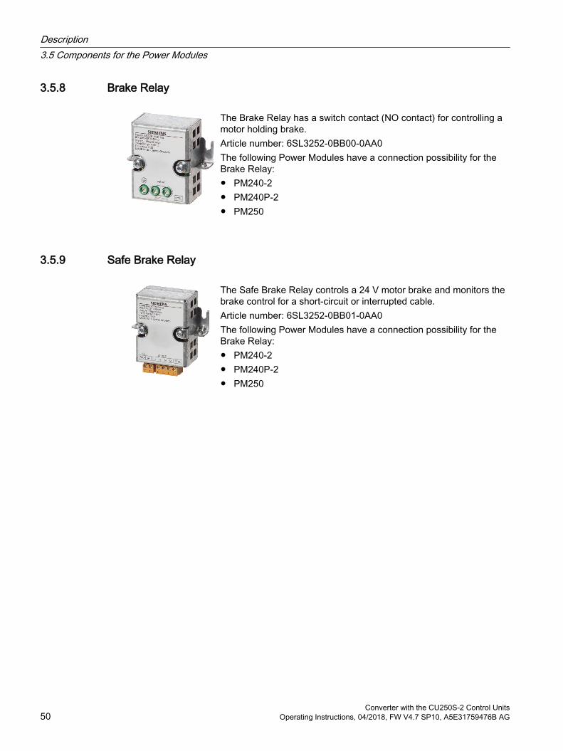
3.5.8 Brake Relay
The Brake Relay has a switch contact (NO contact) for controlling a motor holding brake.Article number: 6SL3252‑0BB00‑0AA0The following Power Modules have a connection possibility for the Brake Relay: PM240-2 PM240P-2 PM250
3.5.9 Safe Brake Relay
The Safe Brake Relay controls a 24 V motor brake and monitors the brake control for a short-circuit or interrupted cable.Article number: 6SL3252-0BB01-0AA0The following Power Modules have a connection possibility for the Brake Relay: PM240-2 PM240P-2 PM250
Description3.5 Components for the Power Modules
Converter with the CU250S-2 Control Units50 Operating Instructions, 04/2018, FW V4.7 SP10, A5E31759476B AG

3.6 Motors and multi-motor drives that can be operated
Siemens motors that can be operatedYou can connect standard induction motors to the inverter.
You can find information on further motors on the Internet:
Motors that can be operated (https://support.industry.siemens.com/cs/ww/en/view/100426622)
Third-party motors that can be operatedYou can operate standard asynchronous motors from other manufacturers with the inverter:
NOTICE
Insulation failure due to unsuitable third-party motor
A higher load occurs on the motor insulation in inverter mode than with line operation. Damage to the motor winding may occur as a result. Please observed the notes in the System Manual "Requirements for third-party motors"
Further information is provided on the Internet:
Requirements for third-party motors (https://support.industry.siemens.com/cs/ww/en/view/79690594)
Multi-motor operationMulti-motor operation involves simultaneously operating several motors from one inverter. For standard induction motors, multi-motor operation is generally permissible.
Additional preconditions and restrictions relating to multi-motor operation are available on the Internet:
Multi-motor drive (http://support.automation.siemens.com/WW/view/en/84049346)
Description3.6 Motors and multi-motor drives that can be operated
Converter with the CU250S-2 Control UnitsOperating Instructions, 04/2018, FW V4.7 SP10, A5E31759476B AG 51
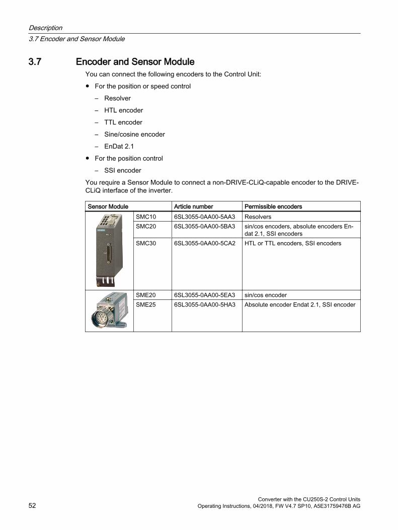
3.7 Encoder and Sensor ModuleYou can connect the following encoders to the Control Unit:
For the position or speed control
– Resolver
– HTL encoder
– TTL encoder
– Sine/cosine encoder
– EnDat 2.1
For the position control
– SSI encoder
You require a Sensor Module to connect a non-DRIVE-CLiQ-capable encoder to the DRIVE-CLiQ interface of the inverter.
Sensor Module Article number Permissible encodersSMC10 6SL3055-0AA00-5AA3 ResolversSMC20 6SL3055-0AA00-5BA3 sin/cos encoders, absolute encoders En‐
dat 2.1, SSI encodersSMC30 6SL3055-0AA00-5CA2 HTL or TTL encoders, SSI encoders
SME20 6SL3055-0AA00-5EA3 sin/cos encoderSME25 6SL3055-0AA00-5HA3 Absolute encoder Endat 2.1, SSI encoder
Description3.7 Encoder and Sensor Module
Converter with the CU250S-2 Control Units52 Operating Instructions, 04/2018, FW V4.7 SP10, A5E31759476B AG
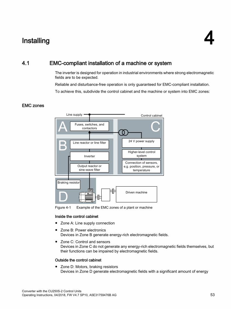
Installing 44.1 EMC-compliant installation of a machine or system
The inverter is designed for operation in industrial environments where strong electromagnetic fields are to be expected.
Reliable and disturbance-free operation is only guaranteed for EMC-compliant installation.
To achieve this, subdivide the control cabinet and the machine or system into EMC zones:
EMC zones
Figure 4-1 Example of the EMC zones of a plant or machine
Inside the control cabinet Zone A: Line supply connection
Zone B: Power electronicsDevices in Zone B generate energy-rich electromagnetic fields.
Zone C: Control and sensorsDevices in Zone C do not generate any energy-rich electromagnetic fields themselves, but their functions can be impaired by electromagnetic fields.
Outside the control cabinet Zone D: Motors, braking resistors
Devices in Zone D generate electromagnetic fields with a significant amount of energy
Converter with the CU250S-2 Control UnitsOperating Instructions, 04/2018, FW V4.7 SP10, A5E31759476B AG 53
4.1.1 Control cabinet Assign the various devices to zones in the control cabinet.
Electromagnetically uncouple the zones from each other by means of one of the following actions:
– Side clearance ≥ 25 cm
– Separate metal enclosure
– Large-area partition plates
Route cables of various zones in separate cable harnesses or cable ducts.
Install filters or isolation amplifiers at the interfaces of the zones.
Control cabinet assembly Connect the door, side panels, top and base plate of the control cabinet with the control
cabinet frame using one of the following methods:
– Electrical contact surface of several cm² for each contact location
– Several screw connections
– Short, finely stranded, braided copper wires with cross-sections ≥ 95 mm² / 000 (3/0) (‑2) AWG
Install a shield support for shielded cables that are routed out of the control cabinet.
Connect the PE bar and the shield support to the control cabinet frame through a large surface area to establish a good electrical connection.
Mount the control cabinet components on a bare metal mounting plate.
Connect the mounting plate to the control cabinet frame and PE bar and shield support through a large surface area to establish a good electrical connection.
For screw connections onto painted or anodized surfaces, establish a good conductive contact using one of the following methods:
– Use special (serrated) contact washers that cut through the painted or anodized surface.
– Remove the insulating coating at the contact locations.
Measures required for several control cabinets Install equipotential bonding for all control cabinets.
Screw the frames of the control cabinets together at several locations through a large surface area using serrated washers to establish a good electrical connection.
In plants and systems where the control cabinets are lined up next to one another, and which are installed in two groups back to back, connect the PE bars of the two cabinet groups at as many locations as possible.
Installing4.1 EMC-compliant installation of a machine or system
Converter with the CU250S-2 Control Units54 Operating Instructions, 04/2018, FW V4.7 SP10, A5E31759476B AG
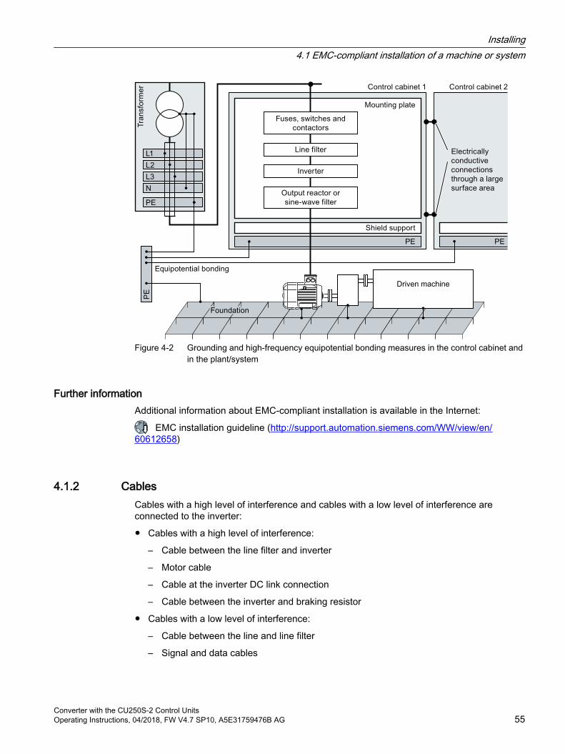
Figure 4-2 Grounding and high-frequency equipotential bonding measures in the control cabinet and in the plant/system
Further informationAdditional information about EMC-compliant installation is available in the Internet:
EMC installation guideline (http://support.automation.siemens.com/WW/view/en/60612658)
4.1.2 CablesCables with a high level of interference and cables with a low level of interference are connected to the inverter:
Cables with a high level of interference:
– Cable between the line filter and inverter
– Motor cable
– Cable at the inverter DC link connection
– Cable between the inverter and braking resistor
Cables with a low level of interference:
– Cable between the line and line filter
– Signal and data cables
Installing4.1 EMC-compliant installation of a machine or system
Converter with the CU250S-2 Control UnitsOperating Instructions, 04/2018, FW V4.7 SP10, A5E31759476B AG 55
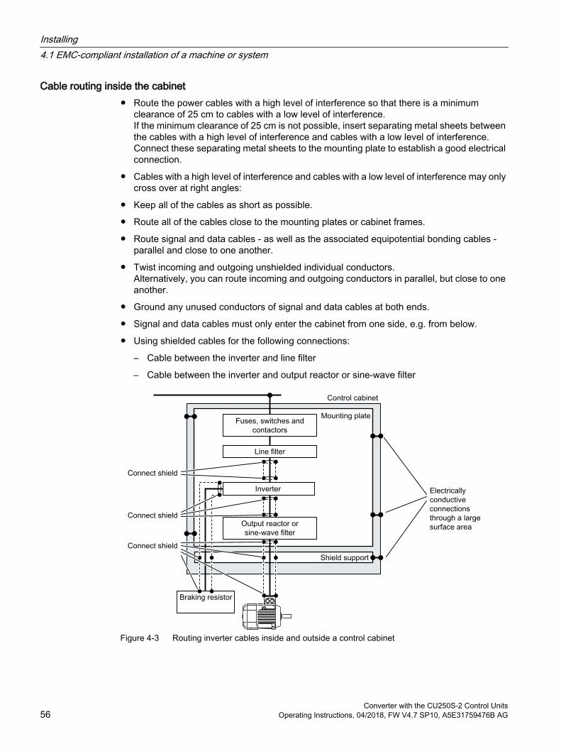
Cable routing inside the cabinet Route the power cables with a high level of interference so that there is a minimum
clearance of 25 cm to cables with a low level of interference.If the minimum clearance of 25 cm is not possible, insert separating metal sheets between the cables with a high level of interference and cables with a low level of interference. Connect these separating metal sheets to the mounting plate to establish a good electrical connection.
Cables with a high level of interference and cables with a low level of interference may only cross over at right angles:
Keep all of the cables as short as possible.
Route all of the cables close to the mounting plates or cabinet frames.
Route signal and data cables - as well as the associated equipotential bonding cables - parallel and close to one another.
Twist incoming and outgoing unshielded individual conductors.Alternatively, you can route incoming and outgoing conductors in parallel, but close to one another.
Ground any unused conductors of signal and data cables at both ends.
Signal and data cables must only enter the cabinet from one side, e.g. from below.
Using shielded cables for the following connections:
– Cable between the inverter and line filter
– Cable between the inverter and output reactor or sine-wave filter
Figure 4-3 Routing inverter cables inside and outside a control cabinet
Installing4.1 EMC-compliant installation of a machine or system
Converter with the CU250S-2 Control Units56 Operating Instructions, 04/2018, FW V4.7 SP10, A5E31759476B AG
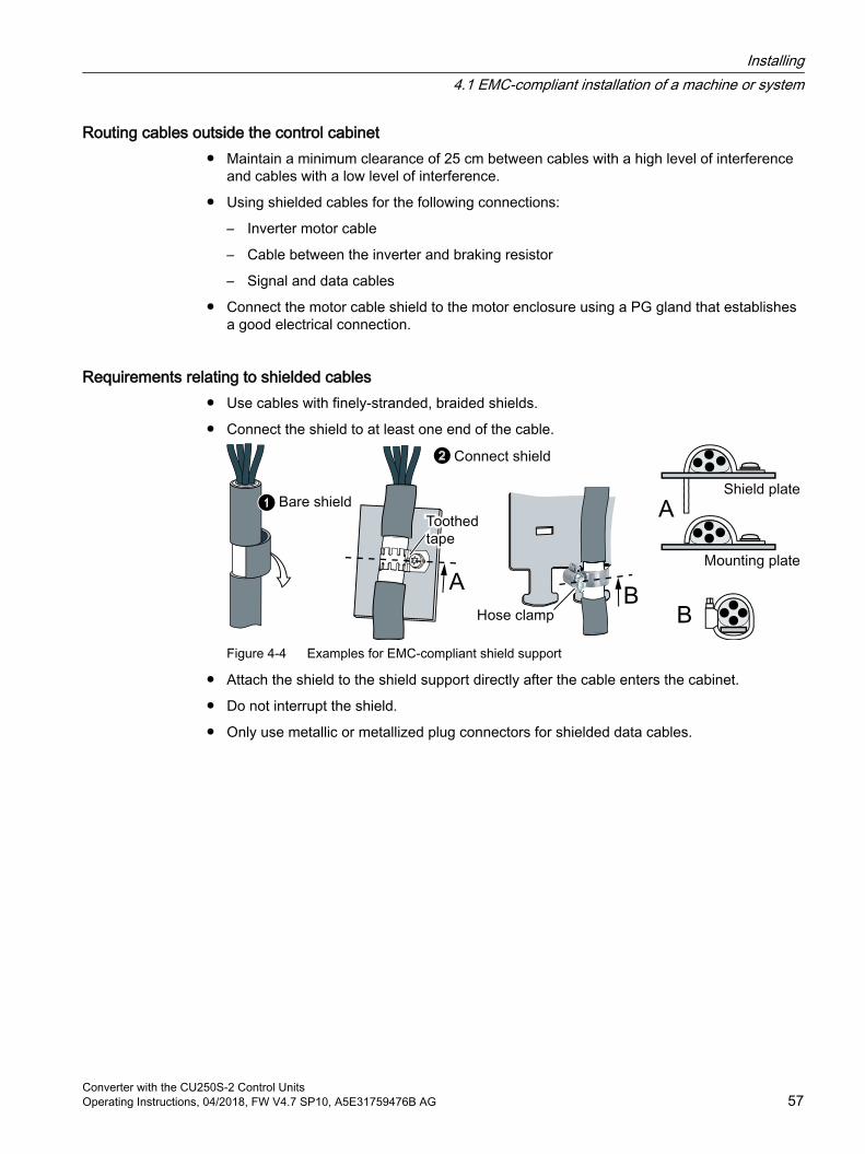
Routing cables outside the control cabinet Maintain a minimum clearance of 25 cm between cables with a high level of interference
and cables with a low level of interference.
Using shielded cables for the following connections:
– Inverter motor cable
– Cable between the inverter and braking resistor
– Signal and data cables
Connect the motor cable shield to the motor enclosure using a PG gland that establishes a good electrical connection.
Requirements relating to shielded cables Use cables with finely-stranded, braided shields.
Connect the shield to at least one end of the cable.
Figure 4-4 Examples for EMC-compliant shield support
Attach the shield to the shield support directly after the cable enters the cabinet.
Do not interrupt the shield.
Only use metallic or metallized plug connectors for shielded data cables.
Installing4.1 EMC-compliant installation of a machine or system
Converter with the CU250S-2 Control UnitsOperating Instructions, 04/2018, FW V4.7 SP10, A5E31759476B AG 57
4.1.3 Electromechanical components
Surge voltage protection circuit Connect surge voltage protection circuits to the following components:
– Coils of contactors
– Relays
– Solenoid valves
– Motor holding brakes
Connect the surge voltage protection circuit directly at the coil.
Use RC elements or varistors for AC-operated coils and freewheeling diodes or varistors for DC-operated coils.
Installing4.1 EMC-compliant installation of a machine or system
Converter with the CU250S-2 Control Units58 Operating Instructions, 04/2018, FW V4.7 SP10, A5E31759476B AG

4.2 Installing reactors, filters and braking resistors
Installing reactors, filters and braking resistorsThe following supplementary components may be required depending on the Power Modules and the particular application:
Line reactors
Filter
Braking resistors
Brake Relay
Installing these components is described in the documentation provided.
Installing4.2 Installing reactors, filters and braking resistors
Converter with the CU250S-2 Control UnitsOperating Instructions, 04/2018, FW V4.7 SP10, A5E31759476B AG 59

4.3 Installing Power Modules
4.3.1 Basic installation rules for built-in units
Protection against the spread of fireThe device may be operated only in closed housings or in control cabinets with protective covers that are closed, and when all of the protective devices are used. The installation of the device in a metal control cabinet or the protection with another equivalent measure must prevent the spread of fire and emissions outside the control cabinet.
Protection against condensation or electrically conductive contaminationProtect the device, e.g. by installing it in a control cabinet with degree of protection IP54 according to IEC 60529 or NEMA 12. Further measures may be necessary for particularly critical operating conditions.
If condensation or conductive pollution can be excluded at the installation site, a lower degree of control cabinet protection may be permitted.
Installing
NOTICE
Overheating due to inadmissible mounting
If mounted in an inadmissible fashion, the Power Module can overheat and therefore be damaged. Follow the mounting instructions.
Installing4.3 Installing Power Modules
Converter with the CU250S-2 Control Units60 Operating Instructions, 04/2018, FW V4.7 SP10, A5E31759476B AG
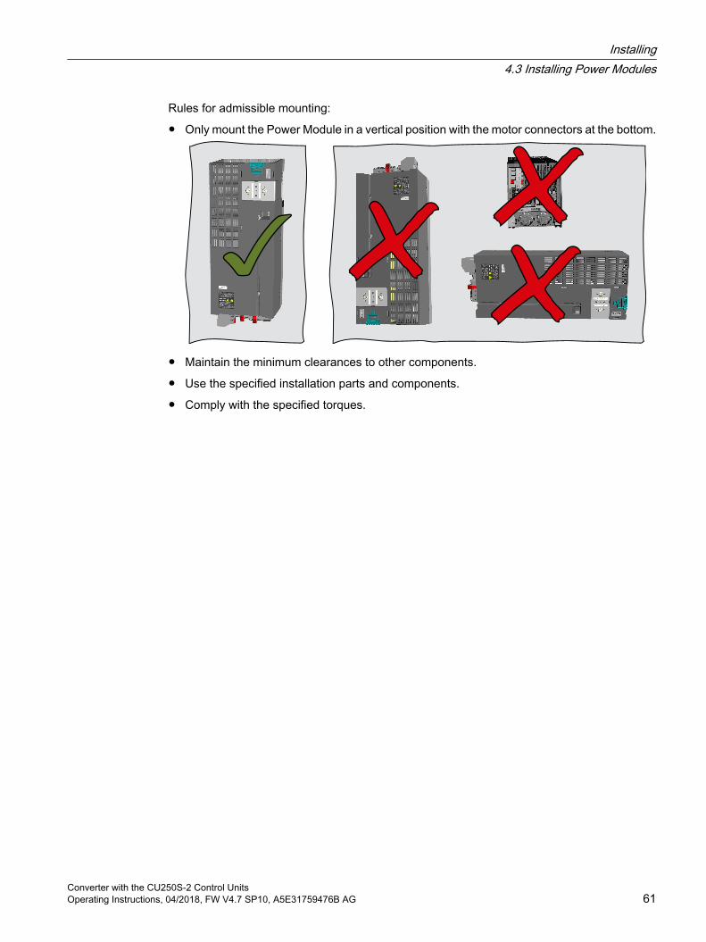
Rules for admissible mounting:
Only mount the Power Module in a vertical position with the motor connectors at the bottom.
Maintain the minimum clearances to other components.
Use the specified installation parts and components.
Comply with the specified torques.
Installing4.3 Installing Power Modules
Converter with the CU250S-2 Control UnitsOperating Instructions, 04/2018, FW V4.7 SP10, A5E31759476B AG 61
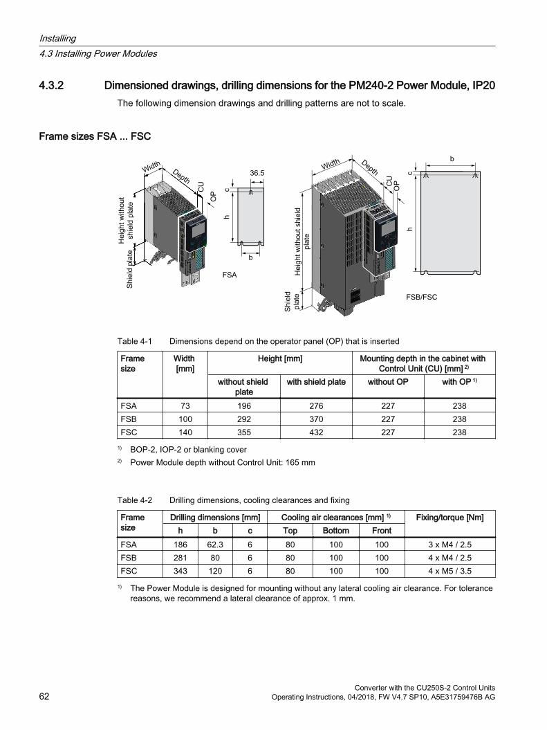
4.3.2 Dimensioned drawings, drilling dimensions for the PM240-2 Power Module, IP20The following dimension drawings and drilling patterns are not to scale.
Frame sizes FSA ... FSC
Table 4-1 Dimensions depend on the operator panel (OP) that is inserted
Frame size
Width [mm]
Height [mm] Mounting depth in the cabinet with Control Unit (CU) [mm] 2)
without shield plate
with shield plate without OP with OP 1)
FSA 73 196 276 227 238FSB 100 292 370 227 238FSC 140 355 432 227 238
1) BOP-2, IOP-2 or blanking cover2) Power Module depth without Control Unit: 165 mm
Table 4-2 Drilling dimensions, cooling clearances and fixing
Frame size
Drilling dimensions [mm] Cooling air clearances [mm] 1) Fixing/torque [Nm]h b c Top Bottom Front
FSA 186 62.3 6 80 100 100 3 x M4 / 2.5FSB 281 80 6 80 100 100 4 x M4 / 2.5FSC 343 120 6 80 100 100 4 x M5 / 3.5
1) The Power Module is designed for mounting without any lateral cooling air clearance. For tolerance reasons, we recommend a lateral clearance of approx. 1 mm.
Installing4.3 Installing Power Modules
Converter with the CU250S-2 Control Units62 Operating Instructions, 04/2018, FW V4.7 SP10, A5E31759476B AG
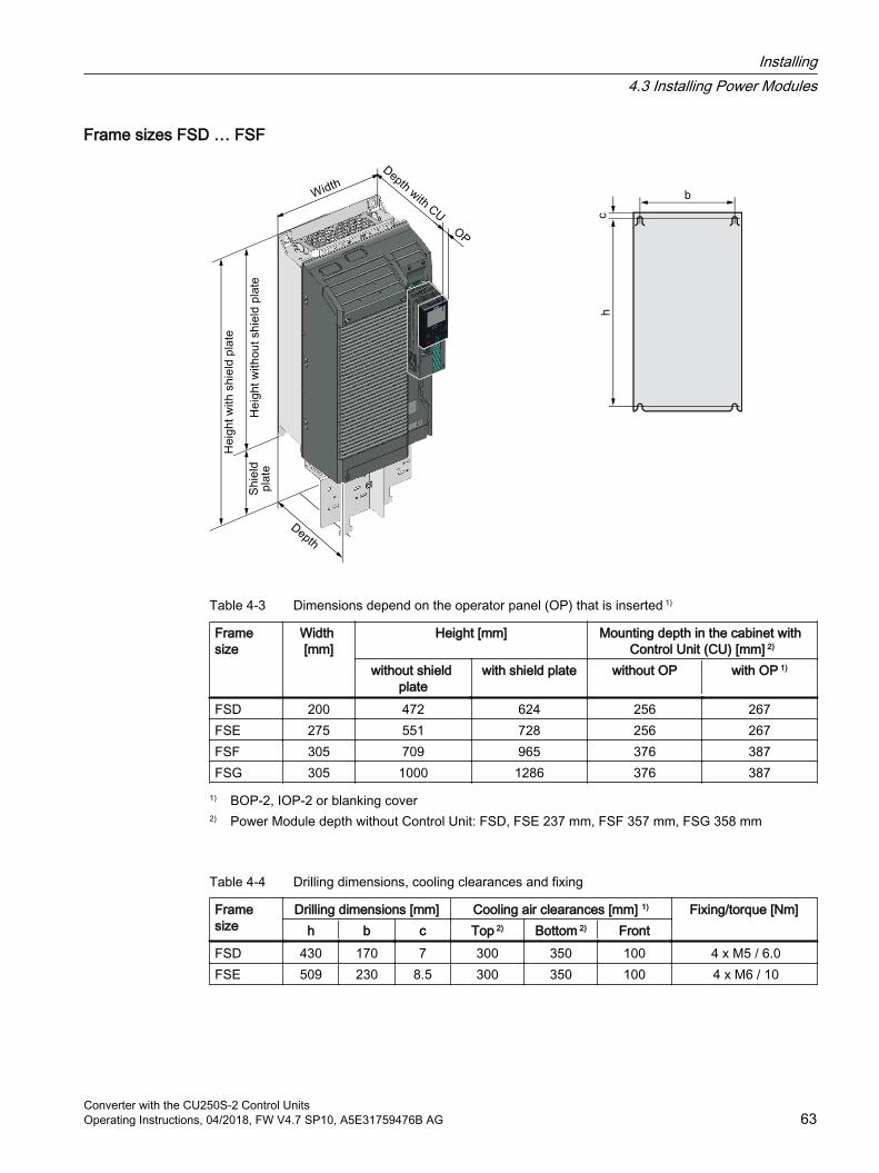
Frame sizes FSD … FSF
Table 4-3 Dimensions depend on the operator panel (OP) that is inserted 1)
Frame size
Width [mm]
Height [mm] Mounting depth in the cabinet with Control Unit (CU) [mm] 2)
without shield plate
with shield plate without OP with OP 1)
FSD 200 472 624 256 267FSE 275 551 728 256 267FSF 305 709 965 376 387FSG 305 1000 1286 376 387
1) BOP-2, IOP-2 or blanking cover2) Power Module depth without Control Unit: FSD, FSE 237 mm, FSF 357 mm, FSG 358 mm
Table 4-4 Drilling dimensions, cooling clearances and fixing
Frame size
Drilling dimensions [mm] Cooling air clearances [mm] 1) Fixing/torque [Nm]h b c Top 2) Bottom 2) Front
FSD 430 170 7 300 350 100 4 x M5 / 6.0FSE 509 230 8.5 300 350 100 4 x M6 / 10
Installing4.3 Installing Power Modules
Converter with the CU250S-2 Control UnitsOperating Instructions, 04/2018, FW V4.7 SP10, A5E31759476B AG 63

Frame size
Drilling dimensions [mm] Cooling air clearances [mm] 1) Fixing/torque [Nm]h b c Top 2) Bottom 2) Front
FSF 680 270 13 300 350 100 4 x M8 / 25FSG 970.5 265 15 300 350 100 4 x M8 / 25
1) The Power Module is designed for mounting without any lateral cooling air clearance. For tolerance reasons, we recommend a lateral clearance of approx. 1 mm.
2) The top and bottom cooling air clearances refer to the Power Module without shield plate
Installing4.3 Installing Power Modules
Converter with the CU250S-2 Control Units64 Operating Instructions, 04/2018, FW V4.7 SP10, A5E31759476B AG
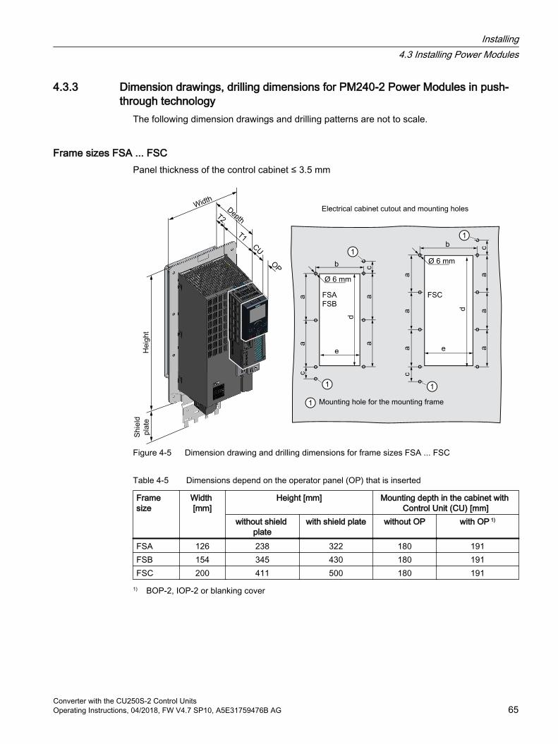
4.3.3 Dimension drawings, drilling dimensions for PM240-2 Power Modules in push-through technology
The following dimension drawings and drilling patterns are not to scale.
Frame sizes FSA ... FSCPanel thickness of the control cabinet ≤ 3.5 mm
Figure 4-5 Dimension drawing and drilling dimensions for frame sizes FSA ... FSC
Table 4-5 Dimensions depend on the operator panel (OP) that is inserted
Frame size
Width [mm]
Height [mm] Mounting depth in the cabinet with Control Unit (CU) [mm]
without shield plate
with shield plate without OP with OP 1)
FSA 126 238 322 180 191FSB 154 345 430 180 191FSC 200 411 500 180 191
1) BOP-2, IOP-2 or blanking cover
Installing4.3 Installing Power Modules
Converter with the CU250S-2 Control UnitsOperating Instructions, 04/2018, FW V4.7 SP10, A5E31759476B AG 65
Table 4-6 Cooling air clearances and additional dimensions
Frame size
Power Module depth [mm] T1 T2 Cooling air clearances [mm] 1)
Top Bottom FrontFSA … FSC
171 118 53 80 100 100
1) The Power Module is designed for mounting without any lateral cooling air clearance. For tolerance reasons, we recommend a lateral clearance of 1 mm.
Table 4-7 Electrical cabinet cutout and mounting holes
Frame size
Control cabinet cutout [mm] Fixing/torque [Nm]a b c d e
FSA 103 106 27 198 88 8 × M5 / 3.5FSB 148 134 34.5 304 116 8 × M5 / 3.5FSC 123 174 30.5 365 156 10 × M5 / 3.5
Installing4.3 Installing Power Modules
Converter with the CU250S-2 Control Units66 Operating Instructions, 04/2018, FW V4.7 SP10, A5E31759476B AG
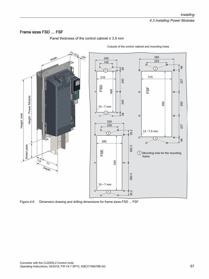
Frame sizes FSD … FSFPanel thickness of the control cabinet ≤ 3.5 mm
Figure 4-6 Dimension drawing and drilling dimensions for frame sizes FSD ... FSF
Installing4.3 Installing Power Modules
Converter with the CU250S-2 Control UnitsOperating Instructions, 04/2018, FW V4.7 SP10, A5E31759476B AG 67
Table 4-8 Dimensions depend on the operator panel (OP) that is inserted 1)
Frame size
Width [mm]
Height [mm] Mounting depth in the cabinet with Control Unit (CU) [mm]
without shield plate
with shield plate without OP with OP 1)
FSD 275 517 650 158 169FSE 354 615 722 158 169FSF 384 754 1021 196 207
1) BOP-2, IOP-2 or blanking cover
Table 4-9 Cooling air clearances and additional dimensions
Frame size
Power Module depth [mm] T1 T2 Cooling air clearances [mm]Top Bottom Front
FSD, FSE 237 141 97.5 350 350 29FSF 358 177.5 180.5 80 100 100
Table 4-10 Mounting
Frame size
Fixing/torque [Nm]
FSD, FSE 10 × M5 / 3.5FSF 12 × M6 / 5.9
Installing4.3 Installing Power Modules
Converter with the CU250S-2 Control Units68 Operating Instructions, 04/2018, FW V4.7 SP10, A5E31759476B AG
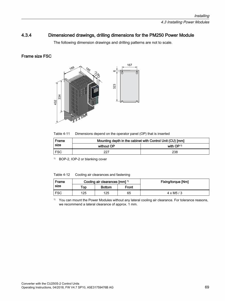
4.3.4 Dimensioned drawings, drilling dimensions for the PM250 Power ModuleThe following dimension drawings and drilling patterns are not to scale.
Frame size FSC
Table 4-11 Dimensions depend on the operator panel (OP) that is inserted
Frame size
Mounting depth in the cabinet with Control Unit (CU) [mm]without OP with OP 1)
FSC 227 2381) BOP-2, IOP-2 or blanking cover
Table 4-12 Cooling air clearances and fastening
Frame size
Cooling air clearances [mm] 1) Fixing/torque [Nm]Top Bottom Front
FSC 125 125 65 4 x M5 / 31) You can mount the Power Modules without any lateral cooling air clearance. For tolerance reasons,
we recommend a lateral clearance of approx. 1 mm.
Installing4.3 Installing Power Modules
Converter with the CU250S-2 Control UnitsOperating Instructions, 04/2018, FW V4.7 SP10, A5E31759476B AG 69
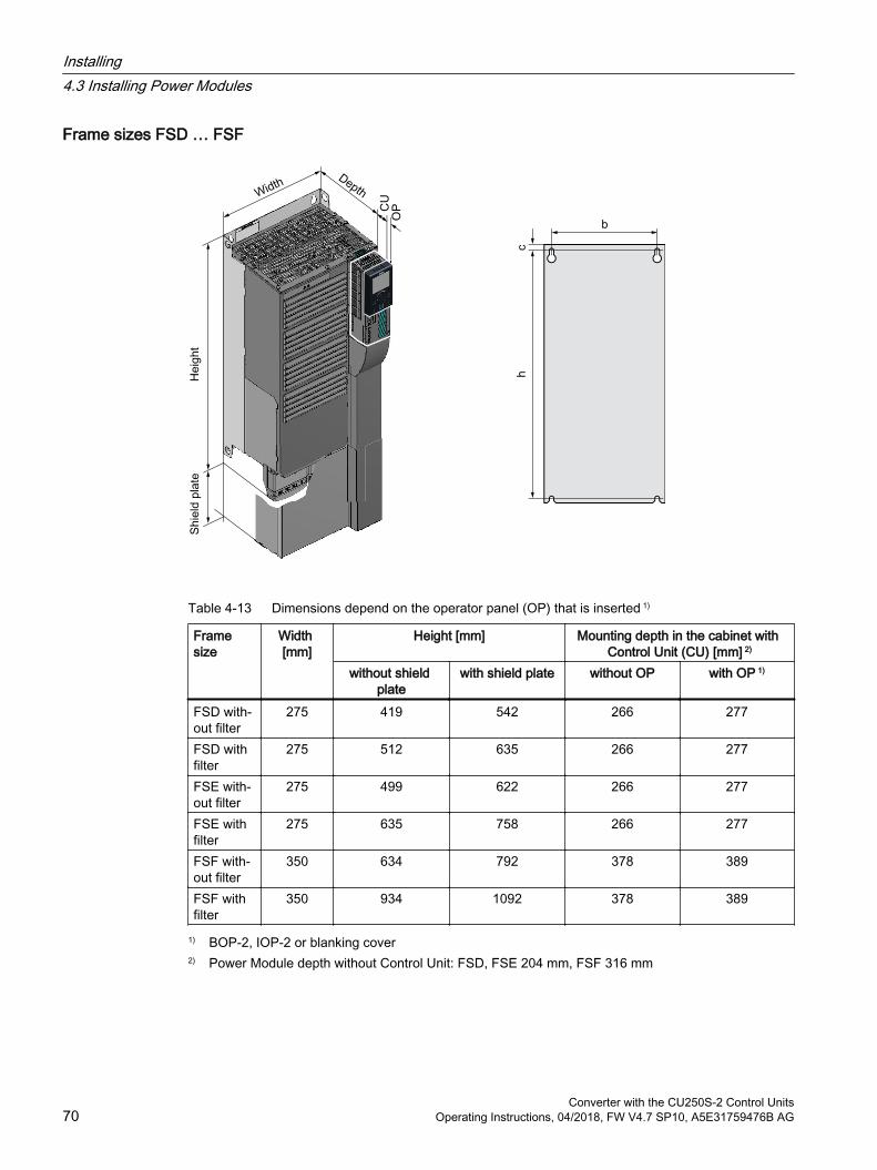
Frame sizes FSD … FSF
Table 4-13 Dimensions depend on the operator panel (OP) that is inserted 1)
Frame size
Width [mm]
Height [mm] Mounting depth in the cabinet with Control Unit (CU) [mm] 2)
without shield plate
with shield plate without OP with OP 1)
FSD with‐out filter
275 419 542 266 277
FSD with filter
275 512 635 266 277
FSE with‐out filter
275 499 622 266 277
FSE with filter
275 635 758 266 277
FSF with‐out filter
350 634 792 378 389
FSF with filter
350 934 1092 378 389
1) BOP-2, IOP-2 or blanking cover2) Power Module depth without Control Unit: FSD, FSE 204 mm, FSF 316 mm
Installing4.3 Installing Power Modules
Converter with the CU250S-2 Control Units70 Operating Instructions, 04/2018, FW V4.7 SP10, A5E31759476B AG
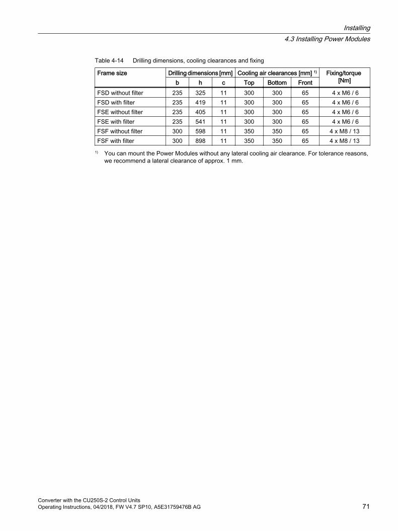
Table 4-14 Drilling dimensions, cooling clearances and fixing
Frame size Drilling dimensions [mm] Cooling air clearances [mm] 1) Fixing/torque [Nm]b h c Top Bottom Front
FSD without filter 235 325 11 300 300 65 4 x M6 / 6FSD with filter 235 419 11 300 300 65 4 x M6 / 6FSE without filter 235 405 11 300 300 65 4 x M6 / 6FSE with filter 235 541 11 300 300 65 4 x M6 / 6FSF without filter 300 598 11 350 350 65 4 x M8 / 13FSF with filter 300 898 11 350 350 65 4 x M8 / 13
1) You can mount the Power Modules without any lateral cooling air clearance. For tolerance reasons, we recommend a lateral clearance of approx. 1 mm.
Installing4.3 Installing Power Modules
Converter with the CU250S-2 Control UnitsOperating Instructions, 04/2018, FW V4.7 SP10, A5E31759476B AG 71
4.4 Connecting the line supply and motor
WARNING
Electric shock when the motor terminal box is open
As soon as the inverter is connected to the line supply, the motor connections of the inverter may carry dangerous voltages. When the motor is connected to the inverter, there is danger to life through contact with the motor terminals if the motor terminal box is open. Close the motor terminal box before connecting the inverter to the line supply.
NoteFault protection for the motor circuit
The electronic overcurrent trip complies with the requirements laid down in IEC 60364-3-2:2005/AMD1:- Section 411 for protection against electric shock. Observe the installation specifications provided in this manual. Observe the applicable installation standards. Ensure the continuity of the protective conductor.
4.4.1 Permissible line supplies
Restrictions for installation altitudes above 2000 mAbove an installation altitude of 2000 m, the permissible line supplies are restricted.
Restrictions for special ambient conditions (Page 478)
Installing4.4 Connecting the line supply and motor
Converter with the CU250S-2 Control Units72 Operating Instructions, 04/2018, FW V4.7 SP10, A5E31759476B AG

Screw for functional grounding on the converter, frame size FSGIf you wish to use the inverters with integrated C3 line filter, please note the information in the sections "TN line system", "TT line system" and "IT system" below.
Figure 4-7 Remove screw for functional grounding
4.4.1.1 TN line system
A TN line system transfers the PE protective conductor to the installed plant or system us‐ing a cable.Generally, in a TN line system the neutral point is grounded. There are versions of a TN system with a grounded line conductor, e.g. with grounded L1.A TN line system can transfer the neutral con‐ductor N and the PE protective conductor ei‐ther separately or combined.
Installing4.4 Connecting the line supply and motor
Converter with the CU250S-2 Control UnitsOperating Instructions, 04/2018, FW V4.7 SP10, A5E31759476B AG 73
Inverter connected to a TN system Inverters with integrated line filter:
– Operation on TN line systems with grounded neutral point permissible.
– Operation on TN line systems with grounded line conductor not permissible.
NoteSpecial feature of FSG inverters
FSG inverters with integrated C3 line filter can be operated in TN line systems ≤ 600 V with a grounded line conductor if you remove the screw for functional grounding.
Figure 4-7 Remove screw for functional grounding (Page 73)
If you remove the screw for functional grounding, the EMC properties deteriorate and the requirements of Class C3 are no longer met.
Inverters with external line filter:
– Operation on TN line systems with grounded neutral point permissible.
– Operation on TN line systems with grounded line conductor not permissible.
Inverter without line filter:
– Operation on all TN line systems ≤ 600 V permissible
– Operation on TN line systems > 600 V and grounded neutral point permissible.
– Operation on TN line systems > 600 V and grounded line conductor not permissible.
Installing4.4 Connecting the line supply and motor
Converter with the CU250S-2 Control Units74 Operating Instructions, 04/2018, FW V4.7 SP10, A5E31759476B AG
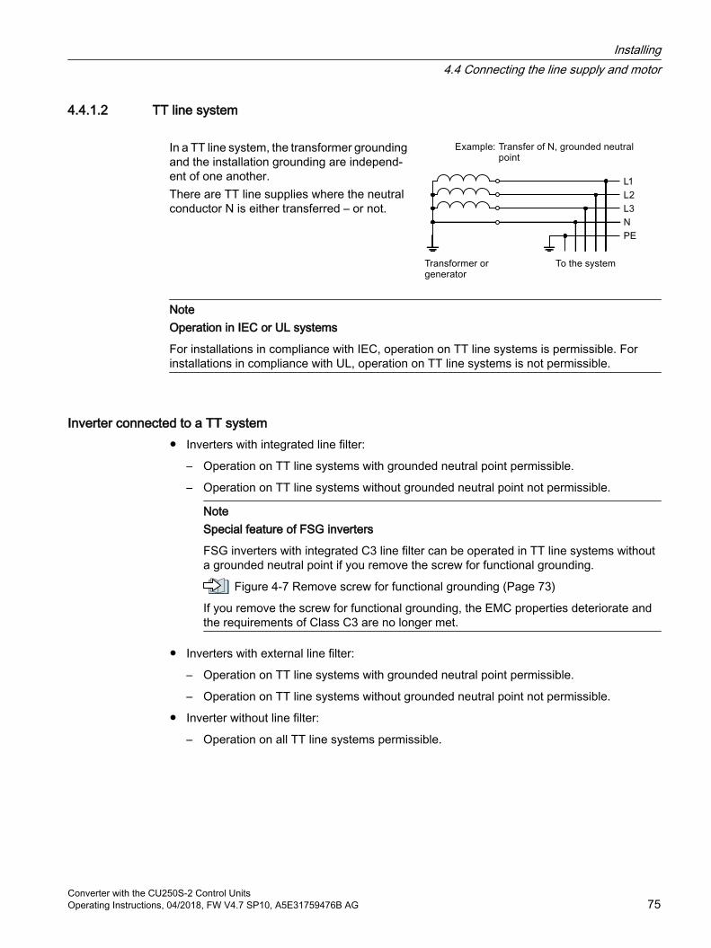
4.4.1.2 TT line system
In a TT line system, the transformer grounding and the installation grounding are independ‐ent of one another.There are TT line supplies where the neutral conductor N is either transferred – or not.
NoteOperation in IEC or UL systems
For installations in compliance with IEC, operation on TT line systems is permissible. For installations in compliance with UL, operation on TT line systems is not permissible.
Inverter connected to a TT system Inverters with integrated line filter:
– Operation on TT line systems with grounded neutral point permissible.
– Operation on TT line systems without grounded neutral point not permissible.
NoteSpecial feature of FSG inverters
FSG inverters with integrated C3 line filter can be operated in TT line systems without a grounded neutral point if you remove the screw for functional grounding.
Figure 4-7 Remove screw for functional grounding (Page 73)
If you remove the screw for functional grounding, the EMC properties deteriorate and the requirements of Class C3 are no longer met.
Inverters with external line filter:
– Operation on TT line systems with grounded neutral point permissible.
– Operation on TT line systems without grounded neutral point not permissible.
Inverter without line filter:
– Operation on all TT line systems permissible.
Installing4.4 Connecting the line supply and motor
Converter with the CU250S-2 Control UnitsOperating Instructions, 04/2018, FW V4.7 SP10, A5E31759476B AG 75
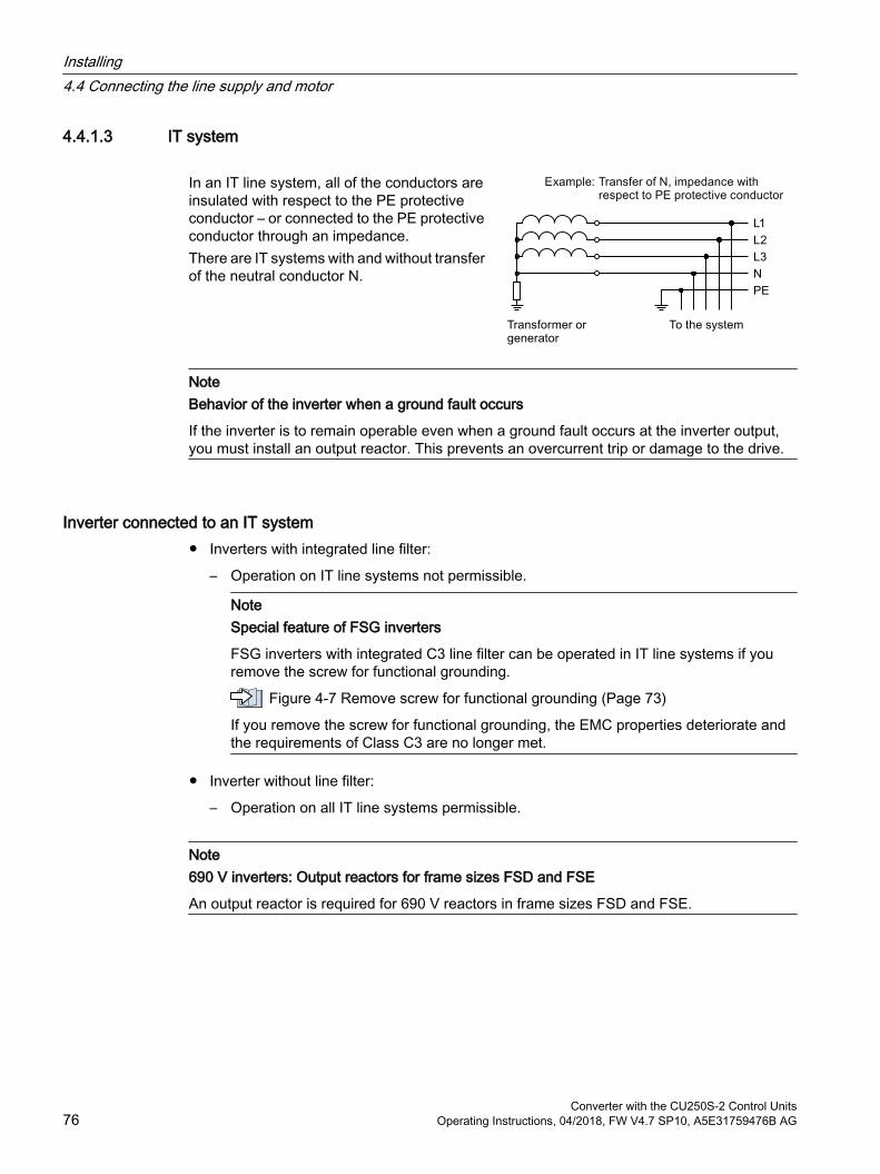
4.4.1.3 IT system
In an IT line system, all of the conductors are insulated with respect to the PE protective conductor – or connected to the PE protective conductor through an impedance.There are IT systems with and without transfer of the neutral conductor N.
NoteBehavior of the inverter when a ground fault occurs
If the inverter is to remain operable even when a ground fault occurs at the inverter output, you must install an output reactor. This prevents an overcurrent trip or damage to the drive.
Inverter connected to an IT system Inverters with integrated line filter:
– Operation on IT line systems not permissible.
NoteSpecial feature of FSG inverters
FSG inverters with integrated C3 line filter can be operated in IT line systems if you remove the screw for functional grounding.
Figure 4-7 Remove screw for functional grounding (Page 73)
If you remove the screw for functional grounding, the EMC properties deteriorate and the requirements of Class C3 are no longer met.
Inverter without line filter:
– Operation on all IT line systems permissible.
Note690 V inverters: Output reactors for frame sizes FSD and FSE
An output reactor is required for 690 V reactors in frame sizes FSD and FSE.
Installing4.4 Connecting the line supply and motor
Converter with the CU250S-2 Control Units76 Operating Instructions, 04/2018, FW V4.7 SP10, A5E31759476B AG
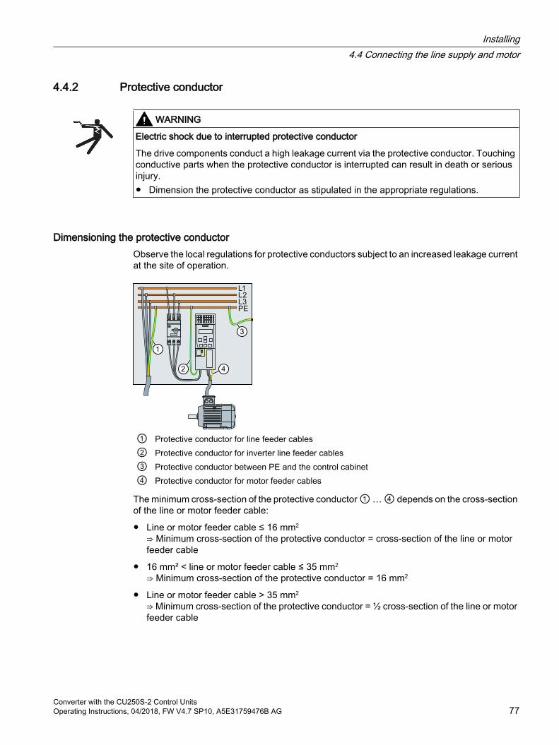
4.4.2 Protective conductor
WARNING
Electric shock due to interrupted protective conductor
The drive components conduct a high leakage current via the protective conductor. Touching conductive parts when the protective conductor is interrupted can result in death or serious injury. Dimension the protective conductor as stipulated in the appropriate regulations.
Dimensioning the protective conductorObserve the local regulations for protective conductors subject to an increased leakage current at the site of operation.
① Protective conductor for line feeder cables② Protective conductor for inverter line feeder cables ③ Protective conductor between PE and the control cabinet④ Protective conductor for motor feeder cables
The minimum cross-section of the protective conductor ① … ④ depends on the cross-section of the line or motor feeder cable:
Line or motor feeder cable ≤ 16 mm2
⇒ Minimum cross-section of the protective conductor = cross-section of the line or motor feeder cable
16 mm² < line or motor feeder cable ≤ 35 mm2
⇒ Minimum cross-section of the protective conductor = 16 mm2
Line or motor feeder cable > 35 mm2 ⇒ Minimum cross-section of the protective conductor = ½ cross-section of the line or motor feeder cable
Installing4.4 Connecting the line supply and motor
Converter with the CU250S-2 Control UnitsOperating Instructions, 04/2018, FW V4.7 SP10, A5E31759476B AG 77
Additional requirements placed on the protective conductor ①:
For permanent connection, the protective conductor must fulfill at least one of the following conditions:
– The protective conductor is routed so that it is protected against damage along its complete length.Cables routed inside switch cabinets or enclosed machine housings are considered to be adequately protected against mechanical damage.
– As a conductor of a multi-conductor cable, the protective conductor has a cross-section ≥ 2.5 mm² Cu.
– For an individual conductor, the protective conductor has a cross-section ≥ 10 mm² Cu.
– The protective conductor consists of two individual conductors with the same cross-section.
When connecting a multi-core cable using an industrial plug connector according to EN 60309, the protective conductor must have a cross-section of ≥ 2.5 mm² Cu.
Installing4.4 Connecting the line supply and motor
Converter with the CU250S-2 Control Units78 Operating Instructions, 04/2018, FW V4.7 SP10, A5E31759476B AG

4.4.3 Connecting an inverter with the PM240-2 Power Module
Figure 4-8 Connection of the PM240-2 Power Module, 3 AC, FSA … FSC
Figure 4-9 Connection of the PM240-2 Power Module, 3 AC, FSD … FSF
Figure 4-10 Connection of the PM240-2 Power Module, 1 AC 200 V, FSA … FSC
Installing4.4 Connecting the line supply and motor
Converter with the CU250S-2 Control UnitsOperating Instructions, 04/2018, FW V4.7 SP10, A5E31759476B AG 79
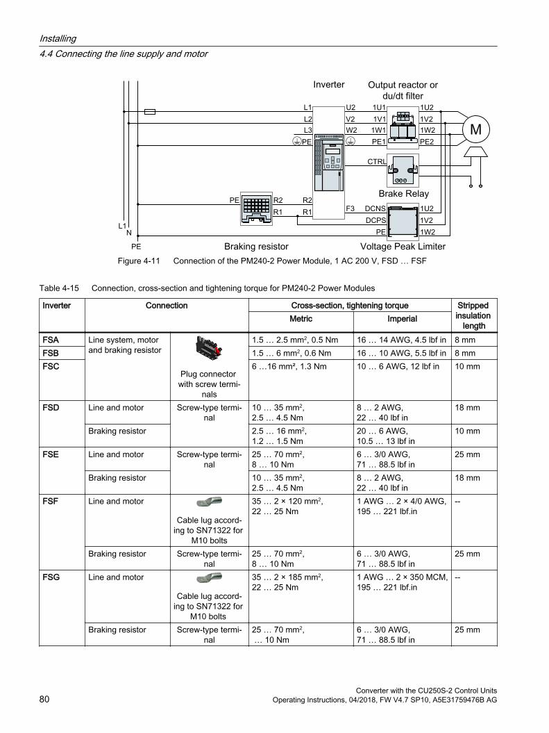
Figure 4-11 Connection of the PM240-2 Power Module, 1 AC 200 V, FSD … FSF
Table 4-15 Connection, cross-section and tightening torque for PM240-2 Power Modules
Inverter Connection Cross-section, tightening torque Stripped insulation
lengthMetric Imperial
FSA Line system, motor and braking resistor
Plug connector with screw termi‐
nals
1.5 … 2.5 mm2, 0.5 Nm 16 … 14 AWG, 4.5 lbf in 8 mmFSB 1.5 … 6 mm2, 0.6 Nm 16 … 10 AWG, 5.5 lbf in 8 mmFSC 6 …16 mm², 1.3 Nm 10 … 6 AWG, 12 lbf in 10 mm
FSD Line and motor Screw-type termi‐nal
10 … 35 mm2, 2.5 … 4.5 Nm
8 … 2 AWG, 22 … 40 lbf in
18 mm
Braking resistor 2.5 … 16 mm2, 1.2 … 1.5 Nm
20 … 6 AWG,10.5 … 13 lbf in
10 mm
FSE Line and motor Screw-type termi‐nal
25 … 70 mm2, 8 … 10 Nm
6 … 3/0 AWG,71 … 88.5 lbf in
25 mm
Braking resistor 10 … 35 mm2, 2.5 … 4.5 Nm
8 … 2 AWG, 22 … 40 lbf in
18 mm
FSF Line and motor
Cable lug accord‐ing to SN71322 for
M10 bolts
35 … 2 × 120 mm2,22 … 25 Nm
1 AWG … 2 × 4/0 AWG,195 … 221 lbf.in
--
Braking resistor Screw-type termi‐nal
25 … 70 mm2, 8 … 10 Nm
6 … 3/0 AWG,71 … 88.5 lbf in
25 mm
FSG Line and motor
Cable lug accord‐ing to SN71322 for
M10 bolts
35 … 2 × 185 mm2,22 … 25 Nm
1 AWG … 2 × 350 MCM,195 … 221 lbf.in
--
Braking resistor Screw-type termi‐nal
25 … 70 mm2, … 10 Nm
6 … 3/0 AWG,71 … 88.5 lbf in
25 mm
Installing4.4 Connecting the line supply and motor
Converter with the CU250S-2 Control Units80 Operating Instructions, 04/2018, FW V4.7 SP10, A5E31759476B AG
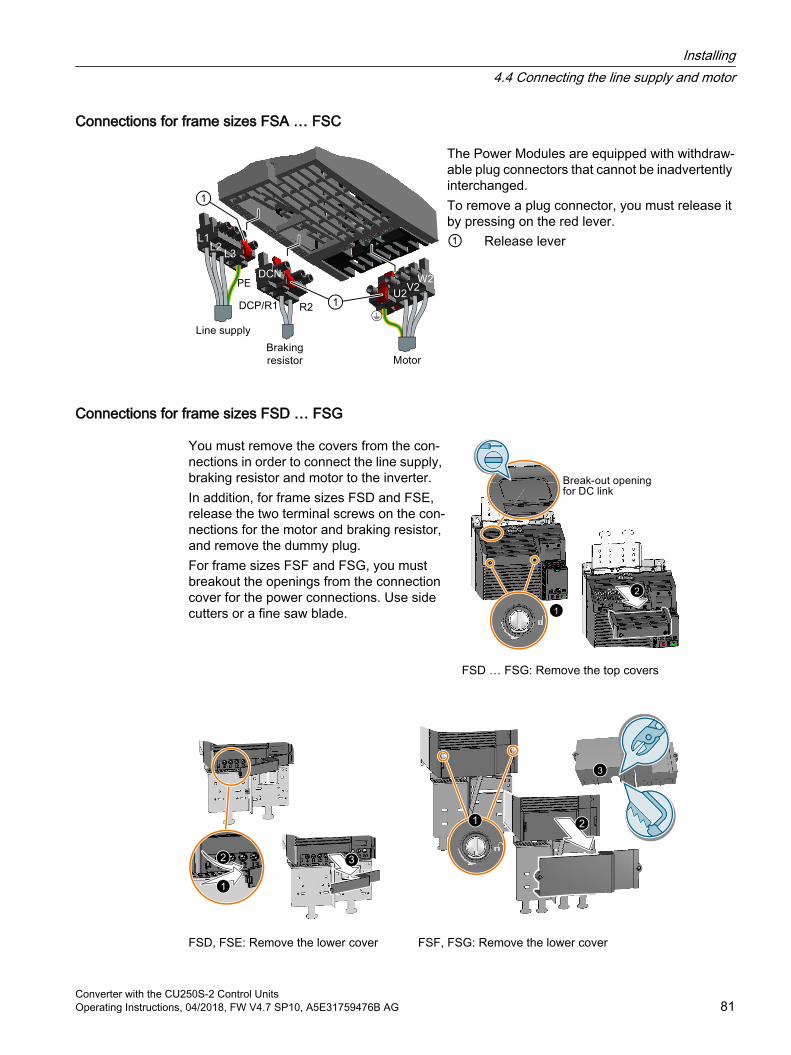
Connections for frame sizes FSA … FSC
The Power Modules are equipped with withdraw‐able plug connectors that cannot be inadvertently interchanged.To remove a plug connector, you must release it by pressing on the red lever.① Release lever
Connections for frame sizes FSD … FSG
You must remove the covers from the con‐nections in order to connect the line supply, braking resistor and motor to the inverter.In addition, for frame sizes FSD and FSE, release the two terminal screws on the con‐nections for the motor and braking resistor, and remove the dummy plug.For frame sizes FSF and FSG, you must breakout the openings from the connection cover for the power connections. Use side cutters or a fine saw blade.
1
2
FSD … FSG: Remove the top covers
FSD, FSE: Remove the lower cover
3
FSF, FSG: Remove the lower cover
Installing4.4 Connecting the line supply and motor
Converter with the CU250S-2 Control UnitsOperating Instructions, 04/2018, FW V4.7 SP10, A5E31759476B AG 81
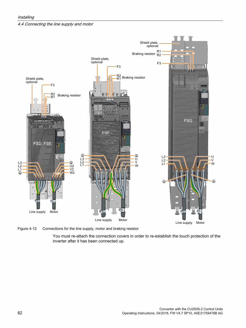
Figure 4-12 Connections for the line supply, motor and braking resistor
You must re-attach the connection covers in order to re-establish the touch protection of the inverter after it has been connected up.
Installing4.4 Connecting the line supply and motor
Converter with the CU250S-2 Control Units82 Operating Instructions, 04/2018, FW V4.7 SP10, A5E31759476B AG
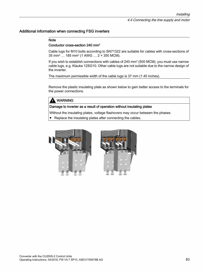
Additional information when connecting FSG inverters
NoteConductor cross-section 240 mm2
Cable lugs for M10 bolts according to SN71322 are suitable for cables with cross-sections of 35 mm2 … 185 mm2 (1 AWG … 2 × 350 MCM).
If you wish to establish connections with cables of 240 mm2 (500 MCM), you must use narrow cable lugs, e.g. Klauke 12SG10. Other cable lugs are not suitable due to the narrow design of the inverter.
The maximum permissible width of the cable lugs is 37 mm (1.45 inches).
Remove the plastic insulating plate as shown below to gain better access to the terminals for the power connections.
WARNING
Damage to inverter as a result of operation without insulating plates
Without the insulating plates, voltage flashovers may occur between the phases. Replace the insulating plates after connecting the cables.
Installing4.4 Connecting the line supply and motor
Converter with the CU250S-2 Control UnitsOperating Instructions, 04/2018, FW V4.7 SP10, A5E31759476B AG 83
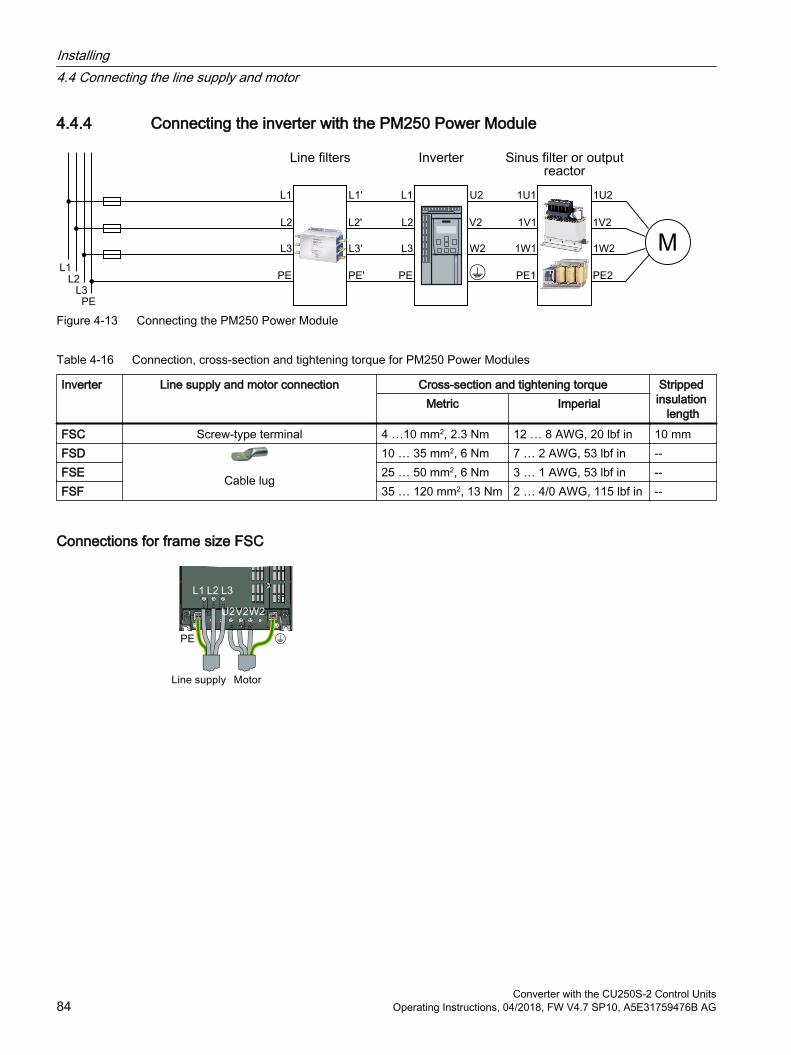
4.4.4 Connecting the inverter with the PM250 Power Module
Figure 4-13 Connecting the PM250 Power Module
Table 4-16 Connection, cross-section and tightening torque for PM250 Power Modules
Inverter Line supply and motor connection Cross-section and tightening torque Stripped insulation
lengthMetric Imperial
FSC Screw-type terminal 4 …10 mm2, 2.3 Nm 12 … 8 AWG, 20 lbf in 10 mmFSD
Cable lug
10 … 35 mm2, 6 Nm 7 … 2 AWG, 53 lbf in --FSE 25 … 50 mm2, 6 Nm 3 … 1 AWG, 53 lbf in --FSF 35 … 120 mm2, 13 Nm 2 … 4/0 AWG, 115 lbf in --
Connections for frame size FSC
Installing4.4 Connecting the line supply and motor
Converter with the CU250S-2 Control Units84 Operating Instructions, 04/2018, FW V4.7 SP10, A5E31759476B AG
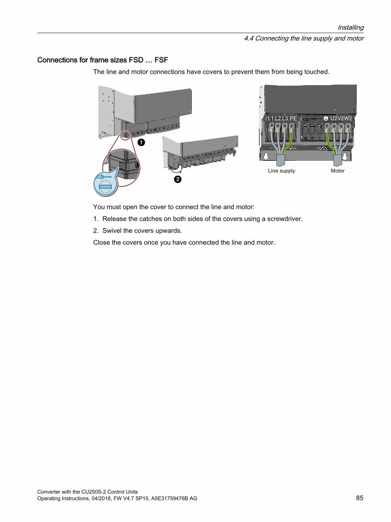
Connections for frame sizes FSD … FSFThe line and motor connections have covers to prevent them from being touched.
You must open the cover to connect the line and motor:
1. Release the catches on both sides of the covers using a screwdriver.
2. Swivel the covers upwards.
Close the covers once you have connected the line and motor.
Installing4.4 Connecting the line supply and motor
Converter with the CU250S-2 Control UnitsOperating Instructions, 04/2018, FW V4.7 SP10, A5E31759476B AG 85
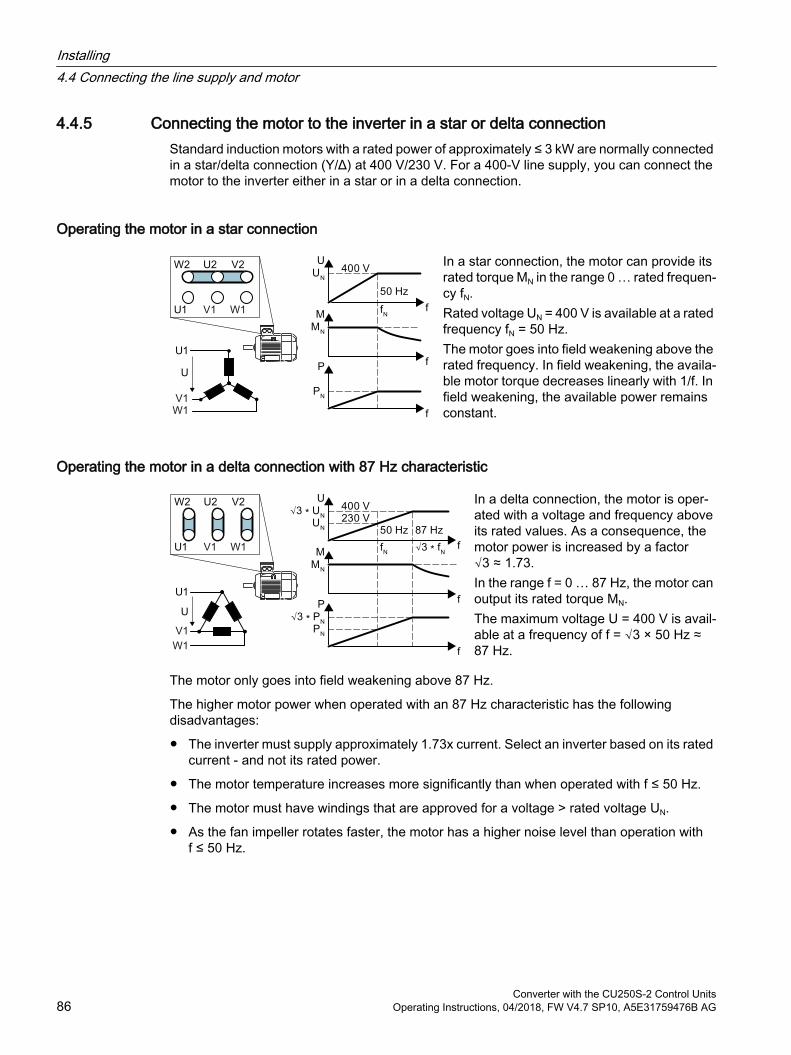
4.4.5 Connecting the motor to the inverter in a star or delta connectionStandard induction motors with a rated power of approximately ≤ 3 kW are normally connected in a star/delta connection (Y/Δ) at 400 V/230 V. For a 400‑V line supply, you can connect the motor to the inverter either in a star or in a delta connection.
Operating the motor in a star connection
In a star connection, the motor can provide its rated torque MN in the range 0 … rated frequen‐cy fN.Rated voltage UN = 400 V is available at a rated frequency fN = 50 Hz.The motor goes into field weakening above the rated frequency. In field weakening, the availa‐ble motor torque decreases linearly with 1/f. In field weakening, the available power remains constant.
Operating the motor in a delta connection with 87 Hz characteristic
In a delta connection, the motor is oper‐ated with a voltage and frequency above its rated values. As a consequence, the motor power is increased by a factor √3 ≈ 1.73.In the range f = 0 … 87 Hz, the motor can output its rated torque MN.The maximum voltage U = 400 V is avail‐able at a frequency of f = √3 × 50 Hz ≈ 87 Hz.
The motor only goes into field weakening above 87 Hz.
The higher motor power when operated with an 87 Hz characteristic has the following disadvantages:
The inverter must supply approximately 1.73x current. Select an inverter based on its rated current - and not its rated power.
The motor temperature increases more significantly than when operated with f ≤ 50 Hz.
The motor must have windings that are approved for a voltage > rated voltage UN.
As the fan impeller rotates faster, the motor has a higher noise level than operation with f ≤ 50 Hz.
Installing4.4 Connecting the line supply and motor
Converter with the CU250S-2 Control Units86 Operating Instructions, 04/2018, FW V4.7 SP10, A5E31759476B AG
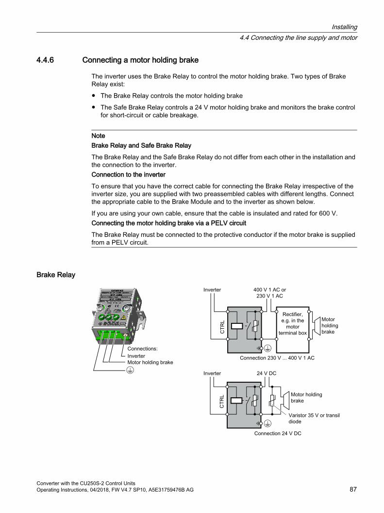
4.4.6 Connecting a motor holding brake
The inverter uses the Brake Relay to control the motor holding brake. Two types of Brake Relay exist:
The Brake Relay controls the motor holding brake
The Safe Brake Relay controls a 24 V motor holding brake and monitors the brake control for short-circuit or cable breakage.
NoteBrake Relay and Safe Brake Relay
The Brake Relay and the Safe Brake Relay do not differ from each other in the installation and the connection to the inverter.Connection to the inverter
To ensure that you have the correct cable for connecting the Brake Relay irrespective of the inverter size, you are supplied with two preassembled cables with different lengths. Connect the appropriate cable to the Brake Module and to the inverter as shown below.
If you are using your own cable, ensure that the cable is insulated and rated for 600 V.Connecting the motor holding brake via a PELV circuit
The Brake Relay must be connected to the protective conductor if the motor brake is supplied from a PELV circuit.
Brake Relay
Installing4.4 Connecting the line supply and motor
Converter with the CU250S-2 Control UnitsOperating Instructions, 04/2018, FW V4.7 SP10, A5E31759476B AG 87
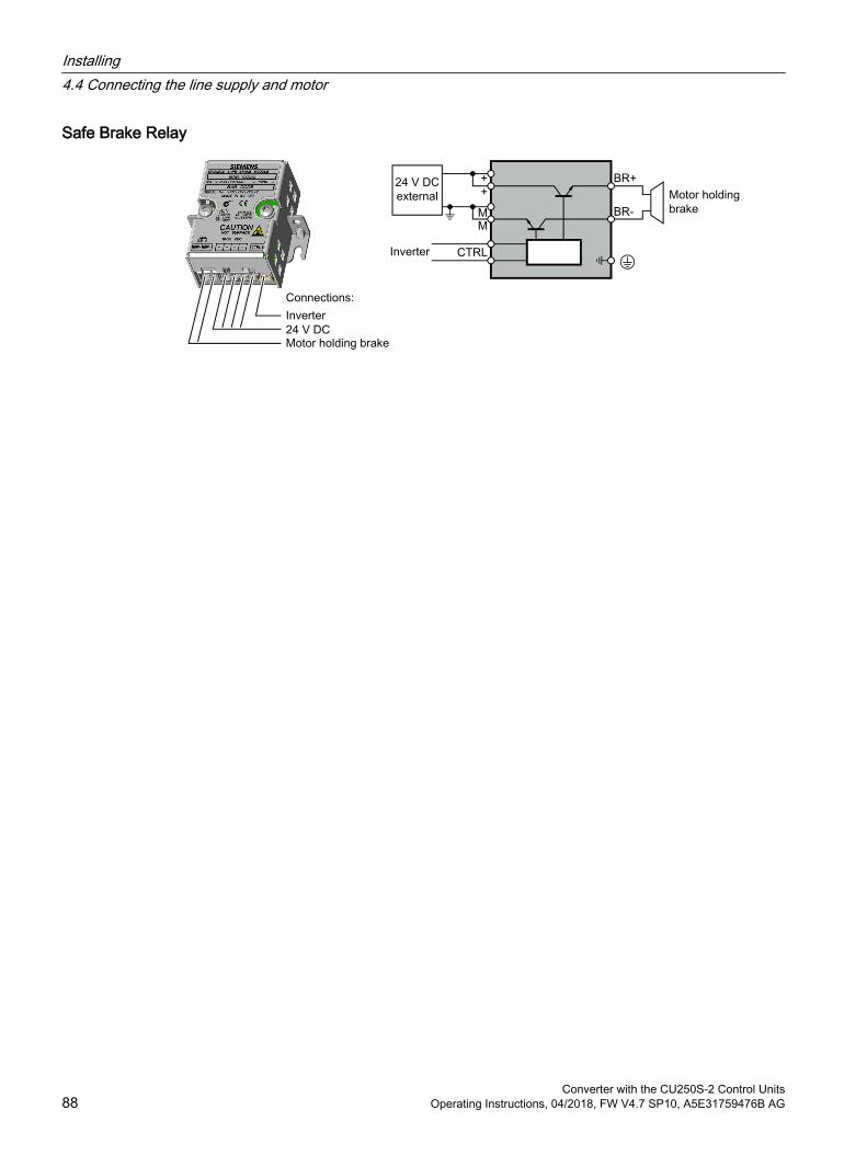
Safe Brake Relay
Installing4.4 Connecting the line supply and motor
Converter with the CU250S-2 Control Units88 Operating Instructions, 04/2018, FW V4.7 SP10, A5E31759476B AG
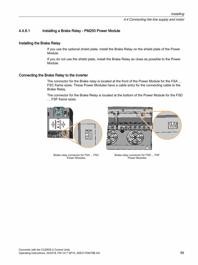
4.4.6.1 Installing a Brake Relay - PM250 Power Module
Installing the Brake RelayIf you use the optional shield plate, install the Brake Relay on the shield plate of the Power Module.
If you do not use the shield plate, install the Brake Relay as close as possible to the Power Module.
Connecting the Brake Relay to the inverterThe connector for the Brake relay is located at the front of the Power Module for the FSA … FSC frame sizes. These Power Modules have a cable entry for the connecting cable to the Brake Relay.
The connector for the Brake Relay is located at the bottom of the Power Module for the FSD … FSF frame sizes.
Installing4.4 Connecting the line supply and motor
Converter with the CU250S-2 Control UnitsOperating Instructions, 04/2018, FW V4.7 SP10, A5E31759476B AG 89
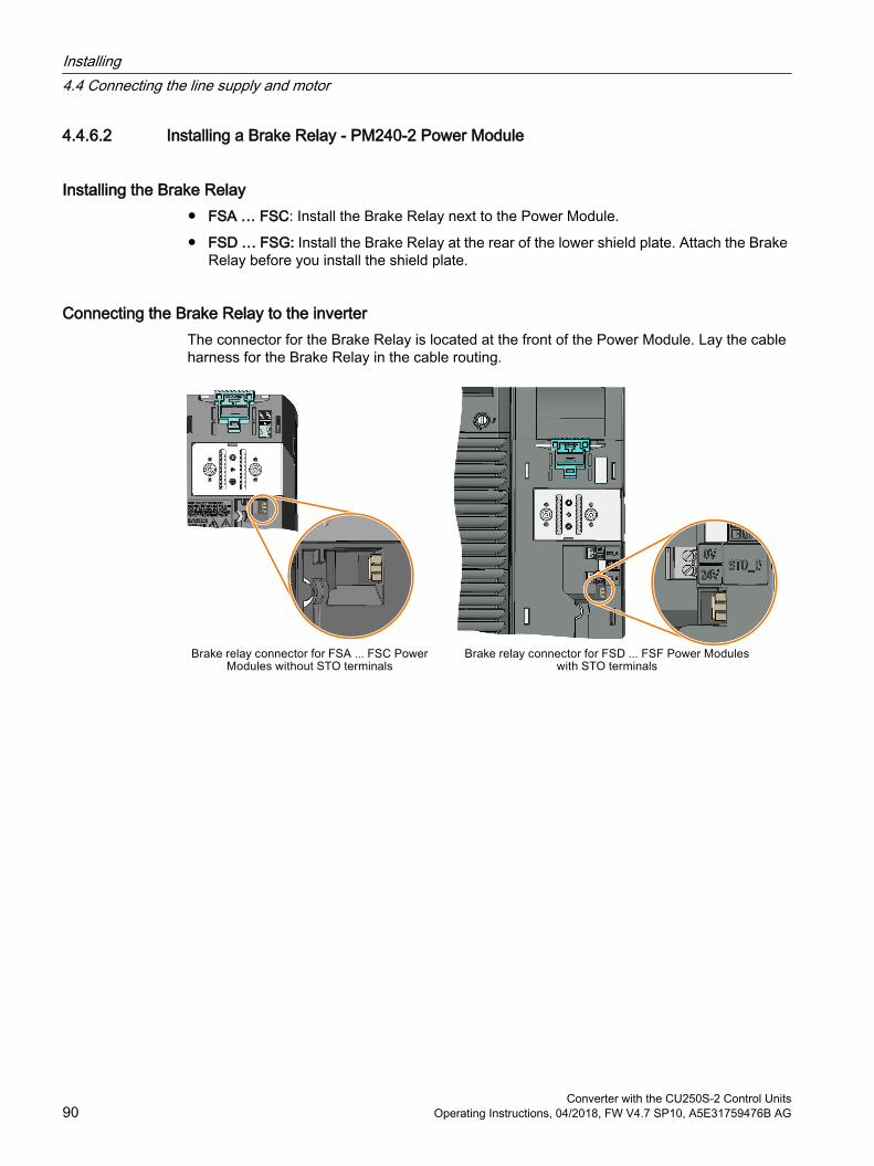
4.4.6.2 Installing a Brake Relay - PM240-2 Power Module
Installing the Brake Relay FSA … FSC: Install the Brake Relay next to the Power Module.
FSD … FSG: Install the Brake Relay at the rear of the lower shield plate. Attach the Brake Relay before you install the shield plate.
Connecting the Brake Relay to the inverterThe connector for the Brake Relay is located at the front of the Power Module. Lay the cable harness for the Brake Relay in the cable routing.
Installing4.4 Connecting the line supply and motor
Converter with the CU250S-2 Control Units90 Operating Instructions, 04/2018, FW V4.7 SP10, A5E31759476B AG
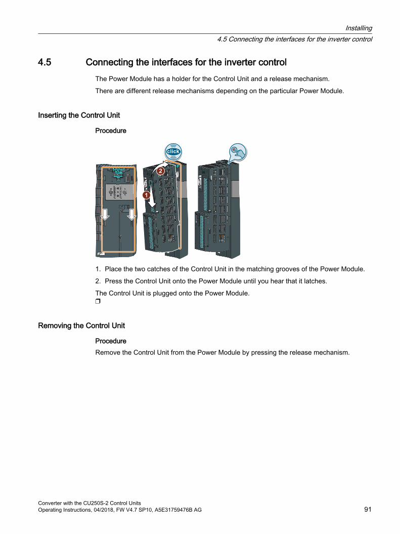
4.5 Connecting the interfaces for the inverter controlThe Power Module has a holder for the Control Unit and a release mechanism.
There are different release mechanisms depending on the particular Power Module.
Inserting the Control Unit
Procedure
1. Place the two catches of the Control Unit in the matching grooves of the Power Module.
2. Press the Control Unit onto the Power Module until you hear that it latches.
The Control Unit is plugged onto the Power Module.
Removing the Control Unit
ProcedureRemove the Control Unit from the Power Module by pressing the release mechanism.
Installing4.5 Connecting the interfaces for the inverter control
Converter with the CU250S-2 Control UnitsOperating Instructions, 04/2018, FW V4.7 SP10, A5E31759476B AG 91
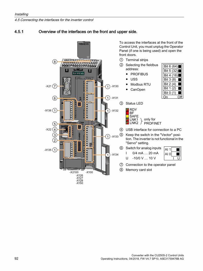
4.5.1 Overview of the interfaces on the front and upper side.
To access the interfaces at the front of the Control Unit, you must unplug the Operator Panel (if one is being used) and open the front doors. ① Terminal strips② Selecting the fieldbus
address: PROFIBUS USS Modbus RTU CanOpen
③ Status LED
④ USB interface for connection to a PC⑤ Keep the switch in the "Vector" posi‐
tion. The inverter is not functional in the "Servo" setting.
⑥
Switch for analog inputsI 0/4 mA … 20 mAU -10/0 V … 10 V
⑦ Connection to the operator panel⑧ Memory card slot
Installing4.5 Connecting the interfaces for the inverter control
Converter with the CU250S-2 Control Units92 Operating Instructions, 04/2018, FW V4.7 SP10, A5E31759476B AG
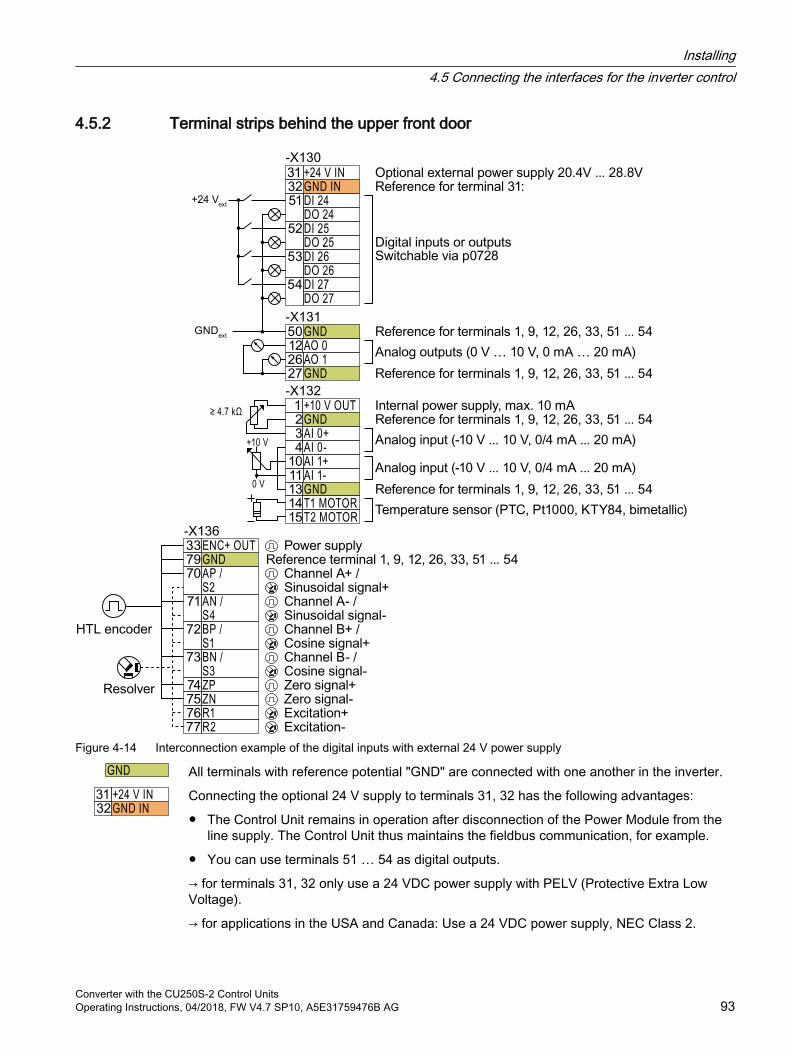
4.5.2 Terminal strips behind the upper front door
Figure 4-14 Interconnection example of the digital inputs with external 24 V power supply
All terminals with reference potential "GND" are connected with one another in the inverter.
Connecting the optional 24 V supply to terminals 31, 32 has the following advantages:
The Control Unit remains in operation after disconnection of the Power Module from the line supply. The Control Unit thus maintains the fieldbus communication, for example.
You can use terminals 51 … 54 as digital outputs.
→ for terminals 31, 32 only use a 24 VDC power supply with PELV (Protective Extra Low Voltage).
→ for applications in the USA and Canada: Use a 24 VDC power supply, NEC Class 2.
Installing4.5 Connecting the interfaces for the inverter control
Converter with the CU250S-2 Control UnitsOperating Instructions, 04/2018, FW V4.7 SP10, A5E31759476B AG 93
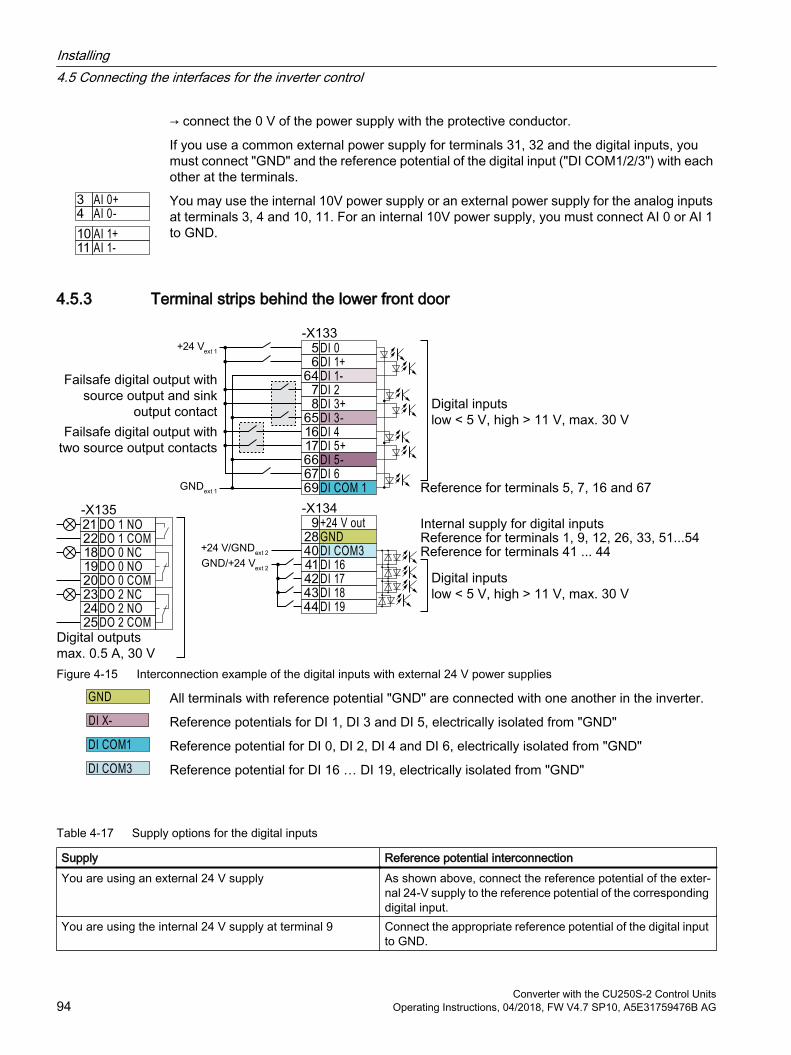
→ connect the 0 V of the power supply with the protective conductor.
If you use a common external power supply for terminals 31, 32 and the digital inputs, you must connect "GND" and the reference potential of the digital input ("DI COM1/2/3") with each other at the terminals.
You may use the internal 10V power supply or an external power supply for the analog inputs at terminals 3, 4 and 10, 11. For an internal 10V power supply, you must connect AI 0 or AI 1 to GND.
4.5.3 Terminal strips behind the lower front door
Figure 4-15 Interconnection example of the digital inputs with external 24 V power supplies
All terminals with reference potential "GND" are connected with one another in the inverter.
Reference potentials for DI 1, DI 3 and DI 5, electrically isolated from "GND"
Reference potential for DI 0, DI 2, DI 4 and DI 6, electrically isolated from "GND"
Reference potential for DI 16 … DI 19, electrically isolated from "GND"
Table 4-17 Supply options for the digital inputs
Supply Reference potential interconnectionYou are using an external 24 V supply As shown above, connect the reference potential of the exter‐
nal 24‑V supply to the reference potential of the corresponding digital input.
You are using the internal 24 V supply at terminal 9 Connect the appropriate reference potential of the digital input to GND.
Installing4.5 Connecting the interfaces for the inverter control
Converter with the CU250S-2 Control Units94 Operating Instructions, 04/2018, FW V4.7 SP10, A5E31759476B AG
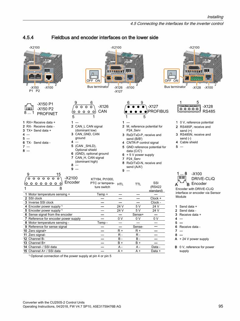
4.5.4 Fieldbus and encoder interfaces on the lower side
Installing4.5 Connecting the interfaces for the inverter control
Converter with the CU250S-2 Control UnitsOperating Instructions, 04/2018, FW V4.7 SP10, A5E31759476B AG 95
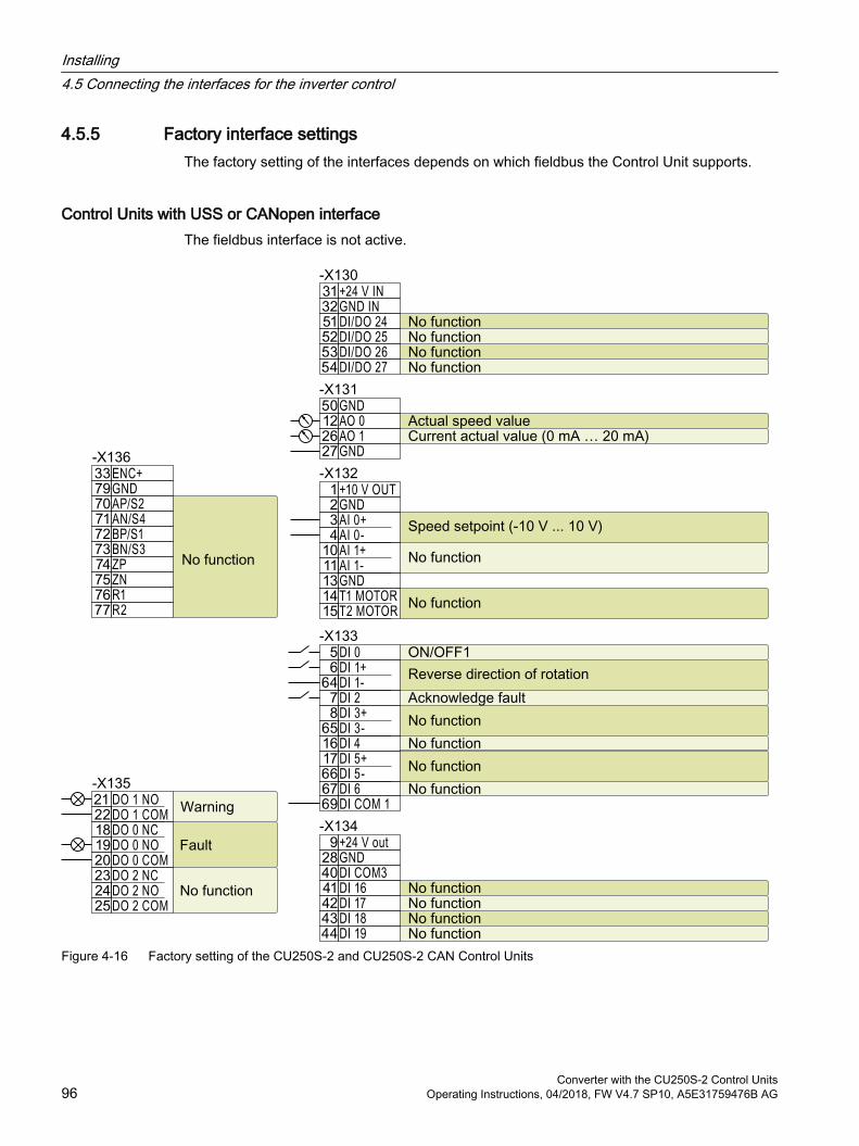
4.5.5 Factory interface settingsThe factory setting of the interfaces depends on which fieldbus the Control Unit supports.
Control Units with USS or CANopen interfaceThe fieldbus interface is not active.
Figure 4-16 Factory setting of the CU250S-2 and CU250S-2 CAN Control Units
Installing4.5 Connecting the interfaces for the inverter control
Converter with the CU250S-2 Control Units96 Operating Instructions, 04/2018, FW V4.7 SP10, A5E31759476B AG
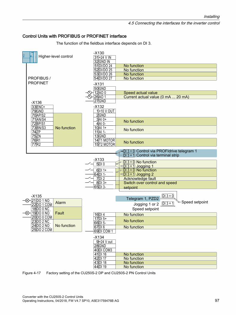
Control Units with PROFIBUS or PROFINET interfaceThe function of the fieldbus interface depends on DI 3.
Figure 4-17 Factory setting of the CU250S-2 DP and CU250S-2 PN Control Units
Installing4.5 Connecting the interfaces for the inverter control
Converter with the CU250S-2 Control UnitsOperating Instructions, 04/2018, FW V4.7 SP10, A5E31759476B AG 97

4.5.6 Default setting of the interfaces
Changing the function of the terminalsThe function of the terminals and fieldbus interface can be adjusted.
In order that you do not have to successively change terminal for terminal, several terminals can be jointly set using default settings ("p0015 Macro drive unit").
The terminal settings made in the factory described above correspond to the following default settings:
Default setting 12 (p0015 = 12): "Standard I/O with analog setpoint"
Default setting 7 (p0015 = 7): "Fieldbus with data set switchover"
Default setting 1: "Conveyor technology with 2 fixed frequencies"
DO 0: p0730, DO 1: p0731 AO 0: p0771[0], AO 1: p0771[1] DI 0: r0722.0, …, DI 5: r0722.5Fixed speed setpoint 3: p1003, fixed speed setpoint 4: p1004, fixed speed setpoint active: r1024Speed setpoint (main setpoint): p1070[0] = 1024DI 4 and DI 5 = high: The inverter adds both fixed speed setpointsDesignation in the BOP-2: coN 2 SP
Installing4.5 Connecting the interfaces for the inverter control
Converter with the CU250S-2 Control Units98 Operating Instructions, 04/2018, FW V4.7 SP10, A5E31759476B AG
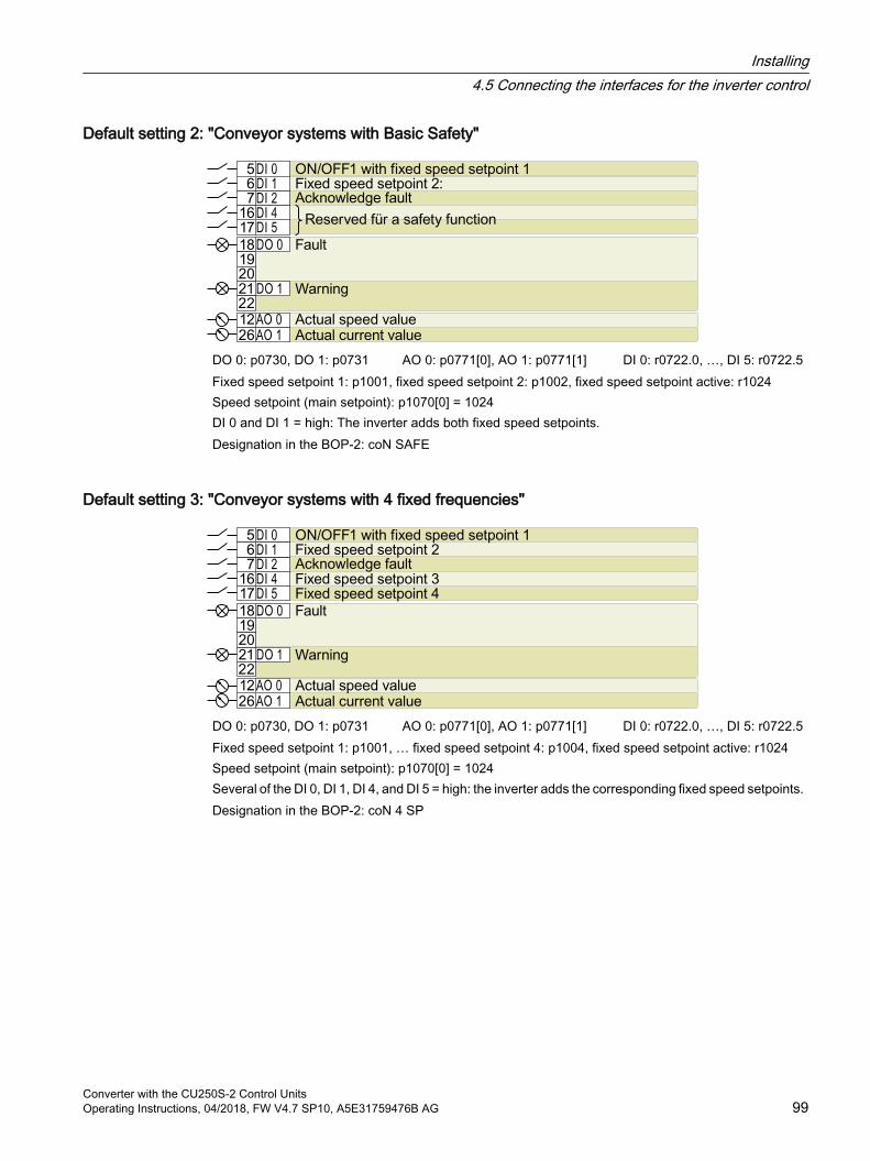
Default setting 2: "Conveyor systems with Basic Safety"
DO 0: p0730, DO 1: p0731 AO 0: p0771[0], AO 1: p0771[1] DI 0: r0722.0, …, DI 5: r0722.5Fixed speed setpoint 1: p1001, fixed speed setpoint 2: p1002, fixed speed setpoint active: r1024Speed setpoint (main setpoint): p1070[0] = 1024DI 0 and DI 1 = high: The inverter adds both fixed speed setpoints.Designation in the BOP-2: coN SAFE
Default setting 3: "Conveyor systems with 4 fixed frequencies"
DO 0: p0730, DO 1: p0731 AO 0: p0771[0], AO 1: p0771[1] DI 0: r0722.0, …, DI 5: r0722.5Fixed speed setpoint 1: p1001, … fixed speed setpoint 4: p1004, fixed speed setpoint active: r1024Speed setpoint (main setpoint): p1070[0] = 1024Several of the DI 0, DI 1, DI 4, and DI 5 = high: the inverter adds the corresponding fixed speed setpoints.Designation in the BOP-2: coN 4 SP
Installing4.5 Connecting the interfaces for the inverter control
Converter with the CU250S-2 Control UnitsOperating Instructions, 04/2018, FW V4.7 SP10, A5E31759476B AG 99
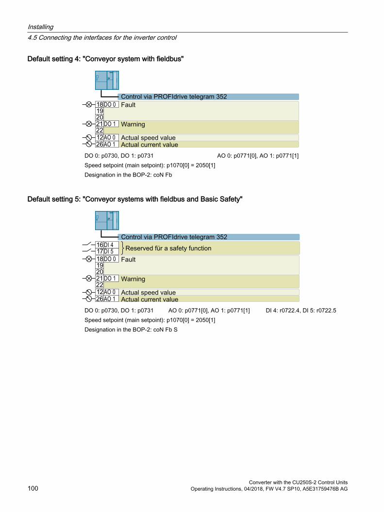
Default setting 4: "Conveyor system with fieldbus"
DO 0: p0730, DO 1: p0731 AO 0: p0771[0], AO 1: p0771[1]Speed setpoint (main setpoint): p1070[0] = 2050[1]Designation in the BOP-2: coN Fb
Default setting 5: "Conveyor systems with fieldbus and Basic Safety"
DO 0: p0730, DO 1: p0731 AO 0: p0771[0], AO 1: p0771[1] DI 4: r0722.4, DI 5: r0722.5Speed setpoint (main setpoint): p1070[0] = 2050[1]Designation in the BOP-2: coN Fb S
Installing4.5 Connecting the interfaces for the inverter control
Converter with the CU250S-2 Control Units100 Operating Instructions, 04/2018, FW V4.7 SP10, A5E31759476B AG
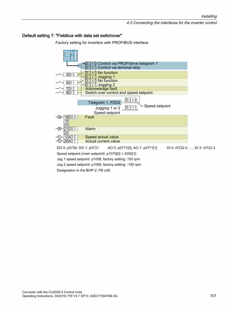
Default setting 7: "Fieldbus with data set switchover"Factory setting for inverters with PROFIBUS interface
DO 0: p0730, DO 1: p0731 AO 0: p0771[0], AO 1: p0771[1] DI 0: r0722.0, …, DI 3: r0722.3Speed setpoint (main setpoint): p1070[0] = 2050[1]Jog 1 speed setpoint: p1058, factory setting: 150 rpmJog 2 speed setpoint: p1059, factory setting: -150 rpmDesignation in the BOP-2: FB cdS
Installing4.5 Connecting the interfaces for the inverter control
Converter with the CU250S-2 Control UnitsOperating Instructions, 04/2018, FW V4.7 SP10, A5E31759476B AG 101
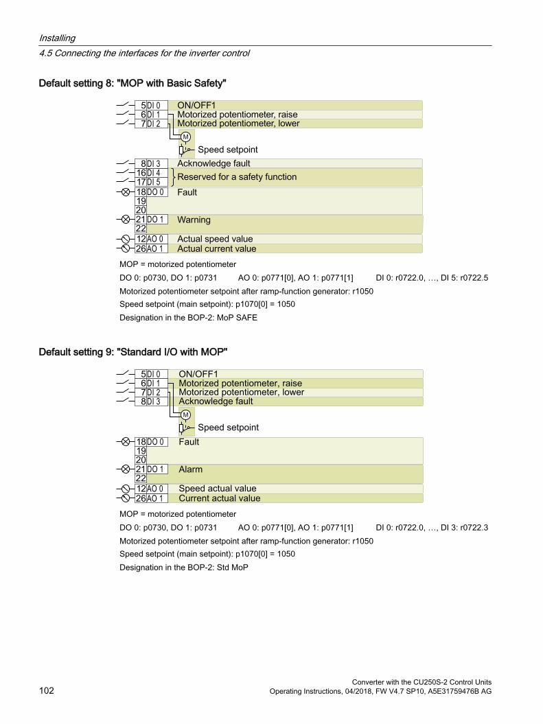
Default setting 8: "MOP with Basic Safety"
MOP = motorized potentiometerDO 0: p0730, DO 1: p0731 AO 0: p0771[0], AO 1: p0771[1] DI 0: r0722.0, …, DI 5: r0722.5Motorized potentiometer setpoint after ramp-function generator: r1050Speed setpoint (main setpoint): p1070[0] = 1050Designation in the BOP-2: MoP SAFE
Default setting 9: "Standard I/O with MOP"
MOP = motorized potentiometerDO 0: p0730, DO 1: p0731 AO 0: p0771[0], AO 1: p0771[1] DI 0: r0722.0, …, DI 3: r0722.3Motorized potentiometer setpoint after ramp-function generator: r1050Speed setpoint (main setpoint): p1070[0] = 1050Designation in the BOP-2: Std MoP
Installing4.5 Connecting the interfaces for the inverter control
Converter with the CU250S-2 Control Units102 Operating Instructions, 04/2018, FW V4.7 SP10, A5E31759476B AG
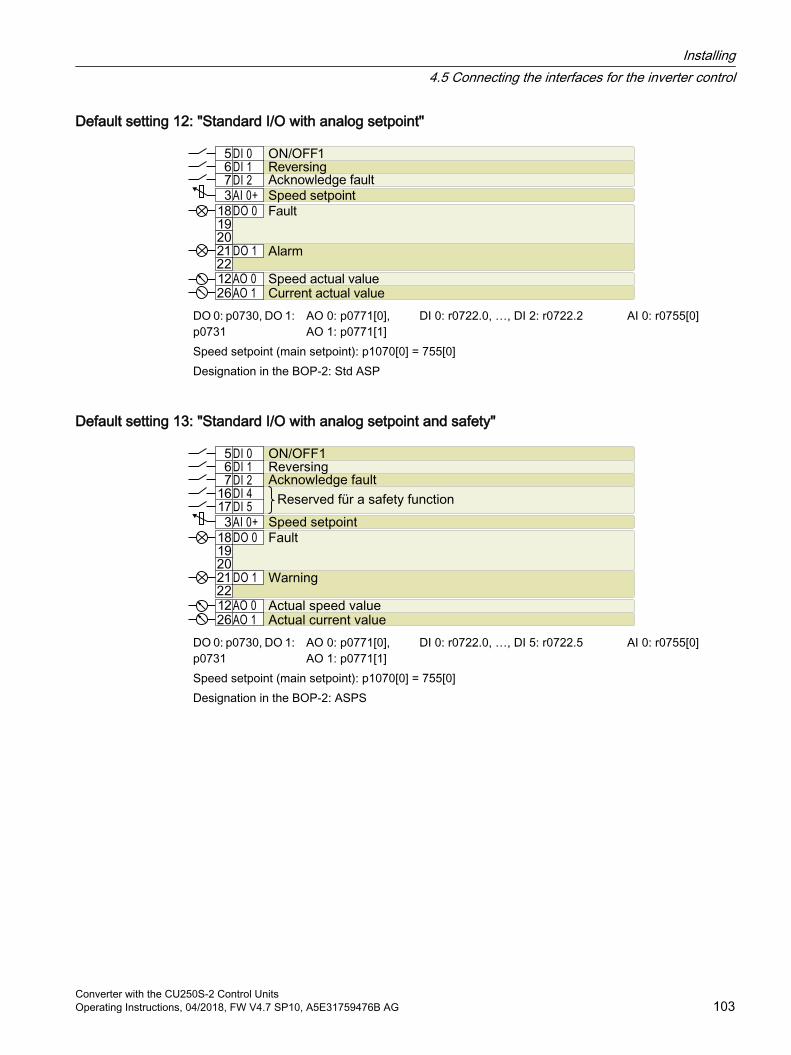
Default setting 12: "Standard I/O with analog setpoint"
DO 0: p0730, DO 1: p0731
AO 0: p0771[0], AO 1: p0771[1]
DI 0: r0722.0, …, DI 2: r0722.2 AI 0: r0755[0]
Speed setpoint (main setpoint): p1070[0] = 755[0]Designation in the BOP-2: Std ASP
Default setting 13: "Standard I/O with analog setpoint and safety"
DO 0: p0730, DO 1: p0731
AO 0: p0771[0], AO 1: p0771[1]
DI 0: r0722.0, …, DI 5: r0722.5 AI 0: r0755[0]
Speed setpoint (main setpoint): p1070[0] = 755[0]Designation in the BOP-2: ASPS
Installing4.5 Connecting the interfaces for the inverter control
Converter with the CU250S-2 Control UnitsOperating Instructions, 04/2018, FW V4.7 SP10, A5E31759476B AG 103
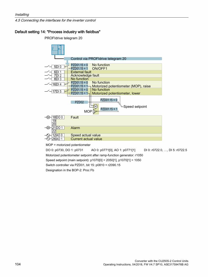
Default setting 14: "Process industry with fieldbus"PROFIdrive telegram 20
MOP = motorized potentiometerDO 0: p0730, DO 1: p0731 AO 0: p0771[0], AO 1: p0771[1] DI 0: r0722.0, …, DI 5: r0722.5Motorized potentiometer setpoint after ramp-function generator: r1050Speed setpoint (main setpoint): p1070[0] = 2050[1], p1070[1] = 1050Switch controller via PZD01, bit 15: p0810 = r2090.15Designation in the BOP-2: Proc Fb
Installing4.5 Connecting the interfaces for the inverter control
Converter with the CU250S-2 Control Units104 Operating Instructions, 04/2018, FW V4.7 SP10, A5E31759476B AG
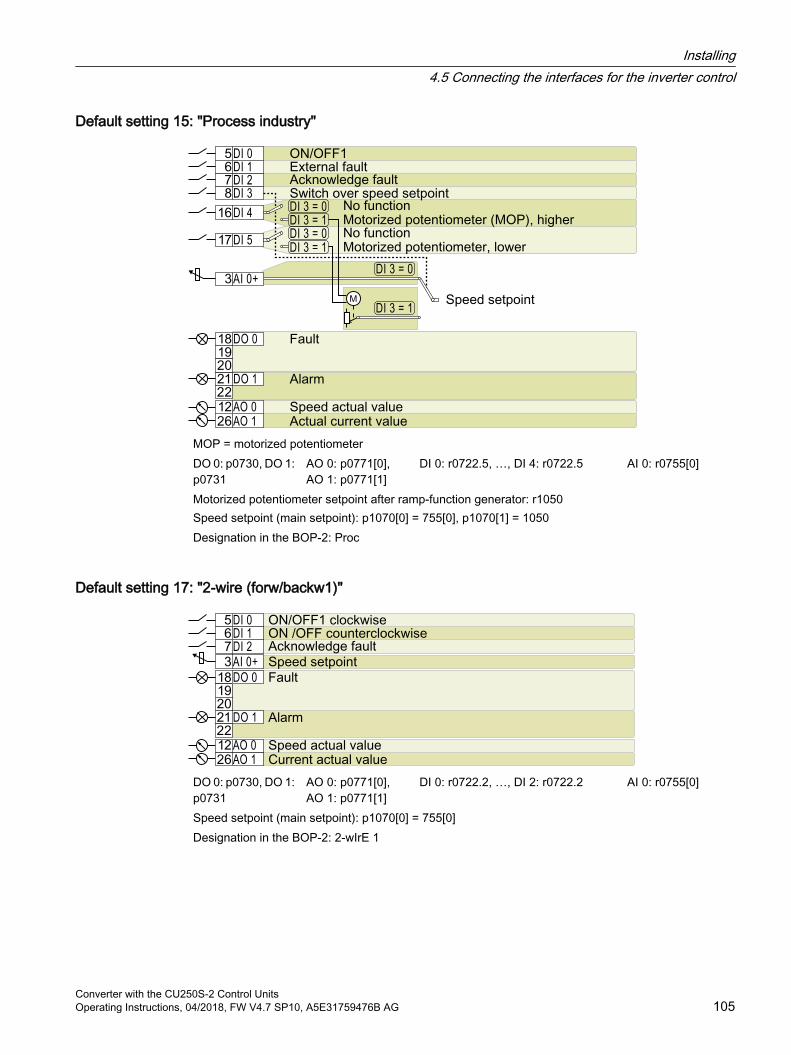
Default setting 15: "Process industry"
MOP = motorized potentiometerDO 0: p0730, DO 1: p0731
AO 0: p0771[0], AO 1: p0771[1]
DI 0: r0722.5, …, DI 4: r0722.5 AI 0: r0755[0]
Motorized potentiometer setpoint after ramp-function generator: r1050Speed setpoint (main setpoint): p1070[0] = 755[0], p1070[1] = 1050Designation in the BOP-2: Proc
Default setting 17: "2-wire (forw/backw1)"
DO 0: p0730, DO 1: p0731
AO 0: p0771[0], AO 1: p0771[1]
DI 0: r0722.2, …, DI 2: r0722.2 AI 0: r0755[0]
Speed setpoint (main setpoint): p1070[0] = 755[0]Designation in the BOP-2: 2-wIrE 1
Installing4.5 Connecting the interfaces for the inverter control
Converter with the CU250S-2 Control UnitsOperating Instructions, 04/2018, FW V4.7 SP10, A5E31759476B AG 105
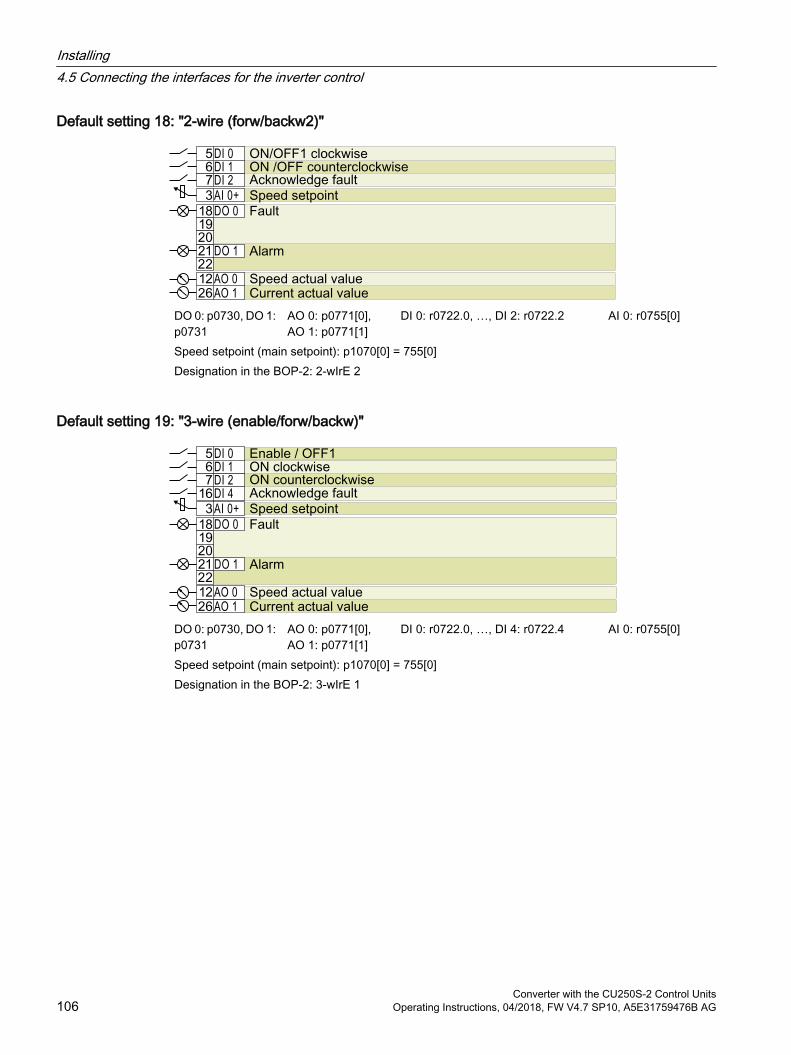
Default setting 18: "2-wire (forw/backw2)"
DO 0: p0730, DO 1: p0731
AO 0: p0771[0], AO 1: p0771[1]
DI 0: r0722.0, …, DI 2: r0722.2 AI 0: r0755[0]
Speed setpoint (main setpoint): p1070[0] = 755[0]Designation in the BOP-2: 2-wIrE 2
Default setting 19: "3-wire (enable/forw/backw)"
DO 0: p0730, DO 1: p0731
AO 0: p0771[0], AO 1: p0771[1]
DI 0: r0722.0, …, DI 4: r0722.4 AI 0: r0755[0]
Speed setpoint (main setpoint): p1070[0] = 755[0]Designation in the BOP-2: 3-wIrE 1
Installing4.5 Connecting the interfaces for the inverter control
Converter with the CU250S-2 Control Units106 Operating Instructions, 04/2018, FW V4.7 SP10, A5E31759476B AG
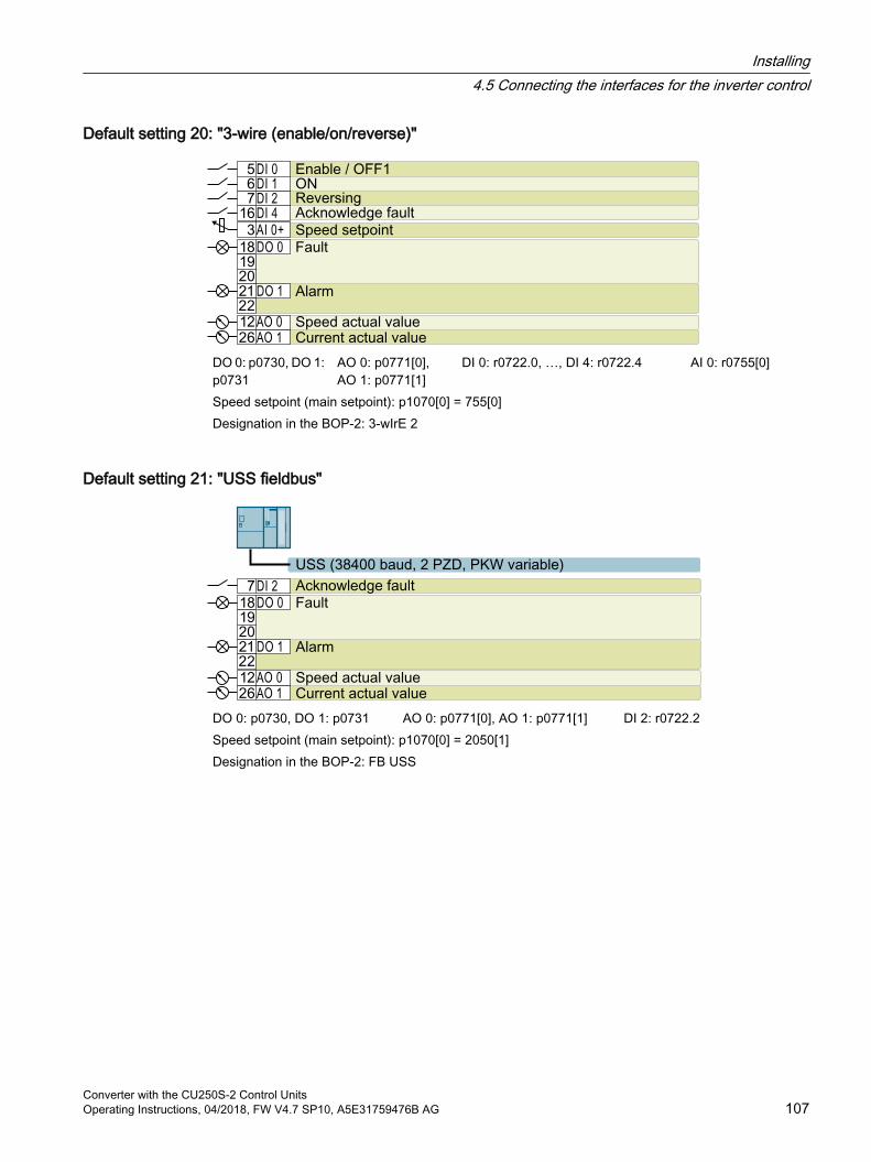
Default setting 20: "3-wire (enable/on/reverse)"
DO 0: p0730, DO 1: p0731
AO 0: p0771[0], AO 1: p0771[1]
DI 0: r0722.0, …, DI 4: r0722.4 AI 0: r0755[0]
Speed setpoint (main setpoint): p1070[0] = 755[0]Designation in the BOP-2: 3-wIrE 2
Default setting 21: "USS fieldbus"
DO 0: p0730, DO 1: p0731 AO 0: p0771[0], AO 1: p0771[1] DI 2: r0722.2Speed setpoint (main setpoint): p1070[0] = 2050[1]Designation in the BOP-2: FB USS
Installing4.5 Connecting the interfaces for the inverter control
Converter with the CU250S-2 Control UnitsOperating Instructions, 04/2018, FW V4.7 SP10, A5E31759476B AG 107

Default setting 22: "CAN fieldbus"
DO 0: p0730, DO 1: p0731 AO 0: p0771[0], AO 1: p0771[1] DI 2: r0722.2Speed setpoint (main setpoint): p1070[0] = 2050[1]Designation in the BOP-2: FB CAN
Installing4.5 Connecting the interfaces for the inverter control
Converter with the CU250S-2 Control Units108 Operating Instructions, 04/2018, FW V4.7 SP10, A5E31759476B AG
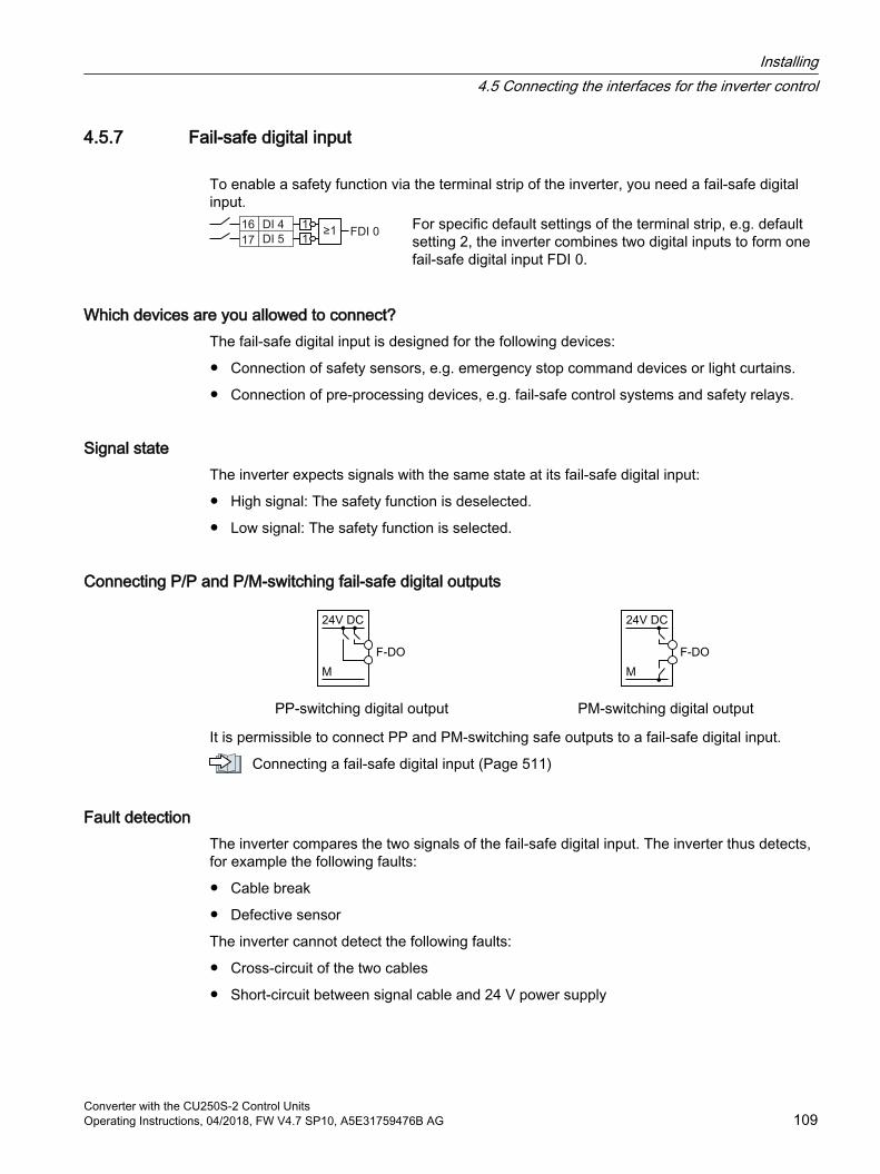
4.5.7 Fail-safe digital input
To enable a safety function via the terminal strip of the inverter, you need a fail-safe digital input.
For specific default settings of the terminal strip, e.g. default setting 2, the inverter combines two digital inputs to form one fail-safe digital input FDI 0.
Which devices are you allowed to connect?The fail-safe digital input is designed for the following devices:
Connection of safety sensors, e.g. emergency stop command devices or light curtains.
Connection of pre-processing devices, e.g. fail-safe control systems and safety relays.
Signal stateThe inverter expects signals with the same state at its fail-safe digital input:
High signal: The safety function is deselected.
Low signal: The safety function is selected.
Connecting P/P and P/M-switching fail-safe digital outputs
PP-switching digital output PM-switching digital output
It is permissible to connect PP and PM-switching safe outputs to a fail-safe digital input.
Connecting a fail-safe digital input (Page 511)
Fault detectionThe inverter compares the two signals of the fail-safe digital input. The inverter thus detects, for example the following faults:
Cable break
Defective sensor
The inverter cannot detect the following faults:
Cross-circuit of the two cables
Short-circuit between signal cable and 24 V power supply
Installing4.5 Connecting the interfaces for the inverter control
Converter with the CU250S-2 Control UnitsOperating Instructions, 04/2018, FW V4.7 SP10, A5E31759476B AG 109
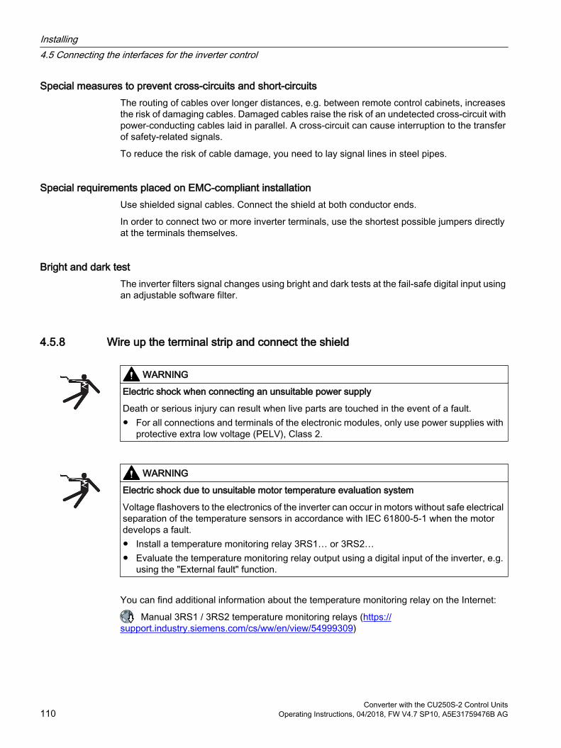
Special measures to prevent cross-circuits and short-circuitsThe routing of cables over longer distances, e.g. between remote control cabinets, increases the risk of damaging cables. Damaged cables raise the risk of an undetected cross-circuit with power-conducting cables laid in parallel. A cross-circuit can cause interruption to the transfer of safety-related signals.
To reduce the risk of cable damage, you need to lay signal lines in steel pipes.
Special requirements placed on EMC-compliant installationUse shielded signal cables. Connect the shield at both conductor ends.
In order to connect two or more inverter terminals, use the shortest possible jumpers directly at the terminals themselves.
Bright and dark testThe inverter filters signal changes using bright and dark tests at the fail-safe digital input using an adjustable software filter.
4.5.8 Wire up the terminal strip and connect the shield
WARNING
Electric shock when connecting an unsuitable power supply
Death or serious injury can result when live parts are touched in the event of a fault. For all connections and terminals of the electronic modules, only use power supplies with
protective extra low voltage (PELV), Class 2.
WARNING
Electric shock due to unsuitable motor temperature evaluation system
Voltage flashovers to the electronics of the inverter can occur in motors without safe electrical separation of the temperature sensors in accordance with IEC 61800‑5‑1 when the motor develops a fault. Install a temperature monitoring relay 3RS1… or 3RS2… Evaluate the temperature monitoring relay output using a digital input of the inverter, e.g.
using the "External fault" function.
You can find additional information about the temperature monitoring relay on the Internet:
Manual 3RS1 / 3RS2 temperature monitoring relays (https://support.industry.siemens.com/cs/ww/en/view/54999309)
Installing4.5 Connecting the interfaces for the inverter control
Converter with the CU250S-2 Control Units110 Operating Instructions, 04/2018, FW V4.7 SP10, A5E31759476B AG
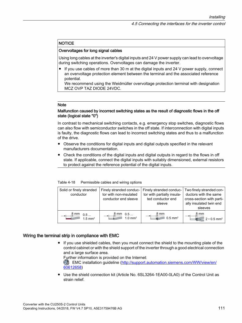
NOTICE
Overvoltages for long signal cables
Using long cables at the inverter's digital inputs and 24 V power supply can lead to overvoltage during switching operations. Overvoltages can damage the inverter. If you use cables of more than 30 m at the digital inputs and 24 V power supply, connect
an overvoltage protection element between the terminal and the associated reference potential.We recommend using the Weidmüller overvoltage protection terminal with designation MCZ OVP TAZ DIODE 24VDC.
NoteMalfunction caused by incorrect switching states as the result of diagnostic flows in the off state (logical state "0")
In contrast to mechanical switching contacts, e.g. emergency stop switches, diagnostic flows can also flow with semiconductor switches in the off state. If interconnection with digital inputs is faulty, the diagnostic flows can lead to incorrect switching states and thus to a malfunction of the drive. Observe the conditions for digital inputs and digital outputs specified in the relevant
manufacturers documentation. Check the conditions of the digital inputs and digital outputs in regard to the flows in off
state. If applicable, connect the digital inputs with suitably dimensioned, external resistors to protect against the reference potential of the digital inputs.
Table 4-18 Permissible cables and wiring options
Solid or finely stranded conductor
Finely stranded conduc‐tor with non-insulated conductor end sleeve
Finely stranded conduc‐tor with partially insula‐
ted conductor end sleeve
Two finely stranded con‐ductors with the same cross-section with parti‐ally insulated twin end
sleeves
Wiring the terminal strip in compliance with EMC If you use shielded cables, then you must connect the shield to the mounting plate of the
control cabinet or with the shield support of the inverter through a good electrical connection and a large surface area.Further information is provided on the Internet:
EMC installation guideline (http://support.automation.siemens.com/WW/view/en/60612658)
Use the shield connection kit (Article No. 6SL3264-1EA00-0LA0) of the Control Unit as strain relief.
Installing4.5 Connecting the interfaces for the inverter control
Converter with the CU250S-2 Control UnitsOperating Instructions, 04/2018, FW V4.7 SP10, A5E31759476B AG 111
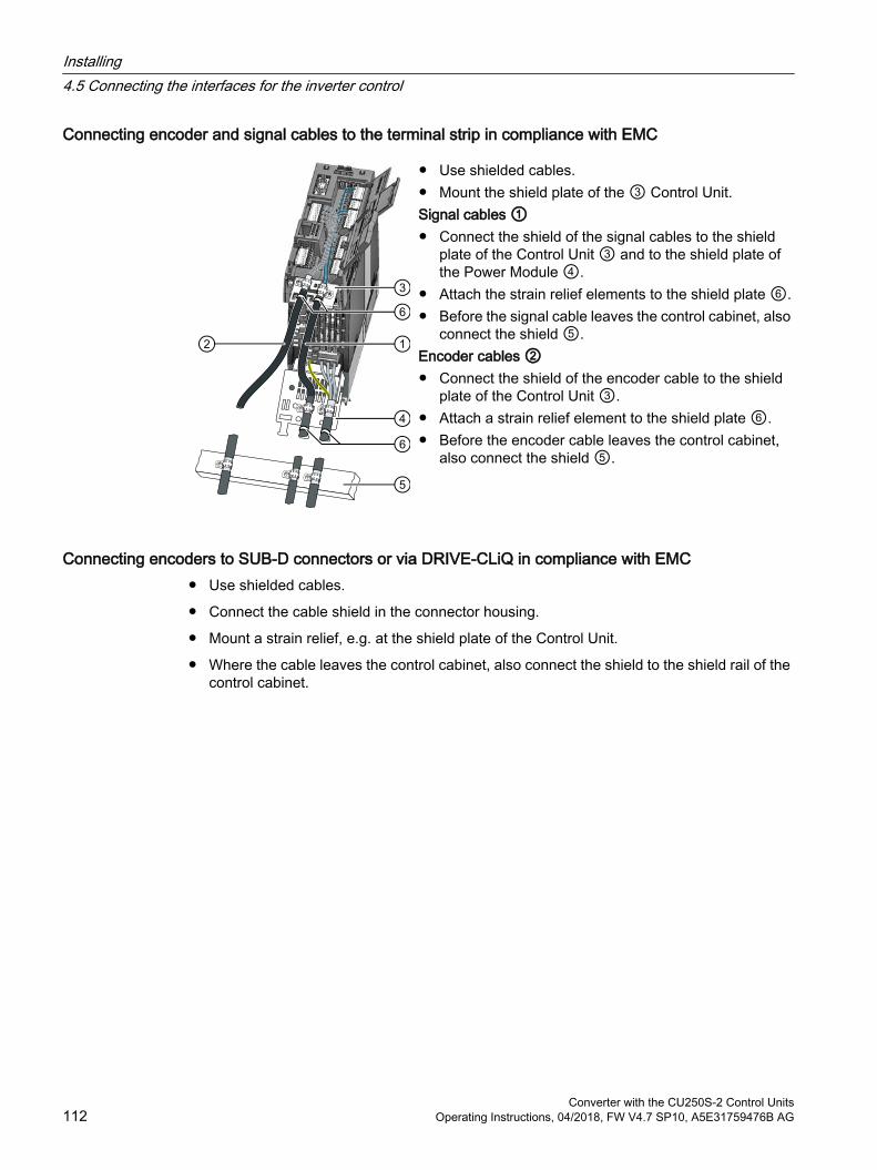
Connecting encoder and signal cables to the terminal strip in compliance with EMC
Use shielded cables. Mount the shield plate of the ③ Control Unit.Signal cables ① Connect the shield of the signal cables to the shield
plate of the Control Unit ③ and to the shield plate of the Power Module ④.
Attach the strain relief elements to the shield plate ⑥. Before the signal cable leaves the control cabinet, also
connect the shield ⑤.Encoder cables ② Connect the shield of the encoder cable to the shield
plate of the Control Unit ③. Attach a strain relief element to the shield plate ⑥. Before the encoder cable leaves the control cabinet,
also connect the shield ⑤.
Connecting encoders to SUB-D connectors or via DRIVE-CLiQ in compliance with EMC Use shielded cables.
Connect the cable shield in the connector housing.
Mount a strain relief, e.g. at the shield plate of the Control Unit.
Where the cable leaves the control cabinet, also connect the shield to the shield rail of the control cabinet.
Installing4.5 Connecting the interfaces for the inverter control
Converter with the CU250S-2 Control Units112 Operating Instructions, 04/2018, FW V4.7 SP10, A5E31759476B AG
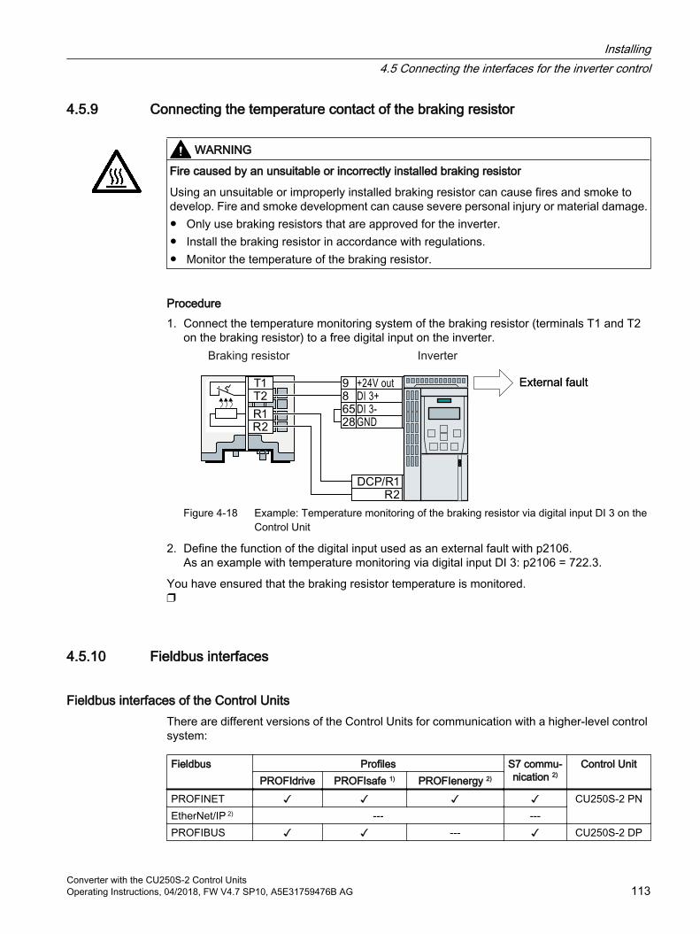
4.5.9 Connecting the temperature contact of the braking resistor
WARNING
Fire caused by an unsuitable or incorrectly installed braking resistor
Using an unsuitable or improperly installed braking resistor can cause fires and smoke to develop. Fire and smoke development can cause severe personal injury or material damage. Only use braking resistors that are approved for the inverter. Install the braking resistor in accordance with regulations. Monitor the temperature of the braking resistor.
Procedure1. Connect the temperature monitoring system of the braking resistor (terminals T1 and T2
on the braking resistor) to a free digital input on the inverter.
Figure 4-18 Example: Temperature monitoring of the braking resistor via digital input DI 3 on the Control Unit
2. Define the function of the digital input used as an external fault with p2106.As an example with temperature monitoring via digital input DI 3: p2106 = 722.3.
You have ensured that the braking resistor temperature is monitored.
4.5.10 Fieldbus interfaces
Fieldbus interfaces of the Control UnitsThere are different versions of the Control Units for communication with a higher-level control system:
Fieldbus Profiles S7 commu‐nication 2)
Control UnitPROFIdrive PROFIsafe 1) PROFIenergy 2)
PROFINET CU250S-2 PNEtherNet/IP 2) --- ---PROFIBUS --- CU250S-2 DP
Installing4.5 Connecting the interfaces for the inverter control
Converter with the CU250S-2 Control UnitsOperating Instructions, 04/2018, FW V4.7 SP10, A5E31759476B AG 113
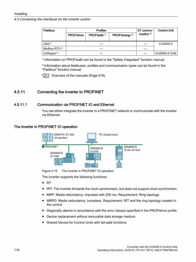
Fieldbus Profiles S7 commu‐nication 2)
Control UnitPROFIdrive PROFIsafe 1) PROFIenergy 2)
USS 2) --- --- CU250S-2Modbus RTU 2) --- ---CANopen 2) --- --- CU250S-2 CAN
1) Information on PROFIsafe can be found in the "Safety Integrated" function manual.2) Information about fieldbuses, profiles and communication types can be found in the "Fieldbus" function manual.
Overview of the manuals (Page 519)
4.5.11 Connecting the inverter to PROFINET
4.5.11.1 Communication via PROFINET IO and EthernetYou can either integrate the inverter in a PROFINET network or communicate with the inverter via Ethernet.
The inverter in PROFINET IO operation
Figure 4-19 The inverter in PROFINET IO operation
The inverter supports the following functions:
RT
IRT: The inverter forwards the clock synchronism, but does not support clock synchronism.
MRP: Media redundancy, impulsed with 200 ms. Requirement: Ring topology
MRPD: Media redundancy, bumpless. Requirement: IRT and the ring topology created in the control
Diagnostic alarms in accordance with the error classes specified in the PROFIdrive profile.
Device replacement without removable data storage medium
Shared Device for Control Units with fail-safe functions
Installing4.5 Connecting the interfaces for the inverter control
Converter with the CU250S-2 Control Units114 Operating Instructions, 04/2018, FW V4.7 SP10, A5E31759476B AG
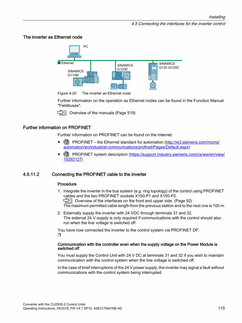
The inverter as Ethernet node
Figure 4-20 The inverter as Ethernet node
Further information on the operation as Ethernet nodes can be found in the Function Manual "Fieldbuses".
Overview of the manuals (Page 519)
Further information on PROFINETFurther information on PROFINET can be found on the Internet:
PROFINET – the Ethernet standard for automation (http://w3.siemens.com/mcms/automation/en/industrial-communications/profinet/Pages/Default.aspx)
PROFINET system description (https://support.industry.siemens.com/cs/ww/en/view/19292127)
4.5.11.2 Connecting the PROFINET cable to the inverter
Procedure1. Integrate the inverter in the bus system (e.g. ring topology) of the control using PROFINET
cables and the two PROFINET sockets X150-P1 and X150-P2. Overview of the interfaces on the front and upper side. (Page 92)
The maximum permitted cable length from the previous station and to the next one is 100 m.
2. Externally supply the inverter with 24 VDC through terminals 31 and 32. The external 24 V supply is only required if communications with the control should also run when the line voltage is switched off.
You have now connected the inverter to the control system via PROFINET DP.
Communication with the controller even when the supply voltage on the Power Module is switched offYou must supply the Control Unit with 24 V DC at terminals 31 and 32 if you wish to maintain communication with the control system when the line voltage is switched off.
In the case of brief interruptions of the 24 V power supply, the inverter may signal a fault without communications with the control system being interrupted.
Installing4.5 Connecting the interfaces for the inverter control
Converter with the CU250S-2 Control UnitsOperating Instructions, 04/2018, FW V4.7 SP10, A5E31759476B AG 115
4.5.11.3 What do you have to set for communication via PROFINET?
Configuring PROFINET communication in the I/O controllerYou require the appropriate engineering system to configure PROFINET communication in the IO controller.
If required, load the GSDML file of the inverter into the engineering system.
Installing GSDML (Page 117)
Device nameIn addition to the MAC address and IP address, PROFINET also uses the device name to identify PROFINET devices (Device name). The device name must be unique across the PROFINET network.
To assign the device name, you need an engineering software, e.g. HW-Config or STARTER.
The inverter saves the device name on the inserted memory card.
IP addressIn addition to the device name, PROFINET also uses an IP address.
You have the following options to specify the IP address of the inverter:
You specify the IP address via an engineering software, e.g. via HW-Config or STARTER.
The IO Controller assigns an IP address to the inverter.
TelegramSet the same telegram in the inverter as in the IO Controller. Interconnect the telegrams in the control program of the IO Controller with the signals of your choosing.
Drive control via PROFIBUS or PROFINET (Page 183)
Application examplesYou can find application examples for PROFINET communication on the Internet:
Controlling the speed of a SINAMICS G110M/G120/G120C/G120D with S7-300/400F via PROFINET or PROFIBUS, with Safety Integrated (via terminal) and HMI (https://support.industry.siemens.com/cs/ww/en/view/60441457)
Controlling the speed of a SINAMICS G110M / G120 (Startdrive) with S7-1500 (TO) via PROFINET or PROFIBUS, with Safety Integrated (via terminal) and HMI (https://support.industry.siemens.com/cs/ww/en/view/78788716)
Installing4.5 Connecting the interfaces for the inverter control
Converter with the CU250S-2 Control Units116 Operating Instructions, 04/2018, FW V4.7 SP10, A5E31759476B AG
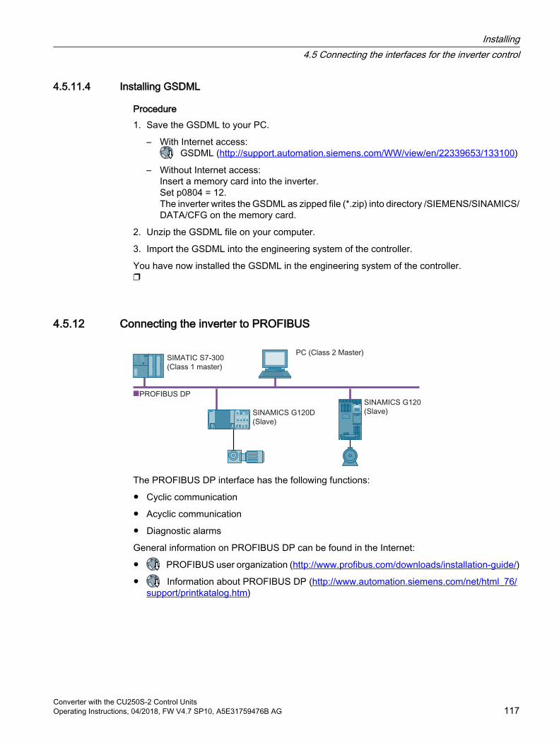
4.5.11.4 Installing GSDML
Procedure1. Save the GSDML to your PC.
– With Internet access: GSDML (http://support.automation.siemens.com/WW/view/en/22339653/133100)
– Without Internet access:Insert a memory card into the inverter.Set p0804 = 12.The inverter writes the GSDML as zipped file (*.zip) into directory /SIEMENS/SINAMICS/DATA/CFG on the memory card.
2. Unzip the GSDML file on your computer.
3. Import the GSDML into the engineering system of the controller.
You have now installed the GSDML in the engineering system of the controller.
4.5.12 Connecting the inverter to PROFIBUS
The PROFIBUS DP interface has the following functions:
Cyclic communication
Acyclic communication
Diagnostic alarms
General information on PROFIBUS DP can be found in the Internet:
PROFIBUS user organization (http://www.profibus.com/downloads/installation-guide/)
Information about PROFIBUS DP (http://www.automation.siemens.com/net/html_76/support/printkatalog.htm)
Installing4.5 Connecting the interfaces for the inverter control
Converter with the CU250S-2 Control UnitsOperating Instructions, 04/2018, FW V4.7 SP10, A5E31759476B AG 117
4.5.12.1 Connecting the PROFIBUS cable to the inverter
Procedure1. Integrate the inverter into the bus system (e.g. line topology) of the control using PROFIBUS
cables via socket X126. Overview of the interfaces on the front and upper side. (Page 92)
The maximum permitted cable length to the previous station and the subsequent one is 100 m at a baud rate of 12 Mbit/s.
2. Externally supply the inverter with 24 VDC through terminals 31 and 32. The external 24 V supply is only required if communications with the control should also run when the line voltage is switched off.
You have now connected the inverter to the control system using PROFIBUS DP.
4.5.12.2 What do you have to set for communication via PROFIBUS?
Configuring PROFIBUS communicationYou require the appropriate engineering system to configure PROFIBUS communication in the PROFIBUS master.
If required, load the GSD file of the inverter into the engineering system.
Installing the GSD (Page 119)
Setting the addressSet the address of the PROFIBUS slave.
Setting the address (Page 119)
Setting the telegramSet the telegram in the inverter as in the PROFIBUS master. Interconnect the telegrams in the control program of the PROFIBUS master with the signals of your choosing.
Drive control via PROFIBUS or PROFINET (Page 183)
Application examplesYou can find application examples for PROFIBUS communication on the Internet:
Controlling the speed of a SINAMICS G110M/G120/G120C/G120D with S7-300/400F via PROFINET or PROFIBUS, with Safety Integrated (via terminal) and HMI (https://support.industry.siemens.com/cs/ww/en/view/60441457)
Controlling the speed of a SINAMICS G110M / G120 (Startdrive) with S7-1500 (TO) via PROFINET or PROFIBUS, with Safety Integrated (via terminal) and HMI (https://support.industry.siemens.com/cs/ww/en/view/78788716)
Installing4.5 Connecting the interfaces for the inverter control
Converter with the CU250S-2 Control Units118 Operating Instructions, 04/2018, FW V4.7 SP10, A5E31759476B AG
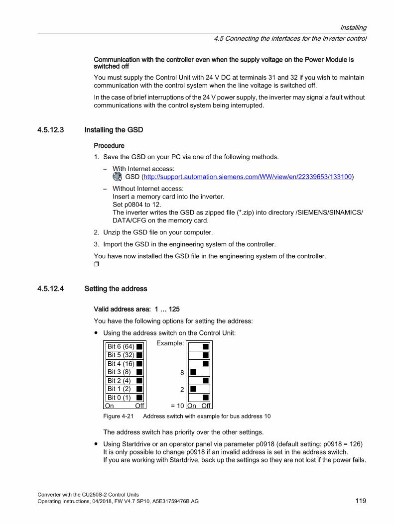
Communication with the controller even when the supply voltage on the Power Module is switched offYou must supply the Control Unit with 24 V DC at terminals 31 and 32 if you wish to maintain communication with the control system when the line voltage is switched off.
In the case of brief interruptions of the 24 V power supply, the inverter may signal a fault without communications with the control system being interrupted.
4.5.12.3 Installing the GSD
Procedure1. Save the GSD on your PC via one of the following methods.
– With Internet access:GSD (http://support.automation.siemens.com/WW/view/en/22339653/133100)
– Without Internet access:Insert a memory card into the inverter.Set p0804 to 12.The inverter writes the GSD as zipped file (*.zip) into directory /SIEMENS/SINAMICS/DATA/CFG on the memory card.
2. Unzip the GSD file on your computer.
3. Import the GSD in the engineering system of the controller.
You have now installed the GSD file in the engineering system of the controller.
4.5.12.4 Setting the address
Valid address area: 1 … 125
You have the following options for setting the address:
Using the address switch on the Control Unit:
Figure 4-21 Address switch with example for bus address 10
The address switch has priority over the other settings.
Using Startdrive or an operator panel via parameter p0918 (default setting: p0918 = 126)It is only possible to change p0918 if an invalid address is set in the address switch.If you are working with Startdrive, back up the settings so they are not lost if the power fails.
Installing4.5 Connecting the interfaces for the inverter control
Converter with the CU250S-2 Control UnitsOperating Instructions, 04/2018, FW V4.7 SP10, A5E31759476B AG 119

Overview of the interfaces on the front and upper side. (Page 92)
Setting the bus address
Procedure1. Set the address using one of the subsequently listed options:
– Via the address switch
– On an operator panel via p0918
– With StartdriveConfirm the prompt for saving your settings (copy RAM to ROM).
2. Switch off the inverter power supply.
3. Wait until all LEDs on the inverter are dark.
4. Switch on the inverter power supply again.Your settings become effective after switching on.
The PROFIBUS address is set.
Installing4.5 Connecting the interfaces for the inverter control
Converter with the CU250S-2 Control Units120 Operating Instructions, 04/2018, FW V4.7 SP10, A5E31759476B AG
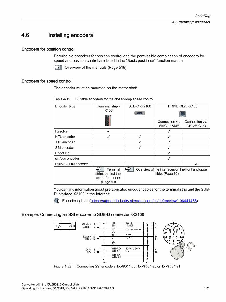
4.6 Installing encoders
Encoders for position controlPermissible encoders for position control and the permissible combination of encoders for speed and position control are listed in the "Basic positioner" function manual.
Overview of the manuals (Page 519)
Encoders for speed controlThe encoder must be mounted on the motor shaft.
Table 4-19 Suitable encoders for the closed-loop speed control
Encoder type Terminal strip -X136
SUB-D -X2100 DRIVE-CLiQ -X100
Connection viaSMC or SME
Connection via DRIVE-CLiQ
Resolver HTL encoder TTL encoder SSI encoder Endat 2.1 sin/cos encoder DRIVE-CLiQ encoder Terminal
strips behind the upper front door
(Page 93)
Overview of the interfaces on the front and upper side. (Page 92)
You can find information about prefabricated encoder cables for the terminal strip and the SUB-D interface-X2100 in the Internet:
Encoder cables (https://support.industry.siemens.com/cs/de/en/view/108441438)
Example: Connecting an SSI encoder to SUB-D connector -X2100
Figure 4-22 Connecting SSI encoders 1XP8014-20, 1XP8024-20 or 1XP8024-21
Installing4.6 Installing encoders
Converter with the CU250S-2 Control UnitsOperating Instructions, 04/2018, FW V4.7 SP10, A5E31759476B AG 121

Suitable prefabricated encoder cables:
6FX5002-2CC06-…
6FX8002-2CC06-…
Example: Connecting an HTL encoder at terminal strip -X136
Figure 4-23 Connecting a bipolar HTL encoder 1XP8012 or 1XP8032
Suitable prefabricated encoder cables:
6FX5002-2CA12-…
6FX8002-2CA12-…
Example: Connecting a unipolar HTL encoder at terminal strip -X136
Figure 4-24 Connecting a unipolar HTL encoder
Installing4.6 Installing encoders
Converter with the CU250S-2 Control Units122 Operating Instructions, 04/2018, FW V4.7 SP10, A5E31759476B AG
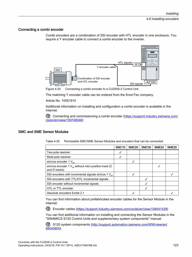
Connecting a combi encoderCombi encoders are a combination of SSI encoder with HTL encoder in one enclosure. You require a Y encoder cable to connect a combi encoder to the inverter.
Figure 4-25 Connecting a combi encoder to a CU250S-2 Control Unit
The matching Y encoder cable can be ordered from the KnorrTec company.
Article No. 10051910
Additional information on installing and configuration a combi encoder is available in the Internet:
Connecting and commissioning a combi encoder (https://support.industry.siemens.com/cs/en/en/view/109748046)
SMC and SME Sensor Modules
Table 4-20 Permissible SMC/SME Sensor Modules and encoders that can be connected
SMC10 SMC20 SMC30 SME20 SME25Two-pole resolver Multi-pole resolver sin/cos encoder 1 Vpp sin/cos encoder 1 Vpp without rotor position track (C and D tracks)
SSI encoders with incremental signals sin/cos 1 Vpp SSI encoders with TTL/HTL incremental signals SSI encoder without incremental signals HTL or TTL encoder Absolute encoders Endat 2.1
You can find information about prefabricated encoder cables for the Sensor Module in the Internet:
Encoder cables (https://support.industry.siemens.com/cs/de/en/view/108441438)
You can find additional information on installing and connecting the Sensor Modules in the "SINAMICS S120 Control Units and supplementary system components" manual.
S120 system components (http://support.automation.siemens.com/WW/view/en/68040800)
Installing4.6 Installing encoders
Converter with the CU250S-2 Control UnitsOperating Instructions, 04/2018, FW V4.7 SP10, A5E31759476B AG 123

Installing4.6 Installing encoders
Converter with the CU250S-2 Control Units124 Operating Instructions, 04/2018, FW V4.7 SP10, A5E31759476B AG
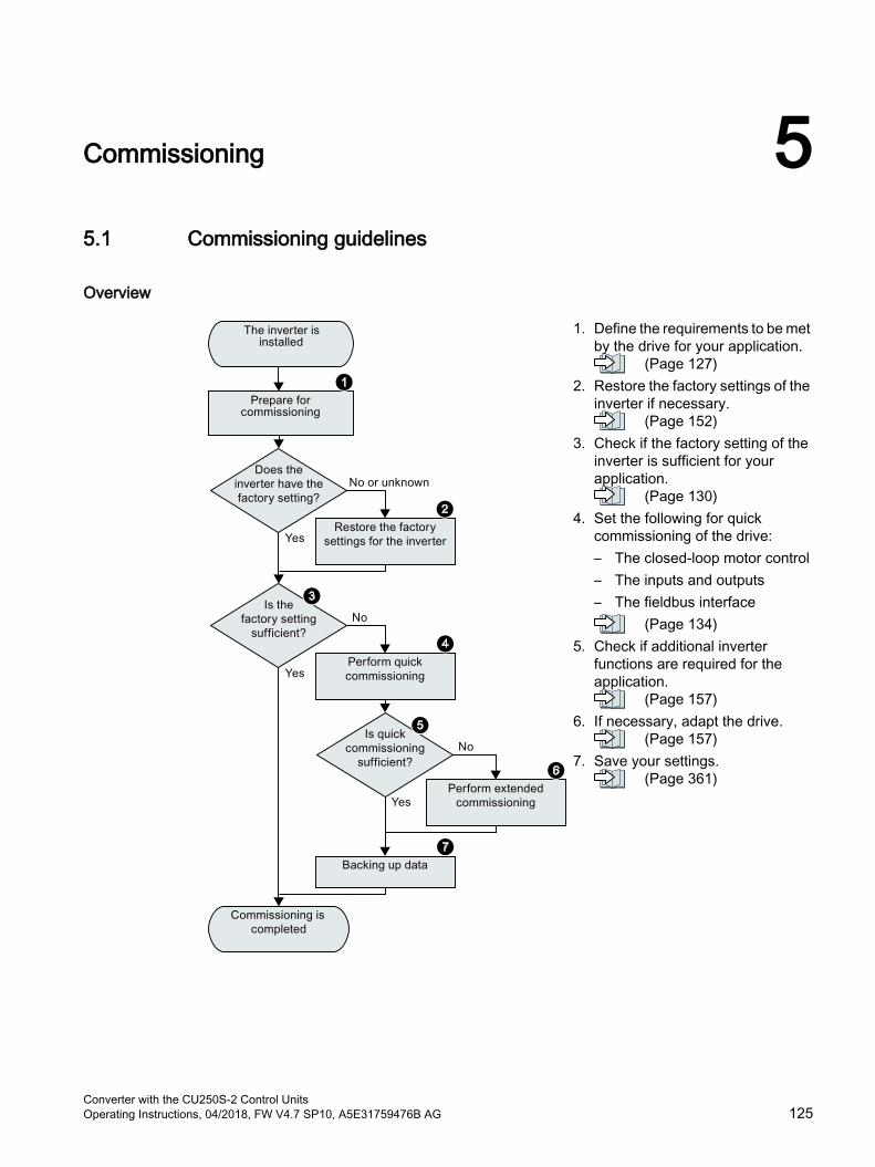
Commissioning 55.1 Commissioning guidelines
Overview
1. Define the requirements to be met by the drive for your application.
(Page 127)2. Restore the factory settings of the
inverter if necessary. (Page 152)
3. Check if the factory setting of the inverter is sufficient for your application.
(Page 130)4. Set the following for quick
commissioning of the drive:– The closed-loop motor control– The inputs and outputs– The fieldbus interface
(Page 134)5. Check if additional inverter
functions are required for the application.
(Page 157)6. If necessary, adapt the drive.
(Page 157)7. Save your settings.
(Page 361)
Converter with the CU250S-2 Control UnitsOperating Instructions, 04/2018, FW V4.7 SP10, A5E31759476B AG 125
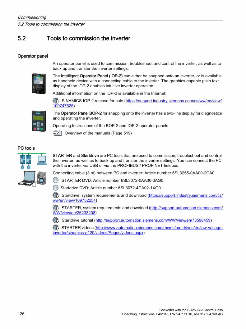
5.2 Tools to commission the inverter
Operator panelAn operator panel is used to commission, troubleshoot and control the inverter, as well as to back up and transfer the inverter settings.
The Intelligent Operator Panel (IOP‑2) can either be snapped onto an inverter, or is available as handheld device with a connecting cable to the inverter. The graphics-capable plain text display of the IOP‑2 enables intuitive inverter operation.
Additional information on the IOP‑2 is available in the Internet:
SINAMICS IOP-2 release for sale (https://support.industry.siemens.com/cs/ww/en/view/109747625)
The Operator Panel BOP‑2 for snapping onto the inverter has a two-line display for diagnostics and operating the inverter.
Operating Instructions of the BOP-2 and IOP-2 operator panels:
Overview of the manuals (Page 519)
PC toolsSTARTER and Startdrive are PC tools that are used to commission, troubleshoot and control the inverter, as well as to back up and transfer the inverter settings. You can connect the PC with the inverter via USB or via the PROFIBUS / PROFINET fieldbus.
Connecting cable (3 m) between PC and inverter: Article number 6SL3255-0AA00-2CA0
STARTER DVD: Article number 6SL3072-0AA00-0AG0
Startdrive DVD: Article number 6SL3072-4CA02-1XG0
Startdrive, system requirements and download (https://support.industry.siemens.com/cs/ww/en/view/109752254)
STARTER, system requirements and download (http://support.automation.siemens.com/WW/view/en/26233208)
Startdrive tutorial (http://support.automation.siemens.com/WW/view/en/73598459)
STARTER videos (http://www.automation.siemens.com/mcms/mc-drives/en/low-voltage-inverter/sinamics-g120/videos/Pages/videos.aspx)
Commissioning5.2 Tools to commission the inverter
Converter with the CU250S-2 Control Units126 Operating Instructions, 04/2018, FW V4.7 SP10, A5E31759476B AG
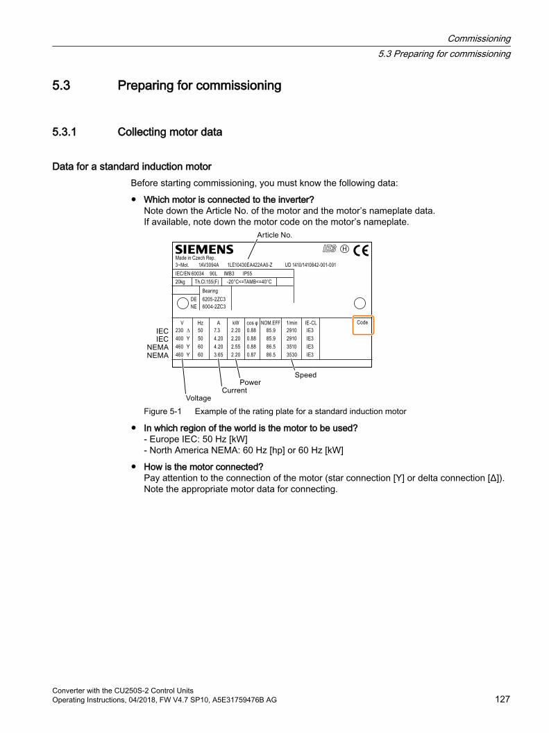
5.3 Preparing for commissioning
5.3.1 Collecting motor data
Data for a standard induction motorBefore starting commissioning, you must know the following data:
Which motor is connected to the inverter?Note down the Article No. of the motor and the motor’s nameplate data.If available, note down the motor code on the motor’s nameplate.
Figure 5-1 Example of the rating plate for a standard induction motor
In which region of the world is the motor to be used?- Europe IEC: 50 Hz [kW]- North America NEMA: 60 Hz [hp] or 60 Hz [kW]
How is the motor connected?Pay attention to the connection of the motor (star connection [Y] or delta connection [Δ]). Note the appropriate motor data for connecting.
Commissioning5.3 Preparing for commissioning
Converter with the CU250S-2 Control UnitsOperating Instructions, 04/2018, FW V4.7 SP10, A5E31759476B AG 127
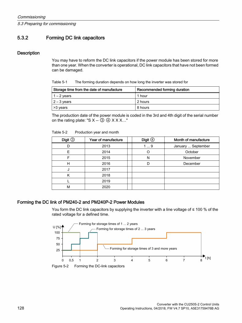
5.3.2 Forming DC link capacitors
DescriptionYou may have to reform the DC link capacitors if the power module has been stored for more than one year. When the converter is operational, DC link capacitors that have not been formed can be damaged.
Table 5-1 The forming duration depends on how long the inverter was stored for
Storage time from the date of manufacture Recommended forming duration1 – 2 years 1 hour2 – 3 years 2 hours>3 years 8 hours
The production date of the power module is coded in the 3rd and 4th digit of the serial number on the rating plate: "S X ‑- ③ ④ X X X…"
Table 5-2 Production year and month
Digit ③ Year of manufacture Digit ④ Month of manufactureD 2013 1 ... 9 January ... SeptemberE 2014 O OctoberF 2015 N NovemberH 2016 D DecemberJ 2017 K 2018 L 2019 M 2020
Forming the DC link of PM240-2 and PM240P-2 Power ModulesYou form the DC link capacitors by supplying the inverter with a line voltage of ≤ 100 % of the rated voltage for a defined time.
Figure 5-2 Forming the DC-link capacitors
Commissioning5.3 Preparing for commissioning
Converter with the CU250S-2 Control Units128 Operating Instructions, 04/2018, FW V4.7 SP10, A5E31759476B AG

Form DC Link of other power modulesFormation of the DC link capacitors is not required for the following power modules even after a lengthy period of storage.
PM230
PM250
Commissioning5.3 Preparing for commissioning
Converter with the CU250S-2 Control UnitsOperating Instructions, 04/2018, FW V4.7 SP10, A5E31759476B AG 129

5.3.3 Inverter factory setting
MotorWith its factory settings, the inverter is set up for an induction motor suitable for the power rating of the Power Module.
Inverter interfacesThe inputs and outputs and the fieldbus interface of the inverter have specific functions when set to the factory settings.
Factory interface settings (Page 96)
Switching the motor on and off
Figure 5-3 Switching on and switching off the motor and reversing in the factory setting
The inverter is set in the factory as follows:
After the ON command, the motor accelerates with a ramp-up time of 10 s (referred to 1500 rpm) to its speed setpoint.
After the OFF1 command, the motor brakes down to standstill with 10 s ramp-down time.
The motor direction of rotation reverses with the reversing command.
The ramp-up and ramp-down times define the maximum motor acceleration when the speed setpoint changes. The ramp-up and ramp-down time is derived from the time between motor standstill and the maximum speed, or between the maximum speed and motor standstill.
Commissioning5.3 Preparing for commissioning
Converter with the CU250S-2 Control Units130 Operating Instructions, 04/2018, FW V4.7 SP10, A5E31759476B AG
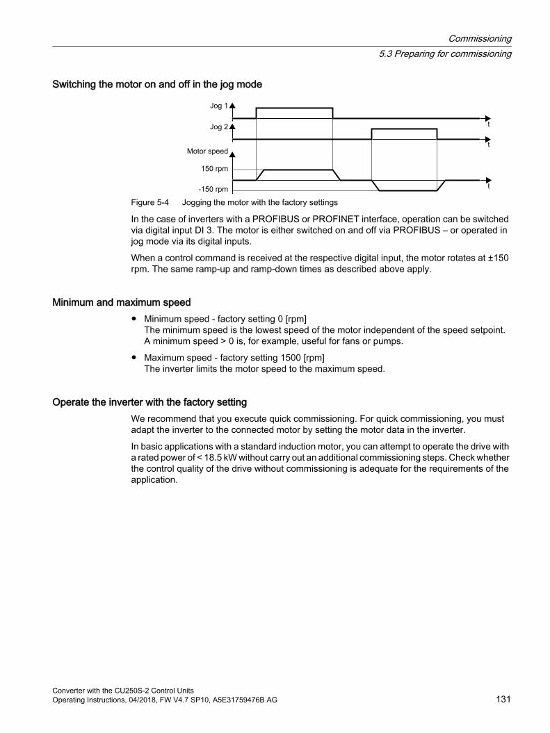
Switching the motor on and off in the jog mode
Figure 5-4 Jogging the motor with the factory settings
In the case of inverters with a PROFIBUS or PROFINET interface, operation can be switched via digital input DI 3. The motor is either switched on and off via PROFIBUS – or operated in jog mode via its digital inputs.
When a control command is received at the respective digital input, the motor rotates at ±150 rpm. The same ramp-up and ramp-down times as described above apply.
Minimum and maximum speed Minimum speed - factory setting 0 [rpm]
The minimum speed is the lowest speed of the motor independent of the speed setpoint. A minimum speed > 0 is, for example, useful for fans or pumps.
Maximum speed - factory setting 1500 [rpm]The inverter limits the motor speed to the maximum speed.
Operate the inverter with the factory settingWe recommend that you execute quick commissioning. For quick commissioning, you must adapt the inverter to the connected motor by setting the motor data in the inverter.
In basic applications with a standard induction motor, you can attempt to operate the drive with a rated power of < 18.5 kW without carry out an additional commissioning steps. Check whether the control quality of the drive without commissioning is adequate for the requirements of the application.
Commissioning5.3 Preparing for commissioning
Converter with the CU250S-2 Control UnitsOperating Instructions, 04/2018, FW V4.7 SP10, A5E31759476B AG 131
5.3.4 Inverter function modules
Function modulesNot all of the inverter functions are enabled in the factory setting. For instance, you must enable the "Encoder" function, so that the inverter can evaluate an encoder signal.
A function module is a set of inverter functions that can be released or inhibited all together.
You configure the following function modules in the quick commissioning:
Fieldbus interface
DRIVE-CLiQ interface
Technology controller
Basic positioner
Evaluating encoders
Extended messages Extended messages (Page 242)
Extended setpoint channel, e.g. motorized potentiometer and fixed setpoints
Free function blocks
You configure the following function modules when commissioning your drive:
You monitor the motor speed using the Extended safety functions.
The extended ramp-function generator allows the motor to be accelerated and braked smoothly without any jerk.
Commissioning5.3 Preparing for commissioning
Converter with the CU250S-2 Control Units132 Operating Instructions, 04/2018, FW V4.7 SP10, A5E31759476B AG
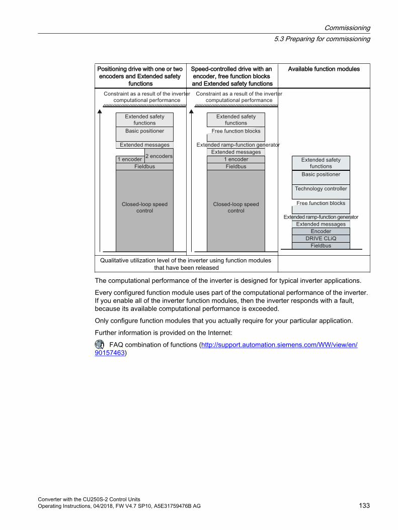
Positioning drive with one or two encoders and Extended safety
functions
Speed-controlled drive with an encoder, free function blocks and Extended safety functions
Available function modules
Qualitative utilization level of the inverter using function modules that have been released
The computational performance of the inverter is designed for typical inverter applications.
Every configured function module uses part of the computational performance of the inverter. If you enable all of the inverter function modules, then the inverter responds with a fault, because its available computational performance is exceeded.
Only configure function modules that you actually require for your particular application.
Further information is provided on the Internet:
FAQ combination of functions (http://support.automation.siemens.com/WW/view/en/90157463)
Commissioning5.3 Preparing for commissioning
Converter with the CU250S-2 Control UnitsOperating Instructions, 04/2018, FW V4.7 SP10, A5E31759476B AG 133

5.4 Quick commissioning with a PCThe screen forms that are shown in this manual show generally valid examples. The number of setting options available in screen forms depends on the particular inverter type.
5.4.1 Creating a project
Creating a new project
Procedure1. Start the Startdrive commissioning software.
2. In the menu, select "Project" → "New…".
3. Specify a name of your choice for the project.
You have created a new project.
Commissioning5.4 Quick commissioning with a PC
Converter with the CU250S-2 Control Units134 Operating Instructions, 04/2018, FW V4.7 SP10, A5E31759476B AG
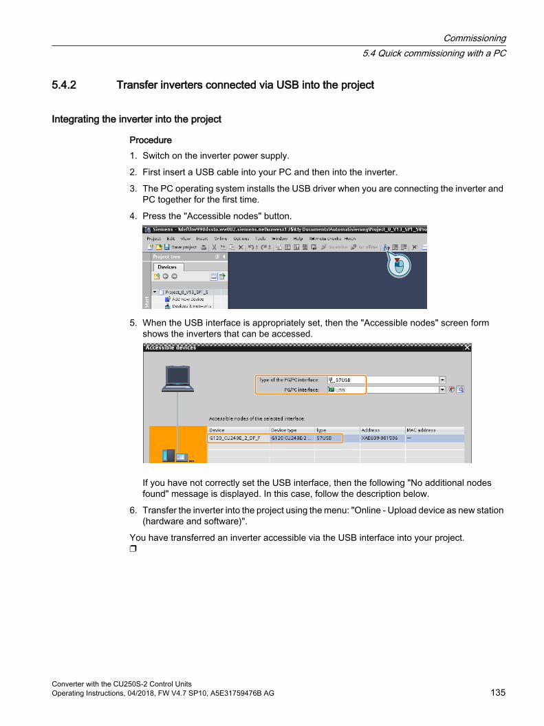
5.4.2 Transfer inverters connected via USB into the project
Integrating the inverter into the project
Procedure1. Switch on the inverter power supply.
2. First insert a USB cable into your PC and then into the inverter.
3. The PC operating system installs the USB driver when you are connecting the inverter and PC together for the first time.
4. Press the "Accessible nodes" button.
5. When the USB interface is appropriately set, then the "Accessible nodes" screen form shows the inverters that can be accessed.
If you have not correctly set the USB interface, then the following "No additional nodes found" message is displayed. In this case, follow the description below.
6. Transfer the inverter into the project using the menu: "Online - Upload device as new station (hardware and software)".
You have transferred an inverter accessible via the USB interface into your project.
Commissioning5.4 Quick commissioning with a PC
Converter with the CU250S-2 Control UnitsOperating Instructions, 04/2018, FW V4.7 SP10, A5E31759476B AG 135

5.4.3 Starting wizards for the quick commissioning
Starting commissioning wizards
Procedure1. In the project, select the drive you wish to commission.
2. Press the following buttons:
You have started the commissioning wizard.
Select the application class
ProcedureWhen selecting an application class, the inverter assigns the motor control with the appropriate default settings:
[1] Standard Drive Control (Page 139)
[2] Dynamic Drive Control (Page 141)
[0] Expert - or if no application class is listed: Expert (Page 143)
Commissioning5.4 Quick commissioning with a PC
Converter with the CU250S-2 Control Units136 Operating Instructions, 04/2018, FW V4.7 SP10, A5E31759476B AG
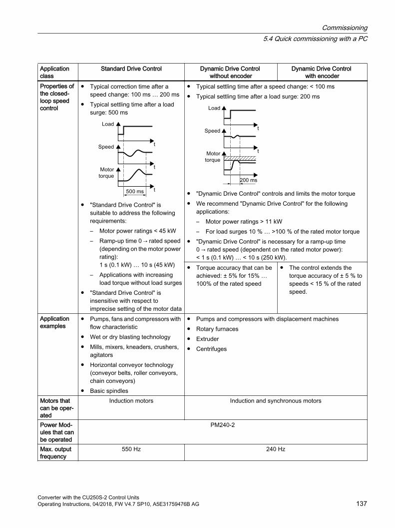
Application class
Standard Drive Control Dynamic Drive Control without encoder
Dynamic Drive Control with encoder
Properties of the closed-loop speed control
Typical correction time after a speed change: 100 ms … 200 ms
Typical settling time after a load surge: 500 ms
"Standard Drive Control" is suitable to address the following requirements:– Motor power ratings < 45 kW– Ramp-up time 0 → rated speed
(depending on the motor power rating): 1 s (0.1 kW) … 10 s (45 kW)
– Applications with increasing load torque without load surges
"Standard Drive Control" is insensitive with respect to imprecise setting of the motor data
Typical settling time after a speed change: < 100 ms Typical settling time after a load surge: 200 ms
"Dynamic Drive Control" controls and limits the motor torque We recommend "Dynamic Drive Control" for the following
applications:– Motor power ratings > 11 kW– For load surges 10 % … >100 % of the rated motor torque
"Dynamic Drive Control" is necessary for a ramp-up time 0 → rated speed (dependent on the rated motor power): < 1 s (0.1 kW) … < 10 s (250 kW).
Torque accuracy that can be achieved: ± 5% for 15% … 100% of the rated speed
The control extends the torque accuracy of ± 5 % to speeds < 15 % of the rated speed.
Application examples
Pumps, fans and compressors with flow characteristic
Wet or dry blasting technology Mills, mixers, kneaders, crushers,
agitators Horizontal conveyor technology
(conveyor belts, roller conveyors, chain conveyors)
Basic spindles
Pumps and compressors with displacement machines Rotary furnaces Extruder Centrifuges
Motors that can be oper‐ated
Induction motors Induction and synchronous motors
Power Mod‐ules that can be operated
PM240-2
Max. output frequency
550 Hz 240 Hz
Commissioning5.4 Quick commissioning with a PC
Converter with the CU250S-2 Control UnitsOperating Instructions, 04/2018, FW V4.7 SP10, A5E31759476B AG 137
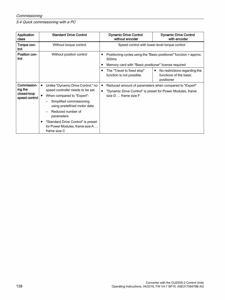
Application class
Standard Drive Control Dynamic Drive Control without encoder
Dynamic Drive Control with encoder
Torque con‐trol
Without torque control Speed control with lower-level torque control
Position con‐trol
Without position control Positioning cycles using the "Basic positioner" function > approx. 500ms
Memory card with "Basic positioner" license required The "Travel to fixed stop"
function is not possible. No restrictions regarding the
functions of the basic positioner
Commission‐ing the closed-loop speed control
Unlike "Dynamic Drive Control," no speed controller needs to be set
When compared to "Expert":– Simplified commissioning
using predefined motor data– Reduced number of
parameters "Standard Drive Control" is preset
for Power Modules, frame size A … frame size C
Reduced amount of parameters when compared to "Expert" "Dynamic Drive Control" is preset for Power Modules, frame
size D … frame size F
Commissioning5.4 Quick commissioning with a PC
Converter with the CU250S-2 Control Units138 Operating Instructions, 04/2018, FW V4.7 SP10, A5E31759476B AG
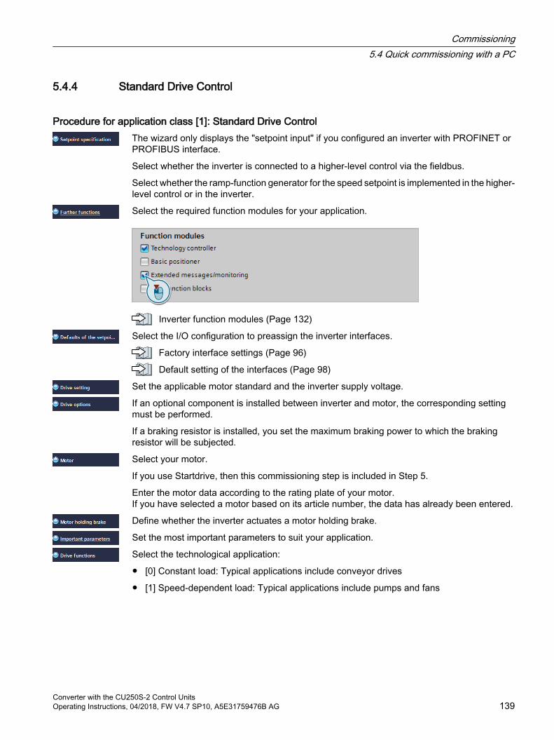
5.4.4 Standard Drive Control
Procedure for application class [1]: Standard Drive ControlThe wizard only displays the "setpoint input" if you configured an inverter with PROFINET or PROFIBUS interface.
Select whether the inverter is connected to a higher-level control via the fieldbus.
Select whether the ramp-function generator for the speed setpoint is implemented in the higher-level control or in the inverter.
Select the required function modules for your application.
Inverter function modules (Page 132)
Select the I/O configuration to preassign the inverter interfaces.
Factory interface settings (Page 96)
Default setting of the interfaces (Page 98)
Set the applicable motor standard and the inverter supply voltage.
If an optional component is installed between inverter and motor, the corresponding setting must be performed.
If a braking resistor is installed, you set the maximum braking power to which the braking resistor will be subjected.
Select your motor.
If you use Startdrive, then this commissioning step is included in Step 5.
Enter the motor data according to the rating plate of your motor.If you have selected a motor based on its article number, the data has already been entered.
Define whether the inverter actuates a motor holding brake.
Set the most important parameters to suit your application.
Select the technological application:
[0] Constant load: Typical applications include conveyor drives
[1] Speed-dependent load: Typical applications include pumps and fans
Commissioning5.4 Quick commissioning with a PC
Converter with the CU250S-2 Control UnitsOperating Instructions, 04/2018, FW V4.7 SP10, A5E31759476B AG 139

Motor identification (not all the following settings may be visible in Startdrive):
[0]: No motor data identification
[2]: Recommended setting. Measure the motor data at standstill. The inverter switches off the motor after the motor data identification has been completed.Select this setting if the motor cannot freely rotate, e.g. for a mechanically limited traversing range.
[12]: The same setting as [2]. The motor accelerates to the currently set setpoint after the motor data identification.
If you selected the "Basic positioner" function module, you must configure the encoder:
Configuring encoders (Page 147)
If you did not selected the "Basic positioner" function module, close the commissioning wizard:
Set the check mark for "RAM data to EEPROM (save data in the drive)" to save your data in the inverter so that it is not lost if the power fails.
Press the "Finish" button.
You have entered all of the data that is necessary for the quick commissioning of the inverter.
Commissioning5.4 Quick commissioning with a PC
Converter with the CU250S-2 Control Units140 Operating Instructions, 04/2018, FW V4.7 SP10, A5E31759476B AG
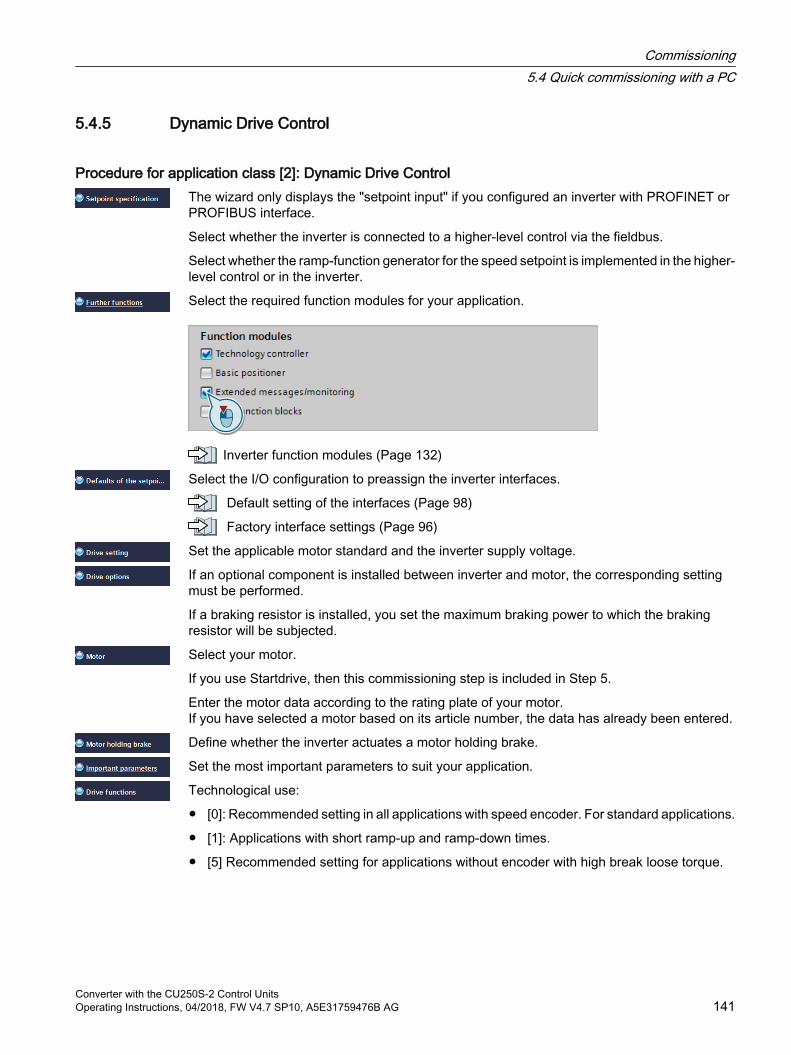
5.4.5 Dynamic Drive Control
Procedure for application class [2]: Dynamic Drive Control The wizard only displays the "setpoint input" if you configured an inverter with PROFINET or PROFIBUS interface.
Select whether the inverter is connected to a higher-level control via the fieldbus.
Select whether the ramp-function generator for the speed setpoint is implemented in the higher-level control or in the inverter.
Select the required function modules for your application.
Inverter function modules (Page 132)
Select the I/O configuration to preassign the inverter interfaces.
Default setting of the interfaces (Page 98)
Factory interface settings (Page 96)
Set the applicable motor standard and the inverter supply voltage.
If an optional component is installed between inverter and motor, the corresponding setting must be performed.
If a braking resistor is installed, you set the maximum braking power to which the braking resistor will be subjected.
Select your motor.
If you use Startdrive, then this commissioning step is included in Step 5.
Enter the motor data according to the rating plate of your motor.If you have selected a motor based on its article number, the data has already been entered.
Define whether the inverter actuates a motor holding brake.
Set the most important parameters to suit your application.
Technological use:
[0]: Recommended setting in all applications with speed encoder. For standard applications.
[1]: Applications with short ramp-up and ramp-down times.
[5] Recommended setting for applications without encoder with high break loose torque.
Commissioning5.4 Quick commissioning with a PC
Converter with the CU250S-2 Control UnitsOperating Instructions, 04/2018, FW V4.7 SP10, A5E31759476B AG 141

Motor identification:
[1]: Recommended setting. Measure the motor data at standstill and with the motor rotating. The inverter switches off the motor after the motor data identification has been completed.
[2]: Measure the motor data at standstill. The inverter switches off the motor after the motor data identification has been completed.Select this setting if the motor cannot freely rotate, e.g. for a mechanically limited traversing range.
[3]: Measure the motor data while the motor is rotating. The inverter switches off the motor after the motor data identification has been completed.
[11]: The same setting as [1]. The motor accelerates to the currently set setpoint after the motor data identification.
[12]: The same setting as [2]. The motor accelerates to the currently set setpoint after the motor data identification.
Configuring encoders (Page 147)
Commissioning5.4 Quick commissioning with a PC
Converter with the CU250S-2 Control Units142 Operating Instructions, 04/2018, FW V4.7 SP10, A5E31759476B AG

5.4.6 Expert
Procedure without application class or for the application class [0]: Expert The wizard only displays the "setpoint input" if you configured an inverter with PROFINET or PROFIBUS interface.
Select whether the inverter is connected to a higher-level control via the fieldbus.
Select whether the ramp-function generator for the speed setpoint is implemented in the higher-level control or in the inverter.
Select the required function modules for your application.
Inverter function modules (Page 132)
Select the control mode.
Commissioning5.4 Quick commissioning with a PC
Converter with the CU250S-2 Control UnitsOperating Instructions, 04/2018, FW V4.7 SP10, A5E31759476B AG 143
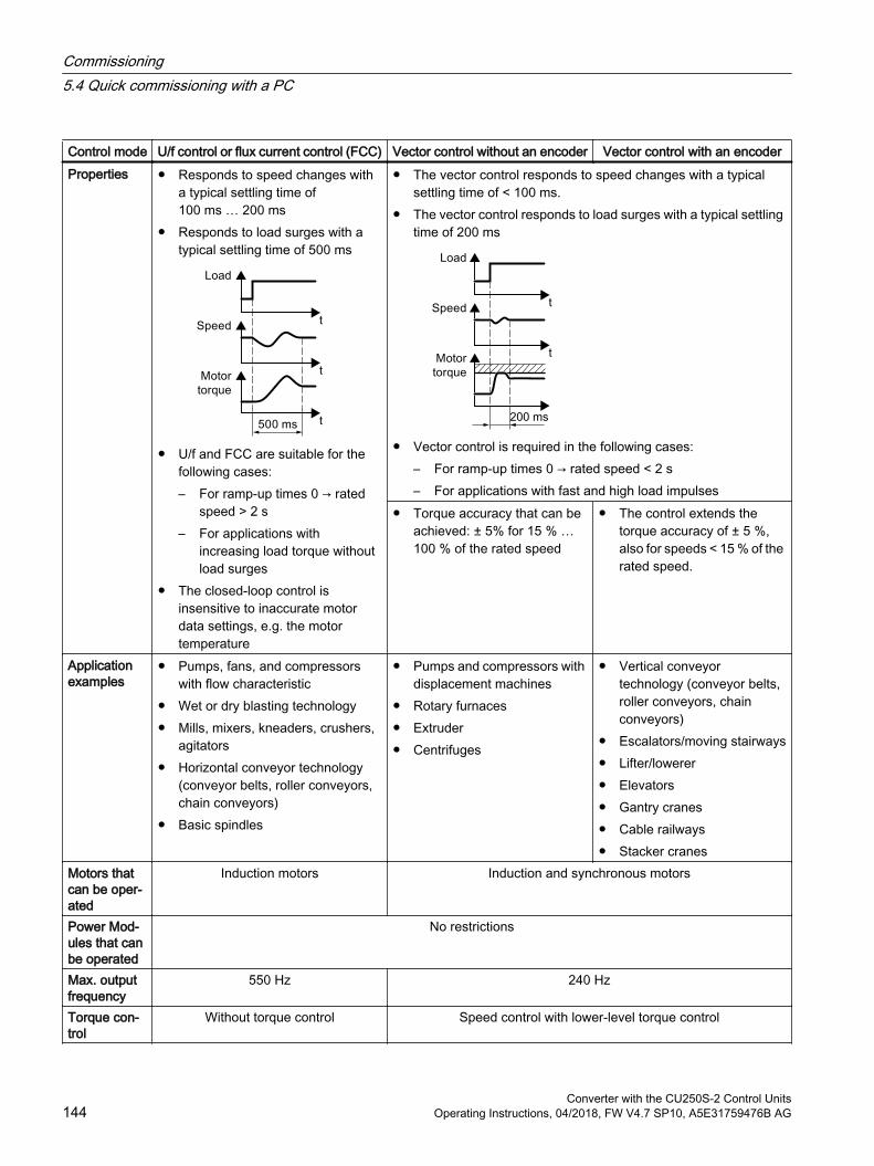
Control mode U/f control or flux current control (FCC) Vector control without an encoder Vector control with an encoderProperties Responds to speed changes with
a typical settling time of 100 ms … 200 ms
Responds to load surges with a typical settling time of 500 ms
U/f and FCC are suitable for the following cases:– For ramp-up times 0 → rated
speed > 2 s– For applications with
increasing load torque without load surges
The closed-loop control is insensitive to inaccurate motor data settings, e.g. the motor temperature
The vector control responds to speed changes with a typical settling time of < 100 ms.
The vector control responds to load surges with a typical settling time of 200 ms
Vector control is required in the following cases:– For ramp-up times 0 → rated speed < 2 s– For applications with fast and high load impulses
Torque accuracy that can be achieved: ± 5% for 15 % … 100 % of the rated speed
The control extends the torque accuracy of ± 5 %, also for speeds < 15 % of the rated speed.
Application examples
Pumps, fans, and compressors with flow characteristic
Wet or dry blasting technology Mills, mixers, kneaders, crushers,
agitators Horizontal conveyor technology
(conveyor belts, roller conveyors, chain conveyors)
Basic spindles
Pumps and compressors with displacement machines
Rotary furnaces Extruder Centrifuges
Vertical conveyor technology (conveyor belts, roller conveyors, chain conveyors)
Escalators/moving stairways Lifter/lowerer Elevators Gantry cranes Cable railways Stacker cranes
Motors that can be oper‐ated
Induction motors Induction and synchronous motors
Power Mod‐ules that can be operated
No restrictions
Max. output frequency
550 Hz 240 Hz
Torque con‐trol
Without torque control Speed control with lower-level torque control
Commissioning5.4 Quick commissioning with a PC
Converter with the CU250S-2 Control Units144 Operating Instructions, 04/2018, FW V4.7 SP10, A5E31759476B AG
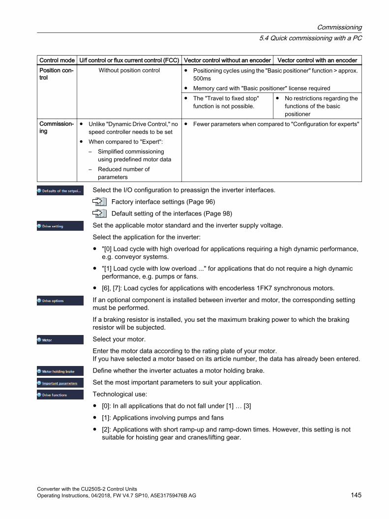
Control mode U/f control or flux current control (FCC) Vector control without an encoder Vector control with an encoderPosition con‐trol
Without position control Positioning cycles using the "Basic positioner" function > approx. 500ms
Memory card with "Basic positioner" license required The "Travel to fixed stop"
function is not possible. No restrictions regarding the
functions of the basic positioner
Commission‐ing
Unlike "Dynamic Drive Control," no speed controller needs to be set
When compared to "Expert":– Simplified commissioning
using predefined motor data– Reduced number of
parameters
Fewer parameters when compared to "Configuration for experts"
Select the I/O configuration to preassign the inverter interfaces.
Factory interface settings (Page 96)
Default setting of the interfaces (Page 98)
Set the applicable motor standard and the inverter supply voltage.
Select the application for the inverter:
"[0] Load cycle with high overload for applications requiring a high dynamic performance, e.g. conveyor systems.
"[1] Load cycle with low overload ..." for applications that do not require a high dynamic performance, e.g. pumps or fans.
[6], [7]: Load cycles for applications with encoderless 1FK7 synchronous motors.
If an optional component is installed between inverter and motor, the corresponding setting must be performed.
If a braking resistor is installed, you set the maximum braking power to which the braking resistor will be subjected.
Select your motor.
Enter the motor data according to the rating plate of your motor.If you have selected a motor based on its article number, the data has already been entered.
Define whether the inverter actuates a motor holding brake.
Set the most important parameters to suit your application.
Technological use:
[0]: In all applications that do not fall under [1] … [3]
[1]: Applications involving pumps and fans
[2]: Applications with short ramp-up and ramp-down times. However, this setting is not suitable for hoisting gear and cranes/lifting gear.
Commissioning5.4 Quick commissioning with a PC
Converter with the CU250S-2 Control UnitsOperating Instructions, 04/2018, FW V4.7 SP10, A5E31759476B AG 145

[3]: Setting only for steady-state operation with slow speed changes. We recommend setting [1] if load surges in operation cannot be ruled out.
[5]: Applications with high breakaway torque
Motor identification:
[1]: Recommended setting. Measure the motor data at standstill and with the motor rotating. The inverter switches off the motor after the motor data identification has been completed.
[2]: Measure the motor data at standstill. The inverter switches off the motor after the motor data identification has been completed.Recommended setting for the following cases:
– You have selected "Speed control" as control mode, however the motor cannot freely rotate, e.g. for mechanically limited traversing sections.
– You have set "V/f control" as control mode.
[3]: Measure the motor data while the motor is rotating. The inverter switches off the motor after the motor data identification has been completed.
[11]: The same setting as [1]. The motor accelerates to the currently set setpoint after the motor data identification.
[12]: The same setting as [2]. The motor accelerates to the currently set setpoint after the motor data identification.
Calculating the motor parameters: Select "Complete calculation".
Configuring encoders (Page 147)
Commissioning5.4 Quick commissioning with a PC
Converter with the CU250S-2 Control Units146 Operating Instructions, 04/2018, FW V4.7 SP10, A5E31759476B AG
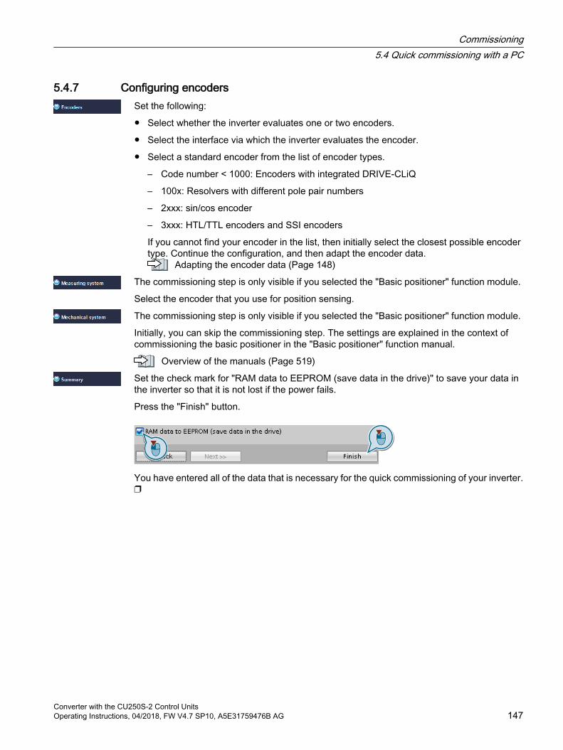
5.4.7 Configuring encodersSet the following:
Select whether the inverter evaluates one or two encoders.
Select the interface via which the inverter evaluates the encoder.
Select a standard encoder from the list of encoder types.
– Code number < 1000: Encoders with integrated DRIVE-CLiQ
– 100x: Resolvers with different pole pair numbers
– 2xxx: sin/cos encoder
– 3xxx: HTL/TTL encoders and SSI encoders
If you cannot find your encoder in the list, then initially select the closest possible encoder type. Continue the configuration, and then adapt the encoder data.
Adapting the encoder data (Page 148)
The commissioning step is only visible if you selected the "Basic positioner" function module.
Select the encoder that you use for position sensing.
The commissioning step is only visible if you selected the "Basic positioner" function module.
Initially, you can skip the commissioning step. The settings are explained in the context of commissioning the basic positioner in the "Basic positioner" function manual.
Overview of the manuals (Page 519)
Set the check mark for "RAM data to EEPROM (save data in the drive)" to save your data in the inverter so that it is not lost if the power fails.
Press the "Finish" button.
You have entered all of the data that is necessary for the quick commissioning of your inverter.
Commissioning5.4 Quick commissioning with a PC
Converter with the CU250S-2 Control UnitsOperating Instructions, 04/2018, FW V4.7 SP10, A5E31759476B AG 147
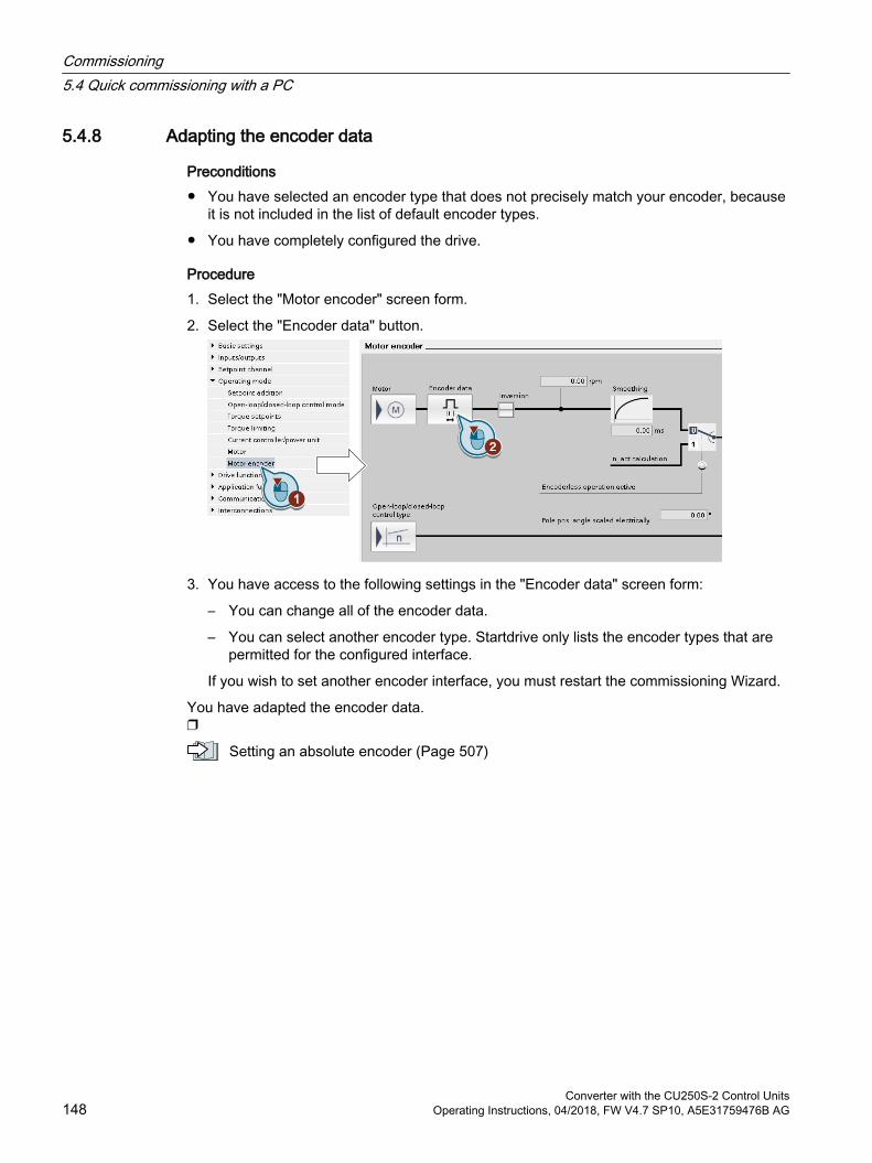
5.4.8 Adapting the encoder data
Preconditions You have selected an encoder type that does not precisely match your encoder, because
it is not included in the list of default encoder types.
You have completely configured the drive.
Procedure1. Select the "Motor encoder" screen form.
2. Select the "Encoder data" button.
3. You have access to the following settings in the "Encoder data" screen form:
– You can change all of the encoder data.
– You can select another encoder type. Startdrive only lists the encoder types that are permitted for the configured interface.
If you wish to set another encoder interface, you must restart the commissioning Wizard.
You have adapted the encoder data.
Setting an absolute encoder (Page 507)
Commissioning5.4 Quick commissioning with a PC
Converter with the CU250S-2 Control Units148 Operating Instructions, 04/2018, FW V4.7 SP10, A5E31759476B AG

5.4.9 Loading the settings into the inverter
Procedure1. Select your drive.
2. Press the "Load to device" button. .
3. In the following screen form, select "Back up parameter assignment in the EEPROM".
4. Load your settings into the inverter.
5. Wait until loading has been completed.
You have loaded your settings to the inverter.
Commissioning5.4 Quick commissioning with a PC
Converter with the CU250S-2 Control UnitsOperating Instructions, 04/2018, FW V4.7 SP10, A5E31759476B AG 149
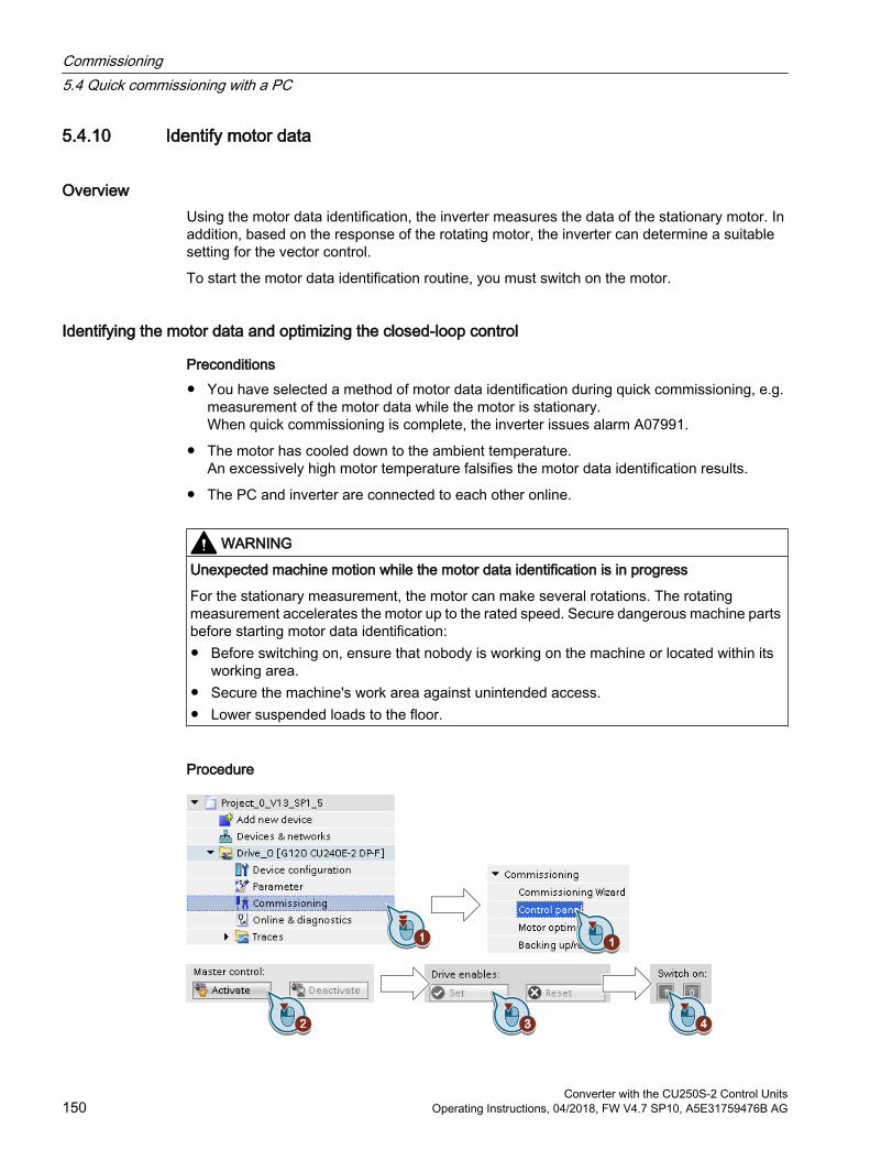
5.4.10 Identify motor data
OverviewUsing the motor data identification, the inverter measures the data of the stationary motor. In addition, based on the response of the rotating motor, the inverter can determine a suitable setting for the vector control.
To start the motor data identification routine, you must switch on the motor.
Identifying the motor data and optimizing the closed-loop control
Preconditions You have selected a method of motor data identification during quick commissioning, e.g.
measurement of the motor data while the motor is stationary.When quick commissioning is complete, the inverter issues alarm A07991.
The motor has cooled down to the ambient temperature.An excessively high motor temperature falsifies the motor data identification results.
The PC and inverter are connected to each other online.
WARNING
Unexpected machine motion while the motor data identification is in progress
For the stationary measurement, the motor can make several rotations. The rotating measurement accelerates the motor up to the rated speed. Secure dangerous machine parts before starting motor data identification: Before switching on, ensure that nobody is working on the machine or located within its
working area. Secure the machine's work area against unintended access. Lower suspended loads to the floor.
Procedure
Commissioning5.4 Quick commissioning with a PC
Converter with the CU250S-2 Control Units150 Operating Instructions, 04/2018, FW V4.7 SP10, A5E31759476B AG
1. Open the control panel.
2. Assume master control for the inverter.
3. Set the "Drive enables"
4. Switch on the motor.The inverter starts the motor data identification. This measurement can take several minutes.Depending on the setting, after motor data identification has been completed, the inverter switches off the motor - or it accelerates it to the currently set setpoint.
5. If required, switch off the motor.
6. Relinquish the master control after the motor data identification.
7. Save the settings in the inverter (RAM → EEPROM):
You have completed the motor data identification.
Self-optimization of the speed controlIf you have not only selected motor data identification with the motor stationary, but also rotating measurement with self-optimization of the speed control, you must switch on the motor again as described above and wait for the optimization run to finish.
Quick commissioning has been completed once the motor data identification has been successfully completed.
Commissioning5.4 Quick commissioning with a PC
Converter with the CU250S-2 Control UnitsOperating Instructions, 04/2018, FW V4.7 SP10, A5E31759476B AG 151
5.5 Restoring the factory setting
When must you reset the inverter to the factory settings?Reset the inverter to the factory settings in the following cases:
The line voltage was interrupted during commissioning and you were not able to complete commissioning.
You can no longer trace the settings that you made during commissioning.
You do not know whether the inverter was already operational.
Restoring the factory settings when the safety functions are enabledIf you are using the integrated safety functions of the inverter, e.g. "Safe Torque Off", you must reset the safety functions separately from the remaining inverter settings.
The settings of the safety functions are protected by a password.
Settings that are not changed when restoring the factory settingThe communication settings and the settings of the motor standard (IEC/NEMA) are kept when restoring the factory setting.
Commissioning5.5 Restoring the factory setting
Converter with the CU250S-2 Control Units152 Operating Instructions, 04/2018, FW V4.7 SP10, A5E31759476B AG
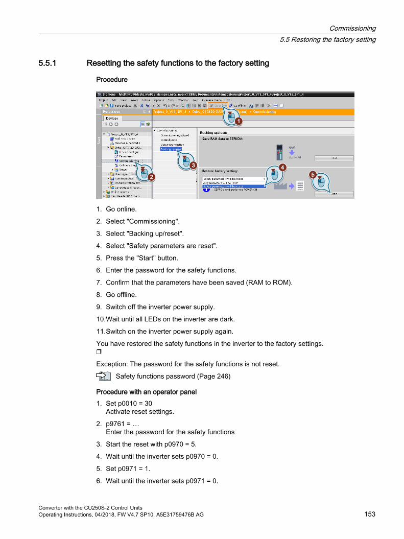
5.5.1 Resetting the safety functions to the factory setting
Procedure
1. Go online.
2. Select "Commissioning".
3. Select "Backing up/reset".
4. Select "Safety parameters are reset".
5. Press the "Start" button.
6. Enter the password for the safety functions.
7. Confirm that the parameters have been saved (RAM to ROM).
8. Go offline.
9. Switch off the inverter power supply.
10.Wait until all LEDs on the inverter are dark.
11.Switch on the inverter power supply again.
You have restored the safety functions in the inverter to the factory settings.
Exception: The password for the safety functions is not reset.
Safety functions password (Page 246)
Procedure with an operator panel1. Set p0010 = 30
Activate reset settings.
2. p9761 = …Enter the password for the safety functions
3. Start the reset with p0970 = 5.
4. Wait until the inverter sets p0970 = 0.
5. Set p0971 = 1.
6. Wait until the inverter sets p0971 = 0.
Commissioning5.5 Restoring the factory setting
Converter with the CU250S-2 Control UnitsOperating Instructions, 04/2018, FW V4.7 SP10, A5E31759476B AG 153

7. Switch off the inverter power supply.
8. Wait until all LEDs on the inverter are dark.
9. Switch on the inverter power supply again.
You have restored the safety function settings of your inverter to the factory settings.
Commissioning5.5 Restoring the factory setting
Converter with the CU250S-2 Control Units154 Operating Instructions, 04/2018, FW V4.7 SP10, A5E31759476B AG
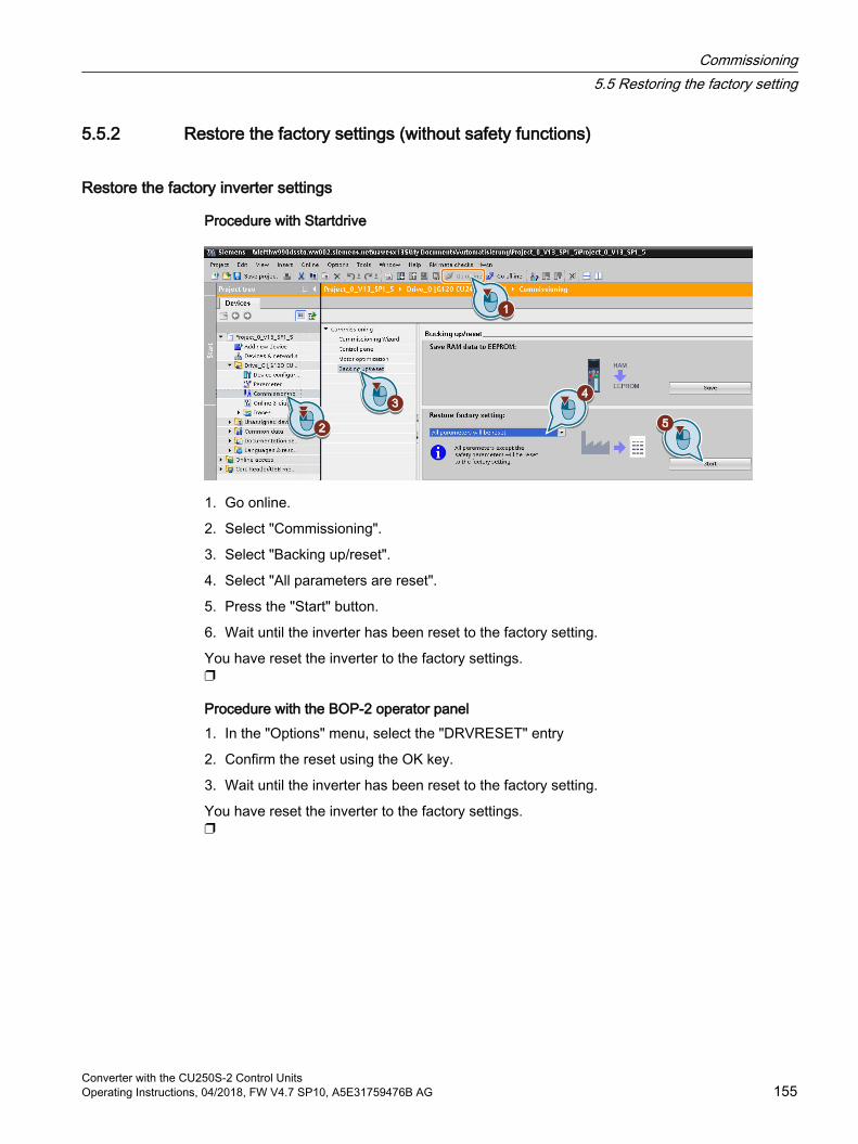
5.5.2 Restore the factory settings (without safety functions)
Restore the factory inverter settings
Procedure with Startdrive
1. Go online.
2. Select "Commissioning".
3. Select "Backing up/reset".
4. Select "All parameters are reset".
5. Press the "Start" button.
6. Wait until the inverter has been reset to the factory setting.
You have reset the inverter to the factory settings.
Procedure with the BOP-2 operator panel1. In the "Options" menu, select the "DRVRESET" entry
2. Confirm the reset using the OK key.
3. Wait until the inverter has been reset to the factory setting.
You have reset the inverter to the factory settings.
Commissioning5.5 Restoring the factory setting
Converter with the CU250S-2 Control UnitsOperating Instructions, 04/2018, FW V4.7 SP10, A5E31759476B AG 155

Commissioning5.5 Restoring the factory setting
Converter with the CU250S-2 Control Units156 Operating Instructions, 04/2018, FW V4.7 SP10, A5E31759476B AG
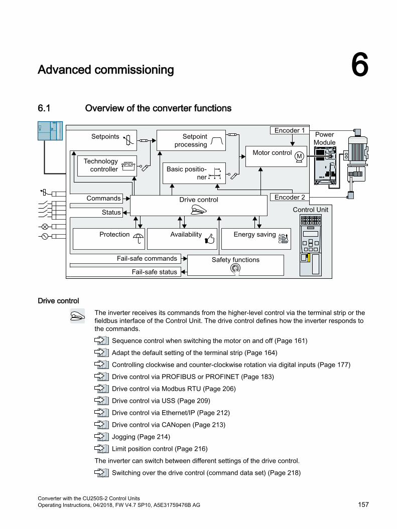
Advanced commissioning 66.1 Overview of the converter functions
Drive controlThe inverter receives its commands from the higher-level control via the terminal strip or the fieldbus interface of the Control Unit. The drive control defines how the inverter responds to the commands.
Sequence control when switching the motor on and off (Page 161)
Adapt the default setting of the terminal strip (Page 164)
Controlling clockwise and counter-clockwise rotation via digital inputs (Page 177)
Drive control via PROFIBUS or PROFINET (Page 183)
Drive control via Modbus RTU (Page 206)
Drive control via USS (Page 209)
Drive control via Ethernet/IP (Page 212)
Drive control via CANopen (Page 213)
Jogging (Page 214)
Limit position control (Page 216)
The inverter can switch between different settings of the drive control.
Switching over the drive control (command data set) (Page 218)
Converter with the CU250S-2 Control UnitsOperating Instructions, 04/2018, FW V4.7 SP10, A5E31759476B AG 157
The inverter provides a motor holding brake control. The motor holding brake holds the motor in position when it is switched off.
Motor holding brake (Page 220)
The free function blocks permit configurable signal processing within the inverter.
Free function blocks (Page 224)
You can select in which physical units the inverter represents its associated values.
Selecting physical units (Page 238)
You can activate additional monitoring functions in the inverter.
Extended messages (Page 242)
Safety functionsThe safety functions fulfill increased requirements regarding the functional safety of the drive.
Safe Torque Off (STO) safety function (Page 244)
The extended safety functions monitor the drive speed. You require a license to operate the inverter with the extended safety functions.
Activating licensed functions (Page 492)
The extended safety functions are described in the "Safety Integrated" function manual.
Overview of the manuals (Page 519)
Setpoints and setpoint conditioningThe setpoint generally determines the motor speed.
Setpoints (Page 258)
The setpoint processing uses a ramp-function generator to prevent speed steps occurring and to limit the speed to a permissible maximum value.
Setpoint calculation (Page 273)
Technology controllerThe technology controller controls process variables, e.g. pressure, temperature, level or flow. The motor closed-loop control either receives its setpoint from the higher-level control - or from the technology controller.
PID technology controller (Page 283)
Basic positionerThe basic positioner traverses an axis with position control to a target position.
You require a license to use the basic positioner.
Activating licensed functions (Page 492)
The basic positioner is described in the "Basic positioner" function manual.
Advanced commissioning6.1 Overview of the converter functions
Converter with the CU250S-2 Control Units158 Operating Instructions, 04/2018, FW V4.7 SP10, A5E31759476B AG
Overview of the manuals (Page 519)
Motor controlThe motor closed-loop control ensures that the motor follows the speed setpoint. You can choose between various control modes.
Motor control (Page 288)
The inverter has various methods to electrically brake the motor. When electrically braking, the motor develops a torque, which reduces the speed down to standstill.
Electrically braking the motor (Page 316)
Protection of the drive and the driven loadThe protection functions prevent damage to the motor, inverter and driven load.
Overcurrent protection (Page 326)
Inverter protection using temperature monitoring (Page 327)
Motor protection with temperature sensor (Page 330)
Motor protection by calculating the temperature (Page 333)
Motor and inverter protection by limiting the voltage (Page 335)
The monitoring of the driven load prevents impermissible operating modes, e.g. dry-running of a pump.
Monitoring the driven load (Page 337)
Increasing the drive availabilityThe kinetic buffering converts the kinetic energy of the load into electrical energy to buffer short-term power failures.
Kinetic buffering (Vdc min control) (Page 350)
The "Flying restart" function permits the fault-free switching on of the motor while it is still turning.
Flying restart – switching on while the motor is running (Page 344)
For active automatic restart, after a power failure, the inverter attempts to automatically restart the motor and to acknowledge any faults that occur.
Automatic restart (Page 346)
Energy savingFor standard induction motors, the efficiency optimization reduces the motor losses in the partial load range.
Efficiency optimization (Page 352)
If necessary, the main contactor control disconnects the inverter from the power system and so reduces the inverter losses.
Advanced commissioning6.1 Overview of the converter functions
Converter with the CU250S-2 Control UnitsOperating Instructions, 04/2018, FW V4.7 SP10, A5E31759476B AG 159

Line contactor control (Page 355)
The inverter calculates how much energy controlled inverter operation saves when compared to mechanical flow control (e.g. throttle).
Calculating the energy saving for fluid flow machines (Page 357)
Advanced commissioning6.1 Overview of the converter functions
Converter with the CU250S-2 Control Units160 Operating Instructions, 04/2018, FW V4.7 SP10, A5E31759476B AG
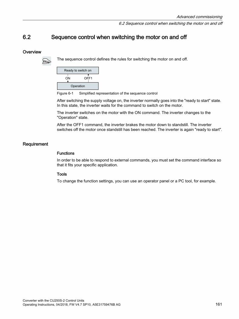
6.2 Sequence control when switching the motor on and off
OverviewThe sequence control defines the rules for switching the motor on and off.
Figure 6-1 Simplified representation of the sequence control
After switching the supply voltage on, the inverter normally goes into the "ready to start" state. In this state, the inverter waits for the command to switch on the motor.
The inverter switches on the motor with the ON command. The inverter changes to the "Operation" state.
After the OFF1 command, the inverter brakes the motor down to standstill. The inverter switches off the motor once standstill has been reached. The inverter is again "ready to start".
Requirement
FunctionsIn order to be able to respond to external commands, you must set the command interface so that it fits your specific application.
ToolsTo change the function settings, you can use an operator panel or a PC tool, for example.
Advanced commissioning6.2 Sequence control when switching the motor on and off
Converter with the CU250S-2 Control UnitsOperating Instructions, 04/2018, FW V4.7 SP10, A5E31759476B AG 161
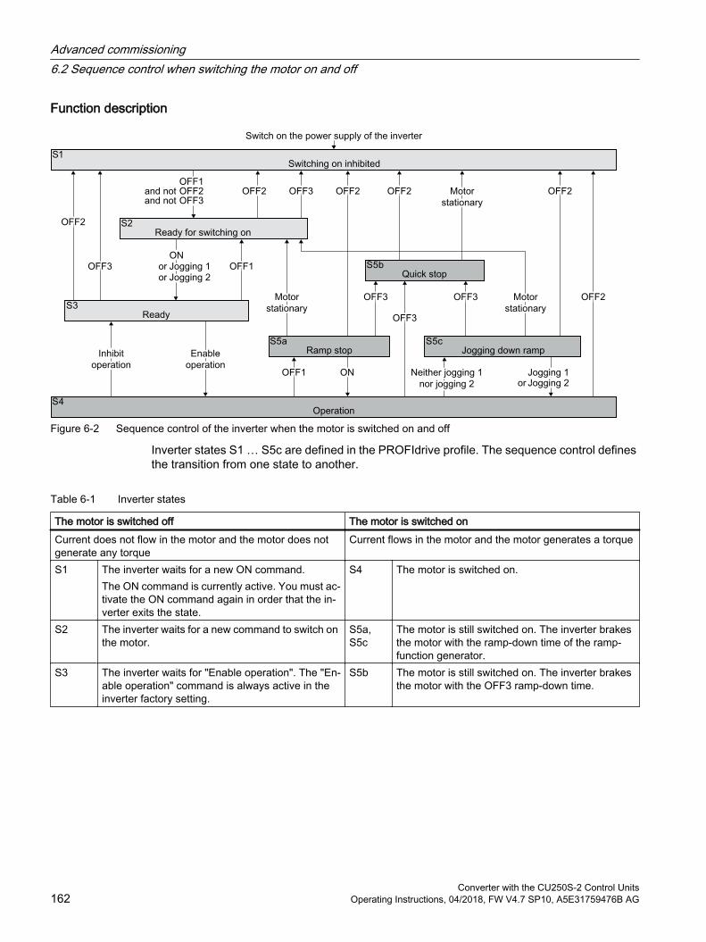
Function description
Figure 6-2 Sequence control of the inverter when the motor is switched on and off
Inverter states S1 … S5c are defined in the PROFIdrive profile. The sequence control defines the transition from one state to another.
Table 6-1 Inverter states
The motor is switched off The motor is switched onCurrent does not flow in the motor and the motor does not generate any torque
Current flows in the motor and the motor generates a torque
S1 The inverter waits for a new ON command.The ON command is currently active. You must ac‐tivate the ON command again in order that the in‐verter exits the state.
S4 The motor is switched on.
S2 The inverter waits for a new command to switch on the motor.
S5a, S5c
The motor is still switched on. The inverter brakes the motor with the ramp-down time of the ramp-function generator.
S3 The inverter waits for "Enable operation". The "En‐able operation" command is always active in the inverter factory setting.
S5b The motor is still switched on. The inverter brakes the motor with the OFF3 ramp-down time.
Advanced commissioning6.2 Sequence control when switching the motor on and off
Converter with the CU250S-2 Control Units162 Operating Instructions, 04/2018, FW V4.7 SP10, A5E31759476B AG
Table 6-2 Commands for switching the motor on and off
ONJogging 1Jogging 2Enable operation
The inverter switches the motor on.
OFF1, OFF3 The inverter brakes the motor. The inverter switches off the motor once it comes to a standstill.The motor is considered to be stationary if the speed is less than a defined minimum speed.
OFF2Inhibit operation
The inverter switches off the motor immediately without first braking it.
Parameter
Parameter Description Settingp1226 Standstill detection, speed
threshold [rpm]Factory setting: 20.00 rpm
The inverter identifies that the motor is at a standstill after OFF1 or OFF3 when at least one of the following conditions has been satisfied: The speed actual value falls below the
threshold in p1226 and the time started in p1228 has expired.
The speed setpoint falls below the threshold in p1226, and the time subsequently started in p1227 has expired.
p1227 Standstill detection monitor‐ing time [s]
Factory setting: 300.00 s
p1228 Pulse cancellation delay time [s]
Factory setting: 0.01 s
Further informationYou will find additional information in function diagram 2610 of the List Manual.
Advanced commissioning6.2 Sequence control when switching the motor on and off
Converter with the CU250S-2 Control UnitsOperating Instructions, 04/2018, FW V4.7 SP10, A5E31759476B AG 163
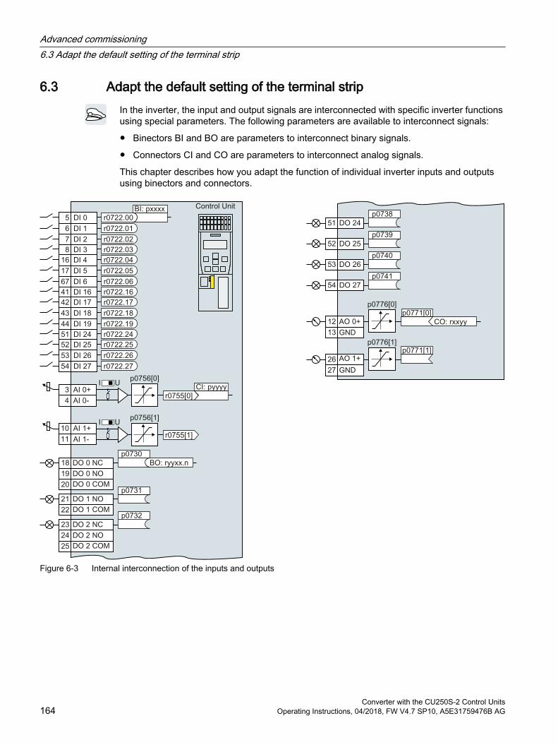
6.3 Adapt the default setting of the terminal stripIn the inverter, the input and output signals are interconnected with specific inverter functions using special parameters. The following parameters are available to interconnect signals:
Binectors BI and BO are parameters to interconnect binary signals.
Connectors CI and CO are parameters to interconnect analog signals.
This chapter describes how you adapt the function of individual inverter inputs and outputs using binectors and connectors.
Figure 6-3 Internal interconnection of the inputs and outputs
Advanced commissioning6.3 Adapt the default setting of the terminal strip
Converter with the CU250S-2 Control Units164 Operating Instructions, 04/2018, FW V4.7 SP10, A5E31759476B AG
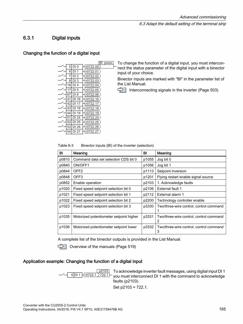
6.3.1 Digital inputs
Changing the function of a digital input
To change the function of a digital input, you must intercon‐nect the status parameter of the digital input with a binector input of your choice.Binector inputs are marked with "BI" in the parameter list of the List Manual.
Interconnecting signals in the inverter (Page 503)
Table 6-3 Binector inputs (BI) of the inverter (selection)
BI Meaning BI Meaningp0810 Command data set selection CDS bit 0 p1055 Jog bit 0p0840 ON/OFF1 p1056 Jog bit 1p0844 OFF2 p1113 Setpoint inversionp0848 OFF3 p1201 Flying restart enable signal sourcep0852 Enable operation p2103 1. Acknowledge faultsp1020 Fixed speed setpoint selection bit 0 p2106 External fault 1p1021 Fixed speed setpoint selection bit 1 p2112 External alarm 1p1022 Fixed speed setpoint selection bit 2 p2200 Technology controller enablep1023 Fixed speed setpoint selection bit 3 p3330 Two/three-wire control, control command
1p1035 Motorized potentiometer setpoint higher p3331 Two/three-wire control, control command
2p1036 Motorized potentiometer setpoint lower p3332 Two/three-wire control, control command
3
A complete list of the binector outputs is provided in the List Manual.
Overview of the manuals (Page 519)
Application example: Changing the function of a digital input
To acknowledge inverter fault messages, using digital input DI 1 you must interconnect DI 1 with the command to acknowledge faults (p2103).Set p2103 = 722.1.
Advanced commissioning6.3 Adapt the default setting of the terminal strip
Converter with the CU250S-2 Control UnitsOperating Instructions, 04/2018, FW V4.7 SP10, A5E31759476B AG 165
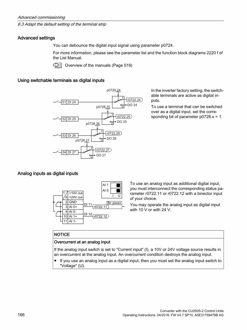
Advanced settingsYou can debounce the digital input signal using parameter p0724.
For more information, please see the parameter list and the function block diagrams 2220 f of the List Manual.
Overview of the manuals (Page 519)
Using switchable terminals as digital inputs
In the inverter factory setting, the switch‐able terminals are active as digital in‐puts.To use a terminal that can be switched over as a digital input, set the corre‐sponding bit of parameter p0728.x = 1.
Analog inputs as digital inputs
To use an analog input as additional digital input, you must interconnect the corresponding status pa‐rameter r0722.11 or r0722.12 with a binector input of your choice.You may operate the analog input as digital input with 10 V or with 24 V.
NOTICE
Overcurrent at an analog input
If the analog input switch is set to "Current input" (I), a 10V or 24V voltage source results in an overcurrent at the analog input. An overcurrent condition destroys the analog input. If you use an analog input as a digital input, then you must set the analog input switch to
"Voltage" (U).
Advanced commissioning6.3 Adapt the default setting of the terminal strip
Converter with the CU250S-2 Control Units166 Operating Instructions, 04/2018, FW V4.7 SP10, A5E31759476B AG

Defining a fail-safe digital inputTo enable a safety function via the terminal strip of the inverter, you need a fail-safe digital input.
The inverter combines two digital inputs into one fail-safe digital input.
Additional information on fail-safe digital inputs can be obtained in the description of the STO safety function.
Safe Torque Off (STO) safety function (Page 244)
Advanced commissioning6.3 Adapt the default setting of the terminal strip
Converter with the CU250S-2 Control UnitsOperating Instructions, 04/2018, FW V4.7 SP10, A5E31759476B AG 167
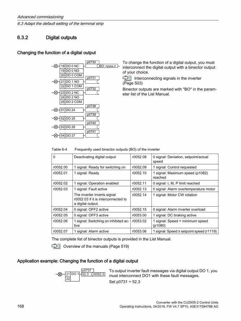
6.3.2 Digital outputs
Changing the function of a digital output
To change the function of a digital output, you must interconnect the digital output with a binector output of your choice.
Interconnecting signals in the inverter (Page 503)Binector outputs are marked with "BO" in the param‐eter list of the List Manual.
Table 6-4 Frequently used binector outputs (BO) of the inverter
0 Deactivating digital output r0052.08 0 signal: Deviation, setpoint/actual speed
r0052.00 1 signal: Ready for switching on r0052.09 1 signal: Control requestedr0052.01 1 signal: Ready r0052.10 1 signal: Maximum speed (p1082)
reachedr0052.02 1 signal: Operation enabled r0052.11 0 signal: I, M, P limit reachedr0052.03 1 signal: Fault active
The inverter inverts signal r0052.03 if it is interconnected to a digital output.
r0052.13 0 signal: Alarm overtemperature motorr0052.14 1 signal: Motor CW rotation
r0052.04 0 signal: OFF2 active r0052.15 0 signal: Alarm inverter overloadr0052.05 0 signal: OFF3 active r0053.00 1 signal: DC braking activer0052.06 1 signal: Switching on inhibited ac‐
tiver0053.02 1 signal: Speed > minimum speed
(p1080)r0052.07 1 signal: Alarm active r0053.06 1 signal: Speed ≥ setpoint speed (r1119)
The complete list of binector outputs is provided in the List Manual.
Overview of the manuals (Page 519)
Application example: Changing the function of a digital output
To output inverter fault messages via digital output DO 1, you must interconnect DO1 with these fault messages.Set p0731 = 52.3
Advanced commissioning6.3 Adapt the default setting of the terminal strip
Converter with the CU250S-2 Control Units168 Operating Instructions, 04/2018, FW V4.7 SP10, A5E31759476B AG
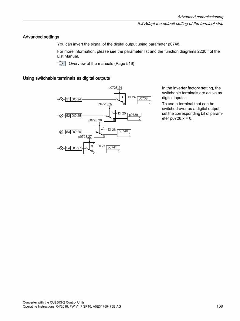
Advanced settingsYou can invert the signal of the digital output using parameter p0748.
For more information, please see the parameter list and the function diagrams 2230 f of the List Manual.
Overview of the manuals (Page 519)
Using switchable terminals as digital outputs
In the inverter factory setting, the switchable terminals are active as digital inputs.To use a terminal that can be switched over as a digital output, set the corresponding bit of param‐eter p0728.x = 0.
Advanced commissioning6.3 Adapt the default setting of the terminal strip
Converter with the CU250S-2 Control UnitsOperating Instructions, 04/2018, FW V4.7 SP10, A5E31759476B AG 169
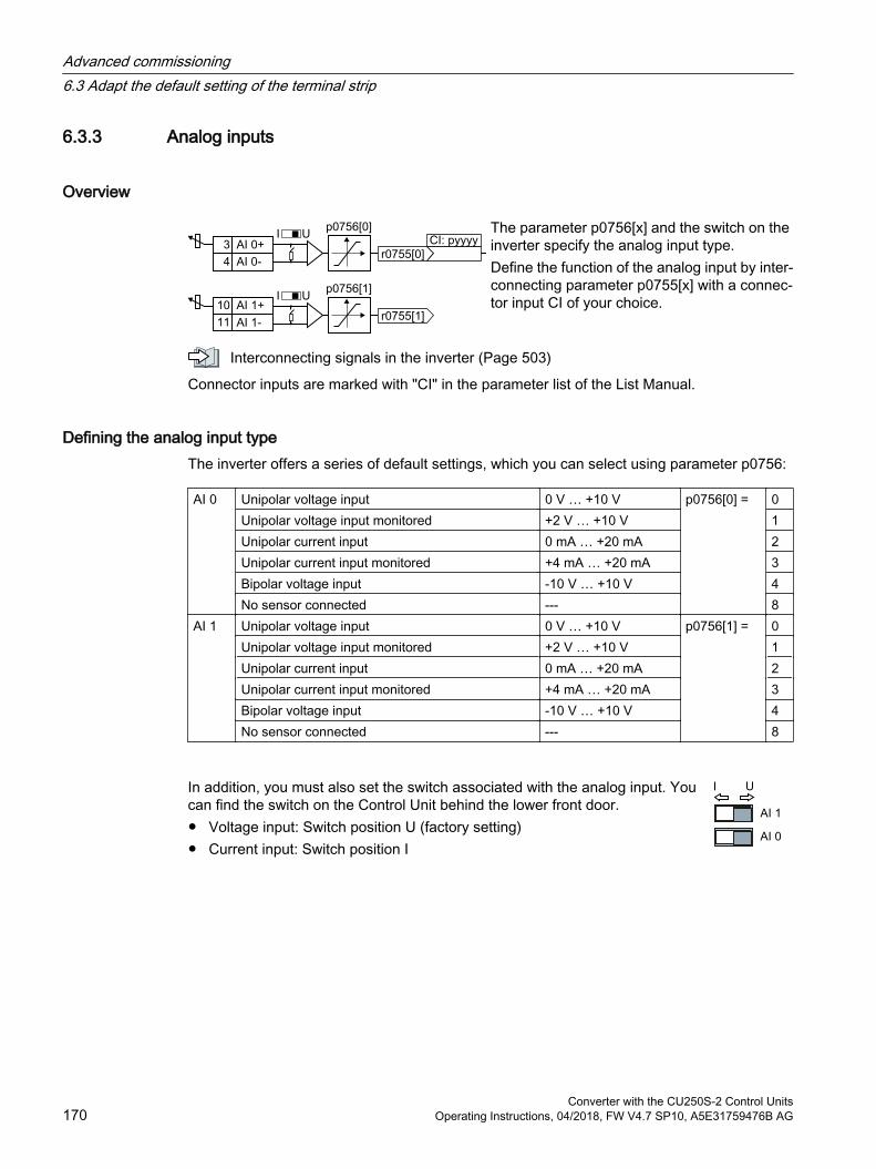
6.3.3 Analog inputs
Overview
The parameter p0756[x] and the switch on the inverter specify the analog input type.Define the function of the analog input by inter‐connecting parameter p0755[x] with a connec‐tor input CI of your choice.
Interconnecting signals in the inverter (Page 503)
Connector inputs are marked with "CI" in the parameter list of the List Manual.
Defining the analog input typeThe inverter offers a series of default settings, which you can select using parameter p0756:
AI 0 Unipolar voltage input 0 V … +10 V p0756[0] = 0Unipolar voltage input monitored +2 V … +10 V 1Unipolar current input 0 mA … +20 mA 2Unipolar current input monitored +4 mA … +20 mA 3Bipolar voltage input ‑10 V … +10 V 4No sensor connected --- 8
AI 1 Unipolar voltage input 0 V … +10 V p0756[1] = 0Unipolar voltage input monitored +2 V … +10 V 1Unipolar current input 0 mA … +20 mA 2Unipolar current input monitored +4 mA … +20 mA 3Bipolar voltage input ‑10 V … +10 V 4No sensor connected --- 8
In addition, you must also set the switch associated with the analog input. You can find the switch on the Control Unit behind the lower front door. Voltage input: Switch position U (factory setting) Current input: Switch position I
Advanced commissioning6.3 Adapt the default setting of the terminal strip
Converter with the CU250S-2 Control Units170 Operating Instructions, 04/2018, FW V4.7 SP10, A5E31759476B AG
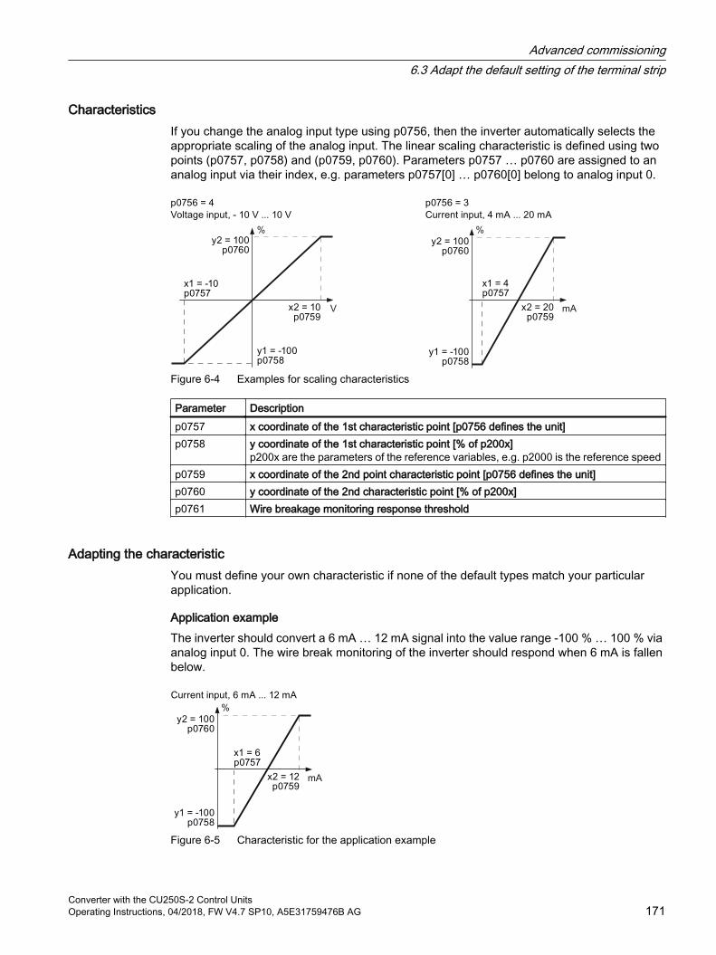
CharacteristicsIf you change the analog input type using p0756, then the inverter automatically selects the appropriate scaling of the analog input. The linear scaling characteristic is defined using two points (p0757, p0758) and (p0759, p0760). Parameters p0757 … p0760 are assigned to an analog input via their index, e.g. parameters p0757[0] … p0760[0] belong to analog input 0.
Figure 6-4 Examples for scaling characteristics
Parameter Description p0757 x coordinate of the 1st characteristic point [p0756 defines the unit] p0758 y coordinate of the 1st characteristic point [% of p200x]
p200x are the parameters of the reference variables, e.g. p2000 is the reference speedp0759 x coordinate of the 2nd point characteristic point [p0756 defines the unit]p0760 y coordinate of the 2nd characteristic point [% of p200x]p0761 Wire breakage monitoring response threshold
Adapting the characteristicYou must define your own characteristic if none of the default types match your particular application.
Application exampleThe inverter should convert a 6 mA … 12 mA signal into the value range ‑100 % … 100 % via analog input 0. The wire break monitoring of the inverter should respond when 6 mA is fallen below.
Figure 6-5 Characteristic for the application example
Advanced commissioning6.3 Adapt the default setting of the terminal strip
Converter with the CU250S-2 Control UnitsOperating Instructions, 04/2018, FW V4.7 SP10, A5E31759476B AG 171
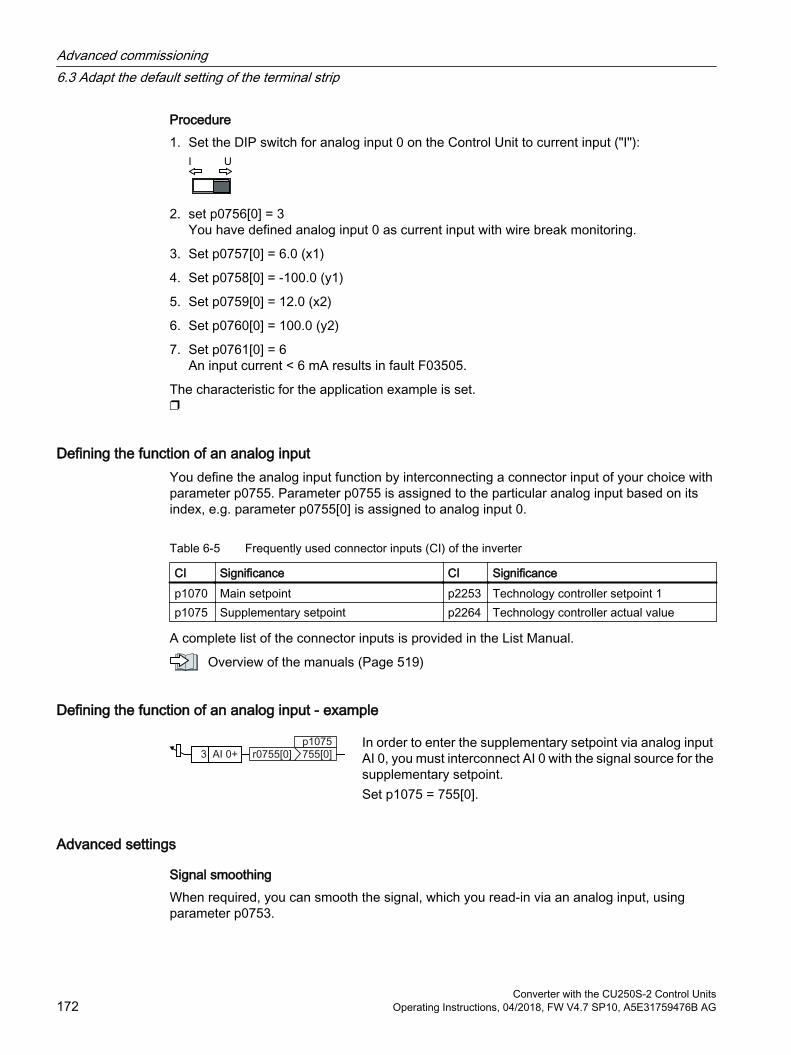
Procedure1. Set the DIP switch for analog input 0 on the Control Unit to current input ("I"):
2. set p0756[0] = 3You have defined analog input 0 as current input with wire break monitoring.
3. Set p0757[0] = 6.0 (x1)
4. Set p0758[0] = -100.0 (y1)
5. Set p0759[0] = 12.0 (x2)
6. Set p0760[0] = 100.0 (y2)
7. Set p0761[0] = 6An input current < 6 mA results in fault F03505.
The characteristic for the application example is set.
Defining the function of an analog inputYou define the analog input function by interconnecting a connector input of your choice with parameter p0755. Parameter p0755 is assigned to the particular analog input based on its index, e.g. parameter p0755[0] is assigned to analog input 0.
Table 6-5 Frequently used connector inputs (CI) of the inverter
CI Significance CI Significancep1070 Main setpoint p2253 Technology controller setpoint 1p1075 Supplementary setpoint p2264 Technology controller actual value
A complete list of the connector inputs is provided in the List Manual.
Overview of the manuals (Page 519)
Defining the function of an analog input - example
In order to enter the supplementary setpoint via analog input AI 0, you must interconnect AI 0 with the signal source for the supplementary setpoint.Set p1075 = 755[0].
Advanced settings
Signal smoothingWhen required, you can smooth the signal, which you read-in via an analog input, using parameter p0753.
Advanced commissioning6.3 Adapt the default setting of the terminal strip
Converter with the CU250S-2 Control Units172 Operating Instructions, 04/2018, FW V4.7 SP10, A5E31759476B AG
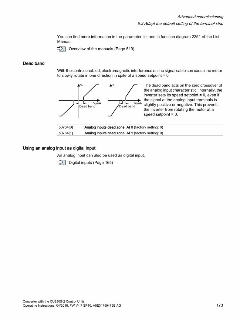
You can find more information in the parameter list and in function diagram 2251 of the List Manual.
Overview of the manuals (Page 519)
Dead bandWith the control enabled, electromagnetic interference on the signal cable can cause the motor to slowly rotate in one direction in spite of a speed setpoint = 0.
The dead band acts on the zero crossover of the analog input characteristic. Internally, the inverter sets its speed setpoint = 0, even if the signal at the analog input terminals is slightly positive or negative. This prevents the inverter from rotating the motor at a speed setpoint = 0.
p0764[0] Analog inputs dead zone, AI 0 (factory setting: 0)p0764[1] Analog inputs dead zone, AI 1 (factory setting: 0)
Using an analog input as digital inputAn analog input can also be used as digital input.
Digital inputs (Page 165)
Advanced commissioning6.3 Adapt the default setting of the terminal strip
Converter with the CU250S-2 Control UnitsOperating Instructions, 04/2018, FW V4.7 SP10, A5E31759476B AG 173
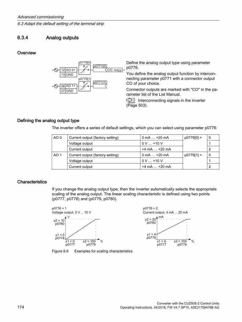
6.3.4 Analog outputs
Overview
Define the analog output type using parameter p0776.You define the analog output function by intercon‐necting parameter p0771 with a connector output CO of your choice.Connector outputs are marked with "CO" in the pa‐rameter list of the List Manual.
Interconnecting signals in the inverter (Page 503).
Defining the analog output typeThe inverter offers a series of default settings, which you can select using parameter p0776:
AO 0 Current output (factory setting) 0 mA … +20 mA p0776[0] = 0Voltage output 0 V … +10 V 1Current output +4 mA … +20 mA 2
AO 1 Current output (factory setting) 0 mA … +20 mA p0776[1] = 0Voltage output 0 V … +10 V 1Current output +4 mA … +20 mA 2
CharacteristicsIf you change the analog output type, then the inverter automatically selects the appropriate scaling of the analog output. The linear scaling characteristic is defined using two points (p0777, p0778) and (p0779, p0780).
Figure 6-6 Examples for scaling characteristics
Advanced commissioning6.3 Adapt the default setting of the terminal strip
Converter with the CU250S-2 Control Units174 Operating Instructions, 04/2018, FW V4.7 SP10, A5E31759476B AG

Parameters p0777 … p0780 are assigned to an analog output via their index, e.g. parameters p0777[0] … p0770[0] belong to analog output 0.
Table 6-6 Parameters for the scaling characteristic
Parameter Description p0777 x coordinate of the 1st characteristic point [% of p200x]
p200x are the parameters of the reference variables, e.g. p2000 is the reference speed.p0778 y coordinate of the 1st characteristic point [V or mA]p0779 x coordinate of the 2nd characteristic point [% of p200x]p0780 y coordinate of the 2nd characteristic point [V or mA]
Setting the characteristicYou must define your own characteristic if none of the default types match your particular application.
Application exampleVia analog output 0, the inverter should convert a signal in the value range 0 % … 100 % into an output signal 6 mA … 12 mA.
Figure 6-7 Characteristics for the application example
Procedure1. Set p0776[0] = 2
This defines analog output 0 as a current output.
2. Set p0777[0] = 0.0 (x1)
3. Set p0778[0] = 6.0 (y1)
4. Set p0779[0] = 100.0 (x2)
5. Set p0780[0] = 12.0 (y2)
The characteristic for the application example is set.
Advanced commissioning6.3 Adapt the default setting of the terminal strip
Converter with the CU250S-2 Control UnitsOperating Instructions, 04/2018, FW V4.7 SP10, A5E31759476B AG 175
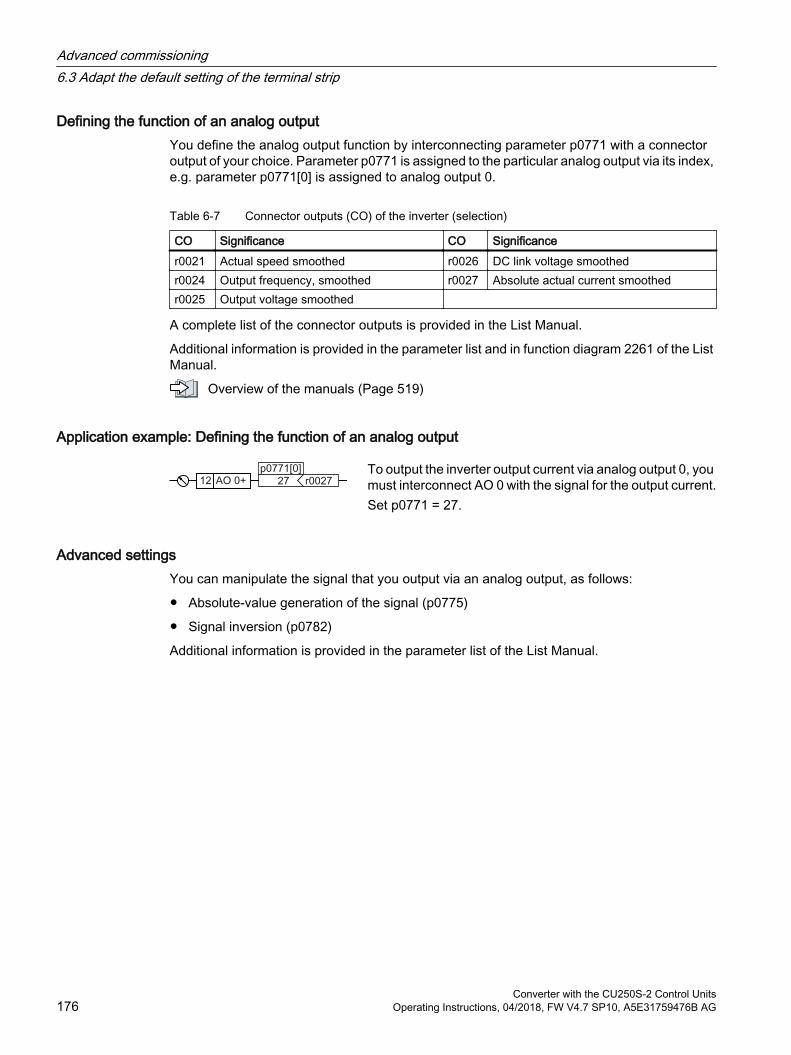
Defining the function of an analog outputYou define the analog output function by interconnecting parameter p0771 with a connector output of your choice. Parameter p0771 is assigned to the particular analog output via its index, e.g. parameter p0771[0] is assigned to analog output 0.
Table 6-7 Connector outputs (CO) of the inverter (selection)
CO Significance CO Significancer0021 Actual speed smoothed r0026 DC link voltage smoothedr0024 Output frequency, smoothed r0027 Absolute actual current smoothedr0025 Output voltage smoothed
A complete list of the connector outputs is provided in the List Manual.
Additional information is provided in the parameter list and in function diagram 2261 of the List Manual.
Overview of the manuals (Page 519)
Application example: Defining the function of an analog output
To output the inverter output current via analog output 0, you must interconnect AO 0 with the signal for the output current.Set p0771 = 27.
Advanced settingsYou can manipulate the signal that you output via an analog output, as follows:
Absolute-value generation of the signal (p0775)
Signal inversion (p0782)
Additional information is provided in the parameter list of the List Manual.
Advanced commissioning6.3 Adapt the default setting of the terminal strip
Converter with the CU250S-2 Control Units176 Operating Instructions, 04/2018, FW V4.7 SP10, A5E31759476B AG
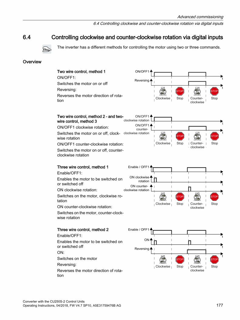
6.4 Controlling clockwise and counter-clockwise rotation via digital inputsThe inverter has a different methods for controlling the motor using two or three commands.
Overview
Two wire control, method 1ON/OFF1:Switches the motor on or offReversing:Reverses the motor direction of rota‐tion
Two wire control, method 2 - and two-wire control, method 3ON/OFF1 clockwise rotation:Switches the motor on or off, clock‐wise rotationON/OFF1 counter-clockwise rotation:Switches the motor on or off, counter-clockwise rotation Three wire control, method 1Enable/OFF1:Enables the motor to be switched on or switched offON clockwise rotation:Switches on the motor, clockwise ro‐tationON counter-clockwise rotation:Switches on the motor, counter-clock‐wise rotation Three wire control, method 2Enable/OFF1:Enables the motor to be switched on or switched offON:Switches on the motorReversing:Reverses the motor direction of rota‐tion
Advanced commissioning6.4 Controlling clockwise and counter-clockwise rotation via digital inputs
Converter with the CU250S-2 Control UnitsOperating Instructions, 04/2018, FW V4.7 SP10, A5E31759476B AG 177
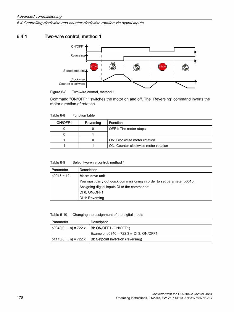
6.4.1 Two-wire control, method 1
Figure 6-8 Two-wire control, method 1
Command "ON/OFF1" switches the motor on and off. The "Reversing" command inverts the motor direction of rotation.
Table 6-8 Function table
ON/OFF1 Reversing Function0 0 OFF1: The motor stops0 11 0 ON: Clockwise motor rotation1 1 ON: Counter-clockwise motor rotation
Table 6-9 Select two-wire control, method 1
Parameter Descriptionp0015 = 12 Macro drive unit
You must carry out quick commissioning in order to set parameter p0015.Assigning digital inputs DI to the commands:DI 0: ON/OFF1DI 1: Reversing
Table 6-10 Changing the assignment of the digital inputs
Parameter Descriptionp0840[0 … n] = 722.x BI: ON/OFF1 (ON/OFF1)
Example: p0840 = 722.3 ⇒ DI 3: ON/OFF1p1113[0 … n] = 722.x BI: Setpoint inversion (reversing)
Advanced commissioning6.4 Controlling clockwise and counter-clockwise rotation via digital inputs
Converter with the CU250S-2 Control Units178 Operating Instructions, 04/2018, FW V4.7 SP10, A5E31759476B AG

6.4.2 Two-wire control, method 2
Figure 6-9 Two-wire control, method 2
Commands "ON/OFF1 clockwise rotation" and "ON/OFF1 counter-clockwise rotation" switch on the motor - and simultaneously select a direction of rotation. The inverter only accepts a new command when the motor is at a standstill.
Table 6-11 Function table
ON/OFF1 clockwise rota‐tion
ON/OFF1 counter-clock‐wise rotation
Function
0 0 OFF1: The motor stops.1 0 ON: Clockwise motor rotation.0 1 ON: Counter-clockwise motor rotation.1 1 ON: The motor direction of rotation is defined
by the command that first reaches state "1".
Table 6-12 Select two-wire control, method 2
Parameter Descriptionp0015 = 17 Macro drive unit
You must carry out quick commissioning in order to set parameter p0015.Assigning digital inputs DI to the commands:DI 0: ON/OFF1 clockwise rotationDI 1: ON/OFF1 counter-clockwise rotation
Table 6-13 Changing the assignment of the digital inputs
Parameter Descriptionp3330[0 … n] = 722.x BI: 2/3 wire control command 1 (ON/OFF1 clockwise rotation)p3331[0 … n] = 722.x BI: 2/3 wire control command 2 (ON/OFF1 counter-clockwise rotation)
Example: p3331 = 722.0 ⇒ DI 0: ON/OFF1 counter-clockwise rotation
Advanced commissioning6.4 Controlling clockwise and counter-clockwise rotation via digital inputs
Converter with the CU250S-2 Control UnitsOperating Instructions, 04/2018, FW V4.7 SP10, A5E31759476B AG 179
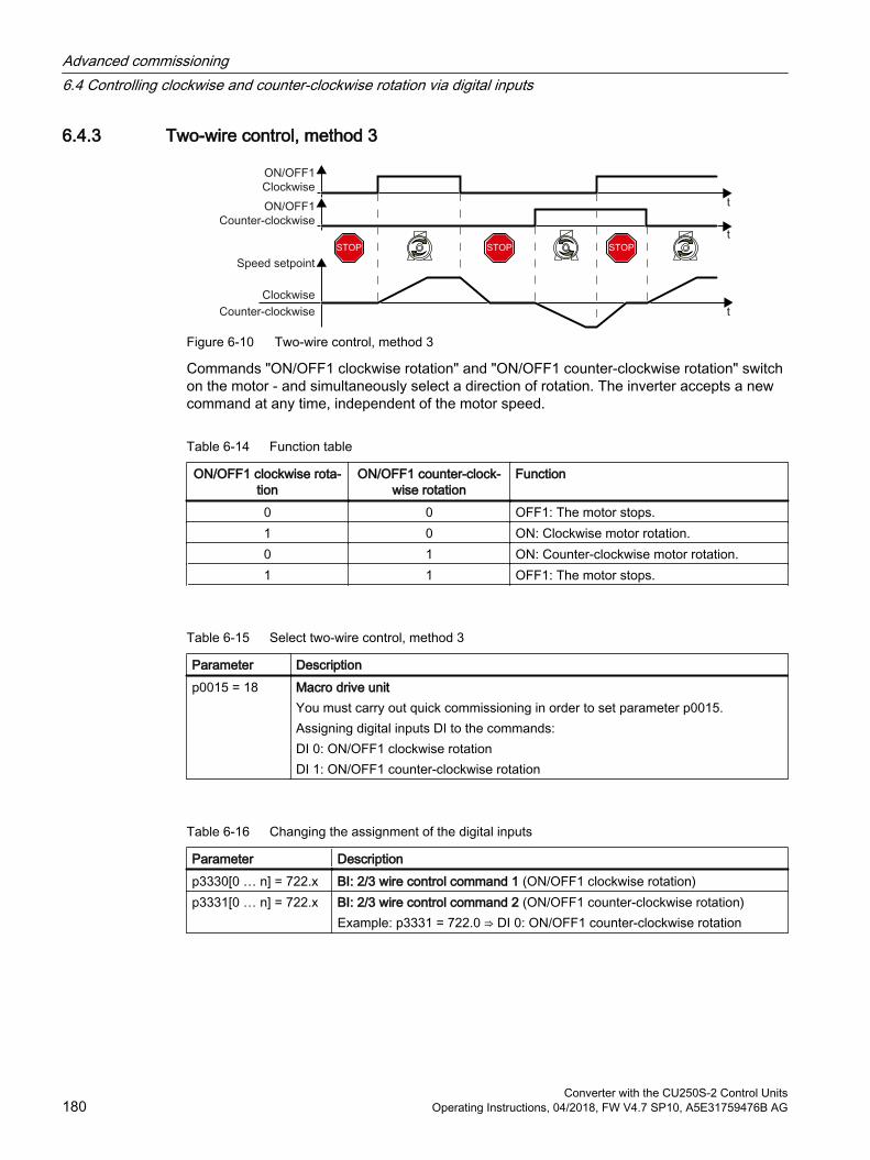
6.4.3 Two-wire control, method 3
Figure 6-10 Two-wire control, method 3
Commands "ON/OFF1 clockwise rotation" and "ON/OFF1 counter-clockwise rotation" switch on the motor - and simultaneously select a direction of rotation. The inverter accepts a new command at any time, independent of the motor speed.
Table 6-14 Function table
ON/OFF1 clockwise rota‐tion
ON/OFF1 counter-clock‐wise rotation
Function
0 0 OFF1: The motor stops.1 0 ON: Clockwise motor rotation.0 1 ON: Counter-clockwise motor rotation.1 1 OFF1: The motor stops.
Table 6-15 Select two-wire control, method 3
Parameter Descriptionp0015 = 18 Macro drive unit
You must carry out quick commissioning in order to set parameter p0015.Assigning digital inputs DI to the commands:DI 0: ON/OFF1 clockwise rotationDI 1: ON/OFF1 counter-clockwise rotation
Table 6-16 Changing the assignment of the digital inputs
Parameter Descriptionp3330[0 … n] = 722.x BI: 2/3 wire control command 1 (ON/OFF1 clockwise rotation)p3331[0 … n] = 722.x BI: 2/3 wire control command 2 (ON/OFF1 counter-clockwise rotation)
Example: p3331 = 722.0 ⇒ DI 0: ON/OFF1 counter-clockwise rotation
Advanced commissioning6.4 Controlling clockwise and counter-clockwise rotation via digital inputs
Converter with the CU250S-2 Control Units180 Operating Instructions, 04/2018, FW V4.7 SP10, A5E31759476B AG

6.4.4 Three-wire control, method 1
Figure 6-11 Three-wire control, method 1
The "Enable" command is a precondition for switching on the motor. Commands "ON clockwise rotation" and "ON counter-clockwise rotation" switch on the motor - and simultaneously select a direction of rotation. Removing the enable switches the motor off (OFF1).
Table 6-17 Function table
Enable / OFF1 ON clockwise rota‐tion
ON counter-clock‐wise rotation
Function
0 0 or 1 0 or 1 OFF1: The motor stops.1 0→1 0 ON: Clockwise motor rotation.1 0 0→1 ON: Counter-clockwise motor rota‐
tion.1 1 1 OFF1: The motor stops.
Table 6-18 Select three-wire control, method 1
Parameter Descriptionp0015 = 19 Macro drive unit
You must carry out quick commissioning in order to set parameter p0015.Assigning digital inputs DI to the commands:DI 0: Enable / OFF1DI 1: ON clockwise rotationDI 2: ON counter-clockwise rotation
Table 6-19 Changing the assignment of the digital inputs
Parameter Descriptionp3330[0 … n] = 722.x BI: 2/3 wire control command 1 (enable/OFF1)p3331[0 … n] = 722.x BI: 2/3 wire control command 2 (ON clockwise rotation)p3332[0 … n] = 722.x BI: 2/3 wire control command 3 (ON counter-clockwise rotation)
Example: p3332 = 722.0 ⇒ DI 0: ON counter-clockwise rotation
Advanced commissioning6.4 Controlling clockwise and counter-clockwise rotation via digital inputs
Converter with the CU250S-2 Control UnitsOperating Instructions, 04/2018, FW V4.7 SP10, A5E31759476B AG 181
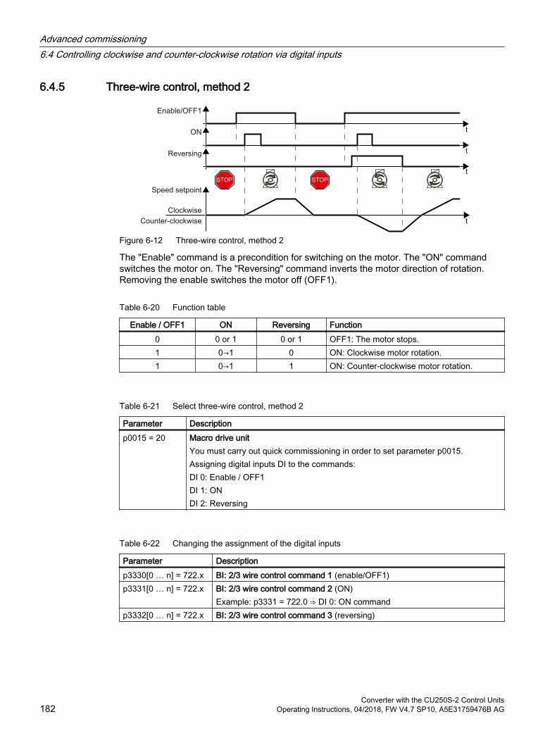
6.4.5 Three-wire control, method 2
Figure 6-12 Three-wire control, method 2
The "Enable" command is a precondition for switching on the motor. The "ON" command switches the motor on. The "Reversing" command inverts the motor direction of rotation. Removing the enable switches the motor off (OFF1).
Table 6-20 Function table
Enable / OFF1 ON Reversing Function0 0 or 1 0 or 1 OFF1: The motor stops.1 0→1 0 ON: Clockwise motor rotation.1 0→1 1 ON: Counter-clockwise motor rotation.
Table 6-21 Select three-wire control, method 2
Parameter Descriptionp0015 = 20 Macro drive unit
You must carry out quick commissioning in order to set parameter p0015.Assigning digital inputs DI to the commands:DI 0: Enable / OFF1DI 1: ONDI 2: Reversing
Table 6-22 Changing the assignment of the digital inputs
Parameter Descriptionp3330[0 … n] = 722.x BI: 2/3 wire control command 1 (enable/OFF1)p3331[0 … n] = 722.x BI: 2/3 wire control command 2 (ON)
Example: p3331 = 722.0 ⇒ DI 0: ON commandp3332[0 … n] = 722.x BI: 2/3 wire control command 3 (reversing)
Advanced commissioning6.4 Controlling clockwise and counter-clockwise rotation via digital inputs
Converter with the CU250S-2 Control Units182 Operating Instructions, 04/2018, FW V4.7 SP10, A5E31759476B AG
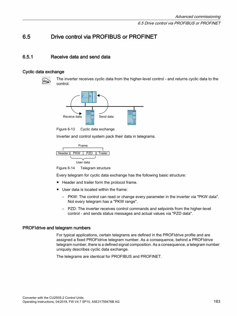
6.5 Drive control via PROFIBUS or PROFINET
6.5.1 Receive data and send data
Cyclic data exchangeThe inverter receives cyclic data from the higher-level control - and returns cyclic data to the control.
Figure 6-13 Cyclic data exchange
Inverter and control system pack their data in telegrams.
Figure 6-14 Telegram structure
Every telegram for cyclic data exchange has the following basic structure:
Header and trailer form the protocol frame.
User data is located within the frame:
– PKW: The control can read or change every parameter in the inverter via "PKW data".Not every telegram has a "PKW range".
– PZD: The inverter receives control commands and setpoints from the higher-level control - and sends status messages and actual values via "PZD data".
PROFIdrive and telegram numbersFor typical applications, certain telegrams are defined in the PROFIdrive profile and are assigned a fixed PROFIdrive telegram number. As a consequence, behind a PROFIdrive telegram number, there is a defined signal composition. As a consequence, a telegram number uniquely describes cyclic data exchange.
The telegrams are identical for PROFIBUS and PROFINET.
Advanced commissioning6.5 Drive control via PROFIBUS or PROFINET
Converter with the CU250S-2 Control UnitsOperating Instructions, 04/2018, FW V4.7 SP10, A5E31759476B AG 183
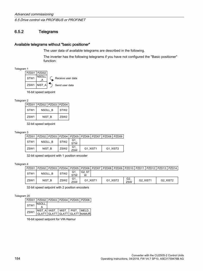
6.5.2 Telegrams
Available telegrams without "basic positioner"The user data of available telegrams are described in the following.
The inverter has the following telegrams if you have not configured the "Basic positioner" function:
16-bit speed setpoint
32-bit speed setpoint
32-bit speed setpoint with 1 position encoder
32-bit speed setpoint with 2 position encoders
16-bit speed setpoint for VIK-Namur
Advanced commissioning6.5 Drive control via PROFIBUS or PROFINET
Converter with the CU250S-2 Control Units184 Operating Instructions, 04/2018, FW V4.7 SP10, A5E31759476B AG
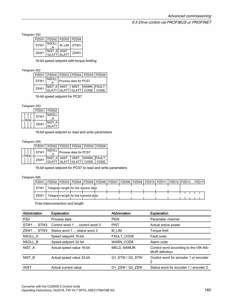
16-bit speed setpoint with torque limiting
16-bit speed setpoint for PCS7
16-bit speed setpoint to read and write parameters
16-bit speed setpoint for PCS7 to read and write parameters
Free interconnection and length
Abbreviation Explanation Abbreviation ExplanationPZD Process data PKW Parameter channelSTW1 … STW3 Control word 1 … control word 3 PIST Actual active powerZSW1 … STW3 Status word 1 ... status word 3 M_LIM Torque limitNSOLL_A Speed setpoint 16-bit FAULT_CODE Fault codeNSOLL_B Speed setpoint 32-bit WARN_CODE Alarm codeNIST_A Actual speed value 16-bit MELD_NAMUR Control word according to the VIK-NA‐
MUR definitionNIST_B Actual speed value 32-bit G1_STW / G2_STW Control word for encoder 1 or encoder
2IAIST Actual current value G1_ZSW / G2_ZSW Status word for encoder 1 / encoder 2
Advanced commissioning6.5 Drive control via PROFIBUS or PROFINET
Converter with the CU250S-2 Control UnitsOperating Instructions, 04/2018, FW V4.7 SP10, A5E31759476B AG 185
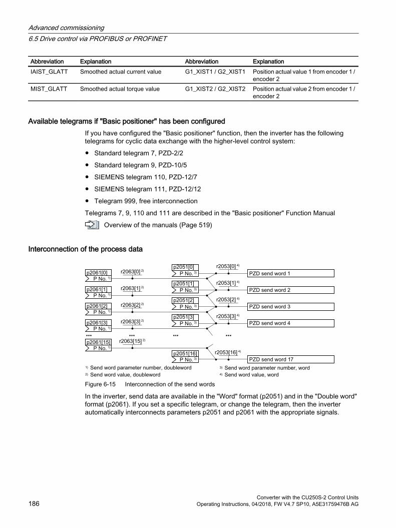
Abbreviation Explanation Abbreviation ExplanationIAIST_GLATT Smoothed actual current value G1_XIST1 / G2_XIST1 Position actual value 1 from encoder 1 /
encoder 2MIST_GLATT Smoothed actual torque value G1_XIST2 / G2_XIST2 Position actual value 2 from encoder 1 /
encoder 2
Available telegrams if "Basic positioner" has been configuredIf you have configured the "Basic positioner" function, then the inverter has the following telegrams for cyclic data exchange with the higher-level control system:
Standard telegram 7, PZD-2/2
Standard telegram 9, PZD-10/5
SIEMENS telegram 110, PZD-12/7
SIEMENS telegram 111, PZD-12/12
Telegram 999, free interconnection
Telegrams 7, 9, 110 and 111 are described in the "Basic positioner" Function Manual
Overview of the manuals (Page 519)
Interconnection of the process data
Figure 6-15 Interconnection of the send words
In the inverter, send data are available in the "Word" format (p2051) and in the "Double word" format (p2061). If you set a specific telegram, or change the telegram, then the inverter automatically interconnects parameters p2051 and p2061 with the appropriate signals.
Advanced commissioning6.5 Drive control via PROFIBUS or PROFINET
Converter with the CU250S-2 Control Units186 Operating Instructions, 04/2018, FW V4.7 SP10, A5E31759476B AG
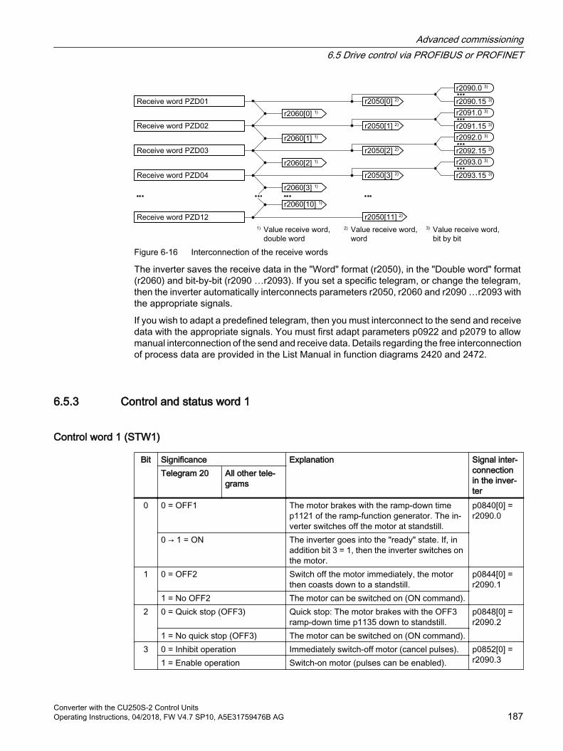
Figure 6-16 Interconnection of the receive words
The inverter saves the receive data in the "Word" format (r2050), in the "Double word" format (r2060) and bit-by-bit (r2090 …r2093). If you set a specific telegram, or change the telegram, then the inverter automatically interconnects parameters r2050, r2060 and r2090 …r2093 with the appropriate signals.
If you wish to adapt a predefined telegram, then you must interconnect to the send and receive data with the appropriate signals. You must first adapt parameters p0922 and p2079 to allow manual interconnection of the send and receive data. Details regarding the free interconnection of process data are provided in the List Manual in function diagrams 2420 and 2472.
6.5.3 Control and status word 1
Control word 1 (STW1)
Bit Significance Explanation Signal inter‐connection in the inver‐ter
Telegram 20 All other tele‐grams
0 0 = OFF1 The motor brakes with the ramp-down time p1121 of the ramp-function generator. The in‐verter switches off the motor at standstill.
p0840[0] = r2090.0
0 → 1 = ON The inverter goes into the "ready" state. If, in addition bit 3 = 1, then the inverter switches on the motor.
1 0 = OFF2 Switch off the motor immediately, the motor then coasts down to a standstill.
p0844[0] = r2090.1
1 = No OFF2 The motor can be switched on (ON command).2 0 = Quick stop (OFF3) Quick stop: The motor brakes with the OFF3
ramp-down time p1135 down to standstill.p0848[0] = r2090.2
1 = No quick stop (OFF3) The motor can be switched on (ON command).3 0 = Inhibit operation Immediately switch-off motor (cancel pulses). p0852[0] =
r2090.31 = Enable operation Switch-on motor (pulses can be enabled).
Advanced commissioning6.5 Drive control via PROFIBUS or PROFINET
Converter with the CU250S-2 Control UnitsOperating Instructions, 04/2018, FW V4.7 SP10, A5E31759476B AG 187
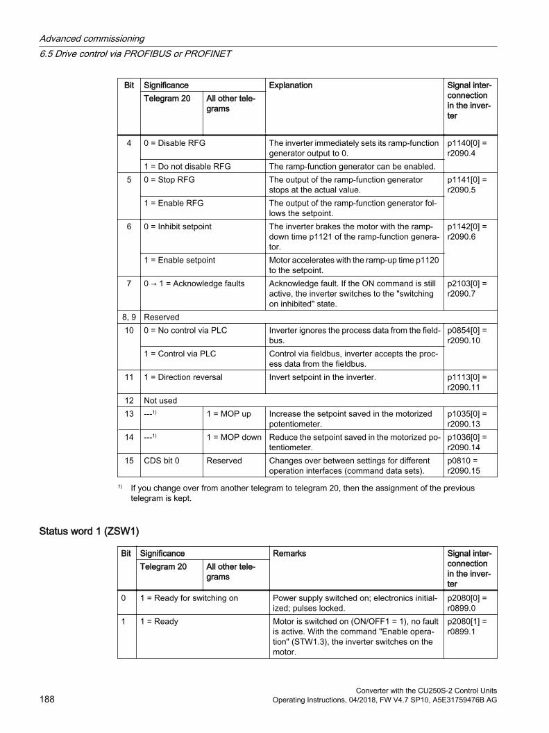
Bit Significance Explanation Signal inter‐connection in the inver‐ter
Telegram 20 All other tele‐grams
4 0 = Disable RFG The inverter immediately sets its ramp-function generator output to 0.
p1140[0] = r2090.4
1 = Do not disable RFG The ramp-function generator can be enabled.5 0 = Stop RFG The output of the ramp-function generator
stops at the actual value.p1141[0] = r2090.5
1 = Enable RFG The output of the ramp-function generator fol‐lows the setpoint.
6 0 = Inhibit setpoint The inverter brakes the motor with the ramp-down time p1121 of the ramp-function genera‐tor.
p1142[0] = r2090.6
1 = Enable setpoint Motor accelerates with the ramp-up time p1120 to the setpoint.
7 0 → 1 = Acknowledge faults Acknowledge fault. If the ON command is still active, the inverter switches to the "switching on inhibited" state.
p2103[0] = r2090.7
8, 9 Reserved10 0 = No control via PLC Inverter ignores the process data from the field‐
bus.p0854[0] = r2090.10
1 = Control via PLC Control via fieldbus, inverter accepts the proc‐ess data from the fieldbus.
11 1 = Direction reversal Invert setpoint in the inverter. p1113[0] = r2090.11
12 Not used13 ---1) 1 = MOP up Increase the setpoint saved in the motorized
potentiometer.p1035[0] = r2090.13
14 ---1) 1 = MOP down Reduce the setpoint saved in the motorized po‐tentiometer.
p1036[0] = r2090.14
15 CDS bit 0 Reserved Changes over between settings for different operation interfaces (command data sets).
p0810 = r2090.15
1) If you change over from another telegram to telegram 20, then the assignment of the previous telegram is kept.
Status word 1 (ZSW1)
Bit Significance Remarks Signal inter‐connection in the inver‐ter
Telegram 20 All other tele‐grams
0 1 = Ready for switching on Power supply switched on; electronics initial‐ized; pulses locked.
p2080[0] = r0899.0
1 1 = Ready Motor is switched on (ON/OFF1 = 1), no fault is active. With the command "Enable opera‐tion" (STW1.3), the inverter switches on the motor.
p2080[1] = r0899.1
Advanced commissioning6.5 Drive control via PROFIBUS or PROFINET
Converter with the CU250S-2 Control Units188 Operating Instructions, 04/2018, FW V4.7 SP10, A5E31759476B AG
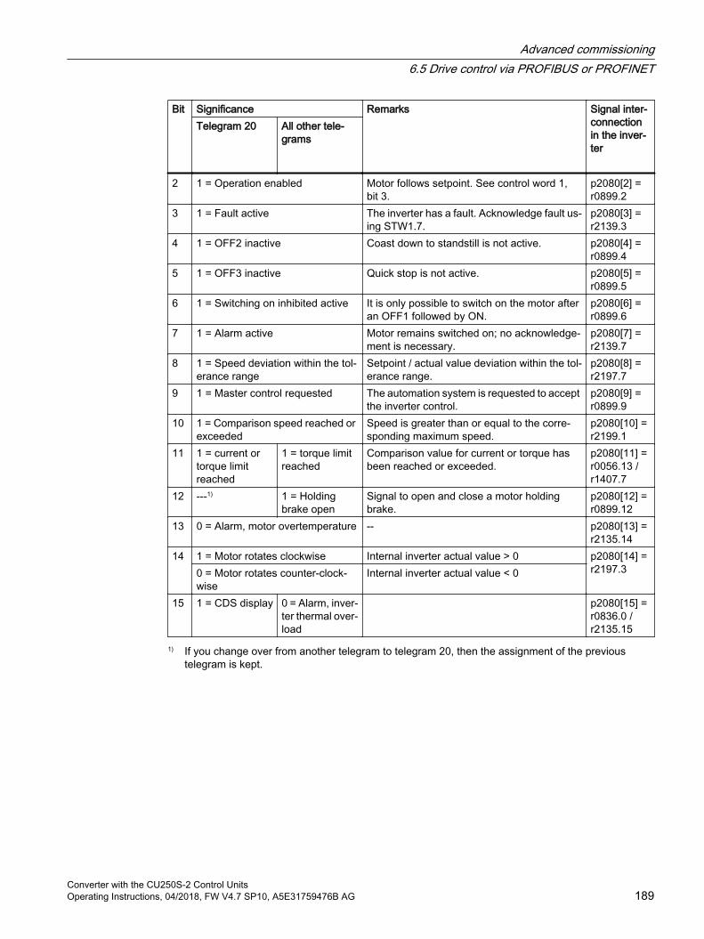
Bit Significance Remarks Signal inter‐connection in the inver‐ter
Telegram 20 All other tele‐grams
2 1 = Operation enabled Motor follows setpoint. See control word 1, bit 3.
p2080[2] = r0899.2
3 1 = Fault active The inverter has a fault. Acknowledge fault us‐ing STW1.7.
p2080[3] = r2139.3
4 1 = OFF2 inactive Coast down to standstill is not active. p2080[4] = r0899.4
5 1 = OFF3 inactive Quick stop is not active. p2080[5] = r0899.5
6 1 = Switching on inhibited active It is only possible to switch on the motor after an OFF1 followed by ON.
p2080[6] = r0899.6
7 1 = Alarm active Motor remains switched on; no acknowledge‐ment is necessary.
p2080[7] = r2139.7
8 1 = Speed deviation within the tol‐erance range
Setpoint / actual value deviation within the tol‐erance range.
p2080[8] = r2197.7
9 1 = Master control requested The automation system is requested to accept the inverter control.
p2080[9] = r0899.9
10 1 = Comparison speed reached or exceeded
Speed is greater than or equal to the corre‐sponding maximum speed.
p2080[10] = r2199.1
11 1 = current or torque limit reached
1 = torque limit reached
Comparison value for current or torque has been reached or exceeded.
p2080[11] = r0056.13 / r1407.7
12 ---1) 1 = Holding brake open
Signal to open and close a motor holding brake.
p2080[12] = r0899.12
13 0 = Alarm, motor overtemperature -- p2080[13] = r2135.14
14 1 = Motor rotates clockwise Internal inverter actual value > 0 p2080[14] = r2197.30 = Motor rotates counter-clock‐
wiseInternal inverter actual value < 0
15 1 = CDS display 0 = Alarm, inver‐ter thermal over‐load
p2080[15] = r0836.0 / r2135.15
1) If you change over from another telegram to telegram 20, then the assignment of the previous telegram is kept.
Advanced commissioning6.5 Drive control via PROFIBUS or PROFINET
Converter with the CU250S-2 Control UnitsOperating Instructions, 04/2018, FW V4.7 SP10, A5E31759476B AG 189
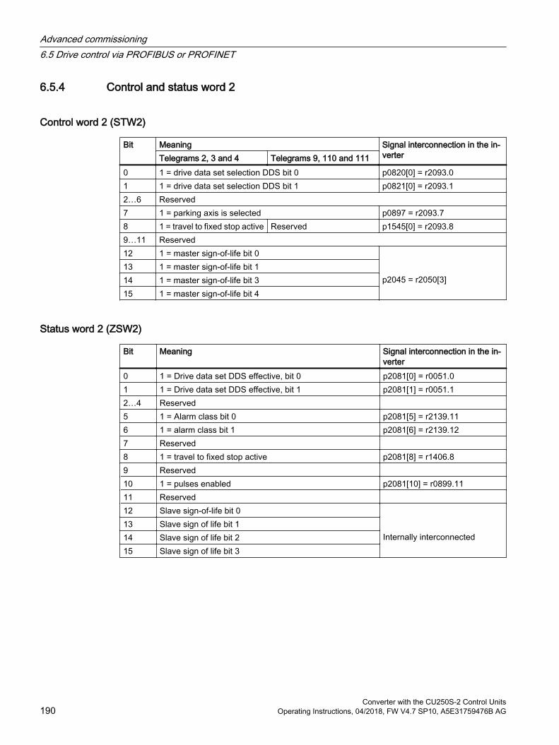
6.5.4 Control and status word 2
Control word 2 (STW2)
Bit Meaning Signal interconnection in the in‐verterTelegrams 2, 3 and 4 Telegrams 9, 110 and 111
0 1 = drive data set selection DDS bit 0 p0820[0] = r2093.01 1 = drive data set selection DDS bit 1 p0821[0] = r2093.12…6 Reserved7 1 = parking axis is selected p0897 = r2093.78 1 = travel to fixed stop active Reserved p1545[0] = r2093.89…11 Reserved12 1 = master sign-of-life bit 0
p2045 = r2050[3]
13 1 = master sign-of-life bit 114 1 = master sign-of-life bit 315 1 = master sign-of-life bit 4
Status word 2 (ZSW2)
Bit Meaning Signal interconnection in the in‐verter
0 1 = Drive data set DDS effective, bit 0 p2081[0] = r0051.01 1 = Drive data set DDS effective, bit 1 p2081[1] = r0051.12…4 Reserved 5 1 = Alarm class bit 0 p2081[5] = r2139.116 1 = alarm class bit 1 p2081[6] = r2139.127 Reserved 8 1 = travel to fixed stop active p2081[8] = r1406.89 Reserved 10 1 = pulses enabled p2081[10] = r0899.1111 Reserved 12 Slave sign-of-life bit 0
Internally interconnected
13 Slave sign of life bit 114 Slave sign of life bit 215 Slave sign of life bit 3
Advanced commissioning6.5 Drive control via PROFIBUS or PROFINET
Converter with the CU250S-2 Control Units190 Operating Instructions, 04/2018, FW V4.7 SP10, A5E31759476B AG
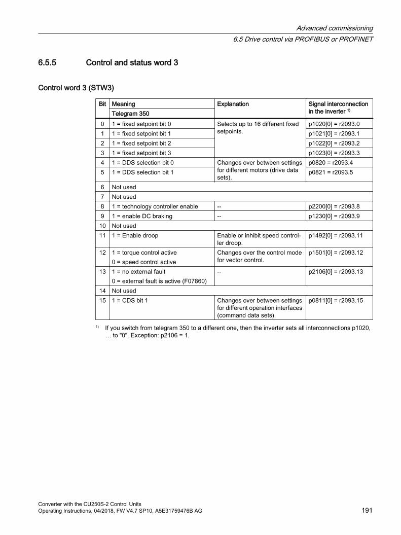
6.5.5 Control and status word 3
Control word 3 (STW3)
Bit Meaning Explanation Signal interconnection in the inverter 1)Telegram 350
0 1 = fixed setpoint bit 0 Selects up to 16 different fixed setpoints.
p1020[0] = r2093.01 1 = fixed setpoint bit 1 p1021[0] = r2093.12 1 = fixed setpoint bit 2 p1022[0] = r2093.23 1 = fixed setpoint bit 3 p1023[0] = r2093.34 1 = DDS selection bit 0 Changes over between settings
for different motors (drive data sets).
p0820 = r2093.45 1 = DDS selection bit 1 p0821 = r2093.5
6 Not used7 Not used8 1 = technology controller enable -- p2200[0] = r2093.89 1 = enable DC braking -- p1230[0] = r2093.910 Not used11 1 = Enable droop Enable or inhibit speed control‐
ler droop.p1492[0] = r2093.11
12 1 = torque control active0 = speed control active
Changes over the control mode for vector control.
p1501[0] = r2093.12
13 1 = no external fault0 = external fault is active (F07860)
-- p2106[0] = r2093.13
14 Not used15 1 = CDS bit 1 Changes over between settings
for different operation interfaces (command data sets).
p0811[0] = r2093.15
1) If you switch from telegram 350 to a different one, then the inverter sets all interconnections p1020, … to "0". Exception: p2106 = 1.
Advanced commissioning6.5 Drive control via PROFIBUS or PROFINET
Converter with the CU250S-2 Control UnitsOperating Instructions, 04/2018, FW V4.7 SP10, A5E31759476B AG 191
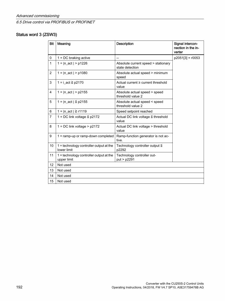
Status word 3 (ZSW3)
Bit Meaning Description Signal intercon‐nection in the in‐verter
0 1 = DC braking active -- p2051[3] = r00531 1 = |n_act | > p1226 Absolute current speed > stationary
state detection2 1 = |n_act | > p1080 Absolute actual speed > minimum
speed3 1 = i_act ≧ p2170 Actual current ≥ current threshold
value4 1 = |n_act | > p2155 Absolute actual speed > speed
threshold value 25 1 = |n_act | ≦ p2155 Absolute actual speed < speed
threshold value 26 1 = |n_act | ≧ r1119 Speed setpoint reached7 1 = DC link voltage ≦ p2172 Actual DC link voltage ≦ threshold
value8 1 = DC link voltage > p2172 Actual DC link voltage > threshold
value9 1 = ramp-up or ramp-down completed Ramp-function generator is not ac‐
tive.10 1 = technology controller output at the
lower limitTechnology controller output ≦ p2292
11 1 = technology controller output at the upper limit
Technology controller out‐put > p2291
12 Not used13 Not used14 Not used15 Not used
Advanced commissioning6.5 Drive control via PROFIBUS or PROFINET
Converter with the CU250S-2 Control Units192 Operating Instructions, 04/2018, FW V4.7 SP10, A5E31759476B AG
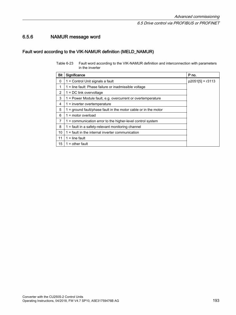
6.5.6 NAMUR message word
Fault word according to the VIK-NAMUR definition (MELD_NAMUR)
Table 6-23 Fault word according to the VIK-NAMUR definition and interconnection with parameters in the inverter
Bit Significance P no.0 1 = Control Unit signals a fault p2051[5] = r31131 1 = line fault: Phase failure or inadmissible voltage2 1 = DC link overvoltage3 1 = Power Module fault, e.g. overcurrent or overtemperature4 1 = inverter overtemperature5 1 = ground fault/phase fault in the motor cable or in the motor6 1 = motor overload7 1 = communication error to the higher-level control system8 1 = fault in a safety-relevant monitoring channel10 1 = fault in the internal inverter communication11 1 = line fault15 1 = other fault
Advanced commissioning6.5 Drive control via PROFIBUS or PROFINET
Converter with the CU250S-2 Control UnitsOperating Instructions, 04/2018, FW V4.7 SP10, A5E31759476B AG 193
6.5.7 Control and status word, encoderTelegrams 3 and 4 allow the higher-level control system to directly access the encoder.
Direct access is necessary, if the higher-level control is responsible for the closed-loop position control for the drive.
If you enable the "Basic positioner" position control in the inverter, then telegrams 3 and 4 cannot be selected, and the inverter handles the encoder control.
Control word encoder (G1_STW and G2_STW)
Bit Meaning Explanation Signal interconnec‐tion in the inverter
Bit 7 = 0 Bit 7 = 1 0 Function 1 1 = search for refer‐
ence cam 1 with a pos‐itive start direction
1 = request flying referencing to the rising edge of refer‐ence cam 1
Telegram 3:Encoder 1:p0480[0] = r2050[4] Telegram 4:Encoder 1:p0480[0] = r2050[4]encoder 2:p0480[1] = p2050[9] Telegram 102:Encoder 1:p0480[0] = r2050[5] Telegram 103:Encoder 1:p0480[0] = r2050[5]encoder 2:p0480[1] = p2050[10]
1 Function 2 1 = search for refer‐ence cam 1 with a neg‐ative start direction
1 = request flying referencing to the falling edge of refer‐ence cam 1
2 Function 3 1 = search for refer‐ence cam 2 with a pos‐itive start direction
1 = request flying referencing to the rising edge of refer‐ence cam 2
3 Function 4 1 = search for refer‐ence cam 2 with a neg‐ative start direction
1 = request flying referencing to the falling edge of refer‐ence cam 2
4 Command bit 0 1 = activate the function requested using bit 0 … 35 Command bit 1 1 = read the value requested using bit 0 … 36 Command bit 2 Reserved7 Mode 1 = flying referencing
0 = search for reference cams8…12
Reserved ---
13 Cyclic absolute value
1 = request for the cyclic transfer of the position actual value in G1_XIST2 or G2_XIST2
14 Parking 1 = request to park the encoder15 Acknowledge 0 → 1 = acknowledge encoder fault
Advanced commissioning6.5 Drive control via PROFIBUS or PROFINET
Converter with the CU250S-2 Control Units194 Operating Instructions, 04/2018, FW V4.7 SP10, A5E31759476B AG

Status word encoder (G1_ZSW and G2_ZSW)
Bit Meaning Explanation Signal interconnec‐tion in the inverter
Bit 7 = 0 Bit 7 = 1 0 Function 1 1 = search for refer‐
ence cam 1 is active1 = flying referencing to the rising edge of reference cam 1 is active
Telegram 3:Encoder 1:p2051[4] = r0481[0] Telegram 4:Encoder 1:p2051[4] = r0481[0] encoder 2:p2051[9] = r0481[1] Telegram 102:Encoder 1:p2051[5] = r0481[0] Telegram 103:Encoder 1:p2051[5] = r0481[0]encoder 2:p2051[10] = r0481[0]
1 Function 2 1 = search for refer‐ence cam 1 is active
1 = flying referencing to the falling edge of reference cam 1 is active
2 Function 3 1 = search for refer‐ence cam 2 is active
1 = flying referencing to the rising edge of reference cam 2 is active
3 Function 4 1 = search for refer‐ence cam 2 is active
1 = flying referencing to the falling edge of reference cam 2 is active
4 Status value 1 1 = position actual value is at refer‐ence cam 1
1 = flying referencing to the rising edge of reference cam 1 has been completed
5 Status value 2 1 = position actual value is at refer‐ence cam 1
1 = flying referencing to the falling edge of reference cam 1 has been completed
6 Status value 3 1 = position actual value is at refer‐ence cam 2
1 = flying referencing to the rising edge of reference cam 2 has been completed
7 Status value 4 1 = position actual value is at refer‐ence cam 2
1 = flying referencing to the falling edge of reference cam 2 has been completed
8 Reference cam 1
1 = reference cam 1 supplies a high signal0 = reference cam 1 supplies a low signal
9 Reference cam 2
1 = reference cam 2 supplies a high signal0 = reference cam 2 supplies a low signal
10 Reserved ---11 Acknowledge 1 = acknowledge encoder fault is active12 Reserved ---13 Cyclic abso‐
lute value1 = the position actual value is in G1_XIST2 or G2_XIST2.
14 Parking 1 = the encoder is parked15 Fault 1 = the encoder indicates its actual fault in r0483
Advanced commissioning6.5 Drive control via PROFIBUS or PROFINET
Converter with the CU250S-2 Control UnitsOperating Instructions, 04/2018, FW V4.7 SP10, A5E31759476B AG 195
6.5.8 Position actual value of the encoder
G1_XIST1 and G2_XIST1In the factory setting, the inverter transfers the encoder position actual value with a fine resolution of 11 bits to the higher-level control system.
Figure 6-17 G1_XIST1 and G2_XIST1
The transferred encoder signal has the following properties:
After the inverter power supply has been switched on, the encoder signal = 0.
The higher-level control must be able to handle a counter overflow of the encoder signal.
G1_XIST2 and G2_XIST2In G1_XIST2 or G2_XIST2, the inverter transfers different values to the higher-level control system:
Encoder x parked Gx_ZSW.14 = 1Encoder fault x Gx_ZSW.15 = 1Referencing encoder x Gx_ZSW.4 = 1 or Gx_ZSW.5 = 1 or Gx_ZSW.6 = 1 or Gx_ZSW.7 = 1
Figure 6-18 G1_XIST2 and G2_XIST2
The inverter transfers the position values in the same format (encoder pulse number and fine resolution) the same as G1_XIST1 and G2_XIST1.
Table 6-24 Fault code
No. Explanation Possible cause1 Encoder fault One or more encoder faults.
Observe the inverter message.2 Zero-mark monitoring ---
Advanced commissioning6.5 Drive control via PROFIBUS or PROFINET
Converter with the CU250S-2 Control Units196 Operating Instructions, 04/2018, FW V4.7 SP10, A5E31759476B AG
No. Explanation Possible cause3 Encoder parking canceled Parking was already requested.4 Search for reference canceled Encoder has no zero mark (reference mark).
Reference mark 2, 3 or 4 was requested. Switchover to "Flying measurement" was
requested during search for reference. Command "Read value x" requested during
search for reference mark. Inconsistent position measured value with
distance-coded reference marks.5 Retrieve reference value canceled More than four values were requested.
No value requested. Requested value is not available.
6 Flying referencing canceled Reference cam has not been configured During "Flying referencing" a changeover was
made to search for reference. During "Flying referencing" a request was issued
"Read value x".7 Retrieve measured value canceled More than one value was requested.
No value requested. Requested value is not available. Encoder is parked.
8 Position actual value transfer canceled No absolute encoder available. Alarm bit in the absolute value protocol set.
3841 Encoder does not support the function ---
Advanced commissioning6.5 Drive control via PROFIBUS or PROFINET
Converter with the CU250S-2 Control UnitsOperating Instructions, 04/2018, FW V4.7 SP10, A5E31759476B AG 197
6.5.9 Parameter channel
Structure of the parameter channel The parameter channel consists of four words. The 1st and 2nd words transfer the parameter number, index and the type of task (read or write). The 3rd and 4th words contain the parameter content. The parameter contents can be 16-bit values (such as baud rate) or 32-bit values (e.g. CO parameters).
Bit 11 in the 1st word is reserved and is always assigned 0.
You can find application examples relating to the parameter channel at the end of this section.
AK: Request and response IDsBits 12 … 15 of the 1st The parameter channel words contain the request and response identifier AK.
Table 6-25 Request identifiers, control → inverter
AK Description Response identifierpositive negative
0 No request 0 7 / 81 Request parameter value 1 / 2 7 / 82 Change parameter value (word) 1 7 / 83 Change parameter value (double word) 2 7 / 84 Request descriptive element 1) 3 7 / 86 2) Request parameter value (field) 1) 4 / 5 7 / 87 2) Change parameter value (field, word) 1) 4 7 / 88 2) Change parameter value (field, double word) 1) 5 7 / 89 Request number of field elements 6 7 / 8
1) The required element of the parameter is specified in IND (2nd word).2) The following request IDs are identical: 1 ≡ 6, 2 ≡ 7 3 ≡ 8.
We recommend that you use identifiers 6, 7, and 8.
Table 6-26 Response identifiers, inverter → control
AK Description0 No response1 Transfer parameter value (word)2 Transfer parameter value (double word)
Advanced commissioning6.5 Drive control via PROFIBUS or PROFINET
Converter with the CU250S-2 Control Units198 Operating Instructions, 04/2018, FW V4.7 SP10, A5E31759476B AG
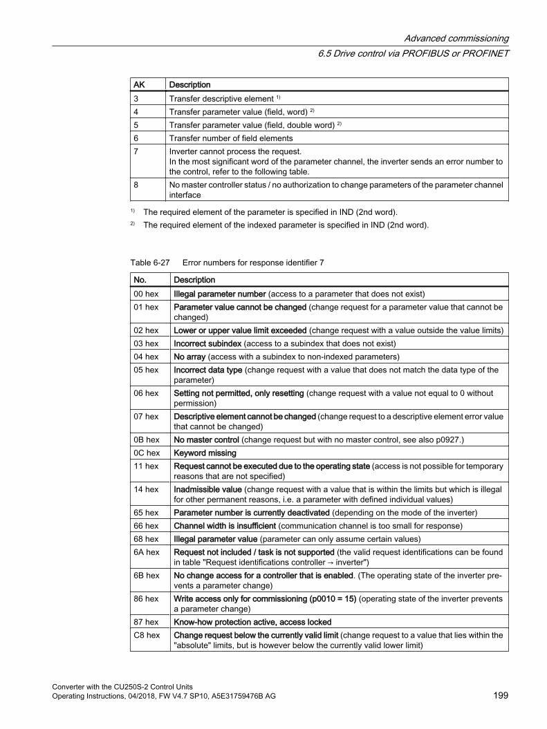
AK Description3 Transfer descriptive element 1)
4 Transfer parameter value (field, word) 2)
5 Transfer parameter value (field, double word) 2)
6 Transfer number of field elements7 Inverter cannot process the request.
In the most significant word of the parameter channel, the inverter sends an error number to the control, refer to the following table.
8 No master controller status / no authorization to change parameters of the parameter channel interface
1) The required element of the parameter is specified in IND (2nd word).2) The required element of the indexed parameter is specified in IND (2nd word).
Table 6-27 Error numbers for response identifier 7
No. Description00 hex Illegal parameter number (access to a parameter that does not exist)01 hex Parameter value cannot be changed (change request for a parameter value that cannot be
changed)02 hex Lower or upper value limit exceeded (change request with a value outside the value limits)03 hex Incorrect subindex (access to a subindex that does not exist)04 hex No array (access with a subindex to non-indexed parameters)05 hex Incorrect data type (change request with a value that does not match the data type of the
parameter)06 hex Setting not permitted, only resetting (change request with a value not equal to 0 without
permission)07 hex Descriptive element cannot be changed (change request to a descriptive element error value
that cannot be changed)0B hex No master control (change request but with no master control, see also p0927.)0C hex Keyword missing 11 hex Request cannot be executed due to the operating state (access is not possible for temporary
reasons that are not specified)14 hex Inadmissible value (change request with a value that is within the limits but which is illegal
for other permanent reasons, i.e. a parameter with defined individual values)65 hex Parameter number is currently deactivated (depending on the mode of the inverter)66 hex Channel width is insufficient (communication channel is too small for response)68 hex Illegal parameter value (parameter can only assume certain values)6A hex Request not included / task is not supported (the valid request identifications can be found
in table "Request identifications controller → inverter")6B hex No change access for a controller that is enabled. (The operating state of the inverter pre‐
vents a parameter change)86 hex Write access only for commissioning (p0010 = 15) (operating state of the inverter prevents
a parameter change)87 hex Know-how protection active, access lockedC8 hex Change request below the currently valid limit (change request to a value that lies within the
"absolute" limits, but is however below the currently valid lower limit)
Advanced commissioning6.5 Drive control via PROFIBUS or PROFINET
Converter with the CU250S-2 Control UnitsOperating Instructions, 04/2018, FW V4.7 SP10, A5E31759476B AG 199
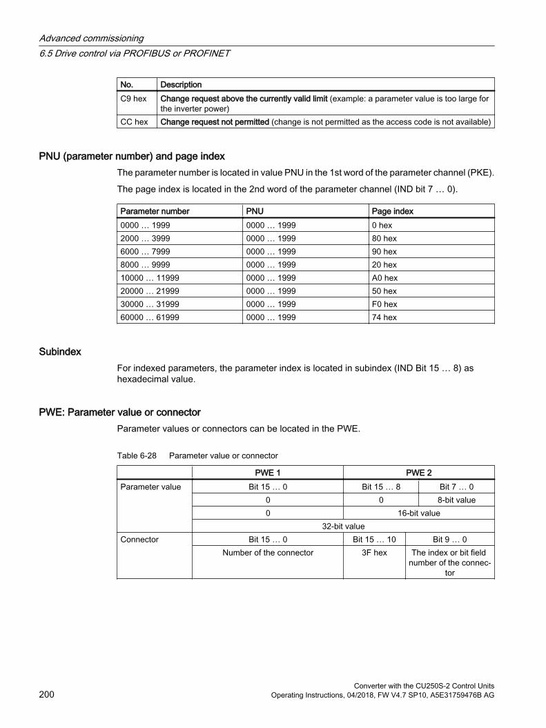
No. DescriptionC9 hex Change request above the currently valid limit (example: a parameter value is too large for
the inverter power)CC hex Change request not permitted (change is not permitted as the access code is not available)
PNU (parameter number) and page indexThe parameter number is located in value PNU in the 1st word of the parameter channel (PKE).
The page index is located in the 2nd word of the parameter channel (IND bit 7 … 0).
Parameter number PNU Page index0000 … 1999 0000 … 1999 0 hex2000 … 3999 0000 … 1999 80 hex6000 … 7999 0000 … 1999 90 hex8000 … 9999 0000 … 1999 20 hex10000 … 11999 0000 … 1999 A0 hex20000 … 21999 0000 … 1999 50 hex30000 … 31999 0000 … 1999 F0 hex60000 … 61999 0000 … 1999 74 hex
SubindexFor indexed parameters, the parameter index is located in subindex (IND Bit 15 … 8) as hexadecimal value.
PWE: Parameter value or connectorParameter values or connectors can be located in the PWE.
Table 6-28 Parameter value or connector
PWE 1 PWE 2Parameter value Bit 15 … 0 Bit 15 … 8 Bit 7 … 0
0 0 8-bit value0 16-bit value
32-bit valueConnector Bit 15 … 0 Bit 15 … 10 Bit 9 … 0
Number of the connector 3F hex The index or bit field number of the connec‐
tor
Advanced commissioning6.5 Drive control via PROFIBUS or PROFINET
Converter with the CU250S-2 Control Units200 Operating Instructions, 04/2018, FW V4.7 SP10, A5E31759476B AG
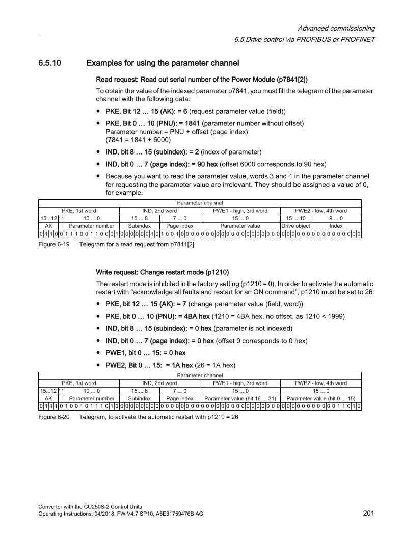
6.5.10 Examples for using the parameter channel
Read request: Read out serial number of the Power Module (p7841[2])To obtain the value of the indexed parameter p7841, you must fill the telegram of the parameter channel with the following data:
PKE, Bit 12 … 15 (AK): = 6 (request parameter value (field))
PKE, Bit 0 … 10 (PNU): = 1841 (parameter number without offset)Parameter number = PNU + offset (page index)(7841 = 1841 + 6000)
IND, bit 8 … 15 (subindex): = 2 (index of parameter)
IND, bit 0 … 7 (page index): = 90 hex (offset 6000 corresponds to 90 hex)
Because you want to read the parameter value, words 3 and 4 in the parameter channel for requesting the parameter value are irrelevant. They should be assigned a value of 0, for example.
Figure 6-19 Telegram for a read request from p7841[2]
Write request: Change restart mode (p1210)The restart mode is inhibited in the factory setting (p1210 = 0). In order to activate the automatic restart with "acknowledge all faults and restart for an ON command", p1210 must be set to 26:
PKE, bit 12 … 15 (AK): = 7 (change parameter value (field, word))
PKE, bit 0 … 10 (PNU): = 4BA hex (1210 = 4BA hex, no offset, as 1210 < 1999)
IND, bit 8 … 15 (subindex): = 0 hex (parameter is not indexed)
IND, bit 0 … 7 (page index): = 0 hex (offset 0 corresponds to 0 hex)
PWE1, bit 0 … 15: = 0 hex
PWE2, Bit 0 … 15: = 1A hex (26 = 1A hex)
Figure 6-20 Telegram, to activate the automatic restart with p1210 = 26
Advanced commissioning6.5 Drive control via PROFIBUS or PROFINET
Converter with the CU250S-2 Control UnitsOperating Instructions, 04/2018, FW V4.7 SP10, A5E31759476B AG 201
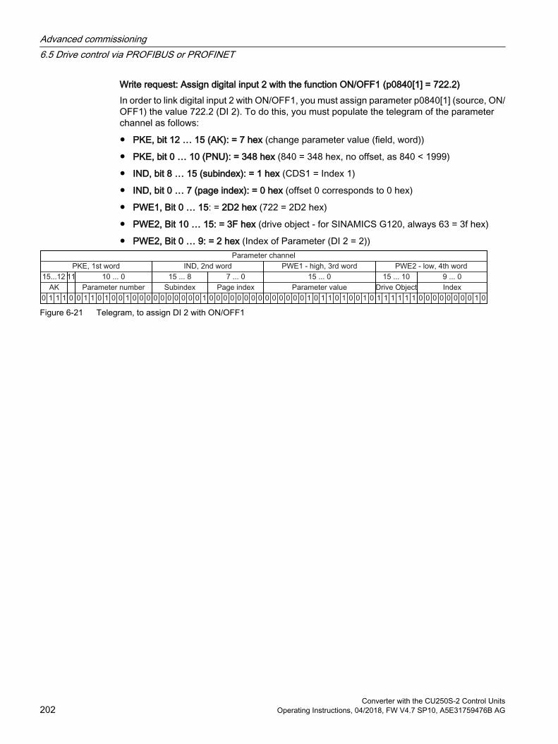
Write request: Assign digital input 2 with the function ON/OFF1 (p0840[1] = 722.2)In order to link digital input 2 with ON/OFF1, you must assign parameter p0840[1] (source, ON/OFF1) the value 722.2 (DI 2). To do this, you must populate the telegram of the parameter channel as follows:
PKE, bit 12 … 15 (AK): = 7 hex (change parameter value (field, word))
PKE, bit 0 … 10 (PNU): = 348 hex (840 = 348 hex, no offset, as 840 < 1999)
IND, bit 8 … 15 (subindex): = 1 hex (CDS1 = Index 1)
IND, bit 0 … 7 (page index): = 0 hex (offset 0 corresponds to 0 hex)
PWE1, Bit 0 … 15: = 2D2 hex (722 = 2D2 hex)
PWE2, Bit 10 … 15: = 3F hex (drive object - for SINAMICS G120, always 63 = 3f hex)
PWE2, Bit 0 … 9: = 2 hex (Index of Parameter (DI 2 = 2))
Figure 6-21 Telegram, to assign DI 2 with ON/OFF1
Advanced commissioning6.5 Drive control via PROFIBUS or PROFINET
Converter with the CU250S-2 Control Units202 Operating Instructions, 04/2018, FW V4.7 SP10, A5E31759476B AG

6.5.11 Extending the telegram
OverviewWhen you have selected a telegram, the inverter interconnects the corresponding signals with the fieldbus interface. Generally, these interconnections are locked so that they cannot be changed. However, with the appropriate setting in the inverter, the telegram can be extended or even freely interconnected.
Extending the telegram
Procedure1. Set p0922 = 999.
2. Set parameter p2079 to the value of the corresponding telegram.The interconnections contained in the telegram are locked.
3. Extend the telegram by "attaching" additional signals.Interconnect additional PZD send words and PZD receive words with signals of your choice via parameters r2050 and p2051.
You have extended the telegram.
Freely interconnecting signals in the telegram
Procedure1. Set p0922 = 999.
2. Set p2079 = 999.The interconnections contained in the telegram are enabled.
3. Interconnect additional PZD send words and PZD receive words with signals of your choice via parameters r2050 and p2051.
You have freely interconnected the signals transferred in the telegram.
Parameter
Parameter Descriptionp0922 PROFIdrive telegram selection
999: Free telegram (message frame) configuration
Advanced commissioning6.5 Drive control via PROFIBUS or PROFINET
Converter with the CU250S-2 Control UnitsOperating Instructions, 04/2018, FW V4.7 SP10, A5E31759476B AG 203
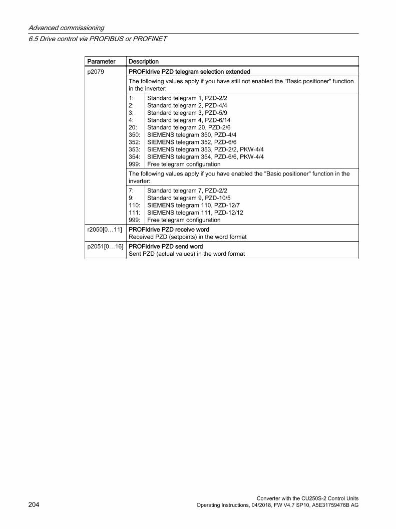
Parameter Descriptionp2079 PROFIdrive PZD telegram selection extended
The following values apply if you have still not enabled the "Basic positioner" function in the inverter:1:2:3:4:20:350:352:353:354: 999:
Standard telegram 1, PZD-2/2Standard telegram 2, PZD-4/4Standard telegram 3, PZD-5/9Standard telegram 4, PZD-6/14Standard telegram 20, PZD-2/6SIEMENS telegram 350, PZD-4/4SIEMENS telegram 352, PZD-6/6SIEMENS telegram 353, PZD-2/2, PKW-4/4SIEMENS telegram 354, PZD-6/6, PKW-4/4Free telegram configuration
The following values apply if you have enabled the "Basic positioner" function in the inverter:7:9:110:111:999:
Standard telegram 7, PZD-2/2Standard telegram 9, PZD-10/5SIEMENS telegram 110, PZD-12/7SIEMENS telegram 111, PZD-12/12Free telegram configuration
r2050[0…11] PROFIdrive PZD receive wordReceived PZD (setpoints) in the word format
p2051[0…16] PROFIdrive PZD send wordSent PZD (actual values) in the word format
Advanced commissioning6.5 Drive control via PROFIBUS or PROFINET
Converter with the CU250S-2 Control Units204 Operating Instructions, 04/2018, FW V4.7 SP10, A5E31759476B AG
6.5.12 Slave-to-slave communication
Overview"Direct data exchange" is sometimes called "slave-to-slave communication" or "data exchange broadcast". With direct data exchange, slaves exchange data without any direct involvement of the master.
Further information about the "Direct data exchange" function is provided in the Fieldbus function manual.
Overview of the manuals (Page 519)
6.5.13 Acyclically reading and writing inverter parameters
OverviewThe inverter supports the writing and reading of parameters via acyclic communication:
For PROFIBUS: Up to 240 bytes per write or read request via data set 47
For PROFINET: Write or read requests via B02E hex and B02F hex
Further information about acyclic communication is provided in the Fieldbus function manual.
Overview of the manuals (Page 519)
Application example, "Read and write to parameters"Further information is provided on the Internet:
Application examples (https://support.industry.siemens.com/cs/ww/en/view/29157692)
Advanced commissioning6.5 Drive control via PROFIBUS or PROFINET
Converter with the CU250S-2 Control UnitsOperating Instructions, 04/2018, FW V4.7 SP10, A5E31759476B AG 205
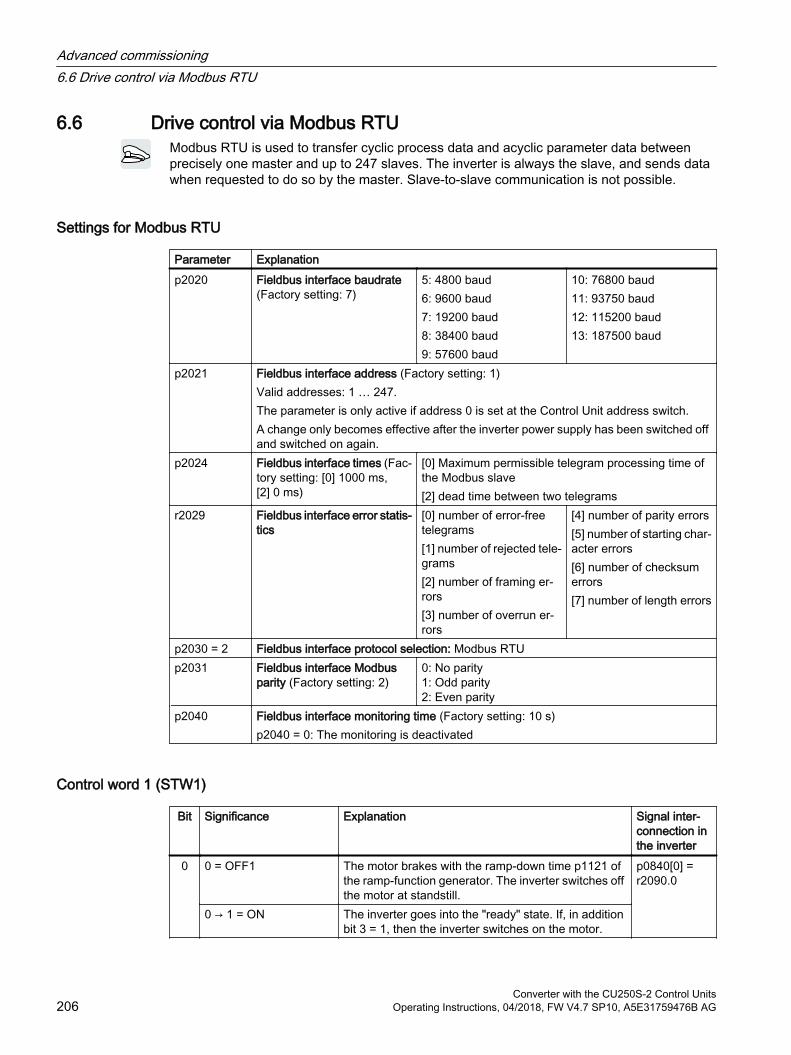
6.6 Drive control via Modbus RTUModbus RTU is used to transfer cyclic process data and acyclic parameter data between precisely one master and up to 247 slaves. The inverter is always the slave, and sends data when requested to do so by the master. Slave-to-slave communication is not possible.
Settings for Modbus RTU
Parameter Explanationp2020 Fieldbus interface baudrate
(Factory setting: 7)5: 4800 baud6: 9600 baud7: 19200 baud8: 38400 baud9: 57600 baud
10: 76800 baud11: 93750 baud12: 115200 baud13: 187500 baud
p2021 Fieldbus interface address (Factory setting: 1)Valid addresses: 1 … 247.The parameter is only active if address 0 is set at the Control Unit address switch.A change only becomes effective after the inverter power supply has been switched off and switched on again.
p2024 Fieldbus interface times (Fac‐tory setting: [0] 1000 ms, [2] 0 ms)
[0] Maximum permissible telegram processing time of the Modbus slave[2] dead time between two telegrams
r2029 Fieldbus interface error statis‐tics
[0] number of error-free telegrams[1] number of rejected tele‐grams[2] number of framing er‐rors[3] number of overrun er‐rors
[4] number of parity errors[5] number of starting char‐acter errors[6] number of checksum errors[7] number of length errors
p2030 = 2 Fieldbus interface protocol selection: Modbus RTUp2031 Fieldbus interface Modbus
parity (Factory setting: 2)0: No parity1: Odd parity2: Even parity
p2040 Fieldbus interface monitoring time (Factory setting: 10 s)p2040 = 0: The monitoring is deactivated
Control word 1 (STW1)
Bit Significance Explanation Signal inter‐connection in the inverter
0 0 = OFF1 The motor brakes with the ramp-down time p1121 of the ramp-function generator. The inverter switches off the motor at standstill.
p0840[0] = r2090.0
0 → 1 = ON The inverter goes into the "ready" state. If, in addition bit 3 = 1, then the inverter switches on the motor.
Advanced commissioning6.6 Drive control via Modbus RTU
Converter with the CU250S-2 Control Units206 Operating Instructions, 04/2018, FW V4.7 SP10, A5E31759476B AG
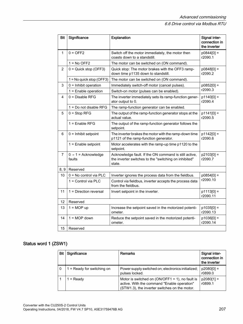
Bit Significance Explanation Signal inter‐connection in the inverter
1 0 = OFF2 Switch off the motor immediately, the motor then coasts down to a standstill.
p0844[0] = r2090.1
1 = No OFF2 The motor can be switched on (ON command).2 0 = Quick stop (OFF3) Quick stop: The motor brakes with the OFF3 ramp-
down time p1135 down to standstill.p0848[0] = r2090.2
1 = No quick stop (OFF3) The motor can be switched on (ON command).3 0 = Inhibit operation Immediately switch-off motor (cancel pulses). p0852[0] =
r2090.31 = Enable operation Switch-on motor (pulses can be enabled). 4 0 = Disable RFG The inverter immediately sets its ramp-function gener‐
ator output to 0.p1140[0] = r2090.4
1 = Do not disable RFG The ramp-function generator can be enabled.5 0 = Stop RFG The output of the ramp-function generator stops at the
actual value.p1141[0] = r2090.5
1 = Enable RFG The output of the ramp-function generator follows the setpoint.
6 0 = Inhibit setpoint The inverter brakes the motor with the ramp-down time p1121 of the ramp-function generator.
p1142[0] = r2090.6
1 = Enable setpoint Motor accelerates with the ramp-up time p1120 to the setpoint.
7 0 → 1 = Acknowledge faults
Acknowledge fault. If the ON command is still active, the inverter switches to the "switching on inhibited" state.
p2103[0] = r2090.7
8, 9 Reserved10 0 = No control via PLC Inverter ignores the process data from the fieldbus. p0854[0] =
r2090.101 = Control via PLC Control via fieldbus, inverter accepts the process data from the fieldbus.
11 1 = Direction reversal Invert setpoint in the inverter. p1113[0] = r2090.11
12 Reserved13 1 = MOP up Increase the setpoint saved in the motorized potenti‐
ometer.p1035[0] = r2090.13
14 1 = MOP down Reduce the setpoint saved in the motorized potenti‐ometer.
p1036[0] = r2090.14
15 Reserved
Status word 1 (ZSW1)
Bit Significance Remarks Signal inter‐connection in the inverter
0 1 = Ready for switching on Power supply switched on; electronics initialized; pulses locked.
p2080[0] = r0899.0
1 1 = Ready Motor is switched on (ON/OFF1 = 1), no fault is active. With the command "Enable operation" (STW1.3), the inverter switches on the motor.
p2080[1] = r0899.1
Advanced commissioning6.6 Drive control via Modbus RTU
Converter with the CU250S-2 Control UnitsOperating Instructions, 04/2018, FW V4.7 SP10, A5E31759476B AG 207
Bit Significance Remarks Signal inter‐connection in the inverter
2 1 = Operation enabled Motor follows setpoint. See control word 1, bit 3. p2080[2] = r0899.2
3 1 = Fault active The inverter has a fault. Acknowledge fault using STW1.7.
p2080[3] = r2139.3
4 1 = OFF2 inactive Coast down to standstill is not active. p2080[4] = r0899.4
5 1 = OFF3 inactive Quick stop is not active. p2080[5] = r0899.5
6 1 = Switching on inhibited ac‐tive
It is only possible to switch on the motor after an OFF1 followed by ON.
p2080[6] = r0899.6
7 1 = Alarm active Motor remains switched on; no acknowledge‐ment is necessary.
p2080[7] = r2139.7
8 1 = Speed deviation within the tolerance range
Setpoint / actual value deviation within the toler‐ance range.
p2080[8] = r2197.7
9 1 = Master control requested The automation system is requested to accept the inverter control.
p2080[9] = r0899.9
10 1 = Comparison speed reached or exceeded
Speed is greater than or equal to the correspond‐ing maximum speed.
p2080[10] = r2199.1
11 1 = Torque limit not reached Comparison value for current or torque has been fallen below.
p2080[11] = r0056.13 / r1407.7
12 Reserved p2080[12] = r0899.12
13 0 = Alarm, motor overtempera‐ture
-- p2080[13] = r2135.14
14 1 = Motor rotates clockwise Internal inverter actual value > 0 p2080[14] = r2197.30 = Motor rotates counter-
clockwiseInternal inverter actual value < 0
15 0 = Alarm, inverter thermal overload
p2080[15] = r2135.15
1) If you change over from another telegram to telegram 20, then the assignment of the previous telegram is kept.
Further informationFurther information about Modbus RTU is provided in the "Fieldbus" function manual.
Overview of the manuals (Page 519)
Advanced commissioning6.6 Drive control via Modbus RTU
Converter with the CU250S-2 Control Units208 Operating Instructions, 04/2018, FW V4.7 SP10, A5E31759476B AG
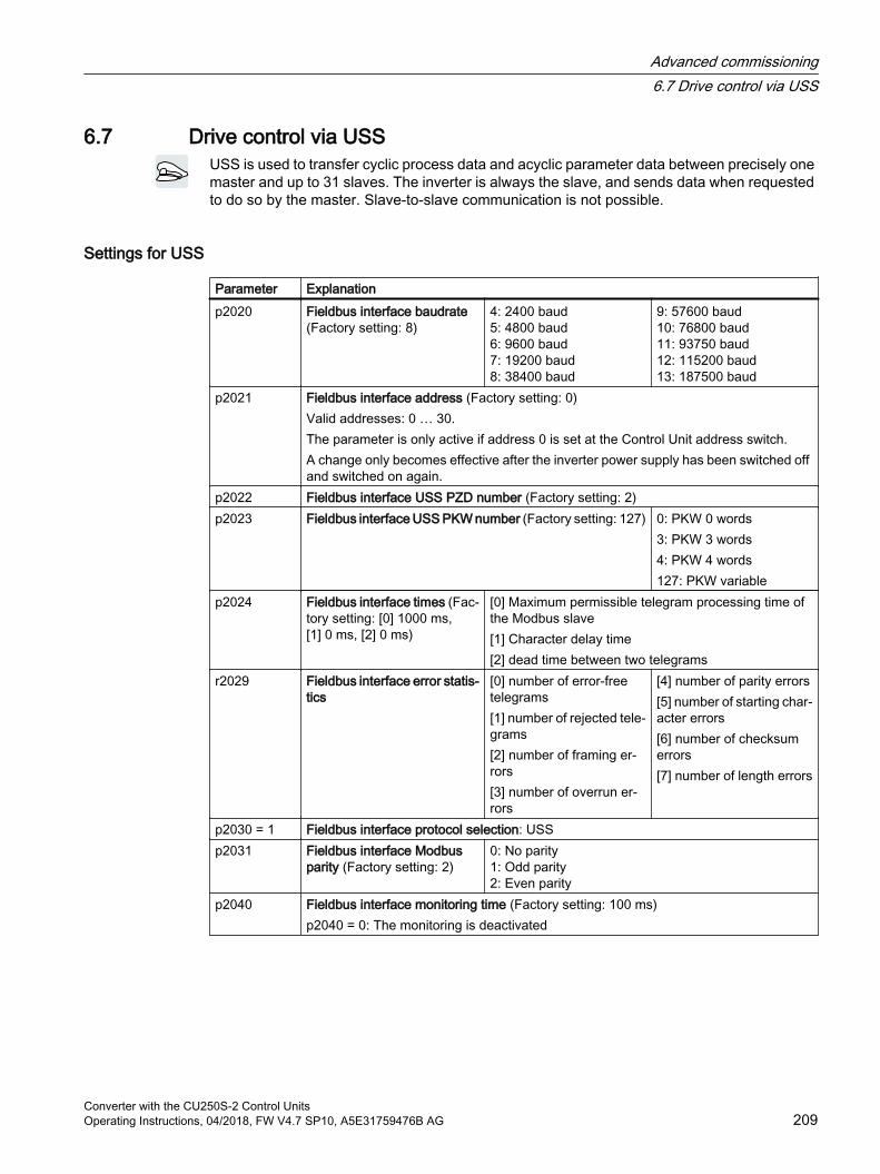
6.7 Drive control via USSUSS is used to transfer cyclic process data and acyclic parameter data between precisely one master and up to 31 slaves. The inverter is always the slave, and sends data when requested to do so by the master. Slave-to-slave communication is not possible.
Settings for USS
Parameter Explanationp2020 Fieldbus interface baudrate
(Factory setting: 8)4: 2400 baud5: 4800 baud6: 9600 baud7: 19200 baud8: 38400 baud
9: 57600 baud10: 76800 baud11: 93750 baud12: 115200 baud13: 187500 baud
p2021 Fieldbus interface address (Factory setting: 0)Valid addresses: 0 … 30.The parameter is only active if address 0 is set at the Control Unit address switch.A change only becomes effective after the inverter power supply has been switched off and switched on again.
p2022 Fieldbus interface USS PZD number (Factory setting: 2)p2023 Fieldbus interface USS PKW number (Factory setting: 127) 0: PKW 0 words
3: PKW 3 words4: PKW 4 words127: PKW variable
p2024 Fieldbus interface times (Fac‐tory setting: [0] 1000 ms, [1] 0 ms, [2] 0 ms)
[0] Maximum permissible telegram processing time of the Modbus slave[1] Character delay time[2] dead time between two telegrams
r2029 Fieldbus interface error statis‐tics
[0] number of error-free telegrams[1] number of rejected tele‐grams[2] number of framing er‐rors[3] number of overrun er‐rors
[4] number of parity errors[5] number of starting char‐acter errors[6] number of checksum errors[7] number of length errors
p2030 = 1 Fieldbus interface protocol selection: USSp2031 Fieldbus interface Modbus
parity (Factory setting: 2)0: No parity1: Odd parity2: Even parity
p2040 Fieldbus interface monitoring time (Factory setting: 100 ms)p2040 = 0: The monitoring is deactivated
Advanced commissioning6.7 Drive control via USS
Converter with the CU250S-2 Control UnitsOperating Instructions, 04/2018, FW V4.7 SP10, A5E31759476B AG 209
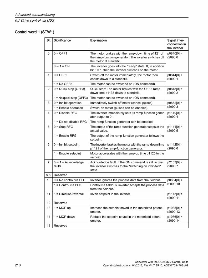
Control word 1 (STW1)
Bit Significance Explanation Signal inter‐connection in the inverter
0 0 = OFF1 The motor brakes with the ramp-down time p1121 of the ramp-function generator. The inverter switches off the motor at standstill.
p0840[0] = r2090.0
0 → 1 = ON The inverter goes into the "ready" state. If, in addition bit 3 = 1, then the inverter switches on the motor.
1 0 = OFF2 Switch off the motor immediately, the motor then coasts down to a standstill.
p0844[0] = r2090.1
1 = No OFF2 The motor can be switched on (ON command).2 0 = Quick stop (OFF3) Quick stop: The motor brakes with the OFF3 ramp-
down time p1135 down to standstill.p0848[0] = r2090.2
1 = No quick stop (OFF3) The motor can be switched on (ON command).3 0 = Inhibit operation Immediately switch-off motor (cancel pulses). p0852[0] =
r2090.31 = Enable operation Switch-on motor (pulses can be enabled). 4 0 = Disable RFG The inverter immediately sets its ramp-function gener‐
ator output to 0.p1140[0] = r2090.4
1 = Do not disable RFG The ramp-function generator can be enabled.5 0 = Stop RFG The output of the ramp-function generator stops at the
actual value.p1141[0] = r2090.5
1 = Enable RFG The output of the ramp-function generator follows the setpoint.
6 0 = Inhibit setpoint The inverter brakes the motor with the ramp-down time p1121 of the ramp-function generator.
p1142[0] = r2090.6
1 = Enable setpoint Motor accelerates with the ramp-up time p1120 to the setpoint.
7 0 → 1 = Acknowledge faults
Acknowledge fault. If the ON command is still active, the inverter switches to the "switching on inhibited" state.
p2103[0] = r2090.7
8, 9 Reserved10 0 = No control via PLC Inverter ignores the process data from the fieldbus. p0854[0] =
r2090.101 = Control via PLC Control via fieldbus, inverter accepts the process data from the fieldbus.
11 1 = Direction reversal Invert setpoint in the inverter. p1113[0] = r2090.11
12 Reserved13 1 = MOP up Increase the setpoint saved in the motorized potenti‐
ometer.p1035[0] = r2090.13
14 1 = MOP down Reduce the setpoint saved in the motorized potenti‐ometer.
p1036[0] = r2090.14
15 Reserved
Advanced commissioning6.7 Drive control via USS
Converter with the CU250S-2 Control Units210 Operating Instructions, 04/2018, FW V4.7 SP10, A5E31759476B AG
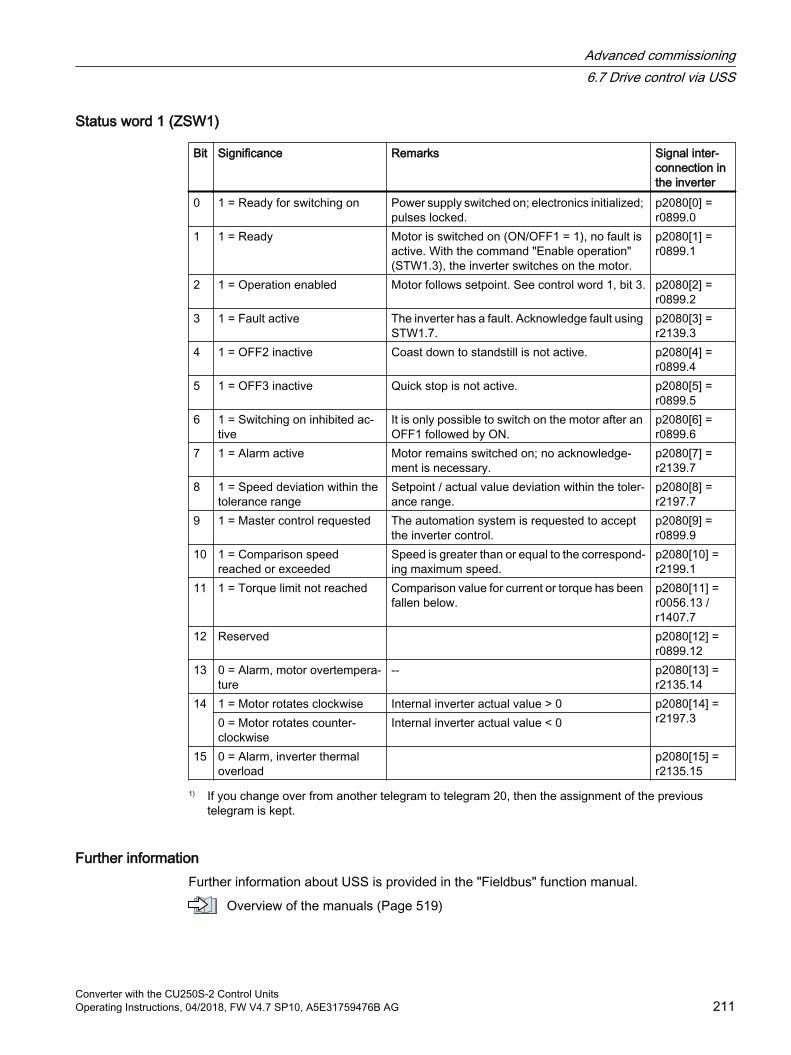
Status word 1 (ZSW1)
Bit Significance Remarks Signal inter‐connection in the inverter
0 1 = Ready for switching on Power supply switched on; electronics initialized; pulses locked.
p2080[0] = r0899.0
1 1 = Ready Motor is switched on (ON/OFF1 = 1), no fault is active. With the command "Enable operation" (STW1.3), the inverter switches on the motor.
p2080[1] = r0899.1
2 1 = Operation enabled Motor follows setpoint. See control word 1, bit 3. p2080[2] = r0899.2
3 1 = Fault active The inverter has a fault. Acknowledge fault using STW1.7.
p2080[3] = r2139.3
4 1 = OFF2 inactive Coast down to standstill is not active. p2080[4] = r0899.4
5 1 = OFF3 inactive Quick stop is not active. p2080[5] = r0899.5
6 1 = Switching on inhibited ac‐tive
It is only possible to switch on the motor after an OFF1 followed by ON.
p2080[6] = r0899.6
7 1 = Alarm active Motor remains switched on; no acknowledge‐ment is necessary.
p2080[7] = r2139.7
8 1 = Speed deviation within the tolerance range
Setpoint / actual value deviation within the toler‐ance range.
p2080[8] = r2197.7
9 1 = Master control requested The automation system is requested to accept the inverter control.
p2080[9] = r0899.9
10 1 = Comparison speed reached or exceeded
Speed is greater than or equal to the correspond‐ing maximum speed.
p2080[10] = r2199.1
11 1 = Torque limit not reached Comparison value for current or torque has been fallen below.
p2080[11] = r0056.13 / r1407.7
12 Reserved p2080[12] = r0899.12
13 0 = Alarm, motor overtempera‐ture
-- p2080[13] = r2135.14
14 1 = Motor rotates clockwise Internal inverter actual value > 0 p2080[14] = r2197.30 = Motor rotates counter-
clockwiseInternal inverter actual value < 0
15 0 = Alarm, inverter thermal overload
p2080[15] = r2135.15
1) If you change over from another telegram to telegram 20, then the assignment of the previous telegram is kept.
Further informationFurther information about USS is provided in the "Fieldbus" function manual.
Overview of the manuals (Page 519)
Advanced commissioning6.7 Drive control via USS
Converter with the CU250S-2 Control UnitsOperating Instructions, 04/2018, FW V4.7 SP10, A5E31759476B AG 211

6.8 Drive control via Ethernet/IPEtherNet/IP is an Ethernet-based fieldbus. EtherNet/IP is used to transfer cyclic process data as well as acyclic parameter data.
Settings for Ethernet/IP
Parameter Explanationp2030 = 10 Fieldbus interface protocol selection: Ethernet/IPp8920 PN Name of Stationp8921 PN IP address (Factory setting: 0)p8922 PN default gateway (factory setting: 0)p8923 PN Subnet Mask (Factory setting: 0)p8924 PN DHCP mode (Factory set‐
ting: 0)0: DHCP off2: DHCP on, identification based on MAC address3: DHCP on, identification based on Name of Station
p8925 PN interface configuration (Factory setting: 0)
0: No function1: Reserved2: Save the configuration and activate3: Delete configuration
p8980 Ethernet/IP profile (Factory setting: 0)A change only becomes effective after the inverter power supply has been switched off and switched on again.
0: SINAMICS1: ODVA AC/DC
p8982 Ethernet/IP ODVA speed scaling (Factory setting: 128)A change only becomes effective after the inverter power supply has been switched off and switched on again.123: 32124: 16125: 8126: 4
127: 2128: 1129: 0.5130: 0.25
131: 0.125132: 0.0625133: 0.03125
Further informationFurther information about USS is provided in the "Fieldbus" function manual.
Overview of the manuals (Page 519)
Advanced commissioning6.8 Drive control via Ethernet/IP
Converter with the CU250S-2 Control Units212 Operating Instructions, 04/2018, FW V4.7 SP10, A5E31759476B AG
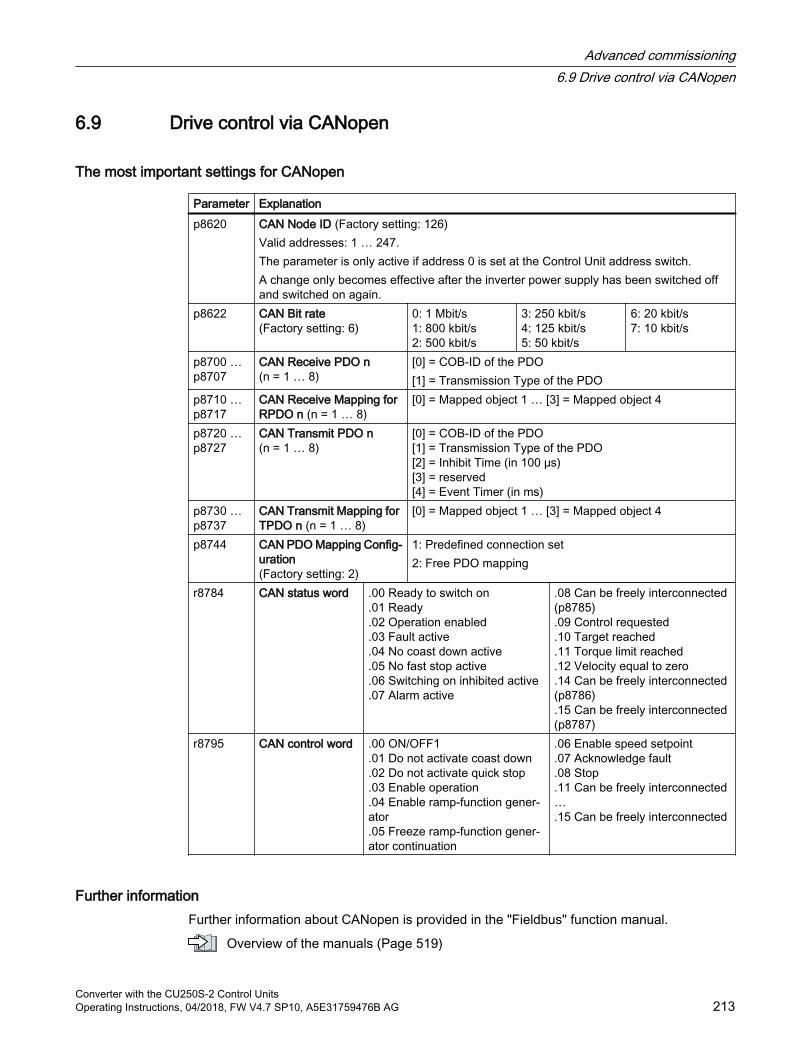
6.9 Drive control via CANopen
The most important settings for CANopen
Parameter Explanationp8620 CAN Node ID (Factory setting: 126)
Valid addresses: 1 … 247.The parameter is only active if address 0 is set at the Control Unit address switch.A change only becomes effective after the inverter power supply has been switched off and switched on again.
p8622 CAN Bit rate(Factory setting: 6)
0: 1 Mbit/s1: 800 kbit/s2: 500 kbit/s
3: 250 kbit/s4: 125 kbit/s5: 50 kbit/s
6: 20 kbit/s7: 10 kbit/s
p8700 … p8707
CAN Receive PDO n(n = 1 … 8)
[0] = COB-ID of the PDO[1] = Transmission Type of the PDO
p8710 … p8717
CAN Receive Mapping for RPDO n (n = 1 … 8)
[0] = Mapped object 1 … [3] = Mapped object 4
p8720 … p8727
CAN Transmit PDO n (n = 1 … 8)
[0] = COB-ID of the PDO[1] = Transmission Type of the PDO[2] = Inhibit Time (in 100 μs)[3] = reserved[4] = Event Timer (in ms)
p8730 … p8737
CAN Transmit Mapping for TPDO n (n = 1 … 8)
[0] = Mapped object 1 … [3] = Mapped object 4
p8744 CAN PDO Mapping Config‐uration(Factory setting: 2)
1: Predefined connection set2: Free PDO mapping
r8784 CAN status word .00 Ready to switch on.01 Ready.02 Operation enabled.03 Fault active.04 No coast down active.05 No fast stop active.06 Switching on inhibited active.07 Alarm active
.08 Can be freely interconnected (p8785).09 Control requested.10 Target reached.11 Torque limit reached.12 Velocity equal to zero.14 Can be freely interconnected (p8786).15 Can be freely interconnected (p8787)
r8795 CAN control word .00 ON/OFF1.01 Do not activate coast down.02 Do not activate quick stop.03 Enable operation.04 Enable ramp-function gener‐ator.05 Freeze ramp-function gener‐ator continuation
.06 Enable speed setpoint
.07 Acknowledge fault
.08 Stop
.11 Can be freely interconnected….15 Can be freely interconnected
Further informationFurther information about CANopen is provided in the "Fieldbus" function manual.
Overview of the manuals (Page 519)
Advanced commissioning6.9 Drive control via CANopen
Converter with the CU250S-2 Control UnitsOperating Instructions, 04/2018, FW V4.7 SP10, A5E31759476B AG 213
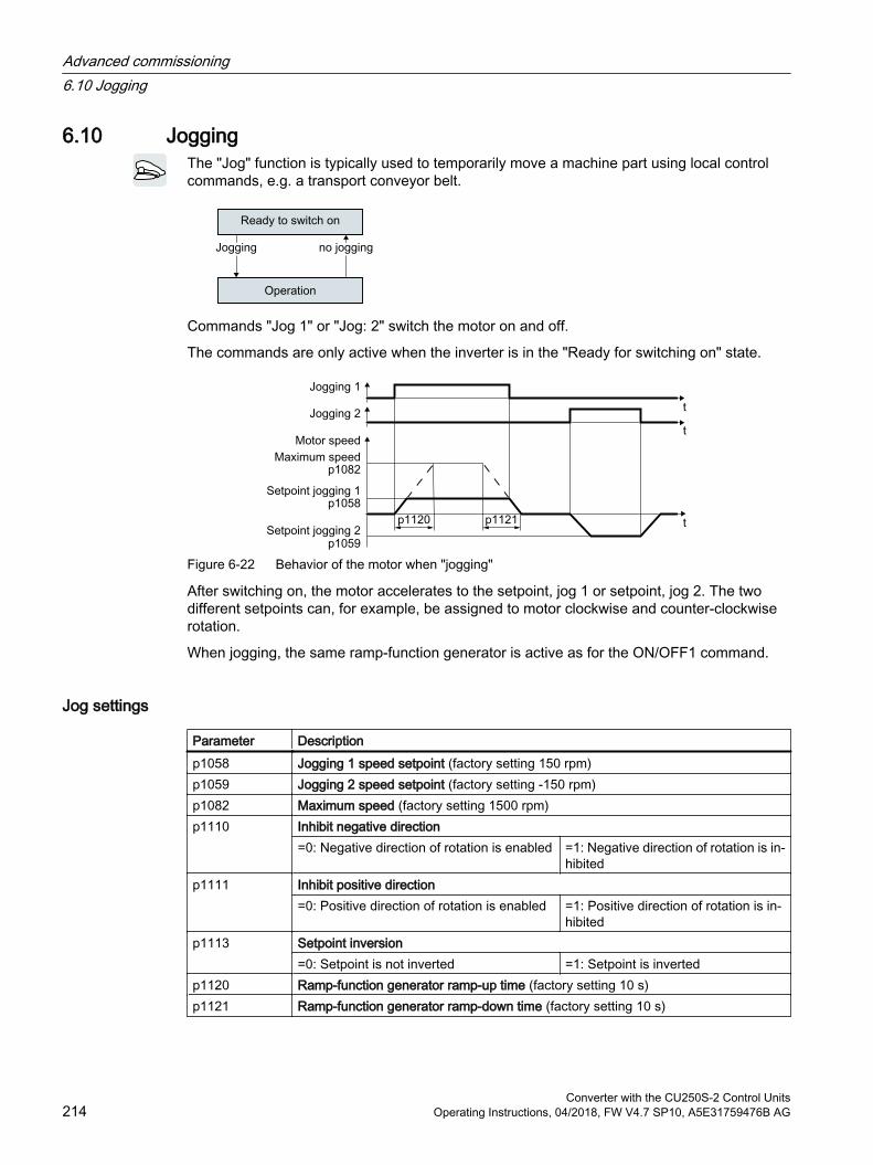
6.10 JoggingThe "Jog" function is typically used to temporarily move a machine part using local control commands, e.g. a transport conveyor belt.
Commands "Jog 1" or "Jog: 2" switch the motor on and off.
The commands are only active when the inverter is in the "Ready for switching on" state.
Figure 6-22 Behavior of the motor when "jogging"
After switching on, the motor accelerates to the setpoint, jog 1 or setpoint, jog 2. The two different setpoints can, for example, be assigned to motor clockwise and counter-clockwise rotation.
When jogging, the same ramp-function generator is active as for the ON/OFF1 command.
Jog settings
Parameter Description p1058 Jogging 1 speed setpoint (factory setting 150 rpm)p1059 Jogging 2 speed setpoint (factory setting -150 rpm)p1082 Maximum speed (factory setting 1500 rpm)p1110 Inhibit negative direction
=0: Negative direction of rotation is enabled =1: Negative direction of rotation is in‐hibited
p1111 Inhibit positive direction=0: Positive direction of rotation is enabled =1: Positive direction of rotation is in‐
hibitedp1113 Setpoint inversion
=0: Setpoint is not inverted =1: Setpoint is invertedp1120 Ramp-function generator ramp-up time (factory setting 10 s)p1121 Ramp-function generator ramp-down time (factory setting 10 s)
Advanced commissioning6.10 Jogging
Converter with the CU250S-2 Control Units214 Operating Instructions, 04/2018, FW V4.7 SP10, A5E31759476B AG

Parameter Description p1055 = 722.0 Jog bit 0: Select jogging 1 via digital input 0p1056 = 722.1 Jog bit 1: Select jogging 2 via digital input 1
Advanced commissioning6.10 Jogging
Converter with the CU250S-2 Control UnitsOperating Instructions, 04/2018, FW V4.7 SP10, A5E31759476B AG 215
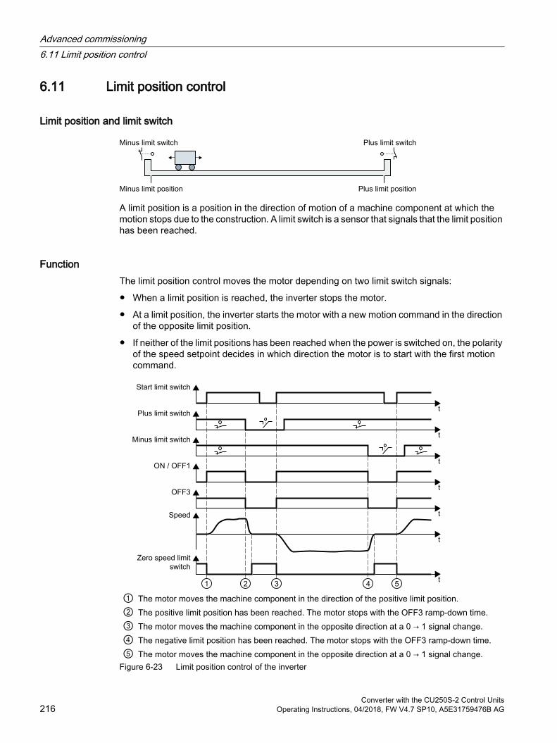
6.11 Limit position control
Limit position and limit switch
A limit position is a position in the direction of motion of a machine component at which the motion stops due to the construction. A limit switch is a sensor that signals that the limit position has been reached.
FunctionThe limit position control moves the motor depending on two limit switch signals:
When a limit position is reached, the inverter stops the motor.
At a limit position, the inverter starts the motor with a new motion command in the direction of the opposite limit position.
If neither of the limit positions has been reached when the power is switched on, the polarity of the speed setpoint decides in which direction the motor is to start with the first motion command.
① The motor moves the machine component in the direction of the positive limit position.② The positive limit position has been reached. The motor stops with the OFF3 ramp-down time.③ The motor moves the machine component in the opposite direction at a 0 → 1 signal change.④ The negative limit position has been reached. The motor stops with the OFF3 ramp-down time.⑤ The motor moves the machine component in the opposite direction at a 0 → 1 signal change.
Figure 6-23 Limit position control of the inverter
Advanced commissioning6.11 Limit position control
Converter with the CU250S-2 Control Units216 Operating Instructions, 04/2018, FW V4.7 SP10, A5E31759476B AG
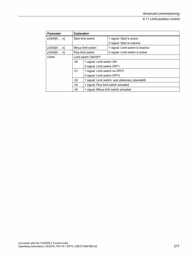
Parameter Explanationp3340[0 … n] Start limit switch 1 signal: Start is active
0 signal: Start is inactivep3342[0 … n] Minus limit switch 1 signal: Limit switch is inactive
0 signal: Limit switch is activep3343[0 … n] Plus limit switchr3344 Limit switch ON/OFF
.00 1 signal: Limit switch ON0 signal: Limit switch OFF1
.01 1 signal: Limit switch no OFF30 signal: Limit switch OFF3
.02 1 signal: Limit switch, axis stationary (standstill)
.04 1 signal: Plus limit switch actuated
.05 1 signal: Minus limit switch actuated
Advanced commissioning6.11 Limit position control
Converter with the CU250S-2 Control UnitsOperating Instructions, 04/2018, FW V4.7 SP10, A5E31759476B AG 217
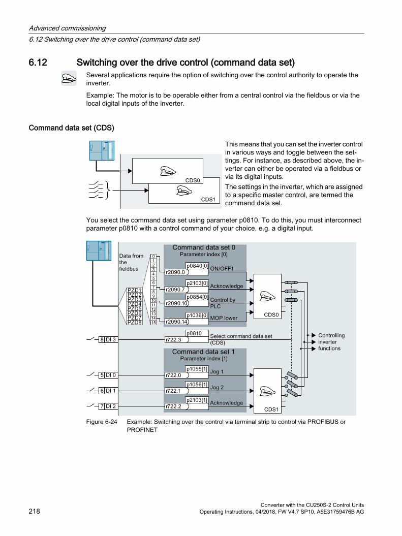
6.12 Switching over the drive control (command data set)Several applications require the option of switching over the control authority to operate the inverter.
Example: The motor is to be operable either from a central control via the fieldbus or via the local digital inputs of the inverter.
Command data set (CDS)
This means that you can set the inverter control in various ways and toggle between the set‐tings. For instance, as described above, the in‐verter can either be operated via a fieldbus or via its digital inputs.The settings in the inverter, which are assigned to a specific master control, are termed the command data set.
You select the command data set using parameter p0810. To do this, you must interconnect parameter p0810 with a control command of your choice, e.g. a digital input.
Figure 6-24 Example: Switching over the control via terminal strip to control via PROFIBUS or PROFINET
Advanced commissioning6.12 Switching over the drive control (command data set)
Converter with the CU250S-2 Control Units218 Operating Instructions, 04/2018, FW V4.7 SP10, A5E31759476B AG
An overview of all the parameters that belong to the command data sets is provided in the List Manual.
Note
It takes approximately 4 ms to toggle between command data sets.
Changing the number of command data sets
Procedure1. Set p0010 = 15.
2. The number of command data sets is configured with p0170.
3. Set p0010 = 0.
You have changed the number of command data sets.
Copying command data sets
Procedure1. Set p0809[0] to the number of the command data set whose settings you wish to copy
(source).
2. Set p0809[1] to the number of the command data set in which you wish to copy the settings.
3. Set p0809[2] = 1
4. The inverter sets p0809[2] = 0.
You have copied the settings of a command data set into another command data set.
Parameter
Parameter Description p0010 Drive commissioning parameter filterr0050 Command data set CDS active
Displays the number of the currently active command data setp0170 Number of command data sets (CDS) (factory setting: 2)
p0170 = 2, 3 or 4p0809[0] Copying the command data set CDS (factory setting: 0)
[0] Source command data set[1] Target command data set[2] 0→1: Starts the copy operation
p0810 Command data set selection CDS bit 0p0811 Command data set selection CDS bit 1
Advanced commissioning6.12 Switching over the drive control (command data set)
Converter with the CU250S-2 Control UnitsOperating Instructions, 04/2018, FW V4.7 SP10, A5E31759476B AG 219
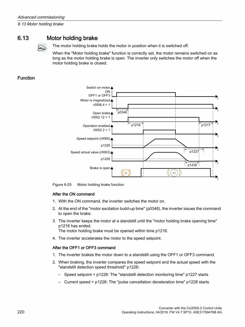
6.13 Motor holding brakeThe motor holding brake holds the motor in position when it is switched off.
When the "Motor holding brake" function is correctly set, the motor remains switched on as long as the motor holding brake is open. The inverter only switches the motor off when the motor holding brake is closed.
Function
Figure 6-25 Motor holding brake function
After the ON command1. With the ON command, the inverter switches the motor on.
2. At the end of the "motor excitation build-up time" (p0346), the inverter issues the command to open the brake.
3. The inverter keeps the motor at a standstill until the "motor holding brake opening time" p1216 has ended.The motor holding brake must be opened within time p1216.
4. The inverter accelerates the motor to the speed setpoint.
After the OFF1 or OFF3 command1. The inverter brakes the motor down to a standstill using the OFF1 or OFF3 command.
2. When braking, the inverter compares the speed setpoint and the actual speed with the "standstill detection speed threshold" p1226:
– Speed setpoint < p1226: The "standstill detection monitoring time" p1227 starts
– Current speed < p1226: The "pulse cancellation deceleration time" p1228 starts
Advanced commissioning6.13 Motor holding brake
Converter with the CU250S-2 Control Units220 Operating Instructions, 04/2018, FW V4.7 SP10, A5E31759476B AG
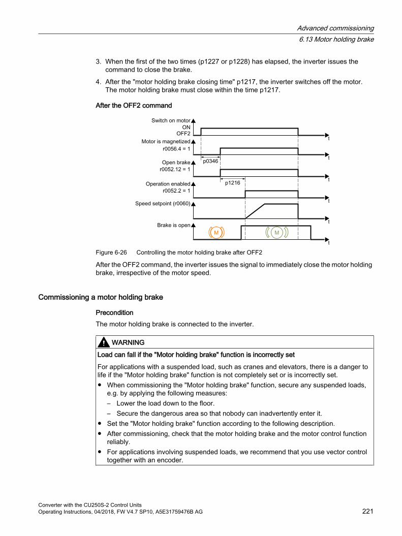
3. When the first of the two times (p1227 or p1228) has elapsed, the inverter issues the command to close the brake.
4. After the "motor holding brake closing time" p1217, the inverter switches off the motor.The motor holding brake must close within the time p1217.
After the OFF2 command
Figure 6-26 Controlling the motor holding brake after OFF2
After the OFF2 command, the inverter issues the signal to immediately close the motor holding brake, irrespective of the motor speed.
Commissioning a motor holding brake
PreconditionThe motor holding brake is connected to the inverter.
WARNING
Load can fall if the "Motor holding brake" function is incorrectly set
For applications with a suspended load, such as cranes and elevators, there is a danger to life if the "Motor holding brake" function is not completely set or is incorrectly set. When commissioning the "Motor holding brake" function, secure any suspended loads,
e.g. by applying the following measures:– Lower the load down to the floor.– Secure the dangerous area so that nobody can inadvertently enter it.
Set the "Motor holding brake" function according to the following description. After commissioning, check that the motor holding brake and the motor control function
reliably. For applications involving suspended loads, we recommend that you use vector control
together with an encoder.
Advanced commissioning6.13 Motor holding brake
Converter with the CU250S-2 Control UnitsOperating Instructions, 04/2018, FW V4.7 SP10, A5E31759476B AG 221
Procedure1. Set p1215 = 1.
The "Motor holding brake" function is enabled.
2. Check the magnetizing time p0346.The magnetizing time must be greater than zero. The inverter assigns the magnetizing time when it is being commissioned.
3. Find out the mechanical opening and closing times from the technical data of the motor holding brake.
– Depending on the brake size, brake opening times lie between 25 ms and 500 ms.
– Depending on the brake size, brake closing times lie between 15 ms and 300 ms.
4. Set the following parameters in the inverter suitably for the mechanical opening and closing times of the motor holding brake:
– p1216 ≥ mechanical opening time of the motor holding brake
– p1217 > mechanical closing time of the motor holding brake
5. Switch on the motor.
6. Check the acceleration behavior of the drive immediately after the motor has been switched on:
– If the motor holding brake opens too late, the inverter will accelerate the motor suddenly against the closed motor holding brake.Set p1216 larger.
– If the motor waits too long before accelerating after the motor holding brake has opened, reduce p1216.For applications involving a pulling load, e.g. lifting gear/crane, if p1216 is too long, then the load can briefly sag/sink after the motor holding brake is opened. If you reduce p1216, then the amount that the load sags/sinks is reduced.
7. If the load sags after switching on the motor, then you must increase the motor torque when opening the motor holding brake. Depending on the control mode, you must set different parameters:
– U/f control (p1300 = 0 to 3):Increase p1310 in small steps.Increase p1351 in small steps.
– Vector control (p1300 ≥ 20):Increase p1475 in small steps.
8. Switch off the motor.
9. Check the behavior of the drive immediately after the motor has been switched off:
– If the motor holding brake closes too late, the load briefly sags before the motor holding brake closes.Set a larger value for p1217.
– If the motor waits too long before switching off after the motor holding brake has closed, reduce p1217.
The "Motor holding brake" function has been commissioned.
Advanced commissioning6.13 Motor holding brake
Converter with the CU250S-2 Control Units222 Operating Instructions, 04/2018, FW V4.7 SP10, A5E31759476B AG
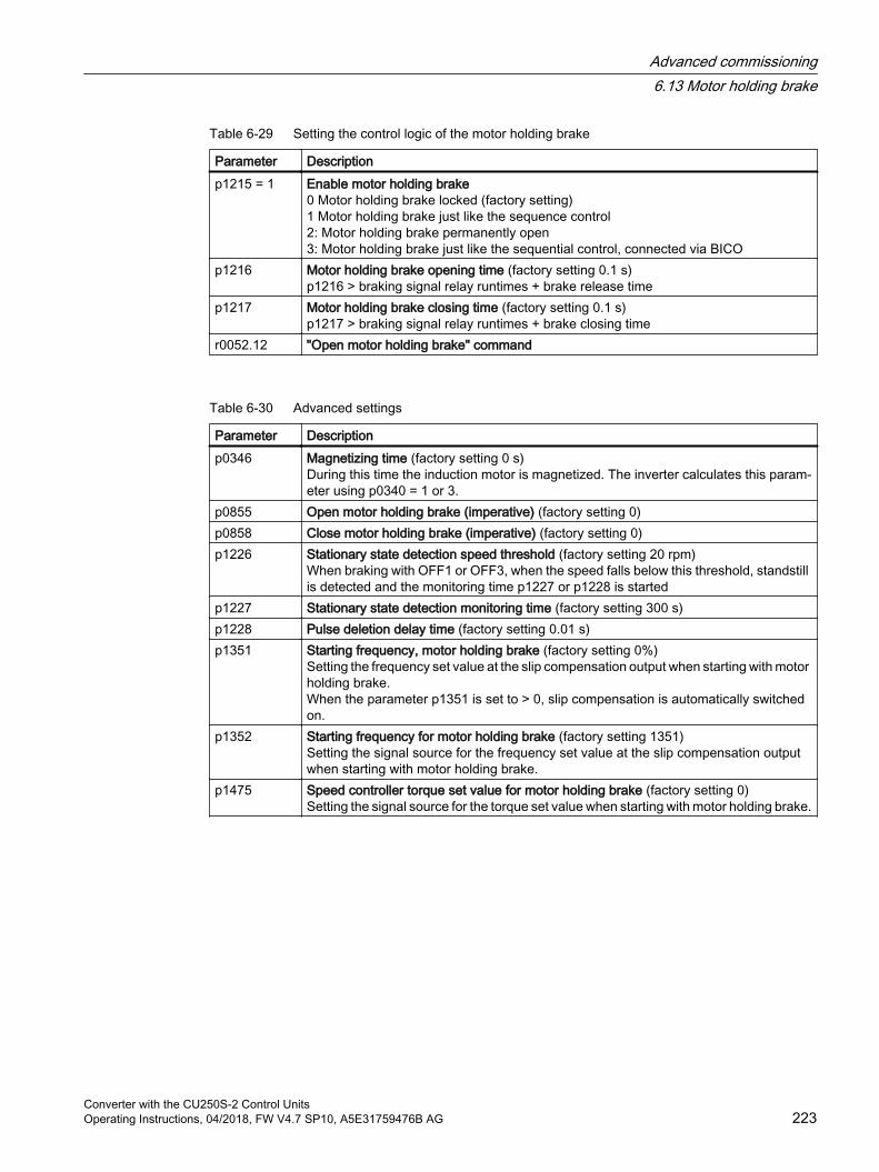
Table 6-29 Setting the control logic of the motor holding brake
Parameter Description p1215 = 1 Enable motor holding brake
0 Motor holding brake locked (factory setting) 1 Motor holding brake just like the sequence control2: Motor holding brake permanently open3: Motor holding brake just like the sequential control, connected via BICO
p1216 Motor holding brake opening time (factory setting 0.1 s)p1216 > braking signal relay runtimes + brake release time
p1217 Motor holding brake closing time (factory setting 0.1 s)p1217 > braking signal relay runtimes + brake closing time
r0052.12 "Open motor holding brake" command
Table 6-30 Advanced settings
Parameter Description p0346 Magnetizing time (factory setting 0 s)
During this time the induction motor is magnetized. The inverter calculates this param‐eter using p0340 = 1 or 3.
p0855 Open motor holding brake (imperative) (factory setting 0)p0858 Close motor holding brake (imperative) (factory setting 0)p1226 Stationary state detection speed threshold (factory setting 20 rpm)
When braking with OFF1 or OFF3, when the speed falls below this threshold, standstill is detected and the monitoring time p1227 or p1228 is started
p1227 Stationary state detection monitoring time (factory setting 300 s)p1228 Pulse deletion delay time (factory setting 0.01 s)p1351 Starting frequency, motor holding brake (factory setting 0%)
Setting the frequency set value at the slip compensation output when starting with motor holding brake.When the parameter p1351 is set to > 0, slip compensation is automatically switched on.
p1352 Starting frequency for motor holding brake (factory setting 1351)Setting the signal source for the frequency set value at the slip compensation output when starting with motor holding brake.
p1475 Speed controller torque set value for motor holding brake (factory setting 0)Setting the signal source for the torque set value when starting with motor holding brake.
Advanced commissioning6.13 Motor holding brake
Converter with the CU250S-2 Control UnitsOperating Instructions, 04/2018, FW V4.7 SP10, A5E31759476B AG 223
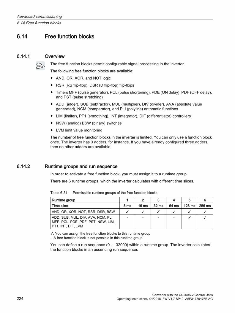
6.14 Free function blocks
6.14.1 OverviewThe free function blocks permit configurable signal processing in the inverter.
The following free function blocks are available:
AND, OR, XOR, and NOT logic
RSR (RS flip-flop), DSR (D flip-flop) flip-flops
Timers MFP (pulse generator), PCL (pulse shortening), PDE (ON delay), PDF (OFF delay), and PST (pulse stretching)
ADD (adder), SUB (subtractor), MUL (multiplier), DIV (divider), AVA (absolute value generated), NCM (comparator), and PLI (polyline) arithmetic functions
LIM (limiter), PT1 (smoothing), INT (integrator), DIF (differentiator) controllers
NSW (analog) BSW (binary) switches
LVM limit value monitoring
The number of free function blocks in the inverter is limited. You can only use a function block once. The inverter has 3 adders, for instance. If you have already configured three adders, then no other adders are available.
6.14.2 Runtime groups and run sequenceIn order to activate a free function block, you must assign it to a runtime group.
There are 6 runtime groups, which the inverter calculates with different time slices.
Table 6-31 Permissible runtime groups of the free function blocks
Runtime group 1 2 3 4 5 6Time slice 8 ms 16 ms 32 ms 64 ms 128 ms 256 msAND, OR, XOR, NOT, RSR, DSR, BSW ADD, SUB, MUL, DIV, AVA, NCM, PLI, MFP, PCL, PDE, PDF, PST, NSW, LIM, PT1, INT, DIF, LVM
- - - -
: You can assign the free function blocks to this runtime group-: A free function block is not possible in this runtime group
You can define a run sequence (0 … 32000) within a runtime group. The inverter calculates the function blocks in an ascending run sequence.
Advanced commissioning6.14 Free function blocks
Converter with the CU250S-2 Control Units224 Operating Instructions, 04/2018, FW V4.7 SP10, A5E31759476B AG
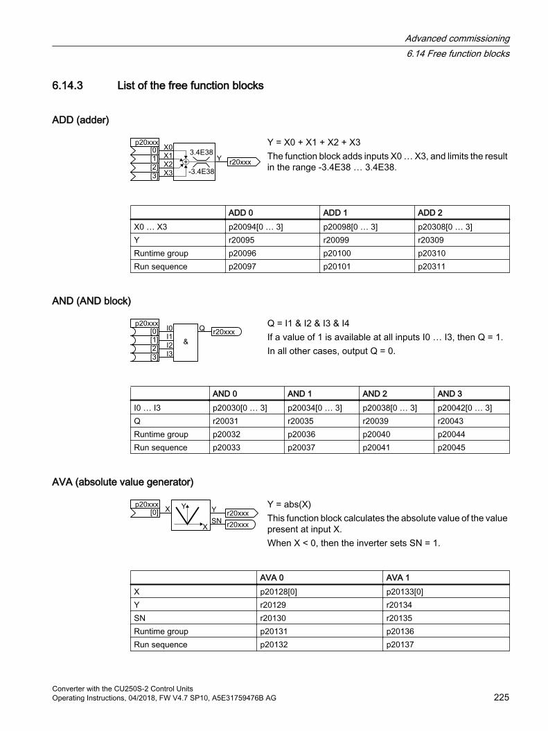
6.14.3 List of the free function blocks
ADD (adder)
Y = X0 + X1 + X2 + X3The function block adds inputs X0 … X3, and limits the result in the range -3.4E38 … 3.4E38.
ADD 0 ADD 1 ADD 2X0 … X3 p20094[0 … 3] p20098[0 … 3] p20308[0 … 3]Y r20095 r20099 r20309Runtime group p20096 p20100 p20310Run sequence p20097 p20101 p20311
AND (AND block)
Q = I1 & I2 & I3 & I4If a value of 1 is available at all inputs I0 … I3, then Q = 1.In all other cases, output Q = 0.
AND 0 AND 1 AND 2 AND 3I0 … I3 p20030[0 … 3] p20034[0 … 3] p20038[0 … 3] p20042[0 … 3]Q r20031 r20035 r20039 r20043Runtime group p20032 p20036 p20040 p20044Run sequence p20033 p20037 p20041 p20045
AVA (absolute value generator)
Y = abs(X)This function block calculates the absolute value of the value present at input X.When X < 0, then the inverter sets SN = 1.
AVA 0 AVA 1X p20128[0] p20133[0]Y r20129 r20134SN r20130 r20135Runtime group p20131 p20136Run sequence p20132 p20137
Advanced commissioning6.14 Free function blocks
Converter with the CU250S-2 Control UnitsOperating Instructions, 04/2018, FW V4.7 SP10, A5E31759476B AG 225
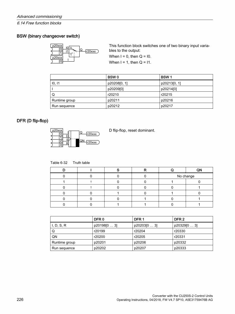
BSW (binary changeover switch)
This function block switches one of two binary input varia‐bles to the output:When I = 0, then Q = I0.When I = 1, then Q = I1.
BSW 0 BSW 1I0, I1 p20208[0, 1] p20213[0, 1]I p20209[0] p20214[0]Q r20210 r20215Runtime group p20211 p20216Run sequence p20212 p20217
DFR (D flip-flop)
D flip-flop, reset dominant.
Table 6-32 Truth table
D I S R Q QN0 0 0 0 No change1 ↑ 0 0 1 00 ↑ 0 0 0 10 0 1 0 1 00 0 0 1 0 10 0 1 1 0 1
DFR 0 DFR 1 DFR 2I, D, S, R p20198[0 … 3] p20203[0 … 3] p20329[0 … 3]Q r20199 r20204 r20330QN r20200 r20205 r20331Runtime group p20201 p20206 p20332Run sequence p20202 p20207 p20333
Advanced commissioning6.14 Free function blocks
Converter with the CU250S-2 Control Units226 Operating Instructions, 04/2018, FW V4.7 SP10, A5E31759476B AG
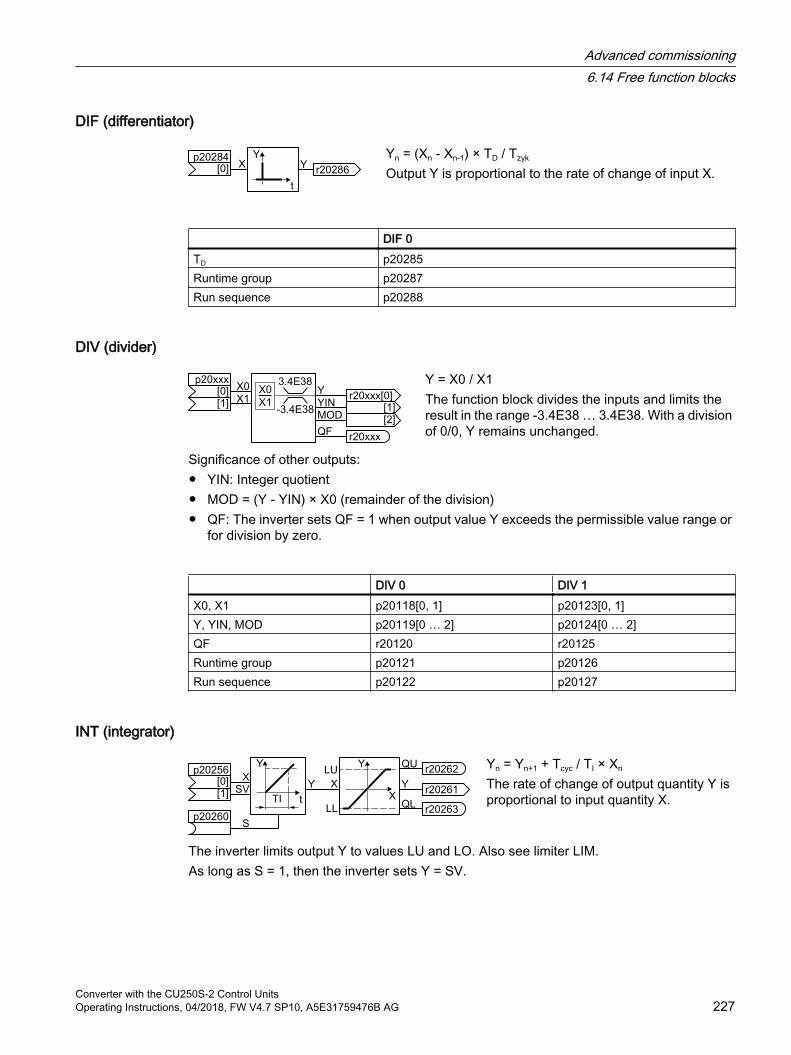
DIF (differentiator)
Yn = (Xn - Xn-1) × TD / Tzyk
Output Y is proportional to the rate of change of input X.
DIF 0TD p20285Runtime group p20287Run sequence p20288
DIV (divider)
Y = X0 / X1The function block divides the inputs and limits the result in the range -3.4E38 … 3.4E38. With a division of 0/0, Y remains unchanged.
Significance of other outputs: YIN: Integer quotient MOD = (Y - YIN) × X0 (remainder of the division) QF: The inverter sets QF = 1 when output value Y exceeds the permissible value range or
for division by zero.
DIV 0 DIV 1X0, X1 p20118[0, 1] p20123[0, 1]Y, YIN, MOD p20119[0 … 2] p20124[0 … 2]QF r20120 r20125Runtime group p20121 p20126Run sequence p20122 p20127
INT (integrator)
Yn = Yn+1 + Tcyc / TI × Xn
The rate of change of output quantity Y is proportional to input quantity X.
The inverter limits output Y to values LU and LO. Also see limiter LIM.As long as S = 1, then the inverter sets Y = SV.
Advanced commissioning6.14 Free function blocks
Converter with the CU250S-2 Control UnitsOperating Instructions, 04/2018, FW V4.7 SP10, A5E31759476B AG 227
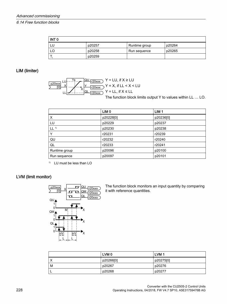
INT 0LU p20257 Runtime group p20264LO p20258 Run sequence p20265TI p20259
LIM (limiter)
Y = LU, if X ≥ LUY = X, if LL < X < LUY = LL, if X ≤ LLThe function block limits output Y to values within LL … LO.
LIM 0 LIM 1X p20228[0] p20236[0]LU p20229 p20237LL 1) p20230 p20238Y r20231 r20239QU r20232 r20240QL r20233 r20241Runtime group p20096 p20100Run sequence p20097 p20101
1) LU must be less than LO
LVM (limit monitor)
The function block monitors an input quantity by comparing it with reference quantities.
LVM 0 LVM 1X p20266[0] p20275[0]M p20267 p20276L p20268 p20277
Advanced commissioning6.14 Free function blocks
Converter with the CU250S-2 Control Units228 Operating Instructions, 04/2018, FW V4.7 SP10, A5E31759476B AG
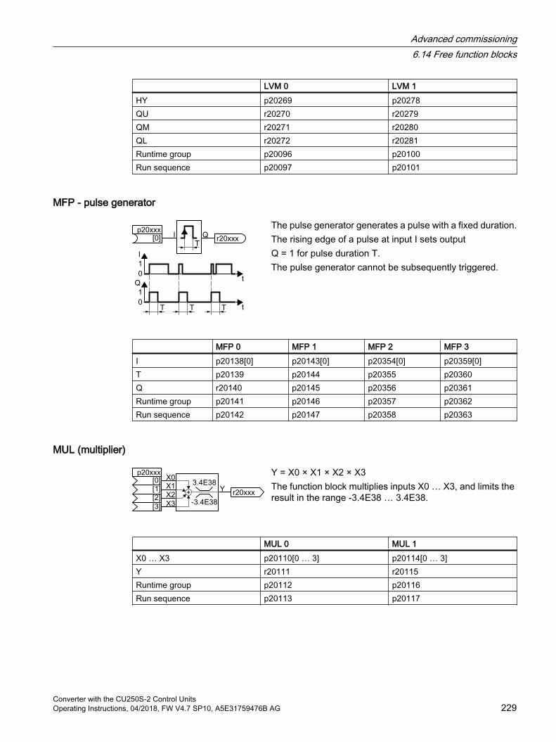
LVM 0 LVM 1HY p20269 p20278QU r20270 r20279QM r20271 r20280QL r20272 r20281Runtime group p20096 p20100Run sequence p20097 p20101
MFP - pulse generator
The pulse generator generates a pulse with a fixed duration.The rising edge of a pulse at input I sets outputQ = 1 for pulse duration T.The pulse generator cannot be subsequently triggered.
MFP 0 MFP 1 MFP 2 MFP 3I p20138[0] p20143[0] p20354[0] p20359[0]T p20139 p20144 p20355 p20360Q r20140 p20145 p20356 p20361Runtime group p20141 p20146 p20357 p20362Run sequence p20142 p20147 p20358 p20363
MUL (multiplier)
Y = X0 × X1 × X2 × X3The function block multiplies inputs X0 … X3, and limits the result in the range -3.4E38 … 3.4E38.
MUL 0 MUL 1X0 … X3 p20110[0 … 3] p20114[0 … 3]Y r20111 r20115Runtime group p20112 p20116Run sequence p20113 p20117
Advanced commissioning6.14 Free function blocks
Converter with the CU250S-2 Control UnitsOperating Instructions, 04/2018, FW V4.7 SP10, A5E31759476B AG 229
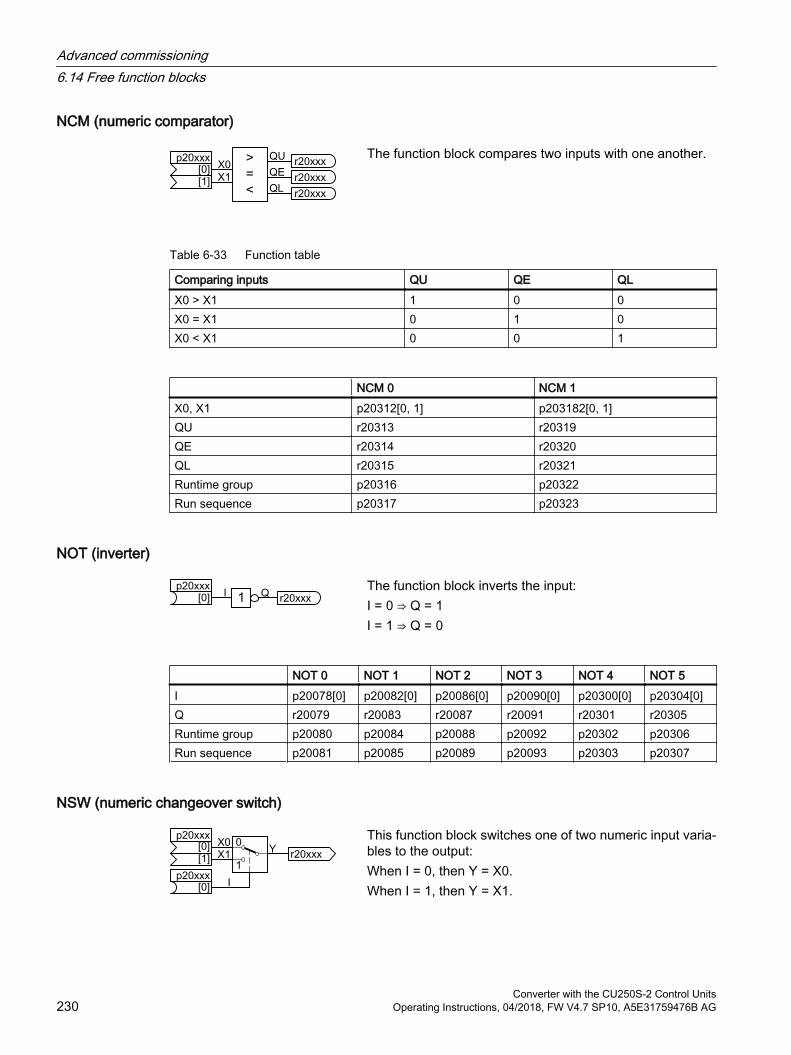
NCM (numeric comparator)
The function block compares two inputs with one another.
Table 6-33 Function table
Comparing inputs QU QE QLX0 > X1 1 0 0X0 = X1 0 1 0X0 < X1 0 0 1
NCM 0 NCM 1X0, X1 p20312[0, 1] p203182[0, 1]QU r20313 r20319QE r20314 r20320QL r20315 r20321Runtime group p20316 p20322Run sequence p20317 p20323
NOT (inverter)
The function block inverts the input:I = 0 ⇒ Q = 1I = 1 ⇒ Q = 0
NOT 0 NOT 1 NOT 2 NOT 3 NOT 4 NOT 5I p20078[0] p20082[0] p20086[0] p20090[0] p20300[0] p20304[0]Q r20079 r20083 r20087 r20091 r20301 r20305Runtime group p20080 p20084 p20088 p20092 p20302 p20306Run sequence p20081 p20085 p20089 p20093 p20303 p20307
NSW (numeric changeover switch)
This function block switches one of two numeric input varia‐bles to the output:When I = 0, then Y = X0.When I = 1, then Y = X1.
Advanced commissioning6.14 Free function blocks
Converter with the CU250S-2 Control Units230 Operating Instructions, 04/2018, FW V4.7 SP10, A5E31759476B AG
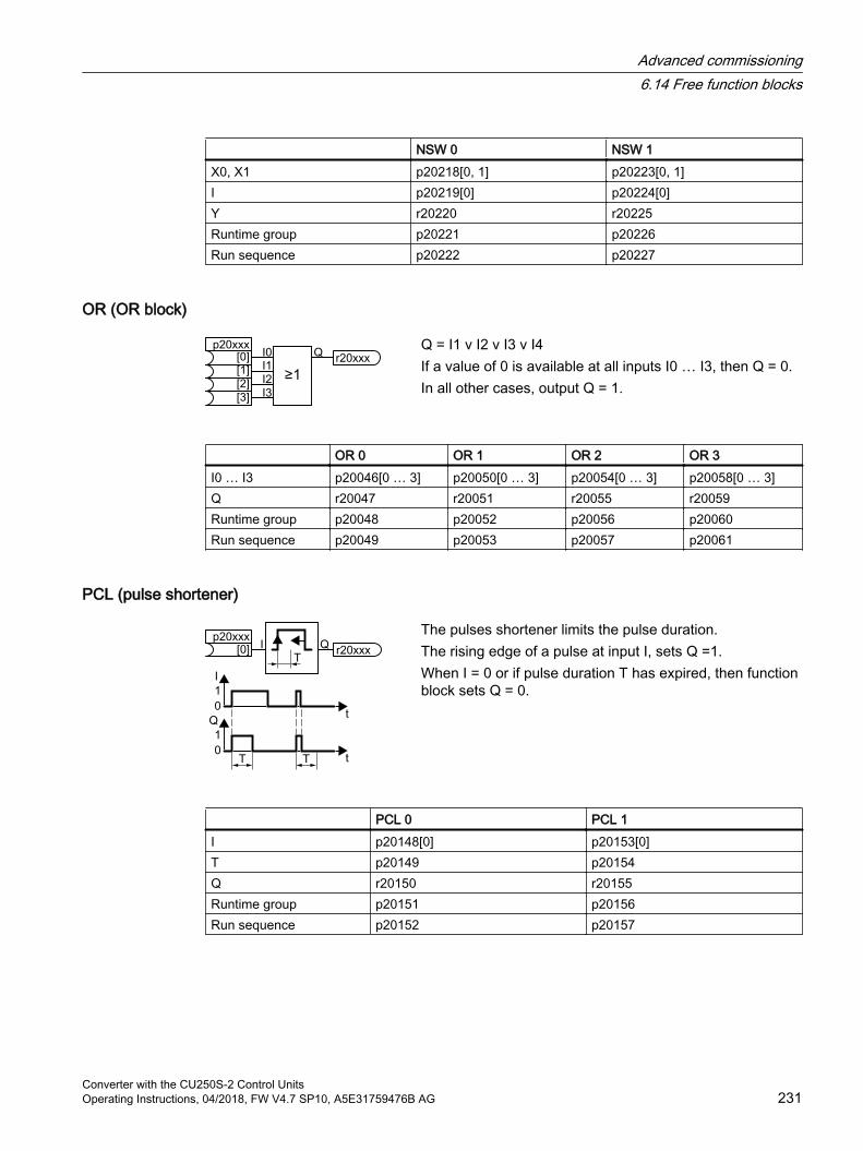
NSW 0 NSW 1X0, X1 p20218[0, 1] p20223[0, 1]I p20219[0] p20224[0]Y r20220 r20225Runtime group p20221 p20226Run sequence p20222 p20227
OR (OR block)
Q = I1 v I2 v I3 v I4If a value of 0 is available at all inputs I0 … I3, then Q = 0.In all other cases, output Q = 1.
OR 0 OR 1 OR 2 OR 3I0 … I3 p20046[0 … 3] p20050[0 … 3] p20054[0 … 3] p20058[0 … 3]Q r20047 r20051 r20055 r20059Runtime group p20048 p20052 p20056 p20060Run sequence p20049 p20053 p20057 p20061
PCL (pulse shortener)
The pulses shortener limits the pulse duration.The rising edge of a pulse at input I, sets Q =1.When I = 0 or if pulse duration T has expired, then function block sets Q = 0.
PCL 0 PCL 1I p20148[0] p20153[0]T p20149 p20154Q r20150 r20155Runtime group p20151 p20156Run sequence p20152 p20157
Advanced commissioning6.14 Free function blocks
Converter with the CU250S-2 Control UnitsOperating Instructions, 04/2018, FW V4.7 SP10, A5E31759476B AG 231
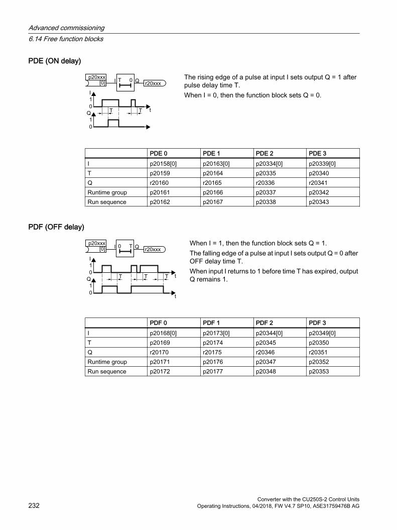
PDE (ON delay)
The rising edge of a pulse at input I sets output Q = 1 after pulse delay time T.When I = 0, then the function block sets Q = 0.
PDE 0 PDE 1 PDE 2 PDE 3I p20158[0] p20163[0] p20334[0] p20339[0]T p20159 p20164 p20335 p20340Q r20160 r20165 r20336 r20341Runtime group p20161 p20166 p20337 p20342Run sequence p20162 p20167 p20338 p20343
PDF (OFF delay)
When I = 1, then the function block sets Q = 1.The falling edge of a pulse at input I sets output Q = 0 after OFF delay time T.When input I returns to 1 before time T has expired, output Q remains 1.
PDF 0 PDF 1 PDF 2 PDF 3I p20168[0] p20173[0] p20344[0] p20349[0]T p20169 p20174 p20345 p20350Q r20170 r20175 r20346 r20351Runtime group p20171 p20176 p20347 p20352Run sequence p20172 p20177 p20348 p20353
Advanced commissioning6.14 Free function blocks
Converter with the CU250S-2 Control Units232 Operating Instructions, 04/2018, FW V4.7 SP10, A5E31759476B AG
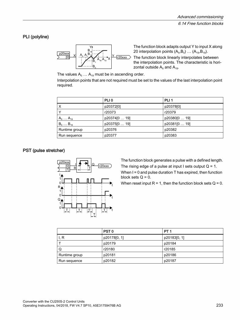
PLI (polyline)
The function block adapts output Y to input X along 20 interpolation points (A0,B0) … (A19,B19).The function block linearly interpolates between the interpolation points. The characteristic is hori‐zontal outside A0 and A19.
The values A0 … A19 must be in ascending order.Interpolation points that are not required must be set to the values of the last interpolation point required.
PLI 0 PLI 1X p20372[0] p20378[0]Y r20373 r20379A0 … A19 p20374[0 … 19] p20380[0 … 19]B0 … B19 p20375[0 … 19] p20381[0 … 19]Runtime group p20376 p20382Run sequence p20377 p20383
PST (pulse stretcher)
The function block generates a pulse with a defined length.The rising edge of a pulse at input I sets output Q = 1.When I = 0 and pulse duration T has expired, then function block sets Q = 0.When reset input R = 1, then the function block sets Q = 0.
PST 0 PT 1I, R p20178[0, 1] p20183[0, 1]T p20179 p20184Q r20180 r20185Runtime group p20181 p20186Run sequence p20182 p20187
Advanced commissioning6.14 Free function blocks
Converter with the CU250S-2 Control UnitsOperating Instructions, 04/2018, FW V4.7 SP10, A5E31759476B AG 233
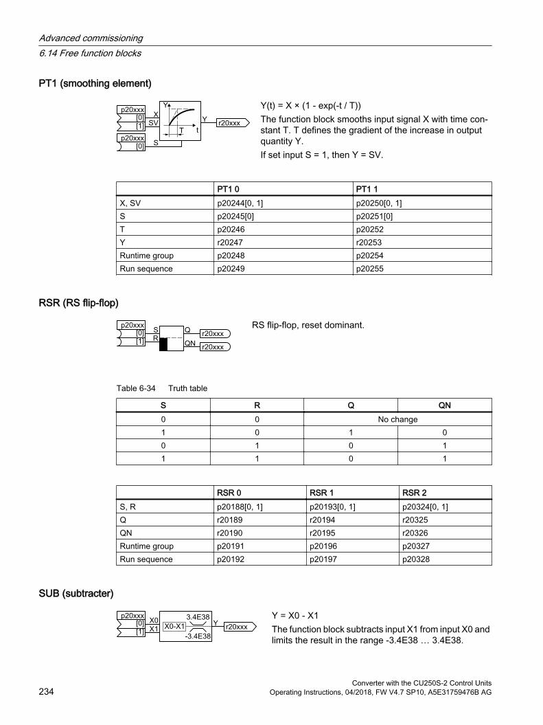
PT1 (smoothing element)
Y(t) = X × (1 - exp(-t / T))The function block smooths input signal X with time con‐stant T. T defines the gradient of the increase in output quantity Y.If set input S = 1, then Y = SV.
PT1 0 PT1 1X, SV p20244[0, 1] p20250[0, 1]S p20245[0] p20251[0]T p20246 p20252Y r20247 r20253Runtime group p20248 p20254Run sequence p20249 p20255
RSR (RS flip-flop)
RS flip-flop, reset dominant.
Table 6-34 Truth table
S R Q QN0 0 No change1 0 1 00 1 0 11 1 0 1
RSR 0 RSR 1 RSR 2S, R p20188[0, 1] p20193[0, 1] p20324[0, 1]Q r20189 r20194 r20325QN r20190 r20195 r20326Runtime group p20191 p20196 p20327Run sequence p20192 p20197 p20328
SUB (subtracter)
Y = X0 - X1The function block subtracts input X1 from input X0 and limits the result in the range -3.4E38 … 3.4E38.
Advanced commissioning6.14 Free function blocks
Converter with the CU250S-2 Control Units234 Operating Instructions, 04/2018, FW V4.7 SP10, A5E31759476B AG
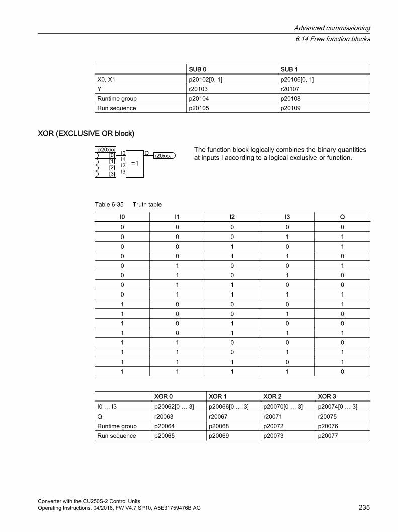
SUB 0 SUB 1X0, X1 p20102[0, 1] p20106[0, 1]Y r20103 r20107Runtime group p20104 p20108Run sequence p20105 p20109
XOR (EXCLUSIVE OR block)
The function block logically combines the binary quantities at inputs I according to a logical exclusive or function.
Table 6-35 Truth table
I0 I1 I2 I3 Q0 0 0 0 00 0 0 1 10 0 1 0 10 0 1 1 00 1 0 0 10 1 0 1 00 1 1 0 00 1 1 1 11 0 0 0 11 0 0 1 01 0 1 0 01 0 1 1 11 1 0 0 01 1 0 1 11 1 1 0 11 1 1 1 0
XOR 0 XOR 1 XOR 2 XOR 3I0 … I3 p20062[0 … 3] p20066[0 … 3] p20070[0 … 3] p20074[0 … 3]Q r20063 r20067 r20071 r20075Runtime group p20064 p20068 p20072 p20076Run sequence p20065 p20069 p20073 p20077
Advanced commissioning6.14 Free function blocks
Converter with the CU250S-2 Control UnitsOperating Instructions, 04/2018, FW V4.7 SP10, A5E31759476B AG 235
6.14.4 ScalingIf you interconnect a physical quantity, e.g. speed or voltage to the input of a free function block, then the inverter automatically scales the signal to a value of 1. The analog output signals of the free function blocks are also scaled: 0 ≙ 0 %, 1≙ 100 %.
If you interconnect the output signal of a free function block with a function that requires physical input quantities, then the inverter converts the scaled signal into the physical quantity.
Scaling parameters of physical quantities
Speed 100 % ≙ p2000 (reference speed) Example: p2000 = 3000 rpm, actual speed 2100 rpm ⇒ the scaled input quantity
= 2100 / 3000 = 0.7.Voltage 100 % ≙ p2001 reference voltageCurrent 100 % ≙ p2002 reference currentTorque 100 % ≙ p2003 reference torquePower 100 % ≙ p2004 reference powerAngle 100 % ≙ p2005 reference angleTemperature 100 % ≙ p2006 reference temperature Example: p2006 = 100 °C, actual temperature = 120 °C. ⇒ the scaled input
quantity = 120 °C / 100 °C = 1.2.
The allocation of parameters and scaling parameters is provided in the parameter description of the List Manual.
LimitsThe inverter expects limits within the free function blocks as scaled values:
Scaled limit = physical limit value / value of the reference parameter
Advanced commissioning6.14 Free function blocks
Converter with the CU250S-2 Control Units236 Operating Instructions, 04/2018, FW V4.7 SP10, A5E31759476B AG

6.14.5 Activating free function blockThe free function blocks are not active in the factory setting.
Activating and interconnecting free function blocks
PreconditionYou have configured the inverter with the "Free function blocks" function module.
Quick commissioning with a PC (Page 134)
Procedure1. Activate the function block: Assign the function block to a runtime group of your choice.
Example: Assign ADD 0 to runtime group 1: p20096 = 1.
2. If you have assigned several function blocks to the same runtime group, define a sensible run sequence within the runtime group.Example: Calculate ADD 0 before ADD 1: p20097 < p20101.
3. Interconnect the inputs and outputs of the function block with the required signals in the inverter.
You have activated a free function block and interconnected its inputs and outputs.
6.14.6 Further information
Application description for the free function blocksFurther information is provided on the Internet:
FAQ (http://support.automation.siemens.com/WW/view/en/85168215)
Advanced commissioning6.14 Free function blocks
Converter with the CU250S-2 Control UnitsOperating Instructions, 04/2018, FW V4.7 SP10, A5E31759476B AG 237
6.15 Selecting physical units
6.15.1 Motor standard
Selection options and parameters involvedThe inverter represents the motor data corresponding to motor standard IEC or NEMA in different system units: SI units or US units.
Table 6-36 Parameters involved when selecting the motor standard
Parame‐ter
Designation Motor standard IEC/NEMA, p0100 =01)
IEC motor50 Hz, SI units
1NEMA motor
60 Hz, US units
2NEMA motor
60 Hz, SI unitsr0206 Power Module rated power kW hp kWp0219 Braking resistor braking power kW hp kWp0307 Rated motor power kW hp kWp0316 Motor torque constant Nm/A lbf ft/A Nm/Ar0333 Rated motor torque Nm lbf ft Nmp0341 Motor moment of inertia kgm2 lb ft2 kgm2
p0344 Motor weight kg Lb kgr0394 Rated motor power kW hp kWr1493 Total moment of inertia, scaled kgm2 lb ft2 kgm2
1) Factory setting
It is only possible to change the motor standard during quick commissioning.
6.15.2 System of unitsSome physical units depend on the system of units selected (SI or US), for example the power [kW or hp] or the torque [Nm or lbf ft]. You can select in which system of units the converter represents its physical values.
Options when selecting the system of unitsThe following options apply when selecting the system of units:
p0505 = 1: System of units SI (factory setting)Torque [Nm], power [kW], temperature [°C or K]
p0505 = 2: Referred system of units/SIRepresented as [%]
Advanced commissioning6.15 Selecting physical units
Converter with the CU250S-2 Control Units238 Operating Instructions, 04/2018, FW V4.7 SP10, A5E31759476B AG
p0505 = 3: US system of unitsTorque [lbf ft], power [hp], temperature [°F]
p0505 = 4: System of units, referred/USRepresented as [%]
Special featuresThe values for p0505 = 2 and for p0505 = 4 - represented in the converter - are identical. However, the reference to SI or US units is required for internal calculations and to output physical variables.
For variables, which cannot be represented as [%], then the following applies: p0505 = 1 ≙ p0505 = 2 and p0505 = 3 ≙ p0505 = 4.
In the case of variables whose units are identical in the SI system and US system, and which can be displayed as a percentage, the following applies: p0505 = 1 ≙ p0505 = 3 and p0505 = 2 ≙ p0505 = 4.
Reference variablesThere is a reference variable in the converter for most parameters with physical units. When the referred representation [%] is set, then the converter scales the physical variables based on the particular reference variable.
When the reference variable changes, then the significance of the scaled value also changes. Example:
Reference speed = 1500 rpm → fixed speed = 80 % ≙ 1200 rpm
Reference speed = 3000 rpm → fixed speed = 80 % ≙ 2400 rpm
For each parameter you can find the associated reference variable for scaling in the List Manual. Example: r0065 is scaled with reference variable p2000.
If scaling is not specified in the List Manual, then the converter always represents/displays the parameter unscaled (not normalized).
Groups of unitsThe parameters associated with the selection of a physical unit, belong to different groups of units.
You can find the associated group of units in the List Manual for each parameter. Example: r0333 belongs to unit group 7_4.
An overview of the unit groups and the possible physical units can also be found in the List Manual.
Advanced commissioning6.15 Selecting physical units
Converter with the CU250S-2 Control UnitsOperating Instructions, 04/2018, FW V4.7 SP10, A5E31759476B AG 239
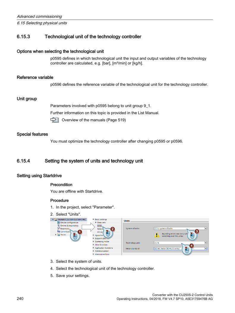
6.15.3 Technological unit of the technology controller
Options when selecting the technological unitp0595 defines in which technological unit the input and output variables of the technology controller are calculated, e.g. [bar], [m³/min] or [kg/h].
Reference variablep0596 defines the reference variable of the technological unit for the technology controller.
Unit groupParameters involved with p0595 belong to unit group 9_1.
Further information on this topic is provided in the List Manual.
Overview of the manuals (Page 519)
Special featuresYou must optimize the technology controller after changing p0595 or p0596.
6.15.4 Setting the system of units and technology unit
Setting using Startdrive
PreconditionYou are offline with Startdrive.
Procedure1. In the project, select "Parameter".
2. Select "Units".
3. Select the system of units.
4. Select the technological unit of the technology controller.
5. Save your settings.
Advanced commissioning6.15 Selecting physical units
Converter with the CU250S-2 Control Units240 Operating Instructions, 04/2018, FW V4.7 SP10, A5E31759476B AG

6. Go online.The inverter signals that offline, other units and process variables are set than in the inverter itself.
7. Accept these settings in the inverter.
You have selected the motor standard and system of units.
Advanced commissioning6.15 Selecting physical units
Converter with the CU250S-2 Control UnitsOperating Instructions, 04/2018, FW V4.7 SP10, A5E31759476B AG 241

6.16 Extended messages
OverviewYou must configure the "Extended messages" function module in order to be able to use the extended messages.
Inverter function modules (Page 132)
Parameter Explanationp2152 Delay for comparison n > n_max (Factory setting: 200 ms)p2157 Speed threshold value 5 (Factory setting: 900 rpm)p2158 Delay for n_act comparison with speed threshold value 5 (Factory setting: 10 ms)p2159 Speed threshold value 6 (Factory setting: 900 rpm)p2160 Delay for n_act comparison with speed threshold value 6 (Factory setting: 10 ms)p2170 Current threshold value (Factory setting: 0 A)p2171 Current threshold value reached delay time (Factory setting: 10 ms)p2172 DC-link voltage threshold value (Factory setting: 800 V)p2173 DC-link voltage comparison delay time (Factory setting: 10 ms)p2176 Torque threshold value comparison delay time (Factory setting: 200 ms)
Advanced commissioning6.16 Extended messages
Converter with the CU250S-2 Control Units242 Operating Instructions, 04/2018, FW V4.7 SP10, A5E31759476B AG
Parameter Explanationp2179 Output load detection current limit (Factory setting: 0 A) Rotation
monitoring (Page 341)
p2180 Output load detection delay time (Factory setting: 2000 ms)p2181 Load monitoring response (Factory setting: 0)
0: Load monitoring deactivated1: A07920 for torque/speed too low2: A07921 for torque/speed too high3: A07922 for torque/speed out of tolerance4: F07923 for torque/speed too low5: F07924 for torque/speed too high6: F07925 for torque/speed outside the tolerance
p2182 Load monitoring speed threshold 1 (Factory setting: 150 rpm)p2183 Load monitoring speed threshold 2 (Factory setting: 900 rpm)p2184 Load monitoring speed threshold 3 (Factory setting: 1500 rpm)p2185 Load monitoring torque threshold 1 upper (Factory setting:
1000000 Nm)p2186 Load monitoring torque threshold 1 lower (Factory setting: 0 Nm)p2187 Load monitoring torque threshold 2 upper (Factory setting:
1000000 Nm)p2188 Load monitoring torque threshold 2 lower (Factory setting: 0 Nm)p2189 Load monitoring torque threshold 3 upper (Factory setting:
1000000 Nm)p2190 Load monitoring torque threshold 3 lower (Factory setting: 0 Nm)p2192 Load monitoring delay time (Factory setting: 10 s)p2193 Load monitoring configuration (factory setting: 1)
0: Monitoring deactivated1: Torque and load failure monitoring2: Speed and load failure monitoring3: Load failure monitoring
p3231 Load monitoring speed deviation (Factory setting: 150 rpm)p3233 Torque actual value filter time constant (Factory setting: 100 ms)
You will find more information in the List Manual.
Overview of the manuals (Page 519)
Advanced commissioning6.16 Extended messages
Converter with the CU250S-2 Control UnitsOperating Instructions, 04/2018, FW V4.7 SP10, A5E31759476B AG 243
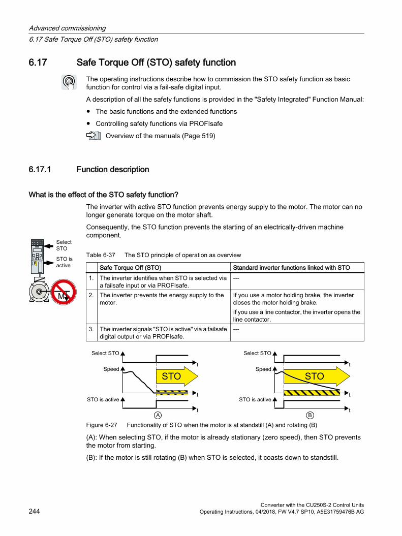
6.17 Safe Torque Off (STO) safety functionThe operating instructions describe how to commission the STO safety function as basic function for control via a fail-safe digital input.
A description of all the safety functions is provided in the "Safety Integrated" Function Manual:
The basic functions and the extended functions
Controlling safety functions via PROFIsafe
Overview of the manuals (Page 519)
6.17.1 Function description
What is the effect of the STO safety function?The inverter with active STO function prevents energy supply to the motor. The motor can no longer generate torque on the motor shaft.
Consequently, the STO function prevents the starting of an electrically-driven machine component.
Table 6-37 The STO principle of operation as overview
Safe Torque Off (STO) Standard inverter functions linked with STO1. The inverter identifies when STO is selected via
a failsafe input or via PROFIsafe.---
2. The inverter prevents the energy supply to the motor.
If you use a motor holding brake, the inverter closes the motor holding brake.If you use a line contactor, the inverter opens the line contactor.
3. The inverter signals "STO is active" via a failsafe digital output or via PROFIsafe.
---
Figure 6-27 Functionality of STO when the motor is at standstill (A) and rotating (B)
(A): When selecting STO, if the motor is already stationary (zero speed), then STO prevents the motor from starting.
(B): If the motor is still rotating (B) when STO is selected, it coasts down to standstill.
Advanced commissioning6.17 Safe Torque Off (STO) safety function
Converter with the CU250S-2 Control Units244 Operating Instructions, 04/2018, FW V4.7 SP10, A5E31759476B AG
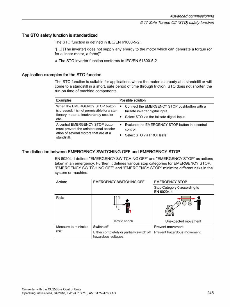
The STO safety function is standardized The STO function is defined in IEC/EN 61800-5-2:
"[…] [The inverter] does not supply any energy to the motor which can generate a torque (or for a linear motor, a force)".
⇒ The STO inverter function conforms to IEC/EN 61800-5-2.
Application examples for the STO functionThe STO function is suitable for applications where the motor is already at a standstill or will come to a standstill in a short, safe period of time through friction. STO does not shorten the run-on time of machine components.
Examples Possible solutionWhen the EMERGENCY STOP button is pressed, it is not permissible for a sta‐tionary motor to inadvertently acceler‐ate.
Connect the EMERGENCY STOP pushbutton with a failsafe inverter digital input.
Select STO via the failsafe digital input.
A central EMERGENCY STOP button must prevent the unintentional acceler‐ation of several motors that are at a standstill.
Evaluate the EMERGENCY STOP button in a central control.
Select STO via PROFIsafe.
The distinction between EMERGENCY SWITCHING OFF and EMERGENCY STOPEN 60204‑1 defines "EMERGENCY SWITCHING OFF" and "EMERGENCY STOP" as actions taken in an emergency. Further, it defines various stop categories for EMERGENCY STOP. "EMERGENCY SWITCHING OFF" and "EMERGENCY STOP" minimize different risks in the system or machine.
Action: EMERGENCY SWITCHING OFF EMERGENCY STOPStop Category 0 according to EN 60204‑1
Risk:
Electric shock Unexpected movementMeasure to minimize risk:
Switch offEither completely or partially switch off hazardous voltages.
Prevent movementPrevent hazardous movement.
Advanced commissioning6.17 Safe Torque Off (STO) safety function
Converter with the CU250S-2 Control UnitsOperating Instructions, 04/2018, FW V4.7 SP10, A5E31759476B AG 245
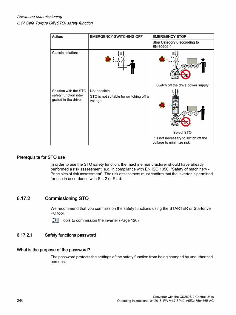
Action: EMERGENCY SWITCHING OFF EMERGENCY STOPStop Category 0 according to EN 60204‑1
Classic solution:
Switch off the drive power supplySolution with the STO safety function inte‐grated in the drive:
Not possible.STO is not suitable for switching off a voltage.
Select STOIt is not necessary to switch off the voltage to minimize risk.
Prerequisite for STO useIn order to use the STO safety function, the machine manufacturer should have already performed a risk assessment, e.g. in compliance with EN ISO 1050, "Safety of machinery - Principles of risk assessment". The risk assessment must confirm that the inverter is permitted for use in accordance with SIL 2 or PL d.
6.17.2 Commissioning STO
We recommend that you commission the safety functions using the STARTER or Startdrive PC tool.
Tools to commission the inverter (Page 126)
6.17.2.1 Safety functions password
What is the purpose of the password?The password protects the settings of the safety function from being changed by unauthorized persons.
Advanced commissioning6.17 Safe Torque Off (STO) safety function
Converter with the CU250S-2 Control Units246 Operating Instructions, 04/2018, FW V4.7 SP10, A5E31759476B AG
Do you have to assign a password?You do not have to assign a password.
The machine manufacturer decides whether or not a password is required.
The probabilities of failure (PFH) and certification of the safety functions also apply without password.
What do I do if I lose the password?
RequirementYou have forgotten the password, however, you would nevertheless like to change the setting of the safety functions.
Procedure1. Create a new project for the inverter using Startdrive.
Leave all the factory setting in the project.
2. Load the project in the inverter.After loading, the inverter has the factory settings.
3. If a memory card inserted in the inverter, remove it.
4. Recommission the inverter.
You can obtain more information or learn about alternative procedures from Technical Support.
No. Description p9761 Entering a password (factory setting 0000 hex)
0: No password set1 … FFFF FFFF: Password is set
p9762 New passwordp9763 Password confirmation
Advanced commissioning6.17 Safe Torque Off (STO) safety function
Converter with the CU250S-2 Control UnitsOperating Instructions, 04/2018, FW V4.7 SP10, A5E31759476B AG 247
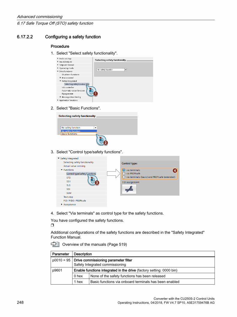
6.17.2.2 Configuring a safety function
Procedure1. Select "Select safety functionality".
2. Select "Basic Functions".
3. Select "Control type/safety functions".
4. Select "Via terminals" as control type for the safety functions.
You have configured the safety functions.
Additional configurations of the safety functions are described in the "Safety Integrated" Function Manual.
Overview of the manuals (Page 519)
Parameter Description p0010 = 95 Drive commissioning parameter filter
Safety Integrated commissioningp9601 Enable functions integrated in the drive (factory setting: 0000 bin)
0 hex None of the safety functions has been released1 hex Basic functions via onboard terminals has been enabled
Advanced commissioning6.17 Safe Torque Off (STO) safety function
Converter with the CU250S-2 Control Units248 Operating Instructions, 04/2018, FW V4.7 SP10, A5E31759476B AG
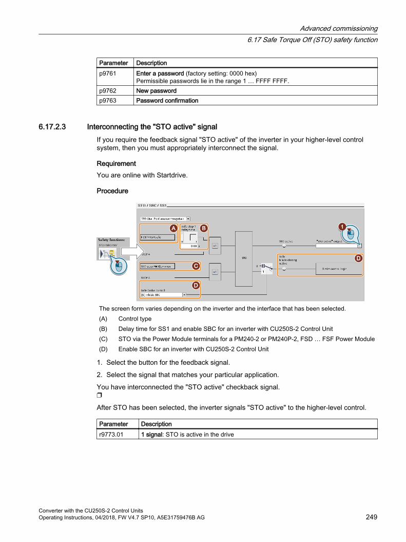
Parameter Description p9761 Enter a password (factory setting: 0000 hex)
Permissible passwords lie in the range 1 … FFFF FFFF.p9762 New passwordp9763 Password confirmation
6.17.2.3 Interconnecting the "STO active" signalIf you require the feedback signal "STO active" of the inverter in your higher-level control system, then you must appropriately interconnect the signal.
RequirementYou are online with Startdrive.
Procedure
The screen form varies depending on the inverter and the interface that has been selected.(A) Control type(B) Delay time for SS1 and enable SBC for an inverter with CU250S‑2 Control Unit(C) STO via the Power Module terminals for a PM240‑2 or PM240P‑2, FSD … FSF Power Module(D) Enable SBC for an inverter with CU250S‑2 Control Unit
1. Select the button for the feedback signal.
2. Select the signal that matches your particular application.
You have interconnected the "STO active" checkback signal.
After STO has been selected, the inverter signals "STO active" to the higher-level control.
Parameter Description r9773.01 1 signal: STO is active in the drive
Advanced commissioning6.17 Safe Torque Off (STO) safety function
Converter with the CU250S-2 Control UnitsOperating Instructions, 04/2018, FW V4.7 SP10, A5E31759476B AG 249
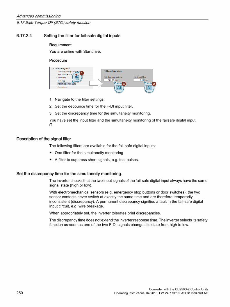
6.17.2.4 Setting the filter for fail-safe digital inputs
RequirementYou are online with Startdrive.
Procedure
1. Navigate to the filter settings.
2. Set the debounce time for the F-DI input filter.
3. Set the discrepancy time for the simultaneity monitoring.
You have set the input filter and the simultaneity monitoring of the failsafe digital input.
Description of the signal filterThe following filters are available for the fail-safe digital inputs:
One filter for the simultaneity monitoring
A filter to suppress short signals, e.g. test pulses.
Set the discrepancy time for the simultaneity monitoring.The inverter checks that the two input signals of the fail-safe digital input always have the same signal state (high or low).
With electromechanical sensors (e.g. emergency stop buttons or door switches), the two sensor contacts never switch at exactly the same time and are therefore temporarily inconsistent (discrepancy). A permanent discrepancy signifies a fault in the fail-safe digital input circuit, e.g. wire breakage.
When appropriately set, the inverter tolerates brief discrepancies.
The discrepancy time does not extend the inverter response time. The inverter selects its safety function as soon as one of the two F-DI signals changes its state from high to low.
Advanced commissioning6.17 Safe Torque Off (STO) safety function
Converter with the CU250S-2 Control Units250 Operating Instructions, 04/2018, FW V4.7 SP10, A5E31759476B AG
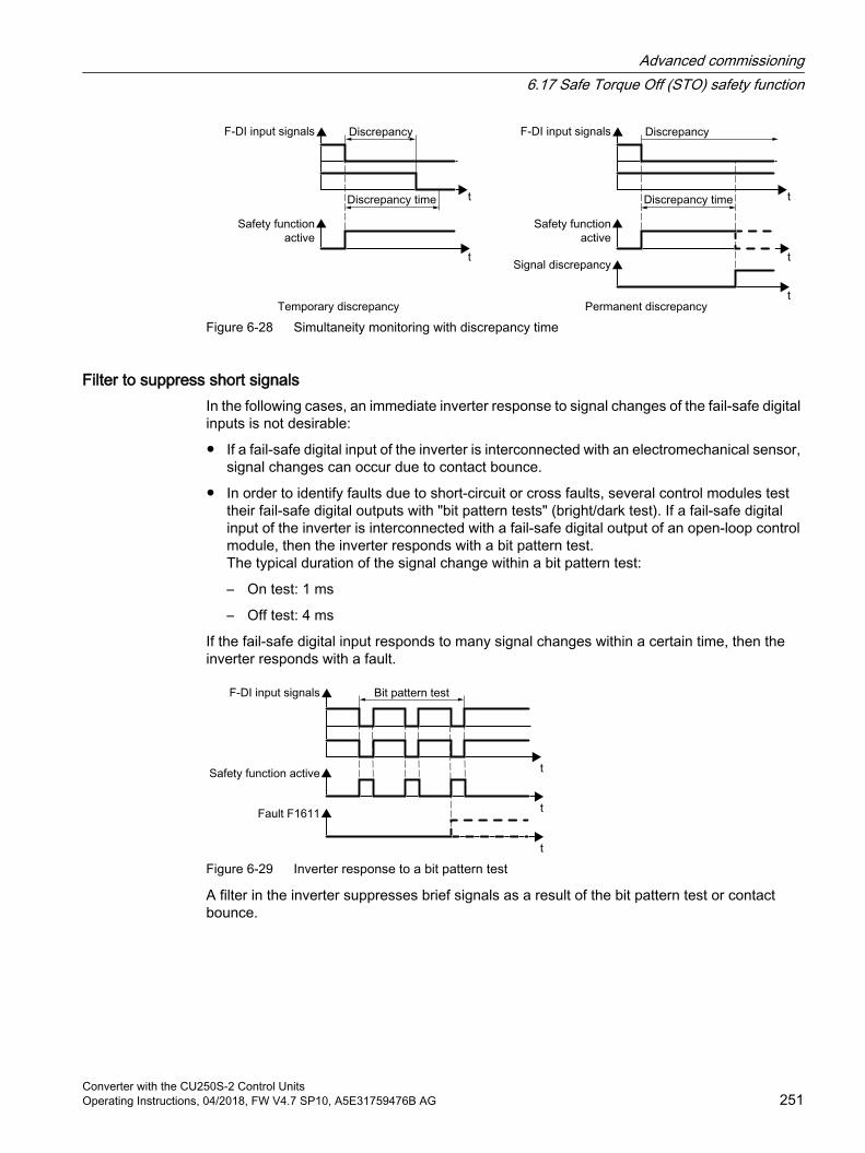
Figure 6-28 Simultaneity monitoring with discrepancy time
Filter to suppress short signalsIn the following cases, an immediate inverter response to signal changes of the fail-safe digital inputs is not desirable:
If a fail-safe digital input of the inverter is interconnected with an electromechanical sensor, signal changes can occur due to contact bounce.
In order to identify faults due to short-circuit or cross faults, several control modules test their fail-safe digital outputs with "bit pattern tests" (bright/dark test). If a fail-safe digital input of the inverter is interconnected with a fail-safe digital output of an open-loop control module, then the inverter responds with a bit pattern test.The typical duration of the signal change within a bit pattern test:
– On test: 1 ms
– Off test: 4 ms
If the fail-safe digital input responds to many signal changes within a certain time, then the inverter responds with a fault.
Figure 6-29 Inverter response to a bit pattern test
A filter in the inverter suppresses brief signals as a result of the bit pattern test or contact bounce.
Advanced commissioning6.17 Safe Torque Off (STO) safety function
Converter with the CU250S-2 Control UnitsOperating Instructions, 04/2018, FW V4.7 SP10, A5E31759476B AG 251
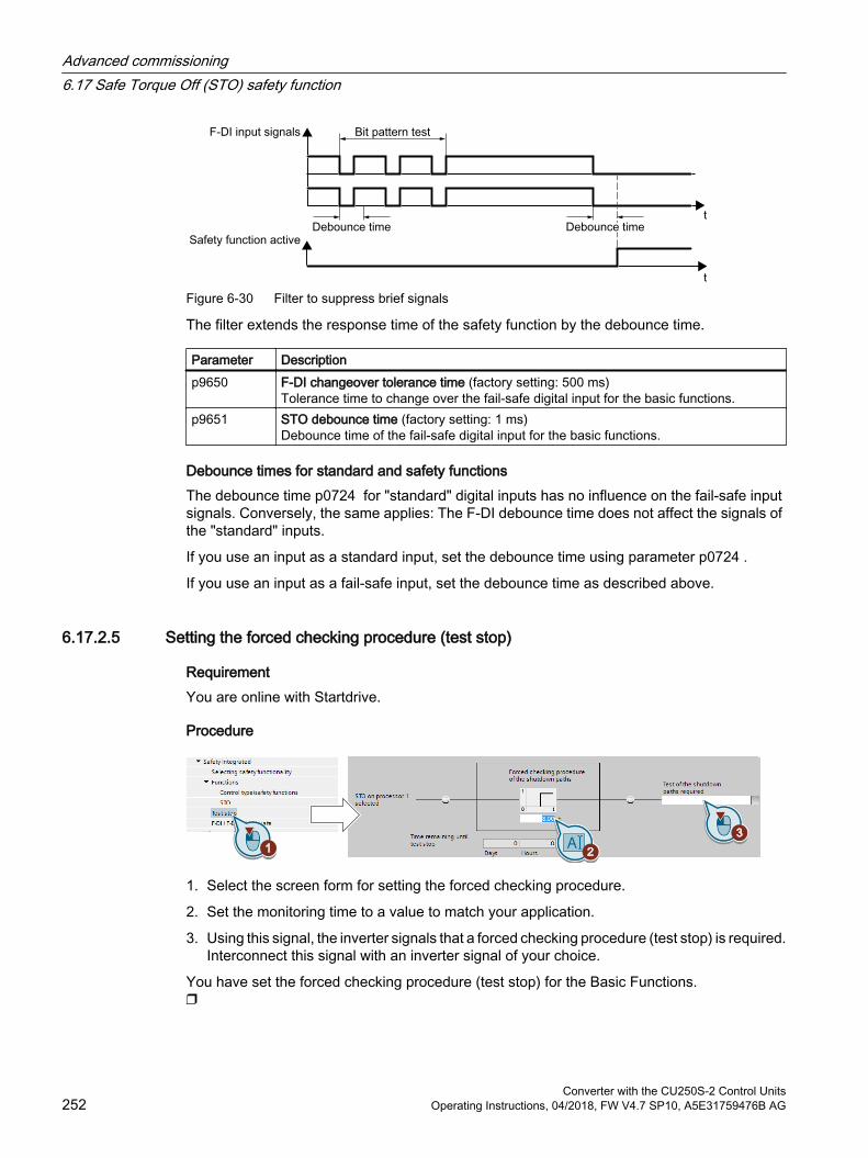
Figure 6-30 Filter to suppress brief signals
The filter extends the response time of the safety function by the debounce time.
Parameter Description p9650 F-DI changeover tolerance time (factory setting: 500 ms)
Tolerance time to change over the fail-safe digital input for the basic functions.p9651 STO debounce time (factory setting: 1 ms)
Debounce time of the fail-safe digital input for the basic functions.
Debounce times for standard and safety functionsThe debounce time p0724 for "standard" digital inputs has no influence on the fail-safe input signals. Conversely, the same applies: The F-DI debounce time does not affect the signals of the "standard" inputs.
If you use an input as a standard input, set the debounce time using parameter p0724 .
If you use an input as a fail-safe input, set the debounce time as described above.
6.17.2.5 Setting the forced checking procedure (test stop)
RequirementYou are online with Startdrive.
Procedure
1. Select the screen form for setting the forced checking procedure.
2. Set the monitoring time to a value to match your application.
3. Using this signal, the inverter signals that a forced checking procedure (test stop) is required.Interconnect this signal with an inverter signal of your choice.
You have set the forced checking procedure (test stop) for the Basic Functions.
Advanced commissioning6.17 Safe Torque Off (STO) safety function
Converter with the CU250S-2 Control Units252 Operating Instructions, 04/2018, FW V4.7 SP10, A5E31759476B AG
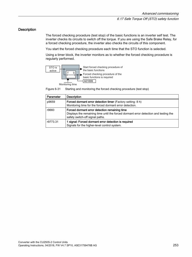
DescriptionThe forced checking procedure (test stop) of the basic functions is an inverter self test. The inverter checks its circuits to switch off the torque. If you are using the Safe Brake Relay, for a forced checking procedure, the inverter also checks the circuits of this component.
You start the forced checking procedure each time that the STO function is selected.
Using a timer block, the inverter monitors as to whether the forced checking procedure is regularly performed.
Figure 6-31 Starting and monitoring the forced checking procedure (test stop)
Parameter Description p9659 Forced dormant error detection timer (Factory setting: 8 h)
Monitoring time for the forced dormant error detection.r9660 Forced dormant error detection remaining time
Displays the remaining time until the forced dormant error detection and testing the safety switch-off signal paths.
r9773.31 1 signal: Forced dormant error detection is requiredSignals for the higher-level control system.
Advanced commissioning6.17 Safe Torque Off (STO) safety function
Converter with the CU250S-2 Control UnitsOperating Instructions, 04/2018, FW V4.7 SP10, A5E31759476B AG 253
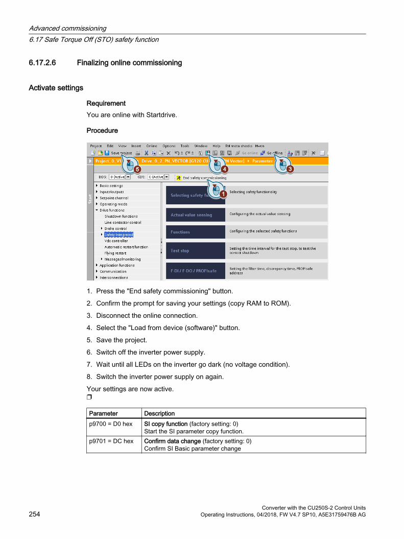
6.17.2.6 Finalizing online commissioning
Activate settings
RequirementYou are online with Startdrive.
Procedure
1. Press the "End safety commissioning" button.
2. Confirm the prompt for saving your settings (copy RAM to ROM).
3. Disconnect the online connection.
4. Select the "Load from device (software)" button.
5. Save the project.
6. Switch off the inverter power supply.
7. Wait until all LEDs on the inverter go dark (no voltage condition).
8. Switch the inverter power supply on again.
Your settings are now active.
Parameter Description p9700 = D0 hex SI copy function (factory setting: 0)
Start the SI parameter copy function.p9701 = DC hex Confirm data change (factory setting: 0)
Confirm SI Basic parameter change
Advanced commissioning6.17 Safe Torque Off (STO) safety function
Converter with the CU250S-2 Control Units254 Operating Instructions, 04/2018, FW V4.7 SP10, A5E31759476B AG
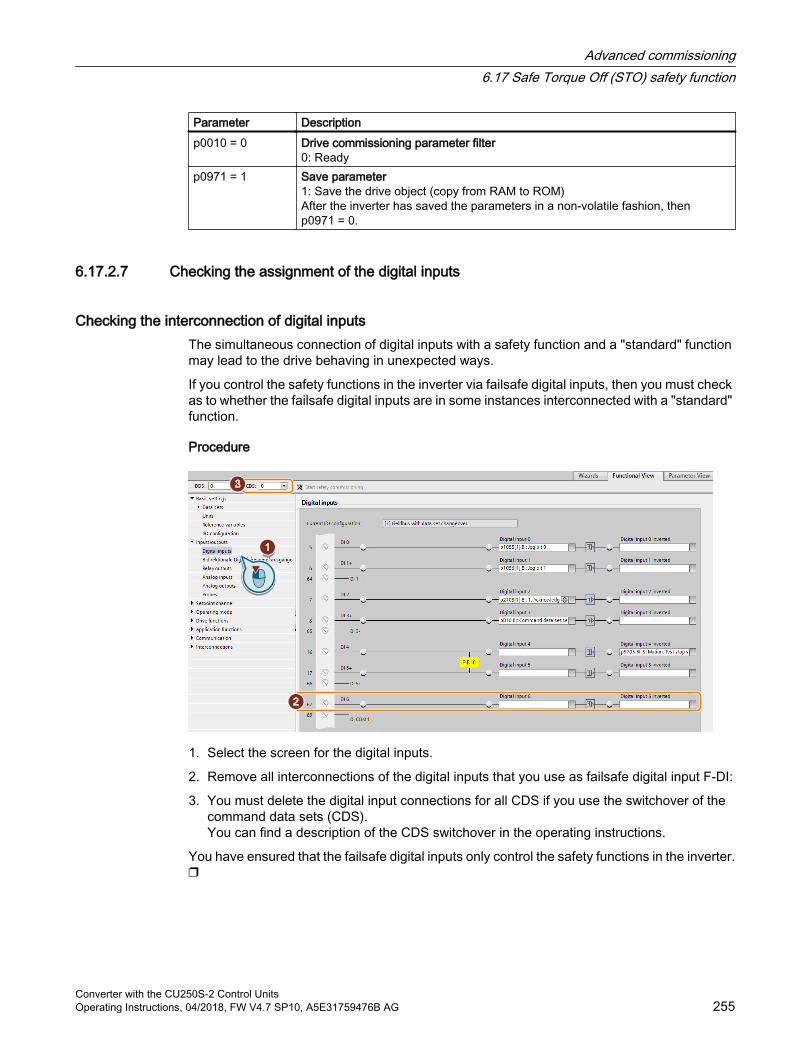
Parameter Description p0010 = 0 Drive commissioning parameter filter
0: Readyp0971 = 1 Save parameter
1: Save the drive object (copy from RAM to ROM)After the inverter has saved the parameters in a non-volatile fashion, then p0971 = 0.
6.17.2.7 Checking the assignment of the digital inputs
Checking the interconnection of digital inputsThe simultaneous connection of digital inputs with a safety function and a "standard" function may lead to the drive behaving in unexpected ways.
If you control the safety functions in the inverter via failsafe digital inputs, then you must check as to whether the failsafe digital inputs are in some instances interconnected with a "standard" function.
Procedure
1. Select the screen for the digital inputs.
2. Remove all interconnections of the digital inputs that you use as failsafe digital input F-DI:
3. You must delete the digital input connections for all CDS if you use the switchover of the command data sets (CDS). You can find a description of the CDS switchover in the operating instructions.
You have ensured that the failsafe digital inputs only control the safety functions in the inverter.
Advanced commissioning6.17 Safe Torque Off (STO) safety function
Converter with the CU250S-2 Control UnitsOperating Instructions, 04/2018, FW V4.7 SP10, A5E31759476B AG 255
6.17.2.8 Acceptance - completion of commissioning
What is an acceptance?The machine manufacturer is responsible in ensuring that his plant or machine functions perfectly. As a consequence, after commissioning, the machine manufacturer must check those functions or have them checked by specialist personnel, which represent an increased risk of injury or material damage. This acceptance or validation is, for example, also specified in the European machinery directive and essentially comprises two parts:
Checking the safety-relevant functions and machine parts.→ Acceptance test.
Generate an "Acceptance report" that describes the test results. → Documentation.
Supply information for the validation, e.g. the harmonized European standards EN ISO 13849‑1 and EN ISO 13849‑2.
Acceptance test of the machine or plantThe acceptance test checks whether the safety-relevant functions in the plant or machine function correctly. The documentation of the components used in the safety functions can also provide information about the necessary tests.
Testing the safety-related functions includes, e.g. the following:
Are all safety equipment such as protective door monitoring devices, light barriers or emergency-off switches connected and ready for operation?
Does the higher-level control respond as expected to the safety-relevant feedback signals of the inverter?
Do the inverter settings match the configured safety-relevant function in the machine?
Acceptance test of the inverterThe acceptance test of the inverter is a part of the acceptance test of the entire machine or plant.
The acceptance test of the inverter checks whether the integrated drive safety functions are set up correctly for the planned safety function of the machine.
Recommended acceptance test (Page 513)
Documentation of the inverterThe following must be documented for the inverter:
The results of the acceptance test.
The settings of the integrated drive safety functions.
The documentation must be signed.
Advanced commissioning6.17 Safe Torque Off (STO) safety function
Converter with the CU250S-2 Control Units256 Operating Instructions, 04/2018, FW V4.7 SP10, A5E31759476B AG

Who may perform the acceptance test of the inverter?Personnel from the machine manufacturer, who, on account of their technical qualifications and knowledge of the safety functions, are in a position to perform the acceptance test in the correct manner are authorized to perform the acceptance testing of the inverter.
Wizard for the acceptance test The "Startdrive Advanced" commissioning tool (requires an appropriate license) includes a wizard for the acceptance test of the safety functions integrated in the drive.
"Startdrive Advanced" guides you through the acceptance test, generates the appropriate traces to analyze the machine response – and generates an acceptance report as Excel file.
Further information is provided on the Internet:
Startdrive, system requirements and download (https://support.industry.siemens.com/cs/ww/en/view/109752254)
Reduced acceptance test after function expansionsA full acceptance test is necessary only after first commissioning. A reduced acceptance test is sufficient when safety functions are expanded.
Measure Acceptance testAcceptance test Documentation
Functional expansion of the ma‐chine (additional drive).
Yes.Only check the safety functions of the new drive.
Supplement machine overview Supplement inverter data Add function table Log the new checksums Countersignature
Transfer of inverter settings to oth‐er identical machines by means of series commissioning.
No.Only check the control of all of the safety func‐tions.
Add machine description Check checksums Check firmware versions
Advanced commissioning6.17 Safe Torque Off (STO) safety function
Converter with the CU250S-2 Control UnitsOperating Instructions, 04/2018, FW V4.7 SP10, A5E31759476B AG 257

6.18 Setpoints
6.18.1 OverviewThe inverter receives its main setpoint from the setpoint source. The main setpoint mainly specifies the motor speed.
Figure 6-32 Setpoint sources for the inverter
You have the following options when selecting the source of the main setpoint:
Inverter fieldbus interface
Analog input of the inverter
Motorized potentiometer emulated in the inverter
Fixed setpoints stored in the inverter
Probe: The inverter converts a sequence of pulse signals at the digital input into an analog value.
You have the same selection options when selecting the source of the supplementary setpoint.
Advanced commissioning6.18 Setpoints
Converter with the CU250S-2 Control Units258 Operating Instructions, 04/2018, FW V4.7 SP10, A5E31759476B AG

Under the following conditions, the inverter switches from the main setpoint to other setpoints:
When the technology controller is active and appropriately interconnected, its output specifies the motor speed.
When jogging is active
When controlling from an operator panel or the STARTER PC tool.
Advanced commissioning6.18 Setpoints
Converter with the CU250S-2 Control UnitsOperating Instructions, 04/2018, FW V4.7 SP10, A5E31759476B AG 259
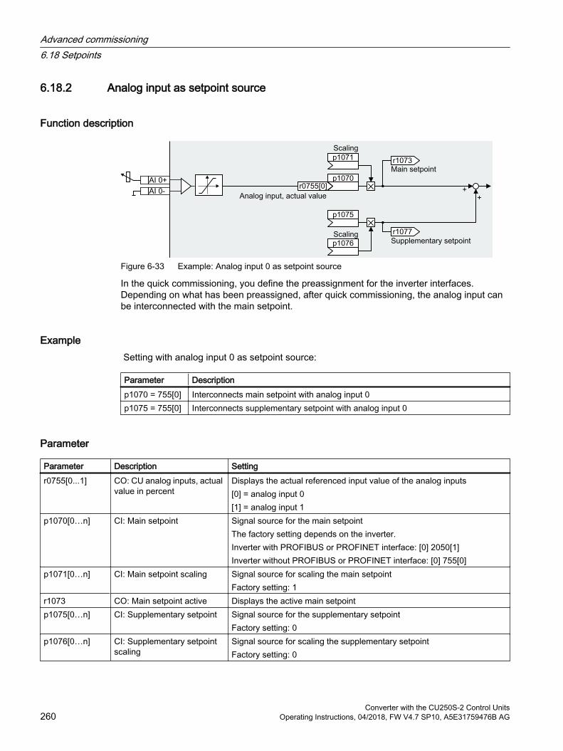
6.18.2 Analog input as setpoint source
Function description
Figure 6-33 Example: Analog input 0 as setpoint source
In the quick commissioning, you define the preassignment for the inverter interfaces. Depending on what has been preassigned, after quick commissioning, the analog input can be interconnected with the main setpoint.
Example Setting with analog input 0 as setpoint source:
Parameter Descriptionp1070 = 755[0] Interconnects main setpoint with analog input 0p1075 = 755[0] Interconnects supplementary setpoint with analog input 0
Parameter
Parameter Description Settingr0755[0...1] CO: CU analog inputs, actual
value in percentDisplays the actual referenced input value of the analog inputs[0] = analog input 0[1] = analog input 1
p1070[0…n] CI: Main setpoint Signal source for the main setpointThe factory setting depends on the inverter.Inverter with PROFIBUS or PROFINET interface: [0] 2050[1]Inverter without PROFIBUS or PROFINET interface: [0] 755[0]
p1071[0…n] CI: Main setpoint scaling Signal source for scaling the main setpointFactory setting: 1
r1073 CO: Main setpoint active Displays the active main setpointp1075[0…n] CI: Supplementary setpoint Signal source for the supplementary setpoint
Factory setting: 0p1076[0…n] CI: Supplementary setpoint
scalingSignal source for scaling the supplementary setpointFactory setting: 0
Advanced commissioning6.18 Setpoints
Converter with the CU250S-2 Control Units260 Operating Instructions, 04/2018, FW V4.7 SP10, A5E31759476B AG

Further informationFor further information refer to the function diagrams 2250 ff and 3030 of the List Manual.
Advanced commissioning6.18 Setpoints
Converter with the CU250S-2 Control UnitsOperating Instructions, 04/2018, FW V4.7 SP10, A5E31759476B AG 261
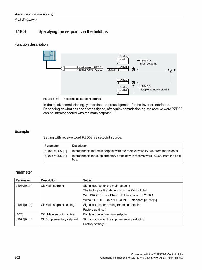
6.18.3 Specifying the setpoint via the fieldbus
Function description
Figure 6-34 Fieldbus as setpoint source
In the quick commissioning, you define the preassignment for the inverter interfaces. Depending on what has been preassigned, after quick commissioning, the receive word PZD02 can be interconnected with the main setpoint.
ExampleSetting with receive word PZD02 as setpoint source:
Parameter Descriptionp1070 = 2050[1] Interconnects the main setpoint with the receive word PZD02 from the fieldbus.p1075 = 2050[1] Interconnects the supplementary setpoint with receive word PZD02 from the field‐
bus.
Parameter
Parameter Description Settingp1070[0…n] CI: Main setpoint Signal source for the main setpoint
The factory setting depends on the Control Unit.With PROFIBUS or PROFINET interface: [0] 2050[1]Without PROFIBUS or PROFINET interface: [0] 755[0]
p1071[0…n] CI: Main setpoint scaling Signal source for scaling the main setpointFactory setting: 1
r1073 CO: Main setpoint active Displays the active main setpointp1075[0…n] CI: Supplementary setpoint Signal source for the supplementary setpoint
Factory setting: 0
Advanced commissioning6.18 Setpoints
Converter with the CU250S-2 Control Units262 Operating Instructions, 04/2018, FW V4.7 SP10, A5E31759476B AG
Parameter Description Settingp1076[0…n] CI: Supplementary setpoint
scalingSignal source for scaling the supplementary setpointFactory setting: 0
r2050[0…11] CO: PROFIdrive PZD receive word
Connector output to interconnect the PZD received from the fieldbus con‐troller in the word format.[1] Most standard telegrams receive the speed setpoint as receive word PZD02.
Further informationFor further information refer to the function diagrams 2468, 9360 and 3030 of the List Manual.
Advanced commissioning6.18 Setpoints
Converter with the CU250S-2 Control UnitsOperating Instructions, 04/2018, FW V4.7 SP10, A5E31759476B AG 263
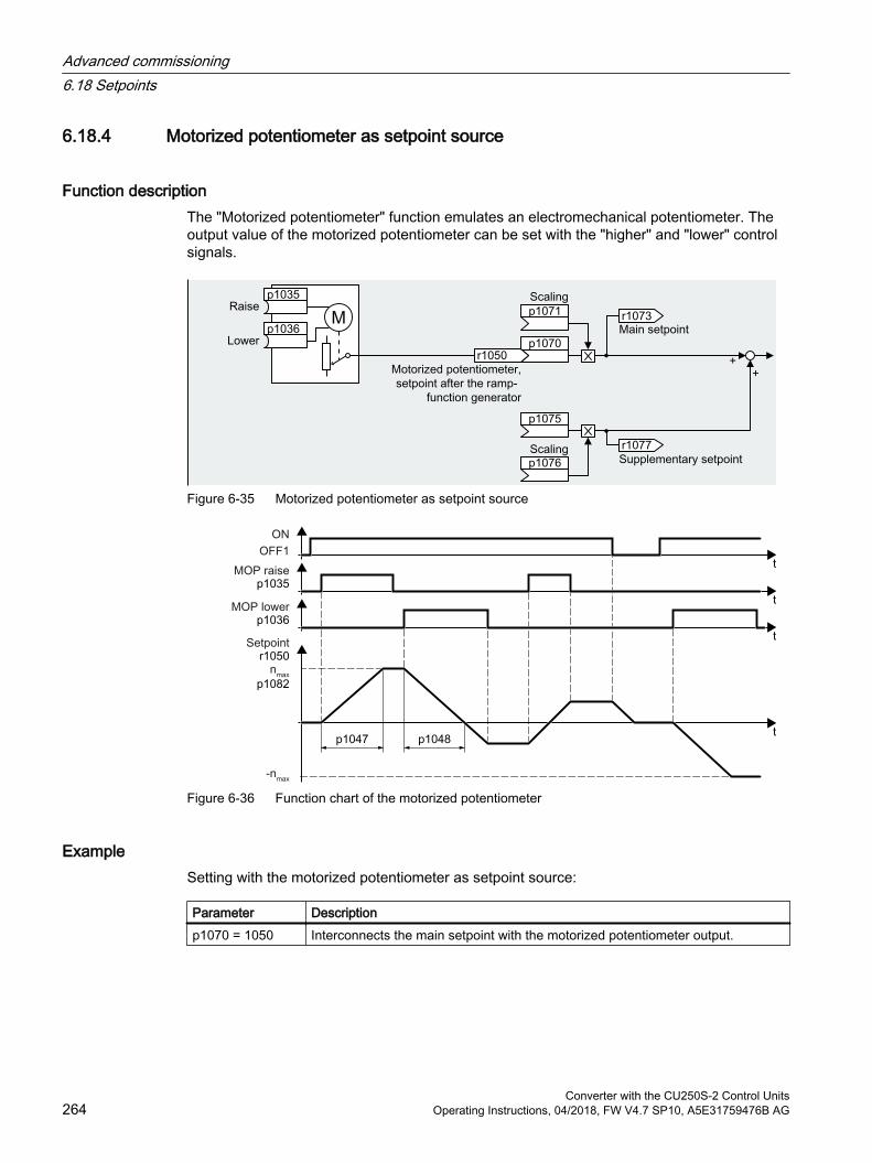
6.18.4 Motorized potentiometer as setpoint source
Function descriptionThe "Motorized potentiometer" function emulates an electromechanical potentiometer. The output value of the motorized potentiometer can be set with the "higher" and "lower" control signals.
Figure 6-35 Motorized potentiometer as setpoint source
Figure 6-36 Function chart of the motorized potentiometer
ExampleSetting with the motorized potentiometer as setpoint source:
Parameter Descriptionp1070 = 1050 Interconnects the main setpoint with the motorized potentiometer output.
Advanced commissioning6.18 Setpoints
Converter with the CU250S-2 Control Units264 Operating Instructions, 04/2018, FW V4.7 SP10, A5E31759476B AG

Parameter
Table 6-38 Basic setup of motorized potentiometer
Parameter Description Settingp1035[0…n] BI: Motorized potentiometer
setpoint higherSignal source to continuously increase the setpointThe factory setting depends on the inverter.Inverters with PROFIBUS or PROFINET interface:[0] 2090.13[1] 0Inverters without PROFIBUS or PROFINET interface: 0
p1036[0…n] BI: Motorized potentiometer setpoint lower
Signal source to continuously decrease the setpointThe factory setting depends on the inverter.Inverters with PROFIBUS or PROFINET interface:[0] 2090.14[1] 0Inverters without PROFIBUS or PROFINET interface: 0
p1040[0…n] Motorized potentiometer start value [rpm]
Start value that is effective when the motor is switched on.Factory setting: 0 rpm
p1047 MOP ramp-up time [s] MOP ramp-up timeFactory setting: 10 s
p1048 MOP ramp-down time [s] MOP ramp-down time:Factory setting: 10 s
r1050 Motorized potentiometer, set‐point after the ramp-function generator
Motorized potentiometer, setpoint after the ramp-function generator
p1070[0…n] CI: Main setpoint Signal source for the main setpointThe factory setting depends on the Control Unit.With PROFIBUS or PROFINET interface: [0] 2050[1]Without PROFIBUS or PROFINET interface: [0] 755[0]
p1071[0…n] CI: Main setpoint scaling Signal source for scaling the main setpointFactory setting: 1
r1073 CO: Main setpoint active Displays the active main setpointp1075[0…n] CI: Supplementary setpoint Signal source for the supplementary setpoint
Factory setting: 0p1076[0…n] CI: Supplementary setpoint
scalingSignal source for scaling the supplementary setpointFactory setting: 0
Advanced commissioning6.18 Setpoints
Converter with the CU250S-2 Control UnitsOperating Instructions, 04/2018, FW V4.7 SP10, A5E31759476B AG 265
Table 6-39 Extended setup of motorized potentiometer
Parameter Description Settingp1030[0…n] Motorized potentiometer con‐
figurationConfiguration for the motorized potentiometerFactory setting: 00110 bin.00Storage active= 0: After the motor has been switched on, the setpoint = p1040= 1: After the motor has switched off, the inverter saves the setpoint. After the motor has switched on, the setpoint = the stored value.01Automatic mode, ramp-function generator active (1-signal via BI: p1041)= 0: Ramp-up/ramp-down time = 0= 1: With ramp-function generatorIn manual mode (p1041 = 0), the ramp-function generator is always active..02Initial rounding active1: With initial rounding. Using the initial rounding function it is possible to enter very small setpoint changes.03Storage in NVRAM active1: If bit 00 = 1, the setpoint is retained during a power failure.04Ramp-function generator always active1: The inverter also calculates the ramp-function generator when the motor is switched off
p1037[0…n] Motorized potentiometer maximum speed [rpm]
The inverter limits the motorized potentiometer output to p1037.Factory setting: 0 rpmAfter quick commissioning, the inverter sets the parameter to the appro‐priate value.
p1038[0…n] Motorized potentiometer min‐imum speed [rpm]
The inverter limits the motorized potentiometer output to p1038.Factory setting: 0 rpmAfter quick commissioning, the inverter sets the parameter to the appro‐priate value.
p1043[0…n] BI: Motorized potentiometer, accept setting value
Signal source for accepting the setting value. The motorized potentiometer accepts the setting value p1044 on signal change p1043 = 0 → 1.Factory setting: 0
p1044[0…n] CI: Motorized potentiometer, setting value
Signal source for the setting valueFactory setting: 0
Further informationFor more information about the motorized potentiometer, refer to function diagram 3020 in the List Manual.
Advanced commissioning6.18 Setpoints
Converter with the CU250S-2 Control Units266 Operating Instructions, 04/2018, FW V4.7 SP10, A5E31759476B AG
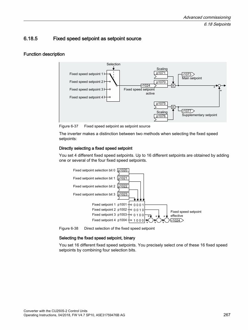
6.18.5 Fixed speed setpoint as setpoint source
Function description
Figure 6-37 Fixed speed setpoint as setpoint source
The inverter makes a distinction between two methods when selecting the fixed speed setpoints:
Directly selecting a fixed speed setpointYou set 4 different fixed speed setpoints. Up to 16 different setpoints are obtained by adding one or several of the four fixed speed setpoints.
Figure 6-38 Direct selection of the fixed speed setpoint
Selecting the fixed speed setpoint, binaryYou set 16 different fixed speed setpoints. You precisely select one of these 16 fixed speed setpoints by combining four selection bits.
Advanced commissioning6.18 Setpoints
Converter with the CU250S-2 Control UnitsOperating Instructions, 04/2018, FW V4.7 SP10, A5E31759476B AG 267
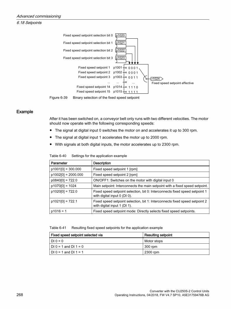
Figure 6-39 Binary selection of the fixed speed setpoint
ExampleAfter it has been switched on, a conveyor belt only runs with two different velocities. The motor should now operate with the following corresponding speeds:
The signal at digital input 0 switches the motor on and accelerates it up to 300 rpm.
The signal at digital input 1 accelerates the motor up to 2000 rpm.
With signals at both digital inputs, the motor accelerates up to 2300 rpm.
Table 6-40 Settings for the application example
Parameter Descriptionp1001[0] = 300.000 Fixed speed setpoint 1 [rpm]p1002[0] = 2000.000 Fixed speed setpoint 2 [rpm]p0840[0] = 722.0 ON/OFF1: Switches on the motor with digital input 0p1070[0] = 1024 Main setpoint: Interconnects the main setpoint with a fixed speed setpoint.p1020[0] = 722.0 Fixed speed setpoint selection, bit 0: Interconnects fixed speed setpoint 1
with digital input 0 (DI 0).p1021[0] = 722.1 Fixed speed setpoint selection, bit 1: Interconnects fixed speed setpoint 2
with digital input 1 (DI 1).p1016 = 1 Fixed speed setpoint mode: Directly selects fixed speed setpoints.
Table 6-41 Resulting fixed speed setpoints for the application example
Fixed speed setpoint selected via Resulting setpointDI 0 = 0 Motor stopsDI 0 = 1 and DI 1 = 0 300 rpmDI 0 = 1 and DI 1 = 1 2300 rpm
Advanced commissioning6.18 Setpoints
Converter with the CU250S-2 Control Units268 Operating Instructions, 04/2018, FW V4.7 SP10, A5E31759476B AG
Parameter
Parameter Description Settingp1001[0...n] Fixed speed setpoint 1 [rpm] Fixed speed setpoint 1
Factory setting: 0 rpmp1002[0...n] Fixed speed setpoint 2 [rpm] Fixed speed setpoint 2
Factory setting: 0 rpm... ... ...p1015[0...n] Fixed speed setpoint 15 [rpm] Fixed speed setpoint 15
Factory setting: 0 rpmp1016 Fixed speed setpoint mode Fixed speed setpoint mode
Factory setting: 11: Direct2: Binary
p1020[0...n] Fixed speed setpoint selec‐tion, bit 0
Fixed speed setpoint selection, bit 0Factory setting: 0
p1021[0...n] Fixed speed setpoint selec‐tion, bit 1
Fixed speed setpoint selection, bit 1Factory setting: 0
p1022[0...n] Fixed speed setpoint selec‐tion, bit 2
Fixed speed setpoint selection, bit 2Factory setting: 0
p1023[0...n] Fixed speed setpoint selec‐tion, bit 3
Fixed speed setpoint selection, bit 3Factory setting: 0
r1024 Fixed speed setpoint active Fixed speed setpoint activer1025.0 Fixed speed setpoint status Fixed speed setpoint status
1 signal: Fixed speed setpoint is selected
Further informationAdditional information about binary selection can be found in function diagram 3010 in the List Manual.
Additional information about direct selection can be found in function diagram 3011 in the List Manual.
Application example: Directly selecting two fixed speed setpointsThe motor should operate at different speeds as follows:
The signal on digital input 0 switches the motor on and accelerates it to 300 rpm.
The signal at digital input 1 accelerates the motor to 2000 rpm.
The signals at the two digital inputs accelerate the motor to 2300 rpm.
Advanced commissioning6.18 Setpoints
Converter with the CU250S-2 Control UnitsOperating Instructions, 04/2018, FW V4.7 SP10, A5E31759476B AG 269

Table 6-42 Settings for the application example
Parameter Descriptionp1001 = 300.000 Fixed speed setpoint 1 [rpm]p1002 = 2000.000 Fixed speed setpoint 2 [rpm]p0840 = 722.0 ON/OFF1: Switches on the motor with digital input 0p1070 = 1024 Main setpoint: Interconnects the main setpoint with fixed speed setpoint.p1020 = 722.0 Fixed speed setpoint selection bit 0: Interconnects fixed speed setpoint 1
with digital input 0 (DI 0).p1021 = 722.1 Fixed speed setpoint selection bit 1: Interconnects fixed speed setpoint 2
with digital input 1 (DI 1).p1016 = 1 Fixed speed setpoint mode: Directly selects fixed speed setpoints.
Table 6-43 Resulting fixed speed setpoints for the application example
Fixed speed setpoint selected via Resulting setpointDI 0 = 0 Motor stopsDI 0 = 1 and DI 1 = 0 300 rpmDI 0 = 1 and DI 1 = 1 2300 rpm
Advanced commissioning6.18 Setpoints
Converter with the CU250S-2 Control Units270 Operating Instructions, 04/2018, FW V4.7 SP10, A5E31759476B AG
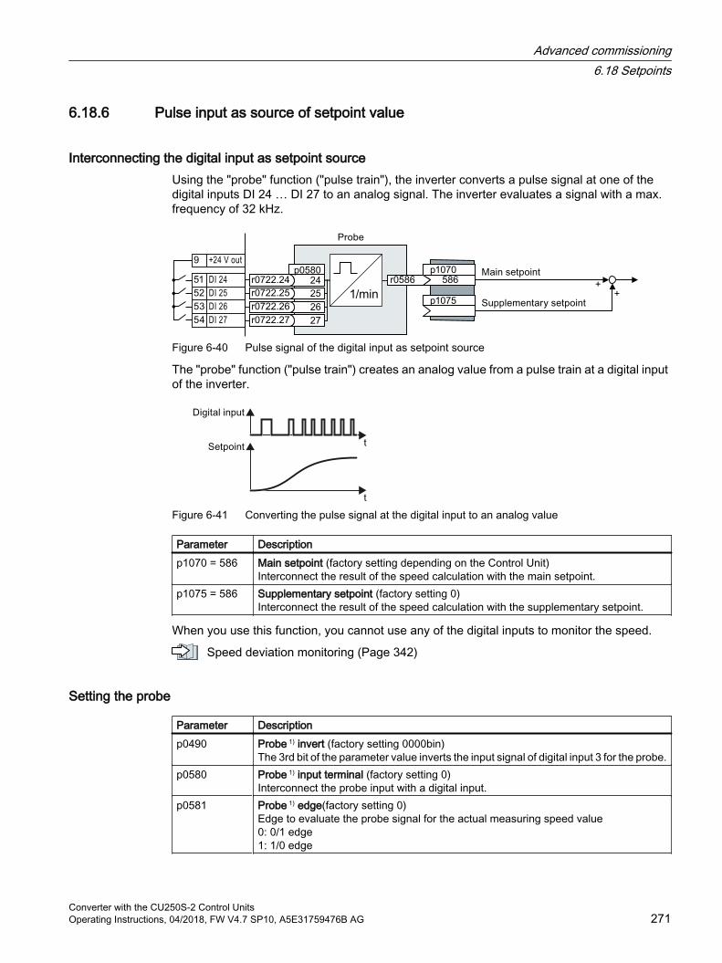
6.18.6 Pulse input as source of setpoint value
Interconnecting the digital input as setpoint sourceUsing the "probe" function ("pulse train"), the inverter converts a pulse signal at one of the digital inputs DI 24 … DI 27 to an analog signal. The inverter evaluates a signal with a max. frequency of 32 kHz.
Figure 6-40 Pulse signal of the digital input as setpoint source
The "probe" function ("pulse train") creates an analog value from a pulse train at a digital input of the inverter.
Figure 6-41 Converting the pulse signal at the digital input to an analog value
Parameter Descriptionp1070 = 586 Main setpoint (factory setting depending on the Control Unit)
Interconnect the result of the speed calculation with the main setpoint.p1075 = 586 Supplementary setpoint (factory setting 0)
Interconnect the result of the speed calculation with the supplementary setpoint.
When you use this function, you cannot use any of the digital inputs to monitor the speed.
Speed deviation monitoring (Page 342)
Setting the probe
Parameter Descriptionp0490 Probe 1) invert (factory setting 0000bin)
The 3rd bit of the parameter value inverts the input signal of digital input 3 for the probe.p0580 Probe 1) input terminal (factory setting 0)
Interconnect the probe input with a digital input.p0581 Probe 1) edge(factory setting 0)
Edge to evaluate the probe signal for the actual measuring speed value0: 0/1 edge1: 1/0 edge
Advanced commissioning6.18 Setpoints
Converter with the CU250S-2 Control UnitsOperating Instructions, 04/2018, FW V4.7 SP10, A5E31759476B AG 271
Parameter Descriptionp0582 Probe 1) Pulses per revolution (factory setting 1)
Number of pulses per revolution.p0583 Probe 1) Maximum measurement time (factory setting 10 s)
Maximum measurement time for the probe. If there is no new pulse before the maxi‐mum measuring time elapses, the inverter sets the actual speed value in r0586 to zero.The time is restarted with the next pulse.
p0585 Probe 1) Gear ratio (factory setting 1)The inverter multiplies the measured speed by the gear ratio before displaying it in r0586.
r0586 Probe 1) Actual speed valueResult of the speed calculation.
Advanced commissioning6.18 Setpoints
Converter with the CU250S-2 Control Units272 Operating Instructions, 04/2018, FW V4.7 SP10, A5E31759476B AG
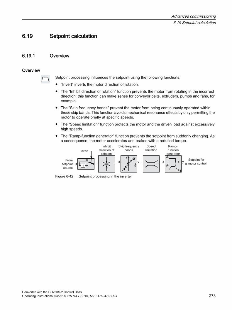
6.19 Setpoint calculation
6.19.1 Overview
OverviewSetpoint processing influences the setpoint using the following functions:
"Invert" inverts the motor direction of rotation.
The "Inhibit direction of rotation" function prevents the motor from rotating in the incorrect direction; this function can make sense for conveyor belts, extruders, pumps and fans, for example.
The "Skip frequency bands" prevent the motor from being continuously operated within these skip bands. This function avoids mechanical resonance effects by only permitting the motor to operate briefly at specific speeds.
The "Speed limitation" function protects the motor and the driven load against excessively high speeds.
The "Ramp-function generator" function prevents the setpoint from suddenly changing. As a consequence, the motor accelerates and brakes with a reduced torque.
Figure 6-42 Setpoint processing in the inverter
Advanced commissioning6.19 Setpoint calculation
Converter with the CU250S-2 Control UnitsOperating Instructions, 04/2018, FW V4.7 SP10, A5E31759476B AG 273
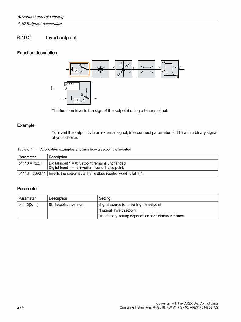
6.19.2 Invert setpoint
Function description
The function inverts the sign of the setpoint using a binary signal.
ExampleTo invert the setpoint via an external signal, interconnect parameter p1113 with a binary signal of your choice.
Table 6-44 Application examples showing how a setpoint is inverted
Parameter Descriptionp1113 = 722.1 Digital input 1 = 0: Setpoint remains unchanged.
Digital input 1 = 1: Inverter inverts the setpoint.p1113 = 2090.11 Inverts the setpoint via the fieldbus (control word 1, bit 11).
Parameter
Parameter Description Settingp1113[0…n] BI: Setpoint inversion Signal source for inverting the setpoint
1 signal: Invert setpointThe factory setting depends on the fieldbus interface.
Advanced commissioning6.19 Setpoint calculation
Converter with the CU250S-2 Control Units274 Operating Instructions, 04/2018, FW V4.7 SP10, A5E31759476B AG
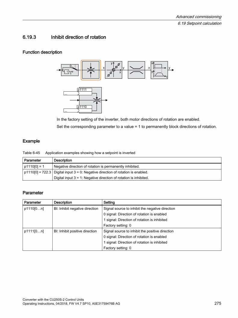
6.19.3 Inhibit direction of rotation
Function description
In the factory setting of the inverter, both motor directions of rotation are enabled.
Set the corresponding parameter to a value = 1 to permanently block directions of rotation.
Example
Table 6-45 Application examples showing how a setpoint is inverted
Parameter Descriptionp1110[0] = 1 Negative direction of rotation is permanently inhibited.p1110[0] = 722.3 Digital input 3 = 0: Negative direction of rotation is enabled.
Digital input 3 = 1: Negative direction of rotation is inhibited.
Parameter
Parameter Description Settingp1110[0…n] BI: Inhibit negative direction Signal source to inhibit the negative direction
0 signal: Direction of rotation is enabled1 signal: Direction of rotation is inhibitedFactory setting: 0
p1111[0…n] BI: Inhibit positive direction Signal source to inhibit the positive direction0 signal: Direction of rotation is enabled1 signal: Direction of rotation is inhibitedFactory setting: 0
Advanced commissioning6.19 Setpoint calculation
Converter with the CU250S-2 Control UnitsOperating Instructions, 04/2018, FW V4.7 SP10, A5E31759476B AG 275
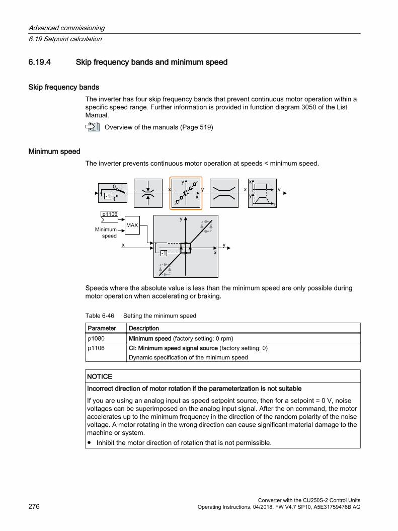
6.19.4 Skip frequency bands and minimum speed
Skip frequency bandsThe inverter has four skip frequency bands that prevent continuous motor operation within a specific speed range. Further information is provided in function diagram 3050 of the List Manual.
Overview of the manuals (Page 519)
Minimum speedThe inverter prevents continuous motor operation at speeds < minimum speed.
Speeds where the absolute value is less than the minimum speed are only possible during motor operation when accelerating or braking.
Table 6-46 Setting the minimum speed
Parameter Description p1080 Minimum speed (factory setting: 0 rpm)p1106 CI: Minimum speed signal source (factory setting: 0)
Dynamic specification of the minimum speed
NOTICE
Incorrect direction of motor rotation if the parameterization is not suitable
If you are using an analog input as speed setpoint source, then for a setpoint = 0 V, noise voltages can be superimposed on the analog input signal. After the on command, the motor accelerates up to the minimum frequency in the direction of the random polarity of the noise voltage. A motor rotating in the wrong direction can cause significant material damage to the machine or system. Inhibit the motor direction of rotation that is not permissible.
Advanced commissioning6.19 Setpoint calculation
Converter with the CU250S-2 Control Units276 Operating Instructions, 04/2018, FW V4.7 SP10, A5E31759476B AG
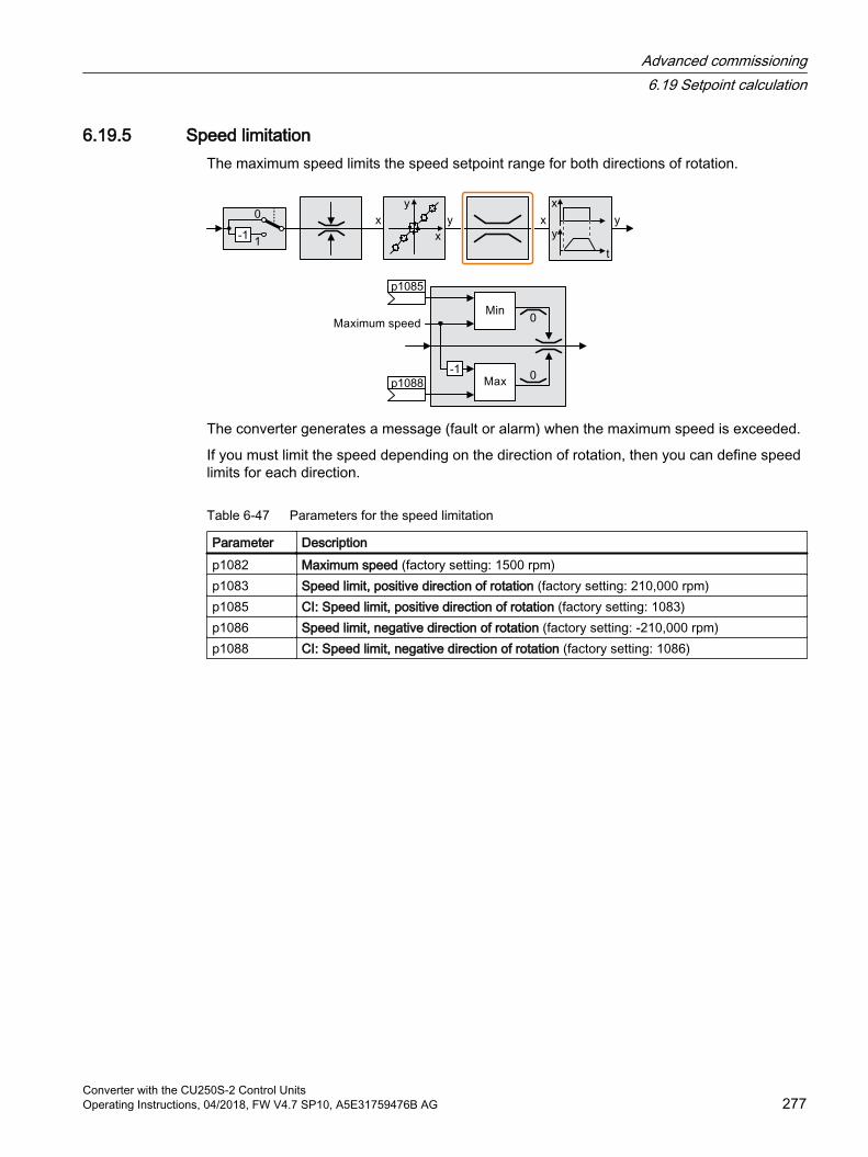
6.19.5 Speed limitationThe maximum speed limits the speed setpoint range for both directions of rotation.
The converter generates a message (fault or alarm) when the maximum speed is exceeded.
If you must limit the speed depending on the direction of rotation, then you can define speed limits for each direction.
Table 6-47 Parameters for the speed limitation
Parameter Description p1082 Maximum speed (factory setting: 1500 rpm)p1083 Speed limit, positive direction of rotation (factory setting: 210,000 rpm)p1085 CI: Speed limit, positive direction of rotation (factory setting: 1083)p1086 Speed limit, negative direction of rotation (factory setting: -210,000 rpm)p1088 CI: Speed limit, negative direction of rotation (factory setting: 1086)
Advanced commissioning6.19 Setpoint calculation
Converter with the CU250S-2 Control UnitsOperating Instructions, 04/2018, FW V4.7 SP10, A5E31759476B AG 277
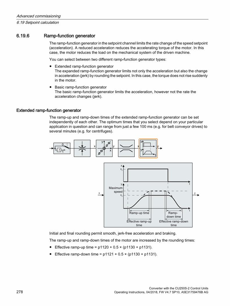
6.19.6 Ramp-function generatorThe ramp-function generator in the setpoint channel limits the rate change of the speed setpoint (acceleration). A reduced acceleration reduces the accelerating torque of the motor. In this case, the motor reduces the load on the mechanical system of the driven machine.
You can select between two different ramp-function generator types:
Extended ramp-function generatorThe expanded ramp-function generator limits not only the acceleration but also the change in acceleration (jerk) by rounding the setpoint. In this case, the torque does not rise suddenly in the motor.
Basic ramp-function generatorThe basic ramp-function generator limits the acceleration, however not the rate the acceleration changes (jerk).
Extended ramp-function generatorThe ramp-up and ramp-down times of the extended ramp-function generator can be set independently of each other. The optimum times that you select depend on your particular application in question and can range from just a few 100 ms (e.g. for belt conveyor drives) to several minutes (e.g. for centrifuges).
Initial and final rounding permit smooth, jerk-free acceleration and braking.
The ramp-up and ramp-down times of the motor are increased by the rounding times:
Effective ramp-up time = p1120 + 0.5 × (p1130 + p1131).
Effective ramp-down time = p1121 + 0.5 × (p1130 + p1131).
Advanced commissioning6.19 Setpoint calculation
Converter with the CU250S-2 Control Units278 Operating Instructions, 04/2018, FW V4.7 SP10, A5E31759476B AG
Table 6-48 Additional parameters to set the extended ramp-function generator
Parameter Description p1115 Ramp-function generator selection (factory setting: 1)
Select ramp-function generator:0: Basic ramp-function generator1: Extended ramp-function generator
p1120 Ramp-function generator, ramp-up time (factory setting: 10 s)Accelerating time in seconds from zero speed up to the maximum speed p1082
p1121 Ramp-function generator, ramp-down time (factory setting: 10 s)Braking time in seconds from the maximum speed down to standstill
p1130 Ramp-function generator initial rounding time (factory setting: 0 s)Initial rounding for the extended ramp-function generator. The value applies for ramp up and ramp down.
p1131 Ramp-function generator final rounding time (factory setting: 0 s)Final rounding for the extended ramp-function generator. The value applies for ramp up and ramp down.
p1134 Ramp-function rounding type (factory setting: 0)0: Continuous smoothing1: Discontinuous smoothing
p1135 OFF3 ramp-down time (factory setting 0 s)The quick stop (OFF3) has its own ramp-down time.
p1136 OFF3 initial rounding time (factory setting: 0 s)Initial rounding for OFF3 for the extended ramp-function generator.
p1137 OFF3 final rounding time (factory setting: 0 s)Final rounding for OFF3 for the extended ramp-function generator.
You can find more information in function diagram 3070 and in the parameter list of the List Manual.
Setting the extended ramp-function generator
Procedure1. Enter the highest possible speed setpoint.
2. Switch on the motor.
Advanced commissioning6.19 Setpoint calculation
Converter with the CU250S-2 Control UnitsOperating Instructions, 04/2018, FW V4.7 SP10, A5E31759476B AG 279
3. Evaluate your drive response.
– If the motor accelerates too slowly, then reduce the ramp-up time.An excessively short ramp-up time means that the motor will reach its current limiting when accelerating, and will temporarily not be able to follow the speed setpoint. In this case, the drive exceeds the set time.
– If the motor accelerates too fast, then extend the ramp-up time.
– Increase the initial rounding if the acceleration is jerky.
– In most applications, it is sufficient when the final rounding is set to the same value as the initial rounding.
4. Switch off the motor.
5. Evaluate your drive response.
– If the motor decelerates too slowly, then reduce the ramp-down time.The minimum ramp-down time that makes sense depends on your particular application. Depending on the Power Module used, for an excessively short ramp-down time, the inverter either reaches the motor current, or the DC link voltage in the inverter becomes too high.
– Extend the ramp-down time if the motor is braked too quickly or the inverter goes into a fault condition when braking.
6. Repeat steps 1 … 5 until the drive behavior meets the requirements of the machine or plant.
You have set the extended ramp-function generator.
Basic ramp-function generator
When compared to the extended ramp-function generator, the basic ramp-function generator has no rounding times.
Advanced commissioning6.19 Setpoint calculation
Converter with the CU250S-2 Control Units280 Operating Instructions, 04/2018, FW V4.7 SP10, A5E31759476B AG
Table 6-49 Parameters for setting the ramp-function generator
Parameter Descriptionp1115 = 0 Ramp-function generator selection (factory setting: 1)
Select ramp-function generator:0: Basic ramp-function generator1: Extended ramp-function generator
p1120 Ramp-function generator, ramp-up time (factory setting: 10 s)Accelerating time in seconds from zero speed up to the maximum speed p1082
p1121 Ramp-function generator, ramp-down time (factory setting: 10 s)Braking time in seconds from the maximum speed down to standstill
p1135 OFF3 ramp-down time (factory setting: 0 s)The quick stop (OFF3) has its own ramp-down time.
Changing the ramp-up and ramp-down times in operationThe ramping up and down time of the ramp-function generator can be changed during operation. The scaling value can come, e.g. from the fieldbus.
Table 6-50 Parameters for setting the scaling
Parameter Descriptionp1138 Up ramp scaling (factory setting: 1)
Signal source for scaling the acceleration ramp. p1139 Deceleration ramp scaling (factory setting: 1)
Signal source for scaling the deceleration ramp.
Application exampleIn the following application example, the higher-level control sets the ramp-up and ramp-down times of the inverter via PROFIBUS.
Figure 6-43 Application example for changing the ramp-function generator times in operation
Advanced commissioning6.19 Setpoint calculation
Converter with the CU250S-2 Control UnitsOperating Instructions, 04/2018, FW V4.7 SP10, A5E31759476B AG 281

Preconditions You have commissioned the communication between the inverter and the control system.
Free telegram 999 has been set in the inverter and in your higher-level control system. Extending the telegram (Page 203)
The control sends the scaling value to the inverter in PZD 3.
Procedure1. Set p1138 = 2050[2].
This means that you have interconnected the scaling factor for the ramp-up time with PZD receive word 3.
2. Set p1139 = 2050[2].This means that you have interconnected the scaling factor for the ramp-down time with PZD receive word 3.
The inverter receives the value for scaling the ramp-up and ramp-down times via PZD receive word 3.
Further information is provided on the Internet:
FAQ (https://support.industry.siemens.com/cs/ww/en/view/82604741)
Advanced commissioning6.19 Setpoint calculation
Converter with the CU250S-2 Control Units282 Operating Instructions, 04/2018, FW V4.7 SP10, A5E31759476B AG
6.20 PID technology controller
OverviewThe technology controller controls process variables, e.g. pressure, temperature, level or flow.
Figure 6-44 Example: Technology controller as a level controller
Precondition
Additional functionsThe motor closed-loop control is set
ToolsTo change the function settings, you can use an operator panel or a PC tool, for example.
Function description
Function diagramThe technology controller is implemented as a PID controller (controller with proportional, integral, and derivative action).
Advanced commissioning6.20 PID technology controller
Converter with the CU250S-2 Control UnitsOperating Instructions, 04/2018, FW V4.7 SP10, A5E31759476B AG 283
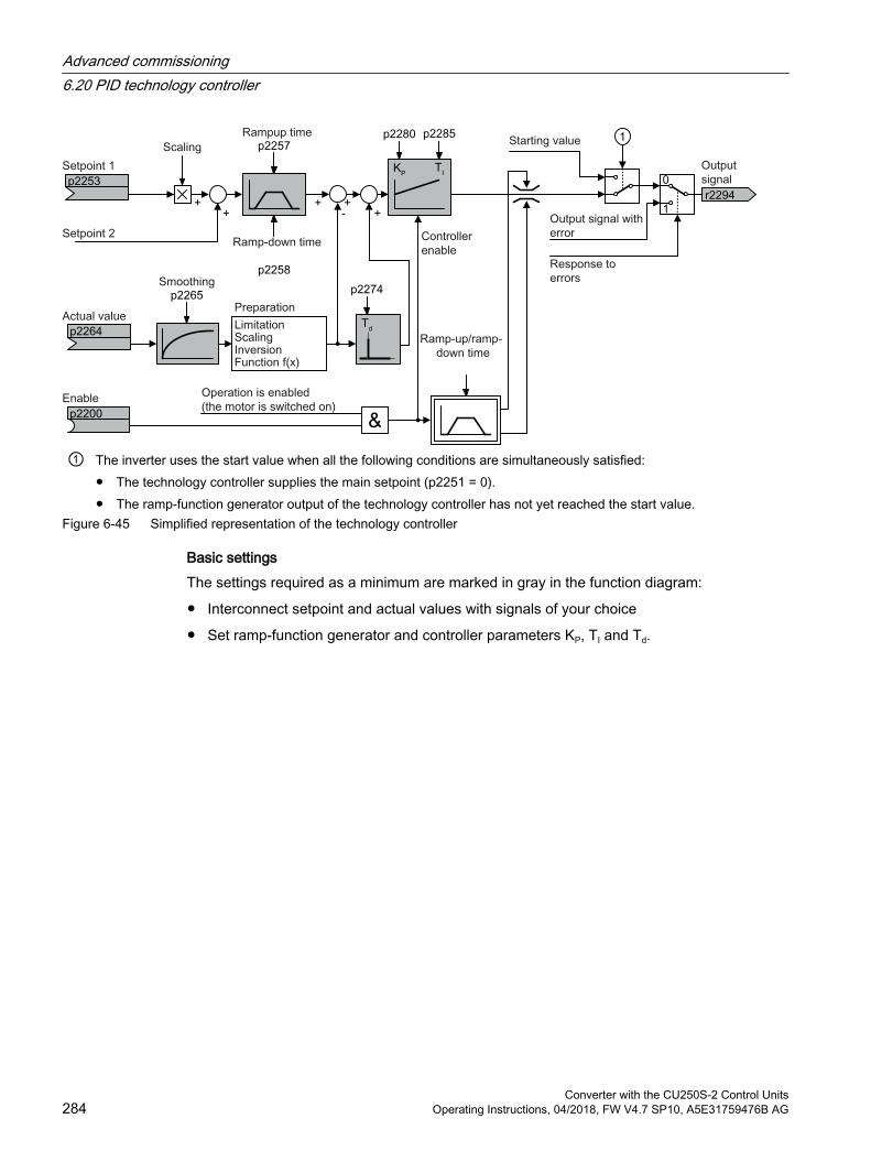
① The inverter uses the start value when all the following conditions are simultaneously satisfied: The technology controller supplies the main setpoint (p2251 = 0). The ramp-function generator output of the technology controller has not yet reached the start value.
Figure 6-45 Simplified representation of the technology controller
Basic settingsThe settings required as a minimum are marked in gray in the function diagram:
Interconnect setpoint and actual values with signals of your choice
Set ramp-function generator and controller parameters KP, TI and Td.
Advanced commissioning6.20 PID technology controller
Converter with the CU250S-2 Control Units284 Operating Instructions, 04/2018, FW V4.7 SP10, A5E31759476B AG
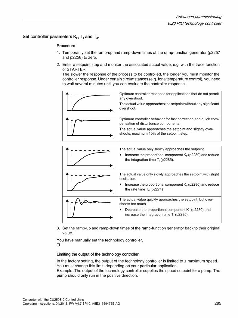
Set controller parameters KP, TI and Td.
Procedure1. Temporarily set the ramp-up and ramp-down times of the ramp-function generator (p2257
and p2258) to zero.
2. Enter a setpoint step and monitor the associated actual value, e.g. with the trace function of STARTER.The slower the response of the process to be controlled, the longer you must monitor the controller response. Under certain circumstances (e.g. for a temperature control), you need to wait several minutes until you can evaluate the controller response.
Optimum controller response for applications that do not permit any overshoot.The actual value approaches the setpoint without any significant overshoot.
Optimum controller behavior for fast correction and quick com‐pensation of disturbance components.The actual value approaches the setpoint and slightly over‐shoots, maximum 10% of the setpoint step.
The actual value only slowly approaches the setpoint. Increase the proportional component KP (p2280) and reduce
the integration time TI (p2285).
The actual value only slowly approaches the setpoint with slight oscillation. Increase the proportional component KP (p2280) and reduce
the rate time Td (p2274)
The actual value quickly approaches the setpoint, but over‐shoots too much. Decrease the proportional component KP (p2280) and
increase the integration time TI (p2285).
3. Set the ramp-up and ramp-down times of the ramp-function generator back to their original value.
You have manually set the technology controller.
Limiting the output of the technology controllerIn the factory setting, the output of the technology controller is limited to ± maximum speed. You must change this limit, depending on your particular application.Example: The output of the technology controller supplies the speed setpoint for a pump. The pump should only run in the positive direction.
Advanced commissioning6.20 PID technology controller
Converter with the CU250S-2 Control UnitsOperating Instructions, 04/2018, FW V4.7 SP10, A5E31759476B AG 285
Parameter
Table 6-51 Basic settings
Parameter Description Settingp2200 BI: Technology controller en‐
able1 signal: Technology controller is enabled.Factory setting: 0
r2294 CO: Technology controller output signal
To interconnect the main speed setpoint with the technology controller output, set p1070 = 2294.
p2253 CI: Technology controller set‐point 1
Setpoint for the technology controller.Example:p2253 = 2224: Fixed setpoint p2201 is interconnected with the setpoint of the technology controller.p2220 = 1: The fixed setpoint p2201 is selected.Factory setting: 0
p2264 CI: Technology controller ac‐tual value
Technology controller actual value.Factory setting: 0
p2257, p2258 Technology controller ramp-up time and ramp-down time [s]
Factory setting: 0.0 s
p2274 Technology controller differ‐entiation time constant Td [s]
The differentiation improves the rise time for very slow controlled varia‐bles, e.g. a temperature control.Factory setting: 0.0 s
p2280 Technology controller propor‐tional gain KP
Factory setting: 1.0
p2285 Technology controller inte‐gration time (integral time) Td
Factory setting: 30 s
Table 6-52 Limiting the output of the technology controller
Parameter Description Settingp2297 CI: Technology controller
maximum limiting signal source
Factory setting: 1084
p2298 CI: Technology controller minimum limiting signal source
Factory setting: 2292
p2291 CO: Technology controller maximum limiting [%]
Factory setting: 100 %
p2292 CO: Technology controller minimum limiting [%]
Factory setting: 0 %
Advanced commissioning6.20 PID technology controller
Converter with the CU250S-2 Control Units286 Operating Instructions, 04/2018, FW V4.7 SP10, A5E31759476B AG
Table 6-53 Adapting the actual value of the technology controller
Parameter Description Settingp2267 Technology controller upper
limit actual value [%]Factory setting: 100 %
p2268 Technology controller lower limit actual value [%]
Factory setting: -100 %
p2269 Technology controller gain actual value [%]
Factory setting: 100 %
p2271 Technology controller actual value inversion
Technology controller actual value inversionIf the actual value decreases with increasing motor speed, then p2271 must be set = 1.0: no inversion1: actual value signal is invertedFactory setting: 0
p2270 Technology controller actual value function
Technology controller actual value function 0: no function1: √2: x2
3: x3
Factory setting: 0
Further informationFor additional information refer to the function diagrams 7950 ff of the List Manual.
You will find additional information on the following PID controller components in the Internet at:
Setpoint input: Analog value or fixed setpoint
Setpoint channel: Scaling, ramp-function generator and filter
Actual value channel: Filter, limiting and signal processing
PID controller Principle of operation of the D component, inhibiting the I component and the control sense
Enable, limiting the controller output and fault response
FAQ (http://support.automation.siemens.com/WW/view/en/92556266)
Advanced commissioning6.20 PID technology controller
Converter with the CU250S-2 Control UnitsOperating Instructions, 04/2018, FW V4.7 SP10, A5E31759476B AG 287
6.21 Motor controlThe inverter has two alternative methods to control (closed loop) the motor speed:
U/f control
Vector control
6.21.1 Reactor, filter and cable resistance at the inverter output
Correctly setting the components between the inverter and motorComponents between the inverter and the motor influence the closed-loop control quality of the inverter:
Output reactor or sine-wave filterIn the factory setting, for the motor data identification, the inverter assumes that neither output reactor nor sine wave filter are connected at to the inverter output.
Motor cable with unusually high cable resistance.For the motor data identification, the inverter assumes a cable resistance = 20 % of the stator resistance of the cold motor.
You must correctly set the components between the inverter and motor to achieve an optimum closed-loop control quality
Setting the reactor, filter and cable resistance between the inverter and motor
Procedure1. Set p0010 = 2.
2. Set the cable resistance in p0352.
3. Set p0230 to the appropriate value.
4. Set p0235 to the appropriate value.
5. Set p0010 = 0.
6. Carry out the quick commissioning and the motor identification again. Commissioning (Page 125)
You have set the reactor, filter and cable resistance between the inverter and motor.
Advanced commissioning6.21 Motor control
Converter with the CU250S-2 Control Units288 Operating Instructions, 04/2018, FW V4.7 SP10, A5E31759476B AG
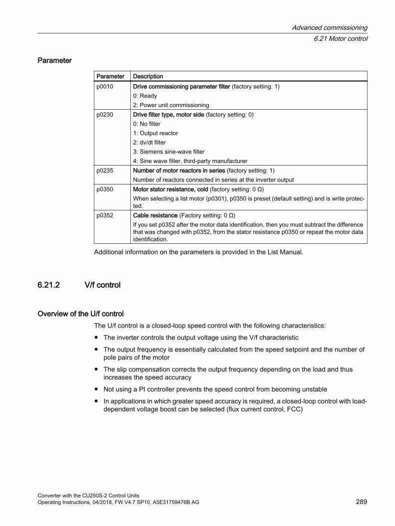
Parameter
Parameter Descriptionp0010 Drive commissioning parameter filter (factory setting: 1)
0: Ready2: Power unit commissioning
p0230 Drive filter type, motor side (factory setting: 0)0: No filter1: Output reactor2: dv/dt filter3: Siemens sine-wave filter4: Sine wave filter, third-party manufacturer
p0235 Number of motor reactors in series (factory setting: 1)Number of reactors connected in series at the inverter output
p0350 Motor stator resistance, cold (factory setting: 0 Ω)When selecting a list motor (p0301), p0350 is preset (default setting) and is write protec‐ted.
p0352 Cable resistance (Factory setting: 0 Ω)If you set p0352 after the motor data identification, then you must subtract the difference that was changed with p0352, from the stator resistance p0350 or repeat the motor data identification.
Additional information on the parameters is provided in the List Manual.
6.21.2 V/f control
Overview of the U/f controlThe U/f control is a closed-loop speed control with the following characteristics:
The inverter controls the output voltage using the V/f characteristic
The output frequency is essentially calculated from the speed setpoint and the number of pole pairs of the motor
The slip compensation corrects the output frequency depending on the load and thus increases the speed accuracy
Not using a PI controller prevents the speed control from becoming unstable
In applications in which greater speed accuracy is required, a closed-loop control with load-dependent voltage boost can be selected (flux current control, FCC)
Advanced commissioning6.21 Motor control
Converter with the CU250S-2 Control UnitsOperating Instructions, 04/2018, FW V4.7 SP10, A5E31759476B AG 289
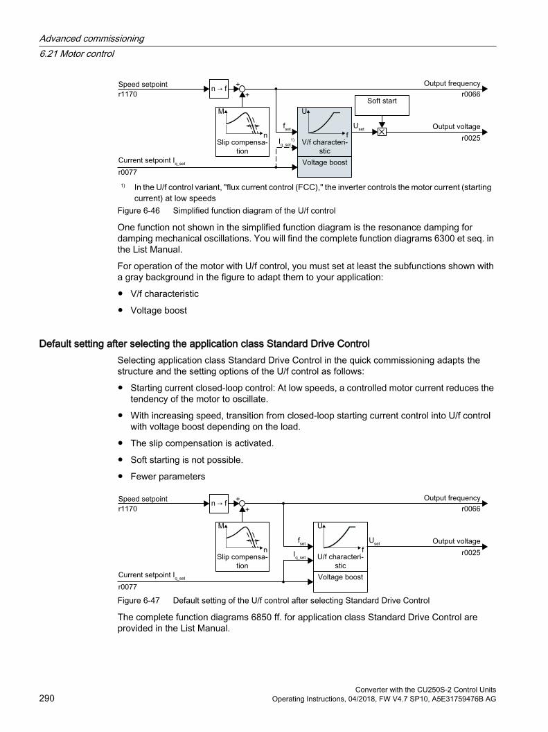
1) In the U/f control variant, "flux current control (FCC)," the inverter controls the motor current (starting current) at low speeds
Figure 6-46 Simplified function diagram of the U/f control
One function not shown in the simplified function diagram is the resonance damping for damping mechanical oscillations. You will find the complete function diagrams 6300 et seq. in the List Manual.
For operation of the motor with U/f control, you must set at least the subfunctions shown with a gray background in the figure to adapt them to your application:
V/f characteristic
Voltage boost
Default setting after selecting the application class Standard Drive ControlSelecting application class Standard Drive Control in the quick commissioning adapts the structure and the setting options of the U/f control as follows:
Starting current closed-loop control: At low speeds, a controlled motor current reduces the tendency of the motor to oscillate.
With increasing speed, transition from closed-loop starting current control into U/f control with voltage boost depending on the load.
The slip compensation is activated.
Soft starting is not possible.
Fewer parameters
Figure 6-47 Default setting of the U/f control after selecting Standard Drive Control
The complete function diagrams 6850 ff. for application class Standard Drive Control are provided in the List Manual.
Advanced commissioning6.21 Motor control
Converter with the CU250S-2 Control Units290 Operating Instructions, 04/2018, FW V4.7 SP10, A5E31759476B AG
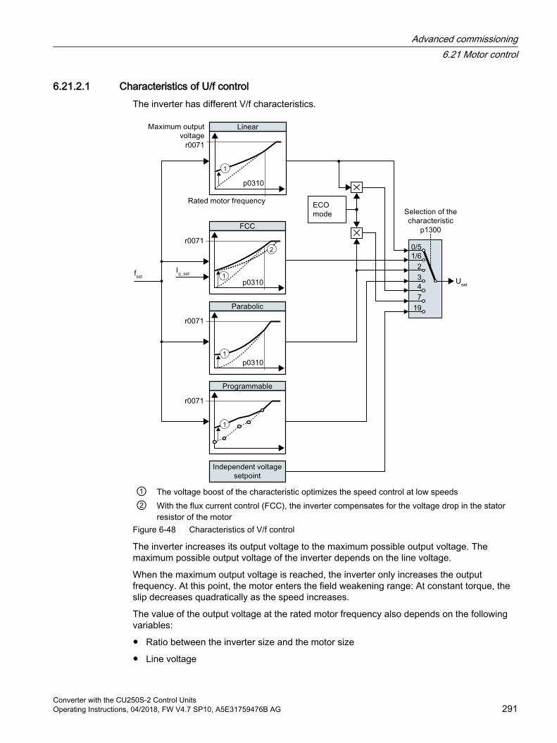
6.21.2.1 Characteristics of U/f controlThe inverter has different V/f characteristics.
① The voltage boost of the characteristic optimizes the speed control at low speeds② With the flux current control (FCC), the inverter compensates for the voltage drop in the stator
resistor of the motorFigure 6-48 Characteristics of V/f control
The inverter increases its output voltage to the maximum possible output voltage. The maximum possible output voltage of the inverter depends on the line voltage.
When the maximum output voltage is reached, the inverter only increases the output frequency. At this point, the motor enters the field weakening range: At constant torque, the slip decreases quadratically as the speed increases.
The value of the output voltage at the rated motor frequency also depends on the following variables:
Ratio between the inverter size and the motor size
Line voltage
Advanced commissioning6.21 Motor control
Converter with the CU250S-2 Control UnitsOperating Instructions, 04/2018, FW V4.7 SP10, A5E31759476B AG 291
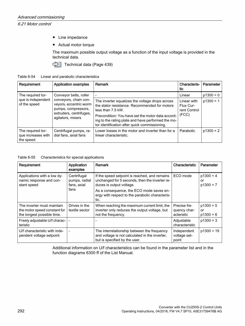
Line impedance
Actual motor torque
The maximum possible output voltage as a function of the input voltage is provided in the technical data.
Technical data (Page 439)
Table 6-54 Linear and parabolic characteristics
Requirement Application examples Remark Characteris‐tic
Parameter
The required tor‐que is independent of the speed
Conveyor belts, roller conveyors, chain con‐veyors, eccentric worm pumps, compressors, extruders, centrifuges, agitators, mixers
- Linear p1300 = 0The inverter equalizes the voltage drops across the stator resistance. Recommended for motors less than 7.5 kW.Precondition: You have set the motor data accord‐ing to the rating plate and have performed the mo‐tor identification after quick commissioning.
Linear with Flux Cur‐rent Control (FCC)
p1300 = 1
The required tor‐que increases with the speed
Centrifugal pumps, ra‐dial fans, axial fans
Lower losses in the motor and inverter than for a linear characteristic.
Parabolic p1300 = 2
Table 6-55 Characteristics for special applications
Requirement Application examples
Remark Characteristic Parameter
Applications with a low dy‐namic response and con‐stant speed
Centrifugal pumps, radial fans, axial fans
If the speed setpoint is reached, and remains unchanged for 5 seconds, then the inverter re‐duces is output voltage.As a consequence, the ECO mode saves en‐ergy with respect to the parabolic characteris‐tic.
ECO mode p1300 = 4 or p1300 = 7
The inverter must maintain the motor speed constant for the longest possible time.
Drives in the textile sector
When reaching the maximum current limit, the inverter only reduces the output voltage, but not the frequency.
Precise fre‐quency char‐acteristic
p1300 = 5 or p1300 = 6
Freely adjustable U/f charac‐teristic
- - Adjustable characteristic
p1300 = 3
U/f characteristic with inde‐pendent voltage setpoint
- The interrelationship between the frequency and voltage is not calculated in the inverter, but is specified by the user.
Independent voltage set‐point
p1300 = 19
Additional information on U/f characteristics can be found in the parameter list and in the function diagrams 6300 ff of the List Manual.
Advanced commissioning6.21 Motor control
Converter with the CU250S-2 Control Units292 Operating Instructions, 04/2018, FW V4.7 SP10, A5E31759476B AG
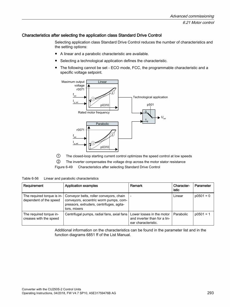
Characteristics after selecting the application class Standard Drive ControlSelecting application class Standard Drive Control reduces the number of characteristics and the setting options:
A linear and a parabolic characteristic are available.
Selecting a technological application defines the characteristic.
The following cannot be set - ECO mode, FCC, the programmable characteristic and a specific voltage setpoint.
① The closed-loop starting current control optimizes the speed control at low speeds② The inverter compensates the voltage drop across the motor stator resistance
Figure 6-49 Characteristics after selecting Standard Drive Control
Table 6-56 Linear and parabolic characteristics
Requirement Application examples Remark Character‐istic
Parameter
The required torque is in‐dependent of the speed
Conveyor belts, roller conveyors, chain conveyors, eccentric worm pumps, com‐pressors, extruders, centrifuges, agita‐tors, mixers
- Linear p0501 = 0
The required torque in‐creases with the speed
Centrifugal pumps, radial fans, axial fans Lower losses in the motor and inverter than for a lin‐ear characteristic.
Parabolic p0501 = 1
Additional information on the characteristics can be found in the parameter list and in the function diagrams 6851 ff of the List Manual.
Advanced commissioning6.21 Motor control
Converter with the CU250S-2 Control UnitsOperating Instructions, 04/2018, FW V4.7 SP10, A5E31759476B AG 293
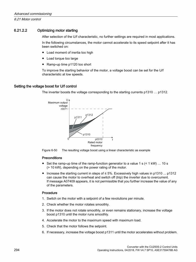
6.21.2.2 Optimizing motor startingAfter selection of the U/f characteristic, no further settings are required in most applications.
In the following circumstances, the motor cannot accelerate to its speed setpoint after it has been switched on:
Load moment of inertia too high
Load torque too large
Ramp-up time p1120 too short
To improve the starting behavior of the motor, a voltage boost can be set for the U/f characteristic at low speeds.
Setting the voltage boost for U/f control The inverter boosts the voltage corresponding to the starting currents p1310 … p1312.
Figure 6-50 The resulting voltage boost using a linear characteristic as example
Preconditions Set the ramp-up time of the ramp-function generator to a value 1 s (< 1 kW) … 10 s
(> 10 kW), depending on the power rating of the motor.
Increase the starting current in steps of ≤ 5%. Excessively high values in p1310 ... p1312 can cause the motor to overheat and switch off (trip) the inverter due to overcurrent.If message A07409 appears, it is not permissible that you further increase the value of any of the parameters.
Procedure1. Switch on the motor with a setpoint of a few revolutions per minute.
2. Check whether the motor rotates smoothly.
3. If the motor does not rotate smoothly, or even remains stationary, increase the voltage boost p1310 until the motor runs smoothly.
4. Accelerate the motor to the maximum speed with maximum load.
5. Check that the motor follows the setpoint.
6. If necessary, increase the voltage boost p1311 until the motor accelerates without problem.
Advanced commissioning6.21 Motor control
Converter with the CU250S-2 Control Units294 Operating Instructions, 04/2018, FW V4.7 SP10, A5E31759476B AG
In applications with a high break loose torque, you must also increase parameter p1312 in order to achieve a satisfactory motor response.
You have set the voltage boost.
Parameter Description p1310 Starting current (voltage boost) permanent (factory setting 50%)
Compensates for voltage drops caused by long motor cables and the ohmic losses in the motor.
p1311 Starting current (voltage boost) when accelerating (factory setting 0%)Provides additional torque when the motor accelerates.
p1312 Starting current (voltage boost) when starting (factory setting 0%)Provides additional torque, however, only when the motor accelerates for the first time after it has been switched on ("break loose torque").
You will find more information on this function in the parameter list and in function diagram 6301 in the List Manual.
Advanced commissioning6.21 Motor control
Converter with the CU250S-2 Control UnitsOperating Instructions, 04/2018, FW V4.7 SP10, A5E31759476B AG 295
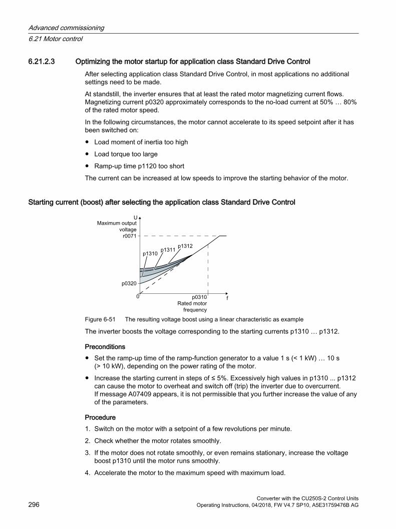
6.21.2.3 Optimizing the motor startup for application class Standard Drive ControlAfter selecting application class Standard Drive Control, in most applications no additional settings need to be made.
At standstill, the inverter ensures that at least the rated motor magnetizing current flows. Magnetizing current p0320 approximately corresponds to the no-load current at 50% … 80% of the rated motor speed.
In the following circumstances, the motor cannot accelerate to its speed setpoint after it has been switched on:
Load moment of inertia too high
Load torque too large
Ramp-up time p1120 too short
The current can be increased at low speeds to improve the starting behavior of the motor.
Starting current (boost) after selecting the application class Standard Drive Control
Figure 6-51 The resulting voltage boost using a linear characteristic as example
The inverter boosts the voltage corresponding to the starting currents p1310 … p1312.
Preconditions Set the ramp-up time of the ramp-function generator to a value 1 s (< 1 kW) … 10 s
(> 10 kW), depending on the power rating of the motor.
Increase the starting current in steps of ≤ 5%. Excessively high values in p1310 ... p1312 can cause the motor to overheat and switch off (trip) the inverter due to overcurrent.If message A07409 appears, it is not permissible that you further increase the value of any of the parameters.
Procedure1. Switch on the motor with a setpoint of a few revolutions per minute.
2. Check whether the motor rotates smoothly.
3. If the motor does not rotate smoothly, or even remains stationary, increase the voltage boost p1310 until the motor runs smoothly.
4. Accelerate the motor to the maximum speed with maximum load.
Advanced commissioning6.21 Motor control
Converter with the CU250S-2 Control Units296 Operating Instructions, 04/2018, FW V4.7 SP10, A5E31759476B AG
5. Check that the motor follows the setpoint.
6. If necessary, increase the voltage boost p1311 until the motor accelerates without problem.
In applications with a high break loose torque, you must also increase parameter p1312 in order to achieve a satisfactory motor response.
You have set the voltage boost.
Parameter Description p1310 Starting current (voltage boost) permanent (factory setting 50%)
Compensates for voltage drops caused by long motor cables and the ohmic losses in the motor.After commissioning, depending on the motor power rating and the technological appli‐cation p0501, the inverter sets p1310.
p1311 Starting current (voltage boost) when accelerating (factory setting 0%)Provides additional torque when the motor accelerates.After commissioning, depending on the motor power rating and the technological appli‐cation p0501, the inverter sets p1311.
p1312 Starting current (voltage boost) when starting (factory setting 0%)Provides additional torque, however, only when the motor accelerates for the first time after it has been switched on ("break loose torque").
You can find more information about this function in the parameter list and in function diagram 6851 of the List Manual.
Advanced commissioning6.21 Motor control
Converter with the CU250S-2 Control UnitsOperating Instructions, 04/2018, FW V4.7 SP10, A5E31759476B AG 297
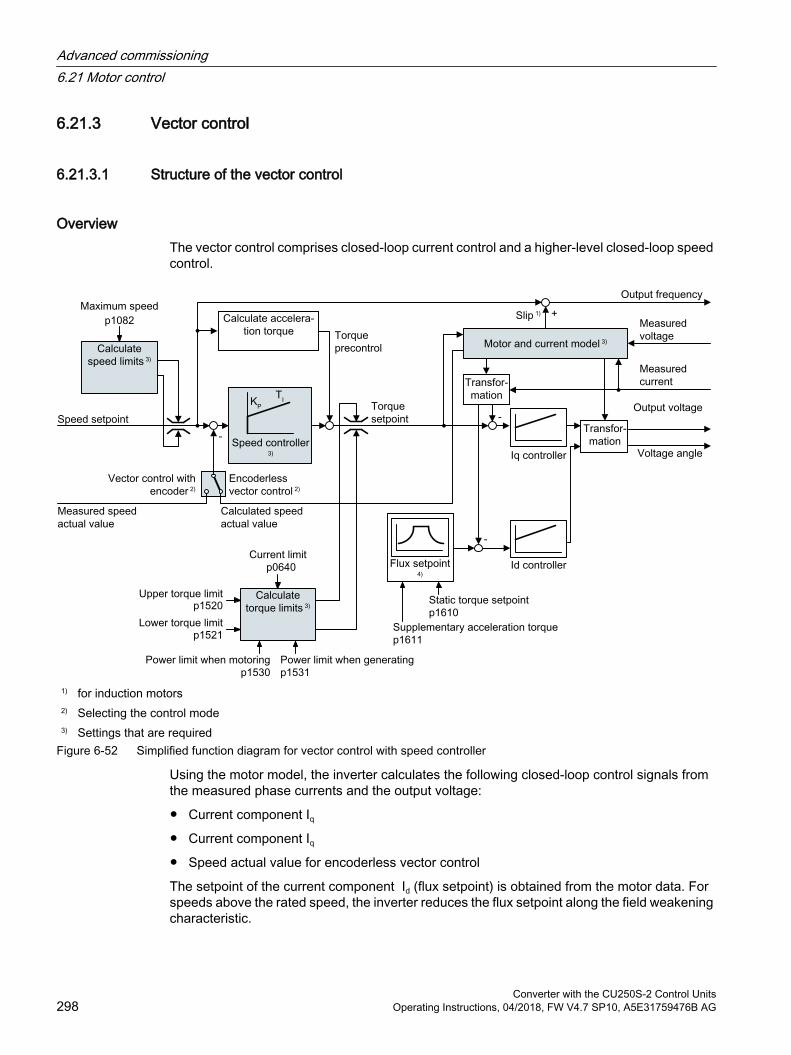
6.21.3 Vector control
6.21.3.1 Structure of the vector control
OverviewThe vector control comprises closed-loop current control and a higher-level closed-loop speed control.
1) for induction motors2) Selecting the control mode3) Settings that are required
Figure 6-52 Simplified function diagram for vector control with speed controller
Using the motor model, the inverter calculates the following closed-loop control signals from the measured phase currents and the output voltage:
Current component Iq
Current component Iq
Speed actual value for encoderless vector control
The setpoint of the current component Id (flux setpoint) is obtained from the motor data. For speeds above the rated speed, the inverter reduces the flux setpoint along the field weakening characteristic.
Advanced commissioning6.21 Motor control
Converter with the CU250S-2 Control Units298 Operating Instructions, 04/2018, FW V4.7 SP10, A5E31759476B AG
When the speed setpoint is increased, the speed controller responds with a higher setpoint for current component Iq (torque setpoint). The closed-loop control responds to a higher torque setpoint by adding a higher slip frequency to the output frequency. The higher output frequency also results in a higher motor slip, which is proportional to the accelerating torque. Iq and Idcontrollers keep the motor flux constant using the output voltage, and adjust the matching current component Iq in the motor.
The complete function diagrams 6020 ff. for vector control are provided in the List Manual.
Settings that are requiredSelect the vector control during to quick commissioning.
Quick commissioning with a PC (Page 134)
In order to achieve a satisfactory control response, as a minimum you must set the partial functions – shown with gray background in the diagram above – to match your particular application:
Motor and current model: In the quick commissioning, correctly set the motor data on the rating plate corresponding to the connection type (Y/Δ), and carry out the motor data identification routine at standstill.
Speed limits and torque limits: In the quick commissioning, set the maximum speed (p1082) and current limit (p0640) to match your particular application. When exiting quick commissioning, the inverter calculates the torque and power limits corresponding to the current limit. The actual torque limits are obtained from the converted current and power limits and the set torque limits.
Speed controller: Start the rotating measurement of the motor data identification. You must manually optimize the controller if the rotating measurement is not possible.
WARNING
The load falls due to incorrect closed-loop control settings
For encoderless vector control, the inverter calculates the actual speed based on an electric motor model. In applications with pulling loads - e.g. hoisting gear, lifting tables or vertical conveyors - an incorrectly set motor model or other incorrect settings can mean that the load falls. A falling load can result in death or serious injury. Correctly set the motor data during the quick commissioning. Carry out the motor data identification. Correctly set the "Motor holding brake" function.
Motor holding brake (Page 220) For pulling loads, carefully comply with the recommended settings for vector control.
Advanced settings (Page 303)
Advanced commissioning6.21 Motor control
Converter with the CU250S-2 Control UnitsOperating Instructions, 04/2018, FW V4.7 SP10, A5E31759476B AG 299
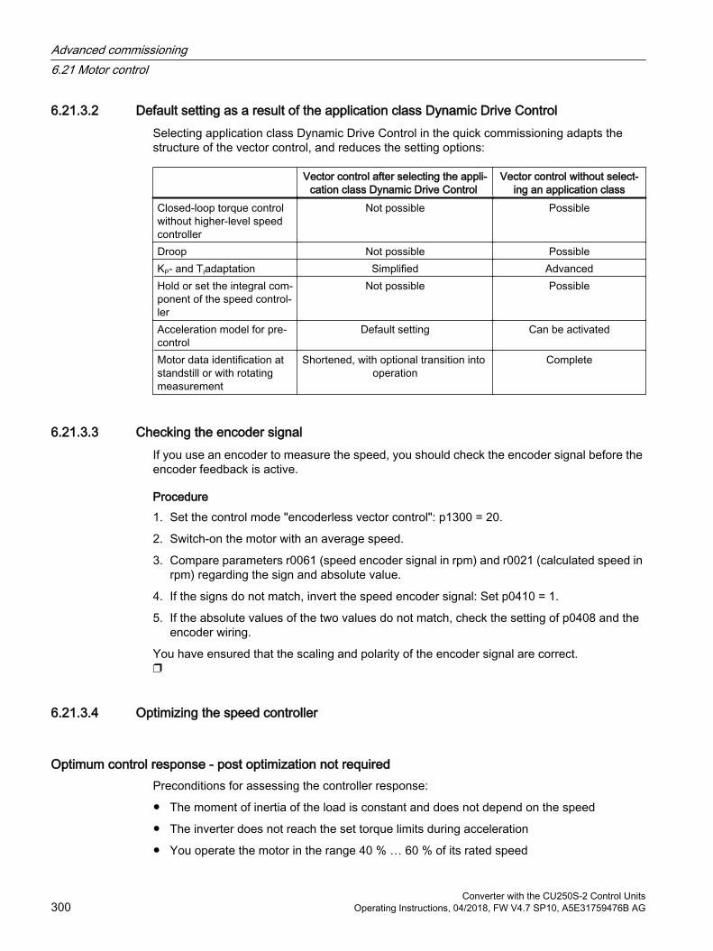
6.21.3.2 Default setting as a result of the application class Dynamic Drive ControlSelecting application class Dynamic Drive Control in the quick commissioning adapts the structure of the vector control, and reduces the setting options:
Vector control after selecting the appli‐cation class Dynamic Drive Control
Vector control without select‐ing an application class
Closed-loop torque control without higher-level speed controller
Not possible Possible
Droop Not possible PossibleKP- and TIadaptation Simplified AdvancedHold or set the integral com‐ponent of the speed control‐ler
Not possible Possible
Acceleration model for pre‐control
Default setting Can be activated
Motor data identification at standstill or with rotating measurement
Shortened, with optional transition into operation
Complete
6.21.3.3 Checking the encoder signalIf you use an encoder to measure the speed, you should check the encoder signal before the encoder feedback is active.
Procedure 1. Set the control mode "encoderless vector control": p1300 = 20.
2. Switch-on the motor with an average speed.
3. Compare parameters r0061 (speed encoder signal in rpm) and r0021 (calculated speed in rpm) regarding the sign and absolute value.
4. If the signs do not match, invert the speed encoder signal: Set p0410 = 1.
5. If the absolute values of the two values do not match, check the setting of p0408 and the encoder wiring.
You have ensured that the scaling and polarity of the encoder signal are correct.
6.21.3.4 Optimizing the speed controller
Optimum control response - post optimization not requiredPreconditions for assessing the controller response:
The moment of inertia of the load is constant and does not depend on the speed
The inverter does not reach the set torque limits during acceleration
You operate the motor in the range 40 % … 60 % of its rated speed
Advanced commissioning6.21 Motor control
Converter with the CU250S-2 Control Units300 Operating Instructions, 04/2018, FW V4.7 SP10, A5E31759476B AG
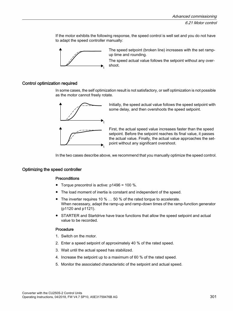
If the motor exhibits the following response, the speed control is well set and you do not have to adapt the speed controller manually:
The speed setpoint (broken line) increases with the set ramp-up time and rounding.The speed actual value follows the setpoint without any over‐shoot.
Control optimization requiredIn some cases, the self optimization result is not satisfactory, or self optimization is not possible as the motor cannot freely rotate.
Initially, the speed actual value follows the speed setpoint with some delay, and then overshoots the speed setpoint.
First, the actual speed value increases faster than the speed setpoint. Before the setpoint reaches its final value, it passes the actual value. Finally, the actual value approaches the set‐point without any significant overshoot.
In the two cases describe above, we recommend that you manually optimize the speed control.
Optimizing the speed controller
Preconditions Torque precontrol is active: p1496 = 100 %.
The load moment of inertia is constant and independent of the speed.
The inverter requires 10 % … 50 % of the rated torque to accelerate.When necessary, adapt the ramp-up and ramp-down times of the ramp-function generator (p1120 and p1121).
STARTER and Startdrive have trace functions that allow the speed setpoint and actual value to be recorded.
Procedure1. Switch on the motor.
2. Enter a speed setpoint of approximately 40 % of the rated speed.
3. Wait until the actual speed has stabilized.
4. Increase the setpoint up to a maximum of 60 % of the rated speed.
5. Monitor the associated characteristic of the setpoint and actual speed.
Advanced commissioning6.21 Motor control
Converter with the CU250S-2 Control UnitsOperating Instructions, 04/2018, FW V4.7 SP10, A5E31759476B AG 301
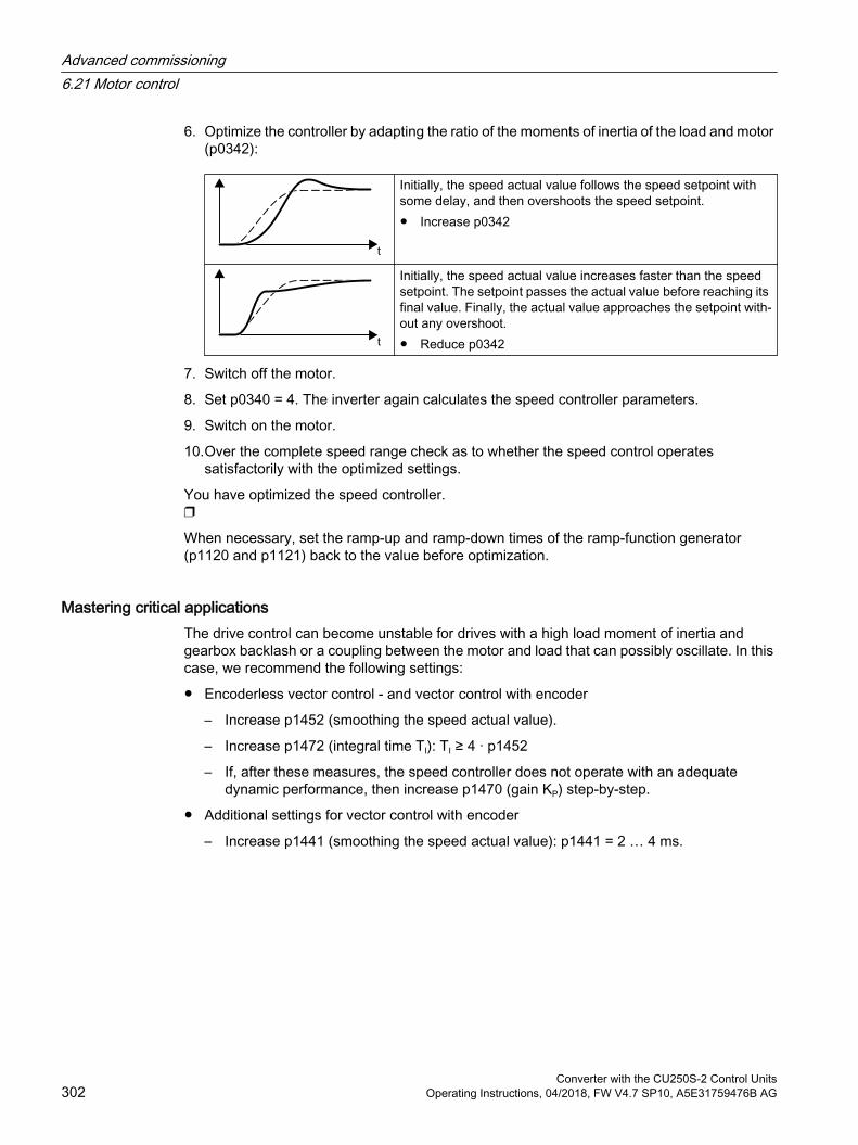
6. Optimize the controller by adapting the ratio of the moments of inertia of the load and motor (p0342):
Initially, the speed actual value follows the speed setpoint with some delay, and then overshoots the speed setpoint. Increase p0342
Initially, the speed actual value increases faster than the speed setpoint. The setpoint passes the actual value before reaching its final value. Finally, the actual value approaches the setpoint with‐out any overshoot. Reduce p0342
7. Switch off the motor.
8. Set p0340 = 4. The inverter again calculates the speed controller parameters.
9. Switch on the motor.
10.Over the complete speed range check as to whether the speed control operates satisfactorily with the optimized settings.
You have optimized the speed controller.
When necessary, set the ramp-up and ramp-down times of the ramp-function generator (p1120 and p1121) back to the value before optimization.
Mastering critical applicationsThe drive control can become unstable for drives with a high load moment of inertia and gearbox backlash or a coupling between the motor and load that can possibly oscillate. In this case, we recommend the following settings:
Encoderless vector control - and vector control with encoder
– Increase p1452 (smoothing the speed actual value).
– Increase p1472 (integral time TI): TI ≥ 4 · p1452
– If, after these measures, the speed controller does not operate with an adequate dynamic performance, then increase p1470 (gain KP) step-by-step.
Additional settings for vector control with encoder
– Increase p1441 (smoothing the speed actual value): p1441 = 2 … 4 ms.
Advanced commissioning6.21 Motor control
Converter with the CU250S-2 Control Units302 Operating Instructions, 04/2018, FW V4.7 SP10, A5E31759476B AG
The most important parameters
Table 6-57 Encoderless speed control
Parameter Description p0342 Moment of inertia ratio, total to motor (factory setting: 1.0)p1496 Acceleration precontrol scaling (factory setting: 0 %)
For the rotating measurement of the motor data identification the inverter sets the pa‐rameters to 100 %.
p1452 Speed controller speed actual value smoothing time (without encoder) (factory setting: 10 ms)
p1470 Speed controller operation without encoder P gain (factory setting: 0.3)p1472 Speed controller operation without encoder integral action time (factory setting: 20 ms)
Table 6-58 Speed control with encoder
Parameter Description p0342 Moment of inertia ratio, total to motor (factory setting: 1.0)p1496 Acceleration precontrol scaling (factory setting: 0 %)
For the rotating measurement of the motor data identification the inverter sets the pa‐rameters to 100 %.
p1441 Speed controller smoothing time (factory setting: 0 ms)p1442 Speed controller speed actual value smoothing time (factory setting: 4 ms)p1460 Speed controller operation without encoder P gain (factory setting: 0.3)p1462 Speed controller operation without encoder integral action time (factory setting: 20 ms)
6.21.3.5 Advanced settings
KP- and TIadaptationKp and TI adaptation suppress speed control oscillations that may occur. The "rotating measurement" of the motor data identification optimizes the speed controller. If you have performed the rotating measurement, then the Kp- and Tnadaptation has been set.
You can find additional information in the List Manual:
Vector control with speed controller: Function diagram 6050
Vector control after presetting the application class Dynamic Drive Control Function diagram 6824
DroopFor mechanically coupled drives, there is the risk that the drives oppose one another: Small deviations in the speed setpoint or actual value of the coupled drives can mean that the drives are operated with significantly different torques.
Advanced commissioning6.21 Motor control
Converter with the CU250S-2 Control UnitsOperating Instructions, 04/2018, FW V4.7 SP10, A5E31759476B AG 303
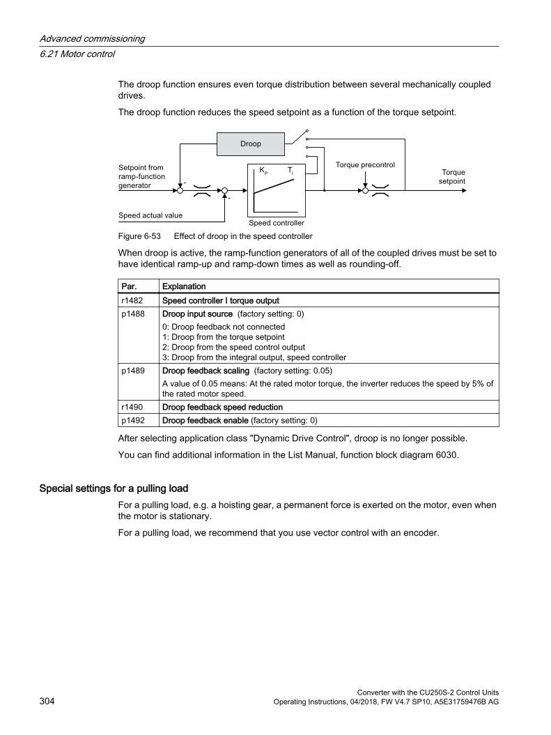
The droop function ensures even torque distribution between several mechanically coupled drives.
The droop function reduces the speed setpoint as a function of the torque setpoint.
Figure 6-53 Effect of droop in the speed controller
When droop is active, the ramp-function generators of all of the coupled drives must be set to have identical ramp-up and ramp-down times as well as rounding-off.
Par. Explanationr1482 Speed controller I torque outputp1488 Droop input source (factory setting: 0)
0: Droop feedback not connected1: Droop from the torque setpoint2: Droop from the speed control output3: Droop from the integral output, speed controller
p1489 Droop feedback scaling (factory setting: 0.05)A value of 0.05 means: At the rated motor torque, the inverter reduces the speed by 5% of the rated motor speed.
r1490 Droop feedback speed reductionp1492 Droop feedback enable (factory setting: 0)
After selecting application class "Dynamic Drive Control", droop is no longer possible.
You can find additional information in the List Manual, function block diagram 6030.
Special settings for a pulling loadFor a pulling load, e.g. a hoisting gear, a permanent force is exerted on the motor, even when the motor is stationary.
For a pulling load, we recommend that you use vector control with an encoder.
Advanced commissioning6.21 Motor control
Converter with the CU250S-2 Control Units304 Operating Instructions, 04/2018, FW V4.7 SP10, A5E31759476B AG
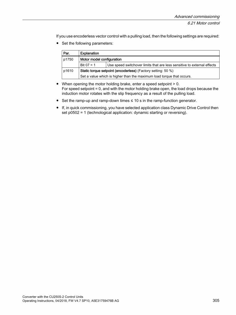
If you use encoderless vector control with a pulling load, then the following settings are required:
Set the following parameters:
Par. Explanationp1750 Motor model configuration
Bit 07 = 1 Use speed switchover limits that are less sensitive to external effectsp1610 Static torque setpoint (encoderless) (Factory setting: 50 %)
Set a value which is higher than the maximum load torque that occurs.
When opening the motor holding brake, enter a speed setpoint > 0.For speed setpoint = 0, and with the motor holding brake open, the load drops because the induction motor rotates with the slip frequency as a result of the pulling load.
Set the ramp-up and ramp-down times ≤ 10 s in the ramp-function generator.
If, in quick commissioning, you have selected application class Dynamic Drive Control then set p0502 = 1 (technological application: dynamic starting or reversing).
Advanced commissioning6.21 Motor control
Converter with the CU250S-2 Control UnitsOperating Instructions, 04/2018, FW V4.7 SP10, A5E31759476B AG 305

6.21.3.6 Friction characteristic
FunctionIn many applications, e.g. applications with geared motors or belt conveyors, the frictional torque of the load is not negligible.
The inverter provides the possibility of precontrolling the torque setpoint, bypassing the speed controller. The precontrol reduces overshooting of the speed after speed changes.
Figure 6-54 Precontrol of the speed controller with frictional torque
The inverter calculates the current frictional torque from a friction characteristic with 10 intermediate points.
Figure 6-55 Friction characteristic
The intermediate points of the friction characteristic are defined for positive speeds. In the negative direction of rotation, the inverter uses the intermediate points with a negative sign.
Recording a friction characteristicAfter quick commissioning, the inverter sets the speeds of the intermediate points to values suitable for the rated speed of the motor. The frictional torque of all intermediate points is still equal to zero. On request, the inverter records the friction characteristic: The inverter accelerates the motor step by step up to the rated speed, measures the frictional torque und writes the frictional torque into the intermediate points of the friction characteristic.
PreconditionThe motor is permitted to accelerate up to the rated speed without endangering persons or property.
Advanced commissioning6.21 Motor control
Converter with the CU250S-2 Control Units306 Operating Instructions, 04/2018, FW V4.7 SP10, A5E31759476B AG
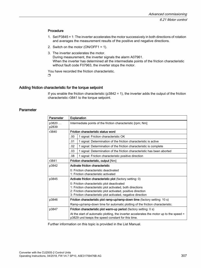
Procedure
1. Set P3845 = 1: The inverter accelerates the motor successively in both directions of rotation and averages the measurement results of the positive and negative directions.
2. Switch on the motor (ON/OFF1 = 1).
3. The inverter accelerates the motor.During measurement, the inverter signals the alarm A07961.When the inverter has determined all the intermediate points of the friction characteristic without fault code F07963, the inverter stops the motor.
You have recorded the friction characteristic.
Adding friction characteristic for the torque setpointIf you enable the friction characteristic (p3842 = 1), the inverter adds the output of the friction characteristic r3841 to the torque setpoint.
Parameter
Parameter Explanationp3820 … p2839
Intermediate points of the friction characteristic [rpm; Nm]
r3840 Friction characteristic status word.00 1 signal: Friction characteristic OK.01 1 signal: Determination of the friction characteristic is active.02 1 signal: Determination of the friction characteristic is complete.03 1 signal: Determination of the friction characteristic has been aborted.08 1 signal: Friction characteristic positive direction
r3841 Friction characteristic, output [Nm]p3842 Activate friction characteristic
0: Friction characteristic deactivated1: Friction characteristic activated
p3845 Activate friction characteristic plot (factory setting: 0)0: Friction characteristic plot deactivated 1: Friction characteristic plot activated, both directions 2: Friction characteristic plot activated, positive direction 3: Friction characteristic plot activated, negative direction
p3846 Friction characteristic plot ramp-up/ramp-down time (factory setting: 10 s)Ramp-up/ramp-down time for automatic plotting of the friction characteristic.
p3847 Friction characteristic plot warm-up period (factory setting: 0 s)At the start of automatic plotting, the inverter accelerates the motor up to the speed = p3829 und keeps the speed constant for this time.
Further information on this topic is provided in the List Manual.
Advanced commissioning6.21 Motor control
Converter with the CU250S-2 Control UnitsOperating Instructions, 04/2018, FW V4.7 SP10, A5E31759476B AG 307
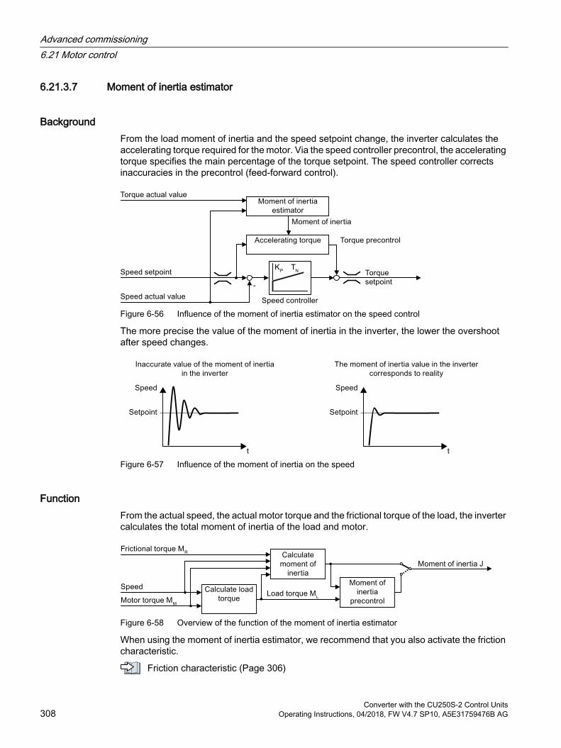
6.21.3.7 Moment of inertia estimator
BackgroundFrom the load moment of inertia and the speed setpoint change, the inverter calculates the accelerating torque required for the motor. Via the speed controller precontrol, the accelerating torque specifies the main percentage of the torque setpoint. The speed controller corrects inaccuracies in the precontrol (feed-forward control).
Figure 6-56 Influence of the moment of inertia estimator on the speed control
The more precise the value of the moment of inertia in the inverter, the lower the overshoot after speed changes.
Figure 6-57 Influence of the moment of inertia on the speed
FunctionFrom the actual speed, the actual motor torque and the frictional torque of the load, the inverter calculates the total moment of inertia of the load and motor.
Figure 6-58 Overview of the function of the moment of inertia estimator
When using the moment of inertia estimator, we recommend that you also activate the friction characteristic.
Friction characteristic (Page 306)
Advanced commissioning6.21 Motor control
Converter with the CU250S-2 Control Units308 Operating Instructions, 04/2018, FW V4.7 SP10, A5E31759476B AG
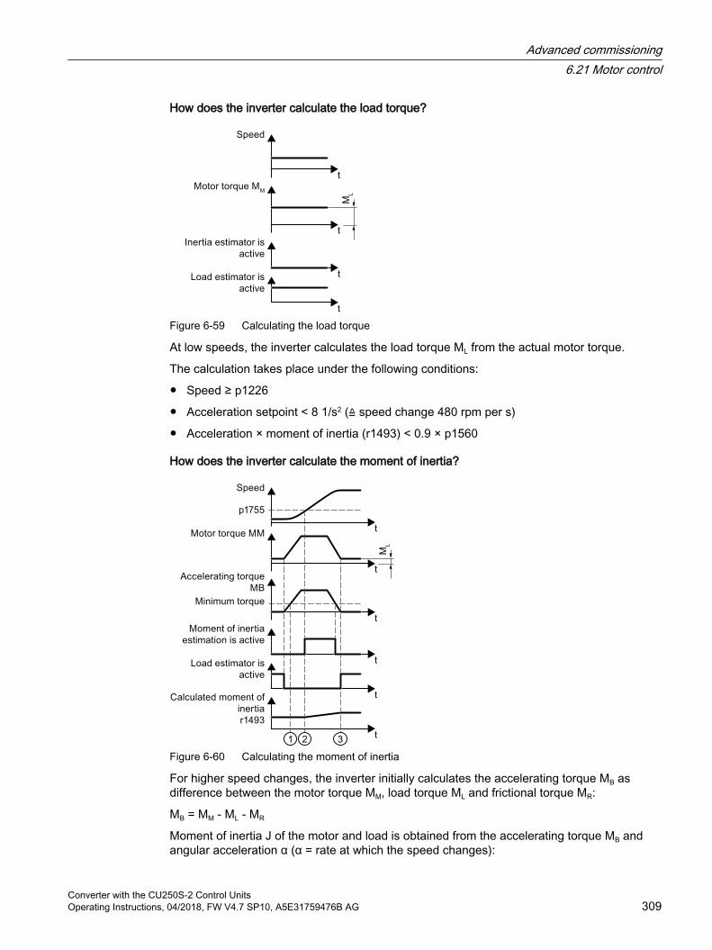
How does the inverter calculate the load torque?
Figure 6-59 Calculating the load torque
At low speeds, the inverter calculates the load torque ML from the actual motor torque.
The calculation takes place under the following conditions:
Speed ≥ p1226
Acceleration setpoint < 8 1/s2 (≙ speed change 480 rpm per s)
Acceleration × moment of inertia (r1493) < 0.9 × p1560
How does the inverter calculate the moment of inertia?
Figure 6-60 Calculating the moment of inertia
For higher speed changes, the inverter initially calculates the accelerating torque MB as difference between the motor torque MM, load torque ML and frictional torque MR:
MB = MM - ML - MR
Moment of inertia J of the motor and load is obtained from the accelerating torque MB and angular acceleration α (α = rate at which the speed changes):
Advanced commissioning6.21 Motor control
Converter with the CU250S-2 Control UnitsOperating Instructions, 04/2018, FW V4.7 SP10, A5E31759476B AG 309
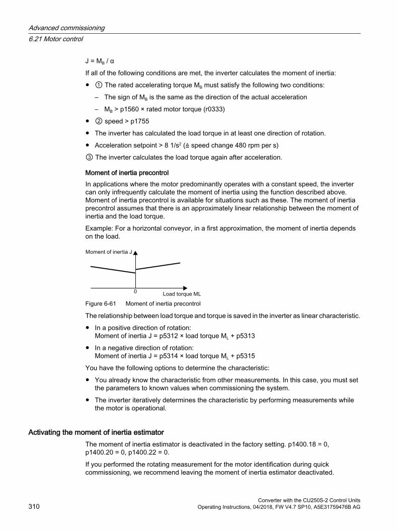
J = MB / α
If all of the following conditions are met, the inverter calculates the moment of inertia:
① The rated accelerating torque MB must satisfy the following two conditions:
– The sign of MB is the same as the direction of the actual acceleration
– MB > p1560 × rated motor torque (r0333)
② speed > p1755
The inverter has calculated the load torque in at least one direction of rotation.
Acceleration setpoint > 8 1/s2 (≙ speed change 480 rpm per s)
③ The inverter calculates the load torque again after acceleration.
Moment of inertia precontrolIn applications where the motor predominantly operates with a constant speed, the inverter can only infrequently calculate the moment of inertia using the function described above. Moment of inertia precontrol is available for situations such as these. The moment of inertia precontrol assumes that there is an approximately linear relationship between the moment of inertia and the load torque.
Example: For a horizontal conveyor, in a first approximation, the moment of inertia depends on the load.
Figure 6-61 Moment of inertia precontrol
The relationship between load torque and torque is saved in the inverter as linear characteristic.
In a positive direction of rotation:Moment of inertia J = p5312 × load torque ML + p5313
In a negative direction of rotation:Moment of inertia J = p5314 × load torque ML + p5315
You have the following options to determine the characteristic:
You already know the characteristic from other measurements. In this case, you must set the parameters to known values when commissioning the system.
The inverter iteratively determines the characteristic by performing measurements while the motor is operational.
Activating the moment of inertia estimatorThe moment of inertia estimator is deactivated in the factory setting. p1400.18 = 0, p1400.20 = 0, p1400.22 = 0.
If you performed the rotating measurement for the motor identification during quick commissioning, we recommend leaving the moment of inertia estimator deactivated.
Advanced commissioning6.21 Motor control
Converter with the CU250S-2 Control Units310 Operating Instructions, 04/2018, FW V4.7 SP10, A5E31759476B AG
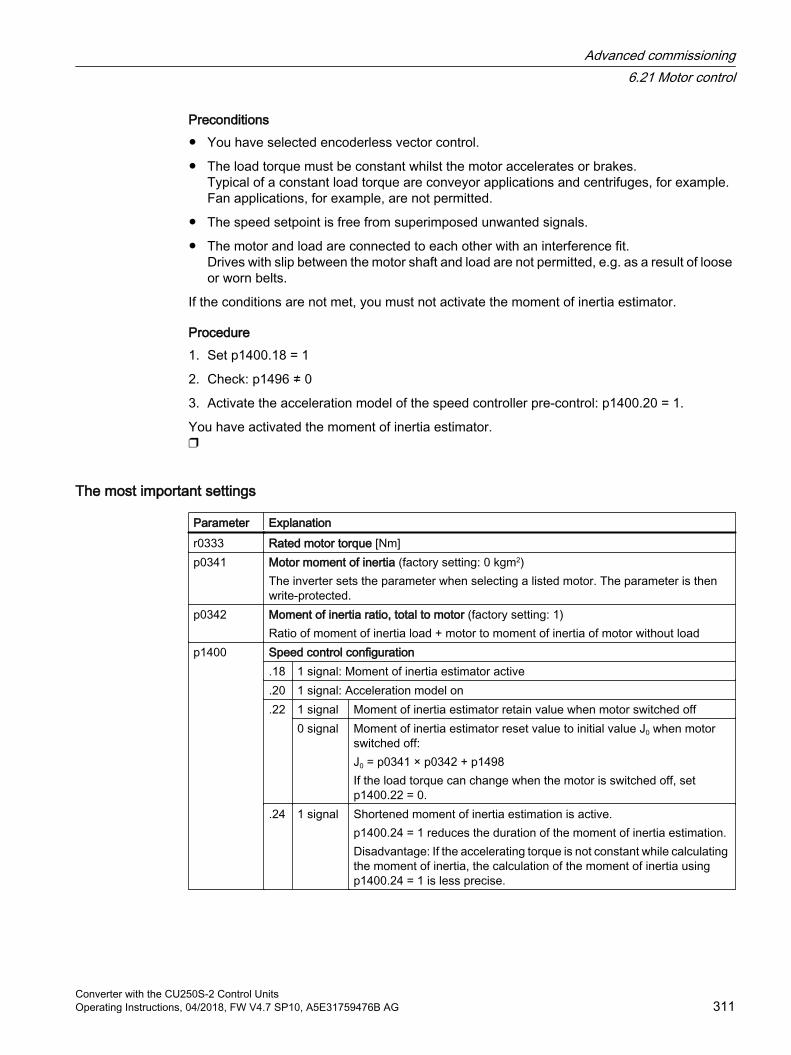
Preconditions You have selected encoderless vector control.
The load torque must be constant whilst the motor accelerates or brakes.Typical of a constant load torque are conveyor applications and centrifuges, for example.Fan applications, for example, are not permitted.
The speed setpoint is free from superimposed unwanted signals.
The motor and load are connected to each other with an interference fit.Drives with slip between the motor shaft and load are not permitted, e.g. as a result of loose or worn belts.
If the conditions are not met, you must not activate the moment of inertia estimator.
Procedure1. Set p1400.18 = 1
2. Check: p1496 ≠ 0
3. Activate the acceleration model of the speed controller pre-control: p1400.20 = 1.
You have activated the moment of inertia estimator.
The most important settings
Parameter Explanationr0333 Rated motor torque [Nm]p0341 Motor moment of inertia (factory setting: 0 kgm2)
The inverter sets the parameter when selecting a listed motor. The parameter is then write-protected.
p0342 Moment of inertia ratio, total to motor (factory setting: 1)Ratio of moment of inertia load + motor to moment of inertia of motor without load
p1400 Speed control configuration.18 1 signal: Moment of inertia estimator active.20 1 signal: Acceleration model on.22 1 signal Moment of inertia estimator retain value when motor switched off
0 signal Moment of inertia estimator reset value to initial value J0 when motor switched off:J0 = p0341 × p0342 + p1498If the load torque can change when the motor is switched off, set p1400.22 = 0.
.24 1 signal Shortened moment of inertia estimation is active.p1400.24 = 1 reduces the duration of the moment of inertia estimation.Disadvantage: If the accelerating torque is not constant while calculating the moment of inertia, the calculation of the moment of inertia using p1400.24 = 1 is less precise.
Advanced commissioning6.21 Motor control
Converter with the CU250S-2 Control UnitsOperating Instructions, 04/2018, FW V4.7 SP10, A5E31759476B AG 311
Parameter Explanationr1407 Status word, speed controller
.24 1 signal: Moment of inertia estimator is active
.25 1 signal: Load estimator is active
.26 1 signal: Moment of inertia estimator is engaged
.27 1 signal: Shortened moment of inertia estimation is active.r1493 Total moment of inertia, scaled
r1493 = p0341 × p0342 × p1496p1496 Acceleration precontrol scaling (factory setting: 0 %)
According to rotating measurement of the motor data identification is p1496 = 100%.p1498 Load moment of inertia (factory setting: 0 kgm2)p1502 Freeze moment of inertia estimator (factory setting: 0)
If the load torque changes when accelerating the motor, set this signal to 0.0 signal Moment of inertia estimator is active1 signal Determined moment of inertia is frozen
p1755 Motor model changeover speed encoderless operationDefines the switchover between open-loop and closed-loop controlled operation of the encoderless vector control.When selecting the closed-loop speed control, the inverter sets p1755 = 13.3% × rated speed.
Advanced settings
Parameter Explanationp1226 Standstill detection, speed threshold (factory setting: 20 rpm)
The moment of inertia estimator only measures the load torque for speeds ≥ p1226.p1226 also defines from which speed the inverter switches-off the motor for OFF1 and OFF3.
p1560 Moment of inertia estimator accelerating torque threshold value (factory setting: 10%)p1561 Moment of inertia estimator change time
inertia (factory setting: 500 ms)The lower that p1561 or p1562 is, the short‐er the moment of inertia estimator meas‐urements.The larger p1561 or p1562 is, the more ac‐curate the results provided by the moment of inertia estimator.
p1562 Moment of inertia estimator change time load (factory setting: 10 ms)
p1563 Moment of inertia estimator load torque positive direction of rotation (factory setting: 0 Nm)
p1564 Moment of inertia estimator load torque negative direction of rotation (factory setting: 0 Nm)
Advanced commissioning6.21 Motor control
Converter with the CU250S-2 Control Units312 Operating Instructions, 04/2018, FW V4.7 SP10, A5E31759476B AG
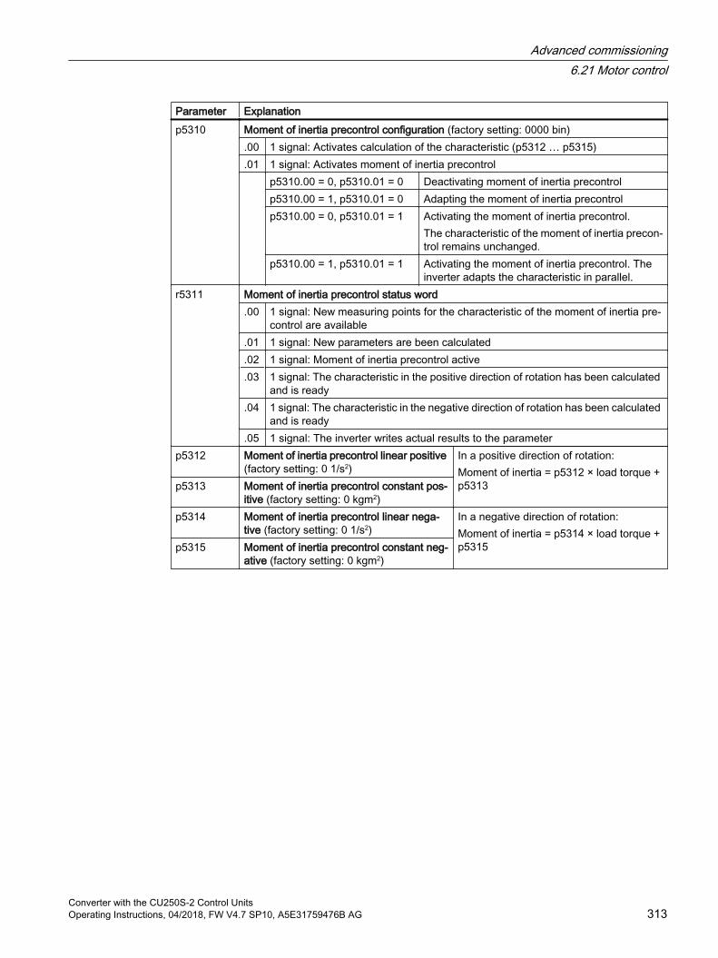
Parameter Explanationp5310 Moment of inertia precontrol configuration (factory setting: 0000 bin)
.00 1 signal: Activates calculation of the characteristic (p5312 … p5315)
.01 1 signal: Activates moment of inertia precontrol p5310.00 = 0, p5310.01 = 0 Deactivating moment of inertia precontrol
p5310.00 = 1, p5310.01 = 0 Adapting the moment of inertia precontrolp5310.00 = 0, p5310.01 = 1 Activating the moment of inertia precontrol.
The characteristic of the moment of inertia precon‐trol remains unchanged.
p5310.00 = 1, p5310.01 = 1 Activating the moment of inertia precontrol. The inverter adapts the characteristic in parallel.
r5311 Moment of inertia precontrol status word.00 1 signal: New measuring points for the characteristic of the moment of inertia pre‐
control are available.01 1 signal: New parameters are been calculated.02 1 signal: Moment of inertia precontrol active.03 1 signal: The characteristic in the positive direction of rotation has been calculated
and is ready.04 1 signal: The characteristic in the negative direction of rotation has been calculated
and is ready.05 1 signal: The inverter writes actual results to the parameter
p5312 Moment of inertia precontrol linear positive (factory setting: 0 1/s2)
In a positive direction of rotation:Moment of inertia = p5312 × load torque + p5313p5313 Moment of inertia precontrol constant pos‐
itive (factory setting: 0 kgm2)p5314 Moment of inertia precontrol linear nega‐
tive (factory setting: 0 1/s2)In a negative direction of rotation:Moment of inertia = p5314 × load torque + p5315p5315 Moment of inertia precontrol constant neg‐
ative (factory setting: 0 kgm2)
Advanced commissioning6.21 Motor control
Converter with the CU250S-2 Control UnitsOperating Instructions, 04/2018, FW V4.7 SP10, A5E31759476B AG 313
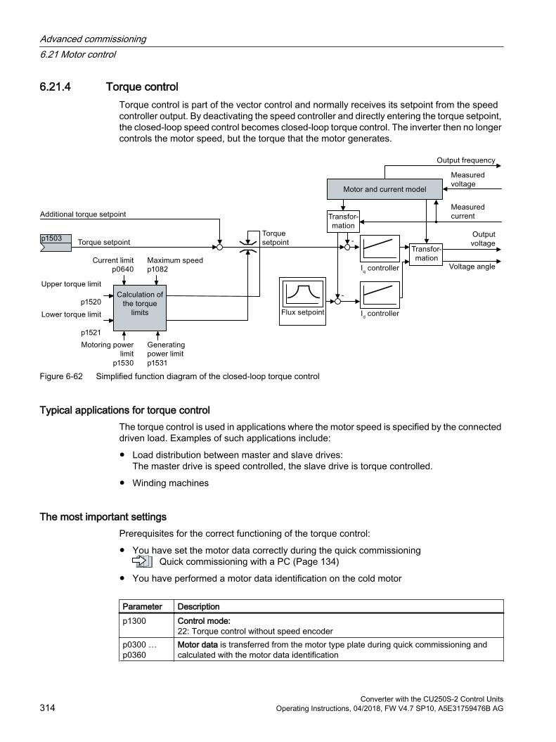
6.21.4 Torque controlTorque control is part of the vector control and normally receives its setpoint from the speed controller output. By deactivating the speed controller and directly entering the torque setpoint, the closed-loop speed control becomes closed-loop torque control. The inverter then no longer controls the motor speed, but the torque that the motor generates.
Figure 6-62 Simplified function diagram of the closed-loop torque control
Typical applications for torque controlThe torque control is used in applications where the motor speed is specified by the connected driven load. Examples of such applications include:
Load distribution between master and slave drives:The master drive is speed controlled, the slave drive is torque controlled.
Winding machines
The most important settingsPrerequisites for the correct functioning of the torque control:
You have set the motor data correctly during the quick commissioning Quick commissioning with a PC (Page 134)
You have performed a motor data identification on the cold motor
Parameter Description p1300 Control mode:
22: Torque control without speed encoderp0300 … p0360
Motor data is transferred from the motor type plate during quick commissioning and calculated with the motor data identification
Advanced commissioning6.21 Motor control
Converter with the CU250S-2 Control Units314 Operating Instructions, 04/2018, FW V4.7 SP10, A5E31759476B AG
Parameter Description p1511 Additional torquep1520 Upper torque limitp1521 Lower torque limitp1530 Motoring power limitp1531 Regenerative power limit
Additional information about this function is provided in the parameter list and in function diagrams 6030 onwards in the List Manual.
6.21.5 Application examples for closed-loop motor controlAdditional information for setting the closed-loop motor control in certain applications is provided in the Internet:
Engineering and commissioning series lifting equipment/cranes (https://support.industry.siemens.com/cs/de/en/view/103156155)
Advanced commissioning6.21 Motor control
Converter with the CU250S-2 Control UnitsOperating Instructions, 04/2018, FW V4.7 SP10, A5E31759476B AG 315
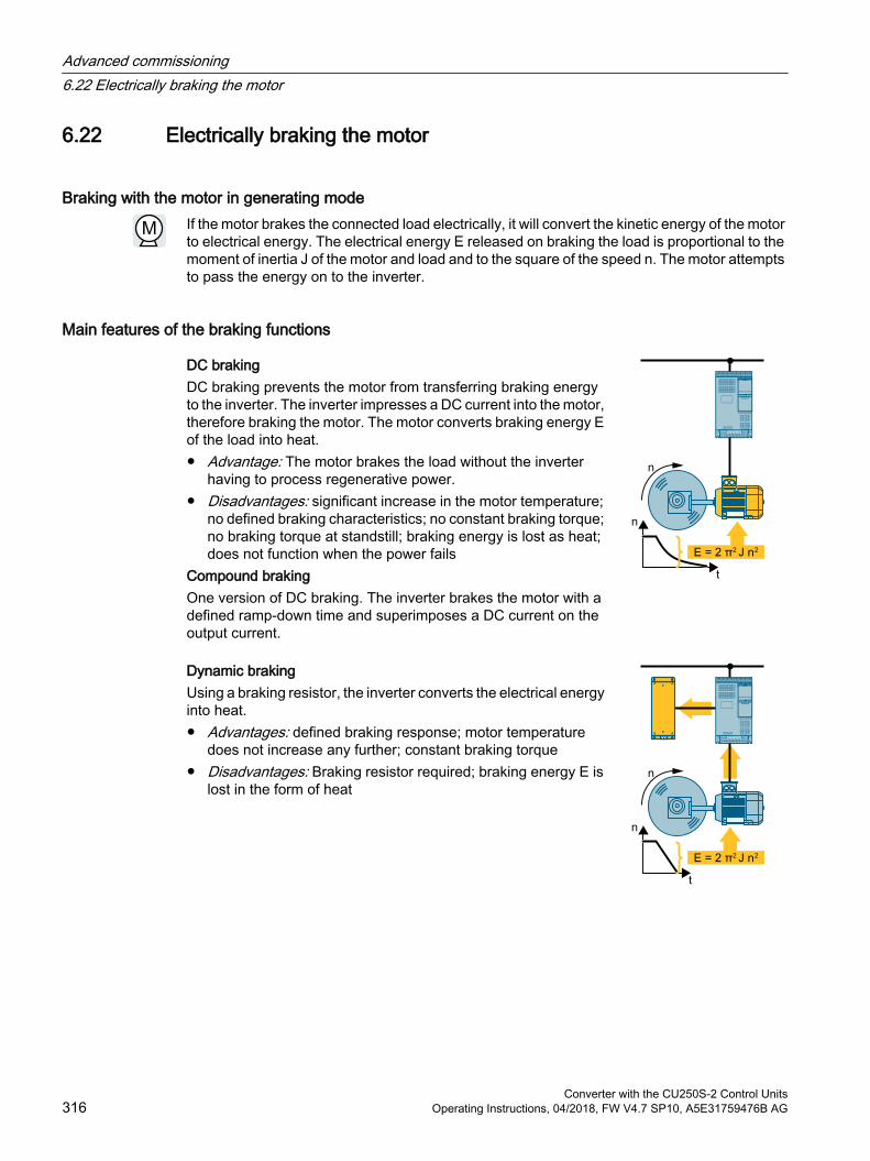
6.22 Electrically braking the motor
Braking with the motor in generating modeIf the motor brakes the connected load electrically, it will convert the kinetic energy of the motor to electrical energy. The electrical energy E released on braking the load is proportional to the moment of inertia J of the motor and load and to the square of the speed n. The motor attempts to pass the energy on to the inverter.
Main features of the braking functions
DC braking DC braking prevents the motor from transferring braking energy to the inverter. The inverter impresses a DC current into the motor, therefore braking the motor. The motor converts braking energy E of the load into heat. Advantage: The motor brakes the load without the inverter
having to process regenerative power. Disadvantages: significant increase in the motor temperature;
no defined braking characteristics; no constant braking torque; no braking torque at standstill; braking energy is lost as heat; does not function when the power fails
Compound brakingOne version of DC braking. The inverter brakes the motor with a defined ramp-down time and superimposes a DC current on the output current.
Dynamic brakingUsing a braking resistor, the inverter converts the electrical energy into heat. Advantages: defined braking response; motor temperature
does not increase any further; constant braking torque Disadvantages: Braking resistor required; braking energy E is
lost in the form of heat
Advanced commissioning6.22 Electrically braking the motor
Converter with the CU250S-2 Control Units316 Operating Instructions, 04/2018, FW V4.7 SP10, A5E31759476B AG
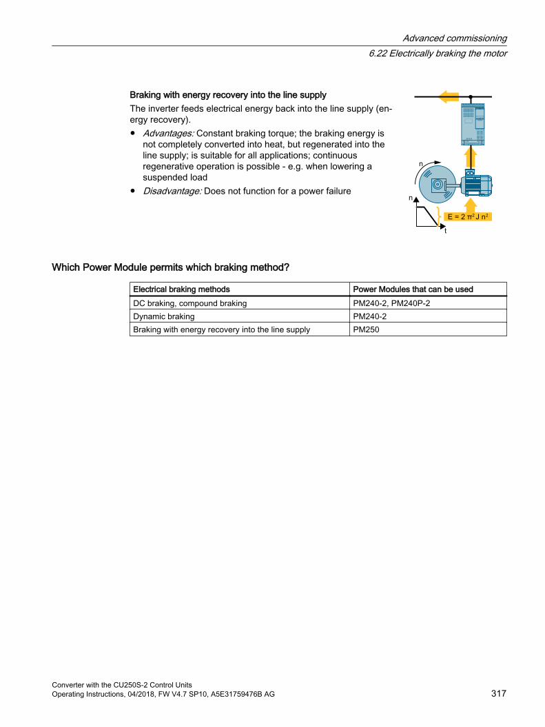
Braking with energy recovery into the line supplyThe inverter feeds electrical energy back into the line supply (en‐ergy recovery). Advantages: Constant braking torque; the braking energy is
not completely converted into heat, but regenerated into the line supply; is suitable for all applications; continuous regenerative operation is possible - e.g. when lowering a suspended load
Disadvantage: Does not function for a power failure
Which Power Module permits which braking method?
Electrical braking methods Power Modules that can be usedDC braking, compound braking PM240-2, PM240P-2Dynamic braking PM240-2Braking with energy recovery into the line supply PM250
Advanced commissioning6.22 Electrically braking the motor
Converter with the CU250S-2 Control UnitsOperating Instructions, 04/2018, FW V4.7 SP10, A5E31759476B AG 317
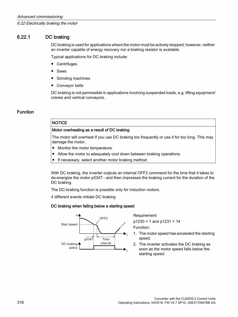
6.22.1 DC brakingDC braking is used for applications where the motor must be actively stopped; however, neither an inverter capable of energy recovery nor a braking resistor is available.
Typical applications for DC braking include:
Centrifuges
Saws
Grinding machines
Conveyor belts
DC braking is not permissible in applications involving suspended loads, e.g. lifting equipment/cranes and vertical conveyors.
Function
NOTICE
Motor overheating as a result of DC braking
The motor will overheat if you use DC braking too frequently or use it for too long. This may damage the motor. Monitor the motor temperature. Allow the motor to adequately cool down between braking operations. If necessary, select another motor braking method.
With DC braking, the inverter outputs an internal OFF2 command for the time that it takes to de-energize the motor p0347 - and then impresses the braking current for the duration of the DC braking.
The DC-braking function is possible only for induction motors.
4 different events initiate DC braking
DC braking when falling below a starting speed
Requirement:p1230 = 1 and p1231 = 14Function:1. The motor speed has exceeded the starting
speed.2. The inverter activates the DC braking as
soon as the motor speed falls below the starting speed.
Advanced commissioning6.22 Electrically braking the motor
Converter with the CU250S-2 Control Units318 Operating Instructions, 04/2018, FW V4.7 SP10, A5E31759476B AG
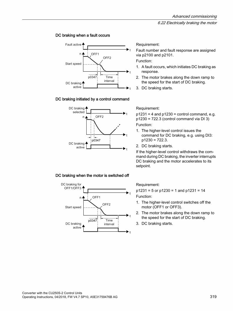
DC braking when a fault occurs
Requirement:Fault number and fault response are assigned via p2100 and p2101.Function:1. A fault occurs, which initiates DC braking as
response.2. The motor brakes along the down ramp to
the speed for the start of DC braking.3. DC braking starts.
DC braking initiated by a control command
Requirement:p1231 = 4 and p1230 = control command, e.g. p1230 = 722.3 (control command via DI 3)Function:1. The higher-level control issues the
command for DC braking, e.g. using DI3: p1230 = 722.3.
2. DC braking starts.If the higher-level control withdraws the com‐mand during DC braking, the inverter interrupts DC braking and the motor accelerates to its setpoint.
DC braking when the motor is switched off
Requirement:p1231 = 5 or p1230 = 1 and p1231 = 14Function:1. The higher-level control switches off the
motor (OFF1 or OFF3).2. The motor brakes along the down ramp to
the speed for the start of DC braking.3. DC braking starts.
Advanced commissioning6.22 Electrically braking the motor
Converter with the CU250S-2 Control UnitsOperating Instructions, 04/2018, FW V4.7 SP10, A5E31759476B AG 319

Settings for DC braking
Parameter Descriptionp0347 Motor de-excitation time (calculated after quick commissioning)
The inverter can trip due to an overcurrent during DC braking if the de-excitation time is too short.
p1230 DC braking activation (factory setting: 0)Signal source to activate DC braking 0 signal: Deactivated 1 signal: Active
p1231 Configuring DC braking (factory setting: 0)04514
No DC brakingGeneral release for DC brakingDC braking for OFF1/OFF3DC braking below the starting speed
p1232 DC braking braking current (factory setting 0 A)p1233 DC braking duration (factory setting 1 s)p1234 DC braking start speed (factory setting 210000 rpm)r1239 DC braking status word
.08
.10
.11
.12
.13
DC braking activeDC braking readyDC braking selectedDC braking selection internally lockedDC braking for OFF1/OFF3
Table 6-59 Configuring DC braking as a response to faults
Parameter Descriptionp2100 Set fault number for fault response (factory setting 0)
Enter the fault number for which DC braking should be activated, e.g. p2100[3] = 7860 (external fault 1).
p2101 = 6 Fault response setting (factory setting 0)Assigning the fault response: p2101[3] = 6.
The fault is assigned an index of p2100. Assign the same index of p2100 or p2101 to the fault and fault response.The inverter's List Manual lists in the "Faults and alarms" list the possible fault responses for every fault. Entry "DCBRK" means that you may set DC braking as response for this fault.
Advanced commissioning6.22 Electrically braking the motor
Converter with the CU250S-2 Control Units320 Operating Instructions, 04/2018, FW V4.7 SP10, A5E31759476B AG
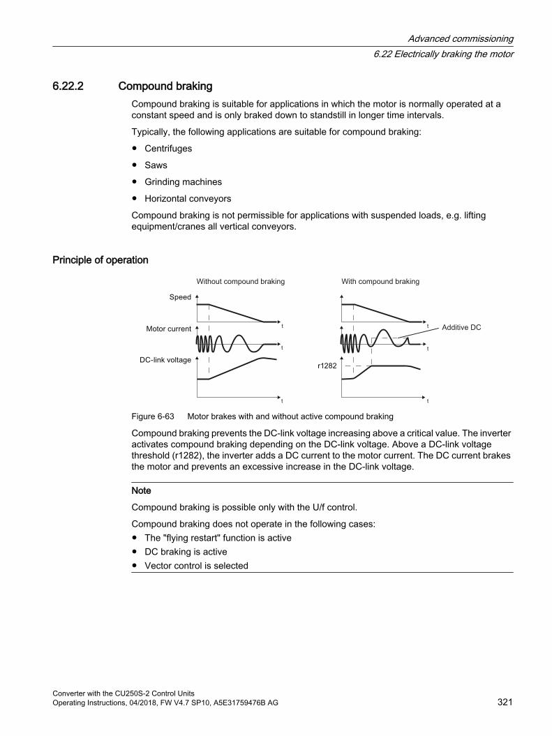
6.22.2 Compound brakingCompound braking is suitable for applications in which the motor is normally operated at a constant speed and is only braked down to standstill in longer time intervals.
Typically, the following applications are suitable for compound braking:
Centrifuges
Saws
Grinding machines
Horizontal conveyors
Compound braking is not permissible for applications with suspended loads, e.g. lifting equipment/cranes all vertical conveyors.
Principle of operation
Figure 6-63 Motor brakes with and without active compound braking
Compound braking prevents the DC-link voltage increasing above a critical value. The inverter activates compound braking depending on the DC-link voltage. Above a DC-link voltage threshold (r1282), the inverter adds a DC current to the motor current. The DC current brakes the motor and prevents an excessive increase in the DC-link voltage.
Note
Compound braking is possible only with the U/f control.
Compound braking does not operate in the following cases: The "flying restart" function is active DC braking is active Vector control is selected
Advanced commissioning6.22 Electrically braking the motor
Converter with the CU250S-2 Control UnitsOperating Instructions, 04/2018, FW V4.7 SP10, A5E31759476B AG 321
Setting and enabling compound braking
Parameter Descriptionp3856 Compound braking current (%)
With the compound braking current, the magnitude of the DC current is defined, which is additionally generated when stopping the motor for operation with U/f control to increase the braking effect.p3856 = 0Compound braking lockedp3856 = 1 … 250Current level of the DC braking current as a % of the rated motor current (p0305)Recommendation: p3856 < 100% × (r0209 - r0331) / p0305 / 2
r3859.0 Compound-braking status wordr3859.0 = 1: Compound braking is active
NOTICE
Overheating of the motor due to compound braking
The motor will overheat if you use compound braking too frequently or for too long. This may damage the motor. Monitor the motor temperature. Allow the motor to adequately cool down between braking operations. If necessary, select another motor braking method.
Advanced commissioning6.22 Electrically braking the motor
Converter with the CU250S-2 Control Units322 Operating Instructions, 04/2018, FW V4.7 SP10, A5E31759476B AG
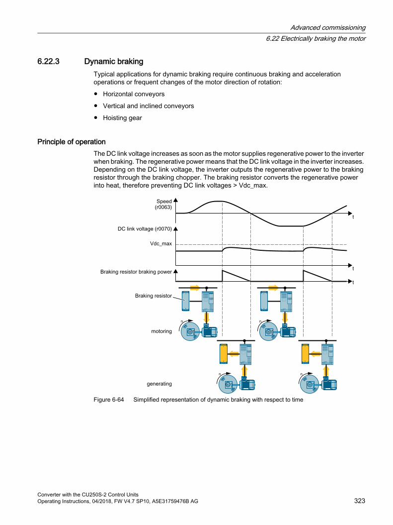
6.22.3 Dynamic brakingTypical applications for dynamic braking require continuous braking and acceleration operations or frequent changes of the motor direction of rotation:
Horizontal conveyors
Vertical and inclined conveyors
Hoisting gear
Principle of operationThe DC link voltage increases as soon as the motor supplies regenerative power to the inverter when braking. The regenerative power means that the DC link voltage in the inverter increases. Depending on the DC link voltage, the inverter outputs the regenerative power to the braking resistor through the braking chopper. The braking resistor converts the regenerative power into heat, therefore preventing DC link voltages > Vdc_max.
Figure 6-64 Simplified representation of dynamic braking with respect to time
Advanced commissioning6.22 Electrically braking the motor
Converter with the CU250S-2 Control UnitsOperating Instructions, 04/2018, FW V4.7 SP10, A5E31759476B AG 323
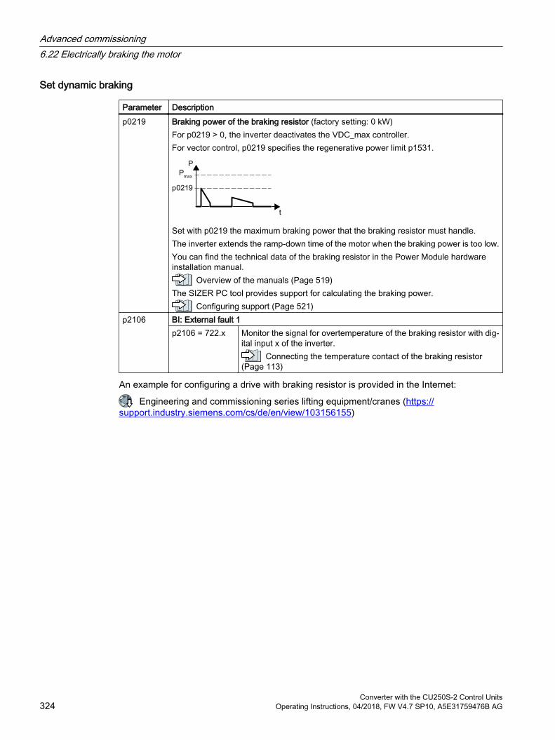
Set dynamic braking
Parameter Descriptionp0219 Braking power of the braking resistor (factory setting: 0 kW)
For p0219 > 0, the inverter deactivates the VDC_max controller.For vector control, p0219 specifies the regenerative power limit p1531.
Set with p0219 the maximum braking power that the braking resistor must handle.The inverter extends the ramp-down time of the motor when the braking power is too low.You can find the technical data of the braking resistor in the Power Module hardware installation manual.
Overview of the manuals (Page 519)The SIZER PC tool provides support for calculating the braking power.
Configuring support (Page 521)p2106 BI: External fault 1
p2106 = 722.x Monitor the signal for overtemperature of the braking resistor with dig‐ital input x of the inverter.
Connecting the temperature contact of the braking resistor (Page 113)
An example for configuring a drive with braking resistor is provided in the Internet:
Engineering and commissioning series lifting equipment/cranes (https://support.industry.siemens.com/cs/de/en/view/103156155)
Advanced commissioning6.22 Electrically braking the motor
Converter with the CU250S-2 Control Units324 Operating Instructions, 04/2018, FW V4.7 SP10, A5E31759476B AG
6.22.4 Braking with regenerative feedback to the lineThe typical applications for braking with energy recovery (regenerative feedback into the line supply) are as follows:
Hoist drives
Centrifuges
Unwinders
For these applications, the motor must brake for longer periods of time.
The inverter can feed back up to 100% of its rated power into the line supply (referred to "High Overload" base load).
Technical data, PM250 Power Module (Page 471)
Setting the braking with regenerative feedback to the line
Parameter DescriptionLimiting the regenerative feedback for V/f control (p1300 < 20) p0640 Motor series overload factor (factory setting: 0.00 A, default for quick commissioning)
It is only possible to limit the regenerative power with V/f control by limiting the motor current.If the current exceeds this value for longer than 10 s, the inverter shuts down the motor with fault F07806.
Limiting feedback with vector control (p1300 ≥ 20)p1531 Power limit generative (factory setting: -0.01 kW)
The inverter calculates the parameter based on the quick commissioning or with p0340 = 5.
Advanced commissioning6.22 Electrically braking the motor
Converter with the CU250S-2 Control UnitsOperating Instructions, 04/2018, FW V4.7 SP10, A5E31759476B AG 325
6.23 Overcurrent protectionThe vector control ensures that the motor current remains within the set torque limits.
If you use U/f control, you cannot set any torque limits. The U/f control prevents too high a motor current by influencing the output frequency and the motor voltage (I-max controller).
I_max controller
RequirementsThe torque of the motor must decrease at lower speeds, which is the case, for example, with fans.
The load must not drive the motor continuously, e.g. when lowering hoisting gear.
FunctionThe I-max controller influences the output frequency and the motor voltage.
If the motor current reaches the current limit during acceleration, the I-max controller extends the acceleration operation.
If the load of the motor is so large during stationary operation that the motor current reaches the current limit, the I-max controller reduces the speed and the motor voltage until the motor current is in the permissible range again.
If the motor current reaches the current limit during deceleration, the I-max controller extends the deceleration operation.
SettingsYou only have to change the factory settings of the I-max controller if the drive tends to oscillate when it reaches the current limit or if it is shut down due to overcurrent.
Table 6-60 I-max controller parameters
Parameter Description p0305 Rated motor currentp0640 Motor current limitp1340 Proportional gain of the I-max controller for speed reductionp1341 Integral time of the I-max controller for speed reductionr0056.13 Status: I-max controller activer1343 Speed output of the I-max controller
Shows the amount to which the I-max controller reduces the speed.
For more information about this function, see function diagram 6300 in the List Manual.
Advanced commissioning6.23 Overcurrent protection
Converter with the CU250S-2 Control Units326 Operating Instructions, 04/2018, FW V4.7 SP10, A5E31759476B AG
6.24 Inverter protection using temperature monitoringThe inverter temperature is essentially defined by the following effects:
The ambient temperature
The ohmic losses increasing with the output current
Switching losses increasing with the pulse frequency
Monitoring typesThe inverter monitors its temperature using the following monitoring types:
I2t monitoring (alarm A07805, fault F30005)
Measuring the chip temperature of the Power Module (alarm A05006, fault F30024)
Measuring the heat sink temperature of the Power Module (alarm A05000, fault F30004)
Inverter response to thermal overload
Parameter Description r0036 Power unit overload I2t [%]
The I2t monitoring calculates the inverter utilization based on a current reference value defined in the factory. Actual current > reference value: r0036 becomes higher. Actual current < reference value: r0036 becomes lower or remains = 0.
r0037 Power unit temperatures [°C]p0290 Power unit overload response
Factory setting and the ability to be changed depends on the hardware. The dependency is described in the List Manual.A thermal overload is present if the inverter temperature is greater than that specified in p0292.You define how the inverter responds if there is a risk of thermal overload using this pa‐rameter. The details are described below.
p0292 Power unit temperature warning threshold (factory setting: Heat sink [0] 5 °C, power semiconductor [1] 15 °C)The value is set as a difference to the shutdown temperature.
p0294 Power unit warning at I2t overload (factory setting: 95 %)
Overload response for p0290 = 0The inverter responds depending on the control mode that has been set:
In vector control, the inverter reduces the output current.
In U/f control, the inverter reduces the speed.
Once the overload condition has been removed, the inverter re-enables the output current or speed.
Advanced commissioning6.24 Inverter protection using temperature monitoring
Converter with the CU250S-2 Control UnitsOperating Instructions, 04/2018, FW V4.7 SP10, A5E31759476B AG 327
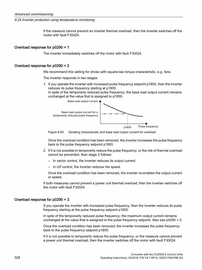
If the measure cannot prevent an inverter thermal overload, then the inverter switches off the motor with fault F30024.
Overload response for p0290 = 1The inverter immediately switches off the motor with fault F30024.
Overload response for p0290 = 2We recommend this setting for drives with square-law torque characteristic, e.g. fans.
The inverter responds in two stages:
1. If you operate the inverter with increased pulse frequency setpoint p1800, then the inverter reduces its pulse frequency starting at p1800.In spite of the temporarily reduced pulse frequency, the base load output current remains unchanged at the value that is assigned to p1800.
Figure 6-65 Derating characteristic and base load output current for overload
Once the overload condition has been removed, the inverter increases the pulse frequency back to the pulse frequency setpoint p1800.
2. If it is not possible to temporarily reduce the pulse frequency, or the risk of thermal overload cannot be prevented, then stage 2 follows:
– In vector control, the inverter reduces its output current.
– In U/f control, the inverter reduces the speed.
Once the overload condition has been removed, the inverter re-enables the output current or speed.
If both measures cannot prevent a power unit thermal overload, then the inverter switches off the motor with fault F30024.
Overload response for p0290 = 3If you operate the inverter with increased pulse frequency, then the inverter reduces its pulse frequency starting at the pulse frequency setpoint p1800.
In spite of the temporarily reduced pulse frequency, the maximum output current remains unchanged at the value that is assigned to the pulse frequency setpoint. Also see p0290 = 2.
Once the overload condition has been removed, the inverter increases the pulse frequency back to the pulse frequency setpoint p1800.
If it is not possible to temporarily reduce the pulse frequency, or the measure cannot prevent a power unit thermal overload, then the inverter switches off the motor with fault F30024.
Advanced commissioning6.24 Inverter protection using temperature monitoring
Converter with the CU250S-2 Control Units328 Operating Instructions, 04/2018, FW V4.7 SP10, A5E31759476B AG
Overload response for p0290 = 12The inverter responds in two stages:
1. If you operate the inverter with increased pulse frequency setpoint p1800, then the inverter reduces its pulse frequency starting at p1800.There is no current derating as a result of the higher pulse frequency setpoint.Once the overload condition has been removed, the inverter increases the pulse frequency back to the pulse frequency setpoint p1800.
2. If it is not possible to temporarily reduce the pulse frequency, or the risk of inverter thermal overload cannot be prevented, then stage 2 follows:
– In vector control, the inverter reduces the output current.
– In U/f control, the inverter reduces the speed.
Once the overload condition has been removed, the inverter re-enables the output current or speed.
If both measures cannot prevent a power unit thermal overload, then the inverter switches off the motor with fault F30024.
Overload response for p0290 = 13We recommend this setting for drives with high starting torque, e.g. horizontal conveyors or extruders.
If you operate the inverter with increased pulse frequency, then the inverter reduces its pulse frequency starting at the pulse frequency setpoint p1800.
There is no current derating as a result of the higher pulse frequency setpoint.
Once the overload condition has been removed, the inverter increases the pulse frequency back to the pulse frequency setpoint p1800.
If it is not possible to temporarily reduce the pulse frequency, or the measure cannot prevent a power unit thermal overload, then the inverter switches off the motor with fault F30024.
Advanced commissioning6.24 Inverter protection using temperature monitoring
Converter with the CU250S-2 Control UnitsOperating Instructions, 04/2018, FW V4.7 SP10, A5E31759476B AG 329
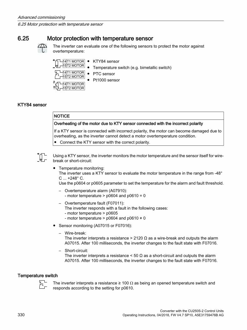
6.25 Motor protection with temperature sensorThe inverter can evaluate one of the following sensors to protect the motor against overtemperature:
KTY84 sensor Temperature switch (e.g. bimetallic switch) PTC sensor Pt1000 sensor
KTY84 sensor
NOTICE
Overheating of the motor due to KTY sensor connected with the incorrect polarity
If a KTY sensor is connected with incorrect polarity, the motor can become damaged due to overheating, as the inverter cannot detect a motor overtemperature condition. Connect the KTY sensor with the correct polarity.
Using a KTY sensor, the inverter monitors the motor temperature and the sensor itself for wire-break or short-circuit:
Temperature monitoring: The inverter uses a KTY sensor to evaluate the motor temperature in the range from -48° C ... +248° C. Use the p0604 or p0605 parameter to set the temperature for the alarm and fault threshold.
– Overtemperature alarm (A07910):- motor temperature > p0604 and p0610 = 0
– Overtemperature fault (F07011):The inverter responds with a fault in the following cases: - motor temperature > p0605- motor temperature > p0604 and p0610 ≠ 0
Sensor monitoring (A07015 or F07016):
– Wire-break: The inverter interprets a resistance > 2120 Ω as a wire-break and outputs the alarm A07015. After 100 milliseconds, the inverter changes to the fault state with F07016.
– Short-circuit: The inverter interprets a resistance < 50 Ω as a short-circuit and outputs the alarm A07015. After 100 milliseconds, the inverter changes to the fault state with F07016.
Temperature switchThe inverter interprets a resistance ≥ 100 Ω as being an opened temperature switch and responds according to the setting for p0610.
Advanced commissioning6.25 Motor protection with temperature sensor
Converter with the CU250S-2 Control Units330 Operating Instructions, 04/2018, FW V4.7 SP10, A5E31759476B AG

PTC sensorThe inverter interprets a resistance > 1650 Ω as being an overtemperature and responds according to the setting for p0610.
The inverter interprets a resistance < 20 Ω as being a short-circuit and responds with alarm A07015. If the alarm is present for longer than 100 milliseconds, the inverter shuts down with fault F07016.
Pt1000 sensorUsing a Pt1000 sensor, the inverter monitors the motor temperature and the sensor itself for wire breakage and/or short-circuit:
Temperature monitoring:Using a Pt1000 sensor, the inverter evaluates the motor temperature in the range from -48 °C ... +248 °C.You set the temperature for the alarm and fault thresholds using parameters p0604 and p0605.
– Overtemperature alarm (A07910):- motor temperature > p0604 and p0610 = 0
– Overtemperature fault (F07011):The inverter responds with a fault in the following cases: - motor temperature > p0605- motor temperature > p0604 and p0610 ≠ 0
Sensor monitoring (A07015 or F07016):
– Wire-break: The inverter interprets a resistance > 2120 Ω as a wire-break and outputs the alarm A07015. After 100 milliseconds, the inverter changes to the fault state with F07016.
– Short-circuit: The inverter interprets a resistance < 603 Ω as a short-circuit and outputs the alarm A07015. After 100 milliseconds, the inverter changes to the fault state with F07016.
Setting parameters for the temperature monitoring
Parameter Descriptionp0335 Motor-cooling method (factory setting: 0)
0: Natural cooling - with fan on the motor shaft1: Forced ventilation - with a separately driven fan2: Liquid cooling 128: No fan
p0601 Motor temperature sensor type0: No sensor (factory setting)1: PTC2: KTY844: Temperature switch6: Pt1000
p0604 Mot_temp_mod 2 / sensor alarm threshold (factory setting 130° C)For monitoring the motor temperature using KTY84/Pt1000.
Advanced commissioning6.25 Motor protection with temperature sensor
Converter with the CU250S-2 Control UnitsOperating Instructions, 04/2018, FW V4.7 SP10, A5E31759476B AG 331
Parameter Descriptionp0605 Mot_temp_mod 1/2 / sensor threshold and temperature value (factory setting: 145° C)
For monitoring the motor temperature using KTY84/Pt1000.p0610 Motor overtemperature response (factory setting: 12)
Determines the inverter behavior when the motor temperature reaches the alarm threshold p0604.0: Alarm (A07910), no fault1: Alarm A07910 and fault F07011
The inverter reduces the current limit.2, 12:
Alarm A07910 and fault F07011The inverter does not reduce the current limit.
p0640 Current limit [A]
Additional information on the motor temperature monitoring can be found in function diagram 8016 of the List Manual.
Advanced commissioning6.25 Motor protection with temperature sensor
Converter with the CU250S-2 Control Units332 Operating Instructions, 04/2018, FW V4.7 SP10, A5E31759476B AG
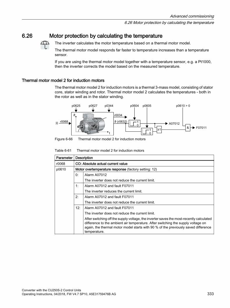
6.26 Motor protection by calculating the temperatureThe inverter calculates the motor temperature based on a thermal motor model.
The thermal motor model responds far faster to temperature increases than a temperature sensor.
If you are using the thermal motor model together with a temperature sensor, e.g. a Pt1000, then the inverter corrects the model based on the measured temperature.
Thermal motor model 2 for induction motorsThe thermal motor model 2 for induction motors is a thermal 3-mass model, consisting of stator core, stator winding and rotor. Thermal motor model 2 calculates the temperatures - both in the rotor as well as in the stator winding.
Figure 6-66 Thermal motor model 2 for induction motors
Table 6-61 Thermal motor model 2 for induction motors
Parameter Description r0068 CO: Absolute actual current valuep0610 Motor overtemperature response (factory setting: 12)
0: Alarm A07012The inverter does not reduce the current limit.
1: Alarm A07012 and fault F07011The inverter reduces the current limit.
2: Alarm A07012 and fault F07011The inverter does not reduce the current limit.
12: Alarm A07012 and fault F07011The inverter does not reduce the current limit.After switching off the supply voltage, the inverter saves the most-recently calculated difference to the ambient air temperature. After switching the supply voltage on again, the thermal motor model starts with 90 % of the previously saved difference temperature.
Advanced commissioning6.26 Motor protection by calculating the temperature
Converter with the CU250S-2 Control UnitsOperating Instructions, 04/2018, FW V4.7 SP10, A5E31759476B AG 333
Parameter Description p0344 Motor weight (for thermal motor type) (factory setting: 0.0 kg) After selecting an induc‐
tion motor (p0300) or a listed induction motor (p0301) during the com‐missioning, the inverter sets the parameters to values appropriate for the motor.The parameters are write-protected for listed motors (p0301 ≥ 0).
p0604 Mot_temp_mod 2/KTY alarm threshold (factory setting: 130.0° C)Motor temperature > p0604 ⇒ fault F07011.
p0605 Mot_temp_mod 1/2 threshold (factory setting: 145.0° C)Motor temperature > p0605 ⇒ alarm A07012.
p0612 Mot_temp_mod activation.01 1 signal: Activate motor temperature model 2 for induc‐
tion motors.09 1 signal: Activate motor temperature model 2 expansions
The inverter sets bit 09 = 1 after commissioning. If you load the parameter settings for firmware version ≤ V4.6 into the inverter, bit 09 = 0 remains.
p0627 Motor overtemperature, stator winding (factory setting: 80 K)p0625 Motor ambient temperature during commissioning (factory setting: 20° C)
Specification of the motor ambient temperature in °C at the instant of the motor data iden‐tification.
r0632 Mot_temp_mod stator winding temperature [°C]p0640 Current limit [A]
Further information is provided in the function charts 8016 and 8017 of the List Manual.
Thermal motor model 1 for synchronous motorsFurther information about thermal motor model 1 for synchronous motors is provided in the function charts 8016 and 8017 of the List Manual.
Advanced commissioning6.26 Motor protection by calculating the temperature
Converter with the CU250S-2 Control Units334 Operating Instructions, 04/2018, FW V4.7 SP10, A5E31759476B AG
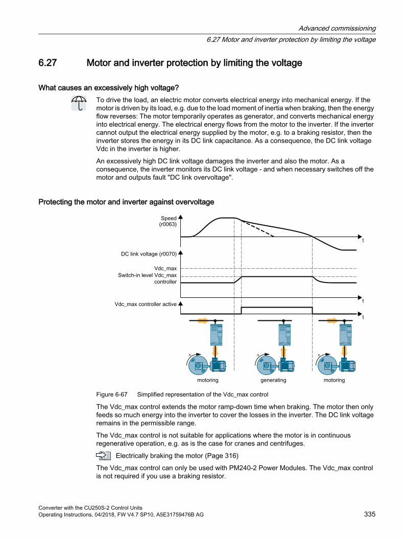
6.27 Motor and inverter protection by limiting the voltage
What causes an excessively high voltage?To drive the load, an electric motor converts electrical energy into mechanical energy. If the motor is driven by its load, e.g. due to the load moment of inertia when braking, then the energy flow reverses: The motor temporarily operates as generator, and converts mechanical energy into electrical energy. The electrical energy flows from the motor to the inverter. If the inverter cannot output the electrical energy supplied by the motor, e.g. to a braking resistor, then the inverter stores the energy in its DC link capacitance. As a consequence, the DC link voltage Vdc in the inverter is higher.
An excessively high DC link voltage damages the inverter and also the motor. As a consequence, the inverter monitors its DC link voltage - and when necessary switches off the motor and outputs fault "DC link overvoltage".
Protecting the motor and inverter against overvoltage
Figure 6-67 Simplified representation of the Vdc_max control
The Vdc_max control extends the motor ramp-down time when braking. The motor then only feeds so much energy into the inverter to cover the losses in the inverter. The DC link voltage remains in the permissible range.
The Vdc_max control is not suitable for applications where the motor is in continuous regenerative operation, e.g. as is the case for cranes and centrifuges.
Electrically braking the motor (Page 316)
The Vdc_max control can only be used with PM240-2 Power Modules. The Vdc_max control is not required if you use a braking resistor.
Advanced commissioning6.27 Motor and inverter protection by limiting the voltage
Converter with the CU250S-2 Control UnitsOperating Instructions, 04/2018, FW V4.7 SP10, A5E31759476B AG 335
PM250 Power Modules feed back regenerative energy into the line supply. Therefore, the Vdc_max control is not required for a PM250 Power Module.
Parameters of the Vdc_max controlThe parameters differ depending on the motor control mode.
Parameter for V/f control
Parameter for vector control
Description
p1280 = 1 p1240 = 1 Vdc controller configuration(Factory setting: 1)1: VDC controller is enabled
r1282 r1242 Vdc_max control activation levelDC link voltage value above which the Vdc_max control is activa‐ted
p1283 p1243 Vdc_max control dynamic factor (factory setting: 100 %)Scaling control parameters p1290, p1291 and p1292
p1284 --- Vdc_max controller time thresholdSetting the monitoring time of the Vdc_max controller.
p1290 p1250 Vdc_max control proportional gain (factory setting: 1)p1291 p1251 Vdc_max control integral time (factory setting p1291: 40 ms,
p1251: 0 ms)p1292 p1252 Vdc_max control rate time (factory setting p1292: 10 ms, p1252:
0 ms)p1294 p1254 Vdc_max control automatic ON level sensing(factory setting, de‐
pendent on the Power Module)Automatically sense switch-on levels of the Vdc_max control.0: Automatic detection disabled1: Automatic detection enabled
p0210 p0210 Unit supply voltageIf p1254 or p1294 = 0, the inverter uses this parameter to calculate the switch-in thresholds of the Vdc_max control.Set this parameter to the actual value of the input voltage.
For more information about this function, see the List Manual (function diagrams 6320 and 6220).
Advanced commissioning6.27 Motor and inverter protection by limiting the voltage
Converter with the CU250S-2 Control Units336 Operating Instructions, 04/2018, FW V4.7 SP10, A5E31759476B AG
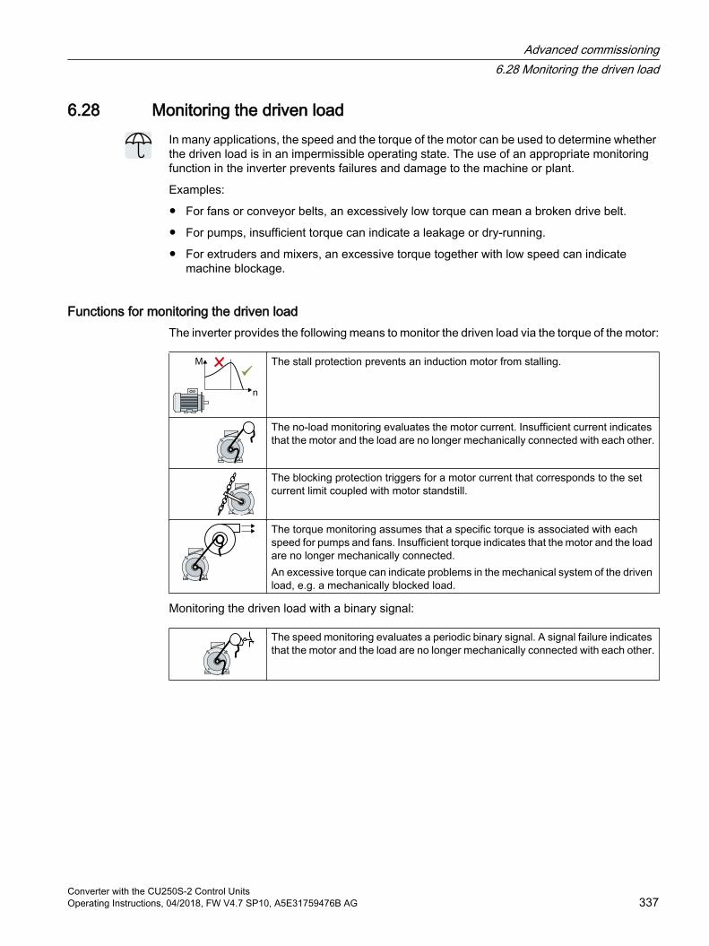
6.28 Monitoring the driven loadIn many applications, the speed and the torque of the motor can be used to determine whether the driven load is in an impermissible operating state. The use of an appropriate monitoring function in the inverter prevents failures and damage to the machine or plant.
Examples:
For fans or conveyor belts, an excessively low torque can mean a broken drive belt.
For pumps, insufficient torque can indicate a leakage or dry-running.
For extruders and mixers, an excessive torque together with low speed can indicate machine blockage.
Functions for monitoring the driven loadThe inverter provides the following means to monitor the driven load via the torque of the motor:
The stall protection prevents an induction motor from stalling.
The no-load monitoring evaluates the motor current. Insufficient current indicates that the motor and the load are no longer mechanically connected with each other.
The blocking protection triggers for a motor current that corresponds to the set current limit coupled with motor standstill.
The torque monitoring assumes that a specific torque is associated with each speed for pumps and fans. Insufficient torque indicates that the motor and the load are no longer mechanically connected.An excessive torque can indicate problems in the mechanical system of the driven load, e.g. a mechanically blocked load.
Monitoring the driven load with a binary signal:
The speed monitoring evaluates a periodic binary signal. A signal failure indicates that the motor and the load are no longer mechanically connected with each other.
Advanced commissioning6.28 Monitoring the driven load
Converter with the CU250S-2 Control UnitsOperating Instructions, 04/2018, FW V4.7 SP10, A5E31759476B AG 337
6.28.1 Breakdown protectionIf the load of a standard induction motor exceeds the stall torque of the motor, the motor can also stall during operation on the inverter. A stalled motor is stationary and does not develop sufficient torque to accelerate the load.
If the "Motor model fault signal stall detection" r1746 for the time p2178 is present via the "Motor model error threshold stall detection" p1745, the inverter signals "Motor stalled" and fault F07902.
Parameter Descriptionr1408 Current controller status word
r1408.12 = 1: Motor stalledp1745 Motor model fault threshold value stall detection (factory setting: 5%)
If the motor stalls too early with this setting, then using the trace function you have the option of determining a better value. To do this, set p1745 = 100.
r1746 Motor model fault signal stall detection [%]p2178 Motor stalled delay time (factory setting: 0.01 s)r2198 Status word monitoring 2
r2198.07 = 1: Motor stalled
6.28.2 No-load monitoringIn applications with fans, compressors or conveyor belts, an insufficient motor current indicates that the power transmission from the motor to the load is interrupted.
If the motor current for the time p2180 lies below the current level p2179, the inverter signals "output load not available" and alarm A07929.
Parameters Descriptionr0068 Actual current value [A]
[0] = Unsmoothed[1] = Smoothed with p0045
p2179 Output load detection current limit (Factory setting: 0 A)p2179 = 0: No load detection deactivated
p2180 Output load detection delay time (factory setting: 2000 ms)r2197 Status word, monitoring functions 1
r2197.11 = 1: Output load not available
Advanced commissioning6.28 Monitoring the driven load
Converter with the CU250S-2 Control Units338 Operating Instructions, 04/2018, FW V4.7 SP10, A5E31759476B AG
6.28.3 Blocking protectionIn applications with extruders or mixers, the motor can block for an excessive mechanical load. For a blocked motor, the motor current corresponds to the set current limit without the speed reaching the specified setpoint.
If the speed lies below the speed threshold p2175 for the time p2177 while the motor current reaches the current limit, the inverter signals "Motor blocked" and fault F07900.
Parameter Descriptionr0063 Actual speed value [rpm]
[0] = Unsmoothed[1] = Smoothed with p0045
p2175 Motor blocked speed threshold (factory setting: 120 rpm)p2175 = 0: Blocking protection deactivated
p2177 Motor blocked delay time (factory setting: 3 s)r2198 Status word monitoring 2
r2198.06 = 1: Motor blocked
Advanced commissioning6.28 Monitoring the driven load
Converter with the CU250S-2 Control UnitsOperating Instructions, 04/2018, FW V4.7 SP10, A5E31759476B AG 339
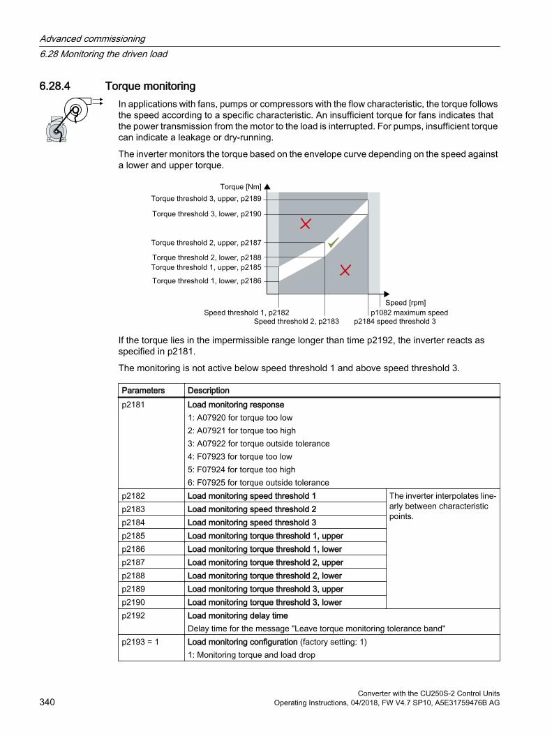
6.28.4 Torque monitoringIn applications with fans, pumps or compressors with the flow characteristic, the torque follows the speed according to a specific characteristic. An insufficient torque for fans indicates that the power transmission from the motor to the load is interrupted. For pumps, insufficient torque can indicate a leakage or dry-running.
The inverter monitors the torque based on the envelope curve depending on the speed against a lower and upper torque.
If the torque lies in the impermissible range longer than time p2192, the inverter reacts as specified in p2181.
The monitoring is not active below speed threshold 1 and above speed threshold 3.
Parameters Descriptionp2181 Load monitoring response
1: A07920 for torque too low2: A07921 for torque too high3: A07922 for torque outside tolerance4: F07923 for torque too low5: F07924 for torque too high6: F07925 for torque outside tolerance
p2182 Load monitoring speed threshold 1 The inverter interpolates line‐arly between characteristic points.
p2183 Load monitoring speed threshold 2p2184 Load monitoring speed threshold 3p2185 Load monitoring torque threshold 1, upperp2186 Load monitoring torque threshold 1, lowerp2187 Load monitoring torque threshold 2, upperp2188 Load monitoring torque threshold 2, lowerp2189 Load monitoring torque threshold 3, upperp2190 Load monitoring torque threshold 3, lowerp2192 Load monitoring delay time
Delay time for the message "Leave torque monitoring tolerance band"p2193 = 1 Load monitoring configuration (factory setting: 1)
1: Monitoring torque and load drop
Advanced commissioning6.28 Monitoring the driven load
Converter with the CU250S-2 Control Units340 Operating Instructions, 04/2018, FW V4.7 SP10, A5E31759476B AG
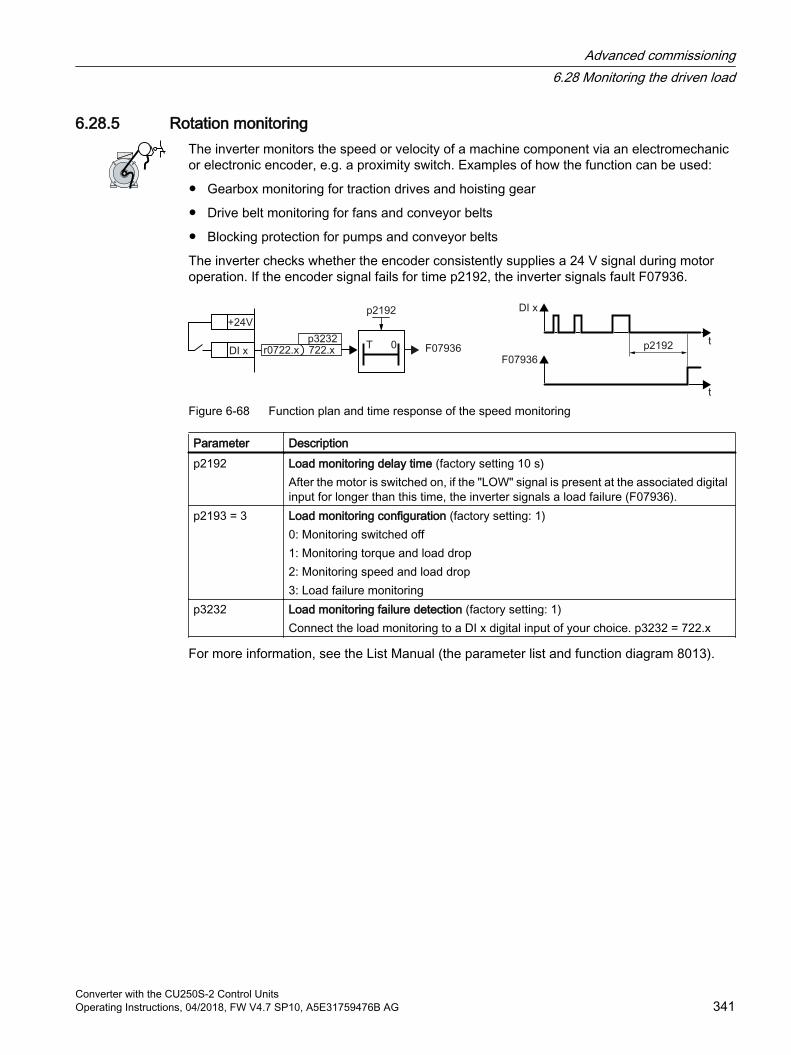
6.28.5 Rotation monitoringThe inverter monitors the speed or velocity of a machine component via an electromechanic or electronic encoder, e.g. a proximity switch. Examples of how the function can be used:
Gearbox monitoring for traction drives and hoisting gear
Drive belt monitoring for fans and conveyor belts
Blocking protection for pumps and conveyor belts
The inverter checks whether the encoder consistently supplies a 24 V signal during motor operation. If the encoder signal fails for time p2192, the inverter signals fault F07936.
Figure 6-68 Function plan and time response of the speed monitoring
Parameter Descriptionp2192 Load monitoring delay time (factory setting 10 s)
After the motor is switched on, if the "LOW" signal is present at the associated digital input for longer than this time, the inverter signals a load failure (F07936).
p2193 = 3 Load monitoring configuration (factory setting: 1)0: Monitoring switched off1: Monitoring torque and load drop2: Monitoring speed and load drop3: Load failure monitoring
p3232 Load monitoring failure detection (factory setting: 1)Connect the load monitoring to a DI x digital input of your choice. p3232 = 722.x
For more information, see the List Manual (the parameter list and function diagram 8013).
Advanced commissioning6.28 Monitoring the driven load
Converter with the CU250S-2 Control UnitsOperating Instructions, 04/2018, FW V4.7 SP10, A5E31759476B AG 341
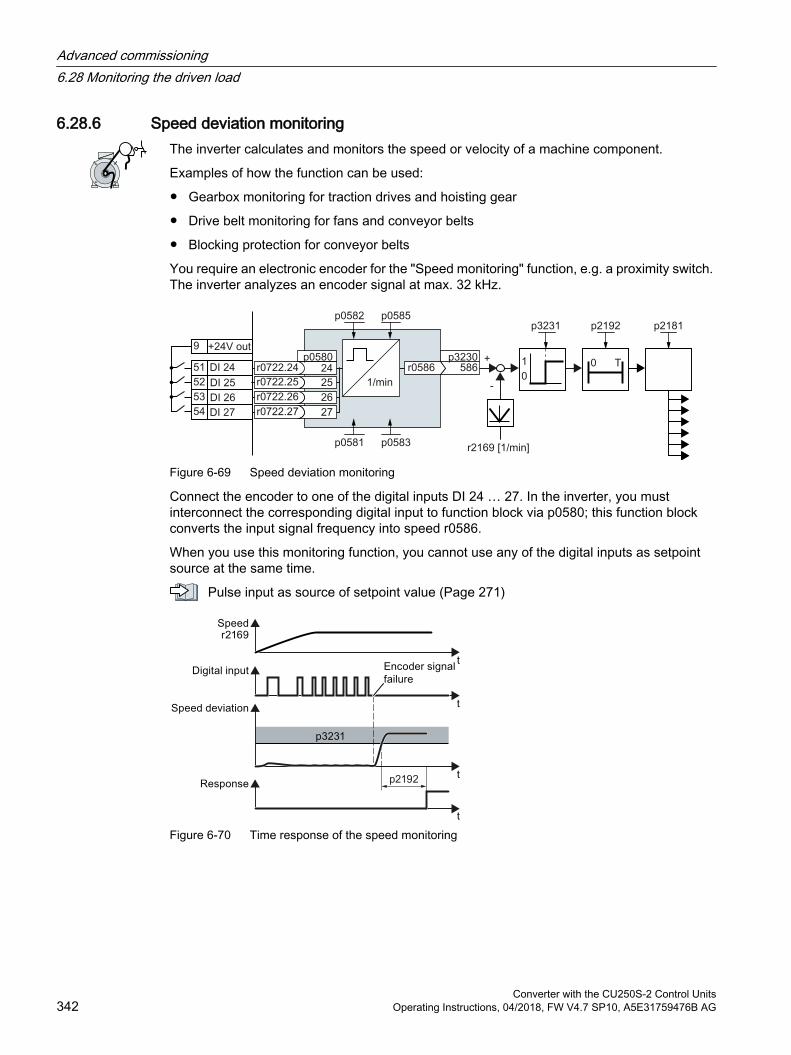
6.28.6 Speed deviation monitoringThe inverter calculates and monitors the speed or velocity of a machine component.
Examples of how the function can be used:
Gearbox monitoring for traction drives and hoisting gear
Drive belt monitoring for fans and conveyor belts
Blocking protection for conveyor belts
You require an electronic encoder for the "Speed monitoring" function, e.g. a proximity switch. The inverter analyzes an encoder signal at max. 32 kHz.
Figure 6-69 Speed deviation monitoring
Connect the encoder to one of the digital inputs DI 24 … 27. In the inverter, you must interconnect the corresponding digital input to function block via p0580; this function block converts the input signal frequency into speed r0586.
When you use this monitoring function, you cannot use any of the digital inputs as setpoint source at the same time.
Pulse input as source of setpoint value (Page 271)
Figure 6-70 Time response of the speed monitoring
Advanced commissioning6.28 Monitoring the driven load
Converter with the CU250S-2 Control Units342 Operating Instructions, 04/2018, FW V4.7 SP10, A5E31759476B AG
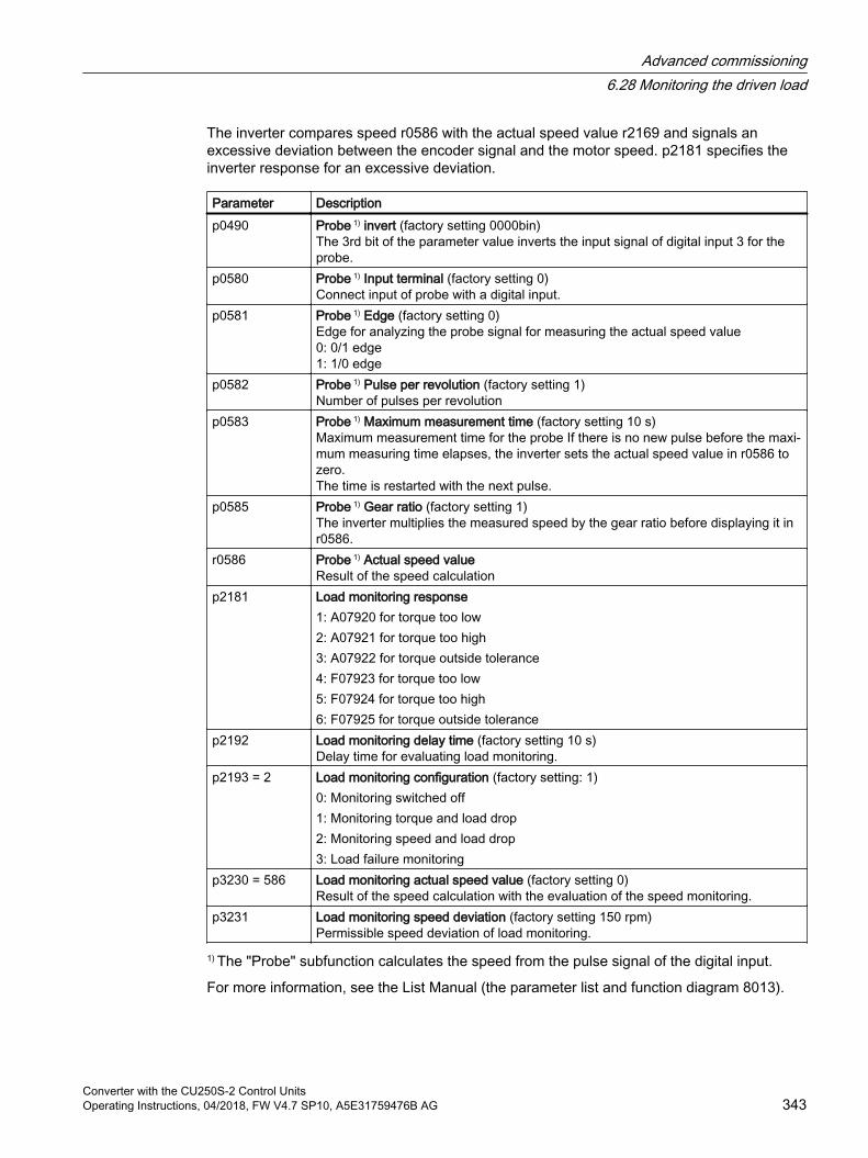
The inverter compares speed r0586 with the actual speed value r2169 and signals an excessive deviation between the encoder signal and the motor speed. p2181 specifies the inverter response for an excessive deviation.
Parameter Descriptionp0490 Probe 1) invert (factory setting 0000bin)
The 3rd bit of the parameter value inverts the input signal of digital input 3 for the probe.
p0580 Probe 1) Input terminal (factory setting 0)Connect input of probe with a digital input.
p0581 Probe 1) Edge (factory setting 0)Edge for analyzing the probe signal for measuring the actual speed value0: 0/1 edge1: 1/0 edge
p0582 Probe 1) Pulse per revolution (factory setting 1)Number of pulses per revolution
p0583 Probe 1) Maximum measurement time (factory setting 10 s)Maximum measurement time for the probe If there is no new pulse before the maxi‐mum measuring time elapses, the inverter sets the actual speed value in r0586 to zero.The time is restarted with the next pulse.
p0585 Probe 1) Gear ratio (factory setting 1)The inverter multiplies the measured speed by the gear ratio before displaying it in r0586.
r0586 Probe 1) Actual speed valueResult of the speed calculation
p2181 Load monitoring response1: A07920 for torque too low2: A07921 for torque too high3: A07922 for torque outside tolerance4: F07923 for torque too low5: F07924 for torque too high6: F07925 for torque outside tolerance
p2192 Load monitoring delay time (factory setting 10 s)Delay time for evaluating load monitoring.
p2193 = 2 Load monitoring configuration (factory setting: 1)0: Monitoring switched off1: Monitoring torque and load drop2: Monitoring speed and load drop3: Load failure monitoring
p3230 = 586 Load monitoring actual speed value (factory setting 0)Result of the speed calculation with the evaluation of the speed monitoring.
p3231 Load monitoring speed deviation (factory setting 150 rpm)Permissible speed deviation of load monitoring.
1) The "Probe" subfunction calculates the speed from the pulse signal of the digital input.
For more information, see the List Manual (the parameter list and function diagram 8013).
Advanced commissioning6.28 Monitoring the driven load
Converter with the CU250S-2 Control UnitsOperating Instructions, 04/2018, FW V4.7 SP10, A5E31759476B AG 343
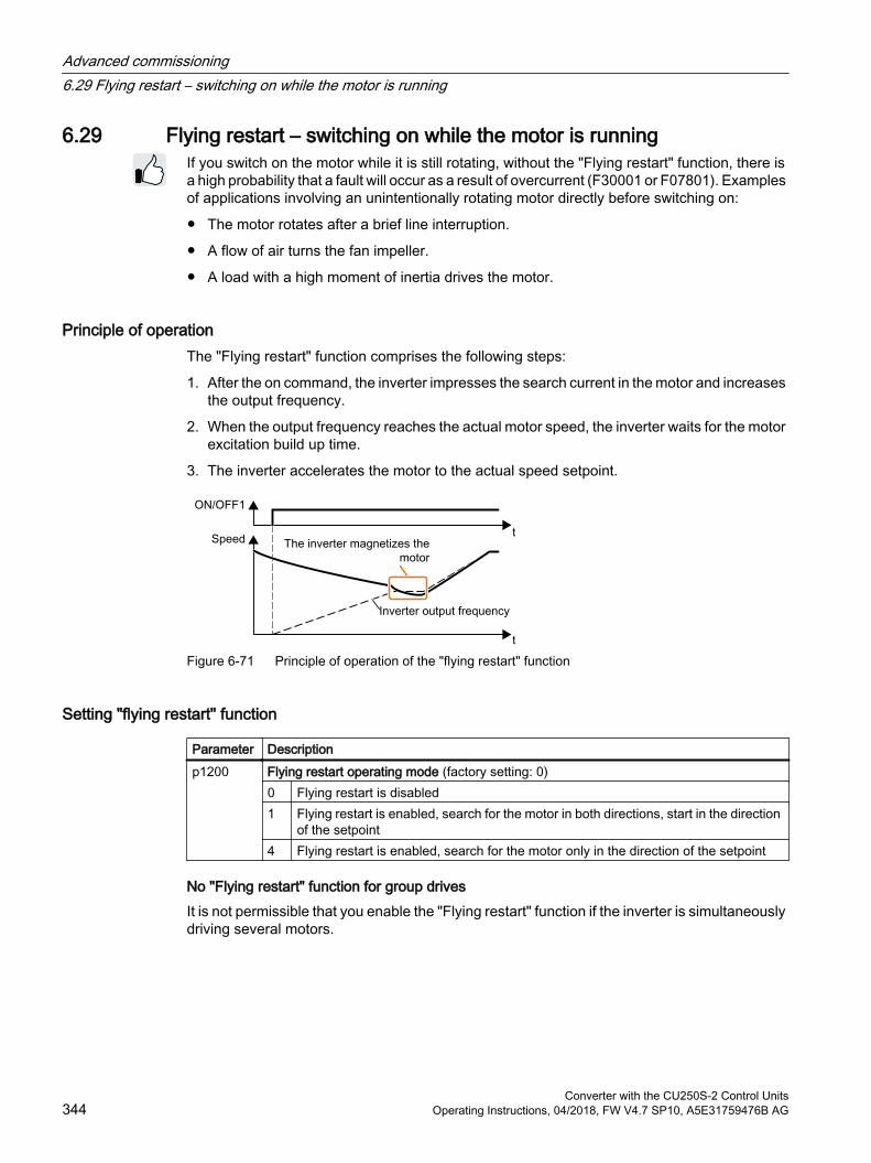
6.29 Flying restart – switching on while the motor is runningIf you switch on the motor while it is still rotating, without the "Flying restart" function, there is a high probability that a fault will occur as a result of overcurrent (F30001 or F07801). Examples of applications involving an unintentionally rotating motor directly before switching on:
The motor rotates after a brief line interruption.
A flow of air turns the fan impeller.
A load with a high moment of inertia drives the motor.
Principle of operationThe "Flying restart" function comprises the following steps:
1. After the on command, the inverter impresses the search current in the motor and increases the output frequency.
2. When the output frequency reaches the actual motor speed, the inverter waits for the motor excitation build up time.
3. The inverter accelerates the motor to the actual speed setpoint.
Figure 6-71 Principle of operation of the "flying restart" function
Setting "flying restart" function
Parameter Description p1200 Flying restart operating mode (factory setting: 0)
0 Flying restart is disabled1 Flying restart is enabled, search for the motor in both directions, start in the direction
of the setpoint4 Flying restart is enabled, search for the motor only in the direction of the setpoint
No "Flying restart" function for group drivesIt is not permissible that you enable the "Flying restart" function if the inverter is simultaneously driving several motors.
Advanced commissioning6.29 Flying restart – switching on while the motor is running
Converter with the CU250S-2 Control Units344 Operating Instructions, 04/2018, FW V4.7 SP10, A5E31759476B AG
Exception: a mechanical coupling ensures that all of the motors always operate with the same speed.
Table 6-62 Advanced settings
Parameter Description p0346 Motor excitation build up time
Wait time between switching on the motor and enabling the ramp-function generator.p0347 Motor de-excitation time
Within the motor de-excitation time, after an OFF command, the inverter prevents the induction motor from being switched on again.
p1201 Flying restart enable signal source (factory setting: 1)Defines a control command, e.g. a digital input, which enables the flying restart function.
p1202 Flying restart search current (Factory setting depends on the Power Module)Defines the search current with respect to the magnetizing current (r0331), which flows in the motor during the flying restart.
p1203 Flying restart search current factor (Factory setting depends on the Power Module)The value influences the speed with which the output frequency is changed during the flying restart. A higher value results in a longer search time.If the inverter does not find the motor, reduce the search speed (increase p1203).
Advanced commissioning6.29 Flying restart – switching on while the motor is running
Converter with the CU250S-2 Control UnitsOperating Instructions, 04/2018, FW V4.7 SP10, A5E31759476B AG 345
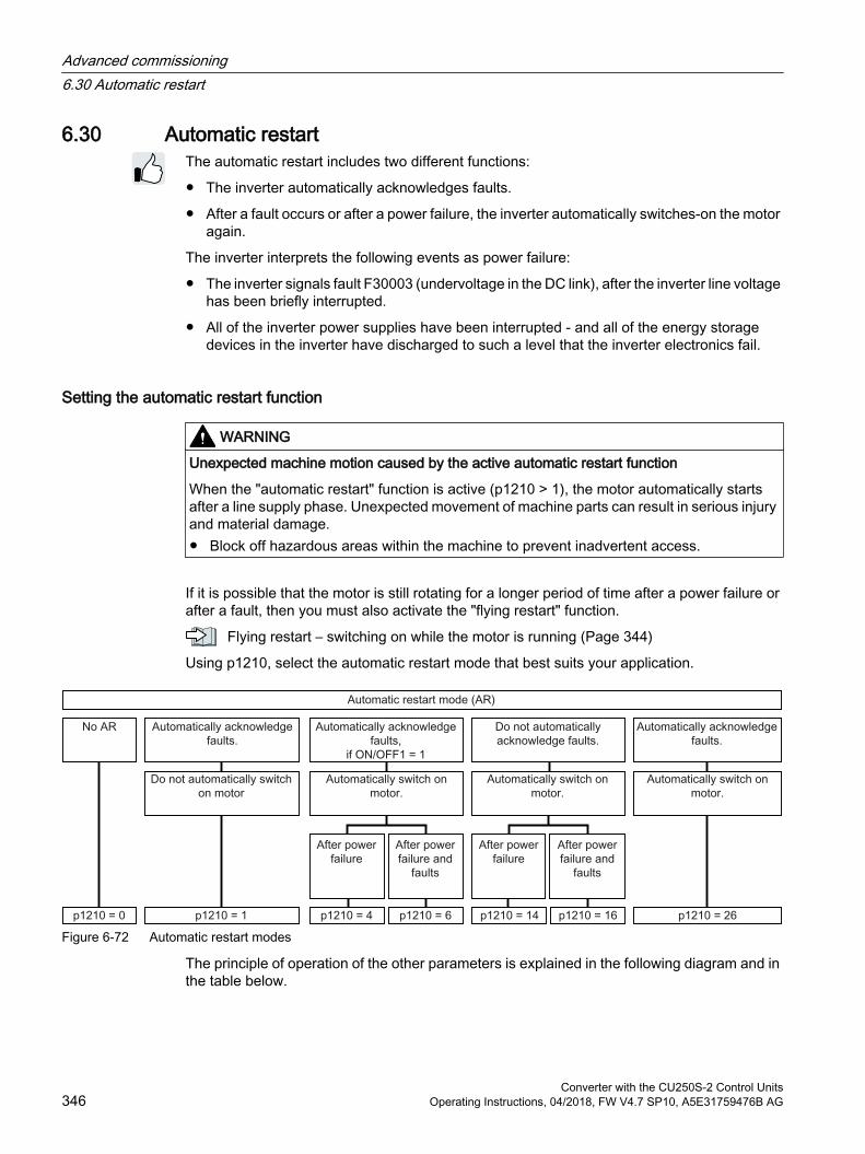
6.30 Automatic restartThe automatic restart includes two different functions:
The inverter automatically acknowledges faults.
After a fault occurs or after a power failure, the inverter automatically switches-on the motor again.
The inverter interprets the following events as power failure:
The inverter signals fault F30003 (undervoltage in the DC link), after the inverter line voltage has been briefly interrupted.
All of the inverter power supplies have been interrupted - and all of the energy storage devices in the inverter have discharged to such a level that the inverter electronics fail.
Setting the automatic restart function
WARNING
Unexpected machine motion caused by the active automatic restart function
When the "automatic restart" function is active (p1210 > 1), the motor automatically starts after a line supply phase. Unexpected movement of machine parts can result in serious injury and material damage. Block off hazardous areas within the machine to prevent inadvertent access.
If it is possible that the motor is still rotating for a longer period of time after a power failure or after a fault, then you must also activate the "flying restart" function.
Flying restart – switching on while the motor is running (Page 344)
Using p1210, select the automatic restart mode that best suits your application.
Figure 6-72 Automatic restart modes
The principle of operation of the other parameters is explained in the following diagram and in the table below.
Advanced commissioning6.30 Automatic restart
Converter with the CU250S-2 Control Units346 Operating Instructions, 04/2018, FW V4.7 SP10, A5E31759476B AG
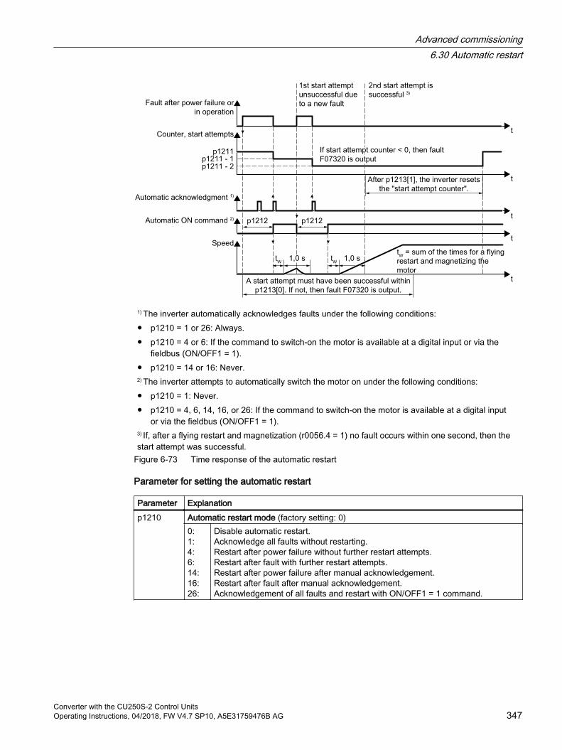
1) The inverter automatically acknowledges faults under the following conditions: p1210 = 1 or 26: Always. p1210 = 4 or 6: If the command to switch-on the motor is available at a digital input or via the
fieldbus (ON/OFF1 = 1). p1210 = 14 or 16: Never.
2) The inverter attempts to automatically switch the motor on under the following conditions: p1210 = 1: Never. p1210 = 4, 6, 14, 16, or 26: If the command to switch-on the motor is available at a digital input
or via the fieldbus (ON/OFF1 = 1).
3) If, after a flying restart and magnetization (r0056.4 = 1) no fault occurs within one second, then the start attempt was successful.
Figure 6-73 Time response of the automatic restart
Parameter for setting the automatic restart
Parameter Explanationp1210 Automatic restart mode (factory setting: 0)
0:1:4:6:14:16:26:
Disable automatic restart.Acknowledge all faults without restarting.Restart after power failure without further restart attempts.Restart after fault with further restart attempts.Restart after power failure after manual acknowledgement.Restart after fault after manual acknowledgement.Acknowledgement of all faults and restart with ON/OFF1 = 1 command.
Advanced commissioning6.30 Automatic restart
Converter with the CU250S-2 Control UnitsOperating Instructions, 04/2018, FW V4.7 SP10, A5E31759476B AG 347

Parameter Explanationp1211 Automatic restart start attempts (factory setting: 3)
This parameter is only effective for the settings p1210 = 4, 6, 14, 16, 26.You define the maximum number of start attempts using p1211. After each successful acknowledgement, the inverter decrements its internal counter of start attempts by 1.p1211 = 0 or 1: The inverter only tries to start once. After an unsuccessful start attempt, the inverter issues fault F07320.p1211 = n, n > 1: The inverter tries to start n-times The inverter outputs fault F07320 if the nth starting attempt was unsuccessful.The inverter sets the start attempt counter back again to the value of p1211, if one of the following conditions is fulfilled: After a successful start attempt, the time in p1213[1] has expired. After fault F07320, switch off the motor (OFF1) and acknowledge the fault. You change the start value p1211 or the mode p1210.
p1212 Automatic restart wait time start attempt (factory setting: 1.0 s)This parameter is only effective for the settings p1210 = 4, 6, 26.Examples for setting this parameter:1. After a power failure, a certain time must elapse before the motor can be switched-
on, e.g. because other machine components are not immediately ready. In this case, set p1212 longer than the time, after which all of the fault causes have been removed.
2. In operation, the inverter develops a fault condition. The lower you select p1212, then the sooner the inverter attempts to switch-on the motor again.
p1213[0] Automatic restart monitoring time for restart (factory setting: 60 s)This parameter is only effective for the settings p1210 = 4, 6, 14, 16, 26.With this monitoring function, you limit the time in which the inverter may attempt to au‐tomatically switch-on the motor again.The monitoring function starts when a fault is identified and ends with a successful start attempt. If the motor has not successfully started after the monitoring time has expired, fault F07320 is signaled.Set the monitoring time longer than the sum of the following times:+ p1212+ Time that the inverter requires to start the motor on the fly.+ Motor magnetizing time (p0346)+ 1 secondYou deactivate the monitoring function with p1213 = 0.
p1213[1] Automatic restart monitoring time to reset the fault counter (factory setting: 0 s)This parameter is only effective for the settings p1210 = 4, 6, 14, 16, 26.Using this monitoring time, you prevent that faults, which continually occur within a certain time period, are automatically acknowledged each time.The monitoring function starts with a successful start attempt and ends after the monitor‐ing time has expired.If, during the monitoring time p1213[1], the inverter made more successful starting at‐tempts than defined in p1211, the inverter interrupts the automatic restart function and signals fault F07320. To switch on the motor again you must acknowledge the fault and switch on the inverter (ON/OFFS1 = 1).
Additional information is provided in the parameter list of the List Manual.
Advanced commissioning6.30 Automatic restart
Converter with the CU250S-2 Control Units348 Operating Instructions, 04/2018, FW V4.7 SP10, A5E31759476B AG
Advanced settingsIf you with to suppress the automatic restart function for certain faults, then you must enter the appropriate fault numbers in p1206[0 … 9].
Example: p1206[0] = 07331 ⇒ No restart for fault F07331.
Suppressing the automatic restart only functions for the setting p1210 = 6, 16 or 26.
NoteMotor starts in spite of an OFF command via the fieldbus
The inverter responds with a fault if fieldbus communication is interrupted. For one of the settings p1210 = 6, 16 or 26, the inverter automatically acknowledges the fault and the motor restarts, even if the higher-level control attempts to send an OFF command to the inverter. In order to prevent the motor automatically starting when the fieldbus communication fails,
you must enter the fault number of the communication error in parameter p1206.Example for PROFINET:Fault number F08501 means: Communication failure.Set p1206[n] = 8501 (n = 0 … 9).
Advanced commissioning6.30 Automatic restart
Converter with the CU250S-2 Control UnitsOperating Instructions, 04/2018, FW V4.7 SP10, A5E31759476B AG 349
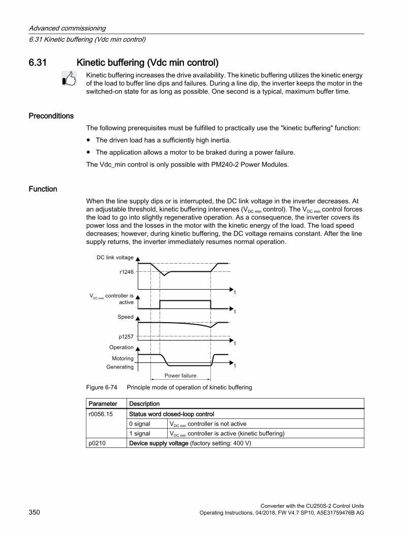
6.31 Kinetic buffering (Vdc min control)Kinetic buffering increases the drive availability. The kinetic buffering utilizes the kinetic energy of the load to buffer line dips and failures. During a line dip, the inverter keeps the motor in the switched-on state for as long as possible. One second is a typical, maximum buffer time.
PreconditionsThe following prerequisites must be fulfilled to practically use the "kinetic buffering" function:
The driven load has a sufficiently high inertia.
The application allows a motor to be braked during a power failure.
The Vdc_min control is only possible with PM240-2 Power Modules.
FunctionWhen the line supply dips or is interrupted, the DC link voltage in the inverter decreases. At an adjustable threshold, kinetic buffering intervenes (VDC min control). The VDC min control forces the load to go into slightly regenerative operation. As a consequence, the inverter covers its power loss and the losses in the motor with the kinetic energy of the load. The load speed decreases; however, during kinetic buffering, the DC voltage remains constant. After the line supply returns, the inverter immediately resumes normal operation.
Figure 6-74 Principle mode of operation of kinetic buffering
Parameter Descriptionr0056.15 Status word closed-loop control
0 signal VDC min controller is not active1 signal VDC min controller is active (kinetic buffering)
p0210 Device supply voltage (factory setting: 400 V)
Advanced commissioning6.31 Kinetic buffering (Vdc min control)
Converter with the CU250S-2 Control Units350 Operating Instructions, 04/2018, FW V4.7 SP10, A5E31759476B AG
Parameter Descriptionp1240 VDC controller configuration (factory setting: 1)
0 Inhibit VDC controller1 Enable VDC max controller2 Enable VDC min controller (kinetic buffering)3 Enable VDC min controller and VDC max controller
p1245 VDC mincontroller activation level (kinetic buffering) (factory setting depends on the Power Module, 73 % or 76 %)
r1246 VDC min controller activation level[V]r1246 = p1245 × √2 × p0210
p1247 VDC min controller dynamic factor (factory setting: 300 %)p1255 VDC min controller time threshold (factory setting: 0 s)
Maximum duration of the kinetic buffering If kinetic buffering lasts longer than that speci‐fied in the parameter value, the inverter outputs fault F7406.A value of 0 deactivates the monitoring.
p1257 VDC min controller speed threshold (factory setting: 50 rpm)When fallen below, the inverter outputs fault F7405.
Advanced commissioning6.31 Kinetic buffering (Vdc min control)
Converter with the CU250S-2 Control UnitsOperating Instructions, 04/2018, FW V4.7 SP10, A5E31759476B AG 351
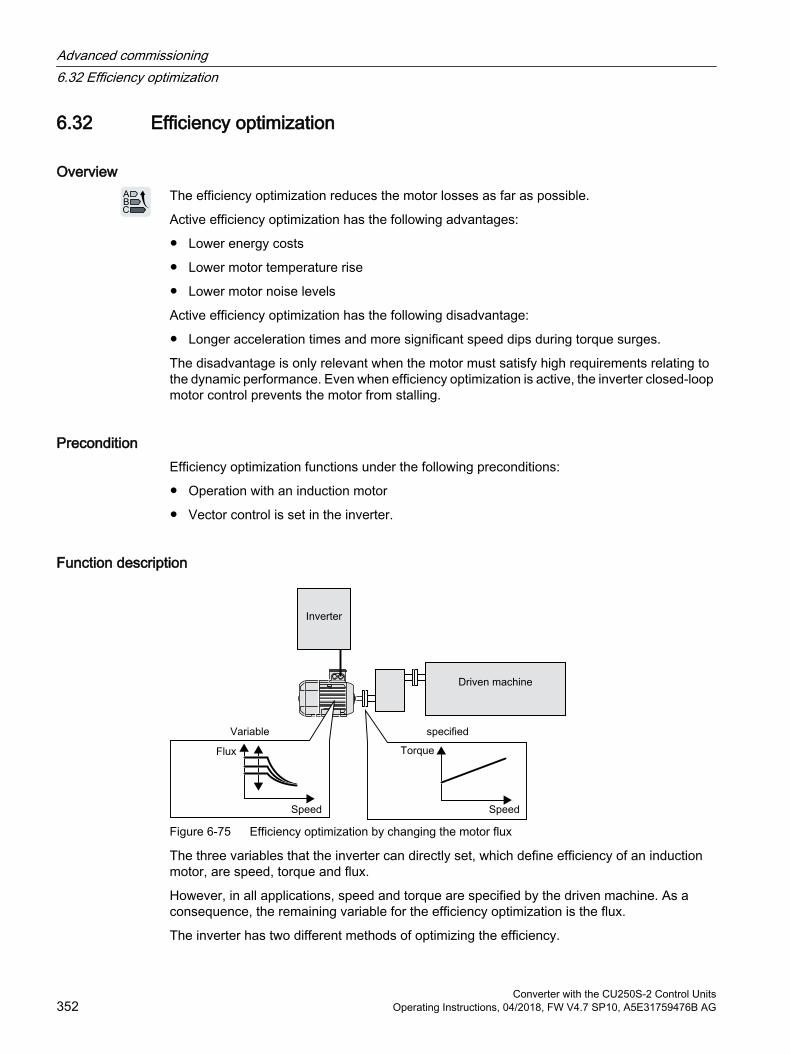
6.32 Efficiency optimization
OverviewThe efficiency optimization reduces the motor losses as far as possible.
Active efficiency optimization has the following advantages:
Lower energy costs
Lower motor temperature rise
Lower motor noise levels
Active efficiency optimization has the following disadvantage:
Longer acceleration times and more significant speed dips during torque surges.
The disadvantage is only relevant when the motor must satisfy high requirements relating to the dynamic performance. Even when efficiency optimization is active, the inverter closed-loop motor control prevents the motor from stalling.
PreconditionEfficiency optimization functions under the following preconditions:
Operation with an induction motor
Vector control is set in the inverter.
Function description
Figure 6-75 Efficiency optimization by changing the motor flux
The three variables that the inverter can directly set, which define efficiency of an induction motor, are speed, torque and flux.
However, in all applications, speed and torque are specified by the driven machine. As a consequence, the remaining variable for the efficiency optimization is the flux.
The inverter has two different methods of optimizing the efficiency.
Advanced commissioning6.32 Efficiency optimization
Converter with the CU250S-2 Control Units352 Operating Instructions, 04/2018, FW V4.7 SP10, A5E31759476B AG
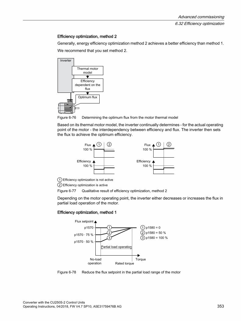
Efficiency optimization, method 2Generally, energy efficiency optimization method 2 achieves a better efficiency than method 1.
We recommend that you set method 2.
Figure 6-76 Determining the optimum flux from the motor thermal model
Based on its thermal motor model, the inverter continually determines - for the actual operating point of the motor - the interdependency between efficiency and flux. The inverter then sets the flux to achieve the optimum efficiency.
Figure 6-77 Qualitative result of efficiency optimization, method 2
Depending on the motor operating point, the inverter either decreases or increases the flux in partial load operation of the motor.
Efficiency optimization, method 1
Figure 6-78 Reduce the flux setpoint in the partial load range of the motor
Advanced commissioning6.32 Efficiency optimization
Converter with the CU250S-2 Control UnitsOperating Instructions, 04/2018, FW V4.7 SP10, A5E31759476B AG 353
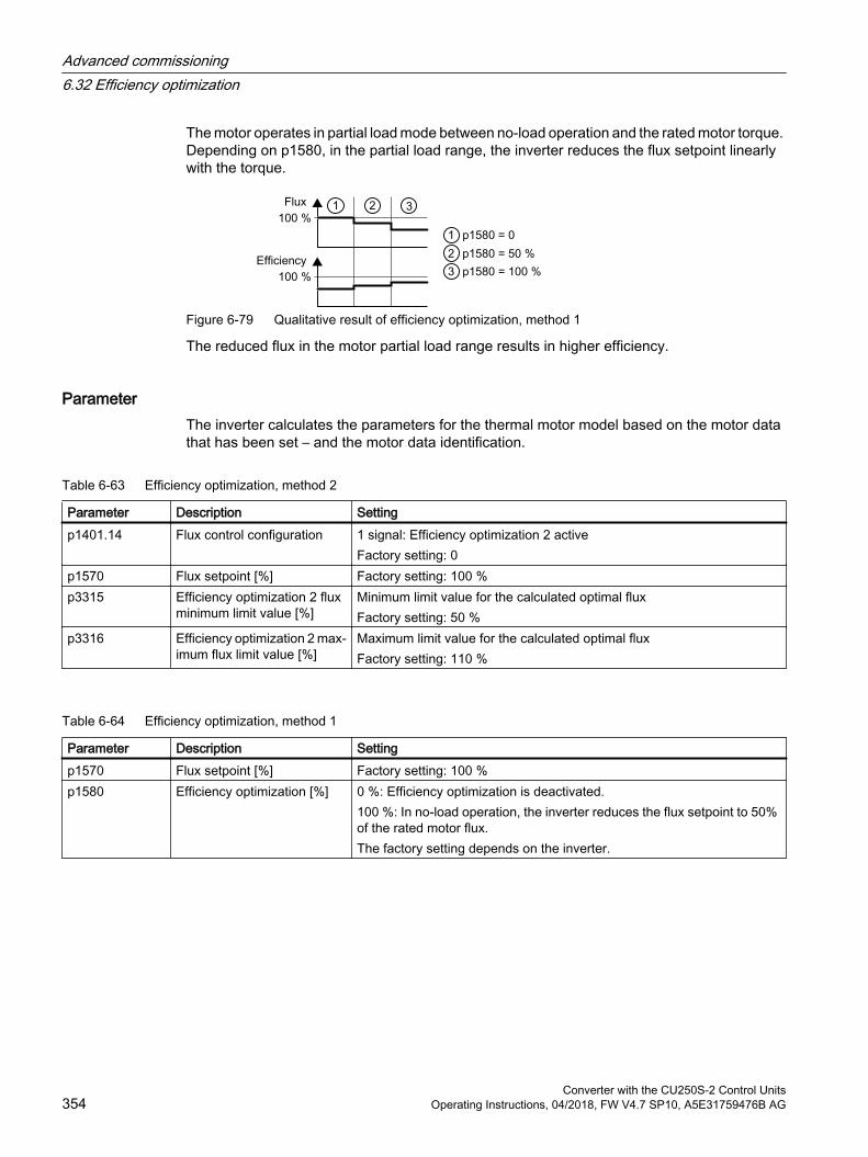
The motor operates in partial load mode between no-load operation and the rated motor torque. Depending on p1580, in the partial load range, the inverter reduces the flux setpoint linearly with the torque.
Figure 6-79 Qualitative result of efficiency optimization, method 1
The reduced flux in the motor partial load range results in higher efficiency.
ParameterThe inverter calculates the parameters for the thermal motor model based on the motor data that has been set – and the motor data identification.
Table 6-63 Efficiency optimization, method 2
Parameter Description Settingp1401.14 Flux control configuration 1 signal: Efficiency optimization 2 active
Factory setting: 0p1570 Flux setpoint [%] Factory setting: 100 %p3315 Efficiency optimization 2 flux
minimum limit value [%]Minimum limit value for the calculated optimal fluxFactory setting: 50 %
p3316 Efficiency optimization 2 max‐imum flux limit value [%]
Maximum limit value for the calculated optimal fluxFactory setting: 110 %
Table 6-64 Efficiency optimization, method 1
Parameter Description Settingp1570 Flux setpoint [%] Factory setting: 100 %p1580 Efficiency optimization [%] 0 %: Efficiency optimization is deactivated.
100 %: In no-load operation, the inverter reduces the flux setpoint to 50% of the rated motor flux.The factory setting depends on the inverter.
Advanced commissioning6.32 Efficiency optimization
Converter with the CU250S-2 Control Units354 Operating Instructions, 04/2018, FW V4.7 SP10, A5E31759476B AG
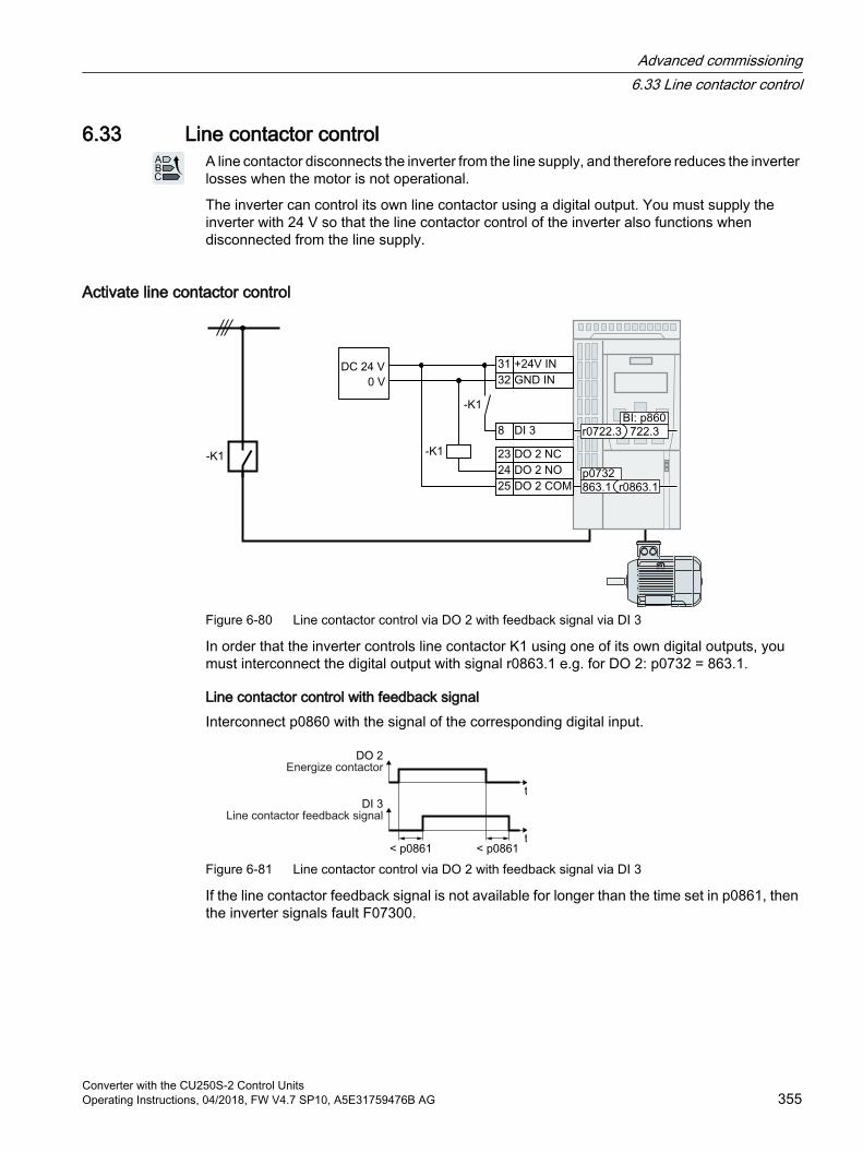
6.33 Line contactor controlA line contactor disconnects the inverter from the line supply, and therefore reduces the inverter losses when the motor is not operational.
The inverter can control its own line contactor using a digital output. You must supply the inverter with 24 V so that the line contactor control of the inverter also functions when disconnected from the line supply.
Activate line contactor control
Figure 6-80 Line contactor control via DO 2 with feedback signal via DI 3
In order that the inverter controls line contactor K1 using one of its own digital outputs, you must interconnect the digital output with signal r0863.1 e.g. for DO 2: p0732 = 863.1.
Line contactor control with feedback signalInterconnect p0860 with the signal of the corresponding digital input.
Figure 6-81 Line contactor control via DO 2 with feedback signal via DI 3
If the line contactor feedback signal is not available for longer than the time set in p0861, then the inverter signals fault F07300.
Advanced commissioning6.33 Line contactor control
Converter with the CU250S-2 Control UnitsOperating Instructions, 04/2018, FW V4.7 SP10, A5E31759476B AG 355
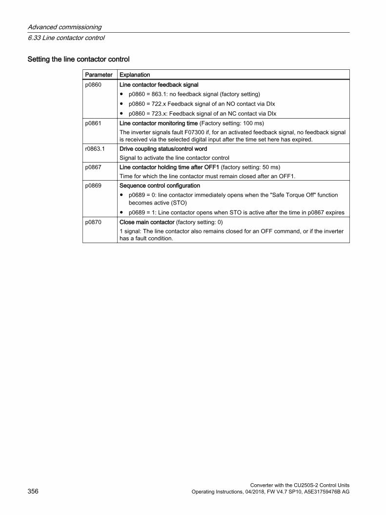
Setting the line contactor control
Parameter Explanationp0860 Line contactor feedback signal
p0860 = 863.1: no feedback signal (factory setting) p0860 = 722.x Feedback signal of an NO contact via DIx p0860 = 723.x: Feedback signal of an NC contact via DIx
p0861 Line contactor monitoring time (Factory setting: 100 ms)The inverter signals fault F07300 if, for an activated feedback signal, no feedback signal is received via the selected digital input after the time set here has expired.
r0863.1 Drive coupling status/control wordSignal to activate the line contactor control
p0867 Line contactor holding time after OFF1 (factory setting: 50 ms)Time for which the line contactor must remain closed after an OFF1.
p0869 Sequence control configuration p0689 = 0: line contactor immediately opens when the "Safe Torque Off" function
becomes active (STO) p0689 = 1: Line contactor opens when STO is active after the time in p0867 expires
p0870 Close main contactor (factory setting: 0)1 signal: The line contactor also remains closed for an OFF command, or if the inverter has a fault condition.
Advanced commissioning6.33 Line contactor control
Converter with the CU250S-2 Control Units356 Operating Instructions, 04/2018, FW V4.7 SP10, A5E31759476B AG
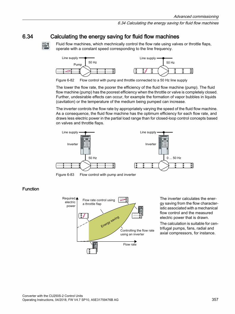
6.34 Calculating the energy saving for fluid flow machinesFluid flow machines, which mechnically control the flow rate using valves or throttle flaps, operate with a constant speed corresponding to the line frequency.
Figure 6-82 Flow control with pump and throttle connected to a 50 Hz line supply
The lower the flow rate, the poorer the efficiency of the fluid flow machine (pump). The fluid flow machine (pump) has the poorest efficiency when the throttle or valve is completely closed. Further, undesirable effects can occur, for example the formation of vapor bubbles in liquids (cavitation) or the temperature of the medium being pumped can increase.
The inverter controls the flow rate by appropriately varying the speed of the fluid flow machine. As a consequence, the fluid flow machine has the optimum efficiency for each flow rate, and draws less electric power in the partial load range than for closed-loop control concepts based on valves and throttle flaps.
Figure 6-83 Flow control with pump and inverter
Function
The inverter calculates the ener‐gy saving from the flow character‐istic associated with a mechanical flow control and the measured electric power that is drawn.The calculation is suitable for cen‐trifugal pumps, fans, radial and axial compressors, for instance.
Advanced commissioning6.34 Calculating the energy saving for fluid flow machines
Converter with the CU250S-2 Control UnitsOperating Instructions, 04/2018, FW V4.7 SP10, A5E31759476B AG 357
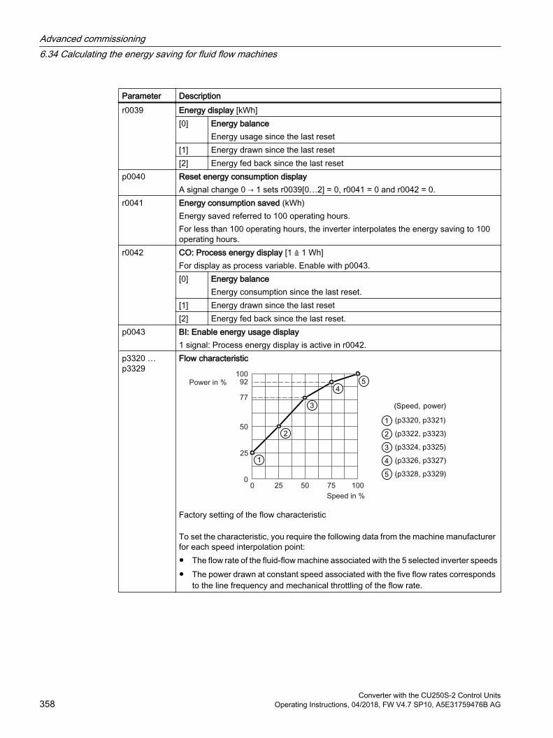
Parameter Descriptionr0039 Energy display [kWh]
[0] Energy balanceEnergy usage since the last reset
[1] Energy drawn since the last reset[2] Energy fed back since the last reset
p0040 Reset energy consumption displayA signal change 0 → 1 sets r0039[0…2] = 0, r0041 = 0 and r0042 = 0.
r0041 Energy consumption saved (kWh)Energy saved referred to 100 operating hours.For less than 100 operating hours, the inverter interpolates the energy saving to 100 operating hours.
r0042 CO: Process energy display [1 ≙ 1 Wh]For display as process variable. Enable with p0043.[0] Energy balance
Energy consumption since the last reset.[1] Energy drawn since the last reset[2] Energy fed back since the last reset.
p0043 BI: Enable energy usage display1 signal: Process energy display is active in r0042.
p3320 … p3329
Flow characteristic
Factory setting of the flow characteristic
To set the characteristic, you require the following data from the machine manufacturer for each speed interpolation point: The flow rate of the fluid-flow machine associated with the 5 selected inverter speeds The power drawn at constant speed associated with the five flow rates corresponds
to the line frequency and mechanical throttling of the flow rate.
Advanced commissioning6.34 Calculating the energy saving for fluid flow machines
Converter with the CU250S-2 Control Units358 Operating Instructions, 04/2018, FW V4.7 SP10, A5E31759476B AG
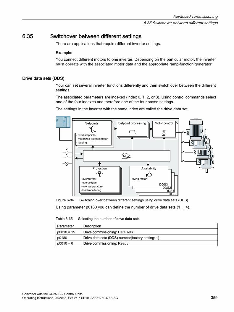
6.35 Switchover between different settingsThere are applications that require different inverter settings.
Example:You connect different motors to one inverter. Depending on the particular motor, the inverter must operate with the associated motor data and the appropriate ramp-function generator.
Drive data sets (DDS) Your can set several inverter functions differently and then switch over between the different settings.
The associated parameters are indexed (index 0, 1, 2, or 3). Using control commands select one of the four indexes and therefore one of the four saved settings.
The settings in the inverter with the same index are called the drive data set.
Figure 6-84 Switching over between different settings using drive data sets (DDS)
Using parameter p0180 you can define the number of drive data sets (1 ... 4).
Table 6-65 Selecting the number of drive data sets
Parameter Description p0010 = 15 Drive commissioning: Data setsp0180 Drive data sets (DDS) number(factory setting: 1)p0010 = 0 Drive commissioning: Ready
Advanced commissioning6.35 Switchover between different settings
Converter with the CU250S-2 Control UnitsOperating Instructions, 04/2018, FW V4.7 SP10, A5E31759476B AG 359
Table 6-66 Parameters for switching the drive data sets:
Parameter Description p0820[0…n] Drive data set selection DDS bit 0 If you use several command data sets
CDS, then you must set this parameter for each CDS. The parameters are assigned to a CDS through their index:CDS0: p0820[0], p0821[0]CDS1: p0820[1], p0821[1]…
p0821[0…n] Drive data set selection DDS bit 1
p0826 Motor changeover, motor numberEach drive data set is assigned a motor number:p0826[0] = motor number for drive data set 0.…p0826[3] = motor number for drive data set 3.If you operate the same motor with different drive data sets, then you must enter the same motor number in every index of parameter p0826. In this particular case, you can also switch over between the different drive data sets in operation.If you operate different motors on one inverter, then you must number the motors in parameter p0826. In this case, you may only switch over the drive data sets in the "ready for operation" state with the motor switched-off. The switchover time is approx. 50 ms.
r0051 Displaying the number of the DDS that is currently effective
For an overview of all the parameters that belong to the drive data sets and can be switched, see the List Manual.
Table 6-67 Parameters for copying the drive data sets
Parameter Description p0819[0] Source drive data setp0819[1] Target drive data setp0819[2] = 1 Start copy operation
For more information, see the List Manual (the parameter list and function diagram 8565).
Advanced commissioning6.35 Switchover between different settings
Converter with the CU250S-2 Control Units360 Operating Instructions, 04/2018, FW V4.7 SP10, A5E31759476B AG
Saving the settings and series commissioning 7Saving settings outside the inverter
After commissioning, your settings are saved in the inverter so that they are protected against power failure.
We recommend that you additionally back up the settings on a storage medium outside the inverter. Without backup, your settings could be lost if the inverter develops a defect.
Replacing the Control Unit without data backup (Page 421)
The following storage media are available for your settings:
Memory card
PG/PC
Operator panel
NoteData backup using Operator Panels with USB connection with the PG/PC is not possible
If the inverter is connected with a PG/PC via a USB cable, you cannot backup data to a memory card via an operator panel. Disconnect the USB connection between the PG/PC and inverter before you backup data
to the memory card via an operator panel.
Carrying out series commissioningSeries commissioning is the commissioning of several identical drives.
PreconditionThe Control Unit to which the settings are transferred has the same article number and the same or a higher firmware version as the source Control Unit.
Overview of the procedure1. Commission the first inverter.
2. Back up the settings of the first inverter to an external storage medium.
3. Transfer the settings from the first inverter to an additional inverter via the data storage medium.
Converter with the CU250S-2 Control UnitsOperating Instructions, 04/2018, FW V4.7 SP10, A5E31759476B AG 361
7.1 Saving settings on a memory card
7.1.1 Memory cards
Recommended memory cards
Table 7-1 Memory cards to back up inverter settings
Scope of delivery Article numberMemory card without firmware 6SL3054-4AG00-2AA0Memory card with firmware V4.7 6SL3054-7EH00-2BA0Memory card with firmware V4.7 SP3 6SL3054-7TB00-2BA0Memory card with firmware V4.7 SP6 6SL3054-7TD00-2BA0Memory card with firmware V4.7 SP9 6SL3054-7TE00-2BA0Memory card with firmware V4.7 SP10 6SL3054-7TF00-2BA0
LicensesIf you use the "Basic positioner" function or the expanded safety functions, then you must insert a memory card with a valid license in the Control Unit.
There are two ways of ordering a license:
Without a memory card:You order a license and you then transfer it to precisely one memory card.
With memory card:You order the license on a memory card with or without firmware. The license cannot be transferred
The inverter also uses the inserted license card as memory card to back up its settings.
Table 7-2 License for basic positioners
Scope of delivery Article numberLicense without memory card 6SL3074-7AA04-0AA0License with memory card without firmware 6SL3054-4AG00-2AA0-Z E01License with memory card with firmware V4.7 6SL3054-7EH00-2BA0-Z E01License with memory card with firmware V4.7 SP3 6SL3054-7TB00-2BA0-Z E01License with memory card with firmware V4.7 SP6 6SL3054-7TD00-2BA0-Z E01License with memory card with firmware V4.7 SP9 6SL3054-7TE00-2BA0-Z E01License with memory card with firmware V4.7 SP10 6SL3054-7TF00-2BA0-Z E01
Saving the settings and series commissioning7.1 Saving settings on a memory card
Converter with the CU250S-2 Control Units362 Operating Instructions, 04/2018, FW V4.7 SP10, A5E31759476B AG
Table 7-3 License for the extended safety functions
Scope of delivery Article numberLicense without memory card 6SL3074-0AA10-0AA0License with memory card without firmware 6SL3054-4AG00-2AA0-Z F01License with memory card with firmware V4.7 6SL3054-7EH00-2BA0-Z F01License with memory card with firmware V4.7 SP3 6SL3054-7TB00-2BA0-Z F01License with memory card with firmware V4.7 SP6 6SL3054-7TD00-2BA0-Z F01License with memory card with firmware V4.7 SP9 6SL3054-7TE00-2BA0-Z F01License with memory card with firmware V4.7 SP10 6SL3054-7TF00-2BA0-Z F01
Table 7-4 Basic positioner license + license for the extended safety functions
Scope of delivery Article numberLicense without memory card 6SL3074-0AA10-0AA0License with memory card without firmware 6SL3054-4AG00-2AA0-Z E01 + F01License with memory card with firmware V4.7 6SL3054-7EH00-2BA0-Z E01 + F01License with memory card with firmware V4.7 SP3 6SL3054-7TB00-2BA0-Z E01 + F01License with memory card with firmware V4.7 SP6 6SL3054-7TD00-2BA0-Z E01 + F01License with memory card with firmware V4.7 SP9 6SL3054-7TE00-2BA0-Z E01 + F01License with memory card with firmware V4.7 SP10 6SL3054-7TF00-2BA0-Z E01 + F01
Using memory cards from other manufacturersThe inverter only supports memory cards up to 2 GB. SDHC cards (SD High Capacity) and SDXC cards (SD Extended Capacity) are not permitted.
If you use other SD or MMC memory cards, then you must format the memory card as follows:
MMC: Format FAT 16
– Insert the card into your PC's card reader.
– Command to format the card:format x: /fs:fat (x: Drive code of the memory card on your PC)
SD: Format FAT 16 or FAT 32
– Insert the card into your PC's card reader.
– Command to format the card: format x: /fs:fat or format x: /fs:fat32 (x: Drive code of the memory card on your PC.)
Saving the settings and series commissioning7.1 Saving settings on a memory card
Converter with the CU250S-2 Control UnitsOperating Instructions, 04/2018, FW V4.7 SP10, A5E31759476B AG 363

Functional restrictions with memory cards from other manufacturersThe following functions are either not possible – or only with some restrictions – when using memory cards from other manufacturers:
Licensing functions is only possible using the recommended memory cards.
Know-how protection is only possible with one of the recommended memory cards.
Under certain circumstances, memory cards from other manufacturers do not support writing or reading data from/to the inverter.
Saving the settings and series commissioning7.1 Saving settings on a memory card
Converter with the CU250S-2 Control Units364 Operating Instructions, 04/2018, FW V4.7 SP10, A5E31759476B AG
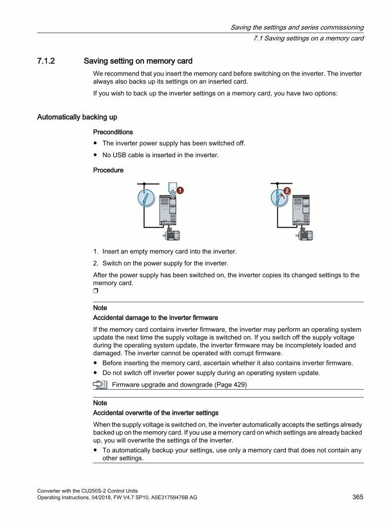
7.1.2 Saving setting on memory cardWe recommend that you insert the memory card before switching on the inverter. The inverter always also backs up its settings on an inserted card.
If you wish to back up the inverter settings on a memory card, you have two options:
Automatically backing up
Preconditions The inverter power supply has been switched off.
No USB cable is inserted in the inverter.
Procedure
1. Insert an empty memory card into the inverter.
2. Switch on the power supply for the inverter.
After the power supply has been switched on, the inverter copies its changed settings to the memory card.
NoteAccidental damage to the inverter firmware
If the memory card contains inverter firmware, the inverter may perform an operating system update the next time the supply voltage is switched on. If you switch off the supply voltage during the operating system update, the inverter firmware may be incompletely loaded and damaged. The inverter cannot be operated with corrupt firmware. Before inserting the memory card, ascertain whether it also contains inverter firmware. Do not switch off inverter power supply during an operating system update.
Firmware upgrade and downgrade (Page 429)
NoteAccidental overwrite of the inverter settings
When the supply voltage is switched on, the inverter automatically accepts the settings already backed up on the memory card. If you use a memory card on which settings are already backed up, you will overwrite the settings of the inverter. To automatically backup your settings, use only a memory card that does not contain any
other settings.
Saving the settings and series commissioning7.1 Saving settings on a memory card
Converter with the CU250S-2 Control UnitsOperating Instructions, 04/2018, FW V4.7 SP10, A5E31759476B AG 365

Manually backing upPreconditions
The inverter power supply has been switched on.
No memory card is inserted in the inverter.
Procedure with Startdrive
1. Go online.
2. Select "Online & diagnostics".
3. Select "Backing up/reset".
4. Back up the settings to the EEPROM of the inverter.
5. Select the settings as shown in the diagram.
6. Start data transfer
7. Wait until Startdrive reports that data backup has been completed.
You have backed up the inverter settings to a memory card.
Procedure with the BOP-2
1. Remove any USB cable that is inserted in the inverter.2. In the "OPTIONS" menu, select "TO CARD".
Saving the settings and series commissioning7.1 Saving settings on a memory card
Converter with the CU250S-2 Control Units366 Operating Instructions, 04/2018, FW V4.7 SP10, A5E31759476B AG

3. Set the number of your data backup. You can back up 99 different settings on the memory card.
4. Start data transfer with OK.
5. Wait until the inverter has backed up the settings to the memory card.
You have backed up the settings of the inverter to the memory card.
Saving the settings and series commissioning7.1 Saving settings on a memory card
Converter with the CU250S-2 Control UnitsOperating Instructions, 04/2018, FW V4.7 SP10, A5E31759476B AG 367
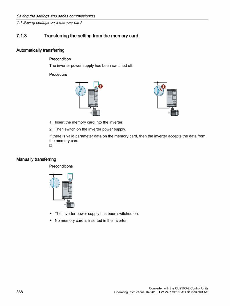
7.1.3 Transferring the setting from the memory card
Automatically transferring
PreconditionThe inverter power supply has been switched off.
Procedure
1. Insert the memory card into the inverter.
2. Then switch on the inverter power supply.
If there is valid parameter data on the memory card, then the inverter accepts the data from the memory card.
Manually transferringPreconditions
The inverter power supply has been switched on.
No memory card is inserted in the inverter.
Saving the settings and series commissioning7.1 Saving settings on a memory card
Converter with the CU250S-2 Control Units368 Operating Instructions, 04/2018, FW V4.7 SP10, A5E31759476B AG
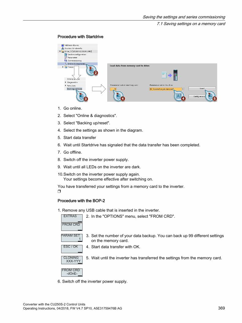
Procedure with Startdrive
1. Go online.
2. Select "Online & diagnostics".
3. Select "Backing up/reset".
4. Select the settings as shown in the diagram.
5. Start data transfer
6. Wait until Startdrive has signaled that the data transfer has been completed.
7. Go offline.
8. Switch off the inverter power supply.
9. Wait until all LEDs on the inverter are dark.
10.Switch on the inverter power supply again.Your settings become effective after switching on.
You have transferred your settings from a memory card to the inverter.
Procedure with the BOP-2
1. Remove any USB cable that is inserted in the inverter.2. In the "OPTIONS" menu, select "FROM CRD".
3. Set the number of your data backup. You can back up 99 different settings on the memory card.
4. Start data transfer with OK.
5. Wait until the inverter has transferred the settings from the memory card.
6. Switch off the inverter power supply.
Saving the settings and series commissioning7.1 Saving settings on a memory card
Converter with the CU250S-2 Control UnitsOperating Instructions, 04/2018, FW V4.7 SP10, A5E31759476B AG 369
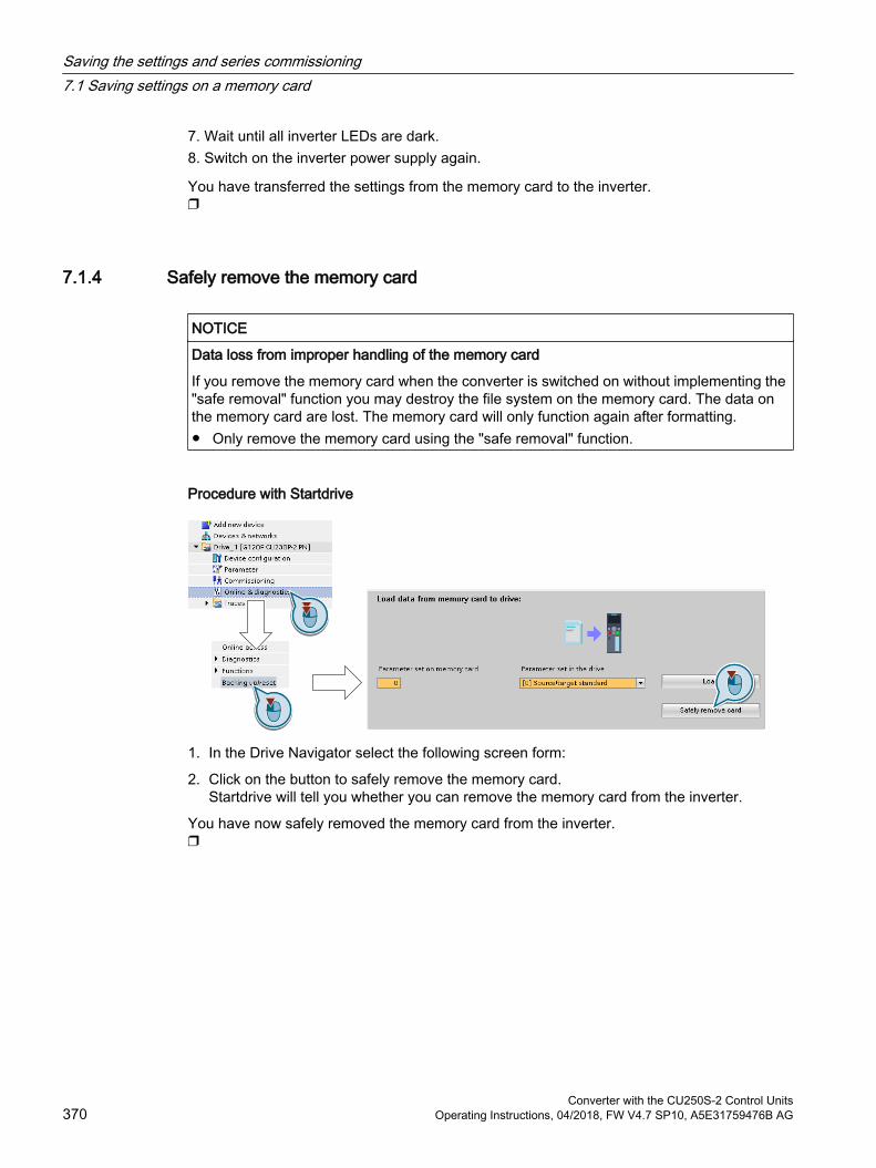
7. Wait until all inverter LEDs are dark.8. Switch on the inverter power supply again.
You have transferred the settings from the memory card to the inverter.
7.1.4 Safely remove the memory card
NOTICE
Data loss from improper handling of the memory card
If you remove the memory card when the converter is switched on without implementing the "safe removal" function you may destroy the file system on the memory card. The data on the memory card are lost. The memory card will only function again after formatting. Only remove the memory card using the "safe removal" function.
Procedure with Startdrive
1. In the Drive Navigator select the following screen form:
2. Click on the button to safely remove the memory card.Startdrive will tell you whether you can remove the memory card from the inverter.
You have now safely removed the memory card from the inverter.
Saving the settings and series commissioning7.1 Saving settings on a memory card
Converter with the CU250S-2 Control Units370 Operating Instructions, 04/2018, FW V4.7 SP10, A5E31759476B AG
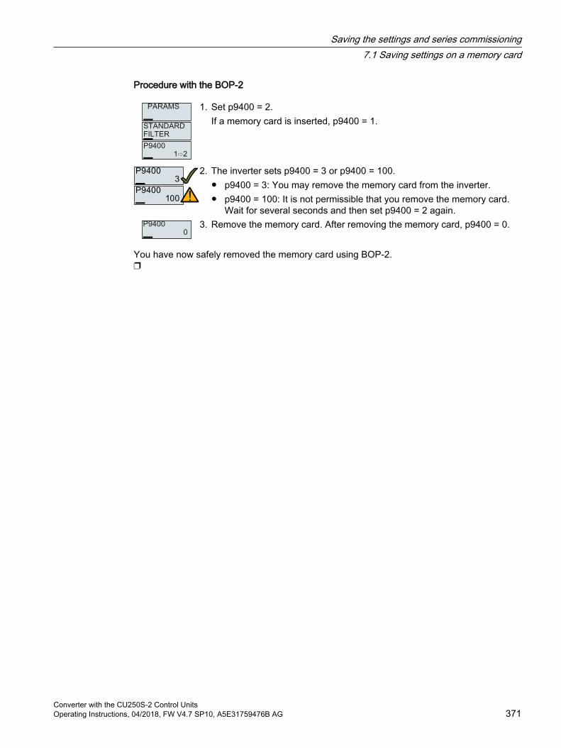
Procedure with the BOP-2
1. Set p9400 = 2.If a memory card is inserted, p9400 = 1.
2. The inverter sets p9400 = 3 or p9400 = 100. p9400 = 3: You may remove the memory card from the inverter. p9400 = 100: It is not permissible that you remove the memory card.
Wait for several seconds and then set p9400 = 2 again.3. Remove the memory card. After removing the memory card, p9400 = 0.
You have now safely removed the memory card using BOP-2.
Saving the settings and series commissioning7.1 Saving settings on a memory card
Converter with the CU250S-2 Control UnitsOperating Instructions, 04/2018, FW V4.7 SP10, A5E31759476B AG 371

7.1.5 Activate message for a memory card that is not inserted
FunctionThe inverter identifies that a memory card is not inserted, and signals this state. The message is deactivated in the inverter factory setting.
Activate message
Procedure1. Set p2118[x] = 1101, x = 0, 1, … 19
2. Set p2119[x] = 2
Message A01101 for a memory card that is not inserted is activated.
To cyclically signal to a higher-level control that a memory card is not inserted, interconnect parameter r9401 to the send data of a PROFIdrive telegram of your choice.
Deactivate message
Procedure1. Set p2118[x] = 1101, x = 0, 1, … 19
2. Set p2119[x] = 3
Message A01101 for a memory card that is not inserted is deactivated.
Parameter
Parameter Explanationp2118[0 … 19] Change message type message number (factory setting: 0)p2119[0 … 19] Change message type (factory setting: 0)
1: Fault2: Alarm3: No message
r9401 Safely remove memory card status.00 1 signal: Memory card inserted.01 1 signal: Memory card activated.02 1 signal: SIEMENS memory card.03 1 signal: Memory card used as USB data storage medium from the PC
Saving the settings and series commissioning7.1 Saving settings on a memory card
Converter with the CU250S-2 Control Units372 Operating Instructions, 04/2018, FW V4.7 SP10, A5E31759476B AG
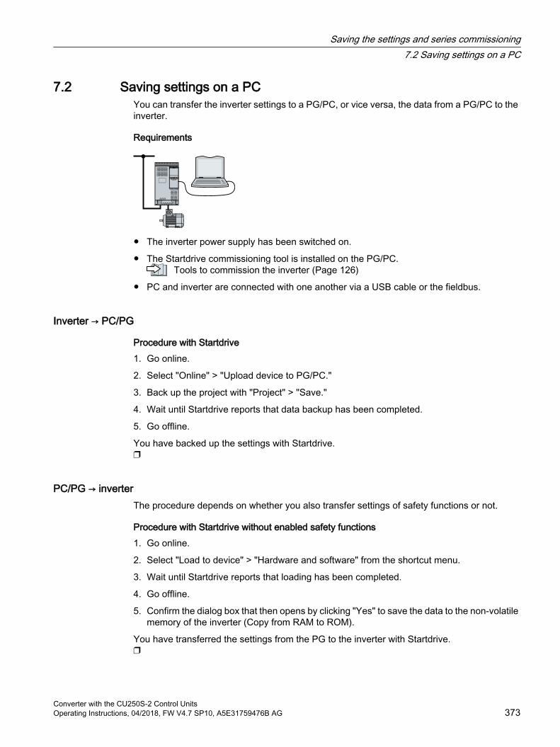
7.2 Saving settings on a PCYou can transfer the inverter settings to a PG/PC, or vice versa, the data from a PG/PC to the inverter.
Requirements
The inverter power supply has been switched on.
The Startdrive commissioning tool is installed on the PG/PC. Tools to commission the inverter (Page 126)
PC and inverter are connected with one another via a USB cable or the fieldbus.
Inverter → PC/PG
Procedure with Startdrive1. Go online.
2. Select "Online" > "Upload device to PG/PC."
3. Back up the project with "Project" > "Save."
4. Wait until Startdrive reports that data backup has been completed.
5. Go offline.
You have backed up the settings with Startdrive.
PC/PG → inverter The procedure depends on whether you also transfer settings of safety functions or not.
Procedure with Startdrive without enabled safety functions1. Go online.
2. Select "Load to device" > "Hardware and software" from the shortcut menu.
3. Wait until Startdrive reports that loading has been completed.
4. Go offline.
5. Confirm the dialog box that then opens by clicking "Yes" to save the data to the non-volatile memory of the inverter (Copy from RAM to ROM).
You have transferred the settings from the PG to the inverter with Startdrive.
Saving the settings and series commissioning7.2 Saving settings on a PC
Converter with the CU250S-2 Control UnitsOperating Instructions, 04/2018, FW V4.7 SP10, A5E31759476B AG 373
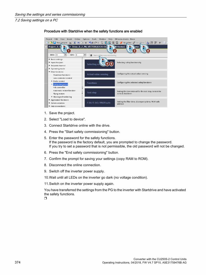
Procedure with Startdrive when the safety functions are enabled
1. Save the project.
2. Select "Load to device".
3. Connect Startdrive online with the drive.
4. Press the "Start safety commissioning" button.
5. Enter the password for the safety functions.If the password is the factory default, you are prompted to change the password. If you try to set a password that is not permissible, the old password will not be changed.
6. Press the "End safety commissioning" button.
7. Confirm the prompt for saving your settings (copy RAM to ROM).
8. Disconnect the online connection.
9. Switch off the inverter power supply.
10.Wait until all LEDs on the inverter go dark (no voltage condition).
11.Switch on the inverter power supply again.
You have transferred the settings from the PG to the inverter with Startdrive and have activated the safety functions.
Saving the settings and series commissioning7.2 Saving settings on a PC
Converter with the CU250S-2 Control Units374 Operating Instructions, 04/2018, FW V4.7 SP10, A5E31759476B AG
7.3 Saving settings to an operator panelYou can transfer the inverter settings to the Operator Panel BOP‑2 or vice versa, the data from the BOP‑2 to the inverter.
PreconditionThe inverter power supply has been switched on.
Inverter → BOP-2
Procedure
1. In the "OPTIONS" menu, select "TO BOP".
2. Start data transfer with OK.
3. Wait until the inverter has backed up the settings to the BOP‑2.
You have backed up the settings to the BOP-2.
BOP-2 → inverter
Procedure
1. In the "OPTIONS" menu, select "FROM BOP".
2. Start data transfer with OK.
3. Wait until the inverter has written the settings to the memory card.
4. Switch off the inverter power supply.
Saving the settings and series commissioning7.3 Saving settings to an operator panel
Converter with the CU250S-2 Control UnitsOperating Instructions, 04/2018, FW V4.7 SP10, A5E31759476B AG 375

5. Wait until all inverter LEDs are dark.6. Switch on the inverter power supply again. Your settings become effective after switching on.
You have transferred the settings to the inverter.
Saving the settings and series commissioning7.3 Saving settings to an operator panel
Converter with the CU250S-2 Control Units376 Operating Instructions, 04/2018, FW V4.7 SP10, A5E31759476B AG

7.4 Other ways to back up settingsIn addition to the default setting, the inverter has an internal memory for backing up three other settings.
On the memory card, you can back up 99 other settings in addition to the default setting.
Additional information is available on the Internet: Memory options (http://support.automation.siemens.com/WW/view/en/43512514).
Saving the settings and series commissioning7.4 Other ways to back up settings
Converter with the CU250S-2 Control UnitsOperating Instructions, 04/2018, FW V4.7 SP10, A5E31759476B AG 377
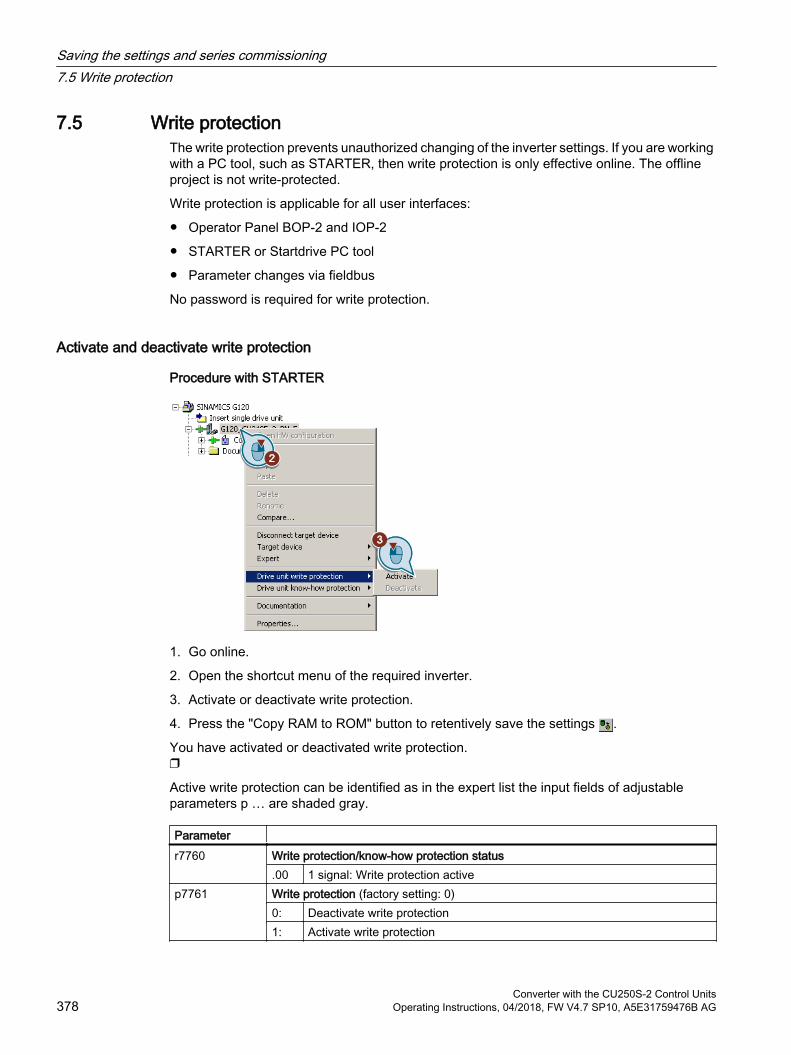
7.5 Write protectionThe write protection prevents unauthorized changing of the inverter settings. If you are working with a PC tool, such as STARTER, then write protection is only effective online. The offline project is not write-protected.
Write protection is applicable for all user interfaces:
Operator Panel BOP-2 and IOP‑2
STARTER or Startdrive PC tool
Parameter changes via fieldbus
No password is required for write protection.
Activate and deactivate write protection
Procedure with STARTER
1. Go online.
2. Open the shortcut menu of the required inverter.
3. Activate or deactivate write protection.
4. Press the "Copy RAM to ROM" button to retentively save the settings .
You have activated or deactivated write protection.
Active write protection can be identified as in the expert list the input fields of adjustable parameters p … are shaded gray.
Parameter r7760 Write protection/know-how protection status
.00 1 signal: Write protection activep7761 Write protection (factory setting: 0)
0: Deactivate write protection1: Activate write protection
Saving the settings and series commissioning7.5 Write protection
Converter with the CU250S-2 Control Units378 Operating Instructions, 04/2018, FW V4.7 SP10, A5E31759476B AG

Exceptions to write protectionSome functions are excluded from write protection, e.g.:
Activating/deactivating write protection
Changing the access level (p0003)
Saving parameters (p0971)
Safely removing the memory card (p9400)
Restoring the factory setting
Transfer the settings from an external data backup, e.g. upload into the inverter from a memory card.
The parameters that are not write protected are in the List Manual in Section "Parameters for write protection and know-how protection".
NoteWrite protection for multimaster fieldbus systems
Via multimaster fieldbus systems, e.g. BACnet or Modbus RTU, in spite of write protection being activated, parameters can still be changed. So that write protection is also active when accessing via these fieldbuses, you must additionally set p7762 to 1.
In STARTER and Startdrive, this setting is only possible using the expert list.
Saving the settings and series commissioning7.5 Write protection
Converter with the CU250S-2 Control UnitsOperating Instructions, 04/2018, FW V4.7 SP10, A5E31759476B AG 379
7.6 Know-how protection
OverviewKnow-how protection prevents unauthorized reading of the inverter settings.
To protect your inverter settings against unauthorized copying, in addition to know-how protection, you can also activate copy protection.
PreconditionKnow-how protection requires a password.
Combination of know-how protection and copy protection
Is a memory card necessary?
Know-how protection without copy protection The inverter can be operated with or without memory card.
Know-how protection with basic copy protection The inverter can only be operated with a SIEMENS memory card
Memory cards (Page 362)Know-how protection with extended copy pro‐
tection
Function descriptionThe active know-how protection provides the following:
With just a few exceptions, the values of all adjustable parameters p … are invisible. In STARTER, instead of the parameter values, the text "Know-how protection" is displayed.
– Several adjustable parameters can be read and changed when know-how protection is active. You can find a list of the adjustable parameters that can be read and changed in the List Manual under "KHP_WRITE_NO_LOCK".In addition, you can define an exception list of adjustable parameters, which end users may change.
– Several adjustable parameters can be read but not changed when know-how protection is active. You can find a list of the adjustable parameters that can be read in the List Manual under "KHP_ACTIVE_READ".
You can hide know-how protected parameters in the expert list of STARTER using the "Without know-how protection" display filter.
The values of monitoring parameters r … remain visible.
STARTER does not display any screen forms.
Adjustable parameters cannot be changed using commissioning tools, e.g. an operator panel or Startdrive.
Saving the settings and series commissioning7.6 Know-how protection
Converter with the CU250S-2 Control Units380 Operating Instructions, 04/2018, FW V4.7 SP10, A5E31759476B AG
Locked functions:
– Downloading inverter settings using STARTER or Startdrive
– Automatic controller optimization
– Stationary or rotating measurement of the motor data identification
– Deleting the alarm history and the fault history
– Generating acceptance documents for safety functions
Executable functions:
– Restoring factory settings
– Acknowledging faults
– Displaying faults, alarms, fault history, and alarm history
– Reading out the diagnostic buffer
– Controlling the inverter via the control panel in STARTER or Startdrive
– Uploading adjustable parameters that can be changed or read when know-how protection is active.
– Displaying acceptance documents for safety functions
– Depending on the know-how protection settings, the trace function in STARTER can also be active when know-how protection is active.
When know-how protection is active, support can only be provided (from Technical Support) after prior agreement from the machine manufacturer (OEM).
Know-how protection without copy protectionYou can transfer inverter settings to other inverters using a memory card, an operator panel, STARTER or Startdrive.
Know-how protection with basic copy protectionAfter replacing an inverter, to be able to operate the new inverter with the settings of the replaced inverter without knowing the password, the memory card must be inserted in the new inverter.
Know-how protection with extended copy protectionIt is not possible to insert and use the memory card in another inverter without knowing the password.
Commissioning know-how protection1. Check as to whether you must extend the exception list.
List of exceptions (Page 382)
2. Activate the know-how protection. Know-how protection (Page 383)
Saving the settings and series commissioning7.6 Know-how protection
Converter with the CU250S-2 Control UnitsOperating Instructions, 04/2018, FW V4.7 SP10, A5E31759476B AG 381
7.6.1 Extending the exception list for know-how protectionIn the factory setting, the exception list only includes the password for know-how protection.
Before activating know-how protection, you can additionally enter the adjustable parameters in the exception list, which must still be able to be read and changed by end users – even if know-how protection has been activated.
You do not need to change the exception list, if, with exception of the password, you do not require additional adjustable parameters in the exception list.
Absolute know-how protectionIf you remove password p7766 from the exception list, it is no longer possible to enter or change the password for know-how protection.
You must reset the inverter to the factory settings in order to be able to gain access to the inverter adjustable parameters. When restoring the factory settings, you lose what you have configured in the inverter, and you must recommission the inverter.
Extending the exception list
Procedure with STARTER1. Backup the inverter settings using the button on the PC.
2. Go offline ( )
3. Using p7763, in the expert list, define the required number of parameters n (n = 1 … 500) of the exception list.
4. Save the project.
5. Go online.
6. Load the project using the button in the inverter.
7. In p7764[0 … n-1], assign the required parameter numbers to the indices of p7763.
You have extended the exception list for know-how protection.
Parameter
Parameter Description p7763 KHP OEM exception list number of indices for p7764 (factory setting 1)p7764 KHP OEM exception list (factory setting [0] 7766, [1 …499 ] 0)
p7766 is the password for know-how protection
Saving the settings and series commissioning7.6 Know-how protection
Converter with the CU250S-2 Control Units382 Operating Instructions, 04/2018, FW V4.7 SP10, A5E31759476B AG

7.6.2 Activating and deactivating know-how protection
Activating know-how protection
Preconditions The inverter has now been commissioned.
You have generated the exception list for know-how protection.
To guarantee know-how protection, you must ensure that the project does not remain at the end user as a file.
Procedure with STARTER1. Go online with STARTER.
If you have generated a project offline on your computer, you must load the project into the inverter and go online.
2. Select the required inverter in the project.
3. In the shortcut menu, select "Know-how protection drive unit/activating ....".
4. The "Without copy protection" option is active by default. If an appropriate memory card is inserted in the Control Unit, you can select one of two copy protection options:
– With basic copy protection (permanently linked to the memory card)
– With extended copy protection (permanently linked to the memory card and Control Unit)
Select the required copy protection option.
5. If, in spite of active know-how protection, you wish to permit diagnostic functions, activate option "Allow diagnostic functions (trace and measuring functions)".
6. Click on "Define"
Saving the settings and series commissioning7.6 Know-how protection
Converter with the CU250S-2 Control UnitsOperating Instructions, 04/2018, FW V4.7 SP10, A5E31759476B AG 383
7. Enter your password. Length of the password: 1 … 30 characters.Recommendation for assigning a password:
– Only use characters from the ASCII set of characters.If you use arbitrary characters for the password, changing the windows language settings after activating know-how protection can result in problems when subsequently checking a password.
– For an adequately secure password, the password must have a minimum length of 8 characters, and must include uppercase and lowercase letters as well as a combination of letters, numbers and special characters.
8. The "Copy RAM to ROM" option is active as standard.The option must be active in order that the inverter keeps the know-how protection settings after switching off and switching on the power supply.
9. Click on "OK".
You have activated know-how protection.
Preventing data reconstruction from the memory cardAs soon as know-how protection has been activated, the inverter only backs up encrypted data to the memory card.
In order to guarantee know-how protection, after activating know-how protection, we recommend that you insert a new, empty memory card. For memory cards that have already been written to, previously backed up data that was not encrypted can be reconstructed.
Changing the password
Procedure with STARTERSelect the inverter in the project and open the dialog screen form using the shortcut menu "Know-how protection drive unit → Change password ...".
Deactivating know-how protection, deleting a password
Procedure with STARTER1. Go online with STARTER.
2. Select the required inverter in the project.
Saving the settings and series commissioning7.6 Know-how protection
Converter with the CU250S-2 Control Units384 Operating Instructions, 04/2018, FW V4.7 SP10, A5E31759476B AG
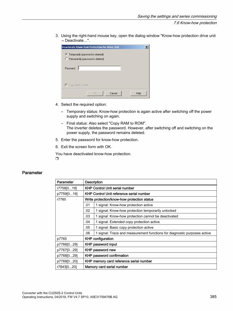
3. Using the right-hand mouse key, open the dialog window "Know-how protection drive unit → Deactivate…".
4. Select the required option:
– Temporary status: Know-how protection is again active after switching off the power supply and switching on again.
– Final status: Also select "Copy RAM to ROM".The inverter deletes the password. However, after switching off and switching on the power supply, the password remains deleted.
5. Enter the password for know-how protection.
6. Exit the screen form with OK.
You have deactivated know-how protection.
Parameter
Parameter Description r7758[0...19] KHP Control Unit serial numberp7759[0...19] KHP Control Unit reference serial numberr7760 Write protection/know-how protection status
.01 1 signal: Know-how protection active
.02 1 signal: Know-how protection temporarily unlocked
.03 1 signal: Know-how protection cannot be deactivated
.04 1 signal: Extended copy protection active
.05 1 signal: Basic copy protection active
.06 1 signal: Trace and measurement functions for diagnostic purposes activep7765 KHP configurationp7766[0...29] KHP password inputp7767[0...29] KHP password new p7768[0...29] KHP password confirmationp7769[0...20] KHP memory card reference serial numberr7843[0...20] Memory card serial number
Saving the settings and series commissioning7.6 Know-how protection
Converter with the CU250S-2 Control UnitsOperating Instructions, 04/2018, FW V4.7 SP10, A5E31759476B AG 385

Saving the settings and series commissioning7.6 Know-how protection
Converter with the CU250S-2 Control Units386 Operating Instructions, 04/2018, FW V4.7 SP10, A5E31759476B AG

Alarms, faults and system messages 8The inverter has the following diagnostic types:
LED The LEDs at the front of the inverter immediately inform you about the most important inverter states.
System runtimeThe system run time is the total time that the inverter has been supplied with power since the initial commissioning.
Alarms and faultsEvery alarm and every fault has a unique number.The inverter signals alarms and faults via the following interfaces:
– Fieldbus
– Terminal strip with the appropriate setting
– Interface to the BOP-2 or IOP‑2 operator panel
– Interface to STARTER or Startdrive
Identification & maintenance data (I&M)If requested, the inverter sends data to the higher-level control via PROFIBUS or PROFINET:
– Inverter-specific data
– Plant-specific data
Converter with the CU250S-2 Control UnitsOperating Instructions, 04/2018, FW V4.7 SP10, A5E31759476B AG 387
8.1 Operating states indicated on LEDs
Table 8-1 Explanation of symbols for the following tables
LED is ONLED is OFF
LED flashes slowly
LED flashes quickly
LED flashes with variable frequency
Please contact Technical Support for LED states that are not described in the following.
Table 8-2 Basic states
RDY ExplanationTemporary state after the supply voltage is switched on.
The inverter is operating fault-free
Commissioning or reset to factory settings
A fault is active
Licensing is not sufficient.Activating licensed functions (Page 492)
Firmware update is active
Inverter waits until the power supply is switched off and switched on again after a firmware update
Alarms, faults and system messages8.1 Operating states indicated on LEDs
Converter with the CU250S-2 Control Units388 Operating Instructions, 04/2018, FW V4.7 SP10, A5E31759476B AG
Table 8-3 Integrated safety functions
SAFE ExplanationOne or more safety functions are enabled, but not active.
One or more safety functions are active and error-free.
The inverter has detected a safety function fault and initiated a stop response.
Table 8-4 PROFINET and PROFIBUS fieldbuses
BF ExplanationData exchange between the inverter and control system is active
Fieldbus interface is not being used
The fieldbus is improperly configured.RDY In conjunction with a synchronously flashing LED RDY:
Inverter waits until the power supply is switched off and switched on again after a firmware update
No communication with higher-level controllerRDY In conjunction with an asynchronously flashing LED RDY:
Incorrect memory card
Firmware update failed
Firmware update is active
Table 8-5 PROFINET fieldbus
LNK ExplanationCommunication via PROFINET is error-free
Device naming is active
No communication via PROFINET
Alarms, faults and system messages8.1 Operating states indicated on LEDs
Converter with the CU250S-2 Control UnitsOperating Instructions, 04/2018, FW V4.7 SP10, A5E31759476B AG 389
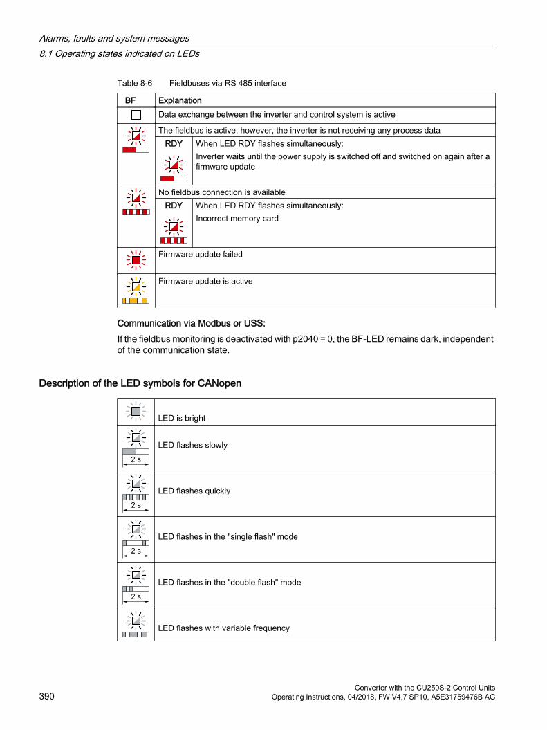
Table 8-6 Fieldbuses via RS 485 interface
BF ExplanationData exchange between the inverter and control system is active
The fieldbus is active, however, the inverter is not receiving any process dataRDY When LED RDY flashes simultaneously:
Inverter waits until the power supply is switched off and switched on again after a firmware update
No fieldbus connection is availableRDY When LED RDY flashes simultaneously:
Incorrect memory card
Firmware update failed
Firmware update is active
Communication via Modbus or USS:If the fieldbus monitoring is deactivated with p2040 = 0, the BF-LED remains dark, independent of the communication state.
Description of the LED symbols for CANopen
LED is bright LED flashes slowly
LED flashes quickly
LED flashes in the "single flash" mode
LED flashes in the "double flash" mode
LED flashes with variable frequency
Alarms, faults and system messages8.1 Operating states indicated on LEDs
Converter with the CU250S-2 Control Units390 Operating Instructions, 04/2018, FW V4.7 SP10, A5E31759476B AG
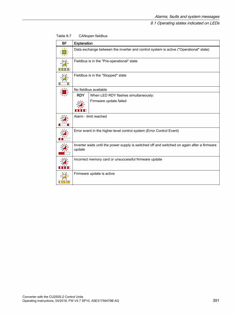
Table 8-7 CANopen fieldbus
BF ExplanationData exchange between the inverter and control system is active ("Operational" state)
Fieldbus is in the "Pre-operational" state
Fieldbus is in the "Stopped" state
No fieldbus availableRDY When LED RDY flashes simultaneously:
Firmware update failed
Alarm - limit reached
Error event in the higher-level control system (Error Control Event)
Inverter waits until the power supply is switched off and switched on again after a firmware update
Incorrect memory card or unsuccessful firmware update
Firmware update is active
Alarms, faults and system messages8.1 Operating states indicated on LEDs
Converter with the CU250S-2 Control UnitsOperating Instructions, 04/2018, FW V4.7 SP10, A5E31759476B AG 391
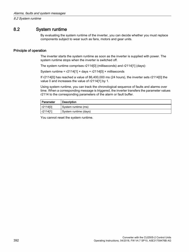
8.2 System runtimeBy evaluating the system runtime of the inverter, you can decide whether you must replace components subject to wear such as fans, motors and gear units.
Principle of operationThe inverter starts the system runtime as soon as the inverter is supplied with power. The system runtime stops when the inverter is switched off.
The system runtime comprises r2114[0] (milliseconds) and r2114[1] (days):
System runtime = r2114[1] × days + r2114[0] × milliseconds
If r2114[0] has reached a value of 86,400,000 ms (24 hours), the inverter sets r2114[0] the value 0 and increases the value of r2114[1] by 1.
Using system runtime, you can track the chronological sequence of faults and alarms over time. When a corresponding message is triggered, the inverter transfers the parameter values r2114 to the corresponding parameters of the alarm or fault buffer.
Parameter Descriptionr2114[0] System runtime (ms)r2114[1] System runtime (days)
You cannot reset the system runtime.
Alarms, faults and system messages8.2 System runtime
Converter with the CU250S-2 Control Units392 Operating Instructions, 04/2018, FW V4.7 SP10, A5E31759476B AG
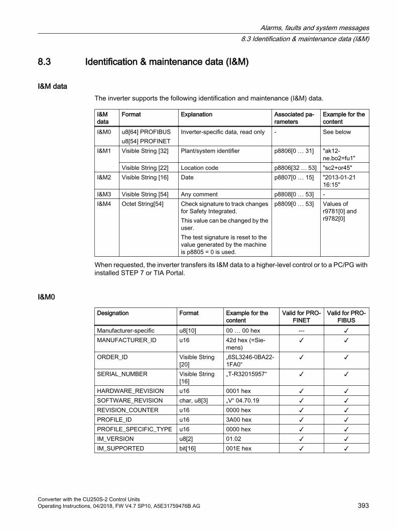
8.3 Identification & maintenance data (I&M)
I&M dataThe inverter supports the following identification and maintenance (I&M) data.
I&M data
Format Explanation Associated pa‐rameters
Example for the content
I&M0 u8[64] PROFIBUSu8[54] PROFINET
Inverter-specific data, read only - See below
I&M1 Visible String [32] Plant/system identifier p8806[0 … 31] "ak12-ne.bo2=fu1"
Visible String [22] Location code p8806[32 … 53] "sc2+or45" I&M2 Visible String [16] Date p8807[0 … 15] "2013-01-21
16:15"I&M3 Visible String [54] Any comment p8808[0 … 53] -I&M4 Octet String[54] Check signature to track changes
for Safety Integrated. This value can be changed by the user.The test signature is reset to the value generated by the machine is p8805 = 0 is used.
p8809[0 … 53] Values of r9781[0] and r9782[0]
When requested, the inverter transfers its I&M data to a higher-level control or to a PC/PG with installed STEP 7 or TIA Portal.
I&M0
Designation Format Example for the content
Valid for PRO‐FINET
Valid for PRO‐FIBUS
Manufacturer-specific u8[10] 00 … 00 hex --- MANUFACTURER_ID u16 42d hex (=Sie‐
mens)
ORDER_ID Visible String [20]
„6SL3246-0BA22-1FA0“
SERIAL_NUMBER Visible String [16]
„T-R32015957“
HARDWARE_REVISION u16 0001 hex SOFTWARE_REVISION char, u8[3] „V“ 04.70.19 REVISION_COUNTER u16 0000 hex PROFILE_ID u16 3A00 hex PROFILE_SPECIFIC_TYPE u16 0000 hex IM_VERSION u8[2] 01.02 IM_SUPPORTED bit[16] 001E hex
Alarms, faults and system messages8.3 Identification & maintenance data (I&M)
Converter with the CU250S-2 Control UnitsOperating Instructions, 04/2018, FW V4.7 SP10, A5E31759476B AG 393
8.4 Alarms, alarm buffer, and alarm history
AlarmsAlarms have the following properties:
Incoming alarms have no direct influence on the inverter.
Alarms disappear again when the cause is eliminated.
Alarms do not have to be acknowledged.
Alarms are displayed as follows:
– Display via bit 7 in status word 1 (r0052)
– Display on the operator panel with Axxxxx
– Display in Startdrive or STARTER
Alarm code or alarm value describe the cause of the alarm.
Alarm buffer
Figure 8-1 Alarm buffer
The inverter saves incoming alarms in the alarm buffer. An alarm includes an alarm code, an alarm value, and two alarm times:
Alarm code: r2122
Alarm value: r2124 in fixed-point format "I32", r2134 in floating-point format "Float"
Alarm time received = r2145 + r2123
Alarm time removed = r2146 + r2125
The inverter takes its internal time calculation to save the alarm times.
System runtime (Page 392)
Up to 8 alarms can be saved in the alarm buffer.
In the alarm buffer, the warnings are sorted according to "Warning time received". If the alarm buffer is completely filled and an additional alarm occurs, then the inverter overwrites the values with Index [7].
Alarms, faults and system messages8.4 Alarms, alarm buffer, and alarm history
Converter with the CU250S-2 Control Units394 Operating Instructions, 04/2018, FW V4.7 SP10, A5E31759476B AG
Alarm history
Figure 8-2 Shifting removed alarms into the alarm history
If the alarm buffer is completely filled and an additional alarm occurs, the inverter shifts all removed alarms into the alarm history. The following occurs in detail:
1. To create space after position [8] in the alarm history, the inverter shifts the alarms already stored in the alarm history "down" by one or more positions.If the alarm history is completely full, the inverter will delete the oldest alarms.
2. The inverter moves the removed alarms from the alarm buffer to the now freed up positions of the alarm history.Alarms that have not been removed remain in the alarm buffer.
3. The inverter closes gaps in the alarm buffer that occurred when the removed alarms were shifted in the alarm history by shifting the alarms that have not been removed "up".
4. The inverter saves the received alarm as the latest alarm in the alarm buffer.
The alarm history saves up to 56 alarms.
In the alarm history, alarms are sorted according to the "alarm time received". The latest alarm has Index [8].
Parameters of the alarm buffer and the alarm history
Parameter Descriptionp2111 Alarm counter
Number of alarms that have occurred after the last resetWhen setting p2111 = 0, all of the alarms that have been removed from the alarm buffer [0...7] are transferred into the alarm history [8...63]
r2122 Alarm codeDisplays the numbers of the alarms that have occurred
Alarms, faults and system messages8.4 Alarms, alarm buffer, and alarm history
Converter with the CU250S-2 Control UnitsOperating Instructions, 04/2018, FW V4.7 SP10, A5E31759476B AG 395
Parameter Descriptionr2123 Alarm time received in milliseconds
Displays the time in milliseconds when the alarm occurredr2124 Alarm value
Displays additional information about the alarmr2125 Alarm time removed in milliseconds
Displays the time in milliseconds when the alarm was removedr2145 Alarm time received in days
Displays the time in days when the alarm occurredr2132 Actual alarm code
Displays the code of the alarm that last occurredr2134 Alarm value for float values
Displays additional information about the alarm that occurred for float valuesr2146 Alarm time removed in days
Displays the time in days when the alarm was removed
Extended settings for alarms
Parameter DescriptionYou can change up to 20 different alarms into a fault or suppress alarms:p2118[0 … 19]
Setting the message number for the message type Selection of the alarms for which the message type should be changed
p2119[0 … 19]
Setting the message typeSetting the message type for the selected alarm1: Fault2: Alarm3: No message
You will find details in function diagram 8075 and in the parameter description of the List Manual.
Alarms, faults and system messages8.4 Alarms, alarm buffer, and alarm history
Converter with the CU250S-2 Control Units396 Operating Instructions, 04/2018, FW V4.7 SP10, A5E31759476B AG
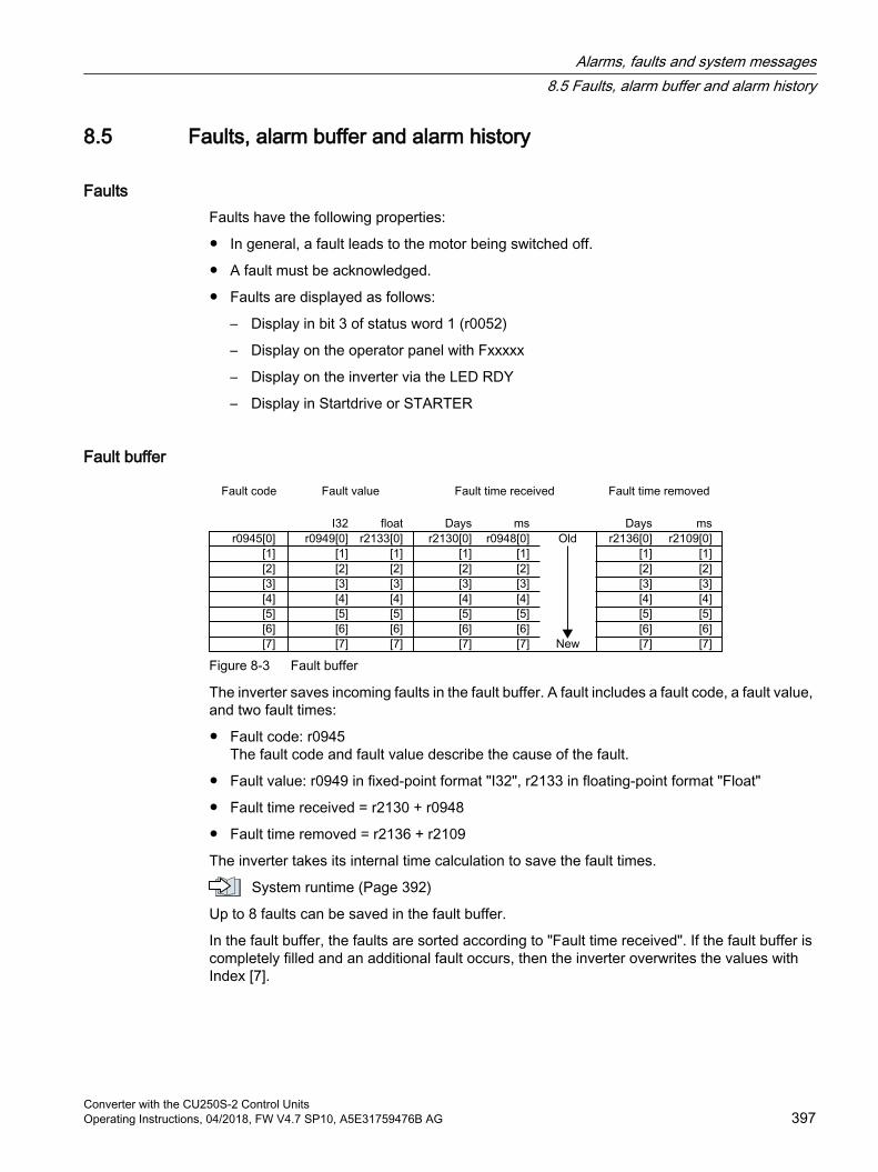
8.5 Faults, alarm buffer and alarm history
FaultsFaults have the following properties:
In general, a fault leads to the motor being switched off.
A fault must be acknowledged.
Faults are displayed as follows:
– Display in bit 3 of status word 1 (r0052)
– Display on the operator panel with Fxxxxx
– Display on the inverter via the LED RDY
– Display in Startdrive or STARTER
Fault buffer
Figure 8-3 Fault buffer
The inverter saves incoming faults in the fault buffer. A fault includes a fault code, a fault value, and two fault times:
Fault code: r0945The fault code and fault value describe the cause of the fault.
Fault value: r0949 in fixed-point format "I32", r2133 in floating-point format "Float"
Fault time received = r2130 + r0948
Fault time removed = r2136 + r2109
The inverter takes its internal time calculation to save the fault times.
System runtime (Page 392)
Up to 8 faults can be saved in the fault buffer.
In the fault buffer, the faults are sorted according to "Fault time received". If the fault buffer is completely filled and an additional fault occurs, then the inverter overwrites the values with Index [7].
Alarms, faults and system messages8.5 Faults, alarm buffer and alarm history
Converter with the CU250S-2 Control UnitsOperating Instructions, 04/2018, FW V4.7 SP10, A5E31759476B AG 397
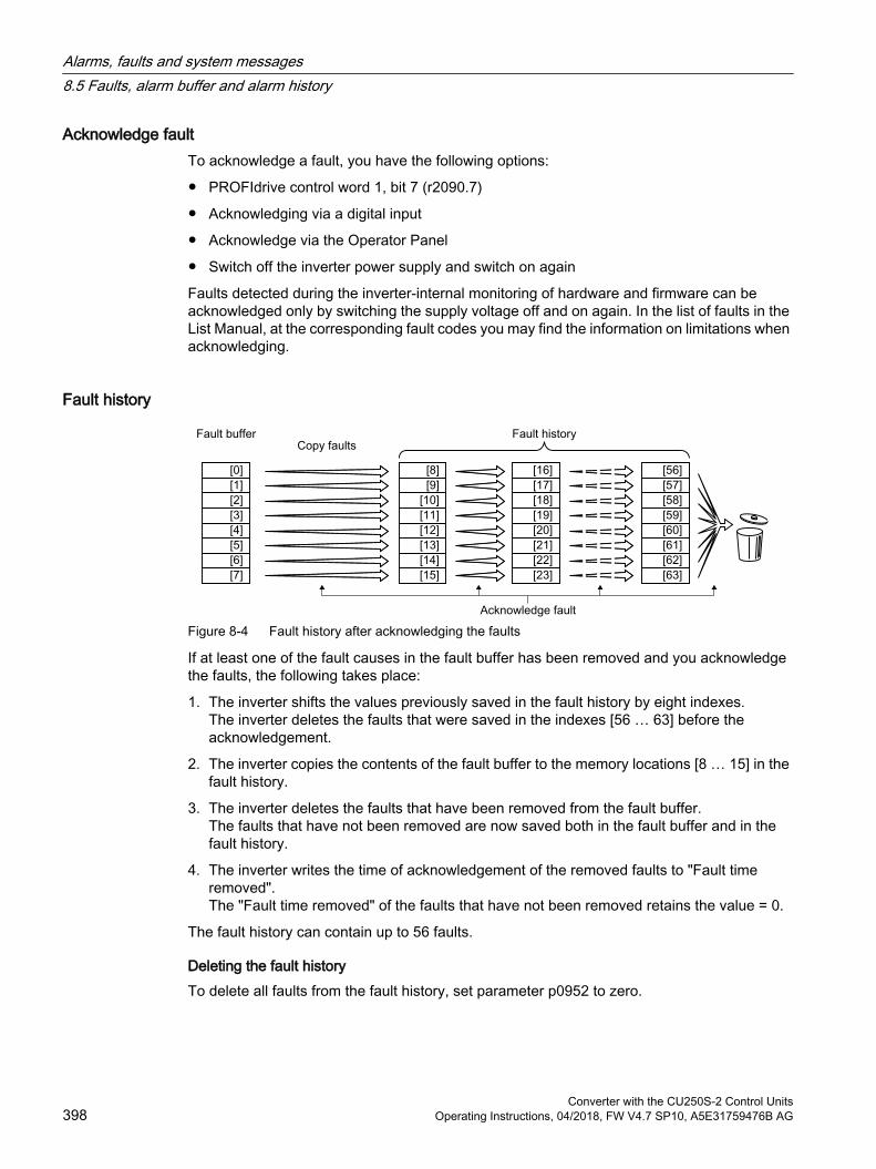
Acknowledge faultTo acknowledge a fault, you have the following options:
PROFIdrive control word 1, bit 7 (r2090.7)
Acknowledging via a digital input
Acknowledge via the Operator Panel
Switch off the inverter power supply and switch on again
Faults detected during the inverter-internal monitoring of hardware and firmware can be acknowledged only by switching the supply voltage off and on again. In the list of faults in the List Manual, at the corresponding fault codes you may find the information on limitations when acknowledging.
Fault history
Figure 8-4 Fault history after acknowledging the faults
If at least one of the fault causes in the fault buffer has been removed and you acknowledge the faults, the following takes place:
1. The inverter shifts the values previously saved in the fault history by eight indexes.The inverter deletes the faults that were saved in the indexes [56 … 63] before the acknowledgement.
2. The inverter copies the contents of the fault buffer to the memory locations [8 … 15] in the fault history.
3. The inverter deletes the faults that have been removed from the fault buffer.The faults that have not been removed are now saved both in the fault buffer and in the fault history.
4. The inverter writes the time of acknowledgement of the removed faults to "Fault time removed".The "Fault time removed" of the faults that have not been removed retains the value = 0.
The fault history can contain up to 56 faults.
Deleting the fault historyTo delete all faults from the fault history, set parameter p0952 to zero.
Alarms, faults and system messages8.5 Faults, alarm buffer and alarm history
Converter with the CU250S-2 Control Units398 Operating Instructions, 04/2018, FW V4.7 SP10, A5E31759476B AG
Parameters of the fault buffer and the fault history
Parameter Descriptionr0945 Fault code
Displays the numbers of the faults that have occurredr0948 Fault time received in milliseconds
Displays the time in milliseconds when the fault occurredr0949 Fault value
Displays additional information about the faultp0952 Fault cases, counter
A fault case can contain one or several faults.Number of fault cases that have occurred since the last acknowledgement. With p0952 = 0 you delete the fault buffer and the fault history.
r2109 Fault time removed in millisecondsDisplays the time in milliseconds when the fault occurred
r2130 Fault time received in daysDisplays the time in days when the fault occurred
r2131 Actual fault codeDisplays the code of the oldest fault that is still active
r2133 Fault value for float valuesDisplays additional information about the fault that occurred for float values
r2136 Fault time removed in daysDisplays the time in days when the fault was removed
Extended settings for faults
Parameter Descriptionp2100[0 … 19] Setting the fault number for fault response
Selecting the faults for which the fault response should be changed.You can modify the motor fault response for up to 20 different fault codes.
p2101[0 … 19] Setting, fault responseSetting the fault response for the selected fault
p2118[0 … 19] Setting the message number for the message type Selection of the message for which the message type should be changed.You can change up to 20 different faults into an alarm, or suppress faults:
p2119[0 … 19] Setting the message typeSetting the message type for the selected fault1: Fault2: Alarm3: No message
Alarms, faults and system messages8.5 Faults, alarm buffer and alarm history
Converter with the CU250S-2 Control UnitsOperating Instructions, 04/2018, FW V4.7 SP10, A5E31759476B AG 399

Parameter Descriptionp2126[0 … 19] Setting the fault number for the acknowledgement mode
Selection of the faults for which the acknowledgement type should be changed.You can modify the acknowledgement type for up to 20 different fault codes.
p2127[0 … 19] Setting, acknowledgement modeSetting the acknowledgement type for the selected fault1: Acknowledgement only using POWER ON2: IMMEDIATE acknowledgement after removing the fault cause
You will find details in function diagram 8075 and in the parameter description of the List Manual.
Alarms, faults and system messages8.5 Faults, alarm buffer and alarm history
Converter with the CU250S-2 Control Units400 Operating Instructions, 04/2018, FW V4.7 SP10, A5E31759476B AG
8.6 List of alarms and faultsAxxxxx Alarm
Fyyyyy: Fault
Table 8-8 The most important alarms and faults
Number Cause RemedyF01000 Software error in the CU Replace CU.F01001 Floating point exception Switch off CU and switch on again.F01015 Software error in the CU Upgrade firmware or contact technical support.F01018 Power-up aborted more than once 1. Switch the module off and on again.
2. After this fault has been output, the module is powered up with the factory settings.
3. Recommission the inverter.A01028 Configuration error Explanation: Parameterization on the memory card has been created with
a different type of module (Article number, MLFB).Check the module parameters and recommission if necessary.
F01033 Switching over units: Reference pa‐rameter value invalid
Set the value of the reference parameter not equal to 0.0 (p0304, p0305, p0310, p0596, p2000, p2001, p2002, p2003, r2004).
F01034 Switching over units: Calculation of the parameter values after refer‐ence value change unsuccessful
Select the value of the reference parameter so that the parameters involved can be calculated in the per unit notation (p0304, p0305, p0310, p0596, p2000, p2001, p2002, p2003, r2004).
F01040 Parameters must be saved Save parameters (p0971).Switch CU off and on again.
F01044 Error loading data from memory card
Replace memory card or CU.
A01053 System overload measured The maximum computing power of the Control Unit was exceeded. The following measures reduce the load on the Control Unit: Use only one data record (CDS and DDS) Only use the safety features of the basic functions Deactivate the technology controller Use the simple ramp-function generator rather than the extended ramp-
function generator Do not use any free function components Reduce the sampling time of the free function blocks
F01054 System limit exceeded
A01101 Memory card not available Insert a memory card or deactivate alarm A01101. Activate message for a memory card that is not inserted
(Page 372)F01105 CU: Insufficient memory Reduce number of data sets.F01122 Frequency at the probe input too
highReduce the frequency of the pulses at the probe input.
F01205 CU: Time slice overflow Contact technical support.F01250 CU hardware fault Replace CU.F01303 The DRIVE-CLiQ does not support
the requested functionA function requested by the Control Unit is not supported by a DRIVE-CLiQ component.
Alarms, faults and system messages8.6 List of alarms and faults
Converter with the CU250S-2 Control UnitsOperating Instructions, 04/2018, FW V4.7 SP10, A5E31759476B AG 401

Number Cause RemedyF01512 An attempt has been made to es‐
tablish a conversion factor for scal‐ing which does not exist
Create scaling or check transfer value.
A01590 Motor maintenance interval elapsed Carry out maintenance and reset the maintenance interval (p0651).F01600 STOP A initiated Select STO and then deselect again.F01625 Sign-of-life error in the Safety data Check the electrical cabinet design and cable routing for EMC
compliance. Check whether an impermissible voltage is connected at one of the
digital outputs. Check whether a digital output is loaded with an impermissible current. Check whether additional faults exist and perform diagnostics if
applicable. Select STO safety function and then deselect again. Switch off the inverter power supply and switch it on again.
F01650 Acceptance test required Carry out an acceptance test and create test certificate.Switch off the Control Unit and switch on again.
F01659 Write task for parameter rejected Cause: The inverter should be reset to the factory setting. However, it is not permissible to reset the safety functions as the safety functions are currently enabled.Remedy with operator panel:p0010 = 30 Parameter resetp9761 = … Enter password for the safety functions.p0970 = 5 Reset start safety parameter.
The inverter sets p0970 = 5 once it has reset the param‐eters.
Then reset the inverter to the factory setting again.F01662 Error, internal communications Check the electrical cabinet design and cable routing for EMC
compliance. Check whether an impermissible voltage is connected at one of the
digital outputs. Check whether a digital output is loaded with an impermissible current.If the checks are unsuccessful: Switch off the inverter power supply and switch it on again Upgrade the firmware Contact technical support
A01666 Static 1 signal at the F-DI for safe acknowledgement
Set fail-safe digital input F-DI to a logical 0 signal.
A01698 Commissioning mode active for safety functions
This message is withdrawn after the Safety commissioning has ended.
A01699 Switch-off signal path test required After the next time that the "STO" function is deselected, the message is withdrawn and the monitoring time is reset.
F01800 DRIVE-CLiQ: Incorrect hardware/configuration
A DRIVE-CLiQ connection error has occurred.Check the DRIVE-CLiQ cables at the Control Unit.
Alarms, faults and system messages8.6 List of alarms and faults
Converter with the CU250S-2 Control Units402 Operating Instructions, 04/2018, FW V4.7 SP10, A5E31759476B AG
Number Cause RemedyA01900 PROFIBUS: Configuration tele‐
gram faultyExplanation: A PROFIBUS master is attempting to establish a connection with a faulty configuration telegram.Check the bus configuration on the master and slave side.
A01910F01910
Setpoint timeout The alarm is generated when p2040 ≠ 0 ms and one of the following causes is present: The bus connection is interrupted The Modbus master is switched off Communications error (CRC, parity bit, logical error) An excessively low value for the fieldbus monitoring time (p2040)
A01920 PROFIBUS: Cyclic connection in‐terrupt
Explanation: The cyclic connection to PROFIBUS master is interrupted.Establish the PROFIBUS connection and activate the PROFIBUS master with cyclic operation.
F03505 Analog input, wire break Check the wiring for interruptions.Check the level of the injected signal.The input current measured by the analog input can be read out in r0752.
A03520 Temperature sensor fault Check that the sensor is connected correctly.A05000A05001A05002A05004A05006
Power Module overtemperature Check the following:- Is the ambient temperature within the defined limit values?- Are the load conditions and duty cycle configured accordingly?- Has the cooling failed?
Inverter protection using temperature monitoring (Page 327)F06310 Supply voltage (p0210) incorrectly
setCheck the set supply voltage and if required change (p0210).Check the line voltage.
F07011 Motor overtemperature Reduce the motor load.Check ambient temperature.Check the wiring and connection of the sensor.
A07012 I2t motor model overtemperature Check and if necessary reduce the motor load. Check the motor's ambient temperature.Check the thermal time constant p0611.Check overtemperature fault threshold p0605.
A07015 Motor temperature sensor alarm Check that the sensor is connected correctly.Check the parameter assignment (p0601).
F07016 Motor temperature sensor fault Make sure that the sensor is connected correctly.Check the parameterization (p0601).Deactivate the motor temperature sensor fault evaluation (p0607 = 0).
F07086F07088
Switching over units: Parameter lim‐it violation
Check the adapted parameter values and if required correct.
F07320 Automatic restart aborted Increase the number of restart attempts (p1211). The current number of start attempts is shown in r1214.Increase the wait time in p1212 and/or monitoring time in p1213.Connect an ON command (p0840).Increase the monitoring time of the power unit or switch off (p0857).Reduce the wait time for resetting the fault counter p1213[1] so that fewer faults are registered in the time interval.
Alarms, faults and system messages8.6 List of alarms and faults
Converter with the CU250S-2 Control UnitsOperating Instructions, 04/2018, FW V4.7 SP10, A5E31759476B AG 403
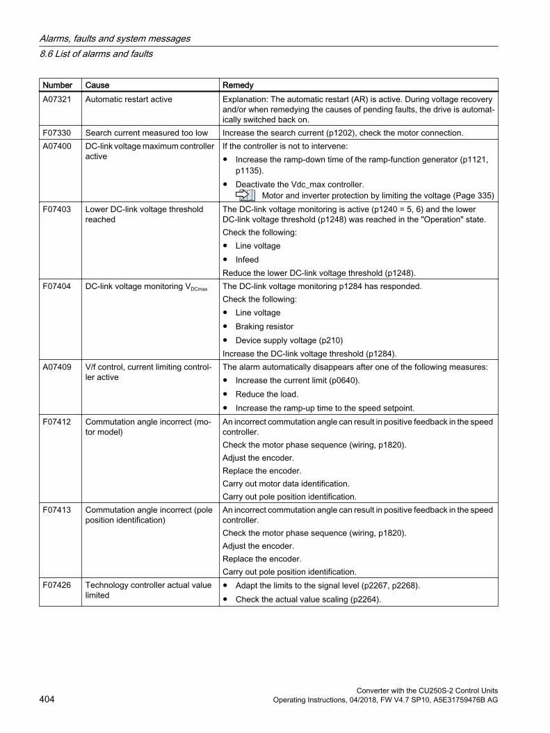
Number Cause RemedyA07321 Automatic restart active Explanation: The automatic restart (AR) is active. During voltage recovery
and/or when remedying the causes of pending faults, the drive is automat‐ically switched back on.
F07330 Search current measured too low Increase the search current (p1202), check the motor connection.A07400 DC-link voltage maximum controller
activeIf the controller is not to intervene: Increase the ramp-down time of the ramp-function generator (p1121,
p1135). Deactivate the Vdc_max controller.
Motor and inverter protection by limiting the voltage (Page 335)F07403 Lower DC-link voltage threshold
reachedThe DC-link voltage monitoring is active (p1240 = 5, 6) and the lowerDC-link voltage threshold (p1248) was reached in the "Operation" state.Check the following: Line voltage InfeedReduce the lower DC-link voltage threshold (p1248).
F07404 DC-link voltage monitoring VDCmax The DC-link voltage monitoring p1284 has responded.Check the following: Line voltage Braking resistor Device supply voltage (p210)Increase the DC-link voltage threshold (p1284).
A07409 V/f control, current limiting control‐ler active
The alarm automatically disappears after one of the following measures: Increase the current limit (p0640). Reduce the load. Increase the ramp-up time to the speed setpoint.
F07412 Commutation angle incorrect (mo‐tor model)
An incorrect commutation angle can result in positive feedback in the speed controller.Check the motor phase sequence (wiring, p1820).Adjust the encoder.Replace the encoder.Carry out motor data identification.Carry out pole position identification.
F07413 Commutation angle incorrect (pole position identification)
An incorrect commutation angle can result in positive feedback in the speed controller.Check the motor phase sequence (wiring, p1820).Adjust the encoder.Replace the encoder.Carry out pole position identification.
F07426 Technology controller actual value limited
Adapt the limits to the signal level (p2267, p2268). Check the actual value scaling (p2264).
Alarms, faults and system messages8.6 List of alarms and faults
Converter with the CU250S-2 Control Units404 Operating Instructions, 04/2018, FW V4.7 SP10, A5E31759476B AG

Number Cause RemedyF07801 Motor overcurrent Check current limits (p0640).
Vector control: Check current controller (p1715, p1717).V/f control: Check the current limiting controller (p1340 … p1346).Increase the acceleration ramp (p1120) or reduce the load.Check the motor and motor cables for short-circuit and ground fault.Check the motor regarding the star/delta connection and rating plate pa‐rameterization.Check power unit / motor combination.Select the flying restart function (p1200) if switched to rotating motor.
A07805 Drive: Power unit overload I2t Reduce the continuous load. Adapt the load cycle. Check the assignment of rated currents of the motor and power unit.
Inverter protection using temperature monitoring (Page 327)F07806 Regenerative power limit exceeded Increase the deceleration ramp.
Reduce the driving load.Use a power unit with higher energy recovery capability.For vector control, the regenerative power limit in p1531 can be reduced until the fault is no longer activated.
F07807 Short-circuit detected Check the inverter connection on the motor side for any phase-phase short-circuit.
Rule out that line and motor cables have been interchanged.A07850A07851A07852
External alarm 1 … 3 The signal for "external alarm 1" has been triggered.Parameters p2112, p2116 and p2117 determine the signal sources for the external alarm 1… 3.Remedy: Remove the causes of these alarms.
F07860F07861F07862
External fault 1 … 3 Remove the external causes for this fault.
F07900 Motor blocked Check that the motor can run freely.Check the torque limits (r1538 and r1539).Check the parameters of the "Motor blocked" message (p2175, p2177).
F07901 Motor overspeed Activate the precontrol for the speed limiting controller (p1401 bit 7 = 1).Increase the hysteresis for overspeed signal p2162.
F07902 Motor stalled Check whether the motor data has been set correctly and perform a motor identification.Check the current limits (p0640, r0067, r0289). If the current limits are too low, the drive cannot be magnetized.Check whether motor cables are disconnected during operation.
A07903 Motor speed deviation Increase p2163 and/or p2166.Increase the torque, current and power limits.
Alarms, faults and system messages8.6 List of alarms and faults
Converter with the CU250S-2 Control UnitsOperating Instructions, 04/2018, FW V4.7 SP10, A5E31759476B AG 405
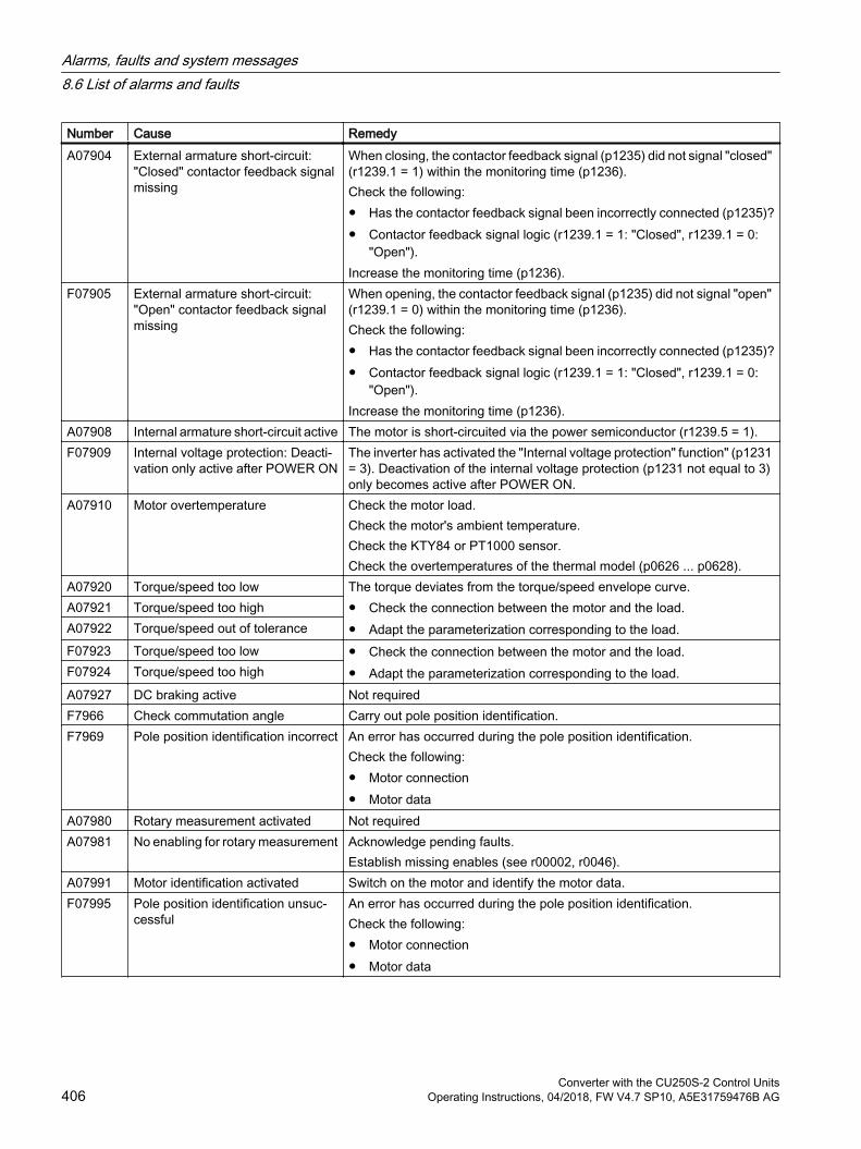
Number Cause RemedyA07904 External armature short-circuit:
"Closed" contactor feedback signal missing
When closing, the contactor feedback signal (p1235) did not signal "closed" (r1239.1 = 1) within the monitoring time (p1236).Check the following: Has the contactor feedback signal been incorrectly connected (p1235)? Contactor feedback signal logic (r1239.1 = 1: "Closed", r1239.1 = 0:
"Open").Increase the monitoring time (p1236).
F07905 External armature short-circuit: "Open" contactor feedback signal missing
When opening, the contactor feedback signal (p1235) did not signal "open" (r1239.1 = 0) within the monitoring time (p1236).Check the following: Has the contactor feedback signal been incorrectly connected (p1235)? Contactor feedback signal logic (r1239.1 = 1: "Closed", r1239.1 = 0:
"Open").Increase the monitoring time (p1236).
A07908 Internal armature short-circuit active The motor is short-circuited via the power semiconductor (r1239.5 = 1).F07909 Internal voltage protection: Deacti‐
vation only active after POWER ONThe inverter has activated the "Internal voltage protection" function" (p1231 = 3). Deactivation of the internal voltage protection (p1231 not equal to 3) only becomes active after POWER ON.
A07910 Motor overtemperature Check the motor load.Check the motor's ambient temperature.Check the KTY84 or PT1000 sensor.Check the overtemperatures of the thermal model (p0626 ... p0628).
A07920 Torque/speed too low The torque deviates from the torque/speed envelope curve. Check the connection between the motor and the load. Adapt the parameterization corresponding to the load.
A07921 Torque/speed too highA07922 Torque/speed out of toleranceF07923 Torque/speed too low Check the connection between the motor and the load.
Adapt the parameterization corresponding to the load.F07924 Torque/speed too high
A07927 DC braking active Not requiredF7966 Check commutation angle Carry out pole position identification.F7969 Pole position identification incorrect An error has occurred during the pole position identification.
Check the following: Motor connection Motor data
A07980 Rotary measurement activated Not requiredA07981 No enabling for rotary measurement Acknowledge pending faults.
Establish missing enables (see r00002, r0046).A07991 Motor identification activated Switch on the motor and identify the motor data.F07995 Pole position identification unsuc‐
cessfulAn error has occurred during the pole position identification.Check the following: Motor connection Motor data
Alarms, faults and system messages8.6 List of alarms and faults
Converter with the CU250S-2 Control Units406 Operating Instructions, 04/2018, FW V4.7 SP10, A5E31759476B AG

Number Cause RemedyF08501 Setpoint timeout Check the PROFINET connection.
Set the controller to RUN mode. If the fault occurs repeatedly, check the monitoring time set p2044.
F08502 Monitoring time, sign-of-life expired Check the PROFINET connection.F08510 Send configuration data not valid Check the PROFINET configurationA08511 Receive configuration data not validA08526 No cyclic connection Activate the control with cyclic operation.
Check the parameters "Name of Station" and "IP of Station" (r61000, r61001).
A08565 Consistency error affecting adjusta‐ble parameters
Check the following: IP address, subnet mask or default gateway is not correct. IP address or station name used twice in the network. Station name contains invalid characters.
A08800 PROFIenergy energy-saving mode active
The PROFIenergy energy-saving mode is active.The alarm automatically disappears when the energy-saving mode is exi‐ted.
A13000 Licensing is not sufficient You are using functions that require a license, but you don't have the ap‐propriate licenses.
Activating licensed functions (Page 492)F13010 Licensing is not sufficient Options requiring a license are used in the inverter, and the licensing is not
sufficient.F13010 Licensing, function module not li‐
censed.At least one function module requiring a license is not licensed.Deactivate the function module that is not licensed.
F13101 Know-how protection: Copy protec‐tion cannot be activated
Insert a valid memory card.
F30001 Overcurrent Check the following: Motor data, if required, carry out commissioning Motor connection method (Υ / Δ) V/f operation: Assignment of rated currents of motor and Power Module Line quality Make sure that the line commutating reactor is connected properly Power cable connections Power cables for short-circuit or ground fault Power cable length Line phases Short-circuit at the Control Unit output terminalsIf this doesn't help: V/f operation: Increase the acceleration ramp Reduce the load Replace the power unit
Alarms, faults and system messages8.6 List of alarms and faults
Converter with the CU250S-2 Control UnitsOperating Instructions, 04/2018, FW V4.7 SP10, A5E31759476B AG 407
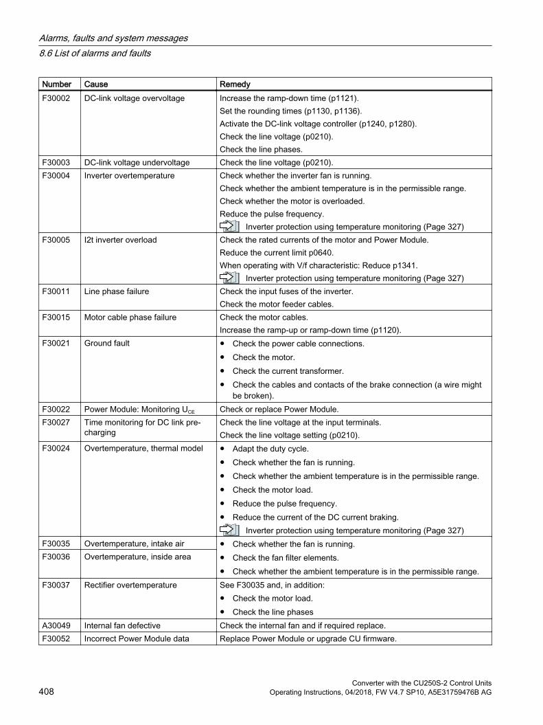
Number Cause RemedyF30002 DC-link voltage overvoltage Increase the ramp-down time (p1121).
Set the rounding times (p1130, p1136).Activate the DC-link voltage controller (p1240, p1280).Check the line voltage (p0210).Check the line phases.
F30003 DC-link voltage undervoltage Check the line voltage (p0210).F30004 Inverter overtemperature Check whether the inverter fan is running.
Check whether the ambient temperature is in the permissible range.Check whether the motor is overloaded.Reduce the pulse frequency.
Inverter protection using temperature monitoring (Page 327)F30005 I2t inverter overload Check the rated currents of the motor and Power Module.
Reduce the current limit p0640.When operating with V/f characteristic: Reduce p1341.
Inverter protection using temperature monitoring (Page 327)F30011 Line phase failure Check the input fuses of the inverter.
Check the motor feeder cables.F30015 Motor cable phase failure Check the motor cables.
Increase the ramp-up or ramp-down time (p1120).F30021 Ground fault Check the power cable connections.
Check the motor. Check the current transformer. Check the cables and contacts of the brake connection (a wire might
be broken).F30022 Power Module: Monitoring UCE Check or replace Power Module.F30027 Time monitoring for DC link pre-
chargingCheck the line voltage at the input terminals.Check the line voltage setting (p0210).
F30024 Overtemperature, thermal model Adapt the duty cycle. Check whether the fan is running. Check whether the ambient temperature is in the permissible range. Check the motor load. Reduce the pulse frequency. Reduce the current of the DC current braking.
Inverter protection using temperature monitoring (Page 327)F30035 Overtemperature, intake air Check whether the fan is running.
Check the fan filter elements. Check whether the ambient temperature is in the permissible range.
F30036 Overtemperature, inside area
F30037 Rectifier overtemperature See F30035 and, in addition: Check the motor load. Check the line phases
A30049 Internal fan defective Check the internal fan and if required replace.F30052 Incorrect Power Module data Replace Power Module or upgrade CU firmware.
Alarms, faults and system messages8.6 List of alarms and faults
Converter with the CU250S-2 Control Units408 Operating Instructions, 04/2018, FW V4.7 SP10, A5E31759476B AG

Number Cause RemedyF30053 Error in FPGA data Replace the Power Module.F30059 Internal fan defective Check the internal fan and if required replace.F30074 Communications error between
Control Unit and Power ModuleThere is a communications fault between the Control Unit and the Power Module. Possible causes: The Control Unit may have been removed or inserted incorrectly. The external 24 V Control Unit power supply has dipped to ≤95% of the
rated voltage for ≤3 msA30502 DC-link overvoltage Check the device supply voltage (p0210).
Check the line reactor dimensioningA30920 Temperature sensor fault Check that the sensor is connected correctly.F30600 STOP A initiated Select STO and then deselect again.F30662 CU hardware fault Switch CU off and on again, upgrade firmware, or contact technical support.F30664 CU power up aborted Switch CU off and on again, upgrade firmware, or contact technical support.F30850 Software fault in the Power Module Replace Power Module or contact technical support.A50001 PROFINET configuration error A PROFINET control is attempting to establish a connection with an incor‐
rect configuration telegram. Check whether "Shared Device" is activated (p8929 = 2).
A50010 PROFINET name of station invalid Correct the name of station (p8920) and activate (p8925 = 2).A50020 PROFINET: Second control missing "Shared Device" is activated (p8929 = 2). However, only the connection to
a PROFINET control is available.You will find more information in the List Manual.
For further information, please refer to the List Manual.
Overview of the manuals (Page 519)
Alarms, faults and system messages8.6 List of alarms and faults
Converter with the CU250S-2 Control UnitsOperating Instructions, 04/2018, FW V4.7 SP10, A5E31759476B AG 409

Alarms, faults and system messages8.6 List of alarms and faults
Converter with the CU250S-2 Control Units410 Operating Instructions, 04/2018, FW V4.7 SP10, A5E31759476B AG

Corrective maintenance 99.1 Spare parts compatibility
Continuous development within the scope of product maintenance Inverter components are being continuously developed within the scope of product maintenance. Product maintenance includes, for example, measures to increase the ruggedness or hardware changes which become necessary as components are discontinued.
These further developments are "spare parts-compatible" and do not change the article number.
In the scope of such spare parts-compatible ongoing development, plug connector or connection positions are sometimes slightly modified. This does not cause any problems when the components are properly used. Please take this fact into consideration in special installation situations (e.g. allow sufficient reserve regarding the cable length).
Converter with the CU250S-2 Control UnitsOperating Instructions, 04/2018, FW V4.7 SP10, A5E31759476B AG 411

9.2 Replacing inverter components
WARNING
Fire or electric shock due to defective components
If an overcurrent protection device is triggered, the inverter may be defective. A defective inverter can cause a fire or electric shock. Have the inverter and the overcurrent protection device checked by a specialist.
Repair
WARNING
Fire or electric shock due to improper repair
Improper repair of the inverter may cause malfunctions or result in consequential damage such as fire or electric shock. Only commission the following persons to repair the inverter:
– Siemens customer service– A repair center that has been authorized by Siemens– Specialist personnel who are thoroughly acquainted with all the warnings and operating
procedures contained in this manual. Only use original spare parts when carrying out repairs.
Recycling and disposal
For environmentally-friendly recycling and disposal of your old device, please contact a company certified for the disposal of waste electrical and electronic equipment, and dispose of the old device as prescribed in the respective country of use.
Corrective maintenance9.2 Replacing inverter components
Converter with the CU250S-2 Control Units412 Operating Instructions, 04/2018, FW V4.7 SP10, A5E31759476B AG
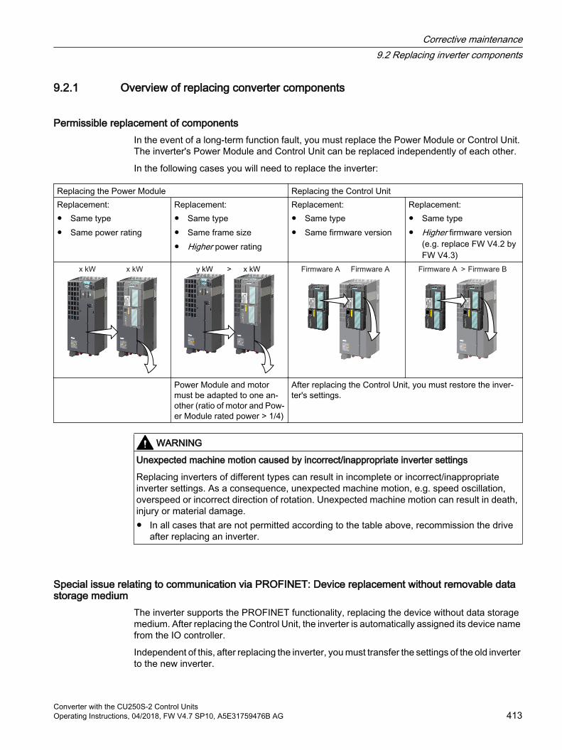
9.2.1 Overview of replacing converter components
Permissible replacement of componentsIn the event of a long-term function fault, you must replace the Power Module or Control Unit. The inverter's Power Module and Control Unit can be replaced independently of each other.
In the following cases you will need to replace the inverter:
Replacing the Power Module Replacing the Control UnitReplacement: Same type Same power rating
Replacement: Same type Same frame size Higher power rating
Replacement: Same type Same firmware version
Replacement: Same type Higher firmware version
(e.g. replace FW V4.2 by FW V4.3)
Power Module and motor must be adapted to one an‐other (ratio of motor and Pow‐er Module rated power > 1/4)
After replacing the Control Unit, you must restore the inver‐ter's settings.
WARNING
Unexpected machine motion caused by incorrect/inappropriate inverter settings
Replacing inverters of different types can result in incomplete or incorrect/inappropriate inverter settings. As a consequence, unexpected machine motion, e.g. speed oscillation, overspeed or incorrect direction of rotation. Unexpected machine motion can result in death, injury or material damage. In all cases that are not permitted according to the table above, recommission the drive
after replacing an inverter.
Special issue relating to communication via PROFINET: Device replacement without removable data storage medium
The inverter supports the PROFINET functionality, replacing the device without data storage medium. After replacing the Control Unit, the inverter is automatically assigned its device name from the IO controller.
Independent of this, after replacing the inverter, you must transfer the settings of the old inverter to the new inverter.
Corrective maintenance9.2 Replacing inverter components
Converter with the CU250S-2 Control UnitsOperating Instructions, 04/2018, FW V4.7 SP10, A5E31759476B AG 413

Details of the device replacement without removable storage medium can be found in the Internet:
PROFINET system description (http://support.automation.siemens.com/WW/view/en/19292127).
Corrective maintenance9.2 Replacing inverter components
Converter with the CU250S-2 Control Units414 Operating Instructions, 04/2018, FW V4.7 SP10, A5E31759476B AG
9.2.2 Replacing a Control Unit with enabled safety function
Replacing a Control Unit with data backup on a memory cardIf you use a memory card with firmware, after the replacement, you obtain a precise copy (firmware and settings) of the replaced Control Unit.
RequirementYou have a memory card with the actual settings of the Control unit to be replaced.
Procedure1. Disconnect the line voltage to the Power Module and (if installed) the external 24 V supply
or the voltage for the digital outputs of the Control Unit.
2. Remove the signal cables from the Control Unit.
3. Remove the defective Control Unit.
4. Remove the memory card from the old Control Unit and insert it in the new Control Unit.
5. Mount the new Control Unit on the Power Module. The new Control Unit must have the same article number and the same or higher firmware version as the Control Unit that was replaced.
6. Reconnect the signal cables of the Control Unit.
7. Switch on the line voltage again.
8. The inverter loads the settings from the memory card.
9. Check what the inverter reports after loading.
– Alarm A01028:The loaded settings are not compatible with the inverter.Set p0971 = 1 to delete the alarm. Check the inverter settings. We recommend that you recommission the drive.
– Fault F01641:Acknowledge the message.Perform a reduced acceptance test.
Reduced acceptance after a component has been replaced and a firmware change (Page 436)
You have replaced the Control Unit and transferred the safety function settings from the memory card to the new Control Unit.
Replacing a Control Unit with data backup in Startdrive
RequirementYou have backed up the actual settings of the Control Unit to be replaced to a PC using Startdrive.
Corrective maintenance9.2 Replacing inverter components
Converter with the CU250S-2 Control UnitsOperating Instructions, 04/2018, FW V4.7 SP10, A5E31759476B AG 415

Procedure1. Switch off the line voltage to the Power Module and (if installed) the external 24 V supply
or the voltage for the digital outputs of the Control Unit.
2. Remove the signal cables of the Control Unit.
3. Remove the defective Control Unit.
4. Mount the new Control Unit on the Power Module.
5. Reconnect the signal cables of the Control Unit.
6. Switch on the line voltage again.
7. Open the right project for the drive in the PC.
8. Select "Load to device".
9. Connect Startdrive online with the drive.The inverter signals faults after the download. Ignore these faults, as they will be automatically acknowledged by the following steps.
10.Press the "Start safety commissioning" button.
11.Enter the password for the safety functions.
12.Confirm the prompt for saving your settings (copy RAM to ROM).
13.Disconnect the online connection.
14.Switch off the inverter power supply.
15.Wait until all LEDs on the inverter are dark.
16.Switch the inverter power supply on again.
17.Perform a reduced acceptance test. Reduced acceptance after a component has been replaced and a firmware change
(Page 436)
You have replaced the Control Unit and transferred the safety function settings from the PC to the new Control Unit.
Replacing the Control Unit with data backup in the operator panel
RequirementYou have backed up the actual settings of the Control Unit to be replaced to an operator panel.
Procedure1. Switch off the line voltage to the Power Module and (if installed) the external 24 V supply
or the voltage for the digital outputs of the Control Unit.
2. Remove the signal cables of the Control Unit.
3. Remove the defective Control Unit.
4. Mount the new Control Unit on the Power Module.
5. Reconnect the signal cables of the Control Unit.
Corrective maintenance9.2 Replacing inverter components
Converter with the CU250S-2 Control Units416 Operating Instructions, 04/2018, FW V4.7 SP10, A5E31759476B AG

6. Switch on the line voltage again.
7. Plug the Operator Panel into the Control Unit or connect the Operator Panel handheld device with the inverter.
8. Transfer the settings from the operator panel to the inverter.
9. Wait until the transfer is complete.
10.After loading, check whether the inverter outputs Alarm A01028.
– Alarm A01028:The loaded settings are not compatible with the inverter.Set p0971 = 1 to delete the alarm. Check the inverter settings. We recommend that you recommission the drive.
– No alarm A01028: Proceed with the next step.
11.Switch off the inverter power supply.
12.Wait until all LEDs on the inverter are dark.
13.Switch the inverter power supply on again.The inverter reports the faults F01641, F01650, F01680 and F30680. Ignore these faults, as they will be automatically acknowledged by the following steps.
14.Set p0010 to 95.
15.Set p9761 to the safety password.
16.Set p9701 to AC hex.
17.Set p0010 = 0.
18.Back up the settings so they are not lost when the power fails:
– For BOP‑2 in the menu "EXTRAS" - "RAM-ROM".
– IOP in the menu "SAVE RAM TO ROM".
19.Switch off the inverter power supply.
20.Wait until all LEDs on the inverter are dark.
21.Switch the inverter power supply on again.
22.Perform a reduced acceptance test Reduced acceptance after a component has been replaced and a firmware change
(Page 436)
You have replaced the Control Unit and transferred the safety function settings from the operator panel to the new Control Unit.
Corrective maintenance9.2 Replacing inverter components
Converter with the CU250S-2 Control UnitsOperating Instructions, 04/2018, FW V4.7 SP10, A5E31759476B AG 417

9.2.3 Replacing the Control Unit without the safety functions enabled
Replacing a Control Unit with data backup on a memory cardIf you use a memory card with firmware, after the replacement, you obtain a precise copy (firmware and settings) of the replaced Control Unit.
PreconditionYou have a memory card with the actual settings of the Control unit to be replaced.
Procedure1. Disconnect the line voltage to the Power Module and (if installed) the external 24 V supply
or the voltage for the digital outputs of the Control Unit.
2. Remove the signal cables from the Control Unit.
3. Remove the defective Control Unit.
4. Mount the new Control Unit on the Power Module. The new Control Unit must have the same article number and the same or higher firmware version as the Control Unit that was replaced.
5. Remove the memory card from the old Control Unit and insert it in the new Control Unit.
6. Reconnect the signal cables of the Control Unit.
7. Switch on the line voltage again.
8. The inverter loads the settings from the memory card.
9. After loading, check whether the inverter outputs Alarm A01028.
– Alarm A01028:The loaded settings are not compatible with the inverter.Clear the alarm with p0971 = 1 and recommission the drive.
– No alarm A01028:The inverter accepts the settings that have been loaded.
You have successfully replaced the Control Unit.
Replacing a Control Unit with data backup in Startdrive
PreconditionYou have backed up the actual settings of the Control Unit to be replaced to a PC using Startdrive.
Procedure1. Switch off the line voltage to the Power Module and (if installed) the external 24 V supply
or the voltage for the digital outputs of the Control Unit.
2. Remove the signal cables of the Control Unit.
3. Remove the defective Control Unit.
Corrective maintenance9.2 Replacing inverter components
Converter with the CU250S-2 Control Units418 Operating Instructions, 04/2018, FW V4.7 SP10, A5E31759476B AG
4. Mount the new Control Unit on the Power Module.
5. Reconnect the signal cables of the Control Unit.
6. Switch on the line voltage again.
7. Open the right project for the drive in the PC.
8. Select "Load to device".
9. Connect Startdrive online with the drive.
10.Confirm the prompt for saving your settings (copy RAM to ROM).
11.Disconnect the online connection.
You have replaced the Control Unit and transferred the settings from the PC to the new Control Unit.
Replacing the Control Unit with data backup in the operator panel
PreconditionYou have backed up the actual settings of the Control Unit to be replaced to an operator panel.
Procedure1. Disconnect the line voltage to the Power Module and (if installed) the external 24 V supply
or the voltage for the digital outputs of the Control Unit.
2. Remove the signal cables of the Control Unit.
3. Remove the defective Control Unit.
4. Mount the new Control Unit on the Power Module.
5. Reconnect the signal cables of the Control Unit.
6. Switch on the line voltage again.
7. Plug the Operator Panel into the Control Unit or connect the Operator Panel handheld device with the inverter.
8. Transfer the settings from the operator panel to the inverter.
9. Wait until the transfer is complete.
10.After loading, check whether the inverter outputs Alarm A01028.
– Alarm A01028:The loaded settings are not compatible with the inverter.Clear the alarm with p0971 = 1 and recommission the drive.
– No alarm A01028: Proceed with the next step.
11.Back up the settings so they are not lost when the power fails:
– For BOP‑2 in the menu "EXTRAS" - "RAM-ROM".
– For IOP‑2 in the menu "SAVE RAM TO ROM".
Corrective maintenance9.2 Replacing inverter components
Converter with the CU250S-2 Control UnitsOperating Instructions, 04/2018, FW V4.7 SP10, A5E31759476B AG 419

You have replaced the Control Unit and transferred the safety function settings from the operator panel to the new Control Unit.
Corrective maintenance9.2 Replacing inverter components
Converter with the CU250S-2 Control Units420 Operating Instructions, 04/2018, FW V4.7 SP10, A5E31759476B AG
9.2.4 Replacing the Control Unit without data backupIf you do not backup the settings, then you must recommission the drive after replacing the Control Unit.
Procedure1. Switch off the line voltage to the Power Module and (if installed) the external 24 V supply
or the voltage for the digital outputs of the Control Unit.
2. Remove the signal cables of the Control Unit.
3. Remove the defective Control Unit.
4. Mount the new Control Unit on the Power Module.
5. Reconnect the signal cables of the Control Unit.
6. Switch on the line voltage again.
7. Recommission the drive.
The Control Unit replacement has been completed once the drive has been successfully commissioned.
9.2.5 Replacing a Control Unit with active know-how protection
Replacing devices with know-how protection without copy protectionIn the case of know-how protection without copy protection, the inverter settings can be transferred to another inverter using a memory card.
Saving setting on memory card (Page 365)
Transferring the setting from the memory card (Page 368)
Replacing devices with know-how protection with copy protectionThe know-how protection with copy protection hides the inverter settings and also prevents the duplication of the inverter settings.
If the inverter settings can neither be copied nor forwarded, a recommissioning is required after inverter replacement.
To avoid the recommissioning, you must use a Siemens memory card, and the machine manufacturer must have an identical prototype machine that it uses as sample.
There are two options for replacing the device:
Corrective maintenance9.2 Replacing inverter components
Converter with the CU250S-2 Control UnitsOperating Instructions, 04/2018, FW V4.7 SP10, A5E31759476B AG 421
Option 1: The machine manufacturer only knows the serial number of the new inverter1. The end customer provides the machine manufacturer with the following information:
– For which machine must the inverter be replaced?
– What is the serial number (r7758) of the new inverter?
2. The machine manufacturer performs the following steps online on the prototype machine:
– Deactivating know-how protection Activating and deactivating know-how protection (Page 383)
– Enter the serial number of the new inverter in p7759.
– Enter the serial number of the inserted memory card as reference serial number in p7769.
– Activate know-how protection with copy protection. "Copy RAM to ROM" must be activated.
Activating and deactivating know-how protection (Page 383)
– Write the configuration with p0971 = 1 to the memory card.
– Send the memory card to the end customer.
3. The end customer inserts the memory card and switches on the power supply for the inverter.
When powering up, the inverter checks the serial numbers of the card and when there is a match, the inverter goes into the "ready to start" state.
If the numbers do not match, then the inverter signals fault F13100 (no valid memory card).
Corrective maintenance9.2 Replacing inverter components
Converter with the CU250S-2 Control Units422 Operating Instructions, 04/2018, FW V4.7 SP10, A5E31759476B AG
Option 2: The machine manufacturer knows the serial number of the new inverter and the serial number of the memory card1. The end customer provides the machine manufacturer with the following information:
– For which machine must the inverter be replaced?
– What is the serial number (r7758) of the new inverter?
– What is the serial number of the memory card?
2. The machine manufacturer performs the following steps online on the prototype machine:
– Deactivating know-how protection Activating and deactivating know-how protection (Page 383)
– Enter the serial number of the new inverter in p7759.
– Enter the serial number of the customer's memory card as reference serial number in p7769.
– Activate know-how protection with copy protection. "Copy RAM to ROM" must be activated.
Activating and deactivating know-how protection (Page 383)
– Write the configuration with p0971 = 1 to the memory card.
– Copy the encrypted project from the card to the associated PC.
– Send the encrypted project to the end customer, e.g. via e-mail.
3. The end customer copies the project to the Siemens memory card that belongs to the machine, inserts it in the inverter and switches on the power supply for the inverter.
When powering up, the inverter checks the serial numbers of the card and when there is a match, the inverter goes into the "ready to start" state.
If the numbers do not match, then the inverter signals fault F13100 (no valid memory card).
Corrective maintenance9.2 Replacing inverter components
Converter with the CU250S-2 Control UnitsOperating Instructions, 04/2018, FW V4.7 SP10, A5E31759476B AG 423
9.2.6 Replacing a Power Module with enabled safety function
WARNING
Electric shock due to residual charge in the Power Module
After switching off the line voltage, it will take up to 5 minutes until the capacitors in the Power Module are sufficiently discharged for the residual voltage to be safe. Death or serious injury will result if energized parts are touched. Check the safe isolation of the Power Module connections before carrying out installation
work.
NOTICE
Motor damage due to interchanged motor connecting cables
The direction in which the motor rotates switches if you exchange the two phases of the motor line. A motor with an incorrect direction of rotation can damage the machine or installation. Driven loads with only one permissible direction of rotation include certain saws. Connect the three phases of the motor lines in the right order. After replacing the Power Module, check the direction of motor rotation.
Procedure1. Switch off the line voltage of the Power Module.
You can leave any external 24 V supply to the Control Unit switched on.
2. Remove the connecting cables of the Power module.
3. Remove the Control Unit from the Power Module.
4. Replace the Power Module.
5. Mount the Control Unit onto the new Power Module.
6. Connect up the new Power Module using the connecting cables.
7. Switch on the line supply and, if necessary, the 24 V supply of the Control Unit.
8. The inverter reports F01641.
9. Perform a reduced acceptance test Reduced acceptance after a component has been replaced and a firmware change
(Page 436)
You have successfully replaced the Power Module.
Corrective maintenance9.2 Replacing inverter components
Converter with the CU250S-2 Control Units424 Operating Instructions, 04/2018, FW V4.7 SP10, A5E31759476B AG
9.2.7 Replacing a Power Module without the safety function being enabled
Procedure1. Switch off the supply voltage to the Power Module.
You do not have to switch off an external 24 V power supply for the Control Unit if one is being used.
2. Remove the connecting cables of the Power Module.
3. Remove the Control Unit from the Power Module.
4. Replace the old Power Module with the new Power Module.
5. Mount the Control Unit onto the new Power Module.
6. Connect up the new Power Module using the connecting cables.
NOTICE
Motor damage due to interchanged motor connecting cables
The direction in which the motor rotates switches if you exchange the two phases of the motor line. A motor with an incorrect direction of rotation can damage the machine or installation. Work machines with only one permissible direction of rotation include certain compressors, saws and pumps. Connect the three phases of the motor lines in the right order. After replacing the Power Module, check the direction of motor rotation.
7. Switch on the line supply and, if necessary, the 24 V supply of the Control Unit.
You have successfully replaced the Power Module.
Corrective maintenance9.2 Replacing inverter components
Converter with the CU250S-2 Control UnitsOperating Instructions, 04/2018, FW V4.7 SP10, A5E31759476B AG 425
9.3 Replacing an encoder
Same interface, same encoder typeIf you have to replace a defective encoder, then it is best if you use the same encoder type.
Replacing the encoder - same encoder type (Page 426)
Same interface, different encoder typeIf you use an different encoder type:
Replacing the encoder - different encoder type (Page 427)
Different interfaceIf you connect the encoder at a different interface, you must perform a recommissioning.
Starting wizards for the quick commissioning (Page 136)
9.3.1 Replacing the encoder - same encoder type
Procedure1. Switch off the inverter power supply, including the external 24 V supply for the Control Unit
and digital outputs.
2. Replace the encoder. Connect the encoder cable shield as specified. EMC-compliant installation of a machine or system (Page 53)
3. Switch on the power supplies.
4. If you have replaced an absolute encoder, and you use this encoder to sense positions, then you must adjust the encoder. Further information about this topic is provided in the "Basic positioner" function manual.
Overview of the manuals (Page 519)
You have replaced the encoder.
Corrective maintenance9.3 Replacing an encoder
Converter with the CU250S-2 Control Units426 Operating Instructions, 04/2018, FW V4.7 SP10, A5E31759476B AG

9.3.2 Replacing the encoder - different encoder type
PreconditionYou have backed up the actual inverter settings to your PC using Startdrive.
Procedure1. Switch off the inverter power supply, including the external 24 V supply for the Control Unit
and the digital outputs.
2. Remove the encoder to be replaced.
3. Switch on the power supplies.
4. Change the encoder data in Startdrive (see below).
5. Acknowledge the changes by pressing OK and save the data to your computer.
6. Go online.
7. In the project, select the inverter
8. Press the "Load to device" button. .
9. In the following screen form, select "Back up parameter assignment in the EEPROM".
10.Go offline.
11.Connect the new encoder.Connect the encoder cable shield as specified.
EMC-compliant installation of a machine or system (Page 53)
12.Switch on the power supplies.
13.Check that the drive functions correctly.
You have replaced the encoder with another encoder type.
Corrective maintenance9.3 Replacing an encoder
Converter with the CU250S-2 Control UnitsOperating Instructions, 04/2018, FW V4.7 SP10, A5E31759476B AG 427
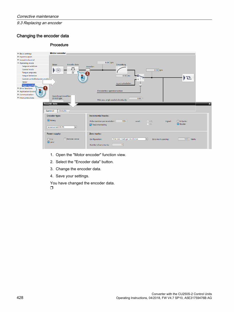
Changing the encoder data
Procedure
1. Open the "Motor encoder" function view.
2. Select the "Encoder data" button.
3. Change the encoder data.
4. Save your settings.
You have changed the encoder data.
Corrective maintenance9.3 Replacing an encoder
Converter with the CU250S-2 Control Units428 Operating Instructions, 04/2018, FW V4.7 SP10, A5E31759476B AG

9.4 Firmware upgrade and downgrade
Preparing a memory card for a firmware upgrade or downgrade
Procedure1. Download the required firmware to your PC from the Internet.
Download (https://support.industry.siemens.com/cs/ww/en/view/67364620)
2. Extract the files to a directory of your choice on your PC.
3. Transfer the unzipped files into the root directory of the memory card.
Figure 9-1 Example of memory card contents after the file transfer
Depending on the firmware, the filenames and the number of files may differ from the display above.The "USER" directory does not exist on unused memory cards. After the memory card is plugged in for the first time, the inverter creates a new "USER" directory.
You have prepared the memory card for the firmware upgrade or downgrade.
Memory cards that can be ordered:
Memory cards (Page 362)
Corrective maintenance9.4 Firmware upgrade and downgrade
Converter with the CU250S-2 Control UnitsOperating Instructions, 04/2018, FW V4.7 SP10, A5E31759476B AG 429
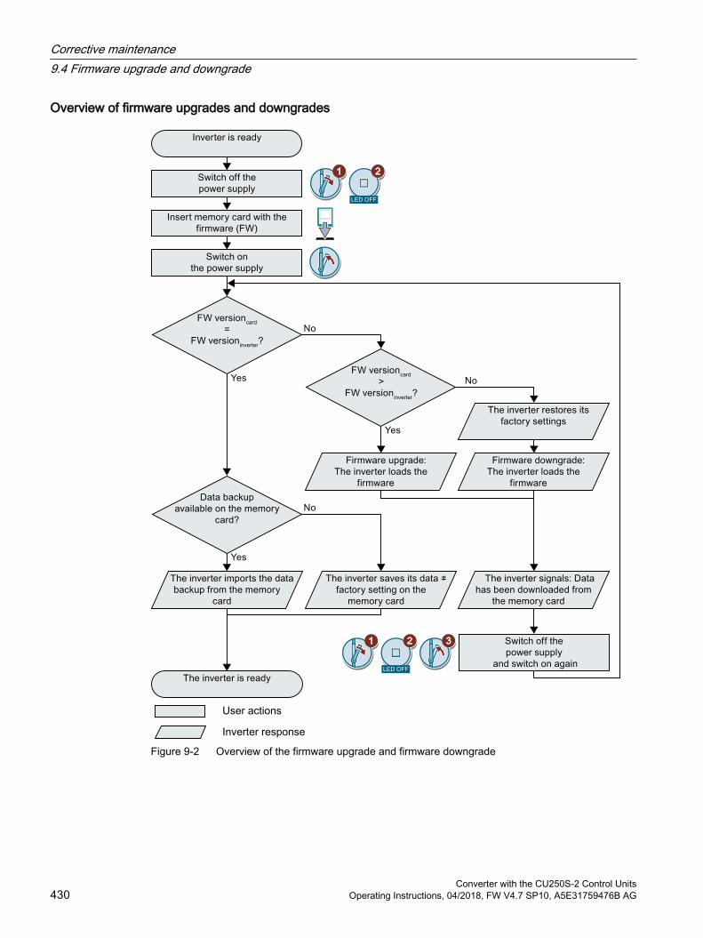
Overview of firmware upgrades and downgrades
User actions
Inverter response
Figure 9-2 Overview of the firmware upgrade and firmware downgrade
Corrective maintenance9.4 Firmware upgrade and downgrade
Converter with the CU250S-2 Control Units430 Operating Instructions, 04/2018, FW V4.7 SP10, A5E31759476B AG
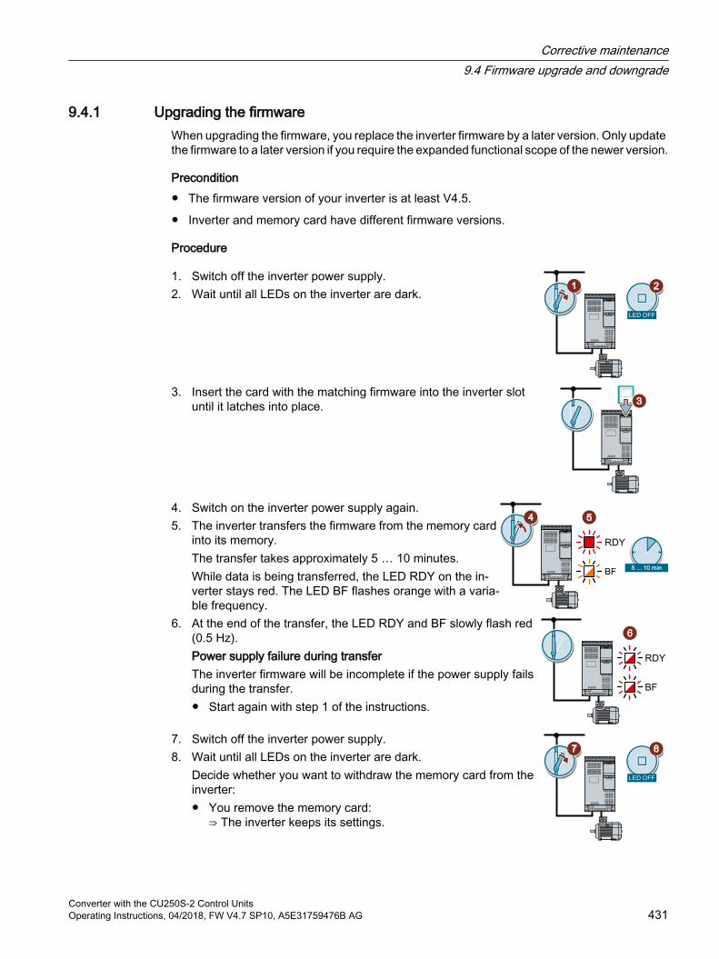
9.4.1 Upgrading the firmwareWhen upgrading the firmware, you replace the inverter firmware by a later version. Only update the firmware to a later version if you require the expanded functional scope of the newer version.
Precondition The firmware version of your inverter is at least V4.5.
Inverter and memory card have different firmware versions.
Procedure
1. Switch off the inverter power supply.2. Wait until all LEDs on the inverter are dark.
3. Insert the card with the matching firmware into the inverter slot until it latches into place.
4. Switch on the inverter power supply again.5. The inverter transfers the firmware from the memory card
into its memory.The transfer takes approximately 5 … 10 minutes.While data is being transferred, the LED RDY on the in‐verter stays red. The LED BF flashes orange with a varia‐ble frequency.
6. At the end of the transfer, the LED RDY and BF slowly flash red (0.5 Hz).Power supply failure during transferThe inverter firmware will be incomplete if the power supply fails during the transfer. Start again with step 1 of the instructions.
7. Switch off the inverter power supply.8. Wait until all LEDs on the inverter are dark.
Decide whether you want to withdraw the memory card from the inverter: You remove the memory card:
⇒ The inverter keeps its settings.
Corrective maintenance9.4 Firmware upgrade and downgrade
Converter with the CU250S-2 Control UnitsOperating Instructions, 04/2018, FW V4.7 SP10, A5E31759476B AG 431
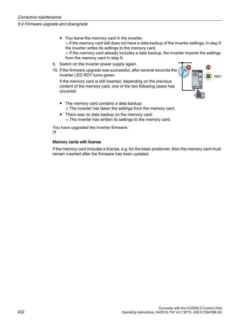
You leave the memory card in the inverter:⇒ If the memory card still does not have a data backup of the inverter settings, in step 9 the inverter writes its settings to the memory card.⇒ If the memory card already includes a data backup, the inverter imports the settings from the memory card in step 9.
9. Switch on the inverter power supply again.10. If the firmware upgrade was successful, after several seconds the
inverter LED RDY turns green.If the memory card is still inserted, depending on the previous content of the memory card, one of the two following cases has occurred:
The memory card contains a data backup:⇒ The inverter has taken the settings from the memory card.
There was no data backup on the memory card:⇒ The inverter has written its settings to the memory card.
You have upgraded the inverter firmware.
Memory cards with licenseIf the memory card includes a license, e.g. for the basic positioner, then the memory card must remain inserted after the firmware has been updated.
Corrective maintenance9.4 Firmware upgrade and downgrade
Converter with the CU250S-2 Control Units432 Operating Instructions, 04/2018, FW V4.7 SP10, A5E31759476B AG
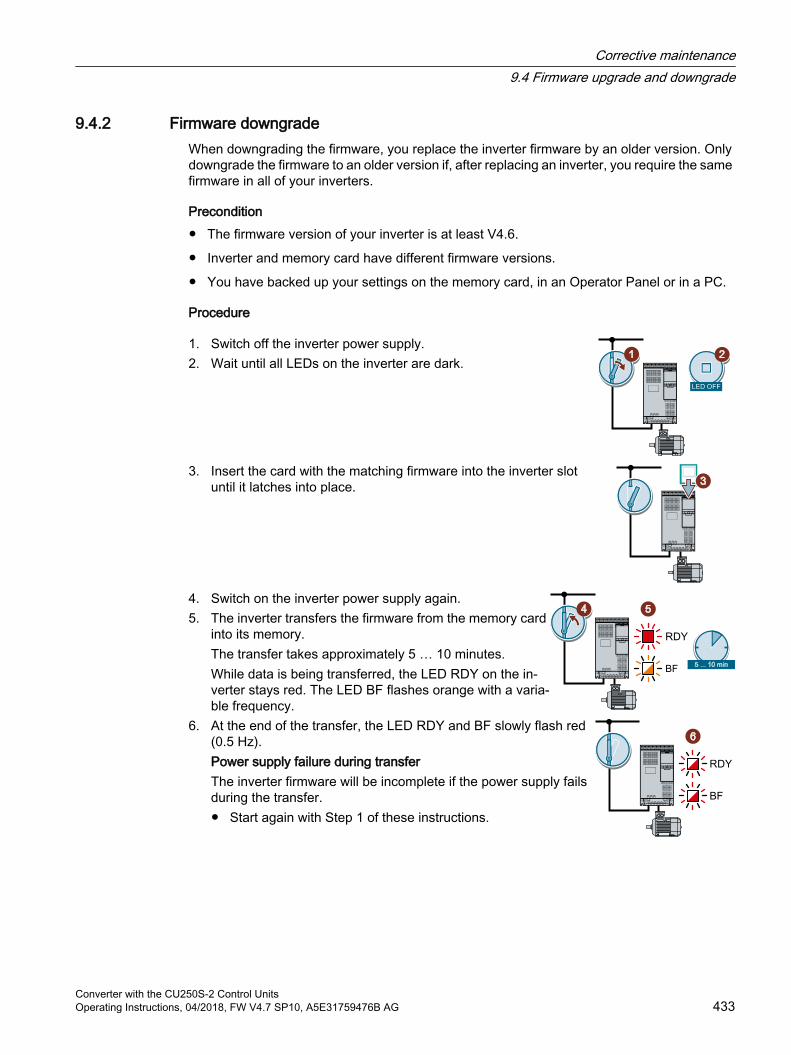
9.4.2 Firmware downgradeWhen downgrading the firmware, you replace the inverter firmware by an older version. Only downgrade the firmware to an older version if, after replacing an inverter, you require the same firmware in all of your inverters.
Precondition The firmware version of your inverter is at least V4.6.
Inverter and memory card have different firmware versions.
You have backed up your settings on the memory card, in an Operator Panel or in a PC.
Procedure
1. Switch off the inverter power supply.2. Wait until all LEDs on the inverter are dark.
3. Insert the card with the matching firmware into the inverter slot until it latches into place.
4. Switch on the inverter power supply again.5. The inverter transfers the firmware from the memory card
into its memory.The transfer takes approximately 5 … 10 minutes.While data is being transferred, the LED RDY on the in‐verter stays red. The LED BF flashes orange with a varia‐ble frequency.
6. At the end of the transfer, the LED RDY and BF slowly flash red (0.5 Hz).Power supply failure during transferThe inverter firmware will be incomplete if the power supply fails during the transfer. Start again with Step 1 of these instructions.
Corrective maintenance9.4 Firmware upgrade and downgrade
Converter with the CU250S-2 Control UnitsOperating Instructions, 04/2018, FW V4.7 SP10, A5E31759476B AG 433

7. Switch off the inverter power supply.8. Wait until all LEDs on the inverter are dark.
Decide whether you want to withdraw the memory card from the inverter: The memory card contains a data backup:
⇒ The inverter has taken the settings from the memory card. There was no data backup on the memory card:
⇒ The inverter has the factory setting.9. Switch on the inverter power supply again.10. If the firmware downgrade was successful, after several seconds
the inverter LED RDY turns green.If the memory card is still inserted, depending on the previous content of the memory card, one of the two following cases has occurred:
The memory card contains a data backup:⇒ The inverter has taken the settings from the memory card.
There was no data backup on the memory card:⇒ The inverter has the factory setting.
11. If the memory card did not contain a data backup of the inverter settings, then you must transfer your settings to the inverter from another data backup.
Saving the settings and series commissioning (Page 361)
You have replaced the inverter firmware by an older version.
Memory cards with licenseIf the memory card includes a license, e.g. for the basic positioner, then the memory card must remain inserted after the firmware has been updated.
Corrective maintenance9.4 Firmware upgrade and downgrade
Converter with the CU250S-2 Control Units434 Operating Instructions, 04/2018, FW V4.7 SP10, A5E31759476B AG

9.4.3 Correcting an unsuccessful firmware upgrade or downgrade
How does the inverter signal an unsuccessful upgrade or downgrade?
The inverter signals an unsuccessful firmware upgrade or downgrade by a quickly flashing LED RDY and the lit LED BF.
Correcting an unsuccessful upgrade or downgradeYou can check the following to correct an unsuccessful firmware upgrade or downgrade:
Does the firmware version of your inverter fulfill the preconditions?
– For an upgrade, as a minimum V4.5.
– For a downgrade, as a minimum V4.6.
Have you correctly inserted the card?
Does the card contain the correct firmware?
Repeat the appropriate procedure.
Corrective maintenance9.4 Firmware upgrade and downgrade
Converter with the CU250S-2 Control UnitsOperating Instructions, 04/2018, FW V4.7 SP10, A5E31759476B AG 435

9.5 Reduced acceptance after a component has been replaced and a firmware change
After a component has been replaced or the firmware updated, a reduced acceptance test of the safety functions must be performed.
Table 9-1 Reduced acceptance test after component replacement
Measure Acceptance test DocumentationReplacing the Control Unit or the inverter with an identical type
An acceptance test for the safety functions is not re‐quired.Only check the direction of rotation of the motor.
Supplement the inverter data Document the modified
checksum and time stamp 1)
CountersignatureReplacing a Power Module with an identical type
Supplement the hardware version in the inverter data.
Replacing the motor with an identi‐cal pole pair number
No change
Replace the gearbox with an iden‐tical ratio Replacing the Safe Brake Relay Check the SBC function. Supplement the hardware version
in the inverter data.Replacing safety-related I/O devi‐ces (e.g. Emergency Stop switch).
Check the control of the safe‐ty functions affected by the components that have been replaced.
No change
Inverter firmware update An acceptance test for the safety functions is not re‐quired.Check as to whether the firm‐ware update was successful and the inverter functions as expected.
Supplement firmware version in the inverter data
Document the modified checksum and time stamp 1)
Countersignature
1) The inverter changes the following parameters after replacing inverter components and after a firmware update:
- checksum r9781- time stamp r9782
Acceptance - completion of commissioning (Page 256)
Corrective maintenance9.5 Reduced acceptance after a component has been replaced and a firmware change
Converter with the CU250S-2 Control Units436 Operating Instructions, 04/2018, FW V4.7 SP10, A5E31759476B AG
9.6 If the converter no longer responds
If the inverter no longer respondsFor example, when loading an incorrect file from the memory card, the inverter can go into a state where it can no longer respond to commands from the operator panel or from a higher-level control system. In this case, you must reset the inverter to its factory setting and recommission it. This inverter state is manifested in two different ways:
Case 1 The motor is switched off.
You cannot communicate with the inverter, either via the operator panel or other interfaces.
The LEDs flicker and after 3 minutes the inverter has still not powered up.
Procedure1. Remove the memory card if one is inserted in the inverter.
2. Switch off the inverter power supply.
3. Wait until all LEDs on the inverter are dark. Then switch on the inverter power supply again.
4. Repeat steps 2 and 3 as often as required until the inverter outputs fault F01018.
5. Set p0971 = 1.
6. Switch off the inverter power supply.
7. Wait until all LEDs on the inverter are dark. Then switch on the inverter power supply again.The inverter now powers up with the factory settings.
8. Recommission the inverter.
You have restored the inverter factory settings.
Case 2 The motor is switched off.
You cannot communicate with the inverter, either via the operator panel or other interfaces.
The LEDs flash and are dark - this process is continually repeated.
Procedure1. Remove the memory card if one is inserted in the inverter.
2. Switch off the inverter power supply.
3. Wait until all LEDs on the inverter are dark. Then switch on the inverter power supply again.
4. Wait until the LEDs flash orange.
5. Repeat steps 2 and 3 as often as required until the inverter outputs fault F01018.
6. Now set p0971 = 1.
7. Switch off the inverter power supply.
Corrective maintenance9.6 If the converter no longer responds
Converter with the CU250S-2 Control UnitsOperating Instructions, 04/2018, FW V4.7 SP10, A5E31759476B AG 437

8. Wait until all LEDs on the inverter are dark. Then switch on the inverter power supply again.The inverter now powers up with the factory settings.
9. Recommission the inverter.
You have restored the inverter factory settings.
The motor cannot be switched-onIf the motor cannot be switched-on, then check the following:
Is a fault present?If there is, then remove the fault cause and acknowledge the fault.
Has the inverter been completely commissioned p0010 = 0?If not, the inverter is e.g. still in a commissioning state.
Is the inverter reporting the "ready to start" status (r0052.0 = 1)?
Is the inverter missing some enable signals (r0046)?
How does the inverter receive its setpoint and commands?Digital inputs, analog inputs or fieldbus?
Corrective maintenance9.6 If the converter no longer responds
Converter with the CU250S-2 Control Units438 Operating Instructions, 04/2018, FW V4.7 SP10, A5E31759476B AG
Technical data 1010.1 Technical data, CU250S-2 Control Unit
Feature DataFieldbus interfaces CU250S‑2 With RS485 interface for the
following protocols: USS Modbus RTU
Article numbers: Overview of Control
Units (Page 33)
CU250S‑2 DP With PROFIBUS interfaceCU250S‑2 PN With RJ45 connector for the
following fieldbuses: PROFINET EtherNet/IP
CU250S‑2 CAN With CANopen interfaceOperating voltage You have two options for the Control Unit power supply:
External supply via terminals 31 and 32 with 20.4 V … 28.8 V DC. Internal supply from the power module.
The summation of all currents of the following interfaces is limited to 0.8 A:– Encoder power supply– DRIVE-CLiQ– Power supply for the Operator Panel– Analog outputs– 24 V output voltage (terminal 9)– 24 V PROFIBUS teleservice– Resolver excitation
Current drain when supplied via 31 and 32
≤1.5 A
Power loss 12.0 W plus the power loss of all output voltagesOutput voltages +24 V out (terminal 9) 18 V … 26.8 V, ≤ 200 mA
+10 V out (terminal 1) 9.5 V … 10.5 V, ≤ 10 mAHTL encoder (terminal 33) 24 V, ≤ 200 mAHTL encoder (pins 4 and 5 of the Sub-D connector on the lower side of the Control Unit)
24 V, ≤ 350 mA
TTL encoder (pins 4 and 5 of the Sub-D connector on the lower side of the Control Unit)
4.75 V … 5.25 V, ≤ 350 mA
Setpoint resolution 0.01 HzMaximum frequency of the HTL en‐coder
500 kHz
Converter with the CU250S-2 Control UnitsOperating Instructions, 04/2018, FW V4.7 SP10, A5E31759476B AG 439

Feature DataDigital inputs 11 fixed DI 0 … DI 6 and DI 16 … DI 19
Electrically isolated4 can be switched over DI 24 … DI 27
Not isolatedCommon data Voltage: ≤ 30 V
Voltage for "low" state: < 5 V Voltage for "high" state: > 11 V Current for 24 V input voltage: 2.7 mA … 4.7 mA Minimum current for the "high" state: 1.8 mA … 3.9 mA Compatible to SIMATIC outputs Response time for debounce time p0724 = 0. 10 ms
Pulse inputs 4 (DI 24 … DI27) Input frequency ≤ 32 kHzAnalog inputs 2 (AI 0, AI 1) Differential inputs
Resolution: 13 bit (12 bits plus sign) Response time: 13 ms ± 1 ms AI 0 and AI 1 can be switched over:
– 0 V … 10 V or ‑10 V … +10 V (typical power consumption: 0.1 mA, voltage < 35 V)
– 0 mA … 20 mA (120 Ω input resistance, voltage < 10 V, current < 80 mA)
If AI 0 and AI 1 are configured as supplementary digital inputs: Voltage < 35 V, low < 1.6 V, high > 4.0 V, 13 ms ± 1 ms response time for debounce time p0724 = 0.
Digital outputs 3 fixed DO 0 … DO 2: Relay outputs, 30 VDC / ≤ 0.5 A with resistive load
For applications that require UL certification, the voltage at DO 0 … DO 2 must not exceed 30 VDC referred to ground potential and must be supplied via a grounded Class‑2‑pow‐er supply.
4 can be switched over DO 24 … DO27: Transistor outputs Output current: ≤ 0.1 A per output Output current for "low" state: ≤ 0.5 mA An external power supply is required via terminals 31
and 32 Update time: 2 ms
Analog outputs 2 (AO 0, AO 1) 0 V … 10 V or 0 mA … 20 mA Reference potential: "GND" Resolution: 16 bit Update time: 4 ms
Technical data10.1 Technical data, CU250S-2 Control Unit
Converter with the CU250S-2 Control Units440 Operating Instructions, 04/2018, FW V4.7 SP10, A5E31759476B AG
Feature DataEncoder input HTL, TTL Input frequency: ≤ 500 kHz
SSI Baud rate: ≤ 1 MHz The dependency on baud rate and cable length is shown in the diagram below.
Resolver Ratio ü = 0.3 … 0.7Resolvers with ratios ü < 0.3 or ü > 0.7 reduce the accuracy of the speed sensing and the resolution of the position actual value.
Excitation voltage for ü = 0.5: 1.8 Vrms
Excitation frequency, synchronized to the current controller clock cycle: 8 kHz
The impedances that can be connected and the maximum speed that can be evaluated are listed below.
Temperature sensor PTC Short-circuit monitoring < 20 Ω Overtemperature 1650 Ω
KTY84 Short-circuit monitoring < 50 Ω Wire-break: > 2120 Ω
Pt1000 Short-circuit monitoring < 603 Ω Wire-break > 2120 Ω
Temperature switch with NC contactFailsafe digital input for enabled Basic Functions
1 (DI 4 and DI 5) Maximum input voltage: 30 V, 5.5 mA Response time:
– Typical: 5 ms + debounce time p9651– Typical, if debounce time = 0: 6 ms– Worst-case scenario: 15 ms + debounce time– Worst case, if debounce time = 0: 16 ms
You can find the failsafe inputs of the Extended safety functions in the "Safety Integra‐ted" function manual.
Overview of the manuals (Page 519)PFH 5 × 10E-8 Probability of failure of the safety functions (probability of
failure per hour – PFH)USB interface Mini-BDimensions (WxHxD) 73 mm × 199 mm × 63
mm The depth specification is valid when mounting on the Pow‐er Module.
Weight 0.49 kgMemory cards Slot for SD or MMC memory cards
Memory cards (Page 362)Operating temperature -10° C … 50° C Without inserted Operator Panel
0 °C … 50 °C With inserted BOP‑2 or IOP-2 operator panelObserve any possible restrictions regarding the operating temperature as a result of the Power Module.
Storage temperature - 40° C … 70° CRelative humidity < 95% Condensation is not permissible.
Technical data10.1 Technical data, CU250S-2 Control Unit
Converter with the CU250S-2 Control UnitsOperating Instructions, 04/2018, FW V4.7 SP10, A5E31759476B AG 441
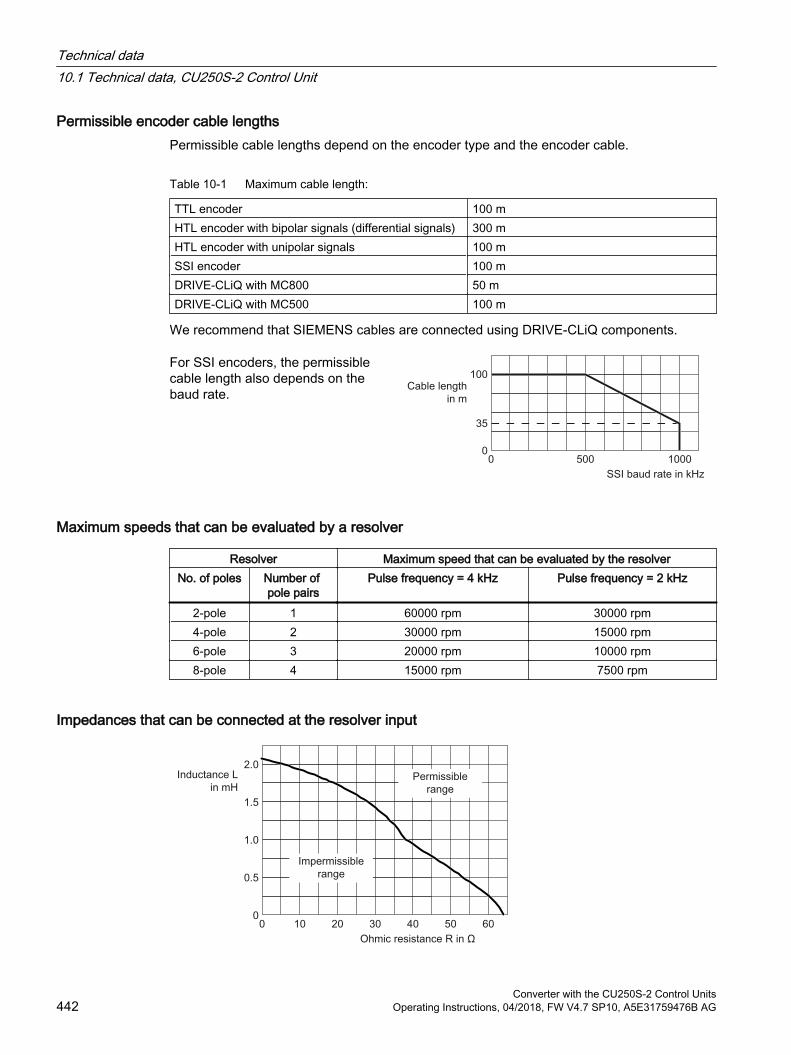
Permissible encoder cable lengthsPermissible cable lengths depend on the encoder type and the encoder cable.
Table 10-1 Maximum cable length:
TTL encoder 100 mHTL encoder with bipolar signals (differential signals) 300 m HTL encoder with unipolar signals 100 mSSI encoder 100 mDRIVE-CLiQ with MC800 50 mDRIVE-CLiQ with MC500 100 m
We recommend that SIEMENS cables are connected using DRIVE-CLiQ components.
For SSI encoders, the permissible cable length also depends on the baud rate.
Maximum speeds that can be evaluated by a resolver
Resolver Maximum speed that can be evaluated by the resolverNo. of poles Number of
pole pairsPulse frequency = 4 kHz Pulse frequency = 2 kHz
2-pole 1 60000 rpm 30000 rpm4-pole 2 30000 rpm 15000 rpm6-pole 3 20000 rpm 10000 rpm8-pole 4 15000 rpm 7500 rpm
Impedances that can be connected at the resolver input
Technical data10.1 Technical data, CU250S-2 Control Unit
Converter with the CU250S-2 Control Units442 Operating Instructions, 04/2018, FW V4.7 SP10, A5E31759476B AG

Figure 10-1 Connectable impedances with an excitation frequency of f = 8kHz
Technical data10.1 Technical data, CU250S-2 Control Unit
Converter with the CU250S-2 Control UnitsOperating Instructions, 04/2018, FW V4.7 SP10, A5E31759476B AG 443
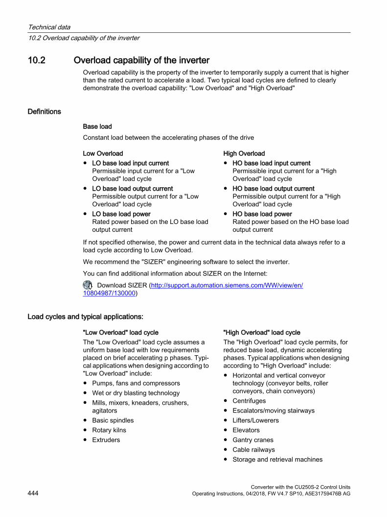
10.2 Overload capability of the inverterOverload capability is the property of the inverter to temporarily supply a current that is higher than the rated current to accelerate a load. Two typical load cycles are defined to clearly demonstrate the overload capability: "Low Overload" and "High Overload"
Definitions
Base loadConstant load between the accelerating phases of the drive
Low Overload High Overload LO base load input current
Permissible input current for a "Low Overload" load cycle
LO base load output currentPermissible output current for a "Low Overload" load cycle
LO base load powerRated power based on the LO base load output current
HO base load input currentPermissible input current for a "High Overload" load cycle
HO base load output currentPermissible output current for a "High Overload" load cycle
HO base load powerRated power based on the HO base load output current
If not specified otherwise, the power and current data in the technical data always refer to a load cycle according to Low Overload.
We recommend the "SIZER" engineering software to select the inverter.
You can find additional information about SIZER on the Internet:
Download SIZER (http://support.automation.siemens.com/WW/view/en/10804987/130000)
Load cycles and typical applications:
"Low Overload" load cycle "High Overload" load cycleThe "Low Overload" load cycle assumes a uniform base load with low requirements placed on brief accelerating p phases. Typi‐cal applications when designing according to "Low Overload" include: Pumps, fans and compressors Wet or dry blasting technology Mills, mixers, kneaders, crushers,
agitators Basic spindles Rotary kilns Extruders
The "High Overload" load cycle permits, for reduced base load, dynamic accelerating phases. Typical applications when designing according to "High Overload" include: Horizontal and vertical conveyor
technology (conveyor belts, roller conveyors, chain conveyors)
Centrifuges Escalators/moving stairways Lifters/Lowerers Elevators Gantry cranes Cable railways Storage and retrieval machines
Technical data10.2 Overload capability of the inverter
Converter with the CU250S-2 Control Units444 Operating Instructions, 04/2018, FW V4.7 SP10, A5E31759476B AG
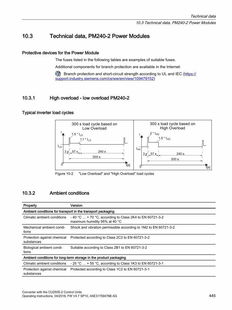
10.3 Technical data, PM240-2 Power Modules
Protective devices for the Power ModuleThe fuses listed in the following tables are examples of suitable fuses.
Additional components for branch protection are available in the Internet:
Branch protection and short-circuit strength according to UL and IEC (https://support.industry.siemens.com/cs/ww/en/view/109479152)
10.3.1 High overload - low overload PM240-2
Typical inverter load cycles
Figure 10-2 "Low Overload" and "High Overload" load cycles
10.3.2 Ambient conditions
Property VersionAmbient conditions for transport in the transport packagingClimatic ambient conditions ‑ 40 °C … + 70 °C, according to Class 2K4 to EN 60721‑3‑2
maximum humidity 95% at 40 °CMechanical ambient condi‐tions
Shock and vibration permissible according to 1M2 to EN 60721‑3‑2
Protection against chemical substances
Protected according to Class 2C2 to EN 60721‑3‑2
Biological ambient condi‐tions
Suitable according to Class 2B1 to EN 60721‑3‑2
Ambient conditions for long-term storage in the product packagingClimatic ambient conditions ‑ 25 °C … + 55 °C, according to Class 1K3 to EN 60721‑3‑1Protection against chemical substances
Protected according to Class 1C2 to EN 60721‑3‑1
Technical data10.3 Technical data, PM240-2 Power Modules
Converter with the CU250S-2 Control UnitsOperating Instructions, 04/2018, FW V4.7 SP10, A5E31759476B AG 445
Property VersionBiological ambient condi‐tions
Suitable according to class 1B1 to EN 60721‑3‑1
Ambient conditions in operationInstallation altitude Up to 1000 m above sea level without limitations
Restrictions for special ambient conditions (Page 478)Climatic ambient conditions 1)
FSA ... FSC ambient operating temperature 2)
– For operation according to Low Overload: -10 °C … +40 °C – For operation according to High Overload: -10 °C … +50 °C – Restrictions for special ambient conditions (Page 478)
FSD ... FSG ambient operating temperature 2) – For operation according to Low Overload: -20 °C … +40 °C– For operation according to High Overload: -20 °C … +50 °C– Restrictions for special ambient conditions (Page 478)
Relative humidity: 5 … 95%, condensation not permitted Oil mist, salt mist, ice formation, condensation, dripping water, spraying water, splashing
water and water jets are not permittedMechanical ambient condi‐tions
Vibration test during operation according to IEC 60068-2-6 Test Fc (sinusoidal) 0 ... 57 Hz: 0.075 mm deflection amplitude 57 ... 150 Hz: 1 g acceleration amplitude 10 frequency cycles per axisShock test according to IEC 60068-2-27 Test Ea (half-sine) 5 g peak acceleration 30 ms duration 3 shocks in all three axes in both directions
Protection against chemical substances
FSA … FSC: Protected according to 3C2 to EN 60721‑3‑3 FSD … FSG: 3C3 protection according to EN 60721‑3‑3
Biological ambient condi‐tions
Suitable according to 3B1 to EN 60721‑3‑3
Pollution Suitable for environments with degree of pollution 2 according to EN 61800-5-1Cooling Forced air cooling AF, according to EN 60146Cooling air Clean and dry airNoise emission Maximum 75 db(A)
1) Increased ruggedness regarding temperature range and relative humidity; therefore better than 3K3 according to EN 60721-3-3
2) Observe the permissible ambient operating temperatures for the Control Unit and the Operator Panel (IOP-2 or BOP‑2).
Technical data10.3 Technical data, PM240-2 Power Modules
Converter with the CU250S-2 Control Units446 Operating Instructions, 04/2018, FW V4.7 SP10, A5E31759476B AG
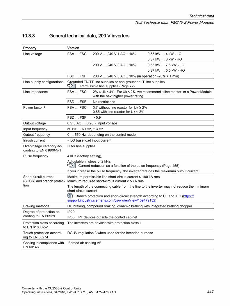
10.3.3 General technical data, 200 V inverters
Property VersionLine voltage FSA … FSC 200 V … 240 V 1 AC ± 10% 0.55 kW … 4 kW - LO
0.37 kW … 3 kW - HO200 V … 240 V 3 AC ± 10% 0.55 kW … 7.5 kW - LO
0.37 kW … 5.5 kW - HOFSD … FSF 200 V … 240 V 3 AC ± 10% (in operation -20% < 1 min)
Line supply configurations Grounded TN/TT line supplies or non-grounded IT line supplies Permissible line supplies (Page 72)
Line impedance FSA … FSC
2% ≤ Uk < 4%. For Uk < 2%, we recommend a line reactor, or a Power Module with the next higher power rating.
FSD … FSF No restrictionsPower factor λ FSA … FSC
0.7 without line reactor for Uk ≥ 2%0.85 with line reactor for Uk < 2%
FSD … FSF > 0.9Output voltage 0 V 3 AC … 0.95 × input voltageInput frequency 50 Hz … 60 Hz, ± 3 Hz Output frequency 0 … 550 Hz, depending on the control modeInrush current < LO base load input currentOvervoltage category ac‐cording to EN 61800-5-1
III for line supplies
Pulse frequency 4 kHz (factory setting), Adjustable in steps of 2 kHz.
Current reduction as a function of the pulse frequency (Page 455)If you increase the pulse frequency, the inverter reduces the maximum output current.
Short-circuit current (SCCR) and branch protec‐tion
Maximum permissible line short-circuit current ≤ 100 kA rmsMinimum required short-circuit current ≥ 5 kA rmsThe length of the connecting cable from the line to the inverter may not reduce the minimum short-circuit current
Branch protection and short-circuit strength according to UL and IEC (https://support.industry.siemens.com/cs/ww/en/view/109479152)
Braking methods DC braking, compound braking, dynamic braking with integrated braking chopperDegree of protection ac‐cording to EN 60529
IP20IP55 PT devices outside the control cabinet
Protection class according to EN 61800-5-1
The inverters are devices with protection class I
Touch protection accord‐ing to EN 50274
DGUV regulation 3 when used for the intended purpose
Cooling in compliance with EN 60146
Forced air cooling AF
Technical data10.3 Technical data, PM240-2 Power Modules
Converter with the CU250S-2 Control UnitsOperating Instructions, 04/2018, FW V4.7 SP10, A5E31759476B AG 447
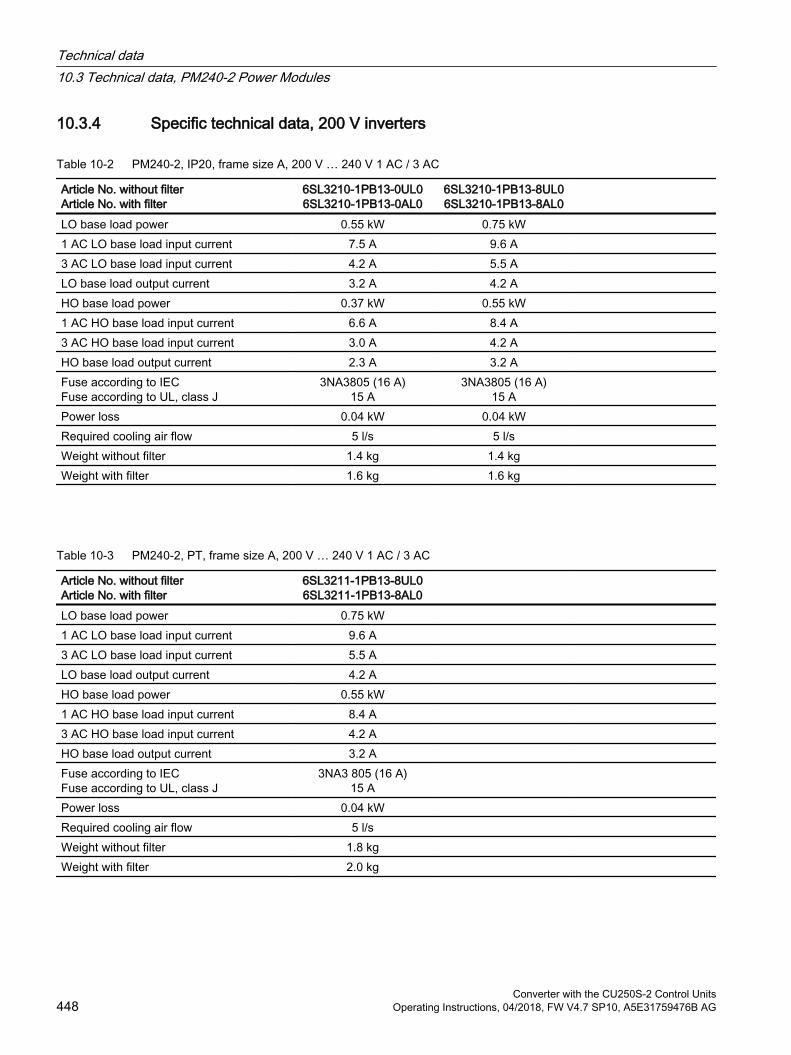
10.3.4 Specific technical data, 200 V inverters
Table 10-2 PM240-2, IP20, frame size A, 200 V … 240 V 1 AC / 3 AC
Article No. without filterArticle No. with filter
6SL3210-1PB13-0UL06SL3210-1PB13-0AL0
6SL3210-1PB13-8UL06SL3210-1PB13-8AL0
LO base load power 0.55 kW 0.75 kW 1 AC LO base load input current 7.5 A 9.6 A 3 AC LO base load input current 4.2 A 5.5 A LO base load output current 3.2 A 4.2 A HO base load power 0.37 kW 0.55 kW 1 AC HO base load input current 6.6 A 8.4 A 3 AC HO base load input current 3.0 A 4.2 A HO base load output current 2.3 A 3.2 A Fuse according to IECFuse according to UL, class J
3NA3805 (16 A)15 A
3NA3805 (16 A)15 A
Power loss 0.04 kW 0.04 kW Required cooling air flow 5 l/s 5 l/s Weight without filter 1.4 kg 1.4 kg Weight with filter 1.6 kg 1.6 kg
Table 10-3 PM240-2, PT, frame size A, 200 V … 240 V 1 AC / 3 AC
Article No. without filterArticle No. with filter
6SL3211-1PB13-8UL06SL3211-1PB13-8AL0
LO base load power 0.75 kW 1 AC LO base load input current 9.6 A 3 AC LO base load input current 5.5 A LO base load output current 4.2 A HO base load power 0.55 kW 1 AC HO base load input current 8.4 A 3 AC HO base load input current 4.2 A HO base load output current 3.2 A Fuse according to IECFuse according to UL, class J
3NA3 805 (16 A)15 A
Power loss 0.04 kW Required cooling air flow 5 l/s Weight without filter 1.8 kg Weight with filter 2.0 kg
Technical data10.3 Technical data, PM240-2 Power Modules
Converter with the CU250S-2 Control Units448 Operating Instructions, 04/2018, FW V4.7 SP10, A5E31759476B AG
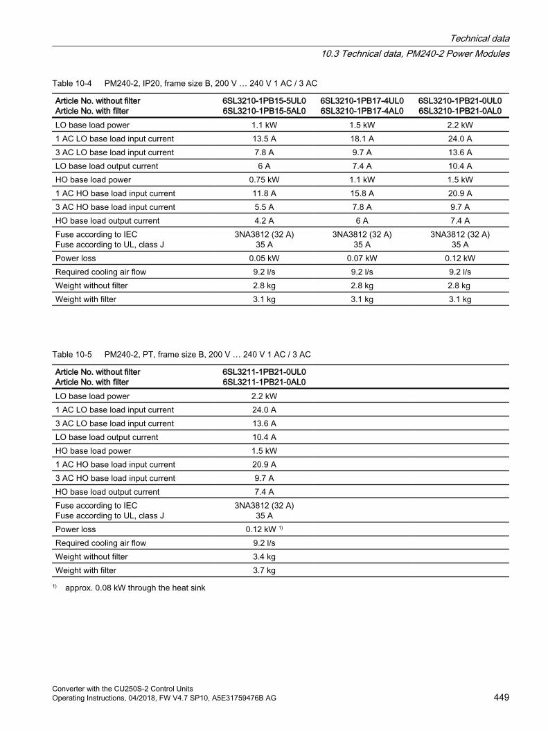
Table 10-4 PM240-2, IP20, frame size B, 200 V … 240 V 1 AC / 3 AC
Article No. without filterArticle No. with filter
6SL3210-1PB15-5UL06SL3210-1PB15-5AL0
6SL3210-1PB17-4UL06SL3210-1PB17-4AL0
6SL3210-1PB21-0UL06SL3210-1PB21-0AL0
LO base load power 1.1 kW 1.5 kW 2.2 kW1 AC LO base load input current 13.5 A 18.1 A 24.0 A3 AC LO base load input current 7.8 A 9.7 A 13.6 ALO base load output current 6 A 7.4 A 10.4 AHO base load power 0.75 kW 1.1 kW 1.5 kW1 AC HO base load input current 11.8 A 15.8 A 20.9 A3 AC HO base load input current 5.5 A 7.8 A 9.7 AHO base load output current 4.2 A 6 A 7.4 AFuse according to IECFuse according to UL, class J
3NA3812 (32 A)35 A
3NA3812 (32 A)35 A
3NA3812 (32 A)35 A
Power loss 0.05 kW 0.07 kW 0.12 kWRequired cooling air flow 9.2 l/s 9.2 l/s 9.2 l/sWeight without filter 2.8 kg 2.8 kg 2.8 kg Weight with filter 3.1 kg 3.1 kg 3.1 kg
Table 10-5 PM240-2, PT, frame size B, 200 V … 240 V 1 AC / 3 AC
Article No. without filterArticle No. with filter
6SL3211-1PB21-0UL06SL3211-1PB21-0AL0
LO base load power 2.2 kW 1 AC LO base load input current 24.0 A 3 AC LO base load input current 13.6 A LO base load output current 10.4 A HO base load power 1.5 kW 1 AC HO base load input current 20.9 A 3 AC HO base load input current 9.7 A HO base load output current 7.4 A Fuse according to IECFuse according to UL, class J
3NA3812 (32 A)35 A
Power loss 0.12 kW 1) Required cooling air flow 9.2 l/s Weight without filter 3.4 kg Weight with filter 3.7 kg
1) approx. 0.08 kW through the heat sink
Technical data10.3 Technical data, PM240-2 Power Modules
Converter with the CU250S-2 Control UnitsOperating Instructions, 04/2018, FW V4.7 SP10, A5E31759476B AG 449
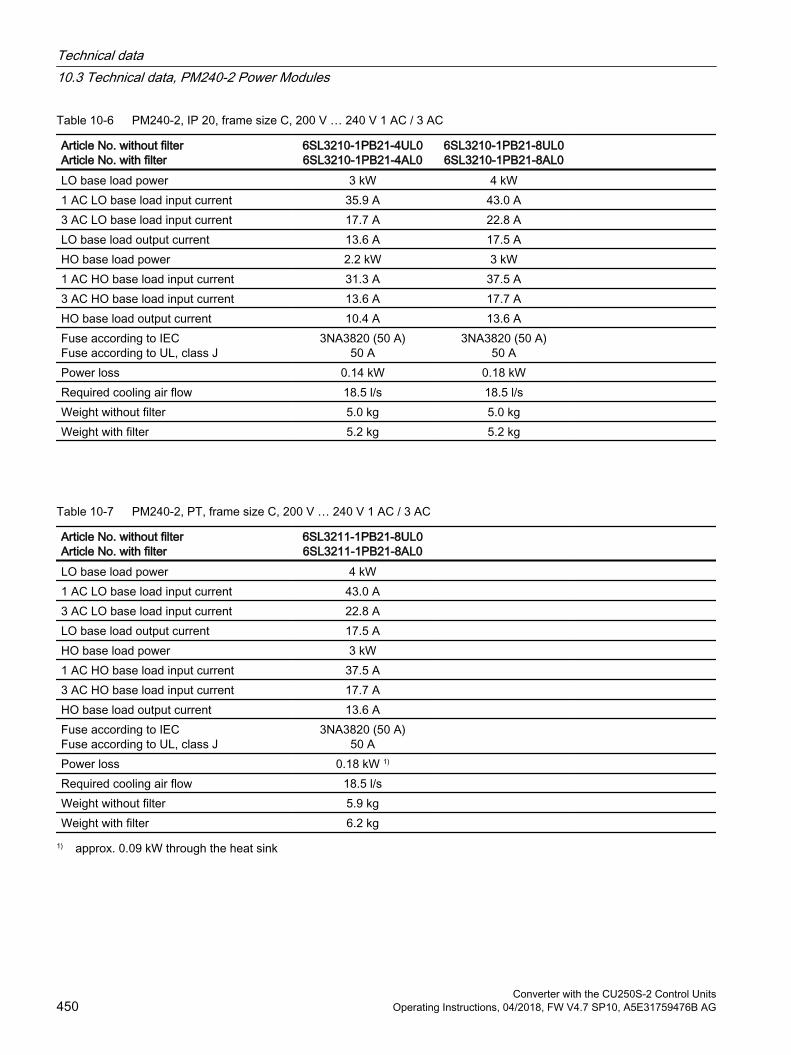
Table 10-6 PM240-2, IP 20, frame size C, 200 V … 240 V 1 AC / 3 AC
Article No. without filterArticle No. with filter
6SL3210-1PB21-4UL06SL3210-1PB21-4AL0
6SL3210-1PB21-8UL06SL3210-1PB21-8AL0
LO base load power 3 kW 4 kW 1 AC LO base load input current 35.9 A 43.0 A 3 AC LO base load input current 17.7 A 22.8 A LO base load output current 13.6 A 17.5 A HO base load power 2.2 kW 3 kW 1 AC HO base load input current 31.3 A 37.5 A 3 AC HO base load input current 13.6 A 17.7 A HO base load output current 10.4 A 13.6 A Fuse according to IECFuse according to UL, class J
3NA3820 (50 A)50 A
3NA3820 (50 A)50 A
Power loss 0.14 kW 0.18 kW Required cooling air flow 18.5 l/s 18.5 l/s Weight without filter 5.0 kg 5.0 kg Weight with filter 5.2 kg 5.2 kg
Table 10-7 PM240-2, PT, frame size C, 200 V … 240 V 1 AC / 3 AC
Article No. without filterArticle No. with filter
6SL3211-1PB21-8UL06SL3211-1PB21-8AL0
LO base load power 4 kW 1 AC LO base load input current 43.0 A 3 AC LO base load input current 22.8 A LO base load output current 17.5 A HO base load power 3 kW 1 AC HO base load input current 37.5 A 3 AC HO base load input current 17.7 A HO base load output current 13.6 A Fuse according to IECFuse according to UL, class J
3NA3820 (50 A)50 A
Power loss 0.18 kW 1) Required cooling air flow 18.5 l/s Weight without filter 5.9 kg Weight with filter 6.2 kg
1) approx. 0.09 kW through the heat sink
Technical data10.3 Technical data, PM240-2 Power Modules
Converter with the CU250S-2 Control Units450 Operating Instructions, 04/2018, FW V4.7 SP10, A5E31759476B AG
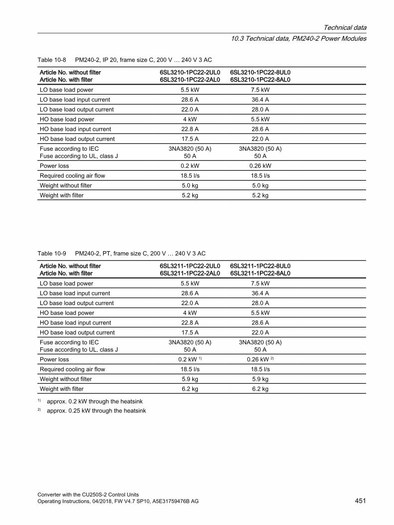
Table 10-8 PM240-2, IP 20, frame size C, 200 V … 240 V 3 AC
Article No. without filterArticle No. with filter
6SL3210-1PC22-2UL06SL3210-1PC22-2AL0
6SL3210-1PC22-8UL06SL3210-1PC22-8AL0
LO base load power 5.5 kW 7.5 kW LO base load input current 28.6 A 36.4 A LO base load output current 22.0 A 28.0 A HO base load power 4 kW 5.5 kW HO base load input current 22.8 A 28.6 A HO base load output current 17.5 A 22.0 A Fuse according to IECFuse according to UL, class J
3NA3820 (50 A)50 A
3NA3820 (50 A)50 A
Power loss 0.2 kW 0.26 kW Required cooling air flow 18.5 l/s 18.5 l/s Weight without filter 5.0 kg 5.0 kg Weight with filter 5.2 kg 5.2 kg
Table 10-9 PM240-2, PT, frame size C, 200 V … 240 V 3 AC
Article No. without filterArticle No. with filter
6SL3211-1PC22-2UL06SL3211-1PC22-2AL0
6SL3211-1PC22-8UL06SL3211-1PC22-8AL0
LO base load power 5.5 kW 7.5 kW LO base load input current 28.6 A 36.4 A LO base load output current 22.0 A 28.0 A HO base load power 4 kW 5.5 kW HO base load input current 22.8 A 28.6 A HO base load output current 17.5 A 22.0 A Fuse according to IECFuse according to UL, class J
3NA3820 (50 A)50 A
3NA3820 (50 A)50 A
Power loss 0.2 kW 1) 0.26 kW 2) Required cooling air flow 18.5 l/s 18.5 l/s Weight without filter 5.9 kg 5.9 kg Weight with filter 6.2 kg 6.2 kg
1) approx. 0.2 kW through the heatsink2) approx. 0.25 kW through the heatsink
Technical data10.3 Technical data, PM240-2 Power Modules
Converter with the CU250S-2 Control UnitsOperating Instructions, 04/2018, FW V4.7 SP10, A5E31759476B AG 451
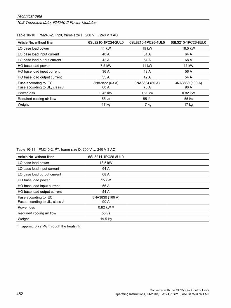
Table 10-10 PM240-2, IP20, frame size D, 200 V … 240 V 3 AC
Article No. without filter 6SL3210-1PC24-2UL0 6SL3210-1PC25-4UL0 6SL3210-1PC26-8UL0LO base load power 11 kW 15 kW 18.5 kWLO base load input current 40 A 51 A 64 ALO base load output current 42 A 54 A 68 AHO base load power 7.5 kW 11 kW 15 kWHO base load input current 36 A 43 A 56 AHO base load output current 35 A 42 A 54 AFuse according to IECFuse according to UL, class J
3NA3822 (63 A)60 A
3NA3824 (80 A)70 A
3NA3830 (100 A)90 A
Power loss 0.45 kW 0.61 kW 0.82 kWRequired cooling air flow 55 l/s 55 l/s 55 l/sWeight 17 kg 17 kg 17 kg
Table 10-11 PM240-2, PT, frame size D, 200 V … 240 V 3 AC
Article No. without filter 6SL3211-1PC26-8UL0 LO base load power 18.5 kW LO base load input current 64 A LO base load output current 68 A HO base load power 15 kW HO base load input current 56 A HO base load output current 54 A Fuse according to IECFuse according to UL, class J
3NA3830 (100 A)90 A
Power loss 0.82 kW 1) Required cooling air flow 55 l/s Weight 19.5 kg
1) approx. 0.72 kW through the heatsink
Technical data10.3 Technical data, PM240-2 Power Modules
Converter with the CU250S-2 Control Units452 Operating Instructions, 04/2018, FW V4.7 SP10, A5E31759476B AG
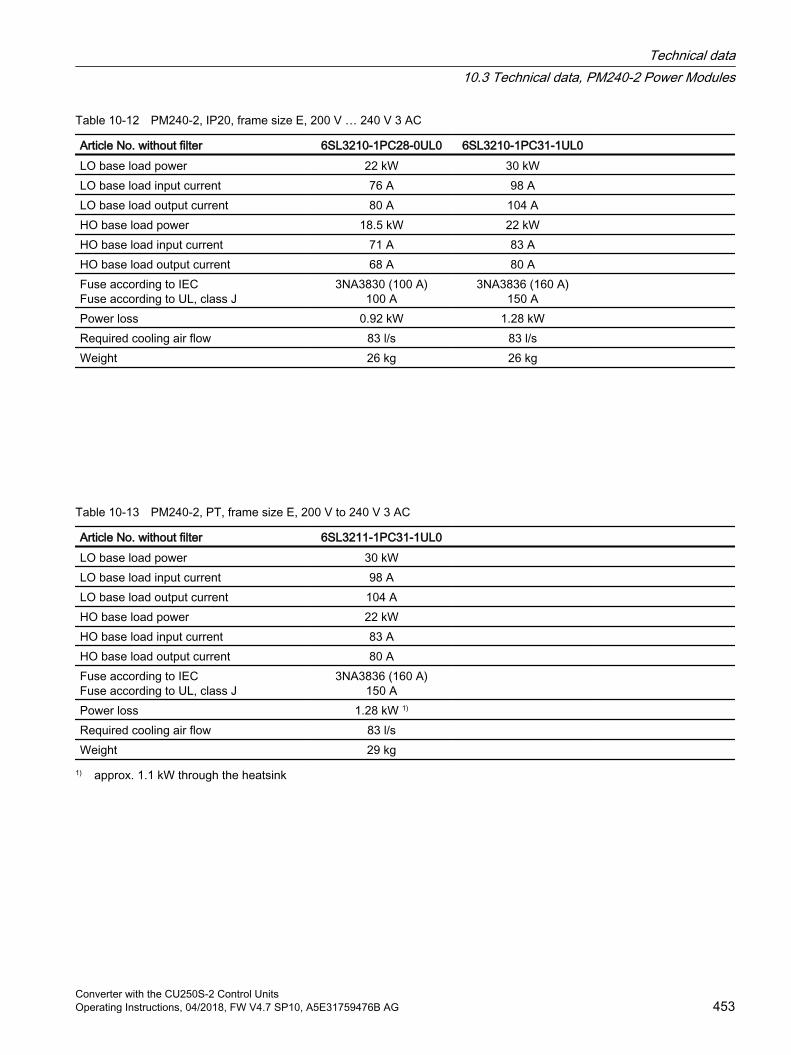
Table 10-12 PM240-2, IP20, frame size E, 200 V … 240 V 3 AC
Article No. without filter 6SL3210-1PC28-0UL0 6SL3210-1PC31-1UL0 LO base load power 22 kW 30 kW LO base load input current 76 A 98 A LO base load output current 80 A 104 A HO base load power 18.5 kW 22 kW HO base load input current 71 A 83 A HO base load output current 68 A 80 A Fuse according to IECFuse according to UL, class J
3NA3830 (100 A)100 A
3NA3836 (160 A)150 A
Power loss 0.92 kW 1.28 kW Required cooling air flow 83 l/s 83 l/s Weight 26 kg 26 kg
Table 10-13 PM240-2, PT, frame size E, 200 V to 240 V 3 AC
Article No. without filter 6SL3211-1PC31-1UL0 LO base load power 30 kW LO base load input current 98 A LO base load output current 104 A HO base load power 22 kW HO base load input current 83 A HO base load output current 80 A Fuse according to IECFuse according to UL, class J
3NA3836 (160 A)150 A
Power loss 1.28 kW 1) Required cooling air flow 83 l/s Weight 29 kg
1) approx. 1.1 kW through the heatsink
Technical data10.3 Technical data, PM240-2 Power Modules
Converter with the CU250S-2 Control UnitsOperating Instructions, 04/2018, FW V4.7 SP10, A5E31759476B AG 453
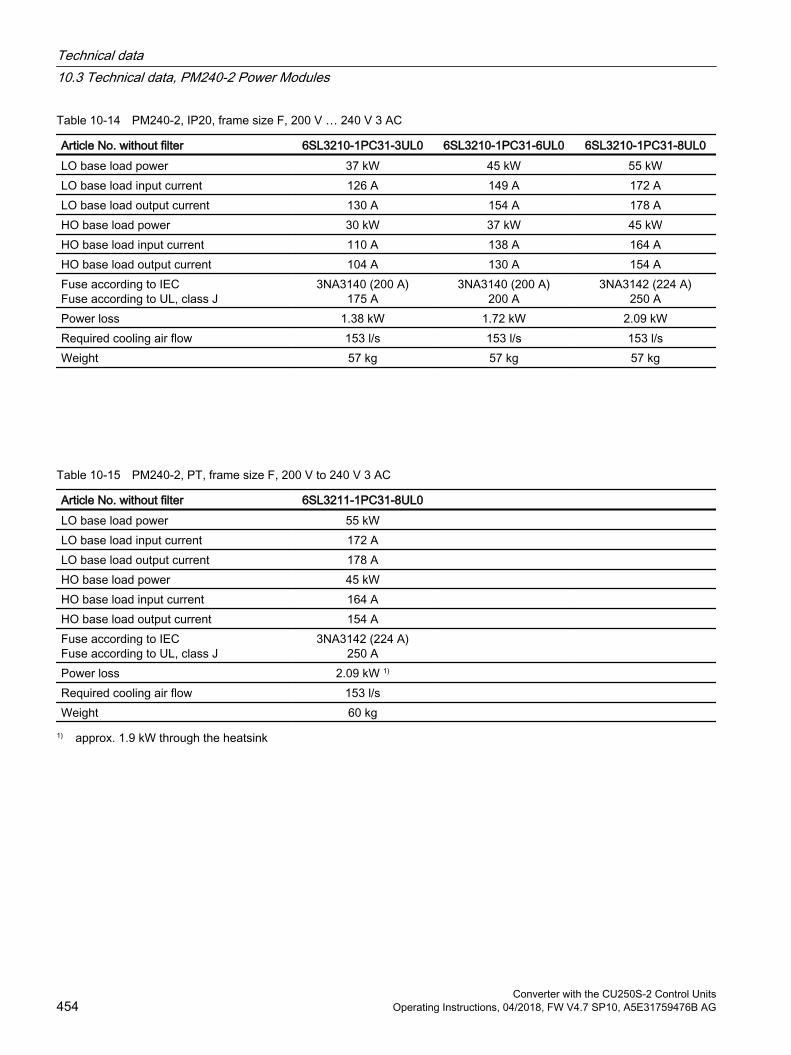
Table 10-14 PM240-2, IP20, frame size F, 200 V … 240 V 3 AC
Article No. without filter 6SL3210-1PC31-3UL0 6SL3210-1PC31-6UL0 6SL3210-1PC31-8UL0LO base load power 37 kW 45 kW 55 kWLO base load input current 126 A 149 A 172 ALO base load output current 130 A 154 A 178 AHO base load power 30 kW 37 kW 45 kWHO base load input current 110 A 138 A 164 AHO base load output current 104 A 130 A 154 AFuse according to IECFuse according to UL, class J
3NA3140 (200 A)175 A
3NA3140 (200 A)200 A
3NA3142 (224 A)250 A
Power loss 1.38 kW 1.72 kW 2.09 kWRequired cooling air flow 153 l/s 153 l/s 153 l/sWeight 57 kg 57 kg 57 kg
Table 10-15 PM240-2, PT, frame size F, 200 V to 240 V 3 AC
Article No. without filter 6SL3211-1PC31-8UL0 LO base load power 55 kW LO base load input current 172 A LO base load output current 178 A HO base load power 45 kW HO base load input current 164 A HO base load output current 154 A Fuse according to IECFuse according to UL, class J
3NA3142 (224 A)250 A
Power loss 2.09 kW 1) Required cooling air flow 153 l/s Weight 60 kg
1) approx. 1.9 kW through the heatsink
Technical data10.3 Technical data, PM240-2 Power Modules
Converter with the CU250S-2 Control Units454 Operating Instructions, 04/2018, FW V4.7 SP10, A5E31759476B AG
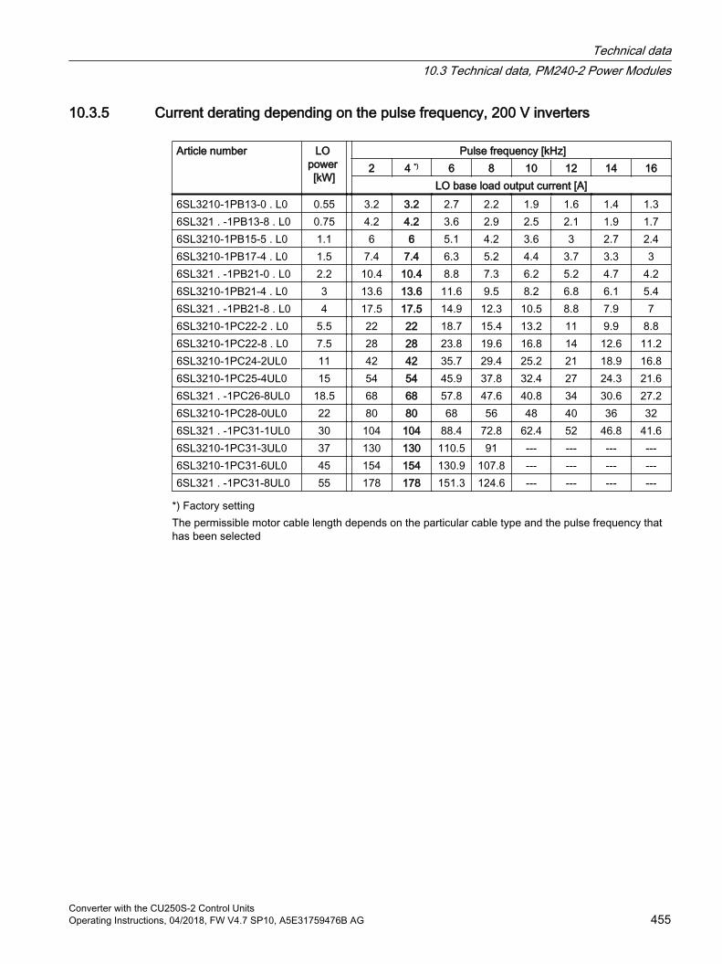
10.3.5 Current derating depending on the pulse frequency, 200 V inverters
Article number LO power [kW]
Pulse frequency [kHz]2 4 *) 6 8 10 12 14 16
LO base load output current [A]6SL3210-1PB13-0 . L0 0.55 3.2 3.2 2.7 2.2 1.9 1.6 1.4 1.36SL321 . -1PB13-8 . L0 0.75 4.2 4.2 3.6 2.9 2.5 2.1 1.9 1.76SL3210-1PB15-5 . L0 1.1 6 6 5.1 4.2 3.6 3 2.7 2.46SL3210-1PB17-4 . L0 1.5 7.4 7.4 6.3 5.2 4.4 3.7 3.3 36SL321 . -1PB21-0 . L0 2.2 10.4 10.4 8.8 7.3 6.2 5.2 4.7 4.26SL3210-1PB21-4 . L0 3 13.6 13.6 11.6 9.5 8.2 6.8 6.1 5.46SL321 . -1PB21-8 . L0 4 17.5 17.5 14.9 12.3 10.5 8.8 7.9 76SL3210-1PC22-2 . L0 5.5 22 22 18.7 15.4 13.2 11 9.9 8.86SL3210-1PC22-8 . L0 7.5 28 28 23.8 19.6 16.8 14 12.6 11.26SL3210-1PC24-2UL0 11 42 42 35.7 29.4 25.2 21 18.9 16.86SL3210-1PC25-4UL0 15 54 54 45.9 37.8 32.4 27 24.3 21.66SL321 . -1PC26-8UL0 18.5 68 68 57.8 47.6 40.8 34 30.6 27.26SL3210-1PC28-0UL0 22 80 80 68 56 48 40 36 326SL321 . -1PC31-1UL0 30 104 104 88.4 72.8 62.4 52 46.8 41.66SL3210-1PC31-3UL0 37 130 130 110.5 91 --- --- --- ---6SL3210-1PC31-6UL0 45 154 154 130.9 107.8 --- --- --- ---6SL321 . -1PC31-8UL0 55 178 178 151.3 124.6 --- --- --- ---
*) Factory settingThe permissible motor cable length depends on the particular cable type and the pulse frequency that has been selected
Technical data10.3 Technical data, PM240-2 Power Modules
Converter with the CU250S-2 Control UnitsOperating Instructions, 04/2018, FW V4.7 SP10, A5E31759476B AG 455
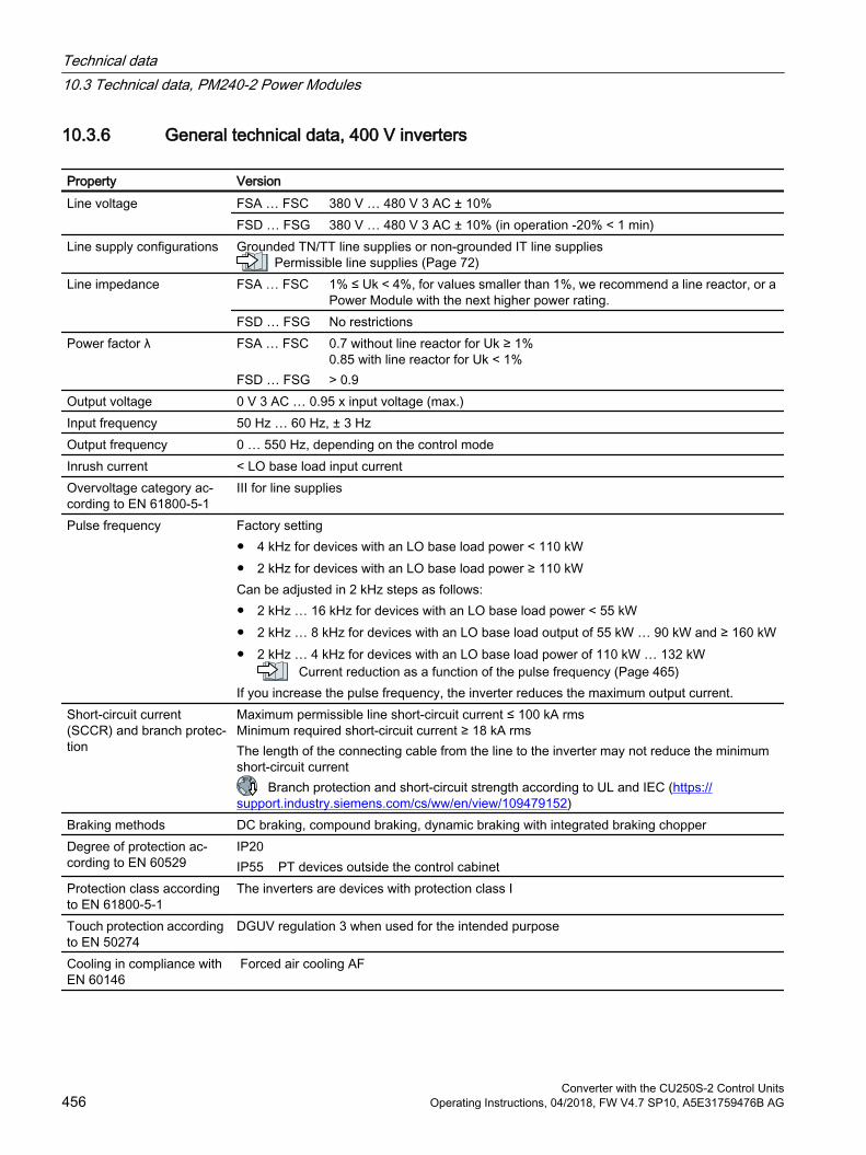
10.3.6 General technical data, 400 V inverters
Property VersionLine voltage FSA … FSC 380 V … 480 V 3 AC ± 10%
FSD … FSG 380 V … 480 V 3 AC ± 10% (in operation -20% < 1 min)Line supply configurations Grounded TN/TT line supplies or non-grounded IT line supplies
Permissible line supplies (Page 72)Line impedance FSA … FSC 1% ≤ Uk < 4%, for values smaller than 1%, we recommend a line reactor, or a
Power Module with the next higher power rating. FSD … FSG No restrictions
Power factor λ FSA … FSC FSD … FSG
0.7 without line reactor for Uk ≥ 1%0.85 with line reactor for Uk < 1%> 0.9
Output voltage 0 V 3 AC … 0.95 x input voltage (max.) Input frequency 50 Hz … 60 Hz, ± 3 Hz Output frequency 0 … 550 Hz, depending on the control mode Inrush current < LO base load input current Overvoltage category ac‐cording to EN 61800-5-1
III for line supplies
Pulse frequency Factory setting 4 kHz for devices with an LO base load power < 110 kW 2 kHz for devices with an LO base load power ≥ 110 kWCan be adjusted in 2 kHz steps as follows: 2 kHz … 16 kHz for devices with an LO base load power < 55 kW 2 kHz … 8 kHz for devices with an LO base load output of 55 kW … 90 kW and ≥ 160 kW 2 kHz … 4 kHz for devices with an LO base load power of 110 kW … 132 kW
Current reduction as a function of the pulse frequency (Page 465)If you increase the pulse frequency, the inverter reduces the maximum output current.
Short-circuit current (SCCR) and branch protec‐tion
Maximum permissible line short-circuit current ≤ 100 kA rmsMinimum required short-circuit current ≥ 18 kA rmsThe length of the connecting cable from the line to the inverter may not reduce the minimum short-circuit current
Branch protection and short-circuit strength according to UL and IEC (https://support.industry.siemens.com/cs/ww/en/view/109479152)
Braking methods DC braking, compound braking, dynamic braking with integrated braking chopperDegree of protection ac‐cording to EN 60529
IP20IP55 PT devices outside the control cabinet
Protection class according to EN 61800-5-1
The inverters are devices with protection class I
Touch protection according to EN 50274
DGUV regulation 3 when used for the intended purpose
Cooling in compliance with EN 60146
Forced air cooling AF
Technical data10.3 Technical data, PM240-2 Power Modules
Converter with the CU250S-2 Control Units456 Operating Instructions, 04/2018, FW V4.7 SP10, A5E31759476B AG
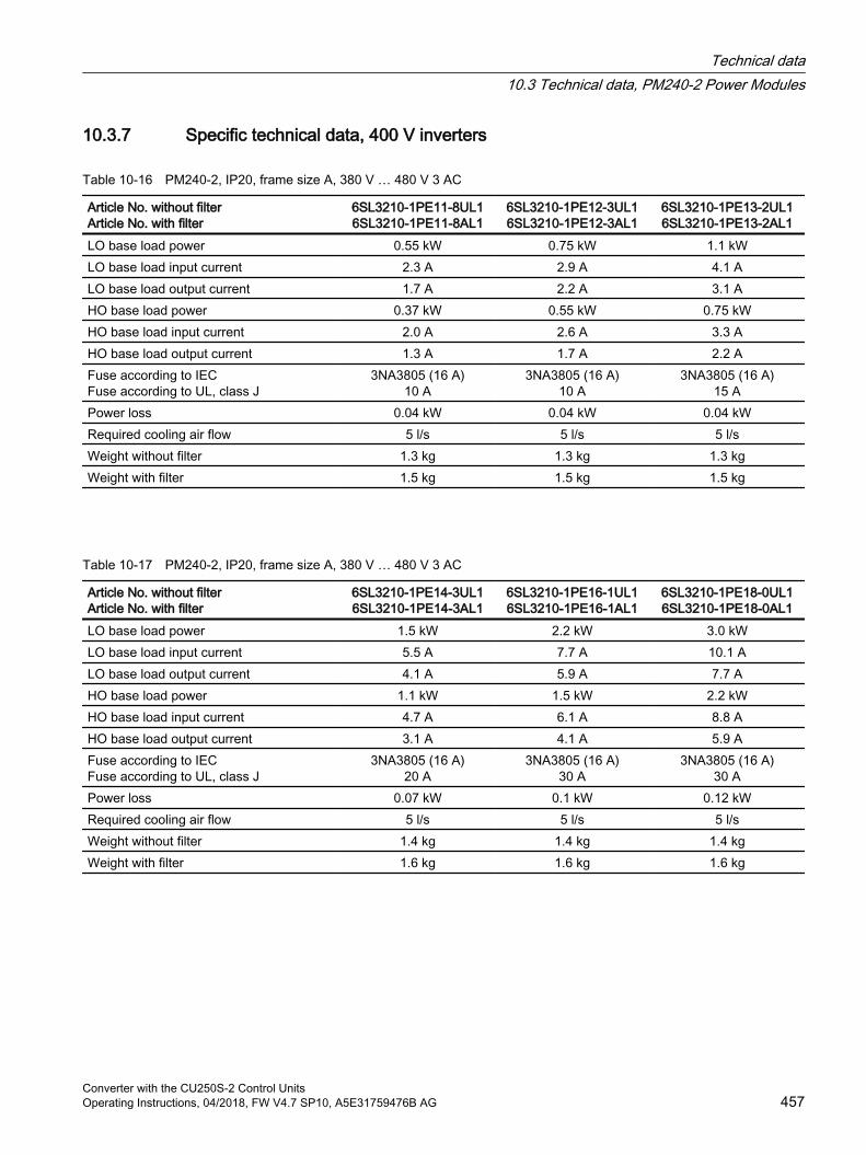
10.3.7 Specific technical data, 400 V inverters
Table 10-16 PM240-2, IP20, frame size A, 380 V … 480 V 3 AC
Article No. without filterArticle No. with filter
6SL3210-1PE11-8UL16SL3210-1PE11-8AL1
6SL3210-1PE12-3UL16SL3210-1PE12-3AL1
6SL3210-1PE13-2UL16SL3210-1PE13-2AL1
LO base load power 0.55 kW 0.75 kW 1.1 kWLO base load input current 2.3 A 2.9 A 4.1 ALO base load output current 1.7 A 2.2 A 3.1 AHO base load power 0.37 kW 0.55 kW 0.75 kWHO base load input current 2.0 A 2.6 A 3.3 AHO base load output current 1.3 A 1.7 A 2.2 AFuse according to IECFuse according to UL, class J
3NA3805 (16 A)10 A
3NA3805 (16 A)10 A
3NA3805 (16 A)15 A
Power loss 0.04 kW 0.04 kW 0.04 kWRequired cooling air flow 5 l/s 5 l/s 5 l/sWeight without filter 1.3 kg 1.3 kg 1.3 kgWeight with filter 1.5 kg 1.5 kg 1.5 kg
Table 10-17 PM240-2, IP20, frame size A, 380 V … 480 V 3 AC
Article No. without filterArticle No. with filter
6SL3210-1PE14-3UL16SL3210-1PE14-3AL1
6SL3210-1PE16-1UL16SL3210-1PE16-1AL1
6SL3210-1PE18-0UL16SL3210-1PE18-0AL1
LO base load power 1.5 kW 2.2 kW 3.0 kWLO base load input current 5.5 A 7.7 A 10.1 ALO base load output current 4.1 A 5.9 A 7.7 AHO base load power 1.1 kW 1.5 kW 2.2 kWHO base load input current 4.7 A 6.1 A 8.8 AHO base load output current 3.1 A 4.1 A 5.9 AFuse according to IECFuse according to UL, class J
3NA3805 (16 A)20 A
3NA3805 (16 A)30 A
3NA3805 (16 A)30 A
Power loss 0.07 kW 0.1 kW 0.12 kWRequired cooling air flow 5 l/s 5 l/s 5 l/sWeight without filter 1.4 kg 1.4 kg 1.4 kgWeight with filter 1.6 kg 1.6 kg 1.6 kg
Technical data10.3 Technical data, PM240-2 Power Modules
Converter with the CU250S-2 Control UnitsOperating Instructions, 04/2018, FW V4.7 SP10, A5E31759476B AG 457
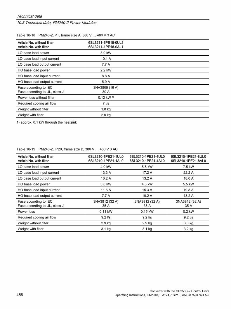
Table 10-18 PM240-2, PT, frame size A, 380 V … 480 V 3 AC
Article No. without filterArticle No. with filter
6SL3211-1PE18-0UL16SL3211-1PE18-0AL1
LO base load power 3.0 kW LO base load input current 10.1 A LO base load output current 7.7 A HO base load power 2.2 kW HO base load input current 8.8 A HO base load output current 5.9 A Fuse according to IECFuse according to UL, class J
3NA3805 (16 A)30 A
Power loss without filter 0.12 kW 1) Required cooling air flow 7 l/s Weight without filter 1.8 kg Weight with filter 2.0 kg
1) approx. 0.1 kW through the heatsink
Table 10-19 PM240-2, IP20, frame size B, 380 V … 480 V 3 AC
Article No. without filterArticle No. with filter
6SL3210-1PE21-1UL06SL3210-1PE21-1AL0
6SL3210-1PE21-4UL06SL3210-1PE21-4AL0
6SL3210-1PE21-8UL06SL3210-1PE21-8AL0
LO base load power 4.0 kW 5.5 kW 7.5 kWLO base load input current 13.3 A 17.2 A 22.2 ALO base load output current 10.2 A 13.2 A 18.0 AHO base load power 3.0 kW 4.0 kW 5.5 kWHO base load input current 11.6 A 15.3 A 19.8 AHO base load output current 7.7 A 10.2 A 13.2 AFuse according to IECFuse according to UL, class J
3NA3812 (32 A)35 A
3NA3812 (32 A)35 A
3NA3812 (32 A)35 A
Power loss 0.11 kW 0.15 kW 0.2 kWRequired cooling air flow 9.2 l/s 9.2 l/s 9.2 l/sWeight without filter 2.9 kg 2.9 kg 3.0 kgWeight with filter 3.1 kg 3.1 kg 3.2 kg
Technical data10.3 Technical data, PM240-2 Power Modules
Converter with the CU250S-2 Control Units458 Operating Instructions, 04/2018, FW V4.7 SP10, A5E31759476B AG
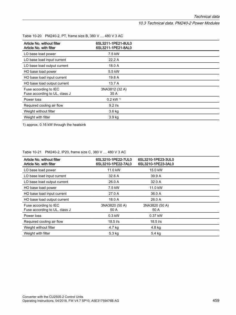
Table 10-20 PM240-2, PT, frame size B, 380 V … 480 V 3 AC
Article No. without filterArticle No. with filter
6SL3211-1PE21-8UL06SL3211-1PE21-8AL0
LO base load power 7.5 kW LO base load input current 22.2 A LO base load output current 18.0 A HO base load power 5.5 kW HO base load input current 19.8 A HO base load output current 13.7 A Fuse according to IECFuse according to UL, class J
3NA3812 (32 A)35 A
Power loss 0.2 kW 1) Required cooling air flow 9.2 l/s Weight without filter 3.6 kg Weight with filter 3.9 kg
1) approx. 0.16 kW through the heatsink
Table 10-21 PM240-2, IP20, frame size C, 380 V … 480 V 3 AC
Article No. without filterArticle No. with filter
6SL3210-1PE22-7UL06SL3210-1PE22-7AL0
6SL3210-1PE23-3UL06SL3210-1PE23-3AL0
LO base load power 11.0 kW 15.0 kW LO base load input current 32.6 A 39.9 A LO base load output current 26.0 A 32.0 A HO base load power 7.5 kW 11.0 kW HO base load input current 27.0 A 36.0 A HO base load output current 18.0 A 26.0 A Fuse according to IECFuse according to UL, class J
3NA3820 (50 A)50 A
3NA3820 (50 A)50 A
Power loss 0.3 kW 0.37 kW Required cooling air flow 18.5 l/s 18.5 l/s Weight without filter 4.7 kg 4.8 kg Weight with filter 5.3 kg 5.4 kg
Technical data10.3 Technical data, PM240-2 Power Modules
Converter with the CU250S-2 Control UnitsOperating Instructions, 04/2018, FW V4.7 SP10, A5E31759476B AG 459
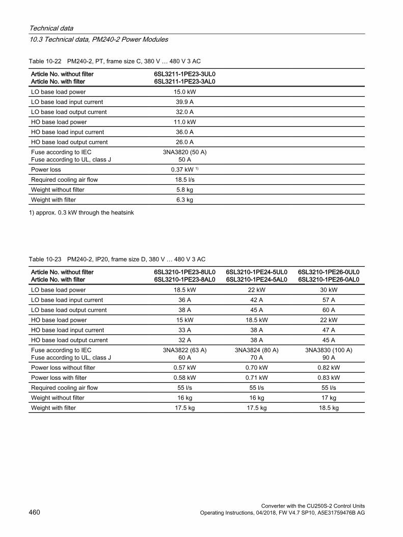
Table 10-22 PM240-2, PT, frame size C, 380 V … 480 V 3 AC
Article No. without filterArticle No. with filter
6SL3211-1PE23-3UL06SL3211-1PE23-3AL0
LO base load power 15.0 kW LO base load input current 39.9 A LO base load output current 32.0 A HO base load power 11.0 kW HO base load input current 36.0 A HO base load output current 26.0 A Fuse according to IECFuse according to UL, class J
3NA3820 (50 A)50 A
Power loss 0.37 kW 1) Required cooling air flow 18.5 l/s Weight without filter 5.8 kg Weight with filter 6.3 kg
1) approx. 0.3 kW through the heatsink
Table 10-23 PM240-2, IP20, frame size D, 380 V … 480 V 3 AC
Article No. without filterArticle No. with filter
6SL3210-1PE23-8UL06SL3210-1PE23-8AL0
6SL3210-1PE24-5UL06SL3210-1PE24-5AL0
6SL3210-1PE26-0UL06SL3210-1PE26-0AL0
LO base load power 18.5 kW 22 kW 30 kWLO base load input current 36 A 42 A 57 ALO base load output current 38 A 45 A 60 AHO base load power 15 kW 18.5 kW 22 kWHO base load input current 33 A 38 A 47 AHO base load output current 32 A 38 A 45 AFuse according to IECFuse according to UL, class J
3NA3822 (63 A)60 A
3NA3824 (80 A)70 A
3NA3830 (100 A)90 A
Power loss without filter 0.57 kW 0.70 kW 0.82 kWPower loss with filter 0.58 kW 0.71 kW 0.83 kWRequired cooling air flow 55 l/s 55 l/s 55 l/sWeight without filter 16 kg 16 kg 17 kgWeight with filter 17.5 kg 17.5 kg 18.5 kg
Technical data10.3 Technical data, PM240-2 Power Modules
Converter with the CU250S-2 Control Units460 Operating Instructions, 04/2018, FW V4.7 SP10, A5E31759476B AG
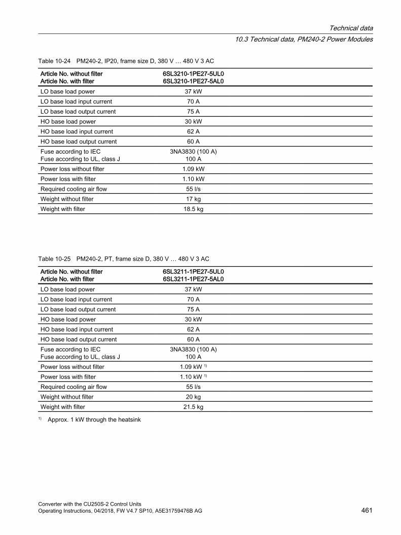
Table 10-24 PM240-2, IP20, frame size D, 380 V … 480 V 3 AC
Article No. without filterArticle No. with filter
6SL3210-1PE27-5UL06SL3210-1PE27-5AL0
LO base load power 37 kW LO base load input current 70 A LO base load output current 75 A HO base load power 30 kW HO base load input current 62 A HO base load output current 60 A Fuse according to IECFuse according to UL, class J
3NA3830 (100 A)100 A
Power loss without filter 1.09 kW Power loss with filter 1.10 kW Required cooling air flow 55 l/s Weight without filter 17 kg Weight with filter 18.5 kg
Table 10-25 PM240-2, PT, frame size D, 380 V … 480 V 3 AC
Article No. without filterArticle No. with filter
6SL3211-1PE27-5UL06SL3211-1PE27-5AL0
LO base load power 37 kW LO base load input current 70 A LO base load output current 75 A HO base load power 30 kW HO base load input current 62 A HO base load output current 60 A Fuse according to IECFuse according to UL, class J
3NA3830 (100 A)100 A
Power loss without filter 1.09 kW 1) Power loss with filter 1.10 kW 1) Required cooling air flow 55 l/s Weight without filter 20 kg Weight with filter 21.5 kg
1) Approx. 1 kW through the heatsink
Technical data10.3 Technical data, PM240-2 Power Modules
Converter with the CU250S-2 Control UnitsOperating Instructions, 04/2018, FW V4.7 SP10, A5E31759476B AG 461
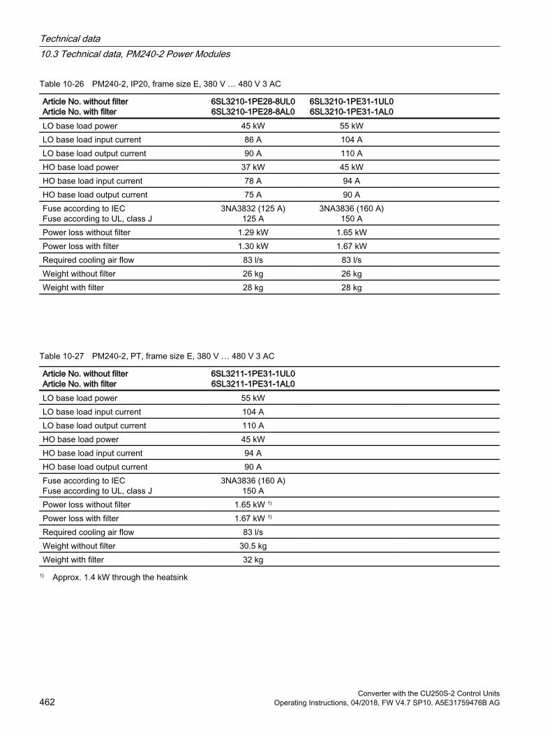
Table 10-26 PM240-2, IP20, frame size E, 380 V … 480 V 3 AC
Article No. without filterArticle No. with filter
6SL3210-1PE28-8UL06SL3210-1PE28-8AL0
6SL3210-1PE31-1UL06SL3210-1PE31-1AL0
LO base load power 45 kW 55 kW LO base load input current 86 A 104 A LO base load output current 90 A 110 A HO base load power 37 kW 45 kW HO base load input current 78 A 94 A HO base load output current 75 A 90 A Fuse according to IECFuse according to UL, class J
3NA3832 (125 A)125 A
3NA3836 (160 A)150 A
Power loss without filter 1.29 kW 1.65 kW Power loss with filter 1.30 kW 1.67 kW Required cooling air flow 83 l/s 83 l/s Weight without filter 26 kg 26 kg Weight with filter 28 kg 28 kg
Table 10-27 PM240-2, PT, frame size E, 380 V … 480 V 3 AC
Article No. without filterArticle No. with filter
6SL3211-1PE31-1UL06SL3211-1PE31-1AL0
LO base load power 55 kW LO base load input current 104 A LO base load output current 110 A HO base load power 45 kW HO base load input current 94 A HO base load output current 90 A Fuse according to IECFuse according to UL, class J
3NA3836 (160 A)150 A
Power loss without filter 1.65 kW 1) Power loss with filter 1.67 kW 1) Required cooling air flow 83 l/s Weight without filter 30.5 kg Weight with filter 32 kg
1) Approx. 1.4 kW through the heatsink
Technical data10.3 Technical data, PM240-2 Power Modules
Converter with the CU250S-2 Control Units462 Operating Instructions, 04/2018, FW V4.7 SP10, A5E31759476B AG
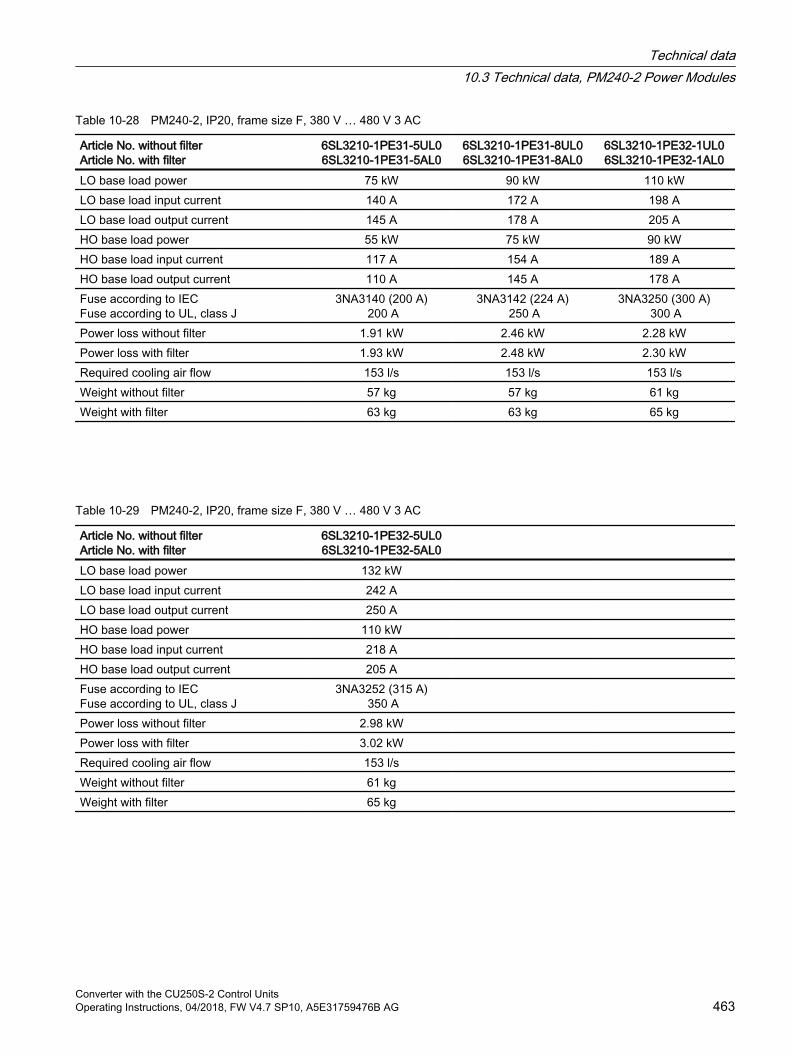
Table 10-28 PM240-2, IP20, frame size F, 380 V … 480 V 3 AC
Article No. without filterArticle No. with filter
6SL3210-1PE31-5UL06SL3210-1PE31-5AL0
6SL3210-1PE31-8UL06SL3210-1PE31-8AL0
6SL3210-1PE32-1UL06SL3210-1PE32-1AL0
LO base load power 75 kW 90 kW 110 kWLO base load input current 140 A 172 A 198 ALO base load output current 145 A 178 A 205 AHO base load power 55 kW 75 kW 90 kWHO base load input current 117 A 154 A 189 AHO base load output current 110 A 145 A 178 AFuse according to IECFuse according to UL, class J
3NA3140 (200 A) 200 A
3NA3142 (224 A) 250 A
3NA3250 (300 A) 300 A
Power loss without filter 1.91 kW 2.46 kW 2.28 kWPower loss with filter 1.93 kW 2.48 kW 2.30 kWRequired cooling air flow 153 l/s 153 l/s 153 l/sWeight without filter 57 kg 57 kg 61 kgWeight with filter 63 kg 63 kg 65 kg
Table 10-29 PM240-2, IP20, frame size F, 380 V … 480 V 3 AC
Article No. without filterArticle No. with filter
6SL3210-1PE32-5UL06SL3210-1PE32-5AL0
LO base load power 132 kW LO base load input current 242 A LO base load output current 250 A HO base load power 110 kW HO base load input current 218 A HO base load output current 205 A Fuse according to IECFuse according to UL, class J
3NA3252 (315 A) 350 A
Power loss without filter 2.98 kW Power loss with filter 3.02 kW Required cooling air flow 153 l/s Weight without filter 61 kg Weight with filter 65 kg
Technical data10.3 Technical data, PM240-2 Power Modules
Converter with the CU250S-2 Control UnitsOperating Instructions, 04/2018, FW V4.7 SP10, A5E31759476B AG 463
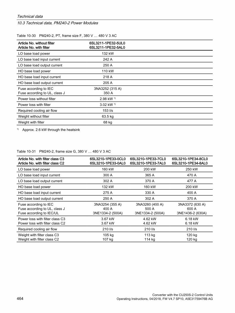
Table 10-30 PM240-2, PT, frame size F, 380 V … 480 V 3 AC
Article No. without filterArticle No. with filter
6SL3211-1PE32-5UL0 6SL3211-1PE32-5AL0
LO base load power 132 kW LO base load input current 242 A LO base load output current 250 A HO base load power 110 kW HO base load input current 218 A HO base load output current 205 A Fuse according to IECFuse according to UL, class J
3NA3252 (315 A) 350 A
Power loss without filter 2.98 kW 1) Power loss with filter 3.02 kW 1) Required cooling air flow 153 l/s Weight without filter 63.5 kg Weight with filter 68 kg
1) Approx. 2.6 kW through the heatsink
Table 10-31 PM240-2, frame size G, 380 V … 480 V 3 AC
Article No. with filter class C3Article No. with filter class C2
6SL3210-1PE33-0CL06SL3210-1PE33-0AL0
6SL3210-1PE33-7CL06SL3210-1PE33-7AL0
6SL3210-1PE34-8CL06SL3210-1PE34-8AL0
LO base load power 160 kW 200 kW 250 kWLO base load input current 300 A 365 A 470 ALO base load output current 302 A 370 A 477 AHO base load power 132 kW 160 kW 200 kWHO base load input current 275 A 330 A 400 AHO base load output current 250 A 302 A 370 AFuse according to IEC Fuse according to UL, class J Fuse according to IEC/UL
3NA3254 (355 A)400 A
3NE1334-2 (500A)
3NA3260 (400 A)500 A
3NE1334-2 (500A)
3NA3372 (630 A)600 A
3NE1436-2 (630A)Power loss with filter class C3Power loss with filter class C2
3.67 kW3.67 kW
4.62 kW4.62 kW
6.18 kW6.18 kW
Required cooling air flow 210 l/s 210 l/s 210 l/sWeight with filter class C3Weight with filter class C2
105 kg107 kg
113 kg114 kg
120 kg120 kg
Technical data10.3 Technical data, PM240-2 Power Modules
Converter with the CU250S-2 Control Units464 Operating Instructions, 04/2018, FW V4.7 SP10, A5E31759476B AG
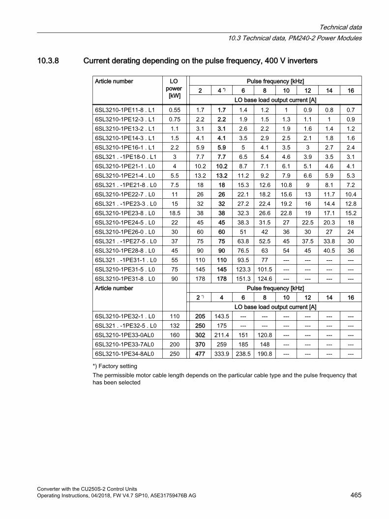
10.3.8 Current derating depending on the pulse frequency, 400 V inverters
Article number LO power [kW]
Pulse frequency [kHz]2 4 *) 6 8 10 12 14 16
LO base load output current [A]6SL3210-1PE11-8 . L1 0.55 1.7 1.7 1.4 1.2 1 0.9 0.8 0.76SL3210-1PE12-3 . L1 0.75 2.2 2.2 1.9 1.5 1.3 1.1 1 0.96SL3210-1PE13-2 . L1 1.1 3.1 3.1 2.6 2.2 1.9 1.6 1.4 1.26SL3210-1PE14-3 . L1 1.5 4.1 4.1 3.5 2.9 2.5 2.1 1.8 1.66SL3210-1PE16-1 . L1 2.2 5.9 5.9 5 4.1 3.5 3 2.7 2.46SL321 . -1PE18-0 . L1 3 7.7 7.7 6.5 5.4 4.6 3.9 3.5 3.16SL3210-1PE21-1 . L0 4 10.2 10.2 8.7 7.1 6.1 5.1 4.6 4.16SL3210-1PE21-4 . L0 5.5 13.2 13.2 11.2 9.2 7.9 6.6 5.9 5.36SL321 . -1PE21-8 . L0 7.5 18 18 15.3 12.6 10.8 9 8.1 7.26SL3210-1PE22-7 . L0 11 26 26 22.1 18.2 15.6 13 11.7 10.46SL321 . -1PE23-3 . L0 15 32 32 27.2 22.4 19.2 16 14.4 12.86SL3210-1PE23-8 . L0 18.5 38 38 32.3 26.6 22.8 19 17.1 15.26SL3210-1PE24-5 . L0 22 45 45 38.3 31.5 27 22.5 20.3 186SL3210-1PE26-0 . L0 30 60 60 51 42 36 30 27 246SL321 . -1PE27-5 . L0 37 75 75 63.8 52.5 45 37.5 33.8 306SL3210-1PE28-8 . L0 45 90 90 76.5 63 54 45 40.5 366SL321 . -1PE31-1 . L0 55 110 110 93.5 77 --- --- --- ---6SL3210-1PE31-5 . L0 75 145 145 123.3 101.5 --- --- --- ---6SL3210-1PE31-8 . L0 90 178 178 151.3 124.6 --- --- --- ---Article number Pulse frequency [kHz]
2 *) 4 6 8 10 12 14 16 LO base load output current [A]
6SL3210-1PE32-1 . L0 110 205 143.5 --- --- --- --- --- ---6SL321 . -1PE32-5 . L0 132 250 175 --- --- --- --- --- ---6SL3210-1PE33-0AL0 160 302 211.4 151 120.8 --- --- --- ---6SL3210-1PE33-7AL0 200 370 259 185 148 --- --- --- ---6SL3210-1PE34-8AL0 250 477 333.9 238.5 190.8 --- --- --- ---
*) Factory settingThe permissible motor cable length depends on the particular cable type and the pulse frequency that has been selected
Technical data10.3 Technical data, PM240-2 Power Modules
Converter with the CU250S-2 Control UnitsOperating Instructions, 04/2018, FW V4.7 SP10, A5E31759476B AG 465
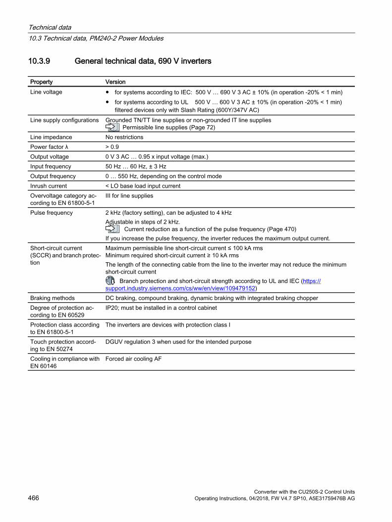
10.3.9 General technical data, 690 V inverters
Property VersionLine voltage for systems according to IEC: 500 V … 690 V 3 AC ± 10% (in operation -20% < 1 min)
for systems according to UL 500 V … 600 V 3 AC ± 10% (in operation -20% < 1 min) filtered devices only with Slash Rating (600Y/347V AC)
Line supply configurations Grounded TN/TT line supplies or non-grounded IT line suppliesPermissible line supplies (Page 72)
Line impedance No restrictionsPower factor λ > 0.9 Output voltage 0 V 3 AC … 0.95 x input voltage (max.)Input frequency 50 Hz … 60 Hz, ± 3 Hz Output frequency 0 … 550 Hz, depending on the control modeInrush current < LO base load input currentOvervoltage category ac‐cording to EN 61800-5-1
III for line supplies
Pulse frequency 2 kHz (factory setting), can be adjusted to 4 kHzAdjustable in steps of 2 kHz.
Current reduction as a function of the pulse frequency (Page 470)If you increase the pulse frequency, the inverter reduces the maximum output current.
Short-circuit current (SCCR) and branch protec‐tion
Maximum permissible line short-circuit current ≤ 100 kA rmsMinimum required short-circuit current ≥ 10 kA rmsThe length of the connecting cable from the line to the inverter may not reduce the minimum short-circuit current
Branch protection and short-circuit strength according to UL and IEC (https://support.industry.siemens.com/cs/ww/en/view/109479152)
Braking methods DC braking, compound braking, dynamic braking with integrated braking chopperDegree of protection ac‐cording to EN 60529
IP20; must be installed in a control cabinet
Protection class according to EN 61800-5-1
The inverters are devices with protection class I
Touch protection accord‐ing to EN 50274
DGUV regulation 3 when used for the intended purpose
Cooling in compliance with EN 60146
Forced air cooling AF
Technical data10.3 Technical data, PM240-2 Power Modules
Converter with the CU250S-2 Control Units466 Operating Instructions, 04/2018, FW V4.7 SP10, A5E31759476B AG
10.3.10 Specific technical data, 690 V inverters
Table 10-32 PM240-2, IP20, frame size D, 500 V … 690 V 3 AC
Article No. - without filterArticle No. - with filter
6SL3210-1PH21-4UL0 6SL3210-1PH21-4AL0
6SL3210-1PH22-0UL0 6SL3210-1PH22 -0AL0
6SL3210-1PH22-3UL0 6SL3210-1PH22 -3AL0
LO base load power 11 kW 15 kW 18.5 kWLO base load input current 14 A 18 A 22 ALO base load output current 14 A 19 A 23 AHO base load power 7.5 kW 11 kW 15 kWHO base load input current 11 A 14 A 20 A HO base load output current 11 A 14 A 19 AFuse according to IECFuse according to UL, class J
3NA3807-6 (20 A) 20 A
3NA3810-6 (25 A) 25 A
3NA3812-6 (32 A) 30 A
Power loss without filter 0.35 kW 0.44 kW 0.52 kWPower loss with filter 0.35 kW 0.45 kW 0.52 kWRequired cooling air flow 55 l/s 55 l/s 55 l/sWeight without filter 17 kg 17 kg 17 kgWeight with filter 18.5 kg 18.5 kg 18.5 kg
Table 10-33 PM240-2, IP20, frame size D, 500 V … 690 V 3 AC
Article No. - without filterArticle No. - with filter
6SL3210-1PH22-7UL0 6SL3210-1PH22-7AL0
6SL3210-1PH23-5UL0 6SL3210-1PH23 -5AL0
6SL3210-1PH24-2UL0 6SL3210-1PH24-2AL0
LO base load power 22 kW 30 kW 37 kWLO base load input current 25 A 33 A 40 ALO base load output current 27 A 35 A 42 AHO base load power 18.5 kW 22 kW 30 kWHO base load input current 24 A 28 A 36 A HO base load output current 23 A 27 A 35 ASiemens fuse according to IECFuse according to UL, class J
3NA3817-6KJ (40 A)35 A
3NA3820-6KJ (50 A)45 A
33NA3822-6 (63 A)60 A
Power loss without filter 0.60 kW 0.77 kW 0.93 kWPower loss with filter 0.60 kW 0.78 kW 0.94 kWRequired cooling air flow 55 l/s 55 l/s 55 l/sWeight without filter 17 kg 17 kg 17 kgWeight with filter 18.5 kg 18.5 kg 18.5 kg
Technical data10.3 Technical data, PM240-2 Power Modules
Converter with the CU250S-2 Control UnitsOperating Instructions, 04/2018, FW V4.7 SP10, A5E31759476B AG 467
Table 10-34 PM240-2, IP20, frame size E, 500 V … 690 V 3 AC
Article No. - without filterArticle No. - with filter
6SL3210-1PH25-2UL0 6SL3210-1PH25-2AL0
6SL3210-1PH26-2UL0 6SL3210-1PH26-2AL0
LO base load power 45 kW 55 kW LO base load input current 50 A 59 A LO base load output current 52 A 62 A HO base load power 37 kW 45 kW HO base load input current 44 A 54 A HO base load output current 42 A 52 A Siemens fuse according to IECFuse according to UL, class J
3NA3824-6 (80A)80 A
3NA3824-6 (80A)80 A
Power loss without filter 1.07 kW 1.30 kW Power loss with filter 1.08 kW 1.31 kW Required cooling air flow 83 l/s 83 l/s Weight without filter 26 kg 26 kg Weight with filter 28 kg 28 kg
Table 10-35 PM240-2, IP20, frame size F, 500 V … 690 V 3 AC
Article No. - without filterArticle No. - with filter
6SL3210-1PH28-0UL0 6SL3210-1PH28-0AL0
6SL3210-1PH31-0UL0 6SL3210-1PH31-0AL0
6SL3210-1PH31-2UL0 6SL3210-1PH31-2AL0
LO base load power 75 kW 90 kW 110 kWLO base load input current 78 A 97 A 111 ALO base load output current 80 A 100 A 115 AHO base load power 55 kW 75 kW 90 kWHO base load input current 66 A 85 A 106 A HO base load output current 62 A 80 A 100 ASiemens fuse according to IECFuse according to UL, class J
3NA3830-6 (100 A) 100 A
3NA3132-6 (125 A) 125 A
3NA3136-6 (160 A) 150 A
Power loss without filter 1.37 kW 1.74 kW 1.95 kWPower loss with filter 1.38 kW 1.76 kW 1.97 kWRequired cooling air flow 153 l/s 153 l/s 153 l/sWeight without filter 60 kg 60 kg 60 kgWeight with filter 64 kg 64 kg 64 kg
Technical data10.3 Technical data, PM240-2 Power Modules
Converter with the CU250S-2 Control Units468 Operating Instructions, 04/2018, FW V4.7 SP10, A5E31759476B AG
Table 10-36 PM240-2, IP20, frame size F, 500 V … 690 V 3 AC
Article No. - without filterArticle No. - with filter
6SL3210-1PH31-4UL06SL3210-1PH31-4AL0
LO base load power 132 kW LO base load input current 137 A LO base load output current 142 A HO base load power 110 kW HO base load input current 122 A HO base load output current 115 A Siemens fuse according to IECFuse according to UL, class J
3NA3140-6 (200 A) 200 A
Power loss without filter 2.48 kW Power loss with filter 2.51 kW Required cooling air flow 153 l/s Weight without filter 60 kg Weight with filter 64 kg
Table 10-37 PM240-2, frame size G, 500 V … 690 V 3 AC
Article No. with filter 6SL3210-1PH31-7CL0 6SL3210-1PH32-1CL0 6SL3210-1PH32-5CL0LO base load power 160 kW 200 kW 250 kWLO base load input current 170 A 205 A 250 ALO base load output current 171 A 208 A 250 AHO base load power 132 kW 160 kW 200 kWHO base load input current 160 A 185 A 225 AHO base load output current 144 A 171 A 208 AFuse according to the IEC/UL 3NE1227-0 (250A) 3NE1230-0 (315A) 3NE1331-0 (350A)Power loss 2.94 kW 3.70 kW 4.64 kWRequired cooling air flow 210 l/s 210 l/s 210 l/sWeight 114 kg 114 kg 114 kg
Technical data10.3 Technical data, PM240-2 Power Modules
Converter with the CU250S-2 Control UnitsOperating Instructions, 04/2018, FW V4.7 SP10, A5E31759476B AG 469
10.3.11 Current derating depending on the pulse frequency, 690 V inverters
Article number LO power [kW] Pulse frequency [kHz]2 *) 4
LO base load output current [A]6SL3210-1PH21-4 . L0 11 14 8.46SL3210-1PH22-0 . L0 15 19 11.46SL3210-1PH22-3 . L0 18.5 23 13.86SL3210-1PH22-7 . L0 22 27 16.26SL3210-1PH23-5 . L0 30 35 216SL321 . -1PH24-2 . L0 37 42 25.26SL3210-1PH25-2 . L0 45 52 31.26SL321 . -1PH26-2 . L0 55 62 37.26SL3210-1PH28-0 . L0 75 80 486SL3210-1PH31-0 . L0 90 100 606SL3210-1PH31-2 . L0 110 115 696SL3210-1PH31-4 . L0 132 142 85.26SL3210-1PH31-7CL0 160 171 102.66SL3210-1PH32-1CL0 200 208 124.86SL3210-1PH32-5CL0 250 250 150
*) Factory settingThe permissible motor cable length depends on the particular cable type and the pulse frequency that has been selected
Technical data10.3 Technical data, PM240-2 Power Modules
Converter with the CU250S-2 Control Units470 Operating Instructions, 04/2018, FW V4.7 SP10, A5E31759476B AG
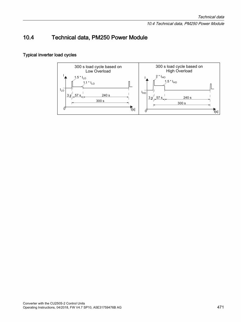
10.4 Technical data, PM250 Power Module
Typical inverter load cycles
Technical data10.4 Technical data, PM250 Power Module
Converter with the CU250S-2 Control UnitsOperating Instructions, 04/2018, FW V4.7 SP10, A5E31759476B AG 471
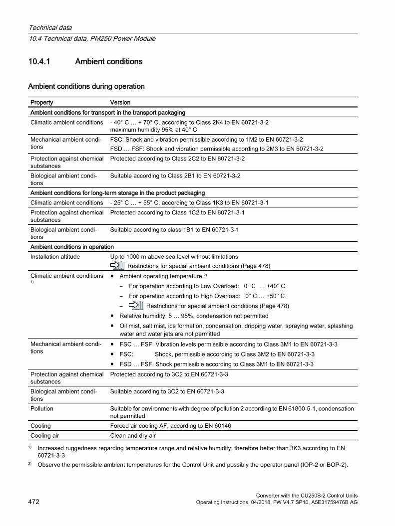
10.4.1 Ambient conditions
Ambient conditions during operation
Property VersionAmbient conditions for transport in the transport packagingClimatic ambient conditions ‑ 40° C … + 70° C, according to Class 2K4 to EN 60721‑3‑2
maximum humidity 95% at 40° CMechanical ambient condi‐tions
FSC: Shock and vibration permissible according to 1M2 to EN 60721‑3‑2FSD … FSF: Shock and vibration permissible according to 2M3 to EN 60721‑3‑2
Protection against chemical substances
Protected according to Class 2C2 to EN 60721‑3‑2
Biological ambient condi‐tions
Suitable according to Class 2B1 to EN 60721‑3‑2
Ambient conditions for long-term storage in the product packagingClimatic ambient conditions ‑ 25° C … + 55° C, according to Class 1K3 to EN 60721‑3‑1Protection against chemical substances
Protected according to Class 1C2 to EN 60721‑3‑1
Biological ambient condi‐tions
Suitable according to class 1B1 to EN 60721‑3‑1
Ambient conditions in operationInstallation altitude Up to 1000 m above sea level without limitations
Restrictions for special ambient conditions (Page 478)Climatic ambient conditions 1)
Ambient operating temperature 2)
– For operation according to Low Overload: 0° C … +40° C – For operation according to High Overload: 0° C … +50° C – Restrictions for special ambient conditions (Page 478)
Relative humidity: 5 … 95%, condensation not permitted Oil mist, salt mist, ice formation, condensation, dripping water, spraying water, splashing
water and water jets are not permittedMechanical ambient condi‐tions
FSC … FSF: Vibration levels permissible according to Class 3M1 to EN 60721-3-3 FSC: Shock, permissible according to Class 3M2 to EN 60721-3-3 FSD … FSF: Shock permissible according to Class 3M1 to EN 60721-3-3
Protection against chemical substances
Protected according to 3C2 to EN 60721‑3‑3
Biological ambient condi‐tions
Suitable according to 3C2 to EN 60721‑3‑3
Pollution Suitable for environments with degree of pollution 2 according to EN 61800-5-1, condensation not permitted
Cooling Forced air cooling AF, according to EN 60146Cooling air Clean and dry air
1) Increased ruggedness regarding temperature range and relative humidity; therefore better than 3K3 according to EN 60721-3-3
2) Observe the permissible ambient temperatures for the Control Unit and possibly the operator panel (IOP-2 or BOP‑2).
Technical data10.4 Technical data, PM250 Power Module
Converter with the CU250S-2 Control Units472 Operating Instructions, 04/2018, FW V4.7 SP10, A5E31759476B AG
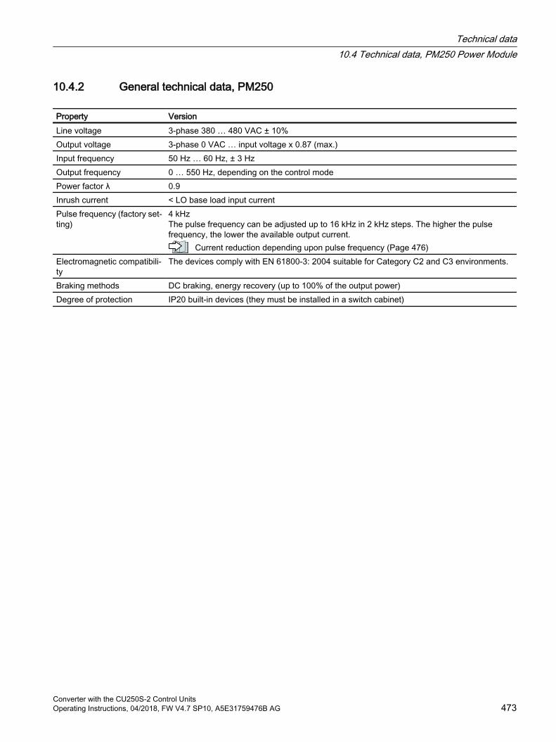
10.4.2 General technical data, PM250
Property VersionLine voltage 3-phase 380 … 480 VAC ± 10%Output voltage 3-phase 0 VAC … input voltage x 0.87 (max.)Input frequency 50 Hz … 60 Hz, ± 3 HzOutput frequency 0 … 550 Hz, depending on the control modePower factor λ 0.9Inrush current < LO base load input current Pulse frequency (factory set‐ting)
4 kHz The pulse frequency can be adjusted up to 16 kHz in 2 kHz steps. The higher the pulse frequency, the lower the available output current.
Current reduction depending upon pulse frequency (Page 476)Electromagnetic compatibili‐ty
The devices comply with EN 61800-3: 2004 suitable for Category C2 and C3 environments.
Braking methods DC braking, energy recovery (up to 100% of the output power)Degree of protection IP20 built-in devices (they must be installed in a switch cabinet)
Technical data10.4 Technical data, PM250 Power Module
Converter with the CU250S-2 Control UnitsOperating Instructions, 04/2018, FW V4.7 SP10, A5E31759476B AG 473

10.4.3 Specific technical data, PM250
Note
The values for Low Overload (LO) are identical with those of the rated values.
Table 10-38 PM250, IP20, Frame Size C, 3-ph. AC 380 V … 480 V
Article no. 6SL3225-0BE25-5AA1 6SL3225-0BE27-5AA1 6SL3225-0BE31-1AA1LO base load output 7.5 kW 11 kW 15 kWLO base load input current 18 A 25 A 32 ALO base load output current 18 A 25 A 32 AHO base load output 5.5 kW 7.5 kW 11 kWHO base load input current 13.2 A 19 A 26 AHO base load output current 13.2 A 19 A 26 AFuse 20 A, Class J 32 A, Class J 35 A, Class JPower loss 0.24 kW 0.30 kW 0.31 kWRequired cooling air flow 38 l/s 38 l/s 38 l/sWeight 7.5 kg 7.5 kg 7.5 kg
Table 10-39 PM250, IP20, Frame Size D, 3-ph. AC 380 V … 480 V
Article no. 6SL3225-0BE31-5AA0 6SL3225-0BE31-8AA0 6SL3225-0BE32-2AA0LO base load output 18.5 kW 22 kW 30 kWLO base load input current 36 A 42 A 56 ALO base load output current 38 A 45 A 60 AHO base load output 15 kW 18.5 kW 22 kWHO base load input current 30 A 36 A 42 AHO base load output current 32 A 38 A 45 AFuse according to IECFuse according to UL
3NA382050 A, Class J3NE1817-0
3NA382263 A, Class J3NE1818-0
3NA382480 A, Class J3NE1820-0
Power loss 0.44 kW 0.55 kW 0.72 kWRequired cooling air flow 22 l/s 22 l/s 39 l/sWeight 15 kg 15 kg 16 kg
Table 10-40 PM250, IP20, Frame Size E, 3-ph. AC 380 V … 480 V
Article no. 6SL3225-0BE33-0AA0 6SL3225-0BE33-7AA0 LO base load output 37 kW 45 kW LO base load input current 70 A 84 A LO base load output current 75 A 90 A
Technical data10.4 Technical data, PM250 Power Module
Converter with the CU250S-2 Control Units474 Operating Instructions, 04/2018, FW V4.7 SP10, A5E31759476B AG
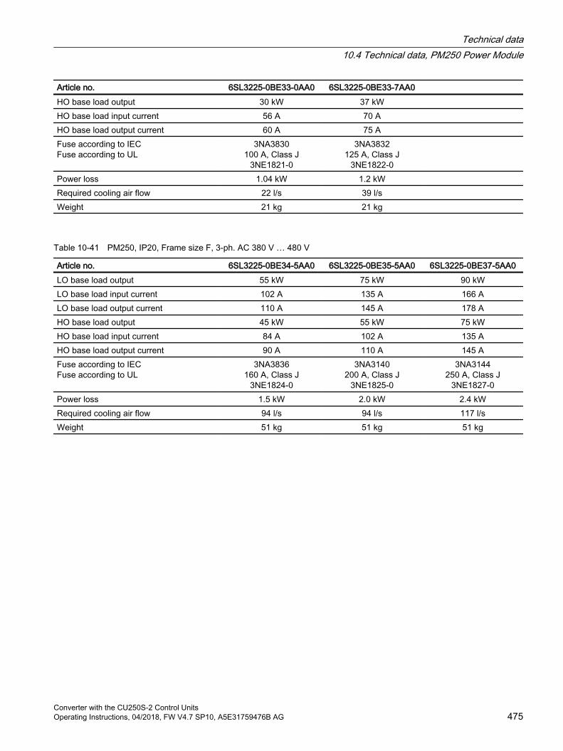
Article no. 6SL3225-0BE33-0AA0 6SL3225-0BE33-7AA0 HO base load output 30 kW 37 kW HO base load input current 56 A 70 A HO base load output current 60 A 75 A Fuse according to IECFuse according to UL
3NA3830100 A, Class J
3NE1821-0
3NA3832125 A, Class J
3NE1822-0
Power loss 1.04 kW 1.2 kW Required cooling air flow 22 l/s 39 l/s Weight 21 kg 21 kg
Table 10-41 PM250, IP20, Frame size F, 3-ph. AC 380 V … 480 V
Article no. 6SL3225-0BE34-5AA0 6SL3225-0BE35-5AA0 6SL3225-0BE37-5AA0LO base load output 55 kW 75 kW 90 kWLO base load input current 102 A 135 A 166 ALO base load output current 110 A 145 A 178 AHO base load output 45 kW 55 kW 75 kWHO base load input current 84 A 102 A 135 AHO base load output current 90 A 110 A 145 AFuse according to IECFuse according to UL
3NA3836160 A, Class J
3NE1824-0
3NA3140200 A, Class J
3NE1825-0
3NA3144250 A, Class J
3NE1827-0Power loss 1.5 kW 2.0 kW 2.4 kWRequired cooling air flow 94 l/s 94 l/s 117 l/sWeight 51 kg 51 kg 51 kg
Technical data10.4 Technical data, PM250 Power Module
Converter with the CU250S-2 Control UnitsOperating Instructions, 04/2018, FW V4.7 SP10, A5E31759476B AG 475
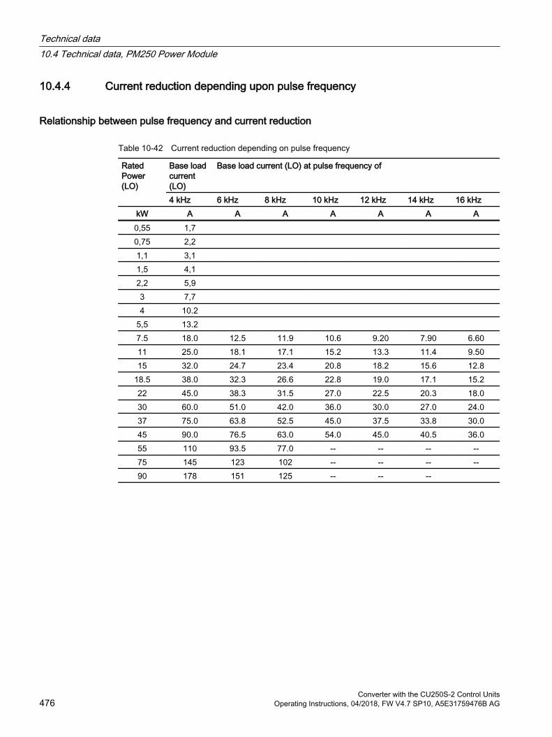
10.4.4 Current reduction depending upon pulse frequency
Relationship between pulse frequency and current reduction
Table 10-42 Current reduction depending on pulse frequency
Rated Power (LO)
Base load current (LO)
Base load current (LO) at pulse frequency of
4 kHz 6 kHz 8 kHz 10 kHz 12 kHz 14 kHz 16 kHzkW A A A A A A A0,55 1,7 0,75 2,2 1,1 3,1 1,5 4,1 2,2 5,9 3 7,7 4 10.2
5,5 13.2 7.5 18.0 12.5 11.9 10.6 9.20 7.90 6.6011 25.0 18.1 17.1 15.2 13.3 11.4 9.5015 32.0 24.7 23.4 20.8 18.2 15.6 12.8
18.5 38.0 32.3 26.6 22.8 19.0 17.1 15.222 45.0 38.3 31.5 27.0 22.5 20.3 18.030 60.0 51.0 42.0 36.0 30.0 27.0 24.037 75.0 63.8 52.5 45.0 37.5 33.8 30.045 90.0 76.5 63.0 54.0 45.0 40.5 36.055 110 93.5 77.0 -- -- -- --75 145 123 102 -- -- -- --90 178 151 125 -- -- --
Technical data10.4 Technical data, PM250 Power Module
Converter with the CU250S-2 Control Units476 Operating Instructions, 04/2018, FW V4.7 SP10, A5E31759476B AG

10.5 Data regarding the power loss in partial load operationYou can find data regarding power loss in partial load operation in the Internet:
Partial load operation (http://support.automation.siemens.com/WW/view/en/94059311)
Technical data10.5 Data regarding the power loss in partial load operation
Converter with the CU250S-2 Control UnitsOperating Instructions, 04/2018, FW V4.7 SP10, A5E31759476B AG 477
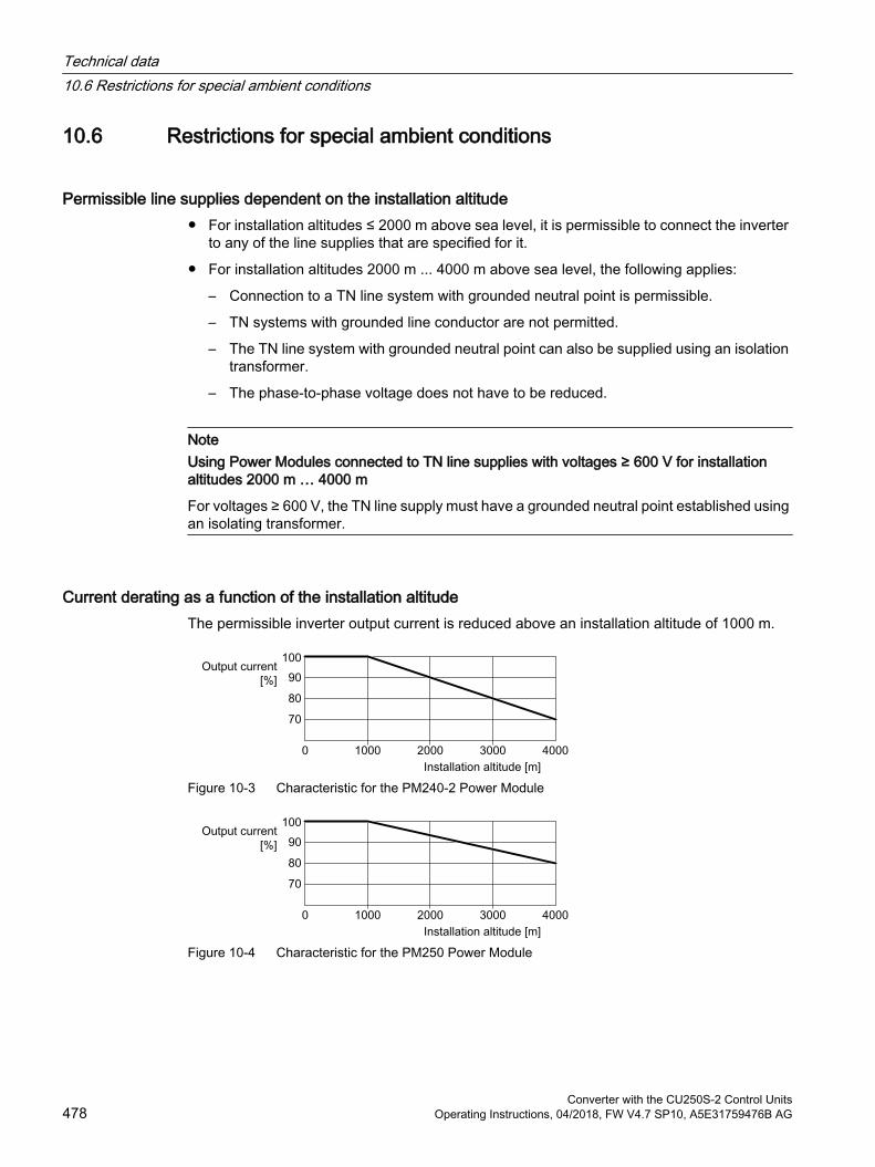
10.6 Restrictions for special ambient conditions
Permissible line supplies dependent on the installation altitude For installation altitudes ≤ 2000 m above sea level, it is permissible to connect the inverter
to any of the line supplies that are specified for it.
For installation altitudes 2000 m ... 4000 m above sea level, the following applies:
– Connection to a TN line system with grounded neutral point is permissible.
– TN systems with grounded line conductor are not permitted.
– The TN line system with grounded neutral point can also be supplied using an isolation transformer.
– The phase-to-phase voltage does not have to be reduced.
NoteUsing Power Modules connected to TN line supplies with voltages ≥ 600 V for installation altitudes 2000 m … 4000 m
For voltages ≥ 600 V, the TN line supply must have a grounded neutral point established using an isolating transformer.
Current derating as a function of the installation altitudeThe permissible inverter output current is reduced above an installation altitude of 1000 m.
Figure 10-3 Characteristic for the PM240-2 Power Module
Figure 10-4 Characteristic for the PM250 Power Module
Technical data10.6 Restrictions for special ambient conditions
Converter with the CU250S-2 Control Units478 Operating Instructions, 04/2018, FW V4.7 SP10, A5E31759476B AG
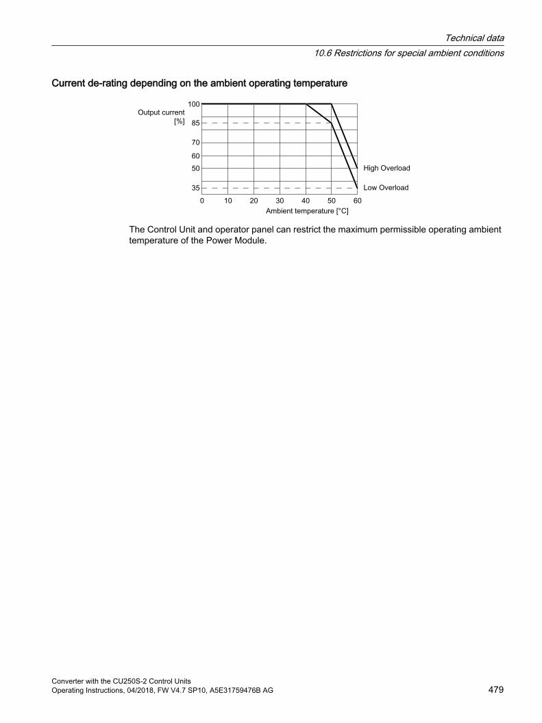
Current de-rating depending on the ambient operating temperature
The Control Unit and operator panel can restrict the maximum permissible operating ambient temperature of the Power Module.
Technical data10.6 Restrictions for special ambient conditions
Converter with the CU250S-2 Control UnitsOperating Instructions, 04/2018, FW V4.7 SP10, A5E31759476B AG 479

Technical data10.6 Restrictions for special ambient conditions
Converter with the CU250S-2 Control Units480 Operating Instructions, 04/2018, FW V4.7 SP10, A5E31759476B AG
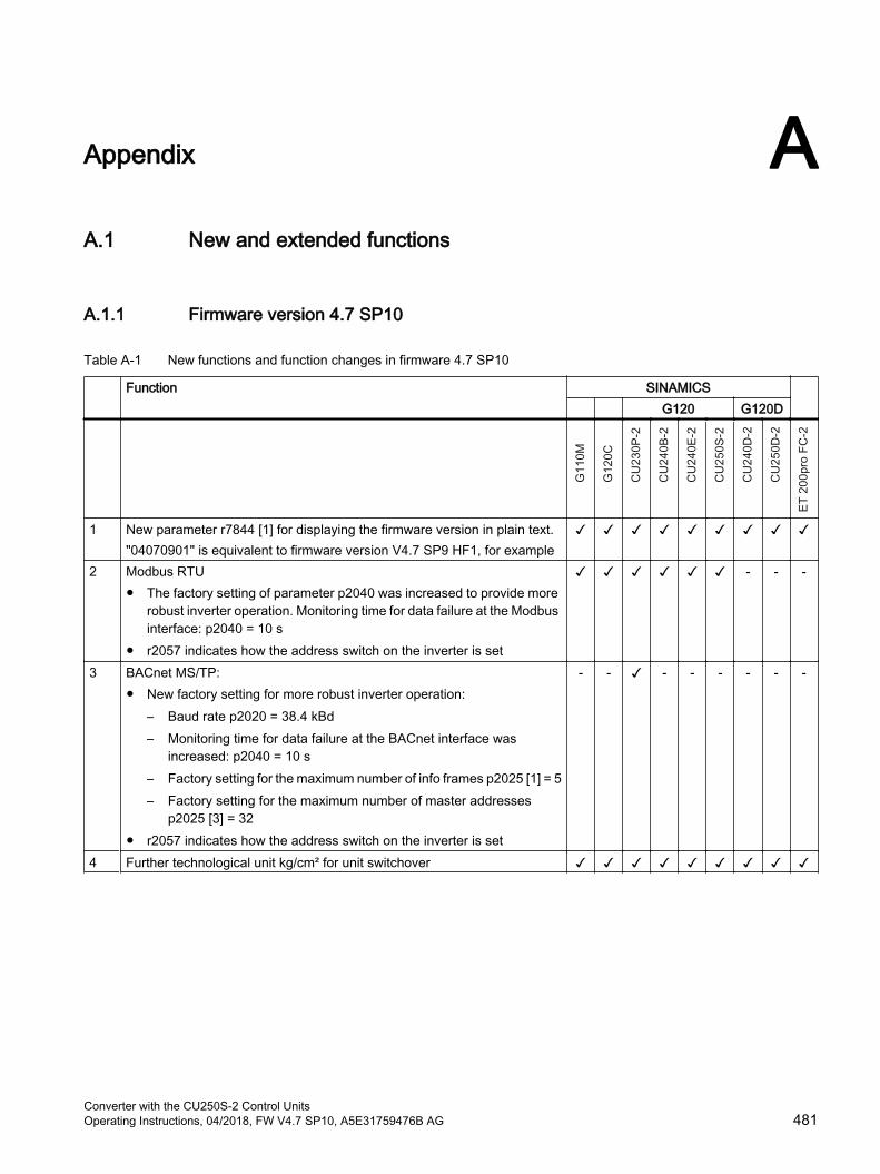
Appendix AA.1 New and extended functions
A.1.1 Firmware version 4.7 SP10
Table A-1 New functions and function changes in firmware 4.7 SP10
Function SINAMICS G120 G120D
1 New parameter r7844 [1] for displaying the firmware version in plain text."04070901" is equivalent to firmware version V4.7 SP9 HF1, for example
2 Modbus RTU The factory setting of parameter p2040 was increased to provide more
robust inverter operation. Monitoring time for data failure at the Modbus interface: p2040 = 10 s
r2057 indicates how the address switch on the inverter is set
- - -
3 BACnet MS/TP: New factory setting for more robust inverter operation:
– Baud rate p2020 = 38.4 kBd– Monitoring time for data failure at the BACnet interface was
increased: p2040 = 10 s– Factory setting for the maximum number of info frames p2025 [1] = 5– Factory setting for the maximum number of master addresses
p2025 [3] = 32 r2057 indicates how the address switch on the inverter is set
- - - - - - - -
4 Further technological unit kg/cm² for unit switchover
Converter with the CU250S-2 Control UnitsOperating Instructions, 04/2018, FW V4.7 SP10, A5E31759476B AG 481
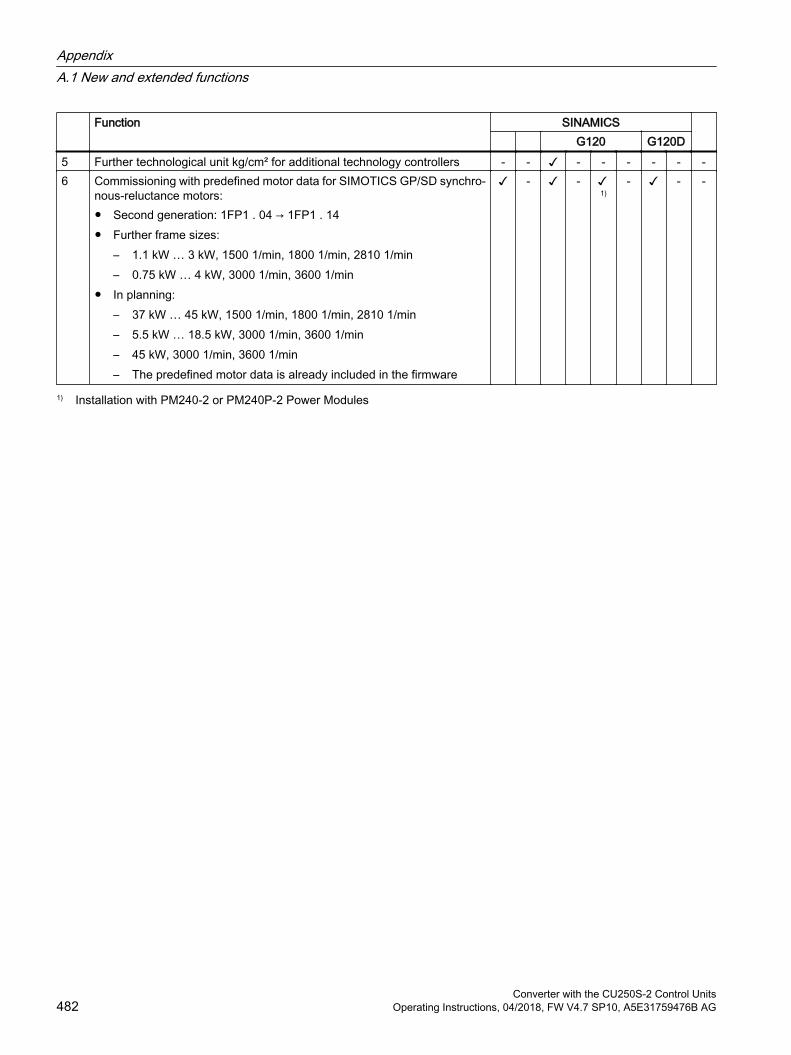
Function SINAMICS G120 G120D
5 Further technological unit kg/cm² for additional technology controllers - - - - - - - -6 Commissioning with predefined motor data for SIMOTICS GP/SD synchro‐
nous-reluctance motors: Second generation: 1FP1 . 04 → 1FP1 . 14 Further frame sizes:
– 1.1 kW … 3 kW, 1500 1/min, 1800 1/min, 2810 1/min– 0.75 kW … 4 kW, 3000 1/min, 3600 1/min
In planning:– 37 kW … 45 kW, 1500 1/min, 1800 1/min, 2810 1/min– 5.5 kW … 18.5 kW, 3000 1/min, 3600 1/min– 45 kW, 3000 1/min, 3600 1/min– The predefined motor data is already included in the firmware
- -
1)- - -
1) Installation with PM240-2 or PM240P-2 Power Modules
AppendixA.1 New and extended functions
Converter with the CU250S-2 Control Units482 Operating Instructions, 04/2018, FW V4.7 SP10, A5E31759476B AG
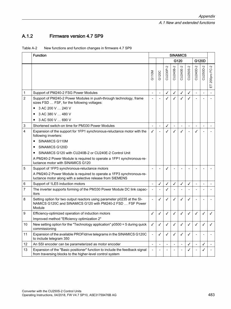
A.1.2 Firmware version 4.7 SP9
Table A-2 New functions and function changes in firmware 4.7 SP9
Function SINAMICS G120 G120D
1 Support of PM240‑2 FSG Power Modules - - - - -2 Support of PM240‑2 Power Modules in push-through technology, frame
sizes FSD … FSF, for the following voltages: 3 AC 200 V … 240 V 3 AC 380 V … 480 V 3 AC 500 V … 690 V
- - - - -
3 Shortened switch-on time for PM330 Power Modules - - - - - - - -4 Expansion of the support for 1FP1 synchronous-reluctance motor with the
following inverters: SINAMICS G110M SINAMICS G120D SINAMICS G120 with CU240B‑2 or CU240E‑2 Control UnitA PM240‑2 Power Module is required to operate a 1FP1 synchronous-re‐luctance motor with SINAMICS G120
- - - -
5 Support of 1FP3 synchronous-reluctance motorsA PM240‑2 Power Module is required to operate a 1FP3 synchronous-re‐luctance motor along with a selective release from SIEMENS
- - - - - - - -
6 Support of 1LE5 induction motors - - - -7 The inverter supports forming of the PM330 Power Module DC link capac‐
itors- - - - - - - -
8 Setting option for two output reactors using parameter p0235 at the SI‐NAMICS G120C and SINAMICS G120 with PM240-2 FSD … FSF Power Module
- - - -
9 Efficiency-optimized operation of induction motorsImproved method "Efficiency optimization 2"
10 New setting option for the "Technology application" p0500 = 5 during quick commissioning
11 Expansion of the available PROFIdrive telegrams in the SINAMICS G120C to include telegram 350
- - - -
12 An SSI encoder can be parameterized as motor encoder - - - - - - -13 Expansion of the "Basic positioner" function to include the feedback signal
from traversing blocks to the higher-level control system- - - - - - -
AppendixA.1 New and extended functions
Converter with the CU250S-2 Control UnitsOperating Instructions, 04/2018, FW V4.7 SP10, A5E31759476B AG 483
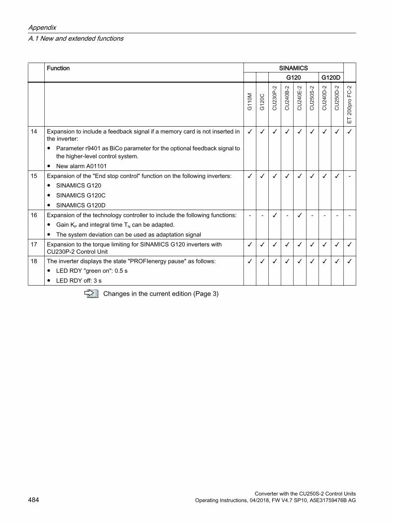
Function SINAMICS G120 G120D
14 Expansion to include a feedback signal if a memory card is not inserted in the inverter: Parameter r9401 as BiCo parameter for the optional feedback signal to
the higher-level control system. New alarm A01101
15 Expansion of the "End stop control" function on the following inverters: SINAMICS G120 SINAMICS G120C SINAMICS G120D
-
16 Expansion of the technology controller to include the following functions: Gain KP and integral time TN can be adapted. The system deviation can be used as adaptation signal
- - - - - - -
17 Expansion to the torque limiting for SINAMICS G120 inverters with CU230P‑2 Control Unit
18 The inverter displays the state "PROFIenergy pause" as follows: LED RDY "green on": 0.5 s LED RDY off: 3 s
Changes in the current edition (Page 3)
AppendixA.1 New and extended functions
Converter with the CU250S-2 Control Units484 Operating Instructions, 04/2018, FW V4.7 SP10, A5E31759476B AG
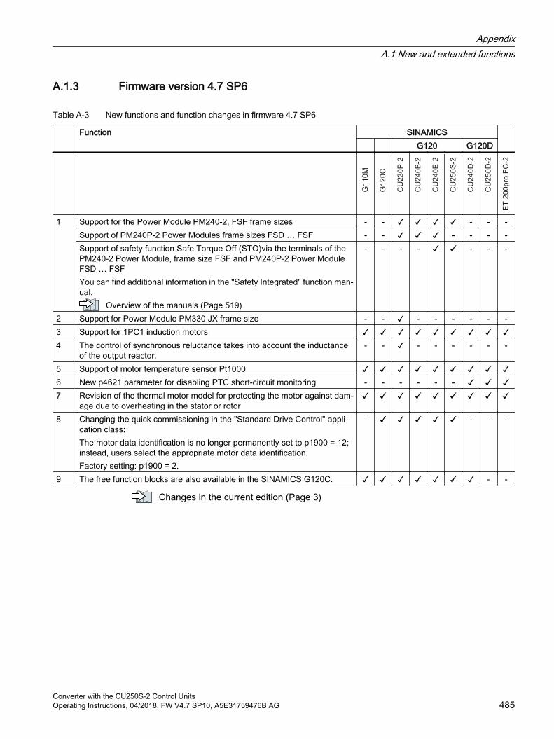
A.1.3 Firmware version 4.7 SP6
Table A-3 New functions and function changes in firmware 4.7 SP6
Function SINAMICS G120 G120D
1
Support for the Power Module PM240-2, FSF frame sizes - - - - -Support of PM240P‑2 Power Modules frame sizes FSD … FSF - - - - - -Support of safety function Safe Torque Off (STO)via the terminals of the PM240‑2 Power Module, frame size FSF and PM240P‑2 Power Module FSD … FSFYou can find additional information in the "Safety Integrated" function man‐ual.
Overview of the manuals (Page 519)
- - - - - - -
2 Support for Power Module PM330 JX frame size - - - - - - - -3 Support for 1PC1 induction motors 4 The control of synchronous reluctance takes into account the inductance
of the output reactor.- - - - - - - -
5 Support of motor temperature sensor Pt1000 6 New p4621 parameter for disabling PTC short-circuit monitoring - - - - - - 7 Revision of the thermal motor model for protecting the motor against dam‐
age due to overheating in the stator or rotor
8 Changing the quick commissioning in the "Standard Drive Control" appli‐cation class:The motor data identification is no longer permanently set to p1900 = 12; instead, users select the appropriate motor data identification.Factory setting: p1900 = 2.
- - - -
9 The free function blocks are also available in the SINAMICS G120C. - -
Changes in the current edition (Page 3)
AppendixA.1 New and extended functions
Converter with the CU250S-2 Control UnitsOperating Instructions, 04/2018, FW V4.7 SP10, A5E31759476B AG 485
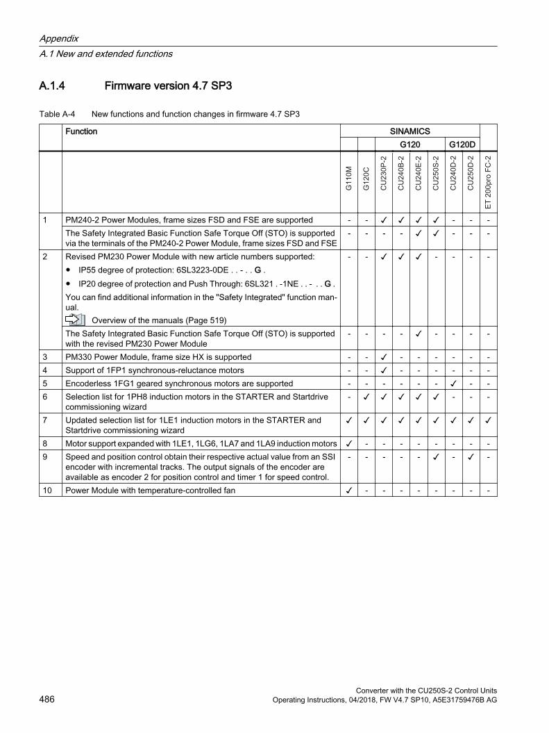
A.1.4 Firmware version 4.7 SP3
Table A-4 New functions and function changes in firmware 4.7 SP3
Function SINAMICS G120 G120D
1
PM240‑2 Power Modules, frame sizes FSD and FSE are supported - - - - -The Safety Integrated Basic Function Safe Torque Off (STO) is supported via the terminals of the PM240‑2 Power Module, frame sizes FSD and FSE
- - - - - - -
2 Revised PM230 Power Module with new article numbers supported: IP55 degree of protection: 6SL3223-0DE . . - . . G . IP20 degree of protection and Push Through: 6SL321 . -1NE . . - . . G . You can find additional information in the "Safety Integrated" function man‐ual.
Overview of the manuals (Page 519)
- - - - - -
The Safety Integrated Basic Function Safe Torque Off (STO) is supported with the revised PM230 Power Module
- - - - - - - -
3 PM330 Power Module, frame size HX is supported - - - - - - - -4 Support of 1FP1 synchronous-reluctance motors - - - - - - - -5 Encoderless 1FG1 geared synchronous motors are supported - - - - - - - -6 Selection list for 1PH8 induction motors in the STARTER and Startdrive
commissioning wizard- - - -
7 Updated selection list for 1LE1 induction motors in the STARTER and Startdrive commissioning wizard
8 Motor support expanded with 1LE1, 1LG6, 1LA7 and 1LA9 induction motors - - - - - - - -9 Speed and position control obtain their respective actual value from an SSI
encoder with incremental tracks. The output signals of the encoder are available as encoder 2 for position control and timer 1 for speed control.
- - - - - - -
10 Power Module with temperature-controlled fan - - - - - - - -
AppendixA.1 New and extended functions
Converter with the CU250S-2 Control Units486 Operating Instructions, 04/2018, FW V4.7 SP10, A5E31759476B AG
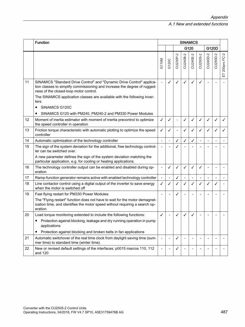
Function SINAMICS G120 G120D
11 SINAMICS "Standard Drive Control" and "Dynamic Drive Control" applica‐tion classes to simplify commissioning and increase the degree of rugged‐ness of the closed-loop motor control.The SINAMICS application classes are available with the following inver‐ters: SINAMICS G120C SINAMICS G120 with PM240, PM240-2 and PM330 Power Modules
- - - -
12 Moment of inertia estimator with moment of inertia precontrol to optimize the speed controller in operation
-
13 Friction torque characteristic with automatic plotting to optimize the speed controller
-
14 Automatic optimization of the technology controller - - - - - -15 The sign of the system deviation for the additional, free technology control‐
ler can be switched over.A new parameter defines the sign of the system deviation matching the particular application, e.g. for cooling or heating applications.
- - - - - - - -
16 The technology controller output can be enabled and disabled during op‐eration
- - - -
17 Ramp-function generator remains active with enabled technology controller - - - - - - - -18 Line contactor control using a digital output of the inverter to save energy
when the motor is switched off -
19 Fast flying restart for PM330 Power Modules:The "Flying restart" function does not have to wait for the motor demagnet‐ization time, and identifies the motor speed without requiring a search op‐eration.
- - - - - - - -
20 Load torque monitoring extended to include the following functions: Protection against blocking, leakage and dry running operation in pump
applications Protection against blocking and broken belts in fan applications
- - - - -
21 Automatic switchover of the real time clock from daylight saving time (sum‐mer time) to standard time (winter time).
- - - - - - - -
22 New or revised default settings of the interfaces: p0015 macros 110, 112 and 120
- - - - - - - -
AppendixA.1 New and extended functions
Converter with the CU250S-2 Control UnitsOperating Instructions, 04/2018, FW V4.7 SP10, A5E31759476B AG 487
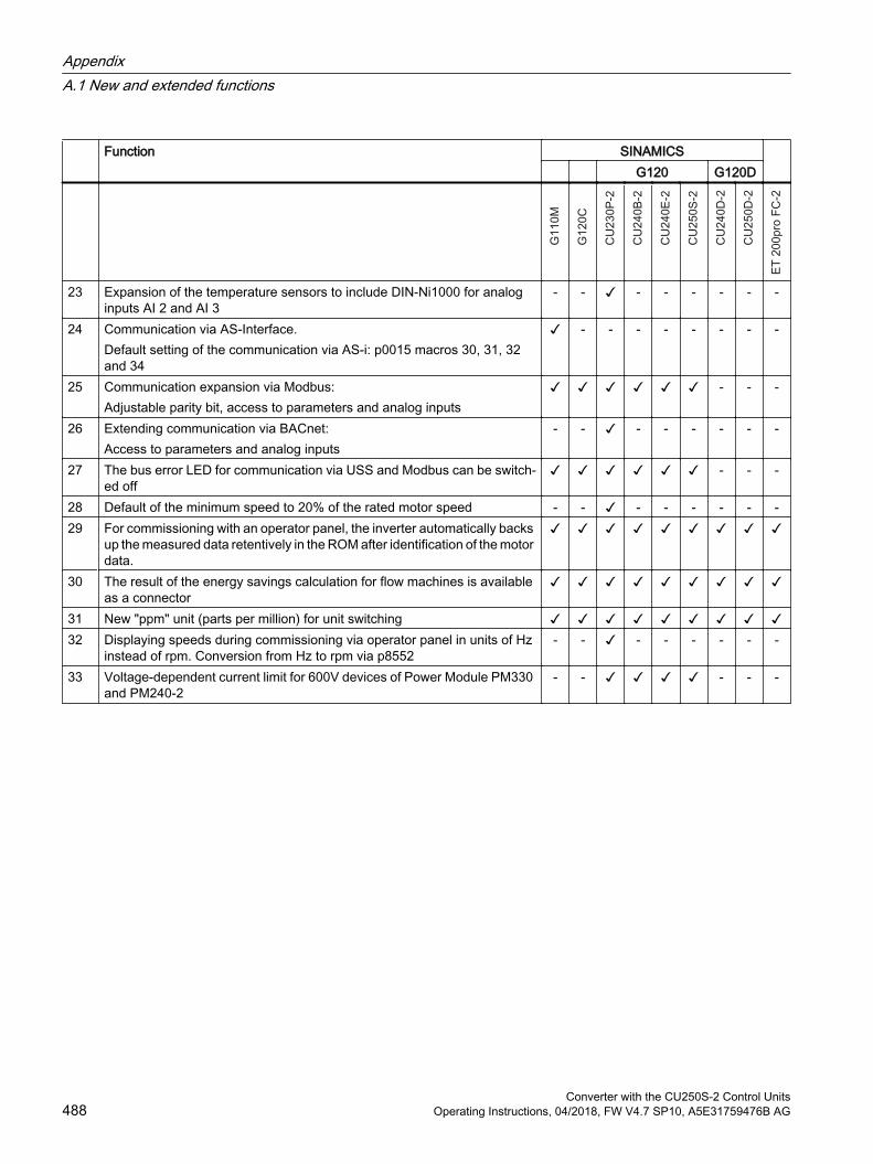
Function SINAMICS G120 G120D
23 Expansion of the temperature sensors to include DIN-Ni1000 for analog inputs AI 2 and AI 3
- - - - - - - -
24 Communication via AS-Interface.Default setting of the communication via AS-i: p0015 macros 30, 31, 32 and 34
- - - - - - - -
25 Communication expansion via Modbus:Adjustable parity bit, access to parameters and analog inputs
- - -
26 Extending communication via BACnet:Access to parameters and analog inputs
- - - - - - - -
27 The bus error LED for communication via USS and Modbus can be switch‐ed off
- - -
28 Default of the minimum speed to 20% of the rated motor speed - - - - - - - -29 For commissioning with an operator panel, the inverter automatically backs
up the measured data retentively in the ROM after identification of the motor data.
30 The result of the energy savings calculation for flow machines is available as a connector
31 New "ppm" unit (parts per million) for unit switching 32 Displaying speeds during commissioning via operator panel in units of Hz
instead of rpm. Conversion from Hz to rpm via p8552- - - - - - - -
33 Voltage-dependent current limit for 600V devices of Power Module PM330 and PM240-2
- - - - -
AppendixA.1 New and extended functions
Converter with the CU250S-2 Control Units488 Operating Instructions, 04/2018, FW V4.7 SP10, A5E31759476B AG

A.1.5 Firmware version 4.7
Table A-5 New functions and function changes in Firmware 4.7
Function SINAMICS G120 G120D
1 Supporting the identification & maintenance datasets (I&M1 … 4) 2 Fall in pulse rate with increased drive power required by the motor
The inverter temporarily lowers the pulse frequency if required when the motor is started up, and simultaneously increases the current limit.
3 S7 communication Direct data exchange between the inverter and human-machine interface
(HMI). Increase in communication performance with the engineering tools and
support of the S7 routing
4 The basic functions of Safety Integrated are unrestrictedly available in all control types with 1FK7 encoderless permanent-field synchronous motors
- - - - - - -
5 Encoderless 1FK7 synchronous motors are supported Direct motor selection based on the article number with associated code
number It is not necessary to input individual motor data
- - - - - - -
6 Pulse input as source of setpoint value The inverter calculates its speed setpoint from a sequence of pulses at the
digital input.
- - - - - - -
7 Dynamic IP address assignment (DHCP) and temporary device names for PROFINET
-
8 PROFIenergy Slave profile 2 and 3 - 9 Uniform behavior for component replacement
After a component is replaced, an inverter with activated Safety Integrated will report what type of component has been replaced using a unique code.
- -
10 Improved direct-component control in PM230 Optimized efficiency for pump and fan applications
- - - - - - -
11 Rounding down of BACnet and macros - - - - - - -
AppendixA.1 New and extended functions
Converter with the CU250S-2 Control UnitsOperating Instructions, 04/2018, FW V4.7 SP10, A5E31759476B AG 489
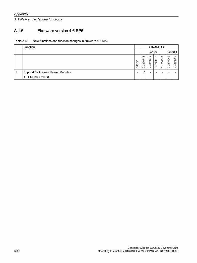
A.1.6 Firmware version 4.6 SP6
Table A-6 New functions and function changes in firmware 4.6 SP6
Function SINAMICS G120 G120D
1 Support for the new Power Modules PM330 IP20 GX
- - - - - -
AppendixA.1 New and extended functions
Converter with the CU250S-2 Control Units490 Operating Instructions, 04/2018, FW V4.7 SP10, A5E31759476B AG
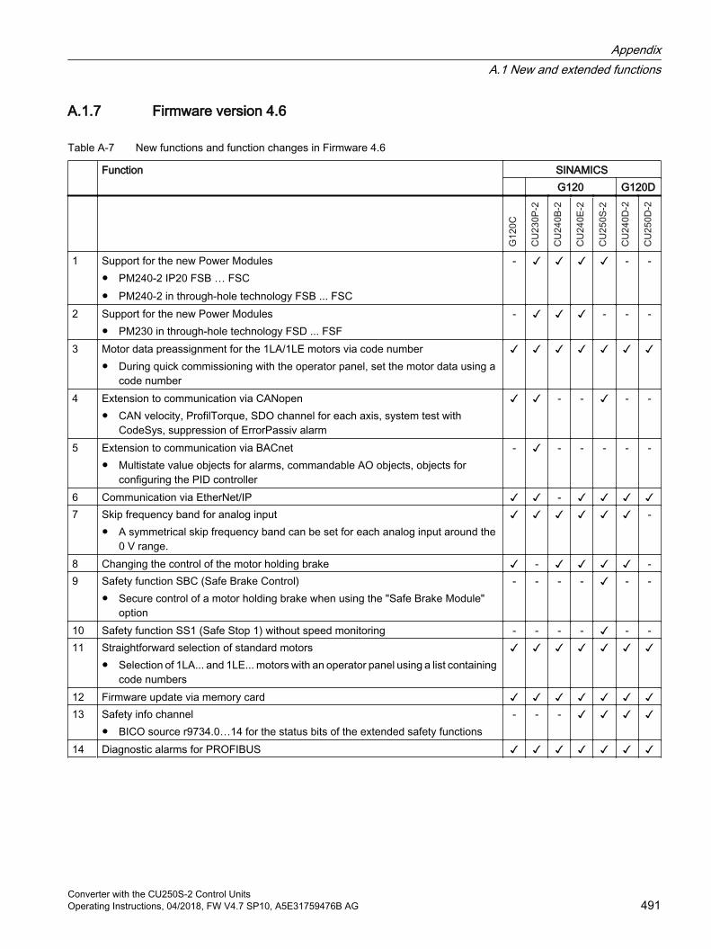
A.1.7 Firmware version 4.6
Table A-7 New functions and function changes in Firmware 4.6
Function SINAMICS G120 G120D
1 Support for the new Power Modules PM240-2 IP20 FSB … FSC PM240-2 in through-hole technology FSB ... FSC
- - -
2 Support for the new Power Modules PM230 in through-hole technology FSD ... FSF
- - - -
3 Motor data preassignment for the 1LA/1LE motors via code number During quick commissioning with the operator panel, set the motor data using a
code number
4 Extension to communication via CANopen CAN velocity, ProfilTorque, SDO channel for each axis, system test with
CodeSys, suppression of ErrorPassiv alarm
- - - -
5 Extension to communication via BACnet Multistate value objects for alarms, commandable AO objects, objects for
configuring the PID controller
- - - - - -
6 Communication via EtherNet/IP - 7 Skip frequency band for analog input
A symmetrical skip frequency band can be set for each analog input around the 0 V range.
-
8 Changing the control of the motor holding brake - -9 Safety function SBC (Safe Brake Control)
Secure control of a motor holding brake when using the "Safe Brake Module" option
- - - - - -
10 Safety function SS1 (Safe Stop 1) without speed monitoring - - - - - -11 Straightforward selection of standard motors
Selection of 1LA... and 1LE... motors with an operator panel using a list containing code numbers
12 Firmware update via memory card 13 Safety info channel
BICO source r9734.0…14 for the status bits of the extended safety functions- - -
14 Diagnostic alarms for PROFIBUS
AppendixA.1 New and extended functions
Converter with the CU250S-2 Control UnitsOperating Instructions, 04/2018, FW V4.7 SP10, A5E31759476B AG 491

A.2 Activating licensed functions
A.2.1 Licensing
Purchasing a memory card with license
Procedure1. Order a memory card - with or without firmware – with the license that you require.
2. Switch off the inverter power supply.
3. Insert the card into the inverter.
4. Switch on the power supply for the inverter.
You have activated the licensed function.
Purchasing a license and loading to a memory cardPrecondition
You have a memory card without a license.
Memory cards (Page 362)
Procedure1. Order the license for the function that you require.
2. You receive the "Certificate of License", it contains:
– the software order number
– the license number
– the delivery note number
3. Create the license key using the "WEB License Manager".License key (Page 493)
4. Insert the card into the inverter.
5. Write the license key to the card using STARTER or BOP-2.Writing the license key to the card (Page 496)
6. Switch off the inverter power supply.
7. Switch on the inverter power supply again.
You have activated the licensed function.
AppendixA.2 Activating licensed functions
Converter with the CU250S-2 Control Units492 Operating Instructions, 04/2018, FW V4.7 SP10, A5E31759476B AG

A.2.2 Creating or displaying the license key
OverviewThe WEB License Manager has the following functions:
Generate the license key for a new license
Display the licenses on a card
WEB License Manager on the Internet:
http://www.siemens.com/automation/license (https://workplace.automation.siemens.com/pls/swl-pub/SWL_MAIN_MENU.NAVIGATION_HEAD?a_lang_id=E&a_action=)
Creating the license key using "WEB License Manager"
Preconditions You know the license number and the delivery note number from the Certificate of License.
You know the serial number of your memory card.
Procedure1. Open the WEB License Manager.
2. Click "Direct access" in the WEB License Manager in the navigation bar.
3. Enter the license number and delivery note number from your Certificate of License.
4. Click "Next".
5. Progress display: "Identify product".Enter the serial number of the memory card.
6. Select for "Product": SINAMICS G120
7. Click "Next".If licenses are already assigned to your software, they are displayed here.
8. Click "Next".
9. Progress display: "Select licenses".The WEB License Manager displays the licenses that you can assign. Select the checkbox for assignment.
10.Click "Next".
AppendixA.2 Activating licensed functions
Converter with the CU250S-2 Control UnitsOperating Instructions, 04/2018, FW V4.7 SP10, A5E31759476B AG 493

11.Progress display: "Assign licenses".The WEB License Manager displays a summary of the licenses selected for assignment.
12.Click "Assign".
13.Confirm the following confirmation prompt with OK.
14.Progress display: "Generate license key".The licenses are permanently assigned to the specified memory card. The license key is displayed.
15.Save the license key on your PC.
You have created a license key.
Displaying and requesting the license key using the "WEB License Manager"With this function, the WEB License Manager displays which inverter functions are assigned to which card with which license keys.
PreconditionOne of the following requirements must be satisfied:
You know the serial number of the memory card
You know the license number of the inverter function
Procedure1. Open the WEB License Manager.
2. Select "Show license key"
3. In the drop-down list, make the entry based on the license key you wish to display or request.
4. Complete the fields below appropriately.
AppendixA.2 Activating licensed functions
Converter with the CU250S-2 Control Units494 Operating Instructions, 04/2018, FW V4.7 SP10, A5E31759476B AG
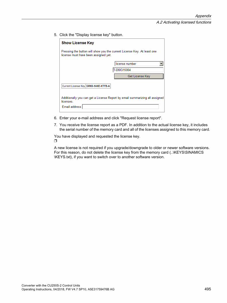
5. Click the "Display license key" button.
6. Enter your e-mail address and click "Request license report".
7. You receive the license report as a PDF. In addition to the actual license key, it includes the serial number of the memory card and all of the licenses assigned to this memory card.
You have displayed and requested the license key.
A new license is not required if you upgrade/downgrade to older or newer software versions. For this reason, do not delete the license key from the memory card (..\KEYS\SINAMICS\KEYS.txt), if you want to switch over to another software version.
AppendixA.2 Activating licensed functions
Converter with the CU250S-2 Control UnitsOperating Instructions, 04/2018, FW V4.7 SP10, A5E31759476B AG 495
A.2.3 Writing the license key to the card
OverviewYou write the license key to the memory card by writing the individual positions – in an ascending order – into the bits of parameter p9920, and then subsequently activate the key using p9921.
The procedure for Startdrive and BOP-2, based on the fictitious "E1MQ-4BEA" license key, is described below.
Note
If you subsequently purchase an additional license, then you will require a new license key. You must overwrite the old license key. The new license key can have more than 9 positions.
You must set p9920[0] = 0 in order to reset the license key.
Activating the license key with Startdrive
Procedure1. Go online and switch over to the parameter view.
2. In the parameter view, go to parameter p9920
3. Enter the license key (example: "E1MQ-4BEA") - always use uppercase letters:
– p9920[0] = E
– p9920[1] = 1
– …
– p9920[7] = E
– p9920[8] = A
4. Set p9921 = 1.After activation, the inverter sets p9921 = 0.
You have activated the license key using Startdrive.
AppendixA.2 Activating licensed functions
Converter with the CU250S-2 Control Units496 Operating Instructions, 04/2018, FW V4.7 SP10, A5E31759476B AG
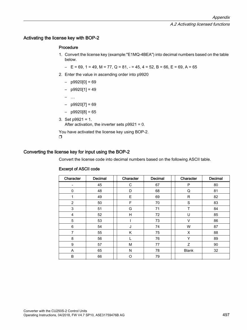
Activating the license key with BOP-2
Procedure1. Convert the license key (example:"E1MQ-4BEA") into decimal numbers based on the table
below.
– E = 69, 1 = 49, M = 77, Q = 81, - = 45, 4 = 52, B = 66, E = 69, A = 65
2. Enter the value in ascending order into p9920
– p9920[0] = 69
– p9920[1] = 49
– …
– p9920[7] = 69
– p9920[8] = 65
3. Set p9921 = 1.After activation, the inverter sets p9921 = 0.
You have activated the license key using BOP-2.
Converting the license key for input using the BOP-2Convert the license code into decimal numbers based on the following ASCII table.
Excerpt of ASCII code
Character Decimal Character Decimal Character Decimal- 45 C 67 P 800 48 D 68 Q 811 49 E 69 R 822 50 F 70 S 833 51 G 71 T 844 52 H 72 U 855 53 I 73 V 866 54 J 74 W 877 55 K 75 X 888 56 L 76 Y 899 57 M 77 Z 90A 65 N 78 Blank 32B 66 O 79
AppendixA.2 Activating licensed functions
Converter with the CU250S-2 Control UnitsOperating Instructions, 04/2018, FW V4.7 SP10, A5E31759476B AG 497
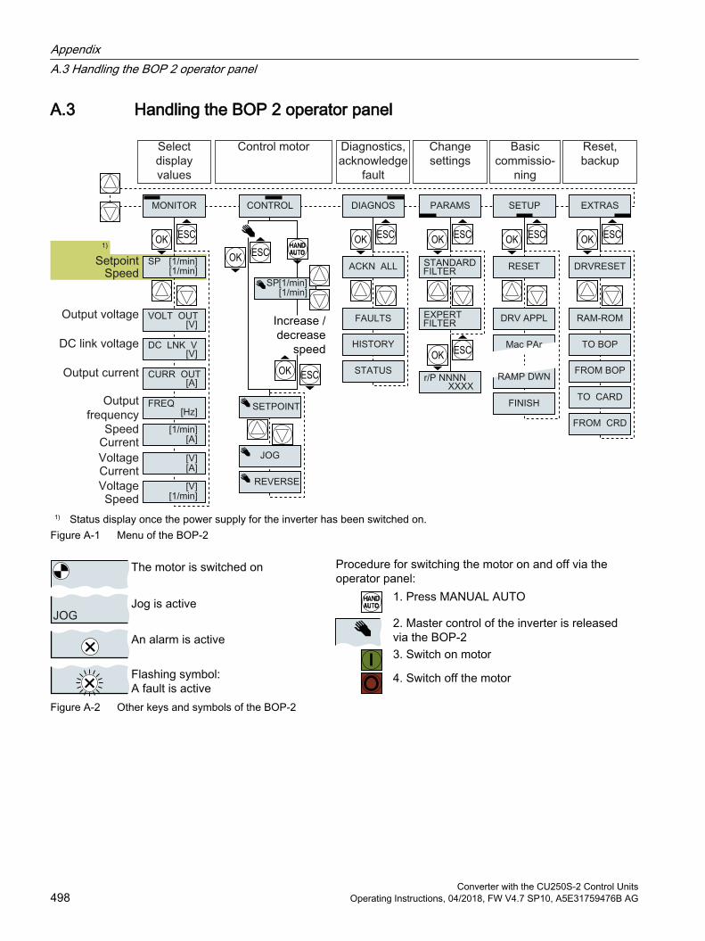
A.3 Handling the BOP 2 operator panel
1) Status display once the power supply for the inverter has been switched on.Figure A-1 Menu of the BOP-2
Figure A-2 Other keys and symbols of the BOP-2
AppendixA.3 Handling the BOP 2 operator panel
Converter with the CU250S-2 Control Units498 Operating Instructions, 04/2018, FW V4.7 SP10, A5E31759476B AG
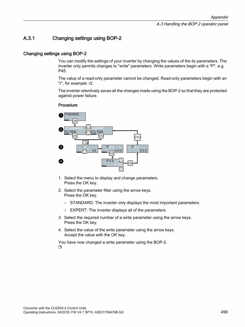
A.3.1 Changing settings using BOP-2
Changing settings using BOP-2You can modify the settings of your inverter by changing the values of the its parameters. The inverter only permits changes to "write" parameters. Write parameters begin with a "P", e.g. P45.
The value of a read-only parameter cannot be changed. Read-only parameters begin with an "r", for example: r2.
The inverter retentively saves all the changes made using the BOP-2 so that they are protected against power failure.
Procedure
1. Select the menu to display and change parameters.Press the OK key.
2. Select the parameter filter using the arrow keys.Press the OK key.
– STANDARD: The inverter only displays the most important parameters.
– EXPERT: The inverter displays all of the parameters.
3. Select the required number of a write parameter using the arrow keys.Press the OK key.
4. Select the value of the write parameter using the arrow keys.Accept the value with the OK key.
You have now changed a write parameter using the BOP-2.
AppendixA.3 Handling the BOP 2 operator panel
Converter with the CU250S-2 Control UnitsOperating Instructions, 04/2018, FW V4.7 SP10, A5E31759476B AG 499
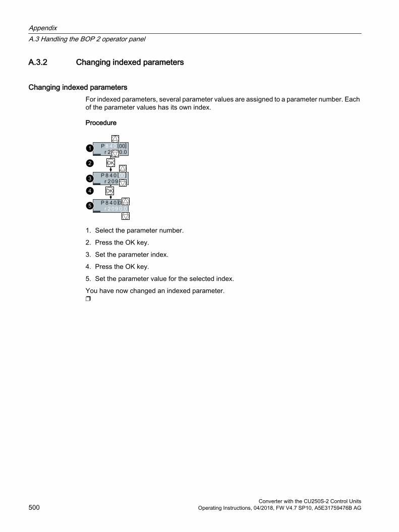
A.3.2 Changing indexed parameters
Changing indexed parametersFor indexed parameters, several parameter values are assigned to a parameter number. Each of the parameter values has its own index.
Procedure
1. Select the parameter number.
2. Press the OK key.
3. Set the parameter index.
4. Press the OK key.
5. Set the parameter value for the selected index.
You have now changed an indexed parameter.
AppendixA.3 Handling the BOP 2 operator panel
Converter with the CU250S-2 Control Units500 Operating Instructions, 04/2018, FW V4.7 SP10, A5E31759476B AG
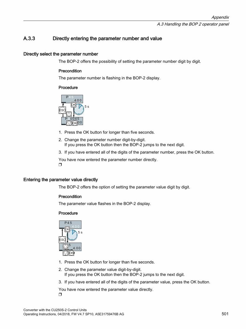
A.3.3 Directly entering the parameter number and value
Directly select the parameter numberThe BOP‑2 offers the possibility of setting the parameter number digit by digit.
PreconditionThe parameter number is flashing in the BOP-2 display.
Procedure
1. Press the OK button for longer than five seconds.
2. Change the parameter number digit-by-digit.If you press the OK button then the BOP‑2 jumps to the next digit.
3. If you have entered all of the digits of the parameter number, press the OK button.
You have now entered the parameter number directly.
Entering the parameter value directlyThe BOP‑2 offers the option of setting the parameter value digit by digit.
PreconditionThe parameter value flashes in the BOP-2 display.
Procedure
1. Press the OK button for longer than five seconds.
2. Change the parameter value digit-by-digit.If you press the OK button then the BOP‑2 jumps to the next digit.
3. If you have entered all of the digits of the parameter value, press the OK button.
You have now entered the parameter value directly.
AppendixA.3 Handling the BOP 2 operator panel
Converter with the CU250S-2 Control UnitsOperating Instructions, 04/2018, FW V4.7 SP10, A5E31759476B AG 501
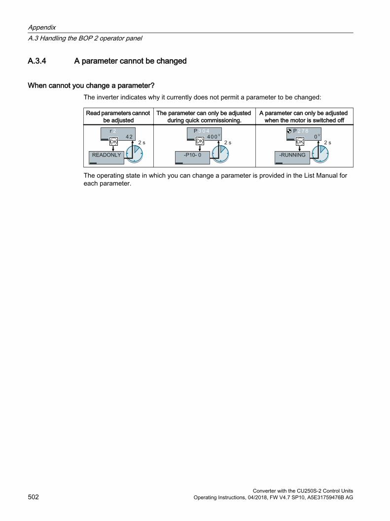
A.3.4 A parameter cannot be changed
When cannot you change a parameter?The inverter indicates why it currently does not permit a parameter to be changed:
Read parameters cannot be adjusted
The parameter can only be adjusted during quick commissioning.
A parameter can only be adjusted when the motor is switched off
The operating state in which you can change a parameter is provided in the List Manual for each parameter.
AppendixA.3 Handling the BOP 2 operator panel
Converter with the CU250S-2 Control Units502 Operating Instructions, 04/2018, FW V4.7 SP10, A5E31759476B AG
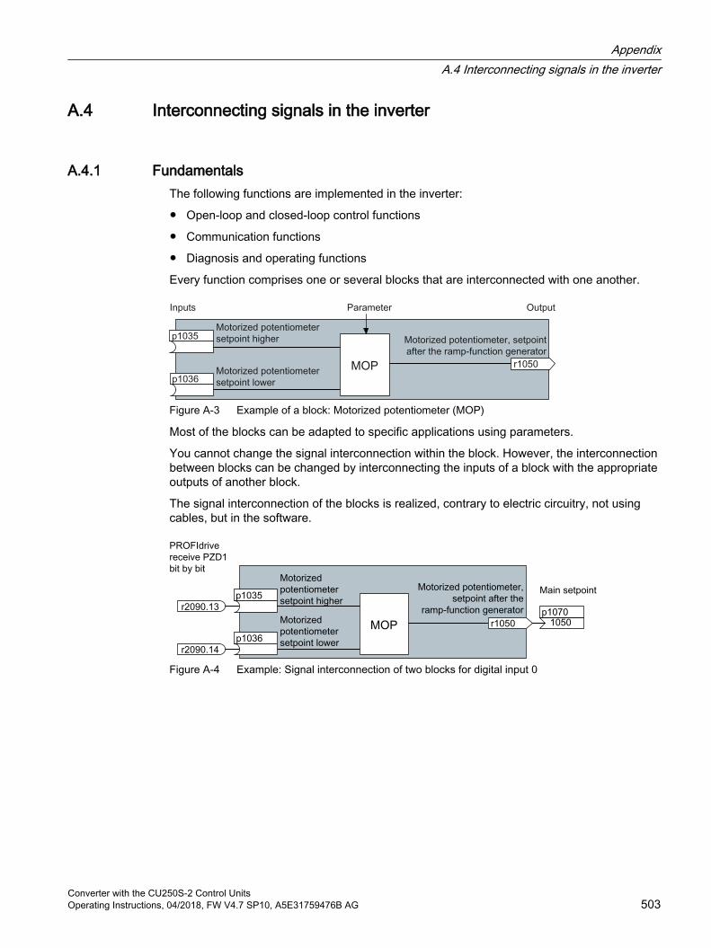
A.4 Interconnecting signals in the inverter
A.4.1 FundamentalsThe following functions are implemented in the inverter:
Open-loop and closed-loop control functions
Communication functions
Diagnosis and operating functions
Every function comprises one or several blocks that are interconnected with one another.
Figure A-3 Example of a block: Motorized potentiometer (MOP)
Most of the blocks can be adapted to specific applications using parameters.
You cannot change the signal interconnection within the block. However, the interconnection between blocks can be changed by interconnecting the inputs of a block with the appropriate outputs of another block.
The signal interconnection of the blocks is realized, contrary to electric circuitry, not using cables, but in the software.
Figure A-4 Example: Signal interconnection of two blocks for digital input 0
AppendixA.4 Interconnecting signals in the inverter
Converter with the CU250S-2 Control UnitsOperating Instructions, 04/2018, FW V4.7 SP10, A5E31759476B AG 503
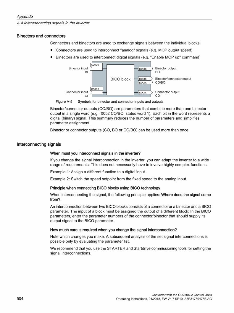
Binectors and connectorsConnectors and binectors are used to exchange signals between the individual blocks:
Connectors are used to interconnect "analog" signals (e.g. MOP output speed)
Binectors are used to interconnect digital signals (e.g. "Enable MOP up" command)
Figure A-5 Symbols for binector and connector inputs and outputs
Binector/connector outputs (CO/BO) are parameters that combine more than one binector output in a single word (e.g. r0052 CO/BO: status word 1). Each bit in the word represents a digital (binary) signal. This summary reduces the number of parameters and simplifies parameter assignment.
Binector or connector outputs (CO, BO or CO/BO) can be used more than once.
Interconnecting signals
When must you interconnect signals in the inverter?If you change the signal interconnection in the inverter, you can adapt the inverter to a wide range of requirements. This does not necessarily have to involve highly complex functions.
Example 1: Assign a different function to a digital input.
Example 2: Switch the speed setpoint from the fixed speed to the analog input.
Principle when connecting BICO blocks using BICO technologyWhen interconnecting the signal, the following principle applies: Where does the signal come from?
An interconnection between two BICO blocks consists of a connector or a binector and a BICO parameter. The input of a block must be assigned the output of a different block: In the BICO parameters, enter the parameter numbers of the connector/binector that should supply its output signal to the BICO parameter.
How much care is required when you change the signal interconnection?Note which changes you make. A subsequent analysis of the set signal interconnections is possible only by evaluating the parameter list.
We recommend that you use the STARTER and Startdrive commissioning tools for setting the signal interconnections.
AppendixA.4 Interconnecting signals in the inverter
Converter with the CU250S-2 Control Units504 Operating Instructions, 04/2018, FW V4.7 SP10, A5E31759476B AG
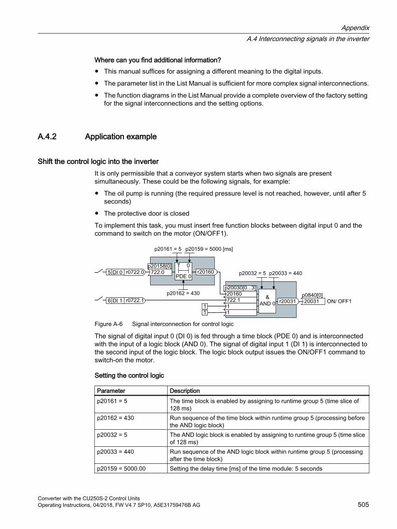
Where can you find additional information? This manual suffices for assigning a different meaning to the digital inputs.
The parameter list in the List Manual is sufficient for more complex signal interconnections.
The function diagrams in the List Manual provide a complete overview of the factory setting for the signal interconnections and the setting options.
A.4.2 Application example
Shift the control logic into the inverterIt is only permissible that a conveyor system starts when two signals are present simultaneously. These could be the following signals, for example:
The oil pump is running (the required pressure level is not reached, however, until after 5 seconds)
The protective door is closed
To implement this task, you must insert free function blocks between digital input 0 and the command to switch on the motor (ON/OFF1).
Figure A-6 Signal interconnection for control logic
The signal of digital input 0 (DI 0) is fed through a time block (PDE 0) and is interconnected with the input of a logic block (AND 0). The signal of digital input 1 (DI 1) is interconnected to the second input of the logic block. The logic block output issues the ON/OFF1 command to switch-on the motor.
Setting the control logic
Parameter Descriptionp20161 = 5 The time block is enabled by assigning to runtime group 5 (time slice of
128 ms)p20162 = 430 Run sequence of the time block within runtime group 5 (processing before
the AND logic block)p20032 = 5 The AND logic block is enabled by assigning to runtime group 5 (time slice
of 128 ms)p20033 = 440 Run sequence of the AND logic block within runtime group 5 (processing
after the time block)p20159 = 5000.00 Setting the delay time [ms] of the time module: 5 seconds
AppendixA.4 Interconnecting signals in the inverter
Converter with the CU250S-2 Control UnitsOperating Instructions, 04/2018, FW V4.7 SP10, A5E31759476B AG 505
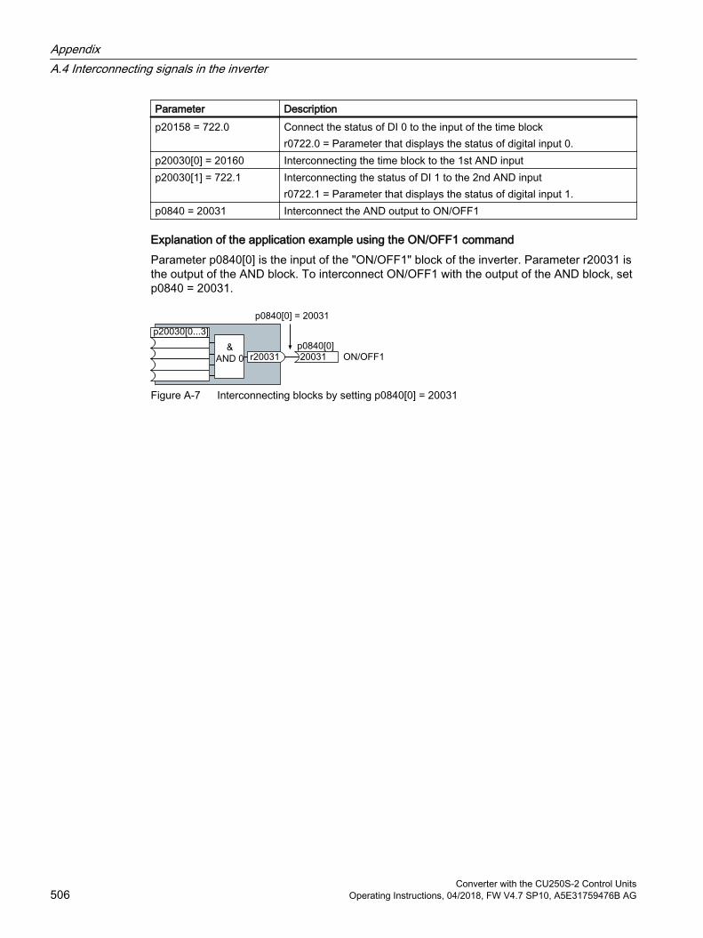
Parameter Descriptionp20158 = 722.0 Connect the status of DI 0 to the input of the time block
r0722.0 = Parameter that displays the status of digital input 0.p20030[0] = 20160 Interconnecting the time block to the 1st AND inputp20030[1] = 722.1 Interconnecting the status of DI 1 to the 2nd AND input
r0722.1 = Parameter that displays the status of digital input 1.p0840 = 20031 Interconnect the AND output to ON/OFF1
Explanation of the application example using the ON/OFF1 commandParameter p0840[0] is the input of the "ON/OFF1" block of the inverter. Parameter r20031 is the output of the AND block. To interconnect ON/OFF1 with the output of the AND block, set p0840 = 20031.
Figure A-7 Interconnecting blocks by setting p0840[0] = 20031
AppendixA.4 Interconnecting signals in the inverter
Converter with the CU250S-2 Control Units506 Operating Instructions, 04/2018, FW V4.7 SP10, A5E31759476B AG
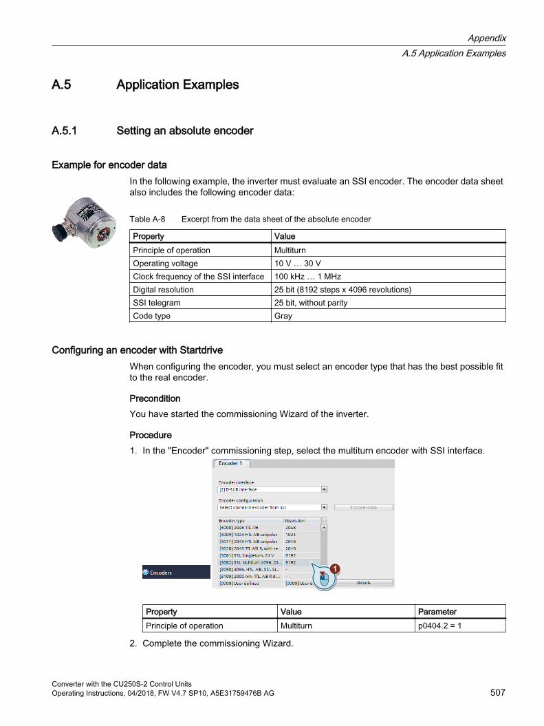
A.5 Application Examples
A.5.1 Setting an absolute encoder
Example for encoder dataIn the following example, the inverter must evaluate an SSI encoder. The encoder data sheet also includes the following encoder data:
Table A-8 Excerpt from the data sheet of the absolute encoder
Property ValuePrinciple of operation MultiturnOperating voltage 10 V … 30 VClock frequency of the SSI interface 100 kHz … 1 MHzDigital resolution 25 bit (8192 steps x 4096 revolutions)SSI telegram 25 bit, without parityCode type Gray
Configuring an encoder with StartdriveWhen configuring the encoder, you must select an encoder type that has the best possible fit to the real encoder.
PreconditionYou have started the commissioning Wizard of the inverter.
Procedure1. In the "Encoder" commissioning step, select the multiturn encoder with SSI interface.
Property Value ParameterPrinciple of operation Multiturn p0404.2 = 1
2. Complete the commissioning Wizard.
AppendixA.5 Application Examples
Converter with the CU250S-2 Control UnitsOperating Instructions, 04/2018, FW V4.7 SP10, A5E31759476B AG 507

You have now configured the absolute encoder.
Adapting the encoder dataAfter the configuration you may now adapt the encoder data.
Preconditions You have now configured an absolute encoder.
You have completely configured the drive.
AppendixA.5 Application Examples
Converter with the CU250S-2 Control Units508 Operating Instructions, 04/2018, FW V4.7 SP10, A5E31759476B AG
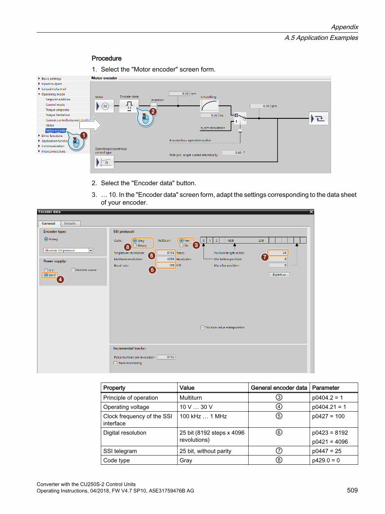
Procedure1. Select the "Motor encoder" screen form.
2. Select the "Encoder data" button.
3. … 10. In the "Encoder data" screen form, adapt the settings corresponding to the data sheet of your encoder.
Property Value General encoder data ParameterPrinciple of operation Multiturn ③ p0404.2 = 1Operating voltage 10 V … 30 V ④ p0404.21 = 1Clock frequency of the SSI interface
100 kHz … 1 MHz ⑤ p0427 = 100
Digital resolution 25 bit (8192 steps x 4096 revolutions)
⑥ p0423 = 8192p0421 = 4096
SSI telegram 25 bit, without parity ⑦ p0447 = 25Code type Gray ⑧ p429.0 = 0
AppendixA.5 Application Examples
Converter with the CU250S-2 Control UnitsOperating Instructions, 04/2018, FW V4.7 SP10, A5E31759476B AG 509
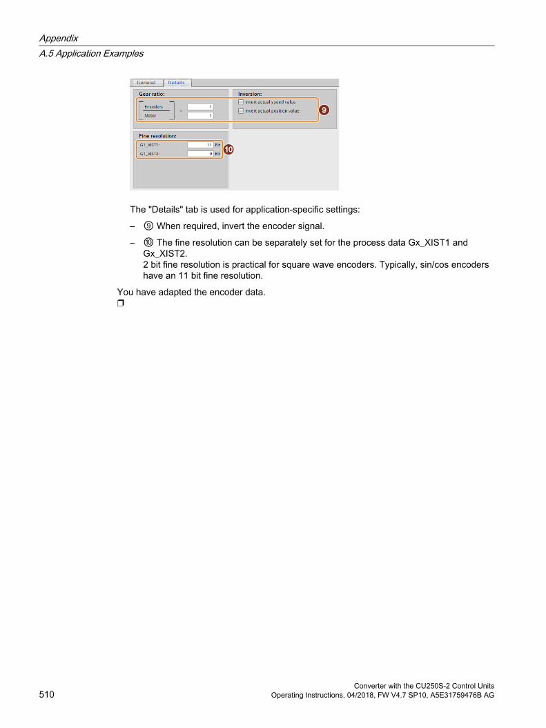
The "Details" tab is used for application-specific settings:
– ⑨ When required, invert the encoder signal.
– ⑩ The fine resolution can be separately set for the process data Gx_XIST1 and Gx_XIST2.2 bit fine resolution is practical for square wave encoders. Typically, sin/cos encoders have an 11 bit fine resolution.
You have adapted the encoder data.
AppendixA.5 Application Examples
Converter with the CU250S-2 Control Units510 Operating Instructions, 04/2018, FW V4.7 SP10, A5E31759476B AG
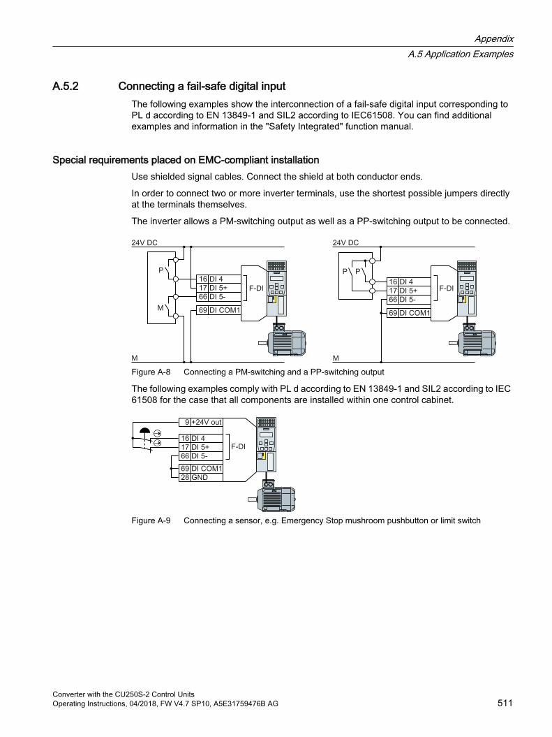
A.5.2 Connecting a fail-safe digital inputThe following examples show the interconnection of a fail-safe digital input corresponding to PL d according to EN 13849-1 and SIL2 according to IEC61508. You can find additional examples and information in the "Safety Integrated" function manual.
Special requirements placed on EMC-compliant installationUse shielded signal cables. Connect the shield at both conductor ends.
In order to connect two or more inverter terminals, use the shortest possible jumpers directly at the terminals themselves.
The inverter allows a PM-switching output as well as a PP-switching output to be connected.
Figure A-8 Connecting a PM-switching and a PP-switching output
The following examples comply with PL d according to EN 13849-1 and SIL2 according to IEC 61508 for the case that all components are installed within one control cabinet.
Figure A-9 Connecting a sensor, e.g. Emergency Stop mushroom pushbutton or limit switch
AppendixA.5 Application Examples
Converter with the CU250S-2 Control UnitsOperating Instructions, 04/2018, FW V4.7 SP10, A5E31759476B AG 511
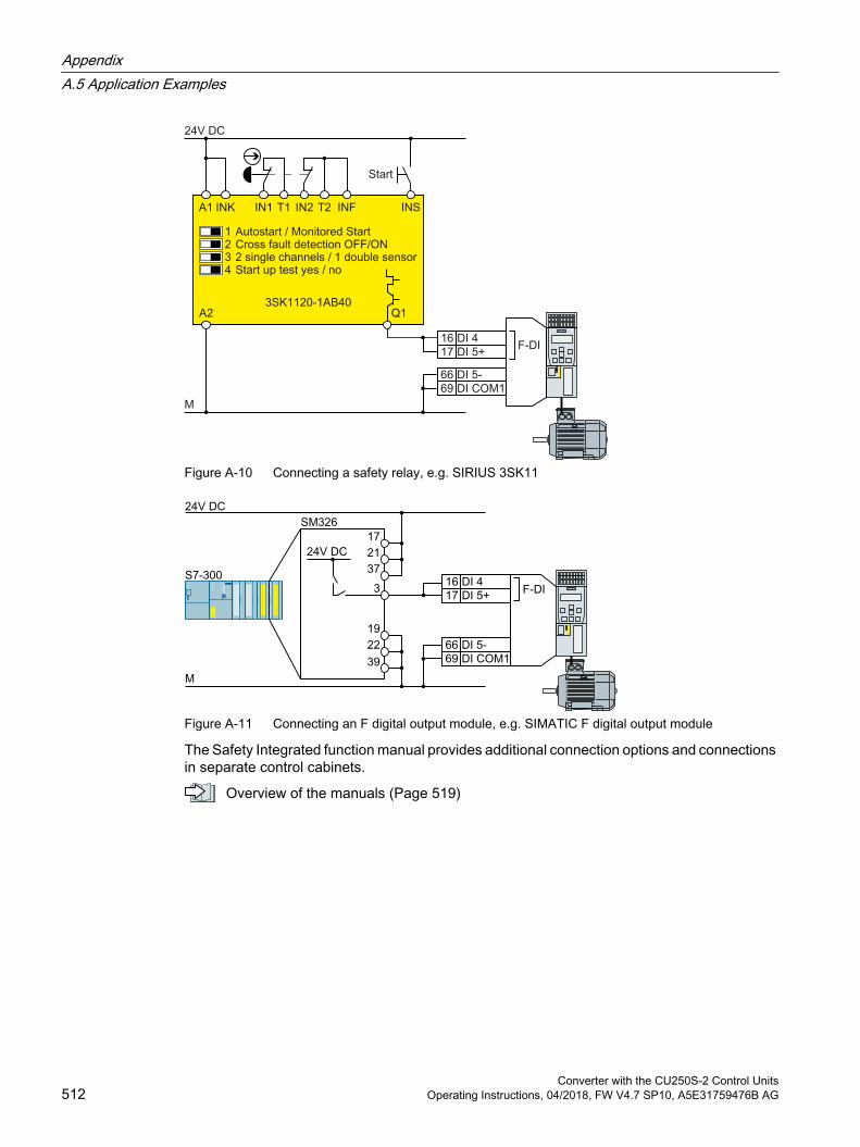
Figure A-10 Connecting a safety relay, e.g. SIRIUS 3SK11
Figure A-11 Connecting an F digital output module, e.g. SIMATIC F digital output module
The Safety Integrated function manual provides additional connection options and connections in separate control cabinets.
Overview of the manuals (Page 519)
AppendixA.5 Application Examples
Converter with the CU250S-2 Control Units512 Operating Instructions, 04/2018, FW V4.7 SP10, A5E31759476B AG
A.6 Acceptance tests for the safety functions
A.6.1 Recommended acceptance testThe following descriptions for the acceptance test are recommendations that illustrate the principle of acceptance. You may deviate from these recommendations if you check the following once you have completed commissioning:
Correct assignment of the interfaces of each converter with the safety function:
– Fail-safe inputs
– PROFIsafe address
Correct setting of the STO safety function.
Note
Perform the acceptance test with the maximum possible velocity and acceleration in order to test the expected maximum braking distances and braking times.
NoteNon-critical alarms
The following alarms are issued following each system ramp-up and are not critical for acceptance: A01697 A01796
AppendixA.6 Acceptance tests for the safety functions
Converter with the CU250S-2 Control UnitsOperating Instructions, 04/2018, FW V4.7 SP10, A5E31759476B AG 513
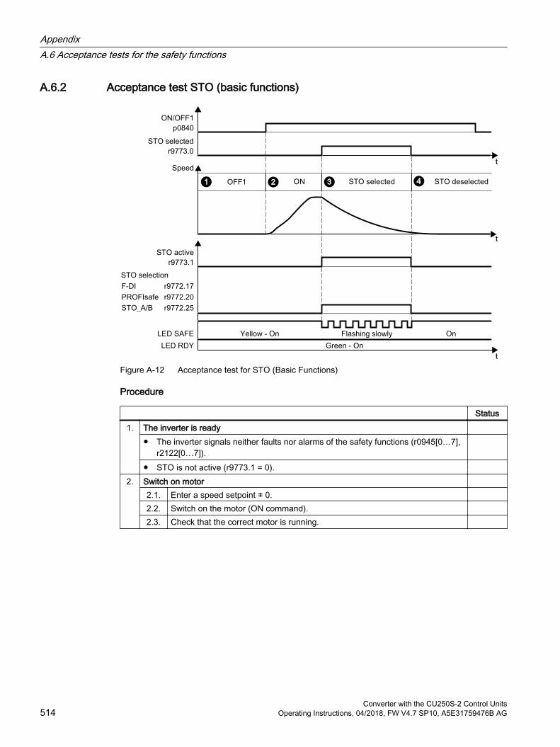
A.6.2 Acceptance test STO (basic functions)
Figure A-12 Acceptance test for STO (Basic Functions)
Procedure
Status1. The inverter is ready
The inverter signals neither faults nor alarms of the safety functions (r0945[0…7], r2122[0…7]).
STO is not active (r9773.1 = 0). 2. Switch on motor
2.1. Enter a speed setpoint ≠ 0. 2.2. Switch on the motor (ON command). 2.3. Check that the correct motor is running.
AppendixA.6 Acceptance tests for the safety functions
Converter with the CU250S-2 Control Units514 Operating Instructions, 04/2018, FW V4.7 SP10, A5E31759476B AG
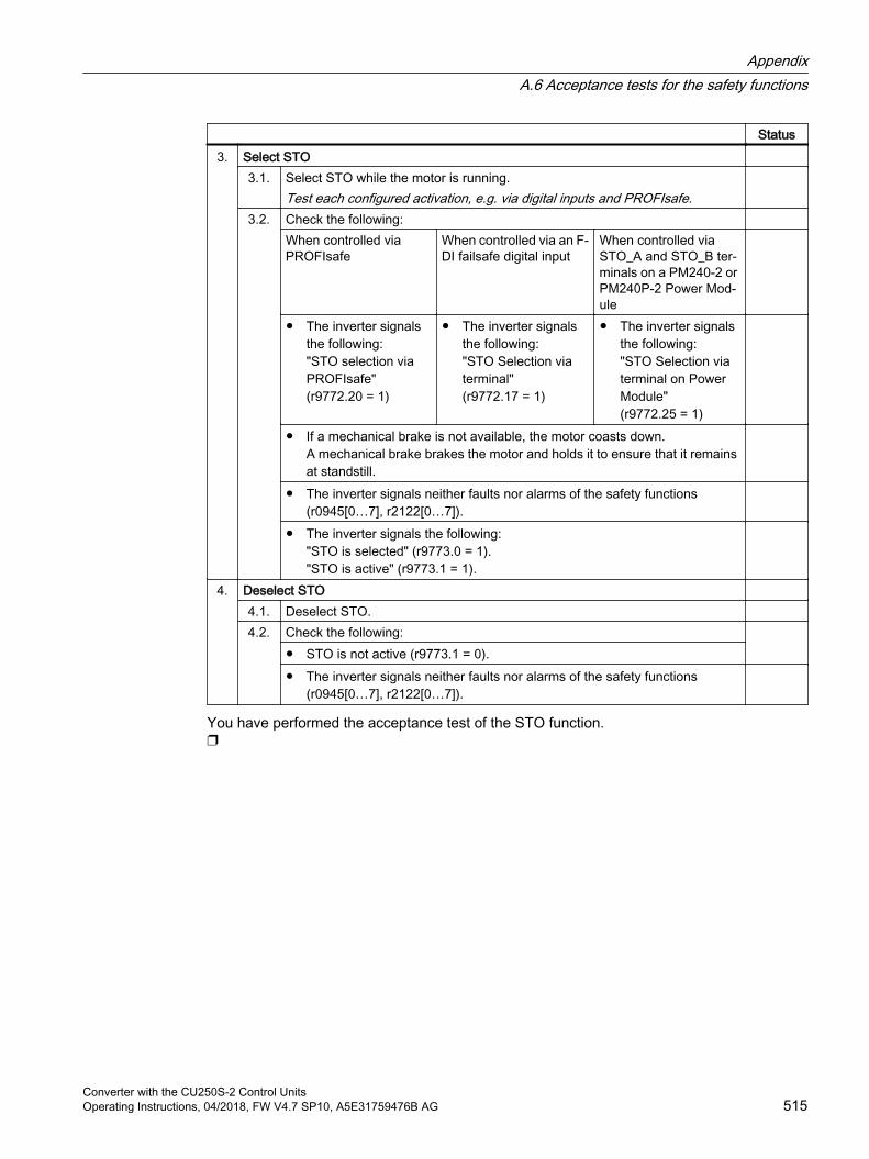
Status3. Select STO
3.1. Select STO while the motor is running.Test each configured activation, e.g. via digital inputs and PROFIsafe.
3.2.
Check the following: When controlled via PROFIsafe
When controlled via an F-DI failsafe digital input
When controlled via STO_A and STO_B ter‐minals on a PM240‑2 or PM240P‑2 Power Mod‐ule
The inverter signals the following: "STO selection via PROFIsafe" (r9772.20 = 1)
The inverter signals the following: "STO Selection via terminal" (r9772.17 = 1)
The inverter signals the following: "STO Selection via terminal on Power Module" (r9772.25 = 1)
If a mechanical brake is not available, the motor coasts down. A mechanical brake brakes the motor and holds it to ensure that it remains at standstill.
The inverter signals neither faults nor alarms of the safety functions (r0945[0…7], r2122[0…7]).
The inverter signals the following: "STO is selected" (r9773.0 = 1). "STO is active" (r9773.1 = 1).
4. Deselect STO 4.1. Deselect STO. 4.2. Check the following:
STO is not active (r9773.1 = 0). The inverter signals neither faults nor alarms of the safety functions
(r0945[0…7], r2122[0…7]).
You have performed the acceptance test of the STO function.
AppendixA.6 Acceptance tests for the safety functions
Converter with the CU250S-2 Control UnitsOperating Instructions, 04/2018, FW V4.7 SP10, A5E31759476B AG 515
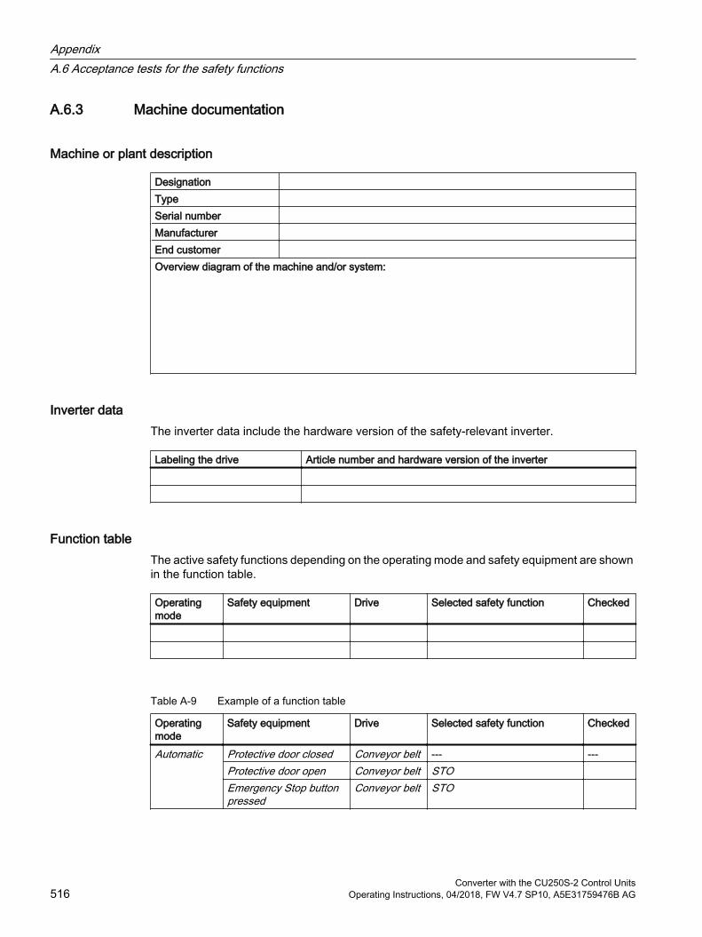
A.6.3 Machine documentation
Machine or plant description
Designation Type Serial number Manufacturer End customer Overview diagram of the machine and/or system:
Inverter dataThe inverter data include the hardware version of the safety-relevant inverter.
Labeling the drive Article number and hardware version of the inverter
Function tableThe active safety functions depending on the operating mode and safety equipment are shown in the function table.
Operating mode
Safety equipment Drive Selected safety function Checked
Table A-9 Example of a function table
Operating mode
Safety equipment Drive Selected safety function Checked
Automatic Protective door closed Conveyor belt --- ---Protective door open Conveyor belt STO Emergency Stop button pressed
Conveyor belt STO
AppendixA.6 Acceptance tests for the safety functions
Converter with the CU250S-2 Control Units516 Operating Instructions, 04/2018, FW V4.7 SP10, A5E31759476B AG

Acceptance test reports
File name of the acceptance reports
Data backup
Data Storage medium Holding areaArchiving type Designation Date
Acceptance test reports PLC program Circuit diagrams
Countersignatures
Commissioning engineerThe commissioning engineer confirms that the tests and checks listed above have been correctly executed.
Date Name Company/dept. Signature… … … …
Machine manufacturerThe machine OEM confirms the correctness of the settings documented above.
Date Name Company/dept. Signature… … … …
AppendixA.6 Acceptance tests for the safety functions
Converter with the CU250S-2 Control UnitsOperating Instructions, 04/2018, FW V4.7 SP10, A5E31759476B AG 517
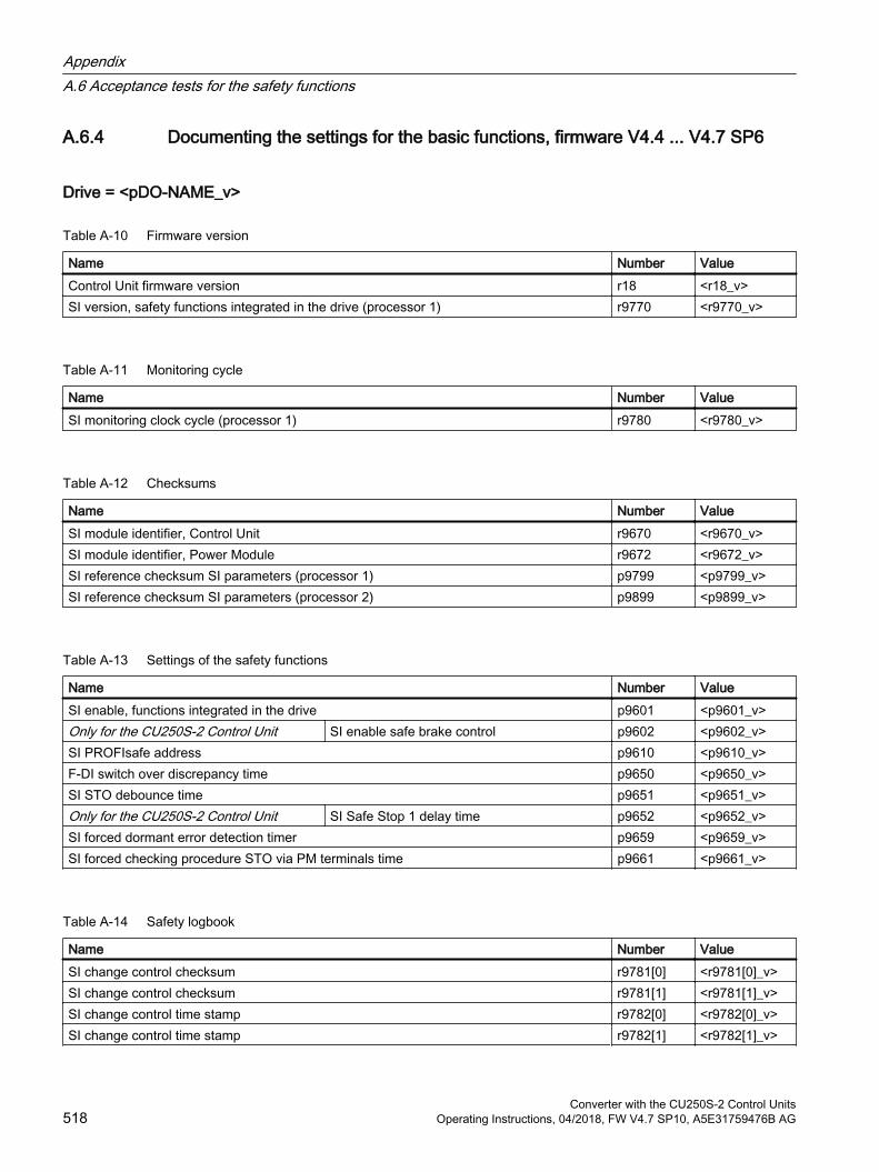
A.6.4 Documenting the settings for the basic functions, firmware V4.4 ... V4.7 SP6
Drive = <pDO-NAME_v>
Table A-10 Firmware version
Name Number ValueControl Unit firmware version r18 <r18_v>SI version, safety functions integrated in the drive (processor 1) r9770 <r9770_v>
Table A-11 Monitoring cycle
Name Number ValueSI monitoring clock cycle (processor 1) r9780 <r9780_v>
Table A-12 Checksums
Name Number ValueSI module identifier, Control Unit r9670 <r9670_v>SI module identifier, Power Module r9672 <r9672_v>SI reference checksum SI parameters (processor 1) p9799 <p9799_v>SI reference checksum SI parameters (processor 2) p9899 <p9899_v>
Table A-13 Settings of the safety functions
Name Number ValueSI enable, functions integrated in the drive p9601 <p9601_v>Only for the CU250S-2 Control Unit SI enable safe brake control p9602 <p9602_v>SI PROFIsafe address p9610 <p9610_v>F-DI switch over discrepancy time p9650 <p9650_v>SI STO debounce time p9651 <p9651_v>Only for the CU250S-2 Control Unit SI Safe Stop 1 delay time p9652 <p9652_v>SI forced dormant error detection timer p9659 <p9659_v>SI forced checking procedure STO via PM terminals time p9661 <p9661_v>
Table A-14 Safety logbook
Name Number ValueSI change control checksum r9781[0] <r9781[0]_v>SI change control checksum r9781[1] <r9781[1]_v>SI change control time stamp r9782[0] <r9782[0]_v>SI change control time stamp r9782[1] <r9782[1]_v>
AppendixA.6 Acceptance tests for the safety functions
Converter with the CU250S-2 Control Units518 Operating Instructions, 04/2018, FW V4.7 SP10, A5E31759476B AG

A.7 Manuals and technical support
A.7.1 Overview of the manuals
Manuals with additional information that can be downloaded CU250S-2 Compact Operating Instructions (https://support.industry.siemens.com/cs/
ww/en/view/109482988)Commissioning the inverter.
CU250S-2 operating instructions (https://support.industry.siemens.com/cs/ww/en/view/109482997)Installing, commissioning and maintaining the inverters. Advanced commissioning (this manual)
EMC installation guideline (http://support.automation.siemens.com/WW/view/en/60612658)EMC-compliant control cabinet design, equipotential bonding and cable routing
"Basic positioner" function manual (https://support.industry.siemens.com/cs/ww/en/view/109477922)Commissioning the basic positioner.
"Safety Integrated" function manual (https://support.industry.siemens.com/cs/ww/ene/view/109751320)Configuring PROFIsafe. Installing, commissioning and operating failsafe functions of the inverter.
"Fieldbus" function manual (https://support.industry.siemens.com/cs/ww/en/view/109751350)Configuring fieldbuses
CU250S-2 List Manual (https://support.industry.siemens.com/cs/ww/en/view/109482981)Parameter list, alarms and faults. Graphic function diagrams
Power Module Installation Manual (https://support.industry.siemens.com/cs/ww/en/ps/13224/man)Installing Power Modules, reactors and filters. Technical data, maintenance
BOP-2 operating instructions (https://support.industry.siemens.com/cs/ww/en/view/109483379)Using the operator panel.
AppendixA.7 Manuals and technical support
Converter with the CU250S-2 Control UnitsOperating Instructions, 04/2018, FW V4.7 SP10, A5E31759476B AG 519
Operating instructions IOP-2 (https://support.industry.siemens.com/cs/ww/en/view/109752613)Using the operator panel, mounting the door mounting kit for IOP.
Accessories manual (https://support.industry.siemens.com/cs/ww/en/ps/13225/man)Descriptions of how to install inverter components, e.g. line reactors and line filters. The printed installation descriptions are supplied together with the components.
S110 Manual (https://support.industry.siemens.com/cs/ww/en/view/109478122)Installing the PM340 Power Module, technical data and maintenance.
S120 Manual (https://support.industry.siemens.com/cs/ww/en/view/109478725)Description of the SMC and SME Sensor Modules
Finding the most recent edition of a manualIf there a multiple editions of a manual, select the latest edition:
Configuring a manualFurther information about the configurability of manuals is available in the Internet:
MyDocumentationManager (https://www.industry.siemens.com/topics/global/en/planning-efficiency/documentation/Pages/default.aspx).
Select "Display and configure" and add the manual to your "mySupport-documentation":
Not all manuals can be configured.
The configured manual can be exported in RTF, PDF or XML format.
AppendixA.7 Manuals and technical support
Converter with the CU250S-2 Control Units520 Operating Instructions, 04/2018, FW V4.7 SP10, A5E31759476B AG

A.7.2 Configuring support
CatalogOrdering data and technical information for SINAMICS G inverters.
Catalogs for download or online catalog (Industry Mall):
Everything about SINAMICS G120 (www.siemens.en/sinamics-g120)
SIZERThe configuration tool for SINAMICS, MICROMASTER and DYNAVERT T drives, motor starters, as well as SINUMERIK, SIMOTION controllers and SIMATIC technology
SIZER on DVD:
Article number: 6SL3070-0AA00-0AG0
Download SIZER (http://support.automation.siemens.com/WW/view/en/10804987/130000)
EMC (electromagnetic compatibility) technical overviewStandards and guidelines, EMC-compliant control cabinet design
EMC overview (https://support.industry.siemens.com/cs/ww/en/view/103704610)
EMC Guidelines configuration manualEMC-compliant control cabinet design, potential equalization and cable routing
EMC installation guideline (http://support.automation.siemens.com/WW/view/en/60612658)
Safety Integrated for novices technical overviewApplication examples for SINAMICS G drives with Safety Integrated
Safety Integrated for novices (https://support.industry.siemens.com/cs/ww/en/view/80561520)
AppendixA.7 Manuals and technical support
Converter with the CU250S-2 Control UnitsOperating Instructions, 04/2018, FW V4.7 SP10, A5E31759476B AG 521

A.7.3 Product SupportYou can find additional information about the product on the Internet:
Product support (https://support.industry.siemens.com/cs/ww/en/)
This URL provides the following:
Up-to-date product information (product announcements)
FAQs
Downloads
The Newsletter contains the latest information on the products you use.
The Knowledge Manager (Intelligent Search) helps you find the documents you need.
Users and specialists from around the world share their experience and knowledge in the Forum.
You can find your local representative for Automation & Drives via our contact database under "Contact & Partner".
Information about local service, repair, spare parts and much more can be found under "Services".
AppendixA.7 Manuals and technical support
Converter with the CU250S-2 Control Units522 Operating Instructions, 04/2018, FW V4.7 SP10, A5E31759476B AG

Index
887 Hz characteristic, 86
AAbsolute encoder, 507Absolute value generator, 225Acceptance test, 256
Complete, 256Reduced scope, 436Reduced scope of, 257STO (Basic Functions), 514, 515Test scope, 257
Acceptance test record, 256Acyclic communication, 205ADD, 225Adder, 225Agitators, 137, 144Alarm, 387, 394Alarm buffer, 394Alarm code, 394Alarm history, 395Alarm time, 394Alarm value, 394Ambient temperature, 334Analog input, 93, 96
Function, 164, 172Analog output, 93, 96
Function, 164, 176AND, 225AND block, 225Application example, 116, 118, 165, 168, 171, 176, 205, 268, 269, 274, 275, 505
Reading and writing parameters cyclically via PROFIBUS, 205
Article number, 30ASCII code
Licensing, 497Automatic mode, 218Automatic restart, 346AVA, 225
BBase load, 444Base load input current, 444
Base load output current, 444Base load power, 444Basic positioner, 158BF (Bus Fault), 388, 389, 390BICO block, 503Bimetallic switch, 330Binary changeover switch, 226Binectors, 504Bit pattern test, 251Block, 503BOP-2
Menu, 498Symbols, 498
Brake Relay, 87Braking
Regenerative, 325Braking functions, 316Braking method, 316, 317Braking module, 323Braking resistor, 48, 323BSW, 226Bus termination, 92
CCable railways, 144Cable resistance, 288Catalog, 521CDS (Command Data Set), 218, 255Centrifuge, 137, 144, 318, 321, 325Chain conveyors, 137, 144Characteristic
Additional, 292Linear, 292, 293parabolic, 292, 293square-law, 292, 293
Circuit diagram, 517Clockwise rotation, 177Closed-loop torque control, 314Command Data Set, 218Commissioning
Guidelines, 125Communication
Acyclic, 205Comparator, 230Compound braking, 321, 322Compressor, 137, 144Computational performance, 133Configuring support, 521
Converter with the CU250S-2 Control UnitsOperating Instructions, 04/2018, FW V4.7 SP10, A5E31759476B AG 523
Connectors, 504Consistency, 250Consistent signals, 250Contact bounce, 251Control terminals, 96Control Units, 30Control word
Control word 1, 187, 206, 210Control word 2, 190Control word 3, 191
Control word 2 (STW2), 190Control word 3 (STW3), 191Controlling the motor, 177Conveyor belt, 137, 144, 318Conveyor systems, 145Copy
Series commissioning, 257Copy parameters (series commissioning), 257Counter-clockwise rotation, 177Countersignatures, 517Crane, 221Crushers, 137, 144Current input, 170Current reduction, 476Cyclic communication, 186, 187
DD flip-flop, 226Data backup, 361, 368, 373, 375, 517Data set 47 (DS), 205Data set changeover, 255Data transfer, 368, 373, 375DC braking, 191, 318, 319, 320DC-link overvoltage, 335DC-link voltage, 335Dead band, 173Delta connection, 86Delta connection (Δ), 127Derating
Installation altitude, 478DFR, 226DIF, 227Differentiator, 227Digital input, 93, 96, 177
Function, 164Digital inputs
Multiple assignment, 255Digital output, 93, 96
Function, 164, 168DIP switch
Analog input, 170
Direct data exchange, 205Direction of rotation, 273Direction reversal, 177Discrepancy, 250
Filter, 250Tolerance time, 250
DIV, 227Divider, 227Download, 368, 373, 375Drive control, 157Drive Data Set, DDS, 359Drive Data Sets, 359Droop, 303dv/dt filter, 289Dynamic braking, 323
EElevator, 144, 221EMC, 53EMERGENCY STOP, 245Emergency Stop button, 245EMERGENCY SWITCHING OFF, 245EN 60204‑1, 245EN 61800-5-2, 245Encoder, 300Encoder cable, 121, 123Encoder cables, 112Encoder data, 509End customer, 516Energy recovery, 36Energy recovery option, 325Energy-saving display, 357Escalator, 144EXCLUSIVE OR block, 235Extruder, 137, 144, 329
FFactory assignment, 96Factory settings, 152
Restoring the, 152, 153, 155Failsafe digital input, 167Fan, 137, 144, 145Fans, 328Fault, 387, 397
Acknowledge, 397, 398Motor, 438
Fault buffer, 397Fault case, 399Fault code, 397
Index
Converter with the CU250S-2 Control Units524 Operating Instructions, 04/2018, FW V4.7 SP10, A5E31759476B AG
Fault history, 398Fault time, 397
received, 397removed, 397
Fault value, 397FCC, 289F-DI (Failsafe Digital Input), 167F-digital output module, 512FFC (Flux Current Control), 292Field weakening, 86Fieldbus interfaces, 92Filter
Contact bounce, 251Discrepancy, 250On/off test, 251
Fine resolution, 510Firmware, 30Firmware downgrade, 433Firmware update, 436Firmware version, 413, 481, 482, 483, 484, 485, 486, 487, 488, 489, 490, 491, 516Flip-flop, 226, 234Flow control, 283Flux current control, 289Flying restart, 344Forced checking procedure, 252Forced dormant error detection
setting, 253Formatting, 363Forming the DC link capacitors, 128Free function blocks, 224Function module, 132Function table, 516Functional expansions, 257Functions
BOP-2, 498
GGantry crane, 144Getting Started, 519Grinding machine, 318, 321
HHardware Installation Manual, 519High Overload, 444Hoist drive, 325Hoisting gear, 221, 323Horizontal conveyors, 321, 323, 329Hotline, 522
II_max controller, 326I2t monitoring, 327Inclined conveyors, 323IND (page index), 200Industry Mall, 521Installation altitude, 478Installing, 60INT, 227Integrator, 227Interfaces, 92Interlock, 505Inverter, 230
does not respond, 437Update, 436
Inverter components, 413
JJOG function, 214
KKinetic buffering, 350Kneaders, 137, 144Know-how protection, 364, 381KTY84 sensor, 330
LLED
BF, 388, 389, 390LNK, 389RDY, 388SAFE, 389
LED (light emitting diode), 387Level control, 283License, 158, 364License key
Create, 493Display, 493Entering in STARTER, 496Entry using the BOP-2, 497
LicensingASCII code, 497
Lifter, 144LIM, 228Limit monitor, 228
Index
Converter with the CU250S-2 Control UnitsOperating Instructions, 04/2018, FW V4.7 SP10, A5E31759476B AG 525
Limit position, 216Limit position control, 216Limit switch, 216Limiter, 228Line and motor connection, frame sizes FSD … FSF, 85Line contactor, 244Line dip, 350Line filter, 39Linear characteristic, 292, 293List Manual, 519LNK (PROFINET Link), 389Load failure, 342Low Overload, 444Lowerer, 144LVM, 228
MMachine description, 516Main screen form (basic functions), 249Manual mode, 218Manufacturer, 516Maximum cable length
DRIVE-CLiQ, 442Encoder, 442PROFIBUS, 118PROFINET, 115
Maximum current controller, 326Maximum speed, 131, 273MELD_NAMUR (fault word according to the VIK-Namur definition), 193Memory cards, 362Menu
BOP-2, 498Operator panel, 498
MFP, 229Mills, 137, 144Minimum speed, 131, 273, 276Mixers, 137, 144MMC (memory card), 363Moment of inertia estimator, 308MOP (motorized potentiometer), 264Motor control, 159Motor data, 127
Identify, 301, 314Motor fault, 438Motor holding brake, 220, 221, 244Motor standard, 238Motor temperature sensor, 93, 96, 331Motorized potentiometer, 264MUL, 229
Multiple assignmentDigital inputs, 255
Multiplier, 229Multiturn encoder, 507
NNCM, 230NOT, 230NSW, 230Numeric changeover switch, 230
OOFF delay, 232OFF1 command, 177OFF3 ramp-down time, 279ON command, 177ON delay, 232On/off test, 251Operating instruction, 25Operating Instructions, 519Operating mode, 516Operation, 162Operator panel
BOP-2, 498Menu, 498
Optimizing the closed-loop speed controller, 301OR, 231OR block, 231Output reactor, 288Overload, 326Overview
Section, 26, 27Overvoltage, 335
PPage index, 200Parabolic characteristic, 292, 293Parameter channel, 198
IND, 200Parameter index, 200Parameter number, 200, 501Parameter value, 501Partial load operation, 477password, 247PCL, 231PDE, 232PDF, 232PFH (Probability of failure per hour), 441
Index
Converter with the CU250S-2 Control Units526 Operating Instructions, 04/2018, FW V4.7 SP10, A5E31759476B AG
PID controller, 283PKW (parameter, ID value), 183Plant description, 516PLC functionality, 505PLC program, 517PLI, 233Polyline, 233Power failure, 346Power Module, 30Pre-control, 311Prefabricated encoder cable, 121, 123Pressure control, 283Probe, 271, 343Procedure, 25PROFIBUS, 118PROFIdrive, 113, 114PROFIenergy, 113, 114PROFIsafe, 113, 114Protection functions, 159PST, 233PT1, 234Pt1000 sensor, 330PTC sensor, 330Pulse cancelation, 187, 207, 210Pulse enable, 187, 207, 210Pulse frequency, 328, 329, 476Pulse generator, 229Pulse shortener, 231Pulse stretcher, 233Pulse train, 271Pump, 137, 144, 145PZD (process data), 183
QQuestions, 522
RRamp-down time, 279, 281
Scaling, 281Ramp-function generator, 273, 278Rampup time, 279, 281Ramp-up time
Scaling, 281RDY (Ready), 388Ready, 162Ready for switching on, 162Regenerative feedback, 325Regenerative operation, 316
ReplaceControl Unit, 436Gear unit, 436Hardware, 436Motor, 436Power Module, 436
ResetParameter, 152, 153, 155
Reversing, 273Roller conveyors, 137, 144Rotary furnace, 137, 144Rounding, 279Rounding OFF3, 279RS flip-flop, 234RSR, 234Run sequence, 224Runtime group, 224
SS7 communication, 113, 114SAFE, 389Safe Brake Relay, 50, 87, 253Safety function, 158Safety relay, 512Saw, 318, 321Scaling
Analog input, 171Analog output, 174
SD (memory card), 363Formatting, 363MMC, 363
Self-test, 252Sensor
Electromechanical, 511Sensor Module, 52, 121, 123, 520Sequence control, 162Serial number, 516Series commissioning, 257, 361Setpoint processing, 158, 273Setpoint source, 158
Selecting, 260, 262, 264Settling time, 137, 144Shield connection kit, 38Short-circuit monitoring, 330, 331Signal cables, 112Signal interconnection, 503Signal states, 388Sine-wave filter, 47, 288SIZER, 521Skip frequency band, 273Slip compensation, 289
Index
Converter with the CU250S-2 Control UnitsOperating Instructions, 04/2018, FW V4.7 SP10, A5E31759476B AG 527
SMC (Sensor Module Cabinet), 52, 123SMC: Sensor Module Cabinet, 121SME (Sensor Module External), 52, 123SME: Sensor Module External, 121Smoothing element, 234Speed
change with BOP-2, 498Limiting, 273
Speed control, 298Speed monitoring, 342Spindle, 137, 144Square-law characteristic, 292, 293Stacker crane, 144Standards
EN 61800-3, 31Star connection (Y), 86Startdrive, 246, 373Startdrive commissioning tool, 246Startdrive PC tool, 246STARTER, 246
Download, 126STARTER commissioning tool, 246STARTER PC tool, 246Starting behavior
Optimization, 294, 296Starting current, 290State overview, 162Status word
Status word 1, 188, 207, 211Status word 2, 190Status word 3, 192
Status word 1 (ZSW2), 190STO (Safe Torque Off), 244
Acceptance test, 514, 515select, 244
Stop Category 0, 245Storage medium, 361STW1 (control word 1), 187, 206, 210SUB, 234Subindex, 200Subtracter, 234Support, 522Switch off
Motor, 163OFF1 command, 163OFF2 command, 163OFF3 command, 163
Switch onMotor, 163ON command, 163
Switching on inhibited, 162, 188, 207, 210Switching-on a motor with BOP-2, 498
Switch-off signal paths, 252Symbols, 25System runtime, 392
TTechnical data
Control Unit, 439, 440, 441Technology controller, 191, 240, 283Telegram
Extending, 203Temperature calculation, 333Temperature monitoring, 327, 333Temperature sensor, 93, 96Temperature switch, 330Terminal block, 164Terminal strip, 111
Factory setting, 96Overview, 93
Test signals, 251Three-wire control, 177Time slice, 224Torque accuracy, 137, 144Two-wire control, 177Type plate
Control Unit, 30Power Module, 30
UUnit system, 238Unwinders, 325Update
Firmware, 436Upgrading the firmware, 431Upload, 365, 373, 375Use for the intended purpose, 29User interfaces, 92
VV/f characteristic, 289VDC min controller, 350Vector control, 298, 301, 314Version
Control Unit, 30Firmware, 516Hardware, 516Power Module, 30Safety function, 516
Vertical conveyors, 323
Index
Converter with the CU250S-2 Control Units528 Operating Instructions, 04/2018, FW V4.7 SP10, A5E31759476B AG

Voltage boost, 289, 290, 294, 296Voltage input, 170
WWinders, 325Wire breakage, 250Wire-break monitoring, 171, 330, 331Write protection, 378
XXOR, 235
ZZSW1 (status word 1), 188, 207, 211ZSW3 (status word 3), 192
Index
Converter with the CU250S-2 Control UnitsOperating Instructions, 04/2018, FW V4.7 SP10, A5E31759476B AG 529

Index
Converter with the CU250S-2 Control Units530 Operating Instructions, 04/2018, FW V4.7 SP10, A5E31759476B AG


Scan the QR code for
additional
information about
SINAMICS G120.
Germany
Further information
PROFINET
Safety Integrated
SINAMICS converters:
www.siemens.com/sinamics
www.siemens.com/safety-integrated
www.siemens.com/profinet
Siemens AG
Digital Factory
Motion Control
Postfach 3180
91050 ERLANGEN