Manual - ADEGIS
300
Notes for the User Startup Checklist What is the IP 288? Installing the Module What Data Does the IP 288 Use? Operating the IP 288 Manual Parameterization Software Order No.: 6ES5 998-5SF21 Release 01 How Do You Link the IP 288 Into Your User Program? IP 288 - Reference Section Index
-
Upload
khangminh22 -
Category
Documents
-
view
0 -
download
0
Transcript of Manual - ADEGIS

Notes for the User
Startup Checklist
What is the IP 288?
Installing the Module
What Data Does the IP 288 Use?
Operating the IP 288
Manual Parameterization Software
Order No.: 6ES5 998-5SF21 Release 01 How Do You Link the IP 288
Into Your User Program?
IP 288 - Reference Section
Index

Copyright
Copyright O Siemens AG 1994 All Rights Reserved
The reproduction, transmission or use of this document or its contents is not permitted without express written authority. Offenders will be liable for damages. All rights, including rights created by patent grant or registration of a utility model or design, are reserved.
Liability disclaimer
We have checked the contents of this manual for agreement with the hardware and software described. Since deviations cannot be excluded entirely, we cannot guarantee full agreement. However, the data in this manual are reviewed regulatiy and any necessary corrections induded in subsequent editions. Suggestions for improvement are welcomed.
Technical data subject to change.
Safe p r e l a t e guidelines
This manual contains certain notices which you should observe to ensure your own personal safety, as well as to protect the product and connected equipment. These notices are highlighted in the manual by a warning triangle and are marked as follows according to the level of danger:
A Warning indicates that death, severe personal injury or substantial damage to property can result if proper precautions are not taken.
A Caution indicates that minor personal injury or property damage can result if proper precautions are not taken.
Only qualified personnel should be allowed to install and work on this equipment Qualified persons are defined as persons who are authorized to commission, to ground and to tag equipment, systems and circuits in accordance with established safety practices and standards.
Siemens Aktiengesellschaft ES5 9985SF21 EWK Elekkonikwerk Karkruhe
Rinted in the Federal Republic of Germany

Contents
Contents
........................................................ Notes for the User 1.1
......................................................... Startup Checklist 2.1
What is the IP 288? ....................................................... 3.3
Functions and Principle of Operation of the IP 288 . . . . . . . . . . . . . . . . . . . . . . . . . . . . . . . 3.4
The Electronic Cam Controller ............................................... 3.4 . . . . . . . . . . . . . . . . . . . . . . . . . . . . . . . . . . . . . . . . . . . . . . . . . . . . . . . . . . . . . . Positioning 3.6
How Does the IP 288 Operate? ............................................... 3.8 .............................................................. Monitoring 3.9
Further Possibilities of the IP 288 ............................................. 3.9 . . . . . . . . . . . . . . . . . . . . . . . . . . . . . . . . . . . . . . . . . . . . . . . How is the IP 288 Designed? 3.10
................................................ The Hardware of the IP 288 3.10 How is the Module Connected to the Programmer? .............................. 3.11
.................................... How is the Module Connected to the CPU? 3. 11
..................................................... Installing the Module 4 3
What Must You Do Before You Install the Module? .............................. 4.4 ............................................ Where Can You Use the Module? 4.6
............................................. How Do You Install the Module? 4.8
. . . . . . . . . . . . . . . . . . . . . . . . . . . . . . . . . . . . . . . . . Installation in the S5-135Ul155U PLC 4.8 . . . . . . . . . . . . . . . . . . . . . . . . . . . . . . . . . . . . . . . . . . . . . . . . . . Installation in an S5-115U 4.9
.............................................. How Do You Wire the IP 288? 4.10
.......................................... How Do You Replace the Module? 4.11
What Data Does the IP 288 Use? ............................................ 5.3 ........................................................ SYSID Parameters 5.4
Machine Data ............................................................ 5.7

Contents
Cam Data ............................................................... 5.32
Transferring Cam Sets to the Module ......................................... 5.41 Cam Set Directory ........................................................ 5.42
The Target Set ........................................................... 5.44
Transferring Target Data to the Module ....................................... 5-46 Target Set Directory ...................................................... 5.47
The Target List .......................................................... 5.49
Transferring a Target List to the Module ...................................... 5.5 1
Operating the IP 288 ...................................................... 6.3 Operating Modes and Functions .............................................. 6-4
How Do You Synchronize an Axis? ........................................... 6.8
Synchronization for Incremental Encoders ..................................... 6.8 Synchronization for Absolute Encoders . . . . . . . . . . . . . . . . . . . . . . . . . . . . . . . . . . . . . . . . 6.9 Course of a Traverse ...................................................... 6.11
The Operating Modes for Positioning . . . . . . . . . . . . . . . . . . . . . . . . . . . . . . . . . . . . . . . . 6.14
Jog Mode ............................................................... 6. 14 Reference Point Approach . . . . . . . . . . . . . . . . . . . . . . . . . . . . . . . . . . . . . . . . . . . . . . . . . 6. 15 Absolute Increment Mode .................................................. 6. 18 Relative Increment Mode .................................................. 6.19 Processing the Target Set .................................................. 6.20
The Functions of the IP 288 ................................................ 6.2 1
Setting the Actual Value ................................................... 6.22 Zero OIBet ............................................................. 6.23 Setting the Zero Point ..................................................... 6.24 Adaption ............................................................... 6.26 Cam Track Offset ........................................................ 6.28 Loading the Revolution Comparator . . . . . . . . . . . . . . . . . . . . . . . . . . . . . . . . . . . . . . . . . 6.29 Loading the Actual Position Comparator . . . . . . . . . . . . . . . . . . . . . . . . . . . . . . . . . . . . . . 6.30 Teach-In (for Positioning) . . . . . . . . . . . . . . . . . . . . . . . . . . . . . . . . . . . . . . . . . . . . . . . . . . 6.3 1 Teach-In (for a Cam Controller) . . . . . . . . . . . . . . . . . . . . . . . . . . . . . . . . . . . . . . . . . . . . . 6.32 Simulation . . . . . . . . . . . . . . . . . . . . . . . . . . . . . . . . . . . . . . . . . . . . . . . . . . . . . . . . . . . . . . 6.33 Individual Functions . . . . . . . . . . . . . . . . . . . . . . . . . . . . . . . . . . . . . . . . . . . . . . . . . . . . . . 6.35 Programmer mode ........................................................ 6.35 Trigger reference point .................................................... 6.36 Drive disable . . . . . . . . . . . . . . . . . . . . . . . . . . . . . . . . . . . . . . . . . . . . . . . . . . . . . . . . . . . . 6.36 Follow-up . . . . . . . . . . . . . . . . . . . . . . . . . . . . . . . . . . . . . . . . . . . . . . . . . . . . . . . . . . . . . . 6.37 Roundmg ............................................................... 6.37 Cam track enable ......................................................... 6.40 Functions with Control Bits ................................................ 6.40 Delete memory .......................................................... 6.40 Acknowledging external errors .............................................. 6.41 Acknowledging operator errors ............................................. 6.41 Acknowledging the Watchdog .............................................. 6-41 Process Diagnostics ...................................................... 6.42 Triggering the Diagnostics Memory .......................................... 6.43

Con tents
Parameterization Software ................................................ 7.3
............................................ How Do You Operate COM 288? 7.4
........................................................ How Do You Start? 7.6
. . . . . . . . . . . . . . . . . . . . . . . . . . . . . . . . . . . How Do Find Your Way Around COM 288? 7.7
...................................................... Preparing COM 288 7.10
. . . . . . . . . . . . . . . . . . . . . . . . . . . . Editing. Transferring and Converting Data Sets 7-12
........................................... Operating the IP 288 in Test Mode 7.19
. . . . . . . . . . . . . . . . . . . . . . . . . . . . . . . . . . . . . . . . . . . . . Test Mode for a Cam Controller 7.19 . . . . . . . . . . . . . . . . . . . . . . . . . . . . . . . . . . . . . . . . . . . . . . . . . Test Mode for Positioning 7.22
........................ How Do You Link the IP 288 into Your User Program? 8 3
....................................... Data Structure of the IP 288 . CPU Link 8.4
................................... What Tasks Do the Function Blocks Handle? 8.6
....................................... Cyclic Program Execution with FB ZYK 8.7 . . . . . . . . . . . . . . . . . . . . . . . . . . . . . . . . . . . . . . . . . . . . . . . . Job Processing with FB PAR 8.8
. . . . . . . . . . . . . . . . . . . . . . . . . . . . . . . . . . . . . . . . . . . . Intermpt Processing with FB INT 8.9
............................................................. Data Blocks 8.10
....................................................... DB-ZU Data Block 8.12 . . . . . . . . . . . . . . . . . . . . . . . . . . . . . . . . . . . . . . . . . . . . . . . . . . . . . . . . DB-IP Data Block 8.14
............................................................ Applications 8.14 .................................................... Checkback information 8. 17
.......................................................... Control signals 8.24
.......................................................... Interrupt causes 8.26 . . . . . . . . . . . . . . . . . . . . . . . . . . . . . . . . . . . . . . . . . . . . . . . . . . . . . . DB-APP Data Block 8.28
................................ Userdataofthecontroljobs 1 to4and 16to 18 8.30 . . . . . . . . . . . . . . . . . . . . . . . . . . Assignment of the user data for "Target set processing" 8.32
.................................... Assignment of the user data for "Adaption" 8.33 . . . . . . . . . . . . . . . . . . . . . . . . . . . . . . Assignment of the user data for "Cam track offset" 8.34
..................... Assignment of the user data for "Load revolution comparator" 8.35 Assignment of the user data for "Load actual position comparator" ................. 8.36
.................................... Assignment of the user data for "Teach-In" 8.37 .................................. Assignment of the user data for "Simulation" 8.39
. . . . . . . . . . . . . . . . . . . . . . . . . . . . . . . . . . . . . . . . . . . . . . User data for actual value jobs 8.40 ...................................................... DB-PAR Data Block 8.42
. . . . . . . . . . . . . . . . . . . . . . . . . . . . . . . . . . . . . . . . . . . . . . . . . . . . . . . . . . Transfer Errors 8.44
...................................... How Do You Use the Function Blocks? 8.46
. . . . . . . . . . . . . . . . . . . . . . . . . . . . . . . . . . . . . . . . . . . . . . . . . . . . . . . Interrupt Response 8.46 Interrupting the User Program with Process Interrupts and Time Interrupts ........... 8.47
. . . . . . . . . . . . . . . . . . . . . . . . . . . . . . . . . . . . . . . . . . . . . . . . . . . . Restart Characteristics 8.48 . . . . . . . . . . . . . . . . . . . . . . . . . . . . . . . . . . . . . . . . . . . . . . Controlling axes with FB ZYK 8.49
. . . . . . . . . . . . . . . . . . . . . . . . . . . . . . . . . . . . . . . . . . . . . . . . . . . . Programming Example 8.52
............................................................. Preparation 8.53 ............................................... Procedure for Cam Controller 8.61
.................................................. Procedure for Positioning 8.66
. . . . . . . . . . . . . . . . . . . . . . . . . . . . . . . . . . . . . . . . . . . . . . . . . . . . . . . . . . . . Structograms 8.73

Contents
. . . . . . . . . . . . . . . . . . . . . . . . . . . . . . . . . . . . . . . . . . . Function Blocks FB 38 and FB 39 8.76
..................................................... Function Block FB 38 8.76 FB 39 Function Block ..................................................... 8.78
IP 288 . Reference Section ................................................. 9.3
...................................................... The Pin Assignments 9.4
Connecting Cables and Adapters ............................................. 9.8 Connecting Cable for Siemens Incremental Position Encoders (6FC9320) . . . . . . . . . . . . 9.8 Connecting Cable for Incremental Position Encoders (5 V Supply. 5 V Signal) . . . . . . . . 9.9 Connecting Cable for Incremental Position Encoders (24 V Supply. 5 V Signal) ...... 9.10 Connecting Cable for Incremental Position Encoders (24 V Supply, 24 V Signal) ..... 9. 11
................................... Connecting Cable for SS1 Position Encoders 9.12
................................... Connecting Cable for Digital Inputs/Outputs 9.13 .................................................... Using the 703 Adapter 9. 14
....................................................... Configuring Forms 9. 15
.................................................... Configuring Hardware 9. 15 ............................................. Configuring SYSID Parameters 9. 15
. . . . . . . . . . . . . . . . . . . . . . . . . . . . . . . . . . . . . . . . . . . . . . . . . Configuring Machine Data 9. 16
................................................ The Data Sets of the IP 288 9.21
............................................ Structure of the SYSID Data Set 9.2 1 ........................................... Structure of the Machine Data Set 9.22
...................................... Structure of the Machine Data Directory 9.27 ................................................... Structure of the Cam Set 9.28
........................................... Structure of the Cam Set Directory 9.30 . . . . . . . . . . . . . . . . . . . . . . . . . . . . . . . . . . . . . . . . . . . . . . . . . Structure of the Target Set 9.3 1 . . . . . . . . . . . . . . . . . . . . . . . . . . . . . . . . . . . . . . . . . . . . . . . . . Structure of the Target List 9.33
. . . . . . . . . . . . . . . . . . . . . . . . . . . . . . . . . . . . . . . . . Structure of the Target Set Directory 9.33
How Does the IP 288 Respond in the Event of an Error? ......................... 9.35
............................................................ SYSID Error 9.35 ...................................................... Machine Data Errors 9.36
.......................................................... Cam Set Errors 9.39 ............................................ Target Set and Target List Errors 9.40
........................................................... Internal Errors 9.42 External Errors .......................................................... 9.43
. . . . . . . . . . . . . . . . . . . . . . . . . . . . . . . . . . . . . . . . . . . . . . . . . . . . . . . . . . Operator Errors 9.48 . . . . . . . . . . . . . . . . . . . . . . . . . . . . . . . . . . . . . . . . . Alphabetical List of Error Messages 9.5 1
....................................... Technical Specifications of the Module 9.55
. . . . . . . . . . . . . . . . . . . . . . . . . . . . . . . . Technical Specifications of the Function Blocks 9.56
.................. Technical Specifications of the Function Blocks for the S5-115U 9.56 Technical Specifications of the Function Blocks for the S5-135U (CPU 922) ......... 9.57 Tecbcal Specifications of the Function Blocks for the S5-135U (CPU 928 and CPU 928B) . . . . . . . . . . . . . . . . . . . . . . . . . . . . . . . . . . . . . . . . . . . . . . . . . 9.58
.................. Technical Specifications of the Function Blocks for the S5-155U 9.59 .................................. Technical Specifications of FB 38 and FB 39 9.60

Notes for the User
The following information is designed to make working with the manual easier.
Description of contents
The contents of this manual have been broken down according to subject into the following blocks:
Basics Section 3.1 contains information on the possibilities of using the IP 288 for implementing an electronic cam controller or a positioning controller for rapid traverselcreep speed drives.
Hardware Section 3.2 "How Is the IP 288 Designed?" contains information on the components of the IP 288 and about the connections and indicators on the module. If you require detailed information on the pinouts of the individual interfaces, e.g. for preparing your own connectmg cables, refer to Section 9.1 ("Pin Assignments").
Chapter 4 describes how to install and wire the module. You will find instructions and information concerning:
Setting the page numbers Permissible slots in the different subracks Installation Wiring
To ensure that your programmable controller is noise-immune, you should refer to the Installation Guidelines in your PLC manual or system manual in addition to the information on this subject in this manual. These sources also apply to working with the IP 288.

Notes for the User
Parameterization Chapter 5 tells you which data the IP 288 requires in operation. This chapter contains explanations of the SYSID parameters and the machine data which the IP 288 always requires. You will also find the cam data for a cam controller and the destination data and destination list for positioning in this chapter. Chapter 7 "Parameterization Software" contains information on how to transfer this data to the IP 288 uslng the COM 288 parameterization software. Section 9.4 "The Data Sets of the IP 288" describes the structure of the data sets in which the data is stored. You do not require this information if you work exclusively with COM 28 8.
Operation Chapter 6 "Operating the IP 288" explains the following:
How you can synchronize an axis with incremental or absolute position decoders How to operate the IP 288 via operating modes and settings How an operating mode works
L- in to a user program Chapter 8 "How Do You Link the IP 288 into Your User Program?" describes the function blocks you require to use the IP 288 in an operating system and the data blocks you must set up for this purpose in the CPU memory. Section 8.5 contains an explanation of the programming example for handling function blocks. Th~s example is on the diskette supplied.
Error response The error messages with which the IP 288 responds to both operator errors and system faults are listed and explained in Section 9.5 "How Does the IP 288 Respond to Errors?". Error messages appearing in the case of transfer errors with the standard function blocks are listed in Section 8.3.5 "Transfer Errors". Errors which can only occur while workmg with COM 288 are displayed in plaintext at the operator interface.
Technical specifications The technical specifications of the module are in Section 9.6, and the technical specifications of the function blocks in Section 9.7.

Startup Checklist
You can follow this checklist when starting up the IP 288.
Assembly
Type of action
Planning/preparation
Action
1 by the system
See Manual.. .
I
These must be provided and in working order. I Emergency OFF limit switches must affect the drives directly.
- Drive (control and mechanics) - Position encoders '
Correct selection and adaptation of the direction of rotation
- Connecting cables Standard or home-made connecting cables
- Programmer COM 288 installed and ready to run
Install and wire module - Set page address - Check preset jumpers - Select slot - Install module - Wire module
-
Configuring the system Check the following components - Emergency OFF limit switches
Section 5.2
Section 9.1,9.2
Section 4.1 Section 4.1 Section 4.2 Section 4.3 Section 4.4 or Section 9.1 and 9.2
Determine machine data - Machine data which are determined direct 1 Section 5.2

Checklist
Type of action
Assigning parameters
Assigning parameters
Action See Manual.. .
- Other operating modes and settings, e.g. Section 6.5.1 to Teach-In, coordinate shift 6.5.3
O p e r a k the IP 288
Programming (PLC)
Parameterizing and debugging the IP 288
- Synchronizing the axis
- SYSID parameters - Machine data - Cam data or destination sets or destination list - Testmode
Section 6.2
i Section 5,7 or Section 9.4
Section 7.6
- Jog mode (for positioning) Section 6.4.1 - Increment mode (for positioning) Section 6.4.3, - Parameterize track (cam) i - Enable track (cam) l
Using function blocks - FB ZYK for cyclic program processing - FB PAR for parameterization - FB INT for interrupt processing - Possibly FB 38 for saving scratcMags/system
data and page numbers - Possibly FB 39 for loading scratcMags/system
data and page numbers
Section 8.2.1 Section 8.2.2 Section 8.2.3 Section 8.8.1
Section 8.8.2

What is the IP 288?
Contents of Chapter 3
3 What is the IP 288? ......................................................................................................................... 3-3
3.1 Functions and Principle of Operation of the IP 288 .......................................................................... 3-4
3.1.1 The Electronic Cam Controller ......................................................................................................... 3.4 3.1.2 Positioning ......................................................................................................................................... 3-6 3.1.3 How Does the IP 288 Operate? ......................................................................................................... 3-8
......................................................................................................................................... 3.1.4 Monitoring 3-9 3.1.5 Further Possibilities of the IP 288 ..................................................................................................... 3-9
3.2 How is the IP 288 Designed? .......................................................................................................... 3-10
3.2.1 The Hardware of the IP 288 ............................................................................................................ 3-10 ....................................................................... 3.2.2 How is the Module Connected to the Programmer? 3-11
................................................................................... 3.2.3 How is the Module Connected to the CPU? 3-11

Contents

What is the IP 288?
The IP 288 is a position decoding and positioning module with three channels for the following programmable controllers:
SIMATIC S5-115U CPU 941B, CPU 942B, CPU 943B and CPU 944B
SIMATIC S5-135U CPU 922 (revision level 2 g), CPU 928, CPU 928B
SIMATIC S5-155U CPU 9461947
Each channel can operate independently of the other channels either as an electronic cam controller or as a position controller for rapid traverselcreep speed drives. In both functions, the module supports both linear and rotary axes.
t All the data needed for its operation are stored on the module itself You can start up the module with a programmer (PG) and the COM 288 software package. Since the module has its own programmer port, you can control it with the help of COM 288 direct from the programmer. The COM 288 software offers a dialog-oriented test mode in addition to parameterization of the module and settug and managing data. Values entered are checked for validity, operator errors are prevented and errors are displayed in plaintext. In operation, the CPU of the programmable controller (PLC) controls the IP 288. It links signals from cams and positioning sequences into the automation sequence of the machine.
A RAM on the IP 288 backed up by the battery in the PLC stores the machine data of each axis and all function-specific data such as cam sets for the cam controller and destination setsldestination lists for the positioning controller.
The machine data define the axis function and are determined by the techcal specifications of the connected axis. You can also use basic data sets with partly preset machine data.

Functions and Principle of Operation of the IP 288
3.1 Functions and Principle of Operation of the IP 288
Intelligent I/O module As an "intelligent V 0 module", the IP 288 position decoding and positioning module offers you flexible electronic cam control on the one hand, and on the other, you can use it to position drives. Both these functions can be implemented with the one module and both are often required within one automation task.
"Intelligent" in this context means that the IP 288 handles process signals autonomously within the fiame of reference of its task. This frees and offloads the CPU of the programmable controller from complex technological functions.
3.1 .l The Electronic Cam Certain areas on an axis are especially marked in the case of a cam Controller controller. If the axis traverses into one of these areas, a response is
triggered, e.g., a cooling agent is applied. The response remains in effect as long as the axis is in this area. When the axis exits the area, the response is terminated and application of the cooling agent is switched off.
Path cams, time cams
Cam tracks
These specially marked areas on an axis are called path cams. As well as path cams, there are also time cams. In the case of time cams, a response is also triggered as soon as the axis reaches the cam. The response remains in effect for a programmed time.
Each channel of the IP 288 that has been parameterized as an electronic cam controller has 16 cam tracks. You can parameterize up to eight cams on one track, up to two of which can be time cams. The first four tracks are also effective direct via the digital outputs of the module.
Fig. 3.1 shows a typical cam controller. This one is used to apply tracks of glue of different lengths to wooden boards (e.g. W t u r e components). Each of six tracks has a path cam and each path cam controls a glue spreading nozzle.

Functions and Principle of Operation of the IP 288
Glue tracks
Wooden board
Cam set I I l
Fig. 3.1 Typical cam controller
Dynamic cams In order that a glue track always begins at the same position, regardless of the current speed of the axis , the cams can be shifted dynamically track by track. For this purpose, you need only parameterize the switchmg time of the switching element you have connected and the module determines the correct switching point independent of the current speed.
Direction-dependent tracks Some responses must be triggered dependent on the direction of travel of the axis. For thls reason, you can decide for each track individually whether the cams of this track are to take effect in the case of overshoot forwards, overshoot backwards or both.
In the case of tracks that only take effect in one direction, activated path and time cams are switched off when the axis changes direction.
Switching axes in parallel If 16 tracks are not sufficient, you can switch two channels in parallel if you use incremental position decoders and the 703 adapter, and so use the position encoder of one axis on another axis.

Functions and Ptinciple of Operation of the /P 288
Process interrupt In order to be able to respond very quickly to selected cams in the user program, the IP 288 can trigger a process interrupt to the CPU in the case of up to two switch edges.
Hysteresis
Cam sets
3.1.2 Positioning
Adap tion
A mechanical disturbance can cause slight position changes. If the actual value "oscillated" around the switching edge of a cam this would cause the connected switching element to be switched on and off permanently. To avoid this, the cam controller has a programmable hysteresis function. The hysteresis is a path segment within which no cams can be switched in the case of a change of direction.
All cam data and data referring to the cam track or the connected s w i t c h element is stored in data sets. Each track can be parameterized individually with a cam set. However, the cams of this track are only processed when the track is enabled, assuming the axis is synchronized.
Positioning for rapid traverselcreep speed drives performs the following task: A drive can traverse an axis at two different speeds. If the axis is approacbmg a speclfic target, the drive is switched (changed over) from the higher speed (rapid traverse) to the lower speed (creep speed) at a preset distance from the target. Shortly before the axis reaches the target, the drive is cut off, also at a preset distance from the target. The IP 288 can also be used in those cases where the drive can only be operated at one speed.
If the IP 288 is positioning a rapid traversekreep speed drive, the drive is controlled via four digital outputs with rapid traverse or creep speed and with the relevant direction. At specific points, parameterized as path differences to the target, the drive is switched to the other speed and shortly before the target the drive is switched ofK If the path differences have been specified correctly, the axis reaches the desired position and can be fixed there. You can specify targets either as absolute coordinates or as path segments.
The IP 288 adapts path differences which are too large or too small. If the axis comes to a standstill before the target, the path differences are decreased, and if the axis overshoots the target, the path dfierences are increased.
Fig. 3.2 shows a typical positioning task. A load is transported to a target where it is unloaded from the conveyor. In order that the moment of inertia of the load does not cause it to slip, two drive stages are used with the system first changing over from rapid traverse to creep speed and then cutting off. Safe liffing of the load is guaranteed by monitoring, one the one hand, that the target has been reached, and on the other, that the conveyor has come to a stop at the target.

Functions and Principle of Operation of the /P 288
cP3
Changeover point
I Li,
I.rriij:ii.jjzjj::g::jij:i'::jji%:jjj:q ...................................... $jj:~t;filii*~ii::~Ijjj:<Jjji~jj:.fij::~j/::= .,: ................................................................
'Cutoff point
l
Irliii~iiiiXiiikjj;~jj:P::j;jv "':':':':::".':':" """' """"."'.'."'.""' " ' "' . . . . ...................... .$iii.'~i:::~:i::Cjj:..rijj::~jj:jdjj(.~lii'~:)i(aii ...... . . . . . . . l
Target l
Creep speed
1 Zero speed
Fig. 3.2 Typical positioning task
Target set You can store targets individually on the module as absolute coordinates in target sets. You can change the speed and the directly specified targets at any time during a traverse.
In the case of a drive whose load changes depending on traverse or direction, positioning with long target sets is to be recommended. The path differences for each target can be stored individually and direction-dependent for changing over and cutting off the drive.
Example: An axis traverses with a load forwards and stops at point X. The load is unloaded, the axis traverses without the load in reverse and stops at point y. In the target sets for this traverse movement, you can parameterize stop distances of different lengths.

Functions and Principle of Operation of the /P 288
Target list With the IP 288 you can group several target sets into one target list and so assign several targets to the different production processes.
Process interrupt If the reaching of target is to be M e r processed in the user program very quickly, a process interrupt to the CPU can be initiated.
Rounding "Play" in the drive or axis causes inaccurate positioning. However, you can ensure accurate reaching of the desired position by always approaching each target fiom the same direction with rounding.
3.1.3 How Does the IP 288 Regardless of the set function, the module acquires the encoder Operate? signals from incremental position encoders or absolute position
encoders with "synchronous-serial interface" (SSI) via three connections on the frontside (see Section 5.2; Encoder Type ff.). The module processes Gray code and, in the case of singleturn absolute position encoders, any excess X Gray code (reduced Gray code).
Every axis is equipped with a comparator to ensure that all switching points, cam edges in the case of cam controllers, changeover points and cutoff points in the case of positioning controls, are switched accurately and can be reproduced. If a comparator trips, the relevant response follows immediately.
Independent of this, the module captures the current position of the axis at a fixed interval (8 ms), calculates the current speed and direction and checks the values loaded into the comparators. If, for example, the direction has changed, or if a cam has to be switched before the cam currently loaded in the comparator because of different switchmg times of the connected switching elements, the comparator is reloaded.
So that the module processes the position encoder signals correctly, the following limits must be adhered to:
Limit frequency: 500 kHz in the case of a 5 V incremental position encoder 50 kHz in the case of a 24 V incremental position encoder
Maximum speed: 216 pulses / 24 ms and Length of the traversing range / 2 * 24 ms (rotary axis) and 450,000 mm / min or 45,000 mm 1 min correspondmg to the basic resolution (see Section 5.2).
The limit values of the maximum speed also apply in simulation mode. They are not monitored by the IP 288.

Functions and Principle of Operation of the IP 288
3.1.4 Monitoring
The IP 288 calculates the speed by counting increments per time interval. This speed is smoothed according to the following algorithm: New speed = ((Old speed * 3) + Current speed) 14
The module monitors the following:
Power failure RJAU is evaluated) CPU failure (BASP and ready signal between FB and IP 288 is
7
evaluated, sek section 5.1).
The effect of the S5 NAU signal is identical for a cam controller and for positioning (see Section 6.3). You can define the effect of a CPU failure (see Section 5.1).
The firmware of the IP 288 monitors the acquisition and the course of the actual position. If it discovers a fault it signals an external error (errors concerning the controlled axis). If you parameterize and wire two axes in parallel in the case of a cam controller, i.e. use the encoder of one axis on the other axis, the monitors for the encoder affect both the axes involved.
3.1 .S Further Possibilities of the IP 288
Length measurement
Functions
Teach-In
Process diagnostics
Simulation
Length is measured via a digtal input independent of the other work of the IP 288. The IP 288 can signal the end of the measurement to the CPU per process interrupt.
You can influence cam processing and the course of a positioning task by using different hct ions such as zero offset. You can also influence a cam controller by shfting the cams track by track.
The IP 288 can also execute some actions position-dependent or event-dependent. For example, an axis can be synchronized by setting a digital input or the speed can be changed at a defined position.
You can generate target sets and cam sets using Teach-In. This allows you to generate or change up to 16 cam sets simultaneously.
You can use process diagnostics to check each axis. You can switch specific digital outputs to see the signals of the position encoder or the internal counter status and the counter status at the zero mark of the position encoder.
In simulation mode, you can test generated cam sets or target sets without any need for the drive. The IP 288 simulates the encoder signals accordmg to your specifications.

How is the /P 288 Designed?
3.2 How is the IP 288 Designed?
The IP 288 is a module in doublewidth Eurocard format with h w a r e stored on an EPROM on the module. The firmware determines the functionality of the IP 288. The COM 288 software package acts as a user interface to make things easier for those just starting with the technological tasks described and to simpllfy startup. You link the IP 288 into your user program using standard function blocks.
3.2.1 The Hardware of the You can use the IP 288 position decoding and positioning module in IP 288 the SIMATIC S5-155U and S5-135U programmable controllers and,
via an adapter casing, in the S5-115U. It requires two standard plug-in slots (one plug-in slot in the S5- 1 15U).
Fig. 3.3 The frontplate of the IP 288
LEDs yellow - gresn LEDs red - red
The following connections and indicators are located on the frontplate:
PG RUN 0. 0.
EXF INF
Three connections for position encoders The programmer port One connector for digital inputsloutputs One connector for the 24 V load voltage supply 4 LED5 for indicating different operating modes of the module.
X3 X7 programmer Port Encoder axis 1
X8 Encoder axis 2
X5 X9 Digital inputsloutputs Encoder axis 3
24-V- load voltage supply

How is the /P 288 Designed?
Two backplane connectors on the back of the module form the connection to the PLC. The module has a dual-port RAM for data exchange with the CPU.
3.2.2 How is the Module Using COM 288, you can generate the SYSID data sets, machme data, Connected to the cam sets, target sets and complete target lists with a programmer and Programmer? load them into the module. From there you can read this data again,
edit it, archive it and print it out. You operate COM 288 via function keys and you are supported by Help menus and error diagnostics. You can use COM 288 to operate the connected axes direct in test mode.
3.2.3 How is the Module There are standard function blocks available for linking the functions Connected to the CPU? of the IP 288 into a STEP 5 program. Important data such as the actual
position or the status of the cams, can be read from the IP 288 with every FB call. Simultaneously, you can, for example, enable individual tracks of a cam controller or start a traverse. The IP 288 receives the necessary parameters via job requests.
Larger quantities of data, such as complete target lists, are entered in blocks, i.e. the entire quantity of data is divided among several CPU cycles and transferred.

Installing the Module
Contents of Chapter 4
4 Installing the Module ...................................................................................................................... 4-3
....................................................................... 4.1 What Must You Do Before You Install the Module? 4-4
..................................................................................................... 4.2 Where Can You Use the Module? 4-6
..................................................................................................... 4.3 How Do You Install the Module? 4-8
4.3.1 Installation in the S5-135Ul155U PLC ............................................................................................. 4-8 4.3.2 Installation in an S5-115U ................................................................................................................. 4-9
4.4 How Do You Wire the IP 288? ....................................................................................................... 4-10
4.5 How Do You Replace the Module? ................................................................................................ 4-11

Contents

Installing the Module
The following chapter gives you a step-by-step explanation of how to prepare the module for installation, perform installation and wire the module. For this purpose, the position of the coding switch for the page number on the module and the position of the second coding switch and the plug-in jumpers are shown. You will also learn how to replace a module.
What Must You Do Before You Install the Module?
4.1 What Must You Do Before You Install the Module?
Plug-in jumpers S witches
and coding The module has several plug-in jumpers and coding switches. The module is page addressed and occupies two pages. You must set the page number (page address, identification number) on the coding block with the 7 rocker switches. The page number is an even number between 0 and 254, which is why the coding block has 7 switches. The second coding block and the plug-in jumpers leave the factory with the correct settings.
Setting the page number
The module can be damaged. l Caution
If you change the switches of the wding block with a pencil, graphite particles can enter the switch. This can lead to an uncontrolled conductive connection between the components of the module. Such a connection can cause a short-circuit.
I Never use a pencil to set the identification number. 1
1 Set the page number - Press the switch down with a suitable tool. If the rocker
switch on the OFF side of the switchmg block is pressed down, the relevant bit location is invalid. In Fig. 4.1, the page number 23 + 24 + 26 = 88 is set
- The module occupies the number set and the number following this.
Fig. 4.1 Setting the coding block for the page number

What Must You Do Before You lnstall the Module?
2 Make a note of this s e w 3 Check the setting of the second coding block and the position
of the plug-in jumpers according to Fig. 4.2. The second coding block and the position of the plug-in jumpers are set before leaving the factory and must not be changed. The plug-in jumpers are used exclusively for internal checking purposes.
Second coding block Coding blocks for page numbers
Plug-in jumpers Fuse F2 Fuse F1 6.3 A time-lag 6.3 A time-lag
Fig. 4.2 Position and setting of the jumper bridges and coding block (ex factory)

Where Can You Use the Module?
4.2 Where Can You Use the Module?
You can use the IP 288 in the following central controllers:
S5-115U with adapter casing (CPU 941B, 942B, 943B and 944B)
S5-135U with CPU 922 (revision level 2 9), CPU 928 or
CPU 928B
SS-155U with CPU 9461947
In addition, you can also use the IP 288 in all expansion units with central controller bus.
Interrupt generation Interrupt generation via the IRx interrupt line is possible in the permissible central controllers and, in the case of the S5-115U and S5-155U PLCs, in the ER 701-3 and EU 186U expansion units. You must then use the IM 307 and IM 3 17 interface modules to connect the expansion units.
You can operate the IP 288 in the following slots in the different central controllers and expansion units:
1 CC S5-115U, subrack CR 700-OLB ~
1 S5- 1 15U expansion unit, subrack ER 70 1-3 l
CC S5-115U, subrack CR 700-2 and CR 700-3
Interrupt signals are only possible with IM 307 and IM 3 17
P S C P U O
The following intermpt signals are possible:
CPU 941B, CPU 942B, 943B, 944B m, m, and m
6 1 M 5 1 2 3 4

Where Can You Use the Module?
Interrupt signals only possible with IM 307 - IM 3 17.
EU 185U
Note If you operate the IP 288 together with an IM 300-3 in the same expansion unit, the jumper BR 1 on the IM 300-3 must be closed.
1) Interrupt processing is not possible on these slots. 2) The jumpers on the wiring backplane must be adapted for the
interrupt signals on these slots (see S5-155U Description).
3
No interrupt signals possible
147 155 11 163 -
35 19 27 43 83 51 91 59 99 67 75 107 115 131 123 139

How Do You Install the Module?
4.3 How Do You Install the Module?
The following is a description of how to install the module in central controllers and expansion units.
Caution The module and the PLC can both be damaged.
If you use undue force to install the module, you can damage the printed circuit board or the connectors. Damaged connectors can cause a short-circuit in the PLC.
Never use force. Find and remove the cause if you meet resistance during any of the following steps.
Only safely isolated low mains voltage ( 60 V I DC) must be used for the inputs and the 24 V DC power supply of the IP 288. Safe isolation can be implemented according to the requirements in, for example
VDE 0 100 Part 41 0 H HD 384-4-4 1 +, IEC 364-4-4 1 as
finctional low voltage with safe isolation, or in
VDE 0805 o EN 60 950 +, IEC 950 as safety extra-low voltage
SELV, or in
VDE0106 Part 101.
1 should not be possible to remove it. 7 /Tip the loclung bar down and slide it back into the subrack.
4.3.1 Installation in the SS-135U1155U PLC
8 I Retighten the two screws on the loclung bar.
1 2
3
4 5
Switch off the power supply of the CCIEU. Loosen the two screws with which the loclung bar is fixed to the subrack. Pull the locking bar forward until it engages. - The bar folds up. Turn the locking screw on the module to the vertical position. Hold the module by the frontplate, slot the basic board into the upper and lower guiding rails and slide the module in to

How Do You Install the Module?
If you want to connect the cables to the position encoders and the digital signal cables immediately, follow the instructions in the next chapter.
4.3.2 Installation in an SS-1 15U
9
10
Follow instructions 9 and l0 in Section 4.3.1.
Connect the 24 V load power supply to the L- L+ connecting sockets. Switch the power supply of the CC/EU back on. - The module starts up. The red LEDs (internal and external
errors) light up for approximately 2 to 3 S. When the green and yellow LEDs then llght up, the module is ready for operation and in programmer mode.

How Do You Wire the /P 288?
4.4 How Do You Wire the IP 288?
Connecting cables
You can operate the following types of position encoder with the IP 288:
Incremental encoders with 24 V signals
Incremental encoders with 5 V differential signals to RS 422
Absolute encoders with SS1 interface.
If you use Siemens encoders (6FC 9320), you can connect them with Standard connecting cables.
If you use other encoders, you can use connecting cables which are prepared on the module side, i.e., they only have one connector to the module. The connecting cables for digital signals are also prepared on the module side only. You must add the second connector or carry out the wiring to the plant yourself. To do this, you require the pin assignments of the module connector listed in Section 9.1 and the assignments of the individual connecting cables in Section 9.2.
If you have suitable connecting cables, proceed as follows:
h off the power supply of the CClEU.
the front connectors during operation of the
lines, shielded data and analog lines or shielded 1230 V

How Do You Replace the Module?
4.5 How Do You Replace the Module?
SS-135Ul155U PLC
SS-115U PLC
.2 3 4 5
1 1 Loosen the cable connections. Loosen the locking screws between the module and the casing. Remove the module fiom the casing using, the removal lever. Install the new module in the casing following the instructions in Section 4.3.

What Data Does the IP 288 Use?
Contents of Chapter 5
5 What Data Does the IP 288 Use? .................................................................................................. 5-3
............................................................................................................................. 5.1 SYSID Parameters 5-4
5.2 Machine Data ..................................................................................................................................... 5-7
5.3 Cam Data ......................................................................................................................................... 5-32
............................................................................................. 5.3.1 Transferring Cam Sets to the Module 5-41 ........................................................................................................................... 5.3.2 Cam Set Directory 5-42
................................................................................................................................. 5.4 The Target Set 5-44
......................................................................................... 5.4.1 Transferring Target Data to the Module 5-46 ........................................................................................................................ 5.4.2 Target Set Directory 5-47
............................................................................................................................... 5.5 The Target List 5 4 9
........................................................................................ 5.5.1 Transferring a Target List to the Module 5-51

Contents

What Data Does the IP 288 Use?
Before you can use the functionality of the IP 288, you must provide it with various data and parameters. You can use COM 288 for this purpose.
This chapter tells you the data the IP 288 requires and the limits within which you can define the relevant values.
The data and parameters can be divided into different groups.
/@ parameters I~c~uis i t ion of the basic parameters which 1
The data and parameters are stored and managed in data sets. The structure of these data sets is described in Section 9.4.
l Machme data (per axis) Target data
Cam data
apply to all axes Definition of the axis function Description of the environment (plant) Storage of targets and the parameters required for them in the case of positioning control Definition of the switching points in the case of a cam controller

SYSID Parameters
5.1 SYSID Parameters
If you use one or more IP 288s in a PLC, you must ensure that each module can be identified unambiguously. All data sets and parameters applying to this module must be compatible wit the SYSID parameters (module ID, module number, module type). This is why there are SYSID (SYStem IDentification) parameters for every module. These parameters contain all the necessary information concerning the module. These parameters also contain those settings which apply to all axes of the module.
At the beginning of the data set, there is information concerning the data set itself and the module.
Data set type
Meaning Here you specify the data set type to which the following data belongs (SYSID parameters in this
Contents
Module ID
Data set number
Module ID Meaning
Contents
Four SYSID parameters have default values.
Here there is an indication that this data set belongs to an IP 288. l' 288", four ASCII characters with a preceding space.
7
Data set number
You can only edit the "Module number" and "Interrupt line" parameters if machine data has not yet been stored on the module.
Meaning
You can always edit the "Effect of S5 CPU failure" parameter and the data set number. If you want to use COM 288 for this purpose, all three axes must be in programmer mode.
Here you assign a number to the data set or you select an already existing data set for further processing. Whether you create a new data set or process an already existing one depends only on whether you select an already assigned number here or not. On the module, the data set number is an unambiguous
I identifier of the data set. Selection / l to 255 (defhult = 1)

SYSID Parameters
You can enter and read the SYSID parameters either via the PLC or via the programmer interface.
Module number
Effect of S5 CPU failure
Module number
Selection
Meaning
Value range
CPU failure is monitored by
Here you define the number under which the IP 288 is to be addressed in future. 1 to 255 (default = 1)
BASP evaluation The "Life" function in FB ZYK (see Section 8.3.1).
With "Effect of CPU failure" SYSID parameter you determine whether or not a CPU failure is to affect the current processing (traverse) on the IP 288.
If you determine that a CPU failure is not to have any effect, current processing is not influenced. However, to ensure that the module can still be operated, all axes switch to programmer mode approximately 4.5 s after the missing "Life" signal has been detected. If you determine that all digital outputs are to be switched off when a BASP signal is detected, the traverse will be aborted and the current operating mode terminated. The drive disable is active or the cam tracks are switched off. All operating modes and functions are prohibited. Position-dependent and event-dependent functions that have not yet been executed are retained. To ensure that the modules can still be operated, all axes switch to programmer mode. You can now enter data sets in the module fiom the programmer.

SYSlD Parameters
Interrupt line Setting this parameter only makes sense if you operate the IP 288 in a slot with interrupt capability.
Interrupt line Meaning ere you define whether or not interrupts are to be I
1 = Interrupts on /IRA line 2 = Interrupts on /IRB line 3 = Interrupts on /IRC line
You have a free choice of interrupt lines in the case of the S5- 115U PLC. In the case of the S5-135U or S5-155U you must note when selecting an interrupt line that the line must be wired on the CPU and IP 288 slots (see PLC manual and Chapter 4).
If you operate the IP 288 in an EU and you want to use the interrupt lines, you must also use the IM 307 - IM 3 17 interface modules.
Two further parameters contain the abbreviated order number of the module and the firmware version. You cannot edit these parameters.
Module type 1 Module type c Contents 1 "288-4UA11 l' (with following space)
Firmware version Firmware version Meaning Contents
Firmware version "V X.XXU (with space after the "V")

Machine Data
5.2 Machine Data
Editing machine data
Worlung with cam controllers or positioning tasks is subject to conditions dictated by the axis, the drives and the encoders, and also by higher-level requirements (safety, accuracy). In order to meet these conditions, you must define them for every axis and transfer them to the P 288. To do this, you edit the machine data, with COM 288 for example, by either overwriting already existing machine data or creating a set of new machine data
You can edit the machine data on the module either via the PLC or via the programmer port. The following conditions must be met before you can enter machine data:
Entry of previous data set must be terminated (the data interface must be free) Module ID and module number must agree with the entries in the SYSID data set. The axis must be in the "completed" status. There must be no existing machine data set for thls axis or you must have deleted the previously valid machine data set. In addition, the data set number you intend to assign to the new data set must not have been assigned to another axis.
You overwrite an existing machine data set (same data set number). In doing so, you must not change the following machine data:
Module ID Data set number Axis type Measuring system Axis function Accuracy range (basic resolution) Encoder type Encoder rotational direction to direction of travel Incrementslencoder revolution Pathlencoder revolution Encoder revolutions Start of traversing range End of traversing range Reference point coordinate Zero mark positionlreference coordinate ID Control signals of the dnve

Machine Data
Overwriting machine data If you try to overwrite an existing machine data set on the module with a new one in which one or more of these machine data items have been changed, the new data set will be rejected and the old one remains in force.
Entering machine data You can enter machine data when the current operating mode is "completed". You can read out machine data at any time, regardless of the status of the axis.
Machine data that you enter on the module is first checked. The module signals an error if you enter machine data that is outside the specified limit ranges or ifthe data contradicts itself. Every error is identified by its error number. The module enters the error, or more precisely the relevant error number, in a data word which you can read out via both int&ces. If this data word contains the value 0, the machine data is correct. Any error remains in force until you enter a new machine data set. Erroneous machme data is not stored on the module.
If there are already cam sets or target sets stored on the module, these are checked again when you enter a new machine data set. Data sets which no longer suitable for the new machine data are deleted from the module.
Example: If you have parameterized a cam controller on a rotary axis and you defhe a new traversing range with new machine data, cam sets with cam edges outside this new traversing range will be deleted.
Deleting machine data You can delete machine data when the axis affected in the "completed" status and if no other axis is using the encoder of this axis. (If this is the case, delete the machine data of the "coupled" axis first .)
If you delete machine data, all set statuses are reset.
In addition, the following happens:
The drive disable is deactivated Any rounding is deactivated Any follow-up mode is deactivated Actual position and rounding comparators are switched off Any pending position-dependent or event-dependent settings or parameter changes are deleted Pending errors (operator errors, external errors) are deleted Track enables are revoked Any simulation is switched off Coordinate offsets and track offsets are deleted

Machine Data
The machine data is explained below.
Data set type
Module ID
Data set number
Module number
Axis number
The general machine data contains specifications concerning the data set itself, the module, the axis and the encoder.
Module ID Meaning Contents
Data set number
An indication that this data set belongs to an IP 288 'l 288", four ASCII characters with preceding space
Meaning
Selection
Module number
Here you assign a number to the data set or you select an already existmg data set for further processing. Whether you create a new data set or process an already existing one depends only on whether you select an already assigned number here or not. On the module, the data set number is an unambiguous identifier of the data set. 1 to 255 (default = 1 )
Meaning
Axis number
Here you specify which IP 288 in the programmable controller this machine data set belongs to. The number you specify must agree with the number in the SYSID of the module affected.
Meaning
Selection
Value range l l to 255
Here you specifL which of the three axes this machine data set belongs to. l to 3

Machine Data
Axis type
Measuring system
-
Axis type
Axis function
Meaning Selection
Basic resolution (Accuracy range)
Here you specify whether your axis is linear or rotary. Linear axis Rotary axis
See also Table on page 5-3 1.
Basic resolution (BRES)
Basic data set
Meaning
Selection
Here you define the multiples of the measuring system in which path and position specifications are to be made. This also determines the limits of the specifications for path, speed and resolution. 1 * measuring system 10 * measuring system 100 * measuring system 1000 * measuring system
Basic data set Meaning
Selection
Here you specify whether you want to edit all the machine data or only the basic data set. In the basic data set some of the machine data described below has default values. If you use the basic data set and you want to change one of the variables with a default value, you must first deselect the basic data set. Basic data set No basic data set

Machine Data
Position reached in the case of a positioning task or startlend of cam in the case of a cam controller Length measurement completed Actual position comparator tripped Revolution counter (rotary axis) reached in the
Process interrupt Process interrupt
case of a cutoff control Default ]All these intermpts are disabled in a basic data set.
Meaning
Selection
Diagnostics interrupt
Here you determine whether or not an axis-specific process interrupt is to be initiated under certain circumstances. You can enable or disable each of the following process interrupt causes:
/ ~ i a m i s t i c s interrupts in the case of encoder faults , Default / Diagnostics interrupts are disabled in a basic data set.
Diagnostics interrupt
Number format
Meaning
Selection
Here you determine whether or not an axis-specific diagnostics interrupt is to be initiated in the case of the following encoder faults:
Short-circuit 24-volt encoder supply Short-circuit 5-volt encoder supply Defective encoder signal cable (not in the case of 24-volt encoders) Encoder signal error or fiame error Impermissible encoder status (SS1 encoders) or zero mark monitor tripped (incremental encoders with zero mark and monitoring by IP 288, see "Encoder Type")
No diagnostics interrupts in the case of encoder faults
Number format Meaning
Selection
Here you define the number format in which the IP 288 specifications are to be transferred fiom the CPU and the display values are to be transferred to the CPU. In the case of an axis which uses the encoder signals of another axis, specification of a number format "from the CPU" is only relevant for transferring values in Teach-In mode. The values to the CPU are binary coded. The values from the CPU are binary coded. The values to the CPU are BCD coded. The values from the CPU are BCD coded.

Machine Data
Coordination input
Switching digital outputs .Switchg digital outputs Meaning
Selection
Default
The following machine data describes the connected encoder and its link to the axis. Path specifications are given for the measuring system 10-3 in the following.
Here you specify whether or not each of the four digital outputs of the axis is wired. If a current of less than 6 mA flows across a wired and switched-on output, the IP 288 signals a wirebreak. Output not wired output wired In a basic data set, the outputs are entered as "Not wired".
Coordination input
Encoder type
Meaning
Selection
Default
You can initiate an external start or an external stop via the coordination input @I3) in the axis function "Positioning". Here you specify whether or not an extemal start is to be initiated in the case of signal state 1 (level-driven) or at the transition fiom 0 to 1 (edge-driven), or whether or not an extemal stop is to be initiated in the case of signal state 0 (level-driven) or at the transition fiom 0 to 1 (edgedriven). Level-driven Edge-driven Not used In basic data set, the coordination input is not used.
Axis and incremental encoder only: Encoder for axis 1 Encoder for axis 2
Encoder type Meaning Contents
Here you specify the encoder type you are using. 5 V incremental encoder without zero mark 5 V incremental encoder with zero mark and not monitored by IP288 5 V incremental encoder with zero mark and monitored by P288 24 V incremental encoder without zero mark 24 V incremental encoder with zero mark and not monitored by P288 24 V incremental encoder with zero mark and monitored by P288 SS1 encoder (Gray code or Excess X Gray code)
Machine Data
Monitoring by the /P 288 If you set the encoder type as incremental encoder with monitoring, the P288 implements the following monitors:
Zero mark monitor There must be one full encoder revolution f 4 counter pulses between two passes of a zero mark (without reversal). The counter pulses amount to 0 f 4 counter pulses between two passes of a zero mark (with reversal). A zero mark must be reached at the latest after one full revolution 4 counter pulses of the encoder. If this is not the case, external error 11 "Zero mark error" is signalled (see Section 9.5.6). Reduction switch adjustment monitor, so that the same zero mark is always used for synchronization. Before and after the end of a reduction switch, a distance must be maintained to the previous and the next zero mark. This distance must be large enough for the axis to traverse at least 24 ms between passing the zero mark and detecting the end of the reduction switch. This monitor only takes effect if more than one encoder revolution has been traversed before leaving the reduction switch in the direction of the zero mark position in the case of a reference point approach or when triggering the reference point. If the monitor trips, external error 18 "Reduction switch adjustment'' is signalled (see Section 9.5.6). When the reduction switch monitor is switched off, this guarantees that the same zero mark will always be used for synchronization if you adjust the encoder manually in such a way that a distance greater than 16 ms * v ~ , d is maintained before and after the end of the reduction switch to the previous and to the next zero mark (v Red = the speed with which the reduction switch is exited in the direction of the zero mark.)
This zero mark IS used for Permissible zero marks . . - . . . -
1 " n c h r O n i z a ~ l 1 Reduction switch
- Direction of travel
--
Fig. 5.1 Monitoring the reduction switch adjustment
If the zero mark is in the shaded area, the reduction switch monitor trips.

Machine Data
Excess X Gray code Excess X Gray code is only possible in the case of singleturn absolute position encoders.
If the total number of steps (incrementslencoder revolution) is not equal to a power of 2, it is excess X Gray code.
Example: The desired number of steps is 12. The next higher power of 2 is 16 (24). Of the 16 positions in the code slice of the encoder, 2 positions have been left out in the upper range and 2 in the lower range. This is an excess X Gray code, where the X represents the number of steps left out on one side.
= Signal 1 = Signal 0
Smallest value: 2 (=X) Largest value: next h~gher power of 2 - X - 1
16 - 2 -1 = 13
Evaluating SS1 encoder signals
If you use SS1 encoders with the IP 288, you must note the following:
The encoder status of an SS1 encoder has always aged by the transmission time T by the time it evaluated by the IP 288. The following applies for T:
T = 120 ps if the frame length is 13 bits T = 216 ps ifthe frame length is 25 bits
(see machine data item "Encoder revolutions") The consequence of this is that cam edges or switchmg points are always switched late by at least the time T. The time T corresponds on the axis to a distance s where
mm 1 s [pm] = v [-l * T [ps] * - m 60000
(v = current speed)

Machine Data
m The encoder status of an SS1 encoder is evaluated with a maximum uncertainty of T'. The following applies for T':
T' = 184 ps if the fiame length is 13 bits T' = 280 ps if the fiame length is 25 bits
T' is the sum of the transmission time and a constant time of 64 ps. (The IP 288 assumes a time of 64 ps between the frames of an encoder). The time T' corresponds on an axis to a reproducibility s of the cam edges or the switching points, where
(v = current speed)
Switching axes in parallel If the 16 tracks are insufficient for a cam controller axis, you can switch two axes in parallel if you are using an incremental encoder. In doing so, axis 3 evaluates the encoder signals of axis 1 or axis 2. For this purpose, you enter "Encoder for axis 1" or "Encoder for axis 2" as the encoder for axis 3 in the machine data item "Encoder type". You use an adapter to connect this encoder to the module (see Section 9.2.7). The axis whose encoder you use for axis 3 must already be parameterized. It is called the "leading axis". The axis function "Cam controller" must be parameterized in the machine data of both the leading axis and axis 3.
The parallel axes remain autonomous as regards evaluation of encoder signals and processing of the cam sets. This means, for example, that cams parameterized at the same position on axis 1 and 3 are not necessarily simultaneously switched (see Section 5.3 "Reproducibility").
The following machine data of axis 3 is overwritten with the relevant data of the leading axis:
Axis type Measuring system Basic resolution (accuracy range) Encoder rotational direction to direction of travel Incrementslencoder revolution Patwencoder revolution Encoder revolutions Start of traversing range End of traversing range Reference point coordinate Zero mark positionlreference point coordinate ID Hysteresis
If an operator error occurs in the case of parallel axes (see Section 9.5.7), you can only acknowledge it via the leading axis. In doing so, there must be no external errors pending on either of the two axes.

Machine Data
Apart from the exceptions below, functions are to be executed only via the leading axis although they affect both axes.
Exceptions:
Teach-In Cam track enable Camtrackoffset Acknowledge external error
Only the high-speed digital input D14 of the leading axis can be used for event-dependent execution of functionslparameter changes. Only digital input D11 of the leading axis is evaluated in the case of the Trigger reference point function.
When switching two axes in parallel, note the technical specifications of the encoder used. The encoder must supply the input current for two actual value inputs of the IP 288 (see Section 9.6).
Observe the following procedure when switchmg axes in parallel:
Parameterize axis 1 or axis 2 Parameterize axis 3 as coupled axis Operate on axis 1 or 2
If one or more operations are executed on axis 1 or 2 before axis 3 has been parameterized as the coupled axis, no guarantee can be given that, after parameterization, axis 3 will respond in the same way as axis 1 or 2. In this case, delete zero offsets and then the machine data of both axes, transfer the machine data anew and only then execute the operations.
In the case of incremental encoders A before B: larger encoder signal (count up) B before A: smaller encoder signal (count down)
Encoder rotational direction to direction of travel
Encoder rotational direction to direction of travel Meaning 'Here you specify the relationship between the
Contents
Default
rotational direction of the encoder and the direction of travel of the axis. Same direction: larger path coordinate corresponds to larger encoder signal Different direction: larger path coordinate corresponds to smaller encoder simal. In a basic data set. "Same direction" is set.

Machine Data
Single-turn encoders
Increments/encoder revolution Incrementslencoder revolution
Half fir tree format
Meaning
Value range
If you use a singletun encoder, you must enter an even number here. If you enter a value 140% (212), the module supplies 13 pulses and expects an absolute position with 13 bits starting with the MSB. If you use an encoder with less than 213 positions, the module will expect zeros after the MSB until 13 bits have been transferred (fiame length = 13 bits). If you enter a value > 212, the module supplies 25 pulses and expects an absolute position with 25 bits starting with the MSB. If you use an encoder with less than 225 positions, the module will expect zeros after the MSB until 25 bits have been transferred (frame length = 25 bits).
Here you specify the number of increments or steps for one revolution of the encoder. A quadruple evaluation of the increments specified here is carried out in the case of incremental encoders. 1 to 225 Even numbers in the case of SS1 encoders In the case of multi-turn encoders, in power-of-two steps, maximum value = 8 192.
This leads to the "half fir tree format" shown below, where the number of steps = S1-20 t S2-21 t S3.22 + ...
MSB LSB
. - !uise/l 2 13 14 ( 5 16 7 a 9 110 H 112 113 1

Machine Data
Multi-turn encoders If you use a multi-turn encoder, the IP 288 only supports the "Fir tree format". The transmission protocol is in the form of a 25-bit word (fiame length = 25 bits). 12 of these bits are for the number of encoder revolutions M ( I 4096, see below) and 13 of the bits are for the number of incrementslencoder revolution S ( I 8 192). The IP 288 supplies 25 pulses and expects the number of encoder revolutions first, starting with the MSB. If you use an encoder with less than 212 positions for the number of encoder revolutions, the module expects zeros in front of the MSB until 12 bits have been transferred. Then IP 288 then expects the number of incrementslencoder revolution, starting with the MSB. If you use an encoder with less than 225 positions, the module expects zeros after the LSB until a total of 25 bits have been transferred.
Fir tree format This leads to the "Fir tree format" shown below, where the number of steps = "Number of revolutions * Number of stepslrevolution = N1.20 + M2.21 + M3.22 + ... l* (S1.20 + S2.21 + S3.22 + ... ) , .
MSB LSB
Example: the frame of an SS1 encoder with 16 * 1024 steps is structured as follows:

Machine Data
Path/encoder revolution
Resolution The IP 288 calculates the resolution fiom the values incrementslencoder revolution and patwencoder revolution:
PaWencoder revolution
path/encoderrev. SS1 encoders: Resolution =
incrernents/encoderrev.
Meaning
Selection
path/encoderrev. Incremental encoders: Resolution =
4.incrern ents/encoder rev.
Here you enter path on the axis covered by one revolution of the encoder 1 * BRES to 100,000,000 * BRES Maximum values:
100,000,000 pm at BRES = 1 * measuring system 1,000,000,000 pm at BRES = 10 * measuring system 1,000,000,000 pm at BRES = 100 * measuring system 1,000,000,000 pm at BRES = 1000 * measuring system
The resolution has the unit (measuring systdincrements) and the accuracy 2-32. The resolution must be between 0.1 * BRES and 1 * BRES.
Encoder revolutions
Note In the case of a rotary axis with an SS1 encoder, the traversing range must be equal to the product of the number of encoder revolutions times the pawencoder revolution. In the case of a linear axis with an SS1 encoder, the traversing range must be less than or equal to the product of the number of encoder revolutions times the pathlencoder revolution.
Encoder revolutions ,
The following machine data describes the traversing range of the axis. If this is deviated fiom during the traverse, external error 12, "Traversing range exited'' is signalled (see Section 9.5.6).
Meaning
Value range
Start of traversing range
Here you enter the number of revolutions of this encoder. l to 4096 In power-of-two steps in the case of multi-turn encoders The value 1 in the case incremental encoders
Start of traversiw range Meaning
Value range
Here you enter the coordinate of the start of the traversing range. All other coordinates must be greater. Exception: reference coordinate in the case of SS1 encoders f 100,000,000 * BRES Maximum value 1,000,000,000 pm at BRES = 2 to 4 Minimum value - 1,000,000,000 pm at BRES = 2 to 4

Machine Data
End of traversing range
If you use an SS1 encoder on a linear axis, the end points belong to the traversing range at maximum coverage.
End of traversing range
In the case of a rotary axis, the traversing range defines the length of one revolution, i.e., with a traversing range of O0 to 50° , you divide one revolution into 50 equal parts.
Meaning
Value range
Note: In the case of a rotary axis in the axis function positioning, the traversing range (end of traversing range - start of traversing range) is limited to 100 m at BRES = 1 or to 1000 m at BRES = 2 to 4.
Here you enter the coordinate of the end of the traversing range. All further coordinates must be less than this. Exception: reference coordinate in the case of SS1 encoders f 100,000,000 * BRES Maximum value 1,000,000,000 pm at BRES = 2 to 4 Minimum value -1,000,000,000 pm at BRES = 2 to 4
Reference point coordinate Reference point coordinate
Reference coordinate in the case of SS1 encoders: to+231-1
Meaning
Value range
,This machine data item gives the relationship between the position of the encoder and the relevant position coordinate. If you use an incremental encoder, enter the position coordinate which corresponds to the first zero mark after leaving the reduction switch in the direction of the zero mark position(see Section 6.4 "The Operating Modes for Positioning").
In the case of an absolute encoder, enter the path coordinate here at which the encoder has its smallest value (encoder start = 0 if no excess X Gray code). You must specifL thls coordinate as reference coordinate in increments. Reference coordinate [incr.] = Coordinate at the smallest encoder value [pm] 1 resolution rclm / incr.1 Reference point coordinate in the case of incremental encoders: f 100 000 000*BRES Maximum value 1,000,000,000 pm
1 Minimum value -1,000,000,000 pm

Machine Data
Reference point coordinate in the case of a linear axis The following applies for positioning: Start of w o w range + Reverse cutoff difference + Zero speed range
I Reference point coordinate I End of working range - Forward cutoff difference - Zero speed range
The following applies for a cam controller: Start of traversing range I Reference point coordinate I End of traversing range
Reference point coordinate in the case of a rotary axis The following applies in both axis functions: Start of traversing range I Reference point coordinate < End of traversing range
Reference coordinate in the case of a linear axis If encoder rotational direction = direction of travel, the following applies in both axis functions: -23 1 < Reference point coordinate [Incr.] I End of traversing range [Incr.l
End of traversing range [Incr.] = End of traversing range [pm] / Resolution [pm/Incr.]
If encoder rotational direction + direction of travel, start of traversing range [incr.] I Reference point coordinate [incr.] < 231
Start of traversing range [Incr.] = Start of traversing range [pm] / Resolution [pmlincr.]
Reference point coordinate in the case of a rotary axis The following applies in both axis function: Start of traversing range [incr.] I Reference point coordinate [incr.] < End of traversing range [incr.]
In general, the following applies: The reference point coordinate must also be within the range unambiguously covered by the encoder.
If the encoder rotational direction = the direction of travel, the range starts at the start of the traversing range and ends at the start of the traversing range + (Pathlrevolution * Number of revolutions)
If the encoder rotational direction direction of travel, the range starts at the end of the traversing range - (PaWrevolution * Number of revolutions) and ends at the end of the traversing range.

Machine Data
Zero mark position/reference coordinate ID
position of the zero mark in relation to the end of the reduction switch.
Start of software switch (start The following machine data are used to describe the working range for of working range) the axis. If this range is exited during traversing, the external error no.
12 "Traversing range exited" (see Section 9.5.6) is signalled.
Value range
If you use an absolute encoder, speclfy here whether or not the reference point is valid. If the reference point is valid, the axis is synchronized after you have entered the machine data. If you declare the reference coordinate to be invalid, the path coordinate of the start of the traversing range is assigned to the start of the encoder (smallest value). The reference coordinate is entered in the IP 288 and set as valid by setting the actual value (see Section 6.2). Zero mark in forward direction Zero mark in reverse direction or Reference coordinate valid Reference coordinate invalid
Start of software switch Meaning
Value range
Default
Here you define the start of the working range for a linear axis in the "Positioning" axis function. This workmg range cannot be exited in any operabng mode. The coordinate of this start must be greater than or equal to the coordinate of the start of the traversing range. f 100 000 000*BRES Maximum value 1 000 000 000 pm Minimum value - 1 000 000 000 pm In a basic data set, the start of the software switch is at the start of the lxaversim range.

Machine Data
End of software switch (end of working range)
Hysteresis
End of software switch
h e a r axis in the "P~sitioning'~ axis function. This worlung range cannot be exited in any operating mode. The coordinate of this end must be less than or equal to the coordinate of the end of the traversing range and greater than the coordinate of the start of the software
Maximum value 1 000 000 000 pm
Special specifications for cam controllers
Hysteresis
The position of the hysteresis range remains unchanged as long as the axis remains in the hysteresis range after a change of direction. A further change of direction within the hysteresis range therefore does not change the hysteresis range. If the axis leaves the hysteresis range, the position of the hysteresis is redefined at the next change of direction.
Meaning
Value range
Within the hysteresis range, path cams are not switched, time cams are not switched on, and the IP 288 signals zero speed. However, already switched on time cams run their course. The actual position is also updated within the hysteresis range. Switchmg edges within the hysteresis range are switched when the hysteresis range is exited.
Here you define the path interval w i t h which no cams can be switched in the case of a change of direction (caused, for example, by axis drift), see Fin. 5.2. 0 to + 100 000 000*BRES Maximum value 1 000 000 000 pm atBRES=2to4

Machine Data
Drive control signals
Cam is switched off
Fig. 5.2 Hysteresis in the case of a cam controller
Special specifications for positioning
Control type 3 Control type 4 DQ 1: Rapid traverse DQ1: Forward rapid traverse DQ2: Creep speed DQ2: Forward creep speed DQ3: Forward traverse DQ3: Reverse rapid traverse 1 Reverse travel DQ4 :Reverse cree p s p eed 1
-Drive control signals Meaning Here you select the pattern according to which digital
outputs for controlling the drive are assigned. You can choose from four patterns giving you a choice of four possible drive control types. In the case of control type 1, digital outputs 1 and 2 are reset at the cutoff point (decelerator). The corresponding direction signal remains set until the actual position is within the zero speed range (stop brake).
j In the case of control type 2, the direction signal in
Selection
each case is reset at the cutoff point (decelerator). Control type 3 and 4 are special control types for hydraulic drives. So that the drive is controlled continuously when changing from rapid traverse to
1 creep speed, creep speed is always active in parallel to rapid traverse. Apart from this, control type 3 corresponds to control type 1. Control type 1 Control type 2
/ DQ 1 : Rapid traverse DQ 1 : 1 : Rapid traverse/
i O: creep speed / DQ2: Creep speed DQ2: Position reached / DQ3: Forward traverse DQ3: Forward traverse I DQ4: Reverse travel DQ4: Reverse travel I

Machine Data
Changeover point ' ~ a p i d h V ~ r e e ~ t Cutoff point
I I Target range !
Drive type 1 ' \
DQ1 Rapid t r a v e r s e 4 7 1 Zero speed range I I
DQ2 Creep speed i 1 j [
DQ3 Forward 4 DQ4 Reverse 8 :
! : I :
I j
Drive type 2 I j I :
DQ1 Rapidlcreep 4 I : i , : , ,
DQ2 Position reached i 1 I 0 : 0 ,
DQ3 Forward 4 1 ; : :
DQ4 Reverse I j l :
Drive type 3
DQ3 Forward
DQ4 Reverse
Drive type 4
DQ1 Forw. rapid t r a
DQ2 Forw, creep s p l
DQ3 Rev, rapid trav. 1 I :
DQ4 Rev, creep sp. 1 j j
! j l
Fig. 5.3 The four control types
Change of direction Change of direction Meaning 1 ere you select between "soft" reversal and "hard"
In "soft" reversal, the drive is first switched to creep speed. Then the distance d = Changeover difference - Cutoff difference is traversed in creep speed and after this the direction of travel is changed and the system switches back to rapid traverse.
In "hard" reversal, the direction of travel is changed in rapid traverse without first switching to creep speed.
i Soft reversal Hard reversal
Default I "Soft reversal" is set in a basic data set.

Machine Data
Fig. 5.4 SoR reversal and hard reversal
(see also Section 6.5.15)
v
Target range
Soff reversal Hard reversal
d = changeover difference - cutoff tiiference
A
Rapid traverse
b
S
%apid traversb
A
v Rapid traverse
Creep speed
Target range
j Creep speed
i
Meaning
Value range
P S
Here you define the accuracy with which a target is to be approached. For this purpose, you define the size of a symmetrical tolerance window (target range). Ifthe actual position is within thls target range, the traverse is terminated or interrupted. In the case of a traverse with specified target (absolute or relative), the P288 signals "Position reached" when entering the target range. The target range must be less than the cutoff difference. If you enter 0 as the size of the target range, the target must be reached exactly. 0 to 100 000 000*BRES
I Rapid traverse
.- d -I i
Maximum value 1 000 000 000 pm

Machine Data
Zero speed range Zero speed monitor
Positive feedback In positioning, the rotational direction of the drive or encoder is monitored. If the actual value changes by more than the zero speed range in the wrong direction after the start of a traverse, the monitor trips and external error 14 "Positive feedback" is signalled (see Section 9.5.6). Positive feedback i s only monitored after module restart with a parameterized axis and in the case of the first traverse after parameterizationlparameter change. The monitor is switched off in the following cases:
Zero speed range
If the actual position has changed by more than the zero speed range in the correct direction If the m a c h e data item "Zero speed range" is equal to 0.
Meaning Here you define the tolerance which is to apply for the zero speed of a drive. For t h ~ s purpose, you define the size of a symmetrical tolerance window around the last approached target (zero speed range). As soon as the actual position is in the zero speed range for the first time, the target entry monitor (see "Monitoring time") is switched off and zero speed is monitored. If the actual position then leaves the zero speed range without the start of a new approach, the zero speed monitor trips and external error 17 "Zero speed area ,exitedN is signalled (see Section 9.5.6). The size of the 'zero speed range must be less than the cutoff 1 dfierence and less than or equal to the size of the
Value range
Default
target range. If you enter 0 as the size of the zero speed range, the zero speed range monitor and positive feedback monitor are switched off. 0 to 100 000 000*BRES Maximum value 1 000 000 000 pm In a basic data set, the size of the target range is entered here.

Machine Data
Monitoring time Monitoring of target entry and actual position
Forward changeover difference
Monitoring Meaning
Value range
time Here you define the value of the monitoring time and thereby a timebase for monitoring actual position and target entry. During traverse, the axis must travel towards the target by at least one increment within the monitoring time. After the cutoff difference has been reached, the axis must enter the zero speed range within the monitoring time. The value of the monitoring time is rounded up to integer multiples of 8 ms. If you spec@ a value less than 8 ms, the actual position and target entry monitors are switched off. If the monitor trips, external error 15 "Actual value change missingltoo small", or 16 "Error during target entry" is signalled (see Section 9.5.6). Please note the special points in the case of jog mode with pending external errors (see Section 6.4.1). 0 to 65532
Forward cutoff difference
,Forward changeover difference Meaning
Value range
Here you define at what distance from the target the drive is switched to creep speed. This distance must be greater than the cutoff difference and at least large enough to allow the drive to decelerate at creep speed to the cutoff point. The forward changeover difference is measured in the direction of the end of the traversing range. 1 to 100 000 000*BRES Maximum value 1 000 000 000 pm
Forward cutoff difference Meaning
Value range
Here you define at what distance from the target the drive is switched off. This distance must be large enough for the drive to completely decelerate before the target. The forward cutoff difference is measured in the direction of the end of the traversing range. 1 to 100 000 000*BRES Maximum value 1 000 000 000 pm

Machine Data
Reverse changeover difference
Reverse changeover difference
Forward adaption value
Meaning
Value range
Default
Reverse cutoff difference Reverse cutoff difference
The reverse changeover difference is measured in the direction of the start of the traversing range. Apart fiom this, it has the same meaning as the forward changeover difference. 1 to 100 000 000*BRES Maximum value 1 000 000 000 pm In a basic data set, the value of the forward changeover difference is automatically entered here.
Meaning
Value range
Default
The cutoff point must be outside the target range and the changeover point must be within the working range. This also applies after adaption.
The reverse cutoff difference is measured in the direction of the start of the traversing range. Apart fiom this, it has the same meaning as the forward cutoff difference. 1 to 100 000 000*BRES Maximum value 1 000 000 000 um In a basic data set, the value of the forward cutoff difference is automatically entered here.
Forward adaption Meaning
Value range
Default
value Here you define the distance by which the changeover point and cutoff point are to be displaced in a traverse in the direction of the end of the traversing range. This value applies for a single traverse movement for positioning with target sets without adaption values (short target sets). The sum of adaption value and cutoff difference must be greater than the target range. In the case of a hear axis, the sum of adaption value and changeover difference must be less than the difference between the end of the software switch and the start of the software switch. In adaption mode, the IP 288 calculates the adaption value autonomously (see Section 6.5.4). k 100 000 000*BRES Maximum value 1 000 000 000 um In a basic data set, this value takes a default of 0.

Machine Data
Re verse adaption value
The cutoff point must be outside the target range and the changeover point must be within the working range. This also applies after adaption.
Reverse adaption value
Using the example of a linear axis, Fig. 5.5 below shows an overview of all the path segments specified by the machine data.
Meaning
Value range
Default
Changeaver difference
The reverse adaption value applies for a traverse in the direction of the start of the traversing range. Apart from thls, it has the same meaning as the forward adaption value. The sum of adaption value and cutoff difference must be greater than the target range. In the case of a linear axis, the sum of adaption value and changeover difference must be less than the difference between the end of the software switch and the start of the software switch. In adaption mode, the IP 288 calculates the adaption value autonomously (see Section 6.5.4). + 100 000 000*BRES Maximum value 1 000 000 000 pm In a basic data set, this value takes a default of 0.
I Fig. 5.5 Overview of the path segments ffom the machine data

Machine Data
The table below represents the relationship between basic resolution, accuracy, resolution and possible positions for the measuring system 1 * 10-3 mm.
Accuracy
Resolution min max
Positions min max
l pdpul .
0, l pdpul. l pdpul .
f l pm f 100m
l 0 pdpul.
l pdpul . l 0 pdpul .
+ 10pm f 1OOOm
100 pdpul .
10 pdpul. 100 pdpul .
f 100pm + 1000 m
1000 pdpul.
100 pdpul . 1000 pdpul.
+ 1000 pm f 1OOOm

Cam Data
5.3 Cam Data
You define the cam data for each track of an axis in the case of the "Cam controller" axis function. The cam data specifies the position and characteristics of the individual cams. In addition, the cam data also contains further axis information, specific to this axis function. Cam data is stored in cam sets.
The general cam data contains information concerning the data set itself, the module and the axis.
Data set type
Module ID
Data set type Meaning
Selection
Data set number
Here you specify the data set type (cam set in this case) to which the following data belongs. "NS"
Module ID Meaning
Contents
Module number
Here there is an indication that this data set belongs to an IP 288. l' 288", four ASCII characters with an initial space
Data set number
Module number Meaning Here you specify to which IP 288 in the programmable
controller this cam set belongs. The number you specify must agree with the number in the SYSID of the module concerned.
Valuera e l to 255 . Meaning
Selection
Here you assign a number to the cam (data) set or you select an already existing cam set for further processing. Whether you create a new cam set or process an existing one depends only on whether or not you select an already assigned number here or not. On the module, the data set number is an unambiguous ID for the data set. 1 to 255

Cam Data
Axis number
Axis type
Axis number
axis or a rotary axis. This specfiation must agree
Meaning
Valuerange
Cams on a rotary axis
Here you specify to which of the three axes this cam set belongs l to 3
On a rotary axis, you always parameterize cam edges in the forward direction, i.e. clockwise. In the figure below, the grey cam is parameterized with the following values in a traversing range from -130' to $230':
Start of cam at -85O End of cam at 185O
The white cam is parameterized with the following values
Start of cam at 185O End of cam at -85O
Fig. 5.6 Cams on a rotary axis
The coordinate of the traversing range (+230° in this case) is never given as an actual position since it is the same as the coordinate for the start of the traversing range (-130° in this case). If a cam is to start at the start of the traversing range or end at the end of the traversing range, you must parameterize the coordinate of the start of the traversing range for this purpose.
Cam Data
Measuring system Measuring system
Track number
Meaning
Selection
Number of cams in the track Number of cams in the track
Here you specify the unit of measurement in which the positions are to be specified and displayed. This specification must agree with the specification in the machine data. 1 * 10 -3 mm 0.1*10 -3 inches 0.1 * 1 0 -3 degrees
Meaning
Value range
Direction
Here you specify the number of cams you want to create in this track. l to 8
Track number Meaning
Value range
If you spec@ here that the cams are to be switched in one direction only, switched-on cams will be switched off if the direction is changed.
Here you specify the number of the track to which this cam set belongs l to 16
Direction
Correction time of dynamic cams
Meaning
Selection
be dynamically offset or not and, if so, by which amount.
Here you define the direction in which the cams of this track are to be switched. The cams are to be switched forward. The cams are to be switched in reverse. The cams are to be switched in both directions.
In each cycle in which the speed has changed by more than 118 of the speed previously used for dynamic offset, or failing this, after 128 ms, the module calculates a path segment as the product of the current speed multiplied by the parameterized correction time and displaces the cams of the track concerned by this path segment towards the actual position.

Cam Data
If the path segment by which the cam edges are displaced as a result of a new dynamic response is greater than the path segment by which the axis has moved during this cycle, an already switched-on cam can be switched off and switched on again later although the axis is, in fact, continuing in the same direction.
The figure below illustrates this relationship.
Direction of travel __+
I
v ( t l ) * tdyn . I
Fig. 5.7 Switching states of a cam in the case of a correction
The following applies: v(t0) = v(t l) v(t2) = v(t3)
At s(tO), the cam is switched on because the on edge has been displaced against the direction of travel by v(t l) * tdyn.
At s(t2), the cam is switched off because the on edge has been displaced against the direction of travel by v(t2) * tdyn.
At s(t3), the cam is switched on because the static range of the cam has been reached.
As : This is the path segment that the axis has actually travelled. As (v(t l ) - v(t2)) * tdyn
Initiating cam for the 1st Up to two cam edges per track can initiate a process interrupt. process in tenupt
I
Initiating cam for the 1st process interrupt Meaning
Value range
l
Here you define the cam that is to initiate the first process interruvt. 0 means no process interrupt will be initiated 1 to 8 corresponds to the number of the cam that will initiate the process interrupt

Cam Data
Initiating cam for the 2nd process interrupt
Edge for the 1 st process interrupt
' ~ d g e for the l st process interrupt Meaning
Selection
Edge for the 2nd process interrupt
Here you specify where the first process interrupt is initiated. The first process intermpt is initiated at the end of the cam. The first process interrupt is initiated at the start of the
Initiating cam for the 2nd process interrupt Meaning
Value range
A process intermpt can also be initiated at the off edge of a time cam.
Here you specify which cam is to initiate the 2nd process interrupt. 0 means no process intermpt is iuitiated 1 to 8 corresponds to the number of the cam that initiates the second process interrupt.
Edge for the 2nd process intermpt
You now define the special cam data for each cam.
Meaning
Selection
Cam number
Here you specify where the second process interrupt is initiated. The second process interrupt is initiated at the end of the cam. The second process interrupt is initiated at the start of the cam.
I Cam numb& Meaning Here you define the cam to which the following cam
Value range l to 8
Cam type Meaning Selection
Here you define the type of cam involved. Path cam Time cam (cam 1 or 2 only)

Cam Data
Start of cam c Meaning I ere you define the coordinate at which this cam is to
End of cam
Contents start. f 1 000 000 000 The value entered must agree with the machine data.
Cams outside the traversing The following applies for a linear axis: range It is permissible for cams or cam edges to be outside the current
traversing range. They will then not be reached.
End of cam
The following applies for a rotary axis: Cams or cam edges must always be inside the current traversing range even if this has been changed by setting the zero point or by zero offset. A zero offset is only executed if it does not result in cam edges being shifted out of the traversing range.
Meaning
Contents
The figure below represents the cam data "Start of cam", "End of cam", Cam number" and "Track number".
In the case of a path cam, you define here the coordinate at which this cam is to end. In the case of a time cam, you define the switch-on time here. f 1 000 000 000 (in the case of path cams) 24 ms to 65532 ms in 8-ms steps (in the case of time cams). You can enter any value between 24 and 65532 and the IP 288 will round it up to the next multiple of 8 ms. The switch-on time of time cams can increase by up to 24 ms in the worst case. The value entered must agree with the machine data.

Cam Data
m l Cams
Track 1 2 I I I I l l
/ \ I b Path
I Start of cam End of cam
Switch-on time i 1 (time cam) -1
/ I Start of cam End o) cam
Fig. 5.8 Cam data items in relation to each other
As this figure shows:
Cams need not be parameterized in rising order It is permissible for cams to overlap (cam 4 and cam 6) It is permissible for cam edges to touch (cam 3 and cam 5)
Reproducibility Every axis of the IP 288 is equipped with a comparator which stores a comparison value. This comparators continuously compare the current positions in each case with the cam edges to be switched. If a comparator trips the corresponding response always takes approximately 500 ps to reach the digital outputs and so become available to the CPU. This response time can increase by up to 500 ps per axis if the cam edges of several axes of the IP 288 come together.
The reproducibility s (uncertainty) in switching the cam edges by the comparator is approximately as follows:
(v = current speed)
So cam edges are switched between 500 ps and 700 ps later (see also Section 5.2 "Evaluation of SS1 Encoder Signals").
So that every cam edge is switched by the comparator, you must position the individual on and off edges, which do not lie exactly on the same coordinate, in such a way that the interval a of the individual cam edges w i t h a track and between tracks is given by
a > v * T i
(v = current speed, T1 see table on the next page but one)

Cam Data
If you operate the cam controller with dynamic response (different correction times for the individual tracks), you must take the correction time tdyn into account for calculating the interval (interval a) (see Fig. 5.10).
Track 1
Track 2
The following figure shows a cam controller with dynamic response and different correction times in each case. The following applies here:
Track8 j
Direction of travel
a i a i a i a a a i a i a i a i Fig. 5.9 Cam controller without dynamic response or all tracks have the same correction time
I
Track
Track
S
0 ,.A,,:.A:,, Cam without dynamic offset 0 Cam with dynamic offset
1 Fig. 5.10 Cam controller with dynamic response
a > v * (Ti +tdyn)
(v =current speed, tdyn = greatest correction time, byn2 in this case, for T1, see the table on the next page).
I l
+ Track 1 i
, 8
If you observe the interval given here, all cam edges are switched by the comparator. Since the greatest correction time and the maximum speed are used here to calculate the interval, a response time of approximately 500 ps can also result in the case of smaller intervals.
--*
I ; 8 8 , 8

Cam Data
If you want to trigger responses at the same position within a track or between tracks on one axis, parameterize the relevant cam edges to exactly the same value. These cam edges will then be processed by the module as a single switchmg point (on value for the comparator). This is also still possible in the case of dynamic tracks (correction time 0), if the correction times of the tracks concerned are the same.
A few examples for the maximum times T1 are given below. Shorter times can result (in steps of 16 ms) depending on the application.
Example / T1 3 axes cam controller: 48 tracks enabled / 32 ms
In order to keep the time T1 as short as possible, always use axis 1 as cam controller. If you operate 2 axes as cam controller, use axis 1 and axis 2.
3 axes cam controller: 24 tracks enabled distributed in any way
2 axes cam controller: 32 tracks enabled 1 axis not parameterized
1 axis cam controller: 16 tracks enabled 2 axes positioning 1 axis cam controller: 16 tracks enabled 2 axes not parameterized
Reproducibility
24 ms (with time cams max. 32 ms) 24 ms (with time cams max. 32 ms) 24 ms
16 ms (with time cams max. 24 ms)
1f you observe the intervals (a) given, the reproducibility is as follows: mm 1
S [pm] l vact [+ * 200 [ps] * - mm 60000
Example: at 3000 5 : S I 10 pm rmn
If you do not observe the intervals (a) given, the resulting reproducibility will be:
mm 1 S [pm] < vact [-l * T1 [ms] * - mm 60
mm Example: at v = 3000 - and T1= 32 ms : S = 1600 pm = 1.6 mm rmn
In order that a path cam is always switched regardless of the reproducibility of the switching edges, the length of the path cam (L) must be at least
1 L M n [mm] L vad [F] * 4 CS] * - nun 60000
Example: at v = 3000 % and T1= 32 ms : L i n = 0.8 mm m

Cam Data
5.3.1 Transferring Cam If you want to transfer a cam set to the module, the following Sets to the Module prerequisites must be Ilfilled:
Any previous data set entry must have been completed. (data interface free) The relevant axis must be parameterized in the axis h c t i o n "Cam controller". The module ID and the module number must agree with the entries in the SYSID data set and the machine data. The measuring system and the axis type must agree with the machine data. There must be no cam set on another IP 288 axis with the number you intend for the new cam set. If this cam set exists already on the this axis and ifthe track number is identical, the existing cam set will be overwritten. Otherwise you will not be able to enter it.
Cam set check
Overwriting the cam set
After you enter it, the cam set will be checked. This means:
The IP 288 converts the correction time for dynamic cams, start of cam, end of cam or switch-on time to an internal representation. The IP 288 checks the number ranges. The IP 288 checks whether or not the cam values are within the current traversing range limits (only in the case of a rotary axis).
A cam set will only be stored on the module if it is error-fiee.
Cam set containing errors are deleted on the module. If you have reentered machine data, all the cam sets of this axis will be checked. Cam sets containing errors or cam sets that no longer match the new machine data will be deleted.
If you attempt to overwrite a correct cam set with an erroneous, the correct cam set remains in force and the erroneous cam set is deleted. You can read out the first error detected and the number of the cam at which the error occurred. If an error has occurred in the track-specific data, 0 is signalled as the cam number.

Cam Data
5.3.2 Cam Set Directory A directory gives information about the cam sets on the module. Thls directory contains the following information:
Data set type
Module identifier
Data set type Meaning Contents
Number of cam sets entered Number of cam sets entered Meaning 1 The total number of cam sets already entered on all
This data set is a directory of cam sets. "DN"
Module identifier
/ axes. Contents 10 to 48
.Meaning _Contents
Number of cam sets which can still be entered
Indicates that this data set belongs to an IP 288. " 288", four ASCII characters with initial space
Number of cam sets which can still be entered Meaning /The number of cam sets you can still enter on all axes. Contents 10 to 48
Number of cam sets per axis
for this axis. If a 0 is entered here, no cam sets exist et for ths axis.
Thls information is followed by information about the tracks and the relevant cam set. The ~nformation begins with axis 1.
Track number Track number Meaninn Contents
The track this cam set was created for. 1 to 16

Cam Data
Cam set number Cam set number
Cams
Meaning .Contents
Number of cams in the track Number of cams in the track
Bit 0 = 1 Cam 1 is parameterized
The number of this data set 1 to 255
Meaninn Contents
l etc.
How many cams are parameterized in this track. l to 8
The cam set directory is always output by the module even if there are no axes parameterized in the "Cam controller'' axis function. The number of cam sets entered is then 0 and the number of cam sets which can still be entered is 48. The cam sets of all 3 axes are always listed in the cam directory. The cam set directory only gives information about cam sets.
In the case of axes which have been parameterized in the "Positioning for rapid traverselcreep speed drives" axis hc t ion , the number of entered cam sets is 0.

The Target Set
5.4 The Target Set
Data set type
The target set contains the information required by the IP 288 to approach a target in the "Positioning for rapid traversekreep speed dnves" axis function.
Module ID
Data set number
Module ID Meaning Contents
Module number
Indicates that this data set belongs to an IP 288 'l 288", four ASCII characters with an initial space
Data set number
Axis number
Meaning
-Selection
Here you assign a number to the target (data) set or you select an already existing target set for further processing. Whether or not you create a new target set or process an already existing one depends only on whether you select an already assigned number here or not. On the module, the data set number is an unambiguous identifier for the data set. 1 to 255
Axis number Meaning
Selection
Here you specify which of the three axes this target set belongs to. l to 3

The Target Set
Axis type
applies. This specification must agree with the
Measuring system
Target set number
Measuring system Meaning
Speed ID
Here you specify the unit of measurement in which the positions are to be specified and displayed. This specification must agree with the specification in the machine data.
Target set number Meaning
Target
Selection
Here you assign a number to the target set or you select an already existing target set for firther processing. Whether or not you create a new target set or process an already existing one depends only on whether you select an already assigned number here or not. On the module, the data set number is an unambiguous identifier for the data set.
Speed ID
1 *10m3 mm 0.1 * 1 o - ~ inches 0.1*10m3 degrees
Meaning
Selection
Long/short target sets
Selection
Here you specify whether the target is to be approached in rapid traverse or in creep speed. Rapid traverse Creep speed
Target
A distinction is made between long and short target sets. Target sets with the data set number 1 to 100 are long and those with the number 101 to 255 are short. In long target sets, you must enter the following information in addition to the specfiations given above:
1 to 255
Meaning Value range
Here you specify the absolute coordinate of the target. rtr l 000 000 000 The value entered must agree with the machine data.

The Target Set
Forward changeover difference Reverse changeover difference Forward cutoff difference Reverse cutoff difference Forward adaption value Reverse adaption value
See Section 5.2 for the structure and value ranges of these parameters. If you work with short target sets, the relevant specifications fiom the machine data are used. When adaption is active, the adaption values in the machine data are changed in the case of positioning with short target sets.
5.4.1 Transferring Target If you want to transfer a target set to the module, the following Data to the Module prerequisites must be fulfilled:
The relevant axis must be parameterized in the "Positioning for rapid traverselcreep speed drives" axis function. The module ID and the module number must agree with the entries in the SYSID data set and the machine data. Any previous data set entry must have been completed. (data interface free) If you want to overwrite an existing target set with a new one, the existing one must not be in process. There must be no target set on another IP 288 axis with the number you intend for the new target set.
Target set check After the target set has been entered, it is preinterpreted. This means:
The IP 288 converts the targets, changeover difference, cutoff difference and adaption values to an internal representation. The IP 288 checks the number range. The IP 288 checks for a linear axis that the absolute target specifications are within the currently valid working range k zero speed range, and for a rotary axis that they are within the maximum permissible number range (k 100 m or + 1000 m) (see Section 6.5.2 "Setting the Zero Point" and Section 6.5.3 "Zero Offset").
A target set is only stored on the module if it is free from errors. The target set is entered in the current target list of the axis.
Erroneous target sets are deleted on the module. If you re-enter machme data, all target sets of the axis concerned are re-checked. Erroneous target sets or target sets that no longer belong to the new machine data are deleted. All target sets of the target list (see Section 5.5) are checked.

The Target Set
Overwriting the target set Target sets stored on the module can be overwritten with target sets with the same target set number. The previous target set is then deleted. If you try to overwrite a correct target set with an erroneous one, the correct target set remains in force and the erroneous one is deleted. You can read out the first deiected error and the number of the erroneous target set.
Deleting the target set A target set can only be deleted if it is not currently being processed.
5.4.2 Target Set Directory A directory gives information about the target sets on the module. l h s directory contains the following information:
Data set type
Module identifier
Data set type Meaning Contents
This data set is a directory of target sets. "DZ"
,Module identifier
1 Contents 0 to 255
Meaning Contents
Number of target sets entered Number of target sets entered
Indicates that thls data set belongs to an IP 288. " 288", four ASCII characters with initial space
Meaning
l h s is followed by information about the individual axes, beginning with axis 1.
The total number of target sets already entered on all
Number of target sets which can still be entered
Number of target sets which can still be entered Meanhg Contents
The number of target sets you can still enter on all axes. 0 to 255

The Target Set
Number of target sets per axis Number of target sets per axis Meaning IFor each axis, the number of target sets already entered 1 for this axis. If a 0 is entered here, no target sets exist
l yet for this axis. Contents lot0255
After this specification, the target list number for each axis (see Section 5.5) and all assigned target set numbers are displayed.
The target set directory is always output by the module even if there are no axes parameterized in the "Positioning with rapid traversdcreep speed drives" axis fimction. The number of cam sets entered is then 0 and the number of target sets which can still be entered is 255. The target sets of all 3 axes are always listed in the target directory. The target set directory only gives information about target sets.
In the case of axes without a target set and axes which have been parameterized in the "Cam controller" axis function, the number of entered target sets is 0.

The Target List
5.5 The Target List
Data set type
Module ID
The target sets are entered in target lists on the module. There is one target list per axis identified by the target list number (see below). If the target list contains at least one target set, the following default applies:
For axis 1, target list 1. For axis 2, target list 2. For axis 3, target list 3.
For an axis which does not yet contain a target set, the target list number 0 is output in the target set directory. If you enter individual target sets in the module, these will be entered in the target list of the axis concerned. If a target list on the module contains at least on target set, you cannot overwrite it.
The target list contains the following information:
Data set number
Module ID Meaning Contents
Indicates that this data set belongs to an IP 288. " 288", four ASCII characters with initial space
Data set number Meaning
Selection
Here you assign a number to the target list or you select an already existing target list for further processing. Whether you create a new target list or process an existing depends only on whether you select an already assigned number here or not. On the module, this number is an unambiguous identifier for the data set concerned. 1 to 255

The Target List
Module number
Axis number
Axis type
Axis number
to. Thls specification must agree with the specification in the machine data.
Meaning
Selection
Measuring system
Here you specify which of the three axes this target list belongs to. l to 3
Number of target sets
Measuring system
axis. If this is a 0, there are no target sets yet avadable
Meaning
Selection
This information is followed by the individual target sets of this target list. The following is specified for every target
Here you specify the unit of measurement in which the positions and position indicators are to be made. This specification must agree with the specification in the machine data. 1 * 1 o - ~ mm 0.1 * 1 o - ~ inches 0.1 * 10" degrees
Data set number (target set number) Speed identifier Target coordinate.

The Target List
5.5.1 Transferring a If you want to transfer a target list to the module, the following Target List to the Module prerequisites must be fulfilled:
The relevant axis must be parameterized in the "Positioning for rapid traverselcreep speed drives" axis function. There must be no target list on the axis concerned. The module ID and the module number must agree with the entries in the SYSID data set and the m a c h e data. The axis must be in the "completed" axis status. Any previous data set entry must have been completed. (data interface free) You must not use the following target list numbers:
for axis 1: 2 ,3 for axis 2: 1 ,3 for axis 3: 1,2
Target list check
Deleting the target list
After the target list has been entered, it is checked. Tlus means:
The IP 288 converts the targets, changeover difference, cutoff difference and adaption values to an internal representation. The IP 288 checks the number range. The IP 288 checks for a linear axis that the absolute target specifications are within the currently valid working range f zero speed range, and for a rotary axis that they are w i t h the maximum permissible number range (-i- 100 m or f 1000 m)
A target list is only stored on the module if it is fiee from errors.
If you reenter m a c h e data, all target sets of the target list are checked (see target set entry). If an error occurs in a target set, only the target set concerned is deleted on the module.
If you delete machine data on the IP 288, a target list which has contained at least one target set, is retained. If you change the axis function, the target list is deleted.
If you want to delete a target list, the following prerequisites must be fulfilled:
The relevant axis must be parameterized in the "Positioning for rapid traverselcreep speed drives" axis function. Any previous data set entry must have been completed. (data interface free) The axis must be in the "completed" axis status.

Operating the IP 288
Contents of Chapter 6
....................................................................................................................... 6 Operating the IP 288 6-3
....................................................................................................... 6.1 Operating Modes and Functions 6-4
................................................................................................. 6.2 How Do You Synchronize an Axis? 6-8
....................................................................................... 6.2.1 Synchronization for Incremental Encoders 6-8 ............................................................................................ 6.2.2 Synchronization for Absolute Encoders 6-9
6.3 Course of a Traverse ........................................................................................................................ 6-11
............................................................................................. 6.4 The Operating Modes for Positioning 6-14
......................................................................................................................................... 6.4.1 Jog Mode 6-14 ............................................................................................................... 6.4.2 Reference Point Approach 6-15 ............................................................................................................... 6.4.3 Absolute Increment Mode 6-18 ................................................................................................................ 6.4.4 Relative Increment Mode 6-19 ................................................................................................................ 6.4.5 Processing the Target Set 6-20
............................................................................................................ The Functions of the IP 288 6-21
Setting the Actual Value .................................................................................................................. 6-22 Zero Offset ....................................................................................................................................... 6-23 Setting the Zero Point ...................................................................................................................... 6-24
.......................................................................................................................................... Adaption 6-26 Cam Track Offset ............................................................................................................................ 6-28 Loading the Revolution Comparator ............................................................................................... 6-29 Loading the Actual Position Comparator ........................................................................................ 6-30

Contents
6.5.8 Teach-In (for Positioning) ........................................................................................................ 6 - 3 1 6.5.9 Teach-In (for a Cam Controller) ..................................................................................................... 6-32 6.5.10 Simulation ........................................................................................................................................ 6-33 6.5.1 1 Individual Functions ....................................................................................................................... -6-3 5
Programmer mode ........................................................................................................................... 6-35 Trigger reference point .................................................................................................................... 6-36 Drive disable .................................................................................................................................... 6-36 Follow-up ......................................................................................................................................... 6-37 Rounding ......................................................................................................................................... 6-37 Cam track enable ............................................................................................................................. 6-40
6.5.12 Functions with Control Bits ............................................................................................................ 6-40 Delete memory ................................................................................................................................ 6-40 Acknowledging external errors ....................................................................................................... 6-41 Acknowledging operator errors ....................................................................................................... 6-41
6.5.13 Acknowledging the Watchdog ........................................................................................................ 6-41 6.5.14 Process Diagnostics ......................................................................................................................... 6-42 6.5.15 Triggering the Diagnostics Memory ............................................................................................... 6-43

Operating the IP 288
Before you operate an axis of the IP 288, you must have stored valid machine data for this axis on the module.
In the positioning axis function, you operate the IP 288 via operating modes and functions.
In the cam controller axis function, you operate the IP 288 via functions.

Operating Modes and Functions
6.1 Operating Modes and Functions
Operating modes The operating modes
Jog Reference point approach Absolute increment mode Relative increment mode Target set processing
all cause the axis to be traversed. You transfer the operating modes to the IP 288 either with COM 288 or via the CPU. Each operating mode is identified by number. Information which more closely specifies the execution of the operating mode, is transferred in the form of parameters when you start the operating mode. Depending on the status which processing has reached, you can change these parameters while the operating mode is running or interrupted.
Functions You use h t i o n s to influence the execution of operating modes or to initiate specific IP 288 actions. You cannot intermpt functions. The IP 288 can process several functions simultaneously.
You can spec@ for the following functions whether they are to their execution is to depend on a position or on an event.
Actual value setting Zero ofiet Zero point setting
These functions are executed when the relevant event occurs (on edge at the high-speed input D14) or when the relevant position has been reached.
You can also change the increment mode parameters according to positions or events.
You can initiate only one position-dependent and one event-dependent functiontparameter change at a time.
Points to note in the case of The IP 288 has one memory for event-dependent actions barameter position-dependent functions changes or functions) and one memory for position-dependent actions. and parameter changes
Event-dependent actions are executed if the on edge at the high-speed input D14 is detected. Position-dependent actions are executed if the relevant position coordinate specified at transfer of the function or parameter change is reached.
Comparator A (software) comparator on the IP 288 detects when the position coordinate is reached. The actual position is compared cyclically with the position coordinate at which the action is to be executed (comparison value). If the valueof this coordinate is reached or overshot, the comparator trips and the relevant action is executed. The comparator is then deleted.

Operating Modes and Functions
Position-dependent actions can only be initiated on a synchronized axis.
Position-dependent actions in Each comparison value must be greater than or equal to the start of the the case of a cam controller traversing range and less than the end of the traversing range.
The comparator trips as soon as the actual position reaches the comparison value regardless of the direction in which the axis is travelling. If, for example, the axis is travel@ in the forward direction and the comparator is loaded with a comparison value less than the current actual position value, the comparator will not trip immediately. In the case of a linear axis, the direction would have to be changed before the comparison value would be reached. In the case of a rotary axis, the comparison value can be reached without changing direction.
Position-dependent actions in In the case of a linear axis, each comparison value must be w i t h the the case of positioning worlung range and in the case of rotary axis, each comparison value
must be within the maximum permissible traversing range.
The comparator only operates in connection with a traverse. It operates from the start of a traverse until the start of new traverse. The comparator can be loaded before or during a traverse.
When the axis status is changed after "completed", any still pending position-dependent parameter changes are deleted. When a new traverse is started, any still pending position-dependent parameter changes or position-dependent fimctions which refer to the previous traverse are deleted.
Traverses without target In the case of traverses without a target (jog, reference point approach, absolute/relative increment mode without target), the comparison value refers to the actual position at the point of loading or at the start of the traverse. Thus, if the axis has already overshot the comparison value at loading, the direction must be changed in the case of a linear axis before the comparator trips. In the case of a rotary axis, the comparison value can be reached in the next revolution without changing direction.
If the comparison value is greater than or equal to the end of the traversing range or less than the start of the traversing range in the case of traverses without target on a rotary axis, then the comparison value will never be reached.
Traverses with target In the case of traverses with a target, the comparison value refers to the traverse, i.e. to the starting point specified for the traverse currently in progress or currently interrupted when the comparator is loaded. Ifthe comparator is loaded before a traverse is started, the comparison value refers to the starting point of the next traverse. If a forward traverse is in progress when the comparator is loaded, or if a forward traverse is started after the comparator is loaded, and if the coordinate of the comparison value is less than (or more negative than) the starting point of the traverse, the comparator trips immediately.

Operating Modes and Functions
It does not trip in the case of a rotary axis if the comparator value is within the range covered by this traverse. This applies for a reverse traverse but in the opposite direction.
In the case of a rotary axis, comparison values greater than or equal to the end of the traversing range and less than the start of the traversing range can also be specified.
Once a relation between a comparison value and the actual position (in the case of traverses without target) or between a comparison value and the specified target (in the case of traverses with target) has been established, it is no longer changed on the IP 288. Thus, if a traverse is started with a loaded comparator, and if a (new) target is specified during the traverse but before the comparator trips, the comparator continues to respond as it would in the case of a traverse without target.
Example 1: Linear axis If the comparator is loaded with the comparison value 50 at the actual position 100 on a traverse fiom 0 to 200, the comparator trips immediately.
Example 2: Linear axis If the comparator is loaded with the comparison value -50 on a traverse from 0 to 200, the comparator trips immediately.
Example 1: Rotary axis If the comparator is loaded with the comparison value 50 on a traverse from 0 degrees to 800 (at 360 degrees per revolution) with a distance to go of 70 degrees (actual position = 10 degrees in the third revolution), the comparator trips immediately.
Example 2: Rotary axis If the comparator is loaded with 45 degrees after 350 degrees (at 360 degrees per revolution) on a traverse of 180 degrees forward, it trips immediately. If the target were 90 degrees in thls case instead of 350 degrees, the comparator would trip at an actual position of 45 degrees.
Event-dependent actions in the case of positioning
When changing the axis status after "completed", still pending parameter changes are deleted. When starting a new traverse, event-dependent functions and event-dependent parameter changes which refer to the previous traverse, remain in force.
Length measurement Length measurement, in connection with digital input D1 4 @&-speed input), runs independently of the operating modes and functions. The length measurement cannot be switched off. The current actual position is stored at the rising edge at the input, and the measured length is set to 0. Measurement ends with the falling edge of the input. The difference between the current actual position and the

Operating Modes and Functions
stored actual position is the measured length. Ifthe actual position has been changed between the beginning and end of measurement by setting the zero point, zero offset, setting the actual value, reference point approach or by triggering the reference point, This change is accounted for in the measurement. In the event of a rising edge at the "high-speed input" D1 4, the actual value is stored first as the "Start of measurement" and then any pending event-dependent actual value setting, zero offset or zero point setting is executed. In this way, the actual value change brought about by the event-dependent function is included in the measurement.
The end of the measurement is flagged at both interfaces @it 11 in DW 85DW 1 17DW 149 in the DB-IP, length measurement completed). In addition, completion of the measurement can be signalled to the CPU with a process interrupt. You can parameterize this interrupt in the machine data. The start of a new measurement resets the "Length measurement" condition code bit.
In the case of module restart with machine data, an already measured length remains in force. In the case of module restart without machine data, and in those cases where you delete the machine data, an already measured length is deleted.
Note: In the case of a rotary axis, the path measured must be completely between the start of the traversing range and the end of the traversing range, i.e. during the measurement, the actual position must move beyond the traversing range limits.

How Do You Synchronize an Axis?
6.2 How Do You Synchronize an Axis?
The IP 288 only acquires the actual positions if the relevant axis has been parameterized. You establish the relation between the actual position and the signals of the position encoder by synchronizing the axis. You can use different operating modes and functions for this purpose, depending on whether you use an incremental or an absolute encoder. If you use an absolute encoder, you can also synchronize the axis by parameterizing a machine data set accordingly and transferring it to the module.
6.2.1 Synchronization for The IP 288 acquires actual positions by counting the encoder Incremental Encoders increments according to the direction. Since the count is relative, you
must establish a relation between the counted encoder increments and the coordinates on your axis (parameterized traversing range with reference point) for the purposes of absolute actual position acquisition. After each module restart, all parameterized axes with incremental encoders are not synchronized. The actual position is set to the reference point entered in the machine data. The increments are counted starting from this value.
The synchronization is deleted in the event of certain external errors. However, in this case, the relation between the actual position and the encoder increments remains in force, i.e. the actual position continues to be updated despite the error. Without synchronization, absolute positions cannot be approached in the case of positioning and cams are not evaluated (switched) in the case of a cam controller.
You can synchronize an axis in both axis functions with the fbnctions below. Synchronization is indicated in the axis status word (see Section 8.3.2, "AXIS status").
Setting the actual value A specified coordinate is assigned to the actual position. Triggering the reference point (only in the case of incremental encoders with zero mark) The value of the reference point coordinate is assigned to the rising edge of the first zero mark of the encoder after leaving the reduction switch in the specified direction (zero mark position).
In the case of positioning, you can also synchronize an axis with the following operating mode:
Reference point approach (only in the case of incremental encoders with zero mark) The value of the reference point coordinate is assigned to the rising edge of the first zero mark of the encoder after leaving the reduction switch in the specified direction (zero mark position).

How Do You Synchronize an Axis?
6.2.2 Synchronization for In the case of absolute encoders, you enter the coordinate that Absolute Encoders corresponds to the start of the encoder in the machine data, instead of
the reference point coordinate. The start of the encoder is the smallest value supplied by the encoder (0 if not an excess X Gray code). You must specify this coordinate as a reference coordinate in increments:
Reference coordinate [incr.] = coordinate at the smallest encoder value [pm]/ resolution [pmlincr.]
The coordinate at the smallest encoder value (zero pass of the encoder) can also be outside the parameterized traversing range. It can also be less than the start of the traversing range in the case of "Encoder rotational direction equal to direction of travel" and greater than the end of the traversing range in the case of "Encoder rotational direction not equal to direction of travel". The validity of this coordinate is described by the reference coordinate ID in the machine data.
If the ID is set ("Reference coordinate valid"), the IP 288 signals that it is synchronized after transfer of the machine data set or after module restart with machine data. After the machine data has been transferred to the module, or after the machine data has been converted and checked, the coordinate system is defined according to the entered coordinate at the start of the encoder.
If the ID is not set as valid, the actual position is determined under the assumption that the encoder supplies its smallest value at the start of the traversing range. The IP 288 signals that it is not synchronized. Absolute positions cannot be approached.
Calculating the reference point Actual position acquisition is always absolute since every encoder status corresponds to a specific coordinate. For this purpose, the encoder must be adjusted with the axis. You can adjust the encoder either mechanically by turning the encoder disk, or per software. Once an adjustment has been made, it is stored in the machine data (reference coordinate valid).
Mechanical adjustment of the encoder: You can take the start of the traversing range as your point of reference. You enter this coordinate in the machine data as the reference coordinate and set the ID to valid. You adjust the encoder in such a way that it supplies its smallest encoder value (e.g. zero) at the start of the traversing range. When transferring the machine data to the module, the coordinate system is defined accordingly; the axis is synchronized.
Adjusting the encoder by setting the actual value: The ID in the machine data set is set as not valid. After transfer of the machine data, the coordmate system is defined under the assumption that the encoder supplies its smallest value at the start of the traversing range. The IP 288 signals that it is not synchronized. The axis is synchronized by setting the actual value (current actual value = specified coordinate). The ID in the machine data set on the IP 288 is set to valid, the coordinate at the encoder start is calculated and

How Do You Synchronize an Axis?
entered as the reference coordinate in increments in the machine data and also output at the PLC interface in the DB-IP ("Current reference point coordinate", see Section 8.3.2). This coordinate is automatically updated (in the machine data and in the DB-IP) each time the actual value is set and so always mirrors the current relation between the measuring unit and the axis. Resetting of the actual value overwrites the old relation.

Course of a Traverse
6.3 Course of a Traverse
Effect of the control bits
In the positioning axis function, a traverse is made by executing an operating mode. The course of an operating mode is influenced by the following actions and events:
Settug of the control bits START, STOP, COW, T t and T- Setting or resetting of the coordination input D1 3 Occurrence of an operator error Occurrence of an external error Occurrence of an internal error Power failure Active command output disable @ASP)
You can change between the axis states "W', "interrupted" and "completed" by setting the control bits or by pressing the relevant function key in COM 288. A change from "running" to "interrupted" or "completed" stops a traverse.
Effect of the coordination You can use the coordination input to coordinate operating modes input D1 3 (COORD) between axes and modules. The following conditions apply here for
all operating modes which you can influence with the control bits START, STOP and CONT:
Level-driven evaluation: Starting the operating mode: START = l and COORD = 1 Interrupting the operating mode: STOP = 1 or COORD = 0 Continuing the operating mode: CONT = 1 and COORD = 1
The following applies for jog mode:
Starting the operating mode: Tt/T- = 1 and COORD = 1 Completing the operating mode: Tt/T- = 0 or COORD = 0
Edge-driven evaluation: Starting the operating mode: START = 1 and COORD 0 + 1 Interrupting the operating mode: STOP = 1 or COORD 0 + 1 Continuing the operating mode: CONT = 1 and COORD 0 + 1
The following applies for jog mode:
Starting the opera- mode: Tt/T- = 1 and COORD 0 + 1 Completing the operating mode: Tt/T- = 0 or COORD 0 + 1
If you interrupt or complete an operating mode via the coordination input, the drive is switched off.
Effect of an operator error In the event of an operator error, the operating mode changes from the "running" status to the "interrupted" status or from the "interrupted" status to the "completed" status. The drive is switched off and the operator error is flagged.

Course of a Traverse
Effect of an external error
Effect of an internal error
Effect of a change from programmer mode to PLC mode
Effect of a power failure
Response in the case of S5 CPU failure
In the event of an external error, the current operating mode is interrupted in the "running" or "interrupted" statuses and the "completed" status is set. You can still move the axis at creep speed in the "jog" mode in the case of the following external errors:
Error 2: Short-circuit 24-volt contact supply for the digital inputs Error 7: Short-circuit 24-volt encoder supply Error 8: Short-circuit 5-volt encoder supply Error 9: Defective encoder signal cable Error 10: Encoder signal error or frame error Error 1 1 : Zero mark errorlillegal encoder value Error 13: Workmg range exited (jog mode only possible in the direction of the tripped software switch) Error 15: Actual value change missingltoo small Error 16: Error at target entry Error 17: Zero speed range exited Error 18: Reduction switch adjustment
In all other cases, you must correct the external error and acknowledge before you can restart an operating mode (see Section 6.5.12).
Internal errors are errors on the module. Program execution is held up by an internal error and you must replace the module.
When you change from PG mode to PLC mode, the running operating mode is interrupted and the drive is switched off. Position-dependent and event-dependent functions and parameter changes remain in force.
In the event of a power failure, the CPU goes to Stop.Power failure is signalled to all 110 modules by the S5 bus signal NAU. On the IP, the processor is at "HALT", all outputs are switched off and the interface to the CPU is not synchronized (see Section 8.3.1 "Synchronization control word" and the programming example). A module restart takes place at power restore. The IP 288 detects an S5 CPU failure either via the command output disable signal (BASP) or from the absence of the ready signal of a function block (FB-ZYK).
You can set the response of the IP 288 to a failure of the S5 CPU in the SYSID data set. Either: all outputs are switched off in the event of a BASP signal, and the drive disable (see Section 6.5.11, "Dnve disable") is switched on, or the cam track enable is switched off. All opera- modes and functions are then prohibited; however, data sets can still be transferred from and to the module. Or: You can speclfy in the SYSID that BASP has no effect on the outputs and there is no direct response from the module.

Course of a Traverse
Position reached
Fictitious target range
Aborting the traverse
After the ready signal disappears, the module switches all axes to PG mode after approximately 4.5 S. Even if all outputs are switched off as a result of your setting in the SYSID, you can change this setting from the programmer after the ready signal has run.
automatically plated
I : axis status I
Fig. 6.1 Exampie of an error-free traverse (e.g. increment mode)
An operating mode is completed or interrupted when the actual position enters the target range. When approaching a target (absolute or relative), the target range lies symmetrically around the target. When the axis reaches the target range, the message "Position reached" is generated. This message remains in force until the start of a new traverse with external start enable.
A target range also exists when a traverse is interrupted, when stopping in jog mode and when stopping because of an error. This target range is arranged symmetrically around the coordinate resulting from the current actual position and the changeover difference (cf. zero speed range). Entering this fictitious target range is flagged and monitored and the message "Position reachedt' is not generated.
In the statuses "running", "Axis waiting for external start" and "interrupted", functions and parameter changes can result in an operator error and a consequent change of status. Correct functions and parameter changes are processed in these statuses and any running traverse is continued accordingly.
Note You can always abort an operating mode (traverse) with "Drive disable" (see Section 6.5.1 1).

The Operating Modes for Positioning
6.4 The Operating Modes for Positioning
In the following sections, you will find explanations of the operating modes with whlch you can operate an axis in the Positioning axis function.
If the "Follow-up" function is active, you cannot execute any operating mode.
The following applies for the operating modes listed below with the exception of jog mode: You can interrupt a running traverse with STOP. You can continue an interrupted traverse with CONT as long as distance to go to the target is still greater than or equal to the cutoff difference t the adaption value. The traverse is completed when the axis has reached the target area.
6.4.1 Jog Mode
For parameter change only: Execution ID
Immediately
Jog
With this operating mode you can cause the axis to travel in the direction specrfied without giving a target. The axis executes this operating mode even if it is not synchronized. Since in that case neither the traversing range limits nor the software switch on the IP 288 are valid, a linear axis can traverse up to the EMERGENCY OFF limit switch. In the case of a synchronized linear axis, the drive is switched off before the limits of the working range are exceeded.
Commands for execution
Parameters
You can change the speed during a traverse.
T + (forward) T - (reverse) CHANGE
Speed identifier Rapid traverselcreep speed
If both control bits T+ and T- are deleted, the drive is switched off. In doing so, the axis status "running" remains in force until the actual position in the fictitious target range is entered. Only then can you change the operating mode. If a direction bit is reset while the drive is being switched off and before the actual position enters the target range, the dnve is restarted or a change of direction is executed.
A change of direction is also made if a direction bit is changed while the axis is traversing with rapid traverse. The change of direction takes place according to the machine data item "Hardlsoft change of direction".

The Operating Modes for Positioning
A change of direction is only executed if the axis is sufficiently far away from the relevant software switch at that moment, i.e. if the axis can still stop before reaching the software switch after changeover. If this is not the case, the axis is switched off.
Jog mode at creep speed with pending external error Jog mode at creep speed is permissible with certain external errors (see Section 9.5.6 and 6.3). If jog mode at creep speed is started when an external error is pending, no further external errors will be monitored. If, for example, a change of direction is requested in jog mode at creep speed without a connected encoder (external error 15 pending), stopping the drive only takes effect after the parameterized monitoring time has run out. If the monitoring time is parameterized at less than 8 ms, the axis can no longer be stopped. You must abort the traverse by switching on the drive disable.
6.4.2 Reference Point Approach I l
If you use an incremental encoder, you can synchronize the axis with this operating mode. There must be a reduction switch (D1 1) available at which the drive decelerates to creep speed. The reference point coordinate is assigned to the first zero mark after leaving the reduction switch in the direction of the zero mark position (see machine data). The reference point can only be reproduced if the axis always travels across the end of the reduction switch at the same speed. In order to ensure this, independent of the course of a reference point approach and independent of any interrupt of the traverse, the reduction switch must be at least as long as the path segment required by the drive to decelerate from rapid traverse to creep speed.
Reference point approach
A reverse switch (D1 2) can also be used. This must be at least as long as the path required between rapid traverse and zero speed.
Command for execution
Parameters
START, STOP, CONT
Speed identifier Rapid traverselcreep speed Direction
Forwardheverse

The Operating Modes for Positioning
The following must apply for the length 1 of the reverse switch and the reduction switch:
The time Ti is relevant for determining the length 1 (see Section 5.3, "Reproducibility"). v = current speed
In the case of a linear axis, one of these switches must be located and detected in the direction in which the drive starts.
If the reference point approach is completed after the reverse switch, you must not start a new reference point approach until the drive is between the reverse switch and the reduction switch. The reverse cam is monitored in the axis status "interrupted", i.e. if you continue the reference point approach, it runs correctly.
A reference point approach can only be "intenupted" with STOP as long as the reduction switch has not yet been reached.
The course of the "Reference point approach" mode depends on the following settings and conditions:
The direction specification is equal to the zero mark position. (See machine data) The direction specification is not equal to the zero mark position. (See machine data) The axis at before or after the reduction switch after the start of the mode. The axis reaches the reverse switch fist after the start of the mode.
The value of the reference point coordinate is assigned to the rising edge of the first zero mark of the encoder after leaving the reduction switch in the specified direction (zero mark position). In the axis status word, the bit "Axis synchronized1' is set.
The following figure is a schematic representation of the four different sequences:

The Operating Modes for Positioning
Fig. 6.2 Sequences of the "Reference point approach" mode
Zero marks of the encoder
I I I I. Reversal switch 7 j Reduction switch Path
:*:2.*:m.$:*a:t ............................... .,.,...,.,.,.,. , , . . . I : Path
j j : : j ! ! ! , . , . start
, . , . , . , . , . add traverse
. , D : : i :
, . , , . . ~ r d e p speed ' : I Location at reduction s$t& 1 : : . , I : : : . . . . Start I
I !
i ! ! ! , . !
1 Traverse against reve6al &itch 1 : : , , : : . j ~ a p i d traverse
start ' : b
L :
If change of direction takes place in reference point approach after leaving the reduction switch in the correct direction, the reference point will be terminated, external error 15 (actual value change missmgltoo small) is set and the axis is not synchronized. This monitor cannot be switched off.
4 cr&ep speed
F a -, I : . I I . - i =travirse
Hard reversal - Difference in case of soft reversal
a = changeover difference - cutoff difference

The Operating Modes for Positioning
6.4.3 Absolute Increment Mode
Linear axis
Rotary axis
For parameter changes only: Execution ID
Immediately Positiondependentl event-dependent
Absolute increment mode
If the axis is synchronized, you can approach a specified target with this operating mode. You specify the target in absolute coordinates.
Commands for execution Parameters
If you start an absolute increment mode traverse without a target, you must specifL a direction. With the CHANGE command, you can change the speed afterwards, speclfy or change a target but not delete one. You can also execute these parameter changes position-dependent or event-dependent.
START, STOP, CONT, CHANGE Speed identifier
Rapid traverselcreep speed Target
Without targetlwith target Direction
Forwardlreverse Shortest path (in the case of a rotary axis)
The following applies for a linear axis: The traversing path between the current position of the axis and the target must be greater than the cutoff difference. In addition, the distance between the target and the next software switch must be at least the cutoff difference t adaption value t zero speed range. Ifthe traversing path is less than the changeover difference, the axis traverses at creep speed even if you have selected rapid traverse as the speed ID.
If you speclfy or change the target later, the new target must be accessible without a change of direction. If this is not the case, the traverse will be intermpted. You can then approach the new target with a change of direction using CONT.
The following applies for a rotary axis: If you traverse a rotary axis, you can choose between approaching the target forward, in reverse or by the shortest path (no direction bit set). If you speclfy forward or reverse as the direction, a traverse is made, even if the target corresponds to the current actual position. If you specify forward as the direction, the target must be greater than or equal to the start of the traversing range and if you specifL reverse as the direction, the target must be less than the end of the traversing range. If you select "Shortest path" and if the axis is precisely opposite the target, i.e. the distance between to the target in the forward

The Operating Modes for Positioning
direction is exactly the same as the distance to the target in the reverse direction, the axis traverses forward.
If you spec@ a target outside the traversing range or beyond the end of the traversing range, the following happens:
The axis traverses at least one full revolution. The coordinate of the specified target is reduced by the length of the traversing range. If the new target coordinate is then within the traversing range, an absolute approach is made. If the new target coordinate is still outside the traversing range, the axis traverses a further fill revolution and a new target coordinate is calculated. This procedure is repeated until the new target coordinate is within the traversing range and an absolute approach to the target can be made.
If you spec@ or change a target with the CHANGE command, the new target refers to the starting point of the traverse in the case of traverses without a target and to the current actual position in the case of traverses with a target.
Example: On a rotary axis with a traversing range of 360°, you start an absolute increment mode traverse at O0 without a target in the forward direction. After two fill revolutions, you specify the target 900° at 90°. The axis now traverses two more full revolutions and then travels to actual position 1 80°. However, if you start an absolute increment mode traverse to 850° at O0 in the forward direction, and if you specify the target 900° at 90° after two fill revolutions, the axis traverses in this revolution to 180°.
A target can only be approached if it is fiuther from the c m n t position than the cutoff difference. Exception: In rounding, the direction of positive mechanical coupling is the opposite of the specified direction.
6.4.4 Relative Increment Mode I
For parameter changes only: Execution ID
Immediately Positiondependentl event-dependent
I Comparison value
Relative increment mode Command for execution Parameters
START, STOP, CONT, CHANGE Speed identifier
Rapid traverselcreep speed Target bath)
Without targetlwith target Direction
Forwardlreverse

The Operating Modes for Positioning
With this operating mode, you can traverse a specified path. The axis need not necessarily be synchronized. Since neither the traversing range limits nor the software switch are then valid on the IP 288, a linear axis can traverse up to the EMERGENCY OFF limit switch. Traversing beyond the maximum value range o f f 1000 m is not monitored. If you specify a path, this must lead in the case of a linear axis to a point whose distance from the next software switch is at least the cutoff difference + adaption value + zero speed range. The path you spec@ must be greater than the cutoff difference. If the path is less than the changeover difference, the axis traverses at creep speed, even if you have selected rapid traverse as the speed ID.
In the case of rotary axis, you can traverse up too 100 m at BRES = 1 or 1000 m at BRES = 2 to 4.
If you start a relative increment mode traverse without specifying a path, the axis traverses in the direction specified. With the CHANGE command, you can change the speed afterwards, spec@ or change a path but not delete one. The new path is added to the previous one. You can also execute these parameter changes position-dependent or event-dependent.
6.4.5 Processing the Target Set
If you approach a target of a long target set (target set number 1 to loo), the direction-dependent changeover and cutoff differences and adaption values parameterized in this target set apply. If adaption is active, the calculated adaption values will be stored in the target set or overwritten.
Processing the target set
If you approach a target of a short target set (target set number 101 to 255), the relevant values from the machine data apply. If adaption is active, the adaption values in the machine data will be overwritten.
Commands for execution
Parameters
If you traverse a rotary axis, you can choose between approaching the target in the forward direction, in reverse or by the shortest path (no direction bit set).
START, STOP, CONT
Target set number Direction
Forwardlreverse Shortest path (only in the case of a rotary axis)

The Functions of the /P 288
6.5 The Functions of the IP 288
Functions influence the course of the operating modes or the processing of the axis functions.
If the "Follow-up" function is active only the following further functions are possible:
Programmer mode onloff Drive disable odoff Simulation odoff.
Every function can be executed in the "completed" axis status.
Special features common to The functions "Set actual value", "Zero offset", "Set zero point", "Shift certain functions cam track" and "Trigger reference point" have the following special
features in common:
Positioning
Cam controller
Special features in the case of positioning A position-dependent or event-dependent function can be transferred before or during a traverse. Ifa position-dependent fhction is still waiting to be processed after a traverse, it will be deleted when a new traverse is started.
Ifthe actual position is between the changeover point and the cutoff point following one of these functions, the system switches immediately to creep speed. Since the cutoff point remains unchanged, it may happen that the cutoff difference will not be adhered to. There is then no guarantee that the axis will enter the target correctly (without external errors).
If the actual position is after the cutoff point following one of these functions, this target can no longer be approached and the drive is switched off. The changeover point then becomes the current actual position and the cutoff point and a fictitious target with target range and zero speed range are recalculated accordingly. The "old" target can no longer be reached without a change of du-ection and is overshot. The axis status changes to "intermpted". As long as the distance between the actual position and the target is greater than the cutoff difference t the adaption value, you can then approach the target with CONT and a change of direction. Otherwise, you cannot approach it with CONT and the axis changes to the "completed" status.
Special features in the case of a cam controller Ifthe axis has already been synchronized, intermpt-initiating cam edges and switch-on edges of time cams skipped by the coordinate shift are switched. A prerequisite is that the track also actually takes effect in the current direction of travel and that the axis is outside the hysteresis. If the axis isinside the hysteresis, switching will not be initiated until it exits the hysteresis.

The Functions of the /P 288
6.5.1 Setting the Actual Value
If interrupt-initiating cam edges and switch-on edges of time cams are slupped at zero speed (no actual value change at the time of executing the function), the response depends on the last direction of travel of the axis. If the last direction of travel was the same as the direction in which the cams are to be switched, the skipped edges will be switched provided the axis is outside the hysteresis.
In executing the function, the IP 288 assigns the specified coordinate to the current actual position. In the case of a linear axis, this coordinate must be within or on the traversing range limits. In the case of a rotary axis, this coordinate must be within the traversing range limits or on the start of the traversing mnge. In addition, the specified coordinate in the positioning axis function must be within the parameterized workmg range f the zero speed range in the case of a linear axis.
Set actual value
The actual value in the case of a rotary axis is always changed "by the shortest path". A coordinate system is then established for the axis and the axis is synchronized. The traversing range limits and the software switch remain unchanged but shift physically on the axis.
Axis function
Commands for execution
Parameters
You canuot use the "Set actual value" function if you have already set the "Trigger reference point" function (see Section 6.5.11).
Positioning Cam controller
ON
Actual value coordinate Execution:
Immediately Event-dependent Position-dependent
Comparison value (in the case of position-dependent execution)
If an actual value is set with a value # 0, rounding errors can result in another value than the one specified being signalled to COM 288 or the PLC.
In the case of the actual value coordinate, you must take into account whether or not you have activated a coordinate offset. The coordinate must at any rate by within the currently valid traversing range.

The Functions of the /P 288
Event-dependent or position-dependent execution of the function is also possible in the "rumhg" or "interrupted" axis status.
Immediate or event-dependent actual value setting can also be executed when the axis is not synchronized. However, position-dependent actual value setting can only be executed if the axis is synchronized.
Event-dependent or position-dependent actual value settings can be deleted before execution of the function with the "Delete memory" function, otherwise, the function is completed after its execution.
Please note the special features shared by the "Set actual value", "Zero offset", "Set zero point" and "Cam track offset" functions.
6.5.2 Zero Offset
In a zero offset, the limits of the traversing range, the software switch (and so also the working range), the reference point and the actual position are all changed according to the value of the offset. If the zero point of the coordinate system is shifted forward, the individual points of the axis each receive a coordinate reduced by this value. If the zero point of the coordinate system is shlfted in the reverse direction, the individual points of the axis each receive a coordinate increased by this value.
Zero offset
When a zero offset is executed, an already existing coordinate system offset (either by zero point offset or by zero point settug) is revoked and the new offset is executed. AU coordinates are updated accordingly. The traversing range remains physically at the same position. The cams and targets retain their coordinates and so shift physically on the axis. All coordinates must still be within the maximum traversing range after the offset.
Axis function
Commands for execution
Parameters
Positioning Cam controller
ON
Value of the offset Execution:
Immediately Event-dependent Position-dependent
Direction: Forward Reverse
Comparison value (in the case of position-dependent execution)

The Functions of the /P 288
Event-dependent or position-dependent execution of the function is also possible in the "muling" or "interrupted" axis status. Immediate or event-dependent zero offset can also be executed when the axis is not synchronized. However, position-dependent zero offset can only be executed if the axis is synchronized.
The zero point coordinate is retained at cold restart of the module in a battery-backed PLC.
Event-dependent or position-dependent zero offset can be deleted before execution of the function with the "Delete memory" function, otherwise, the function is completed after its execution.
Zero offset in the case of cam Cams which are shifted out of the traversing range by a zero offset on controllers a linear axis are no longer switched unless they are shifted back into
the traversing range by a dynamic offset or a track offset. In the case of a rotary axis, cams must not be shifted out of the traversing range by a zero offset, i.e. after the offset, all cam edges must be w i t h the new traversing range lirmts.
A zero offset remains in force after a module restart with machine data (in a battery-backed PLC) and after a new synchronization.
A zero offset can be reset by a zero offset with "0" (forward or reverse).
Please note the special features shared by the "Set actual value", "Zero offset", "Set zero point" and "Cam track offset" functions.
6.5.3 Setting the Zero Point
When a zero point is set, an already existing coordinate system offset is revoked and the specfied coordinate is accepted. This function is executed internally like a zero offset by the difference between the current actual position and the specified zero point coordinate. Thus, the same rules apply for this fimction as for a zero offset.
Set zero point
Axis function l . Positioning
Commands for execution
Parameters
Cam controller
ON
Coordinate of the zero point Execution:
Immediately Event-dependent Position-dependent
Comparison value (in the case of position-dependent

The Functions of the /P 288
Setting the actual value
If a zero point is set with a value # 0, rounding errors can result in a dflerent value to the one specified being signalled to COM 288 or to the PLC.
The zero point coordinate is retained at cold restart of the module in a battery-backed PLC.
Event-dependent or position-dependent execution of the function is also possible in the "rum@" or "interrupted" axis statuses.
Immediate or event-dependent zero point setting can also be executed when the axis is not synchronized. However, position-dependent zero point setting can only be executed if the axis is synchronized.
A zero point setting can be reset by a zero offset with "0" (forward or reverse).
Please note the special features shared by the "Set actual value", "Zero offset", "Set zero point" and "Cam track offset" functions.
Fig. 6.3 below shows the differences between the three functions described above.
Synchronized axis + 710 + 1310
+ 1000 l
Set actual value - 10 -> Coordinate offset 0 - 300 + 300
- 10 I l
1 Zero offset 100 reverse -> Coordinate offset + 100 1
/ Set zero point 290 -> Coordinate offset + 300 l
-
Fig. 6.3 Comparison of the Set actual value, Zero offset and Set zero point
The specified actual value determines the position of the traversing range huts from the machine data of the axis. In order that these agree with the (physical) reality of the axis,the axis must be at the "correct" point when the actual value is set, i.e. the point which is to correspond to the actual value specified.

The Functions of the /P 288
Zero offset
Setting the zero point
6.5.4 Adaption
A zero offset with a negative value increases the value of all coordinates on the axis, an vice versa. The traversing range limits remain physically at the same position.
Example: A reverse zero offset of 100 actual position - 10 increases the value of all coordinates by 100 (coordinate offset: +loo). The new actual position in 90, the new start of the traversing range is -200, the new end of the traversing range is +400. The axis has not moved and the traversing range lirmts remain at the same position.
Setting the zero point shifts the value of all coordinates on the axis by the value X:
X = specified zero point - (actual position - active offset) X = 290 - (90 - (t100)) = 300 The traversing range limits remain at the same position, as does the axis.
Example: Setting the zero point with 290 shifts the value of all coordinates by 290 - (90 - 100). The new actual value is 290, the new start of the traversing range is 0 and the new end of the traversing range is 600. The physical position of the traversing range limits has not changed.
With ths function, you give the JP 288 a factor with which it can adapt the changeover and cutoff differences in the positioning axis function.
Adaption
l b s adaption is executed in the case of increment mode with target and target set processing as follows:
Axis function
Commands for execution
Parameters
Once, if the drive enters the zero speed range after the parameterized monitoring time (+ 0) has m out
Positioning
ON, OFF Adaption factor
1% to 100% in steps of 1%
Cyclically, if the drive exits the zero speed range without a new traverse having been started.
In the case of a synchronized linear axis and traversing without a target, the last reached point is taken as the target and this point is adapted.
The Functions of the /P 288
Adaption value The IP 288 calculates an adaption value according to the following formula:
New adaption value = old adaption + (distance to go * adaption factor 1 100)
Adaption is not carried out within the zero speed range.
In the case of long target sets, the IP 288 enters the adaption value with the correct sign in the relevant target set. With short target sets and incremental mode, the adaption values are changed in the machine data.
Terminating the adaption After you terminate the adaption, a stored adaption value continues to be used in the machine data or in the long data sets. Positioning is performed with the original changeover and cutoff differences only when the adaption values in the machine data or in the relevant target set have been set to zero.
If the zero speed range is exceeded as a result of too low a changeover or cutoff difference, adaption is camed out cyclically until a new traverse is started. However, the correct adaption value will not be calculated until zero speed.
If the axis is moved externally, e.g. manually, while the adaption function is active, this will corrupt the adaption value.
Adaption is deactivated after a module restart or after deletion of the machine data.
The adaption values flagged (in block 2 of DB-IP) remain until the first traverse after module restart or new entry 0 of the machine data. When starting (regardless of the COORD input), the adaption values (fiom the machine data or the long target sets) valid for this traverse are output and possibly changed if adaption is active.
Limiting the adaption value The adaption values are limited by the module without error message. The following must apply:
Changeover difference t adaption value < traversing range
Cutoff difference t adaption value > target range
The cutoff point must be outside the target range also after adaption. If you have a large target range, it can happen that the axis fails to reach the zero speed range despite adaption.

The Functions of the /P 288
This function is only possible for tracks which have been parameterized with a cam set.
6.5.5 Cam Track Offset Cam track offset
When you execute this function, the current offset of the specified track is revoked and the new offset is taken over. You must specify the offset as a positive value.
Axis function
Commands for execution
Parameters
In the case of a rotary axis, all cams must still be within the traversing range after a cam track has been offset. The offset must be less than one revolution of the axis.
Cam controller
ON
Offset Direction
Forward Reverse
Track number
All cams of the track are offset by the specified path segment. The actual position and the traversing range limits remain unchanged. Cams which are shifted out of the traversing range during a cam track offset on a linear axis, will not be tripped again unless they are shifted back into the traversing range by dynamic offset.
A track offset remains in force after module restart with machine data (in a battery-backed PLC) and after a new synchronization.
You can reset a cam track offset by an offset with "0" (forward or reverse).
In the COM 288 Actual Value Display, a "*l' appears after the cam ID bits for offset cam tracks.
Please note the special features shared by the "Set actual value", "Zero offset", "Set zero point" and "Cam track offset" functions.

The Functions of the IP 288
6.5.6 Loading the Revolution Comparator
1 h a d revolution comparator
Revolution comparator
'Axis function
,Commands for execution
Parameters
Cam controller
Positioning Cam controller
CHANGE
Revolution comparison value (1 to 2 l5 -1) Reset revolution comparator
Positioning
This function takes over the specified revolution comparison value and loads it into the revolution comparator. The revolution comparator only exists in rotary axes. It compares the revolution specification with the count value of the revolution counter. If the current number of revolutions is equal to or greater than the comparison value, it trips and sets a condition code bit in the axis status word (bit 13 in DW 85DW 117/DW 149 in the DB-IP). The revolution comparator can be reloaded in any axis status. The old value is overwritten during loading and the condition code bit is reset. After module restart and after deletion of the machme data, the revolution comparator is active and the revolution counter is deleted.
A coordinate offset resulting fiom zero point setting or zero offset does not change the value of the revolution counter.
The effect of the revolution comparator differs between the two axis functions.
Effect with a cam controller:
The revolution counter is incremented if a traversing range limit is exceeded
The revolution counter is deleted every time the direction is changed (within a hysteresis also) every time the revolution counter is loaded with the "reset revolution counter" parameter if the direction seems to change as a result of actual value setting, zero point setting or zero offset, i.e. the offset is greater than the path traversed in th~s IP 288 cycle.
Effect with positioning:
The revolution counter is incremented if the actual position exceeds the starting point of the traverse
The revolution counter is deleted: at the start of a traverse
The revolution counter is frozen and stops counting: every time the direction is changed every time the axis status changes to "completed" or "intempted"

The Functions of the /P 288
If the axis is turned manually in the "completed" or "interrupted" status, this path segment is ignored for the purposes of the revolution count. If you parameterized it in the machine data, a process interrupt can be triggered when the revolution comparator trips.
6.5.7 Loading the Actual Position Comparator
In every axis status, this function accepts the comparison value specified and load it into the actual position comparator. The comparator only works with synchronized axes as soon as it is loaded with a comparison value. It compares the specified comparison value with the current actual position and trips ifboth values are equal. The actual position comparator operates on the same principle as the comparator for position-dependent functions/parameter changes (see Section 6.1).
Load actual position comparator
The following can be specified as comparison value in the case of linear axes:
Axis function
Commands for execution
Parameters
SoRware switch (working range) as maximum in the positioning function The traversing range limits as maximum in the cam controller function.
Positioning Cam controller
CHANGE
Comparison value
In the case of a rotary axis in both axis functions, the traversing range limits without the end of the traversing are the maximum that can be specified.
The relevant condition code bit in the "Axis status" data word (bit 12 in DW 85DW 117/DW 149 in the DB-P) is set ifthe actual position comparator has tripped. The condition code bit in the axis status word is reset when a new comparison value is transferred. The actual position comparator can be loaded with a comparison in any axis status.

The Functions of the /P 288
If you switch this fimction on, it remains active with latchmg until switched off (with OFF). You can switch Teach-In on or off in the "completed" or "interrupted" statuses. You can generate up to 37 complete target sets in Teach-In before terminating the function. Press EXEC at zero speed to store the current actual position as a target coordinate in a target set. In doing so, you must always spec@ the following as parameters:
6.5.8 Teach-In (for Positioning)
Teach-In (for positioning)
the target set number the speed identifier.
Axis function
Commands for execution
Parameters
Long target sets
Positioning
ON, OFF, EXEC
Number of the target set Speed identifier Changeover difference and cutoff difference
In the case of long target sets, you must also specify the following:
Forward changeover difference Forward cutoff difference Reverse changeover difference Reverse cutoff difference
The adaption values are set to zero. Module number, axis number, axis type and measuring system (cf. machine data) are entered in the block. Press TEACH to create a target set for this axis with the specified number and to enter the specified parameters. If the target set already exists on the axis, an operator error is set and the newly created target set is not accepted. The generated target set is checked. If it is free of errors, it is stored in the memory. Teach-In remains switched on.
Target set processing mode is illegal when Teach-In is switched on. Teach-In is switched off as default after module restart.
After you have switched Teach-In off, all the target sets created in Teach-In are interpreted. While this is happening, the data interface is busy. The new target sets only become available when thls interpretation has been completed and the data interface is free again. Only after this can you switch Teach-In back on.

The Functions of the /P 288
When switched on, this function remains active and latched, all tracks of the axis are switched off, until the function is switched off again (with OFF). You can generate or change up to 16 cam sets in Teach-In mode. When Teach-In is on, you can store the current actual position as a cam edge in a cam set by pressing TEACH. In order to assign an unambiguous actual value to the switching edge, you should only do this at zero speed. In doing so, you must specify the following as parameters:
6.5.9 Teach-In (for a Cam Controller)
' Teach-In (for a cam controller)
the cam set number the tracknumber thecamnumber on edge (= I) or off edge (= 0)
Axis function
Commands for execution
Parameters
Press TEACH to check whether a cam set already exists on the axis for this track. If this is not the case, a cam set is created with the number specified. If a cam set already exists for this track but is stored on the module with another number, an operator error is set.
Cam controller
ON, OFF, EXEC Number of the cam set Track number Cam number On or off edge
An operator error is also set in the following cases:
if the track has already been parameterized with a cam set of a different number if the specified cam set number already exists on another track.
If the number is the same, the existing cam set will be changed. Cams can be displaced and inserted.
The module number, axis number, set axis type and set measuring system are entered in the cam set. The generated cams are effective in both directions.
The generated or changed cam sets are checked and incomplete cams, i.e. individual switching edges, are deleted.
Teach-In mode is switched off as default after module restart and deletion of the machine data. Dynamic cams, interrupt initiating cams and time cams cannot be generated in Teach-In.

The Functions of the /P 288
6.5.10 Simulation
If an operator error occurs at a cam edge in the case of EXEC (Teach), you must correct this error before switching Teach-In off. Otherwise, the cam will be deleted when you switch off .
Example: Error: "End of cam before start of cam": First, define new target
After you have switched Teach-In off, aLl cam sets created in Teach-In are interpreted and the data interface is busy. The new or changed cam sets then only become available when this interpretation has been completed and the data interface is fiee again. Only then can you switch Teach-In back on.
You can switch on this finction in all statuses with cam controllers but only in the "completed" or "interrupted" status with positioning. If you switch on a simulation in the "interrupted" axis status, the axis changes to "completed". External errors are deleted when simulation is switched on.
Simulation l
Axis fiinction 1 Positioning Cam controller
The external errors Short-circuit 24-volt encoder supply Short-circuit 5-volt encoder supply Defective encoder signal cable Encoder signal error or frame error Zero mark errorlillegal encoder value
Commands for execution
Parameters
are not detected during a simulation.
ON, OFF
Direction Forward Reverse
Speed Rapid traverse Creep speed
Instead of being captured, the actual position is simulated according to the specified speed@):
Unit: (Measuring systdmin) Format: 4 Byte Value range: 1 * BRESImin bis 45 000 000 * BRESImin Max. value: 450 000 000 pmlmin
In the case of a rotary axis, the module limits the speed to
Traversing range- 3750 - (end of trav. range - start of trav. range)* 2*8ms

The Functions of the /P 288
If one of the specified simulation speeds is less than 1 incr.4 ms (see Section 5.2 "Resolution"), the actual position will not be changed by more than 1 incr.18 ms in every IP 288 cycle. The axis remains at zero speed but a speed of # 0 is flagged.
The limit values of the maximum speed (see Section 3.1.3) also apply in simulation mode. They are not monitored for the maximum value, with the exception of the speed specification.
Simulation is switched off after module restart, after an external error occurs and after deletion of the machme data
Simulation in the case of In the positioning axis function, you can only switch simulation on if positioning the drive disable is active (digital outputs switched om. The
coordination input (D1 3) is not evaluated in simulation mode.
The direction specification is not taken into account.
When positioning is switched on, you can simulate traverses in the following modes:
Jog Absolute and relative increment mode Target set processing
You can execute parameter changes as described in Section 6.4. You can execute the following functions during simulation and so influence the course of a traverse:
Zero offset and zero point setting Programmer mode Drive disable
You can revoke the drive disable during a simulation. All outputs of the axis are then switched on and respond in the same way as they would for a "real" traverse. When you terminate the simulation, the current status of the drive disable remains unchanged.
Switching simulation on Proceed as follows to switch on simulation for positioning:
I ' 1 Connect the 24 V load voltage.
2 Parameterize the axis
- If the monitoring time = 0, target entry and actual position are not monitored.
3 Synchronize the axis (see Section 6.2).
4 Switch the drive disable on.
5 Switch simulation on.

The Functions of the /P 288
Simulation in the case of cam Instead of the simulation speed rapid traverse, the speed with which controllers the actual position is simulated in the direction specified is transferred.
The simulation speed creep speed is not relevant.
Cams are switched according to the enabled tracks (see Section 6.5.1 1).
The simulation runs until terminated with OFF or until an external error occurs. After simulation, all tracks are switched off.
Terminating simulation
6.5.1 1 Individual Functions
Programmer mode
If a simulation is terminated, the following applies:
For incremental encoders: the actual position is the reference point and the axis is no longer synchronized. For SS1 encoders: the actual position is recalculated fiom the encoder status and the reference point and the axis remains synchronized.
For executing the following individual functions
Programmer mode Trigger reference point Follow-up drive disable Rounding Cam track enable
there is one coherent four-byte data area per axis (control signals, DW 187, DW 188DW 193, DW 194DW 199, DW 299) in the DB-IP (see Chapter 8). The function is active if the relevant bit in thls data area is set and the function is not active if the bit is deleted.
You can only change this fimction from the PLC. Regardless of the axis status, setting and transferring bit 0 of the individual hnctions causes the axis concerned to change immediately to programmer mode. In the case of positioning, any r u i n g mode will be interrupted and the drive will be switched off. No further response ensues in the case of a cam controller. A h c t i o n still waiting to be processed (event-dependent or position-dependent) remains in force, as does a parameter change. When the bit is reset, the axis concerned switches back to PLC mode.
Programmer mode
Axis function
'Bit for the function
Parameters
Positioning Cam controller
0 in DW 188/DW 194DW 200

The Functions of the /P 288
After module restart, programmer mode is set until the user program switches to PLC mode.
If an axis is in programmer mode, you can still read data sets and actual values via the PLC interface and switch programmer mode off. The "PG" LED lights up if at least one axis is in programmer mode.
Trigger reference point
Axis function Positioning
You can only execute this function in the case of incremental encoders with zero mark. Setting and transfening bit 1 of the individual functions activates the "Trigger reference point" function which then remains active until the bit is reset. Trigger Reference Point is deactivated if there is no machine data and after module restart. The bit can be changed in any axis status but a change is only executed in the axis status "completed" or "interrupted".
The axis is synchronized at each first rising edge of the zero mark after the reduction switch in the direction of the zero mark position. In doing so, the coordinate of the reference point is assigned to the current actual position at the rising edge of the zero mark and takmg account of any active coordinate offset.
If, during this process, one or more cam edges or switchmg points are skipped, the IP 288 responds as described under the heading "Special features common to certain functions" (see Section 6.5).
The coordinates of the traversing range limits remain unchanged. The cam values and targets retain their coordinates and so shift physically on the axis.
If a position-dependent or event-dependent actual value function has already been initiated but not yet executed, the Trigger Reference Point function is not possible.
Drive disable
If you set bit 2 of the individual functions, the drive disable is switched on and latched and all digital outputs of ths axis are switched off.

The Functions of the /P 288
Rounding
After this, no operating modes are possible and only the programmer mode function and the simulation function can be executed; this applies until you reset the bit and so switch the drive disable off again. The outputs are then enabled again. You can change the bit in any axis status and the change will take effect immediately.
Drive disable is not active without machine data and after module restart.
Note You can use dnve disable to force the end of a traverse. This can become necessary if the axis fails to enter the zero speed range because the target entry monitor has been switched off or because the monitoring time is very long. A traverse started at rapid traverse can only be aborted with "drive disable ON" if the distance to go is less than the changeover difference (the drive already decelerates). If you force the end of a traverse, adaption is not canied out.
If you set bit 3 of the individual functions, zero speed monitoring will be deactivated on the relevant axis.
Follow-up
After this, no operating modes are possible and only the programmer mode function, drive disable function and simulation function can be executed. this applies until you reset the bit and so switch follow-up off again. Zero speed monitoring of the affected axis is then activated again.
Axis function
Bit for the function
Parameters
If the zero speed range has been exited with follow-up switched off and adaption switched on. If follow-up is then switched on, adaption continues.
Positioning
3 in DW 188DW 194DW 200
Follow-up is not active without machme data and after module restart (zero speed monitoring active).
If you set bit 6 or bit 7 in the individual functions, rounding is
Rounding
Axis function
Bit for the function
Parameters
6,7 in DW 188DW 194DW 200

The Functions of the /P 288
activated in the axis status "completed" or "interrupted". The two bits identlfy the direction of the positive mechanical couplmg (the direction in which the target is approached). If you set bit 6 (bit 7 reset), this means there is positive mechanical coupling in the forward direction, and if you set bit 7 (bit 6 reset), this means there is positive mechanical couphug in the reverse direction. Ifboth bits are set, an operator error is signalled.
When rounding is switched on, every target is approached in the positive mechanical coupling direction specfied. If the target is in the opposite direction, rounding is executed, i.e. the target point is first overshot and then approached in the direction specified. You can parameterize the type of direction change, hard or soft, in the machine data. Fig. 6.4 shows a rounding example in the case of "soft" reversal.
Changeover point Cutoff point Forward rapid traverse F
Forward creep speed F
Target Cutoff ~o in t A
1 -
4 Reverse creep speed
Fig. 6.4 Rounding example
Provided the axis does not lose the positive mechanical couphg at zero speed, you can compensate for an unknown backlash with rounding. For this purpose, the axis must overshoot the target by at least the amount of the backlash. S that the axis enters the target properly in rounding, you must have parameterized the changeover difference and the cutoff difference accordingly. The module determines the position of the direction change autonomously fiom the changeover and cutoff differences, taking account of the available adaption values. If adaption is on, only the differences in the positive mechanical couphug direction are adapted. The actual position flagged always agrees with the actual position in the case of rounding in the target. During a traverse in the opposite direction to that specified, the actual position flagged is wrong by the actual backlash.
If both bits are reset, rounding is deactivated. The actual position remains unchanged when activating or deactivating rounding.
Rounding is deactivated without machine data and after module restart. An active rounding h c i t o n remains active even if the positive mechanical couplmg is lost.

The Functions of the /P 288
A target can only be approached in rounding if the distance between the target and the relevant software switch is at least equal to
changeover difference in positive mechanical coupling direction (incl. adaption value) + cutoff difference in hection of travel (incl. adaption value) + zero speed range.
Fig. 6.5 Rounding (marginal conditions)
Changeover difference direction of travel
Rounding with a "hard" reversal is only possible if the distance between the target and the relevant software switch is at least equal to
changeover difference in positive mechanical coupling direction (incl. adaption value) t changeover difference in direction of travel (incl. adaption value) t zero speed range.
Zero speed range
I Cutoff difference _ direction of travel
Sofhvare limit switch
Changeover difference direction of positive mechanical coupling direction
Target -
Fig. 6.6 Rounding (marginal conditions)
*
Target
-
You must ensure that during the entire traverse, it is possible for the axis to stop without overshooting a software switch, even in cases where an external error occurs shortly before the point of a "hard" reversal. It must still be possible to traverse the changeover difference in the direction of travel starting from h s reversal point without reachmg a software switch.
Changeover difference direction of positive mechanical coupling direction
. Changeover difference direction of travel
Software limit switch
Zero speed 'range

The Functions of the /P 288
Cam track enable l l \cam track enable 1
Bits for the function 8 to 15 inDW 188/DW 194/DW 200
You can enable and disable tracks individually with this function.
The bits are assigned to tracks 1 to 16 and fixed as follows:
Bit8=trackl, Bit9=track2, Bit l0 = track 3, etc.
If you set one or more of these bits, the relevant tracks are enabled. If you reset the bits, the tracks are disabled again regardless of whether or not the tracks are parameterized. Enabled tracks are active immediately after parameterization.
All tracks are disabled without machine data and after module restart (basic function). All tracks are disabled if an external error occurs.
Cam tracks which are not enabled, are indicated in the COM 288 Actual Value Display with "-".
6.5.12 Functions with For executing the following individual functions, there is a coherent Control Bits two-byte data area (control bits, DW 186, DW 192/DW 198) in the
DB-IP (see Chapter 8). The function is executed if the relevant bit in this data area is set.
Delete memory
Axis function Positioning
Parameters
You can execute this function in every axis status. It deletes the memories for positiondependent or event-dependent parameter changes or functions, i.e. parameter changes or functions still pending will no longer be executed.

The Functions of the /P 288
You can execute this function in any axis status. The currently pending external error will be deleted provided the cause has been removed (see Section 9.5.6).
Acknowledging external errors
Acknowledging external errors
Acknowledging operator errors
Axis function
Bit for the function
Parameters
Positioning Cam controller
11 in DW 186/DW 192DW 198
You can execute this function in any axis status. The currently pending operator error will be deleted. Each mode or function resets an operator error.
Acknowledging operator errors
6.5.13 Acknowledging the There is a 12-byte coherent data area in DB-IP for this function, Watchdog DW 180 to DW 185 (see Chapter 8).
Axis function
Bit fiir die Einstelluna
Parameters
Positioning Cam controller
12 in DW 186DW 192/DW 198
A watchdog function with a monoflop with a samplmg time of approximately 500 ms has been implemented on the IP 288. After an S5 reset, the monoflop time runs and is then retriggered cyclically provided no error status occurs on the IP 288.
Acknowledging the watchdog;
If the monoflop time runs out, a reset pulse is generated and all outputs on the IP 288 are switched off. A restart takes place in the same way as after an S5 reset. Provided no external error has occurred, the system branches to the RUN status and the watchdog timeout is flagged in the module status word in DW 68 "Module status".
Axls function
Bit for the h c t i o n
,Parameters
If there is a possibility that a one-off fault (e.g. voltage spikes) on the module has led to the monoflop time running out, you can now acknowledge the watchdog and restart program execution on the
Positioning Cam controller
0 in DW 180

The Functions of the /P 288
IP 288 in the same way as after a cold restart. Otherwise, you cannot execute any mode, function or data transfer.
The watchdog timeout in flagged in the module status word bit 5. Data transfer and the execution of modes and functions are not possible until the watchdog has been acknowledged. You can acknowledge via the programmer interface, despite PLC mode being active. The watchdog can also be acknowledged by an S5 reset with correct restart.
6.5.14 Process Diagnostics
You can only execute this function from the programmer in the "completed" and "interrupted" axis functions. The relevant axis is set in process diagnostics mode and changes to the "completed" status.
Process diamostics
All modes and functions are prohbited in process diagnostics mode. The digital outputs of the module are set according to the specifications.
Axis function
Commands for execution
Parameters
Bit 0 - specification for digital output 0 of the axis Bit 1 - specification for digital output 1 of the axis Bit 2 - specification for digital output 2 of the axis Bit 3 - specification for digital output 3 of the axis
Positioning Cam controller
ON, OFF
Specifications for digital outputs
The status of the digital inputs and the current encoder status are updated cyclically at the interfaces. The 16-bit counter status and the 16-bit zero mark value is indicated for incremental encoders and the binary 32-bit encoder status (not in Gray code) is indicated for SS1 encoders.
In the encoder status word, the least sigmficant bit (LSB) is on the right, and the most s i m c a n t bit (MSB) is on the left.
In the digital inputs/outputs, the status of DQ/DI 1 is on the right.
If you switch this function off, process diagnostics mode is terminated.

The Functions of the /P 288
You can execute this function from the programmer in the axis status "completed" or "interrupted".
6.5.15 Triggering the Diagnostics Memory
Trigger diagnostics memory
Diagnostics memory
Axis function
Commands for execution
Parameters
A diagnostics memory exists for each axis. The diagnostics memory is a ring memory with four entries. An entry contains an axis operation (mode, function, data set entry and data set deletion), the response of the axis to the operation (error) and the different statuses and actual values at the point when the operation is transferred to the module. The operation and the individual actual values and statuses are entered in the diagnostics memory before being interpreted. BCD specifications are first converted to binary. When the fourth entry has been made, the next operation becomes the first entry (ring buffer).
Positioning Cam controller
Event type Number of entries after the event Event parameter
In the diagnostics memory, the least sigmficant bit (LSB) is on the right of all bit-coded values. See Chapter 8 for the assignments of the bit-coded values.
The following are not entered in the diagnostics memory: actual value readings, data set readings, watchdog acknowledgement and operations not executed as a result of transfer errors.
Freezing the diagnostics With the "Trigger diagnostics memory" function, you can define the memory event that causes the diagnostics memory to be fiozen and you can
stipulate that the memory is to be frozen a certain number of entries after the event occurs. The entries in the diagnostics memory will then be protected from overwritmg. This status (diagnostics memory frozen) is provided for COM 288.
A new entry will only be made when the diagnostics memory has been triggered again.

Parameterization Software
Contents of Chapter 7
7 Parameterization Software ............................................................................................................. 7 3
7.1 How Do You Operate COM 288? ..................................................................................................... 7-4
7.2 How Do You Start? ........................................................................................................................... 7-6
7.3 How Do Find Your Way Around COM 288? ................................................................................... 7-7
7.4 Preparing COM 288 ........................................................................................................................ 7-10
7.5 Editing. Transferring and Converting Data Sets ......................... .. ..................................... 7-12
7.6 Operating the IP 288 in Test Mode ................................................................................................. 7-19
..................................................................................................... 7.6.1 Test Mode for a Cam Controller 7-19 ............................................................................................................... 7.6.2 Test Mode for Positioning 7-22

Contents

Parameterization Software 7 COM 288 offers you a user interface with which you can parameterize the IP 288, and generate and manage data sets @Ss) more easily. In addition, COM 288 makes it possible to test the Connected axis.
COM 288 has a Help function. Press the <HELP> key to view a Help text on your current input.

How Do You Operate COM 288?
7.1 How Do You Operate COM 288?
The following section explains operation of COM 288. If you have already worked with a COM package, you can skip this section.
Menus and screen forms COM 288 consists of individual menus. Each menu offers one or more screen forms depending on its size. When you work with COM 288, you will use these screen forms to
Edit values Make a suitable selection from a list of defaults Receive messages back from the system.
A typical COM 288 screen form has the following structure:
monitored by IP
InaernenWenwder mvdution Enmd.r br ai I Enmdw br .xi 2
Pdenwder mvolutDn
E n d e r mvolub'on
Fig. 7.1 A typical COM 288 screen form
The screen form header contains the name of the menu in upper case letters (TRAVERSING UNIT in this case)
There are shaded editing fields w i t h the screen form. In these fields, you will either change already existing values, enter new values or select values or defaults from a list. To edit a value in an editing field, you must first position the cursor to this field by using the cursor control keys in the numerical keypad of your programmer keyboard. You use other keys to insert characters, delete characters or to confirm the current entries.

How Do You Operate COM 288?
Selection list If you want to select a value from a list, position the cursor on the editing field concerned and press the <F7> function key. If there is a selection list for this input value, the values from the list appear one after the other in the editing field.
Selection window If more than 3 different defaults are possible, a selection window appears in the screen form. Up to 10 defaults are listed in the window. If the h c t i o n in question permits more than 10 defaults you can scroll the list within the window with the "?l and "&l cursor control keys. A "*" at the top right or bottom right of the selection form indicates the presence of more than 10 possible selections.
Where it is possible to make a selection via a selection list or selection window, you should do so in order to avoid syntax errors (spaces, upper and lower case).
Press <F1> to accept the set values. If this completes a processing step, <F1> automatically takes you to the next higher-level screen form, otherwise it takes you to the next screen form to be processed.
If a menu offers several screen forms, press to change between the different forms.
Press <F8> to abort processing of the current screen form and to return either to the previous screen form or to a higher-level screen form.
Output field There are output fields within the individual screen forms. These are not marked in any special way. The output fields either contain values you have edited somewhere else or values entered by COM as a response to entries you have made.
You can edit values only in the editing fields.

How Do You Start?
7.2 How Do You Start?
1
,2 3
If you use STEP 5 Stage 6.x, proceed as follows:
Copy COM 288 to the hard disk of your programmer. First make a backup copy of the COM 288 diskette supplied and work only with this copy. Call STEP 5. Press<F2> - SS-DOS is loaded. The KOMI (Command Interpreter) screen
form appears first, followed by the PACKAGE SELECTION
4 5
6
'select the COM 288 promm with the cursor control keys. Press <Fl>. - COM 288 is loaded and the CONFIGURATION form appears.
This form shows the update of your COM 288. Press<Fl> - The DEFAULTS form appears. You can now start to work
with COM 288.
1
2 3 4
5
Copy COM 288 to the hard disk of your programmer. First make a backup copy of the COM 288 diskette supplied and work only with this copy. Call STEP 5. Select the menu entry Further in the Change main menu. Use the cursor keys in the selection box to select the path to which you have copied COM 288. Select the package name and confirm the selection with "OK"
1 - COM 288 is loaded and the CONFIGURATION form appears. This form shows the update of COM 288.
6 Press<F1> - The DEFAULTS form appears. You can now start to work
with COM 288.

How Do Find Your Way Around COM 288?
How Do Find Your Way Around COM 288?
Working with COM 288 involves moving between individual menus. In each menu, you perform parts of your overall task. Which menus you work in depends on your overall task.
First, you will generate different data sets with COM 288. You need not understand the structure and workmgs of these data sets. Your entries in the individual COM screen forms will be transferred to the correct destinations. You will generate the following data sets:
Table 7.1 The COM 288 data sets
See Chapter 9 for the structure of the individual data sets.
Name SY SID data set
Machine data set
Target set
Tanzet list Cam set
Use the structure overview below to find your way around COM 288. For enhanced clarity, dus overview is divided into three parts:
Meaning Module parameterization and identification Parameterization of the axis (axes) specific to the axis function in each case Contains targets and the necessary parameters Contains several target sets Defimtions of the s w i t c h points in the case of a cam controller
Off-line functions On-line functions On-line functions for positioning

How Do Find Your Way Around COM 288?
Configuration
r Additional Functions
$ F1
Main Menu
i
Axis Function
Fig. 7.2 Structure of COM 288 (off-line)
Test Mode
1 F1 : Axis 1 F2 : Axis 2 F3 : Axis 3
F2 Actual Value Display
Further Functions
Fig. 7.3 Structure of COM 288 (on-line, cam controller)

How Do Find Your Wav Around COM 288?
F1 : Axis 1 F2 : Axis 2 F3 : Axis 3
Actual Value Display
Further Functions
Fig. 7.4 Structure of COM 288 (on-line, positioning)

Preparing COM 288
7.4 Preparing COM 288
Defaults In the DEFAULTS screen form, you can select the drive and the file in which you want to generate the new data sets or process already existing ones. In addition, you can activate an ON-LINE connection to the module. You can jump to the ADDITIONAL !?UNCTIONS menu and select a printer parameterization created there under SS-DOS andlor activate the LAN connection.
Additional functions
Module type Firmware version Module number Interrupt line Effect of S5 CPU failure COM 288 enters the current values into the corresponding output fields.
1
2
3
4
5
COM takes the date and time of day from the programmer's internal clock. You can change this entry in the DEFAULTS form. This change is transferred to the programmer's internal clock by pressing < F P .
You can now select a printer file and a footer N e in the ADDITIONAL FUNCTIONS menu. You can also select a path file and from this a path name for bus selection. You can also use the files you have already selected on the KOMI level. These are already entered in the form.
Position the cursor on the "Drive" editing field and select the desired dnve with <F7>. Position the cussor on the "File name" editing field. - If you want to create a new file, enter the new file name in this
field. - If you want to process an already existing file, enter the file
name or select one with <F7>. Enter a (short) identifier for your plant in the "Plant identifier" field (only in the case of a new file). Enter the name of the person who generated the program in the "Generated by" field (only in the case of a new file). Choose between ON-LINE and OFF-LINE by pressing <F2>: - If you select ON-LINE; COM 288 reads the following data
from the module:
If you want to continue with COM immediately, slup the next paragraph.

Preparing COM 288
1 1 2 3 4
5
6
Press <F6> to jump to the ADDITIONAL FUNCTIONS menu. - All the files you enter in this form must already exist, as must
the path name. You have previously created these files with the relevant SS-DOS utility.
Select a drive and a file in the "Printer file" field. Select a drive and a file in the "Footer file" field. When a footer file has been selected: Select the width of the footer in the "Footer" field. If you are working with a bus: Specify the path file and the path name. Press <F6> to return to the DEFAULTS menu.

Editing, Transferring and Converting Data Sets
7.5 Editing, Transferring and Converting Data Sets
Main menu From the DEFAULTS form, press <F l> to reach the MAIN MENU. All values entered until now are listed here. The function keys <F1> to <F6> are assigned as follows:
Key <F1>
First, jump to the EDIT menu by pressing <F]>.
+ Menu EDIT
INFO
TEST
TRANSFER
DELETE S5
Function Edits the machine data, target lists, target sets, cam sets or a SYSID. If you specify the device and the data set type you will be shown a list of all the relevant existing data sets. If you list the data sets from the FD, the length of the individual data sets will also be displayed. If you read the data sets from the P, the following information for the data sets will be displayed:
Machine data: Axis number of the data set
Target set: Short or long target sel Target list: Number of target sets
contained Cam set: Number of the
parameterized track ' 0 SYSID: Length of the data set If you selected ON-LINE in the defaults form and if you work with the lTYIAS5 1 1 interface: Branch to test mode. Transfers data sets between different devices or files. If an data set error occurs when transfening to the IP 288, you can get more detailed information if you store the data set on the IP 288 from the EDIT menu. Deletes a file. Converts a data set generated with COM to the S5 format or from the S5 format to a COM 288 file. Pnnts the data set.

Editing, Transferring and Converting Data Sets
<F1> Store is only permissible if you are processing an existing data set or ifa new data set has been completely filled in.
In the case of the "machine data" data set type, an existing data set will be read in if you leave the "Axis" field with <RETURN>; in the case of all other types (except SYSID), the data set will be read in if you leave the data set number field downward. If the data set does not exist, the subsequent fields in the form are empty.
Function COM checks the contents of the data set selected. If it finds an error, it positions the cursor in the screen form of the erroneous value and stays there. Depending on the selected data set type, it branches to the appropriate screen forms. Prints the selected DS type. Returns to the main menu.
Key <F l>
<F2>
<F5> <F8>
Editing SYSID
+ Menu ' STORE
EDIT
PRINT EXIT
If you want to edit a SYSID data set, set the SYSID data set type in the EDIT menu. The special parameters for this data set will then appear in th~s screen form. You can edit the following parameterslspecifications:
Data set number Module number Interrupt line Effect of S5 CPU failure
Save the SYSID data set on the selected device with <F1>.

Editing, Transferring and Converting Data Sets
Editing the machine data First, select the settings for the following parameters:
Device FDiP 288 Data set type (machine data in this case) Data set number Axis
Module number Measuring system Axis function Axistype Accuracy range Basic data set
General overview Press <F2> to jump to the GENERAL OVERVIEW menu. The axis function, axis type, measuring system, accuracy (range), axis number and basic data set parameters are entered in the screen form. The relevant form shows a schematic overview of the selected axis function.
The functions keys in the GENERAL OVERVIEW menu are assigned as follows:
Function After you have defined or checked the parameters in the menus of the individual functions blocks, <F l> takes you to the EDIT menu in each case. Here you can define the following: Which function-specific conditions are to cause a process interrupt? Is there to be a diagnostics intermpt in the case of an encoder error? In which format is data to be transferred fiom or to the CPU? Which binary outputs are wired? Is the coordinate input to take effect level-driven or edge-driven?
Key <F1>
<F2>
Menu EXEC
GENERAL
1

Editing, Transfetring and Converting Data Sets
l ~ e n u TRAVERSING
CONTROLLER: C*M
Function Define the following parameters: Which type of encoder are you using? Is the encoder rotational direction equal to or not equal to the direction of travel.? How many increments correspond to an encoder revolution? How many revolutions does the SS1 encoder resolve? (In the case of incremental encoders this is 1) At which coordinates does the traversing range begin and end? At which coordinate is the reference point? In which direction is the zero mark (in the case of incremental encoders)? Is the ID of the reference coordinate valid or invalid (in the case of SS1 encoders)? At which coordinates are the start and end of the software switch (only in the case of positioning; on a h e a r axis)? Enter the size of the hysteresis
If you want to check the validity and correctness of the machine data, you can press <F l> in the EDIT menu to return to the main menu where you can branch to test mode by pressing <F3> (see Section 7.6).
<F5> <F8>
If you have stored the data on hard disk, you must first transfer the data sets to the module before you can branch to test mode.
Positioning: generating target If you are working in the axis function "Positioning with rapid sets traverselcreep speed drives", generate the target sets now.
or
POSITIONING
PRINT EXIT
or
Define the following: How is the drive controlled? Is a change of direction "hard" or "soft" ,How large are the target range, zero speed range and monitoring time, cutoff difference, changeover difference and adaption value, each in both directions? Pnnts the data sets. The system prompts you to confirm that you want to reject the existing data set and then returns to the EDIT menu.

Editing, Transferring and Converting Data Sets
Set the data set type "Target set" in the EDIT menu and edit the following parameters:
Device Data set type (target set in this case) Data set number (target set number in this case)
Axis Modulenumber Measuring system Axistype
Press <F2> to reach the TARGET SET menu where you speclfy the following values:
Target Speed identifier Forwardreverse changeover difference Forwardheverse cutoff difference Forwardlreverse adaption value
Press <F1> to have the target set checked and to return to the EDIT menu.
Positioning: processing the If you are working in the axis function "Positioning with rapid target list traverselcreep speed drives", you can generate or edit a target list. Set
"Target list" as the data set type in the EDIT menu and select a target list number. Press <F2> to reach the TARGET LIST menu.
Here you can enter target sets in a new target list or changdadd to target sets in an existing target list.
If you enter long target sets in a target list, enter the forward changeover difference, the forward cutoff difference and the forward adaption direction in the editing field at the top. You enter the corresponding reverse values below in the relevant editing fields.

Editing, Transfening and Converting Data Sets
Cam controller: editing cam If you are working in the cam controller axis function, generate the sets cam sets now. Set "Cam set" as the data set type in the EDIT menu
and select the settings for the following parameters:
Device Data set type (cam set in this case) Data set number
Axis Module number Measuring system Axistype
Press <F2> to reach the CAM SET menu. Define the following values in the two screen forms of this menu:
l st screen form Tracknumber Direction Correction time Initiating cam for the fist interrupt Initiating cam for the second intermpt Initiating edge for the first interrupt Initiating edge for the second intermpt
Press <F6> to reach the 2nd screen form Camtype Start ofcam End of cam or switching time in 8-ms intervals (in the case of a time cam)
Press <F l> to have the cam set checked and to return to the EDIT menu.
Converting data sets In the S5 menu, you can transfer IP 288 data sets (machme data, target sets, etc.) to an S5 data block and back. You select DB or DX as the S5 data block type.
Menu in the case of file type source = I88
Menu in the case of file type source = S5D
-Key <F1>
<F4> <F5>
<F6>
Function If a new data set has been entered in an existing DBDX, the DBDX is stored in the selected file. Converts the data set to S5 format in the programmer memory. Displays the new contents of the DBDX in a window after storing. Prints a list of the data sets contained in the DBDX.

Editing, Transferring and Converting Data Sets
Structure of the S5 DBDX thus created:
Key <F4>
<F5> <F6>
DW 0 - 3 ID "IP 288 data set" (with space after data set) DW 4 Number of data sets in the DBDX DW 5 Start of the offset table
Function Transfers all IP 288 data sets contained in the selected source DBDX to the selected I88 file. The data set numbers are taken over. Displays the contents of the selected DBDX. h t s the data sets in the DBDX
Each data set is preceded by a 4-word job specification which is preassigned as far as possible.
DB type (0 = DB/1= DX)
DB number (1 0 - 255)
Job number (data set entry)
DW No. Start DW or the job specification
Data set number i Length of the data set in words Data set ID in ASCII

Operating the /P 288 in Test Mode
7.6 Operating the IP 288 in Test Mode
If you have edited a set of valid machine data, you can work with COM 288 in test mode. In this mode, you can send commands and instructions to the module and call up displays of current values and statuses of the module.
Press <F4> to leave the MAIN MENU and jump to the TEST MODE menu.
Use the following function keys:
After selecting an axis, COM jumps to the ACTUAL VALUE DISPLAY menu.
Key ,<F l> <F2> <F3>
7.6.1 Test Mode for a For a cam controller, the ACTUAL VALUE DISPLAY consists of Cam Controller two screen forms:
Function Selects axis 1 Selects axis 2 Selects axis 3
ACTUAC VALUE DISPLAY CAM IDENTIFIER BITS
The function keys are assigned as follows in the two screen forms:
Key <F1>
Function Jumps to the COMMAND INPUT menu. From there you can press <F l> to return to the ACTUAL VALUE DISPLAY
<F2> <F3> <F6>
l <F7>
Jumps to the ACTUAL VALUE DISPLAY screen form Jumps to the CAM IDENTIFIER BITS screen form If "Yes" is displayed in the external error field in the ACTUAL VALUE DISPLAY form, an error has occurred on the process side. Press <F 1 > to discover in another screen form which error has occurred. Correct the error and acknowledge the error message in this form by pressing <Fl>. Jump to the "Further Functions" menu (see below).

Operating the /P 288 in Test Mode
The following values appear in the ACTUAL VALUE DISPLAY:
Axis Track ID bits Traverse status Actual position Revolution counter Speed Measured length Coordinate offset External error
Information concerning the axis status is displayed in a special window.
Revolution comparator tripped *) Actual position comparator tripped *) Teach-In onloff Axis synchronized Diagnostics memory frozen *) Simulation ON Trigger reference point active *) Position-dependent memory occupied*) Event-dependent memory occupied *)
The following settings and values are displayed in the CAM IDENTIFIER BITS form:
Axis Actual position External error (yeslno) CamID bits Track ID bits
A * after the cam ID bits in this form indicates that this track has been offset.
*) Only where applicable

Operating the /P 288 in Test Mode
Further functions In each screen form of the ACTUAL VALUE DISPLAY menu, <F7> will take you to the FURTHER FUNCTIONS menu. From there you can jump to further menus in which you can scan various diagnostics aids. Use the following function keys:
Processing commands In test mode, you can operate the module with modes and functions. For this purpose, press <F1> to jump from the ACTUAL VALUE DISPLAY to the COMMANDS menu.
Key <F2>
<F3>
<F4>
In the relevant screen form, enter the command number or select one with <F7>. The relevant parameters of the operating mode or the function are then displayed in the screen form for you to process. The function keys in the individual forms are assigned with the specific instructions for executing the commands.
ERRORS
Menu PROCESS DIAGNOS.
DIAGNOS. MEMORY
TRIGGER DIAG.MEM
Function Here you read out the status of the binary inputs, the current encoder value and the counter value at the zero mark. The encoder value is represented both as the value of an SS1 encoder and incremental encoder. Ifa diagnostics memory is frozen, its contents will be displayed in this form. It contains 4 data sets for each axis. Of these, the first is the oldest and the fourth is the newest. If not all data sets are filled with valid data, a message is displayed. Press <F1> to display the next data set and <F2> to display the previous data set. <F3> will take you to a second screen form in which further information on the current instruction is displayed. Here you define the causes which are to lead to freezing of the diagnostics memory. You

Operating the /P 288 in Test Mode
7.6.2 Test Mode for Positioning
In TEACH-IN, the function keys are assigned as follows:
The function keys are assigned as follows in the ACTUAL VALUE DISPLAY screen form:
Key <F 1 > <F2> <F3>
<F6>
Function Returns to the ACTUAL VALUES menu. TEACH-IN ON, the editing; fields are no longer accessible. Terminates TEACH-IN OFF, Teach-In mode and returns to the Actual Value display. The tarnet set is on the module. PREPARATION. The parameters are captured and <F6> is assigned the TEACH function. After the axis has reached the desired actual position, you can accept this as the edge of a cam with <F6>.
Key <F1>
<F6> I J ~ ~ P S to the TEACH-IN menu. <F7> /Jumps to the "Further Functions" menu (see below).
Function Jumps to the COMMAND INPUT menu. From there, press <F 1 > to return to the ACTUAL VALUE
<F2> - <F5>
The following values are shown in the ACTUAL VALUE DISPLAY menu:
DISPLAY menu. Assigned according to the mode set in COMMAND INPUT.
Axis Mode Traverse status Actual position Revolution counter Measured length Distance to go Speed Coordination offset External error

Operating the IP 288 in Test Mode
Teach-In
Further functions
Information concerning the axis status is displayed in a special window:
Revolution comparator tripped *) Actual position comparator tripped *) Teach-In ontoff Forwardreverse rounding active *) Axis synchronized Diagnostics memory frozen *) Simulation ON Trigger reference point active *) Drive disable active *) Follow-up active *) Adaption active *) Position-dependent memory occupied *) Event-dependent memory occupied *)
In this menu, you can assign the parameters for a target set to the actual position and accept them.
Press <F7> in the screen form of the ACTUAL VALUE DISPLAY menu to reach the FURTHER FUNCTIONS menu. From there, you can reach other menus in which you can scan various diagnostics aids. Use the following function keys:
*) Only where applicable
Menu 1 ADAPTION
PROCESS DIAGNOS.
DIAGNOS. MEMORY
Function Here you define the size of the adaption factor and the current forward and reverse adaption values. The actual position and distance to go at the time of exiting the ACTUAL VALUE DISPLAY menu are displayed. Here you can read the status of the binary inputs, the current encoder value and the counter value at the zero mark. The encoder value is represented both as the value of an SS1 encoder and incremental encoder. Ifa diagnostics memory is frozen, its contents will be displayed in thls form. It contains 4 data sets for each axis. Of these, the first is the oldest and the fourth is the newest. If not all data sets are filled with valid data, a message is displayed. Press <F3> to display the next data set and <F3> to display the previous data set. <F3> will take you to a second screen form in which further information on the current instruction is displayed.

Operating the /P 288 in Test Mode
Processing commands In test mode, you can transfer operating modes and functions to the module. For ths purpose, press <F 1 > to jump from the ACTUAL VALUE DISPLAY to the COMMANDS menu.
Key <F4>
<F6>
In the relevant screen form, enter the command number or select one with <F7>. The relevant parameters of the operating mode or the function are then displayed in the screen form for you to process. The function keys in the individual forms are assigned with the specific instructions for executing the commands.
Menu TRIGGER DIAG.MEM
EXT. ERRORS
Function Here you define the causes which are to lead to freezing of the diagnostics memory. You also define the number of subsequent commands (0 to 3) after which the diagnostics memory is to be frozen. All pending external errors are marked with "Yes" in the output fields. You can acknowledge the external errors with <F 1 >.

How Do You Link the IP 288 into Your User Program?
Contents of Chapter 8
8 How Do You Link the IP 288 into Your User Program? ............................................................ 8 3
8.1 Data Structure of the IP 288 . CPU Link .......................................................................................... 8-4
8.2 What Tasks Do the Function Blocks Handle? .................................................................................. 8-6
......................................................................................... 8.2.1 Cyclic Program Execution with FB ZYK 8-7 8.2.2 Job Processing with FB PAR ............................................................................................................ 8-8
..................................................................................................... 8.2.3 Interrupt Processing with FB INT 8-9
8.3 Data Blocks ...................................................................................................................................... 8-10
8.3.1 DB-ZU Data Block .......................................................................................................................... 8-12 8.3.2 DB-IP Data Block ............................................................................................................................ 8-14
..................................................................................................................................... Applications 8-14 Checkback information ................................................................................................................... 8-17 Control signals ................................................................................................................................. 8-24 Interrupt causes ................................................................................................................................ 8-26
8.3.3 DB-MP Data Block ........................................................................................................................ 8-28 User data of the control jobs 1 to 4 and 16 to 18 ............................................................................ 8-30 Assignment of the user data for "Target set processing" ................................................................ 8-32 Assignment of the user data for "Adaption" ................................................................................... 8-33 Assignment of the user data for "Cam track offset" ....................................................................... 8-34 Assignment of the user data for "Load revolution comparator" ..................................................... 8-35 Assignment of the user data for "Load actual position comparator" .............................................. 8-36 Assignment of the user data for "Teach-In" .................................................................................... 8-37 Assignment of the user data for "Simulation" ................................................................................. 8-39 User data for actual value jobs ........................................................................................................ 8-40

Contents
DB-PAR Data Block ....................................................................................................................... 8-42 Transfer Errors ................................................................................................................................. 8-44
How Do You Use the Function Blocks? ......................................................................................... 8-46
Interrupt Response ........................................................................................................................... 8-46 Interrupting the User Program with Process Interrupts and Time Interrupts ................................. 8-47 Restart Characteristics ..................................................................................................................... 8-48 Controlling axes with FB ZYK ....................................................................................................... 8-49
Programming Example .................................................................................................................... 8-52
....................................................................................................................................... Preparation 8-53 Procedure for Cam Controller ......................................................................................................... 8-61 Procedure for Positioning ................................................................................................................ 8-66
Function Blocks FB 38 and FB 39 .................................................................................................. 8-76
Function Block FB 38 ..................................................................................................................... 8-76 FB 39 Function Block ..................................................................................................................... 8-78

How Do You Link the IP 288 into Your User Program?
In order to be able to use the functions of the IP 288 while your plant is in operation, call one or more of the following standard function blocks in the user program:
Programming examples Each of the programmable controllers listed below has its own set of function blocks and a corresponding programming example.
FB ZYK
FB PAR
FB INT L
S5-115U (CPU 941B to CPU 944B) S5-135U (CPU 922, Revision level 5 9) S5-135U (CPU 928-3UA12 and CPU 928-3UB11) S5-155U (CPU 9461947)
The hnction blocks with programming example are stored on the diskettes supplied in the following files:
Name 1PK:ZYK
PK:PAR
1PK:INT
S5-115U S5TC50ST.S5D S5-135U (CPU 922) S5TC22ST.S5D S5-135U (CPU 928, CPU 928B) S5TC23ST.SSD S5-155U S5TC60ST.S5D
Function Synchronize the module Control the axis Read actual values Synchronize the module Write data sets Read data sets Delete data sets Acknowledge and interrupt Read the interrupt cause fiom the module

Data Structure of the /P 288 - CPU Link
8.1 Data Structure of the IP 288 - CPU Link
Below is an overview of the individual data blocks used by the FBs. See Sections 8.3.1 to 8.3.4 for the assignments of these data blocks.
D0 -APP
DB -PAR
Data flow
- - - - - . Interfaces to the user program
Fig. 8.1 Data structure of the link between the IP 288 and the CPU

Data Structure of the IP 288 - CPU Link
DB-ZU data block You must set up the DB-ZU data block at least once in the CPU memory. It contains the following mformation:
List of all the IP 288s addressed by tlus CPU Revision level of the IP 288 Current error message Job status of FB ZYK processing
Each DB-ZU can manage up to 16 IP 288s. If you connect more than 16 IP 288s to one CPU, you must set up fiuther DB-ZUs (with other numbers).
DB-IP data block
DB-APP data block
DB-PAR data block
Set up a DB-IP for every IP 288. It contains the following mformation:
The IP-specific data The interfaces to the user program
The interfaces are implemented in the form of data pointers which point to the user-specific data areas.
Depending on the application, you set up several data areas in the DB-APP. These must contain the following mformation:
Job specification The data to be exchanged with the IP 288
The FB PAR uses one or more DB-PAR data blocks to read or write to data sets. Reading or writing to data sets often involves transfening large quantities of data. This is carried out either during restart (parameterization), at reparameterization (e.g. new cam setsltarget sets) or only in exceptional cases (e.g. when replacing a module).

What Tasks Do the Function Blocks Handle?
8.2 What Tasks Do the Function Blocks Handle?
There are 8 application mailboxes available for transfening jobs to the IP 288. Each of these application mailboxes has a bit in the DB-IP assigned to it. You can use this bit to enable processing of the individual mailboxes (data word "Select application mailboxes").
You must make a distinction between the following job types:
Control/actual value job
Data set job
Job processing
Control or actual value jobs These are for executing functions or operating modes cyclically and for reading current actual values. You must jobs like these in one of the application mailboxes 1 to 7. Processing is then carried out by FB ZXK.
Data set jobs These are for writing, reading or deleting data sets. You must this type ofjob in application mailbox 8. Processing is then carried out by FB PAR.
There are the following data set jobs:
Readjobs The FB writes the job specification, to which the pointer in application mailbox 8 points, to the IP 288 receives data from the module in response. The data is then stored in the data block immediately after the job specification. Write jobs The TB writes the job specification, to which the pointer in application mailbox 8 points, to the IP 288. The job specification itself contains the length of the data which is transferred to the IP 288 together with the job specification. Deletion jobs The FB writes the job specification, to which the pointer in application mailbox 8 points, to the IP 288. The job specfication itself contains the data set to be deleted.
Processing a job can require a function block to be called several times. You can read the current processing status in the "Job status" byte. In the event of an error, the job is aborted with the relevant error number.
The status flags and error flags of the function block are output in the DB-ZUs, the DB-IP and in accumulators 1 and 2. This is where you can evaluate these flags, e.g.:
In the DB-ZU by a higher-level communication system In the DB-IP by the active application In accumulators 1 and 2 din% by the user program after ca lhg the FB.

What Tasks Do the Function Blocks Handle?
Job directory
Only one job is ever active at any given time. A new job is only accepted if the current job has been terminated - with or without errors.
You can use the status flags which the FB provides for each job to keep a "Job directory" for tests and startups. The job directory contains all activities of the FB with all flags listed in the order processed.
8.2.1 Cyclic Program The FB ZXK handles "normal" communication between the CPU and Execution with FB ZYK the IP 288 in cyclic operation.
First, a check is made to ensure that the FB can execute in the existing environment (correct module available, all necessary data blocks set up, etc.). If this is the case, the data transfers described below can be executed consecutively in one call.
Checkback signals
Control signals
Job processing
Block parameters
The checkback signals are divided into 7 frames of equal length for reading data from the IP 288.
In the DB-IP, a bit is assigned to each of the frames. You can switch reading on and off at thls bit (data word "Select cyclic reading of checkback signals"). Each time the function block is called, the frames you have selected are read.
The control signals are divided into 4 frames of equal length for writing data to the IP 288.
In the DB-IP, a bit is assigned to each of the frames. You can activate writing of the control signals at this bit (data word "Select write control signals"). All selected frames are transferred and the relevant bits are then reset by the function block.
The FB ZYK searches application mailboxes 1 to 7 in order to see ifa job is entered (the eighth application mailbox is reserved for job processing with FB PAR). Thts search only takes into account the enabled mailboxes. Processing of a job is initiated if you enter a pointer to a job specification in an application mailbox and ifthe control interface is free at the same time(see Section 8.2.2). The control interface is occupied while the job is being processed.
The function blocks have no block parameters. They are parameterized via accumulator 1 (number of the DB-ZU data block and IP number). The job status and any transmission errors (see Section 8.3.5) are signalled back via accumulator 1; in the event of an error, the result of the logic operation is also set to signal state "1".

What Tasks Do the Function Blocks Handle?
Example :L KY x,y Transfer ofthe parameters : JU FB 1 1 1 Processing of the IP
NAME:IPK:ZYK :T FW 200 Store job status fiom accumulator 1 :JC =ERR Jump if error
X represents the number of the DB-ZU data block y represents the number of the IP in this data block.
The statement :L KY 111, 3
means:
DB l l l is used as DB-ZU Function block FB ZYK operates the IP 288 entered at the third position.
8.2.2 Job Processing with You can use FB PAR to write data sets to the IP 288 FB PAR (parametation), read data sets from the IP 288 (data saving) and
delete data sets on the IP 288.
Before you can write data sets to the IP 288 or delete data sets on the IP 288, the interpretation of already entered data sets must be completed on the IP 288 (data interface fiee).
Transfemng a data set In order to transfer a data set, you must call FB PAR for each IP 288. You can also call FB PAR during normal operation. When you call FB PAR, the number of the DB-ZU data block and the number of the IP 288 in accumulator 1 are transferred. The job status and any transfer errors (see Section 8.3.5) are also signalled back via accumulator 1. Data set errors and any additional information are signalled via accumulator 2 (see Section 9.5). In the event of an error, the result of the logic operation is also set to signal state " 1".
Example :L KY x,y Transfer ofthe parameters : JU FB 1 12 Transfer of the data set
NAME:IPK:PAR :T FW 200 Store job status and transfer errors
:TAK :T FW 202 Data set errors and additional information :JC =ERR Jump if error
X represents the number of the DB-ZU data block y represents the number of the IP in this data block.

What Tasks Do the Function Blocks Handle?
Framing
The statement :L KY 112, 3
means:
DB l l2 is used as DB-ZU FB PAR operates the IP 288 entered at the third position.
FB PAR checks to see if application mailbox 8 is enabled and if a job has been entered. If you have entered a pointer to a job specification in the application mailbox, t h ~ s job will then be processed. You can enter only data set jobs in application mailbox 8.
The number of DB-PAR is between 10 and 255. It identifies the first data block in which the data from the IP 288 are stored or are to be stored. Ifa W h e r data block is required because of the quantity of data, this is assigned the next number. Before calling FB PAR, you must have set up all the data areas required for data transfer. OOH indicates a DB data block type and 0 1 H indicates a DX data block type (S5-135U and S5-155U PLCs only).
A data set can be transferred in several frames (framing) in order to enable calling of DB PAR in cyclic operation without loadmg the cycle time unduly. The frame size is determined by the length entered in the job specification and by the frame size entered in DB-ZU for data traffic with FB PAR. The maximum frame size is 255 words.
8.2.3 Interrupt Processing FB INT is called exclusively in interrupt-driven programs (e.g. in with FB INT organization block OB 2, if interrupt line IRA is set on the IP 288). It
checks to see that the interrupt was initiated by this IP 288 since several modules can occupy the same interrupt line. If the interrupt way initiated by this IP 288, the cause of interrupt is read from the module and the interrupt is acknowledged. To allow you to evaluate the interrupt cause quickly, a data word ("Indicate interrupt on which axis") signals which axes have initiated this interrupt.
Multiprocessor mode In multiprocessor mode, only one CPU can call FB INT for a specific IP 288.

Data Blocks
8.3 Data Blocks
The data structure for the IP 288 - CPU link provides for at least two data blocks: DB-ZU and DB-IP. For the interfaces to the user program, you require two firther data blocksldata areas, DB-APP and DB-PAR. Fig. 8.1 shows the data structure for an IP 288 - CPU link with FB ZYK. The contents of the data blocks specfied are as follows:
l IP 288 version ID l i l l
DB-ZU Number of the DB-IP data block assigned to a specific IP 288
Error message l Job status Synchronization control
DB-IP IP-specfic data which can be updated each time
Selecting the data area in The application pointers in DB-IP point to DB-APP. You can select DB-A PP any data area by speclfylng a data block and a data word as the pointer.
Selecting the data area in Application 8 in DB-IP points to DB-PAR. Application 8 in DB-IP is DB-PAR evaluated by FB PAR. You can select any data area by speclfylng a
data block and a data word as the pointer. The selected DB can be filled from DW 0 up to and includmg DW 2042. If a further data block is required, the DB with the next number is used. The first DB must then have a length of 2043 data words.
DB - APP Job specification for the relevant application 1 to 7
l F B -is called Page number of the IP 288 Pointers whch point to up
DB - PAR Job specification for application 8
Data for the relevant application
IP 288 ID
Data sets
to 8 applications Working area for FB ZYK

Data Blocks
Fig. 8.2 Data structure for an IP 288
DB-ZU number IP number
C IP 288
T
Job 8 M u e Emr number
DB-ZU number IP number
Job .tab. Emr number
DB-ZU number IP number
C DB -APP
Job .btu. Emr number
You can assign the following numbers for the DB:
DB -PAR
data .eb G=+ R e a M
data s e i
" The numbers of DB-APP and DB-PAR are specified by you and they can be within the range specified. You must not use the numbers of DB-ZU and DB-IP.
Data flow
DB -ZU DB -IP DB -APP l)
DB -PAR l)
DB-ZU and DB-IP must be DB data block types.
Number DB 10 to DB 255 DB 10 to DB 255 DB 10 to DB 255 DX 10toDX255 DB 10 to DB 255 DX 10 to DX255
Remark for all PLCs for all PLCs for all PLCs forS5-135UandS5-155U for all PLCs for S5-135U and S5-155U

Data Blocks
Data block type For the application-specific data areas @B-APP and DB-PAR), data blocks (DBs) are permitted and expanded data blocks 0%) in the case of the S5-135U and S5-155U PLCs. The data areas accessed by FB ZYK must not extend beyond DW 255.
If you use an EPROM memory submodule, you must copy the data blocks to internal RAM or set them up there (see CPU description).
8.3.1 DB-ZU Data Block There are 16 words reserved in DB-ZU for each IP 288. DB-ZU appears as follows in the overview:
DB-ZU assignments The assignments are as follows for an individual IP 288. The fields in bold type must be assigned by you. You use these to adapt DB-ZU to your environment. The fields in normal type are only for display purposes.
IPNo. ~ f r o m D W 0 to DW
15 ... ... 0 ,
DWn I I P I D / DB number DB-IP DW n+l / ~irmware version of the IP 288
1
15
2 16 31
3 32 47
4 48 63
5 64 79
6 80 95
7 96 111
8 l12 127

Data Blocks
Description of the individual entries in DB-ZU:
ware of the accessed IP 288 here.
the maximum number of with one FB PAR call. V
DW lDLn 1 DR n
Fntrv -- !J
IPID DB number of the
You enter the value KY = 88 in this data byte as the IP 288 identifier. Tfus defines the number of the DB-IP interface data block. The

Data Blocks
8.3.2 DB-IP Data Block The DB-IP data block forms the actual interface between the user program and the standard function blocks. You specify the number of the DB-IP data block in DB-ZU. You must set up a DB-IP in the RAM memory of the CPU for every IP 288.
DB-IP assignments The DB-IP must be located only in the DB area. The extended DX data blocks in the S5-135U and S5-155U are not permissible. DB-IP is assigned as follows:
Checkback signals
Cause of interrupt
Applications
Application l to 8 Data area DW 32 to DW 63 is divided into eight application mailboxes each with a length of 4 words. These mailboxes are required for transferring PLC jobs to the IP 288. For this purpose, you enter a pointer to the job data to be transferred in any fiee application mailbox. The standard function block detects the entry and starts processing the job when the application mailbox is enabled. In doing

Data Blocks
so, the job status (job in progress or job completed withlwithout errors) and the error information are entered in the processed application mailbox each time the function block is called. After processing the job, the FB overwrites the data word DW n in the job mailbox with 0.
Structure of an application Each of these eight mailboxes has the following structure: mailbox
You enter yourjob in data words DW n to DW n+1. Data words n+2 and DW n+3 contain checkback information fiom the function blocks.
DL n: Data block type: 0: DB type 1: DXtype
'
15 ... ... 8 7 . . . ... 0 Pointer to iob s~ecification in DB-APP data area
You can only use extended DX data blocks in the S5-135Ul155U. This ID is not evaluated in the S5-115U.
DR n: DBAX number: Valid values: 10 to 255
DBAX number DW number Additional information Transfer error
DW n DW n+l DW n+2
DL n t l: Reserved DR n+ l : DW number.
Valid values: 0 to 255
Data block type Reserved Data set error
The DW number points to the first data word of the job specification in data block DB-APP or DB-PAR.
DW n+3 l Job status
DL n+2: Data set error DR n+2: Additional information
The error number entered here is generated by the IP 288 (data set error) and refers to the PLC job entered in application madbox 8 (see Section 9.5). This data word is always 0 for applications 1 to 7.
DL n+3: Job status DR n+3 : Transfer error
The standard function block stores the job status and any transfer errors in this word.

Data Blocks
Job status This word contains the same information as accumulator 1 immediately after the standard fimction block is called.
DW n+3 is assigned as follows:
X Bit is assigned (read access only)
Bit 8 to bit 15: Job status in KM (bit pattern) data format Bit 8 : = No job in progress Bit 9 : = Job in progress Bit 10 : =Job completed without errors Bit 1 1 : = Job terminated with errors (transfer error or data set error) Bit 12 : Not assigned Bit 13 : Not assigned Bit 14 : Not assigned Bit 15 : = IP not synchronized
Bit 0 to bit 7: Transfer error 0 to 255 An error number is entered here if the job has been terminated with a transfer error (see Section 8.3.5). If no errors occurred during processing of the function block, the error byte has the value KY = 0.
You will find a list of data set errors in Section 9.5.
Assignments of the data word Processing of the application mailboxes is enabled in DW 64 "Select "Select applications 1 to n" applications 1 to 8". An application mailbox is only processed by
FB ZYK or FB PAR if the relevant bit is set to " 1". The function block does not change the data word.
Bit 0 : =l Application 1 enabled for FB ZYK Bit 1 : =l Application 2 enabled for FB ZYK Bit 2 : =l Application 3 enabled for FB ZYK Bit 3 : =l Application 4 enabled for FB ZYK Bit 4 : =l Application 5 enabled for FB ZYK Bit 5 : =l Application 6 enabled for FB ZYK Bit 6 : =l Application 7 enabled for FB ZYK Bit 7 : =l Application 8 enabled for FB PAR Bit 8 to 15 : not assigned

Data Blocks
Checkback information
Assignment of the data word You can select and deselect cyclic updating of the relevant frames in "Select cyclic reading of DW 65 "Select cyclic reading of checkback signals". FB ZYK reads checkback signals" checkback information from the IP 288 and stores it in DB-IP only if
the relevant bit is set to "1". The FB does not change the data word.
Bit 0 : = 1 Read module status word Bit 1 : = 1 Read frame 1 axis 1 Bit1 :=lReadframe2axisl Bit1 :=lReadframelaxis2 Bit 1 : = 1 Readframe2axis2 Bit1 :=lReadframelaxis3 Bit 1 :=lReadframe2axis3 Bit 7 to 15: Not assigned
Structure of the module status DW 68: Module status words DW 69: Image of the digital inputs
are assigned as described below. Data words DW 70 to DW 83 are reserved.
Assignments of the data word "Module status"
Bit0 : =OSTOP : = l R U N
Bit 1 : = 0 All axes in PLC mode : = 1 At least one axis in programmer mode
Bit 2 : = 0 All axes without operator errors : = 1 At least one axis with operator errors
Bit 3 : = 0 All axes without external errors : = 1 One external error on one axis
Bit 4 : = 1 Programmer fiame error Bit 5 : = 1 Watchdog timeout, module waiting on acknowledgement Bit6 : = 1 BASP Bit 7 : = 1 Ready signal FB failed Bit 8 : = 0 COM compatible with firmware version
: = 1 COM not compatible with finnware version Bit 9 to 15: Not assigned

Data Blocks
Assignments of the data word "Image of the digital inputs"
Bit 0 : = 1 Digital input 1 , axis 1 set Bit 0 : = 1 Digital input 2, axis 1 set Bit 0 : = 1 Digital input 3, axis 1 set Bit 0 : = 1 Digital input 4, axis 1 set
Bit 0 : = 1 Digital input 3, axis 4 set Bit 0 : = 1 Digital input 4, axis 4 set Bit 12 to 15: Not assigned
Assignments of frame 1 of axis 1,2 and 3
DW 87 I D W 119 I D W 151 / Traverse status DW 88 to DW 120 to I DW 152 to I Current functions DW 90 /DW 122 I D W 154 DW 91 D W 123 I D W 155 l Operator error BFEH
Assignment
Mode in progress (positioning) Track ID bits (cam controller) Axis status
Data word
/ DW 92 and I DW 124 and I DW 156 and l ~xtemal error EXF 1
DW 97 I D W 129 I D W 161 I Revolution counter DW 98 and IDW 130 and I DW 162 and IReserved
Axis 3 DW 148
DW 149 and
Axls 1 DW 84
DW 85 and
Assignments of the data word The data words DW 84iDW 1 16DW 148 are assigned the values "Mode in progresshrack ID "Mode in progress'' in the case of positioning or "Track ID bits" in the bits" case of a cam controller.
Axis 2 DW 116
DW 117 and
DW 84DW 116/DW 148 : Mode in progress
, l5 ... ... 8 7 . . . ... 0 .
Number of the mode
KF 0 : No mode in progress or mode completed KF 1 : Jog KF 2 : Reference point approach KF 3 : Absolute increment mode KF 4 : Relative increment mode KF 5 : Target set processing

Data Blocks
DW 84DW 1 16DW 148 : Track ID bits
Bit 0 : = 1 Track 1, at least one cam set Bit 0 : = 1 Track 2, at least one cam set
Bit 0 : = 1 Track 16, at least one cam set
Assignments of the data word DW 85 and DW 86DW 1 17 and DW 1 18DW 149 and DW 150: "Axis status" Axls status
Control bits
Bit 0 : Image START Bit 1 : Image STOP Bit 2 : Image CONT Bit 3 : Image T t Bit 4 : Image T- Bit 5 : Reserved (= 0) Bit 6 : Image CHANGE
DW 86 Bit 7 : Image EXEC DW118 Bit8 : Image ON DW150 Bit9 : Image OFF
Bit 10 : Image DELETE Bit 11 : Image EXFQ Bit 12 : Image BFEHQ Bit 13 : Reserved (= 0) Bit 14 : =O PLC mode
: =l Programmer mode Bit 15 : =l Process diagnostics mode Bit 0 : = 0 Completed
:=lRunning Bit 1 : =l Interrupted Bit 2 : =l Axis waiting on external start Bit 3 : =l Position-dependent memory occupied Bit 4 : =l Event-dependent memory occupied Bit 5 : =l Control interface occupied
DW 85 Bit 6 : =l Data interface occupied DW117 Bit7 : =l Operator errors BFEH DW 149 Bit 8 : =l External errors EX!?
Bit 9 : =l AXIS parameterized Bit 10 : =l Axis synchronized SYNC Bit 11 : =l Length measurement completed Bit 12 : =l Actual position comparator tripped Bit 13 : =l Revolution comparator tripped Bit 14 : Reserved (= 0) Bit 15 : Reserved (= 0)
The image of the control bits (bit 0 to bit 12 in DW 86DW 1 181 DW 150) is influence by the IP 288 depending on axis status.

Data Blocks
Assignments of the data word DW 87DW 119DW 15 1 : Traverse status "Traverse status"
15 ... ...g 7... ... 0 0 l0 0 10 10 0 10 10 Ix I X Ix Ix X X X X
Bit 0 : =l Current forward direction Bit l : =l Current reverse direction Bit 2 : =l At rapid traverse Bit 3 : =l At creep speed Bit 4 : =l In the cutoff range Bit 5 : =l In the target range Bit 6 : =l In the zero speed range Bit 7 : =l Position reached Bit 8 to 15: Reserved (= 0)
Assignment of the data word DW 88 to DW 90/DW 120 to DW 122DW 152 and DW 154: "Current functions" Current functions
Bit 0 Bit 1 Bit 2 Bit 3
DW 90 Bit 4 DW 122 Bit 5 DW154 Bit6
Bit 7 Bit 8
Bit 15 Bit 0
: =l Programmer mode : =l Trigger reference point : =l Drive disable : =l Follow-up : Reserved (= 0) : Reserved (= 0) : =l Forward rounding : =l Reverse rounding : =l Cam track 1 enabled
: =l Cam track 8 enabled : =l Cam track 9 enabled
: =l Cam track l6 enabled : =l Cam offset on track 1
Bit 15 : =l Cam offset on track 8 Bit 0 : =l Cam offset on track 9
Bit 7 : =l Cam offset on track 16 Bit 8 : =l Coordinate offset active
DW 88 Bit 9 : Reserved (= 0) DW 120 Bit 10 : =l Adaption DW152 Bit11 : =l Teach-In
Bit 12 : =l Simulation Bit 13 : =l Process diagnostics Bit 14 and 15 : Reserved (= 0)

Data Blocks
Assignments of the data word DW 91DW 123DW 155 : Operator errors "Operator errors"
... 15 ... ... 8 7... 0 Error number
The error numbers are listed in Section 9.5.7
Assignments of the data word DW 92 and DW 93/DW 124 and DW 125DW 156 and DW 157: "External errors" External errors
DW 93 Bit 0 : =l External error 1 DW 125 Bit 1 : =l External error 2 DW 157
Bit 15 : =l External error 16 DW 92 Bit 0 : =l External error 17 DW 124 Bit 1 : =l External error 18 DW 156 Bit 2 to 15 : reserved (= 0)
The meanings of the individual external errors are listed in Section 9.5.6.
Assignments of the data word DW 94 to DW 96/DW 126 to DW 128DW 158 to DW 160: "Measured length" Measured length
The measured length can be binary-coded (in two's complement) or BCD coded.
/ coded
S1 = Sign: Positive: Bit 8 to bit 11 = 0000 Negative: Bit 8 to bit 11 = 1 11 1
Assignments of the data word DW 97DW 129DW 161: Revolution counter "Re volution coun tet"
... 15 ... ... 8 7... 0 Number of revolutions
The number of revolutions can be 0 to 32767.

Data Blocks
Assignments of frame 2 of The contents of frame 2 differ according to axis function. axis 1, 2 and 3
Cam controller
Data word 1 Assignment 1 Axls 1 DW 100 to
Assignments of the data word DW 100 to DW 102iDW 132 to DW 134iDW 164 to DW 166: "Actual positionn Actual position
DW 1 l0 DW 11 1 and DW 112 DW 113 to DW 115
The actual position can be binary-coded (in two's complement) or BCD coded.
Axis 2 DW 132 to
DW 142 DW 143 and DW 144 DW 145 to DW 147
S1 = Sign: Positive: Bit 8 to bit 11 = 0000 Negative: Bit 8 to bit 11 = 1 1 11
Axis 3 DW 164 to
BCD-coded Binary coded
Assignments of the data DW 103 to DW 11OiDW 135 to DW 142iDW 167 to DW 174: words "Ca m ID bits" Cam ID bits
-
Actual position
DW 174 DW 175 and DW 176 DW 177 to DW 179
l15 ... ... 8 7... ... 0 ~ D W 103iDW 135iDW 167 /~amIDbits t rack 1 l Cam ID bits track 2
Cam ID bits track 15 an 16 Current reference point coordinate
Reserved
DW 1001 DW 1321 DW 164
ISI I ~ O ~ I ~ O * Reserved
l DW 1 lO/DW 142iDW 174 /Cam ID bits track 15 / Cam ID bits track 16
DW 1011 DW 1331 DW 165 1 0 ~ ~ 1 0 ~ ~ 1 0 ~ 1 0 ~
I D W 104iDW 136/DW 168
DW 102 DW 1341 DW 166 1 0 ~ 1 0 ~ ~ 1 0 ' ~ 1 0 ~ ~
z3' 2O
l
Cam ID bits track 3 Cam ID bits track 4

Data Blocks
Assignments of the data DW 11 1 and DW 112/DW 143 and DW 144DW 175 and DW 176: words 'Current reference Current reference point coordinate point coordinate"
The current reference point coordinate is binary-coded (in two's complement).
Positioning
Assignments of the data DW 100 to DW 102/DW 132 to DW 134/DW 164 to DW 166: words "Actual position" Actual position
Data word l Assignment
The actual position can be binary-coded (in two's complement) or BCD coded.
Axls 1 DW100to DW 102 DW 103 and DW 104 DW 105 and DW 106 DW 107 to DW 110 DW l l l and DW 112 DW 113 to DW 115
Reserved 2" 2O
coded
S1 = Sign: Positive: Bit 8 to bit 11 = 0000 Negative: Bit 8 to bit 11 = 1 1 1 1
Axis 2 DW132to DW 134 DW 135 and DW 136 DW 137 and DW 138 DW 139 to DW 142 DW 143 and DW 144 'DW 145 to DW 147
Axis 3 DW164to DW 166 DW 167and DW 168 DW 169 and DW 170 DW 171 to DW 174 DW 175 and DW 176 DW 177 to DW 179
Actualposition
Forwardadaptionvalue
Reverse adaption value
Reserved
Current reference point coordinate '
Reserved

Data Blocks
Assignments of the data DW 103 and DW 104/DW 135 and DW 136/DW 167 and DW 168: words "Forward adaption Forward adaption value value"
The forward adaption value is binary-coded (in two's complement).
Assignments of the data DW 105 and DW 106/DW 137 and DW 138/DW 169 and DW 170: words "Reverse adaption Reverse adaption value value"
The reverse adaption value is binary-coded (in two's complement).
Assignments of the data DW 11 1 and DW 112/DW 143 and DW 144/DW 175 and DW 176: words "Current reference Current reference point coordinate point coordinate"
The current reference point coordinate is binary-coded (in two's complement).
Control signals
Assignments of the data word You initiate the writing of control signals in DW 66, "Select write "Select write control signals" control signals". FB ZYK only transfers the control signals to the
IP 288 if the relevant bit is at "l". After transfer, FB ZYK resets the relevant bit to "0". Under certain circumstances, this can take longer than one CPU cycle.
Bit 0 : =l Transfer module control to IP 288 Bit 1 : =l Transfer axis 1 control to IP 288 Bit 2 : =l Transfer axis 2 control to IP 288 Bit 3 : =l Transfer axis 3 control to IP 288 Bit 4 to 15 : Not assigned

Data Blocks
Assignments of the data word DW 180 to DW 185 :Watchdog acknowledgement "Watchdog acknowledgement"
DW 180
Bit 0 := 0 No acknowledgement Bit 1 to 15: Not assigned
The data words DW 18 to DW 185 are reserved.
Assignments of the control signals axis 1, 2 and 3
Assignments of the control bits DW 186DW 192DW 198 : Control bits
Bit 0 : =l START, start a mode (except jog) Bit 1 : =l STOP, interrupt or complete a mode
(except jog) Bit 2 : =l CONT, continue a mode (except jog) Bit3 : = l T+,jogforward Bit 4 : =l T-, jog reverse Bit 5 Reserved (=O) Bit 6 : =l CHANGE, change parameter during traverse and
load comparator (revolution counter, actual position, comparison value)
Bit 7 : =l EXEC, accept values in Teach-In Bit 8 : =l ON, activate a function Bit 9 : =l OFF, deactivate a function Bit 10 : =l DELETE, delete memory for position-dependent or
event-dependent parameter changelfunction execution Bit 11 : =l EXFQ, acknowledge an external error EXF Bit 12 : =l BFEHQ, acknowledge an operator error BFEH Bit 13 to 15: Reserved (4)
Assignment
Control bits Individual hct ions
Data word Axis 1 DW 186 DW 187 and
Axis 2 DW 192 DW 193 and
Axis 3 DW 198 DW 199 and

Data Blocks
Assignments of the data DW 187 and DW 188/DW 193 and DW 1941DW 199 and DW 200: words "Individual functions" Individual functions
Bit 0: =l Programmer mode Bit l : =l Trigger reference point Bit 2: =l Drive disable Bit 3: =l Follow-up
DW 188 Bit 4: Reserved (= 0) DW 194 Bit 5: Reserved (= 0) DW 200 Bit 6: =l Forward rounding
Bit 7: =l Reverse rounding Bit 8: =l Enable cam track 1 Bit 9: =l Enable cam track 2
Bit 15: =l Enable cam track 8 DW 187 Bit 0: =l Enable cam track 9 DW 193 DW199 Bit7:=1Enablecamtrack16
Bit 8 to 15: Reserved (= 0)
Interrupt causes
Assignments of the data word Every time FB INT is called, DW 67 "Indicate interrupt on which "Indicate interrupt on which axis" is updated. It shows you which frames contain new mformation. axis " You can then see the precise interrupt cause in each ffame.
Bit 0 : =l Interrupt causes axis 1 updated Bit 1 : =l Interrupt causes axis 2 updated Bit 2 : =l Interrupt causes axis 3 updated Bit 3 to 15 : Not assigned
Assignments of the data words interrupt causes axis I, 2 and 3
Axis 1 4Xis 2 /MS 3 DW 204 1 ~ ~ 2 1 1 ~ D W 218 / Process interrupt~diagnostics interrupt
Data word Assignment
DW 205 and DW 206 DW 207 and
-DW 208 DW 209 and DW 210
Length value in the case of the "Length measurement completed" process interrupt Cam edge flag in the case of the "Cam edge" process interrupt Reserved
DW 212 and DW 213 DW 2 14 and DW 215 DW 216 and DW 217
'DW 219 and DW 220 DW 22 1 and DW 222 DW 223 and DW 224

Data Blocks
Assignments of the data word DL 204DL 21 1 D L 218 : Process interrupt "Process interrupffdiagnostics DR 204DR 21 1DR 21 8 : Diagnostics interrupt interrupt"
Bit 0 : =l Short-circuit 24-volt encoder supply Bit 1 : =l Short-circuit 5-volt encoder supply Bit 2 : =l Defective encoder signal cable
(only in the case of 5 V differential signals) Bit 3 : =l Encoder signal error or fiame error Bit 4 : =l Zero mark errorlillegal encoder value Bit 5 to 7 : Reserved (= 0) Bit 8 : =l Position reachedlcam edge Bit 9 : =l Length measurement completed Bit 10 : =l Actual position comparator tripped Bit 11 : =l Number of revolutions reached (rotary axis) Bit 12 to 15: Reserved (= 0)
Assignments of the data DW 205 and DW 206/DW 212 and DW 213DW 219 and DW 220: words "Length value in the "Length value in the case of the length measurement completed case of the length process interrupt'' measurement completed process interrupt"
Bit 0: Bit 1:
DW208 Bit2: DW215 Bit3: DW 222
Bit 14: Bit 15: Bit 0:
DW 207 Bit l : DW 214 DW 221 Bit 14:
Bit 15:
l st interrupt initiating edge track 1 2nd interrupt initiating edge track 1 1st interrupt initiating edge track 2 2nd interrupt initiating edge track 2
1st interrupt initiating edge track 8 2nd interrupt initiating edge track 8 1st interrupt initiating edge track 9 2nd interrupt initiating edge track 9
l st interrupt initiatmg edge track 16 2nd interrupt initiating edge track 16

Data Blocks
8.3.3 DB-APP Data Block DB-APP contains the control or actual value jobs with data which FB ZYK transfers to the IP 288 or reads from the IP 288 when processing a job. You must provide a corresponding data area for each job. The data area in each case consists ofjob specification (length 4 data words) and a job-specific quantity of user data.
The job specification and the user data must be located in the area between data word DW 0 and DW 255.
The user data is not transferred in fiames.
DB-APP assignments If DB-APP contains data areas to be written to by FB ZYK (actual value jobs), it must be set up in the RAM of the CPU.
l ) The pointer entered in one of the applications 1 to 7 points to this. 2, Number of data words to be transferred in one write job to the IP 288.
Data word DW n and data byte DR n+l are not evaluated. However, you can enter the pointer from the application here (see Section 8.3.2).
In data byte DL n+l, you enter the job number of the desired mode or function or the desired actual value job according to the table below. Depending on the mode or function, you enter the length of the relevant user data (e.g. speed ID, target, etc.) in words in data byte DR nt2. Enter the length 0 in DR nt2 in the case of actual value jobs.
In data byte L n+2, enter the number of the axis (1,2 or 3) to which the control or read job specified via the job number applies.

Data Blocks
The user data or the modes or functions or of the actual value jobs are assigned as follows:
1 Job 1 Job I User data in words Control 1 number 1
2
/ 3
Jog
4
-
Reference point approach
Absolute
5
Number 7
Control jobs
Actual value jobs
a !T+,T-, /
11
7 11
increment mode 1
Target set processing
dent brameter change has been reaiested Always permissible
If no position-dependent or event-depen- dent parameter change has been reauested Always permissible
Relative increment mode
- l CHANGE START, 1 STOP,
16
17
18
20 2 1 32
33
34
3 5 48
49
7 I Ifno position-dependent or event-depen- I START,
Always permissible if execution ID is CHANGE '
STOP, COW, CHANGE START, STOP, CONT,
11
7
11
"Immediately"
Always permissible if execution ID is
-
Set actual value
Set zero point
Zero point offset
Adaption Cam track offset Load revolution comparator Load actual position comparator
START, STOP,
"Immediately" ! COW
7
1 1 I
7
11 7
11 4 7 7
7
Teach-In 0
Lfno position-dependent or event-depen- dent parameter change has been recluested Always permissible If no position-dependent or event-depen- dent parameter change has been requested Always permissible Ifno position-dependent or event-depen- dent parameter change has been reuuested Always permissible
CONT ON
ON
ON
ON. OFF j ON CHANGE
CHANGE
l For switching on/off ON, OFF, EXEC
i
l4
16
For entering the current position in the cam set or in the short target set. If "Quantity of user data" = 4 and a long target set is specified, the changeover and cutoff difference and the adaption values are entered from the machine data. For entering the current position with changeover and cutoff difference in a long target set (only in the case of positioning)
ON, OFF Simulation Read actual values Function values
7 0
0

Data Blocks
User data of the control jobs 1 to 4 and 16 to 18
Assignment of the user data User data for: Jog, reference point approach, absolute increment mode, relative increment mode, set actual value, set zero point, zero offset.
Reserved A
.DW n t 4 n t5 n+6
Execution ID
Comparison value 3, n+14
15 ... ..8 7. . . ... 0 Bit parameter l ) / SueedID2)
value 3,
I ) Reserved in the case ofl1Jog", "Set adual value" and "Set zero point". ') Reserved in the case of "Set actual value", "Set zero poinf' and1!Zero offset". 3, Reserved in the case of "Jog" and "Reference point approach".
Assignments of the data word DW n+4 is assigned as follows: "Bit parameter/speed ID" DL: Bit parameter DR: Speed ID
Value
Speed ID: 0 = Creep speed 1 = Rapid traverse
Bit parameter: Bit 8 : Forward direction Bit 9 : Reverse direction Bit 8 and bit 9 : = 0 Shortest path (in the case of a rotary axis) Bit 10 : Without specified target Bit 11 : Not assigned Bit 12 : Delete revolution counter Bit 13 to 15 : Not assigned
The individual entries in these data words have the following meanings:
Moddfunction or actual value iob l value Jog Reference point approach Absolute increment mode
Reserved Reserved Target
Relative increment mode /Path segment (positive value, sign via direction bits) Set actual value / ~ c t u a l value coordinate Set zero point I zero point coordinate Zero offset /Path segment (positive value, sign via direction bits)

Data Blocks
These entries can be binary-coded (in two's complement) or BCD-coded, according to the specification in the machine data.
l~inary coded j~eserved
S1 = Sign : Positive: Bit 8 to Bit 11 = 0000 Negative: Bit 8 to Bit 11 = 11 1 1
Assignments of the data word DW n+l l is assigned as follows: "Execution ID"
15 ... ... 8 7 . . . ... 0 Execution ID
Execution ID 0 = Immediately l = Event-dependent 2 = Position-dependent
Comparison value The comparison value is entered here for position-dependent execution of a mode or function. Assignment and value representation corresponds to the assignment and representation of the binary-coded or BCD-coded values described above.

Data Blocks
l ) Only in the case of a rotary axis
Assignment of the user data for "Target set processing"
Assignments of the data word DW n+4 is assigned as follows: "Bit parameterLarget set DL: Bit parameter DR: Target set number number
DW nt4 nt5 nt6
15 ... ... 8 7 ... ... 0 1 X X / Target set number
I5 ... .. 8 7 ... ... 0 Bit parameter l ) I Tarnet set number
Reserved
Target set number: 1 to 255, binary-coded
Bit parameter: Bit 8 : =l Forward direction Bit 9 : =l Reverse direction Bit 8 and bit 9 : = 0 Shortest path (in the case of a rotary axis) Bit 10 to 15 : Not assigned

Data Blocks
Assignment of the user data User data for "Adaption" for "Adaption"
I D W 1 5 ... .. 8 7 ... ... 0 1
Assignments of the data byte DW n+4 is assigned as follows: "Adaption factor" DL: Reserved DR: Adaption factor
n+4 nt5 nt6 , nt7
15 ... ... 8 7 ... ... 0 Reserved 1 Adaption factor
Reserved 1 Adaption factor Reserved
-
Adaption factor: 1 to 100

Data Blocks
Assignment of the user data User data for "Cam track offset'' for ''Cam track offset"
Assignments of the data word DW n+4 is assigned as follows: "Bit parameterbrack number" DL: Bit parameter DR: Track number
DW n+4
l nt5 ni-6
, n t 7 l nt8
... 15 ... ... 8 7... 0 I X I X / Track number
15 ... .. 8 7 ... ... 0 Bit parameter / Tracknumber
Offset
Track number: 1 = Offset track 1 2 = Offset track 2
Reserved
16 = Offset track 16 Bit parameter: Bit 8 : =l Forward &ection Bit 9 : =l Reverse direction Bit 10 to 15 : Not assigned
Assignments of the data word This entry can be binary-coded (in two's complement) or BCD-coded, "Offset" according to the specification in the m a c h e data.
S1 = Sign: Positive: Bit 8 to bit 11 = 0000 Negative: Bit 8 to bit 1 1 = 1 1 1 1
BCD-coded Binary coded
DW nt5 I SI 1 log 1 108
Reserved
DW ni-6 / DW n t 7 10' 1 106 1 lo5 1 lo4 / 103 1 102 1 10' 1 loo 231 2O

Data Blocks
n+6 1 n+7 1 Comparison value
Assignment of the user data User data for "Load revolution comparator" for "Load revolution compa- rator"
Reserved
.DW n+4 n+5
Assignments of the data word DW n+4 is assigned as follows: 'Bit parameter" DL: Bit parameter DR: Reserved
... 15 ... .. 8 7 ... 0 Bit parameter 1 Reserved
Reserved
... 15 ... ...g 7 . . . 0 1x l l lx / X l
l Reserved
Bit parameter: Bit 8 :=l Forward direction Bit 9 :=l Reverse direction Bit 10 and bit 11 : Not assigned Bit 12 :=l Delete revolution comparator (only in the case of
cam controller) Bit 13 to 15 : Not assigned
Assignments of the data word This entry is binary-coded. The comparison value is between 0 and comparison value 2 15.
DW n+7 is assigned as follows:
... 15 ... ... 8 7. . . 0 l Comparison value

Data Blocks
Assignment of the user data User data for "Load actual position comparator" for "Load actual position comparator"
Assignments of the data word This entry can be binary-coded (in two's complement) or BCD-coded, comparison value according to the specification in the machine data.
DW n+4 n+5 n t 6 n+7 n+8 n i 9
15 ... ..8 7... ... 0 Reserved I Reserved
Comparison value
Reserved
S1 = Sign : Positive: Bit 8 to bit 11 = 0000 Negative: Bit8tobit 11=1111
B C D - ~ ~ ~ Binary coded
DW n+5 I S I / log / io8
Reserved
DW nt6 / DW n+7 10' l io6 l 105 l 104 / 103 1 102 i 10' 1 loo 23 2O

Data Blocks
Assignment of the user data User data for "Teach-In" for a cam controller for "Teach-In "
Cam set number Reserved
Cam number
Assignment of the data word DW n t 4 is assigned as follows: "Track number/cam set DL : Track number DR : Cam set number number"
115 ... ... 8 7 ... ... 0 j Track number 1 Cam set number
Track number: 1 to 16 Cam set number: 1 to 255
Assignment of the data word DW nt7 is assigned as follows: "On/off edge/cam number" DL: On or off edge DR: Cam number
15 ... ... 8 7... ... 0 1 / X Cam number
On or off edge: Bit 8 : =l On edge Bit 8 : =O Off edge Bit 9 to 15 : Not assigned
Cam number: 1 to 8
User data for "Teach-In" for positioning
... .. 8 7 ...
n+6 Reserved n+7
Forward cutoff difference
p+8 n+9 nt10
n+13 1 n+14 l n+15 1 Reverse changeover difference
Forward changeover difference
n+16 nt17 nt18 n+19
Reverse cutoff difference

Data Blocks
Assignment of the data word DW n t 4 is assigned as follows: "Speed identifierbarget set DL: Speed identifier DR: Target set number number"
15 ... ... 8 7 . . . ... 0 1 X / Target set number
Target set number: 1 to 255, binary-coded
Speed identifier: Bit 0 : =l Rapid traverse Bit 0 : =O Creep speed Bit 1 to 7 : Not assigned
Assignment of the data words These entries can be binary-coded (in two's complement) or changeover difference/cutoff BCD-coded, accordmg to the specification in the machine data. difference
S1 = Sign: Positive: Bit 8 to bit 1 1 = 0000 Negative: Bit 8 to bit 1 1 = 1 1 1 1
BCD-coded Binary coded
ab DW n+8 I S I / lo9 1 108
Reserved
ab DW n+9 lab DW n+lO 10' 106 105 / 104 1 103 1 102 110' 1 loo- 23 2O

Data Blocks
Simulation speed creep speed (positioning) Reserved (cam controller)
Assignment of the user data User data for "Simulation" for "Simulation"
l ) Cam controller only
DW n+4 n+5 n t6
Assignment of the data byte DW n+4 is assigned as follows: "Bit parameter" DL: Bit parameter DR: Reserved
15 ... .. 8 7 ... ... 0 Bit parameter l) / Reserved
Simulation speed rapid traverse (positioning) Simulation speed (cam controller)
15 ... ... 8 7 . . . ... 0 I X /X / Reserved
Bit parameter: Bit 8 : Forward direction Bit 9 : Reverse direction Bit 10 to 15 : Not assigned
Assignment of the data word This entry can be binary-coded (in two's complement) or BCD-coded, "Simulation speed" according to the specification in the machine data.
1 Binary 1 ~eserved 1 2 ~ ~ 2 O 1
S1 = Sign: Positive: Bit 8 to bit 1 1 = 0000 Negative: Bit 8 to bit 1 1 = 11 11
The assignment of the data word Simulation speed creep speed corresponds to the assignment of the data word simulation speed rapid traverse above and begins at DW n+8.

Data Blocks
User data for actual value After the read request fiom the actual value job, the requested data is jobs stored in DB-APP from DW I I + ~ as follows:
Assignment of the user data in the case of "Read actual values"
Actual position
Speed (filtered)
Distance to go (positioning)
Assignment of the data words These entries can be binary-coded (in two's complement) or Actual position, Speed and BCD-coded, according to the specification in the machine data. Distance to go
n+12 n+13 n+14 nt15
7
Reserved
S1 = Sign : Positive : Bit 8 to bit 11 = 0000 Negative : Bit 8 to bit 1 1 = 1 1 1 1
The speed is filtered according to the following algorithm: New Speed = ((old speed * 3) + current speed) l 4
DW n+5 1 DW n+6 107 l 106 l 105 1 104 l 103 1 102 110' 1 loo z3 2O
I DW n t 4
The assignment of the data words Speed and Distance to go correspond to the assignment of the data word Actual position above and begins at DW nt7 or DW nt10.
B C D - ~ & ~ Binary coded
I S I l log l 108 Reserved

Data Blocks
Assignment of the user data for "Function values"
... JW 115 ... .. 8 7 ... 0 n+4 1 n t 5 1 Coordinate offset
Reserved
Assignment of the data word This entry can be binary-coded (in two's complement) or BCD-coded, Coordinate offset according to the specification in the machine data.
S1 = Sign : Positive : Bit 8 to bit 11 = 0000 Negative: Bit8 tobit 11 =l111
Assignment of the data byte DW nt10 is assigned as follows: "Adaption factor" DL: Reserved DR: Adaption factor
DW n+5 I D W ni-6 1 0 7 ~ 1 0 6 1 0 5 ~ 1 0 4 1 ~ 3 ~ 1 ~ 2 ~ 1 ~ 1 ~ 1 ~ 0 23 2O
BCD-coded
... 15 ... ...g 7... 0 Reserved 1 Adaption factor
DW n+4 ISI 1 1 0 ~ / 1 0 *
Adaption factor: 1 to 100.
Binary /Reserved coded

Data Blocks
8.3.4 DB-PAR Data Block DB-PAR contains the data set jobs with the data which FB PAR transfers to the IP 288 or reads from the IP 288 when processing a job. Each job must be provided with a data area which consists of a job specification (length 4 data words) and a job-specific quantity of user data.
DB-PAR assignments The data set jobs of the IP 288 can require large data areas. You can use a DB-PAR up to and including DW 2042. If the data quantity is such as to require a further data block, the data block with the next number is assigned You must set up all the data areas required for data transfer before calling FB PAR.
The user data is transferred in frames whose size is parameterized in DB-ZU.
A job must always be stored in DB-PAR in such a way that the job specification is located completely in the area between data word DW 0 and DW 255.
The DB-PAR data blocks must be set up in the RAM of the CPU before initiation of the relevant job.
The data frames are stored in order in the data blocks or fetched in order from the data blocks.
! First data block
1 l st data frame
1 (n+mm)th data frame
Second data block
y-xx
DWO 15 ... ... 0
(ntmm)th data frame
Y - m
mth data frame

. s la~~Eq: , 113svjo auanbas e se £+U M a p i o ~ olep g !as wep passame
a y j o a&C1 aql lalna pm ztu ?a aGq wep q qolaql no 8ypuadap laqmnu $as etep ImAaIai am iqug 'Molaq alqe] a y o l 8 ~ p i o m e
I+U ?a aGq w q q qortas a.ep pansap a y j o iaqmnu qoray J ~ U Z
palrajsmn Alqaldmcn uaaq seq !as w p aqt ptun 11 lsanbai 01 sannlluw pm trlep 8n l~onoj stsanbai88~ d~ aqt(8.~'6 o3 1 . ~ 6
suoyces aas) $as elep e 8uyqua u a q ~ ]as w q a y j o r@uaj lm3t! aql mqt ssaI q@ual e i w a n o A ~ 'elep lasn aqtjo y8ua1 aql ioj 0 lqua
lsnm noA ?as w q E 8tnta1ap uaqm pm ]as elep e 8 q ~ n @ n o u a m
'(z'E.8 noy:,as aas) aiaq uogm!~dde a y moy lalqod aql Jqua m:, noA ' i a ~ a ~ o ~ .ptenleAa IOU are +U xa ~q etep pue U M a p i o ~ elea
E+m M a ztm M a t+mMa
m M a aw:,nqs
paxy ~ I I M earn alep iasn e saqbal qor q:,q ~p lasn t+u Ma
etep ,, uoue:,yr3ads
( evpi iasn a q j o &ua? laqmnu 19s wea
Mai Jaqmnu qol z tu Aa I t u M a

Data Blocks
Typical FB PAR jobs
Job number
Read
jobs
Write L
Job
Directories DN DZ DN Data sets ID MD ZL ZS
NS Data sets ID MD ZL ZS
8.3.5 Transfer Errors
User data provided (in words) Length of the user
Delete jobs
Bit 0 to bit 7:
Valid data set number 1 to 255
data (in words)
0 0 0
0 0 0 0
0
(6) (63) (7-w (10/22)
The table below contains the error numbers generated by the FBs and indicated in accumulator 1. Some of these error numbers are also entered in DB-ZU or in the processed application mailbox. Other error numbers can occur as well as the error numbers described here. These other numbers are generated by the IP 288 and are described in Section 9.5.
66
/ ~ r r o r /cause of error / Indicatedin 1
7 7 + 1 bytes per ZS 8+2 per NS
14 63 7 t3 per short ZSl15 per long ZS 10 in the case of short ZSl22 for long ZS 1 1+5 per cam
In job specification
In job specification
NS Data sets MD ZL ZS
NO. 1
6 63 7 t3 per short ZSl15 per long ZS 10 in the case of short ZSl22 for long ZS
(l l tx )
0 0 0
2 3 4
5 100 101
In job specificationluser data (data set header)
DB-MP DW 255 or DB-PAR DW 255 exceeded
1 1 t5 per cam
Frame error Data set does not exist Erroneous job specification, wrong job number, wrong axis, wrong data set number Data interface busy Wrong CPU (not in the case of S5-155U) Wrong IP number
In job specification
AWUI IDB-zu i ~ p p i . X
X
X
X
X
X
X
X jx X
X
X
X
X
X
X
X

Data Blocks
/ ~ r r o r /cause of error 1 Indicated in 1 No. 1 102 IDB-ZU number not permissible
/ ~ c c u l X
X
X
X
X
X
X
.X
,103 /DB-zu does not exist /X
220 l ~ a t a set lobs page area occupied1)
130 Number of moni tom cycles < 0 or > 127
104 /DB-ZU too short 110 /wrongIPID -1 11 IDB-IP number not permissible
222 223 224 225 226 227 228 229 230 23 1 232 233
l ) Not in the case of the S5-115U 2, The job has been rejected or it was not used properly.
Repeat the job
DB-ZU
X
X
X
221 !DB-PAR type not permissible (data set iobs)') X X X
X
234 240 241
Appl.
DB-PAR number not permissible (data set jobs) DB-PAR does not exist (data set jobs) DB-PAR too short (data set jobs) DB-PAR DW 255 exceeded (following iob)
112 113 114 115 116
X
DB-IP does not exist /X
DB-IP too short /X
Wrong addressing type iX
Impermissible page number /X
QVZ (timeout) error !X
X
X
X
X
X
Transfer number < 0 or > 255 /X IP does not respond (initiate interrupt on page 2) /X
DB-PAR type not permissible (following job)') /X
DB-PAR number not permissible (following iob) /X
DB-PAR does not exist (following iob) l
/X
DB-PAR too short (following iob) /X
DB-PAR exceeded (following job) I IX
IP does not respond (initiate interrupt on page 2) !X IP does not respond Gob checkback signal) Ix Job aborted due to res~~hr0IIi~atioII (data set jobs) 2, jx
X
X
X IP does not respond (read intempt frames)
X
X
X
X
X
X X
X
X
X
X
X
X
X
X
X
X
X
X
X
X
X
X
X
X
X
X

How Do You Use the Function Blocks?
8.4 How Do You Use the Function Blocks?
Multiprocessor mode
Assignment of accumulator 2 after calling a function block: The error numbers of the data set errors and the additional information are generated by the IP 288 and are described in Section 9.5.
In multiprocessor mode, you assign each IP 288 to a specific CPU. You must not access one and the same IP 288 from different CPUs.
The maximum number of 16 IP 288s is determined by the assignment of the DB-ZU data block. The permissible number of IP 288 can be multiplied depending on the number of DB-ZU data blocks in one CPU. The address of the IP 288 @age number) must only be assigned once within the overall programmable controller.
8.4.1 Interrupt Response The FB ZYK and FB PAR function blocks cannot be intermpted during data transfer from and to the IP 288. This applies for transfer of the control signals and checkback signals as well as for the processing of a job.
In the case of interrupt processing, you must call FB INT in the interrupt organization block which corresponds to the interrupt line set on the module via the SYSID parameters (depending on the PLC used, the CPU and the slot. The interrupt causes are defined in the machine data. FB INT has no block parameters and is parameterized via the assignment of accumulator 1.
Interrupt line IRA
IRB
R C
IRD
In programmable controller
S5-115U(CPU941Bt0944B) S5-135U-KA (CPU 922, CPU 928, CPU 928B) S5-135U-UA (CPU 922, CPU 928, CPU 928B) S5-155U (CPU 9461947, CPU 922, CPU 928, CPU 928B) S5-115U (CPU 941B to 944B all CPUs) S5-135U-KA (CPU 922, CPU 928, CPU 928B) S5-135U-UA (CPU 922, CPU 928, CPU 928B) S5-155U (CPU 9461947, CPU 922, CPU 928, CPU 928B) S5-115U (CPU 941B to 944B) S5-135U-KA (CPU 922, CPU 928, CPU 928B) S5-135U-UA (CPU 922, CPU 928, CPU 928B) S5-155U (CPU 922, CPU 928, CPU 928B) S5-115U(CPU941Bt0944B) S5-135U-KA (CPU 922, CPU 928, CPU 928B) S5-135U-UA (CPU 922, CPU 928, CPU 928B) S5-155U (CPU 922, CPU 928, CPU 928B)
Calls
OB 2 OB 2, slot 1 1 OB 2, slot 1 l OB 2, slot 1 1 OB 3 OB 2, slot 19 OB 2, slot 27 OB 2, slot 5 1 OB 4 OB 2, slot 27 OB 2, slot 43 OB 2, slot 91 OB 5 OB 2, slot 35 OB 2, slot 59 OB 2, slot 99

How Do You Use the Function Blocks?
If you evaluate the interrupts level-dnven, you can set several IP 288s on one interrupt line. You must call FB INT once per interrupt-initiating IP 288 in the user program so that you can determine the modules from which the interrupt was initiated, read the cause of the interrupt and acknowledge the interrupt.
8.4.2 Interrupting the Depending on the PLC used or the CPU used, the user program is User Program with Process interrupted at different points and the interrupt makes different Interrupts and Time requirements on the program structure. lnterrupts
S5- 135U, CPU 922
The user program in the S5-115U is always interrupted at operation boundaries. If you have programmed interrupt OBs in the user program, you must ensure that the scratchflag area (FY 200 to FY 255) is saved at the beginning of the interrupt OB and loaded again before exiting. You must use FB 38 and FB 39 for this purpose.
If you use the IP 288 in the S5-115U or if you also use additional modules with page addressing, you must take account of the following:
If you connect a page or call a block in the cyclic program, you must first save this page number in the user program. Make sure in the interrupt routine that the page saved in the cyclic program is switched back in again before exiting the interrupt OB. You must use FB 38 and FB 39 for this purpose. The IP 288 has pages. However, the standard function blocks for the IP 288 communicate with the IP 288 via only one page in each case. FB ZYK works with the first page and FB PAR with the second. For this reason, you must always save the number of the first page (set on the IP 288) before calling FB ZYK. You must save the number of the second page before callmg FB PAR.
The user program in the S5-135U, CPU 922 is always interrupted at the block boundaries or at the operation boundaries if data block DX 0 is parameterized accordingly. If you have programmed interrupt OBs in the user program, you must ensure that the scratcMag area (FY 200 to FY 255) is saved at the beginning of the interrupt OB and loaded again before exiting. You must use FB 38 and FB 39 for this purpose.
If you use the RS data RS 60 and RS 6 1 in the interrupt-driven program or if you call blocks there whlch use this RS data, you must ensure that this data is saved at the beginning of the interrupt OB and loaded again before exiting.

How Do You Use the Function Blocks?
S5-735U, CPU 928, The user program in the S5-135U, CPU 928, CPU 928B is always CPU 9288 interrupted at the block boundaries or at the operation boundaries if
data block DX 0 is parameterized accordmgly. If you have programmed interrupt OBs in the user program, you must ensure that the scratcMag area (FY 200 to FY 255) is saved at the beginning of the interrupt OB and loaded again before exiting. You can use the integral function OBs 190 to 193 for this purpose.
All PLCs
The user program in the S5-155U, is always interrupted at the block boundaries or at the operation boundaries if data block DX 0 is parameterized accordingly. If you have programmed interrupt OBs in the user program, you must ensure that the scratchflag area (FY 200 to FY 255) is saved at the be- of the interrupt OB and loaded again before exiting. You must use FB 38 and FB 39 for this purpose.
The following applies for all programmable controllers: The function blocks FB 38 and FB 39 or OB 190 and OB 191 work in conjunction with a data block (DB 150 in the example). You must set up this data block up to and including data word DW 8 16. You must always use the function blocks in pairs, i.e. the interrupt OBs must not be exited before time.
Note If you use the IP 288 in the S5-155U, you must operate the CPU 9461947 in 155U mode. For ths purpose, you must set 155U mode in data block DX 0.
8.4.3 Restart There are dfierent restart types in the individual PLCs: Characteristics
') When using the IP 288 in the S5-135U, manual and automatic warm restart are not permitted. Program the statement "STP" (direct transition to the Stop state) in the warm restart OBs (OB 21, OB 22)
') By making the appropriate setting in data block DX 0, you can execute the "Automatic cold restart" function instead of the q'Automatic warm restart" function. After power restore, OB 20 is then processed instead of OB 22 and cyclic program execution is started at the beginning of OB 1.
3, When using the IP 288 in the S5-155U, manual warm restart is not permitted Program the statement "STF'" ( d i d transition to the Stop state) in the warm restart OB (OB 21). You can convert the "Automatic warm restart" fundion into the "Automatic cold restart" function by making settings in the data block DX 0. You will find a precise description of the restart types in the SS-155U Manual.
4, When using the IP 288 in the S5-155U, manual warm restart is not permitted Program the statement " S F ' (direct transition to the Stop state) in the warm restart OB (OB 22). You can convert the "Automatic warm restart" function into the "Automatic cold restart" function by making settings in the data block DX 0. You will find a pfecise description of the restart types in the S5-155U Manual.
PLC S5- 1 15U . S5- 135U .S5- 155U
OB 20 Not available Cold restart Cold restart
OB 21 Manual cold restart ~ a n u a l warm restart l)
Manual warm restart 3,
OB 22 Automatic cold restart Automatic warm restart Automatic warm restart 4,

How Do You Use the Function Blocks?
Synchronization
Transfer errors 2 131233 can occur during warm restart. They can be ignored.
It is not necessary to call a function block in the restart program. However, you must synchronize the IP 288 with the function block at every restart. Synchronization is initiated via the synchronization control word (DW n+lO) in the DB-ZU data block. For this purpose, enter the value KF = t l in the synchronization control word. You must then not use the control word further.
The function block must be called several to complete a full synchronization. Synchronization can be executed either by FB ZYK or by FB PAR. However, the function block whlch starts synchronization must also finish it.
Correct data exchange between the IP 288 and the CPU can only take place when the "IP synchronized" bit @it 15) in the job status word (DW nt3 in an application) has signal state 0.
The time required to complete synchronization depends on the module status. In RUN, this time is 1 second and in restart of the IP 288 up to 10 seconds. After t h ~ s time, the "P not synchronized" bit in the job status word must have signal status 0, if not, the module is defective.
A job initiated but not yet completed before resynchronization is aborted by the synchronization with the relevant error signal.
Controlling axes with F6 Proceed as follows to control an axis with FB ZM(: ZYK
Step 1
2
3
4
5
Action Set up a job specification with user data for a control iob in DB-APP (Section 8.3.3). Enter an application pointer (application 1 to 7) to this lob specification (Section 8.3.2). Select the application by setting the relevant bit in DW 64 of DB-IP. Wait until the first data word of the selected application (DW n) = 0. Now you can evaluate the job status byte (DL nt3) in the selected application, in DB-ZU (DW n+3) or in accumulator 1. (Job completed without errorsljob completed with errors). - If the job has been completed with errors, there was
an error in the transfer of the job specification. You can read out the cause of error in the transfer error (DR nt3) of the selected application, or from DB-ZU (DW nt3) or from accumulator 1 (Section 8.3.5).
- If the job has been completed without errors, the job specification was transferred error-free to the IP 288.

How Do You Use the Function Blocks?
Repeated execution of a The user data of a control job (job specification) transferred to the traverse IP 288 can be used several times (e.g. in the case of relative increment
mode), if you set and transfer the relevant bit again after the end of a traverse.
Step 6
7
8
9
10
11
Simultaneous start of several If several axes are to start simultaneously, FB ZYK must transfer the axes traverse job for the first axis (the first two axes) first without control
bits. The control bits of all axes are then transferred with the traverse job of the last axis. After the IP 288 has interpreted all modes, the axes start simultaneously.
Action Wait until the relevant control bit image in the axis status word @W 86 in DB-IP) has been reset. For this purpose, you must enable fiame 1 of the checkback signal for the axis used by selecting the relevant frame in DW 65 in DB-IP. Set the "Control signals axis X" control bit in DB-IP required for this control job. Transfer the control signals to the IP 288 by ticking the relevant control frame in "Select Write control signals" (DW 66 in DB-IP). Wait until the relevant control bit image in the axis status word (DW 86 in DB-I_P) has been set. Now you can evaluate the operator error (in fiame 1 of the checkback signals). - Ifthe operator error = 0, the initiated job has been
executed error-free by the IP 288. - Ifthe operator error # 0, the initiated job is not
accessible at the moment or it contains errors (Section 9.5.7)
Reset the relevant "Control signals axis X" control bit in DB-IP and transfer the control signals to the IP 288 again (DW 66 in DB-IP). The relevant control bit image in the axis status word (DW 86 in DB-IP now changes back to zero. The IP 288 can now process a new control job.

How Do You Use the Function Blocks?
Setting the control bit Note You must only set a control bit if the relevant control bit image = 0. The IP 288 then sets the control bit image when the control has been set and the relevant interpretation, with or without errors has been completed. It also sets the control bit image if the relevant action is momentarily not permissible.
You delete the control bit (with the exception of T t and T-) when the control bit image has been set. You delete the Tt and T- control bits when you want to terminate the "Jog" mode.
The IP 288 deletes the control bit image when the control bit has been deleted and the action has been completed. It also deletes the control bit image if the relevant action is momentarily not permissible.

Programming Example
Programming Example
You will find the example described below in the files for the individual programmable controllers on the diskettes supplied. The example gives you a quick introduction to handling and to the principle of operation of the function blocks.
The programming examples are located in the following files on the diskettes supplied:
S5-115U SSTC5OST.S5D S5-135U (CPU 922) S5TC22ST.S5D S5-135U (CPU 928, CPU 928B) S5TC23STSD S5-155U S5TC60ST.S5D
You can initiate jobs via digital inputs. Signal states are indicated via digital outputs.
To cany out the example you must first follow Section 8.5.1 "Preparation". It contains a sequence of steps for startup and also some general conventions.
Continue then in Section 8.5.2 if you want to execute the example for the "Cam controller" axis function, and in Section 8.5.3 for the "Positioning" axis function.
A number of IP 288 functions are executed in the example. The example has been designed in such a way as to allow you to link in further functions.

Programming Example
8.5.1 Preparation
Hardware requirements You require the following hardware for the example supplied:
A programmable controller with CPU (see Chapter 3) A programmer with connecting cable to the CPU An IP 288 positioning module A digital input module (32 inputs) with 16 switches A digital output module (32 outputs) A 24 V load power supply
You must execute the following steps:
Set the IP 288 to page addressing with page number 0 (see Section 4.1). Check the other coding switches and the assignment
Step 2
3
4
Action Plugging in the IP 288 and the CPU
Plug the IP 288 into the programmable controller. In the programming example, interrupts are processed via the IRA interrupt h e . Take special care with the S5-1135U and S5-155U to ensure that the CPU and the IP 288 are located in slots in which the selected interrupt line (IRA in the example) is available (see Section 4.2 and the CPU manual).
24 V load voltage Connect the 24 V load voltage to the IP 288 (see Section 3.2).
Plugging in the digital modules Determine the addresses of the digital input and output modules (input words IW 4 and IW 6 and output words QW 8 and QW 10 in the example) and set these addresses. You can use other addresses if you adapt program block PB 10. Plug the digital modules into permissible slots. Wire the digital modules according to the relevant description.

Programming Example
Step l ~ c t i o n
l Switchmg on and transferring the program Switch on the programmable controller and the load
I voltage. Transfer the entire program to the user
6
memory of the PLC. Set all inputs to switch position "0" and execute a cold restart of the CPU. During synchronization, output Q 10.7 is set (IP not synchronized). After synchronization is complete, only output Q 10.0 is set (no job in progress).
Readmg checkback signals cyclically You select reading of the checkback signals in data word DW 65 of DB-IP. The values read are stored at the location provided in DB-P (data block DB 1 13 in the area between data word DW 84 to DW 115). You must select the two frames of axis 1 in the "Select cyclic reading of checkback signals" with the FORCE VAR programmer function (see Variables Block VB2: DW 65 bit 1 = 1 and bit 2 = 1).

Programming Example
Inputs and outputs The program is designed in such a way that you can easily transpose it to other input or output bytes. Blocks FB 10 and OB 2 work with flags only instead of inputsloutputs. The inputs and outputs used are assigned to these flags in program block PB 10. In the example, these are the input words IW 4 and IW 6 and the output words QW 8 and QW 10.
If you want to use other input words or output words, you need only adapt program block PB 10 (the addresses of the digital modules must be set accordingly).
1 I 4.1 1 ~ p p l . mailbox l or 8 / 108.1 IPAFEFB-PAR I I 4.2 1 Del. interrupt indicators 1 1 4.3 1 Delete error indicators I 4.4 1 ~ o b selection 20
Q 8.3 1 Q 8.4 1
15.0 l START 15.1 !STOP I 5.2 / C O W 15.3 15.4 15.5 I 5.6 15.7
T+ I T -
ON OFF EXFQ
16.0 16.1
,
1 16.3 i 16.4 ! 16.5 ' 16.6 16.7
17.0 17.1 I 7.2
1 1 7.3 11 7.4 11 7.5 jI 7.6 11 7.7

Programming Example
Outputs Q 8.0 to Q 8.2 are set and latched as soon as the relevant function block FB ZYK, FB PAR or FB INT detects a transfer or data set error. Output Q 8.7 is set and latched if a job is to be entered in an application mailbox which is still occupied. The application mailbox becomes free when you enable the relevant application (see job selection) or when you delete the first data word of the application mailbox. You can delete outputs Q 8.2 and Q 8.7 with input 14.3.
The job status and transfer error word (output word QW 10) depends on the application mailbox set (see input I 4.1). In the case of application 1, the status of FB ZYK is indicated and in the case of application 8, the status of FB PAR is indicated.
Assignment ofjob status and transfer error (see Section 8.4).
Assignment of the flag area
FY 4 l ~mage of IB 4 FY 5 l Image of IB 5 FY 6 / Image of IB 6 FY 7 1 ~mage of IB 7
FY 20 l J O ~ status O ~ F B ZYK (contents o f ~ c c u 1) FY 21 I ~ransfer error of FB ZYK (contents of Accu 1)
FY 8 FY 9 FY 10 FY 11
FY 24 / Job status of FB PAR (contents of Accu 1) FY 25 / ~ransfer error of FB PAR (contents of Accu 1)
Image of QB 8 Image of QB 9 Image of QB 10 Image of QB 1 1
FY 30.0 l ~ d ~ e flag for 14.0 FY 3 1.0 I pulse flag for I 4.0
F Y 32 l~uxiliary flag byte for application number
~ F Y 33.0 /PAFE FB38FB39 (S5-1 15U only)

Programming Example
Assignment of the data area
DX 0 1 ~efaul ts for the system program I (not in the S5- 1 15U)
I
DB 150 Auxiliary DB for saving scratchflags and page numbers (S5-115U) Auxiliary DB for saving scratchflags and RS data (S5- 1 15U, CPU 922) Auxiliary DB for saving scratchflags S5-135U CPU 928 CPU 928B and S5-155 C
DB 10
-DB 1 1 1 DB 113
List of the available jobs (pointer to DB-APP or DB-PAR) Data block DB-ZU Data block DB-IP for IP 288 (IP number = 1)
Block assignments
DB 200 DB 201 DB 202 -DB 203 P B 204
Job selection
Data area DB-APP for selecting iob 0 Data area DB-APP for selecting job 1 Data area DB-APP for selecting iob 2 Data area DB-APP for selecting job 3 Data area DB-APP for selecting iob 4
Data blocks DB 10, DB 200 to DB 204 and DB 207 to DB 212 are set up in the example for job selection. DB 10 is the central block here. It contains a pointer list for all jobs in the example. Selection of a job is made via inputs I 4.4 with value 2' to I 4.7 with the value Z3. Each pointer points to the data in data area DB-APPDB-PAR belonging to the job. When the job is initiated, thls pointer is copied into the first two data words of the application mailbox selected.
FB 39 Loading flags (also loading page numbers in S5-115U)

Programming Example
List of the available jobs. The first data word of the job specification is always DW 0.
Write machine data positioning (positioning) 1 1 0 1 1 1 ~ ~ 2 1 1 .Read machine data positioning (positioning) / l 1 0 0 ~ D B 212
Set actual value Read actual value Simulation Jog (positioning) Relative increment mode (positioning) Free for user Free for user Write SY SID Write machine data cam controller (cam controller) Read machine data cam controller (cam controller) Write cam set (cam controller)
Job selection procedure You require job selection to execute the example in Section 8.5.2 and 8.5.3. Proceed as follows where you have to execute job selection in the example:
0 0 0 0 0 0 0 1 0 0 1 0 0 0 1 1 0 1 0 0 0 1 0 1 0 1 1 0 0 1 1 1 1 0 0 0 1 0 0 1 1 0 1 0
Free for user -Free for user Free for user
DB 200 DB 20 1 DB 202 DB 203 DB 204 DB 205 DB 206 DB 207 DB 208 DB 209 DB 210
1 1 0 1 1 1 1 0 1 1 1 1
Step 1
2
3
DB 213 DB 214 DB 215
Action Disabling the application mailbox
You must disable the application mailbox via the FORCE VAR programmer function in data word "Select application mailboxes" @B 113, DW 64) (see variables block VB 1). Example: Simulation DB 113 DW 64: KM = 00000000 00000000
All application mailboxes disabled Select job
You select a job with 14.4 to 14.7. Example: Simulation
00 10 : Job selection = 2 DW 4 and DW 5 in DB 10 are valid
Select application mailbox You must select via input 4.1 whether the job is to be entered in application mailbox 1 (I 4.1 = 0) or application mailbox 8 (I 4.1 = 1). You must enter control/actual value jobs (job selection 0 to 4) in application mailbox 1, and data set jobs (job selection 7 to 12) in application mailbox 8. Example: Simulation 14.1 = O Application mailbox 1 is selected.

Programming Example
Step 4
Action Entering the job in the application mailbox
A job is entered in the selected application mailbox with a rising edge at input I 4.0. An entry can only be made if the application mailbox is empty, i.e. if the first data word of the application mailbox contains the value KY = 0,O. Otherwise, output Q 8.7 "Application mailbox occupied" is set.
Check the entry You can check that the job has been entered in the selected application mailbox in data block DB-IP using the FORCE VAR programmer function. The application mailbox is located in data block DB 113 from data word DW 32 to DW 36. Application mailbox 8 is located in data block DB 113 fiom data word DW 60 to DW 64 (see variables block VB1).
Example: Simulation entered in application mailbox 1 DB 113: DW 32: KY = 0,202
Job data in DB 202 DW 33: KY = 0,0 Job data begins from DW 0
Enable the application mailbox No application mailbox is enabled (DW 64: KM = 00000000 00000000) in data word "Select application mailboxes" @B 11 3, DW 64). You must enable the application mailbox in data word "Select application mailboxes" with the FORCE VAR programmer function. (see variables block VB1).
Example: Simulation DB 113 DW 64: KM = 00000000 00000001
Enable application mailbox 1 Check job status
You can check that the job has been processed in the selected application mailbox in data block DB-IP using the FORCE VAR programmer function (see variables block VB1). After the job has been processed by FB ZYK (application mailbox 1) or FB PAR (application mailbox 8), the l st data word of the application mailbox is deleted and the job status is located in the 4th data word of the mailbox.
Example: Simulation in application mailbox 1 DB 113: DW 32 KY 0,O
Job processed DW 33: KY 0,O DW 34: KY 0,O DW 35: KY 4,O Job completed without errors

Programming Example
Follow this procedure for all other job selections in the programmug example.
Intern~pt processing general Interrupt processing is programmed in organization block OB 2 in the programming example. Causes of interrupt are read as soon as the IP 288 intitiates an intermpt. The values read by function block FB INT are located in data block DB-IP (see variables block VB2: DB 113, DW 204 to DW 210).
Output Q 8.5 indicates an initiated interrupt with latching. It can be deleted with input 14.2.

Programming Example
8.5.2 Procedure for Cam You are operating axis 1 of the IP 288 as a cam controller. The actual Controller value is generated by the IP 288 via the simulation function. You need
not connect a position encoder.
The procedure requires that the IP 288 is not parameterized.
Execute the following steps in the order shown.
Action Write SYSID parameters
You write the SYSID parameters to the IP 288 with job selection 7 (see Section 8.5.1): application mailbox 8, 14.1 = 1 The SYSID is stored in data block DB 207 from data word DW 4 (see Section 9.4.1) and includes the following entries: Effect of S5 CPU failure : Switch off
all outputs. Interrupt line: : Interrupts on IRA line
Write machine data cam controller You write the machine data of axis 1 to the IP 288 with job selection 8 (see Section 8.5.1): application mailbox 8,14.1 = 1. The machine data is stored in data block DB 208 from data word DW 4 (see Section 9.4.2). The machine data set for the cam controller contains the following entries:
Data set type : Machinedata Data set number : MD1 Axis 1 Module number 1 Measuring system mm Axis function : Cam controller Axis type : Rotary axis Accuracy range : 0.1 mm1) Basic data set : No
Process interrupt at: Startlend of cam : No Position reached Length measurement completed : No Actual position comparator tripped : No Number of revolutions reached : No Diagnostics interrupt : None
Number format to the S5 CPU : BCD Number format from the S5 CPU: BCD Switching of the digital outputs :
Output 1 ->not wired Output 2 -> not wired Output 3 -> not wired Output 4 -> not wired
Coordination input : notwired
') The value has to be adapted if an encoder is connected.

Programming Example
Step l ~ c t i o n Encodertype : 24 V incr. encoder without
IP monitoring '1 Encoder rotational direction to direction of travel :Same Incrementslencoder revolution : 2500 increments l) Pawencoder revolution : 1OO.OOOmm Encoder revolutions 1 Start of traversing range : 0.0 mm End of traversing range 1000.0 mm Reference point coordinate : 500.000 mm Zero mark position : Forward Start of software switch End of software switch Hysteresis : 0.0 mm
You must select both frames of axis 1 in the data word "Select cyclic reading of checkback signals" with the FORCE VAR programmer function (see variables block VB2: DW 65 bit 1 = 1 and bit 2 = 1)
In the axis status word, "Axis parameterized" is set (see variables block VB2: DW 85, bit 9)
Write cam set You write cam set 1 of axis to the IP 288 with job selection 10 (see Section 8.5.1): application mailbox 8, 14.1. The cam set is stored in data block DB 2 10 from data word DW 4. It contains only path cams for track 1 which are switched in both directions. The start of cam 3 is selected for later interrupt processing (see Steps 8 to 14).
l ) The value has to be adapted if an encoder is connected.
Cam 1 ..................... .................... , ..................... Cam 2 .................. Cam 3 Cam 4 ,.. Track no. 1 j ............
Cam edge 0 100 200 300 400 500 600 700 in mm
Start End Start End Start End Start End
lntermpt initiating
Fig. 8.4 Structure of the first track

Programming Example
Action Set actual value
You write the Set actual value job for axis 1 to the IP 288 with job selection 0 (see Section 8.5.1): application 1, 14.1 = 0. The job data has the following meanings: Immediate execution by control bit ON. Actual value coordinate 0 mm. The data is in data block DB 200 fiom data word DW 4 (see Section 8.3.3). Execution takes place when you set input I 5.5. The program example is designed in such a way as to set the ON control bit in the control signals for axis 1 @B 113, DW 186, bit 8) when the input is energized and simultaneously to initiate transfer of the control signals to the IP 288 (DB 113, DW 66, bit 1). In the axis status word, "Axis synchronized" and "Image ON" are set (see variables block VB2: DW 85, bit 10 and DW 86, bit 8). The actual value indicated is 0 (see variables block VB2: DW l00 to DW 102). The operator error indicated is 0 (see variables block VB2: data word 91). In the event of an error, the operator error indicated must be evaluated (see Section 9.5.7). Reset input I 5.5 after execution. This deletes and transfers the ON control bit. In the axis status word, "Image ON" is deleted (see variables block VB2: DW 86, bit 8).
Switch Simulation on You write the simulation job for axis 1 to the IP 288 with job selection 2 (see Section 8.5.1): application mailbox 1, 14.1 = 0. The job data has the following meanings: simulation speed 5000.000 mmlmin forward. The data is located in data block DB 202 from data word DW 4 (see Section 8.3.3). Execution takes place when you set I 5.5 (ON control bit). The program example then transfers the control signals of axis 1 to the IP 288. "Simulation" is set in the "Current functions" data word (see variables block VB2: DW 88, bit 12). In the axis status word, "Image ON" is set (see variables block VB2: DW 86, bit 8). The operator error indicated is 0 (see variables block VB2: data word 91). In the event of an error, the operator error indicated must be evaluated (see Section 9.5.7). Reset input I 5.5 after execution. This deletes and transfers the ON control bit. In the axis status word, "Image ON" is deleted (see variables block VB2: DW 86, bit 8). The actual value changes with the simulation speed in the forward direction (see variables block VB2: DW 100 to DW 102). Cams are not switched since cam track 1 has not yet been enabled.

Programming Example
Interrupt processing cam If you want to operate the cam controller with interrupts to the S5 controller CPU, execute the following steps:
Step 6
7
Action Disable cam track 1
You must disable cam track 1 in the individual functions for axis 1 with the FORCE VAR programmer function (see variables block VB2: DW 188, bit 8 = 1). Now write the control signals of axis 1 to the IP 288. You must set the control for axis 1 in the data word "Select Write control signals" with the FORCE VAR programmer function (see variables block VB2: DW 66, bit 1 = 1). The bit is reset by the function block FB ZYK as soon as the transfer is complete. "Cam track 1 enabled" is deleted in the "Current functions" data word (see variables block VB2: DW 90, bit 8).
Action Enable cam track 1
You must enable cam track 1 in the individual functions for axis 1 with the FORCE VAR programmer function (see variables block VB2: DW 188, bit 8 = 1). Now write the control signals of axis 1 to the IP 288. You must set the control for axis 1 in the data word "Select write control signals" with the FORCE VAR programmer function (see variables block VB2: DW 66, bit 1 = 1). The bit is reset by the function block FB ZYK as soon as the transfer is complete. "Cam track 1 enabled" is set in the "Current functions" data word (see variables block VB2: DW 90, bit 8).
Evaluate checkback signals The cams of track 1 are not switched depending on the actual value. variables block VB2: Actual position DW 100 to DW 102 Track ID bits DW 84, bit 0 for track 1. Cam bits DW 103, bit 8 to bit 15 for track 1. You can change the job data for simulation in DB 202 (simulation speed and direction, see Section 8.3.3) and then activate (see Step 5). The actual value does not change when simulation speed is 0.

Programming Example
Process interru$/diagnostics interrupt DW 204, bit 8 = 1 Cam edge indicator DW 207 = 0
DW 208, bit 0 = 1
Step 9
10
11
12
13
14
You can supplement further IP 288 functions in the example. For this purpose, use the free job selection numbers 5,6,13,14 and 15. You must also generate the relevant data blocks. In addition, you can change the job data in the relevant data blocks DB 200 to DB 215.
Action Switch simulation off
You write the simulation job for axis 1 to the IP 288 with job selection 2. If you have not executed a job selection since Step 6, you need not select this job. Execution takes place when you set I 5.6 (OFF control bit). "Simulation" is deleted in the "Current fimctions" word (see variables block VB2: DW 86, bit 9). The operator error indicated is 0 (see variables block VB2: data word 91). In the event of an error, the operator error indicated must be evaluated (see Section 9.5.7). Reset input I 5.6 after execution. This deletes and transfers the OFF control bit. In the axis status word, "Image OFF" is deleted (see variables block VB2: DW 86, bit 9). The actual value does not change (see variables block VB2: DW 100 to DW 102).
Adapt machine data cam controller In the process interrupt machine data, you must enable interrupts at the start/end of the cam. You correct the entry in data word DW 12 from KY 0,O to KY 0,l using the BLOCK OUTPUT programmer function, Device: PLC and Block DB 208. Store the changed data block DB 208 in the PLC. Write the machme data to the IP 288 by executing Step 2.
Set the actual value Execute Step 4
Switch Simulation on Execute Step S
Enable cam track 1 Execute Step 6
Evaluate checkback signal See Step 7 In addition, variables block VB2 contains "Indicate interrupt on which axis", "Process interrupt/diagnostics interrupt" and "Cam edge indicator in the case of cam edge process interrupt". When travelhg across the start of cam 3, the IP 288 initiates an interrupt to the S5 CPU. variables block VB2: Indicate i n t e m t on which axis DW 67, bit 0 = 1

Programming Example
8.5.3 Procedure for You are operating axis 1 of the IP 288 as positioning. In doing so, the Positioning actual value is generated by the IP 288 via the simulation function as
soon as a traverse has been started. You need not connect a position encoder.
The procedure requires that the IP 288 is not parameterized.
Execute the following steps in the order shown.
Action Write SYSID parameters
You write the SYSID parameters to the IP 288 with job selection 7 (see Section 8.5.1): application mailbox 8, 14.1 = 1 The SYSID is stored in data block DB 207 from data word DW 4 (see Section 9.4.1) and includes the following entries: Effect of S5 CPU failure : Switch off
all outputs. Interrupt line : Interrupts on IRA line
Write machine data cam controller You write the machme data of axis 1 to the IP 288 with job selection l l (see Section 8.5.1): application mailbox 8,14.1 = 1. The machine data is stored in data block DB 2 1 1 from data word DW 4 (see Section 9.4.2). The machine data set for the cam controller contains the following entries:
Data set type : Machinedata Data set number : MD2 Axis 1 Module number 1 Measuring system : mm Axis function : Cam controller Axis type : Rotaryaxis Accuracy range : 0.1 mm1) Basic data set : No
Process interrupt at: Startlend of cam Position reached :No Length measurement completed :No Actual position comparator tripped :No Number of revolutions reached :No
Diagnostics interrupt : None Number format to the S5 CPU : BCD Number format from the S5 CPU: BCD Switching of the digital outputs:
Output 1 -> not wired Output 2 -> not wired Output 3 -> not wired Output 4 -> not wired
Coordination input : notwired
') The value has to be adapted if an encoder is connected.

Programming Example
Start of traversing range : 0.0 mm End of traversing range 1000.0 mm Reference point coordinate : 500.000 mm Zero mark position : Forward Start of software switch End of software switch
Step 2 Continued
Drive control signals :Control type l Change of direction :Soft reversal Target range :1.0 mm Zero speed range :1.0 mm Monitoring time :O ms
Action Encoder type : 24 V incr. encoder without IP monitoring
Encoder rotational direction to direction of travel: Same Incrementslencoder revolution: 2500 increments1)
Forward changeover difference : 50.0 mm Forward cutoff difference 5.0 mm Reverse changeover difference : 50.0 mm Reverse cutoff difference : 5.0mm Forward adaption value : 0.000 mm Reverse adaption value : 0.000 mm
Pathlencoder revolution : 100.000 1 Encoder revolutions : 1
You must select both frames of axis 1 in the data word "Select cyclic reading of checkback signals" with the FORCE VAR programmer function (see variables block VB2: DW 65 bit 1 = 1 and bit 2 = 1) In the axis status word, "Axis parameterized" is set (see variables block VB2: DW 85, bit 9) In the traverse status word, "in the cutoff range" and "in the target range" and "in the zero speed range" are set (see Q 9.4, Q 9.5 and Q 9.6).
l) The value has to be adapted if an encoder is connected.

Programming Example
Motor drive Rapid traverse
Forward direct~on of travel to 500 Creep speed Target 500
2'zero speed , Changeover Cutoff point range
p o ~ n t 2' target range
Motor drive Reverse direction of travel to 500
100
Changeover
Fig. 8.5 Sequence of the example
Step l~ction 3 Iset actual value
You write the Set actual value job for axis 1 to the IP 288 with job selection 0 (see Section 8.5.1): application 1, 14.1 = O . The job data has the following meanings: Immediate execution by control bit ON. Actual value coordinate 0 mm. The data is in data block DB 200 from data word DW 4 (see Section 8.3.3). Execution takes place when you set input I 5.5. The program example is designed in such a way as to set the ON control bit in the control signals for axis 1 (DB 1 13, DW 186, bit 8) when the input is energized and simultaneously to initiate transfer of the control signals to the IP 288 (DB 113, DW 66, bit 1). In the axis status word, "Axis synchronized" and "Image ON" are set (see variables block VB2: DW 85, bit 10 and DW 86, bit 8). The actual value indicated is 0 (see variables block VB2: DW 100 to DW 102). The operator error indicated is 0 (see variables block VB2: data word 91). In the event of an error, the operator error indicated must be evaluated (see Section 9.5.7). Reset input I 5.5 after execution. This deletes and transfers the ON control bit. In the axis status word, "Image ON" is deleted (see variables block VB2: DW 86, bit 8).

Programming Example
Action Switch on drive disable
You must switch on drive disable in the individual functions for axis 1 with the FORCE VAR programmer function (see variables block VB2: DW 188, bit 2 = 1). Now write the control signals of axis 1 to the IP 288. You must set the control for axis 1 in the data word "Select Write control signals" with the FORCE VAR programmer function (see variables block VB2: DW 66, bit 1 = 1). The bit is reset by the function block FB ZYK as soon as the transfer is complete. "Dnve disable" is set in the "Current functions" data word (see variables block VB2: DW 90,
switch on Simulation You write the simulation job for axis 1 to the IP 288 with job selection 2 (see Section 8.5.1): application mailbox 1, 14.1 = O . The job data has the following meanings: simulation speed 5000.000 mm/& forward and creep speed 500.000 mmlmin. The data is located in data block DB 202 from data word DW 4 (see Section 8.3.3). Execution takes place when you set I 5.5 (ON control bit). The program example then transfers the control signals of axis 1 to the IP 288. "Simulation" is set in the "Current functions" data word (see variables block VB2: DW 88, bit 12). In the axis status word, "Image ON" is set (see variables block VB2: DW 86, bit 8). The operator error indicated is 0 (see variables block VB2: data word 91). In the event of an error, the operator error indicated must be evaluated (see Section 9.5.7). Reset input I 5.5 after execution. This deletes and transfers the ON control bit. In the axis status word, "Image ON" is deleted (see variables block VB2: DW 86, bit 8). As long as a traverse has not been started, the actual value does not change (see variables block VB2: DW 100 to DW 102).

Programming Example
start traverse You can execute a traverse movement in the jog or relative increment modes. Jog mode (see Section 6.4.1): You write the jog job for axis 1 to the IP 288 with job selection 3 (see Section 8.5.1): application mailbox 1, 14.1 = O The job data has the following meaning: speed identifier rapid traverse. The data is located in data block DB 203 fiom data word DW 4 (see Section 8.3.3). Jog mode is executed as soon as you set input I 5.3 (T+ control bit) or input I 5.4 (T- control bit). The axis moves at rapid traverse forward or reverse depending on whether T t or T- is set. In the axis status word, "Running", "Image START", "Image STOP", "Image CONT" and "Image Tt" or "Image T-" are set (see variables block VB2: DW 85, bit 0 and DW 86, bit 0, bit l , bit 2 and bit 3 or bit 4). The operator error indicated is 0 (see variables block VB2: data word 91). In the event of an error, the operator error indicated must be evaluated (see Section 9.5.7). Jog mode is completed when both inputs I 5.4 and I 5.4 are reset and the actual value has entered the fictitious target range. In the axis status word, "Image STOP", and "Image CONT" are set (see variables block VB2: DW 86, bit 1 and bit 2). Relative increment mode (see Section 6.4.4): You write the relative increment mode job for axis 1 to the IP 288 with job selection 4 (see Section 8.5.1): application mailbox 1, I 4.1 = 0 The job data has the following meaning: speed identifier rapid traverse and path segment 800.000 mm in the forward direction. The data is located in data block DB 204 ftom data word DW 4 (see Section 8.3.3). Relative increment mode is executed as soon as you set input I 5.0 (START control bit). The path segment 800.000 mm in the forward direction is traversed at rapid traverse until the changeover point (50.000 mm before the target). In the axis status word, "Rum&'', "Image START", "Image STOP", "Image C O W ' and "Image Tt" or "Image T-" are set (see variables block VB2: DW 85, bit 0 and DW 86, bit 0, bit 2 bit 3 and bit 4). The operator error indicated is 0 (see variables block VB2: data word 9 1). In the event of an error, the operator error indicated must be evaluated (see Section 9.5.7). Reset input I 5.0. This deletes and transfers the START control bit. Relative increment mode is completed when the actual value enters the target range (1.000 mm before the target). The "Position reached" bit is set. In the axis status word, "Image STOP", and "Image CONT" are set (see variables block VB2: DW 86, bit 1 and bit 2).

Programming Example
Interrupt processing positioning
Action Evaluate checkback signals
The actual value changes in the direction indicated (see Q 9.0 and Q 9.1) at 50000.000 mm/min in rapid traverse as long as it is in the rapid traverse range (see Q 9.2). After changeover to creep speed (50.000 mm before the target or T+ and T- control bit deleted), the actual value changes at 500.000 mmlmin as long as it is in the creep speed range (see Q 9.3). After cutoff (5.000 mm before the target), the actual value continues to change at 500.000 d m i n until the zero speed range (1.000 mm before the target). In the traverse status word, "In cutoff range1' Q 9.4, "In target range" Q 9.5 and "In zero speed range" Q 9.6 are set. In the relevant increment mode, "Position reached" Q 9.7 is also set. variables block VB2: Actual position DW 100 to DW 102 Mode DW 84 Axis status word DW 85 and DW 86 You can change the job data for simulation in DB 202 (simulation speed, see Section 8.3.3) and then activate (see Step 5).
If you want to operate positioning with interrupts to the CPU, executed the following steps in the order shown:
itep Action Switch drive disable off
you must switch off drive disable in the individual functions for axis 1 with the FORCE VAR programmer function (see variables block VB2: DW 188, bit 2 = 0). Now write the control signals of axis 1 to the IP 288. You must set the control for axis I in the data word "Select Write control signals" with the FORCE VAR programmer function (see variables block VB2: DW 66, bit 1 = 1). The bit is reset by the function block FB ZYK as soon as the transfer is complete. "Drive disable" is deleted in the "Current functions" data word (see variables block VB2: DW 90, bit 2).

Programming Example
job selection 2 (see Section 8.5.1): application mailbox 1,
Execution takes place when you set input I 5.6 (OFF
"Simulation is deleted in the "Current functions" word (see variables block VB2: DW 88, bit 12). In the axis status word, "Image OFF" is set (see variables block VB2: DW 86, bit 9). The operator error indicated is 0 (see variables block VB2: data word 9 1). In the event of an error, the operator error indicated must be evaluated (see Section 9.5.7). Reset input I 5.6 after execution. This deletes and
F" is deleted (see variables block VB2: DW
In the process interrupt machine datum, you must enable interrupts at "Position reached". You correct the entry in data word DW 12 from KY 0,O to KY 0,l using the
In addition, variables block VB2 contains "Indicate
When the target is reached, the IP 288 initiates an interrupt to the S5 CPU.
You can supplement fiuther IP 288 functions in the example. For this purpose, use the free job selection numbers 5,6,13,14 and 15. You must also generate the relevant data blocks. In addition, you can change the job data in the relevant data blocks DB 200 to DB 2 15.

Structograms
8.6 Structograms
S5-115U restart (OB 21 and OB 22)
OB 21 and OB 22 Segment 1 :<< Request resynchronization<< (Enter ID in data block DB-ZU) Segment 2:<< Free for user program Segment 3:<< Block end
S5-135U restart (OB 20, OB 21, OB 22)
Segment 1 :<< Request resynchronization<< (Enter ID in data block DB-ZU) Segment 2: <<
j~ lock end
OB 21 Segment 1 : << Warm restart not permissible: --> Stop at block end
I OB 22 is not required since "Automatic cold restart" is set in data block DX 0
S5-155U restart (OB 20, OB 21 and OB 22)
Segment l:<< Request resynchronization<< (Enter ID in data block DB-ZU) Segment 2:<<
OB 21 and OB 22 Segment 1 :<< Save scratchflags in data block DB 150 Segment 2:<< Request resynchronization<< (Enter ID in data block DB-ZU) Segment 3:<< Free for user program Segment 4:<< Load scratchflags fiom DB 150 Segment 5:<< Block end

Cyclic program processing S5-115U, S5-135U and S5-155U (OB 1, PB 10)
I Segment l:<< -m block PB 10 Segment 2:<< Block end
Segment: << Copy inputs to flags Segment 2:<< Invocation of function block for cyclic communication with the IP 288 Segment 3:<< Copy flags to outputs Segment 4: << Block end
Interrupt processing (OB 2) S5-115U, S5-135U and S5-155U
OB 2 Segment l:<< Save scratchflags in data block DB 150<< Save RS data in data block DB 150 (S5-135U, CPU 922 only) Segment 2:<< Call function block FB INT<< Flag result of logic operation Segment 3:<< Load scratcMags fiom data block DB 150<< Load RS data fiom data block DB 150 (S5-135U, CPU 922 only)<< Load page number (S5- 1 15U only) Segment 4: << Block end
Time interrupt processing (OB 2) S5-115U, SS-135U and S5-155U
Segment 1 :<< Save scratchflags in data block DB 150<< Save RS data in data block DB 150 (S5-135U, CPU 922 only) Segment 2:<< Free for user program Segment 3:<< Load scratcMags fiom data block DB 150<< Load RS data from data block DB 150 (S5-135U, CPU 922 only)<< Load page number 65-1 15U only) Segment 4:<< Block end

Structograms
FB 10:
/ Segment 1: Parameter bar / Segment 2: Enter job<< ! ifrising edge at flag F 4.0 (= I 4.0)
-Call data block DB-IP (DB 113) if interface for writing control signals is occupied
Jump to segment end
Call data block with pointer list @B 10)<< Fetch job pointer from pointer list and put into intermediate storage in FW 202 and FW 204 ifapplication mailbox 8 ?
then else
Segment 3: Control functions<<
Jump to segment end
Delete interrupt flag (F 8.2) I fF 4.3 (= 14.3) = 1
then else Delete flag for application area occupied<< Delete flag for transfer error Segment 8: Block end l
if application mailbox 8 free? then else
then else
Enter job pointer in application mailbox 8
if application mailbox 1 free? then else
If no change at flag byte FY 5 (= IB 5) then else
then else
Output "Application mailbox occupied" signal
Enter job pointer in application mailbox 1
Jump to segment end
Segment 4: Call function block FB ZYK<< Save page number (No. = 0) (S5-115U only)<< Call function block FB ZYK<< Display result of logic operation<< Store job status, transfer errors, data set errors and additional Information Segment 5: Call hnction block FB PAR<< Save page number (No. = 1) (S5-115U only)<< Call function block FB PAR<< Display result of logic operation<< Store job status, transfer errors, data set errors and additional information Segment 6: Flag iob status, transfer errors and traverse status<< If application mailbox 8 selected?
then else
Output "Application mailbox occupied" signal
Transfer signal states of FY 5.0 to FY 5.6 to data word DW 186 of DB-IP<< ht ia te transfer of control signals axis 1
Flag job status of FB PAR Iftransfer errors 0
Flag transfer errors
Flag iob status of FB ZYK If transfer errors x 0
/Flag transfer errors Flag; traverse status of axis 1 Segment 7: Delete flags<< IfF 4.2 (= 14.1) = 1

Function Blocks FE 38 and F5 39
8.7 Function Blocks FB 38 and FB 39
This chapter describes the function blocks
FB 38 (RETTEN) "Save scratchflagslsystem data and page numbers"
FB 39 (LADEN) Load scratcMags/system data and page numbers"
and their use in the S5- 1 15U.
You will find a description of the use of FB 38 and FB 39 in the S5-155U in the "Basic Functions of Function Blocks" manual. The fimction blocks are to be found on the SS-DOS diskette in the file:
8.7.1 Function Block FB 38 performs the following tasks dependmg on how it is FB 38 parameterized:
1. Saves scratchflags (FY 200 to FY 255) and system data (RS 248 to RS 255) in a data block.
2. Saves page numbers in a data block.
It is called for saving scratcMags/system data at the start of blocks in interrupt-driven processing.
If "Save page numbers" is set, it is called in all blocks which work with a pageaddressed module and which are interrupted by process interrupts or time interrupts (call in OB 2 1, OB 22, OB 1 and in blocks in timecontrolled processing). A renewed call is only required if another page is used.
FB 38 works in conjunction with FB 39. FB 39 handles the reloading of saved data FB 39 is to be called at the end of interrupt-driven processing.
Calling F5 38 In STL:
:L KY c,d :L KY a,d : JU FB
Name : UmEN PAFE :
There is no sense in ca lhg the FB in CSFLAD, since both load operations would have to be programmed in STL and would then be located in a different segment. The order is fured.

Function Blocks FB 38 and FB 39
Explanation of the parameters
Assignment of the parameters
Name PAFE
PAFE : takes signal state "1" if parameterization impermissible. The established error can then be read fiom the assignment of accu 1 : KF = 1 Wrong DB number KF = 2 DB does not exist or is too short KF = 3 Assignment of parameters "b" and 'Id" are
incompatible Accu l : a,b a: Page number to be saved
b: Save scratcMagsJsystem data or page numbers b = 1 : Save page numbers only b = 2 : Save system data only b = 3 : Save all
Accu2 : c,d c: Number ofthe data block 10 1 DB No. 1255
d: Identifier for the organization block d = 1 : OB 1JOB21 JOB22 d = 2 : OB 2 to 5 (interrupts) d = 4 : OB 10 to 13 (time interrupts)
Overview of the permissible In the table below, it is assumed you are worlung with data block combinations DB 38.
Par. Data A B1
In addition, the following assignments apply: P: Page number to be saved X: Irrelevant, i.e. the constant specified here is not taken into account
Description i
Parameter error Accu 1 Left byte) Accu 1 (right byte)
Accu 2 (left byte) Accu 2 (right byte)
Page number to be saved Save scratcMags/system data or page numbers Number of the data block Identifier for the organization block
Called in OB 1
OB21 JOB 22 O B 2 t o 5
OB 10 to 13
Possible functions Save pages
Save scratcMagsJ system data
Assignment of the accu Accu l : KY= K,1 Accu2: KY= 38,l Accu 1 : KY = x,2 Accu2: KY= 38,2
Save scratcMagsJ , Accu 1 : KY = x,2 system data 1 Accu2: KY= 38,4 Save pages / Accul : KY= K,1
/ Accu2: KY=38,4 - Save all / ~ c c u 1 : KY = K,3
i A C C U ~ : KY=38,4

Function Blocks FB 38 and FB 39
Assignment of the data area FB 38 works in conjunction with a parameterized data block. This data block can have a number between 10 and 255 and you must set it up to and including data word DW 80. You must specifL the same time each time FB 38 and FB 39 are called.
Using FB 38 FB 38 handles saving of the scratcMag area (FY 200 to FY 255, saving of the user system data @S 248 to RS 255) andlor saving of the specified page number, depending on how it has been parameterized in the accumulators.
In cyclic operation and in startup, FB 38 must be called with the parameterization "Save page numbers" before writing a page number, provided page accesses have been programmed in the interrupt organization blocks and provided different page numbers are used. The same procedure is followed in blocks for time-controlled processing since these can be interrupted.
Pages can be accessed via data handling blocks, via direct access by the user program or via function blocks.
In the interrupt organization blocks, the scratchflags must be saved at the start and loaded again at the end. FB 39 handles loading of the saved data.
FB 38 and FB 39 must always be used as a pair in the interrupt organization blocks, i.e. these blocks must be exited prematurely with the "BEC".
8.7.2 FB 39 Function FB 39 performs the following tasks depending on how it has been Block parameterized:
1. Saves scratchflags f,TY 200 to FY 255) and system data (RS 248 to RS 255) fiom a data block.
2. Loads page numbers fiom a data block.
It is called for loading scratcMags1system data at the end of blocks in interrupt-driven processing. The data must previously have been saved to the data block by FB 38.
Calling FB 38
:L KY c,d :L KY a,b :JU FB 39
Name :LADEN PAFE :
There is no sense in calling the FB in CSF/LAD, since both load operations would have to be programmed in STL and would then be located in a different segment. The order is fixed.

Function Blocks FB 38 and FB 39
Explanation of the parameters
Assignment of the parameters
PAFE : takes signal state "1" if parameterization impermissible. The established error can then be read fiom the assignment of accu 1 :
Description Parameter error Irrelevant Load scratchflags/system data or page numbers Number of the data block Identifier for the organization block
Name PAFE
KF = 1 Wrong DB number KF = 2 DB does not exist or is too short KF = 3 Assignment of parameters "b" and "d" are
incompatible
Par. Data Q B1
Accu l : a,b a: Irrelevant
Accu 1 (-eft byte) 1 Accu 1 (right byte)
Accu 2 (left byte) Accu 2 (right byte)
b: Selection of everythmg to be loaded
b = 1 : Load page numbers only b = 2 : Load system data only b = 3 : Loadall
Accu 2 : c,d c: Number ofthe data block 10 I DB No. 1 255
d: Identifier for the organization block d = 2 : OB 2 to 5 (interrupts) d = 4 : OB l 0 to 13 (time interrupts)
Overview of the permissible In the table below, it is assumed you are workmg with data block combinations DB 38. In addition, the following assignments apply:
X: Irrelevant, i.e. the constant specified here is not taken into account

Function Blocks FB 38 and FB 39
Assignment of the data area FB 39 works in conjunction with a parameterized data block. This data block can have a number between 10 and 255 and you must set it up to and including data word DW 80.
You must specifi the same time each time FB 38 and FB 39 are called.
Using FB 39 FB 39 handles loading of the scratcMag area (FY 200 to FY 255, loadlng of the user system data (RS 248 to RS 255) and'or loading of the specified page number, depending on how it has been parameterized in the accumulators.
The FB is called at the end of each interrupt-driven program cycle (interrupts, time interrupts). It ensures that the output states apply just as before when a jump is made back to the interrupted program. The data must previously have been saved to the parameterized data block with FB 38.
In the interrupt organization blocks, the scratcMags must be saved at the start and loaded again at the end. FB 38 handles saving of the saved data
FB 38 and FB 39 must always be used as a pair in the interrupt organization blocks, i.e. these blocks must be exited prematurely with the "BEC".

IP 288 . Reference Section
Contents of Chapter 9
9 IP 288 . Reference Section .............................................................................................................. 9-3
......................................................................................................................... 9.1 The Pin Assignments 9-4
9.2 Connecting Cables and Adapters ...................................................................................................... 9-8
9.2.1 Connecting Cable for Siemens Incremental Position Encoders (6FC9320) ..................................... 9-8 9.2.2 Connecting Cable for Incremental Position Encoders (5 V Supply, 5 V Signal) ............................. 9-9 9.2.3 Connecting Cable for Incremental Position Encoders (24 V Supply, 5 V Signal) ......................... 9-10 9.2.4 Connecting Cable for Incremental Position Encoders (24 V Supply. 24 V Signal) ....................... 9-11 9.2.5 Connecting Cable for SS1 Position Encoders .................................................................................. 9-12 9.2.6 Connecting Cable for Digital Inputs/Outputs ................................................................................. 9-13
..................................................................................................................... 9.2.7 Using the 703 Adapter 9-14
.......................................................................................................................... 9.3 Configuring Forms 9-15
..................................................................................................................... 9.3.1 Configuring Hardware 9-15 ...................................................................................................... 9.3.2 Configuring SYSID Parameters 9-15
.............................................................................................................. 9.3.3 Configuring Machine Data 9-16
............................................................................................................. 9.4 The Data Sets of the IP 288 9-21
..................................................................................................... Structure of the SYSID Data Set 9-21 Structure of the Machine Data Set .................................................................................................. 9-22 Structure of the Machme Data Directory ........................................................................................ 9-27 Structure of the Cam Set .................................................................................................................. 9-28 Structure of the Cam Set Directory ................................................................................................. 9-30 Structure of the Target Set ............................................................................................................... 9-31 Structure of the Target List .............................................................................................................. 9-33 Structure of the Target Set Directory .............................................................................................. 9-33

Contents
9.5 How Does the IP 288 Respond in the Event of an Error? ............................................................... 9-35
SYSID Error .................................................................................................................................... 9-35 Machine Data Errors ........................................................................................................................ 9-36 Cam Set Errors ................................................................................................................................. 9-39 Target Set and Target List Errors .................................................................................................... 9-40 Internal Errors .................................................................................................................................. 9-42 External Errors ................................................................................................................................. 9-43 Operator Errors ................................................................................................................................ 9-48 Alphabetical List of Error Messages ............................................................................................... 9-51
9.6 Technical Specfications of the Module .......................................................................................... 9-55
9.7 Technical Specfications of the Function Blocks ............................................................................ 9-56
9.7.1 Technical Specifications of the Function Blocks for the S5-115U ................................................. 9-56 9.7.2 Techcal Specfications of the Function Blocks for the S5-135U (CPU 922) .............................. 9-57 9.7.3 Technical Specifications of the Function Blocks for the SS-135U (CPU 928 and CPU 928B) .... 9-58 9.7.4 Technical Specifications of the Function Blocks for the S5-155U ................................................. 9-59 9.7.5 Technical Specifications of FB 38 and FB 39 ................................................................................ 9-60

IP 288 - Reference Section 9 This chapter brings together the technical information on the IP 288 in a compact form for easy reference.
This information includes:
The pin assignments of the module interfaces
The assignments of the connecting cables supplied
Use of the 703 adapter
A form for configuring hardware, SYSID parameters and machine data
The assignments of the IP 288 data sets
The error messages transferred by the IP 288 in the event of data set errors and external errors
The technical specifications of the IP 288 and the function blocks

The Pin Assignments
9.1 The Pin Assignments
If you prepare your own connecting cables to and from the IP 288, you require the following pin assignments of the sockets on the module. You must use only cables which are comparable to the cables listed in Section 9.2 in their design (cross-section, shielding, twisting). Make sure also that you connect the shielding braid to the metal of the connector cap. In addition, the connectkg cables to the encoders should be run to device reference potential with shielding clamps. See the relevant figures for the location of the pins on the connectors.
The pin assignments of connectors X7, X8 and X9 (actual value acquisition, see Fig. 3.3) are identical.
/ 15 1 A, DAT I~ncoder signal A, SS1 data 1
If you use incremental position encoders with 5 V differential signals, you require the following signals depending on encoder supply.

The Pin Assignments
If you use incremental encoders with 24 V signals, you require the following signals.
You require the following signals for actual value acquisition with the synchronous-serial interface.
Socket l Descri~tion / Ass iment 2 l CLS I SS1 frequency
Pin 8
Fig. 9.1 Comectors at X7, X8 and X9 (solder side)

The Pin Assignments
The pins of the programmer port are assigned as follows:
8 l Shield 9 1 RXD+
Socket 1
Descri~tionlassiment Shield
Pin 8 Pin 15
Pin 9 Pin 1
10 11 12
, l 3 14 15
Fig. 9.2 Connector at X3 (solder side)
Ground -20 &sender Ground -20 &receiver 5.2 V --

The Pin Assignments
The distribution of digital inputs/outputs on the pins of the X4 connector is as follows:
Assignment depends
Reversal switch
23 1~12 2 I Digital input axis 2
Desc. !Drive e l m Dnve type 4 DQ 1 /Rapid traverse /Rapid traverselcreep Rapid traverse / orw ward rapid traverse 1
/Reversal switch l
Fig. 9.3 Connector at X4 (solder side)
22 ! D I ~ 2 l ~ i g j t a l input axis 2
DQ2 DQ 3 DQ 4
/ Coordination input
Creep speed Forward travel Reverse travel
speed ( 1 10) Position reached Forward travel Reverse travel
Creep speed Forward travel Reverse travel
Forward creep speed Reverse rapid traverse Reverse creep speed

Connecting Cables and Adapters
9.2 Connecting Cables and Adapters
This section gives an overview of the cables for connecting position encoders to the IP 288. The individual components of the connecting cables are also listed to allow you to prepare your own cables for special solutions.
In addition, you will also learn how to switch the two channels of the IP 288 in parallel with an adapter.
9.2.1 Connecting Cable for Siemens Incremental Position Encoders (6FC9320)
E n d e r ------------- iP 288 ------------------- I I I I
1 4 redlbr : I
I -- ---------- ------------------ Round conntector shielded Shielding on housing 15pin sub D mnnedor 6FC9341-1FD (boa connectors) shielded with screw lock
Fig. 9.4 Connecting cable for Siemens incremental position encoders (6FC9320)
1- : Cables twisted in pairs Cable 4 X 2 x 0.25 + 1 mm2 (EWK No. 13 1 8 13)
Maximum length 32 m Order number: 6ES5 703-lxxxy
y = 0: Cable exit bottom y = l : Cable exit top

Connecting Cables and Adapters
9.2.2 Connecting Cable for Incremental Position Encoders (5 V Supply, 5 V Cable 4 X 2 X 0.25 t 1 mm2 (EWK No. 131 813) Signal)
Encoder ------------- IP 288 ------------------- I
I
I I I
- - ---------- ------------------ Cable end open 15-pin sub D connector
shielded with screw lock
Fig. 9.5 Connecting cable for 5 V incremental position encoder
1- : Cables twisted in pairs
Maximum length 32 m Order number: 6ES5 703-lxxxy
y = 0: Cable exit bottom y = l : Cable exit top
As 6ES5 703-1~~x0 , but one cable end to the encoder is open.

Connecting Cables and Adapters
9.2.3 Connecting Cable for Incremental Position Encoders (24 V Supply, 5 V Signal) Cable 4 X 2 X 0.5 t 1 mm2 (EWK No. 13 1 824)
Encoder ------------- IP 288 ---------------F--- , I
l I
Cable end open 15-pin sub D connector shielded with screw lock
Fig. 9.6 Connecting cable for incremental position encoder (24 V supply, 5 V signal)
1- : Cables twisted in pain
Maximum length 100 m Order number: 6ES5 703-3xxxy
y = 0: Cable exit bottom y = l: Cable exit top

Connecting Cables and Adapters
9.2.4 Connecting Cable for Incremental Position Encoders (24 V Supply, 24 V Signal) Cable 4 X 2 X 0.5 + 1 mm2 (EWK No. 131 824)
- Encoder ------------- IP 288 -------------------
l I l I
------------------ Cable end open 1Bpin sub D connector
shielded with screw lock
Fig. 9.7 Connection of encoders with P switches or push-pull output
Cable 4 X 2 X 0.5 + 1 mm2 (EWK No. 131 824)
Encoder ------------- IP 288 ------------------- I I I I I I
v
Push-pull -Kl l
M switch l S / j I I
I 2k2 I ellow : 8 I I : I I ; I I brown: : 7 ~,GND
,----- \ I
I .- ,' I I I - - - - - - - - - - - - - ------------------
Cable end open 15-pin sub D connector shielded with screw lock
Fig. 9.8 Connection of encoders with M switches or push-pull outputs
Maximum length 100 m Order number: 6ES5 703-3xxxy
y = 0: Cable exit bottom y = l : Cable exit top

Connecting Cables and Adapters
9.2.5 Connecting Cable for SS1 Position Encoders
Cable 4 X 2 X 0.5 + 1 mm2 (EWK No. 13 1 824)
Encoder ------------ IP 288 ------------------- I
I I
I l I
I ; ; I
T I . - - - - - - - - ------------------
Cable end open lCpin sub D connector shielded with straw lock
Fig. 9.9 Connecting cable for SS1 encoders
: Cables twisted in pairs
Maximum length 320 m Order number: 6ES5 703-5xxxy
y = 0: Cable exit bottom y = l: Cable exit top

Connecting Cables and Adapters
9.2.6 Connecting Cable Cable 16 X 2 x 0.22 t 1 mm2 (EWK No. 196 515) for Digital InputsIOutputs .---.
, S 8 .
, , , , 1
, 2 , < , , , , , 8 I ,
, 8 , , 25
Cable end open shielded with screw lodc
Shield on housing
Fig. 9.10 Connecting cable for digital inputsloutputs
Maximum length 50 m Order number: 6ES5 703-6xxxy y = 0: Cable exit bottom y = l: Cable exit top
black Shield I ~ousing;

Connecting Cables and Adapters
9.2.7 Using the 703 Adapter
channel 1 or 2
Fig. 9.1 1 Two axes of the IP 288 switched in parallel
If you switch two axes of the IP 288 in parallel, you can use the adapter with the order number 6ES5 703-7UA11.

Configuring Forms
9.3 Configuring Forms
Use these preprinted forms or copies of them to define all values required for installing and parameterizing the IP 288.
9.3.1 Configuring Hardware
Where is the IP 288 to be installed?
1 cc: Slot:
EU: Slot:
Which page number does the IP 288 have?
1 Page number:
9.3.2 Configuring SYSlD Parameters
Module identifier
l to255
/Effect of S5 CPU failure I Switch off all outputs No effect
Interrupt line
No interrupt toPLC Interrupts on IRA h e ~nterrupts on m line Interrupts on IRC line Interrupts on line

Configuring Forms
9.3.3 Configuring Machine Data
Data set number
l to255
1 ~ o d u l e number 1 l to255
Axis number
l t o 3
Axis type
Linearaxis Rotary axis
1 Measuring system
1*10-~ 0.1*10-~in~he~ 0.1 *10'~ degrees
( Axis function
Positioning for rapid traverselcreep speed drives Cam controller
1 Accuracy (basic resolution)
l *measuring system l O*measuring system
1 OO*measuring system lOOO*measuring system
Basic data set yesloo
You want to use a basic data set You do not want to use a basic data set
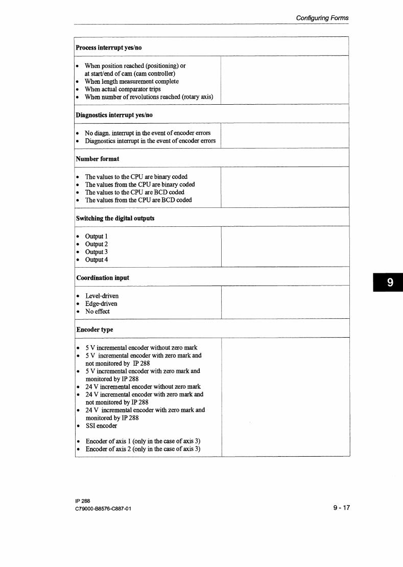
Configuring Forms
Process interrupt yeslno l
When position reached (positioning) or at s t d e n d of cam (cam controller) When length measurement complete ' : w e n actual comparator trips 1 When number of revolutions reached (rotary axis)
1 Diagnostics interrupt yeslno
l No diagn. interrupt in the event of encoder errors Diagnostics interrupt in the event of encoder errors
Number format
The values to the CPU are binary coded The values from the CPU are binary coded The values to the CPU are BCD coded The values from the CPU are BCD coded
1 Switching the digital outputs 1 output l output2 Output3 output4
Coordination input
Level-driven Edgedriven No effect
1 Encoder type
5 V incremental encoder without zero mark 5 V incremental encoder with zero mark and not monitored by IP 288 5 V incremental encoder with zero mark and monitored by IP 288 24 V incremental encoder without zero mark 24 V incremental encoder with zero mark and not monitored by IP 288 24 V incremental encoder with zero mark and monitored by IP 288 SS1 encoder
Encoder of axis 1 (only in the case of axis 3) Encoder of axis 2 (only in the case of axis 3)

Configuring Forms
Same direction; greater path coordinate corresponds to greater encoder signal Direction not the same; greater path coordinate corresponds to smaller encoder signal
1 Incrementslencoder revolution
1 to 225
Patwencoder revolution
1 l* GAL to 100 000 00O*BRES l Resolution (incrementslencoder revolution)/@athlencoder revolution)
Encoder revolutions
l to4096
1 Start of traversing range
1 ~ n d of traversing range
k 100 000 000+BRES
Reference point coordinate
Reference coordinate
Zero mark positionlreference coordinate identifier
Zero mark in positive direction Zero mark in negative direction or Reference coordinate valid Reference coordinate invalid

Configuring Forms
Start of software switch
k 100 000 000*BRES
1 End of software switch
Hysteresis
1 Control signals of the drive
h v e t y p e l Drive type 3 h v e t y p e 2 Drivetype4
1 Change of direction
Hard reversal
1 Target range
At 0, the zero speed monitor is switched off k 100 000 000*BRES
1 Monitoring time
At 0, the actual position and target entry monitors are switched off 0 to65532
Forward cutoff difference
1 Forward changeover difference l

Configuring Forms
Reverse cutoff difference
100 000 000*BRES
Reverse changeover difference 1
1 Forward adaptioa value
f 100 000 000*BRES
Reverse adaption value

The Data Sets of the /P 288
9.4 The Data Sets of the IP 288
You create the following data sets for using the IP 288.
SYSID data set Machedataset Cam set (cam controller) Target set (positioning) Target list (positioning)
The IP 288 provides information in the following directories concerning the data stored:
Machine data directory Target set directory Cam set directory Target list directory (only via COM 288)
The next sections contain a description of these data sets and the relevant data.
9.4.1 Structure of the Every SYSID data set has the same length and begins with a data set SYSlD Data Set header. The header cannot be overwritten with the exception of the
data set number and it contains the following data:
1 ~ a m e 1 or mat 1 Contentslvalue range
The data set header is followed by a variable section which contains default values on the module to begin with.
Data set type
Module ID
Data set number
BASP evaluation
2 ASCII characters 4 ASCII characters l byte
Name
Module number
1 Interrupt line
"ID"
" 288" (with a initial space)
1 to 255
Format
l byte
1
2
3
l byte
l byte
Contentslvalue range
1 to 255
DS error 10
0 = switch off all outputs (default) 1 = no effect 0 = no interrupt toPLC (default) 1 = Intempts on IRA 2 = Interrupts on IRB 3 = Interrupts on E ' 4 = Intempts on IRD
819

The Data Sets of the /P 288
The variable section is followed by a constant section in which the precise description of the module and the version of the firmware are entered.
The SYSID data set has the following length:
Name Module type
Firmware version
Input: 6 words Output: 14 words
Below is a list of the assignments of the SYSID data set with word-orientation. This data is stored on the IP 288 in this format.
Format 10 ASCII characters 6 ASCII characters
bit 15 bit 0
Contentslvalue range "288-4UA11 " (with following space) "V X.XXW (with space after "V")
9.4.2 Structure of the You must enter the machine data in a fixed order in the machine data Machine Data Set set. This is the order in which the machme data is explained below.
0 Data 1 set 2 header 3
4 5 6
Every m a c h e data set has the same length and begins with a data set header. The header must contain the following data:
1 ~ a m e / m or mat I ~ontentslvalue range I D s I
7 8 Moduletype"288-4UAll" 9 10 11 - 12 Firmware version "V 1.00" 13
Data set type: "ID" Module ID: " 288''
Reserved
Reserved , BASP evaluation it 1 0
Data set number
Module number Interm~t line
Data set type
Module ID
Data set number
2 ASCII characters 4 ASCII characters l byte
"MD" (Machine Data)
" 288" (with initial space)
error 1
2
1 to 255 314

The Data Sets of the /P 288
The data set header is followed by the general machine data listed below.
1 ~ a m e l Format Contentslvalue range 1 DS
Module number Axis number Axis type
Measuring system
Axis function
Accuracy range @REs)
Basic data set (yeslno) Process interrupt (yeslno)
Diagnostics interrupt (yeslno)
Number format
Switching the digital outputs
Coordination input
l byte l byte l bit
l byte
l byte
l byte
1 bit
4 bits
l bit
2bits
4 bits
l byte
1 to 255 l t o 3 0 + Linear axis I 1 + Rotary axis 1 + 1*10-~- 2 + 0.1*10-~ inch 3 + 0.1 * 1 0 - ~ degrees i
1 + Positioning for rapid traverselcreep speed drives 2 + Cam controller 1 + l *measuring system 2 + lO*measuring system 3 + 100*measuring system 4 + 1000*measuring; system 0 + Basic data set 1 + No basic data set Bit = 0 + Process interrupt disabled Bit = 1 + Process interrupt possible The individual bits and the interrupts correspond as follows:
Bit 0: Position reached in the case of positioning Startlend of cam in the case of a cam controller
Bit 1 : Length measurement complete Bit 2: Actual position comparator tripped Bit 3: Number of revolutions reached (rotary axis)
In a basic data set, all these bits are set to 0. 0 + No diagnostics interrupt 1 + Diagnostics interrupt in the case of encoder error In a basic data set, this bit is set to 0. Bit 0 = 0 + The values from the CPU are binary coded Bit 0 = 1 + The values from the CPU are BCD coded Bit 1 = 0 + The values to the CPU are binary coded Bit 1 = 1 + The values to the CPU are BCD coded Bit 0 = 0 + Output l not wired (default) ,Bit 0 = l + Output l wired Bit 1 = 0 + Output 2 not wired (default) Bit l = l + Output 2 wired Bit 2 = 0 + Output 3 not wired (default) Bit 2 = l + Output 3 wired Bit 3 = 0 + Output 4 not wired (default) )Bit 3 = l + Output 4 wired 1 + Not used 2 + Level-driven 3 + Edgedriven
error 5 6 -
8
9
10
12
-
16

The Data Sets of the /P 288
1 ~ a m e / or mat I Contentslvalue range I D S 1 Encoder type
Encoder rotational direction to direction of travel
l byte
I
l bit
1 + 5V incremental encoder without zero mark 2 + 5V incremental encoder with zero mark and
without IP 288 monitoring 3 + 5V incremental encoder with zero mark and
with IP 288 monitoring 4 + 24V incremental encoder without zero mark 5 + incremental encoder with zero mark and
without IP 288 monitoring 6 + 24V incremental encoder with zero mark and
with IP 288 monitoring 7 + SS1 encoder 8 + Encoder of axis l 9 + Encoder of axis 2 Bit = 0 + Same direction; greater path coordinate
corresponds to greater encoder signal Bit = 1 + Direction not the same; greater path
coordinate corresponds to smaller encoder
Increments/encoder revolution Pathtencoder revolution Encoder revolutions
Start of traversing range
End of traversing range
Reference point coordinate
Zero mark positionlreference coordinate ID
Start of software switch
End of software switch
Hysteresis
Control signals of the drive
error 20
4 bytes
4 bytes
2 bytes
4 bytes in two's complement 4 bytes in two's complement 4 bytes in two's complement 1 bit
4 bytes in two's complement 4 bytes in two's complement 4 bytes in two's complement l byte
signal 1 to 225 22/29
l*BRES to 100 000 000*BRES
1 to 4096 1 in the case of incremental encoder +l00 000 000*BRES
f l00 000 000*BRES
In the case of incremental encoders: f l00 000 000*BRES 1nthecaseof~~1encoders:-2~~ t 0 + 2 ~ l - 1
In the case of incremental encoders: Bit = 0 + Zero mark in positive direction Bit = 1 + Zero mark in negative direction or in the case of SS1 encoders:
231281 29 24/28
28/30
2813 1
32
Bit = 0 + Reference coordinate valid Bit = 1 + Reference coordinate invalid f l00 000 000*BRES
1 ,
+_l00 000 000*BRES '36
0 to 100 000 000*BRES
1 +Drive type 1 2 +Drive type 2 3 +Drive type 3 4 + Drive type 4
40
50

The Data Sets of the /P 288
/ ~ a m e ( or mat 1 ~ontentslvalue range lDs 1
The machine data set is always 63 words long.
Change of direction
Target range
Zero speed range
Monitoring time
Forward cutoff difference
Forward changeover difference
Reverse cutoff difference
Reverse changeover difference
Forward adaption value
Reverse adaption value
Below is a word-oriented list of the assignments of the machine data. Tlus is the form in which the IP 288 stores the machine data it has entered via one of the two interfaces.
error
52
53
54
l l bit 10 + Soft reversal
4 bytes in two's complement 4 bytes in two's complement 2 bytes
4 bytes in
I l + Hard reversal 0 to 100 000 000*BRES
0 to 100 000 000*BRES At 0, the zero speed monitor and positive feedback monitor are switched off 0 to 65532 The value of the monitoring time is rounded up to integer multiples of 8 ms. At 0 - 7, the actual position and target entry monitors are switched off 1 to 100000000*BRES
two's complement 4 bytes in two's complement 4 bytes in two's complement 4 bytes in two's complement 4 bytes in two's complement 4 bytes in two's complement
5 5 I
l to 100000000*BRES 5 6
1 to 100000000*BRES
1 to 100000000*BRES
+l00 000 000*BRES
f l00 000 000*BRES
57
58
59
60
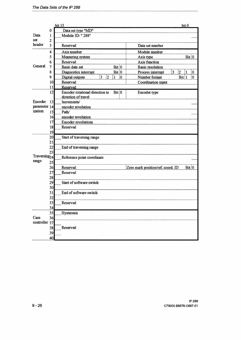
The Data Sets of the /P 288
bit 15 bit 0
direction of travel l I Encoder 13 Increments/ Parameter 14 encoder revolution ization 15 Path1
16 encoder revolution 17 Encoder revolutions 18 - Reserved 19 20 2 1 22 23
Traversing24
rase 25 26 27 28 29 30 3 1 32 33 34 35
Cam 36 controller 37
38 39 40
Start of traversing range
End of traversing range
Reference point coordinate -
Reserved I Zero mark positiodref. coord. ID Bit 10 Reserved
Start of software switch
End of software switch
R e s e r v e d
Hysteresis
Reserved

The Data Sets of the /P 288
bit 15 hit II
9.4.3 Structure of the Machine Data Directory
41 42 43 44 45 46
Cutoff 47 control
48 49 50 5 1 52 53 54 55 56 57 58 59 60 61 62
A machine data directory gives information on all the machine data stored on the module. The directory contains the following general information:
-.. -- --- - Change of direction Bit10 I Control simals of the drive Target range
Zero speed range
Monitoring time Forward changeover difference
Forward cutoff difference
Reverse changeover difference
Reverse cutoff difference
Forward adaption value
Reverse adaption value
Reserved
Datasettype
ModuleID
A data set number between 0 and 255 for each axis. The entry 0 means that there is no machine data for thls axis.
The machine data directory is 7 words long.
The machine data directory has the following structure:
bit 15 bit 0 0 Data set type "DM"
Data 1 Module ID: l' 288" set 2 header 3 Reserved
4 5 6
Reserved Reserved Reserved
Data set number axis 1 Data set number axis 2 Data set number axis 3

The Data Sets of the /P 288
9.4.4 Structure of the You can create a cam set for every track. You can enter cam sets on Cam Set the module, output them fiom the module and delete them on the
module. Each of these actions is possible via both interfaces of the module.
Data set header Every cam set begins with a data set header. This must contain the following data.
1 ~ a m e 1 Format / Contentdvalue range bs 1
The data set header is followed by the general cam data. You also enter axis specifications in this general data.
Data set type
Module ID
Cam set number
/ ~ a m e / or mat / ~ontentdvalue range
2 ASCII characters 4 ASCII characters l byte
Module number Axis number Axistype
Measuring system
"NS" (cam set)
" 288" (with initial space)
1 to 255
the track Track number Direction
Correction time of dynamic cams Initiating cam for the l st process interrupt
Edge for l st process interrupt
error 1
2
3
lbyte l byte l bit
l byte
htiating cam for the 2nd process interrupt
Edge for 2nd process interrupt
1 to 255 / 5 l t o 3 16 Bit = 0 + Linear axis
I 1 - Bit = 1 + Rotary axis l 1 + 1*10-~mm 2 + 0.1*10'~inch 1 3 + 0.1 * 1 0 - ~ degrees
Number of cams in I 1 byte
l byte l byte
lword
l byte
1 bit
l t o 8 111 1
1to16 / 12/27 Bit 0 = 1 + Forward direction Bit 1 = 1 + Reverse direction
0 + No dynamic cams
i l3 If both bits are set, the cams are switched in both directions. /
1 to 65535 ms 0 +No interrupt initiated 15/23 1 to 8 corresponds to the number of the cam which initiates the interrupt Bit = 0 + The interrupt is initiated at the end of the cam -
l Bit = 1 + The interrupt is initiated at the start of the cam / AU interrupt can also be initiated at the falling edge of a
17/24
-
jtime cam. l byte l 0 +No interrupt initiated
1 to 8 corresponds to the number of the cam which initiates / the interrupt
l bit Bit = 0 + The interrupt is initiated at the end of the cam Bit = 1 + The interrupt is initiated at the start of the cam An interrupt can also be initiated at the falling edge of a time cam.

The Data Sets of the /P 288
Now you can create the special cam data for each cam.
[ ~ a m e /Format / Contentslvalue range / DS
The length of a cam set is 11 words t 5 words per cam.
Cam number Cam type
Start of cam
End of cam
The cam data is stored consecutively according to the number of cams in the track. It is not necessary to enter the cams in ascending order of their numbers.
hit l S bit 0
l byte l bit
4 bytes in two's complement 4 bytes in two's complement
16 Cam type 2nd cam Bit / 0 Cam number 2nd cam 17 Start of cam 2nd cam -
2nd cam 18 19 End of cdswi tch on time 2nd cam 20
l t o 8 Bit = 1 + Pathcam Bit = 0 + Time cam (cams 1 and 2 only) f l00 000 000*BRES
e m r 191 26 26
21/25 l l 1
f l00 000 000*BRES in the case of a path cam 24 to 65532 ms in steps of 8 ms in the case of a time cam
221251 28

The Data Sets of the /P 288
9.4.5 Structure of the A cam set directory gives information on the cam sets on the module. Cam Set Directory The directory contains the following general information:
Data set type Module ID Number of cam sets already entered (maximum 48) Number of cam sets whlch can still be entered (maximum 48) Number of cam sets per axis (maximum 16)
The directory contains the following information for each cam set:
Tracknumber Cam set number Number of cams in the track Cams parameterized (this specification is output in bit code, bit 0 = 1 means cam 1 is parameterized, etc.).
The length of a cam set directory is 8 words + 2 words per cam set entered.
The module also outputs the cam set directory for axes parameterized in the positioning axis function. The number of the already entered cam sets is then 0. The cam set directory has the following structure:
bit 15 bit 0 0
Data set 1 header 2
3 .- 4
5 6 7
Data set ID: "DN" Module ID: " 288"
Cam set number Cams parameterized (bit-coded) Reserved Cam set number Cams parameterized (bit-coded)
Cam set number 1 Track number 16. NS Cams parameterized (bit-coded) l~umber of cams in the track
Axls 2
1. NS
Reserved
Track number Number of cams in the track Number of cam sets axis 2 Track number Number of cams in the track
Still enterable NSs Reserved Camsetnumber Cams parameterized (bit-coded)
16. NS
1. NS
Number of NSs entered Number of cam sets axis 1 Track number Number of cams in the track
16.NS
1. NS
Cam set number Cams parameterized (bit-coded) Reserved
, Cam set number Cams oarameterized (bit-coded)
Track number Number of cams in the track Number of cam sets axis 3 Track number Number of cams in the track

The Data Sets of the /P 288
9.4.6 Structure of the Each target set begins with a data set header. This must contain the Target Set following data:
/ ~ a m e / or mat I Contentslvalue range 1 DS l e m r
Data set type 12 ASCII "ZS" (target set) / 1 lcharactm 1
Module ID / 4 ASCII I " 288" (with initial space) / 2 /characters 1
Data set number I 1 byte I 1 to 100 for long target sets 3/11 1 101 to 255 for short target sets
This data set header is followed by general target data. You also enter axis specifications here.
/ ~ a m e j orm mat ~ontents/value range D S 1
The general target data is followed by data describing the target and the positioning task directly. In the case of short target sets, this involves only the first two data items below.
Module number Axis number AXIS type
Measuring system
l byte l bvte l bit
l byte
Name
Target set number Geschwindigkeit
Target
Forward changeover difference
Forward cutoff difference
Reverse changeover difference
Reverse cutoff difference
Forward adaption value
Reverse adaption value
l error 1 to 255 5 1 l t o 3 Bit = 0 + Linear axis Bit = 1 + Rotarv axis 1 + 1*10-~mm 2 + 0.1*10-~inch 3 + 0.1*10-~ degrees
DS error 11
I 13
14
15
16
17
18
19
Format 1 Contentslvalue range
6
8
l byte l bit
4 bytes in two's compl. 4 bytes in two's complement 4 bytes in two's complement 4 bytes in two's complement 4 bytes in two's complement 4 bytes in two's complement 4 bytes in two's complement
1 to 255 Bit =O + Creep speed Bit =l + Rapid traverse +l00 000 000*BRES
l to 100000000*BRES
1 to 100000000*BRES
1 to 100000000*BRES
l 1 to 100000000*BRES
f l00 000 000*BRES
+l00 000 000*BRES

The Data Sets of the /P 288
The length of a target set is 10 words for a short target set and 22 words for a long target set.
The target set is structured as follows:
9 1 10 1 Forward changeover difference
bit 15 bit 0 0 Data set type :'INS"
Data 1 Module ID: " 288"
I 111 12 l orw ward cutoff difference
F
set 2 header 3
4 5 6 7 8
Reserved
Axisnumber Measuring system
13 14
20 Reverse adaption value ,. .
Data set number
Module number Axis type it / 0
Reverse changeover difference F
15 16
The target set are entered in target lists on the module.
Reserved SpeedID Bit / 0 I Target set number Target
Reverse cutoff difference 17 18 Forward adaption value -

The Data Sets of the /P 288
9.4.7 Structure of the There is a target list for each axis (default): Target List
Target list 1 for axis 1 Target list 2 for axis 2 Target list 3 for axis 3
The length of a target list is 7 words + 3 words per short target set + 15 words per long target set.
A target list is structured as follows:
bit 15 bit 0 0
Data 1 set 2 header 3
4 5 6 7 8 0
Data set type: "ZL" Module ID: " 288"
, 10 1 1 12 13
Additional values are entered in the case of long target sets (see Section 9.4.6).
14
9.4.8 Structure of the A target set directory gives information on all the target sets stored on Target Set Directory the module. The directory contains the following general information:
Target l
Reserved
hisnumber Measuring system Number of target sets Speed ID target 1 Bit I 0
Speed ID target 2 Bit I 0 /Target set number target 2 Target 2
SpeedIDtwet3 B i t 1 0 (Target set number target 3
Datasettype ModuleID Number of already entered target sets (maximum 255 over all three axes) Number of target sets which can still be entered (maximum 255 over all three axes).
Data set number -
Module number Axis type Bit 1 0 Reserved Target set number target 1
T a r g e t 2
I
T a r g e t 3
-Target 1
Target 3

The Data Sets of the /P 288
The target set directory contains the following information for each axis:
Number of target sets Target list number First target set number
nth target set number
The length of a target set directory is 7 words t 1 byte per target set, rounded up to words per axis.
The target set directory has the following structure:
Data 0 set 1 header 2
- Data set type "DZ" M o d u l e ID: " 288"
-. 3 4 5 6 7
Axis 1
Axis 2 l l
Reserved
4 5 6 7
Still enterable ZSs Target list number axis 1 Second ZS number axis 1
Number of ZSs entered Number of target sets axis 1 First ZS number axis 1
T a ~ e t list number axis 2 Second ZS number axis 2
4 5 6 7
Axis 3
Number of tarrzet sets axis 2 First ZS number axis 2
Target list number axis 3 Second ZS number axis 3
Number of target sets axis 3 First ZS number axis 3

How Does the /P 288 Respond in the Event of an Error?
9.5 How Does the IP 288 Respond in the Event of an Error?
When you enter data to the module, the data is checked. Limit overranges and inconsistencies between data cause an error. An error is identfied by an error number. If an error occurs whde you are woriung with COM 288, an error message is displayed. If you have to answer a prompt, e.g. "Reject yeslno", this text is also displayed and the relevant menu is displayed. If the error occurs during data transfer with FB PAR, you must read out the error number from data block DB-IP (DL nt2, data set error in the application mailbox). The meaning of an error (error in machine data, error in SYSID, etc.) depends on you last input.
9.5.1 SYSlD Error Below is are the SYSID errors listed according to number:
1 DS 1 Error message 1 ~ e m e d ~ error 1
2
3
8
9
10
' 200
253
Wrong data set type
Wrong module ID
Wrong DS number or DS number already exists Wrong interrupt h e selected Interrupt h e must not be changed Module number must not be changed Wrong job number
Axls not in PGPLC mode
The following types are permissible: ID SYSIDdataset MD machine data NS cam set ZS target set ZL target list
The module ID must be: " 288"
Have you remembered the space before the 2? Permissible numbers are 1 to 255.
Permissible numbers are 0 to 4.
If you want to change the interrupt line, you must first delete all machine data. If you want to change the module number, you must first delete all machme data. Only the following job numbers are permissible:
64 Data set output 65 Data set input.
Set the correct mode (PG or PLC mode) before entering or deleting data sets (see Section 6.5.11).

How Does the /P 288 Respond in the Event of an Error?
9.5.2 Machine Data Errors Below are the machine data errors listed according to number
DS error l
2
3 I
Error message
4
Remedy
Wrong data set type l The following types are permissible:
DSnumbersare / ith her there is already machine data on this axis with another data set
9 10 12
16
20
Scaling of pawencoder
revolutions is wrong
Wrong module ID
Wrong DS number or DS number already
22
increments or doesn't suit traversing range
ID SYSID data set MD machine data ZS target set NS cam set ZL target list
The module ID must be: " 288"
Have you remembered the space before the 2? Permissible numbers are 1 to 255. Machine data with the same data set number must not already exist on another axis.
5
6 8
system Wrong axis function Wrong accuracy range Process interrupt selection wrong
Effect of coordinate input is wrong Wrong encoder type
1 The value must be between 1 * BRES und l W 000 OW * BRES. l
Numbers 1 or 2 are permissible Numbers 1 to 4 are permissible You have set a process interrupt for "Number of revolutions reached", but you have entered Linear axis as the axis type. Either disable the process interrupt or enter Rotary axis for the axis type. Permissible entries are 1 to 3.
You have tried to enter an impermissible encoder type. Entries 1 to 7 or 8 and 9 are permissible. You can specify "Encoder of axis 1" and "Encoder of axis 2" only for axis 3. The relevant axis (axis 1 or 2) must already be parameterized and it must have an incremental
Scalingof incrementslencoder revolution is wrong
The number of encoder revolutions must be between 1 and 4096. In the case of a multi-turn encoder, the value must be a power of 2 and in the case of an incremental encoder, the value must be 1. You have parameterized one axis for an SS1 encoder in such a way that the encoder range does not cover the traversing range including the traversing range limits. In the case of a rotary axis, the traversing range and the encoder range must be identical.
Wrong module number
Wrong axis number Wrong measuring
encoder. You must enter an even number value for a singleturn absolute encoder. For a multi-turn absolute encoder, you must enter a power or 2 (1 223, For an incremental encoder, you must enter a value between
The numbers 1 to 255 are permissible. In addition, you must specify the same number you specified in the SYSID data set. Numbers 1 to 3 are permissible Numbers 1 to 3 are permissible

How Does the /P 288 Respond in the Event of an Error?
I DS Error message 1 e m r
40 1 Hysteresis is wrong IThe hysteresis must be between 0 and 100,000,000 * BRES.
-50 / ~ r i v e type is wrong /The numbers between 1 and 4 are permissible for the dnve type.
29
30
l ' 3 1
32
35
36
Wrong resolution
Start of traversing range is wrong
End of traversing range is wrong
Wrong reference point coordinate Start of software switch is wrong
End of software switch is wrong
52
53
55
56
57
The resolution is the quotient of pathlencoder revolution an incrementslencoder revolution for SS1 encoders or the quotient of pathlencoder revolution and 4 * incrementdencoder revolution for incremental encoders. It must be between 0.1 * BRES and 1 * BRES (see Section 5.2). The coordinate of the start of traversing range must be in the range k 100 000 000 * BRES. Either correct the value of the basic resolution or limit the traversiqg; range. The coordinate of the end of traversing range must be in the range
1 + 100 000 000 * BRES and must be greater than the coordinate of the start of traversing range. Either correct the value of the basic resolution or limit the traversing: range. See Section 5.2 and Section 6.2.
The coordinate of the start of software switch must be in the range + 100 000 000 * BRES and it must be greater than the coordinate of the start of traversing range. Increase the value of the coordinate or extend the traversing range. The coordinate of the end of software switch must be in the range + 100 000 000 * BRES and it must be greater than the coordinate of the start of software switch and less than or equal to the coordinate of the end of traversing range. Reduce the value of the coordinate or extend the traversing range.
Target range is wrong
Zero speed range is wrong
The size of the target range must be between 0 and 100,000,000 * BRES and must be less than the cutoff difference (including adaption value). Either correct the basic resolution value or increase the cutoff difference or reduce the target range. The size of the zero speed range must be between 0 and 100,000,000 * BRES and must be less than or equal to the size of the
1 target range. Either correct the basic resolution value or increase the I target range or reduce the zero speed range.
Forward changeover difference is wrong
Forward cutoff
The forward changeover difference must be between 1 and 100,000,000 * BRES, it must be greater than the forward cutoff difference and, in the case of a linear axis, it must be less than the traversing range including adaption value. Either correct the basic resolution value or increase the forward changeover difference or reduce the forward cutoff dfierence. The forward cutoff difference must be between 1 and
difference is wrong 1 100,000,000 * BRES, it must be less than the forward changeover I difference and, in the case of a linear axis, it must be greater than the I target range including adaption value.
Reverse changeover difference is wrong
The reverse changeover difference must be between 1 and 100,000,000 * BRES, it must be greater than the reverse cutoff difference and, in the case of a linear axis, it must be less than the traversing range including adaption value. Either correct the basic resolution value or increase the reverse changeover difference or reduce the reverse cutoff difference.

How Does the /P 288 Respond in the Event of an Error?
66 Delete data set. 250 1 ~ a t a set does not exist l ~ o n e of the axes has machine data with this number.
DS error 58
59
60
70
200
Error message
25 1
253
254
255
Remedy
Entryldeletion of data set from PLC prohibited Enwdeletion of data sets from PG prohibited Data set cannot be changed Data set cannot be deleted
Reverse cutoff difference is wrong
Forward adaption value is wrong
Reverse adaption value is wrong
Cam sets or target sets have been deleted
Wrong job number
Set the correct mode (PLC mode) before entering or deleting data sets (see Section 6.5.11). Enter the correct mode (PG mode) before entering or deleting data sets (see Section 6.5.11). Either the axis is not yet in the "completed" state or the interpretation of an initiated operation has not yet been completed. You can only delete a machine data set in the "completed" axis state, or you are trying to delete the data set of a leading axis. In thls case, delete the data set of the parallel-switched axis before deleting the data set of the leading axis.
The reverse cutoff difference must be between 1 and 100,000,000 * BRES, it must be less than the reverse changeover difference and, in the case of a linear axis, it must be greater than the target range including adaption value. The forward adaption value must be between 0 and 2 100 000 000 * BRES. In addition, the sum of forward cutoff difference and forward adaption value must be greater than the target range. The sum of forward changeover difference and forward adaption value must be less than the working range in the case of a linear axis. Either reduce the forward adaption value or increase the forward cutoff difference. The reverse adaption value must be between 0 and f 100 000 000 * BRES. In addition, the sum of reverse cutoff difference and reverse adaption value must be greater than the target range. The sum of reverse changeover difference and reverse adaption value must be less than the working range in the case of a h e a r axis. Either reduce the reverse adaption value or increase the reverse cutoff difference. While transferring new error-free machine data, cam sets or target sets have been deleted. You can read out the number of deleted cam sets or target sets from DB-P, DR n+2 in the application mailbox, or from DB-ZU, DR n+8 or fiom accumulator 2. Only the following job numbers are permissible
64 Data set output 65 Data set input

How Does the /P 288 Respond in the Event of an Error?
9.5.3 Cam Set Errors Below are the cam set errors listed according to number.
In the case of errors which refer to one cam, you read out the cam number fiom DB-ZU (DW n+8), ffom accumulator and in DB-IP in DR n+2 in the application mailbox.
/ DS l Error message l ~ e m e d ~ 1 error 1 1
2
3
5
.7 6 8
1 12 1 rack number is wrong The number of the track to which this cam belongs must be between 1 1
1
9
10
11
Wrong data set type
Wrong module ID
Wrong DS number or DS number already exists Wrong module number
Wrong axis type Wrong axis number Wrong measuring
The following types are permissible: ID SY SID data set MD machine data ZS target set NS cam set ZL target list
The module ID must be: " 288"
Have you remembered the space before the 2? Permissible numbers are 1 to 255.
The numbers 1 to 255 are permissible. In addition, you must specifjl ,the same number you specified in the SYSID data set. The axis type must agree with the machme data Numbers 1 to 3 are permissible The measuring system must agree with the entry in the SYSID.
Axis is not parameterized AXIS is not parameterized as a cam controller Number of cams is
, l 3 1 / 15
s y s t e m i The relevant axis must be parameterized before you enter a cam set.
The relevant axis must be parameterized as a cam controller before you enter a cam set.
You can create between 1 and 8 cams in a track.
interrupt 1 Wrong cam number for interrupt 2 Wrong cam number Cam start is wrong
p-
Direction of effect of the track is wrong
Permissible numbers are 0 (no process interrupt) and l to 8.
Permissible numbers are 1 to 8. Permissible absolute coordinates for the start of cam must be between f 1 000 000 000*BRES. Negative values must be entered in two's
c Permissible numbers are 1,2 and 3
Wrong cam number for / permissible numbers are 0 (no process interrupt) and 1 to 8.
j complement. You must enter only values whch agree with the I machine data.
Cam end is wrong The permissible absolute coordinates for the end of cam of a path cam must be between f 1 000 000 000*BRES. Negative values must be entered in two's complement. In the case of a linear axis, the coordinate of the end of cam must be greater than the coordinate of the start of cam. Permissible values for the duration of a time cam must be between 24 and 65532 ms. You must enter only values which agree with the machine data.

How Does the /P 288 Respond in the Event of an Error?
I DS l ~ r r o r message l Remedy 1
9.5.4 Target
error 23
24
25
26
27
28 250 25 1
252
253
Target Set and If an error occurs when entering a target list, the number of the first List Errors target set which was being entered when the error occurred can be
read out in DB-IP, DR nt2 (status information) in the application mailbox, in accumulator 2 and in DW nt8 in DB-ZU. The erroneous target list is not stored on the module.
Below are the target set errors and target list errors listed according to number:
Initiating cam for interrupt 1 is not parameterized Initiating cam for interrupt 2 is not parameterized Cam outside traversing range Cam number of the time cam is wrong Track already parameterized
Switch-on time is w o w Data set does not exist Entryldeletion of data set from PLC prohibited Data set is in Teach-In mode Entryldeletion of data sets from PG prohibited
The cam must be parameterized.
The cam must be parameterized.
In the case of a rotary axis, each cam must be within traversing range parameterized in the maclme data (without end of traversiw range). Only cams 1 and 2 are permissible as time cams.
You are trying to enter a new cam set (with new data set number) on a parameterized track. Change the data set number or delete the already existing cam set. The switch-on time of a time cam must be between 24 and 65532 ms. You are trying to delete a data set which does not exist. Set the correct mode (PLC mode) before entering or deleting data sets (see Section 6.5.11). Terminate Teach-In mode for this data set before entering it again (see Section 6.5.9). Enter the correct mode (PG mode) before entering or deleting data sets (see Section 6.5.11).

How Does the /P 288 Respond in the Event of an Error?
/ DS l ~ r r o r message /Remedy 1 1
2
3
5
6 7 8
1 3 p is wrong The permissible absolute coordinates for a target must be between k 1 000 000 000 * BRES. Negative values must be entered -in two's
9
10
11
Wrong data set type
Wrong module ID
Wrong DS number or DS number already exists Wrong module number
Wrong; axis number Wrong axis type Wrong measuring
The following types are permissible: ID SY SID data set MD machinedata ZS target set NS cam set ZL target list
The module ID must be: 'l 288"
,Have you remembered the space before the 2? Permissible numbers are 1 to 255. In addition, the default target list numbers of the other axes are prohibited for the individual axes (see Section 5.5). The numbers 1 to 255 are permissible. In addition, you must specifi the same number you specified in the SYSID data set. Numbers 1 to 3 are permissible The axis type must agree with the machine data The measuring system must agree with the entry in the SYSID.
system i Axis is not /The relevant axis must be parameterized before you enter a target set. parameterized I
14
15
16
17
Axls isnot parameterized as a position control Target set number is
The relevant axis must be parameterized as a position control before you enter a target set.
Permissible numbers are 1 to 255
Forward changeover difference is wrong
Forward cutoff difference is wrong
Reverse changeover difference is wrong
complement. You must enter only values which agree with the machine data.
l The forward changeover difference must be between 1 and 100,000,000 * BRES, it must be greater than the forward cutoff difference and, in the case of a linear axis, it must be less than the traversing range including adaption value. Either correct the basic resolution value or increase the forward changeover difference or reduce the forward cutoff dflerence. The forward cutoff difference must be between 1 and 100,000,000 * BRES, it must be less than the forward changeover difference and, in the case of a linear axis, it must be greater than the target range including adaption value. The reverse changeover difference must be between 1 and 100,000,000 * BRES, it must be greater than the reverse cutoff difference and, in the case of a linear axis, it must be less than the traversing range including adaption value. Either correct the basic resolution value or increase the reverse changeover difference or IredUce the reverse cutoff dflerence.
Reverse cutoff difference is wrong
The reverse cutoff difference must be between 1 and 100,000,000 * BRES, it must be less than the reverse changeover difference and, in the case of a linear axis, it must be greater than the target range including adaption value.

How Does the /P 288 Respond in the Event of an Error?
9.5.5 Internal Errors Internal errors are errors on the module which cause failure of the module.
LED INF
Remedy
The forward adaption value must be between 0 and + 1 000 000 000 * BRES. In addition, the sum of forward cutoff difference and forward adaption value must be greater than the target range. The sum of forward changeover difference and forward adaption value must be less than the working range in the case of a linear axis. Either reduce the forward adaption value or increase the forward cutoff difference. The reverse adaption value must be between 0 and f 1 000 000 000*BRES. In addition, the sum of reverse cutoff difference and reverse adaption value must be greater than the target range. The sum of reverse changeover difference and reverse adaption value must be less than the working range in the case of a linear axis. Either reduce the reverse adaption value or increase the reverse cutoff difference. You are trying to delete or enter a target set which is currently being processed. You are trying to transfer a target list without target sets to the module. Use only target set numbers whlch do not yet exist on another axis.
You are trying to delete a data set which does not exist. Set the correct mode (PLC mode) before entering or deleting data sets (see Section 6.5.11). Terminate Teach-In mode for th~s data set before entering it again (see Section 6.5.9). Enter the correct mode (PG mode) before entering or deleting data sets (see Section 6.5.1 1). You can only enter a target set or a target list in the "completed" axis state. You cannot overwrite a target list. You can only delete a target set or a target list in the "completed" axis state.
DS error 18
19
20
21 22
250 25 1
252
253
254
255
The outputs of the module are switched off as far as this is possible, the LEDs INF and EXF on the frontplate light up and program processing is held up. You cannot correct an internal error. You must replace the module.
/ ~ r r o r message
Forward adaption value is wrong
Reverse adaption value is wrong
Target set active
Target list empty Target set already exists on another axis Data set does not exist Entryldeletion of data set from PLC prohibited Data set is in Teach-In mode Entryldeletion of data sets from PG prohibited Data set cannot be changed Data set cannot be deleted

How Does the /P 288 Respond in the Event of an Error?
9.5.6 External Errors External errors are errors affecting the process. They are only detected on a parameterized axis.
LED D(F When an error is detected, the LED EXF lights up. All errors cause a m i n g mode to be aborted (completed axis state). Functions waiting to be processed (position-dependent or event-dependent) remain in force. In the case of positioning, parameter changes waiting to be processed are deleted at the transition to the "completed" axis state.
There is a group flag for each axis in the module status word @W 68 in DB-IP) as well as a bit-coded flag per error in DB-IP.
Module flag Module status DW 68 in DB-IP
Frame 1 of axis 1 External errors DW 92 and DW 93 in DB-IP
Frame 1 of axis 2 External errors DW 124 and DW 125 in DB-IP
Frame 1 of axis 1 External errors DW 155 and DW 156 in DB-IP
External errors must be acknowledge with the relation to the axis after they have been corrected. Errors which are signalled on all three axes (e.g. 24 V load voltage missing) must be acknowledged on each axis individually. Provided the errors have been corrected, they will be deleted with the acknowledgement. Only after acknowledgement: is monitoring of pending errors executed again. A new error is then signalled immediately. Following errors are also signalled.
You can read out and acknowledge external errors in COM 288 in test mode (Further Functions). You can read out the external errors via the PLC interface in DB-P, frame 1 of the axis in each case (see Section 8.3.2).
The following external errors are detected:
Error No. 1
/ ~ r r o r message / Description 1 ~ o l l o w i n ~ emor? 1 24 V load voltage missing
Switch off digital outputs Cam controller:
All tracks of all axes are switched off (removal of track enable) and must be enabled again after the error has been corrected.
Reaction on all axes: The synchronization is deleted in the case of incremental encoders.
Positioning:
Fuses F1 and F2 are defective

How Does the /P 288 Respond in the Event of an Error?
Error l Error message / Description I ~ollowing emor?
2
3
4
5
6
7
Short-circuit 24-volt contact supply for the digital inputs
Defective connecting cable digital output 1
Defective connecting cable digital output 2
Defective connecting cable digital output 3
Defective connecting cable digital output 4
Short-circuit 24-volt encoder supply
, l l l j (removal of track enable) and must be i enabled again after the error has been I I corrected.
Reaction on all axes: Positioning:
Changeover to creep speed and cutoff of the drive (digital outputs) after traversing the changeover difference. Jog at creep speed is permissible.
Cam controller: No reaction, only error flag
Reaction on the axis affected Positioning:
Switch off digital outputs. Cam controller:
All tracks of all axes are switched off (removal of track enable) and must be enabled again after the error has been corrected.
Reaction on the axis affected Positioning:
Switch off digital outputs. Cam controller:
All tracks of all axes are switched off (removal of track enable) and must be enabled again after the error has been corrected.
Reaction on the axis affected Positioning:
Switch off digtal outputs. Cam controller:
All tracks of all axes are switched off (removal of track enable) and must be enabled again after the error has been corrected.
Reaction on the axis affected Positioning:
Switch off digital outputs. Cam controller:
All tracks of all axes are switched off (removal of track enable) and must be enabled again after the error has been corrected.
Reaction on all axes, regardless of parameterized encoder type. The synchronization is deleted in the case of incremental encoders. Positioning:
Switch off digital outputs. Jog at creep speed in permissible.
Cam controller: ~ l l tracks of all axes are switched off
Fuse F 1 defective, following error of error 1
Axls 1 and 2: Fuse F2 defective, Axis 3: Fuse F 1 defective, following error of error 1
Axis 1 and 2: Fuse F2 defective, Axis 3: Fuse F 1 defective, following error of error 1
Axis 1 and2: Fuse F2 defective, Axis 3: Fuse F1 defective,
1 following error of error 1
Axis 1 and 2: Fuse F2 defective, Axls 3: Fuse F1 defective, following error of error 1
Fuse F 1 defective, following error of error 1

How Does the /P 288 Respond in the Event of an Error?
/Error Error message / Description / ~ollowing emor? No. 8
9
10
Short-circuit 5-volt encoder supply
Defective encoder signal line (5 V differential signals only).
Reaction on all axes, regardless of parameterized encoder type. The synchronization is deleted in the case of incremental encoders. Positioning:
Switch off digital outputs. Jog at creep speed in permissible.
Cam controller: All tracks of all axes are switched off (removal of track enable) and must be enabled again after the error has been corrected.
Reaction on all axes, regardless of parameterized encoder type. The 1 synchronization is deleted in the case of incremental encoders. Positioning:
Switch off digital outputs. Jog at creep speed in permissible.
Fuse F 1 defective, following error of error 1
Following error of error 1 (when the encoders are supplied by IP 288). Following error of error 8.
Following error of error 1 (when encoders supplied by IP 288). ,Following error of error 8.
/Cam controller:
Encoder signal/frame error.
All tracks of all axes are switched off (removal of track enable) and must be enabled again after the error has been corrected.
Reaction on the axes affected. The synchronization is deleted in the case of incremental encoders.
Incremental encoders: Monitoring of the edge interval between encoder signal A and encoder signal B (see Sections 9.1 and 5.2): SS1 encoders: StarVstop bit error.
Positioning: Switch off digital outputs. Jog at creep speed in permissible.
Cam controller. All tracks of all axes are switched off (removal of track enable) and must be enabled again after the error has been corrected.

How Does the /P 288 Respond in the Event of an Error?
1 ~ r r o r message / Description 1 Following emor? ~ Following error of error l, Following error of error 7, Following error of error 8, Following error of error 9
Zero mark error/impermissible encoder value
Traversing range exited
W o r l w area exited
Positive feedback
Following error of error l l
Reaction on the axes affected. The synchronization is deleted in the case of incremental encoders.
Incremental encoders: Zero mark monitor tripped. The monitor can be switched off in the machine data (see Sections 5.1 and 9.1): SS1 encodels: Encoder value not in the parameterized range.
Positioning: Switch off digital outputs. Jog at creep speed in permissible.
Cam controller: All tracks of all axes are switched off (removal of track enable) and must be enabled again after the error has been corrected.
Reaction on the axes affected. The synchronization is deleted in the case of incremental encoders. Positioning:
Switch off digital outputs. Jog at creep speed in permissible.
Cam controller: All tracks of all axes are switched off (removal of track enable) and must be enabled again after the error has been corrected.
Reaction of the axes affected (axis must be synchronized): Positioning:
No reaction. Jog at creep speed is only permissible in the direction of the overshot software switch. Traverses beyond the overshot software switch cause a parameterization error.
Cam controller: No reaction. The software switches have no effect.
Reaction on the axes affected. Monitor can be switched off in the machine data (zero speed range = 0).
Positioning: Switch off digital outputs.
Cam controller: No positive feedback check possible.
Following error of error l l

How Does the /P 288 Respond in the Event of an Error?
/ Error Error message l Description 1 ~ollowing emor? No. 15
I
16
17
18
Reaction on the axes affected. Monitor can be switched off in the machine data (monitoring time = 0).
Positioning: Switch off digital outputs. Job at creep speed is permissible. The following apply in addition and cannot be switched off via the monitoring time in the m a c h e data: Ifa change of direction takes place after leaving the reduction switch in the case of a reference point approach.
Cam controller: No actual value monitoring possible.
Reaction on the axis affected. Monitor can be switched off in the machine data (monitoring time = 0).
Positioning: Switch off digital outputs. Jog at creep speed is permissible.
Cam controller: No target entry monitoring possible.
Indication on the axis affected. Monitor can be switched off in the machme data (zero speed range = 0).
Positio~mg: Error only indicated. The digital outputs are already switched off. Exception: "Position reached" remains set in the case of drive type 2. Jog at creep speed is permissible.
Cam controller: No zero speed monitoring possible.
Indication on the axis affected In the case of incremental encoders with zero mark. Zero mark too close to the end of the reduction switch during reference point approach or during triggering of reference point (see Section 6.4.2). You can also switch this monitor off with the relevant parameterization in the machine data (see Section 5.2). Positioning:
Change over to creep speed and switch off the drive (digital outputs) after traversing the changeover dfierence. Jog at creep speed is permissible.
Cam controller: No reaction. However, the reference point is not set.
Actual value difference missinghoo small
Error at target entry
Zero speed area exited
I
Reduction switch adjustment
l
I
Following error of error 1 1

How Does the /P 288 Respond in the Event of an Error?
9.5.7 Operator Errors Operator errors occur when operating the axis with modes or functions in the following cases:
If an operation is initiated with impermissible values If an operation which is not permitted in the current axis status is initiated If an operation is not conclusive (e.g. wrong control bit set).
If an operator error occurs, it will be signalled until you either acknowledge the error via the PLC interface or initiate a new (correct) operation. Operator errors on parallel axes are signalled on both axes.
The following operator errors are detected:
/ ~ r r o r / ~ r r o r message I ~ausdremedy 1 No. 1
2
3 4
5
6
7
~oordinateltar~et not Each path specification must be within the traversinglworking range. within traversing /working
8
9 10
Watchdog acknowledgement required
Operation from PG 'prohibited Axis not parameterized Impermissible job
Wrong job length
Wrong command ID
/Axis running or interrupted
Replace the module. If it is possible that a one-off fault on the module (voltage peaks) led to the watchdog timeout, you can acknowledge the watchdog and initiate program processing as you would after a cold restart. Set the correct mode (PG mode),
Enter a machine data set for this axis. You can only initiate an operation which
has a permissible job number is consistent in itself is permissible in the current axis status.
Enter the correct value for the initiated operation as the length of the user data in DB-APP (DR n+2). Enter the correct command ID in the user data of the DB-APP
0 = Immediately I = Eventdependent 2 = Position-dependent.
The initiated operation is only permissible in the "completed" axis
Operation from PLC prohibited Value not BCD coded Coordinateltarget not w i t h maximum value
12
13
14 15
Set the correct mode (PLC mode).
Check the user data in DB-MP. Check the user data in DB-APP.
range Synchronization already in progress
Execution on a coupled axis not permissible BASP pending Setting not permissible with parameterized encoder
Switch off Trigger reference point or delete position-dependentlevent-dependent actual value setting (see Section 6.5.12 or 6.5.1). You can only execute this operation on a leading axis.
CPU is in STOP (see Section 5.1, Effect of S5 CPU failure). Select another synchronization possibility.

How Does the /P 288 Respond in the Event of an Error?
1 Error /Error message 1 ~auselremedy I
occu ied & 36 l ~ a t a set number already /The data set number specified already exists.
No. 16
117
18 19
20 21 22
23 24 25
26 27 28
29
30
3 1 32 33 34
35
-
Not permissible with current functions Both directions /You have set both direction bits simultaneously. simultaneously prohibited Direction missing Relative path specification must be positive Wrong track number Adaption factor is wrong Not permissible with linear axis Axis not synchronized
The track specified has already been parameterized with a cam set 1 with another cam set number. The cam number must be between 1 and 8. The following are permissible
0 = Off edge 1 = On edge
In the case of a linear axis, the start of the cam must be before the end of the cam. A track offset on a rotary axis must be less than one revolution of the
37 Trackalready paramet erized
42 43
l
47
You must specify a direction for this operation. The path specification in DB-APP must be positive.
The track number must be between 1 and 16. The adaption factor must be between 1 and 100%. The "Load revolution comparator" function is only permissible in the case of a rotarv axis.
, Synchronize the axis before executing this function or mode.
38 39
40
41
Teach-In buffer full I Y O U can teach a maximum of 37 t a ~ e t sets simultaneously. Changeover difference is /The changeover difference must be greater than the cutoff difference. < cutoff difference i
No possible with active /Switch process diagnostics off before initiating this function or mode. process diagnostics I
W r o n ~ cam number Wrong edge ID
Cam end prior tolequal to cam start Offset too large
Dnve disable not active I Switch the dnve disable on before executing this function. Rapid traverse less than creep speed Wrong rapid traverse Wrong creep speed Not permissible with ext. error Wrong speed identifier
Target out of reacWno longer in reach
Wrong data set number Data set does not exist Data set not for this axis Target specification cannot be deleted Teach-In buffer still
Rapid traverse must be at least the same as creep speed.
Correct the speed specification (see Section 6.5.10). Correct the speed specification (see Section 6.5.10). Correct and acknowledge all pending external errors of this axis or, if necessary, the coupled axis. The speed specification for this mode must be either rapid traverse or creep speed. The traversing path to the target must be greater than the cutoff difference t adaption value for the direction of traverse. Target is out of reach in the current direction of travel. Also, in the case ofjog: Too close to a limit of the working range in this direction. The data set number must be between 1 and 255.
The data set specified has been created for another axis. Removal of a target is not permitted.
Repeat the input.

How Does the /P 288 Respond in the Event of an Error?
( ~ r r o r l~rror message / cause/remedY
The function is not possible in this axis status.
You are trying to start target set processing during input of machine data.
Not permissible when waitinn for external start
50 5 1
52
53
49 Target set processing prohibited due to input of
Track not parameterized Cam edge outside traversing range
Cutoff difference is <= target r w e Changeover difference is >= working range
You are trying to store a cam edge in Teach-In on a rotary axis. The cam edge would be outside the traversing range limits if the currently active offset were to be removed. Or, you are trying to execute a zero offset which will cause cam edges to be shifted out of the traversing range. You are trying to store a target set in Teach-In in which the cutoff difference is less than or equal to the target range. You are trying to store a target set on a linear axis in Teach-In. The changeover difference in the target set is greater than or equal to the difference between the end of software switch and the start of software switch (working range).

How Does the /P 288 Respond in the Event of an Error?
9.5.8 Alphabetical List of Error Messages
Below is an alphabetical list of the error messages with the relevant error type and error number. This list is designed to help you find more detailed information on the error messages in the previous sections.
/ Error message 1 ~ r r o r type l~r ror 1 - 1 NO.
Actual value change missindtoo small 1 External error / 15

How Does the /P 288 Respond in the Event of an Error?
I Error message 1 Error type IEmr /
Rapid traverse less than creep speed Reduction switch adjustment Relative path specification must be positive Reverse adaption value is wrong Reverse adaption value is wrong Reverse changeover difference is wrong Reverse changeover difference is wrong Reverse cutoff difference is wrong Reverse cutoff difference is wrong
Operator error External error Operator error Machine data error Target sevtarget list error Machine data error Target sevtarget list error Machine data error Target sevtarget list error
25 18 19 60 19 57 16 58 17

How Does the /P 288 Respond in the Event of an Error?
1 ~ r r o r message / ~ m r type
Machine data enor

How Does the /P 288 Respond in the Event of an Error?
Error No.
Error message
Wrong data set type
Wrong edge ID Wrong encoder type W r o n ~ job length Wrong job number Wrong iob number Wrong measuring system
Wrong module ID
Wrong module number
Error type I
Target setltarget list error Cam set error Machine data error SY SID error Operator error Machine data error Operator error Machine data error SYSID error Target sefftarget list error Cam set error Machine data error Target set/target list error Cam set error Machine data error SYSID error Target setltarget list error Cam set error
1
39 20 5 70 200 8
2
5

Technical Specifications of the Module
9.6 Technical Specifications of the Module

Technical Specifications of the Function Blocks
9.7 Technical Specifications of the Function Blocks
9.7.1 Technical Specifications of the Function Blocks for the S5-115U
') see "Data blocks" chapter
Processing times of F6 ZYK
') Write jobs incluk jog mode, reference point approach, absolute incremental mode, relative incremental mode, target set processing, set actual value, set zero point, zero offset, adaption, cam track offset, load revolution comparator, actual paition comparator, Teach-In, simulation
(Time in ms)
') The number of FB calls required for one write job depends on the processing speed of the CPU and on the response time of the IP 288.
-S5- 1 15U central controller CPU 94 1 B l CPU 942B l CPU 943B / CPU 944B
3, Read jobs include: read actual value, read function values

Technical Specifications of the Function Blocks
Processing times of FE PAR
Processing times of FE INT
- - - -
(Times in ms) 1 S5-115U central controller
(Times in ms) S5-115U central controller
Runtime extension per intermpt block
i to be read
,Idle Write joblread job Basic requirements Additional requirements for l 0 DW user data
9.7.2 Technical Specifications of the Function Blocks for the S5-135U (CPU 922)
') See "Data Blocks" chapter
CPU 941B / CPU 942B / CPU 943B 5.8 / 5.4 r8 8.8 18.8 18.7
I
1.1 1 . 1 1 . 0
') The system data words are used like scratchflags, i.e. they can be used freely outside the function blocks. If you use this RS data in the intemrpt-driven program or if you call blocks which use this RS data, the data must be saved at the start of the interrupt routine and loaded again immediately before exiting the interrupt routine.
CPU 944B 1.5
1.9
0.1
3, In the function block, intemrpts and time interrupts are disabled for periods by special functions and then enabled again. This causes any "Disable interrupts" which might be programmed to be revoked.

Technical Specifications of the Function Blocks
Processing times Processing times of FB ZYK: Processing times of FB PAR
/ (Time in ms) S5-135U 1 (Timeinms) ~ 5 - 1 3 5 ~ 1
Job initiation Following job
Job initiation
CPU 922 ri Idle CPU 922 5.3
Write joblread job Basic requirements Additional 8.4 requirements for 10 DW user data 2.3
per actual value Processin times of FB INT bckto be read lL 1 Runtime extension Runtime extension per setpoint block to per interrupt block be written to to be read
l ) Write jobs include: jog mode, reference point approach, absolute incremental mode, relative incremental mode, target set processing, set actual value, set zero point, zero offset, adaption, cam track offset, load revolution comparator, actual position comparator, Teach-In, simulation
') The number of FB calls required for one write job depends on the processing speed of the CPU and on the response time of the IP 288.
3, Read jobs include: read actual value, read function values
9.7.3 Technical Specifications of the Function Blocks for the S5-135U (CPU 928 and CPU 928B)
1) See !'Data Blocks" chapter
I data area
2) In the function block, interrupts and time interrupts are disabled for periods by special functions and then enabled again. This causes any "Disable interrupts" which might be programmed to be revoked.
Other 2) 2) 2)
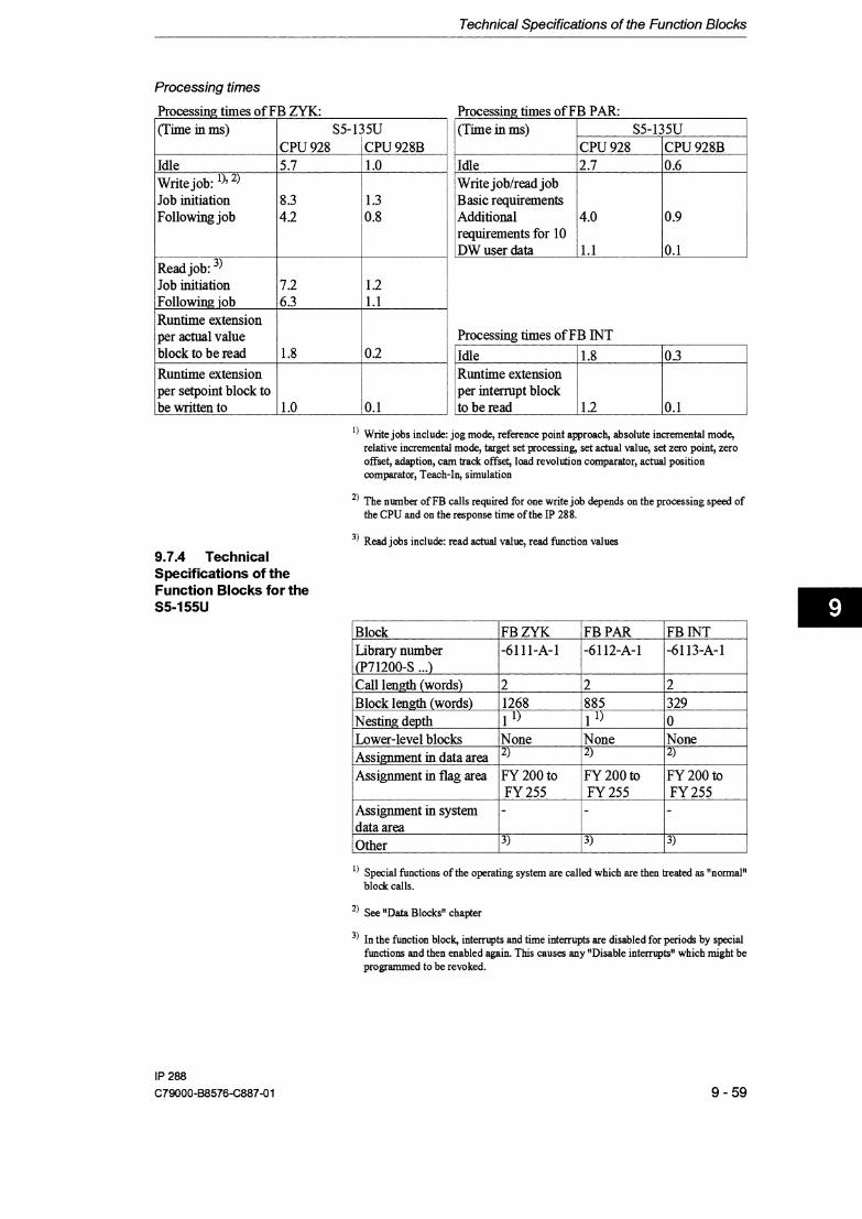
Technical Specifications of the Function Blocks
Processing times
l) Write jobs include: jog mode, reference point approach, absolute incremental mode, relative incremental mode, target set processing, set adual value, set zero point, zero offset, adaption, cam track offset, load revolution comparator, actual position comparator, Teach-In, simulation
Processing times of FB ZYK: Processing times of FB PAR:
') The number of FB calls required for one write job depends on the processing speed of the CPU and on the response time of the IP 288.
3, Read jobs include: read actual value, read function values
(Time in ms)
Idle Write job: l)' 2, Job initiation Following job
9.7.4 Technical Specifications of the Function Blocks for the S5-155U
(Time in ms)
Idle Write joblread job Basic requirements Additional requirements for l0 DW user data
Read job: 3, Job initiation Following job Runtime extension per actual value block to be read Runtime extension per setpoint block to be written to
S5-135U
! i Lower-level m blocks n n e I/ l i Assi ent in data area l Assignment in flag area FY 200 to FY 200 to FY 200 to
FY 255 FY 255 FY 255 Assignment in system -
CPU 928 5.7
8.3 4.2
S5-135U CPU 928B 1 .O
1.3 0.8
CPU 928 2.7
4.0
1.1
I B ~ O C ~ I F B Z Y K I Library number 1-6111-A-1 j Cp71200-S ...) 1
l ) Special functions of the operating system are called which are then treated as "normal" block calls.
Processing times of FB INT
j Runtime extension per interrupt block to be read 0.1
7.2 6.3
1.8
CPU 928B 0.6
0.9
0.1
FBPAR -6112-A-1
2 885 1 l )
1 Call length (words) ,Block length (words) ~Nestmg depth
1 data area
') See "Data Blocks" chapter
1.2 1.1
0.2
FB INT -6113-A-1
2 329 0 I
2 1268 1 l )
l
3, In the function block, interrupts and time interrupts are disabled for periods by special functions and then enabled again. This causes any "Disable internrpts" which might be programmed to be revoked.
1 .O 10.1
i Other 13) 13) 13)

Technical Specifications of the Function Blocks
Processing times
Processing times of FB ZYK: Processing times of FB PAR:
') The number of FB calls required for one write job depends on the processing speed of the CPU and on the response time of the IP 288.
(Time in ms)
Idle Write job:: l)' 2, Job initiation Following job
Read job: 3, Job initiation Following iob Runtime extension per actual value block to be read Runtime extension per setpoint block to be written to
3, Read jobs include: read actual value, read function values
9.7.5 Technical Specifications of FB 38 and FB 39
comparator, Teach-In, simulation
') Write jobs include: jog mode, reference point approach, absolute incremental mode, relative incremental mode, target set processing, set actual value, set zero point, zero offset, adaption, cam track offset, load revolution comparator, actual position
S5-155U CPU 9461947 1.2
1.8 1.1
1.7 1.5
0.3
0.2
Block -5038-A-1 -5039-A-1
Nesting depth Lower-level blocks one o one
(Time in ms)
Idle Write joblread job Basic requirements Additional requirements for 10 DW user data
S5-155U CPU 9461947 0.7
1.1
0.2
Processing times of FB INT
Runtime extension per interrupt block
Assignment in data area
Assignment in flag area System statements Other
-
Pmmeterized data block up to and including DW 80
Parameterized data block up to and including DW 80
FY 248 to FY 255 Yes 1 During processing of the block, intempts are disabled by the UMII and URAII
operations.
F Y 248 to FY 255 yes During processing of the block, interrupts are disabled by the "M" and "RA" operations.

Technical Specifications of the Function Blocks
Use of the "RA" operation in DB 38 or FB 39 revokes any "IA" operation you may have programmed.
Processing times of F5 38
Processing times of F5 39
(Time in ms) CPU 941 CPU 942 / CPU 943 1 CPU 944 B B I B
: Save page No. Save scratcMags/ system data Save both
2.2 5.7
5.8
2.2 5.7
5.8
(Times in ms)
Load page No. ,Load scratcMagd 'system data Load both
CPU 943
1.8 5.5
CPU 944 CPU 941 B 1.5
i 4.3
1.2 1.8
CPU942 B 1.5 4.3
5.7 , 1.9
4.4 1 4.4
B B , 1.2 0.3
4.2
4.3
0.4
0.5

Index
Accuracy range Acknowledge
external errors watchdog
Acknowledge external error Acknowledge watchdog Actual position
assignment Actual position controller
load Actual value job Adaption
terminate Adaption value
llmit Additional functions Application mailbox Axis function
machine data Axis number
cam data target data target list
Axls status assignment
Axis type cam data target data
Basic data set Basic resolution Block parameters BRES
Cam controller edit cam sets general
Cam ID bits assignment
Cam number assignment
Cam set 3-6 overwrite 5-41 transfer 5-41 transfer to the module 5-41
Cam set check 5-41 Cam set number 5-43
assignment 8-37 Cam track 3-5
enable 6-40 offset 6-28
Cam type 5-36 Cams 5-43
dynamic 3-5 Cams outside the traversing range 5-37 Change fiom programmer mode to PLC mode
effect 6-12 Change of direction 5-25 Changeover point 5-30 Checkback signals 8-7 Coding switch 4-4 COM 288
function 3-1 1 Commands
process 7-2 1,7-24 Comparator 6-4 Comparison value
assignment 8-3 1 Connecting cables 4-10 Control bit image 8-5 1 Control bits
assignment 8-25,8-27,8-30 - 8-3 1,8-34 effect 6-1 1 image 8-19
Control job 8-6 Control signals 8-7 Control signals axis 1,2 and 3
assignment 8-25 Convert data sets 7-17 Coordination input 5- 12
effect 6-11 Correction time of dynamic cams 5-34 CPU failure
response in the case of 6-12 Current functions
assignment 8-20

Current reference point coordinate assignment 8-23
Cutoff point 5-30
Data set header am data 9-28
Data set job 8-6 Data set number 5-4,5-49
cam data 5-32 machine data 5-9 target data 5-44
Data set type 5 -4 cam data 5-32 cam set directory 5-42 machine data 5-9 target data 5-44 target list 5-49 target set directory 5-47
Data structure 8-1 1 DB - APP 8-5,8-28
assignment 8-28 contents 8-10
DB - IP 8-5,8-14 application l to 8 8-14 assignment 8-14 contents 8-10 structure of an application mailbox 8- 1 5
DB - PAR 8-5,8-42 assignment 8-42 contents 8-10 data block type 8-12
DB - ZU 8-5,8-12 assignment 8-12 contents 8-10
Defaults 7-10 Diagnostics interrupt 5-1 1
assignment 8-27 Diagnostics memory 6-43
fieeze 6-43 trigger 6-43
Digital input 3-10 Digital output 3-10,5-12 Direction 5-34 Drive control signals 5-24 Drive disable 6-36
Edge for the l st process interrupt 5-36 Edge for the 2nd process interrupt 5-36
Edit machine data 7-14 Edit SYSID 7-13 Effect of S5 CPU failure 5-5 Encoder
incremental 6-8 permissible 5-12
Encoder revolutions 5-19 Encoder rotational direction to d. of travel 5-16 Encoder type 5- 12 End of cam 5-37 End of traversing range 5-20 Error numbers 8-44 Evaluating SS1 encoder signals 5-14 Excess X Gray code 5- 14 Execution ID
assignment 8-3 1 FB 29 8-79 External error
assignment 8-21 effect 6-12
FB 38 assignment of the data area call explanation of the parameters overview of the permissible combinations parameter assignment structure of use
FB 39 assignment of the data area assignment of the pammeters overview of the permissible combinations technical specifications use
FB INT interrupt processing processing times (CPU 922) processing times (CPU928, CPU 928B) processing times (S5- 1 15U) processing times (S5- 155U)
FB PAR job processing processing times (CPU 922) processing times (CPU 928, CPU 928B) processing times (S5- 1 1 5U) processing times (S5- 155U)

Index
FB ZYK cyclic program execution job processing processing times (CPU 922) processing times (CPU 928, CPU 928B) processing times (S5-115U) processing times (S5-155U) readlwrite jobs
Fir tree format half
Firmware version Follow-up Forward adaption value
assignment Forward changeover difference Forward cutoff difference Frame 1 of axis 1 ,2 and 3
assignment Frame 2 of axis 1 ,2 and 3
assignment Framing Function blocks FB 38 and FB 39 Functions
common special features event-dependent parameter changes points to note position-dependent
Further fbnctions Fuse
General overview
Hysteresis
Image of the digital inputs assignment
Increment mode absolute relative
Incrementslencoder revolution Indicator Individual functions
assignment
Initiating cam for the l st process interrupt 5-35 Initiating cam for the 2nd process interrupt 5-36 Installation
in an S5-115U 4-9 in an S5-135UI155U 4-8
Intelligent V 0 module 3-4 Internal error
effect 6-12 Interrupt cause axis 1,2 and 3
assignment 8-26 Interrupt generation
in different controllers 4-6 Interrupt line 5-6 Interrupt response 8-46
Job directory Job processing Job status Jog
LED EXF 9-43 LED INF 9-42 Length measurement 3-9,6-6 Limit frequency 3-8 Linear axis 5-10 Load the revolution comparator
cam controller 6-29 positioning 6-29
Machine data delete edit enter overwrite
Main menu Maximum speed Measured length
assignment Measuring system
cam data machine data target data
Memory delete
Menus and screen forms

Index
Mode in progress assignment
Module ID cam data cam set directory machine data target data target list target set directory
Module number cam data machine data target data target list
Module status assignment
Module type Monitoring by the IP 288 Monitoring time Multi-turn encoder Multiprocessor mode
call FB INT
Number format 5-11 Number of cam sets entered 5-42 Number of cam sets per axis 5-42 Number of cam sets which can still
be entered 5-42 Number of cams in the track 5-34,5-43 Number of target sets entered 5-47 Number of target sets per axis 5-48
Omet for "Cam track offset'' assignment 8-34
Odoff edge assignment 8-37
Operating modes 6-4 Operator error
assignment 8-2 1 effect 6-11
Output field 7-5
Page number setting
Path cam
Pathlencoder revolution Positioning
generate target sets process the target list
Positive feedback Power failure
effect Process diagnostics Process interrupt
assignment Programmer mode Programming example
Reduction switch Reference point
calculate trkger
Reference point coordinate Repeated execution of a traverse Reproducibility Resolution Restart characteristics Reversal
soft or hard Reverse adaption value
assignment Reverse changeover difference Reverse cutoff difference Revolution comparator
load Revolution counter
assignment Rotary axis Rounding
S5 CPU failure 5-5,6-12 Select applications 1 to 8
assignment 8-16 Select cyclic reading of checkback signals
assignment 8-17 Select the data area
in DB - APP 8-10 in DB - PAR 8-10
Selection write control signals 8-24
Selection list 7-5 Selection window 7-5 Set control bit 8-5 1

Set the actual value Simulation
in the case of a cam controller in the case of positioning maximum speed switch on terminate
Simultaneous start of several axes Single-turn encoder Slots
in different CCs and EUs Software switch
end start
Speed Speed ID
assignment Standard function blocks Start of cam Start of traversing range Switching axes in parallel Switching digital inputs Synchronization
absolute encoders incremental encoders
Synchronization control word
Target Target list
delete transfer transfer to the module
Target list check Target range
fictitious Target set
longlshort overwrite transfer transfer to the module
Target set check Target set number
assignment Target set processing Teach-In
cam controller positioning
Time cam Time interrupt Track ID bits
assignment
Track number 5-34,5-42 Track number for "Cam track offset"
assignment 8-34 Track number for "Teach-In"
assignment 8-37 Tracks
direction-dependent 3-5 Transfer a data set 8-8 Traverse status
assignment 8-20
User data for "Cam track offset" assignment 8-34
User data for "Function values" assignment 8-4 1
User data for "Increment mode" assignment 8-30
User data for "Jog" assignment 8-30
User data for "Load actual pos. comparator" assignment 8-36
User data for "Read actual values" assignment 8 -40
User data for "Reference point approach" assignment 8-30
User data for "Set actual value" assignment 8-30
User data for "Set zero point" assignment 8-30
User data for "Simulation" assignment 8-39
User data for "Target set processing" assignment 8-32
User data for "Teach-In" assignment 8-37
User data for "Zero offset" assignment 8-30
User program (S5- 1 15U) interruption 8-47
User program (S5- 13 5U, CPU 922) interruption 8-47
User program (S5-135U, CPU 9281928B) interruption 8-48
User program (S5- 155U) interruption 8-48

Index
Watchdog acknowledgement assignment
Working range
Zero mark positionlreference coordinate ID 5-22 Zero offset
cam controller 6-24 Zero point
offset 6-23 set 6-24
Zero speed monitor 5-27 Zero speed range 5-27

ESD Guidelines
Guidelines for Handling Electrostatically Sensitive Devices (ESD)
1 What is ESD?
VSLl chips (MOS technology) are used in practically all SlMATlC and TELEPERM modules. These VLSl components are, by their nature, very sensitive to overvoltage and thus to electrostatic discharge:
They are therefore defined as Electrostatically Sensitive Devices: "ESD"
"ESD" is the abbreviation used internationally.
The following waming label on the cabinets, subracks and packing indicates that electrostatically sensitive components have been used and that the modules concerned are susceptible to touch:
ESDs can be destroyed by voltage and energy levels which are far below the level perceptible to human beings. Such voltages already occur when a component or a module is touched by a person who has not been electrostatically discharged. Components which have been subjected to such overvoltages cannot, in most cases, be immediately detected as faulty; the fault occurs only after a long period in operation.
An electrostatic discharge - of 3500 V can be felt - of 4500 V can be heard - must take place at a minimum of 5000 V to be seen.
But just a fraction of this voltage can already damage or destroy an electric component.
The typical data of a component can suffer due to damage, overstressing or weakening caused by electrostatic discharge; this can result in temporary fault behavior, e.g. in the case of
- temperature variations, - mechanical shodks, - vibrations, - change of load.
Only the consequent use of protective equipment and careful observation of the precautions for handling such components can effectively prevent functional disturbances and failures of ESD modules.

ESD Guidelines
2 When is a Static Charge Formed?
One can never be sure that the human body or the material and tools which one is using are not electrostatically charged.
Small charges up to 100 V are very common; these can, however, very quickly rise up to 35 000 V!
Examples of static charge:
- Walking on a carpet up to 35 000 V - Walking on a PVC flooring up to 12000V
- Sittjng on a cushioned chair up to 18 000 V - Plastic desoldering unit up to 8 000 V
- Books, etc. with a plastic binding up to 800OV
- Plastic bag up to 5 000 V - Plastic coffee cup up to 5 000 V
3 Important Protective Measures against Static Discharge
Most plastic materials are highly susceptible to static charge and must therefore be kept as far away as possible from ESDs!
Personnel who handle ESDs, the work table and the packing must all be carefully grounded!
4 Handling of ESD Modules
One basic rule to be observed is that electronic modules should be touched by hand only if this is necessary for any work to be done on them. Do not touch the component pins or the conductors. Touch components only if - the person is grounded at all times by means of a wrist strap or - the person is wearing special anti-static shoes or shoes with a grounding strip.
Before touching an electronic module, the person concerned must ensure that (s)he is not carrying any static charge. The simplest way is to touch a conductive, grounded item of equipment (e.g. a blank metallic cabinet part, water pipe, etc.) before touching the module. Modules should not be brought into contact with insulating materials or materials which take up a static charge, e.g. plastic foil, insulating table tops, synthetic clothing, etc.. Modules should only be placed on conductive surfaces (table with anti-static table top, conductive foam material, anti-static plastic bag, anti-static transport container). Modules should not be placed in the vicinity of visual display units, monitors or TV sets (minimum distance from screen > 10 cm).
The diagram on the next page shows the required protective measures against electrostatic discharge.

ESD Guidelines
Sitting position Standing position
a Conductive flooring b Anti-static table c Anti-static shoes d Anti-static coat e Grounding wrist strap f Grounding connection of the
cabinets
Standinglsitting position
5 Measurements and Modifications to ESD Modules
Measurements on modules may only be carried out under the following conditions:
- the measuring equipment is grounded (e.g. via the PE conductor of the power supply system) or
- when electrically isolated measuring equipment is used, the probe must be discharged (e.g. by touching the metallic casing of the equipment) before beginning measurements.
Only grounded soldering irons may be used.
6 Shipping of ESD Modules
Anti-static packing material must always be used for modules and components, e.g. metalized plastic boxes, metal boxes, etc. for storing and dispatch of modules and components.
If the container itself is not conductive, the modules must be wrapped in a conductive material such as conductive foam, anti-static plastic bag, aluminum foil or paper. Normal plastic bags or foils should not be used under any circumstances.
For modules with built-in batteries ensure that the conductive packing does not touch or short-circuit the battery connections; if necessary cover the connections with insulating tape or material.