Operating Manual PacDrive SH Servo Motor - ADEGIS
80
-
Upload
khangminh22 -
Category
Documents
-
view
1 -
download
0
Transcript of Operating Manual PacDrive SH Servo Motor - ADEGIS


Legal notice© All rights reserved to ELAU GmbH, also in case of patent right applications.No part of this documentation or the accompanying software and firmware may bereproduced, transferred, paraphrased, saved to a storage medium or translated toanother language or computer language without the written consent of ELAU GmbH.Any possible measure was taken to ensure that this product documentation is com‐plete and correct. However, since hardware and software are continuously improved,ELAU makes no representations or warranties with respect to the contents of thisdocumentation.All information on our products in this manual are given purely for the purpose of prod‐uct description and is not binding. Misprints, errors and modifications -without priornotice in the course of product development- are reserved. If details contained in thismanual are explicitly a part of an agreement made with ELAU GmbH, then the detailsof the agreements in this manual are exclusively to determine the agreed condition ofthe object of agreement, on behalf of the § 434 BGB (condition guarantee on behalfof legal regulations).
TrademarkPacDrive is a registered trademark of ELAU GmbH. All other trademarks mentioned in this documentation are the exclusive property oftheir manufacturers.
ELAU GmbH Dillberg 12-1697828 Marktheidenfeld, GermanyTel.: +49 (0) 9391 / 606 - 0Fax: +49 (0) 9391 / 606 - 300E-mail: [email protected]: www.elau.de
Legal notice
Page 2 PacDrive SH-Motor ELAU GmbH

Manufacturer's declarationAccording to the EC machine guidelines 98/37/EC
ELN 128-00/02.08page 1/1
The product we delivered:
PacDrive SH-Motor
is intended for installation in a machine.
Commissioning is forbidden until it is established that the machine in which this productis to be installed complies with the provisions of the EC guideline. The manufacturerguarantees that the product delivered was manufactured in accordance with the ap‐plied harmonized standards / specifications.
The following standards were applied:
• EN 60204-1 (2007) Safety of machinery: Electrical equipment of machines - Gen‐eral requirements
• EN 50081-2 (3/1994) Electromagnetic compatibility. Generic emission standard• EN 61000-6-2 (3/2000) Electromagnetic compatibility. Resistance to jamming
Manufacturer: ELAU AGDillberg 12-16 97828 Marktheidenfeld, Germany2008-01-10
Thomas CordChief Executive Officer
Manufacturer's declaration
ELAU GmbH PacDrive SH-Motor Page 3

Contents
1 About this manual 61.1 Introduction ................................................................................................................ 61.2 Symbols, designator and display format of safety notes ........................................... 7
2 Notes for working safely with the product 82.1 Proper use ................................................................................................................. 82.2 Selection and qualification of personnel .................................................................. 102.3 Residual risks .......................................................................................................... 11
3 System overview 143.1 Features of the servo motors .................................................................................. 143.2 Designs ................................................................................................................... 153.3 PacDrive System ..................................................................................................... 15
4 Transport, storage, unpacking 184.1 Transport ................................................................................................................. 184.2 Storage .................................................................................................................... 184.3 Unpacking ............................................................................................................... 184.4 Type plate ................................................................................................................ 18
5 Installation and maintenance 205.1 Initial start-up ........................................................................................................... 205.2 Configuration, programming, diagnosis ................................................................... 235.3 EMC Rules .............................................................................................................. 245.4 Maintenance, repair, cleaning ................................................................................. 255.4.1 Maintenance ............................................................................................................ 255.4.2 Repair ...................................................................................................................... 255.4.3 Cleaning .................................................................................................................. 255.5 Spare part inventory ................................................................................................ 265.6 Type code ................................................................................................................ 275.7 Device replacement ................................................................................................. 285.7.1 SH ............................................................................................................................ 295.8 Cable replacement .................................................................................................. 30
Contents
Page 4 PacDrive SH-Motor ELAU GmbH

6 Technical data 316.1 Technical information .............................................................................................. 316.1.1 Definition of technical data ...................................................................................... 316.1.2 Ambient conditions, approval .................................................................................. 326.1.3 Mounting arrangement and protection class ........................................................... 346.1.4 Motor shaft and bearings ......................................................................................... 366.1.5 Holding brake (optional) .......................................................................................... 386.2 Data tables .............................................................................................................. 396.2.1 Technical features ................................................................................................... 396.2.2 Motor options ........................................................................................................... 396.2.3 PacDrive SH-055-Motor (self-cooled) ..................................................................... 406.2.4 PacDrive SH-070-Motor (self-cooled) ..................................................................... 416.2.5 PacDrive SH-100-Motor (self-cooled) ..................................................................... 426.2.6 PacDrive SH-100-Motor (force-ventilated) .............................................................. 436.2.7 PacDrive SH-140-Motor (self-cooled) ..................................................................... 446.2.8 PacDrive SH-140-Motor (force-ventilated) .............................................................. 456.2.9 PacDrive SH-205-Motor (self-cooled) ..................................................................... 466.2.10 PacDrive SH-205-Motor (force-ventilated) .............................................................. 476.2.11 Brake ....................................................................................................................... 486.2.12 Fan cover ................................................................................................................ 506.2.13 Encoder ................................................................................................................... 506.3 Torque/speed characteristic curves ........................................................................ 516.4 Electrical connections .............................................................................................. 676.5 Dimensions .............................................................................................................. 706.5.1 SH-055 .................................................................................................................... 706.5.2 SH-070 .................................................................................................................... 716.5.3 SH-100 .................................................................................................................... 726.5.4 SH-140 .................................................................................................................... 736.5.5 SH-205 .................................................................................................................... 75
7 Appendix 767.1 Contact addresses .................................................................................................. 767.2 Product training courses .......................................................................................... 767.3 Changes .................................................................................................................. 777.4 Fault report form ...................................................................................................... 78
Contents
ELAU GmbH PacDrive SH-Motor Page 5

1 About this manual
1.1 Introduction
Read and observe this manual before you work on the motor for the first time. Takeparticular note of the safety instructions (see 2.3 Residual risks). As described in sec‐tion 2.4, only those persons who meet the "Selection and qualification of employ‐ees" are allowed to work on the motor.This manual is intended to help you use the motor and its intended applications safelyand properly.By observing this manual, you will help to
• avoid risks,• reduce repair costs and down times of the motor,• increase the life span of the motor• and increase reliability of the motor.
A copy of this manual must always be available for personnel who are entrusted towork on the motor.
1 About this manual
Page 6 PacDrive SH-Motor ELAU GmbH

1.2 Symbols, designator and display format of safety notes
This manual divides the safety instructions into four various categories.Hazards and possible results will be categorized using a certain combination of sym‐bols and signal words.
Symbol / Signal word MeaningIndicates an immediate hazardous situation that can lead to death orserious bodily injury if the safety regulations are not observed.Indicates a potentially hazardous situation that can lead to serious injuryor death if the safety regulations are not observed.Indicates a potentially hazardous situation that may result in bodily harmif the safety regulations are not followed.Indicates a potentially dangerous situation that may result in propertydamage if the safety regulations are not observed.
The following symbols and designators are used in this document:
Symbol/Character MeaningInformation Symbol: After this symbol, you will find important instructionsand useful tips on using the components.
Marker: After this symbol, you will find references for further information.
Prerequisite symbol: This symbol indicates a prerequisite you have tofulfill before you start to implement an instruction.Activity symbol: After this symbol, you will find an instruction. Follow theinstructions in sequence from top to bottom.
üResult symbol: The text after this symbol contains the result of an action.
•First level bullet point
Second level bullet point.
Orientation aid: Information serving as an orientation aid regarding thesection's contents follows this symbol.
bold If the descriptive text contains keywords, such as parameters, they arehighlighted in bold.Program code is written in a different font.
1.2 Symbols, designator and display format of safety notes
ELAU GmbH PacDrive SH-Motor Page 7

2 Notes for working safely with the product
The ELAU Motor is are state of the art and conform to recognized technical safetyregulations. Nevertheless the use of the motor can present a hazard to life and limbor cause property damage. The following section contains general requirements forsafe work with to the motor. Each person who uses or works on the motor must readand follow these requirements.
2.1 Proper use
Use The ELAU Motor is are intended to be installed in a machine or assembled with othercomponents to form a machine or system.The ELAU Motor is part of the PacDrive System. The PacDrive System is the completecontrol system comprising of
• PacDrive Controller of C- or P-Series,• PacDrive Servo Amplifier MC-4 or Power Supply PS-5 with Distribution Box DB-5
and• PacDrive Motor.
What do youneed to ob‐
serve?
Proper use includes that you observe the following points and the resulting rules:
• The regulative, warning and instruction signs on the connected components andin the switching cabinet
• The warning instructions on the motor on the connected components and in theswitch cabinet
• The inspection and maintenance instructions• The operating instructions of the other components• All other documentation
FlawlessState
Operate the motor only when they are in a flawless technical condition. Observe theregulations, act with safety and hazards in mind If circumstances occur that impactsafety or cause changes in the operating performance of of the motor, switch the motoroff immediately and contact the responsible service staff.
Only originalequipment
must be used
Use only the options and mounting parts specified in the documentation and no third-party devices or components that are not expressly approved ELAU recommends.. Donot change or modify the motor inappropriately.
Protectionmeasures
provide for
Before installing, provide for appropriate protective devices in compliance with the localand national standards. Do not commission components without accordant protectivedevices. After installation, commissioning or repair, test the protective devices used.
Forbiddenenvironments
The ELAU components must not be used in the following environments:
• In dangerous (explosive) atmospheres• In mobile, movable or floating systems• In life support systems• In domestic appliances
2 Notes for working safely with the product
Page 8 PacDrive SH-Motor ELAU GmbH

Installationand operating
ambient
You may only use them in accordance with the installation and operating conditionsdescribed in the documentation. The operating conditions at the installation locationmust be checked and maintained in accordance with the required technical data (per‐formance data and ambient conditions). Commissioning is prohibited until it is guar‐anteed that the usable machine or system in which the motor is installed meets allrequirements of EC Directive 98/37/EC (machinery directive).In addition, the following standards, directives and regulations are to be observed:
• DIN EN 60204 Safety of machinery: Electrical equipment of machines• DIN EN 292 Part 1 and Part 2 Safety of machinery: Basic Concepts, General Prin‐
ciples for Design• DIN EN 50178 Electronic equipment for use in high-current electrical systems• EMC directive 89/336/EEC : DINT• The generally applicable local and national safety and accident prevention regu‐
lations.• The rules and regulations on accident prevention and environmental protection that
apply in the country where the product is used• The applicable laws and ordinances
2.1 Proper use
ELAU GmbH PacDrive SH-Motor Page 9

2.2 Selection and qualification of personnel
Target Audi‐ence
of this manual
This manual is geared exclusively toward technically qualified personnel, who havedetailed knowledge in the field of automation technology. The description is mainly forconstruction and application engineers from the engineering and electro-technics di‐vision as well as service and commissioning engineers.
Specialist ortrained
staff
Work on the motor may only be carried out by qualified professional or by trained staffunder the instruction and supervision of a qualified person in accordance with electricalregulations. Professionals are those persons who, as a result of their training, knowl‐edge, and experience and knowledge of the pertinent regulations, can
• evaluate the transferred work,• recognize the meaning of the safety instructions and implement them consistently,• recognize possible hazards and• take appropriate safety measures.
2 Notes for working safely with the product
Page 10 PacDrive SH-Motor ELAU GmbH

2.3 Residual risks
Health risks arising from to the motor have been reduced by means of safety technol‐ogy and design engineering. However a residual risk remains, since the motor workswith electrical voltage and electrical currents.
If activities involve residual risks, a specific note is made at the appropriate points. Thenote details the potential hazard and its effects and describes preventative measuresto avoid it.Mounting and handling
WARNINGRisk of injury during handlingRisk of bodily harm from crushing, shearing, cutting and hitting
• Observe the general construction and safety regulations for handling and mount‐ing.
• Use suitable mounting and transport equipment correctly and use special toolsif necessary.
• Prevent clamping and crushing by taking appropriate precautions.• Wear suitable protective clothing (e.g. safety goggles, safety boots, protective
gloves) if necessary.• Do not stand under suspended loads.
High leakage current
DANGERLeakage current greater than 3.5 mA.Risk of death
• Make sure that the device is firmly connected to the power supply (in accordancewith DIN EN 50178 - Equipment of High-Voltage Systems).
Touching hot surfaces
The housing temperature of the motor exceeds 70°C during nominal operation. Aswarning, the symbol shown here is affixed on the motor.
WARNINGHot surfacesRisk of burns from surface temperatures up to 100 °C.
• Wear safety gloves or wait until the surface temperature has cooled to allow safecontact!
• Attach protective cover or touch guard.
2.3 Residual risks
ELAU GmbH PacDrive SH-Motor Page 11

Touching electrical partsIf parts have contact with voltages greater than 50 V, it can be a hazard for personnel.When electrical devices are in operation, certain parts of these devices must neces‐sarily carry dangerous voltages.
DANGERHigh voltageElectric shock, fire or explosion
• Observe the general construction and safety regulations for working on high-current electrical systems.
• After installation, check the firm connection of the ground conductor to all elec‐trical units to ensure that connection complies with the connection diagram.
• Always make sure that the ground conductor is connected when operating elec‐trical components.
• Disconnect devices with a voltage greater than 50 volts from the power supplybefore working on electrical parts.
• Prevent the unit from being switched back on.• Wait at least 5 minutes after switching off before accessing the components.• Before accessing the device, check the voltage with a voltage meter to be sure
that the voltage is less than 50 volts.• Do not touch the electrical connection points of the components when the device
is switched on.• Before enabling the device, safely cover the live components to prevent contact.• Provide for protection against indirect contact (DIN EN 50178, Section 5.3.2).
Protection against magnetic and electromagnetic fieldsMagnetic and electromagnetic fields that are in immediate environments of electricalconductors and permanent motor magnets represent a serious health hazard to per‐sons with heart pacemakers, metal implants and hearing aids.
WARNINGHealth risk posed by risk groups in the proximity of electrical equipment.Do not allow personnel with pacemakers or similar sensitive implants to work on motors!
2 Notes for working safely with the product
Page 12 PacDrive SH-Motor ELAU GmbH

Dangerous movementsThere can be different causes of dangerous movements:
• Missing or faulty homing of the robot mechanics• Wiring or cabling errors• Errors in the application program• Component errors• Error in the measured value and signal transmitter• Operation error
Personal safety must be guaranteed by primary equipment monitoring or measures.Don't just rely on the internal monitoring of the drive components. Monitoring or meas‐ures should be implemented based on the specific characteristics of the equipment,in line with a risk and error analysis. This includes the valid safety regulations for theequipment. Under no circumstances must the technical safety devices be removed.Do not make any modifications to a protective device that may put it out of operation.Protect existing work stations against unauthorized operation. Effectively restrict ac‐cess to the control terminals to allow access only to authorized persons.
DANGERDangerous movementsRisk of death, serious injury or property damage!
• Prevent entry to a danger zone, e.g. by means protective fencing, mesh guards,protective covers, or light barriers.
• Ensure the protective devices are properly dimensioned.• Position EMERGENCY OFF switches so that they are easily accessible and can
be reached quickly.• Check the functionality of EMERGENCY OFF equipment before start-up and
during maintenance periods.• Prevent unintentional start-ups by disconnecting the drives from power supply
using the EMERGENCY OFF circuit or using a safe start-up lock out.• Before accessing the drives or entering the danger zone, safely bring the drives
to a stop.• While working on the system, power down the electrical equipment using the
main switch and prevent it from being switched back on.• Before working on the system, secure it against start-up.• Avoid operating high-frequency, remote control, and radio devices close to the
system electronics and their feed lines.• Prior to the initial start-up, check the system and the installation for possible mal‐
functions in all usage scenarios.• If necessary, carry out a special EMC check of the system.
2.3 Residual risks
ELAU GmbH PacDrive SH-Motor Page 13

3 System overview
3.1 Features of the servo motors
The high dynamic brushless synchronous AC servomotors of the SH series are per‐manently energized machines that are specially designed for high dynamic positioningtasks.The low inherent moment of inertia in comparison to other AC servomotors not onlyensures excellent acceleration values in connection with high load capacity, it alsolowers energy consumption and heat loss resulting in the motor.The rotor position is determined using an integrated measuring system. The brushlessprinciple described above makes the drives extremely robust and low-maintenance.The motors have the following features:
• High operating reliability• Low-maintenance• Overload protection using an integrated temperature sensor (external evaluation
required)• High power density• High dynamic response• High overload capability• Large torque range• Sinusoidal EMC• High-voltage technology = low currents• Low mass moment of inertia• Motor connections use round connector or terminal box• Fast and simple commissioning thanks to the electronic type plate in the SinCos
encoder
3 System overview
Page 14 PacDrive SH-Motor ELAU GmbH

3.2 Designs
Motor feedback
• SinCos encoder single turn• SinCos multiturn encoder
Brake
• No holding brake (standard)• With holding brake (optional) for securing the axis in the deactivated motor
Output shaft
• Smooth shaft (standard)• Shaft with round-ended feather key (optional)
Miscellaneous
• The SH-motors are also available with a forced cooling fan• Additional cooling systems upon request
3.3 PacDrive System
Figure 3-1: PacDrive System Overview
3.2 Designs
ELAU GmbH PacDrive SH-Motor Page 15

PacDrive Controller Family
The PacDrive Controller, microprocessor-based control hardware with the VxWorksreal-time operating system, centrally implements the PLC and motion functions. APacDrive Controller synchronizes, coordinates, and creates the motion functions formaximum
• 8 drives for the PacDrive Controller C200• 2 drives for the PacDrive Controller C200 A2• 16 drives for the PacDrive Controller C400• 8 drives for the PacDrive Controller C400 A8• 99 drives for the PacDrive Controller C600of a food and packaging machine. Many different HMIs are used for the HMI tasks. Whether it is low-cost clear text orIPC, it is no problem for the flexible PacDrive Controller. The PacDrive P600 controller is additionally equipped with a full-fledged PC. Due toits PC-based architecture, it can perform HMI tasks with no problem in addition to theusual motion functions.PacDrive Servo Amplifier MC-4 and
The MC-4 digital Servo Amplifier features compact, closed, wall-mountable construc‐tion as well as state of the art technology. For the innovative MC-4, the power supplyunit, the final stage and the software servo regulator for an axis are housed in a space-saving housing. Because it communicates with the PacDrive Controller exclusively viafiber optic cable, it is also suitable for peripheral layout. It does not require a userprogram, processes single or multi-turn encoders, and configures itself using the elec‐tronic type plate in the SH-Motor.
Highlights of the PacDrive MC-4
• World voltage range• Integrated power supply unit• Max. 34.5/69 kVA output• Automatic motor detection• Minimal design• Safety input inverter enable• 250 % overload• Integrated SERCOS interface
3 System overview
Page 16 PacDrive SH-Motor ELAU GmbH

SH-Motor
The AC Servo Motors of the SH series meet the highest demands on dynamics andprecision. Five flange sizes with different grades of torque offer the right drive solutionfor virtually any application. New winding technology with single tooth winding enablescompact sizes and reduces production costs compared to traditional motors.
Highly dynamicAC Servo Mo‐
tors
Due to its low moment of inertia compared to other AC servo motors, and in conjunctionwith the high overload capability, the SH-Motor meets all requirements in terms ofaccuracy, dynamics and profitability.SH-Motors are compatible with SM motors and are available in five different flangesizes:
• SH-055• SH-070• SH-100• SH-140• SH-205
Brief summary of technical data:
• Developed for the highest dynamics and precision• single tooth winding• Compact size• High power density• Low internal moment of inertia• High overload capability• High resistance to winding damages• Low detent torque
3.3 PacDrive System
ELAU GmbH PacDrive SH-Motor Page 17

4 Transport, storage, unpacking
4.1 Transport
▶ Avoid heavy shocks and/or vibrations during transport.▶ Check the units for visible transport damage and inform the shipping company
immediately if necessary.
4.2 Storage
• Store devices in a clean, dry room.• The air temperature at the storage location must be between - 25 °C and +70 °C.• Possible temperature variations at the storage location must be maximum 30 K per
hour.
4.3 Unpacking
▶ Remove the packaging.▶ Check that delivery is complete.▶ Check the delivered goods for transport damage.
4.4 Type plate
Figure 4-1: Type plate on the SH-Motor
4 Transport, storage, unpacking
Page 18 PacDrive SH-Motor ELAU GmbH
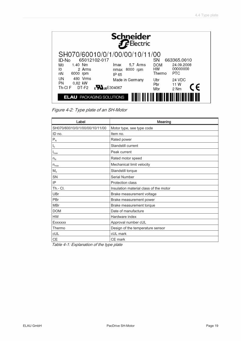
Figure 4-2: Type plate of an SH-Motor
Label MeaningSH070/60010/0/1/00/00/10/11/00 Motor type, see type codeID no. Item no.PN Rated powerI0 Standstill currentImax Peak currentnN Rated motor speednmax Mechanical limit velocityM0 Standstill torqueSN Serial NumberIP Protection classTh.- Cl. Insulation material class of the motorUBr Brake measurement voltagePBr Brake measurement powerMBr Brake measurement torqueDOM Date of manufactureHW Hardware indexExxxxxx Approval number cULThermo Design of the temperature sensorcUL cUL markCE CE markTable 4-1: Explanation of the type plate
4.4 Type plate
ELAU GmbH PacDrive SH-Motor Page 19

5 Installation and maintenance
For warranty reasons, we strongly recommend that you contact ELAU personnel forinitial start-up. The ELAU personnel
• will check the equipment,• determine the optimal configuration• and instruct the operating staff.
5.1 Initial start-up
How to check the shipment and the installation location:Testing ▶ Check that delivery is complete.
▶ Check device for sound condition.Only operate undamaged devices.
▶ Check data against type plates.
CAUTIONElectromagnetic fieldsInterference or system breakdown
• Use mains filters and motor filters in accordance with the combination of the servoamplifier/motor, cable length and mains or motor filter..
▶ Observe requirements for the installation location.▶ Observe requirements for the protection class and the EMC rules.
How to check the brake (if any):Step 1: ▪ Make sure that the motor is off-circuit.
▶ Try to turn the motor shaft manually.✓ When off-circuit, it should not be possible to turn the shaft, or at least you
should feel a very high resistance.✓ If the shaft can be turned without "perceptible" resistance, the brake is de‐
fective.
Step 2: ▶ Connect the control voltage to bleed the brake (pins A and B for P30 connector;pins + and - for P70 connector).
▶ Try to turn the motor shaft manually.✓ When the control voltage is connected, you should be able to turn the shaft.
Please note the manuals for the servo amplifiers (MC-4).
▶ Then install motor.
5 Installation and maintenance
Page 20 PacDrive SH-Motor ELAU GmbH

How to wire the motor:
▶ Connect devices, beginning with the ground conductor.▶ Check if the terminals are securely fastened and the necessary cable cross sec‐
tions are correct.
DANGERLeakage current greater than 3.5 mA.Risk of death
• Make sure that the device is firmly connected to the power supply (in accordancewith DIN EN 50178 - Equipment of High-Voltage Systems).
▶ Tighten the locking nut with a tightening torque of 2 Nm for the power connectorP30 (1) (7 - 8 Nm for P70) and 2.5 Nm for the signal connector (3).
31
2
Figure 5-1: Electrical connections - SH motor1 Brake/temperature/motor connection2 Additional ground connection3 Encoder Connection
▶ Check that shielding is completely correct.▶ Eliminate the possibility of short circuits and interruptions.▶ Check the continuity of the protective conductor system.
5.1 Initial start-up
ELAU GmbH PacDrive SH-Motor Page 21

How to connect the motor to the protective conductor:Option 1:
(recommendedconfiguration)
▶ Connect the motor with the protective conductor system using the additonalgrounding connection on the motor flange (1).
1
Figure 5-2: Ground connection on the motor
▶ Connection cross section of the grounding conductor appropriate for the mainsconnection-wiring has to be chosen for the connected upstream servo amplifier of the mo‐tor.(DIN EN 60204-1:2006, Section 5.2 Table 1).
▶ Use a grounding conductor with a minimum connection cross-section of 4 mm2
(DIN EN 61800-5-1:2008, section 4.3.5.4).
Option 2: ▶ Connect the motor to the grounded machine bed immediately above the motorflange.
▶ The size of the connection should be such that the ampacity is not impaired bymechanical, chemical or electromechanical factors.
According to DIN EN 60204-1:2006 Section 18.2, the correct grounding of the motorhas to be checked respectively proven on the completely installed machine at theinstallation location at all times.How to finish the initial start-up:
▶ Check safety functions such as the EMERGENCY OFF switch.
▶ Resume system operation according to the operating manual (from the packagingmachine manufacturer and servo amplifier).
5 Installation and maintenance
Page 22 PacDrive SH-Motor ELAU GmbH

5.2 Configuration, programming, diagnosis
The motor is matched by ELAU. The customer need not perform any aligning.
The respective servo amplifier documentation tells you how to adjust a servo amplifierto a motor.
Error diagnosis and monitoring of operating statuses are executed within the ELAUcontrols. See also the relevant descriptions for these.
5.2 Configuration, programming, diagnosis
ELAU GmbH PacDrive SH-Motor Page 23

5.3 EMC Rules
To control and regulate the motors, the mains voltage is stored by rectification in theDC bus of the servo amplifier. This stored energy is supplied to the motor by targetedswitching on and off using six semiconductor switches. The steep increase/decreasein voltage places considerable demands on the dielectric strength of the motor winding.An important additional aspect to observe is the electromagnetic compatibility (EMC)with other system components. The high rate of change of the clocked voltage gen‐erates harmonics of great intensity up into the high frequency range.
CAUTIONElectromagnetic fields!Interference or breakdown of system possible!
• During installation, select the HF grounding option with the lowest ohm load (e.g.an uncoated mounting plate on the switching cabinet).
• Ensure largest possible contact surface area (skin effect).• If necessary remove any existing paint to ensure contact.• Lay the grounding in a star configuration from the Central-Earthing-Point.• Current loops of earthing are prohibited and can cause unnecessary interference.• Only use shielded cables.• Supply large-area shielding bridges.• Do not connect shields via the PIN contacts of connectors.• Observe the circuit suggestions.• Shorten the motor cables to a minimal length.• Do not lay any cable loops in the switching cabinet.• In conjunction with electronic controllers, do not switch inductive loads without
suitable interference suppression.• Provide for suitable interference suppression. For direct current operation, this is
achieved by using recovery diodes and protector type-based, industry-standardquenching circuits during alternating current activity.
• Arrange the interference suppression immediately at the point of inductivity, asotherwise even more interference may be generated by the shock of the switch‐ing current on the interference suppression lines.
• Avoid sources of interference instead of eliminating the effects of existing inter‐ference.
• Do not arrange contacts with unsuppressed inductive loads in one room withPacDrive Components. The same applies for connection lines that do not leadsuppressed, switched inductances and lines that run parallel to them.
• Isolate the controller from such interference sources using a Faraday cage (sep‐arately partitioned switching cabinet).
• Mains filters and motor filters may by used depending on the combination of theservo amplifier/motor and the cable length.
5 Installation and maintenance
Page 24 PacDrive SH-Motor ELAU GmbH

5.4 Maintenance, repair, cleaning
5.4.1 Maintenance
Check brake function during operation at least once a year.
5.4.2 Repair
Proceed as follows in case of repair:
▶ Fill in the fault report form in the attachment (can also be sent per Fax).▶ When possible, replace defective parts (see 5.7 Device replacement).
CAUTIONTo avoid damage in transport and to guarantee that the repair process flows smoothly, followthe method outlined in the chapter on "Device Replacement".▶ Send the defective part back to ELAU.
5.4.3 Cleaning
The standard cooling method of the motor is by natural convection. Therefore, keepthe motor surfaces free from dirt.
How to remove dust and foreign objects from to the motor:
CAUTIONLiquids can seep in due to improper cleaning.Damage of the component
• Use cleaning processes appropriate to the protection class of the motor.
▶ Switch motor voltage free.▶ Remove motor.▶ Then blow out motor with dry pressurized air (max. 1 bar).
5.4 Maintenance, repair, cleaning
ELAU GmbH PacDrive SH-Motor Page 25

5.5 Spare part inventory
Keep a stock of the most important components to ensure that the equipment is func‐tioning and ready for operation at all times.
You may only exchange units with the same hardware configuration and the samesoftware version.
Indicate the following information on the spare part order:Item name: e.g. PacDrive SH 070 60030-0-0-00-00-00-00-00Item no.: e.g. 65012102-XXXHardware code: not specifiedSoftware version: not specified
You will find this information on the type plate and in the controller configuration of thePacDrive System.
5 Installation and maintenance
Page 26 PacDrive SH-Motor ELAU GmbH

5.6 Type code
5.6 Type code
ELAU GmbH PacDrive SH-Motor Page 27

5.7 Device replacement
CAUTIONFaulty replacement or opening of the motorDamage of the motorManufacturer's warranty expired
• Do not open motor to put it into operation or replace it.• In addition to the following instructions, you must observe the machine manu‐
facturer's specifications when replacing the motor.
DANGERHigh voltageElectric shock, fire or explosion
• Before working on electrical equipment, always put the main switch in the "OFF"position and secure it against being switched back on.
• Before working on the equipment, discharge the DC bus and use a voltage meterto make sure that there is no voltage.
• Make sure that the drives are at a standstill because potentially fatal voltage canoccur on the motor lines in generator operation.
• Disconnect power connector cables only when the system is deactivated.• Plug in power connector cables only when the system is deactivated.• If you are not using prefabricated ELAU cables, check that the assignment of the
new cables complies with the connection diagram of the machine manufacturer.
CAUTIONElectrostatic discharge.Damage to component
• Touch circuit boards only on edges.• Do not touch any of the circuit points or components.• Discharge any existing static charge by touching a grounded metallic surface
such as a grounded housing.• Prevent electrostatic charges; e.g., by wearing appropriate clothing.
5 Installation and maintenance
Page 28 PacDrive SH-Motor ELAU GmbH

5.7.1 SH
How to replace the motor:
▶ Take preliminary measures.▶ Put main switch in "OFF" position to free system of voltage.▶ Prevent main switch from being switched back on.
CAUTIONMechanical forceDamage to the encoder system
• Prevent impacts on the motor shaft when removing and attaching couplings tothe motor shaft, as this could damage the encoder.
• Use appropriate tools, such as an extractor.• Avoid mechanical damage to the coating of the motor housing.• Do not use any cleaning fluid, as this will damage the motor's aluminum housing.
WARNINGUnintentional axis movements due to loss of references in case of a motor replacementRisk of accident
• For servo axes with indirect distance measuring systems, restore the referenceto the machine coordinate system via the motor encoder every time a motor isreplaced.
▶ Replace the drive according to the machine manufacturer's specifications.▶ Connect earth cable and tighten with a 2.8Nm torque.
DANGERInsufficient shielding/groundingHazard to the drive
• Operate the drive only with fixed cover and cable gland.
▶ Connect additional grounding.▶ Execute the motor grounding for the second grounding connection as well.▶ Make sure that the grounding resistance does not exceed 0.1 Ohm.
5.7 Device replacement
ELAU GmbH PacDrive SH-Motor Page 29

31
2
Figure 5-3: Second ground connection1 Brake / temperature / motor connection cable2 Additional ground connection3 Encoder Connection
5.8 Cable replacement
DANGERHigh voltageElectric shock, fire or explosion
• Before working on electrical equipment, always put the main switch in the "OFF"position and secure it against being switched back on.
• Before working on the equipment, discharge the DC bus and use a voltage meterto make sure that there is no voltage.
• Make sure that the drives are at a standstill because potentially fatal voltage canoccur on the motor lines in generator operation.
• Disconnect power connector cables only when the system is deactivated.• Plug in power connector cables only when the system is deactivated.• If you are not using prefabricated ELAU cables, check that the assignment of the
new cables complies with the connection diagram of the machine manufacturer.
Replacing cables
▶ Put main switch in "OFF" position to free system of voltage.▶ Prevent main switch from being switched back on.▶ Exchange the cable according to the machine manufacturer's specifications.
5 Installation and maintenance
Page 30 PacDrive SH-Motor ELAU GmbH

6 Technical data
6.1 Technical information
6.1.1 Definition of technical data
Abbre‐viation
Unit Explanation
I0 [Arms] Standstill current Standstill current Effective value of the motor current at standstill torque M0
IN [Arms] Rated current Effective value of the motor current at rated torque MN
Imax [Arms] Peak currentEffective value of the motor current at peak torque Mmax
JM [kgcm2] Rotor moment of inertia The rotor inertia refers to a motor without brake.
kT [Nm/Arms] Torque constantQuotient from standstill torque M0 and standstill current I0 (at 120 °C winding temperature)
m [kg] Mass Motor mass without brake and without fan Motor mass without brake and without fan
M0 [Nm] Standstill torque; continuous torque (100% ED) at 5 min-1
At an ambient temperature of 40 °C and a winding temperature of 120 °CMN [Nm] Rated torque, continuous torque (100% ED) at nN
Due to motor speed-dependent losses less than M0. At an ambient temperature of 40 °C and awinding temperature of 120 °C.
Mmax [Nm] Peak Torque The maximum torque that the servo motor can briefly deliver to the output shaft.
nN [min-1] Rated motor speednmax [min-1] Mechanical limit velocityPN [kW] Mechanical rated power (power delivered to the shaft)
At the rated motor speed and load with the rated torqueRU-V, 20 [Ω] Resistance of a motor winding
Resistance between two phases at a winding temperature of 20 °C.LU-V [mH] Winding inductance between two phaseskE [Vrms/kmin-1] Voltage constant; induced voltage between two phases at 1000 min-1
V [m/s2] Maximum vibration (all directions)Y [m/s2] Maximum shock (all directions)TTK [°C] Response limit temperature sensortth [min] Thermal time constantp Pole pair numberTable 6-1: Physical sizes with units and explanations
6.1 Technical information
ELAU GmbH PacDrive SH-Motor Page 31

6.1.2 Ambient conditions, approval
If you operate the motors outside the specified rated data, the motors may be dam‐aged. The following section describes the ambient temperature and geographic in‐stallation altitude factors.
Parameters ValuePermissible ambient tempera‐ture from 0 to 1000 m above sealevel
0 - 40 °C At higher temperatures, rated current reduction by 1% per °C
Humidity Class F according to DIN 40040, condensation not permittedIsolation class FApprovals CETable 6-2: Ambient conditions, approvals
When operating the motor. make sure that power loss (heat) from the motor is divertedsufficiently. If the structure is thermally isolated or convection cooling is insufficient,reduce the motor power accordingly.Power reduction depending on ambient temperature
Increasedambient
temperature
The specified ambient temperature for the motor is 40 °C. At an increased ambienttemperature up to a maximum of 55 °C, the rated current drops by 1% per °C.
Figure 6-1: Power reduction at increased ambient temperature
In the limit range of 40 °C to 55 °C, the performance data is multiplied by the determinedload factor for the ambient temperature.
6 Technical data
Page 32 PacDrive SH-Motor ELAU GmbH

Power reduction depending on geographic altitude of installationLow
Air pressureIn environments lower than 1000 meters above sea level, no rated value power losseswith the motors are expected based on the different air pressure ratio. At altitudesgreater than 1000 meters above sea level and less than 3000 meters above sea level,available performance drops as shown in the diagram below.
Figure 6-2: Power reduction when the installation altitude is exceeded
In the limit range of 1000 m to 3000 m, the performance data is multiplied by the loadfactor determined for the installation altitude.
You must multiply both load factors by the power values when reducing the power thatresulted from both causes.
6.1 Technical information
ELAU GmbH PacDrive SH-Motor Page 33

6.1.3 Mounting arrangement and protection class
The drive protection class depends on the mounting arrangement. The mountingflange for all drive types is designed in such a way that the installation type is possibleaccording to the types of construction IM B5 (mounting flange with through hole). Bythe DIN 42950 Part 1 (Edition 08.77) the drives can be mounted to the machine ac‐cording to the following listing types.:
Figure 6-3: Drive installations
CAUTIONImpermissible mounting position and penetrating liquidsMotor damage
• Liquids must be prevented from remaining on the motor shaft over an extendedperiod of time when mounting the motor in the mounting position IM V3.
It also cannot be ruled out that liquids penetrate the motor housing along the motorshaft even if a shaft sealing ring has been installed.
Motor part Protection class Mounting positionShaft IP 50
IP 54 IP 65
IM V3 IM B5, IM V1 IM V3, IM V1, IM B5 (shaft sealingring)
Surface/connections IP 65 IP 67
IM V3, IM V1, IM B5 IM V3, IM V1, IMB5 (positive pres‐sure)
Table 6-3: Protection class of SH-Motor
Motor part Protection class Mounting positionFan (optional) IP 20 IM V1, IM V3, IM B5Table 6-4: Protection class of the SH-Motor (option)
6 Technical data
Page 34 PacDrive SH-Motor ELAU GmbH

The SH-Motor with optional positive pressureThe optional positive pressure is suitable for using the motor in environments that placehigh requirements on protection against penetrating liquids. For this, it should be taken into account that liquids with creep properties other thanwater are used, and that when the drives heats overpressure is caused, just as whenthe drive cools, underpressure is caused, which both provides favorable conditions forthe penetration of liquids.
Positive pres‐sure
Continuous protection against the penetration of liquids and gases is achieved whenthe housing is held under a slight overpressure with positive pressure. The air con‐sumption is negligible since the system is closed.
Properties Single Body Value CommentPressure 0.1...0.3 bar recommendedPressure 0.4 bar Max.Operating conditions Dust-free using suitable micro filtersOperating conditions Oil-free using appropriate oil separatorsRelative humidity 20...30%Table 6-5: Operating conditions for the usage of positive pressure
Figure 6-4: Positive pressure connection on the SH-Motor
6.1 Technical information
ELAU GmbH PacDrive SH-Motor Page 35

6.1.4 Motor shaft and bearings
Design of the shaft endSmooth
Shaft end(Standard)
With a non-positive connection, torque transmission must be achieved only by surfacepressure. That ensures safe power transmission without backlash.
Shaft end withround-ended
feather key ac‐cording to DIN
6885
Shaft connections with feather keys are positive. The feather key seating can deflectunder continuous strain with changing torques and prolonged reverse operation, caus‐ing backlash. As a result, rotational quality is reduced due to backlash. Increasingdeformation can lead to the feather key breaking and damage to the shaft. This typeof shaft nub connection is only suitable for low requirements. Therefore, we recom‐mend using smooth shaft ends.BearingThe B-side bearing is designed as a fixed bearing and the A-side bearing (shaft output)as a floating bearing.Permissible shaft loadIn case of technical correct use, the life of drives is limited by the bearing life. Thecustomer may not replace the bearing, as the measuring systems integrated in thedrive must then be reinitialized.
Figure 6-5: Definition of shaft load
6 Technical data
Page 36 PacDrive SH-Motor ELAU GmbH

Motor 1000 min-1 2000 min-1 3000 min-1 4000 min-1 5000 min-1 6000 min-1 7000 min-1 8000 min-1
SH-055 80 005 340 270 240 220 200 190 180 170SH-055 80 009 370 290 260 230 220 200 190 190SH-055 80 013 390 310 270 240 230 210 200 190SH-070 60 010 660 520 460 410 380 360 340 330SH-070 60 020 710 560 490 450 410 390 370 350SH-070 60 030 730 580 510 460 430 400 380 360SH-100 50 030 900 720 630 570 530 - - -SH-100 40 060 990 790 690 620 - - - -SH-100 40 080 1050 830 730 660 - - - -SH-100 30 100 1070 850 740 - - - - -SH-140 30 120 2210 1760 1530 - - - - -SH-140 30 200 2430 1930 1680 - - - - -SH-140 30 270 2560 2030 1780 - - - - -SH-140 30 330 2660 2110 1840 - - - - -SH-205 30 360 3730 2960 2580 - - - - -SH-205 20 650 4200 3330 - - - - - -SH-205 20 900 4500 3570 - - - - - -Table 6-6: Permissible radial force Fradial [N]
Basis for calculation:The permissible axial force Fradial [N] is calculated according to:
Faxial = 0.2 x Fradial
• Nominal bearing life L10h = 20,000 h for a shaft without feather key nut (for operatinghours at a 10% failure probability)
• Ambient temperature = 40 °C (approx. 100 °C storage temperature)• Peak torque = 10 % ED• Nominal torque = 100 % ED
6.1 Technical information
ELAU GmbH PacDrive SH-Motor Page 37

6.1.5 Holding brake (optional)
To hold the axes without play during standstill or when the system is deactivated, youcan order the servomotors with a holding brake. The permanent magnetic brake is acontinuous surface unit with which the force of the permanent magnetic field is usedfor generating the braking effect (system opens electromagnetically).
Operating prin‐ciple
The permanent magnetic field is compensated by an electromagnetic field for cancel‐ling the braking effect. Safe release without detent torque that is independent of themounting position is ensured by a steel spring. In addition to frictionless axial armaturemovement, it also offers the transmission of braking torque without backlash. The mo‐tors are provided with a varistor for reducing excess voltage when the brake is en‐gaged.
DANGERDangerous movementsRisk of injury by jamming or shearing of body parts
• The holding brake alone does not ensure protection to persons.• To ensure persons are protected, higher-level constructive measures such as
mesh guards or a second brake are necessary.
CAUTIONEngaging of the holding brake while machinery is in motionPremature wear of the holidng brake
• Use the holding brake only when the axis is at a standstill.• Use the holding brake to brake an axis only in EMERGENCY STOP situations.• The number of emergency stops is limited by the size of the external mass used.
Regrind the holding brake if a motor was stored for over 2 years before mounting.
How to regrind the holding brake:
CAUTIONHigh voltageRisk of death
• Grind the holding brake only when the motor is removed.
▶ Move motor manually when the holding brake is closed by approx. 50 revolutions.✓ The holding brake is now ready for operation.
6 Technical data
Page 38 PacDrive SH-Motor ELAU GmbH

6.2 Data tables
6.2.1 Technical features
Designation DescriptionMotor type Permanent magnet energized three-phase synchronous servomotorMagnet material Neodymium iron boron (NdFeB)Isolation class (according to DIN VDE 0530) Heat class F (155 °C)Lubricant (according to FDA standard for servo‐motors)
Klübersynth UH1 64-62 food safe gearbox grease
Design (according to DIN 42 950) IM B5, IM V1, IM V3Protection class (according to EN 60529) IP50
IP65 (with optional shaft sealing ring) (Mounting position IM V3 shaft sealing ring from FPM (Viton) required)
Cooling Self-cooling, permissible ambient temperature up to 40 °CMotor coating, approval Powder coating, acrylic resin-based
Motor coating RAL 9005Temperature monitoring Three-core PTC thermistor in the stator winding, switching temperature
130 °CShaft end Cylindrical shaft end according to DIN 748 with/without round-ended
feather keyRotational accuracy, concentricity, Axial runout (according to DIN 42 955)
Tolerance N (normal)
Balancing quality (according to DIN ISO 1940) G 2.5Installed measuring system SinCos® SKS 36, SKM 36 with Hiperface® interfaceConnection system Round connector
- straight (IP67)- angular, pivoted (IP67)- terminal box
6.2.2 Motor options
Designation DescriptionMotor shaft Standard shaft with round-ended feather key according to DIN 6885 T1Brake Electromagnetic/permanently magnetic holding brakeStainless steel shaft Stainless steel shaft with/without round-ended feather keyProtection class housing Positive pressure connection (IP 67)Cooling - Air cooling (fan cover)
- Flange cooling (in preparation)Table 6-7: General technical data of the options
6.2 Data tables
ELAU GmbH PacDrive SH-Motor Page 39

6.2.3 PacDrive SH-055-Motor (self-cooled)
Designation Abbreviation [unit] SH-055 80 005 SH-055 80 009 SH-055 80 013General dataStandstill torque M0 [Nm] 0.5 0.8 1.2Peak Torque Mmax [Nm] 1.5 2.5 3.5
Mains voltage UN = 230 VRated motor speed nN [min-1] - - -Rated torque MN [Nm] - - -Rated power PN [kW] - - -
Mains voltage UN = 400 VRated motor speed nN [min-1] 8000 8000 8000Rated torque MN [Nm] 0.48 0.72 1.05Rated power PN [kW] 0.4 0.6 0.88
Electrical dataPole pair number p 3 3 3Motor winding switch Y Y YTorque constant (120 °C) kT [Nm/Arms] 0.68 0.7 0.7Winding resistance Ph-Ph (20 °C) RU-V [Ohm] 41.8 17.4 10.4Winding inductance Ph-Ph LU-V [mH] 71.5 35.3 25Counter EMC Ph-Ph (120 °C) kE [Vrms/kmin-1] 40 40 41Standstill current I0 [Arms] 0.73 1.2 1.7Rated current IN [Arms] 0.62 1.1 1.35Peak current Imax [Arms] 2.9 4.8 6.5
Mechanical dataMoment of inertia of the rotor JM [kgcm²] 0.059 0.096 0.134Maximum permissible mechanical motor speed nmax [min-1] 9000 9000 9000Maximum shock (all directions) S [m/s2] 200 200 200Maximum vibration V [m/s2] 50 50 50Weight m [kg] 1.2 1.5 1.8Thermal dataThermal time constant tth [min] 21 26 33Response limit thermal contact TTK [°C] 130 130 130Table 6-8: Technical data SH-055
6 Technical data
Page 40 PacDrive SH-Motor ELAU GmbH

6.2.4 PacDrive SH-070-Motor (self-cooled)
Designation Abbreviation [unit] SH-070 60 010 SH-070 60 020 SH-070 60 030General dataStandstill torque M0 [Nm] 1.4 2.2 3.1Peak Torque Mmax [Nm] 3.5 7.6 11.3
Mains voltage UN = 230 VRated motor speed nN [min-1] - - -Rated torque MN [Nm] - - -Rated power PN [kW] - - -
Mains voltage UN = 400 VRated motor speed nN [min-1] 6000 6000 6000Rated torque MN [Nm] 1.3 1.9 2.3Rated power PN [kW] 0.82 1.19 1.45
Electrical dataPole pair number p 3 3 3Motor winding switch Y Y YTorque constant (120 °C) kT [Nm/Arms] 0.80 0.77 0.78Winding resistance Ph-Ph (20 °C) RU-V [Ohm] 10.4 4.2 2.7Winding inductance Ph-Ph LU-V [mH] 38.8 19 13Counter EMC Ph-Ph (120 °C) kE [Vrms/kmin-1] 46 48 49Standstill current I0 [Arms] 1.8 2.9 4.1Rated current IN [Arms] 1.6 2.6 3.0Peak current Imax [Arms] 5.7 11.8 17.0
Mechanical dataMoment of inertia of the rotor JM [kgcm²] 0.25 0.41 0.58Maximum permissible mechanical motor speed nmax [min-1] 8000 8000 8000Maximum shock (all directions) S [m/s2] 200 200 200Maximum vibration V [m/s2] 50 50 50Weight m [kg] 2.1 2.8 3.6Thermal dataThermal time constant tth [min] 35 38 51Response limit thermal contact TTK [°C] 130 130 130Table 6-9: Technical data SH-070
6.2 Data tables
ELAU GmbH PacDrive SH-Motor Page 41

6.2.5 PacDrive SH-100-Motor (self-cooled)
Designation Abbreviation[unit]
SH-100 50 030 SH-100 40 060 SH-100 40 080 SH-100 30 100
General dataStandstill torque M0 [Nm] 3.3 5.8 8.0 10.0Peak Torque Mmax [Nm] 9.6 18.3 28.3 40.5
Mains voltage UN = 230 VRated motor speed nN [min-1] - - - -Rated torque MN [Nm] - - - -Rated power PN [kW] - - - -
Mains voltage UN = 400 VRated motor speed nN [min-1] 5000 4000 4000 3000Rated torque MN [Nm] 2.7 4.6 5.7 7.9Rated power PN [kW] 1.41 1.93 2.39 2.48
Electrical dataPole pair number p 4 4 4 4Motor winding switch Y Y Y YTorque constant (120 °C) kT [Nm/Arms] 0.89 1.21 1.22 1.62Winding resistance Ph-Ph (20 °C) RU-V [Ohm] 3.80 2.40 1.43 1.81Winding inductance Ph-Ph LU-V [mH] 17.6 12.7 8.8 11.8Counter EMC Ph-Ph (120 °C) kE [Vrms/kmin-1] 60 77 77 103Standstill current I0 [Arms] 3.5 4.8 6.6 6.2Rated current IN [Arms] 2.8 3.8 4.9 5.3Peak current Imax [Arms] 12 17.1 28.3 32.3
Mechanical dataMoment of inertia of the rotor JM [kgcm²] 1.40 2.31 3.22 4.22Maximum permissible mechanicalmotor speed
nmax [min-1] 6000 6000 6000 6000
Maximum shock (all directions) S [m/s2] 200 200 200 200Maximum vibration V [m/s2] 50 50 50 50Weight m [kg] 4.3 5.8 7.5 9.2Thermal dataThermal time constant tth [min] 44 48 56 58Response limit thermal contact TTK [°C] 130 130 130 130
Table 6-10: Technical data SH-100 (self-cooled)
6 Technical data
Page 42 PacDrive SH-Motor ELAU GmbH

6.2.6 PacDrive SH-100-Motor (force-ventilated)
Designation Abbreviation [unit] SH-100 50030
SH-100 40060
SH-100 40080
SH-100 30100
General dataStandstill torque M0 [Nm] 4.3 7.5 11.0 14.2Peak Torque Mmax [Nm] 9.6 18.3 28.3 40.5
Mains voltage UN = 230 VRated motor speed nN [min-1] - - - -Rated torque MN [Nm] - - - -Rated power PN [kW] - - - -
Mains voltage UN = 400 VRated motor speed nN [min-1] 5000 4000 4000 3000Rated torque MN [Nm] 3.5 6.4 9.0 12.8Rated power PN [kW] 1.83 2.68 3.77 4.02
Electrical dataPole pair number p 4 4 4 4Motor winding switch Y Y Y YTorque constant (120 °C) kT [Nm/Arms] 0.89 1.21 1.22 1.62Winding resistance Ph-Ph (20 °C) RU-V [Ohm] 3.80 2.40 1.43 1.81Winding inductance Ph-Ph LU-V [mH] 17.6 12.7 8.8 11.8Counter EMC Ph-Ph (120 °C) kE [Vrms/kmin-1] 60 77 77 103Standstill current I0 [Arms] 4.7 6.3 9.0 8.9Rated current IN [Arms] 4.0 5.7 7.8 8.5Peak current Imax [Arms] 12 17.1 28.3 32.3
Mechanical dataMoment of inertia of the rotor JM [kgcm²] 1.40 2.31 3.22 4.22Maximum permissible mechanical motorspeed
nmax [min-1] 6000 6000 6000 6000
Maximum shock (all directions) S [m/s2] 200 200 200 200Maximum vibration V [m/s2] 50 50 50 50Weight m [kg] 4.3 5.8 7.5 9.2Thermal dataThermal time constant tth [min] 44 48 56 58Response limit thermal contact TTK [°C] 130 130 130 130
Table 6-11: Technical Data SH-100 (force-ventilated)
6.2 Data tables
ELAU GmbH PacDrive SH-Motor Page 43

6.2.7 PacDrive SH-140-Motor (self-cooled)
Designation Abbreviation [unit] SH-140 30120
SH-140 30200
SH-140 30270
SH-140 30330
General dataStandstill torque M0 [Nm] 11.1 19.5 27.8 33.4Peak Torque Mmax [Nm] 27.0 60.1 90.2 131.9
Mains voltage UN = 230 VRated motor speed nN [min-1] - - - -Rated torque MN [Nm] - - - -Rated power PN [kW] - - - -
Mains voltage UN = 400 VRated motor speed nN [min-1] 3000 3000 3000 3000Rated torque MN [Nm] 9.2 12.3 12.9 16.1Rated power PN [kW] 2.89 3.86 4.05 5.06
Electrical dataPole pair number p 5 5 5 5Motor winding switch Y Y Y YTorque constant (120 °C) kT [Nm/Arms] 1.43 1.47 1.58 1.57Winding resistance Ph-Ph (20 °C) RU-V [Ohm] 1.41 0.60 0.40 0.28Winding inductance Ph-Ph LU-V [mH] 15.6 7.4 5.1 3.9Counter EMC Ph-Ph (120 °C) kE [Vrms/kmin-1] 100 101 105 104Standstill current I0 [Arms] 7.8 13.2 17.6 21.3Rated current IN [Arms] 6.8 8.9 8.7 11.0Peak current Imax [Arms] 20.8 44.1 61.0 95.6
Mechanical dataMoment of inertia of the rotor JM [kgcm²] 7.41 12.68 17.94 23.70Maximum permissible mechanical motorspeed
nmax [min-1] 4000 4000 4000 4000
Maximum shock (all directions) S [m/s2] 200 200 200 200Maximum vibration V [m/s2] 50 50 50 50Weight m [kg] 11.9 16.6 21.3 26.0Thermal dataThermal time constant tth [min] 64 74 79 83Response limit thermal contact TTK [°C] 130 130 130 130
Table 6-12: Technical data SH-140 (self-cooled)
6 Technical data
Page 44 PacDrive SH-Motor ELAU GmbH

6.2.8 PacDrive SH-140-Motor (force-ventilated)
Designation Abbreviation [unit] SH-140 30120
SH-140 30200
SH-140 30270
SH-140 30330
General dataStandstill torque M0 [Nm] 15.6 30.8 42.4 54.8Peak Torque Mmax [Nm] 27 ,0 60.1 90.2 131.9
Mains voltage UN = 230 VRated motor speed nN [min-1] - - - -Rated torque MN [Nm] - - - -Rated power PN [kW] - - - -
Mains voltage UN = 400 VRated motor speed nN [min-1] 3000 3000 3000 3000Rated torque MN [Nm] 13.3 25.0 33.0 35.2Rated power PN [kW] 4.18 7.85 10.37 11.06
Electrical dataPole pair number p 5 5 5 5Motor winding switch Y Y Y YTorque constant (120 °C) kT [Nm/Arms] 1.43 1.47 1.58 1.57Winding resistance Ph-Ph (20 °C) RU-V [Ohm] 1.41 0.60 0.40 0.28Winding inductance Ph-Ph LU-V [mH] 15.6 7.4 5.1 3.9Counter EMC Ph-Ph (120 °C) kE [Vrms/kmin-1] 100 101 105 104Standstill current I0 [Arms] 11.0 21.6 27.7 33.6Rated current IN [Arms] 9.8 17.6 21.4 23.1Peak current Imax [Arms] 20.8 44.1 61.0 95.6
Mechanical dataMoment of inertia of the rotor JM [kgcm²] 7.41 12.68 17.94 23.70Maximum permissible mechanical motorspeed
nmax [min-1] 4000 4000 4000 4000
Maximum shock (all directions) S [m/s2] 200 200 200 200Maximum vibration V [m/s2] 50 50 50 50Weight m [kg] 11.9 16.6 21.3 26.0Thermal dataThermal time constant tth [min] 64 74 79 83Response limit thermal contact TTK [°C] 130 130 130 130Table 6-13: Technical data SH-140
6.2 Data tables
ELAU GmbH PacDrive SH-Motor Page 45

6.2.9 PacDrive SH-205-Motor (self-cooled)
Designation Abbreviation [unit] SH-205 30 360 SH-205 20 650 SH-205 20 900General dataStandstill torque M0 [Nm] 36.9 64.9 94.4Peak Torque Mmax [Nm] 110 220 330
Mains voltage UN = 230 VRated motor speed nN [min-1] - - -Rated torque MN [Nm] - - -Rated power PN [kW] - - -
Mains voltage UN = 400 VRated motor speed nN [min-1] 3000 2000 2000Rated torque MN [Nm] 17.5 38.1 50.7Rated power PN [kW] 5.5 7.98 10.62
Electrical dataPole pair number p 5 5 5Motor winding switch Y Y YTorque constant (120 °C) kT [Nm/Arms] 1.75 2.52 2.84Winding resistance Ph-Ph (20 °C) RU-V [Ohm] 0.3 0.3 0.2Winding inductance Ph-Ph LU-V [mH] 5.8 5.7 4.0Counter EMC Ph-Ph (120 °C) kE [Vrms/kmin-1] 116 162 172Standstill current I0 [Arms] 21.0 25.7 33.2Rated current IN [Arms] 11.5 17.8 20.4Peak current Imax [Arms] 87.2 96.8 136.1
Mechanical dataMoment of inertia of the rotor JM [kgcm²] 71.4 129.0 190.0Maximum permissible mechanical motor speed nmax [min-1] 3800 3800 3800Maximum shock (all directions) S [m/s2] 200 200 200Maximum vibration V [m/s2] 50 50 50Weight m [kg] 35 50 67Thermal dataThermal time constant tth [min] 73 88 101Response limit thermal contact TTK [°C] 130 130 130Table 6-14: Technical data SH-205 (self-cooled)
6 Technical data
Page 46 PacDrive SH-Motor ELAU GmbH

6.2.10 PacDrive SH-205-Motor (force-ventilated)
Designation Abbreviation [unit] SH-205 30360
SH-205 20650
SH-205 20900
General dataStandstill torque M0 [Nm] 46.9 87.2 124.5Peak Torque Mmax [Nm] 110 220 330
Mains voltage UN = 230 VRated motor speed nN [min-1] - - -Rated torque MN [Nm] - - -Rated power PN [kW] - - -
Mains voltage UN = 400 VRated motor speed nN [min-1] 3000 2000 2000Rated torque MN [Nm] 30.7 56.8 71.9Rated power PN [kW] 9.64 11.9 15.06
Electrical dataPole pair number p 5 5 5Motor winding switch Y Y YTorque constant (120 °C) kT [Nm/Arms] 1.62 2.34 2.64Winding resistance Ph-Ph (20 °C) RU-V [Ohm] 0.3 0.3 0.2Winding inductance Ph-Ph LU-V [mH] 5.8 5.7 4.0Counter EMC Ph-Ph (120 °C) kE [Vrms/kmin-1] 116 162 172Standstill current I0 [Arms] 28.9 37.3 47.2Rated current IN [Arms] 21.2 30.8 32.4Peak current Imax [Arms] 87.2 96.8 136.1
Mechanical dataMoment of inertia of the rotor JM [kgcm²] 71.4 129.0 190.0Maximum permissible mechanical motor speed nmax [min-1] 3800 3800 3800Maximum shock (all directions) S [m/s2] 200 200 200Maximum vibration V [m/s2] 50 50 50Weight m [kg] 35 50 67Thermal dataThermal time constant tth [min] 73 88 101Response limit thermal contact TTK [°C] 130 130 130Table 6-15: Technical Data SH-205 (force-ventilated)
6.2 Data tables
ELAU GmbH PacDrive SH-Motor Page 47

6.2.11 Brake
The times mentioned in the following apply when switching in the direct current circuit,when the motor is warm, and at the rated voltage. The disconnection time is the periodfrom the activation of the current to the dying out of the torque to 10% the rated torqueof the brake. The coupling time counts as the period from when the current is switchedoff to the attainment of the rated torque.The holding brake is designed differently for each series:Technical data of the holding brake of the SH-055
Parameters SH-055 80 005 SH-055 80 009 SH-055 80 013 UnitStatic holding torque at 120 °C 0.8 0.8 0.8 [Nm]Coupling time 6 6 6 [ms]Disconnection time 12 12 12 [ms]Mass Motor mass without brake andwithout fan
0.08 0.08 0.08 [kg]
Moment of inertia 0.0213 0.0213 0.0213 [kgcm2]Rated output 10 10 10 [W]Rated voltage 24 +6/-10% 24 +6/-10% 24 +6/-10% [VDC]Table 6-16: Technical data of the holding brake of the SH-055
Technical data of the holding brake of the SH-070
Parameters SH-070 60 010 SH-070 60 020 SH-070 60 030 UnitStatic holding torque at 120 °C 2.0 2.0 3.0 [Nm]Coupling time 8 8 15 [ms]Disconnection time 25 25 35 [ms]Mass Motor mass without brake andwithout fan
0.22 0.22 0.32 [kg]
Moment of inertia 0.072 0.072 0.227 [kgcm2]Rated output 11 11 12 [W]Rated voltage 24 +6/-10% 24 +6/-10% 24 +6/-10% [VDC]Table 6-17: Technical data of the holding brake of the SH-070
Technical data of the holding brake of the SH-100
Parameters SH-100 50 030 SH-100 40 060 SH-100 40 080 SH-100 30 100 UnitStatic holding torque at 120 °C 9.0 9.0 9.0 12.0 [Nm]Coupling time 20 20 20 20 [ms]Disconnection time 40 40 40 45 [ms]Mass Motor mass without brake andwithout fan
0.45 0.45 0.45 0.69 [kg]
Moment of inertia 0.618 0.618 0.618 1.025 [kgcm2]Rated output 18 18 18 17 [W]Rated voltage 24 +6/-10% 24 +6/-10% 24 +6/-10% 24 +6/-10% [VDC]Table 6-18: Technical data of the holding brake of the SH-100
6 Technical data
Page 48 PacDrive SH-Motor ELAU GmbH

Technical data of the holding brake of the SH-140
Parameters SH-140 30 120 SH-140 30 200 SH-140 30 270 SH-140 30 330 UnitStatic holding torque at 120 °C 23.0 23.0 36.0 36.0 [Nm]Coupling time 40 40 45 45 [ms]Disconnection time 50 50 100 100 [ms]Mass Motor mass without brake andwithout fan
1.1 1.1 1.79 1.79 [kg]
Moment of inertia 1.8 1.8 5.5 5.5 [kgcm2]Rated output 24 24 26 26 [W]Rated voltage 24 +6/-10% 24 +6/-10% 24 +6/-10% 24 +6/-10% [VDC]Table 6-19: Technical data of the holding brake of the SH-140
Technical data of the holding brake of the SH-205
Parameters SH-205 30 360 SH-205 20 650 SH-205 20 900 UnitStatic holding torque at 120 °C 80.0 80.0 80.0 [Nm]Coupling time 50 50 50 [ms]Disconnection time 200 200 200 [ms]Mass Motor mass without brake andwithout fan
3.6 3.6 3.6 [kg]
Moment of inertia 16 16 16 [kgcm2]Rated output 40 40 40 [W]Rated voltage 24 +6/-10% 24 +6/-10% 24 +6/-10% [VDC]Table 6-20: Technical data of the holding brake of the SH-205
6.2 Data tables
ELAU GmbH PacDrive SH-Motor Page 49

6.2.12 Fan cover
Parameters Unit SH100 SH140 SH205Rated voltage [V DC] 24 24 24Power consumption [Watt] 9.5 26 3.5Table 6-21: Technical data of the fan 24V DC
6.2.13 Encoder
SinCos® (SKS36) single turn
Parameters Value UnitResolution Dependent on the con‐
trollerNumber of sine/cosine periods 128 Per revolutionAbsolute measuring range 1 RevolutionsError limits of the digital absolute value +/-5.3 Angular minutesError limits when evaluating the 128 signals (inte‐gral non-linearity)
+/-1.3 Angular minutes
Signal form SineSupply voltage 7 ... 12 VoltsRecommended supply voltage 8 VoltsSupply current Max. 60 (without load) MilliamperesTable 6-22: Technical data of the SinCos encoder (SKS-36)
SinCos® (SKM36) multiturn
Parameters Value UnitResolution Dependent on the con‐
trollerNumber of sine/cosine periods 128 Per revolutionAbsolute measuring range 4096 RevolutionsError limits of the digital absolute value +/-5.3 Angular minutesError limits when evaluating the 128 signals (inte‐gral non-linearity)
+/-1.3 Angular minutes
Signal form SineSupply voltage 7 ... 12 VoltsRecommended supply voltage 8 VoltsSupply current Max. 60 (without load) MilliamperesTable 6-23: Technical data of the SinCos® encoder (SKM-36)
6 Technical data
Page 50 PacDrive SH-Motor ELAU GmbH

6.3 Torque/speed characteristic curves
The torque-speed characteristic curve represents the following characteristics:
• The permissible permanent torque (operating type S 1)• The peak torque when the mains voltage = 230 V 3 AC
• The peak torque when the mains voltage = 400 V 3 AC
0,0
0,6
1,2
1,8
2,4
3,0
3,6
0 1000 2000 3000 4000 5000 6000
n [min-1
]
M [
Nm
]
Md
Mmax 230V 3AC Mmax 400V 3AC
Figure 6-6: Example of a torque-speed characteristic curve
The characteristic curves refer to an ambient temperature of 40°C and a maximumwinding temperature of 120°C.
With a one-phase mains connection (230 V), the characteristic curve shifts by approx.20% further to the left due to lower DC bus voltage.
6.3 Torque/speed characteristic curves
ELAU GmbH PacDrive SH-Motor Page 51

Self-cooling
0,0
0,2
0,4
0,6
0,8
1,0
1,2
1,4
1,6
0 1000 2000 3000 4000 5000 6000 7000 8000
n [min-1
]
M [
Nm
]
Md
Mmax 230V 3AC Mmax 400V 3AC
Figure 6-7: Torque-speed characteristics SH 055 80 005 (self-cooling)
0,0
0,4
0,8
1,2
1,6
2,0
2,4
2,8
0 1000 2000 3000 4000 5000 6000 7000 8000
n [min-1
]
M [
Nm
]
Md
Mmax 230V 3AC Mmax 400V 3AC
Figure 6-8: Torque-speed characteristics SH 055 80 009 (self-cooling)
6 Technical data
Page 52 PacDrive SH-Motor ELAU GmbH

0,0
0,6
1,2
1,8
2,4
3,0
3,6
0 1000 2000 3000 4000 5000 6000 7000 8000
n [min-1
]
M [
Nm
]
Md
Mmax 230V 3AC Mmax 400V 3AC
Figure 6-9: Torque-speed characteristics SH 055 80 013 (self-cooling)
0,0
0,6
1,2
1,8
2,4
3,0
3,6
0 1000 2000 3000 4000 5000 6000
n [min-1
]
M [
Nm
]
Md
Mmax 230V 3AC Mmax 400V 3AC
Figure 6-10: Torque-speed characteristics SH 070 60 010 (self-cooling)
6.3 Torque/speed characteristic curves
ELAU GmbH PacDrive SH-Motor Page 53

0,0
1,0
2,0
3,0
4,0
5,0
6,0
7,0
8,0
0 1000 2000 3000 4000 5000 6000
n [min-1
]
M [
Nm
]
Md
Mmax 230V 3AC Mmax 400V 3AC
Figure 6-11: Torque-speed characteristics SH 070 60 020 (self-cooling)
0,0
2,0
4,0
6,0
8,0
10,0
12,0
0 1000 2000 3000 4000 5000 6000
n [min-1
]
M [
Nm
]
Md
Mmax 230V 3AC Mmax 400V 3AC
Figure 6-12: Torque-speed characteristics SH 070 60 030 (self-cooling)
6 Technical data
Page 54 PacDrive SH-Motor ELAU GmbH

0,0
2,0
4,0
6,0
8,0
10,0
0 500 1000 1500 2000 2500 3000 3500 4000 4500 5000
n [min-1
]
M [
Nm
]
Md
Mmax 230V 3AC Mmax 400V 3AC
Figure 6-13: Torque-speed characteristics SH 100 50 030 (self-cooling)
0,0
2,0
4,0
6,0
8,0
10,0
12,0
14,0
16,0
18,0
20,0
0 500 1000 1500 2000 2500 3000 3500 4000
n [min-1
]
M [
Nm
]
Md
Mmax 230V 3AC Mmax 400V 3AC
Figure 6-14: Torque-speed characteristics SH 100 40 060 (self-cooling)
6.3 Torque/speed characteristic curves
ELAU GmbH PacDrive SH-Motor Page 55

0,0
5,0
10,0
15,0
20,0
25,0
30,0
0 500 1000 1500 2000 2500 3000 3500 4000
n [min-1
]
M [
Nm
]
Md
Mmax 230V 3AC Mmax 400V 3AC
Figure 6-15: Torque-speed characteristics SH 100 40 080 (self-cooling)
0,0
5,0
10,0
15,0
20,0
25,0
30,0
35,0
40,0
45,0
0 500 1000 1500 2000 2500 3000
n [min-1
]
M [
Nm
]
Md
Mmax 230V 3AC Mmax 400V 3AC
Figure 6-16: Torque-speed characteristics SH 100 30 100 (self-cooling)
6 Technical data
Page 56 PacDrive SH-Motor ELAU GmbH

0,0
5,0
10,0
15,0
20,0
25,0
30,0
0 500 1000 1500 2000 2500 3000
n [min-1
]
M [
Nm
]
Md
Mmax 230V 3AC Mmax 400V 3AC
Figure 6-17: Torque-speed characteristics SH 140 30 120 (self-cooling)
0,0
10,0
20,0
30,0
40,0
50,0
60,0
70,0
0 500 1000 1500 2000 2500 3000
n [min-1
]
M [
Nm
]
Md
Mmax 230V 3AC Mmax 400V 3AC
Figure 6-18: Torque-speed characteristics SH 140 30 200 (self-cooling)
6.3 Torque/speed characteristic curves
ELAU GmbH PacDrive SH-Motor Page 57

0,0
10,0
20,0
30,0
40,0
50,0
60,0
70,0
80,0
90,0
100,0
0 500 1000 1500 2000 2500 3000
n [min-1
]
M [
Nm
]
Md
Mmax 230V 3AC Mmax 400V 3AC
Figure 6-19: Torque-speed characteristics SH 140 30 270 (self-cooling)
0,0
20,0
40,0
60,0
80,0
100,0
120,0
140,0
0 500 1000 1500 2000 2500 3000
n [min-1
]
M [
Nm
]
Md
Mmax 230V 3AC Mmax 400V 3AC
Figure 6-20: Torque-speed characteristics SH 140 30 330 (self-cooling)
6 Technical data
Page 58 PacDrive SH-Motor ELAU GmbH

0,0
20,0
40,0
60,0
80,0
100,0
120,0
0 500 1000 1500 2000 2500 3000
n [min-1
]
M [
Nm
]
Md
Mmax 230V 3AC Mmax 400V 3AC
Figure 6-21: Torque-speed characteristics SH 205 30 360 (self-cooling)
0,0
40,0
80,0
120,0
160,0
200,0
240,0
0 250 500 750 1000 1250 1500 1750 2000
n [min-1
]
M [
Nm
]
Md
Mmax 230V 3AC Mmax 400V 3AC
Figure 6-22: Torque-speed characteristics SH 205 20 650 (self-cooling)
6.3 Torque/speed characteristic curves
ELAU GmbH PacDrive SH-Motor Page 59

0,0
50,0
100,0
150,0
200,0
250,0
300,0
350,0
0 250 500 750 1000 1250 1500 1750 2000
n [min-1
]
M [
Nm
]
Md
Mmax 230V 3AC Mmax 400V 3AC
Figure 6-23: Torque-speed characteristics SH 205 20 900 (self-cooling)
6 Technical data
Page 60 PacDrive SH-Motor ELAU GmbH

Force-ventilated
0,0
2,0
4,0
6,0
8,0
10,0
0 500 1000 1500 2000 2500 3000 3500 4000 4500 5000
n [min-1
]
M [
Nm
]
Md
Mmax 230V 3AC Mmax 400V 3AC
Figure 6-24: Torque-speed characteristics SH 100 50 030 (force-ventilated)
0,0
2,0
4,0
6,0
8,0
10,0
12,0
14,0
16,0
18,0
20,0
0 500 1000 1500 2000 2500 3000 3500 4000
n [min-1
]
M [
Nm
]
Md
Mmax 230V 3AC Mmax 400V 3AC
Figure 6-25: Torque-speed characteristics SH 100 40 060 (force-ventilated)
6.3 Torque/speed characteristic curves
ELAU GmbH PacDrive SH-Motor Page 61

0,0
5,0
10,0
15,0
20,0
25,0
30,0
0 500 1000 1500 2000 2500 3000 3500 4000
n [min-1
]
M [
Nm
]
Md
Mmax 230V 3AC Mmax 400V 3AC
Figure 6-26: Torque-speed characteristics SH 100 40 080 (force-ventilated)
0,0
5,0
10,0
15,0
20,0
25,0
30,0
35,0
40,0
45,0
0 500 1000 1500 2000 2500 3000
n [min-1
]
M [
Nm
]
Md
Mmax 230V 3AC Mmax 400V 3AC
Figure 6-27: Torque-speed characteristics SH 100 30 100 (force-ventilated)
6 Technical data
Page 62 PacDrive SH-Motor ELAU GmbH

0,0
5,0
10,0
15,0
20,0
25,0
30,0
0 500 1000 1500 2000 2500 3000
n [min-1
]
M [
Nm
]
Md
Mmax 230V 3AC Mmax 400V 3AC
Figure 6-28: Torque-speed characteristics SH 140 30 120 (force-ventilated)
0,0
10,0
20,0
30,0
40,0
50,0
60,0
70,0
0 500 1000 1500 2000 2500 3000
n [min-1
]
M [
Nm
]
Md
Mmax 230V 3AC Mmax 400V 3AC
Figure 6-29: Torque-speed characteristics SH 140 30 200 (force-ventilated)
6.3 Torque/speed characteristic curves
ELAU GmbH PacDrive SH-Motor Page 63

0,0
10,0
20,0
30,0
40,0
50,0
60,0
70,0
80,0
90,0
100,0
0 500 1000 1500 2000 2500 3000
n [min-1
]
M [
Nm
]
Md
Mmax 230V 3AC Mmax 400V 3AC
Figure 6-30: Torque-speed characteristics SH 140 30 270 (force-ventilated)
0,0
20,0
40,0
60,0
80,0
100,0
120,0
140,0
0 500 1000 1500 2000 2500 3000
n [min-1
]
M [
Nm
]
Md
Mmax 230V 3AC Mmax 400V 3AC
Figure 6-31: Torque-speed characteristics SH 140 30 330 (force-ventilated)
6 Technical data
Page 64 PacDrive SH-Motor ELAU GmbH

0,0
20,0
40,0
60,0
80,0
100,0
120,0
0 500 1000 1500 2000 2500 3000
n [min-1
]
M [
Nm
]
Md
Mmax 230V 3AC Mmax 400V 3AC
Figure 6-32: Torque-speed characteristics SH 205 30 360 (force-ventilated)
0,0
40,0
80,0
120,0
160,0
200,0
240,0
0 250 500 750 1000 1250 1500 1750 2000
n [min-1
]
M [
Nm
]
Md
Mmax 230V 3AC Mmax 400V 3AC
Figure 6-33: Torque-speed characteristics SH 205 20 650 (force-ventilated)
6.3 Torque/speed characteristic curves
ELAU GmbH PacDrive SH-Motor Page 65

0,0
50,0
100,0
150,0
200,0
250,0
300,0
350,0
0 250 500 750 1000 1250 1500 1750 2000
n [min-1
]
M [
Nm
]
Md
Mmax 230V 3AC Mmax 400V 3AC
Figure 6-34: Torque-speed characteristics SH 205 20 900 (force-ventilated)
6 Technical data
Page 66 PacDrive SH-Motor ELAU GmbH

6.4 Electrical connections
31
2
Figure 6-35: SH-Motor connection overview1 Brake/temperature/motor connection2 Additional ground connection3 Encoder Connection
31
2
4
Figure 6-36: SH-100, SH-140 and SH-205 with fan cover1 Brake/temperature/motor connection - SH-100/SH-1402 Encoder connection - SH-100/SH-1403 Brake/temperature/motor connection - SH-2054 Encoder connection - SH-205
6.4 Electrical connections
ELAU GmbH PacDrive SH-Motor Page 67
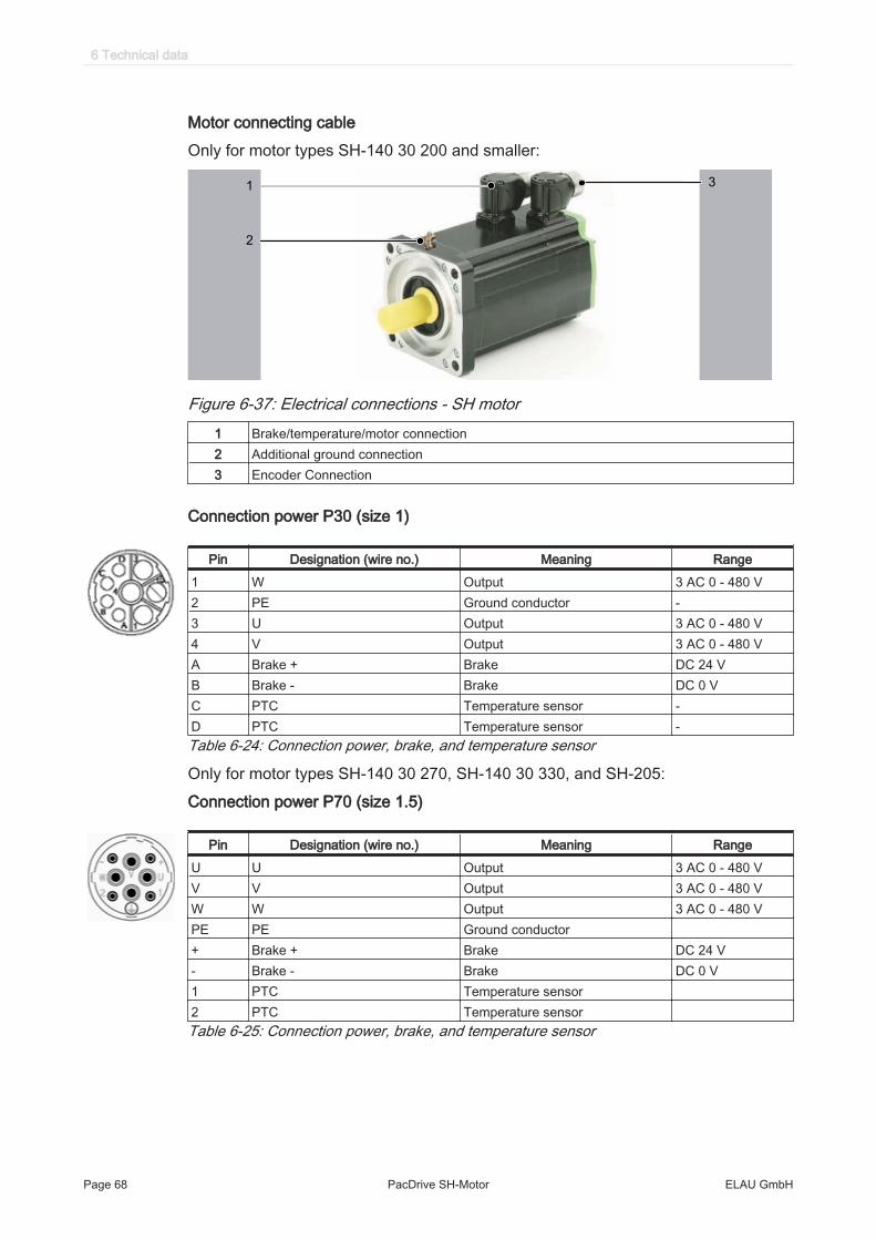
Motor connecting cableOnly for motor types SH-140 30 200 and smaller:
31
2
Figure 6-37: Electrical connections - SH motor1 Brake/temperature/motor connection2 Additional ground connection3 Encoder Connection
Connection power P30 (size 1)
Pin Designation (wire no.) Meaning Range1 W Output 3 AC 0 - 480 V2 PE Ground conductor -3 U Output 3 AC 0 - 480 V4 V Output 3 AC 0 - 480 VA Brake + Brake DC 24 VB Brake - Brake DC 0 VC PTC Temperature sensor -D PTC Temperature sensor -Table 6-24: Connection power, brake, and temperature sensor
Only for motor types SH-140 30 270, SH-140 30 330, and SH-205:Connection power P70 (size 1.5)
Pin Designation (wire no.) Meaning RangeU U Output 3 AC 0 - 480 VV V Output 3 AC 0 - 480 VW W Output 3 AC 0 - 480 VPE PE Ground conductor+ Brake + Brake DC 24 V- Brake - Brake DC 0 V1 PTC Temperature sensor2 PTC Temperature sensorTable 6-25: Connection power, brake, and temperature sensor
6 Technical data
Page 68 PacDrive SH-Motor ELAU GmbH
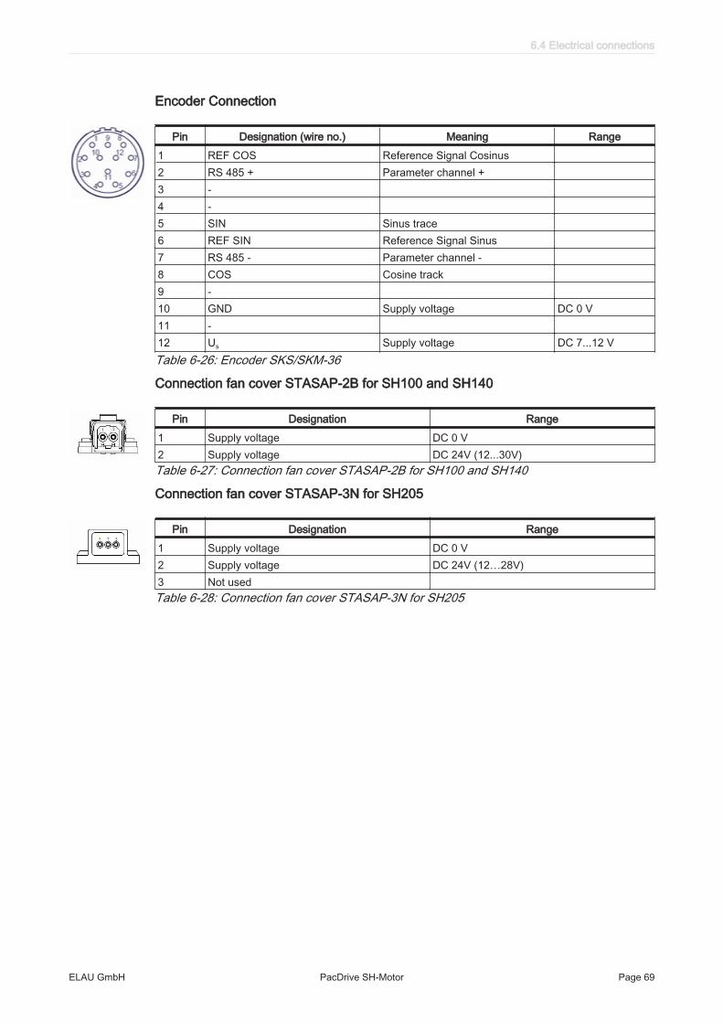
Encoder Connection
Pin Designation (wire no.) Meaning Range1 REF COS Reference Signal Cosinus2 RS 485 + Parameter channel +3 -4 -5 SIN Sinus trace6 REF SIN Reference Signal Sinus7 RS 485 - Parameter channel -8 COS Cosine track9 -10 GND Supply voltage DC 0 V11 -12 Us Supply voltage DC 7...12 VTable 6-26: Encoder SKS/SKM-36
Connection fan cover STASAP-2B for SH100 and SH140
Pin Designation Range1 Supply voltage DC 0 V2 Supply voltage DC 24V (12...30V)Table 6-27: Connection fan cover STASAP-2B for SH100 and SH140
Connection fan cover STASAP-3N for SH205
Pin Designation Range1 Supply voltage DC 0 V2 Supply voltage DC 24V (12…28V)3 Not usedTable 6-28: Connection fan cover STASAP-3N for SH205
6.4 Electrical connections
ELAU GmbH PacDrive SH-Motor Page 69

6.5 Dimensions
6.5.1 SH-055
39
,4
94
,4
Ø 63
55
Ø
C
2
B
16,5
Ø 4
0j6
9
4,5
Ø 5,5
23,5
F G
B
ØC
H
D
E +0,1
29,6
18
0°1
80
°
AK ±1
Figure 6-38: Dimension diagram SH-055
Dimensions SH-055 80 005 SH-055 80 009 SH-055 80 013AK* (with brake) 132.5 (159) 154.5 (181) 176.5 (203)B 20 20 20C 9 k6 9 k6 9 k6D 3 N9 3 N9 3 N9E 1.8 1.8 1.8F 12 12 12G 4 4 4H DIN 332-D M3 DIN 332-D M3 DIN 332-D M3Feather key (N9) DIN 6885-A3x3x12 DIN 6885-A3x3x12 DIN 6885-A3x3x12Table 6-29: Dimensions of the SH-055 (dimension specifications in mm); AK* = self-cooled
6 Technical data
Page 70 PacDrive SH-Motor ELAU GmbH

6.5.2 SH-070111
,4
39
,4
70
5,5
Ø 75
Ø 82
2,5
B
Ø
C
Ø 6
0 j6
8,5
18
0°1
80
°
18,5
8,5
F G Ø C
B
H
D
E+ 0,1
29,5
21,5
AK ±1
Figure 6-39: Dimension diagram SH 070
Dimensions SH-070 60 010 SH-070 60 020 SH-070 60 030AK* (with brake) 154 (180) 187 (213) 220 (256)B 23 23 30C 11 k6 11 k6 14 k6D 4 N9 4 N9 5 N9E 2.5 2.5 3F 18 18 20G 2.5 2.5 5H DIN 332-D M4 DIN 332-D M4 DIN 332-D M5Feather key (N9) DIN 6885-A4x4x18 DIN 6885-A4x4x18 DIN 6885-A5x5x20Table 6-30: Dimensions of the SH-070 (dimension specifications in mm); AK* = self-cooled
6.5 Dimensions
ELAU GmbH PacDrive SH-Motor Page 71

6.5.3 SH-100
39
,4
13
8,4
100
3,514
B
Ø C
Ø 9
5j6
9
32,54,5
Ø 9
Ø115
270°
B
F G
Ø C
D
E+0,1
H270°
27,4
14
9,4
19 o122
61
AK ±1
AF ±1
Figure 6-40: Dimension diagram SH-100
Dimensions SH-100 50 030 SH-100 40 060 SH-100 40 080 SH-100 30 100without brake (with brake)
AK* AF* AK* AF* AK* AF* AK* AF*169 (200) 233 (264) 205 (236) 269 (300) 241 (272) 305 (340) 277 (308) 341 (372)
B 40 40 40 50C 19 k6 19 k6 19 k6 24 k6D 6 N9 6 N9 6 N9 8 N9E 3.5 3.5 3.5 4F 30 30 30 40G 5 5 5 5H DIN 332-D M6 DIN 332-D M6 DIN 332-D M6 DIN 332-D M8Feather key (N9) DIN 6885-A6x6x30 DIN 6885-A6x6x30 DIN 6885-A6x6x30 DIN 6885-A8x7x40Table 6-31: Dimensions of the SH-100 (dimension specifications in mm); AF* = force-ventilated
6 Technical data
Page 72 PacDrive SH-Motor ELAU GmbH

6.5.4 SH-140
140
17
7,9
39
,4
Ø 165
Ø 1
1
AK± 1 B
3,5
12
Ø C
Ø 1
30
j6
12
45
38 42
F G
B
Ø C
H
D
E + 0,1
19 160
18
8
80
AF± 1
270°
270°
Figure 6-41: Dimension diagram SH-140 with P30
Dimensions SH-140 30 120 SH-140 30 200
without brake (with brake)AK* AF * AK* AF *218 (256) 342 (380) 273 (311) 397 (435)
B 50 50C 24 k6 24 k6D 8 N9 8 N9E 4 4F 40 40G 5 5H DIN 332-D M8 DIN 332-D M8Feather key (N9) DIN 6885-A8x7x40 DIN 6885-A8x7x40Table 6-32: Dimensions of the SH-140 (dimension specifications in mm); AF* = force-ventilated
6.5 Dimensions
ELAU GmbH PacDrive SH-Motor Page 73

140
19
8,5
60
39
,4
Ø 11
Ø 165
Ø 1
30
j6
Ø C
3,5
B AK ± 1
12
12
38
38 44
B
F G
Ø C
D
H
E+0,1
19 o160
20
8,5
80
AF ± 1
270°
270°
Figure 6-42: Dimension diagram SH-140 with P70
Dimensions SH-140 30 270 SH-140 30 330
without brake (with brake)AK* AF* AK* AF*328 (366) 452 (490) 383 (421) 507 (545)
B 50 50C 24 k6 24 k6D 8 N9 8 N9E 4 4F 40 40G 5 5H DIN 332-D M8 DIN 332-D M8Feather key (N9) DIN 6885-A8x7x40 DIN 6885-A8x7x40Table 6-33: Dimensions of the SH-140 (dimension specifications in mm); AF* = force-ventilated
6 Technical data
Page 74 PacDrive SH-Motor ELAU GmbH

6.5.5 SH-205
Ø C
B
F G
D
H
205
26
5
60
39
,4Ø 215
Ø 14
AK ±1
34
17 4
B
ØC
Ø 1
80
j6
37,5
21 230
27
7,5
11
5
AF ± 1
E+0,1
270°
270°
Figure 6-43: Dimensinal drawing - SH 205 with connector variant
Dimensions SH-205 30 360 SH-205 20 650 SH-205 20 900without brake (with brake)
AK* AF* AK* AF* AK* AF*321 (370.5) 421(470.5) 405 (454.5) 505 (554.5) 489 (538.5) 589 (638.5)
B 80 80 80C 38 k6 38 k6 38 k6D 10 N9 10 N9 10 N9E 5 5 5F 70 70 70G 5 5 5H DIN 332-D M12 DIN 332-D M12 DIN 332-D M12Feather key (N9) DIN 6885-A10x8x70 DIN 6885-A10x8x70 DIN 6885-A10x8x70Table 6-34: Dimensions of the SH-205 with connector (dimension specifications in mm); AK* = self-cooled, AF*= force-ventilated
6.5 Dimensions
ELAU GmbH PacDrive SH-Motor Page 75

7 Appendix
7.1 Contact addresses
ELAU GmbH DeutschlandDillberg 12 - 1697828 Marktheidenfeld, GermanyTel.: +49 (0) 9391 / 606 - 0Fax: 09391/606-300E-mail: [email protected]: www.elau.de
ELAU GmbH Customer ServicePost office box 125597821 Marktheidenfeld, GermanyTel.: +49 (0) 9391 / 606 - 142Fax: +49 (0) 9391 / 606 - 340E-mail: [email protected]: www.elau.de
See the ELAU homepage (www.elau.de) for additional contact addresses.
7.2 Product training courses
We also offer a number of training courses about our products.Our seminar leaders with several years of experience will help you take advantage ofthe extensive possibilities offered by the PacDrive™ system.
See the ELAU homepage (www.elau.de) for further information and our current sem‐inar schedule.
7 Appendix
Page 76 PacDrive SH-Motor ELAU GmbH

7.3 Changes
The latest product documentation, application notes and the change service are al‐ways available on the ELAU homepage.
10/2005
• Revisions
06/2006
• Series SH-055 and SH-205 added• Torque-speed characteristic curves added• Technical data supplemented• Positive pressure option added• Various corrective actions
08/2007
• Torque-speed characteristics for series SH-100, SH-140, SH-205 (force-ventilat‐ed) added
• Dimensions for series SH-100, SH-140, SH-205 (force-ventilated) added• Technical data supplemented• Various corrective actions
03/2008
• Update of type plates• Update of torque-speed characteristic curves• Update of manufacturer's declaration
11/2008
• Update of dimensional drawings• Update of fan cover data• Update of torque-speed characteristic curves• Update of the structure of chapter "Technical Data"
01/2009
• Update of chapter "Installation and maintenance"
7.3 Changes
ELAU GmbH PacDrive SH-Motor Page 77

7.4 Fault report form
This fault report is required without fail to enable efficient processing.Send the fault report to your ELAU GmbH-representative or to:ELAU GmbH Customer Service DepartmentDillberg 1297828 MarktheidenfeldFax: +49 (0) 93 91 / 606 - 340
Return address:
Company: City: Date:Department: Name: Tel.:
Specifications regarding product in questionItem name: ........................................................................Item no.: ...............................................................................Serial number: ..............................................................................Software version: .............................................................................Hardware code: ...............................................................................Parameters included Yes [ ] No [ ]IEC - Program included: Yes [ ] No [ ]
Information about machine on which the error occurred:Machine manufacturer: ......................................................................Type: .................................................................................................Operating hours: .............................................................................Machine no.: ..................................................................................Date of commissioning: ....................................................................Manufacturer / Type of machine control:........................................................................................................How did the error present:
........................................................................................................
........................................................................................................
........................................................................................................
Additional information:
Condition of error: Causes: Accompanying side effects:[ ] is always available [ ] unknown [ ] problems in the mechanism[ ] during commissioning [ ] wiring error [ ] power failure (24V)
7 Appendix
Page 78 PacDrive SH-Motor ELAU GmbH
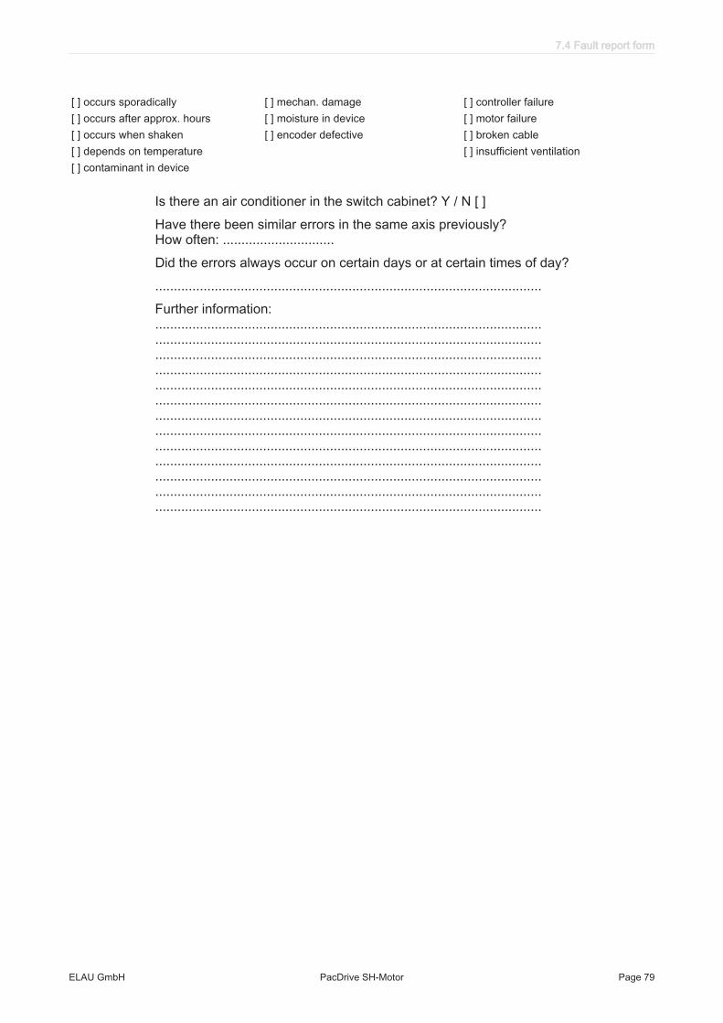
[ ] occurs sporadically [ ] mechan. damage [ ] controller failure[ ] occurs after approx. hours [ ] moisture in device [ ] motor failure[ ] occurs when shaken [ ] encoder defective [ ] broken cable[ ] depends on temperature [ ] insufficient ventilation[ ] contaminant in device
Is there an air conditioner in the switch cabinet? Y / N [ ]Have there been similar errors in the same axis previously? How often: ..............................Did the errors always occur on certain days or at certain times of day?........................................................................................................Further information: ........................................................................................................ ........................................................................................................ ........................................................................................................ ........................................................................................................ ........................................................................................................ ........................................................................................................ ........................................................................................................ ........................................................................................................ ........................................................................................................ ........................................................................................................ ........................................................................................................ ........................................................................................................ ........................................................................................................
7.4 Fault report form
ELAU GmbH PacDrive SH-Motor Page 79

Index
AAmbient conditions 32Approvals 32
BBrake 38
CChanges 77Cleaning 25Connections P70 68Contact addresses 76
DDefinitions 31
EElectrical connections 67EMC Rules 24Encoder connections 69
FFan cover 34, 39, 50Features 14Feedback 15Force ventilation 34, 39, 50
GGrind holding brake 38
HHomepage 2, 76
LLegal notice 2
MMC-4 16Motor shaft 36
OOutput shaft 15Overview 14
PPhysical sizes 31Proper use 8
QQualification of personnel 10
RRisk classification 7
SSeminars 76Service addresses 76Shaft 36SH-Motor characteristics 17Storage 18Surface ventilation 34, 39, 50Symbols 7
TTechnical data 39Trademark 2Training courses 76
Index
Page 80 PacDrive SH-Motor ELAU GmbH