SIMATIC 505 Field Interface Module - ADEGIS
418
SIMA TIC 505 Field Interface Module User Manual Order Number: PPX:505–8124–5 T ext Assembly Number: 2801355–0005 Fifth Edition
-
Upload
khangminh22 -
Category
Documents
-
view
0 -
download
0
Transcript of SIMATIC 505 Field Interface Module - ADEGIS

SIMATIC 505
Field Interface Module
User Manual
Order Number: PPX:505–8124–5Text Assembly Number: 2801355–0005Fifth Edition

! DANGERDANGER indicates an imminently hazardous situation that, if not avoided, willresult in death or serious injury .
DANGER is limited to the most extreme situations.
! WARNINGWARNING indicates a potentially hazardous situation that, if not avoided, couldresult in death or serious injury, and/or property damage.
! CAUTIONCAUTION indicates a potentially hazardous situation that, if not avoided, couldresult in minor or moderate injury, and/or damage to property .
CAUTION is also used for property-damage-only accidents.
Copyright 1996 by Siemens Energy & Automation, Inc. All Rights Reserved — Printed in USA
Reproduction, transmission, or use of this document or contents is not permitted without express consent ofSiemens Energy & Automation, Inc. All rights, including rights created by patent grant or registration of a utility model or design, arereserved.
Since Siemens Energy & Automation, Inc., does not possess full access to data concerning all of the uses and applications ofcustomer’s products, we do not assume responsibility either for customer product design or for any infringements of patents or rightsof others which may result from our assistance.

MANUAL PUBLICATION HISTORY
SIMATIC 505 Field Interface Module User ManualOrder Manual Number: PPX:505–8124–5
Refer to this history in all correspondence and/or discussion about this manual.
Event Date Description
Original Issue 03/93 Original Issue (2801355–0001)Second Edition 08/93 Second Edition (2801355–0002)Third Edition 12/94 Third Edition (2801355–0003)Fourth Edition 06/95 Fourth Edition (2801355–0004)Fifth Edition 11/96 Fifth Edition (2801355–0005)

LIST OF EFFECTIVE PAGES
Pages Description Pages Description
Cover/Copyright FifthHistory/Effective Pages FifthTrademarks and Copyrights Fifth
v — xxiv Fifth1-1 — 1-3 Fifth2-1 — 2-21 Fifth3-1 — 3-124 Fifth4-1 — 4-121 Fifth5-1 — 5-46 Fifth6-1 — 6-66 Fifth
A-1 FifthB-1 — B-3 FifthIndex-1 — Index-6 FifthRegistration Fifth

Trademarks and Copyrights
&� (� $, � + "$,- + � -+�� '�+% )! &� ( �$+ � ���& �)'*�(1�
������� ��������� ���������� ��������� �(� ��� �+ -+�� '�+%, )! �$ ' (, ���
��������� �������� ������� �(� � +$ , ���� �+ -+�� '�+%, )! �$ ' (, �( +"1 � �.-)'�-$)(� �(��
�$ ' (, ��/�(� � �)-)+ ��,- + �1,- ' ������-� $, � -+�� '�+% )! �$ ' (, ���
�$(�)0,� �(� ��2���� �+ + "$,- + � -+�� '�+%, )! �$�+),)!- �)+*)+�-$)(�
� �� $, � + "$,- + � -+�� '�+% )! �(- +(�-$)(�& .,$( ,, ���#$( , �)+*)+�-$)(�
�&& )-# + *+)�.�- (�' , )+ -+�� '�+%, �+ -# *+)* +-1 )! -# $+ + ,* �-$/ )0( +,� �# 1 �+ ., � 0$-#).- + *+ , (-�-$)( �, -) -# $++ & �, !)+ " ( +�& ., �

Contents v
Contents
Preface
Chapter 1 Overview1.1 Features 1-2. . . . . . . . . . . . . . . . . . . . . . . . . . . . . . . . . . . . . . . . . . . . . . . . . . . . . . . . . . . . . . . . . . . . . . . .
1.2 LED Indicators 1-3. . . . . . . . . . . . . . . . . . . . . . . . . . . . . . . . . . . . . . . . . . . . . . . . . . . . . . . . . . . . . . . . . .
Chapter 2 Installation
2.1 Before Installing the Module 2-2. . . . . . . . . . . . . . . . . . . . . . . . . . . . . . . . . . . . . . . . . . . . . . . . . . . . . Visual Inspection 2-2. . . . . . . . . . . . . . . . . . . . . . . . . . . . . . . . . . . . . . . . . . . . . . . . . . . . . . . . . . . . . . . . Handling the Module 2-2. . . . . . . . . . . . . . . . . . . . . . . . . . . . . . . . . . . . . . . . . . . . . . . . . . . . . . . . . . . Hierarchy of Installation 2-3. . . . . . . . . . . . . . . . . . . . . . . . . . . . . . . . . . . . . . . . . . . . . . . . . . . . . . . . .
2.2 Selecting the Application 2-4. . . . . . . . . . . . . . . . . . . . . . . . . . . . . . . . . . . . . . . . . . . . . . . . . . . . . . . Assigning Field Interface Module Base Numbers 2-4. . . . . . . . . . . . . . . . . . . . . . . . . . . . . . . . . . Selecting the Application 2-4. . . . . . . . . . . . . . . . . . . . . . . . . . . . . . . . . . . . . . . . . . . . . . . . . . . . . . .
2.3 Inserting the Module in the I/O Base 2-6. . . . . . . . . . . . . . . . . . . . . . . . . . . . . . . . . . . . . . . . . . . . .
2.4 Communication Ports 2-8. . . . . . . . . . . . . . . . . . . . . . . . . . . . . . . . . . . . . . . . . . . . . . . . . . . . . . . . . . . Overview 2-8. . . . . . . . . . . . . . . . . . . . . . . . . . . . . . . . . . . . . . . . . . . . . . . . . . . . . . . . . . . . . . . . . . . . . . . Communication Port Pinouts 2-11. . . . . . . . . . . . . . . . . . . . . . . . . . . . . . . . . . . . . . . . . . . . . . . . . . . . Using RS-232 2-11. . . . . . . . . . . . . . . . . . . . . . . . . . . . . . . . . . . . . . . . . . . . . . . . . . . . . . . . . . . . . . . . . . . . Using Port 1 2-11. . . . . . . . . . . . . . . . . . . . . . . . . . . . . . . . . . . . . . . . . . . . . . . . . . . . . . . . . . . . . . . . . . . . . Using Port 2 2-12. . . . . . . . . . . . . . . . . . . . . . . . . . . . . . . . . . . . . . . . . . . . . . . . . . . . . . . . . . . . . . . . . . . . . Port 2 – Using the Connector 2-12. . . . . . . . . . . . . . . . . . . . . . . . . . . . . . . . . . . . . . . . . . . . . . . . . . . .
2.5 Termination 2-16. . . . . . . . . . . . . . . . . . . . . . . . . . . . . . . . . . . . . . . . . . . . . . . . . . . . . . . . . . . . . . . . . . . . . Terminations 2-16. . . . . . . . . . . . . . . . . . . . . . . . . . . . . . . . . . . . . . . . . . . . . . . . . . . . . . . . . . . . . . . . . . . . Bias 2-16. . . . . . . . . . . . . . . . . . . . . . . . . . . . . . . . . . . . . . . . . . . . . . . . . . . . . . . . . . . . . . . . . . . . . . . . . . . . Field Interface Connection Examples 2-17. . . . . . . . . . . . . . . . . . . . . . . . . . . . . . . . . . . . . . . . . . . . Connector Schematics 2-18. . . . . . . . . . . . . . . . . . . . . . . . . . . . . . . . . . . . . . . . . . . . . . . . . . . . . . . . .
2.6 Powering Up the Module 2-19. . . . . . . . . . . . . . . . . . . . . . . . . . . . . . . . . . . . . . . . . . . . . . . . . . . . . . . .
2.7 Logging into the Controller 2-20. . . . . . . . . . . . . . . . . . . . . . . . . . . . . . . . . . . . . . . . . . . . . . . . . . . . . .
2.8 FIM Software Field Upgrades 2-21. . . . . . . . . . . . . . . . . . . . . . . . . . . . . . . . . . . . . . . . . . . . . . . . . . . . .
Chapter 3 Drives Interface Application
3.1 Drives Interface Overview 3-4. . . . . . . . . . . . . . . . . . . . . . . . . . . . . . . . . . . . . . . . . . . . . . . . . . . . . . . Features 3-4. . . . . . . . . . . . . . . . . . . . . . . . . . . . . . . . . . . . . . . . . . . . . . . . . . . . . . . . . . . . . . . . . . . . . . . . System Layout 3-6. . . . . . . . . . . . . . . . . . . . . . . . . . . . . . . . . . . . . . . . . . . . . . . . . . . . . . . . . . . . . . . . . . Drives Interface Logical Diagram 3-7. . . . . . . . . . . . . . . . . . . . . . . . . . . . . . . . . . . . . . . . . . . . . . . . Drives Interface Functional Diagrams 3-7. . . . . . . . . . . . . . . . . . . . . . . . . . . . . . . . . . . . . . . . . . . .

vi Contents
3.2 Selecting the Application 3-10. . . . . . . . . . . . . . . . . . . . . . . . . . . . . . . . . . . . . . . . . . . . . . . . . . . . . . . Mode of Operation 3-10. . . . . . . . . . . . . . . . . . . . . . . . . . . . . . . . . . . . . . . . . . . . . . . . . . . . . . . . . . . . . Mute Function 3-12. . . . . . . . . . . . . . . . . . . . . . . . . . . . . . . . . . . . . . . . . . . . . . . . . . . . . . . . . . . . . . . . . . Time-out Delay Function 3-12. . . . . . . . . . . . . . . . . . . . . . . . . . . . . . . . . . . . . . . . . . . . . . . . . . . . . . . .
3.3 Communicating with the Drives 3-13. . . . . . . . . . . . . . . . . . . . . . . . . . . . . . . . . . . . . . . . . . . . . . . . . . Autobaud Operation 3-13. . . . . . . . . . . . . . . . . . . . . . . . . . . . . . . . . . . . . . . . . . . . . . . . . . . . . . . . . . .
3.4 Connecting to Drives 3-14. . . . . . . . . . . . . . . . . . . . . . . . . . . . . . . . . . . . . . . . . . . . . . . . . . . . . . . . . . . . Connecting Port 2 to Drive with Two-Wire RS-485 Port 3-14. . . . . . . . . . . . . . . . . . . . . . . . . . . . . Connecting Port 2 to Drive with Four-Wire RS-485 Port 3-15. . . . . . . . . . . . . . . . . . . . . . . . . . . . .
3.5 Configuring for 10-Word Simple or 10-Word USS Protocols 3-16. . . . . . . . . . . . . . . . . . . . . . . . . . Updating the I/O Configuration Definition 3-16. . . . . . . . . . . . . . . . . . . . . . . . . . . . . . . . . . . . . . . . Sample Configuration 3-16. . . . . . . . . . . . . . . . . . . . . . . . . . . . . . . . . . . . . . . . . . . . . . . . . . . . . . . . . . . Configuring for 10-Word Simple or 10-Word USS Protocol 3-17. . . . . . . . . . . . . . . . . . . . . . . . . . Broadcast/ Immediate Control Channel 3-17. . . . . . . . . . . . . . . . . . . . . . . . . . . . . . . . . . . . . . . . . WX1 – WX10 (Controller Input Words) 3-17. . . . . . . . . . . . . . . . . . . . . . . . . . . . . . . . . . . . . . . . . . . . WY11 – WY20 (Controller Output Words) 3-17. . . . . . . . . . . . . . . . . . . . . . . . . . . . . . . . . . . . . . . . . . Configuring the Broadcast/Immediate Channel (10-Word Simple or 10-Word USS
Protocol) 3-18. . . . . . . . . . . . . . . . . . . . . . . . . . . . . . . . . . . . . . . . . . . . . . . . . . . . . . . . . . . . . Viewing the I/O Configuration Chart 3-20. . . . . . . . . . . . . . . . . . . . . . . . . . . . . . . . . . . . . . . . . . . . .
3.6 Configuring for 4-Word Simple Protocol 3-22. . . . . . . . . . . . . . . . . . . . . . . . . . . . . . . . . . . . . . . . . . . Updating the I/O Configuration Definition 3-22. . . . . . . . . . . . . . . . . . . . . . . . . . . . . . . . . . . . . . . . Sample Configuration 3-22. . . . . . . . . . . . . . . . . . . . . . . . . . . . . . . . . . . . . . . . . . . . . . . . . . . . . . . . . . . Configuring the Broadcast/Immediate Channel (4-Word Simple Protocol) 3-23. . . . . . . . . Configuring for 4-Word Simple Protocol 3-23. . . . . . . . . . . . . . . . . . . . . . . . . . . . . . . . . . . . . . . . . . Broadcast/ Immediate Control Channel 3-23. . . . . . . . . . . . . . . . . . . . . . . . . . . . . . . . . . . . . . . . . WX1 – WX4 (Controller Input Words) 3-23. . . . . . . . . . . . . . . . . . . . . . . . . . . . . . . . . . . . . . . . . . . . . . WY5 – WY8 (Controller Output Words) 3-23. . . . . . . . . . . . . . . . . . . . . . . . . . . . . . . . . . . . . . . . . . . . Viewing the I/O Configuration Chart 3-25. . . . . . . . . . . . . . . . . . . . . . . . . . . . . . . . . . . . . . . . . . . . .
3.7 Configuring for 5-Word USS Protocol 3-26. . . . . . . . . . . . . . . . . . . . . . . . . . . . . . . . . . . . . . . . . . . . . . Updating the I/O Configuration Definition 3-26. . . . . . . . . . . . . . . . . . . . . . . . . . . . . . . . . . . . . . . . Sample Configuration 3-26. . . . . . . . . . . . . . . . . . . . . . . . . . . . . . . . . . . . . . . . . . . . . . . . . . . . . . . . . . . Configuring the Broadcast/Immediate Channel (5-Word USS Protocol) 3-27. . . . . . . . . . . . Configuring for 5-Word USS Protocol 3-27. . . . . . . . . . . . . . . . . . . . . . . . . . . . . . . . . . . . . . . . . . . . . Broadcast/ Immediate Control Channel 3-27. . . . . . . . . . . . . . . . . . . . . . . . . . . . . . . . . . . . . . . . . WX1 – WX6 (Controller Input Words) 3-27. . . . . . . . . . . . . . . . . . . . . . . . . . . . . . . . . . . . . . . . . . . . . . WY7 – WY12 (Controller Output Words) 3-27. . . . . . . . . . . . . . . . . . . . . . . . . . . . . . . . . . . . . . . . . . . Viewing the I/O Configuration Chart 3-29. . . . . . . . . . . . . . . . . . . . . . . . . . . . . . . . . . . . . . . . . . . . .
Contents vii
3.8 Configuring for 5-Word (Modified) USS Protocol 3-30. . . . . . . . . . . . . . . . . . . . . . . . . . . . . . . . . . . Updating the I/O Configuration Definition 3-30. . . . . . . . . . . . . . . . . . . . . . . . . . . . . . . . . . . . . . . . Sample Configuration 3-30. . . . . . . . . . . . . . . . . . . . . . . . . . . . . . . . . . . . . . . . . . . . . . . . . . . . . . . . . . . Configuring the Broadcast/Immediate Channel 5-Word (Modified) USS Protocol 3-31. . . 5-Word (Modified) USS Drive Protocol 3-31. . . . . . . . . . . . . . . . . . . . . . . . . . . . . . . . . . . . . . . . . . . . Configuring for 5-Word (Modified) USS Protocol 3-31. . . . . . . . . . . . . . . . . . . . . . . . . . . . . . . . . . . Broadcast/Immediate Control Channel 3-31. . . . . . . . . . . . . . . . . . . . . . . . . . . . . . . . . . . . . . . . . . WX1 – WX4 (Controller Input Words) 3-32. . . . . . . . . . . . . . . . . . . . . . . . . . . . . . . . . . . . . . . . . . . . . . WY5 – WY8 (Controller Output Words) 3-32. . . . . . . . . . . . . . . . . . . . . . . . . . . . . . . . . . . . . . . . . . . . Viewing the I/O Configuration Chart 3-34. . . . . . . . . . . . . . . . . . . . . . . . . . . . . . . . . . . . . . . . . . . . .
3.9 Programming 3-36. . . . . . . . . . . . . . . . . . . . . . . . . . . . . . . . . . . . . . . . . . . . . . . . . . . . . . . . . . . . . . . . . . . Drives Update Scan 3-36. . . . . . . . . . . . . . . . . . . . . . . . . . . . . . . . . . . . . . . . . . . . . . . . . . . . . . . . . . . . . Broadcast Request 3-40. . . . . . . . . . . . . . . . . . . . . . . . . . . . . . . . . . . . . . . . . . . . . . . . . . . . . . . . . . . . . Broadcast Procedure 3-41. . . . . . . . . . . . . . . . . . . . . . . . . . . . . . . . . . . . . . . . . . . . . . . . . . . . . . . . . . . Immediate I/O Request 3-42. . . . . . . . . . . . . . . . . . . . . . . . . . . . . . . . . . . . . . . . . . . . . . . . . . . . . . . . . Immediate I/O Request Procedure 3-42. . . . . . . . . . . . . . . . . . . . . . . . . . . . . . . . . . . . . . . . . . . . . . Programming Drives 3-43. . . . . . . . . . . . . . . . . . . . . . . . . . . . . . . . . . . . . . . . . . . . . . . . . . . . . . . . . . . . Typical Drive Programming 3-44. . . . . . . . . . . . . . . . . . . . . . . . . . . . . . . . . . . . . . . . . . . . . . . . . . . . . . Typical Drive Program 3-45. . . . . . . . . . . . . . . . . . . . . . . . . . . . . . . . . . . . . . . . . . . . . . . . . . . . . . . . .
3.10 Drives Troubleshooting 3-46. . . . . . . . . . . . . . . . . . . . . . . . . . . . . . . . . . . . . . . . . . . . . . . . . . . . . . . . . . Checking the Operation of the Module 3-46. . . . . . . . . . . . . . . . . . . . . . . . . . . . . . . . . . . . . . . . . . 10-Word Simple and 10-Word USS Protocol 3-47. . . . . . . . . . . . . . . . . . . . . . . . . . . . . . . . . . . . . . . 4-Word Simple and 5-Word (Modified) USS Protocol 3-47. . . . . . . . . . . . . . . . . . . . . . . . . . . . . . . 5-Word USS Protocol 3-48. . . . . . . . . . . . . . . . . . . . . . . . . . . . . . . . . . . . . . . . . . . . . . . . . . . . . . . . . . . . Technical Assistance 3-49. . . . . . . . . . . . . . . . . . . . . . . . . . . . . . . . . . . . . . . . . . . . . . . . . . . . . . . . . . . .
3.11 SIMOREG/SIMOVERT Applications 3-50. . . . . . . . . . . . . . . . . . . . . . . . . . . . . . . . . . . . . . . . . . . . . . . . FIM Drive Protocols 3-50. . . . . . . . . . . . . . . . . . . . . . . . . . . . . . . . . . . . . . . . . . . . . . . . . . . . . . . . . . . . . . AC Drives Supported 3-51. . . . . . . . . . . . . . . . . . . . . . . . . . . . . . . . . . . . . . . . . . . . . . . . . . . . . . . . . . . . DC Drives Supported 3-52. . . . . . . . . . . . . . . . . . . . . . . . . . . . . . . . . . . . . . . . . . . . . . . . . . . . . . . . . . . .
3.12 Setting Up and Wiring 6RA24 3-54. . . . . . . . . . . . . . . . . . . . . . . . . . . . . . . . . . . . . . . . . . . . . . . . . . . . . Required Hardware and Software 3-54. . . . . . . . . . . . . . . . . . . . . . . . . . . . . . . . . . . . . . . . . . . . . . . Required Parameters 3-54. . . . . . . . . . . . . . . . . . . . . . . . . . . . . . . . . . . . . . . . . . . . . . . . . . . . . . . . . . . Required Jumpers 3-59. . . . . . . . . . . . . . . . . . . . . . . . . . . . . . . . . . . . . . . . . . . . . . . . . . . . . . . . . . . . . . USS Protocols 3-59. . . . . . . . . . . . . . . . . . . . . . . . . . . . . . . . . . . . . . . . . . . . . . . . . . . . . . . . . . . . . . . . . . . Setting FIM Additional Delay 3-59. . . . . . . . . . . . . . . . . . . . . . . . . . . . . . . . . . . . . . . . . . . . . . . . . . . . .
3.13 Setting Up and Wiring 6SE21 3-62. . . . . . . . . . . . . . . . . . . . . . . . . . . . . . . . . . . . . . . . . . . . . . . . . . . . . Required Parameters 3-62. . . . . . . . . . . . . . . . . . . . . . . . . . . . . . . . . . . . . . . . . . . . . . . . . . . . . . . . . . . Required Jumpers 3-65. . . . . . . . . . . . . . . . . . . . . . . . . . . . . . . . . . . . . . . . . . . . . . . . . . . . . . . . . . . . . . USS Protocols 3-66. . . . . . . . . . . . . . . . . . . . . . . . . . . . . . . . . . . . . . . . . . . . . . . . . . . . . . . . . . . . . . . . . . . Setting FIM Additional Delay 3-66. . . . . . . . . . . . . . . . . . . . . . . . . . . . . . . . . . . . . . . . . . . . . . . . . . . . .

viii Contents
3.14 Setting Up and Wiring Micromaster/Midimaster Drive (6SE30/6ES31) 3-68. . . . . . . . . . . . . . . .
Required Hardware and Software 3-68. . . . . . . . . . . . . . . . . . . . . . . . . . . . . . . . . . . . . . . . . . . . . . . Required Parameters 3-68. . . . . . . . . . . . . . . . . . . . . . . . . . . . . . . . . . . . . . . . . . . . . . . . . . . . . . . . . . . Required Jumpers 3-73. . . . . . . . . . . . . . . . . . . . . . . . . . . . . . . . . . . . . . . . . . . . . . . . . . . . . . . . . . . . . . USS Protocols 3-73. . . . . . . . . . . . . . . . . . . . . . . . . . . . . . . . . . . . . . . . . . . . . . . . . . . . . . . . . . . . . . . . . . . Setting FIM Additional Delay 3-73. . . . . . . . . . . . . . . . . . . . . . . . . . . . . . . . . . . . . . . . . . . . . . . . . . . . .
3.15 Setting Up and Wiring SI3 3-76. . . . . . . . . . . . . . . . . . . . . . . . . . . . . . . . . . . . . . . . . . . . . . . . . . . . . . .
Required Hardware and Software 3-76. . . . . . . . . . . . . . . . . . . . . . . . . . . . . . . . . . . . . . . . . . . . . . . Required Parameters 3-76. . . . . . . . . . . . . . . . . . . . . . . . . . . . . . . . . . . . . . . . . . . . . . . . . . . . . . . . . . . Required Jumpers 3-77. . . . . . . . . . . . . . . . . . . . . . . . . . . . . . . . . . . . . . . . . . . . . . . . . . . . . . . . . . . . . . Required Switches 3-77. . . . . . . . . . . . . . . . . . . . . . . . . . . . . . . . . . . . . . . . . . . . . . . . . . . . . . . . . . . . . . Setting FIM Additional Delay 3-77. . . . . . . . . . . . . . . . . . . . . . . . . . . . . . . . . . . . . . . . . . . . . . . . . . . . .
3.16 Setting Up and Wiring Z1005 3-80. . . . . . . . . . . . . . . . . . . . . . . . . . . . . . . . . . . . . . . . . . . . . . . . . . . . .
Required Hardware and Software 3-80. . . . . . . . . . . . . . . . . . . . . . . . . . . . . . . . . . . . . . . . . . . . . . . Required Parameters 3-80. . . . . . . . . . . . . . . . . . . . . . . . . . . . . . . . . . . . . . . . . . . . . . . . . . . . . . . . . . . Required Jumpers 3-81. . . . . . . . . . . . . . . . . . . . . . . . . . . . . . . . . . . . . . . . . . . . . . . . . . . . . . . . . . . . . . Setting FIM Additional Delay 3-81. . . . . . . . . . . . . . . . . . . . . . . . . . . . . . . . . . . . . . . . . . . . . . . . . . . . .
3.17 Setting Up and Wiring Z1006 3-84. . . . . . . . . . . . . . . . . . . . . . . . . . . . . . . . . . . . . . . . . . . . . . . . . . . . .
Required Hardware and Software 3-84. . . . . . . . . . . . . . . . . . . . . . . . . . . . . . . . . . . . . . . . . . . . . . . Required Parameters 3-84. . . . . . . . . . . . . . . . . . . . . . . . . . . . . . . . . . . . . . . . . . . . . . . . . . . . . . . . . . . Required Jumpers 3-85. . . . . . . . . . . . . . . . . . . . . . . . . . . . . . . . . . . . . . . . . . . . . . . . . . . . . . . . . . . . . . Setting FIM Additional Delay 3-85. . . . . . . . . . . . . . . . . . . . . . . . . . . . . . . . . . . . . . . . . . . . . . . . . . . . .
3.18 Setting Up and Wiring Z1011 3-88. . . . . . . . . . . . . . . . . . . . . . . . . . . . . . . . . . . . . . . . . . . . . . . . . . . . .
Required Hardware and Software 3-88. . . . . . . . . . . . . . . . . . . . . . . . . . . . . . . . . . . . . . . . . . . . . . . Required Parameters 3-88. . . . . . . . . . . . . . . . . . . . . . . . . . . . . . . . . . . . . . . . . . . . . . . . . . . . . . . . . . . Required Jumpers 3-88. . . . . . . . . . . . . . . . . . . . . . . . . . . . . . . . . . . . . . . . . . . . . . . . . . . . . . . . . . . . . . External Power Supply 3-89. . . . . . . . . . . . . . . . . . . . . . . . . . . . . . . . . . . . . . . . . . . . . . . . . . . . . . . . . . . Required Switches 3-89. . . . . . . . . . . . . . . . . . . . . . . . . . . . . . . . . . . . . . . . . . . . . . . . . . . . . . . . . . . . . . Setting FIM Additional Delay 3-89. . . . . . . . . . . . . . . . . . . . . . . . . . . . . . . . . . . . . . . . . . . . . . . . . . . . .
3.19 Setting Up and Wiring Z2006 3-92. . . . . . . . . . . . . . . . . . . . . . . . . . . . . . . . . . . . . . . . . . . . . . . . . . . . .
Required Hardware and Software 3-92. . . . . . . . . . . . . . . . . . . . . . . . . . . . . . . . . . . . . . . . . . . . . . . Required Parameters 3-92. . . . . . . . . . . . . . . . . . . . . . . . . . . . . . . . . . . . . . . . . . . . . . . . . . . . . . . . . . . Required Jumpers 3-96. . . . . . . . . . . . . . . . . . . . . . . . . . . . . . . . . . . . . . . . . . . . . . . . . . . . . . . . . . . . . . USS Protocols 3-97. . . . . . . . . . . . . . . . . . . . . . . . . . . . . . . . . . . . . . . . . . . . . . . . . . . . . . . . . . . . . . . . . . . Setting FIM Additional Delay 3-97. . . . . . . . . . . . . . . . . . . . . . . . . . . . . . . . . . . . . . . . . . . . . . . . . . . . .
3.20 Setting Up and Wiring the 6SE70 Models FC and SC 3-100. . . . . . . . . . . . . . . . . . . . . . . . . . . . . . .
Required Hardware and Software 3-100. . . . . . . . . . . . . . . . . . . . . . . . . . . . . . . . . . . . . . . . . . . . . . . Required Parameters 3-100. . . . . . . . . . . . . . . . . . . . . . . . . . . . . . . . . . . . . . . . . . . . . . . . . . . . . . . . . . . Required Jumpers 3-106. . . . . . . . . . . . . . . . . . . . . . . . . . . . . . . . . . . . . . . . . . . . . . . . . . . . . . . . . . . . . . Required Switches 3-106. . . . . . . . . . . . . . . . . . . . . . . . . . . . . . . . . . . . . . . . . . . . . . . . . . . . . . . . . . . . . . USS Protocols 3-107. . . . . . . . . . . . . . . . . . . . . . . . . . . . . . . . . . . . . . . . . . . . . . . . . . . . . . . . . . . . . . . . . . . Setting FIM Additional Delay 3-107. . . . . . . . . . . . . . . . . . . . . . . . . . . . . . . . . . . . . . . . . . . . . . . . . . . . .

Contents ix
3.21 Setting Up and Wiring the 6SE70 Model VC 3-108. . . . . . . . . . . . . . . . . . . . . . . . . . . . . . . . . . . . . . . Required Hardware and Software 3-108. . . . . . . . . . . . . . . . . . . . . . . . . . . . . . . . . . . . . . . . . . . . . . . Required Parameters 3-108. . . . . . . . . . . . . . . . . . . . . . . . . . . . . . . . . . . . . . . . . . . . . . . . . . . . . . . . . . . Required Switches 3-113. . . . . . . . . . . . . . . . . . . . . . . . . . . . . . . . . . . . . . . . . . . . . . . . . . . . . . . . . . . . . . USS Protocols 3-113. . . . . . . . . . . . . . . . . . . . . . . . . . . . . . . . . . . . . . . . . . . . . . . . . . . . . . . . . . . . . . . . . . . FIM Additional Delay Set by Dipswitch S3 3-113. . . . . . . . . . . . . . . . . . . . . . . . . . . . . . . . . . . . . . . . .
3.22 Setting Up and Wiring the SCB2 3-116. . . . . . . . . . . . . . . . . . . . . . . . . . . . . . . . . . . . . . . . . . . . . . . . . . Required Hardware and Software 3-116. . . . . . . . . . . . . . . . . . . . . . . . . . . . . . . . . . . . . . . . . . . . . . . Required Parameters 3-116. . . . . . . . . . . . . . . . . . . . . . . . . . . . . . . . . . . . . . . . . . . . . . . . . . . . . . . . . . . Required Switches 3-121. . . . . . . . . . . . . . . . . . . . . . . . . . . . . . . . . . . . . . . . . . . . . . . . . . . . . . . . . . . . . . USS Protocols 3-121. . . . . . . . . . . . . . . . . . . . . . . . . . . . . . . . . . . . . . . . . . . . . . . . . . . . . . . . . . . . . . . . . . . Setting FIM Additional Delay 3-121. . . . . . . . . . . . . . . . . . . . . . . . . . . . . . . . . . . . . . . . . . . . . . . . . . . . .
Chapter 4 PROFIBUS-DP Interface Application4.1 Overview 4-4. . . . . . . . . . . . . . . . . . . . . . . . . . . . . . . . . . . . . . . . . . . . . . . . . . . . . . . . . . . . . . . . . . . . . . .
Features 4-4. . . . . . . . . . . . . . . . . . . . . . . . . . . . . . . . . . . . . . . . . . . . . . . . . . . . . . . . . . . . . . . . . . . . . . . . System Layout 4-5. . . . . . . . . . . . . . . . . . . . . . . . . . . . . . . . . . . . . . . . . . . . . . . . . . . . . . . . . . . . . . . . . .
4.2 Up and Running 4-6. . . . . . . . . . . . . . . . . . . . . . . . . . . . . . . . . . . . . . . . . . . . . . . . . . . . . . . . . . . . . . . . Overview 4-6. . . . . . . . . . . . . . . . . . . . . . . . . . . . . . . . . . . . . . . . . . . . . . . . . . . . . . . . . . . . . . . . . . . . . . . Setting the FIM’s Rotary Switches 4-7. . . . . . . . . . . . . . . . . . . . . . . . . . . . . . . . . . . . . . . . . . . . . . . . Setting Dipswitch S3 4-8. . . . . . . . . . . . . . . . . . . . . . . . . . . . . . . . . . . . . . . . . . . . . . . . . . . . . . . . . . . . . Connecting the PROFIBUS-DP I/O Link 4-9. . . . . . . . . . . . . . . . . . . . . . . . . . . . . . . . . . . . . . . . . . . . Installing RS-485 4-10. . . . . . . . . . . . . . . . . . . . . . . . . . . . . . . . . . . . . . . . . . . . . . . . . . . . . . . . . . . . . . . . . Connecting the FIM to the Controller 4-11. . . . . . . . . . . . . . . . . . . . . . . . . . . . . . . . . . . . . . . . . . . . Configuring the Programmable Controller 4-12. . . . . . . . . . . . . . . . . . . . . . . . . . . . . . . . . . . . . . . . Slave Address Range Selection 4-13. . . . . . . . . . . . . . . . . . . . . . . . . . . . . . . . . . . . . . . . . . . . . . . . . .
4.3 Token Passing 4-14. . . . . . . . . . . . . . . . . . . . . . . . . . . . . . . . . . . . . . . . . . . . . . . . . . . . . . . . . . . . . . . . . . Passing the Token 4-14. . . . . . . . . . . . . . . . . . . . . . . . . . . . . . . . . . . . . . . . . . . . . . . . . . . . . . . . . . . . . . .
4.4 FIM I/O Update Scan 4-16. . . . . . . . . . . . . . . . . . . . . . . . . . . . . . . . . . . . . . . . . . . . . . . . . . . . . . . . . . . . FIM I/O Update Scan 4-16. . . . . . . . . . . . . . . . . . . . . . . . . . . . . . . . . . . . . . . . . . . . . . . . . . . . . . . . . . . . System Error Handling 4-16. . . . . . . . . . . . . . . . . . . . . . . . . . . . . . . . . . . . . . . . . . . . . . . . . . . . . . . . . . .
4.5 Configuring Slaves 4-17. . . . . . . . . . . . . . . . . . . . . . . . . . . . . . . . . . . . . . . . . . . . . . . . . . . . . . . . . . . . . . Configuring Slaves 4-17. . . . . . . . . . . . . . . . . . . . . . . . . . . . . . . . . . . . . . . . . . . . . . . . . . . . . . . . . . . . . . Configuration Example 1 4-18. . . . . . . . . . . . . . . . . . . . . . . . . . . . . . . . . . . . . . . . . . . . . . . . . . . . . . . . Configuration Example 2 4-20. . . . . . . . . . . . . . . . . . . . . . . . . . . . . . . . . . . . . . . . . . . . . . . . . . . . . . . .

x Contents
4.6 Configuring by Byte Matching 4-23. . . . . . . . . . . . . . . . . . . . . . . . . . . . . . . . . . . . . . . . . . . . . . . . . . . Using Byte Match Configuration 4-23. . . . . . . . . . . . . . . . . . . . . . . . . . . . . . . . . . . . . . . . . . . . . . . . . Procedure for Byte Matching Input Points 4-24. . . . . . . . . . . . . . . . . . . . . . . . . . . . . . . . . . . . . . . . Procedure for Byte Matching Output Points 4-25. . . . . . . . . . . . . . . . . . . . . . . . . . . . . . . . . . . . . . Byte Matching Configuration Example 1 4-26. . . . . . . . . . . . . . . . . . . . . . . . . . . . . . . . . . . . . . . . . Byte Matching Configuration Example 2 4-27. . . . . . . . . . . . . . . . . . . . . . . . . . . . . . . . . . . . . . . . . Byte Matching Configuration Example 3 4-28. . . . . . . . . . . . . . . . . . . . . . . . . . . . . . . . . . . . . . . . . Byte Matching Configuration Data Positioning 4-30. . . . . . . . . . . . . . . . . . . . . . . . . . . . . . . . . . . . Byte Matching Input Points 4-32. . . . . . . . . . . . . . . . . . . . . . . . . . . . . . . . . . . . . . . . . . . . . . . . . . . . . . Overmapping Word Input Points 4-32. . . . . . . . . . . . . . . . . . . . . . . . . . . . . . . . . . . . . . . . . . . . . . . . . Overmapping Discrete Input Points 4-34. . . . . . . . . . . . . . . . . . . . . . . . . . . . . . . . . . . . . . . . . . . . . . Byte Matching Output Points 4-36. . . . . . . . . . . . . . . . . . . . . . . . . . . . . . . . . . . . . . . . . . . . . . . . . . . . Overmapping Word Output Points 4-36. . . . . . . . . . . . . . . . . . . . . . . . . . . . . . . . . . . . . . . . . . . . . . . Overmapping Discrete Output Points 4-38. . . . . . . . . . . . . . . . . . . . . . . . . . . . . . . . . . . . . . . . . . . .
4.7 FIM PROFIBUS-DP I/O Cable Specifications 4-40. . . . . . . . . . . . . . . . . . . . . . . . . . . . . . . . . . . . . . . PROFIBUS Cable and Connector Specifications 4-40. . . . . . . . . . . . . . . . . . . . . . . . . . . . . . . . . . . PROFIBUS Cable and Connector Order Numbers 4-41. . . . . . . . . . . . . . . . . . . . . . . . . . . . . . . . .
4.8 Troubleshooting 4-42. . . . . . . . . . . . . . . . . . . . . . . . . . . . . . . . . . . . . . . . . . . . . . . . . . . . . . . . . . . . . . . . . The MOD GOOD LED Is Off—What’s Wrong? 4-42. . . . . . . . . . . . . . . . . . . . . . . . . . . . . . . . . . . . . The COMM LED Is Off—What’s Wrong? 4-43. . . . . . . . . . . . . . . . . . . . . . . . . . . . . . . . . . . . . . . . . . . The CFG LED Is Off—What’s Wrong? 4-44. . . . . . . . . . . . . . . . . . . . . . . . . . . . . . . . . . . . . . . . . . . . . The CFG LED Is Blinking—What’s Wrong? 4-45. . . . . . . . . . . . . . . . . . . . . . . . . . . . . . . . . . . . . . . . . The CFG LED Is On, But Blinks Periodically—What’s Wrong? 4-46. . . . . . . . . . . . . . . . . . . . . . . . Checking the Operation of the Module 4-47. . . . . . . . . . . . . . . . . . . . . . . . . . . . . . . . . . . . . . . . . . Technical Assistance 4-48. . . . . . . . . . . . . . . . . . . . . . . . . . . . . . . . . . . . . . . . . . . . . . . . . . . . . . . . . . . .
4.9 Introducing the PROFIBUS-DP Configurator 4-49. . . . . . . . . . . . . . . . . . . . . . . . . . . . . . . . . . . . . . . . Overview 4-49. . . . . . . . . . . . . . . . . . . . . . . . . . . . . . . . . . . . . . . . . . . . . . . . . . . . . . . . . . . . . . . . . . . . . . . When to Use the PROFIBUS-DP Configurator 4-52. . . . . . . . . . . . . . . . . . . . . . . . . . . . . . . . . . . . . . Hardware Requirements 4-54. . . . . . . . . . . . . . . . . . . . . . . . . . . . . . . . . . . . . . . . . . . . . . . . . . . . . . . .
4.10 Installation and Cabling 4-55. . . . . . . . . . . . . . . . . . . . . . . . . . . . . . . . . . . . . . . . . . . . . . . . . . . . . . . . . Task Overview: Running the PROFIBUS-DP Configurator 4-55. . . . . . . . . . . . . . . . . . . . . . . . . . . . Installing the Configurator File on Your PC 4-56. . . . . . . . . . . . . . . . . . . . . . . . . . . . . . . . . . . . . . . . Creating an Icon in Windows 4-57. . . . . . . . . . . . . . . . . . . . . . . . . . . . . . . . . . . . . . . . . . . . . . . . . . . . Setting Up the PC-to-FIM Connection 4-58. . . . . . . . . . . . . . . . . . . . . . . . . . . . . . . . . . . . . . . . . . . .
4.11 File Configuration 4-61. . . . . . . . . . . . . . . . . . . . . . . . . . . . . . . . . . . . . . . . . . . . . . . . . . . . . . . . . . . . . . . Configuration File Screen Area 4-61. . . . . . . . . . . . . . . . . . . . . . . . . . . . . . . . . . . . . . . . . . . . . . . . . .
4.12 FIM Operations 4-64. . . . . . . . . . . . . . . . . . . . . . . . . . . . . . . . . . . . . . . . . . . . . . . . . . . . . . . . . . . . . . . . . FIM Operations Screen Area 4-64. . . . . . . . . . . . . . . . . . . . . . . . . . . . . . . . . . . . . . . . . . . . . . . . . . . . . Troubleshooting Parameter Table Errors 4-65. . . . . . . . . . . . . . . . . . . . . . . . . . . . . . . . . . . . . . . . . . . FIM Setups Dialog Box 4-66. . . . . . . . . . . . . . . . . . . . . . . . . . . . . . . . . . . . . . . . . . . . . . . . . . . . . . . . . . .

Contents xi
4.13 Slave Operations 4-68. . . . . . . . . . . . . . . . . . . . . . . . . . . . . . . . . . . . . . . . . . . . . . . . . . . . . . . . . . . . . . . Slave Operations Screen Area 4-68. . . . . . . . . . . . . . . . . . . . . . . . . . . . . . . . . . . . . . . . . . . . . . . . . . . Edit Slave Dialog Box 4-69. . . . . . . . . . . . . . . . . . . . . . . . . . . . . . . . . . . . . . . . . . . . . . . . . . . . . . . . . . . . Edit I/O Configuration Dialog Box 4-73. . . . . . . . . . . . . . . . . . . . . . . . . . . . . . . . . . . . . . . . . . . . . . . . Edit User Specified Parameter Data Dialog Box 4-74. . . . . . . . . . . . . . . . . . . . . . . . . . . . . . . . . . . Example: User Parameter Data 4-75. . . . . . . . . . . . . . . . . . . . . . . . . . . . . . . . . . . . . . . . . . . . . . . . . .
4.14 Status and Diagnostics 4-76. . . . . . . . . . . . . . . . . . . . . . . . . . . . . . . . . . . . . . . . . . . . . . . . . . . . . . . . . . Checking Slave Status with the Status Button 4-76. . . . . . . . . . . . . . . . . . . . . . . . . . . . . . . . . . . . . Using Slave Diagnostics 4-77. . . . . . . . . . . . . . . . . . . . . . . . . . . . . . . . . . . . . . . . . . . . . . . . . . . . . . . . . Diagnostic Location Example: ET 200B 4-78. . . . . . . . . . . . . . . . . . . . . . . . . . . . . . . . . . . . . . . . . . . . Diagnostic Location Example: ET 200U 4-79. . . . . . . . . . . . . . . . . . . . . . . . . . . . . . . . . . . . . . . . . . .
4.15 Setting Up and Wiring the 6SE30 PROFIBUS Micromaster Drive 4-80. . . . . . . . . . . . . . . . . . . . . . Required Hardware and Software 4-80. . . . . . . . . . . . . . . . . . . . . . . . . . . . . . . . . . . . . . . . . . . . . . . Required Parameters 4-80. . . . . . . . . . . . . . . . . . . . . . . . . . . . . . . . . . . . . . . . . . . . . . . . . . . . . . . . . . . Required Switches 4-84. . . . . . . . . . . . . . . . . . . . . . . . . . . . . . . . . . . . . . . . . . . . . . . . . . . . . . . . . . . . . .
4.16 OPmP PROFIBUS Module for Micro/Midimaster (6SE31) Drives 4-86. . . . . . . . . . . . . . . . . . . . . . Required Hardware and Software 4-86. . . . . . . . . . . . . . . . . . . . . . . . . . . . . . . . . . . . . . . . . . . . . . . Required Parameters 4-86. . . . . . . . . . . . . . . . . . . . . . . . . . . . . . . . . . . . . . . . . . . . . . . . . . . . . . . . . . . Required Switches 4-90. . . . . . . . . . . . . . . . . . . . . . . . . . . . . . . . . . . . . . . . . . . . . . . . . . . . . . . . . . . . . .
4.17 Setting Up and Wiring the CB1 4-92. . . . . . . . . . . . . . . . . . . . . . . . . . . . . . . . . . . . . . . . . . . . . . . . . . . Required Hardware and Software 4-92. . . . . . . . . . . . . . . . . . . . . . . . . . . . . . . . . . . . . . . . . . . . . . . Required Parameters 4-92. . . . . . . . . . . . . . . . . . . . . . . . . . . . . . . . . . . . . . . . . . . . . . . . . . . . . . . . . . . Required Switches 4-98. . . . . . . . . . . . . . . . . . . . . . . . . . . . . . . . . . . . . . . . . . . . . . . . . . . . . . . . . . . . . .
4.18 CB24 (SIMOREG 6RA24 Communications Board) 4-100. . . . . . . . . . . . . . . . . . . . . . . . . . . . . . . . . . Required Hardware and Software 4-100. . . . . . . . . . . . . . . . . . . . . . . . . . . . . . . . . . . . . . . . . . . . . . . Required Parameters 4-100. . . . . . . . . . . . . . . . . . . . . . . . . . . . . . . . . . . . . . . . . . . . . . . . . . . . . . . . . . . Required Switches 4-105. . . . . . . . . . . . . . . . . . . . . . . . . . . . . . . . . . . . . . . . . . . . . . . . . . . . . . . . . . . . . . Byte Order in the Controller 4-105. . . . . . . . . . . . . . . . . . . . . . . . . . . . . . . . . . . . . . . . . . . . . . . . . . . . . . External Power Supply 4-105. . . . . . . . . . . . . . . . . . . . . . . . . . . . . . . . . . . . . . . . . . . . . . . . . . . . . . . . . . .
4.19 CS51 (SIMOREG 6RA24 and SIMOVERT 6SE12 Communications Board) 4-108. . . . . . . . . . . . . Required Hardware and Software 4-108. . . . . . . . . . . . . . . . . . . . . . . . . . . . . . . . . . . . . . . . . . . . . . . Required Parameters 4-109. . . . . . . . . . . . . . . . . . . . . . . . . . . . . . . . . . . . . . . . . . . . . . . . . . . . . . . . . . . Byte Order in the Controller 4-114. . . . . . . . . . . . . . . . . . . . . . . . . . . . . . . . . . . . . . . . . . . . . . . . . . . . . . Required Switches 4-115. . . . . . . . . . . . . . . . . . . . . . . . . . . . . . . . . . . . . . . . . . . . . . . . . . . . . . . . . . . . . . External Power Supply 4-116. . . . . . . . . . . . . . . . . . . . . . . . . . . . . . . . . . . . . . . . . . . . . . . . . . . . . . . . . . .
4.20 Setting Up and Wiring the SI3 4-118. . . . . . . . . . . . . . . . . . . . . . . . . . . . . . . . . . . . . . . . . . . . . . . . . . . . Required Hardware and Software 4-118. . . . . . . . . . . . . . . . . . . . . . . . . . . . . . . . . . . . . . . . . . . . . . . Required Parameters 4-118. . . . . . . . . . . . . . . . . . . . . . . . . . . . . . . . . . . . . . . . . . . . . . . . . . . . . . . . . . . Required Jumpers 4-119. . . . . . . . . . . . . . . . . . . . . . . . . . . . . . . . . . . . . . . . . . . . . . . . . . . . . . . . . . . . . . Required Switches 4-120. . . . . . . . . . . . . . . . . . . . . . . . . . . . . . . . . . . . . . . . . . . . . . . . . . . . . . . . . . . . . .
xii Contents
Chapter 5 SAMMS Interface Application5.1 SAMMS Interface Overview 5-2. . . . . . . . . . . . . . . . . . . . . . . . . . . . . . . . . . . . . . . . . . . . . . . . . . . . .
Features 5-2. . . . . . . . . . . . . . . . . . . . . . . . . . . . . . . . . . . . . . . . . . . . . . . . . . . . . . . . . . . . . . . . . . . . . . . . System Layout 5-3. . . . . . . . . . . . . . . . . . . . . . . . . . . . . . . . . . . . . . . . . . . . . . . . . . . . . . . . . . . . . . . . . . SAMMS Interface Logical Diagram 5-4. . . . . . . . . . . . . . . . . . . . . . . . . . . . . . . . . . . . . . . . . . . . . . . SAMMS Interface Functional Diagrams 5-5. . . . . . . . . . . . . . . . . . . . . . . . . . . . . . . . . . . . . . . . . . .
5.2 Selecting the Application 5-6. . . . . . . . . . . . . . . . . . . . . . . . . . . . . . . . . . . . . . . . . . . . . . . . . . . . . . . Mode of Operation 5-6. . . . . . . . . . . . . . . . . . . . . . . . . . . . . . . . . . . . . . . . . . . . . . . . . . . . . . . . . . . . . Interface Response Times 5-7. . . . . . . . . . . . . . . . . . . . . . . . . . . . . . . . . . . . . . . . . . . . . . . . . . . . . . . Configuring SAMMS Interface 5-7. . . . . . . . . . . . . . . . . . . . . . . . . . . . . . . . . . . . . . . . . . . . . . . . . . . Configuration Modes 5-8. . . . . . . . . . . . . . . . . . . . . . . . . . . . . . . . . . . . . . . . . . . . . . . . . . . . . . . . . . .
5.3 Communicating with the SAMMS Units 5-9. . . . . . . . . . . . . . . . . . . . . . . . . . . . . . . . . . . . . . . . . . . Autobaud Operation 5-9. . . . . . . . . . . . . . . . . . . . . . . . . . . . . . . . . . . . . . . . . . . . . . . . . . . . . . . . . . . Address Range 5-10. . . . . . . . . . . . . . . . . . . . . . . . . . . . . . . . . . . . . . . . . . . . . . . . . . . . . . . . . . . . . . . . .
5.4 Connecting to SAMMS Unit 5-11. . . . . . . . . . . . . . . . . . . . . . . . . . . . . . . . . . . . . . . . . . . . . . . . . . . . . . Connecting Port 2 to CM1 Communication Module 5-11. . . . . . . . . . . . . . . . . . . . . . . . . . . . . .
5.5 Configuring for Control Mode 5-12. . . . . . . . . . . . . . . . . . . . . . . . . . . . . . . . . . . . . . . . . . . . . . . . . . . . Updating the I/O Configuration Definition 5-12. . . . . . . . . . . . . . . . . . . . . . . . . . . . . . . . . . . . . . . . Sample Configuration 5-12. . . . . . . . . . . . . . . . . . . . . . . . . . . . . . . . . . . . . . . . . . . . . . . . . . . . . . . . . . . Configuring for Control Mode 5-14. . . . . . . . . . . . . . . . . . . . . . . . . . . . . . . . . . . . . . . . . . . . . . . . . . . Broadcast/ Immediate Control Channel 5-14. . . . . . . . . . . . . . . . . . . . . . . . . . . . . . . . . . . . . . . . . WX1 – WX14 (Controller Input Words) 5-14. . . . . . . . . . . . . . . . . . . . . . . . . . . . . . . . . . . . . . . . . . . . WY15 – WY16 (Controller Output Words) 5-14. . . . . . . . . . . . . . . . . . . . . . . . . . . . . . . . . . . . . . . . . . Configuring the Broadcast/Immediate Channel (Control Mode) 5-16. . . . . . . . . . . . . . . . . . Viewing the I/O Configuration Chart 5-18. . . . . . . . . . . . . . . . . . . . . . . . . . . . . . . . . . . . . . . . . . . . .
5.6 Configuring for Status Poll Mode 5-20. . . . . . . . . . . . . . . . . . . . . . . . . . . . . . . . . . . . . . . . . . . . . . . . . Updating the I/O Configuration Definition 5-20. . . . . . . . . . . . . . . . . . . . . . . . . . . . . . . . . . . . . . . . Sample Configuration 5-20. . . . . . . . . . . . . . . . . . . . . . . . . . . . . . . . . . . . . . . . . . . . . . . . . . . . . . . . . . . Configuring the Broadcast/Immediate Channel (Status Poll Mode) 5-22. . . . . . . . . . . . . . . . Configuring for Status Poll Mode 5-22. . . . . . . . . . . . . . . . . . . . . . . . . . . . . . . . . . . . . . . . . . . . . . . . . Broadcast/ Immediate Control Channel 5-22. . . . . . . . . . . . . . . . . . . . . . . . . . . . . . . . . . . . . . . . . WX1 – WX4 (Controller Input Words) 5-23. . . . . . . . . . . . . . . . . . . . . . . . . . . . . . . . . . . . . . . . . . . . . . WY5 – WY8 (Controller Output Words) 5-23. . . . . . . . . . . . . . . . . . . . . . . . . . . . . . . . . . . . . . . . . . . . Viewing the I/O Configuration Chart 5-25. . . . . . . . . . . . . . . . . . . . . . . . . . . . . . . . . . . . . . . . . . . . .
5.7 Programming: Broadcast and Immediate I/O Requests 5-26. . . . . . . . . . . . . . . . . . . . . . . . . . . Broadcast Request 5-26. . . . . . . . . . . . . . . . . . . . . . . . . . . . . . . . . . . . . . . . . . . . . . . . . . . . . . . . . . . . . Broadcast Procedure 5-27. . . . . . . . . . . . . . . . . . . . . . . . . . . . . . . . . . . . . . . . . . . . . . . . . . . . . . . . . . . Immediate I/O Request 5-28. . . . . . . . . . . . . . . . . . . . . . . . . . . . . . . . . . . . . . . . . . . . . . . . . . . . . . . . . Immediate I/O Request Procedure 5-28. . . . . . . . . . . . . . . . . . . . . . . . . . . . . . . . . . . . . . . . . . . . . . Monitoring Communication 5-29. . . . . . . . . . . . . . . . . . . . . . . . . . . . . . . . . . . . . . . . . . . . . . . . . . . . .

Contents xiii
5.8 Programming: Sending Requests 5-30. . . . . . . . . . . . . . . . . . . . . . . . . . . . . . . . . . . . . . . . . . . . . . . . . Sending Requests to the SAMMS Unit 5-30. . . . . . . . . . . . . . . . . . . . . . . . . . . . . . . . . . . . . . . . . . . . . Request Control Word 5-32. . . . . . . . . . . . . . . . . . . . . . . . . . . . . . . . . . . . . . . . . . . . . . . . . . . . . . . . . . . Request Command Byte 5-32. . . . . . . . . . . . . . . . . . . . . . . . . . . . . . . . . . . . . . . . . . . . . . . . . . . . . . . . Request Data Length Bits 5-32. . . . . . . . . . . . . . . . . . . . . . . . . . . . . . . . . . . . . . . . . . . . . . . . . . . . . . . . Request Control Bits 5-33. . . . . . . . . . . . . . . . . . . . . . . . . . . . . . . . . . . . . . . . . . . . . . . . . . . . . . . . . . . . . Send Message Bit 5-33. . . . . . . . . . . . . . . . . . . . . . . . . . . . . . . . . . . . . . . . . . . . . . . . . . . . . . . . . . . . . . . Send Message Repetitively Bit 5-34. . . . . . . . . . . . . . . . . . . . . . . . . . . . . . . . . . . . . . . . . . . . . . . . . . . Response Required Bit 5-34. . . . . . . . . . . . . . . . . . . . . . . . . . . . . . . . . . . . . . . . . . . . . . . . . . . . . . . . . . Request Data Block 5-34. . . . . . . . . . . . . . . . . . . . . . . . . . . . . . . . . . . . . . . . . . . . . . . . . . . . . . . . . . . . .
5.9 Programming: Receiving Response Data 5-35. . . . . . . . . . . . . . . . . . . . . . . . . . . . . . . . . . . . . . . . . Response Status Word 5-35. . . . . . . . . . . . . . . . . . . . . . . . . . . . . . . . . . . . . . . . . . . . . . . . . . . . . . . . . . . Response Byte 5-35. . . . . . . . . . . . . . . . . . . . . . . . . . . . . . . . . . . . . . . . . . . . . . . . . . . . . . . . . . . . . . . . . . Response Status Bits 5-35. . . . . . . . . . . . . . . . . . . . . . . . . . . . . . . . . . . . . . . . . . . . . . . . . . . . . . . . . . . . . Message Sent Bit 5-36. . . . . . . . . . . . . . . . . . . . . . . . . . . . . . . . . . . . . . . . . . . . . . . . . . . . . . . . . . . . . . . . Response Present Bit 5-36. . . . . . . . . . . . . . . . . . . . . . . . . . . . . . . . . . . . . . . . . . . . . . . . . . . . . . . . . . . . Response Length Bits 5-36. . . . . . . . . . . . . . . . . . . . . . . . . . . . . . . . . . . . . . . . . . . . . . . . . . . . . . . . . . . . Response Data Block 5-37. . . . . . . . . . . . . . . . . . . . . . . . . . . . . . . . . . . . . . . . . . . . . . . . . . . . . . . . . . .
5.10 Programming: Application Examples 5-38. . . . . . . . . . . . . . . . . . . . . . . . . . . . . . . . . . . . . . . . . . . . . Setting the Baud Rate and Address 5-38. . . . . . . . . . . . . . . . . . . . . . . . . . . . . . . . . . . . . . . . . . . . . . Sending Requests That Have Responses 5-40. . . . . . . . . . . . . . . . . . . . . . . . . . . . . . . . . . . . . . . . . . Sending Requests That Have No Response 5-41. . . . . . . . . . . . . . . . . . . . . . . . . . . . . . . . . . . . . . . Sending Requests Repetitively 5-42. . . . . . . . . . . . . . . . . . . . . . . . . . . . . . . . . . . . . . . . . . . . . . . . . . .
5.11 SAMMS Units Troubleshooting 5-43. . . . . . . . . . . . . . . . . . . . . . . . . . . . . . . . . . . . . . . . . . . . . . . . . . . . Checking the Operation of the Module 5-44. . . . . . . . . . . . . . . . . . . . . . . . . . . . . . . . . . . . . . . . . . Control Mode 5-44. . . . . . . . . . . . . . . . . . . . . . . . . . . . . . . . . . . . . . . . . . . . . . . . . . . . . . . . . . . . . . . . . . Status Poll Mode 5-44. . . . . . . . . . . . . . . . . . . . . . . . . . . . . . . . . . . . . . . . . . . . . . . . . . . . . . . . . . . . . . . . Monitoring Status between the Controller and FIM 5-45. . . . . . . . . . . . . . . . . . . . . . . . . . . . . . . .
Chapter 6 SPI Application6.1 Introduction 6-2. . . . . . . . . . . . . . . . . . . . . . . . . . . . . . . . . . . . . . . . . . . . . . . . . . . . . . . . . . . . . . . . . . . .
Overview 6-2. . . . . . . . . . . . . . . . . . . . . . . . . . . . . . . . . . . . . . . . . . . . . . . . . . . . . . . . . . . . . . . . . . . . . . . Features 6-2. . . . . . . . . . . . . . . . . . . . . . . . . . . . . . . . . . . . . . . . . . . . . . . . . . . . . . . . . . . . . . . . . . . . . . . . The SPI Configurator 6-4. . . . . . . . . . . . . . . . . . . . . . . . . . . . . . . . . . . . . . . . . . . . . . . . . . . . . . . . . . . . Hardware Requirements 6-5. . . . . . . . . . . . . . . . . . . . . . . . . . . . . . . . . . . . . . . . . . . . . . . . . . . . . . . . System Layout 6-6. . . . . . . . . . . . . . . . . . . . . . . . . . . . . . . . . . . . . . . . . . . . . . . . . . . . . . . . . . . . . . . . . .

xiv Contents
6.2 Up and Running 6-7. . . . . . . . . . . . . . . . . . . . . . . . . . . . . . . . . . . . . . . . . . . . . . . . . . . . . . . . . . . . . . . . Overview 6-7. . . . . . . . . . . . . . . . . . . . . . . . . . . . . . . . . . . . . . . . . . . . . . . . . . . . . . . . . . . . . . . . . . . . . . . Setting the FIM’s Rotary Switches 6-8. . . . . . . . . . . . . . . . . . . . . . . . . . . . . . . . . . . . . . . . . . . . . . . . Setting Dipswitch S3 6-8. . . . . . . . . . . . . . . . . . . . . . . . . . . . . . . . . . . . . . . . . . . . . . . . . . . . . . . . . . . . . Connecting the SPI I/O Link 6-9. . . . . . . . . . . . . . . . . . . . . . . . . . . . . . . . . . . . . . . . . . . . . . . . . . . . . . Installing RS-485 6-10. . . . . . . . . . . . . . . . . . . . . . . . . . . . . . . . . . . . . . . . . . . . . . . . . . . . . . . . . . . . . . . . . Connecting the FIM to the Controller 6-10. . . . . . . . . . . . . . . . . . . . . . . . . . . . . . . . . . . . . . . . . . . . Installing the Configurator File on Your PC 6-11. . . . . . . . . . . . . . . . . . . . . . . . . . . . . . . . . . . . . . . . Creating an Icon in Windows 6-12. . . . . . . . . . . . . . . . . . . . . . . . . . . . . . . . . . . . . . . . . . . . . . . . . . . . Setting Up the PC-to-FIM Connection 6-13. . . . . . . . . . . . . . . . . . . . . . . . . . . . . . . . . . . . . . . . . . . . Creating a Configuration 6-15. . . . . . . . . . . . . . . . . . . . . . . . . . . . . . . . . . . . . . . . . . . . . . . . . . . . . . . Configuring the Programmable Controller 6-16. . . . . . . . . . . . . . . . . . . . . . . . . . . . . . . . . . . . . . . .
6.3 Troubleshooting 6-18. . . . . . . . . . . . . . . . . . . . . . . . . . . . . . . . . . . . . . . . . . . . . . . . . . . . . . . . . . . . . . . . . The MOD GOOD LED Is Off—What’s Wrong? 6-18. . . . . . . . . . . . . . . . . . . . . . . . . . . . . . . . . . . . . The COMM LED Is Off—What’s Wrong? 6-18. . . . . . . . . . . . . . . . . . . . . . . . . . . . . . . . . . . . . . . . . . . The CFG LED Is Off—What’s Wrong? 6-19. . . . . . . . . . . . . . . . . . . . . . . . . . . . . . . . . . . . . . . . . . . . . The CFG LED Is Blinking—What’s Wrong? 6-20. . . . . . . . . . . . . . . . . . . . . . . . . . . . . . . . . . . . . . . . . The CFG LED Is On, But Blinks Periodically—What’s Wrong? 6-21. . . . . . . . . . . . . . . . . . . . . . . . Checking the Operation of the Module 6-22. . . . . . . . . . . . . . . . . . . . . . . . . . . . . . . . . . . . . . . . . . Technical Assistance 6-23. . . . . . . . . . . . . . . . . . . . . . . . . . . . . . . . . . . . . . . . . . . . . . . . . . . . . . . . . . . .
6.4 Programming 6-24. . . . . . . . . . . . . . . . . . . . . . . . . . . . . . . . . . . . . . . . . . . . . . . . . . . . . . . . . . . . . . . . . . . Types of Commands 6-24. . . . . . . . . . . . . . . . . . . . . . . . . . . . . . . . . . . . . . . . . . . . . . . . . . . . . . . . . . . . User Requests 6-24. . . . . . . . . . . . . . . . . . . . . . . . . . . . . . . . . . . . . . . . . . . . . . . . . . . . . . . . . . . . . . . . . . . Random Requests 6-25. . . . . . . . . . . . . . . . . . . . . . . . . . . . . . . . . . . . . . . . . . . . . . . . . . . . . . . . . . . . . . Custom Blocks 6-26. . . . . . . . . . . . . . . . . . . . . . . . . . . . . . . . . . . . . . . . . . . . . . . . . . . . . . . . . . . . . . . . . . Blanket Polls 6-27. . . . . . . . . . . . . . . . . . . . . . . . . . . . . . . . . . . . . . . . . . . . . . . . . . . . . . . . . . . . . . . . . . . . Random Request Example #1 6-28. . . . . . . . . . . . . . . . . . . . . . . . . . . . . . . . . . . . . . . . . . . . . . . . . . . Random Request Example #2 6-30. . . . . . . . . . . . . . . . . . . . . . . . . . . . . . . . . . . . . . . . . . . . . . . . . . . Random Request Example #3 6-32. . . . . . . . . . . . . . . . . . . . . . . . . . . . . . . . . . . . . . . . . . . . . . . . . . . Custom Poll Block Example 6-34. . . . . . . . . . . . . . . . . . . . . . . . . . . . . . . . . . . . . . . . . . . . . . . . . . . . . . Custom Select Block Example 6-36. . . . . . . . . . . . . . . . . . . . . . . . . . . . . . . . . . . . . . . . . . . . . . . . . . . Blanket Poll Example 6-38. . . . . . . . . . . . . . . . . . . . . . . . . . . . . . . . . . . . . . . . . . . . . . . . . . . . . . . . . . . .
6.5 Error Codes 6-40. . . . . . . . . . . . . . . . . . . . . . . . . . . . . . . . . . . . . . . . . . . . . . . . . . . . . . . . . . . . . . . . . . . . .
6.6 Overview of the FIM SPI Configurator 6-42. . . . . . . . . . . . . . . . . . . . . . . . . . . . . . . . . . . . . . . . . . . . . Overview of Configurator Functions 6-42. . . . . . . . . . . . . . . . . . . . . . . . . . . . . . . . . . . . . . . . . . . . . .
6.7 File Configuration 6-44. . . . . . . . . . . . . . . . . . . . . . . . . . . . . . . . . . . . . . . . . . . . . . . . . . . . . . . . . . . . . . . Configuration File Screen Area 6-44. . . . . . . . . . . . . . . . . . . . . . . . . . . . . . . . . . . . . . . . . . . . . . . . . .
6.8 FIM Operations 6-48. . . . . . . . . . . . . . . . . . . . . . . . . . . . . . . . . . . . . . . . . . . . . . . . . . . . . . . . . . . . . . . . . FIM Operations Screen Area 6-48. . . . . . . . . . . . . . . . . . . . . . . . . . . . . . . . . . . . . . . . . . . . . . . . . . . . . Troubleshooting Parameter Table Errors 6-49. . . . . . . . . . . . . . . . . . . . . . . . . . . . . . . . . . . . . . . . . . . FIM Setups Dialog Box 6-50. . . . . . . . . . . . . . . . . . . . . . . . . . . . . . . . . . . . . . . . . . . . . . . . . . . . . . . . . . .

Contents xv
6.9 SPI Device Operations 6-52. . . . . . . . . . . . . . . . . . . . . . . . . . . . . . . . . . . . . . . . . . . . . . . . . . . . . . . . . . SPI Device Operations Area 6-52. . . . . . . . . . . . . . . . . . . . . . . . . . . . . . . . . . . . . . . . . . . . . . . . . . . . . Edit Device Dialog Box 6-54. . . . . . . . . . . . . . . . . . . . . . . . . . . . . . . . . . . . . . . . . . . . . . . . . . . . . . . . . . Edit Custom Block Dialog Box 6-56. . . . . . . . . . . . . . . . . . . . . . . . . . . . . . . . . . . . . . . . . . . . . . . . . . . .
6.10 Example—Configuring SPI Devices for the FIM 6-58. . . . . . . . . . . . . . . . . . . . . . . . . . . . . . . . . . . . Example 1 (FIM) 6-58. . . . . . . . . . . . . . . . . . . . . . . . . . . . . . . . . . . . . . . . . . . . . . . . . . . . . . . . . . . . . . . . Example 2 (FIM) 6-60. . . . . . . . . . . . . . . . . . . . . . . . . . . . . . . . . . . . . . . . . . . . . . . . . . . . . . . . . . . . . . . . How This Custom Poll Block Works 6-63. . . . . . . . . . . . . . . . . . . . . . . . . . . . . . . . . . . . . . . . . . . . . . . . Downloading the Configuration 6-63. . . . . . . . . . . . . . . . . . . . . . . . . . . . . . . . . . . . . . . . . . . . . . . . .
6.11 Example—Configuring SPI Devices for the Programmable Controller 6-64. . . . . . . . . . . . . . . Example 1 (Controller) 6-64. . . . . . . . . . . . . . . . . . . . . . . . . . . . . . . . . . . . . . . . . . . . . . . . . . . . . . . . . . Example 2 (Controller) 6-66. . . . . . . . . . . . . . . . . . . . . . . . . . . . . . . . . . . . . . . . . . . . . . . . . . . . . . . . . .
Appendix A Application Selection . . . . . . . . . . . . . . . . . . . . . . . . . . . . . . . . . . . A-1
Appendix B Specifications and CompliancesB.1 Environmental Specifications B-2. . . . . . . . . . . . . . . . . . . . . . . . . . . . . . . . . . . . . . . . . . . . . . . . . . . .
B.2 Additional Compliances B-3. . . . . . . . . . . . . . . . . . . . . . . . . . . . . . . . . . . . . . . . . . . . . . . . . . . . . . . .
xvi Contents
List of Figures
1-1 505 Field Interface Module 1-2. . . . . . . . . . . . . . . . . . . . . . . . . . . . . . . . . . . . . . . . . . . . . . . . . . . . . . 1-2 Field Interface Module LEDs 1-3. . . . . . . . . . . . . . . . . . . . . . . . . . . . . . . . . . . . . . . . . . . . . . . . . . . . .
2-1 Installation Process 2-3. . . . . . . . . . . . . . . . . . . . . . . . . . . . . . . . . . . . . . . . . . . . . . . . . . . . . . . . . . . . . . 2-2 Field Interface Module Switches 2-5. . . . . . . . . . . . . . . . . . . . . . . . . . . . . . . . . . . . . . . . . . . . . . . . . 2-3 Inserting the Field Interface Module into the I/O Base 2-7. . . . . . . . . . . . . . . . . . . . . . . . . . . . . 2-4 Configuration of Two LANs Connected to the Field Interface Module 2-9. . . . . . . . . . . . . . 2-5 Connecting the Bias Circuit 2-10. . . . . . . . . . . . . . . . . . . . . . . . . . . . . . . . . . . . . . . . . . . . . . . . . . . . . 2-6 Communication Port Pinouts 2-11. . . . . . . . . . . . . . . . . . . . . . . . . . . . . . . . . . . . . . . . . . . . . . . . . . . . 2-7 Connector 2-13. . . . . . . . . . . . . . . . . . . . . . . . . . . . . . . . . . . . . . . . . . . . . . . . . . . . . . . . . . . . . . . . . . . . . 2-8 Routing and Cutting the Cable 2-13. . . . . . . . . . . . . . . . . . . . . . . . . . . . . . . . . . . . . . . . . . . . . . . . . . 2-9 Mounting the Cable on the Connector (Beginning/End of Segment) 2-14. . . . . . . . . . . . . . 2-10 Cutting the Cable, Stripping the Insulation, and Connecting the Cable 2-15. . . . . . . . . . . . 2-11 External Termination Resistor 2-16. . . . . . . . . . . . . . . . . . . . . . . . . . . . . . . . . . . . . . . . . . . . . . . . . . . . . 2-12 External Bias Circuit 2-16. . . . . . . . . . . . . . . . . . . . . . . . . . . . . . . . . . . . . . . . . . . . . . . . . . . . . . . . . . . . . 2-13 Field Interface Module Drives Interface Example 1 2-17. . . . . . . . . . . . . . . . . . . . . . . . . . . . . . . . 2-14 Field Interface Module Drives Interface Example 2 2-17. . . . . . . . . . . . . . . . . . . . . . . . . . . . . . . . 2-15 Connector Schematics 2-18. . . . . . . . . . . . . . . . . . . . . . . . . . . . . . . . . . . . . . . . . . . . . . . . . . . . . . . . .
3-1 I/O System Layout for Three FIMs Running the Drives Interface Application 3-6. . . . . . . . . 3-2 FIM Interface Block Diagram 3-7. . . . . . . . . . . . . . . . . . . . . . . . . . . . . . . . . . . . . . . . . . . . . . . . . . . . 3-3 Functional Block Diagram for 10-Word Simple and 10-Word USS Protocols 3-8. . . . . . . . . . 3-4 Functional Block Diagram for 4-Word Simple Protocol 3-8. . . . . . . . . . . . . . . . . . . . . . . . . . . . . 3-5 Functional Block Diagram for 5-Word USS Protocols 3-9. . . . . . . . . . . . . . . . . . . . . . . . . . . . . . . 3-6 Functional Block Diagram for 5-Word USS (Modified) Protocols 3-9. . . . . . . . . . . . . . . . . . . . . 3-7 Field Interface Module S3 Dipswitch Settings 3-10. . . . . . . . . . . . . . . . . . . . . . . . . . . . . . . . . . . . . 3-8 Connecting the Field Interface Module to Drive with 2-Wire RS-485 Port 3-14. . . . . . . . . . . . 3-9 Connecting the Field Interface Module to Drive with 4-Wire RS-485 Port 3-15. . . . . . . . . . . . 3-10 Sample I/O Configuration Chart for 10-Word Simple or 10-Word USS Protocols 3-16. . . . . . 3-11 I/O Configuration Chart for 10-Word Simple or 10-Word USS Protocols 3-21. . . . . . . . . . . . . . 3-12 Sample I/O Configuration Chart for 4-Word Simple Protocol 3-22. . . . . . . . . . . . . . . . . . . . . . . 3-13 I/O Configuration Chart for 4-Word Simple Protocol 3-25. . . . . . . . . . . . . . . . . . . . . . . . . . . . . . . 3-14 Sample I/O Configuration Chart for 5-Word USS Protocol 3-26. . . . . . . . . . . . . . . . . . . . . . . . . . 3-15 I/O Configuration Chart for 5-Word USS Protocol 3-29. . . . . . . . . . . . . . . . . . . . . . . . . . . . . . . . . . 3-16 Sample I/O Configuration Chart for 5-Word (Modified) USS Protocol 3-30. . . . . . . . . . . . . . . 3-17 I/O Configuration Chart for 5-Word (Modified) USS Protocol 3-35. . . . . . . . . . . . . . . . . . . . . . . 3-18 Control Bits for Main Control Word and Speed Setpoint 3-57. . . . . . . . . . . . . . . . . . . . . . . . . . . 3-19 Status Bits for Standard Status Word and Speed Feedback 3-58. . . . . . . . . . . . . . . . . . . . . . . . 3-20 6RA24 Wiring: All Drives Except at End of Bus 3-60. . . . . . . . . . . . . . . . . . . . . . . . . . . . . . . . . . . . . 3-21 6RA24 Wiring: Drive at End of Bus 3-61. . . . . . . . . . . . . . . . . . . . . . . . . . . . . . . . . . . . . . . . . . . . . . . . 3-22 6SE21 EPROM Label 3-62. . . . . . . . . . . . . . . . . . . . . . . . . . . . . . . . . . . . . . . . . . . . . . . . . . . . . . . . . . . . . 3-23 Control Bits for Main Control Word and Speed Setpoint 3-64. . . . . . . . . . . . . . . . . . . . . . . . . . . 3-24 Status Bits for Standard Status Word and Main Feedback 3-65. . . . . . . . . . . . . . . . . . . . . . . . . .

Contents xvii
3-25 6SE21 Wiring: All Drives Except at End of Bus 3-66. . . . . . . . . . . . . . . . . . . . . . . . . . . . . . . . . . . . . . 3-26 6SE21 Wiring: Drive at End of Bus 3-67. . . . . . . . . . . . . . . . . . . . . . . . . . . . . . . . . . . . . . . . . . . . . . . . . 3-27 Control Bits for Main Control Word and Frequency Setpoint 3-71. . . . . . . . . . . . . . . . . . . . . . . 3-28 Status Bits for Standard Status Word and Main Feedback 3-72. . . . . . . . . . . . . . . . . . . . . . . . . . 3-29 6SE30/6SE31 Wiring: All Drives Except at End of Bus 3-74. . . . . . . . . . . . . . . . . . . . . . . . . . . . . . . . 3-30 6SE30/6SE31 Wiring: Drive at End of Bus 3-75. . . . . . . . . . . . . . . . . . . . . . . . . . . . . . . . . . . . . . . . . . . 3-31 SI3 Wiring: All Drives Except at End of Bus 3-78. . . . . . . . . . . . . . . . . . . . . . . . . . . . . . . . . . . . . . . . . 3-32 SI3 Wiring: Drive at End of Bus 3-79. . . . . . . . . . . . . . . . . . . . . . . . . . . . . . . . . . . . . . . . . . . . . . . . . . . . 3-33 Z1005 Wiring: All Drives Except at End of Bus 3-82. . . . . . . . . . . . . . . . . . . . . . . . . . . . . . . . . . . . . . 3-34 Z1005 Wiring: Drive at End of Bus 3-83. . . . . . . . . . . . . . . . . . . . . . . . . . . . . . . . . . . . . . . . . . . . . . . . . 3-35 Z1006 Wiring: All Drives Except at End of Bus 3-86. . . . . . . . . . . . . . . . . . . . . . . . . . . . . . . . . . . . . . 3-36 Z1006 Wiring: Drive at End of Bus 3-87. . . . . . . . . . . . . . . . . . . . . . . . . . . . . . . . . . . . . . . . . . . . . . . . . 3-37 Z1011 Required Switches 3-89. . . . . . . . . . . . . . . . . . . . . . . . . . . . . . . . . . . . . . . . . . . . . . . . . . . . . . . . 3-38 Z1011 Wiring: All Drives Except at End of Bus 3-90. . . . . . . . . . . . . . . . . . . . . . . . . . . . . . . . . . . . . . 3-39 Z1011 Wiring: Drive at End of Bus 3-91. . . . . . . . . . . . . . . . . . . . . . . . . . . . . . . . . . . . . . . . . . . . . . . . . 3-40 Control Bits for Start/Stop and Speed Setpoint 3-95. . . . . . . . . . . . . . . . . . . . . . . . . . . . . . . . . . . . 3-41 Status Bits for Serial Port Status Word 1 and Speed Feedback 3-96. . . . . . . . . . . . . . . . . . . . . . 3-42 Z2006 Wiring: All Drives Except at End of Bus 3-98. . . . . . . . . . . . . . . . . . . . . . . . . . . . . . . . . . . . . . 3-43 Z2006 Wiring: Drive at End of Bus 3-99. . . . . . . . . . . . . . . . . . . . . . . . . . . . . . . . . . . . . . . . . . . . . . . . . 3-44 Control Bits for Stop/Start and Speed Command 3-103. . . . . . . . . . . . . . . . . . . . . . . . . . . . . . . . . 3-45 Status Bits for Status Word 1 and Main Setpoint 3-105. . . . . . . . . . . . . . . . . . . . . . . . . . . . . . . . . . . 3-46 Master Drive Models FC and SC Wiring: All Drives Except End of Bus 3-106. . . . . . . . . . . . . . . . 3-47 Master Drive Models FC and SC Wiring: Drive at End of Bus 3-107. . . . . . . . . . . . . . . . . . . . . . . . 3-48 Control Bits for Stop/Start and Speed Command 3-111. . . . . . . . . . . . . . . . . . . . . . . . . . . . . . . . . 3-49 Status Bits for Status Word 1 and Main Setpoint 3-112. . . . . . . . . . . . . . . . . . . . . . . . . . . . . . . . . . . 3-50 6SE70 Master Drive Model VC Wiring: All Drives Except End of Bus 3-114. . . . . . . . . . . . . . . . . . 3-51 6SE70 Master Drive Model VC Wiring: Drive at End of Bus 3-115. . . . . . . . . . . . . . . . . . . . . . . . . . 3-52 Control Bits for Stop/Start and Speed Command 3-119. . . . . . . . . . . . . . . . . . . . . . . . . . . . . . . . . 3-53 Status Bits for Status Word 1 and Main Setpoint 3-120. . . . . . . . . . . . . . . . . . . . . . . . . . . . . . . . . . . 3-54 SCB2 Wiring: All Drives Except End of Bus 3-122. . . . . . . . . . . . . . . . . . . . . . . . . . . . . . . . . . . . . . . . . 3-55 SCB2 Wiring: Drive at End of Bus 3-123. . . . . . . . . . . . . . . . . . . . . . . . . . . . . . . . . . . . . . . . . . . . . . . . .
4-1 I/O System Layout for Three FIMs Running the PROFIBUS-DP Interface Application 4-5. . . 4-2 S3 Dipswitch Settings 4-8. . . . . . . . . . . . . . . . . . . . . . . . . . . . . . . . . . . . . . . . . . . . . . . . . . . . . . . . . . . . 4-3 Communication Port Pinouts 4-9. . . . . . . . . . . . . . . . . . . . . . . . . . . . . . . . . . . . . . . . . . . . . . . . . . . . 4-4 ET 200B 32-Point 110V A/C Output 4-18. . . . . . . . . . . . . . . . . . . . . . . . . . . . . . . . . . . . . . . . . . . . . . . 4-5 Sample I/O Configuration Chart 4-19. . . . . . . . . . . . . . . . . . . . . . . . . . . . . . . . . . . . . . . . . . . . . . . . . 4-6 Slave Configuration Example 4-20. . . . . . . . . . . . . . . . . . . . . . . . . . . . . . . . . . . . . . . . . . . . . . . . . . . . 4-7 Sample I/O Configuration Chart 4-22. . . . . . . . . . . . . . . . . . . . . . . . . . . . . . . . . . . . . . . . . . . . . . . . . 4-8 Slave Configuration Example 4-28. . . . . . . . . . . . . . . . . . . . . . . . . . . . . . . . . . . . . . . . . . . . . . . . . . . . 4-9 Main Configurator Window 4-51. . . . . . . . . . . . . . . . . . . . . . . . . . . . . . . . . . . . . . . . . . . . . . . . . . . . . . 4-10 Connecting Cable from PC to FIM 4-58. . . . . . . . . . . . . . . . . . . . . . . . . . . . . . . . . . . . . . . . . . . . . . .
xviii Contents
List of Figures (continued)
4-11 FIM Operations Area 4-59. . . . . . . . . . . . . . . . . . . . . . . . . . . . . . . . . . . . . . . . . . . . . . . . . . . . . . . . . . . . 4-12 PC-to-FIM Communications Setup Dialog Box 4-59. . . . . . . . . . . . . . . . . . . . . . . . . . . . . . . . . . . . 4-13 Configuration File Screen Area 4-61. . . . . . . . . . . . . . . . . . . . . . . . . . . . . . . . . . . . . . . . . . . . . . . . . . 4-14 Open Disk File Dialog Box 4-62. . . . . . . . . . . . . . . . . . . . . . . . . . . . . . . . . . . . . . . . . . . . . . . . . . . . . . . . 4-15 Save File Dialog Box 4-63. . . . . . . . . . . . . . . . . . . . . . . . . . . . . . . . . . . . . . . . . . . . . . . . . . . . . . . . . . . . . 4-16 FIM Operations Screen Area 4-64. . . . . . . . . . . . . . . . . . . . . . . . . . . . . . . . . . . . . . . . . . . . . . . . . . . . . 4-17 FIM Setups Dialog Box 4-66. . . . . . . . . . . . . . . . . . . . . . . . . . . . . . . . . . . . . . . . . . . . . . . . . . . . . . . . . . . 4-18 Slave Operations Screen Area 4-68. . . . . . . . . . . . . . . . . . . . . . . . . . . . . . . . . . . . . . . . . . . . . . . . . . . 4-19 Edit Slave Dialog Box 4-69. . . . . . . . . . . . . . . . . . . . . . . . . . . . . . . . . . . . . . . . . . . . . . . . . . . . . . . . . . . . 4-20 Edit I/O Configuration Dialog Box 4-73. . . . . . . . . . . . . . . . . . . . . . . . . . . . . . . . . . . . . . . . . . . . . . . . 4-21 Edit User Specified Parameter Data Dialog Box 4-74. . . . . . . . . . . . . . . . . . . . . . . . . . . . . . . . . . . 4-22 Control Bits for Main Control Word and Frequency Setpoint 4-82. . . . . . . . . . . . . . . . . . . . . . . 4-23 Status Bits for Standard Status Word and Main Feedback 4-83. . . . . . . . . . . . . . . . . . . . . . . . . . 4-24 6SE30 Wiring: All Drives Except at End of Bus 4-84. . . . . . . . . . . . . . . . . . . . . . . . . . . . . . . . . . . . . . 4-25 6SE30 Wiring: Drive at End of Bus 4-85. . . . . . . . . . . . . . . . . . . . . . . . . . . . . . . . . . . . . . . . . . . . . . . . . 4-26 Control Bits for Main Control Word and Frequency Setpoint 4-88. . . . . . . . . . . . . . . . . . . . . . . 4-27 Status Bits for Standard Status Word and Main Feedback 4-89. . . . . . . . . . . . . . . . . . . . . . . . . . 4-28 6SE31 Wiring: All Drives Except at End of Bus 4-90. . . . . . . . . . . . . . . . . . . . . . . . . . . . . . . . . . . . . . 4-29 6SE31 Wiring: Drive at End of Bus 4-91. . . . . . . . . . . . . . . . . . . . . . . . . . . . . . . . . . . . . . . . . . . . . . . . . 4-30 Control Bits for Stop/Start and Speed Command 4-95. . . . . . . . . . . . . . . . . . . . . . . . . . . . . . . . . 4-31 Status Bits for Status Word 1 and Main Setpoint 4-97. . . . . . . . . . . . . . . . . . . . . . . . . . . . . . . . . . . 4-32 CB1 Wiring: All Drives Except at End of Bus 4-98. . . . . . . . . . . . . . . . . . . . . . . . . . . . . . . . . . . . . . . . 4-33 CB1 Wiring: Drive At End of Bus 4-99. . . . . . . . . . . . . . . . . . . . . . . . . . . . . . . . . . . . . . . . . . . . . . . . . . 4-34 Control Bits for Main Control Word and Speed Setpoint 4-103. . . . . . . . . . . . . . . . . . . . . . . . . . . 4-35 Status Bits for Standard Status Word and Speed Feedback 4-105. . . . . . . . . . . . . . . . . . . . . . . . 4-36 CB24 Wiring: All Drives Except at End of Bus 4-106. . . . . . . . . . . . . . . . . . . . . . . . . . . . . . . . . . . . . . 4-37 CB24 Wiring: Drive At End of Bus 4-107. . . . . . . . . . . . . . . . . . . . . . . . . . . . . . . . . . . . . . . . . . . . . . . . . 4-38 Control Bits for Main Control Word and Speed Setpoint 4-113. . . . . . . . . . . . . . . . . . . . . . . . . . . 4-39 Status Bits for Standard Status Word and Speed Feedback 4-115. . . . . . . . . . . . . . . . . . . . . . . . 4-40 6SE12 Wiring: All Drives Except End of Bus 4-116. . . . . . . . . . . . . . . . . . . . . . . . . . . . . . . . . . . . . . . . . 4-41 6SE12 Wiring: Drive at End of Bus 4-117. . . . . . . . . . . . . . . . . . . . . . . . . . . . . . . . . . . . . . . . . . . . . . . . . 4-42 SI3 Wiring: All Drives Except End of Bus 4-120. . . . . . . . . . . . . . . . . . . . . . . . . . . . . . . . . . . . . . . . . . . . 4-43 SI3 Wiring: Drive at End of Bus 4-121. . . . . . . . . . . . . . . . . . . . . . . . . . . . . . . . . . . . . . . . . . . . . . . . . . . .
5-1 I/O System Layout for Three FIMs Running the SAMMS Interface Application 5-3. . . . . . . . 5-2 FIM Interface Block Diagram 5-4. . . . . . . . . . . . . . . . . . . . . . . . . . . . . . . . . . . . . . . . . . . . . . . . . . . . 5-3 Functional Block Diagram for Control Mode 5-5. . . . . . . . . . . . . . . . . . . . . . . . . . . . . . . . . . . . . . 5-4 Functional Block Diagram for Status Poll Mode 5-5. . . . . . . . . . . . . . . . . . . . . . . . . . . . . . . . . . . 5-5 Field Interface Module S3 Dipswitch Settings 5-6. . . . . . . . . . . . . . . . . . . . . . . . . . . . . . . . . . . . . 5-6 Connecting the Field Interface Module to SAMMS Unit CM1 Communication
Module 5-11. . . . . . . . . . . . . . . . . . . . . . . . . . . . . . . . . . . . . . . . . . . . . . . . . . . . . . . . . . . . . . . . . . . . . . . . 5-7 Sample I/O Configuration Chart for the Control Modes 5-13. . . . . . . . . . . . . . . . . . . . . . . . . . . 5-8 I/O Configuration Chart for Control Mode 5-19. . . . . . . . . . . . . . . . . . . . . . . . . . . . . . . . . . . . . . . .

Contents xix
5-9 Sample I/O Configuration Chart for Status Poll Mode 5-21. . . . . . . . . . . . . . . . . . . . . . . . . . . . . 5-10 I/O Configuration Chart for Status Poll Mode 5-25. . . . . . . . . . . . . . . . . . . . . . . . . . . . . . . . . . . . . 5-11 Request Control Word 5-32. . . . . . . . . . . . . . . . . . . . . . . . . . . . . . . . . . . . . . . . . . . . . . . . . . . . . . . . . . . 5-12 Send Message Handshake Sequence 5-33. . . . . . . . . . . . . . . . . . . . . . . . . . . . . . . . . . . . . . . . . . . . 5-13 Response Status Word 5-35. . . . . . . . . . . . . . . . . . . . . . . . . . . . . . . . . . . . . . . . . . . . . . . . . . . . . . . . . . . 5-14 Send Message/Message Sent Handshake Sequence 5-36. . . . . . . . . . . . . . . . . . . . . . . . . . . . .
6-1 I/O System Layout for Three FIMs Running the SPI Interface Application 6-6. . . . . . . . . . . . 6-2 S3 Dipswitch Settings 6-8. . . . . . . . . . . . . . . . . . . . . . . . . . . . . . . . . . . . . . . . . . . . . . . . . . . . . . . . . . . . 6-3 Communication Port Pinouts 6-9. . . . . . . . . . . . . . . . . . . . . . . . . . . . . . . . . . . . . . . . . . . . . . . . . . . . 6-4 Connecting Cable from PC to FIM 6-13. . . . . . . . . . . . . . . . . . . . . . . . . . . . . . . . . . . . . . . . . . . . . . . 6-5 FIM Operations Area 6-14. . . . . . . . . . . . . . . . . . . . . . . . . . . . . . . . . . . . . . . . . . . . . . . . . . . . . . . . . . . . 6-6 PC-to-FIM Communications Setup Dialog Box 6-14. . . . . . . . . . . . . . . . . . . . . . . . . . . . . . . . . . . . 6-7 Main Configurator Window 6-43. . . . . . . . . . . . . . . . . . . . . . . . . . . . . . . . . . . . . . . . . . . . . . . . . . . . . . 6-8 Configuration File Screen Area 6-44. . . . . . . . . . . . . . . . . . . . . . . . . . . . . . . . . . . . . . . . . . . . . . . . . . 6-9 Open Disk File Dialog Box 6-46. . . . . . . . . . . . . . . . . . . . . . . . . . . . . . . . . . . . . . . . . . . . . . . . . . . . . . . . 6-10 Save File Dialog Box 6-47. . . . . . . . . . . . . . . . . . . . . . . . . . . . . . . . . . . . . . . . . . . . . . . . . . . . . . . . . . . . . 6-11 FIM Operations Screen Area 6-48. . . . . . . . . . . . . . . . . . . . . . . . . . . . . . . . . . . . . . . . . . . . . . . . . . . . . 6-12 FIM Master Parameters Setup Dialog Box 6-50. . . . . . . . . . . . . . . . . . . . . . . . . . . . . . . . . . . . . . . . . 6-13 SPI Device Operations Screen Area 6-52. . . . . . . . . . . . . . . . . . . . . . . . . . . . . . . . . . . . . . . . . . . . . . 6-14 Edit Device Dialog Box 6-54. . . . . . . . . . . . . . . . . . . . . . . . . . . . . . . . . . . . . . . . . . . . . . . . . . . . . . . . . . 6-15 Custom Poll Block Dialog Box 6-56. . . . . . . . . . . . . . . . . . . . . . . . . . . . . . . . . . . . . . . . . . . . . . . . . . . . 6-16 Custom Select Block Dialog Box 6-57. . . . . . . . . . . . . . . . . . . . . . . . . . . . . . . . . . . . . . . . . . . . . . . . . 6-17 Configuring the Mold Temperature Controller 6-59. . . . . . . . . . . . . . . . . . . . . . . . . . . . . . . . . . . . 6-18 SPI Operations Screen Area 6-59. . . . . . . . . . . . . . . . . . . . . . . . . . . . . . . . . . . . . . . . . . . . . . . . . . . . . 6-19 Configuring the Loader 6-61. . . . . . . . . . . . . . . . . . . . . . . . . . . . . . . . . . . . . . . . . . . . . . . . . . . . . . . . . 6-20 Creating a Custom Poll Block for the Loader 6-62. . . . . . . . . . . . . . . . . . . . . . . . . . . . . . . . . . . . . 6-21 SPI Operations Screen Area 6-63. . . . . . . . . . . . . . . . . . . . . . . . . . . . . . . . . . . . . . . . . . . . . . . . . . . . . 6-22 Sample I/O Configuration Chart 6-65. . . . . . . . . . . . . . . . . . . . . . . . . . . . . . . . . . . . . . . . . . . . . . . . . 6-23 Sample I/O Configuration Chart 6-66. . . . . . . . . . . . . . . . . . . . . . . . . . . . . . . . . . . . . . . . . . . . . . . . .

xx Contents
List of Tables
1-1 LED Indicators 1-3. . . . . . . . . . . . . . . . . . . . . . . . . . . . . . . . . . . . . . . . . . . . . . . . . . . . . . . . . . . . . . . . . .
3-1 Protocol Selection 3-11. . . . . . . . . . . . . . . . . . . . . . . . . . . . . . . . . . . . . . . . . . . . . . . . . . . . . . . . . . . . . .
3-2 S3 Dipswitch Settings for Additional Delay 3-12. . . . . . . . . . . . . . . . . . . . . . . . . . . . . . . . . . . . . . . .
3-3 Recommended S3 Dipswitch Settings 3-12. . . . . . . . . . . . . . . . . . . . . . . . . . . . . . . . . . . . . . . . . . . .
3-4 Mapping the Controller Words to the Drive Parameter Words for 10-Word Simple or10-Word USS Protocol 3-17. . . . . . . . . . . . . . . . . . . . . . . . . . . . . . . . . . . . . . . . . . . . . . . . . . . . . . . . . . .
3-5 Mapping the 10-Word Simple or 10-Word USS Protocol Broadcast Channel 3-19. . . . . . . . .
3-6 Mapping the Controller Words to the Drive Parameter Words for 4-Word Simple Protocol 3-23. . . . . . . . . . . . . . . . . . . . . . . . . . . . . . . . . . . . . . . . . . . . . . . . . . . . . . . . . . . . . . . . . . . . . . . .
3-7 Mapping the 4-Word Simple Protocol Broadcast Channel 3-24. . . . . . . . . . . . . . . . . . . . . . . . .
3-8 Mapping the Controller Words to the Drive Parameter Words for 5-Word USS Protocol 3-27. . . . . . . . . . . . . . . . . . . . . . . . . . . . . . . . . . . . . . . . . . . . . . . . . . . . . . . . . . . . . . . . . . . . . . . .
3-9 Mapping the 5-Word USS Protocol Broadcast Channel 3-28. . . . . . . . . . . . . . . . . . . . . . . . . . . .
3-10 USS Drive Telegram Mappings 3-31. . . . . . . . . . . . . . . . . . . . . . . . . . . . . . . . . . . . . . . . . . . . . . . . . . .
3-11 Mapping the Controller Words to the Drive Parameter Words for 5-Word (Modified) USS Protocol 3-32. . . . . . . . . . . . . . . . . . . . . . . . . . . . . . . . . . . . . . . . . . . . . . . . . . . . . . . . . . . . . . . . . . . .
3-12 Mapping 5-Word (Modified) USS Protocol Broadcast Channel 3-33. . . . . . . . . . . . . . . . . . . . .
3-13 Typical Drive Scan Times for 10-Word Simple Protocol 3-36. . . . . . . . . . . . . . . . . . . . . . . . . . . . .
3-14 Typical Drive Scan Times for 10-Word USS Protocol 3-37. . . . . . . . . . . . . . . . . . . . . . . . . . . . . . . .
3-15 Typical Drive Scan Times for 4-Word Simple 3-38. . . . . . . . . . . . . . . . . . . . . . . . . . . . . . . . . . . . . . .
3-16 Typical Drive Scan Times for 5-Word USS Protocol and 5-Word (Modified) 3-39. . . . . . . . . . .
3-17 Troubleshooting the Field Interface Module Using LEDs 3-46. . . . . . . . . . . . . . . . . . . . . . . . . . . .
3-18 Controller-to-Field Interface Module (FIM) Communication Status Using Controller Status Words 3-48. . . . . . . . . . . . . . . . . . . . . . . . . . . . . . . . . . . . . . . . . . . . . . . . . . . . . . . . . . . . . . . . . . . .
3-19 Monitoring Field Interface Module (FIM) to Drive Communication Status Using Controller Status Words 3-49. . . . . . . . . . . . . . . . . . . . . . . . . . . . . . . . . . . . . . . . . . . . . . . . . . . . . . . . . .
3-20 Specific Wiring and Set-up Information 3-53. . . . . . . . . . . . . . . . . . . . . . . . . . . . . . . . . . . . . . . . . . .
4-1 SW2 Baud Rate Selection 4-7. . . . . . . . . . . . . . . . . . . . . . . . . . . . . . . . . . . . . . . . . . . . . . . . . . . . . . . .
4-2 Slave Address Range Selection 4-13. . . . . . . . . . . . . . . . . . . . . . . . . . . . . . . . . . . . . . . . . . . . . . . . . .
4-3 I/O Point Mapping 4-21. . . . . . . . . . . . . . . . . . . . . . . . . . . . . . . . . . . . . . . . . . . . . . . . . . . . . . . . . . . . . .
4-4 Input Bytes WX<–>X 4-31. . . . . . . . . . . . . . . . . . . . . . . . . . . . . . . . . . . . . . . . . . . . . . . . . . . . . . . . . . . . .
4-5 Output Bytes WY<–>Y 4-31. . . . . . . . . . . . . . . . . . . . . . . . . . . . . . . . . . . . . . . . . . . . . . . . . . . . . . . . . . .
4-6 PROFIBUS Line Specifications 4-40. . . . . . . . . . . . . . . . . . . . . . . . . . . . . . . . . . . . . . . . . . . . . . . . . . . .
4-7 PROFIBUS Line Length 4-40. . . . . . . . . . . . . . . . . . . . . . . . . . . . . . . . . . . . . . . . . . . . . . . . . . . . . . . . . . .
4-8 PROFIBUS Cable and Connector Order Numbers 4-41. . . . . . . . . . . . . . . . . . . . . . . . . . . . . . . . .
4-9 Baud Rates 4-46. . . . . . . . . . . . . . . . . . . . . . . . . . . . . . . . . . . . . . . . . . . . . . . . . . . . . . . . . . . . . . . . . . . . .
4-10 Controller-to-Field Interface Module (FIM) Communication Status Using Controller Status Words 4-47. . . . . . . . . . . . . . . . . . . . . . . . . . . . . . . . . . . . . . . . . . . . . . . . . . . . . . . . . . . . . . . . . . . .
4-11 Monitoring Field Interface Module (FIM) to Slave Communication Status Using Controller Status Words 4-48. . . . . . . . . . . . . . . . . . . . . . . . . . . . . . . . . . . . . . . . . . . . . . . . . . . . . . . . . .
4-12 FIM Dipswitch Settings for PROFIBUS-DP 4-58. . . . . . . . . . . . . . . . . . . . . . . . . . . . . . . . . . . . . . . . . . .
4-13 Default Bit Times Based on Baud Rate 4-67. . . . . . . . . . . . . . . . . . . . . . . . . . . . . . . . . . . . . . . . . . . .

Contents xxi
4-14 Diagnostics Locations for the ET 200B 4-78. . . . . . . . . . . . . . . . . . . . . . . . . . . . . . . . . . . . . . . . . . . . . 4-15 Diagnostics Locations for the ET 200U 4-79. . . . . . . . . . . . . . . . . . . . . . . . . . . . . . . . . . . . . . . . . . . .
5-1 Selecting Additional Delay Time 5-7. . . . . . . . . . . . . . . . . . . . . . . . . . . . . . . . . . . . . . . . . . . . . . . . . 5-2 SAMMS Interface Configuration Modes 5-7. . . . . . . . . . . . . . . . . . . . . . . . . . . . . . . . . . . . . . . . . . 5-3 Address Range Selection 5-10. . . . . . . . . . . . . . . . . . . . . . . . . . . . . . . . . . . . . . . . . . . . . . . . . . . . . . . . 5-4 Mapping the Controller (Host) Words to the SAMMS Unit Command 5-15. . . . . . . . . . . . . . . 5-5 Mapping the Control Mode Protocol Broadcast Channel 5-17. . . . . . . . . . . . . . . . . . . . . . . . . 5-6 Mapping the Controller (Host) Words to the SAMMS Parameter Words for Status Poll
Mode 5-23. . . . . . . . . . . . . . . . . . . . . . . . . . . . . . . . . . . . . . . . . . . . . . . . . . . . . . . . . . . . . . . . . . . . . . . . . . 5-7 Mapping the Status Poll Mode Broadcast Channel 5-24. . . . . . . . . . . . . . . . . . . . . . . . . . . . . . . 5-8 SAMMS Unit Request Default Parameters 5-31. . . . . . . . . . . . . . . . . . . . . . . . . . . . . . . . . . . . . . . . . 5-9 Response Data Block Words 5-34. . . . . . . . . . . . . . . . . . . . . . . . . . . . . . . . . . . . . . . . . . . . . . . . . . . . . 5-10 Response Data Buffer Words (Control Mode) 5-37. . . . . . . . . . . . . . . . . . . . . . . . . . . . . . . . . . . . . 5-11 Response Data Buffer Words (Status Poll Mode) 5-37. . . . . . . . . . . . . . . . . . . . . . . . . . . . . . . . . . . 5-12 Troubleshooting the Field Interface Module Using LEDs 5-43. . . . . . . . . . . . . . . . . . . . . . . . . . . . 5-13 Controller-to-FIM Communication Status Using Controller Status Words 5-45. . . . . . . . . . . . . 5-14 Monitoring FIM-to-SAMMS Unit Communication Status Using Controller Status Words 5-46
6-1 SPI Devices 6-3. . . . . . . . . . . . . . . . . . . . . . . . . . . . . . . . . . . . . . . . . . . . . . . . . . . . . . . . . . . . . . . . . . . . . 6-2 Monitoring Controller-to-FIM Communication Status Using Controller Status Words 6-22. . 6-3 Monitoring FIM-to-Device Communication Status Using Controller Status Words 6-23. . . . . 6-4 User Request Values 6-24. . . . . . . . . . . . . . . . . . . . . . . . . . . . . . . . . . . . . . . . . . . . . . . . . . . . . . . . . . . . . 6-5 Error Codes Returned in Response Status Word 6-40. . . . . . . . . . . . . . . . . . . . . . . . . . . . . . . . . . . 6-6 Response Buffer for Custom Poll Block #1 6-63. . . . . . . . . . . . . . . . . . . . . . . . . . . . . . . . . . . . . . . . .
A-1 Application Selection A-1. . . . . . . . . . . . . . . . . . . . . . . . . . . . . . . . . . . . . . . . . . . . . . . . . . . . . . . . . . .
B-1 Environmental Specifications B-2. . . . . . . . . . . . . . . . . . . . . . . . . . . . . . . . . . . . . . . . . . . . . . . . . . . .

Preface xxiii505 Field Interface Module
Preface
This manual describes how to install and program the SIMATIC 505 FieldInterface Module (PPX:505–7202).
The following documents also contain information about operating ortroubleshooting the 505 Field Interface Module (FIM).
• SIMATIC 545 System Manual (PPX:545–8101–x)
• SIMATIC 545/555 System Manual (PPX:545/555–8101–x)
• SIMATIC 575 System Manual (PPX:575–8101–x)
• SIMATIC 545/555/575 System Manual (PPX:505–8201–x)
• SIMATIC 505 Programming Reference Manual (PPX:505–8104–x)
• SIMATIC 545/555/575 Programming Reference Manual(PPX:505–8204–x)
• SIMATIC 505 TISOFT2 User Manual (PPX:TS505–8101–x)
• SIMATIC S5 ET 200 Distributed I/O System Manual(PPX:505–8206–x)
• 6RA24 Instruction Book
• Z1011 Instruction Book
• Z1004 Technology Module Instruction Book
• SAMMS Siemens Advanced Motor Master System SEAbus Protocol (AED–000042–01–1294)
NOTE: The “x” in the manual order number designates the manual edition.
Other Manuals

Prefacexxiv 505 Field Interface Module
The 505 Field Interface Module meets the standards of the followingagencies:
• Underwriters Laboratories, Inc., UL Listed (Industrial ControlEquipment)
• Canadian Standards Association: CSA Certified (Process ControlEquipment)
• Factory Mutual Research Corporation: Approved for Class I, Div. 2Hazardous Locations
• Verband Deutscher Elektrotechniker (VDE) 0160 Clearance/Creepagefor Electrical Equipment (Self-Compliance)
Series 505 products have been developed with consideration of theInternational Electrotechnical Commission (IEC) Standard 1131–2 forprogrammable controllers. Contact Siemens for a listing of the standards towhich Series 505 complies.
If you need information that is not included in this manual, or if you haveproblems using the Field Interface Module, contact your Siemens Energy &Automation, Inc., distributor or sales office. If you need assistance incontacting your U.S. distributor or sales office, call 1–800–964–4114. ForU.S. Drives information, call 1–770–740–3000.
Agency Approvals
Telephoning forAssistance

Overview 1-1505 Field Interface Module
Chapter 1
Overview
1.1 Features 1-2. . . . . . . . . . . . . . . . . . . . . . . . . . . . . . . . . . . . . . . . . . . . . . . . . . . . . . . . . . . . . . . . . . . . . . . .
1.2 LED Indicators 1-3. . . . . . . . . . . . . . . . . . . . . . . . . . . . . . . . . . . . . . . . . . . . . . . . . . . . . . . . . . . . . . . . . .

Overview1-2 505 Field Interface Module
1.1 Features
The SIMATIC 505 Field Interface Module (PPX:505–7202), shown inFigure 1-1, provides an interface between 505 CPUs and non-controllerfamily devices using the RS-485 electrical interconnection.
• The Field Interface Module interfaces between the 545, 555, and 575CPUs and various devices using communication protocols determinedby the application.
• The Field Interface Module does not interface with current releases ofthe 560T/565T. Check with your Siemens Energy & Automation, Inc.,distributor for more information.
The application (or communication protocol) is selected by setting DipswitchS3 to the desired position, as shown in Chapter 2.
Front Bezel
PrintedCircuitBoard
Base PlaneConnector
S3
Figure 1-1 505 Field Interface Module

Overview 1-3505 Field Interface Module
1.2 LED Indicators
The 505 Field Interface Module contains three LED indicators that providea visual indication of the module status as shown in Figure 1-2. Table 1-1describes how the LED indicators function.
MODGOOD
COMM
CFG
FIELDINTERFACE
Figure 1-2 Field Interface Module LEDs
Table 1-1 LED Indicators
LED ON OFF Blinking
MOD GOOD Module functional Power off ordiagnostic failure
—
COMM Communicationestablished withcontroller
No communicationestablished withcontroller
—
CFG Configuration good No configurationfrom the controller
Configurationmismatch
NOTE: The LEDs function as specified in Table 1-1 unless redefined by thespecific application.

Installation 2-1505 Field Interface Module
Chapter 2
Installation
2.1 Before Installing the Module 2-2. . . . . . . . . . . . . . . . . . . . . . . . . . . . . . . . . . . . . . . . . . . . . . . . . . . . . Visual Inspection 2-2. . . . . . . . . . . . . . . . . . . . . . . . . . . . . . . . . . . . . . . . . . . . . . . . . . . . . . . . . . . . . . . . Handling the Module 2-2. . . . . . . . . . . . . . . . . . . . . . . . . . . . . . . . . . . . . . . . . . . . . . . . . . . . . . . . . . . Hierarchy of Installation 2-3. . . . . . . . . . . . . . . . . . . . . . . . . . . . . . . . . . . . . . . . . . . . . . . . . . . . . . . . .
2.2 Selecting the Application 2-4. . . . . . . . . . . . . . . . . . . . . . . . . . . . . . . . . . . . . . . . . . . . . . . . . . . . . . . Assigning Field Interface Module Base Numbers 2-4. . . . . . . . . . . . . . . . . . . . . . . . . . . . . . . . . . Selecting the Application 2-4. . . . . . . . . . . . . . . . . . . . . . . . . . . . . . . . . . . . . . . . . . . . . . . . . . . . . . .
2.3 Inserting the Module in the I/O Base 2-6. . . . . . . . . . . . . . . . . . . . . . . . . . . . . . . . . . . . . . . . . . . . .
2.4 Communication Ports 2-8. . . . . . . . . . . . . . . . . . . . . . . . . . . . . . . . . . . . . . . . . . . . . . . . . . . . . . . . . . . Overview 2-8. . . . . . . . . . . . . . . . . . . . . . . . . . . . . . . . . . . . . . . . . . . . . . . . . . . . . . . . . . . . . . . . . . . . . . . Communication Port Pinouts 2-11. . . . . . . . . . . . . . . . . . . . . . . . . . . . . . . . . . . . . . . . . . . . . . . . . . . . Using RS-232 2-11. . . . . . . . . . . . . . . . . . . . . . . . . . . . . . . . . . . . . . . . . . . . . . . . . . . . . . . . . . . . . . . . . . . . Using Port 1 2-11. . . . . . . . . . . . . . . . . . . . . . . . . . . . . . . . . . . . . . . . . . . . . . . . . . . . . . . . . . . . . . . . . . . . . Using Port 2 2-12. . . . . . . . . . . . . . . . . . . . . . . . . . . . . . . . . . . . . . . . . . . . . . . . . . . . . . . . . . . . . . . . . . . . . Port 2 – Using the Connector 2-12. . . . . . . . . . . . . . . . . . . . . . . . . . . . . . . . . . . . . . . . . . . . . . . . . . . .
2.5 Termination 2-16. . . . . . . . . . . . . . . . . . . . . . . . . . . . . . . . . . . . . . . . . . . . . . . . . . . . . . . . . . . . . . . . . . . . . Terminations 2-16. . . . . . . . . . . . . . . . . . . . . . . . . . . . . . . . . . . . . . . . . . . . . . . . . . . . . . . . . . . . . . . . . . . . Bias 2-16. . . . . . . . . . . . . . . . . . . . . . . . . . . . . . . . . . . . . . . . . . . . . . . . . . . . . . . . . . . . . . . . . . . . . . . . . . . . Field Interface Connection Examples 2-17. . . . . . . . . . . . . . . . . . . . . . . . . . . . . . . . . . . . . . . . . . . . Connector Schematics 2-18. . . . . . . . . . . . . . . . . . . . . . . . . . . . . . . . . . . . . . . . . . . . . . . . . . . . . . . . .
2.6 Powering Up the Module 2-19. . . . . . . . . . . . . . . . . . . . . . . . . . . . . . . . . . . . . . . . . . . . . . . . . . . . . . . .
2.7 Logging into the Controller 2-20. . . . . . . . . . . . . . . . . . . . . . . . . . . . . . . . . . . . . . . . . . . . . . . . . . . . . .
2.8 FIM Software Field Upgrades 2-21. . . . . . . . . . . . . . . . . . . . . . . . . . . . . . . . . . . . . . . . . . . . . . . . . . . . .

Installation2-2 505 Field Interface Module
2.1 Before Installing the Module
If there is any visible damage to the module, contact your Siemens Energy& Automation, Inc., distributor for replacement.
Many integrated circuit (IC) devices are susceptible to damage by thedischarge of static electricity. Follow the suggestions listed below to reducethe probability of damage to these devices when you are handling acontroller, a base controller, or any of the I/O modules.
Both the module and the person handling the module should be at the sameground potential. To accomplish this, ensure the following:
• The module is transported either in an anti-static container or inanti-static material.
• The work area has a conductive pad with a lead connecting it to acommon ground.
• The person handling the module is grounded by making contact withthe conductive pad and/or by wearing a grounded wrist strap.
Visual Inspection
Handling theModule

Installation 2-3505 Field Interface Module
Figure 2-1 provides a simple flowchart of the installation process.
Insert the Module
Connect Wires
Set Dipswitches and Base Address Switch
Power Up
Log into Controller
Figure 2-1 Installation Process
Hierarchy ofInstallation

Installation2-4 505 Field Interface Module
2.2 Selecting the Application
Prior to installing the module into the I/O backplane, configure the moduleby setting the switches. Figure 2-2 shows the location of the switches on theprinted circuit board. Refer to the chapter specific to your application formore information on these switches.
Rotary switch S1 on the Field Interface Module is used to assign the baseaddress for controller I/O system identification. If you are using more thanone Field Interface Module and/or Remote Base Controller (RBC), each onemust be uniquely numbered. Base numbers are the same as the baseaddress switch.
A Field Interface Module uses the address space of one base in theSeries 505 I/O system. A Series 505 I/O system can contain up to 16 totalI/O bases and Field Interface Modules.
NOTE: If you are using a controller with a local base, the number 0 isreserved for local base assignment and cannot be used.
Rotary switch S2 is used if the application requires it. Refer to the chapterspecific to your type of application for more information.
! CAUTIONIf the base address switch is changed, it may cause the FIM to answer with theaddress of an existing FIM or remote base controller .
This may cause the remote base controllers or FIMs to be logged off thesystem.
Do not change the base address switch when the system is operating.
Dipswitch S3 (1 – 4) selects the application type. Dipswitch S3 (5 – 8) is setif the application requires it. Refer to the chapter specific to your applicationtype and to Table A-1, in Appendix A.
Assigning FieldInterface ModuleBase Numbers
Selecting theApplication

Installation 2-5505 Field Interface Module
BasePlaneConnector
S3
Front Bezel
PrintedCircuitBoard
S1
S2
CLOSED/ON/0
OPEN/OFF/1
1 2 3 4 5 6 7 8
CLOSED
OPEN
AP 0AP 1AP 2AP 3
S3
0
1
If theseswitches areused, they aredefined by theapplication.
Figure 2-2 Field Interface Module Switches
Installation2-6 505 Field Interface Module
2.3 Inserting the Module in the I/O Base
The Field Interface Module is a single-wide module. Insert it into anyavailable I/O slot on any Series 505 I/O base (either local or remote). TheField Interface Module receives power from the I/O backplane. (Backplanesignals are not used for communication.)
! WARNINGTo minimize potential shock, turn off power to the I/O base and any modulesinstalled in the base before inserting or removing a module.
Failure to turn off power could cause unpredictable controller operation thatcould result in death or serious injury to personnel, and/or equipment damage.
Ensure that all power is removed from both the base and any modules beforeyou insert or remove a module.
! CAUTIONDo not touch the printed circuit board while inserting the module. T ouching theboard could cause electrostatic damage to the components on the board.
Insert the module as shown in Figure 2-3.
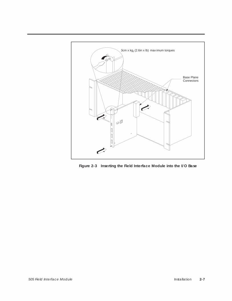
Installation 2-7505 Field Interface Module
Base PlaneConnectors
3cm x kgf (2.6in x lb) max imum torques
Figure 2-3 Inserting the Field Interface Module into the I/O Base

Installation2-8 505 Field Interface Module
2.4 Communication Ports
Both communication Ports 1 and 2 of the Field Interface Module provideserial communication over a shielded, twisted-pair cable system. The cablecan be thought of as a one-bit-wide bus or a local area network (LAN), towhich multiple devices are connected in a multi-drop fashion. The devicesthat are polled by the FIM are called slaves.
The Field Interface Module has two ports that allow it to be connected totwo different LANs. A configuration of two LANs to which the FieldInterface Module is connected is shown in Figure 2-4.
• In the LAN connected to the Field Interface Module Port 1, the FieldInterface Module is a slave device.
• In the LAN connected to Port 2, the Field Interface Module is a masterand controls the network traffic.
In order for the communication links to function properly, they must bewired correctly. Part of the wiring of the remote I/O link includestermination at the extreme ends of the cable. Consult ‘‘Using Port 1,” onpage 2-11, for references that describe this procedure. Wiring the field I/Olink includes termination and bias at the extreme ends of the cable.
“Using Port 2,” on page 2-12, describes how to wire RS-485 I/O, using aspecial connector for each slave device and for the Field Interface Module.
Overview

Installation 2-9505 Field Interface Module
RBC
Series 505 Remote I/O link
Termination andbias required
Terminationrequired
Termination and biasrequired
Terminationrequired
Port 1
FIMPort 2
RBC
Field I/O Link
Slave #1 Slave #2 Slave #7. . .
505 Controller
Figure 2-4 Configuration of Two LANs Connected to the Field Interface Module

Installation2-10 505 Field Interface Module
Communication Ports (continued)
When you use the Field Interface Module as the Port 2 interface, the specialconnector can only be used on the Field Interface Module. If the FieldInterface Module is located at an extreme end of the cable, the switches inthe special connector for the Field Interface Module should be set to the Onposition (note the position of switches 1 and 2 in Figure 2-9, on page 2-14).The slave device, at the other end of the cable, must be terminated andbiased.
In case the Field Interface Module is not at an extreme end of the cable, theswitches in the special connector must be turned off (Figure 2-10, onpage 2-15). Some slave devices provide termination as a selectable feature(generally by placing a jumper in a particular position).
Bias may be applied by way of an external circuit. In some cases, the +5VDC supply is available at the slave device communication connector. If not,an external supply must be used. Check with your Siemens Energy &Automation, Inc., distributor for information specific to your slave deviceand configuration.
The bias should be applied near or at the slave device located at the extremeend of the cable. Figure 2-5 shows how to connect the bias circuit.
R2
R1
TX/RX +
TX/RX –
Shield
+5 VDCSupply
R1 = R2 = 390 ohms
Figure 2-5 Connecting the Bias Circuit
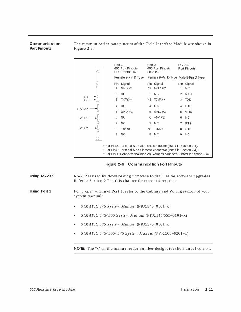
Installation 2-11505 Field Interface Module
The communication port pinouts of the Field Interface Module are shown inFigure 2-6.
+5V P2
Port 1485 Port PinoutsPLC Remote I/O
Port 1
Port 2
Pin Signal1
2
3
GND P1
NC
TX/RX+
Female 9-Pin D Type
Port 2485 Port PinoutsField I/O
S1S2
4
5
6
NC
GND P1
NC
7 NC
8 TX/RX–
9 NC
*1
2
GND P2
NC
TX/RX+
4
5
6
RTS
GND P2
7 NC
*8 TX/RX–
9 NC
Pin Signal
RS-232
NC
RS-232Port Pinouts
1
2
3
NC
RXD
TXD
4
5
6
DTR
GND
7 RTS
8 CTS
9 NC
Pin Signal
Male 9-Pin D TypeFemale 9-Pin D Type
* For Pin 3: Terminal B on Siemens connector (listed in Section 2.4).* For Pin 8: Terminal A on Siemens connector (listed in Section 2.4).* For Pin 1: Connector housing on Siemens connector (listed in Section 2.4).
*3
Figure 2-6 Communication Port Pinouts
RS-232 is used for downloading firmware to the FIM for software upgrades.Refer to Section 2.7 in this chapter for more information.
For proper wiring of Port 1, refer to the Cabling and Wiring section of yoursystem manual:
• SIMATIC 545 System Manual (PPX:545–8101–x)
• SIMATIC 545/555 System Manual (PPX:545/555–8101–x)
• SIMATIC 575 System Manual (PPX:575–8101–x)
• SIMATIC 545/555/575 System Manual (PPX:505–8201–x)
NOTE: The “x” on the manual order number designates the manual edition.
CommunicationPort Pinouts
Using RS-232
Using Port 1

Installation2-12 505 Field Interface Module
Communication Ports (continued)
When connecting the cable to Port 2, note the following information.
• Use the appropriate Siemens Energy & Automation, Inc., special cableconnector (6ES7 972–0BA00–0XA0, 6ES7 972–0BB00–0XA0,6ES7 972–0BA10–0XA0, 6ES7 972–0BB10–0XA0,6ES7 972–0BA20–0XA0, 6ES7 972–0BB20–0XA0), and thePROFIBUS-DP cable (6XV1 830–0AH10). (Model numbers are subjectto change; contact your distributor for up-to-date parts information.)
• The communication cable consists of two color-coded insulated wiresthat are twisted together and surrounded by a shield. The cable isencased in an insulating jacket. When wiring the system, the samecolor of wire must be connected to the TX/RX+ pin throughout thesystem.
On the special connector, terminal B connects to pin 3, which isTX/RX+, and terminal A connects to pin 8, which is TX/RX–. Crossingthe wires at any point in the system causes communication problems.
• Remove enough insulation so that the shielding under the pressuresaddle is exposed.
NOTE: Terminals A and B on the special connector may not necessarilymatch terminals A and B shown on the drives-communication terminalindicated in the Drives Manual. Be sure to connect the TX/RX+drives-communication terminal to terminal B on the special connector andthe TX/RX– drives-communication terminal to terminal A on the specialconnector. Refer to your Drives Manual for more information.
Mount the cable on the connector. The following procedure describes how touse the connection, shown in Figure 2-7.
1. Open the connector housing by loosening both housing screws (see Figure 2-7).
2. Remove the cover of the housing (see Figure 2-7).
3. Wire the cable as shown in Figure 2-8, Figure 2-9, and Figure 2-10.
4. Put the cover back on the connector housing.
You can now plug a connector into Port 2 of the Field Interface Module.
Using Port 2
Port 2 – Using theConnector

Installation 2-13505 Field Interface Module
9-pinD-connector
Housing screwsCable guide
ExternalTerminationSwitch
ON
OFF
Figure 2-7 Connector
1
2
Belden 9271 or PROFIBUS-DP
Figure 2-8 Routing and Cutting the Cable

Installation2-14 505 Field Interface Module
Communication Ports (continued)
Figure 2-9 shows how to mount the cable to a Port 2 connector at thebeginning or end of a segment.
1
2
Approx. 6 mm (1/4 in.)
Approx. 12 mm (1/2 in.)
Cable shieldingApprox. 12 mm (1/2 in.)
BA
3
Cable (beginning orend of a segment)
Switch position ON(termination andbias enabled)
ÉÉ
ÉÉ
A B A B
ON
OFF
Bare shielding mustcontact the metal guide.
Figure 2-9 Mounting the Cable on the Connector (Beginning/End of Segment)

Installation 2-15505 Field Interface Module
Figure 2-10 shows how to loop the cable through the Port 2 connector.
1
2
Cable
3
Approx. 6 mm (1/4 in.)
Approx. 12 mm (1/2 in.)
Cable shieldingApprox. 12 mm (1/2 in.)
BA BA
4
Switch position OFF(termination andbias disabled)
ÉÉ
É
A B A B
ON
OFF
Bare shielding mustcontact the metal guide.
Figure 2-10 Cutting the Cable, Stripping the Insulation, and Connecting the Cable
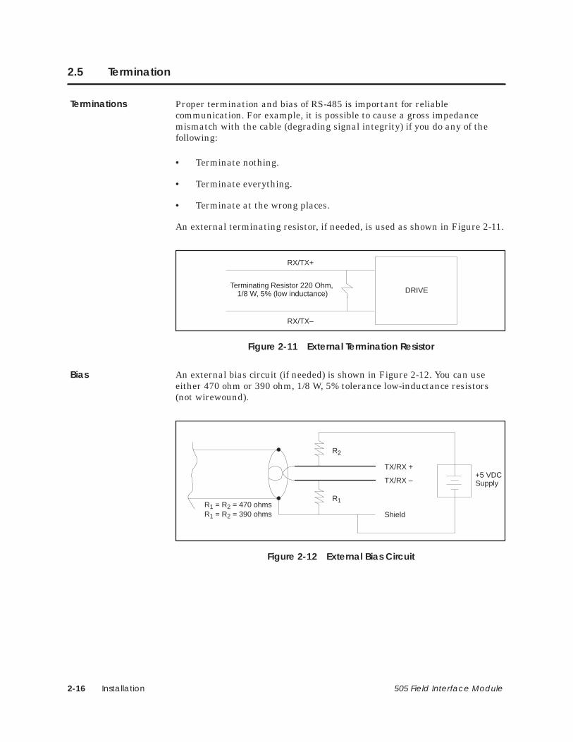
Installation2-16 505 Field Interface Module
2.5 Termination
Proper termination and bias of RS-485 is important for reliablecommunication. For example, it is possible to cause a gross impedancemismatch with the cable (degrading signal integrity) if you do any of thefollowing:
• Terminate nothing.
• Terminate everything.
• Terminate at the wrong places.
An external terminating resistor, if needed, is used as shown in Figure 2-11.
DRIVE
RX/TX+
RX/TX–
Terminating Resistor 220 Ohm, 1/8 W, 5% (low inductance)
Figure 2-11 External Termination Resistor
An external bias circuit (if needed) is shown in Figure 2-12. You can useeither 470 ohm or 390 ohm, 1/8 W, 5% tolerance low-inductance resistors(not wirewound).
R2
R1
TX/RX +
TX/RX –
Shield
+5 VDCSupply
R1 = R2 = 470 ohmsR1 = R2 = 390 ohms
Figure 2-12 External Bias Circuit
Terminations
Bias

Installation 2-17505 Field Interface Module
Figure 2-13 and Figure 2-14 show two examples of the the correct way toconnect the FIM to I/O.
PPX:505–7202
Termination and bias required.
Slave at end of cable must beterminated and biased.
Figure 2-13 Field Interface Module Drives Interface Example 1
PPX:505–7202
Do not terminate and bias.
Slave at end of cable must beterminated and biased.
Slave at end of cable must beterminated and biased.
Figure 2-14 Field Interface Module Drives Interface Example 2
NOTE: For information on termination and bias options on the drives in use,contact your Siemens Energy & Automation, Inc., distributor or sales agent.If you need assistance in contacting your distributor or sales office in theUnited States, call 800–964–4114.
Field InterfaceConnectionExamples

Installation2-18 505 Field Interface Module
Termination (continued)
The schematics for the following PROFIBUS connectors are shown inFigure 2-15:
6ES7 972–0BA00–0XA06ES7 972–0BB00–0XA06ES7 972–0BA10–0XA06ES7 972–0BB10–0XA06ES7 972–0BA20–0XA06ES7 972–0BB20–0XA0
Pin 6(+5V P2)
Pin 3(TX/RX+)
Pin 8(TX/RX–)
Pin 5(GND P2)
Bias Resistor, 390 ohm. 1/8 W, 5%
Termination Resistor, 220 ohm. 1/8 W, 5%
Bias Resistor, 390 ohm. 1/8 W, 5%
Internal Connection BInternal Connection B
Internal Connection AInternal Connection A
Pins 2, 4, 7, and 9 are not connected.
Figure 2-15 Connector Schematics
NOTE: Connector schematics and mechanical features are subject to changewithout notice. Check with your local Siemens Energy & Automation, Inc.,distributor for the latest version.
Pin 1 is not connected to the shell of the D-shell connector and cable shieldas shipped.
ConnectorSchematics

Installation 2-19505 Field Interface Module
2.6 Powering Up the Module
! WARNINGTurn off the power to the I/O base and any modules installed in the base beforeinserting or removing a module.
Failure to do so may cause unexpected controller performance that could resultin death or serious injury to personnel, and/or damage to equipment.
Ensure that all power is removed both from the base and from any modulesbefore you insert or remove a module.
After inserting the module in the base, restore power to the base.
• The MOD GOOD LED lights and stays on.
• The COMM light comes on if communication to the controller is good.
• The CFG light comes on and stays on if the controller I/O configurationmatches the Field Interface Module.
• The CFG light stays off if the Field Interface Module base number isnot configured with TISOFT or is not enabled.
• If the CFG light is blinking, the Field Interface Module may beconfigured incorrectly, or the module may not be communicating withall of its I/O properly.
• If problems persist, refer to Section 3.10 for drives troubleshooting, toSection 4.8 for PROFIBUS-DP troubleshooting, to Section 5.11 forSAMMS troubleshooting, and to Section 6.3 for SPI troubleshooting.

Installation2-20 505 Field Interface Module
2.7 Logging into the Controller
After inserting the module into the base, update the I/O configuration in thecontroller. The module does not automatically configure itself. TISOFT oranother type of programming device must be connected to the controller toregister and verify controller-to-FIM communication.
Refer to the chapter specific to your application for more information.

Installation 2-21505 Field Interface Module
2.8 FIM Software Field Upgrades
The PPX:505–7202 FIM has field upgrade capability using a standard PCand RS-232 port. For feature enhancements, the new firmware for the ROMand a PC-based download utility are available from Siemens Energy &Automation, Inc. To program the new firmware into the FIM’s EEPROM(Electrically Erasable Read Only Memory), place the FIM in a special mode(see instructions supplied with the utility) and run the download utility on aPC that is connected to the FIM’s RS-232 port by means of a standard 505programmable controller programming cable.
For additional information, contact your Siemens Energy & Automation,Inc., distributor or sales agent. If you need assistance in contacting yourdistributor or sales office in the United States, call 800–964–4114.

Drives Interface Application 3-1505 Field Interface Module
Chapter 3
Drives Interface Application
3.1 Drives Interface Overview 3-4. . . . . . . . . . . . . . . . . . . . . . . . . . . . . . . . . . . . . . . . . . . . . . . . . . . . . . . Features 3-4. . . . . . . . . . . . . . . . . . . . . . . . . . . . . . . . . . . . . . . . . . . . . . . . . . . . . . . . . . . . . . . . . . . . . . . . System Layout 3-6. . . . . . . . . . . . . . . . . . . . . . . . . . . . . . . . . . . . . . . . . . . . . . . . . . . . . . . . . . . . . . . . . . Drives Interface Logical Diagram 3-7. . . . . . . . . . . . . . . . . . . . . . . . . . . . . . . . . . . . . . . . . . . . . . . . Drives Interface Functional Diagrams 3-7. . . . . . . . . . . . . . . . . . . . . . . . . . . . . . . . . . . . . . . . . . . .
3.2 Selecting the Application 3-10. . . . . . . . . . . . . . . . . . . . . . . . . . . . . . . . . . . . . . . . . . . . . . . . . . . . . . . Mode of Operation 3-10. . . . . . . . . . . . . . . . . . . . . . . . . . . . . . . . . . . . . . . . . . . . . . . . . . . . . . . . . . . . . Mute Function 3-12. . . . . . . . . . . . . . . . . . . . . . . . . . . . . . . . . . . . . . . . . . . . . . . . . . . . . . . . . . . . . . . . . . Time-out Delay Function 3-12. . . . . . . . . . . . . . . . . . . . . . . . . . . . . . . . . . . . . . . . . . . . . . . . . . . . . . . .
3.3 Communicating with the Drives 3-13. . . . . . . . . . . . . . . . . . . . . . . . . . . . . . . . . . . . . . . . . . . . . . . . . . Autobaud Operation 3-13. . . . . . . . . . . . . . . . . . . . . . . . . . . . . . . . . . . . . . . . . . . . . . . . . . . . . . . . . . .
3.4 Connecting to Drives 3-14. . . . . . . . . . . . . . . . . . . . . . . . . . . . . . . . . . . . . . . . . . . . . . . . . . . . . . . . . . . . Connecting Port 2 to Drive with Two-Wire RS-485 Port 3-14. . . . . . . . . . . . . . . . . . . . . . . . . . . . . Connecting Port 2 to Drive with Four-Wire RS-485 Port 3-15. . . . . . . . . . . . . . . . . . . . . . . . . . . . .
3.5 Configuring for 10-Word Simple or 10-Word USS Protocols 3-16. . . . . . . . . . . . . . . . . . . . . . . . . . Updating the I/O Configuration Definition 3-16. . . . . . . . . . . . . . . . . . . . . . . . . . . . . . . . . . . . . . . . Sample Configuration 3-16. . . . . . . . . . . . . . . . . . . . . . . . . . . . . . . . . . . . . . . . . . . . . . . . . . . . . . . . . . . Configuring for 10-Word Simple or 10-Word USS Protocol 3-17. . . . . . . . . . . . . . . . . . . . . . . . . . Broadcast/ Immediate Control Channel 3-17. . . . . . . . . . . . . . . . . . . . . . . . . . . . . . . . . . . . . . . . . WX1 – WX10 (Controller Input Words) 3-17. . . . . . . . . . . . . . . . . . . . . . . . . . . . . . . . . . . . . . . . . . . . . WY11 – WY20 (Controller Output Words) 3-17. . . . . . . . . . . . . . . . . . . . . . . . . . . . . . . . . . . . . . . . . . Configuring the Broadcast/Immediate Channel (10-Word Simple or 10-Word USS
Protocol) 3-18. . . . . . . . . . . . . . . . . . . . . . . . . . . . . . . . . . . . . . . . . . . . . . . . . . . . . . . . . . . . . Viewing the I/O Configuration Chart 3-20. . . . . . . . . . . . . . . . . . . . . . . . . . . . . . . . . . . . . . . . . . . . .
3.6 Configuring for 4-Word Simple Protocol 3-22. . . . . . . . . . . . . . . . . . . . . . . . . . . . . . . . . . . . . . . . . . . Updating the I/O Configuration Definition 3-22. . . . . . . . . . . . . . . . . . . . . . . . . . . . . . . . . . . . . . . . Sample Configuration 3-22. . . . . . . . . . . . . . . . . . . . . . . . . . . . . . . . . . . . . . . . . . . . . . . . . . . . . . . . . . . Configuring the Broadcast/Immediate Channel (4-Word Simple Protocol) 3-23. . . . . . . . . Configuring for 4-Word Simple Protocol 3-23. . . . . . . . . . . . . . . . . . . . . . . . . . . . . . . . . . . . . . . . . . Broadcast/ Immediate Control Channel 3-23. . . . . . . . . . . . . . . . . . . . . . . . . . . . . . . . . . . . . . . . . WX1 – WX4 (Controller Input Words) 3-23. . . . . . . . . . . . . . . . . . . . . . . . . . . . . . . . . . . . . . . . . . . . . . WY5 – WY8 (Controller Output Words) 3-23. . . . . . . . . . . . . . . . . . . . . . . . . . . . . . . . . . . . . . . . . . . . Viewing the I/O Configuration Chart 3-25. . . . . . . . . . . . . . . . . . . . . . . . . . . . . . . . . . . . . . . . . . . . .

Drives Interface Application3-2 505 Field Interface Module
3.7 Configuring for 5-Word USS Protocol 3-26. . . . . . . . . . . . . . . . . . . . . . . . . . . . . . . . . . . . . . . . . . . . . . Updating the I/O Configuration Definition 3-26. . . . . . . . . . . . . . . . . . . . . . . . . . . . . . . . . . . . . . . . Sample Configuration 3-26. . . . . . . . . . . . . . . . . . . . . . . . . . . . . . . . . . . . . . . . . . . . . . . . . . . . . . . . . . . Configuring the Broadcast/Immediate Channel (5-Word USS Protocol) 3-27. . . . . . . . . . . . Configuring for 5-Word USS Protocol 3-27. . . . . . . . . . . . . . . . . . . . . . . . . . . . . . . . . . . . . . . . . . . . . Broadcast/ Immediate Control Channel 3-27. . . . . . . . . . . . . . . . . . . . . . . . . . . . . . . . . . . . . . . . . WX1 – WX6 (Controller Input Words) 3-27. . . . . . . . . . . . . . . . . . . . . . . . . . . . . . . . . . . . . . . . . . . . . . WY7 – WY12 (Controller Output Words) 3-27. . . . . . . . . . . . . . . . . . . . . . . . . . . . . . . . . . . . . . . . . . . Viewing the I/O Configuration Chart 3-29. . . . . . . . . . . . . . . . . . . . . . . . . . . . . . . . . . . . . . . . . . . . .
3.8 Configuring for 5-Word (Modified) USS Protocol 3-30. . . . . . . . . . . . . . . . . . . . . . . . . . . . . . . . . . . Updating the I/O Configuration Definition 3-30. . . . . . . . . . . . . . . . . . . . . . . . . . . . . . . . . . . . . . . . Sample Configuration 3-30. . . . . . . . . . . . . . . . . . . . . . . . . . . . . . . . . . . . . . . . . . . . . . . . . . . . . . . . . . . Configuring the Broadcast/Immediate Channel 5-Word (Modified) USS Protocol 3-31. . . 5-Word (Modified) USS Drive Protocol 3-31. . . . . . . . . . . . . . . . . . . . . . . . . . . . . . . . . . . . . . . . . . . . Configuring for 5-Word (Modified) USS Protocol 3-31. . . . . . . . . . . . . . . . . . . . . . . . . . . . . . . . . . . Broadcast/Immediate Control Channel 3-31. . . . . . . . . . . . . . . . . . . . . . . . . . . . . . . . . . . . . . . . . . WX1 – WX4 (Controller Input Words) 3-32. . . . . . . . . . . . . . . . . . . . . . . . . . . . . . . . . . . . . . . . . . . . . . WY5 – WY8 (Controller Output Words) 3-32. . . . . . . . . . . . . . . . . . . . . . . . . . . . . . . . . . . . . . . . . . . . Viewing the I/O Configuration Chart 3-34. . . . . . . . . . . . . . . . . . . . . . . . . . . . . . . . . . . . . . . . . . . . .
3.9 Programming 3-36. . . . . . . . . . . . . . . . . . . . . . . . . . . . . . . . . . . . . . . . . . . . . . . . . . . . . . . . . . . . . . . . . . . Drives Update Scan 3-36. . . . . . . . . . . . . . . . . . . . . . . . . . . . . . . . . . . . . . . . . . . . . . . . . . . . . . . . . . . . . Broadcast Request 3-40. . . . . . . . . . . . . . . . . . . . . . . . . . . . . . . . . . . . . . . . . . . . . . . . . . . . . . . . . . . . . Broadcast Procedure 3-41. . . . . . . . . . . . . . . . . . . . . . . . . . . . . . . . . . . . . . . . . . . . . . . . . . . . . . . . . . . Immediate I/O Request 3-42. . . . . . . . . . . . . . . . . . . . . . . . . . . . . . . . . . . . . . . . . . . . . . . . . . . . . . . . . Immediate I/O Request Procedure 3-42. . . . . . . . . . . . . . . . . . . . . . . . . . . . . . . . . . . . . . . . . . . . . . Programming Drives 3-43. . . . . . . . . . . . . . . . . . . . . . . . . . . . . . . . . . . . . . . . . . . . . . . . . . . . . . . . . . . . Typical Drive Programming 3-44. . . . . . . . . . . . . . . . . . . . . . . . . . . . . . . . . . . . . . . . . . . . . . . . . . . . . . Typical Drive Program 3-45. . . . . . . . . . . . . . . . . . . . . . . . . . . . . . . . . . . . . . . . . . . . . . . . . . . . . . . . .
3.10 Drives Troubleshooting 3-46. . . . . . . . . . . . . . . . . . . . . . . . . . . . . . . . . . . . . . . . . . . . . . . . . . . . . . . . . . Checking the Operation of the Module 3-46. . . . . . . . . . . . . . . . . . . . . . . . . . . . . . . . . . . . . . . . . . 10-Word Simple and 10-Word USS Protocol 3-47. . . . . . . . . . . . . . . . . . . . . . . . . . . . . . . . . . . . . . . 4-Word Simple and 5-Word (Modified) USS Protocol 3-47. . . . . . . . . . . . . . . . . . . . . . . . . . . . . . . 5-Word USS Protocol 3-48. . . . . . . . . . . . . . . . . . . . . . . . . . . . . . . . . . . . . . . . . . . . . . . . . . . . . . . . . . . . Technical Assistance 3-49. . . . . . . . . . . . . . . . . . . . . . . . . . . . . . . . . . . . . . . . . . . . . . . . . . . . . . . . . . . .
3.11 SIMOREG/SIMOVERT Applications 3-50. . . . . . . . . . . . . . . . . . . . . . . . . . . . . . . . . . . . . . . . . . . . . . . . FIM Drive Protocols 3-50. . . . . . . . . . . . . . . . . . . . . . . . . . . . . . . . . . . . . . . . . . . . . . . . . . . . . . . . . . . . . . AC Drives Supported 3-51. . . . . . . . . . . . . . . . . . . . . . . . . . . . . . . . . . . . . . . . . . . . . . . . . . . . . . . . . . . . DC Drives Supported 3-52. . . . . . . . . . . . . . . . . . . . . . . . . . . . . . . . . . . . . . . . . . . . . . . . . . . . . . . . . . . .
3.12 Setting Up and Wiring 6RA24 3-54. . . . . . . . . . . . . . . . . . . . . . . . . . . . . . . . . . . . . . . . . . . . . . . . . . . . .
3.13 Setting Up and Wiring 6SE21 3-62. . . . . . . . . . . . . . . . . . . . . . . . . . . . . . . . . . . . . . . . . . . . . . . . . . . . .
3.14 Setting Up and Wiring Micromaster/Midimaster Drive (6SE30/6ES31) 3-68. . . . . . . . . . . . . . . .

Drives Interface Application 3-3505 Field Interface Module
3.15 Setting Up and Wiring SI3 3-76. . . . . . . . . . . . . . . . . . . . . . . . . . . . . . . . . . . . . . . . . . . . . . . . . . . . . . .
3.16 Setting Up and Wiring Z1005 3-80. . . . . . . . . . . . . . . . . . . . . . . . . . . . . . . . . . . . . . . . . . . . . . . . . . . . .
3.17 Setting Up and Wiring Z1006 3-84. . . . . . . . . . . . . . . . . . . . . . . . . . . . . . . . . . . . . . . . . . . . . . . . . . . . .
3.18 Setting Up and Wiring Z1011 3-88. . . . . . . . . . . . . . . . . . . . . . . . . . . . . . . . . . . . . . . . . . . . . . . . . . . . .
3.19 Setting Up and Wiring Z2006 3-92. . . . . . . . . . . . . . . . . . . . . . . . . . . . . . . . . . . . . . . . . . . . . . . . . . . . .
3.20 Setting Up and Wiring the 6SE70 Models FC and SC 3-100. . . . . . . . . . . . . . . . . . . . . . . . . . . . . . .
3.21 Setting Up and Wiring the 6SE70 Model VC 3-108. . . . . . . . . . . . . . . . . . . . . . . . . . . . . . . . . . . . . . .
3.22 Setting Up and Wiring the SCB2 3-116. . . . . . . . . . . . . . . . . . . . . . . . . . . . . . . . . . . . . . . . . . . . . . . . . .
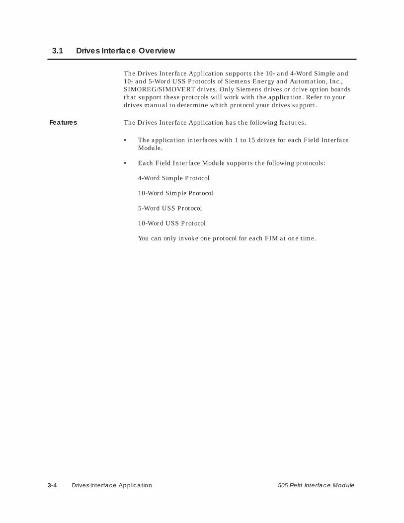
Drives Interface Application3-4 505 Field Interface Module
3.1 Drives Interface Overview
The Drives Interface Application supports the 10- and 4-Word Simple and10- and 5-Word USS Protocols of Siemens Energy and Automation, Inc.,SIMOREG/SIMOVERT drives. Only Siemens drives or drive option boardsthat support these protocols will work with the application. Refer to yourdrives manual to determine which protocol your drives support.
The Drives Interface Application has the following features.
• The application interfaces with 1 to 15 drives for each Field InterfaceModule.
• Each Field Interface Module supports the following protocols:
4-Word Simple Protocol
10-Word Simple Protocol
5-Word USS Protocol
10-Word USS Protocol
You can only invoke one protocol for each FIM at one time.
Features

Drives Interface Application 3-5505 Field Interface Module
• The autobaud operation automatically determines the baud rate bypolling drives. All drives must be at the same baud rate.
• The Drives Interface Application supports Broadcast Messages througha broadcast channel.
• The Drives Interface Application supports Immediate Messages toindividual drives and supplies rapid feedback for immediate I/Orequests.
• You can monitor the status of communication through the controllerstatus words (STW). The status words indicate the status of thecommunication links between the Field Interface Module and thecontroller and between the Field Interface Module and the drives.
• You can reset the Drives Interface Application without power cyclingthe base. To do this, change the protocol selection switch S2.
• You can disable the I/O updates to the drives by using dipswitch S3–8to mute I/O processing for communications errors between the FIM andthe controller.

Drives Interface Application3-6 505 Field Interface Module
Drives Interface Overview (continued)
An I/O system layout for three Field Interface Modules running the DrivesInterface Application is shown in Figure 3-1.
P/S
P/S
Local I/Oup to 16 I/O slots
Series 505 I/O
RBC
545
FIM1
FIM2
Series 505 I/O
Drive 1
Drive 2
Drive 15
.
.
.
Drive 15
Drive 2
Drive 1
.
.
.Port 2 on FIM 1Port 2 on FIM 1
Port 2 on FIM 2
Remote I/O link
FIM3
Drive 1
Drive 2
Drive 15
.
.
.
Port 2 on FIM 3
Port 1 on the Field InterfaceModules (FIM)
Up to 15 drives
Up to 15 drives
Up to 15 drives
Figure 3-1 I/O System Layout for Three FIMs Running the Drives InterfaceApplication
System Layout

Drives Interface Application 3-7505 Field Interface Module
The Drives Interface logical block diagram is shown in Figure 3-2. The FieldInterface Module appears as a remote base controller to the Series 505 I/Osystem.
ControllerFIM
Drive Interface
Remote I/O
RBC 2
Drive 1 Drive 15
Drive 2
. .
. .
(Base 5)*
(Base 1)
*Base 5 is used for this example. The FIM can be set to any valid base number.
Figure 3-2 FIM Interface Block Diagram
Figure 3-3 shows the Drives Interface functional block diagram for the10-Word Simple and 10-Word USS Protocols; Figure 3-4 shows 4-WordSimple Protocol; Figure 3-5 shows 5-Word USS Protocol; and Figure 3-6shows 5-Word USS (Modified) Protocol. The drives connected to the FieldInterface Module appear as modules in a remote base.
Drives InterfaceLogical Diagram
Drives InterfaceFunctionalDiagrams

Drives Interface Application3-8 505 Field Interface Module
Drives Interface Overview (continued)
Controller
FIM Drives Interface
Remote I/O
RBC 2
10-Word Telegram to Drive 1
10-Word Telegram to Drive 2
RBC
10WX10WY
10WX10WY
10WX10WY
Slot 1 2 N
. . .
(Base 1)
*Base 5 is used for this example. The FIM can be set to any valid base number.
(Base 5)*
Figure 3-3 Functional Block Diagram for 10-Word Simple and 10-WordUSS Protocols
Controller
FIM Drives Interface
Remote I/O
RBC 2
4-Word Telegram to Drive 1
4-Word Telegram to Drive 2
RBC
4WX4WY
4WX4WY
4WX4WY
Slot 1 2 N
. . .
(Base 1)
*Base 5 is used for this example. The FIM can be set to any valid base number.
(Base 5)*
Figure 3-4 Functional Block Diagram for 4-Word Simple Protocol

Drives Interface Application 3-9505 Field Interface Module
Controller
FIM Drives Interface
Remote I/O
RBC 2
5-Word Telegram to Drive 1
5-Word Telegram to Drive 2
RBC
6WX6WY
6WX6WY
6WX6WY
Slot 1 2 N
. . .
(Base 1)
*Base 5 is used for this example. The FIM can be set to any valid base number.
(Base 5)*
Figure 3-5 Functional Block Diagram for 5-Word USS Protocols
Controller
FIM Drives Interface
Remote I/O
RBC 2
5-Word Telegram to Drive 1
5-Word Telegram to Drive 2
RBC
4WX4WY
4WX4WY
4WX4WY
Slot 1 2 N
. . .
(Base 1)
*Base 5 is used for this example. The FIM can be set to any valid base number.
(Base 5)*
Figure 3-6 Functional Block Diagram for 5-Word USS (Modified) Protocols

Drives Interface Application3-10 505 Field Interface Module
3.2 Selecting the Application
The mode of operation is determined by setting the S3 dipswitch, as shownin Figure 3-7. This is referred to as the application. The first fourdipswitches (1 – 4) are closed for the Drives Interface Application. SwitchS2, on the front bezel, selects the specific drives-interface protocol. Refer toTable 3-1 for the protocol selection.
NOTE: Early generation SIMOREG drives supported 10-Word SimpleProtocol, and SIMOVERT drives supported the 4-Word Simple protocol.Later drive releases may differ. Check your appropriate SIMOREG orSIMOVERT drive manual to determine the protocol supported.
1 2 3 4 5 6 7 8
CLOSED
OPEN
MUTE
SPAR
DLY 1
DLY 0
AP 0
AP 1
AP 2
AP 3
S3
CLOSED/ON/0
OPEN/OFF/1
Figure 3-7 Field Interface Module S3 Dipswitch Settings
Dipswitch S3 assignments in Figure 3-7 are defined as follows.
• AP 0 – 3 = Application Number 0 – 15 (AP 0 is LSB)
• DLY 0 – 1 = Delay Number 0 – 3 (resolution 14 msec)Refer to Table 3-2 for delay settings.
• SPAR = Spare
• MUTE = Disable I/O updates on programmable controllercommunication error or receipt of an OUTDIS signal from the controller; 1 is disable.
Mode of Operation

Drives Interface Application 3-11505 Field Interface Module
Table 3-1 Protocol Selection
Rotary Switch S2 Protocol
ProgrammableController
Slot Configuration
0 4-Word Simple Protocol 4WX, 4WY
1 10-Word Simple Protocol 10WX, 10WY
2 USS (Modified) 5-Word Protocol 4WX, 4WY
3 USS 10-Word Protocol 10WX, 10WY
4 USS (Full) 5-Word Protocol 6WX, 6WY
5 – F Undefined Undefined
NOTE: Changing any of the switches while the module is plugged in resetsthe module.
NOTE: Although the drive treats the 5-Word USS and 5-Word USS(Modified) Protocols in the same way, the FIM treats them differently. Thesecond word in the 5-Word USS (Modified) going to and from the drive isdiscarded. Most drives do not use this word and so allow you to configurethe drive with only four words in and four words out. The 5-Word (Full) isconfigured as six words in and six words out because you must configure theprogrammable controller in even-numbered words.
You must configure the corresponding controller slot, according to Table 3-1,for each active drive connected to a FIM module. For a description of theWX and WY words in Table 3-1 through Table 3-6, refer to the protocolsection of the Interface Board manual that was shipped with your drive.

Drives Interface Application3-12 505 Field Interface Module
Selecting the Application (continued)
The mute function, added in Release 2.1, is enabled by opening switch S3–8.With mute enabled, the FIM module stops sending data updates to thedrive(s) anytime it either loses communication with the controller orreceives an OUTDIS signal from the controller. With S3–8 closed, the mutefunction is disabled.
Beginning with Release 2.1, I/O data is now sent to establish/re-establishcommunications with a drive instead of sending zero data, provided that theslot is configured properly in the controller; otherwise, zeroes are sent. Thisprevents the drives from clearing sporadically on re-establishment of thelink between the FIM and the drive(s) when communication errors havecaused the link to be disconnected.
If you want to send zeroes to shut down a drive when a communicationerror occurs (and the controller is configured correctly), use RLL statuswords to detect a communication error, then write the zeroes to the wordoutput locations in the controller.
Because some drives can take longer to respond to requests than expected,you can add extra delay to the timeout that is used when the Field InterfaceModule is polling for drives.
You can determine the amount of delay by setting dipswitch S3. Table 3-2shows the amount of additional delay introduced by setting switches S3–5and S3–6.
Table 3-2 S3 Dipswitch Settings for Additional Delay
S3-5 S3-6 Value Time Delay (ms)
Closed Closed 0 0
Open Closed 1 14
Closed Open 2 28
Open Open 3 42
See Figure 2-2 for the location of the S3 dipswitch on the Field InterfaceModule. Table 3-3 lists the dipswitch settings for switch S3.
Table 3-3 Recommended S3 Dipswitch Settings
Drive Type Time Delay (ms)
6SE21 28
All Others 0
Mute Function
Time-out DelayFunction

Drives Interface Application 3-13505 Field Interface Module
3.3 Communicating with the Drives
The Drives Interface Application automatically determines the baud rate ofthe drives connected to it. It cycles through each baud rate, starting withthe lowest numbered drive (drive #1), and proceeding to the highestnumbered drive (drive #15). Once communication is established with adrive, the Drives Interface Application continues to communicate at thatbaud rate until reset. If communication is not established, this cyclingprocess is repeated until the Drives Interface Application locks onto a baudrate.
Each protocol defines the baud rates supported. Valid baud rates for the 10- and 4-Word Simple, 10- and 5-Word USS, and 5-Word USS (Modified)Protocols are shown below. Not all drives support all baud rates. Refer toyour drive manual to determine which baud rates your drive supports.
Valid baud rates for Simple and USS Protocols are as follows:
• 38,400 bits per second
• 19,200 bits per second
• 9,600 bits per second
• 4,800 bits per second
NOTE: The Drives Interface Application communicates with the first drivefound, at the baud rate for that drive. Drives set to different baud rates arenot identified by the Drives Interface Application, and do not appear whenbase status is read by TISOFT.
AutobaudOperation

Drives Interface Application3-14 505 Field Interface Module
3.4 Connecting to Drives
Drives with two-wire RS-485 ports connect directly to the Field InterfaceModule, port 2, as shown in Figure 3-8. The pin numbers for the FieldInterface Module are also shown. Pin numbers on the drive port varyaccording to the drive type and model. Refer to your drive manual for moreinformation about drive pin numbers.
������
���� !��! �$�� �����
������
������
���
������
!# �
�
�����# %! (!&# �#�'� �� &�� �!# �#�'�"!#% &���# � � �! ��%!# "� &���#$�
�
�
�
Field Interface ModulePort 2
Drive RS-485 Port
������ $������
Terminal B on Siemens connector (listed in Section 2.4).
Terminal A on Siemens connector (listed in Section 2.4).
Connector housing on Siemens connector (listed in Section 2.4).
Figure 3-8 Connecting the Field Interface Module to Drive with 2-Wire RS-485 Port
NOTE: Some drive interfaces do not have a ground or common pin on theRS-485 connector. Grounding must be achieved either by using systemgrounds or by grounding to the connector shell of the drive connector.
Port 2 on the Field Interface Module must have a common ground referencewith the drive. Otherwise, communications can become unreliable.
Connecting Port 2to Drive withTwo-Wire RS-485Port

Drives Interface Application 3-15505 Field Interface Module
Drives with four-wire RS-485 ports must connect to the Field InterfaceModule, port 2, as shown in Figure 3-9. The pin numbers for the FieldInterface Module are also shown. Pin numbers on the drive port varyaccording to the drive type and model. Refer to your drive manual for moreinformation about drive pin numbers.
���
���
���� " "!���� �����
���
���
������
���
������
"$ �
�
�����$ &" )"'$ �$�(� �!'�� �"$ �$�(�#"$& !' ��$ �!� �"!!��&"$ #�! !' ��$%�
�
�
�
�
�
Field Interface ModulePort 2
Drive RS-485 Port
������ %������
Terminal B on Siemens connector (listed in Section 2.4).
Terminal A on Siemens connector (listed in Section 2.4).
Connector housing on Siemens connector (listed in Section 2.4).
Figure 3-9 Connecting the Field Interface Module to Drive with 4-Wire RS-485 Port
NOTE: Some drive interfaces do not have a ground or common pin on theRS-485 connector. Grounding must be achieved either by using systemgrounds or by grounding to the connector shell of the drive connector.
Port 2 on the Field Interface Module must have a common ground referencewith the drive. Otherwise, communications can become unreliable.
Connecting Port 2to Drive withFour-Wire RS-485Port

Drives Interface Application3-16 505 Field Interface Module
3.5 Configuring for 10-Word Simple or 10-Word USS Protocols
After inserting the FIM into the base, you must update the I/Oconfiguration in the controller. The module does not automatically configureitself. TISOFT, or another programming device, must be connected to thecontroller to both register and verify controller-to-FIM communication.
This sample configuration description uses one drive; the address switch isset to drive #1. It is configured to the sample configuration chart shown inFigure 3-10. These words can be mapped to any valid I/O address, but inthis example, they start at address 1. The broadcast channel begins ataddress 25, indicating that 24 points are used by drive #1, but, it also canhave any valid I/O address. Do not overlap I/O points across different slots.
Slot Number Directly corresponds todrive address. Slot #16is the Broadcast/Immediate Channel.
��� ������ ���������� ��� �2������� �2���� �
�),0 �%%.&// ! � �! �1+$0(,+
��� �1*#&. ,' �(0 "+% �,.% ��� �-&$(")
�
�
�
�
�
�
�����
�����
�����
�����
�����
�����
�����
�����
����
����
����
����
����
����
����
����
�����
�����
�����
�����
�����
�����
�����
�����
��
��
��
��
��
��
��
��
��
��
��
��
��
��
��
��
��
��
��
��
��
��
��
��
��
��
��
��
��
��
��
��
��
��
��
��
��
��
��
��
��
��
��
��
��
��
��
��
��
��
��
��
��
��
�������
�������
�������
�������
�������
�������
�������
�������
�,
�,
�,
�,
�,
�,
�,
�� ��
Base Number Displays number of the current base and correspondsto number on S1.
I/O Address The drive is logged in as 10 inputwords (WX) and 10 output words (WY).
SF Module The Field Interface Module isnot an SF Module. The defaultfor this definition is NO.
��
��
��
��
��
�
�
�����
�����
�����
�����
�����
�����
�����
�����
����
����
����
����
����
����
����
���
�����
�����
�����
�����
�����
�����
�����
�����
��
��
��
��
��
��
��
�
��
��
��
��
��
��
��
��
��
��
��
��
��
��
��
�
��
��
��
��
��
��
��
��
��
��
��
��
��
��
��
��
��
��
��
��
��
��
��
��
��
��
��
��
��
��
�������
�������
�������
�������
�������
�������
�������
�������
�,
�,
�,
�,
�,
�,
�,
�,
�� ��
Broadcast/ImmediateMessage Control Channel
�,
Figure 3-10 Sample I/O Configuration Chart for 10-Word Simple or10-Word USS Protocols
Updating the I/OConfigurationDefinition
SampleConfiguration

Drives Interface Application 3-17505 Field Interface Module
The Drives Interface Application using the 10-Word Simple or 10-Word USSProtocol is configured as 10 word inputs (WX) and 10 word outputs (WY). Itoccupies 24 points of the controller’s word image register for each drive. Thepoints must be used in multiples of eight when programmed in TISOFT.
The Broadcast/Immediate Control Channel is always in slot #16. It takes upto 16 discrete input points (X), 16 discrete output points (Y), and 10 wordoutput points (WY). The Broadcast/Immediate Control Channel occupies 48points of controller image register for each Field Interface Module using theDrives Interface Application. The points must be used in multiples of eightwhen programmed in TISOFT.
Words WX1 – WX10 are input words to the controller. This is theinformation returning from the drive from the previous request. Thesewords map directly to the drive output words S1 – S10 as shown inTable 3-4.
Words WY11 – WY20 are output words from the controller. This is therequest data that goes to the drive. These words map directly to the driveinput words E1 – E10 as shown in Table 3-4.
Table 3-4 Mapping the Controller Words to the Drive Parameter Wordsfor 10-Word Simple or 10-Word USS Protocol
From the Drive(Drive to Host)
To the Drive(Host to Drive)
Controller InputWords
Drive OutputWords
ControllerOutput Words
Drive InputWords
WX1 S1 WY11 E1
WX2 S2 WY12 E2
WX3 S3 WY13 E3
WX4 S4 WY14 E4
WX5 S5 WY15 E5
WX6 S6 WY16 E6
WX7 S7 WY17 E7
WX8 S8 WY18 E8
WX9 S9 WY19 E9
WX10 S10 WY20 E10
Configuring for10-Word Simple or10-Word USSProtocol
Broadcast/ Immediate ControlChannel
WX1 – WX10(ControllerInput Words)
WY11 – WY20(Controller OutputWords)

Drives Interface Application3-18 505 Field Interface Module
Configuring for 10-Word Simple or 10-Word USS Protocols (continued)
The Broadcast/Immediate Channel is configured in this example as follows:
Immediate I/O Request Control Bits. In this example, bits Y41 – Y55 are immediate I/O request control bits, and correspond to drives 1 – 15.When set, these bits force an immediate I/O request to be sent to thecorresponding drive. Setting bit Y42 forces an interruption in the FieldInterface Module drives update scan, causing a request to be sent todrive #2 immediately. These bits are one-shot and edge-triggered by theDrives Interface Application. For more details, see Section 5.7.
Broadcast Control Bit. In this example, Y56 is the broadcast control bitand operates the same way as the Y41 – Y55 bits, except that setting Y56forces a broadcast to all drives.
Immediate I/O Request Completed Bits. In this example, bitsX25 – X39 are the immediate I/O request completed bits. They are set whenthe immediate I/O request to the corresponding drives 1 – 15 has beencompleted. Bits X25 – X39 are only set if bits Y41 – Y55 remain set after theimmediate I/O request is made. Bits X25 – X39 are reset when thecorresponding bits Y41 – Y55 are reset. Bits X25 – X39 let the programknow when the immediate I/O request is complete. For more details see theprogramming section.
Broadcast Completed Bit. In this example, bit X40 is the broadcastcompleted bit and operates in the same way as X25 – X39, except that X40indicates that a broadcast (caused by setting bit Y56) is complete.
Broadcast Data Words. In this example, controller output wordsWY57 – WY66 contain the information for broadcasts. They correspond tothe drive input words of the broadcast request, just as words WY11 – WY20correspond to the drive input words of drive #1. Refer to Table 3-5.
Configuring theBroadcast/ImmediateChannel (10-WordSimple or 10-WordUSS Protocol)

Drives Interface Application 3-19505 Field Interface Module
Table 3-5 Mapping the 10-Word Simple or 10-Word USS Protocol Broadcast Channel
Immediate I/OReque t Drive Number
Immediate I/OReque t
Broadcast Data Words(Host to Drives)
RequestCompleted Bits
Drive Number RequestControl Bits Controller Output
Words Drive Input Words
X25 1 Y41 WY57 E1
X26 2 Y42 WY58 E2
X27 3 Y43 WY59 E3
X28 4 Y44 WY60 E4
X29 5 Y45 WY61 E5
X30 6 Y46 WY62 E6
X31 7 Y47 WY63 E7
X32 8 Y48 WY64 E8
X33 9 Y49 WY65 E9
X34 10 Y50 WY66 E10
X35 11 Y51
X36 12 Y52 X40 – This is the Broadcast Completed Bit.
X37 13 Y53
X38 14 Y54Y56 – This is the Broadcast Control Bit.
X39 15 Y55Y56 – This is the Broadcast Control Bit.

Drives Interface Application3-20 505 Field Interface Module
Configuring for 10-Word Simple or 10-Word USS Protocols (continued)
Use your programming device to view the I/O Configuration Chart, anexample of which is shown in Figure 3-11. Use SHOW in TISOFT, and notethat only a portion of this information is shown at a time.
• The slot number corresponds to the drive number. This example showsdrive #1, which appears in slot #1.
• Slot #16 is always the Broadcast/Immediate Channel.
• The Drives Interface Application is configured as base 5.
Viewing the I/OConfigurationChart

Drives Interface Application 3-21505 Field Interface Module
I/O CONFIGURATION CHART FOR : CHANNEL ... 1 BASE ..... 05
Slot 1
I/O POINTS
Slot 1
Slot 1
Slot 2
Slot 5
Slot 6
WX0001 WX0002 WX0003 WX0004 WX0005 WX0006 WX0007 WX0008
Slot 7
Slot 8
Slot 9
Slot 10
Slot 11
Slot 12Slot 13
Slot 14
Slot 15
1 2 3 4 5 6 7 8
WX0009 WX0010 WY0011 WY0012 WY0013 WY0014 WY0015 WY0016
9 10 11 12 13 14 15 16
WY0018WY0017 WY0019 WY0020
17 18 19 20
Slot 3
Slot 4
Slot 16
Slot 16
Slot 16
X0025 X0026 X0027 X0028 X0029 X0030 X00311 2 3 4 5 6 7 8
X0033 X0034 X0035 X0036 X0037 X0038 X0039 X0040
9 10 11 12 13 14 15 16
Y0042Y0041 Y0043 Y0044
17 18 19 20
X0032
Y0045 Y0046 Y0047 Y0048
21 22 23 24
Slot 16
Slot 16
Slot 16
Y0049 Y0050 Y0051 Y0052 Y0053 Y0054 Y005525 26 27 28 29 30 31 32
WY0057 WY0058 WY0059 WY0060 WY0061 WY0062 WY0063 WY0064
33 34 35 36 37 38 39 40
WY0066WY0065
41 42
Y0056
Figure 3-11 I/O Configuration Chart for 10-Word Simple or 10-Word USS Protocols

Drives Interface Application3-22 505 Field Interface Module
3.6 Configuring for 4-Word Simple Protocol
After inserting the Field Interface Module into the base, update the I/Oconfiguration in the controller. The module does not automatically configureitself. TISOFT, or another programming device, must be connected to thecontroller in order to both register and verify communication between FIMand the controller.
This configuration description uses one drive; the address switch is set todrive #1. It is configured to the sample configuration chart shown inFigure 3-12. These words can be mapped to any valid I/O address, but, inthis example, they start at address 1. The broadcast channel begins ataddress 9, indicating that eight points are used by drive #1, but it also canhave any valid I/O address. Do not overlap I/O points across different slots.
Slot Number Directly correspondsto drive address.Slot #16 is theBroadcast/ ImmediateChannel.
��� ������ ���������� ��� �2������� �2���� �
�),0 �%%.&// ! � �! �1+$0(,+
��� �1*#&. ,' �(0 "+% �,.% ��� �-&$(")
�
�
�
�
�
�
�����
�����
�����
�����
�����
�����
�����
�����
����
����
����
����
����
����
����
����
�����
�����
�����
�����
�����
�����
�����
�����
��
��
��
��
��
��
��
��
��
��
��
��
��
��
��
��
��
��
��
��
��
��
��
��
��
��
��
��
��
��
��
��
��
��
��
��
��
��
��
��
��
��
��
��
��
��
��
��
��
��
��
��
��
��
�������
�������
�������
�������
�������
�������
�������
�������
�,
�,
�,
�,
�,
�,
�,
�,
�� ��
Base Number Displays number of the current base and correspondsto number on S1.
I/O Address The drive is logged in as 4 input words(WX) and 4 output words (WY).
SF Module The Field Interface Module isnot an SF Module. The defaultfor this definition is NO.
��
��
��
��
��
�
�
�����
�����
�����
�����
�����
�����
�����
�����
����
����
����
����
����
����
����
���
�����
�����
�����
�����
�����
�����
�����
�����
��
��
��
��
��
��
��
�
��
��
��
��
��
��
��
��
��
��
��
��
��
��
��
�
��
��
��
��
��
��
��
��
��
��
��
��
��
��
��
��
��
��
��
��
��
��
��
��
��
��
��
��
��
��
�������
�������
�������
�������
�������
�������
�������
�������
�,
�,
�,
�,
�,
�,
�,
�,
�� ��
Broadcast/ImmediateMessage Control channel.
Figure 3-12 Sample I/O Configuration Chart for 4-Word Simple Protocol
Updating the I/OConfigurationDefinition
SampleConfiguration

Drives Interface Application 3-23505 Field Interface Module
The Broadcast/Immediate Channel is configured in this example as follows:
Immediate I/O Request Control Bits. In this example, bits Y25 – Y39are immediate I/O request control bits, and correspond to drives 1 – 15.When set, these bits force an immediate I/O request to be sent to thecorresponding drive. Setting bit Y26 forces an interruption in the FieldInterface Module drives update scan, causing a request to be sent todrive #2 immediately. These bits are one-shot and edge-triggered by theDrives Interface Application. For more details, see the discussion ofprogramming in Section 5.7.
The Drives Interface Application, using the 4-Word Simple Protocol, isconfigured as 4-Word inputs (WX) and 4-Word outputs (WY). It occupies 8points of the controller word image register per drive.
The Broadcast/Immediate Control Channel is always in slot #16. It takes up16 discrete input points (X), 16 discrete output points (Y), and 4 word outputpoints (WY). The Broadcast/Immediate Channel occupies 40 points ofcontroller image register for each Field Interface Module using the DrivesInterface Application. This is because the points must be used in multiplesof 8 when programmed in TISOFT.
Words WX1 – WX4 are input words to the controller. This is the informationreturning from the drive from the previous request. These words mapdirectly to the drive output words S1 – S4 as shown in Table 3-6.
Words WY5 – WY8 are output words from the controller. This is the requestdata going to the drive. These words map directly to the drive input wordsE1 – E4 as shown in Table 3-6.
Table 3-6 Mapping the Controller Words to the Drive Parameter Wordsfor 4-Word Simple Protocol
Coming from the Drive(Drive to Host)
Going to the Drive(Host to Drive)
Controller InputWords
Drive OutputWords
ControllerOutput Words
Drive InputWords
WX1 S1 WY5 E1
WX2 S2 WY6 E2
WX3 S3 WY7 E3
WX4 S4 WY8 E4
Configuring theBroadcast/ImmediateChannel (4-WordSimple Protocol)
Configuring for4-Word SimpleProtocol
Broadcast/ Immediate ControlChannel
WX1 – WX4(ControllerInput Words)
WY5 – WY8(Controller OutputWords)
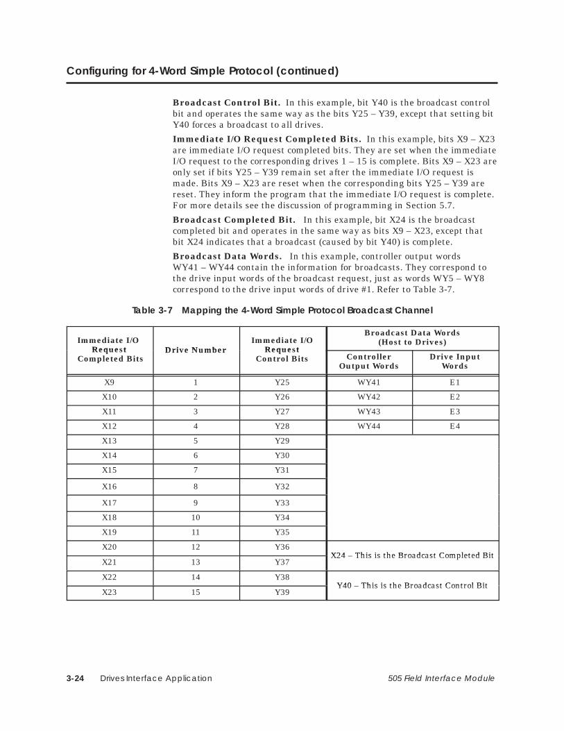
Drives Interface Application3-24 505 Field Interface Module
Configuring for 4-Word Simple Protocol (continued)
Broadcast Control Bit. In this example, bit Y40 is the broadcast controlbit and operates the same way as the bits Y25 – Y39, except that setting bitY40 forces a broadcast to all drives.
Immediate I/O Request Completed Bits. In this example, bits X9 – X23are immediate I/O request completed bits. They are set when the immediateI/O request to the corresponding drives 1 – 15 is complete. Bits X9 – X23 areonly set if bits Y25 – Y39 remain set after the immediate I/O request ismade. Bits X9 – X23 are reset when the corresponding bits Y25 – Y39 arereset. They inform the program that the immediate I/O request is complete.For more details see the discussion of programming in Section 5.7.
Broadcast Completed Bit. In this example, bit X24 is the broadcastcompleted bit and operates in the same way as bits X9 – X23, except thatbit X24 indicates that a broadcast (caused by bit Y40) is complete.
Broadcast Data Words. In this example, controller output wordsWY41 – WY44 contain the information for broadcasts. They correspond tothe drive input words of the broadcast request, just as words WY5 – WY8correspond to the drive input words of drive #1. Refer to Table 3-7.
Table 3-7 Mapping the 4-Word Simple Protocol Broadcast Channel
Immediate I/O Reque t Drive Number
Immediate I/OReque t
Broadcast Data Words(Host to Drives)
Request Completed Bits
Drive Number RequestControl Bits Controller
Output WordsDrive Input
Words
X9 1 Y25 WY41 E1
X10 2 Y26 WY42 E2
X11 3 Y27 WY43 E3
X12 4 Y28 WY44 E4
X13 5 Y29
X14 6 Y30
X15 7 Y31
X16 8 Y32
X17 9 Y33
X18 10 Y34
X19 11 Y35
X20 12 Y36X24 – This is the Broadcast Completed Bit
X21 13 Y37X24 – This is the Broadcast Completed Bit
X22 14 Y38Y40 – This is the Broadcast Control Bit
X23 15 Y39Y40 – This is the Broadcast Control Bit

Drives Interface Application 3-25505 Field Interface Module
Use your programming device to view the I/O Configuration Chart, anexample of which is shown in Figure 3-13. Use SHOW in TISOFT, and notethat only a portion of this information is shown at a time.
• The slot number corresponds to the drive number. This example showsdrive #1, which appears in slot #1.
• Slot #16 is always the Broadcast/Immediate Channel.
• The Drives Interface Application is configured as base #5.
I/O CONFIGURATION CHART FOR : CHANNEL ... 1 BASE ..... 05
Slot 1
I/O POINTS
Slot 2
Slot 5
Slot 6
WX0001 WX0002 WX0003 WX0004 WY0005 WY0006 WY0007 WY0008
Slot 7
Slot 8
Slot 9
Slot 10
Slot 11
Slot 12
Slot 13
Slot 14
Slot 15
1 2 3 4 5 6 7 8
Slot 3
Slot 4
Slot 16
Slot 16
Slot 16
X0009 X0010 X0011 X0012 X0013 X0014 X0015
1 2 3 4 5 6 7 8
X0017 X0018 X0019 X0020 X0021 X0022 X0023 X0024
9 10 11 12 13 14 15 16
Y0026Y0025 Y0027 Y0028
17 18 19 20
X0016
Y0029 Y0030 Y0031 Y0032
21 22 23 24
Slot 16
Slot 16
Y0033 Y0034 Y0035 Y0036 Y0037 Y0038 Y0039
25 26 27 28 29 30 31 32
WY0041 WY0042 WY0043 WY0044
33 34 35 36
Y0040
Figure 3-13 I/O Configuration Chart for 4-Word Simple Protocol
Viewing the I/OConfigurationChart

Drives Interface Application3-26 505 Field Interface Module
3.7 Configuring for 5-Word USS Protocol
After inserting the FIM into the base, update the I/O configuration in thecontroller. The module does not automatically configure itself. TISOFT oranother programming device must be connected to the controller in order toregister and verify communication between the FIM and the controller.
This configuration description uses one drive; the address switch is set todrive #1. It is configured to the sample configuration chart shown inFigure 3-14. These words can be mapped to any valid I/O address; in thisexample, they start at address 1. The broadcast channel begins at address17, indicating that 16 points are used by drive #1, but it also can have anyvalid I/O address. Do not overlap I/O points across different slots.
Slot Number Directly correspondsto drive address.Slot #16 is theBroadcast/ ImmediateChannel.
��� ������ ���������� ��� �2������� �2���� �
�),0 �%%.&// ! � �! �1+$0(,+
��� �1*#&. ,' �(0 "+% �,.% ��� �-&$(")
�
�
�
�
�
�
�����
�����
�����
�����
�����
�����
�����
�����
����
����
����
����
����
����
����
����
�����
�����
�����
�����
�����
�����
�����
�����
��
��
��
��
��
��
��
��
��
��
��
��
��
��
��
��
��
��
��
��
��
��
��
��
��
��
��
��
��
��
��
��
��
��
��
��
��
��
��
��
��
��
��
��
��
��
��
��
��
��
��
��
��
��
�������
�������
�������
�������
�������
�������
�������
�������
�,
�,
�,
�,
�,
�,
�,
�,
� �
Base Number Displays number of the current base and correspondsto number on S1.
I/O Address The drive is logged in as 6 input words(WX) and 6 output words (WY).
SF Module The Field Interface Module isnot an SF Module. The defaultfor this definition is NO.
��
��
��
��
��
�
�
�����
�����
�����
�����
�����
�����
�����
�����
����
����
����
����
����
����
����
����
�����
�����
�����
�����
�����
�����
�����
�����
��
��
��
��
��
��
��
�
��
��
��
��
��
��
��
��
��
��
��
��
��
��
��
�
��
��
��
��
��
��
��
��
��
��
��
��
��
��
��
��
��
��
��
��
��
��
��
��
��
��
��
��
��
�
�������
�������
�������
�������
�������
�������
�������
�������
�,
�,
�,
�,
�,
�,
�,
�,
�� ��
Broadcast/ImmediateMessage control channel
Figure 3-14 Sample I/O Configuration Chart for 5-Word USS Protocol
Updating the I/OConfigurationDefinition
SampleConfiguration

Drives Interface Application 3-27505 Field Interface Module
The Broadcast/Immediate Channel is configured in this example as follows:
Immediate I/O Request Control Bits. In this example, bits Y33 – Y47are immediate I/O request control bits, and correspond to drives 1 – 15.When set, these bits force an immediate I/O request to be sent to thecorresponding drive. Setting bit Y34 forces an interruption in the FieldInterface Module drives update scan, causing a request to be sent todrive #2 immediately. These bits are one-shot and edge-triggered by theDrives Interface Application. For more details, see the discussion ofprogramming in Section 5.7.
The Drives Interface Application, using the 5-Word USS Protocol, isconfigured as 6-word inputs (WX) and 6-word outputs (WY). It occupies 16points of the controller word image register per drive.
The Broadcast/Immediate Control Channel is always in slot #16. It takes up16 discrete input points (X), 16 discrete output points (Y), and 6 word outputpoints (WY). The Broadcast/Immediate Control Channel occupies 40 pointsof controller image register for each Field Interface Module using the DrivesInterface Application. This is because the points must be used in multiplesof 8 when programmed in TISOFT.
Words WX1 – WX6 are input words to the controller. This is the informationreturning from the drive from the previous request. These words mapdirectly to the drive output words DY01 – DY05, as shown in Table 3-8.
Words WY7 – WY12 are output words from the controller. This is therequest data going to the drive. These words map directly to the drive inputwords DX01 – DX05, as shown in Table 3-8.
Table 3-8 Mapping the Controller Words to the Drive Parameter Wordsfor 5-Word USS Protocol
Coming from the Drive(Drive to Host)
Going to the Drive(Host to Drive)
Controller InputWords
Drive OutputWords
ControllerOutput Words
Drive InputWords
WX1 DY01 WY7 DX01
WX2 DY02 WY8 DX02
WX3 DY03 WY9 DX03
WX4 DY04 WY10 DX04
WX5 DY05 WY11 DX05
WX6 WY12
Configuring theBroadcast/ImmediateChannel (5-WordUSS Protocol)
Configuring for5-Word USSProtocol
Broadcast/ Immediate ControlChannel
WX1 – WX6(ControllerInput Words)
WY7 – WY12(Controller OutputWords)

Drives Interface Application3-28 505 Field Interface Module
Configuring for 5-Word USS Protocol (continued)
Broadcast Control Bit. In this example, bit Y48 is the broadcast controlbit and operates the same way as the bits Y33 – Y47, except that settingbit Y48 forces a broadcast to all drives.
Immediate I/O Request Completed Bits. In this example, bitsX17 – X31 are immediate I/O request completed bits. They are set when theimmediate I/O request to the corresponding drives 1 – 15 is complete. BitsX17 – X31 are only set if bits Y33 – Y47 remain set after the immediate I/Orequest is made. Bits X17 – X31 are reset when the corresponding bitsY33 – Y47 are reset. They inform the program that the immediate I/Orequest is complete. For more details see the discussion of programming inSection 5.7.
Broadcast Completed Bit. In this example, bit X32 is the broadcastcompleted bit and operates in the same way as bits X17 – X31, exceptbit X32 indicates that a broadcast (caused by bit Y48) is complete.
Broadcast Data Words. In this example, controller output wordsWY49 – WY54 contain the information for broadcasts. They correspond tothe drive input words of the broadcast request, just as words WY7 – WY12correspond to the drive input words of drive #1. Refer to Table 3-9.
Table 3-9 Mapping the 5-Word USS Protocol Broadcast Channel
Immediate I/OReque t Drive Number
Immediate I/OReque t
Broadcast Data Words(Host to Drives)
Request Completed Bits
Drive Number RequestControl Bits Controller
Output WordsDrive Input
Words
X17 1 Y33 WY49 DX1
X18 2 Y34 WY50 DX2
X19 3 Y35 WY51 DX3
X20 4 Y36 WY52 DX4
X21 5 Y37 WY53 DX5
X22 6 Y38 WY54 Unused
X23 7 Y39
X24 8 Y40
X25 9 Y41
X26 10 Y42
X27 11 Y43
X28 12 Y44X32 – This is the Broadcast Completed Bit
X29 13 Y45X32 – This is the Broadcast Completed Bit
X30 14 Y46Y48 – This is the Broadcast Control Bit
X31 15 Y47Y48 – This is the Broadcast Control Bit

Drives Interface Application 3-29505 Field Interface Module
Use your programming device to view the I/O Configuration Chart, asshown in Figure 3-15. Use SHOW in TISOFT, and note that only a portionof this information is shown at a time.
• The slot number corresponds to the drive number. This example showsdrive #1, which appears in slot #1.
• Slot #16 is always the Broadcast/Immediate Channel.
• The Drives Interface Application is configured as base #5.
Viewing the I/OConfigurationChart
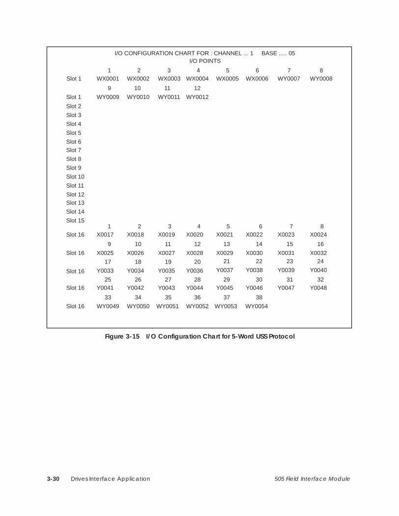
Drives Interface Application3-30 505 Field Interface Module
I/O CONFIGURATION CHART FOR : CHANNEL ... 1 BASE ..... 05
Slot 1
I/O POINTS
Slot 1
Slot 2
Slot 5
Slot 6
WX0001 WX0002 WX0003 WX0004 WX0005 WX0006 WY0007 WY0008
Slot 7
Slot 8
Slot 9
Slot 10
Slot 11
Slot 12Slot 13
Slot 14
Slot 15
1 2 3 4 5 6 7 8
WY0009 WY0010 WY0011 WY0012
9 10 11 12
Slot 3
Slot 4
Slot 16
Slot 16
Slot 16
X0017 X0018 X0019 X0020 X0021 X0022 X00231 2 3 4 5 6 7 8
X0025 X0026 X0027 X0028 X0029 X0030 X0031 X0032
9 10 11 12 13 14 15 16
Y0034Y0033 Y0035 Y0036
17 18 19 20
X0024
Y0037 Y0038 Y0039 Y0040
21 22 23 24
Slot 16
Slot 16
Y0041 Y0042 Y0043 Y0044 Y0045 Y0046 Y004725 26 27 28 29 30 31 32
WY0049 WY0050 WY0051 WY0052 WY0053 WY0054
33 34 35 36 37 38
Y0048
Figure 3-15 I/O Configuration Chart for 5-Word USS Protocol

Drives Interface Application 3-31505 Field Interface Module
3.8 Configuring for 5-Word (Modified) USS Protocol
After inserting the FIM into the base, update the I/O configuration in thecontroller. The module does not automatically configure itself. TISOFT, oranother programming device, must be connected to the controller in order toregister and verify communication between the controller and FIM.
This configuration description uses one drive; the address switch is set todrive #1. It is configured to the sample configuration chart shown inFigure 3-16. These words can be mapped to any valid I/O address. In thisexample, they start at address 1. The broadcast channel begins at address 9,indicating that 8 points are used by drive #1, but it also can have any validI/O address. Do not overlap I/O points across different slots.
Slot Number Directly correspondsto drive address.Slot #16 is theBroadcast/ ImmediateChannel.
��� ������ ���������� ��� �2������� �2���� �
�),0 �%%.&// ! � �! �1+$0(,+
��� �1*#&. ,' �(0 "+% �,.% ��� �-&$(")
�
�
�
�
�
�
�����
�����
�����
�����
�����
�����
�����
�����
����
����
����
����
����
����
����
����
�����
�����
�����
�����
�����
�����
�����
�����
��
��
��
��
��
��
��
��
��
��
��
��
��
��
��
��
��
��
��
��
��
��
��
��
��
��
��
��
��
��
��
��
��
��
��
��
��
��
��
��
��
��
��
��
��
��
��
��
��
��
��
��
��
��
�������
�������
�������
�������
�������
�������
�������
�������
�,
�,
�,
�,
�,
�,
�,
�,
�� ��
Base Number Displays number of the current base and correspondsto number on S1.
I/O Address The drive is logged in as 4 input words(WX) and 4 output words (WY).
SF Module The Field Interface Module isnot an SF Module. The defaultfor this definition is NO.
��
��
��
��
��
�
�
�����
�����
�����
�����
�����
�����
�����
�����
����
����
����
����
����
����
����
���
�����
�����
�����
�����
�����
�����
�����
�����
��
��
��
��
��
��
��
�
��
��
��
��
��
��
��
��
��
��
��
��
��
��
��
�
��
��
��
��
��
��
��
��
��
��
��
��
��
��
��
��
��
��
��
��
��
��
��
��
��
��
��
��
��
��
�������
�������
�������
�������
�������
�������
�������
�������
�,
�,
�,
�,
�,
�,
�,
�,
�� ��
Broadcast/ImmediateMessage Control Channel
Figure 3-16 Sample I/O Configuration Chart for 5-Word (Modified) USSProtocol
Updating the I/OConfigurationDefinition
SampleConfiguration
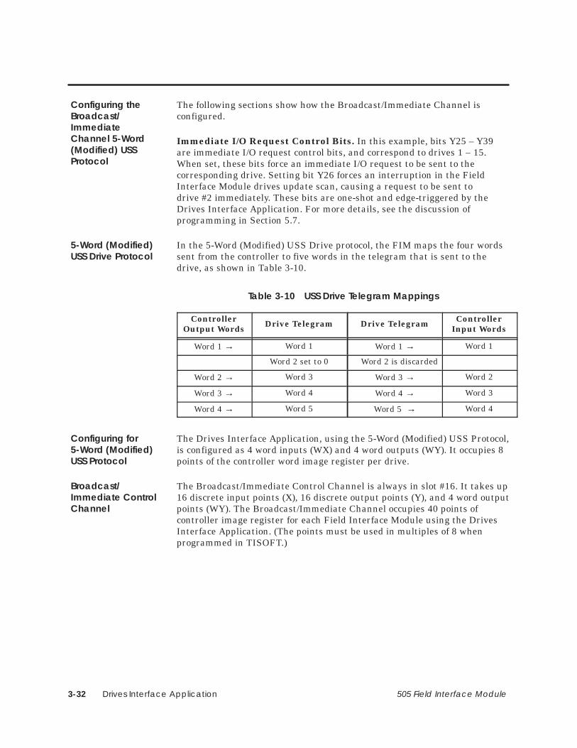
Drives Interface Application3-32 505 Field Interface Module
The following sections show how the Broadcast/Immediate Channel isconfigured.
Immediate I/O Request Control Bits. In this example, bits Y25 – Y39are immediate I/O request control bits, and correspond to drives 1 – 15.When set, these bits force an immediate I/O request to be sent to thecorresponding drive. Setting bit Y26 forces an interruption in the FieldInterface Module drives update scan, causing a request to be sent todrive #2 immediately. These bits are one-shot and edge-triggered by theDrives Interface Application. For more details, see the discussion ofprogramming in Section 5.7.
In the 5-Word (Modified) USS Drive protocol, the FIM maps the four wordssent from the controller to five words in the telegram that is sent to thedrive, as shown in Table 3-10.
Table 3-10 USS Drive Telegram Mappings
ControllerOutput Words Drive Telegram Drive Telegram Controller
Input Words
Word 1 → Word 1 Word 1 → Word 1
Word 2 set to 0 Word 2 is discarded
Word 2 → Word 3 Word 3 → Word 2
Word 3 → Word 4 Word 4 → Word 3
Word 4 → Word 5 Word 5 → Word 4
The Drives Interface Application, using the 5-Word (Modified) USS Protocol,is configured as 4 word inputs (WX) and 4 word outputs (WY). It occupies 8points of the controller word image register per drive.
The Broadcast/Immediate Control Channel is always in slot #16. It takes up16 discrete input points (X), 16 discrete output points (Y), and 4 word outputpoints (WY). The Broadcast/Immediate Channel occupies 40 points ofcontroller image register for each Field Interface Module using the DrivesInterface Application. (The points must be used in multiples of 8 whenprogrammed in TISOFT.)
Configuring theBroadcast/ImmediateChannel 5-Word(Modified) USSProtocol
5-Word (Modified)USS Drive Protocol
Configuring for5-Word (Modified)USS Protocol
Broadcast/Immediate ControlChannel

Drives Interface Application 3-33505 Field Interface Module
Configuring for 5-Word (Modified) USS Protocol (continued)
Words WX1 – WX4 are input words to the controller. This is the informationreturning from the drive from the previous request. These words mapdirectly to the drive output words DY1 – DY5 as shown in Table 3-11.
Words WY5 – WY8 are output words from the controller. This is the requestdata going to the drive. These words map directly to the drive input wordsDX1 – DX5 as shown in Table 3-11.
Table 3-11 Mapping the Controller Words to the Drive Parameter Wordsfor 5-Word (Modified) USS Protocol
Coming from the Drive(Drive to Host)
Going to the Drive(Host to Drive)
Controller InputWords
Drive OutputWords
ControllerOutput Words
Drive InputWords
WX1 DY1 WY5 DX1
00 DY2 Discarded DX2
WX2 DY3 WY6 DX3
WX3 DY4 WY7 DX4
WX4 DY5 WY8 DX5
WX1 – WX4(ControllerInput Words)
WY5 – WY8(Controller OutputWords)

Drives Interface Application3-34 505 Field Interface Module
Broadcast Control Bit. In this example, bit Y40 is the broadcast controlbit and operates the same as the bits Y25 – Y39, except that setting bit Y40forces a broadcast to all drives.
Immediate I/O Request Completed Bits. In this example, bits X9 – X23are immediate I/O request completed bits. They are set when the immediateI/O request to the corresponding drives 1 – 15 is complete. Bits X9 – X23 areonly set if bits Y25 – Y39 remain set after the immediate I/O request ismade. Bits X9 – X23 are reset when the corresponding bits Y25 – Y39 arereset. They inform the program that the immediate I/O request is complete.For more details, see the discussion of programming in Section 5.7.
Broadcast Completed Bit. In this example, bit X24 is the broadcastcompleted bit and operates in the same way as bits X9 – X23, except bit X24indicates that a broadcast (caused by bit Y40) is complete.
Broadcast Data Words. In this example, controller output wordsWY41 – WY44 contain the information for broadcasts. They correspond tothe drive input words of the broadcast request, just as words WY5 – WY8correspond to the drive input words of drive #1. Refer to Table 3-12.
Table 3-12 Mapping 5-Word (Modified) USS Protocol Broadcast Channel
Immediate I/O Reque t Drive Number
Immediate I/OReque t
Broadcast Data Words(Host to Drives)
RequestCompleted Bits
Drive Number RequestControl Bits Controller
Output WordsDrive Input
Words
X9 1 Y25 WY41 DX1
X10 2 Y26 WY42 DX3
X11 3 Y27 WY43 DX4
X12 4 Y28 WY44 DX5
X13 5 Y29
X14 6 Y30
X15 7 Y31
X16 8 Y32
X17 9 Y33
X18 10 Y34
X19 11 Y35
X20 12 Y36X24 – This is the Broadcast Completed Bit
X21 13 Y37X24 – This is the Broadcast Completed Bit
X22 14 Y38Y40 – This is the Broadcast Control Bit
X23 15 Y39Y40 – This is the Broadcast Control Bit

Drives Interface Application 3-35505 Field Interface Module
Configuring for 5-Word (Modified) USS Protocol (continued)
Use your programming device to view the I/O Configuration Chart, asshown in Figure 3-17. Use SHOW in TISOFT, and note that only a portionof this information is shown at a time.
• The slot number corresponds to the drive number. This example showsdrive #1 which appears in slot #1.
• Slot #16 is always the Broadcast/Immediate Channel.
• The Drives Interface Application is configured as base #5.
Viewing the I/OConfigurationChart

Drives Interface Application3-36 505 Field Interface Module
I/O CONFIGURATION CHART FOR : CHANNEL ... 1 BASE ..... 05
Slot 1
I/O POINTS
Slot 2
Slot 5
Slot 6
WX0001 WX0002 WX0003 WX0004 WY0005 WY0006 WY0007 WY0008
Slot 7
Slot 8
Slot 9
Slot 10
Slot 11
Slot 12
Slot 13
Slot 14
Slot 15
1 2 3 4 5 6 7 8
Slot 3
Slot 4
Slot 16
Slot 16
Slot 16
X0009 X0010 X0011 X0012 X0013 X0014 X0015
1 2 3 4 5 6 7 8
X0017 X0018 X0019 X0020 X0021 X0022 X0023 X0024
9 10 11 12 13 14 15 16
Y0026Y0025 Y0027 Y0028
17 18 19 20
X0016
Y0029 Y0030 Y0031 Y0032
21 22 23 24
Slot 16
Slot 16
Y0033 Y0034 Y0035 Y0036 Y0037 Y0038 Y0039
25 26 27 28 29 30 31 32
WY0041 WY0042 WY0043 WY0044
33 34 35 36
Y0040
Figure 3-17 I/O Configuration Chart for 5-Word (Modified) USS Protocol

Drives Interface Application 3-37505 Field Interface Module
3.9 Programming
The Field Interface Module drives update scan is asynchronous with respectto the controller scan. The drive scan is generally much longer than thecontroller scan, so several controller scans usually occur for each drive scan.This depends on the number of drives present, the baud rate of the drives,the protocol, and, of course, the scan time of the controller.
• For typical drive scan times, see Table 3-13 for the 10-Word SimpleProtocol, Table 3-14 for the 10-Word USS Protocol, Table 3-15 for4-Word Simple or 5-Word (Modified) USS Protocol, and Table 3-16 for5-Word USS Protocol. The default scan time of some drives may exceeddrive scan times at lower baud rates. To operate at these baud rates,you must disable the scan timeout of the drive. Refer to your drivemanual for more information.
• The drives update scan sends messages to all drives that are bothcorrectly configured and communicating with the Field InterfaceModule. The scan begins with the lowest-numbered drive and proceedsto the next higher-numbered drive until all present and configureddrives are updated. At the end of a scan, one drive, either not presentor improperly configured, is polled to determine its status. Drives thatbegin to communicate are automatically brought online if they areproperly configured. This is known as “dynamic login.”
Table 3-13 Typical Drive Scan Times for 10-Word Simple Protocol
Number ofDrives
Scan Time at4800 Baud
(MS)
Scan Time at9600 Baud
(MS)
Scan Time at19200 Baud
(MS)
Scan Time at38400 Baud
(MS)
1 266 135 68 37
2 400 203 102 54
3 533 272 137 73
4 666 339 171 91
5 800 408 206 110
6 932 476 240 128
7 1068 544 273 145
8 1204 612 308 164
9 1337 680 342 182
10 1470 748 377 199
11 1603 817 410 218
12 1737 884 443 236
13 1874 952 481 254
14* 1999 1022 514 273
15* 2008 1020 511 272
* The scan time for 15 drives is similar to the scan time for 14 drives. This isbecause there is no polling of drives when all 15 drives are configured andcommunicating properly.
Drives UpdateScan

Drives Interface Application3-38 505 Field Interface Module
Table 3-14 Typical Drive Scan Times for 10-Word USS Protocol
Number ofDrives
Scan Time at4800 Baud
(MS)
Scan Time at9600 Baud
(MS)
Scan Time at19200 Baud
(MS)
Scan Time at38400 Baud
(MS)
1 271 137 69 37
2 407 206 103 54
3 541 276 138 73
4 677 344 173 91
5 814 414 208 110
6 945 483 243 129
7 1078 552 276 146
8 1224 622 312 165
9 1360 691 346 183
10 1495 760 382 200
11 1630 830 415 219
12 1767 898 449 237
13 1906 967 487 256
14* 2033 1038 522 275
15* 2042 1037 519 274
* The scan time for 15 drives is similar to the scan time for 14 drives. This isbecause there is no polling of drives when all 15 drives are configured andcommunicating properly.

Drives Interface Application 3-39505 Field Interface Module
Programming (continued)
Table 3-15 Typical Drive Scan Times for 4-Word Simple
Number ofDrives
Scan Time at4800 Baud
(MS)
Scan Time at9600 Baud
(MS)
Scan Time at19200 Baud
(MS)
Scan Time at38400 Baud
(MS)
1 129 66 35 20
2 193 100 54 28
3 257 133 71 37
4 322 166 90 48
5 387 200 106 56
6 453 234 125 67
7 518 265 142 76
8 583 301 162 84
9 646 332 178 93
10 711 366 196 103
11 775 397 215 112
12 842 432 230 122
13 906 464 249 132
14* 971 496 268 138
15* 973 495 267 140
* The scan time for 15 drives is similar to the scan time for 14 drives. This isbecause there is no polling of drives when all 15 drives are configured andcommunicating properly.

Drives Interface Application3-40 505 Field Interface Module
Table 3-16 Typical Drive Scan Times for 5-Word USS Protocol and 5-Word(Modified)
Number ofDrives
Scan Time at4800 Baud
(MS)
Scan Time at9600 Baud
(MS)
Scan Time at19200 Baud
(MS)
Scan Time at38400 Baud
(MS)
1 134 68 36 20
2 199 103 55 28
3 266 137 73 37
4 333 171 92 48
5 401 206 109 56
6 469 241 128 68
7 536 273 146 77
8 603 310 166 85
9 669 342 183 93
10 736 377 201 104
11 802 409 221 114
12 872 446 236 124
13 938 478 256 134
14* 1005 511 275 140
15* 1007 510 274 142
* The scan time for 15 drives is similar to the scan time for 14 drives. This isbecause there is no polling of drives when all 15 drives are configured andcommunicating properly.

Drives Interface Application 3-41505 Field Interface Module
Programming (continued)
When the broadcast request bit is set, the drive scan is interrupted. Thedata in the WY words of the broadcast channel are sent to all the drivesusing the broadcast address (32) defined by the 10-Word/4-Word Simple or10-Word/5-Word USS protocol. The broadcast has no response datareturning from the drives.
Broadcast requests are used to synchronize actions such as starting orjogging the motors simultaneously. If broadcasts are not used, it may beseveral seconds before all drives are updated, depending on the number ofdrives and baud rate. All drives receive broadcast messages.
! CAUTIONIf bits in the controller output words (RUN, JOG, etc.) do not correspond todrive input words, subsequent update scans may cancel requests performed bythe broadcast.
If broadcast requests are canceled, synchronizing operations do not occur .
To prevent subsequent update scans from canceling broadcast requests, yourprogram must set bits (like RUN, JOG, etc.) in the controller output wordscorresponding to drive input words.
There is no response to a broadcast. If the program needs to know whetheror not the broadcast message was received, then it must poll the drives todetermine if the request sent by the broadcast was executed.
! WARNINGConnecting drives with either address 0, or with addresses greater than 15, andalso sending a broadcast, could start a drive operation that the Field InterfaceModule cannot stop. The Field Interface Module does not update these drives,but all drives receive the broadcast.
Using drive addresses other than 1 through 15 could cause death or seriousinjury to personnel, and/or damage to equipment.
Do not use drive addresses other than 1 through 15.
Broadcast Request

Drives Interface Application3-42 505 Field Interface Module
Here are the steps for the broadcast-request procedure.
1. Reset the broadcast-request bit for at least one controller scan.
2. Set the controller output words (WY) in channel #16 to the desiredrequest values.
3. On the same scan in ladders, set the corresponding control bits/datainto each of the controller output words affected by the broadcast. Thisprevents cancellation of the request by subsequent updates of thenormal drive scan.
4. Set the broadcast-request bit.
5. This request may be repeated by resetting this control bit and setting itagain on another scan of ladders.
6. The broadcast is complete when the broadcast-complete bit is set.
NOTE: If the broadcast-request bit remains set after the request is made,the broadcast-complete bit is set. If you do not use the broadcast completebit to determine if the broadcast message has completed, you must wait atleast five message times before attempting to send another broadcastmessage. This message time may be obtained from the typical drive scantimes found in Table 3-13, Table 3-14, Table 3-15, and Table 3-16. Use theentry of 4 drives at your baud rate and add one drive time for everyimmediate I/O request that may occur simultaneously with this message.
7. Reset the broadcast-request bit.
Once the immediate I/O requests are complete, the immediate I/O requestcompleted bits are set if the original immediate I/O request bits are still set.
BroadcastProcedure

Drives Interface Application 3-43505 Field Interface Module
Programming (continued)
The normal drive update scan can take several seconds, depending on thenumber of drives, the selected protocol, and the baud rate. When a driveneeds to be updated faster than normal drive scan time allows, animmediate I/O request may be sent. Immediate I/O requests are made toone or more drives by setting the immediate I/O request control bitcorresponding to the drive. This immediate I/O request is sent typicallywithin one message transmit time.
Once the immediate I/O request message is sent, the response data isimmediately updated in controller input words. This allows the rapid poll ofdata by external devices, and the immediate response of requests such asjogging or stopping the motor.
If immediate I/O requests are sent to more than one drive, an immediate I/Orequest is first sent to the lowest-numbered drive, followed by an immediateI/O request to the next higher-numbered drive, until all the immediate I/Orequests are sent. If a broadcast request is made with immediate I/Orequests, the broadcast request is sent first. After all immediate I/Orequests are sent, the drive update scan resumes as normal. The immediateI/O request bits are edge-triggered and one-shot. They must be reset for onecontroller scan before the immediate I/O request for that drive is sent again.
Follow these steps to initiate an immediate I/O request.
1. Reset the immediate I/O request bit corresponding to the desired drive,for at least 1 controller scan.
2. Set the controller output data words (WY) to the desired value.
3. Set the immediate I/O request bit that corresponds to the desired drive.
4. This immediate I/O request can be repeated by resetting the immediateI/O request bit and setting it again on alternate controller scans.
The immediate I/O request is complete when the correspondingimmediate I/O request complete bit is set. This bit is only set if theoriginal immediate I/O request bit is still set.
The controller input words (WX) now reflect the response of the drive whenthe immediate I/O request was made.
Immediate I/ORequest
Immediate I/ORequest Procedure

Drives Interface Application3-44 505 Field Interface Module
NOTE: If the immediate I/O-request bit remains set after the request ismade, the immediate I/O-complete bit is set. If you do not use the immediateI/O complete bit to determine if the immediate I/O message has completed,you must wait at least five message times before attempting to send anotherimmediate I/O message. This message time may be obtained from thetypical drive scan times found in Table 3-13, Table 3-14, Table 3-15, andTable 3-16. Use the entry of four drives at your baud rate and add one drivetime for every immediate I/O request or broadcast that may occursimultaneously with this message.
NOTE: The response data words (WX) for immediate I/O request do notreflect the response of the parameter request sent to the drive. It doesreflect what the drive returned when the request was made. Some requeststo the drive take more time for the drive to process, and it may take severalrepeated requests to complete. When the drive has completed the request,the response parameter number is the same as the original request. Refer toyour drive manual for more information on the drive parameterprogramming.
Once configuration is complete, checks to controller status words allow themonitoring of communication to each drive. The drives appear as modules ina base, so in the example configuration shown in Section 3.4, the FieldInterface Module running the Drive Interface Application is set to base #5.The channel number is set to 1, which is the only channel in a 545controller.
Since this example uses base #5, controller status word 16 (STW16) is thecorresponding word containing the status bits. There is one status bit foreach drive. These bits are set by the controller as soon as a loss ofcommunication to that drive is detected. These bits are also set if drives areconfigured incorrectly, corresponding to the drive(s) that do not match.
Slot #16 is occupied by the Drives Interface Application broadcast channelthat takes up the most significant bit. By monitoring this bit, any change inthe drive communication path may be detected by the user program and theproper action can be taken.
ProgrammingDrives
Drives Interface Application 3-45505 Field Interface Module
Programming (continued)
! CAUTIONThe Drives Interface Application does not monitor the drives for internal faults.
If the drive continues to communicate, then the Drives Interface Applicationassumes that the drive is good. You must sample drive status bits, inconjunction with controller status word bits, to ensure that the program detectsreported failures.
Refer to your drives manual for more details on error reporting by the drive.
Drive Motion Control. Although you may modify any drive parameterfrom the controller using the Drives Interface Application, most of theprogram interface to drives deals with direction control and speedadjustments. Varying the speed of most drives involves only changing thecontroller output word (WY) that corresponds to the drive input word forspeed reference. This provides a simple interface to ladder programs ofpowerful loop controls of controllers.
Changing Drive Parameters. To change a parameter in the drive, set theparameter value in the controller output word corresponding to the driveparameter value input word. The change request bit must also be set;otherwise the parameter will be read, not changed.
On the same ladder scan, set the desired change parameter for the numberin the controller output word that corresponds to the drive input word thatholds the parameter number of the request. Update of this new request isautomatic, and the program can poll the controller input word (WX) thatcorresponds to the parameter number of the drive response.
When the parameter number and the parameter value match the originalrequest, the request has been accepted by the drive and is complete.
Reading Drive Parameters. Drive parameters are read in the same wayas they are changed above, except the parameter is set for requests insteadof changes. Refer to your drive manual for more information on the driveprogramming requirements.
Typical DriveProgramming

Drives Interface Application3-46 505 Field Interface Module
When the controller input word (WX) corresponding to the drive outputword that contains the parameter number matches the original parameterword, then the controller input word corresponding to the drive parametervalue output word contains the value of the requested parameter.
Although you may modify and fine tune almost all drive parametersthrough the Drives Interface Application, most programming consists ofcontrolling the speed and direction of the motor. A simplified procedure foroperating a drive follows.
1. Set the controller output word that corresponds to the drive speed to avalue of zero.
2. Reset the stop bits, and set the run bit and the direction bit of thecontroller output word that corresponds to the control word of thedrive.
3. Increase the controller output word that corresponds to the speedreference; the motor speed should increase accordingly. Refer to yourdrive manual for more details on programming drives.
Typical DriveProgram

Drives Interface Application 3-47505 Field Interface Module
3.10 Drives Troubleshooting
Common troubleshooting symptoms, causes, and corrective actions areshown in Table 3-17.
Table 3-17 Troubleshooting the Field Interface Module Using LEDs
Symptom Probable Cause Corrective Action
Re-seat board.
No power to board.
Check for bent pins on boardconnector.
MOD GOOD OffNo power to board.
Check base power supply.MOD OOD Off
Check switch settings.
Bad module, faileddiagnostics.
Return module for repair.
COMM OffBroken cable on Port 1. Repair or replace cable.
COMM OffController not powered up. Power up controller.
Broken cable on Port 1. Repair or replace cable.
CFG Off
Base address set to 0 oncontroller with local base.
Set base address correctly.CFG Off
Base not configured. Configure base.
Base disabled. Enable base
Configured incorrectly. Reconfigure correctly.
Broken cable on Port 2. Repair or replace cable.
Wrong base number selectedon switch S1.
Set S1 to the correct basenumber.
CFG Blinking
Wrong drive number selectedon drive.
Refer to your drive manual forsetting the drive address.CFG Blinking
Wrong baud rate. Set all drives the same.
Wrong protocol selected onswitch S2.
Set to proper protocol.
Drive(s) not powered up. Power up all drives.
Drive failure. Repair or replace drive.
Use TISOFT to check the operation of the module. If you experienceproblems communicating with the SIMOREG or SIMOVERT drives, you canread the base status through TISOFT. The base status indicates propercommunication to individual drives by the presence of I/O points in the slotnumber corresponding to the drive address. I/O points in slot #16 indicategood communication between the Drives Interface Application of the FieldInterface Module and the controller.
Checking theOperation of theModule

Drives Interface Application3-48 505 Field Interface Module
For the 10-Word Simple and 10-Word USS Protocol:
• If the controller is communicating properly to the Drives InterfaceApplication, slot #16 contains 16 discrete input (X), 16 discrete output(Y), and 10 word output (WY) points when base status is read.
• Good communication to individual drives is indicated by the presence of10 word input (WX) and 10 word output (WY) points in the slot numbercorresponding to the drive address switch selection.
• Read the controller status words to determine I/O presence and thecorrect configuration of the Field Interface Module. See Table 3-18 andTable 3-19 for bit mapping.
For the 4-Word Simple and 5-Word (Modified) USS Protocol:
• If the controller is communicating properly to the Drives InterfaceApplication, slot #16 will contain 16 discrete input (X), 16 discreteoutput (Y), and 4 word output (WY) points when base status is read.
• Good communication to individual drives is indicated by the presence of4 word input (WX) and 4 word output (WY) points in the slot numberthat corresponds to the drive address switch selection.
• Read the controller status words to determine I/O presence and thecorrect configuration of the Field Interface Module. See Table 3-18 andTable 3-19 for bit mapping.
10-Word Simpleand 10-Word USSProtocol
4-Word Simple and5-Word (Modified)USS Protocol

Drives Interface Application 3-49505 Field Interface Module
Drives Troubleshooting (continued)
For the 5-Word USS Protocol:
• If the controller is communicating properly to the Drives InterfaceApplication, slot #16 contains 16 discrete input (X), 16 discrete output(Y), and 6 word output (WY) points when base status is read.
• Good communication to individual drives is indicated by the presence of6 word input (WX) and 6 word output (WY) points in the slot numberthat corresponds to the drive address switch selection.
• Read the controller status words to determine I/O presence and thecorrect configuration of the Field Interface Module. See Table 3-18 andTable 3-19 for bit mapping.
Table 3-18 shows status bits for monitoring status between the controllerand the Field Interface Module for the selected base number on the FieldInterface Module. Note that the status words for monitoring status betweenthe Field Interface Module and the drives is also shown in this table.
Bit number to drive number correlation to these status words is shown inTable 3-19, using base 5 as an example.
Table 3-18 Controller-to-Field Interface Module (FIM) CommunicationStatus Using Controller Status Words
FIMBase #
Controller to FIM Communication Status Bit
Status Word for FIM to Drive
Communication Status
0 STW2 – Bit #16 – (least significant bit) STW11
1 STW2 – Bit #15 STW12
2 STW2 – Bit #14 STW13
3 STW2 – Bit #13 STW14
4 STW2 – Bit #12 STW15
5 STW2 – Bit #11 STW16
6 STW2 – Bit #10 STW17
7 STW2 – Bit #9 STW18
8 STW2 – Bit #8 STW19
9 STW2 – Bit #7 STW20
10 STW2 – Bit #6 STW21
11 STW2 – Bit #5 STW22
12 STW2 – Bit #4 STW23
13 STW2 – Bit #3 STW24
14 STW2 – Bit #2 STW25
15 STW2 – Bit #1 – (most significant bit) STW26
5-Word USSProtocol

Drives Interface Application3-50 505 Field Interface Module
Table 3-19 Monitoring Field Interface Module (FIM) to DriveCommunication Status Using Controller Status Words
Drive Address #FIM to Drive
Communication Status Bit (Using the Base 5 Example*)
1 STW16 – Bit #16 – (least significant bit)
2 STW16 – Bit #15
3 STW16 – Bit #14
4 STW16 – Bit #13
5 STW16 – Bit #12
6 STW16 – Bit #11
7 STW16 – Bit #10
8 STW16 – Bit #9
9 STW16 – Bit #8
10 STW16 – Bit #7
11 STW16 – Bit #6
12 STW16 – Bit #5
13 STW16 – Bit #4
14 STW16 – Bit #3
15 STW16 – Bit #2
FIM Broadcast Immediate Channel STW16 – Bit #1 – (most significant bit)* The number of the status word is determined by adding 11 to the number of thebase; hence the status word for base 5 is STW16.
If you need additional help with drive problems, call your distributor, or callthe Siemens Energy & Automation, Inc., Drives Technical Support Hotlineat 1–770–740–3000.
TechnicalAssistance

Drives Interface Application 3-51505 Field Interface Module
3.11 SIMOREG/SIMOVERT Applications
Each Field Interface Module supports any one (but only one at a time) of thefollowing six drive protocols.
• 4-word Simple Protocol (all 4 words available to the controller)
• 10-word Simple Protocol (all 10 words available to the controller)
• 5-word (Modified) USS Protocol (only 4 words available to thecontroller; word #2 removed)
• 5-word USS Protocol (all 5 words available to the controller)
• 10-word USS Protocol (all 10 words available to the controller)
• PROFIBUS-DP (PROFIBUS-DP is the latest version of the SiemensEnergy & Automation, Inc., L2-DP. The FIM only supports portions ofthe older L2-DP.)
! WARNINGThis equipment contains hazardous voltages and hazardous rotatingmechanical parts.
Failure to follow the safety , start-up, and installation considerations describedin the drive instruction manual can result in death, serious injury , and/orproperty damage.
Follow the instructions in this manual as well as the instructions in the manualfor your drive. Systems Integrators must read and understand the instructionmanuals for the SIMA TIC 505 Field Interface Module and all Siemens variablespeed drives and all option boards that are used in the system.
FIM Drive Protocols

Drives Interface Application3-52 505 Field Interface Module
The following SIMOVERT models are supported:
• SIMOVERT P 6SE12 uses the Z2006 option board. The Z2006 optionboard uses 10-word simple protocol or USS protocol with avariable-length telegram that can be set up for either five or ten words.
PROFIBUS-DP uses the CS51 or CB24 option board. The CS51 can beused alone or in conjunction with the Z2006 technology board. Thenewer CB24 option board can also be used only if the Z2006 technologyboard is also used.
• SIMOVERT P 6SE21. The base unit has an RS-485 serial port thatuses 4-word simple protocol or 5-word USS protocol.
• SIMOVERT P 6SE30 (MICROMASTER).The base unit has an RS-485 serial port that uses 5-word USS protocol.
The PROFIBUS MICROMASTER has a built-in PROFIBUS-DP port.
• SIMOVERT 6SE31 (MICRO/MIDIMASTER). The base unit has a RS-485 serial port that uses 5-word USS protocol.
PROFIBUS-DP: the OPmP optional device must be used. When theOPmP device is used, the USS protocol on the base unit becomesinoperable.
• SIMOVERT P PM.The base unit has a RS-485 serial port that uses 10-word USS protocol.
PROFIBUS-DP: the SS13381 optional board must be used.
• SIMOVERT 6SE70 Master Drive. The base unit has one (on the FCand SC models) or two (on the VC model) standard RS-485 serialport(s) that use USS protocol with a variable-length telegram that canbe set up for either five or ten words.
An optional serial communication board (SCB2) can be added. Theserial port on the SCB2 uses USS protocol with a variable lengthtelegram that can be set up for either five or ten words.
PROFIBUS-DP uses the CB1 option board.
• SIMOVERT P 6SE85 uses the SI3 option board. The S13 uses 4-wordsimple protocol.
PROFIBUS-DP uses the S13 option board.
Table 3-20, on page 3-54, lists specific models and the section of this manualwhere they are described.
AC DrivesSupported

Drives Interface Application 3-53505 Field Interface Module
SIMOREG/SIMOVERT Applications (continued)
Third generation SIMOREG models (also known as SIMOREG 6RA22) havethe following requirements:
• One of the following option boards must be used:Z1005 or Z1006 or Z1011 (all use 10-word simple protocol).
Fourth generation SIMOREG 6RA24 models have the followingrequirements:
• The base unit has a RS-485 serial port that uses USS protocol with avariable-length telegram that can be set up for either five or ten words.
• If an optional Z2006 technology board is already attached, it may beadvantageous to use the serial port on the Z2006. The Z2006 uses10-word simple protocol or USS protocol with a variable-lengthtelegram that can be set up for either five or ten words.
• PROFIBUS-DP uses the CB24 or CS51 option board. The CB24 can beused alone or in conjunction with the Z2006 technology board. TheCS51 can be used alone or with the Z2006 Technology board.
DC DrivesSupported

Drives Interface Application3-54 505 Field Interface Module
Table 3-20 lists specific models and the section of this manual where theyare described.
Table 3-20 Specific Wiring and Setup Information
Model Section
SIMOREG 6RA24 3.12
SIMOVERT 6SE21 3.13
SIMOVERT 6SE30/6SE31 MICROMASTER and MIDIMASTER 3.14
SI3 (6SE85 Serial Interface Board) 3.15
Z1005 (Digital Interface Board) 3.16
Z1006 (Coordinated Drive Interface Board) 3.17
Z1011 (Serial Interface Board) 3.18
Z2006 (6SE12 or 6RA24 Technology Board) 3.19
6SE70 (Master Drive Models FC and SC) 3.20
6SE70 (Master Drive Model VC) 3.21
SCB2 (Master Drive Serial Communications Board) 3.22

Drives Interface Application 3-55505 Field Interface Module
3.12 Setting Up and Wiring 6RA24
You can use any hardware version of the SIMOREG 6RA24; use softwareversion 2.00 or later.
The parameters required to set up the 6RA24 are as follows:
P780 must be set to 1192, which selects USS protocol with an 11-bit frame with even parity.
P781 sets the number of process data (PZD) words. The sum of parameters P781 + P782 must be five if 5-word USS protocol is selected on the FIM, or ten if 10-word USS protocol is selected on the FIM.
P782 sets the number of PKW words used for parameter data to either zero or three. The sum of parameters P781 + P782 must be five if 5-word USS protocol is selected on the FIM, or ten if 10-word USS protocol is selected on the FIM.
P783 is normally set to 38,400 baud unless some other drive requires a lower baud rate.
P784 is set based on the 6RA24 Instruction Book and the specific application.
P786 must be set to the individual drive address.
P787 initially is set to zero, which turns off the drive telegram-monitoring function. After the network is operating, decide whether or not to turn on the drive telegram-monitoring function by setting P787 to a non-zero value.
Required Hardwareand Software
RequiredParameters

Drives Interface Application3-56 505 Field Interface Module
After the above parameters have been changed, the drive should be powereddown for at least 10 seconds and then powered back on. This power cyclingallows the drive to initialize communications with the FIM.
NOTE: Unlike some Siemens variable speed drives, the 6RA24 will notautomatically be controlled by serial communications when wired andset up according to this document; it will only communicate. The processdata selection (also refer to P781) defines the control word, status word,setpoints, and actual values for the interface. Definition of the process datasection is very flexible. Individual input, output, and control functions mustbe set (parameterized) for use with serial communications. It is beyond thescope of this document to describe all of the functions and how to set(parameterize) them. Section 10.8 of the 6RA24 Instruction Book describesthe control word, status word, setpoints, and actual values structures, and itis imperative that this section be read and understood completely beforeattempting to control a 6RA24 with a FIM module.

Drives Interface Application 3-57505 Field Interface Module
Setting Up and Wiring 6RA24 (continued)
The following example describes how to assign the Main Control Word andSpeed Setpoint functions to the FIM.
On a Factory Default 6RA24 SIMOREG, these control functions are setto local wired inputs, not to serial port 0.
In order to control the Main Control Word function from port 0 of thedrive (communicating by USS protocol to the FIM), parameter P640must be set to 20. This sets the source of the standard control word toPZD word 1 of the telegrams on serial port 0 (USS). PZD word 1 is word1 of the PLC data area if parameter P782 (see above) is set to 0. PZDword 1 is word 4 of the PLC data area if parameter P782 (see above) isset to 3 (words 1, 2, and 3 are PKW words).
The same concepts apply to the Speed Setpoint signal. In order tocontrol the Speed Setpoint from port 0 of the drive (communicating byUSS protocol to the FIM), parameter P628.0 must be set to 21. Thissets the source of the Speed Setpoint to PZD word 2 of the telegrams onserial port 0 (USS).
In order for the motor to start, the run enable (terminal #37) and theregulator enable (terminal #38) on the base 6RA24 unit must be on.Before parameter P640 was changed, these terminals directlycontrolled the motor. Now they are treated as enable signals.
After P640 is set to 20, Figure 3-18 describes the function of eachcontrol bit in PZD word 1 of the information sent to the drive.

Drives Interface Application3-58 505 Field Interface Module
15 14 13 12 11 10 9 8 7 6 5 4 3 2 1 0
High byte Low byte
1 = Start0 = STOP1 (Normal Stop)0 = STOP2 (Coast Stop)0 = STOP3 (Quick Stop)
1 = Regulators Enable
1 = Ramp Generator Enable
1 = Ramp Generator is not held
1 = Reference Enable
1 = Fault Reset
Not used
Not used
Not used
Not used
Not used
Not used
Not used
Not used
Note: A suggested initial value of PZD word 1 is 007E hex. PZD word 1 can be changed to 007F hex to start the drive.
Figure 3-18 Control Bits for Main Control Word and Speed Setpoint
Also, drive status and feedback (or actual value) information such as motorspeed and other information must be set (parameterized) to the appropriatedestination in order to be read by the FIM module. Section 10.8 of the6RA24 Instruction Book also explains the details.

Drives Interface Application 3-59505 Field Interface Module
Setting Up and Wiring 6RA24 (continued)
The following example describes how to access the Standard Status Wordand Speed Feedback from the FIM:
On a Factory Default 6RA24 SIMOREG, these return informationwords are set to 0. In order to access the standard status word in PZDword 1 from port 0 of the drive (communicating by USS protocol to theFIM), parameter P784.0 must be set to 325. This selects what will bereturned in PZD word 1 of the telegrams on serial port 0 (USS). PZDword 1 is word 1 of the PLC data area if parameter P782 (see above) isset to 0. PZD word 1 is word 4 of the PLC data area if parameter P782(see above) is set to 3 (words 1, 2, and 3 are PKW words).
The same concepts apply to the Speed Feedback (Actual Value) signal.In order to access the Speed Feedback in PZD word 2 from port 0 (USS)(the FIM), parameter P784.1 must be set to 167. This selects what willbe returned in PZD word 2 of the telegrams on serial port 0 (USS).
After P784.0 is set to 325, Figure 3-19 describes the function of eachstatus bit in PZD word 1 of the return information from the drive.
15 14 13 12 11 10 9 8 7 6 5 4 3 2 1 0
High byte Low byte
1 = Ready to start (operating status o7)
1 = Operate enable is present1 = Drive running
1 = Drive fault present
0 = STOP2 (Coast stop command present)
0 = STOP3 (Quick stop command present)
1 = Drive blocked
1 = Drive warning present
1 = Speed controller error within the tolerance band
1 = Serial operation allowed0 = Serial operation blocked – local operation only1 = Speed > nbase (P373)
Future – this may not always be zero
Future – this may not always be zero
Future – this may not always be zero
Future – this may not always be zero
Future – this may not always be zero
Figure 3-19 Status Bits for Standard Status Word and Speed Feedback

Drives Interface Application3-60 505 Field Interface Module
The applicable jumpers follow.
XJ3 Figure 3-20 and Figure 3-21 show the correct position of this jumper.
XJ4 Figure 3-20 and Figure 3-21 show the correct position of this jumper.
XJ5 Figure 3-20 and Figure 3-21 show the correct position of this jumper.
The 5-word USS protocol implementation used by the FIM allows all fivewords of data to be manipulated by the Series 505 programmable controller.The FIM uses a 10-word USS protocol implementation that allows all tenwords of data to be manipulated by the Series 505 programmable controller.
The FIM uses a 5-word (Modified) USS protocol implementation that onlyallows four words of data to be manipulated by the Series 505programmable controller. The second word of the 5-word (Modified) USSprotocol telegram sent to the drives is always set to zero. The second wordof the 5-word (Modified) USS protocol received from the drives is notavailable to the controller.
• The FIM maps the first word sent from the controller into the firstword of the 5-word (Modified) USS protocol telegram sent to the drive.
• The FIM always sends a zero as the second word of the 5-word(Modified) USS protocol telegram to the drive.
• The FIM maps the second word sent from the controller into the thirdword of the 5-word (Modified) USS protocol telegram sent to the drive.
• The FIM maps the third word sent from the controller into the fourthword of the 5-word (Modified) USS protocol telegram sent to the drive.
• The FIM maps the fourth word sent from the controller into the fifthword of the 5-word (Modified) USS protocol telegram sent to the drive.
• A similar technique is used to map the 5-word (Modified) USS protocolreply telegram from the drive into the 4-word reply in the controller.
NOTE: To avoid the complexities of the 5-word (Modified) USS protocol,simply use either the standard 5-word or else 10-word protocol.
Use dipswitch S3 to set the extra delay to 0 milliseconds.
Required Jumpers
USS Protocols
Setting FIMAdditional Delay

Drives Interface Application 3-61505 Field Interface Module
Setting Up and Wiring 6RA24 (continued)
Figure 3-20 shows the wiring for all drives except the end of the bus for the6RA24.
NOTE: Use shielded, twisted, control cable and connect the shields toground at both ends. Be sure that the chassis of the Field Interface Moduleis grounded and at the same potential as all of the grounded drive chassis.Do not exceed 1,000 meters for RS-485 connections.
8
X500Female
TX+/RX+
TX–/RX–
*3
*8
RS-485Transceiver(RX/TX)
6
*1
+5V
GND
First Drive Field Interface Module
390 ohmpull-up resistor220 ohmtermination resistor390 ohmpull-down resistor
(3)
(8)
TX+/RX+
TX–/RX– To next drive
TX+/RX+
TX–/RX–
3RS-485Transceiver(RX/TX)
390ohm
+5V1
2
3JumperXJ5
1
2
3
3
2
1
JumperXJ4
150ohm
390ohm
TerminationJumper X13
GND * For Pin 3: Terminal B on Siemens connector (listed in Section 2.4).* For Pin 8: Terminal A on Siemens connector (listed in Section 2.4).* For Pin 1: Connector housing on Siemens connector (listed in Section 2.4).
The shields are connected to the drive housing at the cable grounding plate located near terminals 1 – 70.
Figure 3-20 6RA24 Wiring: All Drives Except at End of Bus

Drives Interface Application3-62 505 Field Interface Module
Figure 3-21 shows the wiring for the drive at the end of the bus for the6RA24.
NOTE: Use shielded, twisted, control cable and connect the shields toground at both ends. Be sure that the chassis of the Field Interface Moduleis grounded and at the same potential as all of the grounded drive chassis.Do not exceed 1,000 meters for RS-485 connections.
8
X500Female
Last Drive on the Bus
(3)
(8)
TX+/RX+
TX–/RX–
Frompreviousdrive
TX+/RX+
TX–/RX–
3RS-485Transceiver(RX/TX)
390ohm
+5V1
2
3JumperXJ5
1
2
3
3
2
1
JumperXJ4
150ohm
390ohm
TerminationJumper X13
GND
The shields are connected to the drive housing at the cable grounding plate located near terminals 1 – 70.
Figure 3-21 6RA24 Wiring: Drive at End of Bus

Drives Interface Application 3-63505 Field Interface Module
3.13 Setting Up and Wiring 6SE21
You can use any hardware version of the SIMOVERT P 6SE21. Thesoftware version of EPROM IC1 must be K or higher, and the softwareversion of EPROM IC21 must be L or higher. The EPROM label (seeFigure 3-22) indicates the software version.
G85139–Y2709X005–K–ICI
Version K
Figure 3-22 6SE21 EPROM Label
The parameters required to set up the 6SE21 follow.
P20 must be set to one of the following:000 selects 4-word simple protocol, monitor mode only.001 selects 4-word simple protocol, control and monitor mode.002 selects 5-word USS protocol, monitor mode only.003 selects 5-word USS protocol, control and monitor mode.
A large number of special 6SE21 drives are in service in whichthe jog input terminal alters the selection of parameter P20.Contact Siemens for details on these modified 6SE21 drives.
P21 must be set to the individual drive address.
P22 must be set to one of the following:000 selects 2400 baud with even parity.001 selects 4800 baud with even parity.002 selects 9600 baud with even parity.
P22 is normally set to 002, which selects 9,600 baud unless some other drive requires a lower baud rate.
RequiredParameters

Drives Interface Application3-64 505 Field Interface Module
NOTE: Unlike some Siemens variable speed drives, the 6SE21 willautomatically be controlled by serial communications when wired and setup according to this document with P20 = 001 or 003. If P20 = 000 or 002,then the 6SE21 will only communicate status and feedback information.The process data section defines the control word, status word, mainsetpoint and main actual value for the interface. Definition of the processdata section is fixed. The document “Universal Serial Interface Protocol”E20125–D00001–S302–A1–7600 describes the control word, status word,main setpoint, and main actual value structures, and it is imperative thatthis document be read completely and understood before attempting tocontrol a 6SE21 with a FIM module.

Drives Interface Application 3-65505 Field Interface Module
Setting Up and Wiring 6SE21 (continued)
The following example describes how to assign the Main Control Word andSpeed Setpoint functions to the FIM using 5-word USS protocol:
In order to control the Main Control Word function from the serial portof the drive (communicating by USS protocol to the FIM) parameterP20 must be set to 003. This sets the source of the standard controlword to PZD word 1 of the telegrams on the serial port (USS). PZDword 1 is word 4 of the PLC data area (words 1, 2, and 3 are PKWwords).
In addition when P20 is set to 003, the Frequency Setpoint from theserial port of the drive (communicating by USS protocol to the FIM) isused to control the 6SE21 frequency. PZD word 2 of the telegrams onthe serial port (USS) sets the frequency. The scaling is 16,384 (4000hex) = 100% of P08.
After P20 is set to 003, Figure 3-23 describes the function of eachcontrol bit in PZD word 1 of the information sent to the drive.
15 14 13 12 11 10 9 8 7 6 5 4 3 2 1 0
High byte Low byte
1 = Start0 = STOP1 (Normal Stop)0 = STOP2 (Coast Stop)
Not used – must be 1
1 = Enable Operation
1 = Ramp Generator Enable
1 = Ramp Generator is not held
1 = Reference Enable
1 = Fault Reset
1 = Inching 1 - direction defined with bit 11 or 12
1 = Inching 2 - direction defined with bit 11 or 12
1 = Enable Serial Operation Process data from FIM is valid1 = Clockwise direction requested
1 = Counter clockwise direction requested
Not Used
Not Used
1 = PZD word 2 from drive = current0 = PZD word 2 from drive = frequency
Note: A suggested initial value of PZD word 1 is 047E hex. PZD word 1 can be changed to 047F hex to start the drive.
Figure 3-23 Control Bits for Main Control Word and Speed Setpoint

Drives Interface Application3-66 505 Field Interface Module
Drive status and feedback (or actual value) information such as motor speedcan always be read by the FIM Module. The document Universal SerialInterface Protocol E20125–D00001–S302–A1–7600 also explains the details.
The following example describes how to access the Standard Status Wordand Main Feedback from the FIM:
If P20 is set to 001 or 002 or 003, the FIM can access the standardstatus word in PZD word 1 from the port (USS). PZD word 1 is word 4of the PLC data area (words 1, 2, and 3 are PKW words).
In addition, if P20 is set to 001 or 002 or 003, the FIM can access thecurrent or frequency feedback in PZD word 2 of the telegrams from theserial port (USS). The choice between current or frequency is made bybit 15 of the control word (see above).
After P20 is set to 001 or 002 or 003, Figure 3-24 describes the functionof each status bit in PZD word 1 of the information from the drive.
15 14 13 12 11 10 9 8 7 6 5 4 3 2 1 0
High byte Low byte
1 = Ready to start
1 = Ready to operate (converter is on)1 = Operation Enabled
1 = Drive fault present
0 = STOP2 (Coast stop command present)
0 = STOP3 (Quick stop command present)
1 = Switch-on inhibit
1 = Drive warning present
1 = Not used (always 1)
1 = Serial operation allowed0 = Serial operation blocked – local operation only1 = f reached (output f=setpoint f)
1 = Converter output is clockwise
1 = Converter output is counter-clockwise
Future – this may not always be zero
Future – this may not always be zero
Future – this may not always be zero
Figure 3-24 Status Bits for Standard Status Word and Main Feedback
The SIMOVERT P 6SE21 has no applicable jumpers.Required Jumpers

Drives Interface Application 3-67505 Field Interface Module
Setting Up and Wiring 6SE21 (continued)
The 5-word (Modified) USS protocol implementation used by the FIM onlyallows four words of data to be manipulated by the Series 505programmable controller. The second word of the 5-word (Modified) USSprotocol telegram sent to the drives is always set to zero. The second word ofthe 5-word (Modified) USS protocol received from the drives is not availableat the controller. On the 6SE21, the second word of the (Modified) USSprotocol telegram is always the array index word (IND), which is not usedon the 6SE21. On other drives, the second word of the USS protocoltelegram cannot be the array index word (IND). Also, on other drives thearray index word (IND) is normally used.
If other drives are to be used on the same network as the 6SE21, use the5-word USS protocol that allows all five words of data to be manipulated bythe Series 505 programmable controller.
Use dipswitch S3 to set the extra delay to approximately 40 milliseconds.
Figure 3-25 shows the wiring for all drives except the end of the bus for the6SE21.
NOTE: Use shielded, twisted, control cable and connect the shields toground at both ends. Be sure that the chassis of the Field Interface Moduleis grounded and at the same potential as all of the grounded drive chassis.Do not exceed 1,000 meters for RS-485 connections.
GND 0V
B
X11
TX+/RX+
TX–/RX–
*3
*8
RS-485Transceiver(RX/TX)
6
*1
+5V
GND
First drive Field Interface Module
390 ohmpull-up resistor220 ohmtermination resistor390 ohmpull-down resistor
(A)
(B)
TX+/RX+
TX–/RX– To next drive
TX+/RX+
TX–/RX–
ARS-485Transceiver(RX/TX)
* For Pin 3: Terminal B on Siemens connector (listed in Section 2.4).* For Pin 8: Terminal A on Siemens connector (listed in Section 2.4).* For Pin 1: Connector housing on Siemens connector (listed in Section 2.4).
User must earth/chassis groundthe “OV” terminal
Figure 3-25 6SE21 Wiring: All Drives Except at End of Bus
USS Protocols
Setting FIMAdditional Delay

Drives Interface Application3-68 505 Field Interface Module
Figure 3-26 shows the wiring for the drive at the end of the bus for the6SE21.
NOTE: Use shielded, twisted, control cable and connect the shields toground at both ends. Be sure that the chassis of the Field Interface Moduleis grounded and at the same potential as all of the grounded drive chassis.Do not exceed 1,000 meters for RS-485 connections.
0V
B
X11
Last drive on the bus
(A)
(B)
TX+/RX+
TX–/RX–
Frompreviousdrive
TX+/RX+
TX–/RX–
ARS-485Transceiver(RX/TX)
+15V
120ohm
390ohm
2200ohm
User must earth/chassis groundthe “OV” terminal
Figure 3-26 6SE21 Wiring: Drive at End of Bus
Drives Interface Application 3-69505 Field Interface Module
3.14 Setting Up and Wiring Micromaster/Midimaster Drive (6SE30/6ES31)
This section covers two different models of the Micromaster. The first modelnumber is 6ES30; the second model number is 6ES31. Characteristicsunique to just one model number are so noted.
You can use any hardware and/or software version of the Micromaster DriveSIMOVERT P 6SE30/6ES31. If the optional OPmP PROFIBUS module isused on the 6ES31, the USS protocol on the base unit becomes inoperable.
The parameters required for the 6SE30/6SE31 follow:
P091 must be set to the individual drive address.
P092 must be set to one of the following:004 selects 2,400 baud with even parity.005 selects 4,800 baud with even parity.006 selects 9,600 baud with even parity.007 selects 19,200 baud with even parity.
P092 is normally set to 007, which selects 19,200 baud unless some other drive requires a lower baud rate.
P093 is initially set to zero, which turns off the drive telegram-monitoring function. After the network is operating, you can decide whether or not you want to turn on the drive telegram-monitoring function by setting P093 to a non-zero value.
P910 must be set to one of the following:000 selects 5-word USS protocol, monitor mode only.001 selects 5-word USS protocol, control and monitor mode.002 selects 5 word USS protocol, local control (but remote
control of frequency), and monitor mode. (6SE31 only)003 selects 5 word USS protocol, remote control (but local
control of frequency), and monitor mode. (6ES31 only)
Required Hardwareand Software
RequiredParameters

Drives Interface Application3-70 505 Field Interface Module
After the above parameters have been changed, the drive should bepowered down for at least 10 seconds and then powered back on. Thispower cycling allows the drive to initialize communications with theFIM.
NOTE: Unlike some Siemens variable speed drives, the Micromaster willautomatically be controlled by serial communications when wired and setup according to this document with P910=001. If P910=000, theMicromaster will only communicate status and feedback information. Theprocess data section defines the control word, status word, main setpointand main actual value for the interface. Definition of the process datasection is fixed. The document Universal Serial Interface ProtocolE20125–D00001–S302–A1–7600 describes the control word, status word,main setpoint and main actual value structures, and it is imperative thatthis document be read completely and understood before attempting tocontrol a 6SE30/6SE31 with a FIM module.

Drives Interface Application 3-71505 Field Interface Module
Setting Up and Wiring Micromaster/Midimaster Drive (6SE30/6ES31) (continued)
The following example describes how to assign the Main Control Word andFrequency Setpoint functions to the FIM using 5-word USS protocol:
In order to control the Main Control Word function from the serial portof the drive (communicating by USS protocol to the FIM) parameterP910 must be set to 001 or 003 (6ES31 only). This sets the source of thestandard control word to PZD word 1 of the telegrams on the serial port(USS). PZD word 1 is word 4 of the PLC data area (words 1, 2, and 3are PKW words).
In addition when P910 is set to 001 or 002 (6ES31 only), the FrequencySetpoint from the serial port of the drive (communicating by USSprotocol to the FIM) is used to control the Micromaster frequency. PZDword 2 of the telegrams on the serial port (USS) sets the frequency. Thescaling is 16,384 (4000 hex) = 100% of P94.
After P910 is set to 001 or 003 (6ES31 only), Figure 3-27 describes thefunction of each control bit in PZD word 1 of the information sent to thedrive.

Drives Interface Application3-72 505 Field Interface Module
15 14 13 12 11 10 9 8 7 6 5 4 3 2 1 0
High byte Low byte
1 = Start0 = STOP1 (Normal Stop)0 = STOP2 (Coast Stop)0 = STOP3 (Quick Stop)
1 = Enable Operation
1 = Ramp Generator Enable
1 = Ramp Generator is not held
1 = Reference Enable
1 = Fault Reset
1 = Clockwise Inching
1 = Counter-clockwise inching
1 = Enable Serial Operation Process data from FIM is valid1 = Clockwise direction requested
1 = Counter clockwise direction requested
Not used
Not used
Not used
Note: A suggested initial value of PZD word 1 is 047E hex. PZD word 1 can be changed to 047F hex to start the drive.
Figure 3-27 Control Bits for Main Control Word and Frequency Setpoint

Drives Interface Application 3-73505 Field Interface Module
Setting Up and Wiring Micromaster/Midimaster Drive (6SE30/6ES31) (continued)
Drive status and feedback (or actual value) information such as motor speedcan always be read by the FIM Module. The document Universal SerialInterface Protocol E20125–D00001–S302–A1–7600 also explains the details.
The following example describes how to access the Standard Status Wordand Main Feedback from the FIM:
If P910 is set to 000, 001, 002, or 003 (6ES31 only), the FIM can accessthe standard status word in PZD word 1 from the port (USS). PZDword 1 is word 4 of the PLC data area (words 1, 2, and 3 are PKWwords).
In addition, if P910 is set to 000, 001, 002, or 003 (6ES31 only), theFIM can access the frequency feedback in PZD word 2 of the telegramsfrom the serial port (USS).
After P910 is set to 000, 001, 002, or 003 (6ES31 only), Figure 3-28describes the function of each status bit in PZD word 1 of theinformation from the drive.
15 14 13 12 11 10 9 8 7 6 5 4 3 2 1 0
High byte Low byte
1 = Ready to start
1 = Ready to operate (converter is on)1 = Operation Enabled
1 = Drive fault present
0 = STOP2 (Coast stop command present)
0 = STOP3 (Quick stop command present)
1 = Switch-on inhibit
1 = Drive warning present
1 = Not used (always 1)
1 = Serial operation allowed0 = Serial operation blocked – local operation only1 = f reached (output f=setpoint f)
1 = Converter output is clockwise
1 = Converter output is counter-clockwise
Future – this may not always be zero
Future – this may not always be zero
Future – this may not always be zero
Figure 3-28 Status Bits for Standard Status Word and Main Feedback

Drives Interface Application3-74 505 Field Interface Module
The SIMOVERT P 6SE30/6SE31 has no applicable jumpers.
The 5-word (Modified) USS protocol implementation used by the FIM onlyallows four words of data to be manipulated by the Series 505programmable controller. The second word of the 5-word (Modified) USSprotocol telegram sent to the drives is always set to zero. The second word ofthe 5-word (Modified) USS protocol received from the drives is not availableat the controller.
On the 6SE30, the second word of the (Modified) USS protocol telegram isalways the array index word (IND), which is not used on the 6SE30. Onother drives, the second word of the USS protocol telegram cannot be thearray index word (IND). Also, on other drives the array index word (IND) isnormally used.
If other drives are to be used on the same network as the 6SE30, use the5-word USS protocol that allows all five words of data to be manipulated bythe Series 505 programmable controller.
Use the dipswitch S3 to set the extra delay to approximately 40milliseconds.
Required Jumpers
USS Protocols
Setting FIMAdditional Delay

Drives Interface Application 3-75505 Field Interface Module
Setting Up and Wiring Micromaster/Midimaster Drive (6SE30/6ES31) (continued)
Figure 3-29 shows the wiring for all drives except the end of the bus for the6SE30/6SE31 Micromaster Drive.
NOTE: Use shielded, twisted, control cable and connect the shields toground at both ends. Be sure that the chassis of the Field Interface Moduleis grounded and at the same potential as all of the grounded drive chassis.Do not exceed 1,000 meters for RS-485 connections. Shield must be tied tochassis ground or terminal 15. Also, terminal 2 “0V” should be tied tochassis ground.
Chassis 15
14
X100
TX+/RX+
TX–/RX–
*3
*8
RS-485Transceiver(RX/TX)
6
*1
+5V
GND
Field Interface Module
390 ohm*pull-up resistor220 ohm*termination resistor390 ohm*pull-down resistor
(A)
(B)
TX+/RX+
TX–/RX–To next drive
TX+/RX+
TX–/RX–
13RS-485Transceiver(RX/TX) B
A
* For Pin 3: Terminal B on Siemens connector (listed in Section 2.4).* For Pin 8: Terminal A on Siemens connector (listed in Section 2.4).* For Pin 1: Connector housing on Siemens connector (listed in Section 2.4).
First drive
0V 2
*These resistor values are typical.Any values are acceptable aslong as the parallel combinationis approximately 120 ohms.
Figure 3-29 6SE30/6SE31 Wiring: All Drives Except at End of Bus
NOTE: The 6ES31 Micro/Midimaster also has a standard Siemens DB-9female connector, where pin 3 is RX/TX+ and pin 8 is RX/TX–.

Drives Interface Application3-76 505 Field Interface Module
Figure 3-30 shows the wiring for the drive at the end of the bus for the6SE30/6SE31 Micromaster Drive.
NOTE: Use shielded, twisted, control cable and connect the shields toground at both ends. Be sure that the chassis of the Field Interface Moduleis grounded and at the same potential as all of the grounded drive chassis.Do not exceed 1,000 meters for RS-485 connections. The user must attachthe shield to chassis/earth ground or terminal 15. The customer shouldconnect “0V” terminal 2 to chassis/earth ground.
2
14
X100
Last drive on the bus
(A)
(B)
TX+/RX+
TX–/RX–
Frompreviousdrive
TX+/RX+
TX–/RX–
13RS-485Transceiver(RX/TX)
7
120ohm
2200*ohm
0V
B
A
15V
*These resistor values are typical.Any values are acceptable as long asthe parallel combination isapproximately 120 ohms and theaverage voltage is about +2.5V.
15390*ohmChassis
Figure 3-30 6SE30/6SE31 Wiring: Drive at End of Bus
NOTE: The 6ES31 Micro/Midimaster also has a standard Siemens DB-9female connector, where pin 3 is RX/TX+ and pin 8 is RX/TX–.

Drives Interface Application 3-77505 Field Interface Module
3.15 Setting Up and Wiring SI3
You can use any hardware and/or any software version of the SI3(SIMOVERT P 6SE85 Serial Interface Board).
The parameters required for the SI3 follow:
Serial Mode must be set to Port 2, which selects port 2 for serial control.
Protocol Port 2 must be set to Simple, which selects 4-word simple protocol.
Data Length Port 2 must be set to 0, which suppresses the length byte in the telegram.
Address Port 2 must be set to the individual drive address.
Baudrate Port 2 set to 38,400 baud, unless some other drive requiresa lower baud rate.
Link Failure initially set to Ignore, which turns off the drive telegram-monitoring function. After the network isoperating, you can decide whether or not to turn on the drive telegram-monitoring function by setting Link Failure to Trip Drive.
After the above parameters have been changed, the drive should be powereddown for at least 10 seconds and then powered back on. This power cyclingallows the drive to initialize communications with the FIM.
Required Hardwareand Software
RequiredParameters

Drives Interface Application3-78 505 Field Interface Module
The applicable jumpers follow:
JB1 See Figure 3-31 and Figure 3-32 for the correct position of jumper.
JB2 This jumper must be set to two-wire RS-485 operation.
JB3 This jumper must be in the open position.
JB4 This jumper is not applicable.
The S13 has no applicable switches.
Use dipswitch S3 to set the extra delay to 0 milliseconds.
Required Jumpers
Required Switches
Setting FIMAdditional Delay

Drives Interface Application 3-79505 Field Interface Module
Setting Up and Wiring SI3 (continued)
Figure 3-31 shows the wiring for all drives except the end of the bus for theSI3 (SIMOVERT P 6SE85 Serial Interface Board).
NOTE: Use shielded, twisted, control cable and connect the shields toground at both ends. Be sure that the chassis of the Field Interface Moduleis grounded and at the same potential as all of the grounded drive chassis.Do not exceed 1,000 meters for RS-485 connections.
If a cable is removed from one of the S13 boards at a drive, the RS-485 busis broken. If a cable must be removed and operation of the bus is required,the two 9-pin connectors of the cables at the disconnect point can be pluggedtogether to continue the bus connection.
GND 1
8
Port 3Female
TX+/RX+
TX–/RX–
*3
*8
RS-485Transceiver(RX/TX)
6
*1
+5V
GND
First drive Field Interface Module
390 ohmpull-up resistor220 ohmtermination resistor390 ohmpull-down resistor
(3)
(8)
TX+/RX+
TX–/RX–To next drive
TX+/RX+
TX–/RX–
3RS-485Transceiver(RX/TX)
GND
3
1
8
Port 2Male
NotTerm
Term
TerminationJumper JB1
* For Pin 3: Terminal B on Siemens connector (listed in Section 2.4).* For Pin 8: Terminal A on Siemens connector (listed in Section 2.4).* For Pin 1: Connector housing on Siemens connector (listed in Section 2.4).
Figure 3-31 SI3 Wiring: All Drives Except at End of Bus
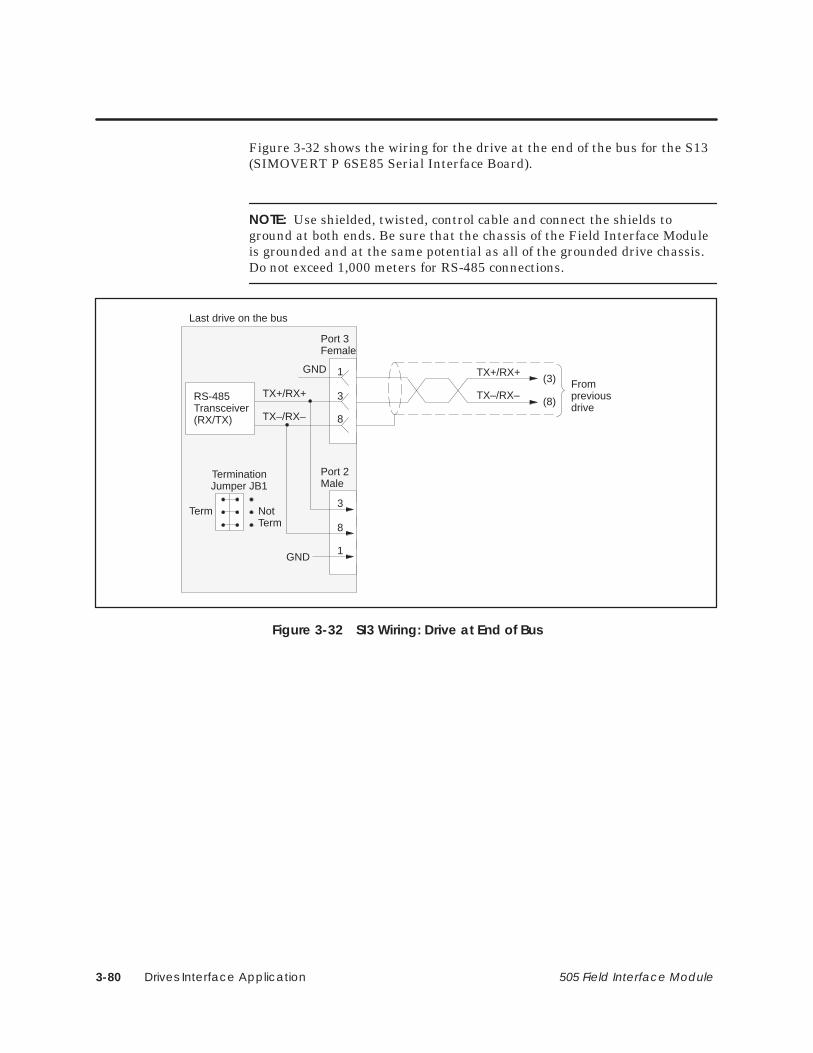
Drives Interface Application3-80 505 Field Interface Module
Figure 3-32 shows the wiring for the drive at the end of the bus for the S13(SIMOVERT P 6SE85 Serial Interface Board).
NOTE: Use shielded, twisted, control cable and connect the shields toground at both ends. Be sure that the chassis of the Field Interface Moduleis grounded and at the same potential as all of the grounded drive chassis.Do not exceed 1,000 meters for RS-485 connections.
GND 1
8
Port 3Female
Last drive on the bus
(3)
(8)
TX+/RX+
TX–/RX–Frompreviousdrive
TX+/RX+
TX–/RX–
3RS-485Transceiver(RX/TX)
GND
3
1
8
Port 2Male
NotTerm
Term
TerminationJumper JB1
Figure 3-32 SI3 Wiring: Drive at End of Bus

Drives Interface Application 3-81505 Field Interface Module
3.16 Setting Up and Wiring Z1005
You can use any hardware and/or any software version of the SIMOREGZ1005 third generation Digital Interface Board.
The parameters required for the Z1005 follow:
H07L is initially set to 2xx, which selects 10-word simple protocol and turns off the drive telegram-monitoring function. After the network is operating, you can turn on the drive telegram-monitoring function by setting H07L to 1xx.
H07M must be set to x0x, which selects an 11-bit frame.
H07R is normally set to xx0, which selects 19,200 baud, unlesssome other drive requires a lower baud rate.
H08 must be set to the individual drive address.
After the above parameters have been changed, the drive should be powereddown for at least 10 seconds and then powered back on. This power cyclingallows the drive to initialize communications with the FIM.
Required Hardwareand Software
RequiredParameters

Drives Interface Application3-82 505 Field Interface Module
The applicable jumpers follow:
A1 This jumper must be set to A1 – A2 to select RS-485 communication.
A2 This jumper must be set to A1 – A2 to select RS-485 communication.
A3 This jumper must be set to A1 – A2 to select RS-485 communication.
A4 Figure 3-33 and Figure 3-34 show the correct position for this jumper.
A5 Figure 3-33 and Figure 3-34 show the correct position for this jumper.
A6 Figure 3-33 and Figure 3-34 show the correct position for this jumper.
Use dipswitch S3 to set the extra delay to 0 milliseconds.
Required Jumpers
Setting FIMAdditional Delay

Drives Interface Application 3-83505 Field Interface Module
Setting Up and Wiring Z1005 (continued)
Figure 3-33 shows the wiring for all drives except the end of the bus for theSIMOREG Z1005 third generation Digital Interface Board.
NOTE: Use shielded, twisted, control cable and connect the shields toground at both ends. Be sure that the chassis of the Field Interface Moduleis grounded and at the same potential as all of the grounded drive chassis.Do not exceed 1,000 meters for RS-485 connections.
If a cable is removed from one of the Z1005 boards at a drive, the RS-485bus is broken. If a cable must be removed and operation of the bus isrequired, the two 9-pin connectors of the cables at the disconnect point canbe plugged together to continue the bus connection.
GND 3
1
X1Female
TX+/RX+
TX–/RX–
*3
*8
RS-485Transceiver(RX/TX)
6
*1
+5V
GND
First drive Field Interface Module
390 ohmpull-up resistor220 ohmtermination resistor390 ohmpull-down resistor
(9)
(1)
TX+/RX+
TX–/RX–To next drive
TX+
TX–
9RS-485Transceiver(TX)
9
6
1
X2Male
TerminationJumper
5
RX+
RX–
6RS-485Transceiver(RX)
GND3
5
A6
A5
A4
120ohm * For Pin 3: Terminal B on Siemens connector (listed in Section 2.4).
* For Pin 8: Terminal A on Siemens connector (listed in Section 2.4).* For Pin 1: Connector housing on Siemens connector (listed in Section 2.4).
Figure 3-33 Z1005 Wiring: All Drives Except at End of Bus

Drives Interface Application3-84 505 Field Interface Module
Figure 3-34 shows the wiring for the drive at the end of the bus for theSIMOREG Z1005 third generation Digital Interface Board.
NOTE: Use shielded, twisted, control cable and connect the shields toground at both ends. Be sure that the chassis of the Field Interface Moduleis grounded and at the same potential as all of the grounded drive chassis.Do not exceed 1,000 meters for RS-485 connections.
If a cable is removed from one of the Z005 boards at a drive, the RS-485 busis broken. If a cable must be removed and operation of the bus is required,the two 9-pin connectors of the cables at the disconnect point can be pluggedtogether to continue the bus connection.
GND 3
1
X1Female
Last drive on the bus
TX+
TX–
9RS-485Transceiver(TX)
* May be required for electrically noisy environments.
9
6
1
X2Male
TerminationJumper
5
RX+
RX–
6RS-485Transceiver(RX)
GND3
5
A6
A5
A4
(9)
(1)
TX+/RX+
TX–/RX–
Frompreviousdrive
(–)120ohm
1,000 ohmpull up*
1,000 ohmpull down*
(+)
5 VDC Power Supply*(external)
Figure 3-34 Z1005 Wiring: Drive at End of Bus

Drives Interface Application 3-85505 Field Interface Module
3.17 Setting Up and Wiring Z1006
You can use any hardware version of the SIMOREG Z1006 third generationCoordinated Drive Interface Board. You must use software version 1.3.0 orlater.
The parameters required for the Z1006 follow:
H07L is initially set to 2xx, which selects 10-word simple protocol and turns off the drive telegram-monitoring function. After the network is operating, you can turn on the drive telegram-monitoring function by setting H07L to 1xx.
H07M must be set to x0x, which selects an 11-bit frame.
H07R is normally set to xx0, which selects 19,200 baud, unless some other drive requires a lower baud rate.
H08 must be set to the individual drive address.
After the above parameters have been changed, the drive should be powereddown for at least 10 seconds and then powered back on. This power cyclingallows the drive to initialize communications with the FIM.
Required Hardwareand Software
RequiredParameters

Drives Interface Application3-86 505 Field Interface Module
The applicable jumpers follow:
T1 This jumper must be set to A1 – A2 to select RS-485 communication.
T2 This jumper must be set to A1 – A2 to select RS-485 communication.
T3 Figure 3-35 and Figure 3-36 show the correct position for this jumper.
Use dipswitch S3 to set the extra delay to 0 milliseconds.
Required Jumpers
Setting FIMAdditional Delay

Drives Interface Application 3-87505 Field Interface Module
Setting Up and Wiring Z1006 (continued)
Figure 3-35 shows the wiring for all drives except the end of the bus for theSIMOREG Z1006 third generation Coordinated Drive Interface Board.
NOTE: Use shielded, twisted, control cable and connect the shields toground at both ends. Be sure that the chassis of the Field Interface Moduleis grounded and at the same potential as all of the grounded drive chassis.Do not exceed 1,000 meters for RS-485 connections.
If a cable is removed from one of the Z1006 boards at a drive, the RS-485bus is broken. If a cable must be removed and operation of the bus isrequired, the two 9-pin connectors of the cables at the disconnect point canbe plugged together to continue the bus connection.
GND
1
X1Female
TX+/RX+
TX–/RX–
*3
*8
RS-485Transceiver(RX/TX)
6
*1
+5V
GND
First drive Field Interface Module
390 ohmpull-up resistor220 ohmtermination resistor390 ohmpull-down resistor
(9)
(1)
TX+/RX+
TX–/RX–To next drive
TX+
TX–
9RS-485Transceiver(TX)
9
6
1
X2Male
TerminationJumper
5
RX+
RX–
6RS-485Transceiver(RX)
GND
5
T3
T2
T1
Shield connected to connectorhousing. Connector fasteningscrews must be used and tightened.
Shield connected to connector housing.Connector fastening screws must be usedand tightened.
120ohm * For Pin 3: Terminal B on Siemens connector (listed in Section 2.4).
* For Pin 8: Terminal A on Siemens connector (listed in Section 2.4).* For Pin 1: Connector housing on Siemens connector (listed in Section 2.4).
Figure 3-35 Z1006 Wiring: All Drives Except at End of Bus

Drives Interface Application3-88 505 Field Interface Module
Figure 3-36 shows the wiring for the drive at the end of the bus for theSIMOREG Z1006 third generation Coordinated Drive Interface Board.
NOTE: Use shielded, twisted, control cable and connect the shields toground at both ends. Be sure that the chassis of the Field Interface Moduleis grounded and at the same potential as all of the grounded drive chassis.Do not exceed 1,000 meters for RS-485 connections.
If a cable is removed from one of the Z1006 boards at a drive, the RS-485bus is broken. If a cable must be removed and operation of the bus isrequired, the two 9-pin connectors of the cables at the disconnect point canbe plugged together to continue the bus connection.
GND
1
X1Female
Last drive on the bus
TX+
TX–
9RS-485Transceiver(TX)
* May be required for electrically noisy environments.
9
6
1
X2Male
TerminationJumper
5
RX+
RX–
6RS-485Transceiver(RX)
GND
5
T3
T2
T1
(9)
(1)
TX+/RX+
TX–/RX–
Frompreviousdrive
(–)120ohm
1,000 ohmpull up*
1,000 ohmpull down*
(+)
5 VDC Power Supply*(external)
Shield connected to connectorhousing. Connector fasteningscrews must be used and tightened.
Connector fastening screw
Figure 3-36 Z1006 Wiring: Drive at End of Bus

Drives Interface Application 3-89505 Field Interface Module
3.18 Setting Up and Wiring Z1011
You must use SIMOREG Z1011 third generation Serial Interface Boardhardware version 9 or later and software version 3.05 or later.
The parameters required for the Z1011 follow.
If used alone:
E00 must be set to nine, which selects the Z1011 with a 10-word telegram.
After the above parameters have been changed, the drive should be powereddown for at least 10 seconds and then powered back on. This power cyclingallows the drive to initialize communications with the FIM.
For additional information, refer to the Z1011 Instruction Book, partnumber A1–106–008–027.
If used with Z1004 Technology Board:
H02L is initially set to 7xx, which selects 10-word simple protocol andturns off the drive telegram-monitoring function. After the network is operating, you can decide whether or not to turn on the drive telegram-monitoring function by setting H02L to 3xx. See Figure 3-37.
H07L must not be set to 1xx or 2xx or 4xx or 5xx.
After the above parameters have been changed, the drive should be powereddown for at least 10 seconds and then powered back on. This power cyclingallows the drive to initialize communications with the FIM.
For additional information, refer to Appendix B of the appropriate Z1004Technology Module Instruction Book.
The applicable jumpers follow.
CST1 This jumper must be set to the CST1 (right) position.
CST2 This jumper must be set to the CST1 (right) position.
W1 See Figure 3-38 and Figure 3-39 for the correct position of this jumper.
Required Hardwareand Software
RequiredParameters
Required Jumpers

Drives Interface Application3-90 505 Field Interface Module
Connect an external 24-volt DC source rated for a minimum of 150 mA toterminal block X3, with P24E as positive and M24E as common. Use aseparate power supply, because this is the power source for the actual serialconnection between drive and host. The resulting communications signalsare optically isolated from the internal microprocessor power supplies toprovide the drive system with noise immunity.
8 7 6 5 4 3 2 1
SW1
ON – selects port 2 for serial reference
OFF – not used
Baud Rate for RS-485 – should normally be set to 38,400 baud unlesssome other drive requires a lower baud rate.
5 4
Off Off 4800 Baud
Off On 9600 Baud
On Off 19200 Baud
On On 38400 Baud
OFF
ON
OFF – selects simple protocol
selects 10 word telegram
NOTE: After the switches have been set, make sure power is cycled OFF and ON. The settings of the switches are only read once during the power ON cycle. Follow appropriate safety precautions before power cycling equipment.
Figure 3-37 Z1011 Required Switches
The applicable switches follow.
SINEC NO. Set the two rotary switches labeled “SINEC NO.” to 39, which turns the RS-232 port off.
DUST NO. Set the two rotary switches labeled “DUST NO.” to the desired drive address from 00 to 30.
Use dipswitch S3 to set the extra delay to 0 milliseconds.
External PowerSupply
Required Switches
Setting FIMAdditional Delay

Drives Interface Application 3-91505 Field Interface Module
Setting Up and Wiring Z1011 (continued)
Figure 3-38 shows the wiring for all drives except the end of the bus for theSIMOREG Z1011 third generation Serial Interface Board.
NOTE: Use shielded, twisted, control cable and connect the shields toground at both ends. Be sure that the chassis of the Field Interface Moduleis grounded and at the same potential as all of the grounded drive chassis.Do not exceed 1,000 meters for RS-485 connections.
If a cable is removed from one of the Z1011 boards at a drive, the RS-485bus is broken. If a cable must be removed and operation of the bus isrequired, the two 9-pin connectors of the cables at the disconnect point canbe plugged together to continue the bus connection.
GND3
1
X1Female
TX+/RX+
TX–/RX–
*3
*8
RS-485Transceiver(RX/TX)
6
*1
+5V
GND
First drive
Field Interface Module
390 ohmpull-up resistor220 ohmtermination resistor390 ohmpull-down resistor
(9)
(1)
TX+/RX+
TX–/RX–To next drive
TX+
TX–
9RS-485Transceiver(TX)
9
6
1
X11Male
TerminationJumper W1
5
RX+
RX–
6RS-485Transceiver(RX)
GND3
5
+5V2
+5V2
B
A
120ohm
* For Pin 3: Terminal B on Siemens connector (listed in Section 2.4).* For Pin 8: Terminal A on Siemens connector (listed in Section 2.4).* For Pin 1: Connector housing on Siemens connector (listed in Section 2.4).
Figure 3-38 Z1011 Wiring: All Drives Except at End of Bus
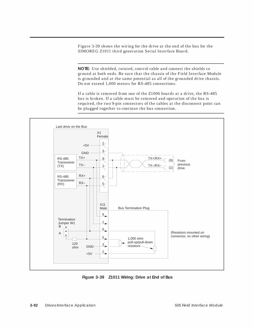
Drives Interface Application3-92 505 Field Interface Module
Figure 3-39 shows the wiring for the drive at the end of the bus for theSIMOREG Z1011 third generation Serial Interface Board.
NOTE: Use shielded, twisted, control cable and connect the shields toground at both ends. Be sure that the chassis of the Field Interface Moduleis grounded and at the same potential as all of the grounded drive chassis.Do not exceed 1,000 meters for RS-485 connections.
If a cable is removed from one of the Z1006 boards at a drive, the RS-485bus is broken. If a cable must be removed and operation of the bus isrequired, the two 9-pin connectors of the cables at the disconnect point canbe plugged together to continue the bus connection.
GND3
1
X1Female
Last drive on the Bus
(9)
(1)
TX+/RX+
TX–/RX–
Frompreviousdrive
TX+
TX–
9RS-485Transceiver(TX)
9
6
1
X11Male
TerminationJumper W1
5
RX+
RX–
6RS-485Transceiver(RX)
GND3
5
+5V2
+5V2
B
A
120ohm
Bus Termination Plug
1,000 ohmpull-up/pull-downresistors
(Resistors mounted onconnector, no other wiring)
Figure 3-39 Z1011 Wiring: Drive at End of Bus

Drives Interface Application 3-93505 Field Interface Module
3.19 Setting Up and Wiring Z2006
You can use any hardware and/or software version of the SIMOREG Z2006(6SE12 or 6RA24 Technology Board).
The parameters required for the Z2006 follow:
PT290 must be set to either Simple Protocol or USS Protocol.
PT291 is set to 38,400 baud, unless some other drive requires a lower baud rate.
PT292 must be set to 11-bit even parity.
PT293 must be set to two-wire operation.
PT294 must be set to the individual drive address.
PT295 is initially set to zero, which turns off the drive telegram-monitoring function. After the network is operating, you can decide whether to turn on the drive telegram-monitoring function by setting PT295 to a non-zero value.
PT296 is used if PT290 is set to USS Protocol. It sets the number of process data (PZD) words. The sum of parameters PT296 + PT297 must be five if 5-word USS protocol is selected on the FIM, or ten if 10-word USS protocol is selected on the FIM.
PT297 is used if PT290 is set to USS Protocol. It sets the number of PKW words used for parameter data. It is set to either zero or three. The sum of parameters PT296 + PT297 must be five if 5-word USS protocol is selected on the FIM, or ten if 10-word USS protocol is selected on the FIM.
After the above parameters have been changed, the drive should be powereddown for at least 10 seconds and then powered back on. This power cyclingallows the drive to initialize communications with the FIM.
Required Hardwareand Software
RequiredParameters

Drives Interface Application3-94 505 Field Interface Module
NOTE: Unlike some Siemens variable speed drives, the Z2006 will notautomatically be controlled by serial communications when wired and setup according to this document, it will only communicate. The process datasection (also refer to PT296) defines the control word, status word, setpointsand actual values for the interface. Definition of the process data section isvery flexible. Individual input, output, and control functions must be set(parameterized) for use with serial communications. It is beyond the scopeof this document to describe all of the functions and how to set(parameterize) them. Appendix B of the Z2006 Instruction Book describesthe control word, status word, setpoints, and actual values structures, and itis imperative that this section be read completely and understood beforeattempting to control a Z2006 with a FIM Module.

Drives Interface Application 3-95505 Field Interface Module
Setting Up and Wiring Z2006 (continued)
The following example describes how to assign the Start/Stop and SpeedSetpoint functions to the FIM using 5-word or 10-word USS protocol (seeparameters PT290, PT296, and PT297 above):
On a Factory Default Z2006, these control functions are set to localwired inputs, not serial the Z2006 serial port.
In order to control the Start/Stop function from the Z2006 serial port ofthe drive (communicating by USS protocol to the FIM) parameterPT183 must be set to TBSP Cntl WD1.14. This sets the source of theSystem Start command to bit 14 of PZD word 1 of the telegrams on theZ2006 serial port (USS). PZD word 1 is word 1 of the PLC data area ifparameter PT297 (see above) is set to 0. PZD word 1 is word 4 of thePLC data area if parameter PT297 (see above) is set to 3 (words 1, 2,and 3 are PKW words).
The same concepts apply to the Speed Setpoint signal. In order tocontrol the Speed Setpoint from the Z2006 serial port of the drive(communicating by USS protocol to the FIM) parameter PT150 must beset to TBSP Ref. 1. This sets the source of the Speed Setpoint to PZDword 2 of the telegrams on the Z2006 serial port (USS).
After PT183 is set to TBSP Cntl WD1.14, Figure 3-40 describes thefunction of each control bit in PZD word 1 of the information sent to theZ2006.

Drives Interface Application3-96 505 Field Interface Module
15 14 13 12 11 10 9 8 7 6 5 4 3 2 1 0
High byte Low byte
Not used – enabled with PT199
Not used – enabled with PT184
Not used – enabled with PT199
Not used – enabled with PT199
Not used – enabled with PT199
Not used – enabled with PT199
Not used – enabled with PT199
Not used – enabled with PT199
Not used – enabled with PT199
Not used – enabled with PT185
1 = Enable Serial Operation
Not used – enabled with PT186
Not used – enabled with PT187
Not used – enabled with PT188
1 = Z2006 System Start
Not used – enabled with PT189Note: A suggested initial value of PZD word 1 is 0400 hex. PZD word 1 can be changed to 4400 hex to start the drive.
Figure 3-40 Control Bits for Start/Stop and Speed Setpoint
Also, drive status and feedback (or actual value) information such as motorspeed must be set (parameterized) to the appropriate destination in order tobe read by the FIM Module. Appendix B of the Z2006 Instruction Book alsoexplains the details.

Drives Interface Application 3-97505 Field Interface Module
Setting Up and Wiring Z2006 (continued)
The following example describes how to access the Serial Port StatusWord 1 and Speed Feedback from the FIM:
On a Factory Default Z2006, the serial port status word 1 is set up, butthe actual values return information words are set to zero. The serialport status word 1 will be automatically returned in PZD word 1 of thetelegrams on serial port 0 (USS). PZD word 1 is word 1 of the PLC dataarea if parameter PT297 (see above) is set to 0. PZD word 1 is word 4 ofthe PLC data area if parameter PT297 (see above) is set to 3 (words 1,2, and 3 are PKW words).
In order to access the Speed Feedback in PZD word 2 from the Z2006serial port of the drive (communicating by USS protocol to the FIM),parameter PT263 must be set to PT007 SpdActVal. This selects whatwill be returned in PZD word 2 of the telegrams on the Z2006 serialport (USS).
Figure 3-41 describes the function of each status bit in PZD word 1 ofthe return information from the Z2006.
15 14 13 12 11 10 9 8 7 6 5 4 3 2 1 0
High byte Low byte
1 = Base Unit Ready to Start
1 = Base Unit Disabled and RUN requested1 = Base Unit Running
1 = Drive Fault
0 = STOP2 (Coast Stop)
0 = STOP3 (Quick Stop)
1 = Base Unit Blocked (by STOP2 or STOP3)
1 = Drive Warning
1 = Speed/Frequency Error Within Tolerance Band
1 = Serial Operation Allowed0 = Serial Operation BlockedFuture – this may not always be zero
Future – this may not always be zero
1 = Meaning dependent on Z2006 Module1 = Meaning dependent on Z2006 Module
1 = Meaning dependent on Z2006 Module
1 = Meaning dependent on Z2006 Module
Figure 3-41 Status Bits for Serial Port Status Word 1 and Speed Feedback
The Z2006 has no applicable jumpers.Required Jumpers

Drives Interface Application3-98 505 Field Interface Module
The 5-word USS protocol implementation used by the FIM allows all fivewords of data to be manipulated by the Series 505 programmable controller.The 10-word USS protocol implementation used by the FIM allows all tenwords of data to be manipulated by the Series 505 programmable controller.
The 5-word (Modified) USS protocol implementation used by the FIM onlyallows four words of data to be manipulated by the Series 505programmable controller. The second word of the 5-word (Modified) USSprotocol telegram sent to the drives is always set to zero. The second wordof the 5-word (Modified) USS protocol received from the drives is notavailable at the controller.
• The FIM maps the first word sent from the controller into the firstword of the 5-word (Modified) USS protocol telegram sent to the drive.
• The FIM always sends a zero as the second word of the 5-word(Modified) USS protocol telegram to the drive.
• The FIM maps the second word sent from the controller into the thirdword of the 5-word (Modified) USS protocol telegram sent to the drive.
• The FIM maps the third word sent from the controller into the fourthword of the 5-word (Modified) USS protocol telegram sent to the drive.
• The FIM maps the fourth word sent from the controller into the fifthword of the 5-word (Modified) USS protocol telegram sent to the drive.
• A similar technique is used to map the 5-word (Modified) USS protocolreply telegram from the drive into the 4-word reply in the controller.
Use dipswitch S3 to set the extra delay to 0 milliseconds.
USS Protocols
Setting FIMAdditional Delay
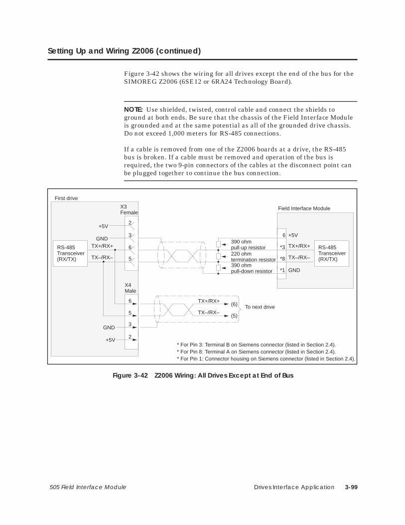
Drives Interface Application 3-99505 Field Interface Module
Setting Up and Wiring Z2006 (continued)
Figure 3-42 shows the wiring for all drives except the end of the bus for theSIMOREG Z2006 (6SE12 or 6RA24 Technology Board).
NOTE: Use shielded, twisted, control cable and connect the shields toground at both ends. Be sure that the chassis of the Field Interface Moduleis grounded and at the same potential as all of the grounded drive chassis.Do not exceed 1,000 meters for RS-485 connections.
If a cable is removed from one of the Z2006 boards at a drive, the RS-485bus is broken. If a cable must be removed and operation of the bus isrequired, the two 9-pin connectors of the cables at the disconnect point canbe plugged together to continue the bus connection.
GND3
5
X3Female
TX+/RX+
TX–/RX–
*3
*8
RS-485Transceiver(RX/TX)
6
*1
+5V
GND
First drive
Field Interface Module
390 ohmpull-up resistor220 ohmtermination resistor390 ohmpull-down resistor
(6)
(5)
TX+/RX+
TX–/RX–To next drive
TX+/RX+
TX–/RX–
6RS-485Transceiver(RX/TX)
GND
6
3
5
X4Male
+5V2
+5V2
* For Pin 3: Terminal B on Siemens connector (listed in Section 2.4).* For Pin 8: Terminal A on Siemens connector (listed in Section 2.4).* For Pin 1: Connector housing on Siemens connector (listed in Section 2.4).
Figure 3-42 Z2006 Wiring: All Drives Except at End of Bus

Drives Interface Application3-100 505 Field Interface Module
Figure 3-43 shows the wiring for the drive at the end of the bus for theSIMOREG Z2006 (6SE12 or 6RA24 Technology Board).
NOTE: Use shielded, twisted, control cable and connect the shields toground at both ends. Be sure that the chassis of the Field Interface Moduleis grounded and at the same potential as all of the grounded drive chassis.Do not exceed 1,000 meters for RS-485 connections.
If a cable is removed from one of the Z2006 boards at a drive, the RS-485bus is broken. If a cable must be removed and operation of the bus isrequired, the two 9-pin connectors of the cables at the disconnect point canbe plugged together to continue the bus connection.
GND3
5
X3Female
Last drive on the bus
(6)
(5)
TX+/RX+
TX–/RX–
Frompreviousdrive
TX+/RX+
TX–/RX–
6RS-485Transceiver(RX/TX)
GND
6
3
5
X4Male
+5V2
+5V2
Bus Termination Plug
1,000 ohmpull up/pull downresistors
(Resistors mounted onconnector, no other wiring)120 ohm
termination resistors
Figure 3-43 Z2006 Wiring: Drive at End of Bus

Drives Interface Application 3-101505 Field Interface Module
3.20 Setting Up and Wiring the 6SE70 Models FC and SC
You can use any hardware version of the SIMOREG 6SE70 Master DriveModels FC and SC, and you can use any software version of the basemicroprocessor board (CU1 or CU3).
The 6SE70 Models FC and SC use the basic converter interface SST1 withUSS protocol. Using SST1 assumes that the optional operator panel OP1 isnot used; if the optional operator panel is used, you must add the optionalserial communications board SCB2. Also note that SST1 is sometimesreferred to as SCOM1.
The parameters required for the 6SE70 Models FC and SC follow:
P053 must be set to allow parameters to be changed from the FIM through SST1 (also refer to P685 i001).
P683 i001 must be set to the individual drive address.
P684 i001 is set to 38,400 baud, unless some other drive requires a lower baud rate.
P685 i001 sets the number of PKW words used for parameter data. It is set to either zero, three, or four. The sum of parameters P685 i001 + P686 i001 must be five if 5-word USS protocol is selected on the FIM, or ten if 10-word USS protocol is selected on the FIM.
P686 i001 sets the number of process data (PZD) words. The sum of parameters P685 i001 + P686 i001 must be five if 5-word USS protocol is selected on the FIM, or ten if 10-word USS protocol is selected on the FIM.
P687 i001 is initially set to zero, which turns off the drive telegram-monitoring function. After the network is operating, you can decide whether or not to turn on the drive telegram-monitoring function by setting P687 i001 to a non-zero value.
After the above parameters have been changed, the drive should be powereddown for at least 10 seconds and then powered back on. This power cyclingallows the drive to initialize communications with the FIM.
Required Hardwareand Software
RequiredParameters

Drives Interface Application3-102 505 Field Interface Module
NOTE: Unlike some Siemens variable speed drives, the 6SE70 will notautomatically be controlled by serial communications when wired and setup according to this document, it will only communicate. The process datasection (also refer to P686 i001) defines the control word, status word,setpoints and actual values for the interface. Definition of the process datasection is very flexible. Individual input, output, and control functions mustbe set (parameterized) for use with serial communications. It is beyond thescope of this document to describe all of the functions and how to set(parameterize) them. Section 4.3 of the 6SE70 Instruction Book describesthe control word, status word, setpoints, and actual values structures, and itis imperative that this section be read completely and understood beforeattempting to control a 6SE70 with a FIM Module.

Drives Interface Application 3-103505 Field Interface Module
Setting Up and Wiring the 6SE70 Models FC and SC (continued)
The following example describes how to assign the Stop/Start and SpeedCommand functions to the FIM:
On a Factory Default 6SE70 Master Drive, these control functions areset to PMU, not serial communications SST1. The PMU is theParameterization Unit which is the membrane keypad in the frontcover of the 6SE70.
In order to control the Start/Stop function from SST1 (the FIM),parameter P554.1 should be set to 2001. This sets the source of theStart/Stop function to bit 0 of PZD word 1 of the telegrams on serialport SST1. PZD word 1 is word 1 of the PLC data area if parameterP685 i001 (see above) is set to 0. PZD word 1 is word 4 of the PLC dataarea if parameter P685 i001 is set to 3 (words 1, 2, and 3 are PKWwords). PZD word 1 is word 5 of the PLC data area if parameterP685 i001 is set to 4 (words 1, 2, 3, and 4 are PKW words). Differentvalues for parameter P554.x must be used if different ports and/ordifferent words in the telegram are used.
The same concepts apply to the Speed Command (or Setpoint) signal.In order to control the Speed Command function from SST1 (the FIM),parameter P443.x must be set to 2002. This sets the source of the SpeedCommand function to word 2 of the incoming telegrams on serial portSST1. Different values for parameter P443.x must be used if differentports and/or different words in the telegram are used.
After P554.1 is set to 2001, Figure 3-44 describes the function of eachcontrol bit in PZD word 1 of the information sent to serial port SST1.

Drives Interface Application3-104 505 Field Interface Module
15 14 13 12 11 10 9 8 7 6 5 4 3 2 1 0
High byte Low byte
1 = Start0 = STOP1 (Normal Stop)Not used – must be enabledNot used – must be enabled
Not used – must be enabled
Not used – must be enabled
Not used – must be enabled
Not used – must be enabled
Not used – must be enabled
Not used – must be enabled
Not used – must be enabled
Not used – must be enabled
Not used – must be enabled
Not used – must be enabled
Not used – must be enabled
Not used – must be enabled
1 = Enable Serial Operation
Note: A suggested initial value of PZD word 1 is 0400 hex. PZD word 1 can be changed to 0401 hex to start the drive.
Figure 3-44 Control Bits for Stop/Start and Speed Command
The same technique must be applied to all functions such asForward/Reverse, Fault Reset, and all other functions that are to becontrolled by the FIM.
Also, drive status and feedback (or actual value) information such as motorspeed and other information must be set (parameterized) to the appropriatedestination in order to be read by the FIM Module. Section 4.3 of the 6SE70Instruction Book also explains the details.

Drives Interface Application 3-105505 Field Interface Module
Setting Up and Wiring the 6SE70 Models FC and SC (continued)
The following example describes how to access the Status Word 1 and MainSetpoint from the FIM:
On a Factory Default 6SE70 Master Drive, the actual values returninformation words are set to 0. In order to access the standard statusword from SST1 (the FIM), parameter P680.1 must be set to 968. Thisselects what will be returned in PZD word 1 of the telegrams on serialport SST1. PZD word 1 is word 1 of the PLC data area if parameterP685 i001 (see above) is set to 0. PZD word 1 is word 4 of the PLC dataarea if parameter P685 i001 is set to 3 (words 1, 2, and 3 are PKWwords). PZD word 1 is word 5 of the PLC data area if parameterP685 i001 is set to 4 (words 1, 2, 3, and 4 are PKW words).
The same concepts apply to access the Main Setpoint in PZD word 2from serial port SST1, parameter P680.2 must be set to 447. Thisselects what will be returned in PZD word 2 of the telegrams on theserial port SST1.
Figure 3-45 describes the function of each status bit in PZD word 1 ofthe return information from the SST1 port.

Drives Interface Application3-106 505 Field Interface Module
15 14 13 12 11 10 9 8 7 6 5 4 3 2 1 0
High byte Low byte
1 = Ready to Start
1 = Ready1 = Running
1 = Drive Fault
0 = STOP2 (Coast Stop)
0 = STOP3 (Quick Stop)
1 = Base Unit Blocked
1 = Drive Warning
1 = Setpoint Error Within Tolerance Band
1 = Serial Operation Allowed0 = Serial Operation Blocked1 = Comparison Frequency Reached
1 = Undervoltage Fault
1 = Main Contactor Energized1 = Ramp Generator Active
1 = Clockwise Phase Sequence
1 = Kinetic Buffering Active
Figure 3-45 Status Bits for Status Word 1 and Main Setpoint

Drives Interface Application 3-107505 Field Interface Module
Setting Up and Wiring the 6SE70 Models FC and SC (continued)
The 6SE70 Master Drive Models FC and SC have no applicable jumpers.
The applicable switches follow:
S1.1 Figure 3-46 and Figure 3-47 show the correct positions of this hook switch.
S1.2 Figure 3-46 and Figure 3-47 show the correct positions of this hook switch.
Figure 3-46 shows the wiring for all drives except the end of the bus for the6SE70 Master Drive Models FC and SC.
NOTE: Use shielded, twisted, control cable and connect the shields toground at both ends. Be sure that the chassis of the Field Interface Moduleis grounded and at the same potential as all of the grounded drive chassis.Do not exceed 1,000 meters for RS-485 connections.
2
CU1–X100or CU3–X100
TX+/RX+
TX–/RX–
*3
*8
RS-485Transceiver(RX/TX)
6
*1
+5V
GND
First Drive Field Interface Module
390 ohmpull-up resistor220 ohmtermination resistor390 ohmpull-down resistor
(1)
(2)
TX+/RX+
TX–/RX– To next drive
TX+/RX+
TX–/RX–
1RS-485Transceiver(RX/TX)
390ohm
GND
+5V The shields are connected to the drive housingusing the drive shield (screen) clamps.
215ohm
390ohm
Switch S1.1
Switch S1.2
* For Pin 3: Terminal B on Siemens connector (listed in Section 2.4).* For Pin 8: Terminal A on Siemens connector (listed in Section 2.4).* For Pin 1: Connector housing on Siemens connector (listed in Section 2.4).
Figure 3-46 Master Drive Models FC and SC Wiring: All Drives Except End of Bus
Required Jumpers
Required Switches

Drives Interface Application3-108 505 Field Interface Module
Figure 3-47 shows the wiring for the drive at the end of the bus for theMaster Drive Models FC and SC.
NOTE: Use shielded, twisted, control cable and connect the shields toground at both ends. Be sure that the chassis of the Field Interface Moduleis grounded and at the same potential as all of the grounded drive chassis.Do not exceed 1,000 meters for RS-485 connections.
2
CU1–X100or CU3–X100
Last Drive on bus
(1)
(2)
TX+/RX+
TX–/RX–
Frompreviousdrive
TX+/RX+
TX–/RX–
1RS-485Transceiver(RX/TX)
390ohm
GND
+5V The shield is connected to the drive housingusing the drive shield (screen) clamps.
215ohm
390ohm
Switch S1.1
Switch S1.2
Figure 3-47 Master Drive Models FC and SC Wiring: Drive at End of Bus
The 5-word USS protocol implementation used by the FIM allows all fivewords of data to be manipulated by the Series 505 controller; the 10-wordUSS protocol implementation used by the FIM allows all ten words of datato be manipulated by the Series 505 controller.
The 5-word modified USS protocol implementation used by the FIM onlyallows four words of data to be manipulated by the Series 505 controller. Donot use the 5-word modified USS protocol implementation with the 6SE70.
Use dipswitch S3 to set the extra delay to 14 milliseconds for the SC model.Use dipswitch S3 to set the extra delay to 28 milliseconds for the FC model.
USS Protocols
Setting FIMAdditional Delay

Drives Interface Application 3-109505 Field Interface Module
3.21 Setting Up and Wiring the 6SE70 Model VC
You can use any hardware version of the 6SE70 Master Drive Model VC,and any software version of the base microprocessor board (CU2).
The 6SE70 Model VC uses the basic converter interface SST2 with the USSprotocol.
If you wish to use the SST2 interface (also referred to as SCo2 in the 6SE70Instruction Book) with any device other than the 6SE70 Master Drive, youmust add the optional Serial Communication Board SCB2.
P053 must be set to allow parameters to be changed from the FIM through SST2 (also refer to P685 i003).
P683 i003 must be set to the individual drive address.
P684 i003 is normally set to 38,400 baud, unless some other drive requires a lower baud rate.
P685 i003 sets the number of PKW words used for parameter data. Set it to either zero, three, or four. The sum of parameters P685 i003 + P686 i003 must be five if 5-word USS protocol is selected on the FIM, or ten if 10-word USS protocol is selected on the FIM.
P686 i003 sets the number of process data (PZD) words. The sum of parameters P685 i003 + P686 i003 must be five if 5-word USS protocol is selected on the FIM, or ten if 10-word USS protocol is selected on the FIM.
P687 i003 is initially set to zero, which turns off the drive telegram-monitoring function. After the network is operating, decide whether or not to turn on the drive telegram-monitoring function by setting P687 i003 to a non-zero value.
After the above parameters have been changed, the drive should be powereddown for at least 10 seconds and then powered back on. This power cyclingallows the drive to initialize communications with the FIM.
Required Hardwareand Software
RequiredParameters

Drives Interface Application3-110 505 Field Interface Module
NOTE: Unlike some Siemens variable speed drives, the 6SE70 will notautomatically be controlled by serial communications when wired and setup according to this document, it will only communicate. The process datasection (also refer to P686 i003) defines the control word, status word,setpoints and actual values for the interface. Definition of the process datasection is very flexible. Individual input, output, and control functions mustbe set (parameterized) for use with serial communications. It is beyond thescope of this document to describe all of the functions and how to set(parameterize) them. Section 4.3 of the 6SE70 Instruction Book describesthe control word, status word, setpoints, and actual values structures, and itis imperative that this section be read completely and understood beforeattempting to control a 6SE70 with a FIM Module.

Drives Interface Application 3-111505 Field Interface Module
Setting Up and Wiring the 6SE70 Model VC (continued)
The following example describes how to assign the Stop/Start and SpeedCommand functions to the FIM:
On a Factory Default 6SE70 Master Drive, these control functions areset to PMU, not to serial communications SST2. The PMU is theParameterization Unit which is the membrane keypad in the frontcover of the 6SE70.
In order to control the Start/Stop function from SST2 (the FIM),parameter P554.1 should be set to 6001. This sets the source of theStart/Stop function to bit 0 of PZD word 1 of the telegrams on serialport SST2. PZD word 1 is word 1 of the PLC data area if parameterP685 i003 (see above) is set to 0. PZD word 1 is word 4 of the PLC dataarea if parameter P685 i003 is set to 3 (words 1, 2, and 3 are PKWwords). PZD word 1 is word 5 of the PLC data area if parameterP685 i003 is set to 4 (words 1, 2, 3, and 4 are PKW words). Differentvalues for parameter P554.x must be used if different ports and/ordifferent words in the telegram are used.
The same concepts apply to the Speed Command (or Setpoint) signal.In order to control the Speed Command function from SST2 (the FIM),parameter P443.x must be set to 6002. This sets the source of the SpeedCommand function to word 2 of the incoming telegrams on serial portSST1. Different values for parameter P443.x must be used if differentports and/or different words in the telegram are used.
After P554.1 is set to 6001, Figure 3-48 describes the function of eachcontrol bit in PZD word 1 of the information sent to serial port SST2.
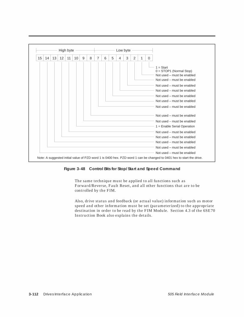
Drives Interface Application3-112 505 Field Interface Module
15 14 13 12 11 10 9 8 7 6 5 4 3 2 1 0
High byte Low byte
1 = Start0 = STOP1 (Normal Stop)Not used – must be enabledNot used – must be enabled
Not used – must be enabled
Not used – must be enabled
Not used – must be enabled
Not used – must be enabled
Not used – must be enabled
Not used – must be enabled
Not used – must be enabled
Not used – must be enabled
Not used – must be enabled
Not used – must be enabled
Not used – must be enabled
Not used – must be enabled
1 = Enable Serial Operation
Note: A suggested initial value of PZD word 1 is 0400 hex. PZD word 1 can be changed to 0401 hex to start the drive.
Figure 3-48 Control Bits for Stop/Start and Speed Command
The same technique must be applied to all functions such asForward/Reverse, Fault Reset, and all other functions that are to becontrolled by the FIM.
Also, drive status and feedback (or actual value) information such as motorspeed and other information must be set (parameterized) to the appropriatedestination in order to be read by the FIM Module. Section 4.3 of the 6SE70Instruction Book also explains the details.

Drives Interface Application 3-113505 Field Interface Module
Setting Up and Wiring the 6SE70 Model VC (continued)
The following example describes how to access the Status Word 1 and MainSetpoint from the FIM:
On a Factory Default 6SE70 Master Drive, the actual values returninformation words are set to 0. In order to access the standard statusword from SST2 (the FIM), parameter P681.1 must be set to 968. Thisselects what will be returned in PZD word 1 of the telegrams on serialport SST2. PZD word 1 is word 1 of the PLC data area if parameterP685 i003 (see above) is set to 0. PZD word 1 is word 4 of the PLC dataarea if parameter P685 i003 is set to 3 (words 1, 2, and 3 are PKWwords). PZD word 1 is word 5 of the PLC data area if parameterP685 i003 is set to 4 (words 1, 2, 3, and 4 are PKW words).
The same concepts apply to access the Main Setpoint in PZD word 2from serial port SST2, parameter P681.2 must be set to 447. Thisselects what will be returned in PZD word 2 of the telegrams on theserial port SST2.
Figure 3-49 describes the function of each status bit in PZD word 1 ofthe return information from the SST2 port.
15 14 13 12 11 10 9 8 7 6 5 4 3 2 1 0
High byte Low byte
1 = Ready to Start
1 = Ready1 = Running
1 = Drive Fault
0 = STOP2 (Coast Stop)
0 = STOP3 (Quick Stop)
1 = Base Unit Blocked
1 = Drive Warning
1 = Setpoint Error Within Tolerance Band
1 = Serial Operation Allowed0 = Serial Operation Blocked1 = Comparison Frequency Reached
1 = Undervoltage Fault
1 = Main Contactor Energized1 = Ramp Generator Active
1 = Clockwise Phase Sequence
1 = Kinetic Buffering Active
Figure 3-49 Status Bits for Status Word 1 and Main Setpoint

Drives Interface Application3-114 505 Field Interface Module
The applicable switches follow:
S2.1 Figure 3-50 and Figure 3-51 show the correct position of this hook switch.
S2.2 Figure 3-50 and Figure 3-51 show the correct position of this hook switch.
The 5-word USS protocol implementation used by the FIM allows all fivewords of data to be manipulated by the Series 505 controller. The 10-wordUSS protocol implementation used by the FIM allows all ten words of datato be manipulated by the Series 505 controller.
The 5-word (modified) USS protocol implementation used by the FIM onlyallows four words of data to be manipulated by the Series 505 controller. Donot use the five-word (modified) USS protocol implementation with the6SE70.
Use dipswitch S3 to set the extra delay to 14 milliseconds.
Required Switches
USS Protocols
FIM AdditionalDelay Set byDipswitch S3

Drives Interface Application 3-115505 Field Interface Module
Setting Up and Wiring the 6SE70 Model VC (continued)
Figure 3-50 shows the wiring for all drives except the end of the bus for the6SE70 Master Drive Model VC.
NOTE: Use shielded, twisted, control cable and connect the shields toground at both ends. Be sure that the chassis of the Field Interface Moduleis grounded and at the same potential as all of the grounded drive chassis.Do not exceed 1,000 meters for RS-485 connections.
2
CU2–X100
TX+/RX+
TX–/RX–
*3
*8
RS-485Transceiver(RX/TX)
6
*1
+5V
GND
Drive Number 01 Field Interface Module
390 ohmpull-up resistor220 ohmtermination resistor390 ohmpull-down resistor
(1)
(2)
TX+/RX+
TX–/RX–To next driveNo. 02
TX+/RX+
TX–/RX–
1RS-485Transceiver(RX/TX)
390ohm
GND
+5V The shields are connected to the drive housingusing the drive shield (screen) clamps.
215ohm
390ohm
Switch S2.1
Switch S2.2
* For Pin 3: Terminal B on Siemens connector (listed in Section 2.4).* For Pin 8: Terminal A on Siemens connector (listed in Section 2.4).* For Pin 1: Connector housing on Siemens connector (listed in Section 2.4).
Figure 3-50 6SE70 Master Drive Model VC Wiring: All Drives Except End of Bus

Drives Interface Application3-116 505 Field Interface Module
Figure 3-51 shows the wiring for the drive at the end of the bus for the6SE70 Master Drive Model VC.
NOTE: Use shielded, twisted, control cable and connect the shields toground at both ends. Be sure that the chassis of the Field Interface Moduleis grounded and at the same potential as all of the grounded drive chassis.Do not exceed 1,000 meters for RS-485 connections.
2
CU2–X100
Drive Number X
(1)
(2)
TX+/RX+
TX–/RX–
Frompreviousdrive
TX+/RX+
TX–/RX–
1RS-485Transceiver(RX/TX)
390ohm
GND
+5V The shield is connected to the drive housingusing the drive shield (screen) clamps.
215ohm
390ohm
Switch S2.1
Switch S2.2
NOTE 1: Use shielded twisted control cable and connect the shields at both ends.
NOTE 2: The chassis of the Field Interface Module must be grounded and at the same potential as all of the grounded drive chassis.
NOTE 3: The maximum recommended distance for RS-485 connections is 1,000 meters.
Figure 3-51 6SE70 Master Drive Model VC Wiring: Drive at End of Bus

Drives Interface Application 3-117505 Field Interface Module
3.22 Setting Up and Wiring the SCB2
You can use any hardware version of the 6SE70. You can use any softwareversion of the base microprocessor board (CU1, CU2, or CU3) and you canuse any software version of the SCB2 Master Drive Serial CommunicationsBoard.
The serial interface on the SCB2 uses USS Protocol. Select USS Protocolwith P682 for this serial interface, which is called SCB–SST [USS].
P053 must be set to allow parameters to be changed from the FIM through SCB with USS (also refer to P685 i002).
P090 or P091 must be set depending on the SCB2 hardware slot.
P682 must be set to two-wire USS.
P683 i002 must be set to the individual drive address.
P684 i002 is normally set to 38,400 baud, unless some other drive requires a lower baud rate.
P685 i002 sets the number of PKW words used for parameter data. Set it to either zero or three. The sum of parameters P685 i002 + P686 i002 must be five if 5-word USS protocol is selected on the FIM, or ten if 10-word USS protocol is selected on the FIM.
P686 i002 sets the number of process data (PZD) words. The sum of parameters P685 i002 + P686 i002 must be five if 5-word USS protocol is selected on the FIM, or ten if 10-word USS protocol is selected on the FIM.
P687 i002 is initially set to zero, which turns off the drive telegram-monitoring function. After the network is operating, decide whether to turn on the drive telegram-monitoring function by setting P687 i002 to a non-zero value.
Required Hardwareand Software
RequiredParameters

Drives Interface Application3-118 505 Field Interface Module
After the above parameters have been changed, the drive should be powereddown for at least 10 seconds and then powered back on. This power cyclingallows the drive to initialize communications with the FIM.
NOTE: Unlike some Siemens variable speed drives, the 6SE70 will notautomatically be controlled by serial communications when wired and setup according to this document, it will only communicate. The process datasection (also refer to P686 i002) defines the control word, status word,setpoints and actual values for the interface. Definition of the process datasection is very flexible. Individual input, output, and control functions mustbe set (parameterized) for use with serial communications. It is beyond thescope of this document to describe all of the functions and how to set(parameterize) them. Section 4.3 of the 6SE70 Instruction Book describesthe control word, status word, setpoints, and actual values structures, and itis imperative that this section be read completely and understood beforeattempting to control a 6SE70 with a FIM Module.

Drives Interface Application 3-119505 Field Interface Module
Setting Up and Wiring the SCB2 (continued)
The following example describes how to assign the Stop/Start and SpeedCommand functions to the FIM:
On a Factory Default 6SE70 Master Drive, these control functions areset to PMU, not serial communications SST1. The PMU is theParameterization Unit which is the membrane keypad in the frontcover of the 6SE70.
In order to control the Start/Stop function from SCB-SST of the drive(communicating by USS protocol to the FIM), parameter P554.1 shouldbe set to 4501. This sets the source of the Start/Stop function to bit 0 ofPZD word 1 of the telegrams on serial port SCB-SST (USS). PZD word1 is word 1 of the PLC data area if parameter P685 i002 (see above) isset to 0. PZD word 1 is word 4 of the PLC data area if parameterP685 i002 is set to 3 (words 1, 2, and 3 are PKW words). PZD word 1 isword 5 of the PLC data area if parameter P685 i002 is set to 4 (words 1,2, 3, and 4 are PKW words). Different values for parameter P554.xmust be used if different ports and/or different words in the telegramare used.
The same concepts apply to the Speed Command (or Setpoint) signal.In order to control the Speed Command function from SCB-SST of thedrive (communicating by USS protocol to the FIM), parameter P443.xmust be set to 4502. This sets the source of the Speed Commandfunction to word 2 of the incoming telegrams on serial port SCB-SST(USS). Different values for parameter P443.x must be used if differentports and/or different words in the telegram are used.
After P554.1 is set to 4501, Figure 3-52 describes the function of eachcontrol bit in PZD word 1 of the information sent to serial portSCB-SST (USS).

Drives Interface Application3-120 505 Field Interface Module
15 14 13 12 11 10 9 8 7 6 5 4 3 2 1 0
High byte Low byte
1 = Start0 = STOP1 (Normal Stop)Not used – must be enabledNot used – must be enabled
Not used – must be enabled
Not used – must be enabled
Not used – must be enabled
Not used – must be enabled
Not used – must be enabled
Not used – must be enabled
Not used – must be enabled
Not used – must be enabled
Not used – must be enabled
Not used – must be enabled
Not used – must be enabled
Not used – must be enabled
1 = Enable Serial Operation
Note: A suggested initial value of PZD word 1 is 0400 hex. PZD word 1 can be changed to 0401 hex to start the drive.
Figure 3-52 Control Bits for Stop/Start and Speed Command
The same technique must be applied to all functions such asForward/Reverse, Fault Reset, and all other functions that are to becontrolled by the FIM.
Also, drive status and feedback (or actual value) information such as motorspeed must be set (parameterized) to the appropriate destination in order tobe read by the FIM Module. Section 4.3 of the 6SE70 Instruction Book alsoexplains the details.

Drives Interface Application 3-121505 Field Interface Module
Setting Up and Wiring the SCB2 (continued)
The following example describes how to access the Status Word 1 and MainSetpoint from the FIM:
On a Factory Default 6SE70 Master Drive, the actual values returninformation words are set to 0. In order to access the standard statusword from SST1 (the FIM), parameter P690.1 must be set to 968. Thisselects what will be returned in PZD word 1 of the telegrams on serialport SST1. PZD word 1 is word 1 of the PLC data area if parameterP685 i002 (see above) is set to 0. PZD word 1 is word 4 of the PLC dataarea if parameter P685 i002 is set to 3 (words 1, 2, and 3 are PKWwords). PZD word 1 is word 5 of the PLC data area if parameterP685 i002 is set to 4 (words 1, 2, 3, and 4 are PKW words).
The same concepts apply to access the Main Setpoint in PZD word 2from serial port SST1, parameter P690.2 must be set to 447. Thisselects what will be returned in PZD word 2 of the telegrams on theserial port SST1.
Figure 3-53 describes the function of each status bit in PZD word 1 ofthe return information from the SST1 port.
15 14 13 12 11 10 9 8 7 6 5 4 3 2 1 0
High byte Low byte
1 = Ready to Start
1 = Ready1 = Running
1 = Drive Fault
0 = STOP2 (Coast Stop)
0 = STOP3 (Quick Stop)
1 = Base Unit Blocked
1 = Drive Warning
1 = Setpoint Error Within Tolerance Band
1 = Serial Operation Allowed0 = Serial Operation Blocked1 = Comparison Frequency Reached
1 = Undervoltage Fault
1 = Main Contactor Energized1 = Ramp Generator Active
1 = Clockwise Phase Sequence
1 = Kinetic Buffering Active
Figure 3-53 Status Bits for Status Word 1 and Main Setpoint

Drives Interface Application3-122 505 Field Interface Module
The applicable switches follow:
S1.1 Figure 3-54 and Figure 3-55 show the correct position of this hook switch.
S1.2 Figure 3-54 and Figure 3-55 show the correct position of this hook switch.
The 5-word USS protocol implementation used by the FIM allows all fivewords of data to be manipulated by the Series 505 controller. The 10-wordUSS protocol implementation used by the FIM allows all ten words of datato be manipulated by the Series 505 controller.
The 5-word (modified) USS protocol implementation used by the FIM onlyallows four words of data to be manipulated by the Series 505 controller. Donot use the 5-word modified USS protocol implementation with the 6SE70.
Use dipswitch S3 to set the extra delay to 0 milliseconds.
Required Switches
USS Protocols
Setting FIMAdditional Delay

Drives Interface Application 3-123505 Field Interface Module
Setting Up and Wiring the SCB2 (continued)
Figure 3-54 shows the wiring for all drives except the end of the bus for theSCB2 Master Drive Serial Communications Board.
NOTE: Use shielded, twisted, control cable and connect the shields toground at both ends. Be sure that the chassis of the Field Interface Moduleis grounded and at the same potential as all of the grounded drive chassis.Do not exceed 1,000 meters for RS-485 connections.
2
SCB2–X128
TX+/RX+
TX–/RX–
*3
*8
RS-485Transceiver(RX/TX)
6
*1
+5V
GND
First Drive Field Interface Module
390 ohmpull-up resistor220 ohmtermination resistor390 ohmpull-down resistor
(1)
(2)
TX+/RX+
TX–/RX– To next drive
TX+/RX+
TX–/RX–
1RS-485Transceiver(RX/TX)
390ohm
GND
+5V The shields are connected to the drive housingusing the drive shield (screen) clamps.
215ohm
390ohm
Switch S1.1
Switch S1.2
* For Pin 3: Terminal B on Siemens connector (listed in Section 2.4).* For Pin 8: Terminal A on Siemens connector (listed in Section 2.4).* For Pin 1: Connector housing on Siemens connector (listed in Section 2.4).
Figure 3-54 SCB2 Wiring: All Drives Except End of Bus

Drives Interface Application3-124 505 Field Interface Module
Figure 3-55 shows the wiring for the drive at the end of the bus for theSCB2 Master Drive Serial Communications Board.
NOTE: Use shielded, twisted, control cable and connect the shields toground at both ends. Be sure that the chassis of the Field Interface Moduleis grounded and at the same potential as all of the grounded drive chassis.Do not exceed 1,000 meters for RS-485 connections.
2
SCB2–X128
Last Drive
(1)
(2)
TX+/RX+
TX–/RX–
Frompreviousdrive
TX+/RX+
TX–/RX–
1RS-485Transceiver(RX/TX)
390ohm
GND
+5V The shield is connected to the drive housingusing the drive shield (screen) clamps.
215ohm
390ohm
Switch S1.1
Switch S1.2
Figure 3-55 SCB2 Wiring: Drive at End of Bus

PROFIBUS-DP Interface Application 4-1505 Field Interface Module
Chapter 4
PROFIBUS-DP Interface Application
4.1 Overview 4-4. . . . . . . . . . . . . . . . . . . . . . . . . . . . . . . . . . . . . . . . . . . . . . . . . . . . . . . . . . . . . . . . . . . . . . . Features 4-4. . . . . . . . . . . . . . . . . . . . . . . . . . . . . . . . . . . . . . . . . . . . . . . . . . . . . . . . . . . . . . . . . . . . . . . . System Layout 4-5. . . . . . . . . . . . . . . . . . . . . . . . . . . . . . . . . . . . . . . . . . . . . . . . . . . . . . . . . . . . . . . . . .
4.2 Up and Running 4-6. . . . . . . . . . . . . . . . . . . . . . . . . . . . . . . . . . . . . . . . . . . . . . . . . . . . . . . . . . . . . . . . Overview 4-6. . . . . . . . . . . . . . . . . . . . . . . . . . . . . . . . . . . . . . . . . . . . . . . . . . . . . . . . . . . . . . . . . . . . . . . Setting the FIM’s Rotary Switches 4-7. . . . . . . . . . . . . . . . . . . . . . . . . . . . . . . . . . . . . . . . . . . . . . . . Setting Dipswitch S3 4-8. . . . . . . . . . . . . . . . . . . . . . . . . . . . . . . . . . . . . . . . . . . . . . . . . . . . . . . . . . . . . Connecting the PROFIBUS-DP I/O Link 4-9. . . . . . . . . . . . . . . . . . . . . . . . . . . . . . . . . . . . . . . . . . . . Installing RS-485 4-10. . . . . . . . . . . . . . . . . . . . . . . . . . . . . . . . . . . . . . . . . . . . . . . . . . . . . . . . . . . . . . . . . Connecting the FIM to the Controller 4-11. . . . . . . . . . . . . . . . . . . . . . . . . . . . . . . . . . . . . . . . . . . . Configuring the Programmable Controller 4-12. . . . . . . . . . . . . . . . . . . . . . . . . . . . . . . . . . . . . . . . Slave Address Range Selection 4-13. . . . . . . . . . . . . . . . . . . . . . . . . . . . . . . . . . . . . . . . . . . . . . . . . .
4.3 Token Passing 4-14. . . . . . . . . . . . . . . . . . . . . . . . . . . . . . . . . . . . . . . . . . . . . . . . . . . . . . . . . . . . . . . . . . Passing the Token 4-14. . . . . . . . . . . . . . . . . . . . . . . . . . . . . . . . . . . . . . . . . . . . . . . . . . . . . . . . . . . . . . .
4.4 FIM I/O Update Scan 4-16. . . . . . . . . . . . . . . . . . . . . . . . . . . . . . . . . . . . . . . . . . . . . . . . . . . . . . . . . . . . FIM I/O Update Scan 4-16. . . . . . . . . . . . . . . . . . . . . . . . . . . . . . . . . . . . . . . . . . . . . . . . . . . . . . . . . . . . System Error Handling 4-16. . . . . . . . . . . . . . . . . . . . . . . . . . . . . . . . . . . . . . . . . . . . . . . . . . . . . . . . . . .
4.5 Configuring Slaves 4-17. . . . . . . . . . . . . . . . . . . . . . . . . . . . . . . . . . . . . . . . . . . . . . . . . . . . . . . . . . . . . . Configuring Slaves 4-17. . . . . . . . . . . . . . . . . . . . . . . . . . . . . . . . . . . . . . . . . . . . . . . . . . . . . . . . . . . . . . Configuration Example 1 4-18. . . . . . . . . . . . . . . . . . . . . . . . . . . . . . . . . . . . . . . . . . . . . . . . . . . . . . . . Configuration Example 2 4-20. . . . . . . . . . . . . . . . . . . . . . . . . . . . . . . . . . . . . . . . . . . . . . . . . . . . . . . .
4.6 Configuring by Byte Matching 4-23. . . . . . . . . . . . . . . . . . . . . . . . . . . . . . . . . . . . . . . . . . . . . . . . . . . Using Byte Match Configuration 4-23. . . . . . . . . . . . . . . . . . . . . . . . . . . . . . . . . . . . . . . . . . . . . . . . . Procedure for Byte Matching Input Points 4-24. . . . . . . . . . . . . . . . . . . . . . . . . . . . . . . . . . . . . . . . Procedure for Byte Matching Output Points 4-25. . . . . . . . . . . . . . . . . . . . . . . . . . . . . . . . . . . . . . Byte Matching Configuration Example 1 4-26. . . . . . . . . . . . . . . . . . . . . . . . . . . . . . . . . . . . . . . . . Byte Matching Configuration Example 2 4-27. . . . . . . . . . . . . . . . . . . . . . . . . . . . . . . . . . . . . . . . . Byte Matching Configuration Example 3 4-28. . . . . . . . . . . . . . . . . . . . . . . . . . . . . . . . . . . . . . . . . Byte Matching Configuration Data Positioning 4-30. . . . . . . . . . . . . . . . . . . . . . . . . . . . . . . . . . . . Byte Matching Input Points 4-32. . . . . . . . . . . . . . . . . . . . . . . . . . . . . . . . . . . . . . . . . . . . . . . . . . . . . . Overmapping Word Input Points 4-32. . . . . . . . . . . . . . . . . . . . . . . . . . . . . . . . . . . . . . . . . . . . . . . . . Overmapping Discrete Input Points 4-34. . . . . . . . . . . . . . . . . . . . . . . . . . . . . . . . . . . . . . . . . . . . . . Byte Matching Output Points 4-36. . . . . . . . . . . . . . . . . . . . . . . . . . . . . . . . . . . . . . . . . . . . . . . . . . . . Overmapping Word Output Points 4-36. . . . . . . . . . . . . . . . . . . . . . . . . . . . . . . . . . . . . . . . . . . . . . . Overmapping Discrete Output Points 4-38. . . . . . . . . . . . . . . . . . . . . . . . . . . . . . . . . . . . . . . . . . . .
4.7 FIM PROFIBUS-DP I/O Cable Specifications 4-40. . . . . . . . . . . . . . . . . . . . . . . . . . . . . . . . . . . . . . . PROFIBUS Cable and Connector Specifications 4-40. . . . . . . . . . . . . . . . . . . . . . . . . . . . . . . . . . . PROFIBUS Cable and Connector Order Numbers 4-41. . . . . . . . . . . . . . . . . . . . . . . . . . . . . . . . .

PROFIBUS-DP Interface Application4-2 505 Field Interface Module
4.8 Troubleshooting 4-42. . . . . . . . . . . . . . . . . . . . . . . . . . . . . . . . . . . . . . . . . . . . . . . . . . . . . . . . . . . . . . . . . The MOD GOOD LED Is Off—What’s Wrong? 4-42. . . . . . . . . . . . . . . . . . . . . . . . . . . . . . . . . . . . . The COMM LED Is Off—What’s Wrong? 4-43. . . . . . . . . . . . . . . . . . . . . . . . . . . . . . . . . . . . . . . . . . . The CFG LED Is Off—What’s Wrong? 4-44. . . . . . . . . . . . . . . . . . . . . . . . . . . . . . . . . . . . . . . . . . . . . The CFG LED Is Blinking—What’s Wrong? 4-45. . . . . . . . . . . . . . . . . . . . . . . . . . . . . . . . . . . . . . . . . The CFG LED Is On, But Blinks Periodically—What’s Wrong? 4-46. . . . . . . . . . . . . . . . . . . . . . . . Checking the Operation of the Module 4-47. . . . . . . . . . . . . . . . . . . . . . . . . . . . . . . . . . . . . . . . . . Technical Assistance 4-48. . . . . . . . . . . . . . . . . . . . . . . . . . . . . . . . . . . . . . . . . . . . . . . . . . . . . . . . . . . .
4.9 Introducing the PROFIBUS-DP Configurator 4-49. . . . . . . . . . . . . . . . . . . . . . . . . . . . . . . . . . . . . . . . Overview 4-49. . . . . . . . . . . . . . . . . . . . . . . . . . . . . . . . . . . . . . . . . . . . . . . . . . . . . . . . . . . . . . . . . . . . . . . When to Use the PROFIBUS-DP Configurator 4-52. . . . . . . . . . . . . . . . . . . . . . . . . . . . . . . . . . . . . . Hardware Requirements 4-54. . . . . . . . . . . . . . . . . . . . . . . . . . . . . . . . . . . . . . . . . . . . . . . . . . . . . . . .
4.10 Installation and Cabling 4-55. . . . . . . . . . . . . . . . . . . . . . . . . . . . . . . . . . . . . . . . . . . . . . . . . . . . . . . . . Task Overview: Running the PROFIBUS-DP Configurator 4-55. . . . . . . . . . . . . . . . . . . . . . . . . . . . Installing the Configurator File on Your PC 4-56. . . . . . . . . . . . . . . . . . . . . . . . . . . . . . . . . . . . . . . . Creating an Icon in Windows 4-57. . . . . . . . . . . . . . . . . . . . . . . . . . . . . . . . . . . . . . . . . . . . . . . . . . . . Setting Up the PC-to-FIM Connection 4-58. . . . . . . . . . . . . . . . . . . . . . . . . . . . . . . . . . . . . . . . . . . .
4.11 File Configuration 4-61. . . . . . . . . . . . . . . . . . . . . . . . . . . . . . . . . . . . . . . . . . . . . . . . . . . . . . . . . . . . . . . Configuration File Screen Area 4-61. . . . . . . . . . . . . . . . . . . . . . . . . . . . . . . . . . . . . . . . . . . . . . . . . .
4.12 FIM Operations 4-64. . . . . . . . . . . . . . . . . . . . . . . . . . . . . . . . . . . . . . . . . . . . . . . . . . . . . . . . . . . . . . . . . FIM Operations Screen Area 4-64. . . . . . . . . . . . . . . . . . . . . . . . . . . . . . . . . . . . . . . . . . . . . . . . . . . . . Troubleshooting Parameter Table Errors 4-65. . . . . . . . . . . . . . . . . . . . . . . . . . . . . . . . . . . . . . . . . . . FIM Setups Dialog Box 4-66. . . . . . . . . . . . . . . . . . . . . . . . . . . . . . . . . . . . . . . . . . . . . . . . . . . . . . . . . . .
4.13 Slave Operations 4-68. . . . . . . . . . . . . . . . . . . . . . . . . . . . . . . . . . . . . . . . . . . . . . . . . . . . . . . . . . . . . . . Slave Operations Screen Area 4-68. . . . . . . . . . . . . . . . . . . . . . . . . . . . . . . . . . . . . . . . . . . . . . . . . . . Edit Slave Dialog Box 4-69. . . . . . . . . . . . . . . . . . . . . . . . . . . . . . . . . . . . . . . . . . . . . . . . . . . . . . . . . . . . Edit I/O Configuration Dialog Box 4-73. . . . . . . . . . . . . . . . . . . . . . . . . . . . . . . . . . . . . . . . . . . . . . . . Edit User Specified Parameter Data Dialog Box 4-74. . . . . . . . . . . . . . . . . . . . . . . . . . . . . . . . . . . Example: User Parameter Data 4-75. . . . . . . . . . . . . . . . . . . . . . . . . . . . . . . . . . . . . . . . . . . . . . . . . .
4.14 Status and Diagnostics 4-76. . . . . . . . . . . . . . . . . . . . . . . . . . . . . . . . . . . . . . . . . . . . . . . . . . . . . . . . . . Checking Slave Status with the Status Button 4-76. . . . . . . . . . . . . . . . . . . . . . . . . . . . . . . . . . . . . Using Slave Diagnostics 4-77. . . . . . . . . . . . . . . . . . . . . . . . . . . . . . . . . . . . . . . . . . . . . . . . . . . . . . . . . Diagnostic Location Example: ET 200B 4-78. . . . . . . . . . . . . . . . . . . . . . . . . . . . . . . . . . . . . . . . . . . . Diagnostic Location Example: ET 200U 4-79. . . . . . . . . . . . . . . . . . . . . . . . . . . . . . . . . . . . . . . . . . .
4.15 Setting Up and Wiring the 6SE30 PROFIBUS Micromaster Drive 4-80. . . . . . . . . . . . . . . . . . . . . . Required Hardware and Software 4-80. . . . . . . . . . . . . . . . . . . . . . . . . . . . . . . . . . . . . . . . . . . . . . . Required Parameters 4-80. . . . . . . . . . . . . . . . . . . . . . . . . . . . . . . . . . . . . . . . . . . . . . . . . . . . . . . . . . . Required Switches 4-84. . . . . . . . . . . . . . . . . . . . . . . . . . . . . . . . . . . . . . . . . . . . . . . . . . . . . . . . . . . . . .

PROFIBUS-DP Interface Application 4-3505 Field Interface Module
4.16 OPmP PROFIBUS Module for Micro/Midimaster (6SE31) Drives 4-86. . . . . . . . . . . . . . . . . . . . . . Required Hardware and Software 4-86. . . . . . . . . . . . . . . . . . . . . . . . . . . . . . . . . . . . . . . . . . . . . . . Required Parameters 4-86. . . . . . . . . . . . . . . . . . . . . . . . . . . . . . . . . . . . . . . . . . . . . . . . . . . . . . . . . . . Required Switches 4-90. . . . . . . . . . . . . . . . . . . . . . . . . . . . . . . . . . . . . . . . . . . . . . . . . . . . . . . . . . . . . .
4.17 Setting Up and Wiring the CB1 4-92. . . . . . . . . . . . . . . . . . . . . . . . . . . . . . . . . . . . . . . . . . . . . . . . . . . Required Hardware and Software 4-92. . . . . . . . . . . . . . . . . . . . . . . . . . . . . . . . . . . . . . . . . . . . . . . Required Parameters 4-92. . . . . . . . . . . . . . . . . . . . . . . . . . . . . . . . . . . . . . . . . . . . . . . . . . . . . . . . . . . Required Switches 4-98. . . . . . . . . . . . . . . . . . . . . . . . . . . . . . . . . . . . . . . . . . . . . . . . . . . . . . . . . . . . . .
4.18 CB24 (SIMOREG 6RA24 Communications Board) 4-100. . . . . . . . . . . . . . . . . . . . . . . . . . . . . . . . . . Required Hardware and Software 4-100. . . . . . . . . . . . . . . . . . . . . . . . . . . . . . . . . . . . . . . . . . . . . . . Required Parameters 4-100. . . . . . . . . . . . . . . . . . . . . . . . . . . . . . . . . . . . . . . . . . . . . . . . . . . . . . . . . . . Required Switches 4-105. . . . . . . . . . . . . . . . . . . . . . . . . . . . . . . . . . . . . . . . . . . . . . . . . . . . . . . . . . . . . . Byte Order in the Controller 4-105. . . . . . . . . . . . . . . . . . . . . . . . . . . . . . . . . . . . . . . . . . . . . . . . . . . . . . External Power Supply 4-105. . . . . . . . . . . . . . . . . . . . . . . . . . . . . . . . . . . . . . . . . . . . . . . . . . . . . . . . . . .
4.19 CS51 (SIMOREG 6RA24 and SIMOVERT 6SE12 Communications Board) 4-108. . . . . . . . . . . . . Required Hardware and Software 4-108. . . . . . . . . . . . . . . . . . . . . . . . . . . . . . . . . . . . . . . . . . . . . . . Required Parameters 4-109. . . . . . . . . . . . . . . . . . . . . . . . . . . . . . . . . . . . . . . . . . . . . . . . . . . . . . . . . . . Byte Order in the Controller 4-114. . . . . . . . . . . . . . . . . . . . . . . . . . . . . . . . . . . . . . . . . . . . . . . . . . . . . . Required Switches 4-115. . . . . . . . . . . . . . . . . . . . . . . . . . . . . . . . . . . . . . . . . . . . . . . . . . . . . . . . . . . . . . External Power Supply 4-116. . . . . . . . . . . . . . . . . . . . . . . . . . . . . . . . . . . . . . . . . . . . . . . . . . . . . . . . . . .
4.20 Setting Up and Wiring the SI3 4-118. . . . . . . . . . . . . . . . . . . . . . . . . . . . . . . . . . . . . . . . . . . . . . . . . . . . Required Hardware and Software 4-118. . . . . . . . . . . . . . . . . . . . . . . . . . . . . . . . . . . . . . . . . . . . . . . Required Parameters 4-118. . . . . . . . . . . . . . . . . . . . . . . . . . . . . . . . . . . . . . . . . . . . . . . . . . . . . . . . . . . Required Jumpers 4-119. . . . . . . . . . . . . . . . . . . . . . . . . . . . . . . . . . . . . . . . . . . . . . . . . . . . . . . . . . . . . . Required Switches 4-120. . . . . . . . . . . . . . . . . . . . . . . . . . . . . . . . . . . . . . . . . . . . . . . . . . . . . . . . . . . . . .

PROFIBUS-DP Interface Application4-4 505 Field Interface Module
4.1 Overview
The FIM PROFIBUS-DP (Distributed Periphery) Interface Applicationallows the Series 505 programmable logic controllers to interface to theworld of PROFIBUS-DP I/O as though each slave were an I/O module in aremote base. The original release of this application was called ET200,because it interfaced to a select group of Siemens AG remote I/O devices inthe ET200 family. The new version, FIM 3.0 and later releases, interfaces toall fully compliant PROFIBUS-DP (PROFIBUS norm) devices.
PROFIBUS-DP is a token ring protocol designed to exchange I/O data in amaster-to-slave configuration. Remote I/O devices, especially those that arePROFIBUS certified, connect to the FIM as slaves.
The FIM seeks these remote devices (slaves) in the selected address rangeand reports the existence of these devices to the programmable controller asthough they were I/O in a remote base. After you configure the base andassign I/O address points to each slot (or slave), the I/O is automaticallyupdated by the FIM with the I/O from the slave, whether input data and/oroutput data.
The FIM operates on an RS-485 link at baud rates from 9600 to 1.5M bitsper second. The FIM supports most I/O devices that operate on thePROFIBUS-DP standard. The FIM also supports Siemens AGPROFIBUS-DP devices, which operate on an earlier release ofPROFIBUS-DP called L2-DP.
The FIM PROFIBUS-DP Interface Application offers the following features.
• It connects up to 16 slave devices for each FIM.
• It allows mapping of configuration points to other I/O point types inorder to save I/O point count and/or match unusual arrangements.
• It supports token passing to a programming device.
• It offers user-selectable baud rates from 9600 to 1.5M bits per second.
• It has a user-selectable addressing range on the PROFIBUS network.
• It supports all consistent data requirements of PROFIBUS-DP slavesand submodules.
• It simultaneously supports the new PROFIBUS-DP, Part 3, standard,and the existing Siemens AG ET200 L2-DP I/O. This mixed protocolsupport is transparent to the user.
For more information on the description, usage, and installation of ET200products, refer to the SIMATIC S5 ET200 Distributed I/O System Manual(PPX:505–8206–x).
Features

PROFIBUS-DP Interface Application 4-5505 Field Interface Module
Figure 4-1 shows an I/O system for three FIMs running the PROFIBUS-DPInterface Application.
P/S
P/S
Local I/O up to16 I/O slots
Series 505I/O
RBC
545
FIM1
FIM2
Series 505 I/O
slave #1
slave #2
slave #16
.
.
.
slave #16
Up to 16 PROFIBUS-DPslave devicesPort 2 on FIM 1Port 2 on FIM 1
Port 2 on FIM 2
505Remote I/O link
.
.
.
Up to 16PROFIBUS-DP slave devices
Port 2 on FIM 3
Up to 16 PROFIBUS-DPslave devices
PROFIBUS-DP Field Bus
PROFIBUS-DPField Bus
PROFIBUS-DPField Bus
.
.
.
P/S
FIM3
Series 505 I/O
Port 1 on the Field InterfaceModules (FIM)
slave #1
slave #2
slave #16
slave #2
slave #1
Figure 4-1 I/O System Layout for Three FIMs Running the PROFIBUS-DPInterface Application
System Layout

PROFIBUS-DP Interface Application4-6 505 Field Interface Module
4.2 Up and Running
Connecting the PROFIBUS-DP to the programmable controller requires youto perform the following tasks:
• Set the FIM switches.
• Connect the PROFIBUS-DP I/O link.
• Connect the FIM to the controller.
• Configure the programmable controller.
This section provides a brief description of each of those tasks. If you wantmore detailed information, refer to the appropriate section later in thischapter.
Overview

PROFIBUS-DP Interface Application 4-7505 Field Interface Module
To set the rotary switches on the front of the FIM, follow the steps below.
1. Set SW1 to the base address desired. For example, set SW1 to 1 forbase 1, 2 for base 2, etc. Letters A – F correspond to bases 10 – 16.
2. Set SW2 to the proper communication baud rate; refer to Table 4-1.
Table 4-1 SW2 Baud Rate Selection
SW2 Baud Rate
0 1,500,000 bits per second
1 750,000 bits per second *
2 500,000 bits per second
3 375,000 bits per second *
4 187,500 bits per second
5 93,750 bits per second
6 19,200 bits per second
7 9,600 bits per second
8 – F Reserved
*Not available on all PROFIBUS-DP modules.
NOTE: Baud rates of 750,000 and 375,000 bits per second are not availableon all PROFIBUS-DP modules.
If you change the baud rate while your PROFIBUS-DP field bus is running,you must power cycle all of the PROFIBUS-DP distributed stationsconnected to this module.
3. Set S3–5, S3–6, and S3–7 according to the desired address rangeselection. Refer to Table 4-2, on page 4-13.
4. Set S3–8 to Closed/On/0 if you do not want token passing, and toOpen/Off/1 if you do. Most setups do not require token passing enabled.For more information about token passing, refer to Section 4.3.
Setting the FIM’sRotary Switches

PROFIBUS-DP Interface Application4-8 505 Field Interface Module
Up and Running (continued)
You determine the mode of operation (Application 0 – 15) by setting the S3dipswitch, as shown in Figure 4-2. This is referred to as the applicationswitch; switch S3–1 is open and switches S3 (2 – 8) are closed for thePROFIBUS-DP Interface Application.
1 2 3 4 5 6 7 8
CLOSED
OPEN
CLOSED/On/0
OPEN/Off/1
TOKEN PASSING
SLAVE ADDRESS 2 (MSB)
AP 0
AP 1
AP 2
AP 3
SLAVE ADDRESS 1
SLAVE ADDRESS 0 (LSB)
Figure 4-2 S3 Dipswitch Settings
Dipswitch S3 settings are defined as follows:
• AP 0 – 3 refer to Application Number 0 – 15 (AP 0 is the LSB)
• Slave address 0 – 2 refer to PROFIBUS-DP Slave Address Range (0 isthe LSB)
• Token passing setting: 0 = Disabled; 1 = Enabled.
Table A-1 in Appendix A describes the S3 switch settings for the otherapplications that can be used with the FIM.
SettingDipswitch S3

PROFIBUS-DP Interface Application 4-9505 Field Interface Module
The PROFIBUS-DP I/O link, which uses twisted pair RS-485 cable, is Port 2on the front bezel of the FIM. The communication port pinouts of the FieldInterface Module are shown in Figure 4-3.
Siemens’ I/O connectors simplify the PROFIBUS-DP connection becausethey have selectable termination and bias built into the connectors. Theseconnectors allow you to daisy chain the I/O link to each of the slaves. Besure to install the RS-485 link properly.
+5V P2
Port 1485 Port PinoutsPLC Remote I/O
Port 1
Port 2
Pin Signal
1
2
3
GND P1
NC
TX/RX+
Female 9-Pin D Type
Port 2485 Port PinoutsField I/O
S1S2
4
5
6
NC
GND P1
NC
7 NC
8 TX/RX–
9 NC
*1
2
*3
GND P2
NC
TX/RX+
4
5
6
RTS
GND P2
7 NC
*8 TX/RX–
9 NC
Pin SignalFemale 9-Pin D Type
* For Pin 3: Terminal B on Siemens connector (listed in Section 2.4).* For Pin 8: Terminal A on Siemens connector (listed in Section 2.4).* For Pin 1: Connector housing on Siemens connector (listed in Section 2.4).
Figure 4-3 Communication Port Pinouts
Connecting thePROFIBUS-DP I/OLink
PROFIBUS-DP Interface Application4-10 505 Field Interface Module
Up and Running (continued)
The rules for proper installation of the RS-485 follow:
• Create a daisy-chain arrangement with the link, not a stararrangement. A daisy chain has two connectors with a single cable (buswire) connection; all other connectors (if any) have two cable (buswires) connections.
• Do not cross the RX/TX+ signals and the RX/TX– signals. Wire all ofthe RX/TX+ pins (terminal B on the Siemens connectors) together oneach slave device and on the FIM. Wire all of the RX/TX– pins(terminal A on the Siemens connectors) together to each slave deviceand to the FIM.
• Ground the link at every connection. Ground the chassis of each slaveto earth ground.
• Terminate and bias both ends of the link. The two ends are theconnectors with a single cable connection between them. If you are notusing Siemens connectors, refer to Section 2.5 for information on howto terminate and bias the cable. If you use Siemens connectors, eitherset the jumper switch to On to enable termination and bias, or to Off todisable it.
• Do not run the cables near power wires.
• Screw down the connectors on the devices and on the FIM to ensuregood ground connection.
Installing RS-485

PROFIBUS-DP Interface Application 4-11505 Field Interface Module
The FIM connects to the programmable controller through Port 1 on thefront bezel. The wiring for this port is shown in Figure 4-3, on page 4-9.
For more information on connecting the FIM to the 505 remote I/O channel,refer to the Cabling and Wiring section of your system manual.
• SIMATIC 545 System Manual (PPX:545–8101–x)
• SIMATIC 555 System Manual (PPX:555–8101–x)
• SIMATIC 575 System Manual (PPX:575–8101–x)
• SIMATIC 545/555/575 System Manual (PPX:505–8201–x)
NOTE: The “x” in the manual order number designates the manual edition.
Connecting theFIM to theController

PROFIBUS-DP Interface Application4-12 505 Field Interface Module
Up and Running (continued)
The I/O represented by the FIM must be assigned I/O addresses in theprogrammable controller. You can assign addresses, or configure, theprogrammable controller either with TISOFT or with any other Series 505programmable controller programming package. The steps below assumethat you are using TISOFT.
1. Ensure that all of the slaves and the FIM are powered up, and that allof the slaves have a unique address within the range selected on theFIM.
Some slaves can have manual baud rate settings. Set these to the samebaud rate as the FIM. Most slaves have autobaud, which automaticallymatches the baud rate that the FIM transmits.
2. If the FIM is communicating with the programmable controller, theCOMM LED is on. If not, use TISOFT to make sure that the base withthe base number of the FIM (SW1 on the FIM) is enabled.
If the base number is enabled, check the FIM’s Port 1 connection to theprogrammable controller.
3. With the FIM communicating to the programmable controller, do aRead Base. Refer to the chapter on configuring I/O for Series 505controllers in the SIMATIC 505 TISOFT User Manual.
Slaves that are communicating appear as modules in the base with X,Y, WX, and/or WY points corresponding to their I/O arrangement.
If you see the error configuration (32X, 32Y, 32WX, and 32WY) in anyslot, the slave has either more than 64 points of only one point type (X,Y, WX, or WY), or else more than 32 points for any point type whenusing more than one point type (X, Y, WX, and/or WY).
Refer to Section 4.6, which describes configuration by byte matching,for a possible solution to this error configuration arrangement.
If each slave appears in the proper position in the base correspondingto the address of the slave, set the I/O address to the desired values.Refer to Section 4.5, which describes configuring slaves, for help indetermining valid I/O addressing.
4. Perform a Write PC to write the configuration of the FIM. The CFG LEDshould come on and stay on (not flashing) if the I/O is working properly.If the CFG LED flashes, it means that either one or more slaves do notmatch the configuration or else that the FIM has lost communicationwith a slave either periodically or completely, which may suggest badwiring/link setup. Check your wiring with the procedure on page 4-10 ifthis happens, and refer to Section 4.8 for other problems.
Configuring theProgrammableController

PROFIBUS-DP Interface Application 4-13505 Field Interface Module
5. You can monitor programmable controller status words to verify yourcommunications. Using status words STW12 (base 1) through STW27(base 15), check to see whether or not any of these bits is a 1.
If these bits are set to 1, even for one scan, then the FIM has lostcommunication with the slave that corresponds to that bit. Refer toTable 4-11, on page 4-48, to determine which slave corresponds to thethis bit. STW2 contains the bit that monitors the loss of communicationto the FIM corresponding to the base address. Refer to Table 4-10, onpage 4-47, to determine which bit corresponds to the base address onthe FIM.
Since the FIM has a maximum of 16 drops, and PROFIBUS-DP can have upto 126 drops, the FIM can be configured to some variation of 16 dropsegments out of the 126.
The address range of the slaves, which the FIM polls, can be selected toallow the FIM to address slaves in different ranges. This selection is madeon the dipswitch using switches S3–5, S3–6, and S3–7. The first address inthe range corresponds to the first slot that the slave appears in, in the FIMbase. The next address corresponds to the next slot in the base, and so on,until the last address in the range, which corresponds to slot 16. Table 4-2shows the correlation of the switches to the address range.
Table 4-2 Slave Address Range Selection
S3–5 S3–6 S3–7 First Slave Address[Slot 1 in base]
Last Slave Address[Slot 16 in base]
Closed/On/0 Closed/On/0 Closed/On/0 17 32
Open/Off/1 Closed/On/0 Closed/On/0 33 48
Closed/On/0 Open/Off/1 Closed/On/0 49 64
Open/Off/1 Open/Off/1 Closed/On/0 65 80
Closed/On/0 Closed/On/0 Open/Off/1 81 96
Open/Off/1 Closed/On/0 Open/Off/1 97 112
Closed/On/0 Open/Off/1 Open/Off/1 *17 *32
Open/Off/1 Open/Off/1 Open/Off/1 *17 *32
ote: 1=Open/Off; 0=Closed/On.Note: Slave addresses are in decimal notation.
Note: 1=Open/Off; 0=Closed/On.* These ranges are reserved for future use.
Slave AddressRange Selection
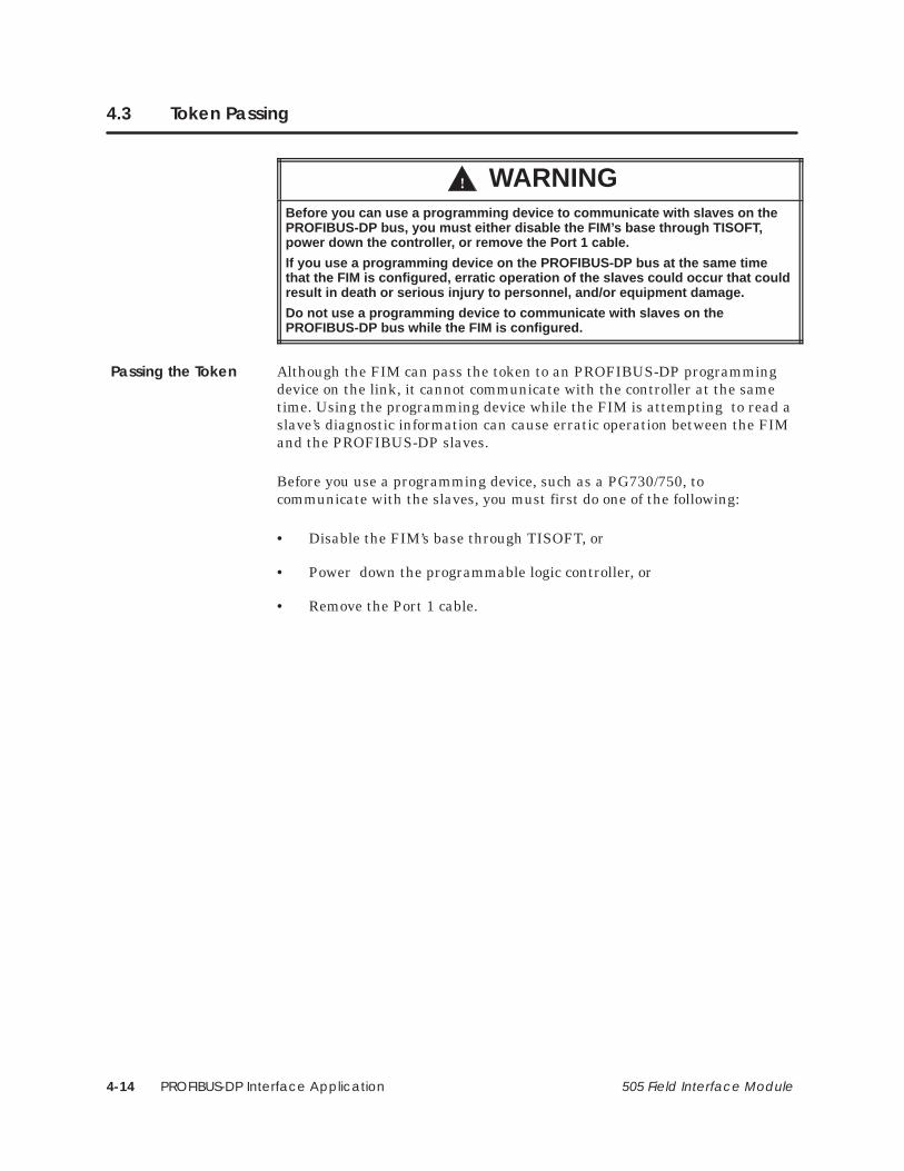
PROFIBUS-DP Interface Application4-14 505 Field Interface Module
4.3 Token Passing
! WARNINGBefore you can use a programming device to communicate with slaves on thePROFIBUS-DP bus, you must either disable the FIM’s base through TISOFT ,power down the controller , or remove the Port 1 cable.
If you use a programming device on the PROFIBUS-DP bus at the same timethat the FIM is configured, erratic operation of the slaves could occur that couldresult in death or serious injury to personnel, and/or equipment damage.
Do not use a programming device to communicate with slaves on thePROFIBUS-DP bus while the FIM is configured.
Although the FIM can pass the token to an PROFIBUS-DP programmingdevice on the link, it cannot communicate with the controller at the sametime. Using the programming device while the FIM is attempting to read aslave’s diagnostic information can cause erratic operation between the FIMand the PROFIBUS-DP slaves.
Before you use a programming device, such as a PG730/750, tocommunicate with the slaves, you must first do one of the following:
• Disable the FIM’s base through TISOFT, or
• Power down the programmable logic controller, or
• Remove the Port 1 cable.
Passing the Token

PROFIBUS-DP Interface Application 4-15505 Field Interface Module
Some slaves may use the token rotation (or lack of it) to determine thestatus of the PROFIBUS-DP link. In these cases, the token passing isselected with dipswitch S3–8.
Dipswitch S3–8 in the Open/Off/1 position indicates that token passing isenabled and that the FIM will attempt to pass the token to anotherPROFIBUS-DP master at address 0.
The default for S3–8 is Closed/On/0 (token passing disabled). Use tokenpassing only when necessary: it slightly reduces the performance of thescan. Consult your slave manual(s) for any requirements of token passing.
NOTE: The hand-held programming device requires that the master (FIM)is either removed or powered down when used to communicate with thePROFIBUS-DP slaves.

PROFIBUS-DP Interface Application4-16 505 Field Interface Module
4.4 FIM I/O Update Scan
The PROFIBUS-DP link can be set at baud rates up to 1.5M bits per second.Some PROFIBUS-DP links operate at 12M bits per second, but the FIM iscurrently limited to 1.5M. The PROFIBUS-DP link is also a token ringnetwork that is optimized for I/O exchange (PROFIBUS-DP), which meansscan update times can be a fraction of programmable controller scan times.This also means that I/O update is virtually synchronous.
If a low baud rate is used, it is possible for the programmable controllerscan to be shorter than the FIM update scan. The I/O update takes placefrom the last programmable controller scan update, regardless of the scantimes. This means that all output data going to all slaves on a FIM comesfrom the same programmable controller scan. All input data going to theprogrammable controller from all slaves on a FIM is updated on the sameprogrammable controller scan.
The FIM attempts to locate or add one new slave every scan. Once a newslave is identified, it is reported to the programmable controller and, if theslave has been previously configured, the FIM begins updating its I/O.
Most slaves use a watchdog timer which monitors time betweencommunications from the FIM. When communication between the FIM andthe slave is broken, the watchdog timer on the slave will expire and set theoutput points to a safe state. The safe state may vary depending on theslave’s design, but most slaves set the output points to zero. Refer to yourslave manual(s) for more information about slave watchdog timer reaction.
The FIM also has a watchdog timer on the communication port to thecontroller. The FIM watchdog timer expires when communication betweenthe controller and the FIM is lost. When a FIM’s base number is disabledby TISOFT, or the controller detects a hard error in the system, thecontroller sends an OUTDIS (outputs disabled) request to the FIM. In FIMRelease 3.1 and higher, the FIM’s watchdog timer expiration and theseOUTDIS events cause the FIM to stop all communication on thePROFIBUS-DP port. This broken communication forces the watchdogtimers on the slaves to expire, which should set the output points to a safestate. When TISOFT performs a read base status, the FIM will retain theprevious I/O base status until communication to the slaves is resumed.
The FIM restarts communications to the slaves in the following events:
• If an error has been detected by the controller, when the error iscleared by the controller.
• If the FIM watchdog timer has timed out, when communicationbetween the FIM and the controller is restored.
• If the base number was disabled by TISOFT, when the base isre-enabled or when the FIM is power-cycled.
FIM I/O UpdateScan
System ErrorHandling

PROFIBUS-DP Interface Application 4-17505 Field Interface Module
4.5 Configuring Slaves
The FIM identifies and reports slaves in terms of I/O points, as though theywere actual modules in a remote base. You must configure slaves (assign I/Oaddresses) before the FIM will update them.
The error configuration can occur, but it depends on the amount of I/O aslave reports. The error configuration is reported as 32X, 32Y, 32WX, and32WY, and the module reports a failed condition. This occurs when the slavehas more I/O points of any one type than can be reported in one slot of abase (the FIM); for instance, if the slave has more than 64 points of any onepoint type, or more than 32 points of any single point type when there ismore than one point type of I/O for that slave.
You can also configure the slave by byte matching. This allows other pointtypes to be substituted for the actual point types in the slave configuration.Byte matching can also be used to conserve I/O points. For moreinformation on byte matching, refer to Section 4.6.
NOTE: If a slave has 29, 30, 31, or 32 word points, whether word inputs orword outputs, they must be configured as 32 points, and are reported as 32points if a Read Base is performed by TISOFT.
To configure a slave, you must enter the desired I/O address to assign toeach slave in a base. Examples of slaves configured by using TISOFT follow.When the slaves are configured properly, the assigned input points areupdated immediately with data from the slave, and the output points arewritten to the slave.
Configuring Slaves

PROFIBUS-DP Interface Application4-18 505 Field Interface Module
Configuring Slaves (continued)
Example 1 uses an ET 200B block at slave address 20 (14 hexadecimal). AnET 200B block is a PROFIBUS-DP remote I/O device that contains variousarrangements of input and output points. In this example, the ET 200Bcontains 32 discrete output points (32Y), and because of the slave address,the ET 200B appears in slot 4 in the FIM’s base as 32Y (see Figure 4-4).
2 0
RS-485 to FieldInterface Module
ET 200B
StationAddress
Field WiringConnections
110 VACField PowerConnection
Figure 4-4 ET 200B 32-Point 110V A/C Output
ConfigurationExample 1

PROFIBUS-DP Interface Application 4-19505 Field Interface Module
The ET 200B block is assigned the starting point address of 49 (decimal).Output points Y49 – Y80 in the ladder program are mapped, or assigned to,this device; see Figure 4-5. The FIM writes these points to the slave deviceonce during each FIM update scan. The FIM update scan is usually muchfaster than the programmable controller’s scan, but it depends on the baudrate, the number of slaves, and the scan time of the programmablecontroller.
Slot Number Corresponds to addresses forPROFIBUS-DP slave units. This exampleconfiguration uses FIM slave addressrange from 17 – 32.
��� ������ ���������� ��� �2������� �2���� �
�),0 �%%.&// ! � �! �1+$0(,+
��� �1*#&. ,' �(0 "+% �,.% ��� �-&$(")
�
�
�
�
�
�
�����
�����
�����
�����
�����
�����
�����
�����
����
����
����
���
����
����
����
����
�����
�����
�����
�����
�����
�����
�����
�����
��
��
��
��
��
��
��
��
��
��
��
��
��
��
��
��
��
��
��
��
��
��
��
��
��
��
��
��
��
��
��
��
��
��
��
��
��
��
��
��
��
��
��
��
��
��
��
��
��
��
��
��
��
��
�������
�������
�������
�������
�������
�������
�������
�������
�,
�,
�,
�,
�,
�,
�,
�� ��
Base Number Displays number of the current base and correspondsto number on S1.
SF Module The Field Interface Module isnot an SF Module. The defaultfor this definition is NO.
��
��
��
��
��
�
�
�����
�����
�����
�����
�����
�����
�����
�����
����
����
����
����
����
����
����
����
�����
�����
�����
�����
�����
�����
�����
�����
��
��
��
��
��
��
��
��
��
��
��
��
��
��
��
��
��
��
��
��
��
��
��
��
��
��
��
��
��
��
��
��
��
��
��
��
��
��
��
��
��
��
��
��
��
��
��
��
��
��
��
��
��
��
�������
�������
�������
�������
�������
�������
�������
�������
�,
�,
�,
�,
�,
�,
�,
�,
�� ��
�,
Figure 4-5 Sample I/O Configuration Chart

PROFIBUS-DP Interface Application4-20 505 Field Interface Module
Configuring Slaves (continued)
Example 2 uses an IM318B at slave address 17 (11 hexadecimal). AnIM318B block is a Siemens AG PROFIBUS-DP Remote I/O Base Controllerthat contains various arrangements of input and output modules. In thisexample, the IM318B contains three 8-point discrete input modules (a totalof 24 X points), an 8-point and a 4-point discrete output module (a total of12 Y points), a 3-point analog input module, and a 2-point analog outputmodule. See Figure 4-6.
8-PointDiscrete
InputModule
(8 X)
4-PointDiscreteOutputModule
(4 Y)
3-PointAnalogInput
Module
(3 WX)
8-PointDiscrete
InputModule
(8 X)
2-PointAnalogOutputModule
(2 WY)
8-PointDiscreteOutputModule
(8 Y)
8-PointDiscrete
InputModule
(8 X)
IM318BI/O
Controller
RS-485 to FIM
NOTE: IM318B I/O controller station address is set to 17 in this example.
Figure 4-6 Slave Configuration Example
Figure 4-7 illustrates how these points are configured in the programmablecontroller and how the FIM represents non-standard (to Series 505) I/Oarrangements. These can be set up on any one of its slaves. (The FIM cansupport up to 16 slaves.) This example appears in slot 1, remote address of17 (11 hexadecimal).
• The discrete output points are not divisible by 8, and the Series 505/FIM interface cannot represent discrete points, unless theyare divisible by 8. Therefore, the FIM corrects this by rounding the Ypoints up to the next divisible-by-eight number. The Y points arereported as 16Y instead of 12Y, and there are four unused discretepoints.
• The four unused points are on the first discrete output module. Thismeans that fourth, fifth, sixth, and seventh output points (Y29, Y30,Y31, and Y32 in this example) are “dummies” and do not actually exist.
ConfigurationExample 2
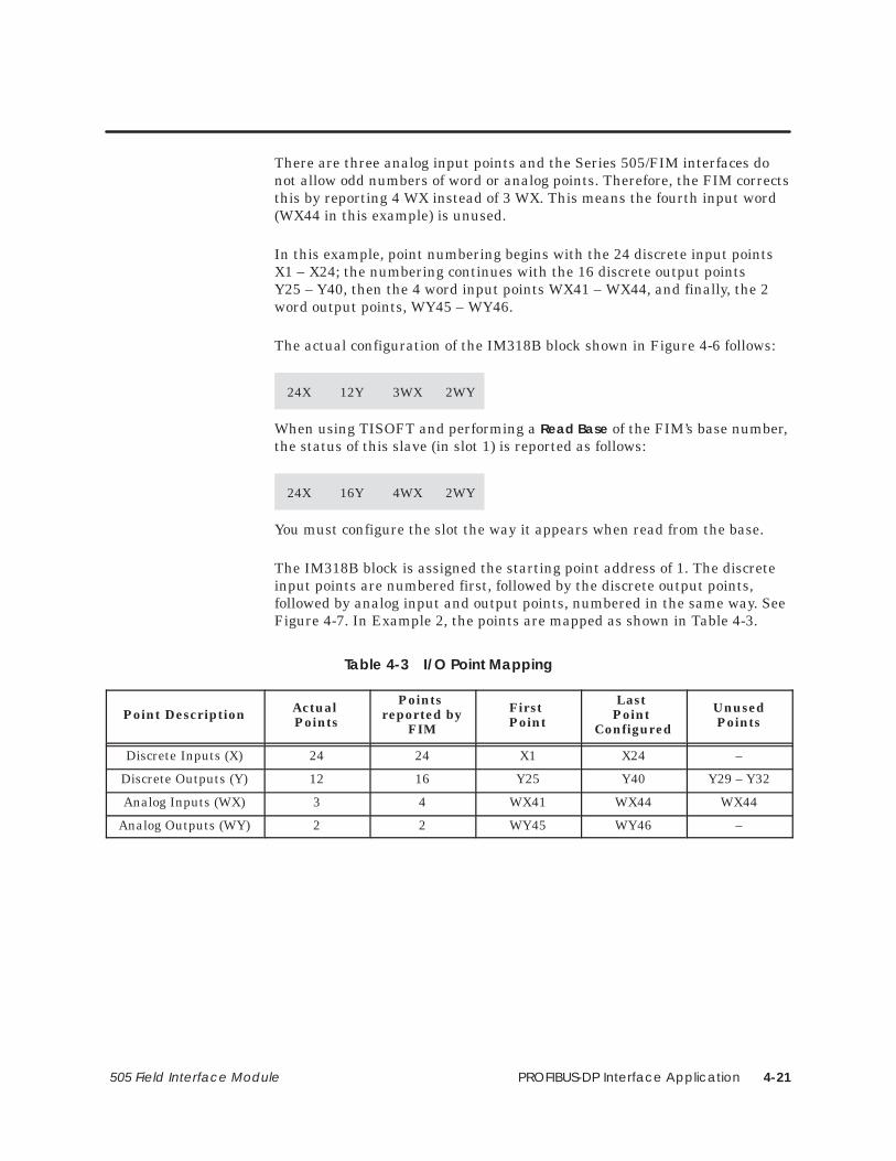
PROFIBUS-DP Interface Application 4-21505 Field Interface Module
There are three analog input points and the Series 505/FIM interfaces donot allow odd numbers of word or analog points. Therefore, the FIM correctsthis by reporting 4 WX instead of 3 WX. This means the fourth input word(WX44 in this example) is unused.
In this example, point numbering begins with the 24 discrete input pointsX1 – X24; the numbering continues with the 16 discrete output pointsY25 – Y40, then the 4 word input points WX41 – WX44, and finally, the 2word output points, WY45 – WY46.
The actual configuration of the IM318B block shown in Figure 4-6 follows:
24X 12Y 3WX 2WY
When using TISOFT and performing a Read Base of the FIM’s base number,the status of this slave (in slot 1) is reported as follows:
24X 16Y 4WX 2WY
You must configure the slot the way it appears when read from the base.
The IM318B block is assigned the starting point address of 1. The discreteinput points are numbered first, followed by the discrete output points,followed by analog input and output points, numbered in the same way. SeeFigure 4-7. In Example 2, the points are mapped as shown in Table 4-3.
Table 4-3 I/O Point Mapping
Point Description Actual Points
Points reported by
FIM
First Point
Last Point
Configured
UnusedPoints
Discrete Inputs (X) 24 24 X1 X24 –
Discrete Outputs (Y) 12 16 Y25 Y40 Y29 – Y32
Analog Inputs (WX) 3 4 WX41 WX44 WX44
Analog Outputs (WY) 2 2 WY45 WY46 –

PROFIBUS-DP Interface Application4-22 505 Field Interface Module
Configuring Slaves (continued)
Slot Number Corresponds to addresses forPROFIBUS-DP slave units. This exampleconfiguration uses FIM slave addressrange from 17 – 32.
��� ������ ���������� ��� �2������� �2���� �
�),0 �%%.&// ! � �! �1+$0(,+
��� �1*#&. ,' �(0 "+% �,.% ��� �-&$(")
�
�
�
�
�
�
�����
�����
�����
�����
�����
�����
�����
�����
����
����
����
����
����
����
����
����
�����
�����
�����
�����
�����
�����
�����
�����
��
��
��
��
��
��
��
��
��
��
��
��
��
��
��
��
�
��
��
��
��
��
��
��
��
��
��
��
��
��
��
��
��
��
��
��
��
��
��
��
��
��
��
��
��
��
��
��
��
��
��
��
��
��
�������
�������
�������
�������
�������
�������
�������
�������
�,
�,
�,
�,
�,
�,
�,
�� ��
Base Number Displays number of the current base and correspondsto number on S1.
SF Module The Field Interface Module isnot an SF Module. The defaultfor this definition is NO.
��
��
��
��
��
�
�
�����
�����
�����
�����
�����
�����
�����
�����
����
����
����
����
����
����
����
����
�����
�����
�����
�����
�����
�����
�����
�����
��
��
��
��
��
��
��
��
��
��
��
��
��
��
��
��
��
��
��
��
��
��
��
��
��
��
��
��
��
��
��
��
��
��
��
��
��
��
��
��
��
��
��
��
��
��
��
��
��
��
��
��
��
��
�������
�������
�������
�������
�������
�������
�������
�������
�,
�,
�,
�,
�,
�,
�,
�,
�� ��
�,
Figure 4-7 Sample I/O Configuration Chart

PROFIBUS-DP Interface Application 4-23505 Field Interface Module
4.6 Configuring by Byte Matching
Byte match configuration is an alternative technique that you can use toconfigure a FIM slot with different point types than it actually has. TISOFT,Rel. 5.1 or later, is required to do some byte-matching configurations. Usebyte matching in the following instances.
• When the slave’s actual I/O point count is greater than the Series 505programmable controllers allow for any one slot, you get an errorconfiguration (namely, 32X, 32Y, 32WX, and 32WY). The Series 505programmable controllers limit the I/O point count of one slot (a slaveto the FIM) in a base (the FIM itself) to a maximum of 64 of one pointtype (X, Y, WX, or WY), and up to 32 of each point type if multiple pointtypes are used.
• To save I/O points and represent discrete points as word points.
A byte is referred to as eight bits: eight discrete points equal one byte. Aword or analog point equals two bytes.
When you apply byte matching to input points (X and WX), the number ofconfigured input bytes must equal the number of actual input bytes. Whenyou apply byte matching to output points (Y and WY), the number ofconfigured output bytes must equal the number of actual output bytes.
When you configure the programmable controller/base with TISOFT, youare telling the FIM how many bytes you expect, in terms of X, Y, WX, andWY points on your PROFIBUS-DP slaves. You are also assigning the bytesan address for your ladder program. In order for the FIM and theprogrammable controller to exchange these bytes, this configuration mustagree with what the FIM actually finds connected to its communication link.
With byte matching, you can tell the FIM to treat groups of 16 discretepoints (X and Y) as though they were one word point (WX or WY), and viceversa.
You can apply byte matching to input points (X and WX) and to outputpoints (Y and WY) in a mutually exclusive manner. You can configure theoutputs normally, and apply byte matching to the input points only, or viceversa. You can also apply it to both inputs and outputs at the same time.
Using Byte MatchConfiguration

PROFIBUS-DP Interface Application4-24 505 Field Interface Module
Configuring by Byte Matching (continued)
Follow the steps below to byte match input points:
1. Determine the actual number of discrete (X) and word (WX) inputpoints present on the slave.
NOTE: You may not be able to determine the actual number of discreteinput points using the Read Base function of TISOFT, because the FIMadjusts the represented number of points to meet the Series 505requirements. Also, the FIM may be returning the error configuration forthat slave. For more information about the configuration process, refer toSection 4.5.
2. Determine the number of input bytes:
Divide the number of discrete input points (Xs) by eight.Multiply the number of word or analog input points (WXs) by two. Add the results together. For example:
Input Bytes=(#X points / 8) + (2 * #WX points)
3. Determine how you want to represent these bytes; use any validcombination of X or WX points.
You must use multiples of four bytes (2 WX = 4 bytes) when assigningsome of the bytes to analog points. You cannot have more than a total of32 of these word or analog points if more than one of these point typesis used, or more than 64 of these word or analog points if only one pointtype is used. You are limited to four bytes (32X = 4 bytes) when you areassigning bytes to discrete inputs because of the 32 point limit, or eightbytes (64X = 8 bytes) if only one point type is used.
4. Once you have determined the arrangement of input bytes, configurethe programmable controller both with this arrangement of inputbytes and any output points. If the bytes match, then, when youperform a Read Base, the FIM reports this configuration as though theI/O were actually as you have it configured. If there is a mismatch,then the FIM reports either the actual I/O arrangement or the errorconfiguration.
Procedure for ByteMatching InputPoints

PROFIBUS-DP Interface Application 4-25505 Field Interface Module
Follow the steps below to byte match output points:
1. Determine the actual number of discrete (Y) and word (WY) outputpoints present on the slave.
NOTE: You may not be able to determine the actual number of discretepoints present on the slave using the Read Base function of TISOFT, becausethe FIM adjusts the represented number of points to meet the Series 505requirements, instead of adjusting the actual number of output points. Also,the FIM may be returning the error configuration for this slave. For moreinformation about the configuration process, refer to Section 4.5.
2. Determine the number of output bytes you have:
Divide the number of discrete output points (Ys) by eight.Multiply the number of word or analog output points (WYs) by two. Add the results together. For example:
Output Bytes = (#Y points / 8) + (2 * #WY points)
3. Determine how you want to represent these bytes; use any validcombination of Y or WY points.
You must use multiples of four bytes (2 WY = 4 bytes) when assigningsome of the bytes to analog points. You cannot have more than a total of32 of these word or analog points if more than one of these point typesare used, or more than 64 of these word or analog points if only onepoint type is used. You are limited to four bytes (32Y = 4 bytes) whenyou are assigning them to discrete outputs because of the 32 pointlimit, or eight bytes (64Y = 8 bytes) if only one point type is used.
4. Once you have determined the arrangements of output bytes, configurethe programmable controller with both this arrangement of outputbytes and any input configuration. If the bytes match, then when youperform a Read Base, the FIM reports this configuration as though theI/O were actually as you have it configured. If there is a mismatch, theFIM reports either the actual I/O arrangement or the errorconfiguration.
Procedure for ByteMatching OutputPoints

PROFIBUS-DP Interface Application4-26 505 Field Interface Module
Configuring by Byte Matching (continued)
Using the ET 200B block in Figure 4-4 (see page 4-18), you can demonstratea byte match configuration. In this example, we have 32 discrete outputpoints (32Y) and no other point types.
You can conserve I/O points and represent this ET 200B slave as wordoutput points (WY). Use the procedure for byte matching output points:first, determine the number of discrete output points (32) and word outputpoints (0) that are actually on the slave; then, determine the number ofoutput bytes as follows:
Output Bytes = (32Y / 8) + (0WY * 2) = 4
You can place as many of the output bytes into word point types as possibleby dividing the number of bytes by two to get the number of words (2WY).In the example, the Y points took addresses 49 – 80.
Configure the points as WY49 and WY50. A slot in a base (or slave on aFIM) must be configured in multiples of eight. Addresses 49 – 56 are used(even though there are only two points used), but addresses 57 – 80 areavailable for other uses, and the same data is sent to the programmablecontroller from the slave. In ladder logic, you can use the individual bits ofword points the same way as you use discrete points; there is nodisadvantage to mapping discrete I/O as word I/O.
Byte MatchingConfigurationExample 1

PROFIBUS-DP Interface Application 4-27505 Field Interface Module
Figure 4-6 (page 4-20) illustrates byte match configuring with the actualstatus of the IM318B. The following example uses the actual status of theslave, IM318B:
24X 12Y 3WX 2WY
The FIM reports this I/O arrangement as follows:
24X 16Y 4WX 2WY
Since word points must be in even numbers, 1WX or word point is not used.Use byte matching both to reduce the point count and to use that unusedpoint. To implement byte matching, apply the “Procedure for Byte MatchingInput Points,” described on page 4-24. Determine the number of discreteinput points (24X) and word input points (3WX) that are actually on theslave. Next, use the following formula to determine the number of inputbytes from these points:
Input Bytes = (24X/ 8) + (3WX * 2)Input Bytes = 3 + 6 = 9 bytes
Take the nine bytes and divide by two to determine how many of these bytesto use as word points. This gives eight bytes, or 4WX points. Determine thenumber of bytes left that must be applied to the discrete points. There is onebyte left, and, since each byte gives eight discrete points, then (1 * 8) = 8X.You configure the slot in the base with:
8X 16Y 4WX 2WY
With this configuration, the FIM matches the slave I/O and begins updatingthe IM318B. The only unused points are the four discrete output points (Y),but all four word input points are now used, and the number of points takenup is reduced by 16 points because the 24X is now 8X (with the other 16points appearing in the first analog word). The FIM now reports the I/Oarrangement of the IM318B just as it is shown above, as though this werethe actual I/O configuration.
Byte MatchingConfigurationExample 2

PROFIBUS-DP Interface Application4-28 505 Field Interface Module
Configuring by Byte Matching (continued)
Byte matching in example 3 illustrates a more complex byte matchingconfiguration. See Figure 4-8.
24-PointDiscrete
InputModule
(24 X)
4-PointDiscreteOutputModule
(4 Y)
3-PointAnalogInput
Module
(3 WX)
8-PointDiscrete
InputModule
(8 X)
2-PointAnalogOutputModule
(2 WY)
8-PointDiscreteOutputModule
(8 Y)
8-PointDiscrete
InputModule
(8 X)
IM318BI/O
Controller
RS-485 to FIM
NOTE: IM318B I/O controller station address is set to 17 in this example.
Figure 4-8 Slave Configuration Example
Figure 4-8 is similar to Figure 4-6, but the first 8-point discrete inputmodule is replaced with a 24-point discrete input module in the IM318B I/Ocontroller. The actual status of this slave (IM318B) follows:
40X 12Y 3WX 2WY
The FIM cannot report this configuration, because there are more than 32points of any one point type (40X). Instead, the FIM reports the errorconfiguration which follows:
32X 32Y 32WX 32WY
When you see this configuration, you know that there are more points ofany one type than can be represented. In most cases, this can be resolvedusing byte matching, which you must do if this slave is to be used as it ishere. To implement byte matching, apply the “Procedure for Byte MatchingInput Points,” described on page 4-24. Determine the number of discreteinput points (40X) and word input points (3WX) that are actually on theslave. Next, use the following formula to determine the number of inputbytes from these points:
Input Bytes = (40X/ 8) + (3WX * 2)Input Bytes = 5 + 6 = 11 bytes
Byte MatchingConfigurationExample 3

PROFIBUS-DP Interface Application 4-29505 Field Interface Module
To determine how many bytes can be used as word points, take the numberof bytes (11) and divide by two, because word points must be an evennumber. The result is 4WX points, or eight bytes. You cannot use ten bytes,because this equals 5WX points when divided by two.
Next, determine the number of remaining bytes that must be applied to thediscrete points. There are three bytes left, and since each byte gives eightdiscrete points, then (3 * 8) = 24X. Now, configure the slot in the base asshown below:
24X 16Y 4WX 2WY
With this configuration, the FIM matches the configuration and beginsupdating the IM318B. The FIM reports the I/O arrangement of the IM318Bjust as it is shown above, as though this were the actual I/O configuration.

PROFIBUS-DP Interface Application4-30 505 Field Interface Module
Configuring by Byte Matching (continued)
When you perform byte matching, the data is placed in different positions.There are two ways of determining these new positions.
• You can turn on a given I/O point and read it in the programmablecontroller (in the case of an input point); or you can FORCE it in theprogrammable controller and then check to see whether or not thatpoint is energized (in the case of an output point).
• You can determine the positioning of inputs first, then determine thepositioning of the outputs. The Series 505 programmable controllernumbers the bits in decreasing order within a word. The tables belowshow you which byte of a word the eight bits (Xs or Ys) are applied to.However, the discrete points are numbered in increasing order. Theorientation of the bits within a word are shown in Table 4-4 andTable 4-5.
Byte MatchingConfiguration DataPositioning

PROFIBUS-DP Interface Application 4-31505 Field Interface Module
Table 4-4 Input Bytes WX<–>X
MSBofbyte
Most Significant Byte (MSB) of WX1LSBofbyte
MSBofbyte
Least Significant Byte (LSB) of WX1LSBofbyte
bit 1 bit 2 bit 3 bit 4 bit 5 bit 6 bit 7 bit 8 bit 9 bit 10 bit 11 bit 12 bit 13 bit 14 bit 15 bit 16
X16 X15 X14 X13 X12 X11 X10 X9 X8 X7 X6 X5 X4 X3 X2 X1
Table 4-5 Output Bytes WY<–>Y
MSBofbyte
Most Significant Byte (MSB) of WY1LSBofbyte
MSBofbyte
Least Significant Byte (LSB) of WY1LSBofbyte
bit 1 bit 2 bit 3 bit 4 bit 5 bit 6 bit 7 bit 8 bit 9 bit 10 bit 11 bit 12 bit 13 bit 14 bit 15 bit 16
Y16 Y15 Y14 Y13 Y12 Y11 Y10 Y9 Y8 Y7 Y6 Y5 Y4 Y3 Y2 Y1

PROFIBUS-DP Interface Application4-32 505 Field Interface Module
Configuring by Byte Matching (continued)
If there are more configured word input points than actual word inputpoints, use the “Overmapping Word Input Points” procedure; if there arefewer configured word input points than actual word input points, use the“Overmapping Discrete Input Points” procedure. Descriptions of bothprocedures follow.
If there are more configured word input points than actual word inputpoints, use the procedure described below.
This example uses an actual arrangement of:
40X 8Y 1WX
and is configured to:
24X 8Y 2WX
1. Group the actual discrete input bytes together, and the actual wordinput bytes together, as shown below.
Byte # 1 2 3 4 5 6 7
Actual Input Bytes X1 – X8 X9 – X16 X17 – X24 X25 – X32 X33 – X40 1WX LSB 1WX MSB
2. Group the configured discrete input bytes together, and the configuredword input bytes together, as shown below.
Byte # 1 2 3 4 5 6 7
Configured Input Bytes X1 – X8 X9 – X16 X17 – X24 1WX LSB 1WX MSB 2WX LSB 2WX MSB
3. If there are any configured discrete input bytes, they are applied firstto the actual discrete input bytes, byte for byte. For example, the firstbyte of actual discrete input goes to the first byte of configured discreteinputs, the second byte of actual discrete inputs goes to the second byteof configured discrete inputs, and so forth.
Actual Input Bytes X1 – X8 X9 – X16 X17 – X24 X25 – X32 X33 – X40 1WX LSB 1WX MSB
Configured Input Bytes X1 – X8 X9 – X16 X17 – X24
Byte MatchingInput Points
OvermappingWord Input Points

PROFIBUS-DP Interface Application 4-33505 Field Interface Module
4. Beginning with the remaining actual discrete input bytes from step 3(or the first actual discrete input bytes if there were no configuredinput bytes in step 3), apply the first configured word points. Whenapplying two bytes of discretes to the two bytes of a word, the lowestnumbered discrete byte is applied to the Least Significant Byte (LSB)of the word, and the next higher numbered discrete input byte isapplied to the Most Significant Byte (MSB) of the word.
Actual Input Bytes X1 – X8 X9 – X16 X17 – X24 X25 – X32 X33 – X40 1WX LSB 1WX MSB
Configured Input Bytes X1 – X8 X9 – X16 X17 – X24 1WX LSB 1WX MSB
5. If there are actual word points, then apply them directly to the nextavailable configured word points from step 4. For example, the lowestnumbered actual input word is applied to the lowest numberedavailable in the configuration input word, and so forth.
Actual Input Bytes X1 – X8 X9 – X16 X17 – X24 X25 – X32 X33 – X40 1WX LSB 1WX MSB
Configured Input Bytes X1 – X8 X9 – X16 X17 – X24 1WX LSB 1WX MSB 2WX LSB 2WX MSB

PROFIBUS-DP Interface Application4-34 505 Field Interface Module
Configuring by Byte Matching (continued)
If there are fewer configured word input points than actual word inputpoints, use the procedure described below.
This example uses an actual arrangement of:
8X 8Y 3WX
and is configured to:
24X 8Y 2WX
1. Group the actual discrete input bytes together, and the actual wordinput bytes together, as shown below.
Byte # 1 2 3 4 5 6 7
Actual Input Bytes X1 – X8 1WX LSB 1WX MSB 2WX LSB 2WX MSB 3WX LSB 3WX MSB
2. Group the configured discrete input bytes together, and the configuredword inputs bytes together, as shown below.
Byte # 1 2 3 4 5 6 7
Configured Input Bytes X1 – X8 X9 – X16 X17 – X24 1WX LSB 1WX MSB 2WX LSB 2WX MSB
3. If there are any actual discrete input bytes, they are applied to theconfigured discrete input bytes, byte for byte. For example, the firstbyte of actual discrete input goes to the first byte of configured discreteinputs, and so forth.
Actual Input Bytes X1 – X8 1WX LSB 1WX MSB 2WX LSB 2WX MSB 3WX LSB 3WX MSB
Configured Input Bytes X1 – X8
OvermappingDiscrete InputPoints

PROFIBUS-DP Interface Application 4-35505 Field Interface Module
4. Beginning with the first actual word input byte, apply the remainingconfigured discrete input bytes (or first configured discrete input bytesif there were no actual discrete input bytes from step 3).
When applying the two bytes of an input word to two bytes of discreteinput, the Least Significant Byte (LSB) of the word is applied to thelowest numbered discrete input byte, and the Most Significant Byte(MSB) of the word is applied to the next higher numbered discreteinput byte.
Actual Input Bytes X1 – X8 1WX LSB 1WX MSB 2WX LSB 2WX MSB 3WX LSB 3WX MSB
Configured Input Bytes X1 – X8 X9 – X16 X17 – X24
5. If there are configured word points, then apply them directly to thenext available actual input word points from step 4. For example, thelowest numbered available actual word input is applied to the lowestnumbered configured input word, and so forth.
Actual Input Bytes X1 – X8 1WX LSB 1WX MSB 2WX LSB 2WX MSB 3WX LSB 3WX MSB
Configured Input Bytes X1 – X8 X9 – X16 X17 – X24 1WX LSB 1WX MSB 2WX LSB 2WX MSB

PROFIBUS-DP Interface Application4-36 505 Field Interface Module
Configuring by Byte Matching (continued)
If there are more configured word output points than actual word outputpoints, use the “Overmapping Word Output Points” procedure. If there arefewer configured word output points than actual word output points, use the“Overmapping Discrete Output Points” procedure. Descriptions of bothprocedures follow.
If there are more configured word output points than actual word outputpoints, use the procedure described below.
This example uses an actual arrangement of:
8X 40Y 1WY
and is configured to:
8X 24Y 2WY
1. Group the actual discrete output bytes together, and the actual wordoutput bytes together, as shown below.
Byte # 1 2 3 4 5 6 7
Actual Output Bytes Y1 – Y8 Y9 – Y16 Y17 – Y24 Y25 – Y32 Y33 – Y40 1WY LSB 1WY MSB
2. Group the configured discrete output bytes together, and the configuredword outputs bytes together, as shown below.
Byte # 1 2 3 4 5 6 7
Configured Output Bytes Y1 – Y8 Y9 – Y16 Y17 – Y24 1WY LSB 1WY MSB 2WY LSB 2WY MSB
3. If there are any configured discrete output bytes, they are applied firstto the actual discrete output bytes, byte for byte. For example, the firstbyte of configured discrete outputs goes to first byte of actual discreteoutputs, and so forth.
Configured Output Bytes
Y1 – Y8 Y9 – Y16 Y17 – Y24 1WY LSB 1WY MSB 2WY LSB 2WY MSB
Actual Output Bytes Y1 – Y8 Y9 – Y16 Y17 – Y24
Byte MatchingOutput Points
OvermappingWord Output Points

PROFIBUS-DP Interface Application 4-37505 Field Interface Module
4. Beginning with the remaining actual discrete output bytes from step 3(or the first actual discrete output bytes if there were no configuredoutput bytes in step 3), apply discrete output bytes to the firstconfigured word points.
When applying two bytes of discretes to the two bytes of a word, thelowest numbered discrete byte is applied to the LSB of the output word,and the next higher numbered discrete output byte is applied to theMSB of the output word.
ConfiguredOutput Bytes Y1 – Y8 Y9 – Y16 Y17 – Y24 1WY LSB 1WY MSB 2WY LSB 2WY MSB
Actual Output Bytes Y1 – Y8 Y9 – Y16 Y17 – Y24 Y25 – Y32 Y33 – Y40
5. If there are actual output word points, then apply them directly to thenext available configured output word points from step 4. For example,the lowest numbered available configured output word is applied to thelowest numbered actual output word, and so forth.
Configured Output Bytes Y1 – Y8 Y9 – Y16 Y17 – Y24 1WY LSB 1WY MSB 2WY LSB 2WY MSB
Actual Output Bytes Y1 – Y8 Y9 – Y16 Y17 – Y24 Y25 – Y32 Y33 – Y40 1 WY LSB 1WY MSB

PROFIBUS-DP Interface Application4-38 505 Field Interface Module
Configuring by Byte Matching (continued)
If there are fewer configured word output points than actual word outputpoints, use the procedure described below.
This example uses an actual arrangement of:
8X 8Y 3WY
and is configured to:
8X 24Y 2WY
1. Group the actual discrete output bytes together, and the actual wordoutput bytes together, as shown below.
Byte # 1 2 3 4 5 6 7
Actual Output Bytes Y1 – Y8 1WY LSB 1WY MSB 2WY LSB 2WY MSB 3WY LSB 3WY MSB
2. Group the configured discrete output bytes together, and the configuredword output bytes together, as shown below.
Byte # 1 2 3 4 5 6 7
Configured Output Bytes Y1 – Y8 Y9 – Y16 Y17 – Y24 1WY LSB 1WY MSB 2WY LSB 2WY MSB
3. If there are any actual discrete output bytes, they are applied to theconfigured discrete output bytes, byte for byte. For example, the firstbyte of configured outputs goes to the first byte of actual outputs, andso forth.
ConfiguredOutput Bytes
Y1 – Y8 Y9 – Y16 Y17 – Y24 1WY LSB 1WY MSB 2WY LSB 2WY MSB
Actual Output Bytes Y1 – Y8
OvermappingDiscrete OutputPoints

PROFIBUS-DP Interface Application 4-39505 Field Interface Module
4. Beginning with the first actual word output byte, apply the remainingconfigured discrete output bytes (or first configured discrete outputbytes if there were no actual discrete output bytes from step 3).
When applying the two bytes of an output word to two bytes of discreteoutput, the LSB of the output word is applied to the lowest numbereddiscrete output byte and the MSB of the output word is applied to thenext higher numbered discrete output byte.
ConfiguredOutput Bytes Y1 – Y8 Y9 – Y16 Y17 – Y24 1WY LSB 1WY MSB 2WY LSB 2WY MSB
Actual Output Bytes Y1 – Y8 1WY LSB 1WY MSB
5. If there are configured output word points, then apply them directly tothe next available actual output word points from step 4. For example,the lowest numbered configured output word is applied to the lowestnumbered available in the actual output word, and so forth.
ConfiguredOutput Bytes Y1 – Y8 Y9 – Y16 Y17 – Y24 1WY LSB 1WY MSB 2WY LSB 2WY MSB
Actual Output Bytes Y1 – Y8 1WY LSB 1WY MSB 2WY LSB 2WY MSB 3WY LSB 3WY MSB

PROFIBUS-DP Interface Application4-40 505 Field Interface Module
4.7 FIM PROFIBUS-DP I/O Cable Specifications
Table 4-6, Table 4-7, and Table 4-8 list the PROFIBUS DIN 19245specifications. Two of the baud rates (375K and 750K) supported by the FIMare non-standard for PROFIBUS DIN 19245 and linear interpolations aremade to derive the values in Table 4-7.
Table 4-6 PROFIBUS Line Specifications
Parameter Value
Impedance 135 – 165 Ohm (3 – 20 MHz)
Capacitance 9.1 pF/ft. (<30 nF/km)
Resistance 33.5 �/1000 ft. (<110 Ohm/km)
Attenuation 0.27 dB/100 ft.(0.9 dB/100 m (f=200kHz))
Conductor Area 20 – 22 AWG (0.3 mm2 ... 0.5 mm2)
Cable Diameter 0.315 in. � 0.02 in. (8 mm � 0.5 mm)
Table 4-7 PROFIBUS Line Length
PROFIBUS Line Length
Baud Rate Distance Repeaters(1)
Repeaters(2)
Repeaters(3)
9.6k baud 1200m 2400m 3600m 4800m
19.2k baud 1200m 2400m 3600m 4800m
93.75k baud 1200m 2400m 3600m 4800m
187.5k baud 1000m 1200m 1800m 2400m
*375k baud 640m 720m 1080m 1440m
500k baud 400m 400m 600m 800m
*750k baud 350m
1500k baud 200m
* Derived from linear interpolations of adjacent baud rates.
Note: The maximum number of repeaters between two stations is 3.
PROFIBUS Cableand ConnectorSpecifications

PROFIBUS-DP Interface Application 4-41505 Field Interface Module
The order number for the PROFIBUS LAN Cable is 6XV1 830–0AH10.See Table 4-8 for PROFIBUS connector order numbers.
Table 4-8 PROFIBUS Cable and Connector Order Numbers
PROFIBUS ConnectorOrder Numbers Comment
6ES7 972–0BA00–0XA0 without PG connection; maximum baud rate 1.5M bps
6ES7 972–0BB00–0XA0 with PG connection; maximum baud rate 1.5M bps
6ES7 972–0BA10–0XA0 without PG connection
6ES7 972–0BB10–0XA0 with PG connection
6ES7 972–0BA20–0XA0 without PG connection; has pivoting strain relief
6ES7 972–0BB20–0XA0 with PG connection; has pivoting strain relief
PROFIBUS Cableand ConnectorOrder Numbers

PROFIBUS-DP Interface Application4-42 505 Field Interface Module
4.8 Troubleshooting
The following pages present common troubleshooting symptoms, causes,and corrective actions.
When the MOD GOOD LED is off, this indicates that the module is notreceiving power or has failed. Use the following checklist to troubleshootthis condition:
• Re-seat the board.
• Check for bent pins on the board connector.
• Check the power supply of the base.
• Check switch settings.
If none of these suggestions works, the module has probably failed. Returnit to the factory for repair.
The MOD GOODLED Is Off—What’sWrong?

PROFIBUS-DP Interface Application 4-43505 Field Interface Module
When the COMM LED is off, this indicates that the FIM is notcommunicating with the CPU. When the FIM establishes goodcommunication to the CPU, the COMM LED turns on. Use the followingchecklist to troubleshoot this condition:
• Make sure the CPU and the FIM are powered up and working. TheMOD GOOD LED on the FIM should be on, and the CPU GOOD LEDon the CPU should be on.
• Check the dipswitches on the FIM. Dipswitch S3 selects the applicationtype. See page 4-8 to ensure that the FIM is set correctly forPROFIBUS-DP.
• Make sure the base number for the FIM is enabled in the controller.The FIM is a remote base, like an RBC. If all remote bases are disabled(1–15), then the CPU does not communicate to the FIM or any otherbase on the remote link. Also, check to make sure the base address forthe FIM is set to the proper base number. The base address switch is onthe front bezel of the FIM and is labeled as S1.
NOTE: Base #0 is the local base of the CPU and cannot be used as a remotebase except with CPUs that do not have a local base.
• Check the connection of the RS-485 cable between the CPU’s I/O portand the FIM’s Port 1. Check the physical connections of the cable,check the cable pinouts for proper wiring, check the cable wire. Tryreplacing the cable with a different cable.
• If the CPU is communicating with other FIMs or RBCs, then tryreplacing this FIM.
• If the CPU is not communicating with other FIMs or RBCs, then tryreplacing the CPU.
The COMM LED IsOff—What’sWrong?

PROFIBUS-DP Interface Application4-44 505 Field Interface Module
Troubleshooting (continued)
When the CFG LED is off, this indicates that the FIM has not received theuser configuration from the CPU. Use the following checklist to troubleshootthis problem:
• Make sure the FIM’s COMM LED is on before attempting to get theCFG LED on.
• Check to make sure the base address for the FIM is set to the properbase number. The base address switch is on the front bezel of the FIMand is labeled as S1.
NOTE: Base #0 is the local base of the CPU and cannot be used as a remotebase except with CPUs that do not have a local base.
• Check to make sure that the base used by the FIM is enabled and isconfigured with I/O. If the base corresponding to the FIM is written tothe CPU as an empty base, then no user configuration is sent to theFIM.
• Check the cable and connection to Port 1.
If none of these suggestions works, the FIM has probably failed. Return it tothe factory for repair.
The CFG LED IsOff—What’sWrong?

PROFIBUS-DP Interface Application 4-45505 Field Interface Module
When the CFG LED is blinking, this indicates that while the FIM iscommunicating with the CPU, and the FIM has been configured by theCPU, the I/O with which the FIM is communicating does not match the userconfiguration. Use the following checklist to troubleshoot this problem:
• Check to make sure the base address for the FIM is set to the properbase number. The base address switch is on the front bezel of the FIMand is labeled as S1.
NOTE: Base #0 is the local base of the CPU and cannot be used as a remotebase except with CPUs that do not have a local base.
• Check the address range dipswitch selection on the FIM. The FIM doesnot normally communicate with slaves set to addresses outside thisrange. The FIM can communicate with any slave addresses that havebeen defined using the Edit Slave dialog box.
• Check the baud rate setting on the FIM. The baud rate switch islabeled S2 on the front bezel of the FIM.
• Check the user configuration using TISOFT. Make sure the I/O isarranged correctly. You can use the Compare Base function of TISOFTto determine which slots are suspect. Each slave device corresponds toa slot in the base.
• Make sure that all of the I/O devices are powered up. If an I/O device isnot communicating with the FIM for any reason, but the device isconfigured in the CPU, it shows up as a configuration error on the FIM.
• Check the slave device settings for the proper slave address, baud rate,etc.
• Check the configuration to see if an improper slave address isconfigured for the slave.
• Check the cable and connections between the FIM and the CPU.
• Wiring may require termination and bias. Refer to Section 2.5 fordetails on termination and bias requirements, and Section 4.2 for tipson how to build proper RS-485 connections.
If none of these suggestions works, the slave device has probably failed.Return it to the factory for repair or replacement.
The CFG LED IsBlinking—What’sWrong?

PROFIBUS-DP Interface Application4-46 505 Field Interface Module
Troubleshooting (continued)
A periodic blink of the CFG LED means that all slaves match theconfiguration, but communication to one or more slaves is being lost forsome period of time. The following list suggests guidelines fortroubleshooting this condition:
• Check to make sure there are no slaves that require parameterizationor are incorrectly parameterized. Check each slave’s manual todetermine if there are user parameterization requirements. The statusbutton feature of the Configurator indicates if a slave is correctlyparameterized.
• Check the wiring for loose or broken connections between the FIM’sPort 2 and the slaves. The connections must be in a daisy-chainconfiguration.
• Wiring may require termination and bias. Refer to Section 2.5 fordetails on termination and bias requirements, and Section 4.2 for tipson how to build proper RS-485 connections.
• Check for proper polarity of the RS-485 wire. All connections must haveRX/TX+ , RX/TX–, and GROUND common throughout the system.
• Make sure you are using the proper cable and not exceeding themaximum distance for cable and baud rate. See Table 4-9 for baudrates. Refer to Section 4.7 for line specifications and cable typerequirements.
• Check for the cable running too close to any magnetic fields (motors,high current wires, relays, etc.).
Table 4-9 Baud Rates
S2 Baud Rate S2 Baud Rate
0 1500K 8 Reserved
1 750K 9 Reserved
2 500K A Reserved
3 375K B Reserved
4 187.5K C Reserved
5 93.75K D Reserved
6 19.2K E Reserved
7 9.6K F Reserved
The CFG LED Is On,But BlinksPeriodically—What’s Wrong?

PROFIBUS-DP Interface Application 4-47505 Field Interface Module
Use TISOFT to check the operation of the module. If you experienceproblems communicating with the slaves, you can read the base statusthrough TISOFT. The base status indicates proper communication toindividual slaves by the presence of I/O points in the slot number thatcorresponds to the station address.
Read the controller status words to determine I/O presence, and the correctconfiguration of the Field Interface Module. See Table 4-10 and Table 4-11for bit mapping.
Table 4-10 shows status bits for monitoring status between the controllerand the Field Interface Module. The status words for monitoring statusbetween the Field Interface Module and the slaves are also shown inTable 4-10.
Bit number to slave number correlation to these status words is shown inTable 4-11.
Table 4-10 Controller-to-Field Interface Module (FIM) CommunicationStatus Using Controller Status Words
FIMBase #
Controller to FIM Communication Status Bit
Status Word for FIM to Slave
Communication Status
0 STW2 – Bit #16 – (least significant bit) STW11
1 STW2 – Bit #15 STW12
2 STW2 – Bit #14 STW13
3 STW2 – Bit #13 STW14
4 STW2 – Bit #12 STW15
5 STW2 – Bit #11 STW16
6 STW2 – Bit #10 STW17
7 STW2 – Bit #9 STW18
8 STW2 – Bit #8 STW19
9 STW2 – Bit #7 STW20
10 STW2 – Bit #6 STW21
11 STW2 – Bit #5 STW22
12 STW2 – Bit #4 STW23
13 STW2 – Bit #3 STW24
14 STW2 – Bit #2 STW25
15 STW2 – Bit #1 – (most significant bit) STW26
Checking theOperation of theModule

PROFIBUS-DP Interface Application4-48 505 Field Interface Module
Troubleshooting (continued)
Table 4-11 shows bit number to slave number correlation for the statuswords from Table 4-10, using base 5 as an example.
Table 4-11 Monitoring Field Interface Module (FIM) to SlaveCommunication Status Using Controller Status Words
Slave Address #(Using Address Range 17 – 32
Selected on the FIM)
FIM to Slave Communication Status Bit (Using the Base 5 Example*)
17 STW16 – Bit #16 – (least significant bit)
18 STW16 – Bit #15
19 STW16 – Bit #14
20 STW16 – Bit #13
21 STW16 – Bit #12
22 STW16 – Bit #11
23 STW16 – Bit #10
24 STW16 – Bit #9
25 STW16 – Bit #8
26 STW16 – Bit #7
27 STW16 – Bit #6
28 STW16 – Bit #5
29 STW16 – Bit #4
30 STW16 – Bit #3
31 STW16 – Bit #2
32 STW16 – Bit #1 – (most significant bit)* The number of the status word is determined by adding 11 to the number of thebase; hence the status word for base 5 is STW16.
If you have questions concerning this information, contact your Siemensdistributor or sales office. If you require assistance in contacting yourdistributor or sales office in the United States, phone 1–800–964–4114. ForU.S. Drives information, call 1–770–740–3000.
TechnicalAssistance

PROFIBUS-DP Interface Application 4-49505 Field Interface Module
4.9 Introducing the PROFIBUS-DP Configurator
The SIMATIC 505 FIM PROFIBUS-DP Configurator is a Windows� 3.1application that allows you to override default parameters set by the FIMPROFIBUS-DP master. It is designed to provide support for SIMATICET 200B analog blocks and other DP slaves that must be configured by themaster upon powerup in order to function on the PROFIBUS-DP I/Ochannel. The Configurator also allows you to change PROFIBUS masterparameters for the FIM itself.
With the Configurator, you can create configuration files and write theconfiguration to the FIM. The configuration is stored in the FIM’snon-volatile memory, which is sometimes called flash memory. The FIM usesthis configuration to initialize the network each time it is power cycled. Theconfiguration files are stored on your computer with the file extension .fim.You can also read the configuration that is stored in the FIM and save it to afile.
Overview

PROFIBUS-DP Interface Application4-50 505 Field Interface Module
Introducing the PROFIBUS-DP Configurator (continued)
The main window of the PROFIBUS-DP Configurator is divided into threescreen areas. See Figure 4-9. To learn more about each area of theConfigurator, consult the appropriate section in this manual, or use theon-line help that is part of the Configurator package.
• Configuration File: allows you to save your work to a file. SeeSection 4.11.
• FIM Operations: allows you to modify the FIM setup (optional), to writeyour configuration changes to the FIM and read them back, and toconfigure communications. See Section 4.12.
• Slave Operations: allows you to edit parameters for your I/O, and toexamine slave status. The Status button (accessed from SlaveOperations) allows you to debug unsuccessful configuration attempts.See Section 4.13.

PROFIBUS-DP Interface Application 4-51505 Field Interface Module
Figure 4-9 shows the main window of the PROFIBUS-DP Configurator.
505–7202 FIM Profibus-DP Slave Configurator
File FIM Slave Help
SIMATIC 505–7202 FIM Profibus–DP Configurator
Configuration File
File Name:Open New
Save Save As
FIM Operations
FIM Description:
FIM Setups Comm
Write FIM Read FIM
Slave Operations
Description:
Edit Status
Station Address:
Slave/Slot #:
Enabled
Exit
Help
1
Figure 4-9 Main Configurator Window
PROFIBUS-DP Interface Application4-52 505 Field Interface Module
Introducing the PROFIBUS-DP Configurator (continued)
Use the configurator only if the parameter default established by the FIMdoes not correspond to the setting needed for a given slave, or if the slaverequires configuration of a parameter that the FIM does not automaticallysupply. Unlike COM ET 200, the Configurator does not require you toconfigure every slave device.
You do not need to manually enter settings for every slave; it is better toaccept the defaults established by the FIM unless you have a specific reasonfor changing them. When you edit slave settings, you are not required toedit every field; make changes only to the specific item or items that youknow must be modified, and leave the other settings alone.
The quickest way to determine if the slave needs special configuration is toconnect it. If the FIM and slave cooperate (and if you do not want diagnosticdata from the slave), then you probably do not need the Configurator. Thefollowing list of conditions can help you determine whether you need theConfigurator for your configuration:
User Parameter Data This is slave-specific information aboutoperational modes of the slave. User parameter data is written to the slaveby the FIM when the slave is logged in to the system. The FIM has no wayof predicting what this data is, so it must be entered by the user for anyslave that requires it. Check your slave manual for requirements pertainingto user parameter data.
Diagnostics Location This is the V-memory location where thediagnostic data, read from the slave, is to be written by the FIM when theslave reports a diagnostic change. It is impractical for the FIM to determineby a default which V-memory locations that are not being used by the userprogram, and which slave(s) the user wants to capture the diagnosticinformation. The Configurator must be used to tell the FIM which slaves (ifany) provide diagnostic information, and where to place the diagnosticinformation it receives from the slave(s).
Disabling unused slaves The FIM attempts to poll all 16 slaves, in orderto identify new slaves dynamically as they appear. This increases the FIM’supdate time for the DP network, because of the time required to poll a slave.Since the FIM cannot predict where and how many slaves are to be used,use the Configurator to disable slave positions where there is not (and neverwill be) a slave. This eliminates unnecessary polling.
Global control messages Some slaves require global control messages tobe sent periodically to enable (or disable) their I/O. The Configurator allowsthe enabling of global control messages. The FIM does not normally sendthese messages.
When to Use thePROFIBUS-DPConfigurator

PROFIBUS-DP Interface Application 4-53505 Field Interface Module
Specification of station address The FIM normally polls slaves basedon the position of the slave within a given address range. For instance,addresses 17–32 are typically used to poll positions 1–16. (Section 4.5 hasexamples of address range selection.) However, some slaves have an addressoutside of the selected range, and their address may not be modifiable (ornot easily changed). For these slaves, you can specify the station addressindividually, while leaving the default for slaves that are in the standardaddress range.
Specific parameters Some parameters tend to be slave-specific, such aswatchdog time, minimum scan time, etc. For instance, you may want toincrease (or decrease) the watchdog time for a specific slave. The FIM’swatchdog time defaults are based on the network baud rate. The FIMcannot predict these parameters in order to configure the individual slaves.The Configurator allows you to configure or adjust these parametersselectively as needed.
Tuning the network You can adjust certain slave parameters, such asslot time, trdy, retries, and minimum scan time, to adjust overallperformance. For instance, you may want to increase the number of retriesfor a network in a very noisy environment, to add robustness. TheConfigurator gives you the capability of modifying these parameters.

PROFIBUS-DP Interface Application4-54 505 Field Interface Module
Introducing the PROFIBUS-DP Configurator (continued)
To use the PROFIBUS-DP Configurator, your system must meet thefollowing minimum requirements:
• PPX:505–7202 FIM, Release 3.2 or higher.
NOTE: The PPX:505–7201 FIM cannot be upgraded to Release 3.2; it lacksthe flash memory and serial port required for the configurator.
• IBM�-compatible personal computer (PC) with Windows 3.1, MS-DOS�5.0 or higher, 4 Mbytes RAM, and 1 Mbyte available hard disk space forstorage of configurator files.
• Available 9-pin RS-232 communications port and cable. (You can usethe same cable and PC port for the configurator that you use tocommunicate between your Series 505 CPU and the PC where you runTISOFT, if the PROFIBUS-DP Configurator and TISOFT applicationsare not used simultaneously.)
You also need the Release 1.0 PROFIBUS-DP Configurator diskette, whichships with Release 3.2 or higher of the FIM.
HardwareRequirements

PROFIBUS-DP Interface Application 4-55505 Field Interface Module
4.10 Installation and Cabling
To run the PROFIBUS-DP Configurator, you need to perform the followingtasks, which are described in detail on the pages that follow.
Install the configurator files (which are shipped on a diskette) on yourpersonal computer.
If necessary, create an icon to represent the PROFIBUS-DPConfigurator in your Windows environment.
Set the dipswitches on the back of the FIM to select the PROFIBUS-DPInterface Application.
Connect cable between your PC and the FIM. You can use theSeries 505 programming cable that is already on the serial port of yourPC; disconnect the cable from the CPU and attach it to the FIM.
Invoke the PROFIBUS-DP Configurator and edit I/O settings asnecessary. The configurator has extensive, context-sensitive on-linehelp available to guide you through the features of the application.
Task Overview:Running thePROFIBUS-DPConfigurator

PROFIBUS-DP Interface Application4-56 505 Field Interface Module
Installation and Cabling (continued)
The PROFIBUS-DP Configurator application ships on a diskette. To installthe configurator on your PC, follow the procedure below.
1. From DOS, create a directory for the configurator files on the desiredhard drive of your PC. For instance, if you intend to use drive C:, typethe following.
md c:\dpcfg {If C: is not suitable, substitute the desireddrive. “dpcfg” is the name of the directory whereyour FIM configurator files will be stored.}
2. Insert your diskette into the diskette drive (e.g., the A: drive) and copyall files onto the hard drive by typing the following.
copy a:\*.* c:\dpcfg
3. Exit DOS by typing the following.
exit
Installing theConfigurator Fileon Your PC

PROFIBUS-DP Interface Application 4-57505 Field Interface Module
To create an icon for your PROFIBUS-DP Configurator in Windows, followthe procedure below.
1. Select the Windows File Manager icon and choose File → New.
2. In the New Program Object window, choose the Program Item field.
3. Complete the Description field as follows.
FIM DP Configurator
4. Complete the Command Line field as follows.
c:\dpcfg\dpcfg.exe {If you used a different drive or directory name when you installed your configuration files, type that path instead.}
5. Complete the Working Directory field as follows.
c:\dpcfg
6. Click on OK to confirm these settings.
The PROFIBUS-DP Configurator icon appears on your Windows desktop.
Creating an Icon inWindows

PROFIBUS-DP Interface Application4-58 505 Field Interface Module
Installation and Cabling (continued)
Follow these steps to set up the PC-to-FIM connection.
1. Turn off power to the I/O base and any modules installed in the basewith the FIM.
2. Remove the FIM and set the dipswitch S3 as shown in Table 4-12:
Table 4-12 FIM Dipswitch Settings for PROFIBUS-DP
FIM Dipswitch (S3) Settings
S3–1 = Open/OFF S3–5 = x (don’t care)
S3–2 = Closed/ON S3–6 = x (don’t care)
S3–3 = Closed/ON S3–7 = x (don’t care)
S3–4 = Closed/ON S3–8 = x (don’t care)
3. Insert the FIM into the I/O base and apply power to the I/O base.
4. Connect a cable from the serial port of the computer that has theConfigurator software to the RS-232 port of the FIM. See Figure 4-10.A suitable cable may be ordered from Siemens using part numberPPX:2601094–8001, which is the standard TISOFT programming cable.
FIM Profibus–DPConfigurator
P
S
5x5
FIM
DPSlave
DPSlave
DPSlave
DPSlave
RS–232
/
Figure 4-10 Connecting Cable from PC to FIM
5. Start the Configurator software on your computer.
NOTE: To invoke the PROFIBUS-DP Configurator, double-click on theapplication icon or run it from the File Manager.
Setting Up thePC-to-FIMConnection

PROFIBUS-DP Interface Application 4-59505 Field Interface Module
6. Select the Comm button in the FIM Operations area. (See Figure 4-11.)
FIM Operations
FIM Description:
FIM Setups Comm
Write FIM Read FIM
Figure 4-11 FIM Operations Area
Result: The PC-to-FIM Communications Setup dialog box appears, asshown in Figure 4-12.
PC-to-FIM Communications Setup
Ok Test Comm
Cancel Help
PC Port #
FIM Dipswitch (S3) SettingsS3–1 = 1(Open/OFF) S3–5 = x(don’t care)S3–2 = 0(Closed/ON) S3–6 = x(don’t care)S3–3 = 0(Closed/ON) S3–7 = x(don’t care)S3–4 = 0(Closed/ON) S3–8 = x(don’t care)
COM1:
COM2:
COM3:
COM4:
Figure 4-12 PC-to-FIM Communications Setup Dialog Box
7. Select the PC Port # that corresponds to the serial port in your computerthat is connected to the FIM.
NOTE: The baud rate for the PC-to-FIM interface on the FIM is fixed at19.2K bps.

PROFIBUS-DP Interface Application4-60 505 Field Interface Module
Installation and Cabling (continued)
8. Select the Test Comm button (shown in Figure 4-12). If everything isconnected properly, a confirmation message is displayed; otherwise, afailure message is displayed.
9. Select the Ok button to save the port selection.
NOTE: Pinouts for the RS-232 port should conform to those specified inChapter 2, in the section on communication port pinouts.
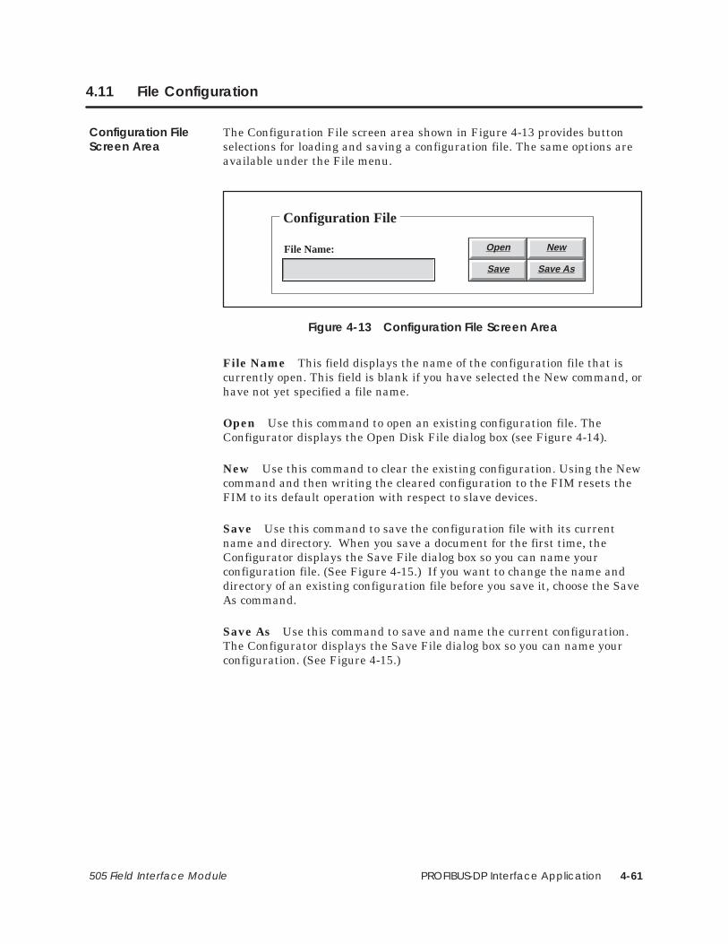
PROFIBUS-DP Interface Application 4-61505 Field Interface Module
4.11 File Configuration
The Configuration File screen area shown in Figure 4-13 provides buttonselections for loading and saving a configuration file. The same options areavailable under the File menu.
Configuration File
File Name: Open New
Save Save As
Figure 4-13 Configuration File Screen Area
File Name This field displays the name of the configuration file that iscurrently open. This field is blank if you have selected the New command, orhave not yet specified a file name.
Open Use this command to open an existing configuration file. TheConfigurator displays the Open Disk File dialog box (see Figure 4-14).
New Use this command to clear the existing configuration. Using the Newcommand and then writing the cleared configuration to the FIM resets theFIM to its default operation with respect to slave devices.
Save Use this command to save the configuration file with its currentname and directory. When you save a document for the first time, theConfigurator displays the Save File dialog box so you can name yourconfiguration file. (See Figure 4-15.) If you want to change the name anddirectory of an existing configuration file before you save it, choose the SaveAs command.
Save As Use this command to save and name the current configuration.The Configurator displays the Save File dialog box so you can name yourconfiguration. (See Figure 4-15.)
Configuration FileScreen Area

PROFIBUS-DP Interface Application4-62 505 Field Interface Module
File Configuration (continued)
Open Disk File
Open
Cancel
File name:
Directory is: c:\cfg–dp
Files:
*.FIM
Directories
[..][-a-][-c-]
Figure 4-14 Open Disk File Dialog Box
The Open Disk File dialog box shown in Figure 4-14 contains the followingfields, which enable you to specify which file to open:
File Name Type or select the name of the file that you want to open.
Directory is Displays the currently selected drive and directory.
Files Displays the configuration files available in the currently selecteddrive and directory.
Directories Select the directory where the file that you want to open isstored.

PROFIBUS-DP Interface Application 4-63505 Field Interface Module
Save File
Save
Cancel
File name:
Directory: c:\cfg–dp
*.FIM
Directories
[..][-a-][-c-]
Figure 4-15 Save File Dialog Box
The Save File dialog box shown in Figure 4-15 contains the following fields,which enable you to specify the name and location of the file that you areabout to save:
File Name Type a new file name to save a configuration with a differentname. A file name can contain up to eight characters, with an extension ofup to three characters.
Directory Displays the currently selected drive and directory.
Directories Select the directory in which you want to store theconfiguration.

PROFIBUS-DP Interface Application4-64 505 Field Interface Module
4.12 FIM Operations
The FIM Operations screen area shown in Figure 4-16 provides thefollowing button selections for configuring the PROFIBUS masterparameters of the FIM, for establishing communications with the FIM, andfor reading or writing configurations from or to the FIM. The same optionsare available under the File menu.
FIM Operations
FIM Description:
FIM Setups Comm
Write FIM Read FIM
Figure 4-16 FIM Operations Screen Area
Setups (FIM Setups button) This function allows you to overridecertain parameters that define how the FIM operates as a master. For moreinformation, see page 4-66.
Communications (Comm button) This function allows you to defineand test serial port assignments for PC-to-FIM communications. For adescription of the procedure involved, see page 4-59.
NOTE: The TestComm button (available when you select the Comm button)tests your communication settings and the connection to the FIM, anddisplays a message that states whether or not communications are workingproperly. You can modify PC serial port settings in the PC-to-FIMCommunications Setup dialog box; a list of required dipswitch settings isalso displayed, and you can manually alter any switches on the back of theFIM as needed.
FIM OperationsScreen Area
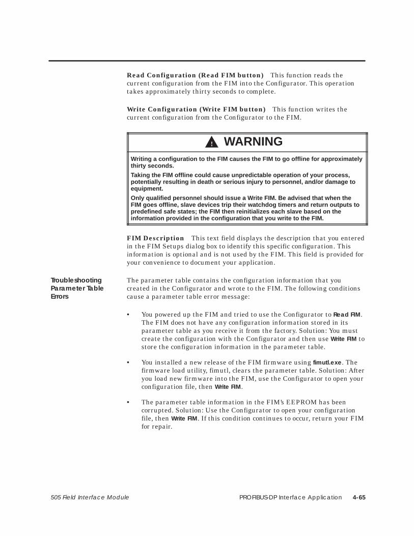
PROFIBUS-DP Interface Application 4-65505 Field Interface Module
Read Configuration (Read FIM button) This function reads thecurrent configuration from the FIM into the Configurator. This operationtakes approximately thirty seconds to complete.
Write Configuration (Write FIM button) This function writes thecurrent configuration from the Configurator to the FIM.
! WARNINGWriting a configuration to the FIM causes the FIM to go offline for approximatelythirty seconds.
Taking the FIM offline could cause unpredictable operation of your process,potentially resulting in death or serious injury to personnel, and/or damage toequipment.
Only qualified personnel should issue a W rite FIM. Be advised that when theFIM goes offline, slave devices trip their watchdog timers and return outputs topredefined safe states; the FIM then reinitializes each slave based on theinformation provided in the configuration that you write to the FIM.
FIM Description This text field displays the description that you enteredin the FIM Setups dialog box to identify this specific configuration. Thisinformation is optional and is not used by the FIM. This field is provided foryour convenience to document your application.
The parameter table contains the configuration information that youcreated in the Configurator and wrote to the FIM. The following conditionscause a parameter table error message:
• You powered up the FIM and tried to use the Configurator to Read FIM.The FIM does not have any configuration information stored in itsparameter table as you receive it from the factory. Solution: You mustcreate the configuration with the Configurator and then use Write FIM tostore the configuration information in the parameter table.
• You installed a new release of the FIM firmware using fimutl.exe. Thefirmware load utility, fimutl, clears the parameter table. Solution: Afteryou load new firmware into the FIM, use the Configurator to open yourconfiguration file, then Write FIM.
• The parameter table information in the FIM’s EEPROM has beencorrupted. Solution: Use the Configurator to open your configurationfile, then Write FIM. If this condition continues to occur, return your FIMfor repair.
TroubleshootingParameter TableErrors

PROFIBUS-DP Interface Application4-66 505 Field Interface Module
FIM Operations (continued)
The FIM Setups dialog box shown in Figure 4-17 allows you to overridecertain parameters that define how the FIM operates as a master on thePROFIBUS network. You do not need to change any of these parameters toset up a configuration. Change them only when you want to override thedefault operation.
FIM Setups
Ok
Clear
Description:
Help
Cancel
Enable Global Control messages
Request Retries:
Min. Scan Time:
Default Trdy:
Default Slot Time:
mSecs
bits
bits
Figure 4-17 FIM Setups Dialog Box
Description This text field allows you to enter a description of thecurrent configuration file. This field is not used by the FIM; it is provided tohelp you document your configuration.
Request Retries This field determines the maximum number of timesthe FIM retries a message to a slave after the initial request message issent. The range for this field is 1 to 4. The default is 2.
Min. Scan Time This field determines the time the FIM performsbackground processing before starting another I/O update cycle. The rangefor this field is 0 to 200 ms. The default is zero.
FIM Setups DialogBox

PROFIBUS-DP Interface Application 4-67505 Field Interface Module
Default Trdy This field determines the minimum number of bit times aslave waits before it responds to a message from the master. The range forthis field is 11 to 55. The default is defined by the baud rate. The default is11 if token passing is disabled, and 55 if token passing is enabled.
Default Slot Time This field determines the maximum number of bittimes that a slave can take to complete transmission of the first character inits response before the FIM times it out. The range for this field is 30 to5,000. The default bit times for each baud rate are listed in Table 4-13.
Table 4-13 Default Bit Times Based on Baud Rate
Baud Rate Bit Times Baud Rate Bit Times
1.5 M 2250 187.5 K 200
750 K 1150 93.75 K 100
500 K 750 19.2 K 100
375 K 563 9.6 K 100
Enable Global Control Messages When selected, this causes the FIM tosend the Global Control message after every fourth update scan. The GlobalControl message forces I/O on for DP slaves that do not default to On.However, sending this message adds additional overhead time to thenetwork. This function is disabled by default. Select this parameter if yournetwork contains the SIMATIC 505 PROFIBUS-DP RBC (PPX:505–6870);otherwise your Series 505 output modules in the PROFIBUS-DP RBC donot update their output data.

PROFIBUS-DP Interface Application4-68 505 Field Interface Module
4.13 Slave Operations
The Slave Operations screen area shown in Figure 4-18 provides buttonselections for configuring slave modules.
Slave Operations
Description:
Edit Status
Station Address:
Slave/Slot #:
Enabled
1
Figure 4-18 Slave Operations Screen Area
Slave/Slot # This field displays the currently selected slave number. TheFIM supports up to 16 slaves, numbered 1 to 16, corresponding to slotnumbers 1 to 16. Selecting displays the information for the previousslave. Selecting displays the information for the next slave. Select one ofthese buttons repeatedly to cycle through the slave list.
Station Address This field displays the PROFIBUS slave address for theslave at this slot.
Enabled This area displays the selected state of the slave. By default,each slave is enabled in the configuration for polling and displays asEnabled in the Slave Operations area. When you select Slave disabled (Notpolled) from the Edit Slave dialog box, the Slave Operations area displaysDisabled for that slave.
Description This field displays the text that you entered in the EditSlave dialog box to describe this particular slave device.
Edit This button summons the Edit Slave dialog box. (See page 4-69.)
Status This button allows you to check the status of a slave. (Seepage 4-76.)
Slave OperationsScreen Area

PROFIBUS-DP Interface Application 4-69505 Field Interface Module
The Edit Slave dialog box shown in Figure 4-19 allows you to override thedefault operation of specific slave devices on the PROFIBUSnetwork.
Edit Slave
Ok
Clear
Station Address:
Read Slave
Help
Slave disabled (Not polled)
# Words (2 Bytes)V:
Cancel
Slave ProtocolProfibus–DP NORM
ET200 V3.0
SPM V1.0
NOTE: # Words MUST include thefirst word, (length of the new
diagnostics data) which is updatedby the FIM.
Station Address:
IDENT Word (hex):
Slave Description:
I/O Configuration (hex):
User Parameter Data (hex):
WatchDog Time (mSecs):
Diagnostics Location:
Edit
Edit
Figure 4-19 Edit Slave Dialog Box
NOTE: Change or provide only the information that is necessary for theoperation of the slave device. You do not have to edit every field.
Station Address This field determines the PROFIBUS network addressfor the slave device. Valid addresses for slaves range from 4 to 126. If theslave is outside of the address range selected for the FIM (by dipswitchsetting), you must enter a value in this field before selecting the Read Slavebutton.
Edit Slave DialogBox

PROFIBUS-DP Interface Application4-70 505 Field Interface Module
Slave Operations (continued)
Slave disabled (Not polled) Select this checkbox to specify that the FIMshould not poll for a slave at this slave position. (Remember that other slavepositions can be set to have this slave’s address in the poll range.) The FIMcan poll up to sixteen slave devices on a PROFIBUS network. If a slave doesnot exist, the FIM continues to poll and retry that slave address. If you havefewer than sixteen slaves, you can reduce the overall scan time by settingthis checkbox for the slave addresses that do not exist. The FIM does notpoll or retry the disabled addresses.
IDENT Word (hex) The IDENT word number is used for the preciseidentification of the device type of a DP slave on the network. All DP slavedevices must have an IDENT word number for reading diagnostics data andwriting parameterization data. This number permits the DP masters toidentify the DP slaves with a minimum of protocol. You do not need to fill inthe IDENT Word field unless your device does not properly return itsdefault IDENT word number.
Be sure to select a protocol (see the description of Slave Protocol onpage 4-72) before editing the IDENT Word field. Selecting any protocolother than PROFIBUS-DP NORM erases the contents of this field andprevents you from editing it.
The IDENT word number for a device is usually identified in themanufacturer’s equipment manual. An individual IDENT word number isassigned to each manufacturer by the PNO (PROFIBUS UserOrganization). This number is not a serial number. After a manufacturerreceives an IDENT word number from the PNO for a device type, themanufacturer can use the same number for every device of this type. If youdo not know what the IDENT word number is, enter the address in theStation Address field and select the Read Slave button. The FIM reads andfills in this value.
Slave Description This optional text field describes the slave device.Enter any descriptive information that helps you identify this particularslave. This field is not used by the FIM; it is provided for your convenienceto document your application. Up to 45 characters can be displayed in thefield at one time. Left-click the mouse in the field to set the edit cursor inthe field. The END key moves the cursor to the end of the text, and theHOME key moves the cursor to the beginning of the text. You can presseither the up or left arrow to move the cursor one character to the left; pressthe down or right arrow to move the cursor one character to the right.
I/O Configuration (hex) This field is the hexadecimal representation ofthe slave’s I/O configuration data. You can enter the hexadecimal data inthis field, or you can select the Edit button, and complete the Edit I/OConfiguration dialog box. (See page 4-73.)

PROFIBUS-DP Interface Application 4-71505 Field Interface Module
Be sure to select a protocol (see the description of Slave Protocol onpage 4-72) before editing the I/O Configuration field. Selecting the SPMV1.0 protocol disables this field and prevents you from editing it.Reselecting the previous protocol setting after selecting the SPM V1.0setting restores the values set under the previous protocol setting.
If you do not know what the I/O configuration value is, enter the address inthe Station Address field, left-click the mouse in this field, and select theRead Slave button. The FIM then reads and fills in this value.
Up to 24 bytes are displayed in the field at one time. Left-click the mouse inthe field to set the edit cursor in the field. The END key moves the cursor tothe end of the text, and the HOME key moves the cursor to the beginning ofthe text. You can press either the up or left arrow to move the cursor onenibble to the left; press the down or right arrow to move the cursor onenibble to the right.
User Parameter Data This field is required by some slave devices toconfigure their operation. For example, the ET 200B–4AI (6ES7134–0HF00–0XB0) and the ET 200B–4AO (6ES7 135–0HF00–0XB0) bothrequire User Parameter Data to define the analog value range and otherdata. You can enter the hexadecimal data in this field, or you can select theEdit button, and complete the Edit User Parameter dialog box (described onpage 4-74).
Be sure to select a protocol (see the description of Slave Protocol onpage 4-72) before editing the User Parameter Data field. Selecting anyprotocol other than PROFIBUS-DP NORM erases the contents of this fieldand prevents you from editing it.
Up to 24 bytes are displayed in the field at one time. Left-click the mouse inthe field to set the edit cursor in the field. The END key moves the cursor tothe end of the text, and the HOME key moves the cursor to the beginning ofthe text. You can press either the up or left arrow to move the cursor onenibble to the left; press the down or right arrow to move the cursor onenibble to the right.
WatchDog Time (hex) The value in this field specifies how long the slavewaits without hearing from the master before it sets its outputs to itspredefined safe state. The watchdog time is sent to the slave device whenthe FIM configures the slave.
Be sure to select a protocol (see the description of Slave Protocol onpage 4-72) before editing this field. Selecting the SPM V1.0 protocoldisables this field and prevents you from editing it. Reselecting the previousprotocol setting after selecting the SPM V1.0 setting restores the values setunder the previous protocol setting.

PROFIBUS-DP Interface Application4-72 505 Field Interface Module
Slave Operations (continued)
Diagnostics Location This field specifies the V-memory location in thecontroller where the FIM stores the station diagnostics information for thisslave. The first word (two bytes) at this V-memory location is the length ofthe diagnostics data returned by the FIM. You must specify the amount ofdiagnostic data in words (multiples of two bytes). For example, if you havethree bytes of diagnostic data, specify two words plus one word for thelength, for a total of three words. If the slave returns more diagnostic datathan you have allocated space for, the data is truncated to the length thatyou specified.
Be sure to select a protocol (see the description of Slave Protocol) beforeediting this field. Selecting any protocol other than PROFIBUS-DP NORMerases the contents of this field and prevents you from editing it.
Slave Protocol These radio buttons specify the PROFIBUS-DP protocolversion that the slave device uses.
PROFIBUS-DP NORM, also known as DP Standard, is used for allslave devices that are PROFIBUS-DP compliant. This is also theprotocol for the IM 318–B when the dipswitch is set to thePROFIBUS-DP NORM setting.
ET 200 V3.0 is for earlier slave devices that use the DP-Siemensprotocol.
SPM V1.0 is for slave devices that incorporate the SPM. Two suchmodules are the ET 200B units, 6ES5–451–2BA11 (16 Discrete Output,24 VDC, 0.5 A) and 6ES5–454–2BA11 (16 Discrete Output, 24 VDC,2.0 A).
If you do not know what the protocol setting is for a given slave, enter theaddress in the Station Address field, select one of the protocol radio buttons,and select the Read Slave button. The FIM reads and fills in this value.
You can select the Read Slave button to read the IDENT word, I/Oconfiguration, and slave protocol information for the specified slave addressfrom the FIM. If the slave is outside of the address range selected for theFIM (by dipswitch setting), you must first enter a value in the SlaveAddress field. Then place the cursor in the field you want to read and selectthe Read Slave button. This provides you with the information that the FIMgathered when it initialized the PROFIBUS network.

PROFIBUS-DP Interface Application 4-73505 Field Interface Module
The Edit I/O Configuration dialog box shown in Figure 4-20 provides fieldsfor configuring individual I/O positions.
Edit I/O Configuration
Ok
Help
Clear
Cancel
Module/Position
I/O Position #:
I/O Points
(X/I) Discrete Input Points:(X/I) Discrete Input Points:
(Y/Q) Discrete Output Points:
Analog/Word Points:
Consistency over whole length:
1
Figure 4-20 Edit I/O Configuration Dialog Box
Module/Position This field identifies the position of the module in thebus interface. You can connect up to 32 modules to a DP slave,corresponding to positions 1 through 32. ET 200B slave devices configurewith only one module position, since they are not modular. Click on toselect the next position; click on to select the previous position.
(X/I) Discrete Input Points This field identifies the total number ofdiscrete input points.
(Y/Q) Discrete Output Points This field identifies the total number ofdiscrete output points. (The 6ES5 422–8MA11 16-point Discrete InputModule requires you to define 16 output points.)
Analog/Word Points Select this checkbox to define the module positionas analog/word, as opposed to discrete. The point count fields above thecheckbox are then transformed to show the number of analog input pointsand analog output points.
Consistency over whole length Select this checkbox to define themodule position as having consistency over the whole length.
Edit I/OConfigurationDialog Box
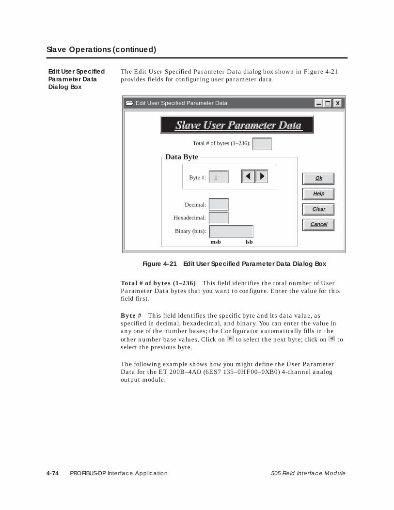
PROFIBUS-DP Interface Application4-74 505 Field Interface Module
Slave Operations (continued)
The Edit User Specified Parameter Data dialog box shown in Figure 4-21provides fields for configuring user parameter data.
Edit User Specified Parameter Data
Ok
Help
Clear
Cancel
Byte #: 1
Data Byte
Decimal:
Hexadecimal:
Binary (bits):
msb lsb
Total # of bytes (1–236):
Figure 4-21 Edit User Specified Parameter Data Dialog Box
Total # of bytes (1–236) This field identifies the total number of UserParameter Data bytes that you want to configure. Enter the value for thisfield first.
Byte # This field identifies the specific byte and its data value, asspecified in decimal, hexadecimal, and binary. You can enter the value inany one of the number bases; the Configurator automatically fills in theother number base values. Click on to select the next byte; click on toselect the previous byte.
The following example shows how you might define the User ParameterData for the ET 200B–4AO (6ES7 135–0HF00–0XB0) 4-channel analogoutput module.
Edit User SpecifiedParameter DataDialog Box

PROFIBUS-DP Interface Application 4-75505 Field Interface Module
The ET 200B analog modules require a 25-byte parameterization frame todefine the diagnostics characteristics and the necessary defaults for analogvalue measurement or analog value output.
Byte#
HexCode Description
1 13
2 00
3 00
4 ?
The four least significant bits determine whether diagnostics areenabled or disabled for each of the four channels. For example:
00 – Diagnostics disabled for all channels.0F – Diagnostics enabled for all channels.05 – Diagnostics enabled for Channels 2 and 0.
5 00
6 00
7 00
8 ? Type and range ofmeasurement for Channel 0. For voltage measurement:
18 – 0 to 10V9 ? Type and range of
measurement for Channel 1.
18 – 0 to 10V19 – �10V
For current measurement:10 ? Type and range of
measurement for Channel 2.For current measurement:
22 – 0 to 20mA23 – 4 to 20mA
11 ? Type and range ofmeasurement for Channel 3.
23 – 4 to 20mA24 – �20mA
12 00
13 00
14 00
15 00
16 00
17 00
18 00
19 00
20 06
21 FF
22 00
23 00
24 00
25 00
Example: UserParameter Data

PROFIBUS-DP Interface Application4-76 505 Field Interface Module
4.14 Status and Diagnostics
The Status button feature of the Configurator is designed to help diagnoseparameterization and configuration errors on individual slaves. Statuscannot be used with SPM V1.0 slave devices. To use the Status buttonfeature, follow these steps:
1. Configure the user I/O for each slave using TISOFT.
2. With the Configurator program running on a PC and connected to theFIM (as described on page 4-58), move to a slave whose status you wishto check.
3. Click on the Status button.
4. Interpret the result. Possible results are described below.
Normally, if the slave is communicating, you get a response dialog boxindicating the current status of the slave. If the slave is a PROFIBUS-DPNORM slave you see all the following status terms; if it is a ET 200 V3.0then you do not see the first two.
• Slave Ident # correct? This indicates whether the IDENT word of theslave has been set, and if so, whether it matches what the slaverequires. If no IDENT word has been set, then the prompt displays NOTSPECIFIED. YES indicates that the specified IDENT word matches whatthe slave requires; NO indicates that the specified IDENT word doesnot match what the slave requires (PROFIBUS-DP NORM only).
• Parameterization correct? This indicates whether or not the slaverejected the parameterization data. Rejection usually means that theUser Parameter Data has not been specified or is specified incorrectly.Rejection can also indicate that the IDENT word is not specified, andneeds to be, or that the IDENT word is specified incorrectly(PROFIBUS-DP NORM only).
• I/O Configuration correct? This indicates whether or not the slaverejected the I/O configuration. The I/O configuration may be rejectedbecause you specified the configuration incorrectly, or because youfailed to specify I/O when a slave requires it.
• Slave ready for I/O This indicates whether or not a slave is ready toexchange I/O with the FIM. Some slaves ignore minor configurationand parameterization messages and exchange I/O regardless.
• Slave diagnostic buffer This is the data field from the slave diagnosticbuffer. You must have the protocol specification (DIN 19245, Part 3) tointerpret this data.
Checking SlaveStatus with theStatus Button

PROFIBUS-DP Interface Application 4-77505 Field Interface Module
You may also receive one of the following error messages instead of thestatus dialog box:
• FIM cannot communicate with this slave! This means that the slave didnot respond to the FIM at the slave address set to this slave position.This could be due to an incorrect address on the slave, an incorrectaddress configured for this slave position, an incorrect address rangesetting for the FIM (if the address is not configured for this slaveposition), an incorrect baud rate on a slave, an incorrect baud rate onthe FIM, a wiring problem, or a slave that is not powered up.
• Slave is an SPM V1.0. This means that the slave answering at this slaveposition has an SPM V1.0 ASIC in it. These devices do not have slaveI/O configurations or parameterization, so status checks are irrelevant.
• Could not talk to the FIM! Communication between the PC running theConfigurator software and the FIM could not be established. Check forthe proper port selection on the Configurator, the correct setting fordipswitches on the FIM, and proper cable connection between the FIMand PC.
The FIM is capable of returning extended diagnostic data forPROFIBUS-DP slaves (DP-Siemens and SPM V1.0 devices are excluded).When a slave signals the FIM that diagnostic information is present, theFIM reads the data and stores it in the V-memory location specified in theEdit Slave dialog box. The data in the V-memory area remains until theslave signals the FIM again or your ladder logic program writes into thisarea.
To handle the extended diagnostic data, set up your ladder logic followingthis procedure:
1. Fill the first V-memory word with zeros on initial startup.
2. Compare the first V-memory word to zero. If non-zero, set a contactthat causes a subroutine to execute.
3. In the subroutine, process the diagnostics data and perform any alertactions. Then fill the first V-memory word with zeros again.
The format of the extended diagnostic data is dependent on the slave device.The following examples show how to reference the diagnostic data in yourladder logic program.
Using SlaveDiagnostics

PROFIBUS-DP Interface Application4-78 505 Field Interface Module
Status and Diagnostics (continued)
Table 4-14 shows the Diagnostics Location fields for an ET 200B. TheET 200B analog modules use ten bytes or five words per slave station fordevice diagnostics information. In this example, the diagnostics location isplaced at V101; the number of words is 6 (5 + 1 for the diagnostics lengthword).
Table 4-14 Diagnostics Locations for the ET 200B
V-MemoryLocation Diagnostics Information
V101 Length of diagnostics data (word).
V102 Beginning of device-related diagnostic information (header word).
V103.9 Wrong parameterization frame.
V103.13 Channel fault exists.
V103.14 External fault, for example, wirebreak.
V103.15 Internal fault of the ET 200B.
V103.16 Diagnostics message pending.
V105.4 Internal error of the ET 200B (analog-digital conversion,ET 200B–4AO only).
V105.6 Internal fault of the ET 200B (EEPROM error, ET 200B–4AI only).
V105 Lower byte: type of analog ET 200B: 71h – 4AI, 4/8AI 73h – 4AO.
V106 Lower byte: number of channels.
DiagnosticLocation Example:ET 200B

PROFIBUS-DP Interface Application 4-79505 Field Interface Module
Table 4-15 shows the Diagnostics Location fields for an ET 200U. TheET 200U slave stations use eight bytes or four words per slave station forthe station and module diagnostics information. In this example, thediagnostics location is placed at V101; the number of words is 5 (4 + 1 forthe diagnostics length word).
Table 4-15 Diagnostics Locations for the ET 200U
V-MemoryLocation Diagnostics Information V-Memory
Location Diagnostics Information
V101 Length of diagnostics data (word). V104.6 Module in slot 10 is faulty.
V102 Beginning of device-related diagnosticinformation. V104.7 Module in slot 9 is faulty.
V102.11 An output has been activatedincorrectly (short circuit L+). V104.8 Module in slot 8 is faulty.
V102.12 Load voltage missing or output shortcircuit of M. V104.9 Module in slot 23 is faulty.
V102.15 Wrong number of identifiersconfigured. V104.10 Module in slot 22 is faulty.
V102.16 Slave station is in slow mode. V104.11 Module in slot 21 is faulty.
V103 Beginning of module-related diagnosticinformation. V104.12 Module in slot 20 is faulty.
V103.9 Module in slot 7 is faulty. V104.13 Module in slot 19 is faulty.
V103.10 Module in slot 6 is faulty. V104.14 Module in slot 18 is faulty.
V103.11 Module in slot 5 is faulty. V104.15 Module in slot 17 is faulty.
V103.12 Module in slot 4 is faulty. V104.16 Module in slot 16 is faulty.
V103.13 Module in slot 3 is faulty. V105.1 Module in slot 31 is faulty.
V103.14 Module in slot 2 is faulty. V105.2 Module in slot 30 is faulty.
V103.15 Module in slot 1 is faulty. V105.3 Module in slot 29 is faulty.
V103.16 Module in slot 0 is faulty. V105.4 Module in slot 28 is faulty.
V104.1 Module in slot 15 is faulty. V105.5 Module in slot 27 is faulty.
V104.2 Module in slot 14 is faulty. V105.6 Module in slot 26 is faulty.
V104.3 Module in slot 13 is faulty. V105.7 Module in slot 25 is faulty.
V104.4 Module in slot 12 is faulty. V105.8 Module in slot 24 is faulty.
V104.5 Module in slot 11 is faulty.
DiagnosticLocation Example:ET 200U

PROFIBUS-DP Interface Application4-80 505 Field Interface Module
4.15 Setting Up and Wiring the 6SE30 PROFIBUS Micromaster Drive
You can use any hardware and/or software version of the 6SE30 PROFIBUSMicromaster Drive.
The parameters required for the 6SE30 follow:
P700 display only – shows the software version.
P701 determines the equipment system number. It has nooperational effect.
P710 display only – shows the motor current.
P711 display only – shows the motor torque.
P712 display only – shows the motor slip.
P720 determines which input/output signals can be controlled or monitored by PROFIBUS.
P721 display only – shows the analog input voltage.
P722 display only – shows the PTC input voltage.
P723 display only – shows the status of the drive digital inputs.
P724 display only – shows the status of the drive relay output.
P880 display only – indexed parameter diagnostic data – fortroubleshooting.
P918 must be set to the individual drive PROFIBUS address. For usewith the FIM, the first valid drive address is 17.
P927 selects local or remote parameter control.0 selects local parameter control.1 selects remote (PROFIBUS) parameter control.
P928 selects local or remote drive control.0 selects local drive control, monitor mode only for PROFIBUS.1 selects remote (PROFIBUS) drive control.
P947 display only – indexed parameter fault log – fortroubleshooting.
P958 display only – warning code.
Required Hardwareand Software
RequiredParameters

PROFIBUS-DP Interface Application 4-81505 Field Interface Module
P963 display only – shows the baud rate of the PROFIBUS serialbus. This is set automatically in PROFIBUS mode.0 baud rate not found96 9600 baud187 187.5 Kbaud192 19.2 Kbaud500 500 Kbaud937 93.75 Kbaud1500 1.5 Mbaud
P967 display only – shows the latest received control word in bitarray format.
P968 display only – shows the latest drive status word in bit arrayformat.
P971 selects if PROFIBUS parameter changes are stored in the drive EEPROM.0 parameter changes are not stored in EEPROM.1 parameter changes are stored in EEPROM.
After the above parameters have been changed, the drive should be powereddown for at least 10 seconds and then powered back on. This power cyclingallows the drive to initialize communications with the FIM.
NOTE: Unlike some Siemens variable speed drives, the PROFIBUSMicromaster will automatically be controlled via serial communicationswhen wired and set up according to this document with P928=1. If P928=0,then the PROFIBUS Micromaster will only communicate status andfeedback information. The process data section defines the control word,status word, main setpoint and main actual value for the interface.Definition of the process data section is fixed. The PROFIBUS Micromasteronly supports PPO types 1 and 3. Type 1 is 4 PKW words and 2 PZD words.Type 3 is 2 PZD words.

PROFIBUS-DP Interface Application4-82 505 Field Interface Module
Setting Up and Wiring the 6SE30 PROFIBUS Micromaster Drive (continued)
The following example describes how to assign the Main Control Word andFrequency Setpoint functions to the FIM using 6 word PPO type 1 protocol:
In order to control the Main Control Word function from thePROFIBUS host (the FIM), parameter P928 must be set to 1. This setsthe source of the standard control word to PZD word 1 of the telegramson the PROFIBUS port. PZD word 1 is word 5 of the PLC data area(words 1, 2, 3, and 4 are PKW words).
In addition, when P928 is set to 1, the Frequency Setpoint from thePROFIBUS port (the FIM) is used to control the PROFIBUSMicromaster frequency. PZD word 2 of the telegrams on thePROFIBUS port sets the frequency. The scaling is 16,384 (4000 hex) =100% of P94.
After P928 is set to 1, Figure 4-22 describes the function of each controlbit in PZD word 1 of the information sent to the drive.
Drive status and feedback (or actual value) information such as motor speedcan always be read by the FIM Module.
15 14 13 12 11 10 9 8 7 6 5 4 3 2 1 0
High byte Low byte
1 = Start0 = STOP1 (Normal Stop)0 = STOP2 (Coast Stop)
0 = STOP3 (Quick Stop)
1 = Enable Operation
1 = Ramp Generator Enable
1 = Ramp Generator is not held
1 = Reference Enable
1 = Fault Reset
1 = Jog Clockwise
1 = Jog Counter-clockwise
1 = Enable Serial Operation (PZD valid) Process data from FIM is validNot used
Not used
Not used
1 = Clockwise direction requested0 = Counter-clockwise direction requestedNot used
Note: A suggested initial value of PZD word 1 is 047E hex. PZD word 1 can be changed to 047F hex to start the drive.
Figure 4-22 Control Bits for Main Control Word and Frequency Setpoint

PROFIBUS-DP Interface Application 4-83505 Field Interface Module
The following example describes how to access the Standard Status Wordand Main Feedback from the FIM:
If P928 is set to 0 or 1, the FIM can access the standard status word inPZD word 1 from the PROFIBUS port. PZD word 1 is word 5 of thePLC data area (words 1, 2, 3, and 4 are PKW words).
In addition, if P928 is set to 0 or 1, the FIM can access the frequencyfeedback in PZD word 2 of the telegrams from the PROFIBUS port.
After P928 is set to 0 or 1, Figure 4-23 describes the function of eachstatus bit in PZD word 1 of the information from the drive.
15 14 13 12 11 10 9 8 7 6 5 4 3 2 1 0
High byte Low byte
1 = Ready to start
1 = Ready to operate (converter is on)1 = Operation Enabled
1 = Drive fault present
0 = STOP2 (Coast stop command present)
0 = STOP3 (Quick stop command present)
1 = Switch-on inhibit
1 = Drive warning present
1 = not used (always 1)
1 = Serial operation allowed0 = Serial operation blocked – local operation only1 = f reached (output f=setpoint f)
Not used
Not used
Not used
1 = Converter output is clockwise0 = Converter output is counter-clockwiseNot used
Figure 4-23 Status Bits for Standard Status Word and Main Feedback
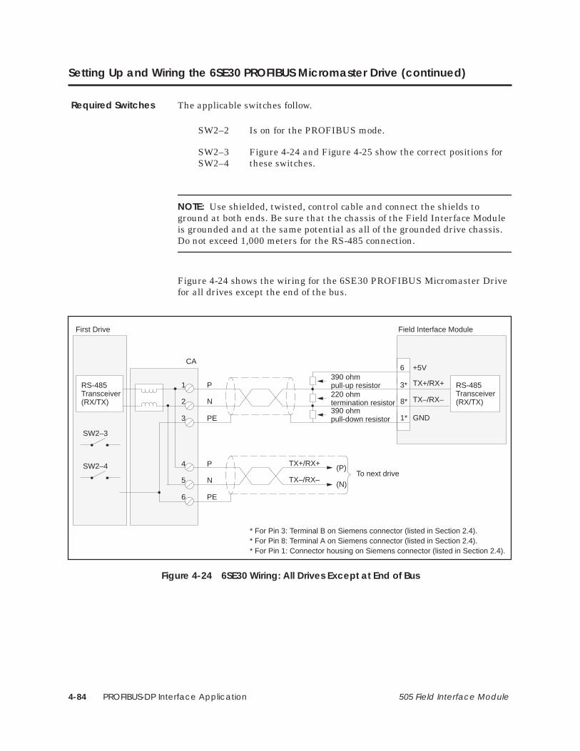
PROFIBUS-DP Interface Application4-84 505 Field Interface Module
Setting Up and Wiring the 6SE30 PROFIBUS Micromaster Drive (continued)
The applicable switches follow.
SW2–2 Is on for the PROFIBUS mode.
SW2–3 Figure 4-24 and Figure 4-25 show the correct positions for SW2–4 these switches.
NOTE: Use shielded, twisted, control cable and connect the shields toground at both ends. Be sure that the chassis of the Field Interface Moduleis grounded and at the same potential as all of the grounded drive chassis. Do not exceed 1,000 meters for the RS-485 connection.
Figure 4-24 shows the wiring for the 6SE30 PROFIBUS Micromaster Drivefor all drives except the end of the bus.
2
TX+/RX+
TX–/RX–
3*
8*
RS-485Transceiver(RX/TX)
6
1*
+5V
GND
First Drive Field Interface Module
390 ohmpull-up resistor220 ohmtermination resistor390 ohmpull-down resistor
(P)
(N)
TX+/RX+
TX–/RX–To next drive
1
CA
3
5
4
6
N
P
PE
N
P
PE
SW2–3
SW2–4
RS-485Transceiver(RX/TX)
* For Pin 3: Terminal B on Siemens connector (listed in Section 2.4).* For Pin 8: Terminal A on Siemens connector (listed in Section 2.4).* For Pin 1: Connector housing on Siemens connector (listed in Section 2.4).
Figure 4-24 6SE30 Wiring: All Drives Except at End of Bus
Required Switches

PROFIBUS-DP Interface Application 4-85505 Field Interface Module
Figure 4-25 shows the wiring for the 6SE30 PROFIBUS Micromaster Drivefor the drive at the end of the bus.
NOTE: Use shielded, twisted, control cable and connect the shields toground at both ends. Be sure that the chassis of the Field Interface Moduleis grounded and at the same potential as all of the grounded drive chassis. Do not exceed 1,000 meters for the RS-485 connection.
2
Last Drive on bus
(P)
(N)
TX+/RX+
TX–/RX–
Frompreviousdrive
1
CA
3
5
4
6
N
P
PE
N
P
PE
SW2–3
SW2–4
RS-485Transceiver(RX/TX)
Figure 4-25 6SE30 Wiring: Drive at End of Bus

PROFIBUS-DP Interface Application4-86 505 Field Interface Module
4.16 OPmP PROFIBUS Module for Micro/Midimaster (6SE31) Drives
Any hardware version of the OPmP device may be used. Any softwareversion may be used. If the OPmP module is used, the USS protocol on thebase unit becomes inoperable.
P700 display only – shows the software version.
P701 determines the equipment system number. It has nooperational effect.
P880 display only – indexed parameter diagnostic data – fortroubleshooting.
P918 must be set to the individual drive PROFIBUS address.For use with the FIM, the first valid drive address is 17.
P927 selects local or remote parameter control.0 selects local parameter control.1 selects remote (PROFIBUS) parameter control
P928 selects local or remote drive control0 selects local drive control, monitor mode only for PROFIBUS.1 selects remote (PROFIBUS) drive control.
P947 display only – indexed parameter fault log– for troubleshooting.
P958 display only – warning code.
P963 display only – shows the baud rate of the PROFIBUS serial bus. This is set automatically in PROFIBUS mode.0 baud rate not found.96 9600 baud187 187.5 Kbaud192 19.2 Kbaud500 500 Kbaud937 93.75 Kbaud1500 1.5 Mbaud
P967 display only – shows the latest received control word in bitarray format.
P968 display only – shows the latest drive status word in bitarray format.
P971 selects if PROFIBUS parameter changes are stored in the driveEEPROM.0 parameter changes are not stored in EEPROM.1 parameter changes are stored in EEPROM.
Required Hardwareand Software
RequiredParameters

PROFIBUS-DP Interface Application 4-87505 Field Interface Module
After the above parameters have been changed, the drive should be powereddown for at least 10 seconds and then powered back on. This power cyclingallows the drive to initialize communications with the FIM.
NOTE: Unlike some devices, the OPmP will automatically be controlled viaserial communications when wired up and set up per this document withP928=1. If P928=0, then the OPmP will only communicate status andfeedback information. The process data section defines the control word,status word, main setpoint and main actual value for the interface.Definition of the process data section is fixed. The OPmP only supports PPOtypes 1 and 3. Type 1 is 4 PKW words and 2 PZD words. Type 3 is 2 PZDwords.

PROFIBUS-DP Interface Application4-88 505 Field Interface Module
OPmP PROFIBUS Module for Micro/Midimaster (6SE31) Drives (continued)
The following example describes how to assign the Main Control Word andFrequency Setpoint functions to the FIM using 6 word PPO type 1 protocol:
In order to control the Main Control Word function from thePROFIBUS host (the FIM), parameter P928 must be set to 1. This setsthe source of the standard control word to PZD word 1 of the telegramson the PROFIBUS port. PZD word 1 is word 5 of the PLC data area(words 1, 2, 3, and 4 are PKW words).
In addition, when P928 is set to 1, the Frequency Setpoint from thePROFIBUS port (the FIM) is used to control the PROFIBUSMicromaster frequency. PZD word 2 of the telegrams on thePROFIBUS port sets the frequency. The scaling is 16,384 (4000 hex) =100% of P94.
After P928 is set to 1, Figure 4-26 describes the function of each controlbit in PZD word 1 of the information sent to the drive.
Drive status and feedback (or actual value) information such as motor speedcan always be read by the FIM Module.
15 14 13 12 11 10 9 8 7 6 5 4 3 2 1 0
High byte Low byte
1 = Start0 = STOP1 (Normal Stop)1 = STOP2 (Coast Stop)1 = STOP3 (Quick Stop)
1 = Enable Operation
1 = Ramp Generator Enable
1 = Ramp Generator is not held
1 = Reference Enable
1 = Fault Reset
1 = Jog Clockwise
1 = Jog Counter-clockwise
1 = Enable Serial Operation (PZD valid) Process data from FIM is validNot used
Not used
Not used
1 = Clockwise direction requested0 = Counter-clockwise direction requestedNot used
Note: A suggested initial value of PZD word 1 is 047E hex. PZD word 1 can be changed to 047F hex to start the drive.
Figure 4-26 Control Bits for Main Control Word and Frequency Setpoint

PROFIBUS-DP Interface Application 4-89505 Field Interface Module
The following example describes how to access the Standard Status Wordand Main Feedback from the FIM:
If P928 is set to 0 or 1, the FIM can access the standard status word inPZD word 1 from the PROFIBUS port. PZD word 1 is word 5 of thePLC data area (words 1, 2, 3, and 4 are PKW words).
In addition, if P928 is set to 0 or 1, the FIM can access the frequencyfeedback in PZD word 2 of the telegrams from the PROFIBUS port.
After P928 is set to 0 or 1, Figure 4-27 describes the function of eachstatus bit in PZD word 1 of the information from the drive.
15 14 13 12 11 10 9 8 7 6 5 4 3 2 1 0
High byte Low byte
1 = Ready to start
1 = Ready to operate (converter is on)1 = Operation Enabled
1 = Drive fault present
0 = STOP2 (Coast stop command present)
0 = STOP3 (Quick stop command present)
1 = Switch-on inhibit
1 = Drive warning present
1 = not used (always 1)
1 = Serial operation allowed0 = Serial operation blocked – local operation only1 = f reached (output f=setpoint f)
Not used
Not used
Not used
1 = Converter output is clockwise0 = Converter output is counter-clockwiseNot used
Figure 4-27 Status Bits for Standard Status Word and Main Feedback

PROFIBUS-DP Interface Application4-90 505 Field Interface Module
OPmP PROFIBUS Module for Micro/Midimaster (6SE31) Drives (continued)
Bus termination resistors are part of the OPmP module and are controlledby a switch on the front, mounted beneath a removable plug. The internaltermination switch should be closed only on the OPmP at the end of the bus.
Figure 4-28 shows the wiring for the 6SE31 PROFIBUS Micromaster Drivefor all drives except the end of the bus.
TX+/RX+
TX–/RX–
3*
8*
RS-485Transceiver(RX/TX)
6
1*
+5V
GND
First drive Field Interface Module
390 ohmpull-up resistor220 ohmtermination resistor390 ohmpull-down resistor
(P)
(N)
TX+/RX+
TX–/RX–To next drive
RS-485Transceiver(RX/TX)
* For Pin 3: Terminal B on Siemens connector (listed in Section 2.4).* For Pin 8: Terminal A on Siemens connector (listed in Section 2.4).* For Pin 1: Connector housing on Siemens connector (listed in Section 2.4).
3
6
DB9Female
TX–/RX–
TX+/RX+
GND
+5V
8
5
A PROFIBUS connector may be used tosimplify this connection.
Internalterminationswitch OFF
OFF ON
Figure 4-28 6SE31 Wiring: All Drives Except at End of Bus
NOTE: Use shielded, twisted, control cable and connect the shields toground at both ends. Be sure that the chassis of the Field Interface Moduleis grounded and at the same potential as all of the grounded drive chassis. Do not exceed 1,000 meters for the RS-485 connection.
Required Switches

PROFIBUS-DP Interface Application 4-91505 Field Interface Module
Figure 4-29 shows the wiring for the 6SE31 PROFIBUS Micromaster Drivefor the drive at the end of the bus.
Last drive
390 ohmpull-up resistor (P)
(N)
TX+/RX+
TX–/RX–To nextdrive
RS-485Transceiver(RX/TX)
3
6
TX–/RX–
TX+/RX+
GND
+5V
8
5
220 ohmtermination resistor390 ohmpull-down resistor
DB9Female
A PROFIBUS connector may be used tosimplify this connection.
Internalterminationswitch ON
OFF ON
NOTE: Only use one method to terminate the last drive on the bus.Either use the internal termination switch on the drive, or use thetermination switch on the PROFIBUS connector. Do not use both.
Figure 4-29 6SE31 Wiring: Drive at End of Bus
NOTE: Use shielded, twisted, control cable and connect the shields toground at both ends. Be sure that the chassis of the Field Interface Moduleis grounded and at the same potential as all of the grounded drive chassis. Do not exceed 1,000 meters for the RS-485 connection.

PROFIBUS-DP Interface Application4-92 505 Field Interface Module
4.17 Setting Up and Wiring the CB1
You can use any hardware version of the 6SE70. You can use any softwareversion of the base microprocessor board (CU1 or CU2) and any softwareversion of the CB1 Master Drive Communications Board.
Use the serial interface (CB) on the CB1.
P053 must be set to allow parameters to be changed from the FIM through CB1 (also refer to P697).
P090 or P091 must be set, depending on the CB1 hardware slot.
P695 initially is set to 0, which turns off the drive telegram-monitoring function. After the network is operating, you can decide whether or not to turn on the drive telegram-monitoring function by setting P695 to a value of 10.
P696 selects special diagnostic information. It is 0 for standard operation.
P697 selects the PPO type of the useful data. If the host system can specify the PPO type at the converter using identification bytes, this parameter is set to 0.If the host system cannot specify the PPO type at the converter using identification bytes, this parameter selects the PPO type. The selection
range follows:
P697 = 0 PPO type 1 PKW data = 4 wordsPZD words = 2 words
P697 = 2 PPO type 2 PKW data = 4 wordsPZD words = 6 words
P697 = 3 PPO type 3 PKW data = 0 wordsPZD words = 2 words
P697 = 4 PPO type 4 PKW data = 0 wordsPZD words = 6 words
P697 = 5 PPO type 5 PKW data = 4 wordsPZD words = 10 words
P918 must be set to the individual drive PROFIBUS address. For use with the FIM, the first valid drive address is 17 if the slave address range selection dipswitches are set to all closed. Refer to Table 4-2 for more information on setting the slave address range selection.
Required Hardwareand Software
RequiredParameters

PROFIBUS-DP Interface Application 4-93505 Field Interface Module
After the above parameters have been changed, the drive should be powereddown for at least 10 seconds and then powered back on. This power cyclingallows the drive to initialize communications with the FIM.
NOTE: Unlike some Siemens variable speed drives, the 6ES70 will notautomatically be controlled by serial communications when wired and setup according to this document; it will only communicate. The process datasection defines the control word, status word, setpoints and actual values forthe interface. Definition of the process data section is very flexible.Individual input, output, and control functions must be set (parameterized)for use with serial communications. It is beyond the scope of this documentto describe all of the functions and how to set (parameterize) them. Section4.3 of the 6SE70 Instruction Book describes the control word, status word,setpoints, and actual values structures, and it is imperative that this sectionbe read completely and understood before attempting to control a 6ES70with a FIM module.

PROFIBUS-DP Interface Application4-94 505 Field Interface Module
Setting Up and Wiring the CB1 (continued)
The following example describes how to assign the Stop/Start and SpeedCommand functions to the FIM:
On a Factory Default 6ES70 Master Drive, these control functions areset to PMU, not serial communications CB. The PMU is theParameterization Unit which is the membrane keypad in the frontcover of the 6ES70.
In order to control the Start/Stop function from CB (the FIM),parameter P554.1 should be set to 3001. This sets the source of theStart/Stop function to bit 0 of PZD word 1 of the telegrams on serialport CB. PZD word 1 is word 1 of the PLC data area if parameter P697(see above) is set to 3 or 4. PZD word 1 is word 5 of the PLC data area ifparameter P697 is set to 0, 2, or 5 (words 1, 2, 3, and 4 are PKWwords). Different values for parameter P554.x must be used if differentports and/or different words in the telegram are used.
The same concepts apply to the Speed Command (or Setpoint) signal.In order to control the Speed Command function from CB (the FIM),parameter P443.x must be set to 3002. This sets the source of the SpeedCommand function to PZD word 2 of the incoming telegrams on serialport CB. Different values for parameter P443.x must be used ifdifferent ports and/or different words in the telegram are used.
After P554.1 is set to 3001, Figure 4-30 describes the function of eachcontrol bit in PZD word 1 of the information sent to the CSB–SST(USS).

PROFIBUS-DP Interface Application 4-95505 Field Interface Module
15 14 13 12 11 10 9 8 7 6 5 4 3 2 1 0
High byte Low byte
1 = Start0 = STOP1 (Normal Stop)Not used – must be enabled
Not used – must be enabled
Not used – must be enabled
1 = Enable Serial Operation
Not used – must be enabled
Not used – must be enabled
Not used – must be enabled
Not used – must be enabled
Not used – must be enabled
Not used – must be enabled
Not used – must be enabled
Not used – must be enabled
Not used – must be enabled
Not used – must be enabled
Not used – must be enabled
Note: A suggested initial value of PZD word 1 is 0400 hex. PZD word 1 can be changed to 0401 hex to start the drive.
Figure 4-30 Control Bits for Stop/Start and Speed Command
This same technique must be applied to all functions such asForward/Reverse, Fault Reset, and all other functions that are to becontrolled by the FIM.
Also, drive status and feedback (or actual value) information such as motorspeed and other information must be set (parameterized) to the appropriatedestination in order to be read by the FIM Module. Section 4.3 of the 6SE70Instruction Book also explains the details.

PROFIBUS-DP Interface Application4-96 505 Field Interface Module
Setting Up and Wiring the CB1 (continued)
The following example describes how to access the Status Word 1 and MainSetpoint from the FIM:
On a Factory Default 6SE70 Master Drive, the actual values returnedby the information words are set to zero. In order to access thestandard status word from CB (the FIM), parameter P694.1 must beset to 968. This selects what will be returned in PZD word 1 of thetelegrams on serial port CB. PZD word 1 is word 1 of the PLC data areaif parameter P697 (see above) is set to 3 or 4. PZD word 1 is word 5 ofthe PLC data area if parameter P697 is set to 0, 2, or 5 (words 1, 2, 3,and 4 are PKW words).
The same concepts apply to access the Main Setpoint in PZD word 2from serial port SST1; parameter P694.2 must be set to 447. Thisselects what will be returned in PZD word 2 of the telegrams on theserial port CB.

PROFIBUS-DP Interface Application 4-97505 Field Interface Module
Figure 4-31 describes the function of each status bit in PZD word 1 of thereturn information from the CB port.
15 14 13 12 11 10 9 8 7 6 5 4 3 2 1 0
High byte Low byte
1 = Ready to start
1 = Ready1 = Running
1 = Drive Fault
0 = STOP2 (Coast stop)
0 = STOP3 (Quick stop)
1 = Base Unit Blocked
1 = Drive Warning
1 = Setpoint Error Within Tolerance Band
1 = Serial Operation Allowed0 = Serial Operation Blocked1 = Comparison Frequency Reached
1 = Undervoltage Fault
1 = Main Contactor Energized
1 = Ramp Generator Active
1 = Clockwise Phase Sequence
1 = Kinetic Buffering Active
Figure 4-31 Status Bits for Status Word 1 and Main Setpoint

PROFIBUS-DP Interface Application4-98 505 Field Interface Module
Setting Up and Wiring the CB1 (continued)
The applicable switches follow.
S1.3 Figure 4-32 and Figure 4-33 show the correct positions of this switch.
S1.4 Figure 4-32 and Figure 4-33 show the correct positions of this switch.
NOTE: Use shielded, twisted, control cable and connect the shields toground at both ends. Be sure that the chassis of the Field Interface Moduleis grounded and at the same potential as all of the grounded drive chassis.Do not exceed 1,000 meters for the RS-485 connection. Refer to the entireChapter 3 in the CB1 instructions manual for details on the PROFIBUSconnector, wiring, and shielding.
Figure 4-32 shows the wiring for the 6SE70, using a CB1 card, for all drivesexcept the end of the bus.
A
CB1–X148
TX+/RX+
TX–/RX–
3*
8*
RS-485Transceiver(RX/TX)
6
1*
+5V
GND
First drive Field Interface Module
390 ohmpull-up resistor220 ohmtermination resistor390 ohmpull-down resistor
(B)
(A)
TX+/RX+
TX–/RX–To next drive
TX+/RX+
TX–/RX–
BRS-485Transceiver(RX/TX)
390ohm
GND
+5V
The shields are connected to the drive housing using the driveshield (screen) clamps.
215ohm
390ohm
Switch S1.3
Switch S1.4
P5
M5
A
B
* For Pin 3: Terminal B on Siemens connector (listed in Section 2.4).* For Pin 8: Terminal A on Siemens connector (listed in Section 2.4).* For Pin 1: Connector housing on Siemens connector (listed in Section 2.4).
Figure 4-32 CB1 Wiring: All Drives Except at End of Bus
Required Switches
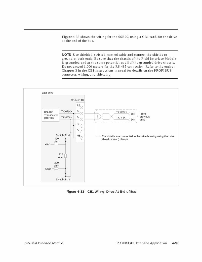
PROFIBUS-DP Interface Application 4-99505 Field Interface Module
Figure 4-33 shows the wiring for the 6SE70, using a CB1 card, for the driveat the end of the bus.
NOTE: Use shielded, twisted, control cable and connect the shields toground at both ends. Be sure that the chassis of the Field Interface Moduleis grounded and at the same potential as all of the grounded drive chassis.Do not exceed 1,000 meters for the RS-485 connection. Refer to the entireChapter 3 in the CB1 instructions manual for details on the PROFIBUSconnector, wiring, and shielding.
Last drive
(B)
(A)
TX+/RX+
TX–/RX–
Frompreviousdrive
The shields are connected to the drive housing using the driveshield (screen) clamps.
A
CB1–X148
TX+/RX+
TX–/RX–
BRS-485Transceiver(RX/TX)
390ohm
GND
+5V
215ohm
390ohm
Switch S1.3
Switch S1.4
P5
M5
A
B
Figure 4-33 CB1 Wiring: Drive At End of Bus

PROFIBUS-DP Interface Application4-100 505 Field Interface Module
4.18 CB24 (SIMOREG 6RA24 Communications Board)
For the SIMOREG 6RA24 with CB24 only, any hardware version of the6RA24 may be used. The 6RA24 software version must be version 2.10 orhigher. Any hardware and software version of the CB24 may be used.
For the SIMOREG 6RA24 with Z2006 and CB24, any hardware version ofthe 6RA24 may be used. The 6RA24 software version must be version 2.00or higher. The Z2006 hardware Revision or Issue No. must be 11 or higher.The Type 1 (Sectional) software version must be 1.40 or higher, type 3(CEMF Winder) software version must be 1.10 or higher, type 4 (ArmatureWinder) software version must be 1.20 or higher. Any hardware andsoftware version of the CB24 may be used.
Serial port 1 on the CB24 is used. This serial port is also referred to asCBP1 (Communication Board Port 1).
NOTE: After the following parameters have been changed, the drive shouldbe powered down for at least 10 seconds and then powered back on. Thispower cycling allows the drive to initialize communications with the FIM.
P900 must be set to a 2 (CS5 Only) if only a CB24 is attached to thedrive or a 4 CS5&ThBd if both a CB24 and a Z2006 are attached to the drive.
P902 must be set to a 9 L2-DP to select PROFIBUS-DP on port 1of the CB24.
P904 must be set to the individual drive PROFIBUS address. For usewith the FIM, the first valid drive address is 17.
P905 selects the PROFIBUS baud rate.
P905 = 1 9,600 baudP905 = 2 19,200 baudP905 = 3 93,750 baudP905 = 4 187,500 baudP905 = 6 500,000 baudP905 = 9 1.5 Mbaud
P906 must be set to a 1 (not used) to turn off port 2 of the CB24.
P910 must be set to 4 to allow parameters to be changed from theFIM through port 1 of the CB24 (also refer to to P925).
P911 must be set to 4 or 5 to allow process data to be changed from the FIM through port 1 of the CB24 (also refer to P924).
P916 selects the actual values that are sent to the host in the PZD section (also refer to P924).
Required Hardwareand Software
RequiredParameters
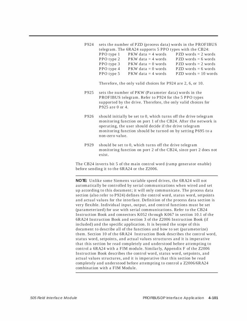
PROFIBUS-DP Interface Application 4-101505 Field Interface Module
P924 sets the number of PZD (process data) words in the PROFIBUStelegram. The 6RA24 supports 5 PPO types with the CB24:PPO type 1 PKW data = 4 words PZD words = 2 wordsPPO type 2 PKW data = 4 words PZD words = 6 wordsPPO type 3 PKW data = 0 words PZD words = 2 wordsPPO type 4 PKW data = 0 words PZD words = 6 wordsPPO type 5 PKW data = 4 words PZD words = 10 words
Therefore, the only valid choices for P924 are 2, 6, or 10.
P925 sets the number of PKW (Parameter data) words in the PROFIBUS telegram. Refer to P924 for the 5 PPO types supported by the drive. Therefore, the only valid choices for P925 are 0 or 4.
P926 should initially be set to 0, which turns off the drive telegram monitoring function on port 1 of the CB24. After the network is operating, the user should decide if the drive telegram monitoring function should be turned on by setting P695 to a non-zero value.
P929 should be set to 0, which turns off the drive telegram monitoring function on port 2 of the CB24, since port 2 does notexist.
The CB24 inverts bit 5 of the main control word (ramp generator enable)before sending it to the 6RA24 or the Z2006.
NOTE: Unlike some Siemens variable speed drives, the 6RA24 will notautomatically be controlled by serial communications when wired and setup according to this document; it will only communicate. The process datasection (also refer to P924) defines the control word, status word, setpointsand actual values for the interface. Definition of the process data section isvery flexible. Individual input, output, and control functions must be set(parameterized) for use with serial communications. Refer to the CB24Instruction Book and connectors K052 through K067 in section 10.1 of the6RA24 Instruction Book and section 3 of the Z2006 Instruction Book (ifincluded) and the specific application. It is beyond the scope of thisdocument to describe all of the functions and how to set (parameterize)them. Section 10 of the 6RA24 Instruction Book describes the control word,status word, setpoints, and actual values structures and it is imperativethat this section be read completely and understood before attempting tocontrol a 6RA24 with a FIM module. Similarly, Appendix F of the Z2006Instruction Book describes the control word, status word, setpoints, andactual values structures, and it is imperative that this section be readcompletely and understood before attempting to control a Z2006/6RA24combination with a FIM Module.

PROFIBUS-DP Interface Application4-102 505 Field Interface Module
CB24 (SIMOREG 6RA24 Communications Board) (continued)
The following example describes how to assign the Main Control Word andSpeed Setpoint functions to the FIM:
On a Factory Default 6RA24 SIMOREG, these control functions are setto local wired inputs, not port CBP1.
In order to control the Main Control Word function from port CBP1(PROFIBUS-DP) (the FIM), parameter P640 must be set to 52. Thissets the source of the standard control word to PZD word 1 of thetelegrams on port CBP1 (PROFIBUS-DP). PZD word 1 is word 1 of thePLC data area if parameter P925 (see above) is set to 0. PZD word 1 isword 5 of the PLC data area if parameter P925 (see above) is set to 4(words 1, 2, 3, and 4 are PKW words).
The same concepts apply to the Speed Setpoint signal. In order tocontrol the Speed Setpoint from CBP1 (PROFIBUS-DP) (the FIM),parameter P628.0 must be set to 53. This sets the source of the SpeedSetpoint to PZD word 2 of the telegrams on port CBP1(PROFIBUS-DP).

PROFIBUS-DP Interface Application 4-103505 Field Interface Module
In order for the motor to start, the run enable (terminal 37) and theregulator enable (terminal 38) on the base 6RA24 unit must be on. Beforeparameter P640 was changed, these terminals directly controlled the motor.Now they are treated as enable signals.
After P640 is set to 52, Figure 4-34 describes the function of each control bitin PZD word 1 of the information sent to the drive.
15 14 13 12 11 10 9 8 7 6 5 4 3 2 1 0
High byte Low byte
1 = Start0 = STOP1 (Normal Stop)0 = STOP2 (Coast Stop)
Not used unless enabled by Z2006
Not used
1 = Enable Serial Operation
Not used unless enabled by Z2006
Not used unless enabled by Z2006
Not used unless enabled by Z2006
Not used unless enabled by Z2006
Not used unless enabled by Z2006
0 = STOP3 (Quick Stop)
1 = Regulators Enable
1 = Ramp Generator Enable
1 = Ramp Generator is not held
1 = Reference Enable
1 = Fault Reset
Note: A suggested initial value of PZD word 1 is 047E hex. PZD word 1 can be changed to 047F hex to start the drive.
Figure 4-34 Control Bits for Main Control Word and Speed Setpoint
Also, drive status and feedback (or actual value) information such as motorspeed and other information must be set (parameterized) to the appropriatedestination in order to be read by the FIM Module. Section 10.8 of the6RA24 Instruction Book also explains the details.

PROFIBUS-DP Interface Application4-104 505 Field Interface Module
CB24 (SIMOREG 6RA24 Communications Board) (continued)
The following example describes how to access the Standard Status Wordand Speed Feedback from the FIM:
On a Factory Default 6RA24 SIMOREG, these return informationwords are set to zero. In order to access the standard status word inPZD word 1 from port CBP1 (PROFIBUS-DP) (the FIM), parameterP916.0 must be set in 325. This selects what will be returned in PZDword 1 of the telegrams on port CBP1 (PROFIBUS-DP). PZD word 1 isword 1 of the PLC data area if parameter P925 (see above) is set to 0.PZD word 1 is word 5 of the PLC data area if parameter P925 (seeabove) is set to 4 (words 1, 2, 3, and 4 are PKW words).
The same concepts apply to the Speed Feedback (or Actual Value)signal. In order to access the Speed Feedback in PZD word 2 from portCBP1 (PROFIBUS-DP) (the FIM), parameter P916.1 must be set to167. This selects what will be returned in PZD word 2 of the telegramson serial port CBP1 (PROFIBUS-DP).
After P916.0 is set to 325, Figure 4-35 describes the function of eachstatus bit in PZD word 1 of the return information from the drive.

PROFIBUS-DP Interface Application 4-105505 Field Interface Module
15 14 13 12 11 10 9 8 7 6 5 4 3 2 1 0
High byte Low byte
1 = Ready to start (operating status o7)
1 = Operate enable is present1 = Drive running
1 = Drive fault present
0 = STOP2 (Coast stop command present)
0 = STOP3 (Quick stop command present)
1 = Drive blocked
1 = Drive Warning present
1 = Speed controller error within the tolerance band
1 = Serial Operation Allowed0 = Serial Operation Blocked – local operation only1 = Speed > nbase (P373)
Dependent on if Z2006 connected
Dependent on if Z2006 connected
Dependent on if Z2006 connected
Dependent on if Z2006 connected
Dependent on if Z2006 connected
Figure 4-35 Status Bits for Standard Status Word and Speed Feedback
Bus termination resistors are part of the CB24 board and are controlled byhook switches S1.3 and S1.4. Switches S1.3 and S1.4 should be closed onlyon the CB24 at the end of the bus.
Switches S1.1 and S1.2 are not used on the CB24.
When the data to and from the CB24 is displayed in word format in theSIMATIC 505 PLC, the bytes are correct, the high byte is in the high byteposition, the low byte is in the low byte position. The documentation in the6RA24, CB24, and Z2006 instruction books can be used directly.
The CB24 does not require an external 24-volt DC source.
Required Switches
Byte Order in theController
External PowerSupply

PROFIBUS-DP Interface Application4-106 505 Field Interface Module
CB24 (SIMOREG 6RA24 Communications Board) (continued)
A
CB24–X148
TX+/RX+
TX–/RX–
3*
8*
RS-485Transceiver(RX/TX)
6
1*
+5V
GND
First drive Field Interface Module
390 ohmpull-up resistor220 ohmtermination resistor390 ohmpull-down resistor
(B)
(A)
TX+/RX+
TX–/RX–To next drive
TX+/RX+
TX–/RX–
BRS-485Transceiver(RX/TX)
390ohm
GND
+5V
The shields are connected to the drive housing using the driveshield (screen) clamps.
215ohm
390ohm
Switch S1.3
Switch S1.4
P5
M5
A
B
* For Pin 3: Terminal B on Siemens connector (listed in Section 2.4).* For Pin 8: Terminal A on Siemens connector (listed in Section 2.4).* For Pin 1: Connector housing on Siemens connector (listed in Section 2.4).
Figure 4-36 CB24 Wiring: All Drives Except at End of Bus
NOTE: Use shielded, twisted, control cable and connect the shields toground at both ends. Be sure that the chassis of the Field Interface Moduleis grounded and at the same potential as all of the grounded drive chassis.Do not exceed 1,000 meters for the RS-485 connection. Refer to the entireChapter 3 in the CB1 instruction manual for details on PROFIBUSconnectors, wiring, and shielding.

PROFIBUS-DP Interface Application 4-107505 Field Interface Module
Drive Number X
(B)
(A)
TX+/RX+
TX–/RX–
Frompreviousdrive
The shields are connected to the drive housing using the driveshield (screen) clamps.
A
CB24–X148
TX+/RX+
TX–/RX–
BRS-485Transceiver(RX/TX)
390ohm
GND
+5V
215ohm
390ohm
Switch S1.3
Switch S1.4
P5
M5
A
B
Figure 4-37 CB24 Wiring: Drive At End of Bus
NOTE: Use shielded, twisted, control cable and connect the shields toground at both ends. Be sure that the chassis of the Field Interface Moduleis grounded and at the same potential as all of the grounded drive chassis.Do not exceed 1,000 meters for the RS-485 connection. Refer to the entireChapter 3 in the CB1 instruction manual for details on PROFIBUSconnectors, wiring, and shielding.

PROFIBUS-DP Interface Application4-108 505 Field Interface Module
4.19 CS51 (SIMOREG 6RA24 and SIMOVERT 6SE12 Communications Board)
For the SIMOREG 6RA24 with CS51 only, any hardware version of the6RA24 may be used. The 6RA24 software version must be version 2.00 orhigher. The version of the CS51 (which includes hardware and software)should be version H or higher.
For the SIMOVERT 6SE12 with CS51 only, any hardware version of the6SE12 may be used. The 6SE12 software version must be version 3.3 orhigher. The version of the CS51 (which includes hardware and software)should be version H or higher.
For the SIMOREG 6RA24 with Z2006 and CS51, any hardware version ofthe 6RA24 may be used. The 6RA24 software version must be version 2.00or higher. The Z2006 hardware Revision or Issue No. must be 11 or higher.The Type 1 (Sectional) software version must be 1.40 or higher, type 3(CEMF Winder) software version must be 1.10 or higher, type 4 (ArmatureWinder) software version must be 1.20 or higher. The version of the CS51(which includes hardware and software) should be version H or higher.
For the SIMOVERT 6SE12 with Z2006 and CS51, any hardware version ofthe 6SE12 may be used. The 6SE12 software version must be version 3.3 orhigher. The Z2006 hardware Revision or Issue No. must be 10 or higher. TheType 1 (Sectional) software version must be 1.40 or higher, type 3 (CEMFWinder) software version must be 1.10 or higher, type 4 (Armature Winder)software version must be 1.20 or higher. The version of the CS51 (whichincludes hardware and software) should be version H or higher.
Required Hardwareand Software

PROFIBUS-DP Interface Application 4-109505 Field Interface Module
Use serial port 1, the Communication Board Port 1 (CBP1), on the CS51.
P900 must be set to a 2 (CS5 Only appears on the screen) if only a CS51 is attached to the drive, or to a 4 (CS5&ThBd appears on the screen), if both a CS51 and a Z2006 are attached to the drive.
P902 must be set to a 9 (L2-DP appears on the screen) to select PROFIBUS-DP on port 1 of the CS51.
P904 must be set to the individual drive’s PROFIBUS address. Whenused with the FIM, the first valid drive address is 17 if the slave address range selection dipswitches are all set to closed. Refer to Table 4-2 for more information on setting the slaveaddress range selection.
P905 selects the PROFIBUS baud rate.
P905 = 1 9,600 baudP905 = 2 19,200 baudP905 = 3 93,750 baudP905 = 4 187,500 baudP905 = 6 500,000 baudP905 = 9 1.5 Mbaud
P906 must be set to 1 (that is, not used) to turn off port 2 ofthe CS51.
P910 6RA24 only – must be set to 4 to allow parameters to be changed from the FIM through port 1 of the CS51 (also referto P925).
P911 6RA24 only – must be set to 4 or 5 to allow process data to be changed from the FIM through port 1 of the CS51 (also refer toP924).
P915 6SE12 only – must be set to allow process data parameters tobe changed from the FIM through port 1 of the CS51.
P916 selects the actual values that are sent to the host in the PZD section (also refer to P924).
P924 sets the number of PZD (process data) words in the PROFIBUS telegram. The 6RA24 and the 6SE12 support four PPO types:
PPO type 1PKW data = 4 words PZD words = 2 wordsPPO type 2 PKW data = 4 words PZD words = 6 wordsPPO type 3 PKW data = 0 words PZD words = 2 wordsPPO type 4 PKW data = 0 words PZD words = 6 words
The only valid choices for P924 are 2 or 6.
RequiredParameters

PROFIBUS-DP Interface Application4-110 505 Field Interface Module
CS51 (SIMOREG 6RA24 / SIMOVERT 6SE12 Communications Board) (continued)
P925 sets the number of PKW (Parameter data) words in the PROFIBUS telegram. Refer to P924 for the 4 PPO types supported by the drive. The only valid choices for P925 are 0 or 4.
P926 initially is set to 0, which turns off the drive telegram-monitoring function on port 1 of the CS51. After the network is operating, you can decide whether or not to turn on the drive telegram-monitoring function by setting P695 to a non-zero value.
P929 is set to 0, which turns off the drive telegram-monitoring function on port 2 of the CS51 because port 2 is not used.
P1005 determines whether PROFIBUS parameter changes are stored in the drive EEPROM. P1005 is reset to 0 when the drive poweron. P1005 can only be accessed and changed through the PROFIBUS:
0 means that parameter changes are not stored in EEPROM.1 means that parameter changes are stored in EEPROM.
After the above parameters have been changed, the drive should be powereddown for at least 10 seconds and then powered back on. This power cyclingallows the drive to initialize communications with the FIM.
NOTE: Note that the CS51 inverts bit 5 of the main control word (rampgenerator enable) before sending it to the 6RA24 or 6SE12 or Z2006.

PROFIBUS-DP Interface Application 4-111505 Field Interface Module
NOTE: For the SIMOREG 6RA24, the drive will not automatically becontrolled by serial communications when wired and set up according to thisdocument; it will only communicate. The process data section (also refer toP924) defines the control word, status word, setpoints and actual values forthe interface. Definition of the process data section is very flexible.Individual input, output, and control functions must be set (parameterized)for use with serial communications. Refer to the CS51 Instruction Book andconnectors K052 through K067 in section 10.1 of the 6RA24 InstructionBook and section 3 of the Z2006 Instruction Book (if included) and thespecific application. It is beyond the scope of this document to describe all ofthe functions and how to set (parameterize) them. Section 10 of the 6RA24Instruction Book describes the control word, status word, setpoints, andactual values structures, and it is imperative that this section be readcompletely and understood before attempting to control a 6RA24 with a FIMmodule. Similarly, Appendix F of the Z2006 Instruction Book describes thecontrol word, status word, setpoints, and actual values structures, and it isimperative that this section be read completely and understood beforeattempting to control a Z2006/6RA24 combination with a FIM Module.

PROFIBUS-DP Interface Application4-112 505 Field Interface Module
CS51 (SIMOREG 6RA24 / SIMOVERT 6SE12 Communications Board) (continued)
The following example describes how to assign the Main Control Word andSpeed Setpoint functions to the FIM:
On a Factory Default 6RA24 SIMOREG, these control functions are setto local wired inputs, not port CBP1.
In order to control the Main Control Word function from port CBP1(communicating by PROFIBUS-DP protocol to the FIM), parameterP640 must be set to 52. This sets the source of the standard controlword to PZD word 1 of the telegrams on port CBP1 (PROFIBUS-DP).PZD word 1 is word 1 of the PLC data area if parameter P925 (seeabove) is set to 0. PZD word 1 is word 5 of the PLC data area ifparameter P925 is set to 4 (words 1, 2, 3, and 4 are PKW words).
The same concepts apply to the Speed Setpoint signal. In order tocontrol the Speed Setpoint from CBP1 (PROFIBUS-DP) (the FIM),parameter P628.0 must be set to 53. This sets the source of the SpeedSetpoint to PZD word 2 of the telegrams on port CBP1(PROFIBUS-DP).
In order for the motor to start, the run enable (terminal 37) and theregulator enable (terminal 38) on the base 6RA24 unit must be on. Theseterminals used to control the motor directly. Now parameter P640 has beenchanged, so that they are treated as enable signals.
After P640 is set to 52, Figure 4-38 describes the function of each control bitin PZD word 1 of the information sent to the drive.
NOTE: As discussed later in this section (see page 4-114), it is assumed thatthe byte order will be reversed by the PLC on the output words immediatelybefore they are sent to the drive.

PROFIBUS-DP Interface Application 4-113505 Field Interface Module
15 14 13 12 11 10 9 8 7 6 5 4 3 2 1 0
High byte Low byte
1 = Start0 = STOP1 (Normal Stop)0 = STOP2 (Coast Stop)
Not used unless enabled by Z2006
Not used
1 = Enable Serial Operation
Not used unless enabled by Z2006
Not used unless enabled by Z2006
Not used unless enabled by Z2006
Not used unless enabled by Z2006
Not used unless enabled by Z2006
0 = STOP3 (Quick Stop)
1 = Regulators Enable
1 = Ramp Generator Enable
1 = Ramp Generator is not held
1 = Reference Enable
1 = Fault Reset
Note: A suggested initial value of PZD word 1 is 047E hex. PZD word 1 can be changed to 047F hex to start the drive.
Figure 4-38 Control Bits for Main Control Word and Speed Setpoint
Also, drive status and feedback (or actual value) information such as motorspeed and other information must be set (parameterized) to the appropriatedestination in order to be read by the FIM Module. Section 10.8 of the6RA24 Instruction Book also explains the details.

PROFIBUS-DP Interface Application4-114 505 Field Interface Module
CS51 (SIMOREG 6RA24 / SIMOVERT 6SE12 Communications Board) (continued)
The following example describes how to access the Standard Status Wordand Speed Feedback from the FIM:
On a Factory Default 6RA24 SIMOREG, these return informationwords are set to zero. In order to access the standard status word inPZD word 1 from port CBP1 (communicating by PROFIBUS-DPprotocol to the FIM), parameter P916.0 must be set in 325. This selectswhat will be returned in PZD word 1 of the telegrams on port CBP1(PROFIBUS-DP). PZD word 1 is word 1 of the PLC data area ifparameter P925 (see above) is set to 0. PZD word 1 is word 5 of the PLCdata area if parameter P925 (see above) is set to 4 (words 1, 2, 3, and 4are PKW words).
The same concepts apply to the Speed Feedback (or Actual Value)signal. In order to access the Speed Feedback in PZD word 2 from portCBP1 (communicating by PROFIBUS-DP to the FIM), parameterP916.1 must be set to 167. This selects what will be returned in PZDword 2 of the telegrams on serial port CBP1 (PROFIBUS-DP).
After P916.0 is set to 325, Figure 4-39 describes the function of eachstatus bit in PZD word 1 of the return information from the drive.
NOTE: It is assumed that the byte order will be reversed by the PLC on theinput words from the drive before any processing starts.
When the data to and from the CS51 is displayed in word format in theSeries 505 controller, the bytes are reversed in each word. This reversal iscaused by the CS51. To avoid confusion, the controller reverses the byteorder on the input words before any processing starts. Similarly, thecontroller reverses the byte order on the output words immediately beforethey are sent to the drive. Doing these byte reversals allows thedocumentation in the 6RA24, 6SE12, CS51, and Z2006 instructions books tobe used directly.
Byte Order in theController

PROFIBUS-DP Interface Application 4-115505 Field Interface Module
15 14 13 12 11 10 9 8 7 6 5 4 3 2 1 0
High byte Low byte
1 = Ready to start (operating status o7)
1 = Operate enable is present1 = Drive running
1 = Drive fault present
0 = STOP2 (Coast stop command present)
0 = STOP3 (Quick stop command present)
1 = Drive blocked
1 = Drive Warning present
1 = Speed controller error within the tolerance band
1 = Serial Operation Allowed0 = Serial Operation Blocked – local operation only1 = Speed > nbase (P373)
Dependent on if Z2006 connected
Dependent on if Z2006 connected
Dependent on if Z2006 connected
Dependent on if Z2006 connected
Dependent on if Z2006 connected
Figure 4-39 Status Bits for Standard Status Word and Speed Feedback
For the SIMOVERT 6SE12, the process data section (also refer to P924)defines the control word, status word, setpoints, and actual values for theinterface. Definition of the process data section is flexible. Refer to the CS51Instruction Book, parameter P915 of the 6SE12 Instruction Book, Section 3of the Z2006 Instruction Book (if included), and the specific application.
NOTE: The CS51 inverts bit 5 of the main control word (ramp generatorenable) before sending it to the 6RA24 or 6ES12 or Z2006.
The CS51 has no applicable switches.Required Switches

PROFIBUS-DP Interface Application4-116 505 Field Interface Module
CS51 (SIMOREG 6RA24 / SIMOVERT 6SE12 Communications Board) (continued)
Connect an external 24 VDC source to terminal block X9 with pin 1 as +24 V and pin 2 as common. Use a separate power supply, because this isthe power source for the actual serial connection between drive and host.The resulting communications signals are optically isolated from theinternal microprocessor power supplies to provide the drive system withnoise immunity.
Figure 4-40 shows the wiring for the CS51 SIMOREG 6RA24 andSIMOVERT 6SE12 Communications Board for all drives except the end ofthe bus.
NOTE: Use shielded, twisted, control cable and connect the shields toground at both ends. Be sure that the chassis of the Field Interface Moduleis grounded and at the same potential as all of the grounded drive chassis.Do not exceed 1,000 meters for the RS-485 connection.
TX+/RX+
TX–/RX–
3*
8*
RS-485Transceiver(RX/TX)
6
1*
+5V
GND
First drive Field Interface Module
390 ohmpull-up resistor220 ohmtermination resistor390 ohmpull-down resistor
(P)
(N)
TX+/RX+
TX–/RX–To next drive
RS-485Transceiver(RX/TX)
3
6
X7Female
TX–/RX–
TX+/RX+
GND
+5V
8
5
A PROFIBUS connector may be used tosimplify this connection.
* For Pin 3: Terminal B on Siemens connector (listed in Section 2.4).* For Pin 8: Terminal A on Siemens connector (listed in Section 2.4).
* For Pin 1: Connector housing on Siemens connector (listed in Section 2.4).* For Pin 5: Connector housing on Siemens connector (listed in Section 2.4).
Figure 4-40 6SE12 Wiring: All Drives Except End of Bus
External PowerSupply

PROFIBUS-DP Interface Application 4-117505 Field Interface Module
Figure 4-41 shows the wiring for the CS51 SIMOREG 6RA24 andSIMOVERT 6SE12 Communications Board for the drive at the end of thebus.
NOTE: Use shielded, twisted, control cable and connect the shields toground at both ends. Be sure that the chassis of the Field Interface Moduleis grounded and at the same potential as all of the grounded drive chassis.Do not exceed 1,000 meters for the RS-485 connection.
Last drive
390 ohmpull-up resistor* (P)
(N)
TX+/RX+
TX–/RX–
Frompreviousdrive
RS-485Transceiver(RX/TX)
3
6
TX–/RX–
TX+/RX+
GND
+5V
8
5
220 ohmtermination resistor*390 ohmpull-down resistor*
X7Female
A PROFIBUS connector may be used tosimplify this connection.
* For Pin 3: Terminal B on Siemens connector (listed in Section 2.4).* For Pin 8: Terminal A on Siemens connector (listed in Section 2.4).* For Pin 5: Connector housing on Siemens connector (listed in Section 2.4).
* These resistor values are typical. Any values are acceptable as long as theparallel combination is approximately 120 ohms.
Figure 4-41 6SE12 Wiring: Drive at End of Bus

PROFIBUS-DP Interface Application4-118 505 Field Interface Module
4.20 Setting Up and Wiring the SI3
You can use any hardware and/or software version of the SI3 (6SE85 SerialInterface Board).
The parameters required to set up the 6SE85 follow.
Serial Mode must be set to port 2, which selects port 2 for serial control.
Protocol Port 2 must be set to L2-DP, which selects 4-word PROFIBUS-DP protocol.
Data Length Port 2 must be set to 8, which includes the length byte in the telegram.
Address Port 2 must be set to the individual drive’s PROFIBUSaddress. When used with the FIM, the first valid drive address is 17 if the slave address range selection is set to all closed. Refer to Table 4-2 for more information on the slave address range selection.
Baudrate Port 2 is normally set to 185.5K baud, unless some other drive requires a lower baud rate.
Link Failure is initially set to Ignore, which turns off the drive telegram-monitoring function. After the network is operating, you can decide whether ornot to turn on the drive telegram-monitoring function by setting Link Failure to Trip Drive.
The fixed 4-word (8-byte) data section defines the control word, status word,setpoints, actual values, and parameter information for the interface.Definition of the data section is fixed. Refer to the SI3 Instruction Book andthe section on the specific configuration; this serial interface is called port 2in that instruction book.
Required Hardwareand Software
RequiredParameters

PROFIBUS-DP Interface Application 4-119505 Field Interface Module
The applicable jumpers follow:
JB1 Figure 4-42 and Figure 4-43 show the correct position of this jumper.
JB2 This jumper must be set to two-wire RS-485 operation.
JB3 This jumper must be in the open position.
JB4 This jumper is not applicable.
Required Jumpers
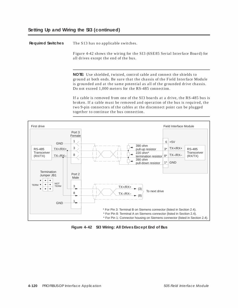
PROFIBUS-DP Interface Application4-120 505 Field Interface Module
Setting Up and Wiring the SI3 (continued)
The S13 has no applicable switches.
Figure 4-42 shows the wiring for the SI3 (6SE85 Serial Interface Board) forall drives except the end of the bus.
NOTE: Use shielded, twisted, control cable and connect the shields toground at both ends. Be sure that the chassis of the Field Interface Moduleis grounded and at the same potential as all of the grounded drive chassis.Do not exceed 1,000 meters for the RS-485 connection.
If a cable is removed from one of the SI3 boards at a drive, the RS-485 bus isbroken. If a cable must be removed and operation of the bus is required, thetwo 9-pin connectors of the cables at the disconnect point can be pluggedtogether to continue the bus connection.
(3)
(8)
TX+/RX+
TX–/RX–To next drive
8
Port 3Female
TX+/RX+
TX–/RX–
3*
8*
RS-485Transceiver(RX/TX)
6
1*
+5V
GND
First drive Field Interface Module
390 ohmpull-up resistor220 ohm*termination resistor390 ohmpull-down resistor
TX+/RX+
TX–/RX–
3RS-485Transceiver(RX/TX)
1GND
8
3
1GND
Port 2Male
TerminationJumper JB1
NOTTERMTERM
* For Pin 3: Terminal B on Siemens connector (listed in Section 2.4).* For Pin 8: Terminal A on Siemens connector (listed in Section 2.4).* For Pin 1: Connector housing on Siemens connector (listed in Section 2.4).
Figure 4-42 SI3 Wiring: All Drives Except End of Bus
Required Switches

PROFIBUS-DP Interface Application 4-121505 Field Interface Module
Figure 4-43 shows the wiring for the SI3 (6SE85 Serial Interface Board) forthe drive at the end of the bus.
NOTE: Use shielded, twisted, control cable and connect the shields toground at both ends. Be sure that the chassis of the Field Interface Moduleis grounded and at the same potential as all of the grounded drive chassis.Do not exceed 1,000 meters for the RS-485 connection.
If a cable is removed from one of the SI3 boards at a drive, the RS-485 bus isbroken. If a cable must be removed and operation of the bus is required, thetwo 9-pin connectors of the cables at the disconnect point can be pluggedtogether to continue the bus connection.
(3)
(8)
TX+/RX+
TX–/RX–To next driveNumber 01
8
Port 3Female
Drive Number X
TX+/RX+
TX–/RX–
3RS-485Transceiver(RX/TX)
1GND
8
3
1GND
Port 2Male
TerminationJumper JB1
NOTTERMTERM
Figure 4-43 SI3 Wiring: Drive at End of Bus

SAMMS Interface Application 5-1505 Field Interface Module
Chapter 5
SAMMS Interface Application
5.1 SAMMS Interface Overview 5-2. . . . . . . . . . . . . . . . . . . . . . . . . . . . . . . . . . . . . . . . . . . . . . . . . . . . .
5.2 Selecting the Application 5-6. . . . . . . . . . . . . . . . . . . . . . . . . . . . . . . . . . . . . . . . . . . . . . . . . . . . . . .
5.3 Communicating with the SAMMS Units 5-9. . . . . . . . . . . . . . . . . . . . . . . . . . . . . . . . . . . . . . . . . . .
5.4 Connecting to SAMMS Unit 5-11. . . . . . . . . . . . . . . . . . . . . . . . . . . . . . . . . . . . . . . . . . . . . . . . . . . . . .
5.5 Configuring for Control Mode 5-12. . . . . . . . . . . . . . . . . . . . . . . . . . . . . . . . . . . . . . . . . . . . . . . . . . . .
5.6 Configuring for Status Poll Mode 5-20. . . . . . . . . . . . . . . . . . . . . . . . . . . . . . . . . . . . . . . . . . . . . . . . .
5.7 Programming: Broadcast and Immediate I/O Requests 5-26. . . . . . . . . . . . . . . . . . . . . . . . . . .
5.8 Programming: Sending Requests 5-30. . . . . . . . . . . . . . . . . . . . . . . . . . . . . . . . . . . . . . . . . . . . . . . . .
5.9 Programming: Receiving Response Data 5-35. . . . . . . . . . . . . . . . . . . . . . . . . . . . . . . . . . . . . . . . .
5.10 Programming: Application Examples 5-38. . . . . . . . . . . . . . . . . . . . . . . . . . . . . . . . . . . . . . . . . . . . .
5.11 SAMMS Units Troubleshooting 5-43. . . . . . . . . . . . . . . . . . . . . . . . . . . . . . . . . . . . . . . . . . . . . . . . . . . .

SAMMS Interface Application5-2 505 Field Interface Module
5.1 SAMMS Interface Overview
The SAMMS Interface Application supports the SEAbus protocol of theSiemens Advanced Motor Master System (SAMMS) of Siemens Energy andAutomation, Inc.
The SAMMS Interface Application has the following features.
• It interfaces with 1 to 15 SAMMS units for each Field InterfaceModule.
• The autobaud operation automatically determines the baud rate bypolling SAMMS units. All SAMMS units must be at the same baudrate.
• It supports Broadcast Messages through a broadcast channel.
• It supports Immediate Messages to individual SAMMS units andsupplies rapid feedback for immediate I/O requests.
• The status of communication can be monitored through the controllerstatus words (STW). This can be done both for the Field InterfaceModule and controller communication link, and for the Field InterfaceModule and SAMMS communication link.
• The SAMMS Interface Application can be reset without power cyclingthe base. To do this, change the SAMMS unit address range switch(S2).
Features
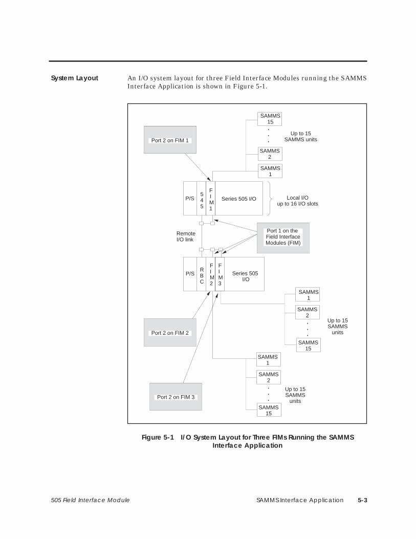
SAMMS Interface Application 5-3505 Field Interface Module
An I/O system layout for three Field Interface Modules running the SAMMSInterface Application is shown in Figure 5-1.
P/S
P/S
Local I/Oup to 16 I/O slots
Series 505 I/O
RBC
545
FIM1
FIM2
Series 505 I/O
SAMMS1
SAMMS2
SAMMS15
Up to 15SAMMS
units
.
.
.
SAMMS15
SAMMS2
SAMMS1
Up to 15SAMMS units
.
.
.Port 2 on FIM 1Port 2 on FIM 1
Port 2 on FIM 2
Remote I/O link
FIM3
SAMMS1
SAMMS2
SAMMS15
.
.
.
Up to 15SAMMS
units
Port 2 on FIM 3
Port 1 on the Field InterfaceModules (FIM)
Figure 5-1 I/O System Layout for Three FIMs Running the SAMMSInterface Application
System Layout

SAMMS Interface Application5-4 505 Field Interface Module
Overview (continued)
The SAMMS Interface logical block diagram is shown in Figure 5-2. TheField Interface Module appears as a remote base controller to the Series 505I/O system.
ControllerFIM
SAMMSInterface
Remote I/O
RBC 2
SAMMS 1 SAMMS 15
SAMMS 2
. . .
. . .
(Base 5)*
(Base 1)
*Base 5 is used for this example. The FIM can be set to any valid base number.
Figure 5-2 FIM Interface Block Diagram
SAMMS InterfaceLogical Diagram
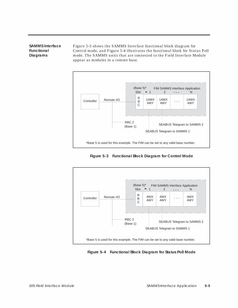
SAMMS Interface Application 5-5505 Field Interface Module
Figure 5-3 shows the SAMMS Interface functional block diagram forControl mode, and Figure 5-4 illustrates the functional block for Status Pollmode. The SAMMS units that are connected to the Field Interface Moduleappear as modules in a remote base.
Controller
FIM SAMMS Interface Application
Remote I/O
RBC 2
SEABUS Telegram to SAMMS 1
SEABUS Telegram to SAMMS 2
RBC
14WX4WY
14WX4WY
14WX4WY
Slot 1 2 N
. . .
(Base 1)
*Base 5 is used for this example. The FIM can be set to any valid base number.
(Base 5)*. . .
Figure 5-3 Functional Block Diagram for Control Mode
Controller
FIM SAMMS Interface Application
Remote I/O
RBC 2
SEABUS Telegram to SAMMS 1
SEABUS Telegram to SAMMS 2
RBC
4WX4WY
4WX4WY
4WX4WY
Slot 1 2 N
. . .
(Base 1)
*Base 5 is used for this example. The FIM can be set to any valid base number.
(Base 5)*. . .
Figure 5-4 Functional Block Diagram for Status Poll Mode
SAMMS InterfaceFunctionalDiagrams

SAMMS Interface Application5-6 505 Field Interface Module
5.2 Selecting the Application
The mode of operation, called the application, is determined by setting theS3 dipswitch, as shown in Figure 5-5. Switches S3–1, S3–3, and S3–4 areclosed and switch S3–2 is open for the SAMMS Interface Application.
1 2 3 4 5 6 7 8
CLOSED
OPEN
Delay0
SPAR
Delay1
MODEAP 0
AP 1
AP 2
AP 3
S3
CLOSED/ON/0
OPEN/OFF/1
Figure 5-5 Field Interface Module S3 Dipswitch Settings
Dipswitch S3 assignments, shown in Figure 5-5, are defined as follows.
• AP 0 – 3 = Application Number 0 – 15 (AP 0 is the LSB)
• MODE = 0 – Control Mode 1 – Status Poll Mode
• SPAR = Spare
• Delay 1 = Additional delay time; see Table 5-1.
• Delay 0 = Additional delay time; see Table 5-1.
Table A-1 in Appendix A describes the S3 switch settings for the otherapplications that can be used with the FIM.
Mode of Operation

SAMMS Interface Application 5-7505 Field Interface Module
The SAMMS interface has response times that are optimized forcommunications with the SAMMS units. This optimization reduces theoverall scan time of the SAMMS interface. Future releases of SAMMS units,however, may require longer response delays than are allowed by theoptimizations. In order to accommodate potential future changes to theSAMMS units, Table 5-1 shows the additional delay time that SAMMSinterface allows. Normally, no additional time is required; leave Delay0 andDelay1 in the Closed/On/0 position.
Table 5-1 Selecting Additional Delay Time
Delay1 Delay0 Additional Delay
Closed/On/0 Closed/On/0 0 mSec
Closed/On/0 Open/Off/1 7 mSec
Open/Off/1 Closed/On/0 21 mSec
Open/Off/1 Open/Off/1 42 mSec
NOTE: Changing any of the switches while the module is plugged in resetsthe module.
You must configure the corresponding controller slot according to Table 5-2for each active SAMMS unit that is connected to a FIM module. For adescription of the WX and WY words, refer to Table 5-4 through Table 5-6.
Table 5-2 SAMMS Interface Configuration Modes
Dipswitch S3–8 Mode Controller SlotConfiguration
Closed/On/0 Control Mode 14WX, 4WY
Open/Off/1 Status Poll Mode 4WX, 4WY
Interface ResponseTimes
ConfiguringSAMMS Interface

SAMMS Interface Application5-8 505 Field Interface Module
Selecting the Application (continued)
If you do not require more than six bytes of data from any SAMMS request,you can select the Status Poll mode. Status poll mode will reduce theamount of I/O required for each SAMMS unit.
Status Poll Mode The Status Poll mode causes the SAMMS units toappear as 4WX, 4WY. The advantage of this mode is that it requires onlyeight words of I/O for each SAMMS unit, and reduces the overall controllerscan time. The disadvantage in using this mode is that the maximumamount of data returned for responses is six bytes.
Control Mode The Control mode causes the SAMMS units to appear as14WX, 4WY. The advantage of this mode is that it can return up to 26 bytesof data from the SAMMS responses to requests. The disadvantage of usingthis mode is that it takes up to 24 words of I/O because the controller mustbe configured in multiples of eight points, and it increases the controllerscan time for each SAMMS unit.
ConfigurationModes

SAMMS Interface Application 5-9505 Field Interface Module
5.3 Communicating with the SAMMS Units
The SAMMS Interface Application automatically determines the baud rateof the SAMMS units connected to it. It cycles through each baud rate,starting with the lowest numbered SAMMS unit (SAMMS 1), andproceeding to the highest numbered SAMMS unit (SAMMS 15). Oncecommunication is first established with any SAMMS unit, the SAMMSInterface Application continues to communicate at that baud rate untilreset. If communication is not established, this cycling process is repeateduntil it locks onto a baud rate.
Valid baud rates for the SAMMS Interface Application follow:
• 9,600 bits per second
• 4,800 bits per second
• 2,400 bits per second
NOTE: The SAMMS Interface Application communicates with the firstSAMMS unit found, at its baud rate. SAMMS units set to different baudrates are not identified by the SAMMS Interface Application, and do notappear when base status is read by TISOFT.
AutobaudOperation
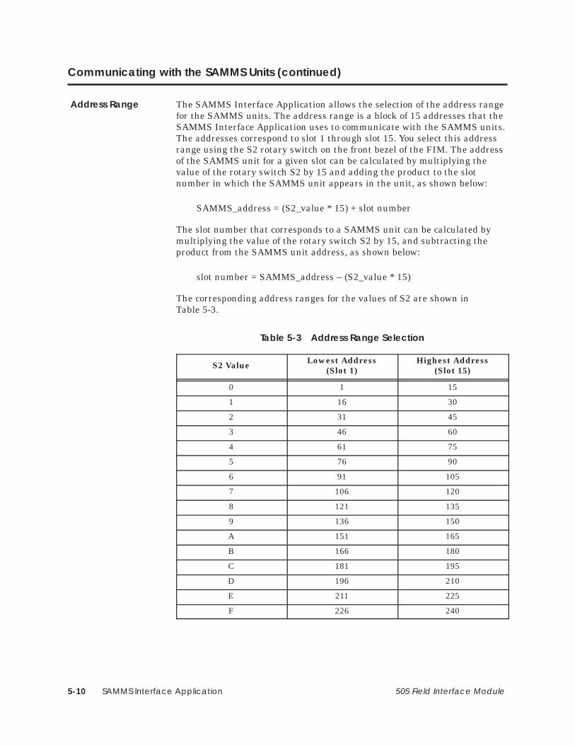
SAMMS Interface Application5-10 505 Field Interface Module
Communicating with the SAMMS Units (continued)
The SAMMS Interface Application allows the selection of the address rangefor the SAMMS units. The address range is a block of 15 addresses that theSAMMS Interface Application uses to communicate with the SAMMS units.The addresses correspond to slot 1 through slot 15. You select this addressrange using the S2 rotary switch on the front bezel of the FIM. The addressof the SAMMS unit for a given slot can be calculated by multiplying thevalue of the rotary switch S2 by 15 and adding the product to the slotnumber in which the SAMMS unit appears in the unit, as shown below:
SAMMS_address = (S2_value * 15) + slot number
The slot number that corresponds to a SAMMS unit can be calculated bymultiplying the value of the rotary switch S2 by 15, and subtracting theproduct from the SAMMS unit address, as shown below:
slot number = SAMMS_address – (S2_value * 15)
The corresponding address ranges for the values of S2 are shown inTable 5-3.
Table 5-3 Address Range Selection
S2 Value Lowest Address(Slot 1)
Highest Address(Slot 15)
0 1 15
1 16 30
2 31 45
3 46 60
4 61 75
5 76 90
6 91 105
7 106 120
8 121 135
9 136 150
A 151 165
B 166 180
C 181 195
D 196 210
E 211 225
F 226 240
Address Range

SAMMS Interface Application 5-11505 Field Interface Module
5.4 Connecting to SAMMS Unit
The SAMMS unit connects to port 2 in the Field Interface Module throughthe CM1 Communication Module; see Figure 5-6. Figure 5-6 also shows thepin numbers for port 2 of the Field Interface Module.
������
���� !��! �#�� �����
������
������
���
������
� !" �
�
�
�
Field Interface ModulePort 2
SAMMS Unit CM1CommunicationModule
� ���� �������
12 VDCSupply
� ���
��� � ��$%"
Terminal B on Siemens connector (listed in Section 2.4).
Terminal A on Siemens connector (listed in Section 2.4).
Connector housing on Siemens connector (listed in Section 2.4).
Figure 5-6 Connecting the Field Interface Module to SAMMS Unit CM1 Communication Module
NOTE: Port 2 on the Field Interface Module must have a common groundreference with the SAMMS unit. Otherwise, communications can becomeunreliable.
Connecting Port 2to CM1CommunicationModule

SAMMS Interface Application5-12 505 Field Interface Module
5.5 Configuring for Control Mode
After inserting the FIM into the base, you must update the I/Oconfiguration in the controller. The module does not automatically configureitself. TISOFT, or another programming device, must be connected to thecontroller to both register and verify controller-to-FIM communication.
This sample configuration description uses one SAMMS unit; the address isset to SAMMS unit 1 and S2 is set to 0, which selects address range 1 to 15for the SAMMS units. Addresses 1 – 15 correspond to slots 1 to 15 of thecontroller. Refer to Table 5-3 for information on address range selection.Table 5-3 is configured to the sample configuration chart, shown inFigure 5-10. These words can be mapped to any valid I/O address; in thisexample, they start at address 1. The broadcast/immediate channel beginsat address 25, indicating that 24 points are taken up by the SAMMS unitbecause the I/O points of the controller must be configured in multiples ofeight. The broadcast/immediate channel can, however, also have any validI/O address. Do not overlap I/O points across different slots.
Updating the I/OConfigurationDefinition
SampleConfiguration

SAMMS Interface Application 5-13505 Field Interface Module
Slot Number Directly corresponds toSAMMS unit addressbased on the S2address rangeselection. Slot 16 is theBroadcast/ ImmediateChannel.
��� ������ ���������� ��� �2������� �2���� �
�),0 �%%.&// ! � �! �1+$0(,+
��� �1*#&. ,' �(0 "+% �,.% ��� �-&$(")
�
�
�
�
�
�
�����
�����
�����
�����
�����
�����
�����
�����
����
����
����
����
����
����
����
����
�����
�����
�����
�����
�����
�����
�����
�����
��
��
��
��
��
��
��
��
��
��
��
��
��
��
��
��
��
��
��
��
��
��
��
��
��
��
��
��
��
��
��
��
��
��
��
��
��
��
��
��
��
��
��
��
��
��
��
��
��
��
��
��
��
��
�������
�������
�������
�������
�������
�������
�������
�������
�,
�,
�,
�,
�,
�,
�,
�� ��
Base Number Displays number of the current base and correspondsto number on S1.
I/O Address The SAMMS unit is logged in as 14input words (WX) and 4 output words(WY).
SF Module The Field Interface Module isnot an SF Module. The defaultfor this definition is NO.
��
��
��
��
��
�
�
�����
�����
�����
�����
�����
�����
�����
�����
����
����
����
����
����
����
����
���
�����
�����
�����
�����
�����
�����
�����
�����
��
��
��
��
��
��
��
�
��
��
��
��
��
��
��
��
��
��
��
��
��
��
��
�
��
��
��
��
��
��
��
��
��
��
��
��
��
��
��
��
��
��
��
��
��
��
��
��
��
��
��
��
��
��
�������
�������
�������
�������
�������
�������
�������
�������
�,
�,
�,
�,
�,
�,
�,
�,
�� ��
Broadcast/ImmediateMessage Control Channel
�,
Figure 5-7 Sample I/O Configuration Chart for the Control Modes
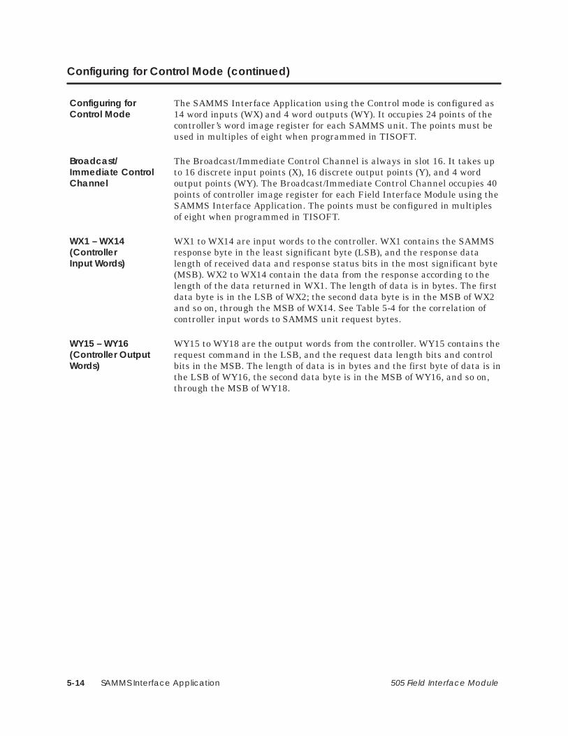
SAMMS Interface Application5-14 505 Field Interface Module
Configuring for Control Mode (continued)
The SAMMS Interface Application using the Control mode is configured as14 word inputs (WX) and 4 word outputs (WY). It occupies 24 points of thecontroller’s word image register for each SAMMS unit. The points must beused in multiples of eight when programmed in TISOFT.
The Broadcast/Immediate Control Channel is always in slot 16. It takes upto 16 discrete input points (X), 16 discrete output points (Y), and 4 wordoutput points (WY). The Broadcast/Immediate Control Channel occupies 40points of controller image register for each Field Interface Module using theSAMMS Interface Application. The points must be configured in multiplesof eight when programmed in TISOFT.
WX1 to WX14 are input words to the controller. WX1 contains the SAMMSresponse byte in the least significant byte (LSB), and the response datalength of received data and response status bits in the most significant byte(MSB). WX2 to WX14 contain the data from the response according to thelength of the data returned in WX1. The length of data is in bytes. The firstdata byte is in the LSB of WX2; the second data byte is in the MSB of WX2and so on, through the MSB of WX14. See Table 5-4 for the correlation ofcontroller input words to SAMMS unit request bytes.
WY15 to WY18 are the output words from the controller. WY15 contains therequest command in the LSB, and the request data length bits and controlbits in the MSB. The length of data is in bytes and the first byte of data is inthe LSB of WY16, the second data byte is in the MSB of WY16, and so on,through the MSB of WY18.
Configuring forControl Mode
Broadcast/ Immediate ControlChannel
WX1 – WX14(ControllerInput Words)
WY15 – WY16(Controller OutputWords)
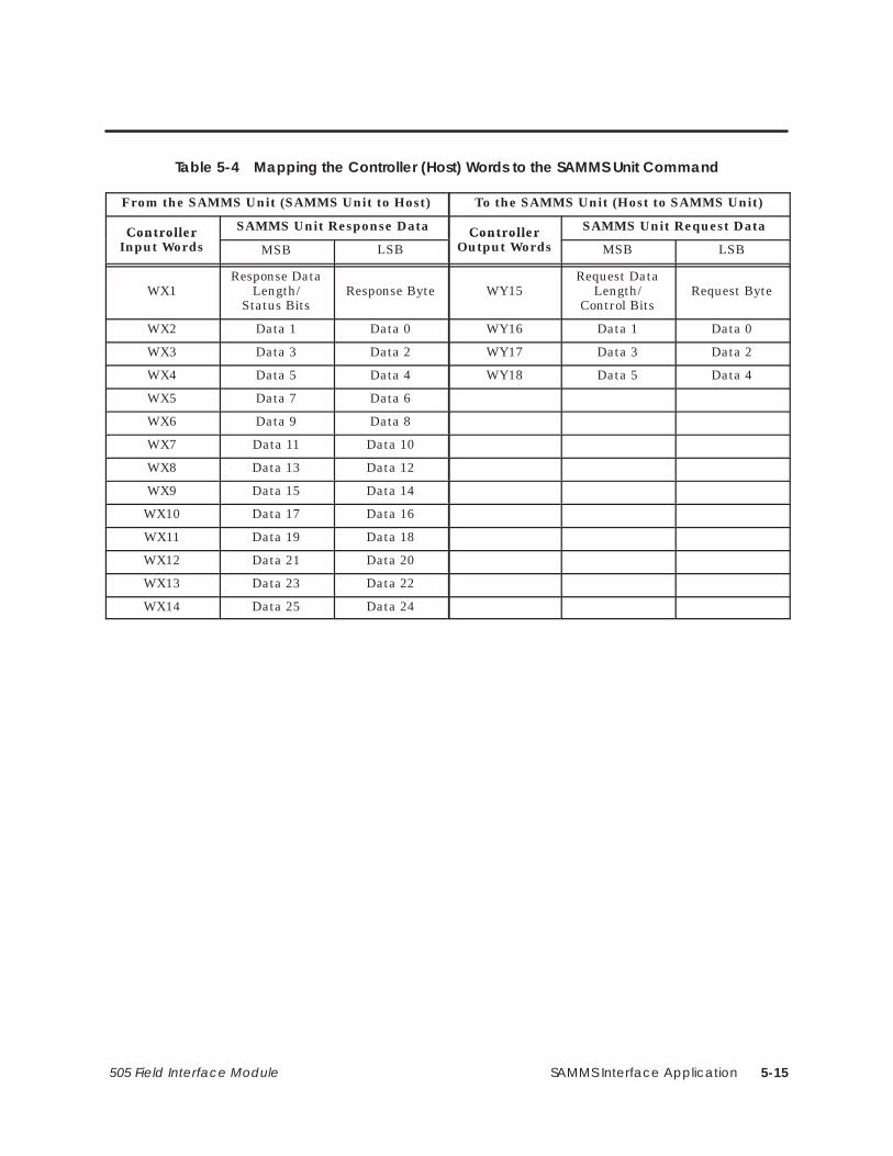
SAMMS Interface Application 5-15505 Field Interface Module
Table 5-4 Mapping the Controller (Host) Words to the SAMMS Unit Command
From the SAMMS Unit (SAMMS Unit to Host) To the SAMMS Unit (Host to SAMMS Unit)
Controllernput Word
SAMMS Unit Response Data ControllerOutput Word
SAMMS Unit Request DataControllerInput Words MSB LSB
ControllerOutput Words MSB LSB
WX1Response Data
Length/Status Bits
Response Byte WY15Request Data
Length/Control Bits
Request Byte
WX2 Data 1 Data 0 WY16 Data 1 Data 0
WX3 Data 3 Data 2 WY17 Data 3 Data 2
WX4 Data 5 Data 4 WY18 Data 5 Data 4
WX5 Data 7 Data 6
WX6 Data 9 Data 8
WX7 Data 11 Data 10
WX8 Data 13 Data 12
WX9 Data 15 Data 14
WX10 Data 17 Data 16
WX11 Data 19 Data 18
WX12 Data 21 Data 20
WX13 Data 23 Data 22
WX14 Data 25 Data 24

SAMMS Interface Application5-16 505 Field Interface Module
Configuring for Control Mode (continued)
The Broadcast/Immediate Channel in this example is configured as follows:
Immediate I/O Request Control Bits. In this example, bits Y41 to Y55are Immediate I/O request control bits and correspond to SAMMS units1 – 15. When set, these bits force an immediate I/O request to be sent to thecorresponding SAMMS unit. Setting bit Y42 forces an interruption in theField Interface Module SAMMS Interface Application update scan, causinga request to be sent to SAMMS unit 2 immediately. These bits are one-shotand are edge-triggered by the SAMMS Interface Application.
Broadcast Control Bit. In this example, Y56 is the broadcast control bitand operates the same way as the Y41 to Y55 bits, except that setting Y56forces a broadcast to all SAMMS units.
Immediate I/O Request Completed Bits. In this example, bits X25 toX39 are the Immediate I/O Request Completed bits. They are set when theimmediate I/O request to the corresponding SAMMS units 1 – 15 has beencompleted. Bits X25 to X39 are only set if bits Y41 to Y55 remain set afterthe immediate I/O request is made. If you require confirmation that theimmediate I/O request has been completed, then leave the Immediate I/ORequest Control bit set until the corresponding Immediate I/O RequestCompleted bit is set by the SAMMS Interface Application. Bits X25 to X39are reset when the corresponding bits Y41 to Y55 are reset. Bits X25 to X39let the program know when the Immediate I/O Request is complete. Formore details see the programming section.
Broadcast Completed Bit. In this example, bit X40 is the broadcastcompleted bit and operates in the same way as X25 to X39, except that X40indicates that a broadcast (caused by setting bit Y56) is complete.
Broadcast Data Words. In this example, controller output words WY57 toWY60 contain the information for broadcasts. They correspond to theSAMMS request input words of the broadcast request, just as words WY15to WY18 correspond to the SAMMS input words of SAMMS unit 1. Refer toTable 5-5. The request control bits are meaningless in the broadcastchannel.
Configuring theBroadcast/ImmediateChannel (ControlMode)

SAMMS Interface Application 5-17505 Field Interface Module
Table 5-5 Mapping the Control Mode Protocol Broadcast Channel
Immediate/O MM mmediate
To the SAMMS Unit (Host to SAMMS Unit)I/O
RequestCompleted
SAMMSAddressNumber
ImmediateI/O RequestControl Bit Controller
Output Word
SAMMS Unit Request DataCompleted
BitsNumber Control Bits Controller
Output Words MSB LSB
X25 1 Y41 WY57 Data Length Request Byte
X26 2 Y42 WY58 Data 1 Data 0
X27 3 Y43 WY59 Data 3 Data 2
X28 4 Y44 WY60 Data 5 Data 4
X29 5 Y45
X30 6 Y46
X31 7 Y47
X32 8 Y48
X33 9 Y49
X34 10 Y50
X35 11 Y51
X36 12 Y52 X40 – This is the Broadcast Completed Bit
X37 13 Y53
X40 – This is the Broadcast Completed Bit
X38 14 Y54Y56 – This is the Broadcast Control Bit
X39 15 Y55Y56 – This is the Broadcast Control Bit

SAMMS Interface Application5-18 505 Field Interface Module
Configuring for Control Mode (continued)
Use your programming device to view the I/O Configuration Chart, shownin Figure 5-8. Use SHOW in TISOFT, and be aware that only a portion ofthis information is shown at a time.
• The slot number corresponds to the SAMMS number. This exampleshows SAMMS 1, which appears in slot 1.
• Slot 16 is always the Broadcast/Immediate Channel.
• The SAMMS Interface Application is configured as base 5.
Viewing the I/OConfigurationChart

SAMMS Interface Application 5-19505 Field Interface Module
I/O CONFIGURATION CHART FOR : CHANNEL ... 1 BASE ..... 05
Slot 1
I/O POINTS
Slot 1
Slot 1
Slot 2
Slot 5
Slot 6
WX0001 WX0002 WX0003 WX0004 WX0005 WX0006 WX0007 WX0008
Slot 7
Slot 8
Slot 9
Slot 10
Slot 11
Slot 12Slot 13
Slot 14
Slot 15
1 2 3 4 5 6 7 8
WX0009 WX0010 WX0011 WX0012 WX0013 WX0014 WY0015 WY0016
9 10 11 12 13 14 15 16
WY0018WY0017
17 18
Slot 3
Slot 4
Slot 16
Slot 16
Slot 16
X0025 X0026 X0027 X0028 X0029 X0030 X00311 2 3 4 5 6 7 8
X0033 X0034 X0035 X0036 X0037 X0038 X0039 X0040
9 10 11 12 13 14 15 16
Y0042Y0041 Y0043 Y0044
17 18 19 20
X0032
Y0045 Y0046 Y0047 Y0048
21 22 23 24
Slot 16
Slot 16
Slot 16
Y0049 Y0050 Y0051 Y0052 Y0053 Y0054 Y005525 26 27 28 29 30 31 32
WY0057 WY0058 WY0059 WY0060
33 34 35 36
Y0056
Figure 5-8 I/O Configuration Chart for Control Mode

SAMMS Interface Application5-20 505 Field Interface Module
5.6 Configuring for Status Poll Mode
After you insert the Field Interface Module into the base, update the I/Oconfiguration in the controller. The module does not automatically configureitself. TISOFT, or another programming device, must be connected to thecontroller in order to both register and verify communication between theFIM and the controller.
This configuration description uses one SAMMS unit; the address is set toSAMMS unit 1. S2 is set to 0, which selects address range 1 to 15,corresponding to slot 1 to 15. The example uses the configuration chartshown in Figure 5-9. Word I/O can be mapped to any valid I/O address, butin this example, they start at address 1. The broadcast/immediate channelbegins at address 9, indicating that 8 points are used by the SAMMS unit,although the broadcast/immediate channel can have any valid I/O address.Do not overlap I/O points across different slots.
Updating the I/OConfigurationDefinition
SampleConfiguration

SAMMS Interface Application 5-21505 Field Interface Module
��� ������ ���������� ��� �2������� �2���� �
�),0 �%%.&// ! � �! �1+$0(,+
��� �1*#&. ,' �(0 "+% �,.% ��� �-&$(")
�
�
�
�
�
�
�����
�����
�����
�����
�����
�����
�����
�����
����
����
����
����
����
����
����
����
�����
�����
�����
�����
�����
�����
�����
�����
��
��
��
��
��
��
��
��
��
��
��
��
��
��
��
��
��
��
��
��
��
��
��
��
��
��
��
��
��
��
��
��
��
��
��
��
��
��
��
��
��
��
��
��
��
��
��
��
��
��
��
��
��
��
�������
�������
�������
�������
�������
�������
�������
�������
�,
�,
�,
�,
�,
�,
�,
�,
�� ��
Base Number Displays number of the current base and correspondsto number on S1.
I/O Address SAMMS UnitThe SAMMS unit is logged in as 4input words (WX) and 4 output words(WY).
SF Module The Field Interface Module isnot an SF Module. The defaultfor this definition is NO.
��
��
��
��
��
�
�
�����
�����
�����
�����
�����
�����
�����
�����
����
����
����
����
����
����
����
���
�����
�����
�����
�����
�����
�����
�����
�����
��
��
��
��
��
��
��
�
��
��
��
��
��
��
��
��
��
��
��
��
��
��
��
�
��
��
��
��
��
��
��
��
��
��
��
��
��
��
��
��
��
��
��
��
��
��
��
��
��
��
��
��
��
��
�������
�������
�������
�������
�������
�������
�������
�������
�,
�,
�,
�,
�,
�,
�,
�,
�� ��
Slot Number Directly correspondsto SAMMS unitaddress based on theS2 address rangeselection. Slot 16 isthe Broadcast/Immediate Channel.
Broadcast/ImmediateMessage Control Channel
Figure 5-9 Sample I/O Configuration Chart for Status Poll Mode

SAMMS Interface Application5-22 505 Field Interface Module
Configuring for Status Poll Mode (continued)
The Broadcast/Immediate Channel is configured in this example as follows:
Immediate I/O Request Control Bits. In this example, bits Y25 to Y39are immediate I/O request control bits, and correspond to SAMMS units1 – 15. When set, these bits force an immediate I/O request to be sent to thecorresponding SAMMS unit. Setting bit Y26 forces an interruption in theField Interface Module SAMMS units update scan, causing a request to besent to SAMMS unit 2 immediately. These bits are one-shot andedge-triggered by the SAMMS Interface Application. For moreprogramming information, see Section 5.7.
The SAMMS Interface Application, using the Status Poll mode, isconfigured as 4 word inputs (WX) and 4 word outputs (WY). It occupies 8points of the controller word image register for each SAMMS unit.
The Broadcast/Immediate Channel is always in slot 16. It takes up 16discrete input points (X), 16 discrete output points (Y), and 4 word outputpoints (WY). The Broadcast/Immediate Channel occupies 40 points ofcontroller image register for each Field Interface Module using the SAMMSInterface Application. This is because the points must be configured inmultiples of eight when programmed in TISOFT.
Configuring theBroadcast/ImmediateChannel (StatusPoll Mode)
Configuring forStatus Poll Mode
Broadcast/ Immediate ControlChannel

SAMMS Interface Application 5-23505 Field Interface Module
WX1 to WX4 are input words to the controller. WX1 contains the SAMMSresponse byte in the least significant byte (LSB), and the response datalength of received data and response status bits in the most significant byte(MSB). WX2 to WX4 contain the data from the response according to thelength of the data returned in WX1. The length of data is in bytes, and thefirst data byte is in LSB of WX2, the second data byte in the MSB of WX2and so on, through the MSB of WX4. See Table 5-6 for the correlation ofcontroller input words to SAMMS unit request bytes.
WY5 to WY8 are the output words from the controller. WY5 contains therequest byte command in the LSB and the request data length bits andrequest control bits of the MSB. The length of data is in bytes. The first byteof data is in the LSB of WY6, the second data byte in the MSB of WY6, andso on, through the MSB of WY8.
Table 5-6 Mapping the Controller (Host) Words to the SAMMS Parameter Words for Status Poll Mode
From the SAMMS Unit (SAMMS Unit to Host) To the SAMMS Unit (Host to SAMMS Unit)
Controllernput Word
SAMMS Unit Response Data ControllerOutput Word
SAMMS Unit Request DataControllerInput Words MSB LSB
ControllerOutput Words MSB LSB
WX1Response Data
Length/Status Bits
Response Byte WY5Request Data
Length/RequestControl Bits
Request Byte
WX2 Data 1 Data 0 WY6 Data 1 Data 0
WX3 Data 3 Data 2 WY7 Data 3 Data 2
WX4 Data 5 Data 4 WY8 Data 5 Data 4
WX1 – WX4(ControllerInput Words)
WY5 – WY8(Controller OutputWords)
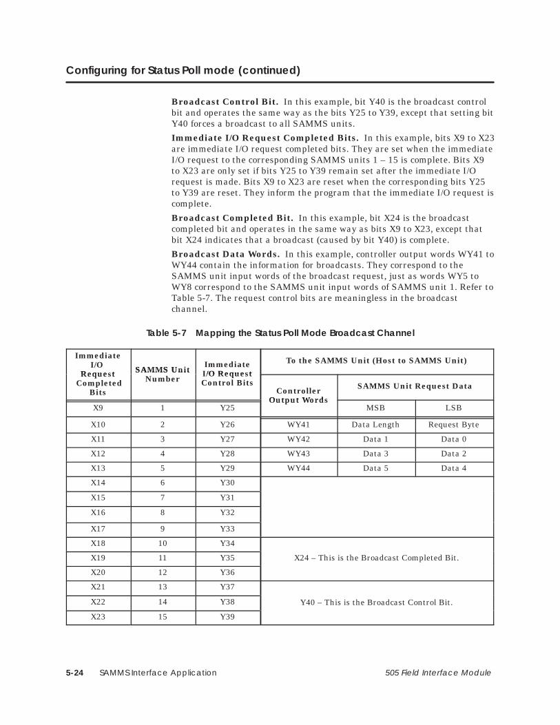
SAMMS Interface Application5-24 505 Field Interface Module
Configuring for Status Poll mode (continued)
Broadcast Control Bit. In this example, bit Y40 is the broadcast controlbit and operates the same way as the bits Y25 to Y39, except that setting bitY40 forces a broadcast to all SAMMS units.
Immediate I/O Request Completed Bits. In this example, bits X9 to X23are immediate I/O request completed bits. They are set when the immediateI/O request to the corresponding SAMMS units 1 – 15 is complete. Bits X9to X23 are only set if bits Y25 to Y39 remain set after the immediate I/Orequest is made. Bits X9 to X23 are reset when the corresponding bits Y25to Y39 are reset. They inform the program that the immediate I/O request iscomplete.
Broadcast Completed Bit. In this example, bit X24 is the broadcastcompleted bit and operates in the same way as bits X9 to X23, except thatbit X24 indicates that a broadcast (caused by bit Y40) is complete.
Broadcast Data Words. In this example, controller output words WY41 toWY44 contain the information for broadcasts. They correspond to theSAMMS unit input words of the broadcast request, just as words WY5 toWY8 correspond to the SAMMS unit input words of SAMMS unit 1. Refer toTable 5-7. The request control bits are meaningless in the broadcastchannel.
Table 5-7 Mapping the Status Poll Mode Broadcast Channel
ImmediateI/O
Reque t SAMMS UnitNumber
Immediate/O Reque t
To the SAMMS Unit (Host to SAMMS Unit)
Request Completed
Bits
SAMMS UnitNumber
I/O RequestControl Bits
ControllerOutput Word
SAMMS Unit Request Data
X9 1 Y25Output Words
MSB LSB
X10 2 Y26 WY41 Data Length Request Byte
X11 3 Y27 WY42 Data 1 Data 0
X12 4 Y28 WY43 Data 3 Data 2
X13 5 Y29 WY44 Data 5 Data 4
X14 6 Y30
X15 7 Y31
X16 8 Y32
X17 9 Y33
X18 10 Y34
X19 11 Y35 X24 – This is the Broadcast Completed Bit.
X20 12 Y36
X21 13 Y37
X22 14 Y38 Y40 – This is the Broadcast Control Bit.
X23 15 Y39

SAMMS Interface Application 5-25505 Field Interface Module
Use your programming device to view the I/O Configuration Chart, asshown in Figure 5-10. Use SHOW in TISOFT, and be aware that only aportion of this information is shown at a time.
• The slot number corresponds to the SAMMS unit number. Thisexample shows SAMMS unit 1 which appears in slot 1.
• Slot 16 is always the Broadcast/Immediate Channel.
• The SAMMS Interface Application is configured as base 5.
I/O CONFIGURATION CHART FOR : CHANNEL ... 1 BASE ..... 05
Slot 1
I/O POINTS
Slot 2
Slot 5
Slot 6
WX0001 WX0002 WX0003 WX0004 WY0005 WY0006 WY0007 WY0008
Slot 7
Slot 8
Slot 9
Slot 10
Slot 11
Slot 12
Slot 13
Slot 14
Slot 15
1 2 3 4 5 6 7 8
Slot 3
Slot 4
Slot 16
Slot 16
Slot 16
X0009 X0010 X0011 X0012 X0013 X0014 X0015
1 2 3 4 5 6 7 8
X0017 X0018 X0019 X0020 X0021 X0022 X0023 X0024
9 10 11 12 13 14 15 16
Y0026Y0025 Y0027 Y0028
17 18 19 20
X0016
Y0029 Y0030 Y0031 Y0032
21 22 23 24
Slot 16
Slot 16
Y0033 Y0034 Y0035 Y0036 Y0037 Y0038 Y0039
25 26 27 28 29 30 31 32
WY0041 WY0042 WY0043 WY0044
33 34 35 36
Y0040
Figure 5-10 I/O Configuration Chart for Status Poll Mode
Viewing the I/OConfigurationChart

SAMMS Interface Application5-26 505 Field Interface Module
5.7 Programming: Broadcast and Immediate I/O Requests
When the broadcast request bit is set, the SAMMS unit scan is interrupted.The data in the WY words of the broadcast channel is sent to all theSAMMS units using the broadcast address (256) defined by the SEAbusprotocol. The broadcast has no response data returning from the SAMMSunits.
Broadcast requests are used to synchronize actions such as starting orjogging the motors simultaneously. If broadcasts are not used, it may beseveral seconds before all SAMMS units are updated, depending on thenumber of SAMMS units and baud rate. All SAMMS units receive broadcastmessages.
! CAUTIONIf bits in the controller output words do not correspond to normal SAMMS unitinput words, subsequent update scans may cancel requests performed by thebroadcast.
If broadcast requests are canceled, synchronizing operations do not occur .
To prevent subsequent update scans from canceling requests performed by thebroadcast, your program must coordinate requests in the controller outputwords so that they correspond to normal SAMMS unit input words.
Broadcast Request

SAMMS Interface Application 5-27505 Field Interface Module
The SAMMS unit does not respond directly to a broadcast. If the programneeds to know whether or not the broadcast message was received, then itmust poll the SAMMS units to determine if the request sent by thebroadcast was executed.
! WARNINGConnecting SAMMS units with addresses outside of the address range selectedon S2, and also sending a broadcast, could start a SAMMS unit operation thatthe Field Interface Module cannot stop. The Field Interface Module does notupdate these SAMMS units, but all SAMMS units receive the broadcast.
Using SAMMS unit addresses outside the selected range could causeunpredictable operation, resulting in death or serious injury to personnel,and/or damage to equipment.
Do not use SAMMS unit addresses outside the selected range.
Follow the steps below for the broadcast-request procedure.
1. Reset the broadcast-request bit for at least one controller scan.
2. Set the controller output words (WY) in channel 16 to the desiredrequest values.
3. On the same scan in ladders, set the corresponding control bits/datainto each of the controller output words affected by the broadcast. Thisprevents cancellation of the request by subsequent updates of thenormal SAMMS unit scan.
4. Set the broadcast-request bit.
5. The broadcast is complete when the broadcast-complete bit is set.
6. Reset the broadcast-request bit.
7. You may send another broadcast when the broadcast-completed bit isreset by the SAMMS Interface Application.
BroadcastProcedure

SAMMS Interface Application5-28 505 Field Interface Module
Programming: Broadcast and Immediate I/O Requests (continued)
The normal SAMMS unit update scan can take several seconds, dependingon the number of SAMMS units, and on the baud rate. When a SAMMSunit needs to be updated faster than the normal SAMMS unit scan timeallows, an immediate I/O request may be sent. Immediate I/O requests aremade to one or more SAMMS units by setting the immediate I/O requestcontrol bit corresponding to the SAMMS unit. This immediate I/O request issent typically within one message transmit time.
Once the immediate I/O request message is sent, the response data isimmediately updated in controller input words. This allows the rapid poll ofdata by external devices, and the immediate response of requests such asjogging or stopping the motor.
If immediate I/O requests are sent to more than one SAMMS unit, animmediate I/O request is first sent to the lowest-numbered SAMMS unit,followed by an immediate I/O request to the next higher-numbered SAMMSunit, until all the immediate I/O requests are sent. If a broadcast request ismade with immediate I/O requests, the broadcast request is sent first. Afterall immediate I/O requests are sent, the SAMMS unit update scan resumesas normal. The immediate I/O request bits are edge-triggered and one-shot.They must be reset for one controller scan before the immediate I/O requestfor that SAMMS unit is sent again.
Once the immediate I/O requests are complete, the immediate I/O requestcompleted bits are set if the original immediate I/O request bits are still set.
Follow these steps to initiate an immediate I/O request.
1. Reset the immediate I/O request bit corresponding to the desiredSAMMS unit for at least 1 controller scan.
2. Set the controller output data words (WY) to the desired value.
3. Set the immediate I/O request bit that corresponds to the desiredSAMMS unit.
4. The immediate I/O request is complete when the correspondingimmediate I/O request complete bit is set. This bit is only set if theoriginal immediate I/O request bit is still set.
5. You may send another immediate request after the immediate I/Orequest complete-bit is reset. To do this, repeat steps 2 through 4.
Immediate I/ORequest
Immediate I/ORequest Procedure
SAMMS Interface Application 5-29505 Field Interface Module
6. The controller input words (WX) now reflect the response of theSAMMS unit when the immediate I/O request was made.
NOTE: The response data words (WX) for the immediate I/O request do notreflect the response of the parameter request sent to the SAMMS unit. Theresponse data words do reflect what the SAMMS unit returned when therequest was made. Some requests to the SAMMS unit take more time forthe SAMMS unit to process, and it may take several repeated requests forthe SAMMS unit to complete the request. When the SAMMS unit hascompleted the request, the response parameter number is the same as theoriginal request. Refer to your SAMMS unit manual for more informationon the SAMMS unit parameter programming.
Once configuration is complete, checks of controller status words allow themonitoring of communication to each SAMMS unit. The SAMMS unitsappear as modules in a base. In the sample configuration shown inSection 5.5, the Field Interface Module running the SAMMS unit InterfaceApplication is set to base 5. The channel number is set to 1, which iscurrently the only channel in a 545/555 controller.
Since this example uses base 5, controller status word 16 (STW16) is thecorresponding word containing the status bits. There is one status bit foreach SAMMS unit. These bits are set by the controller as soon as a loss ofcommunication to that SAMMS unit is detected. These bits are also set ifSAMMS units are configured incorrectly. The status bits that are setcorrespond to the SAMMS unit(s) that do not match.
Slot 16 is occupied by the SAMMS Interface Applicationbroadcast/immediate channel that takes up the most significant bit. Bymonitoring this bit, any interruption in the SAMMS unit communicationpath can be detected by the user program and the proper action can betaken.
! CAUTIONThe SAMMS Interface Application does not monitor the SAMMS units forinternal faults.
If the SAMMS unit continues to communicate, then the SAMMS InterfaceApplication assumes that the SAMMS unit is good. You must sample SAMMSunit status bits, in conjunction with controller status word bits, to ensure thatthe program detects reported failures.
Refer to your SAMMS units manual for more details on error reporting by theSAMMS unit.
MonitoringCommunication

SAMMS Interface Application5-30 505 Field Interface Module
5.8 Programming: Sending Requests
A request to a given SAMMS unit is constructed in the WY (word output)points that are configured for that unit’s corresponding I/O slot. Somerequests to SAMMS units have no response. The SAMMS InterfaceApplication uses a table similar to Table 5-8 to determine if a message has aresponse and how much data to send from the request data buffer. This canbe overridden by bits in the Request Control word. If a request has aresponse, then the response data is placed into the WX (word input)locations for that unit. A request is made up of two basic parts: RequestControl Word and Request Data Block or Buffer (some requests). A responseis also made up of two basic parts: Response Status Word and ResponseData Block or Buffer.
Sending Requeststo the SAMMS Unit

SAMMS Interface Application 5-31505 Field Interface Module
Table 5-8 SAMMS Unit Request Default Parameters
Request Byte DescriptionRequest DataLength (By-
tes)Response ?
001H Request discrete data 0 Y
002H Request configuration data 0 Y
003H Request detailed data 0 Y
004H Request ambient temp. and pickup currents 0 Y
005H 5A CT ratios for OL relays 1 and 2 0 Y
006H Motor type, cold stall time 0 Y
030H 5A CT ratio for overload relay 1 1 N
031H 5A CT ratio for overload relay 2 1 N
032H CT size for overload relay 1 1 N
033H CT size for overload relay 2 1 N
041H Full-load current for overload relay 1 1 N
042H Full-load current for overload relay 2 1 N
043H Overload trip class 1 N
044H Programmable timer 1 1 N
045H Programmable timer 2 1 N
046H Control parameters 1 N
047H Process current 1 N
049H Address setting 1 N
04AH Ambient temperature 1 N
04BH Ground fault pickup current 2 N
04CH Jam pickup current 1 N
04DH Loss of load pickup current 1 N
04EH Motor type 1 N
04FH Cold stall time 1 N
051H Emulate button push 3 N
0A1H Baud rate setting 2 N
0FFH Request device type 0 Y
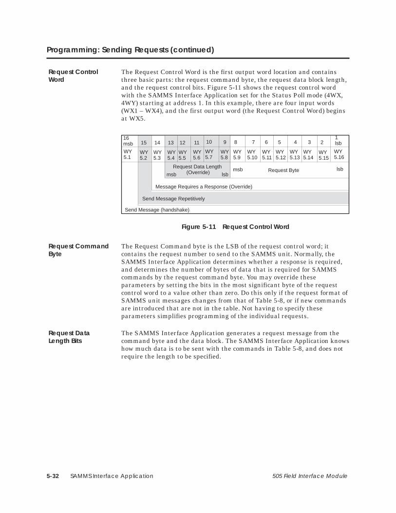
SAMMS Interface Application5-32 505 Field Interface Module
Programming: Sending Requests (continued)
The Request Control Word is the first output word location and containsthree basic parts: the request command byte, the request data block length,and the request control bits. Figure 5-11 shows the request control wordwith the SAMMS Interface Application set for the Status Poll mode (4WX,4WY) starting at address 1. In this example, there are four input words(WX1 – WX4), and the first output word (the Request Control Word) beginsat WX5.
16msb
WY5.1
15
WY5.2
WY5.10
6
WY5.11
4
WY5.13
3
WY5.14
2
WY5.15
1lsb
WY5.16
5
WY5.12
Request Byte
Send Message (handshake)
Send Message Repetitively
14
WY5.3
13
WY5.4
12
WY5.5
11
WY5.6
10
WY5.7
9
WY5.8
8
WY5.9
7
Request Data Length (Override)
Message Requires a Response (Override)
msb lsblsbmsb
Figure 5-11 Request Control Word
The Request Command byte is the LSB of the request control word; itcontains the request number to send to the SAMMS unit. Normally, theSAMMS Interface Application determines whether a response is required,and determines the number of bytes of data that is required for SAMMScommands by the request command byte. You may override theseparameters by setting the bits in the most significant byte of the requestcontrol word to a value other than zero. Do this only if the request format ofSAMMS unit messages changes from that of Table 5-8, or if new commandsare introduced that are not in the table. Not having to specify theseparameters simplifies programming of the individual requests.
The SAMMS Interface Application generates a request message from thecommand byte and the data block. The SAMMS Interface Application knowshow much data is to be sent with the commands in Table 5-8, and does notrequire the length to be specified.
Request ControlWord
Request CommandByte
Request DataLength Bits
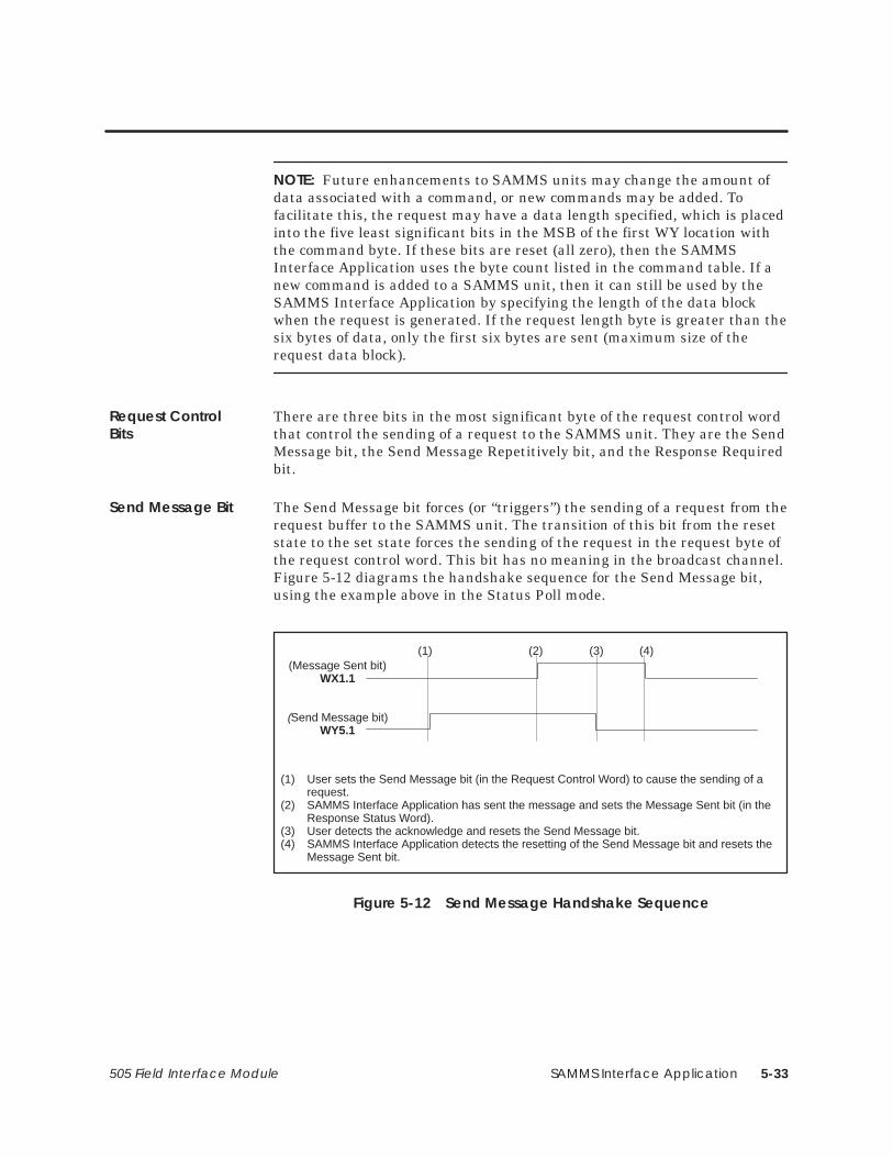
SAMMS Interface Application 5-33505 Field Interface Module
NOTE: Future enhancements to SAMMS units may change the amount ofdata associated with a command, or new commands may be added. Tofacilitate this, the request may have a data length specified, which is placedinto the five least significant bits in the MSB of the first WY location withthe command byte. If these bits are reset (all zero), then the SAMMSInterface Application uses the byte count listed in the command table. If anew command is added to a SAMMS unit, then it can still be used by theSAMMS Interface Application by specifying the length of the data blockwhen the request is generated. If the request length byte is greater than thesix bytes of data, only the first six bytes are sent (maximum size of therequest data block).
There are three bits in the most significant byte of the request control wordthat control the sending of a request to the SAMMS unit. They are the SendMessage bit, the Send Message Repetitively bit, and the Response Requiredbit.
The Send Message bit forces (or “triggers”) the sending of a request from therequest buffer to the SAMMS unit. The transition of this bit from the resetstate to the set state forces the sending of the request in the request byte ofthe request control word. This bit has no meaning in the broadcast channel.Figure 5-12 diagrams the handshake sequence for the Send Message bit,using the example above in the Status Poll mode.
(1) (2) (3) (4)(Message Sent bit)
WX1.1
(Send Message bit)WY5.1
(1) User sets the Send Message bit (in the Request Control Word) to cause the sending of arequest.
(2) SAMMS Interface Application has sent the message and sets the Message Sent bit (in the Response Status Word).
(3) User detects the acknowledge and resets the Send Message bit.(4) SAMMS Interface Application detects the resetting of the Send Message bit and resets the
Message Sent bit.
Figure 5-12 Send Message Handshake Sequence
Request ControlBits
Send Message Bit
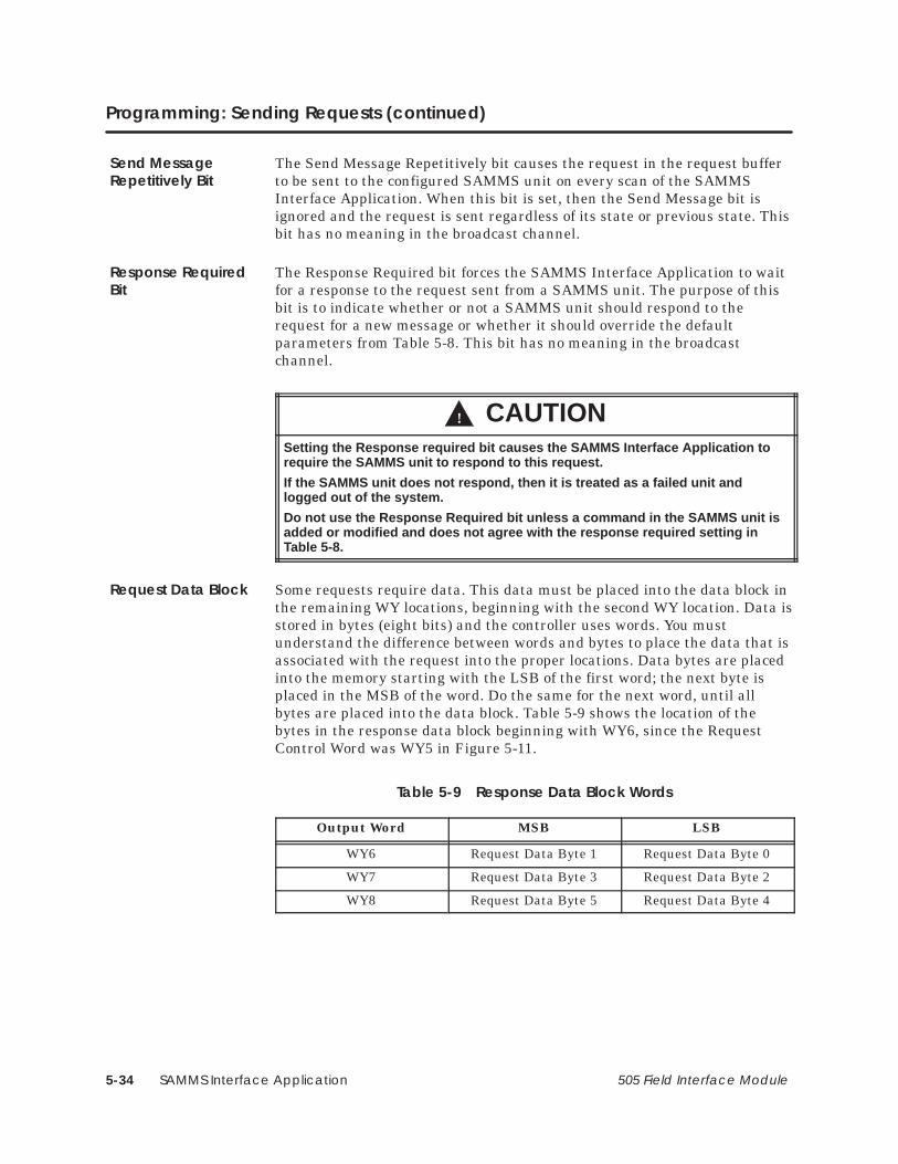
SAMMS Interface Application5-34 505 Field Interface Module
Programming: Sending Requests (continued)
The Send Message Repetitively bit causes the request in the request bufferto be sent to the configured SAMMS unit on every scan of the SAMMSInterface Application. When this bit is set, then the Send Message bit isignored and the request is sent regardless of its state or previous state. Thisbit has no meaning in the broadcast channel.
The Response Required bit forces the SAMMS Interface Application to waitfor a response to the request sent from a SAMMS unit. The purpose of thisbit is to indicate whether or not a SAMMS unit should respond to therequest for a new message or whether it should override the defaultparameters from Table 5-8. This bit has no meaning in the broadcastchannel.
! CAUTIONSetting the Response required bit causes the SAMMS Interface Application torequire the SAMMS unit to respond to this request.
If the SAMMS unit does not respond, then it is treated as a failed unit andlogged out of the system.
Do not use the Response Required bit unless a command in the SAMMS unit isadded or modified and does not agree with the response required setting inTable 5-8.
Some requests require data. This data must be placed into the data block inthe remaining WY locations, beginning with the second WY location. Data isstored in bytes (eight bits) and the controller uses words. You mustunderstand the difference between words and bytes to place the data that isassociated with the request into the proper locations. Data bytes are placedinto the memory starting with the LSB of the first word; the next byte isplaced in the MSB of the word. Do the same for the next word, until allbytes are placed into the data block. Table 5-9 shows the location of thebytes in the response data block beginning with WY6, since the RequestControl Word was WY5 in Figure 5-11.
Table 5-9 Response Data Block Words
Output Word MSB LSB
WY6 Request Data Byte 1 Request Data Byte 0
WY7 Request Data Byte 3 Request Data Byte 2
WY8 Request Data Byte 5 Request Data Byte 4
Send MessageRepetitively Bit
Response RequiredBit
Request Data Block

SAMMS Interface Application 5-35505 Field Interface Module
5.9 Programming: Receiving Response Data
If a request requires a response, then the SAMMS Interface Applicationwaits for the response from the SAMMS unit after it sends the request. Theresponse data is placed into the WX locations in an arrangement similar tothe request. You can detect the completion of a request and the presence of aresponse in the response buffer by reading the response status bits in theMSB of the Response Status Word. If there is no response for a request,then only the Message Sent bit is set in the Response Status Word. Theresponse byte, response data length bits, and the response present bits arereset (all zero).
The first word of the WX word inputs for a given slot is the Response StatusWord. This word contains the status and response byte (if any) of the lastrequest sent to the SAMMS unit. See Figure 5-13.
16msb
WX1.1
15
WX1.2
WX1.10
6
WX1.11
4
WX1.13
3
WX1.14
2
WX1.15
1lsb
WX1.16
5
WX1.12
Response Byte
Message has been sent (acknowledge handshake)
Undefined
14
WX1.3
13
WX1.4
12
WX1.5
11
WX1.6
10
WX1.7
9
WX1.8
8
WX1.9
7
Response Data Length
Response Present in Data Buffer
MSB LSB MSB LSB
Figure 5-13 Response Status Word
The response byte is the command value placed into the LSB of theResponse Status Word. This byte is derived from the response received fromthe SAMMS unit from the last request sent.
The most significant byte of the Response Status Word contains theResponse Status bits that indicate the status of a completed-request and thepresence of a response to that request, if any.
Response StatusWord
Response Byte
Response StatusBits

SAMMS Interface Application5-36 505 Field Interface Module
Programming: Response Data (continued)
The Message Sent bit indicates that the requested message was sent to thecorresponding SAMMS unit. The state of this bit follows the state of theSend Message bit. That is, while the Send Message bit remains set, theSAMMS Interface Application sets the Message Sent bit after it sends therequest and leaves it set as long as the Send Message bit is set. TheSAMMS Interface Application resets this bit when the Send Message bit isreset. Figure 5-14 shows the handshake sequence of these two bits.
(1) (2) (3) (4)(Message Sent bit)
WX1.1
(Send Message bit)WY5.1
(1) User sets the Send Message bit (in the Request Control Word) to cause the sending of arequest.
(2) SAMMS Interface Application has sent the message and sets the Message Sent bit (in the Response Status Word).
(3) User detects the acknowledge and resets the Send Message bit.(4) SAMMS Interface Application detects the resetting of the Send Message bit and resets the
Message Sent bit.
Figure 5-14 Send Message/Message Sent Handshake Sequence
The Response Present bit indicates that a response was received from thelast request and has been placed into the response buffer. This bit is reseton requests that have no response.
The length of the response data is placed into five least significant bits ofthe MSB of the response status word. This length contains the number ofbytes that were placed in the response data block, not necessarily thenumber of bytes that were received from the response. If the response datareceived is larger than the data block, then the SAMMS InterfaceApplication will place only as many bytes of data into the response datablock as it has available.
Message Sent Bit
Response PresentBit
Response LengthBits

SAMMS Interface Application 5-37505 Field Interface Module
The data from the response message is placed into the remaining WXlocations beginning with the second WX location. Data is stored in bytes(eight bits), and the controller uses words. You must understand thedifference between words and bytes to get the data associated with therequest from the proper locations. The data bytes are placed into thememory starting with the LSB of the word, then the next byte is placed inthe MSB of the word. This is repeated for the next word, until all bytes areplaced into the data block. Table 5-10 shows the location of bytes in theResponse Data block for a SAMMS unit starting at I/O address 1 and theSAMMS Interface Application in the Control Mode. Table 5-11 shows thelocation of bytes in the Response Data block for a SAMMS unit starting atI/O address 1 and the SAMMS Interface Application in the Status PollMode.
Table 5-10 Response Data Buffer Words (Control Mode)
Input Word MSB LSB
WX2 Response Data Byte 1 Response Data Byte 0
WX3 Response Data Byte 3 Response Data Byte 2
WX4 Response Data Byte 5 Response Data Byte 4
WX5 Response Data Byte 7 Response Data Byte 6
WX6 Response Data Byte 9 Response Data Byte 8
WX7 Response Data Byte 11 Response Data Byte 10
WX8 Response Data Byte 13 Response Data Byte 12
WX9 Response Data Byte 15 Response Data Byte 14
WX10 Response Data Byte 17 Response Data Byte 16
WX11 Response Data Byte 19 Response Data Byte 18
WX12 Response Data Byte 21 Response Data Byte 20
WX13 Response Data Byte 23 Response Data Byte 22
WX14 Response Data Byte 25 Response Data Byte 24
Table 5-11 Response Data Buffer Words (Status Poll Mode)
Input Word MSB LSB
WX2 Response Data Byte 1 Response Data Byte 0
WX3 Response Data Byte 3 Response Data Byte 2
WX4 Response Data Byte 5 Response Data Byte 4
Response DataBlock

SAMMS Interface Application5-38 505 Field Interface Module
5.10 Programming: Application Examples
SAMMS units are currently shipped from the factory with a default addressof 200 and a default baud rate of 4800. You can change these parameters byusing the hand-held programming device on the front panel of the SAMMSunit. If you do not have a hand-held programming device, then change thesesettings using the FIM. You can change any parameter through the normalI/O channel by setting the SAMMS Interface Application to the properaddress range and then configuring the parameters through the normalrequests. The example in this section, however, describes how to changeparameters by using the broadcast feature of the SAMMS InterfaceApplication.
Before you can use the broadcast feature of the SAMMS InterfaceApplication, you must set up the FIM by setting the S2 rotary switch to theD position. This selects the address range, in which the SAMMS InterfaceApplication polls for SAMMS units, to addresses 196 to 210. This allows theSAMMS Interface Application to autobaud to the powered-up SAMMS unitso that it can send the broadcast message at that SAMMS unit’s currentbaud rate. You must configure the Broadcast/Immediate channel to a uniqueaddress in the controller. For the following example, use I/O address 1 forthe Broadcast channel. This means that the Broadcast Control words are atWY33 – WY36. The Broadcast Control bit is at Y32.
Follow the steps on page 5-39 to set the baud rate to 9600 and to set theaddress of the powered-up SAMMS unit. You must repeat this procedure inorder to set the baud rate and address for each SAMMS unit. Before youbegin, you must power down all SAMMS units except the one in which youare setting the address.
NOTE: Any SAMMS unit that is powered up is set to the same addressbecause the broadcast message is received by every communicating SAMMSunit. Setting two units to the same address causes communication conflicts.
Setting the BaudRate and Address

SAMMS Interface Application 5-39505 Field Interface Module
1. Power up the SAMMS unit to be reprogrammed. Power down all otherSAMMS units.
2. Power cycle the base in which the FIM is located. (Turn it off and thenon). This causes the FIM to start autobaud again.
3. Reset bit Y32. This is the Broadcast Control bit.
4. Set word WY34 to 9600 (2580h). This is the baud rate.
5. Set word WY33 to 161 (00A1h). This is the command number torequest a change of baud rate.
6. Set bit Y32. This forces the SAMMS Interface Application to send thebroadcast request to the SAMMS unit. If you leave Y32 set, bit X16 isset when the broadcast is complete.
7. Reset bit Y32 again to prepare for another broadcast.
8. Power cycle the base in which the FIM is located (turn the base off andthen on again) because the SAMMS unit is now responding to a newbaud rate. This causes the SAMMS Interface Application to startautobaud again.
9. Set word WY34 to the new address value desired for the SAMMS unitthat is currently powered up.
10. Set word WY33 to 73 (0049h). This is the command number to changethe SAMMS unit address.
11. Set bit Y32. This sends the request to change the address to theSAMMS unit. If you leave Y32 set, bit X16 is set when the broadcast iscomplete.
12. Reset bit Y32.
Repeat this procedure to change the baud rates and addresses to the desiredvalues for each additional SAMMS unit.

SAMMS Interface Application5-40 505 Field Interface Module
Programming Application Examples (continued)
Data message requests have responses that contain various dataparameters in the SAMMS unit. The following procedure sends the RequestDetailed Data message to the SAMMS unit in the control modeconfiguration example (see Figure 5-7). This particular message has 25bytes of response data to be returned by the SAMMS unit. In this example,the SAMMS unit is set to the first address in the address range that isselected by the rotary switch on the front bezel; the switch appears in slot 1of the base. The I/O configuration address starts at 1 in this example andcreates the following I/O arrangement:
WX1: Response Control word for SAMMS unit 1.
WX2 – WX14: Response Data Buffer for SAMMS unit 1.
WY15: Request Control word for SAMMS unit 1.
WY16 – WY18: Request Data Buffer for SAMMS unit 1.
1. Place a 3 into the Request Control word (WY15). This is the commandnumber for the Request Detailed Data request message of the SAMMSunit. This also resets any control bit that may be set from a previousrequest.
2. You can send the new request by setting the Send Message Bit(WY15.1) in the Request Control word after the Message Sent bit(WX1.1) is reset by the SAMMS Interface Application.
When the Message Sent bit is set, the Send Message request iscomplete. For this example, the Response Present bit (WX1.3) is set toindicate that there is a response from this completed request in theResponse Data buffer (WX2 – WX14).
The most significant byte of the Response Status word (WX1) contains thelength of bytes from the response in the five least significant bits. You canmask these bits to get the response length, if you want to use it, by ANDingthe byte with 31 (1Fh). The length of the sample response message is 25(19h) bytes. The first two bytes of the response data are the Last TripCurrent (refer to the SEABUS for SAMMS programming manual), and arefound in WX2: byte 1 is in the LSB and byte 2 is in the MSB. This isfollowed by byte 3 in the LSB in WX3, then the MSB for byte 4, and so onthrough the rest of Response Data buffer to the LSB of WX14, whichcontains byte 25.
Sending RequestsThat HaveResponses
SAMMS Interface Application 5-41505 Field Interface Module
Configuration message requests have no response. The following proceduresends the Set Programmable Timer 1 message to the SAMMS unit in thecontrol mode configuration example (see Figure 5-7). This particularmessage sends one byte of data with the request. In this example, theSAMMS unit is set to the first address in the address range selected by therotary switch on the front bezel: it appears in slot 1 of the base. The I/Oconfiguration address starts at 1 in this example and creates the followingI/O arrangement:
WX1: Response control word for SAMMS unit 1.
WX2 – WX14: Response Data Buffer for SAMMS unit 1.
WY15: Request control word for SAMMS unit 1.
WY16 – WY18: Request Data Buffer for SAMMS unit 1.
1. Place a 68 (44h) into the Request Control word (WY15), which is thecommand number for the Set Programmable Timer 1 request messageof the SAMMS unit. This also resets any control bit that may be setfrom a previous request.
2. Place a 40 (28h) into the first byte (least significant byte) of theRequest Data buffer (WY16). This is the data for the request that setsTimer 1 to 40 seconds.
3. You can send the new request by setting the Send Message Bit(WY15.1) in the Request Control word after the Message Sent bit(WX1.1) is reset by the SAMMS Interface Application.
When the Message Sent bit is set, it indicates that the Send Messagerequest is complete. There is no response to this request, so theResponse Present bit (WX1.3) is reset.
Sending RequestsThat Have NoResponse

SAMMS Interface Application5-42 505 Field Interface Module
Programming Application Examples (continued)
You may want to send a request, such as poll of inputs from the SAMMSunit, continually. The following procedure sends the Request Discrete Datamessage, repetitively, to the SAMMS unit in the control mode configurationexample (see Figure 5-7). This particular message has four bytes of responsedata to be returned by the SAMMS unit. In this example, the SAMMS unitis set to the first address in the address range selected by the rotary switchon the front bezel: the SAMMS unit appears in slot 1 of the base. The I/Oconfiguration address starts at 1 in this example and creates the followingI/O arrangement:
WX1: Response control word for SAMMS unit 1.
WX2 – WX14: Response Data Buffer for SAMMS unit 1.
WY15: Request control word for SAMMS unit 1.
WY16 – WY18: Request Data Buffer for SAMMS unit 1.
1. Place a 1 into the Request Control word (WY15), which is the commandnumber for the Request Discrete Data request message of the SAMMSunit. This also resets any control bit that may be set from a previousrequest.
2. Set the Send Message Repetitively bit (WY15.2) to in the RequestControl word to begin sending this message.
The most significant byte of the Response Status word (WX1) contains thelength of bytes from the response in the five least significant bits. You canmask these bits to get the response length, if you want to use it, by ANDingit with 31 (1Fh). The length of the sample response message is four bytes.As long as the Send Message Repetitively bit remains set, this request issent on every scan of the SAMMS Interface Application.
Sending RequestsRepetitively

SAMMS Interface Application 5-43505 Field Interface Module
5.11 SAMMS Units Troubleshooting
Common troubleshooting symptoms, causes and corrective actions areshown in Table 5-12. If you need additional help, contact your distributor orsales office.
Table 5-12 Troubleshooting the Field Interface Module Using LEDs
Symptom Probable Cause Corrective Action
MOD GOOD Off No power to board. Re-seat board.
Check for bent pins on boardconnector.
Check base power supply.
Check switch settings.
Bad module, faileddiagnostics.
Return module for repair.
COMM Off Broken cable on Port 1. Repair or replace cable.
Controller not powered up. Power up controller.
CFG Off Broken cable on Port 1. Repair or replace cable.
Base address set to 0 oncontroller with local base.
Set base address correctly.
Base not configured. Configure base.
Base disabled. Enable base
CFG Blinking Configured incorrectly. Reconfigure correctly.
Broken cable on Port 2. Repair or replace cable.
Wrong base number selectedon switch S1.
Set S1 to the correct basenumber.
Wrong address range selectedon switch S2.
Set S2 to the correct addressrange.
Wrong SAMMS unit numberselected on SAMMS unit.
Refer to your SAMMS unitmanual for setting theSAMMS unit address.
Wrong baud rate. Set all SAMMS units to thesame baud rate.
SAMMS unit(s) not poweredup.
Power up all SAMMS units.
SAMMS unit failure. Repair or replace SAMMSunit.

SAMMS Interface Application5-44 505 Field Interface Module
SAMMS Units Troubleshooting (continued)
Use TISOFT to check the operation of the module. If you experienceproblems communicating with the SAMMS units, you can read the basestatus through TISOFT. Refer to your TISOFT manual for more informationon reading a base. The base status indicates proper communication toindividual SAMMS units by the presence of I/O points in the slot numbercorresponding to the SAMMS unit address. I/O points in slot 16 indicategood communication between the SAMMS Interface Application of the FieldInterface Module and the controller.
For the Control mode:
• If the controller is communicating properly to the SAMMS InterfaceApplication, slot 16 contains 16X, 16Y, and 4WY points when basestatus is read.
• Good communication to individual SAMMS units is indicated by thepresence of 14WX and 4WY points in the slot number that correspondsto the SAMMS unit address based on the S2 address range selection.
• Read the controller status words to determine I/O presence and thecorrect configuration of the Field Interface Module. See Table 5-13 andTable 5-14 for bit mapping.
For the Status Poll Mode:
• If the controller is communicating properly to the SAMMS InterfaceApplication, slot 16 contains 16X, 16Y, and 4WY points when basestatus is read.
• Good communication to individual SAMMS units is indicated by thepresence of 4WX and 4WY points in the slot number that correspondsto the SAMMS unit address based on the S2 address range selection.
• Read the controller status words to determine I/O presence and thecorrect configuration of the Field Interface Module. See Table 5-13 andTable 5-14 for bit mapping.
Table 5-13 shows status bits for monitoring status between the controllerand the Field Interface Module for the selected base number on the FieldInterface Module. Note that the status words for monitoring status betweenthe Field Interface Module and the SAMMS units is also shown in thistable.
Bit number to SAMMS unit number correlation to these status words isshown in Table 5-14, using base 5 as an example.
Checking theOperation of theModule
Control Mode
Status Poll Mode

SAMMS Interface Application 5-45505 Field Interface Module
Table 5-13 shows status bits for monitoring status between the controllerand the Field Interface Module for the selected base number on the FieldInterface Module. The status words for monitoring status between the FieldInterface Module and the SAMMS units is also shown in this table.
The bit number to SAMMS unit number correlation to these status words isshown in Table 5-14, using base 5 as an example.
Table 5-13 Controller-to-FIM Communication Status Using ControllerStatus Words
FIMBase
Number
Controller to FIM Communication Status Bit
Status Word for FIM to SAMMS Unit
Communication Status
0 STW2 – Bit 16 – (least significant bit) STW11
1 STW2 – Bit 15 STW12
2 STW2 – Bit 14 STW13
3 STW2 – Bit 13 STW14
4 STW2 – Bit 12 STW15
5 STW2 – Bit 11 STW16
6 STW2 – Bit 10 STW17
7 STW2 – Bit 9 STW18
8 STW2 – Bit 8 STW19
9 STW2 – Bit 7 STW20
10 STW2 – Bit 6 STW21
11 STW2 – Bit 5 STW22
12 STW2 – Bit 4 STW23
13 STW2 – Bit 3 STW24
14 STW2 – Bit 2 STW25
15 STW2 – Bit 1 – (most significant bit) STW26
Monitoring Statusbetween theController and FIM

SAMMS Interface Application5-46 505 Field Interface Module
SAMMS Units Troubleshooting (continued)
Table 5-14 Monitoring FIM-to-SAMMS Unit Communication Status UsingController Status Words
SAMMS Unit Address NumberFIM to SAMMS Unit
Communication Status Bit (Using the Base 5 Example*)
(S2 setting x 15) + 1 STW16 – Bit 16 – (least significant bit)
(S2 setting x 15) + 2 STW16 – Bit 15
(S2 setting x 15) + 3 STW16 – Bit 14
(S2 setting x 15) + 4 STW16 – Bit 13
(S2 setting x 15) + 5 STW16 – Bit 12
(S2 setting x 15) + 6 STW16 – Bit 11
(S2 setting x 15) + 7 STW16 – Bit 10
(S2 setting x 15) + 8 STW16 – Bit 9
(S2 setting x 15) + 9 STW16 – Bit 8
(S2 setting x 15) + 10 STW16 – Bit 7
(S2 setting x 15) + 11 STW16 – Bit 6
(S2 setting x 15) + 12 STW16 – Bit 5
(S2 setting x 15) + 13 STW16 – Bit 4
(S2 setting x 15) + 14 STW16 – Bit 3
(S2 setting x 15) + 15 STW16 – Bit 2
FIM Broadcast Immediate Channel STW16 – Bit 1 – (most significant bit)* The number of the status word is determined by adding 11 to the number of thebase; hence the status word for base 5 is STW16.
SPI Application 6-1505 Field Interface Module
Chapter 6
SPI Application
6.1 Introduction 6-2. . . . . . . . . . . . . . . . . . . . . . . . . . . . . . . . . . . . . . . . . . . . . . . . . . . . . . . . . . . . . . . . . . . .
6.2 Up and Running 6-7. . . . . . . . . . . . . . . . . . . . . . . . . . . . . . . . . . . . . . . . . . . . . . . . . . . . . . . . . . . . . . . .
6.3 Troubleshooting 6-18. . . . . . . . . . . . . . . . . . . . . . . . . . . . . . . . . . . . . . . . . . . . . . . . . . . . . . . . . . . . . . . . .
6.4 Programming 6-24. . . . . . . . . . . . . . . . . . . . . . . . . . . . . . . . . . . . . . . . . . . . . . . . . . . . . . . . . . . . . . . . . . .
6.5 Error Codes 6-40. . . . . . . . . . . . . . . . . . . . . . . . . . . . . . . . . . . . . . . . . . . . . . . . . . . . . . . . . . . . . . . . . . . . .
6.6 Overview of the FIM SPI Configurator 6-42. . . . . . . . . . . . . . . . . . . . . . . . . . . . . . . . . . . . . . . . . . . . .
6.7 File Configuration 6-44. . . . . . . . . . . . . . . . . . . . . . . . . . . . . . . . . . . . . . . . . . . . . . . . . . . . . . . . . . . . . . .
6.8 FIM Operations 6-48. . . . . . . . . . . . . . . . . . . . . . . . . . . . . . . . . . . . . . . . . . . . . . . . . . . . . . . . . . . . . . . . .
6.9 SPI Device Operations 6-52. . . . . . . . . . . . . . . . . . . . . . . . . . . . . . . . . . . . . . . . . . . . . . . . . . . . . . . . . .
6.10 Example—Configuring SPI Devices for the FIM 6-58. . . . . . . . . . . . . . . . . . . . . . . . . . . . . . . . . . . .
6.11 Example—Configuring SPI Devices for the Programmable Controller 6-64. . . . . . . . . . . . . . .

SPI Application6-2 505 Field Interface Module
6.1 Introduction
The FIM SPI Interface Application operates according to the protocoldeveloped by the Society of the Plastics Industry for the purpose ofstandardizing communications between plastics processing machines andperipheral devices. The SPI Interface Application allows the Series 505programmable logic controllers to interface to the SPI I/O as though eachdevice were an I/O module in a remote base. The FIM and the SPI devicesoperate in a master/slave relationship: the FIM is the master, and the SPIdevices are slaves. The FIM seeks the configured SPI devices, at theassigned baud rate, and maps them into I/O slots. After you configure thebase and assign I/O address points to each slot (or device), the FIMautomatically maintains communications with the devices, and issues pollsand selects as stipulated by the user program. The FIM establishescommunication dynamically: that is to say, if any devices are configured butare not responding, the FIM attempts to locate and add one new device eachFIM scan until all devices are responding. Once a new device is identified, itis reported to the controller. If the device is properly configured in thecontroller, the FIM begins updating its I/O.
The FIM SPI Interface Application offers the following features.
• Supports up to 16 devices for each FIM.
• Operates on an RS-485 link, at baud rates from 1200 to 19.2K bits persecond.
• Provides a Windows-based configuration tool, the FIM SPIConfigurator, for configuring your SPI devices.
• Directly supports most SPI devices (see Table 6-1) and indirectlysupports all others.
Overview
Features

SPI Application 6-3505 Field Interface Module
Table 6-1 SPI Devices
SPI DeviceID (hex) Description
20 Mold Temperature Controller
21 Chiller
22 Dryer
23 Loader
24 Melt Pump
25 Additive Feeder
26 Self-tuning General-Purpose Temperature Controller
28 Blender (Volumetric)
29 Blender (Continuous Weight)
2A Blender (Batch Weight)
NOTE: The FIM indirectly supports alternate/unlisted devices. However, theFIM does not support blanket polls for these devices. If you want to send ablock of commands for an alternate/unlisted device, you must create acustom block.
Also, for alternate/unlisted devices, you need to provide the device ID codewhen you configure the device, and include the data length (in bytes) for allpoll and select requests; the FIM does not handle these mattersautomatically.

SPI Application6-4 505 Field Interface Module
Introduction (continued)
The FIM SPI Configurator is a Windows 3.1 tool, provided with the SPIInterface Application. The Configurator enables you to configurecommunications between the PPX:505–7202 FIM and SPI devices.
Using the SPI Configurator, you create configuration files and write theconfiguration to the FIM. The configuration is stored in the FIM’snon-volatile memory, which is sometimes called flash memory. The FIM usesthis configuration to initialize the network each time it is power cycled. Theconfiguration files are stored on your computer with the file extension .spi.You can also read the configuration that is stored in the FIM and save it to afile.
The SPIConfigurator

SPI Application 6-5505 Field Interface Module
To use the SPI Configurator, your system must meet the following minimumrequirements:
• PPX:505–7202 FIM, Release 3.3 or higher.
NOTE: The PPX:505–7201 FIM cannot be upgraded to Release 3.3; it lacksthe flash memory and serial port required for the configurator.
• IBM-compatible personal computer (PC) with Windows 3.1,MS-DOS 5.0 or higher, 4 Mbytes of RAM, and 1 Mbyte available harddisk space for storage of configurator files.
• Available 9-pin RS-232 communications port and cable. (You can usethe same cable and PC port for the Configurator that you use tocommunicate between your Series 505 CPU and the PC where you runTISOFT, if the SPI Configurator and TISOFT are not usedsimultaneously.)
You also need the SPI Configurator diskette, Release 1.0 or higher, whichships with Release 3.3 or higher of the FIM.
HardwareRequirements

SPI Application6-6 505 Field Interface Module
Introduction (continued)
Figure 6-1 shows an I/O system for three FIMs running the SPI InterfaceApplication.
P/S
P/S
Local I/O up to16 I/O slots
Series 505I/O
RBC
545
FIM1
FIM2
Series 505 I/O
device #1
device #2
device #16
.
.
.
device #16
Up to 16 SPI devicesPort 2 on FIM 1Port 2 on FIM 1
Port 2 on FIM 2
505Remote I/O link
.
.
.Up to 16 SPI
devices
Port 2 on FIM 3
Up to 16 SPI devices
SPI Protocol
SPIProtocol
SPIProtocol
.
.
.
P/S
FIM3
Series 505 I/O
Port 1 on the Field InterfaceModules (FIM)
device #1
device #2
device #16
device #2
device #1
Figure 6-1 I/O System Layout for Three FIMs Running the SPI InterfaceApplication
System Layout

SPI Application 6-7505 Field Interface Module
6.2 Up and Running
Connecting the FIM SPI application to the programmable controllerrequires you to perform the following tasks:
Set the FIM switches.
Connect the SPI I/O link.
Connect the FIM to the controller.
Connect the FIM to the PC that contains the FIM SPI Configurator.
Configure SPI devices using the FIM SPI Configurator.
Configure the programmable controller.
This section provides a brief description of each of those tasks. If you wantmore detailed information, refer to the appropriate section later in thischapter.
Overview

SPI Application6-8 505 Field Interface Module
Up and Running (continued)
To set the rotary switches on the front of the FIM, set SW1 to the baseaddress desired. For example, set SW1 to 1 for base 1, 2 for base 2, etc.Letters A – F correspond to bases 10 – 16. (Rotary switch SW2 is not used;leave it in the position set by the factory (0).)
You determine the mode of operation (Application 0 – 15) by setting the S3dipswitch on the board of the FIM. This is referred to as the applicationswitch. AP 0 – 3 refer to Application Number 0 – 15 (AP 0 is the LSB), asshown in Figure 6-2. For the SPI Interface Application, switches S3–1 andS3–2 are open and switches S3 (3– 8) are closed.
1 2 3 4 5 6 7 8
CLOSED
OPEN
CLOSED/On/0
OPEN/Off/1
not used; leave closed
not used; leave closed
AP 0
AP 1
AP 2
AP 3
not used; leave closed
not used; leave closed
Figure 6-2 S3 Dipswitch Settings
Table A-1 in Appendix A describes the S3 switch settings for the otherapplications that can be used with the FIM.
Setting the FIM’sRotary Switches
SettingDipswitch S3

SPI Application 6-9505 Field Interface Module
The SPI I/O link, which uses twisted pair RS-485 cable, is Port 2 on thefront bezel of the FIM. The communication port pinouts of the FieldInterface Module are shown in Figure 6-3.
Siemens I/O connectors simplify the SPI connection because they haveselectable termination and bias built into the connectors. These connectorsallow you to daisy chain the I/O link to each of the devices. Be sure to installthe RS-485 link properly.
+5V P2
Port 1485 Port PinoutsPLC Remote I/O
Port 1
Port 2
Pin Signal
1
2
3
GND P1
NC
TX/RX+
Female 9-Pin D Type
Port 2485 Port PinoutsField I/O
S1S2
4
5
6
NC
GND P1
NC
7 NC
8 TX/RX–
9 NC
*1
2
*3
GND P2
NC
TX/RX+
4
5
6
RTS
GND P2
7 NC
*8 TX/RX–
9 NC
Pin SignalFemale 9-Pin D Type
* For Pin 3: Terminal B on Siemens connector (listed in Section 2.4).* For Pin 8: Terminal A on Siemens connector (listed in Section 2.4).* For Pin 1: Connector housing on Siemens connector (listed in Section 2.4).
Figure 6-3 Communication Port Pinouts
Connecting the SPII/O Link

SPI Application6-10 505 Field Interface Module
Up and Running (continued)
The rules for proper installation of the RS-485 follow:
• Create a daisy-chain arrangement with the link, not a stararrangement. A daisy chain has two connectors with a single cable (buswire) connection; all other connectors (if any) have two cable (bus wire)connections.
• Do not cross the RX/TX+ signals and the RX/TX– signals. Wire all ofthe RX/TX+ pins (terminal B on the Siemens connectors) together oneach device and on the FIM. Wire all of the RX/TX– pins (terminal A onthe Siemens connectors) together to each device and to the FIM.
• Ground the link at every connection. Ground the chassis of each deviceto earth ground.
• Terminate and bias both ends of the link. The two ends are theconnectors with a single cable connection between them. If you are notusing Siemens connectors, refer to Section 2.5 for information on howto terminate and bias the cable. If you use Siemens connectors, eitherset the jumper switch to On to enable termination and bias, or to Off todisable it.
• Do not run the cables near power wires.
• Screw down the connectors on the devices and on the FIM to ensuregood ground connection.
The FIM connects to the programmable controller through Port 1 on thefront bezel. The wiring for this port is shown in Figure 6-3, on page 6-9.
For more information on connecting the FIM to the 505 remote I/O channel,refer to the Cabling and Wiring section of your system manual.
• SIMATIC 545 System Manual (PPX:545–8101–x)
• SIMATIC 555 System Manual (PPX:555–8101–x)
• SIMATIC 575 System Manual (PPX:575–8101–x)
• SIMATIC 545/555/575 System Manual (PPX:505–8201–x)
NOTE: The “x” in the manual order number designates the manual edition.
Installing RS-485
Connecting theFIM to theController

SPI Application 6-11505 Field Interface Module
The SPI Configurator application ships on a diskette. To install theconfigurator on your PC, follow the procedure below.
1. From DOS, create a directory for the configurator files on the desiredhard drive of your PC. For instance, if you intend to use drive C:, typethe following.
md c:\spicfg {If C: is not suitable, substitute the desireddrive. “spicfg” is the name of the directorywhere your FIM configurator files will be stored.}
2. Insert your diskette into the diskette drive (e.g., the A: drive) and copyall files onto the hard drive by typing the following.
copy a:\*.* c:\spicfg
3. Exit DOS by typing the following.
exit
Installing theConfigurator Fileon Your PC

SPI Application6-12 505 Field Interface Module
Up and Running (continued)
To create an icon for your SPI Configurator in Windows, follow theprocedure below.
1. Select the Windows File Manager icon and choose File → New.
2. In the New Program Object window, choose the Program Item field.
3. Complete the Description field as follows.
FIM SPI Configurator
4. Complete the Command Line field as follows.
c:\spicfg\spicfg.exe {If you used a different drive or directory name when you installed your configuration files, type that path instead.}
5. Complete the Working Directory field as follows.
c:\spicfg
6. Click on OK to confirm these settings.
The SPI Configurator icon appears on your Windows desktop.
Creating an Icon inWindows

SPI Application 6-13505 Field Interface Module
Follow these steps to set up the PC-to-FIM connection.
1. Connect a cable from the serial port of the computer that has theConfigurator software to the RS-232 port of the FIM. See Figure 6-4. Asuitable cable may be ordered from Siemens using part numberPPX:2601094–8001, which is the standard TISOFT programming cable.
FIM SPI Configurator P
S
5x5
FIM
SPIDevice
SPIDevice
SPIDevice
SPIDevice
RS–232
/
Figure 6-4 Connecting Cable from PC to FIM
2. Power up the FIM and the SPI devices.
3. Start the Configurator software on your computer.
NOTE: To invoke the SPI Configurator, double-click on the application iconor run it from the File Manager.
Procedure continues on next page.
Setting Up thePC-to-FIMConnection
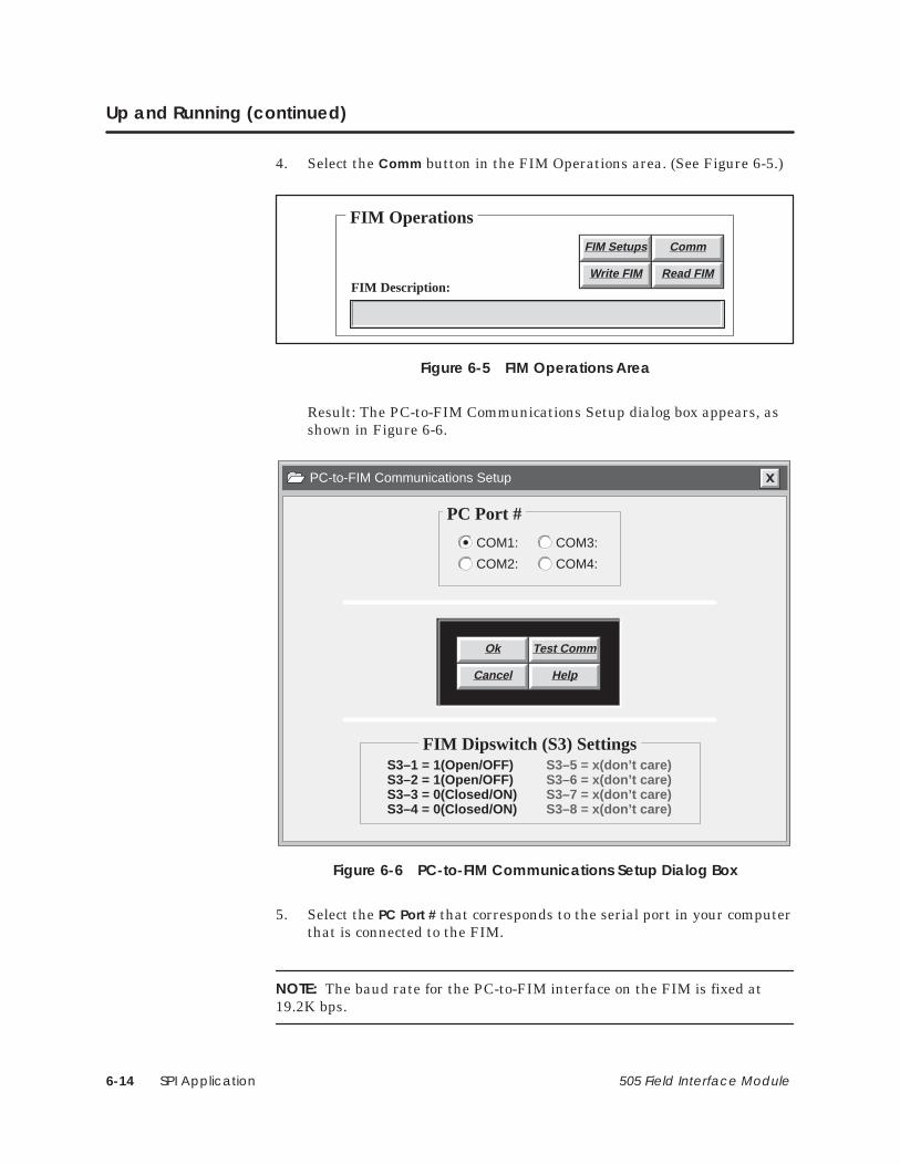
SPI Application6-14 505 Field Interface Module
Up and Running (continued)
4. Select the Comm button in the FIM Operations area. (See Figure 6-5.)
FIM Operations
FIM Description:
FIM Setups Comm
Write FIM Read FIM
Figure 6-5 FIM Operations Area
Result: The PC-to-FIM Communications Setup dialog box appears, asshown in Figure 6-6.
PC-to-FIM Communications Setup
Ok Test Comm
Cancel Help
PC Port #
FIM Dipswitch (S3) SettingsS3–1 = 1(Open/OFF) S3–5 = x(don’t care)S3–2 = 1(Open/OFF) S3–6 = x(don’t care)S3–3 = 0(Closed/ON) S3–7 = x(don’t care)S3–4 = 0(Closed/ON) S3–8 = x(don’t care)
COM1:
COM2:
COM3:
COM4:
Figure 6-6 PC-to-FIM Communications Setup Dialog Box
5. Select the PC Port # that corresponds to the serial port in your computerthat is connected to the FIM.
NOTE: The baud rate for the PC-to-FIM interface on the FIM is fixed at19.2K bps.

SPI Application 6-15505 Field Interface Module
6. Select the Test Comm button (shown in Figure 6-6). If everything isconnected properly, a confirmation message is displayed; otherwise, afailure message is displayed.
7. Select the Ok button to save the port selection.
NOTE: Pinouts for the RS-232 port should conform to those specified inChapter 2, in the section on communication port pinouts.
Once you establish satisfactory communications between the PC and theFIM, you can use the FIM SPI Configurator to perform the following tasks:
• Configure the baud rate and general parameters for the SPI link, usingthe Configurator’s FIM Setups dialog box.
• Configure all of your SPI devices, using the Edit Device, and, ifappropriate, Edit Custom Block, dialog boxes.
• Download your configuration from the PC to the FIM (Write FIM).
If you need detailed information about these tasks, see Sections 6.6 through6.9. However, be sure to come back to this section; your configuration workis not complete until you assign I/O addresses for your SPI devices in theprogrammable controller. The process of configuring the programmablecontroller, which is the last configuration task, is described on page 6-16.
Creating aConfiguration

SPI Application6-16 505 Field Interface Module
Up and Running (continued)
The SPI I/O devices represented by the FIM must be assigned I/O addressesin the programmable controller. You can assign addresses, or configure, theprogrammable controller either with TISOFT or with any other Series 505programmable controller programming package. The steps below assumethat you are using TISOFT.
1. Ensure that all of the devices and the FIM are powered up, and that allof the devices are set to the address and baud rate that you configuredfor them using the FIM SPI Configurator. (See “Creating aConfiguration” on page 6-15.)
2. If the FIM is communicating with the programmable controller, theCOMM LED is on. If not, use TISOFT to make sure that the base withthe base number of the FIM (SW1 on the FIM) is enabled.
If the base number is enabled, check the FIM’s Port 1 connection to theprogrammable controller.
3. With the FIM communicating to the programmable controller, do aRead Base. Refer to the chapter on configuring I/O for Series 505controllers in the SIMATIC 505 TISOFT User Manual.
Devices that are communicating appear as modules in the base withWX and WY points corresponding to their configured input words andoutput words.
If each device appears in the proper position in the base correspondingto the address of the device, set the I/O address to the desired values.Refer to Section 6.9, which describes configuring devices, for help indetermining valid I/O addressing.
4. Perform a Write PC to write the configuration of the FIM. The CFG LEDshould come on and stay on (not flashing) if the I/O is working properly.If the CFG LED flashes, it means that either one or more devices do notmatch the configuration or else that the FIM has lost communicationwith a device either periodically or completely, which may suggest badwiring/link setup. Check your wiring with the procedure on page 6-10 ifthis happens, and refer to Section 6.3 for other problems.
Configuring theProgrammableController

SPI Application 6-17505 Field Interface Module
5. You can monitor programmable controller status words to verify yourcommunications. Using status words STW12 (base 1) through STW27(base 15), check to see whether or not any of these bits is a 1.
If these bits are set to 1, even for one scan, then the FIM has lostcommunication with the device that corresponds to that bit. Refer toTable 6-3, on page 6-23, to determine which device corresponds to thethis bit. STW2 contains the bit that monitors the loss of communicationto the FIM corresponding to the base address. Refer to Table 6-2, onpage 6-22, to determine which bit corresponds to the base address onthe FIM.
Once you assign addresses to your SPI devices in the programmablecontroller, your configuration work is complete. An example scenario, wheretwo SPI devices are configured for the FIM and for the programmablecontroller, is provided in Section 6.10 and Section 6.11 for reference only.

SPI Application6-18 505 Field Interface Module
6.3 Troubleshooting
The following pages present common troubleshooting symptoms, theircauses, and corrective actions.
When the MOD GOOD LED is off, this indicates that the FIM is notreceiving power or has failed. Use the following checklist to troubleshootthis condition:
• Re-seat the board.
• Check for bent pins on the board connector.
• Check the power supply of the base.
• Check switch settings.
If none of these suggestions works, the FIM has probably failed. Return it tothe factory for repair.
When the COMM LED is off, this indicates that the FIM is notcommunicating with the CPU. When the FIM establishes goodcommunication to the CPU, the COMM LED turns on. Use the followingchecklist to troubleshoot this condition:
• Make sure the CPU and the FIM are powered up and working. TheMOD GOOD LED on the FIM should be on, and the CPU GOOD LEDon the CPU should be on.
• Check the dipswitches on the FIM. Dipswitch S3 selects theapplication. See page 6-8 to ensure that the FIM is set correctly forSPI.
• Make sure the base number for the FIM is enabled in the controller.The FIM is a remote base, like an RBC. If all remote bases are disabled(1–15), then the CPU does not communicate to the FIM or any otherbase on the remote link. Also, check to make sure the base address forthe FIM is set to the proper base number. The base address switch is onthe front bezel of the FIM and is labeled as S1.
NOTE: Base 0 is the local base of the CPU and cannot be used as a remotebase except with CPUs that do not have a local base.
The MOD GOODLED Is Off—What’sWrong?
The COMM LED IsOff—What’sWrong?

SPI Application 6-19505 Field Interface Module
• Check the connection of the RS-485 cable between the CPU’s I/O portand the FIM’s Port 1. Check the physical connections of the cable,check the cable pinouts for proper wiring, check the cable wire. Tryreplacing the cable with a different cable.
• If the CPU is communicating with other FIMs or RBCs, then tryreplacing this FIM.
• If the CPU is not communicating with other FIMs or RBCs, then tryreplacing the CPU.
When the CFG LED is off this indicates that the FIM has not received theuser configuration from the CPU. Use the following checklist to troubleshootthis problem:
NOTE: The CFG LED indicates whether the I/O configuration in thecontroller matches your actual field I/O, as located by the FIM. If youconfigure an SPI device in the FIM, but do not hook it up, and do notconfigure it in the controller, the actual field I/O matches the configurationin the controller, and so the CFG LED does not indicate a configurationmismatch. This condition does not cause a problem in the field; the FIMsimply polls for the device on each scan. If you hook up the device later, anddo not modify the I/O configuration in your controller, then the CFG LEDindicates a mismatch.
• Make sure the FIM’s COMM LED is on before attempting to get theCFG LED on.
• Check to make sure the base address for the FIM is set to the properbase number. The base address switch is on the front bezel of the FIMand is labeled as S1.
NOTE: Base 0 is the local base of the CPU and cannot be used as a remotebase except with CPUs that do not have a local base.
• Check to make sure the base used by the FIM is configured with I/O. Ifthe base corresponding to the FIM is written to the CPU as an emptybase, then no user configuration is sent to the FIM.
• Check the cable and connection to Port 1.
If none of these suggestions works, the FIM has probably failed. Return it tothe factory for repair.
The CFG LED IsOff—What’sWrong?

SPI Application6-20 505 Field Interface Module
Troubleshooting (continued)
When the CFG LED is blinking, this indicates that while the FIM iscommunicating with the CPU, and the FIM has been configured by theCPU, the I/O with which the FIM is communicating does not match the userconfiguration. Use the following checklist to troubleshoot this problem.
• Check to make sure the base address for the FIM is set to the properbase number. The base address switch is on the front bezel of the FIMand is labeled as S1.
NOTE: Base 0 is the local base of the CPU and cannot be used as a remotebase except with CPUs that do not have a local base.
• Check the user configuration using TISOFT. Make sure the I/O isarranged correctly. You can use the Compare Base function of TISOFTto determine which slots are suspect. Each SPI device corresponds to aslot in the base.
• Make sure all of the I/O devices are powered up. If an I/O device is notcommunicating with the FIM (for any reason) and is configured in theCPU, it shows up as a configuration error on the FIM.
• Check the device settings for the proper address, baud rate, device typesupported, etc.
• Check the configuration to see if an improper address is configured forthis device.
• Check the cable and connections between the FIM and the CPU.
• Wiring may require termination and bias. Refer to Section 2.5 fordetails on termination and bias requirements, and page 6-10 for tips onhow to build proper RS-485 connections.
The CFG LED IsBlinking—What’sWrong?

SPI Application 6-21505 Field Interface Module
A periodic blink of the CFG LED means that all SPI devices match theconfiguration, but communication to one or more devices is being lost forsome period of time. The following list suggests guidelines fortroubleshooting this condition:
• Check the wiring for loose or broken connections between the FIM’sPort 2 and the SPI devices. The connections must be in a daisy-chainconfiguration.
• Wiring may require termination and bias. Refer to Section 2.5 fordetails on termination and bias requirements, and page 6-10 for tips onhow to build proper RS-485 connections.
• Check for proper polarity of the RS-485 wire. All connections must haveRX/TX+ , RX/TX–, and GROUND common throughout the system.
• Make sure you are using the proper cable and not exceeding themaximum distance for cable and baud rate. Refer to the SPIspecification, or to the EIA 485 standard, for cable length restrictions.
• Check for the cable running too close to any magnetic fields (motors,high current wires, relays, etc.).
The CFG LED Is On,But BlinksPeriodically—What’s Wrong?

SPI Application6-22 505 Field Interface Module
Troubleshooting (continued)
Use TISOFT to check the operation of the module. If you experienceproblems communicating with the devices, you can read the base statusthrough TISOFT. The base status indicates proper communication toindividual devices by the presence of I/O points in the slot number thatcorresponds to the device address.
Read the controller status words to determine I/O presence, and the correctconfiguration of the Field Interface Module. See Table 6-2 and Table 6-3 forbit mapping.
Table 6-2 shows status bits for monitoring status between the controller andthe Field Interface Module. The status words for monitoring status betweenthe Field Interface Module and the devices are also shown in Table 6-2.
Bit number to device number correlation to these status words is shown inTable 6-3.
Table 6-2 Monitoring Controller-to-FIM Communication Status UsingController Status Words
FIMBase #
Controller to FIM Communication Status Bit
Status Word for FIM to Device
Communication Status
0 STW2 – Bit #16 (least significant bit) STW11
1 STW2 – Bit #15 STW12
2 STW2 – Bit #14 STW13
3 STW2 – Bit #13 STW14
4 STW2 – Bit #12 STW15
5 STW2 – Bit #11 STW16
6 STW2 – Bit #10 STW17
7 STW2 – Bit #9 STW18
8 STW2 – Bit #8 STW19
9 STW2 – Bit #7 STW20
10 STW2 – Bit #6 STW21
11 STW2 – Bit #5 STW22
12 STW2 – Bit #4 STW23
13 STW2 – Bit #3 STW24
14 STW2 – Bit #2 STW25
15 STW2 – Bit #1 (most significant bit) STW26
Checking theOperation of theModule

SPI Application 6-23505 Field Interface Module
Table 6-3 shows bit number to device number correlation for the statuswords from Table 6-2, using base 5 as an example.
Table 6-3 Monitoring FIM-to-Device Communication Status UsingController Status Words
Device/Slot # FIM to Device Communication Status Bit
(Example Using Base 5*)
1 STW16 – Bit #16 (least significant bit)
2 STW16 – Bit #15
3 STW16 – Bit #14
4 STW16 – Bit #13
5 STW16 – Bit #12
6 STW16 – Bit #11
7 STW16 – Bit #10
8 STW16 – Bit #9
9 STW16 – Bit #8
10 STW16 – Bit #7
11 STW16 – Bit #6
12 STW16 – Bit #5
13 STW16 – Bit #4
14 STW16 – Bit #3
15 STW16 – Bit #2
16 STW16 – Bit #1 (most significant bit)* The number of the status word is determined by adding 11 to the number of thebase; hence the status word for base 5 is STW16.
If you have questions concerning this information, contact your Siemensdistributor or sales office. If you require assistance in contacting yourdistributor or sales office in the United States, phone 1–800–964–4114.
TechnicalAssistance

SPI Application6-24 505 Field Interface Module
6.4 Programming
When the FIM and the controller have been properly configured, and theFIM is communicating satisfactorily with all of the SPI devices, the CFGLED of the FIM comes on and stays on. Now commands can be sent to theSPI devices.
An SPI command is either a poll, meaning that the FIM reads data from theSPI device, or a select, meaning that the FIM writes data to the SPI device.The following types of commands are supported:
Random poll/select request A single command, either a poll or a select.
Custom poll/select block A block of up to 10 commands, defined in theFIM SPI Configurator. The block must contain only one type of command;you cannot mix polls and selects in a custom block.
Blanket poll A predefined block of poll commands. Most SPI devices haveone unique block, or blanket poll, associated with them; consult your devicemanual for more information.
To initiate a random request, custom block, or blanket poll, you place a userrequest value in the control word of your request. This tells the FIM whattype of command to expect. See Table 6-4.
Table 6-4 User Request Values
RequestWY (1)(hex)
ActionResponse
WX (1)(hex)
Result
0000 Identification only; poll message. (No responsedata put into input word buffer.)
0000 None.
0100 Send blanket poll block. 0100 Data from poll block is put intoresponse buffer.
0200 Send custom poll block #1. 0200 Commands in custom poll block#1 are sent to SPI device.
0300 Send custom poll block #2. 0300 Commands in custom poll block#2 are sent to SPI device.
0400 Send custom select block #1. 0400 Commands in custom selectblock #1 are sent to SPI device.
0500 Send custom select block #2. 0500 Commands in custom selectblock #2 are sent to SPI device.
06xx 1 Send random poll or select request. 06xx The random poll or selectrequest is sent.
1 The value 0600 is used for most random requests; xx signifies that the length of data to be exchangedmust be specified in the least significant byte of the request word when you use an alternate/unlisted SPIdevice or issue a random request that the FIM does not recognize.
Types ofCommands
User Requests

SPI Application 6-25505 Field Interface Module
! CAUTIONThe FIM actively examines user requests and data buffers every scan. If yourprogram does not send complete commands and complete data in the course ofa single scan, the FIM operates based on the incomplete data it finds.
If your program does not take this feature of FIM operation into account, yourdata can become corrupt.
Always zero out the request control word and make sure that the FIM and thecontroller are in sync before issuing SPI commands. Also, make sure that theSPI command and its associated data buffer are changed in the same scan, sothe FIM cannot read one without the other . Leave the request control word atzero until the entire buffer is complete; do not issue a request with anincomplete data buffer .
To send an individual poll or select, use a random request. SPI requestsconsist of two byte commands, referred to as Command 1 (CMD1) andCommand 2 (CMD2). Polls are distinguished by an even value in the CMD2byte; selects have an odd value in CMD2. Typically, the CMD1 byte containseither a value of 20 (hex) or the zone for the request.
Ordinarily, you do not have to specify the expected data length when youissue a random poll or select. However, if the SPI device that you areconfiguring is not directly supported by the FIM (see page 6-3), or if thecommand is not listed in the I/O list of the SPI Matching Division,Communication Protocol, Version 3.01, Section 2, then you must specify theexpected response length, in bytes, in the least significant byte of therequest word.
When a random request is issued, the FIM attempts to send the poll orselect, and update the response buffer (for a poll), for as long as the userrequest (06xx) remains in the request control word. Once the FIMsuccessfully completes the random request, the user request (06xx) is placedin the response word to indicate that the FIM has finished an update. Onthe next scan, the FIM checks the request control word again; if the userrequest has not been updated, then the FIM repeats the previous request.
Random Requests

SPI Application6-26 505 Field Interface Module
Programming (continued)
Sending multiple commands individually takes several scans and requiresextra coding in order to process the commands. An alternative is to create acustom block with the FIM SPI Configurator (see page 6-54 and followingfor information about how to create one). A custom block is like a macro, inwhich you can define up to 10 SPI commands to be sent with one request.You cannot mix command types within a block; each block must be either allpolls (i.e., the FIM is reading data from an SPI device, or all selects (i.e., theFIM is writing data to an SPI device). You have the option of creating up to2 custom poll blocks and 2 custom select blocks, for a total of 4 customblocks.
Before sending a block of commands, the FIM validates each command anddetermines if there is enough room to process all the commands, byexamining input words for a custom poll block or output words for a customselect block. If any of the commands are invalid, or if there is insufficientroom for the data generated by the command, the FIM returns the relevanterror code (see Section 6.5). Otherwise, the FIM attempts to send the pollsor selects, and to update the response buffer (for polls), for as long as theuser request (0200, 0300, 0400, or 0500) remains in the request controlword. Once the FIM successfully completes the custom block, the userrequest (0200, 0300, 0400, or 0500) is placed in the response word toindicate that the FIM has finished an update. On the next scan, the FIMchecks the request control word again; if the user request has not beenupdated, then the FIM repeats the previous request.
Custom Blocks

SPI Application 6-27505 Field Interface Module
The SPI specification defines SPI devices and the commands that are validfor each device. Most SPI devices have a blanket poll request defined;however, the FIM must directly support the device for you to be able to useits blanket poll. (See page 6-3 for a list of the devices that are directlysupported by the FIM.) The blanket poll option allows several data items tobe read from the device with one request.
When a blanket poll is issued, the FIM attempts to send the poll request,and to update the response buffer, for as long as the user request (0100)remains in the request control word. Once the FIM successfully completesthe poll request, the user request (0100) is placed in the response word toindicate that the FIM has finished an update. The data is returned with therespective CMD1 and CMD2 preceding each value. On the next scan, theFIM checks the request control word again; if the user request has not beenupdated, then the FIM repeats the previous request.
Blanket Polls

SPI Application6-28 505 Field Interface Module
Programming (continued)
The following examples illustrate how a random request, custom block, andblanket poll operate.
For the purpose of these examples, assume that the SPI device you areprogramming is a loader (device ID 23) that has 10 input words(WX65 – WX74) and 12 output words (WY75 – WY86) configured. (The samedevice is used in configuration examples later in this chapter; refer toSection 6.10 and Section 6.11.)
This example uses several random requests to read and overwrite loadtimes.
To read a value for Load Time A, using SPI command 2050, follow the stepsbelow:
1. Place a zero into WY75 and wait for WX65 to be zeroed by the FIM.
Result: This ensures that the FIM and the controller are synchronized.
Input Buffer Contents Output Buffer Contents
WX65 0 WY75 0
WX66 – WX74 not used WY76 – WY86 not used
2. Place the value 2050 (hex) into WY76.
Result: The request buffer takes the value for CMD1, namely 20 (hex),in byte 1, and the value for CMD2, namely 50 (hex), in byte 2.
Input Buffer Contents Output Buffer Contents
WX65 0 WY75 0
WX66 – WX74 not used WY76 2050 (hex)
WY77 – WY86 not used
3. Place the value 0600 (hex) into WY75.
Result: The FIM sees the user request (0600) and attempts to executethe random poll request.
Input Buffer Contents Output Buffer Contents
WX65 0 WY75 0600 (hex)
WX66 – WX74 not used WY76 2050 (hex)
WY77 – WY86 not used
Random RequestExample #1

SPI Application 6-29505 Field Interface Module
When the FIM finishes, it writes the value read from the loader device,in numeric (floating point) format, into WX66 and WX67, and writesthe user request (0600) to WX65 to indicate that the poll has executedsuccessfully.
Input Buffer Contents Output Buffer Contents
WX65 0600 (hex) WY75 0600 (hex)
WX66 – WX67 value read fromloader device
WY76 2050 (hex)
WX68 – WX74 not used WY77 – WY86 not used
NOTE: Series 505 controllers do not support numeric (floating point) formatdirectly from RLL. To modify or convert a floating point number from RLL,you must use the SFSUB instruction to call an SF subroutine. Refer to thesection on Call SF Subroutines from RLL, in the RLL Instruction Setchapter of the SIMATIC 505 Programming Reference User Manual.

SPI Application6-30 505 Field Interface Module
Programming (continued)
Next, you can change the value for Load Time A, by issuing a select insteadof a poll. Follow these steps:
1. Place a zero into WY75 and wait for WX65 to be zeroed by the FIM.
Result: This ensures that the FIM and the controller are synchronized.
Input Buffer Contents Output Buffer Contents
WX65 0 WY75 0
WX66 – WX74 not used WY76 – WY86 not used
2. Place the value 2051 (hex) into WY76.
Result: The request buffer takes the value for CMD1, namely 20 (hex),in byte 1, and the value for CMD2, namely 51 (hex), in byte 2.
Input Buffer Contents Output Buffer Contents
WX65 0 WY75 0
WX66 – WX74 not used WY76 2051 (hex)
WY77 – WY86 not used
NOTE: Odd CMD2s, such as 51, are selects, whereas the even CMD2 in theprevious example (50) was a poll.
3. Place the value that is to be written to the loader into WY77 and WY78.
Input Buffer Contents Output Buffer Contents
WX65 0 WY75 0
WX66 – WX74 not used WY76 2051 (hex)
WY77 – WY78 value for loader
WY79 – WY86 not used
Random RequestExample #2

SPI Application 6-31505 Field Interface Module
4. Place the value 0600 (hex) into WY75.
Result: The FIM sees the user request (0600) and attempts to executethe random select request.
Input Buffer Contents Output Buffer Contents
WX65 0 WY75 0600 (hex)
WX66 – WX74 not used WY76 2051 (hex)
WY77 – WY78 value for loader
WY79 – WY86 not used
Once the FIM writes the value read from WY77 – WY78 into the loader,it is finished, and it writes the user request (0600) to WX65 to indicatethat the select has executed successfully. The loader has a new setpointfor Load Time A.
Input Buffer Contents Output Buffer Contents
WX65 0600 (hex) WY75 0600 (hex)
WX66 – WX74 not used WY76 2051 (hex)
WY77 – WY78 value for loader
WY79 – WY86 not used

SPI Application6-32 505 Field Interface Module
Programming (continued)
In the examples above, it was not necessary to include a value for thecommand length. However, in the case of valid commands that are added tothe SPI specification after the release of the FIM, you must use the leastsignificant byte of the request word to specify the number of bytes that thecommand sends or reads. If you fail to specify the length for a commandthat the FIM does not recognize, the FIM rejects the request, and writes theerror code for Illegal Command into the response word.
In the following scenario, assume that the manufacturer of your SPI devicehas added a command for the loader that the FIM does not recognize,namely, Load Time C (CMD1=20, CMD2=54). To read the value for LoadTime C, follow these steps:
1. Place a zero into WY75 and wait for WX65 to be zeroed by the FIM.
Result: This ensures that the FIM and the controller are synchronized.
Input Buffer Contents Output Buffer Contents
WX65 0 WY75 0
WX66 – WX74 not used WY76 – WY86 not used
2. Place the value 2054 (hex) into WY76.
Result: The request buffer takes the value for CMD1, namely 20 (hex),in byte 1, and the value for CMD2, namely 54 (hex), in byte 2.
Input Buffer Contents Output Buffer Contents
WX65 0 WY75 0
WX66 – WX74 not used WY76 2054 (hex)
WY77 – WY86 not used
Random RequestExample #3

SPI Application 6-33505 Field Interface Module
3. Place the value 0604 (hex) into WY75.
Result: The FIM sees the user request (0604) and attempts to executethe random poll request.
Input Buffer Contents Output Buffer Contents
WX65 0 WY75 0604 (hex)
WX66 – WX74 not used WY76 2054 (hex)
WY77 – WY86 not used
NOTE: The 04 value in the user request tells the FIM that this commandreads a numeric value that occupies 4 bytes.
When the FIM finishes, it writes the value read from the loader device,in numeric (floating point) format, into WX66 and WX67, and writesthe user request (0604) to WX65 to indicate that the poll has executedsuccessfully.
Input Buffer Contents Output Buffer Contents
WX65 0604 (hex) WY75 0604 (hex)
WX66 – WX67 value read fromloader device
WY76 2054 (hex)
WX68 – WX74 not used WY77 – WY86 not used

SPI Application6-34 505 Field Interface Module
Programming (continued)
In this example, the FIM executes Custom Poll Block #1, which you haveconfigured to hold two commands, Material Mode Status (CMD1=20,CMD2=48) and Load Time A Setpoint (CMD1=20, CMD2=50).
1. Place a zero into WY75 and wait for WX65 to be zeroed by the FIM.
Result: This ensures that the FIM and the controller are synchronized.
Input Buffer Contents Output Buffer Contents
WX65 0 WY75 0
WX66 – WX74 not used WY76 – WY86 not used
2. Place the value 0200 (hex) into WY75.
Result: The FIM sees the user request (0200) and attempts to executeCustom Poll Block #1.
Input Buffer Contents Output Buffer Contents
WX65 0 WY75 0200 (hex)
WX66 – WX74 not used WY76 – WY86 not used
Custom Poll BlockExample

SPI Application 6-35505 Field Interface Module
When the FIM finishes (assuming no errors), it writes the data fromthe Material Mode Status into WX66 and the data from the LoadTime A Setpoint into WX67 and WX68. The FIM writes the userrequest (0200) to WX65 to indicate that the poll has executedsuccessfully.
Input Buffer Contents Output Buffer Contents
WX65 0200 (hex) WY75 0200 (hex)
WX66 value read fromMaterial Mode
WY76 – WY86 not used
WX67 – WX68 value read fromLoad Time ASetpoint
WX69 – WX74 not used

SPI Application6-36 505 Field Interface Module
Programming (continued)
In this example, the FIM executes Custom Select Block #1, which you haveconfigured to hold two commands, Material Mode Status (CMD1=20,CMD2=49) and Load Time A Setpoint (CMD1=20, CMD2=51).
1. Place a zero into WY75 and wait for WX65 to be zeroed by the FIM.
Result: This ensures that the FIM and the controller are synchronized.
Input Buffer Contents Output Buffer Contents
WX65 0 WY75 0
WX66 – WX74 not used WY76 – WY86 not used
2. Place the values that are to be written to the loader into WY76 andWY77 – WY78.
Input Buffer Contents Output Buffer Contents
WX65 0 WY75 0
WY76 value for MaterialMode
WY77 – WY78 value for LoadTime A Setpoint
WY79 – WY86 not used
Custom SelectBlock Example

SPI Application 6-37505 Field Interface Module
3. Place the value 0400 (hex) into WY75.
Result: The FIM sees the user request (0400) and attempts to executeCustom Select Block #1.
Input Buffer Contents Output Buffer Contents
WX65 0 WY75 0400
WX66 – WX74 not used WY76 value for MaterialMode
WY77 – WY78 value for LoadTime A Setpoint
WY79 – WY86 not used
Once the FIM writes the values from WY76 – WY78 into the loader, itis finished, and it writes the user request (0400) to WX65 to indicatethat Custom Select Block #1 has executed successfully.
Input Buffer Contents Output Buffer Contents
WX65 0400 WY75 0400
WX66 – WX74 not used WY76 value for MaterialMode
WY77 – WY78 value for LoadTime A Setpoint
WY79 – WY86 not used

SPI Application6-38 505 Field Interface Module
Programming (continued)
In this example, the loader issues the blanket poll that is associated with it.(For a description of this blanket poll, consult the SPI specifications.)
1. Place a zero into WY75 and wait for WX65 to be zeroed by the FIM.
Result: This ensures that the FIM and the controller are synchronized.
Input Buffer Contents Output Buffer Contents
WX65 0 WY75 0
WX66 – WX74 not used WY76 – WY86 not used
2. Place the value 0100 (hex) into WY75.
Result: The FIM sees the user request (0100) and attempts to executethe blanket poll.
Input Buffer Contents Output Buffer Contents
WX65 0 WY75 0100 (hex)
WX66 – WX74 not used WY76 – WY86 not used
Blanket PollExample

SPI Application 6-39505 Field Interface Module
When the FIM finishes (assuming no errors), the input buffer(WX66 – WX73) contains 16 bytes of data read from the blanket poll,per the SPI specifications. The FIM writes the user request (0100) toWX65 to indicate that the poll has executed successfully.
Input Buffer Contents Output Buffer Contents
WX65 0100 (hex) WY75 0100 (hex)
WX66 2050 (hex) WY76 – WY86 not used
WX67 – WX68 Value read forLoad Time A
WX69 2052 (hex)
WX70 – WX71 Value read forLoad Time B
WX72 2040 (hex)
WX73 Value read forProcess Status
WX74 not used

SPI Application6-40 505 Field Interface Module
6.5 Error Codes
If an SPI request is not successful, then an error code is returned in theresponse status word. The error code is provided to help you diagnose theproblem with the request. All error codes except the Illegal Request errorcode have the CMD1 CMD2 commands in the second input word, and thelength of the command in the most significant byte of the third input word.Table 6-5 illustrates how the error codes are returned. Specific error codesare listed below.
Table 6-5 Error Codes Returned in Response Status Word
Location Value (hex) Description
WX(n) FF?? Error code
WX(n+1) C1C2 CMD1 (C1) and CMD2 (C2)
WX(n+2) LLxx LL=Length of data for command, in bytes
FF00—Negative Acknowledge Indicates that a request was sent, butthe SPI device returned a Negative Acknowledge, because the device did notrecognize the command that was sent. Check the command itself, and thencheck the SPI specification to see which commands are valid for thatparticular device type.
FF01—Illegal Command Indicates that a request was entered (either arandom request, or a custom block) as a standard command; however, therequest was not recognized as a standard command by the FIM. It may bethat the FIM cannot send the command because it does not know how muchdata is to be polled or selected by the command. Check the SPI specificationto see if the command is valid for the selected device type; if the command isinvalid, you must correct it, and if the command is valid, you need to specifythe data length so that the FIM can transmit it successfully.
FF02—No Data Indicates that a poll command was sent, and the deviceresponded to the command but did not return data. Polls must return data.Check to see if the correct command was specified, and to see if a service onthe device has been disabled. The device manual should provide informationabout the services available for that device.
FF03—Bad Request Indicates that a request was made that is not validor recognized by the FIM. This means that the value entered into therequest word is not recognized, or (in the case of custom poll and selectblocks) that there are no commands in a block request. If you are sending ablock request, check the corresponding block using the configurator: 0200for custom poll block #1; 0300 for custom poll block #2; 0400 for customselect block #1; 0500 for custom select block #2. The block must contain atleast one command. If you are not sending a block, then only 0100 and 06xxare allowed for requests. Entering an illegal request word, such as 0700,would produce this error.
SPI Application 6-41505 Field Interface Module
FF04—Output Buffer Underrun Indicates that a select request(random or block) requires more data than there are output wordsconfigured to handle. This is typically caused by select block commands thattotal more data bytes than the available output bytes configured in theoutput words.
The number of bytes available in the output buffer for random selects canbe calculated according to this formula:
output_buffer_size = (#output_words – 2) x 2
The number of bytes available in the output buffer for custom select blockscan be calculated according to this formula:
output_buffer_size = (#output_words – 1) x 2
To resolve this problem, configure more output words, or else reduce therequests in the custom select block.
FF05—Input Buffer Overflow Indicates that a poll request (random,block, or blanket) contains more data than there are input words configuredto handle. This is typically caused by poll block commands that total moredata bytes than the available input bytes configured in the input words.
The number of bytes available in the input buffer for random polls and/orcustom poll blocks can be calculated according to this formula:
input_buffer_size = (#input_words – 1) x 2
To resolve this problem, configure more input words, or else reduce therequests in the custom poll block.
FF06—Poll Data Length Error Indicates that a poll request (random,block, or blanket) returned less or more data than expected. Check the SPIspecification for the amount of data to be sent with this command. You haveprobably either specified an incorrect data length, or failed to specify thedata length for a device that deviates from the SPI specification, in whichcase the data length must be specified. See your device manual forinformation about possible deviations.

SPI Application6-42 505 Field Interface Module
6.6 Overview of the FIM SPI Configurator
The SIMATIC 505–7202 FIM SPI Configurator application allows you toperform all the steps necessary for configuring an SPI device for the FIM:
• Create a configuration file in which to save your work.
• Define and test parameters for PC-to-FIM communications.
• Define general parameters for your FIM-to-SPI device communications.
• Define specific parameters for each SPI device.
• Create custom blocks for each device.
• Write the configuration to the FIM.
• Read the configuration from the FIM.
The main window of the SPI Configurator is divided into three screen areas.See Figure 6-7. To learn more about each area of the Configurator, consultthe appropriate section in this chapter, or use the on-line help that is part ofthe Configurator package.
• Configuration File: allows you to save your work to a file. SeeSection 6.7.
• FIM Operations: allows you to modify the FIM setup (optional), to writeyour configuration changes to the FIM and read them back, and toconfigure communications. See Section 6.8.
• SPI Device Operations: allows you to edit parameters for each deviceand create custom poll and select blocks. See Section 6.9.
For a detailed example of how to construct a configuration using the FIMSPI Configurator, see Section 6.10.
Overview ofConfiguratorFunctions

SPI Application 6-43505 Field Interface Module
Figure 6-7 shows the main window of the SPI Configurator.
505–7202 FIM SPI Device Configurator
File FIM Device H elp
SIMATIC 505–7202 FIM SPI–Protocol
Configuration File
File Name:Open New
Save Save As
FIM Operations
FIM Description
FIM Setups Comm
Write FIM Read FIM
SPI Device Operations
Description:
Edit
Device Address:
Device/Slot #:
Enabled
Exit
Help
1
Figure 6-7 Main Configurator Window
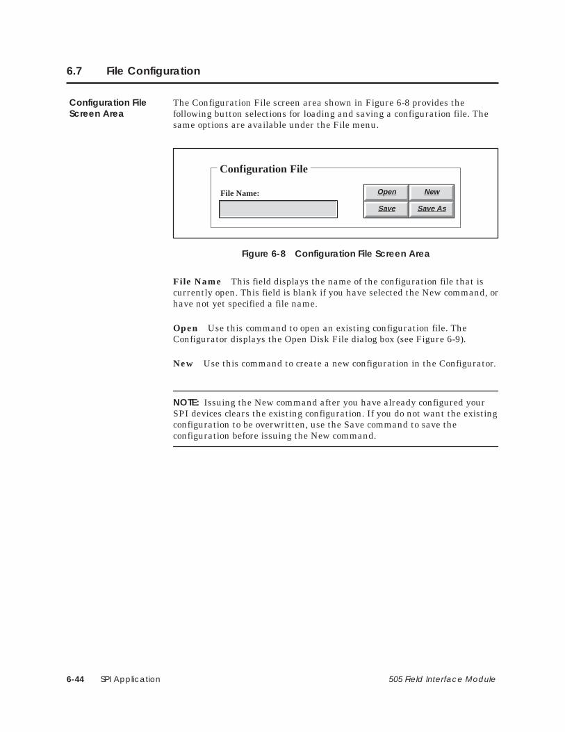
SPI Application6-44 505 Field Interface Module
6.7 File Configuration
The Configuration File screen area shown in Figure 6-8 provides thefollowing button selections for loading and saving a configuration file. Thesame options are available under the File menu.
Configuration File
File Name: Open New
Save Save As
Figure 6-8 Configuration File Screen Area
File Name This field displays the name of the configuration file that iscurrently open. This field is blank if you have selected the New command, orhave not yet specified a file name.
Open Use this command to open an existing configuration file. TheConfigurator displays the Open Disk File dialog box (see Figure 6-9).
New Use this command to create a new configuration in the Configurator.
NOTE: Issuing the New command after you have already configured yourSPI devices clears the existing configuration. If you do not want the existingconfiguration to be overwritten, use the Save command to save theconfiguration before issuing the New command.
Configuration FileScreen Area

SPI Application 6-45505 Field Interface Module
Save Use this command to save the configuration file with its currentname and directory. When you save a document for the first time, theConfigurator displays the Save File dialog box so you can name yourconfiguration file. (See Figure 6-10.) If you want to change the name anddirectory of an existing configuration file before you save it, choose the SaveAs command.
Save As Use this command to save and name the current configuration.The Configurator displays the Save File dialog box so you can name yourconfiguration. (See Figure 6-10.)
Exit Use this command to end your Configurator session.

SPI Application6-46 505 Field Interface Module
File Configuration (continued)
Open Disk File
Open
Cancel
File name:
Directory is: c:\cfg-spi
Files:
*.SPI
Directories
[..][-a-][-c-]
Figure 6-9 Open Disk File Dialog Box
The Open Disk File dialog box shown in Figure 6-9 contains the followingfields, which enable you to specify which file to open:
File Name Type or select the name of the file that you want to open.
Directory is Displays the currently selected drive and directory.
Files Displays the configuration files available in the currently selecteddrive and directory.
Directories Select the directory where the file that you want to open isstored.
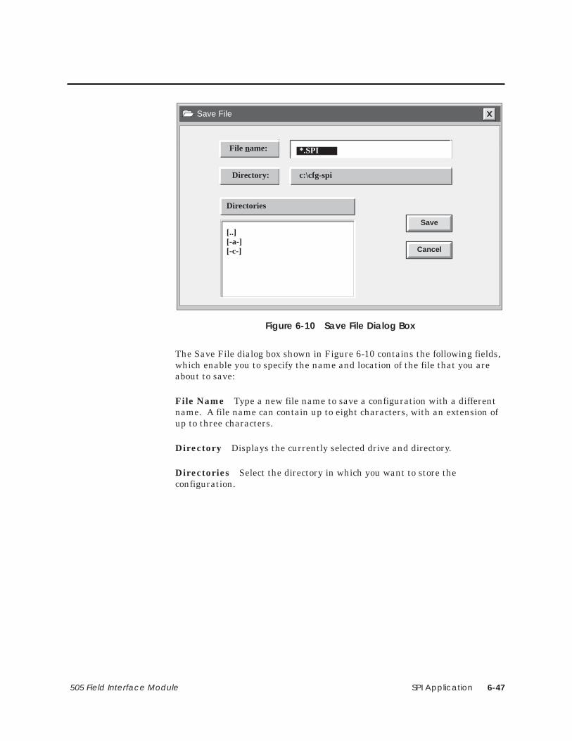
SPI Application 6-47505 Field Interface Module
Save File
Save
Cancel
File name:
Directory: c:\cfg-spi
*.SPI
Directories
[..][-a-][-c-]
Figure 6-10 Save File Dialog Box
The Save File dialog box shown in Figure 6-10 contains the following fields,which enable you to specify the name and location of the file that you areabout to save:
File Name Type a new file name to save a configuration with a differentname. A file name can contain up to eight characters, with an extension ofup to three characters.
Directory Displays the currently selected drive and directory.
Directories Select the directory in which you want to store theconfiguration.

SPI Application6-48 505 Field Interface Module
6.8 FIM Operations
The FIM Operations screen area shown in Figure 6-11 provides thefollowing button selections for establishing general SPI communications,making PC port assignments, and reading or writing configurations from orto the FIM. The same options are available under the FIM menu.
FIM Operations
FIM Description
FIM Setups Comm
Write FIM Read FIM
Figure 6-11 FIM Operations Screen Area
Setups (FIM Setups button) This function allows you to assign generalparameters that govern communications between the FIM and your SPIdevices. For more information, see page 6-50.
Communications (Comm button) This function allows you to defineand test serial port assignments for PC-to-FIM communications. For adescription of the procedure involved, see page 6-14.
NOTE: The TestComm button (available when you select the Comm button)tests your communication settings and the connection to the FIM, anddisplays a message that states whether or not communications are workingproperly. You can modify PC serial port settings in the PC-to-FIMCommunications Setup dialog box; a list of required dipswitch settings isalso displayed, and you can manually alter any switches on the back of theFIM as needed.
FIM OperationsScreen Area

SPI Application 6-49505 Field Interface Module
Read Configuration (Read FIM button) This function reads thecurrent configuration from the FIM into the Configurator. This operationtakes approximately thirty seconds to complete.
Write Configuration (Write FIM button) This function writes thecurrent configuration from the Configurator to the FIM.
! CAUTIONWriting a configuration to the FIM causes the FIM to go offline for approximatelythirty seconds.
The FIM cannot update I/O during the period that it is offline.
Before you issue a Write FIM, ensure that going offline will not cause unduedisruption of your process.
FIM Description This text field displays the description that you enteredin the FIM Setups dialog box to identify this specific configuration. Thisinformation is optional and is not used by the FIM. This field is provided foryour convenience to document your application.
The parameter table contains the configuration information that you createin the Configurator and write to the FIM. The following conditions cause aparameter table error message:
• You powered up the FIM and tried to use the Configurator to Read FIM.The FIM does not have any configuration information stored in itsparameter table as you receive it from the factory. Solution: You mustcreate the configuration with the Configurator and then use Write FIM tostore the configuration information in the parameter table.
• You installed a new release of the FIM firmware using fimutl.exe. Thefirmware load utility, fimutl, clears the parameter table. Solution: Afteryou load new firmware into the FIM, use the Configurator to open yourconfiguration file, then Write FIM.
• The parameter table information in the FIM’s EEPROM has beencorrupted. Solution: Use the Configurator to open your configurationfile, then Write FIM. If this condition continues to occur, return your FIMfor repair.
TroubleshootingParameter TableErrors

SPI Application6-50 505 Field Interface Module
FIM Operations (continued)
The FIM Setups dialog box shown in Figure 6-12 allows you to assigngeneral parameters that govern communications between the FIM and yourSPI devices.
FIM Setups
Ok
Clear
Description:
Help
Cancel
Baud Rate:
Request Retries:
Response Delay:
Turn Around Relay:
mSecs
mSecs
Character Delay: mSecs
9600
Figure 6-12 FIM Master Parameters Setup Dialog Box
Description This text field allows you to enter a description of thecurrent configuration file. This field is not used by the FIM; it is provided tohelp you document your configuration.
Baud Rate Accept the default rate of 9600 bits per second, or click on the button to display a drop-down list, from which you can select another
valid baud rate. The valid baud rates are as follows: 1200, 2400, 4800, 9600,and 19200.
Request Retries Numeric value that determines how many times theFIM retries a request that has been sent to a device. The range is 1 to 4; thedefault value is 2.
NOTE: Accept the default value unless the communication link has noise, oryou have an SPI device that sometimes takes a long period of time torespond.
FIM Setups DialogBox

SPI Application 6-51505 Field Interface Module
Response Delay Numeric value that determines the minimum number ofmilliseconds in which a response from a device must be completed. Therange is 2 to 2000. The default value is 500 milliseconds.
NOTE: Accept the default value unless you know that a device tends todelay its response.
Turn Around Delay Numeric value that determines the number ofmilliseconds that the FIM must wait after any transmission on the link(either from the FIM or from a device) before starting a new message toanother device. The range is 2 to 255 ms. The default value is 30milliseconds.
NOTE: Accept the default value unless you know that it takes too long for adevice to prepare for a new request.
Character Delay Numeric value that determines the number ofmilliseconds that the FIM must wait before concluding that the device hascompleted its response and that no additional characters should beexpected. The range is 2 to 255 ms. The default value is determined fromthe baud rate.

SPI Application6-52 505 Field Interface Module
6.9 SPI Device Operations
The SPI Device Operations screen area shown in Figure 6-13 provides thefollowing button selections for configuring SPI devices. The same optionsare available under the Device menu.
SPI Device Operations
Description:
Edit
Device Address:
Device/Slot #:
Enabled
1
Figure 6-13 SPI Device Operations Screen Area
Device/Slot # This field displays the currently selected device number.The FIM supports up to 16 devices, numbered 1 to 16, corresponding to slotnumbers 1 to 16. Selecting displays the information for the previousdevice. Selecting displays the information for the next device. Select oneof these buttons repeatedly to cycle through the device list.
Device Address This field displays the address for the SPI device at thisslot.
SPI DeviceOperations Area

SPI Application 6-53505 Field Interface Module
Enabled area This area displays the selected state of the device. Bydefault, each device is enabled in the configuration for polling and displaysas Enabled in the SPI Device Operations area. When you select Devicedisabled (Not polled) from the Edit Device dialog box, the SPI DeviceOperations area displays Disabled for that device.
Description This field displays the text that you entered in the EditDevice dialog box to describe this particular SPI device.
Edit This button summons the Edit Device dialog box. (See page 6-54.)

SPI Application6-54 505 Field Interface Module
SPI Device Operations (continued)
The Edit Device dialog box shown in Figure 6-14 is invoked by the Editbutton in the SPI Device operations area of the main Configurator window.The Edit Device dialog box allows you to configure parameters for your SPIdevices.
Edit Device
Ok
Clear
Help
Device disabled (Not polled)
Cancel
Description:
Device Type:
Alt Device ID (hex):
Address:
Input Words (WX):
Output Words (WY):
Edit Custom Poll Block #1
Edit Custom Poll Block #2
Edit Custom Select Block #1
Edit Custom Select Block #2
Figure 6-14 Edit Device Dialog Box
Device disabled (Not polled) Select this checkbox to specify that theFIM should not poll a device at this position. The FIM can poll up to 16 SPIdevices. If a device does not exist, the FIM continues to poll and retry thatposition. If you have fewer than 16 SPI devices, you can reduce the overallscan time by setting this checkbox for any positions where devices do notexist. The FIM does not poll or retry the disabled positions.
Description This optional field allows you to describe the function of theSPI device, using up to 51 characters.
Device Type Complete this field to select the SPI type of your device (fordevices directly supported by the FIM), or to specify an alternate/unlisteddevice.
Edit Device DialogBox

SPI Application 6-55505 Field Interface Module
NOTE: If you specify a non-standard device, the Alt Device ID field isactivated and must be completed.
Alt Device ID (hex) If you specified an Alternate/Unlisted Device in theDevice Type field, you must complete this field. Use a hexadecimal value toassign an ID to your SPI device. The range of valid IDs is 20 to FF (hex).
Address Complete this field to specify the address of the SPI device atthis slot. Use a decimal value. The range of valid addresses is from 32 to256.
Input Words (WX) Complete this field to specify the number of words tobe allocated for input data (that is, data that the FIM sends to thecontroller). The range is even word numbers from 4 to 32, excluding 30words. If you do not enter a value in this field, the Configurator assigns adefault value of 8.
Output Words (WY) Complete this field to specify the number of words tobe allocated for output data (that is, data that the FIM receives from thecontroller). The range is even word numbers from 4 to 32, excluding 30words. If you do not enter a value in this field, the Configurator assigns adefault value of 8.
Edit Custom Poll Block #1 These buttons summon theEdit Custom Poll Block #2 Edit Custom Block dialog boxEdit Custom Select Block #1 for a poll or select block.Edit Custom Select Block #2 (See page 6-56.)
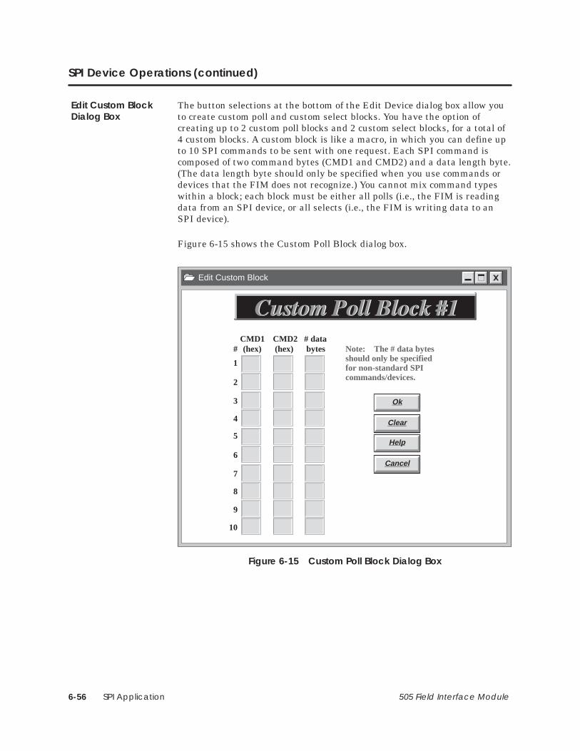
SPI Application6-56 505 Field Interface Module
SPI Device Operations (continued)
The button selections at the bottom of the Edit Device dialog box allow youto create custom poll and custom select blocks. You have the option ofcreating up to 2 custom poll blocks and 2 custom select blocks, for a total of4 custom blocks. A custom block is like a macro, in which you can define upto 10 SPI commands to be sent with one request. Each SPI command iscomposed of two command bytes (CMD1 and CMD2) and a data length byte.(The data length byte should only be specified when you use commands ordevices that the FIM does not recognize.) You cannot mix command typeswithin a block; each block must be either all polls (i.e., the FIM is readingdata from an SPI device, or all selects (i.e., the FIM is writing data to anSPI device).
Figure 6-15 shows the Custom Poll Block dialog box.
Edit Custom Block
Ok
Clear
Help
Cancel
1
2
3
4
5
6
7
8
9
10
# (hex) (hex) bytesCMD1 CMD2 # data
Note: The # data bytesshould only be specifiedfor non-standard SPIcommands/devices.
Figure 6-15 Custom Poll Block Dialog Box
Edit Custom BlockDialog Box
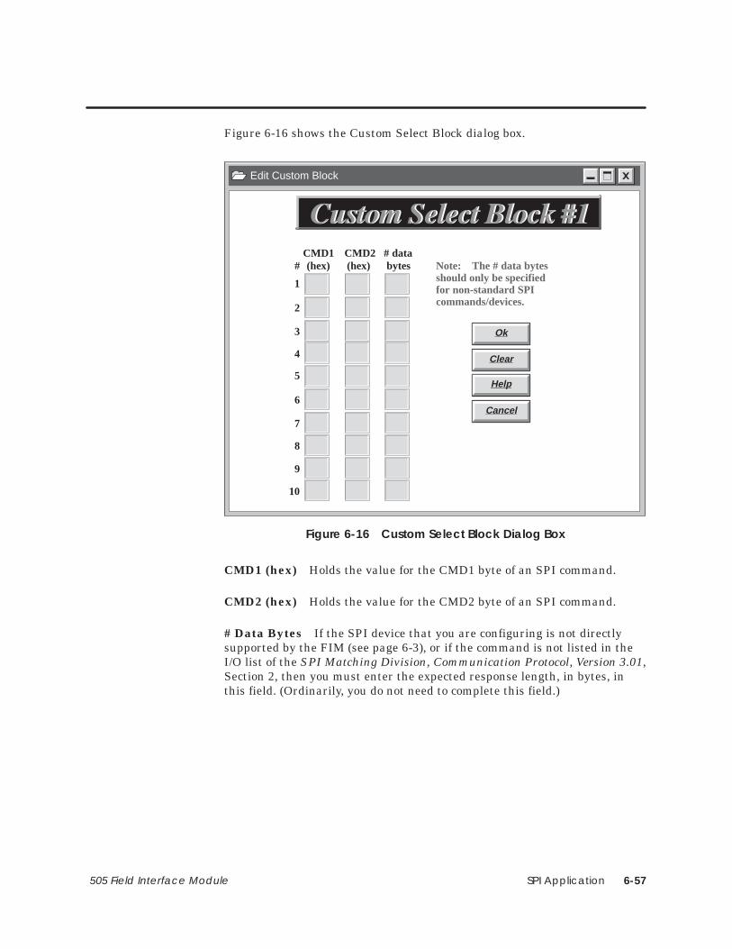
SPI Application 6-57505 Field Interface Module
Figure 6-16 shows the Custom Select Block dialog box.
Edit Custom Block
Ok
Clear
Help
Cancel
1
2
3
4
5
6
7
8
9
10
(hex) (hex) bytesCMD1 CMD2 # data
Note: The # data bytesshould only be specifiedfor non-standard SPIcommands/devices.
#
Figure 6-16 Custom Select Block Dialog Box
CMD1 (hex) Holds the value for the CMD1 byte of an SPI command.
CMD2 (hex) Holds the value for the CMD2 byte of an SPI command.
# Data Bytes If the SPI device that you are configuring is not directlysupported by the FIM (see page 6-3), or if the command is not listed in theI/O list of the SPI Matching Division, Communication Protocol, Version 3.01,Section 2, then you must enter the expected response length, in bytes, inthis field. (Ordinarily, you do not need to complete this field.)

SPI Application6-58 505 Field Interface Module
6.10 Example—Configuring SPI Devices for the FIM
This example illustrates how to assign configuration parameters to an SPIdevice and create a custom block, using the FIM SPI Configurator.Section 6.11 continues the example configuration scenario for aprogrammable controller, using TISOFT.
If you wish, you can enter the values described below into a configurationfile on the FIM, for practice. Example 1 presents a minimal configurationfor an SPI mold temperature controller (Device ID 20).
1. From the SPI Operations area of the Configurator’s main screen, clickonce on the Edit button.
Result: The Edit Device dialog box appears.
NOTE: To move through the dialog box fields, you can either use the Tab key,or click with the mouse in the field where you want to type.
2. In the Description field, type the following text:
Mold Temperature Controller in Building C
3. From the drop-down list in the Device Type field, select the followingline:
(20) Mold Temperature Controller
4. In the Address field, type the following value:
36
NOTE: It is not necessary to enter a value for Input Words (WX) or OutputWords (WY) unless you want to modify the default value of 8 in the field.
Figure 6-17 shows the settings for the Edit Device dialog box.
5. Click on the Ok button.
Result: The Edit Device dialog box closes, and you return to the mainscreen of the FIM SPI Configurator. The SPI Operations area nowdisplays the values that you assigned to the mold temperaturecontroller. See Figure 6-18.
Example 1 (FIM)

SPI Application 6-59505 Field Interface Module
Figure 6-17 shows the completed Edit Device dialog box for the MoldTemperature Controller.
Edit Device
Ok
Clear
Help
Device disabled (Not polled)
Cancel
Description:
Device Type:
Alt Device ID (hex):
Address:
Input Words (WX):
Output Words (WY):
Edit Custom Poll Block #1
Edit Custom Poll Block #2
Edit Custom Select Block #1
Edit Custom Select Block #2
Mold Temperature Controller in Building C
(20) Mold Temperature Controller
36
8
8
Figure 6-17 Configuring the Mold Temperature Controller
Figure 6-18 shows the values that are displayed in the SPI Operationsscreen area after the Mold Temperature Controller is configured.
SPI Device Operations
Description:
Edit
Device Address:
Device/Slot #:
Enabled
1
36
Mold Temperature Controller in Building C
Figure 6-18 SPI Operations Screen Area

SPI Application6-60 505 Field Interface Module
Example—Configuring SPI Devices for the FIM (continued)
Example 2 presents a full configuration for an SPI loader (Device ID 23),including the creation of a custom block.
1. From the SPI Operations area of the Configurator’s main screen, usethe arrow keys to toggle the Device/Slot # position from 1 to 2.
Result: The value 2 appears in the Device/Slot # field.
NOTE: Be sure to change the Device/Slot # value before you click on the Editbutton; otherwise, any work you do in the Edit Device dialog box is appliedto the device at the existing position, overwriting the first values that youassigned.
2. Click on the Edit button.
Result: The Edit Device dialog box appears.
3. In the Description field, type the following text:
Loader in Building D
4. From the drop-down list in the Device Type field, select the followingline:
(23) Loader
5. In the Address field, type the following value:
57
6. In the Input Words (WX) field, type the following value:
10
7. In the Output Words (WY) field, type the following value:
12
Example 2 (FIM)

SPI Application 6-61505 Field Interface Module
Edit Device
Ok
Clear
Help
Device disabled (Not polled)
Cancel
Description:
Device Type:
Alt Device ID (hex):
Address:
Input Words (WX):
Output Words (WY):
Edit Custom Poll Block #1
Edit Custom Poll Block #2
Edit Custom Select Block #1
Edit Custom Select Block #2
Loader in Building D
(23) Loader
57
10
12
Figure 6-19 Configuring the Loader
8. Click on the Edit Custom Poll Block #1 button. (See Figure 6-19.)
Result: The Edit Custom Block dialog box appears.
Procedure continues on next page.

SPI Application6-62 505 Field Interface Module
Example—Configuring SPI Devices for the FIM (continued)
9. In the top row (labeled 1), type 20 in the CMD1 box, and 48 in theCMD2 box.
10. In the next row (labeled 2), type 20 in the CMD1 box, and 50 in theCMD2 box. See Figure 6-20.
NOTE: You do not need to enter a value in the # Data Bytes column, becauseyou are configuring a custom block for an SPI device (the loader) that isdirectly supported by the FIM. (See page 6-57.)
Edit Custom Block
Ok
Clear
Help
Cancel
1
2
3
4
5
6
7
8
9
10
# (hex) (hex) bytesCMD1 CMD2 # data
Note: The # data bytesshould only be specifiedfor non-standard SPIcommands/devices.
20
20
48
50
Figure 6-20 Creating a Custom Poll Block for the Loader
11. Click on the Ok button.
Result: A custom poll block is created with two SPI commands, 20:48(Material Mode Status) and 20:50 (Load Time A Setpoint). The EditCustom Block dialog box closes, and you return to the Edit Devicedialog box.

SPI Application 6-63505 Field Interface Module
12. Click on the Ok button.
Result: The Edit Device dialog box closes, and you return to the mainscreen of the FIM SPI Configurator. The SPI Operations area nowdisplays the values that you assigned to the loader. See Figure 6-21.
SPI Device Operations
Description:
Edit
Device Address:
Device/Slot #:
Enabled
2
57
Loader in Building D
Figure 6-21 SPI Operations Screen Area
When a 0200H value is entered into the request word of the WY75, the FIMsends out both commands of Custom Poll Block #1 (that is, 20:48 and 20:50).When the FIM completes the request, a 0200H is sent to WX65 to indicatethat the request is complete. The data appears in the response buffer asshown in Table 6-6. (For an explanation of the WX and WYs, see page 6-66.)
Table 6-6 Response Buffer for Custom Poll Block #1
Input Word Value Meaning
WX65 0200 Poll block #1 completed.
WX66 xxxx Value of Material Mode Status.
WX67 xxxx Least significant word of Load Time A Setpoint(command 20:50).
WX68 xxxx Most significant word of Load Time A Setpoint(command 20:50).
WX69–74 Don’t care (i.e., not used by this command).
When you are satisfied with your configuration, you can download it fromthe PC to the FIM. Saving the file, although optional, is recommended.
1. From the Configuration File area of the FIM’s main screen, chooseSave, and complete the Save File dialog box. (See page 6-45.)
2. From the FIM Operations area of the FIM’s main screen, choose WriteFIM to download the configuration to the FIM. Click Ok when youreceive the warning about taking the FIM offline. See page 6-49.
Result: Your configuration is downloaded from the PC to the FIM.
How This CustomPoll Block Works
Downloading theConfiguration

SPI Application6-64 505 Field Interface Module
6.11 Example—Configuring SPI Devices for the Programmable Controller
The FIM identifies and reports SPI devices in terms of I/O points, as thoughthey were actual modules in a remote base. You must configure devices (i.e.,assign starting I/O addresses and word inputs and outputs) before the FIMcan update them. Examples of devices configured by using TISOFT follow.When the devices are configured properly, the assigned input points areupdated immediately with data from the device, and the output points arewritten to the device.
To configure a device, you need to know the slot number and number of WXand WY points that were configured from the FIM, and you need to choose astarting I/O address for the device in TISOFT.
Example 1 uses the mold temperature controller. This device was assigned aposition in slot 1, with 8 word input points and 8 word output points, fromthe FIM. From TISOFT, the mold temperature controller is assigned thestarting I/O point address of 49 (decimal). Input words WX49 – WX56 andoutput words WY57 – WY64 in the ladder program are mapped, or assignedto, this device; see Figure 6-22. The FIM writes these points to the deviceonce during each FIM update scan.
Example 1(Controller)

SPI Application 6-65505 Field Interface Module
Figure 6-22 shows the TISOFT I/O configuration for the mold temperaturecontroller example. Assume that the FIM resides in remote base 5.
��� ������ ���������� ��� �2������� �2���� �
�),0 �%%.&// ! � �! �1+$0(,+
��� �1*#&. ,' �(0 "+% �,.% ��� �-&$(")
�
�
�
�
�
�
�����
�����
�����
�����
�����
�����
�����
�����
���
����
����
����
����
����
����
����
�����
�����
�����
�����
�����
�����
�����
�����
��
��
��
��
��
��
��
��
��
��
��
��
��
��
��
��
��
��
��
��
��
��
��
��
��
��
��
��
��
��
��
��
��
��
��
��
��
��
��
��
��
��
��
��
��
��
��
��
��
��
��
��
��
��
�������
�������
�������
�������
�������
�������
�������
�������
�,
�,
�,
�,
�,
�,
�,
�� ��
Base Number Displays number of the current base and correspondsto number on S1.
SF Module The Field Interface Module isnot an SF Module. The defaultfor this definition is NO.
��
��
��
��
��
�
�
�����
�����
�����
�����
�����
�����
�����
�����
����
����
����
����
����
����
����
����
�����
�����
�����
�����
�����
�����
�����
�����
��
��
��
��
��
��
��
��
��
��
��
��
��
��
��
��
��
��
��
��
��
��
��
��
��
��
��
��
��
��
��
��
��
��
��
��
��
��
��
��
��
��
��
��
��
��
��
��
��
��
��
��
��
��
�������
�������
�������
�������
�������
�������
�������
�������
�,
�,
�,
�,
�,
�,
�,
�,
�� ��
�,
Slot Number Corresponds to the slot positions that youconfigured with the FIM SPI Configurator.
Figure 6-22 Sample I/O Configuration Chart

SPI Application6-66 505 Field Interface Module
Example—Configuring SPI Devices for the Programmable Controller (continued)
Example 2 uses the loader. This device was assigned a position in slot 2,with 10 word input points and 12 word output points, from the FIM. FromTISOFT, the loader is assigned the starting I/O point address of 65(decimal). Input words WX65 – WX74 and output words WY75 – WY86 inthe ladder program are mapped, or assigned to, this device; see Figure 6-23.The FIM writes these points to the device once during each FIM updatescan.
��� ������ ���������� ��� �2������� �2���� �
�),0 �%%.&// ! � �! �1+$0(,+
��� �1*#&. ,' �(0 "+% �,.% ��� �-&$(")
�
�
�
�
�
�
�����
�����
�����
�����
�����
�����
�����
�����
���
��
����
����
����
����
����
����
�����
�����
�����
�����
�����
�����
�����
�����
��
��
��
��
��
��
��
��
��
��
��
��
��
��
��
��
��
��
��
��
��
��
��
��
��
��
��
��
��
��
��
��
��
��
��
��
��
��
��
��
��
��
��
��
��
��
��
��
��
��
��
��
��
��
�������
�������
�������
�������
�������
�������
�������
�������
�,
�,
�,
�,
�,
�,
�,
�� ��
Base Number Displays number of the current base and correspondsto number on S1.
SF Module The Field Interface Module isnot an SF Module. The defaultfor this definition is NO.
��
��
��
��
��
�
�
�����
�����
�����
�����
�����
�����
�����
�����
����
����
����
����
����
����
����
����
�����
�����
�����
�����
�����
�����
�����
�����
��
��
��
��
��
��
��
��
��
��
��
��
��
��
��
��
��
��
��
��
��
��
��
��
��
��
��
��
��
��
��
��
��
��
��
��
��
��
��
��
��
��
��
��
��
��
��
��
��
��
��
��
��
��
�������
�������
�������
�������
�������
�������
�������
�������
�,
�,
�,
�,
�,
�,
�,
�,
�� ��
�,
Slot Number Corresponds to the slot positions that youconfigured with the FIM SPI Configurator.
Figure 6-23 Sample I/O Configuration Chart
Example 2(Controller)

Application Selection A-1505 Field Interface Module
Appendix A
Application Selection
A description of switch settings for the application is shown in Table A-1.Refer to your application chapter for more information on switch definitions.
Table A-1 Application Selection
S3
Application S1 S2 (1) (2) (3) (4) (5) (6) (7) (8)
DrivesInterfaceApplication
Baseaddress
Protocolselection closed closed closed closed Additional
delay 0Additionaldelay 1 Not used Mute
function
PROFIBUS-DP InterfaceApplication
Baseaddress Baud Rate open closed closed closed Address
range 0Addressrange 1
Addressrange 2
Enabletokenrotation
SAMMS UnitInterfaceApplication
Baseaddress
Addressrangeselection
closed open closed closed Additionaldelay 0
Additionaldelay 1 Not used Mode
selection
SPI InterfaceApplication
Baseaddress Not used open open closed closed Not used Not used Not used Not used
PROFIBUS-DP SlaveSimulator(Internal Use)
Slaveaddress
Baud(PROFIBUS-DP)
open open closed open Addressrange 0
Addressrange 1
Addressrange 2
LAXmode
FTU(Internal Use)
Baseaddress Not used closed closed open open Not used Not used Not used Not used
Burn-in Test(Internal Use)
Baseaddress1=master
Not used open closed open open Not used Not used Not used Not used
Manual TestApplication(Internal Use)
Baseaddress
Baudrate/port# closed open open open Not used Not used Not used Not used
Final TestApplication(Internal Use)
Not used Not used open open open open Not used Not used Not used Not used

Specifications and Compliances B-1505 Field Interface Module
Appendix B
Specifications and Compliances
B.1 Environmental Specifications B-2. . . . . . . . . . . . . . . . . . . . . . . . . . . . . . . . . . . . . . . . . . . . . . . . . . . .
B.2 Additional Compliances B-3. . . . . . . . . . . . . . . . . . . . . . . . . . . . . . . . . . . . . . . . . . . . . . . . . . . . . . . .

Specifications and CompliancesB-2 505 Field Interface Module
B.1 Environmental Specifications
Environmental specifications of the ET200 Interface Module are shown inTable B-1.
Table B-1 Environmental Specifications
Operating Temperature 0° to 60°C (32° to 140°F)
Storage Temperature –40° to 70°C (–40° to 158°F)
Relative Humidity 5% to 95% noncondensing
Module Power Required fromBase
3.5 W of +5 VDC0 W of –5 VDC
Pollution Degree 2, IEC 664, 664 A
Vibration
Sinusoidal IEC 68–2–6, Test Fc0.15 mm, peak-to-peak, 10-57 Hz;1.0 g 57-150 Hz
Random NAVMAT P–9492 or IEC 68–2–34,Test Fdc with0.04 g2/Hz, 80–350 Hzand 3 dB/octave rolloff, 80–20 Hzand 350–2000 Hz at 10 min/axis
Impact Shock IEC 68–2–27, Test Ea;Half Sine, 15 g, 11 ms
Electrostatic Discharge1 IEC 801, Part 2, Level 4 (15 kV)2
Electrical Noise Immunity IEC 801, Part 4, Level 3
Conducted2 MIL STD 461B, Part 4;CS01, CS02, CS061
IEC 255–4, Appendix E1
EEC 4517/79 Com(78) 766 Final, Part 4IEEE 472, 2.5 kV
Radiated IEC 801, Part 3, Level 3MIL STD 461B, Part 4; RS01, RS02
Corrosion Protection All parts are of corrosion resistant materialor are plated or painted with corrosion protection.
Agency Approvals UL Listed, CSA Certified, FM Approved� �� ����� � ������ �� ���� ������ � ��� ����� �� ������� ������ ��� � ������ ��� ������� �� ������ � � � � � ����� �� ���� ���� �� �� � ��� � �� ����

Specifications and Compliances B-3505 Field Interface Module
B.2 Additional Compliances
In addition, the system complies with applicable requirements of VerbandDeutscher Elektrotechniker (VDE) 0160: Electrical Equipment.
Series 505 products have been developed with consideration of the standardfor programmable controllers put forward by the InternationalElectrotechnical Commission Committee (IEC–1132–2).
Information concerning product reliability and compliance to the IEC orother standards can be provided upon request. Contact your SiemensEnergy & Automation, Inc., distributor for additional information.

Index-1
Index
AAddress range, slaves, 4-13
Agency approvals, B-2
Applicationsetting, 1-2using dipswitches to select, A-1
BBase address, assigning, 2-4
Base number, assigning, 2-4
Baud rate, SAMMS interfacechanging, 5-38using broadcast bit, 5-38
Baud ratesfor PROFIBUS-DP, 4-7for SPI, 6-50SAMMS interface, 5-9USS protocol, 3-13word simple protocols, 3-13
Bias circuit, connecting, 2-10
Broadcast bitsSAMMS interface
control mode, 5-16setting baud rate, 5-38status poll mode, 5-24
USS protocol10 word, 3-18–3-205 word, 3-27–3-295 word modified, 3-31, 3-33
word simple protocol10 word, 3-18–3-204 word, 3-24
Broadcast channelUSS protocol
10 word, 3-195 word, 3-285 word modified, 3-33
word simple protocol10 word, 3-195 word, 3-24
Broadcast messages, programming, 3-40, 3-41
Broadcast request bit, SAMMS units, 5-26
Broadcast/immediate channelSAMMS interface, 5-14–5-16
status poll mode, 5-22–5-25USS protocol
10 word, 3-17–3-195 word, 3-27–3-295 word modified, 3-31–3-33
word simple protocol10 word, 3-17–3-194 word, 3-23
Byte matchingconfiguration data positioning, 4-30configuration example, 4-26, 4-27, 4-28configuring input points, 4-24configuring output points, 4-25configuring PROFIBUS-DP, 4-23input discrete overmapped, 4-34input word overmapped, 4-32output discrete overmapped, 4-38output words overmapped, 4-36
CCable
connecting on port 2, 2-12cutting and connecting, 2-15mounting on connector for port 2, 2-12ports 1 and 2, 2-8PROFIBUS connectors, 2-18–2-21PROFIBUS-DP specifications, 4-40terminating, 2-16–2-19
Communication port, pinouts, 4-9, 6-9
Communication status, monitoring using statuswords, 3-48–3-50
Connectormounting cable, 2-14routing and cutting, 2-13
Control modeI/O configuration chart, SAMMS interface,
5-19mapping broadcast channel, 5-18SAMMS interface, configuring, 5-12

Index-2
Control mode (continued)troubleshooting, 5-44
Controller, logging into, 2-20
Controller wordsSAMMS interface, 5-14–5-16USS protocol
10 word, 3-175 word, 3-27–3-295 word modified, 3-32
word simple protocol10 word, 3-174 word, 3-24
Controller/FIM status, troubleshooting, 5-45
DDipswitches
location of, 2-5rotary, 3-11, 4-7, 5-10, 6-8S3, 3-10, 4-8, 5-6, 6-8setting
address range for PROFIBUS-DP slaves,4-13
address range for SAMMS units, 5-10for Drives Interface, 3-10for mute function, 3-12for PROFIBUS-DP, 4-8for SAMMS Interface, 5-6for SPI, 6-8for time delay, 3-12for token passing, 4-15
using for applications, A-1
Drive programmingchanging drive parameters, 3-44drive motion control, 3-44reading drive parameters, 3-44typical program, 3-45
Drive scan timeUSS protocol
10 word, 3-375 word, 3-395 word modified, 3-39
word simple protocol10 word, 3-364 word, 3-38
Drives interfacecommunicating with, 3-13connecting to, 3-14–3-16
Drives interface (continued)functional diagrams, 3-8–3-10logical diagram, 3-7overview, 3-4programming, 3-44system layout, 3-6
Drives update scan, programming, 3-36
EEnvironmental specifications, B-2
Error handling, 4-16
FFeatures
FIM, 1-2PROFIBUS-DP application, 4-4SPI application, 6-2
floating point values, using, 6-29
GGrounding, handling the module, 2-2
II/O
cable specifications, 4-40configuring, 4-19
SPI for controller, 6-64SPI for FIM, 6-58
drives interface application, 3-6immediate request, 3-42point mapping for slaves, 4-21
I/O configuration chartSAMMS interface, 5-13, 5-18slaves, 4-19, 4-22SPI devices, 6-65, 6-66status poll mode, SAMMS interface, 5-21USS protocol
10 word, 3-16, 3-20–3-225 word, 3-265 word modified, 3-30, 3-34–3-36
word simple protocol10 word, 3-16, 3-20–3-22

Index-3
I/O configuration chartword simple protocol (continued)
4 word, 3-22, 3-25
Immediate request, 3-42SAMMS unit, 5-28
Immediate request bitsSAMMS interface
control mode, 5-16status poll mode, 5-24–5-27
USS protocol10 word, 3-18–3-205 word, 3-27–3-295 word modified, 3-31, 3-33
word simple protocol10 word, 3-18–3-204 word, 3-24
Input wordsSAMMS interface, 5-14–5-16USS protocol
10 word, 3-175 word, 3-275 word modified, 3-32–3-34
word simple protocol10 word, 3-174 word, 3-23
Installation, flowchart, 2-3
LLED
functions, 1-3indicators, 1-3using in troubleshooting, 3-46, 4-42, 6-18
MMapping, SAMMS interface, status poll mode,
5-24
Modulechecking operation, 3-46, 4-42, 6-18connecting to I/O, 2-17inserting into I/O base, 2-6powering up, 2-19
Mounting the cable, connector, 2-14
Mute function, enabling, 3-12
OOutput points, 4-20
Output wordsSAMMS interface, 5-14–5-16USS protocol
10 word, 3-175 word, 3-275 word modified, 3-32–3-34
word simple protocol10 word, 3-174 word, 3-23
PParameters, SAMMS units
changing, 5-30changing with broadcast bit, 5-38reading, 5-30
Pinouts, all ports, 2-11
Port 1, using, 2-11
Port 2using, 2-12using the connector, 2-12
Ports, connecting to drive, 3-14–3-16
PROFIBUS-DPanalog input points, 4-21bias circuit for cables, 4-10cable specifications, 4-40configuring the controller, 4-12installing, 4-10setting baud rate for, 4-7setting up, summary, 4-6
Programmingbroadcast messages, 3-40, 3-41drives, 3-44drives update scan, 3-36SAMMS units, 5-26
example, 5-38

Index-4
RRequest command byte, SAMMS units, 5-32
Request data length bits, SAMMS units, 5-32
SSAMMS interface
broadcast bitscontrol mode, 5-16status poll mode, 5-24
broadcast/immediate channel, 5-14–5-16configuring, 5-7control mode functional diagram, 5-5delay times, 5-6immediate request bits
control mode, 5-16status poll mode, 5-24–5-27
input words, 5-14–5-16logical diagram, 5-4output words, 5-14–5-16overview, 5-2response times, 5-6status poll functional diagram, 5-5status poll mode, 5-20system layout, 5-3
SAMMS interface applicaton, features, 5-2
SAMMS unitsbroadcast request, 5-26changing parameters, 5-30communicating with, 5-9immediate I/O request, 5-28message sent bit, 5-36monitoring communication, 5-29ports, 5-11programming, 5-26reading parameters, 5-30request command byte, 5-32request control bits, 5-33request control word, 5-32request data block, 5-34request data length bits, 5-32request required bit, 5-34request status bit, 5-35response byte, 5-35response data block, 5-37response length bits, 5-36response present bit, 5-36
SAMMS units (continued)response status word, 5-35responses from, 5-34send message bit, 5-33send message repetitively bit, 5-33sending requests, 5-29troubleshooting, 5-43–5-47
Scan, FIM I/O, 4-16
SIMOREG6RA24 version, 3-546SE70 models FC and SC, 3-100Z1005 version, 3-80Z1006 version, 3-84Z1011 version, 3-88Z2006 version, 3-92
SIMOREG drives, parameters, 3-54
SIMOVERT6SE21 version, 3-626SE30 version, 3-68, 3-76serial interface board, 3-76
SIMOVERT and SIMOREG, drives supported,3-51
SIMOVERT drives, overview, 3-50
Slave, configuration example, 4-18, 4-20
Slavesaddress range, 4-13autobaud, 4-12configuring, 4-17, 4-20
Specifications, environmental, B-2
SPIbaud rate
network communications, 6-50PC-to-FIM, 6-14
bias circuit for cables, 6-10communications
character delay, 6-51request retries, 6-50response delay, 6-51turn around delay, 6-51
configuring devices, 6-54for controller, 6-64for FIM, 6-58
configuring the controller, 6-16configuring the FIM, 6-42devices supported, 6-3editing custom blocks, 6-56editing devices, 6-54general communications parameters, 6-50

Index-5
SPI (continued)installing, 6-10PC-to-FIM connection, 6-13programming
blanket polls, 6-27custom blocks, 6-26error codes, 6-40examples, 6-28overview, 6-24random requests, 6-25user requests, 6-24
selecting PC port, 6-14setting up, summary, 6-7SPI device operations area, 6-52system layout, 6-6
SPI Configuratorconfiguration file area, 6-44creating icon for, 6-12FIM operations area, 6-48FIM setups button, 6-50hardware requirements, 6-5installing file on PC, 6-11overview, 6-4, 6-42parameter table errors, 6-49read FIM button, 6-49write FIM button, 6-49
Status poll modeSAMMS interface, 5-22–5-25
broadcast/immediate channel, 5-22–5-25configuring, 5-20–5-22
troubleshooting, 5-44
Status words, using to monitor communication,3-48–3-50
Switches. See Dipswitch
System layout, SAMMS interface application,5-3
TTime delay, switch settings, 3-12
TISOFTconfiguration chart
10 word, 3-204 word, 3-255 word, 3-295 word modified, 3-34–3-36SAMMS interface, 5-13
TISOFT (continued)I/O configuration chart for status poll mode,
view, 5-25
Token passing, dipswitch S3–8, 4-15
Troubleshootingchecking FIM, 4-42, 6-18checking operation of module, 3-46control mode, 5-44controller/FIM status, 5-45SAMMS units, using LEDs, 5-43–5-47status poll mode, 5-44using LEDs, 3-46, 4-42, 6-18using status words, 3-48USS protocol
10 word, 3-475 word, 3-485 word modified, 3-47
word simple protocol10 word, 3-474 word, 3-47
UUSS protocol
10 wordbaud rates, 3-13broadcast bits, 3-18–3-20broadcast channel, 3-19configuring, 3-17configuring I/O, 3-16drive scan time, 3-37immediate request bits, 3-18–3-20input words, 3-17mapping controller words, 3-17troubleshooting, 3-47
5 wordbroadcast bits, 3-27broadcast channel, 3-28broadcast/immediate channel, 3-27configuring I/O, 3-26, 3-29drive scan times, 3-39–3-41immediate request bits, 3-27–3-29input words, 3-27mapping controller words, 3-27–3-29output words, 3-27troubleshooting, 3-48
5 word modifiedbroadcast bits, 3-31broadcast channel, 3-33broadcast/immediate channel, 3-31

Index-6
USS protocol5 word modified (continued)
configuration chart, 3-34–3-36configuring, 3-31configuring I/O, 3-30drive scan times, 3-39–3-41input words, 3-32–3-34mapping controller words, 3-32, 3-33output words, 3-32–3-34troubleshooting, 3-47
WWord simple protocol
10 wordbroadcast bits, 3-18–3-20broadcast channel, 3-19
Word simple protocol10 word (continued)
configuring, 3-17configuring I/O, 3-16drive scan time, 3-36immediate request bits, 3-18–3-20input words, 3-17mapping, 3-17troubleshooting, 3-47valid baud rates, 3-13
4 wordbroadcast bits, 3-24broadcast channel, 3-24configuring I/O, 3-22, 3-25drive scan times, 3-38immediate request bits, 3-24mapping, 3-24mapping controller words, 3-23troubleshooting, 3-47

Customer Response
We would like to know what you think about our user manuals so that we can serve you better.How would you rate the quality of our manuals?
Excellent Good Fair Poor
AccuracyOrganizationClarityCompletenessGraphicsExamplesOverall designSizeIndex
Would you be interested in giving us more detailed comments about our manuals?
Yes! Please send me a questionnaire.
No. Thanks anyway.
Your Name:
Title:
Telephone Number: ( )
Company Name:
Company Address:
Manual Name: SIMATIC 505 Field Interface Module User Manual Edition: Fifth
Text Assembly Number: 2801355–0005 Date: 11/96
Order Number: PPX:505–8124–5

BUSINESS REPLY MAILFIRST CLASS PERMIT NO.3 JOHNSON CITY, TN
FOLD
FOLD
POSTAGE WILL BE PAID BY ADDRESSEE
NO POSTAGENECESSARYIF MAILED
IN THEUNITED STATES
ATTN TECHNICAL COMMUNICATIONS M/S 519SIEMENS ENERGY & AUTOMATION INC PO BOX 1255JOHNSON CITY TN 37605–1255
SIEMENS ENERGY & AUTOMATION INC 3000 BILL GARLAND ROADPO BOX 1255JOHNSON CITY TN 37605–1255

��#��%� !) � (��!)*�(�� *(���$�(" &� ��#��% �!(� � ���#� �&$'�%.�
��� ��� �������� ����� ���� ����� ��� �%� �� �(� *(���$�(") &� �!�$�%) ��
��������� ��������� �������� �%� ��(!�) �� �(� *(���$�(") &� �!�$�%) %�(�. � +*&$�*!&%� �%��
Siemens Advanced Motor Master System (SAMMS�) is a trademark of �!�$�%) ��
## &* �('(&�+�*%�$�)&( *(���$�(")�(� * �'(&'�(*.&� * �!( (�)'��*!,�&-%�()� � �.�(�+)��-!* &+* (�'(�)�%*�*!&%�) *& * �!( (�#��)��&( ��%�(�# +)��