SIMATIC HMI - RS Components
220
Preface, Contents Introduction 1 Functionality 2 Commissioning 3 Operating Touch Panels TP170 A and TP170 B 4 Operating Keyboard Unit OP170 B 5 Screen Objects for TP170 A 6 Screen Objects for TP170 B and OP170 B 7 Recipes for TP170 B and OP170 B 8 System Settings 9 Installation 10 Unit Description 11 Memory Cards for TP170 B and OP170 B 12 Maintenance/Upkeep 13 Operating System Update 14 APPENDICES A E Glossary, Index Release 07/00 6AV6591 --1DC11--1AB0 Touch Panel TP170 A, TP170 B Operator Panel OP170 B Equipment Manual SIMATIC HMI
-
Upload
khangminh22 -
Category
Documents
-
view
0 -
download
0
Transcript of SIMATIC HMI - RS Components
Preface, Contents
Introduction 1
Functionality 2
Commissioning 3Operating Touch PanelsTP170 A and TP170 B 4Operating Keyboard UnitOP170 B 5
Screen Objects for TP170 A 6Screen Objects for TP170 B andOP170 B 7Recipes for TP170 B andOP170 B 8
System Settings 9
Installation 10
Unit Description 11Memory Cards forTP170 B and OP170 B 12
Maintenance/Upkeep 13
Operating System Update 14
APPENDICESA
EGlossary, Index
Release 07/00
6AV6591 -- 1DC11 -- 1AB0
Touch Panel TP170 A, TP170 BOperator Panel OP170 B
Equipment Manual
SIMATIC HMI
Index-2TP170 A, TP 170 B, OP170 B Equipment Manual
Release 07/00
!Warning
indicates that death, severe personal injury or substantial property damage can result if proper precau-tions are not taken.
!Caution
indicates that minor personal injury or property damage can result if proper precautions are not taken.
Note
draws your attention to particularly important information on the product, handling the product, or to aparticular part of the documentation.
Qualified PersonnelEquipment may be commissioned and operated only by qualified personnel. Qualified personnel withinthe meaning of the safety notices in this manual are persons who are authorized to commission, groundand identify equipment, systems and circuits in accordance with safety engineering standards.
Correct UsageNote the following:
!Warning
The equipment may be used only for the applications stipulated in the catalog and in the technical descrip-tion and only in conjunction with other equipment and components recommended or approved by Sie-mens.
Startup must not take place until it is established that the machine, which is to accommodate this compo-nent, is in conformity with the guideline 89/392/EEC.
Faultless and safe operation of the product presupposes proper transportation, proper storage, erectionand installation as well as careful operation and maintenance.
TrademarksThe registered trademarks of Siemens AG are listed in the Preface.
Some of the other designations used in these documents are also registered trademarks; the owner’srights may be violated if they are used be third parties for their own purposes.
ImpressumEditor and Publisher: A&D PT1.
Safety GuidelinesThis manual contains notices which you should observe to ensure your own personal safety, as well as toprotect the product and connected equipment. These notices are highlighted in the manual by a warningtriangle and are marked as follows according to the level of danger:
We have checked the contents of this manual for agreement with the hard-ware and software described. Since deviations cannot be precluded entirely,we cannot guarantee full agreement. However, the data in this manual arereviewed regularly and any necessary corrections included in subsequenteditions. Suggestions for improvement are welcomed.
Disclaimer of LiabilityCopyright Siemens AG 2000 All rights reserved
The reproduction, transmission or use of this document or its contents is notpermitted without express written authority. Offenders will be liable fordamages. All rights, including rights created by patent grant or registration ofan utility model or design, are reserved.
Siemens AGAutomation & DrivesSIMATIC Human Machine InterfacePostfach 4848, D-90327 Nuernberg
E Siemens AG 2000Technical data subject to change.
Siemens Aktiengesellschaft Order no: 6AV6591--1DC11--1AB0
iTP170 A, TP 170 B, OP170 B Equipment ManualRelease 07/00
Preface
This manual
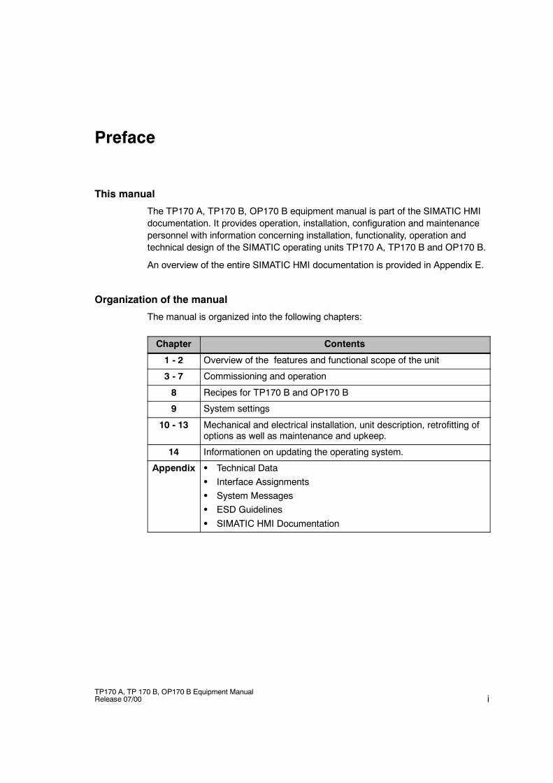
The TP170 A, TP170 B, OP170 B equipment manual is part of the SIMATIC HMIdocumentation. It provides operation, installation, configuration and maintenancepersonnel with information concerning installation, functionality, operation andtechnical design of the SIMATIC operating units TP170 A, TP170 B and OP170 B.
An overview of the entire SIMATIC HMI documentation is provided in Appendix E.
Organization of the manual
The manual is organized into the following chapters:
Chapter Contents
1 - 2 Overview of the features and functional scope of the unit
3 - 7 Commissioning and operation
8 Recipes for TP170 B and OP170 B
9 System settings
10 - 13 Mechanical and electrical installation, unit description, retrofitting ofoptions as well as maintenance and upkeep.
14 Informationen on updating the operating system.
Appendix S Technical DataS Interface AssignmentsS System MessagesS ESD GuidelinesS SIMATIC HMI Documentation
Preface
iiTP170 A, TP 170 B, OP170 B Equipment Manual
Release 07/00
Conventions
The following cionventions are used throughout this manual:
Motor off Text in the operating unit display is presented in thistypewriter font.
Tag Symbolic names representing tag values on the screen arepresented in this italic typewriter font.
Screens Functions available for selection are presented in this italicfont.
ESC The names of keys and buttons are displayed in a differentfont.
History
The various releases of this manual correspond to the following versions of theProTool CS configuration software:
Edition Comment ProTool Version
12/99 First release of the TP170 A equipmentmanual
From V5.2
07/00 Extensions to the TP170 B and OP170 Bunits
From V5.2 + SP2
Trademarks
The following names are registered trademarks of the Siemens AG:
S SIMATICR
S SIMATIC HMIR
S HMIR
S ProToolR
S ProTool/LiteR
S ProTool/ProR
S SIMATIC Multi PanelR
S SIMATIC Multifunctional PlatformR
S MP 270R
S ProAgentR
Preface
iiiTP170 A, TP 170 B, OP170 B Equipment ManualRelease 07/00
Other support
In the case of technical queries, please contact the Siemens representatives in thesubsidiaries and branches responsible for your area.
SIMATIC Customer Support Hotline
Available worldwide, at all times:
Johnson City
Nuernberg
Singapur
SIMATIC Basic Hotline
Nuernberg Johnson City Singapur
SIMATIC BASIC Hotline SIMATIC BASIC Hotline SIMATIC BASIC Hotline
Local time Mo - Fr 7:00 to 17:00 Local time Mo - Fr 8:00 to 19:00 Local time Mo - Fr 8:30 to 17:30
Telephone: +49 (911) 895-7000 Telephone: +1 423 461-2522 Telephone: +65 740-7000
Fax: +49 (911) 895-7002 Fax: +1 423 461-2231 Fax: +65 740-7001
E-Mail: [email protected]
E-Mail: [email protected]
E-Mail: [email protected]
SIMATIC Premium Hotline
(charged, only with SIMATIC Card)
Time: Mo - Fr 0:00 to 24:00
Telephone: +49 (911) 895-7777
Fax: +49 (911) 895-7001
Preface
ivTP170 A, TP 170 B, OP170 B Equipment Manual
Release 07/00
SIMATIC Customer Online Services
SIMATIC Customer Support offers comprehensive additional informationconcerning SIMATIC products through its Online services as follows:
S Up-to-date general information is provided-- in Internet under http://www.ad.siemens.de/simatic-- via the Fax-Polling under 08765-93 02 77 95 00
S Up-to-date product information and downloads for practical use can be found:-- in Internet under http://www.ad.siemens.de/support/html-00/
Abbreviations
The abbreviations used in this user’s guide have the following meaning:
AG (PLC) Programmable Logic Controller
AM Alarm Message
ANSI American National Standards Institute
AS 511 Protocol of the PU interface to SIMATIC S5
ASCII American Standard Code for Information Interchange
CCFL Cold Cathode Fluorescence Lamp
CF Compact Flash
CPU Central Processing Unit
CSV Comma Separated Values
DP Decentralized Periphery
DRAM Dynamic Random Access Memory
DSN Data Source Name
ESD Electrostatically Sensitive Device
EM Event Message
EMC Electromagnetic compatibility
HMI Human Machine Interface
IF Interface
LCD Liquid Crystal Display
LED Light Emitting Diode
MP Multi Panel
MPI Multipoint Interface (SIMATIC S7)
OP Operator Panel
PC Personal Computer
PCL Printer Control Language
PLC Programmable Logic Controller
Preface
vTP170 A, TP 170 B, OP170 B Equipment ManualRelease 07/00
PU Programming Unit
PPI Point to Point Interface (SIMATIC S7)
RAM Random Access Memory
SRAM Static Random Access Memory
STN Super Twisted Nematic
TCP/IP Transmission Control Protocol/Internet Protocol
TFT Thin Film Transistor
TTL Transistor--Transistor Logic
TP Touch Panel
A list of all the specialist terms together with their explanations is provided in theGlossary at the end of this guide.

Preface
viTP170 A, TP 170 B, OP170 B Equipment Manual
Release 07/00
viiTP170 A, TP 170 B, OP170 B Equipment ManualRelease 07/00
Contents
1 Introduction 1-1. . . . . . . . . . . . . . . . . . . . . . . . . . . . . . . . . . . . . . . . . . . . . . . . . . . . . . . . . . . .
2 Functionality 2-1. . . . . . . . . . . . . . . . . . . . . . . . . . . . . . . . . . . . . . . . . . . . . . . . . . . . . . . . . . .
3 Commissioning 3-1. . . . . . . . . . . . . . . . . . . . . . . . . . . . . . . . . . . . . . . . . . . . . . . . . . . . . . . .
3.1 Initial Startup 3-3. . . . . . . . . . . . . . . . . . . . . . . . . . . . . . . . . . . . . . . . . . . . . . . . . . .
3.2 Recommissioning 3-4. . . . . . . . . . . . . . . . . . . . . . . . . . . . . . . . . . . . . . . . . . . . . . .
3.3 Options for Download Mode 3-6. . . . . . . . . . . . . . . . . . . . . . . . . . . . . . . . . . . . . .
3.4 Testing a Project on the Operating Unit 3-10. . . . . . . . . . . . . . . . . . . . . . . . . . . . .
3.5 Download Back (TP170 B and OP170 B) 3-12. . . . . . . . . . . . . . . . . . . . . . . . . . .
3.6 Backup/Restore the Internal Flash Memory(TP170 B and OP170 B) 3-14. . . . . . . . . . . . . . . . . . . . . . . . . . . . . . . . . . . . . . . . .
4 Operating Touch Panels TP170 A and TP170 B 4-1. . . . . . . . . . . . . . . . . . . . . . . . . . .
4.1 Operating Touch Elements 4-1. . . . . . . . . . . . . . . . . . . . . . . . . . . . . . . . . . . . . . . .4.1.1 Enter Numeric Values 4-3. . . . . . . . . . . . . . . . . . . . . . . . . . . . . . . . . . . . . . . . . . . .4.1.2 Enter Alphanumeric Values 4-5. . . . . . . . . . . . . . . . . . . . . . . . . . . . . . . . . . . . . . .4.1.3 Enter Symbolic Values on the TP170 B 4-7. . . . . . . . . . . . . . . . . . . . . . . . . . . . .
4.2 Calling in Help Text on the TP170 B 4-8. . . . . . . . . . . . . . . . . . . . . . . . . . . . . . . .
5 Operating Keyboard Unit OP170 B 5-1. . . . . . . . . . . . . . . . . . . . . . . . . . . . . . . . . . . . . . .
5.1 Integrated Keyboard 5-1. . . . . . . . . . . . . . . . . . . . . . . . . . . . . . . . . . . . . . . . . . . . .
5.2 Key Combinations 5-5. . . . . . . . . . . . . . . . . . . . . . . . . . . . . . . . . . . . . . . . . . . . . . .
5.3 Entering Values 5-7. . . . . . . . . . . . . . . . . . . . . . . . . . . . . . . . . . . . . . . . . . . . . . . . .5.3.1 Enter Numeric Values 5-8. . . . . . . . . . . . . . . . . . . . . . . . . . . . . . . . . . . . . . . . . . . .5.3.2 Enter Alphanumeric Values 5-9. . . . . . . . . . . . . . . . . . . . . . . . . . . . . . . . . . . . . . .5.3.3 Enter Symbolic Values 5-10. . . . . . . . . . . . . . . . . . . . . . . . . . . . . . . . . . . . . . . . . . .
5.4 Call Help Text 5-11. . . . . . . . . . . . . . . . . . . . . . . . . . . . . . . . . . . . . . . . . . . . . . . . . . .
Contents
viiiTP170 A, TP 170 B, OP170 B Equipment Manual
Release 07/00
6 Screen Objects for TP170 A 6-1. . . . . . . . . . . . . . . . . . . . . . . . . . . . . . . . . . . . . . . . . . . . .
6.1 General Operation 6-2. . . . . . . . . . . . . . . . . . . . . . . . . . . . . . . . . . . . . . . . . . . . . . .6.1.1 Operating Screens 6-2. . . . . . . . . . . . . . . . . . . . . . . . . . . . . . . . . . . . . . . . . . . . . .6.1.2 Logging On and Off from the Operating Unit 6-3. . . . . . . . . . . . . . . . . . . . . . . .
6.2 Overview of Screen Objects 6-4. . . . . . . . . . . . . . . . . . . . . . . . . . . . . . . . . . . . . .
6.3 Input Field for Date/Time 6-5. . . . . . . . . . . . . . . . . . . . . . . . . . . . . . . . . . . . . . . . .
6.4 Input Field for Confidential Password Entry 6-5. . . . . . . . . . . . . . . . . . . . . . . . .
6.5 Status Button 6-6. . . . . . . . . . . . . . . . . . . . . . . . . . . . . . . . . . . . . . . . . . . . . . . . . . .
6.6 Messages 6-7. . . . . . . . . . . . . . . . . . . . . . . . . . . . . . . . . . . . . . . . . . . . . . . . . . . . . .
6.7 Bar graphs 6-9. . . . . . . . . . . . . . . . . . . . . . . . . . . . . . . . . . . . . . . . . . . . . . . . . . . . .
7 Screen Objects for TP170 B and OP170 B 7-1. . . . . . . . . . . . . . . . . . . . . . . . . . . . . . . .
7.1 General Operation 7-2. . . . . . . . . . . . . . . . . . . . . . . . . . . . . . . . . . . . . . . . . . . . . . .7.1.1 Operating screens 7-2. . . . . . . . . . . . . . . . . . . . . . . . . . . . . . . . . . . . . . . . . . . . . . .7.1.2 Logging On and Off from the Operating Unit 7-5. . . . . . . . . . . . . . . . . . . . . . . .
7.2 Overview of Screen Objects 7-6. . . . . . . . . . . . . . . . . . . . . . . . . . . . . . . . . . . . . .
7.3 Input Field for Date/Time 7-9. . . . . . . . . . . . . . . . . . . . . . . . . . . . . . . . . . . . . . . . .
7.4 Input Field for Confidential Password Entry 7-9. . . . . . . . . . . . . . . . . . . . . . . . .
7.5 Buttons 7-10. . . . . . . . . . . . . . . . . . . . . . . . . . . . . . . . . . . . . . . . . . . . . . . . . . . . . . . .
7.6 Status Button 7-11. . . . . . . . . . . . . . . . . . . . . . . . . . . . . . . . . . . . . . . . . . . . . . . . . . .
7.7 Switch 7-13. . . . . . . . . . . . . . . . . . . . . . . . . . . . . . . . . . . . . . . . . . . . . . . . . . . . . . . . .
7.8 Messages 7-14. . . . . . . . . . . . . . . . . . . . . . . . . . . . . . . . . . . . . . . . . . . . . . . . . . . . . .7.8.1 ALARM_S 7-16. . . . . . . . . . . . . . . . . . . . . . . . . . . . . . . . . . . . . . . . . . . . . . . . . . . . . .7.8.2 Message Line 7-17. . . . . . . . . . . . . . . . . . . . . . . . . . . . . . . . . . . . . . . . . . . . . . . . . . .7.8.3 Message Window 7-17. . . . . . . . . . . . . . . . . . . . . . . . . . . . . . . . . . . . . . . . . . . . . . .7.8.4 Message Page 7-19. . . . . . . . . . . . . . . . . . . . . . . . . . . . . . . . . . . . . . . . . . . . . . . . . .7.8.5 Message Buffer 7-20. . . . . . . . . . . . . . . . . . . . . . . . . . . . . . . . . . . . . . . . . . . . . . . . .7.8.6 Message View 7-21. . . . . . . . . . . . . . . . . . . . . . . . . . . . . . . . . . . . . . . . . . . . . . . . . .7.8.7 Simple Message View 7-23. . . . . . . . . . . . . . . . . . . . . . . . . . . . . . . . . . . . . . . . . . .
7.9 Bar Graphs 7-24. . . . . . . . . . . . . . . . . . . . . . . . . . . . . . . . . . . . . . . . . . . . . . . . . . . . .
7.10 Trend View 7-25. . . . . . . . . . . . . . . . . . . . . . . . . . . . . . . . . . . . . . . . . . . . . . . . . . . . .
7.11 Date/Time 7-27. . . . . . . . . . . . . . . . . . . . . . . . . . . . . . . . . . . . . . . . . . . . . . . . . . . . . .
7.12 Password List 7-28. . . . . . . . . . . . . . . . . . . . . . . . . . . . . . . . . . . . . . . . . . . . . . . . . .
8 Recipes for TP170 B and OP170 B 8-1. . . . . . . . . . . . . . . . . . . . . . . . . . . . . . . . . . . . . . .
8.1 Overview 8-1. . . . . . . . . . . . . . . . . . . . . . . . . . . . . . . . . . . . . . . . . . . . . . . . . . . . . . .
8.2 Recipe Configuration 8-3. . . . . . . . . . . . . . . . . . . . . . . . . . . . . . . . . . . . . . . . . . . .
8.3 Editing Data Records 8-5. . . . . . . . . . . . . . . . . . . . . . . . . . . . . . . . . . . . . . . . . . . .8.3.1 Recipe View 8-6. . . . . . . . . . . . . . . . . . . . . . . . . . . . . . . . . . . . . . . . . . . . . . . . . . . .8.3.2 Recipe Screens 8-14. . . . . . . . . . . . . . . . . . . . . . . . . . . . . . . . . . . . . . . . . . . . . . . . .8.3.3 Functions and PLC jobs 8-16. . . . . . . . . . . . . . . . . . . . . . . . . . . . . . . . . . . . . . . . . .8.3.4 Import/Export Data Records 8-17. . . . . . . . . . . . . . . . . . . . . . . . . . . . . . . . . . . . . .8.3.5 Reaction on Changing the Recipe Structure 8-20. . . . . . . . . . . . . . . . . . . . . . . .
Contents
ixTP170 A, TP 170 B, OP170 B Equipment ManualRelease 07/00
9 System Settings 9-1. . . . . . . . . . . . . . . . . . . . . . . . . . . . . . . . . . . . . . . . . . . . . . . . . . . . . . . .
9.1 TP170 A Settings 9-2. . . . . . . . . . . . . . . . . . . . . . . . . . . . . . . . . . . . . . . . . . . . . . .9.1.1 Setting an Operating Mode 9-2. . . . . . . . . . . . . . . . . . . . . . . . . . . . . . . . . . . . . . .9.1.2 Screen Settings 9-3. . . . . . . . . . . . . . . . . . . . . . . . . . . . . . . . . . . . . . . . . . . . . . . . .9.1.3 Set Screen Saver Response Time 9-5. . . . . . . . . . . . . . . . . . . . . . . . . . . . . . . . .
9.2 Settings for TP170 B and OP170 B 9-6. . . . . . . . . . . . . . . . . . . . . . . . . . . . . . . .9.2.1 Set Language 9-6. . . . . . . . . . . . . . . . . . . . . . . . . . . . . . . . . . . . . . . . . . . . . . . . . . .9.2.2 Setting an Operating Mode 9-7. . . . . . . . . . . . . . . . . . . . . . . . . . . . . . . . . . . . . . .9.2.3 Screen Settings 9-8. . . . . . . . . . . . . . . . . . . . . . . . . . . . . . . . . . . . . . . . . . . . . . . . .9.2.4 Control Panel Settings 9-10. . . . . . . . . . . . . . . . . . . . . . . . . . . . . . . . . . . . . . . . . . .
10 Installation 10-1. . . . . . . . . . . . . . . . . . . . . . . . . . . . . . . . . . . . . . . . . . . . . . . . . . . . . . . . . . . . .
10.1 Mechanical Installation 10-2. . . . . . . . . . . . . . . . . . . . . . . . . . . . . . . . . . . . . . . . . . .
10.2 Electrical Installation 10-5. . . . . . . . . . . . . . . . . . . . . . . . . . . . . . . . . . . . . . . . . . . . .10.2.1 Connect Configuration Computer 10-7. . . . . . . . . . . . . . . . . . . . . . . . . . . . . . . . . .10.2.2 Connect PLC 10-8. . . . . . . . . . . . . . . . . . . . . . . . . . . . . . . . . . . . . . . . . . . . . . . . . . .10.2.3 Connecting a Printer to TP170 B and OP170 B 10-11. . . . . . . . . . . . . . . . . . . . . .
11 Unit Description 11-1. . . . . . . . . . . . . . . . . . . . . . . . . . . . . . . . . . . . . . . . . . . . . . . . . . . . . . . .
11.1 TP170 A 11-2. . . . . . . . . . . . . . . . . . . . . . . . . . . . . . . . . . . . . . . . . . . . . . . . . . . . . . .11.1.1 Dimensions and mounting area 11-2. . . . . . . . . . . . . . . . . . . . . . . . . . . . . . . . . . . .11.1.2 Connection elements 11-3. . . . . . . . . . . . . . . . . . . . . . . . . . . . . . . . . . . . . . . . . . . .11.1.3 Communication options 11-4. . . . . . . . . . . . . . . . . . . . . . . . . . . . . . . . . . . . . . . . . .
11.2 TP170 B 11-5. . . . . . . . . . . . . . . . . . . . . . . . . . . . . . . . . . . . . . . . . . . . . . . . . . . . . . .11.2.1 Dimensions and mounting area 11-5. . . . . . . . . . . . . . . . . . . . . . . . . . . . . . . . . . . .11.2.2 Connection elements 11-6. . . . . . . . . . . . . . . . . . . . . . . . . . . . . . . . . . . . . . . . . . . .11.2.3 Communication options 11-7. . . . . . . . . . . . . . . . . . . . . . . . . . . . . . . . . . . . . . . . . .
11.3 OP170 B 11-8. . . . . . . . . . . . . . . . . . . . . . . . . . . . . . . . . . . . . . . . . . . . . . . . . . . . . . .11.3.1 Dimensions and Mounting Area 11-8. . . . . . . . . . . . . . . . . . . . . . . . . . . . . . . . . . .11.3.2 Connection Elements 11-9. . . . . . . . . . . . . . . . . . . . . . . . . . . . . . . . . . . . . . . . . . . .11.3.3 Communication Options 11-10. . . . . . . . . . . . . . . . . . . . . . . . . . . . . . . . . . . . . . . . . .11.3.4 Labeling Function Keys (OP170 B) 11-10. . . . . . . . . . . . . . . . . . . . . . . . . . . . . . . .
12 Memory card for TP170 B and OP170 B 12-1. . . . . . . . . . . . . . . . . . . . . . . . . . . . . . . . . .
13 Maintenance/Upkeep 13-1. . . . . . . . . . . . . . . . . . . . . . . . . . . . . . . . . . . . . . . . . . . . . . . . . . . .
Clean Screen/Keyboard 13-1. . . . . . . . . . . . . . . . . . . . . . . . . . . . . . . . . . . . . . . . . . . . . . . . . .
14 Operating System Update 14-1. . . . . . . . . . . . . . . . . . . . . . . . . . . . . . . . . . . . . . . . . . . . . . .
Appendices
A Technical Data A-1. . . . . . . . . . . . . . . . . . . . . . . . . . . . . . . . . . . . . . . . . . . . . . . . . . . . . . . . .
B Interface Assignment B-1. . . . . . . . . . . . . . . . . . . . . . . . . . . . . . . . . . . . . . . . . . . . . . . . . . .
C System Messages C-1. . . . . . . . . . . . . . . . . . . . . . . . . . . . . . . . . . . . . . . . . . . . . . . . . . . . . .
D ESD Guidelines D-1. . . . . . . . . . . . . . . . . . . . . . . . . . . . . . . . . . . . . . . . . . . . . . . . . . . . . . . .
E SIMATIC HMI Documentation E-1. . . . . . . . . . . . . . . . . . . . . . . . . . . . . . . . . . . . . . . . . . . .

Contents
xTP170 A, TP 170 B, OP170 B Equipment Manual
Release 07/00
1-1TP170 A, TP 170 B, OP170 B Equipment ManualRelease 07/00
Introduction
Low-end units
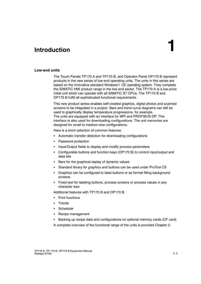
The Touch Panels TP170 A and TP170 B, and Operator Panel OP170 B representproducts in the new series of low-end operating units. The units in this series arebased on the innovative standard WindowsR CE operating system. They completethe SIMATIC HMI product range in the low-end sector. The TP170 A is a low-priceinitial unit which can operate with all SIMATIC S7 CPUs. The TP170 B andOP170 B fulfill all sophisticated functional requirements.
This new product series enables self-created graphics, digital photos and scannedscreens to be integrated in a project. Bars and trend curve diagrams can still beused to graphically display temperature progressions, for example.The units are equipped with an interface for MPI and PROFIBUS-DP. Thisinterface is also used for downloading configurations. The unit memories aredesigned for small to medium-size configurations.
Here is a short selection of common features:
S Automatic transfer detection for downloading configurations
S Password protection
S Input/Output fields to display and modify process parameters
S Configurable buttons and function keys (OP170 B) to control input/output anddata bits
S Bars for the graphical dsplay of dynamic values
S Standard library for graphics and buttons can be used under ProTool CS
S Graphics can be configured to label buttons or as format-filling backgroundscreens
S Fixed text for labeling buttons, process screens or process values in anycharacter size
Additional features with TP170 B and OP170 B:
S Print functions
S Trends
S Scheduler
S Recipe management
S Backing up recipe data and configurations on optional memory cards (CF card)
A complete overview of the functional range of the units is provided Chapter 2.
1
Introduction
1-2TP170 A, TP 170 B, OP170 B Equipment Manual
Release 07/00
Area of use of the units
The units have been conceived for easy machine operation and monitoring. Theyprovide a realistic graphical representation of the machine or system to bemonitored. Their area of use include implementation in machine and apparatusconstruction as well as in the packing and electronics industry.
The high degree of protection (IP65 on the front side) and non-implementation ofmoving storage media, such as hard disks and floppy disks, ensure the operatingunits are also suitable for use in rough industrial environments and directly on siteon the respective machine.
Installation locations for the units include:
S Panels
S Consoles
As a result of their minimum installation depth, the units are particularly suited foroperation near the machine.
Easy to operate and observe
The units enable operating statuses, current process values and errors concerninga connected PLC to be graphically displayed and the relevant machine or systemto be easily monitored and operated. Display and operation of the units can beadapted optimally for the respective process requirements by using theconfiguration software ProTool CS.
The units can be used to:
S control and monitor the process by means of the menu system. Setpoint valuesor control element settings, for instance, can be modified by entering values oractivating configured function keys;
S display processes, machines and systems on full-graphic, dynamic screens;
S display and edit messages and, for example, process tags in output fields, andto visualize bars or status display;
S to intervene directly in processes via the Touch Screen (TP170 A, TP170 B) orusing the integrated keyboard (OP170 B).
Introduction
1-3TP170 A, TP 170 B, OP170 B Equipment ManualRelease 07/00
Configuring using ProTool/Pro CS, ProTool and ProTool/Lite
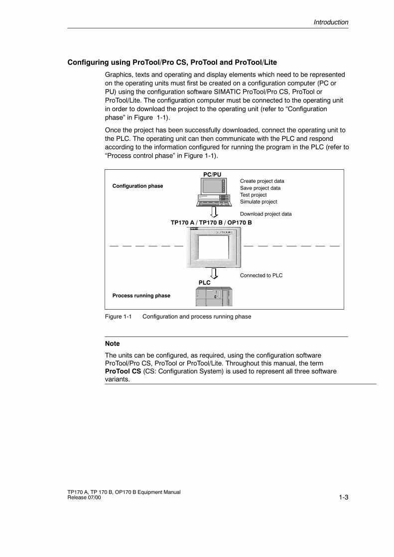
Graphics, texts and operating and display elements which need to be representedon the operating units must first be created on a configuration computer (PC orPU) using the configuration software SIMATIC ProTool/Pro CS, ProTool orProTool/Lite. The configuration computer must be connected to the operating unitin order to download the project to the operating unit (refer to “Configurationphase” in Figure 1-1).
Once the project has been successfully downloaded, connect the operating unit tothe PLC. The operating unit can then communicate with the PLC and respondaccording to the information configured for running the program in the PLC (refer to“Process control phase” in Figure 1-1).
Create project dataSave project dataTest projectSimulate project
Download project data
Connected to PLC
Configuration phase
Process running phase
PC/PU
PLC
TP170 A / TP170 B / OP170 B
Figure 1-1 Configuration and process running phase
Note
The units can be configured, as required, using the configuration softwareProTool/Pro CS, ProTool or ProTool/Lite. Throughout this manual, the termProTool CS (CS: Configuration System) is used to represent all three softwarevariants.
Introduction
1-4TP170 A, TP 170 B, OP170 B Equipment Manual
Release 07/00
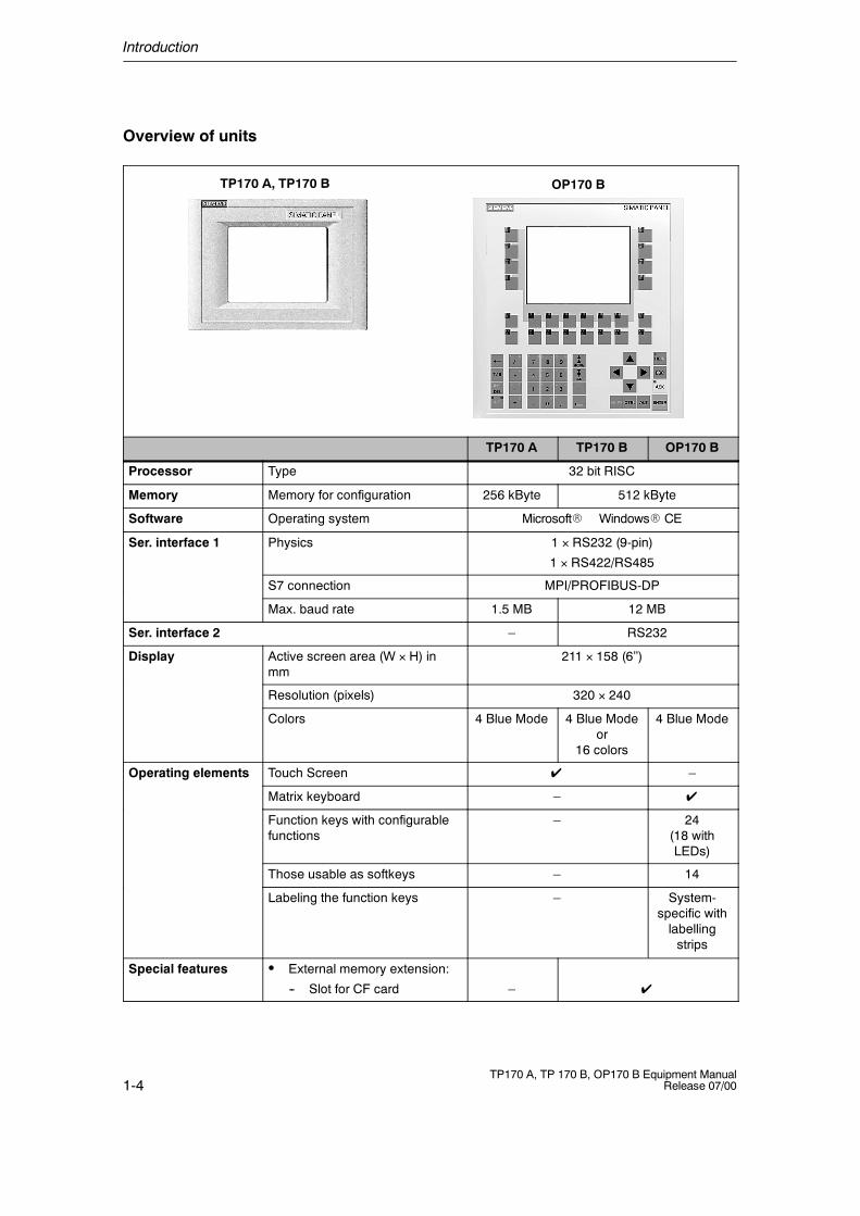
Overview of units
TP170 A, TP170 B OP170 B
TP170 A TP170 B OP170 B
Processor Type 32 bit RISC
Memory Memory for configuration 256 kByte 512 kByte
Software Operating system MicrosoftR WindowsR CE
Ser. interface 1 Physics 1 � RS232 (9-pin)
1 � RS422/RS485
S7 connection MPI/PROFIBUS-DP
Max. baud rate 1.5 MB 12 MB
Ser. interface 2 – RS232
Display Active screen area (W � H) inmm
211 � 158 (6’’)
Resolution (pixels) 320 � 240
Colors 4 Blue Mode 4 Blue Modeor
16 colors
4 Blue Mode
Operating elements Touch Screen ✔ –
Matrix keyboard – ✔
Function keys with configurablefunctions
– 24(18 withLEDs)
Those usable as softkeys – 14
Labeling the function keys – System-specific withlabellingstrips
Special features S External memory extension:
-- Slot for CF card – ✔
Introduction
1-5TP170 A, TP 170 B, OP170 B Equipment ManualRelease 07/00
Further information
Detailed information on the technical data of the operating units is provided inAppendix A of this manual.
Detailed descriptions of the creation of projects for the operating unit andconfiguration software functions are provided in the ProTool ConfiguringWindows-based Systems user’s guide and in the online help for ProTool CS.
Connection of the operating unit to the PLC is described in the Communication forWindows-based Systems user’s manual.
Any new information which could not be taken into account for printing in theguides is provided in the Readme.wri file on the ProTool CD.

Introduction
1-6TP170 A, TP 170 B, OP170 B Equipment Manual
Release 07/00
2-1TP170 A, TP 170 B, OP170 B Equipment ManualRelease 07/00
Functionality
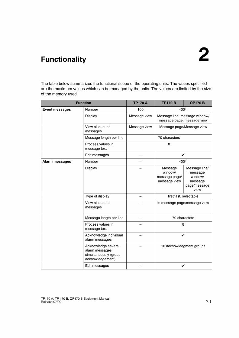
The table below summarizes the functional scope of the operating units. The values specifiedare the maximum values which can be managed by the units. The values are limited by the sizeof the memory used.
Function TP170 A TP170 B OP170 B
Event messages Number 100 4001)
Display Message view Message line, message window/message page, message view
View all queuedmessages
Message view Message page/Message view
Message length per line 70 characters
Process values inmessage text
8
Edit messages – ✔
Alarm messages Number – 4001)
Display – Messagewindow/
message page/message view
Message line/messagewindow/message
page/messageview
Type of display – first/last, selectable
View all queuedmessages
– In message page/message view
Message length per line – 70 characters
Process values inmessage text
– 8
Acknowledge individualalarm messages
– ✔
Acknowledge severalalarm messagessimultaneously (groupacknowledgement)
– 16 acknowledgment groups
Edit messages – ✔
2
Functionality
2-2TP170 A, TP 170 B, OP170 B Equipment Manual
Release 07/00
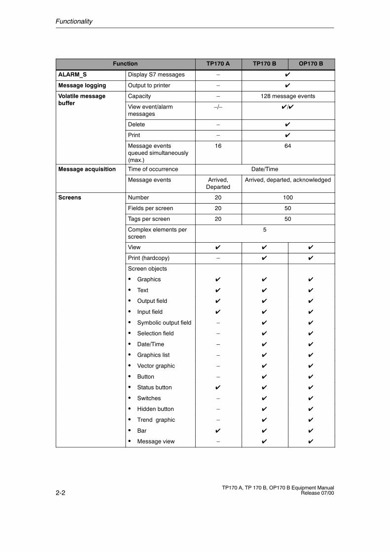
Function TP170 A TP170 B OP170 B
ALARM_S Display S7 messages – ✔
Message logging Output to printer – ✔
Volatile messageb ff
Capacity – 128 message eventsbuffer
View event/alarmmessages
–/– ✔/✔
Delete – ✔
Print – ✔
Message eventsqueued simultaneously(max.)
16 64
Message acquisition Time of occurrence Date/Time
Message events Arrived,Departed
Arrived, departed, acknowledged
Screens Number 20 100
Fields per screen 20 50
Tags per screen 20 50
Complex elements perscreen
5
View ✔ ✔ ✔
Print (hardcopy) – ✔ ✔
Screen objects
S Graphics ✔ ✔ ✔
S Text ✔ ✔ ✔
S Output field ✔ ✔ ✔
S Input field ✔ ✔ ✔
S Symbolic output field – ✔ ✔
S Selection field – ✔ ✔
S Date/Time – ✔ ✔
S Graphics list – ✔ ✔
S Vector graphic – ✔ ✔
S Button – ✔ ✔
S Status button ✔ ✔ ✔
S Switches – ✔ ✔
S Hidden button – ✔ ✔
S Trend graphic – ✔ ✔
S Bar ✔ ✔ ✔
S Message view – ✔ ✔
Functionality
2-3TP170 A, TP 170 B, OP170 B Equipment ManualRelease 07/00
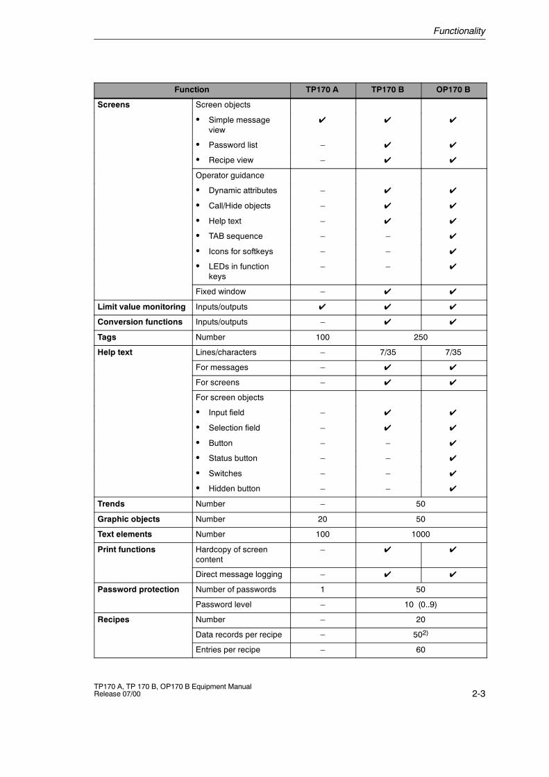
OP170 BTP170 BTP170 AFunction
Screens Screen objects
S Simple messageview
✔ ✔ ✔
S Password list – ✔ ✔
S Recipe view – ✔ ✔
Operator guidance
S Dynamic attributes – ✔ ✔
S Call/Hide objects – ✔ ✔
S Help text – ✔ ✔
S TAB sequence – – ✔
S Icons for softkeys – – ✔
S LEDs in functionkeys
– – ✔
Fixed window – ✔ ✔
Limit value monitoring Inputs/outputs ✔ ✔ ✔
Conversion functions Inputs/outputs – ✔ ✔
Tags Number 100 250
Help text Lines/characters – 7/35 7/35
For messages – ✔ ✔
For screens – ✔ ✔
For screen objects
S Input field – ✔ ✔
S Selection field – ✔ ✔
S Button – – ✔
S Status button – – ✔
S Switches – – ✔
S Hidden button – – ✔
Trends Number – 50
Graphic objects Number 20 50
Text elements Number 100 1000
Print functions Hardcopy of screencontent
– ✔ ✔
Direct message logging – ✔ ✔
Password protection Number of passwords 1 50
Password level – 10 (0..9)
Recipes Number – 20
Data records per recipe – 502)
Entries per recipe – 60
Functionality
2-4TP170 A, TP 170 B, OP170 B Equipment Manual
Release 07/00
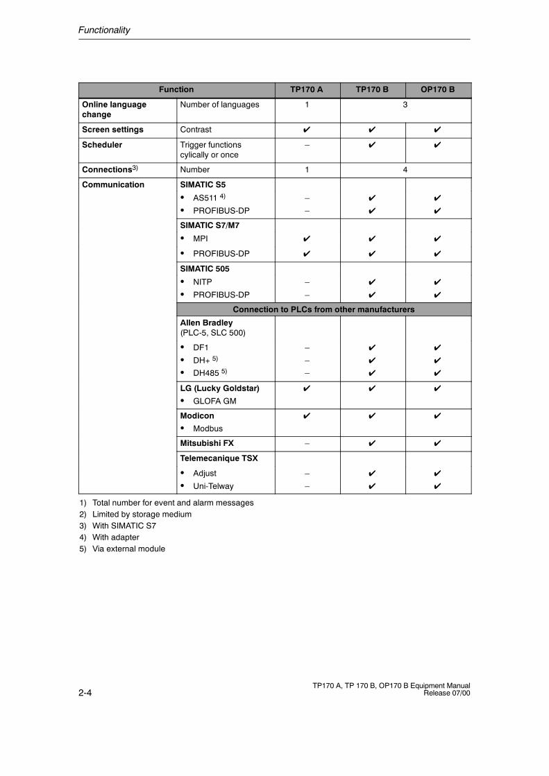
OP170 BTP170 BTP170 AFunction
Online languagechange
Number of languages 1 3
Screen settings Contrast ✔ ✔ ✔
Scheduler Trigger functionscylically or once
– ✔ ✔
Connections3) Number 1 4
Communication SIMATIC S5
S AS511 4)
S PROFIBUS-DP
–
–
✔
✔
✔
✔
SIMATIC S7/M7
S MPI ✔ ✔ ✔
S PROFIBUS-DP ✔ ✔ ✔
SIMATIC 505
S NITP
S PROFIBUS-DP
–
–
✔
✔
✔
✔
Connection to PLCs from other manufacturers
Allen Bradley(PLC-5, SLC 500)
S DF1
S DH+ 5)
S DH485 5)
–
–
–
✔
✔
✔
✔
✔
✔
LG (Lucky Goldstar)
S GLOFA GM
✔ ✔ ✔
Modicon
S Modbus
✔ ✔ ✔
Mitsubishi FX – ✔ ✔
Telemecanique TSX
S Adjust
S Uni-Telway
–
–
✔
✔
✔
✔
1) Total number for event and alarm messages2) Limited by storage medium3) With SIMATIC S74) With adapter5) Via external module
3-1TP170 A, TP 170 B, OP170 B Equipment ManualRelease 07/00
Commissioning
In this chapter
This chapter provides information on:
S starting up the operating unit for the first time (Page 3-3)S restarting the operating unit (Page 3-4)S options for download mode (Page 3-6)S testing the project on the operating unit (Page 3-10)S downloading the project back from the TP170 B and OP170 B (Page 3-12)S backup/restore the internal Flash memory using the TP170 B and
OP170 B (Page 3-14)
Operating the operating units in the start-up phase
TP170 A:Select the required object in the Start menu (Figure 3-1) and Configuration menu(Figure 3-4) by touching the relevant button.
TP170 B:Select the required object in the Start menu (Figure 3-2) and Configuration menu(Figure 3-5) by touching the relevant button.
OP170 B:Proceed as follows to operate the Start menu (Figure 3-3) and Configuration menu(Figure 3-5)::
Step Procedure
1 Select the object to be operated (button, check box or input field) usingthe Tabulator key.
The object currently selected is marked by a border or a different color.
2 S Buttons/Check boxes:Press the Enter key in order to trigger the marked button oractivate/deactivate the marked check box.
3

Commissioning
3-2TP170 A, TP 170 B, OP170 B Equipment Manual
Release 07/00
Further information on operating the units is provided in the following chapters:
S General Operation:TP170 A, TP170 B: Chapter 4OP170 B: Chapter5
S Operating Special Screen Objects:TP170 A: Chapter 6TP170 B, OP170 B: Chapter7
Commissioning
3-3TP170 A, TP 170 B, OP170 B Equipment ManualRelease 07/00
3.1 Initial Startup
Procedure
When the operating unit is started up for the first time, no project has been loadedon it. In order to download the necessary project data and the runtime softwarefrom the configuration computer to the operating unit, proceed as follows,observing the sequence:
Step Procedure
1 Depending on the settings in the Configuration menu (Figure 3-4 or 3-5), connectthe interface IF1A or IF2 (serial)1) or IF1B (MPI) of the operating unit to theconfiguration computer using an appropriate standard cable.
2 Switch on the power supply for the operating unit.
Since no project has been loaded on the operating unit up to this point, itautomatically switches to Download mode. The operating unit displays themessage Connecting to host until it receives data from the configurationcomputer or the button Cancel is pressed.If the message Connecting to host does not appear, it is probable that theoptions for download mode have been incorrectly set (refer to the note onPage 3-8).
3 If data should be downloaded via an MPI connection, set the followingparameters on the configuration computer:
S OP address: 1
S Transmission rate: 187.5 kBaud
Start downloading the project on the configuration computer. Further settingsnecessary on the configuration computer for the download operation areprovided in the ProTool Configuring Windows-based Systems user’s guide.
The configuration computer checks the connection to the operating unit. If theconnection is not available or defective, the corresponding error messageappears.
If downloading from the configuration computer is terminated as a result of acompatibility conflict, please continue as described in Chapter 14.
If the connection is correct, the project data is downloaded to the operating unit.Following successful downloading, the operating unit restarts and displays thestart screen of the project that has just been loaded.
1) TP170 A: IF1ATP170 B, OP170 B: IF2
Commissioning
3-4TP170 A, TP 170 B, OP170 B Equipment Manual
Release 07/00
3.2 Recommissioning
Purpose
During recommissioning, a project already loaded on the operating unit is replacedby another. In this case, the project data is downloaded from the configurationcomputer to the operating unit.
The following options are available to switch the operating unit to Download mode:
S Start downloading manually during the operating unit start-up phase.
S Start downloading automatically while the operating unit is in operation.
S Start downloading via a correspondingly configured operating element while theoperating unit is in operation (refer to Page 9-7).
Start downloading manually during the operating unit start-up phase
Step Procedure
1 Connect interface IF1A or IF2 (serial)1), or IF1B (MPI), on the operating unit tothe configuration computer using an appropriate standard cable.
2 Switch on the power supply for the operating unit.
3 If necessary, check the interface settings in the Configuration menu (Figure 3-4or 3-5) and adapt them as required.
4 During the operating unit start-up phase, the menu illustrated in Figure 3-1, 3-2or 3-3 appears briefly. Press the Download button to set the operating unit toDownload mode before the start-up routine is completed.The operating unit continues to display the message Connecting to hostuntil it receives data from the configuration computer or the Cancel button ispressed.If the message Connecting to host does not appear, it is probable that theoptions for download mode have been incorrectly set (refer to the note onPage 3-8).
5 If downloading should be performed via an MPI connection, set the OP addressand transmission rate valid for the operating unit on the configuration computer(refer to the note on Page 3-5).
Start downloading the project on the configuration computer.
The configuration computer checks the connection to the operating unit. If theconnection is not available or defective, the configuration computer issues thecorresponding error message.
If downloading from the configuration computer is terminated as a result of acompatibility conflict, please continue as described in Chapter 14.
If the connection is correct, the new project is downloaded to the operating unit.Following successful downloading, the operating unit restarts and displays thestart screen of the projects that has just been loaded.
1) TP170 A: IF1ATP170 B, OP170 B: IF2
Commissioning
3-5TP170 A, TP 170 B, OP170 B Equipment ManualRelease 07/00
Start downloading automatically when the operating unit is in operation
The operating unit can be switched automatically to Download mode from normaloperation as soon as downloading is started on the connected configurationcomputer. This option is especially recommended for the test phase of a newproject because the transfer is performed without intervention on the operatingunit. A condition for this is that the following settings have been defined in theConfiguration (TP170 A: Figures 3-4, TP170 B and OP170 B: Figure 3-5):
MPI connection:
S Option MPI Transfer Enable is activatedS Option MPI Transfer Remote Control is activated
Serial connection:
S Option Serial Transfer Enable is activatedS Option Serial Transfer Remote Control is activated
A detailed description of the settings possible in the Configuration menu isprovided on Page 3-8.
Note on MPI transfer
The bus parameters (e.g. MPI address, baud rate etc.) are read out of the projectcurrently loaded on the operating unit.
Only use these parameters when downloading a new project, even if differentparameters are configured for the new project because the new parameters onlytake effect after downloading has been completed successfully.

Commissioning
3-6TP170 A, TP 170 B, OP170 B Equipment Manual
Release 07/00
3.3 Options for Download Mode
Overview
The following options can be set for download mode:
S Automatic switching to download mode from normal operation when datatransfer is initiated from the connected configuration computer
S Download mode can be restricted to a specific connection type so thatdownloading can only occur either via a serial connection or an MPI connection
Call in Configuration menu
The options for Download mode can only be set when the operating unit is in itsstart-up phase. During the start-up phase, the Start menu appears briefly(TP170 A: Figure 3-1, TP170 B: Figure 3-2, OP170 B: Figure 3-3). Press theConfig button to call in the Configuration menu (TP170 A: Figures 3-4, TP170 Band OP170 B: Figure 3-5).
Figure 3-1 TP170 A Start menu
Figure 3-2 TP170 B Start menu
Commissioning
3-7TP170 A, TP 170 B, OP170 B Equipment ManualRelease 07/00
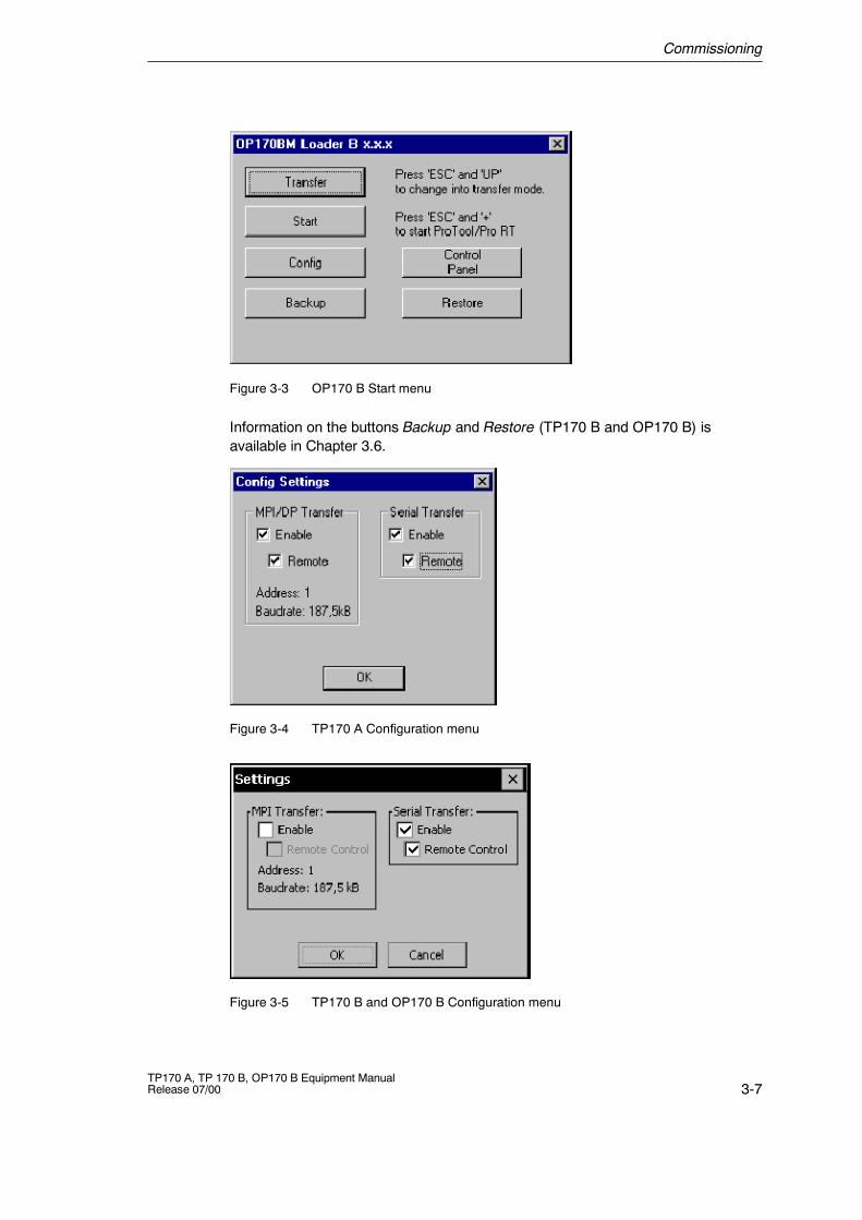
Figure 3-3 OP170 B Start menu
Information on the buttons Backup and Restore (TP170 B and OP170 B) isavailable in Chapter 3.6.
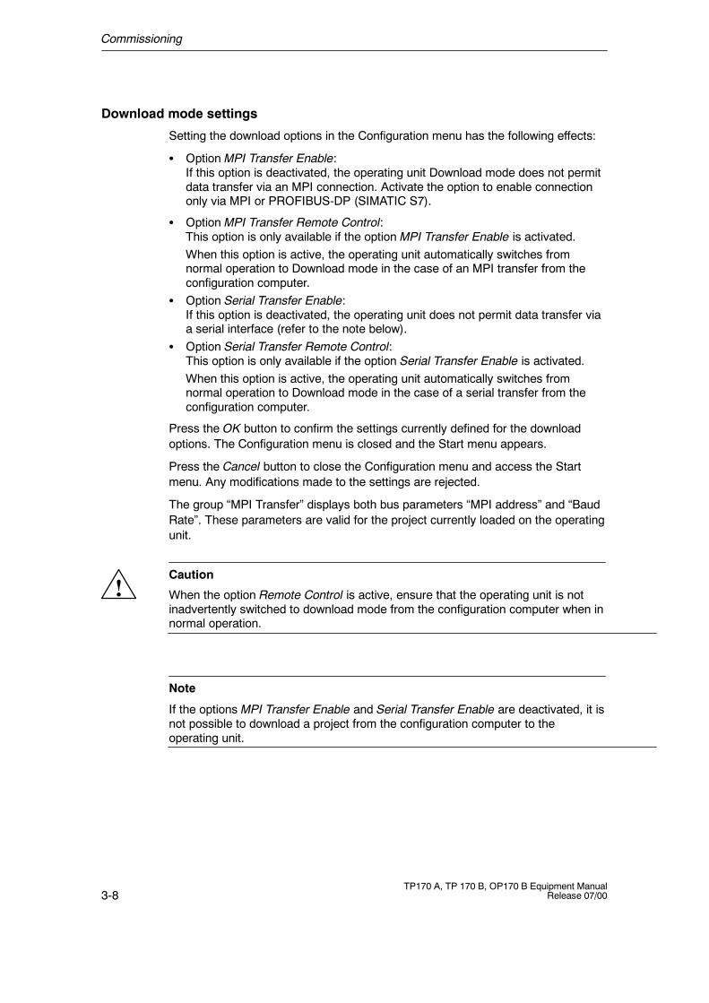
Figure 3-4 TP170 A Configuration menu
Figure 3-5 TP170 B and OP170 B Configuration menu
Commissioning
3-8TP170 A, TP 170 B, OP170 B Equipment Manual
Release 07/00
Download mode settings
Setting the download options in the Configuration menu has the following effects:
S Option MPI Transfer Enable:If this option is deactivated, the operating unit Download mode does not permitdata transfer via an MPI connection. Activate the option to enable connectiononly via MPI or PROFIBUS-DP (SIMATIC S7).
S Option MPI Transfer Remote Control:This option is only available if the option MPI Transfer Enable is activated.When this option is active, the operating unit automatically switches fromnormal operation to Download mode in the case of an MPI transfer from theconfiguration computer.
S Option Serial Transfer Enable:If this option is deactivated, the operating unit does not permit data transfer viaa serial interface (refer to the note below).
S Option Serial Transfer Remote Control:This option is only available if the option Serial Transfer Enable is activated.When this option is active, the operating unit automatically switches fromnormal operation to Download mode in the case of a serial transfer from theconfiguration computer.
Press the OK button to confirm the settings currently defined for the downloadoptions. The Configuration menu is closed and the Start menu appears.
Press the Cancel button to close the Configuration menu and access the Startmenu. Any modifications made to the settings are rejected.
The group “MPI Transfer” displays both bus parameters “MPI address” and “BaudRate”. These parameters are valid for the project currently loaded on the operatingunit.
!Caution
When the option Remote Control is active, ensure that the operating unit is notinadvertently switched to download mode from the configuration computer when innormal operation.
Note
If the options MPI Transfer Enable and Serial Transfer Enable are deactivated, it isnot possible to download a project from the configuration computer to theoperating unit.

Commissioning
3-9TP170 A, TP 170 B, OP170 B Equipment ManualRelease 07/00
Exit Start menu
If the operating unit still has no project, it automatically switches to download modeafter approx. 10 seconds after having been switched on. Press the Downloadbutton to switch the operating unit to Download mode manually.
If the operating unit contains a project, it is started automatically approx.10 seconds after being switched on. The project can be started manually bypressing the Start button.
Commissioning
3-10TP170 A, TP 170 B, OP170 B Equipment Manual
Release 07/00
3.4 Testing a Project on the Operating Unit
Conditions
In order to switch the operating unit between the operating modes OFFLINE andONLINE, the function Change_mode must be linked to an operating element in theproject.
Testing on the configuration computer
The material supplied with ProTool contains a simulation program which can beused to test the project on the configuration computer without the necessity ofconnecting a PLC or operating unit. Detailed information on this is provided in theProTool Configuring Windows-based Systems and in the online help toProTool CS.
Testing without a PLC connected (OFFLINE mode)
After setting the operating unit to operating mode OFFLINE, the individual projectfunctions can be tested without them being affected by the PLC. PLC tags are notupdated in OFFLINE mode.
Step Procedure
1 Switch the operating unit to operating mode OFFLINE (refer to Page 9-7).
2 Check all the configured screens in respect of correct representation.
3 Check the screen hierarchy.
4 Check the input fields.
5 Test the function keys.
If faults occur when executing the individual steps, download the project again.
Commissioning
3-11TP170 A, TP 170 B, OP170 B Equipment ManualRelease 07/00
Testing with a PLC connected (ONLINE mode)
When a PLC is connected, it is possible to test the communication between theoperating unit and PLC in ONLINE mode. This includes checking that the correctdata areas have been configured.
Step Procedure
1 Connect the operating unit to the PLC.
2 Test all the items in the project for which communication with the PLC isnecessary e.g.:
S messages,
S print functions
S automatic message logging
S selecting screens, etc.
Commissioning
3-12TP170 A, TP 170 B, OP170 B Equipment Manual
Release 07/00
3.5 Download Back (TP170 B and OP170 B)
Purpose
During downloading, generally only the run-capable project (*.fwd) which has beengenerated is downloaded on the operating unit. If the original project file is to beused for further development of the project or for fault analysis, it must remain onthe configuration computer.
Not only the generated project can be stored on the TP170 B and OP170 B units,but also the project source file (*.pdb), so that it can be retrieved (downloadedback) from the operating unit later, if necessary.
Advantage
After downloading a project back, it can be analyzed and modified even if theoriginal configuration computer cannot be accessed or the source file (*.pdb) on itfor the project is no longer available.
Conditions
The following conditions must be fulfilled in order to retrieve the source file from therun-capable project file:
S The operating unit must be equipped with a memory card.
S Downloading of the current project file from the configuration computer to theoperating unit must be performed using the option Download Back Enabled.
What happens during download/download back?
In the case of downloading including transfer of the source file, the project iscompressed from the source format (*.pdb) and downloaded to the operating unitas a *.pdz file. After downloading back, the file is decompressed in the ProTool CSconfiguration software.
The project must be given a new name on the configuration computer.
NoteS The downloaded back, decompressed project file (*.pdb) can only be opened
with a ProTool CS whose version number is greater or equal to that of theconfiguration software with which the project was created.
S ProTool CS cannot check whether the source file on the operating unit matchesthe project actually run on it. If downloading is performed at any time withoutthe option “Download Back” being activated, it is possible that old project datais on the operating unit which no longer matches the current project.
Commissioning
3-13TP170 A, TP 170 B, OP170 B Equipment ManualRelease 07/00
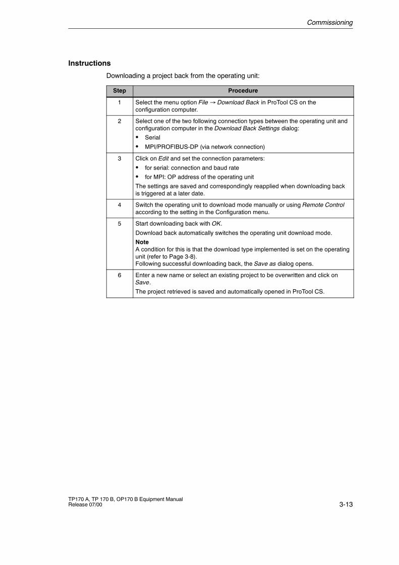
Instructions
Downloading a project back from the operating unit:
Step Procedure
1 Select the menu option File � Download Back in ProTool CS on theconfiguration computer.
2 Select one of the two following connection types between the operating unit andconfiguration computer in the Download Back Settings dialog:
S Serial
S MPI/PROFIBUS-DP (via network connection)
3 Click on Edit and set the connection parameters:
S for serial: connection and baud rate
S for MPI: OP address of the operating unit
The settings are saved and correspondingly reapplied when downloading backis triggered at a later date.
4 Switch the operating unit to download mode manually or using Remote Controlaccording to the setting in the Configuration menu.
5 Start downloading back with OK.
Download back automatically switches the operating unit download mode.
NoteA condition for this is that the download type implemented is set on the operatingunit (refer to Page 3-8).Following successful downloading back, the Save as dialog opens.
6 Enter a new name or select an existing project to be overwritten and click onSave.
The project retrieved is saved and automatically opened in ProTool CS.
Commissioning
3-14TP170 A, TP 170 B, OP170 B Equipment Manual
Release 07/00
3.6 Backup/Restore the Internal Flash Memory(TP170 B and OP170 B)
Purpose
The functions Backup and Restore provide the following options:
S Creating a backup copy of the entire project on memory card,
S Recovering a stored project in the case of a fault,
S Updating a project regardless of where the operating unit is in use, without aconfiguration computer.
Conditions
The two functions, Backup and Restore, are only available in the Start menu(TP170 B: Figure 3-2, OP170 B: Figure 3-3) during the operating unit’s start-upphase. In order to access the Start menu, either the Exit_runtime function must becalled in or the unit restarted.
Insert the memory card in the expansion slot before starting the Backup/Restoreprocess.
Notes on memory cards are provided in Chapter 12.
Backup
During a backup, the entire content of the internal Flash memory is copied onto anexternal storage medium. Both system data and configuration data are copied.This data is stored under Storage Card/pdz.
Commissioning
3-15TP170 A, TP 170 B, OP170 B Equipment ManualRelease 07/00
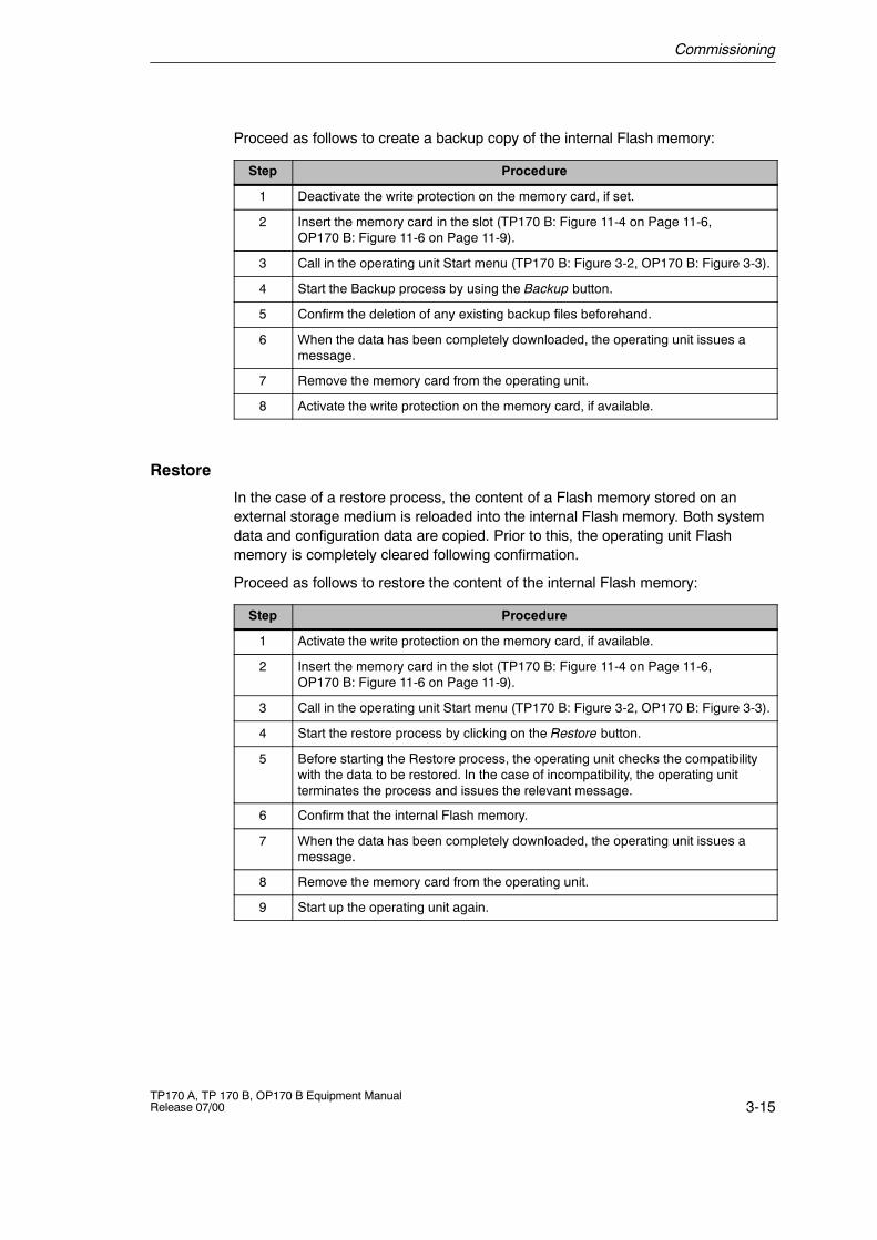
Proceed as follows to create a backup copy of the internal Flash memory:
Step Procedure
1 Deactivate the write protection on the memory card, if set.
2 Insert the memory card in the slot (TP170 B: Figure 11-4 on Page 11-6,OP170 B: Figure 11-6 on Page 11-9).
3 Call in the operating unit Start menu (TP170 B: Figure 3-2, OP170 B: Figure 3-3).
4 Start the Backup process by using the Backup button.
5 Confirm the deletion of any existing backup files beforehand.
6 When the data has been completely downloaded, the operating unit issues amessage.
7 Remove the memory card from the operating unit.
8 Activate the write protection on the memory card, if available.
Restore
In the case of a restore process, the content of a Flash memory stored on anexternal storage medium is reloaded into the internal Flash memory. Both systemdata and configuration data are copied. Prior to this, the operating unit Flashmemory is completely cleared following confirmation.
Proceed as follows to restore the content of the internal Flash memory:
Step Procedure
1 Activate the write protection on the memory card, if available.
2 Insert the memory card in the slot (TP170 B: Figure 11-4 on Page 11-6,OP170 B: Figure 11-6 on Page 11-9).
3 Call in the operating unit Start menu (TP170 B: Figure 3-2, OP170 B: Figure 3-3).
4 Start the restore process by clicking on the Restore button.
5 Before starting the Restore process, the operating unit checks the compatibilitywith the data to be restored. In the case of incompatibility, the operating unitterminates the process and issues the relevant message.
6 Confirm that the internal Flash memory.
7 When the data has been completely downloaded, the operating unit issues amessage.
8 Remove the memory card from the operating unit.
9 Start up the operating unit again.

Commissioning
3-16TP170 A, TP 170 B, OP170 B Equipment Manual
Release 07/00
4-1TP170 A, TP 170 B, OP170 B Equipment ManualRelease 07/00
Operating Touch Panels TP170 A andTP170 B
Operating concept
The screen is used to observe the operating status of the machine or system beingmonitored and, at the same time, to intervene directly in the process runningsimply by touching the buttons and input fields displayed.
4.1 Operating Touch Elements
Definition
Touch elements are contact-sensitive operating elements provided on the touchpanel screen, such as buttons, input fields and message windows. Their operationis basically no different from pressing conventional keys. Touch elements areoperated by touching them lightly with your finger or a suitable object.
Note
Never use pointed or sharp instruments to operate the Touch Panel to preventdamage to the plastic surface of the touch screen.
!Caution
Be sure to touch only one point on the touch panel screen element. Never touchmore than one touch element at a time. Otherwise, an action may beunintentionally initiated.
4
Operating Touch Panels TP170 A and TP170 B
4-2TP170 A, TP 170 B, OP170 B Equipment Manual
Release 07/00
Operation acknowledgement
As soon as the touch panel detects valid contact with a touch element, it respondsby displaying a visual acknowledgement. An acknowledgment is independent ofcommunication with the PLC. It is not an indication of the required action actuallyhaving been executed.
The type of visual acknowledgement is dependent on the operating elementtouched:
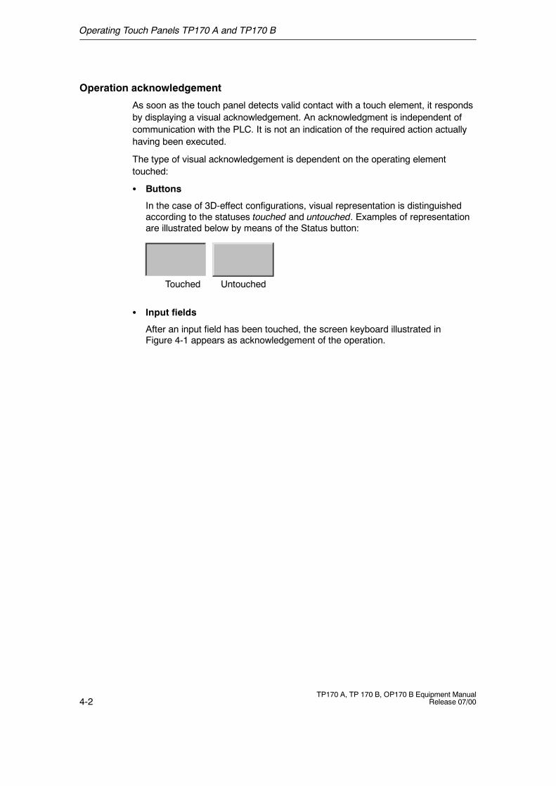
S Buttons
In the case of 3D-effect configurations, visual representation is distinguishedaccording to the statuses touched and untouched. Examples of representationare illustrated below by means of the Status button:
UntouchedTouched
S Input fields
After an input field has been touched, the screen keyboard illustrated inFigure 4-1 appears as acknowledgement of the operation.
Operating Touch Panels TP170 A and TP170 B
4-3TP170 A, TP 170 B, OP170 B Equipment ManualRelease 07/00
4.1.1 Enter Numeric Values
Principles of operation
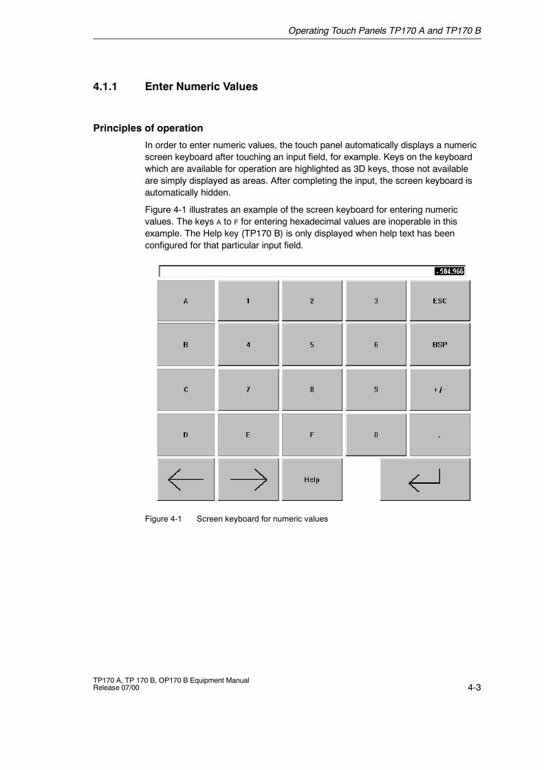
In order to enter numeric values, the touch panel automatically displays a numericscreen keyboard after touching an input field, for example. Keys on the keyboardwhich are available for operation are highlighted as 3D keys, those not availableare simply displayed as areas. After completing the input, the screen keyboard isautomatically hidden.
Figure 4-1 illustrates an example of the screen keyboard for entering numericvalues. The keys A to F for entering hexadecimal values are inoperable in thisexample. The Help key (TP170 B) is only displayed when help text has beenconfigured for that particular input field.
Figure 4-1 Screen keyboard for numeric values
Operating Touch Panels TP170 A and TP170 B
4-4TP170 A, TP 170 B, OP170 B Equipment Manual
Release 07/00
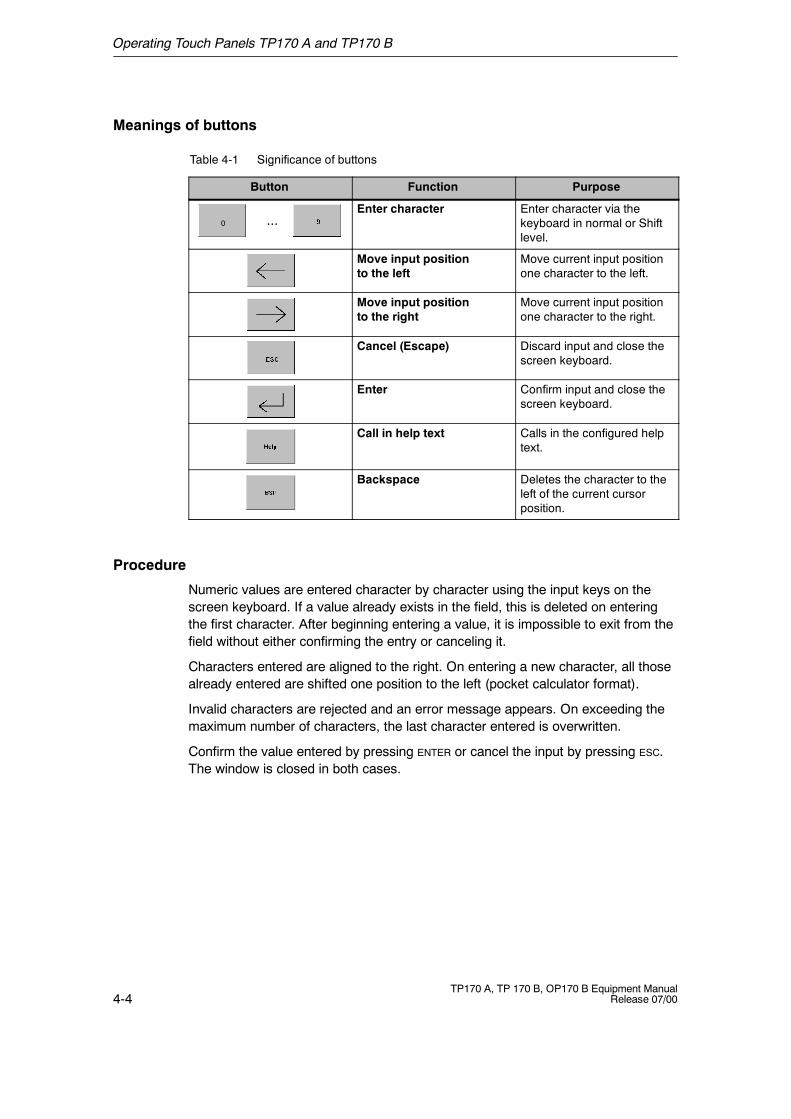
Meanings of buttons
Table 4-1 Significance of buttons
Button Function Purpose
...0
Enter character Enter character via thekeyboard in normal or Shiftlevel.
Move input positionto the left
Move current input positionone character to the left.
Move input positionto the right
Move current input positionone character to the right.
Cancel (Escape) Discard input and close thescreen keyboard.
Enter Confirm input and close thescreen keyboard.
Call in help text Calls in the configured helptext.
Backspace Deletes the character to theleft of the current cursorposition.
Procedure
Numeric values are entered character by character using the input keys on thescreen keyboard. If a value already exists in the field, this is deleted on enteringthe first character. After beginning entering a value, it is impossible to exit from thefield without either confirming the entry or canceling it.
Characters entered are aligned to the right. On entering a new character, all thosealready entered are shifted one position to the left (pocket calculator format).
Invalid characters are rejected and an error message appears. On exceeding themaximum number of characters, the last character entered is overwritten.
Confirm the value entered by pressing ENTER or cancel the input by pressing ESC.The window is closed in both cases.
Operating Touch Panels TP170 A and TP170 B
4-5TP170 A, TP 170 B, OP170 B Equipment ManualRelease 07/00
Limit value test
Limit values can be configured for numeric input fields. In this case, valuesentered are only accepted when they lie within the limits configured. If an attemptis made to enter a value which is outside the configured limits, it is rejected and theoriginal value automatically reinserted.
4.1.2 Enter Alphanumeric Values
Principles of operation
In order to enter alphanumeric values, the touch panel automatically displays analphanumeric screen keyboard after touching an input field. Keys on the keyboardwhich are available for operation are highlighted as 3D keys, those not availableare simply displayed as areas. After completing the input, the screen keyboard isautomatically hidden.
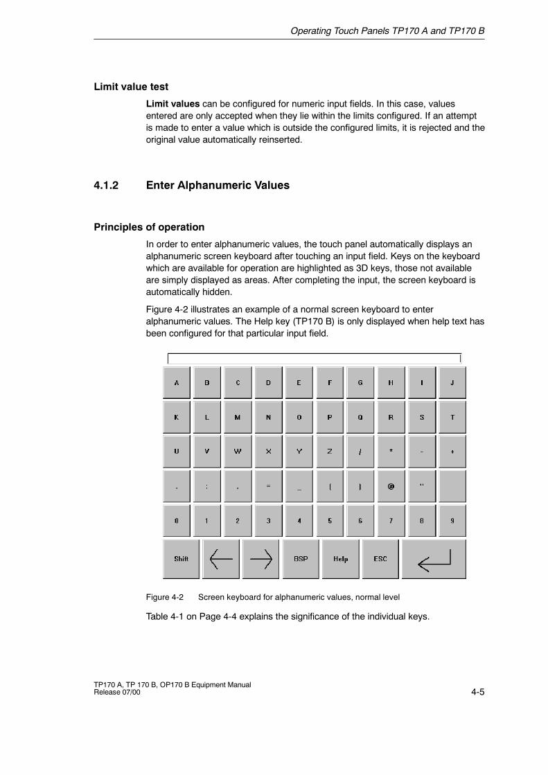
Figure 4-2 illustrates an example of a normal screen keyboard to enteralphanumeric values. The Help key (TP170 B) is only displayed when help text hasbeen configured for that particular input field.
Figure 4-2 Screen keyboard for alphanumeric values, normal level
Table 4-1 on Page 4-4 explains the significance of the individual keys.
Operating Touch Panels TP170 A and TP170 B
4-6TP170 A, TP 170 B, OP170 B Equipment Manual
Release 07/00
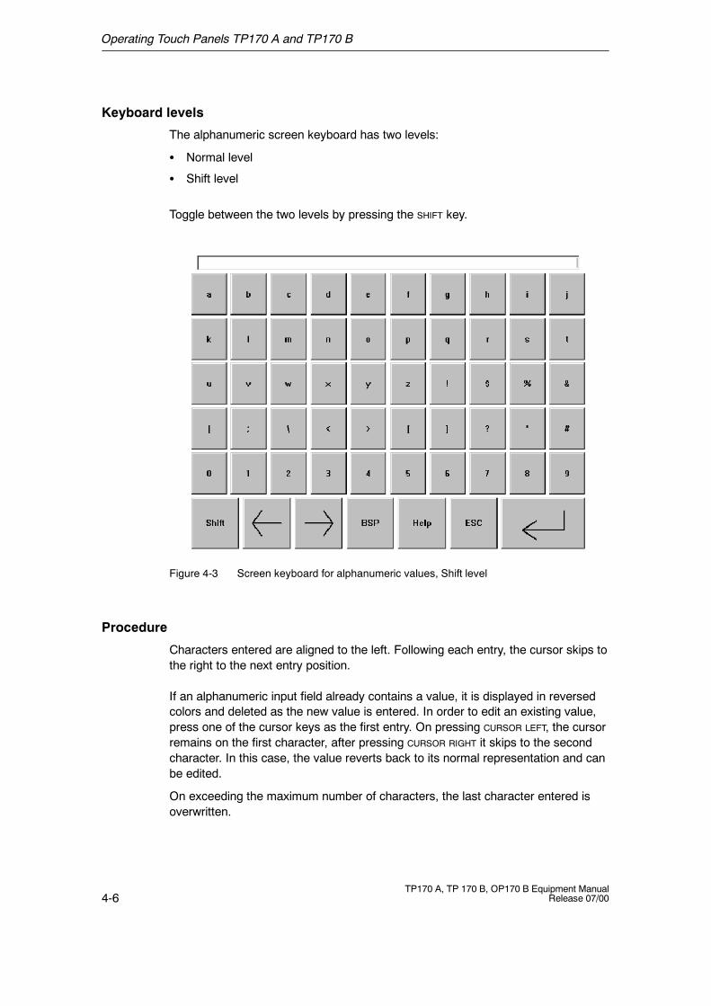
Keyboard levels
The alphanumeric screen keyboard has two levels:
S Normal level
S Shift level
Toggle between the two levels by pressing the SHIFT key.
Figure 4-3 Screen keyboard for alphanumeric values, Shift level
Procedure
Characters entered are aligned to the left. Following each entry, the cursor skips tothe right to the next entry position.
If an alphanumeric input field already contains a value, it is displayed in reversedcolors and deleted as the new value is entered. In order to edit an existing value,press one of the cursor keys as the first entry. On pressing CURSOR LEFT, the cursorremains on the first character, after pressing CURSOR RIGHT it skips to the secondcharacter. In this case, the value reverts back to its normal representation and canbe edited.
On exceeding the maximum number of characters, the last character entered isoverwritten.
Operating Touch Panels TP170 A and TP170 B
4-7TP170 A, TP 170 B, OP170 B Equipment ManualRelease 07/00
Confirm the value entered by pressing ENTER or cancel the input by pressing ESC.The window is closed in both cases.
The current input position is displayed in inverse colors. Invalid characters (e.g.values greater than 23 when specifying the time for a clock) are rejected and anerror message appears. On exceeding the maximum number of characters whichcan be entered, the last character entered is overwritten.
Note
The characters available and layout of the alphanumeric screen keyboard areindependent of the language set on the operating unit.
4.1.3 Enter Symbolic Values on the TP170 B
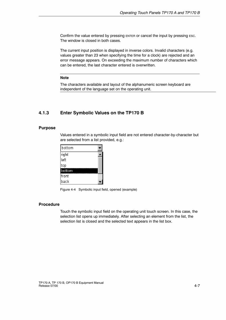
Purpose
Values entered in a symbolic input field are not entered character-by-character butare selected from a list provided, e.g.:
Figure 4-4 Symbolic input field, opened (example)
Procedure
Touch the symbolic input field on the operating unit touch screen. In this case, theselection list opens up immediately. After selecting an element from the list, theselection list is closed and the selected text appears in the list box.
Operating Touch Panels TP170 A and TP170 B
4-8TP170 A, TP 170 B, OP170 B Equipment Manual
Release 07/00
4.2 Calling in Help Text on the TP170 B
Purpose
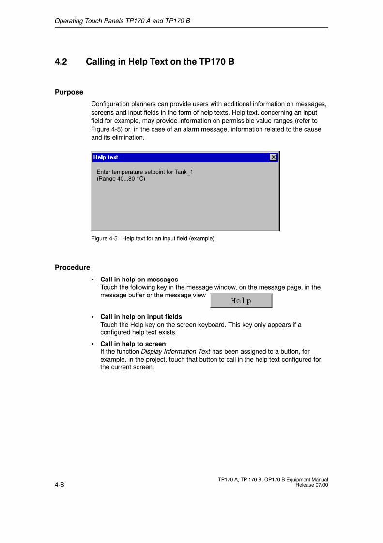
Configuration planners can provide users with additional information on messages,screens and input fields in the form of help texts. Help text, concerning an inputfield for example, may provide information on permissible value ranges (refer toFigure 4-5) or, in the case of an alarm message, information related to the causeand its elimination.
Enter temperature setpoint for Tank_1(Range 40...80 _C)
Figure 4-5 Help text for an input field (example)
Procedure
S Call in help on messagesTouch the following key in the message window, on the message page, in themessage buffer or the message view
S Call in help on input fieldsTouch the Help key on the screen keyboard. This key only appears if aconfigured help text exists.
S Call in help to screenIf the function Display Information Text has been assigned to a button, forexample, in the project, touch that button to call in the help text configured forthe current screen.
5-1TP170 A, TP 170 B, OP170 B Equipment ManualRelease 07/00
Operating Keyboard Unit OP170 B
Operating concept
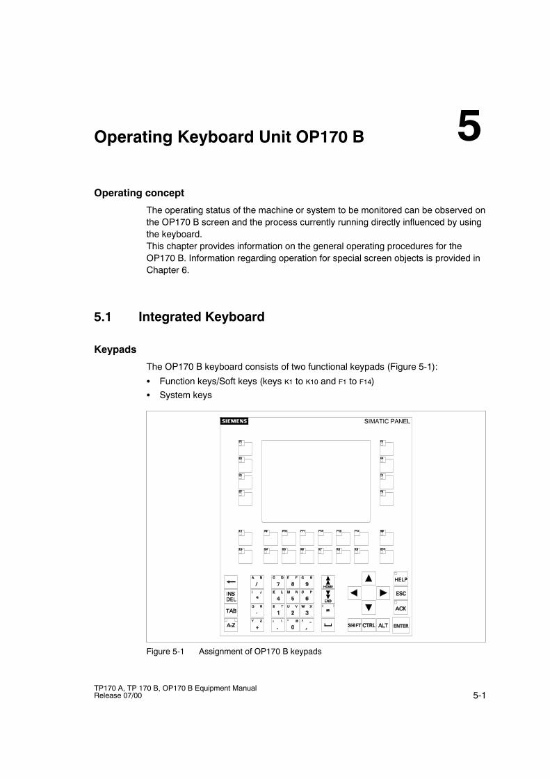
The operating status of the machine or system to be monitored can be observed onthe OP170 B screen and the process currently running directly influenced by usingthe keyboard.This chapter provides information on the general operating procedures for theOP170 B. Information regarding operation for special screen objects is provided inChapter 6.
5.1 Integrated Keyboard
Keypads
The OP170 B keyboard consists of two functional keypads (Figure 5-1):
S Function keys/Soft keys (keys K1 to K10 and F1 to F14)S System keys
Figure 5-1 Assignment of OP170 B keypads
5
Operating Keyboard Unit OP170 B
5-2TP170 A, TP 170 B, OP170 B Equipment Manual
Release 07/00
Function keys for global function assignment
A function key for global function assignment always triggers the same action onthe OP170 B or in the PLC regardless of the screen currently open (globalsignificance on the OP170 B). These actions could include:
S Open screenS Display current alarm messagesS Print screen (hardcopy)
The following function keys can be assigned during configuration:K1 to K10
F1 to F14
Function keys for local function assignment (softkeys)
A function key for local function assignment (softkey) can trigger different actionson the OP170 B or in the PLC according to the screen currently open (localsignificance of current screen). If configured, the function of a softkey is indicatedby an icon located at the edge of the current screen.
All the function keys located directly at the edge of the screen can be assignedlocally significant functions during configuration. In the case of the OP170 B, thisrelates to the keys F1 to F14.
Note
If a function key is pressed directly following changing screens, the correspondingfunction associated with the new screen is triggered before the screen isgenerated.
Operating Keyboard Unit OP170 B
5-3TP170 A, TP 170 B, OP170 B Equipment ManualRelease 07/00
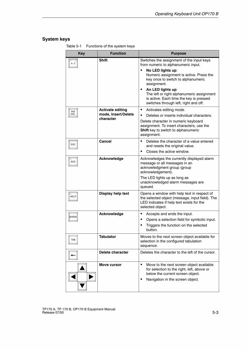
System keysTable 5-1 Functions of the system keys
Key Function Purpose
Shift Switches the assignment of the input keysfrom numeric to alphanumeric input.
S No LED lights up:Numeric assignment is active. Press thekey once to switch to alphanumericassignment.
S An LED lights up:The left or right alphanumeric assignmentis active. Each time the key is pressedswitches through left, right and off.
Activate editingmode, Insert/Deletecharacter
S Activates editing mode.
S Deletes or inserts individual characters.
Delete character in numeric keyboardassignment. To insert characters, use theShift key to switch to alphanumericassignment.
Cancel S Deletes the character of a value enteredand resets the original value.
S Closes the active window.
Acknowledge Acknowledges the currently displayed alarmmessage or all messages in anacknowledgment group (groupacknowledgement).
The LED lights up as long asunacknowledged alarm messages arequeued.
Display help text Opens a window with help text in respect ofthe selected object (message, input field). TheLED indicates if help text exists for theselected object.
Acknowledge S Accepts and ends the input.
S Opens a selection field for symbolic input.
S Triggers the function on the selectedbutton.
Tabulator Moves to the next screen object available forselection in the configured tabulationsequence.
Delete character Deletes the character to the left of the cursor.
Move cursor S Move to the next screen object availablefor selection to the right, left, above orbelow the current screen object.
S Navigation in the screen object.
Operating Keyboard Unit OP170 B
5-4TP170 A, TP 170 B, OP170 B Equipment Manual
Release 07/00
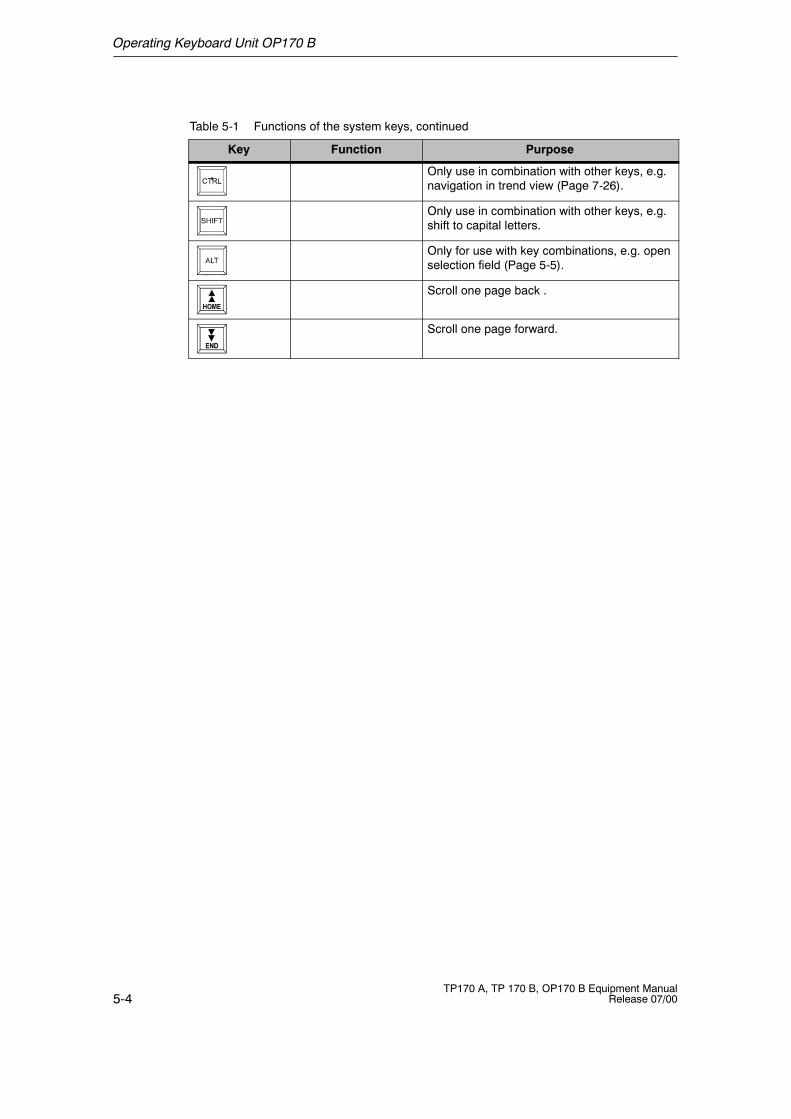
Table 5-1 Functions of the system keys, continued
PurposeFunctionKey
Only use in combination with other keys, e.g.navigation in trend view (Page 7-26).
Only use in combination with other keys, e.g.shift to capital letters.
Only for use with key combinations, e.g. openselection field (Page 5-5).
Scroll one page back .
Scroll one page forward.
Operating Keyboard Unit OP170 B
5-5TP170 A, TP 170 B, OP170 B Equipment ManualRelease 07/00
5.2 Key Combinations
General operation
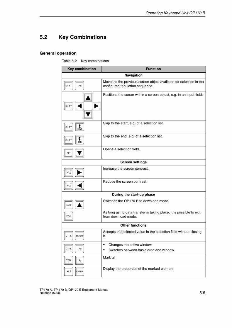
Table 5-2 Key combinations
Key combination Function
Navigation
Moves to the previous screen object available for selection in theconfigured tabulation sequence.
Positions the cursor within a screen object, e.g. in an input field.
Skip to the start, e.g. of a selection list.
Skip to the end, e.g. of a selection list.
Opens a selection field.
Screen settings
Increase the screen contrast.
Reduce the screen contrast.
During the start-up phase
Switches the OP170 B to download mode.
As long as no data transfer is taking place, it is possible to exitfrom download mode.
Other functions
Accepts the selected value in the selection field without closingit.
S Changes the active window.
S Switches between basic area and window.
Mark all
Display the properties of the marked element
Operating Keyboard Unit OP170 B
5-6TP170 A, TP 170 B, OP170 B Equipment Manual
Release 07/00
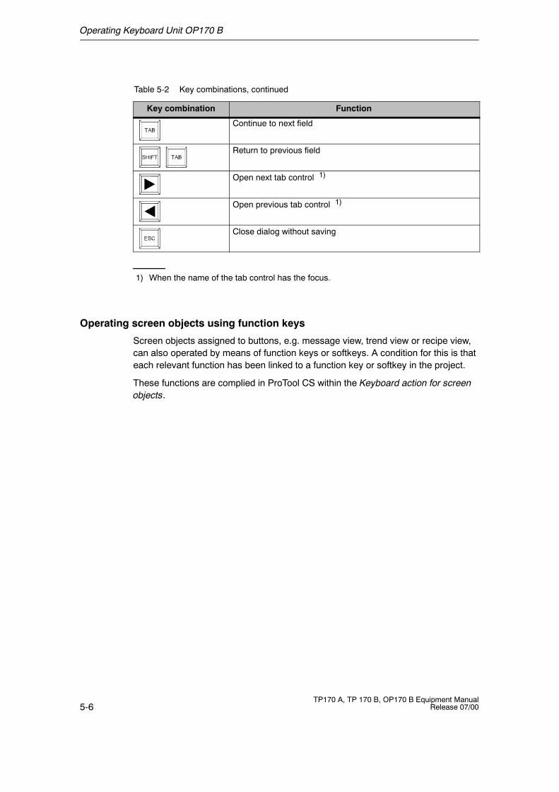
Table 5-2 Key combinations, continued
FunctionKey combination
Continue to next field
Return to previous field
Open next tab control 1)
Open previous tab control 1)
Close dialog without saving
1) When the name of the tab control has the focus.
Operating screen objects using function keys
Screen objects assigned to buttons, e.g. message view, trend view or recipe view,can also operated by means of function keys or softkeys. A condition for this is thateach relevant function has been linked to a function key or softkey in the project.
These functions are complied in ProTool CS within the Keyboard action for screenobjects.
Operating Keyboard Unit OP170 B
5-7TP170 A, TP 170 B, OP170 B Equipment ManualRelease 07/00
5.3 Entering Values
Marking
On selecting an input field, the entire field content is marked by changing color.After pressing a key (except a cursor key), the field content is deleted and the newinput displayed.
After selecting a field, press the SHIFT key and a cursor key simultaneously to clearthe marking on the field contents and enable the cursor to be moved freely withinthe field.
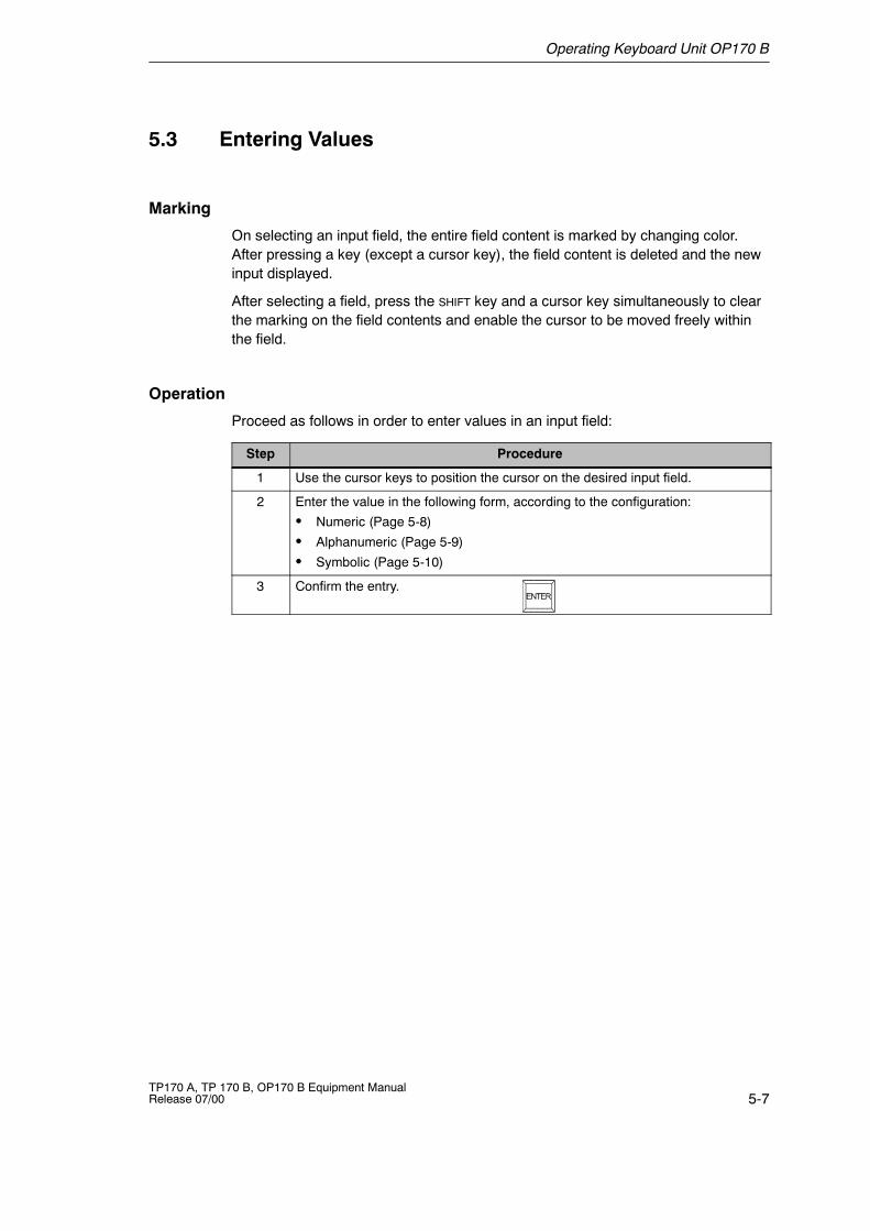
Operation
Proceed as follows in order to enter values in an input field:
Step Procedure
1 Use the cursor keys to position the cursor on the desired input field.
2 Enter the value in the following form, according to the configuration:
S Numeric (Page 5-8)
S Alphanumeric (Page 5-9)
S Symbolic (Page 5-10)
3 Confirm the entry.
Operating Keyboard Unit OP170 B
5-8TP170 A, TP 170 B, OP170 B Equipment Manual
Release 07/00
5.3.1 Enter Numeric Values
Procedure
Numeric values are entered character-by-character using the input keys on thekeyboard. If a value already exists in the field, this is deleted on entering the firstcharacter. After beginning entering a value, it is impossible to exit from the fieldwithout either confirming the entry or canceling it.
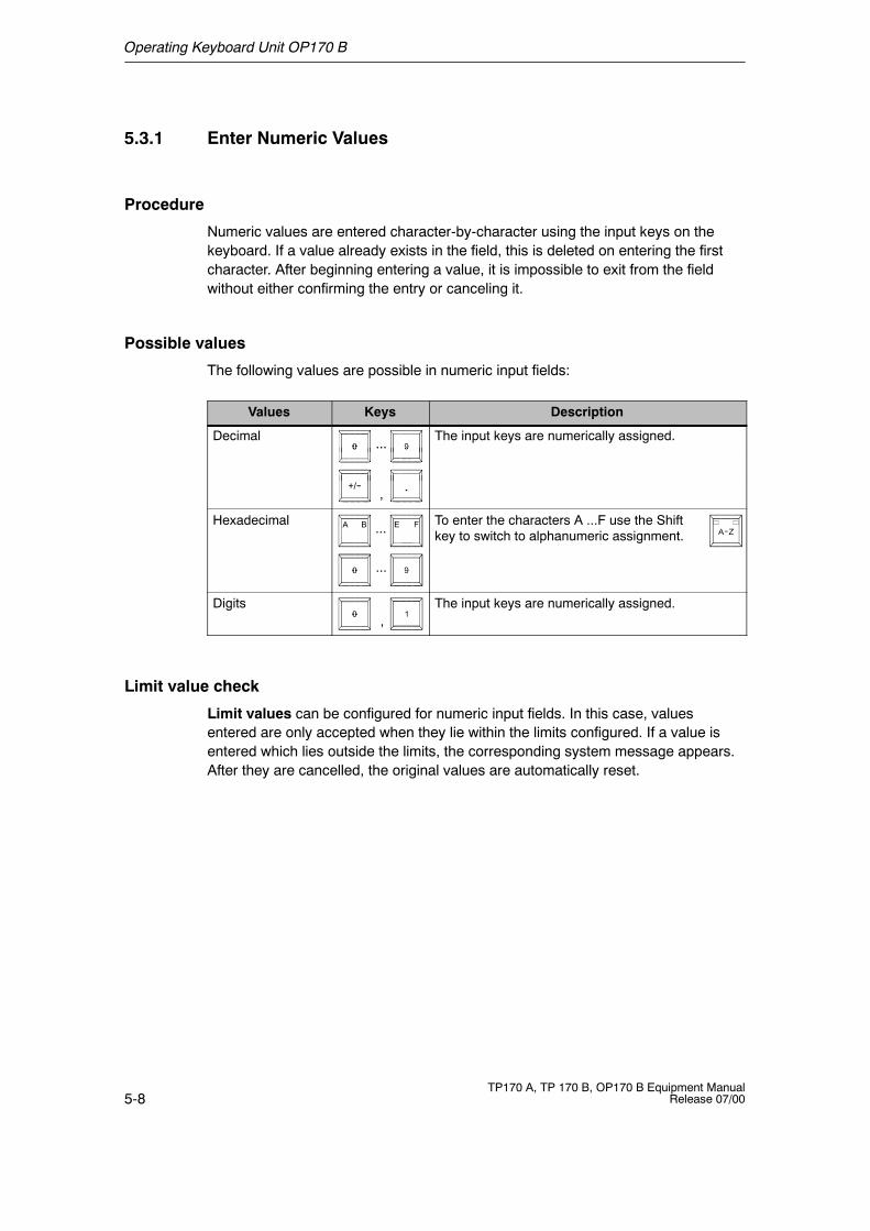
Possible values
The following values are possible in numeric input fields:
Values Keys Description
Decimal ... The input keys are numerically assigned....
,
Hexadecimal...
...
To enter the characters A ...F use the Shiftkey to switch to alphanumeric assignment.
Digits,
The input keys are numerically assigned.
Limit value check
Limit values can be configured for numeric input fields. In this case, valuesentered are only accepted when they lie within the limits configured. If a value isentered which lies outside the limits, the corresponding system message appears.After they are cancelled, the original values are automatically reset.
Operating Keyboard Unit OP170 B
5-9TP170 A, TP 170 B, OP170 B Equipment ManualRelease 07/00
5.3.2 Enter Alphanumeric Values
Procedure
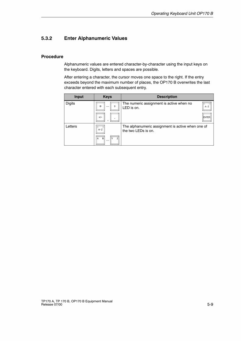
Alphanumeric values are entered character-by-character using the input keys onthe keyboard. Digits, letters and spaces are possible.
After entering a character, the cursor moves one space to the right. If the entryexceeds beyond the maximum number of places, the OP170 B overwrites the lastcharacter entered with each subsequent entry.
Input Keys Description
Digits ...
,
The numeric assignment is active when noLED is on.
Letters
...
The alphanumeric assignment is active when one ofthe two LEDs is on.
Operating Keyboard Unit OP170 B
5-10TP170 A, TP 170 B, OP170 B Equipment Manual
Release 07/00
5.3.3 Enter Symbolic Values
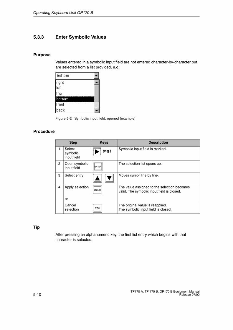
Purpose
Values entered in a symbolic input field are not entered character-by-character butare selected from a list provided, e.g.:
Figure 5-2 Symbolic input field, opened (example)
Procedure
Step Keys Description
1 Select (e g ) Symbolic input field is marked.1 Selectsymbolic (e.g.) Symbolic input field is marked.yinput field
2 Open symbolicinput field
The selection list opens up.
3 Select entry Moves cursor line by line.
4 Apply selection The value assigned to the selection becomesvalid. The symbolic input field is closed.
or
Cancelselection
The original value is reapplied.The symbolic input field is closed.
Tip
After pressing an alphanumeric key, the first list entry which begins with thatcharacter is selected.
Operating Keyboard Unit OP170 B
5-11TP170 A, TP 170 B, OP170 B Equipment ManualRelease 07/00
5.4 Call Help Text
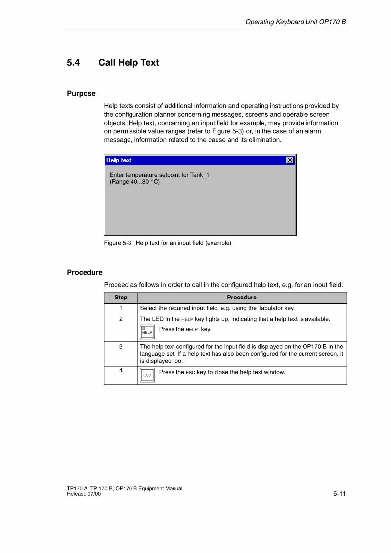
Purpose
Help texts consist of additional information and operating instructions provided bythe configuration planner concerning messages, screens and operable screenobjects. Help text, concerning an input field for example, may provide informationon permissible value ranges (refer to Figure 5-3) or, in the case of an alarmmessage, information related to the cause and its elimination.
Enter temperature setpoint for Tank_1(Range 40...80 _C)
Figure 5-3 Help text for an input field (example)
Procedure
Proceed as follows in order to call in the configured help text, e.g. for an input field:
Step Procedure
1 Select the required input field, e.g. using the Tabulator key.
2 The LED in the HELP key lights up, indicating that a help text is available.
Press the HELP key.
3 The help text configured for the input field is displayed on the OP170 B in thelanguage set. If a help text has also been configured for the current screen, itis displayed too.
4 Press the ESC key to close the help text window.

Operating Keyboard Unit OP170 B
5-12TP170 A, TP 170 B, OP170 B Equipment Manual
Release 07/00
6-1TP170 A, TP 170 B, OP170 B Equipment ManualRelease 07/00
Screen Objects for TP170 A
In this chapter
This chapter introduces the screen objects which may be contained in aconfiguration and explains their operation. It provides the following information:
S General operation (Page 6-2)
S Summary of screen objects (Page 6-4)
S Input field for date/time (Page 6-5)
S Input field for confidential password entry (Page 6-5)
S Status button (Page 6-6
S Messages (Page 6-7)
S Bars (Page 6-9)
6
Screen Objects for TP170 A
6-2TP170 A, TP 170 B, OP170 B Equipment Manual
Release 07/00
6.1 General Operation
In this chapter
This chapter contains information on how to operate screens and logging in andout of the operating unit.
6.1.1 Operating Screens
What is a screen?
Screens visualize the progress of processes and display specified process values.A screen contains logically related process data which the operating unit can bothdisplay and modify by operating the individual values.
Screen partitions
A screen is basically composed of static and dynamic sections. The terms “static”and “dynamic” do not refer to the possibility of dynamically positioning screenpartitions but to the connection to the PLC.
Static partitions, e.g. text and graphics, are not updated by the PLC. Dynamicpartitions, e.g. input and output fields, trend view and bars, are linked to the PLCand display current values constantly read in from the PLC memory. Theirconnection to the PLC is established by means of tags.
A summary of all the screen objects which the operating unit may contain isprovided on Page 6-4.
Select screen
There are several ways in which to select a screen:
S ButtonPressing a button opens the corresponding screen defined in the configuration.
S Input fieldEnter the corresponding number of the screen to be viewed in the input field.
Screen Objects for TP170 A
6-3TP170 A, TP 170 B, OP170 B Equipment ManualRelease 07/00
6.1.2 Logging On and Off from the Operating Unit
Purpose
During the configuration, input fields and buttons can be protected againstunauthorized operation by assigning passwords. Important parameters andsettings can then only be modified by authorized personnel. The password isdefined at the moment the element is configured and cannot be modified via theoperating unit.
Login
If operating elements are to be assigned password protection in the configuration,it must be possible for the operator to log in. In this case, the function Login_usermust be linked with an operating element, preferably an input field, in theconfiguration.
In order to access a password protected operating element during runtime, it isnecessary to log in on the operating unit. It is then possible to access all passwordprotected operating elements up to the point of logging off from the operating unit.
When correspondingly configured, it is also possible to log on via an input field forconfidential password entry. The character string entered is represented byplaceholders (*).
Logoff
In order to rule out operation by unauthorized personnel, the login should notremain active on the operating unit for too long a period of time. The followingoptions are available with which to log off from the operating unit:
S Configured logout time expiresIf the operating unit is not operated by the user within the configured period(logout time), he is automatically logged off from the operating unit.
S Log out of the operating unitIf the configuration links the function Logoff_user with an operating element, theelement can be used to log off from the operating unit.
TipIt is possible to log off by entering an incorrect password.
Screen Objects for TP170 A
6-4TP170 A, TP 170 B, OP170 B Equipment Manual
Release 07/00
6.2 Overview of Screen Objects
Table 6-1 provides a summary of the various screen objects which a TP170 Aproject may contain.
Table 6-1 Screen objects configurable for the TP170 A
Screen object Use/Description
Text Text is used during configuration to label operating anddisplay elements, for example. Text can be configuredover several lines and cannot be altered on theoperating unit.
Graphics Graphics can be used in the configuration, e.g. torepresent a system or as an illustrative symbol forconfigured display and operating elements.
Output field The output field displays the current value in numericor alphanumeric form.
Input field Enter a value in the input field. The values can be innumeric or alphanumeric form. Entries which lieoutside the specified value range are rejectedaccording to the limit values which have beenconfigured.
The input can be protected by means of a password.
Status button A Status button is a display and operating elementwhich has one of two states: Touched and Untouched.The states can be indicated by means of text orgraphics.
The Status button can be configured to be locking(switch function) or non-locking (keying function).
Bar Bar graphs present a value in the form of a rectangulararea. The operating unit thus provides a clearindication of how far the current value is from the limitvalues, or if a setpoint value has been reached, at aglance. Bars are often used to represent fill levels orworkpiece numbers.
Direction, scaling and labeling the axis can beconfigured as required. In order to identify limit values,limit value lines can be called in.
Simple message view Special filter criteria for displaying pending messagesare configured in the message view.
Notes on operation are provided on Page 6-8.
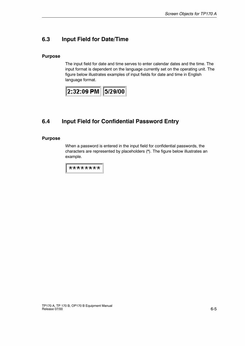
Screen Objects for TP170 A
6-5TP170 A, TP 170 B, OP170 B Equipment ManualRelease 07/00
6.3 Input Field for Date/Time
Purpose
The input field for date and time serves to enter calendar dates and the time. Theinput format is dependent on the language currently set on the operating unit. Thefigure below illustrates examples of input fields for date and time in Englishlanguage format.
6.4 Input Field for Confidential Password Entry
Purpose
When a password is entered in the input field for confidential passwords, thecharacters are represented by placeholders (*). The figure below illustrates anexample.
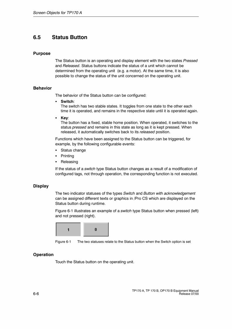
Screen Objects for TP170 A
6-6TP170 A, TP 170 B, OP170 B Equipment Manual
Release 07/00
6.5 Status Button
Purpose
The Status button is an operating and display element with the two states Pressedand Released. Status buttons indicate the status of a unit which cannot bedetermined from the operating unit (e.g. a motor). At the same time, it is alsopossible to change the status of the unit concerned on the operating unit.
Behavior
The behavior of the Status button can be configured:
S Switch:The switch has two stable states. It toggles from one state to the other eachtime it is operated, and remains in the respective state until it is operated again.
S Key:The button has a fixed, stable home position. When operated, it switches to thestatus pressed and remains in this state as long as it is kept pressed. Whenreleased, it automatically switches back to its released position.
Functions which have been assigned to the Status button can be triggered, forexample, by the following configurable events:
S Status changeS PrintingS Releasing
If the status of a switch type Status button changes as a result of a modification ofconfigured tags, not through operation, the corresponding function is not executed.
Display
The two indicator statuses of the types Switch and Button with acknowledgementcan be assigned different texts or graphics in /Pro CS which are displayed on theStatus button during runtime.
Figure 6-1 illustrates an example of a switch type Status button when pressed (left)and not pressed (right).
Figure 6-1 The two statuses relate to the Status button when the Switch option is set
Operation
Touch the Status button on the operating unit.
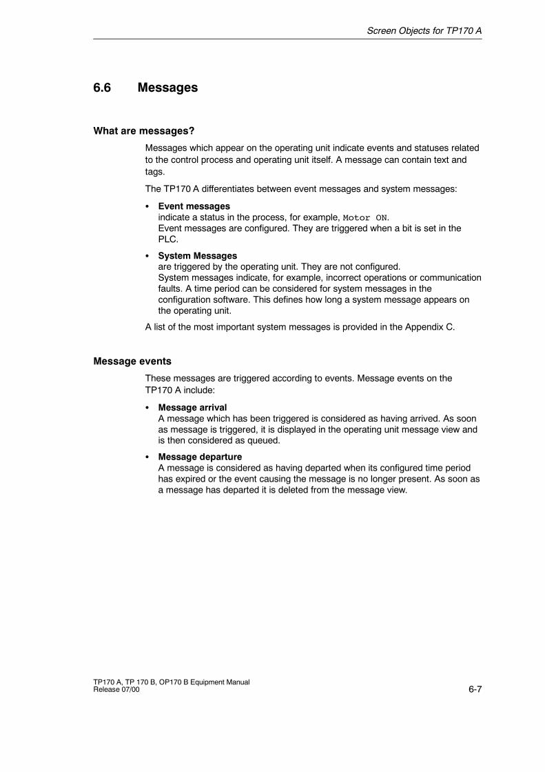
Screen Objects for TP170 A
6-7TP170 A, TP 170 B, OP170 B Equipment ManualRelease 07/00
6.6 Messages
What are messages?
Messages which appear on the operating unit indicate events and statuses relatedto the control process and operating unit itself. A message can contain text andtags.
The TP170 A differentiates between event messages and system messages:
S Event messagesindicate a status in the process, for example, Motor ON.Event messages are configured. They are triggered when a bit is set in thePLC.
S System Messagesare triggered by the operating unit. They are not configured.System messages indicate, for example, incorrect operations or communicationfaults. A time period can be considered for system messages in theconfiguration software. This defines how long a system message appears onthe operating unit.
A list of the most important system messages is provided in the Appendix C.
Message events
These messages are triggered according to events. Message events on theTP170 A include:
S Message arrivalA message which has been triggered is considered as having arrived. As soonas message is triggered, it is displayed in the operating unit message view andis then considered as queued.
S Message departureA message is considered as having departed when its configured time periodhas expired or the event causing the message is no longer present. As soon asa message has departed it is deleted from the message view.
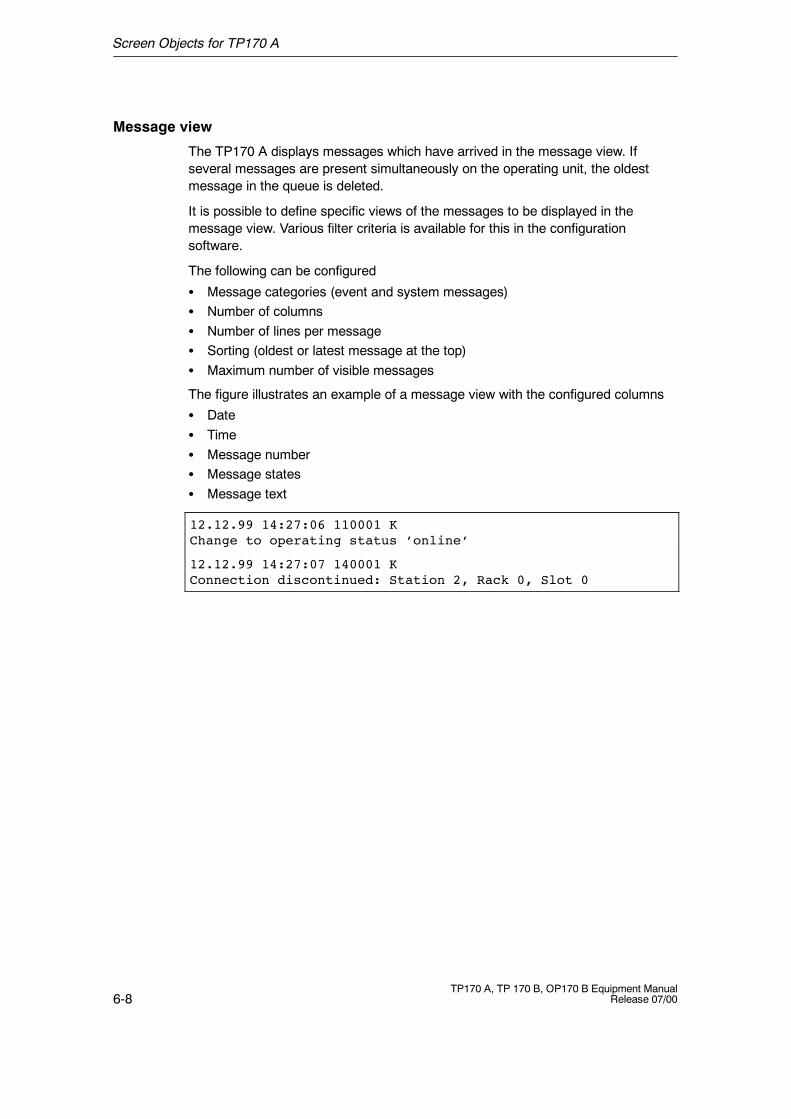
Screen Objects for TP170 A
6-8TP170 A, TP 170 B, OP170 B Equipment Manual
Release 07/00
Message view
The TP170 A displays messages which have arrived in the message view. Ifseveral messages are present simultaneously on the operating unit, the oldestmessage in the queue is deleted.
It is possible to define specific views of the messages to be displayed in themessage view. Various filter criteria is available for this in the configurationsoftware.
The following can be configured
S Message categories (event and system messages)S Number of columnsS Number of lines per messageS Sorting (oldest or latest message at the top)S Maximum number of visible messages
The figure illustrates an example of a message view with the configured columns
S DateS TimeS Message numberS Message statesS Message text
12.12.99 14:27:06 110001 KChange to operating status ’online’
12.12.99 14:27:07 140001 KConnection discontinued: Station 2, Rack 0, Slot 0
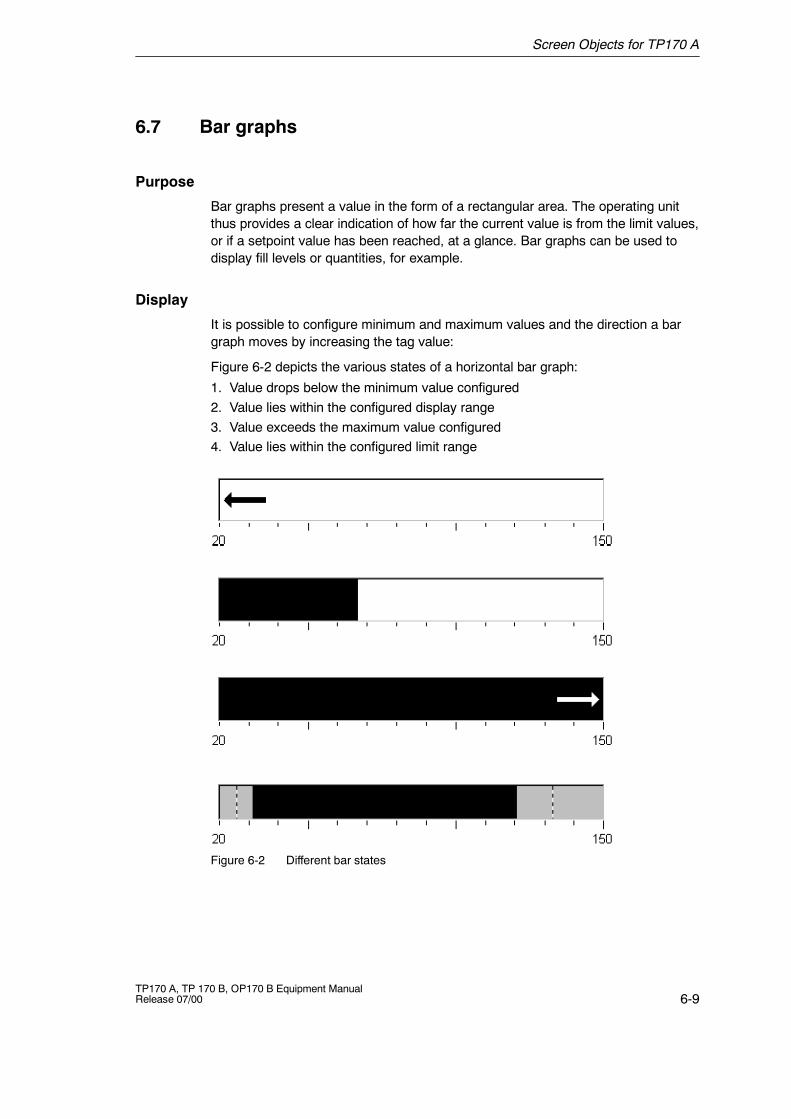
Screen Objects for TP170 A
6-9TP170 A, TP 170 B, OP170 B Equipment ManualRelease 07/00
6.7 Bar graphs
Purpose
Bar graphs present a value in the form of a rectangular area. The operating unitthus provides a clear indication of how far the current value is from the limit values,or if a setpoint value has been reached, at a glance. Bar graphs can be used todisplay fill levels or quantities, for example.
Display
It is possible to configure minimum and maximum values and the direction a bargraph moves by increasing the tag value:
Figure 6-2 depicts the various states of a horizontal bar graph:
1. Value drops below the minimum value configured2. Value lies within the configured display range3. Value exceeds the maximum value configured4. Value lies within the configured limit range
Figure 6-2 Different bar states

Screen Objects for TP170 A
6-10TP170 A, TP 170 B, OP170 B Equipment Manual
Release 07/00
7-1TP170 A, TP 170 B, OP170 B Equipment ManualRelease 07/00
Screen Objects for TP170 B and OP170 B
In this chapter
This chapter introduces the screen objects which may be contained in aconfiguration and explains their operation. It provides the following information:
S General operation (Page 7-2)
S Summary of screen objects (Page 7-6)
S Input field for date/time (Page 7-9)
S Input field for confidential password entry (Page 7-9)
S Button (Page 7-10)
S Status button (Page 7-11)
S Switches (Page 7-13)
S Messages (Page 7-14)
S Bars (Page 7-24)
S Trend view (Page 7-25)
S Date/Time (Page 7-27)
S Password list (Page 7-28)
7
Screen Objects for TP170 B and OP170 B
7-2TP170 A, TP 170 B, OP170 B Equipment Manual
Release 07/00
7.1 General Operation
In this chapter
This chapter contains information on how to operate screens and logging in andout of the operating unit.
7.1.1 Operating screens
What is a screen?
Screens visualize the progress of processes and display specified process values.A screen contains logically related process data which the operating unit can bothdisplay and modify by operating the individual values.
Screen partitions
A screen is basically composed of static and dynamic sections. The terms “static”and “dynamic” do not refer to the possibility of dynamically positioning screenpartitions but to the connection to the PLC.
Static partitions, e.g. text and graphics, are not updated by the PLC. Dynamicpartitions, e.g. input and output fields, trend view and bars, are linked to the PLCand display current values constantly read in from the PLC memory. Theirconnection to the PLC is established by means of tags.
A summary of all the screen objects which the operating unit may contain isprovided in Chapter 7.2.
Fixed window
The fixed window is an area at the top of the screen. The height of the fixedwindow can be configured. Since the content of the fixed window is independent ofthe screen currently displayed, it is especially suited for displaying importantprocess magnitudes or date and time.
An operating element configured in the fixed window is available in every screen.When using touch panels, for example, a button can be configured in the fixedwindow to represent a globally effective function key.
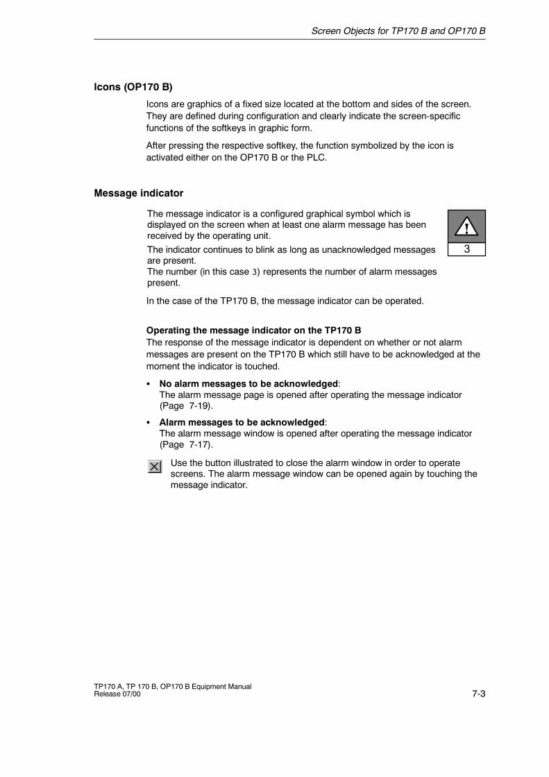
Screen Objects for TP170 B and OP170 B
7-3TP170 A, TP 170 B, OP170 B Equipment ManualRelease 07/00
Icons (OP170 B)
Icons are graphics of a fixed size located at the bottom and sides of the screen.They are defined during configuration and clearly indicate the screen-specificfunctions of the softkeys in graphic form.
After pressing the respective softkey, the function symbolized by the icon isactivated either on the OP170 B or the PLC.
Message indicator
The message indicator is a configured graphical symbol which isdisplayed on the screen when at least one alarm message has beenreceived by the operating unit.The indicator continues to blink as long as unacknowledged messagesare present.The number (in this case 3) represents the number of alarm messagespresent.
In the case of the TP170 B, the message indicator can be operated.
Operating the message indicator on the TP170 BThe response of the message indicator is dependent on whether or not alarmmessages are present on the TP170 B which still have to be acknowledged at themoment the indicator is touched.
S No alarm messages to be acknowledged:The alarm message page is opened after operating the message indicator(Page 7-19).
S Alarm messages to be acknowledged:The alarm message window is opened after operating the message indicator(Page 7-17).
Use the button illustrated to close the alarm window in order to operatescreens. The alarm message window can be opened again by touching themessage indicator.
Screen Objects for TP170 B and OP170 B
7-4TP170 A, TP 170 B, OP170 B Equipment Manual
Release 07/00
Message window
System messagesThe operating unit displays internal operating statuses in the system messagewindow. System messages indicate, for example, incorrect operations orcommunication faults. A summary of some of the most important systemmessages and explanations on how to eliminate the causes are provided inAppendix C of this manual.
Press the key depicted to close the system message window.
Event messagesThe operating unit uses the event message window to display operating statusesand faults concerning the machine or system connected to the PLC. The positionof the window can be configured.
Alarm messagesThe operating unit uses the event and alarm message window to display operatingstatuses and faults concerning the machine or system connected to the PLC. Theposition of the window can be configured.
Since alarm messages indicate abnormal operating statuses, they mustbe acknowledged. Press the key depicted to acknowledge an alarmmessage.
Detailed information regarding the message window is provided on Page 7-17.More options for displaying messages are described on Page 7-14.
Select screen
There are several ways in which to select a screen:
S Function key/ButtonPressing a function key or button opens the corresponding screen defined inthe configuration.
S Input fieldEnter the corresponding number of the screen to be viewed in the input field.
S Edit messagesWhen configured, pressing the Edit button calls in the message assigned to thescreen in the message window or message view, for example.
Screen Objects for TP170 B and OP170 B
7-5TP170 A, TP 170 B, OP170 B Equipment ManualRelease 07/00
7.1.2 Logging On and Off from the Operating Unit
Purpose
During the configuration, input fields and buttons can be protected againstunauthorized operation by assigning passwords. Important parameters andsettings can then only be modified by authorized personnel.
Note
Information concerning password lists is provided on Page 7-28.
Login
If operating elements are to be assigned password protection in the configuration,it must be possible for the operator to log in. In this case, the function Logon_Usermust be linked with an operating element, preferably an input field, in theconfiguration.
In order to access a password protected operating element during runtime, it isnecessary to log in on the operating unit. It is then possible to access all passwordprotected operating elements up to the point of logging off from the operating unit.
When correspondingly configured, it is also possible to log on via an input field forconfidential password entry. The character string entered is represented byplaceholders (*).
Logoff
In order to rule out operation by unauthorized personnel, the login should notremain active on the operating unit for too long a period of time. The followingoptions are available with which to log off from the operating unit:
S Configured logout time expiresIf the operating unit is not operated by the user within the configured period(logout time), he is automatically logged off from the operating unit.
S Log out of the operating unitIf the configuration links the function Logoff_user with an operating element, theelement can be used to log off from the operating unit.
TipIt is possible to log off by entering an incorrect password.
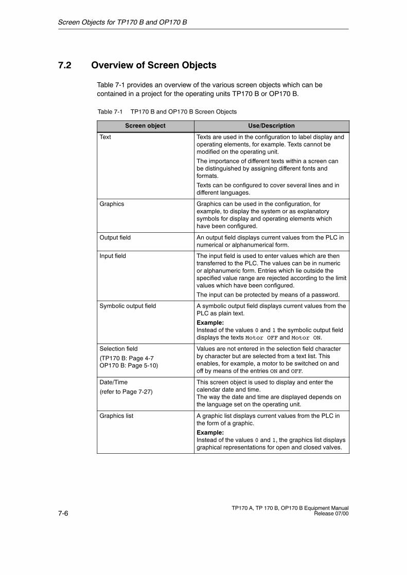
Screen Objects for TP170 B and OP170 B
7-6TP170 A, TP 170 B, OP170 B Equipment Manual
Release 07/00
7.2 Overview of Screen Objects
Table 7-1 provides an overview of the various screen objects which can becontained in a project for the operating units TP170 B or OP170 B.
Table 7-1 TP170 B and OP170 B Screen Objects
Screen object Use/Description
Text Texts are used in the configuration to label display andoperating elements, for example. Texts cannot bemodified on the operating unit.
The importance of different texts within a screen canbe distinguished by assigning different fonts andformats.
Texts can be configured to cover several lines and indifferent languages.
Graphics Graphics can be used in the configuration, forexample, to display the system or as explanatorysymbols for display and operating elements whichhave been configured.
Output field An output field displays current values from the PLC innumerical or alphanumerical form.
Input field The input field is used to enter values which are thentransferred to the PLC. The values can be in numericor alphanumeric form. Entries which lie outside thespecified value range are rejected according to the limitvalues which have been configured.
The input can be protected by means of a password.
Symbolic output field A symbolic output field displays current values from thePLC as plain text.
Example:Instead of the values 0 and 1 the symbolic output fielddisplays the texts Motor OFF and Motor ON.
Selection field
(TP170 B: Page 4-7OP170 B: Page 5-10)
Values are not entered in the selection field characterby character but are selected from a text list. Thisenables, for example, a motor to be switched on andoff by means of the entries ON and OFF.
Date/Time
(refer to Page 7-27)
This screen object is used to display and enter thecalendar date and time.The way the date and time are displayed depends onthe language set on the operating unit.
Graphics list A graphic list displays current values from the PLC inthe form of a graphic.
Example:Instead of the values 0 and 1, the graphics list displaysgraphical representations for open and closed valves.
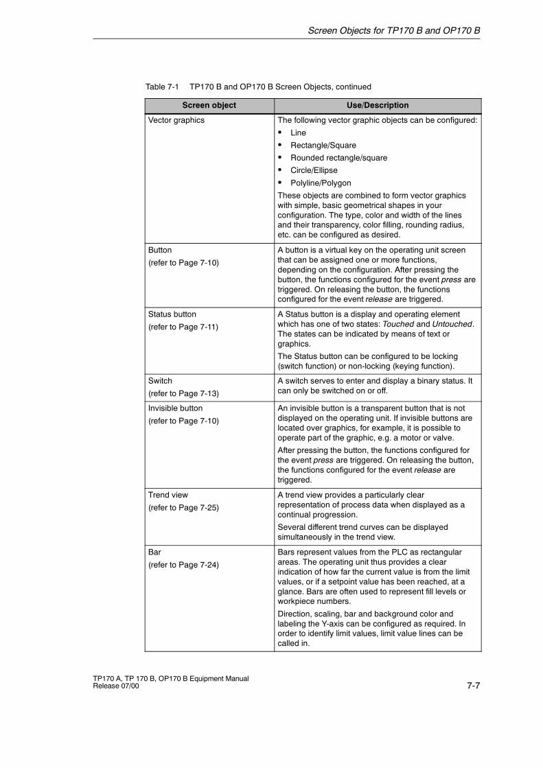
Screen Objects for TP170 B and OP170 B
7-7TP170 A, TP 170 B, OP170 B Equipment ManualRelease 07/00
Table 7-1 TP170 B and OP170 B Screen Objects, continued
Use/DescriptionScreen object
Vector graphics The following vector graphic objects can be configured:
S Line
S Rectangle/Square
S Rounded rectangle/square
S Circle/Ellipse
S Polyline/Polygon
These objects are combined to form vector graphicswith simple, basic geometrical shapes in yourconfiguration. The type, color and width of the linesand their transparency, color filling, rounding radius,etc. can be configured as desired.
Button
(refer to Page 7-10)
A button is a virtual key on the operating unit screenthat can be assigned one or more functions,depending on the configuration. After pressing thebutton, the functions configured for the event press aretriggered. On releasing the button, the functionsconfigured for the event release are triggered.
Status button
(refer to Page 7-11)
A Status button is a display and operating elementwhich has one of two states: Touched and Untouched.The states can be indicated by means of text orgraphics.
The Status button can be configured to be locking(switch function) or non-locking (keying function).
Switch
(refer to Page 7-13)
A switch serves to enter and display a binary status. Itcan only be switched on or off.
Invisible button
(refer to Page 7-10)
An invisible button is a transparent button that is notdisplayed on the operating unit. If invisible buttons arelocated over graphics, for example, it is possible tooperate part of the graphic, e.g. a motor or valve.
After pressing the button, the functions configured forthe event press are triggered. On releasing the button,the functions configured for the event release aretriggered.
Trend view
(refer to Page 7-25)
A trend view provides a particularly clearrepresentation of process data when displayed as acontinual progression.
Several different trend curves can be displayedsimultaneously in the trend view.
Bar
(refer to Page 7-24)
Bars represent values from the PLC as rectangularareas. The operating unit thus provides a clearindication of how far the current value is from the limitvalues, or if a setpoint value has been reached, at aglance. Bars are often used to represent fill levels orworkpiece numbers.
Direction, scaling, bar and background color andlabeling the Y-axis can be configured as required. Inorder to identify limit values, limit value lines can becalled in.
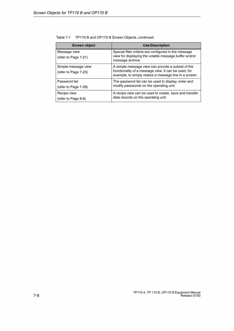
Screen Objects for TP170 B and OP170 B
7-8TP170 A, TP 170 B, OP170 B Equipment Manual
Release 07/00
Table 7-1 TP170 B and OP170 B Screen Objects, continued
Use/DescriptionScreen object
Message view
(refer to Page 7-21)
Special filter criteria are configured in the messageview for displaying the volatile message buffer and/ormessage archive.
Simple message view
(refer to Page 7-23)
A simple message view can provide a subset of thefunctionality of a message view. It can be used, forexample, to simply realize a message line in a screen.
Password list
(refer to Page 7-28)
The password list can be used to display, enter andmodify passwords on the operating unit.
Recipe view
(refer to Page 8-6)
A recipe view can be used to create, save and transferdata records on the operating unit.
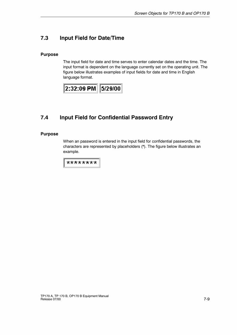
Screen Objects for TP170 B and OP170 B
7-9TP170 A, TP 170 B, OP170 B Equipment ManualRelease 07/00
7.3 Input Field for Date/Time
Purpose
The input field for date and time serves to enter calendar dates and the time. Theinput format is dependent on the language currently set on the operating unit. Thefigure below illustrates examples of input fields for date and time in Englishlanguage format.
7.4 Input Field for Confidential Password Entry
Purpose
When an password is entered in the input field for confidential passwords, thecharacters are represented by placeholders (*). The figure below illustrates anexample.
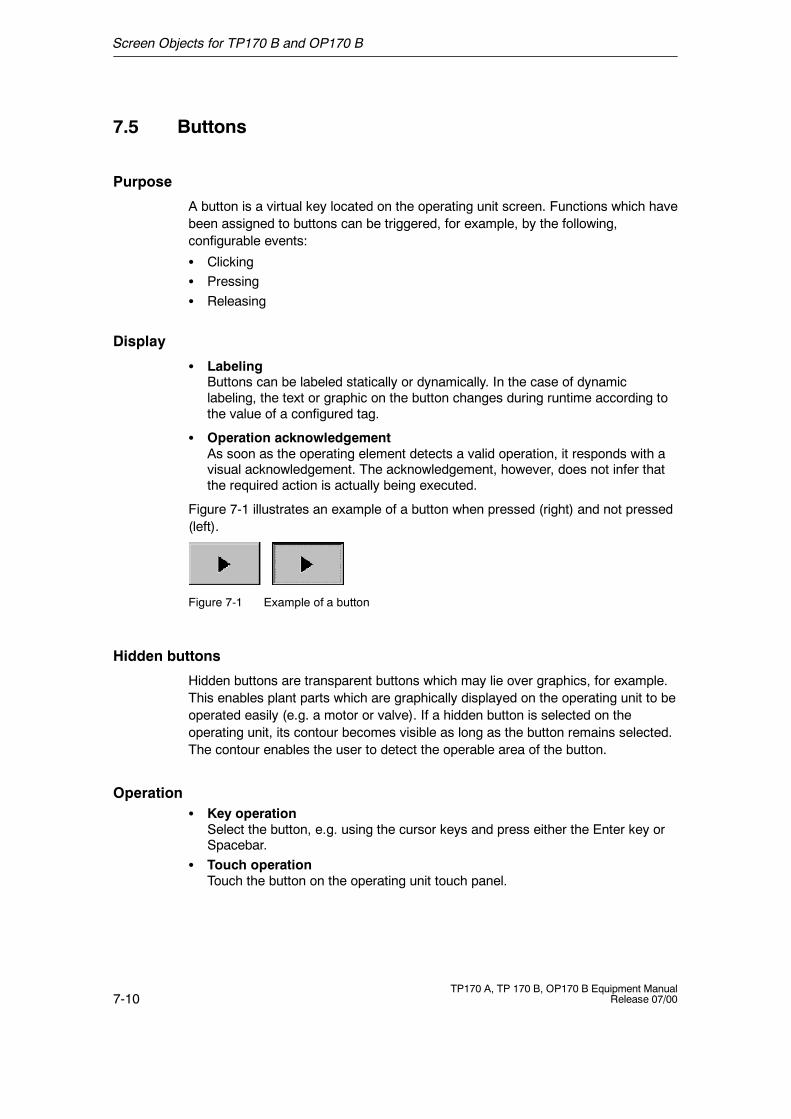
Screen Objects for TP170 B and OP170 B
7-10TP170 A, TP 170 B, OP170 B Equipment Manual
Release 07/00
7.5 Buttons
Purpose
A button is a virtual key located on the operating unit screen. Functions which havebeen assigned to buttons can be triggered, for example, by the following,configurable events:
S ClickingS PressingS Releasing
Display
S LabelingButtons can be labeled statically or dynamically. In the case of dynamiclabeling, the text or graphic on the button changes during runtime according tothe value of a configured tag.
S Operation acknowledgementAs soon as the operating element detects a valid operation, it responds with avisual acknowledgement. The acknowledgement, however, does not infer thatthe required action is actually being executed.
Figure 7-1 illustrates an example of a button when pressed (right) and not pressed(left).
Figure 7-1 Example of a button
Hidden buttons
Hidden buttons are transparent buttons which may lie over graphics, for example.This enables plant parts which are graphically displayed on the operating unit to beoperated easily (e.g. a motor or valve). If a hidden button is selected on theoperating unit, its contour becomes visible as long as the button remains selected.The contour enables the user to detect the operable area of the button.
OperationS Key operation
Select the button, e.g. using the cursor keys and press either the Enter key orSpacebar.
S Touch operationTouch the button on the operating unit touch panel.
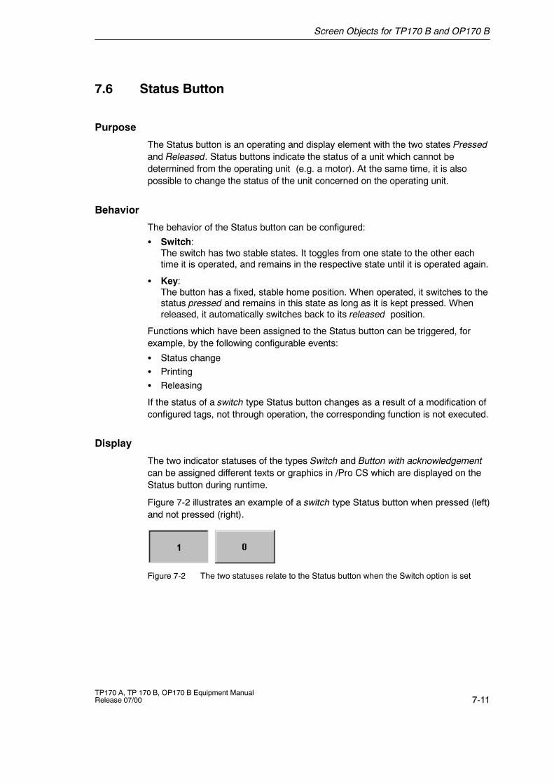
Screen Objects for TP170 B and OP170 B
7-11TP170 A, TP 170 B, OP170 B Equipment ManualRelease 07/00
7.6 Status Button
Purpose
The Status button is an operating and display element with the two states Pressedand Released. Status buttons indicate the status of a unit which cannot bedetermined from the operating unit (e.g. a motor). At the same time, it is alsopossible to change the status of the unit concerned on the operating unit.
Behavior
The behavior of the Status button can be configured:
S Switch:The switch has two stable states. It toggles from one state to the other eachtime it is operated, and remains in the respective state until it is operated again.
S Key:The button has a fixed, stable home position. When operated, it switches to thestatus pressed and remains in this state as long as it is kept pressed. Whenreleased, it automatically switches back to its released position.
Functions which have been assigned to the Status button can be triggered, forexample, by the following configurable events:
S Status changeS PrintingS Releasing
If the status of a switch type Status button changes as a result of a modification ofconfigured tags, not through operation, the corresponding function is not executed.
Display
The two indicator statuses of the types Switch and Button with acknowledgementcan be assigned different texts or graphics in /Pro CS which are displayed on theStatus button during runtime.
Figure 7-2 illustrates an example of a switch type Status button when pressed (left)and not pressed (right).
Figure 7-2 The two statuses relate to the Status button when the Switch option is set

Screen Objects for TP170 B and OP170 B
7-12TP170 A, TP 170 B, OP170 B Equipment Manual
Release 07/00
OperationS Key operation
Select the Status button, e.g. using the cursor keys, and press either the Enterkey or Spacebar.
S Touch operationTouch the Status button on the operating unit touch panel.
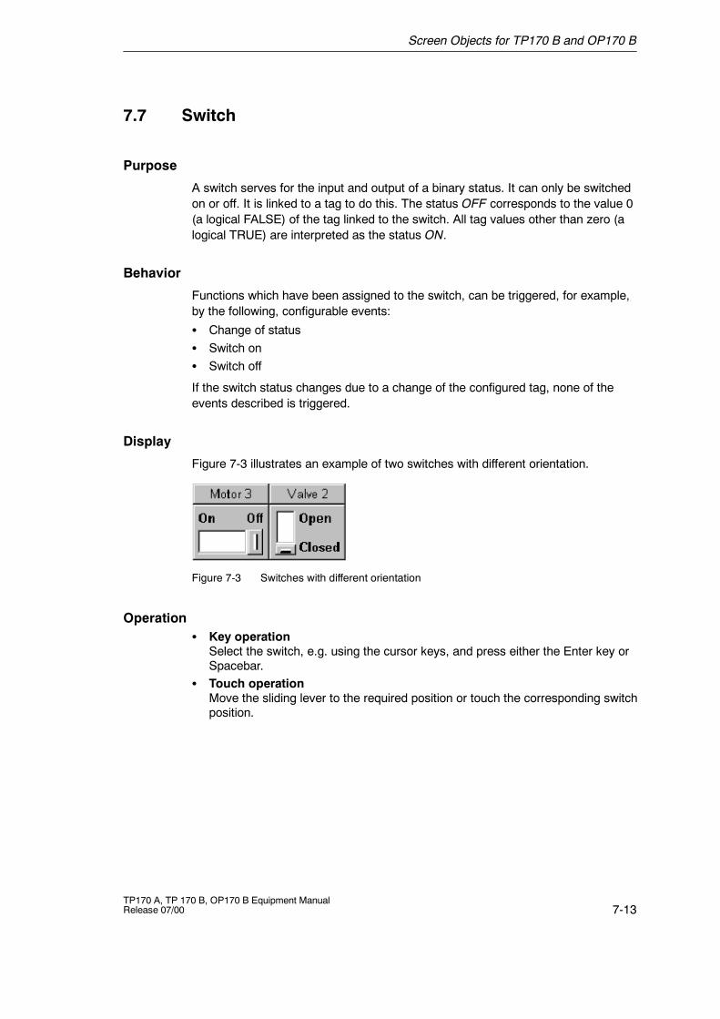
Screen Objects for TP170 B and OP170 B
7-13TP170 A, TP 170 B, OP170 B Equipment ManualRelease 07/00
7.7 Switch
Purpose
A switch serves for the input and output of a binary status. It can only be switchedon or off. It is linked to a tag to do this. The status OFF corresponds to the value 0(a logical FALSE) of the tag linked to the switch. All tag values other than zero (alogical TRUE) are interpreted as the status ON.
Behavior
Functions which have been assigned to the switch, can be triggered, for example,by the following, configurable events:
S Change of statusS Switch onS Switch off
If the switch status changes due to a change of the configured tag, none of theevents described is triggered.
Display
Figure 7-3 illustrates an example of two switches with different orientation.
Figure 7-3 Switches with different orientation
OperationS Key operation
Select the switch, e.g. using the cursor keys, and press either the Enter key orSpacebar.
S Touch operationMove the sliding lever to the required position or touch the corresponding switchposition.
Screen Objects for TP170 B and OP170 B
7-14TP170 A, TP 170 B, OP170 B Equipment Manual
Release 07/00
7.8 Messages
Message categories
Messages indicate control-process events and states on the operating unit. Theoperating unit differentiates between the following message categories:
S Event messagesindicate a status in the process, for example, Motor ON. Event messages areconfigured.
S Alarm messagesindicate an equipment failure, for example, Motor temperature too high.Alarm messages are configured. Alarm messages must be acknowledged dueto their critical nature.
S System messagesare triggered by the operating unit. They are not configured. System messagesindicate, for example, incorrect operations or communication faults. A selectionof important system messages is provided in Appendix C.
S S7 system messagesprovide information on the status of the SIMATIC S7. They are not configured inthe ProTool CS configuration software. Refer to the S7 manual for the errornumber indicated on the operating panel to determine the cause of the error.
Acknowledging alarm messagesAlarm messages must be acknowledged due to their importance. Thiscan be done manually on the operating unit or automatically by the PLC.The message indicator depicted continues to be displayed as long asalarm messages are still present on the operating unit when this featurehas been configured.
In order to acknowledge alarm messages on the OP170 B manually,press the key depicted on the right. The LED integrated in the key lightsup when unacknowledged alarm messages are present.In the case of the TP170 B, the message indicator can be operated.
Operating the message indicator on the TP170 BThe response of the message indicator is dependent on whether or not alarmmessages are present on the TP170 B which still have to be acknowledged at themoment the indicator is touched.
S No alarm messages to be acknowledged:The alarm message page is opened after operating the message indicator(Page 7-19).
S Alarm messages to be acknowledged:The alarm message window is opened after operating the message indicator(Page 7-17).
Use the button illustrated to close the alarm window in order to operatescreens. The alarm message window can be opened again by touching themessage indicator.
Screen Objects for TP170 B and OP170 B
7-15TP170 A, TP 170 B, OP170 B Equipment ManualRelease 07/00
Buffering messages
All message events (arrived, departed, acknowledged) are stored in an internalvolatile buffer. If a message archive has been configured, the message events arealso stored in this message archive.
Display messages
The events stored in the message buffer can be displayed according to differentcriteria. The following predefined objects are available for display purposes:
S Message line (refer to Page 7-17)S Message window (refer to Page 7-17)S Message page (refer to Page 7-19)S Message buffer (refer to Page 7-20)S Message view
-- Message view with full functionality (refer to Page 7-21)-- Simple message view with restricted functionality (refer to Page 7-23)
Deleting messages
All message events concerning event and alarm messages are automaticallystored in the message buffer. There are two methods of deleting messages fromthe buffer:
S Automatic deletion on buffer overflowWhen the message buffer is no longer capable of accepting new messageevents, the operating unit automatically deletes a number of message eventsuntil the configured remaining buffer capacity is reached. In this case, the oldestmessages are deleted first.
S Deletion by operating the operating unitIn order that messages can be deleted manually from the message buffer, thefunction Clear_message_buffer must be available in the configuration. In thisway, the following message categories can be selected for deletion according tothe configuration:-- All messages-- Alarm messages-- Event messages-- System messages
Print messages
When correspondingly configured, event messages can be printed out directlywhen the message events Arrived and Departed occur, and also alarm messageswhen the event Acknowledged occurs. System messages are not logged.
Information on setting printer parameters is provided in Chapter 9-12.
Screen Objects for TP170 B and OP170 B
7-16TP170 A, TP 170 B, OP170 B Equipment Manual
Release 07/00
7.8.1 ALARM_S
Definition
ALARM_S is an active message procedure. If an alarm occurs, the CPU activelyissues the respective message to all the network participants which are logged on.This means that the operating unit is relieved of continuous polling of the messagearea.
Configuring ALARM_S messages
ALARM_S messages are not configured in ProTool CS but in STEP 7. Themessage numbers are automatically assigned during configuration in STEP 7. Theunique assignment of the message text is made according to these numbers.
The display of ALARM_S messages on the operating unit can only be configuredwhen a SIMATIC S7 PLC is used and the /Pro CS configuration software has beenintegrated in STEP 7.
Detailed information on the configuration of ALARM_S messages is available in theProAgent/MP and ProAgent/PC user guides.
Note
Restarting S7 CPUs:Depending on the hardware configuration of the CPUs, it is possible that undercertain circumstances all queued ALARM_S messages will be deleted when S7CPUs are restarted. Older stocks of S7 300 CPUs cannot inform the operatingunits involved of the restart. The result of this is that messages are indicated onthe operating unit as being queued although the CPU has already deleted them.
Remedy:Restart the operating unit.
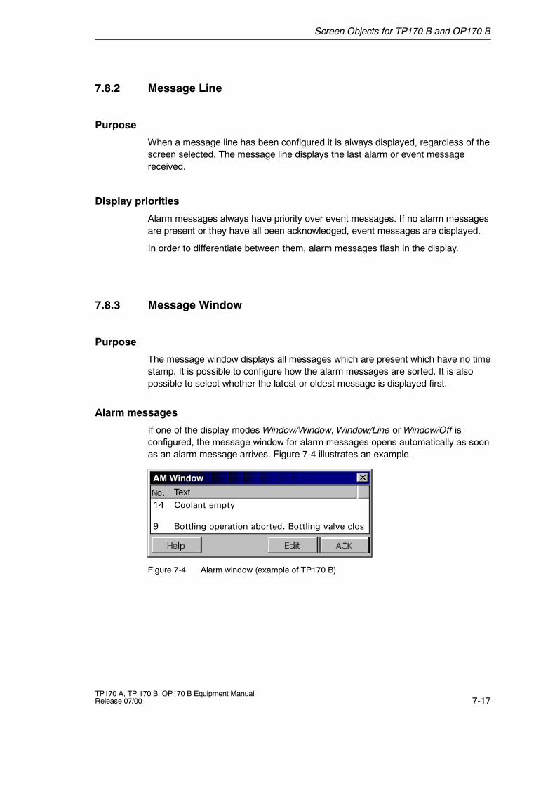
Screen Objects for TP170 B and OP170 B
7-17TP170 A, TP 170 B, OP170 B Equipment ManualRelease 07/00
7.8.2 Message Line
Purpose
When a message line has been configured it is always displayed, regardless of thescreen selected. The message line displays the last alarm or event messagereceived.
Display priorities
Alarm messages always have priority over event messages. If no alarm messagesare present or they have all been acknowledged, event messages are displayed.
In order to differentiate between them, alarm messages flash in the display.
7.8.3 Message Window
Purpose
The message window displays all messages which are present which have no timestamp. It is possible to configure how the alarm messages are sorted. It is alsopossible to select whether the latest or oldest message is displayed first.
Alarm messages
If one of the display modes Window/Window, Window/Line or Window/Off isconfigured, the message window for alarm messages opens automatically as soonas an alarm message arrives. Figure 7-4 illustrates an example.
Text14 Coolant empty
9 Bottling operation aborted. Bottling valve clos
AM Window
Figure 7-4 Alarm window (example of TP170 B)
Screen Objects for TP170 B and OP170 B
7-18TP170 A, TP 170 B, OP170 B Equipment Manual
Release 07/00
Significance of the buttons
Call Help textUse this button to call in the help text configured for theselected message.
Edit MessageUse this button to trigger the function assigned to theEdit Message event for the selected message.
Acknowledge alarm messagesUse this button to acknowledge unacknowledged alarmmessages.
Event messages
In order to be able to open the event message window by means of the mouse orkeyboard the function Display_event_message_window, for example, must belinked to a function key or button in the project.
System messages
The message window for system messages opens automatically as soon as asystem message arrives. The window closes automatically after the configuredduration of display has elapsed.
S Key operationUse the ESC key to close the message window manually.
S Touch operation
Touch the button .
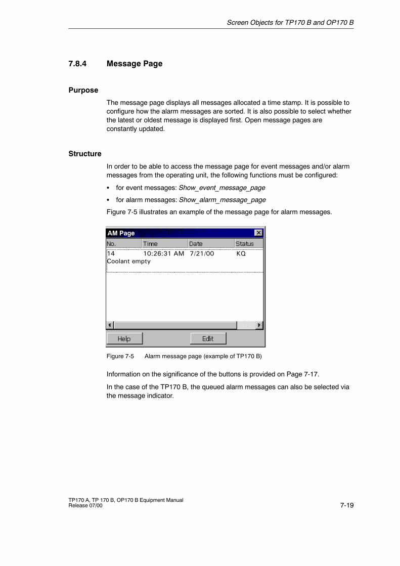
Screen Objects for TP170 B and OP170 B
7-19TP170 A, TP 170 B, OP170 B Equipment ManualRelease 07/00
7.8.4 Message Page
Purpose
The message page displays all messages allocated a time stamp. It is possible toconfigure how the alarm messages are sorted. It is also possible to select whetherthe latest or oldest message is displayed first. Open message pages areconstantly updated.
Structure
In order to be able to access the message page for event messages and/or alarmmessages from the operating unit, the following functions must be configured:
S for event messages: Show_event_message_page
S for alarm messages: Show_alarm_message_page
Figure 7-5 illustrates an example of the message page for alarm messages.
AM Page
14 10:26:31 AM 7/21/00 KQCoolant empty
Figure 7-5 Alarm message page (example of TP170 B)
Information on the significance of the buttons is provided on Page 7-17.
In the case of the TP170 B, the queued alarm messages can also be selected viathe message indicator.
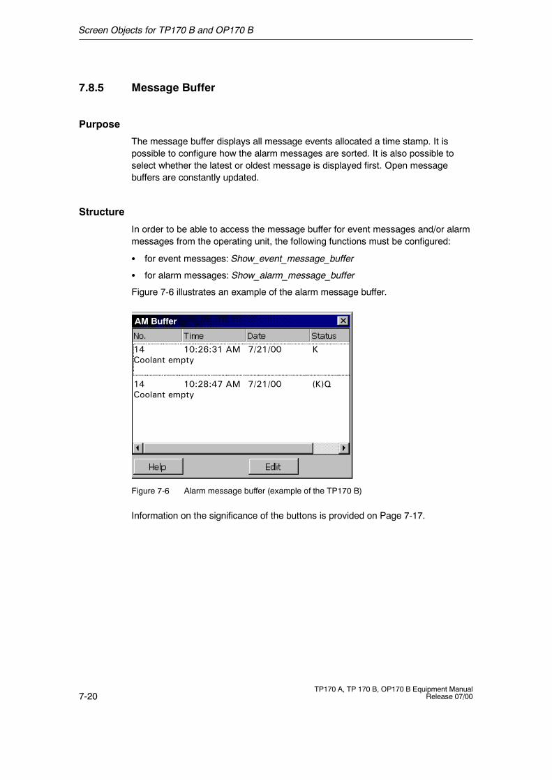
Screen Objects for TP170 B and OP170 B
7-20TP170 A, TP 170 B, OP170 B Equipment Manual
Release 07/00
7.8.5 Message Buffer
Purpose
The message buffer displays all message events allocated a time stamp. It ispossible to configure how the alarm messages are sorted. It is also possible toselect whether the latest or oldest message is displayed first. Open messagebuffers are constantly updated.
Structure
In order to be able to access the message buffer for event messages and/or alarmmessages from the operating unit, the following functions must be configured:
S for event messages: Show_event_message_buffer
S for alarm messages: Show_alarm_message_buffer
Figure 7-6 illustrates an example of the alarm message buffer.
AM Buffer
14 10:26:31 AM 7/21/00 KCoolant empty
14 10:28:47 AM 7/21/00 (K)QCoolant empty
Figure 7-6 Alarm message buffer (example of the TP170 B)
Information on the significance of the buttons is provided on Page 7-17.
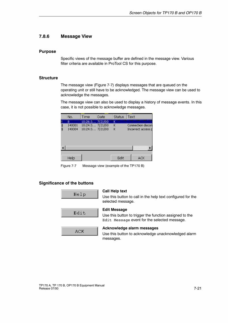
Screen Objects for TP170 B and OP170 B
7-21TP170 A, TP 170 B, OP170 B Equipment ManualRelease 07/00
7.8.6 Message View
Purpose
Specific views of the message buffer are defined in the message view. Variousfilter criteria are available in ProTool CS for this purpose.
Structure
The message view (Figure 7-7) displays messages that are queued on theoperating unit or still have to be acknowledged. The message view can be used toacknowledge the messages.
The message view can also be used to display a history of message events. In thiscase, it is not possible to acknowledge messages.
Figure 7-7 Message view (example of the TP170 B)
Significance of the buttons
Call Help textUse this button to call in the help text configured for theselected message.
Edit MessageUse this button to trigger the function assigned to theEdit Message event for the selected message.
Acknowledge alarm messagesUse this button to acknowledge unacknowledged alarmmessages.

Screen Objects for TP170 B and OP170 B
7-22TP170 A, TP 170 B, OP170 B Equipment Manual
Release 07/00
Message categories
In order to be able to distinguish between the different message categories, theyare marked in the first column of the message view:
! Alarm messages
Empty Event messages
$ System messages
S7 S7 messages
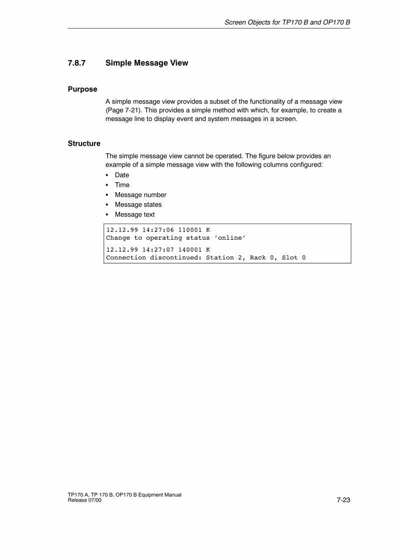
Screen Objects for TP170 B and OP170 B
7-23TP170 A, TP 170 B, OP170 B Equipment ManualRelease 07/00
7.8.7 Simple Message View
Purpose
A simple message view provides a subset of the functionality of a message view(Page 7-21). This provides a simple method with which, for example, to create amessage line to display event and system messages in a screen.
Structure
The simple message view cannot be operated. The figure below provides anexample of a simple message view with the following columns configured:
S DateS TimeS Message numberS Message statesS Message text
12.12.99 14:27:06 110001 KChange to operating status ’online’
12.12.99 14:27:07 140001 KConnection discontinued: Station 2, Rack 0, Slot 0
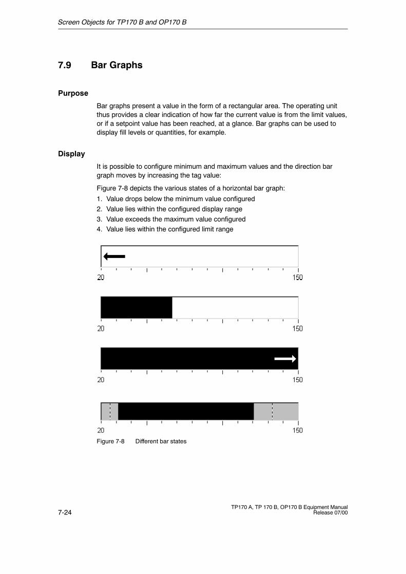
Screen Objects for TP170 B and OP170 B
7-24TP170 A, TP 170 B, OP170 B Equipment Manual
Release 07/00
7.9 Bar Graphs
Purpose
Bar graphs present a value in the form of a rectangular area. The operating unitthus provides a clear indication of how far the current value is from the limit values,or if a setpoint value has been reached, at a glance. Bar graphs can be used todisplay fill levels or quantities, for example.
Display
It is possible to configure minimum and maximum values and the direction bargraph moves by increasing the tag value:
Figure 7-8 depicts the various states of a horizontal bar graph:
1. Value drops below the minimum value configured2. Value lies within the configured display range3. Value exceeds the maximum value configured4. Value lies within the configured limit range
Figure 7-8 Different bar states
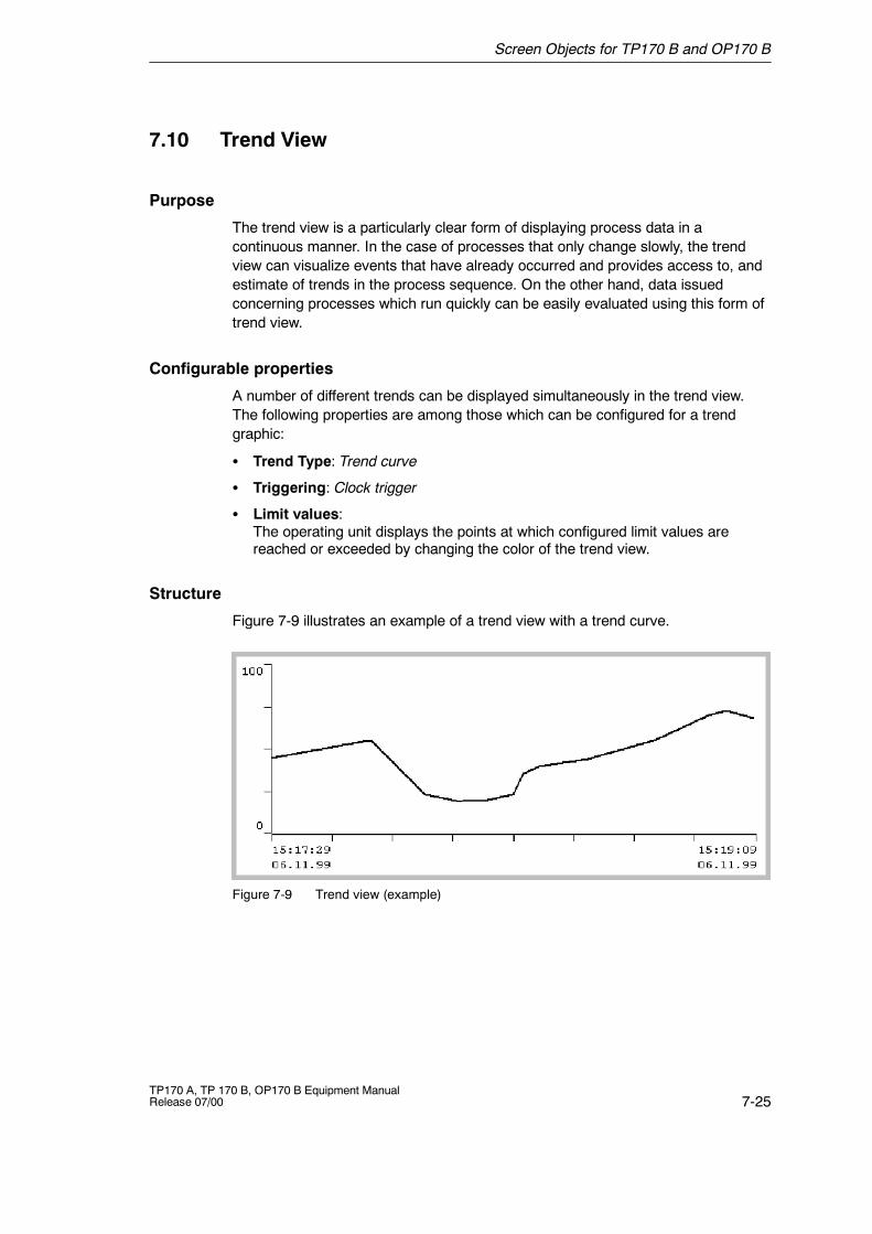
Screen Objects for TP170 B and OP170 B
7-25TP170 A, TP 170 B, OP170 B Equipment ManualRelease 07/00
7.10 Trend View
Purpose
The trend view is a particularly clear form of displaying process data in acontinuous manner. In the case of processes that only change slowly, the trendview can visualize events that have already occurred and provides access to, andestimate of trends in the process sequence. On the other hand, data issuedconcerning processes which run quickly can be easily evaluated using this form oftrend view.
Configurable properties
A number of different trends can be displayed simultaneously in the trend view.The following properties are among those which can be configured for a trendgraphic:
S Trend Type: Trend curve
S Triggering: Clock trigger
S Limit values:The operating unit displays the points at which configured limit values arereached or exceeded by changing the color of the trend view.
Structure
Figure 7-9 illustrates an example of a trend view with a trend curve.
Figure 7-9 Trend view (example)
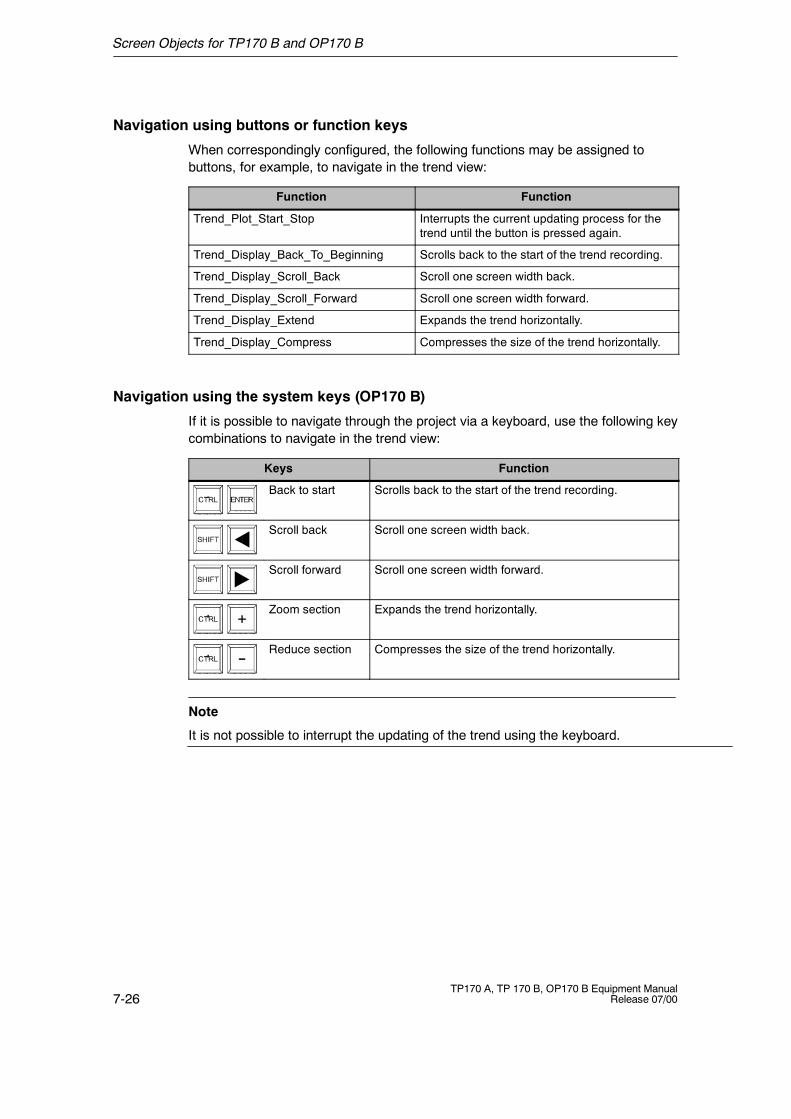
Screen Objects for TP170 B and OP170 B
7-26TP170 A, TP 170 B, OP170 B Equipment Manual
Release 07/00
Navigation using buttons or function keys
When correspondingly configured, the following functions may be assigned tobuttons, for example, to navigate in the trend view:
Function Function
Trend_Plot_Start_Stop Interrupts the current updating process for thetrend until the button is pressed again.
Trend_Display_Back_To_Beginning Scrolls back to the start of the trend recording.
Trend_Display_Scroll_Back Scroll one screen width back.
Trend_Display_Scroll_Forward Scroll one screen width forward.
Trend_Display_Extend Expands the trend horizontally.
Trend_Display_Compress Compresses the size of the trend horizontally.
Navigation using the system keys (OP170 B)
If it is possible to navigate through the project via a keyboard, use the following keycombinations to navigate in the trend view:
Keys Function
Back to start Scrolls back to the start of the trend recording.
Scroll back Scroll one screen width back.
Scroll forward Scroll one screen width forward.
Zoom section Expands the trend horizontally.
Reduce section Compresses the size of the trend horizontally.
Note
It is not possible to interrupt the updating of the trend using the keyboard.
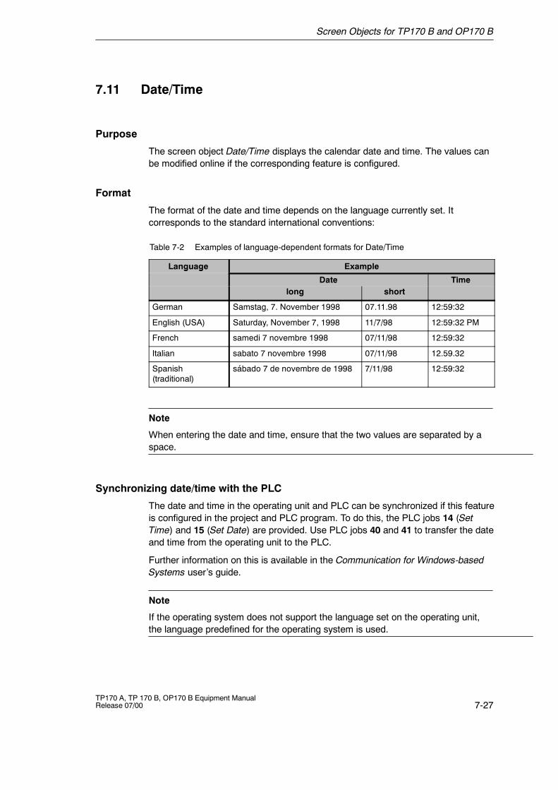
Screen Objects for TP170 B and OP170 B
7-27TP170 A, TP 170 B, OP170 B Equipment ManualRelease 07/00
7.11 Date/Time
Purpose
The screen object Date/Time displays the calendar date and time. The values canbe modified online if the corresponding feature is configured.
Format
The format of the date and time depends on the language currently set. Itcorresponds to the standard international conventions:
Table 7-2 Examples of language-dependent formats for Date/Time
Language Exampleg g
Date Timelong short
German Samstag, 7. November 1998 07.11.98 12:59:32
English (USA) Saturday, November 7, 1998 11/7/98 12:59:32 PM
French samedi 7 novembre 1998 07/11/98 12:59:32
Italian sabato 7 novembre 1998 07/11/98 12.59.32
Spanish(traditional)
sábado 7 de novembre de 1998 7/11/98 12:59:32
Note
When entering the date and time, ensure that the two values are separated by aspace.
Synchronizing date/time with the PLC
The date and time in the operating unit and PLC can be synchronized if this featureis configured in the project and PLC program. To do this, the PLC jobs 14 (SetTime) and 15 (Set Date) are provided. Use PLC jobs 40 and 41 to transfer the dateand time from the operating unit to the PLC.
Further information on this is available in the Communication for Windows-basedSystems user’s guide.
Note
If the operating system does not support the language set on the operating unit,the language predefined for the operating system is used.
Screen Objects for TP170 B and OP170 B
7-28TP170 A, TP 170 B, OP170 B Equipment Manual
Release 07/00
7.12 Password List
Purpose
While the system is being configured using ProTool CS, operating elements can beprotected against unauthorized use by means of passwords. Important parametersand settings can then only be modified by authorized personnel.
Password hierarchy
Hierarchically defined password levels from 0 to 9 exist for password protectionpurposes. When a password is assigned to an individual user or to a whole usergroup, the permission to execute functions at a specific level is assignedsimultaneously. If, for example, a user is assigned to password level 4, he or she isauthorized to execute functions of password levels 0 to 4.
Password level
Password level 0:This minimum password level is assigned to functions that have no, or only aminimal effect on the course of the process. In order to trigger functions assignedto Password Level 0, no password needs to be entered.
Password levels 1 to 8:Functions are assigned to levels 1 to 8 according to their increasing importance.The operating unit requests a password before a function with a password levelhigher than 0 can be executed.
Password level 9Only the supervisor (system support specialist or service technician) is grantedauthorization to execute functions assigned to password level 9. The supervisor isauthorized to access all the functions on the operating unit.
Logging in on the operating unit (login)
After calling a password-protected function, the operating unit automaticallyprompts the user to enter a password. Once entered, the password need not beentered again in order to call in other functions of this password level or lower.
When correspondingly configured, it is also possible to log on via an input field forconfidential password entry. The character string entered is represented byplaceholders (*).
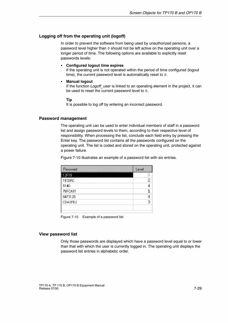
Screen Objects for TP170 B and OP170 B
7-29TP170 A, TP 170 B, OP170 B Equipment ManualRelease 07/00
Logging off from the operating unit (logoff)
In order to prevent the software from being used by unauthorized persons, apassword level higher than 0 should not be left active on the operating unit over alonger period of time. The following options are available to explicitly resetpasswords levels:
S Configured logout time expiresIf the operating unit is not operated within the period of time configured (logouttime), the current password level is automatically reset to 0.
S Manual logoutIf the function Logoff_user is linked to an operating element in the project, it canbe used to reset the current password level to 0.
TipIt is possible to log off by entering an incorrect password.
Password management
The operating unit can be used to enter individual members of staff in a passwordlist and assign password levels to them, according to their respective level ofresponsibility. When processing the list, conclude each field entry by pressing theEnter key. The password list contains all the passwords configured on theoperating unit. The list is coded and stored on the operating unit, protected againsta power failure.
Figure 7-10 illustrates an example of a password list with six entries.
Figure 7-10 Example of a password list
View password list
Only those passwords are displayed which have a password level equal to or lowerthan that with which the user is currently logged in. The operating unit displays thepassword list entries in alphabetic order.
Screen Objects for TP170 B and OP170 B
7-30TP170 A, TP 170 B, OP170 B Equipment Manual
Release 07/00
Creating a password
The user can only edit the password list up to the level with which he is currentlylogged in. All passwords used in the system must be unique. It is not possible toassign identical passwords to different users. It is possible, however, to assign thesame password level to different users without any restrictions.
Deleting a password
To delete a password from the password list, overwrite the password levelassigned to it with 0.
Export/Import password list
If a system includes several operating units which are accessed by the sameusers, the same passwords must be installed on each operating unit. In order thatthe password list need not be re-entered on each operating unit, it can be createdon one unit and imported onto other units.
In order to be able to export/import password lists on the operating unit, thefunction Import_export_passwords must be linked to a button or function key, forexample. The file name of the password list to be exported/imported must bespecified as the function parameter during configuration.
Note
The password list is coded. It cannot be edited with external tools.
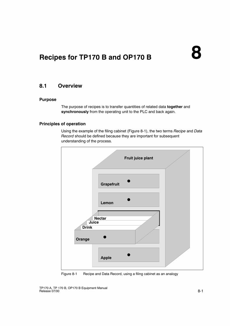
8-1TP170 A, TP 170 B, OP170 B Equipment ManualRelease 07/00
Recipes for TP170 B and OP170 B
8.1 Overview
Purpose
The purpose of recipes is to transfer quantities of related data together andsynchronously from the operating unit to the PLC and back again.
Principles of operation
Using the example of the filing cabinet (Figure 8-1), the two terms Recipe and DataRecord should be defined because they are important for subsequentunderstanding of the process.
Fruit juice plant
Grapefruit
Lemon
Orange
Drink
NectarJuice
Apple
Figure 8-1 Recipe and Data Record, using a filing cabinet as an analogy
8
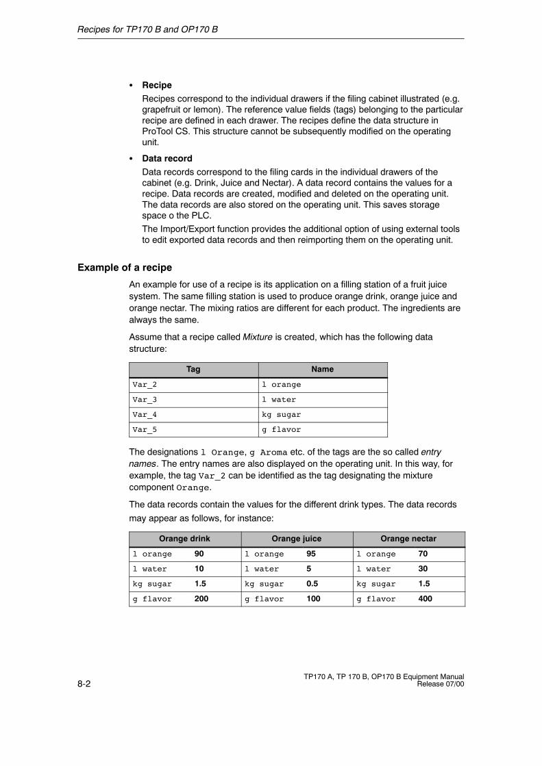
Recipes for TP170 B and OP170 B
8-2TP170 A, TP 170 B, OP170 B Equipment Manual
Release 07/00
S RecipeRecipes correspond to the individual drawers if the filing cabinet illustrated (e.g.grapefruit or lemon). The reference value fields (tags) belonging to the particularrecipe are defined in each drawer. The recipes define the data structure inProTool CS. This structure cannot be subsequently modified on the operatingunit.
S Data recordData records correspond to the filing cards in the individual drawers of thecabinet (e.g. Drink, Juice and Nectar). A data record contains the values for arecipe. Data records are created, modified and deleted on the operating unit.The data records are also stored on the operating unit. This saves storagespace o the PLC.The Import/Export function provides the additional option of using external toolsto edit exported data records and then reimporting them on the operating unit.
Example of a recipe
An example for use of a recipe is its application on a filling station of a fruit juicesystem. The same filling station is used to produce orange drink, orange juice andorange nectar. The mixing ratios are different for each product. The ingredients arealways the same.
Assume that a recipe called Mixture is created, which has the following datastructure:
Tag Name
Var_2 l orange
Var_3 l water
Var_4 kg sugar
Var_5 g flavor
The designations l Orange, g Aroma etc. of the tags are the so called entrynames. The entry names are also displayed on the operating unit. In this way, forexample, the tag Var_2 can be identified as the tag designating the mixturecomponent Orange.
The data records contain the values for the different drink types. The data records
may appear as follows, for instance:
Orange drink Orange juice Orange nectar
l orange 90 l orange 95 l orange 70
l water 10 l water 5 l water 30
kg sugar 1.5 kg sugar 0.5 kg sugar 1.5
g flavor 200 g flavor 100 g flavor 400
Recipes for TP170 B and OP170 B
8-3TP170 A, TP 170 B, OP170 B Equipment ManualRelease 07/00
8.2 Recipe Configuration
Basic procedure
The basic steps to configuring a recipe are listed below:
1. Define the structure of the recipe:Assign tags to the recipe structure. These tags are provided with entries fromthe data records.Define a name for the recipe. This name is used to select the recipe in theproject and on the operating unit.
2. Set recipe tag propertiesThe following options can be configured in ProTool CS:-- Synchronize tags
This option defines that the data from a data record has been read from thePLC or data medium and written in the tag or read from the tags configuredfor the recipe. This establishes a connection between the tags configured inthe recipe and the tags in the screens. When a data record is loaded, thevalues are written to the tags used in the screens.
-- Tags offlineIf this option is also activated, the values entered are only stored in the tags,and not transferred to the PLC. Otherwise, values entered are transferreddirectly to the PLC.
3. Define data record storage medium operating unitThe data storage location for data records can be configured. The followingsettings are possible:-- Internal Flash-- Memory card (CF card)
4. Set download synchronizationIt is possible to configure whether the data records are downloaded to the PLCwith or without synchronization.
5. Creating a recipe screenConfigure one or more screens in order to create, store and download datarecords on the operating unit.
Further information
Detailed information on how to create a recipe is provided in the online help to theProTool CS configuration software and in theProTool Configuring Windows-basedSystems user’s guide.
Recipes for TP170 B and OP170 B
8-4TP170 A, TP 170 B, OP170 B Equipment Manual
Release 07/00
System limits
The table provides an overview of the system limits for recipes.
Elements Number
Number of recipes 20
Data records per recipe 501)
Entries per recipe 60
1) Dependent on storage medium used
Memory requirements for data records
The memory requirements per recipe (in kByte) is calculated from the threesummands D1 + D2 + D3.
The following applies:
D1 = [(no. of entries x 20) + 4] : 1024D2 = [(no. of data records x 12) + 4] : 1024D3 = [no. of data records x (data record length + N) + 4] : 1024
D1, D2 and D3 are rounded up to the next whole number.
The following applies for N:
Data record name < 13 characters: N = 12Data record name > 12 characters: N = 40
Note
The internal Flash memory has a maximum storage capacity of 32 kByte.
Recipes for TP170 B and OP170 B
8-5TP170 A, TP 170 B, OP170 B Equipment ManualRelease 07/00
8.3 Editing Data Records
In this chapter
This chapter provides information on how to edit data records on the operating unit.The following information is included:
S Layout of the recipe view (Page 8-6)S Displaying data records (Page 8-9)S Creating new data records (Page 8-9)S Copying data records (Page 8-10)S Modifying data records (Page 8-11)S Renaming data records (Page 8-12)S Deleting data records (Page 8-12)S Reading data records from the PLC (Page 8-13)S Downloading data records to the PLC (Page 8-13)S Editing data records in recipe screens (Page 8-14)S Functions and PLC jobs (Page 8-16)S Exporting/Importing data records (Page 8-17)S Exporting, editing and importing data records (Page 8-19)S Response following modification of recipe structure (Page 8-20)
Methods
Data records can be edited on the operating unit in tables or screens:
S Tabular editingThe recipe view is available for the tabular editing of data records (Page 8-6).The recipe view enables recipes and data records to be handled in anuncomplicated, quick way.It is typically used to edit data records of smaller recipes. Values entered on theoperating unit are not directly transferred to the PLC when entered.
S Editing in recipe screensThe project engineer can use recipe screens (Page 8-14) to customize the userinterface for editing data records and, for example, simulating the systemvisually, providing graphics and individual masks for entering data records.This method is typically used for processing medium and large data recordsoffline in the recipe view. The values entered on the operating unit are onlysaved in the tags, but not transferred directly to the PLC on input.
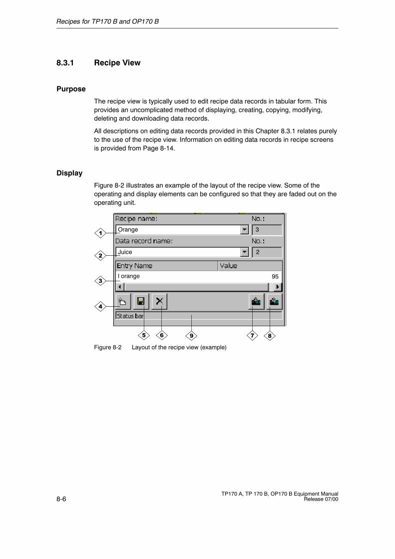
Recipes for TP170 B and OP170 B
8-6TP170 A, TP 170 B, OP170 B Equipment Manual
Release 07/00
8.3.1 Recipe View
Purpose
The recipe view is typically used to edit recipe data records in tabular form. Thisprovides an uncomplicated method of displaying, creating, copying, modifying,deleting and downloading data records.
All descriptions on editing data records provided in this Chapter 8.3.1 relates purelyto the use of the recipe view. Information on editing data records in recipe screensis provided from Page 8-14.
Display
Figure 8-2 illustrates an example of the layout of the recipe view. Some of theoperating and display elements can be configured so that they are faded out on theoperating unit.
Juice
l orange 95
2
3Orange
Figure 8-2 Layout of the recipe view (example)
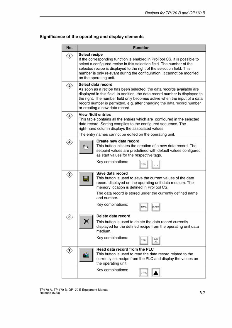
Recipes for TP170 B and OP170 B
8-7TP170 A, TP 170 B, OP170 B Equipment ManualRelease 07/00
Significance of the operating and display elements
No. Function
Select recipeIf the corresponding function is enabled in ProTool CS, it is possible toselect a configured recipe in this selection field. The number of theselected recipe is displayed to the right of the selection field. Thisnumber is only relevant during the configuration. It cannot be modifiedon the operating unit.
Select data recordAs soon as a recipe has been selected, the data records available aredisplayed in this field. In addition, the data record number is displayed tothe right. The number field only becomes active when the input of a datarecord number is permitted, e.g. after changing the data record numberor creating a new data record.
View /Edit entriesThis table contains all the entries which are configured in the selecteddata record. Sorting complies to the configured sequence. Theright-hand column displays the associated values.The entry names cannot be edited on the operating unit.
Create new data recordThis button initiates the creation of a new data record. Thesetpoint values are predefined with default values configuredas start values for the respective tags.
Key combinations:
Save data recordThis button is used to save the current values of the daterecord displayed on the operating unit data medium. Thememory location is defined in ProTool CS.The data record is stored under the currently defined nameand number.
Key combinations:
Delete data recordThis button is used to delete the data record currentlydisplayed for the defined recipe from the operating unit datamedium.
Key combinations:
Read data record from the PLCThis button is used to read the data record related to thecurrently set recipe from the PLC and display the values onthe operating unit.
Key combinations:
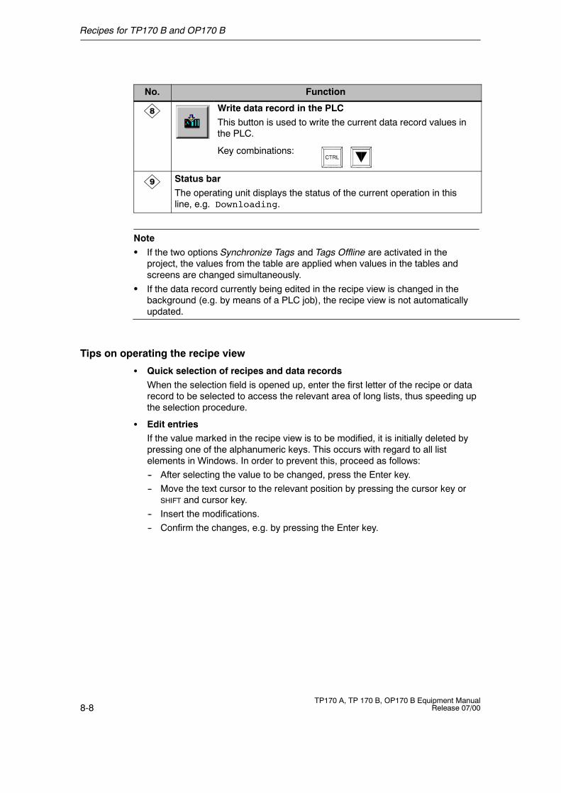
Recipes for TP170 B and OP170 B
8-8TP170 A, TP 170 B, OP170 B Equipment Manual
Release 07/00
FunctionNo.
Write data record in the PLCThis button is used to write the current data record values inthe PLC.
Key combinations:
Status barThe operating unit displays the status of the current operation in thisline, e.g. Downloading.
NoteS If the two options Synchronize Tags and Tags Offline are activated in the
project, the values from the table are applied when values in the tables andscreens are changed simultaneously.
S If the data record currently being edited in the recipe view is changed in thebackground (e.g. by means of a PLC job), the recipe view is not automaticallyupdated.
Tips on operating the recipe view
S Quick selection of recipes and data recordsWhen the selection field is opened up, enter the first letter of the recipe or datarecord to be selected to access the relevant area of long lists, thus speeding upthe selection procedure.
S Edit entriesIf the value marked in the recipe view is to be modified, it is initially deleted bypressing one of the alphanumeric keys. This occurs with regard to all listelements in Windows. In order to prevent this, proceed as follows:-- After selecting the value to be changed, press the Enter key.-- Move the text cursor to the relevant position by pressing the cursor key or
SHIFT and cursor key.-- Insert the modifications.-- Confirm the changes, e.g. by pressing the Enter key.

Recipes for TP170 B and OP170 B
8-9TP170 A, TP 170 B, OP170 B Equipment ManualRelease 07/00
Displaying data records
Proceed as follows to display data records on the operating unit data medium:
Step Procedure
1 Select recipe Step 1 is only possible when recipe selection has beenconfigured.
S Select the selection field for the configured recipes(Position 1 in the figure on Page 8-6).
S Open the selection field and mark the required recipe in theopened selection list.
S Confirm the selection.
2 Select data record S Select the selection field for the existing data records(Position 2 in the figure on Page 8-6).
S Open the selection field and mark the required data record inthe opened selection list.
S Confirm the selection.The selected data record is loaded. The configured entriesare displayed in table form with name and setpoint value.
Creating new data records
Proceed as follows to create new data records on the operating unit:
Step Procedure
1 Select recipe S Select the required recipe, as described in Step 1 on Page8-9.
2 Create data record S Press the key depicted on the left.y pThe name and number of the data record displayed aredeleted. The entries in the table are assigned the configuredstart values.
3 Enter data recordname
S Enter a new data record name in the selection field for datarecords (Position 2 in the figure on Page 8-6).
S After entering the data record name, the next free datarecord number is automatically entered on the right. Thisnumber can be changed, if necessary.
4 Change values S Enter a setpoint value for each entry configured in the table(Position 3 in the figure on Page 8-6).
5 Save data record S Press the key depicted on the left.
Th d d i i h d diThe new data record is written on the data medium.
The operating unit responds with a system message if thename or number entered already exist. The writing process isnot executed in this case.
Recipes for TP170 B and OP170 B
8-10TP170 A, TP 170 B, OP170 B Equipment Manual
Release 07/00
Note
The data storage location for the new data record can be configured. The followingsettings are possible:
S Internal FlashS Memory card (CF card)
Copying data records
In order to copy data records, save them under new names. Proceed as follows:
Step Procedure
1 Select recipe anddata record
S Select the required recipe and the data record to be copiedas described in Steps 1 and 2 on Page 8-9.
2 Enter data recordname
S Enter a new data record name in the selection field for datarecords (Position 2 in the figure on Page 8-6).
S After entering the data record name, the next free datarecord number is automatically entered on the right. Thisnumber can be changed, if necessary.
3 Save data record S Press the key depicted on the left.y p
The new data record is written on the data medium.
The operating unit responds with a system message if thename or number entered already exist.
Recipes for TP170 B and OP170 B
8-11TP170 A, TP 170 B, OP170 B Equipment ManualRelease 07/00
Changing data records
Proceed as follows to change existing data records:
Step Procedure
1 Select recipe anddata record
S Select the required recipe and the data record to be changedas described in Steps 1 and 2 on Page 8-9.
2 Change values S Change the setpoint value in the table (Position 3 in thefigure on Page 8-6).
The entry names cannot be edited on the operating unit.
3 Save data record S Press the key depicted on the left.y p
The modified data record overwrites the original data recordon the data medium.
Recipes for TP170 B and OP170 B
8-12TP170 A, TP 170 B, OP170 B Equipment Manual
Release 07/00
Renaming data records
Proceed as follows to rename existing data records:
Step Procedure
1 Select recipe anddata record
S Select the required recipe and the data record to be copiedas described in Steps 1 and 2 on Page 8-9.
2 Enter data recordname
S Enter a new data record name in the selection field for datarecords (Position 2 in the figure on Page 8-6).
S After entering the data record name, the next free datarecord number is automatically entered on the right. Resetthis number to its original value.
3 Save data record S Press the key depicted on the left.
Th d d i i h d di d hThe data record is written on the data medium under the newname.
The operating unit responds with a system message if thename or number entered already exist.
Deleting data records
Proceed as follows to delete data records on the operating unit data medium:
Step Procedure
1 Select recipe anddata record
S Select the required recipe and the data record to be changedas described in Steps 1 and 2 on Page 8-9.
2 Delete data record S Press the key depicted on the left.y p
The data record is deleted from the data medium afterconfirming a confirmation request.
Recipes for TP170 B and OP170 B
8-13TP170 A, TP 170 B, OP170 B Equipment ManualRelease 07/00
Reading data records from the PLC
Proceed as follows to update data records in the operating unit working memorywith values from the PLC:
Step Procedure
1 Select recipe S Select the required recipe, as described in Step 1 onPage 8-9.
2 Read values S Press the key depicted on the left.y p
S The current values are read from the PLC and displayed.
3 Edit data records S The data can then be edited, e.g. values modified, saved,downloaded to PLC, etc.
The operating unit responds with a system message ifdownloading from the PLC is not possible because, in caseswhere synchronization with the PLC is configured, forexample, the data mailbox is currently locked.
Downloading data records to the PLC
In order that a modified or new data record can take effect in the PLC, it must bedownloaded to the PLC.
Proceed as follows to download data records to the PLC:
Step Procedure
1 Select recipe anddata record
S Select the required recipe and the data record to bedownloaded as described in Steps 1 and 2 on Page 8-9.
2 Write values S Press the key depicted on the left.
The values are written in the PLCThe values are written in the PLC.
The operating unit responds with a system message ifdownloading to the PLC is not possible because, in caseswhere synchronization with the PLC is configured, forexample, the data mailbox is currently locked.
Recipes for TP170 B and OP170 B
8-14TP170 A, TP 170 B, OP170 B Equipment Manual
Release 07/00
8.3.2 Recipe Screens
Purpose
Recipe screens are typically representations of the system. The screens providedisplay and operating elements with which to create, save, modify, delete anddownload data records. Large recipes can be split into several topic-specificscreens and clearly displayed, e.g. with graphic elements.
Components for editing data records
In order to be able to edit data records in recipe screens on the operating unit, thecorresponding components, e.g. input/output fields and functions, must beconfigured:
S Recipe view:Recipe screens can contain a recipe view (Page 8-6) not only to enable theeasy selection of recipes and data records but also for editing data records. Theconfigured functional scope of the recipe view can vary, according to theintended purpose.Information on editing data records in recipe screens is provided fromPage 8-6. The instructions stipulated there generally also apply for editing datarecords in recipe screens. However, in this case, input is performed in thescreens.
S Functions:Depending on whether a recipe view is configured in the project or not, and onthe properties assigned to it, there are various functions available to transferdata records between the operating unit and PLC, e.g.:-- Load_Data_Record-- Save_Date_Record-- Data_Record_PLC_to_Tags-- Data_Record_Tag_to_PLC
More functions and PLC jobs, which are linked to the downloading of data records,are described on Page 8-16.
Editing data records offline
The way in which data records are edited on the operating unit is defined duringconfiguration. It is typically used for the offline editing of data records in recipescreens. Values entered on the operating unit are not directly transferred to thePLC when entered.
Proceed as follows to edit data screens in recipe screens offline:
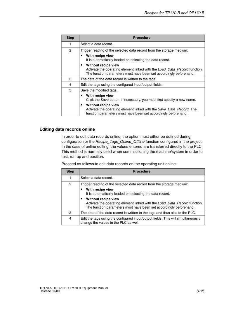
Recipes for TP170 B and OP170 B
8-15TP170 A, TP 170 B, OP170 B Equipment ManualRelease 07/00
Step Procedure
1 Select a data record.
2 Trigger reading of the selected data record from the storage medium:
S With recipe viewIt is automatically loaded on selecting the data record.
S Without recipe viewActivate the operating element linked with the Load_Data_Record function.The function parameters must have been set accordingly beforehand.
3 The data of the data record is written to the tags.
4 Edit the tags using the configured input/output fields.
5 Save the modified tags.
S With recipe viewClick the Save button. If necessary, you must first specify a new name.
S Without recipe viewActivate the operating element linked with the Save_Date_Record. Thefunction parameters must have been set accordingly beforehand.
Editing data records online
In order to edit data records online, the option must either be defined duringconfiguration or the Recipe_Tags_Online_Offline function configured in the project.In the case of online editing, the values entered are transferred directly to the PLC.This method is normally used when commissioning the machine/system in order totest, run-up and position.
Proceed as follows to edit data records on the operating unit online:
Step Procedure
1 Select a data record.
2 Trigger reading of the selected data record from the storage medium:
S With recipe viewIt is automatically loaded on selecting the data record.
S Without recipe viewActivate the operating element linked with the Load_Data_Record function.The function parameters must have been set accordingly beforehand.
3 The data of the data record is written to the tags and thus also to the PLC.
4 Edit the tags using the configured input/output fields. This will simultaneouslychange the values in the PLC as well.
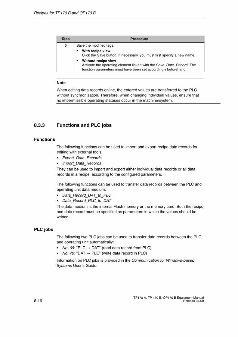
Recipes for TP170 B and OP170 B
8-16TP170 A, TP 170 B, OP170 B Equipment Manual
Release 07/00
ProcedureStep
5 Save the modified tags.
S With recipe viewClick the Save button. If necessary, you must first specify a new name.
S Without recipe viewActivate the operating element linked with the Save_Date_Record. Thefunction parameters must have been set accordingly beforehand.
Note
When editing data records online, the entered values are transferred to the PLCwithout synchronization. Therefore, when changing individual values, ensure thatno impermissible operating statuses occur in the machine/system.
8.3.3 Functions and PLC jobs
Functions
The following functions can be used to import and export recipe data records forediting with external tools:S Export_Data_RecordsS Import_Data_RecordsThey can be used to import and export either individual data records or all datarecords in a recipe, according to the configured parameters.
The following functions can be used to transfer data records between the PLC andoperating unit data medium.S Data_Record_DAT_to_PLCS Data_Record_PLC_to_DATThe data medium is the internal Flash memory or the memory card. Both the recipeand data record must be specified as parameters in which the values should bewritten.
PLC jobs
The following two PLC jobs can be used to transfer data records between the PLCand operating unit automatically:S No. 69: “PLC � DAT” (read data record from PLC)S No. 70: “DAT � PLC” (write data record in PLC)
Information on PLC jobs is provided in the Communication for Windows-basedSystems User’s Guide.
Recipes for TP170 B and OP170 B
8-17TP170 A, TP 170 B, OP170 B Equipment ManualRelease 07/00
8.3.4 Import/Export Data Records
Purpose
When the appropriate features have been configured, data records on theoperating unit can be exported as CSV files to the data medium. This feature canbe used to edit data records with external tools, e.g. with a spreadsheet program ortext editor, and import them on the operating unit again.
Condition
In order to export and import data records during runtime, the project must containthe following functions:
S Export_Data_Records
S Import_Data_Records
These functions must be linked in the ProTool CS configuration software, e.g. to afunction key or button.
File format CSV
With file format CSV, the table columns (entry name and value) are separated by aseparator (e.g. semicolon). Each table row (entry) is terminated by a line feed.
The example in Figure 8-2 (Page 8-6) appears as follows in CSV format for theindividually exported data record Juice:
Orange;Juice
3;2
Var_2;95
Var_3;5
Var_4;0.5
Var_5;100
Additional information is stored in the first two lines:
S Line 1:Name of the recipe and data record
S Line 2:Number of the recipe and data record
The operating unit interprets the information on importing the file.
Note
When the CSV files are edited with an external text editor, the modifications aresaved in text format (without control codes).

Recipes for TP170 B and OP170 B
8-18TP170 A, TP 170 B, OP170 B Equipment Manual
Release 07/00
Export/Import all data records in a recipe
When appropriately configured, all the data records in a recipe can beimported/exported together. The CSV file for the example on Page 8-2 thenappears as follows:
Orange;Drink;Juice;Nectar
3;1;2;3
Var_2;90;95;70
Var_3;10;5;30
Var_4;1.5;0.5;1.5
Var_5;200;100;400
Additional information is stored in the first two lines:
S Line 1:Name of the recipe and all the configured data records
S Line 2:Number of the recipe and all the configured data records
The operating unit interprets the information on importing the file.
In this way, the CSV file can be used, for example, to create new data records bymeans of a spreadsheet program (Figure 8-3). After importing the modified file, thenew data records can be used on the operating unit.
Figure 8-3 Create data records externally (example: MicrosoftR Excel)
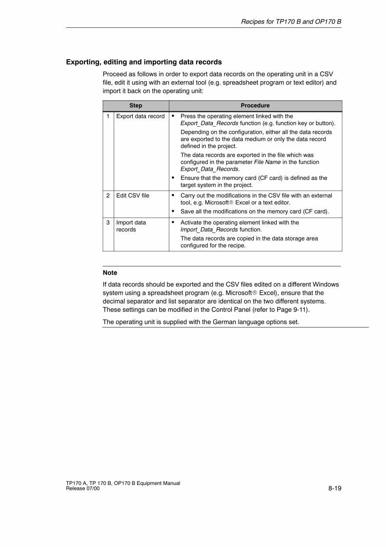
Recipes for TP170 B and OP170 B
8-19TP170 A, TP 170 B, OP170 B Equipment ManualRelease 07/00
Exporting, editing and importing data records
Proceed as follows in order to export data records on the operating unit in a CSVfile, edit it using with an external tool (e.g. spreadsheet program or text editor) andimport it back on the operating unit:
Step Procedure
1 Export data record S Press the operating element linked with theExport_Data_Records function (e.g. function key or button).
Depending on the configuration, either all the data recordsare exported to the data medium or only the data recorddefined in the project.
The data records are exported in the file which wasconfigured in the parameter File Name in the functionExport_Data_Records.
S Ensure that the memory card (CF card) is defined as thetarget system in the project.
2 Edit CSV file S Carry out the modifications in the CSV file with an externaltool, e.g. MicrosoftR Excel or a text editor.
S Save all the modifications on the memory card (CF card).
3 Import datarecords
S Activate the operating element linked with theImport_Data_Records function.
The data records are copied in the data storage areaconfigured for the recipe.
Note
If data records should be exported and the CSV files edited on a different Windowssystem using a spreadsheet program (e.g. MicrosoftR Excel), ensure that thedecimal separator and list separator are identical on the two different systems.These settings can be modified in the Control Panel (refer to Page 9-11).
The operating unit is supplied with the German language options set.
Recipes for TP170 B and OP170 B
8-20TP170 A, TP 170 B, OP170 B Equipment Manual
Release 07/00
8.3.5 Reaction on Changing the Recipe Structure
Standard behavior
The following section describes the standard behavior of the operating unit when itdetects differences between the data record structure stored on the data mediumand the recipe structure currently loaded on the operating unit.
Load and export data records, and write in the PLC
S The data record on the data medium contains additional tags:The values are rejected.
S The data record on the data medium contains values which cannot beconverted to the assigned tag type:The configured start value for the tag is used.
S Tags are missing in the data record on the data medium:The configured start value for the tag is used.
Note
The assignment is lost on changing the tag name.
Import data records
S The imported data record contains additional tags:The values are rejected.
S The imported data record contains values which cannot be converted to theassigned tag type:The configured start value for the tag is used. This occurs, for example, whenthe tag type in the project has been changed.
S Tags are missing in the imported data record:The configured start value for the tag is used.
Tip
Export the data record after changing the recipe structure and check the exportedvalues. In this case, observe the note on Page 8-11.
9-1TP170 A, TP 170 B, OP170 B Equipment ManualRelease 07/00
System Settings
This chapter provides information on the following general settings which can bemodified on the operating unit online:
Overview for TP170 A
S Operating mode (Page 9-2)
S Screen contrast and calibration (Page 9-3)
S Screen saver response time (Page 9-5)
Overview for TP170 B and OP170 B
S Language (Page 9-6)
S Operating mode (Page 9-7)
S Screen settings (Page 9-8)
S Settings on WindowsRCE Control Panel (from Page 9-10)
-- Date/Time
-- Registration
-- Language setting
-- Printer
9
System Settings
9-2TP170 A, TP 170 B, OP170 B Equipment Manual
Release 07/00
9.1 TP170 A Settings
9.1.1 Setting an Operating Mode
Conditions for changing operating modes
In order to switch between the operating modes described below, the functionChange mode must be linked to an operating element in the project.
Operating modes
It is possible to switch between various operating modes on the operating unit:
Offline modeIn this mode there is no logical connection between the operating unit and PLC.The operating unit can be operated, but processes cannot be operated orvisualized.
Online modeWhen using this mode, processes can be operated and visualized withoutrestriction. There is a logical connection between the operating unit and PLC or theoperating unit attempts to establish one.Online mode is the predefined operating mode each time the operating unit isstarted up.
Download modeThis operating mode is used to transfer a configuration from the configurationcomputer to the operating unit. Further information on Download mode is providedin Chapter 3.3.
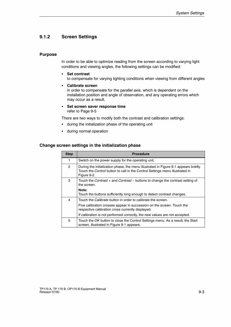
System Settings
9-3TP170 A, TP 170 B, OP170 B Equipment ManualRelease 07/00
9.1.2 Screen Settings
Purpose
In order to be able to optimize reading from the screen according to varying lightconditions and viewing angles, the following settings can be modified:
S Set contrastto compensate for varying lighting conditions when viewing from different angles
S Calibrate screenin order to compensate for the parallel axis, which is dependent on theinstallation position and angle of observation, and any operating errors whichmay occur as a result.
S Set screen saver response timerefer to Page 9-5
There are two ways to modify both the contrast and calibration settings:
S during the initialization phase of the operating unit
S during normal operation
Change screen settings in the initialization phase
Step Procedure
1 Switch on the power supply for the operating unit.
2 During the initialization phase, the menu illustrated in Figure 9-1 appears briefly.Touch the Control button to call in the Control Settings menu illustrated inFigure 9-2.
3 Touch the Contrast + and Contrast -- buttons to change the contrast setting ofthe screen.
Note:Touch the buttons sufficiently long enough to detect contrast changes.
4 Touch the Calibrate button in order to calibrate the screen.
Five calibration crosses appear in succession on the screen. Touch therespective calibration cross currently displayed.
If calibration is not performed correctly, the new values are not accepted.
5 Touch the OK button to close the Control Settings menu. As a result, the Startscreen, illustrated in Figure 9-1 appears.
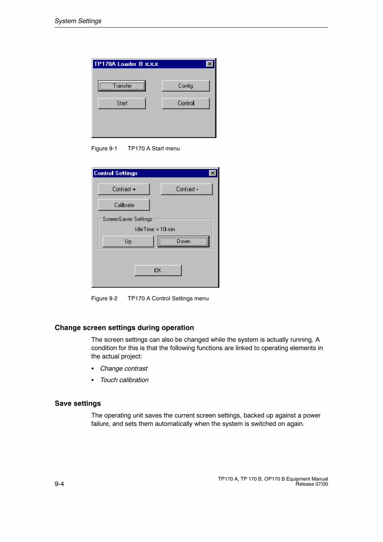
System Settings
9-4TP170 A, TP 170 B, OP170 B Equipment Manual
Release 07/00
New:
Figure 9-1 TP170 A Start menu
New:
Figure 9-2 TP170 A Control Settings menu
Change screen settings during operation
The screen settings can also be changed while the system is actually running. Acondition for this is that the following functions are linked to operating elements inthe actual project:
S Change contrast
S Touch calibration
Save settings
The operating unit saves the current screen settings, backed up against a powerfailure, and sets them automatically when the system is switched on again.
System Settings
9-5TP170 A, TP 170 B, OP170 B Equipment ManualRelease 07/00
9.1.3 Set Screen Saver Response Time
The TP170 A has its own screen saver which is activated when the touch panel isnot operated for a specified length of time. The screen saver is inactive by default.
In order to set the screen saver response time, use the “Up” and “Down” buttons inthe TP170 A Control Settings menu (Figure9-2).
The screen saver is deactivated when system messages arrive. When the definedtime has elapsed, it is reactivated.
System Settings
9-6TP170 A, TP 170 B, OP170 B Equipment Manual
Release 07/00
9.2 Settings for TP170 B and OP170 B
9.2.1 Set Language
Language-dependent objects
When downloading the project from the configuration computer, up to threelanguages can be loaded on the operating unit. It is possible to switch between thelanguages, online, at any time and display language-dependent objects (texts andformats) in other languages.
The following are language-dependent, for example
S Messages
S Screens
S Text lists
S Help texts
S Date/Time
Conditions for changing languages
In order to change languages on the operating unit while it is in operation, thefollowing conditions must be fulfilled:
S The selected language must have been loaded on the operating unit. Theproject languages available during runtime are defined in ProTool CS underSystem � Language Assignment: OP Languages.
S The Language function must be assigned to an operating element, e.g. afunction key or button.
Each time the unit is started up, all language dependent texts are displayed in thelanguage set at the top of the configured languages list.
Change language
Immediately after activating the function, all the language dependent objects aredisplayed in the new language.
Two different types of language change can be configured:
1. Each time the function is activated, the operating unit switches one languagefurther, cyclically.
2. After activating the function, the language can be explicitly selected.
System Settings
9-7TP170 A, TP 170 B, OP170 B Equipment ManualRelease 07/00
9.2.2 Setting an Operating Mode
Conditions for changing operating modes
In order to switch between the operating modes described below, the functionChange mode must be linked to an operating element in the project.
Operating modes
It is possible to switch between various operating modes on the operating unit:
Offline modeIn this mode there is no logical connection between the operating unit and PLC.The operating unit can be operated, but processes cannot be operated orvisualized.
Online modeWhen using this mode, processes can be operated and visualized withoutrestriction. There is a logical connection between the operating unit and PLC or theoperating unit attempts to establish one.Online mode is the predefined operating mode each time the operating unit isstarted up.
Download modeThis operating mode is used to transfer a configuration from the configurationcomputer to the operating unit. Further information on download mode is providedin Chapter 3.3.
System Settings
9-8TP170 A, TP 170 B, OP170 B Equipment Manual
Release 07/00
9.2.3 Screen Settings
Purpose
n order to be able to optimize reading from the screen according to varying lightconditions and viewing angles, the following settings can be modified:
S Set contrastto compensate for varying lighting conditions when viewing from different angles
S Calibrate screenin order to compensate for the parallel axis, which is dependent on theinstallation position and angle of observation, and any operating errors whichmay occur as a result.
There are two options for this setting:
S during the start-up phase of the operating unit
S during normal operation
Setting the screen during the start-up phase (TP170 B)
Step Procedure
1 Switch on the power supply for the operating unit.
2 During the start-up phase, the menu illustrated in Figure 9-3 appears briefly.Touch the Control button to call in the Control Settings menu illustrated inFigure 9-4.
3 Touch the Contrast + and Contrast -- buttons to change the contrast setting ofthe screen.
Note:Touch the buttons sufficiently long enough to detect contrast changes.
4 Touch the Calibrate button in order to calibrate the screen.
Five calibration crosses appear in succession on the screen. Touch therespective calibration cross currently displayed.
If calibration is not performed correctly, the new values are not accepted.
5 Touch the OK button to close the Control Settings menu. As a result, the Startscreen, illustrated in Figure 9-3 appears.
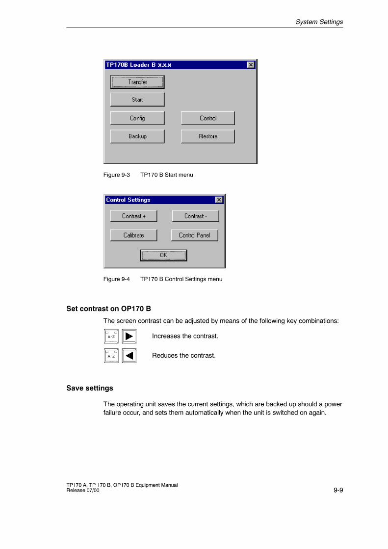
System Settings
9-9TP170 A, TP 170 B, OP170 B Equipment ManualRelease 07/00
New:
Figure 9-3 TP170 B Start menu
Figure 9-4 TP170 B Control Settings menu
Set contrast on OP170 B
The screen contrast can be adjusted by means of the following key combinations:
Increases the contrast.
Reduces the contrast.
Save settings
The operating unit saves the current settings, which are backed up should a powerfailure occur, and sets them automatically when the unit is switched on again.
System Settings
9-10TP170 A, TP 170 B, OP170 B Equipment Manual
Release 07/00
9.2.4 Control Panel Settings
The WindowsRRRRCE Control Panel
The following settings can be defined for the system using the WindowsRCEControl Panel:
S Communication
S Registration
S Language settings
S Printer
Changing the settings using the Control Panel
Proceed as follows to change settings in the Control Panel:
Step Procedure
1 Open the Control Panel
In order to open the Control Panel, press the Control Panel button in theTP170 B Control Settings menu (Figure 9-4) or OP170 B Start menu(Figure 9-5).
2 Exit Runtime
Stop the runtime software before starting to change any system settings.
3 Change language settings
Change the settings for the system in the Control Panel.
4 Save unit settings
Save the current settings permanently (refer to Page 9-11).
5 Close Control Panel
Close the Control Panel using the menu bar.
6 Restart runtime
Start the runtime software via the Start menu.
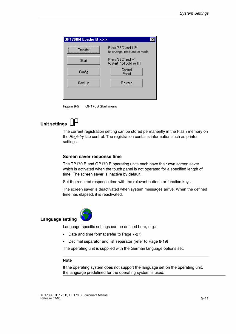
System Settings
9-11TP170 A, TP 170 B, OP170 B Equipment ManualRelease 07/00
New:
Figure 9-5 OP170B Start menu
Unit settings
The current registration setting can be stored permanently in the Flash memory onthe Registry tab control. The registration contains information such as printersettings.
Screen saver response time
The TP170 B and OP170 B operating units each have their own screen saverwhich is activated when the touch panel is not operated for a specified length oftime. The screen saver is inactive by default.
Set the required response time with the relevant buttons or function keys.
The screen saver is deactivated when system messages arrive. When the definedtime has elapsed, it is reactivated.
Language setting
Language-specific settings can be defined here, e.g.:
S Date and time format (refer to Page 7-27)
S Decimal separator and list separator (refer to Page 8-19)
The operating unit is supplied with the German language options set.
Note
If the operating system does not support the language set on the operating unit,the language predefined for the operating system is used.
System Settings
9-12TP170 A, TP 170 B, OP170 B Equipment Manual
Release 07/00
Set printer
A printer can be selected and set up at this point. Some settings are only relevantfor printing a hardcopy of the screen contents and have no influence on themessage logging.
The setting possibilities available are dependent on the printer selected. Thefollowing can be selected, for example:
S PrinterSelect the printer from the list to which the operating unit is connected.
S PortSelect the port and baud rate used by the operating unit to transfer data to theprinter, e.g. COM2: 9600.
S Paper SizeSelect the paper size used in the printer, e.g. A4 or Letter.
S OrientationDefine whether the page should be printed in (Portrait) or (Landscape)format.
S Draft modeDefine the quality of the printout of graphics. If the option is activated, printout isperformed in draft quality, if deactivated printout is in high quality.
Default settings: EPSON 9 matrix printer on COM2 at 9600 Bit/s. Information onconnecting printers is provided on Page 10-11.
NoteS Deactivate in the Configuration menu (Figure 3-5 on Page 3-7) the option Serial
Transfer Remote Control is a serial printer is connected to the TP170 B orOP170 B.
S Since the operating unit operating system operating system only supports WestEuropean character sets, certain characters in non-West European messagesare not printed correctly. The result of printing is also dependent on the printerused.
10-1TP170 A, TP 170 B, OP170 B Equipment ManualRelease 07/00
Installation
In this chapter
This chapter provides information on:
S installation of the operating units (from Page 10-2)
S electrical connections to
-- the power supply (Page 10-6)
-- the configuration computer (Page 10-7)
-- the PLC (Page 10-8)
-- Printers for TP170 B and OP170 B (Page 10-11)
10
Installation
10-2TP170 A, TP 170 B, OP170 B Equipment Manual
Release 07/00
10.1 Mechanical Installation
Installation location and conditions
The operating unit is designed for installation in the front panels of cabinets andconsoles. Cut a mounting cut-out in the front panel in preparation for installation ofthe unit. The thickness of the front panel must not exceed 6 mm. No other holesneed to be drilled for mounting.
Details regarding the installation depth and mounting cut-out are provided on:
S TP170 A: Page 11-2
S TP170 B: Page 11-5
S OP170 B: Page 11-8
Degree of protection
The operating unit must be installed in such a way that at least Protection ClassIP54 is guaranteed.
The IP65 degree of protection for the front panel can only be ensured when theseal on the front plate of the operating unit is fitted correctly.
!Caution
S The unit must be brought to room temperature before it is commissioned. Ifcondensation forms, do not switch the unit on until it absolutely dry.
S To prevent the operating unit overheating during operation,-- the angle of inclination from vertical installation may not exceed a maximum
of±35_.-- do not expose the operating unit to direct sunlight-- ensure that the ventilation slits in the housing remain free after installation.
S When the cabinet is opened, certain parts of the system that may conducthazardous voltage are exposed.
S The unit was function-tested before shipping. If a fault occurs nevertheless,please enclose a full account of the fault when returning the unit.
Before installation of the OP170 B
If the labeling of the function keys needs to be modified, replace the labeling stripsbefore installing the operating unit. Information on this is provided on Page 11-10.
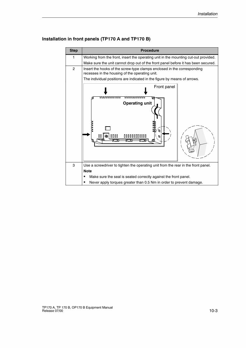
Installation
10-3TP170 A, TP 170 B, OP170 B Equipment ManualRelease 07/00
Installation in front panels (TP170 A and TP170 B)
Step Procedure
1 Working from the front, insert the operating unit in the mounting cut-out provided.
Make sure the unit cannot drop out of the front panel before it has been secured.
2 Insert the hooks of the screw-type clamps enclosed in the correspondingrecesses in the housing of the operating unit.
The individual positions are indicated in the figure by means of arrows.
Front panel
Operating unit
3 Use a screwdriver to tighten the operating unit from the rear in the front panel.
Note
S Make sure the seal is seated correctly against the front panel.
S Never apply torques greater than 0.5 Nm in order to prevent damage.
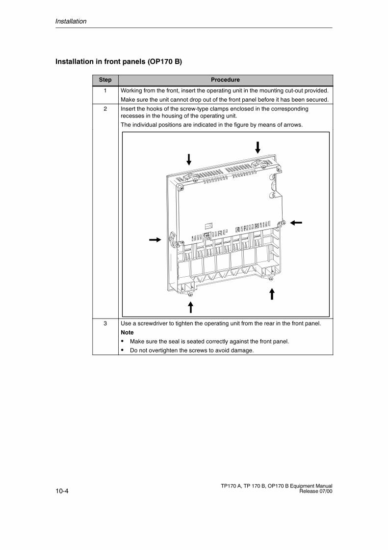
Installation
10-4TP170 A, TP 170 B, OP170 B Equipment Manual
Release 07/00
Installation in front panels (OP170 B)
Step Procedure
1 Working from the front, insert the operating unit in the mounting cut-out provided.
Make sure the unit cannot drop out of the front panel before it has been secured.
2 Insert the hooks of the screw-type clamps enclosed in the correspondingrecesses in the housing of the operating unit.
The individual positions are indicated in the figure by means of arrows.
3 Use a screwdriver to tighten the operating unit from the rear in the front panel.
Note
S Make sure the seal is seated correctly against the front panel.
S Do not overtighten the screws to avoid damage.
Installation
10-5TP170 A, TP 170 B, OP170 B Equipment ManualRelease 07/00
10.2 Electrical Installation
Electrical connections
The operating unit requires electrical connections
S to the power supply,
S to the configuration computer (PU or PC),
S to the PLC,
S to the printer (TP170 B and OP170 B).
An electrical connection to the PU/PC is only required for downloading the projectdata. Following the configuration and test phases, a serial printer can beconnected to the operating unit instead of the configuration computer.
EMC compatible installation
A precondition for error-free operation is an EMC compatible hardware design ofthe PLC and the use of interference-proof cables. The guidelines oninterference-free design of the PLCs apply equally to installation of the operatingunit.
!Caution
S Only shielded cables are permitted for all signal connections.
S Screw or lock all plug connections.
S Do not install signal lines in the same cable ducts as power cables.
S Siemens AG refuses to accept liability for malfunctions and damage arisingfrom use of self-made cables or cables from other manufacturers.
Reverse battery protection
The operating units have reverse battery protection. This has no effect if aconnection already exists to another unit via RS232. Therefore, proceed as followswhen commissioning the operating unit:
1. Connect the operating unit to the power supply.
2. Switch on the power supply.If the operating unit does not start up, the connections are probably reversed.Swap the connections over in this case.
3. When the operating unit has been powered up, connect the configurationcomputer or other periphery equipment to it.
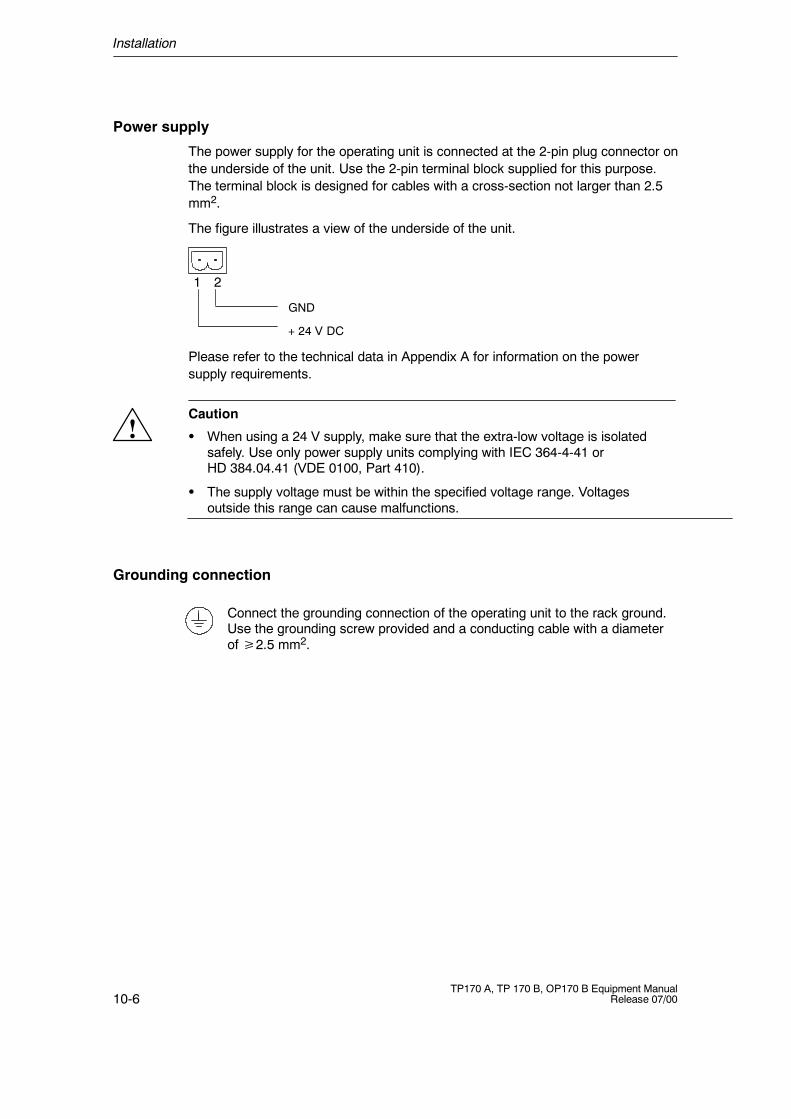
Installation
10-6TP170 A, TP 170 B, OP170 B Equipment Manual
Release 07/00
Power supply
The power supply for the operating unit is connected at the 2-pin plug connector onthe underside of the unit. Use the 2-pin terminal block supplied for this purpose.The terminal block is designed for cables with a cross-section not larger than 2.5mm2.
The figure illustrates a view of the underside of the unit.
GND
+ 24 V DC
1 2
Please refer to the technical data in Appendix A for information on the powersupply requirements.
!Caution
S When using a 24 V supply, make sure that the extra-low voltage is isolatedsafely. Use only power supply units complying with IEC 364-4-41 orHD 384.04.41 (VDE 0100, Part 410).
S The supply voltage must be within the specified voltage range. Voltagesoutside this range can cause malfunctions.
Grounding connection
Connect the grounding connection of the operating unit to the rack ground.Use the grounding screw provided and a conducting cable with a diameterof2.5 mm2.
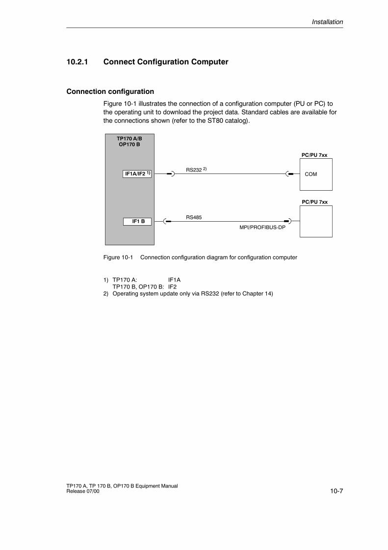
Installation
10-7TP170 A, TP 170 B, OP170 B Equipment ManualRelease 07/00
10.2.1 Connect Configuration Computer
Connection configuration
Figure 10-1 illustrates the connection of a configuration computer (PU or PC) tothe operating unit to download the project data. Standard cables are available forthe connections shown (refer to the ST80 catalog).
COMIF1A/IF2 1)
PC/PU 7xx
TP170 A/BOP170 B
RS232 2)
IF1 BMPI/PROFIBUS-DP
RS485
PC/PU 7xx
Figure 10-1 Connection configuration diagram for configuration computer
1) TP170 A: IF1ATP170 B, OP170 B: IF2
2) Operating system update only via RS232 (refer to Chapter 14)
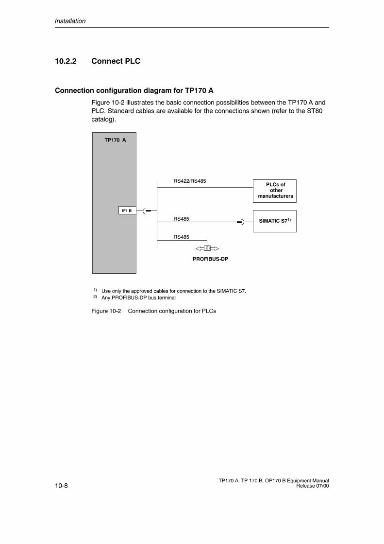
Installation
10-8TP170 A, TP 170 B, OP170 B Equipment Manual
Release 07/00
10.2.2 Connect PLC
Connection configuration diagram for TP170 A
Figure 10-2 illustrates the basic connection possibilities between the TP170 A andPLC. Standard cables are available for the connections shown (refer to the ST80catalog).
PLCs ofother
manufacturers
RS422/RS485
SIMATIC S71)
1) Use only the approved cables for connection to the SIMATIC S7.2) Any PROFIBUS-DP bus terminal
IF1 B
RS485
RS485
TP170 A
PROFIBUS-DP
2)
Figure 10-2 Connection configuration for PLCs
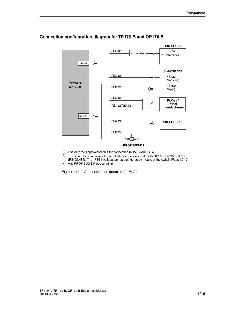
Installation
10-9TP170 A, TP 170 B, OP170 B Equipment ManualRelease 07/00
Connection configuration diagram for TP170 B and OP170 B
PU interfaces
RS232(9/25-pin)
RS422(9-pin)
SIMATIC S5
RS232
PLCs ofother
manufacturers
RS422
RS422/RS485
CPU
SIMATIC 505
SIMATIC S71)
RS232
1) Use only the approved cables for connection to the SIMATIC S7.2) To enable operation using the serial interface, connect either the IF1A (RS232) or IF1B
(RS422/485). The 1F1B interface can be configured by means of the switch (Page 10-10).3) Any PROFIBUS-DP bus terminal
IF1A2)
IF1B2)
RS485
RS485
TP170 B/OP170 B
PROFIBUS-DP
3)
RS232Converter
Figure 10-3 Connection configuration for PLCs
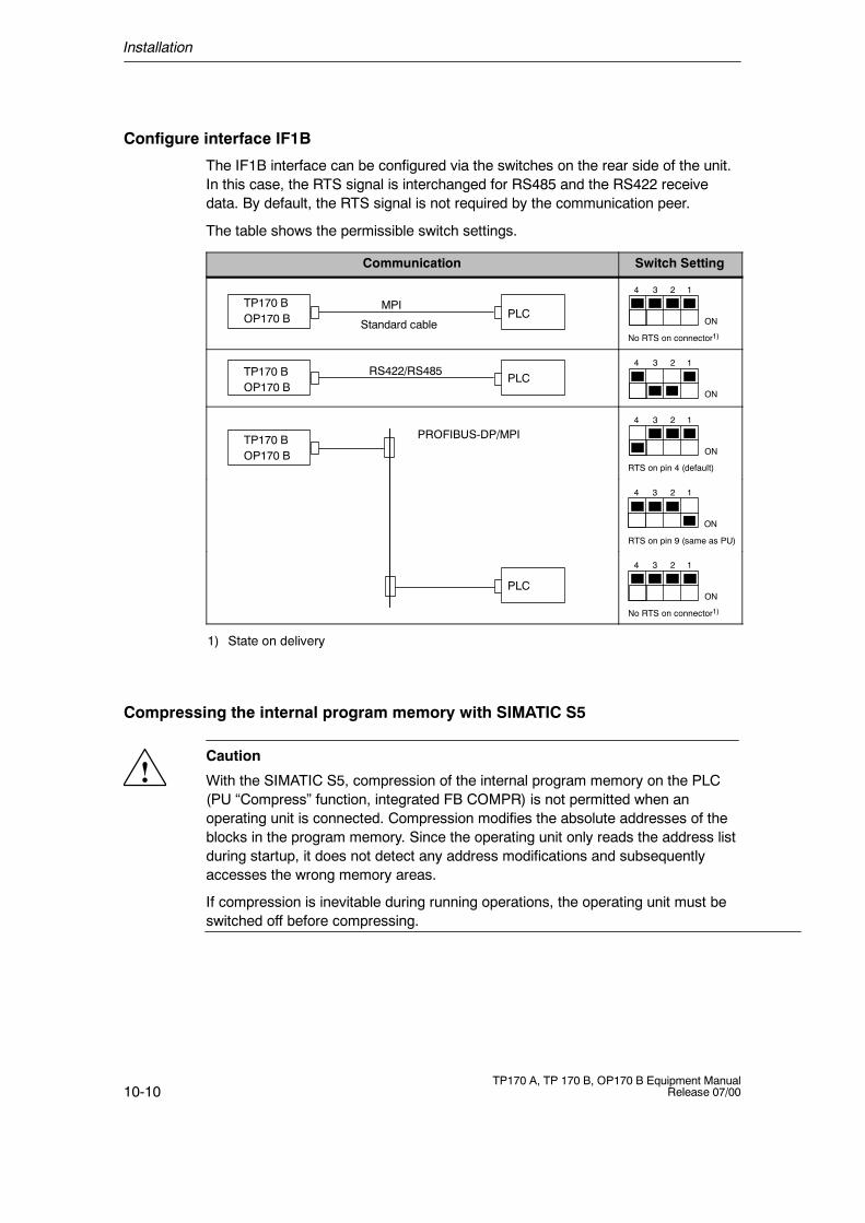
Installation
10-10TP170 A, TP 170 B, OP170 B Equipment Manual
Release 07/00
Configure interface IF1B
The IF1B interface can be configured via the switches on the rear side of the unit.In this case, the RTS signal is interchanged for RS485 and the RS422 receivedata. By default, the RTS signal is not required by the communication peer.
The table shows the permissible switch settings.
Communication Switch Setting
PLCMPI
Standard cable
TP170 BOP170 B ON
1234
No RTS on connector1)
PLCRS422/RS485TP170 B
OP170 BON
1234
PROFIBUS-DP/MPITP170 BOP170 B ON
1234
RTS on pin 4 (default)
RTS on pin 9 (same as PU)
ON
1234
PLC
No RTS on connector1)
ON
1234
1) State on delivery
Compressing the internal program memory with SIMATIC S5
!Caution
With the SIMATIC S5, compression of the internal program memory on the PLC(PU “Compress” function, integrated FB COMPR) is not permitted when anoperating unit is connected. Compression modifies the absolute addresses of theblocks in the program memory. Since the operating unit only reads the address listduring startup, it does not detect any address modifications and subsequentlyaccesses the wrong memory areas.
If compression is inevitable during running operations, the operating unit must beswitched off before compressing.
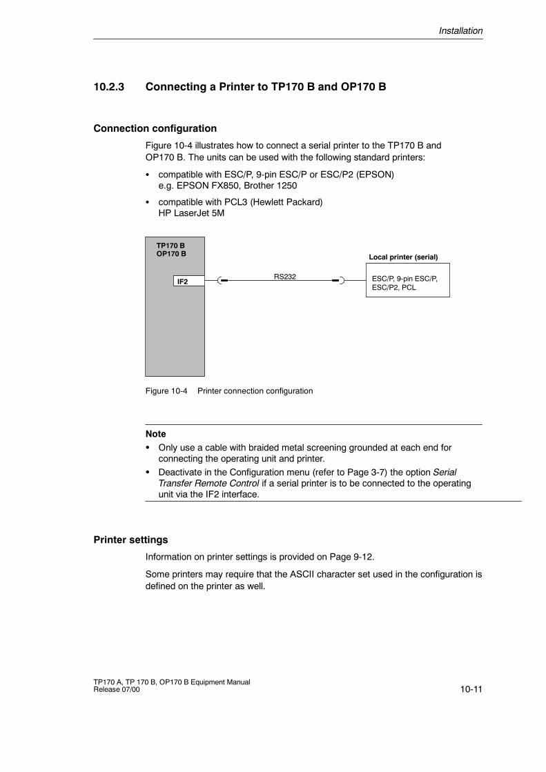
Installation
10-11TP170 A, TP 170 B, OP170 B Equipment ManualRelease 07/00
10.2.3 Connecting a Printer to TP170 B and OP170 B
Connection configuration
Figure 10-4 illustrates how to connect a serial printer to the TP170 B andOP170 B. The units can be used with the following standard printers:
S compatible with ESC/P, 9-pin ESC/P or ESC/P2 (EPSON)e.g. EPSON FX850, Brother 1250
S compatible with PCL3 (Hewlett Packard)HP LaserJet 5M
IF2
Local printer (serial)
ESC/P, 9-pin ESC/P,ESC/P2, PCL
RS232
TP170 BOP170 B
Figure 10-4 Printer connection configuration
NoteS Only use a cable with braided metal screening grounded at each end for
connecting the operating unit and printer.S Deactivate in the Configuration menu (refer to Page 3-7) the option Serial
Transfer Remote Control if a serial printer is to be connected to the operatingunit via the IF2 interface.
Printer settings
Information on printer settings is provided on Page 9-12.
Some printers may require that the ASCII character set used in the configuration isdefined on the printer as well.

Installation
10-12TP170 A, TP 170 B, OP170 B Equipment Manual
Release 07/00
11-1TP170 A, TP 170 B, OP170 B Equipment ManualRelease 07/00
Unit Description
In this chapter
This chapter provides information on:
TP170 A
S Dimensions (Page 11-2),
S Connection elements (Page 11-3),
S Communication options (Page 11-4),
TP170 B
S Dimensions (Page 11-5),
S Connection elements (Page 11-6),
S Communication options (Page 11-7),
OP170 B
S Dimensions (Page 11-8),
S Connection elements (Page 11-9),
S Communication options (Page 11-10),
S Labeling the function keys (Page 11-10).
11
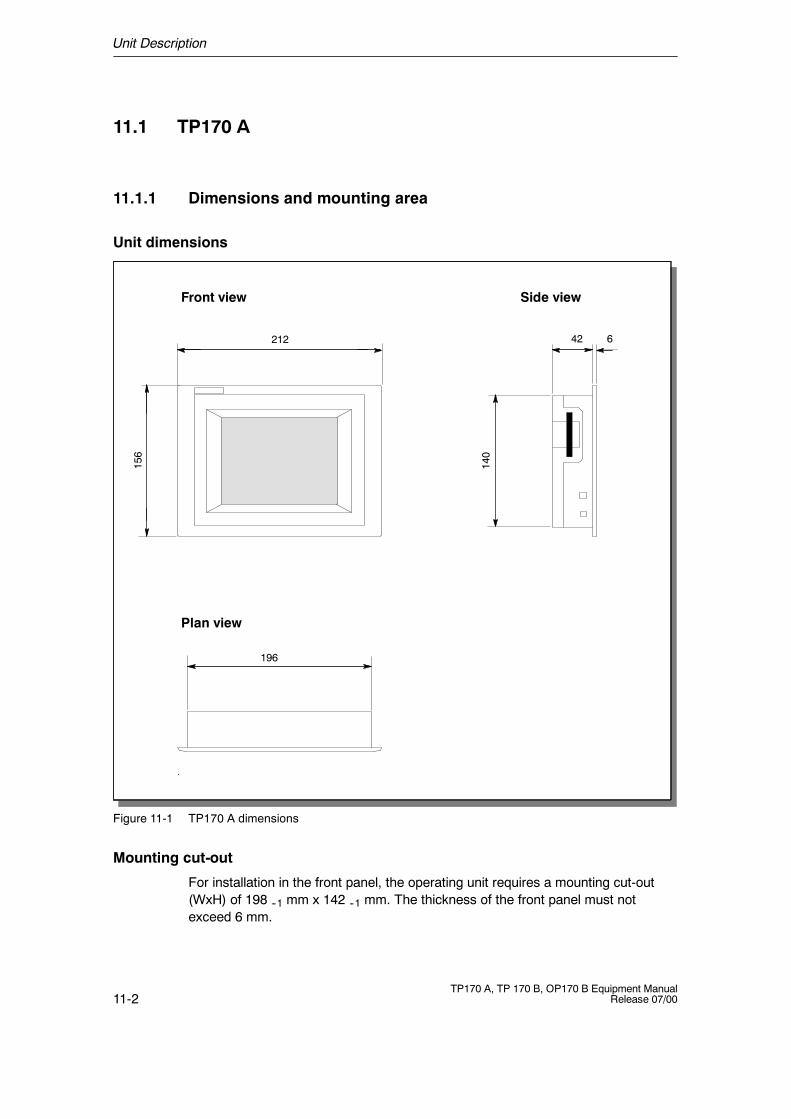
Unit Description
11-2TP170 A, TP 170 B, OP170 B Equipment Manual
Release 07/00
11.1 TP170 A
11.1.1 Dimensions and mounting area
Unit dimensions
196
42212 6
156
Side viewFront view
Plan view
140
Figure 11-1 TP170 A dimensions
Mounting cut-out
For installation in the front panel, the operating unit requires a mounting cut-out(WxH) of 198 --1 mm x 142 --1 mm. The thickness of the front panel must notexceed 6 mm.
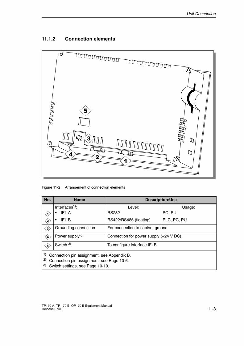
Unit Description
11-3TP170 A, TP 170 B, OP170 B Equipment ManualRelease 07/00
11.1.2 Connection elements
Figure 11-2 Arrangement of connection elements
No. Name Description/Use
Interfaces1): Level: Usage:S IF1 A RS232 PC, PU
S IF1 B RS422/RS485 (floating) PLC, PC, PU
Grounding connection For connection to cabinet ground
Power supply2) Connection for power supply (+24 V DC)
Switch 3) To configure interface IF1B
1) Connection pin assignment, see Appendix B.2) Connection pin assignment, see Page 10-6.3) Switch settings, see Page 10-10.
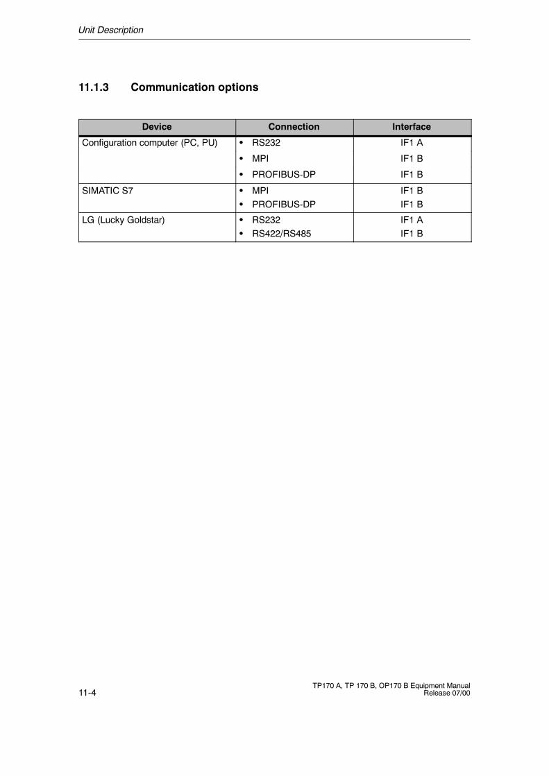
Unit Description
11-4TP170 A, TP 170 B, OP170 B Equipment Manual
Release 07/00
11.1.3 Communication options
Device Connection Interface
Configuration computer (PC, PU) S RS232 IF1 A
S MPI IF1 B
S PROFIBUS-DP IF1 B
SIMATIC S7 S MPIS PROFIBUS-DP
IF1 BIF1 B
LG (Lucky Goldstar) S RS232S RS422/RS485
IF1 AIF1 B
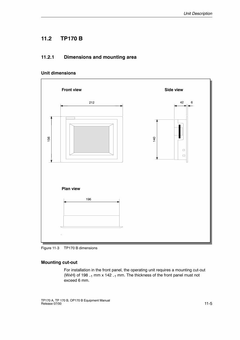
Unit Description
11-5TP170 A, TP 170 B, OP170 B Equipment ManualRelease 07/00
11.2 TP170 B
11.2.1 Dimensions and mounting area
Unit dimensions
196
42212 6
156
Side viewFront view
Plan view
140
Figure 11-3 TP170 B dimensions
Mounting cut-out
For installation in the front panel, the operating unit requires a mounting cut-out(WxH) of 198 --1 mm x 142 --1 mm. The thickness of the front panel must notexceed 6 mm.
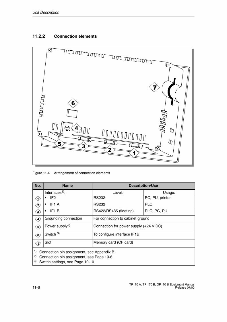
Unit Description
11-6TP170 A, TP 170 B, OP170 B Equipment Manual
Release 07/00
11.2.2 Connection elements
7
Figure 11-4 Arrangement of connection elements
No. Name Description/Use
Interfaces1): Level: Usage:S IF2 RS232 PC, PU, printer
S IF1 A RS232 PLC
S IF1 B RS422/RS485 (floating) PLC, PC, PU
Grounding connection For connection to cabinet ground
Power supply2) Connection for power supply (+24 V DC)
Switch 3) To configure interface IF1B
7 Slot Memory card (CF card)
1) Connection pin assignment, see Appendix B.2) Connection pin assignment, see Page 10-6.3) Switch settings, see Page 10-10.
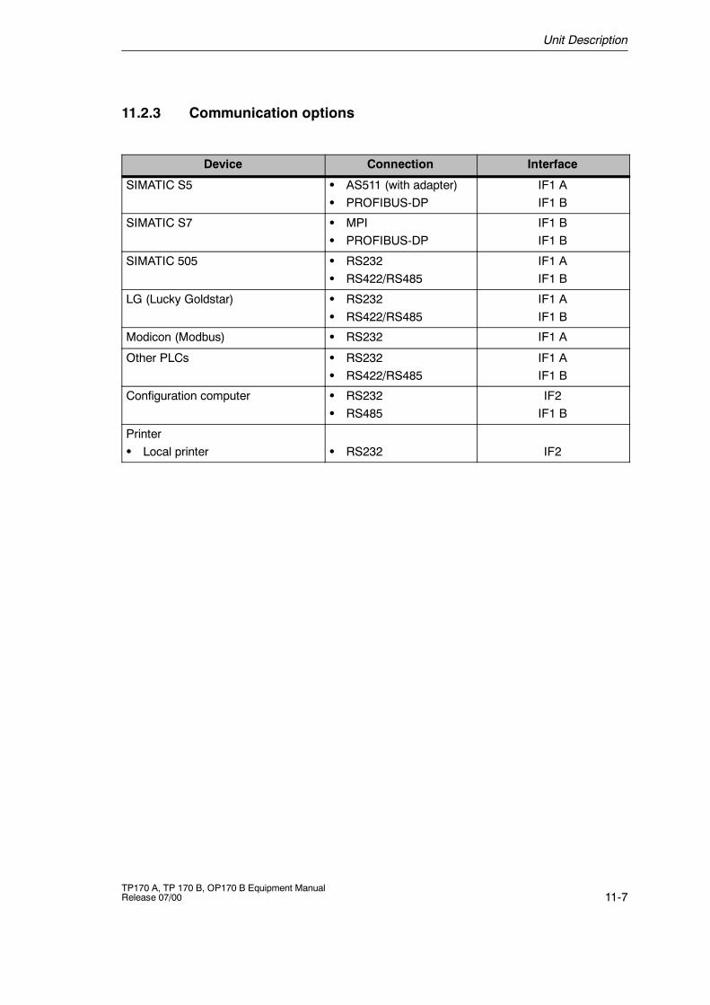
Unit Description
11-7TP170 A, TP 170 B, OP170 B Equipment ManualRelease 07/00
11.2.3 Communication options
Device Connection Interface
SIMATIC S5 S AS511 (with adapter)S PROFIBUS-DP
IF1 AIF1 B
SIMATIC S7 S MPIS PROFIBUS-DP
IF1 BIF1 B
SIMATIC 505 S RS232S RS422/RS485
IF1 AIF1 B
LG (Lucky Goldstar) S RS232S RS422/RS485
IF1 AIF1 B
Modicon (Modbus) S RS232 IF1 A
Other PLCs S RS232S RS422/RS485
IF1 AIF1 B
Configuration computer S RS232S RS485
IF2IF1 B
PrinterS Local printer S RS232 IF2
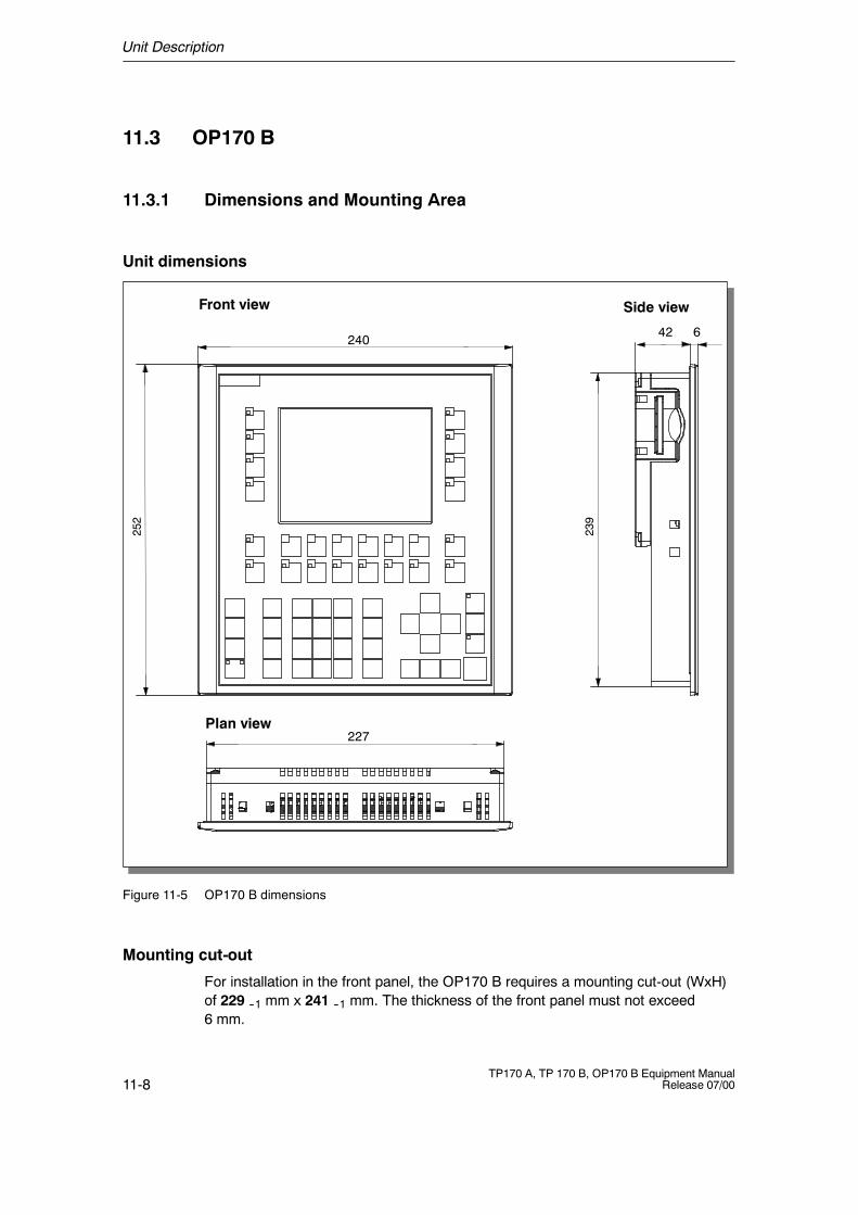
Unit Description
11-8TP170 A, TP 170 B, OP170 B Equipment Manual
Release 07/00
11.3 OP170 B
11.3.1 Dimensions and Mounting Area
Unit dimensions
Side viewFront view
Plan view
240
252
227
239
642
Figure 11-5 OP170 B dimensions
Mounting cut-out
For installation in the front panel, the OP170 B requires a mounting cut-out (WxH)of 229 --1 mm x 241 --1 mm. The thickness of the front panel must not exceed6 mm.
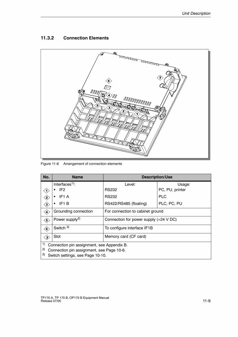
Unit Description
11-9TP170 A, TP 170 B, OP170 B Equipment ManualRelease 07/00
11.3.2 Connection Elements
7
Figure 11-6 Arrangement of connection elements
No. Name Description/Use
Interfaces1): Level: Usage:S IF2 RS232 PC, PU, printer
S IF1 A RS232 PLC
S IF1 B RS422/RS485 (floating) PLC, PC, PU
Grounding connection For connection to cabinet ground
Power supply2) Connection for power supply (+24 V DC)
Switch 3) To configure interface IF1B
7 Slot Memory card (CF card)
1) Connection pin assignment, see Appendix B.2) Connection pin assignment, see Page 10-6.3) Switch settings, see Page 10-10.
Unit Description
11-10TP170 A, TP 170 B, OP170 B Equipment Manual
Release 07/00
11.3.3 Communication Options
Device Connection Interface
SIMATIC S5 S AS511 (with adapter)S PROFIBUS-DP
IF1 AIF1 B
SIMATIC S7 S MPIS PROFIBUS-DP
IF1 BIF1 B
SIMATIC 505 S RS232S RS422/RS485
IF1 AIF1 B
Lucky Goldstar S RS232S RS422/RS485
IF1 AIF1 B
Modicon (Modbus) S RS232 IF1 A
Other PLCs S RS232S RS422/RS485
IF1 AIF1 B
Configuration computer S RS232S RS485
IF2IF1 B
PrinterS Local printer S RS232 IF2
11.3.4 Labeling Function Keys (OP170 B)
Labeling
The OP170 B function keys are labeled as follows on supply:
S F1 to F14 and
S K1 to K10.
The function keys are labeled by means of 8 labeling strips which are inserted inthe unit from the rear. These strips can be exchanged in order to label theOP170 B specifically for the system.
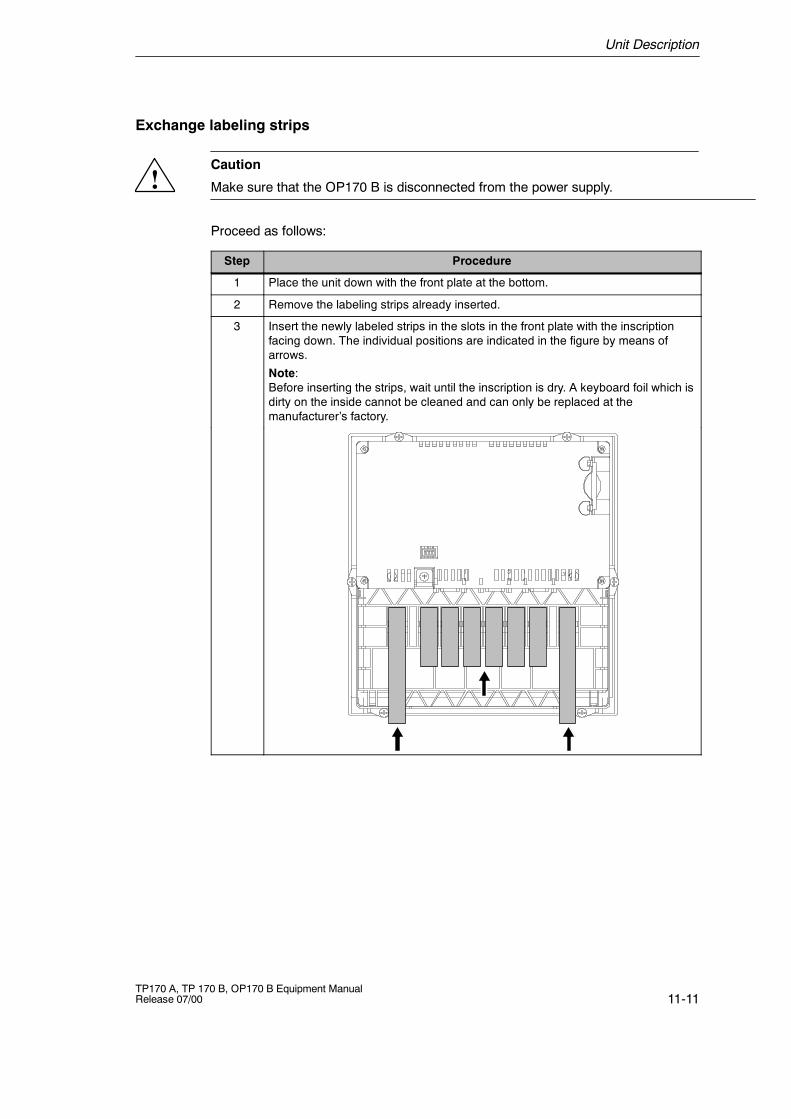
Unit Description
11-11TP170 A, TP 170 B, OP170 B Equipment ManualRelease 07/00
Exchange labeling strips
!Caution
Make sure that the OP170 B is disconnected from the power supply.
Proceed as follows:
Step Procedure
1 Place the unit down with the front plate at the bottom.
2 Remove the labeling strips already inserted.
3 Insert the newly labeled strips in the slots in the front plate with the inscriptionfacing down. The individual positions are indicated in the figure by means ofarrows.
Note:Before inserting the strips, wait until the inscription is dry. A keyboard foil which isdirty on the inside cannot be cleaned and can only be replaced at themanufacturer’s factory.
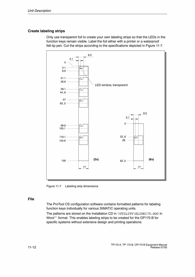
Unit Description
11-12TP170 A, TP 170 B, OP170 B Equipment Manual
Release 07/00
Create labeling strips
Only use transparent foil to create your own labeling strips so that the LEDs in thefunction keys remain visible. Label the foil either with a printer or a waterprooffelt-tip pen. Cut the strips according to the specifications depicted in Figure 11-7.
8.5
LED window, transparent
(2x) (6x)
3.10
8.6
21.126.6
39,144.,6
3.1
5762.,5
99.6105.1
119.1124.6
159
17 17
8.5
3.1
0
22.,628.
62.,5
Figure 11-7 Labeling strip dimensions
FileThe ProTool CS configuration software contains formatted patterns for labelingfunction keys individually for various SIMATIC operating units.
The patterns are stored on the Installation CD in \UTILITY\SLIDE170.DOC inWordt format. This enables labeling strips to be created for the OP170 B forspecific systems without extensive design and printing operations.
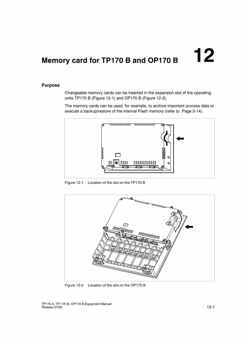
12-1TP170 A, TP 170 B, OP170 B Equipment ManualRelease 07/00
Memory card for TP170 B and OP170 B
Purpose
Changeable memory cards can be inserted in the expansion slot of the operatingunits TP170 B (Figure 12-1) and OP170 B (Figure 12-2).
The memory cards can be used, for example, to archive important process data orexecute a backup/restore of the internal Flash memory (refer to Page 3-14).
Figure 12-1 Location of the slot on the TP170 B
Figure 12-2 Location of the slot on the OP170 B
12

Memory card for TP170 B and OP170 B
12-2TP170 A, TP 170 B, OP170 B Equipment Manual
Release 07/00
Cards supported
The operating unit supports the use of cards complying to Compact FlashStandard (CF). The interface supplies the card with 3.3 V.
If the power supply is interrupted inadvertently during normal operation, theoperating unit checks the memory card after power is returned, repairing defectareas if necessary.
13-1TP170 A, TP 170 B, OP170 B Equipment ManualRelease 07/00
Maintenance/Upkeep
Scope
The operating unit has been designed for low maintenance operation. Maintenanceof the unit is limited to
S regular cleaning of the screen,
S regular cleaning of the keyboard overlay (OP170 B).
Clean Screen/Keyboard
Preparation
Clean the operating unit screen and keyboard foil of the OP170 B at regularintervals. Use a damp cloth. Do not clean the unit while it is turned on. Thisensures that functions are not triggered inadvertently.
Clean screen (TP170 A and TP170 B)
If the function Clean Screen is configured in the project, the screen can be cleanedwithin period displayed (bar) while the unit is switched on without inadvertentlytriggering any functions. All input is blocked during his period.
Protective foil (TP170 A and TP170 B)
A protective foil is available for the touch panels TP170 A and TP170 B (refer toCatalog ST80). The foil prevents the screen being scratched and soiled.
Cleaning agents
Only use water and washing up liquid or screen cleaning foam to dampen cloths.Never spray the cleaning agent directly onto the screen, but onto the cleaningcloth. Never use aggressive solvents or scouring powder.
13

Maintenance/Upkeep
13-2TP170 A, TP 170 B, OP170 B Equipment Manual
Release 07/00
14-1TP170 A, TP 170 B, OP170 B Equipment ManualRelease 07/00
Operating System Update
Purpose
If there is a conflict between the configuration software version and currentoperating system on the operating unit, downloading of a project from theconfiguration computer to the operating unit is terminated and a compatibilityconflict is indicated.
In this case, synchronize the operating unit operating system with the version ofthe SIMATIC ProTool CS configuration software. The procedure is describedbelow.
Note
In the operating system update described in this manual, all the existing data onthe operating unit is deleted.
Procedure
Proceed as follows in order to adapt the operating system on the operating unit tothe configuration software version used:
Step Procedure
1 Switch off the power supply for the operating unit.
1 Connect interface IF1A or IF2 (serial)1) on the operating unit to the to the serialinterface on the configuration computer using a serial zero modem cable.
1 Switch on the power supply for the operating unit.
2 If necessary, check the interface settings in the Configuration menu(Figure 3-4 or 3-5) and adapt them as required.
3 Start the PTUpdate utility program on the configuration computer. It is containedon the configuration software installation CD. It is located in the directory\Images in the unit--specific subdirectory.
4 Select the menu item File � Open and open the image file which corresponds tothe operating unit (file extension .img). The image file is located in the samedirectory as the PTUpdate utility program. The file name contains the characterstring TP170A, TP170B or OP170B. When the image file has been openedsuccessfully, various information concerning the version appears on the screen.
14
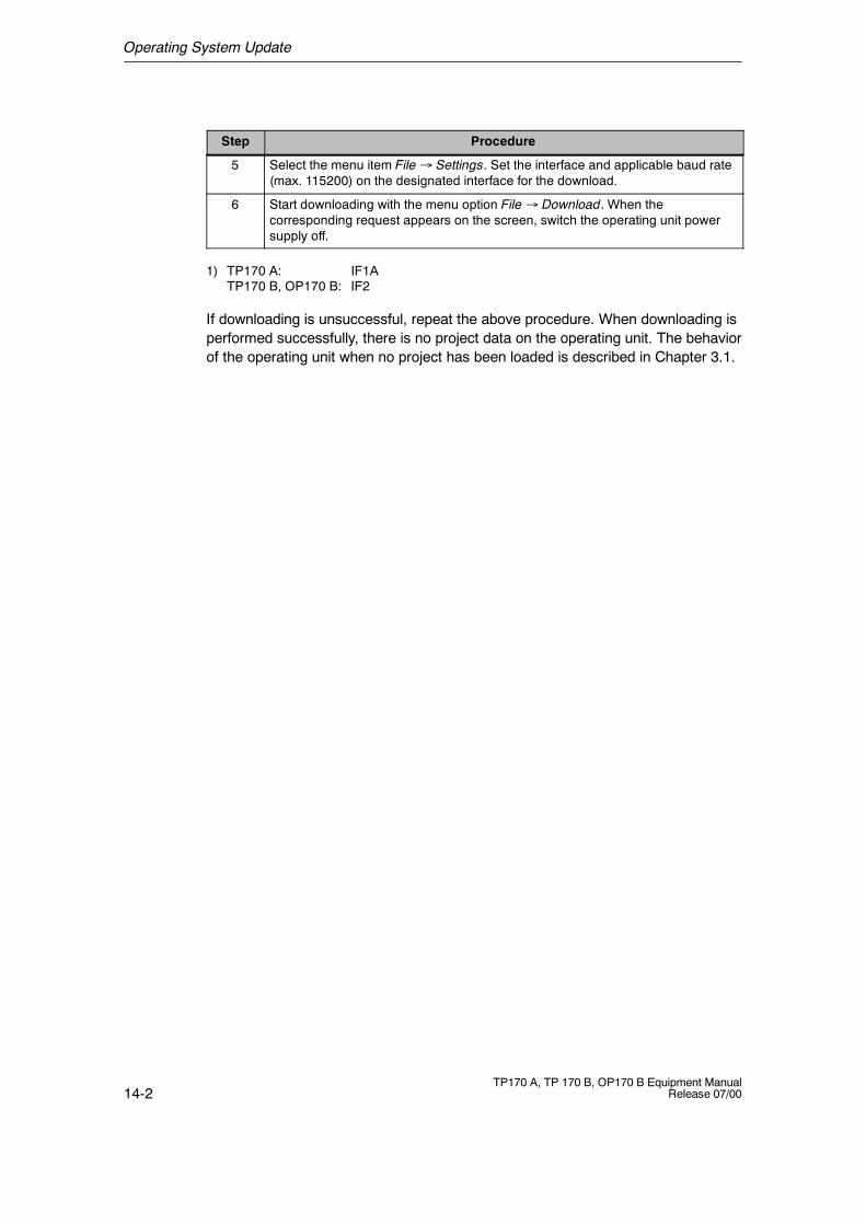
Operating System Update
14-2TP170 A, TP 170 B, OP170 B Equipment Manual
Release 07/00
ProcedureStep
5 Select the menu item File � Settings. Set the interface and applicable baud rate(max. 115200) on the designated interface for the download.
6 Start downloading with the menu option File � Download. When thecorresponding request appears on the screen, switch the operating unit powersupply off.
1) TP170 A: IF1ATP170 B, OP170 B: IF2
If downloading is unsuccessful, repeat the above procedure. When downloading isperformed successfully, there is no project data on the operating unit. The behaviorof the operating unit when no project has been loaded is described in Chapter 3.1.
APPENDICES
A Technical Data
B Interface Assignments
C System Messages
D ESD Guidelines
E SIMATIC HMI Documentation

APPENDICES
N-2TP170 A, TP 170 B, OP170 B Equipment Manual
Release 07/00
A-1TP170 A, TP 170 B, OP170 B Equipment ManualRelease 07/00
Technical Data
In this Appendix
This Appendix contains the following technical data for the units TP170 A,TP170 B and OP170 B:
S Housing
S Processor
S Memory
S Software
S Display
S Keyboard (OP170 B)
S Power supply
S Ambient conditions
S Noise immunity and noise transmission
S Approvals
A
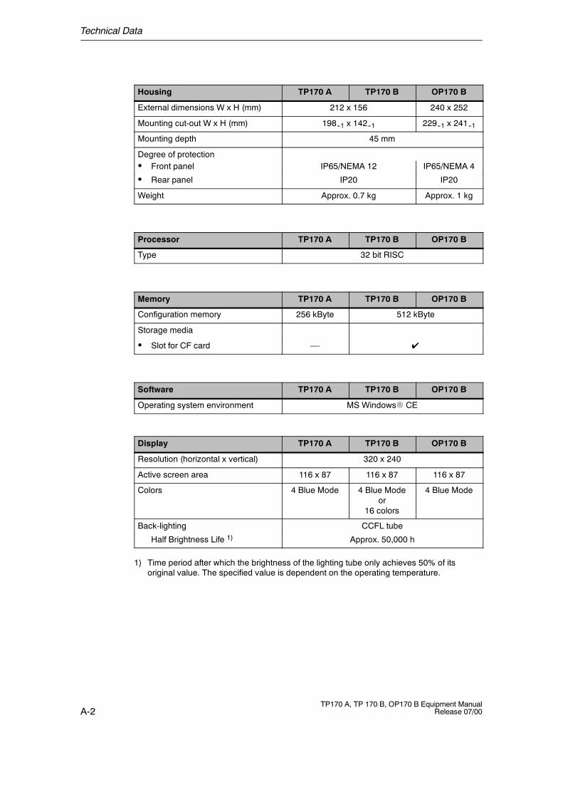
Technical Data
A-2TP170 A, TP 170 B, OP170 B Equipment Manual
Release 07/00
Housing TP170 A TP170 B OP170 B
External dimensions W x H (mm) 212 x 156 240 x 252
Mounting cut-out W x H (mm) 198--1 x 142--1 229--1 x 241--1
Mounting depth 45 mm
Degree of protectionS Front panel IP65/NEMA 12 IP65/NEMA 4
S Rear panel IP20 IP20
Weight Approx. 0.7 kg Approx. 1 kg
Processor TP170 A TP170 B OP170 B
Type 32 bit RISC
Memory TP170 A TP170 B OP170 B
Configuration memory 256 kByte 512 kByte
Storage media
S Slot for CF card –– ✔
Software TP170 A TP170 B OP170 B
Operating system environment MS WindowsR CE
Display TP170 A TP170 B OP170 B
Resolution (horizontal x vertical) 320 x 240
Active screen area 116 x 87 116 x 87 116 x 87
Colors 4 Blue Mode 4 Blue Modeor
16 colors
4 Blue Mode
Back-lighting CCFL tube
Half Brightness Life 1) Approx. 50,000 h
1) Time period after which the brightness of the lighting tube only achieves 50% of itsoriginal value. The specified value is dependent on the operating temperature.
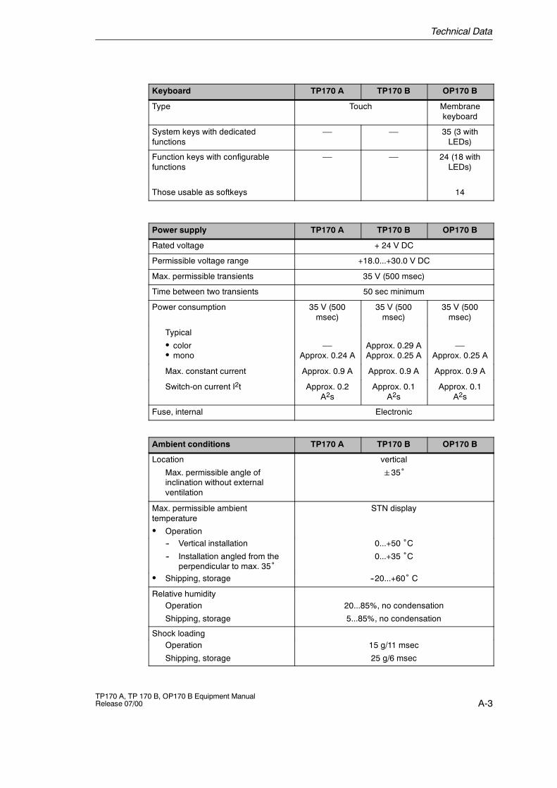
Technical Data
A-3TP170 A, TP 170 B, OP170 B Equipment ManualRelease 07/00
Keyboard TP170 A TP170 B OP170 B
Type Touch Membranekeyboard
System keys with dedicatedfunctions
–– –– 35 (3 withLEDs)
Function keys with configurablefunctions
–– –– 24 (18 withLEDs)
Those usable as softkeys 14
Power supply TP170 A TP170 B OP170 B
Rated voltage + 24 V DC
Permissible voltage range +18.0...+30.0 V DC
Max. permissible transients 35 V (500 msec)
Time between two transients 50 sec minimum
Power consumption 35 V (500msec)
35 V (500msec)
35 V (500msec)
Typical
S colorS mono
––Approx. 0.24 A
Approx. 0.29 AApprox. 0.25 A
––Approx. 0.25 A
Max. constant current Approx. 0.9 A Approx. 0.9 A Approx. 0.9 A
Switch-on current I2t Approx. 0.2A2s
Approx. 0.1A2s
Approx. 0.1A2s
Fuse, internal Electronic
Ambient conditions TP170 A TP170 B OP170 B
Location
Max. permissible angle ofinclination without externalventilation
vertical
35˚
Max. permissible ambienttemperature
S Operation
STN display
-- Vertical installation
-- Installation angled from theperpendicular to max. 35˚
0...+50 ˚C0...+35 ˚C
S Shipping, storage --20...+60˚ C
Relative humidityOperation
Shipping, storage
20...85%, no condensation
5...85%, no condensation
Shock loadingOperation
Shipping, storage
15 g/11 msec
25 g/6 msec
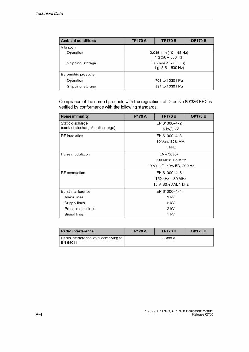
Technical Data
A-4TP170 A, TP 170 B, OP170 B Equipment Manual
Release 07/00
OP170 BTP170 BTP170 AAmbient conditions
VibrationOperation 0.035 mm (10 -- 58 Hz)
1 g (58 -- 500 Hz)
Shipping, storage 3.5 mm (5 -- 8,5 Hz)1 g (8.5 -- 500 Hz)
Barometric pressure
Operation
Shipping, storage
706 to 1030 hPa
581 to 1030 hPa
Compliance of the named products with the regulations of Directive 89/336 EEC isverified by conformance with the following standards:
Noise immunity TP170 A TP170 B OP170 B
Static discharge(contact discharge/air discharge)
EN 61000--4--2
6 kV/8 kV
RF irradiation EN 61000--4--3
10 V/m, 80% AM,
1 kHz
Pulse modulation ENV 50204
900 MHz5 MHz10 V/meff., 50% ED, 200 Hz
RF conduction EN 61000--4--6
150 kHz -- 80 MHz
10 V, 80% AM, 1 kHz
Burst interference
Mains lines
Supply lines
Process data lines
Signal lines
EN 61000--4--4
2 kV
2 kV
2 kV
1 kV
Radio interference TP170 A TP170 B OP170 B
Radio interference level complying toEN 55011
Class A

Technical Data
A-5TP170 A, TP 170 B, OP170 B Equipment ManualRelease 07/00
The following approvals have been applied for or already granted on supply.Please refer to the rating plate on the rear of the unit for identification.
Approvals
UL approval UL Recognition Mark 2)
Underwriters Laboratories (UL) complying with Standard UL 508,File E 116536
UL approval In accordance with the UL/CSA Approval Agreement
FM Approval FM Approval
Complying with Factory Mutual Approval Standard Class Number3611 Hazardous (classified) Locations Class I,
Division 2, Group A, B, C, D
Warning:
Personal injury and equipment damage can occur.
Personal injury and equipment damage can occur inhazardous areas if a plug connection is disconnectedfrom the operating unit while the system is running.
In hazardous areas, always switch off the power supplyto the operating unit before disconnecting plugs.
!
WARNING:
DO NOT DISCONNECT WHILE CIRCUIT IS LIVE UN-LESS LOCATION IS KNOWN TO BE NON-HAZAR-DOUS.
!
2) The UL and CSA file numbers are dependent on the production site. The numbersspecified here changes according to the change of production site.

Technical Data
A-6TP170 A, TP 170 B, OP170 B Equipment Manual
Release 07/00
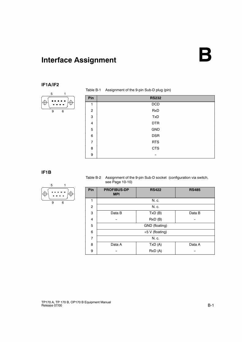
B-1TP170 A, TP 170 B, OP170 B Equipment ManualRelease 07/00
Interface Assignment
IF1A/IF2Table B-1 Assignment of the 9-pin Sub-D plug (pin)
Pin RS232
1 DCD
2 RxD
3 TxD
4 DTR
5 GND
6 DSR
7 RTS
8 CTS
9 --
IF1BTable B-2 Assignment of the 9-pin Sub-D socket (configuration via switch,
see Page 10-10)
Pin PROFIBUS-DPMPI
RS422 RS485
1 N. c.
2 N. c.
3 Data B TxD (B) Data B
4 -- RxD (B) --
5 GND (floating)
6 +5 V (floating)
7 N. c.
8 Data A TxD (A) Data A
9 -- RxD (A) --
B
5 1
9 6
5 1
9 6

Interface Assignment
B-2TP170 A, TP 170 B, OP170 B Equipment Manual
Release 07/00
C-1TP170 A, TP 170 B, OP170 B Equipment ManualRelease 07/00
System Messages
In this chapter
This chapter contains a selection of important system messages forWindows-based systems. The table indicates when the messages occur and howthey, or their cause, can be cleared. Not every message is relevant for eachoperating unit.
System message parameters
The system messages may contain parameters which are not decoded for the userbut which are relevant in respect of the cause of an error since they provide areference to the source code from ProTool/Pro Runtime. These parameters areissued according to the text “Error code:”
Note
System messages are issued in the language currently set on the operating unit.
C
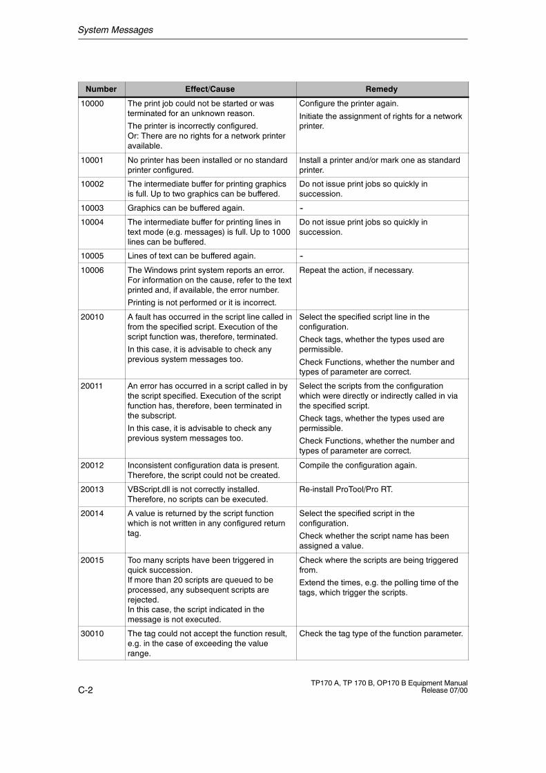
System Messages
C-2TP170 A, TP 170 B, OP170 B Equipment Manual
Release 07/00
Number Effect/Cause Remedy
10000 The print job could not be started or wasterminated for an unknown reason.
The printer is incorrectly configured.Or: There are no rights for a network printeravailable.
Configure the printer again.
Initiate the assignment of rights for a networkprinter.
10001 No printer has been installed or no standardprinter configured.
Install a printer and/or mark one as standardprinter.
10002 The intermediate buffer for printing graphicsis full. Up to two graphics can be buffered.
Do not issue print jobs so quickly insuccession.
10003 Graphics can be buffered again. --
10004 The intermediate buffer for printing lines intext mode (e.g. messages) is full. Up to 1000lines can be buffered.
Do not issue print jobs so quickly insuccession.
10005 Lines of text can be buffered again. --
10006 The Windows print system reports an error.For information on the cause, refer to the textprinted and, if available, the error number.
Printing is not performed or it is incorrect.
Repeat the action, if necessary.
20010 A fault has occurred in the script line called infrom the specified script. Execution of thescript function was, therefore, terminated.
In this case, it is advisable to check anyprevious system messages too.
Select the specified script line in theconfiguration.
Check tags, whether the types used arepermissible.
Check Functions, whether the number andtypes of parameter are correct.
20011 An error has occurred in a script called in bythe script specified. Execution of the scriptfunction has, therefore, been terminated inthe subscript.
In this case, it is advisable to check anyprevious system messages too.
Select the scripts from the configurationwhich were directly or indirectly called in viathe specified script.
Check tags, whether the types used arepermissible.
Check Functions, whether the number andtypes of parameter are correct.
20012 Inconsistent configuration data is present.Therefore, the script could not be created.
Compile the configuration again.
20013 VBScript.dll is not correctly installed.Therefore, no scripts can be executed.
Re-install ProTool/Pro RT.
20014 A value is returned by the script functionwhich is not written in any configured returntag.
Select the specified script in theconfiguration.
Check whether the script name has beenassigned a value.
20015 Too many scripts have been triggered inquick succession.If more than 20 scripts are queued to beprocessed, any subsequent scripts arerejected.In this case, the script indicated in themessage is not executed.
Check where the scripts are being triggeredfrom.
Extend the times, e.g. the polling time of thetags, which trigger the scripts.
30010 The tag could not accept the function result,e.g. in the case of exceeding the valuerange.
Check the tag type of the function parameter.
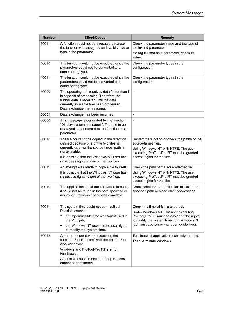
System Messages
C-3TP170 A, TP 170 B, OP170 B Equipment ManualRelease 07/00
RemedyEffect/CauseNumber
30011 A function could not be executed becausethe function was assigned an invalid value ortype in the parameter.
Check the parameter value and tag type ofthe invalid parameter.
If a tag is used as a parameter, check itsvalue.
40010 The function could not be executed since theparameters could not be converted to acommon tag type.
Check the parameter types in theconfiguration.
40011 The function could not be executed since theparameters could not be converted to acommon tag type.
Check the parameter types in theconfiguration.
50000 The operating unit receives data faster than itis capable of processing. Therefore, nofurther data is received until the datacurrently available has been processed.Data exchange then resumes.
--
50001 Data exchange has been resumed. --
60000 This message is generated by the function“Display system messages”. The text to bedisplayed is transferred to the function as aparameter.
--
60010 The file could not be copied in the directiondefined because one of the two files iscurrently open or the source/target path isnot available.
It is possible that the Windows NT user hasno access rights to one of the two files.
Restart the function or check the paths of thesource/target files.
Using Windows NT with NTFS: The userexecuting ProTool/Pro RT must be grantedaccess rights for the files.
60011 An attempt was made to copy a file to itself.
It is possible that the Windows NT user hasno access rights to one of the two files.
Check the path of the source/target file.
Using Windows NT with NTFS: The userexecuting ProTool/Pro RT must be grantedaccess rights for the files.
70010 The application could not be started becauseit could not be found in the path specified orinsufficient memory space was available.
Check whether the application exists in thespecified path or close other applications.
70011 The system time could not be modified.Possible causes:
S an impermissible time was transferred inthe PLC job,
S the Windows NT user has no user rightsto modify the system time.
Check the time which is to be set.
Under Windows NT: The user executingProTool/Pro RT must be assigned the rightsto modify the system time from Windows NT(administration/user manager, guidelines).
70012 An error occurred when executing thefunction “Exit Runtime” with the option “Exitalso Windows”.
Windows and ProTool/Pro RT are notterminated.
A possible cause is that other applicationscannot be terminated.
Terminate all applications currently running.
Then terminate Windows.
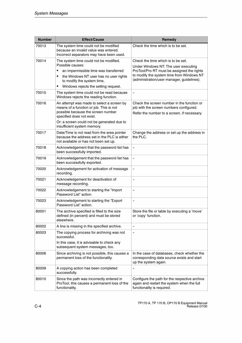
System Messages
C-4TP170 A, TP 170 B, OP170 B Equipment Manual
Release 07/00
RemedyEffect/CauseNumber
70013 The system time could not be modifiedbecause an invalid value was entered.Incorrect separators may have been used.
Check the time which is to be set.
70014 The system time could not be modified.Possible causes:
S an impermissible time was transferred
S the Windows NT user has no user rightsto modify the system time,
S Windows rejects the setting request.
Check the time which is to be set.
Under Windows NT: The user executingProTool/Pro RT must be assigned the rightsto modify the system time from Windows NT(administration/user manager, guidelines).
70015 The system time could not be read becauseWindows rejects the reading function.
--
70016 An attempt was made to select a screen bymeans of a function or job. This is notpossible because the screen numberspecified does not exist.
Or: a screen could not be generated due toinsufficient system memory.
Check the screen number in the function orjob with the screen numbers configured.
Refer the number to a screen, if necessary.
70017 Date/Time is not read from the area pointerbecause the address set in the PLC is eithernot available or has not been set up.
Change the address or set up the address inthe PLC.
70018 Acknowledgement that the password list hasbeen successfully imported.
--
70019 Acknowledgement that the password list hasbeen successfully exported.
--
70020 Acknowledgement for activation of messagerecording.
--
70021 Acknowledgement for deactivation ofmessage recording.
--
70022 Acknowledgement to starting the ”ImportPassword List” action.
--
70023 Acknowledgement to starting the ”ExportPassword List” action.
--
80001 The archive specified is filled to the sizedefined (in percent) and must be storedelsewhere.
Store the file or table by executing a ‘move’or ‘copy’ function.
80002 A line is missing in the specified archive. --
80003 The copying process for archiving was notsuccessful.
In this case, it is advisable to check anysubsequent system messages, too.
--
80006 Since archiving is not possible, this causes apermanent loss of the functionality.
In the case of databases, check whether thecorresponding data source exists and startup the system again.
80009 A copying action has been completedsuccessfully.
--
80010 Since the path was incorrectly entered inProTool, this causes a permanent loss of thefunctionality.
Configure the path for the respective archiveagain and restart the system when the fullfunctionality is required.
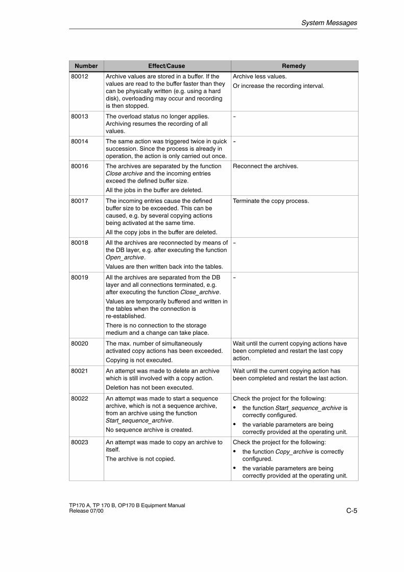
System Messages
C-5TP170 A, TP 170 B, OP170 B Equipment ManualRelease 07/00
RemedyEffect/CauseNumber
80012 Archive values are stored in a buffer. If thevalues are read to the buffer faster than theycan be physically written (e.g. using a harddisk), overloading may occur and recordingis then stopped.
Archive less values.
Or increase the recording interval.
80013 The overload status no longer applies.Archiving resumes the recording of allvalues.
--
80014 The same action was triggered twice in quicksuccession. Since the process is already inoperation, the action is only carried out once.
--
80016 The archives are separated by the functionClose archive and the incoming entriesexceed the defined buffer size.
All the jobs in the buffer are deleted.
Reconnect the archives.
80017 The incoming entries cause the definedbuffer size to be exceeded. This can becaused, e.g. by several copying actionsbeing activated at the same time.
All the copy jobs in the buffer are deleted.
Terminate the copy process.
80018 All the archives are reconnected by means ofthe DB layer, e.g. after executing the functionOpen_archive.
Values are then written back into the tables.
--
80019 All the archives are separated from the DBlayer and all connections terminated, e.g.after executing the function Close_archive.
Values are temporarily buffered and written inthe tables when the connection isre-established.
There is no connection to the storagemedium and a change can take place.
--
80020 The max. number of simultaneouslyactivated copy actions has been exceeded.
Copying is not executed.
Wait until the current copying actions havebeen completed and restart the last copyaction.
80021 An attempt was made to delete an archivewhich is still involved with a copy action.
Deletion has not been executed.
Wait until the current copying action hasbeen completed and restart the last action.
80022 An attempt was made to start a sequencearchive, which is not a sequence archive,from an archive using the functionStart_sequence_archive.
No sequence archive is created.
Check the project for the following:
S the function Start_sequence_archive iscorrectly configured.
S the variable parameters are beingcorrectly provided at the operating unit.
80023 An attempt was made to copy an archive toitself.
The archive is not copied.
Check the project for the following:
S the function Copy_archive is correctlyconfigured.
S the variable parameters are beingcorrectly provided at the operating unit.
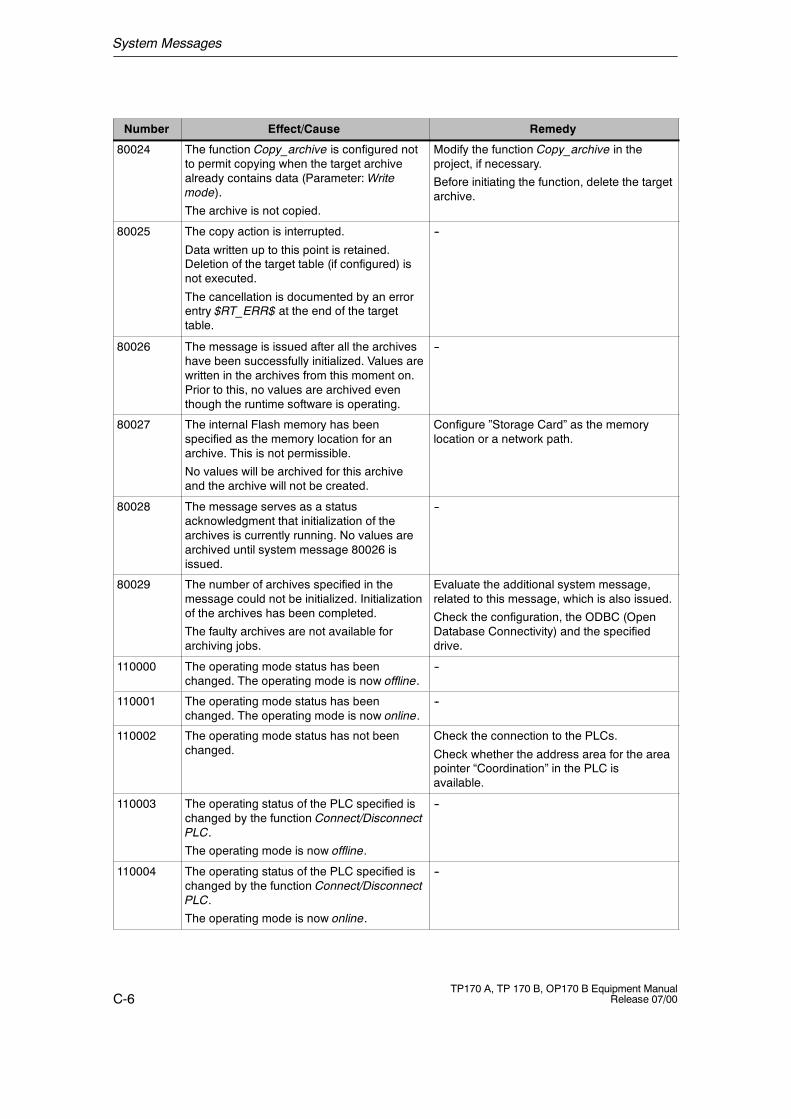
System Messages
C-6TP170 A, TP 170 B, OP170 B Equipment Manual
Release 07/00
RemedyEffect/CauseNumber
80024 The function Copy_archive is configured notto permit copying when the target archivealready contains data (Parameter:Writemode).
The archive is not copied.
Modify the function Copy_archive in theproject, if necessary.
Before initiating the function, delete the targetarchive.
80025 The copy action is interrupted.
Data written up to this point is retained.Deletion of the target table (if configured) isnot executed.
The cancellation is documented by an errorentry $RT_ERR$ at the end of the targettable.
--
80026 The message is issued after all the archiveshave been successfully initialized. Values arewritten in the archives from this moment on.Prior to this, no values are archived eventhough the runtime software is operating.
--
80027 The internal Flash memory has beenspecified as the memory location for anarchive. This is not permissible.
No values will be archived for this archiveand the archive will not be created.
Configure ”Storage Card” as the memorylocation or a network path.
80028 The message serves as a statusacknowledgment that initialization of thearchives is currently running. No values arearchived until system message 80026 isissued.
--
80029 The number of archives specified in themessage could not be initialized. Initializationof the archives has been completed.
The faulty archives are not available forarchiving jobs.
Evaluate the additional system message,related to this message, which is also issued.
Check the configuration, the ODBC (OpenDatabase Connectivity) and the specifieddrive.
110000 The operating mode status has beenchanged. The operating mode is now offline.
--
110001 The operating mode status has beenchanged. The operating mode is now online.
--
110002 The operating mode status has not beenchanged.
Check the connection to the PLCs.
Check whether the address area for the areapointer “Coordination” in the PLC isavailable.
110003 The operating status of the PLC specified ischanged by the function Connect/DisconnectPLC.
The operating mode is now offline.
--
110004 The operating status of the PLC specified ischanged by the function Connect/DisconnectPLC.
The operating mode is now online.
--
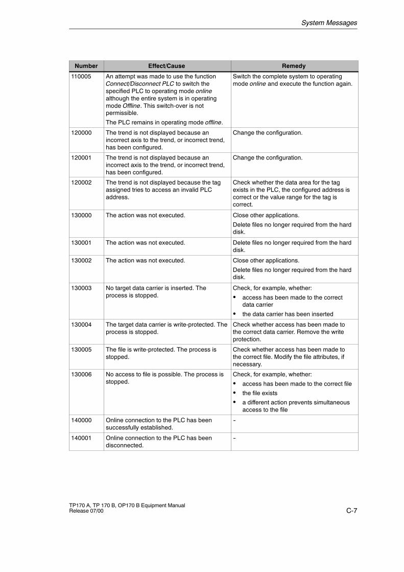
System Messages
C-7TP170 A, TP 170 B, OP170 B Equipment ManualRelease 07/00
RemedyEffect/CauseNumber
110005 An attempt was made to use the functionConnect/Disconnect PLC to switch thespecified PLC to operating mode onlinealthough the entire system is in operatingmode Offline. This switch-over is notpermissible.
The PLC remains in operating mode offline.
Switch the complete system to operatingmode online and execute the function again.
120000 The trend is not displayed because anincorrect axis to the trend, or incorrect trend,has been configured.
Change the configuration.
120001 The trend is not displayed because anincorrect axis to the trend, or incorrect trend,has been configured.
Change the configuration.
120002 The trend is not displayed because the tagassigned tries to access an invalid PLCaddress.
Check whether the data area for the tagexists in the PLC, the configured address iscorrect or the value range for the tag iscorrect.
130000 The action was not executed. Close other applications.
Delete files no longer required from the harddisk.
130001 The action was not executed. Delete files no longer required from the harddisk.
130002 The action was not executed. Close other applications.
Delete files no longer required from the harddisk.
130003 No target data carrier is inserted. Theprocess is stopped.
Check, for example, whether:
S access has been made to the correctdata carrier
S the data carrier has been inserted
130004 The target data carrier is write-protected. Theprocess is stopped.
Check whether access has been made tothe correct data carrier. Remove the writeprotection.
130005 The file is write-protected. The process isstopped.
Check whether access has been made tothe correct file. Modify the file attributes, ifnecessary.
130006 No access to file is possible. The process isstopped.
Check, for example, whether:
S access has been made to the correct file
S the file exists
S a different action prevents simultaneousaccess to the file
140000 Online connection to the PLC has beensuccessfully established.
--
140001 Online connection to the PLC has beendisconnected.
--
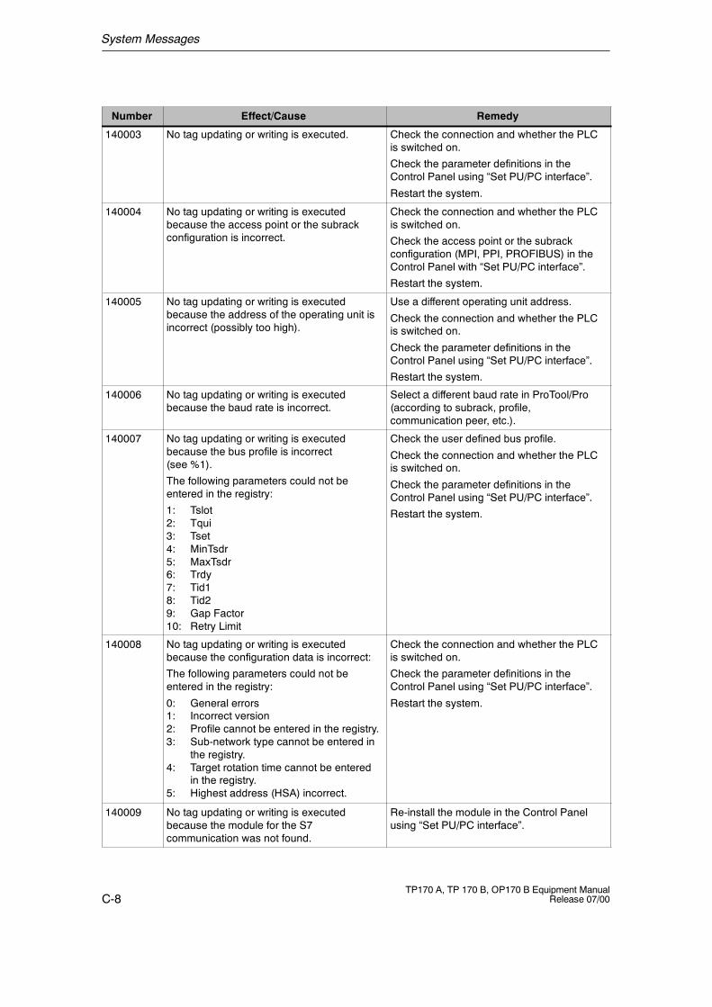
System Messages
C-8TP170 A, TP 170 B, OP170 B Equipment Manual
Release 07/00
RemedyEffect/CauseNumber
140003 No tag updating or writing is executed. Check the connection and whether the PLCis switched on.
Check the parameter definitions in theControl Panel using “Set PU/PC interface”.
Restart the system.
140004 No tag updating or writing is executedbecause the access point or the subrackconfiguration is incorrect.
Check the connection and whether the PLCis switched on.
Check the access point or the subrackconfiguration (MPI, PPI, PROFIBUS) in theControl Panel with “Set PU/PC interface”.
Restart the system.
140005 No tag updating or writing is executedbecause the address of the operating unit isincorrect (possibly too high).
Use a different operating unit address.
Check the connection and whether the PLCis switched on.
Check the parameter definitions in theControl Panel using “Set PU/PC interface”.
Restart the system.
140006 No tag updating or writing is executedbecause the baud rate is incorrect.
Select a different baud rate in ProTool/Pro(according to subrack, profile,communication peer, etc.).
140007 No tag updating or writing is executedbecause the bus profile is incorrect(see %1).
The following parameters could not beentered in the registry:
1: Tslot2: Tqui3: Tset4: MinTsdr5: MaxTsdr6: Trdy7: Tid18: Tid29: Gap Factor10: Retry Limit
Check the user defined bus profile.
Check the connection and whether the PLCis switched on.
Check the parameter definitions in theControl Panel using “Set PU/PC interface”.
Restart the system.
140008 No tag updating or writing is executedbecause the configuration data is incorrect:
The following parameters could not beentered in the registry:
0: General errors1: Incorrect version2: Profile cannot be entered in the registry.3: Sub-network type cannot be entered in
the registry.4: Target rotation time cannot be entered
in the registry.5: Highest address (HSA) incorrect.
Check the connection and whether the PLCis switched on.
Check the parameter definitions in theControl Panel using “Set PU/PC interface”.
Restart the system.
140009 No tag updating or writing is executedbecause the module for the S7communication was not found.
Re-install the module in the Control Panelusing “Set PU/PC interface”.
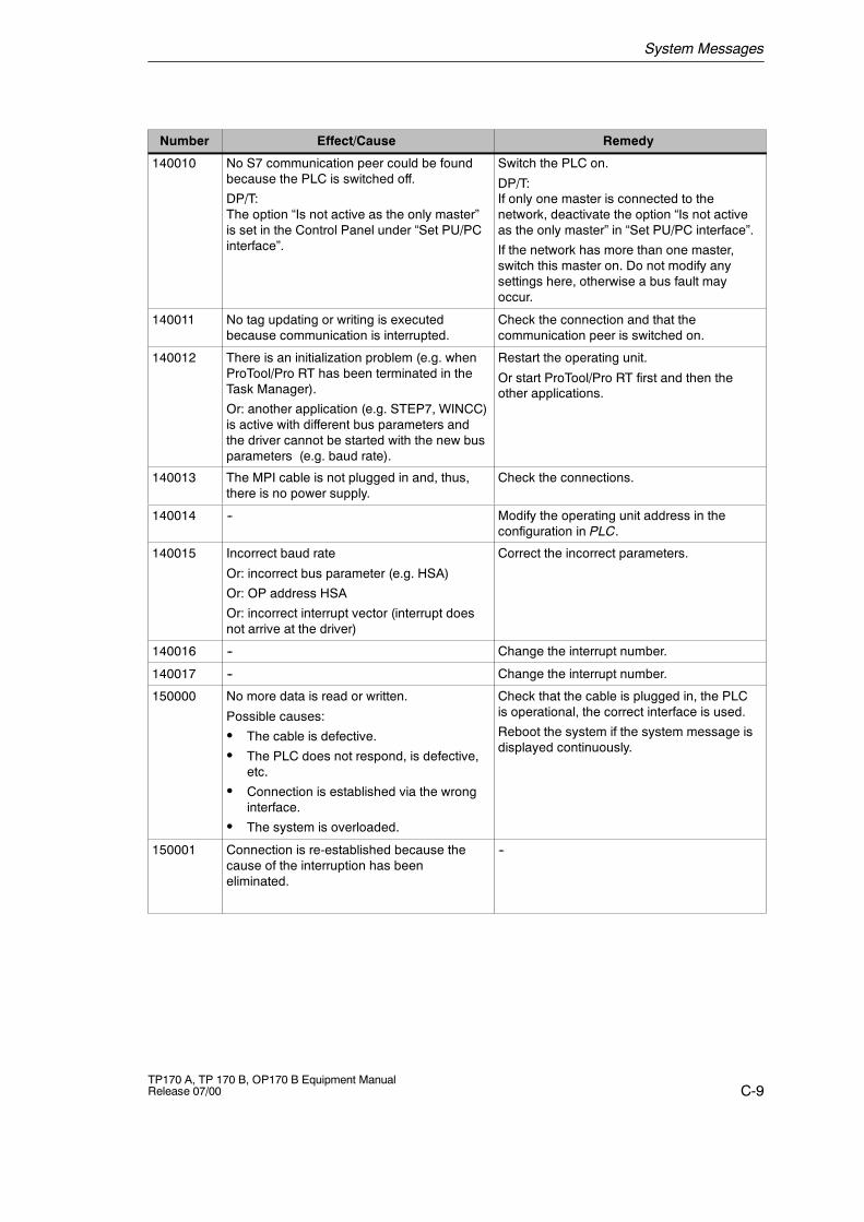
System Messages
C-9TP170 A, TP 170 B, OP170 B Equipment ManualRelease 07/00
RemedyEffect/CauseNumber
140010 No S7 communication peer could be foundbecause the PLC is switched off.
DP/T:The option “Is not active as the only master”is set in the Control Panel under “Set PU/PCinterface”.
Switch the PLC on.
DP/T:If only one master is connected to thenetwork, deactivate the option “Is not activeas the only master” in “Set PU/PC interface”.
If the network has more than one master,switch this master on. Do not modify anysettings here, otherwise a bus fault mayoccur.
140011 No tag updating or writing is executedbecause communication is interrupted.
Check the connection and that thecommunication peer is switched on.
140012 There is an initialization problem (e.g. whenProTool/Pro RT has been terminated in theTask Manager).
Or: another application (e.g. STEP7, WINCC)is active with different bus parameters andthe driver cannot be started with the new busparameters (e.g. baud rate).
Restart the operating unit.
Or start ProTool/Pro RT first and then theother applications.
140013 The MPI cable is not plugged in and, thus,there is no power supply.
Check the connections.
140014 -- Modify the operating unit address in theconfiguration in PLC.
140015 Incorrect baud rate
Or: incorrect bus parameter (e.g. HSA)
Or: OP address HSA
Or: incorrect interrupt vector (interrupt doesnot arrive at the driver)
Correct the incorrect parameters.
140016 -- Change the interrupt number.
140017 -- Change the interrupt number.
150000 No more data is read or written.
Possible causes:
S The cable is defective.
S The PLC does not respond, is defective,etc.
S Connection is established via the wronginterface.
S The system is overloaded.
Check that the cable is plugged in, the PLCis operational, the correct interface is used.
Reboot the system if the system message isdisplayed continuously.
150001 Connection is re-established because thecause of the interruption has beeneliminated.
--
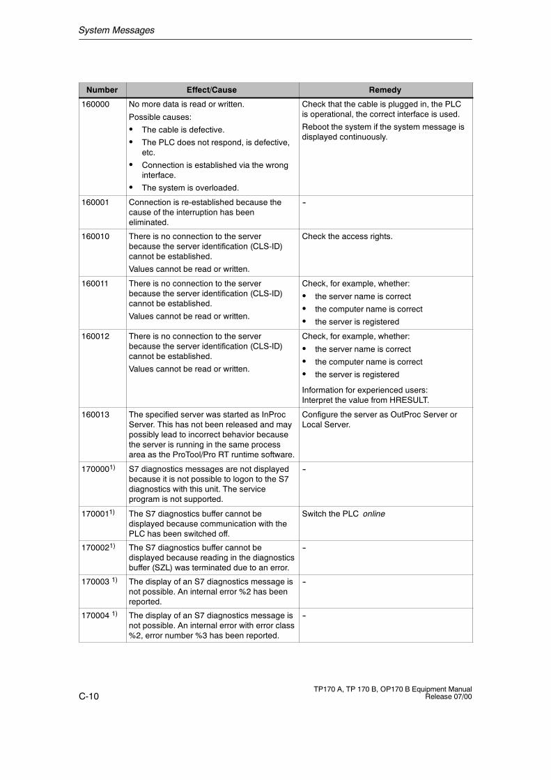
System Messages
C-10TP170 A, TP 170 B, OP170 B Equipment Manual
Release 07/00
RemedyEffect/CauseNumber
160000 No more data is read or written.
Possible causes:
S The cable is defective.
S The PLC does not respond, is defective,etc.
S Connection is established via the wronginterface.
S The system is overloaded.
Check that the cable is plugged in, the PLCis operational, the correct interface is used.
Reboot the system if the system message isdisplayed continuously.
160001 Connection is re-established because thecause of the interruption has beeneliminated.
--
160010 There is no connection to the serverbecause the server identification (CLS-ID)cannot be established.
Values cannot be read or written.
Check the access rights.
160011 There is no connection to the serverbecause the server identification (CLS-ID)cannot be established.
Values cannot be read or written.
Check, for example, whether:
S the server name is correct
S the computer name is correct
S the server is registered
160012 There is no connection to the serverbecause the server identification (CLS-ID)cannot be established.
Values cannot be read or written.
Check, for example, whether:
S the server name is correct
S the computer name is correct
S the server is registered
Information for experienced users:Interpret the value from HRESULT.
160013 The specified server was started as InProcServer. This has not been released and maypossibly lead to incorrect behavior becausethe server is running in the same processarea as the ProTool/Pro RT runtime software.
Configure the server as OutProc Server orLocal Server.
1700001) S7 diagnostics messages are not displayedbecause it is not possible to logon to the S7diagnostics with this unit. The serviceprogram is not supported.
--
1700011) The S7 diagnostics buffer cannot bedisplayed because communication with thePLC has been switched off.
Switch the PLC online
1700021) The S7 diagnostics buffer cannot bedisplayed because reading in the diagnosticsbuffer (SZL) was terminated due to an error.
--
170003 1) The display of an S7 diagnostics message isnot possible. An internal error %2 has beenreported.
--
170004 1) The display of an S7 diagnostics message isnot possible. An internal error with error class%2, error number %3 has been reported.
--
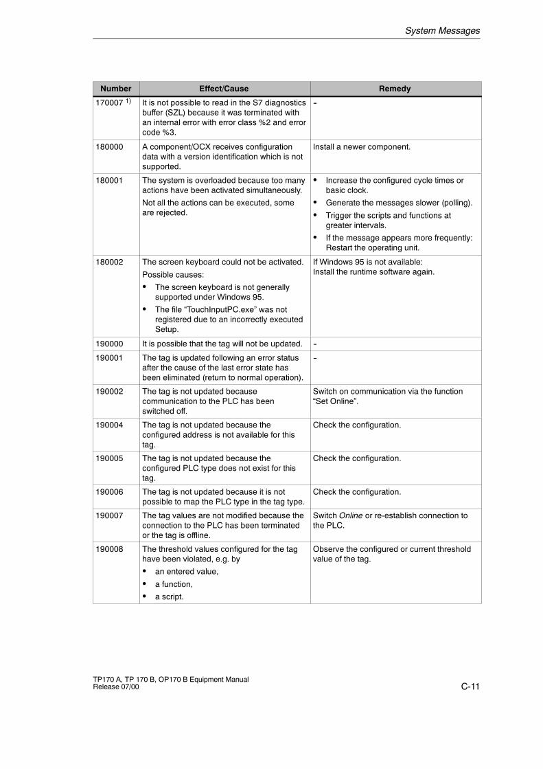
System Messages
C-11TP170 A, TP 170 B, OP170 B Equipment ManualRelease 07/00
RemedyEffect/CauseNumber
170007 1) It is not possible to read in the S7 diagnosticsbuffer (SZL) because it was terminated withan internal error with error class %2 and errorcode %3.
--
180000 A component/OCX receives configurationdata with a version identification which is notsupported.
Install a newer component.
180001 The system is overloaded because too manyactions have been activated simultaneously.
Not all the actions can be executed, someare rejected.
S Increase the configured cycle times orbasic clock.
S Generate the messages slower (polling).
S Trigger the scripts and functions atgreater intervals.
S If the message appears more frequently:Restart the operating unit.
180002 The screen keyboard could not be activated.
Possible causes:
S The screen keyboard is not generallysupported under Windows 95.
S The file “TouchInputPC.exe” was notregistered due to an incorrectly executedSetup.
If Windows 95 is not available:Install the runtime software again.
190000 It is possible that the tag will not be updated. --
190001 The tag is updated following an error statusafter the cause of the last error state hasbeen eliminated (return to normal operation).
--
190002 The tag is not updated becausecommunication to the PLC has beenswitched off.
Switch on communication via the function“Set Online”.
190004 The tag is not updated because theconfigured address is not available for thistag.
Check the configuration.
190005 The tag is not updated because theconfigured PLC type does not exist for thistag.
Check the configuration.
190006 The tag is not updated because it is notpossible to map the PLC type in the tag type.
Check the configuration.
190007 The tag values are not modified because theconnection to the PLC has been terminatedor the tag is offline.
Switch Online or re-establish connection tothe PLC.
190008 The threshold values configured for the taghave been violated, e.g. by
S an entered value,
S a function,
S a script.
Observe the configured or current thresholdvalue of the tag.
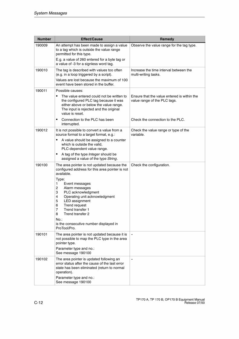
System Messages
C-12TP170 A, TP 170 B, OP170 B Equipment Manual
Release 07/00
RemedyEffect/CauseNumber
190009 An attempt has been made to assign a valueto a tag which is outside the value rangepermitted for this type.
E.g. a value of 260 entered for a byte tag ora value of -3 for a signless word tag.
Observe the value range for the tag type.
190010 The tag is described with values too often(e.g. in a loop triggered by a script).
Values are lost because the maximum of 100event have been stored in the buffer.
Increase the time interval between themulti-writing tasks.
190011 Possible causes:
S The value entered could not be written tothe configured PLC tag because it waseither above or below the value range.The input is rejected and the originalvalue is reset.
Ensure that the value entered is within thevalue range of the PLC tags.
S Connection to the PLC has beeninterrupted.
Check the connection to the PLC.
190012 It is not possible to convert a value from asource format to a target format, e.g.:
S A value should be assigned to a counterwhich is outside the valid,PLC-dependent value range.
S A tag of the type Integer should beassigned a value of the type String.
Check the value range or type of thevariable.
190100 The area pointer is not updated because theconfigured address for this area pointer is notavailable.
Type:1 Event messages2 Alarm messages3 PLC acknowledgment4 Operating unit acknowledgment5 LED assignment6 Trend request7 Trend transfer 18 Trend transfer 2
No.:is the consecutive number displayed inProTool/Pro.
Check the configuration.
190101 The area pointer is not updated because it isnot possible to map the PLC type in the areapointer type.
Parameter type and no.:See message 190100
--
190102 The area pointer is updated following anerror status after the cause of the last errorstate has been eliminated (return to normaloperation).
Parameter type and no.:See message 190100
--
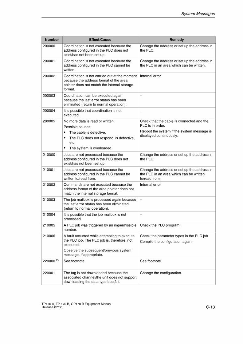
System Messages
C-13TP170 A, TP 170 B, OP170 B Equipment ManualRelease 07/00
RemedyEffect/CauseNumber
200000 Coordination is not executed because theaddress configured in the PLC does notexist/has not been set up.
Change the address or set up the address inthe PLC.
200001 Coordination is not executed because theaddress configured in the PLC cannot bewritten.
Change the address or set up the address inthe PLC in an area which can be written.
200002 Coordination is not carried out at the momentbecause the address format of the areapointer does not match the internal storageformat.
Internal error
200003 Coordination can be executed againbecause the last error status has beeneliminated (return to normal operation).
--
200004 It is possible that coordination is notexecuted.
--
200005 No more data is read or written.
Possible causes:
S The cable is defective.
S The PLC does not respond, is defective,etc.
S The system is overloaded.
Check that the cable is connected and thePLC is in order.
Reboot the system if the system message isdisplayed continuously.
210000 Jobs are not processed because theaddress configured in the PLC does notexist/has not been set up.
Change the address or set up the address inthe PLC.
210001 Jobs are not processed because theaddress configured in the PLC cannot bewritten to/read from.
Change the address or set up the address inthe PLC in an area which can be writtento/read from.
210002 Commands are not executed because theaddress format of the area pointer does notmatch the internal storage format.
Internal error
210003 The job mailbox is processed again becausethe last error status has been eliminated(return to normal operation).
--
210004 It is possible that the job mailbox is notprocessed.
--
210005 A PLC job was triggered by an impermissiblenumber.
Check the PLC program.
210006 A fault occurred while attempting to executethe PLC job. The PLC job is, therefore, notexecuted.
Observe the subsequent/previous systemmessage, if appropriate.
Check the parameter types in the PLC job.
Compile the configuration again.
220000 2) See footnote See footnote
220001 The tag is not downloaded because theassociated channel/the unit does not supportdownloading the data type bool/bit.
Change the configuration.
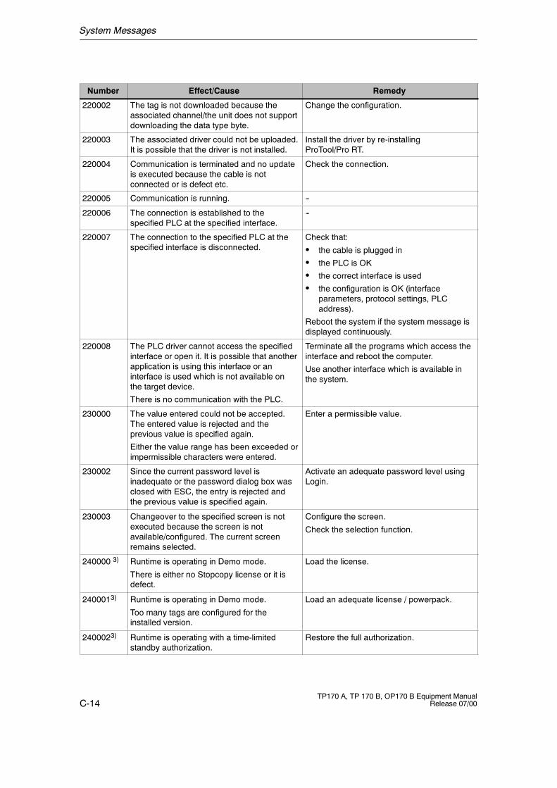
System Messages
C-14TP170 A, TP 170 B, OP170 B Equipment Manual
Release 07/00
RemedyEffect/CauseNumber
220002 The tag is not downloaded because theassociated channel/the unit does not supportdownloading the data type byte.
Change the configuration.
220003 The associated driver could not be uploaded.It is possible that the driver is not installed.
Install the driver by re-installingProTool/Pro RT.
220004 Communication is terminated and no updateis executed because the cable is notconnected or is defect etc.
Check the connection.
220005 Communication is running. --
220006 The connection is established to thespecified PLC at the specified interface.
--
220007 The connection to the specified PLC at thespecified interface is disconnected.
Check that:
S the cable is plugged in
S the PLC is OK
S the correct interface is used
S the configuration is OK (interfaceparameters, protocol settings, PLCaddress).
Reboot the system if the system message isdisplayed continuously.
220008 The PLC driver cannot access the specifiedinterface or open it. It is possible that anotherapplication is using this interface or aninterface is used which is not available onthe target device.
There is no communication with the PLC.
Terminate all the programs which access theinterface and reboot the computer.
Use another interface which is available inthe system.
230000 The value entered could not be accepted.The entered value is rejected and theprevious value is specified again.
Either the value range has been exceeded orimpermissible characters were entered.
Enter a permissible value.
230002 Since the current password level isinadequate or the password dialog box wasclosed with ESC, the entry is rejected andthe previous value is specified again.
Activate an adequate password level usingLogin.
230003 Changeover to the specified screen is notexecuted because the screen is notavailable/configured. The current screenremains selected.
Configure the screen.
Check the selection function.
240000 3) Runtime is operating in Demo mode.
There is either no Stopcopy license or it isdefect.
Load the license.
2400013) Runtime is operating in Demo mode.
Too many tags are configured for theinstalled version.
Load an adequate license / powerpack.
2400023) Runtime is operating with a time-limitedstandby authorization.
Restore the full authorization.
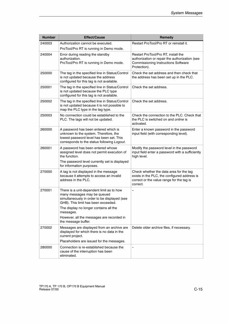
System Messages
C-15TP170 A, TP 170 B, OP170 B Equipment ManualRelease 07/00
RemedyEffect/CauseNumber
240003 Authorization cannot be executed.
ProTool/Pro RT is running in Demo mode.
Restart ProTool/Pro RT or reinstall it.
240004 Error during reading the standbyauthorization.ProTool/Pro RT is running in Demo mode.
Restart ProTool/Pro RT, install theauthorization or repair the authorization (seeCommissioning Instructions SoftwareProtection).
250000 The tag in the specified line in Status/Controlis not updated because the addressconfigured for this tag is not available.
Check the set address and then check thatthe address has been set up in the PLC.
250001 The tag in the specified line in Status/Controlis not updated because the PLC typeconfigured for this tag is not available.
Check the set address.
250002 The tag in the specified line in Status/Controlis not updated because it is not possible tomap the PLC type in the tag type.
Check the set address.
250003 No connection could be established to thePLC. The tags will not be updated.
Check the connection to the PLC. Check thatthe PLC is switched on and online isactivated.
260000 A password has been entered which isunknown to the system. Therefore, thelowest password level has been set. Thiscorresponds to the status following Logout.
Enter a known password in the passwordinput field (with corresponding level).
260001 A password has been entered whoseassigned level does not permit execution ofthe function.
The password level currently set is displayedfor information purposes.
Modify the password level in the passwordinput field enter a password with a sufficientlyhigh level.
270000 A tag is not displayed in the messagebecause it attempts to access an invalidaddress in the PLC.
Check whether the data area for the tagexists in the PLC, the configured address iscorrect or the value range for the tag iscorrect.
270001 There is a unit-dependent limit as to howmany messages may be queuedsimultaneously in order to be displayed (seeGHB). This limit has been exceeded.
The display no longer contains all themessages.
However, all the messages are recorded inthe message buffer.
--
270002 Messages are displayed from an archive aredisplayed for which there is no data in thecurrent project.
Placeholders are issued for the messages.
Delete older archive files, if necessary.
280000 Connection is re-established because thecause of the interruption has beeneliminated.
--
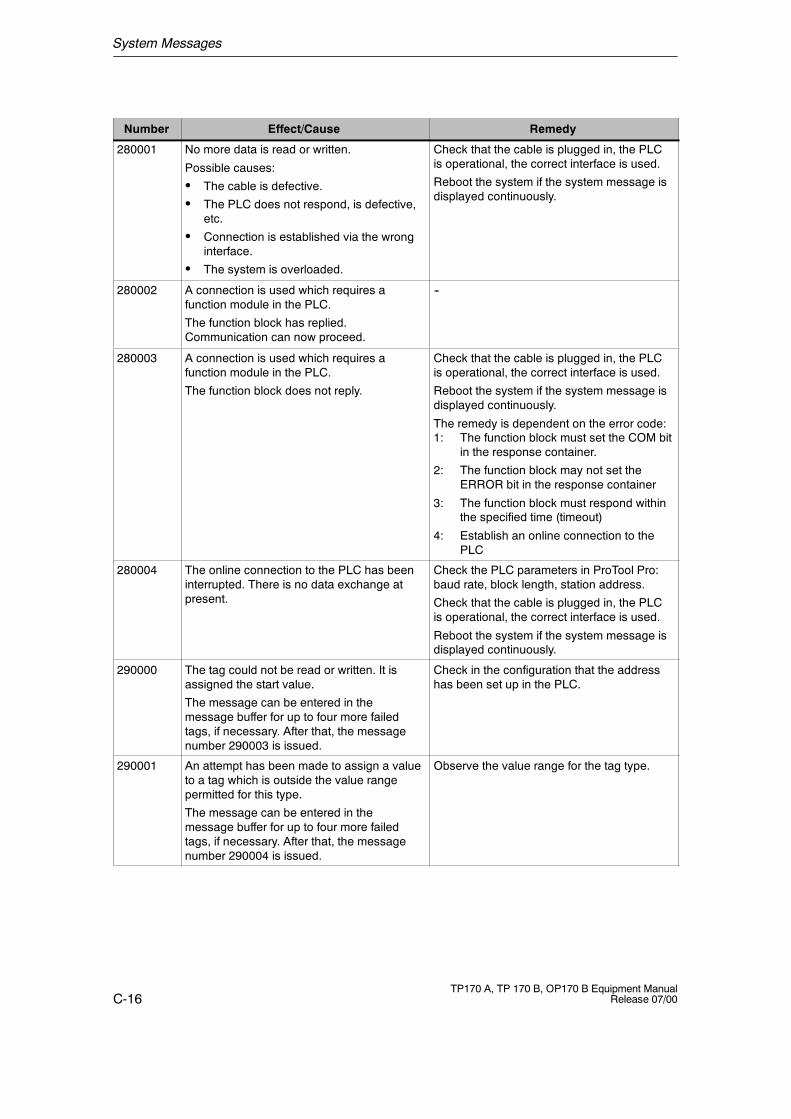
System Messages
C-16TP170 A, TP 170 B, OP170 B Equipment Manual
Release 07/00
RemedyEffect/CauseNumber
280001 No more data is read or written.
Possible causes:
S The cable is defective.
S The PLC does not respond, is defective,etc.
S Connection is established via the wronginterface.
S The system is overloaded.
Check that the cable is plugged in, the PLCis operational, the correct interface is used.
Reboot the system if the system message isdisplayed continuously.
280002 A connection is used which requires afunction module in the PLC.
The function block has replied.Communication can now proceed.
--
280003 A connection is used which requires afunction module in the PLC.
The function block does not reply.
Check that the cable is plugged in, the PLCis operational, the correct interface is used.
Reboot the system if the system message isdisplayed continuously.
The remedy is dependent on the error code:1: The function block must set the COM bit
in the response container.
2: The function block may not set theERROR bit in the response container
3: The function block must respond withinthe specified time (timeout)
4: Establish an online connection to thePLC
280004 The online connection to the PLC has beeninterrupted. There is no data exchange atpresent.
Check the PLC parameters in ProTool Pro:baud rate, block length, station address.
Check that the cable is plugged in, the PLCis operational, the correct interface is used.
Reboot the system if the system message isdisplayed continuously.
290000 The tag could not be read or written. It isassigned the start value.
The message can be entered in themessage buffer for up to four more failedtags, if necessary. After that, the messagenumber 290003 is issued.
Check in the configuration that the addresshas been set up in the PLC.
290001 An attempt has been made to assign a valueto a tag which is outside the value rangepermitted for this type.
The message can be entered in themessage buffer for up to four more failedtags, if necessary. After that, the messagenumber 290004 is issued.
Observe the value range for the tag type.
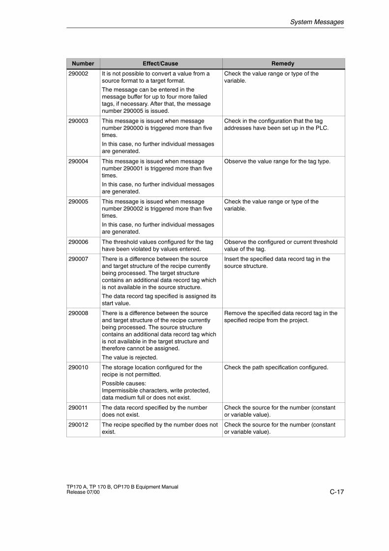
System Messages
C-17TP170 A, TP 170 B, OP170 B Equipment ManualRelease 07/00
RemedyEffect/CauseNumber
290002 It is not possible to convert a value from asource format to a target format.
The message can be entered in themessage buffer for up to four more failedtags, if necessary. After that, the messagenumber 290005 is issued.
Check the value range or type of thevariable.
290003 This message is issued when messagenumber 290000 is triggered more than fivetimes.
In this case, no further individual messagesare generated.
Check in the configuration that the tagaddresses have been set up in the PLC.
290004 This message is issued when messagenumber 290001 is triggered more than fivetimes.
In this case, no further individual messagesare generated.
Observe the value range for the tag type.
290005 This message is issued when messagenumber 290002 is triggered more than fivetimes.
In this case, no further individual messagesare generated.
Check the value range or type of thevariable.
290006 The threshold values configured for the taghave been violated by values entered.
Observe the configured or current thresholdvalue of the tag.
290007 There is a difference between the sourceand target structure of the recipe currentlybeing processed. The target structurecontains an additional data record tag whichis not available in the source structure.
The data record tag specified is assigned itsstart value.
Insert the specified data record tag in thesource structure.
290008 There is a difference between the sourceand target structure of the recipe currentlybeing processed. The source structurecontains an additional data record tag whichis not available in the target structure andtherefore cannot be assigned.
The value is rejected.
Remove the specified data record tag in thespecified recipe from the project.
290010 The storage location configured for therecipe is not permitted.
Possible causes:Impermissible characters, write protected,data medium full or does not exist.
Check the path specification configured.
290011 The data record specified by the numberdoes not exist.
Check the source for the number (constantor variable value).
290012 The recipe specified by the number does notexist.
Check the source for the number (constantor variable value).
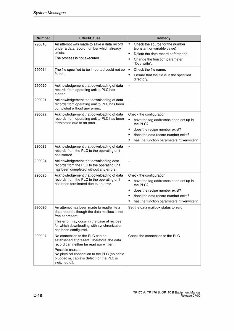
System Messages
C-18TP170 A, TP 170 B, OP170 B Equipment Manual
Release 07/00
RemedyEffect/CauseNumber
290013 An attempt was made to save a data recordunder a data record number which alreadyexists.
The process is not executed.
S Check the source for the number(constant or variable value).
S Delete the data record beforehand.
S Change the function parameter“Overwrite”.
290014 The file specified to be imported could not befound.
S Check the file name.
S Ensure that the file is in the specifieddirectory.
290020 Acknowledgement that downloading of datarecords from operating unit to PLC hasstarted.
--
290021 Acknowledgement that downloading of datarecords from operating unit to PLC has beencompleted without any errors.
--
290022 Acknowledgement that downloading of datarecords from operating unit to PLC has beenterminated due to an error.
Check the configuration:
S have the tag addresses been set up inthe PLC?
S does the recipe number exist?
S does the data record number exist?
S has the function parameters ”Overwrite”?
290023 Acknowledgement that downloading of datarecords from the PLC to the operating unithas started.
--
290024 Acknowledgement that downloading datarecords from the PLC to the operating unithas been completed without any errors.
--
290025 Acknowledgement that downloading of datarecords from the PLC to the operating unithas been terminated due to an error.
Check the configuration:
S have the tag addresses been set up inthe PLC?
S does the recipe number exist?
S does the data record number exist?
S has the function parameters ”Overwrite”?
290026 An attempt has been made to read/write adata record although the data mailbox is notfree at present.
This error may occur in the case of recipesfor which downloading with synchronizationhas been configured.
Set the data mailbox status to zero.
290027 No connection to the PLC can beestablished at present. Therefore, the datarecord can neither be read nor written.
Possible causes:No physical connection to the PLC (no cableplugged in, cable is defect) or the PLC isswitched off.
Check the connection to the PLC.
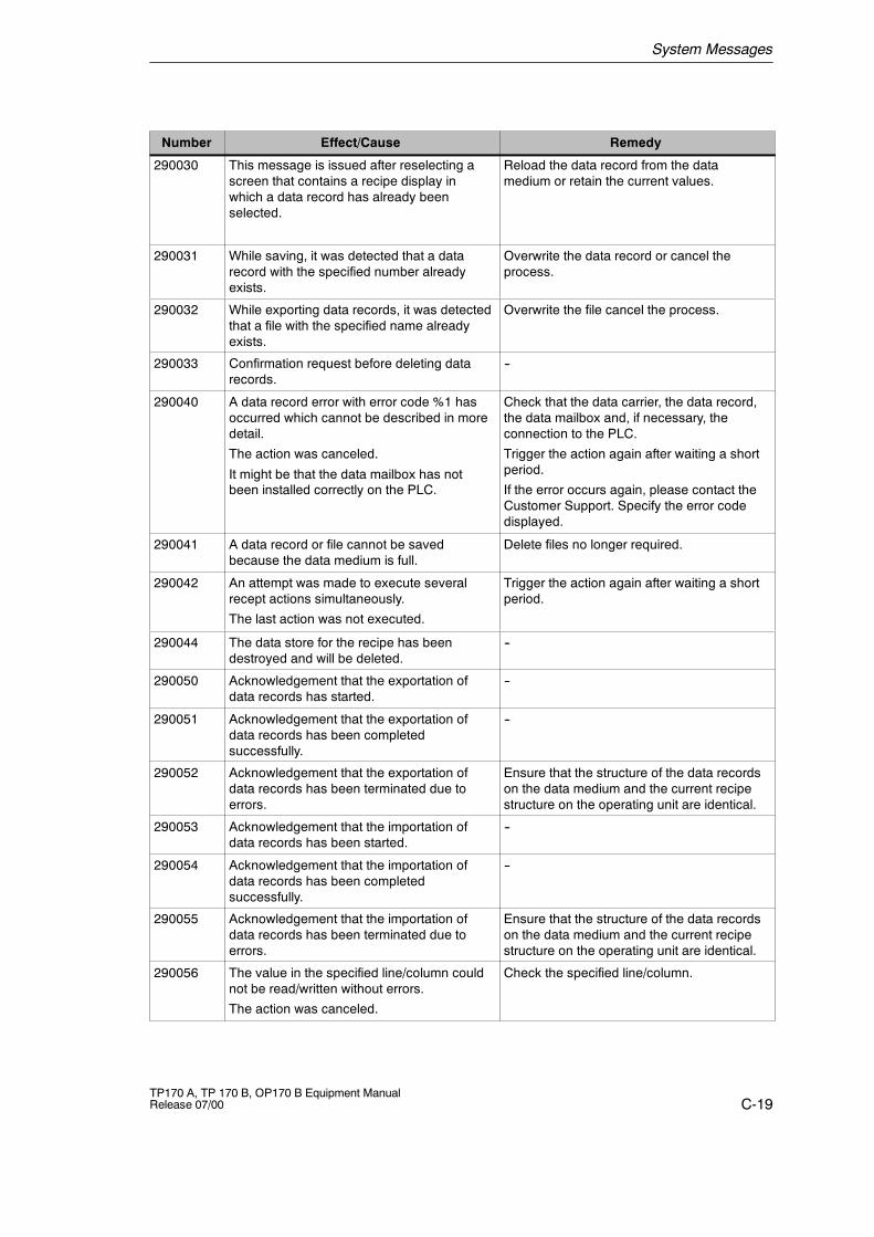
System Messages
C-19TP170 A, TP 170 B, OP170 B Equipment ManualRelease 07/00
RemedyEffect/CauseNumber
290030 This message is issued after reselecting ascreen that contains a recipe display inwhich a data record has already beenselected.
Reload the data record from the datamedium or retain the current values.
290031 While saving, it was detected that a datarecord with the specified number alreadyexists.
Overwrite the data record or cancel theprocess.
290032 While exporting data records, it was detectedthat a file with the specified name alreadyexists.
Overwrite the file cancel the process.
290033 Confirmation request before deleting datarecords.
--
290040 A data record error with error code %1 hasoccurred which cannot be described in moredetail.
The action was canceled.
It might be that the data mailbox has notbeen installed correctly on the PLC.
Check that the data carrier, the data record,the data mailbox and, if necessary, theconnection to the PLC.
Trigger the action again after waiting a shortperiod.
If the error occurs again, please contact theCustomer Support. Specify the error codedisplayed.
290041 A data record or file cannot be savedbecause the data medium is full.
Delete files no longer required.
290042 An attempt was made to execute severalrecept actions simultaneously.
The last action was not executed.
Trigger the action again after waiting a shortperiod.
290044 The data store for the recipe has beendestroyed and will be deleted.
--
290050 Acknowledgement that the exportation ofdata records has started.
--
290051 Acknowledgement that the exportation ofdata records has been completedsuccessfully.
--
290052 Acknowledgement that the exportation ofdata records has been terminated due toerrors.
Ensure that the structure of the data recordson the data medium and the current recipestructure on the operating unit are identical.
290053 Acknowledgement that the importation ofdata records has been started.
--
290054 Acknowledgement that the importation ofdata records has been completedsuccessfully.
--
290055 Acknowledgement that the importation ofdata records has been terminated due toerrors.
Ensure that the structure of the data recordson the data medium and the current recipestructure on the operating unit are identical.
290056 The value in the specified line/column couldnot be read/written without errors.
The action was canceled.
Check the specified line/column.
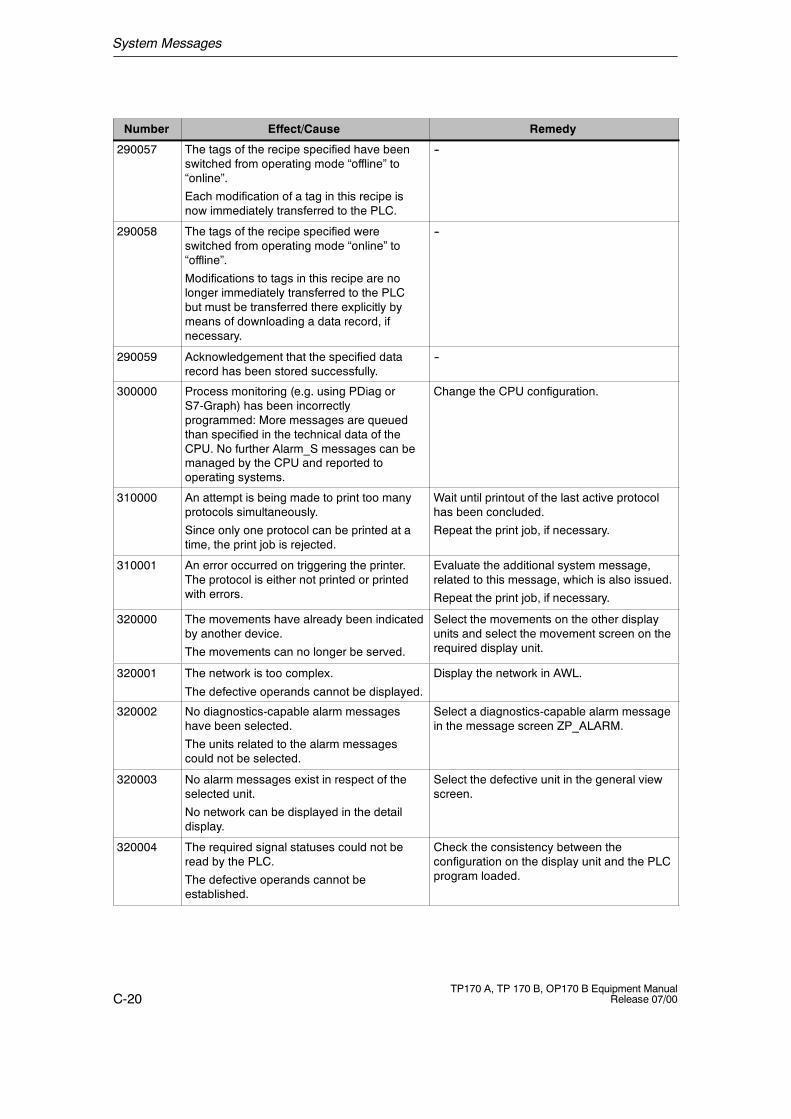
System Messages
C-20TP170 A, TP 170 B, OP170 B Equipment Manual
Release 07/00
RemedyEffect/CauseNumber
290057 The tags of the recipe specified have beenswitched from operating mode “offline” to“online”.
Each modification of a tag in this recipe isnow immediately transferred to the PLC.
--
290058 The tags of the recipe specified wereswitched from operating mode “online” to“offline”.
Modifications to tags in this recipe are nolonger immediately transferred to the PLCbut must be transferred there explicitly bymeans of downloading a data record, ifnecessary.
--
290059 Acknowledgement that the specified datarecord has been stored successfully.
--
300000 Process monitoring (e.g. using PDiag orS7-Graph) has been incorrectlyprogrammed: More messages are queuedthan specified in the technical data of theCPU. No further Alarm_S messages can bemanaged by the CPU and reported tooperating systems.
Change the CPU configuration.
310000 An attempt is being made to print too manyprotocols simultaneously.
Since only one protocol can be printed at atime, the print job is rejected.
Wait until printout of the last active protocolhas been concluded.
Repeat the print job, if necessary.
310001 An error occurred on triggering the printer.The protocol is either not printed or printedwith errors.
Evaluate the additional system message,related to this message, which is also issued.
Repeat the print job, if necessary.
320000 The movements have already been indicatedby another device.
The movements can no longer be served.
Select the movements on the other displayunits and select the movement screen on therequired display unit.
320001 The network is too complex.
The defective operands cannot be displayed.
Display the network in AWL.
320002 No diagnostics-capable alarm messageshave been selected.
The units related to the alarm messagescould not be selected.
Select a diagnostics-capable alarm messagein the message screen ZP_ALARM.
320003 No alarm messages exist in respect of theselected unit.
No network can be displayed in the detaildisplay.
Select the defective unit in the general viewscreen.
320004 The required signal statuses could not beread by the PLC.
The defective operands cannot beestablished.
Check the consistency between theconfiguration on the display unit and the PLCprogram loaded.
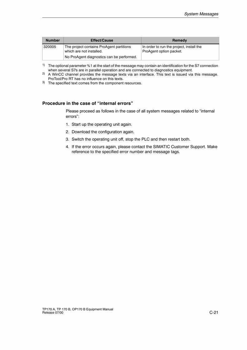
System Messages
C-21TP170 A, TP 170 B, OP170 B Equipment ManualRelease 07/00
RemedyEffect/CauseNumber
320005 The project contains ProAgent partitionswhich are not installed.
No ProAgent diagnostics can be performed.
In order to run the project, install theProAgent option packet.
1) The optional parameter %1 at the start of the message may contain an identification for the S7 connectionwhen several S7s are in parallel operation and are connected to diagnostics equipment.
2) A WinCC channel provides the message texts via an interface. This text is issued via this message.ProTool/Pro RT has no influence on this texts.
3) The specified text comes from the component resources.
Procedure in the case of “internal errors”
Please proceed as follows in the case of all system messages related to “internalerrors”:
1. Start up the operating unit again.
2. Download the configuration again.
3. Switch the operating unit off, stop the PLC and then restart both.
4. If the error occurs again, please contact the SIMATIC Customer Support. Makereference to the specified error number and message tags.

System Messages
C-22TP170 A, TP 170 B, OP170 B Equipment Manual
Release 07/00
D-1TP170 A, TP 170 B, OP170 B Equipment ManualRelease 07/00
ESD Guidelines
What does ESD mean?
Virtually all present-day modules incorporate highly integrated MOS devices orcomponents. For technological reasons, these electronic components are verysensitive to overvoltages and consequently therefore to electrostatic discharge:
These devices are referred to in German as Elektrostatisch GefährdetenBauelemente/ Baugruppen: ”EGB”
The more frequent international name is:
”ESD” (Electrostatic Sensitive Device)
The following symbol on plates on cabinets, mounting racks or packages drawsattention to the use of electrostatic sensitive devices and thus to the contactsensitivity of the assemblies concerned:
ESDs may be destroyed by voltages and energies well below the perceptionthreshold of persons. Voltages of this kind occur as soon as a device or anassembly is touched by a person who is not electrostatically discharged . Devicesexposed to such overvoltages cannot immediately be detected as defective in themajority of cases since faulty behavior may occur only after a long period ofoperation.
Precautions against electrostatic discharge
Most plastics are capable of carrying high charges and it is therefore imperativethat they be kept away from sensitive components.
When handling electrostatic sensitive devices, make sure that persons, workplacesand packages are properly grounded.
D
ESD Guidelines
D-2TP170 A, TP 170 B, OP170 B Equipment Manual
Release 07/00
Handling ESD assemblies
A general rule is that assemblies should be touched only when this cannot beavoided owing to the work that has to performed on them. Under no circumstancesshould you handle printed-circuit boards by touching device pins or circuitry.
You should touch devices only if
S you are grounded by permanently wearing an ESD wrist strap or
S you are wearing ESD shoes or ESD shoe-grounding protection straps inconjunction with an ESD floor.
Before you touch an electronic assembly, your body must be discharged. Thesimplest way of doing this is to touch a conductive, grounded object immediatelybeforehand -- for example, bare metal parts of a cabinet, water pipe etc.
Assemblies should not be brought into contact with charge-susceptible and highlyinsulating materials such as plastic films, insulating table tops and items of clothingetc. containing synthetic fibers.
Assemblies should be deposited only on conductive surfaces (tables with an ESDcoating, conductive ESD cellular material, ESD bags, ESD shipping containers).
Do not place assemblies near visual display units, monitors or television sets(minimum distance to screen > 10 cm).
Measuring and modifying ESD assemblies
Perform measurements on ESD assemblies only when
S the measuring instrument is grounded -- for example, by means of a protectiveconductor -- or
S the measuring head has been briefly discharged before measurements aremade with a potential-free measuring instrument -- for example, by touching abare metal control cabinet.
When soldering, use only grounded soldering irons.
Shipping ESD assemblies
Always store and ship assemblies and devices in conductive packing -- forexample, metallized plastic boxes and tin cans.
If packing is not conductive, assemblies must be conductively wrapped before theyare packed. You can use, for example, conductive foam rubber, ESD bags,domestic aluminum foil or paper (never use plastic bags or foils).
With assemblies containing fitted batteries, make sure that the conductive packingdoes not come into contact with or short-circuit battery connectors. If necessary,cover the connectors beforehand with insulating tape or insulating material.
E-1TP170 A, TP 170 B, OP170 B Equipment ManualRelease 07/00
SIMATIC HMI Documentation
Target groups
This manual is part of the SIMATIC HMI documentation. The documentation isaimed at the following target groups:
S Newcomers
S Users
S Configurers
S Programmers
S Commissioning engineers
How the documentation is organized
The SIMATIC HMI documentation consists of the following components:
S User’s Guides for:-- Configuration software-- Runtime software-- Communication between PLCs and operating units
S Equipment Manuals for the following operating units:-- SIMATIC PC-- MP (Multi Panel)-- OP (Operator Panel)-- TP (Touch Panel)-- TD (Text Display)-- PP (Push Button Panel)
S Online Help on the configuration software
S Start-up Guides
S First Steps
Overview of complete documentation
The following table provides an overview of the SIMATIC HMI documentation andshows you when you require the different documents.
E
SIMATIC HMI Documentation
E-2TP170 A, TP 170 B, OP170 B Equipment Manual
Release 07/00
Documentation Target Group Content
First Steps with ProTool
Product Brief
Newcomers This documentation guides you step by step throughthe configuration of
S a screen with various objects
S changing from one screen to another
S a message.
This documentation is available for:
S Text-based Displays
S Graphics Displays
S Touch Panels
S Windows-based Systems
ProToolConfiguringWindows-based Systems
User’s Guide
Configurers Provides information on working with the configurationsoftware. It contains
S information on installation
S basic principles of configuration
S a detailed description of configurable objects andfunctions.
This documentation is valid for Windows-basedsystems.
ProToolConfiguringGraphics Displays
User’s Guide
Configurers Provides information on working with the configurationsoftware. It contains
S information on installation
S basic principles of configuration
S a detailed description of configurable objects andfunctions.
This documentation is valid for graphic displayoperating units.
ProToolConfiguringText-based Displays
User’s Guide
Configurers Provides information on working with the configurationsoftware. It contains
S information on installation
S basic principles of configuration
S a detailed description of configurable objects andfunctions.
This documentation is valid for text-based displayoperating units.
ProTool
Online Help
Configurers Provides information on the configuration computerwhile working with ProTool. Online Help contains
S context-sensitive help
S detailed instructions and examples
S detailed information
S all the information from the user guide.
ProTool/Pro Runtime
User’s Guide
Commissioningengineers,Users
Provides information on working with ProTool/ProRuntime software. It contains
S installation of the ProTool/Pro Runtime visualizationsoftware
S commissioning and running the software onWindows-based systems.
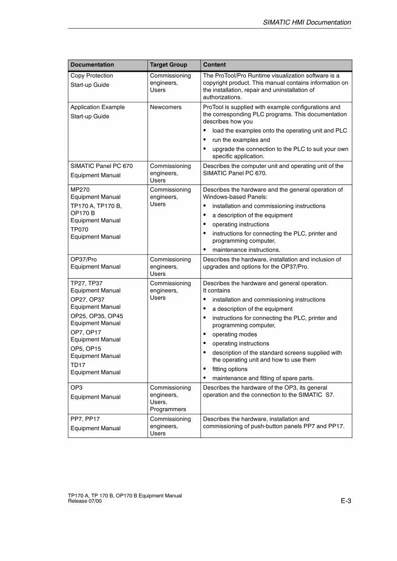
SIMATIC HMI Documentation
E-3TP170 A, TP 170 B, OP170 B Equipment ManualRelease 07/00
ContentTarget GroupDocumentation
Copy Protection
Start-up Guide
Commissioningengineers,Users
The ProTool/Pro Runtime visualization software is acopyright product. This manual contains information onthe installation, repair and uninstallation ofauthorizations.
Application Example
Start-up Guide
Newcomers ProTool is supplied with example configurations andthe corresponding PLC programs. This documentationdescribes how you
S load the examples onto the operating unit and PLC
S run the examples and
S upgrade the connection to the PLC to suit your ownspecific application.
SIMATIC Panel PC 670
Equipment Manual
Commissioningengineers,Users
Describes the computer unit and operating unit of theSIMATIC Panel PC 670.
MP270Equipment Manual
TP170 A, TP170 B,OP170 BEquipment Manual
TP070Equipment Manual
Commissioningengineers,Users
Describes the hardware and the general operation ofWindows-based Panels:
S installation and commissioning instructions
S a description of the equipment
S operating instructions
S instructions for connecting the PLC, printer andprogramming computer,
S maintenance instructions.
OP37/ProEquipment Manual
Commissioningengineers,Users
Describes the hardware, installation and inclusion ofupgrades and options for the OP37/Pro.
TP27, TP37Equipment Manual
OP27, OP37Equipment Manual
OP25, OP35, OP45Equipment Manual
OP7, OP17Equipment Manual
OP5, OP15Equipment Manual
TD17Equipment Manual
Commissioningengineers,Users
Describes the hardware and general operation.It contains
S installation and commissioning instructions
S a description of the equipment
S instructions for connecting the PLC, printer andprogramming computer,
S operating modes
S operating instructions
S description of the standard screens supplied withthe operating unit and how to use them
S fitting options
S maintenance and fitting of spare parts.
OP3
Equipment Manual
Commissioningengineers,Users,Programmers
Describes the hardware of the OP3, its generaloperation and the connection to the SIMATIC S7.
PP7, PP17
Equipment Manual
Commissioningengineers,Users
Describes the hardware, installation andcommissioning of push-button panels PP7 and PP17.
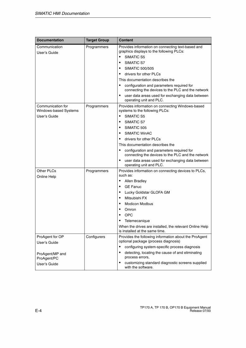
SIMATIC HMI Documentation
E-4TP170 A, TP 170 B, OP170 B Equipment Manual
Release 07/00
ContentTarget GroupDocumentation
Communication
User’s Guide
Programmers Provides information on connecting text-based andgraphics displays to the following PLCs:
S SIMATIC S5
S SIMATIC S7
S SIMATIC 500/505
S drivers for other PLCs
This documentation describes the
S configuration and parameters required forconnecting the devices to the PLC and the network
S user data areas used for exchanging data betweenoperating unit and PLC.
Communication forWindows-based Systems
User’s Guide
Programmers Provides information on connecting Windows-basedsystems to the following PLCs:
S SIMATIC S5
S SIMATIC S7
S SIMATIC 505
S SIMATIC WinAC
S drivers for other PLCs
This documentation describes the
S configuration and parameters required forconnecting the devices to the PLC and the network
S user data areas used for exchanging data betweenoperating unit and PLC.
Other PLCs
Online Help
Programmers Provides information on connecting devices to PLCs,such as:
S Allen Bradley
S GE Fanuc
S Lucky Goldstar GLOFA GM
S Mitsubishi FX
S Modicon Modbus
S Omron
S OPC
S Telemecanique
When the drives are installed, the relevant Online Helpis installed at the same time.
ProAgent for OP
User’s Guide
ProAgent/MP andProAgent/PC
User’s Guide
Configurers Provides the following information about the ProAgentoptional package (process diagnosis)
S configuring system-specific process diagnosis
S detecting, locating the cause of and eliminatingprocess errors,
S customizing standard diagnostic screens suppliedwith the software.
Glossary-1TP170 A, TP 170 B, OP170 B Equipment ManualRelease 07/00
Glossary
Acknowledgement
Acknowledgement of an alarm message on the operating unit confirms that it hasbeen noted. After acknowledgement, the message disappears from the operatingunit. Alarm messages can be acknowledged either on the operating unit or PLC.Alarm messages can be compiled into groups so that several messages can beacknowledged simultaneously.
Acknowledgement groups
During configuration, several alarm messages can be compiled to form anacknowledgement group. After acknowledging the first message, all the othermessages belonging to the same group are simultaneously acknowledged. Thisenables, for example, acknowledgement of alarm messages for the cause of afault and all resulting faults (group acknowledgement).
Alarm message
Provides information on the operating unit concerning operating errors on themachine or system connected to the PLC. The message text may also containcurrent measured values.
Since alarm messages indicate abnormal operating status, they must beacknowledged.
ALARM_S
Active message procedure by which the CPU issued messages to all theregistered network participants. ALARM_S messages are configured in STEP 7.
Archive
A memory area on a data storage medium in which messages or tags can bestored. The size of the archive is defined in ProTool/Pro CS.
Glossary
Glossary-2TP170 A, TP 170 B, OP170 B Equipment Manual
Release 07/00
Area pointer
Defines a memory area in the PLC for data exchange between the PLC andoperating unit.
Bar graphs
Represent values from the PLC as rectangular areas. This is a way of displayingfilling levels or workpiece numbers, for example, on the operating unit.
Baud rate
Rate of speed at which data is downloaded. Baud rate is specified in Bit/s.
Blank
Switch off or dimming the screen back-lighting.
Boot
A loading process which downloads the operating system in the working memoryof the operating unit
Buttons
A virtual button on the operating unit screen. Buttons on operating units with touchscreens are contact sensitive.
Glossary
Glossary-3TP170 A, TP 170 B, OP170 B Equipment ManualRelease 07/00
Combo box
Contains a list of entries from which one can be selected on the operating unit.
Configuration
Definition of system-specific default settings, messages and screens using theconfiguration software ProTool.
Data record
A recipe containing data. A recipe can be comprised of several data records.When a data record is downloaded, all the assigned data is transferred to the PLCtogether and synchronously.
Display message
A screen object with configurable filter criteria which is used to display the volatilemessage buffer or message archive.
Display period
Defines whether and how long a system message is displayed on the operatingunit.
Download
The transfer of run-capable project data to the operating unit. Connect theoperating unit to the configuration computer with a standard cable beforehand.
Download mode
Operating unit operating mode in which data can be downloaded from theconfiguration computer to the operating unit (also refer to Download).
Glossary
Glossary-4TP170 A, TP 170 B, OP170 B Equipment Manual
Release 07/00
Event
Functions are triggered after defined events are received, e.g. on pressing orreleasing keys or buttons. Events can be configured according to objects.
Event message
Provides information on the operating unit concerning the operating statuses of themachine or system connected to the PLC. The message text may also containcurrent measured values.
Fixed window
A configurable window which always appears at the top of the screen whosecontent is independent of the screen currently open. The fixed window can be usedto display important process magnitudes or date and time, for example.
Flash memory
Programmable memory which can be electrically deleted and written to againsegment-by-segment.
Function key
Key on the operating unit to which a configurable function can be assigned. Afunction key with a global function assignment always initiates the same functionregardless of the screen currently open. A function key with a local functionassignment (softkey) can have a different function for each screen.
Global tag
This is a process tag linked to the PLC. Global tags have a fixed address in thePLC. The operating unit accesses this address for reading and writing purposes.
Glossary
Glossary-5TP170 A, TP 170 B, OP170 B Equipment ManualRelease 07/00
Graphics list
A list in which each value relates to a tag assigned to a graphic. This enables, forexample, the assigned graphic to be displayed on the operating unit output fieldinstead of the value.
Group acknowledgement
During the configuration, each alarm message can be assigned to anacknowledgement group. When the alarm message is acknowledged, all theother alarm messages in the same group are simultaneously acknowledged.
Hardcopy
Represents a printout of the current screen content. Windows called in on top arenot printed.
Help text
Configurable, additional information on messages, screens and fields. The helptext concerning an alarm message can, for example, contain information on thecause of the fault and methods of elimination.
Icon
Pixel graphic of a fixed size, e.g. assigned to a softkey, to identify its function.
Input field
Enables the user to enter values which are subsequently downloaded to the PLC.
Invisible buttons
Buttons which are only visible during configuration, not on the operating unit. Ifinvisible buttons are superimposed on components in the process screen, therespective components can be operated by clicking the button with the mouse orpressing them on the touch screen.
Glossary
Glossary-6TP170 A, TP 170 B, OP170 B Equipment Manual
Release 07/00
Limit value
Configurable values of a tag defining a value range. Attempts to define valuesoutside these limits, may cause the following effects on the operating unit:
S Input fieldinput is rejected
S Output fieldvalues are displayed in the configured color
S Trend/Barvalues are displayed in the configured color
Local tag
A tag without a link to the PLC. Local tags are only available on the operating unit.
Logout time
Configurable interval of time after which the password level is reset to zero whenthe operating unit is not used.
Message arrival
Time at which a message was triggered by the PLC or operating unit.
Message buffer
Memory area in the operating unit in which message events can be stored inchronological order as they arrive. Event messages and alarm messages arestored in separate message buffers.
Message departure
Time at which a message was withdrawn by the PLC.
Glossary
Glossary-7TP170 A, TP 170 B, OP170 B Equipment ManualRelease 07/00
Message events
These are stored in chronological order in the operating unit message archive.Message events consist of:
S Message arrival
S Message acknowledgement
S Message departure
Message indicator
A configurable graphical symbol displayed on the operating unit when at least onealarm message is present.
Message logging
Printout of messages parallel to their display on the operating unit display.
Message view
Screen object to display the volatile message buffer and/or message archive.
Normal operation
Operating unit operating mode in which messages are displayed and screens canbe operated.
Object
Is a component part of a screen or message. Depending on the object type,objects serve to display or enter texts and values on the operating unit.
Output field
Displays current values from the PLC on the operating unit.
Glossary
Glossary-8TP170 A, TP 170 B, OP170 B Equipment Manual
Release 07/00
Password
A character string which must be entered on the operating unit before a protectedfunction can be activated. Each password is assigned to a defined passwordlevel.
Password level
The rights to use operating units can be specifically restricted to certain users anduser groups. To do this, the individual functions and operating elements areassigned to hierarchically defined password levels. The password level linked tothe password allocates the rights to execute functions on the operating unitbelonging to that level or lower.
Password list
A screen object for entering passwords related to different authorization levels.
PLC
General term for units and systems with which the operating unit communicates(e.g. SIMATIC S7).
PLC job
PLC jobs can be used by the PLC to trigger functions on the operating unit, e.g.display a screen.
Power-up test
Checks the status of the CPU and memory each time the power is switched on.
Print screen
Printout of a copy of the screen contents.
Process screen
The display of process values and process progress on the operating unit in theform of screens, which may contain graphics, texts and values.
Programmable controller
PLC from the SIMATIC S5 series (e.g. AG S5-115U/135U).
Programmable system
PLC from the SIMATIC S7 series (SIMATIC S7-200/300/400).
Glossary
Glossary-9TP170 A, TP 170 B, OP170 B Equipment ManualRelease 07/00
ProTool
Full-graphic configuration software for configuring text displays, text--based andgraphic operator panels as well as the Windows--based units TP170 A, TP170 B,OP170 B and MP270.
ProTool CS
General name for the three configuration software variants ProTool/Pro CS,ProTool and ProTool/Lite.
ProTool/Lite
Full-graphic configuration software for configuring text displays and text--basedoperator panels as well as the Windows--based units TP170 A.
ProTool/Pro CS
Full-graphic configuration software for configuring the entire SIMATIC HMI productrange and Windows-based systems.
Queued message
A queued message is a message detected by the operating unit as having arrived(message event Arrived) but for which the message event Departed has not beenregistered.
Recipe
A combination of tags to a fixed data structure. The data structure configured canbe assigned data on the operating unit and is then referred to as a data record.The use of recipes ensures that when a data record is downloaded, all theassigned data is transferred to the PLC together and synchronously.
Recipe view
Screen object to create, edit, store and download data records.
Glossary
Glossary-10TP170 A, TP 170 B, OP170 B Equipment Manual
Release 07/00
Remaining buffer
Configurable size of the message buffer. In the case of a buffer overflow, theoperating unit deletes message events until the configured remaining buffercapacity is reached.
Runtime software
The program visualization software SIMATIC ProTool/Pro RT with which the projectcreated using ProTool CS can be run on your Windows-based system.
Screen
A screen displays all the logically related process data on the operating unit,whereby the individual values can be modified. Screens are composed of staticand dynamic parts. Static parts refer to text and graphics, dynamic parts to inputand output fields.
Screen keyboard
A virtual keyboard which appears on the operating unit screen. This enables valuesto be entered without a keyboard actually being connected, in the case of a touchpanel for example.
Selection field
An input element which provides a list of predefined entries. One of the entries inthe list can be selected on the operating unit.
Softkey
Function key on the operating unit with a local function assignment. The functiontriggered by a softkey varies according to the screen currently open.
Start screen
The first screen which automatically appears after the operating unit has startedup.
Status button
A status button is a display and operating element with two possible states: ONand OFF, i.e. touched and untouched. Both states can be configured for displaywith text or graphics, which then label the status button.
Glossary
Glossary-11TP170 A, TP 170 B, OP170 B Equipment ManualRelease 07/00
Superuser
A user with permissions to trigger functions of the highest password level. Thesuperuser has access to all the operating unit functions.
Switch
A screen object for entering and displaying a binary status. A switch can only be inthe status on or off .
System message
Provides information on the operating unit concerning internal statuses of theoperating unit and PLC.
Trend curve
Curve type by which just one curve value is read from the PLC per cycle or triggerresulting in a curve display. If the configured number of measured values is notachieved, each new value overwrites the oldest value. Trend curves are especiallysuited to displaying continual progress.
Trend curve graphic
A screen object for displaying the continual progress of process data. Severaldifferent trend curves can be shown in the trend curve display simultaneously.
Trend view
Trend curves are especially suited to displaying continual progress. Several trendcurves can be shown in the trend view simultaneously, e.g. in the form of trendcurves or profile curves.

Glossary
Glossary-12TP170 A, TP 170 B, OP170 B Equipment Manual
Release 07/00
Index
Index-1TP170 A, TP 170 B, OP170 B Equipment ManualRelease 07/00
Index
AAcknowledge, Key, 5-3Acknowledgement
alarm message, 7-18, 7-21on touching, 4-2
Acknowledging, Alarm message, 7-14Acknowledgment groups, 2-1Air discharge, A-4Alarm message buffer, example, 7-20Alarm message page, 7-19Alarm messages, 2-1, 7-3, 7-4, 7-14, 7-17
acknowledge, 7-18, 7-21Acknowledging, 7-14
ALARM_S, 2-2, 7-16Alignment, printer, 9-12Alphanumeric key assignment, 5-3ALT, Key, 5-4Ambient conditions, A-3Angle of inclination, 10-2, A-3Approvals, A-5Area of use, 1-2Arrangement, connection elements, 11-3, 11-6,
11-9AS511, 2-4ASCII character set, Printer, 10-11Assignment of interfaces, B-1Authorization, 6-3, 7-5, 7-28
password protection, 7-28Automatic transfer, 3-5
BBack--lighting, Screen, A-2Backup, 3-14Bar graph, 6-4, 7-7Bar graphs, 6-9, 7-24Barometric pressure, A-4Baud rate, printer, 9-12Border, 3-1Buffer overflow, Messages, 7-15Buffering, Messages, 7-15Burst interference, A-4
Button, 7-7Message view, 7-21Messages, 7-18
Buttonshidden, 7-10trend view, 7-26
Buttons , 7-10
CCable cross--section, 10-6Cables, 10-5Calibration screen, 9-3, 9-8Call, screen, 6-2, 7-4Cancel
Download, 5-5Key, 5-3
Capacity, Message buffer, 2-2CF card, 8-3Change
data record, 8-11Language, 9-6recipe structure, 8-20
Change contrast, Function, 9-4Change of status, event, 7-13Change structure, recipe, 8-20Change_mode
Function, 9-2, 9-7function, 3-10
Character alignment, 4-4, 4-6Character set, Printer, 10-11Check, Limit value, 5-8Circle, 7-7Clean, unit, 13-1Clean Screen, function, 13-1Cleaning agents, 13-1Clear_message_buffer, Function, 7-15Clicking , event, 7-10Clock trigger, 7-25Color change, 3-1
Input field, 5-7Trend view, 7-25
Index
Index-2TP170 A, TP 170 B, OP170 B Equipment Manual
Release 07/00
Colors, 1-4Commissioning, 3-1Communication, 2-4Communication options
OP170 B, 11-10TP170 A, 11-4TP170 B, 11-7
Compact Flash Card, A-2Compatibility conflict, 3-3, 3-4, 14-1Compress
project file, 3-12PU function, 10-10
Condensation, 10-2Conduction, RF, A-4Configuration computer, 1-3
Connect, 10-7Configuration menu, 3-6, 9-3, 9-8Configuration phase, 1-3Configuration software, 1-3, 1-5Configure, Interface IF1B, 10-10Confirm entry, key, 5-3Conflict, compatibility, 3-3, 3-4, 14-1Connect
Configuration computer, 10-7PLC, 10-8
Connecting, Power supply, 10-6Connection
printer, 10-11to configuration computer, 10-7to PLC, 9-2, 9-7, 10-8, 10-9To printer, 10-11
Connection elementsOP170 B, 11-9TP170 A, 11-3TP170 B, 11-6
Connections, Electrical, 10-5Connector pin--out, B-1Contact discharge, A-4Contour, 7-10Contrast, 2-4
Set, 5-5, 9-3, 9-8, 9-9Control Panel, 9-10Conventions, Date/Time, 7-27Conversion functions, 2-3Copy, data records, 8-10Create
data record, 8-9Labeling strips, 11-12
Cross--section, Power supply, 10-6CSV file, 8-17, 8-18CTRL, Key, 5-4Cursor, Key, 5-3
Curve type, 7-25Cut--out, installation, A-2
DData, Technical, A-1Data record
change, 8-11copy, 8-10create, 8-9definition, 8-1, 8-2downloading, 8-13, 8-14editing, 8-5import, 8-20memory requirements, 8-4number, 8-4renaming, 8-12save, 8-9save as, 8-12
Data recordsdeleting, 8-12display, 8-9editing, 8-19export/import, 8-17exporting, 8-19importing, 8-19read from PLC, 8-13
Data structure, 8-2Data_Record_DAT_to_PLC, function, 8-16Data_Record_PLC_to_DAT, function, 8-16Data_Record_PLC_to_Tags, function, 8-14Data_Record_Tag_to_PLC, function, 8-14Date, 6-5, 7-9, 7-27
synchronization, 7-27Date/Time, 7-6Decompress, project file, 3-12Default settings, Printer, 9-12Degree of protection, 1-2, 10-2, A-2Delete
data records, 8-12Key, 5-3Messages, 7-15messages, 7-15On buffer overflow, 7-15password, 7-30
Depth, Installation, A-2Description, unit , 11-1Digit, enter, 4-4
Index
Index-3TP170 A, TP 170 B, OP170 B Equipment ManualRelease 07/00
Dimensions, A-2OP170 B, 11-8TP170 A, 11-2TP170 B, 11-5
Discharge, Static, A-4Display, 1-4, A-2
contrast setting, 9-9data records, 8-9date/time, 7-27messages, 7-15Set contrast, 9-3, 9-8time, 7-27
Display elementdate/time, 7-27message view, 7-21output field, 7-6status button, 7-11
Display elementsbar graphs, 6-9, 7-24Recipe view, 8-7trend view, 7-25
Display fill level, 7-24Display Information Text, function, 4-8Display priorities, Messages, 7-17Display_event_message_window, Function,
7-18Documentation, E-1Download
Download back, 3-12Operating mode, 9-2, 9-7
Download back, 3-12Download mode, 3-4Downloading, data records to PLC, 8-13Duration of display, 7-18Dynamic labeling, 7-10Dynamic screen partitions, 6-2, 7-2
EEdit
data records, 8-5, 8-19messages, 7-18, 7-21
Editing mode, Key, 5-3Electrical connections, 10-5Electrical Installation, 10-5Ellipse, 7-7EMC--compatible installation, 10-5END, key, 5-5ENTER, 4-4
Enteralphanumeric values, 4-5, 4-7, 5-9, 5-10confirm, 4-4Numeric values, 5-8password, 7-30values, 4-3
Enter numeric values, 5-8Enter values, 4-3Entering
password, 7-28Values, 5-7
Entering values, 5-7, 6-2Entry name, 8-2ESC, 4-4ESC/P compatible, 10-11ESD Guidelines, D-1Event, status change, 6-6, 7-11Event message screen, 7-19Event messages, 2-1, 6-7, 7-4, 7-14, 7-18Events, 7-10, 7-13
printing, 6-6, 7-11releasing, 6-6, 7-11
ExampleDate/Time, 7-27recipe, 8-2
Exchange, Labeling strips, 11-11Exit_runtime, function, 3-14Expand, Trends, 7-26Export
data record, 8-17data records, 8-19password list, 7-30
Export_Data_Records, function, 8-16External dimensions, A-2
FFeatures, 1-1File, Labeling strips, 11-12File format, CSV, 8-17Filter criteria, Message view, 6-8, 7-21Fixation, 10-3, 10-4Fixed window, 7-2Flash memory, 8-3, 8-10, A-2
backup, 3-14Backup/Restore, 3-14restore, 3-15
Flashing, messages, 7-17FM Approval, A-5
Index
Index-4TP170 A, TP 170 B, OP170 B Equipment Manual
Release 07/00
Foil, Labeling strips, 11-12Format
Date/Time, 7-27Paper, 9-12
Front panel, Thickness, 10-2, 11-2, 11-5, 11-8Front view
OP170 B, 11-8TP170 A, 11-2TP170 B, 11-5
FunctionChange_mode, 3-10Data_Record_PLC_to_Tags, 8-14Data_Record_Tag_to_PLC, 8-14Load_Data_Record, 8-14Save_Date_Record, 8-14
Function keys, 1-4, 5-2labeling, 11-10
Functionality, 2-1Functions
Change contrast, 9-4Change_mode, 9-2, 9-7Clean Screen, 13-1Clear_message_buffer, 7-15Data_Record_DAT_to_PLC, 8-16Data_Record_PLC_to_DAT, 8-16Display Information Text, 4-8Display_event_message_window, 7-18Exit_runtime, 3-14Export_Data_Records, 8-16, 8-17, 8-19Import_Data_Records, 8-16, 8-17, 8-19Import_export_passwords, 7-30Language, 9-6Login_user, 6-3, 7-5Logoff_user, 6-3, 7-5, 7-29Show_alarm_message_buffer, 7-20Show_alarm_message_page, 7-19Show_event_message_buffer, 7-20Show_event_message_page, 7-19Touch calibration, 9-4Trend_Display_Back_To_Beginning, 7-26Trend_Display_Compress, 7-26Trend_Display_Extend, 7-26Trend_Display_Scroll_Back, 7-26Trend_Display_Scroll_Forward, 7-26Trend_Plot_Start_Stop, 7-26
Fuse, A-3
GGeneral operation, 4-1
operation, 6-2, 7-2Global function keys, 5-2Graphic, 6-4, 7-6Graphic objects, 2-3Graphics list, 7-6Grounding, 10-6Grounding connection, 10-6, 11-3, 11-6, 11-9Grounding screw, 10-6Group acknowledgement, 2-1, 5-3Guidelines, EEC, A-4
HHardcopy, 2-2, 5-2Hazardous area, A-5Help, 4-4Help text, 2-3
Call, 5-11call in, 4-8confirm, 4-4Display (key), 5-3messages, 7-18, 7-21
Hidden buttons, 7-10Hierarchy, Password, 7-28HOME, key, 5-5Home position, Status button, 6-6, 7-11Housing, A-2Humidity, A-3
IIcon, 5-2, 7-3IF1A interface, assignment, B-1IF1B interface, assignment, B-1IF2 interface, assignment, B-1Import
data record, 8-17data records, 8-19password list, 7-30
Import_Data_Records, function, 8-16Import_export_passwords, function, 7-30Increase, Contrast, 9-9
Index
Index-5TP170 A, TP 170 B, OP170 B Equipment ManualRelease 07/00
Initial startup, 3-3Initial value, tags, 8-20Input
cancel, 4-4confirm, 4-4
Input field, 6-4, 6-5, 7-6, 7-9input field, 4-3, 4-5Insert, Key, 5-3Installation, 10-1
Configuration computer, 10-7electrical, 10-5in front panels, 10-3, 10-4Mechanical, 10-2PLC, 10-8printer, 10-11
Installation conditions, 10-2Installation location, 1-2, 10-2Interface assignment, B-1Interfaces, 1-4, 11-3, 11-6, 11-9
Configure IF1B, 10-10IF1A, 10-8, 10-9IF1B, 10-8, 10-9IF2, 10-7
Interference--free, 10-5Interrupt, Trends, 7-26Introduction, 1-1Invisible buttons, 7-7Irradiation, RF, A-4Isolation, Electrical, 10-6
KKey, Status button, 6-6, 7-11Key combinations, 5-5Keyboard, 1-4, 5-1, A-3Keyboard levels, alphanumeric values, 4-6Keypads, 5-1
LLabeling
buttons, 7-10Function keys, 1-4, 11-10
Labeling strips, 10-2Exchange, 11-11
Landscape, printer, 9-12Language
Function, 9-6Set, 9-6System messages, C-1
Language change, 2-4, 9-6
Language setting, 9-11Language--dependent objects, 9-6LED, 5-11
Acknowledge, 5-3, 7-14Help text, 5-3Shift, 5-3
Length, Message text, 2-1Level, Password, 7-28Limit value check, 5-8Limit value monitoring, 2-3Limit values, Trend view, 7-25Line, 7-7List, passwords, 7-28Literature, 1-5, E-1Load, project data, 3-3Load_Data_Record, function, 8-14Local function keys, 5-2Location, A-3Logging in, 7-28Logging off, 7-29Login, 6-3, 7-5, 7-28Logoff, 6-3, 7-5, 7-29Logoff_user, Function, 6-3, 7-5, 7-29Logout time, 6-3, 7-5, 7-29Low--voltage, 10-6
MMaintenance, 13-1Management, Password, 7-29Marking, Input field, 5-7Maximum value, bar graph, 6-9, 7-24Mechanical installation, 10-2Membrane keyboard, A-3Memory, 1-4, A-2Memory card, 8-3, 8-10, 12-1Memory extension, 1-4Memory requirements, data records, 8-4Message acquisition, 2-2Message archive, 7-15Message arrival, 6-7Message buffer, 2-2, 7-15, 7-20Message categories, 7-14, 7-22Message departure, 6-7Message events, 2-2, 6-7, 7-15Message indicator, 7-3Message line, 7-15, 7-17Message logging, 2-2, 7-15Message page, 7-15, 7-19Message view, 6-4, 6-8, 7-8, 7-15, 7-21
simple, 7-8, 7-23
Index
Index-6TP170 A, TP 170 B, OP170 B Equipment Manual
Release 07/00
Message window, 7-4, 7-15, 7-17Messages, 6-7, 7-14
ALARM_S, 7-16buffering, 7-15Delete, 7-15display, 7-15edit, 7-18, 7-21Print, 7-15
Minimum value, bar graph, 6-9, 7-24Mode, printer, 9-12Mounting area
OP170 B, 11-8TP170 A, 11-2TP170 B, 11-5
Mounting cut--out, 10-3, 10-4, 11-2, 11-5, 11-8,A-2
Mounting depth, A-2Move input position
left, 4-4right, 4-4
MPI, 2-4
NNavigation, trend view, 7-26NITP, 2-4Number
Alarm messages, 2-1data records, 2-3data records per recipe, 8-4Event messages, 2-1Recipes, 2-3recipes, 8-4
Numeric key assignment, 5-3
OOffline
editing data records, 8-14Operating mode, 9-2, 9-7operating mode, 3-10tags, 8-3
Onlineediting data records, 8-15Operating mode, 9-2, 9-7operating mode, 3-11
OP, System settings, 9-11Open
screen, 6-2, 7-4Task Manager, 9-10
Operating concept, 4-1, 5-1
Operating elementstatus button, 7-11switch, 7-13
Operating elementsbuttons , 7-10date/time, 7-27input field, 5-7recipe view, 8-7
Operating modeDownload, 9-2, 9-7Offline, 9-2, 9-7Online, 9-2, 9-7set, 9-2Setting, 9-2, 9-7
Operating screens, values, 6-2Operating special screen object, 7-1Operating system, 1-1, A-2
Update, 14-1Operating system update, 14-1Operating the message indicator, 7-3, 7-14Operation
general, 4-1screen objects, 6-1special screen objects, 7-1start--up phase, 3-1Unauthorized, 6-3, 7-5, 7-28
Operation acknowledgement, 4-2, 7-10Optimization, Contrast, 9-3, 9-8Optimize, contrast, 9-9Output field, 6-4, 7-6Overheating, 10-2Overview, operating units, 1-4
PPaper size, 9-12Parameters, System messages, C-1Password
delete, 7-30Management, 7-29set up, 7-30
Password hierarchy, 7-28Password level, 7-28Password list, 7-8, 7-28Password protection, 2-3, 6-3, 6-9, 7-5, 7-28Passwords
entry, 6-5, 7-9import/export, 7-30number, 2-3
PC, 1-3Connecting, 10-7
Index
Index-7TP170 A, TP 170 B, OP170 B Equipment ManualRelease 07/00
PC card, 8-3, 8-10, 12-1PCL compatible, 10-11Pin array, 10-6Pin assignment, B-1Plan view
OP170 B, 11-8TP170 A, 11-2TP170 B, 11-5
PLC, Connect, 10-8PLC jobs, 7-27, 8-16Plug connections, 10-5Pocket calculator format, 4-4, 4-6Polygon, 7-7Polyline, 7-7Port, printer, 9-12Portrait, printer, 9-12Positioning, 8-15Power cables, 10-5Power consumption, A-3Power supply, 10-6, 11-3, 11-6, 11-9, A-3
Switch on, 3-3Power supply unit, 10-6Pressing, event, 7-10Principles, Entering Values, 4-3, 4-5Print, Messages, 7-15Print functions, 2-3Print quality, set, 9-12Printer
connection, 10-11Set, 9-12
Printing, event, 6-6, 7-11Process control phase, 1-3Processor type, 1-4, A-2Product Category, 1-1PROFIBUS--DP, 2-4, 10-8, 10-9Programming voltage, 12-2Project
download back, 3-12source file, 3-12test, 3-10
Project data, load, 3-3Protection, password, 6-3, 7-5, 7-28Protective foil, 13-1ProTool CS, 1-3PTUpdate, utility program, 14-1PU, 1-3
Connecting, 10-7PU interface, 10-9Pulse modulation, A-4Purpose of recipes, 8-1
QQuality, graphics printout, 9-12Quick selection of data records, 8-8
RRadio interference, A-4Radio interference level, A-4Rated voltage, A-3Read, data record from PLC, 8-13Recipe screens, 8-14Recipe view, 7-8, 8-6, 8-14
display, 8-6operating elements, 8-7
Recipes, 2-3, 8-1change structure, 8-20configuring, 8-3definition, 8-1, 8-2example, 8-2name, 8-3number, 8-4overview, 8-1
Recommissioning, 3-4Rectangle, 7-7Reduce
Contrast, 9-9Trends, 7-26
Registration, 9-11Relative humidity, A-3Releasing, event, 6-6, 7-10, 7-11Remaining capacity, Message buffer, 7-15Renaming, data records, 8-12Reset, Password level, 7-29Resolution, Display, 1-4, A-2Restore, 3-14Reverse battery protection, 10-5RF conduction, A-4RF irradiation, A-4RTS signal, 10-10
SSave, data record, 8-9Save_Date_Record, function, 8-14Scheduler, 2-4
Index
Index-8TP170 A, TP 170 B, OP170 B Equipment Manual
Release 07/00
Screen, A-2contrast setting, 9-9selection, 6-2, 7-4Set brightness, 5-5Set contrast, 5-5, 9-3, 9-8settings, 2-4
Screen calibration, perform, 9-3, 9-8Screen change, 5-2Screen objects, 2-2, 2-3
operation, 6-1, 7-1Overview, 6-4, 7-6
Screen partitions, 6-2, 7-2Screen saver, 9-5, 9-11Screens, operation, 7-2Screw--type clamp, 10-3, 10-4Scrolling, Trends, 7-26Seal, 10-2, 10-3, 10-4Section
Enlarge (trends), 7-26Reduce (Trends), 7-26
Select, screen, 6-2, 7-4Selection field, 7-6Separator , 8-17Serial printer, 10-11Set up
Password, 7-30Printer, 9-12
SettingsCalibration of the screen, 9-3, 9-8Contrast, 5-5, 9-3, 9-8, 9-9Control Panel, 9-10date/time, 7-27Language, 9-6language--specific, 9-11Operating mode, 9-2, 9-7operating mode, 9-2Printer, 9-12, 10-11system, 9-1
Shift, Key, 5-3Shock loading, A-3Show_alarm_message_buffer, Function, 7-20Show_alarm_message_page, Function, 7-19Show_event_message_buffer, Function, 7-20Show_event_message_page, Function, 7-19Side view
OP170 B, 11-8TP170 A, 11-2TP170 B, 11-5
Signal lines, 10-5SIMATIC 505, 2-4SIMATIC HMI documentation, E-1SIMATIC S5, 2-4
SIMATIC S7, 2-4Simple Message view, 7-8Simple message view, 7-23Simulation program, 3-10Size, paper, 9-12Slot A, 12-1Slot B, 12-1Softkeys, 1-4, 5-2Software, 1-4, A-2Sorting
Message buffer, 7-20Message page, 7-19password list, 7-29
Source file, retrieval, 3-12Spreadsheet program, 8-17Square, 7-7Standard cable, 10-7Standards, A-4Start, Update trends, 7-26Start menu, 3-6Start screen, 3-3, 3-4Static discharge, A-4Static screen partitions, 6-2, 7-2Status button, 6-4, 6-6, 7-7, 7-11Status change, event, 6-6, 7-11Stop, Update trends, 7-26Storage location, data records, 8-3, 8-10Storage media, 12-1, A-2Structure of the documentation, E-1Sub--D plug, B-1Sub--D socket, B-1Sunlight, 10-2Superuser, 7-28Switch, 7-7, 7-13, 11-3, 11-6, 11-9
Status button, 6-6, 7-11Switch off, event, 7-13Switch on
event, 7-13Power supply, 3-3
Switch setting, switches, 10-10Switches, 10-10Switching, Task, 9-10Symbolic output field, 7-6Synchronization
data records, 8-3date/time, 7-27
System keys, 5-3System limits, 8-4System messages, 6-7, 7-4, 7-14, 7-18
language, C-1System Settings, 9-1
Index
Index-9TP170 A, TP 170 B, OP170 B Equipment ManualRelease 07/00
TTabulator, Key, 5-3Tags, 2-3
initial value, 8-20offline, 8-3synchronizing, 8-3
Target groups, E-1Technical Data, A-1Terminal block, 10-6Test, project, 3-10Text, 7-6
static, 6-4Text editor, 8-17Text elements, 2-3Thickness, Front panel, 10-2, 11-2, 11-5, 11-8Time, 6-5, 7-9, 7-27
synchronization, 7-27Time specification, date/time, 7-27Time stamp, 7-19, 7-20Time/Date, 7-6Tips on the recipe view, 8-8Torque, 10-3, 10-4Touch calibration, Function, 9-4Touch Elements, 4-1Transfer, automatic start, 3-5Transients, A-3Trend, 7-25Trend view, 7-7, 7-25Trend_Display_Back_To_Beginning, function,
7-26Trend_Display_Compress, function, 7-26Trend_Display_Extend, function, 7-26Trend_Display_Scroll_Back, function, 7-26Trend_Display_Scroll_Forward, function, 7-26Trend_Plot_Start_Stop, function, 7-26Trends, 2-3Trigger, Trends, 7-25
UUL Approval, A-5UL approval, A-5Unauthorized use, 6-3, 7-5, 7-28Unit description, 11-1Unit dimensions
OP170 B, 11-8TP170 A, 11-2TP170 B, 11-5
Updatedate/time, 7-27Trends, 7-26
Upkeep, 13-1Utility program, PTUpdate, 14-1
VVector graphics, 7-7Ventilation slits, 10-2Vibration, A-4View, Password list, 7-29Virtual key, 7-10visual acknowledgement, 4-2
WWeight, A-2Windows CE, 1-1, 9-10, A-2Writing, data records to PLC, 8-13
ZZoom, Trends, 7-26

Index
Index-10TP170 A, TP 170 B, OP170 B Equipment Manual
Release 07/00