SIMATIC ET 200 distributed I/O
147
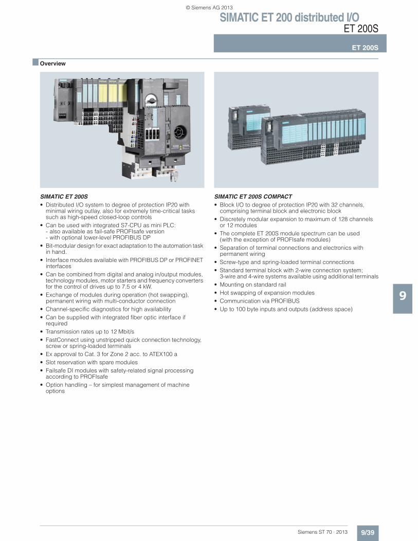
SIMATIC ET 200 distributed I/O ET 200S ET 200S 9/39 Siemens ST 70 · 2013 9 ■ Overview SIMATIC ET 200S • Distributed I/O system to degree of protection IP20 with minimal wiring outlay, also for extremely time-critical tasks such as high-speed closed-loop controls • Can be used with integrated S7-CPU as mini PLC: - also available as fail-safe PROFIsafe version - with optional lower-level PROFIBUS DP • Bit-modular design for exact adaptation to the automation task in hand. • Interface modules available with PROFIBUS DP or PROFINET interfaces • Can be combined from digital and analog in/output modules, technology modules, motor starters and frequency converters for the control of drives up to 7.5 or 4 kW. • Exchange of modules during operation (hot swapping), permanent wiring with multi-conductor connection • Channel-specific diagnostics for high availability • Can be supplied with integrated fiber optic interface if required • Transmission rates up to 12 Mbit/s • FastConnect using unstripped quick connection technology, screw or spring-loaded terminals • Ex approval to Cat. 3 for Zone 2 acc. to ATEX100 a • Slot reservation with spare modules • Failsafe DI modules with safety-related signal processing according to PROFIsafe • Option handling – for simplest management of machine options SIMATIC ET 200S COMPACT • Block I/O to degree of protection IP20 with 32 channels, comprising terminal block and electronic block • Discretely modular expansion to maximum of 128 channels or 12 modules • The complete ET 200S module spectrum can be used (with the exception of PROFIsafe modules) • Separation of terminal connections and electronics with permanent wiring • Screw-type and spring-loaded terminal connections • Standard terminal block with 2-wire connection system; 3-wire and 4-wire systems available using additional terminals • Mounting on standard rail • Hot swapping of expansion modules • Communication via PROFIBUS • Up to 100 byte inputs and outputs (address space) © Siemens AG 2013
-
Upload
khangminh22 -
Category
Documents
-
view
1 -
download
0
Transcript of SIMATIC ET 200 distributed I/O
SIMATIC ET 200 distributed I/OET 200S
ET 200S
9/39Siemens ST 70 · 2013
9
■ Overview
SIMATIC ET 200S• Distributed I/O system to degree of protection IP20 with
minimal wiring outlay, also for extremely time-critical tasks such as high-speed closed-loop controls
• Can be used with integrated S7-CPU as mini PLC:- also available as fail-safe PROFIsafe version- with optional lower-level PROFIBUS DP
• Bit-modular design for exact adaptation to the automation task in hand.
• Interface modules available with PROFIBUS DP or PROFINET interfaces
• Can be combined from digital and analog in/output modules, technology modules, motor starters and frequency converters for the control of drives up to 7.5 or 4 kW.
• Exchange of modules during operation (hot swapping), permanent wiring with multi-conductor connection
• Channel-specific diagnostics for high availability• Can be supplied with integrated fiber optic interface if
required• Transmission rates up to 12 Mbit/s• FastConnect using unstripped quick connection technology,
screw or spring-loaded terminals• Ex approval to Cat. 3 for Zone 2 acc. to ATEX100 a• Slot reservation with spare modules• Failsafe DI modules with safety-related signal processing
according to PROFIsafe• Option handling – for simplest management of machine
options
SIMATIC ET 200S COMPACT• Block I/O to degree of protection IP20 with 32 channels,
comprising terminal block and electronic block • Discretely modular expansion to maximum of 128 channels
or 12 modules• The complete ET 200S module spectrum can be used
(with the exception of PROFIsafe modules)• Separation of terminal connections and electronics with
permanent wiring • Screw-type and spring-loaded terminal connections• Standard terminal block with 2-wire connection system;
3-wire and 4-wire systems available using additional terminals• Mounting on standard rail• Hot swapping of expansion modules• Communication via PROFIBUS• Up to 100 byte inputs and outputs (address space)
© Siemens AG 2013
SIMATIC ET 200 distributed I/OET 200S
ET 200S
9/40 Siemens ST 70 · 2013
9
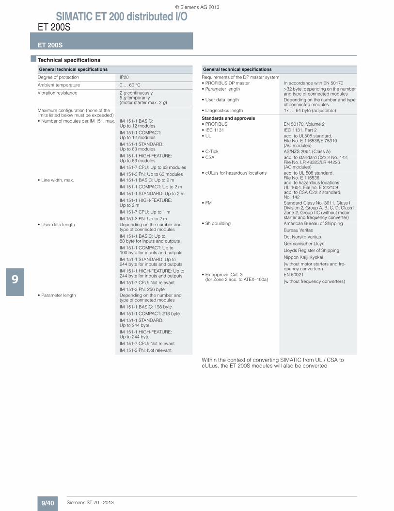
■ Technical specifications
Within the context of converting SIMATIC from UL / CSA to cULus, the ET 200S modules will also be converted
General technical specifications
Degree of protection IP20
Ambient temperature 0 … 60 °C
Vibration resistance 2 g continuously, 5 g temporarily (motor starter max. 2 g)
Maximum configuration (none of the limits listed below must be exceeded)• Number of modules per IM 151, max. IM 151-1 BASIC:
Up to 12 modules
IM 151-1 COMPACT: Up to 12 modules
IM 151-1 STANDARD:Up to 63 modules
IM 151-1 HIGH-FEATURE: Up to 63 modules
IM 151-7 CPU: Up to 63 modules
IM 151-3 PN: Up to 63 modules• Line width, max. IM 151-1 BASIC: Up to 2 m
IM 151-1 COMPACT: Up to 2 m
IM 151-1 STANDARD: Up to 2 m
IM 151-1 HIGH-FEATURE: Up to 2 m
IM 151-7 CPU: Up to 1 m
IM 151-3 PN: Up to 2 m• User data length Depending on the number and
type of connected modules
IM 151-1 BASIC: Up to 88 byte for inputs and outputs
IM 151-1 COMPACT: Up to 100 byte for inputs and outputs
IM 151-1 STANDARD: Up to 244 byte for inputs and outputs
IM 151-1 HIGH-FEATURE: Up to244 byte for inputs and outputs
IM 151-7 CPU: Not relevant
IM 151-3 PN: 256 byte• Parameter length Depending on the number and
type of connected modules
IM 151-1 BASIC: 198 byte
IM 151-1 COMPACT: 218 byte
IM 151-1 STANDARD: Up to 244 byte
IM 151-1 HIGH-FEATURE: Up to 244 byte
IM 151-7 CPU: Not relevant
IM 151-3 PN: Not relevant
Requirements of the DP master system• PROFIBUS DP master In accordance with EN 50170• Parameter length >32 byte, depending on the number
and type of connected modules• User data length Depending on the number and type
of connected modules• Diagnostics length 17 … 64 byte (adjustable)
Standards and approvals• PROFIBUS EN 50170, Volume 2• IEC 1131 IEC 1131, Part 2• UL acc. to UL508 standard,
File No. E 116536/E 75310(AC modules)
• C-Tick AS/NZS 2064 (Class A)• CSA acc. to standard C22.2 No. 142,
File No. LR 48323/LR 44226(AC modules)
• cULus for hazardous locations acc. to UL 508 standard,File No. E 116536acc. to hazardous locationsUL 1604, File no. E 222109acc. to CSA C22.2 standard, No. 142
• FM Standard Class No. 3611, Class I, Division 2, Group A, B, C, D, Class I, Zone 2, Group IIC (without motor starter and frequency converter)
• Shipbuilding American Bureau of Shipping
Bureau Veritas
Det Norske Veritas
Germanischer Lloyd
Lloyds Register of Shipping
Nippon Kaiji Kyokai
(without motor starters and fre-quency converters)
• Ex approval Cat. 3 (for Zone 2 acc. to ATEX–100a)
EN 50021
(without frequency converters)
General technical specifications
© Siemens AG 2013
SIMATIC ET 200 distributed I/OET 200S
Interface modules wih CPUIM 151-7 CPU
9/41Siemens ST 70 · 2013
9
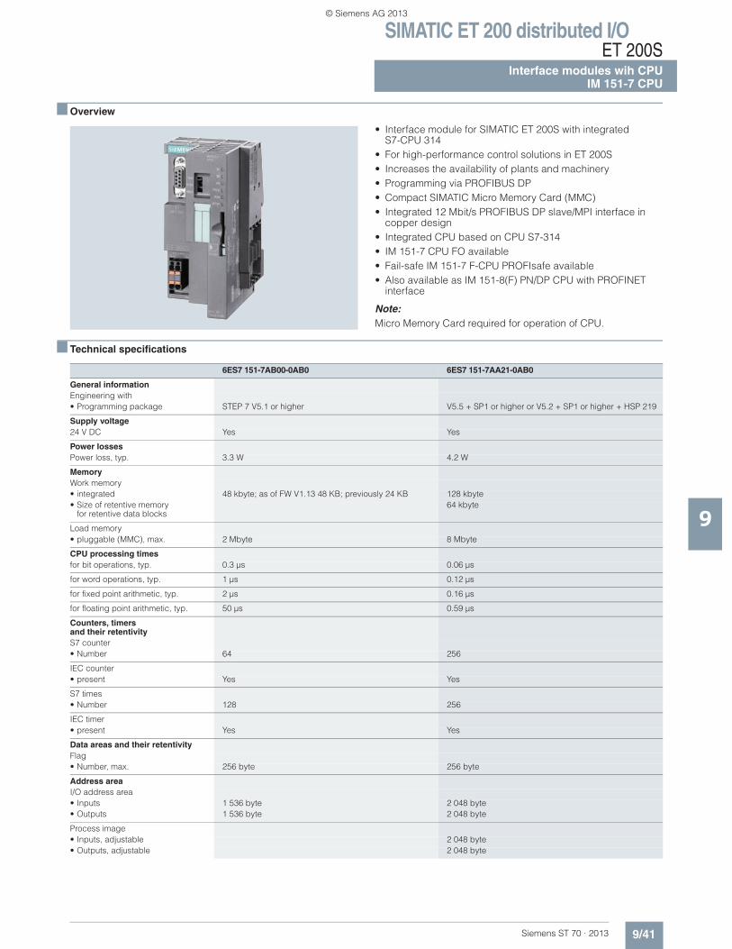
■ Overview
• Interface module for SIMATIC ET 200S with integratedS7-CPU 314
• For high-performance control solutions in ET 200S • Increases the availability of plants and machinery• Programming via PROFIBUS DP• Compact SIMATIC Micro Memory Card (MMC)• Integrated 12 Mbit/s PROFIBUS DP slave/MPI interface in
copper design• Integrated CPU based on CPU S7-314 • IM 151-7 CPU FO available• Fail-safe IM 151-7 F-CPU PROFIsafe available• Also available as IM 151-8(F) PN/DP CPU with PROFINET
interface
Note:Micro Memory Card required for operation of CPU.
■ Technical specifications
6ES7 151-7AB00-0AB0 6ES7 151-7AA21-0AB0
General informationEngineering with• Programming package STEP 7 V5.1 or higher V5.5 + SP1 or higher or V5.2 + SP1 or higher + HSP 219
Supply voltage24 V DC Yes Yes
Power lossesPower loss, typ. 3.3 W 4.2 W
MemoryWork memory• integrated 48 kbyte; as of FW V1.13 48 KB; previously 24 KB 128 kbyte• Size of retentive memory
for retentive data blocks64 kbyte
Load memory• pluggable (MMC), max. 2 Mbyte 8 Mbyte
CPU processing timesfor bit operations, typ. 0.3 μs 0.06 μs
for word operations, typ. 1 μs 0.12 μs
for fixed point arithmetic, typ. 2 μs 0.16 μs
for floating point arithmetic, typ. 50 μs 0.59 μs
Counters, timersand their retentivityS7 counter• Number 64 256
IEC counter• present Yes Yes
S7 times• Number 128 256
IEC timer• present Yes Yes
Data areas and their retentivityFlag• Number, max. 256 byte 256 byte
Address areaI/O address area• Inputs 1 536 byte 2 048 byte• Outputs 1 536 byte 2 048 byte
Process image• Inputs, adjustable 2 048 byte• Outputs, adjustable 2 048 byte
© Siemens AG 2013
SIMATIC ET 200 distributed I/OET 200SInterface modules wih CPUIM 151-7 CPU
9/42 Siemens ST 70 · 2013
■ Technical specifications (continued)
9
Time of dayClock• Hardware clock (real-time clock) Yes
Operating hours counter• Number 0; No 1
1st interfaceType of interface Fiber-optic interface and integrated RS 485 interface for
programmingIntegrated RS 485 interface
Physics Fiber-optic cable or RS 485 RS 485
Functionality• MPI No Yes• DP master No• DP slave Yes Yes; active / passive• Point-to-point connection No No
2nd interfaceType of interface External interface via master module
6ES7138-4HA00-0AB0
Physics RS 485
Functionality• MPI No• DP master Yes• DP slave No
DP master• Number of DP slaves, max. 32; Per station
Isochronous modeIsochronous operation (application synchronized up to terminal)
No
Communication functionsPG/OP communication Yes Yes
Data record routing Yes; With DP master module
Global data communication• supported No Yes
S7 basic communication• supported Yes; as server Yes
S7 communication• supported Yes Yes
S5-compatible communication• supported No
Standard communication (FMS)• supported No
Number of connections• overall 12
Ambient conditionsOperating temperature• Min. 0 °C• max. 60 °C
ConfigurationConfiguration software• STEP 7 Lite Yes; V2.0 or higher No
programming• Programming language
- LAD Yes Yes- FBD Yes Yes- STL Yes Yes- SCL Yes Yes; optional- CFC Yes; optional- GRAPH Yes; optional- HiGraph® Yes; optional
Know-how protection• User program protection/password
protectionYes Yes
• Block encryption Yes; With S7 block Privacy
6ES7 151-7AB00-0AB0 6ES7 151-7AA21-0AB0
© Siemens AG 2013
SIMATIC ET 200 distributed I/OET 200S
Interface modules wih CPUIM 151-7 CPU
9/43Siemens ST 70 · 2013
■ Technical specifications (continued)
9
■ Ordering data Order No. Order No.
1) An MMC is essential for operating the CPU
DimensionsWidth 60 mm 60 mm; DP master module: 35 mm
Height 119.5 mm 119.5 mm
Depth 75 mm 75 mm
WeightWeight, approx. 200 g 200 g; DP master module: Approx. 100 g
6ES7 151-7AB00-0AB0 6ES7 151-7AA21-0AB0
IM 151-7 CPU FOinterface module (48 K)
6ES7 151-7AB00-0AB0
Including termination module
IM 151-7 CPUinterface module (128 K) V3.3
6ES7 151-7AA21-0AB0
Including termination module
Accessories
MMC 64 KB 1) 6ES7 953-8LF20-0AA0
for program backup
MMC 128 KB 1) 6ES7 953-8LG20-0AA0
for program backup
MMC 512 KB 1) 6ES7 953-8LJ30-0AA0
for program backup
MMC 2 MB 1) 6ES7 953-8LL31-0AA0
For program backup and/or firmware update
MMC 4 MB 1) 6ES7 953-8LM20-0AA0
for program backup
MMC 8 MB 1) 6ES7 953-8LP20-0AA0
for program backup
External prommer 6ES7 792-0AA00-0XA0
e.g. for MMC with USB interface
PG on request
With integrated MMC interface
Label sheets DIN A4 (10 pieces)
Each sheet contains 60 labeling strips for peripheral modules and 20 labeling strips for interface modules• petrol 6ES7 193-4BH00-0AA0• red 6ES7 193-4BD00-0AA0• yellow 6ES7 193-4BB00-0AA0• light beige 6ES7 193-4BA00-0AA0
ET 200S distributed I/O system manuals
are available on the Internet as PDF files:
www.siemens.com/simatic-docu
Termination module 6ES7 193-4JA00-0AA0
as spare part for ET 200S
Power supply connector
Spare part;for connecting the 24 V DC supply voltage• with push-in terminals 6ES7 193-4JB00-0AA0
SIMATIC S5, 35 mm DIN rail • Length: 483 mm for 19" cabinets 6ES5 710-8MA11• Length: 530 mm for 600 mm
cabinets6ES5 710-8MA21
• Length: 830 mm for 900 mm cabinets
6ES5 710-8MA31
• Length: 2 m 6ES5 710-8MA41
PROFIBUS DP bus connector RS 485
with 90° cable outlet, max. transfer rate 12 Mbit/s• Without PG interface 6ES7 972-0BA12-0XA0• with PG interface 6ES7 972-0BB12-0XA0
with 90° cable outlet for FastConnect connection system, max. transfer rate 12 Mbit/s• without PG interface, 1 unit 6ES7 972-0BA52-0XA0• without PG interface, 100 units 6ES7 972-0BA52-0XB0• with PG interface, 1 unit 6ES7 972-0BB52-0XA0• with PG interface, 100 units 6ES7 972-0BB52-0XB0
PROFIBUS Fast Connectbus cable
6XV1 830-0EH10
Standard type with special design for quick mounting, 2-core, shielded, sold by the meter, max. delivery unit 1000 m, minimum ordering quantity 20 m
PROFIBUS bus components See IK PI, CA 01 catalogs
For establishing MPI/PROFIBUS communication
© Siemens AG 2013
SIMATIC ET 200 distributed I/OET 200SInterface modules with CPUIM 151-8 PN/DP CPU
9/44 Siemens ST 70 · 2013
9
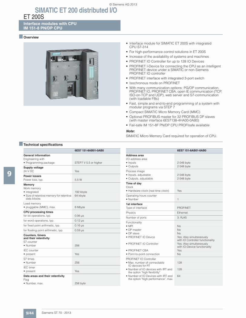
■ Overview
• Interface module for SIMATIC ET 200S with integrated CPU S7-314
• For high-performance control solutions in ET 200S • Increase of the availability of systems and machines • PROFINET IO Controller for up to 128 IO Devices • PROFINET I-Device for connecting the CPU as an intelligent
PROFINET device under a SIMATIC or non-Siemens PROFINET IO controller
• PROFINET interface with integrated 3-port switch• Isochronous mode on PROFINET• With many communication options: PG/OP communication,
PROFINET IO, PROFINET CBA, open IE communication (TCP, ISO-on-TCP and UDP), web server and S7-communication (with loadable FBs)
• Fast, simple and end-to-end programming of a system with modular programs via STEP 7
• Compact SIMATIC Micro Memory Card (MMC)• Optional PROFIBUS master for 32 PROFIBUS DP slaves
(with master interface 6ES7138-4HA00-0AB0)• Fail-safe IM 151-8F PN/DP CPU PROFIsafe available
Note:SIMATIC Micro Memory Card required for operation of CPU.
■ Technical specifications
6ES7 151-8AB01-0AB0
General informationEngineering with• Programming package STEP7 V 5.5 or higher
Supply voltage24 V DC Yes
Power lossesPower loss, typ. 5.5 W
MemoryWork memory• integrated 192 kbyte• Size of retentive memory for retentive
data blocks64 kbyte
Load memory• pluggable (MMC), max. 8 Mbyte
CPU processing timesfor bit operations, typ. 0.06 μs
for word operations, typ. 0.12 μs
for fixed point arithmetic, typ. 0.16 μs
for floating point arithmetic, typ. 0.59 μs
Counters, timersand their retentivityS7 counter• Number 256
IEC counter• present Yes
S7 times• Number 256
IEC timer• present Yes
Data areas and their retentivityFlag• Number, max. 256 byte
Address areaI/O address area• Inputs 2 048 byte• Outputs 2 048 byte
Process image• Inputs, adjustable 2 048 byte• Outputs, adjustable 2 048 byte
Time of dayClock• Hardware clock (real-time clock) Yes
Operating hours counter• Number 1
1st interfaceType of interface PROFINET
Physics Ethernet
Number of ports 3; RJ45
Functionality• MPI No• DP master No• DP slave No• PROFINET IO Device Yes; Also simultaneously
with IO Controller functionality• PROFINET IO Controller Yes; Also simultaneously
with IO-Device functionality• PROFINET CBA Yes• Point-to-point connection No
PROFINET IO Controller• Max. number of connectable
IO devices for RT128
• Number of IO devices with IRT and the option "high flexibility"
128
• Number of IO Devices with IRT and the option "high performance", max.
64
6ES7 151-8AB01-0AB0
© Siemens AG 2013
SIMATIC ET 200 distributed I/OET 200S
Interface modules with CPUIM 151-8 PN/DP CPU
9/45Siemens ST 70 · 2013
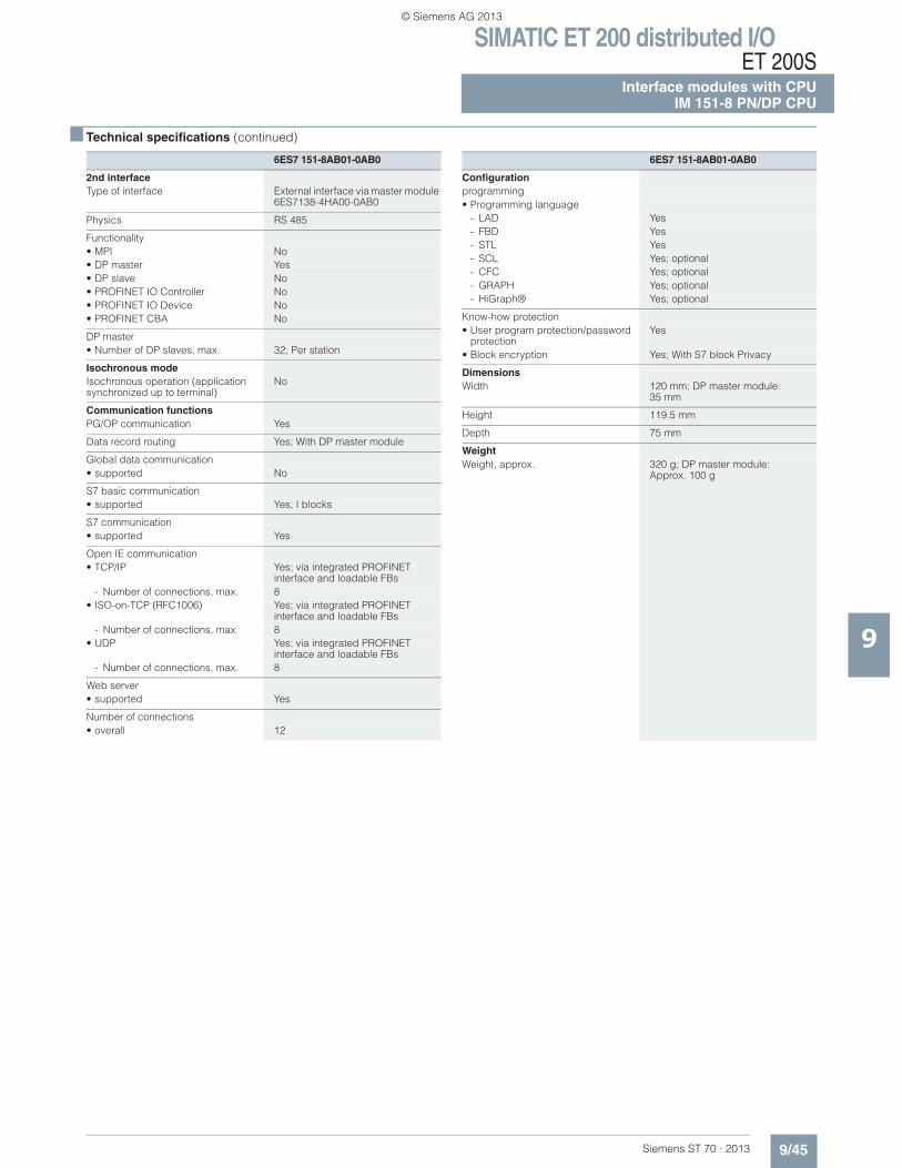
■ Technical specifications (continued)
9
2nd interfaceType of interface External interface via master module
6ES7138-4HA00-0AB0
Physics RS 485
Functionality• MPI No• DP master Yes• DP slave No• PROFINET IO Controller No• PROFINET IO Device No• PROFINET CBA No
DP master• Number of DP slaves, max. 32; Per station
Isochronous modeIsochronous operation (application synchronized up to terminal)
No
Communication functionsPG/OP communication Yes
Data record routing Yes; With DP master module
Global data communication• supported No
S7 basic communication• supported Yes; I blocks
S7 communication• supported Yes
Open IE communication• TCP/IP Yes; via integrated PROFINET
interface and loadable FBs- Number of connections, max. 8
• ISO-on-TCP (RFC1006) Yes; via integrated PROFINET interface and loadable FBs
- Number of connections, max. 8• UDP Yes; via integrated PROFINET
interface and loadable FBs- Number of connections, max. 8
Web server• supported Yes
Number of connections• overall 12
6ES7 151-8AB01-0AB0
Configurationprogramming• Programming language
- LAD Yes- FBD Yes- STL Yes- SCL Yes; optional- CFC Yes; optional- GRAPH Yes; optional- HiGraph® Yes; optional
Know-how protection• User program protection/password
protectionYes
• Block encryption Yes; With S7 block Privacy
DimensionsWidth 120 mm; DP master module:
35 mm
Height 119.5 mm
Depth 75 mm
WeightWeight, approx. 320 g; DP master module:
Approx. 100 g
6ES7 151-8AB01-0AB0
© Siemens AG 2013
SIMATIC ET 200 distributed I/OET 200SInterface modules with CPUIM 151-8 PN/DP CPU
9/46 Siemens ST 70 · 2013
9
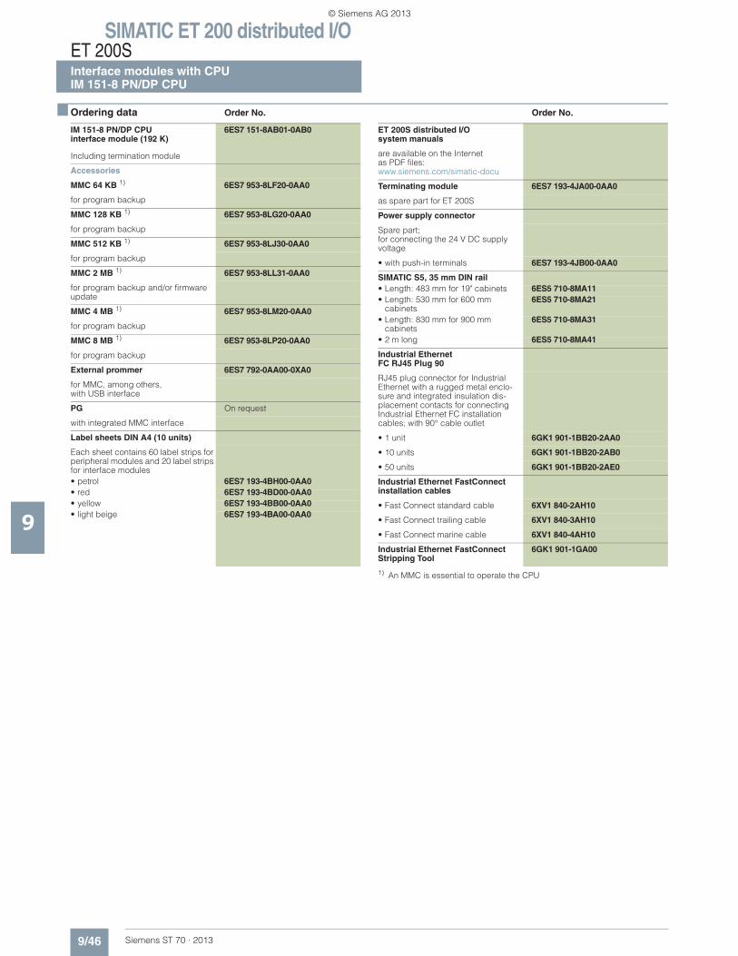
■ Ordering data Order No. Order No.
1) An MMC is essential to operate the CPU
IM 151-8 PN/DP CPUinterface module (192 K)
6ES7 151-8AB01-0AB0
Including termination module
Accessories
MMC 64 KB 1) 6ES7 953-8LF20-0AA0
for program backup
MMC 128 KB 1) 6ES7 953-8LG20-0AA0
for program backup
MMC 512 KB 1) 6ES7 953-8LJ30-0AA0
for program backup
MMC 2 MB 1) 6ES7 953-8LL31-0AA0
for program backup and/or firmware update
MMC 4 MB 1) 6ES7 953-8LM20-0AA0
for program backup
MMC 8 MB 1) 6ES7 953-8LP20-0AA0
for program backup
External prommer 6ES7 792-0AA00-0XA0
for MMC, among others, with USB interface
PG On request
with integrated MMC interface
Label sheets DIN A4 (10 units)
Each sheet contains 60 label strips for peripheral modules and 20 label strips for interface modules• petrol 6ES7 193-4BH00-0AA0• red 6ES7 193-4BD00-0AA0• yellow 6ES7 193-4BB00-0AA0• light beige 6ES7 193-4BA00-0AA0
ET 200S distributed I/O system manuals
are available on the Internet as PDF files:www.siemens.com/simatic-docu
Terminating module 6ES7 193-4JA00-0AA0
as spare part for ET 200S
Power supply connector
Spare part;for connecting the 24 V DC supply voltage
• with push-in terminals 6ES7 193-4JB00-0AA0
SIMATIC S5, 35 mm DIN rail • Length: 483 mm for 19" cabinets 6ES5 710-8MA11• Length: 530 mm for 600 mm
cabinets6ES5 710-8MA21
• Length: 830 mm for 900 mm cabinets
6ES5 710-8MA31
• 2 m long 6ES5 710-8MA41
Industrial EthernetFC RJ45 Plug 90
RJ45 plug connector for Industrial Ethernet with a rugged metal enclo-sure and integrated insulation dis-placement contacts for connecting Industrial Ethernet FC installation cables; with 90° cable outlet
• 1 unit 6GK1 901-1BB20-2AA0
• 10 units 6GK1 901-1BB20-2AB0
• 50 units 6GK1 901-1BB20-2AE0
Industrial Ethernet FastConnect installation cables
• Fast Connect standard cable 6XV1 840-2AH10
• Fast Connect trailing cable 6XV1 840-3AH10
• Fast Connect marine cable 6XV1 840-4AH10
Industrial Ethernet FastConnect Stripping Tool
6GK1 901-1GA00
© Siemens AG 2013
SIMATIC ET 200 distributed I/OET 200S
Interface modules with CPUMaster interface module for IM 151 CPU
9/47Siemens ST 70 · 2013
9
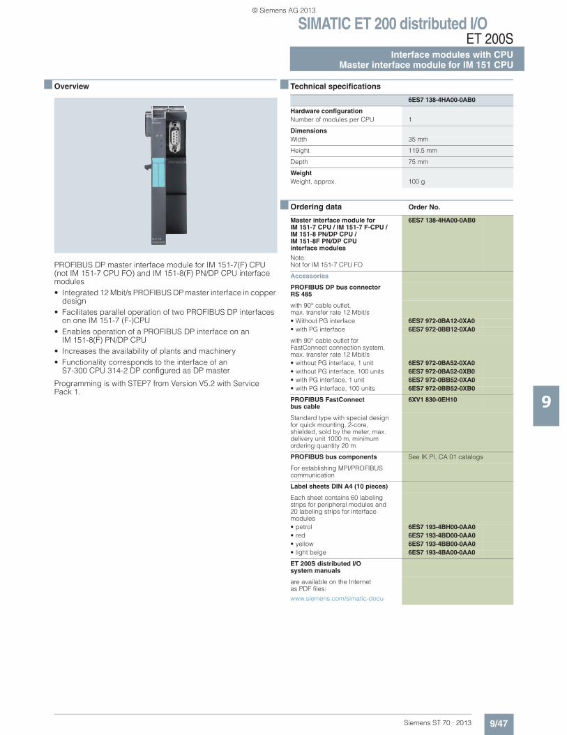
■ Overview
PROFIBUS DP master interface module for IM 151-7(F) CPU (not IM 151-7 CPU FO) and IM 151-8(F) PN/DP CPU interface modules• Integrated 12 Mbit/s PROFIBUS DP master interface in copper
design• Facilitates parallel operation of two PROFIBUS DP interfaces
on one IM 151-7 (F-)CPU• Enables operation of a PROFIBUS DP interface on an
IM 151-8(F) PN/DP CPU• Increases the availability of plants and machinery• Functionality corresponds to the interface of an
S7-300 CPU 314-2 DP configured as DP master
Programming is with STEP7 from Version V5.2 with Service Pack 1.
■ Technical specifications
■ Ordering data Order No.
6ES7 138-4HA00-0AB0
Hardware configurationNumber of modules per CPU 1
DimensionsWidth 35 mm
Height 119.5 mm
Depth 75 mm
WeightWeight, approx. 100 g
Master interface module for IM 151-7 CPU / IM 151-7 F-CPU / IM 151-8 PN/DP CPU / IM 151-8F PN/DP CPUinterface modules
Note:Not for IM 151-7 CPU FO
6ES7 138-4HA00-0AB0
Accessories
PROFIBUS DP bus connector RS 485
with 90° cable outlet, max. transfer rate 12 Mbit/s• Without PG interface 6ES7 972-0BA12-0XA0• with PG interface 6ES7 972-0BB12-0XA0
with 90° cable outlet for FastConnect connection system, max. transfer rate 12 Mbit/s• without PG interface, 1 unit 6ES7 972-0BA52-0XA0• without PG interface, 100 units 6ES7 972-0BA52-0XB0• with PG interface, 1 unit 6ES7 972-0BB52-0XA0• with PG interface, 100 units 6ES7 972-0BB52-0XB0
PROFIBUS FastConnect bus cable
6XV1 830-0EH10
Standard type with special design for quick mounting, 2-core, shielded, sold by the meter, max. delivery unit 1000 m, minimum ordering quantity 20 m
PROFIBUS bus components See IK PI, CA 01 catalogs
For establishing MPI/PROFIBUS communication
Label sheets DIN A4 (10 pieces)
Each sheet contains 60 labeling strips for peripheral modules and 20 labeling strips for interface modules• petrol 6ES7 193-4BH00-0AA0• red 6ES7 193-4BD00-0AA0• yellow 6ES7 193-4BB00-0AA0• light beige 6ES7 193-4BA00-0AA0
ET 200S distributed I/Osystem manuals
are available on the Internet as PDF files:
www.siemens.com/simatic-docu
© Siemens AG 2013
SIMATIC ET 200 distributed I/OET 200SSIPLUS interface modules with CPUSIPLUS IM151-7 CPU
9/48 Siemens ST 70 · 2013
9
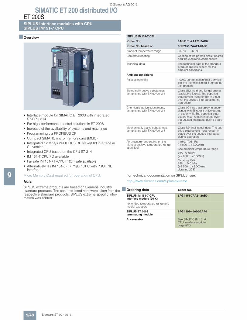
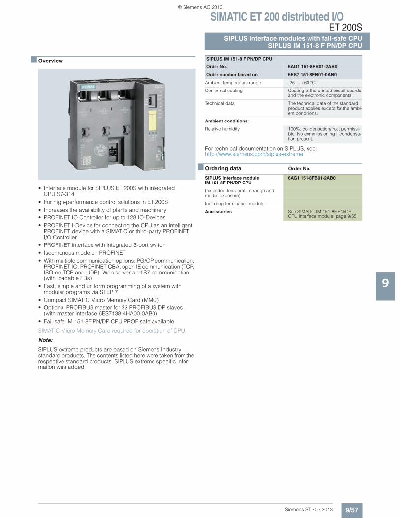
■ Overview
• Interface module for SIMATIC ET 200S with integratedS7-CPU 314
• For high-performance control solutions in ET 200S • Increase of the availability of systems and machines• Programming via PROFIBUS DP• Compact SIMATIC micro memory card (MMC)• Integrated 12 Mbit/s PROFIBUS DP slave/MPI interface in
Cu version• Integrated CPU based on the CPU S7-314 • IM 151-7 CPU FO available• Failsafe IM 151-7 F-CPU PROFIsafe available• Alternatively, as IM 151-8 (F) PN/DP CPU with PROFINET
interface
Micro Memory Card required for operation of CPU.
Note:
SIPLUS extreme products are based on Siemens Industry standard products. The contents listed here were taken from the respective standard products. SIPLUS extreme specific infor-mation was added.
For technical documentation on SIPLUS, see:
http://www.siemens.com/siplus-extreme
■ Ordering data Order No.
SIPLUS IM151-7 CPU
Order No. 6AG1151-7AA21-2AB0
Order No. based on 6ES7151-7AA21-0AB0
Ambient temperature range -25 °C … +60 °C
Conformal coating Coating of the printed circuit boards and the electronic components
Technical data The technical data of the standard product applies except for the ambient conditions.
Ambient conditions
Relative humidity 100%, condensation/frost permissi-ble. No commissioning if condensa-tion present.
Biologically active substances, compliance with EN 60721-3-3
Class 3B2 mold and fungal spores (excluding fauna). The supplied plug covers must remain in place over the unused interfaces during operation!
Chemically active substances, compliance with EN 60721-3-3
Class 3C4 incl. salt spray in accor-dance with EN60068-2-52 (degree of severity 3). The supplied plug covers must remain in place over the unused interfaces during opera-tion!
Mechanically active substances, compliance with EN 60721-3-3
Class 3S4 incl. sand, dust. The sup-plied plug covers must remain in place over the unused interfaces during operation!
Air pressure (depending on the highest positive temperature range specified)
1,080...795 hPa(-1,000 ... +2,000 m)
See ambient temperature range
795...658 hPa(+2 000 ... +3 500m)
Derating 10 K658 ... 540 hPa (+3 500 ... +5 000 m) derating 20 K
SIPLUS IM 151-7 CPU interface module (96 K)
6AG1 151-7AA21-2AB0
(extended temperature range and medial exposure)
SIPLUS ET 200Sterminating module
6AG1 193-4JA00-2AA0
Accessories See SIMATIC IM 151-7 CPU interface module, page 9/43
© Siemens AG 2013
SIMATIC ET 200 distributed I/OET 200S
SIPLUS interface modules with CPUSIPLUS IM151-8 PN/DP CPU
9/49Siemens ST 70 · 2013
9
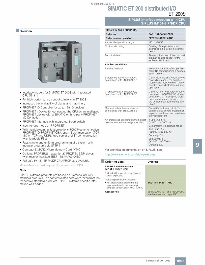
■ Overview
• Interface module for SIMATIC ET 200S with integrated CPU S7-314
• For high-performance control solutions in ET 200S • Increases the availability of plants and machinery • PROFINET IO Controller for up to 128 IO devices • PROFINET I-Device for connecting the CPU as an intelligent
PROFINET device with a SIMATIC or third-party PROFINETI/O Controller
• PROFINET interface with integrated 3-port switch• Isochronous mode on PROFINET• With multiple communication options: PG/OP communication,
PROFINET IO, PROFINET CBA, open IE communication (TCP, ISO-on-TCP and UDP), Web server and S7 communication (with loadable FBs)
• Fast, simple and uniform programming of a system with modular programs via STEP 7
• Compact SIMATIC Micro Memory Card (MMC)• Optional PROFIBUS master for 32 PROFIBUS DP slaves
(with master interface 6ES7 138-4HA00-0AB0)• Fail-safe IM 151-8F PN/DP CPU PROFIsafe available
Micro Memory Card required for operation of CPU.
Note:
SIPLUS extreme products are based on Siemens Industry standard products. The contents listed here were taken from the respective standard products. SIPLUS extreme specific infor-mation was added.
For technical documentation on SIPLUS, see:
http://www.siemens.com/siplus-extreme
■ Ordering data Order No.
SIPLUS IM 151-8 PN/DP CPU
Order No. 6AG1 151-8AB01-7AB0
Order number based on 6ES7 151-8AB01-0AB0
Ambient temperature range -40 ... +70 °C
Conformal coating Coating of the printed circuit boards and the electronic compo-nents
Technical data The technical data of the standard product applies except for the ambient conditions.
Ambient conditions:
Relative humidity 100%, condensation/frost permis-sible. No commissioning if conden-sation present.
Biologically active substances, compliance with EN 60721-3-3
Class 3B2 mold and fungal spores (excluding fauna). The supplied plug covers must remain in place over the unused interfaces during operation!
Chemically active substances, compliance with EN 60721-3-3
Class 3C4 incl. salt spray in accor-dance with EN60068-2-52 (degree of severity 3). The supplied plug covers must remain in place over the unused interfaces during oper-ation!
Mechanically active substances,compliance with EN 60721-3-3
Class 3S4 incl. sand, dust. The supplied plug covers must remain in place over the unused interfaces during operation!
Air pressure (depending on the highest positive temperature range specified)
1 080...795 hPa(-1 000 … +2 000 m)
See ambient temperature range
795…658 hPa(+2 000 … +3 500 m)
Derating 10 K
658...540 hPa(+3 500 ... +5 000m)
Derating 20K
SIPLUS interface moduleIM 151-8 PN/DP CPU
(extended temperature range and medial exposure)
Including termination module• For areas with extreme medial
exposure (conformal coating);ambient temperature -40 ... +70 °C
6AG1 151-8AB01-7AB0
Accessories See SIMATIC IM 151-8 PN/DP CPU interface module, page 9/46
© Siemens AG 2013
SIMATIC ET 200 distributed I/OET 200SSIPLUS interface modules with CPUSIPLUS master interface modules for IM 151 CPU
9/50 Siemens ST 70 · 2013
9
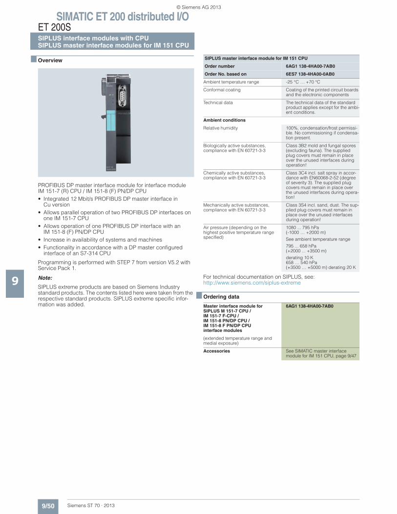
■ Overview
PROFIBUS DP master interface module for interface module IM 151-7 (R) CPU / IM 151-8 (F) PN/DP CPU• Integrated 12 Mbit/s PROFIBUS DP master interface in
Cu version• Allows parallel operation of two PROFIBUS DP interfaces on
one IM 151-7 CPU• Allows operation of one PROFIBUS DP interface with an
IM 151-8 (F) PN/DP CPU• Increase in availability of systems and machines• Functionality in accordance with a DP master configured
interface of an S7-314 CPU
Programming is performed with STEP 7 from version V5.2 with Service Pack 1.
Note:
SIPLUS extreme products are based on Siemens Industry standard products. The contents listed here were taken from the respective standard products. SIPLUS extreme specific infor-mation was added.
For technical documentation on SIPLUS, see:http://www.siemens.com/siplus-extreme
■ Ordering data
SIPLUS master interface module for IM 151 CPU
Order number 6AG1 138-4HA00-7AB0
Order No. based on 6ES7 138-4HA00-0AB0
Ambient temperature range -25 °C … +70 °C
Conformal coating Coating of the printed circuit boards and the electronic components
Technical data The technical data of the standard product applies except for the ambi-ent conditions.
Ambient conditions
Relative humidity 100%, condensation/frost permissi-ble. No commissioning if condensa-tion present.
Biologically active substances, compliance with EN 60721-3-3
Class 3B2 mold and fungal spores (excluding fauna). The supplied plug covers must remain in place over the unused interfaces during operation!
Chemically active substances, compliance with EN 60721-3-3
Class 3C4 incl. salt spray in accor-dance with EN60068-2-52 (degree of severity 3). The supplied plug covers must remain in place over the unused interfaces during opera-tion!
Mechanically active substances, compliance with EN 60721-3-3
Class 3S4 incl. sand, dust. The sup-plied plug covers must remain in place over the unused interfaces during operation!
Air pressure (depending on the highest positive temperature range specified)
1080 ... 795 hPa (-1000 … +2000 m)
See ambient temperature range
795 ... 658 hPa(+2000 ... +3500 m)
derating 10 K658 … 540 hPa(+3500 … +5000 m) derating 20 K
Master interface module for SIPLUS M 151-7 CPU / IM 151-7 F-CPU / IM 151-8 PN/DP CPU /IM 151-8 F PN/DP CPU interface modules
6AG1 138-4HA00-7AB0
(extended temperature range and medial exposure)
Accessories See SIMATIC master interface module for IM 151 CPU, page 9/47
© Siemens AG 2013
SIMATIC ET 200 distributed I/OET 200S
Interface module with fail-safe CPUIM 151-7 F-CPU
9/51Siemens ST 70 · 2013
9
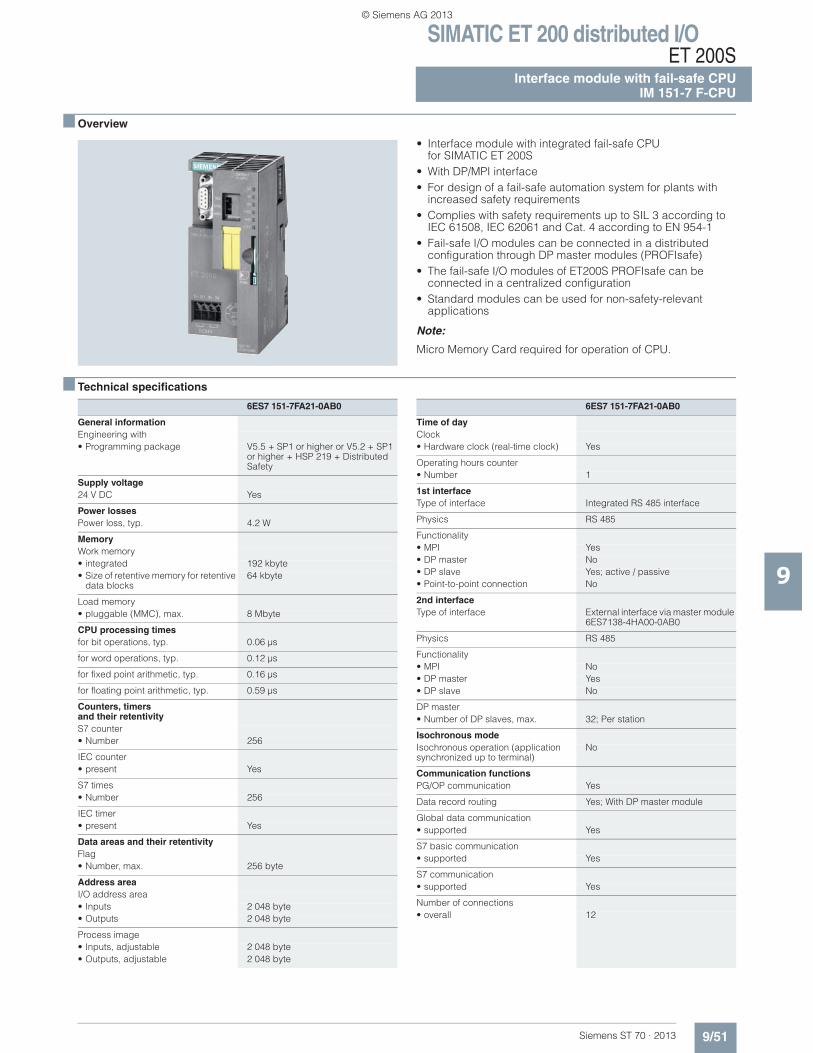
■ Overview
• Interface module with integrated fail-safe CPUfor SIMATIC ET 200S
• With DP/MPI interface• For design of a fail-safe automation system for plants with
increased safety requirements• Complies with safety requirements up to SIL 3 according to
IEC 61508, IEC 62061 and Cat. 4 according to EN 954-1• Fail-safe I/O modules can be connected in a distributed
configuration through DP master modules (PROFIsafe)• The fail-safe I/O modules of ET200S PROFIsafe can be
connected in a centralized configuration• Standard modules can be used for non-safety-relevant
applications
Note:
Micro Memory Card required for operation of CPU.
■ Technical specifications
6ES7 151-7FA21-0AB0
General informationEngineering with• Programming package V5.5 + SP1 or higher or V5.2 + SP1
or higher + HSP 219 + Distributed Safety
Supply voltage24 V DC Yes
Power lossesPower loss, typ. 4.2 W
MemoryWork memory• integrated 192 kbyte• Size of retentive memory for retentive
data blocks64 kbyte
Load memory• pluggable (MMC), max. 8 Mbyte
CPU processing timesfor bit operations, typ. 0.06 μs
for word operations, typ. 0.12 μs
for fixed point arithmetic, typ. 0.16 μs
for floating point arithmetic, typ. 0.59 μs
Counters, timersand their retentivityS7 counter• Number 256
IEC counter• present Yes
S7 times• Number 256
IEC timer• present Yes
Data areas and their retentivityFlag• Number, max. 256 byte
Address areaI/O address area• Inputs 2 048 byte• Outputs 2 048 byte
Process image• Inputs, adjustable 2 048 byte• Outputs, adjustable 2 048 byte
Time of dayClock• Hardware clock (real-time clock) Yes
Operating hours counter• Number 1
1st interfaceType of interface Integrated RS 485 interface
Physics RS 485
Functionality• MPI Yes• DP master No• DP slave Yes; active / passive• Point-to-point connection No
2nd interfaceType of interface External interface via master module
6ES7138-4HA00-0AB0
Physics RS 485
Functionality• MPI No• DP master Yes• DP slave No
DP master• Number of DP slaves, max. 32; Per station
Isochronous modeIsochronous operation (application synchronized up to terminal)
No
Communication functionsPG/OP communication Yes
Data record routing Yes; With DP master module
Global data communication• supported Yes
S7 basic communication• supported Yes
S7 communication• supported Yes
Number of connections• overall 12
6ES7 151-7FA21-0AB0
© Siemens AG 2013
SIMATIC ET 200 distributed I/OET 200SInterface module with fail-safe CPUIM 151-7 F-CPU
9/52 Siemens ST 70 · 2013
■ Technical specifications (continued)
9
■ Ordering data Order No. Order No.
1) For up-to-date information and download availability, see:http://www.siemens.com/tia-online-software-delivery
ConfigurationConfiguration software• STEP 7 Lite No
programming• Programming language
- LAD Yes- FBD Yes- STL Yes- SCL Yes; optional- CFC Yes; optional- GRAPH Yes; optional- HiGraph® Yes; optional
Know-how protection• User program protection/
password protectionYes
• Block encryption Yes; With S7 block Privacy
6ES7 151-7FA21-0AB0
DimensionsWidth 60 mm; DP master module: 35 mm
Height 119.5 mm
Depth 75 mm
WeightWeight, approx. 200 g; DP master module:
Approx. 100 g
6ES7 151-7FA21-0AB0
IM151-7 F-CPU interface module
for configuring a fail-safe automation system
192 KB 6ES7 151-7FA21-0AB0
Accessories
Distributed Safety V5.4 programming tool
Task: Engineering tool for configuring fail-safe user programs for SIMATIC S7-300F, S7-400F, WinAC RTX F, ET 200S, ET 200M, ET 200iSP, ET 200pro, ET 200eco Requirement: STEP 7 V5.3 SP3 and higher
Floating license 6ES7 833-1FC02-0YA5
Floating license for 1 user, license key download without software and documentation1);
email address required for delivery
6ES7 833-1FC02-0YH5
Distributed Safety Upgrade
from V5.x to V5.4; Floating license for 1 user
6ES7 833-1FC02-0YE5
STEP 7 Safety Advanced V11
Task:Engineering tool for configuringfail-safe user programs for SIMATIC S7-300F, S7-400F, WinAC RTX F, ET 200S, ET 200M, ET 200iSP, ET 200pro, ET 200ecoRequirement:STEP 7 Professional V11 SP1
Floating license for 1 user 6ES7 833-1FA11-0YA5
Floating license for 1 user, license key download without software and documentation1);
email address required for delivery
6ES7 833-1FA11-0YH5
STEP 7 Safety Advanced Upgrade
Distributed Safety V5.4 SP5 and STEP 7 Safety Advanced V11 for parallel use; incl. software on CD; Combo License for 1 user
6ES7 833-1FA11-0YE5
Distributed Safety V5.4 SP5 and STEP 7 Safety Advanced V11 for parallel use; incl. software on CD; Combo License for 1 user, license key download without software and documentation1);
email address required for delivery
6ES7 833-1FA11-0YK5
MMC 64 kByte 6ES7 953-8LF20-0AA0
for program backup
MMC 128 kByte 6ES7 953-8LG20-0AA0
for program backup
MMC 512 kByte 6ES7 953-8LJ30-0AA0
for program backup
MMC 2 MByte 6ES7 953-8LL31-0AA0
for program backup and/or firmware update
MMC 4 MByte 6ES7 953-8LM20-0AA0
for program backup
External prommer 6ES7 792-0AA00-0XA0
for MMC with USB interface
Termination module 6ES7 193-4JA00-0AA0
as spare part for ET 200S
SIMATIC S5, 35 mm DIN rail • Length: 483 mm
for 19" cabinets6ES5 710-8MA11
• Length: 530 mm for 600 mm cabinets
6ES5 710-8MA21
• Length: 830 mmfor 900 mm cabinets
6ES5 710-8MA31
• Length: 2 m 6ES5 710-8MA41
© Siemens AG 2013
SIMATIC ET 200 distributed I/OET 200S
Interface module with fail-safe CPUIM 151-8 F PN/DP CPU
9/53Siemens ST 70 · 2013
9
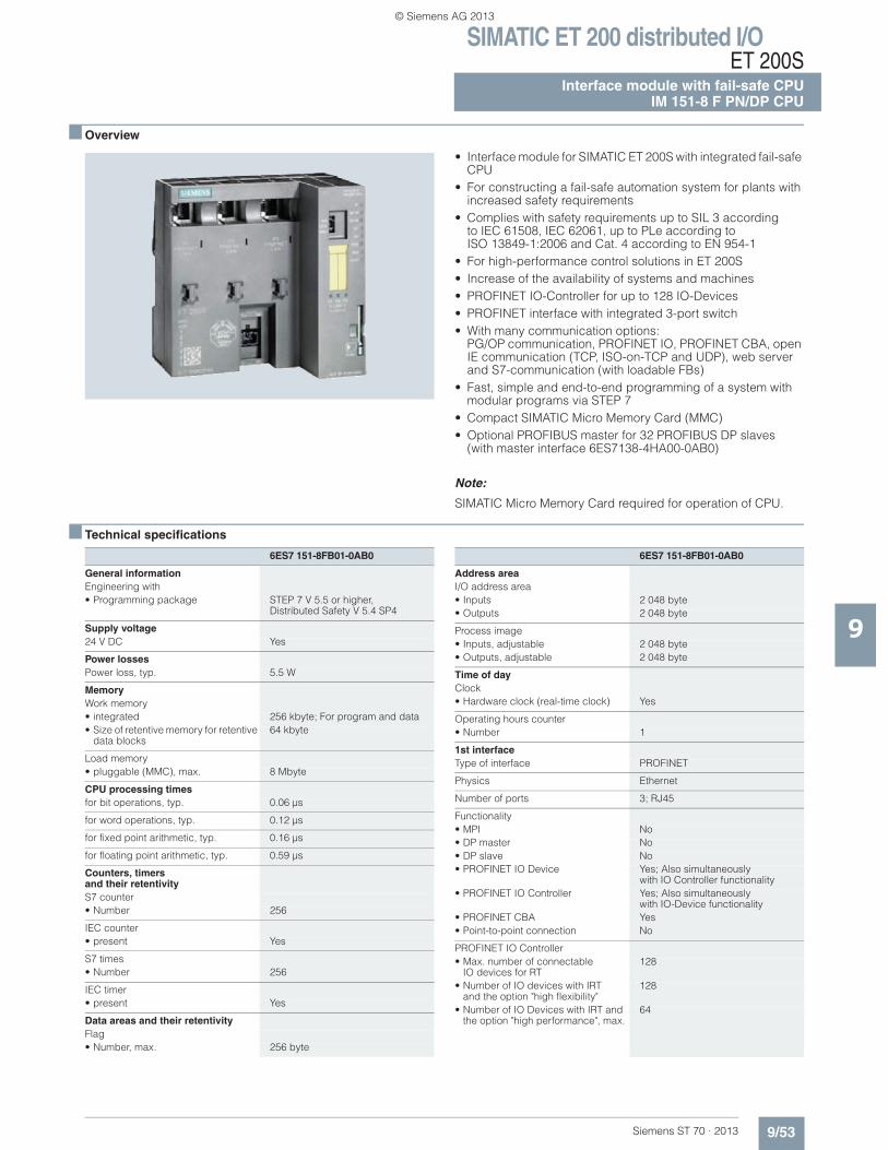
■ Overview
• Interface module for SIMATIC ET 200S with integrated fail-safe CPU
• For constructing a fail-safe automation system for plants with increased safety requirements
• Complies with safety requirements up to SIL 3 accordingto IEC 61508, IEC 62061, up to PLe according to ISO 13849-1:2006 and Cat. 4 according to EN 954-1
• For high-performance control solutions in ET 200S • Increase of the availability of systems and machines • PROFINET IO-Controller for up to 128 IO-Devices • PROFINET interface with integrated 3-port switch• With many communication options:
PG/OP communication, PROFINET IO, PROFINET CBA, open IE communication (TCP, ISO-on-TCP and UDP), web server and S7-communication (with loadable FBs)
• Fast, simple and end-to-end programming of a system with modular programs via STEP 7
• Compact SIMATIC Micro Memory Card (MMC)• Optional PROFIBUS master for 32 PROFIBUS DP slaves
(with master interface 6ES7138-4HA00-0AB0)
Note:
SIMATIC Micro Memory Card required for operation of CPU.
■ Technical specifications
6ES7 151-8FB01-0AB0
General informationEngineering with• Programming package STEP 7 V 5.5 or higher,
Distributed Safety V 5.4 SP4
Supply voltage24 V DC Yes
Power lossesPower loss, typ. 5.5 W
MemoryWork memory• integrated 256 kbyte; For program and data• Size of retentive memory for retentive
data blocks64 kbyte
Load memory• pluggable (MMC), max. 8 Mbyte
CPU processing timesfor bit operations, typ. 0.06 μs
for word operations, typ. 0.12 μs
for fixed point arithmetic, typ. 0.16 μs
for floating point arithmetic, typ. 0.59 μs
Counters, timersand their retentivityS7 counter• Number 256
IEC counter• present Yes
S7 times• Number 256
IEC timer• present Yes
Data areas and their retentivityFlag• Number, max. 256 byte
Address areaI/O address area• Inputs 2 048 byte• Outputs 2 048 byte
Process image• Inputs, adjustable 2 048 byte• Outputs, adjustable 2 048 byte
Time of dayClock• Hardware clock (real-time clock) Yes
Operating hours counter• Number 1
1st interfaceType of interface PROFINET
Physics Ethernet
Number of ports 3; RJ45
Functionality• MPI No• DP master No• DP slave No• PROFINET IO Device Yes; Also simultaneously
with IO Controller functionality• PROFINET IO Controller Yes; Also simultaneously
with IO-Device functionality• PROFINET CBA Yes• Point-to-point connection No
PROFINET IO Controller• Max. number of connectable
IO devices for RT128
• Number of IO devices with IRT and the option "high flexibility"
128
• Number of IO Devices with IRT and the option "high performance", max.
64
6ES7 151-8FB01-0AB0
© Siemens AG 2013
SIMATIC ET 200 distributed I/OET 200SInterface module with fail-safe CPUIM 151-8 F PN/DP CPU
9/54 Siemens ST 70 · 2013
■ Technical specifications (continued)
9
2nd interfaceType of interface External interface via master module
6ES7138-4HA00-0AB0
Physics RS 485
Functionality• MPI No• DP master Yes• DP slave No• PROFINET IO Controller No• PROFINET IO Device No• PROFINET CBA No
DP master• Number of DP slaves, max. 32; Per station
Isochronous modeIsochronous operation (application synchronized up to terminal)
No
Communication functionsPG/OP communication Yes
Data record routing Yes; With DP master module
Global data communication• supported No
S7 basic communication• supported Yes; I blocks
S7 communication• supported Yes
Open IE communication• TCP/IP Yes; via integrated PROFINET
interface and loadable FBs- Number of connections, max. 8
• ISO-on-TCP (RFC1006) Yes; via integrated PROFINETinterface and loadable FBs
- Number of connections, max. 8• UDP Yes; via integrated PROFINET
interface and loadable FBs- Number of connections, max. 8
Web server• supported Yes
Number of connections• overall 12
6ES7 151-8FB01-0AB0
Configurationprogramming• Programming language
- LAD Yes- FBD Yes- STL Yes- SCL Yes; optional- CFC Yes; optional- GRAPH Yes; optional- HiGraph® Yes; optional
Know-how protection• User program protection/password
protectionYes
• Block encryption Yes; With S7 block Privacy
DimensionsWidth 120 mm; DP master module: 35 mm
Height 119.5 mm
Depth 75 mm
Weight
Weight, approx. 320 g; DP master module: Approx. 100 g
6ES7 151-8FB01-0AB0
© Siemens AG 2013
SIMATIC ET 200 distributed I/OET 200S
Interface module with fail-safe CPUIM 151-8 F PN/DP CPU
9/55Siemens ST 70 · 2013
9
■ Ordering data Order No. Order No.
1) An MMC is essential for operating the CPU
IM 151-8F PN/DP CPUinterface module (256 K)
6ES7 151-8FB01-0AB0
Including termination module
Distributed Safety V5.4 programming tool
Task: Engineering tool for configuringfail-safe user programs for SIMATIC S7-300F, S7-400F, WinAC RTX F, ET 200S, ET 200M, ET 200iSP, ET 200pro, ET 200eco Requirement: STEP 7 V5.3 SP3 and higher
Floating license 6ES7 833-1FC02-0YA5
Distributed Safety Upgrade
from V5.x to V5.4; Floating license for 1 user
6ES7 833-1FC02-0YE5
STEP 7 Safety Advanced V11
Task:Engineering tool for configuring fail-safe user programs forSIMATIC S7-300F, S7-400F, WinAC RTX F, ET 200S, ET 200M, ET 200iSP, ET 200pro, ET 200ecoRequirement:STEP 7 Professional V11 SP1
Floating license for 1 user 6ES7 833-1FA11-0YA5
STEP 7 Safety Advanced Upgrade
Distributed Safety V5.4 SP5 and STEP 7 Safety Advanced V11 for parallel use; incl. software on CD; Combo License for 1 user
6ES7 833-1FA11-0YE5
Accessories
MMC 64 KB 1) 6ES7 953-8LF20-0AA0
for program backup
MMC 128 KB 1) 6ES7 953-8LG20-0AA0
for program backup
MMC 512 KB 1) 6ES7 953-8LJ30-0AA0
for program backup
MMC 2 MB 1) 6ES7 953-8LL31-0AA0
for program backup and/or firmware update
MMC 4 MB 1) 6ES7 953-8LM20-0AA0
for program backup
MMC 8 MB 1) 6ES7 953-8LP20-0AA0
for program backup
External prommer 6ES7 792-0AA00-0XA0
e.g. for MMC with USB interface
PG on request
with integrated MMC interface
Label sheets DIN A4 (10 pieces)
Each sheet contains 60 labeling strips for peripheral modules and 20 labeling strips for interface modules• petrol 6ES7 193-4BH00-0AA0• red 6ES7 193-4BD00-0AA0• yellow 6ES7 193-4BB00-0AA0• light beige 6ES7 193-4BA00-0AA0
ET 200S distributed I/Osystem manuals
are available on the Internet as PDF files:
www.siemens.com/simatic-docu
Termination module 6ES7 193-4JA00-0AA0
as spare part for ET 200S
Power supply connector
Spare part;for connecting the 24 V DC supply voltage• with push-in terminals 6ES7 193-4JB00-0AA0
SIMATIC S5, 35 mm DIN rail • Length: 483 mm for 19" cabinets 6ES5 710-8MA11• Length: 530 mm for 600 mm
cabinets6ES5 710-8MA21
• Length: 830 mm for 900 mm cabinets
6ES5 710-8MA31
• Length: 2 m 6ES5 710-8MA41
Industrial EthernetFC RJ45 Plug 90
RJ45 plug connector for Industrial Ethernet with a rugged metal enclo-sure and integrated insulation dis-placement contacts for connecting Industrial Ethernet FC installation cables; with 90° cable outlet• 1 unit 6GK1 901-1BB20-2AA0• 10 units 6GK1 901-1BB20-2AB0• 50 units 6GK1 901-1BB20-2AE0
Industrial Ethernet FastConnect installation cables• Fast Connect standard cable 6XV1 840-2AH10• Fast Connect trailing cable 6XV1 840-3AH10• Fast Connect marine cable 6XV1 840-4AH10
Industrial Ethernet FastConnect stripping tool
6GK1 901-1GA00
© Siemens AG 2013
SIMATIC ET 200 distributed I/OET 200SSIPLUS interface modules with fail-safe CPUSIPLUS IM 151-7 F-CPU
9/56 Siemens ST 70 · 2013
9
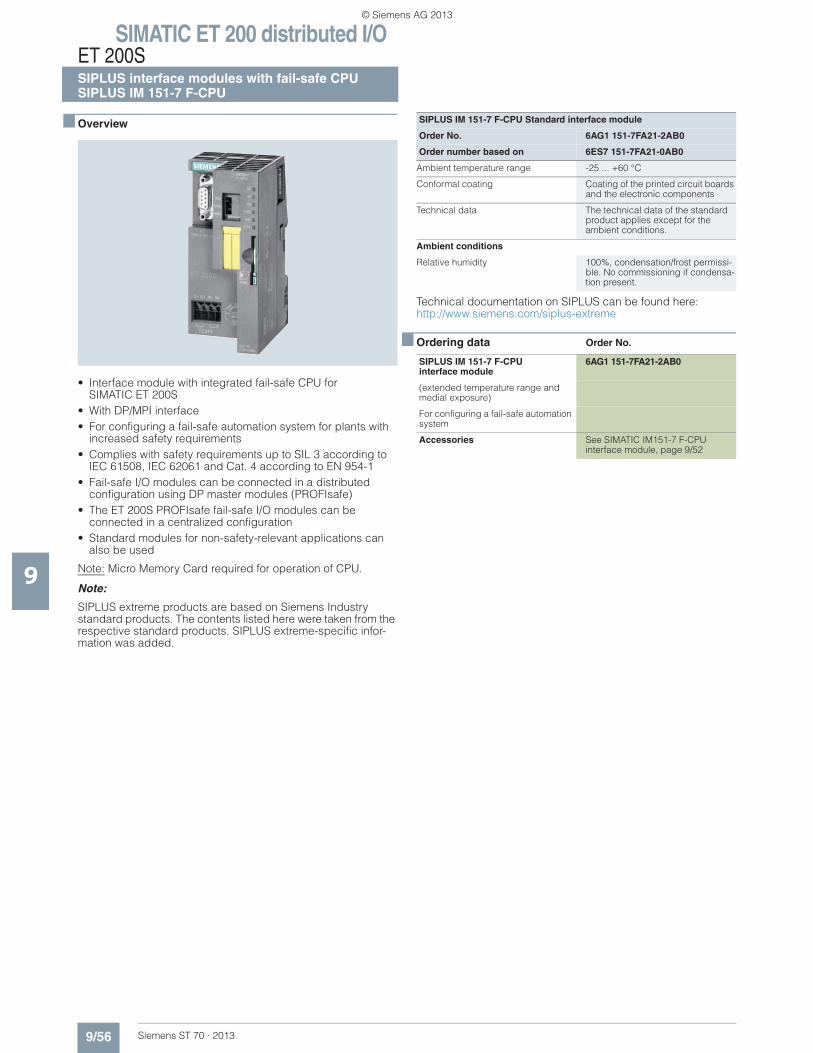
■ Overview
• Interface module with integrated fail-safe CPU for SIMATIC ET 200S
• With DP/MPI interface • For configuring a fail-safe automation system for plants with
increased safety requirements • Complies with safety requirements up to SIL 3 according to
IEC 61508, IEC 62061 and Cat. 4 according to EN 954-1 • Fail-safe I/O modules can be connected in a distributed
configuration using DP master modules (PROFIsafe) • The ET 200S PROFIsafe fail-safe I/O modules can be
connected in a centralized configuration • Standard modules for non-safety-relevant applications can
also be used
Note: Micro Memory Card required for operation of CPU.
Note:
SIPLUS extreme products are based on Siemens Industry standard products. The contents listed here were taken from the respective standard products. SIPLUS extreme-specific infor-mation was added.
Technical documentation on SIPLUS can be found here:http://www.siemens.com/siplus-extreme
■ Ordering data Order No.
SIPLUS IM 151-7 F-CPU Standard interface module
Order No. 6AG1 151-7FA21-2AB0
Order number based on 6ES7 151-7FA21-0AB0
Ambient temperature range -25 ... +60 °C
Conformal coating Coating of the printed circuit boards and the electronic components
Technical data The technical data of the standard product applies except for the ambient conditions.
Ambient conditions
Relative humidity 100%, condensation/frost permissi-ble. No commissioning if condensa-tion present.
SIPLUS IM 151-7 F-CPUinterface module
6AG1 151-7FA21-2AB0
(extended temperature range and medial exposure)
For configuring a fail-safe automation system
Accessories See SIMATIC IM151-7 F-CPUinterface module, page 9/52
© Siemens AG 2013
SIMATIC ET 200 distributed I/OET 200S
SIPLUS interface modules with fail-safe CPUSIPLUS IM 151-8 F PN/DP CPU
9/57Siemens ST 70 · 2013
9
■ Overview
• Interface module for SIPLUS ET 200S with integrated CPU S7-314
• For high-performance control solutions in ET 200S • Increases the availability of plants and machinery • PROFINET IO Controller for up to 128 IO-Devices • PROFINET I-Device for connecting the CPU as an intelligent
PROFINET device with a SIMATIC or third-party PROFINETI/O Controller
• PROFINET interface with integrated 3-port switch• Isochronous mode on PROFINET• With multiple communication options: PG/OP communication,
PROFINET IO, PROFINET CBA, open IE communication (TCP, ISO-on-TCP and UDP), Web server and S7 communication (with loadable FBs)
• Fast, simple and uniform programming of a system with modular programs via STEP 7
• Compact SIMATIC Micro Memory Card (MMC)• Optional PROFIBUS master for 32 PROFIBUS DP slaves
(with master interface 6ES7138-4HA00-0AB0)• Fail-safe IM 151-8F PN/DP CPU PROFIsafe available
SIMATIC Micro Memory Card required for operation of CPU.
Note:
SIPLUS extreme products are based on Siemens Industry standard products. The contents listed here were taken from the respective standard products. SIPLUS extreme specific infor-mation was added.
For technical documentation on SIPLUS, see:http://www.siemens.com/siplus-extreme
■ Ordering data Order No.
SIPLUS IM 151-8 F PN/DP CPU
Order No. 6AG1 151-8FB01-2AB0
Order number based on 6ES7 151-8FB01-0AB0
Ambient temperature range -25 ... +60 °C
Conformal coating Coating of the printed circuit boards and the electronic components
Technical data The technical data of the standard product applies except for the ambi-ent conditions.
Ambient conditions:
Relative humidity 100%, condensation/frost permissi-ble. No commissioning if condensa-tion present.
SIPLUS interface moduleIM 151-8F PN/DP CPU
6AG1 151-8FB01-2AB0
(extended temperature range and medial exposure)
Including termination module
Accessories See SIMATIC IM 151-8F PN/DPCPU interface module, page 9/55
© Siemens AG 2013
SIMATIC ET 200 distributed I/OET 200SInterface modules without CPUIM 151-1
9/58 Siemens ST 70 · 2013
9
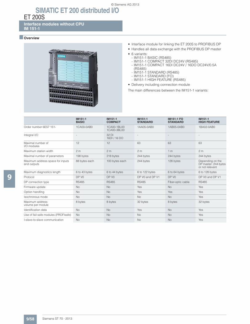
■ Overview
• Interface module for linking the ET 200S to PROFIBUS DP• Handles all data exchange with the PROFIBUS DP master• 6 variants:
- IM151-1 BASIC (RS485)- IM151-1 COMPACT 32DI DC24V (RS485)- IM151-1 COMPACT 16DI DC24V / 16DO DC24V/0.5A
(RS485)- IM151-1 STANDARD (RS485)- IM151-1 STANDARD (FO)- IM151-1 HIGH FEATURE (RS485)
• Delivery including connection module
The main differences between the IM151-1 variants:
IM151-1BASIC
IM151-1 COMPACT
IM151-1 STANDARD
IM151-1 FO STANDARD
IM151-1HIGH FEATURE
Order number 6ES7 151- 1CA00-0AB0 1CA00-1BL001CA00-3BL00
1AA05-0AB0 1AB05-0AB0 1BA02-0AB0
Integral I/O - 32 DI16DI / 16 DO
- - -
Maximal number ofI/O modules
12 12 63 63 63
Maximum station width 2 m 2 m 2 m 1 m 2 m
Maximal number of parameters 198 bytes 218 bytes 244 bytes 244 bytes 244 bytes
Maximum address space for inputs and outputs
88 bytes each 100 bytes each 244 bytes 128 bytes Depending on the DP master: 244 bytes or not relevant
Maximum diagnostics length 6 to 43 bytes 6 to 44 bytes 6 to 122 bytes 6 to 64 bytes 6 to 128 bytes
Protocol DP V0 DP V0 DP V0 and DP V1 DP V0 DP V0 and DP V1
DP connection type RS485 RS485 RS485 Fiber-optic cable RS485
Firmware update No No Yes No Yes
Option handling No No Yes Yes Yes
Isochronous mode No No No No Yes
Maximum address volume per module
8 bytes 8 bytes 32 bytes 8 bytes 32 bytes
Identification data No No Yes No Yes
Use of fail-safe modules (PROFIsafe) No No No No Yes
I-slave-to-slave communication No No No No Yes
© Siemens AG 2013
SIMATIC ET 200 distributed I/OET 200S
Interface modules without CPUIM 151-1
9/59Siemens ST 70 · 2013
9
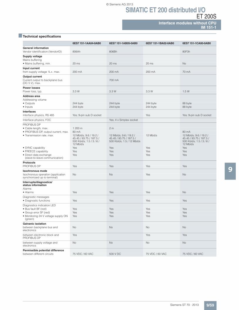
■ Technical specifications
6ES7 151-1AA04-0AB0 6ES7 151-1AB05-0AB0 6ES7 151-1BA02-0AB0 6ES7 151-1CA00-0AB0
General informationVendor identification (VendorID) 806Ah 806Bh 80F3h
Supply voltageMains buffering• Mains buffering, min. 20 ms 20 ms 20 ms No
Input currentfrom supply voltage 1L+, max. 200 mA 200 mA 200 mA 70 mA
Output currentCurrent output to backplane bus(DC 5 V), max.
700 mA
Power lossesPower loss, typ. 3.3 W 3.3 W 3.3 W 1.5 W
Address areaAddressing volume• Outputs 244 byte 244 byte 244 byte 88 byte• Inputs 244 byte 244 byte 244 byte 88 byte
InterfacesInterface physics, RS 485 Yes; 9-pin sub D socket Yes Yes; 9-pin sub D socket
Interface physics, FOC Yes; 4 x Simplex socket
PROFIBUS DP• Cable length, max. 1 200 m 2 m• PROFIBUS DP, output current, max. 80 mA 80 mA• Transmission rate, max. 12 Mbit/s; 9.6 / 19.2 /
45.45 / 93.75 / 187.5 / 500 Kbit/s; 1.5 / 3 / 6 /12 Mbit/s
12 Mbit/s; 9.6 / 19.2 / 45.45 / 93.75 / 187.5 /500 Kbit/s; 1.5 / 12 Mbit/s
12 Mbit/s 12 Mbit/s; 9.6 / 19.2 /45.45 / 93.75 / 187.5 / 500 Kbit/s; 1.5 / 3 / 6 / 12 Mbit/s
• SYNC capability Yes Yes Yes Yes• FREECE capability Yes Yes Yes Yes• Direct data exchange
(slave-to-slave communication)Yes Yes Yes Yes
ProtocolsPROFIBUS DP Yes Yes Yes Yes
Isochronous modeIsochronous operation (application synchronized up to terminal)
No No Yes No
Interrupts/diagnostics/status informationAlarms• Alarms Yes Yes Yes No
Diagnostic messages• Diagnostic functions Yes Yes Yes Yes
Diagnostics indication LED• Bus fault BF (red) Yes Yes Yes Yes• Group error SF (red) Yes Yes Yes Yes• Monitoring 24 V voltage supply ON
(green)Yes Yes Yes Yes
Galvanic isolationbetween backplane bus and electronics
No No No No
between electronic block and PROFIBUS DP
Yes Yes Yes
between supply voltage and electronics
No No No No
Permissible potential differencebetween different circuits 75 VDC / 60 VAC 500 V DC 75 VDC / 60 VAC 75 VDC / 60 VAC
© Siemens AG 2013
SIMATIC ET 200 distributed I/OET 200SInterface modules without CPUIM 151-1
9/60 Siemens ST 70 · 2013
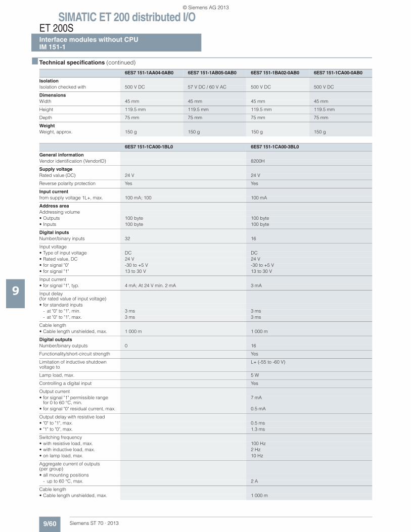
■ Technical specifications (continued)
9
IsolationIsolation checked with 500 V DC 57 V DC / 60 V AC 500 V DC 500 V DC
DimensionsWidth 45 mm 45 mm 45 mm 45 mm
Height 119.5 mm 119.5 mm 119.5 mm 119.5 mm
Depth 75 mm 75 mm 75 mm 75 mm
WeightWeight, approx. 150 g 150 g 150 g 150 g
6ES7 151-1CA00-1BL0 6ES7 151-1CA00-3BL0
General informationVendor identification (VendorID) 8200H
Supply voltageRated value (DC) 24 V 24 V
Reverse polarity protection Yes Yes
Input currentfrom supply voltage 1L+, max. 100 mA; 100 100 mA
Address areaAddressing volume• Outputs 100 byte 100 byte• Inputs 100 byte 100 byte
Digital inputsNumber/binary inputs 32 16
Input voltage• Type of input voltage DC DC• Rated value, DC 24 V 24 V• for signal "0" -30 to +5 V -30 to +5 V• for signal "1" 13 to 30 V 13 to 30 V
Input current• for signal "1", typ. 4 mA; At 24 V min. 2 mA 3 mA
Input delay (for rated value of input voltage)• for standard inputs
- at "0" to "1", min. 3 ms 3 ms- at "0" to "1", max. 3 ms 3 ms
Cable length• Cable length unshielded, max. 1 000 m 1 000 m
Digital outputsNumber/binary outputs 0 16
Functionality/short-circuit strength Yes
Limitation of inductive shutdown voltage to
L+ (-55 to -60 V)
Lamp load, max. 5 W
Controlling a digital input Yes
Output current• for signal "1" permissible range
for 0 to 60 °C, min.7 mA
• for signal "0" residual current, max. 0.5 mA
Output delay with resistive load• "0" to "1", max. 0.5 ms• "1" to "0", max. 1.3 ms
Switching frequency• with resistive load, max. 100 Hz• with inductive load, max. 2 Hz• on lamp load, max. 10 Hz
Aggregate current of outputs(per group)• all mounting positions
- up to 60 °C, max. 2 A
Cable length• Cable length unshielded, max. 1 000 m
6ES7 151-1AA04-0AB0 6ES7 151-1AB05-0AB0 6ES7 151-1BA02-0AB0 6ES7 151-1CA00-0AB0
© Siemens AG 2013
SIMATIC ET 200 distributed I/OET 200S
Interface modules without CPUIM 151-1
9/61Siemens ST 70 · 2013
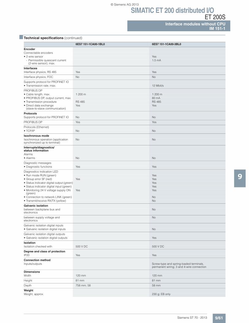
■ Technical specifications (continued)
9
EncoderConnectable encoders• 2-wire sensor Yes
- Permissible quiescent current (2-wire sensor), max.
1.5 mA
InterfacesInterface physics, RS 485 Yes Yes
Interface physics, FOC No No
Supports protocol for PROFINET IO• Transmission rate, max. 12 Mbit/s
PROFIBUS DP• Cable length, max. 1 200 m 1 200 m• PROFIBUS DP, output current, max. 80 mA• Transmission procedure RS 485 RS 485• Direct data exchange
(slave-to-slave communication)Yes Yes
ProtocolsSupports protocol for PROFINET IO No No
PROFIBUS DP Yes Yes
Protocols (Ethernet)• TCP/IP No No
Isochronous modeIsochronous operation (application synchronized up to terminal)
No No
Interrupts/diagnostics/status informationAlarms• Alarms No No
Diagnostic messages• Diagnostic functions Yes Yes
Diagnostics indication LED• Run mode RUN (green) Yes• Group error SF (red) Yes Yes• Status indicator digital output (green) Yes• Status indicator digital input (green) Yes• Monitoring 24 V voltage supply ON
(green)Yes Yes
• Connection to network LINK (green) No• Transmit/receive RX/TX (yellow) No
Galvanic isolationbetween backplane bus and electronics
No
between supply voltage and electronics
No
Galvanic isolation digital inputs• Galvanic isolation digital inputs No
Galvanic isolation digital outputs• Galvanic isolation digital outputs Yes
IsolationIsolation checked with 500 V DC 500 V DC
Degree and class of protectionIP20 Yes Yes
Connection methodInputs/outputs Screw-type and spring-loaded terminals,
permanent wiring; 3 and 4-wire connection
DimensionsWidth 120 mm 120 mm
Height 81 mm 81 mm
Depth 758 mm; 58 58 mm
WeightWeight, approx. 230 g; EB only
6ES7 151-1CA00-1BL0 6ES7 151-1CA00-3BL0
© Siemens AG 2013
SIMATIC ET 200 distributed I/OET 200SInterface modules without CPUIM 151-1
9/62 Siemens ST 70 · 2013
9
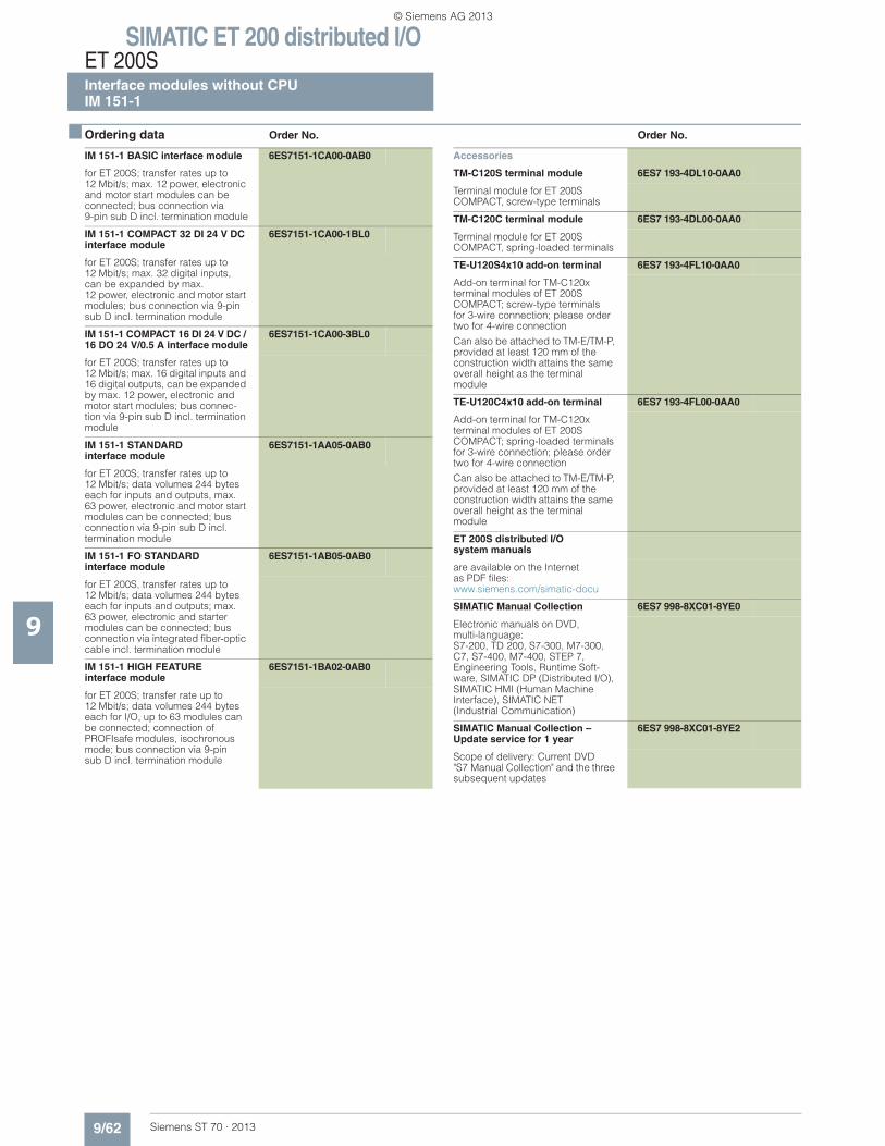
■ Ordering data Order No. Order No.
IM 151-1 BASIC interface module 6ES7151-1CA00-0AB0
for ET 200S; transfer rates up to 12 Mbit/s; max. 12 power, electronic and motor start modules can be connected; bus connection via 9-pin sub D incl. termination module
IM 151-1 COMPACT 32 DI 24 V DC interface module
6ES7151-1CA00-1BL0
for ET 200S; transfer rates up to 12 Mbit/s; max. 32 digital inputs, can be expanded by max. 12 power, electronic and motor start modules; bus connection via 9-pin sub D incl. termination module
IM 151-1 COMPACT 16 DI 24 V DC / 16 DO 24 V/0.5 A interface module
6ES7151-1CA00-3BL0
for ET 200S; transfer rates up to 12 Mbit/s; max. 16 digital inputs and 16 digital outputs, can be expanded by max. 12 power, electronic and motor start modules; bus connec-tion via 9-pin sub D incl. termination module
IM 151-1 STANDARDinterface module
6ES7151-1AA05-0AB0
for ET 200S; transfer rates up to 12 Mbit/s; data volumes 244 bytes each for inputs and outputs, max. 63 power, electronic and motor start modules can be connected; bus connection via 9-pin sub D incl.termination module
IM 151-1 FO STANDARDinterface module
6ES7151-1AB05-0AB0
for ET 200S, transfer rates up to 12 Mbit/s; data volumes 244 bytes each for inputs and outputs; max. 63 power, electronic and starter modules can be connected; bus connection via integrated fiber-optic cable incl. termination module
IM 151-1 HIGH FEATUREinterface module
6ES7151-1BA02-0AB0
for ET 200S; transfer rate up to 12 Mbit/s; data volumes 244 bytes each for I/O, up to 63 modules can be connected; connection of PROFIsafe modules, isochronous mode; bus connection via 9-pinsub D incl. termination module
Accessories
TM-C120S terminal module 6ES7 193-4DL10-0AA0
Terminal module for ET 200S COMPACT, screw-type terminals
TM-C120C terminal module 6ES7 193-4DL00-0AA0
Terminal module for ET 200SCOMPACT, spring-loaded terminals
TE-U120S4x10 add-on terminal 6ES7 193-4FL10-0AA0
Add-on terminal for TM-C120x terminal modules of ET 200S COMPACT; screw-type terminals for 3-wire connection; please order two for 4-wire connection
Can also be attached to TM-E/TM-P, provided at least 120 mm of the construction width attains the same overall height as the terminal module
TE-U120C4x10 add-on terminal 6ES7 193-4FL00-0AA0
Add-on terminal for TM-C120x terminal modules of ET 200S COMPACT; spring-loaded terminals for 3-wire connection; please order two for 4-wire connection
Can also be attached to TM-E/TM-P, provided at least 120 mm of the construction width attains the same overall height as the terminal module
ET 200S distributed I/Osystem manuals
are available on the Internet as PDF files:www.siemens.com/simatic-docu
SIMATIC Manual Collection 6ES7 998-8XC01-8YE0
Electronic manuals on DVD, multi-language: S7-200, TD 200, S7-300, M7-300, C7, S7-400, M7-400, STEP 7, Engineering Tools, Runtime Soft-ware, SIMATIC DP (Distributed I/O), SIMATIC HMI (Human Machine Interface), SIMATIC NET (Industrial Communication)
SIMATIC Manual Collection – Update service for 1 year
6ES7 998-8XC01-8YE2
Scope of delivery: Current DVD "S7 Manual Collection" and the three subsequent updates
© Siemens AG 2013
SIMATIC ET 200 distributed I/OET 200S
Interface modules without CPUIM 151-1
9/63Siemens ST 70 · 2013
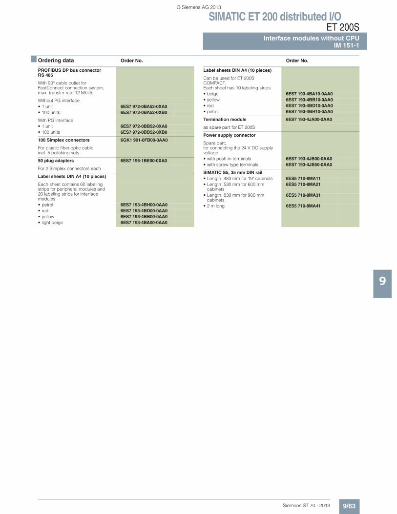
■ Ordering data Order No. Order No.
9
PROFIBUS DP bus connector RS 485
With 90° cable outlet for FastConnect connection system, max. transfer rate 12 Mbit/s
Without PG interface• 1 unit 6ES7 972-0BA52-0XA0• 100 units 6ES7 972-0BA52-0XB0
With PG interface• 1 unit 6ES7 972-0BB52-0XA0• 100 units 6ES7 972-0BB52-0XB0
100 Simplex connectors 6GK1 901-0FB00-0AA0
For plastic fiber-optic cableincl. 5 polishing sets
50 plug adapters 6ES7 195-1BE00-0XA0
For 2 Simplex connectors each
Label sheets DIN A4 (10 pieces)
Each sheet contains 60 labeling strips for peripheral modules and20 labeling strips for interface modules• petrol 6ES7 193-4BH00-0AA0• red 6ES7 193-4BD00-0AA0• yellow 6ES7 193-4BB00-0AA0• light beige 6ES7 193-4BA00-0AA0
Label sheets DIN A4 (10 pieces)
Can be used for ET 200S COMPACT.Each sheet has 10 labeling strips• beige 6ES7 193-4BA10-0AA0• yellow 6ES7 193-4BB10-0AA0• red 6ES7 193-4BD10-0AA0• petrol 6ES7 193-4BH10-0AA0
Termination module 6ES7 193-4JA00-0AA0
as spare part for ET 200S
Power supply connector
Spare part;for connecting the 24 V DC supply voltage• with push-in terminals 6ES7 193-4JB00-0AA0• with screw-type terminals 6ES7 193-4JB50-0AA0
SIMATIC S5, 35 mm DIN rail • Length: 483 mm for 19" cabinets 6ES5 710-8MA11• Length: 530 mm for 600 mm
cabinets6ES5 710-8MA21
• Length: 830 mm for 900 mmcabinets
6ES5 710-8MA31
• 2 m long 6ES5 710-8MA41
© Siemens AG 2013
SIMATIC ET 200 distributed I/OET 200SInterface modules without CPUIM 151-3 PN
9/64 Siemens ST 70 · 2013
9
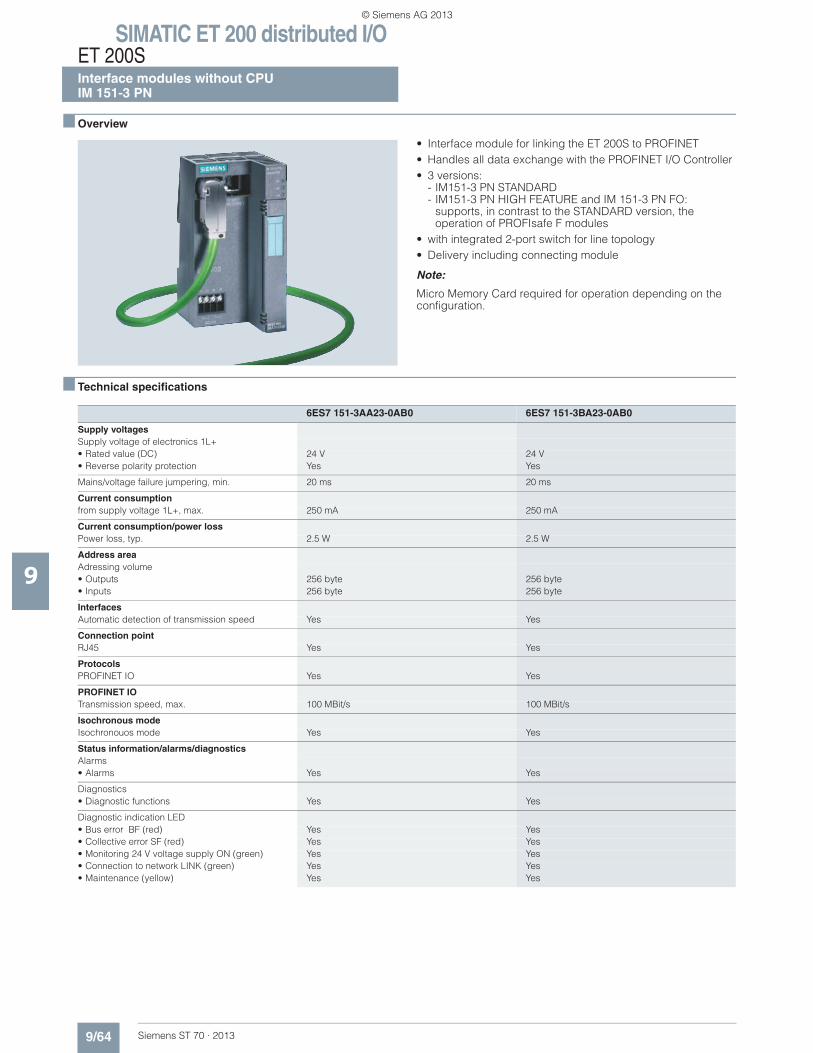
■ Overview
• Interface module for linking the ET 200S to PROFINET• Handles all data exchange with the PROFINET I/O Controller• 3 versions:
- IM151-3 PN STANDARD- IM151-3 PN HIGH FEATURE and IM 151-3 PN FO:
supports, in contrast to the STANDARD version, the operation of PROFIsafe F modules
• with integrated 2-port switch for line topology• Delivery including connecting module
Note:
Micro Memory Card required for operation depending on the configuration.
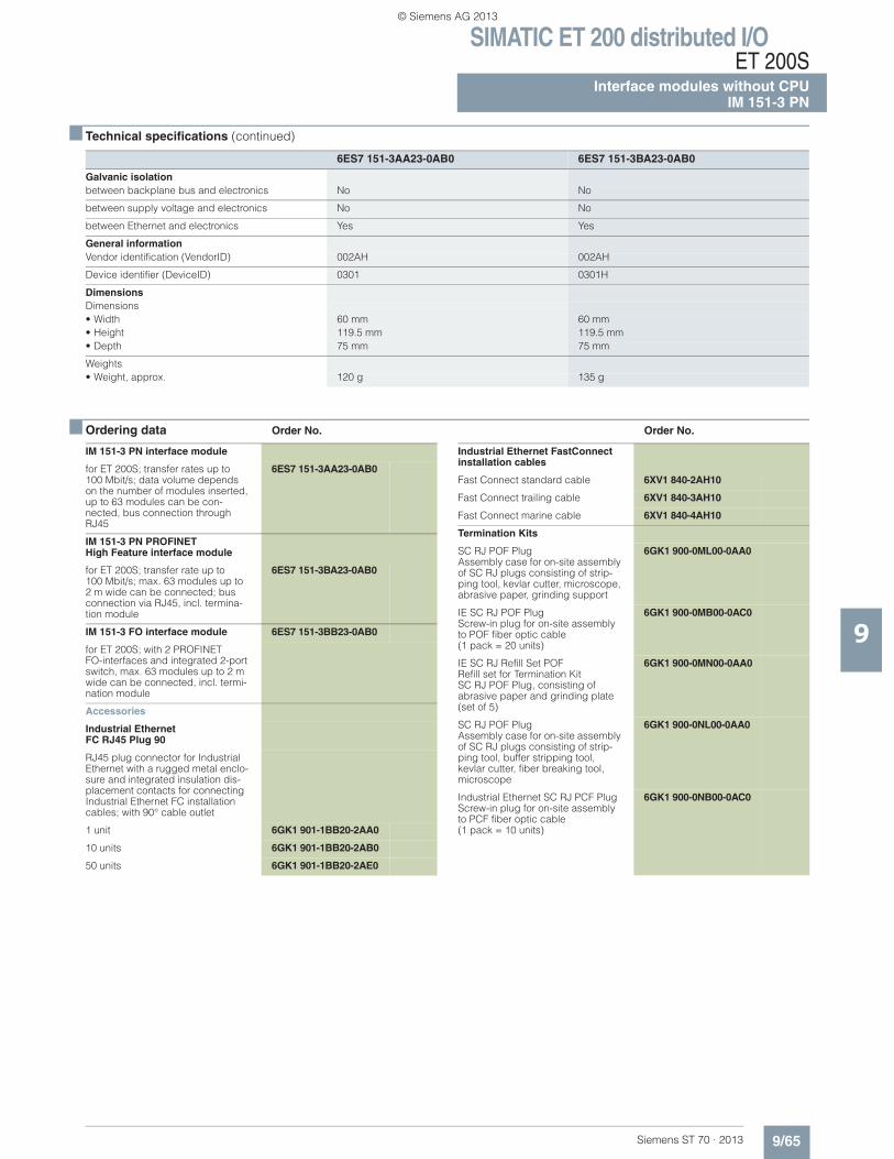
■ Technical specifications
6ES7 151-3AA23-0AB0 6ES7 151-3BA23-0AB0
Supply voltagesSupply voltage of electronics 1L+• Rated value (DC) 24 V 24 V• Reverse polarity protection Yes Yes
Mains/voltage failure jumpering, min. 20 ms 20 ms
Current consumptionfrom supply voltage 1L+, max. 250 mA 250 mA
Current consumption/power lossPower loss, typ. 2.5 W 2.5 W
Address areaAdressing volume• Outputs 256 byte 256 byte• Inputs 256 byte 256 byte
InterfacesAutomatic detection of transmission speed Yes Yes
Connection pointRJ45 Yes Yes
ProtocolsPROFINET IO Yes Yes
PROFINET IOTransmission speed, max. 100 MBit/s 100 MBit/s
Isochronous modeIsochronouos mode Yes Yes
Status information/alarms/diagnosticsAlarms• Alarms Yes Yes
Diagnostics• Diagnostic functions Yes Yes
Diagnostic indication LED• Bus error BF (red) Yes Yes• Collective error SF (red) Yes Yes• Monitoring 24 V voltage supply ON (green) Yes Yes• Connection to network LINK (green) Yes Yes• Maintenance (yellow) Yes Yes
© Siemens AG 2013
SIMATIC ET 200 distributed I/OET 200S
Interface modules without CPUIM 151-3 PN
9/65Siemens ST 70 · 2013
■ Technical specifications (continued)
9
■ Ordering data Order No. Order No.
Galvanic isolationbetween backplane bus and electronics No No
between supply voltage and electronics No No
between Ethernet and electronics Yes Yes
General informationVendor identification (VendorID) 002AH 002AH
Device identifier (DeviceID) 0301 0301H
DimensionsDimensions• Width 60 mm 60 mm• Height 119.5 mm 119.5 mm• Depth 75 mm 75 mm
Weights• Weight, approx. 120 g 135 g
6ES7 151-3AA23-0AB0 6ES7 151-3BA23-0AB0
IM 151-3 PN interface module
for ET 200S; transfer rates up to 100 Mbit/s; data volume depends on the number of modules inserted, up to 63 modules can be con-nected, bus connection through RJ45
6ES7 151-3AA23-0AB0
IM 151-3 PN PROFINET High Feature interface module
for ET 200S; transfer rate up to100 Mbit/s; max. 63 modules up to2 m wide can be connected; bus connection via RJ45, incl. termina-tion module
6ES7 151-3BA23-0AB0
IM 151-3 FO interface module 6ES7 151-3BB23-0AB0
for ET 200S; with 2 PROFINET FO-interfaces and integrated 2-port switch, max. 63 modules up to 2 m wide can be connected, incl. termi-nation module
Accessories
Industrial EthernetFC RJ45 Plug 90
RJ45 plug connector for Industrial Ethernet with a rugged metal enclo-sure and integrated insulation dis-placement contacts for connecting Industrial Ethernet FC installation cables; with 90° cable outlet
1 unit 6GK1 901-1BB20-2AA0
10 units 6GK1 901-1BB20-2AB0
50 units 6GK1 901-1BB20-2AE0
Industrial Ethernet FastConnect installation cables
Fast Connect standard cable 6XV1 840-2AH10
Fast Connect trailing cable 6XV1 840-3AH10
Fast Connect marine cable 6XV1 840-4AH10
Termination Kits
SC RJ POF PlugAssembly case for on-site assembly of SC RJ plugs consisting of strip-ping tool, kevlar cutter, microscope, abrasive paper, grinding support
6GK1 900-0ML00-0AA0
IE SC RJ POF PlugScrew-in plug for on-site assembly to POF fiber optic cable (1 pack = 20 units)
6GK1 900-0MB00-0AC0
IE SC RJ Refill Set POFRefill set for Termination Kit SC RJ POF Plug, consisting ofabrasive paper and grinding plate (set of 5)
6GK1 900-0MN00-0AA0
SC RJ POF PlugAssembly case for on-site assembly of SC RJ plugs consisting of strip-ping tool, buffer stripping tool, kevlar cutter, fiber breaking tool, microscope
6GK1 900-0NL00-0AA0
Industrial Ethernet SC RJ PCF PlugScrew-in plug for on-site assembly to PCF fiber optic cable (1 pack = 10 units)
6GK1 900-0NB00-0AC0
© Siemens AG 2013
SIMATIC ET 200 distributed I/OET 200SInterface modules without CPUIM 151-3 PN
9/66 Siemens ST 70 · 2013
■ Ordering data Order No. Order No.
9
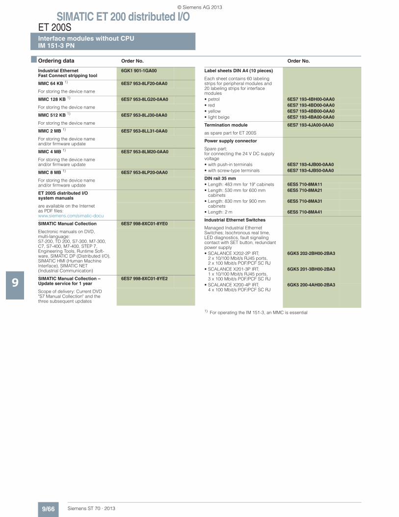
1) For operating the IM 151-3, an MMC is essential
Industrial Ethernet Fast Connect stripping tool
6GK1 901-1GA00
MMC 64 KB 1) 6ES7 953-8LF20-0AA0
For storing the device name
MMC 128 KB 1) 6ES7 953-8LG20-0AA0
For storing the device name
MMC 512 KB 1) 6ES7 953-8LJ30-0AA0
For storing the device name
MMC 2 MB 1) 6ES7 953-8LL31-0AA0
For storing the device name and/or firmware update
MMC 4 MB 1) 6ES7 953-8LM20-0AA0
For storing the device nameand/or firmware update
MMC 8 MB 1) 6ES7 953-8LP20-0AA0
For storing the device nameand/or firmware update
ET 200S distributed I/Osystem manuals
are available on the Internet as PDF files:www.siemens.com/simatic-docu
SIMATIC Manual Collection 6ES7 998-8XC01-8YE0
Electronic manuals on DVD, multi-language: S7-200, TD 200, S7-300, M7-300, C7, S7-400, M7-400, STEP 7, Engineering Tools, Runtime Soft-ware, SIMATIC DP (Distributed I/O), SIMATIC HMI (Human Machine Interface), SIMATIC NET (Industrial Communication)
SIMATIC Manual Collection – Update service for 1 year
6ES7 998-8XC01-8YE2
Scope of delivery: Current DVD "S7 Manual Collection" and thethree subsequent updates
Label sheets DIN A4 (10 pieces)
Each sheet contains 60 labeling strips for peripheral modules and 20 labeling strips for interface modules• petrol 6ES7 193-4BH00-0AA0• red 6ES7 193-4BD00-0AA0• yellow 6ES7 193-4BB00-0AA0• light beige 6ES7 193-4BA00-0AA0
Termination module 6ES7 193-4JA00-0AA0
as spare part for ET 200S
Power supply connector
Spare part;for connecting the 24 V DC supply voltage• with push-in terminals 6ES7 193-4JB00-0AA0• with screw-type terminals 6ES7 193-4JB50-0AA0
DIN rail 35 mm • Length: 483 mm for 19" cabinets 6ES5 710-8MA11• Length: 530 mm for 600 mm
cabinets6ES5 710-8MA21
• Length: 830 mm for 900 mm cabinets
6ES5 710-8MA31
• Length: 2 m 6ES5 710-8MA41
Industrial Ethernet Switches
Managed Industrial Ethernet Switches; Isochronous real time, LED diagnostics, fault signaling contact with SET button, redundant power supply• SCALANCE X202-2P IRT;
2 x 10/100 Mbit/s RJ45 ports, 2 x 100 Mbit/s POF/PCF SC RJ
6GK5 202-2BH00-2BA3
• SCALANCE X201-3P IRT;1 x 10/100 Mbit/s RJ45 ports, 3 x 100 Mbit/s POF/PCF SC RJ
6GK5 201-3BH00-2BA3
• SCALANCE X200-4P IRT;4 x 100 Mbit/s POF/PCF SC RJ
6GK5 200-4AH00-2BA3
© Siemens AG 2013
SIMATIC ET 200 distributed I/OET 200S
SIPLUS interface modules without CPUSIPLUS IM 151-1
9/67Siemens ST 70 · 2013
9
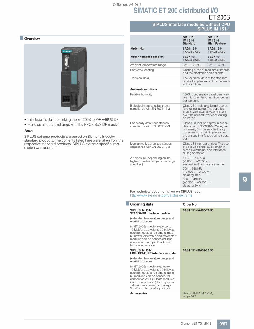
■ Overview
• Interface module for linking the ET 200S to PROFIBUS DP • Handles all data exchange with the PROFIBUS DP master
Note:
SIPLUS extreme products are based on Siemens Industry standard products. The contents listed here were taken from the respective standard products. SIPLUS extreme specific infor-mation was added.
For technical documentation on SIPLUS, see:http://www.siemens.com/siplus-extreme
■ Ordering data Order No.
SIPLUSIM 151-1Standard
SIPLUS IM 151-1High Feature
Order No. 6AG1 151-1AA05-7AB0
6AG1 151-1BA02-2AB0
Order number based on 6ES7 151-1AA05-0AB0
6ES7 151-1BA02-0AB0
Ambient temperature range -25 ... +70 °C -25 ... +60 °C
Conformal coating Coating of the printed circuit boards and the electronic components
Technical data The technical data of the standard product applies except for the ambi-ent conditions.
Ambient conditions
Relative humidity 100%, condensation/frost permissi-ble. No commissioning if condensa-tion present.
Biologically active substances,compliance with EN 60721-3-3
Class 3B2 mold and fungal spores (excluding fauna). The supplied plug covers must remain in place over the unused interfaces during operation!
Chemically active substances, compliance with EN 60721-3-3
Class 3C4 incl. salt spray in accor-dance with EN60068-2-52 (degree of severity 3). The supplied plug covers must remain in place over the unused interfaces during opera-tion!
Mechanically active substances, compliance with EN 60721-3-3
Class 3S4 incl. sand, dust. The sup-plied plug covers must remain in place over the unused interfaces during operation!
Air pressure (depending on the highest positive temperature range specified)
1 080 ... 795 hPa (-1 000 ... +2 000 m) see ambient temperature range
795 ... 658 hPa (+2 000 ... +3 500 m) derating 10 K
658 ... 540 hPa(+3 500 ... +5 000 m) derating 20 K
SIPLUS IM 151-1 STANDARD interface module
6AG1 151-1AA05-7AB0
(extended temperature range and medial exposure)
for ET 200S; transfer rates up to12 Mbit/s; data volumes 244 bytes each for inputs and outputs, max. 63 power, electronic and motor start modules can be connected; bus connection via 9-pin D-sub incl.termination module
SIPLUS IM 151-1 HIGH FEATURE interface module
6AG1 151-1BA02-2AB0
(extended temperature range and medial exposure)
for ET 200S; transfer rate up to 12 Mbit/s; data volumes 244 bytes each for inputs and outputs, up to 63 modules can be connected; connection of PROFIsafe modules, isochronous mode (clock synchroni-zation); bus connection via 9-pin Sub-D incl. terminating module
Accessories See SIMATIC IM 151-1,page 9/62
© Siemens AG 2013
SIMATIC ET 200 distributed I/OET 200SSIPLUS interface modules without CPUSIPLUS IM 151-3PN
9/68 Siemens ST 70 · 2013
9
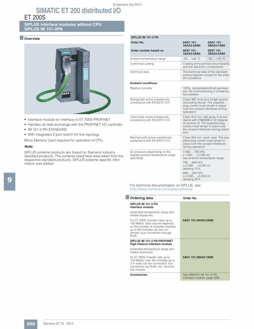
■ Overview
• Interface module for interface to ET 200S PROFINET• Handles all data exchange with the PROFINET I/O controller• IM 151-3 PN STANDARD• With integrated 2-port switch for line topology
Micro Memory Card required for operation of CPU.
Note:
SIPLUS extreme products are based on Siemens Industry standard products. The contents listed here were taken from the respective standard products. SIPLUS extreme specific infor-mation was added.
For technical documentation on SIPLUS, see:http://www.siemens.com/siplus-extreme
■ Ordering data Order No.
SIPLUS IM 151-3 PN
Order No. 6AG1 151-3AA23-2AB0
6AG1 151-3BA23-7AB0
Order number based on 6ES7 151-3AA23-0AB0
6ES7 151-3BA23-0AB0
Ambient temperature range -25 ... +60 °C -25 ... +70 °C
Conformal coating Coating of the printed circuit boards and the electronic components
Technical data The technical data of the standard product applies except for the ambi-ent conditions.
Ambient conditions
Relative humidity 100%, condensation/frost permissi-ble. No commissioning if condensa-tion present.
Biologically active substances, compliance with EN 60721-3-3
Class 3B2 mold and fungal spores (excluding fauna). The supplied plug covers must remain in place over the unused interfaces during operation!
Chemically active substances, compliance with EN 60721-3-3
Class 3C4 incl. salt spray in accor-dance with EN60068-2-52 (degree of severity 3). The supplied plug covers must remain in place over the unused interfaces during opera-tion!
Mechanically active substances, compliance with EN 60721-3-3
Class 3S4 incl. sand, dust. The sup-plied plug covers must remain in place over the unused interfaces during operation!
Air pressure (depending on the highest positive temperature range specified)
1 080 ... 795 hPa (-1 000 ... +2 000 m) see ambient temperature range
795 ... 658 hPa (+2 000 ... +3 500 m) derating 10 K
658 ... 540 hPa (+3 500 ... +5 000 m) derating 20 K
SIPLUS IM 151-3 PNinterface module
(extended temperature range and medial exposure)
For ET 200S; transfer rates up to100 Mbit/s; data volume depends on the number of modules inserted, up to 63 modules can be con-nected, bus connection through RJ45
6AG1 151-3AA23-2AB0
SIPLUS IM 151-3 PN PROFINET High Feature interface module
(extended temperature range and medial exposure)
for ET 200S; transfer rate up to 100 Mbit/s; max. 63 modules up to2 m wide can be connected; bus connection via RJ45, incl. termina-tion module
6AG1 151-3BA23-7AB0
Accessories See SIMATIC IM 151-3 PN interface module, page 9/65
© Siemens AG 2013
SIMATIC ET 200 distributed I/OET 200S
I/O modulesPower modules for PM-E electronic modules
9/69Siemens ST 70 · 2013
9
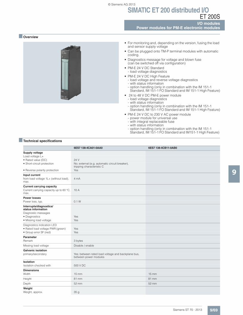
■ Overview
• For monitoring and, depending on the version, fusing the load and sensor supply voltage
• Can be plugged onto TM-P terminal modules with automatic coding.
• Diagnostics message for voltage and blown fuse (can be switched off via configuration)
• PM-E 24 V DC Standard- load voltage diagnostics
• PM-E 24 V DC High Feature- load voltage and reverse voltage diagnostics- with status information - option handling (only in combination with the IM 151-1
Standard, IM 151-1 FO Standard and IM 151-1 High Feature)• 24 to 48 V DC PM-E power module
- load voltage diagnostics- with status information- option handling (only in combination with the IM 151-1
Standard, IM 151-1 FO Standard and IM 151-1 High Feature)• PM-E 24 V DC to 230 V AC power module
- power module for universal use- with integral replaceable fuse- with status information- option handling (only in combination with the IM 151-1
Standard, IM 151-1 FO Standard and IM151-1 High Feature)
■ Technical specifications
6ES7 138-4CA01-0AA0 6ES7 138-4CB11-0AB0
Supply voltageLoad voltage L+• Rated value (DC) 24 V• Short-circuit protection No; external (e.g. automatic circuit breaker),
tripping characteristic C• Reverse polarity protection Yes
Input currentfrom load voltage 1L+ (without load), max.
4 mA
Current carrying capacityCurrent carrying capacity up to 60 °C, max.
10 A
Power lossesPower loss, typ. 0.1 W
Interrupts/diagnostics/status informationDiagnostic messages• Diagnostics Yes• Missing load voltage Yes
Diagnostics indication LED• Rated load voltage PWR (green) Yes• Group error SF (red) Yes
ParameterRemark 3 bytes
Missing load voltage Disable / enable
Galvanic isolationprimary/secondary Yes; between rated load voltage and backplane bus,
between power modules
IsolationIsolation checked with 500 V DC
DimensionsWidth 15 mm 15 mm
Height 81 mm 81 mm
Depth 52 mm 52 mm
WeightWeight, approx. 35 g
© Siemens AG 2013
SIMATIC ET 200 distributed I/OET 200SI/O modulesPower modules for PM-E electronic modules
9/70 Siemens ST 70 · 2013
■ Technical specifications (continued)
9
■ Ordering data Order No. Order No.
1) Can be used for all electronic and technology modules except 2 DI 120 V AC / 2 DI 230 V AC / 2 DO 120/230 V AC
Selection tool for terminal modules
6ES7 138-4CA50-0AB0PM-E 24 to 48 V DC
Supply voltageLoad voltage L+• Rated values 24 to 48 V DC• Short-circuit protection No; external
(e.g. automatic circuit breaker),tripping characteristic B, C
• Reverse polarity protection Yes
Input currentfrom load voltage 1L+ (without load), max.
12 mA
Current carrying capacityCurrent carrying capacity up to 60 °C, max.
10 A
Power lossesPower loss, typ. 500 W; mW
Interrupts/diagnostics/status informationDiagnostic messages• Diagnostics Yes• Missing load voltage Yes
Diagnostics indication LED• Rated load voltage PWR (green) Yes• Group error SF (red) Yes
ParameterRemark 3 bytes
Missing load voltage Disable / enable
Galvanic isolationprimary/secondary Yes; between rated load voltage
and backplane bus, between power modules
IsolationIsolation checked with 500 V DC
DimensionsWidth 15 mm
Height 81 mm
Depth 52 mm
WeightWeight, approx. 35 g
6ES7 138-4CA50-0AB0PM-E 24 to 48 V DC
PM-E 24 V DCStandard power module 1)
For electronic modules; with diagnostics
1 unit 6ES7 138-4CA01-0AA0
5 units 6ES7 138-4CA01-1AA0
PM-E 24 V DCHigh Feature power module 1)
6ES7 138-4CA60-0AB0
For electronic modules; with diag-nostics
24 to 48 V DC PM-E power module
For electronic modules; with diagnostics, with status bit "load voltage" present
1 unit 6ES7 138-4CA50-0AB0
5 units 6ES7 138-4CA50-1AB0
Power modulePM-E 24 V DC to 48 V, 42 to 230 V AC
6ES7 138-4CB11-0AB0
For electronic modules;with diagnostics and fuse
Accessories
Label sheets DIN A4 (10 pieces)
Each sheet contains 60 labeling strips for peripheral modules and 20 labeling strips for interface modules• petrol 6ES7 193-4BH00-0AA0• red 6ES7 193-4BD00-0AA0• yellow 6ES7 193-4BB00-0AA0• light beige 6ES7 193-4BA00-0AA0
Power modules TM-P terminal modules for power modules
Screw-type terminal type designation TM-P15S23-A1 TM-P15S23-A0 TM-P15S22-01 TM-P30S44-A0
Order number 6ES7 193... 4CC20-0AA0 4CD20-0AA0 4CE00-0AA0 4CK20-0AA0
Spring-loaded terminal type designation
TM-P15C23-A1 TM-P15C23-A0 TM-P15C22-01 TM-P30C44-A0
Order number 6ES7 193... 4CC30-0AA0 4CD30-0AA0 4CE10-0AA0 4CK30-0AA0
FastConnect type designation TM-P15N23-A1 TM-P15N23-A0 TM-P15N22-01 Soon to come
Order number 6ES7 193... 4CC70-0AA0 4CD70-0AA0 4CE60-0AA0
PM-E 24 V DC • • •
PM-E 24 V DC to 48 V DC • • •
PM-E 24 V DC/120/230 V AC • • •
PM-E F 24 V DC PROFIsafe •
© Siemens AG 2013
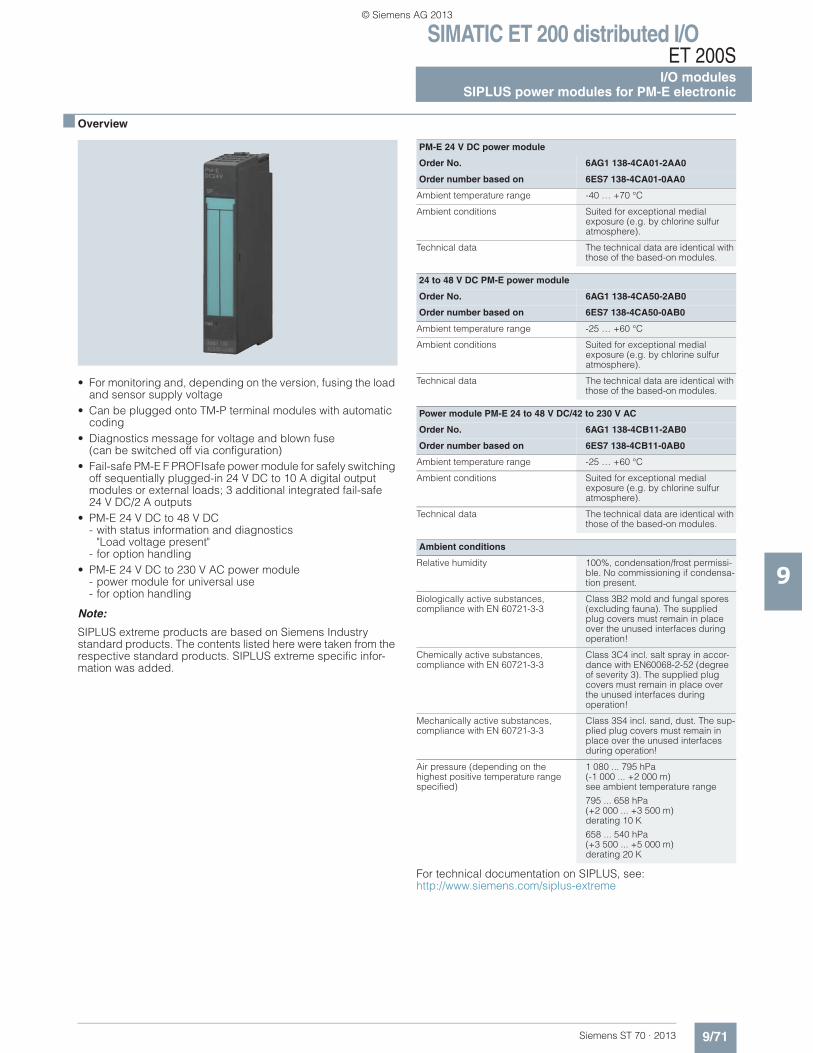
SIMATIC ET 200 distributed I/OET 200S
I/O modulesSIPLUS power modules for PM-E electronic
9/71Siemens ST 70 · 2013
9
■ Overview
• For monitoring and, depending on the version, fusing the load and sensor supply voltage
• Can be plugged onto TM-P terminal modules with automatic coding
• Diagnostics message for voltage and blown fuse(can be switched off via configuration)
• Fail-safe PM-E F PROFIsafe power module for safely switching off sequentially plugged-in 24 V DC to 10 A digital output modules or external loads; 3 additional integrated fail-safe 24 V DC/2 A outputs
• PM-E 24 V DC to 48 V DC - with status information and diagnostics
"Load voltage present" - for option handling
• PM-E 24 V DC to 230 V AC power module - power module for universal use - for option handling
Note:
SIPLUS extreme products are based on Siemens Industry standard products. The contents listed here were taken from the respective standard products. SIPLUS extreme specific infor-mation was added.
For technical documentation on SIPLUS, see: http://www.siemens.com/siplus-extreme
PM-E 24 V DC power module
Order No. 6AG1 138-4CA01-2AA0
Order number based on 6ES7 138-4CA01-0AA0
Ambient temperature range -40 … +70 °C
Ambient conditions Suited for exceptional medialexposure (e.g. by chlorine sulfur atmosphere).
Technical data The technical data are identical with those of the based-on modules.
24 to 48 V DC PM-E power module
Order No. 6AG1 138-4CA50-2AB0
Order number based on 6ES7 138-4CA50-0AB0
Ambient temperature range -25 … +60 °C
Ambient conditions Suited for exceptional medialexposure (e.g. by chlorine sulfur atmosphere).
Technical data The technical data are identical with those of the based-on modules.
Power module PM-E 24 to 48 V DC/42 to 230 V AC
Order No. 6AG1 138-4CB11-2AB0
Order number based on 6ES7 138-4CB11-0AB0
Ambient temperature range -25 … +60 °C
Ambient conditions Suited for exceptional medial exposure (e.g. by chlorine sulfur atmosphere).
Technical data The technical data are identical with those of the based-on modules.
Ambient conditions
Relative humidity 100%, condensation/frost permissi-ble. No commissioning if condensa-tion present.
Biologically active substances, compliance with EN 60721-3-3
Class 3B2 mold and fungal spores (excluding fauna). The supplied plug covers must remain in place over the unused interfaces during operation!
Chemically active substances, compliance with EN 60721-3-3
Class 3C4 incl. salt spray in accor-dance with EN60068-2-52 (degree of severity 3). The supplied plug covers must remain in place over the unused interfaces during operation!
Mechanically active substances, compliance with EN 60721-3-3
Class 3S4 incl. sand, dust. The sup-plied plug covers must remain in place over the unused interfaces during operation!
Air pressure (depending on the highest positive temperature range specified)
1 080 ... 795 hPa (-1 000 ... +2 000 m) see ambient temperature range
795 ... 658 hPa(+2 000 ... +3 500 m) derating 10 K
658 ... 540 hPa (+3 500 ... +5 000 m) derating 20 K
© Siemens AG 2013
SIMATIC ET 200 distributed I/OET 200SI/O modulesSIPLUS power modules for PM-E electronic
9/72 Siemens ST 70 · 2013
9
■ Ordering data Order No. Order No.
1) Can be used for all electronic and technology modules except 2 DI 120 V AC / 2 DI 230 V AC / 2 DO 120/230 V AC
Selection tool for terminal modules
Power module PM-E SIPLUS
(extended temperature range and medial exposure)
PM-E 24 VDC power module 1) 6AG1 138-4CA01-2AA0
For electronic modules; with diag-nostics
24 to 48 VDC PM-E power module 6AG1 138-4CA50-2AB0
For electronic modules; with diag-nostics; with status bit "load voltage" present
Power module PM-E 24 to 48 VDC, 24 to 230 VAC
6AG1 138-4CB11-2AB0
For electronic modules; with diagnostics and fuse
Accessories See SIMATIC PM-E power modules, page 9/70
Power modules Terminal modules TM-P for power modules
Screw-type terminal type designation TM-P15S23-A1 TM-P15S23-A0 TM-P15S22-01 TM-P30S44-A0
Order number 6ES7 193... 4CC20-0AA0 4CD20-0AA0 4CE00-0AA0 4CK20-0AA0
Spring-loaded terminal type designation
TM-P15C23-A1 TM-P15C23-A0 TM-P15C22-01 TM-P30C44-A0
Order number 6ES7 193... 4CC30-0AA0 4CD30-0AA0 4CE10-0AA0 4CK30-0AA0
FastConnect type designation TM-P15N23-A1 TM-P15N23-A0 TM-P15N22-01 Soon to come
Order number 6ES7 193... 4CC70-0AA0 4CD70-0AA0 4CE60-0AA0
PM-E 24 V DC • • •
PM-E 24 V DC to 48 V DC • • •
PM-E 24 V DC/120/230 V AC • • •
PM-E F 24 V DC PROFIsafe •
© Siemens AG 2013
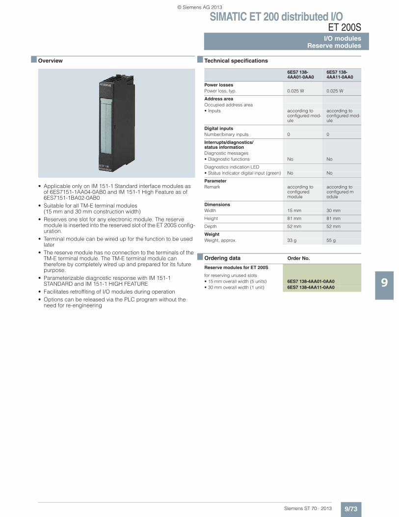
SIMATIC ET 200 distributed I/OET 200S
I/O modulesReserve modules
9/73Siemens ST 70 · 2013
9
■ Overview
• Applicable only on IM 151-1 Standard interface modules asof 6ES7151-1AA04-0AB0 and IM 151-1 High Feature as of 6ES7151-1BA02-0AB0
• Suitable for all TM-E terminal modules(15 mm and 30 mm construction width)
• Reserves one slot for any electronic module. The reserve module is inserted into the reserved slot of the ET 200S config-uration.
• Terminal module can be wired up for the function to be used later
• The reserve module has no connection to the terminals of the TM-E terminal module. The TM-E terminal module can therefore by completely wired up and prepared for its future purpose.
• Parameterizable diagnostic response with IM 151-1 STANDARD and IM 151-1 HIGH FEATURE
• Facilitates retroffiting of I/O modules during operation• Options can be released via the PLC program without the
need for re-engineering
■ Technical specifications
■ Ordering data Order No.
6ES7 138-4AA01-0AA0
6ES7 138-4AA11-0AA0
Power lossesPower loss, typ. 0.025 W 0.025 W
Address areaOccupied address area• Inputs according to
configured mod-ule
according to configured mod-ule
Digital inputsNumber/binary inputs 0 0
Interrupts/diagnostics/status informationDiagnostic messages• Diagnostic functions No No
Diagnostics indication LED• Status indicator digital input (green) No No
ParameterRemark according to
configured module
according to configured module
DimensionsWidth 15 mm 30 mm
Height 81 mm 81 mm
Depth 52 mm 52 mm
WeightWeight, approx. 33 g 55 g
Reserve modules for ET 200S
for reserving unused slots• 15 mm overall width (5 units) 6ES7 138-4AA01-0AA0• 30 mm overall width (1 unit) 6ES7 138-4AA11-0AA0
© Siemens AG 2013
SIMATIC ET 200 distributed I/OET 200SI/O modulesPotential isolation module
9/74 Siemens ST 70 · 2013
9
■ Overview
• Potential isolation module with 4 outputs• Output current 5 A per output / 10 A per module• Nominal load voltage: According to the load voltage on the
power module of this load voltage group• Is suitable for all terminal modules TM-E
(construction width 15 mm)
■ Technical specifications
■ Ordering data Order No.
Potential isolation module 6ES7138-4FD00-0AA0
Module-specific specifications
Supported synchronous operation no
Number of outputs 4
Cable length • Unshielded max. 600 m • Shielded max. 1000 m
Parameter length 1 byte
Voltages, Currents, Potentials
Nominal load voltage L+(from power module)
24 … 48 V DC; 24 AC … 230 V
• Polarity reversal protection no
Total current of the outputs(per module)
max. 10 A
Potential isolation • Between the channels no• Between the channels and
backplane bus Yes
Permissible potential difference • Between the supply voltage and the
backplane bus 75 V DC, 240 V AC
Isolation tested • Between the supply voltage and the
backplane bus 500 V DC, 1500 V AC
Diagnostic alarm no
Data for selecting an actuator
Short-circuit protection for the output No, possible via PM-E or external
Dimensions and weight
Dimensions W × H × D (mm, the total dimensions depend on the selected terminal module)
15 x 81 x 52
Weight Approx. 33 g
Potential isolation module for ET 200S
6ES7138-4FD00-0AA0
for preparing the load voltage on additional terminals, 15 mm construction width, 1 piece
Accessories for labeling
Label sheets DIN A4 (10 pieces)
Each sheet contains 60 labeling strips for peripheral modules and 20 labeling strips for interface modules• petrol 6ES7 193-4BH00-0AA0• red 6ES7 193-4BD00-0AA0• yellow 6ES7 193-4BB00-0AA0• light beige 6ES7 193-4BA00-0AA0
© Siemens AG 2013
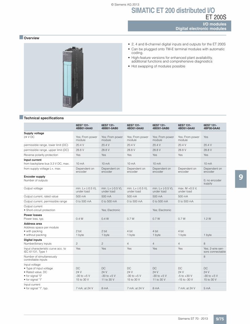
SIMATIC ET 200 distributed I/OET 200S
I/O modulesDigital electronic modules
9/75Siemens ST 70 · 2013
9
■ Overview
• 2, 4 and 8-channel digital inputs and outputs for the ET 200S• Can be plugged onto TM-E terminal modules with automatic
coding.• High-feature versions for enhanced plant availability,
additional functions and comprehensive diagnostics• Hot swapping of modules possible
■ Technical specifications
6ES7 131-4BB01-0AA0
6ES7 131-4BB01-0AB0
6ES7 131-4BD01-0AA0
6ES7 131-4BD01-0AB0
6ES7 131-4BD51-0AA0
6ES7 131-4BF00-0AA0
Supply voltage24 V DC Yes; From power
moduleYes; From power module
Yes; From power module
Yes; From power module
Yes; From power module
Yes
permissible range, lower limit (DC) 20.4 V 20.4 V 20.4 V 20.4 V 20.4 V 20.4 V
permissible range, upper limit (DC) 28.8 V 28.8 V 28.8 V 28.8 V 28.8 V 28.8 V
Reverse polarity protection Yes Yes Yes Yes Yes Yes
Input currentfrom backplane bus 3.3 V DC, max. 10 mA 10 mA 10 mA 10 mA 10 mA
from supply voltage L+, max. Dependent on encoder
Dependent on encoder
Dependent on encoder
Dependent on encoder
Dependent on encoder
Dependent on encoder
Encoder supplyNumber of outputs 0; no encoder
supply
Output voltage min. L+ (-0.5 V), under load
min. L+ (-0.5 V), under load
min. L+ (-0.5 V), under load
min. L+ (-0.5 V), under load
max. M +0.5 V, under load
Output current, rated value 500 mA 500 mA 500 mA 500 mA 500 mA
Output current, permissible range 0 to 500 mA 0 to 500 mA 0 to 500 mA 0 to 500 mA 0 to 500 mA
Output current• Short-circuit protection Yes; Electronic Yes; Electronic
Power lossesPower loss, typ. 0.4 W 0.4 W 0.7 W 0.7 W 0.7 W 1.2 W
Address areaAddress space per module• with packing 2 bit 2 bit 4 bit 4 bit 4 bit• without packing 1 byte 1 byte 1 byte 1 byte 1 byte 1 byte
Digital inputsNumber/binary inputs 2 2 4 4 4 8
Input characteristic curve acc. to IEC 61131, Type 1
Yes Yes Yes Yes Yes Yes; 2-wire sen-sors connectable
Number of simultaneously controllable inputs
8
Input voltage• Type of input voltage DC DC DC DC DC DC• Rated value, DC 24 V 24 V 24 V 24 V 24 V 24 V• for signal "0" -30 to +5 V -30 to +5 V -30 to +5 V -30 to +5 V -5 to +30 V -30 to +5 V• for signal "1" 15 to 30 V 11 to 30 V 15 to 30 V 11 to 30 V -15 to -30 V 15 to 30 V
Input current• for signal "1", typ. 7 mA; at 24 V 8 mA 7 mA; at 24 V 8 mA 7 mA; at 24 V 5 mA
© Siemens AG 2013
SIMATIC ET 200 distributed I/OET 200SI/O modulesDigital electronic modules
9/76 Siemens ST 70 · 2013
■ Technical specifications (continued)
9
Input delay (for rated value of input voltage)• for standard inputs
- Parameterizable No Yes; 0.1 / 0.5 / 3 / 15 ms
No Yes; 0.1 / 0.5 / 3 / 15 ms
No No
- at "0" to "1", min. 2 ms;typically 3 ms
0.05 / 0.4 / 2.7 / 14.85
2 ms; typically 3 ms
0.05 / 0.4 / 2.7 / 14.85
2 ms; typically 3 ms
2 ms
- at "0" to "1", max. 4.5 ms 0,15 / 0,6 / 3,3 / 15,15
4.5 ms 0,15 / 0,6 / 3,3 / 15,15
4.5 ms 4.5 ms
- at "1" to "0", min. 2 ms;typically 3 ms
0.05 / 0.4 / 2.7 / 14.85
2 ms; typically 3 ms
0.05 / 0.4 / 2.7 / 14.85
2 ms;typically 3 ms
2 ms
- at "1" to "0", max. 4.5 ms 0,15 / 0,6 / 3,3 / 15,15
4.5 ms 0,15 / 0,6 / 3,3 / 15,15
4.5 ms 4.5 ms
Cable length• Cable length, shielded, max. 1 000 m 1 000 m 1 000 m 1 000 m 1 000 m 1 000 m• Cable length unshielded, max. 600 m 600 m 600 m 600 m 600 m 600 m
EncoderConnectable encoders• 2-wire sensor Yes Yes Yes Yes Yes Yes
- Permissible quiescent current(2-wire sensor), max.
1.5 mA 1.5 mA 1.5 mA 1.5 mA 1.5 mA 1.5 mA
Isochronous modeIsochronous operation (application synchronized up to terminal)
Yes; TWE = 3000 us
Interrupts/diagnostics/status informationDiagnostic messages• Diagnostic functions No Yes No Yes No No• Short circuit Yes; Short-circuit
of outputs to ground; module by module
Yes; Short-circuit of outputs to ground; module by module
Diagnostics indication LED• Group error SF (red) No Yes No Yes No• Status indicator digital input (green) Yes; per channel Yes; per channel Yes; per channel Yes; per channel Yes; per channel Yes
ParameterRemark 3-byte parameter
(not accessible for the user)
Diagnosis: short circuit Disable / enable Disable / enable
Galvanic isolationGalvanic isolation digital inputs• between the channels No No No No No No• between the channels and the
backplane busYes Yes Yes Yes Yes Yes
Permissible potential differencebetween different circuits 75 VDC / 60 VAC 75 VDC / 60 VAC 75 VDC / 60 VAC 75 VDC / 60 VAC 75 VDC / 60 VAC 75 VDC / 60 VAC
IsolationIsolation checked with 500 V DC 500 V DC 500 V DC 500 V DC 500 V DC 500 V DC
DimensionsWidth 15 mm 15 mm 15 mm 15 mm 15 mm 15 mm
Height 81 mm 81 mm 81 mm 81 mm 81 mm 81 mm
Depth 52 mm 52 mm 52 mm 52 mm 52 mm 52 mm
WeightWeight, approx. 35 g 35 g 35 g 35 g 35 g 35 g
6ES7 131-4BB01-0AA0
6ES7 131-4BB01-0AB0
6ES7 131-4BD01-0AA0
6ES7 131-4BD01-0AB0
6ES7 131-4BD51-0AA0
6ES7 131-4BF00-0AA0
© Siemens AG 2013
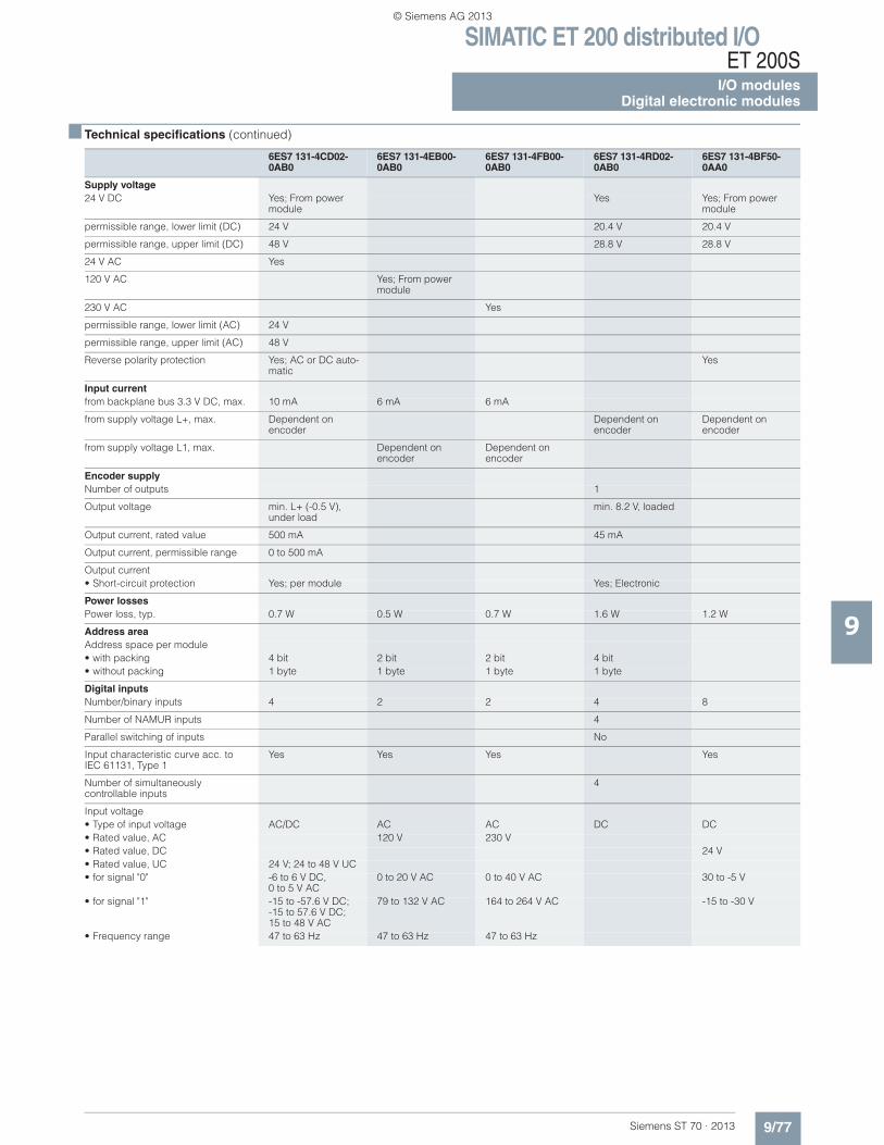
SIMATIC ET 200 distributed I/OET 200S
I/O modulesDigital electronic modules
9/77Siemens ST 70 · 2013
■ Technical specifications (continued)
9
6ES7 131-4CD02-0AB0
6ES7 131-4EB00-0AB0
6ES7 131-4FB00-0AB0
6ES7 131-4RD02-0AB0
6ES7 131-4BF50-0AA0
Supply voltage24 V DC Yes; From power
moduleYes Yes; From power
module
permissible range, lower limit (DC) 24 V 20.4 V 20.4 V
permissible range, upper limit (DC) 48 V 28.8 V 28.8 V
24 V AC Yes
120 V AC Yes; From power module
230 V AC Yes
permissible range, lower limit (AC) 24 V
permissible range, upper limit (AC) 48 V
Reverse polarity protection Yes; AC or DC auto-matic
Yes
Input currentfrom backplane bus 3.3 V DC, max. 10 mA 6 mA 6 mA
from supply voltage L+, max. Dependent on encoder
Dependent on encoder
Dependent on encoder
from supply voltage L1, max. Dependent on encoder
Dependent on encoder
Encoder supplyNumber of outputs 1
Output voltage min. L+ (-0.5 V), under load
min. 8.2 V, loaded
Output current, rated value 500 mA 45 mA
Output current, permissible range 0 to 500 mA
Output current• Short-circuit protection Yes; per module Yes; Electronic
Power lossesPower loss, typ. 0.7 W 0.5 W 0.7 W 1.6 W 1.2 W
Address areaAddress space per module• with packing 4 bit 2 bit 2 bit 4 bit• without packing 1 byte 1 byte 1 byte 1 byte
Digital inputsNumber/binary inputs 4 2 2 4 8
Number of NAMUR inputs 4
Parallel switching of inputs No
Input characteristic curve acc. to IEC 61131, Type 1
Yes Yes Yes Yes
Number of simultaneously controllable inputs
4
Input voltage• Type of input voltage AC/DC AC AC DC DC• Rated value, AC 120 V 230 V• Rated value, DC 24 V• Rated value, UC 24 V; 24 to 48 V UC• for signal "0" -6 to 6 V DC,
0 to 5 V AC0 to 20 V AC 0 to 40 V AC 30 to -5 V
• for signal "1" -15 to -57.6 V DC; -15 to 57.6 V DC; 15 to 48 V AC
79 to 132 V AC 164 to 264 V AC -15 to -30 V
• Frequency range 47 to 63 Hz 47 to 63 Hz 47 to 63 Hz
© Siemens AG 2013
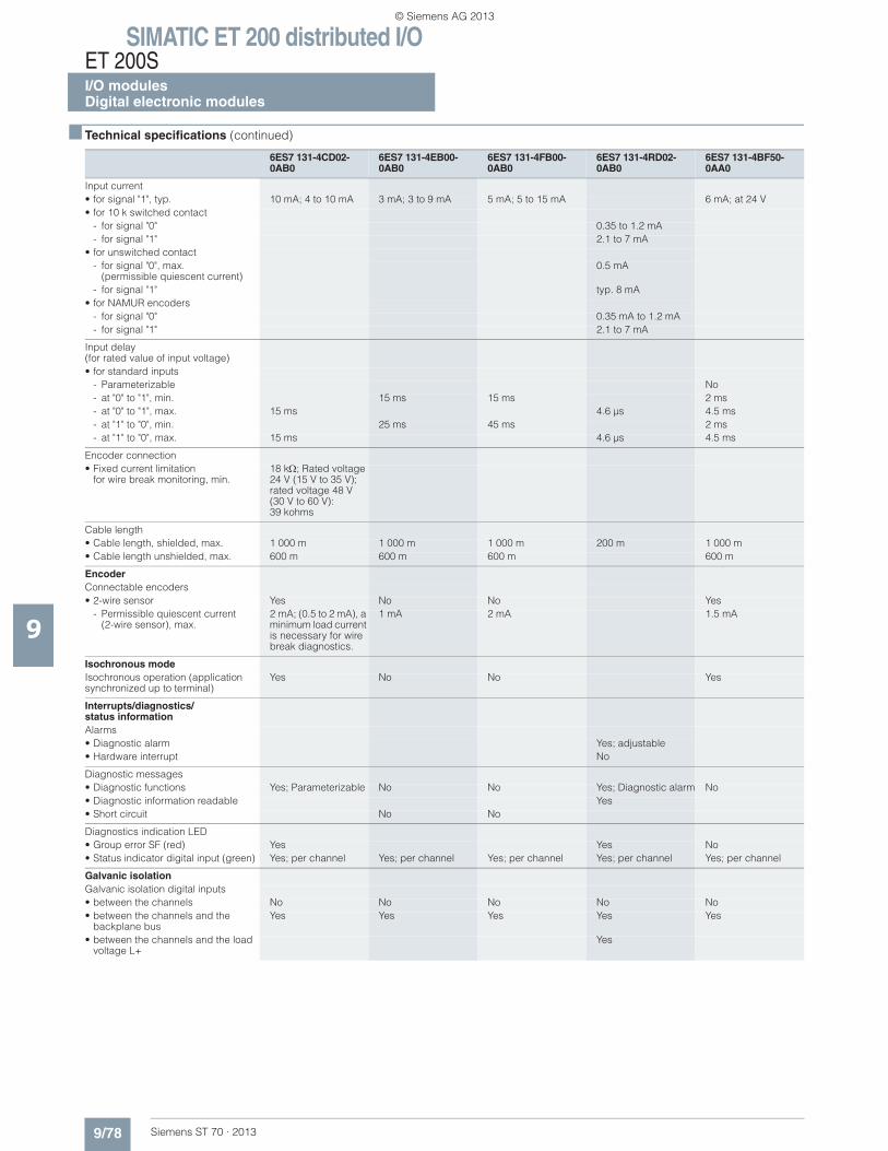
SIMATIC ET 200 distributed I/OET 200SI/O modulesDigital electronic modules
9/78 Siemens ST 70 · 2013
■ Technical specifications (continued)
9
Input current• for signal "1", typ. 10 mA; 4 to 10 mA 3 mA; 3 to 9 mA 5 mA; 5 to 15 mA 6 mA; at 24 V• for 10 k switched contact
- for signal "0" 0.35 to 1.2 mA- for signal "1" 2.1 to 7 mA
• for unswitched contact- for signal "0", max.
(permissible quiescent current)0.5 mA
- for signal "1" typ. 8 mA• for NAMUR encoders
- for signal "0" 0.35 mA to 1.2 mA- for signal "1" 2.1 to 7 mA
Input delay(for rated value of input voltage)• for standard inputs
- Parameterizable No- at "0" to "1", min. 15 ms 15 ms 2 ms- at "0" to "1", max. 15 ms 4.6 μs 4.5 ms- at "1" to "0", min. 25 ms 45 ms 2 ms- at "1" to "0", max. 15 ms 4.6 μs 4.5 ms
Encoder connection• Fixed current limitation
for wire break monitoring, min.18 k ; Rated voltage 24 V (15 V to 35 V); rated voltage 48 V (30 V to 60 V): 39 kohms
Cable length• Cable length, shielded, max. 1 000 m 1 000 m 1 000 m 200 m 1 000 m• Cable length unshielded, max. 600 m 600 m 600 m 600 m
EncoderConnectable encoders• 2-wire sensor Yes No No Yes
- Permissible quiescent current (2-wire sensor), max.
2 mA; (0.5 to 2 mA), a minimum load current is necessary for wire break diagnostics.
1 mA 2 mA 1.5 mA
Isochronous modeIsochronous operation (application synchronized up to terminal)
Yes No No Yes
Interrupts/diagnostics/status informationAlarms• Diagnostic alarm Yes; adjustable• Hardware interrupt No
Diagnostic messages• Diagnostic functions Yes; Parameterizable No No Yes; Diagnostic alarm No• Diagnostic information readable Yes• Short circuit No No
Diagnostics indication LED• Group error SF (red) Yes Yes No• Status indicator digital input (green) Yes; per channel Yes; per channel Yes; per channel Yes; per channel Yes; per channel
Galvanic isolationGalvanic isolation digital inputs• between the channels No No No No No• between the channels and the
backplane busYes Yes Yes Yes Yes
• between the channels and the load voltage L+
Yes
6ES7 131-4CD02-0AB0
6ES7 131-4EB00-0AB0
6ES7 131-4FB00-0AB0
6ES7 131-4RD02-0AB0
6ES7 131-4BF50-0AA0
© Siemens AG 2013
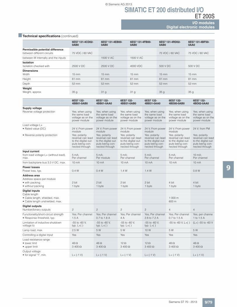
SIMATIC ET 200 distributed I/OET 200S
I/O modulesDigital electronic modules
9/79Siemens ST 70 · 2013
■ Technical specifications (continued)
9
Permissible potential differencebetween different circuits 75 VDC / 60 VAC 75 VDC / 60 VAC 75 VDC / 60 VAC
between M internally and the inputs 1500 V AC 1500 V AC
IsolationIsolation checked with 2500 V DC 2500 V DC 4000 VDC 500 V DC 500 V DC
DimensionsWidth 15 mm 15 mm 15 mm 15 mm 15 mm
Height 81 mm 81 mm 81 mm 81 mm 81 mm
Depth 52 mm 52 mm 52 mm 52 mm 52 mm
WeightWeight, approx. 35 g 31 g 31 g 35 g 35 g
6ES7 132-4BB01-0AB0
6ES7 132-4BB01-0AA0
6ES7 132-4BB31-0AB0
6ES7 132-4BB31-0AA0
6ES7 132-4BD00-0AB0
6ES7 132-4BD02-0AA0
Supply voltageReverse voltage protection Yes; when using
the same load voltage as on the power module
Yes; when using the same load voltage as on the power module
Yes; when using the same load voltage as on the power module
Yes; when using the same load voltage as on the power module
Yes; when using the same load voltage as on the power module
Yes; when using the same load voltage as on the power module
Load voltage L+• Rated value (DC) 24 V; From power
module24 V; From power module
24 V; From power module
24 V; From power module
24 V; From power module
24 V; from PM
• Reverse polarity protection Yes; polarity reversal can lead to the digital out-puts being con-nected through
Yes; polarity reversal can lead to the digital out-puts being con-nected through
Yes; polarity reversal can lead to the digital out-puts being con-nected through
Yes; polarity reversal can lead to the digital out-puts being con-nected through
Yes; polarity reversal can lead to the digital out-puts being con-nected through
Yes; polarity reversal can lead to the digital out-puts being con-nected through
Input currentfrom load voltage L+ (without load), max.
5 mA;Per channel
5 mA; Per module
5 mA; Per channel
5 mA; Per channel
5 mA; Per channel
10 mA; Per channel
from backplane bus 3.3 V DC, max. 10 mA 10 mA 10 mA 10 mA 10 mA 10 mA
Power lossesPower loss, typ. 0.4 W 0.4 W 1.4 W 1.4 W 0.8 W
Address areaAddress space per module• with packing 2 bit 2 bit 2 bit 2 bit 4 bit 4 bit• without packing 1 byte 1 byte 1 byte 1 byte 1 byte 1 byte
Digital inputsCable length• Cable length, shielded, max. 1 000 m• Cable length unshielded, max. 600 m
Digital outputsNumber/binary outputs 2 2 2 2 4 4
Functionality/short-circuit strength Yes; Per channel Yes; Per channel Yes; Per channel Yes; Per channel Yes; Per channel Yes; per channe• Response threshold, typ. 1.5 A 0.7 to 1.8 A 4 A 2.8 to 7.2 A 0.7 to 1.5 A 1 to 1.5 A
Limitation of inductive shutdown voltage to
-55 to -60 V,typ. L+( )
-55 to -60 V,typ. L+( )
-55 to -60 V,typ. L+( )
-55 to -60 V,typ. L+( )
-55 to -60 V, L+( ) (L+) -55 to -60 V
Lamp load, max. 2.5 W 5 W 5 W 10 W 5 W 5 W
Controlling a digital input Yes Yes Yes Yes Yes Yes
Load resistance range• lower limit 48 48 12 12 48 48• upper limit 3 400 3 400 3 400 3 400 3 400 3 400
Output voltage• for signal "1", min. L+ (-1 V) L+ (-1 V) L+ (-1 V) L+ (-1 V) L+ (-1 V) L+ (-1 V)
6ES7 131-4CD02-0AB0
6ES7 131-4EB00-0AB0
6ES7 131-4FB00-0AB0
6ES7 131-4RD02-0AB0
6ES7 131-4BF50-0AA0
© Siemens AG 2013
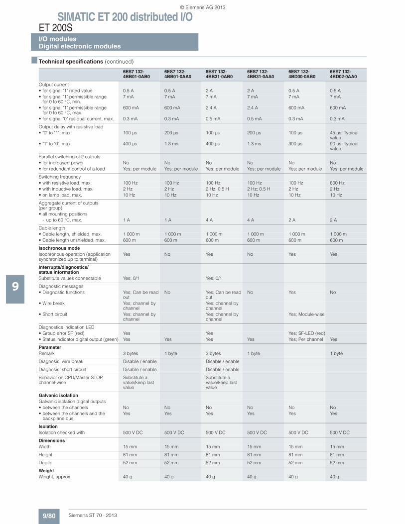
SIMATIC ET 200 distributed I/OET 200SI/O modulesDigital electronic modules
9/80 Siemens ST 70 · 2013
■ Technical specifications (continued)
9
Output current• for signal "1" rated value 0.5 A 0.5 A 2 A 2 A 0.5 A 0.5 A• for signal "1" permissible range
for 0 to 60 °C, min.7 mA 7 mA 7 mA 7 mA 7 mA 7 mA
• for signal "1" permissible rangefor 0 to 60 °C, max.
600 mA 600 mA 2.4 A 2.4 A 600 mA 600 mA
• for signal "0" residual current, max. 0.3 mA 0.3 mA 0.5 mA 0.5 mA 0.3 mA 0.3 mA
Output delay with resistive load• "0" to "1", max. 100 μs 200 μs 100 μs 200 μs 100 μs 45 μs; Typical
value• "1" to "0", max. 400 μs 1.3 ms 400 μs 1.3 ms 300 μs 90 μs; Typical
value
Parallel switching of 2 outputs• for increased power No No No No No No• for redundant control of a load Yes; per module Yes; per module Yes; per module Yes; per module Yes; per module Yes; per module
Switching frequency• with resistive load, max. 100 Hz 100 Hz 100 Hz 100 Hz 100 Hz 800 Hz• with inductive load, max. 2 Hz 2 Hz 2 Hz; 0.5 H 2 Hz; 0.5 H 2 Hz 2 Hz• on lamp load, max. 10 Hz 10 Hz 10 Hz 10 Hz 10 Hz 10 Hz
Aggregate current of outputs(per group)• all mounting positions
- up to 60 °C, max. 1 A 1 A 4 A 4 A 2 A 2 A
Cable length• Cable length, shielded, max. 1 000 m 1 000 m 1 000 m 1 000 m 1 000 m 1 000 m• Cable length unshielded, max. 600 m 600 m 600 m 600 m 600 m 600 m
Isochronous modeIsochronous operation (application synchronized up to terminal)
Yes No Yes No Yes Yes
Interrupts/diagnostics/status informationSubstitute values connectable Yes; 0/1 Yes; 0/1
Diagnostic messages• Diagnostic functions Yes; Can be read
outNo Yes; Can be read
outNo Yes No
• Wire break Yes; channel by channel
Yes; channel by channel
• Short circuit Yes; channel by channel
Yes; channel by channel
Yes; Module-wise
Diagnostics indication LED• Group error SF (red) Yes Yes Yes; SF-LED (red)• Status indicator digital output (green) Yes Yes Yes Yes Yes; Per channel Yes
ParameterRemark 3 bytes 1 byte 3 bytes 1 byte 1 byte
Diagnosis: wire break Disable / enable Disable / enable
Diagnosis: short circuit Disable / enable Disable / enable
Behavior on CPU/Master STOP, channel-wise
Substitute a value/keep last value
Substitute a value/keep last value
Galvanic isolationGalvanic isolation digital outputs• between the channels No No No No No No• between the channels and the
backplane busYes Yes Yes Yes Yes Yes
IsolationIsolation checked with 500 V DC 500 V DC 500 V DC 500 V DC 500 V DC 500 V DC
DimensionsWidth 15 mm 15 mm 15 mm 15 mm 15 mm 15 mm
Height 81 mm 81 mm 81 mm 81 mm 81 mm 81 mm
Depth 52 mm 52 mm 52 mm 52 mm 52 mm 52 mm
WeightWeight, approx. 40 g 40 g 40 g 40 g 40 g 40 g
6ES7 132-4BB01-0AB0
6ES7 132-4BB01-0AA0
6ES7 132-4BB31-0AB0
6ES7 132-4BB31-0AA0
6ES7 132-4BD00-0AB0
6ES7 132-4BD02-0AA0
© Siemens AG 2013
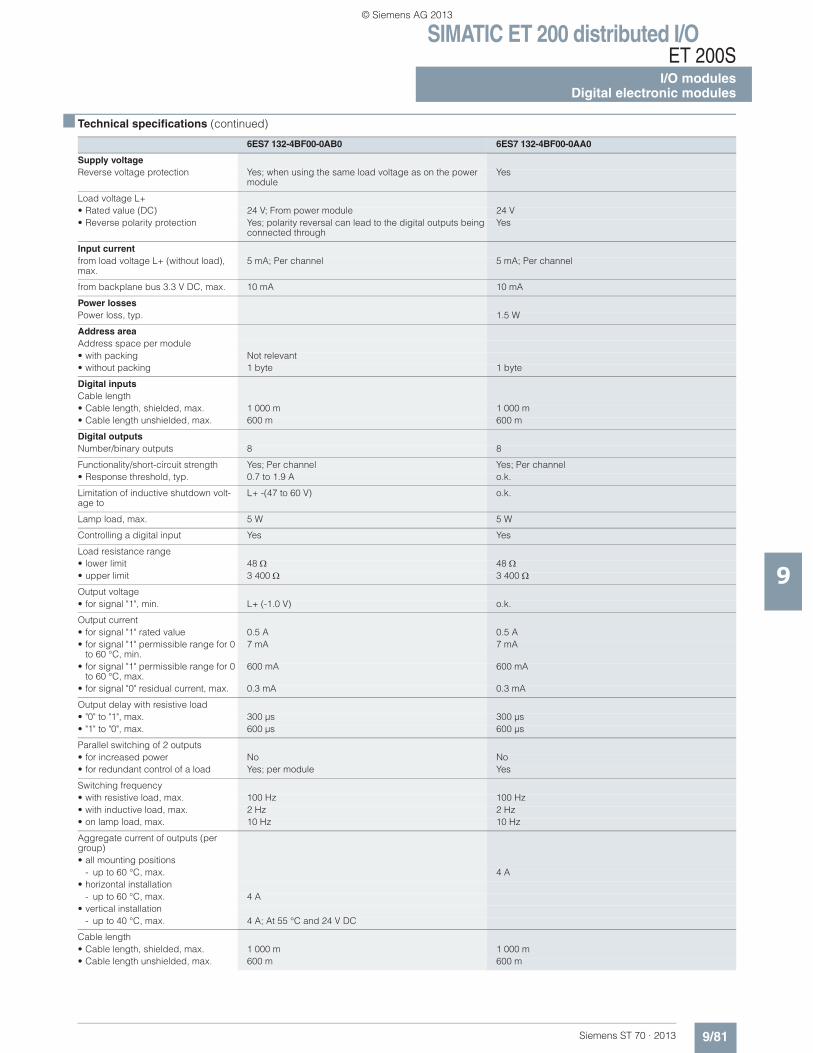
SIMATIC ET 200 distributed I/OET 200S
I/O modulesDigital electronic modules
9/81Siemens ST 70 · 2013
■ Technical specifications (continued)
9
6ES7 132-4BF00-0AB0 6ES7 132-4BF00-0AA0
Supply voltageReverse voltage protection Yes; when using the same load voltage as on the power
moduleYes
Load voltage L+• Rated value (DC) 24 V; From power module 24 V• Reverse polarity protection Yes; polarity reversal can lead to the digital outputs being
connected throughYes
Input currentfrom load voltage L+ (without load), max.
5 mA; Per channel 5 mA; Per channel
from backplane bus 3.3 V DC, max. 10 mA 10 mA
Power lossesPower loss, typ. 1.5 W
Address areaAddress space per module• with packing Not relevant• without packing 1 byte 1 byte
Digital inputsCable length• Cable length, shielded, max. 1 000 m 1 000 m• Cable length unshielded, max. 600 m 600 m
Digital outputsNumber/binary outputs 8 8
Functionality/short-circuit strength Yes; Per channel Yes; Per channel• Response threshold, typ. 0.7 to 1.9 A o.k.
Limitation of inductive shutdown volt-age to
L+ -(47 to 60 V) o.k.
Lamp load, max. 5 W 5 W
Controlling a digital input Yes Yes
Load resistance range• lower limit 48 48• upper limit 3 400 3 400
Output voltage• for signal "1", min. L+ (-1.0 V) o.k.
Output current• for signal "1" rated value 0.5 A 0.5 A• for signal "1" permissible range for 0
to 60 °C, min.7 mA 7 mA
• for signal "1" permissible range for 0 to 60 °C, max.
600 mA 600 mA
• for signal "0" residual current, max. 0.3 mA 0.3 mA
Output delay with resistive load• "0" to "1", max. 300 μs 300 μs• "1" to "0", max. 600 μs 600 μs
Parallel switching of 2 outputs• for increased power No No• for redundant control of a load Yes; per module Yes
Switching frequency• with resistive load, max. 100 Hz 100 Hz• with inductive load, max. 2 Hz 2 Hz• on lamp load, max. 10 Hz 10 Hz
Aggregate current of outputs (per group)• all mounting positions
- up to 60 °C, max. 4 A• horizontal installation
- up to 60 °C, max. 4 A• vertical installation
- up to 40 °C, max. 4 A; At 55 °C and 24 V DC
Cable length• Cable length, shielded, max. 1 000 m 1 000 m• Cable length unshielded, max. 600 m 600 m
© Siemens AG 2013
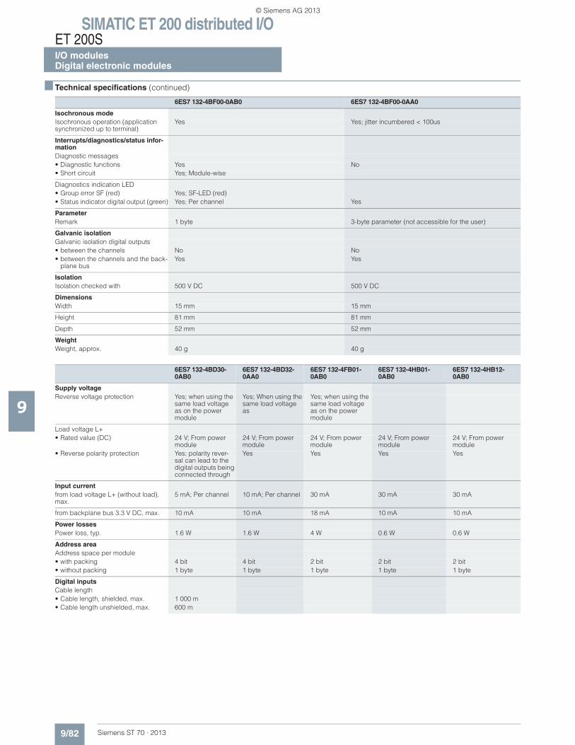
SIMATIC ET 200 distributed I/OET 200SI/O modulesDigital electronic modules
9/82 Siemens ST 70 · 2013
■ Technical specifications (continued)
9
Isochronous modeIsochronous operation (application synchronized up to terminal)
Yes Yes; jitter incumbered < 100us
Interrupts/diagnostics/status infor-mationDiagnostic messages• Diagnostic functions Yes No• Short circuit Yes; Module-wise
Diagnostics indication LED• Group error SF (red) Yes; SF-LED (red)• Status indicator digital output (green) Yes; Per channel Yes
ParameterRemark 1 byte 3-byte parameter (not accessible for the user)
Galvanic isolationGalvanic isolation digital outputs• between the channels No No• between the channels and the back-
plane busYes Yes
IsolationIsolation checked with 500 V DC 500 V DC
DimensionsWidth 15 mm 15 mm
Height 81 mm 81 mm
Depth 52 mm 52 mm
WeightWeight, approx. 40 g 40 g
6ES7 132-4BD30-0AB0
6ES7 132-4BD32-0AA0
6ES7 132-4FB01-0AB0
6ES7 132-4HB01-0AB0
6ES7 132-4HB12-0AB0
Supply voltageReverse voltage protection Yes; when using the
same load voltage as on the power module
Yes; When using the same load voltage as
Yes; when using the same load voltage as on the power module
Load voltage L+• Rated value (DC) 24 V; From power
module24 V; From power module
24 V; From power module
24 V; From power module
24 V; From power module
• Reverse polarity protection Yes; polarity rever-sal can lead to the digital outputs being connected through
Yes Yes Yes Yes
Input currentfrom load voltage L+ (without load), max.
5 mA; Per channel 10 mA; Per channel 30 mA 30 mA 30 mA
from backplane bus 3.3 V DC, max. 10 mA 10 mA 18 mA 10 mA 10 mA
Power lossesPower loss, typ. 1.6 W 1.6 W 4 W 0.6 W 0.6 W
Address areaAddress space per module• with packing 4 bit 4 bit 2 bit 2 bit 2 bit• without packing 1 byte 1 byte 1 byte 1 byte 1 byte
Digital inputsCable length• Cable length, shielded, max. 1 000 m• Cable length unshielded, max. 600 m
6ES7 132-4BF00-0AB0 6ES7 132-4BF00-0AA0
© Siemens AG 2013
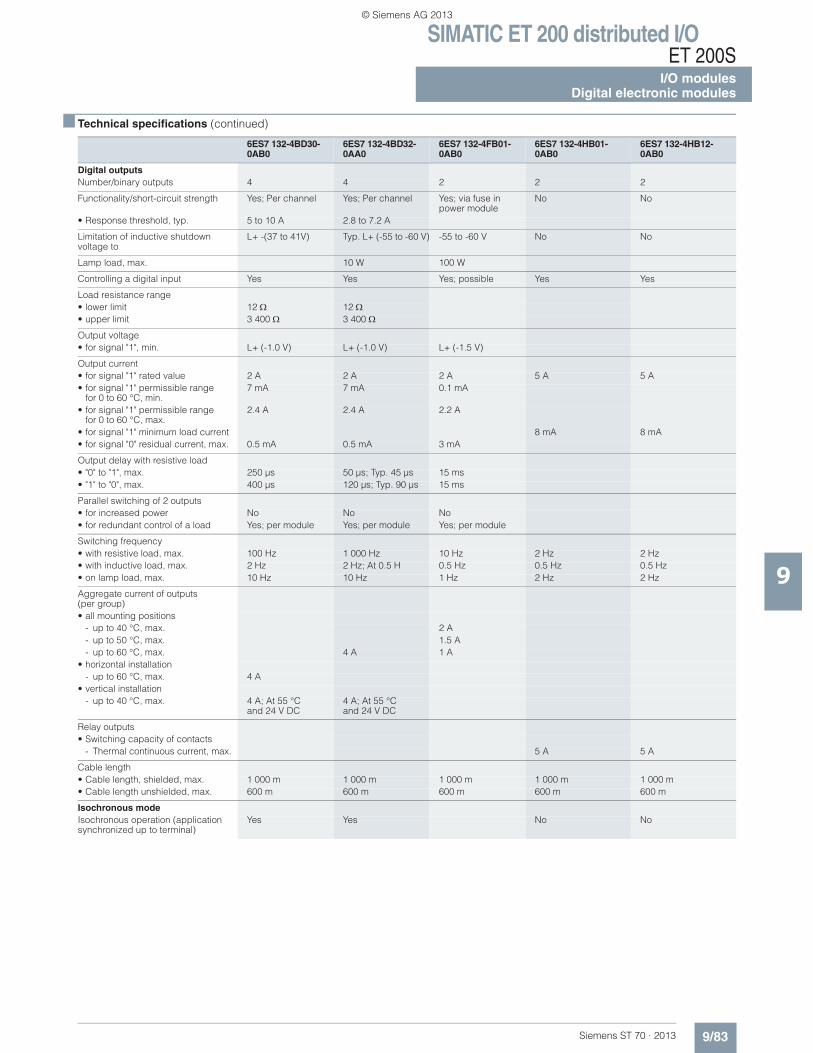
SIMATIC ET 200 distributed I/OET 200S
I/O modulesDigital electronic modules
9/83Siemens ST 70 · 2013
■ Technical specifications (continued)
9
Digital outputsNumber/binary outputs 4 4 2 2 2
Functionality/short-circuit strength Yes; Per channel Yes; Per channel Yes; via fuse in power module
No No
• Response threshold, typ. 5 to 10 A 2.8 to 7.2 A
Limitation of inductive shutdown voltage to
L+ -(37 to 41V) Typ. L+ (-55 to -60 V) -55 to -60 V No No
Lamp load, max. 10 W 100 W
Controlling a digital input Yes Yes Yes; possible Yes Yes
Load resistance range• lower limit 12 12• upper limit 3 400 3 400
Output voltage• for signal "1", min. L+ (-1.0 V) L+ (-1.0 V) L+ (-1.5 V)
Output current• for signal "1" rated value 2 A 2 A 2 A 5 A 5 A• for signal "1" permissible range
for 0 to 60 °C, min.7 mA 7 mA 0.1 mA
• for signal "1" permissible rangefor 0 to 60 °C, max.
2.4 A 2.4 A 2.2 A
• for signal "1" minimum load current 8 mA 8 mA• for signal "0" residual current, max. 0.5 mA 0.5 mA 3 mA
Output delay with resistive load• "0" to "1", max. 250 μs 50 μs; Typ. 45 μs 15 ms• "1" to "0", max. 400 μs 120 μs; Typ. 90 μs 15 ms
Parallel switching of 2 outputs• for increased power No No No• for redundant control of a load Yes; per module Yes; per module Yes; per module
Switching frequency• with resistive load, max. 100 Hz 1 000 Hz 10 Hz 2 Hz 2 Hz• with inductive load, max. 2 Hz 2 Hz; At 0.5 H 0.5 Hz 0.5 Hz 0.5 Hz• on lamp load, max. 10 Hz 10 Hz 1 Hz 2 Hz 2 Hz
Aggregate current of outputs(per group)• all mounting positions
- up to 40 °C, max. 2 A- up to 50 °C, max. 1.5 A- up to 60 °C, max. 4 A 1 A
• horizontal installation- up to 60 °C, max. 4 A
• vertical installation- up to 40 °C, max. 4 A; At 55 °C
and 24 V DC4 A; At 55 °C and 24 V DC
Relay outputs• Switching capacity of contacts
- Thermal continuous current, max. 5 A 5 A
Cable length• Cable length, shielded, max. 1 000 m 1 000 m 1 000 m 1 000 m 1 000 m• Cable length unshielded, max. 600 m 600 m 600 m 600 m 600 m
Isochronous modeIsochronous operation (application synchronized up to terminal)
Yes Yes No No
6ES7 132-4BD30-0AB0
6ES7 132-4BD32-0AA0
6ES7 132-4FB01-0AB0
6ES7 132-4HB01-0AB0
6ES7 132-4HB12-0AB0
© Siemens AG 2013
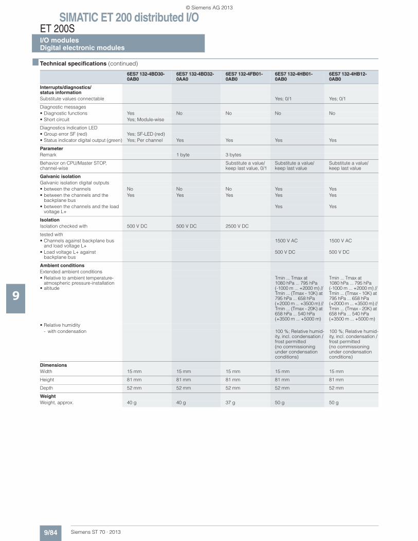
SIMATIC ET 200 distributed I/OET 200SI/O modulesDigital electronic modules
9/84 Siemens ST 70 · 2013
■ Technical specifications (continued)
9
Interrupts/diagnostics/status informationSubstitute values connectable Yes; 0/1 Yes; 0/1
Diagnostic messages• Diagnostic functions Yes No No No No• Short circuit Yes; Module-wise
Diagnostics indication LED• Group error SF (red) Yes; SF-LED (red)• Status indicator digital output (green) Yes; Per channel Yes Yes Yes Yes
ParameterRemark 1 byte 3 bytes
Behavior on CPU/Master STOP, channel-wise
Substitute a value/keep last value, 0/1
Substitute a value/keep last value
Substitute a value/keep last value
Galvanic isolationGalvanic isolation digital outputs• between the channels No No No Yes Yes• between the channels and the
backplane busYes Yes Yes Yes Yes
• between the channels and the load voltage L+
Yes Yes
IsolationIsolation checked with 500 V DC 500 V DC 2500 V DC
tested with• Channels against backplane bus
and load voltage L+1500 V AC 1500 V AC
• Load voltage L+ against backplane bus
500 V DC 500 V DC
Ambient conditionsExtended ambient conditions• Relative to ambient temperature-
atmospheric pressure-installation • altitude
Tmin ... Tmax at 1080 hPa ... 795 hPa(-1000 m ... +2000 m) // Tmin ... (Tmax - 10K) at 795 hPa ... 658 hPa (+2000 m ... +3500 m) // Tmin ... (Tmax - 20K) at 658 hPa ... 540 hPa (+3500 m ... +5000 m)
Tmin ... Tmax at1080 hPa ... 795 hPa (-1000 m ... +2000 m) // Tmin ... (Tmax - 10K) at 795 hPa ... 658 hPa (+2000 m ... +3500 m) // Tmin ... (Tmax - 20K) at 658 hPa ... 540 hPa (+3500 m ... +5000 m)
• Relative humidity- with condensation 100 %; Relative humid-
ity, incl. condensation / frost permitted (no commissioning under condensation conditions)
100 %; Relative humid-ity, incl. condensation / frost permitted (no commissioning under condensation conditions)
DimensionsWidth 15 mm 15 mm 15 mm 15 mm 15 mm
Height 81 mm 81 mm 81 mm 81 mm 81 mm
Depth 52 mm 52 mm 52 mm 52 mm 52 mm
WeightWeight, approx. 40 g 40 g 37 g 50 g 50 g
6ES7 132-4BD30-0AB0
6ES7 132-4BD32-0AA0
6ES7 132-4FB01-0AB0
6ES7 132-4HB01-0AB0
6ES7 132-4HB12-0AB0
© Siemens AG 2013
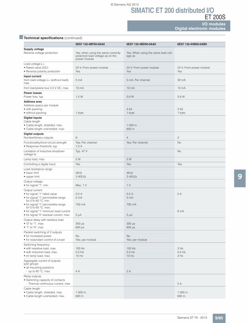
SIMATIC ET 200 distributed I/OET 200S
I/O modulesDigital electronic modules
9/85Siemens ST 70 · 2013
■ Technical specifications (continued)
9
6ES7 132-4BF50-0AA0 6ES7 132-4BD50-0AA0 6ES7 132-4HB50-0AB0
Supply voltageReverse voltage protection Yes; when using the same correctly
polarized load voltage as on the power module
Yes; When using the same load volt-age as
Load voltage L+• Rated value (DC) 24 V; From power module 24 V; From power module 24 V; From power module• Reverse polarity protection Yes Yes Yes
Input currentfrom load voltage L+ (without load), max.
5 mA 5 mA; Per channel 30 mA
from backplane bus 3.3 V DC, max. 10 mA 10 mA 10 mA
Power lossesPower loss, typ. 1.5 W 0.8 W 0.6 W
Address areaAddress space per module• with packing 4 bit 2 bit• without packing 1 byte 1 byte 1 byte
Digital inputsCable length• Cable length, shielded, max. 1 000 m• Cable length unshielded, max. 600 m
Digital outputsNumber/binary outputs 8 4 2
Functionality/short-circuit strength Yes; Per channel Yes; Per channel No• Response threshold, typ. 1.5 A
Limitation of inductive shutdownvoltage to
Typ. 47 V No
Lamp load, max. 5 W 5 W
Controlling a digital input Yes Yes Yes
Load resistance range• lower limit 48 48• upper limit 3 400 3 400
Output voltage• for signal "1", min. Max. 1 V 1 V
Output current• for signal "1" rated value 0.5 A 0.5 A 5 A• for signal "1" permissible range
for 0 to 60 °C, min.5 mA 5 mA
• for signal "1" permissible rangefor 0 to 60 °C, max.
700 mA 700 mA
• for signal "1" minimum load current 8 mA• for signal "0" residual current, max. 5 μA 5 μA
Output delay with resistive load• "0" to "1", max. 300 μs 300 μs• "1" to "0", max. 600 μs 600 μs
Parallel switching of 2 outputs• for increased power No No• for redundant control of a load Yes; per module Yes; per module
Switching frequency• with resistive load, max. 100 Hz 100 Hz 2 Hz• with inductive load, max. 0.5 Hz 0.5 Hz 0.5 Hz• on lamp load, max. 10 Hz 10 Hz 2 Hz
Aggregate current of outputs (per group)• all mounting positions
- up to 60 °C, max. 4 A 2 A
Relay outputs• Switching capacity of contacts
- Thermal continuous current, max. 5 A
Cable length• Cable length, shielded, max. 1 000 m 1 000 m• Cable length unshielded, max. 600 m 600 m
© Siemens AG 2013
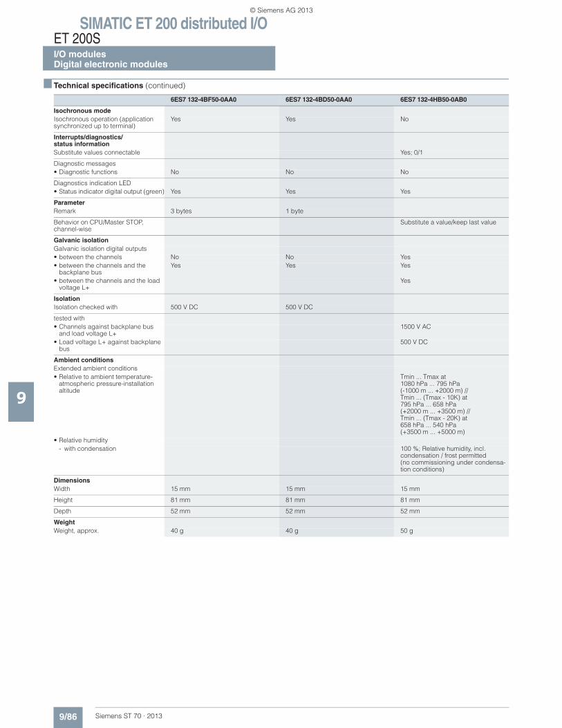
SIMATIC ET 200 distributed I/OET 200SI/O modulesDigital electronic modules
9/86 Siemens ST 70 · 2013
■ Technical specifications (continued)
9
Isochronous modeIsochronous operation (application synchronized up to terminal)
Yes Yes No
Interrupts/diagnostics/status informationSubstitute values connectable Yes; 0/1
Diagnostic messages• Diagnostic functions No No No
Diagnostics indication LED• Status indicator digital output (green) Yes Yes Yes
ParameterRemark 3 bytes 1 byte
Behavior on CPU/Master STOP, channel-wise
Substitute a value/keep last value
Galvanic isolationGalvanic isolation digital outputs• between the channels No No Yes• between the channels and the
backplane busYes Yes Yes
• between the channels and the load voltage L+
Yes
IsolationIsolation checked with 500 V DC 500 V DC
tested with• Channels against backplane bus
and load voltage L+1500 V AC
• Load voltage L+ against backplane bus
500 V DC
Ambient conditionsExtended ambient conditions• Relative to ambient temperature-
atmospheric pressure-installation altitude
Tmin ... Tmax at1080 hPa ... 795 hPa(-1000 m ... +2000 m) // Tmin ... (Tmax - 10K) at795 hPa ... 658 hPa(+2000 m ... +3500 m) //Tmin ... (Tmax - 20K) at658 hPa ... 540 hPa(+3500 m ... +5000 m)
• Relative humidity- with condensation 100 %; Relative humidity, incl.
condensation / frost permitted(no commissioning under condensa-tion conditions)
DimensionsWidth 15 mm 15 mm 15 mm
Height 81 mm 81 mm 81 mm
Depth 52 mm 52 mm 52 mm
WeightWeight, approx. 40 g 40 g 50 g
6ES7 132-4BF50-0AA0 6ES7 132-4BD50-0AA0 6ES7 132-4HB50-0AB0
© Siemens AG 2013
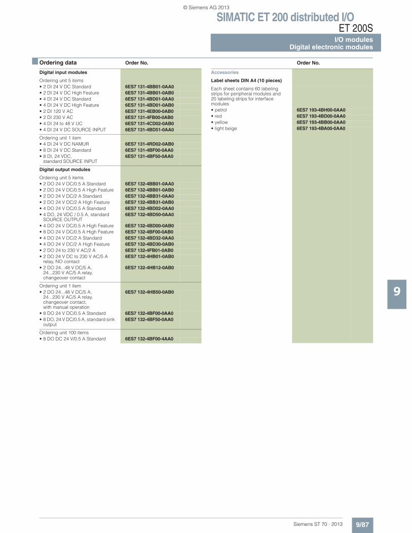
SIMATIC ET 200 distributed I/OET 200S
I/O modulesDigital electronic modules
9/87Siemens ST 70 · 2013
9
■ Ordering data Order No. Order No.
Digital input modules
Ordering unit 5 items• 2 DI 24 V DC Standard 6ES7 131-4BB01-0AA0• 2 DI 24 V DC High Feature 6ES7 131-4BB01-0AB0• 4 DI 24 V DC Standard 6ES7 131-4BD01-0AA0• 4 DI 24 V DC High Feature 6ES7 131-4BD01-0AB0• 2 DI 120 V AC 6ES7 131-4EB00-0AB0• 2 DI 230 V AC 6ES7 131-4FB00-0AB0• 4 DI 24 to 48 V UC 6ES7 131-4CD02-0AB0• 4 DI 24 V DC SOURCE INPUT 6ES7 131-4BD51-0AA0
Ordering unit 1 item• 4 DI 24 V DC NAMUR 6ES7 131-4RD02-0AB0• 8 DI 24 V DC Standard 6ES7 131-4BF00-0AA0• 8 DI, 24 VDC,
standard SOURCE INPUT6ES7 131-4BF50-0AA0
Digital output modules
Ordering unit 5 items• 2 DO 24 V DC/0.5 A Standard 6ES7 132-4BB01-0AA0• 2 DO 24 V DC/0.5 A High Feature 6ES7 132-4BB01-0AB0• 2 DO 24 V DC/2 A Standard 6ES7 132-4BB31-0AA0• 2 DO 24 V DC/2 A High Feature 6ES7 132-4BB31-0AB0• 4 DO 24 V DC/0.5 A Standard 6ES7 132-4BD02-0AA0• 4 DO, 24 VDC / 0.5 A, standard
SOURCE OUTPUT6ES7 132-4BD50-0AA0
• 4 DO 24 V DC/0.5 A High Feature 6ES7 132-4BD00-0AB0• 8 DO 24 V DC/0.5 A High Feature 6ES7 132-4BF00-0AB0• 4 DO 24 V DC/2 A Standard 6ES7 132-4BD32-0AA0• 4 DO 24 V DC/2 A High Feature 6ES7 132-4BD30-0AB0• 2 DO 24 to 230 V AC/2 A 6ES7 132-4FB01-0AB0• 2 DO 24 V DC to 230 V AC/5 A
relay, NO contact6ES7 132-4HB01-0AB0
• 2 DO 24...48 V DC/5 A, 24...230 V AC/5 A relay,changeover contact
6ES7 132-4HB12-0AB0
Ordering unit 1 item• 2 DO 24...48 V DC/5 A,
24...230 V AC/5 A relay, changeover contact,with manual operation
6ES7 132-4HB50-0AB0
• 8 DO 24 V DC/0.5 A Standard 6ES7 132-4BF00-0AA0• 8 DO, 24 V DC/0.5 A, standard sink
output6ES7 132-4BF50-0AA0
Ordering unit 100 items• 8 DO DC 24 V/0.5 A Standard 6ES7 132-4BF00-4AA0
Accessories
Label sheets DIN A4 (10 pieces)
Each sheet contains 60 labeling strips for peripheral modules and 20 labeling strips for interface modules• petrol 6ES7 193-4BH00-0AA0• red 6ES7 193-4BD00-0AA0• yellow 6ES7 193-4BB00-0AA0• light beige 6ES7 193-4BA00-0AA0
© Siemens AG 2013
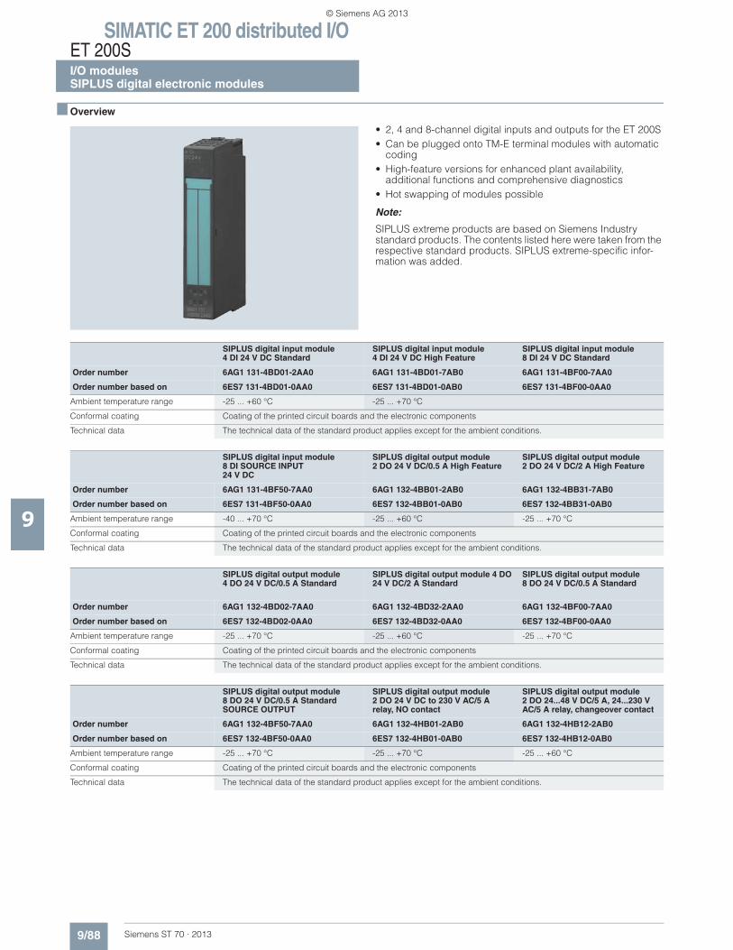
SIMATIC ET 200 distributed I/OET 200SI/O modulesSIPLUS digital electronic modules
9/88 Siemens ST 70 · 2013
9
■ Overview
• 2, 4 and 8-channel digital inputs and outputs for the ET 200S • Can be plugged onto TM-E terminal modules with automatic
coding • High-feature versions for enhanced plant availability,
additional functions and comprehensive diagnostics • Hot swapping of modules possible
Note:
SIPLUS extreme products are based on Siemens Industry standard products. The contents listed here were taken from the respective standard products. SIPLUS extreme-specific infor-mation was added.
SIPLUS digital input module 4 DI 24 V DC Standard
SIPLUS digital input module4 DI 24 V DC High Feature
SIPLUS digital input module 8 DI 24 V DC Standard
Order number 6AG1 131-4BD01-2AA0 6AG1 131-4BD01-7AB0 6AG1 131-4BF00-7AA0
Order number based on 6ES7 131-4BD01-0AA0 6ES7 131-4BD01-0AB0 6ES7 131-4BF00-0AA0
Ambient temperature range -25 ... +60 °C -25 ... +70 °C
Conformal coating Coating of the printed circuit boards and the electronic components
Technical data The technical data of the standard product applies except for the ambient conditions.
SIPLUS digital input module 8 DI SOURCE INPUT24 V DC
SIPLUS digital output module 2 DO 24 V DC/0.5 A High Feature
SIPLUS digital output module 2 DO 24 V DC/2 A High Feature
Order number 6AG1 131-4BF50-7AA0 6AG1 132-4BB01-2AB0 6AG1 132-4BB31-7AB0
Order number based on 6ES7 131-4BF50-0AA0 6ES7 132-4BB01-0AB0 6ES7 132-4BB31-0AB0
Ambient temperature range -40 ... +70 °C -25 ... +60 °C -25 ... +70 °C
Conformal coating Coating of the printed circuit boards and the electronic components
Technical data The technical data of the standard product applies except for the ambient conditions.
SIPLUS digital output module 4 DO 24 V DC/0.5 A Standard
SIPLUS digital output module 4 DO 24 V DC/2 A Standard
SIPLUS digital output module 8 DO 24 V DC/0.5 A Standard
Order number 6AG1 132-4BD02-7AA0 6AG1 132-4BD32-2AA0 6AG1 132-4BF00-7AA0
Order number based on 6ES7 132-4BD02-0AA0 6ES7 132-4BD32-0AA0 6ES7 132-4BF00-0AA0
Ambient temperature range -25 ... +70 °C -25 ... +60 °C -25 ... +70 °C
Conformal coating Coating of the printed circuit boards and the electronic components
Technical data The technical data of the standard product applies except for the ambient conditions.
SIPLUS digital output module 8 DO 24 V DC/0.5 A Standard SOURCE OUTPUT
SIPLUS digital output module2 DO 24 V DC to 230 V AC/5 A relay, NO contact
SIPLUS digital output module2 DO 24...48 V DC/5 A, 24...230 V AC/5 A relay, changeover contact
Order number 6AG1 132-4BF50-7AA0 6AG1 132-4HB01-2AB0 6AG1 132-4HB12-2AB0
Order number based on 6ES7 132-4BF50-0AA0 6ES7 132-4HB01-0AB0 6ES7 132-4HB12-0AB0
Ambient temperature range -25 ... +70 °C -25 ... +70 °C -25 ... +60 °C
Conformal coating Coating of the printed circuit boards and the electronic components
Technical data The technical data of the standard product applies except for the ambient conditions.
© Siemens AG 2013
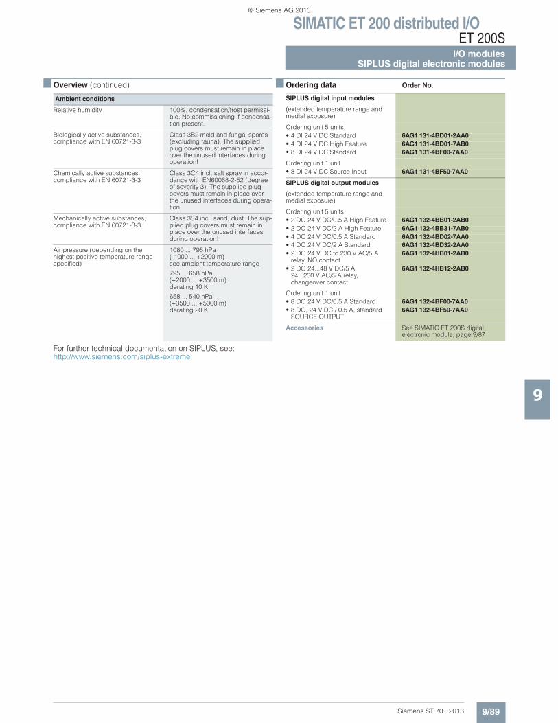
SIMATIC ET 200 distributed I/OET 200S
I/O modulesSIPLUS digital electronic modules
9/89Siemens ST 70 · 2013
■ Overview (continued)
9
For further technical documentation on SIPLUS, see:http://www.siemens.com/siplus-extreme
Ambient conditions
Relative humidity 100%, condensation/frost permissi-ble. No commissioning if condensa-tion present.
Biologically active substances, compliance with EN 60721-3-3
Class 3B2 mold and fungal spores (excluding fauna). The supplied plug covers must remain in place over the unused interfaces during operation!
Chemically active substances,compliance with EN 60721-3-3
Class 3C4 incl. salt spray in accor-dance with EN60068-2-52 (degree of severity 3). The supplied plug covers must remain in place over the unused interfaces during opera-tion!
Mechanically active substances, compliance with EN 60721-3-3
Class 3S4 incl. sand, dust. The sup-plied plug covers must remain in place over the unused interfaces during operation!
Air pressure (depending on the highest positive temperature range specified)
1080 ... 795 hPa(-1000 ... +2000 m) see ambient temperature range
795 ... 658 hPa(+2000 ... +3500 m) derating 10 K
658 ... 540 hPa(+3500 ... +5000 m) derating 20 K
■ Ordering data Order No.
SIPLUS digital input modules
(extended temperature range and medial exposure)
Ordering unit 5 units• 4 DI 24 V DC Standard 6AG1 131-4BD01-2AA0• 4 DI 24 V DC High Feature 6AG1 131-4BD01-7AB0• 8 DI 24 V DC Standard 6AG1 131-4BF00-7AA0
Ordering unit 1 unit• 8 DI 24 V DC Source Input 6AG1 131-4BF50-7AA0
SIPLUS digital output modules
(extended temperature range and medial exposure)
Ordering unit 5 units• 2 DO 24 V DC/0.5 A High Feature 6AG1 132-4BB01-2AB0• 2 DO 24 V DC/2 A High Feature 6AG1 132-4BB31-7AB0• 4 DO 24 V DC/0.5 A Standard 6AG1 132-4BD02-7AA0• 4 DO 24 V DC/2 A Standard 6AG1 132-4BD32-2AA0• 2 DO 24 V DC to 230 V AC/5 A
relay, NO contact6AG1 132-4HB01-2AB0
• 2 DO 24...48 V DC/5 A, 24...230 V AC/5 A relay, changeover contact
6AG1 132-4HB12-2AB0
Ordering unit 1 unit• 8 DO 24 V DC/0.5 A Standard 6AG1 132-4BF00-7AA0• 8 DO, 24 V DC / 0.5 A, standard
SOURCE OUTPUT6AG1 132-4BF50-7AA0
Accessories See SIMATIC ET 200S digital electronic module, page 9/87
© Siemens AG 2013
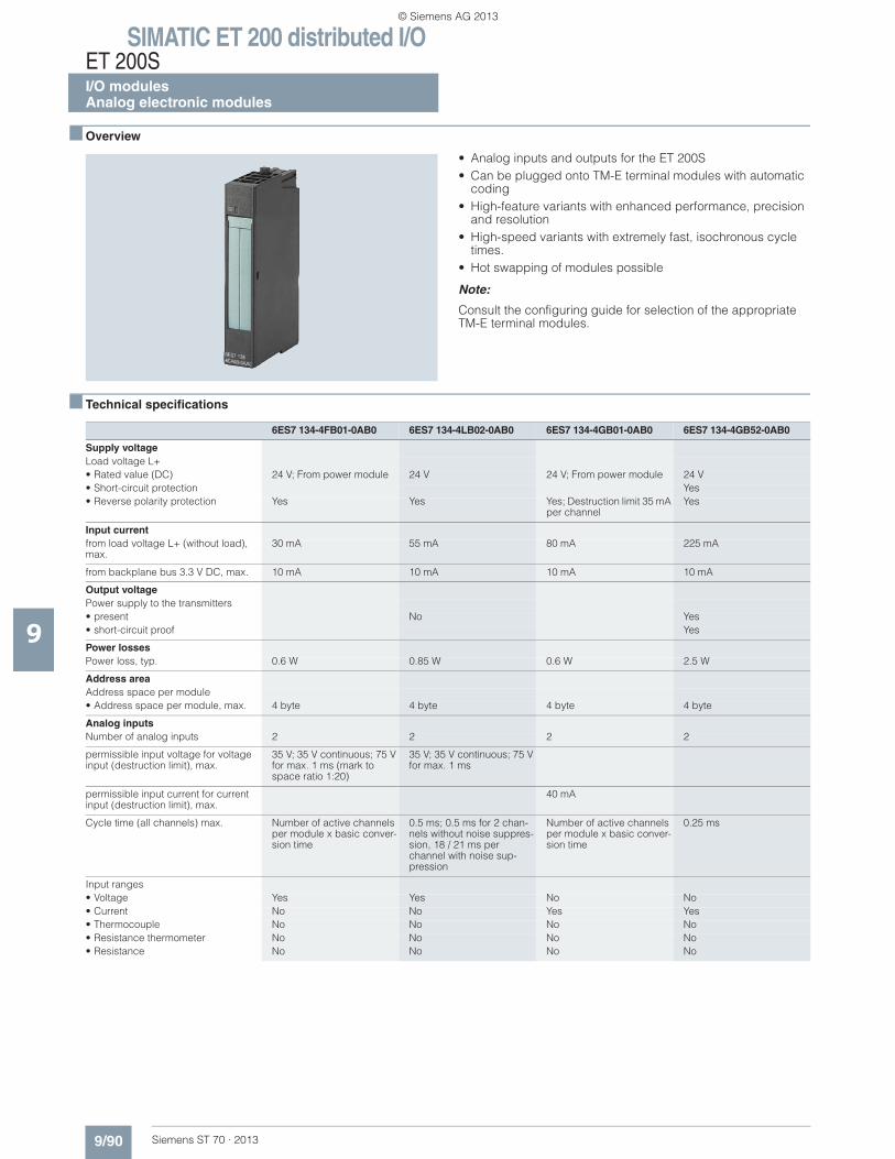
SIMATIC ET 200 distributed I/OET 200SI/O modulesAnalog electronic modules
9/90 Siemens ST 70 · 2013
9
■ Overview
• Analog inputs and outputs for the ET 200S• Can be plugged onto TM-E terminal modules with automatic
coding• High-feature variants with enhanced performance, precision
and resolution• High-speed variants with extremely fast, isochronous cycle
times.• Hot swapping of modules possible
Note:
Consult the configuring guide for selection of the appropriate TM-E terminal modules.
■ Technical specifications
6ES7 134-4FB01-0AB0 6ES7 134-4LB02-0AB0 6ES7 134-4GB01-0AB0 6ES7 134-4GB52-0AB0
Supply voltageLoad voltage L+• Rated value (DC) 24 V; From power module 24 V 24 V; From power module 24 V• Short-circuit protection Yes• Reverse polarity protection Yes Yes Yes; Destruction limit 35 mA
per channelYes
Input currentfrom load voltage L+ (without load), max.
30 mA 55 mA 80 mA 225 mA
from backplane bus 3.3 V DC, max. 10 mA 10 mA 10 mA 10 mA
Output voltagePower supply to the transmitters• present No Yes• short-circuit proof Yes
Power lossesPower loss, typ. 0.6 W 0.85 W 0.6 W 2.5 W
Address areaAddress space per module• Address space per module, max. 4 byte 4 byte 4 byte 4 byte
Analog inputsNumber of analog inputs 2 2 2 2
permissible input voltage for voltage input (destruction limit), max.
35 V; 35 V continuous; 75 V for max. 1 ms (mark to space ratio 1:20)
35 V; 35 V continuous; 75 V for max. 1 ms
permissible input current for current input (destruction limit), max.
40 mA
Cycle time (all channels) max. Number of active channels per module x basic conver-sion time
0.5 ms; 0.5 ms for 2 chan-nels without noise suppres-sion, 18 / 21 ms per channel with noise sup-pression
Number of active channels per module x basic conver-sion time
0.25 ms
Input ranges• Voltage Yes Yes No No• Current No No Yes Yes• Thermocouple No No No No• Resistance thermometer No No No No• Resistance No No No No
© Siemens AG 2013
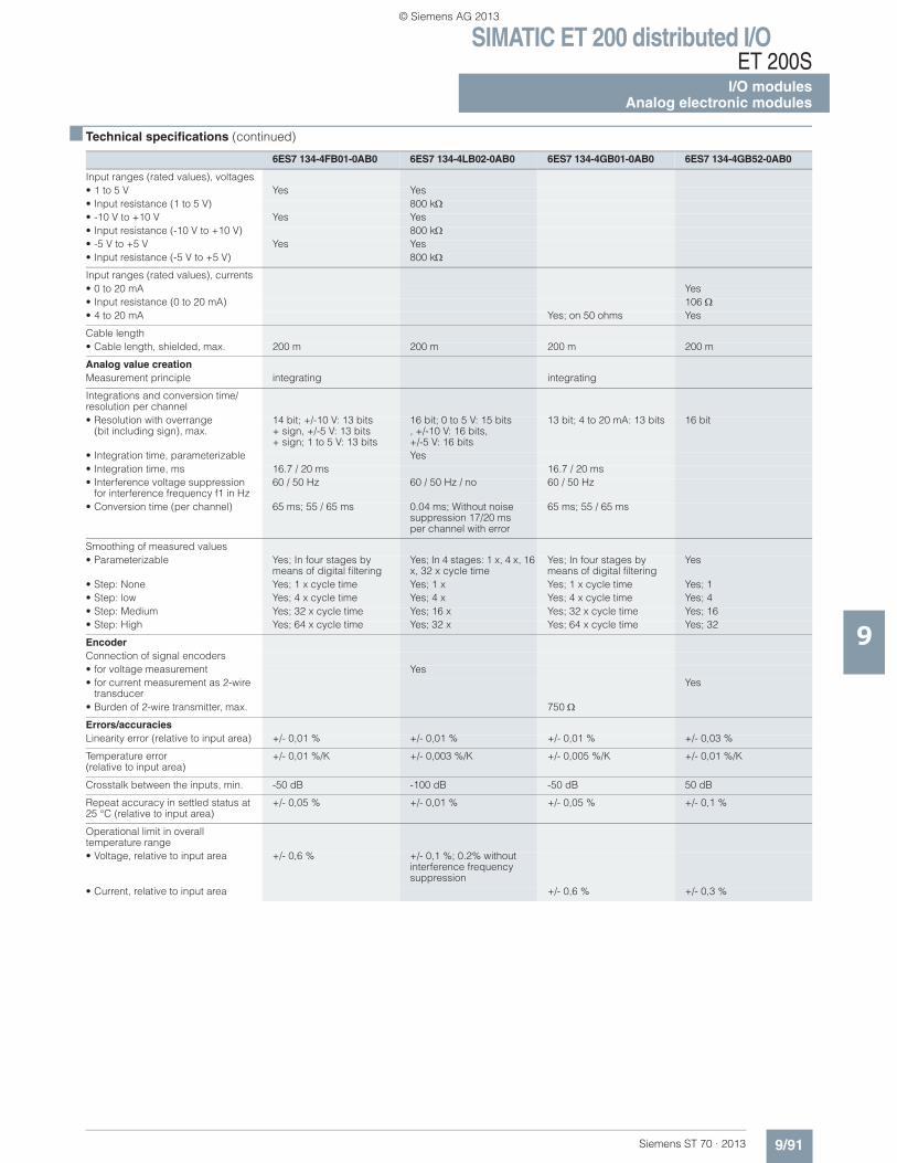
SIMATIC ET 200 distributed I/OET 200S
I/O modulesAnalog electronic modules
9/91Siemens ST 70 · 2013
■ Technical specifications (continued)
9
Input ranges (rated values), voltages• 1 to 5 V Yes Yes• Input resistance (1 to 5 V) 800 k• -10 V to +10 V Yes Yes• Input resistance (-10 V to +10 V) 800 k• -5 V to +5 V Yes Yes• Input resistance (-5 V to +5 V) 800 k
Input ranges (rated values), currents• 0 to 20 mA Yes• Input resistance (0 to 20 mA) 106• 4 to 20 mA Yes; on 50 ohms Yes
Cable length• Cable length, shielded, max. 200 m 200 m 200 m 200 m
Analog value creationMeasurement principle integrating integrating
Integrations and conversion time/resolution per channel• Resolution with overrange
(bit including sign), max.14 bit; +/-10 V: 13 bits + sign, +/-5 V: 13 bits + sign; 1 to 5 V: 13 bits
16 bit; 0 to 5 V: 15 bits, +/-10 V: 16 bits, +/-5 V: 16 bits
13 bit; 4 to 20 mA: 13 bits 16 bit
• Integration time, parameterizable Yes• Integration time, ms 16.7 / 20 ms 16.7 / 20 ms• Interference voltage suppression
for interference frequency f1 in Hz60 / 50 Hz 60 / 50 Hz / no 60 / 50 Hz
• Conversion time (per channel) 65 ms; 55 / 65 ms 0.04 ms; Without noisesuppression 17/20 ms per channel with error
65 ms; 55 / 65 ms
Smoothing of measured values• Parameterizable Yes; In four stages by
means of digital filteringYes; In 4 stages: 1 x, 4 x, 16 x, 32 x cycle time
Yes; In four stages by means of digital filtering
Yes
• Step: None Yes; 1 x cycle time Yes; 1 x Yes; 1 x cycle time Yes; 1• Step: low Yes; 4 x cycle time Yes; 4 x Yes; 4 x cycle time Yes; 4• Step: Medium Yes; 32 x cycle time Yes; 16 x Yes; 32 x cycle time Yes; 16• Step: High Yes; 64 x cycle time Yes; 32 x Yes; 64 x cycle time Yes; 32
EncoderConnection of signal encoders• for voltage measurement Yes• for current measurement as 2-wire
transducerYes
• Burden of 2-wire transmitter, max. 750
Errors/accuraciesLinearity error (relative to input area) +/- 0,01 % +/- 0,01 % +/- 0,01 % +/- 0,03 %
Temperature error (relative to input area)
+/- 0,01 %/K +/- 0,003 %/K +/- 0,005 %/K +/- 0,01 %/K
Crosstalk between the inputs, min. -50 dB -100 dB -50 dB 50 dB
Repeat accuracy in settled status at 25 °C (relative to input area)
+/- 0,05 % +/- 0,01 % +/- 0,05 % +/- 0,1 %
Operational limit in overalltemperature range• Voltage, relative to input area +/- 0,6 % +/- 0,1 %; 0.2% without
interference frequency suppression
• Current, relative to input area +/- 0,6 % +/- 0,3 %
6ES7 134-4FB01-0AB0 6ES7 134-4LB02-0AB0 6ES7 134-4GB01-0AB0 6ES7 134-4GB52-0AB0
© Siemens AG 2013
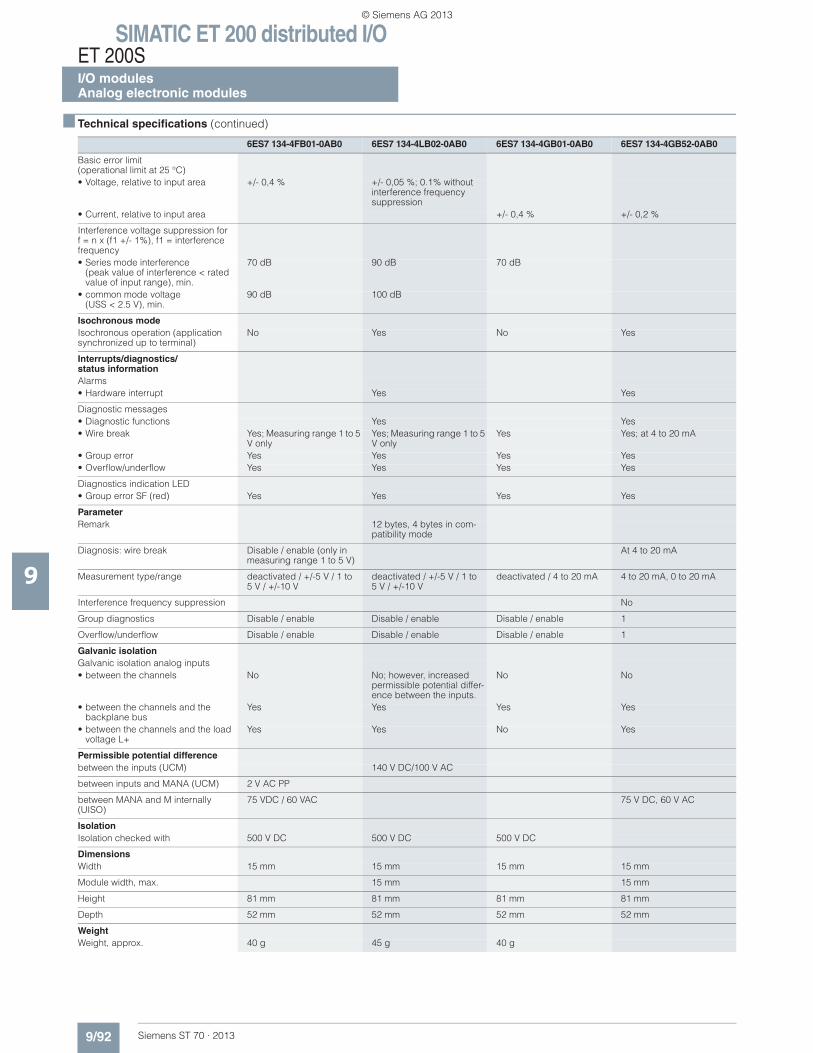
SIMATIC ET 200 distributed I/OET 200SI/O modulesAnalog electronic modules
9/92 Siemens ST 70 · 2013
■ Technical specifications (continued)
9
Basic error limit(operational limit at 25 °C)• Voltage, relative to input area +/- 0,4 % +/- 0,05 %; 0.1% without
interference frequencysuppression
• Current, relative to input area +/- 0,4 % +/- 0,2 %
Interference voltage suppression forf = n x (f1 +/- 1%), f1 = interference frequency• Series mode interference
(peak value of interference < rated value of input range), min.
70 dB 90 dB 70 dB
• common mode voltage(USS < 2.5 V), min.
90 dB 100 dB
Isochronous modeIsochronous operation (application synchronized up to terminal)
No Yes No Yes
Interrupts/diagnostics/status informationAlarms• Hardware interrupt Yes Yes
Diagnostic messages• Diagnostic functions Yes Yes• Wire break Yes; Measuring range 1 to 5
V onlyYes; Measuring range 1 to 5 V only
Yes Yes; at 4 to 20 mA
• Group error Yes Yes Yes Yes• Overflow/underflow Yes Yes Yes Yes
Diagnostics indication LED• Group error SF (red) Yes Yes Yes Yes
ParameterRemark 12 bytes, 4 bytes in com-
patibility mode
Diagnosis: wire break Disable / enable (only in measuring range 1 to 5 V)
At 4 to 20 mA
Measurement type/range deactivated / +/-5 V / 1 to 5 V / +/-10 V
deactivated / +/-5 V / 1 to5 V / +/-10 V
deactivated / 4 to 20 mA 4 to 20 mA, 0 to 20 mA
Interference frequency suppression No
Group diagnostics Disable / enable Disable / enable Disable / enable 1
Overflow/underflow Disable / enable Disable / enable Disable / enable 1
Galvanic isolationGalvanic isolation analog inputs• between the channels No No; however, increased
permissible potential differ-ence between the inputs.
No No
• between the channels and the backplane bus
Yes Yes Yes Yes
• between the channels and the load voltage L+
Yes Yes No Yes
Permissible potential differencebetween the inputs (UCM) 140 V DC/100 V AC
between inputs and MANA (UCM) 2 V AC PP
between MANA and M internally (UISO)
75 VDC / 60 VAC 75 V DC, 60 V AC
IsolationIsolation checked with 500 V DC 500 V DC 500 V DC
DimensionsWidth 15 mm 15 mm 15 mm 15 mm
Module width, max. 15 mm 15 mm
Height 81 mm 81 mm 81 mm 81 mm
Depth 52 mm 52 mm 52 mm 52 mm
WeightWeight, approx. 40 g 45 g 40 g
6ES7 134-4FB01-0AB0 6ES7 134-4LB02-0AB0 6ES7 134-4GB01-0AB0 6ES7 134-4GB52-0AB0
© Siemens AG 2013
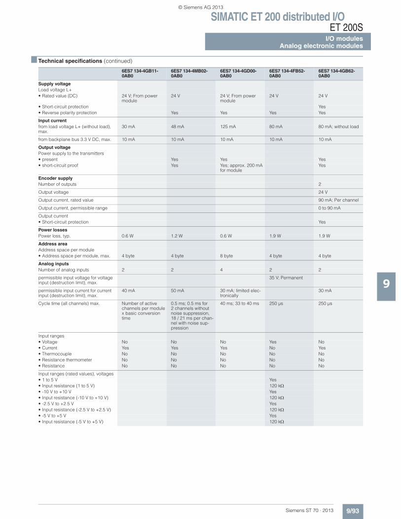
SIMATIC ET 200 distributed I/OET 200S
I/O modulesAnalog electronic modules
9/93Siemens ST 70 · 2013
■ Technical specifications (continued)
9
6ES7 134-4GB11-0AB0
6ES7 134-4MB02-0AB0
6ES7 134-4GD00-0AB0
6ES7 134-4FB52-0AB0
6ES7 134-4GB62-0AB0
Supply voltageLoad voltage L+• Rated value (DC) 24 V; From power
module24 V 24 V; From power
module24 V 24 V
• Short-circuit protection Yes• Reverse polarity protection Yes Yes Yes Yes
Input currentfrom load voltage L+ (without load), max.
30 mA 48 mA 125 mA 80 mA 80 mA; without load
from backplane bus 3.3 V DC, max. 10 mA 10 mA 10 mA 10 mA 10 mA
Output voltagePower supply to the transmitters• present Yes Yes Yes• short-circuit proof Yes Yes; approx. 200 mA
for moduleYes
Encoder supplyNumber of outputs 2
Output voltage 24 V
Output current, rated value 90 mA; Per channel
Output current, permissible range 0 to 90 mA
Output current• Short-circuit protection Yes
Power lossesPower loss, typ. 0.6 W 1.2 W 0.6 W 1.9 W 1.9 W
Address areaAddress space per module• Address space per module, max. 4 byte 4 byte 8 byte 4 byte 4 byte
Analog inputsNumber of analog inputs 2 2 4 2 2
permissible input voltage for voltage input (destruction limit), max.
35 V; Permanent
permissible input current for current input (destruction limit), max.
40 mA 50 mA 30 mA; limited elec-tronically
30 mA
Cycle time (all channels) max. Number of active channels per module x basic conversion time
0.5 ms; 0.5 ms for 2 channels without noise suppression, 18 / 21 ms per chan-nel with noise sup-pression
40 ms; 33 to 40 ms 250 μs 250 μs
Input ranges• Voltage No No No Yes No• Current Yes Yes Yes No Yes• Thermocouple No No No No No• Resistance thermometer No No No No No• Resistance No No No No No
Input ranges (rated values), voltages• 1 to 5 V Yes• Input resistance (1 to 5 V) 120 k• -10 V to +10 V Yes• Input resistance (-10 V to +10 V) 120 k• -2.5 V to +2.5 V Yes• Input resistance (-2.5 V to +2.5 V) 120 k• -5 V to +5 V Yes• Input resistance (-5 V to +5 V) 120 k
© Siemens AG 2013
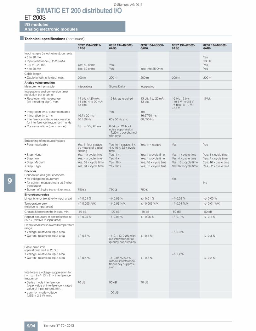
SIMATIC ET 200 distributed I/OET 200SI/O modulesAnalog electronic modules
9/94 Siemens ST 70 · 2013
■ Technical specifications (continued)
9
Input ranges (rated values), currents• 0 to 20 mA Yes• Input resistance (0 to 20 mA) 106• -20 to +20 mA Yes; 50 ohms Yes Yes• 4 to 20 mA Yes; 50 ohms Yes Yes; Into 25 Ohm Yes
Cable length• Cable length, shielded, max. 200 m 200 m 200 m 200 m 200 m
Analog value creationMeasurement principle integrating Sigma Delta integrating
Integrations and conversion time/ resolution per channel• Resolution with overrange
(bit including sign), max.14 bit; +/-20 mA: 14 bits, 4 to 20 mA: 13 bits
16 bit; as required 13 bit; 4 to 20 mA: 13 bits
16 bit; 15 bits: 1 to 5 V; +/-2.5 V; 16 bits: +/-10 V; +/-5 V
16 bit
• Integration time, parameterizable Yes Yes• Integration time, ms 16.7 / 20 ms 16.67/20 ms• Interference voltage suppression
for interference frequency f1 in Hz60 / 50 Hz 60 / 50 Hz / no 60 / 50 Hz
• Conversion time (per channel) 65 ms; 55 / 65 ms 0.04 ms; Without noise suppression 17/20 ms per channel with error
Smoothing of measured values• Parameterizable Yes; In four stages
by means of digital filtering
Yes; In 4 stages: 1 x, 4 x, 16 x, 32 x cycle time
Yes; in 4 stages Yes Yes
• Step: None Yes; 1 x cycle time Yes; 1 x Yes; 1 x cycle time Yes; 1 x cycle time Yes; 1 x cycle time• Step: low Yes; 4 x cycle time Yes; 4 x Yes; 4 x cycle time Yes; 4 x cycle time Yes; 4 x cycle time• Step: Medium Yes; 32 x cycle time Yes; 16 x Yes; 16 x cycle time Yes; 16 x cycle time Yes; 16 x cycle time• Step: High Yes; 64 x cycle time Yes; 32 x Yes; 32 x cycle time Yes; 32 x cycle time Yes; 32 x cycle time
EncoderConnection of signal encoders• for voltage measurement Yes• for current measurement as 2-wire
transducerNo
• Burden of 2-wire transmitter, max. 750 750 750
Errors/accuraciesLinearity error (relative to input area) +/- 0,01 % +/- 0,03 % +/- 0,01 % +/- 0,03 % +/- 0,03 %
Temperature error (relative to input area)
+/- 0,005 %/K +/- 0,03 %/K +/- 0,003 %/K +/- 0,01 %/K +/- 0,01 %/K
Crosstalk between the inputs, min. -50 dB -100 dB -50 dB -50 dB -50 dB
Repeat accuracy in settled status at 25 °C (relative to input area)
+/- 0,05 % +/- 0,01 % +/- 0,05 % +/- 0,1 % +/- 0,1 %
Operational limit in overall temperature range• Voltage, relative to input area +/- 0,3 %• Current, relative to input area +/- 0,6 % +/- 0,1 %; 0.2% with-
out interference fre-quency suppression
+/- 0,4 % +/- 0,3 %
Basic error limit(operational limit at 25 °C)• Voltage, relative to input area +/- 0,2 %• Current, relative to input area +/- 0,4 % +/- 0,05 %; 0.1%
without interference frequency suppres-sion
+/- 0,3 % +/- 0,2 %
Interference voltage suppression forf = n x (f1 +/- 1%), f1 = interference frequency• Series mode interference
(peak value of interference < rated value of input range), min.
70 dB 90 dB 70 dB
• common mode voltage (USS < 2.5 V), min.
100 dB
6ES7 134-4GB11-0AB0
6ES7 134-4MB02-0AB0
6ES7 134-4GD00-0AB0
6ES7 134-4FB52-0AB0
6ES7 134-4GB62-0AB0
© Siemens AG 2013
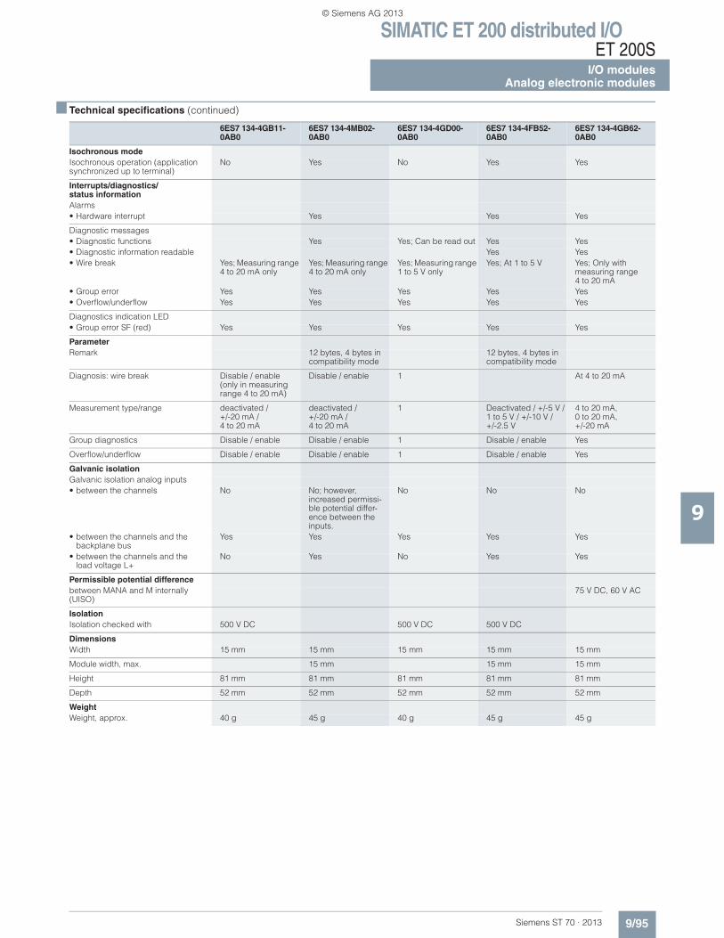
SIMATIC ET 200 distributed I/OET 200S
I/O modulesAnalog electronic modules
9/95Siemens ST 70 · 2013
■ Technical specifications (continued)
9
Isochronous modeIsochronous operation (application synchronized up to terminal)
No Yes No Yes Yes
Interrupts/diagnostics/status informationAlarms• Hardware interrupt Yes Yes Yes
Diagnostic messages• Diagnostic functions Yes Yes; Can be read out Yes Yes• Diagnostic information readable Yes Yes• Wire break Yes; Measuring range
4 to 20 mA onlyYes; Measuring range 4 to 20 mA only
Yes; Measuring range 1 to 5 V only
Yes; At 1 to 5 V Yes; Only withmeasuring range4 to 20 mA
• Group error Yes Yes Yes Yes Yes• Overflow/underflow Yes Yes Yes Yes Yes
Diagnostics indication LED• Group error SF (red) Yes Yes Yes Yes Yes
ParameterRemark 12 bytes, 4 bytes in
compatibility mode12 bytes, 4 bytes in compatibility mode
Diagnosis: wire break Disable / enable(only in measuring range 4 to 20 mA)
Disable / enable 1 At 4 to 20 mA
Measurement type/range deactivated / +/-20 mA /4 to 20 mA
deactivated /+/-20 mA / 4 to 20 mA
1 Deactivated / +/-5 V / 1 to 5 V / +/-10 V / +/-2.5 V
4 to 20 mA,0 to 20 mA, +/-20 mA
Group diagnostics Disable / enable Disable / enable 1 Disable / enable Yes
Overflow/underflow Disable / enable Disable / enable 1 Disable / enable Yes
Galvanic isolationGalvanic isolation analog inputs• between the channels No No; however,
increased permissi-ble potential differ-ence between the inputs.
No No No
• between the channels and the backplane bus
Yes Yes Yes Yes Yes
• between the channels and theload voltage L+
No Yes No Yes Yes
Permissible potential differencebetween MANA and M internally (UISO)
75 V DC, 60 V AC
IsolationIsolation checked with 500 V DC 500 V DC 500 V DC
DimensionsWidth 15 mm 15 mm 15 mm 15 mm 15 mm
Module width, max. 15 mm 15 mm 15 mm
Height 81 mm 81 mm 81 mm 81 mm 81 mm
Depth 52 mm 52 mm 52 mm 52 mm 52 mm
WeightWeight, approx. 40 g 45 g 40 g 45 g 45 g
6ES7 134-4GB11-0AB0
6ES7 134-4MB02-0AB0
6ES7 134-4GD00-0AB0
6ES7 134-4FB52-0AB0
6ES7 134-4GB62-0AB0
© Siemens AG 2013
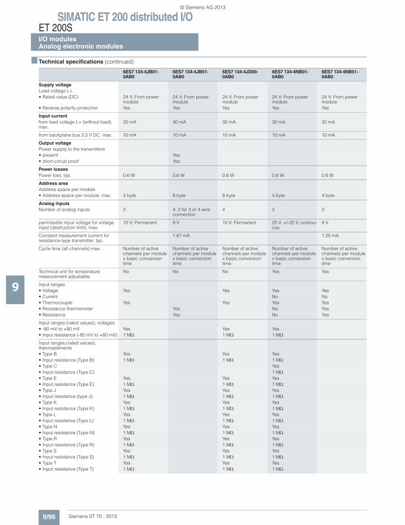
SIMATIC ET 200 distributed I/OET 200SI/O modulesAnalog electronic modules
9/96 Siemens ST 70 · 2013
■ Technical specifications (continued)
9
6ES7 134-4JB01-0AB0
6ES7 134-4JB51-0AB0
6ES7 134-4JD00-0AB0
6ES7 134-4NB01-0AB0
6ES7 134-4NB51-0AB0
Supply voltageLoad voltage L+• Rated value (DC) 24 V; From power
module24 V; From power module
24 V; From power module
24 V; From power module
24 V; From power module
• Reverse polarity protection Yes Yes Yes Yes Yes
Input currentfrom load voltage L+ (without load), max.
30 mA 30 mA 30 mA 30 mA 30 mA
from backplane bus 3.3 V DC, max. 10 mA 10 mA 10 mA 10 mA 10 mA
Output voltagePower supply to the transmitters• present Yes• short-circuit proof Yes
Power lossesPower loss, typ. 0.6 W 0.6 W 0.6 W 0.6 W 0.6 W
Address areaAddress space per module• Address space per module, max. 4 byte 8 byte 8 byte 4 byte 4 byte
Analog inputsNumber of analog inputs 2 4; 2 for 3 or 4-wire
connection4 2 2
permissible input voltage for voltage input (destruction limit), max.
10 V; Permanent 9 V 10 V; Permanent 20 V; +/-20 V, continu-ous
9 V
Constant measurement current for resistance-type transmitter, typ.
1.67 mA 1.25 mA
Cycle time (all channels) max. Number of active channels per module x basic conversion time
Number of active channels per module x basic conversion time
Number of active channels per module x basic conversion time
Number of active channels per module x basic conversion time
Number of active channels per module x basic conversion time
Technical unit for temperature measurement adjustable
No No No Yes Yes
Input ranges• Voltage Yes Yes Yes Yes• Current No No• Thermocouple Yes Yes Yes Yes• Resistance thermometer Yes No Yes• Resistance Yes No Yes
Input ranges (rated values), voltages• -80 mV to +80 mV Yes Yes Yes• Input resistance (-80 mV to +80 mV) 1 M 1 M 1 M
Input ranges (rated values), thermoelements• Type B Yes Yes Yes• Input resistance (Type B) 1 M 1 M 1 M• Type C Yes• Input resistance (Type C) 1 M• Type E Yes Yes Yes• Input resistance (Type E) 1 M 1 M 1 M• Type J Yes Yes Yes• Input resistance (type J) 1 M 1 M 1 M• Type K Yes Yes Yes• Input resistance (Type K) 1 M 1 M 1 M• Type L Yes Yes Yes• Input resistance (Type L) 1 M 1 M 1 M• Type N Yes Yes Yes• Input resistance (Type N) 1 M 1 M 1 M• Type R Yes Yes Yes• Input resistance (Type R) 1 M 1 M 1 M• Type S Yes Yes Yes• Input resistance (Type S) 1 M 1 M 1 M• Type T Yes Yes Yes• Input resistance (Type T) 1 M 1 M 1 M
© Siemens AG 2013
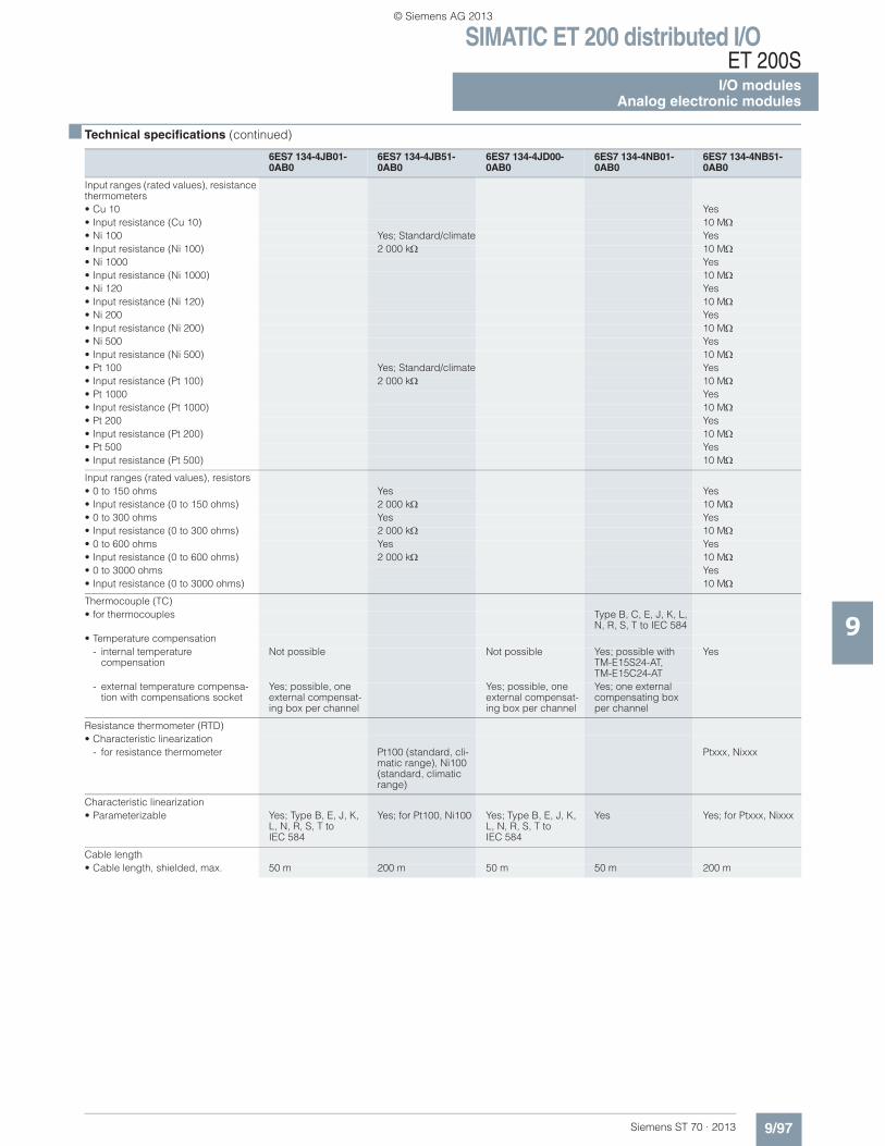
SIMATIC ET 200 distributed I/OET 200S
I/O modulesAnalog electronic modules
9/97Siemens ST 70 · 2013
■ Technical specifications (continued)
9
Input ranges (rated values), resistance thermometers• Cu 10 Yes• Input resistance (Cu 10) 10 M• Ni 100 Yes; Standard/climate Yes• Input resistance (Ni 100) 2 000 k 10 M• Ni 1000 Yes• Input resistance (Ni 1000) 10 M• Ni 120 Yes• Input resistance (Ni 120) 10 M• Ni 200 Yes• Input resistance (Ni 200) 10 M• Ni 500 Yes• Input resistance (Ni 500) 10 M• Pt 100 Yes; Standard/climate Yes• Input resistance (Pt 100) 2 000 k 10 M• Pt 1000 Yes• Input resistance (Pt 1000) 10 M• Pt 200 Yes• Input resistance (Pt 200) 10 M• Pt 500 Yes• Input resistance (Pt 500) 10 M
Input ranges (rated values), resistors• 0 to 150 ohms Yes Yes• Input resistance (0 to 150 ohms) 2 000 k 10 M• 0 to 300 ohms Yes Yes• Input resistance (0 to 300 ohms) 2 000 k 10 M• 0 to 600 ohms Yes Yes• Input resistance (0 to 600 ohms) 2 000 k 10 M• 0 to 3000 ohms Yes• Input resistance (0 to 3000 ohms) 10 M
Thermocouple (TC)• for thermocouples Type B, C, E, J, K, L,
N, R, S, T to IEC 584• Temperature compensation
- internal temperature compensation
Not possible Not possible Yes; possible with TM-E15S24-AT,TM-E15C24-AT
Yes
- external temperature compensa-tion with compensations socket
Yes; possible, one external compensat-ing box per channel
Yes; possible, one external compensat-ing box per channel
Yes; one external compensating box per channel
Resistance thermometer (RTD)• Characteristic linearization
- for resistance thermometer Pt100 (standard, cli-matic range), Ni100 (standard, climatic range)
Ptxxx, Nixxx
Characteristic linearization• Parameterizable Yes; Type B, E, J, K,
L, N, R, S, T to IEC 584
Yes; for Pt100, Ni100 Yes; Type B, E, J, K, L, N, R, S, T to IEC 584
Yes Yes; for Ptxxx, Nixxx
Cable length• Cable length, shielded, max. 50 m 200 m 50 m 50 m 200 m
6ES7 134-4JB01-0AB0
6ES7 134-4JB51-0AB0
6ES7 134-4JD00-0AB0
6ES7 134-4NB01-0AB0
6ES7 134-4NB51-0AB0
© Siemens AG 2013
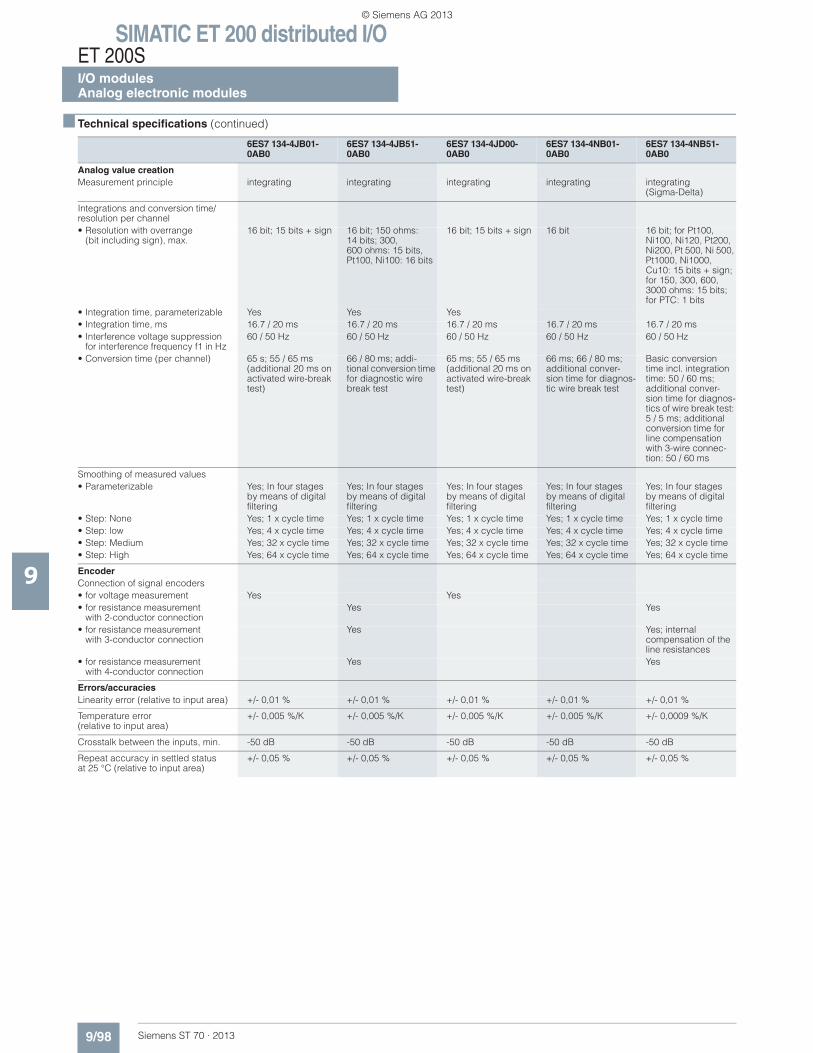
SIMATIC ET 200 distributed I/OET 200SI/O modulesAnalog electronic modules
9/98 Siemens ST 70 · 2013
■ Technical specifications (continued)
9
Analog value creationMeasurement principle integrating integrating integrating integrating integrating
(Sigma-Delta)
Integrations and conversion time/ resolution per channel• Resolution with overrange
(bit including sign), max.16 bit; 15 bits + sign 16 bit; 150 ohms:
14 bits; 300, 600 ohms: 15 bits, Pt100, Ni100: 16 bits
16 bit; 15 bits + sign 16 bit 16 bit; for Pt100, Ni100, Ni120, Pt200, Ni200, Pt 500, Ni 500, Pt1000, Ni1000, Cu10: 15 bits + sign; for 150, 300, 600, 3000 ohms: 15 bits; for PTC: 1 bits
• Integration time, parameterizable Yes Yes Yes• Integration time, ms 16.7 / 20 ms 16.7 / 20 ms 16.7 / 20 ms 16.7 / 20 ms 16.7 / 20 ms• Interference voltage suppression
for interference frequency f1 in Hz60 / 50 Hz 60 / 50 Hz 60 / 50 Hz 60 / 50 Hz 60 / 50 Hz
• Conversion time (per channel) 65 s; 55 / 65 ms (additional 20 ms on activated wire-break test)
66 / 80 ms; addi-tional conversion time for diagnostic wire break test
65 ms; 55 / 65 ms (additional 20 ms on activated wire-break test)
66 ms; 66 / 80 ms; additional conver-sion time for diagnos-tic wire break test
Basic conversion time incl. integration time: 50 / 60 ms; additional conver-sion time for diagnos-tics of wire break test: 5 / 5 ms; additional conversion time for line compensation with 3-wire connec-tion: 50 / 60 ms
Smoothing of measured values• Parameterizable Yes; In four stages
by means of digital filtering
Yes; In four stagesby means of digitalfiltering
Yes; In four stagesby means of digital filtering
Yes; In four stagesby means of digitalfiltering
Yes; In four stagesby means of digital filtering
• Step: None Yes; 1 x cycle time Yes; 1 x cycle time Yes; 1 x cycle time Yes; 1 x cycle time Yes; 1 x cycle time• Step: low Yes; 4 x cycle time Yes; 4 x cycle time Yes; 4 x cycle time Yes; 4 x cycle time Yes; 4 x cycle time• Step: Medium Yes; 32 x cycle time Yes; 32 x cycle time Yes; 32 x cycle time Yes; 32 x cycle time Yes; 32 x cycle time• Step: High Yes; 64 x cycle time Yes; 64 x cycle time Yes; 64 x cycle time Yes; 64 x cycle time Yes; 64 x cycle time
EncoderConnection of signal encoders• for voltage measurement Yes Yes• for resistance measurement
with 2-conductor connectionYes Yes
• for resistance measurementwith 3-conductor connection
Yes Yes; internal compensation of the line resistances
• for resistance measurementwith 4-conductor connection
Yes Yes
Errors/accuraciesLinearity error (relative to input area) +/- 0,01 % +/- 0,01 % +/- 0,01 % +/- 0,01 % +/- 0,01 %
Temperature error(relative to input area)
+/- 0,005 %/K +/- 0,005 %/K +/- 0,005 %/K +/- 0,005 %/K +/- 0,0009 %/K
Crosstalk between the inputs, min. -50 dB -50 dB -50 dB -50 dB -50 dB
Repeat accuracy in settled statusat 25 °C (relative to input area)
+/- 0,05 % +/- 0,05 % +/- 0,05 % +/- 0,05 % +/- 0,05 %
6ES7 134-4JB01-0AB0
6ES7 134-4JB51-0AB0
6ES7 134-4JD00-0AB0
6ES7 134-4NB01-0AB0
6ES7 134-4NB51-0AB0
© Siemens AG 2013
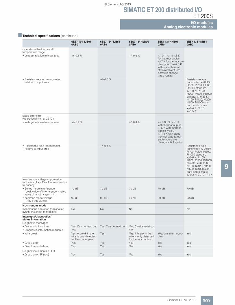
SIMATIC ET 200 distributed I/OET 200S
I/O modulesAnalog electronic modules
9/99Siemens ST 70 · 2013
■ Technical specifications (continued)
9
Operational limit in overall temperature range• Voltage, relative to input area +/- 0,6 % +/- 0,6 % +/- 0,1 %; +/-1.5 K
for thermocouples, +/-7 K for thermocou-ples type C,+/-2.5 K with static thermal state (ambient tem-perature change < 0.3 K/min)
• Resistance-type thermometer, relative to input area
+/- 0,6 % Resistance-type transmitter: +/-0.1%; Pt100, Pt200, Pt500, Pt1000 standard: +/-1.0 K; Pt100, Pt200, Pt500, Pt1000 climate: +/-0.25 K; Ni100, Ni120, Ni200, Ni500, Ni1000 stan-dard and climate: +/-0.4 K; Cu10 +/-1.5 K
Basic error limit (operational limit at 25 °C)• Voltage, relative to input area +/- 0,4 % +/- 0,4 % +/- 0,05 %; +/-1 K
with thermocouples, +/-5 K with thermocouples type C,+/-1.5 K with static thermal state (ambi-ent temperature change < 0.3 K/min)
• Resistance-type thermometer,relative to input area
+/- 0,4 % Resistance-type transmitter: +/-0.05%; Pt100, Pt200, Pt500, Pt1000 standard:+/-0.6 K; Pt100, Pt200, Pt500, Pt1000 climate: +/-0.13 K; Ni100, Ni120, Ni200, Ni500, Ni1000 stan-dard and climate: +/-0.2 K; Cu10 +/-1 K
Interference voltage suppression for f = n x (fl +/- 1%), fl = interference frequency• Series mode interference
(peak value of interference < rated value of input range), min.
70 dB 70 dB 70 dB 70 dB 70 dB
• common mode voltage (USS < 2.5 V), min.
90 dB 90 dB 90 dB 90 dB 90 dB
Isochronous modeIsochronous operation (application synchronized up to terminal)
No No No No
Interrupts/diagnostics/status informationDiagnostic messages• Diagnostic functions Yes; Can be read out Yes; Can be read out Yes; Can be read out• Diagnostic information readable Yes Yes• Wire break Yes; A break in the
wire is only detected for thermocouples
Yes Yes; A break in the wire is only detected for thermocouples
Yes; only thermocou-ples
Yes
• Group error Yes Yes Yes Yes Yes• Overflow/underflow Yes Yes Yes Yes Yes
Diagnostics indication LED• Group error SF (red) Yes Yes Yes Yes Yes
6ES7 134-4JB01-0AB0
6ES7 134-4JB51-0AB0
6ES7 134-4JD00-0AB0
6ES7 134-4NB01-0AB0
6ES7 134-4NB51-0AB0
© Siemens AG 2013
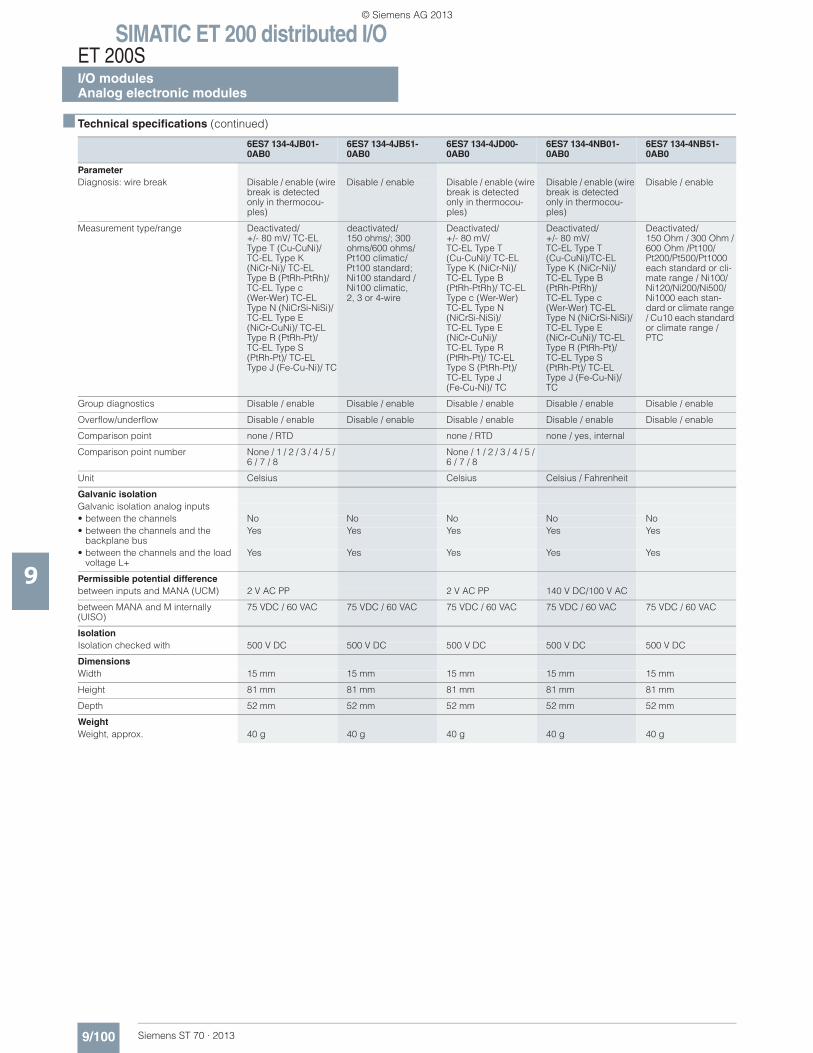
SIMATIC ET 200 distributed I/OET 200SI/O modulesAnalog electronic modules
9/100 Siemens ST 70 · 2013
■ Technical specifications (continued)
9
ParameterDiagnosis: wire break Disable / enable (wire
break is detected only in thermocou-ples)
Disable / enable Disable / enable (wire break is detected only in thermocou-ples)
Disable / enable (wire break is detected only in thermocou-ples)
Disable / enable
Measurement type/range Deactivated/ +/- 80 mV/ TC-EL Type T (Cu-CuNi)/ TC-EL Type K(NiCr-Ni)/ TC-EL Type B (PtRh-PtRh)/ TC-EL Type c(Wer-Wer) TC-EL Type N (NiCrSi-NiSi)/ TC-EL Type E (NiCr-CuNi)/ TC-EL Type R (PtRh-Pt)/TC-EL Type S(PtRh-Pt)/ TC-EL Type J (Fe-Cu-Ni)/ TC
deactivated/150 ohms/; 300 ohms/600 ohms/ Pt100 climatic/Pt100 standard; Ni100 standard / Ni100 climatic,2, 3 or 4-wire
Deactivated/ +/- 80 mV/ TC-EL Type T (Cu-CuNi)/ TC-EL Type K (NiCr-Ni)/ TC-EL Type B(PtRh-PtRh)/ TC-EL Type c (Wer-Wer)TC-EL Type N (NiCrSi-NiSi)/ TC-EL Type E(NiCr-CuNi)/ TC-EL Type R (PtRh-Pt)/ TC-ELType S (PtRh-Pt)/TC-EL Type J (Fe-Cu-Ni)/ TC
Deactivated/ +/- 80 mV/ TC-EL Type T(Cu-CuNi)/TC-EL Type K (NiCr-Ni)/TC-EL Type B (PtRh-PtRh)/ TC-EL Type c (Wer-Wer) TC-EL Type N (NiCrSi-NiSi)/ TC-EL Type E(NiCr-CuNi)/ TC-EL Type R (PtRh-Pt)/ TC-EL Type S (PtRh-Pt)/ TC-ELType J (Fe-Cu-Ni)/TC
Deactivated/ 150 Ohm / 300 Ohm / 600 Ohm /Pt100/Pt200/Pt500/Pt1000 each standard or cli-mate range / Ni100/Ni120/Ni200/Ni500/Ni1000 each stan-dard or climate range / Cu10 each standard or climate range / PTC
Group diagnostics Disable / enable Disable / enable Disable / enable Disable / enable Disable / enable
Overflow/underflow Disable / enable Disable / enable Disable / enable Disable / enable Disable / enable
Comparison point none / RTD none / RTD none / yes, internal
Comparison point number None / 1 / 2 / 3 / 4 / 5 / 6 / 7 / 8
None / 1 / 2 / 3 / 4 / 5 / 6 / 7 / 8
Unit Celsius Celsius Celsius / Fahrenheit
Galvanic isolationGalvanic isolation analog inputs• between the channels No No No No No• between the channels and the
backplane busYes Yes Yes Yes Yes
• between the channels and the load voltage L+
Yes Yes Yes Yes Yes
Permissible potential differencebetween inputs and MANA (UCM) 2 V AC PP 2 V AC PP 140 V DC/100 V AC
between MANA and M internally (UISO)
75 VDC / 60 VAC 75 VDC / 60 VAC 75 VDC / 60 VAC 75 VDC / 60 VAC 75 VDC / 60 VAC
IsolationIsolation checked with 500 V DC 500 V DC 500 V DC 500 V DC 500 V DC
DimensionsWidth 15 mm 15 mm 15 mm 15 mm 15 mm
Height 81 mm 81 mm 81 mm 81 mm 81 mm
Depth 52 mm 52 mm 52 mm 52 mm 52 mm
WeightWeight, approx. 40 g 40 g 40 g 40 g 40 g
6ES7 134-4JB01-0AB0
6ES7 134-4JB51-0AB0
6ES7 134-4JD00-0AB0
6ES7 134-4NB01-0AB0
6ES7 134-4NB51-0AB0
© Siemens AG 2013
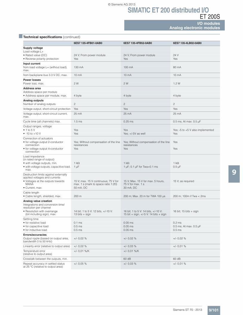
SIMATIC ET 200 distributed I/OET 200S
I/O modulesAnalog electronic modules
9/101Siemens ST 70 · 2013
■ Technical specifications (continued)
9
6ES7 135-4FB01-0AB0 6ES7 135-4FB52-0AB0 6ES7 135-4LB02-0AB0
Supply voltageLoad voltage L+• Rated value (DC) 24 V; From power module 24 V; From power module 24 V• Reverse polarity protection Yes Yes Yes
Input currentfrom load voltage L+ (without load), max.
130 mA 100 mA 80 mA
from backplane bus 3.3 V DC, max. 10 mA 10 mA 10 mA
Power lossesPower loss, max. 2 W 2 W 1.2 W
Address areaAddress space per module• Address space per module, max. 4 byte 4 byte 4 byte
Analog outputsNumber of analog outputs 2 2 2
Voltage output, short-circuit protection Yes Yes Yes
Voltage output, short-circuit current, max.
25 mA 25 mA 25 mA
Cycle time (all channels) max. 1.5 ms 0.25 ms 0.5 ms; At max. 0.5 μF
Output ranges, voltage• 1 to 5 V Yes Yes Yes; -5 to +5 V also implemented• -10 to +10 V Yes Yes; +/-5V as well Yes
Connection of actuators• for voltage output 2-conductor
connectionYes; Without compensation of the line resistances
Yes; Without compensation of the line resistances
Yes
• for voltage output 4-conductorconnection
Yes Yes Yes
Load impedance(in rated range of output)• with voltage outputs, min. 1 k 1 k 1 k• with voltage outputs, capacitive load,
max.1 μF 1 μF; 0.1 μF for Twa=0.1 ms 0.5 μF
Destruction limits against externally applied voltages and currents• Voltages at the outputs towards
MANA15 V; max. 15 V continuous; 75 V for max. 1 s (mark to space ratio 1:20)
15 V; Max. 15 V for max. 5 hours, 75 V for max. 1 s
15 V; as required
• Current, max. 50 mA; DC 30 mA; DC
Cable length• Cable length, shielded, max. 200 m 200 m; Max. 20 m for TWA 100 μs 200 m; 100m if Twa < 2ms
Analog value creationIntegrations and conversion time/resolution per channel• Resolution with overrange
(bit including sign), max.14 bit; 1 to 5 V: 12 bits, +/-10 V: 13 bits + sign
16 bit; 1 to 5 V: 14 bits, +/-10 V: 15 bit + sign, +/-5 V: 14 bits + sign
16 bit; 15 bits + sign
Settling time• for resistive load 0.1 ms 0.05 ms 0.2 ms• for capacitive load 0.5 ms 0.05 ms 0.5 ms; At max. 0.5 μF• for inductive load 0.5 ms 0.05 ms 0.5 ms
Errors/accuraciesOutput ripple (based on output area, bandwidth 0 to 50 kHz)
+/- 0,02 % +/- 0,02 % +/- 0,02 %
Linearity error (relative to output area) +/- 0,02 % +/- 0,03 % +/- 0,01 %
Temperature error (relative to output area)
+/- 0,01 %/K +/- 0,01 %/K
Crosstalk between the outputs, min. 60 dB 60 dB
Repeat accuracy in settled statusat 25 °C (relative to output area)
+/- 0,05 % +/- 0,03 % +/- 0,01 %
© Siemens AG 2013
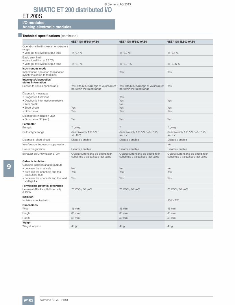
SIMATIC ET 200 distributed I/OET 200SI/O modulesAnalog electronic modules
9/102 Siemens ST 70 · 2013
■ Technical specifications (continued)
9
Operational limit in overall temperature range• Voltage, relative to output area +/- 0,4 % +/- 0,2 % +/- 0,1 %
Basic error limit(operational limit at 25 °C)• Voltage, relative to output area +/- 0,2 % +/- 0,01 % +/- 0,05 %
Isochronous modeIsochronous operation (applicationsynchronized up to terminal)
Yes Yes
Interrupts/diagnostics/status informationSubstitute values connectable Yes; 0 to 65535 (range of values must
be within the rated range)Yes; 0 to 65535 (range of values must be within the rated range)
Yes
Diagnostic messages• Diagnostic functions Yes• Diagnostic information readable Yes Yes• Wire break No• Short circuit Yes Yes Yes• Group error Yes Yes Yes
Diagnostics indication LED• Group error SF (red) Yes Yes Yes
ParameterRemark 7 bytes 7 7 bytes
Output type/range deactivated / 1 to 5 V / +/ -10 V
deactivated / 1 to 5 V / +/ -10 V / +/- 5 V
deactivated / 1 to 5 V / +/ -10 V / +/- 5 V
Diagnosis: short circuit Disable / enable Disable / enable Disable / enable
Interference frequency suppression No
Group diagnostics Disable / enable Disable / enable Disable / enable
Behavior on CPU/Master STOP Output current and de-energized/substitute a value/keep last value
Output current and de-energized/substitute a value/keep last value
Output current and de-energized/substitute a value/keep last value
Galvanic isolationGalvanic isolation analog outputs• between the channels No No No• between the channels and the
backplane busYes Yes Yes
• between the channels and the load voltage L+
Yes Yes Yes
Permissible potential differencebetween MANA and M internally (UISO)
75 VDC / 60 VAC 75 VDC / 60 VAC 75 VDC / 60 VAC
IsolationIsolation checked with 500 V DC
DimensionsWidth 15 mm 15 mm 15 mm
Height 81 mm 81 mm 81 mm
Depth 52 mm 52 mm 52 mm
WeightWeight, approx. 40 g 40 g 40 g
6ES7 135-4FB01-0AB0 6ES7 135-4FB52-0AB0 6ES7 135-4LB02-0AB0
© Siemens AG 2013
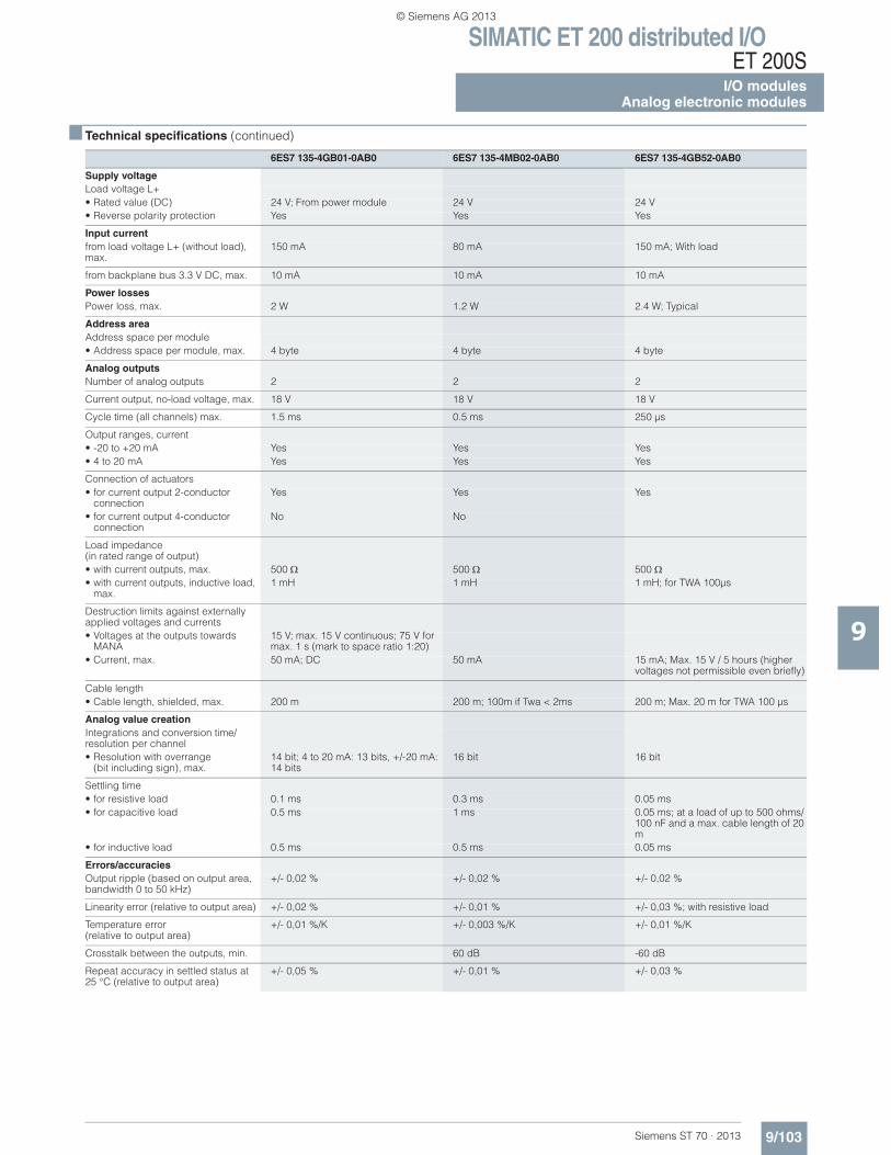
SIMATIC ET 200 distributed I/OET 200S
I/O modulesAnalog electronic modules
9/103Siemens ST 70 · 2013
■ Technical specifications (continued)
9
6ES7 135-4GB01-0AB0 6ES7 135-4MB02-0AB0 6ES7 135-4GB52-0AB0
Supply voltageLoad voltage L+• Rated value (DC) 24 V; From power module 24 V 24 V• Reverse polarity protection Yes Yes Yes
Input currentfrom load voltage L+ (without load), max.
150 mA 80 mA 150 mA; With load
from backplane bus 3.3 V DC, max. 10 mA 10 mA 10 mA
Power lossesPower loss, max. 2 W 1.2 W 2.4 W; Typical
Address areaAddress space per module• Address space per module, max. 4 byte 4 byte 4 byte
Analog outputsNumber of analog outputs 2 2 2
Current output, no-load voltage, max. 18 V 18 V 18 V
Cycle time (all channels) max. 1.5 ms 0.5 ms 250 μs
Output ranges, current• -20 to +20 mA Yes Yes Yes• 4 to 20 mA Yes Yes Yes
Connection of actuators• for current output 2-conductor
connectionYes Yes Yes
• for current output 4-conductor connection
No No
Load impedance(in rated range of output)• with current outputs, max. 500 500 500• with current outputs, inductive load,
max.1 mH 1 mH 1 mH; for TWA 100μs
Destruction limits against externally applied voltages and currents• Voltages at the outputs towards
MANA15 V; max. 15 V continuous; 75 V for max. 1 s (mark to space ratio 1:20)
• Current, max. 50 mA; DC 50 mA 15 mA; Max. 15 V / 5 hours (higher voltages not permissible even briefly)
Cable length• Cable length, shielded, max. 200 m 200 m; 100m if Twa < 2ms 200 m; Max. 20 m for TWA 100 μs
Analog value creationIntegrations and conversion time/resolution per channel• Resolution with overrange
(bit including sign), max.14 bit; 4 to 20 mA: 13 bits, +/-20 mA: 14 bits
16 bit 16 bit
Settling time• for resistive load 0.1 ms 0.3 ms 0.05 ms• for capacitive load 0.5 ms 1 ms 0.05 ms; at a load of up to 500 ohms/
100 nF and a max. cable length of 20 m
• for inductive load 0.5 ms 0.5 ms 0.05 ms
Errors/accuraciesOutput ripple (based on output area, bandwidth 0 to 50 kHz)
+/- 0,02 % +/- 0,02 % +/- 0,02 %
Linearity error (relative to output area) +/- 0,02 % +/- 0,01 % +/- 0,03 %; with resistive load
Temperature error (relative to output area)
+/- 0,01 %/K +/- 0,003 %/K +/- 0,01 %/K
Crosstalk between the outputs, min. 60 dB -60 dB
Repeat accuracy in settled status at 25 °C (relative to output area)
+/- 0,05 % +/- 0,01 % +/- 0,03 %
© Siemens AG 2013
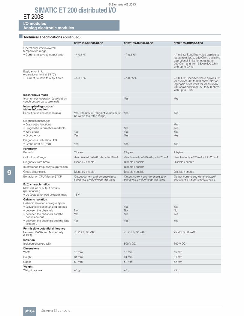
SIMATIC ET 200 distributed I/OET 200SI/O modulesAnalog electronic modules
9/104 Siemens ST 70 · 2013
■ Technical specifications (continued)
9
Operational limit in overall temperature range• Current, relative to output area +/- 0,5 % +/- 0,1 % +/- 0,2 %; Specified value applies to
loads from 200 to 350 Ohm, deviating operational limits for loads up to 200 Ohm and from 350 to 500 Ohm with up to 0.4%
Basic error limit (operational limit at 25 °C)• Current, relative to output area +/- 0,3 % +/- 0,05 % +/- 0,1 %; Specified value applies for
loads from 200 to 350 ohms, deviat-ing basic error limits for loads up to 200 ohms and from 350 to 500 ohms with up to 0.3%
Isochronous modeIsochronous operation (application synchronized up to terminal)
Yes Yes
Interrupts/diagnostics/status informationSubstitute values connectable Yes; 0 to 65535 (range of values must
be within the rated range)Yes Yes
Diagnostic messages• Diagnostic functions Yes• Diagnostic information readable Yes Yes• Wire break Yes Yes Yes• Group error Yes Yes Yes
Diagnostics indication LED• Group error SF (red) Yes Yes Yes
ParameterRemark 7 bytes 7 bytes 7 bytes
Output type/range deactivated / +/-20 mA / 4 to 20 mA deactivated / +/-20 mA / 4 to 20 mA deactivated / +/-20 mA / 4 to 20 mA
Diagnosis: wire break Disable / enable Disable / enable Disable / enable
Interference frequency suppression Disable / enable
Group diagnostics Disable / enable Disable / enable Disable / enable
Behavior on CPU/Master STOP Output current and de-energized/substitute a value/keep last value
Output current and de-energized/substitute a value/keep last value
Output current and de-energized/substitute a value/keep last value
Ex(i) characteristicsMax. values of output circuits (per channel)• Uo (output no-load voltage), max. 18 V
Galvanic isolationGalvanic isolation analog outputs• Galvanic isolation analog outputs Yes Yes• between the channels No No No• between the channels and the
backplane busYes Yes Yes
• between the channels and the load voltage L+
Yes Yes Yes
Permissible potential differencebetween MANA and M internally (UISO)
75 VDC / 60 VAC 75 VDC / 60 VAC 75 VDC / 60 VAC
IsolationIsolation checked with 500 V DC 500 V DC
DimensionsWidth 15 mm 15 mm 15 mm
Height 81 mm 81 mm 81 mm
Depth 52 mm 52 mm 52 mm
WeightWeight, approx. 40 g 40 g 45 g
6ES7 135-4GB01-0AB0 6ES7 135-4MB02-0AB0 6ES7 135-4GB52-0AB0
© Siemens AG 2013
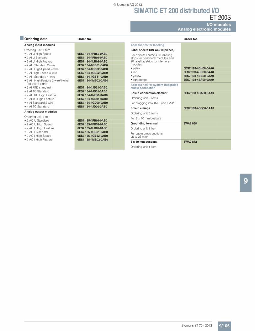
SIMATIC ET 200 distributed I/OET 200S
I/O modulesAnalog electronic modules
9/105Siemens ST 70 · 2013
9
■ Ordering data Order No. Order No.
Analog input modules
Ordering unit 1 item• 2 AI U High Speed 6ES7 134-4FB52-0AB0• 2 AI U Standard 6ES7 134-4FB01-0AB0• 2 AI U High Feature 6ES7 134-4LB02-0AB0• 2 AI I Standard 2-wire 6ES7 134-4GB01-0AB0• 2 AI I High Speed 2-wire 6ES7 134-4GB52-0AB0• 2 AI High Speed 4-wire 6ES7 134-4GB62-0AB0• 2 AI I Standard 4-wire 6ES7 134-4GB11-0AB0• 2 AI I High Feature 2-wire/4-wire
(15 bits + sign)6ES7 134-4MB02-0AB0
• 2 AI RTD standard 6ES7 134-4JB51-0AB0• 2 AI TC Standard 6ES7 134-4JB01-0AB0• 2 AI RTD High Feature 6ES7 134-4NB51-0AB0• 2 AI TC High Feature 6ES7 134-4NB01-0AB0• 4 AI Standard 2-wire 6ES7 134-4GD00-0AB0• 4 AI TC Standard 6ES7 134-4JD00-0AB0
Analog output modules
Ordering unit 1 item• 2 AO U Standard 6ES7 135-4FB01-0AB0• 2 AO U High Speed 6ES7 135-4FB52-0AB0• 2 AO U High Feature 6ES7 135-4LB02-0AB0• 2 AO I Standard 6ES7 135-4GB01-0AB0• 2 AO I High Speed 6ES7 135-4GB52-0AB0• 2 AO I High Feature 6ES7 135-4MB02-0AB0
Accessories for labeling
Label sheets DIN A4 (10 pieces)
Each sheet contains 60 labeling strips for peripheral modules and 20 labeling strips for interface modules• petrol 6ES7 193-4BH00-0AA0• red 6ES7 193-4BD00-0AA0• yellow 6ES7 193-4BB00-0AA0• light beige 6ES7 193-4BA00-0AA0
Accessories for system-integrated shield connection
Shield connection element 6ES7 193-4GA00-0AA0
Ordering unit 5 items
For plugging into TM-E and TM-P
Shield clamps 6ES7 193-4GB00-0AA0
Ordering unit 5 items
For 3 × 10 mm busbars
Grounding terminal 8WA2 868
Ordering unit 1 item
For cable cross-sections up to 25 mm2
3 × 10 mm busbars 8WA2 842
Ordering unit 1 item
© Siemens AG 2013
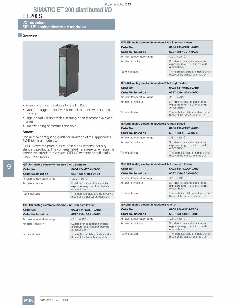
SIMATIC ET 200 distributed I/OET 200SI/O modulesSIPLUS analog electronic modules
9/106 Siemens ST 70 · 2013
9
■ Overview
• Analog inputs and outputs for the ET 200S• Can be plugged onto TM-E terminal modules with automatic
coding• High-speed variants with extremely short isochronous cycle
times• Hot swapping of modules possible
Notes:
Consult the configuring guide for selection of the appropriate TM-E terminal modules.
SIPLUS extreme products are based on Siemens Industry standard products. The contents listed here were taken from the respective standard products. SIPLUS extreme-specific infor-mation was added.
SIPLUS analog electronic module 2 AI U Standard
Order No. 6AG1 134-4FB01-2AB0
Order No. based on 6ES7 134-4FB01-0AB0
Ambient temperature range -25 ... +60 °C
Ambient conditions Suitable for exceptional medial exposure (e.g. in sulfur chloride atmosphere).
Technical data The technical data are identical with those of the based-on modules.
SIPLUS analog electronic module 2 AI I Standard 2-wire
Order No. 6AG1 134-4GB01-2AB0
Order No. based on 6ES7 134-4GB01-0AB0
Ambient temperature range -25 ... +60 °C
Ambient conditions Suitable for exceptional medial exposure (e.g. in sulfur chloride atmosphere).
Technical data The technical data are identical with those of the based-on modules.
SIPLUS analog electronic module 2 AI I Standard 4-wire
Order No. 6AG1 134-4GB11-2AB0
Order No. based on 6ES7 134-4GB11-0AB0
Ambient temperature range -25 ... +60 °C
Ambient conditions Suitable for exceptional medial exposure (e.g. in sulfur chloride atmosphere).
Technical data The technical data are identical with those of the based-on modules.
SIPLUS analog electronic module 2 AI I High Feature
Order No. 6AG1 134-4MB02-2AB0
Order No. based on 6ES7 134-4MB02-0AB0
Ambient temperature range -25 ... +70 °C
Ambient conditions Suitable for exceptional medial exposure (e.g. in sulfur chloride atmosphere).
Technical data The technical data are identical with those of the based-on modules.
SIPLUS analog electronic module 2 AI High Speed
Order No. 6AG1 134-4GB52-2AB0
Order No. based on 6ES7 134-4GB52-0AB0
Ambient temperature range -25 ... +60 °C
Ambient conditions Suitable for exceptional medial exposure (e.g. in sulfur chloride atmosphere).
Technical data The technical data are identical with those of the based-on modules.
SIPLUS analog electronic module 4 AI I Standard 2-wire
Order No. 6AG1 134-4GD00-2AB0
Order No. based on 6ES7 134-4GD00-0AB0
Ambient temperature range -25 ... +70 °C
Ambient conditions Suitable for exceptional medial exposure (e.g. in sulfur chloride atmosphere).
Technical data The technical data are identical with those of the based-on modules.
SIPLUS analog electronic module 2 AI RTD
Order No. 6AG1 134-4JB51-7AB0
Order No. based on 6ES7 134-4JB51-0AB0
Ambient temperature range -25 ... +60 °C
Ambient conditions Suitable for exceptional medial exposure (e.g. in sulfur chloride atmosphere).
Technical data The technical data are identical with those of the based-on modules.
© Siemens AG 2013
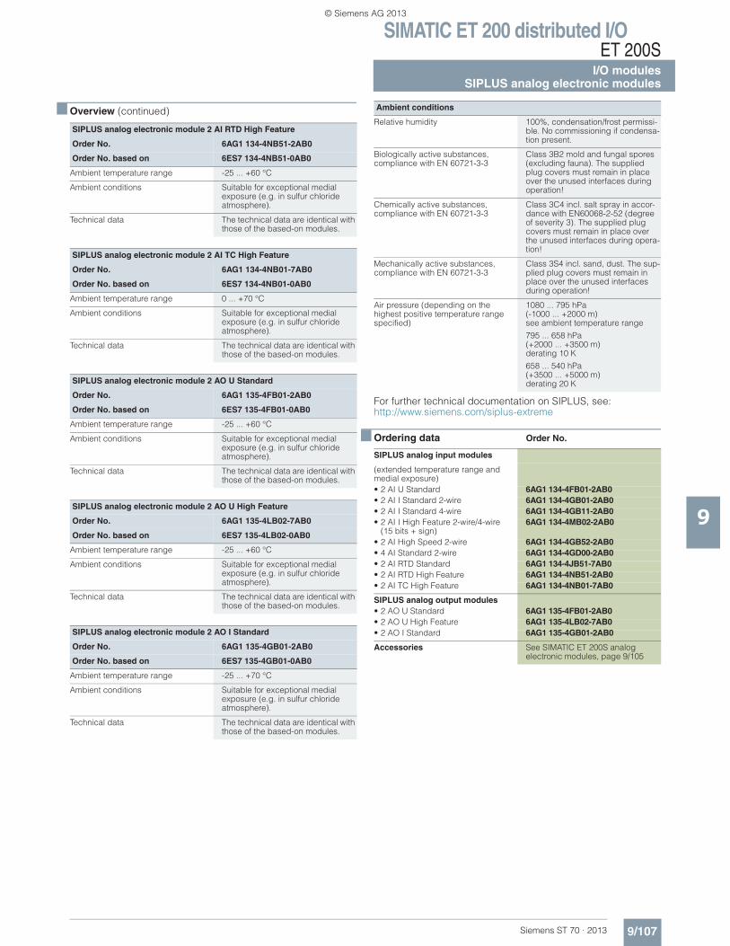
SIMATIC ET 200 distributed I/OET 200S
I/O modulesSIPLUS analog electronic modules
9/107Siemens ST 70 · 2013
■ Overview (continued)
9
SIPLUS analog electronic module 2 AI RTD High Feature
Order No. 6AG1 134-4NB51-2AB0
Order No. based on 6ES7 134-4NB51-0AB0
Ambient temperature range -25 ... +60 °C
Ambient conditions Suitable for exceptional medial exposure (e.g. in sulfur chloride atmosphere).
Technical data The technical data are identical with those of the based-on modules.
SIPLUS analog electronic module 2 AI TC High Feature
Order No. 6AG1 134-4NB01-7AB0
Order No. based on 6ES7 134-4NB01-0AB0
Ambient temperature range 0 ... +70 °C
Ambient conditions Suitable for exceptional medial exposure (e.g. in sulfur chloride atmosphere).
Technical data The technical data are identical with those of the based-on modules.
SIPLUS analog electronic module 2 AO U Standard
Order No. 6AG1 135-4FB01-2AB0
Order No. based on 6ES7 135-4FB01-0AB0
Ambient temperature range -25 ... +60 °C
Ambient conditions Suitable for exceptional medial exposure (e.g. in sulfur chloride atmosphere).
Technical data The technical data are identical with those of the based-on modules.
SIPLUS analog electronic module 2 AO U High Feature
Order No. 6AG1 135-4LB02-7AB0
Order No. based on 6ES7 135-4LB02-0AB0
Ambient temperature range -25 ... +60 °C
Ambient conditions Suitable for exceptional medial exposure (e.g. in sulfur chloride atmosphere).
Technical data The technical data are identical with those of the based-on modules.
SIPLUS analog electronic module 2 AO I Standard
Order No. 6AG1 135-4GB01-2AB0
Order No. based on 6ES7 135-4GB01-0AB0
Ambient temperature range -25 ... +70 °C
Ambient conditions Suitable for exceptional medial exposure (e.g. in sulfur chloride atmosphere).
Technical data The technical data are identical with those of the based-on modules.
For further technical documentation on SIPLUS, see:http://www.siemens.com/siplus-extreme
■ Ordering data Order No.
Ambient conditions
Relative humidity 100%, condensation/frost permissi-ble. No commissioning if condensa-tion present.
Biologically active substances, compliance with EN 60721-3-3
Class 3B2 mold and fungal spores (excluding fauna). The supplied plug covers must remain in place over the unused interfaces during operation!
Chemically active substances, compliance with EN 60721-3-3
Class 3C4 incl. salt spray in accor-dance with EN60068-2-52 (degree of severity 3). The supplied plug covers must remain in place over the unused interfaces during opera-tion!
Mechanically active substances, compliance with EN 60721-3-3
Class 3S4 incl. sand, dust. The sup-plied plug covers must remain in place over the unused interfaces during operation!
Air pressure (depending on the highest positive temperature range specified)
1080 ... 795 hPa(-1000 ... +2000 m) see ambient temperature range
795 ... 658 hPa (+2000 ... +3500 m) derating 10 K
658 ... 540 hPa (+3500 ... +5000 m) derating 20 K
SIPLUS analog input modules
(extended temperature range and medial exposure)• 2 AI U Standard 6AG1 134-4FB01-2AB0• 2 AI I Standard 2-wire 6AG1 134-4GB01-2AB0• 2 AI I Standard 4-wire 6AG1 134-4GB11-2AB0• 2 AI I High Feature 2-wire/4-wire
(15 bits + sign)6AG1 134-4MB02-2AB0
• 2 AI High Speed 2-wire 6AG1 134-4GB52-2AB0• 4 AI Standard 2-wire 6AG1 134-4GD00-2AB0• 2 AI RTD Standard 6AG1 134-4JB51-7AB0• 2 AI RTD High Feature 6AG1 134-4NB51-2AB0• 2 AI TC High Feature 6AG1 134-4NB01-7AB0
SIPLUS analog output modules• 2 AO U Standard 6AG1 135-4FB01-2AB0• 2 AO U High Feature 6AG1 135-4LB02-7AB0• 2 AO I Standard 6AG1 135-4GB01-2AB0
Accessories See SIMATIC ET 200S analogelectronic modules, page 9/105
© Siemens AG 2013
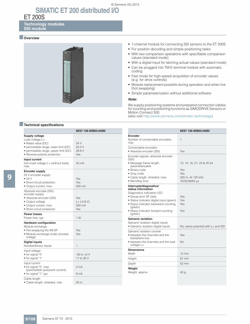
SIMATIC ET 200 distributed I/OET 200STechnology modulesSSI module
9/108 Siemens ST 70 · 2013
9
■ Overview
• 1-channel module for connecting SSI sensors to the ET 200S• For position decoding and simple positioning tasks• With two comparison operations with specifiable comparison
values (standard mode)• With a digital input for latching actual values (standard mode)• Can be plugged into TM-E terminal module with automatic
coding• Fast mode for high-speed acquisition of encoder values
(e.g. for drive controls)• Module replacement possible during operation and when live
(hot swapping)• Simple parameterization without additional software
Note:
We supply positioning systems and prepared connection cables for counting and positioning functions as SIMODRIVE Sensors or Motion Connect 500 (also visit http://www.siemens.com/simatic-technology)
■ Technical specifications
6ES7 138-4DB03-0AB0
Supply voltageLoad voltage L+• Rated value (DC) 24 V• permissible range, lower limit (DC) 20.4 V• permissible range, upper limit (DC) 28.8 V• Reverse polarity protection Yes
Input currentfrom load voltage L+ (without load), max.
40 mA
Encoder supply24 V encoder supply• 24 V Yes• Short-circuit protection Yes• Output current, max. 500 mA
Absolute encoder (SSI)encoder supply• Absolute encoder (SSI) Yes• Output voltage L+ (-0.8 V)• Output current, max. 500 mA• Short-circuit protection Yes
Power lossesPower loss, typ. 1 W
Hardware configurationModule exchange• Hot swapping the IM-DP Yes• Module exchange under process
voltageYes
Digital inputsNumber/binary inputs 1
Input voltage• for signal "0" -30 to +5 V• for signal "1" 11 to 30 V
Input current• for signal "0", max.
(permissible quiescent current)2 mA
• for signal "1", typ. 9 mA
Cable length• Cable length, shielded, max. 50 m
EncoderNumber of connectable encoders, max.
1
Connectable encoders• Absolute encoder (SSI) Yes
Encoder signals, absolute encoder (SSI)• Message frame length,
parameterizable13, 14, 16, 21, 24 & 25 bit
• Binary code Yes• Gray code Yes• Cable length, shielded, max. 320 m; At 125 kHz• Monoflop time 16/32/48/64 μs
Interrupts/diagnostics/status informationDiagnostics indication LED• Group error SF (red) Yes• Status indicator digital input (green) Yes• Status indicator backward counting
(green)Yes
• Status indicator forward counting (green)
Yes
Galvanic isolationGalvanic isolation digital inputs• Galvanic isolation digital inputs No; same potential with L+ and SSI
Galvanic isolation counter• between the channels and the
backplane busYes
• between the channels and the load voltage L+
No
DimensionsWidth 15 mm
Height 81 mm
Depth 52 mm
WeightWeight, approx. 40 g
6ES7 138-4DB03-0AB0
© Siemens AG 2013
SIMATIC ET 200 distributed I/OET 200S
Technology modulesSSI module
9/109Siemens ST 70 · 2013
9
■ Ordering data Order No. Order No.
SSI module 6ES7 138-4DB03-0AB0
For connecting absolute encoders with an SSI interface
Accessories
Label sheets DIN A4 (10 pieces)
Each sheet contains 60 labeling strips for peripheral modules and 20 labeling strips for interface modules• petrol 6ES7 193-4BH00-0AA0• red 6ES7 193-4BD00-0AA0• yellow 6ES7 193-4BB00-0AA0• light beige 6ES7 193-4BA00-0AA0
Signal cable
Preassembled for SSI absolute encoder 6FX2001-5, without D-Sub connector, UL/DESINA
For length code, see page 5/114
6FX5 002-2CC12-....
© Siemens AG 2013
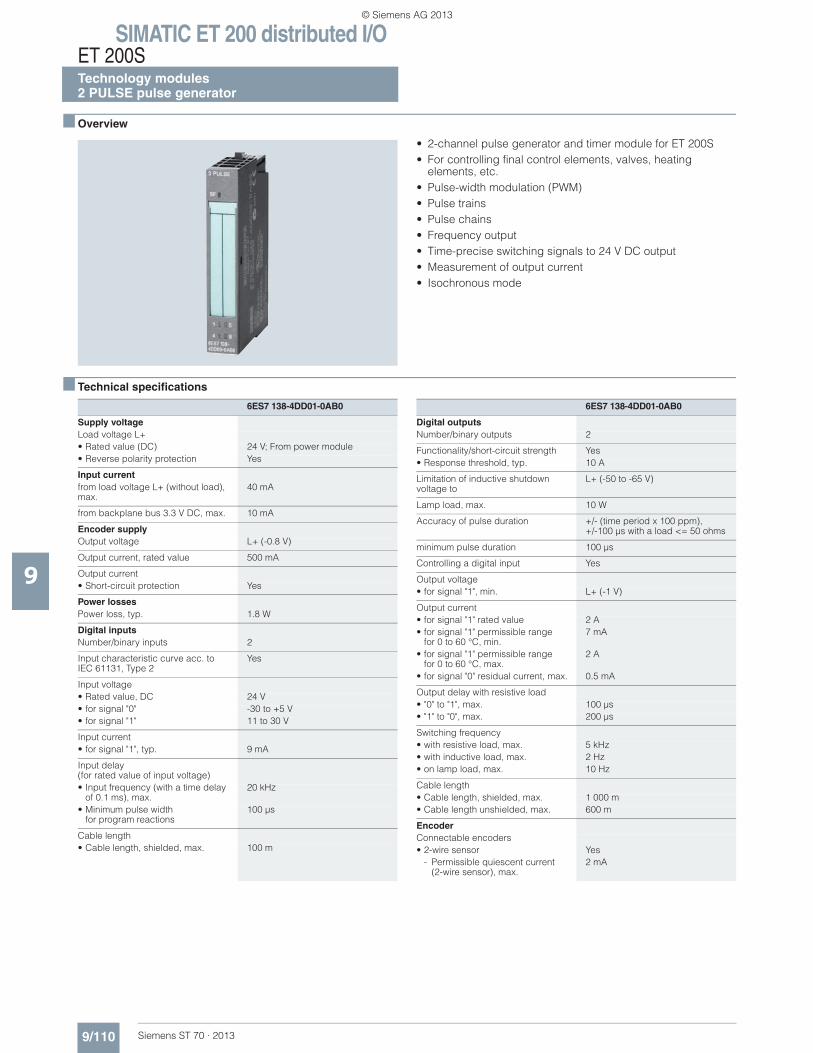
SIMATIC ET 200 distributed I/OET 200STechnology modules2 PULSE pulse generator
9/110 Siemens ST 70 · 2013
9
■ Overview
• 2-channel pulse generator and timer module for ET 200S• For controlling final control elements, valves, heating
elements, etc. • Pulse-width modulation (PWM)• Pulse trains• Pulse chains• Frequency output• Time-precise switching signals to 24 V DC output• Measurement of output current• Isochronous mode
■ Technical specifications
6ES7 138-4DD01-0AB0
Supply voltageLoad voltage L+• Rated value (DC) 24 V; From power module• Reverse polarity protection Yes
Input currentfrom load voltage L+ (without load), max.
40 mA
from backplane bus 3.3 V DC, max. 10 mA
Encoder supplyOutput voltage L+ (-0.8 V)
Output current, rated value 500 mA
Output current• Short-circuit protection Yes
Power lossesPower loss, typ. 1.8 W
Digital inputsNumber/binary inputs 2
Input characteristic curve acc. to IEC 61131, Type 2
Yes
Input voltage• Rated value, DC 24 V• for signal "0" -30 to +5 V• for signal "1" 11 to 30 V
Input current• for signal "1", typ. 9 mA
Input delay(for rated value of input voltage)• Input frequency (with a time delay
of 0.1 ms), max.20 kHz
• Minimum pulse widthfor program reactions
100 μs
Cable length• Cable length, shielded, max. 100 m
Digital outputsNumber/binary outputs 2
Functionality/short-circuit strength Yes• Response threshold, typ. 10 A
Limitation of inductive shutdownvoltage to
L+ (-50 to -65 V)
Lamp load, max. 10 W
Accuracy of pulse duration +/- (time period x 100 ppm),+/-100 μs with a load <= 50 ohms
minimum pulse duration 100 μs
Controlling a digital input Yes
Output voltage• for signal "1", min. L+ (-1 V)
Output current• for signal "1" rated value 2 A• for signal "1" permissible range
for 0 to 60 °C, min.7 mA
• for signal "1" permissible rangefor 0 to 60 °C, max.
2 A
• for signal "0" residual current, max. 0.5 mA
Output delay with resistive load• "0" to "1", max. 100 μs• "1" to "0", max. 200 μs
Switching frequency• with resistive load, max. 5 kHz• with inductive load, max. 2 Hz• on lamp load, max. 10 Hz
Cable length• Cable length, shielded, max. 1 000 m• Cable length unshielded, max. 600 m
EncoderConnectable encoders• 2-wire sensor Yes
- Permissible quiescent current (2-wire sensor), max.
2 mA
6ES7 138-4DD01-0AB0
© Siemens AG 2013
SIMATIC ET 200 distributed I/OET 200S
Technology modules2 PULSE pulse generator
9/111Siemens ST 70 · 2013
■ Technical specifications (continued)
9
Interrupts/diagnostics/status informationDiagnostics indication LED• Group error SF (red) Yes• Status indicator digital output (green) Yes• Status indicator digital input (green) Yes
Pulse generatorNumber of channels 2; 1 digital input and 1 digital output
per channel
Galvanic isolationGalvanic isolation digital inputs• between the channels No• between the channels and the
backplane busYes
Galvanic isolation digital outputs• between the channels No• between the channels and the
backplane busYes
Permissible potential differencebetween different circuits 75 VDC / 60 VAC
IsolationIsolation checked with 500 V DC
DimensionsWidth 15 mm
Height 81 mm
Depth 52 mm
WeightWeight, approx. 40 g
6ES7 138-4DD01-0AB0
■ Ordering data Order No.
Pulse generator and timer module 2PULSE
6ES7 138-4DD01-0AB0
For ET 200S
Accessories
Label sheets DIN A4 (10 pieces)
Each sheet contains 60 labeling strips for peripheral modules and 20 labeling strips for interface modules• petrol 6ES7 193-4BH00-0AA0• red 6ES7 193-4BD00-0AA0• yellow 6ES7 193-4BB00-0AA0• light beige 6ES7 193-4BA00-0AA0
© Siemens AG 2013
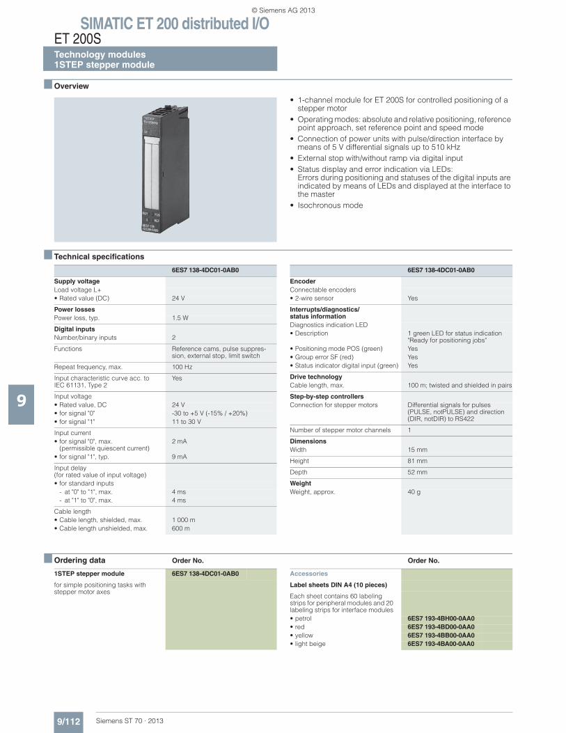
SIMATIC ET 200 distributed I/OET 200STechnology modules1STEP stepper module
9/112 Siemens ST 70 · 2013
9
■ Overview
• 1-channel module for ET 200S for controlled positioning of a stepper motor
• Operating modes: absolute and relative positioning, reference point approach, set reference point and speed mode
• Connection of power units with pulse/direction interface by means of 5 V differential signals up to 510 kHz
• External stop with/without ramp via digital input• Status display and error indication via LEDs:
Errors during positioning and statuses of the digital inputs are indicated by means of LEDs and displayed at the interface to the master
• Isochronous mode
■ Technical specifications
■ Ordering data Order No. Order No.
6ES7 138-4DC01-0AB0
Supply voltageLoad voltage L+• Rated value (DC) 24 V
Power lossesPower loss, typ. 1.5 W
Digital inputsNumber/binary inputs 2
Functions Reference cams, pulse suppres-sion, external stop, limit switch
Repeat frequency, max. 100 Hz
Input characteristic curve acc. to IEC 61131, Type 2
Yes
Input voltage• Rated value, DC 24 V• for signal "0" -30 to +5 V (-15% / +20%)• for signal "1" 11 to 30 V
Input current• for signal "0", max.
(permissible quiescent current)2 mA
• for signal "1", typ. 9 mA
Input delay(for rated value of input voltage)• for standard inputs
- at "0" to "1", max. 4 ms- at "1" to "0", max. 4 ms
Cable length• Cable length, shielded, max. 1 000 m• Cable length unshielded, max. 600 m
EncoderConnectable encoders• 2-wire sensor Yes
Interrupts/diagnostics/status informationDiagnostics indication LED• Description 1 green LED for status indication
"Ready for positioning jobs"• Positioning mode POS (green) Yes• Group error SF (red) Yes• Status indicator digital input (green) Yes
Drive technologyCable length, max. 100 m; twisted and shielded in pairs
Step-by-step controllersConnection for stepper motors Differential signals for pulses
(PULSE, notPULSE) and direction (DIR, notDIR) to RS422
Number of stepper motor channels 1
DimensionsWidth 15 mm
Height 81 mm
Depth 52 mm
WeightWeight, approx. 40 g
6ES7 138-4DC01-0AB0
1STEP stepper module 6ES7 138-4DC01-0AB0
for simple positioning tasks with stepper motor axes
Accessories
Label sheets DIN A4 (10 pieces)
Each sheet contains 60 labeling strips for peripheral modules and 20 labeling strips for interface modules• petrol 6ES7 193-4BH00-0AA0• red 6ES7 193-4BD00-0AA0• yellow 6ES7 193-4BB00-0AA0• light beige 6ES7 193-4BA00-0AA0
© Siemens AG 2013
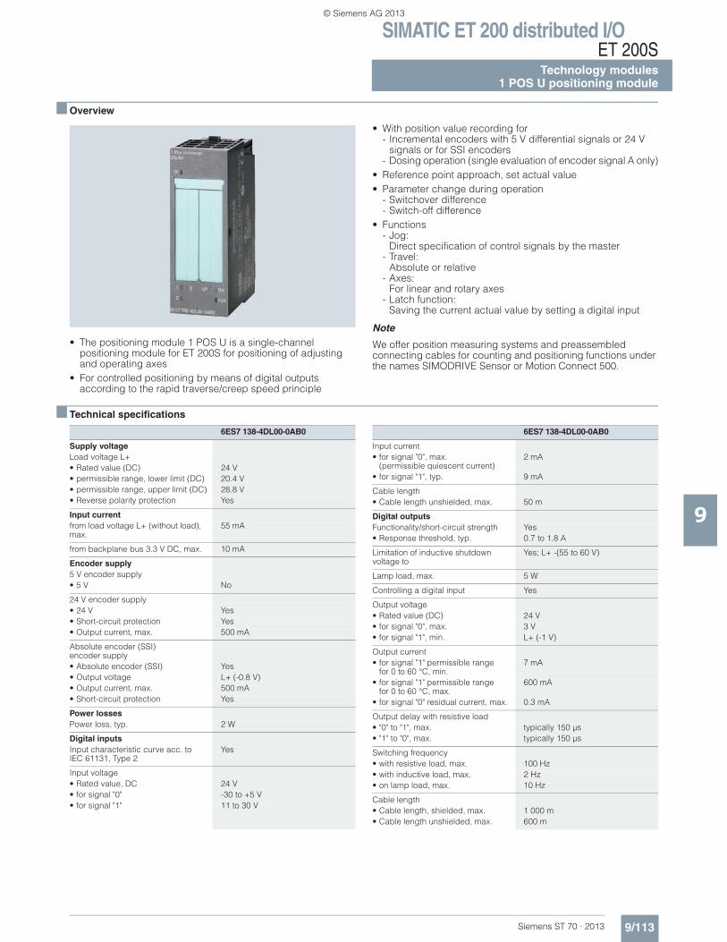
SIMATIC ET 200 distributed I/OET 200S
Technology modules1 POS U positioning module
9/113Siemens ST 70 · 2013
9
■ Overview
• The positioning module 1 POS U is a single-channel positioning module for ET 200S for positioning of adjusting and operating axes
• For controlled positioning by means of digital outputs according to the rapid traverse/creep speed principle
• With position value recording for - Incremental encoders with 5 V differential signals or 24 V
signals or for SSI encoders- Dosing operation (single evaluation of encoder signal A only)
• Reference point approach, set actual value • Parameter change during operation
- Switchover difference - Switch-off difference
• Functions - Jog:
Direct specification of control signals by the master - Travel:
Absolute or relative - Axes:
For linear and rotary axes - Latch function:
Saving the current actual value by setting a digital input
Note
We offer position measuring systems and preassembled connecting cables for counting and positioning functions under the names SIMODRIVE Sensor or Motion Connect 500.
■ Technical specifications
6ES7 138-4DL00-0AB0
Supply voltageLoad voltage L+• Rated value (DC) 24 V• permissible range, lower limit (DC) 20.4 V• permissible range, upper limit (DC) 28.8 V• Reverse polarity protection Yes
Input currentfrom load voltage L+ (without load), max.
55 mA
from backplane bus 3.3 V DC, max. 10 mA
Encoder supply5 V encoder supply• 5 V No
24 V encoder supply• 24 V Yes• Short-circuit protection Yes• Output current, max. 500 mA
Absolute encoder (SSI) encoder supply• Absolute encoder (SSI) Yes• Output voltage L+ (-0.8 V)• Output current, max. 500 mA• Short-circuit protection Yes
Power lossesPower loss, typ. 2 W
Digital inputsInput characteristic curve acc. to IEC 61131, Type 2
Yes
Input voltage• Rated value, DC 24 V• for signal "0" -30 to +5 V• for signal "1" 11 to 30 V
Input current• for signal "0", max.
(permissible quiescent current)2 mA
• for signal "1", typ. 9 mA
Cable length• Cable length unshielded, max. 50 m
Digital outputsFunctionality/short-circuit strength Yes• Response threshold, typ. 0.7 to 1.8 A
Limitation of inductive shutdown voltage to
Yes; L+ -(55 to 60 V)
Lamp load, max. 5 W
Controlling a digital input Yes
Output voltage• Rated value (DC) 24 V• for signal "0", max. 3 V• for signal "1", min. L+ (-1 V)
Output current• for signal "1" permissible range
for 0 to 60 °C, min.7 mA
• for signal "1" permissible rangefor 0 to 60 °C, max.
600 mA
• for signal "0" residual current, max. 0.3 mA
Output delay with resistive load• "0" to "1", max. typically 150 μs• "1" to "0", max. typically 150 μs
Switching frequency• with resistive load, max. 100 Hz• with inductive load, max. 2 Hz• on lamp load, max. 10 Hz
Cable length• Cable length, shielded, max. 1 000 m• Cable length unshielded, max. 600 m
6ES7 138-4DL00-0AB0
© Siemens AG 2013
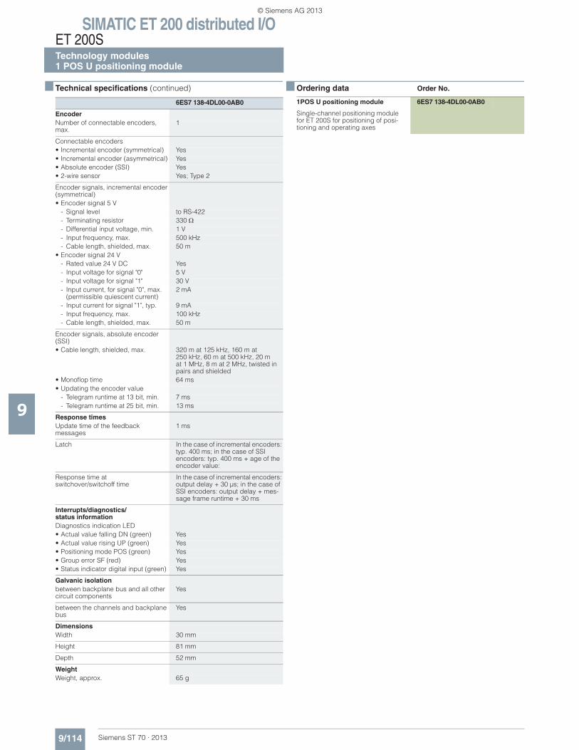
SIMATIC ET 200 distributed I/OET 200STechnology modules1 POS U positioning module
9/114 Siemens ST 70 · 2013
■ Technical specifications (continued)
9
EncoderNumber of connectable encoders, max.
1
Connectable encoders• Incremental encoder (symmetrical) Yes• Incremental encoder (asymmetrical) Yes• Absolute encoder (SSI) Yes• 2-wire sensor Yes; Type 2
Encoder signals, incremental encoder (symmetrical)• Encoder signal 5 V
- Signal level to RS-422- Terminating resistor 330- Differential input voltage, min. 1 V- Input frequency, max. 500 kHz- Cable length, shielded, max. 50 m
• Encoder signal 24 V- Rated value 24 V DC Yes- Input voltage for signal "0" 5 V- Input voltage for signal "1" 30 V- Input current, for signal "0", max.
(permissible quiescent current)2 mA
- Input current for signal "1", typ. 9 mA- Input frequency, max. 100 kHz- Cable length, shielded, max. 50 m
Encoder signals, absolute encoder (SSI)• Cable length, shielded, max. 320 m at 125 kHz, 160 m at
250 kHz, 60 m at 500 kHz, 20 mat 1 MHz, 8 m at 2 MHz, twisted in pairs and shielded
• Monoflop time 64 ms• Updating the encoder value
- Telegram runtime at 13 bit, min. 7 ms- Telegram runtime at 25 bit, min. 13 ms
Response timesUpdate time of the feedback messages
1 ms
Latch In the case of incremental encoders: typ. 400 ms; in the case of SSI encoders: typ. 400 ms + age of the encoder value:
Response time at switchover/switchoff time
In the case of incremental encoders: output delay + 30 μs; in the case of SSI encoders: output delay + mes-sage frame runtime + 30 ms
Interrupts/diagnostics/status informationDiagnostics indication LED• Actual value falling DN (green) Yes• Actual value rising UP (green) Yes• Positioning mode POS (green) Yes• Group error SF (red) Yes• Status indicator digital input (green) Yes
Galvanic isolationbetween backplane bus and all other circuit components
Yes
between the channels and backplane bus
Yes
DimensionsWidth 30 mm
Height 81 mm
Depth 52 mm
WeightWeight, approx. 65 g
6ES7 138-4DL00-0AB0
■ Ordering data Order No.
1POS U positioning module 6ES7 138-4DL00-0AB0
Single-channel positioning module for ET 200S for positioning of posi-tioning and operating axes
© Siemens AG 2013
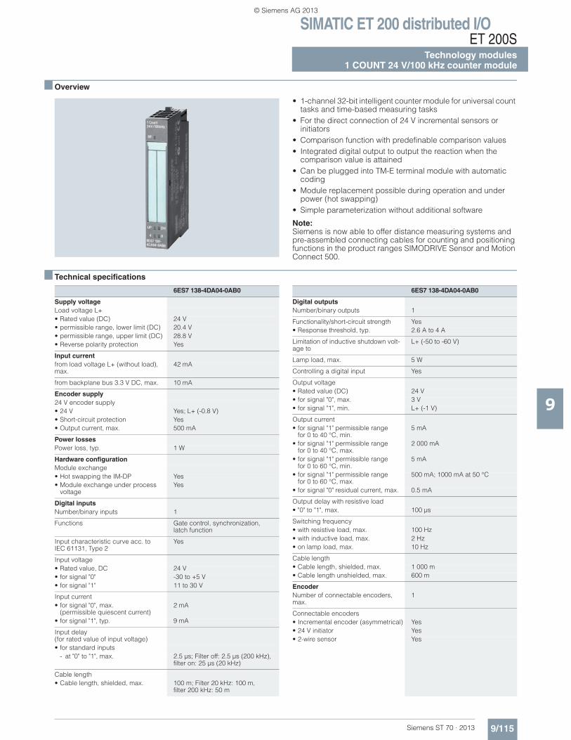
SIMATIC ET 200 distributed I/OET 200S
Technology modules1 COUNT 24 V/100 kHz counter module
9/115Siemens ST 70 · 2013
9
■ Overview
• 1-channel 32-bit intelligent counter module for universal count tasks and time-based measuring tasks
• For the direct connection of 24 V incremental sensors or initiators
• Comparison function with predefinable comparison values• Integrated digital output to output the reaction when the
comparison value is attained• Can be plugged into TM-E terminal module with automatic
coding• Module replacement possible during operation and under
power (hot swapping)• Simple parameterization without additional software
Note:Siemens is now able to offer distance measuring systems and pre-assembled connecting cables for counting and positioning functions in the product ranges SIMODRIVE Sensor and Motion Connect 500.
■ Technical specifications
6ES7 138-4DA04-0AB0
Supply voltageLoad voltage L+• Rated value (DC) 24 V• permissible range, lower limit (DC) 20.4 V• permissible range, upper limit (DC) 28.8 V• Reverse polarity protection Yes
Input currentfrom load voltage L+ (without load), max.
42 mA
from backplane bus 3.3 V DC, max. 10 mA
Encoder supply24 V encoder supply• 24 V Yes; L+ (-0.8 V)• Short-circuit protection Yes• Output current, max. 500 mA
Power lossesPower loss, typ. 1 W
Hardware configurationModule exchange• Hot swapping the IM-DP Yes• Module exchange under process
voltageYes
Digital inputsNumber/binary inputs 1
Functions Gate control, synchronization,latch function
Input characteristic curve acc. to IEC 61131, Type 2
Yes
Input voltage• Rated value, DC 24 V• for signal "0" -30 to +5 V• for signal "1" 11 to 30 V
Input current• for signal "0", max.
(permissible quiescent current)2 mA
• for signal "1", typ. 9 mA
Input delay(for rated value of input voltage)• for standard inputs
- at "0" to "1", max. 2.5 μs; Filter off: 2.5 μs (200 kHz),filter on: 25 μs (20 kHz)
Cable length• Cable length, shielded, max. 100 m; Filter 20 kHz: 100 m,
filter 200 kHz: 50 m
Digital outputsNumber/binary outputs 1
Functionality/short-circuit strength Yes• Response threshold, typ. 2.6 A to 4 A
Limitation of inductive shutdown volt-age to
L+ (-50 to -60 V)
Lamp load, max. 5 W
Controlling a digital input Yes
Output voltage• Rated value (DC) 24 V• for signal "0", max. 3 V• for signal "1", min. L+ (-1 V)
Output current• for signal "1" permissible range
for 0 to 40 °C, min.5 mA
• for signal "1" permissible rangefor 0 to 40 °C, max.
2 000 mA
• for signal "1" permissible rangefor 0 to 60 °C, min.
5 mA
• for signal "1" permissible rangefor 0 to 60 °C, max.
500 mA; 1000 mA at 50 °C
• for signal "0" residual current, max. 0.5 mA
Output delay with resistive load• "0" to "1", max. 100 μs
Switching frequency• with resistive load, max. 100 Hz• with inductive load, max. 2 Hz• on lamp load, max. 10 Hz
Cable length• Cable length, shielded, max. 1 000 m• Cable length unshielded, max. 600 m
EncoderNumber of connectable encoders, max.
1
Connectable encoders• Incremental encoder (asymmetrical) Yes• 24 V initiator Yes• 2-wire sensor Yes
6ES7 138-4DA04-0AB0
© Siemens AG 2013
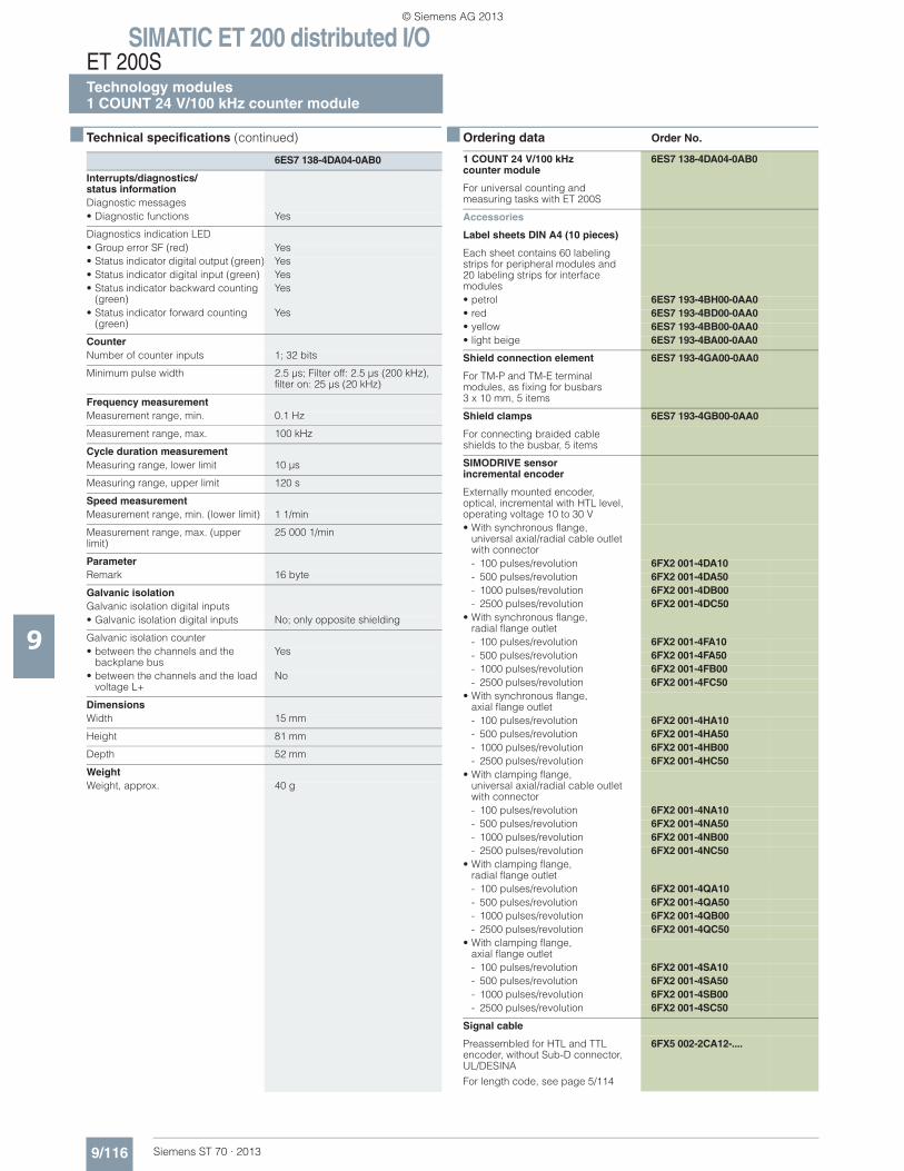
SIMATIC ET 200 distributed I/OET 200STechnology modules1 COUNT 24 V/100 kHz counter module
9/116 Siemens ST 70 · 2013
■ Technical specifications (continued)
9
Interrupts/diagnostics/status informationDiagnostic messages• Diagnostic functions Yes
Diagnostics indication LED• Group error SF (red) Yes• Status indicator digital output (green) Yes• Status indicator digital input (green) Yes• Status indicator backward counting
(green)Yes
• Status indicator forward counting (green)
Yes
CounterNumber of counter inputs 1; 32 bits
Minimum pulse width 2.5 μs; Filter off: 2.5 μs (200 kHz),filter on: 25 μs (20 kHz)
Frequency measurementMeasurement range, min. 0.1 Hz
Measurement range, max. 100 kHz
Cycle duration measurementMeasuring range, lower limit 10 μs
Measuring range, upper limit 120 s
Speed measurementMeasurement range, min. (lower limit) 1 1/min
Measurement range, max. (upper limit)
25 000 1/min
ParameterRemark 16 byte
Galvanic isolationGalvanic isolation digital inputs• Galvanic isolation digital inputs No; only opposite shielding
Galvanic isolation counter• between the channels and the
backplane busYes
• between the channels and the load voltage L+
No
DimensionsWidth 15 mm
Height 81 mm
Depth 52 mm
WeightWeight, approx. 40 g
6ES7 138-4DA04-0AB0
■ Ordering data Order No.
1 COUNT 24 V/100 kHz counter module
6ES7 138-4DA04-0AB0
For universal counting and measuring tasks with ET 200S
Accessories
Label sheets DIN A4 (10 pieces)
Each sheet contains 60 labeling strips for peripheral modules and 20 labeling strips for interface modules• petrol 6ES7 193-4BH00-0AA0• red 6ES7 193-4BD00-0AA0• yellow 6ES7 193-4BB00-0AA0• light beige 6ES7 193-4BA00-0AA0
Shield connection element 6ES7 193-4GA00-0AA0
For TM-P and TM-E terminalmodules, as fixing for busbars 3 x 10 mm, 5 items
Shield clamps 6ES7 193-4GB00-0AA0
For connecting braided cable shields to the busbar, 5 items
SIMODRIVE sensorincremental encoder
Externally mounted encoder, optical, incremental with HTL level, operating voltage 10 to 30 V• With synchronous flange,
universal axial/radial cable outlet with connector- 100 pulses/revolution 6FX2 001-4DA10- 500 pulses/revolution 6FX2 001-4DA50- 1000 pulses/revolution 6FX2 001-4DB00- 2500 pulses/revolution 6FX2 001-4DC50
• With synchronous flange,radial flange outlet- 100 pulses/revolution 6FX2 001-4FA10- 500 pulses/revolution 6FX2 001-4FA50- 1000 pulses/revolution 6FX2 001-4FB00- 2500 pulses/revolution 6FX2 001-4FC50
• With synchronous flange, axial flange outlet- 100 pulses/revolution 6FX2 001-4HA10- 500 pulses/revolution 6FX2 001-4HA50- 1000 pulses/revolution 6FX2 001-4HB00- 2500 pulses/revolution 6FX2 001-4HC50
• With clamping flange,universal axial/radial cable outlet with connector- 100 pulses/revolution 6FX2 001-4NA10- 500 pulses/revolution 6FX2 001-4NA50- 1000 pulses/revolution 6FX2 001-4NB00- 2500 pulses/revolution 6FX2 001-4NC50
• With clamping flange,radial flange outlet- 100 pulses/revolution 6FX2 001-4QA10- 500 pulses/revolution 6FX2 001-4QA50- 1000 pulses/revolution 6FX2 001-4QB00- 2500 pulses/revolution 6FX2 001-4QC50
• With clamping flange, axial flange outlet- 100 pulses/revolution 6FX2 001-4SA10- 500 pulses/revolution 6FX2 001-4SA50- 1000 pulses/revolution 6FX2 001-4SB00- 2500 pulses/revolution 6FX2 001-4SC50
Signal cable
Preassembled for HTL and TTL encoder, without Sub-D connector, UL/DESINA
For length code, see page 5/114
6FX5 002-2CA12-....
© Siemens AG 2013
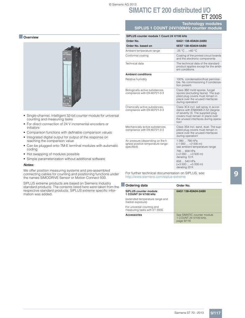
SIMATIC ET 200 distributed I/OET 200S
Technology modulesSIPLUS 1 COUNT 24V/100kHz counter module
9/117Siemens ST 70 · 2013
9
■ Overview
• Single-channel, intelligent 32-bit counter module for universal counting and measuring tasks
• For direct connection of 24 V incremental encoders or initiators
• Comparison functions with definable comparison values• Integrated digital output for output of the response on
reaching the comparison value• Can be plugged onto TM-E terminal modules with automatic
coding• Hot swapping of modules possible• Simple parameterization without additional software
Notes:
We offer position measuring systems and pre-assembled connecting cables for counting and positioning functions under the names SIMODRIVE Sensor or Motion Connect 500.
SIPLUS extreme products are based on Siemens Industry standard products. The contents listed here were taken from the respective standard products. SIPLUS extreme specific infor-mation was added.
For further technical documentation on SIPLUS, see: http://www.siemens.com/siplus-extreme
■ Ordering data Order No.
SIPLUS counter module 1 Count 24 V/100 kHz
Order No. 6AG1 138-4DA04-2AB0
Order No. based on 6ES7 138-4DA04-0AB0
Ambient temperature range -25 °C ... +60 °C
Conformal coating Coating of the printed circuit boards and the electronic components
Technical data The technical data of the standard product applies except for the ambi-ent conditions.
Ambient conditions
Relative humidity 100%, condensation/frost permissi-ble. No commissioning if condensa-tion present.
Biologically active substances, compliance with EN 60721-3-3
Class 3B2 mold spores, fungal spores (excluding fauna). The sup-plied plug covers must remain in place over the unused interfaces during operation!
Chemically active substances, compliance with EN 60721-3-3
Class 3C4 incl. salt spray in accor-dance with EN60068-2-52 (degree of severity 3). The supplied plug covers must remain in place over the unused interfaces during opera-tion!
Mechanically active substances, compliance with EN 60721-3-3
Class 3S4 incl. sand, dust. The sup-plied plug covers must remain in place over the unused interfaces during operation!
Air pressure (depending on the highest positive temperature range specified)
1 080 ... 795 hPa(-1 000 ... +2 000 m) see ambient temperature range
795 ... 658 hPa(+2 000 ... +3 500 m) derating 10 K
658 ... 540 hPa (+3 500 ... +5 000 m) derating 20 K
SIPLUS counter module 1 COUNT 24 V/100 kHz
6AG1 138-4DA04-2AB0
(extended temperature range and medial exposure)
For universal counting and measuring tasks with ET 200S
Accessories See SIMATIC counter module 1 COUNT 24 V/100 kHz, page 9/116
© Siemens AG 2013
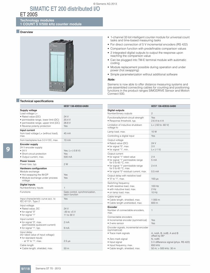
SIMATIC ET 200 distributed I/OET 200STechnology modules1 COUNT 5 V/500 kHz counter module
9/118 Siemens ST 70 · 2013
9
■ Overview
• 1-channel 32-bit intelligent counter module for universal count tasks and time-based measuring tasks
• For direct connection of 5 V incremental encoders (RS 422)• Comparison function with predefinable comparison values• 2 integrated digital outputs to output the response upon
reaching the comparison value• Can be plugged into TM-E terminal module with automatic
coding• Module replacement possible during operation and under
power (hot swapping)• Simple parameterization without additional software
Note:
Siemens is now able to offer distance measuring systems and pre-assembled connecting cables for counting and positioning functions in the product ranges SIMODRIVE Sensor and Motion Connect 500.
■ Technical specifications
6ES7 138-4DE02-0AB0
Supply voltageLoad voltage L+• Rated value (DC) 24 V• permissible range, lower limit (DC) 20.4 V• permissible range, upper limit (DC) 28.8 V• Reverse polarity protection Yes
Input currentfrom load voltage L+ (without load), max.
45 mA
from backplane bus 3.3 V DC, max. 10 mA
Encoder supply24 V encoder supply• 24 V Yes; L+ (-0.8 V)• Short-circuit protection Yes• Output current, max. 500 mA
Power lossesPower loss, typ. 2 W
Hardware configurationModule exchange• Hot swapping the IM-DP Yes• Module exchange under process
voltageYes
Digital inputsNumber/binary inputs 1
Functions Gate control, synchronization,latch function
Input characteristic curve acc. to IEC 61131, Type 2
Yes
Input voltage• Rated value, DC 24 V• for signal "0" -30 to +5 V• for signal "1" 11 to 30 V
Input current• for signal "0", max.
(permissible quiescent current)2 mA
• for signal "1", typ. 9 mA
Input delay (for rated value of input voltage)• for standard inputs
- at "0" to "1", max. 2.5 μs
Cable length• Cable length, shielded, max. 50 m
Digital outputsNumber/binary outputs 2
Functionality/short-circuit strength Yes• Response threshold, typ. 2.6 A to 4 A
Limitation of inductive shutdownvoltage to
L+ (-50 to -60 V)
Lamp load, max. 10 W
Controlling a digital input Yes
Output voltage• Rated value (DC) 24 V• for signal "0", max. 3 V• for signal "1", min. L+ (-1 V)
Output current• for signal "1" rated value 2 A• for signal "1" permissible range
for 0 to 60 °C, min.5 mA
• for signal "1" permissible rangefor 0 to 60 °C, max.
2.4 A
• for signal "0" residual current, max. 0.5 mA
Output delay with resistive load• "0" to "1", max. 100 μs
Switching frequency• with resistive load, max. 100 Hz• with inductive load, max. 2 Hz• on lamp load, max. 10 Hz
Cable length• Cable length, shielded, max. 1 000 m• Cable length unshielded, max. 600 m
EncoderNumber of connectable encoders, max.
1
Connectable encoders• Incremental encoder (symmetrical) Yes• 2-wire sensor Yes
Encoder signals, incremental encoder (symmetrical)• Trace mark signals A, notA, B, notB, A and B
offset by 90°• Zero mark signal N, notN• Input signal 5 V difference signal (phys. RS 422)• Input frequency, max. 650 kHz• Cable length, shielded, max. 50 m; > 500 kHz: 30 m
6ES7 138-4DE02-0AB0
© Siemens AG 2013
SIMATIC ET 200 distributed I/OET 200S
Technology modules1 COUNT 5 V/500 kHz counter module
9/119Siemens ST 70 · 2013
■ Technical specifications (continued)
9
Interrupts/diagnostics/status informationDiagnostic messages• Diagnostic functions Yes
Diagnostics indication LED• Group error SF (red) Yes• Status indicator digital output (green) Yes• Status indicator digital input (green) Yes• Status indicator backward counting
(green)Yes
• Status indicator forward counting (green)
Yes
• Synchronization SYN (green) Yes
CounterNumber of counter inputs 1; 32 bits
Frequency measurementMeasurement range, min. 0.1 Hz
Measurement range, max. 500 kHz
Cycle duration measurementMeasuring range, lower limit 10 μs
Measuring range, upper limit 120 s
6ES7 138-4DE02-0AB0
Speed measurementMeasurement range, min. (lower limit) 1 1/min
Measurement range, max. (upper limit)
25 000 1/min
ParameterRemark 16 byte
Galvanic isolationGalvanic isolation digital inputs• Galvanic isolation digital inputs No; only opposite shielding
Galvanic isolation counter• between the channels and the
backplane busYes
• between the channels and theload voltage L+
No
DimensionsWidth 30 mm
Height 81 mm
Depth 52 mm
WeightWeight, approx. 65 g
6ES7 138-4DE02-0AB0
© Siemens AG 2013
SIMATIC ET 200 distributed I/OET 200STechnology modules1 COUNT 5 V/500 kHz counter module
9/120 Siemens ST 70 · 2013
9
■ Ordering data Order No. Order No.
1 COUNT 5 V/500 kHz counter module
6ES7 138-4DE02-0AB0
For universal counting and measuring tasks with ET 200S
Accessories
Label sheets DIN A4 (10 pieces)
Each sheet contains 60 labeling strips for peripheral modules and 20 labeling strips for interface modules• petrol 6ES7 193-4BH00-0AA0• red 6ES7 193-4BD00-0AA0• yellow 6ES7 193-4BB00-0AA0• light beige 6ES7 193-4BA00-0AA0
Shield connection element 6ES7 193-4GA00-0AA0
For TM-P and TM-E terminal modules, as fixing for busbars3 x 10 mm, 5 items
Shield clamps 6ES7 193-4GB00-0AA0
For connecting braided cable shields to the busbar, 5 items
SIMODRIVEIncremental shaft encoder
with RS422 (TTL),operating voltage 10 to 30 V• With synchronous flange,
universal axial/radial cable outlet with connector- 500 pulses/revolution 6FX2 001-2DA50- 1000 pulses/revolution 6FX2 001-2DB00- 1024 pulses/revolution 6FX2 001-2DB02- 1250 pulses/revolution 6FX2 001-2DB25- 1500 pulses/revolution 6FX2 001-2DB50- 2000 pulses/revolution 6FX2 001-2DC00- 2048 pulses/revolution 6FX2 001-2DC04- 2500 pulses/revolution 6FX2 001-2DC50- 3600 pulses/revolution 6FX2 001-2DD60- 5000 pulses/revolution 6FX2 001-2DF00
• With synchronous flange,radial flange outlet- 500 pulses/revolution 6FX2 001-2FA50- 1000 pulses/revolution 6FX2 001-2FB00- 1024 pulses/revolution 6FX2 001-2FB02- 1250 pulses/revolution 6FX2 001-2FB25- 1500 pulses/revolution 6FX2 001-2FB50- 2000 pulses/revolution 6FX2 001-2FC00- 2048 pulses/revolution 6FX2 001-2FC04- 2500 pulses/revolution 6FX2 001-2FC50- 3600 pulses/revolution 6FX2 001-2FD60- 5000 pulses/revolution 6FX2 001-2FF00
• With synchronous flange, axial flange outlet- 500 pulses/revolution 6FX2 001-2HA50- 1000 pulses/revolution 6FX2 001-2HB00- 1024 pulses/revolution 6FX2 001-2HB02- 1250 pulses/revolution 6FX2 001-2HB25- 1500 pulses/revolution 6FX2 001-2HB50- 2000 pulses/revolution 6FX2 001-2HC00- 2048 pulses/revolution 6FX2 001-2HC04- 2500 pulses/revolution 6FX2 001-2HC50- 3600 pulses/revolution 6FX2 001-2HD60- 5000 pulses/revolution 6FX2 001-2HF00
• With clamping flange, universal axial/radial cable outlet with connector- 500 pulses/revolution 6FX2 001-2NA50- 1000 pulses/revolution 6FX2 001-2NB00- 1024 pulses/revolution 6FX2 001-2NB02- 1250 pulses/revolution 6FX2 001-2NB25- 1500 pulses/revolution 6FX2 001-2NB50- 2000 pulses/revolution 6FX2 001-2NC00- 2048 pulses/revolution 6FX2 001-2NC04- 2500 pulses/revolution 6FX2 001-2NC50- 3600 pulses/revolution 6FX2 001-2ND60- 5000 pulses/revolution 6FX2 001-2NF00
• With clamping flange, radial flange outlet- 500 pulses/revolution 6FX2 001-2QA50- 1000 pulses/revolution 6FX2 001-2QB00- 1024 pulses/revolution 6FX2 001-2QB02- 1250 pulses/revolution 6FX2 001-2QB25- 1500 pulses/revolution 6FX2 001-2QB50- 2000 pulses/revolution 6FX2 001-2QC00- 2048 pulses/revolution 6FX2 001-2QC04- 2500 pulses/revolution 6FX2 001-2QC50- 3600 pulses/revolution 6FX2 001-2QD60- 5000 pulses/revolution 6FX2 001-2QF00
• With clamping flange, axial flange outlet- 500 pulses/revolution 6FX2 001-2SA50- 1000 pulses/revolution 6FX2 001-2SB00- 1024 pulses/revolution 6FX2 001-2SB02- 1250 pulses/revolution 6FX2 001-2SB25- 1500 pulses/revolution 6FX2 001-2SB50- 2000 pulses/revolution 6FX2 001-2SC00- 2048 pulses/revolution 6FX2 001-2SC04- 2500 pulses/revolution 6FX2 001-2SC50- 3600 pulses/revolution 6FX2 001-2SD60- 5000 pulses/revolution 6FX2 001-2SF00
Signal cable
Preassembled for HTL and TTL encoder, without Sub-D connector, UL/DESINA
For length code, see page 5/114
6FX5 002-2CA12-....
© Siemens AG 2013
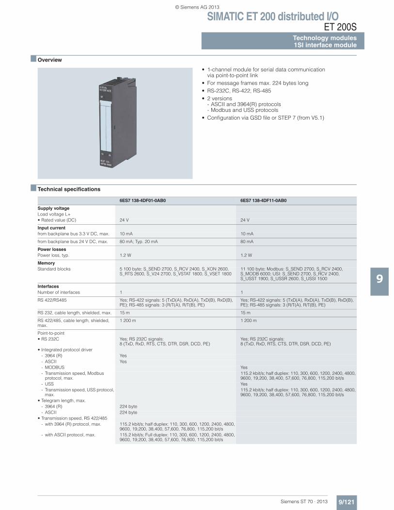
SIMATIC ET 200 distributed I/OET 200S
Technology modules1SI interface module
9/121Siemens ST 70 · 2013
9
■ Overview
• 1-channel module for serial data communication via point-to-point link
• For message frames max. 224 bytes long• RS-232C, RS-422, RS-485• 2 versions
- ASCII and 3964(R) protocols- Modbus and USS protocols
• Configuration via GSD file or STEP 7 (from V5.1)
■ Technical specifications
6ES7 138-4DF01-0AB0 6ES7 138-4DF11-0AB0
Supply voltageLoad voltage L+• Rated value (DC) 24 V 24 V
Input currentfrom backplane bus 3.3 V DC, max. 10 mA 10 mA
from backplane bus 24 V DC, max. 80 mA; Typ. 20 mA 80 mA
Power lossesPower loss, typ. 1.2 W 1.2 W
MemoryStandard blocks 5 100 byte; S_SEND 2700, S_RCV 2400, S_XON 2600,
S_RTS 2600, S_V24 2700, S_VSTAT 1800, S_VSET 180011 100 byte; Modbus: S_SEND 2700, S_RCV 2400, S_MODB 6000; USI: S_SEND 2700, S_RCV 2400, S_USST 1900, S_USSR 2600, S_USSI 1500
InterfacesNumber of interfaces 1 1
RS 422/RS485 Yes; RS-422 signals: 5 (TxD(A), RxD(A), TxD(B), RxD(B), PE); RS-485 signals: 3 (R/T(A), R/T(B), PE)
Yes; RS-422 signals: 5 (TxD(A), RxD(A), TxD(B), RxD(B), PE); RS-485 signals: 3 (R/T(A), R/T(B), PE)
RS 232, cable length, shielded, max. 15 m 15 m
RS 422/485, cable length, shielded, max.
1 200 m 1 200 m
Point-to-point• RS 232C Yes; RS 232C signals:
8 (TxD, RxD, RTS, CTS, DTR, DSR, DCD, PE)Yes; RS 232C signals: 8 (TxD, RxD, RTS, CTS, DTR, DSR, DCD, PE)
• Integrated protocol driver- 3964 (R) Yes- ASCII Yes- MODBUS Yes- Transmission speed, Modbus
protocol, max.115.2 kbit/s; half duplex: 110, 300, 600, 1200, 2400, 4800, 9600, 19,200, 38,400, 57,600, 76,800, 115,200 bit/s
- USS Yes- Transmission speed, USS protocol,
max.115.2 kbit/s; half duplex: 110, 300, 600, 1200, 2400, 4800, 9600, 19,200, 38,400, 57,600, 76,800, 115,200 bit/s
• Telegram length, max.- 3964 (R) 224 byte- ASCII 224 byte
• Transmission speed, RS 422/485- with 3964 (R) protocol, max. 115.2 kbit/s; half duplex: 110, 300, 600, 1200, 2400, 4800,
9600, 19,200, 38,400, 57,600, 76,800, 115,200 bit/s- with ASCII protocol, max. 115.2 kbit/s; Full duplex: 110, 300, 600, 1200, 2400, 4800,
9600, 19,200, 38,400, 57,600, 76,800, 115,200 bit/s
© Siemens AG 2013
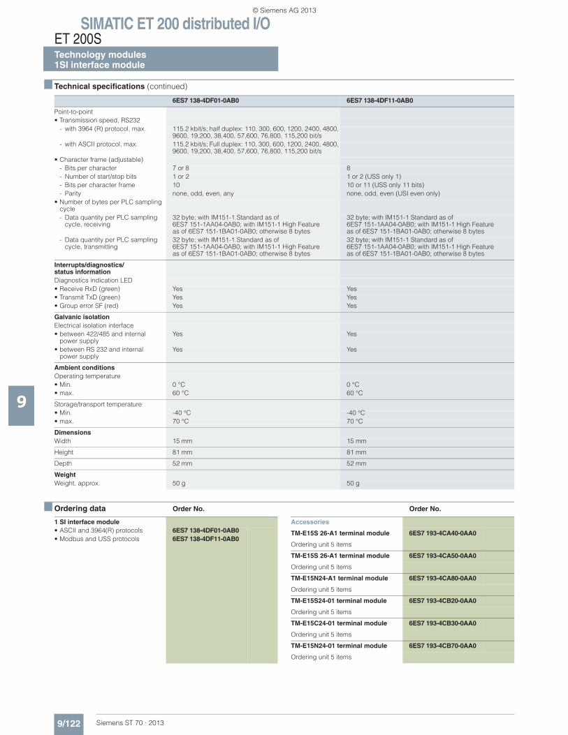
SIMATIC ET 200 distributed I/OET 200STechnology modules1SI interface module
9/122 Siemens ST 70 · 2013
■ Technical specifications (continued)
9
■ Ordering data Order No. Order No.
Point-to-point• Transmission speed, RS232
- with 3964 (R) protocol, max. 115.2 kbit/s; half duplex: 110, 300, 600, 1200, 2400, 4800, 9600, 19,200, 38,400, 57,600, 76,800, 115,200 bit/s
- with ASCII protocol, max. 115.2 kbit/s; Full duplex: 110, 300, 600, 1200, 2400, 4800, 9600, 19,200, 38,400, 57,600, 76,800, 115,200 bit/s
• Character frame (adjustable)- Bits per character 7 or 8 8- Number of start/stop bits 1 or 2 1 or 2 (USS only 1)- Bits per character frame 10 10 or 11 (USS only 11 bits)- Parity none, odd, even, any none, odd, even (USI even only)
• Number of bytes per PLC sampling cycle- Data quantity per PLC sampling
cycle, receiving32 byte; with IM151-1 Standard as of 6ES7 151-1AA04-0AB0; with IM151-1 High Featureas of 6ES7 151-1BA01-0AB0; otherwise 8 bytes
32 byte; with IM151-1 Standard as of 6ES7 151-1AA04-0AB0; with IM151-1 High Featureas of 6ES7 151-1BA01-0AB0; otherwise 8 bytes
- Data quantity per PLC samplingcycle, transmitting
32 byte; with IM151-1 Standard as of 6ES7 151-1AA04-0AB0; with IM151-1 High Feature as of 6ES7 151-1BA01-0AB0; otherwise 8 bytes
32 byte; with IM151-1 Standard as of6ES7 151-1AA04-0AB0; with IM151-1 High Featureas of 6ES7 151-1BA01-0AB0; otherwise 8 bytes
Interrupts/diagnostics/status informationDiagnostics indication LED• Receive RxD (green) Yes Yes• Transmit TxD (green) Yes Yes• Group error SF (red) Yes Yes
Galvanic isolationElectrical isolation interface• between 422/485 and internal
power supplyYes Yes
• between RS 232 and internal power supply
Yes Yes
Ambient conditionsOperating temperature• Min. 0 °C 0 °C• max. 60 °C 60 °C
Storage/transport temperature• Min. -40 °C -40 °C• max. 70 °C 70 °C
DimensionsWidth 15 mm 15 mm
Height 81 mm 81 mm
Depth 52 mm 52 mm
WeightWeight, approx. 50 g 50 g
6ES7 138-4DF01-0AB0 6ES7 138-4DF11-0AB0
1 SI interface module• ASCII and 3964(R) protocols 6ES7 138-4DF01-0AB0• Modbus and USS protocols 6ES7 138-4DF11-0AB0
Accessories
TM-E15S 26-A1 terminal module 6ES7 193-4CA40-0AA0
Ordering unit 5 items
TM-E15S 26-A1 terminal module 6ES7 193-4CA50-0AA0
Ordering unit 5 items
TM-E15N24-A1 terminal module 6ES7 193-4CA80-0AA0
Ordering unit 5 items
TM-E15S24-01 terminal module 6ES7 193-4CB20-0AA0
Ordering unit 5 items
TM-E15C24-01 terminal module 6ES7 193-4CB30-0AA0
Ordering unit 5 items
TM-E15N24-01 terminal module 6ES7 193-4CB70-0AA0
Ordering unit 5 items
© Siemens AG 2013
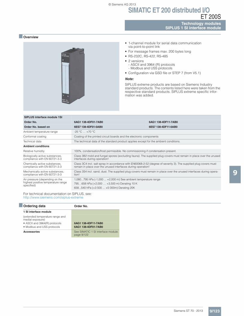
SIMATIC ET 200 distributed I/OET 200S
Technology modulesSIPLUS 1 SI interface module
9/123Siemens ST 70 · 2013
9
■ Overview
• 1-channel module for serial data communicationvia point-to-point link
• For message frames max. 200 bytes long• RS-232C, RS-422, RS-485• 2 versions
- ASCII and 3964 (R) protocols- Modbus and USS protocols
• Configuration via GSD file or STEP 7 (from V5.1)
Note:
SIPLUS extreme products are based on Siemens Industry standard products. The contents listed here were taken from the respective standard products. SIPLUS extreme specific infor-mation was added.
For technical documentation on SIPLUS, see: http://www.siemens.com/siplus-extreme
■ Ordering data Order No.
SIPLUS interface module 1SI
Order No. 6AG1 138-4DF01-7AB0 6AG1 138-4DF11-7AB0
Order No. based on 6ES7 138-4DF01-0AB0 6ES7 138-4DF11-0AB0
Ambient temperature range -25 °C … +70 °C
Conformal coating Coating of the printed circuit boards and the electronic components
Technical data The technical data of the standard product applies except for the ambient conditions.
Ambient conditions
Relative humidity 100%, condensation/frost permissible. No commissioning if condensation present.
Biologically active substances, compliance with EN 60721-3-3
Class 3B2 mold and fungal spores (excluding fauna). The supplied plug covers must remain in place over the unused interfaces during operation!
Chemically active substances, compliance with EN 60721-3-3
Class 3C4 incl. salt spray in accordance with EN60068-2-52 (degree of severity 3). The supplied plug covers must remain in place over the unused interfaces during operation!
Mechanically active substances, compliance with EN 60721-3-3
Class 3S4 incl. sand, dust. The supplied plug covers must remain in place over the unused interfaces during opera-tion!
Air pressure (depending on the highest positive temperature range specified)
1,080...795 hPa (-1,000 ... +2,000 m) See ambient temperature range
795…658 hPa (+2,000 … +3,500 m) Derating 10 K
658...540 hPa (+3 500 ... +5 000m) Derating 20K
1 SI interface module
(extended temperature range and medial exposure)• ASCII and 3964(R) protocols 6AG1 138-4DF11-7AB0• Modbus and USS protocols 6AG1 138-4DF01-7AB0
Accessories See SIMATIC 1 SI interface module. page 9/122
© Siemens AG 2013
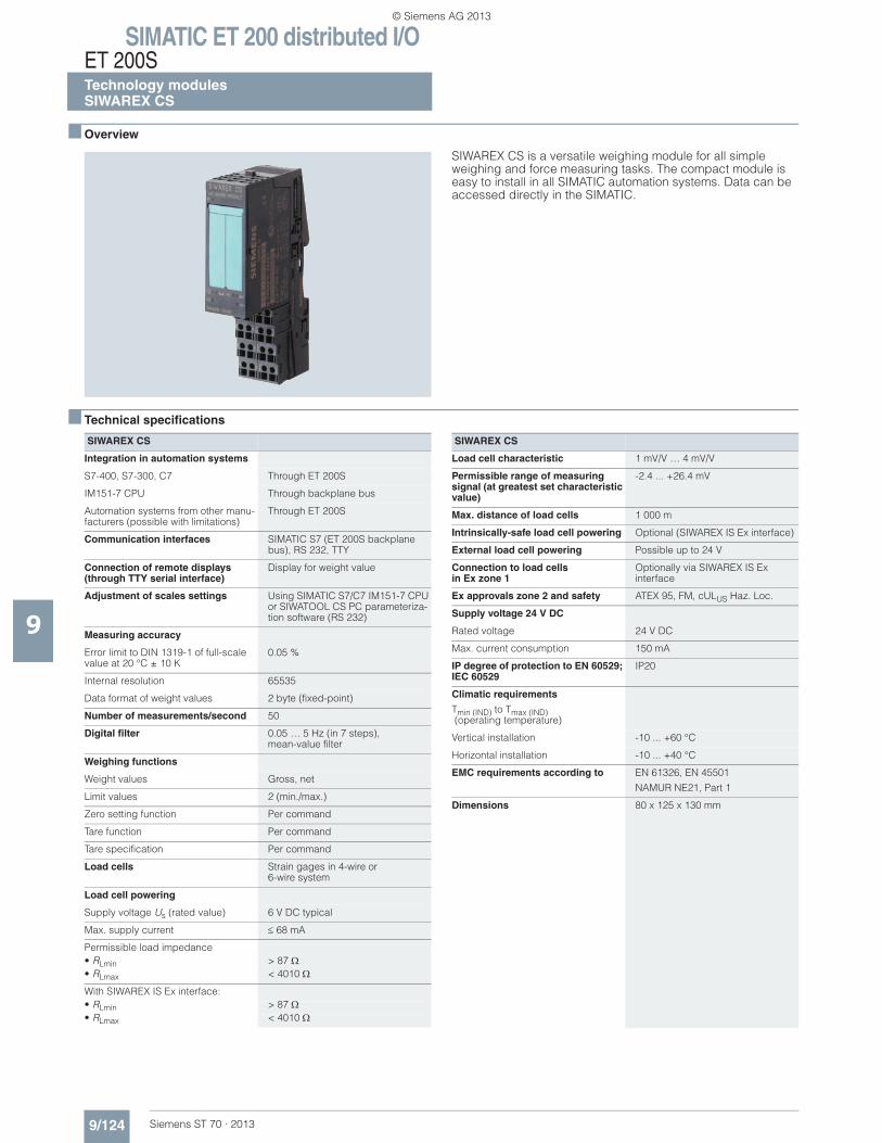
SIMATIC ET 200 distributed I/OET 200STechnology modulesSIWAREX CS
9/124 Siemens ST 70 · 2013
9
■ Overview
SIWAREX CS is a versatile weighing module for all simple weighing and force measuring tasks. The compact module is easy to install in all SIMATIC automation systems. Data can be accessed directly in the SIMATIC.
■ Technical specifications
SIWAREX CS
Integration in automation systems
S7-400, S7-300, C7 Through ET 200S
IM151-7 CPU Through backplane bus
Automation systems from other manu-facturers (possible with limitations)
Through ET 200S
Communication interfaces SIMATIC S7 (ET 200S backplane bus), RS 232, TTY
Connection of remote displays (through TTY serial interface)
Display for weight value
Adjustment of scales settings Using SIMATIC S7/C7 IM151-7 CPU or SIWATOOL CS PC parameteriza-tion software (RS 232)
Measuring accuracy
Error limit to DIN 1319-1 of full-scale value at 20 °C ± 10 K
0.05 %
Internal resolution 65535
Data format of weight values 2 byte (fixed-point)
Number of measurements/second 50
Digital filter 0.05 … 5 Hz (in 7 steps),mean-value filter
Weighing functions
Weight values Gross, net
Limit values 2 (min./max.)
Zero setting function Per command
Tare function Per command
Tare specification Per command
Load cells Strain gages in 4-wire or6-wire system
Load cell powering
Supply voltage Us (rated value) 6 V DC typical
Max. supply current 68 mA
Permissible load impedance• RLmin > 87• RLmax < 4010
With SIWAREX IS Ex interface:• RLmin > 87• RLmax < 4010
Load cell characteristic 1 mV/V … 4 mV/V
Permissible range of measuring signal (at greatest set characteristic value)
-2.4 ... +26.4 mV
Max. distance of load cells 1 000 m
Intrinsically-safe load cell powering Optional (SIWAREX IS Ex interface)
External load cell powering Possible up to 24 V
Connection to load cells in Ex zone 1
Optionally via SIWAREX IS Ex interface
Ex approvals zone 2 and safety ATEX 95, FM, cULUS Haz. Loc.
Supply voltage 24 V DC
Rated voltage 24 V DC
Max. current consumption 150 mA
IP degree of protection to EN 60529; IEC 60529
IP20
Climatic requirements
Tmin (IND) to Tmax (IND) (operating temperature)
Vertical installation -10 ... +60 °C
Horizontal installation -10 ... +40 °C
EMC requirements according to EN 61326, EN 45501
NAMUR NE21, Part 1
Dimensions 80 x 125 x 130 mm
SIWAREX CS
© Siemens AG 2013
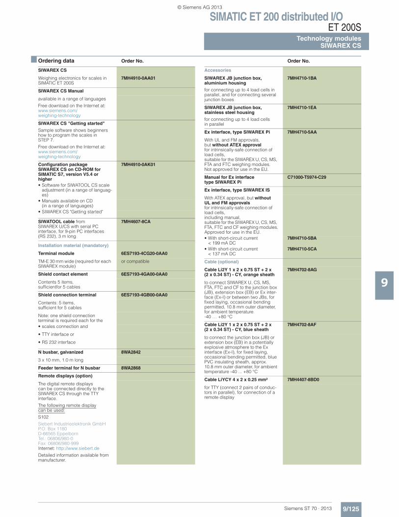
SIMATIC ET 200 distributed I/OET 200S
Technology modulesSIWAREX CS
9/125Siemens ST 70 · 2013
9
■ Ordering data Order No. Order No.
SIWAREX CS
Weighing electronics for scales in SIMATIC ET 200S
7MH4910-0AA01
SIWAREX CS Manual
available in a range of languages
Free download on the Internet at: www.siemens.com/weighing-technology
SIWAREX CS "Getting started"
Sample software shows beginners how to program the scales in STEP 7.
Free download on the Internet at:www.siemens.com/weighing-technology
Configuration package SIWAREX CS on CD-ROM for SIMATIC S7, version V5.4 or higher
7MH4910-0AK01
• Software for SIWATOOL CS scale adjustment (in a range of languag-es)
• Manuals available on CD (in a range of languages)
• SIWAREX CS "Getting started"
SIWATOOL cable from SIWAREX U/CS with serial PCinterface, for 9-pin PC interfaces (RS 232), 3 m long
7MH4607-8CA
Installation material (mandatory)
Terminal module 6ES7193-4CG20-0AA0
TM-E 30 mm wide (required for each SIWAREX module)
or compatible
Shield contact element 6ES7193-4GA00-0AA0
Contents 5 items, sufficientfor 5 cables
Shield connection terminal 6ES7193-4GB00-0AA0
Contents: 5 items,sufficient for 5 cables
Note: one shield connection terminal is required each for the• scales connection and
• TTY interface or
• RS 232 interface
N busbar, galvanized 8WA2842
3 x 10 mm, 1.0 m long
Feeder terminal for N busbar 8WA2868
Remote displays (option)
The digital remote displays can be connected directly to the SIWAREX CS through the TTYinterface.
The following remote displaycan be used:
S102
Siebert Industrieelektronik GmbHP.O. Box 1180D-66565 EppelbornTel.: 06806/980-0Fax: 06806/980-999Internet: http://www.siebert.de
Detailed information available from manufacturer.
Accessories
SIWAREX JB junction box, aluminium housing
for connecting up to 4 load cells in parallel, and for connecting several junction boxes
7MH4710-1BA
SIWAREX JB junction box, stainless steel housing
for connecting up to 4 load cellsin parallel
7MH4710-1EA
Ex interface, type SIWAREX Pi 7MH4710-5AA
With UL and FM approvals, but without ATEX approvalfor intrinsically-safe connection of load cells, suitable for the SIWAREX U, CS, MS, FTA and FTC weighing modules.Not approved for use in the EU.
Manual for Ex interface type SIWAREX Pi
C71000-T5974-C29
Ex interface, type SIWAREX IS
With ATEX approval, but withoutUL and FM approvalsfor intrinsically-safe connection of load cells,including manual, suitable for the SIWAREX U, CS, MS, FTA, FTC and CF weighing modules.Approved for use in the EU.• With short-circuit current
< 199 mA DC7MH4710-5BA
• With short-circuit current < 137 mA DC
7MH4710-5CA
Cable (optional)
Cable Li2Y 1 x 2 x 0.75 ST + 2 x (2 x 0.34 ST) - CY, orange sheath
7MH4702-8AG
to connect SIWAREX U, CS, MS, FTA, FTC and CF to the junction box (JB), extension box (EB) or Ex inter-face (Ex-I) or between two JBs, for fixed laying, occasional bending permitted, 10.8 mm outer diameter, for ambient temperature-40 … +80 °C
Cable Li2Y 1 x 2 x 0.75 ST + 2 x(2 x 0.34 ST) - CY, blue sheath
7MH4702-8AF
to connect the junction box (JB) or extension box (EB) in a potentially explosive atmosphere to the Ex interface (Ex-I), for fixed laying, occasional bending permitted, blue PVC insulating sheath, approx. 10.8 mm outer diameter, for ambient temperature -40 ... +80 °C
Cable LiYCY 4 x 2 x 0.25 mm² 7MH4407-8BD0
for TTY (connect 2 pairs of conduc-tors in parallel), for connection of a remote display
© Siemens AG 2013
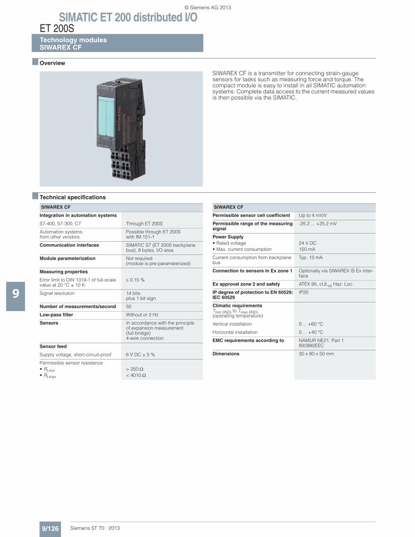
SIMATIC ET 200 distributed I/OET 200STechnology modulesSIWAREX CF
9/126 Siemens ST 70 · 2013
9
■ Overview
SIWAREX CF is a transmitter for connecting strain-gauge sensors for tasks such as measuring force and torque. The compact module is easy to install in all SIMATIC automation systems. Complete data access to the current measured values is then possible via the SIMATIC.
■ Technical specifications
SIWAREX CF
Integration in automation systems
S7-400, S7-300, C7 Through ET 200S
Automation systemsfrom other vendors
Possible through ET 200S with IM 151-1
Communication interfaces SIMATIC S7 (ET 200S backplane bus), 8 bytes, I/O area
Module parameterization Not required(module is pre-parameterized)
Measuring properties
Error limit to DIN 1319-1 of full-scale value at 20 °C ± 10 K
0.15 %
Signal resolution 14 bitsplus 1 bit sign
Number of measurements/second 50
Low-pass filter Without or 2 Hz
Sensors In accordance with the principleof expansion measurement(full bridge)4-wire connection
Sensor feed
Supply voltage, short-circuit-proof 6 V DC ± 5 %
Permissible sensor resistance• RLmin > 250 • RLmax < 4010
Permissible sensor cell coefficient Up to 4 mV/V
Permissible range of the measuring signal
-25.2 ... +25.2 mV
Power Supply• Rated voltage 24 V DC• Max. current consumption 150 mA
Current consumption from backplane bus
Typ. 10 mA
Connection to sensors in Ex zone 1 Optionally via SIWAREX IS Ex inter-face
Ex approval zone 2 and safety ATEX 95, cULus Haz. Loc.
IP degree of protection to EN 60529; IEC 60529
IP20
Climatic requirementsTmin (IND) to Tmax (IND)(operating temperature)
Vertical installation 0 ... +60 °C
Horizontal installation 0 ... +40 °C
EMC requirements according to NAMUR NE21, Part 189/386/EEC
Dimensions 30 x 80 x 50 mm
SIWAREX CF
© Siemens AG 2013
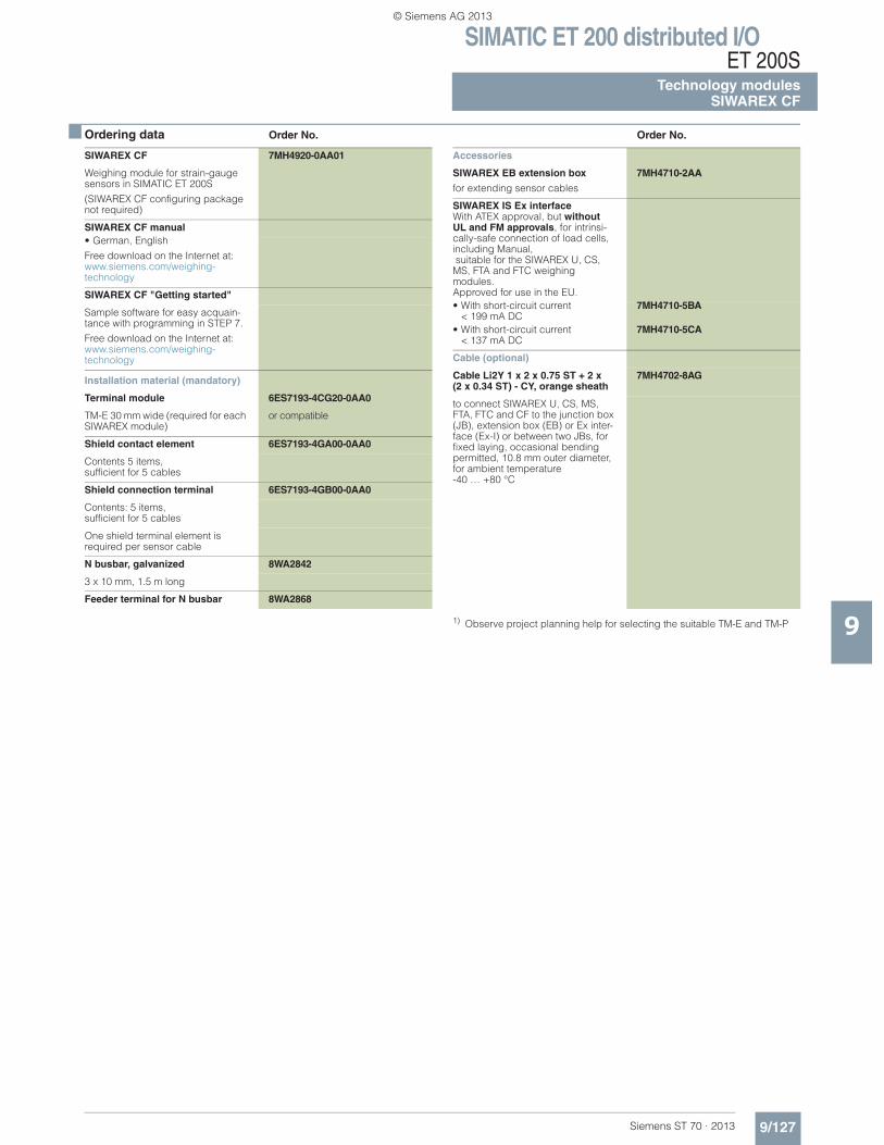
SIMATIC ET 200 distributed I/OET 200S
Technology modulesSIWAREX CF
9/127Siemens ST 70 · 2013
9
■ Ordering data Order No. Order No.
1) Observe project planning help for selecting the suitable TM-E and TM-P
SIWAREX CF 7MH4920-0AA01
Weighing module for strain-gauge sensors in SIMATIC ET 200S
(SIWAREX CF configuring package not required)
SIWAREX CF manual• German, English
Free download on the Internet at: www.siemens.com/weighing-technology
SIWAREX CF "Getting started"
Sample software for easy acquain-tance with programming in STEP 7.
Free download on the Internet at: www.siemens.com/weighing-technology
Installation material (mandatory)
Terminal module 6ES7193-4CG20-0AA0
TM-E 30 mm wide (required for each SIWAREX module)
or compatible
Shield contact element 6ES7193-4GA00-0AA0
Contents 5 items,sufficient for 5 cables
Shield connection terminal 6ES7193-4GB00-0AA0
Contents: 5 items, sufficient for 5 cables
One shield terminal element is required per sensor cable
N busbar, galvanized 8WA2842
3 x 10 mm, 1.5 m long
Feeder terminal for N busbar 8WA2868
Accessories
SIWAREX EB extension box
for extending sensor cables
7MH4710-2AA
SIWAREX IS Ex interfaceWith ATEX approval, but without UL and FM approvals, for intrinsi-cally-safe connection of load cells,including Manual, suitable for the SIWAREX U, CS, MS, FTA and FTC weighing modules.Approved for use in the EU.• With short-circuit current
< 199 mA DC7MH4710-5BA
• With short-circuit current< 137 mA DC
7MH4710-5CA
Cable (optional)
Cable Li2Y 1 x 2 x 0.75 ST + 2 x(2 x 0.34 ST) - CY, orange sheath
7MH4702-8AG
to connect SIWAREX U, CS, MS, FTA, FTC and CF to the junction box (JB), extension box (EB) or Ex inter-face (Ex-I) or between two JBs, for fixed laying, occasional bending permitted, 10.8 mm outer diameter, for ambient temperature-40 … +80 °C
© Siemens AG 2013
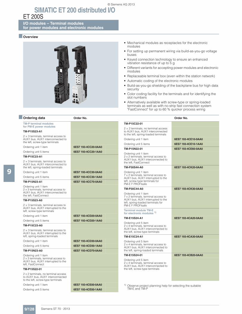
SIMATIC ET 200 distributed I/OET 200SI/O modules – Terminal modulesfor power modules and electronic modules
9/128 Siemens ST 70 · 2013
9
■ Overview
• Mechanical modules as receptacles for the electronic modules
• For setting up permanent wiring via build-as-you-go voltage buses
• Keyed connection technology to ensure an enhanced vibration resistance of up to 5 g
• Different variants for accepting power modules and electronic modules
• Replaceable terminal box (even within the station network)• Automatic coding of the electronic modules• Build-as-you-go shielding of the backplane bus for high data
security• Color coding facility for the terminals and for identifying the
slot numbers• Alternatively available with screw-type or spring-loaded
terminals as well as with no-strip fast connection system "FastConnect" for up to 60 % quicker process wiring
■ Ordering data Order No. Order No.
TM-P terminal modulesfor PM-E power modules
TM-P15S23-A1
2 × 3 terminals, terminal access to AUX1 bus, AUX1 interconnected to the left, screw-type terminals
Ordering unit 1 item 6ES7 193-4CC20-0AA0
Ordering unit 5 items 6ES7 193-4CC20-1AA0
TM-P15C23-A1
2 × 3 terminals, terminal access to AUX1 bus, AUX1 interconnected to the left, spring-loaded terminals
Ordering unit 1 item 6ES7 193-4CC30-0AA0
Ordering unit 5 items 6ES7 193-4CC30-1AA0
TM-P15N23-A1 6ES7 193-4CC70-0AA0
Ordering unit 1 item 2 x 3 terminals, terminal access to AUX1 bus, AUX1 interconnected to the left, FastConnect
TM-P15S23-A0
2 × 3 terminals, terminal access to AUX1 bus, AUX1 interrupted to the left, screw-type terminals
Ordering unit 1 item 6ES7 193-4CD20-0AA0
Ordering unit 5 items 6ES7 193-4CD20-1AA0
TM-P15C23-A0
2 × 3 terminals, terminal access to AUX1 bus, AUX1 interrupted to the left, spring-loaded terminals
Ordering unit 1 item 6ES7 193-4CD30-0AA0
Ordering unit 5 items 6ES7 193-4CD30-1AA0
TM-P15N23-A0 6ES7 193-4CD70-0AA0
Ordering unit 1 item 2 x 3 terminals, terminal access to AUX1 bus, AUX1 interrupted to the left, FastConnect
TM-P15S22-01
2 x 2 terminals, no terminal access to AUX1 bus, AUX1 interconnected to the left, screw-type terminals
Ordering unit 1 item 6ES7 193-4CE00-0AA0
Ordering unit 5 items 6ES7 193-4CE00-1AA0
TM-P15C22-01
2 × 2 terminals, no terminal access to AUX1 bus, AUX1 interconnected to the left, spring-loaded terminals
Ordering unit 1 item 6ES7 193-4CE10-0AA0
Ordering unit 5 items 6ES7 193-4CE10-1AA0
TM-P15N22-01 6ES7 193-4CE60-0AA0
Ordering unit 1 item 2 x 2 terminals, terminal access to AUX1 bus, AUX1 interconnected to the left, FastConnect
TM-P30S44-A0 6ES7 193-4CK20-0AA0
Ordering unit 1 item 7 x 2 terminals, terminal access to AUX1 bus, AUX1 interrupted to the left, screw-type terminals for PM-E F PROFIsafe
TM-P30C44-A0 6ES7 193-4CK30-0AA0
Ordering unit 1 item 7 x 2 terminals, terminal access to AUX1 bus, AUX1 interrupted to the left, spring-loaded terminals for PM-E F PROFIsafe
Terminal module TM-Efor electronic modules 1)
TM-E15S24-A1 6ES7 193-4CA20-0AA0
Ordering unit 5 item 2 x 4 terminals, terminal access to AUX1 bus, AUX1 interconnected to the left, screw-type terminals
TM-E15C24-A1 6ES7 193-4CA30-0AA0
Ordering unit 5 item 2 x 4 terminals, terminal access to AUX1 bus, AUX1 interconnected to the left, spring-loaded terminals
TM-E15S24-01 6ES7 193-4CB20-0AA0
Ordering unit 5 item 2 x 4 terminals, terminal access to AUX1 bus, AUX1 interconnected to the left, screw-type terminals
1) Observe project planning help for selecting the suitable TM-E and TM-P
© Siemens AG 2013
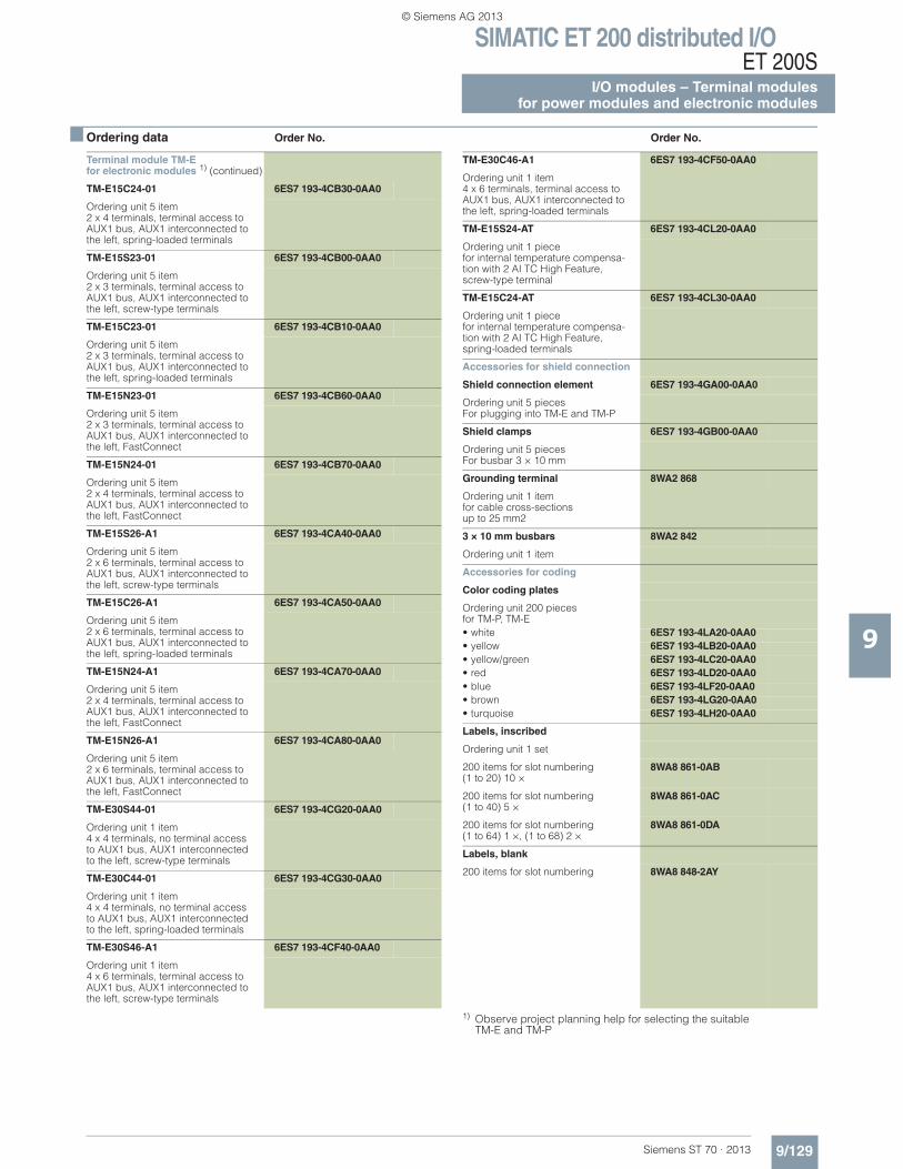
SIMATIC ET 200 distributed I/OET 200S
I/O modules – Terminal modulesfor power modules and electronic modules
9/129Siemens ST 70 · 2013
■ Ordering data Order No. Order No.
9
1) Observe project planning help for selecting the suitable TM-E and TM-P
Terminal module TM-Efor electronic modules 1) (continued)
TM-E15C24-01 6ES7 193-4CB30-0AA0
Ordering unit 5 item 2 x 4 terminals, terminal access to AUX1 bus, AUX1 interconnected to the left, spring-loaded terminals
TM-E15S23-01 6ES7 193-4CB00-0AA0
Ordering unit 5 item 2 x 3 terminals, terminal access to AUX1 bus, AUX1 interconnected to the left, screw-type terminals
TM-E15C23-01 6ES7 193-4CB10-0AA0
Ordering unit 5 item 2 x 3 terminals, terminal access to AUX1 bus, AUX1 interconnected to the left, spring-loaded terminals
TM-E15N23-01 6ES7 193-4CB60-0AA0
Ordering unit 5 item 2 x 3 terminals, terminal access to AUX1 bus, AUX1 interconnected to the left, FastConnect
TM-E15N24-01 6ES7 193-4CB70-0AA0
Ordering unit 5 item 2 x 4 terminals, terminal access to AUX1 bus, AUX1 interconnected to the left, FastConnect
TM-E15S26-A1 6ES7 193-4CA40-0AA0
Ordering unit 5 item 2 x 6 terminals, terminal access to AUX1 bus, AUX1 interconnected to the left, screw-type terminals
TM-E15C26-A1 6ES7 193-4CA50-0AA0
Ordering unit 5 item 2 x 6 terminals, terminal access to AUX1 bus, AUX1 interconnected to the left, spring-loaded terminals
TM-E15N24-A1 6ES7 193-4CA70-0AA0
Ordering unit 5 item 2 x 4 terminals, terminal access to AUX1 bus, AUX1 interconnected to the left, FastConnect
TM-E15N26-A1 6ES7 193-4CA80-0AA0
Ordering unit 5 item 2 x 6 terminals, terminal access to AUX1 bus, AUX1 interconnected to the left, FastConnect
TM-E30S44-01 6ES7 193-4CG20-0AA0
Ordering unit 1 item 4 x 4 terminals, no terminal access to AUX1 bus, AUX1 interconnected to the left, screw-type terminals
TM-E30C44-01 6ES7 193-4CG30-0AA0
Ordering unit 1 item 4 x 4 terminals, no terminal access to AUX1 bus, AUX1 interconnected to the left, spring-loaded terminals
TM-E30S46-A1 6ES7 193-4CF40-0AA0
Ordering unit 1 item 4 x 6 terminals, terminal access to AUX1 bus, AUX1 interconnected to the left, screw-type terminals
TM-E30C46-A1 6ES7 193-4CF50-0AA0
Ordering unit 1 item 4 x 6 terminals, terminal access to AUX1 bus, AUX1 interconnected to the left, spring-loaded terminals
TM-E15S24-AT 6ES7 193-4CL20-0AA0
Ordering unit 1 piecefor internal temperature compensa-tion with 2 AI TC High Feature, screw-type terminal
TM-E15C24-AT 6ES7 193-4CL30-0AA0
Ordering unit 1 piecefor internal temperature compensa-tion with 2 AI TC High Feature, spring-loaded terminals
Accessories for shield connection
Shield connection element 6ES7 193-4GA00-0AA0
Ordering unit 5 pieces For plugging into TM-E and TM-P
Shield clamps 6ES7 193-4GB00-0AA0
Ordering unit 5 pieces For busbar 3 × 10 mm
Grounding terminal 8WA2 868
Ordering unit 1 item for cable cross-sectionsup to 25 mm2
3 × 10 mm busbars 8WA2 842
Ordering unit 1 item
Accessories for coding
Color coding plates
Ordering unit 200 pieces for TM-P, TM-E• white 6ES7 193-4LA20-0AA0• yellow 6ES7 193-4LB20-0AA0• yellow/green 6ES7 193-4LC20-0AA0• red 6ES7 193-4LD20-0AA0• blue 6ES7 193-4LF20-0AA0• brown 6ES7 193-4LG20-0AA0• turquoise 6ES7 193-4LH20-0AA0
Labels, inscribed
Ordering unit 1 set
200 items for slot numbering(1 to 20) 10 ×
8WA8 861-0AB
200 items for slot numbering (1 to 40) 5 ×
8WA8 861-0AC
200 items for slot numbering(1 to 64) 1 ×, (1 to 68) 2 ×
8WA8 861-0DA
Labels, blank
200 items for slot numbering 8WA8 848-2AY
© Siemens AG 2013
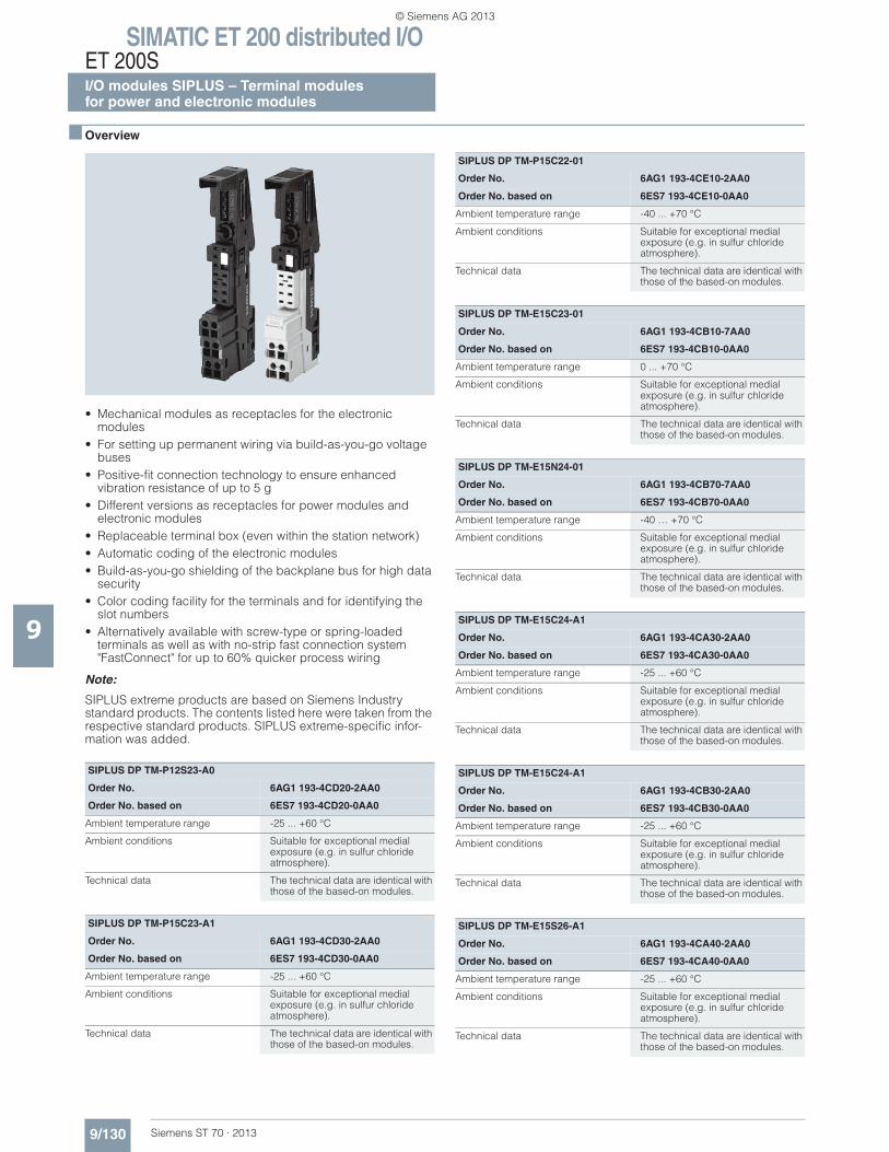
SIMATIC ET 200 distributed I/OET 200SI/O modules SIPLUS – Terminal modulesfor power and electronic modules
9/130 Siemens ST 70 · 2013
9
■ Overview
• Mechanical modules as receptacles for the electronic modules
• For setting up permanent wiring via build-as-you-go voltage buses
• Positive-fit connection technology to ensure enhanced vibration resistance of up to 5 g
• Different versions as receptacles for power modules and electronic modules
• Replaceable terminal box (even within the station network) • Automatic coding of the electronic modules • Build-as-you-go shielding of the backplane bus for high data
security • Color coding facility for the terminals and for identifying the
slot numbers • Alternatively available with screw-type or spring-loaded
terminals as well as with no-strip fast connection system "FastConnect" for up to 60% quicker process wiring
Note:
SIPLUS extreme products are based on Siemens Industry standard products. The contents listed here were taken from the respective standard products. SIPLUS extreme-specific infor-mation was added.
SIPLUS DP TM-P12S23-A0
Order No. 6AG1 193-4CD20-2AA0
Order No. based on 6ES7 193-4CD20-0AA0
Ambient temperature range -25 ... +60 °C
Ambient conditions Suitable for exceptional medial exposure (e.g. in sulfur chloride atmosphere).
Technical data The technical data are identical with those of the based-on modules.
SIPLUS DP TM-P15C23-A1
Order No. 6AG1 193-4CD30-2AA0
Order No. based on 6ES7 193-4CD30-0AA0
Ambient temperature range -25 ... +60 °C
Ambient conditions Suitable for exceptional medial exposure (e.g. in sulfur chloride atmosphere).
Technical data The technical data are identical with those of the based-on modules.
SIPLUS DP TM-P15C22-01
Order No. 6AG1 193-4CE10-2AA0
Order No. based on 6ES7 193-4CE10-0AA0
Ambient temperature range -40 ... +70 °C
Ambient conditions Suitable for exceptional medial exposure (e.g. in sulfur chloride atmosphere).
Technical data The technical data are identical with those of the based-on modules.
SIPLUS DP TM-E15C23-01
Order No. 6AG1 193-4CB10-7AA0
Order No. based on 6ES7 193-4CB10-0AA0
Ambient temperature range 0 ... +70 °C
Ambient conditions Suitable for exceptional medial exposure (e.g. in sulfur chloride atmosphere).
Technical data The technical data are identical with those of the based-on modules.
SIPLUS DP TM-E15N24-01
Order No. 6AG1 193-4CB70-7AA0
Order No. based on 6ES7 193-4CB70-0AA0
Ambient temperature range -40 … +70 °C
Ambient conditions Suitable for exceptional medial exposure (e.g. in sulfur chloride atmosphere).
Technical data The technical data are identical with those of the based-on modules.
SIPLUS DP TM-E15C24-A1
Order No. 6AG1 193-4CA30-2AA0
Order No. based on 6ES7 193-4CA30-0AA0
Ambient temperature range -25 ... +60 °C
Ambient conditions Suitable for exceptional medial exposure (e.g. in sulfur chloride atmosphere).
Technical data The technical data are identical with those of the based-on modules.
SIPLUS DP TM-E15C24-A1
Order No. 6AG1 193-4CB30-2AA0
Order No. based on 6ES7 193-4CB30-0AA0
Ambient temperature range -25 ... +60 °C
Ambient conditions Suitable for exceptional medial exposure (e.g. in sulfur chloride atmosphere).
Technical data The technical data are identical with those of the based-on modules.
SIPLUS DP TM-E15S26-A1
Order No. 6AG1 193-4CA40-2AA0
Order No. based on 6ES7 193-4CA40-0AA0
Ambient temperature range -25 ... +60 °C
Ambient conditions Suitable for exceptional medial exposure (e.g. in sulfur chloride atmosphere).
Technical data The technical data are identical with those of the based-on modules.
© Siemens AG 2013
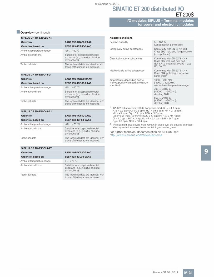
SIMATIC ET 200 distributed I/OET 200S
I/O modules SIPLUS – Terminal modulesfor power and electronic modules
9/131Siemens ST 70 · 2013
■ Overview (continued)
9
1) ISA-S71.04 severity level GX: Long-term load: SO2 < 4.8 ppm;H2S < 9.9 ppm; Cl < 0.2 ppm; HCl < 0.66 ppm; HF < 0.12 ppm;NH < 49 ppm; O3 < 0.1 ppm; NOX < 5.2 ppm Limit value (max. 30 min/d): SO2 < 17.8 ppm; H2S < 49.7 ppm; Cl < 1.0 ppm; HCl < 3.3 ppm; HF < 2.4 ppm; NH < 247 ppm;O3 < 1.0 ppm; NOX < 10.4 ppm
2) The supplied plug covers must remain in place over the unused interface when operated in atmospheres containing corrosive gases!
For further technical documentation on SIPLUS, see: http://www.siemens.com/siplus-extreme
SIPLUS DP TM-E15C26-A1
Order No. 6AG1 193-4CA50-2AA0
Order No. based on 6ES7 193-4CA50-0AA0
Ambient temperature range -25 ... +60 °C
Ambient conditions Suitable for exceptional medial exposure (e.g. in sulfur chloride atmosphere).
Technical data The technical data are identical with those of the based-on modules.
SIPLUS DP TM-E30C44-01
Order No. 6AG1 193-4CG30-2AA0
Order No. based on 6ES7 193-4CG30-0AA0
Ambient temperature range -25 ... +60 °C
Ambient conditions Suitable for exceptional medial exposure (e.g. in sulfur chloride atmosphere).
Technical data The technical data are identical with those of the based-on modules.
SIPLUS DP TM-E30C46-A1
Order No. 6AG1 193-4CF50-7AA0
Order No. based on 6ES7 193-4CF50-0AA0
Ambient temperature range -40 ... +70 °C
Ambient conditions Suitable for exceptional medial exposure (e.g. in sulfur chloride atmosphere).
Technical data The technical data are identical with those of the based-on modules.
SIPLUS DP TM-E15C24-AT
Order No. 6AG1 193-4CL30-7AA0
Order No. based on 6ES7 193-4CL30-0AA0
Ambient temperature range 0 ... +70 °C
Ambient conditions Suitable for exceptional medial exposure (e.g. in sulfur chloride atmosphere).
Technical data The technical data are identical with those of the based-on modules.
Ambient conditions
Relative humidity 5 ... 100 %Condensation permissible
Biologically active substances Conformity with EN 60721-3-3, Class 3B2 mold and fungal spores (except fauna)
Chemically active substances Conformity with EN 60721-3-3, Class 3C4 incl. salt mist andISA–S71.04 severity level G1; G2; G3; GX 1)2)
Mechanically active substances Conformity with EN 60721-3-3, Class 3S4 including conductive sand, dust 2)
Air pressure (depending on the highest positive temperature range specified)
1080 ... 795 hPa(-1000 ... +2000 m) see ambient temperature range
795 ... 658 hPa(+2000 ... +3500 m) derating 10 K
658 ... 540 hPa (+3500 ... +5000 m) derating 20 K
© Siemens AG 2013
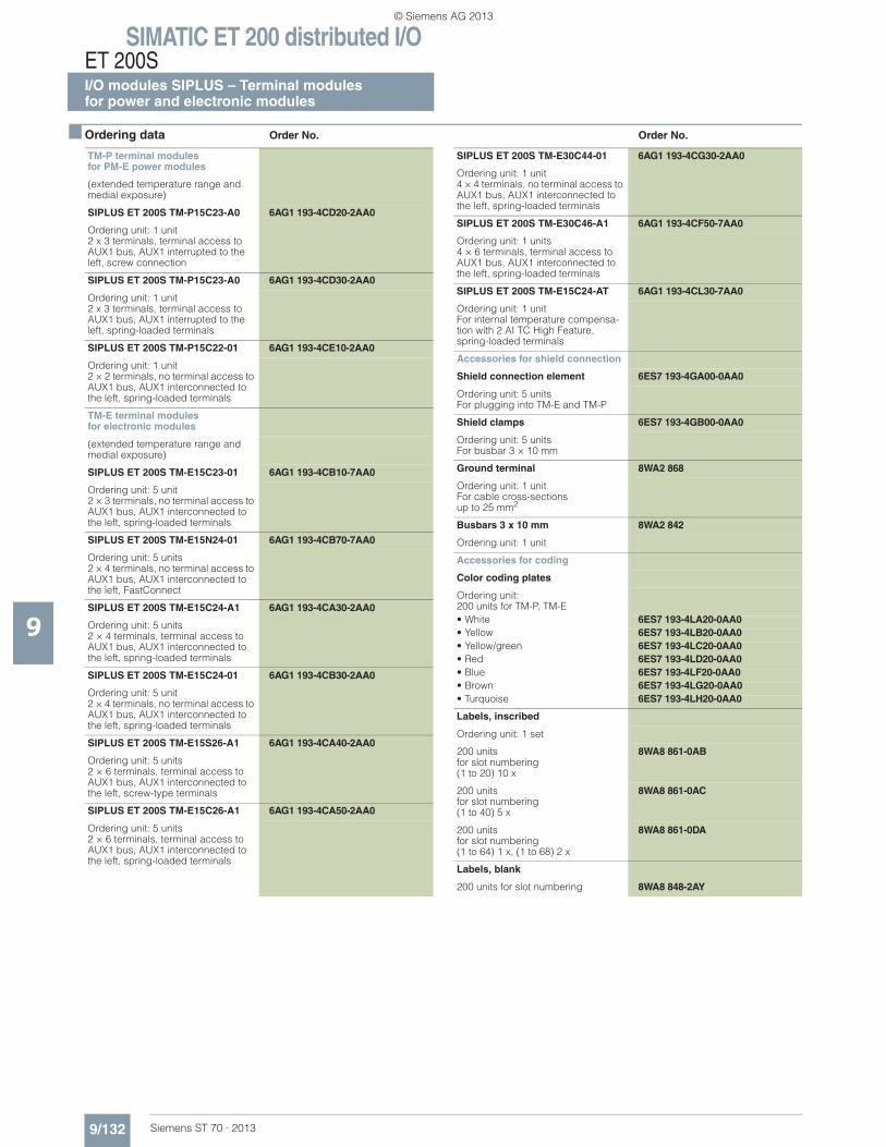
SIMATIC ET 200 distributed I/OET 200SI/O modules SIPLUS – Terminal modulesfor power and electronic modules
9/132 Siemens ST 70 · 2013
9
■ Ordering data Order No. Order No.
TM-P terminal modulesfor PM-E power modules
(extended temperature range and medial exposure)
SIPLUS ET 200S TM-P15C23-A0 6AG1 193-4CD20-2AA0
Ordering unit: 1 unit2 x 3 terminals, terminal access to AUX1 bus, AUX1 interrupted to the left, screw connection
SIPLUS ET 200S TM-P15C23-A0 6AG1 193-4CD30-2AA0
Ordering unit: 1 unit2 x 3 terminals, terminal access to AUX1 bus, AUX1 interrupted to the left, spring-loaded terminals
SIPLUS ET 200S TM-P15C22-01 6AG1 193-4CE10-2AA0
Ordering unit: 1 unit2 × 2 terminals, no terminal access to AUX1 bus, AUX1 interconnected to the left, spring-loaded terminals
TM-E terminal modulesfor electronic modules
(extended temperature range and medial exposure)
SIPLUS ET 200S TM-E15C23-01 6AG1 193-4CB10-7AA0
Ordering unit: 5 unit2 × 3 terminals, no terminal access to AUX1 bus, AUX1 interconnected to the left, spring-loaded terminals
SIPLUS ET 200S TM-E15N24-01 6AG1 193-4CB70-7AA0
Ordering unit: 5 units2 × 4 terminals, no terminal access to AUX1 bus, AUX1 interconnected to the left, FastConnect
SIPLUS ET 200S TM-E15C24-A1 6AG1 193-4CA30-2AA0
Ordering unit: 5 units2 × 4 terminals, terminal access to AUX1 bus, AUX1 interconnected to the left, spring-loaded terminals
SIPLUS ET 200S TM-E15C24-01 6AG1 193-4CB30-2AA0
Ordering unit: 5 unit2 × 4 terminals, no terminal access to AUX1 bus, AUX1 interconnected to the left, spring-loaded terminals
SIPLUS ET 200S TM-E15S26-A1 6AG1 193-4CA40-2AA0
Ordering unit: 5 units2 × 6 terminals, terminal access to AUX1 bus, AUX1 interconnected to the left, screw-type terminals
SIPLUS ET 200S TM-E15C26-A1 6AG1 193-4CA50-2AA0
Ordering unit: 5 units2 × 6 terminals, terminal access to AUX1 bus, AUX1 interconnected to the left, spring-loaded terminals
SIPLUS ET 200S TM-E30C44-01 6AG1 193-4CG30-2AA0
Ordering unit: 1 unit4 × 4 terminals, no terminal access to AUX1 bus, AUX1 interconnected to the left, spring-loaded terminals
SIPLUS ET 200S TM-E30C46-A1 6AG1 193-4CF50-7AA0
Ordering unit: 1 units4 × 6 terminals, terminal access to AUX1 bus, AUX1 interconnected to the left, spring-loaded terminals
SIPLUS ET 200S TM-E15C24-AT 6AG1 193-4CL30-7AA0
Ordering unit: 1 unitFor internal temperature compensa-tion with 2 AI TC High Feature, spring-loaded terminals
Accessories for shield connection
Shield connection element 6ES7 193-4GA00-0AA0
Ordering unit: 5 unitsFor plugging into TM-E and TM-P
Shield clamps 6ES7 193-4GB00-0AA0
Ordering unit: 5 unitsFor busbar 3 × 10 mm
Ground terminal 8WA2 868
Ordering unit: 1 unitFor cable cross-sections up to 25 mm2
Busbars 3 x 10 mm 8WA2 842
Ordering unit: 1 unit
Accessories for coding
Color coding plates
Ordering unit:200 units for TM-P, TM-E• White 6ES7 193-4LA20-0AA0• Yellow 6ES7 193-4LB20-0AA0• Yellow/green 6ES7 193-4LC20-0AA0• Red 6ES7 193-4LD20-0AA0• Blue 6ES7 193-4LF20-0AA0• Brown 6ES7 193-4LG20-0AA0• Turquoise 6ES7 193-4LH20-0AA0
Labels, inscribed
Ordering unit: 1 set
200 unitsfor slot numbering(1 to 20) 10 x
8WA8 861-0AB
200 unitsfor slot numbering(1 to 40) 5 x
8WA8 861-0AC
200 unitsfor slot numbering(1 to 64) 1 x, (1 to 68) 2 x
8WA8 861-0DA
Labels, blank
200 units for slot numbering 8WA8 848-2AY
© Siemens AG 2013
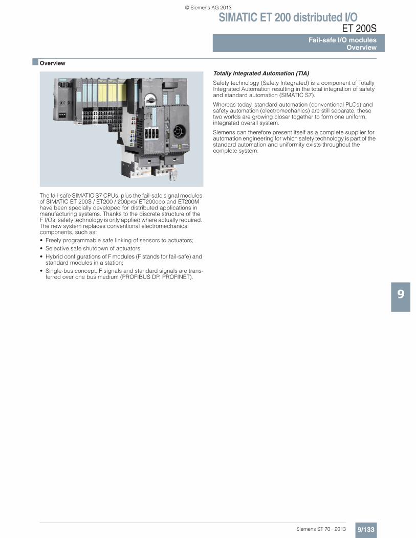
SIMATIC ET 200 distributed I/OET 200S
Fail-safe I/O modulesOverview
9/133Siemens ST 70 · 2013
9
■ Overview
The fail-safe SIMATIC S7 CPUs, plus the fail-safe signal modules of SIMATIC ET 200S / ET200 / 200pro/ ET200eco and ET200M have been specially developed for distributed applications in manufacturing systems. Thanks to the discrete structure of the F I/Os, safety technology is only applied where actually required. The new system replaces conventional electromechanical components, such as:• Freely programmable safe linking of sensors to actuators;• Selective safe shutdown of actuators;• Hybrid configurations of F modules (F stands for fail-safe) and
standard modules in a station;• Single-bus concept, F signals and standard signals are trans-
ferred over one bus medium (PROFIBUS DP, PROFINET).
Totally Integrated Automation (TIA)
Safety technology (Safety Integrated) is a component of Totally Integrated Automation resulting in the total integration of safety and standard automation (SIMATIC S7).
Whereas today, standard automation (conventional PLCs) and safety automation (electromechanics) are still separate, these two worlds are growing closer together to form one uniform, integrated overall system.
Siemens can therefore present itself as a complete supplier for automation engineering for which safety technology is part of the standard automation and uniformity exists throughout the complete system.
© Siemens AG 2013
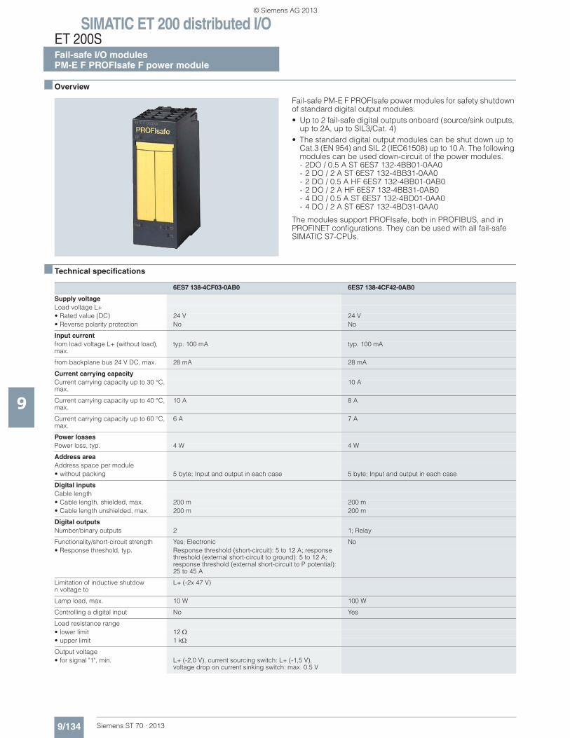
SIMATIC ET 200 distributed I/OET 200SFail-safe I/O modulesPM-E F PROFIsafe F power module
9/134 Siemens ST 70 · 2013
9
■ Overview
Fail-safe PM-E F PROFIsafe power modules for safety shutdown of standard digital output modules.• Up to 2 fail-safe digital outputs onboard (source/sink outputs,
up to 2A, up to SIL3/Cat. 4)• The standard digital output modules can be shut down up to
Cat.3 (EN 954) and SIL 2 (IEC61508) up to 10 A. The following modules can be used down-circuit of the power modules.- 2DO / 0.5 A ST 6ES7 132-4BB01-0AA0- 2 DO / 2 A ST 6ES7 132-4BB31-0AA0- 2 DO / 0.5 A HF 6ES7 132-4BB01-0AB0- 2 DO / 2 A HF 6ES7 132-4BB31-0AB0- 4 DO / 0.5 A ST 6ES7 132-4BD01-0AA0- 4 DO / 2 A ST 6ES7 132-4BD31-0AA0
The modules support PROFIsafe, both in PROFIBUS, and in PROFINET configurations. They can be used with all fail-safe SIMATIC S7-CPUs.
■ Technical specifications
6ES7 138-4CF03-0AB0 6ES7 138-4CF42-0AB0
Supply voltageLoad voltage L+• Rated value (DC) 24 V 24 V• Reverse polarity protection No No
Input currentfrom load voltage L+ (without load), max.
typ. 100 mA typ. 100 mA
from backplane bus 24 V DC, max. 28 mA 28 mA
Current carrying capacityCurrent carrying capacity up to 30 °C, max.
10 A
Current carrying capacity up to 40 °C, max.
10 A 8 A
Current carrying capacity up to 60 °C, max.
6 A 7 A
Power lossesPower loss, typ. 4 W 4 W
Address areaAddress space per module• without packing 5 byte; Input and output in each case 5 byte; Input and output in each case
Digital inputsCable length• Cable length, shielded, max. 200 m 200 m• Cable length unshielded, max. 200 m 200 m
Digital outputsNumber/binary outputs 2 1; Relay
Functionality/short-circuit strength Yes; Electronic No• Response threshold, typ. Response threshold (short-circuit): 5 to 12 A; response
threshold (external short-circuit to ground): 5 to 12 A; response threshold (external short-circuit to P potential): 25 to 45 A
Limitation of inductive shutdown voltage to
L+ (-2x 47 V)
Lamp load, max. 10 W 100 W
Controlling a digital input No Yes
Load resistance range• lower limit 12• upper limit 1 k
Output voltage• for signal "1", min. L+ (-2,0 V), current sourcing switch: L+ (-1,5 V),
voltage drop on current sinking switch: max. 0.5 V
© Siemens AG 2013
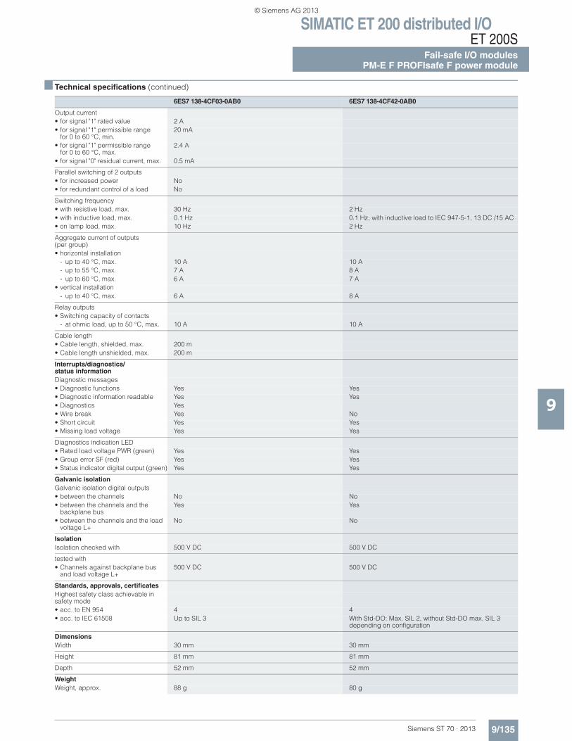
SIMATIC ET 200 distributed I/OET 200S
Fail-safe I/O modulesPM-E F PROFIsafe F power module
9/135Siemens ST 70 · 2013
■ Technical specifications (continued)
9
Output current• for signal "1" rated value 2 A• for signal "1" permissible range
for 0 to 60 °C, min.20 mA
• for signal "1" permissible rangefor 0 to 60 °C, max.
2.4 A
• for signal "0" residual current, max. 0.5 mA
Parallel switching of 2 outputs• for increased power No• for redundant control of a load No
Switching frequency• with resistive load, max. 30 Hz 2 Hz• with inductive load, max. 0.1 Hz 0.1 Hz; with inductive load to IEC 947-5-1, 13 DC /15 AC• on lamp load, max. 10 Hz 2 Hz
Aggregate current of outputs (per group)• horizontal installation
- up to 40 °C, max. 10 A 10 A- up to 55 °C, max. 7 A 8 A- up to 60 °C, max. 6 A 7 A
• vertical installation- up to 40 °C, max. 6 A 8 A
Relay outputs• Switching capacity of contacts
- at ohmic load, up to 50 °C, max. 10 A 10 A
Cable length• Cable length, shielded, max. 200 m• Cable length unshielded, max. 200 m
Interrupts/diagnostics/status informationDiagnostic messages• Diagnostic functions Yes Yes• Diagnostic information readable Yes Yes• Diagnostics Yes• Wire break Yes No• Short circuit Yes Yes• Missing load voltage Yes Yes
Diagnostics indication LED• Rated load voltage PWR (green) Yes Yes• Group error SF (red) Yes Yes• Status indicator digital output (green) Yes Yes
Galvanic isolationGalvanic isolation digital outputs• between the channels No No• between the channels and the
backplane busYes Yes
• between the channels and the load voltage L+
No No
IsolationIsolation checked with 500 V DC 500 V DC
tested with• Channels against backplane bus
and load voltage L+500 V DC 500 V DC
Standards, approvals, certificatesHighest safety class achievable in safety mode• acc. to EN 954 4 4• acc. to IEC 61508 Up to SIL 3 With Std-DO: Max. SIL 2, without Std-DO max. SIL 3
depending on configuration
DimensionsWidth 30 mm 30 mm
Height 81 mm 81 mm
Depth 52 mm 52 mm
WeightWeight, approx. 88 g 80 g
6ES7 138-4CF03-0AB0 6ES7 138-4CF42-0AB0
© Siemens AG 2013
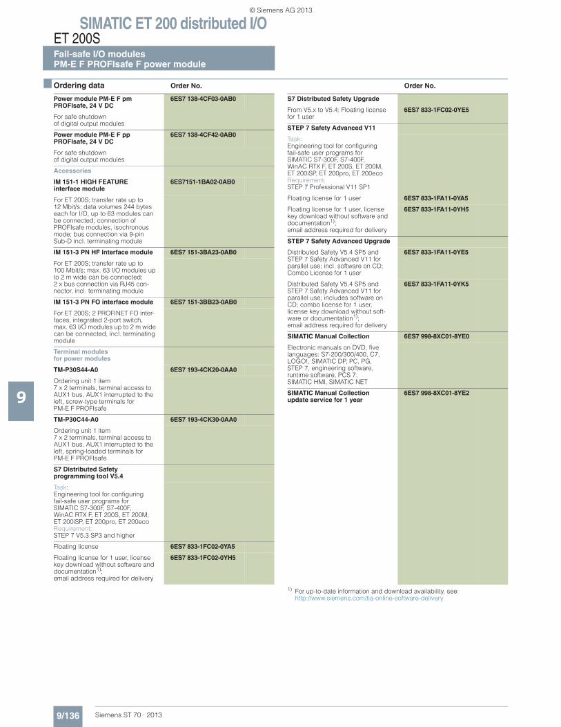
SIMATIC ET 200 distributed I/OET 200SFail-safe I/O modulesPM-E F PROFIsafe F power module
9/136 Siemens ST 70 · 2013
9
■ Ordering data Order No. Order No.
1) For up-to-date information and download availability, see:http://www.siemens.com/tia-online-software-delivery
Power module PM-E F pmPROFIsafe, 24 V DC
6ES7 138-4CF03-0AB0
For safe shutdownof digital output modules
Power module PM-E F ppPROFIsafe, 24 V DC
6ES7 138-4CF42-0AB0
For safe shutdown of digital output modules
Accessories
IM 151-1 HIGH FEATUREinterface module
6ES7151-1BA02-0AB0
For ET 200S; transfer rate up to 12 Mbit/s; data volumes 244 bytes each for I/O, up to 63 modules can be connected; connection of PROFIsafe modules, isochronous mode; bus connection via 9-pin Sub-D incl. terminating module
IM 151-3 PN HF interface module 6ES7 151-3BA23-0AB0
For ET 200S; transfer rate up to100 Mbit/s; max. 63 I/O modules up to 2 m wide can be connected; 2 x bus connection via RJ45 con-nector, incl. terminating module
IM 151-3 PN FO interface module 6ES7 151-3BB23-0AB0
For ET 200S; 2 PROFINET FO inter-faces, integrated 2-port switch, max. 63 I/O modules up to 2 m wide can be connected, incl. terminating module
Terminal modules for power modules
TM-P30S44-A0 6ES7 193-4CK20-0AA0
Ordering unit 1 item 7 x 2 terminals, terminal access to AUX1 bus, AUX1 interrupted to the left, screw-type terminals for PM-E F PROFIsafe
TM-P30C44-A0 6ES7 193-4CK30-0AA0
Ordering unit 1 item 7 x 2 terminals, terminal access to AUX1 bus, AUX1 interrupted to the left, spring-loaded terminals forPM-E F PROFIsafe
S7 Distributed Safety programming tool V5.4
Task: Engineering tool for configuringfail-safe user programs for SIMATIC S7-300F, S7-400F, WinAC RTX F, ET 200S, ET 200M, ET 200iSP, ET 200pro, ET 200eco Requirement: STEP 7 V5.3 SP3 and higher
Floating license 6ES7 833-1FC02-0YA5
Floating license for 1 user, license key download without software and documentation1); email address required for delivery
6ES7 833-1FC02-0YH5
S7 Distributed Safety Upgrade
From V5.x to V5.4; Floating license for 1 user
6ES7 833-1FC02-0YE5
STEP 7 Safety Advanced V11
Task:Engineering tool for configuringfail-safe user programs for SIMATIC S7-300F, S7-400F, WinAC RTX F, ET 200S, ET 200M, ET 200iSP, ET 200pro, ET 200ecoRequirement:STEP 7 Professional V11 SP1
Floating license for 1 user 6ES7 833-1FA11-0YA5
Floating license for 1 user, license key download without software and documentation1); email address required for delivery
6ES7 833-1FA11-0YH5
STEP 7 Safety Advanced Upgrade
Distributed Safety V5.4 SP5 and STEP 7 Safety Advanced V11 for parallel use; incl. software on CD; Combo License for 1 user
6ES7 833-1FA11-0YE5
Distributed Safety V5.4 SP5 and STEP 7 Safety Advanced V11 for parallel use; includes software on CD; combo license for 1 user, license key download without soft-ware or documentation1); email address required for delivery
6ES7 833-1FA11-0YK5
SIMATIC Manual Collection 6ES7 998-8XC01-8YE0
Electronic manuals on DVD, five languages: S7-200/300/400, C7, LOGO!, SIMATIC DP, PC, PG, STEP 7, engineering software, runtime software, PCS 7, SIMATIC HMI, SIMATIC NET
SIMATIC Manual Collection update service for 1 year
6ES7 998-8XC01-8YE2
© Siemens AG 2013
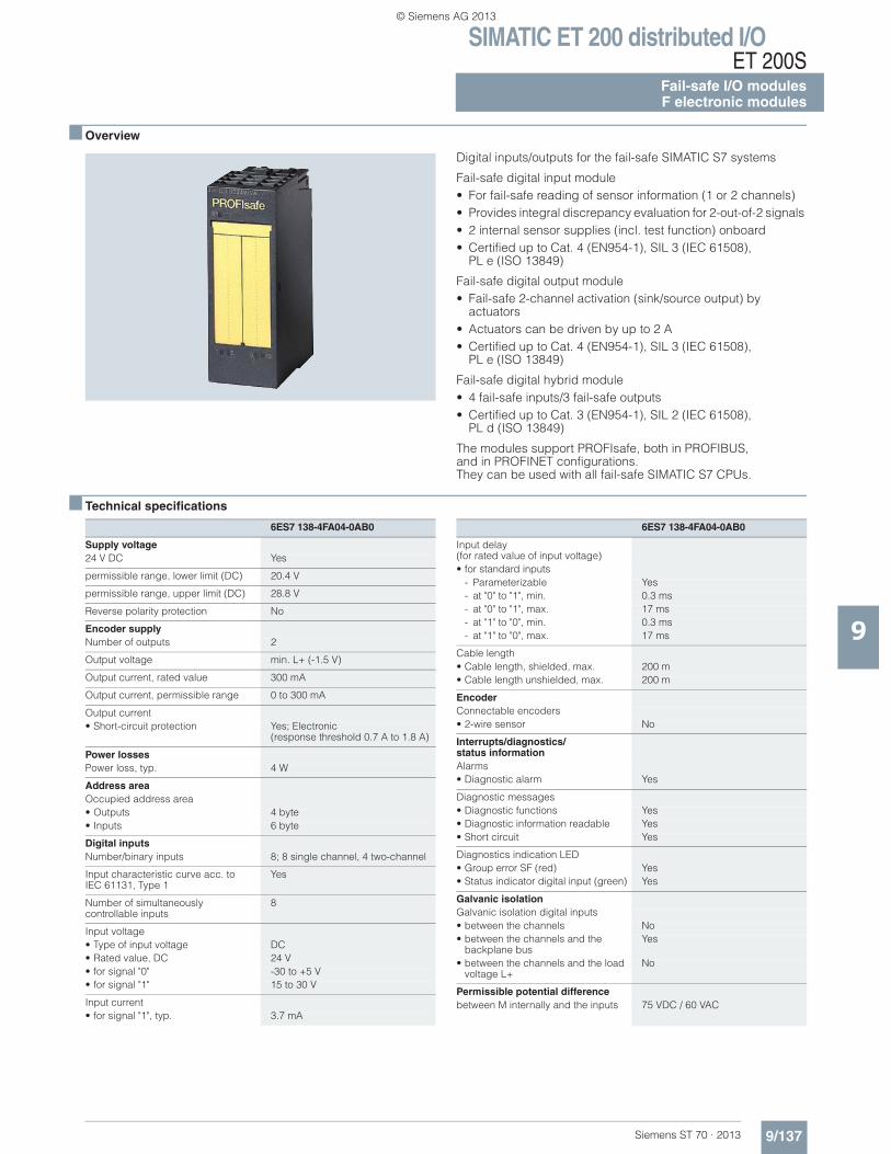
SIMATIC ET 200 distributed I/OET 200S
Fail-safe I/O modulesF electronic modules
9/137Siemens ST 70 · 2013
9
■ Overview
Digital inputs/outputs for the fail-safe SIMATIC S7 systems
Fail-safe digital input module• For fail-safe reading of sensor information (1 or 2 channels) • Provides integral discrepancy evaluation for 2-out-of-2 signals • 2 internal sensor supplies (incl. test function) onboard • Certified up to Cat. 4 (EN954-1), SIL 3 (IEC 61508),
PL e (ISO 13849)
Fail-safe digital output module• Fail-safe 2-channel activation (sink/source output) by
actuators • Actuators can be driven by up to 2 A • Certified up to Cat. 4 (EN954-1), SIL 3 (IEC 61508),
PL e (ISO 13849)
Fail-safe digital hybrid module• 4 fail-safe inputs/3 fail-safe outputs• Certified up to Cat. 3 (EN954-1), SIL 2 (IEC 61508),
PL d (ISO 13849)
The modules support PROFIsafe, both in PROFIBUS, and in PROFINET configurations. They can be used with all fail-safe SIMATIC S7 CPUs.
■ Technical specifications
6ES7 138-4FA04-0AB0
Supply voltage24 V DC Yes
permissible range, lower limit (DC) 20.4 V
permissible range, upper limit (DC) 28.8 V
Reverse polarity protection No
Encoder supplyNumber of outputs 2
Output voltage min. L+ (-1.5 V)
Output current, rated value 300 mA
Output current, permissible range 0 to 300 mA
Output current• Short-circuit protection Yes; Electronic
(response threshold 0.7 A to 1.8 A)
Power lossesPower loss, typ. 4 W
Address areaOccupied address area• Outputs 4 byte• Inputs 6 byte
Digital inputsNumber/binary inputs 8; 8 single channel, 4 two-channel
Input characteristic curve acc. to IEC 61131, Type 1
Yes
Number of simultaneously controllable inputs
8
Input voltage• Type of input voltage DC• Rated value, DC 24 V• for signal "0" -30 to +5 V• for signal "1" 15 to 30 V
Input current• for signal "1", typ. 3.7 mA
Input delay (for rated value of input voltage)• for standard inputs
- Parameterizable Yes- at "0" to "1", min. 0.3 ms- at "0" to "1", max. 17 ms- at "1" to "0", min. 0.3 ms- at "1" to "0", max. 17 ms
Cable length• Cable length, shielded, max. 200 m• Cable length unshielded, max. 200 m
EncoderConnectable encoders• 2-wire sensor No
Interrupts/diagnostics/status informationAlarms• Diagnostic alarm Yes
Diagnostic messages• Diagnostic functions Yes• Diagnostic information readable Yes• Short circuit Yes
Diagnostics indication LED• Group error SF (red) Yes• Status indicator digital input (green) Yes
Galvanic isolationGalvanic isolation digital inputs• between the channels No• between the channels and the
backplane busYes
• between the channels and the load voltage L+
No
Permissible potential differencebetween M internally and the inputs 75 VDC / 60 VAC
6ES7 138-4FA04-0AB0
© Siemens AG 2013
SIMATIC ET 200 distributed I/OET 200SFail-safe I/O modulesF electronic modules
9/138 Siemens ST 70 · 2013
■ Technical specifications (continued)
9
IsolationIsolation checked with 500 V DC
Standards, approvals, certificatesHighest safety class achievable in safety mode• acc. to EN 954 4• acc. to IEC 61508 SIL 2 (single-channel),
SIL 3 (two-channel)
6ES7 138-4FA04-0AB0
DimensionsWidth 30 mm
Height 81 mm
Depth 52 mm
WeightWeight, approx. 78 g
6ES7 138-4FA04-0AB0
6ES7 138-4FB03-0AB0
Supply voltageLoad voltage L+• Rated value (DC) 24 V• Reverse polarity protection No
Input currentfrom load voltage L+ (without load), max.
typ. 100 mA
from backplane bus 3.3 V DC, max. 28 mA
Power lossesPower loss, typ. 3.5 W
Digital outputsNumber/binary outputs 4
Functionality/short-circuit strength Yes; Electronic
Limitation of inductive shutdown voltage to
Typ. (2L+) -47 V
Lamp load, max. 10 W
Controlling a digital input No
Load resistance range• lower limit 12• upper limit 1 k
Output voltage• for signal "1", min. L+ (-2,0 V), current sourcing switch:
L+ (-1,5 V), voltage drop on current sinking switch: max. 0.5 V
Output current• for signal "1" rated value 2 A• for signal "1" permissible range
for 0 to 60 °C, min.20 mA
• for signal "1" permissible rangefor 0 to 60 °C, max.
2.4 A
• for signal "0" residual current, max. 0.5 mA; Current-sourcing: max. 0.5 mA; Current sinking: max. 4 mA
Parallel switching of 2 outputs• for increased power No• for redundant control of a load No
Switching frequency• with resistive load, max. 30 Hz• with inductive load, max. 0.1 Hz• on lamp load, max. 10 Hz
Aggregate current of outputs(per group)• horizontal installation
- up to 40 °C, max. 6 A- up to 55 °C, max. 5 A- up to 60 °C, max. 4 A
• vertical installation- up to 40 °C, max. 4 A
Cable length• Cable length, shielded, max. 200 m• Cable length unshielded, max. 200 m
Interrupts/diagnostics/status informationDiagnostic messages• Diagnostic functions Yes• Wire break Yes• Short circuit Yes
Diagnostics indication LED• Group error SF (red) Yes• Status indicator digital output (green) Yes
Galvanic isolationGalvanic isolation digital outputs• between the channels No• between the channels and the
backplane busYes
• between the channels and the load voltage L+
No
IsolationIsolation checked with 500 V DC
tested with• Channels against backplane bus
and load voltage L+1500 V AC
Standards, approvals, certificatesHighest safety class achievable in safety mode• acc. to EN 954 4• acc. to IEC 61508 SIL 3
DimensionsWidth 30 mm
Height 81 mm
Depth 52 mm
WeightWeight, approx. 85 g
6ES7 138-4FB03-0AB0
© Siemens AG 2013
SIMATIC ET 200 distributed I/OET 200S
Fail-safe I/O modulesF electronic modules
9/139Siemens ST 70 · 2013
9
■ Ordering data Order No. Order No.
1) For up-to-date information and download availability, see:http://www.siemens.com/tia-online-software-delivery
Electronic module 4/8 F-DI PROFIsafe 24 V DC
6ES7 138-4FA04-0AB0
30 mm construction width, up to Category 4 (EN954-1)
Electronic module 4 F-DO PROFIsafe 24 V DC/2A
6ES7 138-4FB03-0AB0
30 mm construction width,up to Category 4 (EN954-1)
Electronic module 4 F-DI / 3 F-DO PROFIsafe 24 V DC/2A
6ES7 138-4FC01-0AB0
30 mm construction width,up to Category 3 (EN954-1) / SIL 2 (IEC 62061)
Accessories
Terminal modulesfor electronic modules
See F terminal modules, page 9/142
IM 151-1 High Featureinterface module
6ES7 151-1BA02-0AB0
For ET 200S; transmission rate up to 12 Mbit/s; max. 63 modules can be connected, with isochronous mode, bus connection via 9-pin Sub-D connector incl. terminating module
IM 151-3 PN HF interface module 6ES7 151-3BA23-0AB0
For ET 200S; transfer rate up to100 Mbit/s; max. 63 I/O modules up to 2 m wide can be connected; 2 x bus connection via RJ45 con-nector, incl. terminating module
IM 151-3 PN FO interface module 6ES7 151-3BB23-0AB0
For ET 200S; 2 PROFINET FO inter-faces, integrated 2-port switch, max. 63 I/O modules up to 2 m wide can be connected, incl. terminating module
S7 Distributed Safety programming tool V5.4
Task: Engineering tool for configuringfail-safe user programs for SIMATIC S7-300F, S7-400F, WinAC RTX F, ET 200S, ET 200M, ET 200iSP, ET 200pro, ET 200eco Requirement: STEP 7 V5.3 SP3 and higher
Floating license 6ES7 833-1FC02-0YA5
Floating license for 1 user, license key download without software and documentation1); email address required for delivery
6ES7 833-1FC02-0YH5
S7 Distributed Safety Upgrade
From V5.x to V5.4; Floating license for 1 user
6ES7 833-1FC02-0YE5
STEP 7 Safety Advanced V11
Task:Engineering tool for configuringfail-safe user programs for SIMATIC S7-300F, S7-400F, WinAC RTX F, ET 200S, ET 200M, ET 200iSP, ET 200pro, ET 200ecoRequirement:STEP 7 Professional V11 SP1
Floating license for 1 user 6ES7 833-1FA11-0YA5
Floating license for 1 user, license key download without software and documentation1); email address required for delivery
6ES7 833-1FA11-0YH5
STEP 7 Safety Advanced Upgrade
Distributed Safety V5.4 SP5 and STEP 7 Safety Advanced V11 for parallel use; incl. software on CD; Combo License for 1 user
6ES7 833-1FA11-0YE5
Distributed Safety V5.4 SP5 and STEP 7 Safety Advanced V11 for parallel use; includes software on CD; combo license for 1 user, license key download without software or documentation1); email address required for delivery
6ES7 833-1FA11-0YK5
SIMATIC Manual Collection 6ES7 998-8XC01-8YE0
Electronic manuals on DVD,multi-language: S7-200, TD 200, S7-300, M7-300, C7, S7-400, M7-400, STEP 7, Engineering Tools, Runtime Soft-ware, SIMATIC DP (Distributed I/O), SIMATIC HMI (Human Machine Interface), SIMATIC NET(Industrial Communication)
SIMATIC Manual Collection – Update service for 1 year
6ES7 998-8XC01-8YE2
Scope of delivery: Current DVD "S7 Manual Collection" and the three subsequent updates
© Siemens AG 2013
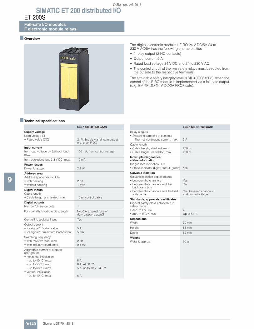
SIMATIC ET 200 distributed I/OET 200SFail-safe I/O modulesF electronic module relays
9/140 Siemens ST 70 · 2013
9
■ Overview
The digital electronic module 1 F-RO 24 V DC/5A 24 to230 V AC/5A has the following characteristics • 1 relay output (2 NO contacts) • Output current 5 A. • Rated load voltage 24 V DC and 24 to 230 V AC • The control circuit of the two safety relays must be routed from
the outside to the respective terminals.
The attainable safety integrity level is SIL3 (IEC61508), when the control of the F-RO module is implemented via a fail-safe output (e.g. EM 4F-DO 24 V DC/2A PROFIsafe).
■ Technical specifications
6ES7 138-4FR00-0AA0
Supply voltageLoad voltage L+• Rated value (DC) 24 V; Supply via fail-safe output,
e.g. of an F-DO
Input currentfrom load voltage L+ (without load), max.
100 mA; from control voltage
from backplane bus 3.3 V DC, max. 10 mA
Power lossesPower loss, typ. 2.1 W
Address areaAddress space per module• with packing 2 bit• without packing 1 byte
Digital inputsCable length• Cable length unshielded, max. 10 m; control cable
Digital outputsNumber/binary outputs 1
Functionality/short-circuit strength No; 6 A external fuse of duty category gL/gG
Controlling a digital input Yes
Output current• for signal "1" rated value 5 A• for signal "1" minimum load current 5 mA
Switching frequency• with resistive load, max. 2 Hz• with inductive load, max. 0.1 Hz
Aggregate current of outputs(per group)• horizontal installation
- up to 40 °C, max. 8 A- up to 55 °C, max. 6 A; At 50 °C- up to 60 °C, max. 5 A; up to max. 24.8 V
• vertical installation- up to 40 °C, max. 6 A
Relay outputs• Switching capacity of contacts
- Thermal continuous current, max. 5 A
Cable length• Cable length, shielded, max. 200 m• Cable length unshielded, max. 200 m
Interrupts/diagnostics/status informationDiagnostics indication LED• Status indicator digital output (green) Yes
Galvanic isolationGalvanic isolation digital outputs• between the channels Yes• between the channels and the
backplane busYes
• between the channels and the load voltage L+
Yes; between channels and control voltage
Standards, approvals, certificatesHighest safety class achievable in safety mode• acc. to EN 954 4• acc. to IEC 61508 Up to SIL 3
DimensionsWidth 30 mm
Height 81 mm
Depth 52 mm
WeightWeight, approx. 90 g
6ES7 138-4FR00-0AA0
© Siemens AG 2013
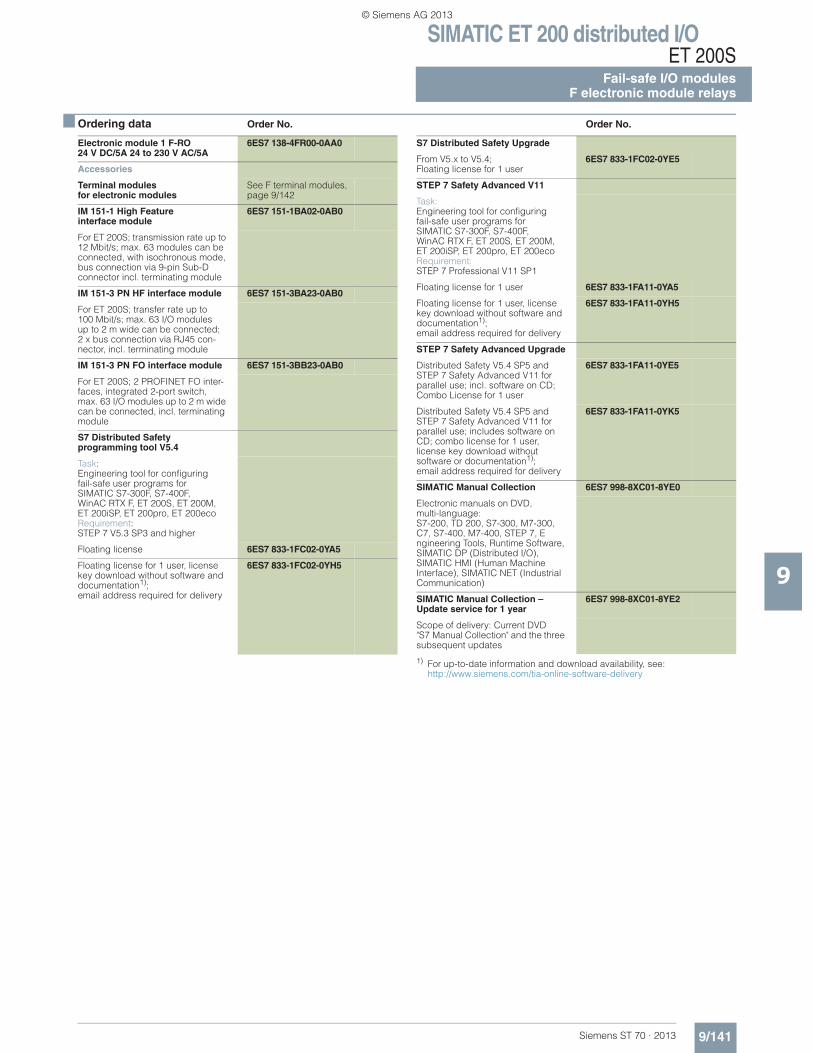
SIMATIC ET 200 distributed I/OET 200S
Fail-safe I/O modulesF electronic module relays
9/141Siemens ST 70 · 2013
9
■ Ordering data Order No. Order No.
1) For up-to-date information and download availability, see:http://www.siemens.com/tia-online-software-delivery
Electronic module 1 F-RO 24 V DC/5A 24 to 230 V AC/5A
6ES7 138-4FR00-0AA0
Accessories
Terminal modulesfor electronic modules
See F terminal modules, page 9/142
IM 151-1 High Feature interface module
6ES7 151-1BA02-0AB0
For ET 200S; transmission rate up to 12 Mbit/s; max. 63 modules can be connected, with isochronous mode, bus connection via 9-pin Sub-D connector incl. terminating module
IM 151-3 PN HF interface module 6ES7 151-3BA23-0AB0
For ET 200S; transfer rate up to 100 Mbit/s; max. 63 I/O modules up to 2 m wide can be connected; 2 x bus connection via RJ45 con-nector, incl. terminating module
IM 151-3 PN FO interface module 6ES7 151-3BB23-0AB0
For ET 200S; 2 PROFINET FO inter-faces, integrated 2-port switch, max. 63 I/O modules up to 2 m wide can be connected, incl. terminating module
S7 Distributed Safety programming tool V5.4
Task: Engineering tool for configuringfail-safe user programs forSIMATIC S7-300F, S7-400F, WinAC RTX F, ET 200S, ET 200M, ET 200iSP, ET 200pro, ET 200eco Requirement: STEP 7 V5.3 SP3 and higher
Floating license 6ES7 833-1FC02-0YA5
Floating license for 1 user, license key download without software and documentation1); email address required for delivery
6ES7 833-1FC02-0YH5
S7 Distributed Safety Upgrade
From V5.x to V5.4; Floating license for 1 user
6ES7 833-1FC02-0YE5
STEP 7 Safety Advanced V11
Task:Engineering tool for configuringfail-safe user programs for SIMATIC S7-300F, S7-400F, WinAC RTX F, ET 200S, ET 200M, ET 200iSP, ET 200pro, ET 200ecoRequirement:STEP 7 Professional V11 SP1
Floating license for 1 user 6ES7 833-1FA11-0YA5
Floating license for 1 user, license key download without software and documentation1); email address required for delivery
6ES7 833-1FA11-0YH5
STEP 7 Safety Advanced Upgrade
Distributed Safety V5.4 SP5 and STEP 7 Safety Advanced V11 for parallel use; incl. software on CD; Combo License for 1 user
6ES7 833-1FA11-0YE5
Distributed Safety V5.4 SP5 and STEP 7 Safety Advanced V11 for parallel use; includes software on CD; combo license for 1 user, license key download without software or documentation1); email address required for delivery
6ES7 833-1FA11-0YK5
SIMATIC Manual Collection 6ES7 998-8XC01-8YE0
Electronic manuals on DVD, multi-language: S7-200, TD 200, S7-300, M7-300, C7, S7-400, M7-400, STEP 7, Engineering Tools, Runtime Software, SIMATIC DP (Distributed I/O), SIMATIC HMI (Human Machine Interface), SIMATIC NET (Industrial Communication)
SIMATIC Manual Collection – Update service for 1 year
6ES7 998-8XC01-8YE2
Scope of delivery: Current DVD "S7 Manual Collection" and the three subsequent updates
© Siemens AG 2013
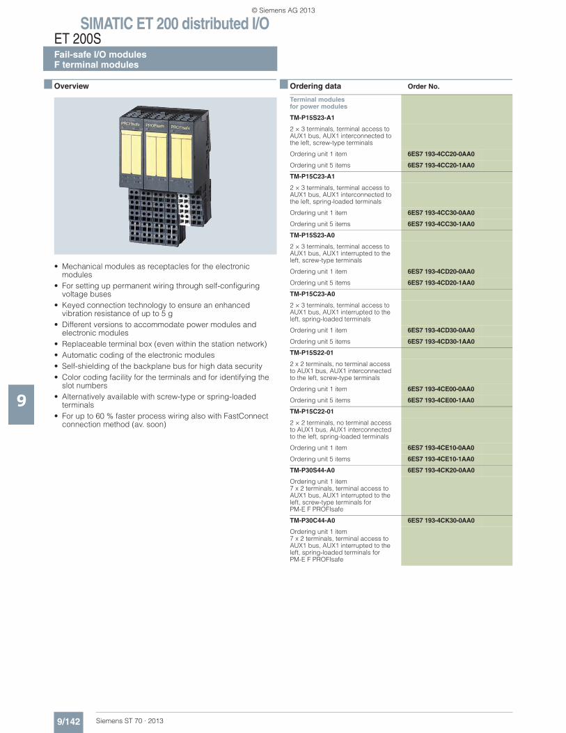
SIMATIC ET 200 distributed I/OET 200SFail-safe I/O modulesF terminal modules
9/142 Siemens ST 70 · 2013
9
■ Overview
• Mechanical modules as receptacles for the electronic modules
• For setting up permanent wiring through self-configuring voltage buses
• Keyed connection technology to ensure an enhanced vibration resistance of up to 5 g
• Different versions to accommodate power modules and electronic modules
• Replaceable terminal box (even within the station network)• Automatic coding of the electronic modules• Self-shielding of the backplane bus for high data security• Color coding facility for the terminals and for identifying the
slot numbers• Alternatively available with screw-type or spring-loaded
terminals• For up to 60 % faster process wiring also with FastConnect
connection method (av. soon)
■ Ordering data Order No.
Terminal modulesfor power modules
TM-P15S23-A1
2 × 3 terminals, terminal access to AUX1 bus, AUX1 interconnected to the left, screw-type terminals
Ordering unit 1 item 6ES7 193-4CC20-0AA0
Ordering unit 5 items 6ES7 193-4CC20-1AA0
TM-P15C23-A1
2 × 3 terminals, terminal access to AUX1 bus, AUX1 interconnected to the left, spring-loaded terminals
Ordering unit 1 item 6ES7 193-4CC30-0AA0
Ordering unit 5 items 6ES7 193-4CC30-1AA0
TM-P15S23-A0
2 × 3 terminals, terminal access to AUX1 bus, AUX1 interrupted to the left, screw-type terminals
Ordering unit 1 item 6ES7 193-4CD20-0AA0
Ordering unit 5 items 6ES7 193-4CD20-1AA0
TM-P15C23-A0
2 × 3 terminals, terminal access to AUX1 bus, AUX1 interrupted to the left, spring-loaded terminals
Ordering unit 1 item 6ES7 193-4CD30-0AA0
Ordering unit 5 items 6ES7 193-4CD30-1AA0
TM-P15S22-01
2 x 2 terminals, no terminal access to AUX1 bus, AUX1 interconnected to the left, screw-type terminals
Ordering unit 1 item 6ES7 193-4CE00-0AA0
Ordering unit 5 items 6ES7 193-4CE00-1AA0
TM-P15C22-01
2 × 2 terminals, no terminal access to AUX1 bus, AUX1 interconnected to the left, spring-loaded terminals
Ordering unit 1 item 6ES7 193-4CE10-0AA0
Ordering unit 5 items 6ES7 193-4CE10-1AA0
TM-P30S44-A0 6ES7 193-4CK20-0AA0
Ordering unit 1 item 7 x 2 terminals, terminal access to AUX1 bus, AUX1 interrupted to the left, screw-type terminals for PM-E F PROFIsafe
TM-P30C44-A0 6ES7 193-4CK30-0AA0
Ordering unit 1 item 7 x 2 terminals, terminal access to AUX1 bus, AUX1 interrupted to the left, spring-loaded terminals for PM-E F PROFIsafe
© Siemens AG 2013
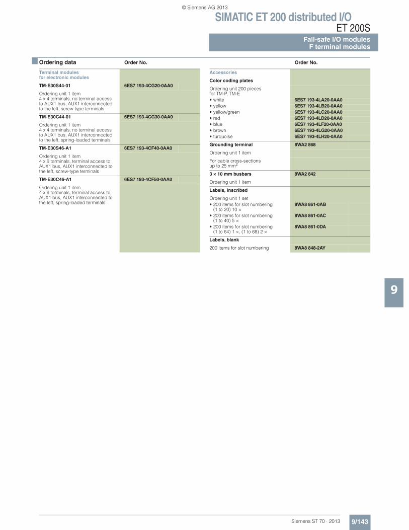
SIMATIC ET 200 distributed I/OET 200S
Fail-safe I/O modulesF terminal modules
9/143Siemens ST 70 · 2013
■ Ordering data Order No. Order No.
9
Terminal modulesfor electronic modules
TM-E30S44-01 6ES7 193-4CG20-0AA0
Ordering unit 1 item 4 x 4 terminals, no terminal access to AUX1 bus, AUX1 interconnected to the left, screw-type terminals
TM-E30C44-01 6ES7 193-4CG30-0AA0
Ordering unit 1 item 4 x 4 terminals, no terminal access to AUX1 bus, AUX1 interconnected to the left, spring-loaded terminals
TM-E30S46-A1 6ES7 193-4CF40-0AA0
Ordering unit 1 item 4 x 6 terminals, terminal access to AUX1 bus, AUX1 interconnected to the left, screw-type terminals
TM-E30C46-A1 6ES7 193-4CF50-0AA0
Ordering unit 1 item 4 x 6 terminals, terminal access to AUX1 bus, AUX1 interconnected to the left, spring-loaded terminals
Accessories
Color coding plates
Ordering unit 200 piecesfor TM-P, TM-E• white 6ES7 193-4LA20-0AA0• yellow 6ES7 193-4LB20-0AA0• yellow/green 6ES7 193-4LC20-0AA0• red 6ES7 193-4LD20-0AA0• blue 6ES7 193-4LF20-0AA0• brown 6ES7 193-4LG20-0AA0• turquoise 6ES7 193-4LH20-0AA0
Grounding terminal 8WA2 868
Ordering unit 1 item
For cable cross-sectionsup to 25 mm2
3 × 10 mm busbars 8WA2 842
Ordering unit 1 item
Labels, inscribed
Ordering unit 1 set• 200 items for slot numbering
(1 to 20) 10 ×8WA8 861-0AB
• 200 items for slot numbering (1 to 40) 5 ×
8WA8 861-0AC
• 200 items for slot numbering(1 to 64) 1 ×, (1 to 68) 2 ×
8WA8 861-0DA
Labels, blank
200 items for slot numbering 8WA8 848-2AY
© Siemens AG 2013
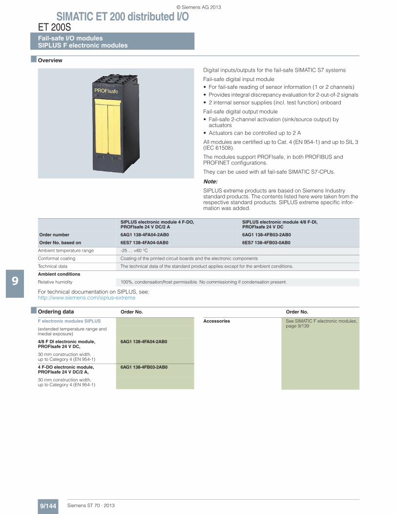
SIMATIC ET 200 distributed I/OET 200SFail-safe I/O modulesSIPLUS F electronic modules
9/144 Siemens ST 70 · 2013
9
■ Overview
Digital inputs/outputs for the fail-safe SIMATIC S7 systems
Fail-safe digital input module• For fail-safe reading of sensor information (1 or 2 channels) • Provides integral discrepancy evaluation for 2-out-of-2 signals • 2 internal sensor supplies (incl. test function) onboard
Fail-safe digital output module• Fail-safe 2-channel activation (sink/source output) by
actuators • Actuators can be controlled up to 2 A
All modules are certified up to Cat. 4 (EN 954-1) and up to SIL 3 (IEC 61508).
The modules support PROFIsafe, in both PROFIBUS and PROFINET configurations.
They can be used with all fail-safe SIMATIC S7-CPUs.
Note:
SIPLUS extreme products are based on Siemens Industry standard products. The contents listed here were taken from the respective standard products. SIPLUS extreme specific infor-mation was added.
For technical documentation on SIPLUS, see:http://www.siemens.com/siplus-extreme
■ Ordering data Order No. Order No.
SIPLUS electronic module 4 F-DO, PROFIsafe 24 V DC/2 A
SIPLUS electronic module 4/8 F-DI, PROFIsafe 24 V DC
Order number 6AG1 138-4FA04-2AB0 6AG1 138-4FB03-2AB0
Order No. based on 6ES7 138-4FA04-0AB0 6ES7 138-4FB03-0AB0
Ambient temperature range -25 ... +60 °C
Conformal coating Coating of the printed circuit boards and the electronic components
Technical data The technical data of the standard product applies except for the ambient conditions.
Ambient conditions
Relative humidity 100%, condensation/frost permissible. No commissioning if condensation present.
F electronic modules SIPLUS
(extended temperature range and medial exposure)
4/8 F DI electronic module, PROFIsafe 24 V DC,
6AG1 138-4FA04-2AB0
30 mm construction width,up to Category 4 (EN 954-1)
4 F-DO electronic module, PROFIsafe 24 V DC/2 A,
6AG1 138-4FB03-2AB0
30 mm construction width,up to Category 4 (EN 954-1)
Accessories See SIMATIC F electronic modules, page 9/139
© Siemens AG 2013
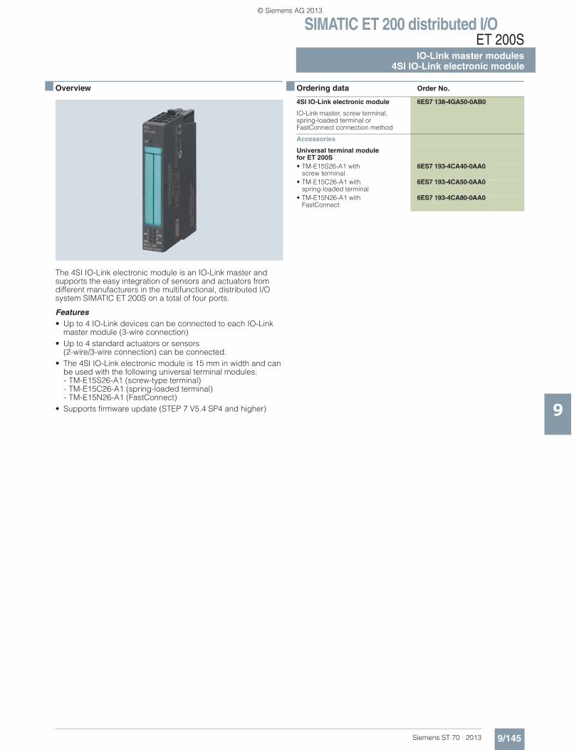
SIMATIC ET 200 distributed I/OET 200S
IO-Link master modules4SI IO-Link electronic module
9/145Siemens ST 70 · 2013
9
■ Overview
The 4SI IO-Link electronic module is an IO-Link master and supports the easy integration of sensors and actuators from different manufacturers in the multifunctional, distributed I/O system SIMATIC ET 200S on a total of four ports.
Features• Up to 4 IO-Link devices can be connected to each IO-Link
master module (3-wire connection)• Up to 4 standard actuators or sensors
(2-wire/3-wire connection) can be connected.• The 4SI IO-Link electronic module is 15 mm in width and can
be used with the following universal terminal modules: - TM-E15S26-A1 (screw-type terminal)- TM-E15C26-A1 (spring-loaded terminal)- TM-E15N26-A1 (FastConnect)
• Supports firmware update (STEP 7 V5.4 SP4 and higher)
■ Ordering data Order No.
4SI IO-Link electronic module 6ES7 138-4GA50-0AB0
IO-Link master, screw terminal, spring-loaded terminal or FastConnect connection method
Accessories
Universal terminal modulefor ET 200S• TM-E15S26-A1 with
screw terminal6ES7 193-4CA40-0AA0
• TM-E15C26-A1 withspring-loaded terminal
6ES7 193-4CA50-0AA0
• TM-E15N26-A1 with FastConnect
6ES7 193-4CA80-0AA0
© Siemens AG 2013
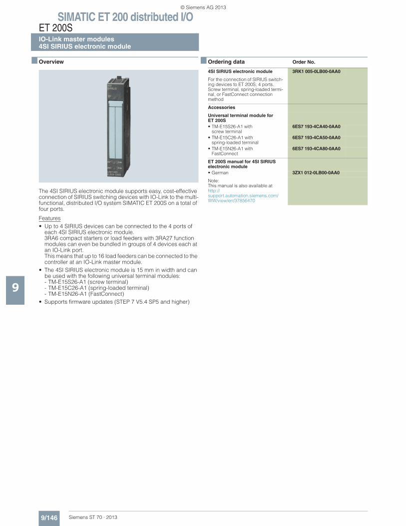
SIMATIC ET 200 distributed I/OET 200SIO-Link master modules4SI SIRIUS electronic module
9/146 Siemens ST 70 · 2013
9
■ Overview
The 4SI SIRIUS electronic module supports easy, cost-effective connection of SIRIUS switching devices with IO-Link to the multi-functional, distributed I/O system SIMATIC ET 200S on a total of four ports.
Features• Up to 4 SIRIUS devices can be connected to the 4 ports of
each 4SI SIRIUS electronic module.3RA6 compact starters or load feeders with 3RA27 function modules can even be bundled in groups of 4 devices each at an IO-Link port.This means that up to 16 load feeders can be connected to the controller at an IO-Link master module.
• The 4SI SIRIUS electronic module is 15 mm in width and can be used with the following universal terminal modules:- TM-E15S26-A1 (screw terminal)- TM-E15C26-A1 (spring-loaded terminal)- TM-E15N26-A1 (FastConnect)
• Supports firmware updates (STEP 7 V5.4 SP5 and higher)
■ Ordering data Order No.
4SI SIRIUS electronic module 3RK1 005-0LB00-0AA0
For the connection of SIRIUS switch-ing devices to ET 200S; 4 ports. Screw terminal, spring-loaded termi-nal, or FastConnect connection method
Accessories
Universal terminal module for ET 200S• TM-E15S26-A1 with
screw terminal6ES7 193-4CA40-0AA0
• TM-E15C26-A1 withspring-loaded terminal
6ES7 193-4CA50-0AA0
• TM-E15N26-A1 with FastConnect
6ES7 193-4CA80-0AA0
ET 200S manual for 4SI SIRIUS electronic module• German 3ZX1 012-0LB00-0AA0
Note:This manual is also available athttp://support.automation.siemens.com/WW/view/en/37856470
© Siemens AG 2013
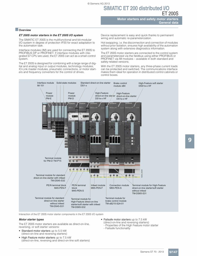
SIMATIC ET 200 distributed I/OET 200S
9/147Siemens ST 70 · 2013
Motor starters and safety motor startersGeneral data
9
■ Overview
ET 200S motor starters in the ET 200S I/O system
The SIMATIC ET 200S is the multifunctional and bit-modular I/O system in degree of protection IP20 for exact adaptation to the automation task.
Interface modules (IM) are used for connecting the ET 200S to PROFIBUS DP or PROFINET. If interface modules with inte-grated S7-CPU are used, the ET 200S can act as a small control system.
The ET 200S is designed for combining with a large range of dig-ital and analog input or output modules, technology modules, IO-Link master modules, pneumatic connections, or motor start-ers and frequency converters for the control of drives.
Device replacement is easy and quick thanks to permanent wiring and automatic re-parameterization.
Hot swapping, i.e. the disconnection and connection of modules without prior isolation, ensures high availability of the automation system along with extensive diagnostics information.
The ET 200S motor starters are connected to the control system and parameterized via the fieldbus using either PROFIBUS or PROFINET via IM modules – available in both standard and safety-related versions.
With the ET 200S motor starters, any three-phase current loads can be protected and switched. The communications interface makes them ideal for operation in distributed control cabinets or control boxes.
Interaction of the ET 200S motor starter components in the ET 200S I/O system
Motor starter types
The ET 200S motor starters are available as direct-on-line,reversing, or soft starter versions:• Standard motor starters up to 5.5 kW
(direct-on-line and reversing starters)• High Feature motor starters up to 7.5 kW
(direct-on-line, reversing and direct-on-line soft starters)
• Failsafe motor starters up to 7.5 kW (direct-on-line and reversing starters)- Properties of the High Feature motor starter- Failsafe functionality
Interface moduleIM 151
Power modulePM-E
Terminal module for PM-D TM-P15
Solid-state modules
Power modulePM-D
Standard direct-on-line starterDS1-x
High-Feature direct-on-line starterDS1e-x HF
High-Feature direct-on-line starter DS1e-x HF
Brake control module xB4
High-Feature soft starter DSS1e-x HF
Terminal module for standard direct-on-line starter with infeed
TM-DS45-S32
Terminal module for High-Feature direct-on-line starter/soft starter with infeedTM-DS65-S32
Terminal module for High-Feature direct-on-line starter/soft starter without infeedTM-DS65-S31
Terminal module for standard direct-on-line starter
without infeed TM-DS45-S31
Terminal module for brake control moduleTM-xB215-S24-01
PE/N terminal blockM45-PEN-F
PE/N terminal blockM45-PEN-S
Infeed moduleM65-PEN-F
Connection moduleM65-PEN-S
NS
A0_
0045
9
© Siemens AG 2013
SIMATIC ET 200 distributed I/OET 200SMotor starters and safety motor startersGeneral data
9/148 Siemens ST 70 · 2013
9
Innovation of the ET 200S High Feature motor starters
The ET 200S High Feature motor starters have undergone radical innovation and now support the acyclic services on PROFIBUS and PROFINET as well as PROFIenergy on PROFINET.
They are now:• Even more flexible – flexible assignment of parameters• Even better integrated in TIA (Totally Integrated Automation)• Even more transparent – through comprehensive diagnostic
data records• Even more anticipatory – through maintenance functions• Energy-efficient – through PROFIenergy
Basic functionality of the ET 200S motor starters
All versions of the ET 200S motor starters have the following functionality. The further specific functionality is described for the respective versions. • Fully pre-wired motor starters for switching and protecting any
AC loads up to 7.5 kW at 400 V AC and 500 V AC• With self-assembling 40/50 A power bus, i.e. the load voltage
is only fed once for a group of motor starters• All supply voltages are connected only once, i.e. when mod-
ules are added, they are automatically connected to the next module
• Hot swapping is permissible• Integrated inputs and outputs for control and status signaling• Control of the motor starter from the control system and exten-
sive diagnostics status via the cyclic process image• Diagnostics capability for active monitoring of the switching
and protection functions• The signal states in the process image of the motor starter pro-
vide information about protective devices (short-circuit or overload), the switching states of contactor(s) or soft starters, and system faults.
• Interface for controlling an expansion module, e. g. brake con-trol module xB1...xB4 for controlling mechanical brakes in three-phase motors for 24 V DC and 500 V DC.
• Brake control module xB5 and xB6 for 400 V AC• Can be combined with safety technology for use in safety-
related system components (IEC 62061 and ISO 13849-1)
Mounting
As the motor starters are fully pre-wired, up to 80% of the wiring outlay can be saved. The control cabinets can be assembled far more quickly and compactly.
Expansions are easily possible through the subsequent adding of terminal modules. Due to their modular terminal design (10 mm²), they also replace any previously required marshaling wiring. Through the permanent wiring and the "hot swapping" function (disconnection and connection during operation) a mo-tor starter can be replaced within seconds if necessary. The mo-tor starters are therefore recommendable in particular for appli-cations with special demands on availability.
Parameterization and configuration
Configuration is made easier by the bit-modular structure.
When using the ET 200S motor starters, the list of parts per load feeder is reduced to two main items: the passive terminal mod-ule and the motor starter. This makes the ET 200S ideal for mod-ular machine concepts as well.
All ET 200S motor starters are set up without fuses. Contactors and soft starters are activated through the integrated outputs. The inputs of the motor starters evaluate the signal states of the protective devices (short-circuit or overload), the switching states of contactor(s) or soft starters, and system faults.
The motor starter protector signaling is freely programmable with regard to group fault signals (group fault at motor starter protector "Off"/group fault signal at motor starter protector "Off" only in case of "On" command from the motor starter).
Brake control modules and optional digital inputs and outputs
With one of the optional brake control modules (xB1-xB6), which is butt-mounted to the right of a motor starter, it is possible to control a mechanical holding brake on a three-phase motor from the process image of the motor starter.
Motors with 24 V DC brakes (xB1, xB3) as well as motors with 500 V DC brakes (xB2, xB4) can be controlled using the brake control modules xB1-xB4.
The modules xB5 (without digital input) and xB6 (with two digital inputs) have been added to the range in order to control a mechanical holding brake with a rated operational voltage of 400 V AC. A further motor brake voltage commonly found on the market is thus supported.
The 24 V DC brakes have an external supply and can be vented independently of the switching state of the motor starter. By con-trast, the 500 V DC brakes and the 400 V AC brakes usually have a direct supply from the terminal board of the motor through a rectifier module and therefore cannot be vented when the motor starter is switched off. These brakes cannot be used in combi-nation with the DSS1e-x motor starter (soft starter).
The outputs of the brake control modules can be used alterna-tively for other purposes, e.g. for controlling DC valves.
With two digital inputs available on the brake control modules (xB3, xB4, xB6) and another two digital inputs available on the optional control module it is possible to realize autonomous spe-cial functions which work independently of the bus and the higher-level control system, e.g. as a quick stop on gate valve controls. The signals of these digital inputs are in the process im-age and are reported to the control system.
Power supply through terminal module
Power is supplied through the terminal modules for motor start-ers:• the auxiliary voltages are fed in only once via the PM-D or
PM-DFx power module which must be connected to the left of the first motor starter.
• The load voltage is fed in at the first (left) TM-xxxxS32 terminal module of a motor starter. The other TM-xxxxS31 terminal modules are automatically supplied with power through the integrated power bus when they are mounted side by side. If the power bus is utilized to its full capacity of 40 A for Stan-dard motor starters or 50 A for High Feature motor starters, a new supply must be fed in through an additional TM-xxxxS32 terminal module.
TM-DS and TM-RS terminal modules for motor starters• Mechanical modules in which the motor starter and expansion
modules are inserted• For constructing the permanent wiring and self-assembling
voltage buses• For connecting the motor connection cables• Positive-locking connection to ensure enhanced vibration
resistance
© Siemens AG 2013
SIMATIC ET 200 distributed I/OET 200S
9/149Siemens ST 70 · 2013
Motor starters and safety motor startersGeneral data
9
Terminal modules are purely mechanical components for ac-commodating the ET 200S peripherals. The self-assembling voltage buses integrated into the terminal modules reduce wir-ing outlay to the single infeed (both of auxiliary and load volt-age). All modules following on the right are automatically sup-plied upon plugging the terminal modules together. The robust design and keyed connection technology enables use in harsh industrial conditions.
The TM-DS and TM-RS terminal modules are available in various versions for the Standard motor starters and the High Feature motor starters.
Terminal modules with the suffix "-S32" • The terminal modules with the suffix "-S32" have connection
terminals for feeding into the integrated 40A/50A power bus and connection terminals for the motor connection cable. They are mounted at the beginning (left) of a power bus seg-ment.
• To configure a new load group, another "-S32" terminal module is plugged in.
• The "-S32" terminal modules are supplied with three caps for closing the power bus contacts on the final terminal module of a segment.
• Optionally expandable with PE/N blocks
Terminal modules with the suffix "-S31"• The terminal modules with the suffix "-S31" have only connec-
tion terminals for the motor connection cable. These terminal modules follow on the right after a "-S32" terminal module.
• Optionally expandable with PE/N blocks
All connection terminals of the terminal modules for motor start-ers are equipped with strong 10 mm² screw terminals.
Power module (page 9/159)
PM-D power modules are used for monitoring the two 24 V DC auxiliary voltages for the group of motor starters following on the right or for supplying power to the group of frequency converters following on the right.
TM-P terminal module for PM-D power module (page 9/160)• Connection using screw-type terminals• Light colored enclosure for visual distinction• Always before the first TM-DS/TM-RS
ET 200S Safety motor starters with integrated safety technology
The safety-related, communication-capable ET 200S motor starters offer the right solution for every safety application. The range extends from the simple local safety solution down to the user-friendly variant with PROFIsafe that can be used in conjunc-tion with a safe control system (see "Safety modules local and PROFIsafe", page 9/164).
The safety engineering is an integral part and is therefore pre-wired at the factory.
The ET 200S Safety motor starters Solutions comprise:• Safety modules (page 9/165)• Standard motor starters (page 9/153) • High Feature motor starters (page 9/156) • Failsafe motor starters (page 9/161)
System configuration with ET 200S motor starters
When constructing an ET 200S station with motor starters a dis-tinction can be made between the following configurations:• Conventional ET 200S motor starter solution consisting of:
- PM-D module- Standard motor starter or High Feature motor starter
• ET 200S Safety motor starter Solution local (see page 9/164) • ET 200S Safety motor starter Solutions PROFIsafe
(see page 9/168)
SIRIUS motor starter block library for SIMATIC PCS 7
With the SIRIUS motor starter PCS 7 block library, SIRIUS ET 200S motor starters (direct-on-line and reversing starters, direct-on-line soft starters) can be easily and simply integrated into the SIMATIC PCS 7 process control system. The SIRIUS motor starter PCS 7 function block library contains the diagnostics and driver blocks corresponding with the diagnostics and driver concept of SIMATIC PCS 7 as well as the elements required for operation and monitoring (symbols and faceplates), see Catalog IC 10, Chapter "Parametrization, Configuration and Visualization with SIRIUS".
Configuration tool for ET 200S station
The "SIMATIC Selection Tool" enables the fast and accurate se-lection of SIMATIC hardware. It is available as a configurator in the Siemens Industry Mall free of charge. Set your stations (for B. S7-1200, S7-300, S7-400, S7-400H) together and select the desired distributed I/O (for B. ET 200S, ET 200pro). You can transfer the parts list you received to the Industry Mall shopping cart and place your order quickly, conveniently and with no problems.
You can find detailed information about the ET 200S system at:
www.siemens.com/ET200S
Here you will find a link to the SIMATIC Selection Tool.
© Siemens AG 2013
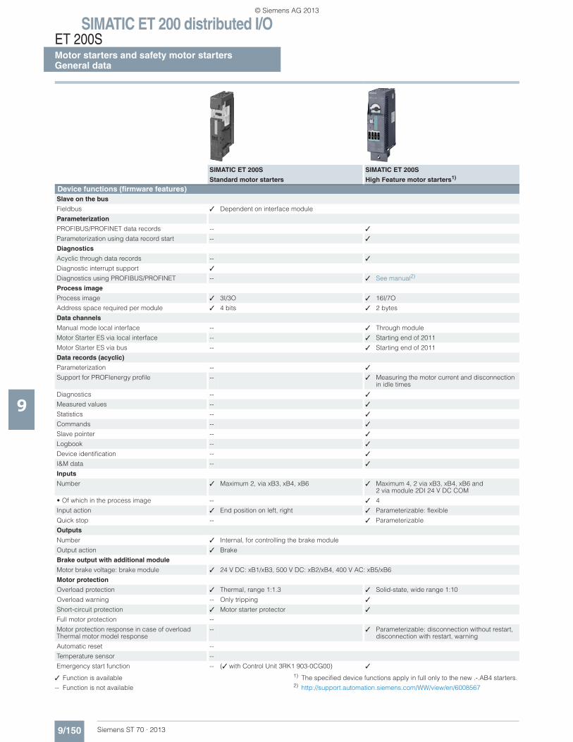
SIMATIC ET 200 distributed I/OET 200SMotor starters and safety motor startersGeneral data
9/150 Siemens ST 70 · 2013
9
✓ Function is available
-- Function is not available
1) The specified device functions apply in full only to the new .-.AB4 starters.2) http://support.automation.siemens.com/WW/view/en/6008567
SIMATIC ET 200S SIMATIC ET 200S
Standard motor starters High Feature motor starters1) Device functions (firmware features) Slave on the bus
Fieldbus ✓ Dependent on interface module
Parameterization
PROFIBUS/PROFINET data records -- ✓
Parameterization using data record start -- ✓
Diagnostics
Acyclic through data records -- ✓
Diagnostic interrupt support ✓
Diagnostics using PROFIBUS/PROFINET -- ✓ See manual2)
Process image
Process image ✓ 3I/3O ✓ 16I/7O
Address space required per module ✓ 4 bits ✓ 2 bytes
Data channels
Manual mode local interface -- ✓ Through module
Motor Starter ES via local interface -- ✓ Starting end of 2011
Motor Starter ES via bus -- ✓ Starting end of 2011
Data records (acyclic)
Parameterization -- ✓
Support for PROFIenergy profile -- ✓ Measuring the motor current and disconnection in idle times
Diagnostics -- ✓
Measured values -- ✓
Statistics -- ✓
Commands -- ✓
Slave pointer -- ✓
Logbook -- ✓
Device identification -- ✓
I&M data -- ✓
Inputs
Number ✓ Maximum 2, via xB3, xB4, xB6 ✓ Maximum 4, 2 via xB3, xB4, xB6 and 2 via module 2DI 24 V DC COM
• Of which in the process image -- ✓ 4
Input action ✓ End position on left, right ✓ Parameterizable: flexible
Quick stop -- ✓ Parameterizable
Outputs
Number ✓ Internal, for controlling the brake module
Output action ✓ Brake
Brake output with additional module
Motor brake voltage: brake module ✓ 24 V DC: xB1/xB3, 500 V DC: xB2/xB4, 400 V AC: xB5/xB6
Motor protection
Overload protection ✓ Thermal, range 1:1.3 ✓ Solid-state, wide range 1:10
Overload warning -- Only tripping ✓
Short-circuit protection ✓ Motor starter protector ✓
Full motor protection --
Motor protection response in case of overloadThermal motor model response
-- ✓ Parameterizable: disconnection without restart, disconnection with restart, warning
Automatic reset --
Temperature sensor --
Emergency start function -- (✓ with Control Unit 3RK1 903-0CG00) ✓
© Siemens AG 2013
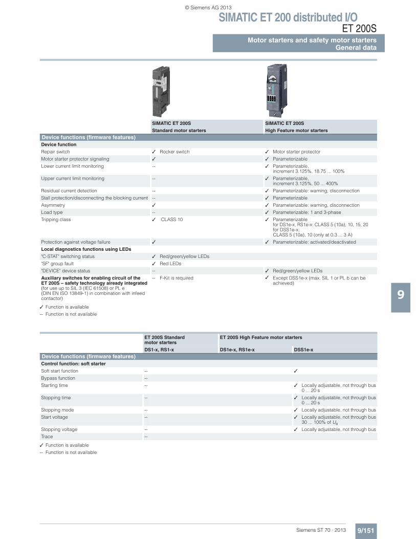
SIMATIC ET 200 distributed I/OET 200S
9/151Siemens ST 70 · 2013
Motor starters and safety motor startersGeneral data
9✓ Function is available
-- Function is not available
✓ Function is available
-- Function is not available
SIMATIC ET 200S SIMATIC ET 200S
Standard motor starters High Feature motor startersDevice functions (firmware features) Device function
Repair switch ✓ Rocker switch ✓ Motor starter protector
Motor starter protector signaling ✓ ✓ Parameterizable
Lower current limit monitoring -- ✓ Parameterizable, increment 3.125%, 18.75 ... 100%
Upper current limit monitoring -- ✓ Parameterizable, increment 3.125%, 50 ... 400%
Residual current detection -- ✓ Parameterizable: warning, disconnection
Stall protection/disconnecting the blocking current -- ✓ Parameterizable
Asymmetry ✓ ✓ Parameterizable: warning, disconnection
Load type -- ✓ Parameterizable: 1 and 3-phase
Tripping class ✓ CLASS 10 ✓ Parameterizablefor DS1e-x, RS1e-x: CLASS 5 (10a), 10, 15, 20 for DSS1e-x: CLASS 5 (10a), 10 (only at 0.3 ... 3 A)
Protection against voltage failure ✓ ✓ Parameterizable: activated/deactivated
Local diagnostics functions using LEDs
"C-STAT" switching status ✓ Red/green/yellow LEDs
"SF" group fault ✓ Red LEDs
"DEVICE" device status -- ✓ Red/green/yellow LEDs
Auxiliary switches for enabling circuit of the ET 200S – safety technology already integrated (for use up to SIL 3 (IEC 61508) or PL e(DIN EN ISO 13849-1) in combination with infeed contactor)
-- F-Kit is required ✓ Except DSS1e-x (max. SIL 1 or PL b can be achieved)
ET 200S Standard motor starters
ET 200S High Feature motor starters
DS1-x, RS1-x DS1e-x, RS1e-x DSS1e-xDevice functions (firmware features)Control function: soft starter
Soft start function -- ✓
Bypass function --
Starting time -- ✓ Locally adjustable, not through bus0 ... 20 s
Stopping time -- ✓ Locally adjustable, not through bus0 ... 20 s
Stopping mode -- ✓ Locally adjustable, not through bus
Start voltage -- ✓ Locally adjustable, not through bus30 ... 100% of Ue
Stopping voltage -- ✓ Locally adjustable, not through bus
Trace --
© Siemens AG 2013
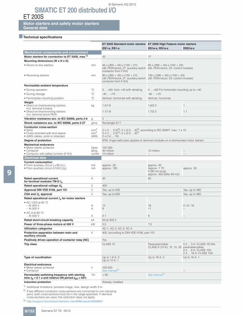
SIMATIC ET 200 distributed I/OET 200SMotor starters and safety motor startersGeneral data
9/152 Siemens ST 70 · 2013
9
■ Technical specifications
1) Additional limitations: process image, max. design width 2 m.2) If two different conductor cross-sections are connected to one clamping
point, both cross-sections must be in the range specified. If identical cross-sections are used, this restriction does not apply.
3) http://support.automation.siemens.com/WW/view/en/6008567
ET 200S Standard motor starters ET 200S High Feature motor starters
DS1-x, RS1-x DS1e-x, RS1e-x DSS1e-x
Mechanical components and environmentMotor starters for connection to ET 200S, max.1) 42 17
Mounting dimensions (W x H x D)
• Direct-on-line starters mm 45 x (265 + 45) x (120 + 27); (45: PE/N block; 27: auxiliary switch contactor from F-Kit)
65 x (290 + 45) x (150 + 23); (45: PE/N block; 23: control module)
• Reversing starters mm 90 x (265 + 45) x (120 + 27); (45: PE/N block; 27: auxiliary switch contactor from F-Kit)
130 x (290 + 45) x (150 + 23); (45: PE/N block; 23: control module)
Permissible ambient temperature
• During operation °C 0 ... +60, from +40 with derating 0 ... +60 For horizontal mounting up to +40
• During storage °C -40 ... +70 -40 ... +70
• Permissible mounting position °C Vertical, horizontal with derating Vertical, horizontal
Weight• Direct-on-line/reversing starters
incl. terminal modulekg 1.0/1.6 1.6/2.2 1
• Direct-on-line/reversing startersincl. terminal block PE/N
1.1/1.8 1.7/2.3 1.1
Vibration resistance acc. to IEC 60068, parts 2-6 g 2
Shock resistance acc. to IEC 60068, parts 2-27 g/ms Rectangle 5/11
Conductor cross-section• Solid mm2 2 x (1 ... 2.5)2); 2 x (2.5 ... 6)2), according to IEC 60947: max. 1 x 10• Finely stranded with end sleeve mm2 2 x (1 ... 2.5)2); 2 x (2.5 ... 6)2)
• AWG cables, solid or stranded AWG 2 x (14 ... 10)
Degree of protection IP20, finger-safe (also applies to terminal modules on a dismounted motor starter)
Mechanical endurance• Motor starter protector Oper-
ating cycles
100 000• Contactor 30 million 10 million --• Contactor with safety function (F-Kit) 10 million -- --
Electrical dataCurrent consumption• From auxiliary circuit L+/M (U1) mA approx. 20 approx. 40• From auxiliary circuit A1/A2 (U2) mA approx. 100 Approx. 1 70
0 (80 ms long),approx. 350 (after 80 ms)
approx. 30
Rated operational currentfor terminal modules TM-D Ie
A 40 50
Rated operational voltage Ue V 400
Approval DIN VDE 0106, part 101 V Yes, up to 500 Yes, up to 480
CSA and UL approval V Yes, up to 600 Yes, up to 480
Rated operational current Ie for motor starters
• AC-1/2/3 at 60 °C- At 400 V A 12 16 3 / 8 / 16- At 500 V A 9 11 --
• AC-4 at 60 °C- At 400 V A 4.1 9 --
Rated short-circuit breaking capacity kA 50 at 400 V
Power of three-phase motors at 500 V kW 5.5 7.5
Utilization categories AC-1, AC-2, AC-3, AC-4
Protective separation between main and auxiliary circuits
V 400, according to DIN VDE 0106, part 101
Positively driven operation of contactor relay (NC) Yes --
Trip class CLASS 10 ParameterizableCLASS 5 (10 A), 10, 15, 20
0.3 ... 3 A: CLASS 10/10A, parameterizable; 2.4 ... 8 A: CLASS 10A 2.4 ... 16 A: CLASS 10A
Type of coordination Up to 1.6 A: 2Up to 12 A: 1
Up to 16 A: 2 Up to 16 A: 1
Electrical endurance• Motor starter protector h 100 000• Contactor See manual3) --
Permissible switching frequency with starting time tA = 0.1 s and relative ON period tED = 50%
1/h < 80 See manual3)
Induction protection Already installed
© Siemens AG 2013
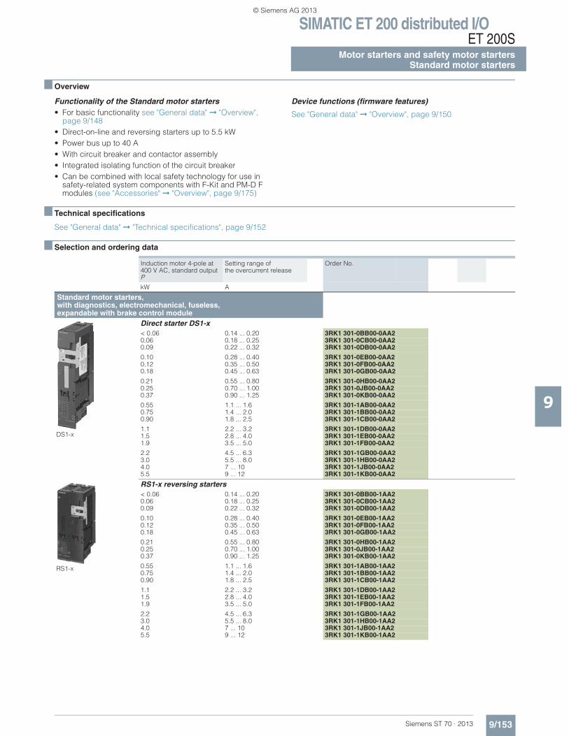
SIMATIC ET 200 distributed I/OET 200S
9/153Siemens ST 70 · 2013
Motor starters and safety motor startersStandard motor starters
9
■ Overview
Functionality of the Standard motor starters• For basic functionality see "General data" ➞ "Overview",
page 9/148• Direct-on-line and reversing starters up to 5.5 kW• Power bus up to 40 A• With circuit breaker and contactor assembly• Integrated isolating function of the circuit breaker• Can be combined with local safety technology for use in
safety-related system components with F-Kit and PM-D F modules (see "Accessories" ➞ "Overview", page 9/175)
Device functions (firmware features)
See "General data" ➞ "Overview", page 9/150
■ Technical specifications
See "General data" ➞ "Technical specifications", page 9/152
■ Selection and ordering data
Induction motor 4-pole at 400 V AC, standard output P
Setting range of the overcurrent release
Order No.
kW A
Standard motor starters, with diagnostics, electromechanical, fuseless, expandable with brake control module
DS1-x
Direct starter DS1-x< 0.06 0.14 ... 0.20 3RK1 301-0BB00-0AA20.06 0.18 ... 0.25 3RK1 301-0CB00-0AA20.09 0.22 ... 0.32 3RK1 301-0DB00-0AA2
0.10 0.28 ... 0.40 3RK1 301-0EB00-0AA20.12 0.35 ... 0.50 3RK1 301-0FB00-0AA20.18 0.45 ... 0.63 3RK1 301-0GB00-0AA2
0.21 0.55 ... 0.80 3RK1 301-0HB00-0AA20.25 0.70 ... 1.00 3RK1 301-0JB00-0AA20.37 0.90 ... 1.25 3RK1 301-0KB00-0AA2
0.55 1.1 ... 1.6 3RK1 301-1AB00-0AA20.75 1.4 ... 2.0 3RK1 301-1BB00-0AA20.90 1.8 ... 2.5 3RK1 301-1CB00-0AA2
1.1 2.2 ... 3.2 3RK1 301-1DB00-0AA21.5 2.8 ... 4.0 3RK1 301-1EB00-0AA21.9 3.5 ... 5.0 3RK1 301-1FB00-0AA2
2.2 4.5 ... 6.3 3RK1 301-1GB00-0AA23.0 5.5 ... 8.0 3RK1 301-1HB00-0AA24.0 7 ... 10 3RK1 301-1JB00-0AA25.5 9 ... 12 3RK1 301-1KB00-0AA2
RS1-x
RS1-x reversing starters< 0.06 0.14 ... 0.20 3RK1 301-0BB00-1AA20.06 0.18 ... 0.25 3RK1 301-0CB00-1AA20.09 0.22 ... 0.32 3RK1 301-0DB00-1AA2
0.10 0.28 ... 0.40 3RK1 301-0EB00-1AA20.12 0.35 ... 0.50 3RK1 301-0FB00-1AA20.18 0.45 ... 0.63 3RK1 301-0GB00-1AA2
0.21 0.55 ... 0.80 3RK1 301-0HB00-1AA20.25 0.70 ... 1.00 3RK1 301-0JB00-1AA20.37 0.90 ... 1.25 3RK1 301-0KB00-1AA2
0.55 1.1 ... 1.6 3RK1 301-1AB00-1AA20.75 1.4 ... 2.0 3RK1 301-1BB00-1AA20.90 1.8 ... 2.5 3RK1 301-1CB00-1AA2
1.1 2.2 ... 3.2 3RK1 301-1DB00-1AA21.5 2.8 ... 4.0 3RK1 301-1EB00-1AA21.9 3.5 ... 5.0 3RK1 301-1FB00-1AA2
2.2 4.5 ... 6.3 3RK1 301-1GB00-1AA23.0 5.5 ... 8.0 3RK1 301-1HB00-1AA24.0 7 ... 10 3RK1 301-1JB00-1AA25.5 9 ... 12 3RK1 301-1KB00-1AA2
© Siemens AG 2013
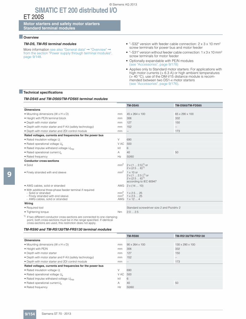
SIMATIC ET 200 distributed I/OET 200SMotor starters and safety motor startersStandard terminal modules
9/154 Siemens ST 70 · 2013
9
■ Overview
TM-DS, TM-RS terminal modules
More information see also "General data" ➞ "Overview" ➞from the section "Power supply through terminal modules", page 9/148.
• "–S32" version with feeder cable connection: 2 x 3 x 10 mm² screw terminals for power bus and motor feeder
• "–S31" version without feeder cable connection: 1 x 3 x 10 mm² screw terminals for motor feeder
• Optionally expandable with PE/N modules(see "Accessories", page 9/178)
• Applies only to Standard motor starters: For applications with high motor currents (> 6.3 A) or high ambient temperatures(> 40 °C), use of the DM-V15 distance module is recom-mended between two DS1-x motor starters (see "Accessories", page 9/176).
■ Technical specifications
TM-DS45 and TM-DS65/TM-FDS65 terminal modules
1) If two different conductor cross-sections are connected to one clamping point, both cross-sections must be in the range specified. If identical cross-sections are used, this restriction does not apply.
TM-RS90 and TM-RS130/TM-FRS130 terminal modules
TM-DS45 TM-DS65/TM-FDS65
Dimensions
• Mounting dimensions (W x H x D) mm 45 x 264 x 100 65 x 290 x 100
• Height with PE/N terminal block mm 306 332
• Depth with motor starter mm 127 150
• Depth with motor starter and F-Kit (safety technology) mm 152 --
• Depth with motor starter and 2DI control module mm -- 173
Rated voltages, currents and frequencies for the power bus
• Rated insulation voltage Ui V 690
• Rated operational voltage Ue V AC 500
• Rated impulse withstand voltage Uimp kV 6
• Rated operational current Ie A 40 50
• Rated frequency Hz 50/60
Conductor cross-sections
• Solid mm2 2 x (1 ... 2.5)1) or 2 x (2.5 ... 6)1)
• Finely stranded with end sleeve mm2 1 x 10 or2 x (1 ... 2.5 )1) or2 x (2.5 ... 6)1) according to IEC 60947
• AWG cables, solid or stranded AWG 2 x (14 ... 10)
• With additional three-phase feeder terminal if required- Solid or stranded mm2 1 x 2.5 ... 25- Finely stranded with end sleeve mm2 1 x 2.5 ... 25- AWG cables, solid or stranded AWG 1 x 12 ... 4
Wiring
• Required tool Standard screwdriver size 2 and Pozidriv 2
• Tightening torque Nm 2.0 ... 2.5
TM-RS90 TM-RS130/TM-FRS130
Dimensions
• Mounting dimensions (W x H x D) mm 90 x 264 x 100 130 x 290 x 100
• Height with PE/N mm 306 332
• Depth with motor starter mm 127 150
• Depth with motor starter and F-Kit (safety technology) mm 152 --
• Depth with motor starter and 2DI control module mm -- 173
Rated voltages, currents and frequencies for the power bus
• Rated insulation voltage Ui V 690
• Rated operational voltage Ue V AC 500
• Rated impulse withstand voltage Uimp kV 6
• Rated operational current Ie A 40 50
• Rated frequency Hz 50/60
© Siemens AG 2013
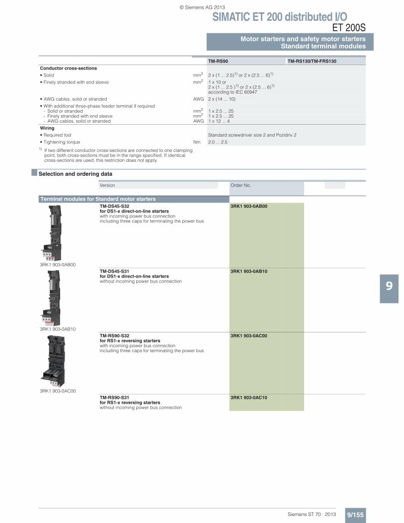
SIMATIC ET 200 distributed I/OET 200S
9/155Siemens ST 70 · 2013
Motor starters and safety motor startersStandard terminal modules
9
1) If two different conductor cross-sections are connected to one clamping point, both cross-sections must be in the range specified. If identical cross-sections are used, this restriction does not apply.
■ Selection and ordering data
Conductor cross-sections
• Solid mm2 2 x (1 ... 2.5)1) or 2 x (2.5 ... 6)1)
• Finely stranded with end sleeve mm2 1 x 10 or2 x (1 ... 2.5 )1) or 2 x (2.5 ... 6)1) according to IEC 60947
• AWG cables, solid or stranded AWG 2 x (14 ... 10)
• With additional three-phase feeder terminal if required- Solid or stranded mm2 1 x 2.5 ... 25- Finely stranded with end sleeve mm2 1 x 2.5 ... 25- AWG cables, solid or stranded AWG 1 x 12 ... 4
Wiring
• Required tool Standard screwdriver size 2 and Pozidriv 2
• Tightening torque Nm 2.0 ... 2.5
TM-RS90 TM-RS130/TM-FRS130
Version Order No.
Terminal modules for Standard motor starters
3RK1 903-0AB00
TM-DS45-S32 for DS1-x direct-on-line starters with incoming power bus connectionincluding three caps for terminating the power bus
3RK1 903-0AB00
3RK1 903-0AB10
TM-DS45-S31 for DS1-x direct-on-line starterswithout incoming power bus connection
3RK1 903-0AB10
3RK1 903-0AC00
TM-RS90-S32 for RS1-x reversing starters with incoming power bus connectionincluding three caps for terminating the power bus
3RK1 903-0AC00
TM-RS90-S31 for RS1-x reversing starters without incoming power bus connection
3RK1 903-0AC10
© Siemens AG 2013
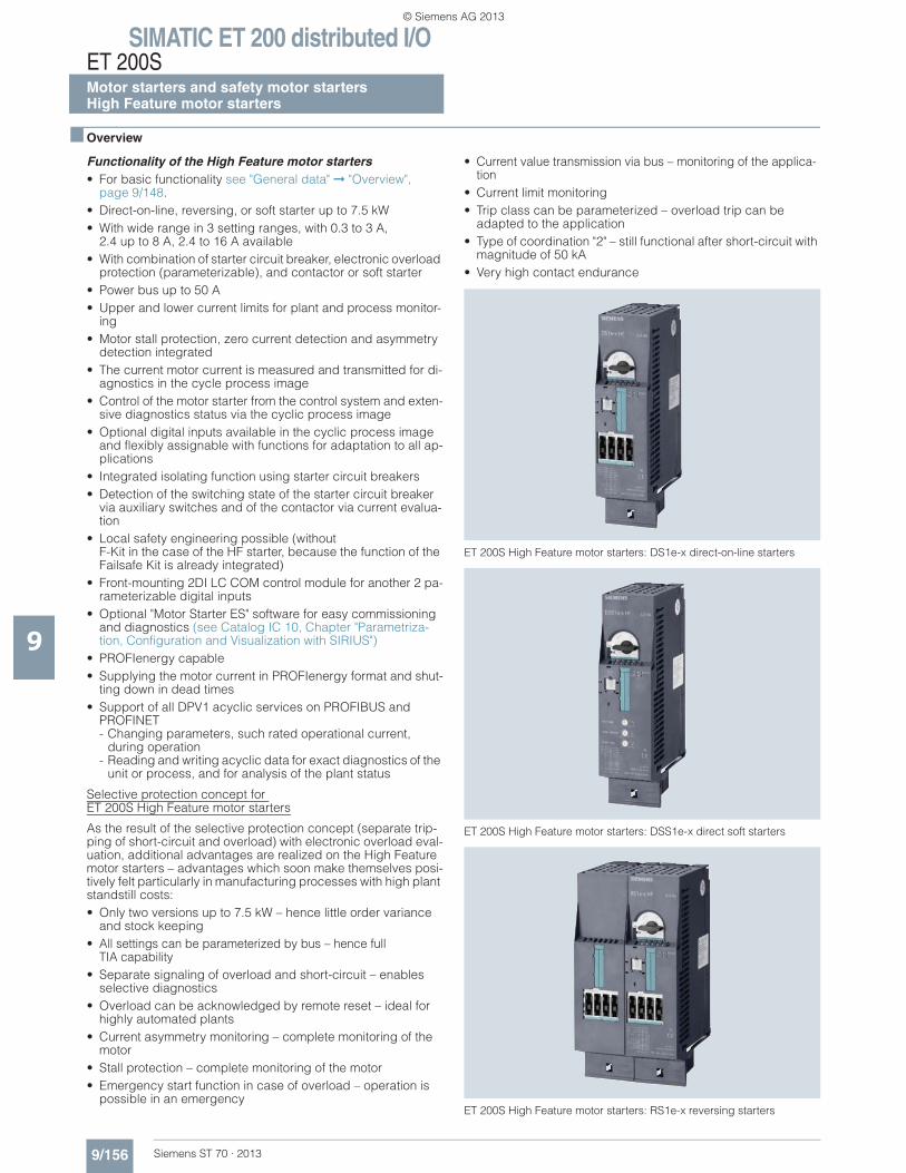
SIMATIC ET 200 distributed I/OET 200SMotor starters and safety motor startersHigh Feature motor starters
9/156 Siemens ST 70 · 2013
9
■ Overview
Functionality of the High Feature motor starters• For basic functionality see "General data" ➞ "Overview",
page 9/148.• Direct-on-line, reversing, or soft starter up to 7.5 kW• With wide range in 3 setting ranges, with 0.3 to 3 A,
2.4 up to 8 A, 2.4 to 16 A available• With combination of starter circuit breaker, electronic overload
protection (parameterizable), and contactor or soft starter• Power bus up to 50 A• Upper and lower current limits for plant and process monitor-
ing• Motor stall protection, zero current detection and asymmetry
detection integrated• The current motor current is measured and transmitted for di-
agnostics in the cycle process image• Control of the motor starter from the control system and exten-
sive diagnostics status via the cyclic process image• Optional digital inputs available in the cyclic process image
and flexibly assignable with functions for adaptation to all ap-plications
• Integrated isolating function using starter circuit breakers• Detection of the switching state of the starter circuit breaker
via auxiliary switches and of the contactor via current evalua-tion
• Local safety engineering possible (without F-Kit in the case of the HF starter, because the function of the Failsafe Kit is already integrated)
• Front-mounting 2DI LC COM control module for another 2 pa-rameterizable digital inputs
• Optional "Motor Starter ES" software for easy commissioning and diagnostics (see Catalog IC 10, Chapter "Parametriza-tion, Configuration and Visualization with SIRIUS")
• PROFIenergy capable• Supplying the motor current in PROFIenergy format and shut-
ting down in dead times• Support of all DPV1 acyclic services on PROFIBUS and
PROFINET- Changing parameters, such rated operational current,
during operation- Reading and writing acyclic data for exact diagnostics of the
unit or process, and for analysis of the plant status
Selective protection concept for ET 200S High Feature motor starters
As the result of the selective protection concept (separate trip-ping of short-circuit and overload) with electronic overload eval-uation, additional advantages are realized on the High Feature motor starters – advantages which soon make themselves posi-tively felt particularly in manufacturing processes with high plant standstill costs:• Only two versions up to 7.5 kW – hence little order variance
and stock keeping• All settings can be parameterized by bus – hence full
TIA capability• Separate signaling of overload and short-circuit – enables
selective diagnostics• Overload can be acknowledged by remote reset – ideal for
highly automated plants• Current asymmetry monitoring – complete monitoring of the
motor• Stall protection – complete monitoring of the motor• Emergency start function in case of overload – operation is
possible in an emergency
• Current value transmission via bus – monitoring of the applica-tion
• Current limit monitoring• Trip class can be parameterized – overload trip can be
adapted to the application• Type of coordination "2" – still functional after short-circuit with
magnitude of 50 kA• Very high contact endurance
ET 200S High Feature motor starters: DS1e-x direct-on-line starters
ET 200S High Feature motor starters: DSS1e-x direct soft starters
ET 200S High Feature motor starters: RS1e-x reversing starters
© Siemens AG 2013
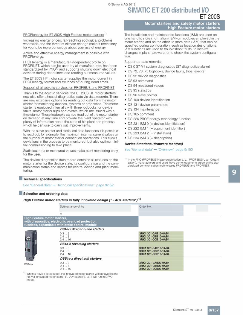
SIMATIC ET 200 distributed I/OET 200S
9/157Siemens ST 70 · 2013
Motor starters and safety motor startersHigh Feature motor starters
9
PROFIenergy for ET 200S High Feature motor starters1)
Increasing energy prices, far-reaching ecological problems worldwide and the threat of climate change make it necessary for you to be more conscious about your use of energy.
Active and effective energy management is possible with PROFIenergy.
PROFIenergy is a manufacturer-independent profile on PROFINET, which can be used by all manufacturers, has been standardized by PNO1) and supports shutting down electrical devices during dead times and reading out measured values.
The ET 200S HF motor starter supplies the motor current in PROFIenergy format and switches off during dead times.
Support of all acyclic services on PROFIBUS and PROFINET
Thanks to the acyclic services, the ET 200S HF motor starters now also offer a host of diagnostics data via data records. There are new extensive options for reading out data from the motor starter for monitoring devices, systems or processes. The motor starter is equipped internally with three logbooks for device faults, motor starter trips and events, which are issued with a time stamp. These logbooks can be read out of the motor starter on demand at any time and provide the plant operator with plenty of information about the state of his plant and process which he can use to carry out improvements.
With the slave pointer and statistical data functions it is possible to read out, for example, the maximum internal current values or the number of motor starter connection operations. This allows deviations in the process to be monitored, but also optimum ini-tial commissioning to take place.
Statistical data or measured values make plant monitoring easy for the user.
The device diagnostics data record contains all statuses on the motor starter for the device state, its configuration and the com-munication status and serves for central device and plant moni-toring.
The installation and maintenance functions (I&M) are used on one hand to store information (I&M) on modules employed in the motor starter, and on the other, to store data (I&M) that can be specified during configuration, such as location designations. I&M functions are used to troubleshoot faults, to localize changes in plant hardware, or to check the system configura-tion.
Supported data records:• DS 0 S7-V1 system diagnostics (S7 diagnostics alarm)• DS 72, 73, 75 logbooks, device faults, trips, events• DS 92 device diagnostics • DS 93 command• DS 94 measured values• DS 95 statistics • DS 96 slave pointer• DS 100 device identification • DS 131 device parameters• DS 134 maintenance• DS 165 comment• DS 226 PROFIenergy technology function • DS 231 I&M 0 (= device identification) • DS 232 I&M 1 (= equipment identifier) • DS 233 I&M 2 (= installation) • DS 234 I&M 3 (= description)
Device functions (firmware features)
See "General data" ➞ "Overview", page 9/150
1) In the PNO (PROFIBUS Nutzerorganisation e. V. - PROFIBUS User Organi-zation), manufacturers and users have come together to agree on the stan-dardized communication technologies PROFIBUS and PROFINET.
■ Technical specifications
See "General data" ➞ "Technical specifications", page 9/152
■ Selection and ordering data
High Feature motor starters in fully innovated design (".-.AB4 starters") 1)
1) When a device is replaced, the innovated motor starter will behave like the not yet innovated motor starter (".-.AA4 starter"), i.e. it will run in DPV0 mode.
Setting range of the Order No.
A
High Feature motor starters, with diagnostics, electronic overload protection, fuseless, expandable with brake control module
DS1e-x
DS1e-x direct-on-line starters 0.3 ... 3 3RK1 301-0AB10-0AB42.4 ... 8 3RK1 301-0BB10-0AB42.4 ... 16 3RK1 301-0CB10-0AB4
RS1e-x reversing starters 0.3 ... 3 3RK1 301-0AB10-1AB42.4 ... 8 3RK1 301-0BB10-1AB42.4 ... 16 3RK1 301-0CB10-1AB4
DSS1e-x direct soft starters 0.3 ... 3 3RK1 301-0AB20-0AB42.4 ... 8 3RK1 301-0BB20-0AB42.4 ... 16 3RK1 301-0CB20-0AB4
© Siemens AG 2013
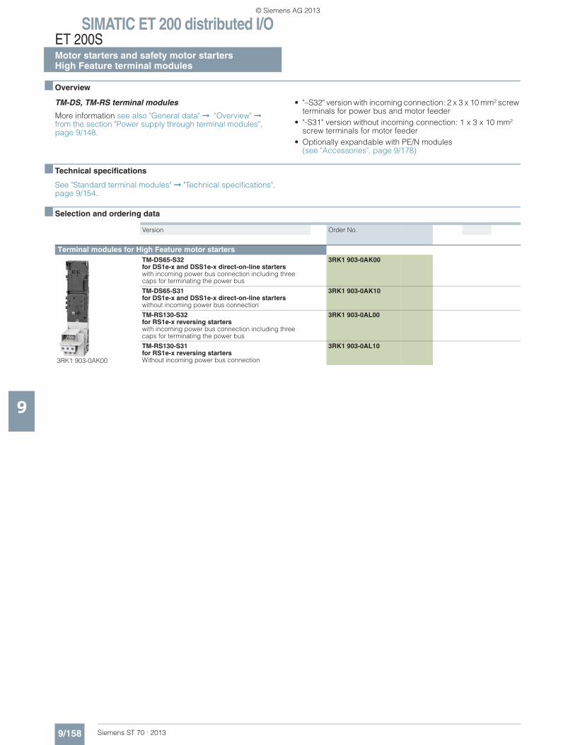
SIMATIC ET 200 distributed I/OET 200SMotor starters and safety motor startersHigh Feature terminal modules
9/158 Siemens ST 70 · 2013
9
■ Overview
TM-DS, TM-RS terminal modules
More information see also "General data" ➞ "Overview" ➞from the section "Power supply through terminal modules", page 9/148.
• "–S32" version with incoming connection: 2 x 3 x 10 mm² screw terminals for power bus and motor feeder
• "-S31" version without incoming connection: 1 x 3 x 10 mm² screw terminals for motor feeder
• Optionally expandable with PE/N modules(see "Accessories", page 9/178)
■ Technical specifications
See "Standard terminal modules" ➞ "Technical specifications", page 9/154.
■ Selection and ordering data
Version Order No.
Terminal modules for High Feature motor starters
3RK1 903-0AK00
TM-DS65-S32 for DS1e-x and DSS1e-x direct-on-line starters with incoming power bus connection including three caps for terminating the power bus
3RK1 903-0AK00
TM-DS65-S31 for DS1e-x and DSS1e-x direct-on-line starters without incoming power bus connection
3RK1 903-0AK10
TM-RS130-S32 for RS1e-x reversing starters with incoming power bus connection including three caps for terminating the power bus
3RK1 903-0AL00
TM-RS130-S31 for RS1e-x reversing starters Without incoming power bus connection
3RK1 903-0AL10
© Siemens AG 2013
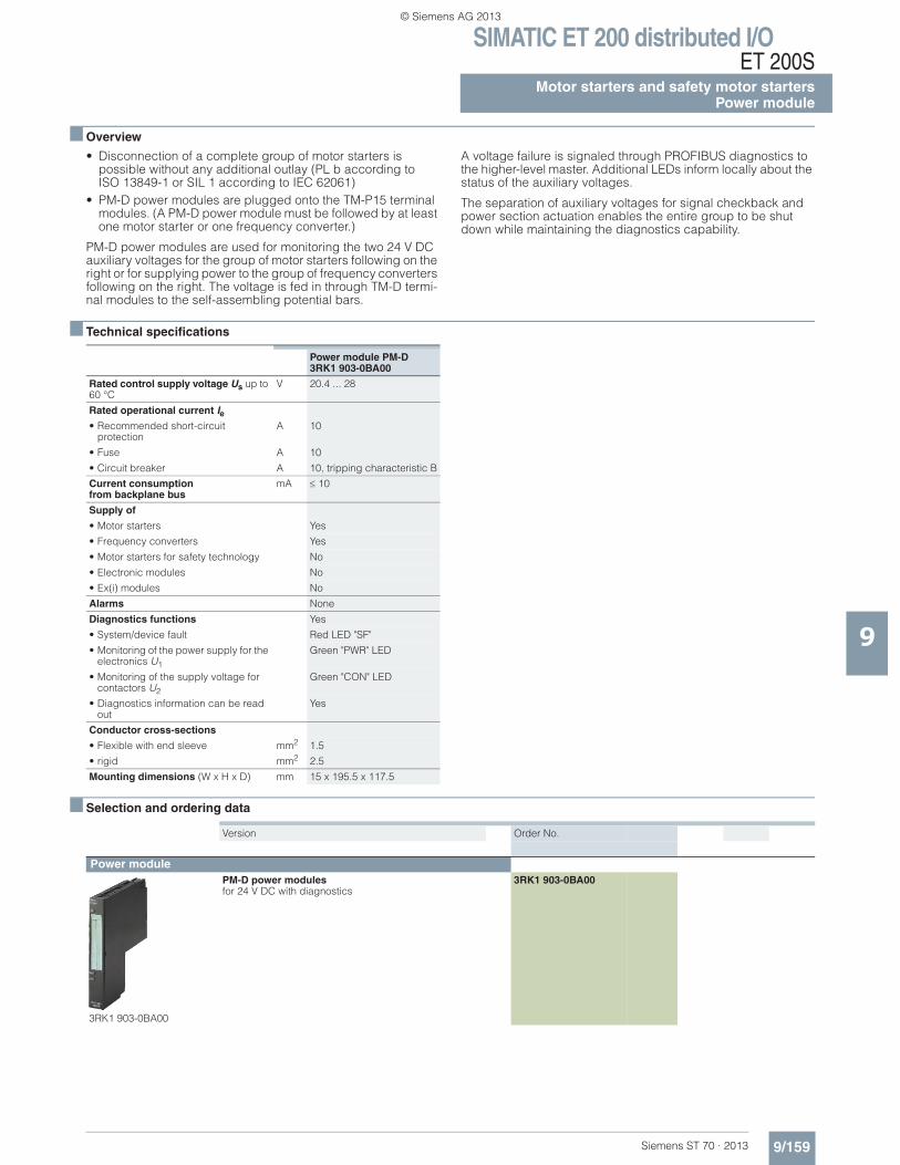
SIMATIC ET 200 distributed I/OET 200S
9/159Siemens ST 70 · 2013
Motor starters and safety motor startersPower module
9
■ Overview
• Disconnection of a complete group of motor starters is possible without any additional outlay (PL b according to ISO 13849-1 or SIL 1 according to IEC 62061)
• PM-D power modules are plugged onto the TM-P15 terminal modules. (A PM-D power module must be followed by at least one motor starter or one frequency converter.)
PM-D power modules are used for monitoring the two 24 V DC auxiliary voltages for the group of motor starters following on the right or for supplying power to the group of frequency converters following on the right. The voltage is fed in through TM-D termi-nal modules to the self-assembling potential bars.
A voltage failure is signaled through PROFIBUS diagnostics to the higher-level master. Additional LEDs inform locally about the status of the auxiliary voltages.
The separation of auxiliary voltages for signal checkback and power section actuation enables the entire group to be shut down while maintaining the diagnostics capability.
■ Technical specifications
■ Selection and ordering data
Power module PM-D3RK1 903-0BA00
Rated control supply voltage Us up to 60 °C
V 20.4 ... 28
Rated operational current Ie• Recommended short-circuit
protectionA 10
• Fuse A 10
• Circuit breaker A 10, tripping characteristic B
Current consumptionfrom backplane bus
mA 10
Supply of
• Motor starters Yes
• Frequency converters Yes
• Motor starters for safety technology No
• Electronic modules No
• Ex(i) modules No
Alarms None
Diagnostics functions Yes
• System/device fault Red LED "SF"
• Monitoring of the power supply for the electronics U1
Green "PWR" LED
• Monitoring of the supply voltage for contactors U2
Green "CON" LED
• Diagnostics information can be read out
Yes
Conductor cross-sections
• Flexible with end sleeve mm2 1.5
• rigid mm2 2.5
Mounting dimensions (W x H x D) mm 15 x 195.5 x 117.5
Version Order No.
Power module
3RK1 903-0BA00
PM-D power modules for 24 V DC with diagnostics
3RK1 903-0BA00
© Siemens AG 2013
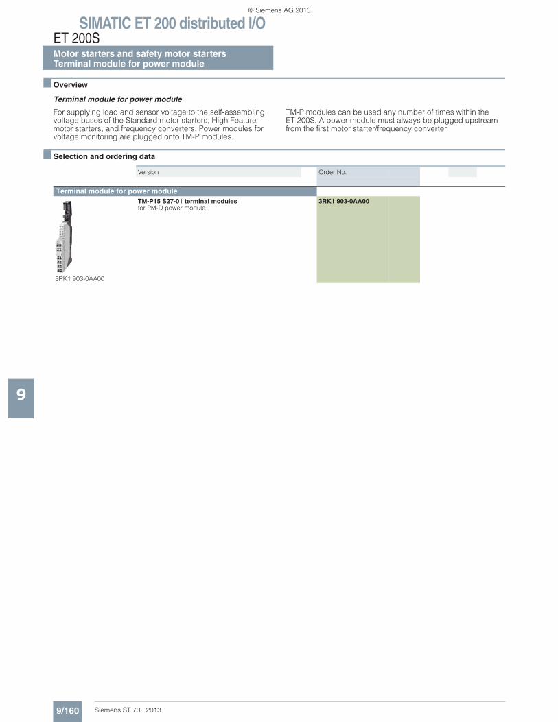
SIMATIC ET 200 distributed I/OET 200SMotor starters and safety motor startersTerminal module for power module
9/160 Siemens ST 70 · 2013
9
■ Overview
Terminal module for power module
For supplying load and sensor voltage to the self-assembling voltage buses of the Standard motor starters, High Feature motor starters, and frequency converters. Power modules for voltage monitoring are plugged onto TM-P modules.
TM-P modules can be used any number of times within the ET 200S. A power module must always be plugged upstream from the first motor starter/frequency converter.
■ Selection and ordering data
Version Order No.
Terminal module for power module
3RK1 903-0AA00
TM-P15 S27-01 terminal modulesfor PM-D power module
3RK1 903-0AA00
© Siemens AG 2013
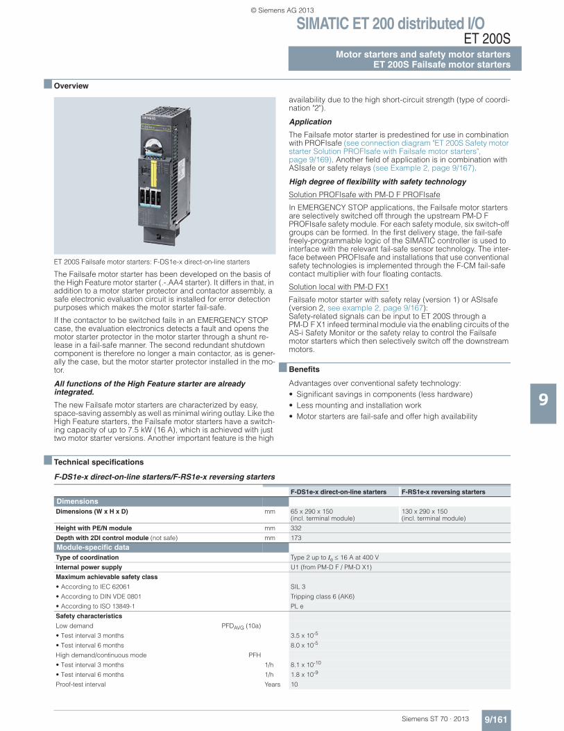
SIMATIC ET 200 distributed I/OET 200S
9/161Siemens ST 70 · 2013
Motor starters and safety motor startersET 200S Failsafe motor starters
9
■ Overview
ET 200S Failsafe motor starters: F-DS1e-x direct-on-line starters
The Failsafe motor starter has been developed on the basis of the High Feature motor starter (.-.AA4 starter). It differs in that, in addition to a motor starter protector and contactor assembly, a safe electronic evaluation circuit is installed for error detection purposes which makes the motor starter fail-safe.
If the contactor to be switched fails in an EMERGENCY STOP case, the evaluation electronics detects a fault and opens the motor starter protector in the motor starter through a shunt re-lease in a fail-safe manner. The second redundant shutdown component is therefore no longer a main contactor, as is gener-ally the case, but the motor starter protector installed in the mo-tor.
All functions of the High Feature starter are already integrated.
The new Failsafe motor starters are characterized by easy, space-saving assembly as well as minimal wiring outlay. Like the High Feature starters, the Failsafe motor starters have a switch-ing capacity of up to 7.5 kW (16 A), which is achieved with just two motor starter versions. Another important feature is the high
availability due to the high short-circuit strength (type of coordi-nation "2").
Application
The Failsafe motor starter is predestined for use in combination with PROFIsafe (see connection diagram "ET 200S Safety motor starter Solution PROFIsafe with Failsafe motor starters", page 9/169). Another field of application is in combination with ASIsafe or safety relays (see Example 2, page 9/167).
High degree of flexibility with safety technology
Solution PROFIsafe with PM-D F PROFIsafe
In EMERGENCY STOP applications, the Failsafe motor starters are selectively switched off through the upstream PM-D F PROFIsafe safety module. For each safety module, six switch-off groups can be formed. In the first delivery stage, the fail-safe freely-programmable logic of the SIMATIC controller is used to interface with the relevant fail-safe sensor technology. The inter-face between PROFIsafe and installations that use conventional safety technologies is implemented through the F-CM fail-safe contact multiplier with four floating contacts.
Solution local with PM-D FX1
Failsafe motor starter with safety relay (version 1) or ASIsafe (version 2, see example 2, page 9/167): Safety-related signals can be input to ET 200S through a PM-D F X1 infeed terminal module via the enabling circuits of the AS-i Safety Monitor or the safety relay to control the Failsafe motor starters which then selectively switch off the downstream motors.
■ Benefits
Advantages over conventional safety technology:• Significant savings in components (less hardware)• Less mounting and installation work • Motor starters are fail-safe and offer high availability
■ Technical specifications
F-DS1e-x direct-on-line starters/F-RS1e-x reversing starters
F-DS1e-x direct-on-line starters F-RS1e-x reversing starters
Dimensions Dimensions (W x H x D) mm 65 x 290 x 150
(incl. terminal module)130 x 290 x 150 (incl. terminal module)
Height with PE/N module mm 332
Depth with 2DI control module (not safe) mm 173
Module-specific data Type of coordination Type 2 up to Ie 16 A at 400 V
Internal power supply U1 (from PM-D F / PM-D X1)
Maximum achievable safety class
• According to IEC 62061 SIL 3
• According to DIN VDE 0801 Tripping class 6 (AK6)
• According to ISO 13849-1 PL e
Safety characteristics
Low demand PFDAVG (10a)
• Test interval 3 months 3.5 x 10⁻⁵
• Test interval 6 months 8.0 x 10⁻⁵
High demand/continuous mode PFH
• Test interval 3 months 1/h 8.1 x 10⁻¹⁰
• Test interval 6 months 1/h 1.8 x 10⁻⁹
Proof-test interval Years 10
© Siemens AG 2013
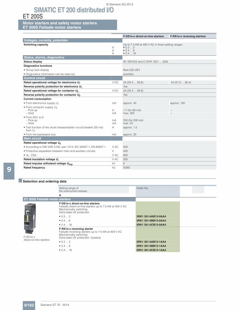
SIMATIC ET 200 distributed I/OET 200SMotor starters and safety motor startersET 200S Failsafe motor starters
9/162 Siemens ST 70 · 2013
9
■ Selection and ordering data
Voltages, currents, potentials Switching capacity
AAA
Up to 7.5 kW at 400 V AC in three setting ranges• 0.3 ... 3• 2.4 ... 8• 2.4 ... 16
Status, alarms, diagnostics Status display SF, DEVICE and C-STAT, SG1 ... SG6
Diagnostics functions
• Group fault display Red LED (SF)
• Diagnostics information can be read out possible
Control circuit Rated operational voltage for electronics U1 V DC 24 (20.4 ... 28.8) 24 (21.6 ... 26.4)
Reverse polarity protection for electronics U1 Yes
Rated operational voltage for contactor U2 V DC 24 (20.4 ... 28.8)
Reverse polarity protection for contactor U2 Yes
Current consumption
• From electronics supply U1 mA approx. 40 approx. 100
• From contactor supply U2- Pick-up A 1.7 (for 80 ms) --- Hold mA max. 350 --
• From SG1 to 6- Pick-up mA 250 (for 200 ms)- Hold mA max. 55
• Test function of the shunt release/starter circuit breaker (50 ms)from U1
A approx. 1.5
• From the backplane bus mA approx. 20
Main circuit Rated operational voltage Ue
• According to DIN VDE 0106, part 1014, IEC 60947-1, EN 60947-1 V AC 500
• Protective separation between main and auxiliary circuits V 400
• UL, CSA V AC 600
Rated insulation voltage Ui V AC 500
Rated impulse withstand voltage Uimp kV 6
Rated frequency Hz 50/60
F-DS1e-x direct-on-line starters F-RS1e-x reversing starters
Setting range of the overcurrent release
Order No.
A
ET 200S Failsafe motor starters
F-DS1e-x direct-on-line starters
F-DS1e-x direct-on-line startersFailsafe direct-on-line starters up to 7.5 kW at 400 V ACMechanically switchingSolid-state UE protection
• 0.3 ... 3 3RK1 301-0AB13-0AA4
• 2.4 ... 8 3RK1 301-0BB13-0AA4
• 2.4 ... 16 3RK1 301-0CB13-0AA4
F-RS1e-x reversing starterFailsafe reversing starters up to 7.5 kW at 400 V ACMechanically switchingSolid-state UE protection, fuseless
• 0.3 ... 3 3RK1 301-0AB13-1AA4
• 2.4 ... 8 3RK1 301-0BB13-1AA4
• 2.4 ... 16 3RK1 301-0CB13-1AA4
© Siemens AG 2013
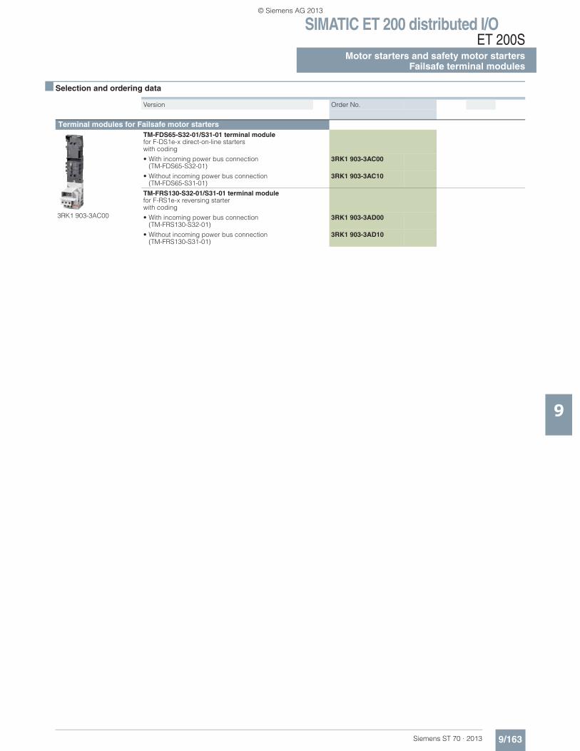
SIMATIC ET 200 distributed I/OET 200S
9/163Siemens ST 70 · 2013
Motor starters and safety motor startersFailsafe terminal modules
9
■ Selection and ordering data
Version Order No.
Terminal modules for Failsafe motor starters
3RK1 903-3AC00
TM-FDS65-S32-01/S31-01 terminal module for F-DS1e-x direct-on-line starters with coding
• With incoming power bus connection (TM-FDS65-S32-01)
3RK1 903-3AC00
• Without incoming power bus connection (TM-FDS65-S31-01)
3RK1 903-3AC10
TM-FRS130-S32-01/S31-01 terminal module for F-RS1e-x reversing starter with coding
• With incoming power bus connection (TM-FRS130-S32-01)
3RK1 903-3AD00
• Without incoming power bus connection(TM-FRS130-S31-01)
3RK1 903-3AD10
© Siemens AG 2013
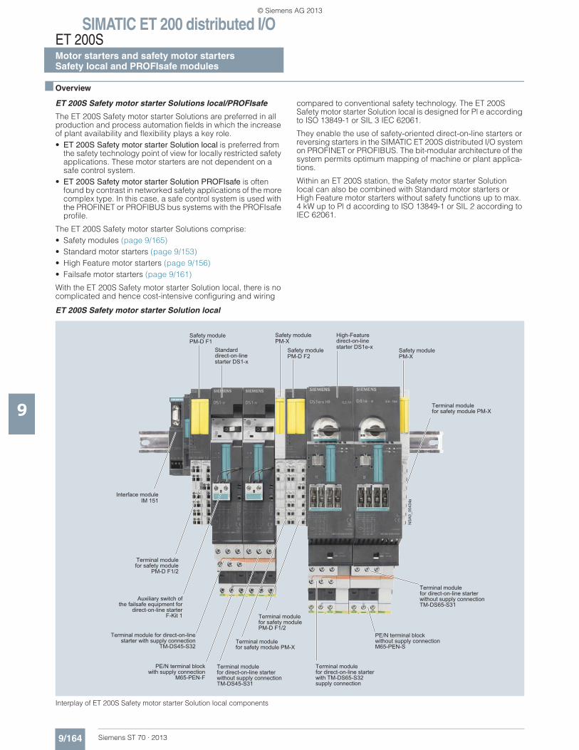
SIMATIC ET 200 distributed I/OET 200SMotor starters and safety motor startersSafety local and PROFIsafe modules
9/164 Siemens ST 70 · 2013
9
■ Overview
ET 200S Safety motor starter Solutions local/PROFIsafe
The ET 200S Safety motor starter Solutions are preferred in all production and process automation fields in which the increase of plant availability and flexibility plays a key role.• ET 200S Safety motor starter Solution local is preferred from
the safety technology point of view for locally restricted safety applications. These motor starters are not dependent on a safe control system.
• ET 200S Safety motor starter Solution PROFIsafe is often found by contrast in networked safety applications of the more complex type. In this case, a safe control system is used with the PROFINET or PROFIBUS bus systems with the PROFIsafe profile.
The ET 200S Safety motor starter Solutions comprise:• Safety modules (page 9/165) • Standard motor starters (page 9/153) • High Feature motor starters (page 9/156) • Failsafe motor starters (page 9/161)
With the ET 200S Safety motor starter Solution local, there is no complicated and hence cost-intensive configuring and wiring
compared to conventional safety technology. The ET 200S Safety motor starter Solution local is designed for Pl e according to ISO 13849-1 or SIL 3 IEC 62061.
They enable the use of safety-oriented direct-on-line starters or reversing starters in the SIMATIC ET 200S distributed I/O system on PROFINET or PROFIBUS. The bit-modular architecture of the system permits optimum mapping of machine or plant applica-tions.
Within an ET 200S station, the Safety motor starter Solution local can also be combined with Standard motor starters or High Feature motor starters without safety functions up to max. 4 kW up to Pl d according to ISO 13849-1 or SIL 2 according to IEC 62061.
ET 200S Safety motor starter Solution local
Interplay of ET 200S Safety motor starter Solution local components
Terminal modulefor safety module PM-X
Terminal modulefor direct-on-line starterwith TM-DS65-S32supply connection
Terminal modulefor safety modulePM-D F1/2
Terminal module for safety module PM-X
Terminal modulefor direct-on-line starterwithout supply connectionTM-DS45-S31
Terminal module for direct-on-line starter with supply connection
TM-DS45-S32
Auxiliary switch ofthe failsafe equipment for
direct-on-line starter F-Kit 1
Terminal modulefor safety module
PM-D F1/2
Safety modulePM-D F1
Standard direct-on-line starter DS1-x
Safety modulePM-X
Safety modulePM-D F2
High-Feature direct-on-line starter DS1e-x Safety module
PM-X
Terminal modulefor direct-on-line starterwithout supply connectionTM-DS65-S31
Interface moduleIM 151
PE/N terminal blockwithout supply connectionM65-PEN-S
PE/N terminal blockwith supply connection
M65-PEN-F
NS
A0_
0043
4a
© Siemens AG 2013
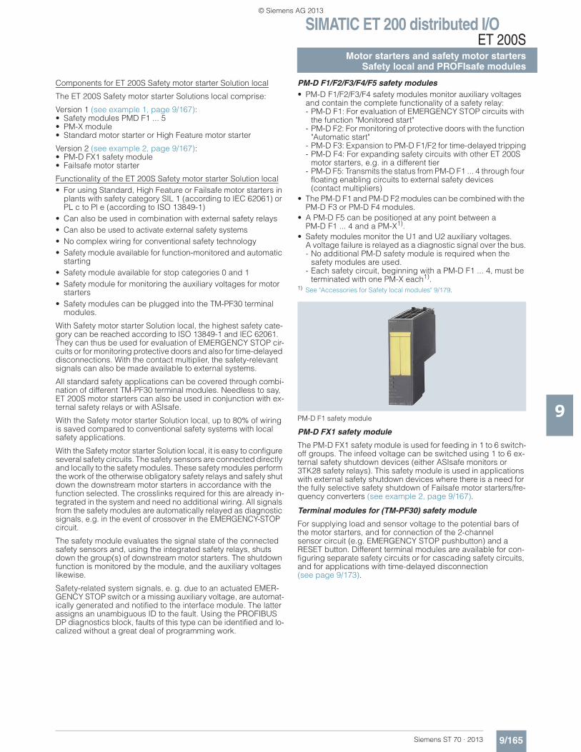
SIMATIC ET 200 distributed I/OET 200S
9/165Siemens ST 70 · 2013
Motor starters and safety motor startersSafety local and PROFIsafe modules
9
Components for ET 200S Safety motor starter Solution local
The ET 200S Safety motor starter Solutions local comprise:
Version 1 (see example 1, page 9/167): • Safety modules PMD F1 ... 5 • PM-X module• Standard motor starter or High Feature motor starter
Version 2 (see example 2, page 9/167): • PM-D FX1 safety module• Failsafe motor starter
Functionality of the ET 200S Safety motor starter Solution local• For using Standard, High Feature or Failsafe motor starters in
plants with safety category SIL 1 (according to IEC 62061) or PL c to Pl e (according to ISO 13849-1)
• Can also be used in combination with external safety relays• Can also be used to activate external safety systems• No complex wiring for conventional safety technology• Safety module available for function-monitored and automatic
starting• Safety module available for stop categories 0 and 1• Safety module for monitoring the auxiliary voltages for motor
starters• Safety modules can be plugged into the TM-PF30 terminal
modules.
With Safety motor starter Solution local, the highest safety cate-gory can be reached according to ISO 13849-1 and IEC 62061. They can thus be used for evaluation of EMERGENCY STOP cir-cuits or for monitoring protective doors and also for time-delayed disconnections. With the contact multiplier, the safety-relevant signals can also be made available to external systems.
All standard safety applications can be covered through combi-nation of different TM-PF30 terminal modules. Needless to say, ET 200S motor starters can also be used in conjunction with ex-ternal safety relays or with ASIsafe.
With the Safety motor starter Solution local, up to 80% of wiring is saved compared to conventional safety systems with local safety applications.
With the Safety motor starter Solution local, it is easy to configure several safety circuits. The safety sensors are connected directly and locally to the safety modules. These safety modules perform the work of the otherwise obligatory safety relays and safely shut down the downstream motor starters in accordance with the function selected. The crosslinks required for this are already in-tegrated in the system and need no additional wiring. All signals from the safety modules are automatically relayed as diagnostic signals, e.g. in the event of crossover in the EMERGENCY-STOP circuit.
The safety module evaluates the signal state of the connected safety sensors and, using the integrated safety relays, shuts down the group(s) of downstream motor starters. The shutdown function is monitored by the module, and the auxiliary voltages likewise.
Safety-related system signals, e. g. due to an actuated EMER-GENCY STOP switch or a missing auxiliary voltage, are automat-ically generated and notified to the interface module. The latter assigns an unambiguous ID to the fault. Using the PROFIBUS DP diagnostics block, faults of this type can be identified and lo-calized without a great deal of programming work.
PM-D F1/F2/F3/F4/F5 safety modules• PM-D F1/F2/F3/F4 safety modules monitor auxiliary voltages
and contain the complete functionality of a safety relay:- PM-D F1: For evaluation of EMERGENCY STOP circuits with
the function "Monitored start"- PM-D F2: For monitoring of protective doors with the function
"Automatic start"- PM-D F3: Expansion to PM-D F1/F2 for time-delayed tripping- PM-D F4: For expanding safety circuits with other ET 200S
motor starters, e.g. in a different tier- PM-D F5: Transmits the status from PM-D F1 ... 4 through four
floating enabling circuits to external safety devices(contact multipliers)
• The PM-D F1 and PM-D F2 modules can be combined with the PM-D F3 or PM-D F4 modules.
• A PM-D F5 can be positioned at any point between a PM-D F1 ... 4 and a PM-X1).
• Safety modules monitor the U1 and U2 auxiliary voltages. A voltage failure is relayed as a diagnostic signal over the bus.- No additional PM-D safety module is required when the
safety modules are used.- Each safety circuit, beginning with a PM-D F1 ... 4, must be
terminated with one PM-X each1).1) See "Accessories for Safety local modules" 9/179.
PM-D F1 safety module
PM-D FX1 safety module
The PM-D FX1 safety module is used for feeding in 1 to 6 switch-off groups. The infeed voltage can be switched using 1 to 6 ex-ternal safety shutdown devices (either ASIsafe monitors or 3TK28 safety relays). This safety module is used in applications with external safety shutdown devices where there is a need for the fully selective safety shutdown of Failsafe motor starters/fre-quency converters (see example 2, page 9/167).
Terminal modules for (TM-PF30) safety module
For supplying load and sensor voltage to the potential bars of the motor starters, and for connection of the 2-channel sensor circuit (e.g. EMERGENCY STOP pushbutton) and a RESET button. Different terminal modules are available for con-figuring separate safety circuits or for cascading safety circuits, and for applications with time-delayed disconnection (see page 9/173).
© Siemens AG 2013
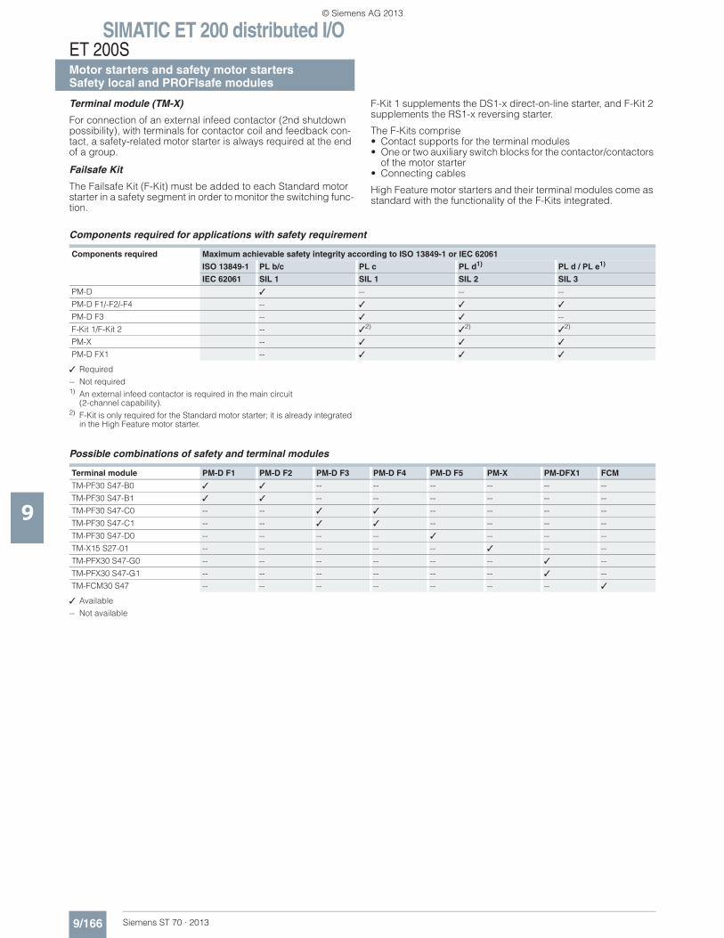
SIMATIC ET 200 distributed I/OET 200SMotor starters and safety motor startersSafety local and PROFIsafe modules
9/166 Siemens ST 70 · 2013
9
Terminal module (TM-X)
For connection of an external infeed contactor (2nd shutdown possibility), with terminals for contactor coil and feedback con-tact, a safety-related motor starter is always required at the end of a group.
Failsafe Kit
The Failsafe Kit (F-Kit) must be added to each Standard motor starter in a safety segment in order to monitor the switching func-tion.
F-Kit 1 supplements the DS1-x direct-on-line starter, and F-Kit 2 supplements the RS1-x reversing starter.
The F-Kits comprise • Contact supports for the terminal modules • One or two auxiliary switch blocks for the contactor/contactors
of the motor starter• Connecting cables
High Feature motor starters and their terminal modules come as standard with the functionality of the F-Kits integrated.
Components required for applications with safety requirement
✓ Required
-- Not required1) An external infeed contactor is required in the main circuit
(2-channel capability).2) F-Kit is only required for the Standard motor starter; it is already integrated
in the High Feature motor starter.
Possible combinations of safety and terminal modules
✓ Available
-- Not available
Components required Maximum achievable safety integrity according to ISO 13849-1 or IEC 62061
ISO 13849-1 PL b/c PL c PL d1) PL d / PL e1)
IEC 62061 SIL 1 SIL 1 SIL 2 SIL 3
PM-D ✓ -- -- --
PM-D F1/-F2/-F4 -- ✓ ✓ ✓
PM-D F3 -- ✓ ✓ --
F-Kit 1/F-Kit 2 -- ✓2) ✓2) ✓2)
PM-X -- ✓ ✓ ✓
PM-D FX1 -- ✓ ✓ ✓
Terminal module PM-D F1 PM-D F2 PM-D F3 PM-D F4 PM-D F5 PM-X PM-DFX1 FCM
TM-PF30 S47-B0 ✓ ✓ -- -- -- -- -- --
TM-PF30 S47-B1 ✓ ✓ -- -- -- -- -- --
TM-PF30 S47-C0 -- -- ✓ ✓ -- -- -- --
TM-PF30 S47-C1 -- -- ✓ ✓ -- -- -- --
TM-PF30 S47-D0 -- -- -- -- ✓ -- -- --
TM-X15 S27-01 -- -- -- -- -- ✓ -- --
TM-PFX30 S47-G0 -- -- -- -- -- -- ✓ --
TM-PFX30 S47-G1 -- -- -- -- -- -- ✓ --
TM-FCM30 S47 -- -- -- -- -- -- -- ✓
© Siemens AG 2013
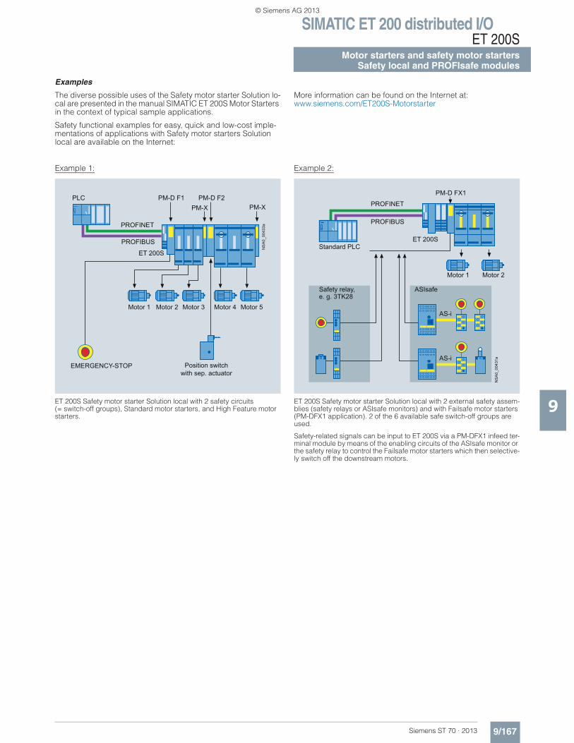
SIMATIC ET 200 distributed I/OET 200S
9/167Siemens ST 70 · 2013
Motor starters and safety motor startersSafety local and PROFIsafe modules
9
Examples
The diverse possible uses of the Safety motor starter Solution lo-cal are presented in the manual SIMATIC ET 200S Motor Starters in the context of typical sample applications.
Safety functional examples for easy, quick and low-cost imple-mentations of applications with Safety motor starters Solution local are available on the Internet:
More information can be found on the Internet at:www.siemens.com/ET200S-Motorstarter
Example 1:
ET 200S Safety motor starter Solution local with 2 safety circuits(= switch-off groups), Standard motor starters, and High Feature motor starters.
Example 2:
ET 200S Safety motor starter Solution local with 2 external safety assem-blies (safety relays or ASIsafe monitors) and with Failsafe motor starters (PM-DFX1 application). 2 of the 6 available safe switch-off groups are used.
Safety-related signals can be input to ET 200S via a PM-DFX1 infeed ter-minal module by means of the enabling circuits of the ASIsafe monitor or the safety relay to control the Failsafe motor starters which then selective-ly switch off the downstream motors.
NS
A0_
0043
3a
PROFIBUS
PROFINET
PLC
EMERGENCY-STOP Position switchwith sep. actuator
Motor 4 Motor 5Motor 1 Motor 2 Motor 3
ET 200S
PM-D F1 PM-D F2PM-XPM-X
ET 200S
PROFIBUS
PROFINET
PM-D FX1
ASIsafe
AS-i
AS-i
NS
A0_
0043
1a
Safety relay,e. g. 3TK28
Standard PLC
Motor 1 Motor 2
© Siemens AG 2013
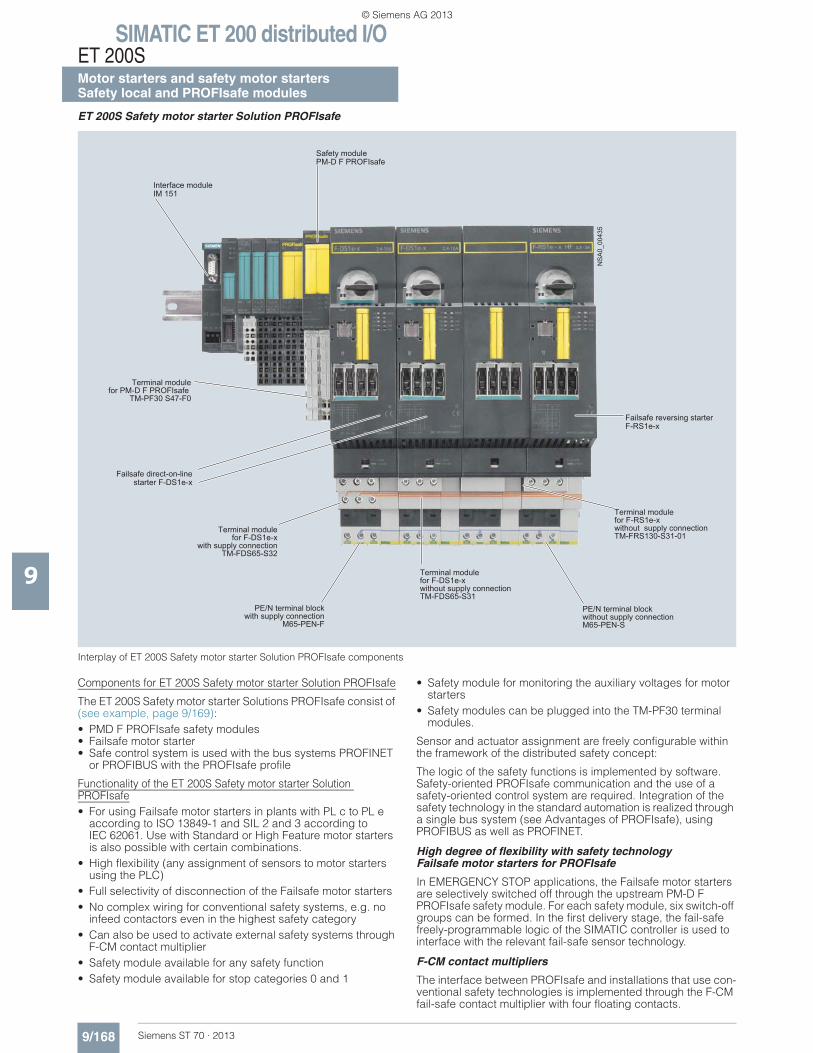
SIMATIC ET 200 distributed I/OET 200SMotor starters and safety motor startersSafety local and PROFIsafe modules
9/168 Siemens ST 70 · 2013
9
ET 200S Safety motor starter Solution PROFIsafe
Interplay of ET 200S Safety motor starter Solution PROFIsafe components
Components for ET 200S Safety motor starter Solution PROFIsafe
The ET 200S Safety motor starter Solutions PROFIsafe consist of (see example, page 9/169):• PMD F PROFIsafe safety modules• Failsafe motor starter• Safe control system is used with the bus systems PROFINET
or PROFIBUS with the PROFIsafe profile
Functionality of the ET 200S Safety motor starter Solution PROFIsafe• For using Failsafe motor starters in plants with PL c to PL e
according to ISO 13849-1 and SIL 2 and 3 according to IEC 62061. Use with Standard or High Feature motor starters is also possible with certain combinations.
• High flexibility (any assignment of sensors to motor starters using the PLC)
• Full selectivity of disconnection of the Failsafe motor starters• No complex wiring for conventional safety systems, e.g. no
infeed contactors even in the highest safety category• Can also be used to activate external safety systems through
F-CM contact multiplier• Safety module available for any safety function• Safety module available for stop categories 0 and 1
• Safety module for monitoring the auxiliary voltages for motor starters
• Safety modules can be plugged into the TM-PF30 terminal modules.
Sensor and actuator assignment are freely configurable within the framework of the distributed safety concept:
The logic of the safety functions is implemented by software. Safety-oriented PROFIsafe communication and the use of a safety-oriented control system are required. Integration of the safety technology in the standard automation is realized through a single bus system (see Advantages of PROFIsafe), using PROFIBUS as well as PROFINET.
High degree of flexibility with safety technology Failsafe motor starters for PROFIsafe
In EMERGENCY STOP applications, the Failsafe motor starters are selectively switched off through the upstream PM-D F PROFIsafe safety module. For each safety module, six switch-off groups can be formed. In the first delivery stage, the fail-safe freely-programmable logic of the SIMATIC controller is used to interface with the relevant fail-safe sensor technology.
F-CM contact multipliers
The interface between PROFIsafe and installations that use con-ventional safety technologies is implemented through the F-CM fail-safe contact multiplier with four floating contacts.
Terminal modulefor F-DS1e-x
with supply connection TM-FDS65-S32
Failsafe direct-on-line starter F-DS1e-x
Terminal modulefor PM-D F PROFIsafe
TM-PF30 S47-F0
Safety modulePM-D F PROFIsafe
PE/N terminal blockwith supply connection
M65-PEN-F
Interface moduleIM 151
Terminal modulefor F-DS1e-xwithout supply connectionTM-FDS65-S31
PE/N terminal blockwithout supply connectionM65-PEN-S
Terminal modulefor F-RS1e-xwithout supply connectionTM-FRS130-S31-01
Failsafe reversing starterF-RS1e-x
NS
A0_
0043
5
© Siemens AG 2013
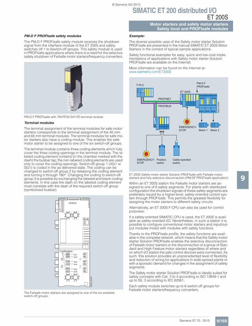
SIMATIC ET 200 distributed I/OET 200S
9/169Siemens ST 70 · 2013
Motor starters and safety motor startersSafety local and PROFIsafe modules
9
PM-D F PROFIsafe safety modules
The PM-D F PROFIsafe safety module receives the shutdown signal from the interface module of the ET 200S and safely switches off 1 to 6switch-off groups. This safety module is used in PROFIsafe applications where there is a need for the selective safety shutdown of Failsafe motor starters/frequency converters.
PM-D F PROFIsafe with TM-PF30 S47-F0 terminal module
Terminal modules
The terminal assignment of the terminal modules for safe motor starters corresponds to the terminal assignment of the 45 mm and 65 mm terminal modules. The terminal modules for safe mo-tor starters also have a coding module. This enables the safe motor starter to be assigned to one of the six switch-off groups.
The terminal module contains three coding elements which fully cover the three coding openings in the terminal module. The la-beled coding element contains (in the chamber marked with the dash) the busbar tap; the non-labeled coding elements are used only to cover the coding openings. Switch-off group 1 (AG1 or SG1) is coded in the as-delivered state. The coding can be changed to switch-off group 2 by releasing the coding element and turning it through 180°. Changing the coding to switch-off group 3 is possible by exchanging the labeled and blank coding elements. In this case the dash on the labeled coding element must correlate with the dash of the required switch-off group (symbolized busbar).
The Failsafe motor starters are assigned to one of the six possible switch-off groups.
Example:
The diverse possible uses of the Safety motor starter Solution PROFIsafe are presented in the manual SIMATIC ET 200S Motor Starters in the context of typical sample applications.
Safety functional examples for easy, quick and low-cost imple-mentations of applications with Safety motor starter Solution PROFIsafe are available on the Internet:
More information can be found on the Internet at:www.siemens.com/ET200S
ET 200S Safety motor starter Solution PROFIsafe with Failsafe motor starters and fully selective disconnection (PM-DF PROFIsafe application)
Within an ET 200S station the Failsafe motor starters are as-signed to one of 6 safety segments. For plants with distributed configuration the shutdown signals of these safety segments are preferably issued by a higher-level, safety-oriented control sys-tem through PROFIsafe. This permits the greatest flexibility for assigning the motor starters to different safety circuits.
Alternatively, an ET 200S F-CPU can also be used for control purposes.
If a safety-oriented SIMATIC CPU is used, the ET 200S is avail-able as safety-oriented I/O. Nevertheless, in such a station it is possible to configure conventional motor starters and input/out-put modules mixed with modules with safety functions.
Thanks to the PROFIsafe profile, the safety functions are avail-able in the complete network, which means that the Safety motor starter Solution PROFIsafe enables the selective disconnection of Failsafe motor starters or the disconnection of a group of Stan-dard and High Feature motor starters regardless of where and on which I/O station the safe control devices were connected. As such, this solution provides an unprecedented level of flexibility and reduction of wiring for applications in wide-spread plants or with a sporadic demand for changes in the assignment of safety segments.
The Safety motor starter Solution PROFIsafe is ideally suited for safety concepts with Cat. 2 to 4 according to ISO 13849-1 and up to SIL 3 according to IEC 62061.
Each safety module switches up to 6 switch-off groups for Failsafe motor starters/frequency converters.
E 0
1
SG1SG2
SG3SG4
SG5SG6
NS
A0_
0033
465
4321
8 765
4321
8 7
65
4321
8 765
4321
8 7
SIEMENS
Codification
NSA
0_00
432a
ET 200S
PM-D FPROFIsafe
PROFIBUS
PROFINET
F-PLC
EMERGENCY-STOP
Positionswitch
Cable-operatedswitch
Motor 1 Motor 2
EMERGENCY-STOP
© Siemens AG 2013
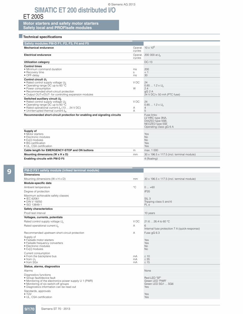
SIMATIC ET 200 distributed I/OET 200SMotor starters and safety motor startersSafety local and PROFIsafe modules
9/170 Siemens ST 70 · 2013
9
■ Technical specifications
Safety modules PM-D F1, F2, F3, F4 and F5 Mechanical endurance Operat.
cycles10 x 106
Electrical endurance Operat. cycles
200 000 at Ie
Utilization category DC-13
Control times • Minimum command duration ms 200• Recovery time s < 1• OFF-delay ms 30
Control circuit U1• Rated control supply voltage US V DC 24• Operating range DC up to 60 °C 0.85 ... 1.2 x Us• Power consumption W 2.4• Recommended short-circuit protection gG 2 A• Output OUT+/OUT- for controlling expansion modules 24 V DC/< 50 mA (PTC fuse)
Switched auxiliary circuit U2• Rated control supply voltage US V DC 24• Operating range DC up to 60 °C 0.85 ... 1.2 x Us• Rated operational current Ie (13 ... 24 V DC) A 4• Uninterrupted thermal current Ith A 5
Recommended short-circuit protection for enabling and signaling circuits Fuse links: LV HRC type 3NA, DIAZED type 5SB, NEOZED type 5SE Operating class gG 6 A
Supply of • Motor starters Yes • Electronic modules No• Ex(i) modules No• BG certification Yes• UL, CSA certification Yes
Cable length for EMERGENCY-STOP and ON buttons m max. 1 000
Mounting dimensions (W x H x D) mm 30 x 196.5 x 117.5 (incl. terminal module)
Enabling circuits with PM-D F5 4 (floating)
PM-D FX1 safety module (infeed terminal module)Dimensions
Mounting dimensions (W x H x D) mm 30 x 196.5 x 117.5 (incl. terminal module)
Module-specific data
Ambient temperature °C 0 ... +60
Degree of protection IP20
Maximum achievable safety classes• IEC 62061 SIL 3• DIN V 19250 Tripping class 5 and 6• ISO 13849-1 PL e
Safety characteristics
Proof-test interval 10 years
Voltages, currents, potentials
Rated control supply voltage Us V DC 21.6 ... 26.4 to 60 °C
Rated operational current Ie A 6 Internal fuse protection 7 A (quick-response)
Recommended upstream short-circuit protection A Fuse gG 6.3
Supply of• Failsafe motor starters Yes• Failsafe frequency converters Yes• Electronic modules No• Ex[i] modules No
Current consumption• From the backplane bus mA 10 • from U1 mA 35 • from SGx mA 15
Status, alarms, diagnostics
Alarms None
Diagnostics functions• Group fault/device fault Red LED "SF"• Monitoring of the electronics power supply U 1 (PWR) Green LED "PWR"• Monitoring of six switch-off groups Green LED SG1 ... SG6• Diagnostics information can be read out Yes
Standards, approvals • TÜV Yes• UL, CSA certification Yes
© Siemens AG 2013
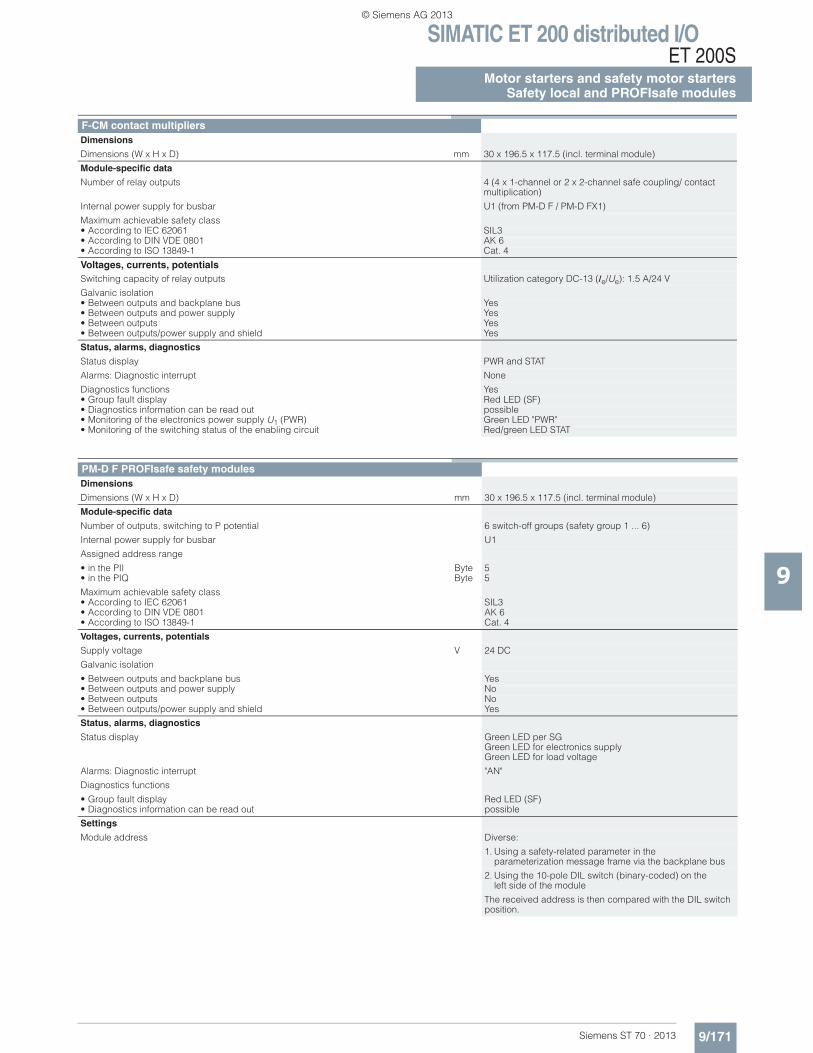
SIMATIC ET 200 distributed I/OET 200S
9/171Siemens ST 70 · 2013
Motor starters and safety motor startersSafety local and PROFIsafe modules
9
F-CM contact multipliersDimensions
Dimensions (W x H x D) mm 30 x 196.5 x 117.5 (incl. terminal module)
Module-specific data
Number of relay outputs 4 (4 x 1-channel or 2 x 2-channel safe coupling/ contact multiplication)
Internal power supply for busbar U1 (from PM-D F / PM-D FX1)
Maximum achievable safety class• According to IEC 62061 SIL3• According to DIN VDE 0801 AK 6• According to ISO 13849-1 Cat. 4
Voltages, currents, potentials Switching capacity of relay outputs Utilization category DC-13 (Ie/Ue): 1.5 A/24 V
Galvanic isolation• Between outputs and backplane bus Yes• Between outputs and power supply Yes• Between outputs Yes• Between outputs/power supply and shield Yes
Status, alarms, diagnostics
Status display PWR and STAT
Alarms: Diagnostic interrupt None
Diagnostics functions Yes• Group fault display Red LED (SF)• Diagnostics information can be read out possible• Monitoring of the electronics power supply U1 (PWR) Green LED "PWR"• Monitoring of the switching status of the enabling circuit Red/green LED STAT
PM-D F PROFIsafe safety modulesDimensions
Dimensions (W x H x D) mm 30 x 196.5 x 117.5 (incl. terminal module)
Module-specific data
Number of outputs, switching to P potential 6 switch-off groups (safety group 1 ... 6)
Internal power supply for busbar U1
Assigned address range
• in the PII Byte 5 • in the PIQ Byte 5
Maximum achievable safety class• According to IEC 62061 SIL3• According to DIN VDE 0801 AK 6• According to ISO 13849-1 Cat. 4
Voltages, currents, potentials
Supply voltage V 24 DC
Galvanic isolation
• Between outputs and backplane bus Yes• Between outputs and power supply No• Between outputs No• Between outputs/power supply and shield Yes
Status, alarms, diagnostics
Status display Green LED per SGGreen LED for electronics supplyGreen LED for load voltage
Alarms: Diagnostic interrupt "AN"
Diagnostics functions
• Group fault display Red LED (SF)• Diagnostics information can be read out possible
Settings
Module address Diverse:
1. Using a safety-related parameter in the parameterization message frame via the backplane bus
2. Using the 10-pole DIL switch (binary-coded) on theleft side of the module
The received address is then compared with the DIL switch position.
© Siemens AG 2013
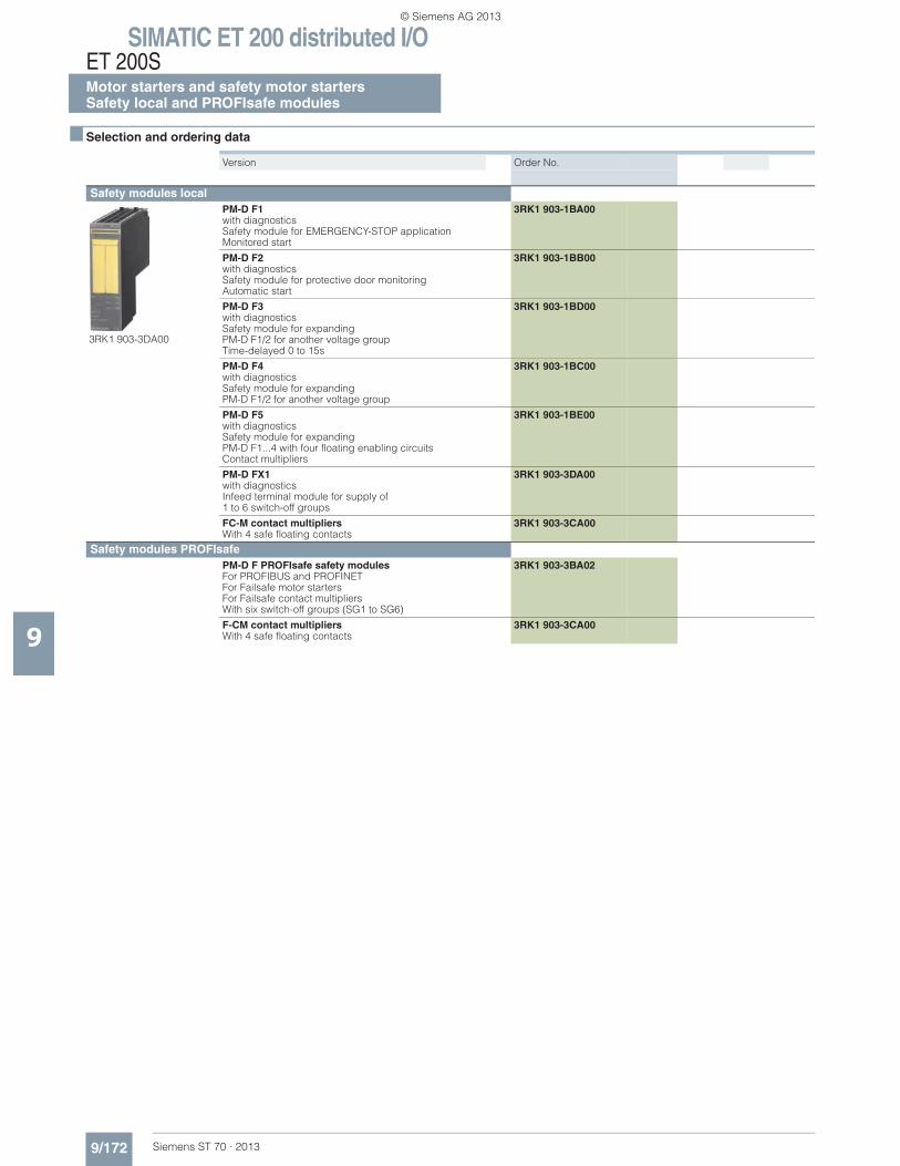
SIMATIC ET 200 distributed I/OET 200SMotor starters and safety motor startersSafety local and PROFIsafe modules
9/172 Siemens ST 70 · 2013
9
■ Selection and ordering data
Version Order No.
Safety modules local
3RK1 903-3DA00
PM-D F1 with diagnostics Safety module for EMERGENCY-STOP application Monitored start
3RK1 903-1BA00
PM-D F2 with diagnostics Safety module for protective door monitoring Automatic start
3RK1 903-1BB00
PM-D F3 with diagnostics Safety module for expanding PM-D F1/2 for another voltage groupTime-delayed 0 to 15s
3RK1 903-1BD00
PM-D F4 with diagnostics Safety module for expanding PM-D F1/2 for another voltage group
3RK1 903-1BC00
PM-D F5 with diagnostics Safety module for expanding PM-D F1...4 with four floating enabling circuitsContact multipliers
3RK1 903-1BE00
PM-D FX1 with diagnostics Infeed terminal module for supply of 1 to 6 switch-off groups
3RK1 903-3DA00
FC-M contact multipliers With 4 safe floating contacts
3RK1 903-3CA00
Safety modules PROFIsafe PM-D F PROFIsafe safety modulesFor PROFIBUS and PROFINETFor Failsafe motor starters For Failsafe contact multipliers With six switch-off groups (SG1 to SG6)
3RK1 903-3BA02
F-CM contact multipliersWith 4 safe floating contacts
3RK1 903-3CA00
© Siemens AG 2013
SIMATIC ET 200 distributed I/OET 200S
9/173Siemens ST 70 · 2013
Terminal modules forSafety local and PROFIsafe modules
9
■ Overview
Terminal module for PM-D F1/F2/F3/F4/F5 safety modules
For supplying load and sensor voltage to the self-assembling voltage buses of the Standard motor starters, High Feature mo-tor starters, and frequency converters. Safety modules for volt-age monitoring are plugged onto TM-P modules. TM-P modules can be used any number of times within the ET 200S. A safety module must always be plugged upstream from the first motor starter.
Different safety circuits can be functionally separated or else cascaded using different terminal modules. Each group in such a case must be terminated with a PM-X safety module (connec-tion module).
TM-PF30 S47-B1
The terminal module is always positioned at the beginning of a safety segment and accommodates the PM-DF1 safety module for EMERGENCY STOP applications or the PM-DF2 safety mod-ule for protective door monitoring. The 24 V control supply volt-ages for the electronics (U1) and those for supplying the contac-tors (U2) of the motor starters must be connected to this terminal module along with the 2-channel connection of the safety sen-sors (e.g. EMERGENCY STOP pushbuttons). Connections for the ON button (enabling) and safe output of the safety module are available in addition.
TM-PF30 S47-B0
The terminal module is used to cascade lower level safety seg-ments and accommodates the PM-DF1 safety module for EMER-GENCY-STOP applications or the PM-DF2 safety module for pro-tective door monitoring. No other auxiliary voltage has to be connected to this terminal module. The supply comes from the preceding PM-DF1 or PM-DF2 module over the potential bars of the terminal modules. Once the potential of the preceding safety module is disconnected, this sub-potential also has no voltage.
TM-PF30 S47-C1
The terminal module is always positioned at the beginning of a safety segment expansion in a new station, e.g. at an interlace point. It accommodates the PM-D F3 safety module for time-de-layed shutdown or the PM-D F4 safety module for direct shut-down in separately located ET 200S stations. The 24 V control supply voltages for the electronics (U1) and those for supplying the contactors (U2) are fed in new. The shutdown command from an upstream ET 200S station is re-ceived through a safe input. Separate terminals are available to connect the feedback circuit to the upstream ET 200S station. No safety sensors can be connected to this terminal module.
TM-PF30 S47-C0
The terminal module is used to cascade lower-level safety seg-ments and accommodates the PM-D F3 safety module for time-delayed shutdown, or the PM-D F4 safety module. Only the U2 control supply voltage for the contactors must be connected to this terminal module. The U1 supply comes from the preceding safety module (sub-potential group) over the potential bars of the terminal modules. No safety sensors can be connected to this terminal module.
TM-PF30 S47-D0
The terminal module is used to accommodate the PM-D F5 safety module. On this terminal module, safe signals can be relayed to external systems through four groups, each with two safety relay contacts configured with redundancy. The terminal module must always be positioned between one of the above mentioned terminal modules and a terminal module for the TM-X connection module. No safety sensors can be con-nected to this terminal module.
Terminal module for PM-X safety module (TM-X)
TM-X15 S27-01
For connection of an external infeed contactor (second shut-down option) for SIL 2 and SIL 3 or PL d and PL e. The PM-X safety module (connection module) is plugged in on the right next to the last motor starter of a safety segment. On the TM-X terminal module there are the terminals for connecting the posi-tively driven NC contact of the contactors as well as the termi-nals for connecting the contactor coil. If no contactor with redun-dant switching is required, e.g. for PL c (ISO 13849-1), the feedback circuit has to be closed at these terminals with a jumper. In applications with external safety relays it is also used instead of the safety module as interface to the external safety relay.
© Siemens AG 2013
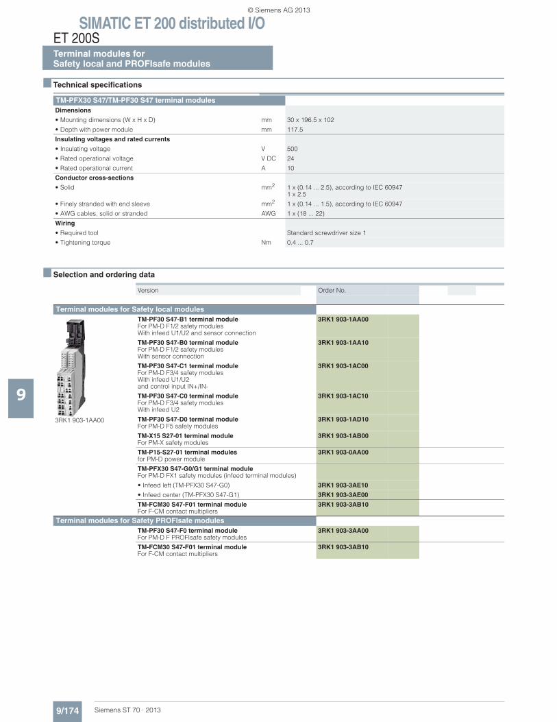
SIMATIC ET 200 distributed I/OET 200STerminal modules forSafety local and PROFIsafe modules
9/174 Siemens ST 70 · 2013
9
■ Technical specifications
■ Selection and ordering data
TM-PFX30 S47/TM-PF30 S47 terminal modulesDimensions
• Mounting dimensions (W x H x D) mm 30 x 196.5 x 102
• Depth with power module mm 117.5
Insulating voltages and rated currents
• Insulating voltage V 500
• Rated operational voltage V DC 24
• Rated operational current A 10
Conductor cross-sections
• Solid mm2 1 x (0.14 ... 2.5), according to IEC 609471 x 2.5
• Finely stranded with end sleeve mm2 1 x (0.14 ... 1.5), according to IEC 60947
• AWG cables, solid or stranded AWG 1 x (18 ... 22)
Wiring
• Required tool Standard screwdriver size 1
• Tightening torque Nm 0.4 ... 0.7
Version Order No.
Terminal modules for Safety local modules
3RK1 903-1AA00
TM-PF30 S47-B1 terminal module For PM-D F1/2 safety modules With infeed U1/U2 and sensor connection
3RK1 903-1AA00
TM-PF30 S47-B0 terminal module For PM-D F1/2 safety modules With sensor connection
3RK1 903-1AA10
TM-PF30 S47-C1 terminal module For PM-D F3/4 safety modules With infeed U1/U2 and control input IN+/IN-
3RK1 903-1AC00
TM-PF30 S47-C0 terminal module For PM-D F3/4 safety modules With infeed U2
3RK1 903-1AC10
TM-PF30 S47-D0 terminal module For PM-D F5 safety modules
3RK1 903-1AD10
TM-X15 S27-01 terminal module For PM-X safety modules
3RK1 903-1AB00
TM-P15-S27-01 terminal modules for PM-D power module
3RK1 903-0AA00
TM-PFX30 S47-G0/G1 terminal moduleFor PM-D FX1 safety modules (infeed terminal modules)
• Infeed left (TM-PFX30 S47-G0) 3RK1 903-3AE10
• Infeed center (TM-PFX30 S47-G1) 3RK1 903-3AE00
TM-FCM30 S47-F01 terminal moduleFor F-CM contact multipliers
3RK1 903-3AB10
Terminal modules for Safety PROFIsafe modulesTM-PF30 S47-F0 terminal moduleFor PM-D F PROFIsafe safety modules
3RK1 903-3AA00
TM-FCM30 S47-F01 terminal moduleFor F-CM contact multipliers
3RK1 903-3AB10
© Siemens AG 2013
SIMATIC ET 200 distributed I/OET 200S
9/175Siemens ST 70 · 2013
Motor starters and safety motor startersAccessories
9
■ Overview
Accessories for Standard motor starters
Control kit
The control kit for the Standard motor starter provides the possi-bility of testing the motor during start-up or service by actuating the motor starter protector. Using the control kit with the motor starter protector tripped, the contactor is mechanically locked in the ON position.
Control unit
With the control unit the contactor coils of the Standard motor starter can be directly controlled using 24 V DC. The motor starter can thus be started as normal using a local control station without PLC or bus.
Note:
The control unit cannot be used in combination with the safety system or a brake control module.
DM-V15 distance module• Passive module without bus connection and terminals• Does not need a separate terminal module • Follows a TM-DS45 or TM-RS90 or TM-xB if required• Does not need to be taken into account when configuring the
GSD file
The distance module is available for applications with high motor currents or high ambient temperatures involving Standard motor starters. It can be used to the right and left of a DS1-x direct-on-line starter, or to the right of an xB1...4 brake module in order to improve heat dissipation to the side. The distance module is a completely passive module and does not need to be taken into account with regard to the control system during configuration. Details of the distance module can be found in the manual "SIMATIC ET 200S". If you have any queries concerning the use of the distance module, contact Technical Support for Siemens Low Voltage Controls (Fax: +49(0)911/895-5907).
Accessories for High Feature motor starters
Control module 2DI LC COM
The 2DI control module is plugged onto the interface on the front of the motor starter. The module provides two inputs which can receive signals from the process and be assigned directly to the starter.
The functionality can be selected from a list of various control functions as part of the PROFIBUS parameterization. Local con-trol station, emergency start and quick stop, for example, are available as functions. The signal levels can also be parameter-ized (NO/NC). For more extensive control functions the two in-puts of a xB3 or x4 brake control module, which is plugged in alongside on the right, can be integrated in addition. The signal states of all inputs are transmitted in parallel with the internal use to the higher-level control system.
When a motor starter is replaced, the parameterization is auto-matically transmitted by download to the new starter. The inputs on the motor starter ensure autonomous operation, e.g. in the event of PLC failure, on the one hand and short response times through direct processing in the starter on the other hand. An-other advantage results from the direct assignment of functions to modular machine concepts.
The 2DI LC COM control module has in addition a PC interface for connecting the ES Motor Starter parameterization and diag-nostics software switch (Version 2.0 and higher). The module works solely on High Feature motor starters with Motor Starter ES interface. The Logo! PC cable is used as connecting cable be-
tween the 2DI LC COM control module and the High Feature mo-tor starter.
Accessories for Standard and High Feature motor starters
PE/N bridge module
PE/N bridge modules are used to bridge gaps in the PE/N bus which are caused, for example, by using brake control modules, PM-D(F) power modules or PM-X connection modules. If a bridge module is used, the supply must not be fed in anew. They are available in 15 mm and in 30 mm widths.
Bridge modules L123
The L123 bridge modules are used to bridge gaps in the power bus (see above). They are available in 15 mm and in 30 mm widths.
Brake control module
For motors with mechanical brake (see "General data" ➞ "Over-view", page 9/148)
Terminal modules for brake control modules
The TM-xB terminal modules are used to accommodate the xB1, xB2, xB3 and xB4 brake control modules. The TM-xB terminal module must always follow immediately after a terminal module for Standard motor starters, High Feature motor starters, or fre-quency converters as control of the electronic braking switch is provided through an output of the motor starter/frequency con-verter. The xB215 terminal modules for the brake control mod-ules have not only the terminals for connecting the cable for the motor brake but also the terminals of the two local acting inputs. These local inputs are not evaluated by a frequency converter, which is why the xB215 terminal module can only be switched behind a motor starter.
Accessories for Standard, High Feature and Failsafe motor starters
PE/N terminal blocks
The PE/N terminal block is required for direct connection of the protective conductor in the motor cable without intermediate ter-minals. It is plugged together with the terminal module for motor starters or frequency converters before the latter is mounted on the standard mounting rail. With two PE terminals and one N ter-minal the "-F" version is connected to the "-S32" terminal modules for motor starters or frequency converters. The "-S" version is combined with the "-S31" terminal module. The "F" terminal mod-ules are delivered with two caps for closing the PE/N bus con-tacts on the final terminal module of a segment. The modules for the Standard motor starters have a width of 45 mm and the mod-ules for the High Feature motor starters and frequency convert-ers have a width of 65 mm.
There is no electrical connection between the terminals of the PE/N terminal block and the integrated shielding of the fre-quency converter. The PE/N terminal block must therefore not be used for the shielding of the motor cable.
Accessories for Safety local modules
The Failsafe Kit (F-Kit) is required for Standard motor starters in a safety segment (see page 9/166).
© Siemens AG 2013
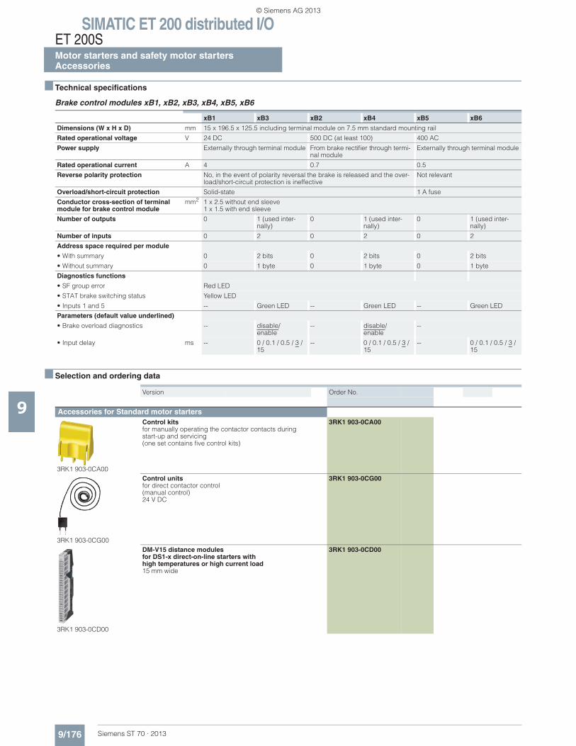
SIMATIC ET 200 distributed I/OET 200SMotor starters and safety motor startersAccessories
9/176 Siemens ST 70 · 2013
9
■ Technical specifications
Brake control modules xB1, xB2, xB3, xB4, xB5, xB6
■ Selection and ordering data
xB1 xB3 xB2 xB4 xB5 xB6
Dimensions (W x H x D) mm 15 x 196.5 x 125.5 including terminal module on 7.5 mm standard mounting rail
Rated operational voltage V 24 DC 500 DC (at least 100) 400 AC
Power supply Externally through terminal module From brake rectifier through termi-nal module
Externally through terminal module
Rated operational current A 4 0.7 0.5
Reverse polarity protection No, in the event of polarity reversal the brake is released and the over-load/short-circuit protection is ineffective
Not relevant
Overload/short-circuit protection Solid-state 1 A fuse
Conductor cross-section of terminal module for brake control module
mm2 1 x 2.5 without end sleeve 1 x 1.5 with end sleeve
Number of outputs 0 1 (used inter-nally)
0 1 (used inter-nally)
0 1 (used inter-nally)
Number of inputs 0 2 0 2 0 2
Address space required per module
• With summary 0 2 bits 0 2 bits 0 2 bits
• Without summary 0 1 byte 0 1 byte 0 1 byte
Diagnostics functions
• SF group error Red LED
• STAT brake switching status Yellow LED
• Inputs 1 and 5 -- Green LED -- Green LED -- Green LED
Parameters (default value underlined)
• Brake overload diagnostics -- disable/enable
-- disable/enable
--
• Input delay ms -- 0 / 0.1 / 0.5 / 3 / 15
-- 0 / 0.1 / 0.5 / 3 / 15
-- 0 / 0.1 / 0.5 / 3 / 15
Version Order No.
Accessories for Standard motor starters
3RK1 903-0CA00
Control kits for manually operating the contactor contacts during start-up and servicing (one set contains five control kits)
3RK1 903-0CA00
3RK1 903-0CG00
Control units for direct contactor control(manual control)24 V DC
3RK1 903-0CG00
3RK1 903-0CD00
DM-V15 distance modulesfor DS1-x direct-on-line starters withhigh temperatures or high current load 15 mm wide
3RK1 903-0CD00
© Siemens AG 2013
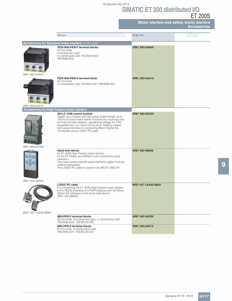
SIMATIC ET 200 distributed I/OET 200S
9/177Siemens ST 70 · 2013
Motor starters and safety motor startersAccessories
9
Accessories for Standard motor starters (continued)
3RK1 903-2AA00
PE/N M45-PEN-F terminal blocks 45 mm wideincluding two capsin combination with TM-DS45-S32 / TM-RS90-S32
3RK1 903-2AA00
3RK1 903-2AA10
PE/N M45-PEN-S terminal block 45 mm widein combination with TM-DS45-S31 /TM-RS90-S31
3RK1 903-2AA10
Accessories for High Feature motor starters
3RK1 903-0CH20
2DI LC COM control module Digital input module with two inputs (cable length up to 100 m) for local motor starter functions for mounting onto the front of motor starters, operational voltage 24 V DC (supplied from U1), short-circuit proof, floating contact with serial interface for connecting Motor Starter ES, connection using LOGO! PC cable
3RK1 903-0CH20
3RK1 922-3BA00
Hand-held devicefor ET 200S High Feature motor starters (or for ET 200pro and M200D motor starters) for local operation. The motor-starter-specific serial interface cables must be ordered separately.The LOGO! PC cable is used for the MS ET 200S HF.
3RK1 922-3BA00
6ED1 057-1AA00-0BA0
LOGO! PC cable For connecting the ET 200S High Feature motor starters to the RS232 interface of a PG/PC/laptop (with the Motor Starter ES software) or the hand-held device 3RK1 922-3BA00.
6ED1 057-1AA00-0BA0
M65-PEN-F terminal blocks 65 mm wide, including two caps, in combination with TM-DS65-S32 / TM-RS130-S32
3RK1 903-2AC00
M65-PEN-S terminal blocks 65 mm wide, in combination with TM-DS65-S31 / TM-RS130-S31
3RK1 903-2AC10
Version Order No.
© Siemens AG 2013
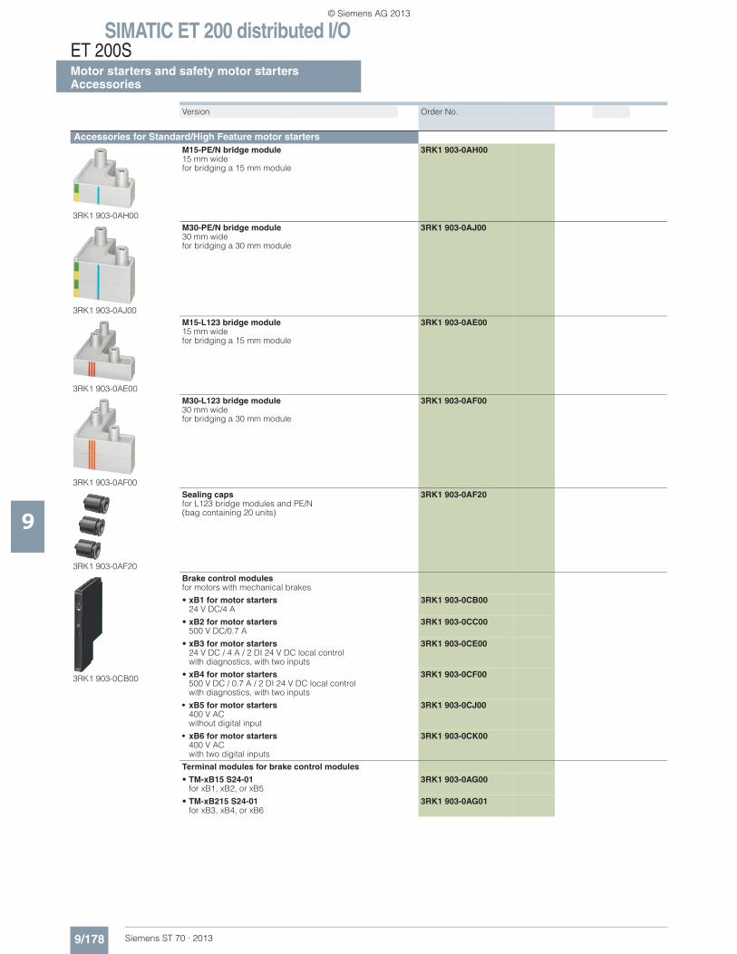
SIMATIC ET 200 distributed I/OET 200SMotor starters and safety motor startersAccessories
9/178 Siemens ST 70 · 2013
9
Accessories for Standard/High Feature motor starters
3RK1 903-0AH00
M15-PE/N bridge module 15 mm widefor bridging a 15 mm module
3RK1 903-0AH00
3RK1 903-0AJ00
M30-PE/N bridge module 30 mm widefor bridging a 30 mm module
3RK1 903-0AJ00
3RK1 903-0AE00
M15-L123 bridge module 15 mm widefor bridging a 15 mm module
3RK1 903-0AE00
3RK1 903-0AF00
M30-L123 bridge module 30 mm widefor bridging a 30 mm module
3RK1 903-0AF00
3RK1 903-0AF20
Sealing capsfor L123 bridge modules and PE/N(bag containing 20 units)
3RK1 903-0AF20
3RK1 903-0CB00
Brake control modules for motors with mechanical brakes
• xB1 for motor starters24 V DC/4 A
3RK1 903-0CB00
• xB2 for motor starters500 V DC/0.7 A
3RK1 903-0CC00
• xB3 for motor starters 24 V DC / 4 A / 2 DI 24 V DC local controlwith diagnostics, with two inputs
3RK1 903-0CE00
• xB4 for motor starters 500 V DC / 0.7 A / 2 DI 24 V DC local controlwith diagnostics, with two inputs
3RK1 903-0CF00
• xB5 for motor starters400 V ACwithout digital input
3RK1 903-0CJ00
• xB6 for motor starters400 V ACwith two digital inputs
3RK1 903-0CK00
Terminal modules for brake control modules
• TM-xB15 S24-01 for xB1, xB2, or xB5
3RK1 903-0AG00
• TM-xB215 S24-01 for xB3, xB4, or xB6
3RK1 903-0AG01
Version Order No.
© Siemens AG 2013
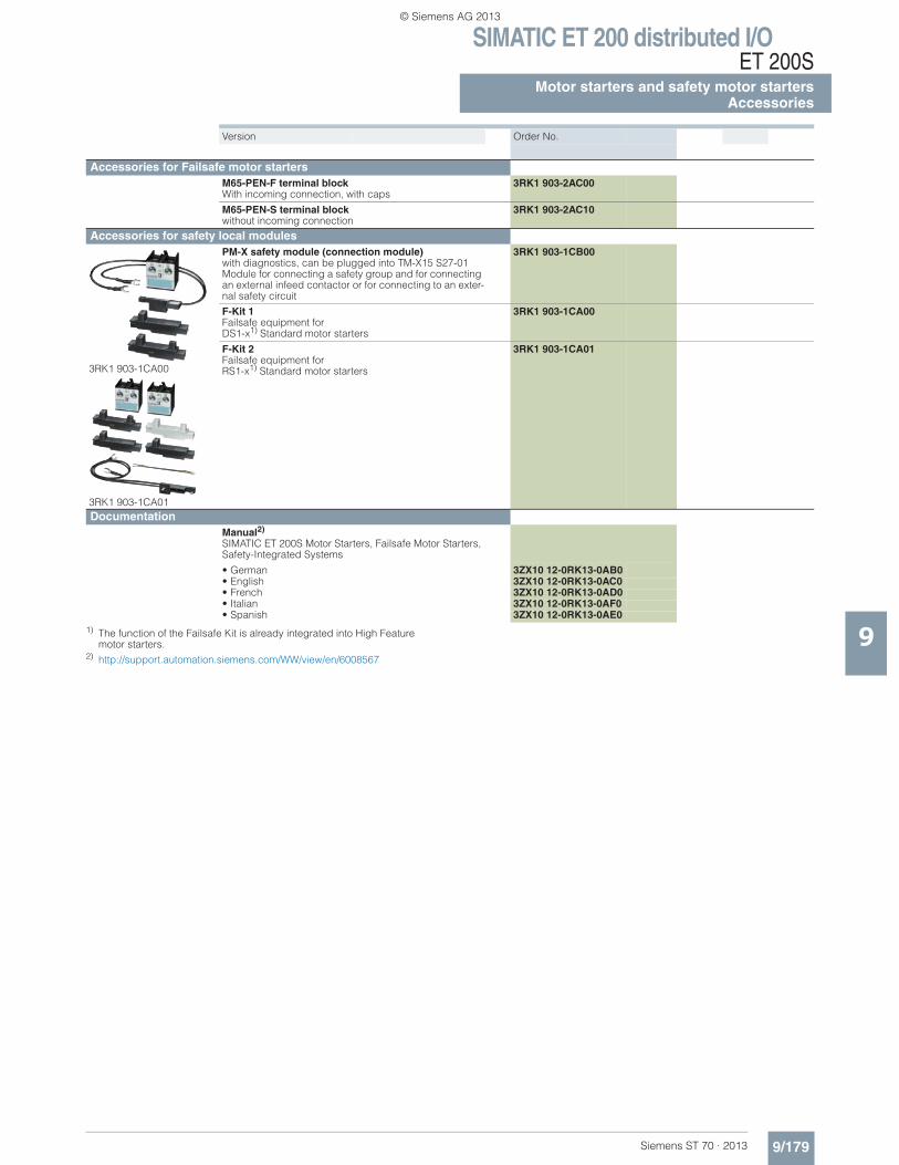
SIMATIC ET 200 distributed I/OET 200S
9/179Siemens ST 70 · 2013
Motor starters and safety motor startersAccessories
91) The function of the Failsafe Kit is already integrated into High Feature motor starters.
2) http://support.automation.siemens.com/WW/view/en/6008567
Accessories for Failsafe motor startersM65-PEN-F terminal blockWith incoming connection, with caps
3RK1 903-2AC00
M65-PEN-S terminal blockwithout incoming connection
3RK1 903-2AC10
Accessories for safety local modules
3RK1 903-1CA00
3RK1 903-1CA01
PM-X safety module (connection module)with diagnostics, can be plugged into TM-X15 S27-01Module for connecting a safety group and for connecting an external infeed contactor or for connecting to an exter-nal safety circuit
3RK1 903-1CB00
F-Kit 1 Failsafe equipment for DS1-x1) Standard motor starters
3RK1 903-1CA00
F-Kit 2 Failsafe equipment for RS1-x1) Standard motor starters
3RK1 903-1CA01
DocumentationManual2) SIMATIC ET 200S Motor Starters, Failsafe Motor Starters, Safety-Integrated Systems
• German 3ZX10 12-0RK13-0AB0• English 3ZX10 12-0RK13-0AC0• French 3ZX10 12-0RK13-0AD0• Italian 3ZX10 12-0RK13-0AF0• Spanish 3ZX10 12-0RK13-0AE0
Version Order No.
© Siemens AG 2013
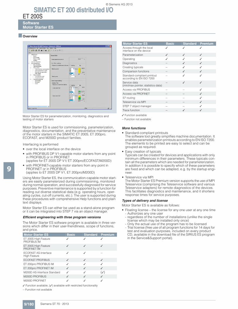
SIMATIC ET 200 distributed I/OET 200SSoftwareMotor Starter ES
9/180 Siemens ST 70 · 2013
9
■ Overview
Motor Starter ES for parameterization, monitoring, diagnostics and testing of motor starters
Motor Starter ES is used for commissioning, parameterization, diagnostics, documentation, and the preventative maintenance of the motor starters in the SIMATIC ET 200S, ET 200pro, ECOFAST, and M200D product families.
Interfacing is performed• over the local interface on the device• with PROFIBUS DP V1-capable motor starters from any point
in PROFIBUS or in PROFINET (applies for ET 200S DP V1/ ET 200pro/ECOFAST/M200D)
• with PROFINET-capable motor starters from any point in PROFINET or in PROFIBUS (applies to ET 200S DP V1, ET 200pro/M200D)
Using Motor Starter ES, the communication-capable motor start-ers are easily parameterized during commissioning, monitored during normal operation, and successfully diagnosed for service purposes. Preventive maintenance is supported by a function for reading out diverse statistical data (e.g. operating hours, oper-ating cycles, cut-off currents, etc.). The user is supported during these procedures with comprehensive Help functions and plain text displays.
Motor Starter ES can either be used as a stand-alone program or it can be integrated into STEP 7 via an object manager.
Efficient engineering with three program versions
The Motor Starter ES software program is available in three ver-sions which differ in their user-friendliness, scope of functions, and price.
✓ Function available, (✓) available with restricted functionality
-- Function not available
✓ Function available
-- Function not available
More functions• Standard-compliant printouts
The software tool greatly simplifies machine documentation. It enables parameterization printouts according to EN ISO 7200. The elements to be printed are easy to select and can be grouped as required.
• Easy creation of typicalsTypicals can be created for devices and applications with only minimum differences in their parameters. These typicals con-tain all the parameters which are needed for parameterization. In addition it is possible to specify which of these parameters are fixed and which can be adapted, e.g. by the startup engi-neer.
• Teleservice via MPIThe Motor Starter ES Premium version supports the use of MPI Teleservice (comprising the Teleservice software and various Teleservice adapters) for remote diagnostics of the devices. This facilitates diagnostics and maintenance, and it shortens response times for service purposes.
Types of delivery and licenseMotor Starter ES is available as follows: • Floating license – the license for any one user at any one time
- Authorizes any one user- regardless of the number of installations (unlike the single
license which may be installed only once)- Only the actual use of the program has to be licensed- Trial license (free use of all program functions for 14 days for
test and evaluation purposes, included on every product CD, available in the download file of the SIRIUS ES program in the Service&Support portal).
Motor Starter ES Basic Standard PremiumET 200S High Feature PROFIBUS IM
✓ ✓ ✓
ET 200S High Feature PROFINET IM
✓ ✓ ✓
ECOFAST AS-Interface High Feature
✓ ✓ --
ECOFAST PROFIBUS ✓ ✓ ✓
ET 200pro PROFIBUS IM ✓ ✓ ✓
ET 200pro PROFINET IM ✓ ✓ ✓
M200D AS-Interface Standard ✓ ✓ (✓)M200D PROFIBUS ✓ ✓ ✓
M200D PROFINET ✓ ✓ ✓
Motor Starter ES Basic Standard PremiumAccess through the local interface on the device
✓ ✓ ✓
Parameterization ✓ ✓ ✓
Operating ✓ ✓ ✓
Diagnostics -- ✓ ✓
Creating typicals -- ✓ ✓
Comparison functions -- ✓ ✓
Standard-compliant printoutaccording to EN ISO 7200
-- ✓ ✓
Service data (min/max pointer, statistics data)
-- ✓ ✓
Access via PROFIBUS -- -- ✓
Access via PROFINET -- -- ✓
S7 routing -- -- ✓
Teleservice via MPI -- -- ✓
STEP 7 object manager -- -- ✓
Trace function -- ✓ ✓
© Siemens AG 2013
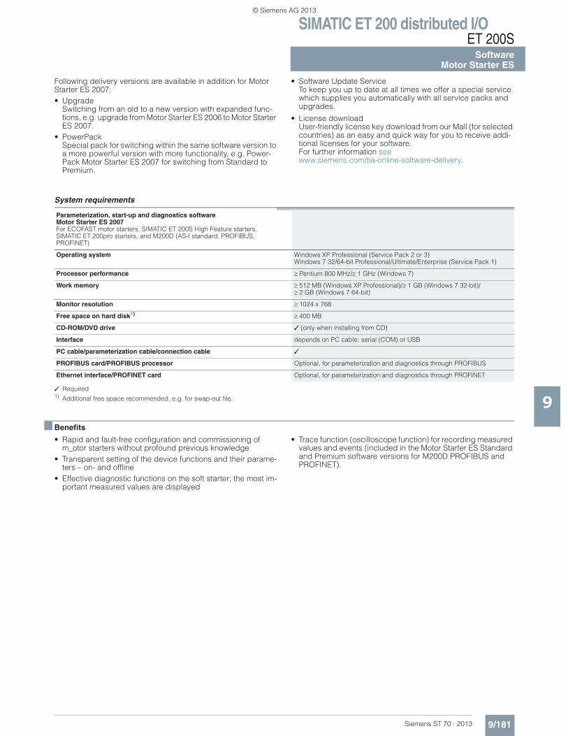
SIMATIC ET 200 distributed I/OET 200S
9/181Siemens ST 70 · 2013
SoftwareMotor Starter ES
9
Following delivery versions are available in addition for Motor Starter ES 2007:• Upgrade
Switching from an old to a new version with expanded func-tions, e.g. upgrade from Motor Starter ES 2006 to Motor Starter ES 2007.
• PowerPackSpecial pack for switching within the same software version to a more powerful version with more functionality, e.g. Power-Pack Motor Starter ES 2007 for switching from Standard to Premium.
• Software Update ServiceTo keep you up to date at all times we offer a special service which supplies you automatically with all service packs and upgrades.
• License downloadUser-friendly license key download from our Mall (for selected countries) as an easy and quick way for you to receive addi-tional licenses for your software.For further information seewww.siemens.com/tia-online-software-delivery.
System requirements
✓ Required1) Additional free space recommended, e.g. for swap-out file.
■ Benefits
• Rapid and fault-free configuration and commissioning of m_otor starters without profound previous knowledge
• Transparent setting of the device functions and their parame-ters – on- and offline
• Effective diagnostic functions on the soft starter; the most im-portant measured values are displayed
• Trace function (oscilloscope function) for recording measured values and events (included in the Motor Starter ES Standard and Premium software versions for M200D PROFIBUS and PROFINET).
Parameterization, start-up and diagnostics software Motor Starter ES 2007For ECOFAST motor starters, SIMATIC ET 200S High Feature starters, SIMATIC ET 200pro starters, and M200D (AS-I standard, PROFIBUS, PROFINET)
Operating system Windows XP Professional (Service Pack 2 or 3)Windows 7 32/64-bit Professional/Ultimate/Enterprise (Service Pack 1)
Processor performance Pentium 800 MHz/ 1 GHz (Windows 7)
Work memory 512 MB (Windows XP Professional)/ 1 GB (Windows 7 32-bit)/2 GB (Windows 7 64-bit)
Monitor resolution 1024 x 768
Free space on hard disk1) 400 MB
CD-ROM/DVD drive ✓ (only when installing from CD)
Interface depends on PC cable: serial (COM) or USB
PC cable/parameterization cable/connection cable ✓
PROFIBUS card/PROFIBUS processor Optional, for parameterization and diagnostics through PROFIBUS
Ethernet interface/PROFINET card Optional, for parameterization and diagnostics through PROFINET
© Siemens AG 2013
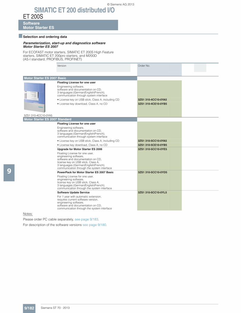
SIMATIC ET 200 distributed I/OET 200SSoftwareMotor Starter ES
9/182 Siemens ST 70 · 2013
9
■ Selection and ordering data
Parameterization, start-up and diagnostics software Motor Starter ES 2007
For ECOFAST motor starters, SIMATIC ET 200S High Feature starters, SIMATIC ET 200pro starters, and M200D(AS-I standard, PROFIBUS, PROFINET)
Notes:
Please order PC cable separately, see page 9/183.
For description of the software versions see page 9/180.
Version Order No.
Motor Starter ES 2007 Basic
3ZS1 310-4CC10-0YA5
Floating License for one user
Engineering software, software and documentation on CD, 3 languages (German/English/French), communication through system interface
• License key on USB stick, Class A, including CD 3ZS1 310-4CC10-0YA5
• License key download, Class A, no CD 3ZS1 310-4CE10-0YB5
Motor Starter ES 2007 StandardFloating License for one user
Engineering software, software and documentation on CD, 3 languages (German/English/French), communication through system interface
• License key on USB stick, Class A, including CD 3ZS1 310-5CC10-0YA5
• License key download, Class A, no CD 3ZS1 310-5CE10-0YB5
Upgrade for Motor Starter ES 2006
Floating License for one user,engineering software,software and documentation on CD, license key on USB stick, Class A, 3 languages (German/English/French), communication through the system interface
3ZS1 310-5CC10-0YE5
PowerPack for Motor Starter ES 2007 Basic
Floating License for one user,engineering software, license key on USB stick, Class A, 3 languages (German/English/French), communication through the system interface
3ZS1 310-5CC10-0YD5
Software Update Service
For 1 year with automatic extension, requires current software version, engineering software, software and documentation on CD, communication through the system interface
3ZS1 310-5CC10-0YL5
© Siemens AG 2013
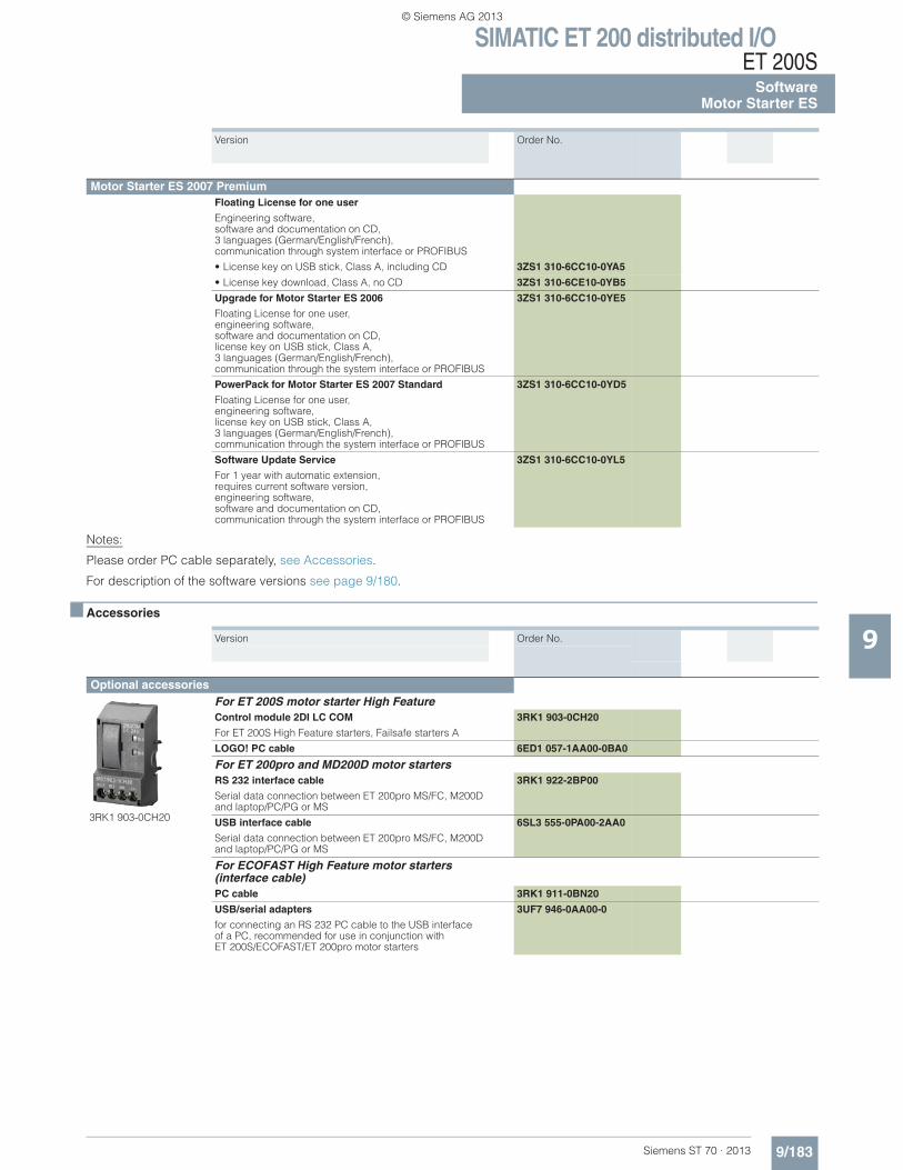
SIMATIC ET 200 distributed I/OET 200S
9/183Siemens ST 70 · 2013
SoftwareMotor Starter ES
9
Notes:
Please order PC cable separately, see Accessories.
For description of the software versions see page 9/180.
■ Accessories
Version Order No.
Motor Starter ES 2007 PremiumFloating License for one user
Engineering software, software and documentation on CD, 3 languages (German/English/French), communication through system interface or PROFIBUS
• License key on USB stick, Class A, including CD 3ZS1 310-6CC10-0YA5
• License key download, Class A, no CD 3ZS1 310-6CE10-0YB5
Upgrade for Motor Starter ES 2006
Floating License for one user,engineering software, software and documentation on CD, license key on USB stick, Class A, 3 languages (German/English/French), communication through the system interface or PROFIBUS
3ZS1 310-6CC10-0YE5
PowerPack for Motor Starter ES 2007 Standard
Floating License for one user,engineering software, license key on USB stick, Class A, 3 languages (German/English/French), communication through the system interface or PROFIBUS
3ZS1 310-6CC10-0YD5
Software Update Service
For 1 year with automatic extension, requires current software version, engineering software,software and documentation on CD, communication through the system interface or PROFIBUS
3ZS1 310-6CC10-0YL5
Version Order No.
Optional accessories
3RK1 903-0CH20
For ET 200S motor starter High FeatureControl module 2DI LC COM
For ET 200S High Feature starters, Failsafe starters A
3RK1 903-0CH20
LOGO! PC cable 6ED1 057-1AA00-0BA0
For ET 200pro and MD200D motor startersRS 232 interface cable
Serial data connection between ET 200pro MS/FC, M200D and laptop/PC/PG or MS
3RK1 922-2BP00
USB interface cable
Serial data connection between ET 200pro MS/FC, M200D and laptop/PC/PG or MS
6SL3 555-0PA00-2AA0
For ECOFAST High Feature motor starters(interface cable)PC cable 3RK1 911-0BN20
USB/serial adapters
for connecting an RS 232 PC cable to the USB interfaceof a PC, recommended for use in conjunction with ET 200S/ECOFAST/ET 200pro motor starters
3UF7 946-0AA00-0
© Siemens AG 2013
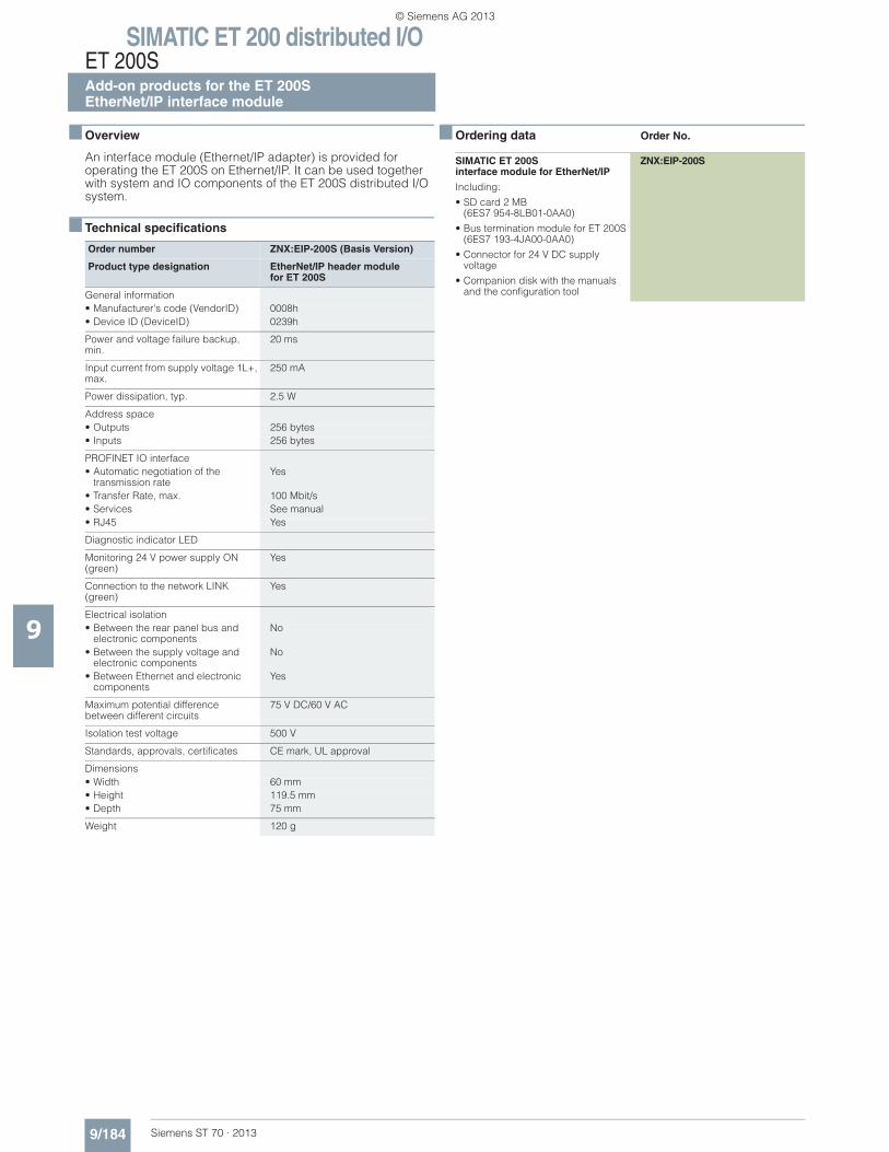
SIMATIC ET 200 distributed I/OET 200SAdd-on products for the ET 200SEtherNet/IP interface module
9/184 Siemens ST 70 · 2013
9
■ Overview
An interface module (Ethernet/IP adapter) is provided for operating the ET 200S on Ethernet/IP. It can be used together with system and IO components of the ET 200S distributed I/O system.
■ Technical specifications
■ Ordering data Order No.
Order number ZNX:EIP-200S (Basis Version)
Product type designation EtherNet/IP header modulefor ET 200S
General information• Manufacturer's code (VendorID) 0008h• Device ID (DeviceID) 0239h
Power and voltage failure backup, min.
20 ms
Input current from supply voltage 1L+, max.
250 mA
Power dissipation, typ. 2.5 W
Address space• Outputs 256 bytes• Inputs 256 bytes
PROFINET IO interface• Automatic negotiation of the
transmission rateYes
• Transfer Rate, max. 100 Mbit/s• Services See manual• RJ45 Yes
Diagnostic indicator LED
Monitoring 24 V power supply ON (green)
Yes
Connection to the network LINK (green)
Yes
Electrical isolation• Between the rear panel bus and
electronic componentsNo
• Between the supply voltage and electronic components
No
• Between Ethernet and electronic components
Yes
Maximum potential difference between different circuits
75 V DC/60 V AC
Isolation test voltage 500 V
Standards, approvals, certificates CE mark, UL approval
Dimensions• Width 60 mm• Height 119.5 mm• Depth 75 mm
Weight 120 g
SIMATIC ET 200S interface module for EtherNet/IP
Including:
• SD card 2 MB (6ES7 954-8LB01-0AA0)
• Bus termination module for ET 200S(6ES7 193-4JA00-0AA0)
• Connector for 24 V DC supply voltage
• Companion disk with the manuals and the configuration tool
ZNX:EIP-200S
© Siemens AG 2013
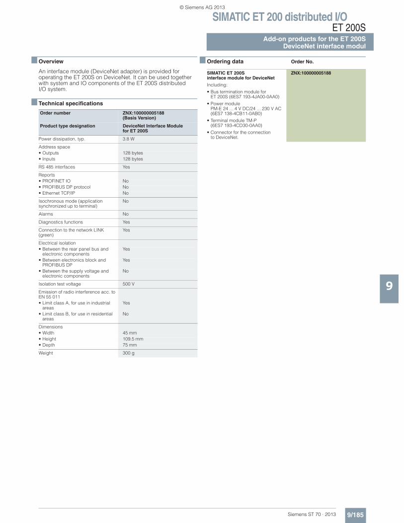
SIMATIC ET 200 distributed I/OET 200S
Add-on products for the ET 200SDeviceNet interface modul
9/185Siemens ST 70 · 2013
9
■ Overview
An interface module (DeviceNet adapter) is provided for operating the ET 200S on DeviceNet. It can be used together with system and IO components of the ET 200S distributed I/O system.
■ Technical specifications
■ Ordering data Order No.
Order number ZNX:100000005188(Basis Version)
Product type designation DeviceNet Interface Modulefor ET 200S
Power dissipation, typ. 3.8 W
Address space• Outputs 128 bytes• Inputs 128 bytes
RS 485 interfaces Yes
Reports• PROFINET IO No• PROFIBUS DP protocol No• Ethernet TCP/IP No
Isochronous mode (applicationsynchronized up to terminal)
No
Alarms No
Diagnostics functions Yes
Connection to the network LINK (green)
Yes
Electrical isolation• Between the rear panel bus and
electronic componentsYes
• Between electronics block andPROFIBUS DP
Yes
• Between the supply voltage and electronic components
No
Isolation test voltage 500 V
Emission of radio interference acc. to EN 55 011• Limit class A, for use in industrial
areasYes
• Limit class B, for use in residentialareas
No
Dimensions• Width 45 mm• Height 109.5 mm• Depth 75 mm
Weight 300 g
SIMATIC ET 200Sinterface module for DeviceNet
Including:
• Bus termination module forET 200S (6ES7 193-4JA00-0AA0)
• Power module PM-E 24 ... 4 V DC/24 ... 230 V AC(6ES7 138-4CB11-0AB0)
• Terminal module TM-P (6ES7 193-4CD30-0AA0)
• Connector for the connection to DeviceNet.
ZNX:100000005188
© Siemens AG 2013