MTS 200 - Weldability | Sif
33
MTS 200 User Manual SWMTS001 TSX1D200MTS
-
Upload
khangminh22 -
Category
Documents
-
view
2 -
download
0
Transcript of MTS 200 - Weldability | Sif

MTS 200 User Manual
SWMTS001
TSX1D200MTS

TSX1D200MTS V1 FEB13 - 2 -
DECLARATION OF CONFORMITY The Low voltage Directive 2006/95/EC of 12 December 2006, entering into force 16 January 2007
Type of Equipment Welding power source for MIG/MAG, TIG/TAG, MMA welding Brand name or trade mark Sif Type designation etc. SifWeld MTS200 Manufacturer or his authorised representative established within the EEA Name, address, telephone no, fax no
Weldability Sif, Peters House, The Orbital Centre, Icknield Way, Letchworth, Hertfordshire,. SG6 1ET Phone: 01462 482200 Fax: 01462 482202 The following harmonised standard in force with the EEA has been used in the design:
EN60974-1- Arc welding equipment- Part 1: Welding power sources
Additional information: restrictive use, Class A equipment, intended for use in locations other than residential
By signing this document, the undersigned declares as manufacturer, or the manufacturer’s authorised representative established within the EEA, that the equipment in question complies with the safety requirements stated above.
Place and Date Signature Position Letchworth 01-04-2013 Quality Director Weldability Sif
Keith Mullan
WEEE Directive & Product Disposal At the end of its serviceable life, this product should not be treated as household or general waste. It should be handed over to the applicable collection point for the recycling of electrical and electronic equipment, or returned to the supplier for disposal.

TSX1D200MTS V1 FEB13 - 3 -
1 SAFETY
2 INTRODUCTION
3 TECHNICAL DATA
4 INSTALLATION 4.1 MIG Installation 4.2 TIG Installation 4.3 MMA Installation
5 OPERATION 5.1 Connection and Control Devices 5.2 Display Function Diagram 5.3 Operating Functions 5.4 MIG Function Set Up 5.5 TIG Function Set Up 5.6 MMA Function Set Up
6 RECOMMENDED WELD PARAMETERS
7 DAILY CHECKLIST & ROUTINE MAINTENANCE
8 PARTS LIST & CIRCUIT DIAGRAM
9 FAULT TRACING & TROUBLESHOOTING
10 ACCESSORIES
TSX1D200MTS V1 FEB13 - 4 -
1 Safety Weldability Sif does not accept any liability for damage to the product or personal injury caused by ignoring the safety instructions in this manual, or by negligence during installation, use, maintenance, and repair of the product mentioned on the cover of this document and any corresponding accessories. Specific working conditions or used accessories may require additional safety instructions. Immediately contact your supplier if you detect a potential danger when using the product. The user of the product is always fully responsible for observing the local safety instructions and regulations. Observe all applicable safety instructions and regulations. All work must be carried out by a trained personnel well-acquainted with the operation of the equipment. Incorrect operation of the equipment may lead to hazardous situations which can result in injury to the operator and damage to the equipment.
WARNING
Arc welding and cutting can cause injury to yourself and others. Take necessary precautions when welding and cutting, ensuring you use adequate protection. Ask for your employer’s safety practices which should be based on manufactures’ hazard data. ELECTRIC SHOCK- Can Kill
• Install and earth the unit in accordance with application standards
• Do not touch live electrical parts or electrodes with bare skin, wet gloves or wet clothing
• Insulate yourself from earth and the workplace
• Ensure your working stance is safe
FUMES AND GASES - Can be dangerous to health
• Keep your head out of the fumes.
• Use ventilation, extraction at the arc, or both, to take fumes and gases away from your breathing zone and the general area
ARC RAYS - Can injure eyes and burn skin
• Protect your eyes and body. Use the correct welding screen and filter lens, and wear protective clothing
• Protect bystanders with suitable screens or curtains
FIRE HAZARD
• Sparks (spatter) can cause fite. Make sure therefore that there are no flammable materials nearby
NOISE- Excessive noise can damage hearing
• Protect your ears. Use ear defenders or other hearing protection
• Warn bystanders of the risk
MALFUNCTION- Call for expert assistance in the even of malfunction
• If you incur any difficulties curing the installation, please check the manual
• If you are unable to resolve your issue, please contact our Technical Department
Read and understand the instruction manual before installing or operating
TSX1D200MTS V1 FEB13 - 5 -
ENVIRONMENT
• The welding environment should be dry, where humidity is below 90%
• The environment temperature should range between 10˚C and 40˚C
• Protect the machine against heavy rain, or in hot environments out of direct sunlight
• Do not allow the machine to come into contact with water
• Keep the environment free of dust, acid and corrosive gases
• Ensure the environment is free from drafts
The SifWeld MTS200 welding machine has been installed with a pressure, flow and overheating protection circuit. When the network voltage, output current and machine temperature exceeds a set standard, the machine shall automatically stop working. However, excessive use (such as high voltage) can still lead to damage of the welding machine, therefore you shall need to pay attention to the following: Ensure Good Ventilation The SifWeldMTS 200 is a small sized welding machine which has an internal cooling fan to regulate operating temperature during use. For optimum ventilation, the operator must ensure there is sufficient space between the machine and surrounding objects, this must be a minimum of 30cm. It is vital to keep the machine serviced and maintained on a regular basis. Duty Cycle The operator should always consider duty cycles for the current they are welding at, ensuring the duty cycle is not exceeded. Should the duty cycle be exceeded, the Thermal Cut Out will engage therefore halting welding operation. At the same time the overheating signal on the front panel shall activate and light up. In this instance do not unplug the machine, however allow the fan to cool the machine to the required temperature to start welding again. Current overload will reduce the service life, and could result in damage of the machine and even burning out of the thermal inverter. Mains Input Supply Refer to the Recommended Weld Parameters within this manual for your chosen application. Use the correct voltage input for your application, and ensure this is not exceeded. Voltage above the maximum permitted voltage may cause damage to the welding machine. Make sure the earth cable is connected correctly prior to using the machine to remove necessary residual voltage.
2 Introduction The SifWeld MTS200 is an inverter welder which adopts the latest Insulated Gate Bipolar Transistor (IGBT) technology. The working principle is to use a single tube IGBT switching device rectifying input power into a DC output then inverted to a high frequency, then stepped-down through the pulse width modulator (PWM) to produce the welding output. Using a digital liquid crystal (LCD) display panel, weld parameters can be adjusted via the MCP (Mono Control Point) easily and accurately. The feedback circuit gives precise control of the welding arc, therefore providing excellent welding characteristics. The SifWeld MTS200 is an easily portable, multi-functional machine suitable for both on-site and workshop use. Boasting stable wire feed speed, no electromagnetic noise, good arc force, molten pool and low spatter along with high duty cycle. This unit is also energy efficient and is suitable for the welding of various materials.

TSX1D200MTS V1 FEB13 - 6 -
3 Technical Data
Model
Item SifWeld MTS200
Power Voltage (V) 1ph AC 230/240V
Frequency (Hz) 50/60
Rated Input Current (A) I-1max 40.6
Rated Input Current (A) I-1eff 20.3
MIG 5-200
TIG 5-200
Rated Current Range
(A) MMA 30-200
Recommended Fuse Rating 32A
No Load Voltage 63
MIG 20.2-28
TIG 10.2-18 Output Voltage
(V) MMA 16.5-24
Duty Cycle (%) 40˚C 10min 25%
Efficiency 0.73
Wire Feed Speed (m/mm) 2.7-14.4
Wire Diameter (mm) 0.6/0.8/1.0
Protection Class IP23S
Insulation Class F
Weight (Kg) 15
Dimensions (mm) 439x214x405

TSX1D200MTS V1 FEB13 - 7 -
4 Installation The SifWeld MTS200 is equipped with a network voltage compensation device, this ensures that when the network voltage changes within the 15% range, the machine can still continue to work. The cross-sectional area of any extension cable must be above the cross-sectional area of the machines mains input cable to minimise voltage drop. Prior to installation, check the following:
• Confirm both air-vents are no covered, obstructed or blocked otherwise this could result in failure of the cooling system
• Ensure the machine is connected to a suitable grounded mains supply
Installation for MIG Applications
1. Connect to a suitable cylinder with required regulator and gas hose.
2. Select desired polarity via the quick-connect sockets on the front of the machine.
3. Select the MIG function via the switch inside the machine. Fit the correct wire feed roll, and screw into place.

TSX1D200MTS V1 FEB13 - 8 -
4. Install wire spool, by unscrewing the plastic retainer and placing the wire spool onto the spool hub.
5. Release the pressure arm.
6. Feed the wire into the guide tube, and through the wire feed roll. Set the correct pressure on the arm, and fit back into place. Ensure that the pressure is enough to hold the wire in place, however not too much as this will deform the wire.
7. Insert the MIG gun onto the front of the machine, and feed the wire through into the gun.

TSX1D200MTS V1 FEB13 - 9 -
Diagram for Installation for MIG Applications
TSX1D200MTS V1 FEB13 - 10 -
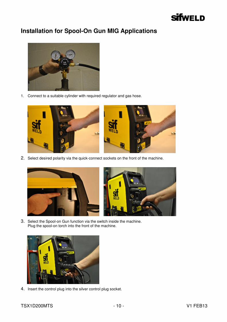
Installation for Spool-On Gun MIG Applications
1. Connect to a suitable cylinder with required regulator and gas hose.
2. Select desired polarity via the quick-connect sockets on the front of the machine.
3. Select the Spool-on Gun function via the switch inside the machine.
Plug the spool-on torch into the front of the machine.
4. Insert the control plug into the silver control plug socket.

TSX1D200MTS V1 FEB13 - 11 -
5. Open the spool gun and mount the wire spool onto the spindle.
6. Secure the spool with the retaining screw.
7. Feed wire into the guide tube.
8. Release the pressure of the feed rolls, and feed the wire through into the tip of the torch.

TSX1D200MTS V1 FEB13 - 12 -
Diagram for Installation for Spool-On Gun MIG Applications

TSX1D200MTS V1 FEB13 - 13 -
Installation for TIG Applications
1. Connect to a suitable cylinder with required regulator and gas hose. 2. Screw gas adaptor onto the gas fitting.
3. Insert the TIG adaptor into the negative polarity socket, and screw onto the gas fitting.
4. Connect the TIG torch into the adaptor, and connect the control cable into the silver control plug socket.
Insert the control plug of the earth clamp into the positive polarity socket, and connect the earth clamp to the work piece.

TSX1D200MTS V1 FEB13 - 14 -
Diagram for Installation for TIG Applications

TSX1D200MTS V1 FEB13 - 15 -
Installation for MMA Applications
1. Insert the electrode holder control plug into the desired polarity socket for application.
2. Insert the earth clamp control plug into the desired polarity socket for application. The SifWeld MTS200 machine allows for two welding modes, DC + and DC -. In DC positive applications, ensure the electrode holder is connected to the positive polarity socket. In DC negative applications, ensure the electrode holder is connected to the negative polarity socket.

TSX1D200MTS V1 FEB13 - 16 -
Diagram for Installation for MMA Applications

TSX1D200MTS V1 FEB13 - 17 -
5 Operation
Connection and Control Devices 1. LCD Display 6. Gas Socket 2. MCP- Mono Control Point 7. Input Hose 3. Welding Current Connectors 8. Mains Switch 4. Euro Block 9. Mains Input Cable 5. Control Socket
Display Function Diagram 1. Mains Supply Switch 2. Overheating Indicator 3. MCP (Mono Control Point) Adjustment Knob 4. LCD Display
2
1
3
4
2 1 7
3
4
5 6
8
9
WELD
MTS200
TSX1D200MTS V1 FEB13 - 18 -
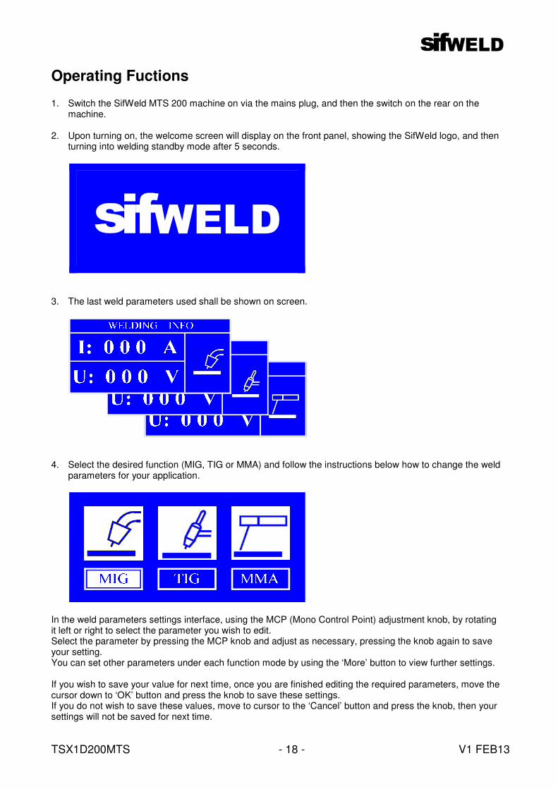
Operating Fuctions
1. Switch the SifWeld MTS 200 machine on via the mains plug, and then the switch on the rear on the machine.
2. Upon turning on, the welcome screen will display on the front panel, showing the SifWeld logo, and then turning into welding standby mode after 5 seconds.
3. The last weld parameters used shall be shown on screen.
4. Select the desired function (MIG, TIG or MMA) and follow the instructions below how to change the weld parameters for your application.
In the weld parameters settings interface, using the MCP (Mono Control Point) adjustment knob, by rotating it left or right to select the parameter you wish to edit. Select the parameter by pressing the MCP knob and adjust as necessary, pressing the knob again to save your setting. You can set other parameters under each function mode by using the ‘More’ button to view further settings. If you wish to save your value for next time, once you are finished editing the required parameters, move the cursor down to ‘OK’ button and press the knob to save these settings. If you do not wish to save these values, move to cursor to the ‘Cancel’ button and press the knob, then your settings will not be saved for next time.
WELD

TSX1D200MTS V1 FEB13 - 19 -
MIG Function Set Up The settings parameters for MIG welding include: 1. Wire speed The adjusting range of wire speed depends on different types of machine 2. Welding Voltage 3. Inductance
4. Trigger Speed 5. Pre Gas Time In default situations, the pre-gas time and post-gas time should be 0.1 second and the max value 5 seconds. 6. Post Gas Time In default situations, the pre-gas time and post-gas time should be 0.1 second and the max value 5 seconds.
2T
MIG SetUp...
Trigger
Pre Gas
Post Gas
0.1S
0.1S
Ok Cancel More
7. Burn Back 8. Gas Test The gas test is mainly to confirm whether the gas circuit is free. 9. Wire Test The wire test is mainly to confirm whether the machine can produce wire, and during installing wire you can select the wire test option to feed the wire through the liner on the MIG torch.

TSX1D200MTS V1 FEB13 - 20 -
MIG SetUp
Burn Back
Gas Test
Wire Test
Medium 1
OFF
OFF
Ok Cancel
TIG Function Set Up The settings parameters for TIG welding include: 1. Current Upon adjustment of the welding current, the voltage will change, however you are unable to change the voltage independently. 2. Welding Voltage The voltage is unable to be changed independently. 3. Down Slope Time
4. Trigger 5. Pre Gas In default situations, the pre-gas time and post-gas time should be 0.1 second and the max value 5 seconds.
6. Post Gas Time In default situations, the pre-gas time and post-gas time should be 0.1 second and the max value 5 seconds.

TSX1D200MTS V1 FEB13 - 21 -
7. Gas Test The gas test is mainly to confirm whether the gas circuit is free.
MMA Function Set Up The settings parameters for TIG welding include: 1. Current Upon adjustment of the welding current, the voltage will change, however you are unable to change the voltage independently. 2. Voltage The voltage is unable to be changed independently. 3. Arc Force The size of the Arc force will be changed with the current, and it gets from the percentage of present welding current setting value.
MMA SetUp...
Current
Voltage
ARC Force
10A
20.4V
0%

TSX1D200MTS V1 FEB13 - 22 -
4. Hot Start

TSX1D200MTS V1 FEB13 - 23 -
6 Recommended Welding Parameters
MIG Welding Parameters Plate
Thickness (mm)
Wire Diameter
(mm)
Current (A)
Voltage (V)
Welding Speed (cm/mi)
Stick Out (mm)
Gas Flow Rate
(LPM)
0.8 0.8 60 - 70 16 - 16.5 50 - 60 10 10
1 0.8 75 - 85 17 - 17.5 50 - 60 10 10 - 15
1.2 0.8 80 - 90 16 - 16.5 50 - 60 10 10 - 15
1.6 0.8 95 - 105 17 - 18 45 - 50 10 10 - 15
2 1.0 110 - 120 18 - 19 45 - 50 10 10 - 15
2.4 1.0 120 - 130 19 - 19.5 45 - 50 10 10 - 15
3.2 1.0 140 - 150 20 - 21 45 - 50 10 - 15 10 - 15
Normal Welding Speed
4.5 1.0 160 - 180 22 - 23 45 - 50 15 15
0.8 0.8 100 17 130 10 15
1.0 0.8 110 17.5 130 10 15
1.2 0.8 120 18.5 130 10 15
1.6 1.0 180 19.5 130 10 15
Square Butt Joint
High Welding Speed
2 1.0 200 21 100 15 15
1.6 1.8 60 - 80 16 - 17 40 - 50 10 10
2.4 0.8 80 - 100 19 - 20 40 - 55 10 10 - 15
3.2 1.0 120 - 160 20 - 22 35 - 45 10 - 15 10 - 15 Corner Joint
4.5 1.0 150 - 180 21 - 23 30 - 40 10 - 15 20 - 25
1 0.8 70 - 80 17 - 18 50 - 60 10 10 - 15
1.2 1.0 85 - 90 18 - 19 50 - 60 10 10 - 15
1.6 1.0 100 - 110 19 - 20 50 - 60 10 10 - 15
2 1.0 115 - 125 19 - 20 50 - 60 10 10 - 15
2.4 1.0 130 - 140 20 - 21 50 - 60 10 10 - 15
3.2 1.0 150 - 170 21 - 22 45 - 50 15 15 - 20
Normal Welding Speed
4.5 1.0 140 - 200 22 - 24 45 - 50 15 15 - 20
1 0.8 140 19 - 20 160 10 15
1.2 0.8 130 - 150 19 - 20 120 10 15
T Joint
High Welding Speed 1.6 1.0 180 22 - 23 120 10 15 - 20
0.8 0.8 60 - 70 16 - 17 40 - 45 10 10 - 15
1.2 0.8 80 - 90 18 - 19 45 - 50 10 10 - 15
1.6 0.8 90 - 100 19 - 20 45 - 50 10 10 - 15
2.4 0.8 100 - 130 20 - 21 45- 50 10 10 - 15
T Joint Normal Welding Speed
3.2 1.0 150 - 180 20 - 22 35 - 45 10 - 15 20 - 25
TIG Welding Parameters Plate
Thickness (mm)
Tungsten Diameter
(mm)
Wire Diameter
(mm)
Connection Type
Current (A)
Gas Flow Rate
(LPM)
0.5 1.0 1.0 Butt Joint 35 - 40 4 - 6
0.8 1.0 1.0 Add Wire 35 - 45 4 - 6
1.0 1.6 1.6 40 - 70 5 - 8
1.5 1.6 1.6 50 - 85 6 - 8
2.0 2.0 - 2.5 2.0 80 - 130 8 - 10
3.0 2.5 - 3.0 2.25 120 - 150 10 - 12
MMA Welding Parameters Electrode Size
(mm) 2.5 3.2 4.0
Welding Current A) 70 - 100 110 - 140 170 - 200

TSX1D200MTS V1 FEB13 - 24 -
7 Daily Checklist and Routine Maintenance
Daily Checklist These checks should be performed each time prior to using the SifWeld MTS200 unit, to ensure the unit is it perfect condition to avoid any issues
Power Source
Section To Check Note
1. Switch operation, all connections and general machine are in good condition
Operation Control Panel
2. Check power light turns on and off
Cooling Fan 1. Check air flow and sound of fan are normal If the fan does not work, and no sound can be heard the fan needs repair.
1. When power is on, check for shaking or buzzing sound
2. When power is on, check for peculiar smell Power Section
3. Check for overheating by any colour change on the unit
1. Check whether the gas pipeline is damaged or the connection is loose
Periphery 1. Check the outer shell and other parts are
not loose
Welding Gun
Section To Check Note
1. Whether this is securely fitted
Nozzle
2. Clear of spatter
1. Whether this is securely fitted
Contact Nozzle
2. Damage to the tip or if blocked
1. Ensure the correct liner size is chosen for the wire diameter being used
2. Check for kinks in the liner
3. Check for dirt and blockages in the liner
4. Check for kinks in the wire This can cause extra erosion to the liner
Wire Hose
5. Check for damage to the O-Ring This can cause leaking gas and effects the weld

TSX1D200MTS V1 FEB13 - 25 -
Internal Unit
Section To Check Note
Pressure Arm 1. Ensure the pressure arm is at the correct
pressure for the wire diameter used
1. Whether savings have accumulated in the guide tube and wire feed mechanism
Sweep away the shavings and investigate the problem
2. Whether the guide tube used matches the wire diameter used
Wire Guide Tube
3. Ensure the guide tube is in line with the wire feed roll
1. Ensure correct wire feed roll is selected for the wire diameter used
Wire Feed Roll 2. Check for blockages or dirt in the wire feed
unit
Pressure Roll 1. Check the pressure roll rotates freely and
does not pressurise the wire This can result in damaging the wire if the pressure is too high
Cables
Section To Check Note
1. Ensure the welding gun cable is not over bent
Welding Gun Cable 2. Ensure the connections of the quick plug
are in good condition
1. Check the insulation is in good condition
Welding Cable 2. Check the fittings and that there is no
damage to the installation or bare metal
1. Ensure the mains input is fitted with an appropriately rated fuse
2. Ensure all connections on both the machine end and fuse end are in good condition
Mains Input Cable
3. Ensure the insulation is in good condition and there is no bare metal
Earth Cable 1. Ensure the fittings are in good condition
and not damaged

TSX1D200MTS V1 FEB13 - 26 -
Routine Maintenance
WARNING
All maintenance and checks must be performed after shutting off the power supply, and ensure the
plug is removed from the mains supply before opening the machine.
• Using dry compressed air, clear the inside of the welding machine at least once a month, ensuring
you use the correct air pressure to avoid damaging the machine
• Check the internal electrical connections are in good condition, reinforcing any loose parts
• If there is any corrosion within the internal electrical connections, remove this as required and reconnect
• Do not use the welder in damp or wet conditions
• If the welder is not used for a prolonged period, put this in the original packaging and store in a dry place
• Service the drive motor every 300 hours for this to continue to run smoothly

TSX1D200MTS V1 FEB13 - 27 -
8 Parts List & Circuit Diagram
Parts Diagram
TSX1D200MTS V1 FEB13 - 28 -
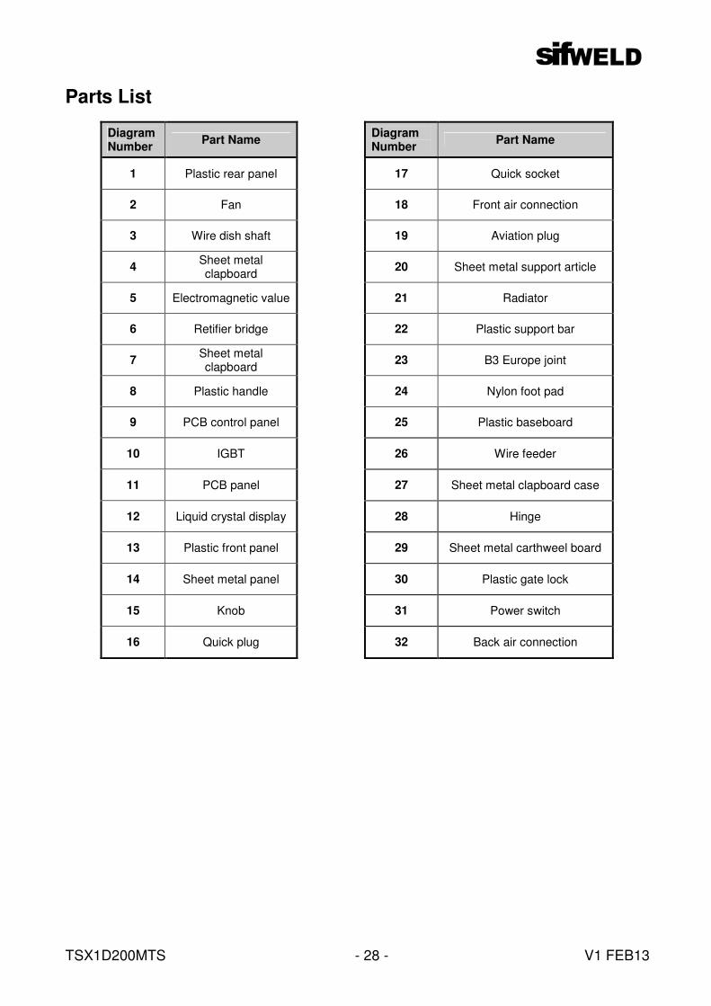
Parts List
Diagram Number
Part Name Diagram Number
Part Name
1 Plastic rear panel 17 Quick socket
2 Fan 18 Front air connection
3 Wire dish shaft 19 Aviation plug
4 Sheet metal clapboard
20 Sheet metal support article
5 Electromagnetic value 21 Radiator
6 Retifier bridge 22 Plastic support bar
7 Sheet metal clapboard
23 B3 Europe joint
8 Plastic handle 24 Nylon foot pad
9 PCB control panel 25 Plastic baseboard
10 IGBT 26 Wire feeder
11 PCB panel 27 Sheet metal clapboard case
12 Liquid crystal display 28 Hinge
13 Plastic front panel 29 Sheet metal carthweel board
14 Sheet metal panel 30 Plastic gate lock
15 Knob 31 Power switch
16 Quick plug 32 Back air connection

TSX1D200MTS V1 FEB13 - 29 -
Circuit Diagram

TSX1D200MTS V1 FEB13 - 30 -
9 Fault Tracing & Troubleshooting The faults listed below may relate to either the welding accessories, welding materials, environmental factors or power supply. Ensure that any faults are corrected immediately to avoid machine break down and further problems.
Problematic arc starting
• Check the earth connection is good
• Check all cable joints
Under current
• Low input voltage results in low output current, therefore check the input supply
Unstable welding current
• Check stability of input voltage
• Check for interference from the network or other equipment
Porosity in the weld
• Check gas supply for leaks
• Ensure the workplace is clean from oil ,dust, rust and paint
Troubleshooting
If a fault should occur with the SifWeld MTS200, please check the diagnostic table, and check all options before attempting to repair the unit. This table can be found on the next page.
WARNING
The following operations require the operator to have competent electrical knowledge, comprehensive safety knowledge, and hold the required qualification to repair this unit. If in doubt, please contact the Weldability Sif Technical Department on 0870 330 7757.
Fault Solution
Display light is not on, the fan does not work and no welding output
1. Confirm the unit is switched on. 2. Ensure the power electrical supply is working.
3. Check the fuse. It would seem that the display panel is damaged, therefore please contact
Weldability Sif Technical department on 0870 330 7757
Display light is on, the fan is working
but no welding output
1. Check cables and torch are connected properly. 2. Check they are connected to the correct polarity sockets.
3. Check continuity of torch, able & switch. It would seem that the control circuit is damaged, therefore please contact
Weldability Sif Technical department on 0870 330 7757
TSX1D200MTS V1 FEB13 - 31 -
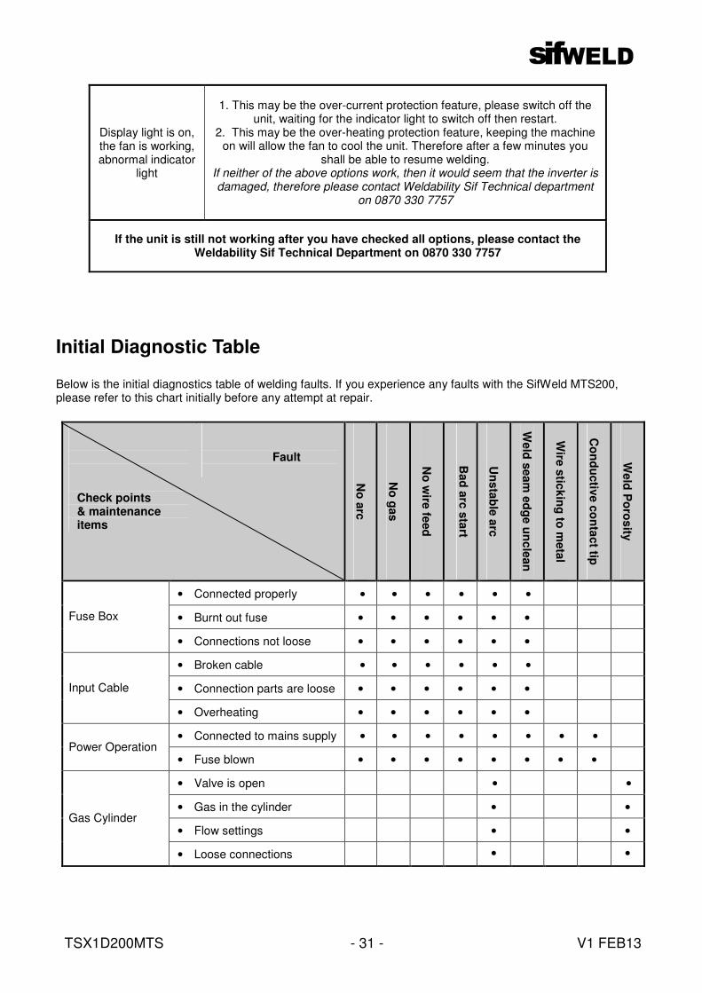
Initial Diagnostic Table
Below is the initial diagnostics table of welding faults. If you experience any faults with the SifWeld MTS200, please refer to this chart initially before any attempt at repair.
Display light is on, the fan is working, abnormal indicator
light
1. This may be the over-current protection feature, please switch off the unit, waiting for the indicator light to switch off then restart.
2. This may be the over-heating protection feature, keeping the machine on will allow the fan to cool the unit. Therefore after a few minutes you
shall be able to resume welding. If neither of the above options work, then it would seem that the inverter is damaged, therefore please contact Weldability Sif Technical department
on 0870 330 7757
If the unit is still not working after you have checked all options, please contact the Weldability Sif Technical Department on 0870 330 7757
Check points & maintenance items
Fault
No
arc
No
gas
No
wire
feed
Bad
arc
sta
rt
Un
sta
ble
arc
Weld
seam
ed
ge u
nc
lean
Wire
stic
kin
g to
meta
l
Co
nd
uctiv
e c
on
tact tip
Weld
Po
ros
ity
• Connected properly • • • • • •
• Burnt out fuse • • • • • • Fuse Box
• Connections not loose • • • • • •
• Broken cable • • • • • •
• Connection parts are loose • • • • • • Input Cable
• Overheating • • • • • •
• Connected to mains supply • • • • • • • • Power Operation
• Fuse blown • • • • • • • •
• Valve is open • •
• Gas in the cylinder • •
• Flow settings • •
Gas Cylinder
• Loose connections • •

TSX1D200MTS V1 FEB13 - 32 -
Check points & maintenance items
Fault
No
arc
No
gas
No
wire
feed
Bad
arc
sta
rt
Un
sta
ble
arc
Weld
seam
ed
ge u
nc
lean
Wire
stic
kin
g to
meta
l
Co
nd
uctiv
e c
on
tact tip
Weld
Po
ros
ity
• Loose connection • Gas Hose
• Damaged gas tube • • Correct size feed roll &
guide tube for wire diameter • • • •
• Clean groove in drive roll • • • • Wire Feeder
• Pressure is not too tight, and guide tube is clear of shavings
• • • •
• The cable is not over bent • •
Welding Gun & Cable
• Torch consumables are not damaged, and are correct for the application
•
• Contact tip, nozzle and nozzle joint are secure
• •
Welding Gun • Torch fitting is not too tight
or loose
• •
• Cables are not broken • • • • • Gun Power Cable
& Switch Control Cable • Cables are not damaged • •
• Clean from oil, dirt, rust and paint
• • • Material surface & wire length • Wire does not need cutting
back • • •
• Good earth connection • • • • Output Cables
• Cable connections are tight • • •
• Ensure the cross-sectional area of the cable is sufficient for current required
• • • • Welding Cable
• Cable is not coiled
Welding Conditions
• Check parameters, torch geometry, welding speed and stick out
• • • • •
TSX1D200MTS V1 FEB13 - 33 -
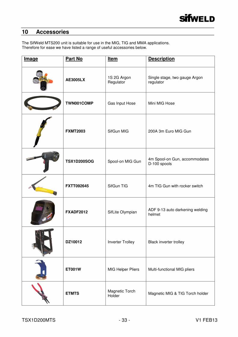
10 Accessories The SifWeld MTS200 unit is suitable for use in the MIG, TIG and MMA applications. Therefore for ease we have listed a range of useful accessories below.
Image Part No
Item Description
AE3005LX 1S 2G Argon Regulator
Single stage, two gauge Argon regulator
TWN001COMP Gas Input Hose Mini MIG Hose
FXMT2003 SifGun MIG 200A 3m Euro MIG Gun
TSX1D200SOG Spool-on MIG Gun 4m Spool-on Gun, accommodates D-100 spools
FXTT092645 SifGun TIG 4m TIG Gun with rocker switch
FXADF2012 SifLite Olympian ADF 9-13 auto darkening welding helmet
DZ10012 Inverter Trolley Black inverter trolley
ET001W MIG Helper Pliers Multi-functional MIG pliers
ETMTS Magnetic Torch Holder
Magnetic MIG & TIG Torch holder