Machining program simulation software - MTS NC – Editor ...
17
MTS Editor Software designed to create, test, modify and view the program. It can also be a great learning tool because clicking on a particular code snippet can see what the code means and how it can changed. In order to start MTS Editor Software, firstly, you need to press the <MTS TopStart> program icon (Fig.1.1). . Figure 1.1 In the opened window, select <MTS Editor> (Fig. 1.2). Figure 1.2 Main <MTS Editor> window will open (Fig. 1.3). Figure 1.3 To create a new program, click the icon for the new file - (Fig.1.4). In the opened window, you can open existing program or the program which you have already created. Click the icon - and select the file what you want. Click icon and select the file – „Abdeckplatte1.fnc“, located in the MTS folder of the local disk C - C:\MTS\MTS CNC-System 8.0\NC Programs\MTS ISO extended Mill@MTS M-VMC T40 SK40. Machining program simulation software - MTS NC – Editor (ISO version) 1. Description of MTS Editor
-
Upload
khangminh22 -
Category
Documents
-
view
1 -
download
0
Transcript of Machining program simulation software - MTS NC – Editor ...

95
MTS Editor Software designed to create, test, modify and view the program. It can also be a greatlearning tool because clicking on a particular code snippet can see what the code means and howit can changed. In order to start MTS Editor Software, firstly, you need to press the<MTS TopStart> program icon (Fig.1.1).
.Figure 1.1
In the opened window, select <MTS Editor> (Fig. 1.2).
Figure 1.2Main <MTS Editor> window will open (Fig. 1.3).
Figure 1.3To create a new program, click the icon for the new file - (Fig.1.4). In the opened window, youcan open existing program or the program which you have already created. Click the icon -and select the file what you want.Click icon and select the file – „Abdeckplatte1.fnc“, located in the MTS folder of the localdisk C - C:\MTS\MTS CNC-System 8.0\NC Programs\MTS ISO extended Mill@MTS M-VMCT40 SK40.
Machining program simulation software - MTS NC –Editor (ISO version)
1. Description of MTS Editor

96
Figure 1.4In the bottom of the main window (Fig. 1.5), is seen the program (box [1]) that has been selected.Scrolling down the window you will find the place, where the machining program starts.Clicking on the block <N2 T8 M3 G97 S1400>, you can see that the other windows, related tothe code T8 M3 G97 S1400, become active. In the box [2] you can change programmingfunctions, coordinates, or other parameters programmed earlier.In the box [3] you can see the image that helps you to understand what does the showed letters onthe sketch means.Box [4] show widely description of the selected features. Choosing another function you can seehow the information changes in the program box [1].
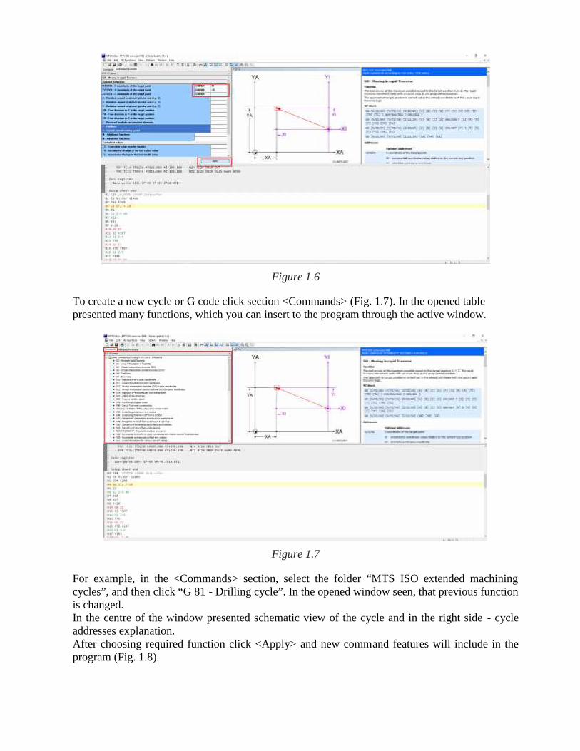
Figure 1.5Selected function is possible to change manually, writing it to the program or using activewindow, which allows setting selected functions in the current row. To change parameters fromthe active window, click on the item you want to change. To confirm, press <Apply>. Themodified block will appear (Fig. 1.6).
97
Figure 1.6
To create a new cycle or G code click section <Commands> (Fig. 1.7). In the opened tablepresented many functions, which you can insert to the program through the active window.
Figure 1.7
For example, in the <Commands> section, select the folder “MTS ISO extended machiningcycles”, and then click “G 81 - Drilling cycle”. In the opened window seen, that previous functionis changed.In the centre of the window presented schematic view of the cycle and in the right side - cycleaddresses explanation.After choosing required function click <Apply> and new command features will include in theprogram (Fig. 1.8).

98
Figure 1.8
To save the job press icon <Save> and turn off the program.
2. Machining program preparation
The drawing for the machining program creation showed in Fig. 2.1. Workpiece dimensions in(mm): L×B×H=120×45× 45.
Figure 2.1

99
The machining program will be prepared for the coloured surface of the workpiece (Fig.2.2).
Figure 2.2 Figure2.3
Model of the workpiece presented in Fig. 2.3.
Before programing, you need to prepare machining plan, define workpiece clamping type andcutting tools as described in the “MTS Software Manual” Task No. 2.
To create a new machining program, open MTS software and select “MTS ISO extendedMill@MTS M-VMC T40 SK40” cnc machine. Then click <NC Editor> and create a new file(Fig. 2.4).
Figure 2.4
In the work screen put selected machining tools you want to use during processing. Thisinformation intended to the user for better understanding what tool is assigned to a specificoperation. These commands are comments and are marked by sign “ ; “ ; it means that thisinformation processor excludes from the reading.For example (Fig. 2.5):
N5 ; T1 D=50 CR=0 - ZMIN=-1 - face mill
N10 ; T3 D=4,2 CR=0 TAPER=118deg - ZMIN=-37 - drill
N15 ; T4 D=8 CR=0 - ZMIN=-37 - end mill
N20 ; T5 M5 CR=0 TAPER=118deg - ZMIN=-41 – tapping cycle

100
Figure 2.5
After this, put in this window additional commands which describes overall settings for the entireprogram. To perform these actions click section <Commands> and select needed code. After this,click <Apply>. This procedure you need to do always when a new code inserted to the program.For example:
N25 G54 ; Adjustable absolute zero points
N30 G94 F2000 G97 S3000 ; Feed rate in millimetres (mm) per minute
N35 G14 ; Approach of the configured tool change point
Click section <Commands> (Fig. 2.6), select code G54 and press <Apply> (Fig. 2.7). Theprogram will insert selected code to the program automatically.
Figure 2.6

101
Figure 2.7
After insertion of each new function, is need to click on the text and move the cursor to a newline. It can be done by pressing the keyboard button <Enter>. After this, a new block number(N30) will appear automatically (Fig. 2.8).
Figure 2.8
A new code can written by the hand or selected from the functions table. In this case, clicksection <Commands> find the function G94 in the commands table, mark it and click computermouse two times. A new window will open (Figs. 2.9).

102
Figure 2.9
In the same manner, put address G94 F2000 G97 S3000 and code G14 in the program (Figs. 2.10– 2.11) by clicking section <Commands>, in the table mark required code, click <Apply> andfinally press keyboard button<Enter>.
Figure 2.10

103
Figure 2.11
3. Programming
Face millingFor milling use face mill with diameter of Ø 50 mm (T1). Workpiece width B=45 mm, thereforethere are two ways to cut it:
By one pass with the depth of 2 mm; By two passes
In order to save machining time, is selected one pass milling with the machining trajectory forthis mill type as shown in Fig. 3.1.
Figure 3.1
From the technological point of view, it is useful to separate machining operations. Accordingmachining plan first operation is face milling, therefore in the program block we have to insertthe sentence “Face1”: <N40 ; Face1 > (Fig. 3.2).
104
Figure 3.2
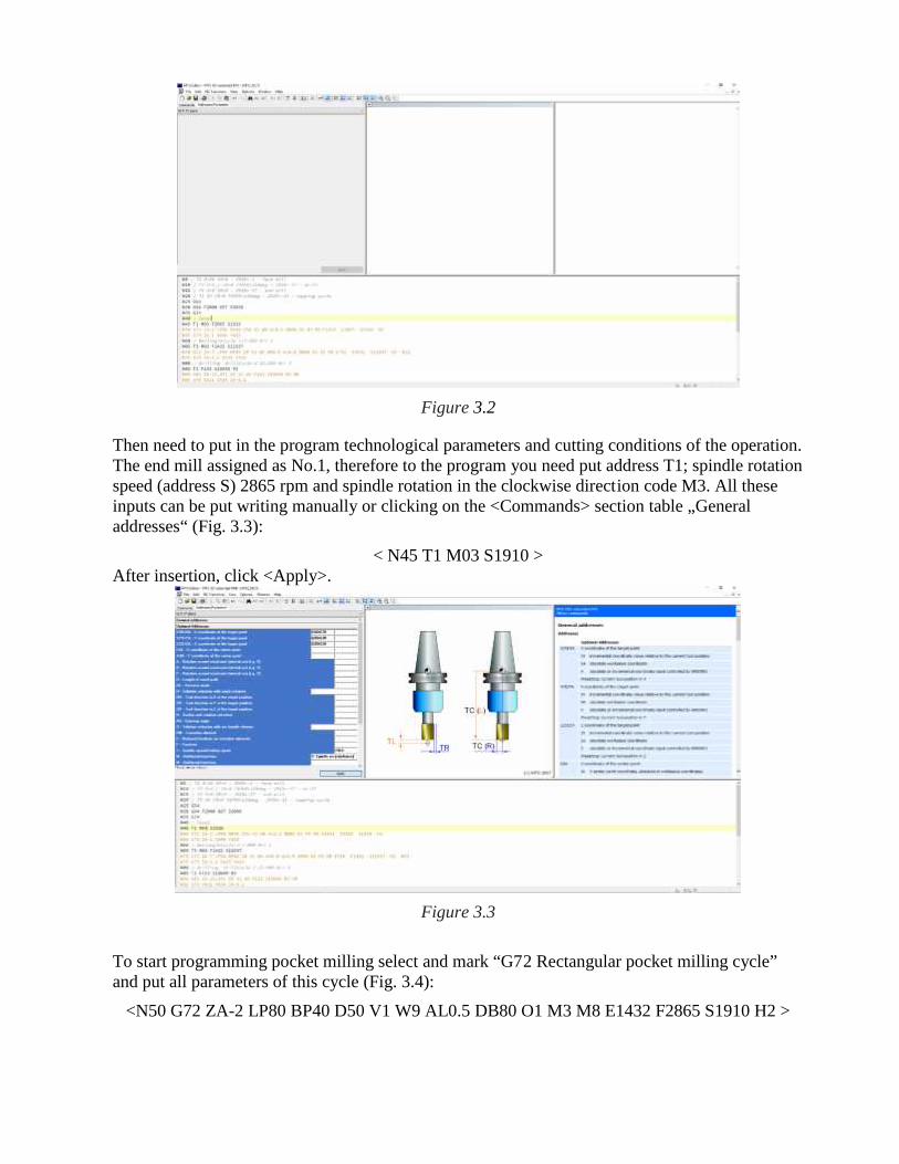
Then need to put in the program technological parameters and cutting conditions of the operation.The end mill assigned as No.1, therefore to the program you need put address T1; spindle rotationspeed (address S) 2865 rpm and spindle rotation in the clockwise direction code M3. All theseinputs can be put writing manually or clicking on the <Commands> section table „Generaladdresses“ (Fig. 3.3):
< N45 T1 M03 S1910 >After insertion, click <Apply>.
Figure 3.3
To start programming pocket milling select and mark “G72 Rectangular pocket milling cycle”and put all parameters of this cycle (Fig. 3.4):
<N50 G72 ZA-2 LP80 BP40 D50 V1 W9 AL0.5 DB80 O1 M3 M8 E1432 F2865 S1910 H2 >
105
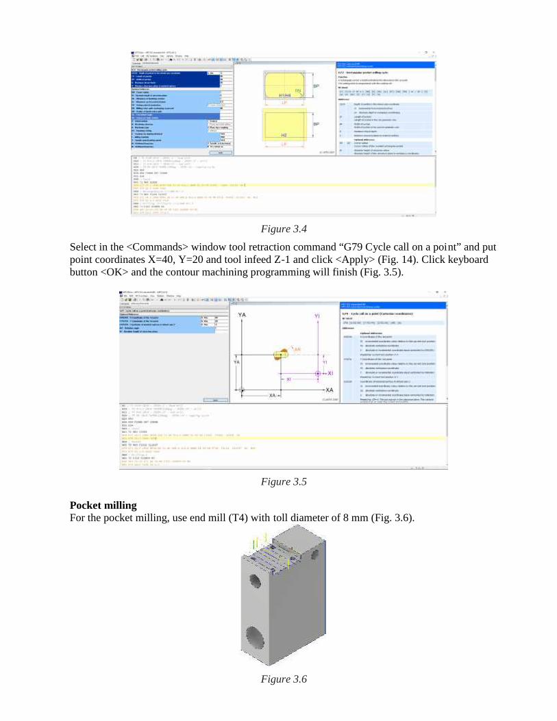
Figure 3.4Select in the <Commands> window tool retraction command “G79 Cycle call on a point” and putpoint coordinates X=40, Y=20 and tool infeed Z-1 and click <Apply> (Fig. 14). Click keyboardbutton <OK> and the contour machining programming will finish (Fig. 3.5).
Figure 3.5
Pocket millingFor the pocket milling, use end mill (T4) with toll diameter of 8 mm (Fig. 3.6).
Figure 3.6
106
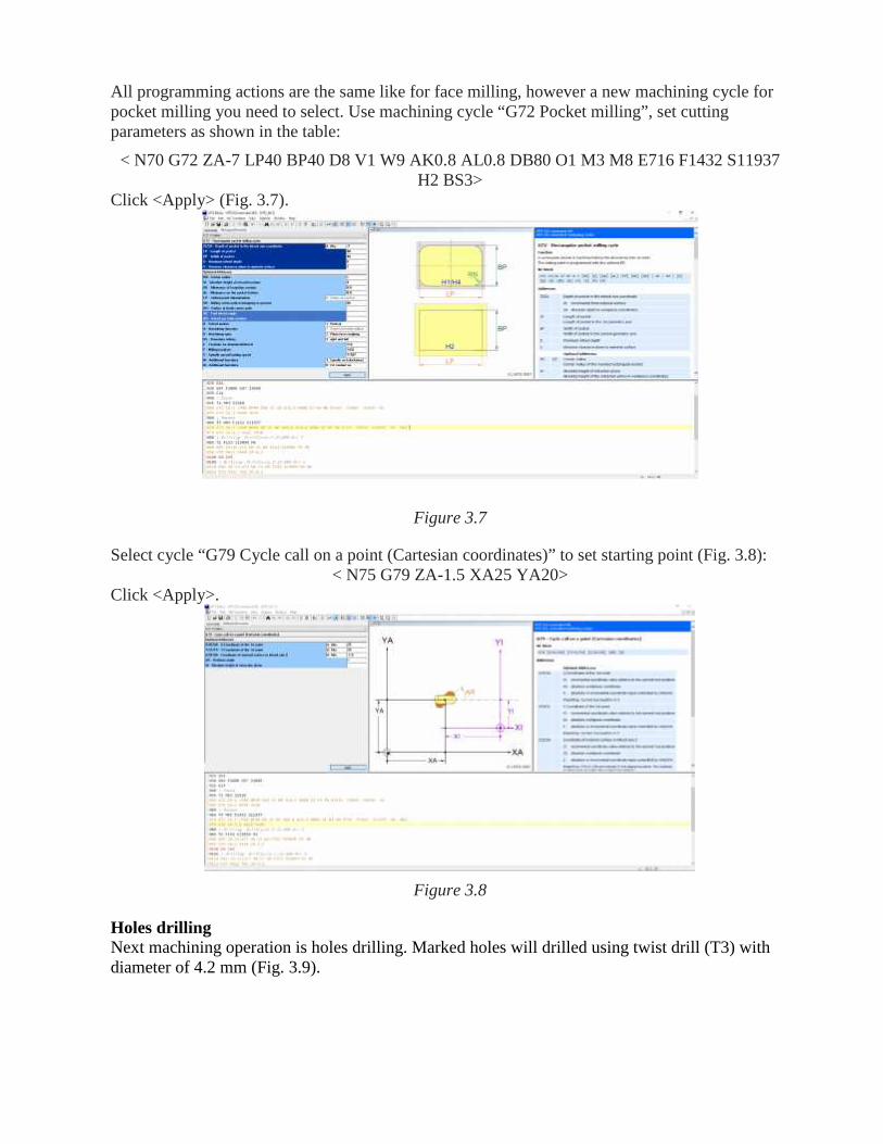
All programming actions are the same like for face milling, however a new machining cycle forpocket milling you need to select. Use machining cycle “G72 Pocket milling”, set cuttingparameters as shown in the table:
< N70 G72 ZA-7 LP40 BP40 D8 V1 W9 AK0.8 AL0.8 DB80 O1 M3 M8 E716 F1432 S11937H2 BS3>
Click <Apply> (Fig. 3.7).
Figure 3.7
Select cycle “G79 Cycle call on a point (Cartesian coordinates)” to set starting point (Fig. 3.8):< N75 G79 ZA-1.5 XA25 YA20>
Click <Apply>.
Figure 3.8
Holes drillingNext machining operation is holes drilling. Marked holes will drilled using twist drill (T3) withdiameter of 4.2 mm (Fig. 3.9).

107
Figure 3.9
Drilling 1.Use for this operation deep hole drilling cycle “G83 – Deep-hole drilling” (Fig. 3.10). Clicksection <Commands>, mark cycle and set parameters of the cycle:
< N90 G83 ZA-23.471 D0 V1 W9 F153 S19099 M3 M8>Click <Apply>.
Figure 3.10
Select “G79 Cycle call on a point (Cartesian coordinates)” and set XA=11, YA=34 and ZA=-6.2(Fig. 3.11):
<N95 G79 XA11 YA34 ZA-6.2>Click <Apply>.
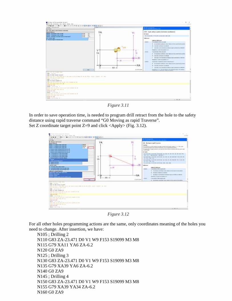
108
Figure 3.11
In order to save operation time, is needed to program drill retract from the hole to the safetydistance using rapid traverse command “G0 Moving as rapid Traverse”.Set Z coordinate target point Z=9 and click <Apply> (Fig. 3.12).
Figure 3.12
For all other holes programming actions are the same, only coordinates meaning of the holes youneed to change. After insertion, we have:
N105 ; Drilling 2N110 G83 ZA-23.471 D0 V1 W9 F153 S19099 M3 M8N115 G79 XA11 YA6 ZA-6.2N120 G0 ZA9N125 ; Drilling 3N130 G83 ZA-23.471 D0 V1 W9 F153 S19099 M3 M8N135 G79 XA39 YA6 ZA-6.2N140 G0 ZA9N145 ; Drilling 4N150 G83 ZA-23.471 D0 V1 W9 F153 S19099 M3 M8N155 G79 XA39 YA34 ZA-6.2N160 G0 ZA9

109
Hole tappingNext machining operation is M5 screw tapping (T5). Marked tapping is the same hols in Fig.3.12. First select tools, spindle speed, federate and spindle rotate direction. Then select tappingcycle - G84. Put cycle parameters < N175 G84 ZA-20 F7.85 M3 V10 W30 S500 M8>, and click<Apply> (Fig. 3.13).
Figure 3.13
Then add the coordinates for all tapping holes using codes G84, G79 and G0 as described above:N165 ; Tapping 1N170 T4 F7.85 S500 M3N175 G84 ZA-20 F7.85 M3 V10 W30 S500 M8N180 G79 XA11 YA34 ZA-6.2N185 G0 ZA9N190 ; Tapping 2N195 G84 ZA-20 F7.85 M3 V10 W30 S500 M8N200 G79 XA11 YA6 ZA-6.2N205 G0 ZA9N210 ; Tapping 3N215 G84 ZA-20 F7.85 M3 V10 W30 S500 M8N220 G79 XA39 YA6 ZA-6.2N225 G0 ZA9N230 ; Tapping 4N235 G84 ZA-20 F7.85 M3 V10 W30 S500 M8N240 G79 XA39 YA34 ZA-6.2N245 G0 ZA9
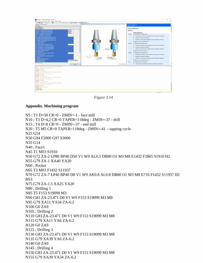
End programTo finish the program select G14 code for moving the tool to its reference point and set codeM30 to terminate the program (Fig. 3.14).
110
Figure 3.14
Appendix. Machining program
N5 ; T1 D=50 CR=0 - ZMIN=-1 - face millN10 ; T3 D=4,2 CR=0 TAPER=118deg - ZMIN=-37 - drillN15 ; T4 D=8 CR=0 - ZMIN=-37 - end millN20 ; T5 M5 CR=0 TAPER=118deg - ZMIN=-41 – tapping cycleN25 G54N30 G94 F2000 G97 S3000N35 G14N40 ; Face1N45 T1 M03 S1910N50 G72 ZA-2 LP80 BP40 D50 V1 W9 AL0.5 DB80 O1 M3 M8 E1432 F2865 S1910 H2N55 G79 ZA-1 XA40 YA20N60 ; PocketN65 T3 M03 F1432 S11937N70 G72 ZA-7 LP40 BP40 D8 V1 W9 AK0.8 AL0.8 DB80 O1 M3 M8 E716 F1432 S11937 H2BS3N75 G79 ZA-1.5 XA25 YA20N80 ; Drilling 1N85 T5 F153 S19099 M3N90 G83 ZA-23.471 D0 V1 W9 F153 S19099 M3 M8N95 G79 XA11 YA34 ZA-6.2N100 G0 ZA9N105 ; Drilling 2N110 G83 ZA-23.471 D0 V1 W9 F153 S19099 M3 M8N115 G79 XA11 YA6 ZA-6.2N120 G0 ZA9N125 ; Drilling 3N130 G83 ZA-23.471 D0 V1 W9 F153 S19099 M3 M8N135 G79 XA39 YA6 ZA-6.2N140 G0 ZA9N145 ; Drilling 4N150 G83 ZA-23.471 D0 V1 W9 F153 S19099 M3 M8N155 G79 XA39 YA34 ZA-6.2

111
N160 G0 ZA9N165 ; Tapping 1N170 T5 F7.85 S500 M3N175 G84 ZA-20 F7.85 M3 V10 W30 S500 M8N180 G79 XA11 YA34 ZA-6.2N185 G0 ZA9N190 ; Tapping 2N195 G84 ZA-20 F7.85 M3 V10 W30 S500 M8N200 G79 XA11 YA6 ZA-6.2N205 G0 ZA9N210 ; Tapping 3N215 G84 ZA-20 F7.85 M3 V10 W30 S500 M8N220 G79 XA39 YA6 ZA-6.2N225 G0 ZA9N230 ; Tapping 4N235 G84 ZA-20 F7.85 M3 V10 W30 S500 M8N240 G79 XA39 YA34 ZA-6.2N245 G0 ZA9N250 ; End programN255 G14N260 M30