MACHINING -LEVEL II
149
MACHINING -LEVEL II Based on Version 2 February 2017 Occupational Standard (OS) Training Module –Learning Guide 14- 03 Unit of Competence: Perform mensuration and calculation Module Title: Performing mensuration and calculations TTLM Code: IND MAC2 TTLM05 1019v1 October 2019
-
Upload
khangminh22 -
Category
Documents
-
view
0 -
download
0
Transcript of MACHINING -LEVEL II

MACHINING -LEVEL II
Based on Version 2 February 2017 Occupational Standard (OS)
Training Module –Learning Guide 14-
03
Unit of Competence: Perform mensuration and
calculation
Module Title: Performing mensuration
and calculations
TTLM Code: IND MAC2 TTLM05 1019v1
October 2019

Page 2 of 149
Federal TVET Agency Author/Copyright
TVET program title- Machining Level -2 Version -1
October 2019
Module Title: Performing mensuration
and calculations
TTLM Code: IND MAC2 TTLM05 1019v1
This module includes the following Learning
Guides
LG 14: Select measuring Instruments
LG Code: IND MAC2 M05 LO1-LG-14
LG 15: Carry-out measurements and calculations
LG Code: IND MAC2 M05 LO2-LG-15
LG 16: Carry-out measurements and calculations.
LG Code: IND MAC2 M05 LO3-LG-16

Page 3 of 149
Federal TVET Agency Author/Copyright
TVET program title- Machining Level -2 Version -1
October 2019
Thi
s learning guide is developed to provide you the necessary information regarding the
following content coverage and topics:
classify and interpret geometric shapes`
Select and identify measuring tools
Use alternative measuring tools
This guide will also assist you to attain the learning outcome stated in the cover page.
Specifically, upon completion of this Learning Guide, you will be able to:
Identify, classify and interpret Object or component to be measured
according to the appropriate regular geometric shape and drawing standard
Select/identify measuring tools as per object to be measured or work requirement
Use alternative measuring tools without sacrificing cost and quality of work
Learning Instructions:
1. Read the specific objectives of this Learning Guide.
2. Follow the instructions described below.
3. Read the information written in the ―Information Sheets‖. Try to understand what are
being discussed. Ask your trainer for assistance if you have hard time understanding
them.
4. Accomplish the ―Self-checks‖ which are placed following all information sheets.
5. Ask from your trainer the key to correction (key answers) or you can request your
trainer to correct your work. (You are to get the key answer only after you finished
answering the Self-checks).
6. If you earned a satisfactory evaluation proceed to ―Operation sheets
7. Perform ―the Learning activity performance test‖ which is placed following ―Operation
sheets‖ ,
8. If your performance is satisfactory proceed to the next learning guide,
9. If your performance is unsatisfactory, see your trainer for further instructions or go back
to ―Operation sheets‖.
Instruction Sheet Learning Guide 14

Page 4 of 149
Federal TVET Agency Author/Copyright
TVET program title- Machining Level -2 Version -1
October 2019
Information Sheet-1 classify and interpret geometric shapes
1.1. Geometric Shapes
1.1.1. definition of geometric Shapes
Geometric Shapes can be defined as figure or area closed by a boundary which is created
by combining the specific amount of curves, points, and lines. Different geometric
shapes are Triangle, Circle, Square, etc
Such shapes are called polygons and include triangles, squares, and pentagons. Other
shapes may be bounded by curves such as the circle or the ellipse
1.1.2. Classify
Classify. To arrange in groups, by some property. These shapes are classified by the
number of sides. Simple shapes can often be classified into basic geometric objects such
as a point, a line, a curve, a plane, a plane figure (e.g. square or circle), or a solid figure
(e.g. cube or sphere)
Many of these shapes, or polygons, can be described as flat closed figures with 3 or more
sides. Polygons are two-dimensional objects, not solids. Polygons are classified and
described by the number of sides, the kind of angles, and whether any of the sides are the
same length (or congruent)
Polygon
A polygon is a closed figure made by connecting line segments, where each line segment
end connects to only one end of two other line segments.
Examples:
The following are examples of polygons:
.
The figure below is not a polygon, since it is not a closed figure:
The figure below is not a polygon, since it is not made of line segments

Page 5 of 149
Federal TVET Agency Author/Copyright
TVET program title- Machining Level -2 Version -1
October 2019
The figure below is not a polygon, since its sides do not intersect in exactly two places
each:
Regular Polygon
A regular polygon is a polygon whose sides are all the same length, and whose angles are
all the same. The sum of the angles of a polygon with n sides, where n is 3 or more, is
180° × (n - 2) degrees
Examples:
The following are examples of regular polygons:
Examples:
The following are not examples of regular polygons
Vertex
1) The vertex of an angle is the point where the two rays that form the angle intersect
2) The vertices of a polygon are the points where its sides intersect.

Page 6 of 149
Federal TVET Agency Author/Copyright
TVET program title- Machining Level -2 Version -1
October 2019
Triangle
A three-sided polygon. The sum of the angles of a triangle is 180 degrees
Equilateral Triangle or Equiangular Triangle
A triangle having all three sides of equal length. The angles of an equilateral triangle all
measure 60 degrees.
Examples:
Isosceles Triangle
A triangle having two sides of equal length.
Examples:
Scalene Triangle
A triangle having three sides of different lengths.
Examples:

Page 7 of 149
Federal TVET Agency Author/Copyright
TVET program title- Machining Level -2 Version -1
October 2019
Acute Triangle
A triangle having three acute angles.
Examples:
Obtuse Triangle
A triangle having an obtuse angle. One of the angles of the triangle measures more than
90 degrees.
Examples:
Right Triangle
A triangle having a right angle. One of the angles of the triangle measures 90 degrees.
The side opposite the right angle is called the hypotenuse. The two sides that form the
right angle are called the legs. A right triangle has the special property that the sum of the
squares of the lengths of the legs equals the square of the length of the hypotenuse. This
is known as the Pythagorean Theorem.
Examples:

Page 8 of 149
Federal TVET Agency Author/Copyright
TVET program title- Machining Level -2 Version -1
October 2019
Example:
For the right triangle above, the lengths of the legs are A and B, and the hypotenuse has
length C. Using the Pythagorean Theorem, we know that A2 + B2 = C2.
Example:
In the right triangle above, the hypotenuse has length 5, and we see that
32 + 42 = 52 according to the Pythagorean Theorem.
Quadrilateral
A four-sided polygon. The sum of the angles of a quadrilateral is 360 degrees.
Examples:
Rectangle
A four-sided polygon having all right angles. The sum of the angles of a rectangle is 360
degrees.
Examples:
Square
A four-sided polygon having equal-
length sides meeting at right angles.
The sum of the angles of a square is
360 degrees.
Examples:

Page 9 of 149
Federal TVET Agency Author/Copyright
TVET program title- Machining Level -2 Version -1
October 2019
Parallelogram
A four-sided polygon with two pairs of parallel sides. The sum of the angles of a
parallelogram is 360 degrees.
Examples:
Rhombus
A four-sided polygon having all four sides of equal length. The sum of the angles of a
rhombus is 360 degrees.
Examples:
Trapezoid
A four-sided polygon having exactly one
pair of parallel sides. The two sides that are
parallel are called the bases of the
trapezoid. The sum of the angles of a
trapezoid is 360 degrees.
Examples:
Pentagon
A five-sided polygon. The sum of the angles of a pentagon is 540 degrees.
Examples:

Page 10 of 149
Federal TVET Agency Author/Copyright
TVET program title- Machining Level -2 Version -1
October 2019
A regular pentagon An irregular pentagon
Hexagon
A six sided polygon. The sum of the angle of hexagon is 720 degrees
Examples: An irregular hexagon
A regular hexagon An irregular hexagon
Heptagon: Seven-sided polygon. The sum of the angles of a heptagon is 900
degrees
Examples:
A regular heptagon An irregular heptagon
. :
Octagon
An eight-sided polygon. The sum of the angles of an octagon is 1080 degrees.
Examples:
A regular octagon:
An irregular octagon:
Nonagon
Nine-sided polygon. The sum of the angles of a nonagon is 1260 degrees.
Examples:
:
A regular
nonagon
An irregular

Page 11 of 149
Federal TVET Agency Author/Copyright
TVET program title- Machining Level -2 Version -1
October 2019
nonagon
Decagon
:
Ten -sided polygon. The sum of the angles of a decagon is 1440 degrees.
Examples:
:
A regular decagon An irregular decagon
Circle
A circle is the collection of points in a plane that are all the same distance from a fixed
point. The fixed point is called the center. A line segment joining the center to any point on
the circle is called a radius.
Example:
The blue line is the radius r, and the collection of red points is the circle.

Page 12 of 149
Federal TVET Agency Author/Copyright
TVET program title- Machining Level -2 Version -1
October 2019
Convex
A figure is convex if every line segment drawn between any two points inside the figure lies
entirely inside the figure. A figure that is not convex is called a concave figure.
Example:
The following figures are convex.

Page 13 of 149
Federal TVET Agency Author/Copyright
TVET program title- Machining Level -2 Version -1
October 2019
Self-Check-1 Written test
Directions: choose the best answer for the following question (2 point each)
1. A polygon with six sides
A. hexagon
B. Octagon
C. Triangle
D. Square
2. A point where the two rays that form the angle intersect.
a. Convex
b. Vertex
c. Decagon
d. Circle
3. A collection of points in a plane that are all the same distance from a fixed point.
The fixed point is called the center. A line segment joining the center to any point on
the circle is called a radius.
A. Octagon
B. Decagon
C. Triangle
D. Circle
4. A four-sided polygon having exactly one pair of parallel sides. The sum of the
angles is 360 deg.
A. Circle
B. Parallelogram
C. Trapezoid
D. Triangle
5. Square is an example of;
A. Circle
B. Parallelogram
C. Trapezoid
D. Triangle
Note: Satisfactory rating - 5 points Unsatisfactory - below 5 points
You can ask you teacher for the copy of the correct answers.

Page 14 of 149
Federal TVET Agency Author/Copyright
TVET program title- Machining Level -2 Version -1
October 2019
Information Sheet-2 Select and identify measuring tools
2.1 INTRODUCTION
Linear measurement includes the measurement of lengths, diameters, heights and
thickness. The basic principle of linear measurement (mechanical type) is that of
comparison with standard dimensions on a suitably engraved instrument or device.
Linear measuring instruments are categorized depending upon their accuracy. The
two categories are non-precision instruments and precision instruments. Non-
precision instruments include steel rule, caliper divider, and telescopic gauge that
are used to measure to the line graduations of a rule. Precision instruments include
micrometers, vernier calipers, height gauges and slip gauges. A wide variety of
electrical measuring devices is also available. Electric measuring devices are
mainly transducers, i.e. they transform the displacement into suitable measurable
parameter like voltage and current. Some of the displacement transducers are
strain gauges, linear variable differential transformers (LVDT) and potentiometers.
This unit will discuss different type of linear measuring devices and comparators.
2.1.1 NON-PRECISION MEASURING INSTRUMENTS
Non-precision instruments are limited to the measurement of parts to a visible line
graduation on the instrument used. There are several non-precision measuring
devices. They are used where high measurement accuracy is not required. This
section describes some of the non-precision measuring devices
Steel Rule
It is the simplest and most common measuring instruments in inspection. The
principle behind steel rule is of comparing an unknown length to the one previously
calibrated. The rule must be graduated uniformly throughout its length. Rules are
made in 150, 300, 500 and 1000 mm length. There are rules that have got some
attachment and special features with them to make their use more versatile. They
may be made in folded form so that they can be kept in pockets. The degree of
accuracy when measurements are made by a steel rule depends upon the quality
of the rule, and the skill of the user in estimating part of a millimeter
Calipers
Calipers are used for measurement of the parts, which cannot be measured directly
with the scale. Thus, they are accessories to scales. The calipers consist of two
legs hinged at top, and the ends of legs span part to be inspected. This span is
maintained and transferred to the scale. Calipers are of two types : spring type and
firm joint type
Spring Type
Spring type calipers are of following types
(Outside Spring Calipers , Inside Spring Calipers)

Page 15 of 149
Federal TVET Agency Author/Copyright
TVET program title- Machining Level -2 Version -1
October 2019
Fig 1.Outside Spring Caliper
Fig 2.Inside Spring Caliper
Firm Joint Type
Firm joint calipers are of following types :

Page 16 of 149
Federal TVET Agency Author/Copyright
TVET program title- Machining Level -2 Version -1
October 2019
(Outside caliper, Inside Caliper, Transfer caliper, Hermaphrodite
caliper
Fig 3.Outside Firm Joint Caliper
Fig 4.Inside Firm Joint Caliper
Fig 5.Transfer Caliper

Page 17 of 149
Federal TVET Agency Author/Copyright
TVET program title- Machining Level -2 Version -1
October 2019
Fig 6.Hermaphrodite Caliper
Divider
A divider is similar in construction to a caliper except that both legs are straight with
sharp hardened points at the end as shown in Figure. These are used for scribing arcs
and circles and general layout work. The distance between the fulcrum roller centre and
the extreme working end of one of legs is known as the nominal size Dividers are
available in the sizes of 100, 200, 300 mm. In practice, one point is placed in the centre
position and the circle or arc may then be scribed on the job with the other point. A steel
scale must be used with this instrument. Figure shows a divider.
Fig 7.Divider
Telescopic Gauge
The telescopic gauge shown in Figure is used for the measurement of internal diameter of
a hole during machining operation. It consists of a handle and two plungers, one
telescopic into the other and both under spring tension. Ends of the plungers have
spherical contacts. The plunger can be locked in position by turning a knurled screw at the
end of the handle. To measure the diameter of a hole, the plungers are first compressed
and locked in position. Next, the plunger end is inserted in the hole and allowed to expand

Page 18 of 149
Federal TVET Agency Author/Copyright
TVET program title- Machining Level -2 Version -1
October 2019
the opposite edges. Finally, they are locked in place, taken out of the hole, and measured
by an outside micrometer.
Fig 8.Telescopic Gauge
Depth Gauge
This tool is used to measure the depth of blind holes, grooves, slots, the heights of
shoulders in holes and dimensions of similar character. This is essentially a narrow steel
rule to which a sliding head is clamped at the right angles to the rule as shown in Figure .
The head forms a convenient marker in places where the rule must be held in a distance
from the point being measured.
Fig 9.Depth Gauge
2.1.2 Precision measuring instruments Since modern production processes is concerned with interchangeable products, precise
dimensional control is required in industry. Precision measurement instruments use
different techniques and phenomena to measure distance with accuracy. We will discuss
some of the precision measuring instruments in this section.
Vernier Calipers
Vernier calipers are precision measuring instruments that give an accuracy of 0.1 mm to
0.01 mm. The main scale carries the fixed graduations, one of two measuring jaws, a
vernier head having a vernier scale engraved on. The vernier head carries the other jaw
and slides on main scale. The vernier head can be locked to the main scale by the knurled
screw attached to its head. Enlarged diagram of the metric vernier scale is shown in
Figure 5.10

Page 19 of 149
Federal TVET Agency Author/Copyright
TVET program title- Machining Level -2 Version -1
October 2019
Fig 10.Vernier Caliper
To understand the working principle of a vernier caliper, let us consider that the vernier
scale has got 20 divisions which equals to 19 divisions of the main scale. Thus, one
smallest division of the vernier scale is slightly smaller than the smallest division of the
main scale. This difference is called vernier constant for that particular vernier caliper and
when it is multiplied with the smallest unit of the main scale gives the least count of that
vernier. Now, 20 vernier scale divisions (VSD) = 19 main scale division (MSD)
Now, if the smallest unit of the main scale be 1 mm, the least count of the vernier scale
= VC
If the smallest unit in the main scale be 0.5 mm, the least count of the vernier scale is,

Page 20 of 149
Federal TVET Agency Author/Copyright
TVET program title- Machining Level -2 Version -1
October 2019
To read a measurement from a vernier caliper, first the main scale reading up to the zero
of the vernier scale is noted down. It will give accuracy up to the smallest division of the
main scale. Now, vernier number of vernier scale division from its zero, which coincides
exactly with the main scale is noted. This number when multiplied with the vernier constant
gives the vernier scale reading. The actual length is obtained when the vernier scale
reading is added to the main scale reading
The caliper is placed on the object to be measured and the fine adjustment screw is
adjusted until the jaws tightly fit against the Work piece. There are vernier calipers that
incorporate arrangements for measurement of internal dimensions and depth. The vernier
calipers are designed to measure both internal and external dimensions. The lower jaws of
a vernier scale are used for external measurement and the upper jaws for the
measurement of internal dimensions. The rectangular rod carried by the movable jaw is
used for the measurement of depth
Micrometers
Micrometer is one of the most widely used precision instruments. It is primarily used to
measure external dimensions like diameters of shafts, thickness of parts etc. to an
accuracy of 0.01 mm. The essential parts of the instruments shown in Figure 5.11, consist
of
(a)Frame
(b)Anvil and spindle
(c) Screwed spindle
(d) Graduated sleeve or barrel
(e) Thimble
(f) Ratchet or friction stop
(g) Spindle clamp
Fig 11.Micrometer
The frame is made of steel, malleable cast iron or light alloy. The anvil shall protrude from
the frame for a distance of at least 3-mm in order to permit the attachment of measuring

Page 21 of 149
Federal TVET Agency Author/Copyright
TVET program title- Machining Level -2 Version -1
October 2019
wire support. The spindle does the actual measuring and possesses the threads of 0.5
mm pitch. The barrel has datum and fixed graduations Thimble is tubular cover fastened
with the spindle. The beveled edge of the spindle is divided into 50 equal parts, every fifth
being numbered. The ratchet is a small extension to the thimble. It slips when the pressure
on the screw exceeds a certain amount. It produces uniform reading and prevents damage
or distortion of the instruments. The spindle clamp is used to lock the instrument at any
desired setting
Procedure for Reading in a Micrometer
The graduation on the barrel is in two parts divided by a line along the axis of the
barrel called the reference line. The graduation above the reference is graduated in
1 mm intervals. The first and every fifth are long and numbered 0, 5, 10, 15, etc.
The lower graduations are marked in 1 mm intervals but each graduation shall be
placed at the middle of the two successive upper graduations to be read 0.5mm.
The thimble advances a distance of 0.5 mm in one complete rotation. It is called the
pitch of the micrometer. The thimble has a scale of 50 divisions around its
circumference. Thus, one smallest division of the circular scale is equivalent to
longitudinal movement of 0.5 m. It is the least count of the
micrometer
The job is measured between the end of the spindle and the anvil that is fitted to
the frame. When the micrometer is closed, the line marked zero on the thimble
coincides with the line marked zero on the barrel. If the zero graduation does not
coincide, the micrometer requires adjustment.
To take a reading from the micrometer, (1) the number of main divisions in
millimeters above the reference line, (2) the number of sub-divisions below the
reference line exceeding only the upper graduation, and (3) the number of
divisions in the thimble have to be noted down. For example if a micrometer
shows a reading of 8.78 mm when
8 divisions above the reference line = 8.00mm
1 division below the reference line =.5mm
28 thimble divisions =0.28mm
______________________ ________________________
8.78
The various important terms used in connection with micrometers are given below
Backlash
It is the total travel of the measuring spindle for a given micrometer
Measuring Range
It is the total travel of the measuring spindle for a given micrometer.
Cumulative Error
It is the deviation of measurement from the nominal dimension determined at
any optional point of the measuring range. It includes the effect of all possible individual
errors such as errors of the thread, errors of measuring faces etc. It can be determined by
using slip gauges.

Page 22 of 149
Federal TVET Agency Author/Copyright
TVET program title- Machining Level -2 Version -1
October 2019
The following are the various types of micrometers Inside Micrometer Caliper
The measuring tips of inside micrometer are constituted by jaws with contact
surface, which are hardened and ground to a radius. Unlike the conventional
micrometer, an inside micrometer does not have any U-shape frame and spindle.
One of the jaws is held stationary at the end and second one moves by the
movement of the thimble. A locknut is provided to check the movement of the
movable jaw. This facilitates the inspection of small internal dimension.
Fig 12.Inside Micrometer Caliper
Inside Micrometer
The inside micrometer is intended for internal measurement to an accuracy of 0.001 mm.
In principle, it is similar to an external micrometer and is used for measuring holes with a
diameter over 50 cm. It consists of :
(a)measuring unit
(b)extension rod with or without spacing collar, and
(c)handle.
When the micrometer screw is turned in the barrel, the distance between the
measuring faces of the micrometer can vary from 50 to 63 mm. To measure the
holes with a diameter over 63 mm, the micrometer is fitted with extension rods.
The extension rods of the sizes 13, 25, 50, 100, 150, 200 and 600 mm are in
common use.
Page 23 of 149
Federal TVET Agency Author/Copyright
TVET program title- Machining Level -2 Version -1
October 2019
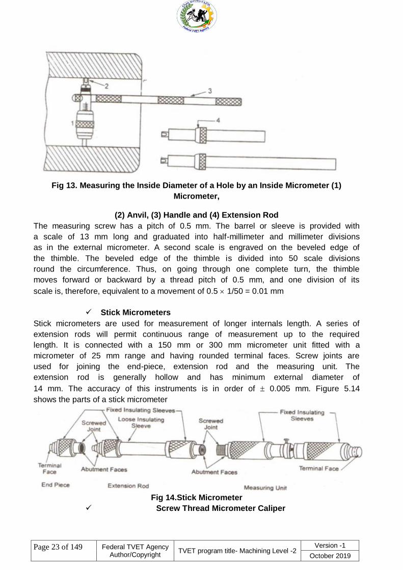
Fig 13. Measuring the Inside Diameter of a Hole by an Inside Micrometer (1)
Micrometer,
(2) Anvil, (3) Handle and (4) Extension Rod
The measuring screw has a pitch of 0.5 mm. The barrel or sleeve is provided with
a scale of 13 mm long and graduated into half-millimeter and millimeter divisions
as in the external micrometer. A second scale is engraved on the beveled edge of
the thimble. The beveled edge of the thimble is divided into 50 scale divisions
round the circumference. Thus, on going through one complete turn, the thimble
moves forward or backward by a thread pitch of 0.5 mm, and one division of its
scale is, therefore, equivalent to a movement of 0.5 1/50 = 0.01 mm
Stick Micrometers
Stick micrometers are used for measurement of longer internals length. A series of
extension rods will permit continuous range of measurement up to the required
length. It is connected with a 150 mm or 300 mm micrometer unit fitted with a
micrometer of 25 mm range and having rounded terminal faces. Screw joints are
used for joining the end-piece, extension rod and the measuring unit. The
extension rod is generally hollow and has minimum external diameter of
14 mm. The accuracy of this instruments is in order of 0.005 mm. Figure 5.14
shows the parts of a stick micrometer
Fig 14.Stick Micrometer
Screw Thread Micrometer Caliper

Page 24 of 149
Federal TVET Agency Author/Copyright
TVET program title- Machining Level -2 Version -1
October 2019
The shape of a Screw thread Micrometer is more or less like an ordinary micrometer with
the difference that it is equipped with a pointed spindle and a double V-anvil, both correctly
shaped to contact the screw thread of the work to be gauged. The angle of the V-anvil and
the conical point at the end of the spindle correspond to the included angle of the profile of
the thread. The extreme point of the cone is rounded so that it will not bear on the root
diameter at the bottom of the thread, and similarly clearance is provided at the bottom of
the groove in the V-anvil so that it will not bear on the thread crest. The spindle point of
such a micrometer can be applied to the thread of any pitch provided the form or included
angle is always same.
Fig 15.Screw Thread Micrometer Caliper
V-anvil Micrometer Caliper
This is a special purpose micrometer used for checking out-of-roundness condition in
centreless grinding and machining operations, odd-fluted taps, milling cutters, reamers etc.
Use of special fixtures is eliminated in this type of micrometer.
The V equals 60 degrees and the tip of the Vee coincides with axis of spindle. The zero
reading of micrometer starts from a point where the two sides of the V meet.
Figure 5.16 shows a V-anvil micrometer caliper
Fig 16.V-anvil Micrometer Caliper
Blade Type Micrometer
It is ideally suited for fast and accurate measurement of circular formed tools, diameters
and depth of all types of narrow grooves, slots, keyways, recesses etc. It has non-rotating
spindle which advances to contact the work without rotation.

Page 25 of 149
Federal TVET Agency Author/Copyright
TVET program title- Machining Level -2 Version -1
October 2019
Fig 17.
Bench Micrometer
A bench micrometer is a high precision micrometer with an anvil retractor
device for repeated measurement. The worktable is adjustable and the
indicator can measure up to 1 m. The Anvil pressure is adjustable and linear
friction transfer mechanism is used between anvil and indicator for high
accuracy.
Groove Micrometer
It is used for measuring grooves, recesses and shoulders located inside a
bore. Standard discs with diameter 12.7 mm and 6.35 mm are used to measure
the locations inside a small bore. It is also capable of measuring an edge of a
land and groove
Blade Type Micrometer
Fig 18.Groove Micrometer
Digital Micrometer
Digital micrometer is capable of giving direct reading up to 0.001 mm. The
spindle thread is hardened, ground and lapped in this type of micrometers. The
positive locking clamp ensures locking of spindle at any desired setting.
Operation is very simple with push button controls for ―Zero‖ reset and
indication ―hold‖

Page 26 of 149
Federal TVET Agency Author/Copyright
TVET program title- Machining Level -2 Version -1
October 2019
Fig 19.Digital Micrometer
Height Gauge
This also uses the same principle of vernier caliper and is used especially for the
measurement of height. It is equipped with a special base block, sliding jaw assembly
and a removable clamp. The upper and lower surfaces of the measuring jaws are parallel
to the base, which make possible to measure both over and under surfaces. A scribing
attachment in place of measuring jaw can be used for scribing lines at certain distance
above the surface. Specification of a vernier height gauge is made by specifying the range
of measurement, type of scale required and any particular requirement in regard to the
type of vernier desired.
Fig 20.Vernier Height Gauge

Page 27 of 149
Federal TVET Agency Author/Copyright
TVET program title- Machining Level -2 Version -1
October 2019
Self-Check-2 Written test
choose the best answer for the following question (2 point each)
1. -------------is the science of measurement
A, mensuration B, metrology C, geometric D, none
2. ----------the mathematical name for calculating the volume , length area &etc.
A, geometric B, mensuration C, metrology D, c & a
3. vernier scale it slide on the ---------------------..
A, jaw B, upper jaw C, main scale D, all
4. vernier depth gauge is used for measuring depth of hole &slots. .
A. true B. false
5. Vernier height gauge is measuring height of an object &marking line on object of
given distance from datum base. .
A, true B, false C, no answer
6, on the Micrometer --------------ensure a uniform pressure b/n the measuring
surface. .
A, thimble B, anvil C, ratchet stop D, spindle lock nut
Note: Satisfactory rating - 6 points Unsatisfactory - below 6 points
You can ask you teacher for the copy of the correct answers.

Page 28 of 149
Federal TVET Agency Author/Copyright
TVET program title- Machining Level -2 Version -1
October 2019
Operation Sheet-1 Select and identify measuring tools
Operation Sheet No. 1
Title: - Select and identify measuring tools
Purpose: - Reading measurements by Using a Divider
Demands: Measure Work piece and Obtain Accurate measurements to limit of the
accuracy of the tool/ Instruments
Materials/Tools/ Equipment Needed:
1. Students Guide
2. Steel ruler
3. Object to measure
4. divider
5. Pencil or pen
6. Paper
Activities:
1. Set the desired radius on the dividers using the appropriate graduations on a rule.
2. Place the point of one of the divider legs on the point to be used as the center.
3. Lean the dividers in the direction of movement and scribe the circle by revolving the
dividers

Page 29 of 149
Federal TVET Agency Author/Copyright
TVET program title- Machining Level -2 Version -1
October 2019
Information Sheet-3 Use alternative measuring tools
3.1 MEASURING INSTRUMENTS
-Measuring instrument is a types of instrument that used to measure an object.
-To measure means to test. To test is to determine whether the work piece & materiel
fulfill the specified requirements. Testing consists of compare the achieved size color,
surface quality, strength, heat resistance mass etc with the desired specification or
standard. Measuring & testing are continuous process throughout manufacturing weather
working with hand tools.Measurement may be direct or indirect
3.1.1 Direct measurements are: vernier caliper, micrometer etc
3.1.2 Indirect measurements are: dial gauge indicator, calipers set to plug gauge
3.2 Destination between measuring & gauging
– The two basic activities involved in testing liner dimensions are
measuring & gauging.
– Measuring consists of the numerical comparison of the length to be
measured with a physical of measure.
– The observation contained the real value.
– Gauging is the method of ascertaining whether the test object confirms
to specified limits regarding length, angle or shape etc
3.3 Measuring tools & instruments
3.3.1 Gauges: are used to test the dimensions as well as the shapes of work
pieces. E.g. Profile gauges, measuring gauges, limiting gauges
3.3.2 Engineer’s steel rule (metric):is also called steel rule because it is made of
carbon steel or stainless steel. The rule is usually provided with a hole at its
end for safe storage. The ―zero‖ mark on a rule is made on the extreme end.
Fig 1. Engineer‘s steel rule.

Page 30 of 149
Federal TVET Agency Author/Copyright
TVET program title- Machining Level -2 Version -1
October 2019
metric steel rule is graduated in millimeters & half millimeters. These
Graduations are divisions of lines.
Division is a space between two line
The smallest division is half millimeter & the largest division is 10 millimeters
(mm).
The steel rule is used to measure distance that does not require any great accuracy. in
addition they are used.
A. To measure size of work
B. Checking the marking on a wok piece
C. Setting other tools such as a pair of dividers
N.B. Errors in measurement with steel rule can occur from any or combination of the
following.
A. Wear on the end of the rule
B. Graduations errors in the manufacturing of the rule
C. Rule not holds parallel or at right angles to the work piece.
N.B. for general use steel rules are made in lengths up to 150mm & 300mm, & for larger
lengths up to 2metter For greater lengths steel tapes (flexible steel rules) are used. They
may have a length of up to 5metter.
Accuracy: of an instrument is the lowest dimension that can be measured using
the tool or it is the extent to which the reading it gives might be wrong.
Eg. Steel rule has an accuracy of ± 0.5mm
-Vernier caliper has an accuracy of ± 0.1, 0.2, 0.05mm
-Micro meter has an accuracy of ± 0.01, 0.02, 0.05mm etc
Eg. A piece of metal is measured its length using steel rule & reads 20± 0.5mm, then the
measuring value may be 20 + 0.5= 20.5 or 20-0.5 =19.5mm
Precision: is used to describe the closeness occurring between the results
obtained for a quantity when it is measured several times under the same condition
The error of measurement: is the difference between the result of the
measurement & the true value of the errors may be random or systematic.
– In measuring, the height of permissible value is the maximum limit & the
lowest permissible value is the minimum limit.
–
N.B. the difference between these two limits is called tolerance.
Eg. Normal dimension of the work piece specified 32.5±0.2mm.then the maximum &
minimum limit is as follows
ML= 32.5+0.2=32.7mm
ml = 32.5-0.2 =32.3mm
Tolerance = 32.7-32.3=0.4mm
N.B. The convenient measuring unit in general mechanics is millimeter (metric) & inch
(with orth) That is 1 inch = 25.54mm

Page 31 of 149
Federal TVET Agency Author/Copyright
TVET program title- Machining Level -2 Version -1
October 2019
3.3.3 Measuring with vernier caliper
– Vernier calipers used to measure (take) internal, external, depth
measurements. It is made from high quality alloy & instrument steels. -
Vernier calipers have one fixed & one movable jaw.
– N.B. Using vernier calipers:
A. Taking external measurements
B. Taking internal measurements
C. Taking depth of a hole or groves
Fig 2. vernier caliper
-The common parts are beam which incorporates the fixed jaws & the main scale, the
sliding jaw, which moves along the beam & to the object to be measured
-The slandered vernier scale values are, 1/10mm,1/20mm or 1/50mm. the standard length
of the 1/10mmis 19mm & the 1/20mm vernier scale length is 39mm & also for 1/50mm
standard the length is 49mm
Care of the vernier calipers:
-The following points should be remembered while using vernier calipers,
A. Dropping the vernier caliper is forbidden
B. Always clean & close the jaws in to their position & place the calipers in its case
after use.
C. Calipers should be oiled to prevent from rust.
D. Ensure that all the screws are in position at all times.
3.3.4 MICRO METER
-Micrometer is commonly used when a part has to be measured to the second place of
decimal in metric system. It gives more accurate measurements than steel rule.
Micrometers are divided into outside, inside & depth micrometers & are used for taking:
A. External
B. Internal
C. Depth measurements

Page 32 of 149
Federal TVET Agency Author/Copyright
TVET program title- Machining Level -2 Version -1
October 2019
Fig 3. Micrometer
-Spindale & anvil face are the measuring faces made from tungsten carbide. Lock nut
used to lock the spindle before reading is taken. Sleeve has measuring graduations for the
main scale.
N.B. Micro meter used to measure 0.01mm or smaller.
-It is very accurate. We have three types of micrometer, these are:
A. Outside micro meter: used to measure outside diameter of an object.
B. Inside micrometer: used to measure parts of rings, slots & tubes.
C. Depth micro meter: used to measure holes, slots & steps.
READING THE MICROMETER
– When a complete turn of the micrometer spindle is made, it makes
movements of 0.5mm. This is because of the screw of the micrometer has a
pitch of 0.5mm. So that the jaws open 0.5mm for each turn of the thimble is
divided (graduated) in to 50 parts÷ which gives a reading of 0.5 ÷ 50 =0.01.
Fig. Reading the micro meter (12.65)
-When reading the micrometer, we have to follow the following things
A. The number of whole millimeter visible on the sleeve
B. The half millimeters on the sleeve
C. The thimble division coinciding with the datum line.
-The reading is taken as follows
A. The number of whole millimeters ------------------ 12
B. The half millimeters -------------------------------------0.5
C. The number of thimble divides ( 15x 0.01 )--------0.15
The reading ------------ 12.65mm
-N.B. Measure mentees are made between the anvil & the spindle.
CARE OF MICROMETER
A. Not to be handled liner than necessary.
B. Not to be knocked to the floor & damage.
C. Avoid the possibility of error by cleaned before measurement is taken etc ---
3.3.5 PROTRACTOR

Page 33 of 149
Federal TVET Agency Author/Copyright
TVET program title- Machining Level -2 Version -1
October 2019
-The measuring instruments used to measure the angle of the work pieces. There are two
types of protractor. These are:
A. Plain bevel protractor
B. Vernier protractor
Plain bevel protractor: is one of the common protractors used in general
mechanic work shop. It made from tool steel, hardened & tempered. The tool has
two parts, these are
Protractor, which is graduated in degrees from 0 degree to 90 degree on
either side of the 90 degree mark.
A blade, which is longer & held on to the protractor by a knurled lock nut.
-The blade can be set at a various angles. The plain bevel protractor has an accuracy of
degree, & hence it is not convenient for accurate (precision) work
Fig 4. plain bevel protractor.
Vernier protractor: is another type of measuring instruments which is fitted to the
vernier scale enabling angles to read to within 5 minutes of arc. This protractor is
used to measure angle from 0 degree to 10 8 degree. It consists of:
Protractor dial graduated in degrees
A base with a vernier scale attached
A sliding blade which can be extended & set in all direction
Fig 5. vernier protract
READING THE VERNIER PROTRACTOR

Page 34 of 149
Federal TVET Agency Author/Copyright
TVET program title- Machining Level -2 Version -1
October 2019
Read the number of whole degree between the zero on the main scale &
zero on the vernier scale.
Count the number of division of spaces from zero on the vernier scale to the
point where a vernier line coincides with a line on the main scale
Multiply this number by five (each division on the vernier represents
5minutes).then add to the whole number of degrees.
E.g From the figure, we get the following results,
A. The number of whole degree is 60 degree
B. The coinciding mark of the vernier scale & main scale is on the fourth line which is 4
x 5 minute = 20 minute.
C. Therefore the reading is 60 degree, 20 minute
3.3.6 VERNIER HEIGHT GAUGE
-It used to measure the heights to within an accuracy of 0.02mm. It made from high quality
alloy steel & has the following parts.
A. A HEAVY BASE: which is flat at the bottom that slides on the surface plate
B. VETICAL BEAM: which is graduated in millimeters,& has a 300 mm height
C. VERNIER SCALE: that slides up & down the beam. It has two locking screws &
fine adjustment nut &screw.
D. A SCRIBER: held on to the vernier scale. Used to make line on the work pieces.
-Height gauge is mostly used to for lay out work.
-It placed on the surface plate
-It also used for inspection.

Page 35 of 149
Federal TVET Agency Author/Copyright
TVET program title- Machining Level -2 Version -1
October 2019
Fig 6. vernier height gauge.
3.3.7 FEELER GAUGE
A FEELER GAUGE: is an instrument which consists of a series of different sizes of blades
used for checking gapes & clearance between surfaces ,mating parts ,bearing
clearances, errors in square ness, & when setting up work or adjusting tools in machines.
-Blades ranging in size are from 0.04 mm to 5.0 mm.
There are two ranges of feeler gauges.
One type has thirteen (13) blades whose thickness in mm. these are 0.05, 0.1,
0.15, 0.2, 0.25, 0.3, 0.4, 0.5, 0.6, 0.7, 0.8, 0.9, and 1.0.
-The length of each blade is 100mm & it is tapered in width.
The other type has ten (10) blades whose thick ness in mm is 0.05, 0.1, 0.15, 0.2,
0.3, 0.4, 0.5, 0.6, 0.7, & 0.8. The length of each blade is 75mm & is tapered in
width. Sometimes blades range from 0.04 to 5.0mm.
Fig 7. feeler gauge

Page 36 of 149
Federal TVET Agency Author/Copyright
TVET program title- Machining Level -2 Version -1
October 2019
Depth gauge: used to measure groves, holes, & depth
Radius gauge: used to measure the rounding of the corners.
Internal radios gauge: used to measure internal surface.
External radios gauge: used tom measure external surface.
Pitch gauge: used to measure threads.
Major diameter (D)
Minor diameter ( d)
Screw gauge:
Ring gauge: used to test external threads.
Plug gauge: used to test internal threads
3.3.8 THE ENGINER’S TRY SQUARE
-It also called solid Steel Square or right edge.
-Used to check the square ness of two surfaces
-The solid steel square has two main parts these are,
A. Blade: made of hardened steel. Has a straight & parallel edge.
B. Stock: made of hardened steel. Has straight & parallel surface.
-The blade & stock are fixed such that two accurate right angles.
-Three uses of a solid square:
A. To check a surface for flatness
B. To determine ,if two surfaces are at right angles or square to each other
C. To check the accuracy of other squares
Fig 8.Engineer‘s try square
3.3.9 CALIPERS
-Used to measure the distance in directly & these measuring values are transferred to the
steel rule or other convenient measuring instrument.
-Used to measure the diameter of the holes, the diameter of round bares etc.
-The common types of calipers are the following
A. Outside calipers
B. Inside calipers
C. Odd leg or hermaphrodite calipers
Outside calipers: are two legged steel instruments with these legs bent inside.
-Used to measure diameter of round object, to test the thickness of plates & for testing
parallel surfaces
-The distance between the legs is measured by the rule

Page 37 of 149
Federal TVET Agency Author/Copyright
TVET program title- Machining Level -2 Version -1
October 2019
Fig 9.outside caliper
The inside calipers: are two legged steel instruments bent out wards. They are
used for testing the diameter of holes, the distance between shoulders & the sides
of the holes for parallelism
Fig 10. inside calipers
Fig 11. An odd leg calipers & its parts

Page 38 of 149
Federal TVET Agency Author/Copyright
TVET program title- Machining Level -2 Version -1
October 2019
Self-Check-3 Written test
choose the best answer for the following question (2 point each)
1. The inside calipers with two legged steel instruments bent out wards are used for
testing.
A. diameter of holes, B. the distance between shoulders C. the sides of the holes
for parallelism. .
D. All of the above
2. One of the following is not the uses of a solid square. .
A. To check a surface for flatness
B. To determine if two surfaces are at right angles or square to each other
C. To check the accuracy of other squares
D. None
3. Calipers should be oiled to prevent from rust. .
A. True B. False
4. Which one of the following instruments is used to measure angle from 0 degree to 10
8 degree. .
A. Caliper B. Micrometer C. protractor D. feeler gauge
Note: Satisfactory rating - 4 points Unsatisfactory - below 4 points
You can ask you teacher for the copy of the correct answ

Page 39 of 149
Federal TVET Agency Author/Copyright
TVET program title- Machining Level -2 Version -1
October 2019
Operation Sheet -2 alternative measuring tools
Operation Sheet No. 2
Title: - alternative measuring tools
Purpose: - Take measurements with avernier caliper, an outside micrometer, a depth
micrometer.
Demands: Measure Work piece and Obtain Accurate measurements to limit of the
accuracy of the tool/ Instruments
Materials/Tools/ Equipment Needed:
1. Students Guide
2. Veriner caliper
3. Outside micrometer
4. Inside micrometer
5. Pencil or pen
6. Paper
Activities:
1. Taking external measurements
2. Taking internal measurements
3. Taking depth of a hole or groves
4. Clean the measuring instrument.

Page 40 of 149
Federal TVET Agency Author/Copyright
TVET program title- Machining Level -2 Version -1
October 2019
Name: _____________________________ Date: ________________
Time started: ________________________ Time finished: ________________
Instructions: Given necessary templates, tools and materials you are required to
perform the following tasks within --- hour.
Task 1- Select and identify measuring tools Task 2 - use alternative measuring tools
LAP Test Select measuring instruments

Page 41 of 149
Federal TVET Agency Author/Copyright
TVET program title- Machining Level -2 Version -1
October 2019
Instruction Sheet Learning Guide #15
This learning guide is developed to provide you the necessary information regarding the
following content coverage and topics:
Obtain accurate measurements
Perform trigonometric functions, algebraic computations
Self-check numerical computation
Construct where appropriate, formulae to enable problems to be solved
Reading instruments
This guide will also assist you to attain the learning outcome stated in the cover page.
Specifically, upon completion of this Learning Guide, you will be able to:
. Obtain accurate measurements according to work requirements / ISO standard
Perform calculation needed, including : trigonometric functions, algebraic
computations to complete work tasks using the four basic process
Self-check and correct numerical computation for accuracy
. Construct where appropriate, formulae to enable problems to be solved based on
applied calculations
. Read instruments to the limit of accuracy of the tool
Learning Instructions:
1. Read the specific objectives of this Learning Guide.
2. Follow the instructions described below.
3. Read the information written in the ―Information Sheets‖. Try to understand what are
being discussed. Ask your trainer for assistance if you have hard time understanding
them.
4. Accomplish the ―Self-checks‖ which are placed following all information sheets.
5. Ask from your trainer the key to correction (key answers) or you can request your
trainer to correct your work. (You are to get the key answer only after you finished
answering the Self-checks).
6. If you earned a satisfactory evaluation proceed to ―Operation sheets
7. Perform ―the Learning activity performance test‖ which is placed following ―Operation
sheets‖ ,
8. If your performance is satisfactory proceed to the next learning guide,
9. If your performance is unsatisfactory, see your trainer for further instructions or go back
to ―Operation sheets‖.

Page 42 of 149
Federal TVET Agency Author/Copyright
TVET program title- Machining Level -2 Version -1
October 2019
Information Sheet-1 Obtain accurate measurements
1.1 . Definition: Accuracy is the ability of the instrument to measure the accurate value. In
other words, it is the closeness of the measured value to a standard or true value. The
accuracy can be obtained by taking the small readings
The accurate measurements are near the center. To determine if a value is accurate
compare it to the accepted value. As these values can be anything a concept called percent
error has been developed. Find the difference (subtract) between the accepted value and
the experimental value, then divide by the accepted valu
1.2. Accuracy & Precision
Accuracy
Definition: Accuracy is the ability of the instrument to measure the accurate value.
In other words, it is the closeness of the measured value to a standard or true value. The
accuracy can be obtained by taking the small readings. The small reading reduces the
error of the calculation. The accuracy of the system is classified in the following ways.
1. Point Accuracy – Point accuracy means the accuracy of the instrument is only at
the particular point on its scale. This accuracy does not give any information about
the general accuracy of the instrument.
2. 2. Accuracy as Percentage of Scale Range – The uniform scale range
determines the accuracy of the instrument. This can be easily be understood by the
help of the example shown below.
3. Consider the thermometer having the range up to 500ºC. The accuracy of the
thermometer is considered up to ±0.5, i.e. ±0.5 percent increases or decrease in the
value of the instrument is negligible. But if the reading is more or less than 0.5ºC, it
is considered the high-value error.
4. 3. Accuracy as Percentage of True Value – Such type of accuracy of the
instruments is determined by identifying the measured value regarding their true
value. The accuracy of the instruments is neglected up to ±0.5 percent from the true
value.

Page 43 of 149
Federal TVET Agency Author/Copyright
TVET program title- Machining Level -2 Version -1
October 2019
Fig 1.
Precision
Definition: The term precision means two or more values of the measurements are
closed to each other. The value of precision differs because of the observational error.
The precision is used for finding the consistency or reproducibility of the measurement.
The conformity and the number of significant figures are the characteristics of the
precision. The high precision means the result of the measurements are consistent or the
repeated values of the reading are obtained. The low precision means the value of the
measurement varies. But it is not necessary that the highly precise reading gives the
accurate result.
Example – Consider the 100V, 101V, 102V, 103V and 105V are the different readings of
the voltages taken by the voltmeter. The readings are nearly close to each other.They are
not exactly same because of the error. But as the reading are close to each other then we
say that the readings are precise.
Ohm’s Law
Ohm's law states that, in an electrical circuit, the current passing through most materials is
directly proportional to the potential difference applied across them.

Page 44 of 149
Federal TVET Agency Author/Copyright
TVET program title- Machining Level -2 Version -1
October 2019
Fig.2
Ohm‘s Law Formulas
There are three forms of Ohm‘s Law:
I = V/R
V = IR
R = V/I
where:
I = Current , V = Voltage , R = Resistance
Fig. 3-4: A circle diagram to help in memorizing the Ohm‘s Law formulas
V = IR, I = V/R, and R= V/I. The V is always at the top
Fig .3
3-1: The Current I = V/R
I = V/R
In practical units, this law may be stated as: amperes = volts / ohms
Fig. 3-1: Increasing the applied voltage V produces more current I to light the bulb with
more intensity.

Page 45 of 149
Federal TVET Agency Author/Copyright
TVET program title- Machining Level -2 Version -1
October 2019
Fig . 4
3-4: Practical Units
The three forms of Ohm‘s law can be used to define the practical units of current voltage,
and resistance:
1 ampere = 1 volt / 1 ohm
1 volt = 1 ampere × 1 ohm
1 ohm = 1 volt / 1 ampere

Page 46 of 149
Federal TVET Agency Author/Copyright
TVET program title- Machining Level -2 Version -1
October 2019
Fig . 5
Problem
Solve for the resistance, R, when V and I are known
a. V = 14 V, I = 2 A, R = ?
b. V = 25 V, I = 5 A, R = ?
c. V = 6 V, I = 1.5 A, R = ?
d. V = 24 V, I = 4 A, R = ?
3-5: Multiple and Submultiple Units
Units of Voltage The basic unit of voltage is the volt (V). Multiple units of voltage are:
kilovolt (kV) 1 thousand volts or 103 V megavolt (MV) 1 million volts or 106 V Submultiple
units of voltage are: millivolt (mV) 1-thousandth of a volt or 10-3 V microvolt (µV) 1-
millionth of a volt or 10-6 V
3-5: Multiple and Submultiple Units
Units of Current The basic unit of current is the ampere (A). Sub multiple units of current
are: milliampere (mA) 1-thousandth of an ampere or 10-3 A microampere (µA) 1-millionth
of an ampere or 10-6 A
3-5: Multiple and Submultiple Units
Units of Resistance The basic unit of resistance is the Ohm (Ω). Multiple units of
resistance are: kilohm (kΩ) 1 thousand ohms or 103 Megohm (MΩ) 1 million ohms or
106 Ω
Problem
How much is the current, I, in a 470-kΩ resistor if its voltage is 23.5 V? How much
voltage will be dropped across a 40 kΩ resistance whose current is 250 µA?
Wattage

Page 47 of 149
Federal TVET Agency Author/Copyright
TVET program title- Machining Level -2 Version -1
October 2019
Electric power is the rate, per unit time, at which electrical energy is transferred by an
electric circuit. The SI unit of power is the watt, one joule per second.
Electric power is usually produced by electric generators, but can also be supplied by
sources such as electric batteries. It is usually supplied to businesses and homes (as
domestic mains electricity) by the electric power industry through an electric power grid.
Electric energy is usually sold by the kilowatt hour (1 kW·h = 3.6 MJ) which is the product
of the power in kilowatts multiplied by running time in hours. Electric utilities measure
power using an electricity meter, which keeps a running total of the electric energy
delivered to a customer.
Electrical power provides a low entropy form of energy and can be carried long distances
and converted into other forms of energy such as motion, light or heat with high energy
efficiency.[1] Electric power, like mechanical power, is the rate of doing work, measured in
watts, and represented by the letter P. The term wattage is used colloquially to mean
"electric power in watts." The electric power in watts produced by an electric current I
consisting of a charge of Q coulombs every t seconds passing through an electric potential
(voltage) difference of V is
where
Q is electric charge in coulombs
t is time in seconds
I is electric current in amperes
V is electric potential or voltage in volts
What is voltage and wattage?
Volts are the base unit used to measure Voltage. One volt is defined as the "difference in
electric potential between two points of a conducting wire when an electric current of one
ampere dissipates one watt of power between those points." As the number of volts
increases, the current increases too.
To determine the wattage, use a simple multiplication formula. The ampere (or amps) is
the amount of electricity used. Voltage measures the force or pressure of the electricity.
The number of watts is equal to amps multiplied by volts.
Frequency
At its most basic, frequency is how often something repeats. In the case of electrical
current, frequency is the number of times a sine wave repeats, or completes, a positive-to-
negative cycle. The more cycles that occur per second, the higher the frequency. ... Power
line frequency (normally 50 Hz or 60 Hz)
Role of frequency
In every case it is measured in Hertz or number of times per second. Mains frequency is
the measure of the number of voltage cycles (polarity change) per second in the mains AC
supply. Signal processing is all about electrical signal frequencies and how various circuits
respond to them.
Relation between current, voltage and frequency

Page 48 of 149
Federal TVET Agency Author/Copyright
TVET program title- Machining Level -2 Version -1
October 2019
n AC electrical circuits, there are many components where many factors like current,
voltage, impedance and frequency are correlated. Talking about inductive load, it's
inductive reactance is directly proportional to frequency of operation and thus since current
is inversely proportional to the inductive reactance
The formula for frequency is: f (frequency) = 1 / T (period). f = c / λ = wave speed c (m/s) /
wavelength λ (m). The formula for time is: T (period) = 1 / f (frequency). λ = c / f = wave
speed c (m/s) / frequency f (Hz)
End play
The end play allows room for the formation of an oil film, misalignment, and thermal
expansion of the bearing components. End play is the total distance the shaft can move
between the two thrust bearings and is sometimes called float, thrust bearing clearance or
axial clearance
This is the amount of clearance between the crankshaft's thrust plate and the vertical
surface of the main thrust bearing. Mount a magnetic base to the engine and set the dial
indicator to read off the crank snout. Gently pry the crank all the way forward and zero the
gauge
Bearing internal clearance (fig. 1) is defined as the total distance through which one
bearing ring can be moved relative to the other in the radial direction (radial internal
clearance) or in the axial direction (axial internal clearance).
https://www.enginelabs.com/videos/
conductance
Conductance is an expression of the ease with which electric current flows through a
substance. In equations, conductance is symbolized by the uppercase letter G. The
standard unit of conductance is the siemens (abbreviated S), formerly known as the mho.
When a current of one ampere (1 A) passes through a component across which a voltage
of one volt (1 V) exists, then the conductance of that component is 1 S. The siemens is, in
fact, equivalent to one ampere per volt. If G is the conductance of a component (in
siemens), I is the current through the component (in amperes), and E is the voltage across
the component (in volts), then:
G = I/E
In general, when the applied voltage is held constant, the current in a direct-current (DC)
circuit is directly proportional to the conductance. If the conductance is doubled, the
current is also doubled; if the conductance is cut to 1/10 its initial value, the current also
becomes 1/10 as great. This rule also holds for most low-frequency alternating-current
(AC) systems, such as household utility circuits. In some AC circuits, especially at high
frequencies, the situation is more complex, because some components in these systems
store and release energy, as well as dissipating or converting it.
Conductance is inversely related to resistance. If R is the resistance of a component or
device (in ohms), then the conductance G (in siemens) is given by:
G = 1/R

Page 49 of 149
Federal TVET Agency Author/Copyright
TVET program title- Machining Level -2 Version -1
October 2019
Impedance:
Since AC circuits containing reactance also contain resistance, the two combine to
oppose the flow of current. This combined opposition by the resistance and the reactance
is called the Impedance, and is represented by the symbol Z.
Assume you want to find the impedance of a series combination of 8 ohms resistance and
5 ohms inductive reactance. Start by drawing a horizontal line, R, representing 8 ohms
resistance, as the base of the triangle. Then, since the effect of the reactance is always at
right angles, or 90 degrees, to that of the resistance, draw the line XL, representing 5
ohms inductive reactance, as the altitude of the triangle. This is shown in figure below.
Now, complete the hypotenuse (longest side) of the triangle. Then, the hypotenuse
represents the impedance of the circuit.
Fig . 6
Fig. the vector diagram relationship of resistance, inductive reactance, and impedance in a
series circuit.
Now suppose you apply this equation to check your results in the example given above

Page 50 of 149
Federal TVET Agency Author/Copyright
TVET program title- Machining Level -2 Version -1
October 2019
Capacitance
A capacitor is a passive electronic component that stores energy in the form of an
electrostatic field. In its simplest form, a capacitor consists of two conducting plates
separated by an insulating material called the dielectric. ... Because of their tiny physical
size, these components have low capacitance
What is the formula for capacitance?
The definition of capacitance is given by this equation: capacitance C, measured in
farads, equals charge Q, measured in coulombs, divided by voltage V, measured in volts.
The capacitance is based on the physical characteristics of the capacito
What do you mean by capacitance?
Capacitance is the ability of a system of electrical conductors and insulators to store
electric charge when a potential difference exists between the conductors. The symbol for
capacitance is C. Capacitance is expressed as a ratio of the electrical charge stored to
the voltage across the conductors.
Capacitance Formula. ... The capacitance is the collected charge divided by the voltage
difference across the capacitor. Capacitance is measured in Farads (F), charge is
measured in Coulombs (C), and voltage is measured in Volts (V). Be careful not to
confuse capacitance: C, and the unit Coulombs: C
Electrical capacitance is a property of objects that can hold electric charge. A capacitor is
an electric component that results from creating a small gap between charge-carrying
layers, for example, a parallel-plate capacitor. The capacitance is the collected charge
divided by the voltage difference across the capacitor. Capacitance is measured in Farads
(F), charge is measured in Coulombs (C), and voltage is measured in Volts (V). Be careful
not to confuse capacitance: C, and the unit Coulombs: C.
C = capacitance (Farads, F)
Q = the charge built up on the capacitor (Coulombs, C)

Page 51 of 149
Federal TVET Agency Author/Copyright
TVET program title- Machining Level -2 Version -1
October 2019
V = voltage difference between two sides of a capacitor (Volts, V)
Capacitance Formula Questions:
1) In an electric circuit, a capacitor is holding a charge of 0.500 C. The voltage difference
across the capacitor is 5.00 V. What is the capacitance?
Answer: The capacitance can be found using the formula:
C = 0.100 F
The capacitance is 0.100 F, which can also be written in milli-Farads: 100 mF.
2) The charge held on a small parallel-plate capacitor is 100 μC (micro-Coulombs). The
voltage difference across the capacitor is 20.0 mV (milliVolts). What is the capacitance?
Answer: The charge is given in units of μC. One micro-Coulomb is equal to one one-
millionth of a Coulomb: 1 μC = 1/1000000C. The voltage is given in units of mV. One
milliVolt is equal to one one-thousandth of a Volt: 1 mV = 1/1000 V. Using these values,
the capacitance can be found using the formula:
C = 0.00500 F
The capacitance is 0.00500 F, which can also be written in milli-Farads: 5.00 mF.
Position, Displacement, And Distance
In describing an object‘s motion, we should first talk about position – where is the object?
A position is a vector because it has both a magnitude and a direction: it is some distance
from a zero point (the point we call the origin) in a particular direction. With one-
dimensional motion, we can define a straight line along which the object moves. Let‘s call
this the x-axis, and represent different locations on the x-axis using variables such as and,
as in Figure below.
Where the + and – signs indicate the
direction.
Displacement: a vector representing a change in position. A displacement is
measured in length units, so the MKS unit for displacement is the meter (m). We
generally use the Greek letter capital delta (!) to represent a change. If the initial

Page 52 of 149
Federal TVET Agency Author/Copyright
TVET program title- Machining Level -2 Version -1
October 2019
position is and the final position is we can express the displacement as:
Displacement is given by
, From the above position equestrian
To determine the displacement of an object, you only have to consider the change in
position between the starting point and the ending point. The path followed from one point
to the other does not matter. For instance, let‘s say you start at and you then have a
displacement of 8 meters to the left followed by a second displacement of 3 meters right.
The total distance traveled is the sum of the magnitudes of the individual displacements, 8
m + 3 m = 11 m. The net displacement (the vector sum of the individual displacements),
however, is still 5 meters to the left:
Out of roundness
Roundness Parameters
This is the term used to describe the position of the center of a profile relative to some
datum point. It is a vector quantity in that it has magnitude and direction. The magnitude of
the eccentricity is expressed simply as the distance between the profile center (defined as
the center of the fitted reference circle) and the datum point. The direction is expressed as
an angle from the datum point.
Fig. 7
This is similar to eccentricity but has only a magnitude and no direction. The concentricity
is defined as the diameter of the circle described by the profile center when rotated about

Page 53 of 149
Federal TVET Agency Author/Copyright
TVET program title- Machining Level -2 Version -1
October 2019
the datum point. It can be seen that the concentricity value is twice the magnitude of the
eccentricity
Fig. 8
Sometimes referred to as TIR (Total Indicated Reading), Run out is defined as the radial
difference between two concentric circles centered on the datum point and
drawn such that one coincides with the nearest and the other coincides with the farthest
point on the profile. Run out is a useful parameter in that it combines the effect of form
error and concentricity to give a predicted performance when rotated about a datum.
Fig. 9
A reference plane is fitted and flatness calculated as the peak to valley departure from that
plane. Either LS (least squares) or MZ (minimum zone) can be used.
Taper calculations
Fig .10
Solution:
Step 1. Find triangle
Step 2. label known & needed
Step 3. select trig rule = use TAN

Page 54 of 149
Federal TVET Agency Author/Copyright
TVET program title- Machining Level -2 Version -1
October 2019
Step 4. tan angle = opp / adj
tan angle = 0.876 / 1.2510
angle = 35 degree

Page 55 of 149
Federal TVET Agency Author/Copyright
TVET program title- Machining Level -2 Version -1
October 2019
Self-Check-1 Written test
Directions: choose the best answer for the following question (2 point each)
1. ability of the instrument to measure the accurate value.
A. precision B. Accuracy
2. The term ---------- means two or more values of the measurements are closed to
each other.
A. precision B. Accuracy
3. The accurate measurements are near the center.
A. True B. False
Note: Satisfactory rating - 3 points Unsatisfactory - below 3 points
You can ask you teacher for the copy of the correct answers.

Page 56 of 149
Federal TVET Agency Author/Copyright
TVET program title- Machining Level -2 Version -1
October 2019
Information Sheet-2 Perform trigonometric functions, algebraic
computations
2.1 Algebraic Expressions
A basic characteristic of algebra is the use of letters (or combinations of letters) to
represent numbers. The letters used to represent the numbers are variables, and
combinations of letters and numbers are algebraic expressions. Here are a few
examples
Definition of Algebraic Expression
A collection of letters (called variables) and real numbers (called constants)
combined using the operations of addition, subtraction, multiplication, division, and
exponentiation is called an algebraic expression .
The terms of an algebraic expression are those parts that are separated by
addition. For example, the algebraic expression has three terms:
. Note that is a term, rather than because
Think of subtraction as a form of addition
The terms are called the variable terms of the expression, and is
called the constant term of the expression. The numerical factor of a variable
term is called the coefficient of the variable term. For instance, the coefficient of
the variable term is a and the coefficient of the variable term is
(The constant term of an expression is also considered to be a coefficient.)
Example 1 Identifying Terms and Coefficients
Identify the terms and coefficients in each algebraic expression.

Page 57 of 149
Federal TVET Agency Author/Copyright
TVET program title- Machining Level -2 Version -1
October 2019
Properties of Algebra
The properties of real numbers (see Section P.2) can be used to rewrite algebraic
expressions. The following list is similar to those given in Section P.2, except that
the examples involve algebraic expressions. In other words, the properties are true
for variables and algebraic expressions as well as for real numbers.

Page 58 of 149
Federal TVET Agency Author/Copyright
TVET program title- Machining Level -2 Version -1
October 2019
Because subtraction is defined as ―adding the opposite,‖ the Distributive
Property is also true for subtraction. For instance, the ―subtraction form‖ of
In addition to these properties, the properties of equality, zero, and negation given in
Section P.2 are also valid for algebraic expressions. The next example illustrates the use
of a variety of these properties
Example 2 Identifying the Properties of Algebra
Identify the property of algebra illustrated in each statement
Solution
(a) This statement illustrates the Commutative Property of Multiplication.
In other words, you obtain the same result whether you multiply
(b) This statement illustrates the Additive Inverse Property. In terms of subtraction, this
property simply states that when any expression is subtracted from
itself the result is zero.

Page 59 of 149
Federal TVET Agency Author/Copyright
TVET program title- Machining Level -2 Version -1
October 2019
(c) This statement illustrates the Distributive Property. In other words, multiplication is
distributed over addition.
(d) This statement illustrates the Associative Property of Addition. In other
words, to form the sum
it does not matter whether are added first or are added first.
(e) This statement illustrates the Multiplicative Inverse Property. Note that it is
important that x be a nonzero number. If x were zero, the reciprocal of x
would be undefined.
(f ) This statement illustrates the Distributive Property in reverse order.
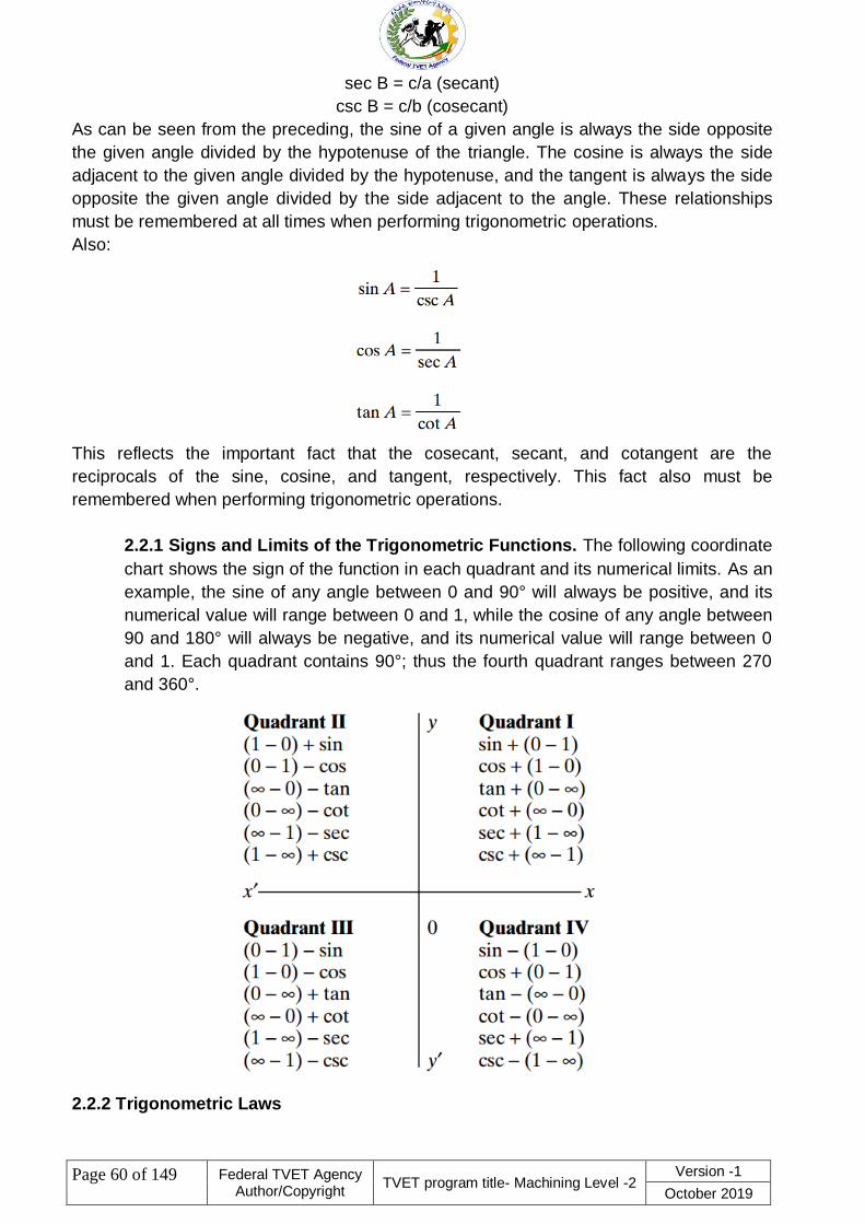
2.2 PLANE TRIGONOMETRY
There are six trigonometric functions: sine, cosine, tangent, cotangent, secant, and
cosecant. The relationships of the trigonometric functions are shown in Fig. 1.20.
Trigonometric functions shown for angle A (right-angled triangle) include
sin A = a/c (sine)
cos A = b/c (cosine)
tan A = a/b (tangent)
cot A = b/a (cotangent)
sec A = c/b (secant)
csc A = c/a (cosecant)
For angle B, the functions would become
(see Fig. 1.20)
sin B = b/c (sine)
cos B = a/c (cosine)
Fig 1. Right-angled triangle.
tan B = b/a (tangent)
cot B = a/b (cotangent)
Page 60 of 149
Federal TVET Agency Author/Copyright
TVET program title- Machining Level -2 Version -1
October 2019
sec B = c/a (secant)
csc B = c/b (cosecant)
As can be seen from the preceding, the sine of a given angle is always the side opposite
the given angle divided by the hypotenuse of the triangle. The cosine is always the side
adjacent to the given angle divided by the hypotenuse, and the tangent is always the side
opposite the given angle divided by the side adjacent to the angle. These relationships
must be remembered at all times when performing trigonometric operations.
Also:
This reflects the important fact that the cosecant, secant, and cotangent are the
reciprocals of the sine, cosine, and tangent, respectively. This fact also must be
remembered when performing trigonometric operations.
2.2.1 Signs and Limits of the Trigonometric Functions. The following coordinate
chart shows the sign of the function in each quadrant and its numerical limits. As an
example, the sine of any angle between 0 and 90° will always be positive, and its
numerical value will range between 0 and 1, while the cosine of any angle between
90 and 180° will always be negative, and its numerical value will range between 0
and 1. Each quadrant contains 90°; thus the fourth quadrant ranges between 270
and 360°.
2.2.2 Trigonometric Laws

Page 61 of 149
Federal TVET Agency Author/Copyright
TVET program title- Machining Level -2 Version -1
October 2019
The trigonometric laws show the relationships between the sides and angles of nonright-
angle triangles or oblique triangles and allow us to calculate the unknown
parts of the triangle when certain values are known. Refer to Fig. 1.21 for illustrations of
the trigonometric laws that follow.
Fig 2. Oblique triangle.
The Law of Sines.
The Law of Cosines
The Law of Tangents
With the preceding laws, the trigonometric functions for right-angled triangles, the
Pythagorean theorem, and the following triangle solution chart, it will be possible to
find the solution to any plane triangle problem, provided the correct parts are specified

Page 62 of 149
Federal TVET Agency Author/Copyright
TVET program title- Machining Level -2 Version -1
October 2019
Self-Check-2 Written test
Directions: choose the best answer for the following question (2 point each
1. An algebraic expression containing three terms is called a.
(a) monomial (b) binomial (c) trinomial (d) All of these
2. Which one of the following is numeric expressions. .
A, 5 + 13 B, 5 k + 4 B, C, 5 h D, ALL
3. Identify from the following variable expressions. .
A, 5 + 13 B, 5 k + 4 C, 2 × 5 –
4. When you solve math problems, you can use a letter or a symbol
to stand in for the number. The letter or symbol is called a .
A. Coefficient B. Variables C. Constant D. all
Note: Satisfactory rating - 4 points Unsatisfactory - below 4 points
You can ask you teacher for the copy of the correct answers

Page 63 of 149
Federal TVET Agency Author/Copyright
TVET program title- Machining Level -2 Version -1
October 2019
Operation Sheet -1 Perform trigonometric functions, algebraic
computations
Operation Sheet No. 1
Title: - trigonometric functions, algebraic computations
Purpose: - perform basic mathematical operations with emphasis in
Trigonometric Functions and algebraic computations
Materials/Tools/ Equipment Needed:
7. Students Guide
8. Paper
9. Pen
10. Mathematical tables
Activities: The trainees shall be able to:-
1. Illustrating the basic steps in solving and in presenting solutions of mathematical
problems
2. Multiplying, dividing, adding, and subtracting Trigonometric Functions
Performance Standard:
The student shall be able to perform basic mathematical operations with emphasis
in Trigonometric Functions.
Information:
Illustrating the Basic Steps in Solving and in Presenting Solutions of Mathematical
Problems
Basic Steps
1. Statement of the Problem
2. Comprehension
Read the text of the problem slowly and carefully and visualize the situation clearly. If
possible, make a sketch.
3. Framework
Write down neatly the values which have been given and which are to be found,
using symbols and dimensions.
4. Basic Equation
Relate the situation recognized to the relevant Basic Equation, Only then solve for the
required value.
5. Illustration
Notes:
Make sure that the calculation proceeds step by step. Formulate the answer — at least
in your head — as a complete sentence.
In addition it is a good idea to do a rough calculation before the final one. Besides this,
always check the dimensions by carrying and shortening the units of measurement.

Page 64 of 149
Federal TVET Agency Author/Copyright
TVET program title- Machining Level -2 Version -1
October 2019
Remarks:
The teacher shall always set a deadline for finishing a task. But fast students should be
given a chance to solve more calculation problems and in so doing acquire more
experience.
The teacher should act as a student‘s consultant, which is an active role. Thus, he shall
go around in the class, look at the students‘ solutions while they do them and give
advice.

Page 65 of 149
Federal TVET Agency Author/Copyright
TVET program title- Machining Level -2 Version -1
October 2019
Information Sheet-3 Self-check numerical computation
3.1 identify the terms of the algebraic expression.
3.2 identify the coefficient of the term.
3.3 identify the property of algebra that is illustrated by the
statement.
3.4 use the property to rewrite the expression

Page 66 of 149
Federal TVET Agency Author/Copyright
TVET program title- Machining Level -2 Version -1
October 2019
4 Sample Problems Using Trigonometry
4.1 Samples of Solutions to Triangles
Solving Right-Angled Triangles by Trigonometry. Required: Any one side and
angle A or angle B (see Fig. 1.). Solve for side a:

Page 67 of 149
Federal TVET Agency Author/Copyright
TVET program title- Machining Level -2 Version -1
October 2019
Fig 1.
Solve the triangle.
Solve for side b:
Then

Page 68 of 149
Federal TVET Agency Author/Copyright
TVET program title- Machining Level -2 Version -1
October 2019
We now know sides a, b, and c and angles A, B, and C.
Solving Non-Right-Angled Triangles Using the Trigonometric Laws. Solve the
triangle in Fig. 2. Given: Two angles and one side:
Fig 2.
Solve the triangle.
First, find angle C:
Second, find side b by the law of sines:
Therefore,
:
Third, find side c by the law of sines:

Page 69 of 149
Federal TVET Agency Author/Copyright
TVET program title- Machining Level -2 Version -1
October 2019
Therefore,
The solution to this triangle has been calculated as a b c
angle A B C
We now use the Mollweide equation to check the calculated answer by substituting the
parts into the equation and checking for a balance, which signifies equality
and the correct solution.
This
equality shows that the calculated solution to the triangle shown in Fig. 2. is
correct.
Solve the triangle in Fig. 3. Given: Two sides and one angle:

Page 70 of 149
Federal TVET Agency Author/Copyright
TVET program title- Machining Level -2 Version -1
October 2019
Fig 3.
Solve the triangle.
First, find angle B from the law of sines
Second, find angle C:

Page 71 of 149
Federal TVET Agency Author/Copyright
TVET program title- Machining Level -2 Version -1
October 2019
Third, find side c from the law of sines:
We may now find the altitude or height x of this triangle (see Fig. 3). Refer to Fig.
2. and text for the following equation for x.
This height x also can be found from the sine function of angle C′, when side a is

Page 72 of 149
Federal TVET Agency Author/Copyright
TVET program title- Machining Level -2 Version -1
October 2019
known, as shown here
3.4 Systems of measurement and conversion
3.4.1 Units of measurements
• This class addresses common units of measurement used in manufacturing and
explains how to convert from one unit of measurement to another
• Below are all the competencies and job programs that contain the class units of
measurement. Competencies are our latest job specific curricula that help to
practical, hands on task….
3.4.2 Definition of English System
• A standard system of measurements based on the inch, pound, and Fahrenheit
degrees.
• English measurements are primarily used in the United States and England.
3.4.3 Definition of Metric System
• A standard system of measurement based on the meter, kilogram. And celsius
degrees. The metric system is internationally recognized.
Identify the English and Metric
Metric System English System
Length meter inch, foot, mile
Mass gram ounce, pound, ton
Volume liter pint, quart, gallon
Power watt horsepower
Torque newton-meter pound-foot
Temperature degrees Celsius degree-fahrenheit

Page 73 of 149
Federal TVET Agency Author/Copyright
TVET program title- Machining Level -2 Version -1
October 2019
3.3.4 Convert Metric to English

Page 74 of 149
Federal TVET Agency Author/Copyright
TVET program title- Machining Level -2 Version -1
October 2019
Illustrating the Basic Steps in Solving and in
Converting Length Measurements
Measurement of length
Length
Length is the measurement of something from one end to the other end.
• The SI unit of length is meter (m) (base unit).
• other units include centimeters (cm), millimeters (mm) and kilometers (km
• One meter is the distance travelled by light in a vacuum in 1/299792458 of a
second.
Metric System
– used for scientific work in the United States
– Measurements are based on the meter
• 1 Meter = 100 centimeters (cm)
• 1 Meter = 1,000 millimeters (mm)
• 1000 Meters = a Kilometer (km)
• Units are in multiples of 10
• The unit is the meter. Subdivisions follow the decimal system.
Note: The conversion factor from one unit to another is ten — there is a ―jump of ten‖ from
one place unit to the next Sizes comparison Inch System
• English – standard measurement in the United States, now called U.S. Customary
System
– Uses, inch, foot, yard, rod and mile as units
– 12 inches in a foot
– 3 feet in a yard
– 16 ½ feet in a rod
– 5,280 foot in a mile
• Traditional unit for woodworking and metalworking

Page 75 of 149
Federal TVET Agency Author/Copyright
TVET program title- Machining Level -2 Version -1
October 2019
• Some fine rules or scales have 32 marks per inch.
• Most rules have 16 marks per inch with each mark equaling 1/16 of an inch.
The length unit ―inch‖, with its standard symbol ―in‖, is divided into 16 parts

Page 76 of 149
Federal TVET Agency Author/Copyright
TVET program title- Machining Level -2 Version -1
October 2019
Self-Check-3 Written test
Directions: choose the best answer for the following question (2 point each)
1. 5x + = + 5x
A. commutative property of addition
B. commutative property of multiplication
C. .associative property of addition
D. associative property of multiplication
2. (a+b)+c =a+(b+c)
A. commutative property of addition
B. commutative property of multiplication
C. associative property of addition
D. associative property of multiplication
3. Which one show distributive properties.
A.(ab)c=a(bc) B.(a+b)+c=a+(b+c)
C.a(b+c)=ab+ac D.a+b=b+a
Note: Satisfactory rating - 3 points Unsatisfactory - below 3 points
You can ask you teacher for the copy of the correct answers

Page 77 of 149
Federal TVET Agency Author/Copyright
TVET program title- Machining Level -2 Version -1
October 2019
Operation Sheet -2 numerical computation
Operation Sheet No. 2
Title: - Applications of Basic numerical computation
Purpose: - perform basic mathematical operations with emphasis in fractions.
Materials/Tools/ Equipment Needed:
4. Students Guide
5. Paper
6. Pen
7. Mathematical tables
Activities:
1. Illustrating the basic steps in solving and in presenting solutions
of mathematical problems
2. Multiplying, dividing, adding, and subtracting fractions
Performance Standard:
The student shall be able to perform basic mathematical operations with emphasis
in fractions.
Information:
Illustrating the Basic Steps in Solving and in Presenting Solutions of Mathematical
Problems
Basic Steps
4.1.1 Statement of the Problem
4.1.2 Comprehension
Read the text of the problem slowly and carefully and visualize the situation clearly. If
possible, make a sketch.
4.1.3 Framework
Write down neatly the values which have been given and which are to be found,
using symbols and dimensions.
4.1.4 Basic Equation
Relate the situation recognized to the relevant Basic Equation, Only then solve for the
required value.
4.1.5 Illustration
4.1.6 Solution of Problems
Notes:
Make sure that the calculation proceeds step by step. Formulate the answer — at least
in your head — as a complete sentence.
In addition it is a good idea to do a rough calculation before the final one. Besides this,
always check the dimensions by carrying and shortening the units of measurement.
Remarks:

Page 78 of 149
Federal TVET Agency Author/Copyright
TVET program title- Machining Level -2 Version -1
October 2019
The teacher shall always set a deadline for finishing a task. But fast students should be
given a chance to solve more calculation problems and in so doing acquire more
experience.
The teacher should act as a student‘s consultant, which is an active role. Thus, he shall
go around in the class, look at the students‘ solutions while they do them and give
advice.

Page 79 of 149
Federal TVET Agency Author/Copyright
TVET program title- Machining Level -2 Version -1
October 2019
Information Sheet-4 Construct where appropriate, formulae to
enable problems to be solved
MENSURATION
Mensuration is the mathematical name for calculating the areas, volumes, length of sides,
and other geometric parts of standard geometric shapes such as circles,
spheres, polygons, prisms, cylinders, cones, etc., through the use of mathematical
equations or formulas. Included here are the most frequently used and important
mensuration formulas for the common geometric figures, both plane and solid. (See
Figs. 4.1 through 4.35.)
Symbols
A area
a, b, etc. sides
A, B, C angles
h height perpendicular to base
b
L length of side or edge
r radius
n number of sides
C circumference
V volume
S surface area
Table -1
Fig 4.1. Oblique triangle.

Page 80 of 149
Federal TVET Agency Author/Copyright
TVET program title- Machining Level -2 Version -1
October 2019
Fig 4.2. Oblique triangle.
Fig 4.3.Rectangle
Fig 4.4. Parallelogram.
Fig 4.5. Rhombus

Page 81 of 149
Federal TVET Agency Author/Copyright
TVET program title- Machining Level -2 Version -1
October 2019
Fig 4.6. Trapezoid
MENSURATION OF PLANE AND SOLID FIGURES
Table -2 Polyhedral.
Fig 4.7. Trapezium
Fig 4.8. Regular polygon.

Page 82 of 149
Federal TVET Agency Author/Copyright
TVET program title- Machining Level -2 Version -1
October 2019
Fig 4.9.Inscribed circle.
Fig 4.10.Circumscribed circle.
Fig. 4.11.Inscribed polygon.
Fig 4.12. Polygon Circumscribed

Page 83 of 149
Federal TVET Agency Author/Copyright
TVET program title- Machining Level -2 Version -1
October 2019
Fig 4.13.Circle—circumference.
Fig 4.14. Circle—area.
Fig 4.15.Length of arc.

Page 84 of 149
Federal TVET Agency Author/Copyright
TVET program title- Machining Level -2 Version -1
October 2019
Fig 4.16. Chord and sector.
Fig 4.17. Segment of a circle.
Fig 4.18.Ring.
Fig 4.19.Ellipse

Page 85 of 149
Federal TVET Agency Author/Copyright
TVET program title- Machining Level -2 Version -1
October 2019
Fig 4.20.Pyramid.
Fig 4.21.Sphere.
Fig 4.22.Cylinder
Fig 4.23.Cone.

Page 86 of 149
Federal TVET Agency Author/Copyright
TVET program title- Machining Level -2 Version -1
October 2019
Fig 4.24.Spherical segment.
Fig 4.25.Frustum of a cone.
Fig 4.26.Truncated cylinder.
Fig 4.27.Spherical zone.

Page 87 of 149
Federal TVET Agency Author/Copyright
TVET program title- Machining Level -2 Version -1
October 2019
Fig 4.28.Spherical wedge.
Fig 4.29.Parabolic.
4.19. Fig 4.30. Spherical sector.
Fig 4.31.Spherical segment.
Fig 4.32.Torus.

Page 88 of 149
Federal TVET Agency Author/Copyright
TVET program title- Machining Level -2 Version -1
October 2019
Fig 4.33.Portion of a cylinder.
Fig 4.34.Special case of a cylinder.
Note. Use c c when base area is smaller than
half the base circle.
Fig 4.35.Wedge.

Page 89 of 149
Federal TVET Agency Author/Copyright
TVET program title- Machining Level -2 Version -1
October 2019
Self-Check-4 Written test
Directions: choose the best answer for the following question (2 point each)
1. Mensuration is the mathematical name of calculating the area, volumes,
length of sides and other geometric shapes.
A. True B. False
2. To find the area of rectangle and parallelogram A=ab
A. True B. False
3. Area of the ring between circles is:
A. A = π(R + r)(R - r) B. A = 1 r 2 (φ - sinφ)
2
C. A = πab D. none
4. The distance around a two dimensional shape, or the measurement of the
distance around something; the length of the boundary.
A. Area
B. Perimeter
C. Rhombus
D. Ellipse
5.In the area formulae of a circle, what does ―r‖ stand for.
A. Circumference
B. Area
C .Radius
D Length
Note: Satisfactory rating - 5 points Unsatisfactory - below 5 points
You can ask you teacher for the copy of the correct answers

Page 90 of 149
Federal TVET Agency Author/Copyright
TVET program title- Machining Level -2 Version -1
October 2019
Operation Sheet 3 appropriate, formulae
Operation Sheet No. 3
Title: - Applications of Basic appropriate, formulae
Purpose: - perform basic mathematical operations with emphasis in conversions.
Materials/Tools/ Equipment Needed:
11. Students Guide
12. Paper
13. Pen
14. Mathematical tables
Activities:
5 Solve problems on the applications the pythagoras‘ theorem;
6 Solve problems on the applications of shapes and circumference;
7 Solve problems on the applications of time and angular units;
8 Solve problems on the applications of trigonometric functions;
9 Solve problems on the applications of areas; and
10 Solve problems on the application of volumes.
Performance Standard:
The trainees should be able to solve problems concerning the applications of
trigonometry, areas, and volumes.
Information:
Illustrating the Basic Steps in Solving and in Presenting Solutions of Mathematical
Problems
Basic Steps
11. Statement of the Problem
12. Comprehension
Read the text of the problem slowly and carefully and visualize the situation clearly. If
possible, make a sketch.
10.1.1 Framework
Write down neatly the values which have been given and which are to be found,
using symbols and dimensions.
10.1.2 Basic Equation
Relate the situation recognized to the relevant Basic Equation, Only then solve for the
required value.
10.1.3 Illustration
10.1.4 Solve correctly the questions given the evaluation section of the lesson.
10.1.5 Solution of Problems.
Notes:
Make sure that the calculation proceeds step by step. Formulate the answer — at least
in your head — as a complete sentence.
In addition it is a good idea to do a rough calculation before the final one. Besides this,
always check the dimensions by carrying and shortening the units of measurement.

Page 91 of 149
Federal TVET Agency Author/Copyright
TVET program title- Machining Level -2 Version -1
October 2019
Remarks:
The emphasis in the lesson is the capability of the students to solve application
problems. It is therefore recommended that due attention should be given to the
exercises with the close supervision of the instructor. In mathematics, there is no
substitute for practice.
The teacher shall always set a deadline for finishing a task. But fast students should be
given a chance to solve more calculation problems and in so doing acquire more
experience.
The teacher should act as a student‘s consultant, which is an active role. Thus, he shall
go around in the class, look at the students‘ solutions while they do them and give
advice.
Summary:
Read – comprehend - sketch
Relate the situation to the basic equation

Page 92 of 149
Federal TVET Agency Author/Copyright
TVET program title- Machining Level -2 Version -1
October 2019
Information Sheet-5 Reading instruments
5.1 READING A VERNIER CALIPER To read a vernier caliper, you must understand both
the steel rule and vernier scales. The vernier scale is located on the sliding jaw of the
caliper. The steel rule scale is located on the caliper's long arm.
Understanding the Scales Figure 1, below, shows a portion of a typical steel rule scale.
The steel rule scale may be graduated by English or metric measure. English measure
uses inches. Metric measure uses centimeters and millimeters
Fig. 1.
THE STEEL RULE SCALE
Steel Rule Scale. Usually, the steel rule scale on a vernier caliper is in English
measure. The longest lines show the whole inch markings. Each inch is divided into
tenth inch parts which are numbered. Each tenth inch portion is divided into four
parts. Each of these parts equals 0.025 of an inch. Thus, the full inch is divided into
40 equal parts .The smallest graduation is 0.025 (1/40) of an inch etric Scale.
Sometimes the back side of a vernier caliper has a metric scale. When this is the
case, the steel rule is divided into centimeters (cm). Each full centimeter is divided
into ten parts. Each of these parts is equal to one millimeter (mm). There are ten
millimeters in one centimeter. The space between each millimeter mark is divided
into quarters, each of which is equal to 0.25mm. Vernier Scale. The vernier scale is
divided into 25 parts. These parts are numbered at the 0, 5, 10, 15, 20, and 25
marks. These 25 parts take up the same distance (length) as 24 parts on the steel
rule. The difference
between the width of one of the 25 spaces on the vernier scale and one of
the 24 spaces on the rule equals 1/1000 (0.001) of an inch. Relationship of the
Scales. Imagine that the tool is set so that the 0 line on the vernier scale lines up
exactly with the 0 line on the rule. The 0 lines are said to coincide. The line to the
right of the 0 on the vernier scale will differ from the line to the right of 0 on the rule
by 1/1000 (0.001) of an inch. The second line will differ by 2/1000 (0.002) of an
inch. The difference will keep increasing by 1/1000 of an inch for each division until

Page 93 of 149
Federal TVET Agency Author/Copyright
TVET program title- Machining Level -2 Version -1
October 2019
vernier line 25 coincides with rule line 24. Using this relation, the vernier scale can
be used to measure fractional parts of the 1/40 (0.025) inch spaces on the rule.
Reading a Standard Vernier Caliper: Example 1 Let's look at two examples of
how the relationship of the scales works in an actual measurement. Figure 2, on the
next page, shows one example of a scale setting on a vernier caliper. To read this
measurement, use the following steps:
Step 1.
Read the number of whole inches on the top (rule) scale to the left of the vernier zero.
Record this number. In this example, you would record 2.000 inches.
Step 2.
Next, read the number of tenths to the left of the vernier zero. In this case, that number is
three tenths of an inch. Record it as 0.300 inch. You now know how many whole and how
many tenths inches the measurement is. In this example, you have 2.000 inches plus
0.300 inch, equaling 2.300 inches.
Step 3.
Remember, each tenth inch is divided into four parts. Each of these parts equals 0.025
inch. Read how many of these 0.025 inch parts are between the tenths mark you recorded
and the zero on the vernier scale. In the example shown in figure 2, there are two of these
0.025 inch parts. Therefore, multiply 2 times 0.025 inch. This equals 0.05 inch. Add this
amount to the 2.300 inches you already have. The total now equals 2.350 inches
Figure 2
READING A VERNIER CALIPER - EXAMPLE 1
Step 4.
For the last part of the reading, find the line on the vernier scale which exactly coincides
with a line on the rule. In the example shown in figure 6, the coinciding vernier line is zero.
Therefore, there is no fractional part of a 0.025 inch space to calculate. The exact reading
for this sample is 2.350 inches. Reading a Standard Vernier Caliper: Example 2
Now let's look at another sample reading. Figure 7, on the next page, shows a scale

Page 94 of 149
Federal TVET Agency Author/Copyright
TVET program title- Machining Level -2 Version -1
October 2019
setting that is almost the same as the one we saw in figure 2. In fact, the first readings will
be identical, as shown below:
Step 1. The number of whole inches to the left of the vernier scale zero is 2.000 inches.
Step 2. The number of tenths inches to the left of the vernier zero is 3, equaling 0.300
inch.
Step 3. Two whole 0.025 spaces lie between the 3 tenths mark and the vernier zero. Thus,
2 times 0.25 inch equals 0.050 inch. The total reading so far is 2.000 inches plus 0.300
inch, plus 0.050 inch. This equals 2.350 inches. In this sample, however, the vernier zero
does not exactly coincide with a line on the rule scale. The total reading will be 2.350
inches plus a fraction of a space on the rule.
Fig .3
READING A VERNIER CALIPER - EXAMPLE 2
Step 4. To interpret the rest of the reading, find the line on the vernier scale that exactly
coincides with a line on the rule scale. In the sample shown in figure 3, the vernier line 18
exactly coincides with a line on the rule scale. This tells you that 18/25 of a whole space
must be added to the measurement. Remember that 1/25 of a space equals 0.001 inch.
Therefore, 18/25 of a space equals 0.018 inch. Calculate the total reading by adding 2.350
inches and 0.018 inch. The sum is 2.368 inches this is the exact measurement reading
shown in figure 3. Reading a Metric Vernier Caliper The standard vernier caliper you just
learned to read uses the English measurement scales (inches). Some calipers have a
metric scale on the back side. Therefore, you must also know how to interpret readings
from a metric vernier caliper. The methods used to interpret a reading from a metric scale
on a vernier caliper are nearly the same as those you just learned. The only difference is
that you are working in centimeters and millimeters instead of inches. Assume that the
scales shown in figure 7 (on the previous page) are metric. You would interpret the
reading as follows:
Step 1. The number of whole centimeters (cm) to the left of the vernier zero equals
2.000cm. Each centimeter equals 10 millimeters. Therefore, the reading in millimeters
(mm) is 20.000mm.

Page 95 of 149
Federal TVET Agency Author/Copyright
TVET program title- Machining Level -2 Version -1
October 2019
Step 2. The number of millimeters (mm) to the left of the vernier zero equals 3mm. The
total reading so far is 20.000mm plus 3mm, or 23.000mm. Step 3. Read the number of
0.25mm spaces between the 3 millimeter mark and the vernier zero. There are two of
these spaces, equaling 2 times 0.25mm, or 0.50mm. Added to the previous amount, the
total reading so far is23.50mm.
Step 4. Read the highest line on the vernier scale which lines up exactly with the line on
the rule scale. This is line 18. Multiply 18 times 0.01mm. This equals 0.18mm. Add
0.18mm to 23.500mm to get the exact total reading of 23.68mm.
Reading Inside Measurements with a Vernier Caliper The jaws of a vernier caliper are
shaped so that you can use the tool to make inside measurements. On most vernier
calipers, the back side reads "INSIDE." When this is the case, the scale positions on that
side of the caliper are set to adjust for the thickness of the jaw tips. Read the scales on the
side of the caliper marked "INSIDE" just as you would for an outside measurement.
Sometimes the scale isn't marked. If the scale isn't marked, measure an inside length
using the caliper side normally used for outside. Read the scales as you would for an
outside reading. Then add the measuring point allowance (the thickness of the tips) to
your reading. This point allowance can be found in the manufacturer's instructions. Or you
can use table 1, below:
5.2 READING A MICROMETER Interpreting a reading of a micrometer measurement is
much like reading a vernier caliper. To read a micrometer, you compare the positions of
two scales. The scales on an outside micrometer and a depth micrometer work the same.
If you learn to read one, you will know how to read the other. The only calculation
difference will be the way you count the size (range) of the outside micrometer used or the
length of extension rod used on a depth micrometer. First, let's learn how the scales work.
Understanding Standard Micrometer Scales Again, you must understand how the scales
work before you can interpret a reading. The scales on standard and metric micrometers
both work on the same idea. However, the meaning of the graduation lines changes. To
understand how the scales work, we will use the standard micrometer as an example. On
a standard micrometer, one scale is on the barrel. The other scale is on the thimble. The
scale on the barrel is fixed. It does not move. The scale on the thimble moves along the
barrel scale (figure 4, below).

Page 96 of 149
Federal TVET Agency Author/Copyright
TVET program title- Machining Level -2 Version -1
October 2019
figure 4
MICROMETER SCALES
The lines on the barrel scale stand for full turns of the thimble, and therefore of the
micrometer screw. The thimble edge moves one line along the barrel scale for every full
turn (revolution) of the thimble.
On a standard micrometer, the measurement is in inches. Each line on the barrel scale
equals 1/40 (0.025) of an inch. For each revolution, the micrometer screw moves forward
or back 1/40 (0.025 of an inch). On an outside micrometer, this means that the screw
moves the spindle away from or toward the anvil exactly 1/40 (0.025) of an inch for every
full turn. The full length of the barrel scale represents one inch of micrometer screw
movement forward or back. The long horizontal line on the barrel is called the revolution
line. It is divided into the 40 parts which make up the barrel scale. Each line on the barrel
scale equals 1/40 (0.025) of an inch of screw movement. Every fourth line is numbered 1,
2, 3, and so forth. Each numbered line equals 1/10 (0.10) of an inch of screw movement.
Thimble Scale. The thimble scale moves along the barrel scale. The beveled edge of the
thimble is divided into 25 equal parts. As the thimble is turned, each line of the thimble
scale will, in turn, line up with the revolution line on the barrel. Each line on the thimble
scale stands for 1/1000 (0.001) of an inch of screw movement. Every fifth line on the
thimble is numbered (5, 10, 15, etc.). One complete and exact revolution of the thimble
equals 25/1000, or 1/40 (0.025) of an inch.
Reading a Standard Micrometer Once you understand how the scales work, it is not hard
to read the micrometer.
Just follow these steps:
Step 1.
First, check where the thimble edge is on the barrel scale. Read the highest figure visible
on the barrel. In figure 4, on the previous page, this number is 2. Therefore, you know that
the micrometer screw has moved more than 2/10 (0.20) of an inch.

Page 97 of 149
Federal TVET Agency Author/Copyright
TVET program title- Machining Level -2 Version -1
October 2019
Step 2.
Count the number of lines you can see between the number you just read (in this case, 2)
and the thimble edge. In the sample in figure 4, you can see only one line. Each line
stands for 0.025 inch. Add what you have so far. In this case, you should get (0.20 inch +
0.025 inches) a total of 0.225 inch. You now know that the screw has moved more than
0.225 inch.
Step 3.
Now, look at the thimble scale. Find the line on the thimble scale that lines up with or has
passed the revolution line in the barrel. In figure 8, this line is number 16 on the thimble
scale. Each thimble scale line stands for 0.001 inch, so 16 of these equal 0.016 inch. Add
this (0.016 inch) to what you have so far (0.225 inch) and the total measurement is 0.241
inch.
Reading a Vernier Micrometer A vernier micrometer is just like a standard micrometer
except that it has a second scale on the barrel (figure 5, below). This second scale is a
vernier scale. With the vernier scale added, the micrometer can be accurate to ten-
thousandths (0.0001) of an inch. Use of the vernier scale gives the fine readings between
the lines on the thimble. Without the vernier scale, you would have to estimate a ten-
thousandth reading.
Fig. 5
VERNIER MICROMETER SCALES.
This vernier scale is divided into ten spaces. The ten spaces on the vernier scale
take up the same length as nine spaces on the thimble scale. Each unit on the vernier
scale equals 0.0009 inch. The size difference between the units on each scale is 0.0001
inch. You read the vernier micrometer the same as you read a standard one. However,
you must take one more step. This step adds the vernier reading to the total size. Figure 6,
below, shows the relationship of the barrel, thimble, and vernier scales. We will use this
figure as a sample. To read the measurement shown in figure 10, Use these steps:
Step 1.
Read the highest figure showing on the barrel. In this case, that figure is 2. A 2 showing on
the barrel means 0.200 inch.

Page 98 of 149
Federal TVET Agency Author/Copyright
TVET program title- Machining Level -2 Version -1
October 2019
Fig 6
5.2.1 READING A VERNIER MICROMETER
Step 2.
Count the number of lines showing between the number you read (in this case 2) and the
thimble edge . The sample in figure 6 has 3 lines showing. Each line stands for 0.025 inch.
Therefore, 3 times 0.025 inch equals 0.075 inch. Add 0.075 inch to 0.200 inch.The sub
total is 0.275inch.
Step 3. Find the thimble scale line that lines up with or has passed the revolution line.For
the setting in figure 10, the thimble scale line is 11. Each thimble line equals 0.001 inch, so
11 of them equal 0.011 inch. Add this (0.011 inch) to 0.275 inch to get 0.286 inch
Step 4.
So far, the reading is the same as it would have been on a standard micrometer. Now,
however, you can use the vernier scale to get even greater accuracy. Find the line on the
vernier scale that coincides (exactly lines up with) a line on the thimble. In figure 10,
vernier scale line 2 coincides with a thimble scale line. Each line on the vernier scale
stands for 0.0001 inch. Therefore, 2 vernier lines equal 0.0002 inch. Add this amount to
the subtotal 0.286 inch. The result is 0.2862 inch. This is the exact size measured to the
nearest 0.0001 of aninch. Understanding the Scales on a Metric Micrometer The metric
micrometer uses the same scale/screw movement principle as the standard micrometer.
However, the meaning of the lines on the barrel and thimble scales changes. On a metric
micrometer, each full thimble turn moves the screw 0.5 millimeter (mm). The lines on the
barrel scale (figure 7, below) read in millimeters, from 0 to 25. It takes two full thimble
revolutions to move the screw 1.0mm

Page 99 of 149
Federal TVET Agency Author/Copyright
TVET program title- Machining Level -2 Version -1
October 2019
Fig.7
READING A METRIC MICROMETER
The thimble scale has 50 lines. Every fifth line is numbered. As you turn the thimble, each
thimble line passes the revolution line on the barrel. A turn equal to one thimble line moves
the micrometer screw 1/50 of 0.5mm, or 1/100mm. Two thimble lines equal 2/100mm, and
so forth Reading a Metric Micrometer Read a metric micrometer much like you read a
standard one. Remember, it takes two full turns for the thimble edge to move one full
space (one millimeter) on the barrel scale. To read the metric micrometer shown in figure
7 (on the previous page), use these steps:
Step 1. Read the highest number you can see on the barrel. In figure 7, the number is 20.
This equals 20.0mm. Record this number.
Step 2. Count the number of lines you can see between the number 20 (the highest
number you could see on the barrel) and the thimble edge. Each of these lines equals
1.0mm. In this case there are two lines. Two times 1.0mm equals 2.0mm. Add 2.0mm to
20.0mm, and the reading so far is 22.0mm.
Step 3. Find the thimble line that lines up exactly (coincides) with or has passed the
revolution line (long line) on the barrel. In figure 7, this line is 36. Because each line on the
thimble equals 0.01mm, 36 lines equals 0.36mm. Add this value to 22.0mm to arrive at the
total measurement reading of 22.36mm.
NOTE
When finding the value for step 3 above, remember that each full turn of the thimble is
equal to only 0.5mm. It takes two full turns of the thimble to move the spindle one whole
millimeter. You found the number 36 in step 3 by assuming that the thimble was on its
first turn. This was true because the thimble edge nearly touched the barrel mark. If the
thimble was on its second turn, the edge would be away from the barrel line. In that case,
the reading would have been 86 (50 + 36). The Effects of Outside Micrometer Size
(Range) on a Reading Remember that the total movement between the anvil and spindle
on an outside micrometer is only one inch. To make readings on items of various sizes,
you must choose the right size outside micrometer. When you interpret the reading you

Page 100 of 149
Federal TVET Agency Author/Copyright
TVET program title- Machining Level -2 Version -1
October 2019
take with an outside micrometer, you must consider the size of micrometer you are using.
The size of outside micrometer you are using tells you the biggest distance that you can
measure with that micrometer. A two inch micrometer has a range between one and two
inches. That means that it will only measure items that are between one and two inches in
size. The biggest measurement reading you can get with this micrometer is two inches. A
three inch micrometer has a range from 2 to 3 inches. It will measure items that are
between 2 and 3 inches in size. The biggest
measurement you can make with a three inch micrometer is 3 inches. Let's use a three
inch outside micrometer as an example. To interpret the reading of a measurement you
might take with a three inch micrometer, use these steps:
Step 1. Because it is a three inch micrometer, it will measure items between 2 and 3
inches in size. This tells you that the size of the item you are measuring is at least 2
inches; however, itcan't be more than 3 inches. Therefore, the first number you record is
2.0 inches. You will find out how much bigger than 2.0 inches the size is by reading the
micrometer scales.
Step 2. You read the scales exactly as you did before. First read the highest figure you
can see on the barrel. Remember, each number on the barrel equals 0.1 inch. For
example, if the number you see is 2, you would multiply 2 times 0.1 inch. The result is 0.2
inch. record 0.2 inch. Add 0.2 inch to 2.0 inches. The reading so far is 2.2 inches.
Step 3. Count the number of lines you can see between the highest figure
seen on the barrel and the edge of the thimble. Remember, each of these lines equals
0.025 inch. For the current example, assume that you can see three lines. You would
multiply 3 times 0.025 inch. The value is 0.075 inch. Add 0.075 inch to the 2.2 inches
recorded from step 2. The subtotal for this example (2.2 inches + 0.075 inch) equals
2.275.
Step 4. Find the line on the thimble that coincides with or has passed the
revolution line (long line) on the barrel. Assume that this line on the thimble is 24. Each
thimble line is equal to 0.001 inch. Multiply 0.001 inch by 24. You should get 0.024 inch.
Add this to the subtotal from step 3 (2.275 inches). Your grand total for the measurement
should be2.299 inches (2.275 inches + 0.024 inch). As you can see, the size of outside
micrometer you are using will add whole inch values to your final reading. The outside
micrometer size tells you the biggest reading you can get by using that micrometer. The
Effects of a Depth Micrometer Extension Rod on a Reading Just as the size of outside
micrometer effected your measurement reading, the size of the extension rod you select
for your depth micrometer will have an effect. However, the kind of effect it has is slightly
different. The outside micrometer size told you the biggest reading you could get with that
micrometer. The size of the extension rod you choose for your depth micrometer tells you
the smallest distance it will span. Using this knowledge as a guide, the first number you
should record for a measurement reading taken with a depth micrometer is the size of the
extension rod. For example, suppose your are taking a measurement using a depth
micrometer with a 5 inch extension rod. The first number you should record is 5.0 inches.

Page 101 of 149
Federal TVET Agency Author/Copyright
TVET program title- Machining Level -2 Version -1
October 2019
Then read the micrometer scales just as .you would for any micrometer measurement.
Suppose the scales read 0.294 inch. Add this number to the 5.0 inches you have already
recorded. The total depth measurement would be 5.294 inches.
5.2.2CONCLUSION
This task has shown you how the scales on a vernier caliper and on a micrometer work.
You have learned how to interpret the readings of these scales to come up with accurate
measurements. Now you must learn how to actually use the tools to make precision
measurements. Task 3 will show you the techniques for using these tools.
5.2.3 CHOOSING THE RIGHT MEASURING TOOL Which tool you select to take a
measurement depends on the type of measurement you are taking and the accuracy you
need. When taking inside and outside measurements, you can use either a vernier caliper
or a micrometer (inside or outside). For depth measurements, you will be able to select
from several depth instruments. There are advantages and disadvantages to each type of
tool. Inside and Outside Measurements You can make inside or outside precision
measurements with either a vernier caliper or with a micrometer (inside or outside).
Vernier calipers tend to be more adaptable than micrometers. Micrometers, however, are
more accurate. You can use the vernier caliper for many different kinds of measurements.
You can use this one tool for both inside and outside measurements. Because of the
shape of the jaws and their position with respect to the scale, the vernier caliper is more
adaptable than a micrometer. However, the vernier caliper is not as accurate as a
micrometer. If you need a very precise measurement, use a micrometer. A micrometer is
more reliable and more accurate than a caliper.
Vernier Caliper. You may decide a vernier caliper is best for the measurement you are
making. If this is so, you must choose a vernier caliper in a size that is larger than the
measurement you want to make. Vernier calipers come in 6, 12, 24, and 36 inch sizes.
Standard metric sizes are 150mm, 300mm, and 600mm. Remember that vernier calipers
are not as accurate as micrometers. However, you can rely on given standards of
accuracy from a well maintained caliper. If you check any one inch of its length, the caliper
should be accurate within 0.001 inch. In any 12 inches, you should obtain accuracy within
0.002 inches. At most, this amount of inaccuracy should only increase by about 0.001 inch
for each additional 12 inches
5.2.4Inside Micrometers. You may choose to use an inside micrometer to make an inside
measurement. This sub course will not show you the specific techniques for using an
inside micrometer. We will, however, take a brief look at how to select the right inside
micrometer extension rod You must choose an inside micrometer (figure 8, below) with a
range that includes the approximate size you want to measure. This means you must
consider the size of the micrometer unit, the range of its screw, and the length of the
extension rods available. The smallest size you can check is equal to the size of the
micrometer unit with its screw set to zero and its shortest anvil in place. The average
inside micrometer set has a range from 2 to 10 inches. You use extension rods to cover
the steps (by 1 inch increments) of this range. The micrometer set may also have a collar.

Page 102 of 149
Federal TVET Agency Author/Copyright
TVET program title- Machining Level -2 Version -1
October 2019
This collar is 0.5 inch long. It is used for splitting the inch step between two rods. The
collar extends a rod another 0.5 inch. This allows the range of each step to overlap the
next
Fig 8
CHOOSING AN INSIDE MICROMETER.
The range of the micrometer screw itself is very short. The smallest models have a 0.25
inch screw. Average models have a 0.5 inch screw. The largest inside micrometers have
only a 1 inchscrew. There are several things to consider if you want to properly choose an
inside micrometer to make a measurement. First you must estimate the inside
measurement you want to make. This estimate should be within the range of the
micrometer screw. The size of the extension rod you need depends on the size and range
of the inside micrometer. With the inside micrometer screw set to zero, you will fit an
extension rod to the micrometer. If you choose the right extension rod, the total length of
the micrometer and rod will be less than (but within the micrometer screw range of) the
estimated distance to be measured.
Depth Measurements You can use a depth micrometer to get very accurate
depth measurements. Two other types of measuring tools are available for depth
measurements. One of these is the rule depth gage; the other is the vernier
depth gage. Although you will only learn how to use a depth micrometer in this
sub course, we will describe the other two depth gages briefly . This is so that
you can be familiar with the tools that might be available to you in the shop. If you
want to learn more about using the rule depth gage or a vernier depth gage, look
in TM 9-243. Rule Depth Gage. The rule depth gage (figure 13, on the next page)
is a graduated rule. You may use it to measure the depth of holes, slots, counter
bores, and recesses. This gage has a sliding head designed to bridge a hole or
slot. The head holds the rule perpendicular to the surface from which you are me
The rule depth gage has a range of zero to five inches. The sliding head has a
clamping screw so that it can be clamped in any position. The sliding head is flat.
It is perpendicular to the axis of the rule. The head ranges in size from 2 to 2 5/8
inches wide and from 1/8 to 1/4 inch thick.
5.2.5 Depth Micrometer. The depth micrometer has a flat base attached to the barrel of a
micrometer head. It usually has a range from zero to nine inches. Its range depends on
the length of extension rod used. The hollow micrometer screw itself has a range of either
1/2 inch or 1 inch. The size of the flat base from 2 to 6 inches. The depth micrometer can
enter a hole only 3/32 of an inch in diameter.

Page 103 of 149
Federal TVET Agency Author/Copyright
TVET program title- Machining Level -2 Version -1
October 2019
Vernier Depth Gage. The vernier depth gage (figure 9, on the next page) consists of a
scale and a sliding head. The scale is either 6 or 12 inches long. The sliding head is a lot
like the one on a vernier caliper. This head is specially designed to bridge holes and slots.
.
Fig .9
CHOOSING A RULE DEPTH GAGE
Fig 10
CHOOSING A VERNIER DEPTH GAGE
You can use a vernier The vernier depth gage has the range of the rule depth gage. It is
not quite as accurate as a depth micrometer. It cannot enter holes that are less than 1/4
inch in diameter. The depth micrometer is able to enter holes that have a 3/32 inch
diameter. However, the vernier depth gage will enter a 1/32 inch slot, while the depth
micrometer cannot. Selecting the proper tool for a measurement is important. It will help

Page 104 of 149
Federal TVET Agency Author/Copyright
TVET program title- Machining Level -2 Version -1
October 2019
you get the best measurement with the least amount of trouble. After you select a tool, you
must know how to use it properly. First we will look at how to use a vernier cal USING A
VERNIER CALIPER Vernier calipers work a lot like slide calipers. caliper to make a very
accurate outside measurement (figure 11, below). You can also use it to make an inside
measurement (figure 12, on the next page). To make an accurate measurement, you must
not only know how to operate the caliper, but how to use the right amount of pressure.
Fig 11
USING A VERNIER CALIPER TO MAKE
AN OUTSIDE MEASUREMENT
Operating the Vernier Caliper To use a vernier caliper, first loosen both locking screws.
This will allow you to move the sliding jaw along the rule. Hold the fixed jaw in one hand,
and move the sliding jaw with your other hand. When the jaws are in the position you
want, secure the sliding jaw. Do this by tightening the locking screw above the adjustment
control. Use the adjustment control to make any needed fine adjustments to the vernier
scale. Tighten the second locking screw. If you are using the right amount of measuring
pressure, you can now read an accurate measurement on the vernier caliper.

Page 105 of 149
Federal TVET Agency Author/Copyright
TVET program title- Machining Level -2 Version -1
October 2019
Fig 12
USING A VERNIER CALIPER TO MAKE
AN INSIDE MEASUREMENT
Using the Right Pressure You will not get an accurate measurement with a vernier caliper
unless you use the right amount of measuring pressure. If you use too much pressure, you
might get a wrong reading because of play in the sliding jaw. Too little pressure can also
result in the wrong reading. To get the right amount of pressure, you must be able to "feel"
the measurement. The jaws of the caliper are long, and there can be some play in the
sliding jaw, especially if you use too much pressure. This can cause inaccurate
measurements. Therefore, you must develop the ability to handle the caliper. One way to
do this is to practice by using the caliper to measure known standards. You might try
measuring gage blocks or gage plugs until you consistently get accurate readings.
5.2.6 USING AN OUTSIDE MICROMETER
If you choose an outside micrometer instead of a vernier caliper, you will also get accurate
readings of outside dimensions. Just as with the vernier caliper, the technique you use will
effect the accuracy of your measurement.
Measuring Small Parts Figure 13, below, shows how you should hold your hands when
you use an outside micrometer to measure a small part. You should hold the part in one
hand; hold the micrometer in the other hand. Hold the micrometer so that the thimble rests
between your thumb and your forefinger. From this position, you can use your third finger
to hold the frame against the palm of your hand. If you support the frame this way, it will be
easy to guide the part you are measuring over the anvil. Your thumb and forefinger are in
a position to turn the thimble so that the spindle will move over against the part.

Page 106 of 149
Federal TVET Agency Author/Copyright
TVET program title- Machining Level -2 Version -1
October 2019
Fig 13
MEASURING A SMALL PART USING
AN OUTSIDE MICROMETER
Measuring Larger Work
When you measure larger work, you must hold the workpiece still, in a position where you
can get at it with the micrometer. When you check a part too large to be held in one hand,
you should use the method shown in figure 14, on the next page. Hold the frame in one
hand to position it and to locate it square to the measured surface. Use your other hand to
turn the thimble. A large, flat part should be checked in several places. This will tell you
how much variation there is in the thickness of the part

Page 107 of 149
Federal TVET Agency Author/Copyright
TVET program title- Machining Level -2 Version -1
October 2019
Fig 14
USING AN OUTSIDE MICROMETER TO
MEASURE LARGER WORK
Techniques for Gaging a Shaft The hand positions you should use when gaging a shaft
are shown in figure 15, on the next page. You hold the frame in one hand while turning the
thimble with the other hand. When you gage a cylindrical part with a micrometer, you must
be able to ―feel" the setting. This is the only way you can be sure that the spindle is on the
diameter. You must also check the diameter in several places to determine the out-of-
roundness of the shaft.
Measuring Very Large Diameters
When you need to measure very large diameters, you may need to screw a special anvil
to the frame of a micrometer. Outside micrometers are made in various sizes up to 168
inches. You can reduce the range of one of these micrometers by using a special anvil. A
set of different length anvils lets you use a large micrometer over a wide range of sizes
even though the spindle only moves one inch.

Page 108 of 149
Federal TVET Agency Author/Copyright
TVET program title- Machining Level -2 Version -1
October 2019
Fig 15
USING AN OUTSIDE MICROMETER
TO GAGE A SHAFT
USING A DEPTH MICROMETER
When using a vernier caliper and an outside micrometer, you used special
hand positions and techniques to get accurate measurements. The depth micrometer also
requires special hand positions. Figure 16, on the next page, shows a depth micrometer
being used to measure a projection. Look at the hand positions. You will use one hand to
hold the flat base firmly against the measuring surface. In the other hand, you will hold the
depth micrometer so that you can turn the thimble with the thumb and forefinger. When
you use a depth micrometer, you must remember to select the proper extension rod. The
rod you choose should be less than one inch shorter than your estimate of the
measurement. For example, if you estimate that the measurement will be 4 1/4 inches,
you should set the screw to zero and then fit a 4 inch extension rod to the micrometer. The
one inch movement of the micrometer screw allows accurate measurement of the
remaining distance

Page 109 of 149
Federal TVET Agency Author/Copyright
TVET program title- Machining Level -2 Version -1
October 2019
Fig 16
USING A DEPTH MICROMETER
5.3CONCLUSION
You should now be able to select the right tool for the measurement you want to make.
After selecting either a vernier caliper, an outside micrometer, or a depth micrometer, you
should be able to use the techniques needed to get an accurate measurement. With the
chosen tool in place, you will be able to read its scales accurately. You also now know
how to properly care for one of these tools after you use it. Before you take the
examination, try the practice exercise on the next page. It will help you check what you
have learned about these three tools
1.4 .1 Try-square and Protractor, Telescopic gauge, Dial gauge.
Try Square: Care should be taken to ensure that its blade is perpendicular to the surface being
tested
Fig. 17

Page 110 of 149
Federal TVET Agency Author/Copyright
TVET program title- Machining Level -2 Version -1
October 2019
Fig.18
Fig .19
5.4.2 Telescopic gauge
Used to measure inside cylinders.
Allow ―T‖ gauge to extend to inside opening
Lock shaft
Measure with micrometer

Page 111 of 149
Federal TVET Agency Author/Copyright
TVET program title- Machining Level -2 Version -1
October 2019
Fig.20
5.4.3 Dial Indicators: The dial indicators or dial gauges are generally
used for testing flatness of surfaces and parallelism of bars and
rods. They are also used for testing the machine tools.
Fig.21
5.5 Ammeter, Voltmeter and Mega-Ohmmeter
5.5.1 Ammeter:
Measures current (A)
connected in series (current must go through instrument)
5.5.2 5.5.2 Voltmeter:
measures potential difference (V)
connected in parallel
5.5.3 Ohmmeter:

Page 112 of 149
Federal TVET Agency Author/Copyright
TVET program title- Machining Level -2 Version -1
October 2019
measures resistance of an isolated
resistor (not in a working circuit)
Effect of Ammeter on circuit
Measuring current in a simple circuit: connect ammeter in series
Are we measuring the correct current? (The current in the circuit without ammeter)
Measuring current in a simple circuit: connect ammeter in series
Are we measuring the correct current? (The current in the circuit without ammeter)
Any ammeter has some resistance r.
current in presence of ammeter is
current without the ammeter would be
Actual current without ammeter

Page 113 of 149
Federal TVET Agency Author/Copyright
TVET program title- Machining Level -2 Version -1
October 2019
5.5 PROTRACTOR
The measuring instruments used to measure the angle of the work pieces. There are two
types of protractor. These are:
A. Plain bevel protractor B. Vernier protractor
B.
5.5.1 Plain bevel protractor: is one of the common protractors used in general mechanic
work shop. It made from tool steel, hardened & tempered. The tool has two parts, these
are
A. Protractor, which is graduated in degrees from 0 degree to 90 degree on either
side of the 90 degree mark.
B. A blade, which is longer & held on to the protractor by a knurled lock nut.
-The blade can be set at a various angles. The plain bevel protractor has an
accuracy of degree, & hence it is not convenient for accurate (precision)
work
Fig . 22 plain bevel protractor.

Page 114 of 149
Federal TVET Agency Author/Copyright
TVET program title- Machining Level -2 Version -1
October 2019
5.5.2 Vernier protractor: is another type of measuring instruments which is fitted to the
vernier scale enabling angles to read to within 5 minutes of arc. This protractor is used to
measure angle from 0 degree to 10 8 degree. It consists of:
A. A Protractor dial graduated in degrees
B. A base with a vernier scale attached
C. A sliding blade which can be extended & set in all direction
Fig. 23
READING THE VERNIER PROTRACTOR
A. Read the number of whole degree between the zero on the main scale & zero on
the vernier scale.
B. Count the number of division of spaces from zero on the vernier scale to the point
where a vernier line coincides with a line on the main scale
C. Multiply this number by five (each division on the vernier represents 5minutes).then
add to the whole number of degrees
E.g From the figure, we get the following results,
D. The number of whole degree is 60 degree
The coinciding mark of the vernier scale & main scale is on the fourth line
which is 4 x 5 minute = 20 minute. Therefore the reading is 60 degree, 20
minute
Fig.24 THICKNESS GAUGE

Page 115 of 149
Federal TVET Agency Author/Copyright
TVET program title- Machining Level -2 Version -1
October 2019
Code Range Accuracy Type Graduation
2366-30 0-30mm A ±0.035mm 0.01mm
2366-30B 0-30mm B ±0.035mm 0.01mm
STRAIGHT EDGE
Check flatness and straightness, as well as for marking Graduation on the beveled edge
Made o f hardened tool steel Chrome plated
Code Size(L) W H Straightness
50mm 4700-50 5 20 2.2µm
75mm 4700-75 5 25 2.3µm
100mm 4700-100 5 25 2.4µm
125mm 4700-125 5 25 2.5µm
150mm 4700-150 6 30 2.6µm
200mm 4700-200 6 30 2.8µm
250mm 4700-250 8 40 3.0µm
300mm 4700-300 8 40 3.2µm
400mm 4700-400 10 50 3.6µm
500mm 4700-500 10 50 4.0µm

Page 116 of 149
Federal TVET Agency Author/Copyright
TVET program title- Machining Level -2 Version -1
October 2019
(mm)
Fig .25
CENTER MARKING GAUGE
Marking the center of round plates and shafts
Made of stainless steel
Satin chrome plated

Page 117 of 149
Federal TVET Agency Author/Copyright
TVET program title- Machining Level -2 Version -1
October 2019
Fig.26

Page 118 of 149
Federal TVET Agency Author/Copyright
TVET program title- Machining Level -2 Version -1
October 2019
Self-Check-5 Reading instruments
Directions: choose the best answer for the following question (2 point each)
1. You measure the outside of the pipe with the vernier caliper. You hold
the fixed jaw of the caliper in one hand what do you hold in the other hand?
A.Thimbel B. The sliding jaw C. The locking nuts D. fixed jaw
2. You measure the outside of the pipe with the vernier caliper. You hold
the fixed jaw of the caliper in one hand What must be loosened so that the sliding jaw will
move?
A. The locking nuts B. . fixed jaw C. sliding jaw D. None
3. You measure the outside of the pipe with the vernier caliper. You hold
the fixed jaw of the caliper in one hand what can happen if you use too much pressure
during the measurement?
A. You may get inaccurate measurements B. You may get accurate measurements
C. You may unable to read D. All
4. What part of the caliper is used to make fine adjustments after the
caliper is in place?
A. The locking nuts B. sliding jaw C. The adjustment control D. fixed jaw
5. As you gage the tube, you check the diameter in several places. What
are you trying to determine?
A T he amount of out-of-roundness B.T he amount of-roundness C .Both A&B D.
None
Note: Satisfactory rating - 5 points Unsatisfactory - below 5 points
You can ask you teacher for the copy of the correct answers

Page 119 of 149
Federal TVET Agency Author/Copyright
TVET program title- Machining Level -2 Version -1
October 2019
Operation Sheet -4 Reading instruments
Operation Sheet No. 4
Title: Reading instruments
Purpose: - Reading a Steel Ruler
Demands: Measure Work piece and Obtain Accurate measurements to limit of the
accuracy of the tool/ Instruments
Materials/Tools/ Equipment Needed:
12. Students Guide
13. Steel ruler
14. Object to measure
15. Pencil or pen
16. Paper
Activities:
1. Place your ruler against the object, making sure that the first line of the ruler's gauge
lines up exactly with your object's leading edge. Some gauges don't start right at the edge
of the ruler, so make sure this slight gap is not included in your measurement.
2. Since rulers measure left-to-right, you will normally start at the object's left edge. But if
the object is fixed in a place that won't accommodate the ruler, it may be necessary to flip
the ruler around and read it from right to left. Make sure to place the unit gauge you're
most comfortable with (e.g., inches) against the object's edge.
3. Read the gauge carefully. If you are measuring to determine the object's overall
length, record the closest graduation marking that lines up with the end of the object.
4. To measure an object for cutting, mark the edge of the object with a fine pencil line at
the desired dimension. Remember that sloppy marks will decrease accuracy, so avoid
wide, slanting lines that obscure your measurement.
Performance Standard:
To get the full accuracy out of a rule
To get the full accuracy out of a rule, it is important to use it correctly. Never use the
end of the rule to align with the edge of the work for a measurement (Figure 1). The
end of a rule is often rounded off from misuse, and a true measurement will not be
made.
Figure 1

Page 120 of 149
Federal TVET Agency Author/Copyright
TVET program title- Machining Level -2 Version -1
October 2019
Even if the workpiece is held firmly against a reference surface such as an angle
plate (Figure 2), this will not assure an accurate measurement if the end of the rule
is worn off.
Figure 2.
To offset this, use an inch graduation as a reference point on the rule (Figure 3).
Precision and reliable measurements are possible this way. With the graduation
directly on the edge of the work and by not using the end of the rule, wear is
inconsequential.
Figure 3
When measuring a length, the rule must be kept in a straight line parallel to the
centerline of the work. If it is tilted, the measurement will be longer than the actual
part. See Figure 4.
Correct Incorrect
Figure 4.
One other important factor in using the rule is to be aware of parallax. This is an
observation error from the person measuring or holding at the part in relation to the
part being held.
Incorrect Correct
(Rule Lying Flat) (Rule Standing on Edge)
Figure 5.
The figure on the left is an incorrect way of measuring, and parallax is greatly increased
because of the thickness of the rule. The graduations do not come in direct contact with
the work. The arrows pointing to the right and left will cause parallax, and even though the
arrow pointing straight up is the correct way to view the rule, there is a chance for error in
reading due to the thickness of the rule. The figure on the right is used with the rule on
edge. As can be seen, the graduation comes in contact with the work which is the correct

Page 121 of 149
Federal TVET Agency Author/Copyright
TVET program title- Machining Level -2 Version -1
October 2019
way of measuring. Although the arrows pointing to the right and left will cause an improper
reading, it will not be as great an error as when used like the figure on the left. The proper
way is to view the graduation straight up as the center arrow.

Page 122 of 149
Federal TVET Agency Author/Copyright
TVET program title- Machining Level -2 Version -1
October 2019
Name: _____________________________ Date: ________________
Time started: ________________________ Time finished: ________________
Instructions: Given necessary templates, tools and materials you are required to
perform the following tasks within --- hour.
Task 1- trigonometric functions, algebraic computations
Task 2- Applications of Basic numerical computation
Task 3- Applications of Basic appropriate, formulae
Task 4- Reading instruments
LAP Test Carry-out measurements and calculations

Page 123 of 149
Federal TVET Agency Author/Copyright
TVET program title- Machining Level -2 Version -1
October 2019
Instruction Sheet Learning Guide #16
This learning guide is developed to provide you the necessary information regarding the
following content coverage and topics:
Carrying out transposition of formulae involving the four fundamental operations.
Solving equations involving one unknown
Computing percentages
Computing ratio and proportion
This guide will also assist you to attain the learning outcome stated in the cover page.
Specifically, upon completion of this Learning Guide, you will be able to:
Carry. transposition of formulae out to isolate the variable required
, involving the four fundamental operations
Solve. equations involving one unknown correctly
. Compute percentages using Appropriate formula.
. Compute ratio and proportion using appropriate formula.
Learning Instructions:
1. Read the specific objectives of this Learning Guide.
2. Follow the instructions described below.
3. Read the information written in the ―Information Sheets‖. Try to understand what are
being discussed. Ask your trainer for assistance if you have hard time understanding
them.
4. Accomplish the ―Self-checks‖ which are placed following all information sheets.
5. Ask from your trainer the key to correction (key answers) or you can request your
trainer to correct your work. (You are to get the key answer only after you finished
answering the Self-checks).
6. If you earned a satisfactory evaluation proceed to ―Operation sheets
7. Perform ―the Learning activity performance test‖ which is placed following ―Operation
sheets‖ ,
8. If your performance is satisfactory proceed to the next learning guide,
9. If your performance is unsatisfactory, see your trainer for further instructions or go back
to ―Operation sheets‖.

Page 124 of 149
Federal TVET Agency Author/Copyright
TVET program title- Machining Level -2 Version -1
October 2019
Information Sheet-1 Carrying out transposition of formulae involving
the four fundamental operations.
1. CALCULATIONS ON ALJEBRIC EXPRESSION
1.1Transposition of formula: is similar to solving equations .the basic rule which you
must obey is ‗‘ do to the left what you do to the right‖
Eg. Y =4x- 3, find the value of x
-add 3 to both sides
3+y = 4x-3 +3
= y+3 =4x +0
= y+3 =4x
-divide both sides by 4.
Y+3/4 =4x/4 x = y+3/4 ¼(y+3) x= 1/4x+3/4
Eg. Find the value of y from the given equation. 3y =6-ay
ay +3y = 6-ay
ay +3y =6-ay +ay
6= ay +3y
6/a+3= y(a+3)/a+3
Y = 6/a+3
EXERCISE FOUR
-Find the value of letters in bracket
Y= 3x-10 -- (x) Y =7-2z
A. Y=5/x+1 -(x)
B. C2 =a2+b2 -(b)
C. Y = y+x---(x)
D. A =1/3b+5 -(b)
E. A =b-c +d –(d)
F. Y= x+1/x – (x)
G. Y = x/z –(z)
H. P= f-t/f+t –(f)
Transposition of formulae
1.1.1Transposition of Equations with Addition and Subtraction
= equals
- minus
+ plus
Concept of equality
An equation can be compared to a pair of scales, which always remains in equilibrium.
Thus we can transpose the two sides.

Page 125 of 149
Federal TVET Agency Author/Copyright
TVET program title- Machining Level -2 Version -1
October 2019
Fig.1
Thus 9 = 5 + x
5 + x = 9
Note
The commutation rule can be used.
Alterations
We must always do the same thing on both sides, in order to maintain equilibrium
Fig 2
Note
Add the same
We must treat both sides in the same fashion
We can transpose the two sides
We should isolate the value sought on the left side-
Fig. 4
Following the basic rule
+ becomes –
- becomes +
1. Example
A cyclist covers a distance bounded by kilometer stone 4,8 and kilometer stone 56,4.
How many kilometers have be traveled?

Page 126 of 149
Federal TVET Agency Author/Copyright
TVET program title- Machining Level -2 Version -1
October 2019
Fig.5
Find s
Given s1 = 4.8 km preliminary consideration
That s2 = 56.4km a clarifying sketch helps
Solution s2 = s1 + s
S = s2 - s1
S = 56.4 km – 4.8km = 51,6km
Note
The numbering of the kilometer stones starts at zero.
1.1.2 Transposition of Equations with Multiplication and Division
= equal
x multiplied by
--- divided by
Concept of equality
Always keep the equilibrium –scales in a state of balance.
20 = 4 x X
4 x X = 20
Fig.6
Note
The communication rule can be used.
Alterations
We must always do the same thing on both sides, in order to maintain equilibrium.

Page 127 of 149
Federal TVET Agency Author/Copyright
TVET program title- Machining Level -2 Version -1
October 2019
Fig.7
Note
Multiply by the same amount on both sides or
Divide by the same amount on both sides
Basic Rule
We derive the following relationship from the diagram below:
Fig.8
4 x X = 20
X = 20/4 = 5
Result
When sides are changed, the sign also changes
Rule
x becomes /
/ becomes x
Summary
We must treat both sides in the same fashion
We can transpose the two sides
We should isolate the value sought on the left side-
Fig .9

Page 128 of 149
Federal TVET Agency Author/Copyright
TVET program title- Machining Level -2 Version -1
October 2019
Following the basic rule
x becomes /
/ becomes x
1. Example
A 385 mm long flat steel rail is to have six holes drilled in it, with the same distances
between their center and edges. Calculate the spacing of the holes in mm
Fig 10
Find t
Given L = 385 mm preliminary consideration
That n = 6 clarifying sketch helps
Solution L = (n + 1) x t
t = L___
n + 1
= 385 mm
----------------
6 + 1
t = 55mm
Note
A different distance from the edges influences the spacing equation

Page 129 of 149
Federal TVET Agency Author/Copyright
TVET program title- Machining Level -2 Version -1
October 2019
Self-Check-1 Transposition
Directions: choose the best answer for the following question (2 point each)
1. Transposition means do to the left what you do to the right.
A. True B. False
2. During transposition alterations means.
A. Always Add the same amount to both sides
B. Always Subtract the same amount from both sides
C. Add or Subtract the same amount from both sides
D. None
Note: Satisfactory rating - 2 points Unsatisfactory - below 2 points
You can ask you teacher for the copy of the correct answers

Page 130 of 149
Federal TVET Agency Author/Copyright
TVET program title- Machining Level -2 Version -1
October 2019
Operation Sheet 1 Transposition
Operation Sheet No. 1
Title: - Perform calculations on algebraic expressions
Purpose: - perform calculations on algebraic expressions using the four fundamental
operations with emphasis in Transposition.
Materials/Tools/ Equipment Needed:
1. Students Guide
1. Paper
2. Pen
3. Mathematical tables
Activities:
1. Perform Simple calculations on algebraic expressions using the four fundamental
operations
2. Carry out Transposition of formulae to isolate the variable required, involving the
four fundamental operations.
3. Construct appropriate formulae to enable problems to be solved
Performance Standard:
The trainees should be able to solve problems concerning the applications of algebraic
expressions using the four fundamental operations
Information:
Illustrating the Basic Steps in Solving and in Presenting Solutions of Mathematical
Problems
Basic Steps
1. Statement of the Problem
2. Comprehension
Read the text of the problem slowly and carefully and visualize the situation clearly. If
possible, make a sketch.
3. Framework
Write down neatly the values which have been given and which are to be found,
using symbols and dimensions.
4. Basic Equation
Relate the situation recognized to the relevant Basic Equation, Only then solve for the
required value.
5. Illustration
6. Solve correctly the questions given the evaluation section of the lesson.

Page 131 of 149
Federal TVET Agency Author/Copyright
TVET program title- Machining Level -2 Version -1
October 2019
Notes:
Make sure that the calculation proceeds step by step. Formulate the answer — at least
in your head — as a complete sentence.
In addition it is a good idea to do a rough calculation before the final one. Besides this,
always check the dimensions by carrying and shortening the units of measurement.
Remarks:
The emphasis in the lesson is the capability of the students to solve application
problems. It is therefore recommended that due attention should be given to the
exercises with the close supervision of the instructor. In mathematics, there is no
substitute for practice.
The teacher shall always set a deadline for finishing a task. But fast students should be
given a chance to solve more calculation problems and in so doing acquire more
experience.
The teacher should act as a student‘s consultant, which is an active role. Thus, he shall
go around in the class, look at the students‘ solutions while they do them and give
advice.
Summary:
Read – comprehend - sketch
Relate the situation to the basic equation

Page 132 of 149
Federal TVET Agency Author/Copyright
TVET program title- Machining Level -2 Version -1
October 2019
Information Sheet -2 Solving equations involving one unknown
2.1 EQUATIONS WITH ONE UNKNOWN variable
Eg. 7= 2x-13 --- the unknown is x. The equation is a liner equation. 13+7=2x-13
+13= 20=2x+0, x=10
2.1.1 When unknown occurs twice: 5x+7=2x+40 5x-2x = 40-7 3x=33, x=11
2.1.2Equation with fractions: 2(3x+104)=8x
6x+208=8x 208=8x-6x 208=2x
.Exercise Solve the equation, . Equations with brackets:
2( x-3)= 5(x-21) 2x-6=5x-105 105-6=5x-2x , 99=3x, x=33
- Exercise Solve the equations, 3(x+7) = 2(x+29) -------- x= 37
2.2 Equations with un known denominator:
.Eg. 3/2x=5, x=0.3
.Exercise Solve the equations
A. 7/3x =5, x=7/15 C. 5/X+2 =4/X-3, X=23
B. 3/x+7 = 1/x+1, x=2
2.3 SYMULTANEOUS EQUATIONS
Eg. 3x+y =8 3x+y =8, 3(4) +y, 12+y =8, y= 4
2x-y =12
5x =20, x= 4
Exercise 5x+3y =31 5x+3y =31
3x+y =17 5(5) +3y =31
5x+3y 31 25 +3y =31
-9x- 3y =51 3y =31-25, y=2
-4x =-20
X= 5
.Exercise Solve these equations.
A. 3x-5y =16
4x+3y =31, x=7, y =1
B 2X+7Y = 39
5X -4Y = 10, X= 2, Y =5

Page 133 of 149
Federal TVET Agency Author/Copyright
TVET program title- Machining Level -2 Version -1
October 2019
Self-Check-2 Written Test
Directions: choose the best answer for the following question
Evaluate each algebraic expression when x=-2 and y= 5 (6 points)
A. 2y-3x B. 5x + C. . 5 -
1. Evaluate each algebraic expression when x=2 y= -1 (2
points)
A. x2 - 2xy + y2
2. Evaluate each algebraic expression when 3/x+7 = 1/x+1, x=2 (2 points)
Note: Satisfactory rating - 5 points Unsatisfactory - below 5 points
You can ask you teacher for the copy of the correct answers

Page 134 of 149
Federal TVET Agency Author/Copyright
TVET program title- Machining Level -2 Version -1
October 2019
Operation Sheet 2 equations involving one unknown
Operation Sheet No. 2
Title: - equations involving one unknown
Purpose: - Computing equations involving one unknown.
Materials/Tools/ Equipment Needed:
1. Students Guide
2. Paper
3. Pen
4. Mathematical tables
Activities:
1. Solve problems on the applications of equations;
2. Solve problems on the applications of equations involving one unknown.
Performance Standard:
The trainees should be able to solve problems concerning the applications of equation
and Solve problems on the applications of one unknown;
Information:
Illustrating the Basic Steps in Solving and in Presenting Solutions of Mathematical
Problems
Basic Steps
B. Statement of the Problem
C. Comprehension
Read the text of the problem slowly and carefully and visualize the situation clearly. If
possible, make a sketch.
D. Framework
Write down neatly the values which have been given and which are to be found,
using symbols and dimensions.
E. Basic Equation
Relate the situation recognized to the relevant Basic Equation, Only then solve for the
required value.
F. Illustration
G. Solve correctly the questions given the evaluation section of the lesson.
Notes:
Make sure that the calculation proceeds step by step. Formulate the answer — at least
in your head — as a complete sentence.
In addition it is a good idea to do a rough calculation before the final one. Besides this,
always check the dimensions by carrying and shortening the units of measurement.
Remarks:

Page 135 of 149
Federal TVET Agency Author/Copyright
TVET program title- Machining Level -2 Version -1
October 2019
The emphasis in the lesson is the capability of the students to solve application
problems. It is therefore recommended that due attention should be given to the
exercises with the close supervision of the instructor. In mathematics, there is no
substitute for practice.
The teacher shall always set a deadline for finishing a task. But fast students should be
given a chance to solve more calculation problems and in so doing acquire more
experience.
The teacher should act as a student‘s consultant, which is an active role. Thus, he shall
go around in the class, look at the students‘ solutions while they do them and give
advice.
Summary:
Read – comprehend - sketch
Relate the situation to the basic equation

Page 136 of 149
Federal TVET Agency Author/Copyright
TVET program title- Machining Level -2 Version -1
October 2019
Information Sheet-3 Computing percentages
3.1 Percentage calculations
Percentage calculation procedures have many applications in machining, design, and
metalworking problems. Although the procedures are relatively simple, it is easy to
make mistakes in the manipulations of the numbers involved.
Ordinarily, 100 percent of any quantity is represented by the number 1.00, meaning the
total quantity. Thus, if we take 50 percent of any quantity, or any multiple of
100 percent, it must be expressed as a decimal:
1% = 0.01
10% = 0.10
65.5% = 0.655
145% = 1.45
In effect, we are dividing the percentage figure, such as 65.5 percent, by 100 to arrive
at the decimal equivalent required for calculations.
Let us take a percentage of a given number:
45% of 136.5 = 0.45 × 136.5 = 61.425
33.5% of 235.7 = 0.335 × 235.7 = 78.9595
Let us now compare two arbitrary numbers, 33 and 52, as an illustration:
Thus, the number 52 is 57.58 percent larger than the number 33.We also can say that
33 increased by 57.58 percent is equal to 52; that is, 0.5758 × 33 + 33 = 52. Now,
Thus, the number 52 minus 36.54 percent of itself is 33. We also can say that 33 is
36.54 percent less than 52, that is, 0.3654 × 52 = 19 and 52 - 19 = 33.The number 33 is
what percent of 52? That is, 33/52 = 0.6346. Therefore, 33 is 63.46 percent of 52.
Example of a Practical Percentage Calculation. Aspring is compressed to 417 lbf
and later decompressed to 400 lbf, or load. The percentage pressure drop is (417 -
400)/417 = 0.0408,or 4.08 percent. The pressure, or load, is then increased to 515 lbf. The
percentage increase over 400 lbf is therefore (515 - 400)/515 = 0.2875, or 28.75 percent.
Percentage problem errors are quite common, even though the calculations are
simple. In most cases, if you remember that the divisor is the number of which you
want the percentage, either increasing or decreasing, the simple errors can be avoided.
Always back-check your answers using the percentages against the numbers.

Page 137 of 149
Federal TVET Agency Author/Copyright
TVET program title- Machining Level -2 Version -1
October 2019
1st example
2nd example

Page 138 of 149
Federal TVET Agency Author/Copyright
TVET program title- Machining Level -2 Version -1
October 2019
Self-Check-3 Compute percentage
Directions choose the best answer for the following questions
1. Express each of the following percentages as fraction.( 8 points)
A. B. ) 70% C. ) 8% D. 40%
2. Express each of the following percentages as decimals.
A. 50% B. ) 85% C. 7% D.
Note: Satisfactory rating - 8 points Unsatisfactory - below 8 points
You can ask you teacher for the copy of the correct answers

Page 139 of 149
Federal TVET Agency Author/Copyright
TVET program title- Machining Level -2 Version -1
October 2019
Operation Sheet 3 Compute percentage
Operation Sheet No. 3
Title: - Compute percentage
Purpose: - Computing Percentages using appropriate formula.
Materials/Tools/ Equipment Needed:
3. Students Guide
4. Paper
5. Pen
6. Mathematical tables
Activities:
1. Solve problems on the applications of equations;
2. Solve problems on the applications of percentages;
Performance Standard:
The trainees should be able to solve problems concerning the applications of equation
and Solve problems on the applications of percentages;
Information:
Illustrating the Basic Steps in Solving and in Presenting Solutions of Mathematical
Problems.
Basic Steps
i. Statement of the Problem
ii. Comprehension
Read the text of the problem slowly and carefully and visualize the situation clearly. If
possible, make a sketch.
iii. Framework
Write down neatly the values which have been given and which are to be found,
using symbols and dimensions.
iv. Basic Equation
Relate the situation recognized to the relevant Basic Equation, Only then solve for the
required value.
v. Illustration
vi. Solve correctly the questions given the evaluation section of the lesson.
Notes:
Make sure that the calculation proceeds step by step. Formulate the answer — at least
in your head — as a complete sentence. In addition it is a good idea to do a rough
calculation before the final one. Besides this, always check the dimensions by carrying
and shortening the units of measurement.

Page 140 of 149
Federal TVET Agency Author/Copyright
TVET program title- Machining Level -2 Version -1
October 2019
Remarks:
The emphasis in the lesson is the capability of the students to solve application
problems. It is therefore recommended that due attention should be given to the
exercises with the close supervision of the instructor. In mathematics, there is no
substitute for practice. The teacher shall always set a deadline for finishing a task. But
fast students should be given a chance to solve more calculation problems and in so
doing acquire more experience. The teacher should act as a student‘s consultant, which
is an active role. Thus, he shall go around in the class, look at the students‘ solutions
while they do them and give advice.
Summary:
Read – comprehend - sketch
Relate the situation to the basic equation

Page 141 of 149
Federal TVET Agency Author/Copyright
TVET program title- Machining Level -2 Version -1
October 2019
Information Sheet-4 Computing ratio and proportion
4.1. Ratios
A ratio is used to make comparisons between two similar terms. The items within a
ratio are typically of the same units and the resulting comparison is dimensionless
(i.e., no units).
Ratios are typically expressed in one of three ways, the first being the most common:
A fraction (division):
In words, using ―to‖: 5 to 6
With a colon: 5:6
For instance, RU has 409 biology majors and 76 math majors. As a ratio the number of
biology majors to math majors is
The number of biology majors : math majors is approximately 5:1.
Ex.) The Energy Payback Ratio is used to evaluate power plants:
What is the payback ratio when 2,800,000 GJ are consumed to generate 11,350,000 GJ in
a plant powered by natural gas?
Ex.) In an experiment Mendel interbred true yellow round seed peas with true green
wrinkled seed peas. The F2 progeny produced were 315 yellow round seeds, 108 green
round seeds, 101 yellow wrinkled seeds and 32 green rinkled seeds. Approximate the ratio
of phenotypes as A:B:C:D so that A+B+C+D=16

Page 142 of 149
Federal TVET Agency Author/Copyright
TVET program title- Machining Level -2 Version -1
October 2019
4.2 Proportion
4.2.1 Introduction
Proportion is another way of expressing notions of part and whole. You might say that the
proportion of village inhabitants who are children is a quarter, or that the proportion of fruit
juice in the punch is two thirds, or that the proportion of sand in the concrete is three
quarters. All these examples involve the fractions , , . Problems involving proportions
are best handled by manipulating fractions, generally, by division or multiplication. The
task is to decide which fraction to manipulate, in what way, and at what stage!
4.2.2 Direct proportion
In a recipe the quantity of each ingredient needed depends upon the number of portions.
As the number of portions increases, the quantity required increases. The quantity per
portion is the same. This is called direct proportion. The quantity is said to be directly
proportional to the number of portions. If 2 potatoes are required for one portion, 4 will be
required for two portions etc. A useful method for direct proportion problems is to find the
quantity for one and multiply by the number you want.
4.2.3 Inverse proportion
In Section 2.2 you saw that direct proportion described relationships between two
quantities, where as one increased, so did the other. Sometimes as one quantity increases
the other decreases instead of increasing. This is called indirect proportion. Team tasks
are often an example of this. The time taken to do a job is indirectly proportional to the
number of people in the team.
A difficulty with the real-life context of such problems is that, in many cases, it is hard to
believe that people working in a team will work at the same rate regardless of the size of
the team, unless the team work independently, i.e. ‗in parallel‘. The main idea behind this
type of problem is that increasing the number of people working decreases the time taken
to complete the task. (An obvious exception to this is decision-making in a committee: if
two people can reach a decision in an hour, four people are liable to take twice as long!)

Page 143 of 149
Federal TVET Agency Author/Copyright
TVET program title- Machining Level -2 Version -1
October 2019
Such problems can be compared with certain problems involving speed: doubling the
number of people working is the same as doubling the speed at which the team work. In
either case the time is halved. It is useful to find out how long it would take one person to
do the whole job, then divide by the number of people sharing the work. This is a good
approach to most indirect proportion problems.

Page 144 of 149
Federal TVET Agency Author/Copyright
TVET program title- Machining Level -2 Version -1
October 2019
Self-Check-4 ratio and proportion
Directions: choose the best answer for the following question (2 point each)
Which one of the following is not used to express ratio
A. Fraction B. Bywords C. Colon D. None
1. Ratio is used to make comparisons between two different terms.(
A. True B. False
Note: Satisfactory rating - 2 points Unsatisfactory - below 2 points
You can ask you teacher for the copy of the correct answers

Page 145 of 149
Federal TVET Agency Author/Copyright
TVET program title- Machining Level -2 Version -1
October 2019
Operation Sheet 4 ratio and proportion
Operation Sheet No. 4
Title: - Compute ratio and Proportion
Purpose: - Computing ratio using appropriate formula.
Materials/Tools/ Equipment Needed:
3. Students Guide
4. Paper
5. Pen
6. Mathematical tables
Activities:
1. Solve problems on the applications the equations;
2. Solve problems on the applications of ratio and Proportion;
Performance Standard:
The trainees should be able to solve problems concerning the applications of equation
and Solve problems on the applications of percentages;
Information:
Illustrating the Basic Steps in Solving and in Presenting Solutions of Mathematical
Problems
Basic Steps
i. Statement of the Problem
ii. Comprehension
Read the text of the problem slowly and carefully and visualize the situation clearly. If
possible, make a sketch.
iii. Framework
Write down neatly the values which have been given and which are to be found,
using symbols and dimensions.
iv. Basic Equation
Relate the situation recognized to the relevant Basic Equation, Only then solve for the
required value.
v. Illustration
vi. Solve correctly the questions given the evaluation section of the lesson.
Notes:
Make sure that the calculation proceeds step by step. Formulate the answer — at least
in your head — as a complete sentence.
In addition it is a good idea to do a rough calculation before the final one. Besides this,
always check the dimensions by carrying and shortening the units of measurement.

Page 146 of 149
Federal TVET Agency Author/Copyright
TVET program title- Machining Level -2 Version -1
October 2019
Remarks:
The emphasis in the lesson is the capability of the students to solve application
problems. It is therefore recommended that due attention should be given to the
exercises with the close supervision of the instructor. In mathematics, there is no
substitute for practice.
The teacher shall always set a deadline for finishing a task. But fast students should be
given a chance to solve more calculation problems and in so doing acquire more
experience.
The teacher should act as a student‘s consultant, which is an active role. Thus, he shall
go around in the class, look at the students‘ solutions while they do them and give
advice.
Summary:
Read – comprehend - sketch
Relate the situation to the basic equation

Page 147 of 149
Federal TVET Agency Author/Copyright
TVET program title- Machining Level -2 Version -1
October 2019
Name: _____________________________ Date: ________________
Time started: ________________________ Time finished: ________________
Instructions: Given necessary templates, tools and materials you are required to
perform the following tasks within --- hour.
Task 1- Perform calculations on algebraic expressions
Task 2- equations involving one unknown
Task 3- Compute percentage
Task 4- Compute ratio and Proportion
LAP Test Carry-out measurements and calculations

Page 148 of 149
Federal TVET Agency Author/Copyright
TVET program title- Machining Level -2 Version -1
October 2019
List of references:
1. HAND BOOK OF MACHINING AND METALWORKING CALCULATIONSRonald A.
Walsh
2. hanical and Metal Trades Hand Book 2nd English edition.
3. Calibration hand book of measuring instruments Alessandro Brunel
4. Tools and Rules For Precision Measuring Starrett
5. Quick Guide to Precision Measuring instruments Mitutoyo
6. Measuring instruments catalogue NO 2012 E
7. http.phy.ntnu.edu.tw /ntnu java/ index. Php ? topic=31.0
8. Technical drawing grade 11th text book
9. Calibration hand book of measuring instruments Alessandro Brunel

Page 149 of 149
Federal TVET Agency Author/Copyright
TVET program title- Machining Level -2 Version -1
October 2019
The trainers who developed the learning guide
No Name Qualification Region E-mail
1 Wakweya Tolera A Oromia [email protected]
2 Mohammed Abdela A Dire Dewa [email protected]
3 Waliyi Bena A Oromia [email protected]
4 Elias Zemenu A Somali [email protected]
5 Gurmu Mulatu A Adis
Ababa
6 Muluneh Negussie B Amhara [email protected]
7 Teshome
W/Yuhanis
A SNNPR [email protected]
8 Solomon Aderaw B Amhara [email protected]