Ch5 Metal Machining
24
ME 482 - Manufacturing ME 482 - Manufacturing Systems Systems Metal Machining
-
Upload
independent -
Category
Documents
-
view
2 -
download
0
Transcript of Ch5 Metal Machining
ME 482 - Manufacturing ME 482 - Manufacturing SystemsSystems
MetalMachining
ME 482 - Manufacturing ME 482 - Manufacturing SystemsSystems
Objectives
• Introduce cutting terminology and principles• Review modern machining technologies and new methods (papers)• Introduce cutting parameters• Develop cutting models• Analyze a cutting example

ME 482 - Manufacturing ME 482 - Manufacturing SystemsSystems
Machining types• Turning
• Drilling
• Milling
• Shaping
• Planing
• Broaching

ME 482 - Manufacturing ME 482 - Manufacturing SystemsSystems
Machining tools
• Single point
• Multiple point

ME 482 - Manufacturing ME 482 - Manufacturing SystemsSystems
Machining tool materials
Most modern cutting tool materials are a matrix of materials designed to be very hard. These materials will be covered in the next chapter.
ME 482 - Manufacturing ME 482 - Manufacturing SystemsSystems
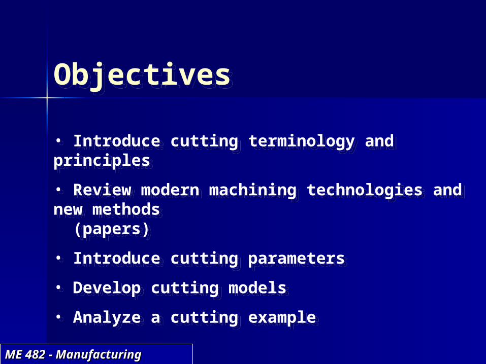
Machining surface finish
ME 482 - Manufacturing ME 482 - Manufacturing SystemsSystems
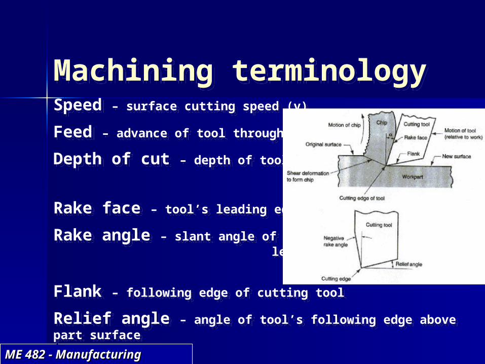
Machining terminologySpeed – surface cutting speed (v)Feed – advance of tool through the part (f)Depth of cut – depth of tool into part (d)
Rake face – tool’s leading edgeRake angle – slant angle of tool’s leading edge ()
Flank – following edge of cutting toolRelief angle – angle of tool’s following edge above part surface
ME 482 - Manufacturing ME 482 - Manufacturing SystemsSystems
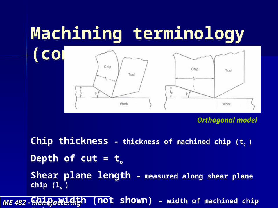
Machining terminology (cont.)
Chip thickness – thickness of machined chip (tc )
Depth of cut = to
Shear plane length – measured along shear plane chip (ls )
Chip width (not shown) – width of machined chip (w )
Shear angle – angle of shearing surface measured from tool direction ()
ls
Orthogonal model
ME 482 - Manufacturing ME 482 - Manufacturing SystemsSystems
Cutting conditionsNote: - Primary cutting due to speed
- Lateral motion of tool is feed- Tool penetration is depth of cut
The three together form the material removal rate (MRR):
MRR = v f d with units of (in/min)(in/rev)(in) = in3/min/rev (or vol/min-rev)
Types of cuts: Roughing: feeds of 0.015 – 0.05 in/rev depths of 0.1 – 0.75 in
Finishing: feeds of 0.005 – 0.015 in/rev depths of 0.03 – 0.075 in
ME 482 - Manufacturing ME 482 - Manufacturing SystemsSystems
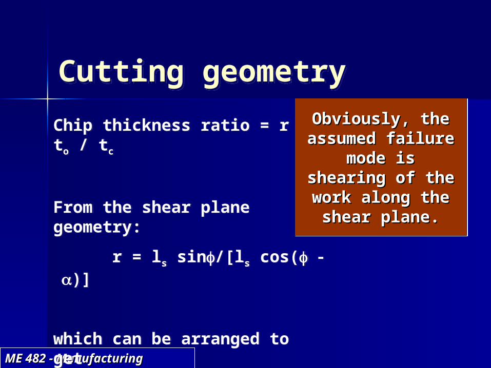
Cutting geometryChip thickness ratio = r = to / tc
From the shear plane geometry:
r = ls sin/[ls cos(-)]
which can be arranged to get
tan = r cos /[1 – r sin]
Obviously, the Obviously, the assumed failure assumed failure
mode is mode is shearing of the shearing of the work along the work along the shear plane.shear plane.

ME 482 - Manufacturing ME 482 - Manufacturing SystemsSystems
Cutting geometryNote from the triangles in (c) that the shear strain () can be estimated as
= AC/BD = (DC + AD)/BD = tan(-) + cot
Thus, if Thus, if know r and know r and
can can determine determine
, and , and given given
and and , can , can determine determine
..

ME 482 - Manufacturing ME 482 - Manufacturing SystemsSystems
Cutting forcesSince R = R’ = R’’, we can get the force balance equations:
F = Fc sin + Ft cos F = friction force; N = normal to chip force
N = Fc cos - Ft sin Fc = cutting force; Ft = thrust forceFs = Fc cos - Ft sin Fs = shear force; Fn = normal to
shear plane forceFn = Fc sin + Ft cos
Friction angle = tan= = F/N
Shear plane stress: = Fs/As
where As = to w/sin
Forces are presented as Forces are presented as function of Ffunction of Fcc and F and Ftt because these can be because these can be measured.measured.

ME 482 - Manufacturing ME 482 - Manufacturing SystemsSystems
Cutting forces given shear strengthLetting S = shear strength, we can derive the following equations for the cutting and thrust forces*:
Fs = S As
Fc = Fs cos (cos (
Ft = Fs sin (cos (
* The other forces can be determined from the equations on the previous slide.

ME 482 - Manufacturing ME 482 - Manufacturing SystemsSystems
Merchant equationsCombining the equations from the previous slides:
= (Fc cos - Ft sin tow/sinMerchant eqn
The most likely shear angle will minimize the energy. Applying d/d = 0 gives: = 45° + Merchant reln
What does the Merchant relation indicate?- increase in friction angle decreases shear angle- increase in rake angle increases shear angle
If we increase the shear If we increase the shear angle, we decrease the angle, we decrease the tool force and power tool force and power
requirements!requirements!
The Merchant reln is a The Merchant reln is a function of function of and and . Where . Where did these variables come did these variables come from? from?
AnswerAnswer - - Although the Although the Merchant eqn is not shown Merchant eqn is not shown as a direct function of as a direct function of and and , these enter from , these enter from the equations for Fthe equations for Fc c and Fand Ft t
from the previous slide!from the previous slide!

ME 482 - Manufacturing ME 482 - Manufacturing SystemsSystems
Cutting modelsThe orthogonal model for turning approximates the complex shearing process: to = feed (f)
w = depth of cut (d)

ME 482 - Manufacturing ME 482 - Manufacturing SystemsSystems
Cutting powerPower is force times speed:
P = Fc v (ft-lb/min)The cutting horsepower ishpc = Fc v/33,000 (hp)The unit horsepower is
hpu = hpc/MRR units?
Due to efficiency losses (E about 90%), the gross hp is
hpg = hpc/E

ME 482 - Manufacturing ME 482 - Manufacturing SystemsSystems
Cutting energySpecific energy is
U = Fc v/(v tow) = Fc /(tow) (in-lb/in3)The table shown contains power and specific energy ratings for several work materials at a chip thickness of 0.01 in. For other chip thicknesses, apply the figure to get a correction factor multiply U by correction factor for thickness different than 0.01”).

ME 482 - Manufacturing ME 482 - Manufacturing SystemsSystems
Machining exampleIn orthogonal machining the tool has rake angle 10°,
chip thickness before cut is to = 0.02 in, and chip thickness after cut is tc = 0.045 in. The cutting and thrust forces are measured at Fc = 350 lb and Ft = 285 lb while at a cutting speed of 200 ft/min. Determine the machining shear strain, shear stress, and cutting horsepower.Solution (shear strain):
Determine r = 0.02/0.045 = 0.444Determine shear plane angle from tan = r cos /[1 – r sin]
tan = 0.444 cos /[1 – 0.444 sin] => = 25.4°Now calculate shear strain from = tan(-) + cot
= tan(25.4 - 10) + cot 25.4 = 2.386 in/inanswer!
ME 482 - Manufacturing ME 482 - Manufacturing SystemsSystems
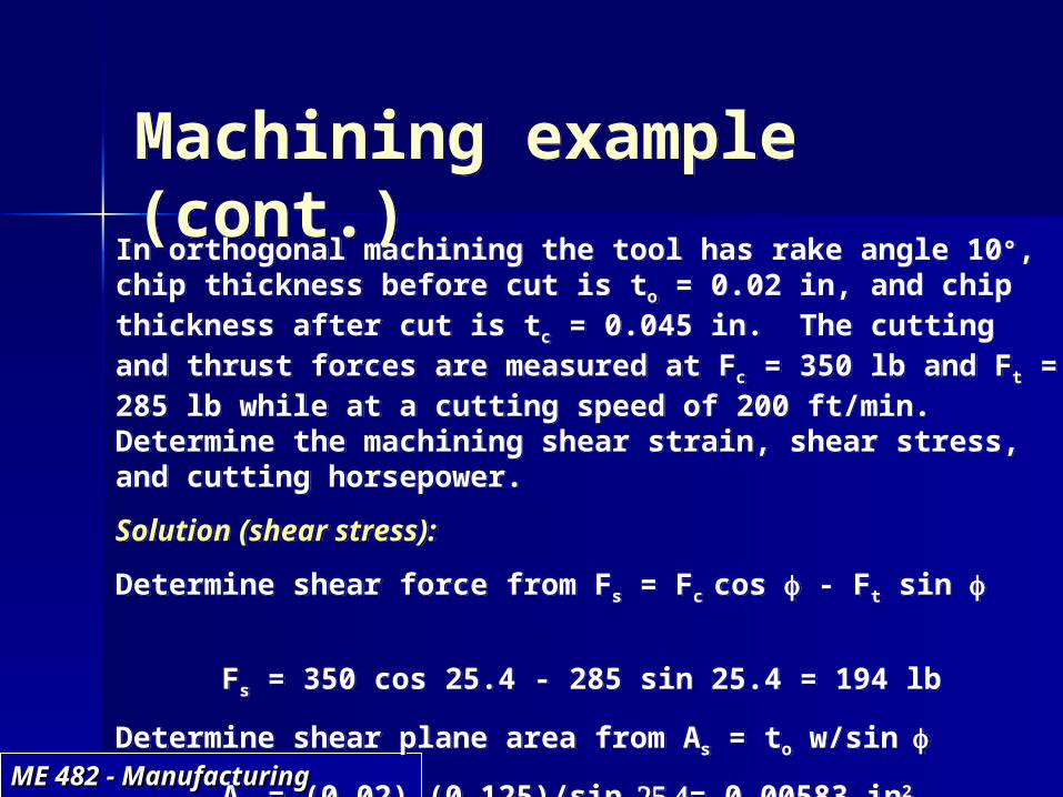
Machining example (cont.)In orthogonal machining the tool has rake angle 10°,
chip thickness before cut is to = 0.02 in, and chip thickness after cut is tc = 0.045 in. The cutting and thrust forces are measured at Fc = 350 lb and Ft = 285 lb while at a cutting speed of 200 ft/min. Determine the machining shear strain, shear stress, and cutting horsepower.Solution (shear stress):
Determine shear force from Fs = Fc cos - Ft sin
Fs = 350 cos 25.4 - 285 sin 25.4 = 194 lbDetermine shear plane area from As = to w/sin
As = (0.02) (0.125)/sin= 0.00583 in2
The shear stress is = 194/0.00583 = 33,276 lb/in2 answer!

ME 482 - Manufacturing ME 482 - Manufacturing SystemsSystems
Machining example (cont.)In orthogonal machining the tool has rake angle 10°,
chip thickness before cut is to = 0.02 in, and chip thickness after cut is tc = 0.045 in. The cutting and thrust forces are measured at Fc = 350 lb and Ft = 285 lb while at a cutting speed of 200 ft/min. Determine the machining shear strain, shear stress, and cutting horsepower.
Solution (cutting horsepower):
Determine cutting hp from hpc = Fc v/33,000 hpc = (350) (200)/33,000 = 2.12 hp answer!

ME 482 - Manufacturing ME 482 - Manufacturing SystemsSystems
Cutting temperaturesIn machining 98% of the cutting energy is converted into heat. This energy flows into the work part, chip, and tool. Cook determined an experimental equation for predicting the temperature rise at the tool-chip interface during machining:
T = 0.4 U (v to/K)0.333/(c)where
T = mean temperature rise (°F)U = specific energy (in-lb/in3)v = cutting speed (in/s) to = chip thickness before cut (in) c= volumetric specific heat of the work
material (in-lb/(in3-°F)) K = thermal diffusivity of the work material (in2/s)Note - To get total temperature at tool-chip interface, must add in ambient temperature!
Example in text Example in text calculates calculates TT = = 936936°° total tool total tool temperature, temperature, given v = 200 given v = 200
ft/min, ft/min, cc = 120 = 120 in-lb/(inin-lb/(in33- - °F°F) ) and K = 0.125 and K = 0.125
inin22/s/s
ME 482 - Manufacturing ME 482 - Manufacturing SystemsSystems
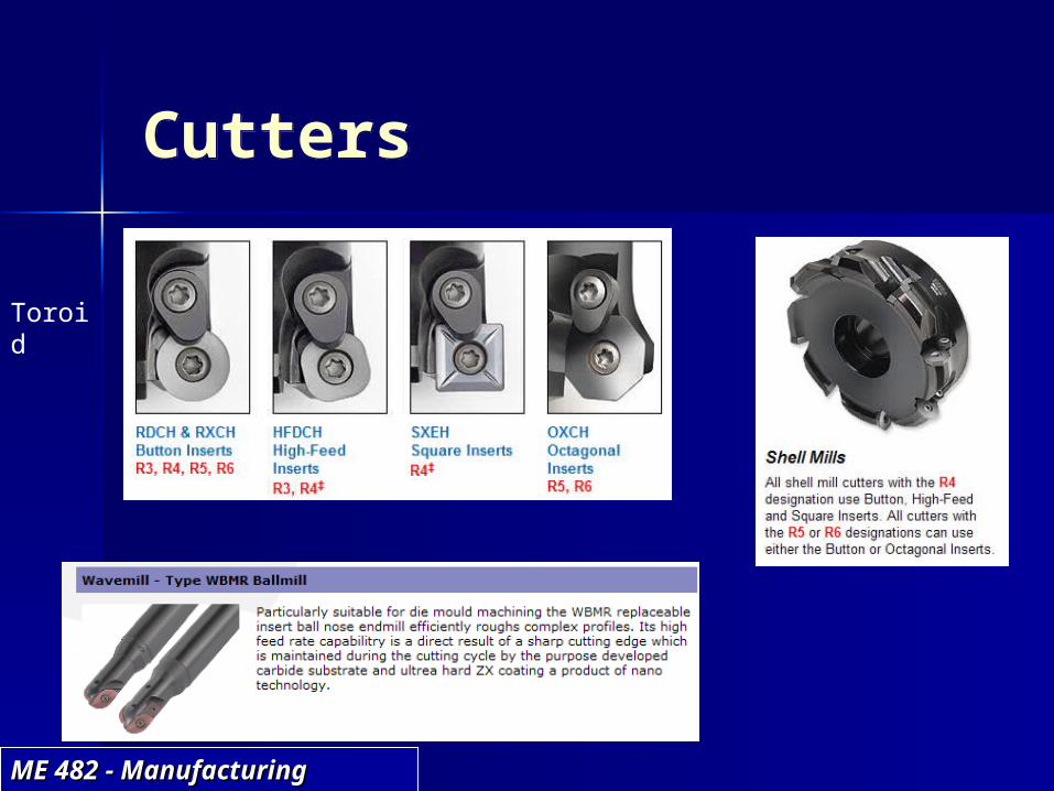
Cutters
Toroid

ME 482 - Manufacturing ME 482 - Manufacturing SystemsSystems
Cutters

ME 482 - Manufacturing ME 482 - Manufacturing SystemsSystems
Machining
What did we learn?