Feature Based Modeling of Machining Process Products
12
Feature Based Modeling of Machining Process Products F. Tanaka, T. Kishinami Manufacturing Information Engineering Lab, Division of Systems and Information Engineering, Graduate School of Engineering, Hokkaido University Kita-13, Nishi-8, Kita-ku Sapporo 060 JAPAN, TEL +81-11-706-6449 FAX +81-11-706-7836 E-mail [email protected] Abstract In this paper, we propose feature models of a machining operation and machined surface, which correspond directly to the machining process model. The feature model of the machining operation is proposed from the viewpoint of the dimension of a macro cutting tool, the dimension of feed motion, and the number of enveloping constraints. The machining feature is also proposed from the viewpoint of the removal volume (tool swept shape), machined surface (enveloping tool swept shape), and the contacting shape between the required surface and cutting edge during one cutting motion (unit-shaping element). We proposed the abstract model of the machining process and the abstract model of operation planning which could represent the linear equations. We also pointed out that there are only 15 types of machining operations. Keywords Machining Feature, Machining Process Model, Computer Aided Manufacturing, Computer Aided Process Planning, Form Shaping Function G. Jacucci et al. (eds.), Globalization of Manufacturing in the Digital Communications Era of the 21 st Century © Springer Science+Business Media New York 1998
-
Upload
khangminh22 -
Category
Documents
-
view
0 -
download
0
Transcript of Feature Based Modeling of Machining Process Products
Feature Based Modeling of Machining Process Products
F. Tanaka, T. Kishinami Manufacturing Information Engineering Lab, Division of Systems and Information Engineering, Graduate School of Engineering, Hokkaido University Kita-13, Nishi-8, Kita-ku Sapporo 060 JAPAN, TEL +81-11-706-6449 FAX +81-11-706-7836 E-mail [email protected]
Abstract In this paper, we propose feature models of a machining operation and machined surface, which correspond directly to the machining process model. The feature model of the machining operation is proposed from the viewpoint of the dimension of a macro cutting tool, the dimension of feed motion, and the number of enveloping constraints. The machining feature is also proposed from the viewpoint of the removal volume (tool swept shape), machined surface (enveloping tool swept shape ), and the contacting shape between the required surface and cutting edge during one cutting motion (unit-shaping element). We proposed the abstract model of the machining process and the abstract model of operation planning which could represent the linear equations. We also pointed out that there are only 15 types of machining operations.
Keywords Machining Feature, Machining Process Model, Computer Aided
Manufacturing, Computer Aided Process Planning, Form Shaping Function
G. Jacucci et al. (eds.), Globalization of Manufacturing in the Digital Communications Era of the 21st Century © Springer Science+Business Media New York 1998
164
1 INTRODUCTION
Feature-based approaches have been very popular in a variety of CAD/CAM implementations. In design, features capture explicit engineering attributes and relationships among product definition entities. This information is essential for various design tasks and analyses. In manufacturing, features can be linked to manufacturing knowledge of various types. This knowledge facilitates computeraided process planning (CAPP) and helps to generate the detailed operating instructions required by production systems (Elmaragy, 1993). The typical approach of process planning is to consider the removal volume as a collection of machining features, and to do the planning on a feature-by-feature basis (Cutkosky and Tenenbaum, 1990) (Shah and Mantyla, 1995) (Wong and Leung, 1995) (Requicha, 1996) (Mantyla et al. 1996). In the past, "if-then" production rules were the most commonly used techniques to code manufacturing knowledge, such as the mapping rule, in operation planning systems. In recent years, it has been recognized that the knowledge encoded in these rules is shallow (Shirur and Shah, 1996). Also, in CAPP, it is important tobe able to obtain features that correspond directly to manufacturing operations. However, such features are not available in many existing approaches (Gupta et al. 1994). Because machining featuressuch as holes, slots, and pockets do not generally take into account the micro-level geometrical characteristics of a contacting shape between the required surface and the cutting edge during a cutting motion and the macro-level geometrical characteristics of removal volume, these machining features do not have sufficient information in order to determine the appropriate machining operation. One of the reasons why these situations occur is that there are no suitable machining process models for linkage between machining features and machining operations.
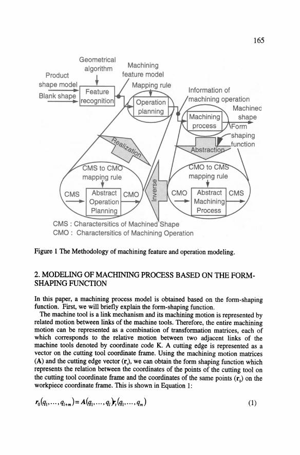
In order to capture the fundamental characteristics of the machining process and make suitable machining process models based on them, we propose the following modeling methodology based on the form-shaping function proposed by Reshetov and Portman (1988). In this methodology, as shown in Figure 1, first the machining process is modeled as an abstract machining process in order to capture the general and fundamental characteristics of the machining process. Second, an abstract operation planning activity is obtained by inverting the abstract machining process. Finally, an operation planning activity and a machining feature can be obtained based on the abstract operation planning. In the abstract machining operation, an abstract model of machining operation information is defined as the characteristics of machining operation (CMO), and an abstract model of machined shape information is defined as the characteristics of a machined shape (CMS). Therefore, the characteristics of a machined shape can been seen as a model of machining features.
Geometrical algorithm
Product 1 shape model r----'''--.........,
Machining feature model
Mapping rule
165
Blank shape machining operation
CMS : Charactersitics of Machined Shape CMO : Charactersitics of Machining Operation
Machined shape
Form shaping function
Figure 1 The Methodology of machining feature and operation modeling.
2. MODEUNO OF MACHINING PROCESS BASED ON THE FORMSHAPING FUNCTION
In this paper, a machining process model is obtained based on the form-shaping function. First, we will briefly explain the form-shaping function.
The machine tool is a link mechanism and its machining motion is represented by related motion between links of the machine tools. Therefore, the entire machining motion can be represented as a combination of transformation matrices, each of which corresponds to the relative motion between two adjacent links of the machine tools denoted by coordinate code K. A cutting edge is represented as a vector on the cutting tool coordinate frame. Using the machining motion matrices (A) and the cutting edge vector (r,), we can obtain the form shaping function which represents the relation between the coordinates of the points of the cutting tool on the cutting tool coordinate frame and the coordinates of the same points (r0) on the workpiece coordinate frame. This is shown in Equation 1:
(1)
166
where, q; is an i-th relative motion variable or a parameter of the cutting edge vector, l is the number of relative motions of the machine tools, and m is the number of parameters of the cutting edge vector.
In order to derive the equation of the specific machined surface, we must specify functional constraints, enveloping constraints and implicit constraints to the formshaping function. The functional constraints (h, ... Jlf ) are equations which represent the motion constraints of the machine tools. The enveloping constraints (h, ... fu ) are equations employed when the machined surface forms an enveloping family of the instantaneous positions of the cutting point of the cutting tool. The implicit constraints (h, ... ,fu ) are equations which remove the redundant variables in the form-shaping function.
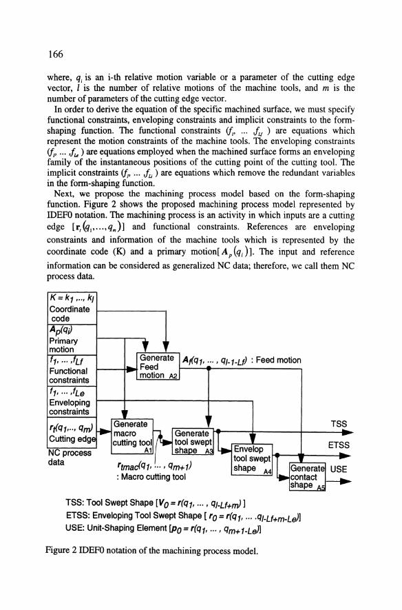
Next, we propose the machining process model based on the form-shaping function. Figure 2 shows the proposed machining process model represented by IDEFO notation. The machining process is an activity in which inputs are a cutting edge [r,{qi' ... ,qJ] and functional constraints. References are enveloping constraints and information of the machine tools which is represented by the coordinate code (K) and a primary motion[ A P (q;) ]. The input and reference
information can be considered as generalized NC data; therefore, we call them NC process data.
K=kt , .. , kJ Coordinate code Ap(q;) Primary motion '
,. 't· ··· .tu Generate Af(q1, ... , QJ-1-Lf) : Feed motion
Feed Functional - motion A2. constraints
ft, ··· ·'Le Enveloping constraints ,.
r rf{i mJ Generate TSS .. -Cutt1ng edge cutting tool tool swe~~ I. ETSS
q,, .. , q • macro {+- Generate n
NC process A1 shaoe A Envelop data tool swept
1 -
'tmacfqt, ··· • Qm+t) shape A4 Generate USE : Macro cutting tool • contact ~
shape AB
TSS: Tool Swept Shape [Vo = r(qt • ... , QJ.Lf+mJ 1 ETSS: Enveloping Tool Swept Shape [ ro = r(qt, ... . QJ.Lf+m-LeJ] USE: Unit-Shaping Element lPo = r(qt, ... , Qm+1-LeJ1
Figure 2 IDEFO notation of the machining process model.
167
Outputs of the machining process are related to the machining features. These are a family of instantaneous positions of a cutting point (Tool Swept Shape: TSS), an envelop of the family of instantaneous positions of a cutting point (Enveloping Tool Swept Shape: ETSS), and a unit-shaping element (USE).
The machining process is modeled from two viewpoints, the viewpoint of the action in the machine tools and the viewpoint of the action to the workpiece. Using a form shaping function, these activities are formulated by matrix equations.
From the viewpoint of the action in the machine tools, there are three activities: "generate macro cutting tool"; "generate feed motion"; and "generate tool swept shape". The frrst activity, "generate macro cutting tool", is the activity in which the macro cutting tool r 111111C( q1, ••• , q.,.1), the locus of the cutting edge, is generated by adding the primary motion to the cutting tool. In the second activity, "generate machining motion", a feed motion A1 (q1 , ••• , q1_u) of the machine tools having coordinate code K is generated under functional constraints. In the third activity, "generate removal volume", the machine tool generates a family of the instantaneous positions of the cutting points of the cutting tool by adding the feed motion to the macro cutting tool. The family of the instantaneous positions of the cutting points of the cutting tool is obtained by sweeping the macro cutting tool along with the feed motion, defined as the tool swept shape. The portion of the tool swept shape is considered as the removal volume of the workpiece from the material removal viewpoint. The tool swept shape v0 is represented by Equation 2.
(2)
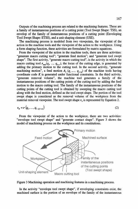
From the viewpoint of the action to the workpiece, there are two activities: "envelope tool swept shape" and "generate contact shape". Figure 3 shows the model of machining process on the workpiece and its constitutions.
I ' I
Macro cutting tool Unit-shaping element
amily of the instantaneous positions of the cutting points
(T ool swept shape)
Figure 3 Machining operation and machining features in a machining process.
In the activity "envelope tool swept shape", if enveloping constraints exist, the machined surface is the portion of an envelope of the family of the instantaneous
168
positions of the cutting points of the cutting tool (an enveloping tool swept shape). Otherwise, the machined surface is the portion of the tool swept shape. In this paper, the implicit constraints are not taken into account and the machined surface r0 is represented by Equation 3.
ro = r (ql • · · · • qi-Lf +m-Le) (3)
In the activity "generate contact shape", the macro cutting tool is in contact with the machined surface. As shown in Figure 3, a contact portion of the macro cutting tool can be obtained by stopping the feed motion. The equation of the contact portion of macro cutting tool is derived by constant values for the variables which represent the feed motion in Equation 3. We name the contact portion of the macro cutting tool the unit-shaping element p0• The unit-shaping element is represented by Equation 4.
Po = r(ql' ... ' qm+I-Le) (4)
Concequently, the feature of the machined shape consists of the tool swept shape (v 0)., the enveloping tool swept shape (r0) and the unit-shaping element (p 0).
3 ABSTRACT MODEL OF MACHINING OPERATION AND MACHINING FEATURES
3.1 Characteristics of the machining operation
According to the model of the machining process, as mentioned above, we propose an abstract model of a machining process in order to capture the general and fundamental characteristics of a machining process. This abstraction is based on the mathematical representations of the machining operation and the machined shape. The characteristics of the machining process are the number of variables in the equations which represent the machining operation and the machined shape, and the number of constraints in the machining process model. Figure 4 shows the changing process of the number of variables in the machining process model.
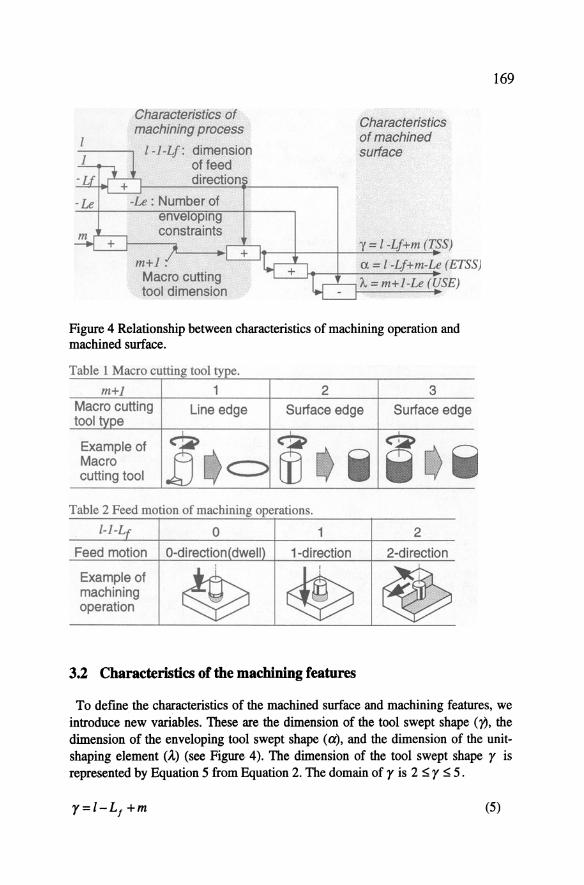
The characteristics of machining operation are the dimension of the macro cutting tool (m+ 1), the dimension of feed motion in the machining operation (I - 1- L 1 ), and the number of enveloping constraints (LJ The dimension of the
macro cutting tool indicates the type of macro cutting tool, as shown in Table 1. The domain of the dimension of the macro cutting tool is 1 ::;; m + 1 ::;; 3 . The dimension of the feed motion is the degree of freedom of the macro cutting tool as shown in Table 2. The domain of the dimension of feed motion is 0 s; l -1- L 1 s; 2 . The domain of the number of enveloping constraints is
0!5:L, !5:2.
Characteristics of machining process
l -1-Lf : dimension
m+l.
of feed direction
Macro cutting tool dimension
Characteristics of machined surface
'Y =I -Lf+m (TSS)
a =I -Lf+m-Le (ETSS)
A. = m+l-Le (USE)
Figure 4 Relationship between characteristics of machining operation and machined surface.
Table 1 Macro cutting tool type.
m+J 1 Macro cutting Une edge tool e
Example of .e Macro cutting tool
2
Surface edge
Table 2 Feed motion of machining operations.
l-1-4 0 1
Feed motion 0-di rection( dwell) 1-di rection
Example of
~ ~ machining operation
3.2 Characteristics of the machining features
3
Surface edge
2
2-direction
~
169
To defme the characteristics of the machined surface and machining features, we introduce new variables. Theseare the dimension of the tool swept shape ()?, the dimension of the enveloping tool swept shape (a), and the dimension of the unitshaping element (A.) (see Figure 4). The dimension of the tool swept shape r is represented by Equation 5 from Equation 2. The domain of r is 2 ~ r ~ 5.
r=l-L1 +m (5)
170
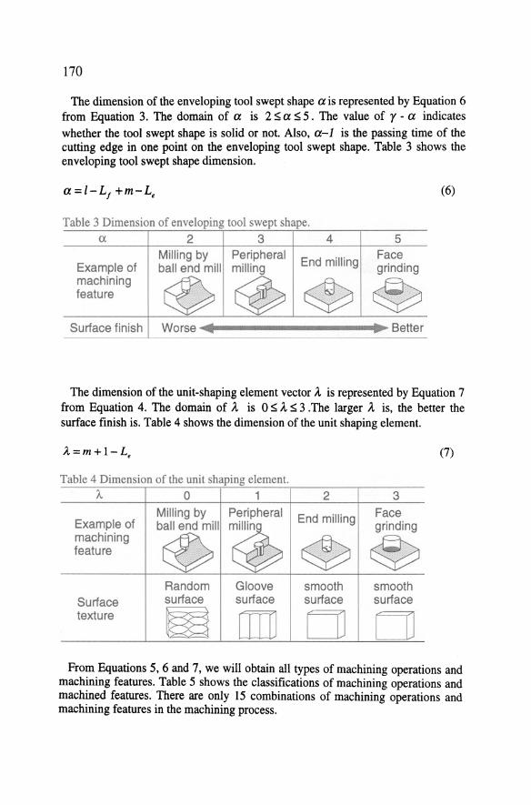
The dimension of the enveloping tool swept shape a is represented by Equation 6 from Equation 3. The domain of a is 2 $ a $ 5 . The value of r -a indicates whether the tool swept shape is solid or not. Also, a-1 is the passing time of the cutting edge in one point on the enveloping tool swept shape. Table 3 shows the enveloping tool swept shape dimension.
a =l-L1 +m-L, (6)
Table 3 Dimension of enveloping tool swept shape. a 2 3 4 5
Milling by Peripheral End milling
Face Example of ball end mill milling grinding machining
© @ @ ~ feature
Surface finish Worse Setter
The dimension of the unit-shaping element vector A. is represented by Equation 7 from Equation 4. The domain of A. is 0$ A. $3 .The !arger A. is, the better the surface finish is. Table 4 shows the dimension of the unit shaping element.
A..=m+l-L, (7)
Table 4 Dimension of the unit shaping element. /.. 0 1 2 3
Milling by Peripheral End milling Face Example of ball end mill
~ grinding
machining
~ @ ~ feature
Random Gloove smooth smooth Surface surface surface surface surface texture w [l] []] []]
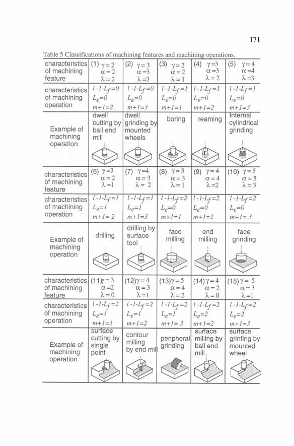
From Equations 5, 6 and 7, we will obtain all types of machining operations and machining features. Table 5 shows the classifications of machining operations and machined features. There are only 15 combinations of machining operations and machining features in the machining process.
171
T bl 5 Cl 'fi a e ass1 cat.tons o mac mmg eatures an mac mmg operat10ns. f h' . ~ d h' .
characteristics (1) y= 2 (2) Y= 3 (3) y= 2 (4) y=3 (5) y=4 of machining a=2 a=3 a=2 a=3 a=4 feature /..=2 /..=3 A.=l "-=2 /..=3
characteristics l-1-Lt=O l-1-Lt=O l-1-Lt=1 l-1-Lt=l l-1-Lt=l of machining Le=O Le=O Le=O Le=O Le=O operation m+1=2 m+1=3 m+1=1 m+1=2 m+1=3
dwell dwell boring reaming Interna I
cutting by grinding b~ cylindrical Example of ball end mounted grinding machining mill wheels
I operation
~ ~ ~ '
® @ characteristics (6) 'Y =3 (7) y=4 (8) y=3 (9) r= 4 (10) r= 5
a=2 a=3 a=3 a=4 a=5 of machining "-=1 "-= 2 "-=1 "-=2 /...=3 feature
characte ristics l-1-Lt=l l-1-Lt=l l-1-Lt=2 l-l-Lj=2 l-1-Lt=2 of machining Le=l Le=l Le=O Le=O Le=O operation m+1=2 m+1=3 m+l=l m+1=2 m+l= 3
drilling by face end face Example of
drilling surface milling milling grinding tool machining
~ ~ ~ 4 ~ operation
characteristics (11)Y= 3 (12)Y= 4 (13)Y= 5 (14)Y = 4 (15)Y= 5 of machining a=2 a=3 a=4 a =2 a=3 feature A.=O "-=1 /... = 2 A.=O "-=1
characteristics l-1-Lt=2 l-1-Lt=2 l-1-Lt=2 l-1-Lt=2 l-l-Lt=2 of machining Le=1 Le=1 Le=l Le=2 Le=2 operation m+l=1 m+l=2 m+l=3 m+l=2 m+l=3
surtace contour surrace surrace cutting by
milling peripheral milling by grinfing by Example of single grinding ball end mounted machining
~ by end mil
~ (b operation I
~ @

172
3.3 Abstractmodel of the macbining process and operation planning
The abstract model of the machining process is the relationship between the characteristics of the machining operation and the machining feature. From Equations 5, 6 and 7, the abstract model of the machining process is represented by Equation 8.
(8)
The abstract model of operation planning can be obtained by reversing the abstract model of machining process. From Equation 8, the abstract model of the operation planning is represented by Equation 9.
(9)
4 MODEL EXAMPLE
To verify the efficiency of our abstract model, we give an example of an abstract model ofthe machining process and operation lannin as shown in Figure 5.
Feature 'Y = 3 a =3 ')., = 1
~llli:::::::_])
machining feature
Operatio Oparatio l-1-Lf=l l-l-Lf=2 Le=l Le=O
m+1=2
machining operation
Figure 5 An example of the abstract model of the machining process.

173
In Figure 5, there are three types of machining features related to their machining operations. As shown in this figure, the characteristics of the machining features corresponds directly to the characteristies of the machining operations via equation (8) and (9).
5 CONCLUSIONS
In this paper, we proposed feature models of a machining operation and machined surface, which correspond directly to the machining process model. The eonelusions are as follows: ( 1) The feature model of the machining operation was proposed from the viewpoint
of the dimension of a maero eutting tool, the dimension of feed motion, and the number of enveloping constraints.
(2) The maehining feature was proposed from the viewpoint of the removal volume (tool swept shape), machined surfaee (enveloping tool swept shape), and the eontaeting shape between the required surfaee and eutting edge during one eutting motion (unit-shaping element).
(3) We proposed an abstract model ofthe machining proeess and an abstraet model of operation planning which eould represent the linear equations. We also pointed out that there are only 15 types of maehining operations.
(4) We showed a maehining feature model example to demoostrate eorrespondenee from the feature model to the machining operation model.
6 REFERENCES
Cutkosky, M.R. and Tenenbaum, J.M. (1990) A Methodology and Computational Framework for Coneurrent Product and Process Design, Mechanism and Machine Theory, 25, 3, 365-381.
Elmaragy, H.A.(1993) Evolution and Future Perspectives of CAPP, Ann. CIRP, 42, 2, 739-751.
Faux, I.D. and Pratt, M.J. (1979) Computational Geometry for Design and Manufaeturing, Ellis Horwood, New York
Gupta, S.K., Kramer, T.R., Nau, D.S., Regli, W.C. and Zhang, G. (1994) Building MRSEV models for CAM applieations, Advances in Engineering Software, 20, 121-139.
Mantyla, M., Nau, D. and Shah, J.J. (1996) Challenges in Feature-Based Manufacturing Research, Comm. ofthe ACM, 39,2,77-85.
Requicha, A.A.G. (1996) Geometrie Reasoning for Intelligent Manufaeturing, Comm. ofthe ACM, 39, 2, 71-76.
Reshetov, D.N. and Portman, V.T. (1988) Aeeuraey of Maehine Tools, ASME Press, New York.
Shah, J.J. and Mantyla M. (1995) Parametrie and Feature-based CAD/CAM, John Wiley & Sons, New York
174
Shirur, A. and Shah, J.J. (1996) Machining Algebra for Mapping Volumes to Machining Operations, Proc. of the 1996 ASME Design Engineering Technical Conferences and Computers in Engineering Conference, 96-DETCDFM-1303.
Wong, T.N. and Leung, C.B. (1995) Feature Conversion between Neutral Features and Application Features, Computersand Industrial Engineering, 29, 1-4,625-629
7 BIOGRAPHY
Fumiki Tanaka received the M.Eng. Degree from Hokkaido University in 1987. He is research assistant of the division of systems and information engineering, Hokkaido University. Hisresearch interests include machining process modelling, geometric modelling, inspection of mechanical products, information modeHing of manufacturing for mechanical products. He is a member of JSPE (Japan society for Precision Engineering).
Takeshi Kishinami received the D.Eng. Degree from Hokkaido University in 1971. He is Professor of the division of systems and information engineering, Hokkaido University. Hisresearch interests include informationmodeHing of manufacturing for mechanical products, rapid prototyping, He is a member of JSPE and JSME (Japan society for Mechanical Engineers).